Embed Size (px)
Citation preview

1
Mtd
. Ba
llB
ea
rin
gs
G-2
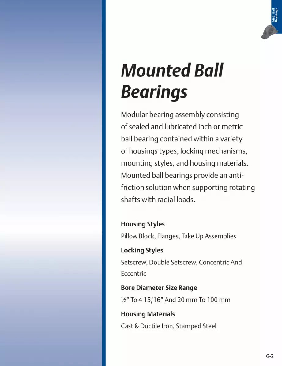
Mounted Ball BearingsModular bearing assembly consisting
of sealed and lubricated inch or metric
ball bearing contained within a variety
of housings types, locking mechanisms,
mounting styles, and housing materials.
Mounted ball bearings provide an anti-
friction solution when supporting rotating
shafts with radial loads.
Housing Styles
Pillow Block, Flanges, Take Up Assemblies
Locking Styles
Setscrew, Double Setscrew, Concentric And
Eccentric
Bore Diameter Size Range
½” To 4 15/16” And 20 mm To 100 mm
Housing Materials
Cast & Ductile Iron, Stamped Steel
Mtd
. Ba
ll
Be
ari
ng
s

G-3
Mtd
. Ba
ll
Be
ari
ng
s
Mounted Ball Bearing Selection GuideLock Type Size Range
Brand Image Series Housing Style Duty Setscrew Concentric Double Setscrew Housing Material Standard Seal Seal Options Inch Metric Section Name Pages
Sealmaster
NPTwo Bolt
Pillow Block - High Base
Standard NP NP-T NPD
Cast Iron Felt Contact
1/2” - 2 15/16” 20mm - 75mm
Performance Mounted Ball
Bearings
G-31 to G-33
NPLTwo Bolt
Pillow Block - Low Base
Standard NPL NPL-T 1/2” - 2 11/16” 20mm - 60mm G-34 to G-35
SPTwo Bolt
Pillow Block - Heavy Duty
Standard SP SP-T SPD 13/16” - 3 7/16” 36mm - 80mm G-36 to G-38
MPTwo Bolt
Pillow Block - High Base
Medium MP MP-T MPD 15/16” - 4” 25mm - 100mm G-39 to G-41
MFPFour Bolt
Pillow Block - High Base
Medium MFP MFPD 1 15/16” - 5” 50mm - 100mm G-42 to G-43
MSPDTwo Bolt
Pillow Block - Heavy Duty
Medium MSPD 1 11/16” - 4 15/16” N/A G-44
MSFPDFour Bolt
Pillow Block - Heavy Duty
Medium MSFPD 1 15/16” - 4 15/16” N/A G-45
SPMTwo Bolt
Pillow Block - Heavy Duty
Medium SPM 1 3/16” - 2 1/2” N/A G-46
TB Tapped Base Pillow Block Standard TB TB-T 1/2” - 2” 20mm - 50mm G-47 to G-48
SF Four Bolt Flange Standard SF SF-T 1/2” - 2 15/16” 20mm - 75mm G-49 to G-50
MSF Four Bolt Flange Medium MSF MSF-T 15/16” - 4 15/16” 25mm - 100mm G-51 to G-52
SFT Two Bolt Flange Standard SFT SFT-T 1/2” - 2 3/16” 20mm - 55mm G-53 to G-54
MSFT Two Bolt Flange Medium MSFT MSFT-T 15/16” - 2” 25mm - 50mm G-55 to G-56
G-3
® Mounted Ball Bearings

G-4
Mtd
. Ba
ll
Be
ari
ng
s
Lock Type Size Range
Brand Image Series Housing Style Duty Setscrew Concentric Double Setscrew Housing Material Standard Seal Seal Options Inch Metric Section Name Pages
Sealmaster
NPTwo Bolt
Pillow Block - High Base
Standard NP NP-T NPD
Cast Iron Felt Contact
1/2” - 2 15/16” 20mm - 75mm
Performance Mounted Ball
Bearings
G-31 to G-33
NPLTwo Bolt
Pillow Block - Low Base
Standard NPL NPL-T 1/2” - 2 11/16” 20mm - 60mm G-34 to G-35
SPTwo Bolt
Pillow Block - Heavy Duty
Standard SP SP-T SPD 13/16” - 3 7/16” 36mm - 80mm G-36 to G-38
MPTwo Bolt
Pillow Block - High Base
Medium MP MP-T MPD 15/16” - 4” 25mm - 100mm G-39 to G-41
MFPFour Bolt
Pillow Block - High Base
Medium MFP MFPD 1 15/16” - 5” 50mm - 100mm G-42 to G-43
MSPDTwo Bolt
Pillow Block - Heavy Duty
Medium MSPD 1 11/16” - 4 15/16” N/A G-44
MSFPDFour Bolt
Pillow Block - Heavy Duty
Medium MSFPD 1 15/16” - 4 15/16” N/A G-45
SPMTwo Bolt
Pillow Block - Heavy Duty
Medium SPM 1 3/16” - 2 1/2” N/A G-46
TB Tapped Base Pillow Block Standard TB TB-T 1/2” - 2” 20mm - 50mm G-47 to G-48
SF Four Bolt Flange Standard SF SF-T 1/2” - 2 15/16” 20mm - 75mm G-49 to G-50
MSF Four Bolt Flange Medium MSF MSF-T 15/16” - 4 15/16” 25mm - 100mm G-51 to G-52
SFT Two Bolt Flange Standard SFT SFT-T 1/2” - 2 3/16” 20mm - 55mm G-53 to G-54
MSFT Two Bolt Flange Medium MSFT MSFT-T 15/16” - 2” 25mm - 50mm G-55 to G-56
G-4
Mounted Ball Bearings ®

G-5
Mounted Ball Bearing Selection GuideLock Type Size Range
Brand Image Series Housing Style Duty Setscrew Concentric Double Setscrew Housing Material Standard Seal Seal Options Inch Metric Section Name Pages
Sealmaster
FB Flange Bracket Standard FB FB-T
Cast Iron
Felt Contact
1/2” - 2” 20mm - 50mm
Performance Mounted Ball
Bearings
G-57 to G-58
SFC Piloted Flange Cartridge Standard SFC SFC-T 1 1/8” - 3 3/16” 30mm - 80mm G-59 to G-60
MFC Piloted Flange Cartridge Medium MFC MFC-T MFCD 15/16” - 4” 25mm - 100mm G-61 to G-63
SEHB Hanger Bearing External Lube Varies SEHB SEHB-T SEHBD
Ductile Iron
15/16” - 4” 25mm - 100mm G-64 to G-66
SCHB Hanger Bearing Internal Lube Varies SCHB 15/16” - 4” 25mm - 100mm G-67
SC Cylindrical Cartridge Standard SC SC-T
Cast Iron
1/2” - 2 15/16” 20mm - 75mm G-68 to G-69
MSC Cylindrical Cartridge Medium MSC MSC-T 15/16” - 4” 25mm - 100mm G-70 to G-71
ST Wide Slot Take Up Standard ST ST-T 1/2” - 3 7/16” 20mm - 80mm G-72 to G-73
MST Wide Slot Take Up Medium MST MST-T 15/16” - 4” 25mm - 100mm G-74 to G-75
STH Center Pull Take Up Frame Standard STH
N/A N/A N/A
7/8” - 2 15/16” 25mm - 75mm G-76 to G-78
MSTH Center Pull Take Up Frame Medium MSTH 1 11/16” - 2 1/2” N/A G-79
TF/TFS Top Mount Take Up Frame Standard 7/8” - 2 3/16” 25mm - 55mm G-80 to G-82
TFT-T Two Bolt Flange Standard TFT-T Ductile Iron Felt Contact 15/16” - 1 7/16” N/A G-83
G-5
® Mounted Ball BearingsMtd
. Ba
ll
Be
ari
ng
s

G-6
Lock Type Size Range
Brand Image Series Housing Style Duty Setscrew Concentric Double Setscrew Housing Material Standard Seal Seal Options Inch Metric Section Name Pages
Sealmaster
FB Flange Bracket Standard FB FB-T
Cast Iron
Felt Contact
1/2” - 2” 20mm - 50mm
Performance Mounted Ball
Bearings
G-57 to G-58
SFC Piloted Flange Cartridge Standard SFC SFC-T 1 1/8” - 3 3/16” 30mm - 80mm G-59 to G-60
MFC Piloted Flange Cartridge Medium MFC MFC-T MFCD 15/16” - 4” 25mm - 100mm G-61 to G-63
SEHB Hanger Bearing External Lube Varies SEHB SEHB-T SEHBD
Ductile Iron
15/16” - 4” 25mm - 100mm G-64 to G-66
SCHB Hanger Bearing Internal Lube Varies SCHB 15/16” - 4” 25mm - 100mm G-67
SC Cylindrical Cartridge Standard SC SC-T
Cast Iron
1/2” - 2 15/16” 20mm - 75mm G-68 to G-69
MSC Cylindrical Cartridge Medium MSC MSC-T 15/16” - 4” 25mm - 100mm G-70 to G-71
ST Wide Slot Take Up Standard ST ST-T 1/2” - 3 7/16” 20mm - 80mm G-72 to G-73
MST Wide Slot Take Up Medium MST MST-T 15/16” - 4” 25mm - 100mm G-74 to G-75
STH Center Pull Take Up Frame Standard STH
N/A N/A N/A
7/8” - 2 15/16” 25mm - 75mm G-76 to G-78
MSTH Center Pull Take Up Frame Medium MSTH 1 11/16” - 2 1/2” N/A G-79
TF/TFS Top Mount Take Up Frame Standard 7/8” - 2 3/16” 25mm - 55mm G-80 to G-82
TFT-T Two Bolt Flange Standard TFT-T Ductile Iron Felt Contact 15/16” - 1 7/16” N/A G-83
G-6
Mounted Ball Bearings ®
Mtd
. Ba
ll
Be
ari
ng
s
G-7
Mounted Ball Bearing Selection GuideLock Type Size Range
Brand Image Series Housing Style Duty Setscrew Concentric Double Setscrew Housing Material Standard Seal Seal Options Inch Metric Section Name Pages
Sealmaster
SRF Rubber Mounted Flange Light SRF
Stamped Steel
Felt Contact
1/2” - 1 1/4” N/A
Performance Mounted Ball
Bearings
G-84
SRP Rubber Mounted Pillow Block Light SRP 1/2” - 1 1/4” N/A G-85
SRC Rubber Mounted Cartridge Light SRC Rubber 1/2” - 1 1/4” N/A G-86
RB Rubber Mount Insert Light RB N/A 1/2” - 1 1/4” N/A G-87
AR-2 Expansion Insert Standard AR-2 AR-2-T
Brass
1/2”-3 1/2” 20mm - 90mm G-88 to G-89
AR-3 Expansion Insert Medium AR-3 AR-3-T 15/16” - 4” 25mm - 100mm G-90 to G-91
2- Insert Standard 2- 2-T 2-D
N/A
1/2” - 3 1/2” 20mm - 90mm G-92 to G-94
3- Insert Medium 3- 3-T 3-D 15/16” - 4 15/16” 25mm - 100mm G-95 to G-97
ER Cylindrical O.D. Insert Standard ER ER-T 1/2” - 4” 20mm - 80mm
Performance Cylindrical O.D. Bearings (ER)
G-107 to G-108
NPMH Pillow Block Standard NPMH NPMH-T
Cast Iron
Contact Seal + Flinger
N/A
1” - 2 3/16” N/A
Material Handling Bearings
G-113 to G-114
TBMH Tapped Base Pillow Block Standard TBMH TBMH-T 1” - 1 15/16” N/A G-115 to G-116
SFMH Four Bolt Flange Standard SFMH SFMH-T
Contact + Flinger
1” - 2 7/16” N/A G-117 to G-118
SFTMH Two Bolt Flange Standard SFTMH SFTMH-T 1” - 2 3/16” N/A G-119 to G-120
G-7
® Mounted Ball BearingsMtd
. Ba
ll
Be
ari
ng
s

G-8
Lock Type Size Range
Brand Image Series Housing Style Duty Setscrew Concentric Double Setscrew Housing Material Standard Seal Seal Options Inch Metric Section Name Pages
Sealmaster
SRF Rubber Mounted Flange Light SRF
Stamped Steel
Felt Contact
1/2” - 1 1/4” N/A
Performance Mounted Ball
Bearings
G-84
SRP Rubber Mounted Pillow Block Light SRP 1/2” - 1 1/4” N/A G-85
SRC Rubber Mounted Cartridge Light SRC Rubber 1/2” - 1 1/4” N/A G-86
RB Rubber Mount Insert Light RB N/A 1/2” - 1 1/4” N/A G-87
AR-2 Expansion Insert Standard AR-2 AR-2-T
Brass
1/2”-3 1/2” 20mm - 90mm G-88 to G-89
AR-3 Expansion Insert Medium AR-3 AR-3-T 15/16” - 4” 25mm - 100mm G-90 to G-91
2- Insert Standard 2- 2-T 2-D
N/A
1/2” - 3 1/2” 20mm - 90mm G-92 to G-94
3- Insert Medium 3- 3-T 3-D 15/16” - 4 15/16” 25mm - 100mm G-95 to G-97
ER Cylindrical O.D. Insert Standard ER ER-T 1/2” - 4” 20mm - 80mm
Performance Cylindrical O.D. Bearings (ER)
G-107 to G-108
NPMH Pillow Block Standard NPMH NPMH-T
Cast Iron
Contact Seal + Flinger
N/A
1” - 2 3/16” N/A
Material Handling Bearings
G-113 to G-114
TBMH Tapped Base Pillow Block Standard TBMH TBMH-T 1” - 1 15/16” N/A G-115 to G-116
SFMH Four Bolt Flange Standard SFMH SFMH-T
Contact + Flinger
1” - 2 7/16” N/A G-117 to G-118
SFTMH Two Bolt Flange Standard SFTMH SFTMH-T 1” - 2 3/16” N/A G-119 to G-120
G-8
Mounted Ball Bearings ®
Mtd
. Ba
ll
Be
ari
ng
s

G-9
Mounted Ball Bearing Selection GuideLock Type Size Range
Brand Image Series Housing Style Duty Setscrew Concentric Double Setscrew Housing Material Standard Seal Seal Options Inch Metric Section Name Pages
Sealmaster
FBMH Flange Bracket Standard FBMH FBMH-T
Cast Iron
Contact + Flinger
N/A
1” - 1 15/16” N/A
Material Handling Bearings
G-121 to G-122
STMH Wide Slot Take Up Standard STMH STMH-T 1” - 2 3/16” N/A G-123 to G-124
MH Insert Standard MH MH-T N/A 1” - 2 7/16” N/A G-125 to G-126
PVR-x3xx Pillow Block Varies
Varies Varies
1 1/8” - 1 3/4” N/A
Paver Bearings
G-130
PVR-x4xx Tapped Base Pillow Block Varies 1” - 2” N/A G-131
PVR-x5xx Four Bolt Flange Varies 1 1/2” 2 11/16” N/A G-132
PVR-x6xx Two Bolt Flange Varies 1 7/16” - 2” N/A G-133
PVR-x1xx Piloted Flange Cartridge Varies 1 15/16” - 2 3/16” N/A G-134
PVR-x2xx Hanger Bearing Varies 2” - 2 11/16” N/A G-135
PVR-x7xx Cylindrical Cartridge Varies 1 3/4” N/A G-136
® Mounted Ball BearingsMtd
. Ba
ll
Be
ari
ng
s

G-10
Lock Type Size Range
Brand Image Series Housing Style Duty Setscrew Concentric Double Setscrew Housing Material Standard Seal Seal Options Inch Metric Section Name Pages
Sealmaster
FBMH Flange Bracket Standard FBMH FBMH-T
Cast Iron
Contact + Flinger
N/A
1” - 1 15/16” N/A
Material Handling Bearings
G-121 to G-122
STMH Wide Slot Take Up Standard STMH STMH-T 1” - 2 3/16” N/A G-123 to G-124
MH Insert Standard MH MH-T N/A 1” - 2 7/16” N/A G-125 to G-126
PVR-x3xx Pillow Block Varies
Varies Varies
1 1/8” - 1 3/4” N/A
Paver Bearings
G-130
PVR-x4xx Tapped Base Pillow Block Varies 1” - 2” N/A G-131
PVR-x5xx Four Bolt Flange Varies 1 1/2” 2 11/16” N/A G-132
PVR-x6xx Two Bolt Flange Varies 1 7/16” - 2” N/A G-133
PVR-x1xx Piloted Flange Cartridge Varies 1 15/16” - 2 3/16” N/A G-134
PVR-x2xx Hanger Bearing Varies 2” - 2 11/16” N/A G-135
PVR-x7xx Cylindrical Cartridge Varies 1 3/4” N/A G-136
Mounted Ball Bearings ®
Mtd
. Ba
ll
Be
ari
ng
s

G-11
Mounted Ball Bearing Selection GuideLock Type Size Range
Brand Image Series Housing Style Duty Setscrew Concentric Eccentric Housing Material Standard Seal Seal Options Inch Metric Section Name Pages
Browning
VP 100Two Bolt
Pillow Block - High Base
Intermediate VPS 100 VPE 100
Cast Iron
Contact
N/A
1/2” - 2 3/16” N/A
Mounted Ball Bearings
G-145 to G-146
VP 200Two Bolt
Pillow Block - High Base
Standard VPS 200 VPB 200 VPE 200
Contact + Flinger
1/2” - 2 15/16” 20 mm - 60 mm G-147 to G-150
VP 300Two Bolt
Pillow Block - High Base
Medium VPS 300 VPB 300 1” - 2 3/16” N/A G-151 to G-152
VPL 100Two Bolt
Pillow Block - Low Base
Intermediate VPLS 100 VPLE 100 Contact 1/2” - 2 3/16” N/A G-153 to G-154
VPL 200Two Bolt
Pillow Block - Low Base
Standard VPLS 200 VPLB 200 VPLE 200
Contact + Flinger
1/2” - 2 7/16” N/A G-155 to G-157
VPD 200Two Bolt
Pillow Block - Alternate Base
Standard VPDS 200 1 3/16” - 1 1/2” N/A G-158
VTB 100 Tapped Base Pillow Block Intermediate VTBE 100 Contact 3/4” - 2” N/A G-159
VTB 200 Tapped Base Pillow Block Standard VTBS 200 VTBB 200 Contact + Flinger 1/2” - 2” 20mm - 50mm G-160 to G-162
VF4 100 Four Bolt Flange Intermediate VF4S 100 VF4E 100 Contact 1/2” - 2 3/16” N/A G-163 to G-164
VF4 200 Four Bolt Flange Standard VF4S 200 VF4B 200 VF4E 200
Contact + Flinger
1/2” - 2 7/16” 20mm - 60mm G-165 to G-168
VF4 300 Four Bolt Flange Medium VF4S 300 VF4B 300 1” - 2 3/16” N/A G-169 to G-170
VF2 100 Two Bolt Flange Intermediate VF2S 100 VF2E 100 Contact 1/2” - 2 3/16” N/A G-171 to G-172
VF2 200 Two Bolt Flange Standard VF2S 200 VF2B 200 VF2E 200 Contact + Flinger 1/2” - 2 7/16” 20mm - 60mm G-173 to G-176
® Mounted Ball BearingsMtd
. Ba
ll
Be
ari
ng
s

G-12
Lock Type Size Range
Brand Image Series Housing Style Duty Setscrew Concentric Eccentric Housing Material Standard Seal Seal Options Inch Metric Section Name Pages
Browning
VP 100Two Bolt
Pillow Block - High Base
Intermediate VPS 100 VPE 100
Cast Iron
Contact
N/A
1/2” - 2 3/16” N/A
Mounted Ball Bearings
G-145 to G-146
VP 200Two Bolt
Pillow Block - High Base
Standard VPS 200 VPB 200 VPE 200
Contact + Flinger
1/2” - 2 15/16” 20 mm - 60 mm G-147 to G-150
VP 300Two Bolt
Pillow Block - High Base
Medium VPS 300 VPB 300 1” - 2 3/16” N/A G-151 to G-152
VPL 100Two Bolt
Pillow Block - Low Base
Intermediate VPLS 100 VPLE 100 Contact 1/2” - 2 3/16” N/A G-153 to G-154
VPL 200Two Bolt
Pillow Block - Low Base
Standard VPLS 200 VPLB 200 VPLE 200
Contact + Flinger
1/2” - 2 7/16” N/A G-155 to G-157
VPD 200Two Bolt
Pillow Block - Alternate Base
Standard VPDS 200 1 3/16” - 1 1/2” N/A G-158
VTB 100 Tapped Base Pillow Block Intermediate VTBE 100 Contact 3/4” - 2” N/A G-159
VTB 200 Tapped Base Pillow Block Standard VTBS 200 VTBB 200 Contact + Flinger 1/2” - 2” 20mm - 50mm G-160 to G-162
VF4 100 Four Bolt Flange Intermediate VF4S 100 VF4E 100 Contact 1/2” - 2 3/16” N/A G-163 to G-164
VF4 200 Four Bolt Flange Standard VF4S 200 VF4B 200 VF4E 200
Contact + Flinger
1/2” - 2 7/16” 20mm - 60mm G-165 to G-168
VF4 300 Four Bolt Flange Medium VF4S 300 VF4B 300 1” - 2 3/16” N/A G-169 to G-170
VF2 100 Two Bolt Flange Intermediate VF2S 100 VF2E 100 Contact 1/2” - 2 3/16” N/A G-171 to G-172
VF2 200 Two Bolt Flange Standard VF2S 200 VF2B 200 VF2E 200 Contact + Flinger 1/2” - 2 7/16” 20mm - 60mm G-173 to G-176
Mounted Ball Bearings ®
Mtd
. Ba
ll
Be
ari
ng
s

G-13
Mounted Ball Bearing Selection GuideLock Type Size Range
Brand Image Series Housing Style Duty Setscrew Concentric Eccentric Housing Material Standard Seal Seal Options Inch Metric Section Name Pages
Browning
VF2 300 Two Bolt Flange Medium VF2S 300 VF2B 300
Cast Iron
Contact + Flinger
N/A
1” - 2”
N/A Mounted Ball Bearings
G-177 to G-178
VFB 200 Flange Bracket Standard VFBS 200 VFBB 200 3/4” - 2” G-179 to G-180
VFC 200 Piloted Flange Cartridge Standard VFCS 200 VFCB 200 1 1/8” - 2 7/16” G-181 to G-182
VFC 300 Piloted Flange Cartridge Medium VFCS 300 VFCB 300 1” - 2 1/4” G-183 to G-184
VTW 100 Wide Slot Take Up Intermediate VTWS 100 VTWE 100 Contact 3/4” - 2 3/16” G-185 to G-186
VTW 200 Wide Slot Take Up Standard VTWS 200 VTWE 200
Contact + Flinger
1/2” - 2 7/16” G-187 to G-188
VTW 300 Wide Slot Take Up Medium VTWS 300 1” - 2 1/4” G-189
SF Center Pull Take Up Frame Standard xSFxx
N/A N/A
1/2” - 2 7/16” G-190
TF/TFS Top Mount Take Up Frame Standard xTFSxx 3/4” - 2 7/16” G-191
VP 100M Pillow Block Intermediate VPS100-M
Ductile Iron
Contact
1/2” - 1 7/16” G-192
VF2 100M Two Bolt Flange Intermediate VF2S100-M 1/2” - 1 7/16” G-193
VF3 100M Three Bolt Flange Intermediate VF3S100-M 1/2” - 1 7/16” G-194
SSP 100 Pillow Block Light SSPS 100 Stamped Steel 7/8” - 1 1/4” G-195
® Mounted Ball BearingsMtd
. Ba
ll
Be
ari
ng
s

G-14
Lock Type Size Range
Brand Image Series Housing Style Duty Setscrew Concentric Eccentric Housing Material Standard Seal Seal Options Inch Metric Section Name Pages
Browning
VF2 300 Two Bolt Flange Medium VF2S 300 VF2B 300
Cast Iron
Contact + Flinger
N/A
1” - 2”
N/A Mounted Ball Bearings
G-177 to G-178
VFB 200 Flange Bracket Standard VFBS 200 VFBB 200 3/4” - 2” G-179 to G-180
VFC 200 Piloted Flange Cartridge Standard VFCS 200 VFCB 200 1 1/8” - 2 7/16” G-181 to G-182
VFC 300 Piloted Flange Cartridge Medium VFCS 300 VFCB 300 1” - 2 1/4” G-183 to G-184
VTW 100 Wide Slot Take Up Intermediate VTWS 100 VTWE 100 Contact 3/4” - 2 3/16” G-185 to G-186
VTW 200 Wide Slot Take Up Standard VTWS 200 VTWE 200
Contact + Flinger
1/2” - 2 7/16” G-187 to G-188
VTW 300 Wide Slot Take Up Medium VTWS 300 1” - 2 1/4” G-189
SF Center Pull Take Up Frame Standard xSFxx
N/A N/A
1/2” - 2 7/16” G-190
TF/TFS Top Mount Take Up Frame Standard xTFSxx 3/4” - 2 7/16” G-191
VP 100M Pillow Block Intermediate VPS100-M
Ductile Iron
Contact
1/2” - 1 7/16” G-192
VF2 100M Two Bolt Flange Intermediate VF2S100-M 1/2” - 1 7/16” G-193
VF3 100M Three Bolt Flange Intermediate VF3S100-M 1/2” - 1 7/16” G-194
SSP 100 Pillow Block Light SSPS 100 Stamped Steel 7/8” - 1 1/4” G-195
Mounted Ball Bearings ®
Mtd
. Ba
ll
Be
ari
ng
s

G-15
Mounted Ball Bearing Selection GuideLock Type Size Range
Brand Image Series Housing Style Duty Setscrew Concentric Eccentric Housing Material Standard Seal Seal Options Inch Metric Section Name Pages
Browning
SSRP 100 Pillow Block Light SSRPS 100 Stamped Steel with Rubber Grommet
Contact
N/A
3/4” - 1”
N/A
Mounted Ball Bearings
G-196
SSF4 100 Four Bolt Flange Light SSF4S 100
Stamped Steel
1 1/2” - 1 15/16” G-197
SSF3 100 Three Bolt Flange Light SSF3S 100 3/4” - 1 7/16” G-198
SSF3T 100 Three Bolt Flange Light SSF3TS 100 3/4” - 1 1/4” G-199
SSF2 100 Two Bolt Flange Light SSF2S 100 1/2” - 1 1/4” G-200
RUBR 100 Rubber Grommet Light RUBRS 100 RUBRB 100 RUBRE 100 Rubber 1/2” - 1” G-201 to G-202
SL 100 Cylindrical O.D. Insert Light SLS 100
N/A
1/2” - 1 1/2” G-203
L 100 Insert Light LS 100 1/2” - 1 15/16” G-204
LR 100 Insert Light LRS 100 3/4” - 1 1/4” G-205
V 100 Insert Intermediate VS 100 VE 100 1/2” - 2 3/16” G-206 to G-207
V 200 Insert Standard VS 200 VB 200 VE 200
Contact + Flinger
1/2” - 2 7/16” 20mm - 60mm G-208 to G-211
V 300 Insert Medium VS 300 VB 300 1” - 2 3/16”
N/A
G-212 to G-213
VER 200 Cylindrical O.D. Insert Standard VER 200 1/2” - 2 7/16” Cylindrical O.D.
Insert Bearings G-218
® Mounted Ball BearingsMtd
. Ba
ll
Be
ari
ng
s

G-16
Lock Type Size Range
Brand Image Series Housing Style Duty Setscrew Concentric Eccentric Housing Material Standard Seal Seal Options Inch Metric Section Name Pages
Browning
SSRP 100 Pillow Block Light SSRPS 100 Stamped Steel with Rubber Grommet
Contact
N/A
3/4” - 1”
N/A
Mounted Ball Bearings
G-196
SSF4 100 Four Bolt Flange Light SSF4S 100
Stamped Steel
1 1/2” - 1 15/16” G-197
SSF3 100 Three Bolt Flange Light SSF3S 100 3/4” - 1 7/16” G-198
SSF3T 100 Three Bolt Flange Light SSF3TS 100 3/4” - 1 1/4” G-199
SSF2 100 Two Bolt Flange Light SSF2S 100 1/2” - 1 1/4” G-200
RUBR 100 Rubber Grommet Light RUBRS 100 RUBRB 100 RUBRE 100 Rubber 1/2” - 1” G-201 to G-202
SL 100 Cylindrical O.D. Insert Light SLS 100
N/A
1/2” - 1 1/2” G-203
L 100 Insert Light LS 100 1/2” - 1 15/16” G-204
LR 100 Insert Light LRS 100 3/4” - 1 1/4” G-205
V 100 Insert Intermediate VS 100 VE 100 1/2” - 2 3/16” G-206 to G-207
V 200 Insert Standard VS 200 VB 200 VE 200
Contact + Flinger
1/2” - 2 7/16” 20mm - 60mm G-208 to G-211
V 300 Insert Medium VS 300 VB 300 1” - 2 3/16”
N/A
G-212 to G-213
VER 200 Cylindrical O.D. Insert Standard VER 200 1/2” - 2 7/16” Cylindrical O.D.
Insert Bearings G-218
Mounted Ball Bearings ®
Mtd
. Ba
ll
Be
ari
ng
s

G-17
® Performance Mounted Ball Bearings Performance Mounted Ball BearingsMtd
. Ba
ll
Be
ari
ng
s
Sealmaster Gold Mounted Ball BearingsSealmaster Gold mounted ball bearings feature a wide outer race insert bearing with land riding metallic retainer. The black oxide treated bearing steel insert features an exclusive lock pin and dimple system providing a direct path for lubrication into the bearing, and prevents outer ring rotation within the housing. Shaft lock is achieved by either setscrew or Skwezloc® concentric locking collar. The felt seal with flinger provide a good balance between contaminant entry, GoldPlex® HP grease loss and friction. Depending on your preference, these bearings are available in both inch and metric shaft sizes with a wide variety of cast iron, stamped steel or rubber mount housings, sealing, and lubrication options or industry specific solutions as illustrated on the pages to follow.
Grade 10 BallLand Riding
Brass Retainer
± 2° Alignment
Diamond Faceted Setscrews
120° Position
Felt Seal & Flinger
Felt Seal & Flinger
Solid Cast Iron Base
Lock Pin (Under Fitting)
Wide Black Oxided Outer Ring With Direct Lubrication Inlet Hole
Wide Zone Hardened Black Oxided Inner Ring
Riveted Nameplate

G-18
Performance Mounted Ball Bearings Performance Mounted Ball Bearings ®
Mtd
. Ba
llB
ea
rin
gs
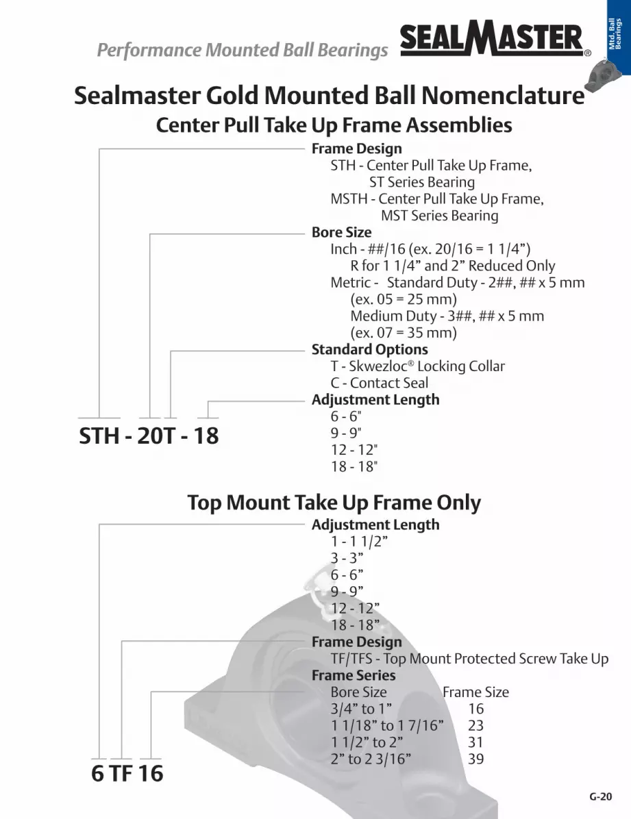
Sealmaster Gold Mounted Ball Nomenclature
Prefix E - Expansion UnitHousing* (see table below)D - Double Setscrew LockingBore Size Inch - ##/16 (ex. 20/16 = 1 1/4”) R for 1 1/4” and 2” Reduced Only Metric - Standard Duty - 2##, ## x 5 mm
(ex. 05 = 25 mm) Medium Duty - 3##, ## x 5 mm
(ex. 07 = 35 mm) Standard Option T - Skwezloc® Locking Collar M - Metric Hardware (Metric-SKWEZ™) C - Contact SealCommon Options*(see table below)
E NP D-20 T CXU*Housing Housing Style Bearing Duty *Common OptionsFB Flange Bracket Standard 2C Double Lip Contact Seal - replaced by DRT in most SizesMFC Piloted Flange Cartridge Medium 3C Trip Lip Contact Seal - replaced by DRT in most sizesMFP Four Bolt Pillow Block - High Base Medium AS Backed Off Felt SealMP Pillow Block - High Base Medium BF Spring Seal - Spring OutMSC Cylindrical Cartridge Medium CXU Air HandlingMSF Four Bolt Flange Medium DRT High ContaminationMSFPD Four Bolt Pillow Block - High Base Medium H High Performance SealMSFT Two Bolt Flange Medium HI High Temperature Krytox*** GreaseMSPD Four Bolt Pillow Block - High Base Medium HS High SpeedMST Wide Slot Take Up Medium HT High TemperatureNP Pillow Block - High Base Standard HTA High Temperature Air HandlingNPL Pillow Block - Low Base Standard HTC High Temperature Contact SealRB Rubber Mount Insert Only Standard LO Low DragSC Cylindrical Cartridge Standard RM Reduced MaintenanceSF Four Bolt Flange Standard SF Double Lip Contact SealSFC Piloted Flange Cartridge Standard U Spring Seal - Spring InSFT Rubber Mounted Flange Standard VA FKM Spring Seal - Spring InSP Pillow Block - Heavy Duty Standard VS FKM Spring Seal - Spring OutSPM Pillow Block - High Base Medium X Labyrinth SealSRC Rubber Mounted Cartridge Standard XLO Extra Low DragSRF Rubber Mounted Flange Standard SRP Rubber Mounted Pillow Block Standard ST Wide Slot Take Up Standard TB Tapped Base Pillow Block Standard
TFT Two Bolt Flange Standard
Housing Units
**Not all confi gurations available in all sizes. Prior to selection consult Bearing Application Engineer for proper option selection for your application and consult engineering sections for speed limits.***KRYTOX is a registered trademark of E.I. du Pont de Nemurs and Company. This trade name, trademark and/or registered trademark is property of their respective owner and is not owned or controlled by Regal Power Transmission Solutions.

G-19
® Performance Mounted Ball Bearings Performance Mounted Ball BearingsMtd
. Ba
llB
ea
rin
gs
Sealmaster Gold Mounted Ball Nomenclature
Prefix AR - Standard Expansion RingBearing 2 - Inch Standard Duty 3 - Inch Medium Duty 52 - Metric Standard Duty 53 - Metric Medium DutyBore Size Inch - First Digit - Number of Inches Second & Third Digit - Number of
1/16” of Inches (ex. 215 = 2 15/16”) Metric - ## x 5 mm (05 = 25 mm)Standard Option C - Contact Seal D - Double Setscrew T - Skwezloc® Locking Collar M - Metric Hardware (Metric-SKWEZ™)Common Options* (see table below)
AR - 2 - 215 - T - DRT*Common Options
2C Double Lip Contact Seal - replaced by DRT in most Sizes LO Low Drag3C Trip Lip Contact Seal - replaced by DRT in most sizes M Metric Hardware (Metric-SKWEZ only)AS Backed Off Felt Seal RM Reduced MaintenanceBF Spring Seal - Spring Out SF High Temperature Double Lip Contact SealDRT High Contamination U Spring Seal - Spring InH High Performance Seal VA FKM Spring Seal - Spring InHI High Temperature Krytox** Grease VS FKM Spring Seal - Spring OutHS High Speed X Labyrinth SealHT High Temperature XLO Extra Low DragHTC High Temperature Contact Seal
Inserts
Prefix S - Housing Assembly SK - Bearing InsertSequential Number
SK - ####
Specials
*Note: Confi gurations are not available in all sizes or housing styles. Consult the product tables, option sections and engineering sections for more detail or consult a Bearing Application Engineer.**KRYTOX is a registered trademark of E.I. du Pont de Nemurs and Company. This trade name, trademark and/or registered trademark is property of their respective owner and is not owned or controlled by Regal Power Transmission Solutions.
G-20
Performance Mounted Ball Bearings Performance Mounted Ball Bearings ®
Mtd
. Ba
llB
ea
rin
gs
Sealmaster Gold Mounted Ball Nomenclature
Frame Design STH - Center Pull Take Up Frame,
ST Series Bearing MSTH - Center Pull Take Up Frame,
MST Series BearingBore Size Inch - ##/16 (ex. 20/16 = 1 1/4”) R for 1 1/4” and 2” Reduced Only Metric - Standard Duty - 2##, ## x 5 mm
(ex. 05 = 25 mm) Medium Duty - 3##, ## x 5 mm
(ex. 07 = 35 mm) Standard Options T - Skwezloc® Locking Collar C - Contact SealAdjustment Length 6 - 6" 9 - 9" 12 - 12" 18 - 18"
Adjustment Length 1 - 1 1/2” 3 - 3” 6 - 6” 9 - 9” 12 - 12” 18 - 18”Frame Design TF/TFS - Top Mount Protected Screw Take UpFrame Series Bore Size Frame Size 3/4” to 1” 16 1 1/18” to 1 7/16” 23 1 1/2” to 2” 31 2” to 2 3/16” 39
STH - 20T - 18
6 TF 16
Center Pull Take Up Frame Assemblies
Top Mount Take Up Frame Only

G-21
® Performance Mounted Ball Bearings Performance Mounted Ball BearingsMtd
. Ba
ll
Be
ari
ng
s
Wide Outer RingSealmaster has the industry’s widest outer ring. The black oxided outer ring is 20 to 30% wider than industry standard outer rings. This feature results in increased grease capacity, and room for improved sealing options. A wider outer ring has increased surface area contact with the housing to better absorb shock load.
Lock Pin and DimpleThe Sealmaster exclusive locking pin and dimple system provides a direct lubricant path into the bearing cavity & ball path instead of around a lubrication groove. The pin also prevents outer ring rotation (sometimes referred to as “creep”), and allows ±2° static misalignment of the bearing insert.
Multiple Locking Methods Setscrew Locking120° spaced, balanced three point contact minimizes inner ring distortion vibration, reduces noise, and improves reliability. Precision manufactured diamond faceted setscrews contribute to improved clamping and resistance to back out.
Features and Benefits
Skwezloc® Concentric Locking CollarSKWEZLOC is a concentric locking collar clamp design that results in near-perfect concentricity of the shaft to bearing bore and maintains near perfect ball path roundness, while reducing fretting corrosion. This design eliminates the shaft damage of setscrew locking, and minimizes bearing induced vibration for smoother quieter operation. The collar has a TORX head cap screw that outlasts stripping 12 times longer than hex head cap screws.
Multiple Sealing Options Felt Seal with FlingerThe standard felt seal provides a tight labyrinth seal which retains lubrication and acts as a filter to exclude contamination. The external stamping is a flinger which shields the felt from large contaminants and directs them away from the sealing surface. The design operates with less drag and less heat generation than rubber contact seals.
Single Lip Contact SealSingle Lip Contact Seal consists of a nitrile rubber washer in metal shroud to shield the lip from large contaminants. The seal is designed to balance drag and protection in wet and dry environments. This can be specified by adding the suffix C to the part number. Additional Sealing Options can be found in the Custom Select section on pages G-24 to G-27.

G-22
Performance Mounted Ball Bearings Performance Mounted Ball Bearings ®
Mtd
. Ba
ll
Be
ari
ng
s
Land Riding RetainerThe Sealmaster unique land riding metal retainer design provides superior pocket clearance that allows for 360° grease circulation around the rolling elements resulting in better retained and utilized lubrication. The land riding design of the retainer minimizes wear on both Ball and retainer, while maximizing stability, which is especially important in applications involving vibration, shock loading or high operating speeds.
Zone Hardened Inner RaceSealmaster incorporates a unique heat treat process that hardens the inner race only where it is needed…under the ball path. The black oxided zone hardened inner race results in improved lock reliability as a result of less distortion at the setscrew location and improved thread conformity resulting in improved clamping and resistance to setscrew back-out
Solid Base Solid bases are standard on Sealmaster Gold ball bearing pillow blocks. The solid base provides improved stability, resistance to shock and vibration and prevents frame buckling under base compared to semi-solid and hollow mounting bases.
Housing Fit All bearings are assembled with a controlled housing fit between the bearing outer ring and housing bore. This fit allows the bearing to properly self-align in common industrial applications. Special fits are available based on your specific application need.
NameplateMetal nameplate riveted to the housing allows for easy identification even after years of operation.
Features and Benefits continued

G-23
® Performance Mounted Ball Bearings Performance Mounted Ball BearingsMtd
. Ba
ll
Be
ari
ng
s
OptionsSealmaster Gold Mounted Ball Bearing OptionsBearings are typically selected using L10 fatigue life calculations based on ideal operating conditions. However, most bearing problems are not fatigue related, but occur due to contamination, lubrication starvation, or other environmental issues. As a result, our engineers have developed custom solutions to meet the varying severity, operating parameters and maintenance regularity, such as Reduced Maintenance and Custom Select.
Reduced Maintenance “RM”Sealmaster Reduced Maintenance bearings are the result of a patented Tapered Lands bearing race profile which means that critical lubricant is circulated more efficiently, while requiring no regular service intervals. The bearing are supplied from the factory with a plug instead of a lubrication fitting. The outer land surface in a conventional bearing is parallel to the axis of the inner ring. The Tapered Lands surface is tapered in a radial direction toward the bearing race. This subtle yet crucial design change allows lubricant to more easily flow back to the raceway. With improved bearing lubricant circulation comes significantly longer bearing service life. This improved circulation and service life comes without any reductions in bearing radial or thrust capacities. * For bearings that are maintained and relubricated on a regular basis, there is no significant difference in expected service life.

G-24
Performance Mounted Ball Bearings Performance Mounted Ball Bearings ®
Mtd
. Ba
ll
Be
ari
ng
s
Sealmaster Custom Select options are available in popular shaft sizes from ½” to 2 7/16” in common housing con-figurations.
High Temperature
Custom Select
Suffix Description Temperature Environment Speed LimitsHT* Standard High Temp
200°F to 400°F Dry/Dusty
pages G-235 to G-240HI* High Performance High Temp
HTA* High Temp Air Handling HTC* High Temp Contact Seal Wet/Moisture
*For expansion units add an E prefix (example: ENP-23 HTA). Information on expansion units can be found on page G-29.
High Performance High Temperature "HI" High temperature bearing with increased radial internal clearance to accom-modate thermal expansion of components and Nomex** seal and Krytox* 226 grease. Available in expansion version in some sizes with half-dog and wire, suffix “HIY”, see page G-104 for more information.
High Temperature Air Handling “HTA” Utilizes the same features as our high temperature “HT” option with the additional features that are important in Air Handling equipment:• Controlled air handling housing fit that allows the bearing to properly self-
align when mounted on light weight frames• Two stage noise testing verification procedure for quiet operation• For standard operating temperatures, consider the Air Handling “CXU”
option shown on following pages
High Temperature "HT" High temperature bearing with increased radial internal clearance to accom-modate thermal expansion of components and Nomex* seal and high tem-perature synthetic grease.
High Temperature Contact Seal “HTC” High temperature bearing with increased radial internal clearance to accom-modate thermal expansion of components, single lip silicone fiberglass or FKM spring seal and high temperature synthetic grease.

G-25
® Performance Mounted Ball Bearings Performance Mounted Ball BearingsMtd
. Ba
ll
Be
ari
ng
s
High Contamination
High Contamination “DRT” Heavy Duty Multi-Lip contact seal (depending on size and series, either sup-plied with “2C” double lip or “3C” triple lip seal), 100% Grease Fill with Sealmas-ter GoldPlex HP Grease.
Custom Select continued
Suffix Description Temperature Environment Speed Limits DRT Highly Contaminated -40°F to 200°F Highly Contaminated pages G-235 to G-240
2C Seal 3C Seal
High Speed
High Speed “HS” • Available in SKWEZLOC locking collar only • Backed off, felt seal reduces contact area between the felt sealing material
and the internal metal flinger • Controlled air handling housing fit that allows the bearing to properly self-
align when mounted on lightweight frames • Increased radial internal clearance to accommodate radial thermal
expansion of components
Suffix Description Temperature Environment Speed Limits HS High Speed -40°F to 200°F Dry/Dusty pages G-235 to G-240

G-26
Performance Mounted Ball Bearings Performance Mounted Ball Bearings ®
Mtd
. Ba
ll
Be
ari
ng
s
Air Handling
Air Handling “CXU” Utilizes many of the same features as standard Sealmaster Gold Mounted Ball Bearings but designed and manufactured for Air Handling equipment. • Controlled air handling housing fit that allows the bearing to properly self-
align when mounted on lightweight frames • Available with the standard Sealmaster felt seal for decreased energy
consumption • Two stage noise testing verification procedure for quiet operation
High Temperature Air Handling “HTA” Features listed on page G-24
Custom Select continued
Suffix Description Temperature Environment Speed Limits CXU Air Handling -40°F to 200°F
Dry/Dusty pages G-235 to G-240 HTA* High Temp Air Handling 200°F to 400°F
*For expansion units add an E prefix to unit assembly (example: EMP-23 HTA)

G-27
® Performance Mounted Ball Bearings Performance Mounted Ball BearingsMtd
. Ba
ll
Be
ari
ng
s
Low Drag
Bearing Rotational Torque - Comparison Chart
Low Drag “LO” • Felt seal cut down to reduce drag • Provides excellent barrier that works to retain grease and acts as a filter to
reduce the ingress of debris contaminants • Features a channeling grease that reduces drag while lubricating the
bearing • A reduced housing fit to allow for the bearing to properly self-align on light
weight frames
Suffix Description Temperature Environment Speed Limits LO Low Drag -20°F to 180°F
Dry/Dusty pages G-235 to G-240 XLO Extra Low Drag -20°F to 100°F
Company Suffix Option Seal Type Lubrication
LO Drag Bearing Options
AMI® FS Non-Contact OilSealmaster XLO Low Drag Felt Oil
MB® HFF Steel Labyrinth OilPeer® ZSFF Steel Labyrinth Oil
Sealmaster LO Low Drag Felt GreaseMB MHFF Steel Labyrinth Grease
FYH® DSK3 Non-Contact OilPeer ZMKFF Steel Labyrinth Grease
Standard Bearing Drag (Reference)
Sealmaster - Felt Grease
Sealmaster C Contact Grease
X-Tra Low Drag “XLO” • Felt seal cut down and oil soaked for extra low drag • Oil lubricated and supplied with an adapter and plug for easy field
relubrication• A reduced housing fit to allow for the bearing to properly self-align on light
weight frames
Custom Select continued
0.0 2.0 4.0 6.0 8.0 10.0 12.0 14.0
Sealmaster - ContactSealmaster - Felt
Peer - ZMKFFFYH - DSK3MB - MHFF
Sealmaster - LOPeer- ZSFF
MB - HFFSealmaster - XLO
in-ozs Based on 1”
AMI - FS

G-28
Performance Mounted Ball Bearings Performance Mounted Ball Bearings ®
Mtd
. Ba
ll
Be
ari
ng
s
Optional Fittings
Custom Select continued
Suffix Description CSK 90° Grease Fitting CSJ 45° Grease Fitting CTJ Adapter and Plug CTY Plug W Adapter and Grease Fitting
CSK – 90° Grease Fitting
CSJ – 45° Grease Fitting
W – Adaptor and Grease Fitting
CTJ – Adaptor and Plastic Plug
CTY - Plug
Note:• Fittings are designed to properly position the lock pin anti-rotation device. Other fittings not designed for
Sealmaster brand bearings may not provide this function causing reduced bearing life.• Fittings are factory adjusted to properly position the lock pin anti-rotation device. Improper field adjustment
of the fitting may cause reduced bearing life. Consult Bearing Technical Services for proper adjustment techniques or review installation instructions.
• For specific hole sizes per housing assembly refer to section L - Accessories.

G-29
® Performance Mounted Ball Bearings Performance Mounted Ball BearingsMtd
. Ba
ll
Be
ari
ng
s
Expansion Units Options
Additional Options
Axial shaft expansion is compensated by a non-expansion (fixed) and expansion (float) arrangement. Many bearings are offered in both fixed and float arrangements and have identical mounting dimensions. It is recommended to use both units on one shaft in high temperature applications to help account for linear shaft expansion. For more information see page G-249 in the Mounted Ball Bearing Engineering section.
Expansion Unit Availability Chart
Bore Diameter Unit Size
Standard Duty Expansion Capability
Bore Diameter Unit Size
Medium Duty Expansion Capabilityin mm ENP ESP ESF ESFT in mm EMFP EMFPD EMP EMSPD EMSFPD EMSF EMSFT EMFC
5/8 10
3/32”
15/16 15 1/8” 11/16 11 25 305
3/4 12 1 1620 204 30 306
1/8” 13/16 13
3/32”
1 3/16 19 7/8 14 1 1/4 20
15/16 15 35 307 1/8”
25 205 1 7/16 231 16 1 1/2 24
1/8”1 1/16 17
1/8”
40 3081 1/8 18 1 11/16 27
3/16”30 206 1 3/4 281 3/6 19 45 3091 1/4 20R 1 15/16 31
3/16”1 1/4 20
1/8”
50 3101 5/16 21 2 321 3/8 22 55 311
3/16”35 207 2 3/16 351 7/16 23 2 1/4 361 1/2 24
1/8”2 7/16 39
3/16”1 9/16 25 2 1/2 4040 208 65 313
1 5/8 26
1/8”
2 11/16 43 3/16”
1 11/16 27 70 3141 3/4 28 2 15/16 47
1/4”45 209 75 3151 13/16 29
3/16”
3 481 7/8 30 80 316
1/4”1 15/16 31 3 3/16 5150 210 3 1/4 52
2 32R 3 7/16 55 9/32”2 32
3/16”
3 15/16 63 9/32”2 1/8 34 100 320
55 211 4 642 3/16 35 4 7/16 71
7/16”2 1/4 36
3/16”
4 15/16 7960 212 Expansion option exists for the bearing and housing combination
2 3/8 38 Note: 1. Not all combinations of housing styles, locking types and seal options are available. Consult customer service for availability and possible set-up charges.2 7/16 39
2 1/2 40 3/16”
2. Alternate expansion version available in some sizes and configurations with half-dog and wire, suffix “HIY”, see page G-104 for more information.2 11/16 43
70 2142 7/8 46
3/16”2 15/16 4775 215
3 48 1/4”80 216
3 3/16 51

G-30
Performance Mounted Ball Bearings Performance Mounted Ball Bearings ®
Mtd
. Ba
ll
Be
ari
ng
s
Custom CapabilitiesAdditional Industry specific options exist such as the:
Sealmaster Paver Bearing – page G-127Sealmaster Material Handling Bearing - page G-109Sealmaster PN Gold – Corrosion Resistant – page K-29
Our Application Engineers will design a bearing based on your unique application parameters, utilizing a variety of existing components or special components. By combining your equipment knowledge and our Application Engineers bearing expertise, a product solution can be designed to maximize bearing performance in your specific application. Thousands of customers benefit from this capability every year, and now you no longer have to endure the lead time associated with these custom engineered solutions. In many cases, a higher performance product can be designed and developed specifically for your application.
GreasesOptional greases are readily available, consult Application Engineering for complete list
Additional Options
KRYTOX* Extended Lube• Used in HI suffix modified bearings• KYRTOX GPL 226, an extremely high performance perflourinated oil and
PTFE thickened grease• KRYTOX grease has a superior service life and therefore diminishes re-
lubrication frequency and extends life• Engineers have found that, compared to other high temperature greases,
the thermal stability and lubricity of the KRYTOX can improve high temperature bearing life by a factor of 4 to 45 times
High Temperature Synthetic• Used in HT, HTA, and HTC suffix modified bearings• High quality, synthetic hydrocarbon, lithium complex thickened grease
NLGI#2, and ISO 220 viscosity• Superior high temperature (200 F to 400F) stability
*KRYTOX is a registered trademark of E.I. du Pont de Nemurs and Company. This trade name, trademark and/or registered trademark is property of their respective owner and is not owned or controlled by Regal Power Transmission Solutions.

G-31
® Performance Mounted Ball Bearings Performance Mounted Ball BearingsMtd
. Ba
ll
Be
ari
ng
s
NP Series Standard Duty Pillow Blocks - Setscrew Locking
B
H
C
AG
JK
L
D
Duty: Standard
Rolling Elements: Ball
Housing: Cast Iron Pillow Block – High Base
Self Alignment: +/- 2 Degrees
Lock: Setscrew
Seal: Felt
Optional Seal: Contact
Temperature: -20° to 220°F
Bearing SelectionPage G-3
Nomenclature AidPage G-18
Features & BenefitsPage G-21
Product OptionsPage G-23
Technical EngineeringPage G-220
Bore DiameterPart No.
Bearing Insert
No.
Basic Dynamic Rating
lb/N
Dimensions inch / mmBolt Size
Unit Wt. lb/kgA B
CD G H J K Linch mm min. max.
1/2 NP-8 2-082611
116141 3/1630.2
5 127.0
3 3/8 85.7
4 1/8 104.8
1 1/2 38.1
1/2 12.7
2 7/1661.9
1 7/3231.0
23/3218.3
1 3/1630.2 3/8 1.7
.77 9/16 NP-9 2-09 5/8 NP-10 2-010
11/16 NP-11 2-011 3/4 NP-12 2-012 2611 1 5/16 5 3 3/8 4 1/8 1 1/2 1/2 2 9/16 1 7/32 23/32 1 3/16 3/8 1.9
20 NP-204 5204 11614 33.3 127.0 85.7 104.8 38.1 12.7 65.1 31.0 18.3 30.2 .86 13/16 NP-13 2-013
280112459
1 7/1636.5
5 1/2 139.7
3 7/8 98.4
4 3/8 111.1
1 1/2 38.1
1/2 12.7
2 13/1671.4
1 3/8 34.9
13/1620.6
1 3/8 34.9 3/8 2.2
1.00
7/8 NP-14 2-014 15/16 NP-15 2-015
1 NP-16 2-125 NP-205 5205
1 1/16 NP-17 2-11
438119487
1 11/1642.9
6 1/2 165.1
4 7/16112.7
5 1/16128.6
1 7/8 47.6
9/1614.3
3 3/8 85.7
1 1/2 38.1
7/8 22.2
1 19/3240.5 1/2 3.6
1.63
1 1/8 NP-18 2-121 3/16 NP-19 2-131 1/4 NP-20R 1-14
30 NP-206 52061 1/4 NP-20 2-14
578225718
1 7/8 47.6
6 9/16166.7
4 11/16119.1
5 5/16134.9
1 7/8 47.6
5/8 15.9
3 3/4 95.3
1 11/1642.9
1 25.4
1 55/6447.2 1/2 4.5
2.04
1 5/16 NP-21 2-151 3/8 NP-22 2-16
1 7/16 NP-23 2-1735 NP-207 5207
1 1/2 NP-24 2-187340
326481 15/16
49.27 1/4 184.2
4 7/8 123.8
5 7/8 149.2
2 1/8 54.0
11/1617.5
3 15/16100.0
1 15/1649.2
1 3/1630.2
2 1/1652.4 1/2 5.7
2.591 9/16 NP-25 2-1940 NP-208 5208
1 5/8 NP-26 2-1101 11/16 NP-27 2-111 7901 2 1/8 7 1/2 5 7/16 6 1/16 2 1/8 11/16 4 1/4 1 15/16 1 3/16 2 19/64 1/2 6.51 3/4 NP-28 2-112 35144 54.0 190.5 138.1 154.0 54.0 17.5 108.0 49.2 30.2 58.3 2.95
45 NP-209 52091 13/16 NP-29 2-113
788935090
2 1/4 57.2
8 1/8 206.4
6 152.4
6 1/2 165.1
2 3/8 60.3
3/4 19.1
4 9/16115.9
2 1/3251.6
1 9/3232.5
2 15/3262.7 5/8 7.9
3.58
1 7/8 NP-30 2-1141 15/16 NP-31 2-115
2 NP-32R 1-250 NP-210 5210
2 NP-32 2-22 1/8 NP-34 2-22 9752 2 1/2 8 5/8 6 1/2 7 2 3/8 3/4 5 2 3/16 1 5/16 2 23/32 5/8 9.7
2 3/16 NP-35 2-23 43377 63.5 219.1 165.1 177.8 60.3 19.1 127.0 55.6 33.3 69.1 4.4055 NP-211 5211
2 1/4 NP-36 2-24
5/8 2 3/8 NP-38 2-26 11789 2 3/4 9 1/2 6 7/8 7 5/8 2 3/4 7/8 5 9/16 2 9/16 1 9/16 2 63/64 13.72 7/16 NP-39 2-27 52437 69.9 241.3 174.6 193.7 69.9 22.2 141.3 65.1 39.7 75.8 6.21
60 NP-212 52122 7/8 NP-46 2-214
1483966004
3.588.9
13330.2
8 1/2215.9
9 1/2241.3
3 1/288.9
1 1/828.6
7177.8
3 1/1677.8
1 3/444.5
3 41/6492.5
27.912.662 15/16 NP-47 2-215 7/8
75 NP-215 5215
For Standard Duty Bearing Inserts-Single Lock see page G-92.
Metric dimensions for reference only.
Not all parts are available from stock. Please contact customer service for availability (800) 626-2120.
For more information on bearing capabilities outside of our standard offering, please contact Application Engineering (800) 626-2093.

G-32
Performance Mounted Ball Bearings Performance Mounted Ball Bearings ®
Mtd
. Ba
ll
Be
ari
ng
s
Bearing SelectionPage G-3
Nomenclature AidPage G-18
Features & BenefitsPage G-21
Product OptionsPage G-23
Technical EngineeringPage G-220
NP-T Series Standard Duty Pillow Block - SKWEZLOC Locking Collar - Inch
BC
G
H
A
L
D
JK
Duty: Standard
Rolling Elements: Ball
Housing: Cast Iron Pillow Block – High Base
Self Alignment: +/- 2 Degrees
Lock: SKWEZLOC Locking Collar
Seal: Felt
Optional Seal: Contact
Temperature: -20° to 220°F
Bore Diameter Part No. Bearing
Insert No.
Basic Dynamic Rating
lb/N
Dimensions inch / mmBolt Size
Unit Wt. lb/kgA B
CD G H J K Linch min. max.
3/4 NP-12T 2-012T 2611 1 5/16 5 3 3/8 4 1/8 1 1/2 1/2 2 9/16 1 9/32 25/32 1 3/4 3/8 2.011614 33.3 127.0 85.7 104.8 38.1 12.7 65.1 32.5 19.8 44.5 .91
15/16 NP-15T 2-015T 2801 1 7/16 5 1/2 3 7/8 4 3/8 1 1/2 1/2 2 13/16 1 7/16 7/8 1 15/16 3/8 2.41 NP-16T 2-1T 12459 36.5 139.7 98.4 111.1 38.1 12.7 71.4 36.5 22.2 49.2 1.09
1 1/8 NP-18T 2-12T 438119487
1 11/1642.9
6 1/2 165.1
4 7/16112.7
5 1/16128.6
1 7/8 47.6
9/1614.3
3 3/8 85.7
1 9/1639.7
15/1623.8
2 3/1655.6
1/2 3.8
1.721 3/16 NP-19T 2-13T1 1/4 NP-20RT 1-14T
1 1/4 NP-20T 2-14T 5782 1 7/8 6 9/16 4 11/16 5 5/16 1 7/8 5/8 3 3/4 1 3/4 1 1/16 2 7/16 1/2 4.825718 47.6 166.7 119.1 134.9 47.6 15.9 95.3 44.5 27.0 61.9 2.18
1 3/8 NP-22T 2-16T 4782 1 7/8 6 9/16 4 11/16 5 5/16 1 7/8 5/8 3 3/4 1 3/4 1 1/16 2 9/16 1/2 4.81 7/16 NP-23T 2-17T 21270 47.6 166.7 119.1 134.9 47.6 15.9 95.3 44.5 27.0 65.1 2.18
1 1/2 NP-24T 2-18T 7340 1 15/16 7 1/4 4 7/8 5 7/8 2 1/8 11/16 3 15/16 2 1 1/4 2 11/16 1/2 6.032648 49.2 184.2 123.8 149.2 54.0 17.5 100.0 50.8 31.8 68.3 2.72
1 5/8 NP-26T 2-110T 7901 2 1/8 7 1/2 5 7/16 6 1/16 2 1/8 11/16 4 1/4 2 1 1/4 2 13/16 1/2 6.835144 54.0 190.5 138.1 154.0 54.0 17.5 108.0 50.8 31.8 71.4 3.08
1 11/16 NP-27T 2-111T 7901 2 1/8 7 1/2 5 7/16 6 1/16 2 1/8 11/16 4 1/4 2 1 1/4 2 15/16 1/2 6.81 3/4 NP-28T 2-112T 35144 54.0 190.5 138.1 154.0 54.0 17.5 108.0 50.8 31.8 74.6 3.08
1 15/16 NP-31T 2-115T 7889 2 1/4 8 1/8 6 6 1/2 2 3/8 3/4 4 9/16 2 3/32 1 11/32 3 3/8 5/8 8.52 NP-32RT 1-2T 35090 57.2 206.4 152.4 165.1 60.3 19.1 115.9 53.2 34.1 85.7 3.86
2 NP-32T 2-2T 9752 2 1/2 8 5/8 6 1/2 7 2 3/8 3/4 5 2 1/4 1 3/8 3 1/2 5/8 10.343377 63.5 219.1 165.1 177.8 60.3 19.1 127.0 57.2 34.9 88.9 4.67
2 1/8 NP-34T 2-22T 9752 2 1/2 8 5/8 6 1/2 7 2 3/8 3/4 5 2 1/4 1 3/8 3 5/8 5/8 10.32 3/16 NP-35T 2-23T 43377 63.5 219.1 165.1 177.8 60.3 19.1 127.0 57.2 34.9 92.1 4.67
2 1/4 NP-36T 2-24T 11789 2 3/4 9 1/2 6 7/8 7 5/8 2 3/4 7/8 5 9/16 2 5/8 1 5/8 4 1/16 5/8 14.952437 69.9 241.3 174.6 193.7 69.9 22.2 141.3 66.7 41.3 103.2 6.76
2 3/8 NP-38T 2-26T 11789 2 3/4 9 1/2 6 7/8 7 5/8 2 3/4 7/8 5 9/16 2 5/8 1 5/8 4 1/8 5/8 14.952437 69.9 241.3 174.6 193.7 69.9 22.2 141.3 66.7 41.3 104.8 6.76
Bore Diameter Part No. Bearing
Insert No.
Basic Dynamic Rating
N/lb
Dimensions mm / inchBolt Size
Unit Wt. lb/kgA B
CD G H J K Lmm min. max.
20 NP-204TMC 5204TMC 11614 33.3 127.0 85.7 104.8 38.2 12.7 65.1 32.5 19.8 44.5 M10 4.84782 1 5/16 5 3 3/8 4 1/8 1 1/2 1/2 2 9/16 1 9/32 25/32 1 3/4 .91
25 NP-205TMC 5205TMC 19487 36.5 139.7 98.4 111.1 38.1 12.7 71.4 36.5 22.2 49.2 M10 2.42801 1 7/16 5 1/2 3 7/8 4 3/8 1 1/2 1/2 2 13/16 1 7/16 7/8 1 15/16 1.1
30 NP-206TMC 5206TMC 19487 42.9 165.1 112.7 128.6 47.6 14.3 85.7 39.7 23.8 55.6 M10 3.84381 1 11/16 6 1/2 4 7/16 5 1/16 1 7/8 9/16 3 3/8 1 9/16 15/16 2 3/16 1.72
35 NP-207TMC 5207TMC 21270 47.6 166.7 119.1 134.9 47.6 15.9 95.3 44.5 27.0 65.1 M10 4.84782 1 7/8 6 9/16 4 11/16 5 5/16 1 7/8 5/8 3 3/4 1 3/4 1 1/16 2 9/16 2.18
40 NP-208TMC 5208TMC 32648 49.2 184.2 123.8 149.2 54.0 17.5 100.0 54.8 31.8 68.3 M14 6.07340 1 15/16 7 1/4 4 7/8 5 7/8 2 1/8 11/16 3 15/16 2 5/32 1 1/4 2 11/16 2.72
45 NP-209TMC 5209TMC 35144 54.0 190.5 138.1 154.0 54.0 17.5 108.0 50.8 31.8 74.6 M14 6.87901 2 1/8 7 1/2 5 7/16 6 1/16 2 1/8 11/16 4 1/4 2 1 1/4 2 15/16 3.08
50 NP-210TMC 5210TMC 35090 57.2 206.4 152.4 165.1 60.3 19.1 115.9 53.2 34.1 85.7 M16 8.57889 2 1/4 8 1/8 6 6 1/2 2 3/8 3/4 4 9/16 2 3/32 1 11/32 3 3/8 3.86
55 NP-211TMC 5211TMC 43377 63.5 219.1 165.1 177.8 60.3 19.1 127.0 57.2 34.9 92.1 M16 10.39752 2 1/2 8 5/8 6 1/2 7 2 3/8 3/4 5 2 1/4 1 3/8 3 5/8 4.67
60 NP-212TMC 5212TMC 11789 69.9 241.3 174.6 193.7 69.9 22.2 141.3 66.7 41.3 104.8 M16 14.952437 2 3/4 9 1/2 6 7/8 7 5/8 2 3/4 7/8 5 9/16 2 5/8 1 5/8 4 1/8 6.8
NP-T Series Standard Duty Pillow Block - SKWEZLOC Locking Collar - Metric -SKWEZTM
For Standard Duty Bearing Inserts - SKWEZLOC Locking Collar see page G-93. For Replacement Lock Collar see page G-98.

G-33
® Performance Mounted Ball Bearings Performance Mounted Ball BearingsMtd
. Ba
ll
Be
ari
ng
s
Bore Diameter Part No. Bearing
Insert No.
Basic Dynamic Rating
lb/N
Dimensions inch / mmBolt Size
Unit Wt. lb/kgA B
CD G H J K Linch min. max.
7/8 NPD-14 2-014D2801
124591 7/1636.5
5 1/2 139.7
3 7/8 98.4
4 3/8 111.1
1 1/2 38.1
1/2 12.7
2 13/1671.4
1 1/2 38.1
3/4 19.1
1 3/8 34.9
2.41.09 15/16 NPD-15 2-015D 3/8
1 NPD-16 2-1D
1 3/16 NPD-19 2-13D 438119487
1 11/1642.9
6 1/2 165.1
4 7/16112.7
5 1/16128.6
1 7/8 47.6
9/1614.3
3 3/8 85.7
1 3/4 44.5
7/8 22.2
1 19/3240.5 1/2 3.8
1.72
1 1/4 NPD-20 2-14D5782
257181 7/8 47.6
6 9/16166.7
4 11/16119.1
5 5/16134.9
1 7/8 47.6
5/8 15.9
3 3/4 95.3
2 50.8
1 25.4
1 55/6447.2 1/2 4.7
2.131 3/8 NPD-22 2-16D1 7/16 NPD-23 2-17D1 1/2 NPD-24 2-18D 7340 1 15/16 7 1/4 4 7/8 5 7/8 2 1/8 11/16 3 15/16 2 5/16 1 5/32 2 1/16
1/2 6.0
1 9/16 NPD-25 2-19D 32648 49.2 184.2 123.8 149.2 54.0 17.5 100.0 58.7 29.4 52.4 2.731 11/16 NPD-27 2-111D 7901
351442 1/8 54.0
7 1/2 190.5
5 7/16138.1
6 1/16154.0
2 1/8 54.0
11/1617.5
4 1/4 108.0
2 3/8 60.3
1 3/1630.2
2 19/6458.3 1/2 6.5
2.951 3/4 NPD-28 2-112D1 7/8 NPD-30 2-114D 7889 2 1/4 8 1/8 6 6 1/2 2 3/8 3/4 4 9/16 2 1/2 1 1/4 2 15/32
5/8 8.3
1 15/16 NPD-31 2-115D 35090 57.2 206.4 152.4 165.1 60.3 19.1 115.9 63.5 31.8 62.7 3.762 NPD-32 2-2D
975243377
2 1/2 63.5
8 5/8 219.1
6 1/2 165.1
7 177.8
2 3/8 60.3
3/4 19.1
5 127.0
2 5/8 66.7
1 5/1633.3
2 23/3269.1 5/8 10.0
4.542 1/8 NPD-34 2-22D2 3/16 NPD-35 2-23D2 1/4 NPD-36 2-24D
1178952437
2 3/4 69.9
9 1/2 241.3
6 7/8 174.6
7 5/8 193.7
2 3/4 69.9
7/8 22.2
5 9/16141.3
3 1/8 79.4
1 9/1639.7
2 63/6475.8 5/8 14.0
6.352 3/8 NPD-38 2-26D2 7/16 NPD-39 2-27D
For Standard Duty Bearing Inserts-Double Lock see page G-94.
NPD Series Standard Duty Pillow Blocks With Double Lock - Setscrew Locking
B
C
G
H L
K
J
A
D
Duty: Standard
Rolling Elements: Ball
Housing: Cast Iron Pillow Block – High Base
Self Alignment: +/- 2 Degrees
Lock: Double Setscrew
Seal: Felt
Optional Seal: Contact
Temperature: -20° to 220°F
Metric dimensions for reference only.
Not all parts are available from stock. Please contact customer service for availability (800) 626-2120.
For more information on bearing capabilities outside of our standard offering, please contact Application Engineering (800) 626-2093.
Bearing SelectionPage G-3
Nomenclature AidPage G-18
Features & BenefitsPage G-21
Product OptionsPage G-23
Technical EngineeringPage G-220

G-34
Performance Mounted Ball Bearings Performance Mounted Ball Bearings ®
Mtd
. Ba
ll
Be
ari
ng
s
NPL Series Standard Duty Pillow Blocks - Setscrew Locking
B
H
C
A
G
JK
L
D
Duty: Standard
Rolling Elements: Ball
Housing: Cast Iron Pillow Block – Low Base
Self Alignment +/- 2 Degrees
Lock Setscrew
Seal: Felt
Optional Seal: Contact
Temperature: -20° to 220°F
Bore Diameter Part No.
Bearing Insert
No.
Basic Dynamic Rating
lb/N
Dimensions inch / mmBolt Size
Unit Wt. lb/kgA B
CD G H J K Linch mm min. max.
1/2 NPL-8 2-08
3/8 9/16 NPL-9 2-09 2611 1 1/16 5 3 3/8 4 1/8 1 1/2 3/8 2 5/16 1 7/32 23/32 1 3/16 1.7 5/8 NPL-10 2-010 11614 27.0 127.0 85.7 104.8 38.1 9.5 58.7 31.0 18.3 30.2 .77
11/16 NPL-11 2-011 3/4 NPL-12 2-012 2611 1 1/4 5 3 3/8 4 1/8 1 1/2 7/16 2 1/2 1 7/32 23/32 1 3/16
3/8 1.7
20 NPL-204 5204 11614 31.8 127.0 85.7 104.8 38.1 11.1 63.5 31.0 18.3 30.2 .77 13/16 NPL-13 2-013
280112459
1 5/1633.3
5 1/2139.7
3 7/898.4
4 3/8111.1
1 1/238.1
1/2 12.7
2 11/1668.3
1 3/834.9
13/1620.6
1 3/8 34.9 3/8 2.0
.91
7/8 NPL-14 2-014 15/16 NPL-15 2-015
1 NPL-16 2-125 NPL-205 5205
1 1/16 NPL-17 2-11
438119487
1 9/1639.7
6 1/2165.1
4 7/16112.7
5 1/16128.6
1 7/847.6
7/1611.1
3 1/482.6
1 1/238.1
7/8 22.2
1 19/3240.5 1/2 3.6
1.63
1 1/8 NPL-18 2-121 3/16 NPL-19 2-131 1/4 NPL-20R 1-14
30 NPL-206 52061 1/4 NPL-20 2-14
578225718
1 13/1646.0
6 9/16166.7
4 11/16119.1
5 5/16134.9
1 7/847.6
9/1614.3
3 11/1693.7
1 11/1642.9
125.4
1 55/6447.2 1/2 4.4
2.00
1 5/16 NPL-21 2-151 3/8 NPL-22 2-16
1 7/16 NPL-23 2-1735 NPL-207 5207
1 1/2 NPL-24 2-187340
326481 15/16
49.27 1/4184.2
4 7/8123.8
5 7/8149.2
2 1/854.0
11/1617.5
3 15/16100.0
1 15/1649.2
1 3/1630.2
2 1/1652.4 1/2 5.7
2.591 9/16 NPL-25 2-1940 NPL-208 5208
1 5/8 NPL-26 2-110
1/2 1 11/16 NPL-27 2-111 7901 2 1/16 7 1/2 5 7/16 6 1/16 2 1/8 5/8 4 3/16 1 15/16 1 3/16 2 19/64 6.21 3/4 NPL-28 2-112 35144 52.4 190.5 138.1 154.0 54.0 15.9 106.4 49.2 30.2 58.3 2.81
45 NPL-209 52091 13/16 NPL-29 2-113
788935090
2 3/1655.6
8 1/8206.4
6152.4
6 1/2165.1
2 3/860.3
11/1617.5
4 1/2114.3
2 1/3251.6
1 9/3232.5
2 15/3262.7 5/8 7.8
3.54
1 7/8 NPL-30 2-1141 15/16 NPL-31 2-115
2 NPL-32R 1-250 NPL-210 5210
2 NPL-32 2-2
5/8 2 1/8 NPL-34 2-22 9752 2 7/16 8 5/8 6 1/2 7 2 3/8 11/16 4 15/16 2 3/16 1 5/16 2 23/32 9.6
2 3/16 NPL-35 2-23 43377 61.9 219.1 165.1 177.8 60.3 17.5 125.4 55.6 33.3 69.1 4.3555 NPL-211 5211
2 1/4 NPL-36 2-24
5/8 2 3/8 NPL-38 2-26 11789 2 11/16 9 1/2 6 7/8 7 5/8 2 3/4 13/16 5 1/2 2 9/16 1 9/16 2 63/64 13.5
2 7/16 NPL-39 2-27 52437 68.3 241.3 174.6 193.7 69.9 20.6 139.7 65.1 39.7 75.8 6.1260 NPL-212 5212
2 11/16 NPL-43 2-211 13971 62143
3 76.2
11 1/4 285.8
7 1/8 181.0
8 7/8 225.4
3 1/4 82.6
1 1/16 27.0
6 1/4 158.8
2 3/4 69.9
1 11/16 42.9
3 7/16 87.3 3/4 21.5
9.75
For Standard Duty Bearing Inserts-Single Lock see page G-92.
Bearing SelectionPage G-3
Nomenclature AidPage G-18
Features & BenefitsPage G-21
Product OptionsPage G-23
Technical EngineeringPage G-220

G-35
® Performance Mounted Ball Bearings Performance Mounted Ball BearingsMtd
. Ba
ll
Be
ari
ng
s
NPL-T Series Standard Duty Pillow Block - SKWEZLOC Locking Collar
BC
G
H
A
L
D
J
K
Bore Diameter Part No. Bearing
Insert No.
Basic Dynamic Rating
lb/N
Dimensions inch / mmBolt Size
Unit Wt. lb/kgA B
CD G H J K Linch min. max.
3/4 NPL-12T 2-012T2611 1 1/4 5 3 3/8 4 1/8 1 1/2 7/16 2 1/2 1 9/32 25/32 1 3/4
3/8 1.8
11614 31.8 127.0 85.7 104.8 38.1 11.1 63.5 32.5 19.8 44.5 .82
15/16 NPL-15T 2-015T 2801 1 5/16 5 1/2 3 7/8 4 3/8 1 1/2 1/2 2 11/16 1 7/16 7/8 1 15/16 3/8
2.2
1 NPL-16T 2-1T 12459 33.3 139.7 98.4 111.1 38.1 12.7 68.3 36.5 22.2 49.2 1.00
1 1/8 NPL-18T 2-12T4381
194871 9/1639.7
6 1/2165.1
4 7/16112.7
5 1/16128.6
1 7/847.6
7/1611.1
3 1/482.6
1 9/1639.7
15/1623.8
2 3/1655.6 1/2 3.8
1.721 3/16 NPL-19T 2-13T
1 1/4 NPL-20RT 1-14T
1 1/4 NPL-20T 2-14T5782 1 13/16 6 9/16 4 11/16 5 5/16 1 7/8 9/16 3 11/16 1 3/4 1 1/16 2 7/16
1/2 4.7
25718 46.0 166.7 119.1 134.9 47.6 14.3 93.7 44.5 27.0 61.9 2.13
1 3/8 NPL-22T 2-16T 5782 1 13/16 6 9/16 4 11/16 5 5/16 1 7/8 9/16 3 11/16 1 3/4 1 1/16 2 9/16 1/2
4.7
1 7/16 NPL-23T 2-17T 25718 46.0 166.7 119.1 134.9 47.6 14.3 93.7 44.5 27.0 65.1 2.13
1 1/2 NPL-24T 2-18T7340 1 15/16 7 1/4 4 7/8 5 7/8 2 1/8 11/16 3 15/16 2 1 1/4 2 11/16
1/2 6.0
32648 49.2 184.2 123.8 149.2 54.0 17.5 100.0 50.8 31.8 68.3 2.72
1 5/8 NPL-26T 2-110T7901 2 1/16 7 1/2 5 7/16 6 1/16 2 1/8 5/8 4 3/16 2 1 1/4 2 13/16
1/2 6.5
35144 52.4 190.5 138.1 154.0 54.0 15.9 106.4 50.8 31.8 71.4 2.95
1 11/16 NPL-27T 2-111T 7901 2 1/16 7 1/2 5 7/16 6 1/16 2 1/8 5/8 4 3/16 2 1 1/4 2 15/16 1/2
6.5
1 3/4 NPL-28T 2-112T 35144 52.4 190.5 138.1 154.0 54.0 15.9 106.4 50.8 31.8 74.6 2.95
1 15/16 NPL-31T 2-115T 7889 2 3/16 8 1/8 6 6 1/2 2 3/8 11/16 4 1/2 2 3/32 1 11/32 3 3/8 5/8
8.4
2 NPL-32RT 1-2T 35090 55.6 206.4 152.4 165.1 60.3 17.5 114.3 53.2 34.1 85.7 3.81
2 NPL-32T 2-2T9752 2 7/16 8 5/8 6 1/2 7 2 3/8 11/16 4 15/16 2 1/4 1 3/8 3 1/2
5/8 10.2
43377 61.9 219.1 165.1 177.8 60.3 17.5 125.4 57.2 34.9 88.9 4.63
2 1/8 NPL-34T 2-22T 9752 2 7/16 8 5/8 6 1/2 7 2 3/8 11/16 4 15/16 2 1/4 1 3/8 3 5/8 5/8
10.2
2 3/16 NPL-35T 2-23T 43377 61.9 219.1 165.1 177.8 60.3 17.5 125.4 57.2 34.9 92.1 4.63
2 1/4 NPL-36T 2-24T11789 2 11/16 9 1/2 6 7/8 7 5/8 2 3/4 13/16 5 1/2 2 5/8 1 5/8 4 1/16
5/8 14.7
52437 68.3 241.3 174.6 193.7 69.9 20.6 139.7 66.7 41.3 103.2 6.67
2 3/8 NPL-38T 2-26T 11789 2 11/16 9 1/2 6 7/8 7 5/8 2 3/4 13/16 5 1/2 2 5/8 1 5/8 4 1/8 5/8
14.7
2 7/16 NPL-39T 2-27T 52437 68.3 241.3 174.6 193.7 69.9 20.6 139.7 66.7 41.3 104.8 6.67
For Standard Duty SKWEZLOC Locking Collar Bearing inserts see page G-93. For Replacement Lock Collar see page G-98.
Duty: Standard
Rolling Elements: Ball
Housing: Cast Iron Pillow Block – Low Base
Self Alignment: +/- 2 Degrees
Lock: SKWEZLOC Locking Collar
Seal: Felt
Optional Seal: Contact
Temperature: -20° to 220°F
Metric dimensions for reference only.
Not all parts are available from stock. Please contact customer service for availability (800) 626-2120.
For more information on bearing capabilities outside of our standard offering, please contact Application Engineering (800) 626-2093.
Bearing SelectionPage G-3
Nomenclature AidPage G-18
Features & BenefitsPage G-21
Product OptionsPage G-23
Technical EngineeringPage G-220

G-36
Performance Mounted Ball Bearings Performance Mounted Ball Bearings ®
Mtd
. Ba
ll
Be
ari
ng
s
SP Series Standard Duty Pillow Blocks - Setscrew Locking
B
H
C
AG
JK
L
D
Duty: Standard
Rolling Elements: Ball
Housing: Cast Iron Pillow Block – Heavy Duty
Self Alignment: +/- 2 Degrees
Lock: Setscrew
Seal: Felt
Optional Seal: Contact
Temperature: -20° to 220°F
Bore Diameter Part No. Bearing
Insert No.
Basic Dynamic Rating
lb/N
Dimensions inch / mmBolt Size
Unit Wt. lb/kgA B
CD G H J K Linch mm min. max.
13/16 SP-13 2-013
280112459
1 3/444.5
7 177.8
5 1/8 130.2
5 5/8 142.9
2 50.8
9/1614.3
3 5/1684.1
1 3/834.9
13/1620.6
1 3/8 34.9 1/2 3.6
1.63
7/8 SP-14 2-014 15/16 SP-15 2-015
1 SP-16 2-125 SP-205 5205
1 1/16 SP-17 2-11
438119487
2 50.8
7 1/2 190.5
5 3/8 136.5
6 1/8 155.6
2 50.8
5/8 15.9
3 7/898.4
1 1/238.1
7/8 22.2
1 19/3240.5 1/2 5.0
2.27
1 1/8 SP-18 2-121 3/16 SP-19 2-131 1/4 SP-20R 2-14
30 SP-206 52061 1/4 SP-20 2-14
5782 2 3/8 60.3
8 1/4 209.6
5 5/8 142.9
6 7/8 174.6
2 1/4 57.2
3/4 19.1
4 1/2114.3
1 11/1642.9
125.4
1 55/6447.2 5/8 7.0
3.18
1 5/16 SP-21 2-151 3/8 SP-22 2-16
1 7/16 SP-23 2-1735 SP-207 5207
1 1/2 SP-24 2-187340
326482 5/1658.7
8 1/2 215.9
5 7/8 149.2
7 1/8 181.0
2 3/8 60.3
3/4 19.1
4 9/16115.9
1 15/1649.2
1 3/1630.2
2 1/1652.4 5/8 7.6
3.451 9/16 SP-25 2-1940 SP-208 5208
1 5/8 SP-26 2-110
5/8 1 11/16 SP-27 2-111 7901 2 3/8 8 3/4 5 7/8 7 1/8 2 3/8 3/4 4 5/8 1 15/16 1 3/16 2 19/64 8.11 3/4 SP-28 2-112 35144 60.3 222.3 149.2 181.0 60.3 19.1 117.5 49.2 30.2 58.3 3.67
45 SP-209 52091 13/16 SP-29 2-113
788935090
2 3/4 69.9
10 1/2 266.7
6 3/4 171.5
8 1/2 215.9
2 1/2 63.5
7/8 22.2
5 5/16134.9
2 1/3251.6
1 9/3232.5
2 15/3262.7 5/8 11.6
5.26
1 7/8 SP-30 2-1141 15/16 SP-31 2-115
2 SP-32R 1-250 SP-210 5210
2 SP-32 2-2
5/8 2 1/8 SP-34 2-22 9752 3 1/8 11 1/4 7 5/8 9 3/8 2 3/4 7/8 5 15/16 2 3/16 1 5/16 2 23/32 14.1
2 3/16 SP-35 2-23 43377 79.4 285.8 193.7 238.1 69.9 22.2 150.8 55.6 33.3 69.1 6.4055 SP-211 5211
2 1/4 SP-36 2-24
3/4 2 3/8 SP-38 2-26 11789 3 1/8 11 1/2 7 7/8 9 3/8 3 7/8 6 1/16 2 9/16 1 9/16 2 63/64 16.5
2 7/16 SP-39 2-27 52437 79.4 292.1 200.0 238.1 76.2 22.2 154.0 65.1 39.7 75.8 7.4860 SP-212 5212
2 1/2 SP-40 3-281397162143
3 3/4 95.3
12 5/8 320.7
9 3/8 238.1
10 5/8 269.9
3 3/8 85.7
125.4
7 1/8181.0
2 3/469.9
1 11/1642.9
3 7/1687.3 3/4 26.3
11.932 11/16 SP-43 2-21170 SP-214 5214
2 7/8 SP-46 2-2141483966004
3 3/4 95.3
13 330.2
9 1/4 235.0
10 3/4 273.1
3 3/8 85.7
125.4
7 3/16182.6
3 1/1677.8
1 3/444.5
3 41/6492.5 3/4 26.6
12.072 15/16 SP-47 2-21575 SP-215 5215
3 SP-48 3-31741277449
4 101.6
14 1/2 368.3
10 5/8 269.9
12 1/8 308.0
3 3/4 95.3
1 1/828.6
7 13/16198.4
3 1/482.6
1 15/1649.2
3 59/6499.6 3/4 34.0
15.423 3/16 SP-51 2-3380 SP-216 5216
3 1/4 SP-52 2-341868183093
4 101.6
15 381.0
9 5/8 244.5
11 7/8 301.6
4 1/4 108.0
1 1/431.8
8 1/16204.8
3 3/885.7
2 1/3251.6
4 5/32105.6 7/8 42.1
19.103 3/8 SP-54 2-363 7/16 SP-55 2-37
For Standard Duty Bearing Inserts-Single Lock see page G-93.
Bearing SelectionPage G-3
Nomenclature AidPage G-18
Features & BenefitsPage G-21
Product OptionsPage G-23
Technical EngineeringPage G-220
G-37
® Performance Mounted Ball Bearings Performance Mounted Ball BearingsMtd
. Ba
ll
Be
ari
ng
s
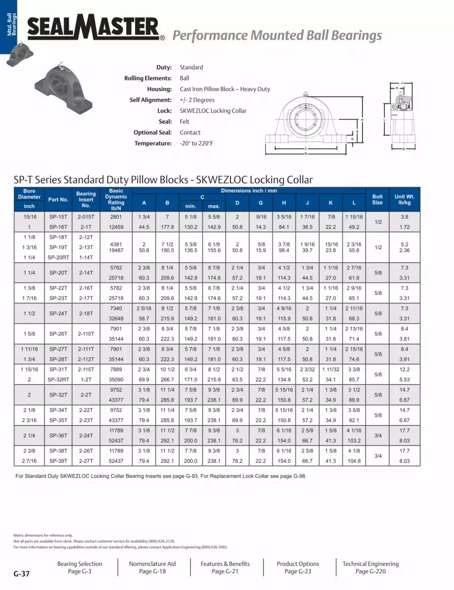
Bore Diameter Part No.
Bearing Insert
No.
Basic Dynamic Rating
lb/N
Dimensions inch / mmBolt Size
Unit Wt. lb/kgA B
CD G H J K Linch min. max.
15/16 SP-15T 2-015T 2801 1 3/4 7 5 1/8 5 5/8 2 9/16 3 5/16 1 7/16 7/8 1 15/16 1/2
3.8
1 SP-16T 2-1T 12459 44.5 177.8 130.2 142.9 50.8 14.3 84.1 36.5 22.2 49.2 1.72
1 1/8 SP-18T 2-12T4381
194872
50.87 1/2190.5
5 3/8136.5
6 1/8155.6
250.8
5/8 15.9
3 7/898.4
1 9/1639.7
15/1623.8
2 3/1655.6 1/2 5.2
2.361 3/16 SP-19T 2-13T
1 1/4 SP-20RT 1-14T
1 1/4 SP-20T 2-14T5782 2 3/8 8 1/4 5 5/8 6 7/8 2 1/4 3/4 4 1/2 1 3/4 1 1/16 2 7/16
5/87.3
25718 60.3 209.6 142.9 174.6 57.2 19.1 114.3 44.5 27.0 61.9 3.31
1 3/8 SP-22T 2-16T 5782 2 3/8 8 1/4 5 5/8 6 7/8 2 1/4 3/4 4 1/2 1 3/4 1 1/16 2 9/16 5/8
7.3
1 7/16 SP-23T 2-17T 25718 60.3 209.6 142.9 174.6 57.2 19.1 114.3 44.5 27.0 65.1 3.31
1 1/2 SP-24T 2-18T7340 2 5/16 8 1/2 5 7/8 7 1/8 2 3/8 3/4 4 9/16 2 1 1/4 2 11/16
5/87.3
32648 58.7 215.9 149.2 181.0 60.3 19.1 115.9 50.8 31.8 68.3 3.31
1 5/8 SP-26T 2-110T7901 2 3/8 8 3/4 5 7/8 7 1/8 2 3/8 3/4 4 5/8 2 1 1/4 2 13/16
5/8 8.4
35144 60.3 222.3 149.2 181.0 60.3 19.1 117.5 50.8 31.8 71.4 3.81
1 11/16 SP-27T 2-111T 7901 2 3/8 8 3/4 5 7/8 7 1/8 2 3/8 3/4 4 5/8 2 1 1/4 2 15/16 5/8
8.4
1 3/4 SP-28T 2-112T 35144 60.3 222.3 149.2 181.0 60.3 19.1 117.5 50.8 31.8 74.6 3.81
1 15/16 SP-31T 2-115T 7889 2 3/4 10 1/2 6 3/4 8 1/2 2 1/2 7/8 5 5/16 2 3/32 1 11/32 3 3/8 5/8
12.2
2 SP-32RT 1-2T 35090 69.9 266.7 171.5 215.9 63.5 22.2 134.9 53.2 34.1 85.7 5.53
2 SP-32T 2-2T9752 3 1/8 11 1/4 7 5/8 9 3/8 2 3/4 7/8 5 15/16 2 1/4 1 3/8 3 1/2
5/814.7
43377 79.4 285.8 193.7 238.1 69.9 22.2 150.8 57.2 34.9 88.9 6.67
2 1/8 SP-34T 2-22T 9752 3 1/8 11 1/4 7 5/8 9 3/8 2 3/4 7/8 5 15/16 2 1/4 1 3/8 3 5/8 5/8
14.7
2 3/16 SP-35T 2-23T 43377 79.4 285.8 193.7 238.1 69.9 22.2 150.8 57.2 34.9 92.1 6.67
2 1/4 SP-36T 2-24T11789 3 1/8 11 1/2 7 7/8 9 3/8 3 7/8 6 1/16 2 5/8 1 5/8 4 1/16
3/4 17.7
52437 79.4 292.1 200.0 238.1 76.2 22.2 154.0 66.7 41.3 103.2 8.03
2 3/8 SP-38T 2-26T 11789 3 1/8 11 1/2 7 7/8 9 3/8 3 7/8 6 1/16 2 5/8 1 5/8 4 1/8 3/4
17.7
2 7/16 SP-39T 2-27T 52437 79.4 292.1 200.0 238.1 76.2 22.2 154.0 66.7 41.3 104.8 8.03
For Standard Duty SKWEZLOC Locking Collar Bearing Inserts see page G-93. For Replacement Lock Collar see page G-98.
SP-T Series Standard Duty Pillow Blocks - SKWEZLOC Locking Collar
BC
G
H
A
L
D
JK
Duty: Standard
Rolling Elements: Ball
Housing: Cast Iron Pillow Block – Heavy Duty
Self Alignment: +/- 2 Degrees
Lock: SKWEZLOC Locking Collar
Seal: Felt
Optional Seal: Contact
Temperature: -20° to 220°F
Metric dimensions for reference only.
Not all parts are available from stock. Please contact customer service for availability (800) 626-2120.
For more information on bearing capabilities outside of our standard offering, please contact Application Engineering (800) 626-2093.
Bearing SelectionPage G-3
Nomenclature AidPage G-18
Features & BenefitsPage G-21
Product OptionsPage G-23
Technical EngineeringPage G-220

G-38
Performance Mounted Ball Bearings Performance Mounted Ball Bearings ®
Mtd
. Ba
ll
Be
ari
ng
s
Bore Diameter Part No. Bearing
Insert No.
Basic Dynamic Rating
lb/N
Dimensions inch / mmBolt Size
Unit Wt. lb/kgA B
CD G H J K Linch min. max.
7/8 SPD-14 2-014D2801
124591 3/4 44.5
7 177.8
5 1/8 130.2
5 5/8 142.9
2 50.8
9/1614.3
3 5/1684.1
1 1/2 38.1
3/4 19.1
1 3/8 34.9 1/2 3.6
1.63 15/16 SPD-15 2-015D
1 SPD-16 2-1D
1 3/16 SPD-19 2-13D 438119487
2 50.8
7 1/2 190.5
5 3/8 136.5
6 1/8 155.6
2 50.8
5/8 15.9
3 7/8 98.4
1 3/4 44.5
7/8 22.2
1 19/3240.5 1/2 5
2.27
1 1/4 SPD-20 2-14D5782
257182 3/8 60.3
8 1/4 209.6
5 5/8 142.9
6 7/8 174.6
2 1/4 57.2
3/4 19.1
4 1/2 114.3
2 50.8
1 25.4
1 55/6447.2 5/8 7.2
3.271 3/8 SPD-22 2-16D
1 7/16 SPD-23 2-17D
1 1/2 SPD-24 2-18D 7340 2 5/16 8 1/2 5 7/8 7 1/8 2 3/8 3/4 4 9/16 2 5/16 1 5/32 2 1/16 5/8
7.7
1 9/16 SPD-25 2-19D 32648 58.7 215.9 149.2 181.0 60.3 19.1 115.9 58.7 29.4 52.4 3.49
1 11/16 SPD-27 2-111D 790135144
2 3/8 60.3
8 3/4 222.3
5 7/8 149.2
7 1/8 181.0
2 3/8 60.3
3/4 19.1
4 5/8 117.5
2 3/8 60.3
1 3/1630.2
2 19/6458.3 5/8 8.3
3.761 3/4 SPD-28 2-112D
1 7/8 SPD-30 2-114D 7889 2 3/4 10 1/2 6 3/4 8 1/2 2 1/2 7/8 5 5/16 2 1/2 1 1/4 2 15/32 5/8
11.6
1 15/16 SPD-31 2-115D 35090 69.9 266.7 171.5 215.9 63.5 22.2 134.9 63.5 31.8 62.7 5.26
2 SPD-32 2-2D9752
433773 1/8 79.4
11 1/4 285.8
7 5/8 193.7
9 3/8 238.1
2 3/4 69.9
7/8 22.2
5 15/16150.8
2 5/8 66.7
1 5/1633.3
2 23/3269.1 5/8 14.1
6.402 1/8 SPD-34 2-22D
2 3/16 SPD-35 2-23D
2 1/4 SPD-36 2-24D1178952437
3 1/8 79.4
11 1/2 292.1
7 7/8 200.0
9 3/8 238.1
3 76.2
7/8 22.2
6 1/16154.0
3 1/8 79.4
1 9/1639.7
2 63/6475.8 3/4 17
7.712 3/8 SPD-38 2-26D
2 7/16 SPD-39 2-27D
2 1/2 SPD-40 3-28D 13971 3 3/4 12 5/8 9 3/8 10 5/8 3 3/8 1 7 1/8 3 1/2 1 3/4 3 7/16 3/4
26.8
2 11/16 SPD-43 2-211D 62143 95.3 320.7 238.1 269.9 85.7 25.4 181.0 88.9 44.5 87.3 12.16
2 7/8 SPD-46 2-214D 14839 3 3/4 13 9 1/4 10 3/4 3 3/8 1 7 3/16 3 1/2 1 3/4 3 41/64 3/4
26.8
2 15/16 SPD-47 2-215D 66004 95.3 330.2 235.0 273.1 85.7 25.4 182.6 88.9 44.5 92.5 12.16
3 SPD-48 3-3D 17412 4 14 1/2 10 5/8 12 1/8 3 3/4 1 1/8 7 13/16 3 7/8 1 15/16 3 59/64 3/4
34.5
3 3/16 SPD-51 2-33D 77449 101.6 368.3 269.9 308.0 95.3 28.6 198.4 98.4 49.2 99.6 15.65
For Standard Duty Bearing Inserts-Double Lock see page G-94.
Duty: Standard
Rolling Elements: Ball
Housing: Cast Iron Pillow Block – Heavy Duty
Self Alignment: +/- 2 Degrees
Lock: Double Setscrew
Seal: Felt
Optional Seal: Contact
Temperature: -20° to 220°F
SPD Series Standard Duty Pillow Blocks With Double Lock - Setscrew Locking
B
C
G
H L
K
J
A
D
Bearing SelectionPage G-3
Nomenclature AidPage G-18
Features & BenefitsPage G-21
Product OptionsPage G-23
Technical EngineeringPage G-220

G-39
® Performance Mounted Ball Bearings Performance Mounted Ball BearingsMtd
. Ba
ll
Be
ari
ng
s
Duty: Medium
Rolling Elements: Ball
Housing: Cast Iron Pillow Block - High Base
Self Alignment: +/- 2 Degrees
Lock: Setscrew
Seal: Felt
Optional Seal: Contact
Temperature: -20° to 220°F
MP Series Medium Duty Pillow Blocks - Setscrew Locking
B
H
C
AG
JK
L
D
Bore DiameterPart No.
Bearing Insert
No.
Basic Dynamic Rating
lb/N
Dimensions inch / mmBolt Size
Unit Wt. lb/kgA B
CD G H J K Linch mm min. max.
15/16 MP-15 3-0154381
194871 3/4 44.5
6 1/4 158.8
4 3/16106.4
5 3/16131.8
2 50.8
5/8 15.9
3 7/1687.3
1 1/2 38.1
7/8 22.2
1 19/3240.5 1/2 4.0
1.811 MP-16 3-125 MP-305 5305
1 3/16 MP-19 3-135782
257181 7/8 47.6
6 7/8 174.6
4 1/2 114.3
5 1/2 139.7
2 1/4 57.2
11/1617.5
3 13/1696.8
1 11/1642.9
1 25.4
1 55/6447.2 1/2 5.4
2.451 1/4 MP-20 2-1430 MP-306 5306
1 7/16 MP-23 3-17 734032648
2 1/8 54.0
8 203.2
5 127.0
6 3/8 161.9
2 1/4 57.2
3/4 19.1
4 3/16106.4
1 15/1649.2
1 3/1630.2
2 1/1652.4 1/2 6.8
3.081.378 35 MP-307 53071 1/2 MP-24 3-18 7901
351442 5/1658.7
8 3/4 222.3
5 1/2 139.7
6 3/4 171.5
2 5/8 66.7
13/1620.6
4 9/16115.9
1 15/1649.2
1 3/1630.2
2 19/6458.3 5/8 9.0
4.0840 MP-308 53081 11/16 MP-27 3-111
788935090
2 5/1658.7
8 3/4 222.3
5 7/16138.1
6 13/16173.0
2 5/8 66.7
13/1620.6
4 5/8 117.5
2 1/3251.6
1 9/3232.5
2 15/3262.7 5/8 9.5
4.311 3/4 MP-28 3-11245 MP-309 5309
1 15/16 MP-31 3-1159752
433772 1/2 63.5
9 1/2 241.3
5 15/16150.8
7 9/16192.1
2 7/8 73.0
7/8 22.2
5 3/32129.4
2 3/1655.6
1 5/1633.3
2 23/3269.1 5/8 11.7
5.312 MP-32 2-250 MP-310 5310
2 3/16 MP-35 3-231178952437
2 3/4 69.9
10 1/4 260.4
6 9/16166.7
7 15/16201.6
3 1/8 79.4
1 1/1627.0
5 5/8 142.9
2 9/1665.1
1 9/1639.7
2 63/6475.8 3/4 16.2
7.352 1/4 MP-36 2-2455 MP-311 5311
2 7/16 MP-39 3-271397162143
3 76.2
11 1/4 285.8
7 1/8 181.0
8 7/8 225.4
3 1/4 82.6
1 1/1627.0
6 1/4 158.8
2 3/4 69.9
1 11/1642.9
3 7/1687.3 3/4 21.5
9.752 1/2 MP-40 3-2865 MP-313 5313
2 11/16 MP-43 3-211 1483966004
3 1/2 88.9
13 330.2
7 7/8 200.0
10 1/8 257.2
3 1/2 88.9
1 1/8 28.6
7 177.8
3 1/1677.8
1 3/4 44.5
3 41/6492.5 7/8 29.2
13.242.756 70 MP-314 53142 15/16 MP-47 3-215
1741277449
3 1/2 88.9
13 330.2
7 7/8 200.0
10 1/8 257.2
3 1/2 88.9
1 1/4 31.8
7 1/4 184.2
3 1/4 82.6
1 15/1649.2
3 59/6499.6 7/8 31.5
14.293 MP-48 3-375 MP-315 5315
3 3/16 MP-51 3-331868183093
4 101.6
15 381.0
9 11/16246.1
12 9/16319.1
4 101.6
1 1/4 31.8
8 203.2
3 3/8 85.7
2 1/3251.6
4 5/32105.6 7/8 44.1
20.003 1/4 MP-52 2-3480 MP-316 5316
3 7/16 MP-55 3-37 2156695926
4 101.6
15 381.0
9 5/8 244.5
12 5/8 320.7
4 3/8 111.1
1 5/1633.3
8 1/4 209.6
3 25/3296.0
2 7/3256.4
4 25/64111.5 7/8 47.8
21.683 1/2 MP-56 2-383 15/16 MP-63 3-315
29905133017
5 127.0
17 431.8
11 3/4 298.5
14 3/4 374.7
4 3/4 120.7
1 5/1633.3
10 254.0
4 5/8 117.5
2 11/1668.3
5 11/64131.4 1 73.2
33.204 MP-64 3-4100 MP-320 5320
For Medium Duty Bearing Inserts-Single Lock see page G-95.
Metric dimensions for reference only.
Not all parts are available from stock. Please contact customer service for availability (800) 626-2120.
For more information on bearing capabilities outside of our standard offering, please contact Application Engineering (800) 626-2093.
Bearing SelectionPage G-3
Nomenclature AidPage G-18
Features & BenefitsPage G-21
Product OptionsPage G-23
Technical EngineeringPage G-220

G-40
Performance Mounted Ball Bearings Performance Mounted Ball Bearings ®
Mtd
. Ba
ll
Be
ari
ng
s
Duty: Medium
Rolling Elements: Ball
Housing: Cast Iron Pillow Block - High Base
Self Alignment: +/- 2 Degrees
Lock: SKWEZLOC Locking Collar
Seal: Felt
Optional Seal: Contact
Temperature: -20° to 220°F
MP-T Series Medium Duty Pillow Blocks - SKWEZLOC Locking Collar
BC
G
H
A
L
D
JK
Bore Diameter Part No. Bearing
Insert No.
Basic Dynamic Rating
lb/N
Dimensions inch / mmBolt Size
Unit Wt. lb/kgA B
CD G H J K Linch min. max.
1 MP-16T 3-1T 438119487
1 3/4 44.5
6 1/4 158.8
4 3/16106.4
5 3/16131.8
2 50.8
5/8 15.9
3 7/1687.3
1 9/1639.7
15/1623.8
2 1/1652.4 1/2 4.2
1.91
1 3/16 MP-19T 3-13T 578225718
1 7/8 47.6
6 7/8 174.6
4 1/2 114.3
5 1/2 139.7
2 1/4 57.2
11/1617.5
3 13/1696.8
1 3/4 44.5
1 1/1627.0
2 7/1661.9 1/2 5.7
2.591 1/4 MP-20T 2-14T
1 7/16 MP-23T 3-17T 734032648
2 1/8 54.0
8 203.2
5 127.0
6 3/8 161.9
2 1/4 57.2
3/4 19.1
4 3/16106.4
2 50.8
1 1/4 31.8
2 11/1668.3 1/2 7.1
3.22
1 1/2 MP-24T 3-18T 790135144
2 5/1658.7
8 3/4 222.3
5 1/2 139.7
6 3/4 171.5
2 5/8 66.7
13/1620.6
4 9/16115.9
2 50.8
1 1/4 31.8
2 13/1671.4 5/8 9.3
4.22
1 11/16 MP-27T 3-111T 788935090
2 5/1658.7
8 3/4 222.3
5 7/16138.1
6 13/16173.0
2 5/8 66.7
13/1620.6
4 5/8 117.5
2 3/3253.2
1 11/3234.1
3 1/4 82.6 5/8 10.1
4.581 3/4 MP-28T 3-112T
1 15/16 MP-31T 3-115T 975243377
2 1/2 63.5
9 1/2 241.3
5 15/16150.8
7 9/16192.1
2 7/8 73.0
7/8 22.2
5 3/32129.4
2 1/4 57.2
1 3/8 34.9
3 1/2 88.9 5/8 12.3
5.582 MP-32T 2-2T
2 3/16 MP-35T 3-23T 1178952437
2 3/4 69.9
10 1/4 260.4
6 9/16166.7
7 15/16201.6
3 1/8 79.4
1 1/1627.0
5 5/8 142.9
2 5/8 66.7
1 5/8 41.3
4 1/16103.2 3/4 17.4
7.892 1/4 MP-36T 2-24T
For Medium Duty SKWEZLOC Locking Collar Bearing inserts see page G-96. For Replacement Lock Collar see page G-98.
Bearing SelectionPage G-3
Nomenclature AidPage G-18
Features & BenefitsPage G-21
Product OptionsPage G-23
Technical EngineeringPage G-220

G-41
® Performance Mounted Ball Bearings Performance Mounted Ball BearingsMtd
. Ba
ll
Be
ari
ng
s
Duty: Medium
Rolling Elements: Ball
Housing: Cast Iron Pillow Block - High Base
Self Alignment: +/- 2 Degrees
Lock: Double Setscrew
Seal: Felt
Optional Seal: Contact
Temperature: -20° to 220°F
MPD Series Medium Duty Pillow Blocks With Double Lock - Setscrew Locking
B
C
G
H L
K
J
A
D
Bore Diameter Part No.
Bearing Insert
No.
Basic Dynamic Rating
lb/N
Dimensions inch / mmBolt Size
Unit Wt. lb/kgA B
CD G H J K Linch min. max.
1 MPD-16 3-1D 438119487
1 3/4 44.5
6 1/4 158.8
4 3/16106.4
5 3/16131.8
2 50.8
5/8 15.9
3 7/1687.3
1 3/4 44.5
7/8 22.2
1 19/3240.5 1/2 4.0
1.81
1 3/16 MPD-19 3-13D 578225718
1 7/8 47.6
6 7/8 174.6
4 1/2 114.3
5 1/2 139.7
2 1/4 57.2
11/1617.5
3 13/1696.8
2 50.8
1 25.4
1 55/6447.2 1/2 5.4
2.451 1/4 MPD-20 2-14D
1 7/16 MPD-23 3-17D 734032648
2 1/8 54.0
8 203.2
5 127.0
6 3/8 161.9
2 1/4 57.2
3/4 19.1
4 3/16106.4
2 5/1658.7
1 5/3229.4
2 1/1652.4 1/2 6.8
3.08
1 1/2 MPD-24 3-18D 790135144
2 5/1658.7
8 3/4 222.3
5 1/2 139.7
6 3/4 171.5
2 5/8 66.7
13/1620.6
4 9/16115.9
2 3/8 60.3
1 3/1630.2
2 19/6458.3 5/8 9.0
4.08
1 11/16 MPD-27 3-111D 788935090
2 5/1658.7
8 3/4 222.3
5 7/16138.1
6 13/16173.0
2 5/8 66.7
13/1620.6
4 5/8 117.5
2 1/2 63.5
1 1/4 31.8
2 15/3262.7 5/8 9.5
4.311 3/4 MPD-28 3-112D
1 15/16 MPD-31 3-115D 975243377
2 1/2 63.5
9 1/2 241.3
5 15/16150.8
7 9/16192.1
2 7/8 73.0
7/8 22.2
5 3/32129.4
2 5/8 66.7
1 5/1633.3
2 23/3269.1 5/8 11.7
5.312 MPD-32 2-2D
2 3/16 MPD-35 3-23D 1178952437
2 3/4 69.9
10 1/4 260.4
6 9/16166.7
7 15/16201.6
3 1/8 79.4
1 1/1627.0
5 5/8 142.9
3 1/8 79.4
1 9/1639.7
2 63/6475.8 3/4 16.2
7.352 1/4 MPD-36 2-24D
2 7/16 MPD-39 3-27D 1397162143
3 76.2
11 1/4 285.8
7 1/8 181.0
8 7/8 225.4
3 1/4 82.6
1 1/1627.0
6 1/4 158.8
3 1/2 88.9
1 3/4 44.5
3 7/1687.3 3/4 21.5
9.752 1/2 MPD-40 3-28D
2 11/16 MPD-43 3-211D 1483966004
3 1/2 88.9
13 330.2
7 7/8 200.0
10 1/8 257.2
3 1/2 88.9
1 1/8 28.6
7 177.8
3 1/2 88.9
1 3/4 44.5
3 41/6492.5 7/8 29.2
13.24
2 15/16 MPD-47 3-215D 1741277449
3 1/2 88.9
13 330.2
7 7/8 200.0
10 1/8 257.2
3 1/2 88.9
1 1/4 31.8
7 1/4 184.2
3 7/8 98.4
1 15/1649.2
3 59/6499.6 7/8 31.5
14.293 MPD-48 3-3D
3 3/16 MPD-51 3-33D 18681 4 101.6
15 381.0
9 11/16246.1
12 9/16319.1
4 101.6
1 1/4 31.8
8 203.2
4 1/16103.2
2 1/3251.6
4 5/32105.6 7/8 44.1
20.003 1/4 MPD-52 2-34D 83093
3 7/16 MPD-55 3-37D 21566 4 101.6
15 381.0
9 5/8 244.5
12 5/8 320.7
4 3/8 111.1
1 5/1633.3
8 1/4 209.6
4 7/16112.7
2 7/3256.4
4 25/64111.5 7/8 47.8
21.683 1/2 MPD-56 2-38D 95926
3 15/16 MPD-63 3-315D 29905 5 127.0
17 431.8
11 3/4 298.5
14 3/4 374.7
4 3/4 120.7
1 5/1633.3
10 254.0
5 3/8 136.5
2 11/1668.3
5 11/64131.4 1 73.2
33.204 MPD-64 3-4D 133017
For Medium Duty Bearing Inserts-Double Lock see page G-97.
Metric dimensions for reference only.
Not all parts are available from stock. Please contact customer service for availability (800) 626-2120.
For more information on bearing capabilities outside of our standard offering, please contact Application Engineering (800) 626-2093.
Bearing SelectionPage G-3
Nomenclature AidPage G-18
Features & BenefitsPage G-21
Product OptionsPage G-23
Technical EngineeringPage G-220

G-42
Performance Mounted Ball Bearings Performance Mounted Ball Bearings ®
Mtd
. Ba
ll
Be
ari
ng
s
MFP Series Medium Duty Four-Bolt Base Pillow Blocks - Setscrew Locking
L
D
G
A
H
BEC
JK
Duty: Medium
Rolling Elements: Ball
Housing: Cast Iron Four Bolt Pillow Block - High Base
Self Alignment +/- 2 Degrees
Lock: Setscrew
Seal: Felt
Optional Seal: Contact
Temperature: -20° to 220°F
Relube: Relube
Bore Diameter Part No.
Bearing Insert
No.
Basic Dynamic Rating
lb/N
Dimensions inch / mmBolt Size
Unit Wt.
lb/kgA BC
D E G H J K Linch mm min. max.
1 15/16 MFP-31 3-1159752
433772 1/2 63.5
9 3/4 247.7
6 3/8 161.9
7 5/8 193.7
4 101.6
2 1/4 57.2
13/1620.6
5 3/8 136.5
2 3/1655.6
1 5/1633.3
2 23/3269.1 5/8 13.7
6.212 MFP-32 2-2
50 MFP-310 5310
2 3/16 MFP-35 3-231178952437
2 3/4 69.9
10 1/4 260.4
6 7/8 174.6
8 1/8 206.4
4 1/8 104.8
2 1/4 57.2
7/8 22.2
5 13/16147.6
2 9/1665.1
1 9/1639.7
2 63/6475.8 5/8 17.0
7.712 1/4 MFP-36 2-24
55 MFP-311 5311
2 7/16 MFP-39 3-271397162143
3 76.2
11 1/4 285.8
7 1/2 190.5
9 228.6
4 1/2 114.3
2 5/8 66.7
1 25.4
6 1/2 165.1
2 3/4 69.9
1 11/1642.9
3 7/1687.3 5/8 23.3
10.572 1/2 MFP-40 3-28
65 MFP-313 5313
2 11/16 MFP-43 3-211 14839 3 1/2 13 9 10 1/2 5 2 3/4 1 1/8 7 1/4 3 1/16 1 3/4 3 41/64 3/4
34.0
70 MFP-314 5314 66004 88.9 330.2 228.6 266.7 127.0 69.9 28.6 184.2 77.8 44.5 92.5 15.42
2 15/16 MFP-47 3-2151741277449
3 1/2 88.9
13 330.2
9 228.6
10 1/2 266.7
5 127.0
2 3/4 69.9
1 25.4
7 3/8 187.3
3 1/4 82.6
1 15/1649.2
3 59/6499.6 3/4 36.5
16.563 MFP-48 3-3
75 MFP-315 5315
3 3/16 MFP-51 3-331868183093
4 101.6
15 381.0
10 3/4 273.1
12 1/4 311.2
5 127.0
3 76.2
1 1/1627.0
8 7/16214.3
3 3/8 85.7
2 1/3251.6
4 5/32105.6 3/4 44.5
20.183 1/4 MFP-52 2-34
80 MFP-316 5316
3 7/16 MFP-55 3-37 21566 4 15 10 3/4 12 1/4 5 3 1 1/16 8 7/16 3 25/32 2 7/32 4 25/64 3/4
48.6
3 1/2 MFP-56 2-38 95926 101.6 381.0 273.1 311.2 127.0 76.2 27.0 214.3 96.0 56.4 111.5 22.04
3 15/16 MFP-63 3-31529905
1330175
127.017
431.812 7/16315.9
14 1/16357.2
6 152.4
3 1/2 88.9
1 1/4 31.8
10 1/4 260.4
4 5/8 117.5
2 11/1668.3
5 11/64131.4 7/8 83.5
37.874 MFP-64 3-4
100 MFP-320 5320
For Medium Duty Bearing Inserts-Single Lock see page G-95.
Bearing SelectionPage G-3
Nomenclature AidPage G-18
Features & BenefitsPage G-21
Product OptionsPage G-23
Technical EngineeringPage G-220

G-43
® Performance Mounted Ball Bearings Performance Mounted Ball BearingsMtd
. Ba
ll
Be
ari
ng
s
MFPD Series Medium Duty Four-Bolt Base Pillow Blocks With Double Lock - Setscrew Locking
Duty: Medium
Rolling Elements: Ball
Housing: Cast Iron Four Bolt Pillow Block - High Base
Self Alignment: +/- 2 Degrees
Lock: Double Setscrew
Seal: Felt
Optional Seal: Contact
Temperature: -20° to 220°F
Bore Diameter Part No.
Bearing Insert
No.
Basic Dynamic Rating
lb/N
Dimensions inch / mmBolt Size
Unit Wt.
lb/kgA BC
D E G H J K Linch min. max.
1 15/16 MFPD-31 3-115D 975243377
2 1/2 63.5
9 3/4 247.7
6 3/8 161.9
7 5/8 193.7
4 101.6
2 1/4 57.2
13/1620.6
5 3/8 136.5
2 5/8 66.7
1 5/1633.3
2 23/3269.1 5/8 13.7
6.21
2 3/16 MFPD-35 3-23D 1178952437
2 3/4 69.9
10 1/4 260.4
6 7/8 174.6
8 1/8 206.4
4 1/8 104.8
2 1/4 57.2
7/8 22.2
5 13/16147.6
3 1/8 79.4
1 9/1639.7
2 63/6475.8 5/8 17
7.71
2 7/16 MFPD-39 3-27D 13971 3 76.2
11 1/4 285.8
7 1/2 190.5
9 228.6
4 1/2 114.3
2 5/8 66.7
1 25.4
6 1/2 165.1
3 1/2 88.9
1 3/4 44.5
3 7/1687.3 5/8 23.3
10.572 1/2 MFPD-40 3-28D 62143
2 11/16 MFPD-43 3-211D14839 3 1/2
88.913
330.29
228.610 1/2 266.7
5 127.0
2 3/4 69.9
1 1/8 28.6
7 1/4 184.2
3 1/2 88.9
1 3/4 44.5
3 41/6492.5 3/4 34
863.666004
2 15/16 MFPD-47 3-215D 1741277449
3 1/2 88.9
13 330.2
9 228.6
10 1/2 266.7
5 127.0
2 3/4 69.9
1 25.4
7 3/8 187.3
3 7/8 98.4
1 15/1649.2
3 59/6499.6 3/4 36.5
16.563 MFPD-48 3-3D
3 7/16 MFPD-55 3-37D 2156695926
4 101.6
15 381.0
25 3/4 654.1
12 1/4 311.2
5 127.0
3 76.2
1 1/1627.0
8 7/16214.3
4 39/89112.7
2 7/3256.4
4 25/64111.5 3/4 48.6
22.043 1/2 MFPD-56 2-38D
3 15/16 MFPD-63 3-315D 29905133017
5 127.0
17 431.8
12 7/16315.9
14 1/16357.2
6 152.4
3 1/2 88.9
1 1/4 31.8
10 1/4 260.4
5 3/8 136.5
2 11/1668.3
5 11/64131.4 7/8 83.5
37.874 MFPD-64 3-4D
4 7/16 MFPD-71* 3-47D37482
1667206
152.419
482.614
355.616
406.45 1/2 139.7
3 1/4 82.6
1 5/8 41.3
12 1/8 308.0
5 3/4 146.1
2 7/8 73.0
6 11/32161.1 1 130.0
58.974 15/16 MFPD-79* 3-415D
5 MFPD-80 3-500D
* Units MFPD-71, MFPD-79 and MFPD-80 are not available with contact seal. For Medium Duty Bearing Inserts-Double Lock see page G-97.
Metric dimensions for reference only.
Not all parts are available from stock. Please contact customer service for availability (800) 626-2120.
For more information on bearing capabilities outside of our standard offering, please contact Application Engineering (800) 626-2093.
L
G
A
H
CB
ED
KJ
Bearing SelectionPage G-3
Nomenclature AidPage G-18
Features & BenefitsPage G-21
Product OptionsPage G-23
Technical EngineeringPage G-220

G-44
Performance Mounted Ball Bearings Performance Mounted Ball Bearings ®
Mtd
. Ba
ll
Be
ari
ng
s
Duty: Medium
Rolling Elements: Ball
Housing: Cast Iron Pillow Block – Heavy Duty
Self Alignment: +/- 2 Degrees
Lock: Double Setscrew
Seal: Felt
Optional Seal: Contact
Temperature: -20° to 220°F
MSPD Series Medium Duty Pillow Blocks With Double Lock - Setscrew Locking
D
A
H
G
CB
L
KJ
Bore Diameter Part No.
Bearing Insert
No.
Basic Dynamic Rating
lb/N
Dimensions inch / mmBolt Size
Unit Wt. lb/kgA B
CD G H J K Linch min. max.
1 11/16 MSPD-27 3-111D 788935090
2 3/8 60.3
8 7/8 225.4
6 7/16163.5
7 7/16188.9
2 1/2 63.5
3/4 19.1
4 13/16122.2
2 1/2 63.5
1 1/4 31.8
2 1/2 63.5 5/8 9.5
4.311 3/4 MSPD-28 3-112D
1 15/16 MSPD-31 3-115D 975243377
2 3/4 69.9
10 254.0
7 1/8 181.0
8 3/8 212.7
2 5/8 66.7
7/8 22.2
5 7/16138.1
2 5/8 66.7
1 5/1633.3
2 5/8 66.7 5/8 12.5
5.672 MSPD-32 2-2D
2 3/16 MSPD-35 3-23D 1178952437
3 1/8 79.4
10 7/8 276.2
7 7/8 200.0
9 3/8 238.1
2 3/4 69.9
15/1623.8
6 1/16154.0
3 1/8 79.4
1 9/1639.7
2 63/6475.8 5/8 17.0
7.712 1/4 MSPD-36 2-24D
2 7/16 MSPD-39 3-27D 1397162143
3 1/8 79.4
11 3/4 298.5
8 3/4 222.3
9 7/8 250.8
3 76.2
1 25.4
6 5/16160.3
3 1/2 88.9
1 3/4 44.5
3 1/2 88.9 3/4 22.0
9.982 1/2 MSPD-40 3-28D
2 11/16 MSPD-43 3-211D 1483966004
3 3/4 95.3
13 3/8 339.7
10 1/8 257.2
11 3/8 288.9
3 1/4 82.6
1 25.4
7 5/16185.7
3 1/2 88.9
1 3/4 44.5
3 1/2 88.9 3/4 28.0
12.70
2 15/16 MSPD-47 3-215D 1741277449
3 3/4 95.3
13 3/4 349.3
10 254.0
11 1/2 292.1
3 3/8 85.7
1 3/1630.2
7 1/2 190.5
3 7/8 98.4
1 15/1649.2
3 7/8 98.4 7/8 33.0
14.973 MSPD-48 3-3D
3 7/16 MSPD-55 3-37D 2156695926
4 9/16115.9
15 3/8 390.5
12 1/8 308.0
13 1/2 342.9
4 101.6
1 1/4 31.8
8 13/16223.8
4 7/16112.7
2 7/3256.4
4 7/16112.7 7/8 51.0
23.133 1/2 MSPD-56 2-38D
3 15/16 MSPD-63 3-315D 29905133017
5 1/8 130.2
17 431.8
13 1/8 333.4
14 3/4 374.7
4 3/4 120.7
1 1/4 31.8
10 1/8 257.2
5 3/8 136.5
2 11/1668.3
5 3/8 136.5 1 74.5
33.794 MSPD-64 3-4D
4 7/16 MSPD-71 3-47D * 37482166720
6 1/4 158.8
21 1/4 539.8
15 1/16382.6
18 3/16462.0
6 1/4 158.8
1 3/4 44.5
12 1/2 317.5
5 3/4 146.1
2 7/8 73.0
5 3/4 146.1 1 1/8 159.0
72.124 15/16 MSPD-79 3-415D *
* Units MSPD-71 and MSPD-79 are not available with contact seal. For Medium Duty Bearing Inserts-Double Lock see page G-97.
Bearing SelectionPage G-3
Nomenclature AidPage G-18
Features & BenefitsPage G-21
Product OptionsPage G-23
Technical EngineeringPage G-220

G-45
® Performance Mounted Ball Bearings Performance Mounted Ball BearingsMtd
. Ba
ll
Be
ari
ng
s
MSFPD Series Medium Duty Four-Bolt Base Pillow Blocks With Double Lock - Setscrew Locking
L
G
A
H
CB
ED
KJ
Duty: Medium
Rolling Elements: Ball
Housing: Cast Iron Four Bolt Pillow Block – Heavy Duty
Self Alignment: +/- 2 Degrees
Lock: Double Setscrew
Seal: Felt
Optional Seal: Contact
Temperature: -20° to 220°F
Bore Diameter Part No.
Bearing Insert
No.
Basic Dynamic Rating lb/N
Dimensions inch / mmBolt Size
Unit Wt.
lb/kgA BC
D E G H J K Linch min. max.
1 15/16 MSFPD-31 3-115D 975243377
2 3/4 69.9
9 3/4 247.7
6 3/8 161.9
7 5/8 193.7
4 101.6
2 1/4 57.2
1 1/1627.0
5 5/8 142.9
2 5/8 66.7
1 5/1633.3
2 5/8 66.7 5/8 15.4
6.992 MSFPD-32 2-2D
2 3/16 MSFPD-35 3-23D 1178952437
3 1/8 79.4
10 1/4 260.4
6 7/8 174.6
8 1/8 206.4
4 1/8 104.8
2 1/4 57.2
1 1/4 31.8
6 3/16157.2
3 1/8 79.4
1 9/1639.7
2 63/6475.8 5/8 20.1
9.122 1/4 MSFPD-36 2-24D
2 7/16 MSFPD-39 3-27D 1397162143
3 1/8 79.4
11 5/16287.3
7 1/2 190.5
9 228.6
4 1/2 114.3
2 5/8 66.7
1 1/8 28.6
6 5/8 168.3
3 1/2 88.9
1 3/4 44.5
3 1/2 88.9 5/8 25.4
11.522 1/2 MSFPD-40 3-28D
2 11/16 MSFPD-43 3-211D 1483966004
3 3/4 95.3
13 330.2
9 228.6
10 1/2 266.7
5 127.0
2 3/4 69.9
1 3/8 34.9
7 1/2 190.5
3 1/2 88.9
1 3/4 44.5
3 1/2 88.9 3/4 37.3
16.92
2 15/16 MSFPD-47 3-215D 1741277449
3 3/4 95.3
13 330.2
9 228.6
10 1/2 266.7
5 127.0
2 3/4 69.9
1 1/4 31.8
7 5/8 193.7
3 7/8 98.4
1 15/1649.2
3 7/8 98.4 3/4 40.1
18.193 MSFPD-48 3-3D
3 3/16 MSFPD-51 3-33D 1868183093
4 1/8 104.8
15 381.0
10 3/4 273.1
12 1/4 311.2
5 127.0
3 76.2
1 3/1630.2
8 9/16217.5
4 1/16103.2
2 1/3251.6
4 5/32105.6 3/4 51.2
23.223 1/4 MSFPD-52 2-34D
3 7/16 MSFPD-55 3-37D 2156695926
4 9/16115.9
15 381.0
10 3/4 273.1
12 1/4 311.2
5 127.0
3 76.2
1 1/4 31.8
9 228.6
4 7/16112.7
2 7/3256.4
4 7/16112.7 3/4 51.8
23.503 1/2 MSFPD-56 2-38D
3 15/16 MSFPD-63 3-315D 29905133017
5 1/8 130.2
17 431.8
12 7/16315.9
14 1/16357.2
6 152.4
3 1/2 88.9
1 3/8 34.9
10 3/8 263.5
5 3/8 136.5
2 11/1668.3
5 3/8 136.5 7/8 84.6
38.374 MSFPD-64 3-4D
4 7/16 MSFPD-71 3-47D 37482166720
6 1/4 158.8
19 482.6
14 355.6
16 406.4
5 1/2 139.7
3 1/4 82.6
1 7/8 47.6
12 3/8 314.3
5 3/4 146.1
2 7/8 73.0
5 3/4 146.1 1 136.0
61.694 15/16 MSFPD-79 3-415D
For Medium Duty Bearing Inserts-Double Lock see page G-97.Units MSFPD-71 and MSFPD-79 are not available with contact seal.
Metric dimensions for reference only.
Not all parts are available from stock. Please contact customer service for availability (800) 626-2120.
For more information on bearing capabilities outside of our standard offering, please contact Application Engineering (800) 626-2093.
Bearing SelectionPage G-3
Nomenclature AidPage G-18
Features & BenefitsPage G-21
Product OptionsPage G-23
Technical EngineeringPage G-220

G-46
Performance Mounted Ball Bearings Performance Mounted Ball Bearings ®
Mtd
. Ba
ll
Be
ari
ng
s
Bore Diameter Part No. Bearing
Insert No.
Basic Dynamic Rating
lb/N
Dimensions inch / mmBolt Size
Unit Wt. lb/kgA B
CD G H J K Linch min. max.
1 3/16 SPM-19 3-13 578225718
2 50.8
7 1/2 190.5
5 3/8 136.5
6 1/8 155.6
2 50.8
5/8 15.9
3 7/8 98.4
1 11/1642.9
1 25.4
1 55/6447.2 1/2 6.9
3.13
1 7/16 SPM-23 3-17 734032648
2 3/8 60.3
8 1/4 209.6
5 5/8 142.9
6 7/8 174.6
2 1/4 57.2
3/4 19.1
4 1/2 114.3
1 15/1649.2
1 3/1630.2
2 1/1652.4 5/8 7.1
3.22
1 11/16 SPM-27 3-111 788935090
2 3/8 60.3
8 3/4 222.3
5 7/8 149.2
7 1/8 181.0
2 3/8 60.3
3/4 19.1
4 5/8 117.5
2 1/3251.6
1 9/3232.5
2 15/3262.7 5/8 9.7
4.401 3/4 SPM-28 3-112
1 15/16 SPM-31 3-115 975243377
2 3/4 69.9
10 1/2 266.7
6 3/4 171.5
8 1/2 215.9
2 1/2 63.5
7/8 22.2
5 5/16134.9
2 3/1655.6
1 5/1633.3
2 23/3269.1 5/8 11.9
5.40
2 3/16 SPM-35 3-23 1178952437
3 1/8 79.4
11 1/4 285.8
7 5/8 193.7
9 3/8 238.1
2 3/4 69.9
7/8 22.2
5 15/16150.8
2 9/1665.1
1 9/1639.7
2 63/6475.8 5/8 16.6
7.53
2 7/16 SPM-39 3-27 1397162143
3 1/8 79.4
11 1/2 292.1
7 7/8 200.0
9 3/8 238.1
3 76.2
7/8 22.2
6 1/4 158.8
2 3/4 69.9
1 11/1642.9
3 7/1687.3 3/4 20.1
9.122 1/2 SPM-40 3-28
For Medium Duty Bearing Inserts-Single Lock see page G-95.
Duty: Medium
Rolling Elements: Ball
Housing: Cast Iron Pillow Block - Heavy Duty
Self Alignment: +/- 2 Degrees
Lock: Setscrew
Seal: Felt
Optional Seal: Contact
Temperature: -20° to 220°F
SPM Series Medium Duty Pillow Blocks - Setscrew Locking
B
H
C
AG
JK
L
D
Bearing SelectionPage G-3
Nomenclature AidPage G-18
Features & BenefitsPage G-21
Product OptionsPage G-23
Technical EngineeringPage G-220

G-47
® Performance Mounted Ball Bearings Performance Mounted Ball BearingsMtd
. Ba
ll
Be
ari
ng
s
Duty: Standard
Rolling Elements: Ball
Housing: Cast Iron Tapped Base Pillow Block
Self Alignment: +/- 2 Degrees
Lock: Setscrew
Seal: Felt
Optional Seal: Contact
Temperature: -20° to 220°F
TB Series Tapped Base Pillow Blocks - Setscrew Locking
H
J
CB
A
D
N
L
K
TAPPED BASE HOLES
Bore DiameterPart No.
Bearing Insert
No.
Basic Dynamic Rating
lb/N
Dimensions inch / mm Bolt UNC-2B Thread
Unit Wt.
lb/kgA B C D H J K L N Tap Depthinch mm
1/2 TB-8 2-08
3/8-16
9/16 TB-9 2-09 5/8 TB-10 2-010 2611 1 5/16 3 1/8 2 1 1/2 2 9/16 1 7/32 23/32 1 3/16 1/2 1.8
11/16 TB-11 2-011 11614 33.3 79.4 50.8 38.1 65.1 31.0 18.3 30.2 12.7 .82 3/4 TB-12 2-012
20 TB-204 5204 7/8 TB-14 2-014
3/8-16 15/16 TB-15 2-015 2801 1 7/16 3 2 1 1/2 2 13/16 1 3/8 13/16 1 3/8 1/2 2.0
1 TB-16 2-1 12459 36.5 76.2 50.8 38.1 71.4 34.9 20.6 34.9 12.7 .9125 TB-205 5205
1 1/16 TB-17 2-11
438119487
1 11/1642.9
4 101.6
3 76.2
1 1/2 38.1
3 13/3286.5
1 1/2 38.1
7/8 22.2
1 19/3240.5
5/8 15.9 7/16-14 3.5
1.59
1 1/8 TB-18 2-121 3/16 TB-19 2-131 1/4 TB-20R 1-14
30 TB-206 52061 1/4 TB-20 2-14
578225718
1 7/8 47.6
4 1/4 108.0
3 1/4 82.6
1 7/8 47.6
3 3/4 95.3
1 11/1642.9
1 25.4
1 55/6447.2
3/4 19.1 1/2-13 4.5
2.04
1 5/16 TB-21 2-151 3/8 TB-22 2-16
1 7/16 TB-23 2-1735 TB-207 5207
1 1/2 TB-24 2-187340
326481 15/16
49.24 5/8 117.5
3 1/2 88.9
1 7/8 47.6
3 15/16100.0
1 15/1649.2
1 3/1630.2
2 1/1652.4
3/4 19.1
6.02.721 9/16 TB-25 2-19 1/2-13
40 TB-208 52081 5/8 TB-26 2-110
1/2-131 11/16 TB-27 2-111 7901 2 1/8 5 3 3/4 2 4 1/4 1 15/16 1 3/16 2 19/64 3/4 6.51 3/4 TB-28 2-112 35144 54.0 127.0 95.3 50.8 108.0 49.2 30.2 58.3 19.1 2.95
45 TB-209 52091 7/8 TB-30 2-114
5/8-111 15/16 TB-31 2-115 7889 2 1/4 5 1/2 4 2 4 5/8 2 1/32 1 9/32 2 15/32 7/8 8.0
2 TB-32R 1-2 35090 57.2 139.7 101.6 50.8 117.5 51.6 32.5 62.7 22.2 3.6350 TB-210 5210
For Standard Duty Bearing Inserts-Single Lock see page G-92.
Metric dimensions for reference only.
Not all parts are available from stock. Please contact customer service for availability (800) 626-2120.
For more information on bearing capabilities outside of our standard offering, please contact Application Engineering (800) 626-2093.
Bearing SelectionPage G-3
Nomenclature AidPage G-18
Features & BenefitsPage G-21
Product OptionsPage G-23
Technical EngineeringPage G-220

G-48
Performance Mounted Ball Bearings Performance Mounted Ball Bearings ®
Mtd
. Ba
ll
Be
ari
ng
s
TB-T Series Standard Duty Tapped Base Pillow Block - SKWEZLOC Locking Collar - Inch
TAPPED BASE HOLESCB
A
H L
D
N
KJ
Bore Diameter Part No. Bearing
Insert No.
Basic Dynamic Rating
lb/N
Dimensions inch / mm Bolt UNC-2B Thread
Unit Wt. lb/kgA B C D H J K L
NTap
Depthinch
3/4 *TB-12T 2-012T2611 1 5/16 3 1/8 2 1 1/2 2 9/16 1 9/32 25/32 1 3/4 1/2
3/8-161.8
11614 33.3 79.4 50.8 38.1 65.1 32.5 19.8 44.5 12.7 .82 15/16 TB-15T 2-015T 2801 1 7/16 3 2 1 1/2 2 13/16 1 7/16 7/8 1 15/16 1/2
3/8-162.0
1 TB-16T 2-1T 12459 36.5 76.2 50.8 38.1 71.4 36.5 22.2 49.2 12.7 .911 1/8 TB-18T 2-12T
438119487
1 11/1642.9
4101.6
376.2
1 1/2 38.1
3 13/3286.5
1 9/1639.7
15/1623.8
2 3/1655.6
5/8 15.9
7/16-143.7
1.681 3/16 TB-19T 2-13T1 1/4 TB-20RT 1-14T
1 1/4 TB-20T 2-14T5782 1 7/8 4 1/4 3 1/4 1 7/8 3 3/4 1 3/4 1 1/16 2 7/16 3/4
1/2-134.8
25718 47.6 108.0 82.6 47.6 95.3 44.5 27.0 61.9 19.1 2.181 3/8 TB-22T 2-16T 5782 1 7/8 4 1/4 3 1/4 1 7/8 3 3/4 1 3/4 1 1/16 2 9/16 3/4
1/2-134.8
1 7/16 TB-23T 2-17T 25718 47.6 108.0 82.6 47.6 95.3 44.5 27.0 65.1 19.1 2.18
1 1/2 TB-24T 2-18T7340 1 15/16 4 5/8 3 1/2 1 7/8 3 15/16 2 1 1/4 2 11/16 3/4
1/2-136.3
32648 49.2 117.5 88.9 47.6 100.0 50.8 31.8 68.3 19.1 2.86
1 5/8 TB-26T 2-110T7901 2 1/8 5 3 3/4 2 4 1/4 2 1 1/4 2 13/16 3/4
1/2-136.8
35144 54.0 127.0 95.3 50.8 108.0 50.8 31.8 71.4 19.1 3.081 11/16 TB-27T 2-111T 7901 2 1/8 5 3 3/4 2 4 1/4 2 1 1/4 2 15/16 3/4
1/2-136.8
1 3/4 TB-28T 2-112T 35144 54.0 127.0 95.3 50.8 108.0 50.8 31.8 74.6 19.1 3.081 15/16 TB-31T 2-115T 7889 2 1/4 5 1/2 4 2 4 5/8 2 3/32 1 11/32 3 3/8 7/8
5/8-118.6
2 TB-32RT 1-2T 35090 57.2 139.7 101.6 50.8 117.5 53.2 34.1 85.7 22.2 3.90
* Bearing reversed in housing for collar clearance
Duty: Standard
Rolling Elements: Ball
Housing: Cast Iron Tapped Base Pillow Block
Self Alignment: +/- 2 Degrees
Lock: SKWEZLOC Locking Collar
Seal: Felt
Optional Seal: Contact
Temperature: -20° to 220°F
TB-T Series Standard Duty Tapped Base Pillow Block - SKWEZLOC Locking Collar - Metric -SKWEZTM
Bore Diameter Part No. Bearing
Insert No.
Basic Dynamic Rating
N/lb
Dimensions mm / inch M Bolt
Thread mm
Unit Wt.
kg/lbA B C D H J K LN
Min. Tap Depthmm
20 *TB-204TMC 5204TMC11614 33.3 79.4 52.0 38.1 65.1 32.5 19.8 44.5 11
M10 x 1.5.82
2611 1 5/16 3 1/8 2 3/64 1 1/2 2 9/16 1 9/32 25/32 1 3/4 7/16 1.8
25 TB-205TMC 5205TMC12459 36.5 76.2 56.0 38.1 71.4 36.5 22.2 49.2 11
M10 x 1.5.91
2801 1 7/16 3 2 13/64 1 1/2 2 13/16 1 7/16 7/8 1 15/16 7/16 2.0
30 TB-206TMC 5206TM19487 42.9 101.6 65.9 38.1 86.5 39.7 23.8 55.6 16
M14 x 2.01.68
4381 1 11/16 4 2 19/32 1 1/2 3 13/32 1 9/16 15/16 2 3/16 5/8 3.7
35 TB-207TMC 5207TMC25718 47.6 108.0 80.2 47.6 95.3 44.5 27.0 65.1 17.5
M14 x 2.02.18
5782 1 7/8 4 1/4 3 5/32 1 7/8 3 3/4 1 3/4 1 1/16 2 9/16 11/16 4.8
40 TB-208TMC 5208TMC32648 49.2 117.5 84.1 47.6 100.0 50.8 31.8 68.3 17.5
M14 x 2.02.86
7340 1 15/16 4 5/8 3 5/16 1 7/8 3 15/16 2 1 1/4 2 11/16 11/16 6.3
45 TB-209TMC 5209TMC35144 54.0 127.0 90.1 50.8 108.0 50.8 31.8 74.6 22
M14 x 2.03.08
7901 2 1/8 5 3 35/64 2 4 1/4 2 1 1/4 2 15/16 7/8 6.8
50 TB-210TMC 5210TMC35090 57.2 139.7 94.1 50.8 117.5 53.2 34.1 85.7 22
M16 x 2.03.90
7889 2 1/4 5 1/2 3 45/64 2 4 5/8 2 3/32 1 11/32 3 3/8 7/8 8.6
* Bearing reversed in housing for collar clearance For Standard Duty SKWELOC Single Locking Collar Bearing Inserts see page G-93. For Replacement Lock Collar see page G-98.
Bearing SelectionPage G-3
Nomenclature AidPage G-18
Features & BenefitsPage G-21
Product OptionsPage G-23
Technical EngineeringPage G-220

G-49
® Performance Mounted Ball Bearings Performance Mounted Ball BearingsMtd
. Ba
ll
Be
ari
ng
s
Duty: Standard
Rolling Elements: Ball
Housing: Cast Iron Four Bolt Flange
Self Alignment: +/- 2 Degrees
Lock: Setscrew
Seal: Felt
Optional Seal: Contact
Temperature: -20° to 220°F
SF Series Standard Duty Four-Bolt Flange Units - Setscrew Locking
A
LM
H
G
NB
D
J
T
Bore DiameterPart No. Bearing
Insert No.
Basic Dynamic Rating
lb/N
Dimensions inch / mmBolt Size
Unit Wt. lb/kgA B* D G H J N L M T
Coreinch mm 1/2 SF-8 2-08
3/8 9/16 SF-9 2-09 2611 3 2 1/8 59/64 7/16 1 9/32 1 7/32 1/2 1 3/16 2 17/64 2 1.4 5/8 SF-10 2-010 11614 76.2 54.0 23.4 11.1 32.5 31.0 12.7 30.2 57.5 50.8 .64
11/16 SF-11 2-011 3/4 SF-12 2-012 2611 3 3/8 2 1/2 59/64 7/16 1 9/32 1 7/32 1/2 1 3/16 2 11/32 2 3/8 1.5
20 SF-204 5204 11614 85.7 63.5 23.4 11.1 32.5 31.0 12.7 30.2 59.5 50.8 .68 13/16 SF-13 2-013
280112459
3 3/4 95.3
2 3/4 69.9
1 1/3226.2
17/3213.5
1 7/1636.5
1 3/8 34.9
9/1614.3
1 3/8 34.9
2 23/3269.1
2 3/8 60.3 7/16 2.1
.95
7/8 SF-14 2-014 15/16 SF-15 2-015
1 SF-16 2-125 SF-205 5205
1 1/16 SF-17 2-11
438119487
4 1/4 108.0
3 1/4 82.6
1 11/6429.8
17/3213.5
1 9/1639.7
1 1/2 38.1
5/8 15.9
1 19/3240.5
3 7/3281.8
2 7/8 73.0 7/16 3.6
1.63
1 1/8 SF-18 2-121 3/16 SF-19 2-131 1/4 SF-20R 1-14
30 SF-206 52061 1/4 SF-20 2-14
578225718
4 5/8 117.5
3 5/8 92.1
1 11/3234.1
9/1614.3
1 3/4 44.5
1 11/1642.9
11/1617.5
1 55/6447.2
3 23/3294.5
3 5/1684.1 1/2 4.1
1.86
1 5/16 SF-21 2-151 3/8 SF-22 2-16
1 7/16 SF-23 2-1735 SF-207 5207
1 1/2 SF-24 2-187340
326485 1/8 130.2
4 101.6
1 1/2 38.1
9/1614.3
2 1/6451.2
1 15/1649.2
3/4 19.1
2 1/1652.4
4 5/64103.6
3 1/2 88.9 1/2 5.5
2.491 9/16 SF-25 2-1940 SF-208 5208
1 5/8 SF-26 2-110
9/161 11/16 SF-27 2-111 7901 5 3/8 4 1/8 1 9/16 9/16 2 3/64 1 15/16 3/4 2 19/64 4 21/64 3 7/8 5.71 3/4 SF-28 2-112 35144 136.5 104.8 39.7 14.3 52.0 49.2 19.1 58.3 109.9 98.4 2.59
45 SF-209 52091 13/16 SF-29 2-113
788935090
5 5/8 142.9
4 3/8 111.1
1 9/1639.7
9/1614.3
2 5/3254.8
2 1/3251.6
3/4 19.1
2 15/3262.7
4 33/64114.7
4 101.6 9/16 6.4
2.90
1 7/8 SF-30 2-1141 15/16 SF-31 2-115
2 SF-32R 1-250 SF-210 5210
2 SF-32 2-2
5/8 2 1/8 SF-34 2-22 9752 6 3/8 5 1/8 1 3/4 13/16 2 5/16 2 3/16 7/8 2 23/32 5 3/16 4 1/4 10.52 3/16 SF-35 2-23 43377 161.9 130.2 44.5 20.6 58.7 55.6 22.2 69.1 131.8 108.0 4.76
55 SF-211 52112 1/4 SF-36 2-24
5/8 2 3/8 SF-38 2-26 11789 6 7/8 5 5/8 1 15/16 13/16 2 11/16 2 9/16 1 2 63/64 5 7/16 5 11.82 7/16 SF-39 2-27 52437 174.6 142.9 49.2 20.6 68.3 65.1 25.4 75.8 138.1 127.0 5.35
60 SF-212 52122 1/2 SF-40 3-28
1397162143
7 3/8 187.3
5 7/8 149.2
2 5/1658.7
11/1617.5
3 76.2
2 3/4 69.9
1 1/1627.0
3 7/1687.3
6 1/8 155.6
5 1/8 130.2 5/8 16.4
7.442 11/16 SF-43 2-21170 SF-214 5214
2 7/8 SF-46 2-2141483966004
7 3/4 196.9
6 152.4
2 3/8 60.3
1 25.4
3 3/1681.0
3 1/1677.8
1 5/1633.3
3 41/6492.5
6 1/2 165.1
5 7/8 149.2 3/4 19.4
8.802 15/16 SF-47 2-21575 SF-215 5215
For Standard Duty Bearing Inserts-Single Lock see page G-92. *To obtain bolt circle, multiply B x 1.414”.
Bearing SelectionPage G-3
Nomenclature AidPage G-18
Features & BenefitsPage G-21
Product OptionsPage G-23
Technical EngineeringPage G-220
Metric dimensions for reference only.

G-50
Performance Mounted Ball Bearings Performance Mounted Ball Bearings ®
Mtd
. Ba
ll
Be
ari
ng
s
Bore Diameter Part No. Bearing
Insert No.Basic Dynamic
Rating lb/N
Dimensions inch / mmBolt Size
Unit Wt.
lb/kgA B* D G H J L M N TCoreinch
3/4 SF-12T 2-012T 2611 3 3/8 2 1/2 59/64 7/16 1 11/32 1 9/32 1 3/4 2 11/32 1/2 2 3/8 1.611614 85.7 63.5 23.4 11.1 34.1 32.5 44.5 59.5 12.7 50.8 .73
15/16 SF-15T 2-015T 2801 3 3/4 2 3/4 1 1/32 17/32 1 1/2 1 7/16 1 15/16 2 23/32 9/16 2 3/8 7/16 2.31 SF-16T 2-1T 12459 95.3 69.9 26.2 13.5 38.1 36.5 49.2 69.1 14.3 60.3 1.04
1 1/8 SF-18T 2-12T 438119487
4 1/4 108.0
3 1/4 82.6
1 11/6429.8
17/3213.5
1 5/8 41.3
1 9/1639.7
2 3/1655.6
3 7/3281.8
5/8 15.9
2 7/8 73.0
7/163.8
1.721 3/16 SF-19T 2-13T1 1/4 SF-20RT 1-14T
1 1/4 SF-20T 2-14T 5782 4 5/8 3 5/8 1 11/32 9/16 1 13/16 1 3/4 2 7/16 3 23/32 11/16 3 5/16 1/2 4.425718 117.5 92.1 34.1 14.3 46.0 44.5 61.9 94.5 17.5 84.1 2.00
1 3/8 SF-22T 2-16T 5782 4 5/8 3 5/8 1 11/32 9/16 1 13/16 1 3/4 2 9/16 3 23/32 11/16 3 5/16 1/2 4.41 7/16 SF-23T 2-17T 25718 117.5 92.1 34.1 14.3 46.0 44.5 65.1 94.5 17.5 84.1 2.00
1 1/2 SF-24T 2-18T 7340 5 1/8 4 1 1/2 9/16 2 5/64 2 2 11/16 4 1/8 3/4 3 1/2 1/2 5.832648 130.2 101.6 38.1 14.3 52.8 50.8 68.3 104.8 19.1 88.9 2.63
1 5/8 SF-26T 2-110T 7901 5 3/8 4 1/8 1 9/16 9/16 2 7/64 2 2 13/16 4 21/64 3/4 3 7/8 9/16 6.035144 136.5 104.8 39.7 14.3 53.6 50.8 71.4 109.9 19.1 98.4 2.72
1 11/16 SF-27T 2-111T 7901 5 3/8 4 1/8 1 9/16 9/16 2 7/64 2 2 15/16 4 21/64 3/4 3 7/8 9/16 6.01 3/4 SF-28T 2-112T 35144 136.5 104.8 39.7 14.3 53.6 50.8 74.6 109.9 19.1 98.4 2.72
1 15/16 SF-31T 2-115T 7889 5 5/8 4 3/8 1 9/16 9/16 2 7/32 2 3/32 3 3/8 4 33/64 3/4 4 9/16 7.02 SF-32RT 1-2T 35090 142.9 111.1 39.7 14.3 56.4 53.2 85.7 114.7 19.1 101.6 3.18
2 SF-32T 2-2T 9752 6 3/8 5 1/8 1 3/4 13/16 2 3/8 2 1/4 3 1/2 5 3/16 7/8 4 1/4 5/8 11.143377 161.9 130.2 44.5 20.6 60.3 57.2 88.9 131.8 22.2 108.0 5.03
2 1/8 SF-34T 2-22T 9752 6 3/8 5 1/8 1 3/4 13/16 2 3/8 2 1/4 3 5/8 5 3/16 7/8 4 1/4 5/8 11.12 3/16 SF-35T 2-23T 43377 161.9 130.2 44.5 20.6 60.3 57.2 92.1 131.8 22.2 108.0 5.03
2 1/4 SF-36T 2-24T 11789 6 7/8 5 5/8 1 15/16 13/16 2 3/4 2 5/8 4 1/16 5 7/16 1 5 5/8 13.052437 174.6 142.9 49.2 20.6 69.9 66.7 103.2 138.1 25.4 127.0 5.90
2 3/8 SF-38T 2-26T 11789 6 7/8 5 5/8 1 15/16 13/16 2 3/4 2 5/8 4 1/8 5 7/16 1 5 5/8 13.02 7/16 SF-39T 2-27T 52437 174.6 142.9 49.2 20.6 69.9 66.7 104.8 138.1 25.4 127.0 5.90
Bore Diameter Part No. Bearing
Insert No.Basic Dynamic
Rating N/lb
Dimensions mm / inchBolt Size
Unit Wt.
kg/lbA B* D G H J L M N TCoremm
20 SF-204TMC 5204TMC 11614 85.7 63.5 23.4 11.1 34.1 32.5 44.5 59.5 12.7 50.8 M10 .732611 3 3/8 2 1/2 59/64 7/16 1 11/32 1 9/32 1 3/4 2 11/32 1/2 2 1.6
25 SF-205TMC 5205TMC 12459 95.3 69.9 26.2 13.5 38.1 36.5 49.2 69.1 14.3 60.3 M10 1.042801 3 3/4 2 3/4 1 1/32 17/32 1 1/2 1 7/16 1 15/16 2 23/32 9/16 2 3/8 2.3
30 SF-206TMC 5206TMC 19487 108.0 82.6 29.8 13.5 41.3 39.7 55.6 81.8 15.9 73.0 M12 1.724381 4 1/4 3 1/4 1 11/64 17/32 1 5/8 1 9/16 2 3/16 3 7/32 5/8 2 7/8 3.8
35 SF-207TMC 5207TMC 25718 117.5 92.1 34.1 14.3 46.0 44.5 65.1 94.5 17.5 3 5/16 M14 2.005782 4 5/8 3 5/8 1 11/32 9/16 1 13/16 1 3/4 2 9/16 3 23/32 11/16 84.1 4.4
40 SF-208TMC 5208TMC 32648 130.2 101.6 38.1 14.3 52.8 50.8 68.3 4 5/64 19.1 3 1/2 M14 2.637340 5 1/8 4 1 1/2 9/16 2 5/64 2 2 11/16 103.6 3/4 88.9 5.8
45 SF-209TMC 5209TMC 35144 136.5 104.8 39.7 14.3 53.6 50.8 74.6 109.9 19.1 98.4 M14 2.727901 5 3/8 4 1/8 1 9/16 9/16 2 7/64 2 2 15/16 4 21/64 3/4 3 7/8 6.0
50 SF-210TMC 5210TMC 35090 142.9 111.1 39.7 14.3 56.4 53.2 85.7 114.7 19.1 101.6 M16 3.187889 5 5/8 4 3/8 1 9/16 9/16 2 7/32 2 3/32 3 3/8 4 33/64 3/4 4 7.0
55 SF-211TMC 5211TMC 43377 161.9 130.2 44.5 20.6 60.3 57.2 92.1 131.8 22.2 108.0 M16 5.039752 6 3/8 5 1/8 1 3/4 13/16 2 3/8 2 1/4 3 5/8 5 3/16 7/8 4 1/4 11.1
60 SF-212TMC 5212TMC 52437 174.6 142.9 49.2 20.6 69.9 2 5/8 104.8 138.1 25.4 127.0 M16 5.9011789 6 7/8 5 5/8 1 15/16 13/16 2 3/4 66.7 4 1/8 5 7/16 1 5 13.0
SF-T Series Standard Duty Four Bolt Flange - SKWEZLOC Locking Collar - Inch
SF-T Series Standard Four Bolt Flange - SKWEZLOC Locking Collar - Metric -SKWEZTM
Duty: Standard
Rolling Elements: Ball
Housing: Cast Iron Four Bolt Flange
Self Alignment: +/- 2 Degrees
Lock: SKWEZLOC Locking Collar
Seal: Felt
Optional Seal: Contact
Temperature: -20° to 220°F
H
M L
AB
JN
GD
T
For standard duty SKWEZLOC Locking Collar Bearing Inserts see page G-93. For Replacement Lock Collar see page G-98. *To obtain bolt circle, multiply B x 1.414”.
Bearing SelectionPage G-3
Nomenclature AidPage G-18
Features & BenefitsPage G-21
Product OptionsPage G-23
Technical EngineeringPage G-220

G-51
® Performance Mounted Ball Bearings Performance Mounted Ball BearingsMtd
. Ba
ll
Be
ari
ng
s
Duty: Medium
Rolling Elements: Ball
Housing: Cast Iron Four Bolt Flange
Self Alignment: +/- 2 Degrees
Lock: Setscrew
Seal: Felt
Optional Seal: Contact
Temperature: -20° to 220°F
MSF Series Medium Duty Four-Bolt Flange Units - Setscrew Locking
A
LM
H
G
NB
D
J
T
Bore DiameterPart No.
Bearing Insert
No.
Basic Dynamic Rating
lb/N
Dimensions inch / mmBolt Size
Unit Wt. lb/kgA B* D G H J N L M T
Coreinch mm
15/16 MSF-15 3-0154381
194874 1/4 108.0
3 1/4 82.6
1 11/6429.8
17/3213.5
1 9/1639.7
1 1/2 38.1
5/8 15.9
1 19/3240.5
3 7/3281.8
2 7/8 73.0 7/16 3.6
1.631 MSF-16 3-125 MSF-305 5305
1 3/16 MSF-19 3-135782
257184 5/8 117.5
3 5/8 92.1
1 11/3234.1
9/1614.3
1 3/4 44.5
1 11/1642.9
11/1617.5
1 55/6447.2
3 23/3294.5
3 5/1684.1 1/2 4.1
1.861 1/4 MSF-20 2-1430 MSF-306 5306
1 7/16 MSF-23 3-17 734032648
5 1/8 130.2
4 101.6
1 1/2 38.1
9/1614.3
2 1/6451.2
1 15/1649.2
3/4 19.1
2 1/1652.4
4 5/64103.6
3 1/2 88.9 1/2 5.5
2.4935 MSF-307 53071 1/2 MSF-24 3-18 7901
351445 3/8 136.5
4 1/8 104.8
1 9/1639.7
9/1614.3
2 3/6452.0
1 15/1649.2
3/4 19.1
2 19/6458.3
4 21/64109.9
3 7/8 98.4 9/16
6.040 MSF-308 5308 2.72
1 11/16 MSF-27 3-1117889
350905 5/8 142.9
4 3/8 111.1
1 9/1639.7
9/1614.3
2 5/3254.8
2 1/3251.6
3/4 19.1
2 15/3262.7
4 33/64114.7
4 101.6 9/16 6.8
3.081 3/4 MSF-28 3-11245 MSF-309 5309
1 15/16 MSF-31 3-1159752
433776 3/8 161.9
5 1/8 130.2
1 3/4 44.5
13/1620.6
2 5/1658.7
2 3/1655.6
7/8 22.2
2 23/3269.1
5 3/16131.8
4 1/4 108.0 5/8 10.5
4.762 MSF-32 2-250 MSF-310 5310
2 3/16 MSF-35 3-231178952437
6 7/8 174.6
5 5/8 142.9
1 15/1649.2
13/1620.6
2 11/1668.3
2 9/1665.1
1 25.4
2 63/6475.8
5 7/16138.1
5 127.0 5/8 12.1
5.492 1/4 MSF-36 2-2455 MSF-311 5311
2 7/16 MSF-39 3-271397162143
7 3/8 187.3
5 7/8 149.2
2 5/1658.7
11/1617.5
3 76.2
2 3/4 69.9
1 1/1627.0
3 7/1687.3
6 1/8 155.6
5 10/77130.3 5/8 16.4
7.442 1/2 MSF-40 3-2865 MSF-313 5313
2 11/16 MSF-43 3-211 1483966004
7 3/4 196.9
6 152.4
2 3/8 60.3
1 25.4
3 3/1681.0
3 1/1677.8
1 5/1633.3
3 41/6492.5
6 1/2 165.1
5 22/25149.4 3/4 20.6
9.3470 MSF-314 53142 15/16 MSF-47 3-215
1741277449
7 3/4 196.9
6 152.4
2 11/1668.3
7/8 22.2
3 1/2 88.9
3 1/4 82.6
1 5/1633.3
3 59/6499.6
6 3/4 171.5
5 14/25141.2 3/4 21.4
9.713 MSF-48 3-375 MSF-315 5315
3 3/16 MSF-51 3-331868183093
8 7/16214.3
6 3/4 171.5
2 3/4 69.9
1 25.4
3 17/3289.7
3 3/8 85.7
1 11/3234.1
4 5/32105.6
7 1/4 184.2
6 152.4 3/4 26.7
12.113 1/4 MSF-52 2-3480 MSF-316 5316
3 7/16 MSF-55 3-37 2156695926
8 7/16214.3
6 3/4 171.5
3 76.2
1 25.4
3 31/32100.8
3 25/3296.0
1 9/1639.7
4 25/64111.5
7 3/4 196.9
6 22/71160.3 7/8 30.0
13.613 1/2 MSF-56 3-383 15/16 MSF-63 3-315
29905133017
10 9/16268.3
8 5/16211.1
3 13/1696.8
1 1/4 31.8
5 127.0
4 5/8 117.5
1 15/1649.2
5 11/64131.4
9 1/4 235.0
7 11/25189.0 1 55.1
24.994 MSF-64 3-4100 MSF-320 5320
4 7/16 MSFD-71 3-47D 37482166720
12 3/4 323.9
10 254.0
4 3/4 120.7
1 9/1639.7
6 152.4
5 3/4 146.1
2 7/8 73.0
6 11/32161.1
11 1/2 292.1
9 1/2 241.3
1 1/4 115.052.164 15/16 MSFD-79 3-415D 32
Units MSFD-71 and MSFD-79 are equipped with four set screws: two on each end of inner race extensions.Units MSFD-71 and MSFD-79 are not available with contact seal.*To obtain bolt circle, multiply B x 1.414”.For Medium Duty Bearing Inserts-Single Lock see page G-95.For Medium Duty Bearing Inserts-Double Lock see page G-97.
Metric dimensions for reference only.
Not all parts are available from stock. Please contact customer service for availability (800) 626-2120.
For more information on bearing capabilities outside of our standard offering, please contact Application Engineering (800) 626-2093.
Bearing SelectionPage G-3
Nomenclature AidPage G-18
Features & BenefitsPage G-21
Product OptionsPage G-23
Technical EngineeringPage G-220

G-52
Performance Mounted Ball Bearings Performance Mounted Ball Bearings ®
Mtd
. Ba
ll
Be
ari
ng
s
MSF-T Series Medium Duty Four-Bolt Flange Units - SKWEZLOC Locking Collar
H
M L
AB
JN
GD
T
Duty: Medium
Rolling Elements: Ball
Housing: Cast Iron Four Bolt Flange
Self Alignment: +/- 2 Degrees
Lock: SKWEZLOC Locking Collar
Seal: Felt
Optional Seal: Contact
Temperature: -20° to 220°F
Bore Diameter Part No.
Bearing Insert
No.
Basic Dynamic Rating
lb/N
Dimensions inch / mmBolt Size
Unit Wt. lb/kgA B* D G H J N L M T
Coreinch
1 MSF-16T 3-1T 438119487
4 1/4 108.0
3 1/4 82.6
1 11/6429.8
17/3213.5
1 5/8 41.3
1 9/1639.7
5/8 15.9
2 1/1652.4
3 7/3281.8
2 7/8 73.0 7/16 3.8
1.72
1 3/16 MSF-19T 3-13T 578225718
4 5/8 117.5
3 5/8 92.1
1 11/3234.1
9/1614.3
1 13/1646.0
1 3/4 44.5
11/1617.5
2 7/1661.9
3 23/3294.5
3 5/1684.1 1/2 4.4
2.001 1/4 MSF-20T 2-14T
1 7/16 MSF-23T 3-17T 734032648
5 1/8 130.2
4 101.6
1 1/2 38.1
9/1614.3
2 5/6452.8
2 50.8
3/4 19.1
2 11/1668.3
4 1/8 104.8
3 1/2 88.9 1/2 5.8
2.63
1 1/2 MSF-24T 3-18T 790135144
5 3/8 136.5
4 1/8 104.8
1 9/1639.7
9/1614.3
2 7/6453.6
250.8
3/4 19.1
2 13/1671.4
4 21/64109.9
3 7/8 98.4 9/16 6.3
2.86
1 11/16 MSF-27T 3-111T 788935090
5 5/8 142.9
4 3/8 111.1
1 9/1639.7
9/1614.3
2 7/3256.4
2 3/3253.2
3/4 19.1
3 1/4 82.6
4 33/64114.7
4101.6 9/16 7.4
3.361 3/4 MSF-28T 3-112T
1 15/16 MSF-31T 3-115T 975243377
6 3/8 161.9
5 1/8 130.2
1 3/4 44.5
13/1620.6
2 3/8 60.3
2 1/4 57.2
7/8 22.2
3 1/2 88.9
5 3/16131.8
4 1/4 108.0 5/8 11.1
5.032 MSF-32T 2-2T
2 3/16 MSF-35T 3-23T 1178952437
6 7/8 174.6
5 5/8 142.9
1 15/1649.2
13/1620.6
2 3/4 69.9
2 5/8 66.7
125.4
4 1/16103.2
5 7/16138.1
5127.0 5/8 13.3
6.032 1/4 MSF-36T 2-24T
For Medium Duty SKWEZLOC Locking Collar Bearing Inserts see page G-96. For Replacement Lock Collar see page G-98. *To obtain bolt circle, multiply B x 1.414”.
Bearing SelectionPage G-3
Nomenclature AidPage G-18
Features & BenefitsPage G-21
Product OptionsPage G-23
Technical EngineeringPage G-220

G-53
® Performance Mounted Ball Bearings Performance Mounted Ball BearingsMtd
. Ba
ll
Be
ari
ng
s
Duty: Standard
Rolling Elements: Ball
Housing: Cast Iron Two Bolt Flange
Self Alignment: +/- 2 Degrees
Lock: Setscrew
Seal: Felt
Optional Seal: Contact
Temperature: -20° to 220°F
SFT Series Standard Duty Two-Bolt Flange Units - Setscrew Locking
45°
BA
C L T
H
N
J
G
D
Bore DiameterPart No. Bearing
Insert No.
Basic Dynamic Rating
lb/N
Dimensions inch / mmBolt Size
Unit Wt.
lb/kgA B C D G H J N L TCoreinch mm
1/2 SFT-8 2-08
3/8 9/16 SFT-9 2-09 2611 3 7/8 3 2 5/16 59/64 7/16 1 9/32 1 7/32 1/2 1 3/16 2 1.2 5/8 SFT-10 2-010 11614 98.4 76.2 58.7 23.4 11.1 32.5 31.0 12.7 30.2 50.8 .54
11/16 SFT-11 2-011 3/4 SFT-12 2-012 2611 4 13/32 3 17/32 2 3/8 59/64 7/16 1 9/32 1 7/32 1/2 1 3/16 2
3/8 1.2
20 SFT-204 5204 11614 111.9 89.7 60.3 23.4 11.1 32.5 31.0 12.7 30.2 50.8 .54 13/16 SFT-13 2-013
280112459
4 7/8 123.8
3 57/6498.8
2 3/4 69.9
1 1/3226.2
17/3213.5
1 7/1636.5
1 3/8 34.9
9/1614.3
1 3/8 34.9
2 3/8 60.3 7/16 1.6
.73
7/8 SFT-14 2-014 15/16 SFT-15 2-015
1 SFT-16 2-125 SFT-205 5205
1 1/16 SFT-17 2-11
438119487
5 9/16141.3
4 19/32116.7
3 1/4 82.6
1 11/6429.8
17/3213.5
1 9/1639.7
1 1/2 38.1
5/8 15.9
1 19/3240.5
2 7/8 73.0 7/16 2.2
1.00
1 1/8 SFT-18 2-121 3/16 SFT-19 2-131 1/4 SFT-20R 1-14
30 SFT-206 52061 1/4 SFT-20 2-14
578225718
6 1/8 155.6
5 1/8 130.2
3 3/4 95.3
1 11/3234.1
9/1614.3
1 3/4 44.5
1 11/1642.9
11/1617.5
1 55/6447.2
3 5/1684.1 1/2 3.2
1.45
1 5/16 SFT-21 2-151 3/8 SFT-22 2-16
1 7/16 SFT-23 2-1735 SFT-207 5207
1 1/2 SFT-24 2-187340
326486 3/4 171.5
5 21/32143.7
4 1/8 104.8
1 1/2 38.1
9/1614.3
2 1/6451.2
1 15/1649.2
3/4 19.1
2 1/1652.4
3 1/2 88.9 1/2 4.5
2.041 9/16 SFT-25 2-1940 SFT-208 5208
1 5/8 SFT-26 2-110
9/161 11/16 SFT-27 2-111 7901 7 1/16 5 27/32 4 3/8 1 9/16 9/16 2 3/64 1 15/16 3/4 2 19/64 3 7/8 51 3/4 SFT-28 2-112 35144 179.4 148.4 111.1 39.7 14.3 52.0 49.2 19.1 58.3 98.4 2.27
45 SFT-209 52091 13/16 SFT-29 2-113
788935090
7 7/16188.9
6 3/16157.2
4 9/16115.9
1 9/1639.7
9/1614.3
2 5/3254.8
2 1/3251.6
3/4 19.1
2 15/3262.7
4 101.6 9/16 5.4
2.45
1 7/8 SFT-30 2-1141 15/16 SFT-31 2-115
2 SFT-32R 1-250 SFT-210 5210
2 SFT-32 2-2
5/8 2 1/8 SFT-34 2-22 9752 8 1/2 7 1/4 5 1/4 1 3/4 13/16 2 5/16 2 3/16 7/8 2 23/32 4 1/4 8.4
2 3/16 SFT-35 2-23 43377 215.9 184.2 133.4 44.5 20.6 58.7 55.6 22.2 69.1 108.0 3.8155 SFT-211 5211
For Standard Duty Bearing Inserts-Single Lock see page G-92.
Metric dimensions for reference only.
Not all parts are available from stock. Please contact customer service for availability (800) 626-2120.
For more information on bearing capabilities outside of our standard offering, please contact Application Engineering (800) 626-2093.
Bearing SelectionPage G-3
Nomenclature AidPage G-18
Features & BenefitsPage G-21
Product OptionsPage G-23
Technical EngineeringPage G-220

G-54
Performance Mounted Ball Bearings Performance Mounted Ball Bearings ®
Mtd
. Ba
ll
Be
ari
ng
s
Bore Diameter Part No. Bearing
Insert No.
Basic Dynamic Rating
lb/N
Dimensions inch / mmBolt Size
Unit Wt. lb/kgA B C D G H J L N T
Coreinch
3/4 SFT-12T 2-012T2611 4 13/32 3 17/32 2 3/8 59/64 7/16 1 11/32 1 9/32 1 3/4 1/2 2
3/8 1.3
11614 111.9 89.7 60.3 23.4 11.1 34.1 32.5 44.5 12.7 50.8 .59 15/16 SFT-15T 2-015T 2801 4 7/8 3 57/64 2 3/4 1 1/32 17/32 1 1/2 1 7/16 1 15/16 9/16 2 3/8
7/161.8
1 SFT-16T 2-1T 12459 123.8 98.8 69.9 26.2 13.5 38.1 36.5 49.2 14.3 60.3 .821 1/8 SFT-18T 2-12T
438119487
5 9/16141.3
4 19/32116.7
3 1/4 82.6
1 11/6429.8
17/3213.5
1 5/8 41.3
1 9/1639.7
2 3/1655.6
5/8 15.9
2 7/8 73.0
7/162.4
1.091 3/16 SFT-19T 2-13T1 1/4 SFT-20RT 1-14T
1 1/4 SFT-20T 2-14T5782 6 1/8 5 1/8 3 3/4 1 11/32 9/16 1 13/16 1 3/4 2 7/16 11/16 3 5/16
1/23.5
25718 155.6 130.2 95.3 34.1 14.3 46.0 44.5 61.9 17.5 84.1 1.591 3/8 SFT-22T 2-16T 5782 6 1/8 5 1/8 3 3/4 1 11/32 9/16 1 13/16 1 3/4 2 9/16 11/16 3 5/16
1/2 3.5
1 7/16 SFT-23T 2-17T 25718 155.6 130.2 95.3 34.1 14.3 46.0 44.5 65.1 17.5 84.1 1.59
1 1/2 SFT-24T 2-18T7340 6 3/4 5 21/32 4 1/8 1 1/2 9/16 2 5/64 2 2 11/16 3/4 3 1/2
1/2 4.8
32648 171.5 143.7 104.8 38.1 14.3 52.8 50.8 68.3 19.1 88.9 2.18
1 5/8 SFT-26T 2-110T7901 7 1/16 5 27/32 4 3/8 1 9/16 9/16 2 7/64 2 2 13/16 3/4 3 7/8
9/165.3
35144 179.4 148.4 111.1 39.7 14.3 53.6 50.8 71.4 19.1 98.4 2.401 11/16 SFT-27T 2-111T 7901 7 1/16 5 27/32 4 3/8 1 9/16 9/16 2 7/64 2 2 15/16 3/4 3 7/8
9/165.3
1 3/4 SFT-28T 2-112T 35144 179.4 148.4 111.1 39.7 14.3 53.6 50.8 74.6 19.1 98.4 2.401 15/16 SFT-31T 2-115T 7889 7 7/16 6 3/16 4 9/16 1 9/16 9/16 2 7/32 2 3/32 3 3/8 3/4 4
9/166
2 SFT-32RT 1-2T 35090 188.9 157.2 115.9 39.7 14.3 56.4 53.2 85.7 19.1 101.6 2.72
2 SFT-32T 2-2T9752 8 1/2 7 1/4 5 1/4 1 3/4 13/16 2 3/8 2 1/4 3 1/2 7/8 4 1/4
5/8 9
43377 215.9 184.2 133.4 44.5 20.6 60.3 57.2 88.9 22.2 108.0 4.082 1/8 SFT-34T 2-22T 9752 8 1/2 7 1/4 5 1/4 1 3/4 13/16 2 3/8 2 1/4 3 5/8 7/8 4 1/4
5/8 9
2 3/16 SFT-35T 2-23T 43377 215.9 184.2 133.4 44.5 20.6 60.3 57.2 92.1 22.2 108.0 4.08
Bore Diameter Part No. Bearing
Insert No.Basic Dynamic
Rating N/lb
Dimensions mm / inchBolt Size
Unit Wt. kg/lbA B C D G H J L N T
Coremm
20 SFT-204TMC 5204TMC11614 111.9 89.7 60.3 23.4 11.1 34.1 32.5 44.5 12.7 50.8
M10.59
2611 4 13/32 3 17/32 2 3/8 59/64 7/16 1 11/32 1 9/32 1 3/4 1/2 2 1.3
25 SFT-205TMC 5205TMC12459 123.8 98.8 69.9 26.2 13.5 38.1 36.5 49.2 14.3 60.3
M10.82
2801 4 7/8 3 57/64 2 3/4 1 1/32 17/32 1 1/2 1 7/16 1 15/16 9/16 2 3/8 1.8
30 SFT-206TMC 5206TMC19487 141.3 116.7 82.6 29.8 13.5 41.3 39.7 55.6 15.9 73.0
M121.09
4381 5 9/16 4 19/32 3 1/4 1 11/64 17/32 1 5/8 1 9/16 2 3/16 5/8 2 7/8 2.4
35 SFT-207TMC 5207TMC25718 155.6 130.2 95.3 34.1 14.3 46.0 44.5 65.1 17.5 84.1
M141.59
5782 6 1/8 5 1/8 3 3/4 1 11/32 9/16 1 13/16 1 3/4 2 9/16 11/16 3 5/16 3.5
40 SFT-208TMC 5208TMC32648 171.5 143.7 104.8 38.1 14.3 52.8 50.8 68.3 19.1 88.9
M142.18
7340 6 3/4 5 21/32 4 1/8 1 1/2 9/16 2 5/64 2 2 11/16 3/4 3 1/2 4.8
45 SFT-209TMC 5209TMC35144 179.4 148.4 111.1 39.7 14.3 53.6 50.8 74.6 19.1 98.4
M142.40
7901 7 1/16 5 27/32 4 3/8 1 9/16 9/16 2 7/64 2 2 15/16 3/4 3 7/8 5.3
50 SFT-210TMC 5210TMC35090 188.9 157.2 115.9 39.7 14.3 56.4 53.2 85.7 19.1 101.6
M162.72
7889 7 7/16 6 3/16 4 9/16 1 9/16 9/16 2 7/32 2 3/32 3 3/8 3/4 4 6
55 SFT-211TMC 5211TMC43377 215.9 184.2 133.4 44.5 20.6 60.3 57.2 92.1 22.2 108.0
M164.08
9752 8 1/2 7 1/4 5 1/4 1 3/4 13/16 2 3/8 2 1/4 3 5/8 7/8 4 1/4 9For Medium Duty SKWEZLOC Locking Collar Bearing Inserts see page G-93. For Replacement Lock Collar see page G-98.
SFT-T Series Standard Duty Two Bolt Flange - SKWEZLOC Locking Collar - Inch
SFT-T Series Standard Two Bolt Flange - SKWEZLOC Locking Collar - Metric -SKWEZTM
T
G
BA
LC
H
45°
D
NJ
Duty: Standard
Rolling Elements: Ball
Housing: Cast Iron Two Bolt Flange
Self Alignment: +/- 2 Degrees
Lock: SKWEZLOC Locking Collar
Seal: Felt
Optional Seal: Contact
Temperature: -20° to 220°F
Bearing SelectionPage G-3
Nomenclature AidPage G-18
Features & BenefitsPage G-21
Product OptionsPage G-23
Technical EngineeringPage G-220

G-55
® Performance Mounted Ball Bearings Performance Mounted Ball BearingsMtd
. Ba
ll
Be
ari
ng
s
Duty: Medium
Rolling Elements: Ball
Housing: Cast Iron Two Bolt Flange
Self Alignment: +/- 2 Degrees
Lock: Setscrew
Seal: Felt
Optional Seal: Contact
Temperature: -20° to 220°F
MSFT Series Medium Duty Two-Bolt Flange Units - Setscrew Locking
45°
BA
C L T
H
N
J
G
D
Metric dimensions for reference only.
Not all parts are available from stock. Please contact customer service for availability (800) 626-2120.
For more information on bearing capabilities outside of our standard offering, please contact Application Engineering (800) 626-2093.
Bearing SelectionPage G-3
Nomenclature AidPage G-18
Features & BenefitsPage G-21
Product OptionsPage G-23
Technical EngineeringPage G-220
Bore DiameterPart No. Bearing
Insert No.
Basic Dynamic Rating
lb/N
Dimensions inch / mmBolt Size
Unit Wt. lb/kgA B C D G H J N L T
Coreinch mm
15/16 MSFT-15 3-0154381
194875 9/16141.3
4 19/32116.7
3 1/4 82.6
1 11/6429.8
17/3213.5
1 9/1639.7
1 1/2 38.1
5/8 15.9
1 19/3240.5
2 7/873.0 7/16 2.4
1.091 MSFT-16 3-125 MSFT-305 5305
1 3/16 MSFT-19 3-135782
257186 1/8 155.6
5 1/8 130.2
3 3/4 95.3
1 11/3234.1
9/1614.3
1 3/4 44.5
1 11/1642.9
11/1617.5
1 55/6447.2
3 5/1684.1 1/2 3.4
1.541 1/4 MSFT-20 2-1430 MSFT-306 5306
1 7/16 MSFT-23 3-17 7340 6 3/4 5 21/32 4 1/8 1 1/2 9/16 2 1/64 1 15/16 3/4 2 1/16 3 1/2
1/2 4.6
MSFT-307 5307 32648 171.5 143.7 104.8 38.1 14.3 51.2 49.2 19.1 52.4 88.9 2.09
1 1/2 MSFT-24 3-18 7901 7 1/16 5 27/32 4 3/8 1 9/16 9/16 2 3/64 1 15/16 3/4 2 19/64 3 7/8
9/165.2
MSFT-308 5308 35144 179.4 148.4 111.1 39.7 14.3 52.0 49.2 19.1 58.3 98.4 2.361 11/16 MSFT-27 3-111
788935090
7 7/16188.9
6 3/16157.2
4 9/16115.9
1 9/1639.7
9/1614.3
2 5/3254.8
2 1/3251.6
3/4 19.1
2 15/3262.7
4101.6 9/16 5.6
2.541 3/4 MSFT-28 3-11245 MSFT-309 5309
1 15/16 MSFT-31 3-1159752
433778 1/2 215.9
7 1/4 184.2
5 1/4 133.4
1 3/4 44.5
13/1620.6
2 5/1658.7
2 3/1655.6
7/8 22.2
2 23/3269.1
4 1/4108.0 5/8 8.6
3.902 MSFT-32 2-250 MSFT-310 5310
For Medium Duty Bearing Inserts-Single Lock see page G-95.

G-56
Performance Mounted Ball Bearings Performance Mounted Ball Bearings ®
Mtd
. Ba
ll
Be
ari
ng
s
MSFT-T Series Medium Duty Two-Bolt Flange Units - SKWEZLOC Locking Collar
T
G
BA
LC
H
45°
D
NJ
Bore Diameter Part No. Bearing
Insert No.Basic Dynamic
Rating lb/N
Dimensions inch / mmBolt Size
Unit Wt. lb/kgA B C D G H J N L T
Coreinch
1 MSFT-16T 3-1T4381 5 9/16 4 19/32 3 1/4 1 11/64 17/32 1 5/8 1 9/16 5/8 2 1/16 2 7/8
7/162.6
19487 141.3 116.7 82.6 29.8 13.5 41.3 39.7 15.9 52.4 73.0 1.18
1 3/16 MSFT-19T 3-13T 5782 6 1/8 5 1/8 3 3/4 1 11/32 9/16 1 13/16 1 3/4 11/16 2 7/16 3 5/16 1/2
3.7
1 1/4 MSFT-20T 2-14T 25718 155.6 130.2 95.3 34.1 14.3 46.0 44.5 17.5 61.9 84.1 1.68
1 7/16 MSFT-23T 3-17T7340 6 3/4 5 21/32 4 1/8 1 1/2 9/16 2 5/64 2 3/4 2 11/16 3 1/2
1/2 4.9
32648 171.5 143.7 104.8 38.1 14.3 52.8 50.8 19.1 68.3 88.9 2.22
1 1/2 MSFT-24T 3-18T7901 7 1/16 5 27/32 4 3/8 1 9/16 9/16 2 7/64 2 3/4 2 13/16 3 7/8
9/165.5
35144 179.4 148.4 111.1 39.7 14.3 53.6 50.8 19.1 71.4 98.4 2.49
1 11/16 MSFT-27T 3-111T 7889 7 7/16 6 3/16 4 9/16 1 9/16 9/16 2 7/32 2 3/32 3/4 3 1/4 4 9/16
6.2
1 3/4 MSFT-28T 3-112T 35090 188.9 157.2 115.9 39.7 14.3 56.4 53.2 19.1 82.6 101.6 2.81
1 15/16 MSFT-31T 3-115T 9752 8 1/2 7 1/4 5 1/4 1 3/4 13/16 2 3/8 2 1/4 7/8 3 1/2 4 1/4 5/8
9.2
2 MSFT-32T 2-2T 43377 215.9 184.2 133.4 44.5 20.6 60.3 57.2 22.2 88.9 108.0 4.17
For Medium Duty SKWEZLOC Locking Collar Bearing Inserts see page G-96. For Replacement Lock Collar see page G-98.
Duty: Medium
Rolling Elements: Ball
Housing: Cast Iron Two Bolt Flange
Self Alignment: +/- 2 Degrees
Lock: SKWEZLOC Locking Collar
Seal: Felt
Optional Seal: Contact
Temperature: -20° to 220°F
Bearing SelectionPage G-3
Nomenclature AidPage G-18
Features & BenefitsPage G-21
Product OptionsPage G-23
Technical EngineeringPage G-220
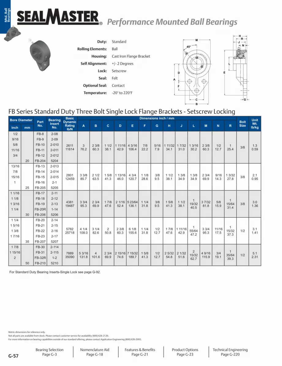
G-57
® Performance Mounted Ball Bearings Performance Mounted Ball BearingsMtd
. Ba
ll
Be
ari
ng
s
Duty: Standard
Rolling Elements: Ball
Housing: Cast Iron Flange Bracket
Self Alignment: +/- 2 Degrees
Lock: Setscrew
Seal: Felt
Optional Seal: Contact
Temperature: -20° to 220°F
FB Series Standard Duty Three Bolt Single Lock Flange Brackets - Setscrew Locking
45° N
M
A
D
F
BC
E
L
H
G
JR
Bore Diameter Part No.
Bearing Insert
No.
Basic Dynamic Rating
lb/N
Dimensions inch / mmBolt Size
Unit Wt.
lb/kgA B C D E F G H J L M N Rinch mm
1/2 FB-8 2-08
261111614
3 76.2
2 3/8 60.3
1 1/2 38.1
1 11/1642.9
4 3/16106.4
7/8 22.2
5/167.9
1 11/3234.1
1 7/3231.0
1 3/1630.2
2 3/8 60.3
1/2 12.7
1 25.4 3/8 1.3
0.59
9/16 FB-9 2-09 5/8 FB-10 2-010
11/16 FB-11 2-011 3/4 FB-12 2-012
20 FB-204 5204 13/16 FB-13 2-013
280112459
3 3/8 85.7
2 1/2 63.5
1 5/8 41.3
1 13/1646.0
4 3/4 120.7
1 1/8 28.6
3/8 9.5
1 1/2 38.1
1 3/8 34.9
1 3/8 34.9
2 3/4 69.9
9/1614.3
1 3/3227.8 3/8 2.1
0.95
7/8 FB-14 2-014 15/16 FB-15 2-015
1 FB-16 2-125 FB-205 5205
1 1/16 FB-17 2-11
438119487
3 3/4 95.3
2 3/4 69.9
1 7/8 47.6
2 1/1652.4
5 23/64136.1
1 1/4 31.8
3/8 9.5
1 5/8 41.3
1 1/2 38.1
1 19/3240.5
3 7/3281.8
5/8 15.9
1 15/6431.4
3/8 3.01.36
1 1/8 FB-18 2-121 3/16 FB-19 2-131 1/4 FB-20R 1-14
30 FB-206 52061 1/4 FB-20 2-14
578225718
4 1/4 108.0
3 1/4 82.6
2 50.8
2 3/8 60.3
6 1/8 155.6
1 1/4 31.8
1/2 12.7
1 7/8 47.6
1 11/1642.9
1 55/6447.2
3 3/4 95.3
11/1617.5
1 15/3237.3
1/2 3.11.41
1 5/16 FB-21 2-151 3/8 FB-22 2-16
1 7/16 FB-23 2-1735 FB-207 5207
1 7/8 FB-30 2-114
788935090
5 3/16131.8
4 101.6
2 3/4 69.9
2 15/1674.6
7 15/32189.7
1 5/8 41.3
1/2 12.7
2 5/3254.8
2 1/3251.6
2 15/3262.7
4 9/16115.9
3/4 19.1
1 35/6439.3
1/2 5.12.31
1 15/16 FB-31 2-1152 FB-32R 1-2
50 FB-210 5210
For Standard Duty Bearing Inserts-Single Lock see page G-92.
Metric dimensions for reference only.
Not all parts are available from stock. Please contact customer service for availability (800) 626-2120.
For more information on bearing capabilities outside of our standard offering, please contact Application Engineering (800) 626-2093.
Bearing SelectionPage G-3
Nomenclature AidPage G-18
Features & BenefitsPage G-21
Product OptionsPage G-23
Technical EngineeringPage G-220

G-58
Performance Mounted Ball Bearings Performance Mounted Ball Bearings ®
Mtd
. Ba
ll
Be
ari
ng
s
FB-T Series Standard Duty Flange Bracket - SKWEZLOC Locking Collar - Inch
FB-T Series Standard Flange Bracket - SKWEZLOC Locking Collar - Metric -SKWEZTM
F
A
D
CB
M
G
E
L
H
NJ
45°
R
Bore Diameter Part No.
Bearing Insert
No.
Basic Dynamic Rating
lb/N
Dimensions inch / mmBolt Size
Unit Wt. lb/kgA B C D E F G H J L M N Rinch
3/4 FB-12T 2-012T2611
116143
76.22 3/8 60.3
1 1/2 38.1
1 11/1642.9
4 3/16106.4
7/8 22.2
5/167.9
1 13/3235.7
1 9/3232.5
1 3/4 44.5
2 3/8 60.3
1/2 12.7
125.4
3/81.4
0.64
15/16 FB-15T 2-015T 280112459
3 3/8 85.7
2 1/2 63.5
1 5/8 41.3
1 13/1646.0
4 3/4 120.7
1 1/8 28.6
3/8 9.5
1 9/1639.7
1 7/1636.5
1 15/1649.2
2 3/4 69.9
9/1614.3
1 1/8 27.8
3/82.3
1.041 FB-16T 2-1T
1 1/8 FB-18T 2-12T4381
194873 3/4 95.3
2 3/4 69.9
1 7/8 47.6
2 1/1652.4
5 23/64136.1
1 1/4 31.8
3/8 9.5
1 11/1642.9
1 9/1639.7
2 3/1655.6
3 7/3281.8
5/8 15.9
1 1/4 31.8
3/83.2
1.451 3/16 FB-19T 2-13T
1 1/4 FB-20RT 1-14T
1 1/4 FB-20T 2-14T5782
257184 1/4 108.0
3 1/4 82.6
250.8
2 3/8 60.3
6 1/8 155.6
1 1/4 31.8
1/2 12.7
1 15/1649.2
1 3/4 44.5
2 7/1661.9
3 3/4 95.3
11/1617.5
1 7/1636.5
1/23.4
1.54
1 3/8 FB-22T 2-16T 578225718
4 1/4 108.0
3 1/4 82.6
250.8
2 3/8 60.3
6 1/8 155.6
1 1/4 31.8
1/2 12.7
1 15/1649.2
1 3/4 44.5
2 9/1665.1
3 3/4 95.3
11/1617.5
1 1/2 37.3
1/23.4
1.541 7/16 FB-23T 2-17T
1 15/16 FB-31T 2-115T 788935090
5 3/16131.8
4101.6
2 3/4 69.9
2 15/1674.6
7 15/32189.7
1 5/8 41.3
1/2 12.7
2 7/3256.4
2 3/3253.2
3 3/8 85.7
4 9/16115.9
3/4 19.1
1 35/6439.3
1/25.7
2.592 FB-32RT 1-2T
Bore Diameter Part No.
Bearing Insert
No.
Basic Dynamic Rating
N/lb
Dimensions mm / inchBolt Size
Unit Wt. kg/lbA B C D E F G H J L M N Rmm
20 FB-204TMC 5204TMC116142611
76.23
60.32 3/8
32.11 17/64
42.11 21/32
106.44 3/16
27.01 1/16
7.9 5/16
35.71 13/32
32.51 9/32
44.51 3/4
60.32 3/8
12.7 1/2
25.41
M8.641.4
25 FB-205TMC 5205TMC124592801
85.73 3/8
63.52 1/2
34.11 11/32
44.81 49/64
120.74 3/4
27.01 1/16
9.5 3/8
39.71 9/16
36.51 7/16
49.21 15/16
69.92 3/4
14.3 9/16
27.81 1/8
M81.042.3
30 FB-206TMC 5206TMC194874381
95.33 3/4
69.92 3/4
40.11 37/64
501 31/32
136.15 23/64
29.01 9/64
9.5 3/8
42.91 11/16
39.71 9/16
55.62 3/16
81.83 7/32
15.9 5/8
31.81 1/4
M81.453.2
35 FB-207TMC 5207TMC257185782
108.04 1/4
82.63 1/4
46.01 13/16
55.22 11/64
155.66 1/8
32.11 17/64
12.7 1/2
49.21 15/16
44.51 3/4
65.12 9/16
95.33 3/4
17.5 11/16
37.31 1/2
M81.543.4
50 FB-210TMC 5210TMC350907889
131.85 3/16
101.64
57.92 9/32
67.92 43/64
189.77 15/32
46.01 13/16
12.7 1/2
56.42 7/32
53.22 3/32
85.73 3/8
115.94 9/16
19.1 3/4
39.31 35/64
M102.595.7
For Medium Duty SKWEZLOC Locking Collar Bearing Inserts see page G-93. For Replacement Lock Collar see page G-98.
Duty: Standard
Rolling Elements: Ball
Housing: Cast Iron Flange Bracket
Self Alignment: +/- 2 Degrees
Lock: SKWEZLOC Locking Collar
Seal: Felt
Optional Seal: Contact
Temperature: -20° to 220°F
Bearing SelectionPage G-3
Nomenclature AidPage G-18
Features & BenefitsPage G-21
Product OptionsPage G-23
Technical EngineeringPage G-220

G-59
® Performance Mounted Ball Bearings Performance Mounted Ball BearingsMtd
. Ba
ll
Be
ari
ng
s
Duty: Standard
Rolling Elements: Ball
Housing: Cast Iron Piloted Flange Cartridge
Self Alignment: +/- 2 Degrees
Lock: Setscrew
Seal: Felt
Optional Seal: Contact
Temperature: -20° to 220°F
SFC Series Standard Duty Flange Cartridge Units - Setscrew Locking
A L
BC
-.002”+.000”
P
HN
J
GO
D
Bore DiameterPart No. Bearing
Insert No.
Basic Dynamic Rating
lb/N
Dimensions inch / mmBolt Size
Unit Wt. lb/kgA BC D G H J L N O P*inch mm
1 1/8 SFC-18 2-12
5/161 3/16 SFC-19 2-13 4381 4 3/8 3 5/8 1 11/64 3/8 1 5/16 1 9/16 1 19/32 5/8 1/4 3.000 3.01 1/4 SFC-20R 1-14 19487 111.1 92.1 29.8 9.5 33.3 39.7 40.5 15.9 6.4 76.20 1.36
30 SFC-206 52061 1/4 SFC-20 2-14
578225718
5 127.0
4 1/8 104.8
1 9/3232.5
3/8 9.5
1 5/1633.3
1 11/1642.9
1 55/6447.2
11/1617.5
3/8 9.5
3.37585.73 3/8 3.9
1.77
1 5/16 SFC-21 2-151 3/8 SFC-22 2-16
1 7/16 SEF-23 2-1735 SFC-207 5207
1 1/2 SFC-24 2-187340
326485 1/4 133.4
4 3/8 111.1
1 25/64 35.3
7/1611.1
1 1/2 38.1
1 15/1649.2
2 1/1652.4
3/4 19.1
7/1611.1
3.62592.08 3/8 4.7
2.131 9/16 SFC-25 2-1940 SFC-208 5208
1 5/8 SFC-26 2-110
7/161 11/16 SFC-27 2-111 7901 6 1/8 5 1/8 1 27/64 7/16 1 1/2 1 15/16 2 19/64 3/4 7/16 4.250 6.01 3/4 SFC-28 2-112 35144 155.6 130.2 36.1 11.1 38.1 49.2 58.3 19.1 11.1 107.95 2.72
45 SFC-209 52091 7/8 SFC-30 2-114
7/161 15/16 SFC-31 2-115 7889 6 1/8 5 1/8 1 25/64 7/16 1 9/16 2 1/32 2 15/32 3/4 15/32 4.250 6.5
2 SFC-32R 1-2 35090 155.6 130.2 35.3 11.1 39.7 51.6 62.7 19.1 11.9 107.95 2.9550 SFC-210 5210
2 SFC-32 2-2
7/162 1/8 SFC-34 2-22 9752 6 3/8 5 3/8 1 19/32 7/16 1 9/16 2 3/16 2 23/32 7/8 5/8 4.500 7.5
2 3/16 SFC-35 2-23 43377 161.9 136.5 40.5 11.1 39.7 55.6 69.1 22.2 15.9 114.30 3.4055 SFC-211 5211
2 1/4 SFC-36 2-24
1/2 2 3/8 SFC-38 2-26 11789 7 1/8 6 1 25/32 1/2 1 11/16 2 9/16 2 63/64 1 7/8 5.000 10.5
2 7/16 SFC-39 2-27 52437 181.0 152.4 45.2 12.7 42.9 65.1 75.8 25.4 22.2 127.00 4.7660 SFC-212 5212
2 11/16 SFC-43 2-211 13971 7 5/8 6 1/2 2 5/32 9/16 1 3/4 2 27/32 3 7/16 1 5/32 1 3/32 5.500 1/2
14.570 SFC-214 5214 62143 193.7 165.1 54.8 14.3 44.5 72.2 87.3 29.4 27.8 139.70 6.58
2 7/8 SFC-46 2-2141483966004
8 3/4 222.3
7 1/2 190.5
2 9/32 57.9
9/1614.3
2 50.8
3 1/1677.8
3 41/6492.5
1 5/1633.3
1 1/1627.0
6.375161.93 5/8 18.7
8.482 15/16 SFC-47 2-21575 SFC-215 5215
3 3/16 SFC-51 2-33 17412 8 3/4 7 1/2 2 13/32 21/32 2 3 1/4 3 59/64 1 5/16 1 1/4 6.375 5/8
20.080 SFC-216 5216 77449 222.3 190.5 61.1 16.7 50.8 82.6 99.6 33.3 31.8 161.93 9.07
For Standard Duty Bearing Inserts-Single Lock see page G-92. *Recommended hole size for pilot +.002” / -.000”.
Bearing SelectionPage G-3
Nomenclature AidPage G-18
Features & BenefitsPage G-21
Product OptionsPage G-23
Technical EngineeringPage G-220
Metric dimensions for reference only.

G-60
Performance Mounted Ball Bearings Performance Mounted Ball Bearings ®
Mtd
. Ba
ll
Be
ari
ng
s
SFC-T Series Standard Duty Piloted Flange Cartridge- SKWEZLOC Locking Collar - Inch
SFC-T Series Standard Piloted Flange Cartridge - SKWEZLOC Locking Collar - Metric -SKWEZTM
HN
J
GO
D
A LP
+.000”-.002”
BC
Bore Diameter Part No. Bearing
Insert No.Basic Dynamic
Rating lb/N
Dimensions inch / mmBolt Size
Unit Wt. lb/kgA BC D G H J L N O Pinch
1 1/8 SFC-18T 2-12T4381
194874 3/8 111.1
3 5/8 92.1
1 11/6429.8
3/8 9.5
1 3/8 34.9
1 5/8 41.3
2 3/1655.6
5/8 15.9
1/4 6.4
3.00076.200
5/163.2
1.451 3/16 SFC-19T 2-13T1 1/4 SFC-20RT 1-14T
1 1/4 SFC-20T 2-14T5782 5 4 1/8 1 9/32 3/8 1 3/8 1 3/4 2 7/16 11/16 3/8 3.375
3/8 4.2
25718 127.0 104.8 32.5 9.5 34.9 44.5 61.9 17.5 9.5 85.725 1.911 3/8 SFC-22T 2-16T 5782 5 4 1/8 1 9/32 3/8 1 3/8 1 3/4 2 9/16 11/16 3/8 3.375
3/8 4.2
1 7/16 SFC-23T 2-17T 25718 127.0 104.8 32.5 9.5 34.9 44.5 65.1 17.5 9.5 85.725 1.911 1/2 SFC-24T 2-18T 7340 5 1/4 4 3/8 1 25/64 7/16 1 9/16 2 2 11/16 3/4 7/16 3.625
3/8 5.0
1 9/16 SFC-25T 2-19T 32648 133.4 111.1 35.3 11.1 39.7 50.8 68.3 19.1 11.1 92.075 2.27
1 5/8 SFC-26T 2-110T7901 6 1/8 5 1/8 1 27/64 7/16 1 9/16 2 2 13/16 3/4 7/16 4.250
7/166.3
35144 155.6 130.2 36.1 11.1 39.7 50.8 71.4 19.1 11.1 107.950 2.861 11/16 SFC-27T 2-111T 7901 6 1/8 5 1/8 1 27/64 7/16 1 9/16 2 2 15/16 3/4 7/16 4.250
7/166.3
1 3/4 SFC-28T 2-112T 35144 155.6 130.2 36.1 11.1 39.7 50.8 74.6 19.1 11.1 107.950 2.861 15/16 SFC-31T 2-115T 7889 6 1/8 5 1/8 1 25/64 7/16 1 5/8 2 3/32 3 3/8 3/4 15/32 4.250
7/167.1
2 SFC-32RT 1-2T 35090 155.6 130.2 35.3 11.1 41.3 53.2 85.7 19.1 11.9 107.950 3.22
2 SFC-32T 2-2T9752 6 3/8 5 3/8 1 19/32 7/16 1 5/8 2 1/4 3 1/2 7/8 5/8 4.500
7/168.1
43377 161.9 136.5 40.5 11.1 41.3 57.2 88.9 22.2 15.9 114.300 3.672 1/8 SFC-34T 2-22T 9752 6 3/8 5 3/8 1 19/32 7/16 1 5/8 2 1/4 3 5/8 7/8 5/8 4.500
7/168.1
2 3/16 SFC-35T 2-23T 43377 161.9 136.5 40.5 11.1 41.3 57.2 92.1 22.2 15.9 114.300 3.67
2 1/4 SFC-36T 2-24T11789 7 1/8 6 1 25/32 1/2 1 3/4 2 5/8 4 1/16 1 7/8 5.000
1/2 11.7
52437 181.0 152.4 45.2 12.7 44.5 66.7 103.2 25.4 22.2 127.000 5.312 3/8 SFC-38T 2-26T 11789 7 1/8 6 1 25/32 1/2 1 3/4 2 5/8 4 1/8 1 7/8 5.000
1/2 11.7
2 7/16 SFC-39T 2-27T 52437 181.0 152.4 45.2 12.7 44.5 66.7 104.8 25.4 22.2 127.000 5.31
Bore Diameter Part No. Bearing
Insert No.Basic Dynamic
Rating N/lb
Dimensions mm / inchBolt Size
Unit Wt. kg/lbA BC D G H J L N O Pmm
30 SFC-206TMC 5206TMC19487 111.1 92.1 29.8 9.5 34.9 41.3 55.6 15.9 6.4 76.200
M101.45
4381 4 3/8 3 5/8 1 11/64 3/8 1 3/8 1 5/8 2 3/16 .63 1/4 3.000 3.2
35 SFC-207TMC 5207TMC25718 127.0 104.8 32.5 9.5 34.9 44.5 65.1 17.5 9.5 85.725
M121.91
5782 5 4 1/8 1 9/32 3/8 1 3/8 1 3/4 2 9/16 1 1/16 3/8 3.375 4.2
40 SFC-208TMC 5208TMC32648 133.4 111.1 35.3 11.1 39.7 50.8 68.3 19.1 11.1 92.075
M122.27
7340 5 1/4 4 3/8 1 25/64 7/16 1 9/16 2 2 11/16 3/4 7/16 3.625 5
45 SFC-209TMC 5209TMC35144 155.6 130.2 36.1 11.1 39.7 50.8 74.6 19.1 11.1 107.950
M142.86
7901 6 1/8 5 1/8 1 27/64 7/16 1 9/16 2 2 15/16 3/4 7/16 4.250 6.3
50 SFC-210TMC 5210TMC35090 155.6 130.2 35.3 11.1 41.3 53.2 85.7 19.1 11.9 107.950
M143.22
7889 6 1/8 5 1/8 1 25/64 7/16 1 5/8 2 3/32 3 3/8 3/4 15/32 4.250 7.1
55 SFC-211TMC 5211TMC43377 161.9 136.5 40.5 11.1 41.3 57.2 92.1 22.2 15.9 114.300
M143.67
9752 6 3/8 5 3/8 1 19/32 7/16 1 5/8 2 1/4 3 5/8 7/8 5/8 4.500 8.1
60 SFC-212TMC 5212TMC52437 181.0 152.4 45.2 12.7 44.5 66.7 104.8 25.4 22.2 127.000
M165.31
11789 7 1/8 6 1 25/32 1/2 1 3/4 2 5/8 4 1/8 1 7/8 5.000 11.7
For Medium Duty SKWEZLOC Locking Collar Bearing Inserts see page G-93. For Replacement Lock Collar see page G-98.
Duty: Standard
Rolling Elements: Ball
Housing: Cast Iron Piloted Flange Cartridge
Self Alignment: +/- 2 Degrees
Lock: SKWEZLOC Locking Collar
Seal: Felt
Optional Seal: Contact
Temperature: -20° to 220°F
Bearing SelectionPage G-3
Nomenclature AidPage G-18
Features & BenefitsPage G-21
Product OptionsPage G-23
Technical EngineeringPage G-220

G-61
® Performance Mounted Ball Bearings Performance Mounted Ball BearingsMtd
. Ba
ll
Be
ari
ng
s
Duty: Medium
Rolling Elements: Ball
Housing: Cast Iron Piloted Flange Cartridge
Self Alignment: +/- 2 Degrees
Lock: Setscrew
Seal: Felt
Optional Seal: Contact
Temperature: -20° to 220°F
MFC Series Medium Duty Flange Cartridge Units - Setscrew Locking
A L
BC
-.002”+.000”
P
HN
J
GO
D
Bore DiameterPart No. Bearing
Insert No.
Basic Dynamic Rating
lb/N
Dimensions inch / mmBolt Size
Unit Wt.
lb/kgA BC D G H J L N O P*inch mm
15/16 MFC-15 3-0154381
194874 3/8 111.1
3 5/8 92.1
1 11/6429.8
3/8 9.5
1 5/1633.3
1 9/1639.7
1 19/3240.5
5/8 15.9
1/4 6.4
3.00076.20 5/16 3.0
1.361 MFC-16 3-1.984 25 MFC-305 5305
1 3/16 MFC-19 3-135782
257185
127.04 1/8 104.8
1 9/3232.5
3/8 9.5
1 5/1633.3
1 11/1642.9
1 55/6447.2
11/1617.5
3/8 9.5
3.37585.73 3/8 3.9
1.771 1/4 MFC-20 2-141.181 30 MFC-306 53061 7/16 MFC-23 3-17 7340
326485 1/4 133.4
4 3/8 111.1
1 25/6435.3
7/1611.1
1 1/2 38.1
1 15/1649.2
2 1/1652.4
3/4 19.1
13/3210.3
3.62592.08 3/8 4.7
2.131.378 35 MFC-307 53071 1/2 MFCH-24 3-18 7901 6 1/8 5 1/8 1 27/64 7/16 1 1/2 1 15/16 2 19/64 3/4 13/32 4.250
7/166
40 MFC-308 5308 35144 155.6 130.2 36.1 11.1 38.1 49.2 58.3 19.1 10.3 107.95 2.721 11/16 MFC-27 3-111
788935090
6 1/8 155.6
5 1/8 130.2
1 25/6435.3
7/1611.1
1 9/1639.7
2 1/3251.6
2 15/3262.7
3/4 19.1
7/1611.1
4.250107.95 7/16 6.5
2.951 3/4 MFC-28 3-11245 MFC-309 5309
1 15/16 MFC-31 3-1159752
433776 3/8 161.9
5 3/8 136.5
1 19/3240.5
7/1611.1
1 9/1639.7
2 3/1655.6
2 23/3269.1
7/8 22.2
19/3215.1
4.500114.30 7/16 7.5
3.402 MFC-32 2-250 MFC-310 5310
2 3/16 MFC-35 3-231178952437
7 1/8 181.0
6 152.4
1 25/3245.2
1/2 12.7
1 11/1642.9
2 9/1665.1
2 63/6475.8
1 25.4
27/3221.4
5.000127.00 1/2 10.5
4.762 1/4 MFC-36 2-2455 MFC-311 5311
2 7/16 MFC-39 3-271397162143
7 5/8 193.7
6 1/2 165.1
2 5/3254.8
9/1614.3
1 3/4 44.5
2 7/8 73.0
3 7/1687.3
1 1/1627.0
1 3/3227.8
5.500139.70 1/2 14.0
6.352 1/2 MFC-40 3-2865 MFC-313 5313
2 11/16 MFC-43 3-211 14839 8 3/4 7 1/2 2 9/32 9/16 2 3 1/16 3 41/64 1 5/16 1 1/32 6.375 5/8
18.770 MFC-314 5314 66004 222.3 190.5 57.9 14.3 50.8 77.8 92.5 33.3 26.2 161.93 8.48
2 15/16 MFC-47 3-2151741277449
8 3/4 222.3
7 1/2 190.5
2 13/3261.1
5/8 15.9
2 50.8
3 1/4 82.6
3 59/6499.6
1 5/1633.3
1 7/3231.0
6.375161.93 5/8 20.0
9.073 MFC-48 3-375 MFC-315 5315
3 7/16 MFC-55 3-37 21566 10 1/4 8 5/8 2 23/32 3/4 2 21/32 3 25/32 4 25/64 1 9/16 1 3/32 7.375 3/4
32.03 1/2 MFC-56 2-38 95926 260.4 219.1 69.1 19.1 67.5 96.0 111.5 39.7 27.8 187.33 14.51
3 15/16 MFC-63 3-31529905
13301710 7/8 276.2
9 3/8 238.1
3 7/3281.8
7/8 22.2
3 1/2 88.9
4 5/8 117.5
5 11/64131.4
1 15/1649.2
1 3/3227.8
8.125206.38 3/4 44.0
19.964 MFC-64 3-4100 MFC-320 5320
For Medium Duty Bearing Inserts-Single Lock see page G-95.*Recommended hole size for pilot 15/16 to 3 1/2 +.000” / -.002” and 3 15/16 to 4 +.000” / -.004”.
Metric dimensions for reference only.
Not all parts are available from stock. Please contact customer service for availability (800) 626-2120.
For more information on bearing capabilities outside of our standard offering, please contact Application Engineering (800) 626-2093.
Bearing SelectionPage G-3
Nomenclature AidPage G-18
Features & BenefitsPage G-21
Product OptionsPage G-23
Technical EngineeringPage G-220

G-62
Performance Mounted Ball Bearings Performance Mounted Ball Bearings ®
Mtd
. Ba
ll
Be
ari
ng
s
MFC-T Series Medium Duty Flange Cartridge Units - SKWEZLOC Locking Collar
HN
J
GO
D
A LP
+.000”-.002”
BC
Bore Diameter Part No. Bearing
Insert No.
Basic Dynamic Rating
lb/N
Dimensions inch / mmBolt Size
Unit Wt. lb/kgA BC D G H J L N O P*inch
1 MFC-16T 3-1T4381 4 3/8 3 5/8 1 3/16 3/8 1 3/8 1 5/8 2 1/16 5/8 1/4 3.000
5/163.2
19487 111.1 92.1 30.2 9.5 34.9 41.3 52.4 15.9 6.4 76.20 1.451 3/16 MFC-19T 3-13T 5782 5 4 1/8 1 9/32 3/8 1 3/8 1 3/4 2 7/16 11/16 3/8 3.375
3/8 4.2
1 1/4 MFC-20T 2-14T 25718 127.0 104.8 32.5 9.5 34.9 44.5 61.9 17.5 9.5 85.73 1.911 7/16 MFC-23T 3-17T 7340 5 1/4 4 3/8 1 25/64 7/16 1 9/16 2 2 11/16 3/4 7/16 3.625
3/8 5.2
1 1/2 MFC-24T 2-18T 32648 133.4 111.1 35.3 11.1 39.7 50.8 68.3 19.1 11.1 92.08 2.36
1 1/2 MFCH-24T 3-18T7901 6 1/8 5 1/8 1 7/16 7/16 1 9/16 2 2 13/16 3/4 7/16 4.250
7/166.3
35144 155.6 130.2 36.5 11.1 39.7 50.8 71.4 19.1 11.1 107.95 2.861 11/16 MFC-27T 3-111T 7889 6 1/8 5 1/8 1 25/64 7/16 1 5/8 2 3/32 3 1/4 3/4 15/32 4.250
7/167.1
1 3/4 MFC-28T 3-112T 35090 155.6 130.2 35.3 11.1 41.3 53.2 82.6 19.1 11.9 107.95 3.221 15/16 MFC-31T 3-115T 9752 6 3/8 5 3/8 1 5/8 7/16 1 5/8 2 1/4 3 1/2 27/32 5/8 4.500
7/168.1
2 MFC-32T 2-2T 43377 161.9 136.5 41.3 11.1 41.3 57.2 88.9 21.4 15.9 114.30 3.672 3/16 MFC-35T 3-23T 11789 7 1/8 6 1 25/32 1/2 1 3/4 2 5/8 4 1/16 1 7/8 5.000
1/2 11.7
2 1/4 MFC-36T 2-24T 52437 181.0 152.4 45.2 12.7 44.5 66.7 103.2 25.4 22.2 127.00 5.31
Duty: Medium
Rolling Elements: Ball
Housing: Cast Iron Piloted Flange Cartridge
Self Alignment: +/- 2 Degrees
Lock: SKWEZLOC Locking Collar
Seal: Felt
Optional Seal: Contact
Temperature: -20° to 220°F
For Medium Duty SKWEZLOC Locking Collar Bearing inserts see page G-96. For Replacement Lock Collar see page G-98.*Recommended hole size for pilot +.000” / -.002”.
Bearing SelectionPage G-3
Nomenclature AidPage G-18
Features & BenefitsPage G-21
Product OptionsPage G-23
Technical EngineeringPage G-220

G-63
® Performance Mounted Ball Bearings Performance Mounted Ball BearingsMtd
. Ba
ll
Be
ari
ng
s
Duty: Medium
Rolling Elements: Ball
Housing: Cast Iron Piloted Flange Cartridge
Self Alignment: +/- 2 Degrees
Lock: Double Setscrew
Seal: Felt
Optional Seal: Contact
Temperature: -20° to 220°F
MFCD Series Medium Duty Flange Cartridge Units With Double Lock - Setscrew Locking
-.002”+.000”
P
BC
H
A
N
J
GO
D
L
Bore Diameter Part No. Bearing
Insert No.
Basic Dynamic Rating
lb/N
Dimensions inch / mmBolt Size
Unit Wt. lb/kgA BC D G H J L N O P*inch
1 MFCD-16 3-14381 4 3/8 3 5/8 1 11/64 3/8 1 5/16 1 3/4 1 19/32 11/16 1/4 3.000
5/16 3.81.719487 111.1 92.1 29.8 9.5 33.3 44.5 40.5 17.5 6.4 76.20
1 3/16 MFCD-19 3-13 5782 5 4 1/8 1 9/32 3/8 1 5/16 2 1 55/64 11/16 3/8 3.375 3/8 3.9
1.81 1/4 MFCD-20 2-14 25718 127.0 104.8 32.5 9.5 33.3 50.8 47.2 17.5 9.5 85.731 7/16 MFCD-23 3-17 7340 5 1/4 4 3/8 1 25/64 7/16 1 1/2 2 5/16 2 1/16 3/4 13/32 3.625
3/8 4.72.11 1/2 MFCD-24 2-18 32648 133.4 111.1 35.3 11.1 38.1 58.7 52.4 19.1 10.3 92.08
1 11/16 MFCD-27 3-111 7889 6 1/8 5 1/8 1 25/64 7/16 1 9/16 2 1/2 2 15/32 23/32 7/16 4.250 7/16 6.5
3.01 3/4 MFCD-28 3-112 35090 155.6 130.2 35.3 11.1 39.7 63.5 62.7 18.3 11.1 107.951 15/16 MFCD-31 3-115 9752 6 3/8 5 3/8 1 19/32 7/16 1 9/16 2 5/8 2 23/32 27/32 19/32 4.500
7/16 7.63.52 MFCD-32 2-2 43377 161.9 136.5 40.5 11.1 39.7 66.7 69.1 21.4 15.1 114.30
2 3/16 MFCD-35 3-23 11789 7 1/8 6 1 25/32 1/2 1 11/16 3 1/8 3 1/8 31/32 27/32 5.0001/2 10.4
4.72 1/4 MFCD-36 2-24 52437 181.0 152.4 45.2 12.7 42.9 79.4 79 24.6 21.4 127.002 7/16 MFCD-39 3-27 13971 7 5/8 6 1/2 2 5/32 9/16 1 3/4 3 1/2 3 7/16 1 5/32 1 3/32 5.500
1/2 14.36.52 1/2 MFCD-40 3-28 62143 193.7 165.1 54.8 14.3 44.5 88.9 87.3 29.4 27.8 139.70
2 11/16 MFCD-43 3-21114839 8 3/4 7 1/2 2 9/32 9/16 2 3 1/2 3 41/64 1 9/32 1 1/32 6.375
5/8 18.98.666004 222.3 190.5 57.9 14.3 50.8 88.9 92.5 32.5 26.2 161.93
2 15/16 MFCD-47 3-215 17412 8 3/4 7 1/2 2 13/32 5/8 2 3 7/8 3 59/64 1 15/32 1 7/32 6.375 5/8 20.8
9.53 MFCD-48 3-3 77449 222.3 190.5 61.1 15.9 50.8 98.4 99.6 37.3 31.0 161.933 7/16 MFCD-55 3-37 21566 10 1/4 8 5/8 2 23/32 3/4 2 21/32 4 7/16 4 25/64 2 7/32 1 3/32 7.375
3/4 32.814.93 1/2 MFCD-56 2-38 95926 260.4 219.1 69.1 19.1 67.5 112.7 111.5 56.4 27.8 187.33
3 15/16 MFCD-63 3-315 29905 10 7/8 9 3/8 3 7/32 7/8 3 1/2 5 3/8 5 11/64 2 11/16 1 3/32 8.125 3/4 46.0
20.94 MFCD-64 3-4 133017 276.2 238.1 81.8 22.2 88.9 136.5 131.4 68.3 27.8 206.38
For Medium Duty Bearing Inserts-Single Lock see page G-95.*Recommended hole size for pilot 15/16 to 3 1/2 +.000” / -.002” and 3 15/16 to 4 +.000” / -.004”.
Metric dimensions for reference only.
Not all parts are available from stock. Please contact customer service for availability (800) 626-2120.
For more information on bearing capabilities outside of our standard offering, please contact Application Engineering (800) 626-2093.
Bearing SelectionPage G-3
Nomenclature AidPage G-18
Features & BenefitsPage G-21
Product OptionsPage G-23
Technical EngineeringPage G-220

G-64
Performance Mounted Ball Bearings Performance Mounted Ball Bearings ®
Mtd
. Ba
ll
Be
ari
ng
s
SEHB Series Hanger Bearing External Lube - Setscrew Locking
A
E
TAPPED FOR STRAIGHTPIPE THREADF
J
CK
L
M
N
Duty: Varies
Rolling Elements: Ball
Housing: Ductile Iron Hanger Bearing
Self Alignment: +/- 2 Degrees
Lock: Setscrew
Seal: Felt
Optional Seal: Contact
Temperature: -20° to 220°F
Bore DiameterPart No.
Bearing Insert
No.
Basic Dynamic Rating
lb/N
Dimensions inch / mmPipe Tap* N.P.S.M.
NUnit Wt.
lb/kgA C E F J K L M Thread Lengthinch mm
15/16 SEHB-15 3-015
438119487
2 1/2 63.5 - 4 1/16
103.21 9/1639.7
1 1/2 38.1
7/8 22.2
1 19/3240.5
3 1/8 79.4 3/4-14 13/16 2.2
1.00
25 SEHB-305 53051 SEHB-16 3-1
1 1/16 SEHB-17 2-1130 SEHB-206 5206
1 3/16 SEHB-19 3-13
578225718
2 3/4 69.9 - 4 9/16
115.91 9/1639.7
1 11/1642.9
1 25.4
1 55/6447.2
3 5/8 92.1 3/4-14 3/4 3.1
1.41
1 1/4 SEHB-20 2-141 5/16 SEHB-21 2-151 3/8 SEHB-22 2-16
35 SEHB-207 52071 7/16 SEHB-23 3-17
3/4-14 3/41 1/2 SEHB-24 2-18 7340 2 7/8 3/32 4 3/4 1 9/16 1 15/16 1 3/16 2 1/16 3 3/4 3.4
1 9/16 SEHB-25 2-19 32648 73.0 2.4 120.7 39.7 49.2 30.2 52.4 95.3 1.5440 SEHB-208 5208
1 11/16 SEHB-27 3-111
1-11 1/2 13/16
1 3/4 SEHB-28 3-1121 7/8 SEHB-30 2-114 7889 3 1/4 3/16 5 7/16 1 7/8 2 1/32 1 9/32 2 15/32 4 3/8 4.5
1 15/16 SEHB-31 2-115 35090 82.6 4.8 138.1 47.6 51.6 32.5 62.7 111.1 2.042 SEHB-32R 1-2
50 SEHB-210 52102 3/16 SEHB-35 3-23
1178952437
4 101.6
11/328.7
6 13/16173.0
2 5/1658.7
2 9/1665.1
1 9/1639.7
2 63/6475.8
5 5/8 142.9 1 1/4-11 1/2 1 1/8 9
4.08
2 1/4 SEHB-36 2-242 3/8 SEHB-38 2-26
2 7/16 SEHB-39 2-2760 SEHB-212 5212
2 11/16 SEHB-43 3-211
1483966004 1 1/2-11 1/2 1 1/4
2 7/8 SEHB-46 2-214 4 5/8 3/8 7 7/8 2 3/4 3 1/16 1 3/4 3 41/64 6 1/2 14.62 15/16 SEHB-47 2-215 117.5 9.5 200.0 69.9 77.8 44.5 92.5 165.1 6.62
75 SEHB-215 52153 SEHB-48 3-3
1741277449
4 7/8 123.8
5/167.9
8 5/16211.1
2 13/1671.4
3 1/4 82.6
1 15/1649.2
3 59/6499.6
6 7/8 174.6
16.87.623 3/16 SEHB-51 2-33 1 1/2-11 1/2 1 1/4
80 SEHB-216 52163 15/16 SEHB-63 3-315
29905133017
8 1/8 206.4
13 1/4 336.6
4 3/8 111.1
4 5/8 117.5
2 11/1668.3
5 11/64131.4
10 1/4 260.4
6228.124 SEHB-64 3-4 2 1/2-8 1/2 2 5/8
100 SEHB-320 5320
For Standard (2-) Duty Bearing Inserts-Double Lock see page G-95. For Medium (3-) Duty Bearing Inserts-Double Lock see page G-97.*Use Straight Pipe Thread.Note: Units may be provided with tight internal bearing clearance and housing fits by adding suffix BDZ to Part No., as SEHB-19 BDZ.
Bearing SelectionPage G-3
Nomenclature AidPage G-18
Features & BenefitsPage G-21
Product OptionsPage G-23
Technical EngineeringPage G-220

G-65
® Performance Mounted Ball Bearings Performance Mounted Ball BearingsMtd
. Ba
ll
Be
ari
ng
s
SEHB-T Series Hanger Bearing External Lube - SKWEZLOC Locking Collar
TAPPED FOR STRAIGHTPIPE THREAD
FJ
CK
L
N
E
A
M
Bore DiameterPart No.
Bearing Insert
No.
Basic Dynamic Rating
lb/N
Dimensions inch / mmPipe Tap* N.P.S.M.
NUnit Wt.
lb/kgA C E F J K L M Thread Lengthinch mm
15/16 SEHB-15T 3-015T
438119487
2 1/2 63.5 - 4 1/16
103.21 9/1639.7
1 9/1639.7
7/8 22.2
2 1/1652.4
3 1/8 79.4 3/4-14 13/16 2.2
1.0025 SEHB-305T 5305T
1 SEHB-16T 3-1T
1 1/16 SEHB-17T 2-11T
1 3/16 SEHB-19T 3-13T 578225718
2 3/4 69.9 - 4 9/16
115.91 9/1639.7
1 3/4 44.5
1 1/1627.0
2 7/1661.9
3 5/8 92.1 3/4-14 3/4 3.1
1.411 1/4 SEHB-20 T 2-14T
1 7/16 SEHB-23T 3-17T7340
326482 7/8 73.0
3/322.4
4 3/4 120.7
1 9/1639.7
2 50.8
1 1/4 31.8
2 11/16 68.3
3 3/4 95.3 3/4-14 3/4 3.4
1.541 1/2 SEHB-24T 2-18T
40 SEHB-208T 5208T
1 11/16 SEHB-27T 3-111T
788935090
3 1/4 82.6
3/164.8
5 7/16138.1
1 7/8 47.6
2 3/3253.2
1 11/3234.1
3 1/4 82.6
4 3/8 111.1 1-11 1/2 13/16 4.5
2.04
1 3/4 SEHB-28T 3-112T
1 7/8 SEHB-30T 2-114T
1 15/16 SEHB-31T 2-115T
2 SEHB-32T 1-2T
50 SEHB-210T 5210T
2 3/16 SEHB-35T 3-23T 1178952437
4 101.6
11/328.7
6 13/16173.0
2 5/1658.7
2 5/8 66.7
1 5/8 41.3
4 1/16 103.2
5 5/8 142.9 1 1/4-11 1/2 1 1/8 9
4.08
2 7/16 60 SEHB-39TSEHB-212T
2-27T5212T
1178952437
4 101.6
11/328.7
6 13/16173.0
2 5/1658.7
2 5/8 66.7
1 5/8 41.3
4 1/8 104.8
5 5/8 142.9 1 1/4-11 1/2 1 1/8 9
4.08
For Standard (2-) Duty Bearing Inserts - SKWELOC Locking Collar see page G-94. For Medium (3-) Duty Bearing Inserts - SKWELOC Locking Collar see page G-95. For Replacement Lock Collar see page G-98.*Use Straight Pipe Thread.Note: Units may be provided with tight internal bearing clearance and housing fits by adding suffix BDZ to Part No., as SEHB-19T BDZ.
Duty: Varies
Rolling Elements: Ball
Housing: Ductile Iron Hanger Bearing
Self Alignment: +/- 2 Degrees
Lock: SKWEZLOC Locking Collar
Seal: Felt
Optional Seal: Contact
Temperature: -20° to 220°F
Metric dimensions for reference only.
Not all parts are available from stock. Please contact customer service for availability (800) 626-2120.
For more information on bearing capabilities outside of our standard offering, please contact Application Engineering (800) 626-2093.
Bearing SelectionPage G-3
Nomenclature AidPage G-18
Features & BenefitsPage G-21
Product OptionsPage G-23
Technical EngineeringPage G-220
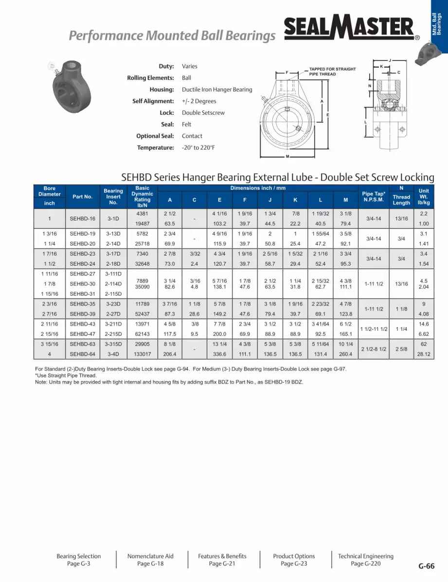
G-66
Performance Mounted Ball Bearings Performance Mounted Ball Bearings ®
Mtd
. Ba
ll
Be
ari
ng
s
SEHBD Series Hanger Bearing External Lube - Double Set Screw Locking
TAPPED FOR STRAIGHTPIPE THREADF
A
E
M
CK
J
N
L
Duty: Varies
Rolling Elements: Ball
Housing: Ductile Iron Hanger Bearing
Self Alignment: +/- 2 Degrees
Lock: Double Setscrew
Seal: Felt
Optional Seal: Contact
Temperature: -20° to 220°F
Bore Diameter Part No.
Bearing Insert
No.
Basic Dynamic Rating
lb/N
Dimensions inch / mmPipe Tap* N.P.S.M.
N Unit Wt.
lb/kgA C E F J K L M Thread Lengthinch
1 SEHBD-16 3-1D4381 2 1/2
-4 1/16 1 9/16 1 3/4 7/8 1 19/32 3 1/8
3/4-14 13/162.2
19487 63.5 103.2 39.7 44.5 22.2 40.5 79.4 1.00
1 3/16 SEHBD-19 3-13D 5782 2 3/4 -
4 9/16 1 9/16 2 1 1 55/64 3 5/8 3/4-14 3/4
3.1
1 1/4 SEHBD-20 2-14D 25718 69.9 115.9 39.7 50.8 25.4 47.2 92.1 1.41
1 7/16 SEHBD-23 3-17D 7340 2 7/8 3/32 4 3/4 1 9/16 2 5/16 1 5/32 2 1/16 3 3/4 3/4-14 3/4
3.4
1 1/2 SEHBD-24 2-18D 32648 73.0 2.4 120.7 39.7 58.7 29.4 52.4 95.3 1.54
1 11/16 SEHBD-27 3-111D7889
350903 1/4 82.6
3/164.8
5 7/16138.1
1 7/8 47.6
2 1/2 63.5
1 1/4 31.8
2 15/3262.7
4 3/8 111.1 1-11 1/2 13/16 4.5
2.041 7/8 SEHBD-30 2-114D
1 15/16 SEHBD-31 2-115D
2 3/16 SEHBD-35 3-23D 11789 3 7/16 1 1/8 5 7/8 1 7/8 3 1/8 1 9/16 2 23/32 4 7/8 1-11 1/2 1 1/8
9
2 7/16 SEHBD-39 2-27D 52437 87.3 28.6 149.2 47.6 79.4 39.7 69.1 123.8 4.08
2 11/16 SEHBD-43 3-211D 13971 4 5/8 3/8 7 7/8 2 3/4 3 1/2 3 1/2 3 41/64 6 1/2 1 1/2-11 1/2 1 1/4
14.6
2 15/16 SEHBD-47 2-215D 62143 117.5 9.5 200.0 69.9 88.9 88.9 92.5 165.1 6.62
3 15/16 SEHBD-63 3-315D 29905 8 1/8 -
13 1/4 4 3/8 5 3/8 5 3/8 5 11/64 10 1/4 2 1/2-8 1/2 2 5/8
62
4 SEHBD-64 3-4D 133017 206.4 336.6 111.1 136.5 136.5 131.4 260.4 28.12
For Standard (2-)Duty Bearing Inserts-Double Lock see page G-94. For Medium (3-) Duty Bearing Inserts-Double Lock see page G-97.*Use Straight Pipe Thread.Note: Units may be provided with tight internal and housing fits by adding suffix BDZ to Part No., as SEHBD-19 BDZ.
Bearing SelectionPage G-3
Nomenclature AidPage G-18
Features & BenefitsPage G-21
Product OptionsPage G-23
Technical EngineeringPage G-220

G-67
® Performance Mounted Ball Bearings Performance Mounted Ball BearingsMtd
. Ba
ll
Be
ari
ng
s
Duty: Varies
Rolling Elements: Ball
Housing: Ductile Iron Hanger Bearing
Self Alignment: +/- 2 Degrees
Lock: Setscrew
Seal: Felt
Optional Seal: Contact
Temperature: -20° to 220°F
SCHB Series Hanger Bearing Internal Lube - Setscrew LockingBore Diameter
Part No.Bearing Insert
No.
Basic Dynamic Rating
lb/N
Dimensions inch / mm Pipe Tap*
N.P.S.M.
N T Brg. To Lub.
Ftg. Centers
Unit Wt. lb/kgA C E F J K L M Thread
Lengthinch mm
15/16 SCHB-15 3-015
438119487
2 1/2 63.5 - 4 1/16
103.21 9/1639.7
1 1/2 38.1
7/8 22.2
1 19/3240.5
3 1/8 79.4 3/4 - 14 13/16
0.37¸ 7/320.10
2.21.00
25 SCHB-305 53051 SCHB-16 3-1
1 1/16 SCHB-18 2-1230 SCHB-206 5206
1 3/16 SCHB-19 3-13
578225718
2 3/4 69.9
4 9/16115.9
1 9/1639.7
1 11/1642.9
1 25.4
1 55/6447.2
3 5/8 92.1
3/4 0.34
¸ 1/4 0.11
3.11.41
1 1/4 SCHB-20 2-141 5/16 SCHB-21 2-15 - 3/4 - 141 3/8 SCHB-22 2-16
35 SCHB-207 52071 7/16 SCHB-23 3-17
3/4 - 141 1/2 SCHB-24 2-18 7340 2 7/8 3/32 4 3/4 1 9/16 1 15/16 1 3/16 2 1/16 3 3/4 3/4 ¸ 19/64 3.4
1 9/16 SCHB-25 2-19 32648 73.0 2.4 120.7 39.7 49.2 30.2 52.4 95.3 0.34 0.13 1.5440 SCHB-208 5208
1 11/16 SCHB-27 3-111
1 - 11 1/2
1 3/4 SCHB-28 3-1121 7/8 SCHB-30 2-114 7889 3 1/4 3/16 5 7/16 1 7/8 2 1/32 1 9/32 2 15/32 4 3/8 13/16 17/64 4.5
1 15/16 SCHB-31 2-115 35090 82.6 4.8 138.1 47.6 51.6 32.5 62.7 111.1 0.37 0.12 2.042 SCHB-32R 1-2
50 SCHB-210 52102 3/16 SCHB-35 3-23
1178952437
4 101.6
11/328.7
6 13/16173.0
2 5/1658.7
2 9/1665.1
1 9/1639.7
2 63/6475.8
5 5/8 142.9
1 1/4 - 11 1/2
1 1/8 0.51
21/640.15
9.04.08
2 1/4 SCHB-36 2-242 3/8 SCHB-38 2-26
2 7/16 SCHB-39 2-2760 SCHB-212 5212
2 11/16 SCHB-43 3-211
1 1/2 - 11 1/2
2 7/8 SCHB-46 2-214 14839 4 5/8 3/8 7 7/8 2 3/4 3 1/16 1 3/4 3 41/64 6 1/2 1 1/4 3/8 14.62 15/16 SCHB-47 2-215 66004 117.5 9.5 200.0 69.9 77.8 44.5 92.5 165.1 0.57 0.17 6.62
75 SCHB-215 52153 3/16 SCHB-51 2-33 17412 4 7/8 5/16 8 5/16 2 13/16 3 1/4 1 15/16 3 59/64 6 7/8 1 1/2 -
11 1/21 1/4 13/32 16.8
80 SCHB-216 5216 77449 123.8 7.9 211.1 71.4 82.6 49.2 99.6 174.6 0.57 0.18 7.623 15/16 SCHB-63 3-315
29905133017
8 1/8 206.4
13 1/4 336.6
4 3/8 111.1
4 5/8 117.5
2 11/1668.3
5 11/64131.4
10 1/4 260.4
2 1/2 - 8 1/2
2 5/8 1.19
19/320.27
6228.124 SCHB-64 3-4
100 SCHB-320 5320
For Standard Duty Bearing inserts-Single Lock see page G-92. ¸ No Adapter or Fitting*Use Straight Pipe Thread
Metric dimensions for reference only.
Not all parts are available from stock. Please contact customer service for availability (800) 626-2120.
For more information on bearing capabilities outside of our standard offering, please contact Application Engineering (800) 626-2093.
PIPE THREADT
C
E
M
F
KJ
N
L
TAPPED FOR STRAIGHT
A
Bearing SelectionPage G-3
Nomenclature AidPage G-18
Features & BenefitsPage G-21
Product OptionsPage G-23
Technical EngineeringPage G-220
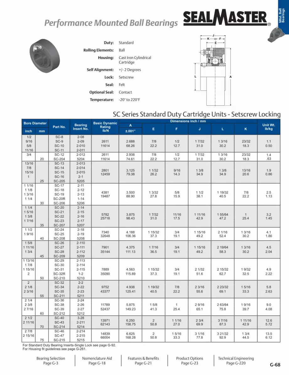
G-68
Performance Mounted Ball Bearings Performance Mounted Ball Bearings ®
Mtd
. Ba
ll
Be
ari
ng
s
Duty: Standard
Rolling Elements: Ball
Housing: Cast Iron Cylindrical Cartridge
Self Alignment: +/- 2 Degrees
Lock: Setscrew
Seal: Felt
Optional Seal: Contact
Temperature: -20° to 220°F
SC Series Standard Duty Cartridge Units - Setscrew Locking
L A
EK
JF
Bore DiameterPart No. Bearing
Insert No.Basic Dynamic
Rating lb/N
Dimensions inch / mmUnit Wt.
lb/kgA
E F J L Kinch mm ±.001”
1/2 SC-8 2-08 9/16 SC-9 2-09 2611 2.688 7/8 1/2 1 7/32 1 3/16 23/32 1.1 5/8 SC-10 2-010 11614 68.26 22.2 12.7 31.0 30.2 18.3 0.50
11/16 SC-11 2-011 3/4 SC-12 2-012 2611 2.938 7/8 1/2 1 7/32 1 3/16 23/32 1.4
.6320 SC-204 5204 11614 74.61 22.2 12.7 31.0 30.2 18.3 13/16 SC-13 2-013
280112459
3.12579.38
1 1/3226.2
9/1614.3
1 3/8 34.9
1 3/8 34.9
13/1620.6
1.90.86
7/8 SC-14 2-014 15/16 SC-15 2-015
1 SC-16 2-125 SC-205 5205
1 1/16 SC-17 2-11
438119487
3.50088.90
1 3/3227.8
5/8 15.9
1 1/2 38.1
1 19/3240.5
7/8 22.2
2.51.13
1 1/8 SC-18 2-121 3/16 SC-19 2-131 1/4 SC-20R 1-14
30 SC-206 52061 1/4 SC-20 2-14
578225718
3.87598.43
1 7/3231.0
11/1617.5
1 11/1642.9
1 55/6447.2
1 25.4
3.21.45
1 5/16 SC-21 2-151 3/8 SC-22 2-16
1 7/16 SC-23 2-1735 SC-207 5207
1 1/2 SC-24 2-187340
326484.188
106.361 15/32
37.3 3/4 19.1
1 15/1649.2
2 1/1652.4
1 3/1630.2
4.11.861 9/16 SC-25 2-19
40 SC-208 52081 5/8 SC-26 2-110
1 11/16 SC-27 2-111 7901 4.375 1 7/16 3/4 1 15/16 2 19/64 1 3/16 4.51 3/4 SC-28 2-112 35144 111.13 36.5 19.1 49.2 58.3 30.2 2.04
45 SC-209 52091 13/16 SC-29 2-113
1 7/8 SC-30 2-1141 15/16 SC-31 2-115 7889 4.563 1 15/32 3/4 2 1/32 2 15/32 1 9/32 4.9
2 SC-32R 1-2 35090 115.89 37.3 19.1 51.6 62.7 32.5 2.2250 SC-210 5210
2 SC-32 2-22 1/8 SC-34 2-22 9752 4.938 1 19/32 7/8 2 3/16 2 23/32 1 5/16 5.8
2 3/16 SC-35 2-23 43377 125.41 40.5 22.2 55.6 69.1 33.3 2.6355 SC-211 5211
2 1/4 SC-36 2-242 3/8 SC-38 2-26 11789 5.875 1 5/8 1 2 9/16 2 63/64 1 9/16 9.0
2 7/16 SC-39 2-27 52437 149.23 41.3 25.4 65.1 75.8 39.7 4.0860 SC-212 5212
2 1/2 SC-40 3-281397162143
6.250158.75
2 50.8
1 1/1627.0
2 3/4 69.9
3 7/1687.3
1 11/1642.9
12.65.722 11/16 SC-43 2-211
70 SC-214 52142 7/8 SC-46 2-214
1483966004
6.625168.28
2 50.8
1 5/1633.3
3 1/1677.8
3 21/3292.9
1 3/4 44.5
13.56.122 15/16 SC-47 2-215
75 SC-215 5215For Standard Duty Bearing Inserts-Single Lock see page G-92. For Housing fit guidelines see page G-261.
Bearing SelectionPage G-3
Nomenclature AidPage G-18
Features & BenefitsPage G-21
Product OptionsPage G-23
Technical EngineeringPage G-220

G-69
® Performance Mounted Ball Bearings Performance Mounted Ball BearingsMtd
. Ba
ll
Be
ari
ng
s
SC-T Series Standard Duty Cartridge Units - SKWEZLOC Locking Collar - Inch
SC-T Series Standard Cartridge Units - SKWEZLOC Locking Collar - Metric - SKWEZTM
AL
EK
JF
Bore Diameter Part No. Bearing
Insert No.
Basic Dynamic Rating
lb/N
Dimensions inch / mmUnit Wt.
lb/kgA
E F J K Linch ±.001” 15/16 SC-15T* 2-015T 2801 3 1/8 1 1/32 9/16 1 7/16 7/8 1 15/16 1.9
1 SC-16T* 2-1T 12459 79.38 26.2 14.3 36.5 22.2 49.2 .861 1/8 SC-18T* 2-12T 4381
194873 1/2 88.90
1 3/3227.8
9/1614.3
1 9/1639.7
15/1623.8
2 3/1655.6
2.51.13
1 3/16 SC-19T* 2-13T1 1/4 SC-20RT* 1-14T
1 1/4 SC-20T 2-14T 5782 3 7/8 1 7/32 5/8 1 3/4 1 1/16 2 7/16 3.325718 98.43 31.0 15.9 44.5 27.0 61.9 1.47
1 3/8 SC-22T 2-16T 5782 3 7/8 1 7/32 5/8 1 3/4 1 1/16 2 9/16 3.21 7/16 SC-23T 2-17T 25718 98.43 31.0 15.9 44.5 27.0 65.1 1.451 1/2 SC-24T 2-18T 7340 4 3/16 1 15/32 3/4 2 1 1/4 2 11/16 4.1
1 9/16 SC-25T 2-19T 32648 106.36 37.3 19.1 50.8 31.8 68.3 1.86
1 5/8 SC-26T 2-110T 7901 4 3/8 1 7/16 23/32 2 1 1/4 2 13/16 4.635144 111.13 36.5 18.3 50.8 31.8 71.4 2.09
1 11/16 SC-27T 2-111T 7901 4 3/8 1 7/16 23/32 2 1 1/4 2 15/16 4.51 3/4 SC-28T 2-112T 35144 111.13 36.5 18.3 50.8 31.8 74.6 2.04
1 15/16 SC-31T 2-115T 7889 4 9/16 1 15/32 3/4 2 3/32 1 11/32 3 3/8 4.935090 115.89 37.3 19.1 53.2 34.1 85.7 2.22
2 SC-32T 2-2T 9752 4 15/16 1 19/32 27/32 2 1/4 1 3/8 3 1/2 5.843377 125.41 40.5 21.4 57.2 34.9 88.9 2.63
2 1/8 SC-34T 2-22T 9752 4 15/16 1 19/32 27/32 2 1/4 1 3/8 3 5/8 5.82 3/16 SC-35T 2-23T 43377 125.41 40.5 21.4 57.2 34.9 92.1 2.63
2 1/4 SC-36T 2-24T 11789 5 7/8 1 5/8 13/16 2 5/8 1 5/8 4 1/16 9.052437 149.23 41.3 20.6 66.7 41.3 103.2 4.08
2 3/8 SC-38T 2-26T 11789 5 7/8 1 5/8 13/16 2 5/8 1 5/8 4 1/8 9.02 7/16 SC-39T 2-27T 52437 149.23 41.3 20.6 66.7 41.3 104.8 4.08
Bore Diameter Part No. Bearing
Insert No.
Basic Dynamic Rating
lb/N
Dimensions mm / inchUnit Wt.
lb/kgA
E F J K Lmm ±.0025 mm
25 SC-205TMC* 5205TMC 12459 79.38 26.2 14.3 36.5 22.2 49.2 .862801 3 1/8 1 1/32 9/16 1 7/16 7/8 1 15/16 1.9
30 SC-206TMC* 5206TMC 19487 88.90 27.8 14.3 39.7 23.8 55.6 1.134381 3 1/2 1 3/32 9/16 1 9/16 15/16 2 3/16 2.5
35 SC-207TMC 5207TMC 25718 98.43 31.0 15.9 44.5 27.0 65.1 1.455782 3 7/8 1 7/32 5/8 1 3/4 1 1/16 2 9/16 3.2
40 SC-208TMC 5208TMC 32648 106.36 37.3 19.1 50.8 31.8 68.3 1.867340 4 3/16 1 15/32 3/4 2 1 1/4 2 11/16 4.1
45 SC-209TMC 5209TMC 35144 111.13 36.5 18.3 50.8 31.8 74.6 2.047901 4 3/8 1 7/16 23/32 2 1 1/4 2 15/16 4.5
50 SC-210TMC 5210TMC 35090 115.89 37.3 19.1 53.2 34.1 85.7 2.227889 4 9/16 1 15/32 3/4 2 3/32 1 11/32 3 3/8 4.9
55 SC-211TMC 5211TMC 43377 125.41 40.5 21.4 57.2 34.9 92.1 2.639752 4 15/16 1 19/32 27/32 2 1/4 1 3/8 3 5/8 5.8
60 SC-212TMC 5212TMC 52437 149.23 41.3 20.6 66.7 41.3 104.8 4.0811789 5 7/8 1 5/8 13/16 2 5/8 1 5/8 4 1/8 9.0
*Reversed Inner Ring; Misalignment Capability ± 1 1/2° For standard Duty SKWEZLOC Bearing inserts see page G-93. For Housing fit guidelines see page G-261. For Replacement Lock Collar see page G-98.
Duty: Standard
Rolling Elements: Ball
Housing: Cast Iron Cylindrical Cartridge
Self Alignment: Consult Application Engineering*
Lock: SKWEZLOC Locking Collar
Seal: Felt
Optional Seal: Contact
Temperature: -20° to 220°F
Bearing SelectionPage G-3
Nomenclature AidPage G-18
Features & BenefitsPage G-21
Product OptionsPage G-23
Technical EngineeringPage G-220
Metric dimensions for reference only.

G-70
Performance Mounted Ball Bearings Performance Mounted Ball Bearings ®
Mtd
. Ba
ll
Be
ari
ng
s
Duty: Medium
Rolling Elements: Ball
Housing: Cast Iron Cylindrical Cartridge
Self Alignment: +/- 2 Degrees
Lock: Setscrew
Seal: Felt
Optional Seal: Contact
Temperature: -20° to 220°F
MSC Series Medium Duty Cartridge Units - Setscrew Locking
L A
EK
JF
Bore DiameterPart No. Bearing Insert
No.
Basic Dynamic Rating
lb/N
Dimensions inch / mmUnit Wt.
lb/kgA
E F J K Linch mm ±.001”
15/16 MSC-15 3-0154381
194873.50088.90
1 3/3227.8
9/1614.3
1 1/2 38.1
7/8 22.2
1 19/3240.5
2.51.131 MSC-16 3-1
25 MSC-305 53051 3/16 MSC-19 3-13
578225718
3.87598.43
1 7/3231.0
5/8 15.9
1 11/1642.9
1 25.4
1 55/6447.2
3.21.451 1/4 MSC-20 2-14
30 MSC-306 53061 3/8 MSC-22 3-16
734032648
4.188106.36
1 15/3237.3
3/4 19.1
1 15/1649.2
1 3/1630.2
2 1/1652.4
4.11.861 7/16 MSC-23 3-17
35 MSC-307 53071 1/2 MSC-24 3-18 7901 4.375 1 7/16 23/32 1 15/16 1 3/16 2 19/64 4.5
40 MSC-308 5308 35144 111.13 36.5 18.3 49.2 30.2 58.3 2.041 11/16 MSC-27 3-111
788935090
4.563115.89
1 15/3237.3
3/4 19.1
2 1/3251.6
1 9/3232.5
2 15/3262.7
4.92.221 3/4 MSC-28 3-112
45 MSC-309 53091 15/16 MSC-31 3-115
975243377
4.938125.41
1 19/3240.5
51/6420.2
2 3/1655.6
1 5/1633.3
2 23/3269.1
5.82.632 MSC-32 2-2
50 MSC-310 53102 3/16 MSC-35 3-23
1178952437
5.875149.23
1 5/8 41.3
13/1620.6
2 9/1665.1
1 9/1639.7
2 63/6475.8
9.54.312 1/4 MSC-36 2-24
55 MSC-311 53112 7/16 MSC-39 3-27
1397162143
6.250158.75
2 50.8
1 25.4
2 3/4 69.9
1 11/1642.9
3 7/1687.3
12.65.722 1/2 MSC-40 3-28
65 MSC-313 53132 11/16 MSC-43 3-211
1483966004
6.625168.28
2 50.8
1 25.4
3 1/1677.8
1 3/4 44.5
3 21/3292.9
14.16.402 3/4 MSC-44 3-212
70 MSC-314 53142 15/16 MSC-47 3-215
1741277449
7.000177.80
2 3/1655.6
1 3/3227.8
3 1/4 82.6
1 15/1649.2
3 59/6499.6
16.67.533 MSC-48 3-3
75 MSC-315 53153 3/16 MSC-51 3-333 1/4 MSC-52 2-34 18681 7.438 2 1/2 1 1/4 3 3/8 2 1/32 4 5/32 20.23 3/8 MSC-54 2-36 83093 188.91 63.5 31.8 85.7 51.6 105.6 9.16
80 MSC-316 53163 7/16 MSC-55 3-37 21566 8.188 2 1/2 1 1/4 3 25/32 2 7/32 4 25/64 25.83 1/2 MSC-56 2-38 95926 207.96 63.5 31.8 96.0 56.4 111.5 11.70
3 15/16 MSC-63 3-31529905
1330179.500
241.303
76.21 1/2 38.1
4 5/8 117.5
2 11/1668.3
5 11/64131.4
4219.054 MSC-64 3-4
100 MSC-320 5320
For Medium Duty Bearing Inserts-Single Lock see page G-95.For Housing fit guidelines see page G-261.
Bearing SelectionPage G-3
Nomenclature AidPage G-18
Features & BenefitsPage G-21
Product OptionsPage G-23
Technical EngineeringPage G-220

G-71
® Performance Mounted Ball Bearings Performance Mounted Ball BearingsMtd
. Ba
ll
Be
ari
ng
s
MSC-T Series Medium Duty Cartridge Units- SKWEZLOC Locking Collar
AL
EK
JF
Bore Diameter Part No. Bearing Insert
No.
Basic Dynamic Rating
lb/N
Dimensions inch / mmUnit Wt.
lb/kgA E J K F Linch
1 MSC-16T 3-1T4381 3 1/2 1 3/32 1 9/16 15/16 9/16 2 1/16 2.5
19487 88.90 27.8 39.7 23.8 14.3 52.4 1.13
1 3/16 MSC-19T 3-13T 5782 3 7/8 1 7/32 1 3/4 1 1/16 5/8 2 7/16 3.2
1 1/4 MSC-20T 2-14T 25718 98.43 31.0 44.5 27.0 15.9 61.9 1.45
1 7/16 MSC-23T 3-17T7340 4 3/16 1 15/32 2 1 1/4 3/4 2 11/16 4.1
32648 106.36 37.3 50.8 31.8 19.1 68.3 1.86
1 1/2 MSC-24T 3-18T7901 4 3/8 1 7/16 2 1 1/4 23/32 2 13/16 4.5
35144 111.13 36.5 50.8 31.8 18.3 71.4 2.04
1 11/16 MSC-27T 3-111T 7889 4 9/16 1 15/32 2 3/32 1 11/32 3/4 3 1/4 4.9
1 3/4 MSC-28T 3-112T 35090 115.89 37.3 53.2 34.1 19.1 82.6 2.22
1 15/16 MSC-31T 3-115T 9752 4 15/16 1 19/32 2 1/4 1 3/8 27/32 3 1/2 5.8
2 MSC-32T 2-2T 43377 125.41 40.5 57.2 34.9 21.4 88.9 2.63
2 3/16 MSC-35T 3-23T 11789 5 7/8 1 5/8 2 5/8 1 5/8 13/16 4 1/16 9.0
2 1/4 MSC-36T 2-24T 52437 149.23 41.3 66.7 41.3 20.6 103.2 4.08
* Misalignment capability reduced as a result of SKWEZLOC collar clearance.For Medium Duty SKWEZLOC Locking Collar Bearing inserts see page G-96. For Housing fit guidelines see page G-261. For Replacement Lock Collar see page G-98.
Duty: Medium
Rolling Elements: Ball
Housing: Cast Iron Cylindrical Cartridge
Self Alignment: Consult Application Engineering*
Lock: SKWEZLOC Locking Collar
Seal: Felt
Optional Seal: Contact
Temperature: -20° to 220°F
Metric dimensions for reference only.
Not all parts are available from stock. Please contact customer service for availability (800) 626-2120.
For more information on bearing capabilities outside of our standard offering, please contact Application Engineering (800) 626-2093.
Bearing SelectionPage G-3
Nomenclature AidPage G-18
Features & BenefitsPage G-21
Product OptionsPage G-23
Technical EngineeringPage G-220

G-72
Performance Mounted Ball Bearings Performance Mounted Ball Bearings ®
Mtd
. Ba
ll
Be
ari
ng
s
ST Series Standard Duty Take-UP Units - Setscrew Locking
NH
DA
R SC
B
G F
P
T
KJ
L
30°
O
Bore DiameterPart No.
Bearing Insert
No.
Basic Dynamic Rating lb/N
Dimensions inch / mmUnit Wt.
lb/kgA B C D F GH
J K L N OP
R S Tinch mm Core Hub
1/2 ST-8 2-08
17/32
9/16 ST-9 2-09 5/8 ST-10 2-010 2611 2 11/16 5/8 2 3 11/16 2 1 1/4 3/4 1 7/32 23/32 1 3/16 3 3 1/2 1 3/8 1 5/16 1 3/8 2.1
11/16 ST-11 2-011 11614 68.3 15.9 50.8 93.7 50.8 31.8 19.1 31.0 18.3 30.2 76.2 88.9 34.9 33.3 34.9 0.95 3/4 ST-12 2-012
20 ST-204 5204 13/16 ST-13 2-013
280112459
2 13/1671.4
5/8 15.9
2 50.8
3 13/1696.8
2 50.8
1 1/4 31.8
3/4 19.1
1 3/8 34.9
13/1620.6
1 3/8 34.9
3 76.2
3 1/2 88.9
1 1/2 38.1
1 3/8 34.9
1 7/1636.5 17/32 2.6
1.18
7/8 ST-14 2-014 15/16 ST-15 2-015
1 ST-16 2-125 ST-205 5205
1 1/16 ST-17 2-11
438119487
3 7/1687.3
5/8 15.9
2 1/4 57.2
4 7/16112.7
2 3/1655.6
1 7/1636.5
7/8 22.2
1 1/2 38.1
7/8 22.2
1 19/3240.5
3 1/2 88.9
4 101.6
1 3/4 44.5
1 11/1642.9
1 3/4 44.5 17/32 3.4
1.54
1 1/8 ST-18 2-121 3/16 ST-19 2-131 1/4 ST-20R 1-14
30 ST-206 52061 1/4 ST-20 2-14
578225718
3 15/16100.0
5/8 15.9
2 1/2 63.5
5 1/16128.6
2 1/2 63.5
1 7/1636.5
7/8 22.2
1 11/1642.9
1 25.4
1 55/6447.2
3 1/2 88.9
4 101.6
1 3/4 44.5
2 50.8
1 15/1649.2 17/32 4.0
1.81
1 5/16 ST-21 2-151 3/8 ST-22 2-16
1 7/16 ST-23 2-1735 ST-207 5207
1 1/2 ST-24 2-187340
326484 5/16109.5
3/4 19.1
3 1/4 82.6
5 11/16144.5
3 1/4 82.6
1 15/1649.2
1 1/8 28.6
1 15/1649.2
1 3/1630.2
2 1/1652.4
4 101.6
4 1/2 114.3
2 1/8 54.0
2 3/1655.6
2 1/8 54.0 11/16 6.0
2.71 9/16 ST-25 2-1940 ST-208 5208
1 5/8 ST-26 2-110
11/161 11/16 ST-27 2-111 7901 4 5/16 3/4 3 1/4 5 11/16 3 1/4 1 15/16 1 1/8 1 15/16 1 3/16 2 19/64 4 4 5/8 2 3/16 2 1/4 2 1/16 6.01 3/4 ST-28 2-112 35144 109.5 19.1 82.6 144.5 82.6 49.2 28.6 49.2 30.2 58.3 101.6 117.5 55.6 57.2 52.4 2.72
45 ST-209 52091 13/16 ST-29 2-113
788935090
4 1/2 114.3
3/4 19.1
3 3/8 85.7
5 7/8 149.2
3 1/4 82.6
1 15/1649.2
1 1/8 28.6
2 1/3251.6
1 9/3232.5
2 15/3262.7
4 101.6
4 5/8 117.5
2 3/1655.6
2 5/1658.7
2 3/1655.6 11/16 6.0
2.72
1 7/8 ST-30 2-1141 15/16 ST-31 2-115
2 ST-32R 1-250 ST-210 5210
2 ST-32 2-2
1 1/162 1/8 ST-34 2-22 9752 5 1 3 3/4 6 3/4 4 2 1/2 1 3/8 2 3/16 1 5/16 2 23/32 5 1/8 5 3/4 2 1/4 2 9/16 2 7/16 9.82 3/16 ST-35 2-23 43377 127.0 25.4 95.3 171.5 101.6 63.5 34.9 55.6 33.3 69.1 130.2 146.1 57.2 65.1 61.9 4.4
55 ST-211 52112 1/4 ST-36 2-24
1 1/162 3/8 ST-38 2-26 11789 5 5/8 1 1/4 4 7 5/8 4 2 1/2 1 3/8 2 9/16 1 9/16 2 63/64 5 1/8 5 3/4 2 3/8 2 15/16 2 11/16 12.32 7/16 ST-39 2-27 52437 142.9 31.8 101.6 193.7 101.6 63.5 34.9 65.1 39.7 75.8 130.2 146.1 60.3 74.6 68.3 5.58
60 ST-212 52122 1/2 ST-40 3-28
1397162143
6 3/4 171.5
1 1/4 31.8
4 3/4 120.7
8 13/16223.8
4 3/8 111.1
2 3/4 69.9
1 5/8 41.3
2 3/4 69.9
1 11/1642.9
3 7/1687.3
5 15/16150.8
6 9/16166.7
3 3/8 85.7
3 7/1687.3
3 5/1684.1 1 1/16 19.0
8.622 11/16 ST-43 2-21170 ST-214 5214
2 7/8 ST-46 2-2141483966004
7 1/16179.4
1 1/4 31.8
4 3/4 120.7
9 1/8 231.8
4 3/8 111.1
2 3/4 69.9
1 5/8 41.3
3 1/1677.8
1 3/4 44.5
3 41/6492.5
5 15/16150.8
6 9/16166.7
3 3/8 85.7
3 5/8 92.1
3 7/1687.3
1 1/1627.0
19.08.622 15/16 ST-47 2-215
75 ST-215 52153 3/16 ST-51 2-33 17412 7 3/16 1 1/4 4 3/4 9 1/4 4 3/8 2 3/4 1 5/8 3 1/4 1 15/16 3 59/64 6 1/2 7 1/4 3 3/8 3 3/4 3 7/16 1 1/16 22.1
80 ST-216 5216 77449 182.6 31.8 120.7 235.0 111.1 69.9 41.3 82.6 49.2 99.6 165.1 184.2 85.7 95.3 87.3 27.0 10.023 1/4 ST-52 2-34
1868183093
7 5/8 193.7
1 1/2 38.1
6 3/16157.2
10 1/4 260.4
4 7/8 123.8
2 7/8 73.0
1 7/8 47.6
3 3/8 85.7
2 1/3251.6
4 5/32105.6
6 13/16173.0
7 13/16198.4
3 1/2 88.9
3 7/8 98.4
3 3/4 95.3
1 13/1646.0
31.414.23 3/8 ST-54 2-36
3 7/16 ST-55 2-37
For Standard Duty Bearing Inserts-Single Lock see page G-92. For Take-Up Frames see pages G-76 to G-78.
Duty: Standard
Rolling Elements: Ball
Housing: Cast Iron Wide Slot Take Up
Self Alignment: +/- 2 Degrees
Lock: Setscrew
Seal: Felt
Optional Seal: Contact
Temperature: -20° to 220°F
Bearing SelectionPage G-3
Nomenclature AidPage G-18
Features & BenefitsPage G-21
Product OptionsPage G-23
Technical EngineeringPage G-220
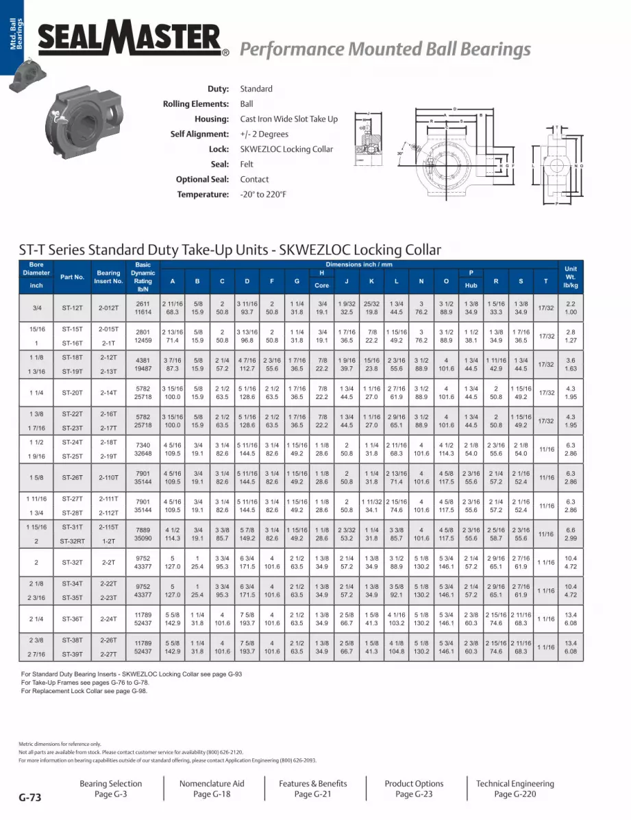
G-73
® Performance Mounted Ball Bearings Performance Mounted Ball BearingsMtd
. Ba
ll
Be
ari
ng
s
ST-T Series Standard Duty Take-Up Units - SKWEZLOC Locking Collar
30°
JK R
DA
SC
B
H G F L
P
T
N O
Bore Diameter Part No. Bearing
Insert No.
Basic Dynamic Rating
lb/N
Dimensions inch / mmUnit Wt.
lb/kgA B C D F GH
J K L N OP
R S Tinch Core Hub
3/4 ST-12T 2-012T 261111614
2 11/1668.3
5/8 15.9
2 50.8
3 11/1693.7
2 50.8
1 1/4 31.8
3/4 19.1
1 9/3232.5
25/3219.8
1 3/4 44.5
3 76.2
3 1/2 88.9
1 3/8 34.9
1 5/1633.3
1 3/8 34.9 17/32 2.2
1.00
15/16 ST-15T 2-015T 280112459
2 13/1671.4
5/8 15.9
2 50.8
3 13/1696.8
2 50.8
1 1/4 31.8
3/4 19.1
1 7/1636.5
7/8 22.2
1 15/1649.2
3 76.2
3 1/2 88.9
1 1/2 38.1
1 3/8 34.9
1 7/1636.5 17/32 2.8
1.271 ST-16T 2-1T
1 1/8 ST-18T 2-12T 438119487
3 7/1687.3
5/8 15.9
2 1/4 57.2
4 7/16112.7
2 3/1655.6
1 7/1636.5
7/8 22.2
1 9/1639.7
15/1623.8
2 3/1655.6
3 1/2 88.9
4 101.6
1 3/4 44.5
1 11/1642.9
1 3/4 44.5 17/32 3.6
1.631 3/16 ST-19T 2-13T
1 1/4 ST-20T 2-14T 578225718
3 15/16100.0
5/8 15.9
2 1/2 63.5
5 1/16128.6
2 1/2 63.5
1 7/1636.5
7/8 22.2
1 3/4 44.5
1 1/1627.0
2 7/1661.9
3 1/2 88.9
4 101.6
1 3/4 44.5
2 50.8
1 15/1649.2 17/32 4.3
1.95
1 3/8 ST-22T 2-16T 578225718
3 15/16100.0
5/8 15.9
2 1/2 63.5
5 1/16128.6
2 1/2 63.5
1 7/1636.5
7/8 22.2
1 3/4 44.5
1 1/1627.0
2 9/1665.1
3 1/2 88.9
4 101.6
1 3/4 44.5
2 50.8
1 15/1649.2 17/32 4.3
1.951 7/16 ST-23T 2-17T
1 1/2 ST-24T 2-18T 734032648
4 5/16109.5
3/4 19.1
3 1/4 82.6
5 11/16144.5
3 1/4 82.6
1 15/1649.2
1 1/8 28.6
2 50.8
1 1/4 31.8
2 11/1668.3
4 101.6
4 1/2 114.3
2 1/8 54.0
2 3/1655.6
2 1/8 54.0 11/16 6.3
2.861 9/16 ST-25T 2-19T
1 5/8 ST-26T 2-110T 790135144
4 5/16109.5
3/4 19.1
3 1/4 82.6
5 11/16144.5
3 1/4 82.6
1 15/1649.2
1 1/8 28.6
2 50.8
1 1/4 31.8
2 13/1671.4
4 101.6
4 5/8 117.5
2 3/1655.6
2 1/4 57.2
2 1/1652.4 11/16 6.3
2.86
1 11/16 ST-27T 2-111T 790135144
4 5/16109.5
3/4 19.1
3 1/4 82.6
5 11/16144.5
3 1/4 82.6
1 15/1649.2
1 1/8 28.6
2 50.8
1 11/3234.1
2 15/1674.6
4 101.6
4 5/8 117.5
2 3/1655.6
2 1/4 57.2
2 1/1652.4 11/16 6.3
2.861 3/4 ST-28T 2-112T
1 15/16 ST-31T 2-115T 788935090
4 1/2 114.3
3/4 19.1
3 3/8 85.7
5 7/8 149.2
3 1/4 82.6
1 15/1649.2
1 1/8 28.6
2 3/3253.2
1 1/4 31.8
3 3/8 85.7
4 101.6
4 5/8 117.5
2 3/1655.6
2 5/1658.7
2 3/1655.6 11/16 6.6
2.992 ST-32RT 1-2T
2 ST-32T 2-2T 975243377
5 127.0
1 25.4
3 3/4 95.3
6 3/4 171.5
4 101.6
2 1/2 63.5
1 3/8 34.9
2 1/4 57.2
1 3/8 34.9
3 1/2 88.9
5 1/8 130.2
5 3/4 146.1
2 1/4 57.2
2 9/1665.1
2 7/1661.9 1 1/16 10.4
4.72
2 1/8 ST-34T 2-22T 975243377
5 127.0
1 25.4
3 3/4 95.3
6 3/4 171.5
4 101.6
2 1/2 63.5
1 3/8 34.9
2 1/4 57.2
1 3/8 34.9
3 5/8 92.1
5 1/8 130.2
5 3/4 146.1
2 1/4 57.2
2 9/1665.1
2 7/1661.9 1 1/16 10.4
4.722 3/16 ST-35T 2-23T
2 1/4 ST-36T 2-24T 1178952437
5 5/8 142.9
1 1/4 31.8
4 101.6
7 5/8 193.7
4 101.6
2 1/2 63.5
1 3/8 34.9
2 5/8 66.7
1 5/8 41.3
4 1/16103.2
5 1/8 130.2
5 3/4 146.1
2 3/8 60.3
2 15/1674.6
2 11/1668.3 1 1/16 13.4
6.08
2 3/8 ST-38T 2-26T 1178952437
5 5/8 142.9
1 1/4 31.8
4 101.6
7 5/8 193.7
4 101.6
2 1/2 63.5
1 3/8 34.9
2 5/8 66.7
1 5/8 41.3
4 1/8 104.8
5 1/8 130.2
5 3/4 146.1
2 3/8 60.3
2 15/1674.6
2 11/1668.3 1 1/16 13.4
6.082 7/16 ST-39T 2-27T
For Standard Duty Bearing Inserts - SKWEZLOC Locking Collar see page G-93For Take-Up Frames see pages G-76 to G-78. For Replacement Lock Collar see page G-98.
Duty: Standard
Rolling Elements: Ball
Housing: Cast Iron Wide Slot Take Up
Self Alignment: +/- 2 Degrees
Lock: SKWEZLOC Locking Collar
Seal: Felt
Optional Seal: Contact
Temperature: -20° to 220°F
Metric dimensions for reference only.
Not all parts are available from stock. Please contact customer service for availability (800) 626-2120.
For more information on bearing capabilities outside of our standard offering, please contact Application Engineering (800) 626-2093.
Bearing SelectionPage G-3
Nomenclature AidPage G-18
Features & BenefitsPage G-21
Product OptionsPage G-23
Technical EngineeringPage G-220

G-74
Performance Mounted Ball Bearings Performance Mounted Ball Bearings ®
Mtd
. Ba
ll
Be
ari
ng
s
Duty: Medium
Rolling Elements: Ball
Housing: Cast Iron Wide Slot Take Up
Self Alignment: +/- 2 Degrees
Lock: Setscrew
Seal: Felt
Optional Seal: Contact
Temperature: -20° to 220°F
MST Series Medium Duty Take-Up Units - Setscrew Locking
NH
DA
R SC
B
G F
P
T
KJ
L
30°
O
Bore Diameter Part No.
Bearing Insert
No.
Basic Dynamic Rating
lb/N
Dimensions inch / mm Unit Wt.
lb/kgA B C D F GH
J K N OP
R S Tinch mm Core Hub
15/16 MST-15 3-0154381
194873 7/1687.3
5/8 15.9
2 1/4 57.2
4 7/16112.7
2 3/1655.6
1 7/1636.5
7/8 22.2
1 1/2 38.1
7/8 22.2
3 1/2 88.9
4 101.6
1 3/4 44.5
1 11/1642.9
1 3/4 44.5 17/32 3.4
1.541 MST-16 3-125 MST-305 5305
1 3/16 MST-19 3-135782
257183 15/16100.0
5/8 15.9
2 1/2 63.5
5 1/16128.6
2 1/2 63.5
1 7/1636.5
7/8 22.2
1 11/1642.9
1 25.4
3 1/2 88.9
4 101.6
1 3/4 44.5
2 50.8
1 15/1649.2
17/32 4.01.811 1/4 MST-20 2-14
30 MST-306 53061 7/16 MST-23 3-17 7340
326484 5/16109.5
3/4 19.1
3 1/4 82.6
5 11/16144.5
3 1/4 82.6
1 15/1649.2
1 1/8 28.6
1 15/1649.2
1 3/1630.2
4 101.6
4 1/2 114.3
2 1/8 54.0
2 3/1655.6
2 1/8 54.0 11/16 6.2
2.8135 MST-307 53071 1/2 MST-24 3-18 7901
351444 5/16109.5
3/4 19.1
3 1/4 82.6
5 11/16144.5
3 1/4 82.6
1 15/1649.2
1 1/8 28.6
1 15/1649.2
1 3/1630.2
4 101.6
4 5/8 117.5
2 3/1655.6
2 1/4 57.2
2 1/1652.4 11/16 6.2
2.8140 MST-308 53081 11/16 MST-27 3-111
788935090
4 1/2 114.3
3/4 19.1
3 3/8 85.7
5 7/8 149.2
3 1/4 82.6
1 15/1649.2
1 1/8 28.6
2 1/3251.6
1 9/3232.5
4 101.6
4 5/8 117.5
2 3/1655.6
2 5/1658.7
2 3/1655.6 11/16 6.4
2.901 3/4 MST-28 3-11245 MST-309 5309
1 15/16 MST-31 3-1159752
433775
127.01
25.43 3/4 95.3
6 3/4 171.5
4 101.6
2 1/2 63.5
1 3/8 34.9
2 3/1655.6
1 5/1633.3
5 1/8 130.2
5 3/4 146.1
2 1/4 57.2
2 9/1665.1
2 7/1661.9 11/16 10.0
4.542 MST-32 2-250 MST-310 5310
2 3/16 MST-35 3-231178952437
5 5/8 142.9
1 1/4 31.8
4 101.6
7 5/8 193.7
4 101.6
2 1/2 63.5
1 3/8 34.9
2 9/1665.1
1 9/1639.7
5 1/8 130.2
5 3/4 146.1
2 3/8 60.3
2 15/1674.6
2 11/1668.3 1 1/16 12.3
5.582 1/4 MST-36 2-2455 MST-311 5311
2 7/16 MST-39 3-271397162143
6 3/4 171.5
1 1/4 31.8
4 3/4 120.7
8 13/16223.8
4 3/8 111.1
2 3/4 69.9
1 5/8 41.3
2 3/4 69.9
1 11/1642.9
5 15/16150.8
6 9/16166.7
3 3/8 85.7
3 7/1687.3
3 5/1684.1 1 1/16 19.5
8.852 1/2 MST-40 3-2865 MST-313 5313
2 11/16 MST-43 3-211 1483966004
7 1/16179.4
1 1/4 31.8
4 3/4 120.7
9 1/8 231.8
4 3/8 111.1
2 3/4 69.9
1 5/8 41.3
3 1/1677.8
1 3/4 44.5
5 15/16150.8
6 9/16166.7
3 3/8 85.7
3 5/8 92.1
3 7/1687.3 1 1/16 19.8
8.9870 MST-314 53142 15/16 MST-47 3-215
1741277449
7 3/16182.6
1 1/4 31.8
4 3/4 120.7
9 1/4 235.0
4 3/8 111.1
2 3/4 69.9
1 5/8 41.3
3 1/4 82.6
1 15/1649.2
6 1/2 165.1
7 1/4 184.2
3 3/8 85.7
3 3/4 95.3
3 7/1687.3 1 1/16 23.0
10.433 MST-48 3-375 MST-315 5315
3 3/16 MST-51 3-331868183093
7 5/8 193.7
1 1/2 38.1
6 3/16
157.2
10 1/4 260.4
4 7/8 123.8
2 7/8 73.0
1 7/8 47.6
3 3/8 85.7
2 1/3251.6
6 13/16173.0
7 13/16198.4
3 1/2 88.9
3 7/8 98.4
3 3/4 95.3 1 13/16 31.8
14.423 1/4 MST-52 2-3480 MST-316 5316
3 15/16 MST-63 3-31529905
1330179 1/4 235.0
1 1/2 38.1
6 1/2 165.1
11 7/8 301.6
4 7/8 123.8
2 7/8 73.0
1 7/8 47.6
4 5/8 117.5
2 11/1668.3
8 3/8 212.7
9 3/8 238.1
3 1/2 88.9
4 3/4 120.7
4 1/2 114.3 1 13/16 50.0
22.684 MST-64 3-4100 MST-320 5320
For Medium Duty Bearing Inserts-Single Lock see page G-95.For Take-Up Frames see page G-78.
Bearing SelectionPage G-3
Nomenclature AidPage G-18
Features & BenefitsPage G-21
Product OptionsPage G-23
Technical EngineeringPage G-220

G-75
® Performance Mounted Ball Bearings Performance Mounted Ball BearingsMtd
. Ba
ll
Be
ari
ng
s
MST-T Series Medium Duty Take-Up Units - SKWEZLOC Locking Collar
30°
JK R
DA
SC
B
H G F L
P
T
N O
Bore Diameter Part No.
Bearing Insert
No.
Basic Dynamic Rating lb/N
Dimensions inch / mmUnit Wt.
lb/kgA B C D F GH
J K L N OP
R S Tinch Core Hub
1 MST-16T 3-1T 438119487
3 7/1687.3
5/8 15.9
2 1/4 57.2
4 7/16112.7
2 3/1655.6
1 7/1636.5
7/8 22.2
1 9/1639.7
15/1623.8
2 1/1652.4
3 1/2 88.9
4 101.6
1 3/4 44.5
1 11/1642.9
1 3/4 44.5 17/32 3.6
1.63
1 3/16 MST-19T 3-13T 578225718
3 15/16100.0
5/815.9
2 1/2 63.5
5 1/16128.6
2 1/2 63.5
1 7/1636.5
7/8 22.2
1 3/4 44.5
1 1/1627.0
2 7/1661.9
3 1/2 88.9
4 101.6
1 3/4 44.5
2 50.8
1 15/1649.2 17/32 4.3
1.951 1/4 MST-20T 2-14T
1 7/16 MST-23T 3-17T 734032648
4 5/16109.5
3/419.1
3 1/4 82.6
5 11/16144.5
3 1/4 82.6
1 15/1649.2
1 1/8 28.6
2 50.8
1 1/4 31.8
2 11/1668.3
4 101.6
4 1/2 114.3
2 1/8 54.0
2 3/1655.6
2 1/8 54.0 11/16 6.3
2.86
1 1/2 MST-24T 3-18T 790135144
4 5/16109.5
3/419.1
3 1/4 82.6
5 11/16144.5
3 1/4 82.6
1 15/1649.2
1 1/8 28.6
2 50.8
1 1/4 31.8
2 13/1671.4
4 101.6
4 5/8 117.5
2 3/1655.6
2 1/4 57.2
2 1/1652.4 11/16 6.3
2.86
1 11/16 MST-27T 3-111T 788935090
4 1/2 114.3
3/419.1
3 3/8 85.7
5 7/8 149.2
3 1/4 82.6
1 15/1649.2
1 1/8 28.6
2 3/3253.2
1 11/3234.1
3 1/4 82.6
4 101.6
4 5/8 117.5
2 3/1655.6
2 5/1658.7
2 3/1655.6 11/16 6.6
2.991 3/4 MST-28T 3-112T
1 15/16 MST-31T 3-115T 975243377
5 127.0
1 25.4
3 3/4 95.3
6 3/4 171.5
4 101.6
2 1/2 63.5
1 3/8 34.9
2 1/4 57.2
1 3/8 34.9
3 1/2 88.9
5 1/8 130.2
5 3/4 146.1
2 1/4 57.2
2 9/1665.1
2 7/1661.9 1 1/16 10.4
4.722 MST-32T 2-2T
2 3/16 MST-35T 3-23T 1178952437
5 5/8 142.9
1 1/4 31.8
4 101.6
7 5/8 193.7
4 101.6
2 1/2 63.5
1 3/8 34.9
2 5/8 66.7
1 5/8 41.3
4 1/16103.2
5 1/8 130.2
5 3/4 146.1
2 3/8 60.3
2 15/1674.6
2 11/1668.3 1 1/16 13.4
6.082 1/4 MST-36T 2-24T
For medium duty SKWEZLOC Locking Collar Bearing Inserts see page G-96.For Take-Up Frames see page G-80. For Replacement Lock Collar see page G-98.
Duty: Medium
Rolling Elements: Ball
Housing: Cast Iron Wide Slot Take Up
Self Alignment: +/- 2 Degrees
Lock: SKWEZLOC Locking Collar
Seal: Felt
Optional Seal: Contact
Temperature: -20° to 220°F
Metric dimensions for reference only.
Not all parts are available from stock. Please contact customer service for availability (800) 626-2120.
For more information on bearing capabilities outside of our standard offering, please contact Application Engineering (800) 626-2093.
Bearing SelectionPage G-3
Nomenclature AidPage G-18
Features & BenefitsPage G-21
Product OptionsPage G-23
Technical EngineeringPage G-220

G-76
Performance Mounted Ball Bearings Performance Mounted Ball Bearings ®
Mtd
. Ba
ll
Be
ari
ng
s
STH Center Pull Take Up Frames
N
G
JK
R
B B F
E T CA T
S
D
Duty: Standard
Rolling Elements: Ball
Housing: Center Pull Take Up Frame & Take Up Housing
Self Alignment: +/- 2 Degrees
Lock: Setscrew
Optional Lock: SKWEZLOC Locking Collar
Seal: Felt
Optional Seal: Contact
Temperature: -20° to 220°F
Bore Diameter Part No.
Housing Assembly Included
Bearing Insert
No.
Dimensions inch / mmBolt Size
Unit Wt. lb/kg Frame Only Part No.T
Travel A B C D E F G J K N R Sinch mm
7/8 STH-14-6
ST-14 2-014
6 15 4 5/8
3/8
11.6STH 12 TO 16-6 DZU
152.4 381.0 117.5 3 1/4 3/4 3 1/4 2 1/2 7 9/16 13/16 1 1/8 1 3/4 3/4 6 1/16 5.3
STH-14-99 18 6 1/8 82.6 19.1 82.6 63.5 192.1 20.6 28.6 44.5 19.1 154.0 13.6
STH 12 TO 16-9 DZU228.6 457.2 155.6 6.2
15/16STH-15-6
ST-15 2-015
6 15 4 5/8
3/8
11.6STH 12 TO 16-6 DZU
152.4 381.0 117.5 3 1/4 3/4 3 1/4 2 1/2 7 9/16 13/16 1 1/8 1 3/4 3/4 6 1/16 5.3
STH-15-99 18 6 1/8 82.6 19.1 82.6 63.5 192.1 20.6 28.6 44.5 19.1 154.0 13.6
STH 12 TO 16-9 DZU228.6 457.2 155.6 6.2
25STH-205-6
ST-205 5205
6 15 4 5/8
3/8
11.6STH 12 TO 16-6 DZU
152.4 381.0 117.5 3 1/4 3/4 3 1/4 2 1/2 7 9/16 13/16 1 1/8 1 3/4 3/4 6 1/16 5.3
STH-205-99 18 6 1/8 82.6 19.1 82.6 63.5 192.1 20.6 28.6 44.5 19.1 154.0 13.6
STH 12 TO 16-9 DZU228.6 457.2 155.6 6.2
1STH-16-6
ST-16 2-1
6 15 4 5/8
3/8
11.6STH 12 TO 16-6 DZU
152.4 381.0 117.5 3 1/4 3/4 3 1/4 2 1/2 7 9/16 13/16 1 1/8 1 3/4 3/4 6 1/16 5.3
STH-16-99 18 6 1/8 82.6 19.1 82.6 63.5 192.1 20.6 28.6 44.5 19.1 154.0 13.6
STH 12 TO 16-9 DZU228.6 457.2 155.6 6.2
1 1/8 STH-18-6
ST-18 2-12
6 16 1/8 5
3/8
14.1STH 17 TO 16-6 DZU
152.4 409.6 127.0 3 1/2 3/4 3 3/4 2 1/2 8 1/16 7/8 1 1/4 1 3/4 3/4 6 9/16 6.4
STH-18-99 19 1/8 6 1/2 88.9 19.1 95.3 63.5 204.8 22.2 31.8 44.5 19.1 166.7 17.4
STH 17 TO 16-9 DZU228.6 485.8 165.1 7.9
30STH-206-6
ST-206 5206
6 16 1/8 5
3/8
14.1STH 17 TO 19-6 DZU
152.4 409.6 127.0 3 1/2 3/4 3 3/4 2 1/2 8 1/16 7/8 1 1/4 1 3/4 3/4 6 9/16 6.4
STH-206-99 19 1/8 6 1/2 88.9 19.1 95.3 63.5 204.8 22.2 31.8 44.5 19.1 166.7 16
STH 17 TO 19-9 DZU228.6 485.8 165.1 7.3
1 3/16STH-19-6
ST-19 2-13
6 16 1/8 5
3/8
14.1STH 17 TO 19-6 DZU
152.4 409.6 127.0 3 1/2 3/4 3 3/4 2 1/2 8 1/16 7/8 1 1/4 1 3/4 3/4 6 9/16 6.4
STH-19-99 19 1/8 6 1/2 88.9 19.1 95.3 63.5 204.8 22.2 31.8 44.5 19.1 166.7 16
STH 17 TO 19-9 DZU228.6 485.8 165.1 7.3
1 1/4 STH-20-9
ST-20 2-14
9 19 11/16 6 13/16
3/8
16STH 20 TO 23-9 DZU
228.6 500.1 173.0 3 7/8 3/4 4 2 1/2 8 1/16 1 1 1/4 1 3/4 3/4 6 9/16 7.3
STH-20-1212 22 11/16 8 5/16 98.4 19.1 101.6 63.5 204.8 25.4 31.8 44.5 19.1 166.7 19.5
STH 20 TO 23-12 DZU304.8 576.3 211.1 8.8
1 3/8 STH-22-9
ST-22 2-16
9 19 11/16 6 13/16
3/8
17.4STH 20 TO 23-9 DZU
228.6 500.1 173.0 3 7/8 3/4 4 2 1/2 8 1/16 1 1 1/4 1 3/4 3/4 6 9/16 7.9
STH-22-1212 22 11/16 8 5/16 98.4 19.1 101.6 63.5 204.8 25.4 31.8 44.5 19.1 166.7 19.5
STH 20 TO 23-12 DZU304.8 576.3 211.1 8.8
35STH-207-9
ST-207 5207
9 19 11/16 6 13/16
3/8
17.4STH 20 TO 23-9 DZU
228.6 500.1 173.0 3 7/8 3/4 4 2 1/2 8 1/16 1 1 1/4 1 3/4 3/4 6 9/16 7.9
STH-207-1212 22 11/16 8 5/16 98.4 19.1 101.6 63.5 204.8 25.4 31.8 44.5 19.1 166.7 19.5
STH 20 TO 23-12 DZU304.8 576.3 211.1 8.8
1 7/16STH-23-9
ST-23 2-17
9 19 11/16 6 13/16
3/8
17.4STH 20 TO 23-9 DZU
228.6 500.1 173.0 3 7/8 3/4 4 2 1/2 8 1/16 1 1 1/4 1 3/4 3/4 6 9/16 7.9
STH-23-1212 22 11/16 8 5/16 98.4 19.1 101.6 63.5 204.8 25.4 31.8 44.5 19.1 166.7 19.5
STH 20 TO 23-12 DZU304.8 576.3 211.1 8.8
1 1/2 STH-24-12
ST-24 2-18
12 23 9/16 8 9/16
3/8
27.2STH 24 TO 28-12 DZU
304.8 598.5 217.5 4 1/4 7/8 4 1/4 2 1/2 9 5/16 1 3/16 1 3/8 2 7/8 7 9/16 12.3
STH-24-1818 29 9/16 11 9/16 108.0 22.2 108.0 63.5 236.5 30.2 34.9 50.8 22.2 192.1 32
STH 24 TO 28-18 DZU457.2 750.9 293.7 14.5
See notes on page G-78.
Bearing SelectionPage G-3
Nomenclature AidPage G-18
Features & BenefitsPage G-21
Product OptionsPage G-23
Technical EngineeringPage G-220

G-77
® Performance Mounted Ball Bearings Performance Mounted Ball BearingsMtd
. Ba
ll
Be
ari
ng
s
Duty: Standard
Rolling Elements: Ball
Housing: Cast Iron Center Pull Take Up Frame & Take Up Housing
Self Alignment: +/- 2 Degrees
Lock: Setscrew
Optional Lock: SKWEZLOC Locking Collar
Seal: Felt
Optional Seal: Contact
Temperature: -20° to 220°F
STH Center Pull Take Up Frames
N
G
JK
R
B B F
E T CA T
S
D
Bore Diameter Part No.
Housing Assembly Included
Bearing Insert
No.
Dimensions inch / mmBolt Size
Unit Wt. lb/kg Frame Only Part No.T
Travel A B C D E F G J K N R Sinch mm
1 9/16STH-25-12
ST-25 2-19
12 23 9/16 8 9/16
3/8
27.2STH 24 TO 28-12 DZU
304.8 598.5 217.5 4 1/4 7/8 4 1/4 2 1/2 9 5/16 1 3/16 1 3/8 2 7/8 7 9/16 12.3
STH-25-1818 29 9/16 11 9/16 108.0 22.2 108.0 63.5 236.5 30.2 34.9 50.8 22.2 192.1 32.0
STH 24 TO 28-18 DZU457.2 750.9 293.7 14.5
40STH-208-12
ST-208 5208
12 23 9/16 8 9/16
3/8
27.2STH 24 TO 28-12 DZU
304.8 598.5 217.5 4 1/4 7/8 4 1/4 2 1/2 9 5/16 1 3/16 1 3/8 2 7/8 7 9/16 12.3
STH-208-1818 29 9/16 11 9/16 108.0 22.2 108.0 63.5 236.5 30.2 34.9 50.8 22.2 192.1 32.0
STH 24 TO 28-18 DZU457.2 750.9 293.7 14.5
1 5/8 STH-26-12
ST-26 2-110
12 23 9/16 8 9/16
3/8
27.2STH 24 TO 28-12 DZU
304.8 598.5 217.5 4 1/4 7/8 4 1/4 2 1/2 9 5/16 1 3/16 1 3/8 2 7/8 7 9/16 12.3
STH-26-1818 29 9/16 11 9/16 108.0 22.2 108.0 63.5 236.5 30.2 34.9 50.8 22.2 192.1 32.0
STH 24 TO 28-18 DZU457.2 750.9 293.7 14.5
1 11/16STH-27-12
ST-27 2-111
12 23 9/16 8 9/16
3/8
27.2STH 24 TO 28-12 DZU
304.8 598.5 217.5 4 1/4 7/8 4 1/4 2 1/2 9 5/16 1 3/16 1 3/8 2 7/8 7 9/16 12.3
STH-27-1818 29 9/16 11 9/16 108.0 22.2 108.0 63.5 236.5 30.2 34.9 50.8 22.2 192.1 32.0
STH 24 TO 28-18 DZU457.2 750.9 293.7 14.5
1 3/4 STH-28-12
ST-28 2-112
12 23 9/16 8 9/16
3/8
27.2STH 24 TO 28-12 DZU
304.8 598.5 217.5 4 1/4 7/8 4 1/4 2 1/2 9 5/16 1 3/16 1 3/8 2 7/8 7 9/16 12.3
STH-28-1818 29 9/16 11 9/16 108.0 22.2 108.0 63.5 236.5 30.2 34.9 50.8 22.2 192.1 32.0
STH 24 TO 28-18 DZU457.2 750.9 293.7 14.5
45STH-209-12
ST-209 5209
12 23 9/16 8 9/16
3/8
27.2STH 24 TO 28-12 DZU
304.8 598.5 217.5 4 1/4 7/8 4 1/4 2 1/2 9 5/16 1 3/16 1 3/8 2 7/8 7 9/16 12.3
STH-209-1818 29 9/16 11 9/16 108.0 22.2 108.0 63.5 236.5 30.2 34.9 50.8 22.2 192.1 32.0
STH 24 TO 28-18 DZU457.2 750.9 293.7 14.5
1 7/8 STH-30-12
ST-30 2-114
12 23 11/16 8 5/8
1/2
27.2STH 30 TO 31-12 DZU
304.8 601.7 219.1 4 3/8 7/8 4 1/4 2 1/2 9 5/16 1 9/32 1 3/8 2 7/8 7 9/16 12.3
STH-30-1818 29 11/16 11 5/8 111.1 22.2 108.0 63.5 236.5 32.5 34.9 50.8 22.2 192.1 33.0
STH 30 TO 31-18 DZU457.2 754.1 295.3 15.0
1 15/16STH-31-12
ST-31 2-115
12 23 11/16 8 5/8
1/2
27.2STH 30 TO 31-12 DZU
304.8 601.7 219.1 4 3/8 7/8 4 1/4 2 1/2 9 5/16 1 9/32 1 3/8 2 7/8 7 9/16 12.3
STH-31-1818 29 11/16 11 5/8 111.1 22.2 108.0 63.5 236.5 32.5 34.9 50.8 22.2 192.1 33.0
STH 30 TO 31-18 DZU457.2 754.1 295.3 15.0
50STH-210-12
ST-210 5210
12 23 11/16 8 5/8
1/2
27.2STH 30 TO 31-12 DZU
304.8 601.7 219.1 4 3/8 7/8 4 1/4 2 1/2 9 5/16 1 9/32 1 3/8 2 7/8 7 9/16 12.3
STH-210-1818 29 11/16 11 5/8 111.1 22.2 108.0 63.5 236.5 32.5 34.9 50.8 22.2 192.1 33.0
STH 30 TO 31-18 DZU457.2 754.1 295.3 15.0
2 STH-32-12
ST-32 2-2
12 24 13/16 9 1/16
1/2
41.6STH 32 TO 35-12 DZU
304.8 630.2 230.2 4 7/8 7/8 4 1/2 2 3/8 11 3/16 1 5/16 1 1/2 2 1/2 7/8 9 7/16 18.9
STH-32-1818 30 13/16 12 1/16 123.8 22.2 114.3 60.3 284.2 33.3 38.1 63.5 22.2 239.7 50.6
STH 32 TO 35-18 DZU457.2 782.6 306.4 23.0
2 1/8 STH-34-12
ST-34 2-22
12 24 13/16 9 1/16
1/2
41.6STH 32 TO 35-12 DZU
304.8 630.2 230.2 4 7/8 7/8 4 1/2 2 3/8 11 3/16 1 5/16 1 1/2 2 1/2 7/8 9 7/16 18.9
STH-34-1818 30 13/16 12 1/16 123.8 22.2 114.3 60.3 284.2 33.3 38.1 63.5 22.2 239.7 50.6
STH 32 TO 35-18 DZU457.2 782.6 306.4 23.0
55STH-211-12
ST-211 5211
12 24 13/16 9 1/16
1/2
41.6STH 32 TO 35-12 DZU
304.8 630.2 230.2 4 7/8 7/8 4 1/2 2 3/8 11 3/16 1 5/16 1 1/2 2 1/2 7/8 9 7/16 18.9
STH-211-1818 30 13/16 12 1/16 123.8 22.2 114.3 60.3 284.2 33.3 38.1 63.5 22.2 239.7 50.6
STH 32 TO 35-18 DZU457.2 782.6 306.4 23.0
See notes on page G-78.
Metric dimensions for reference only.
Not all parts are available from stock. Please contact customer service for availability (800) 626-2120.
For more information on bearing capabilities outside of our standard offering, please contact Application Engineering (800) 626-2093.
Bearing SelectionPage G-3
Nomenclature AidPage G-18
Features & BenefitsPage G-21
Product OptionsPage G-23
Technical EngineeringPage G-220

G-78
Performance Mounted Ball Bearings Performance Mounted Ball Bearings ®
Mtd
. Ba
ll
Be
ari
ng
s
STH Center Pull Take Up Frames
N
G
JK
R
B B F
E T CA T
S
D
Bore Diameter Part No.
Housing Assembly Included
Bearing Insert
No.
Dimensions inch / mmBolt Size
Unit Wt. lb/kg Frame Only Part No.T
Travel A B C D E F G J K N R Sinch mm
2 3/16STH-35-12
ST-35 2-23
12 24 13/16 9 1/16
1/2
41.6STH 32 TO 35-12 DZU
304.8 630.2 230.2 4 7/8 7/8 4 1/2 2 3/8 11 3/16 1 5/16 1 1/2 2 1/2 7/8 9 7/16 18.9
STH-35-1818 30 13/16 12 1/16 123.8 22.2 114.3 60.3 284.2 33.3 38.1 63.5 22.2 239.7 50.6
STH 32 TO 35-18 DZU457.2 782.6 306.4 23.0
2 1/4 STH-36-12
ST-36 2-24
12 25 9/16 9 9/16
1/2
45.0STH 36 TO 39-12 DZU
304.8 649.3 242.9 5 3/8 7/8 5 2 3/8 11 3/16 1 9/16 1 1/2 2 1/2 7/8 9 7/16 20.4
STH-36-1818 31 9/16 12 9/16 136.5 22.2 127.0 60.3 284.2 39.7 38.1 63.5 22.2 239.7 53.0
STH 36 TO 39-18 DZU457.2 801.7 319.1 24.0
60STH-212-12
ST-212 5212
12 25 9/16 9 9/16
1/2
45.0STH 36 TO 39-12 DZU
304.8 649.3 242.9 5 3/8 7/8 5 2 3/8 11 3/16 1 9/16 1 1/2 2 1/2 7/8 9 7/16 20.4
STH-212-1818 31 9/16 12 9/16 136.5 22.2 127.0 60.3 284.2 39.7 38.1 63.5 22.2 239.7 53.0
STH 36 TO 39-18 DZU457.2 801.7 319.1 24.0
2 3/8 STH-38-12
ST-38 2-26
12 25 9/16 9 9/16
1/2
45.0STH 36 TO 39-12 DZU
304.8 649.3 242.9 5 3/8 7/8 5 2 3/8 11 3/16 1 9/16 1 1/2 2 1/2 7/8 9 7/16 20.4
STH-38-1818 31 9/16 12 9/16 136.5 22.2 127.0 60.3 284.2 39.7 38.1 63.5 22.2 239.7 53.0
STH 36 TO 39-18 DZU457.2 801.7 319.1 24.0
2 7/16STH-39-12
ST-39 2-27
12 25 9/16 9 9/16
1/2
45.0STH 36 TO 39-12 DZU
304.8 649.3 242.9 5 3/8 7/8 5 2 3/8 11 3/16 1 9/16 1 1/2 2 1/2 7/8 9 7/16 20.4
STH-39-1818 31 9/16 12 9/16 136.5 22.2 127.0 60.3 284.2 39.7 38.1 63.5 22.2 239.7 53.0
STH 36 TO 39-18 DZU457.2 801.7 319.1 24.0
2 1/2 STH-40-12
ST-40 3-28
12 27 1/2 10 1/4
5/8
62.5STH 40 TO 47-12 DZU
304.8 698.5 260.4 6 3/16 7/8 5 11/16 2 1/2 12 1 11/16 2 3 7/8 10 1/4 28.3
STH-40-1818 33 1/2 13 1/4 157.2 22.2 144.5 63.5 304.8 42.9 50.8 76.2 22.2 260.4 73.7
STH 40 TO 47-18 DZU457.2 850.9 336.6 33.4
2 11/16STH-43-12
ST-43 2-211
12 27 1/2 10 1/4
5/8
62.5STH 40 TO 47-12 DZU
304.8 698.5 260.4 6 3/16 7/8 5 11/16 2 1/2 12 1 11/16 2 3 7/8 10 1/4 28.3
STH-43-1818 33 1/2 13 1/4 157.2 22.2 144.5 63.5 304.8 42.9 50.8 76.2 22.2 260.4 73.7
STH 40 TO 47-18 DZU457.2 850.9 336.6 33.4
70STH-214-12
ST-214 5214
12 27 1/2 10 1/4
5/8
62.5STH 40 TO 47-12 DZU
304.8 698.5 260.4 6 3/16 7/8 5 11/16 2 1/2 12 1 11/16 2 3 7/8 10 1/4 28.3
STH-214-1818 33 1/2 13 1/4 157.2 22.2 144.5 63.5 304.8 42.9 50.8 76.2 22.2 260.4 73.7
STH 40 TO 47-18 DZU457.2 850.9 336.6 33.4
2 7/8 STH-46-12
ST-46 2-214
12 27 1/2 10 1/4
5/8
62.5STH 40 TO 47-12 DZU
304.8 698.5 260.4 6 3/16 7/8 5 11/16 2 1/2 12 1 3/4 2 3 7/8 10 1/4 28.3
STH-46-1818 33 1/2 13 1/4 157.2 22.2 144.5 63.5 304.8 44.5 50.8 76.2 22.2 260.4 73.7
STH 40 TO 47-18 DZU457.2 850.9 336.6 33.4
2 15/16STH-47-12
ST-47 2-215
12 27 1/2 10 1/4
5/8
62.5STH 40 TO 47-12 DZU
304.8 698.5 260.4 6 3/16 7/8 5 11/16 2 1/2 12 1 3/4 2 3 7/8 10 1/4 28.3
STH-47-1818 33 1/2 13 1/4 157.2 22.2 144.5 63.5 304.8 44.5 50.8 76.2 22.2 260.4 73.7
STH 40 TO 47-18 DZU457.2 850.9 336.6 33.4
75STH-215-12
ST-215 5215
12 27 1/2 10 1/4
5/8
62.5STH 40 TO 47-12 DZU
304.8 698.5 260.4 6 3/16 7/8 5 11/16 2 1/2 12 1 3/4 2 3 7/8 10 1/4 28.3
STH-215-1818 33 1/2 13 1/4 157.2 22.2 144.5 63.5 304.8 44.5 50.8 76.2 22.2 260.4 73.7
STH 40 TO 47-18 DZU457.2 850.9 336.6 33.4
The STH series style H, are side mounting frame take-up units designed to incorporate the ST series take-up units (see pages G-72 to G-74), as indicated in the accompanying charts. They are used where shaft adjustment and/or belt tightening is required in conveyor applications. They are manufactured from heavy gauge structural steel members and equipped with heavy duty Acme (square) threads for positive action.Adjustment is made by turning the square head with an open end wrench.For SKWEZLOC Locking Collar add T suffix example STH-23T-12For Contact Seal add C suffix example STH-23C-12
Duty: Standard
Rolling Elements: Ball
Housing: Cast Iron Center Pull Take Up Frame & Take Up Housing
Self Alignment: +/- 2 Degrees
Lock: Setscrew
Optional Lock: SKWEZLOC Locking Collar
Seal: Felt
Optional Seal: Contact
Temperature: -20° to 220°F
Bearing SelectionPage G-3
Nomenclature AidPage G-18
Features & BenefitsPage G-21
Product OptionsPage G-23
Technical EngineeringPage G-220

G-79
® Performance Mounted Ball Bearings Performance Mounted Ball BearingsMtd
. Ba
ll
Be
ari
ng
s
Duty: Medium
Rolling Elements: Ball
Housing: Cast Iron Center Pull Take Up Frame & Take Up Housing
Self Alignment: +/- 2 Degrees
Lock: Setscrew
Seal: Felt
Optional Seal: Contact
Temperature: -20° to 220°F
MSTH Center Pull Take Up Frames
N
G
JK
R
B B F
H
E T CA T
S
D
Bore Diameter Part No.
Housing Assembly Included
Bearing Insert
No.
Dimensions inch / mmBolt Size
Unit Wt.
lb/kgFrame Only
Part No.T Travel A B C D E F G H J K N R Sinch
1 11/16
2
MSTH-31-12
MSTH-32-12
MST-31
MST-32
3-115
2-2
12
304.8
23 11/16
630.2
8 5/8
230.2
4 3/8
123.8
7/8
22.2
4 1/4
114.3
2 1/2
60.3
9 5/16
284.2
20 5/8
542.9
1 9/32
33.3
1 1/2
38.1
2 1/2
63.5
7/8
22.2
9 7/16
239.7 1/2
41.6
18.9STH 32 TO 35-12
2 7/16
2 1/2
MSTH-39-12
MSTH-40-12
MST-39
MST-40
3-27
3-28
12
304.8
25 9/16
698.5
9 9/16
260.4
5 3/8
157.2
7/8
22.2
5
144.5
2 3/8
63.5
11 3/16
304.8
22 3/8
606.4
1 9/16
44.5
1 1/2
50.8
2 1/2
76.2
7/8
22.2
9 7/16
260.45/8
62.5
28.3STH 40 TO 47-12
The MSTH series style H, are side mounting take-up units designed to incorporate MST series take-up units (see page G-80) as indicated in the table above. They are used where shaft adjustment and/or belt tightening is required in conveyor applications. They are manufactured from heavy gauge structural steel members and equipped with heavy duty Acme (square) threads for positive action. Adjustment is made by turning the square head with an open wrench.
Metric dimensions for reference only.
Not all parts are available from stock. Please contact customer service for availability (800) 626-2120.
For more information on bearing capabilities outside of our standard offering, please contact Application Engineering (800) 626-2093.
Bearing SelectionPage G-3
Nomenclature AidPage G-18
Features & BenefitsPage G-21
Product OptionsPage G-23
Technical EngineeringPage G-220

G-80
Performance Mounted Ball Bearings Performance Mounted Ball Bearings ®
Mtd
. Ba
ll
Be
ari
ng
s
Bearing SelectionPage G-3
Nomenclature AidPage G-18
Features & BenefitsPage G-21
Product OptionsPage G-23
Technical EngineeringPage G-220
TF and TFS Series Standard Duty Top Mount Take-Up Frame
G
B1
J2
W
A
B2L
H R
G
T
S
J1
BoltSize
Adjustment
Bore Diameter Range
Frame Part No. Adjustment
Dimensions Inch / Mm Bolt Size
Unit Wt.
lb/kg L B1 B2 W A G MIN H J1 J2 R S T
3/4 - 1”
6TF16 6
152.417 1/8 435.0
13 7/8 352.4
15 7/8 403.2
3 1/4 82.6
2 1/4 57.2
3 5/1684.1
2 3/8 60.3
7/1611.1
9/1614.3
9/1614.3
5/8 15.9
3/164.8
3/8 10
6.02.72
9TF16 9
228.620 1/8 511.2
16 7/8 428.6
18 7/8 479.4
3 1/4 82.6
2 1/4 57.2
3 5/1684.1
2 3/8 60.3
7/1611.1
9/1614.3
9/1614.3
5/8 15.9
3/164.8
3/8 10
6.73.04
1 1/16 - 1 15/16”
6TF31 6
152.418 3/16462.0
15 7/16392.1
16 15/16430.2
3 1/2 88.9
2 1/2 63.5
3 3/8 85.7
2 13/1671.4
7/1611.1
9/1614.3
7/8 22.2
3/4 19.1
3/164.8
1/2 13
8.94.04
9TF31 9
228.622 5/8 574.7
19 7/8 504.8
21 3/8 542.9
3 1/2 88.9
2 1/2 63.5
3 3/8 85.7
2 13/1671.4
7/1611.1
9/1614.3
7/8 22.2
3/4 19.1
3/164.8
1/2 13
10.34.67
12TF31 12
304.824 3/16614.4
21 7/16544.5
22 15/16582.6
3 1/2 88.9
2 1/2 63.5
3 3/8 85.7
2 13/1671.4
7/1611.1
9/1614.3
7/8 22.2
3/4 19.1
3/164.8
1/2 13
10.94.94
18TF31 18
457.231 5/8 803.3
28 7/8 733.4
30 3/8 771.5
3 1/2 88.9
2 1/2 63.5
3 3/8 85.7
2 13/1671.4
7/1611.1
9/1614.3
7/8 22.2
3/4 19.1
3/164.8
1/2 13
13.36.03
2 - 2 7/16”
12TF39 12
304.828
711.224 3/4 628.7
26 3/4 679.5
4 1/2 114.3
376.2
4101.6
3 5/1684.1
9/1614.3
11/1617.5
15/1623.8
125.4
1/4 6.4
5/8 16
18.38.30
18TF39 18
457.234
863.630 3/4 781.1
32 3/4 831.9
4 1/2 114.3
376.2
4101.6
3 5/1684.1
9/1614.3
11/1617.5
15/1623.8
125.4
1/4 6.4
5/8 16
21.209.62
2 1/4 - 2 7/16”
12TFS39 12 304.8
31 787.4
30 762 -
4 1/2 114.3
376.2
3 1/2 88.9
3 76.2
5/8 16 - -
125.4
1/3 8.5
3/4 16
25.66 11.64
18TFS39 18 457.2
37 939.8
36 914.4 -
4 1/2 114.3
376.2
3 1/2 88.9
3 76.2
5/8 16 - -
125.4
1/3 8.5
3/4 16
29.18 13.24
Metric dimensions for reference only.
Not all parts are available from stock. Please contact customer service for availability (800) 626-2120.
For more information on bearing capabilities outside of our standard offering, please contact Application Engineering (800) 626-2093.

G-81
® Performance Mounted Ball Bearings Performance Mounted Ball BearingsMtd
. Ba
ll
Be
ari
ng
s
Bearing SelectionPage G-3
Nomenclature AidPage G-18
Features & BenefitsPage G-21
Product OptionsPage G-23
Technical EngineeringPage G-220
Table of Legacy Sealmaster Top Mount Take Up Frame to Replacement FrameDimensions Dimensions
Old Assembly Housing Only Old Frame Only A B H L W Replacement Frame A B H L W
NPG-14-6NP-14
NPG 14 TO 16-6 DZW 2.50 18.00 2.31 19.50 3.75 6TF16 2.25 13.88 2.38 17.13 3.25
NPG-14-9 NPG 14 TO 16-9 DZW 2.50 21.00 2.31 22.50 3.75 9TF16 2.25 16.88 2.38 20.13 3.25
NPG-15-6NP-15
NPG 14 TO 16-6 DZW 2.50 18.00 2.31 19.50 3.75 6TF16 2.25 13.88 2.38 17.13 3.25
NPG-15-9 NPG 14 TO 16-9 DZW 2.50 21.00 2.31 22.50 3.75 9TF16 2.25 16.88 2.38 20.13 3.25
NPG-16-6NP-16
NPG 14 TO 16-6 DZW 2.50 18.00 2.31 19.50 3.75 6TF16 2.25 13.88 2.38 17.13 3.25
NPG-16-9 NPG 14 TO 16-9 DZW 2.50 21.00 2.31 22.50 3.75 9TF16 2.25 16.88 2.38 20.13 3.25
NPG-205-6NP-205
NPG 14 TO 16-6 DZW 2.50 18.00 2.31 19.50 3.75 6TF16 2.25 13.88 2.38 17.13 3.25
NPG-205-9 NPG 14 TO 16-9 DZW 2.50 21.00 2.31 22.50 3.75 9TF16 2.25 16.88 2.38 20.13 3.25
NPG-18-6NP-18
NPG 17 TO 19-6 DZW 2.50 19.00 2.31 20.50 3.75 6TF31 2.50 15.44 2.81 18.19 3.50
NPG-18-9 NPG 17 TO 19-9 DZW 2.50 22.00 2.31 23.50 3.75 9TF31 2.50 19.88 2.81 22.63 3.50
NPG19-6NP-19
NPG 17 TO 19-6 DZW 2.5 19.00 2.31 20.50 3.75 6TF31 2.5 15.44 2.81 18.19 3.50
NPG19-9 NPG 17 TO 19-9 DZW 2.5 22.00 2.31 23.50 3.75 9TF31 2.5 19.88 2.81 22.63 3.50
NPG-206-6NP-206
NPG 17 TO 19-6 DZW 2.50 19.00 2.31 20.50 3.75 6TF31 2.50 15.44 2.81 18.19 3.50
NPG-206-9 NPG 17 TO 19-9 DZW 2.50 22.00 2.31 23.50 3.75 9TF31 2.50 19.88 2.81 22.63 3.50
NPG-20-9NP-20
NPG 20 TO 23-9 DZW 2.50 25.25 2.31 23.75 3.75 9TF31 2.50 19.88 2.81 22.63 3.50
NPG-20-12 NPG 20 TO 23-12 DZW 2.50 22.25 2.31 26.75 3.75 12TF31 2.50 21.44 2.81 24.19 3.50
NPG-22-9NP-22
NPG 20 TO 23-9 DZW 2.50 25.25 2.31 23.75 3.75 9TF31 2.50 19.88 2.81 22.63 3.50
NPG-22-12 NPG 20 TO 23-12 DZW 2.50 22.25 2.31 26.75 3.75 12TF31 2.50 21.44 2.81 24.19 3.50
NPG-23-9NP-23
NPG 20 TO 23-9 DZW 2.5 25.25 2.31 23.75 3.75 9TF31 2.50 19.88 2.81 22.63 3.50
NPG-23-12 NPG 20 TO 23-12 DZW 2.5 22.25 2.31 26.75 3.75 12TF31 2.50 21.44 2.81 24.19 3.50
NPG-207-9NP-207
NPG 20 TO 23-9 DZW 2.50 25.25 2.31 23.75 3.75 9TF31 2.50 19.88 2.81 22.63 3.50
NPG-207-12 NPG 20 TO 23-12 DZW 2.50 22.25 2.31 26.75 3.75 12TF31 2.50 21.44 2.81 24.19 3.50
NPG-24-12NP-24
NPG 24 TO 28-12 DZW 2.50 26.00 2.31 27.50 3.75 12TF31 2.50 21.44 2.81 21.19 3.50
NPG-24-18 NPG 24 TO 28-18 DZW 2.50 32.00 2.31 33.50 3.75 18TF31 2.50 28.88 2.81 31.63 3.50
NPG-25-12NP-25
NPG 24 TO 28-12 DZW 2.50 26.00 2.31 27.50 3.75 12TF31 2.50 21.44 2.81 21.19 3.50
NPG-25-18 NPG 24 TO 28-18 DZW 2.50 32.00 2.31 33.50 3.75 18TF31 2.50 28.88 2.81 31.63 3.50
NPG-208-12NP-208
NPG 24 TO 28-12 DZW 2.50 26.00 2.31 27.50 3.75 12TF31 2.50 21.44 2.81 21.19 3.50
NPG-208-18 NPG 24 TO 28-18 DZW 2.50 32.00 2.31 33.50 3.75 18TF31 2.50 28.88 2.81 31.63 3.50
NPG-26-12NP-26
NPG 24 TO 28-12 DZW 2.50 26.00 2.31 27.50 3.75 12TF31 2.50 21.44 2.81 21.19 3.50
NPG-26-18 NPG 24 TO 28-18 DZW 2.50 32.00 2.31 33.50 3.75 18TF31 2.50 28.88 2.81 31.63 3.50
NPG-27-12NP-27
NPG 24 TO 28-12 DZW 2.50 26.00 2.31 27.50 3.75 12TF31 2.50 21.44 2.81 21.19 3.50
NPG-27-18 NPG 24 TO 28-18 DZW 2.50 32.00 2.31 33.50 3.75 18TF31 2.50 28.88 2.81 31.63 3.50
Note: Housing must be ordered separately.
NPG/SPG Design TF/TFS Design

G-82
Performance Mounted Ball Bearings Performance Mounted Ball Bearings ®
Mtd
. Ba
ll
Be
ari
ng
s
Bearing SelectionPage G-3
Nomenclature AidPage G-18
Features & BenefitsPage G-21
Product OptionsPage G-23
Technical EngineeringPage G-220
NPG/SPG Design TF/TFS Design
Table of Legacy Sealmaster Top Mount Take Up Frame to Replacement FrameDimensions Dimensions
Old Assembly Housing Only Old Frame Only A B H L W Replacement Frame A B H L W
NPG-28-12NP-28
NPG 24 TO 28-12 DZW 2.50 26.00 2.31 27.50 3.75 12TF31 2.50 21.44 2.81 21.19 3.50
NPG-28-18 NPG 24 TO 28-18 DZW 2.50 32.00 2.31 33.50 3.75 18TF31 2.50 28.88 2.81 31.63 3.50
NPG-209-12NP-209
NPG 24 TO 28-12 DZW 2.50 26.00 2.31 27.50 3.75 12TF31 2.50 21.44 2.81 21.19 3.50
NPG-209-18 NPG 24 TO 28-18 DZW 2.50 32.00 2.31 33.50 3.75 18TF31 2.50 28.88 2.81 31.63 3.50
NPG-30-12NP-30
NPG 30 T0 31-12 DZW 2.50 24.00 2.31 28.25 3.75 12TF39 3.00 24.75 3.31 28.00 4.50
NPG-30-18 NPG 30 T0 31-18 DZW 2.50 30.00 2.31 34.25 3.75 18TF39 3.00 30.75 3.31 34.00 4.50
NPG-31-12NP-31
NPG 30 T0 31-12 DZW 2.50 24.00 2.31 28.25 3.75 12TF39 3.00 24.75 3.31 28.00 4.50
NPG-31-18 NPG 30 T0 31-18 DZW 2.50 30.00 2.31 34.25 3.75 18TF39 3.00 30.75 3.31 34.00 4.50
NPG-210-12NP-210
NPG 30 T0 31-12 DZW 2.50 24.00 2.31 28.25 3.75 12TF39 3.00 24.75 3.31 28.00 4.50
NPG-210-18 NPG 30 T0 31-18 DZW 2.50 30.00 2.31 34.25 3.75 18TF39 3.00 30.75 3.31 34.00 4.50
NPG-32-12NP-32
NPG 32 TO 35-12 DZW 3.00 24.50 2.69 29.00 4.75 12TF39 3.00 24.75 3.31 28.00 4.50
NPG-32-18 NPG 32 TO 35-18 DZW 3.00 30.50 2.69 35.00 4.75 18TF39 3.00 30.75 3.31 34.00 4.50
NPG-34-12NP-34
NPG 32 TO 35-12 DZW 3.00 24.50 2.69 29.00 4.75 12TF39 3.00 24.75 3.31 28.00 4.50
NPG-34-18 NPG 32 TO 35-18 DZW 3.00 30.50 2.69 35.00 4.75 18TF39 3.00 30.75 3.31 34.00 4.50
NPG-211-12NP-211
NPG 32 TO 35-12 DZW 3.00 24.50 2.69 29.00 4.75 12TF39 3.00 24.75 3.31 28.00 4.50
NPG-211-18 NPG 32 TO 35-18 DZW 3.00 30.50 2.69 35.00 4.75 18TF39 3.00 30.75 3.31 34.00 4.50
NPG-35-12NP-35
NPG 32 TO 35-12 DZW 3.00 24.50 2.69 29.00 4.75 12TF39 3.00 24.75 3.31 28.00 4.50
NPG-35-18 NPG 32 TO 35-18 DZW 3.00 30.50 2.69 35.00 4.75 18TF39 3.00 30.75 3.31 34.00 4.50
SPG-36-12SP-36
SPG 36 TO 39-12 DZW 3.00 30.00 2.69 31.75 4.75 12TFS39 3.00 30.00 3.06 31.75 4.50
SPG-36-18 SPG 36 TO 39-18 DZW 3.00 36.00 2.69 37.75 4.75 18TFS39 3.00 36.00 3.06 37.75 4.50
SPG-38-12SP-38
SPG 36 TO 39-12 DZW 3.00 30.00 2.69 31.75 4.75 12TFS39 3.00 30 3.06 31.75 4.50
SPG-38-18 SPG 36 TO 39-18 DZW 3.00 36.00 2.69 37.75 4.75 18TFS39 3.00 36 3.06 37.75 4.50
SPG-39-12SP-39
SPG 36 TO 39-12 DZW 3.00 30.00 2.69 31.75 4.75 12TFS39 3.00 30 3.06 31.75 4.50
SPG-39-18 SPG 36 TO 39-18 DZW 3.00 36.00 2.69 37.75 4.75 18TFS39 3.00 36 3.06 37.75 4.50
SPG-212-12SP-212
SPG 36 TO 39-12 DZW 3.00 30.00 2.69 31.75 4.75 12TFS39 3.00 30 3.06 31.75 4.50
SPG-212-18 SPG 36 TO 39-18 DZW 3.00 36.00 2.69 37.75 4.75 18TFS39 3.00 36 3.06 37.75 4.50
Note: Housing must be ordered separately.

G-83
® Performance Mounted Ball Bearings Performance Mounted Ball BearingsMtd
. Ba
ll
Be
ari
ng
s
TFT-T Series Standard Duty Two-Bolt Flange Units - SKWEZLOC Locking Collar
- 2 Adapter Fitting
- 1 Grease Fitting
Options
G
H
N
C
A
45°
B J
D
L
Bore Diameter
Part No.Part No.
Basic Dynamic Rating
lb/N
Dimensions inch / mmBolt Size
Unit Wt. lb/kgStandard
With PlugWith Grease
FittingWith Adapter
Fitting A B C D H K L Ninch
15/16 TFT-15TC TFT-15TC-1 TFT-15TC-2 2-015TC 2801 3 3/4 3 2 3/4 11/16 1 1/2 1 7/16 1 15/16 9/163/8
1.6
1 TFT-16TC TFT-16TC-1 TFT-16TC-2 2-1TC 12459 95.3 76.2 69.9 17.5 38.1 36.5 49.2 14.3 0.73
1 1/8 TFT-18TC TFT-18TC-1 TFT-18TC-2 2-12TC
438119487
4 7/16112.7
3 9/1690.5
3 1/4 82.6
13/1620.6
1 5/8 41.3
1 9/1639.7
2 3/1655.6
5/8 15.9 3/8 2.3
1.041 3/16 TFT-19TC TFT-19TC-1 TFT-19TC-2 2-13TC
1 1/4 TFT-20RT* TFT-20RT* TFT-20RT* 1-14T
1 1/4 TFT-20TC TFT-20TC-1 TFT-20TC-2 2-14TC5782 4 7/8 3 15/16 3 11/16 7/8 1 13/16 1 3/4 2 7/16 11/16
3/83
25718 123.8 100.0 93.7 22.2 46.0 44.5 61.9 17.5 1.36
1 3/8 TFT-22TC TFT-22TC-1 TFT-22TC-2 2-16TC 5782 4 7/8 3 15/16 3 11/16 7/8 1 13/16 1 3/4 2 9/16 11/163/8
3
1 7/16 TFT-23TC TFT-23TC-1 TFT-23TC-2 2-17TC 25718 123.8 100.0 93.7 22.2 46.0 44.5 65.1 17.5 1.36
For standard duty SKWEZLOC Locking Collar Bearing inserts, see page G-93. *1 1/4 Reduced not available with contact seal, felt only.
Duty: Standard
Rolling Elements: Ball
Housing: Ductile Iron Two Bolt Flange
Self Alignment: +/- 2 Degrees
Lock: Concentric
Lock: SKWEZLOC Locking Collar
Seal: Felt
Optional Seal: Contact
Temperature: -20° to 220°F
Metric dimensions for reference only.
Not all parts are available from stock. Please contact customer service for availability (800) 626-2120.
For more information on bearing capabilities outside of our standard offering, please contact Application Engineering (800) 626-2093.
Bearing SelectionPage G-3
Nomenclature AidPage G-18
Features & BenefitsPage G-21
Product OptionsPage G-23
Technical EngineeringPage G-220

G-84
Performance Mounted Ball Bearings Performance Mounted Ball Bearings ®
Mtd
. Ba
ll
Be
ari
ng
s
SRF Series Light Duty Rubber Mounted Flange Blocks - Setscrew Locking
BA
L T
J
D
H
K
M
Duty: Light
Rolling Elements: Ball
Housing: Stamped Steel Rubber Mounted Flange
Lock: Setscrew
Seal: Felt
Optional Seal: Contact
Temperature: -20° to 220°F
Relube: No
Bore Diameter Part No.
Bearing Insert
No.
Max. Steady Radial Loads
lb/N
Dimensions inch / mmBolt Size
Unit Wt. lb/kgA B D H J K M T Hole Sizeinch
1/2 SRF-8 SRC-8400
17794 1/2 114.3
3 5/8 92.1
1 3/3227.8
1 3/8 34.9
1 9/3232.5
7/8 22.2
2 41/6467.1
2 45/6468.7
7/1611.1 3/8 .75
.34 5/8 SRF-10 SRC-10 3/4 SRF-12 SRC-12 7/8 SRF-14 SRC-14
4001779
4 1/2 114.3
3 5/8 92.1
1 3/3227.8
1 3/8 34.9
1 3/834.9
7/8 22.2
2 41/6467.1
2 45/6468.7
7/1611.1 3/8 .85
.39 15/16 SRF-15 SRC-151 SRF-16 SRC-16
1 1/8 SRF-18 SRC-18600
26695 3/8 136.5
4 3/8 111.1
1 1/4 31.8
1 21/3242.1
1 5/8 41.3
1 1/1627.0
3 1/4 82.6
3 1/2 88.9
1/2 12.7 7/16 1.50
.681 3/16 SRF-19 SRC-191 1/4 SRF-20R SRC-20R
Maximum steady radial load is based upon the housing strength and materials composition. Thrust load ratings 40% of radial loads..
Bearing SelectionPage G-3
Nomenclature AidPage G-18
Features & BenefitsPage G-21
Product OptionsPage G-23
Technical EngineeringPage G-220

G-85
® Performance Mounted Ball Bearings Performance Mounted Ball BearingsMtd
. Ba
ll
Be
ari
ng
s
Duty: Light
Rolling Elements: Ball
Housing: Stamped Steel Rubber Mounted Pillow Block
Lock: Setscrew
Seal: Felt
Optional Seal: Contact
Temperature: -20° to 220°F
Relube: No
SRP Series Light Duty Rubber Mounted Pillow Blocks - Setscrew Locking
H
A
G
BC D
L
JK
M
Bore Diameter Part No. Bearing
Insert No.Max. Steady Radial Loads
lb/N
Dimensions inch / mmHole Size
Bolt Size
Unit Wt. lb/kgA B C D G H J K Minch
1/2 SRP-8 SRC-8
200890
1 1/2 38.1
4 3/4 120.7
3 5/8 92.1
1 5/1633.3
11/644.4
2 13/1671.4
1 9/3232.5
7/8 22.2
1 1/8 28.6
7/1611.1 3/8 .85
.39 5/8 SRP-10 SRC-10
3/4 SRP-12 SRC-12
7/8 SRP-14 SRC-14
200890
1 1/2 38.1
4 3/4 120.7
3 5/8 92.1
1 5/1633.3
11/644.4
2 13/1671.4
1 3/8 34.9
7/8 22.2
1 1/8 28.6
7/1611.1 3/8 1
.4515/16 SRP-15 SRC-15
1 SRP-16 SRC-16
1 1/8 SRP-18 SRC-18
3001334
1 3/4 44.5
5 1/4 133.4
4 1/8 104.8
1 1/2 38.1
7/325.6
3 3/8 85.7
1 5/8 41.3
1 1/1627.0
1 11/3234.1
7/1611.1 3/8 1.6
.731 3/16 SRP-19 SRC-19
1 1/4 SRP-20R SRC-20R
Maximum steady radial load is based upon the housing strength and materials composition. Thrust load rating 40% of radial loads.
Metric dimensions for reference only.
Not all parts are available from stock. Please contact customer service for availability (800) 626-2120.
For more information on bearing capabilities outside of our standard offering, please contact Application Engineering (800) 626-2093.
Bearing SelectionPage G-3
Nomenclature AidPage G-18
Features & BenefitsPage G-21
Product OptionsPage G-23
Technical EngineeringPage G-220

G-86
Performance Mounted Ball Bearings Performance Mounted Ball Bearings ®
Mtd
. Ba
ll
Be
ari
ng
s
SRC Series Light Duty Rubber Mounted Cartridge Units - Setscrew Locking
E
G
DJ
L ARADIUS
Duty: Light
Rolling Elements: Ball
Housing: Rubber Mounted Insert
Lock: Setscrew
Seal: Felt
Optional Seal: Contact
Temperature: -20° to 220°F
Relube: No
Bore Diameter Part No. Bearing
Insert No.Max. Steady Radial Loads
lb/N
Dimensions inch / mmUnit Wt.
lb/kgA D E G L Jinch
1/2 SRC-8 RB-8
200890
2 17/3264.3
7/8 22.2
1 25.4
3/164.8
1 3/1630.2
1 9/3232.5
.60
.27 5/8 SRC-10 RB-10
3/4 SRC-12 RB-12
7/8 SRC-14 RB-14
200890
2 17/3264.3
7/8 22.2
1 25.4
3/164.8
1 3/8 34.9
1 3/8 34.9
.65
.29 15/16 SRC-15 RB-15
1 SRC-16 RB-16
1 1/8 SRC-18 RB-18
3001334
3 3/3278.6
1 1/1627.0
1 13/6430.6
7/325.6
1 19/3240.5
1 5/8 41.3
1.00.451 3/16 SRC-19 RB-19
1 1/4 SRC-20R RB-20R
Maximum steady radial load is based upon the housing strength and materials composition. Thrust load ratings 40% of radial loads.
Bearing SelectionPage G-3
Nomenclature AidPage G-18
Features & BenefitsPage G-21
Product OptionsPage G-23
Technical EngineeringPage G-220

G-87
® Performance Mounted Ball Bearings Performance Mounted Ball BearingsMtd
. Ba
ll
Be
ari
ng
s
Outside diameter may be oversized due to seal press fit.
Metric dimensions for reference only.
Not all parts are available from stock. Please contact customer service for availability (800) 626-2120.
For more information on bearing capabilities outside of our standard offering, please contact Application Engineering (800) 626-2093.
RB Series Bearing Assemblies
A
DJ
EG
L N
RADIUS
Bore Diameter Part No.
Basic Dynamic Rating
lb/N
Dimensions inch / mmMax. Rad. to Clear
Setscrew Thread
Unit Wt. lb/kgA D E G J L Ninch
1/2 RB-8
261111614
1.85047.00
7/8 22.2
5/8 15.9
3/164.8
1 9/3232.5
1 3/1630.2
1 5/8 41.3
.0401.02 1/4-28 .50
.23 5/8 RB-10
3/4 RB-12
7/8 RB-14
280112459
2.04752.00
7/8 22.2
3/4 19.1
3/164.8
1 3/8 34.9
1 3/8 34.9
1 55/6447.2
.0401.02 1/4-28 .60
.27 15/16 RB-15
1 RB-16
1 1/8 RB-18
438119487
2.44162.00
1 1/1627.0
7/8 22.2
7/325.6
1 5/8 41.3
1 9/3232.5
1 19/3240.5
.0401.02 1/4-28 .90
.411 3/16 RB-19
1 1/4 RB-20R
Duty: Light
Rolling Elements: Ball
Lock: Setscrew
Seal: Felt
Optional Seal: Contact
Temperature: -20° to 220°F
Relube: No
Bearing SelectionPage G-3
Nomenclature AidPage G-18
Features & BenefitsPage G-21
Product OptionsPage G-23
Technical EngineeringPage G-220

G-88
Performance Mounted Ball Bearings Performance Mounted Ball Bearings ®
Mtd
. Ba
ll
Be
ari
ng
s
Duty: Standard
Rolling Elements: Ball
Self Alignment: +/- 2 Degrees
Lock: Setscrew
Seal: Felt
Optional Seal: Contact
Temperature: -20° to 220°F
AR Series Standard Duty Expansion Insert - Setscrew Locking
L
D
HG
J
E
A
RADIUS
I
Bore DiameterPart No. Bearing
Insert No.
Basic Dynamic Rating
lb/N
Dimensions inch / mmMax Rad. To Clear
Setscrew Thread
Unit Wt. lb/kg
AD E G H I J L+.000”
-.005”inch mm
1/2 AR-2-08 2-08
1/4-28
9/16 AR-2-09 2-09 5/8 AR-2-010 2-010 2611 2.062 23/32 49/64 3/16 1/8 1/4 1 7/32 1 3/16 .040 .8
11/16 AR-2-011 2-011 11614 52.375 18.3 19.4 4.8 3.2 6.4 31.0 30.2 1.02 .36 3/4 AR-2-012 2-012
20 AR-204 5204 13/16 AR-2-013 2-013
280112459
2.27257.709
13/1620.6
49/6419.4
7/325.6
11/644.4
1/4 6.4
1 3/8 34.9
1 3/8 34.9
.0401.02 1/4-28 1.0
.45
7/8 AR-2-014 2-014 15/16 AR-2-015 2-015
1 AR-2-1 2-125 AR-205 5205
1 1/16 AR-2-11 2-11
438119487
2.68768.250
7/8 22.2
61/6424.2
7/325.6
7/325.6
1/4 6.4
1 1/2 38.1
1 19/3240.5
.0401.02 1/4-28 1.5
.68
1 1/8 AR-2-12 2-121 3/16 AR-2-13 2-131 1/4 AR-1-14 1-14
30 AR-206 52061 1/4 AR-2-14 2-14
578225718
3.14079.756
1 25.4
1 1/6425.8
1/4 6.4
1/4 6.4
1/4 6.4
1 11/1642.9
1 55/6447.2
.0401.02
2.1.95
1 5/16 AR-2-15 2-151 3/8 AR-2-16 2-16 5/16-24
1 7/16 AR-2-17 2-1735 AR-207 5207
1 1/2 AR-2-18 2-187340
326483.375
85.7251 3/1630.2
1 11/6429.8
5/167.9
19/647.5
1/4 6.4
1 15/1649.2
2 1/1652.4
.0621.57
2.81.271 9/16 AR-2-19 2-19 5/16-24
40 AR-208 52081 5/8 AR-2-110 2-110
790135144
3.56290.475
1 3/1630.2
1 11/6429.8
5/167.9
19/647.5
1/4 6.4
1 15/1649.2
2 19/6458.3
.0621.57
31.36
1 11/16 AR-2-111 2-1111 3/4 AR-2-112 2-112 5/16-24
45 AR-209 52091 13/16 AR-2-113 2-113
788935090
3.87598.425
1 9/3232.5
1 13/6430.6
3/8 9.5
17/646.7
11/328.7
2 1/3251.6
2 15/3262.7
.0621.57
3.51.59
1 7/8 AR-2-114 2-1141 15/16 AR-2-115 2-115 3/8-24
2 AR-1-2 1-250 AR-210 5210
2 AR-2-2 2-2
3/8-242 1/8 AR-2-22 2-22 9752 4.250 1 5/16 1 17/64 3/8 19/64 11/32 2 3/16 2 23/32 .080 4.4
2 3/16 AR-2-23 2-23 43377 107.950 33.3 32.1 9.5 7.5 8.7 55.6 69.1 2.03 2.0055 AR-211 5211
2 1/4 AR-2-24 2-24
3/8-242 3/8 AR-2-26 2-26 11789 4.718 1 9/16 1 21/64 7/16 21/64 11/32 2 9/16 2 63/64 .080 5.8
2 7/16 AR-2-27 2-27 52437 119.837 39.7 33.7 11.1 8.3 8.7 65.1 75.8 2.03 2.6360 AR-212 5212
2 11/16 AR-2-211 2-211 13971 5.170 1 11/16 1 29/64 7/16 3/8 11/32 2 3/4 3 7/16 .080 7/16-20 9.370 AR-214 5214 62143 131.318 42.9 36.9 11.1 9.5 8.7 69.9 87.3 2.03 4.22
2 7/8 AR-2-214 2-2141483966004
5.375136.525
1 3/4 44.5
1 37/6440.1
7/1611.1
3/8 9.5
11/328.7
3 1/1677.8
3 41/6492.5
.0802.03
9.64.352 15/16 AR-2-215 2-215 7/16-20
75 AR-215 52153 3/16 AR-2-33 2-33 17412 5.875 1 15/16 1 53/64 17/32 13/32 15/32 3 1/4 3 59/64 .120 7/16-20 12.23.150 80 AR-216 5216 77449 149.225 49.2 46.4 13.5 10.3 11.9 82.6 99.6 3.0 5.533 1/4 AR-2-34 2-34
1868183093
6.280159.512
2 1/3251.6
2 5/6452.8
15/3211.9
17/3213.5
15/3211.9
3 3/8 85.7
4 5/32105.6
.1203.05 7/16-20 15.2
6.893 3/8 AR-2-36 2-363 7/16 AR-2-37 2-373 1/2 AR-2-38 2-38 21566 6.750 2 7/32 2 9/64 5/8 15/32 15/32 3 25/32 4 25/64 .120 1/2-20 18.5
90 AR-218 5218 95926 171.450 56.4 54.4 15.9 11.9 11.9 96.0 111.5 3.05 8.39
For Standard Duty Bearing Inserts - Single Lock see page G-92.
Bearing SelectionPage G-3
Nomenclature AidPage G-18
Features & BenefitsPage G-21
Product OptionsPage G-23
Technical EngineeringPage G-220

G-89
® Performance Mounted Ball Bearings Performance Mounted Ball BearingsMtd
. Ba
ll
Be
ari
ng
s
AR-T Standard Duty Expansion Insert - SKWEZLOC Locking Collar - Inch
AR-T Standard Duty Expansion Insert - Metric - SKWEZTM
L
RADIUS
HE
DJ
A
I
M
Duty: Standard
Rolling Elements: Ball
Self Alignment: +/- 2 Degrees
Lock: SKWEZLOC Locking Collar
Seal: Felt
Optional Seal: Contact
Temperature: -20° to 220°F
Bore Diameter Part No. Bearing
Insert No.
Basic Dynamic Rating
lb/N
Dimensions inch / mmMax Rad. To Clear
Torx Cap Screw
Unit Wt. lb/kg
AD E H I J L M+.000”
-.005”inch
3/4 AR-2-012T 2-012T2611 2.0620 25/32 49/64 9/64 1/4 1 9/32 1 3/4 1 3/16 .040
T-25.9
11614 52.375 22.8 19.4 3.6 6.4 35.5 44.5 30.2 1.02 .41 15/16 AR-2-015T 2-015T 2801 2.2720 7/8 49/64 11/64 1/4 1 7/16 1 15/16 1 3/8 .040
T-251.2
1 AR-2-1T 2-1T 12459 57.709 22.2 19.4 4.4 6.4 36.5 49.2 34.9 1.02 .54
1 1/8 AR-2-12T 2-12T4381 2.6870 15/16 61/64 7/32 1/4 1 9/16 2 3/16 1 19/32 .040
T-251.7
19487 68.250 22.8 24.2 5.6 6.4 35.5 55.6 40.5 1.02 .77
1 1/4 AR-2-14T 2-14T5782 3.1400 1 1/16 1 1/64 1/4 1/4 1 3/4 2 7/16 1 55/64 .040
T-272.4
25718 79.756 27.0 25.8 6.4 6.4 44.5 61.9 47.2 1.02 1.091 3/8 AR-2-16T 2-16T 5782 3.1400 1 1/16 1 1/64 1/4 1/4 1 3/4 2 9/16 1 55/64 .040
T-272.4
1 7/16 AR-2-17T 2-17T 25718 79.756 27.0 25.8 6.4 6.4 44.5 65.1 47.2 1.02 1.09
1 1/2 AR-2-18T 2-18T7340 3.3750 1 1/4 1 11/64 19/64 1/4 2 2 11/16 2 1/16 .062
T-273.1
32648 85.725 31.8 29.8 7.5 6.4 50.8 68.3 52.4 1.57 1.41
1 5/8 AR-2-110T 2-110T7901 3.5620 1 1/4 1 11/64 19/64 1/4 2 2 13/16 2 19/64 .062
T-273.3
35144 90.475 31.8 29.8 7.5 6.4 50.8 71.4 58.3 1.57 1.501 11/16 AR-2-111T 2-111T 7901 3.5620 1 1/4 1 11/64 19/64 1/4 2 2 15/16 2 19/64 .062
T-273.3
1 3/4 AR-2-112T 2-112T 35144 90.475 31.8 29.8 7.5 6.4 50.8 74.6 58.3 1.57 1.50
1 15/16 AR-2-115T 2-115T7889 3.8750 1 11/32 1 13/64 17/64 11/32 2 3/32 3 3/8 2 15/32 .062
T-304.1
35090 98.425 34.1 30.6 6.7 8.7 53.2 85.7 62.7 1.57 1.86
2 AR-2-2T 2-2T9752 4.2500 1 3/8 1 17/64 19/64 11/32 2 1/4 3 1/2 2 23/32 .080
T-305.0
43377 107.950 34.9 32.1 7.5 8.7 57.2 88.9 69.1 2.03 2.272 3/16 AR-2-23T 2-23T 9752 4.2500 1 3/8 1 17/64 19/64 11/32 2 1/4 3 5/8 2 23/32 .080
T-305.0
AR-211TMC 5211TMC 43377 107.950 34.9 32.1 7.5 8.7 57.2 92.1 69.1 2.03 2.27
2 1/4 AR-2-24T 2-24T11789 4.7190 1 5/8 1 21/64 21/64 11/32 2 5/8 4 1/16 2 63/64 .080
T-457.0
52437 119.863 41.3 33.7 8.3 8.7 66.7 103.2 75.8 2.03 3.182 3/8 AR-2-26T 2-26T 11789 4.7190 1 5/8 1 21/64 21/64 11/32 2 5/8 4 1/8 2 63/64 .080
T-457.0
2 7/16 AR-2-27T 2-27T 52437 119.863 41.3 33.7 8.3 8.7 66.7 104.8 75.8 2.03 3.18
Bore Diameter Part No. Bearing
Insert No.
Basic Dynamic Rating
lb/N
Dimensions mm / inchMax Rad. To Clear
Torx Cap Screw
Unit Wt. kg/lb
AD E H I J L M+.000mm
-.125mmmm
20 AR-204TMC 5204TMC11614 52.375 22.8 19.4 3.6 6.4 35.5 44.5 30.2 1.02
T-25.41
2611 2.0620 25/32 49/64 9/64 1/4 1 9/32 1 3/4 1 3/16 .040 .9
25 AR-205TMC 5205TMC12459 57.709 22.2 19.4 4.4 6.4 36.5 49.2 34.9 1.02
T-25.54
2801 2.2720 7/8 49/64 11/64 1/4 1 7/16 1 15/16 1 3/8 .040 1.2
30 AR-206TMC 5206TMC19487 68.250 22.8 24.2 5.6 6.4 35.5 55.6 40.5 1.02
T-25.77
4381 2.6870 15/16 61/64 7/32 1/4 1 9/16 2 3/16 1 19/32 .040 1.7
35 AR-207TMC 5207TMC25718 79.756 27.0 25.8 6.4 6.4 44.5 65.1 47.2 1.02
T-271.09
5782 3.1400 1 1/16 1 1/64 1/4 1/4 1 3/4 2 9/16 1 55/64 .040 2.4
40 AR-208TMC 5208TMC32648 85.725 31.8 29.8 7.5 6.4 50.8 68.3 52.4 1.57
T-271.41
7340 3.3750 1 1/4 1 11/64 19/64 1/4 2 2 11/16 2 1/16 .062 3.1
45 AR-209TMC 5209TMC35144 90.475 31.8 29.8 7.5 6.4 50.8 74.6 58.3 1.57
T-271.50
7901 3.5620 1 1/4 1 11/64 19/64 1/4 2 2 15/16 2 19/64 .062 3.3
50 AR-210TMC 5210TMC35090 98.425 34.1 30.6 6.7 8.7 53.2 85.7 62.7 1.57
T-301.86
7889 3.8750 1 11/32 1 13/64 17/64 11/32 2 3/32 3 3/8 2 15/32 .062 4.1
55 AR-211TMC 5211TMC43377 107.950 34.9 32.1 7.5 8.7 57.2 92.1 69.1 2.03
T-302.27
9752 4.2500 1 3/8 1 17/64 19/64 11/32 2 1/4 3 5/8 2 23/32 .080 5.0
60 AR-212TMC 5212TMC52437 119.863 41.3 33.7 8.3 8.7 66.7 104.8 75.8 2.03
T-453.18
11789 4.7190 1 5/8 1 21/64 21/64 11/32 2 5/8 4 1/8 2 63/64 .080 7.0For Standard Duty Bearing Inserts - SKWEZLOC Locking collar see page G-93. For Replacement Lock Collar see page G-98.
Bearing SelectionPage G-3
Nomenclature AidPage G-18
Features & BenefitsPage G-21
Product OptionsPage G-23
Technical EngineeringPage G-220

G-90
Performance Mounted Ball Bearings Performance Mounted Ball Bearings ®
Mtd
. Ba
ll
Be
ari
ng
s
Duty: Medium
Rolling Elements: Ball
Self Alignment: +/- 2 Degrees
Lock: Setscrew
Seal: Felt
Optional Seal: Contact
Temperature: -20° to 220°F
AR Series Medium Duty Expansion Insert - Setscrew Locking
L
D
HG
J
E
A
RADIUS
I
Bore DiameterPart No. Bearing
Insert No.
Basic Dynamic Rating
lb/N
Dimensions inch / mmMax Rad. To Clear
Setscrew Thread
Unit Wt. lb/kg
AD E G H I J L+.000”
-.005”inch mm
15/16 AR-3-015 3-0154381
194872.687
68.250 7/8 22.2
61/6424.2
7/325.6
7/325.6
1/4 6.4
1 1/2 38.1
1 19/3240.5
.0401.02
1/4-281.5.68
1 AR-3-1 3-1
25 AR-305 5305
1 3/16 AR-3-13 3-13 5782 3.14 1 1 1/64 1/4 1/4 1/4 1 11/16 1 55/64 .0405/16-24
2.1
30 AR-306 5306 25718 79.756 25.4 25.8 6.4 6.4 6.4 42.9 47.2 1.02 .95
1 7/16 AR-3-17 3-17 7340 3.375 1 3/16 1 11/64 5/16 19/64 1/4 1 15/16 2 1/16 .0625/16-24
2.8
35 AR-307 5307 32648 85.725 30.2 29.8 7.9 7.5 6.4 49.2 52.4 1.57 1.27
1 1/2 AR-3-18 3-18 7901 3.562 1 3/16 1 11/64 5/16 19/64 1/4 1 15/16 2 19/64 .0625/16-24
3
40 AR-308 5308 35144 90.475 30.2 29.8 7.9 7.5 6.4 49.2 58.3 1.57 1.36
1 11/16 AR-3-111 3-1117889
350903.875
98.4251 9/3232.5
1 13/6430.6
3/8 9.5
17/646.7
11/328.7
2 1/3251.6
2 15/3262.7
.0621.57
3/8-243.5
1.591 3/4 AR-3-112 3-112
45 AR-309 5309
1 15/16 AR-3-115 3-115 9752 4.25 1 5/16 1 17/64 3/8 19/64 11/32 2 3/16 2 23/32 .0803/8-24
4.4
50 AR-310 5310 43377 107.950 33.3 32.1 9.5 7.5 8.7 55.6 69.1 2.03 2.00
2 3/16 AR-3-23 3-23 11789 4.718 1 9/16 1 21/64 7/16 21/64 11/32 2 9/16 2 63/64 .0803/8-24
5.8
55 AR-311 5311 52437 119.837 39.7 33.7 11.1 8.3 8.7 65.1 75.8 2.03 2.63
2 7/16 AR-3-27 3-271397162143
5.17131.318
1 11/1642.9
1 29/6436.9
7/1611.1
3/8 9.5
11/328.7
2 3/4 69.9
3 7/1687.3
.0802.03
9.34.22
2 1/2 AR-3-28 3-28 7/16-20
65 AR-313 5313
2 11/16 AR-3-211 3-211 14839 5.375 1 3/4 1 37/64 7/16 3/8 11/32 3 1/16 3 41/64 .0807/16-20
9.6
70 AR-314 5314 66004 136.525 44.5 40.1 11.1 9.5 8.7 77.8 92.5 2.03 4.35
2 15/16 AR-3-215 3-2151741277449
5.875149.225
1 15/1649.2
1 53/6446.4
17/3213.5
13/3210.3
15/3211.9
3 1/4 82.6
3 59/6499.6
.1203.05
12.25.53
3 AR-3-3 3-3 7/16-20
75 AR-315 5315
3 3/16 AR-3-33 3-33 18681 6.28 2 1/32 2 5/64 15/32 17/32 15/32 3 3/8 4 5/32 .1207/16-20
15.2
80 AR-316 5316 83093 159.512 51.6 52.8 11.9 13.5 11.9 85.7 105.6 3.05 6.89
3 7/16 AR-3-37 3-3721566 6.75 2 7/32 2 9/64 5/8 15/32 15/32 3 25/32 4 25/64 .120
1/2-2018.5
95926 171.450 56.4 54.4 15.9 11.9 11.9 96.0 111.5 3.05 8.39
3 15/16 AR-3-315 3-531529905
1330178.063
204.8002 11/16
68.32 33/64
63.9 3/4 19.1
19/3215.1
15/3211.9
4 5/8 117.5
5 11/64131.4
.1203.05
32.914.92
4 AR-3-4 3-4 5/8-18
100 AR-320 320
For Medium Duty Bearing Inserts - Single Lock see page G-95.
Bearing SelectionPage G-3
Nomenclature AidPage G-18
Features & BenefitsPage G-21
Product OptionsPage G-23
Technical EngineeringPage G-220

G-91
® Performance Mounted Ball Bearings Performance Mounted Ball BearingsMtd
. Ba
ll
Be
ari
ng
s
AR-T Medium Duty Expansion Insert - SKWEZLOC Locking Collar
L
RADIUS
HE
DJ
A
I
M
Bore Diameter
Part No. Bearing Insert No.
Basic Dynamic Rating
lb/N
Dimensions inch / mmMax
Rad. To Clear
Torx Cap
ScrewUnit Wt.
lb/kgA
D E H I J L M+.000” -.005”inch
1 AR-3-1T 3-1T 438119487
2.68768.250
15/1623.8
61/6424.2
7/325.6
1/4 6.4
1 9/1639.7
2 1/1652.4
1 19/3240.5
.0401.02 T-25 1.7
.77
1 1/4 AR-2-14T 2-14T 578225718
3.1479.756
1 1/1627.0
1 25.4
1/4 6.4
1/4 6.4
1 3/4 44.5
2 7/1661.9
1 27/3246.8
.0401.02 T-27 2.4
1.09
1 7/16 AR-3-17T 3-17T 734032648
3.37585.725
1 1/4 31.8
1 11/6429.8
19/647.5
1/4 6.4
2 50.8
2 11/1668.3
2 1/1652.4
.0621.57 T-27 3.1
1.41
1 1/2 AR-3-18T 3-18T 790135144
3.56290.475
1 1/4 31.8
1 11/6429.8
19/647.5
1/4 6.4
2 50.8
2 13/1671.4
2 5/1658.7
.0621.57 T-27 3.3
1.50
1 11/16 AR-3-111T 3-111T 788935090
3.87598.425
1 11/3234.1
1 13/6430.6
17/646.7
11/328.7
2 3/3253.2
3 1/4 82.6
2 15/3262.7
.0621.57 T-30 4.1
1.861 3/4 AR-3-112T 3-112T
1 15/16 AR-3-115T 2-115T 788935090
4.25107.950
1 3/8 34.9
1 17/6432.1
19/647.5
11/328.7
2 1/4 57.2
3 1/2 88.9
2 23/3269.1
.0802.03 T-30 5.0
2.27
2 3/16 AR-3-23T 3-23T 1178952437
4.719119.863
1 5/8 41.3
1 21/6433.7
21/648.3
11/328.7
2 5/8 66.7
4 1/16103.2
2 63/6475.8
.0802.03 T-45 7.0
3.18
For Medium Duty SKWEZLOC Locking Collar Bearing inserts see page G-96. For Replacement Lock Collar see page G-98.
Duty: Medium
Rolling Elements: Ball
Housing: Brass Expansion Insert
Self Alignment: +/- 2 Degrees
Lock: SKWEZLOC Locking Collar
Seal: Felt
Optional Seal: Contact
Temperature: -20° to 220°F
Metric dimensions for reference only.
Not all parts are available from stock. Please contact customer service for availability (800) 626-2120.
For more information on bearing capabilities outside of our standard offering, please contact Application Engineering (800) 626-2093.
Bearing SelectionPage G-3
Nomenclature AidPage G-18
Features & BenefitsPage G-21
Product OptionsPage G-23
Technical EngineeringPage G-220

G-92
Performance Mounted Ball Bearings Performance Mounted Ball Bearings ®
Mtd
. Ba
ll
Be
ari
ng
s
Duty: Standard
Rolling Elements: Ball
Lock: Setscrew
Seal: Felt
Optional Seal: Contact
Temperature: -20° to 220°F
Standard Duty Bearing Insert – Setscrew
DJ
RADIUSL A
GH
E
Bore DiameterPart No.
Basic Dynamic Rating
lb/N
Dimensions inch / mm
Max Rad. To Clear Setscrew Thread
Unit Wt. lb/kgA D E G H J L
inch mm
1/2 2-08
1.850447
1 3/1630.2 1/4-28
9/16 2-09 5/8 2-010 2611 23/32 5/8 3/16 1/8 1 7/32 .040 .5
11/16 2-011 11614 18.3 15.9 4.8 3.2 31.0 1.02 .23 3/4 2-012
20 5204 13/16 2-013
280112459
2.047252
13/1620.6
11/1617.5
7/325.6
11/644.4
1 3/8 34.9
1 3/8 34.9
.0401.02
.6.27
7/8 2-014 15/16 2-015 1/4-28
1 2-1 25 5205
1 1/16 2-11
438119487
2.440962
7/8 22.2
7/8 22.2
7/325.6
7/325.6
1 1/2 38.1
1 19/3240.5
.0401.02
1.0.45
1 1/8 2-121 3/16 2-13 1/4-28 1 1/4 1-14
30 52061 1/4 2-14
578225718
2.831672
1 25.4
15/1623.8
1/4 6.4
1/4 6.4
1 11/1642.9
1 55/6447.2
.0401.02 5/16-24 1.5
.68
1 5/16 2-151 3/8 2-16
1 7/16 2-1735 5207
1 1/2 2-187340
326483.1490
801 3/1630.2
1 3/3227.8
5/167.9
19/647.5
1 15/1649.2
2 1/1652.4
.0621.57
1.9.861 9/16 2-19 5/16-24
40 5208 1 5/8 2-110
790135144
3.346585
1 3/1630.2
1 3/3227.8
5/167.9
19/647.5
1 15/1649.2
2 19/6458.3
.0621.57 5/16-24 2.2
1.001 11/16 2-1111 3/4 2-112
45 52091 13/16 2-113
788935090
3.543390
1 9/3232.5
1 1/8 28.6
3/8 9.5
17/646.7
2 1/3251.6
2 15/3262.7
.0621.57
2.41.09
1 7/8 2-1141 15/16 2-115 3/8-24
2 1-2 50 5210
2 2-23.9370
100 3/8-24 2 1/8 2-22 9752 1 5/16 1 3/16 3/8 19/64 2 3/16 2 23/32 .080 2.8
2 3/16 2-23 43377 33.3 30.2 9.5 7.5 55.6 69.1 2.03 1.2755 5211
2 1/4 2-24 4.3307
110
3/8-24 2 3/8 2-26 11789 1 9/16 1 1/4 7/16 21/64 2 9/16 2 63/64 .080 3.7
2 7/16 2-27 52437 39.7 31.8 11.1 8.3 65.1 75.8 2.03 1.6860 5212
2 11/16 2-211 13971 4.9213125
1 11/16 1 3/8 7/16 3/8 2 3/4 3 7/16 .080 7/16-20 5.45
2.4770 5214 62143 42.9 34.9 11.1 9.5 69.9 87.3 2.032 7/8 2-214
1483966004
5.1181130
1 3/4 44.5
1 1/2 38.1
7/1611.1
3/8 9.5
3 1/1677.8
3 41/6492.5
.0802.03
6.83.082 15/16 2-215 7/16-20
75 5215 3 3/16 2-33 17412 5.5118
1401 15/16 1 11/16 17/32 13/32 3 1/4 3 59/64 .120
7/16-20 7.2
80 5216 77449 49.2 42.9 13.5 10.3 82.6 99.6 3.05 3.273 1/4 2-34
1868183093
5.9055150
2 1/3251.6
1 15/1649.2
15/3211.9
17/3213.5
3 3/8 85.7
4 5/32105.6
.1203.05
9.34.223 3/8 2-36 7/16-20
3 7/16 2-37 3 1/2 2-38 21566 6.2992
1602 7/32 2 5/8 15/32 3 25/32 4 25/64 .120
1/2-20 11.7
90 5218 95926 56.4 50.8 15.9 11.9 96.0 111.5 3.05 5.31
Bearing SelectionPage G-3
Nomenclature AidPage G-18
Features & BenefitsPage G-21
Product OptionsPage G-23
Technical EngineeringPage G-220

G-93
® Performance Mounted Ball Bearings Performance Mounted Ball BearingsMtd
. Ba
ll
Be
ari
ng
s
Standard Duty Bearing Insert – SKWEZLOC Locking Collar
RADIUS
EH
DJ
AL M
G
Bore DiameterPart No.
Basic Dynamic Rating
lb/N
Dimensions inch / mmMax Rad. To Clear
Torx Cap Screw
Unit Wt. lb/kgA D E G H J L M
inch mm
3/4 2-012T 2611 1.8504 23/32 5/8 3/8 9/64 1 9/32 1 3/4 1 3/16 .040T-25
.6020 5204TMC 11614 47 18.3 15.9 9.5 3.6 32.5 44.5 30.2 1.02 .27
15/16 2-015T2801
124592.0472
52 13/1620.6
11/1617.5
3/8 9.5
11/644.4
1 7/1636.5
1 15/1649.2
1 3/8 34.9
.0401.02
.80
.361 2-1T T-25
25 5205TMC1 1/8 2-12T
T-251 3/16 2-13T 4381 2.4409 7/8 7/8 3/8 7/32 1 9/16 2 3/16 1 19/32 .040 1.21 1/4 1-14T 19487 62 22.2 22.2 9.5 5.6 39.7 55.6 40.5 1.02 .54
30 5206TMC
1 1/4 2-14T5782 2.8346 1 15/16 7/16 1/4 1 3/4 2 7/16 1 55/64 .040
T-271.8
25718 72 25.4 23.8 11.1 6.4 44.5 61.9 47.2 1.02 .821 3/8 2-16T
578225718
2.834672
1 25.4
15/1623.8
7/1611.1
1/4 6.4
1 3/4 44.5
2 9/1665.1
1 55/6447.2
.0401.02
T-271.8.82
1 7/16 2-17T35 5207TMC
1 1/2 2-18T7340
326483.1496
801 3/1630.2
1 3/3227.8
7/1611.1
19/647.5
2 50.8
2 11/1668.3
2 1/1652.4
.0621.57
T-272.2
1.001 9/16 2-19T
40 5208TMC
1 5/8 2-110T7901 3.3465 1 3/16 1 3/32 7/16 19/64 2 2 13/16 2 19/64 .062
T-272.5
35144 85 30.2 27.8 11.1 7.5 50.8 71.4 58.3 1.57 1.131 11/16 2-111T
790135144
3.346585
1 3/1630.2
1 3/3227.8
7/1611.1
19/647.5
2 50.8
2 15/1674.6
2 19/6458.3
.0621.57
2.51.13
1 3/4 2-112T T-2745 5209TMC
1 15/16 2-115T7889
350903.5433
901 9/3232.5
1 1/8 28.6
9/1614.3
17/646.7
2 3/3253.2
3 3/8 85.7
2 15/3262.7
.0621.57
3.01.36
2 1-2T T-3050 5210TMC
2 2-2T9752 3.9370 1 5/16 1 3/16 9/16 19/64 2 1/4 3 1/2 2 23/32 .080
T-303.4
43377 100 33.3 30.2 14.3 7.5 57.2 88.9 69.1 2.03 1.542 1/8 2-22T
975243377
3.9370100
1 5/1633.3
1 3/1630.2
9/1614.3
19/647.5
2 1/4 57.2
3 5/8 92.1
2 23/3269.1
.0802.03
3.41.54
2 3/16 2-23T T-3055 5211TMC
2 1/4 2-24T11789 4.3307 1 9/16 1 1/4 11/16 21/64 2 5/8 4 1/16 2 63/64 .080
T-454.9
52437 110 39.7 31.8 17.5 8.3 66.7 103.2 75.8 2.03 2.222 3/8 2-26T
1178952437
4.3307110
1 9/1639.7
1 1/4 31.8
11/1617.5
21/648.3
2 5/8 66.7
4 1/8 104.8
2 63/6475.8
.0802.03
4.92.22
2 7/16 2-27T T-4560 5212TMC
For Replacement Lock Collar see page G-98.
Duty: Standard
Rolling Elements: Ball
Lock: SKWEZLOC Locking Collar
Seal: Felt
Optional Seal: Contact
Temperature: -20° to 220°F
Metric dimensions for reference only.
Not all parts are available from stock. Please contact customer service for availability (800) 626-2120.
For more information on bearing capabilities outside of our standard offering, please contact Application Engineering (800) 626-2093.
Bearing SelectionPage G-3
Nomenclature AidPage G-18
Features & BenefitsPage G-21
Product OptionsPage G-23
Technical EngineeringPage G-220

G-94
Performance Mounted Ball Bearings Performance Mounted Ball Bearings ®
Mtd
. Ba
ll
Be
ari
ng
s
Duty: Standard
Rolling Elements: Ball
Lock: Double Setscrew
Seal: Felt
Optional Seal: Contact
Temperature: -20° to 220°F
Standard Duty Bearing Insert – Double Setscrew
DJ
RADIUSL A
GH
E
Bore Diameter Bearing Insert
No.Basic Dynamic
Rating lb/N
Dimensions inch / mmMax Rad. To Clear
Setscrew Thread
Unit Wt. lb/kgA D E G H J L
inch
7/8 2-014D2801
124592.0472
52 3/4 19.1
11/1617.5
7/325.6
11/644.4
1 1/2 38
1 3/8 34.9
.0401.02
1/4-28.6
.27 15/16 2-015D
1 2-1D
1 3/16 2-13D4381
194872.4409
62 7/8 22.2
7/8 22.2
7/325.6
7/325.6
1 3/4 44
1 19/3240.5
.0401.02
1/4-281.0.45
1 1/4 2-14D5782
257182.8346
721
25.4 15/1623.8
1/4 6.4
1/4 6.4
2 51
1 55/6447.2
.0401.02
5/16-241.5.68
1 3/8 2-16D1 7/16 2-17D1 1/2 2-18D 7340 3.1496 1 5/32 1 3/32 5/16 19/64 2 5/16 2 1/16 .062
5/16-241.9
1 9/16 2-19D 32648 80 29.4 27.8 7.9 7.5 59 52.4 1.57 .861 11/16 2-111D 7901
351443.3465
851 3/1630.2
1 3/3227.8
11/328.7
19/647.5
2 3/8 60
2 19/6458.3
.0621.57
5/16-242.2
1.001 3/4 2-112D1 7/8 2-114D 7889 3.5433 1 1/4 1 1/8 11/32 17/64 2 1/2 2 15/32 .062
3/8-242.4
1 15/16 2-115D 35090 90 31.8 28.6 8.7 6.7 64 62.7 1.57 1.092 2-2D
975243377
3.9370100
1 5/1633.3
1 3/1630.2
5/167.9
19/647.5
2 5/8 67
2 23/3269.1
.0802.03
2.81.27
2 1/8 2-22D 3/8-242 3/16 2-23D2 1/4 2-24D
1178952437
4.3307110
1 9/1639.7
1 1/4 31.8
13/3210.3
21/648.3
3 1/8 79
2 63/6475.8
.0802.03
3/8-243.7
1.682 3/8 2-26D
2 7/16 2-27D
2 11/16 2-211D13971 4.9213 1 3/4 1 3/8 15/32 3/8 3 1/2 3 7/16 .080
7/16-205.8
62143 125 44.5 34.9 11.9 9.5 89 87.3 2.03 2.632 7/8 2-214D 14839 5.1181 1 3/4 1 1/2 7/16 3/8 3 1/2 3 41/64 .080
7/16-206.8
2 15/16 2-215D 66004 130 44.5 38.1 11.1 9.5 89 92.5 2.03 3.08
3 3/16 2-33D17412 5.5118 1 15/16 1 11/16 9/16 13/32 3 7/8 3 59/64 .120
7/16-207.2
77449 140 49.2 42.9 14.3 10.3 98 99.6 3.05 3.273 1/4 2-34D
1868183093
5.9055150
2 1/3251.6
1 15/1649.2
1/2 12.7
17/3213.5
4 1/16103
4 5/32105.6
.1203.05
9.34.22
3 3/8 2-36D 7/16-203 7/16 2-37D
3 1/2 2-38D21566 6.2992 2 7/32 2 1/2 15/32 4 7/16 4 25/64 .120
1/2-2011.7
95926 160 56.4 50.8 12.7 11.9 113 111.5 3.05 5.31
Bearing SelectionPage G-3
Nomenclature AidPage G-18
Features & BenefitsPage G-21
Product OptionsPage G-23
Technical EngineeringPage G-220
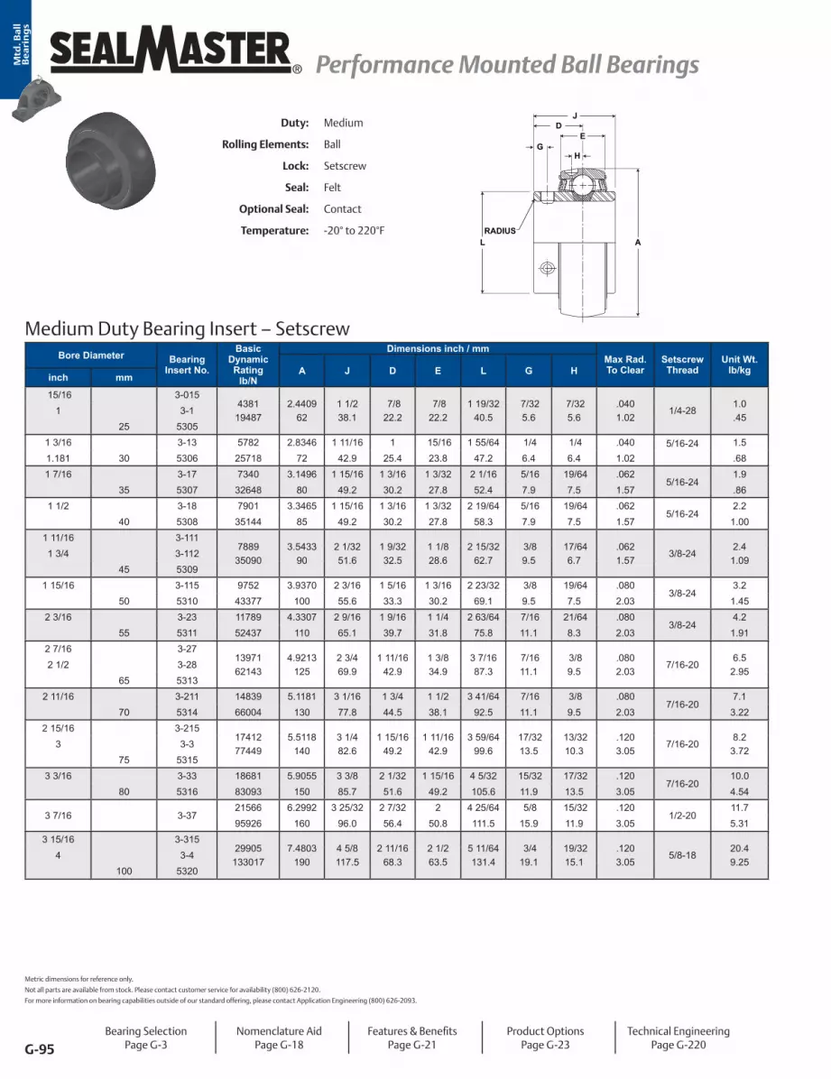
G-95
® Performance Mounted Ball Bearings Performance Mounted Ball BearingsMtd
. Ba
ll
Be
ari
ng
s
Medium Duty Bearing Insert – Setscrew
DJ
RADIUSL A
GH
EDuty: Medium
Rolling Elements: Ball
Lock: Setscrew
Seal: Felt
Optional Seal: Contact
Temperature: -20° to 220°F
Bore Diameter Bearing Insert No.
Basic Dynamic Rating
lb/N
Dimensions inch / mmMax Rad. To Clear
Setscrew Thread
Unit Wt. lb/kgA J D E L G H
inch mm
15/16 3-0154381
194872.4409
621 1/2 38.1
7/8 22.2
7/8 22.2
1 19/3240.5
7/325.6
7/325.6
.0401.02
1/4-281.0.45
1 3-125 5305
1 3/16 3-13 5782 2.8346 1 11/16 1 15/16 1 55/64 1/4 1/4 .040 5/16-24
1.51.181 30 5306 25718 72 42.9 25.4 23.8 47.2 6.4 6.4 1.02 .681 7/16 3-17 7340 3.1496 1 15/16 1 3/16 1 3/32 2 1/16 5/16 19/64 .062
5/16-241.9
35 5307 32648 80 49.2 30.2 27.8 52.4 7.9 7.5 1.57 .861 1/2 3-18 7901 3.3465 1 15/16 1 3/16 1 3/32 2 19/64 5/16 19/64 .062
5/16-242.2
40 5308 35144 85 49.2 30.2 27.8 58.3 7.9 7.5 1.57 1.001 11/16 3-111
788935090
3.543390
2 1/3251.6
1 9/3232.5
1 1/8 28.6
2 15/3262.7
3/8 9.5
17/646.7
.0621.57
3/8-242.4
1.091 3/4 3-112
45 53091 15/16 3-115 9752 3.9370 2 3/16 1 5/16 1 3/16 2 23/32 3/8 19/64 .080
3/8-243.2
50 5310 43377 100 55.6 33.3 30.2 69.1 9.5 7.5 2.03 1.452 3/16 3-23 11789 4.3307 2 9/16 1 9/16 1 1/4 2 63/64 7/16 21/64 .080
3/8-244.2
55 5311 52437 110 65.1 39.7 31.8 75.8 11.1 8.3 2.03 1.912 7/16 3-27
1397162143
4.9213125
2 3/4 69.9
1 11/1642.9
1 3/8 34.9
3 7/1687.3
7/1611.1
3/8 9.5
.0802.03
7/16-206.5
2.952 1/2 3-28
65 53132 11/16 3-211 14839 5.1181 3 1/16 1 3/4 1 1/2 3 41/64 7/16 3/8 .080
7/16-207.1
70 5314 66004 130 77.8 44.5 38.1 92.5 11.1 9.5 2.03 3.222 15/16 3-215
1741277449
5.5118140
3 1/4 82.6
1 15/1649.2
1 11/1642.9
3 59/6499.6
17/3213.5
13/3210.3
.1203.05
7/16-208.2
3.723 3-3
75 53153 3/16 3-33 18681 5.9055 3 3/8 2 1/32 1 15/16 4 5/32 15/32 17/32 .120
7/16-20 10.0
80 5316 83093 150 85.7 51.6 49.2 105.6 11.9 13.5 3.05 4.54
3 7/16 3-3721566 6.2992 3 25/32 2 7/32 2 4 25/64 5/8 15/32 .120
1/2-2011.7
95926 160 96.0 56.4 50.8 111.5 15.9 11.9 3.05 5.313 15/16 3-315
29905133017
7.4803190
4 5/8 117.5
2 11/1668.3
2 1/2 63.5
5 11/64131.4
3/4 19.1
19/3215.1
.1203.05
5/8-1820.49.25
4 3-4100 5320
Metric dimensions for reference only.
Not all parts are available from stock. Please contact customer service for availability (800) 626-2120.
For more information on bearing capabilities outside of our standard offering, please contact Application Engineering (800) 626-2093.
Bearing SelectionPage G-3
Nomenclature AidPage G-18
Features & BenefitsPage G-21
Product OptionsPage G-23
Technical EngineeringPage G-220

G-96
Performance Mounted Ball Bearings Performance Mounted Ball Bearings ®
Mtd
. Ba
ll
Be
ari
ng
s
Medium Duty Bearing Insert - SKWEZLOC Locking Collar
RADIUS
EH
DJ
AL M
G
Bore DiameterPart No.
Basic Dynamic Rating
lb/N
Dimensions inch / mmMax Rad. To Clear
Torx Cap Screw
Unit Wt. lb/kgA J D E G H L Minch mm
1 25.4 3-1T4381 2.4409 1 9/16 7/8 7/8 3/8 7/32 2 1/16 1 19/32 .040
T-251.2
19487 62 39.7 22.2 22.2 9.5 5.6 52.4 40.5 1.02 .54
1 3/16 30.2 3-13T5782 2.8346 1 3/4 1 15/16 7/16 1/4 2 7/16 1 55/64 .040
T-271.8
25718 72 44.5 25.4 23.8 11.1 6.4 61.9 47.2 1.02 .82
1 7/16 36.5 3-17T7340 3.1496 2 1 3/16 1 3/32 7/16 19/64 2 11/16 2 1/16 .062
T-272.2
32648 80 50.8 30.2 27.8 11.1 7.5 68.3 52.4 1.57 1.00
1 1/2 38.1 3-18T7901 3.3470 2 1 3/16 1 3/32 7/16 19/64 2 13/16 2 19/64 .062
T-272.5
35144 85 50.8 30.2 27.8 11.1 7.5 71.4 58.3 1.57 1.131 11/16 42.9 3-111T 7889 3.5433 2 3/32 1 9/32 1 1/8 9/16 17/64 3 1/4 2 15/32 0.062
T-303.0
1 3/4 44.5 3-112T 35090 90 53.2 32.5 28.6 14.3 6.7 82.6 62.7 1.57 1.36
1 15/16 49.2 3-115T9752 3.9370 2 1/4 1 5/16 1 3/16 9/16 19/64 3 1/2 2 23/32 .080
T-303.8
1.7243377 100 57.2 33.3 30.2 14.3 7.5 88.9 69.1 2.03
2 3/16 55.6 3-23T11789 4.3307 2 5/8 1 9/16 1 1/4 11/16 21/64 4 1/16 2 63/64 .080
T-454.9
52437 110 66.7 39.7 31.8 17.5 8.3 103.2 75.8 2.03 2.22
For Replacement Lock Collar see page G-98.
Duty: Medium
Rolling Elements: Ball
Lock: SKWEZLOC Locking Collar
Seal: Felt
Optional Seal: Contact
Temperature: -20° to 220°F
Bearing SelectionPage G-3
Nomenclature AidPage G-18
Features & BenefitsPage G-21
Product OptionsPage G-23
Technical EngineeringPage G-220

G-97
® Performance Mounted Ball Bearings Performance Mounted Ball BearingsMtd
. Ba
ll
Be
ari
ng
s
Medium Duty Bearing Insert – Double Setscrew
Duty: Medium
Rolling Elements: Ball
Lock: Double Setscrew
Seal: Felt
Optional Seal: Contact
Temperature: -20° to 220°F
DJ
RADIUSL A
GH
E
Bore Diameter Part No.
Basic Dynamic Rating
lb/N
Dimensions inch / mmMax Rad. To Clear
Setscrew Thread
Unit Wt. lb/kgA D E G H L Jinch
1 3-1D4381 2.4409 7/8 7/8 7/32 7/32 1 19/32 1 3/4 .040
1/4-281.0
19487 62 22.2 22.2 5.6 5.6 40.5 44.5 1.02 .45
1 3/16 3-13D 57822.8346 1 15/16 1/4 1/4 1 55/64 2 .040
5/16-241.5
72 25.4 23.8 6.4 6.4 47.2 50.8 1.02 .68
1 7/16 3-17D7340 3.1496 1 5/32 1 3/32 31/99 19/64 2 1/16 2 5/16 .062
5/16-242.0
32648 80 29.4 27.8 8.0 7.5 52.4 58.7 1.57 .91
1 1/2 3-18D 79013.3470 1 3/16 1 3/32 11/32 19/64 2 19/64 2 3/8 .062
5/16-242.5
85 30.2 27.8 8.7 7.5 58.3 60.3 1.57 1.131 11/16 3-111D 7889 3.5433 1 1/4 1 1/8 11/32 17/64 2 15/32 2 1/2 .062
3/8-242.7
1 3/4 3-112D 35090 90 31.8 28.6 8.7 6.7 62.7 63.5 1.57 1.22
1 15/16 3-115D 97523.9370 1 5/16 1 3/16 31/99 19/64 2 23/32 2 5/8 .080
3/8-243.5
100 33.3 30.2 8.0 7.5 69.1 66.7 2.03 1.592 7/16 3-27D 13971 4.9207 1 3/4 1 3/8 15/32 3/8 3 7/16 3 1/2 .080
7/16-207.1
2 1/2 3-28D 62143 125 44.5 34.9 11.9 9.5 87.3 88.9 2.03 3.22
2 11/16 3-211D 148395.1181 1 3/4 1 1/2 39/89 3/8 3 41/64 3 1/2 .080
1/2-207.3
130 44.5 38.1 11.1 9.5 92.5 88.9 2.03 3.312 15/16 3-215D 17412 5.5118 1 15/16 1 11/16 49/87 13/32 3 59/64 3 7/8 .120
1/2-209
3 3-3D 77449 140 49.2 42.9 14.3 10.3 99.6 98.4 3.05 4.08
3 3/16 3-33D 186815.9055 2 1/32 1 15/16 1/2 17/32 4 5/32 4 1/16 .120
1/2-2010.8
150 51.6 49.2 12.7 13.5 105.6 103.2 3.05 4.90
3 7/16 3-37D21566 6.2992 2 7/32 2 1/2 15/32 4 25/64 4 7/16 .120
1/2-2012.6
95926 160 56.4 50.8 12.7 11.9 111.5 112.7 3.05 5.723 15/16 3-315D 29905 7.4803 2 11/16 2 1/2 64/89 19/32 5 11/64 5 3/8 .120
5/8-1821.6
4 3-4D 133017 190 68.3 63.5 18.3 15.1 131.4 136.5 3.05 9.804 7/16 3-47D 37482 9.0551 2 7/8 2 5/8 5/8 5/8 6 11/32 5 3/4 .120
5/8-1840
4 15/16 3-415D 166720 230 73.0 66.7 15.9 15.9 161.1 146.1 3.05 18.14
Metric dimensions for reference only.
Not all parts are available from stock. Please contact customer service for availability (800) 626-2120.
For more information on bearing capabilities outside of our standard offering, please contact Application Engineering (800) 626-2093.
Bearing SelectionPage G-3
Nomenclature AidPage G-18
Features & BenefitsPage G-21
Product OptionsPage G-23
Technical EngineeringPage G-220

G-98
Performance Mounted Ball Bearings Performance Mounted Ball Bearings ®
Mtd
. Ba
ll
Be
ari
ng
s
Locking Collar Replacement TableSKWEZLOC Locking Collar Table
Bore Diameter Standard Duty ER MHCollar
Medium Dutyinch mm Insert Insert Insert Insert Collar3/4 2-012T ER-12T
2-012B Lock Collar20 5204TM ER-204TMC
15/16 2-015T 2-015 Lock Collar
2-13A Lock Collar1 2-1T ER-16T MH-16T 3-1T
25 5205TM ER-205TMC1 1/8 2-12T ER-18T
2-13B Lock Collar
1 3/16 2-13T ER-19T MH-19T 3-13T 2-17A Lock Collar1 1/4* 1-14T ER-20RT MH-20RT
30 5206TM ER-206TMC1 1/4 2-14T ER-20T MH20T 2-17A Lock Collar 2-14T 2-17A Lock Collar1 3/8 2-16T ER-22T
2-17B Lock Collar
2-19A Lock Collar1 7/16 2-17T ER-23T MH-23T 3-17T35 5207TM ER-207TMC
1 1/2 2-18T ER-24T MH-24T2-19A Lock Collar
3-18T2-111A Lock Collar1 9/16 2-19T
40 5208TM ER-208TMC1 5/8 2-110T ER-26T 2-111A Lock Collar
1 11/16 2-111T ER-27T MH-27T2-111B Lock Collar
3-111T2-115A Lock Collar1 3/4 2-112T ER-28T 3-112T
45 5209TM ER-209TMC1 15/16 2-115T ER-31T MH-31T
2-115B Lock Collar3-115T
2-23A Lock Collar2* 1-2T50 5210TM ER-210TMC
2 2-2T ER-32T MH-32T 2-23A Lock Collar 2-2T 2-23A Lock Collar2 1/8
2-22T
2-23B Lock Collar
2-27A Lock Collar 2 3/16 2-23T ER-35T MH-35T 3-23T55 5211TM ER-211TMC
2 1/4 2-24T ER-36T 2-27A Lock Collar 2 3/8 2-26T ER-38T
2-27B Lock Collar2 7/16 2-27T ER-39T MH-39T60 5212TM ER-512TMC
*Reduced Housing

G-99
® Performance Cylindrical OD Bearings (ER) Performance Cylindrical OD Bearings (ER)Mtd
. Ba
ll
Be
ari
ng
s
Sealmaster ER Style Ball BearingsSealmaster Gold ER bearings feature a cylindrical OD and snap ring for easy installation in a roll assembly. Shaft lock is achieved by either setscrew or Skwezloc® concentric locking collar. The felt seal with flinger provide a good balance between contaminant entry, GoldPlex HP™ grease loss and friction. Depending on your preference, these bearings are available in both inch and metric shaft sizes with a wide variety of sealing and lubrication options or ERX-TREME industry specific solutions as illustrated on the pages to follow.
Felt Seal & Flinger
Grade 10 Steel Balls
Land Riding Brass Retainer
Snap Ring
Black Oxided Outer Ring
Lubrication Groove
Felt Seal & Flinger
Diamond Faceted Setscrews 120°
Position
Zone Hardened Black Oxided
Inner Ring

G-100
Performance Cylindrical OD Bearings (ER) Performance Cylindrical OD Bearings (ER) ®
Mtd
. Ba
llB
ea
rin
gs
ER Style NomenclatureER - Cylindrical O.D. Bearing With Snap RingX - ERX-TREME OptionBore Size Inch - ##/16 (ex. 20/16 = 1 1/4”) R for 1 1/4” and 2” Reduced Only Metric - Standard Duty - 2##, ## x 5 mm
(ex. 05 = 25 mm)Standard Option T - Skwezloc® Locking Collar M - Metric Hardware (Metric - SKWEZ™) C - Contact SealCommon Option* (see table below)
ER X 16 T XLO
Common Option3C Triple Lip Contact Seal - replaced by DRT in most sizesDRT High ContaminationHI ERX-Treme High Temperature Krytox* GreaseHIY ERX-Treme High Temperature Krytox* Grease ExpansionLO ERX-Treme Low DragX Labyrinth SealXLO ERX-Treme Extra Low Drag
*Note: Confi gurations are not available in all sizes or housing styles. Consult the product tables, option sections and engineering sections for more detail or consult a Bearing Application Engineer.**KRYTOX is a registered trademark of E.I. du Pont de Nemurs and Company. This trade name, trademark and/or registered trademark is property of their respective owner and is not owned or controlled by Regal Power Transmission Solutions.
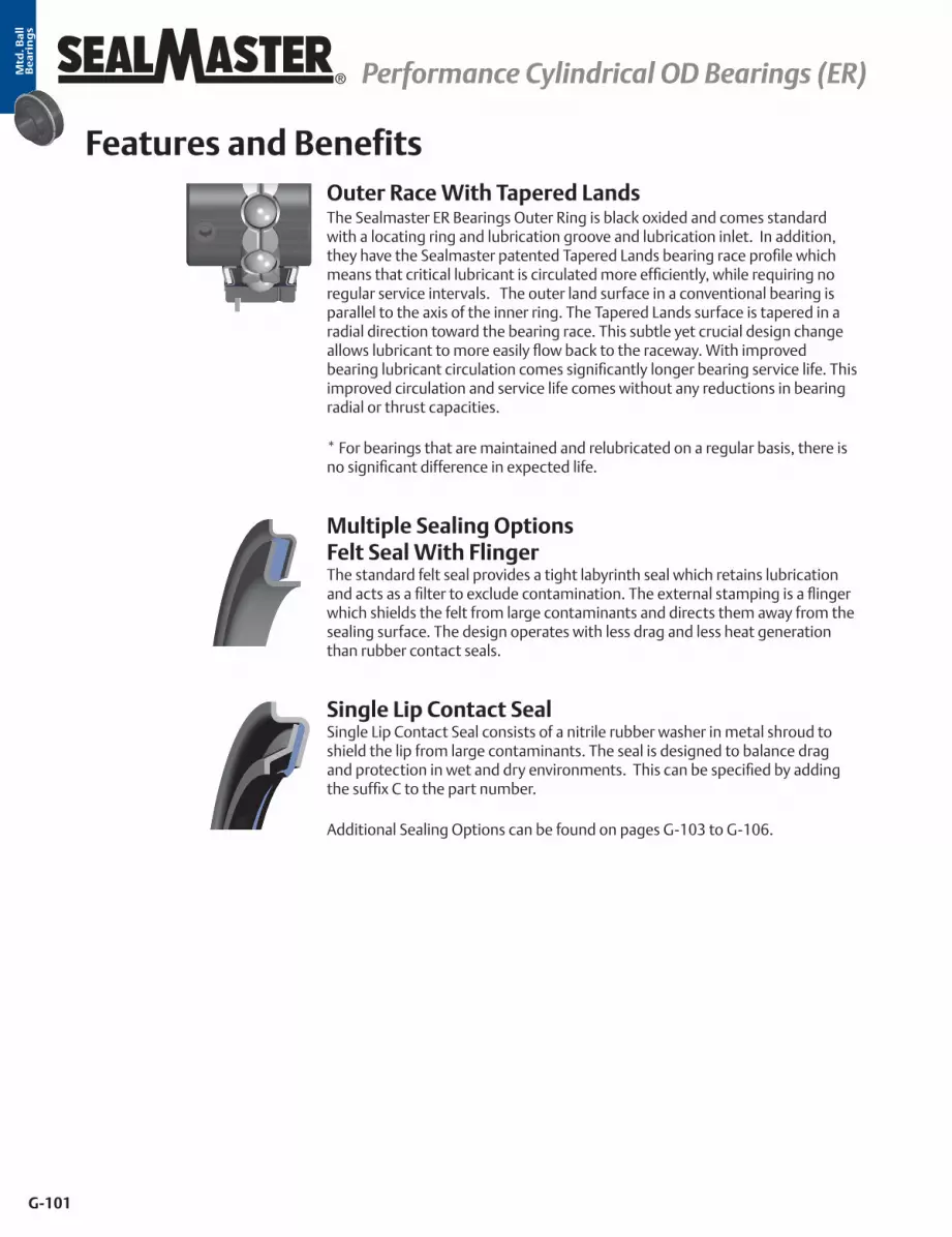
G-101
® Performance Cylindrical OD Bearings (ER) Performance Cylindrical OD Bearings (ER)Mtd
. Ba
ll
Be
ari
ng
s
Outer Race With Tapered LandsThe Sealmaster ER Bearings Outer Ring is black oxided and comes standard with a locating ring and lubrication groove and lubrication inlet. In addition, they have the Sealmaster patented Tapered Lands bearing race profile which means that critical lubricant is circulated more efficiently, while requiring no regular service intervals. The outer land surface in a conventional bearing is parallel to the axis of the inner ring. The Tapered Lands surface is tapered in a radial direction toward the bearing race. This subtle yet crucial design change allows lubricant to more easily flow back to the raceway. With improved bearing lubricant circulation comes significantly longer bearing service life. This improved circulation and service life comes without any reductions in bearing radial or thrust capacities. * For bearings that are maintained and relubricated on a regular basis, there is no significant difference in expected life.
Features and Benefits
Single Lip Contact SealSingle Lip Contact Seal consists of a nitrile rubber washer in metal shroud to shield the lip from large contaminants. The seal is designed to balance drag and protection in wet and dry environments. This can be specified by adding the suffix C to the part number. Additional Sealing Options can be found on pages G-103 to G-106.
Multiple Sealing Options Felt Seal With FlingerThe standard felt seal provides a tight labyrinth seal which retains lubrication and acts as a filter to exclude contamination. The external stamping is a flinger which shields the felt from large contaminants and directs them away from the sealing surface. The design operates with less drag and less heat generation than rubber contact seals.

G-102
Performance Cylindrical OD Bearings (ER) Performance Cylindrical OD Bearings (ER) ®
Mtd
. Ba
ll
Be
ari
ng
s
Sealmaster Skwezloc® Concentric Locking CollarSKWEZLOC is a concentric locking collar clamp design that results in near-perfect concentricity of the shaft to the bearing bore and maintains near perfect ball path roundness, while reducing fretting corrosion. This design eliminates the shaft damage of setscrew locking, and minimizes bearing induced vibration for smoother quieter operation. The collar has a TORX head cap screw that outlasts stripping 12 times longer than hex head cap screws.
Multiple Locking Methods Setscrew Locking120° spaced, balanced three point contact minimizes inner ring distortion vibration, reduces noise, and improves reliability. Precision manufactured diamond faceted setscrews contribute to improved clamping and resistance to back out.
Zone Hardened Inner RaceSealmaster incorporates a unique heat treat process that hardens the inner race only where it is needed…under the ball path. The black oxided zone hardened inner race results in improved lock reliability as a result of less distortion at the setscrew location and improved thread conformity resulting in improved clamping and resistance to setscrew back-out.
Land Riding RetainerThe Sealmaster unique land riding metal retainer design provides superior pocket clearance allows for 360° oil circulation around the rolling elements resulting in better retained and utilized lubrication.
Features and Benefits continued

G-103
® Performance Cylindrical OD Bearings (ER) Performance Cylindrical OD Bearings (ER)Mtd
. Ba
ll
Be
ari
ng
s
ERX-TREME Options Low Drag
ERX-TREME X-Tra Low Drag “XLO” • Felt seal cut down and oil soaked for extra low drag • Oil lubricated
ERX-TREME Low Drag “LO” • Felt seal cut down to reduce drag • Provides excellent barrier that works to retain grease and acts as a filter to
reduce the ingress of debris contaminants • Features a channeling grease that reduces drag while lubricating the
bearing
Suffix Description Temperature Environment Speed Limits LO Low Drag -20°F to 180°F
Dry/Dusty Pages G-235 to G-240 XLO Extra Low Drag -20°F to 100°F
OptionsBearings are typically selected using L10 fatigue life calculations based on ideal operating conditions. However, most bearing problems are not fatigue related, but occur due to contamination, lubrication starvation, or other environmental issues. As a result our Bearing engineers have developed custom solutions to meet the varying severity, operating parameters and maintenance regularity, such as ERX-TREME and Custom Select.
Bearing Rotational Torque - Comparison Chart
Company Suffix Option Seal Type Lubrication
LO Drag Bearing Options
AMI® FS Non-Contact OilSealmaster XLO Low Drag Felt Oil
MB® HFF Steel Labyrinth OilPeer® ZSFF Steel Labyrinth Oil
Sealmaster LO Low Drag Felt GreaseMB MHFF Steel Labyrinth Grease
FYH® DSK3 Non-Contact OilPeer ZMKFF Steel Labyrinth Grease
Standard Bearing Drag (Reference)
Sealmaster - Felt Grease
Sealmaster C Contact Grease
0.0 2.0 4.0 6.0 8.0 10.0 12.0 14.0
Sealmaster - ContactSealmaster - Felt
Peer - ZMKFFFYH - DSK3MB - MHFF
Sealmaster - LOPeer- ZSFF
MB - HFFSealmaster - XLO
in-ozs Based on 1”
AMI - FS
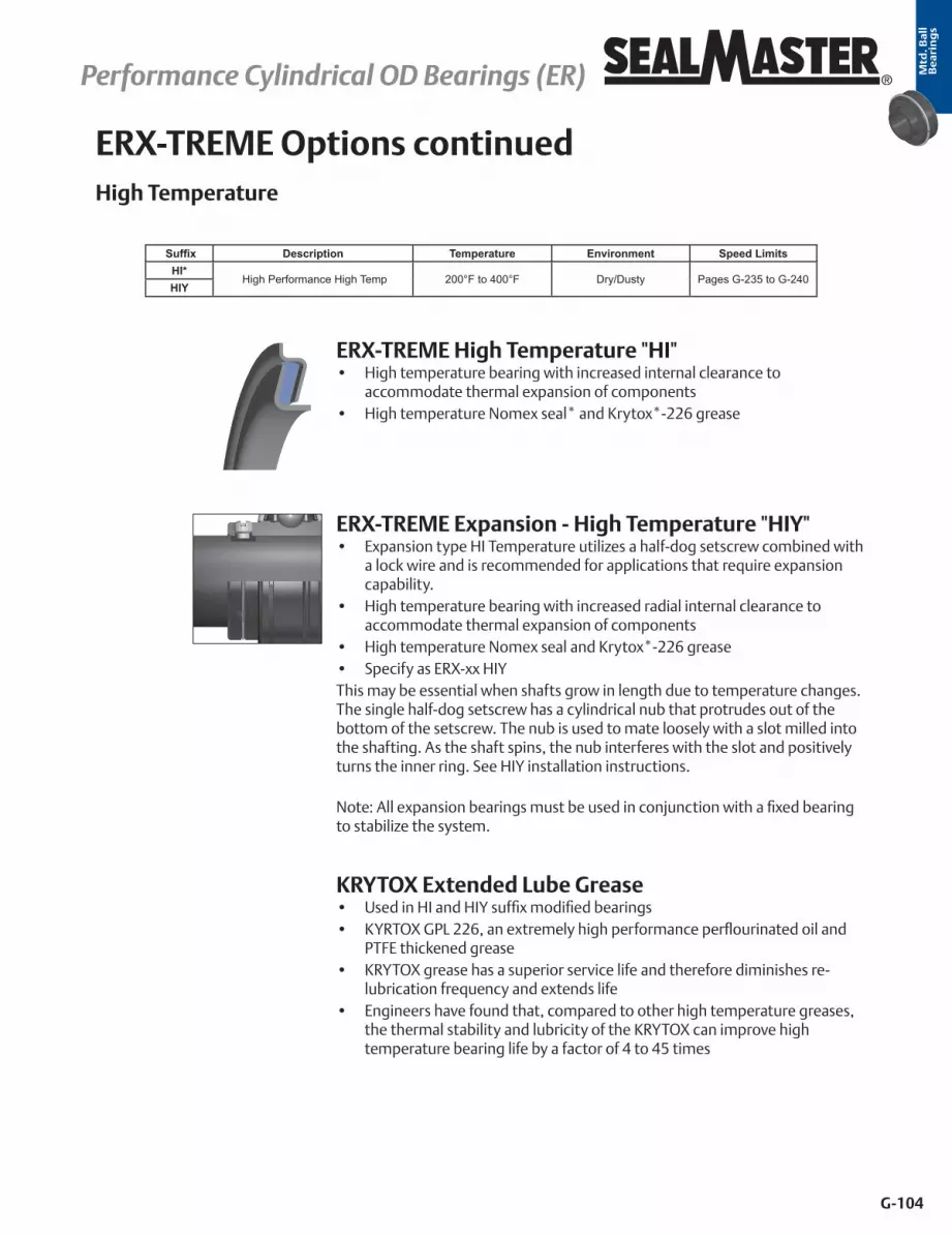
G-104
Performance Cylindrical OD Bearings (ER) Performance Cylindrical OD Bearings (ER) ®
Mtd
. Ba
ll
Be
ari
ng
s
ERX-TREME Options continuedHigh Temperature
ERX-TREME Expansion - High Temperature "HIY" • Expansion type HI Temperature utilizes a half-dog setscrew combined with
a lock wire and is recommended for applications that require expansion capability.
• High temperature bearing with increased radial internal clearance to accommodate thermal expansion of components
• High temperature Nomex seal and Krytox*-226 grease • Specify as ERX-xx HIYThis may be essential when shafts grow in length due to temperature changes. The single half-dog setscrew has a cylindrical nub that protrudes out of the bottom of the setscrew. The nub is used to mate loosely with a slot milled into the shafting. As the shaft spins, the nub interferes with the slot and positively turns the inner ring. See HIY installation instructions. Note: All expansion bearings must be used in conjunction with a fixed bearing to stabilize the system.
Suffix Description Temperature Environment Speed LimitsHI*
High Performance High Temp 200°F to 400°F Dry/Dusty Pages G-235 to G-240HIY
ERX-TREME High Temperature "HI" • High temperature bearing with increased internal clearance to
accommodate thermal expansion of components • High temperature Nomex seal* and Krytox*-226 grease
KRYTOX Extended Lube Grease• Used in HI and HIY suffix modified bearings• KYRTOX GPL 226, an extremely high performance perflourinated oil and
PTFE thickened grease• KRYTOX grease has a superior service life and therefore diminishes re-
lubrication frequency and extends life• Engineers have found that, compared to other high temperature greases,
the thermal stability and lubricity of the KRYTOX can improve high temperature bearing life by a factor of 4 to 45 times

G-105
® Performance Cylindrical OD Bearings (ER) Performance Cylindrical OD Bearings (ER)Mtd
. Ba
ll
Be
ari
ng
s
Custom Select
High Contamination
Suffix Description Temperature Environment Speed Limits DRT Highly Contaminated -20°F to 200°F Highly Contaminated Pages G-235 to G-240
High Contamination “DRT” Heavy Duty Multi-Lip contact seal (depending on size and series, either sup-plied with “2C” double lip or “3C” triple lip seal), 100% Grease Fill with Sealmas-ter GoldPlex HP Grease.
2C Seal 3C Seal
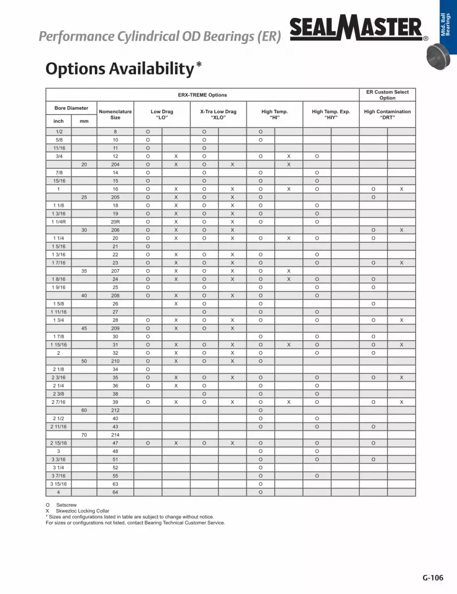
G-106
Performance Cylindrical OD Bearings (ER) Performance Cylindrical OD Bearings (ER) ®
Mtd
. Ba
ll
Be
ari
ng
s
Options Availability*ERX-TREME Options ER Custom Select
Option
Bore DiameterNomenclature
SizeLow Drag
“LO”X-Tra Low Drag
“XLO”High Temp.
“HI”High Temp. Exp.
“HIY”High Contamination
“DRT”inch mm
1/2 8 O O O 5/8 10 O O O
11/16 11 O O 3/4 12 O X O O X O
20 204 O X O X X 7/8 14 O O O O
15/16 15 O O O O1 16 O X O X O X O O X
25 205 O X O X O O1 1/8 18 O X O X O O
1 3/16 19 O X O X O O1 1/4R 20R O X O X O O
30 206 O X O X O X1 1/4 20 O X O X O X O O
1 5/16 21 O1 3/16 22 O X O X O O1 7/16 23 O X O X O O O X
35 207 O X O X O X1 8/16 24 O X O X O X O O1 9/16 25 O O O O O
40 208 O X O X O O1 5/8 26 X O O O
1 11/16 27 O O O1 3/4 28 O X O X O O O X
45 209 O X O X1 7/8 30 O O O O
1 15/16 31 O X O X O X O O X2 32 O X O X O O O
50 210 O X O X O2 1/8 34 O
2 3/16 35 O X O X O O O X2 1/4 36 O X O O O2 3/8 38 O O O
2 7/16 39 O X O X O X O O X60 212 O
2 1/2 40 O O2 11/16 43 O O O
70 2142 15/16 47 O X O X O O O
3 48 O O3 3/16 51 O O O3 1/4 52 O
3 7/16 55 O O3 15/16 63 O
4 64 O
O SetscrewX Skwezloc Locking Collar* Sizes and configurations listed in table are subject to change without notice.For sizes or configurations not listed, contact Bearing Technical Customer Service.
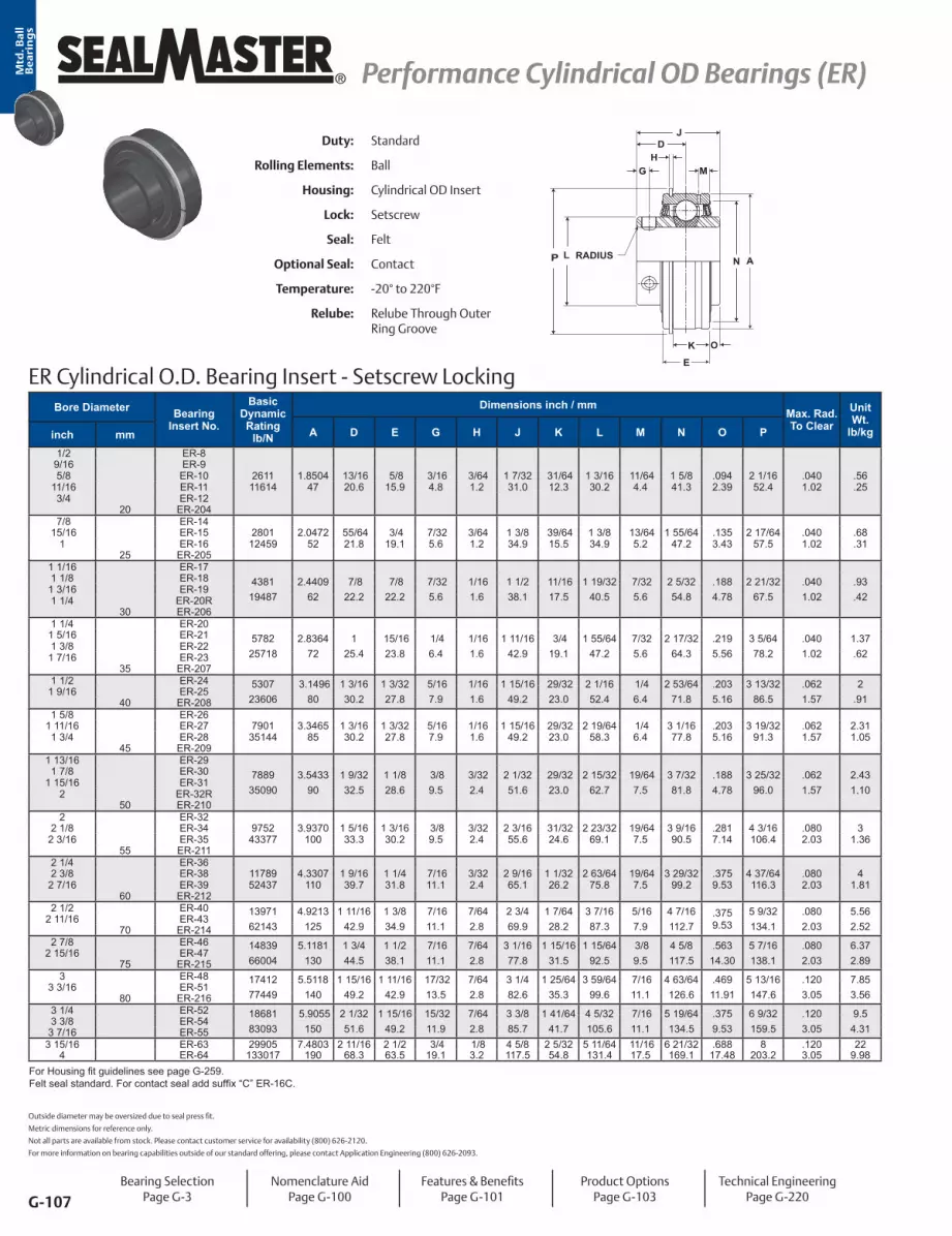
G-107
® Performance Cylindrical OD Bearings (ER) Performance Cylindrical OD Bearings (ER)Mtd
. Ba
ll
Be
ari
ng
s
Bore Diameter Bearing Insert No.
Basic Dynamic Rating
lb/N
Dimensions inch / mmMax. Rad. To Clear
Unit Wt.
lb/kgA D E G H J K L M N O Pinch mm 1/2 ER-8
9/16 ER-9 5/8 ER-10 2611 1.8504 13/16 5/8 3/16 3/64 1 7/32 31/64 1 3/16 11/64 1 5/8 .094 2 1/16 .040 .56
11/16 ER-11 11614 47 20.6 15.9 4.8 1.2 31.0 12.3 30.2 4.4 41.3 2.39 52.4 1.02 .25 3/4 ER-12
20 ER-204 7/8 ER-14
15/16 ER-15 2801 2.0472 55/64 3/4 7/32 3/64 1 3/8 39/64 1 3/8 13/64 1 55/64 .135 2 17/64 .040 .681 ER-16 12459 52 21.8 19.1 5.6 1.2 34.9 15.5 34.9 5.2 47.2 3.43 57.5 1.02 .31
25 ER-2051 1/16 ER-17
438119487
2.440962
7/8 22.2
7/8 22.2
7/325.6
1/161.6
1 1/2 38.1
11/1617.5
1 19/3240.5
7/325.6
2 5/3254.8
.1884.78
2 21/3267.5
.0401.02
.93
.42
1 1/8 ER-181 3/16 ER-191 1/4 ER-20R
30 ER-2061 1/4 ER-20
578225718
2.836472
1 25.4
15/1623.8
1/4 6.4
1/161.6
1 11/1642.9
3/4 19.1
1 55/6447.2
7/325.6
2 17/3264.3
.2195.56
3 5/6478.2
.0401.02
1.37.62
1 5/16 ER-211 3/8 ER-22
1 7/16 ER-2335 ER-207
1 1/2 ER-24 530723606
3.149680
1 3/1630.2
1 3/3227.8
5/167.9
1/161.6
1 15/1649.2
29/3223.0
2 1/1652.4
1/4 6.4
2 53/6471.8
.2035.16
3 13/3286.5
.0621.57
2.91
1 9/16 ER-2540 ER-208
1 5/8 ER-261 11/16 ER-27 7901 3.3465 1 3/16 1 3/32 5/16 1/16 1 15/16 29/32 2 19/64 1/4 3 1/16 .203 3 19/32 .062 2.311 3/4 ER-28 35144 85 30.2 27.8 7.9 1.6 49.2 23.0 58.3 6.4 77.8 5.16 91.3 1.57 1.05
45 ER-2091 13/16 ER-29
788935090
3.543390
1 9/3232.5
1 1/8 28.6
3/8 9.5
3/322.4
2 1/3251.6
29/3223.0
2 15/3262.7
19/647.5
3 7/3281.8
.1884.78
3 25/3296.0
.0621.57
2.431.10
1 7/8 ER-301 15/16 ER-31
2 ER-32R50 ER-210
2 ER-322 1/8 ER-34 9752 3.9370 1 5/16 1 3/16 3/8 3/32 2 3/16 31/32 2 23/32 19/64 3 9/16 .281 4 3/16 .080 3
2 3/16 ER-35 43377 100 33.3 30.2 9.5 2.4 55.6 24.6 69.1 7.5 90.5 7.14 106.4 2.03 1.3655 ER-211
2 1/4 ER-362 3/8 ER-38 11789 4.3307 1 9/16 1 1/4 7/16 3/32 2 9/16 1 1/32 2 63/64 19/64 3 29/32 .375 4 37/64 .080 4
2 7/16 ER-39 52437 110 39.7 31.8 11.1 2.4 65.1 26.2 75.8 7.5 99.2 9.53 116.3 2.03 1.8160 ER-212
2 1/2 ER-40 1397162143
4.9213125
1 11/1642.9
1 3/8 34.9
7/1611.1
7/642.8
2 3/4 69.9
1 7/6428.2
3 7/1687.3
5/167.9
4 7/16112.7
.375 9.53
5 9/32134.1
.0802.03
5.562.52
2 11/16 ER-4370 ER-214
2 7/8 ER-46 1483966004
5.1181130
1 3/4 44.5
1 1/2 38.1
7/1611.1
7/642.8
3 1/1677.8
1 15/16 31.5
1 15/6492.5
3/8 9.5
4 5/8 117.5
.56314.30
5 7/16138.1
.0802.03
6.372.89
2 15/16 ER-4775 ER-215
3 ER-48 1741277449
5.5118140
1 15/1649.2
1 11/1642.9
17/3213.5
7/642.8
3 1/4 82.6
1 25/6435.3
3 59/6499.6
7/1611.1
4 63/64126.6
.46911.91
5 13/16147.6
.1203.05
7.853.56
3 3/16 ER-5180 ER-216
3 1/4 ER-52 1868183093
5.9055150
2 1/3251.6
1 15/1649.2
15/3211.9
7/642.8
3 3/8 85.7
1 41/6441.7
4 5/32105.6
7/1611.1
5 19/64134.5
.375 9.53
6 9/32159.5
.1203.05
9.54.31
3 3/8 ER-543 7/16 ER-55
3 15/16 ER-63 29905 7.4803 2 11/16 2 1/2 3/4 1/8 4 5/8 2 5/32 5 11/64 11/16 6 21/32 .688 8 .120 224 ER-64 133017 190 68.3 63.5 19.1 3.2 117.5 54.8 131.4 17.5 169.1 17.48 203.2 3.05 9.98
For Housing fit guidelines see page G-259. Felt seal standard. For contact seal add suffix “C” ER-16C.
ER Cylindrical O.D. Bearing Insert - Setscrew Locking
N
E
P
J
HM
D
G
K
L ARADIUS
O
Duty: Standard
Rolling Elements: Ball
Housing: Cylindrical OD Insert
Lock: Setscrew
Seal: Felt
Optional Seal: Contact
Temperature: -20° to 220°F
Relube: Relube Through Outer Ring Groove
Bearing SelectionPage G-3
Nomenclature AidPage G-100
Features & BenefitsPage G-101
Product OptionsPage G-103
Technical EngineeringPage G-220
Outside diameter may be oversized due to seal press fit.
Metric dimensions for reference only.
Not all parts are available from stock. Please contact customer service for availability (800) 626-2120.
For more information on bearing capabilities outside of our standard offering, please contact Application Engineering (800) 626-2093.

G-108
Performance Cylindrical OD Bearings (ER) Performance Cylindrical OD Bearings (ER) ®
Mtd
. Ba
ll
Be
ari
ng
s
Duty: Standard
Rolling Elements: Ball
Housing: Cylindrical OD Insert
Lock: SKWEZLOC Locking Collar
Seal: Felt
Optional Seal: Contact
Temperature: -20° to 220°F
Relube: Relube Through Outer Ring Groove
ER-T Cylindrical O.D. Bearing - SKWEZLOC Locking Collar - Inch
ER-T Cylindrical O.D. Bearing - SKWEZLOC Locking Collar - Metric - SKWEZTM
RADIUSLP A
K
N
THD
J
OE
M
Bearing SelectionPage G-3
Nomenclature AidPage G-100
Features & BenefitsPage G-101
Product OptionsPage G-103
Technical EngineeringPage G-220
Bore Diameter Bearing
Insert No.
Basic Dynamic Rating
lb/N
Dimensions inch / mmMax. Rad. To Clear
Unit Wt. lb/kgA D E H J K L M N O P Tinch
3/4 ER-12T 2611 1.8504 7/8 5/8 3/64 1 9/32 31/64 1 3/4 1 3/16 1 5/8 .094 2 1/16 1/8 .04 .5611614 47.0 19.8 15.9 1.2 32.5 12.3 44.5 30.2 41.3 2.39 52.4 3.2 1.02 .25
1 ER-16T 2801 2.0472 59/64 3/4 3/64 1 7/16 39/64 1 15/16 1 3/8 1 27/32 .135 2 17/64 13/64 .04 .6812459 52.0 22.1 19.1 1.2 36.5 15.5 49.2 34.9 46.8 3.43 57.5 5.2 1.02 .31
1 1/8 ER-18T 438119487
2.440962.0
15/1623.8
7/8 22.2
1/161.6
1 9/1639.7
11/1617.5
2 3/1655.6
1 19/3240.5
2 5/3254.8
.1884.78
2 21/3267.5
7/325.6
.041.02
.93
.421 3/16 ER-19T1 1/4 ER-20RT
1 1/4 ER-20T 5782 2.8346 1 1/16 15/16 1/16 1 3/4 3/4 2 7/16 1 55/64 2 17/32 .219 3 5/64 7/32 .04 1.3725718 72.0 27.0 23.8 1.6 44.5 19.1 61.9 47.2 64.3 5.56 78.2 5.6 1.02 .62
1 3/8 ER-22T 5782 2.8346 1 1/16 15/16 1/16 1 3/4 3/4 2 9/16 1 55/64 2 17/32 .219 3 5/64 7/32 .04 1.371 7/16 ER-23T 25718 72.0 27.0 23.8 1.6 44.5 19.1 65.1 47.2 64.3 5.56 78.2 5.6 1.02 .62
1 1/2 ER-24T 7340 3.1496 1 1/4 1 3/32 1/16 2 29/32 2 11/16 2 1/16 2 53/64 .203 3 13/32 1/4 .06 2.0032648 80.0 31.8 27.8 1.6 50.8 23.0 68.3 52.4 71.8 5.16 86.5 6.4 1.57 .91
1 5/8 ER-26T 7901 3.3465 1 1/4 1 3/32 1/16 2 29/32 2 13/16 2 19/64 3 1/32 .203 3 19/32 1/4 .06 2.3135144 85.0 31.8 27.8 1.6 50.8 23.0 71.4 58.3 77.0 5.16 91.3 6.4 1.57 1.05
1 11/16 ER-27T 7901 3.3465 1 1/4 1 3/32 1/16 2 29/32 2 15/16 2 19/64 3 1/32 .203 3 19/32 1/4 .06 2.311 3/4 ER-28T 35144 85.0 31.8 27.8 1.6 50.8 23.0 74.6 58.3 77.0 5.16 91.3 6.4 1.57 1.05
1 15/16 ER-31T 7889 3.5433 1 11/32 1 1/8 3/32 2 3/32 29/32 3 3/8 2 15/32 3 7/32 .188 3 25/32 19/64 .06 2.4335090 90.0 34.1 28.6 2.4 53.2 23.0 85.7 62.7 81.8 4.78 96.0 7.5 1.57 1.10
2 ER-32T 9752 3.9370 1 3/8 1 3/16 3/32 2 1/4 31/32 3 1/2 2 23/32 3 9/16 .281 4 3/16 19/64 .08 3.0043377 100.0 34.9 30.2 2.4 57.2 24.6 88.9 69.1 90.5 7.14 106.4 7.5 2.03 1.36
2 3/16 ER-35T 9752 3.9370 1 3/8 1 3/16 3/32 2 1/4 31/32 3 5/8 2 23/32 3 9/16 .281 4 3/16 19/64 .08 3.0043377 100.0 34.9 30.2 2.4 57.2 24.6 92.1 69.1 90.5 7.14 106.4 7.5 2.03 1.36
2 1/4 ER-36T 11789 4.3307 1 5/8 1 1/4 3/32 2 5/8 1 1/32 4 1/16 2 63/64 3 29/32 .375 4 37/64 19/64 .08 4.0052437 110.0 41.3 31.8 2.4 66.7 26.2 103.2 75.8 99.2 9.53 116.3 7.5 2.03 1.81
2 3/8 ER-38T 11789 4.3307 1 5/8 1 1/4 3/32 2 5/8 1 1/32 4 1/8 2 63/64 3 29/32 .375 4 37/64 19/64 .08 4.002 7/16 ER-39T 52437 110.0 41.3 31.8 2.4 66.7 26.2 104.8 75.8 99.2 9.53 116.3 7.5 2.03 1.81
Bore Diameter Bearing
Insert No.
Basic Dynamic Rating
N/lb
Dimensions mm / inchMax. Rad. To Clear
Unit Wt. kg/lbA D E L H J K M N O P Tmm
20 ER-204TMC 11614 47.0 19.8 15.9 44.5 1.2 32.5 12.3 30.2 41.3 2.39 52.4 3.2 1.02 .252611 1.8504 7/8 5/8 1 3/4 3/64 1 9/32 31/64 1 3/16 1 5/8 .094 2 1/16 1/8 .04 .56
25 ER-205TMC 12459 52.0 22.1 19.1 49.2 1.2 36.5 15.5 34.9 46.8 3.43 57.5 5.2 1.02 .312801 2.0472 59/64 3/4 1 15/16 3/64 1 7/16 39/64 1 3/8 1 27/32 .135 2 17/64 13/64 .04 .68
30 ER-206TMC 19487 62.0 23.8 22.2 55.6 1.6 39.7 17.5 40.5 54.8 4.75 67.5 5.6 1.02 .424381 2.4409 15/16 7/8 2 3/16 1/16 1 9/16 11/16 1 19/32 2 5/32 .187 2 21/32 7/32 .04 .93
35 ER-207TMC 25718 72.0 27.0 23.8 65.1 1.6 44.5 19.1 47.2 64.3 5.56 78.2 5.6 1.02 .625782 2.8346 1 1/16 15/16 2 9/16 1/16 1 3/4 3/4 1 55/64 2 17/32 .219 3 5/64 7/32 .04 1.37
40 ER-208TMC 32648 80.0 31.8 27.8 68.3 1.6 50.8 23.0 52.4 71.8 4.76 86.5 6.4 1.57 .917340 3.1496 1 1/4 1 3/32 2 11/16 1/16 2 29/32 2 1/16 2 53/64 .188 3 13/32 1/4 .06 2.00
45 ER-209TMC 35144 85.0 31.8 27.8 74.6 1.6 50.8 23.0 58.3 77.0 4.76 91.3 6.4 1.57 1.057901 3.3465 1 1/4 1 3/32 2 15/16 1/16 2 29/32 2 19/64 3 1/32 .188 3 19/32 1/4 .06 2.31
50 ER-210TMC 35090 90.0 34.1 28.6 85.7 2.4 53.2 23.0 62.7 81.8 4.78 96.0 7.5 1.57 1.107889 3.5433 1 11/32 1 1/8 3 3/8 3/32 2 3/32 29/32 2 15/32 3 7/32 .188 3 25/32 19/64 .06 2.43
55 ER-211TMC 43377 100.0 34.9 30.2 92.1 2.4 57.2 24.6 69.1 90.5 7.14 106.4 7.5 2.03 1.369752 3.9370 1 3/8 1 3/16 3 5/8 3/32 2 1/4 31/32 2 23/32 3 9/16 .281 4 3/16 19/64 .08 3.00
60 ER-212TMC 52437 110.0 41.3 31.8 104.8 2.4 66.7 26.2 75.8 99.2 9.53 116.3 7.5 2.03 1.8111789 4.3307 1 5/8 1 1/4 4 1/8 3/32 2 5/8 1 1/32 2 63/64 3 29/32 .375 4 37/64 19/64 .08 4.00
For Housing fit guidelines see page G-259. For Replacement Lock Collar see page G-98.

Mtd
. Ba
llB
ea
rin
gs
G-109
® Material Handling Bearings Material Handling Bearings
Sealmaster Material Handling Mounted Ball BearingsSealmaster material handling mounted ball bearings feature cast iron housings, an extended inner race insert bearing with ball riding nylon retainer. The insert features a rivet to prevent outer ring rotation and is available with setscrew or SKWEZLOC® concentric locking collar and optional snap on end cover. The contact seal, with black oxide treated fl inger provides a good balance between contaminant resistance, grease loss and friction. Depending on your preference, these bearings are available in common unit material handling industry bore sizes and housing confi gurations as illustrated on the pages to follow.
Nylon Retainer
Grade 10 Balls
Contact Seal and Flinger
Wide Zone Hardened Inner Ring
Anti-Rotation Rivet
Solid Cast Iron Base
Plug*optional grease
fi tting in box
Contact Seal & Flinger
Riveted Nameplate
Optional End Caporder separately
Diamond Fauceted Setscrews
120° Position

Mtd
. Ba
llB
ea
rin
gs
G-110
Material Handling Bearings Material Handling Bearings ®
Material Handling Mounted Ball Nomenclature
G-110
Housing - Housing Style NP - Pillow Block - High Base TB - Tapped Base Pillow Block SF - Four Bolt Flange SFT - Two Bolt Flange FB - Flange Bracket ST - Wide Slot Take UpMaterial Handling BearingBore Size* Inch - ##/16 (ex. 20/16 = 1 1/4”) R for 1 1/4” and 2” Reduced OnlyLocking Option* T - Skwezloc® Locking CollarCommon Option* CSK - 90° Lube Fitting
Material HandlingBore Size* Inch - ##/16 (ex. 20/16 = 1 1/4”) R for 1 1/4” and 2” Reduced OnlyStandard Option* Setscrew T - Skwezloc® Locking Collar
NP MH-16 T CSK
MH-16 T
Housing Units
Inserts
*Note: Confi gurations are not available in all sizes or housing styles. Consult the product tables and engineering sections for more detail or consult a Bearing Application Engineer.

Mtd
. Ba
llB
ea
rin
gs
G-111
® Material Handling Bearings Material Handling Bearings
Setscrew Locking120° spaced, balanced three point contact minimizes inner ring distortion vibration, reduces noise, and improves reliability. Precision manufactured diamond faceted setscrews contributes to improved clamping and resistance to back out.
Skwezloc® Concentric Locking CollarSKWEZLOC is a concentric locking collar clamp design that results in near-perfect concentricity of the shaft to the bearing bore and maintains near perfect ball path roundness, while reducing fretting corrosion. This design eliminates the shaft damage of setscrew locking, and minimizes bearing induced vibration for smoother quieter operation. The collar has a TORX head cap screw that outlasts stripping 12 times longer than hex head cap screws.
End CapsThe Sealmaster Material Handling Bearings housing are machined to accept an optional safety yellow polymer snap on end cap to cover rotating shafts, allowing users to better conform to OSHA requirements for personal protection from rotating shafts. The end cap can easily snap into the housing without the need for special tooling.
Sealed for LifeThe Sealmaster Material Handling Bearings are supplied with a plug in the housing to prevent relubrication. A standard lubrication fi tting is supplied loose in the box for those customers who prefer relubricating the bearings.
Features and Benefits
SealingPositive contact molded nitrile rubber contact seal with an auxiliary fl inger element standard. The contact seal allows grease purge and helps keep contamination out of the bearing while the fl inger provides a rotating shield that directs contamination away from the seal.
Multiple Locking Methods

Mtd
. Ba
ll
Be
ari
ng
s
G-112
Material Handling Bearings Material Handling Bearings ®
Anti-Rotation RivetAn Anti-rotation rivet prevents outer ring creep, or rotation, within the housing.
Zone Hardened Inner RaceSealmaster incorporates a unique heat treat process that hardened the inner race only where it is needed...under the ball path. The zone hardened inner race results in improved lock reliability as a result of less distortion at setscrew location and improved thread conformity resulting in improved clamping and resistance to setscrew back-out.
Solid Cast Iron BaseSolid bases are standard on Sealmaster Material Handling ball bearing pillow blocks. The solid base provides improved stability, resistance to shock and vibration and prevents frame buckling under base compared to semi-solid and hollow mounting bases.
NameplateMetal nameplate riveted to the housing allows for easy identification even after years of operation.
Features and Benefits continued

Mtd
. Ba
ll
Be
ari
ng
s
G-113
® Material Handling Bearings Material Handling Bearings
NPMH Series Standard Duty Pillow Block - Setscrew Locking
B
G
A
H
D
L
KJ
C
P
Duty: Standard
Rolling Elements: Ball
Housing: Cast Iron Pillow Block
Self Alignment: +/- 1.5 Degrees
Lock: Setscrew
Seal: Contact Seal and Flinger
Temperature: -20° to 200°F
Relube: Plugged, Grease Fitting Included
Bore Diameter Part No. Bearing
Insert No.Optional End Cap*
Basic Dynamic Rating
lb/N
Dimensions inch / mmBolt Size
Unit Wt. lb/kgA B
CD G H J K L Pinch Min. Max.
1 NPMH-16 MH-16 ECC-162801
124591 7/1636.5
5 1/2 139.7
3 7/8 98.4
4 3/8 111.1
1 1/2 38.1
1/2 12.7
2 13/1671.4
1 3/8 34.9
13/1620.6
1 3/8 34.9
1 11/16 42.9
3/8 2.0.91
1 3/16 NPMH-19 MH-19ECC-19
438119487
1 11/1642.9
6 1/2 165.1
4 7/16112.7
5 1/16128.6
1 7/8 47.6
9/1614.3
3 3/8 85.7
1 1/2 38.1
7/8 22.2
1 19/3240.5
1 3/444.5
1/2 3.6
1.621 1/4 NPMH-20R MH-20R
1 1/4 NPMH-20 MH-20ECC-23
578225718
1 7/8 47.6
6 9/16166.7
4 11/16119.1
5 5/16134.9
1 7/8 47.6
5/8 15.9
3 3/4 95.3
1 11/1642.9
1 25.4
1 55/6447.2
1 7/847.6
1/2 4.4
1.981 7/16 NPMH-23 MH-23
1 1/2 NPMH-24 MH-24 ECC-247340
326481 15/16
49.27 1/4 184.2
4 7/8 123.8
5 7/8 149.2
2 1/8 54.0
11/1617.5
3 15/16100.0
1 15/1649.2
1 3/1630.2
2 1/1652.4
2 1/16 52.4
1/2 5.4
2.45
1 11/16 NPMH-27 MH-27 ECC-277901
351442 1/8 54.0
7 1/2 190.5
5 7/16138.1
6 1/16154.0
2 1/8 54.0
11/1617.5
4 1/4 108.0
1 15/1649.2
1 3/1630.2
2 19/6458.3
2 1/6 52.4
1/2 6.1
2.75
1 15/16 NPMH-31 MH-31 ECC-317889
350902 1/4 57.2
8 1/8 206.4
6 152.4
6 1/2 165.1
2 3/8 60.3
3/4 19.1
4 9/16115.9
2 1/3251.6
1 9/3232.5
2 15/3262.7
2 1/1652.4
5/8 7.4
3.34
2 NPMH-32 MH-32ECC-35
975243377
2 1/2 63.5
8 5/8 219.1
6 1/2 165.1
7 177.8
2 3/8 60.3
11/1617.5
4 15/16125.4
2 3/1655.6
1 5/1633.3
2 23/3269.1
2 15/6456.8
5/8 9.4
4.242 3/16 NPMH-35 MH-35
*Closed End Cap part number is shown for Open End Cap. See page L-4 in the Accessories section.
Metric dimensions for reference only.
Not all parts are available from stock. Please contact customer service for availability (800) 626-2120.
For more information on bearing capabilities outside of our standard offering, please contact Application Engineering (800) 626-2093.
Bearing SelectionPage G-3
Nomenclature AidPage G-110
Features & BenefitsPage G-111
Technical EngineeringPage G-220

Mtd
. Ba
ll
Be
ari
ng
s
G-114
Material Handling Bearings Material Handling Bearings ®
Duty: Standard
Rolling Elements: Ball
Housing: Cast Iron Pillow Block
Self Alignment: +/- 1.5 Degrees
Lock: Skwezloc Locking Collar
Seal: Contact Seal and Flinger
Temperature: -20° to 200°F
Relube: Plugged, Grease Fitting Included
NPMH-T Series Standard Duty Pillow Block - Skwezloc Locking Collar
A
BD
G
H
JK
L
C
P
Bore Diameter Part No. Bearing
Insert No.Optional End Cap*
Basic Dynamic Rating
lb/N
Dimensions inch / mmBolt Size
Unit Wt.
lb/kgA BC
D G H J K L Pinch Min. Max.
1 NPMH-16T MH-16T ECC-162801
124591 7/1636.5
5 1/2 139.7
3 7/8 98.4
4 3/8 111.1
1 1/2 38.1
1/2 12.7
2 13/1671.4
1 7/1636.5
7/8 22.2
1 15/1649.2
1 11/16 42.9
3/8 2.1.96
1 3/16 NPMH-19T MH-19T ECC-19 438119487
1 11/1642.9
6 1/2 165.1
4 7/16112.7
5 1/16128.6
1 7/8 47.6
9/1614.3
3 3/8 85.7
1 9/1639.7
15/1623.8
2 3/1655.6
1 3/444.5
1/2 3.8
1.701 1/4 NPMH-20RT MH-20RT ECC-19
1 1/4 NPMH-20T MH-20T ECC-235782
257181 7/8 47.6
6 9/16166.7
4 11/16119.1
5 5/16134.9
1 7/8 47.6
5/8 15.9
3 3/4 95.3
1 3/4 44.5
1 1/1627.0
2 7/1661.9
1 7/847.6
1/2 4.6
2.08
1 7/16 NPMH-23T MH-23T ECC-235782
257181 7/8 47.6
6 9/16166.7
4 11/16119.1
5 5/16134.9
1 7/8 47.6
5/8 15.9
3 3/4 95.3
1 3/4 44.5
1 1/1627.0
2 9/1665.1
1 7/847.6
1/2 4.5
2.02
1 1/2 NPMH-24T MH-24T ECC-247340
326481 15/16
49.27 1/4 184.2
4 7/8 123.8
5 7/8 149.2
2 1/8 54.0
11/1617.5
3 15/16100.0
2 50.8
1 1/4 31.8
2 11/1668.3
2 1/6 52.4
1/2 5.7
2.57
1 11/16 NPMH-27T MH-27T ECC-277901
351442 1/8 54.0
7 1/2 190.5
5 7/16138.1
6 1/16154.0
2 1/8 54.0
11/1617.5
4 1/4 108.0
2 50.8
1 1/4 31.8
2 15/1674.6
2 1/16 52.4
1/2 6.4
2.88
1 15/16 NPMH-31T MH-31T ECC-317889
350902 1/4 57.2
8 1/8 206.4
6 152.4
6 1/2 165.1
2 3/8 60.3
3/4 19.1
4 9/16115.9
2 3/3253.2
1 11/3234.1
3 3/8 85.7
2 1/1652.4
5/8 8.0
3.62
2 NPMH-32T MH-32T ECC-359752
433772 1/2 63.5
8 5/8 219.1
6 1/2 165.1
7 177.8
2 3/8 60.3
11/1617.5
4 15/16125.4
2 1/4 57.2
1 3/8 34.9
3 1/2 88.9
2 15/6456.8
5/8 9.9
4.50
2 3/16 NPMH-35T MH-35T ECC-359752
433772 1/2 63.5
8 5/8 219.1
6 1/2 165.1
7 177.8
2 3/8 60.3
11/1617.5
4 15/16125.4
2 1/4 57.2
1 3/8 34.9
3 5/8 92.1
2 15/6456.8
5/8 9.6
4.37
*Closed End Cap part number is shown for Open End Cap. See page L-4 in the Accessories section.For Replacement Lock Collar see page G-98.
Bearing SelectionPage G-3
Nomenclature AidPage G-110
Features & BenefitsPage G-111
Technical EngineeringPage G-220

Mtd
. Ba
ll
Be
ari
ng
s
G-115
® Material Handling Bearings Material Handling Bearings
TBMH Series Tapped Base Pillow Block - Setscrew Locking
TAPPED BASE HOLES
B
A
H L
D
KJ
N
C
P
Duty: Standard
Rolling Elements: Ball
Housing: Cast Iron Tapped Base
Self Alignment: +/- 1.5 Degrees
Lock: Setscrew
Seal: Contact Seal and Flinger
Temperature: -20° to 200°F
Relube: Plugged, Grease Fitting Included
Bore Diameter Part No. Bearing
Insert No.Optional End Cap*
Basic Dynamic Rating
lb/N
Dimensions inch / mmBolt
UNC-2B Thread
Unit Wt.
lb/kgA B C D H J K L PN
Min. Tap Depthinch
1 TBMH-16 MH-16 ECC-162801
124591 7/1636.5
3 76.2
2 50.8
1 1/2 38.1
2 13/1671.4
1 3/8 34.9
13/1620.6
1 3/8 34.9
1 3/4 44.5
1/2 12.7
3/8-161.6.72
1 3/16 TBMH-19 MH-19ECC-19
438119487
1 3/4 44.5
4 101.6
3 76.2
1 1/2 38.1
3 13/3286.5
1 1/2 38.1
7/8 22.2
1 19/3240.5
1 49/6444.8
5/8 15.9
7/16-142.9
1.301 1/4 TBMH-20R MH-20R
1 1/4 TBMH-20 MH-20 ECC-23 578225718
1 7/8 47.6
4 1/4 108.0
3 1/4 82.6
1 7/8 47.6
3 3/4 95.3
1 11/1642.9
1 25.4
1 55/6447.2
1 7/847.6
3/4 19.1
1/2-133.9
1.751 7/16 TBMH-23 MH-23 ECC-23
1 1/2 TBMH-24 MH-24 ECC-247340
326481 15/16
49.24 5/8 117.5
3 1/2 88.9
1 7/8 47.6
3 15/16100.0
1 15/1649.2
1 3/1630.2
2 1/1652.4
2 3/3253.2
3/4 19.1
1/2-134.6
2.10
1 11/16 TBMH-27 MH-27 ECC-277901
351442 1/8 54.0
5 127.0
3 3/4 95.3
2 50.8
4 1/4 108.0
1 15/1649.2
1 3/1630.2
2 19/6458.3
2 5/3254.8
3/4 19.1
1/2-135.7
2.57
1 15/16 TBMH-31 MH-31 ECC-317889
350902 1/4 57.2
5 1/2 139.7
4 101.6
2 50.8
4 5/8 117.5
2 1/3251.6
1 9/3232.5
2 15/3262.7
2 1/8 53.9
7/8 22.2
5/8-116.7
3.05
*Closed End Cap part number is shown for Open End Cap. See page L-4 in the Accessories section.
Metric dimensions for reference only.
Not all parts are available from stock. Please contact customer service for availability (800) 626-2120.
For more information on bearing capabilities outside of our standard offering, please contact Application Engineering (800) 626-2093.
Bearing SelectionPage G-3
Nomenclature AidPage G-110
Features & BenefitsPage G-111
Technical EngineeringPage G-220

Mtd
. Ba
ll
Be
ari
ng
s
G-116
Material Handling Bearings Material Handling Bearings ®
Duty: Standard
Rolling Elements: Ball
Housing: Cast Iron Tapped Base
Self Alignment: +/- 1.5 Degrees
Lock: Skwezloc Locking Collar
Seal: Contact Seal and Flinger
Temperature: -20° to 200°F
Relube: Plugged, Grease Fitting Included
TBMH-T Series Tapped Base Pillow Block - Skwezloc Locking Collar
B
A
H
D
N
C
L
K J
TAPPED BASE HOLES
P
Bore Diameter Part No. Bearing
Insert No.Optional End Cap*
Basic Dynamic Rating
lb/N
Dimensions inch / mmBolt
UNC-2B Thread
Unit Wt. lb/kgA B C D H J K L P
NMin. Tap
Depthinch
1 TBMH-16T MH-16T ECC-162801
124591 7/1636.5
3 76.2
2 50.8
1 1/2 38.1
2 13/1671.4
1 7/1636.5
7/8 22.2
1 15/1649.2
1 3/4 44.5
1/2 12.7
3/8-161.7.78
1 3/16 TBMH-19T MH-19TECC-19
438119487
1 3/4 44.5
4 101.6
3 76.2
1 1/2 38.1
3 13/3286.5
1 9/1639.7
15/1623.8
2 3/1655.6
1 49/6444.8
5/8 15.9
7/16-143.0
1.371 1/4 TBMH-20RT MH-20RT
1 1/4 TBMH-20T MH-20T ECC-235782
257181 7/8 47.6
4 1/4 108.0
3 1/4 82.6
1 7/8 47.6
3 3/4 95.3
1 3/4 44.5
1 1/1627.0
2 7/1661.9
1 7/847.6
3/4 19.1
1/2-134.1
1.85
1 7/16 TBMH-23T MH-23T ECC-235782
257181 7/8 47.6
4 1/4 108.0
3 1/4 82.6
1 7/8 47.6
3 3/4 95.3
1 3/4 44.5
1 1/1627.0
2 9/1665.1
1 7/847.6
3/4 19.1
1/2-133.9
1.79
1 1/2 TBMH-24T MH-24T ECC-247340
326481 15/16
49.24 5/8 117.5
3 1/2 88.9
1 7/8 47.6
3 15/16100.0
2 50.8
1 1/4 31.8
2 11/1668.3
2 3/3253.2
3/4 19.1
1/2-134.9
2.22
1 11/16 TBMH-27T MH-27T ECC-277901
351442 1/8 54.0
5 127.0
3 3/4 95.3
2 50.8
4 1/4 108.0
2 50.8
1 1/4 31.8
2 15/1674.6
2 5/3254.8
3/4 19.1
1/2-136.0
2.70
1 15/16 TBMH-31T MH-31T ECC-317889
350902 1/4 57.2
5 1/2 139.7
4 101.6
2 50.8
4 5/8 117.5
2 3/3253.2
1 11/3234.1
3 3/8 85.7
2 1/8 53.9
7/8 22.2
5/8-117.3
3.32
*Closed End Cap part number is shown for Open End Cap. See page L-4 in the Accessories section.For Replacement Lock Collar see page G-98.
Bearing SelectionPage G-3
Nomenclature AidPage G-110
Features & BenefitsPage G-111
Technical EngineeringPage G-220

Mtd
. Ba
ll
Be
ari
ng
s
G-117
® Material Handling Bearings Material Handling Bearings
SFMH Series Standard Duty 4-Bolt Flange - Setscrew Locking
LM
P
N
D
H
BA
G
T
JDuty: Standard
Rolling Elements: Ball
Housing: Cast Iron Four Bolt Flange
Self Alignment: +/- 1.5 Degrees
Lock: Setscrew
Seal: Contact Seal and Flinger
Temperature: -20° to 200°F
Relube: Plugged, Grease Fitting Included
Bore Diameter Part No.
Bearing Insert
No.Optional End Cap*
Basic Dynamic Rating
lb/N
Dimensions inch / mmBolt Size
Unit Wt.
lb/kgA B D G H J L M N P Tinch
1 SFMH-16 MH-16 ECC-16 280112459
3 3/4 95.3
2 3/4 69.9
1 1/3226.2
17/3213.5
1 7/1636.5
1 3/834.9
1 3/834.9
2 23/3269.1
9/1614.3
2 19/6458.3
2 3/8 60.3 7/16 1.9
.87
1 3/16 SFMH-19 MH-19ECC-19 4381
194874 1/4 108.0
3 1/4 82.6
1 11/6429.8
17/3213.5
1 9/1639.7
1 1/2 1 19/3240.5
3 7/3281.8
5/8 15.9
2 27/6461.5
2 7/8 73.0 7/16 2.7
1.231 1/4R SFMH-20R MH-20R 38.1
1 1/4 SFMH-20 MH-20 ECC-23 578225718
4 5/8 117.5
3 5/8 92.1
1 11/3234.1
9/1614.3
1 3/4 44.5
1 11/1642.9
1 55/6447.2
3 23/3294.5
11/1617.5
2 43/6467.8
3 5/1684.1 1/2 3.7
1.681 7/16 SFMH-23 MH-23 ECC-23
1 1/2 SFMH-24 MH-24 ECC-24 734032648
5 1/8 130.2
4 101.6
1 1/2 38.1
9/1614.3
2 1/6451.2
1 15/1649.2
2 1/1652.4
4 5/64103.6
3/4 19.1
2 15/1674.6
3 1/2 88.9 1/2 4.8
2.18
1 11/16 SFMH-27 MH-27 ECC-27 790135144
5 3/8 136.5
4 1/8 104.8
1 9/1639.7
9/1614.3
2 3/6452.0
1 15/1649.2
2 19/6458.3
4 21/64109.9
3/4 19.1
3 76.2
3 3/8 85.7 1/2 5.4
2.43
1 15/16 SFMH-31 MH-31 ECC-31 788935090
5 5/8 142.9
4 3/8 111.1
1 9/1639.7
9/1614.3
2 5/3254.8
2 1/3251.6
2 15/3262.7
4 33/64114.7
3/4 19.1
2 63/6475.8
4 101.6 9/16 5.7
2.60
2 SFMH-32 MH-32 ECC-35 975243377
6 3/8 161.9
5 1/8 130.2
1 3/4 44.5
13/1620.6
2 5/1658.7
2 3/1655.6
2 23/3269.1
5 3/16131.8
7/8 22.2
3 23/6485.3
4 1/4 108.0 5/8 9.9
4.482 3/16 SFMH-35 MH-35 ECC-35
2 7/16 SFMH-39 MH-39 ECC-39 1178952437
6 7/8 174.6
5 5/8 142.9
1 15/1649.2
13/1620.6
2 11/1668.3
2 34/6165.0
2 63/6475.8
5 7/16138.1
1 25.4
3 45/6494.1
4 1/4 108.0 5/8 10.6
4.80
*Closed End Cap part number is shown for Open End Cap. See page L-4 in the Accessories section.
Metric dimensions for reference only.
Not all parts are available from stock. Please contact customer service for availability (800) 626-2120.
For more information on bearing capabilities outside of our standard offering, please contact Application Engineering (800) 626-2093.
Bearing SelectionPage G-3
Nomenclature AidPage G-110
Features & BenefitsPage G-111
Technical EngineeringPage G-220

Mtd
. Ba
ll
Be
ari
ng
s
G-118
Material Handling Bearings Material Handling Bearings ®
SFMH-T Series Standard Duty 4-Bolt Flange - Skwezloc Locking Collar
BA
LM
GD
NJH
T
PDuty: Standard
Rolling Elements: Ball
Housing: Cast Iron Four Bolt Flange
Self Alignment: +/- 1.5 Degrees
Lock: Skwezloc
Seal: Contact Seal and Flinger
Temperature: -20° to 200°F
Relube: Plugged, Grease Fitting Included
Bore Diameter Part No. Bearing
Insert No.Optional End Cap*
Basic Dynamic Rating
lb/N
Dimensions inch / mmBolt Size
Unit Wt.
lb/kgA B D G H J L M N P Tinch
1 SFMH-16T MH-16T ECC-162801
124593 3/4 95.3
2 3/4 69.9
1 1/3226.2
17/3213.5
1 1/2 38.1
1 7/1636.5
1 15/1649.2
2 23/3269.1
9/1614.3
2 19/6458.3
2 3/8 60.3
7/162.0.92
1 3/16 SFMH-19T MH-19TECC-19
438119487
4 1/4 108.0
3 1/4 82.6
1 11/6429.8
17/3213.5
1 5/8 41.3
1 9/1639.7
2 3/1655.6
3 7/3281.8
5/8 15.9
2 27/6461.5
2 7/8 73.0
7/162.9
1.311 1/4R SFMH-20RT MH-20RT
1 1/4 SFMH-20T MH-20T ECC-235782
257184 5/8 117.5
3 5/8 92.1
1 11/3234.1
9/1614.3
1 13/1646.0
1 3/4 44.5
2 7/1661.9
3 23/3294.5
11/1617.5
2 43/6467.8
3 5/1684.1
1/23.9
1.78
1 7/16 SFMH-23T MH-23T ECC-235782
257184 5/8 117.5
3 5/8 92.1
1 11/3234.1
9/1614.3
1 13/1646.0
1 3/4 44.5
2 9/1665.1
3 23/3294.5
11/1617.5
2 11/1668.3
3 5/1684.1
9/163.8
1.72
1 1/2 SFMH-24T MH-24T ECC-247340
326485 1/8 130.2
4 101.6
1 1/2 38.1
9/1614.3
2 5/6452.8
2 50.8
2 11/1668.3
4 5/64103.6
3/4 19.1
2 15/1674.6
3 1/2 88.9
1/2 5.1
2.30
1 11/16 SFMH-27T MH-27T ECC-277901
351445 3/8 136.5
4 1/8 104.8
1 9/1639.7
9/1614.3
2 7/6453.6
2 50.8
2 15/1674.6
4 21/64109.9
3/4 19.1
3 76.2
3 7/8 98.4
1/2 5.7
2.56
1 15/16 SFMH-31T MH-31T ECC-317889
350905 5/8 142.9
4 3/8 111.1
1 9/1639.7
9/1614.3
2 7/3256.4
2 3/3253.2
3 3/8 85.7
4 33/64114.7
3/4 19.1
2 63/6475.8
4 101.6
9/166.3
2.88
2 SFMH-32T MH-32T ECC-359752
433776 3/8 161.9
5 1/8 130.2
1 3/4 44.5
13/1620.6
2 3/8 60.3
2 3/3253.2
3 1/2 88.9
5 3/16131.8
7/8 22.2
3 23/64 85.3
4 1/4 108.0
5/8 10.54.74
2 3/16 SFMH-35T MH-35T ECC-359752
433776 3/8 161.9
5 1/8 130.2
1 3/4 44.5
13/1620.6
2 3/8 60.3
2 1/4 57.2
3 5/8 92.1
5 3/16131.8
7/8 22.2
3 23/64 85.3
4 1/4 108.0
5/8 10.94.94
2 7/16 SFMH-39T MH-39T ECC-391178952437
6 7/8 174.6
5 5/8 142.9
1 15/1649.2
13/1620.6
2 11/1668.3
2 34/6165.0
4 1/8 104.8
1 25.4
5 7/16138.1
3 45/6494.1
4 1/4 108.0
5/8 11.75.32
*Closed End Cap part number is shown for Open End Cap. See page L-4 in the Accessories section.For Replacement Lock Collar see page G-98.
Bearing SelectionPage G-3
Nomenclature AidPage G-110
Features & BenefitsPage G-111
Technical EngineeringPage G-220

Mtd
. Ba
ll
Be
ari
ng
s
G-119
® Material Handling Bearings Material Handling Bearings
SFTMH Series Standard Duty 2-Bolt Flange - Setscrew Locking
AB J
N
H
D
LC
G
T
45°
PDuty: Standard
Rolling Elements: Ball
Housing: Cast Iron Two Bolt Flange
Self Alignment: +/- 1.5 Degrees
Lock: Setscrew
Seal: Contact Seal and Flinger
Temperature: -20° to 200°F
Relube: Plugged, Grease Fitting Included
Bore Diameter Part No. Bearing
Insert No.Optional End Cap*
Basic Dynamic Rating
lb/N
Dimensions inch / mmBolt Size
Unit Wt. lb/kgA B C D G H J L N P Tinch
1 SFTMH-16 MH-16 ECC-162801
124594 7/8 123.8
3 57/6498.8
2 3/4 69.9
1 1/3226.2
17/3213.5
1 7/1636.5
1 3/8 34.9
1 3/8 34.9
9/1614.3
2 19/6458.3
2 3/8 60.3
7/161.4.61
1 3/16 SFTMH-19 MH-19ECC-19
438119487
5 9/16141.3
4 19/32116.7
3 1/4 82.6
1 11/6429.8
17/3213.5
1 9/1639.7
1 1/2 38.1
1 19/3240.5
5/8 15.9
2 27/6461.5
2 7/8 73.0
7/162.0
0.921 1/4R SFTMH-20R MH-20R
1 1/4 SFTMH-20 MH-20ECC-23
578225718
6 1/8 155.6
5 1/8 130.2
3 3/4 95.3
1 11/3234.1
9/1614.3
1 3/4 44.5
1 11/1642.9
1 55/6447.2
11/1617.5
2 43/6467.8
3 5/1684.1
1/2 3.2
1.451 7/16 SFTMH-23 MH-23
1 1/2 SFTMH-24 MH-24 ECC-247340
326486 3/4 171.5
5 21/32143.7
4 1/8 104.8
1 1/2 38.1
9/1614.3
2 1/6451.2
1 15/1649.2
2 1/1652.4
3/4 19.1
2 15/1674.6
3 1/2 88.9
1/2 3.9
1.79
1 11/16 SFTMH-27 MH-27 ECC-277901
351447 1/16179.4
5 27/32148.4
4 3/8 111.1
1 9/1639.7
9/1614.3
2 3/6452.0
1 15/1649.2
2 19/6458.3
3/4 19.1
3 76.2
3 7/8 98.4
9/164.4
2.00
1 15/16 SFTMH-31 MH-31 ECC-317889
350907 7/16188.9
6 3/16157.2
4 9/16115.9
1 9/1639.7
9/1614.3
2 5/3254.8
2 1/3251.6
2 15/3262.7
3/4 19.1
2 63/6475.8
4 101.6
5/8 4.7
2.12
2 SFTMH-32 MH-32ECC-35
975243377
8 1/2 215.9
7 1/4 184.2
5 1/4 133.4
1 3/4 44.5
13/1620.6
2 5/1658.7
2 3/1655.6
2 23/3269.1
7/8 22.2
3 5/32 80.2
4 1/4 108.0
5/8 7.7
3.512 3/16 SFTMH-35 MH-35
*Closed End Cap part number is shown for Open End Cap. See page L-4 in the Accessories section.
Metric dimensions for reference only.
Not all parts are available from stock. Please contact customer service for availability (800) 626-2120.
For more information on bearing capabilities outside of our standard offering, please contact Application Engineering (800) 626-2093.
Bearing SelectionPage G-3
Nomenclature AidPage G-110
Features & BenefitsPage G-111
Technical EngineeringPage G-220

Mtd
. Ba
ll
Be
ari
ng
s
G-120
Material Handling Bearings Material Handling Bearings ®
Duty: Standard
Rolling Elements: Ball
Housing: Cast Iron Two Bolt Flange
Self Alignment: +/- 1.5 Degrees
Lock: Skwezloc Locking Collar
Seal: Contact Seal and Flinger
Temperature: -20° to 200°F
Relube: Plugged, Grease Fitting Included
SFTMH-T Series Standard Duty 2-Bolt Flange - Skwezloc Locking Collar
BA
JN
H
D
LC
G
T
45°
P
Bore Diameter Part No. Bearing
Insert No.Optional End Cap*
Basic Dynamic Rating
lb/N
Dimensions inch / mmBolt Size
Unit Wt. lb/kgA B C D G H J L N P Tinch
1 SFTMH-16T MH-16T ECC-162801
124594 7/8 123.8
3 57/6498.8
2 3/4 69.9
1 1/3226.2
17/3213.5
1 1/2 38.1
1 7/1636.5
1 15/1649.2
9/1614.3
2 19/6458.3
2 3/8 60.3
7/161.5.67
1 3/16 SFTMH-19T MH-19TECC-19
438119487
5 9/16141.3
4 19/32116.7
3 1/4 82.6
1 11/6429.8
17/3213.5
1 5/8 41.3
1 9/1639.7
2 3/1655.6
5/8 15.9
2 27/6461.5
2 7/8 73.0
7/162.2.991 1/4R SFTMH-20RT MH-20RT
1 1/4 SFTMH-20T MH-20T ECC-235782
257186 1/8 155.6
5 1/8 130.2
3 3/4 95.3
1 11/3234.1
9/1614.3
1 13/1646.0
1 3/4 44.5
2 7/1661.9
11/1617.5
2 43/6467.8
3 5/1684.1
1/2 3.5
1.58
1 7/16 SFTMH-23T MH-23T ECC-235782
257186 1/8 155.6
5 1/8 130.2
3 3/4 95.3
1 11/3234.1
9/1614.3
1 13/1646.0
1 3/4 44.5
2 9/1665.1
11/1617.5
2 43/6467.8
3 5/1684.1
1/2 3.3
1.49
1 1/2 SFTMH-24T MH-24T ECC-247340
326486 3/4 171.5
5 21/32143.7
4 1/8 104.8
1 1/2 38.1
9/1614.3
2 5/6452.8
2 50.8
2 11/1668.3
3/4 19.1
2 15/1674.6
3 1/2 88.9
1/2 4.2
1.91
1 11/16 SFTMH-27T MH-27T ECC-277901
351447 1/16179.4
5 27/32148.4
4 3/8 111.1
1 9/1639.7
9/1614.3
2 7/6453.6
2 50.8
2 15/1674.6
3/4 19.1
3 76.2
3 7/8 98.4
9/164.7
2.14
1 15/16 SFTMH-31T MH-31T ECC-317889
350907 7/16188.9
6 3/16157.2
4 9/16115.9
1 9/1639.7
9/1614.3
2 7/3256.4
2 3/3253.2
3 3/8 85.7
3/4 19.1
2 63/6475.8
4 101.6
5/8 5.3
2.39
2 SFTMH-32T MH-32T ECC-359752
433778 1/2 215.9
7 1/4 184.2
5 1/4 133.4
1 3/4 44.5
13/1620.6
2 3/8 60.3
2 3/3253.2
3 1/2 88.9
7/8 22.2
3 5/3280.2
4 1/4 108.0
5/8 8.3
3.77
2 3/16 SFTMH-35T MH-35T ECC-359752
433778 1/2 215.9
7 1/4 184.2
5 1/4 133.4
1 3/4 44.5
13/1620.6
2 3/8 60.3
2 1/4 57.2
3 5/8 92.1
7/8 22.2
3 5/32 80.2
4 1/4 108.0
5/8 8.1
3.66
*Closed End Cap part number is shown for Open End Cap. See page L-4 in the Accessories section.For Replacement Lock Collar see page G-98.
Bearing SelectionPage G-3
Nomenclature AidPage G-110
Features & BenefitsPage G-111
Technical EngineeringPage G-220

Mtd
. Ba
ll
Be
ari
ng
s
G-121
® Material Handling Bearings Material Handling Bearings
FBMH Series Standard Duty Flange Bracket - Setscrew Locking
E
F
D
A
45°M
L
G
HJ
N
BC
PRDuty: Standard
Rolling Elements: Ball
Housing: Cast Iron Flange Bracket
Self Alignment: +/- 1.5 Degrees
Lock: Setscrew
Seal: Contact Seal and Flinger
Temperature: -20° to 200°F
Relube: Plugged, Grease Fitting Included
Bore Diameter Part No.
Bearing Insert
No.Optional End Cap*
Basic Dynamic Rating
lb/N
Dimensions inch / mmBolt Size
Unit Wt.
lb/kgA B C D E F G H J L M N P Rinch
1 FBMH-16 MH-16 ECC-162801
124593 3/8 85.7
2 1/2 63.5
1 5/8 41.3
1 13/1646.0
4 3/4 120.7
1 1/8 28.6
3/8 9.5
1 1/2 38.1
1 3/8 34.9
1 3/834.9
2 3/4 69.9
9/1614.3
2 23/6459.9
1 3/3227.8
3/81.5.68
1 3/16 FBMH-19 MH-19ECC-19
438119487
3 3/4 95.3
2 3/4 69.9
1 7/8 47.6
2 1/1652.4
5 23/64136.1
1 1/4 31.8
3/8 9.5
1 5/8 41.3
1 1/2 38.1
1 19/3240.5
3 7/3281.8
5/8 15.9
2 15/3262.7
1 15/6431.4
3/82.1
0.961 1/4R FBMH-20R MH-20R
1 1/4 FBMH-20 MH-20ECC-23
578225718
4 1/4 108.0
3 1/4 82.6
2 50.8
2 3/8 60.3
6 1/8 155.6
1 1/4 31.8
1/2 12.7
1 7/8 47.6
1 11/1642.9
1 55/6447.2
3 3/4 95.3
11/1617.5
2 25/3270.6
1 15/3237.3
1/2 3.6
1.621 7/16 FBMH-23 MH-23
1 15/16 FBMH-31 MH-31 ECC-317889
350905 3/16131.8
4 101.6
2 3/4 69.9
2 15/1674.6
7 15/32189.7
1 5/8 41.3
1/2 12.7
2 5/3254.8
2 1/3251.6
2 15/3262.7
4 9/16115.9
3/4 19.1
2 31/3275.4
1 35/6439.3
1/2 5.4
2.44
*Closed End Cap part number is shown for Open End Cap. See page L-4 in the Accessories section.
Metric dimensions for reference only.
Not all parts are available from stock. Please contact customer service for availability (800) 626-2120.
For more information on bearing capabilities outside of our standard offering, please contact Application Engineering (800) 626-2093.
Bearing SelectionPage G-3
Nomenclature AidPage G-110
Features & BenefitsPage G-111
Technical EngineeringPage G-220

Mtd
. Ba
ll
Be
ari
ng
s
G-122
Material Handling Bearings Material Handling Bearings ®
Duty: Standard
Rolling Elements: Ball
Housing: Cast Iron Flange Bracket
Self Alignment: +/- 1.5 Degrees
Lock: Skwezloc Locking Collar
Seal: Contact Seal and Flinger
Temperature: -20° to 200°F
Relube: Plugged, Grease Fitting Included
FBMH-T Series Standard Duty Flange Bracket - Skwezloc Locking Collar
M
D
FA
L
E
J
G
HP
N
BC
45°R
Bore Diameter Part No.
Bearing Insert
No.
Optional End Cap*
Basic Dynamic Rating
lb/N
Dimensions inch / mmBolt Size
Unit Wt. lb/kgA B C D E F G H J L M N P Rinch
1 FBMH-16T MH-16T ECC-162801
124593 3/8 85.7
2 1/2 63.5
1 5/8 41.3
1 13/1646.0
4 3/4 120.7
1 1/8 28.6
3/8 9.5
1 9/1639.7
1 7/1636.5
1 15/1649.2
2 3/4 69.9
9/1614.3
2 23/6459.9
1 3/3227.8
3/81.7.75
1 3/16 FBMH-19T MH-19TECC-19
438119487
3 3/4 95.3
2 3/4 69.9
1 7/8 47.6
2 1/1652.4
5 23/64136.1
1 1/4 31.8
3/8 9.5
1 11/1642.9
1 9/1639.7
2 3/1655.6
3 7/3281.8
5/8 15.9
2 15/3262.7
1 15/6431.4
3/82.3
1.041 1/4R FBMH-20RT MH-20RT
1 1/4 FBMH-20T MH-20T ECC-235782
257184 1/4 108.0
3 1/4 82.6
2 50.8
2 3/8 60.3
6 1/8 155.6
1 1/4 31.8
1/2 12.7
1 15/1649.2
1 3/4 44.5
2 7/1661.9
3 3/4 95.3
11/1617.5
2 25/3270.6
1 15/3237.3
1/2 3.8
1.73
1 7/16 FBMH-23T MH-23T ECC-235782
257184 1/4 108.0
3 1/4 82.6
2 50.8
2 3/8 60.3
6 1/8 155.6
1 1/4 31.8
1/2 12.7
1 15/1649.2
1 3/4 44.5
2 9/1665.1
3 3/4 95.3
11/1617.5
2 25/3270.6
1 15/3237.3
1/2 3.7
1.66
1 15/16 FBMH-31T MH-31T ECC-317889
350905 3/16131.8
4 101.6
2 3/4 69.9
2 15/1674.6
7 15/32189.7
1 5/8 41.3
1/2 12.7
2 7/3256.4
2 3/3253.2
3 3/8 85.7
4 9/16115.9
3/4 19.1
2 31/3275.4
1 35/6439.3
1/2 6.0
2.72
*Closed End Cap part number is shown for Open End Cap. See page L-4 in the Accessories section.For Replacement Lock Collar see page G-98.
Bearing SelectionPage G-3
Nomenclature AidPage G-110
Features & BenefitsPage G-111
Technical EngineeringPage G-220

Mtd
. Ba
ll
Be
ari
ng
s
G-123
® Material Handling Bearings Material Handling Bearings
STMH Series Standard Duty Wide Slot Take Up - Setscrew Locking
C KJSR
AD
B
H G F
T
N
M
L
P
O
Duty: Standard
Rolling Elements: Ball
Housing: Cast Iron Wide Slot Take Up
Self Alignment: +/- 1.5 Degrees
Lock: Setscrew
Seal: Contact Seal and Flinger
Temperature: -20° to 200°F
Relube: Plugged, Grease Fitting Included
Bore Diameter Part No.
Bearing Insert
No.
Optional End Cap*
Basic Dynamic Rating
lb/N
Dimensions inch / mmUnit Wt.
lb/kgA B C D F G H Core J K L M
Hub N O P R S Tinch
1 STMH-16 MH-16 ECC-162801
124592 13/16
71.4 5/8 15.9
2 50.8
3 13/1696.8
2 50.8
1 1/4 31.8
3/4 19.1
1 3/8 34.9
13/1620.6
1 3/834.9
1 1/2 38.1
3 76.2
3 1/2 88.9
1 23/3243.7
1 3/8 34.9
1 7/1636.5
17/321.9.88
1 3/16 STMH-19 MH-19ECC-19
438119487
3 7/1687.3
5/8 15.9
2 1/4 57.2
4 7/16112.7
2 3/1655.6
1 7/1636.5
7/8 22.2
1 1/2 38.1
7/1611.1
1 19/3240.5
1 3/4 44.5
3 1/2 88.9
4 101.6
1 25/3245.2
1 11/1642.9
1 7/1636.5
17/323.1
1.411 1/4R STMH-20R MH-20R
1 1/4 STMH-20 MH-20ECC-23
578225718
3 15/16100.0
5/8 15.9
2 1/2 63.5
5 1/16128.6
2 1/2 63.5
1 7/1636.5
7/8 22.2
1 11/1642.9
1 25.4
1 55/6447.2
1 3/4 44.5
3 1/2 88.9
4 101.6
1 55/6447.2
2 50.8
1 15/1649.2
17/323.9
1.771 7/16 STMH-23 MH-23
1 1/2 STMH-24 MH-24 ECC-247340
326484 5/16109.5
3/4 19.1
3 1/4 82.6
5 11/16144.5
3 1/4 82.6
1 15/1649.2
1 1/8 28.6
1 5/1633.3
1 3/1630.2
2 1/1652.4
2 1/8 54.0
4 101.6
4 1/2 114.3
1 63/64 50.4
2 3/1655.6
2 1/8 54.0
11/163.8
1.71
1 11/16 STMH-27 MH-27 ECC-277901
351444 5/16109.5
3/4 19.1
3 1/4 82.6
5 11/16144.5
3 1/4 82.6
1 15/1649.2
1 1/8 28.6
1 5/1633.3
1 3/1630.2
2 19/6458.3
2 3/1655.6
4 101.6
4 5/8 117.5
2 1/1652.4
2 1/4 57.2
2 1/1652.4
11/165.8
2.65
1 15/16 STMH-31 MH-31 ECC-317889
350904 1/2 114.3
3/4 19.1
3 3/8 85.7
5 7/8 149.2
3 1/4 82.6
1 15/1649.2
1 1/8 28.6
2 1/3251.6
1 9/3232.5
2 15/3262.7
2 3/1655.6
4 101.6
4 5/8 117.5
2 1/1652.4
2 5/1658.7
2 3/1655.6
11/165.8
2.64
2 STMH-32 MH-32ECC-35
975243377
5 127.0
1 25.4
3 3/4 95.3
6 3/4 171.5
4 101.6
2 1/2 63.5
1 3/8 34.9
2 3/1655.6
1 5/1633.3
2 23/3269.1
2 1/4 57.2
5 1/8 130.2
5 3/4 146.1
2 5/1658.7
2 9/1665.1
2 7/1661.9
1 1/166.1
2.782 3/16 STMH-35 MH-35
*Closed End Cap part number is shown for Open End Cap. See page L-4 in the Accessories section.
Metric dimensions for reference only.
Not all parts are available from stock. Please contact customer service for availability (800) 626-2120.
For more information on bearing capabilities outside of our standard offering, please contact Application Engineering (800) 626-2093.
Bearing SelectionPage G-3
Nomenclature AidPage G-110
Features & BenefitsPage G-111
Technical EngineeringPage G-220

Mtd
. Ba
ll
Be
ari
ng
s
G-124
Material Handling Bearings Material Handling Bearings ®
Duty: Standard
Rolling Elements: Ball
Housing: Cast Iron Wide Slot Take Up
Self Alignment: +/- 1.5 Degrees
Lock: Skwezloc
Seal: Contact Seal and Flinger
Temperature: -20° to 200°F
Relube: Plugged, Grease Fitting Included
STMH-T Series Standard Duty Wide Slot Take Up - Skwezloc Locking Collar
H
A B
C
FG
JK
M
R S
T
30°
D
NL
P
O
Bore Diameter Part No.
Bearing Insert
No.
Optional End Cap*
Basic Dynamic Rating
lb/N
Dimensions inch / mm Unit Wt.
lb/kgA B C D F G H Core J K L M
Hub N O P R S Tinch
1 STMH-16T MH-16T ECC-162801
124592 13/16
71.4 5/8 15.9
2 50.8
3 13/1696.8
2 50.8
1 1/4 31.8
3/4 19.1
1 7/1636.5
7/8 22.2
1 15/1649.2
1 1/2 38.1
3 76.2
3 1/2 88.9
1 23/3243.7
1 3/8 34.9
1 7/1636.5
17/321.9.88
1 3/16 STMH-19T MH-19T ECC-19 438119487
3 7/1687.3
5/8 15.9
2 1/4 57.2
4 7/16112.7
2 3/1655.6
1 7/1636.5
7/8 22.2
1 9/1639.7
15/1623.8
2 3/1655.6
1 3/4 44.5
3 1/2 88.9
4 101.6
1 25/3245.2
1 11/1642.9
1 3/4 44.5
17/323.1
1.411 1/4 STMH-20RT MH-20RT ECC-19
1 1/4 STMH-20T MH-20T ECC-235782
257183 15/16100.0
5/8 15.9
2 1/2 63.5
5 1/16128.6
2 1/2 63.5
1 7/1636.5
7/8 22.2
1 3/4 44.5
1 1/1627.0
2 7/1661.9
1 3/4 44.5
3 1/2 88.9
4 101.6
1 55/6447.2
2 50.8
1 15/1649.2
17/323.9
1.77
1 7/16 STMH-23T MH-23T ECC-235782
257183 15/16100.0
5/8 15.9
2 1/2 63.5
5 1/16128.6
2 1/2 63.5
1 7/1636.5
7/8 22.2
1 3/4 44.5
1 1/1627.0
2 9/1665.1
1 3/4 44.5
3 1/2 88.9
4 101.6
1 55/6447.2
2 50.8
1 15/1649.2
17/323.8
1.71
1 1/2 STMH-24T MH-24T ECC-247340
326484 5/16109.5
3/4 19.1
3 1/4 82.6
5 11/16144.5
3 1/4 82.6
1 15/1649.2
1 1/8 28.6
2 50.8
1 1/4 31.8
2 11/1668.3
2 1/8 54.0
4 101.6
4 1/2 114.3
1 63/6450.4
2 3/1655.6
2 1/8 54.0
11/165.8
2.65
1 11/16 STMH-27T MH-27T ECC-277901
351444 5/16109.5
3/4 19.1
3 1/4 82.6
5 11/16144.5
3 1/4 82.6
1 15/1649.2
1 1/8 28.6
2 50.8
1 1/4 31.8
2 15/1674.6
2 3/1655.6
4 101.6
4 5/8 117.5
2 1/1652.4
2 1/4 57.2
2 1/1652.4
11/165.8
2.64
1 15/16 STMH-31T MH-31T ECC-317889
350904 1/2 114.3
3/4 19.1
3 3/8 85.7
5 7/8 149.2
3 1/4 82.6
1 15/1649.2
1 1/8 28.6
2 3/3253.2
1 11/3234.1
3 3/8 85.7
2 3/1655.6
4 101.6
4 5/8 117.5
2 1/1652.4
2 5/1658.7
2 3/1655.6
11/166.1
2.78
2 STMH-32T MH-32T ECC-359752
433775
127.01
25.43 3/4 95.3
6 3/4 171.5
4 101.6
2 1/2 63.5
1 3/8 34.9
2 1/4 57.2
1 3/8 34.9
3 1/2 88.9
2 1/4 57.2
5 1/8 130.2
5 3/4 146.1
2 5/1658.7
2 9/1665.1
2 7/1661.9
1 1/169.9
4.50
2 3/16 STMH-35T MH-35T ECC-359752
433775
127.01
25.43 3/4 95.3
6 3/4 171.5
4 101.6
2 1/2 63.5
1 3/8 34.9
2 1/4 57.2
1 3/8 34.9
3 5/8 92.1
2 1/4 57.2
5 1/8 130.2
5 3/4 146.1
2 5/1658.7
2 9/1665.1
2 7/1661.9
1 1/1610.44.69
*Closed End Cap part number is shown for Open End Cap. See page L-4 in the Accessories section.For Replacement Lock Collar see page G-98.
Bearing SelectionPage G-3
Nomenclature AidPage G-110
Features & BenefitsPage G-111
Technical EngineeringPage G-220

Mtd
. Ba
ll
Be
ari
ng
s
G-125
® Material Handling Bearings Material Handling Bearings
MH Series Standard Duty Insert - Setscrew Locking
RADIUS
LA
J
GH
EDDuty: Standard
Rolling Elements: Ball
Lock: Setscrew
Seal: Contact Seal and Flinger
Temperature: -20° to 200°F
Bore Diameter Part No.
Dimensions inch / mmMax. Rad. To
ClearSetscrew Thread
Unit Wt. lb/kgA D E G H J Linch
1 MH-162.0472
52.0 13/1620.6
.59115.0
7/325.6
5/324.0
1 3/834.9
1 3/834.9
.0401.0
1/4-28.6
.27
1 3/16 MH-19 2.440962.0
7/8 22.2
39/5518.0
7/325.6
13/645.2
1 1/238.1
1 19/3240.5
.0401.0
1/4-28.9
.411 1/4 MH-20R
1 1/4 MH-20 2.834672.0
125.4
.74819.0
1/4 6.4
15/646.0
1 11/1642.9
1 55/6447.2
.0401.0
5/16-241.2.541 7/16 MH-23
1 1/2 MH-243.1496
80.01 3/1630.2
.86622.0
5/167.9
17/646.7
1 15/1649.2
2 1/1652.4
.0621.6
5/16-241.5.68
1 11/16 MH-273.3465
85.01 3/1630.2
.86622.0
5/167.9
17/646.7
1 15/1649.2
2 19/6458.3
.0621.6
5/16-241.6.73
1 15/16 MH-313.5433
90.01 9/3232.5
.90623.0
3/8 9.5
9/327.1
2 1/3251.6
2 15/3262.7
.0621.6
3/8-241.8.82
2 MH-32 3.9370100.0
1 5/1633.3
.98425.0
3/8 9.5
5/167.9
2 3/1655.6
2 23/3269.1
.0802.0
3/8-242.3
1.042 3/16 MH-35
2 7/16 MH-394.3303110.0
1 9/1639.6
1.06026.9
7/1611.1
21/648.3
2 9/1665.0
2 63/6475.8
.0802.0
3/8-243.141.42
Metric dimensions for reference only.
Not all parts are available from stock. Please contact customer service for availability (800) 626-2120.
For more information on bearing capabilities outside of our standard offering, please contact Application Engineering (800) 626-2093.
Bearing SelectionPage G-3
Nomenclature AidPage G-110
Features & BenefitsPage G-111
Technical EngineeringPage G-220

Mtd
. Ba
ll
Be
ari
ng
s
G-126
Material Handling Bearings Material Handling Bearings ®
Duty: Standard
Rolling Elements: Ball
Lock: Skwezloc Locking Collar
Seal: Contact Seal and Flinger
Temperature: -20° to 200°F
MH-T Series Standard Duty Insert - Skwezloc Locking Collar
MRADIUS
LA
DE
H
J
Bore Diameter Part No.
Dimensions inch / mmMax. Rad. To
ClearTorx Cap
ScrewUnit Wt.
lb/kgA D E H J L Minch
1 MH-16T2.0472
52.0 7/8 22.2
19/3215.1
5/324.0
1 7/1636.5
1 15/1649.2
1 3/8 34.9
.0401.0
T-25.8
.36
1 3/16 MH-19T 2.440962.0
15/1623.8
45/6417.9
13/645.2
1 9/1639.7
2 3/1655.6
1 19/3240.5
.0401.0
T-251.1.501 1/4 MH20RT
1 1/4 MH-20T2.8346
72.01 1/1627.0
3/419.1
15/646.0
1 3/4 44.5
2 7/1661.9
1 55/6447.2
.0401.0
T-271.5.68
1 7/16 MH-23T2.8346
72.01 1/1627.0
3/419.1
15/646.0
1 3/4 44.5
2 9/1665.1
1 55/64 .0401.0
T-271.5.6847.2
1 1/2 MH-24T3.1496
80.01 1/4 31.8
7/822.2
17/646.7
2 50.8
2 11/1668.3
2 1/1652.4
.0621.6
T-271.8.82
1 11/16 MH-27T3.3465
85.01 1/4 31.8
7/822.2
17/646.7
2 50.8
2 15/1674.6
2 19/6458.3
.0621.6
T-271.9.86
1 15/16 MH-31T3.5433
90.01 11/32
34.129/3223.0
9/327.1
2 3/3253.2
3 3/8 85.7
2 15/3262.7
.0621.6
T-302.4
1.09
2 MH-32T3.9370
90.01 3/8 34.1
63/6423.0
5/167.1
2 1/4 53.2
3 1/2 85.7
2 23/3262.7
.0801.6
T-302.901.09
2 3/16 MH-35T3.9370100.0
1 3/8 34.9
63/6425.0
5/167.9
2 1/4 57.2
3 5/8 92.1
2 23/3269.1
.0802.0
T-302.9
1.32
2 7/16 MH-394.3303110.0
1 9/1639.9
1 1/1626.9
7/1611.1
2 9/1665.0
4 1/8104.8
2 63/6475.8
.0802.0
T-453.141.42
Bearing SelectionPage G-3
Nomenclature AidPage G-110
Features & BenefitsPage G-111
Technical EngineeringPage G-220
For Replacement Lock Collar see page G-98.

Mtd
. Ba
ll
Be
ari
ng
s
G-127
® Paver Bearings Paver Bearings
Sealmaster Paver BearingsPaver bearings utilize standard Sealmaster features and improved sealing technology to meet the continuing performance needs of industrial paving equipment. Paver bearings were developed by working closely with OEM’s in order to provide reliability and uptime for these severe duty applications.
Land Riding Brass Retainer
Grade 10 Steel Balls
Black Oxided Outer Ring
Optional Rotating Shield and Ductile End Cap
(not available on all sizes)
High TemperatureContact Seal
Cast or Ductile Iron Housing
High TemperatureContact Seal
Wide Black OxideZone Hardened
Inner Race
Optional Rotating Shield and Ductile End Cap
(not available on all sizes)
Riveted Nameplate
Diamond Faceted Setscrews 120°
Position

Mtd
. Ba
llB
ea
rin
gs
G-128
Paver Bearings Paver Bearings ®
Paver Bearings Nomenclature
PVR Paver BearingPaver Brand - Legacy* 1 - Blaw Knox 2 - Cedarapids 3 - Global/AllattHousing Style 1 - Piloted Flange 2 - Hanger 3 - Pillow Block - High Base 4 - Tapped Base Pillow Block 5 - 4 Bolt Flange 6 - 2 Bolt Flange 7 - Cylindrical Cartridge 8 - Wide Slot Take UpPaver Bearing Part Number 00-99 - Sequential Number
PVR 1 2 03

Mtd
. Ba
ll
Be
ari
ng
s
G-129
® Paver Bearings Paver Bearings
Rotating ShieldThe black oxided shield is fixed to the extended inner ring and precision machined to run with a small clearance with the end cap. The shield resists asphalt erosion and helps protect the inner sealing elements.
Ductile Iron End CapA tough, wear resistant end cap that helps keep asphalt from forcing its way into the bearing. The ductile-iron, bolt-on end cap mates with the casting providing the first barrier against abrasive asphalt.
Self-Adjusting WasherA conical-shaped mechanical seal is located directly behind the rotating shield supplying the bearing with a third contamination barrier. The stainless steel washer attaches to the bearing’s inner ring.
Features and Benefits
High Temperature Contact SealThe double lip high temperature contact seal is the most popular design used, some designs incorporate a high temperature single lip contact seal , or combination of different seals for the front and back side of the bearing.
Sealmaster Paver Bearings have been developed in conjunction with original equipment manufacturers and features vary by part number. Some common features are listed below.
Nomex* Seal with FlingerThe Nomex seal provides a high temperature, tight labyrinth seal which retains lubrication and acts as a filter to exclude contamination. The external stamping is a flinger which shields the felt from large contaminants and directs them away from the sealing surface.
*NOMEX is registered trademark of E.I. du Pont de Nemurs and Company. This trade name, trademark and/or registered trademark is property of their respective owner and is not owned or controlled by Regal Power Transmission Solutions.

Mtd
. Ba
ll
Be
ari
ng
s
G-130
Paver Bearings Paver Bearings ®
B
H
C
AG
JK
L
D
Duty: Varies
Rolling Elements: Ball
Housing: Pillow Block
Lock: Varies
Seal: Varies
PVR x 3xx Pillow Block AssemblyBore
Diameter Part No.Dimensions inch / mm
Bolt Size
Unit Wt. lb/kgA B
CD G H J K Linch min. max.
1 1/8 PVR-13141 11/16
42.96 1/2 165.1
4 7/16112.7
5 1/16128.6
1 7/8 47.6
9/1614.3
3 3/8 85.7
1 1/2 38.0
7/8 22.2
1 19/3240.5
1/2 3.6
1.63
1 3/4 PVR-13252 1/8 54.0
7 1/2 190.5
5 7/16138.1
6 1/16154.0
2 1/8 54.0
11/1617.5
4 1/4 108.0
1 15/1649.2
1 3/1630.2
2 19/6458.3
1/2 6.5
2.95
Popular Paver bearing designs are listed, if you require information on another part number or size please consult Bearing Technical Customer Service.The basic dimensions as listed are for guidance only, the image shown may not exactly represent the unit, many units have special machining or special casting designs.
Bearing SelectionPage G-3
Nomenclature AidPage G-128
Features & BenefitsPage G-129
OEM Substitute GuidePage G-137
Technical EngineeringPage G-226
Metric dimensions for reference only.
Not all parts are available from stock. Please contact customer service for availability (800) 626-2120.
For more information on bearing capabilities outside of our standard offering, please contact Application Engineering (800) 626-2093.

Mtd
. Ba
ll
Be
ari
ng
s
G-131
® Paver Bearings Paver Bearings
Duty: Varies
Rolling Elements: Ball
Housing: Tapped Base
Lock: Varies
Seal: Varies
PVR x 4xx Tapped Base Pillow Block Assembly
H
J
CB
A
D
N
L
K
TAPPED BASE HOLES
Bore Diameter Part No.
Dimensions inch / mm Bolt UNC-2B Thread
Unit Wt. lb/kgA B C D H J K L
N Min. Tap
Depthinch
1 PVR-14161 7/1636.5
3 76.2
2 50.8
1 1/2 38.1
2 13/1671.4
1 3/8 34.9
13/1620.6
1 3/8 34.9
1/2 12.7
3/8-162.0.91
1 7/16 PVR-14171 7/8 47.6
4 1/4 108.0
3 1/4 82.6
1 7/8 47.6
3 3/4 95.3
1 11/1642.9
1 25.4
1 55/6447.2
3/419.1
1/2-134.5
2.04
2 PVR-14502 1/4 57.2
5 127.0
4 101.6
2 50.8
4 5/8 117.5
2 1/3251.6
1 9/3232.5
2 15/3262.7
7/822.2
5/8-118.0
3.63
Popular Paver bearing designs are listed, if you require information on another part number or size please consult Bearing Technical Customer Service.The basic dimensions as listed are for guidance only, the image shown may not exactly represent the unit, many units have special machining or special casting designs.
Metric dimensions for reference only.
Not all parts are available from stock. Please contact customer service for availability (800) 626-2120.
For more information on bearing capabilities outside of our standard offering, please contact Application Engineering (800) 626-2093.
Bearing SelectionPage G-3
Nomenclature AidPage G-128
Features & BenefitsPage G-129
OEM Substitute GuidePage G-137
Technical EngineeringPage G-226

Mtd
. Ba
ll
Be
ari
ng
s
G-132
Paver Bearings Paver Bearings ®
PVR x 5xx Four Bolt Flange Assembly
A
LM
H
G
NB
D
J
T
Duty: Varies
Rolling Elements: Ball
Housing: Four Bolt Flange
Lock: Varies
Seal: Varies
Bore Diameter Part No.
Dimensions inch / mmBolt Size
Unit Wt. lb/kgA B D G H J N L M T
Coreinch
1 1/2 PVR-15045 1/8 130.2
4 101.6
1 1/2 38.1
9/1614.3
2 1/6451.2
1 15/1649.2
3/4 19.1
2 1/1652.4
4 5/64103.6
3 1/288.9
1/25.5
2.49
1 9/16 PVR-15185 1/8 130.2
4 101.6
1 1/2 38.1
9/1614.3
2 1/6451.2
1 15/1649.2
3/4 19.1
2 1/1652.4
4 5/64103.6
3 1/288.9
1/25.5
2.49
1 3/4 PVR-35465 3/8 136.5
4 1/8 104.8
1 9/1639.7
9/1614.3
2 3/6452.0
1 15/1649.2
3/4 19.1
2 19/6458.3
4 11/32110.3
3 7/898.4
9/165.7
2.59
1 3/4 PVR-15015 3/8 136.5
4 1/8 104.8
1 9/1639.7
9/1614.3
2 3/6452.0
1 15/1649.2
3/4 19.1
2 19/6458.3
4 21/64109.9
3 7/898.4
9/165.7
2.59
1 7/8 PVR-15095 5/8 142.9
4 3/8 111.1
1 9/1639.7
9/1614.3
2 5/32 2 1/3251.6
3/4 19.1
2 15/3262.7
4 33/64114.7
4101.6
9/166.4
2.9054.8
2 PVR-15076 3/8 161.9
5 1/8 130.2
1 3/4 44.5
13/1620.6
2 5/1658.7
2 3/1655.6
7/8 22.2
2 23/3269.1
5 3/16131.8
4 1/4108.0
5/810.54.76
2 3/16 PVR-25335 3/4 146.1
4 7/16112.7
1 3/4 44.5
13/1620.6
2 3/8 60.3
2 3/1655.6
7/8 22.2
3 5/8 92.1
5 3/16131.8
4 1/4108.0
9/1611.15.03
2 3/16 PVR-25385 3/4 146.1
4 39/89112.7
1 49/6444.8
25/3219.8
2 31/3275.4
2 13/1671.4
1 3/3227.8
3 76.2
5 1/4 133.4
4 1/4108.0
9/1611.15.03
2 1/2 PVR-15517 3/8 187.3
5 7/8 149.2
2 5/1658.7
11/1617.5
3 76.1
2 3/4 69.9
1 1/1627.0
3 7/1687.3
6 1/8 155.6
5 1/8130.2
5/816.47.44
2 11/16 PVR-15227 3/4 196.9
6 152.4
2 3/8 60.3
1 25.4
3 3/1681.0
3 1/1677.8
1 5/1633.3
3 41/6492.5
6 1/2 165.1
5 7/8149.2
3/420.69.34
Popular Paver bearing designs are listed, if you require information on another part number or size please consult Bearing Technical Customer Service.The basic dimensions as listed are for guidance only, the image shown may not exactly represent the unit, many units have special machining or special casting designs.
Bearing SelectionPage G-3
Nomenclature AidPage G-128
Features & BenefitsPage G-129
OEM Substitute GuidePage G-137
Technical EngineeringPage G-226

Mtd
. Ba
ll
Be
ari
ng
s
G-133
® Paver Bearings Paver Bearings
Duty: Varies
Rolling Elements: Ball
Housing: Two Bolt Flange
Lock: Varies
Seal: Varies
PVR x 6xx Two Bolt Flange Assembly
45°
BA
C L T
H
N
J
G
D
Bore Diameter Part No.
Dimensions inch / mmBolt Size
Unit Wt. lb/kgA B C D G H J N L T
Coreinch
1 7/16 PVR-36476 1/8 155.6
5 1/8 130.2
3 3/495.3
1 11/3234.1
9/1614.3
1 3/4 44.5
1 11/1642.9
11/1617.5
1 27/3246.8
3 5/1684.1
1/2 3.2
1.45
1 9/16 PVR-16056 3/4 171.5
5 21/32143.7
4 1/8104.8
1 1/2 38.1
35/6413.9
2 1/6451.2
1 15/1649.2
3/4 19.1
2 1/1652.4
3 1/2 88.9
1/2 4.5
2.04
1 11/16 PVR-36487 1/16179.4
5 27/32148.4
4 3/8111.1
1 9/1639.7
9/1614.3
2 3/6452.0
1 15/1649.2
3/4 19.1
2 5/1658.7
3 7/8 98.4
9/165.0
2.27
1 3/4 PVR-16247 1/16179.4
5 65/77148.4
4 3/8111.1
1 9/1639.7
9/1614.3
2 3/6452.0
1 15/1649.2
3/4 19.1
2 5/1658.7
3 7/8 98.4
9/165.0
2.27
1 3/4 PVR-16267 7/16188.9
6 16/85157.2
4 9/16115.9
1 9/1639.7
9/1614.3
2 5/3254.8
2 1/3251.6
3/4 19.1
2 15/3262.7
4 101.6
9/165.6
2.54
1 7/8 PVR-16157 7/16188.9
6 16/85157.2
4 9/16115.9
1 9/1639.7
9/1614.3
2 5/3254.8
2 1/3251.6
3/4 19.1
2 15/3262.7
4 101.6
9/165.4
2.45
1 15/16 PVR-16087 7/16188.9
6 16/85157.2
4 9/16115.9
1 9/1639.7
9/1614.3
2 5/3254.8
2 1/3251.6
3/4 19.1
2 15/3262.7
4 101.6
9/165.4
2.45
2 PVR-16128 1/2 215.9
7 1/4 184.2
5 1/4133.4
1 3/4 44.5
13/1620.6
2 5/1658.7
2 3/1655.6
7/8 22.2
2 23/3269.1
4 1/4 108.0
5/8 8.4
3.81
Popular Paver bearing designs are listed, if you require information on another part number or size please consult Bearing Technical Customer Service.The basic dimensions as listed are for guidance only, the image shown may not exactly represent the unit, many units have special machining or special casting designs.
Metric dimensions for reference only.
Not all parts are available from stock. Please contact customer service for availability (800) 626-2120.
For more information on bearing capabilities outside of our standard offering, please contact Application Engineering (800) 626-2093.
Bearing SelectionPage G-3
Nomenclature AidPage G-128
Features & BenefitsPage G-129
OEM Substitute GuidePage G-137
Technical EngineeringPage G-226

Mtd
. Ba
ll
Be
ari
ng
s
G-134
Paver Bearings Paver Bearings ®
PVR x 1xx Piloted Flange Assembly
A L
BC
-.002”+.000”
P
HN
J
GO
D
Duty: Varies
Rolling Elements: Ball
Housing: Flange Cartridge
Lock: Varies
Seal: Varies
Bore Diameter Part No.
Dimensions inch / mmBolt Size End Cap Unit Wt.
lb/kgA BC D G H J L N O Pinch
1 15/16 PVR-21376 1/8 155.6
5 1/8 130.2
1 25/6435.3
61/6424.2
2 50.8
2 1/3251.6
2 15/3262.7
23/3218.3
7/1611.1
4 1/4 108.0
7/16 No7.1
3.22
2 PVR-11276 3/8 161.9
5 3/8 136.5
1 19/3240.5
1 25.4
2 5/3254.8
2 3/1655.6
2 23/3269.1
27/3221.4
19/3215.1
4 1/2 114.3
7/16 No7.5
3.40
2 3/16 PVR-11027 3/4 196.9
6 1/2 165.1
1 43/6442.5
9/1614.3
2 3/8 60.3
2 9/1665.1
2 63/6475.8
1 25.4
5/167.9
5 1/4 133.4
1/2 Yes10.54.76
2 3/16 PVR-11067 3/4 196.9
6 1/2 165.1
2 50.8
9/1614.3
2 3/4 69.9
2 9/1665.1
2 63/6475.8
1 5/8 41.3
5/167.9
5 1/4 133.4
1/2 No10.54.76
2 3/16 PVR-11137 3/4 196.9
6 1/2 165.1
2 50.8
9/1614.3
2 3/8 60.3
2 9/1665.1
2 63/6475.8
1 25.4
5/167.9
5 1/4 133.4
1/2 No10.54.76
2 3/16 PVR-11217 3/4 196.9
6 1/2 165.1
1 43/6442.5
9/1614.3
2 3/8 60.3
2 9/1665.1
2 63/6475.8
1 25.4
5/167.9
5 1/4 133.4
1/2 Yes10.54.76
2 3/16 PVR-11287 3/4 196.9
6 1/2 165.1
2 50.8
9/1614.3
2 3/8 60.3
2 9/1665.1
2 63/6475.8
1 25.4
5/167.9
5 1/4 133.4
1/2 No10.54.76
2 3/16 PVR-31517 1/8 181.0
6 152.4
1 25/3245.2
59/6423.4
2 17/3264.3
2 9/1665.1
2 63/6475.8
31/3224.6
27/3221.4
5 127.0
1/2 Yes10.54.76
Popular Paver bearing designs are listed, if you require information on another part number or size please consult Bearing Technical Customer Service.The basic dimensions as listed are for guidance only, the image shown may not exactly represent the unit, many units have special machining or special casting designs.
Bearing SelectionPage G-3
Nomenclature AidPage G-128
Features & BenefitsPage G-129
OEM Substitute GuidePage G-137
Technical EngineeringPage G-226

Mtd
. Ba
ll
Be
ari
ng
s
G-135
® Paver Bearings Paver Bearings
Duty: Varies
Rolling Elements: Ball
Housing: Hanger Bearing
Lock: Varies
Seal: Varies
PVR x 2xx Hanger Bearing Assembly
TAPPED FOR STRAIGHTPIPE THREAD
L
CK
J
N
M
A
E
FT
Bore Diameter Part No.
Dimensions inch / mmPipe Tap* N.P.S.M.
NThread Length
Unit Wt. lb/kgA C E F J K L Minch
2 PVR-32453 1/4 82.6
3/164.8
5 7/16138.1
1 7/8 47.6
2 1/3251.6
1 9/3232.5
2 15/3262.7
4 3/8 111.1
1-11 1/2 13/1620.6
4.52.04
2 7/16 PVR-32434
101.6 11/32
8.76 13/16173.0
2 5/1658.7
2 9/1665.1
1 9/1639.7
2 63/6475.8
5 5/8 142.9
1 1/4-11 1/21 1/8 28.6
9.24.17
2 7/16PVR-1229 4 1/4
108.0 5/167.9
7 1/8 181.0
2 3/4 69.9
2 9/1665.1
1 9/1639.7
2 63/6475.8
5 3/4 146.1
1 1/2-11 1/2 1 1/8 28.6
9.04.08PVR-1203
2 11/16 PVR-12194 5/8 117.5
3/8 9.5
7 7/8 200.0
2 3/4 69.9
3 1/1677.8
1 3/4 44.5
3 41/6492.5
6 1/2 165.1
1 1/2-11 1/2
1 1/4 31.8
14.66.62
Popular Paver bearing designs are listed, if you require information on another part number or size please consult Bearing Technical Customer Service.The basic dimensions as listed are for guidance only, the image shown may not exactly represent the unit, many units have special machining or special casting designs.*Use Straight Pipe Thread.
Metric dimensions for reference only.
Not all parts are available from stock. Please contact customer service for availability (800) 626-2120.
For more information on bearing capabilities outside of our standard offering, please contact Application Engineering (800) 626-2093.
Bearing SelectionPage G-3
Nomenclature AidPage G-128
Features & BenefitsPage G-129
OEM Substitute GuidePage G-137
Technical EngineeringPage G-226

Mtd
. Ba
ll
Be
ari
ng
s
G-136
Paver Bearings Paver Bearings ®
PVR x 7xx Cylindrical Cartridge Assembly
L A
EK
JF
Duty: Varies
Rolling Elements: Ball
Housing: Cylindrical Cartridge
Lock: Varies
Seal: Varies
Bore DiameterPart No.
Dimensions inch / mmUnit Wt.
lb/kgA±.001 E F J L Kinch
1 3/4 PVR-17204.375111.13
1 7/1636.51
23/3218.26
1 15/1649.21
2 19/6458.34
1 3/1630.16
4.52.04
Popular Paver bearing designs are listed, if you require information on another part number or size please consult Bearing Technical Customer Service.The basic dimensions as listed are for guidance only, the image shown may not exactly represent the unit, many units have special machining or special casting designs.
Bearing SelectionPage G-3
Nomenclature AidPage G-128
Features & BenefitsPage G-129
OEM Substitute GuidePage G-137
Technical EngineeringPage G-226

Mtd
. Ba
ll
Be
ari
ng
s
G-137
® Paver Bearings Paver Bearings
Paver Manufacturer* Model Manufacturer Part No. Sealmaster Part No. Bearing
Description Location on Paver
Global/Allatt/Champion Various 13031950 PVR-3840 Take up Conveyor
Global/Allatt/Champion Various 13031943 PVR-3841 Take up Conveyor
Global/Allatt/Champion Various 13031919 PVR-3142 Piloted Flange Auger Inner
Global/Allatt/Champion Various 13031091 PVR-3243 Hanger Auger Outer
Global/Allatt/Champion Various 13117833 PVR-3144 Piloted Flange Auger Inner
Global/Allatt/Champion Various 13054846 PVR-3245 Hanger Auger Outer
Global/Allatt/Champion 575T 13116702 PVR-3546 4 Bolt Flange Conveyor
Global/Allatt/Champion 575T 13131974 PVR-3647 2 Bolt Flange Auger
Global/Allatt/Champion 575T 13038591 PVR-3648 2 Bolt Flange Auger
Global/Allatt/Champion Various 13031927 PVR-3149 Piloted Flange Auger Inner
Global/Allatt/Champion Various 13031091 PVR-3250 Hanger Auger Outer
Global/Allatt/Champion Various 13031919, 13117833 PVR-3151 Piloted Flange Auger Inner
Blaw Knox PF-400A 116-112 PVR-1711 AR Style Auger Box
Blaw Knox Various 116-099 PVR-1710 AR Style Auger Box
Blaw Knox PF-150/150H 116-118 PVR-1626 2 Bolt Flange Auger Outer
Blaw Knox PF-172/172B 116-119,116-026 PVR-1314 Pillow Block Screed
Blaw Knox Various 116-011,116-083 PVR-1325 Pillow Block Screed
Blaw Knox PF-115 116-036 PVR-1624 2 Bolt Flange Auger/Conveyor Drive
Blaw Knox PF-180/180H/180X 116-051 PVR-1612 2 Bolt Flange Auger/Conveyor Drive
Blaw Knox Various 116-093 PVR-1723 SC Cartridge Auger Box
Blaw Knox Various 116-092 PVR-1522 4 Bolt Flange Chain Box
Blaw Knox PF-115, PF-120H, PF-500 116-015, 116-034, 116-103 PVR-1504 4 Bolt Flange Conveyor/Screed
Blaw Knox PF-161, PF-180H 116-131 PVR-1113 Piloted Flange Conveyor Drive Screed
Blaw Knox PF-161, PF-410, PF-3172, PF-3180, PF-3200, PF-4410, PF-5500, PF-5510 116-139 PVR-1106 Piloted Flange Conveyor Outer Rear
Blaw Knox
PF-161, PF-172/172B, PF-180/180X, PF-510,PF-200/200B, PF-410, PF-
500, PF-3200, PF-4410,PF-3172, PF-3180, PF-5500, PF-5510
116-114 PVR-1229 Hanger Auger Outer
Blaw Knox
PF-161, PF-172/172B, PF-180/180X, PF-200/200B, PF-410, PF-500, PF-
510, PF-3200, PF-4410,PF-3172, PF-3180, PF-5500, PF-5510
116-123, 116-127, 116-129, 116-141 PVR-1203 Hanger Auger Outer
Blaw Knox PF-200/200B, PF-172/172B, PF-161,
PF-410, PF-500, PF-510, PF-3172, PF-3180, PF-4410, PF-5500, PF-5510
116-113, 116-128, 116-130, 116-143 PVR-1128 Piloted Flange Auger Inner/Conveyor
Rear Inner
Blaw Knox PF-200/200B, PF-172/172B, PF-161,
PF-410, PF-500, PF-510, PF-3172, PF-3180, PF-4410, PF-5500, PF-5510
116-142 PVR-1102 Piloted Flange Auger Inner/Conveyor Rear Inner
Original Equipment Manufacture Substitution Guide

Mtd
. Ba
ll
Be
ari
ng
s
G-138
Paver Bearings Paver Bearings ®
Original Equipment Manufacture Substitution Guide continued
Paver Manufacturer* Model Manufacturer Part No. Sealmaster Part No. Bearing
Description Location on Paver
Blaw Knox PF-3200, PF-3180, PF-3172 116-144 PVR-1121 Piloted Flange Auger Inner-Power Flight Auger
Blaw Knox
PF-115,PF-120H, PF-161, PF-172/172B, PF-180/180X, PF-
200/200B, PF-410, PF-510, PF-3180, PF-3200, PF-4410, PF-5500, PF-5510
116-035, 116-070, 116-071, 116-072, 116-133, 116-137,
116-138
PVR-1501 4 Bolt Flange Conveyor
Blaw Knox PF-150/150H 116-117 PVR-1720 SC Cartridge Auger Inner/Conveyor Drive
Blaw Knox Various 115-328,116-094 PVR-1219 Hanger Auger Outer
Blaw Knox Various 116-068,116-109 PVR-1518 4 Bolt Flange Auger
Blaw Knox PF-115 116-063 PVR-1509 4 Bolt Flange Conveyor
Blaw Knox PF-180/180H 116-032,116-041 PVR-1507 4 Bolt Flange Conveyor
Blaw Knox PF-115, PF120H, PF-161, PF-180/180X 116-033 PVR-1127 Piloted Flange Conveyor
Blaw Knox PF-180H, PF-120 116-031,116-090 PVR-1608 2 Bolt Flange Auger/Conveyor Drive
Blaw Knox Various 116-069 PVR-1605 2 Bolt Flange Auger
Blaw Knox PF-115, PF-400A 116-064,116-122 PVR-1615 2 Bolt Flange Auger
Blaw Knox Various 116-145 PVR-1416 Tapped Base Screed
Blaw Knox PF-150/150H 116-067 PVR-1417 Tapped Base Conveyor Front
Blaw Knox Various 116-098 PVR-1450 Tapped Base Conveyor
Blaw Knox Various 116-091 PVR-1551 4 Bolt Flange Conveyor
Blaw Knox Road Wideners 116-095 MSF-28 4 Bolt Flange Conveyor
Blaw Knox Road Wideners 116-084 MSF-24 4 Bolt Flange Conveyor
Blaw Knox Most 115-021 ER-23 ER Style Push Roller
Cedarapids Various 45134-010-37 PVR-2431 Tapped Base Auger Inner
Cedarapids Various 45134-010-41 PVR-2130 Piloted Flange Auger Inner
Cedarapids Various 45134-010-39 PVR-2432 Tapped Base Auger Remix
Cedarapids Various 45134-010-47 PVR-2533 4 Bolt Flange Conveyor
Cedarapids CR-351 45134-010-40 PVR-2534 4 Bolt Flange Conveyor
Cedarapids CR-351, CR-451, CR-461, CR-551, CR-561 F0115-FGA PVR-2535 4 Bolt Flange Conveyor
Cedarapids Various 45134-010-37 PVR-2436 Tapped Base Auger Outer
Cedarapids Various 45134-010-41 PVR-2137 Piloted Flange Auger Inner
Cedarapids Various 45134-010-47, F0203FGA PVR-2538 4 Bolt Flange Conveyor
Cedarapids CR-351, CR-451, CR461, CR-551, CR-561
45134-010-40, F0115-FGA PVR-2539 4 Bolt Flange Conveyor

Mtd
. Ba
ll
Be
ari
ng
s
G-139
Mounted Ball Bearings
Browning Mounted Ball BearingsBrowning mounted ball bearings feature multiple housing styles, materials and configurations, an extended inner race insert bearing with ball riding nylon retainer. The insert features a rivet to prevent outer ring rotation and is available with setscrew, eccentric, or BOA concentric locking collar. The contact seal, with black oxide treated flinger provides a good balance between contaminant resistance, grease loss and friction. Depending on your preference, these bearings are available in inch and metric bore with a wide variety of cast iron, stamped steel or rubber mount housings or specific industry solutions as illustrated on the pages to follow.
Brand Identification
Grade 10 Balls
Semi-Solid Cast Iron Bases
Anti-Rotation Rivet
Wide Zone Hardened Inner Ring
Contact Seal and Flinger
Contact Seal and Flinger
Diamond Faceted Setscrews 120°
Position
Part Identification
Nylon Retainer
+/-1.5° Alignment

Mtd
. Ba
llB
ea
rin
gs
G-140
Mounted Ball Bearings
Housing Styles* (see below)Locking Option B - BOA Concentric E - Eccentric S - SetscrewBearing Duty Omit for Metric 1 - Light or Intermediate Duty / 100 Series 2 - Standard Duty / 200 Series 3 - Medium Duty / 300 SeriesBore Size Inch - ##/16 (ex. 20/16 = 1 1/4”) S for 1 1/4” and 2” Reduced Metric - ex. 25 MMMaterial Option M - Malleable 2 Bolt and 4 Bolt 100 Series onlyCommon Option AH - Air Handling CTY - Plugged Lubed Hole CSK - 90° Lube Fitting S-#### - Special Design
Browning Mounted Ball NomenclatureHousing Units
Housing Housing Style MaterialRUBR Grommet RubberSSF2 Two Bolt Flange Stamped SteelSSF3 Three Bolt Flange Stamped SteelSSF3T Three Bolt Flange Stamped SteelSSF4 Four Bolt Flange Stamped SteelSSP Pillow Block Stamped SteelSSRP Pillow Block Stamped Steel / RubberVF2 Two Bolt Flange Cast IronVF3 Three Bolt Flange Cast IronVF4 Four Bolt Flange Cast IronVFB Flange Bracket Cast IronVFC Piloted Flange Cartridge Cast IronVP Pillow Block - High Base Cast IronVPD Pillow Block - Alternate Base Cast IronVPL Pillow Block - Low Base Cast IronVTB Tapped Base Pillow Block Cast IronVTW Wide Slot Take Up Cast Iron
VP S-1 16 M AH
*Note: Confi gurations are not available in all sizes or housing styles. Consult the product tables, option sections and engineering sections for more detail or consult a Bearing Application Engineer.

Mtd
. Ba
llB
ea
rin
gs
G-141
Mounted Ball Bearings
Browning Mounted Ball Nomenclature
Prefix V - Spherical O.D. Bearing Insert L - Spherical O.D. Bearing Insert - No Relube LR - Spherical O.D. Bearing Insert - No Relube LRS - Spherical O.D. Bearing Insert - No Relube SL - Cylindrical O.D. Bearing Insert - No RelubeLocking Option B - BOA Concentric E - Eccentric S - SetscrewInsert Duty Omit for Metric 1 - Light or Intermediate Duty / 100 Series 2 - Standard Duty / 200 Series 3 - Medium Duty / 300 SeriesBore Size Inch - ##/16 (ex. 20/16 = 1 1/4”) S for 1 1/4” and 2” Reduced Metric - ex. 25 MMOptions SK### - Special Design
V S-2 24 S####
Inserts
*Note: Confi gurations are not available in all sizes or housing styles. Consult the product tables, option sections and engineering sections for more detail or consult a Bearing Application Engineer.

Mtd
. Ba
llB
ea
rin
gs
G-142
Mounted Ball Bearings
Browning Mounted Ball Nomenclature
Adjustment Length 1 - 1 1/2” 3 - 3” 6 - 6” 9 - 9” 12 - 12” 18 - 18”Frame Design SF - Center Pull Take Up TF/TFS - Top Mount Protected Screw Take UpFrame Series Bore Size Frame Size 3/4” to 1” 16 1 1/8” to 1 7/16” 23 1 1/2” to 2” 31 2” to 2 3/16” 39
6 SF 16
Take Up Frame

Mtd
. Ba
ll
Be
ari
ng
s
G-143
Mounted Ball Bearings
Multiple Methods Locking
BOA ConcentricBOA is a concentric locking collar clamp design that results in near-perfect concentricity of the shaft to the bearing bore and maintains near perfect ball path roundness, while reducing fretting corrosion. This design eliminates the shaft damage of setscrew locking, and minimizes bearing induced vibration for smoother quieter operation. The collar has a TORX head cap screw that outlasts stripping 12 times longer than hex head cap screws.
Setscrew Locking120° spaced, balanced three point contact minimizes inner ring distortion vibration, reduces noise, and improves reliability. Precision manufactured diamond faceted setscrews contribute to improved clamping and resistance to back out.
Eccentric LockingEccentric locking design incorporates a precision eccentric collar to mate with the inner ring extension for shaft hold. Note: The eccentric is designed for single direction of rotation and should not be used when two direction rotation is present.
Anti-Rotation RivetAn anti-rotation rivet prevents outer ring creep, or rotation, within the housing.
Features and Benefits
SealingPositive contact molded nitrile rubber contact seal with an auxiliary flinger element standard. The contact seal allows grease purge and helps keep contamination out of the bearing while the flinger provides a rotating shield that helps direct contamination away from the seal.

Mtd
. Ba
ll
Be
ari
ng
s
G-144
Mounted Ball Bearings
Semi-Solid Cast Iron BaseThe rugged base design provides an excellent mounting foundation. This is integral to prevent sheet metal “buckling”
Zone Hardening Inner RaceBrowning incorporates a unique heat treat process that hardens the inner race only where it is needed...under the ball path. The zone hardened inner race results in improved lock reliability as a result of less distortion at setscrew location and improved thread conformity resulting in improved clamping and resistance to setscrew back-out.
Features and Benefits continued
Identification MarkingBrowning cast iron housing bearing units have a sticker with part description and brand washer under the lubrication fitting. This allows for easy verification of the part number during installation and for replacement.
Popular shaft sizes and housing configurations in the normal and medium duty series are available “off-the-shelf” these air handling features (designated by the AH suffix). These products are offered in both setscrew and BOA concentric locking.
Noise TestAll Air Handling “AH” bearings must pass a two stage noise testing verification for quiet operation to meet the noise level standards of the air handling industry.
AH Housing FitAir Handling “AH” ball bearings are manufactured with a controlled housing fit that allows the bearing to properly self-align when mounted on lightweight frames commonly found on air handling equipment.
Air Handling “AH” OptionThe Browning Air Handling mounted ball bearing has the same features as the standard Browning mounted ball bearing expect for the following air handling features.

Mtd
. Ba
ll
Be
ari
ng
s
G-145
Mounted Ball Bearings
VPS 100 Series Intermediate Duty Pillow Blocks - Setscrew Locking
L
KJ
D
G
A
H
CB
45°
RIVET
Duty: Intermediate
Rolling Elements: Ball
Housing: Cast Iron Pillow Block
Self Alignment: +/- 1.5 Degrees
Lock: Setscrew
Seal: Contact
Temperature: -20° to 200°F
Bearing SelectionPage G-3
Nomenclature AidPage G-140
Features & BenefitsPage G-143
Technical EngineeringPage G-220
Metric dimensions for reference only.
Not all parts are available from stock. Please contact customer service for availability (800) 626-2120.
For more information on bearing capabilities outside of our standard offering, please contact Application Engineering (800) 626-2093.
Bore Diameter Part No. Bearing
Insert No.
Basic Dynamic Rating
lb/N
Dimensions inch / mmBolt Size
Unit Wt. lb/kgA B
CD G H J K Linch min. max.
1/2 VPS-108 VS-108 21089377
1 3/1630.2
4 7/8 123.8
3 1/879.4
4 1/8104.8
1 7/3231.0
15/3211.9
2 7/3256.4
15/1623.8
5/8 15.9
31/3224.6
3/8 .80.36 5/8 VPS-110 VS-110
3/4 VPS-112 VS-11122611
116141 5/1633.3
5 127.0
3 15/32 88.1
4 9/32108.7
1 11/3234.1
17/3213.5
2 17/3264.3
1 1/1627.0
23/3218.3
1 3/1630.2
3/81.4.64
7/8 VPS-114 VS-114
280112459
1 7/1636.5
5 1/2 139.7
3 11/1693.7
4 9/16115.9
1 13/3235.7
19/3215.1
2 13/1671.4
1 7/6428.2
49/6419.4
1 3/8 34.9
3/8 1.6.73
15/16 VPS-115 VS-115
1 VPS-116 VS-116
1 1/8 VPS-118 VS-118
438119487
1 11/1642.9
6 3/16157.2
4 3/16106.4
5 1/16128.6
1 3/4 44.5
21/3216.7
3 9/3283.3
1 5/3229.4
25/3219.8
1 19/3240.5
1/2 2.6
1.181 3/16 VPS-119 VS-119
1 1/4 VPS-120S VS-120S
1 1/4 VPS-120 VS-120
578225718
1 7/8 47.6
6 3/4 171.5
4 5/8 117.5
5 3/8 136.5
1 3/4 44.5
23/3218.3
3 11/1693.7
1 9/3232.5
55/6421.8
1 55/6447.2
1/2 3.5
1.591 3/8 VPS-122 VS-122
1 7/16 VPS-123 VS-123
1 1/2 VPS-124 VS-1247340
326482
50.87 1/8 181.0
4 7/8 123.8
5 7/8 149.2
1 15/1649.2
13/1620.6
4 101.6
1 27/6436.1
15/1623.8
2 1/1652.4
1/2 4.4
2.00
1 11/16 VPS-127 VS-127 790135144
2 1/8 54.0
7 3/8 187.3
5 1/4 133.4
6 1/16154.0
2 50.8
3/4 19.1
4 1/4 108.0
1 7/1636.5
61/6424.2
2 19/6458.3
1/25.3
2.401 3/4 VPS-128 VS-128
1 15/16 VPS-131 VS-131 788935090
2 1/4 57.2
8 203.2
5 7/8 149.2
6 1/2 165.1
2 3/1655.6
3/4 19.1
4 9/16115.9
1 35/6439.3
1 3/6426.6
2 15/3262.7
5/8 5.8
147.32 VPS-132S VS-132S
2 VPS-132 VS-132 975243377
2 1/2 63.5
8 13/16223.8
6 9/16166.7
7 5/16185.7
2 5/1658.7
7/8 22.2
4 31/32126.2
1 21/3242.1
1 7/6428.2
2 23/3269.1
5/8 7.7
3.492 3/16 VPS-135 VS-135
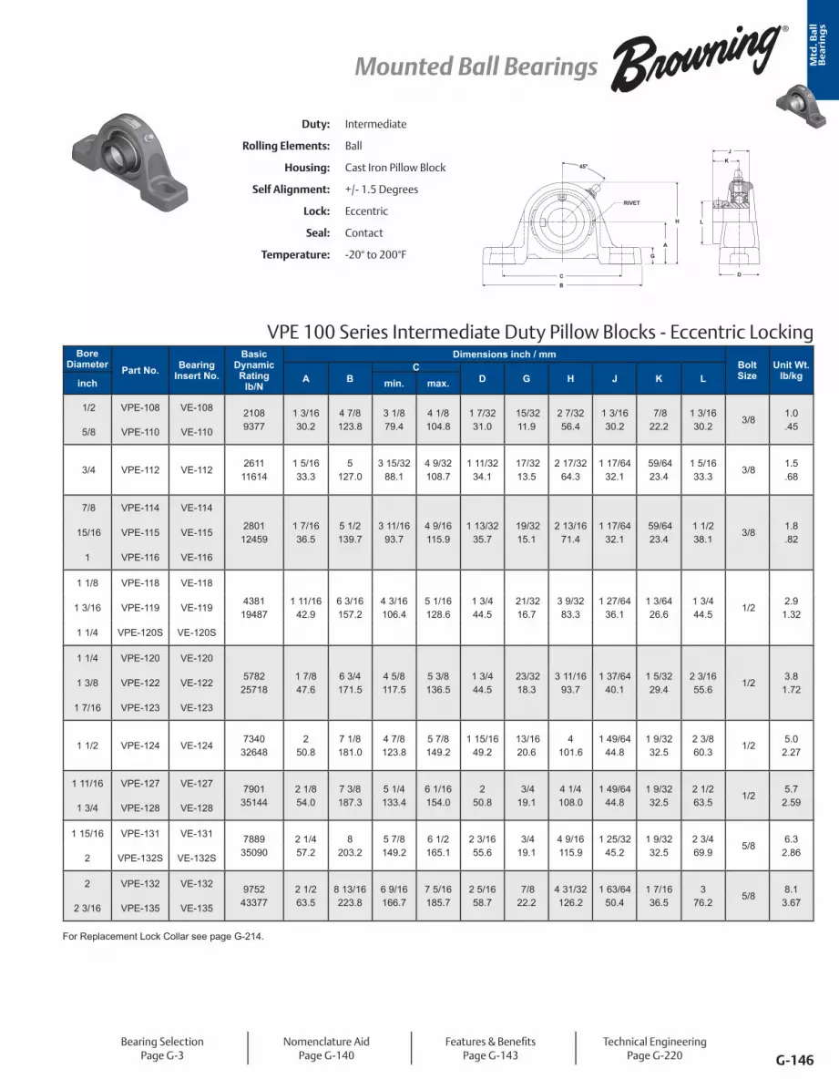
Mtd
. Ba
ll
Be
ari
ng
s
G-146
Mounted Ball Bearings
Bearing SelectionPage G-3
Nomenclature AidPage G-140
Features & BenefitsPage G-143
Technical EngineeringPage G-220
Duty: Intermediate
Rolling Elements: Ball
Housing: Cast Iron Pillow Block
Self Alignment: +/- 1.5 Degrees
Lock: Eccentric
Seal: Contact
Temperature: -20° to 200°F
VPE 100 Series Intermediate Duty Pillow Blocks - Eccentric Locking
L
DCB
G
A
45°K
RIVET
H
J
Bore Diameter Part No. Bearing
Insert No.
Basic Dynamic Rating
lb/N
Dimensions inch / mmBolt Size
Unit Wt. lb/kgA B
CD G H J K Linch min. max.
1/2 VPE-108 VE-108 21089377
1 3/1630.2
4 7/8 123.8
3 1/879.4
4 1/8104.8
1 7/3231.0
15/3211.9
2 7/3256.4
1 3/1630.2
7/8 22.2
1 3/1630.2
3/8 1.0.45 5/8 VPE-110 VE-110
3/4 VPE-112 VE-1122611
116141 5/1633.3
5 127.0
3 15/32 88.1
4 9/32108.7
1 11/3234.1
17/3213.5
2 17/3264.3
1 17/6432.1
59/6423.4
1 5/1633.3
3/8 1.5.68
7/8 VPE-114 VE-114
280112459
1 7/1636.5
5 1/2 139.7
3 11/1693.7
4 9/16115.9
1 13/3235.7
19/3215.1
2 13/1671.4
1 17/6432.1
59/6423.4
1 1/2 38.1
3/8 1.8.82
15/16 VPE-115 VE-115
1 VPE-116 VE-116
1 1/8 VPE-118 VE-118
438119487
1 11/1642.9
6 3/16157.2
4 3/16106.4
5 1/16128.6
1 3/4 44.5
21/3216.7
3 9/3283.3
1 27/6436.1
1 3/6426.6
1 3/4 44.5
1/2 2.9
1.321 3/16 VPE-119 VE-119
1 1/4 VPE-120S VE-120S
1 1/4 VPE-120 VE-120
578225718
1 7/8 47.6
6 3/4 171.5
4 5/8 117.5
5 3/8 136.5
1 3/4 44.5
23/3218.3
3 11/1693.7
1 37/6440.1
1 5/3229.4
2 3/1655.6
1/2 3.8
1.721 3/8 VPE-122 VE-122
1 7/16 VPE-123 VE-123
1 1/2 VPE-124 VE-1247340
326482
50.87 1/8 181.0
4 7/8 123.8
5 7/8 149.2
1 15/1649.2
13/1620.6
4 101.6
1 49/6444.8
1 9/3232.5
2 3/8 60.3
1/2 5.0
2.27
1 11/16 VPE-127 VE-127 790135144
2 1/8 54.0
7 3/8 187.3
5 1/4 133.4
6 1/16154.0
2 50.8
3/4 19.1
4 1/4 108.0
1 49/6444.8
1 9/3232.5
2 1/2 63.5
1/2 5.7
2.591 3/4 VPE-128 VE-128
1 15/16 VPE-131 VE-131 788935090
2 1/4 57.2
8 203.2
5 7/8 149.2
6 1/2 165.1
2 3/1655.6
3/4 19.1
4 9/16115.9
1 25/3245.2
1 9/3232.5
2 3/4 69.9
5/8 6.3
2.862 VPE-132S VE-132S
2 VPE-132 VE-132 975243377
2 1/2 63.5
8 13/16223.8
6 9/16166.7
7 5/16185.7
2 5/1658.7
7/8 22.2
4 31/32126.2
1 63/6450.4
1 7/1636.5
3 76.2
5/8 8.1
3.672 3/16 VPE-135 VE-135
For Replacement Lock Collar see page G-214.

Mtd
. Ba
ll
Be
ari
ng
s
G-147
Mounted Ball Bearings
Bore Diameter Part No. Bearing
Insert No.
Basic Dynamic Rating
lb/N
Dimensions inch / mmBolt Size
Unit Wt. lb/kgA B
CD G H J K Linch min. max.
1/2 VPS-208 VS-208 21089377
1 3/1630.2
4 7/8123.8
3 1/879.4
4 1/8104.8
1 7/3231.0
15/3211.9
2 7/3256.4
1 1/3226.2
5/8 15.9
31/3224.6
3/8 .9
.41 5/8 VPS-210 VS-210
3/4 VPS-212 VS-2122611
116141 5/1633.3
5127.0
3 3/885.7
4 3/16106.4
1 11/3234.1
17/3213.5
2 17/3264.3
1 7/3231.0
23/3218.3
1 3/1630.2
3/8 1.4.64
7/8 VPS-214 VS-2142801
124591 7/1636.5
5 1/2139.7
3 11/1693.7
4 9/16115.9
1 13/3235.7
19/3215.1
2 13/1671.4
1 3/834.9
13/1620.6
1 3/8 34.9
3/8 1.5.68
15/16 VPS-215 VS-215
1 VPS-216 VS-216
1 1/8 VPS-218 VS-2184381
194871 11/16
42.96 3/16157.2
4 3/16105.6
5 1/16128.6
1 3/4 44.5
21/3216.7
3 9/3283.3
1 1/2 38.1
7/8 22.2
1 19/3240.5
1/2 2.5
1.131 3/16 VPS-219 VS-219
1 1/4 VPS-220S VS-220S
1 1/4 VPS-220 VS-2205782
257181 7/847.6
6 3/4171.5
4 5/8117.5
5 3/8136.5
1 3/444.5
23/3218.3
3 11/1693.7
1 11/1642.9
125.4
1 55/6447.2
1/23.5
1.591 3/8 VPS-222 VS-222
1 7/16 VPS-223 VS-223
1 1/2 VPS-224 VS-2247340
326482
50.87 1/8181.0
4 7/8 123.8
5 7/8 149.2
1 15/1649.2
13/1620.6
4101.6
1 15/1649.2
1 3/1630.2
2 1/1652.4
1/2 4.7
2.13
1 5/8 VPS-226 VS-2267901
351442 1/854.0
7 3/8187.3
5 1/4133.4
6 1/16154.0
250.8
3/4 19.1
4 1/4108.0
1 15/1649.2
1 3/1630.2
2 19/6458.3
1/2 5.5
2.491 11/16 VPS-227 VS-227
1 3/4 VPS-228 VS-228
1 15/16 VPS-231 VS-231 788935090
2 1/457.2
8203.2
5 7/8149.2
6 1/2165.1
2 3/1655.6
3/4 19.1
4 9/16115.9
2 1/3251.6
1 9/3232.5
2 15/3262.7
5/8 6.03.52 VPS-232S VS-232S
2 VPS-232 VS-232 975243377
2 1/263.5
8 13/16223.8
6 9/16166.7
7 5/16185.7
2 5/1658.7
7/8 22.2
4 31/32126.2
2 3/1655.6
1 5/1633.3
2 23/3269.1
5/8 7.8
3.542 3/16 VPS-235 VS-235
2 1/4 VPS-236 VS-236 1178952437
2 3/469.9
9 1/2241.3
6 7/8174.6
7 15/16201.6
2 3/860.3
7/8 22.2
5 9/16141.3
2 9/1665.1
1 9/1639.7
2 63/6475.8
5/8 10.13.52 7/16 VPS-239 VS-239
2 15/16 VPS-247 VS-2471483966004
3 5/1684.1
12304.8
9 1/8 231.8
9 7/8 250.8
2 7/873.0
125.4
6 5/8168.3
3 1/1677.8
1 3/444.5
3 11/6442.5
7/8 16.97.67
VPS 200 Series Standard Duty Pillow Blocks - Setscrew Locking - Inch
45°
G
A
H L
J
K
DC
B
RIVET
Duty: Standard
Rolling Elements: Ball
Housing: Cast Iron Pillow Block
Self Alignment: +/- 1.5 Degrees
Lock: Setscrew
Seal: Contact and Flinger
Temperature: -20° to 200°F
Bearing SelectionPage G-3
Nomenclature AidPage G-140
Features & BenefitsPage G-143
Air Handling OptionPage G-144
Technical EngineeringPage G-220
Metric dimensions for reference only.
Not all parts are available from stock. Please contact customer service for availability (800) 626-2120.
For more information on bearing capabilities outside of our standard offering, please contact Application Engineering (800) 626-2093.
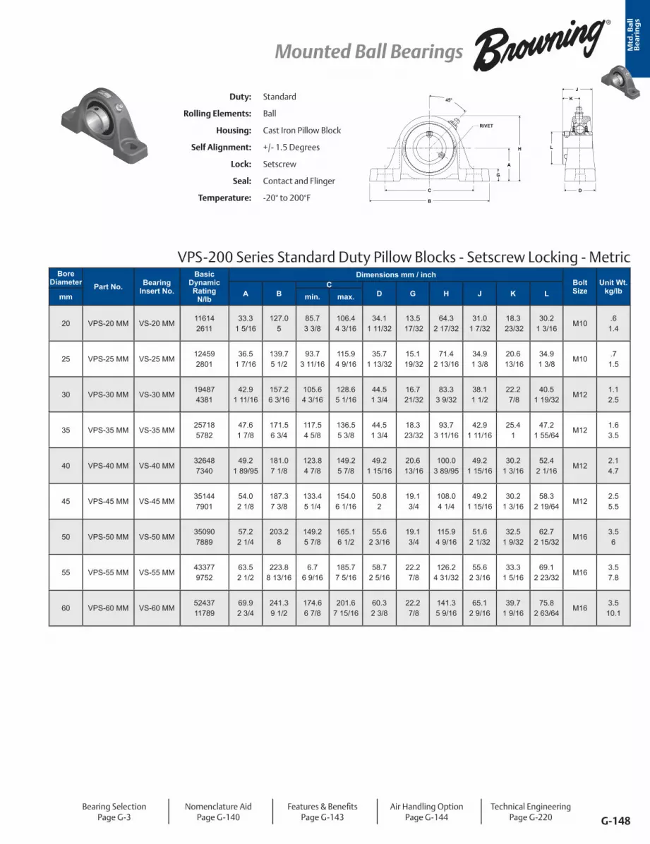
Mtd
. Ba
ll
Be
ari
ng
s
G-148
Mounted Ball Bearings
Bore Diameter Part No. Bearing
Insert No.
Basic Dynamic Rating
N/lb
Dimensions mm / inchBolt Size
Unit Wt. kg/lbA B
CD G H J K Lmm min. max.
20 VPS-20 MM VS-20 MM116142611
33.31 5/16
127.05
85.73 3/8
106.44 3/16
34.11 11/32
13.5 17/32
64.32 17/32
31.01 7/32
18.3 23/32
30.21 3/16
M10.6
1.4
25 VPS-25 MM VS-25 MM124592801
36.51 7/16
139.75 1/2
93.73 11/16
115.94 9/16
35.71 13/32
15.1 19/32
71.42 13/16
34.91 3/8
20.6 13/16
34.91 3/8
M10 .7
1.5
30 VPS-30 MM VS-30 MM194874381
42.91 11/16
157.26 3/16
105.64 3/16
128.65 1/16
44.51 3/4
16.7 21/32
83.33 9/32
38.11 1/2
22.2 7/8
40.51 19/32
M121.12.5
35 VPS-35 MM VS-35 MM257185782
47.61 7/8
171.56 3/4
117.54 5/8
136.55 3/8
44.51 3/4
18.3 23/32
93.73 11/16
42.91 11/16
25.41
47.21 55/64
M121.63.5
40 VPS-40 MM VS-40 MM326487340
49.21 89/95
181.07 1/8
123.84 7/8
149.25 7/8
49.21 15/16
20.6 13/16
100.03 89/95
49.21 15/16
30.21 3/16
52.42 1/16
M122.14.7
45 VPS-45 MM VS-45 MM351447901
54.02 1/8
187.37 3/8
133.45 1/4
154.06 1/16
50.82
19.1 3/4
108.04 1/4
49.21 15/16
30.21 3/16
58.32 19/64
M12 2.55.5
50 VPS-50 MM VS-50 MM350907889
57.22 1/4
203.28
149.25 7/8
165.16 1/2
55.62 3/16
19.1 3/4
115.94 9/16
51.62 1/32
32.51 9/32
62.72 15/32
M16 3.56
55 VPS-55 MM VS-55 MM433779752
63.52 1/2
223.88 13/16
6.76 9/16
185.77 5/16
58.72 5/16
22.2 7/8
126.24 31/32
55.62 3/16
33.31 5/16
69.12 23/32
M16 3.57.8
60 VPS-60 MM VS-60 MM5243711789
69.92 3/4
241.39 1/2
174.66 7/8
201.67 15/16
60.32 3/8
22.2 7/8
141.35 9/16
65.12 9/16
39.71 9/16
75.82 63/64
M16 3.5
10.1
VPS-200 Series Standard Duty Pillow Blocks - Setscrew Locking - Metric
45°
G
A
H L
J
K
DC
B
RIVET
Duty: Standard
Rolling Elements: Ball
Housing: Cast Iron Pillow Block
Self Alignment: +/- 1.5 Degrees
Lock: Setscrew
Seal: Contact and Flinger
Temperature: -20° to 200°F
Bearing SelectionPage G-3
Nomenclature AidPage G-140
Features & BenefitsPage G-143
Air Handling OptionPage G-144
Technical EngineeringPage G-220

Mtd
. Ba
ll
Be
ari
ng
s
G-149
Mounted Ball Bearings
Duty: Standard
Rolling Elements: Ball
Housing: Cast Iron Pillow Block
Self Alignment: +/- 1.5 Degrees
Lock: BOA Concentric
Seal: Contact and Flinger
Temperature: -20° to 200°F
VPB 200 Series Standard Duty Pillow Blocks - BOA Concentric Locking
KJ
L
G
A
H
CB
D
45°
RIVET
Bore DiameterPart No. Bearing
Insert No.
Basic Dynamic Rating
lb/N
Dimensions inch / mmBolt Size
Unit Wt. lb/kgA B
CD G H J K Linch mm min. max.
3/4 - VPB-212 VB-212 261111614
1 5/1633.3
5 127.0
3 3/8 85.7
4 3/16106.4
1 11/3234.1
17/3213.5
2 17/3264.3
1 9/3232.5
25/3219.8
1 3/4 44.5
3/8 1.6.73- 20 VPB-20MM VB-20MM
7/8 - VPB-214 VB-214
280112459
1 7/1636.5
5 1/2 139.7
3 11/1693.7
4 9/16115.9
1 13/3235.7
19/3215.1
2 13/1671.4
1 7/1636.5
7/8 22.2
1 15/1649.2
3/8 1.9.86
15/16 - VPB-215 VB-215
1 - VPB-216 VB-216
- 25 VPB-25MM VB-25MM
1 1/8 - VPB-218 VB-218
438119487
1 11/1642.9
6 3/16157.2
4 3/16106.4
5 1/16128.6
1 3/4 44.5
21/3216.7
3 9/3283.3
1 9/1639.7
15/1623.8
2 3/1655.6
1/22.9
1.321 3/16 - VPB-219 VB-219
1 1/4 - VPB-220S VB-220S
- 30 VPB-30MM VB-30MM
1 1/4 - VPB-220 VB-2205782
257181 7/8 47.6
6 3/4 171.5
4 5/8 117.5
5 3/8 136.5
1 3/4 44.5
23/3218.3
3 11/1693.7
1 3/4 44.5
1 1/1627.0
2 7/1661.9
1/23.8
1.72
1 3/8 - VPB-222 VB-2225782
257181 7/8 47.6
6 3/4 171.5
4 5/8 117.5
5 3/8 136.5
1 3/4 44.5
23/3218.3
3 11/1693.7
1 3/4 44.5
1 1/1627.0
2 9/1665.1
1/2 3.8
1.721 7/16 - VPB-223 VB-223
- 35 VPB-35MM VB-35MM
1 1/2 - VPB-224 VB-224 734032648
2 50.8
7 1/8 181.0
4 7/8 123.8
5 7/8 149.2
1 15/1649.2
13/1620.6
4 101.6
2 50.8
1 1/4 31.8
2 11/1668.3
1/2 4.9
2.22- 40 VPB-40MM VB-40MM
1 5/8 - VPB-226 VB-2267901
351442 1/8 54.0
7 3/8 187.3
5 1/4 133.4
6 1/16154.0
2 50.8
3/4 19.1
4 1/4 108.0
2 50.8
1 1/4 31.8
2 13/1671.4
1/2 5.6
2.54
1 11/16 - VPB-227 VB-2277901
351442 1/8 54.0
7 3/8 187.3
5 1/4 133.4
6 1/16154.0
2 50.8
3/4 19.1
4 1/4 108.0
2 50.8
1 1/4 31.8
2 15/1674.6
1/2 5.6
2.541 3/4 - VPB-228 VB-228
- 45 VPB-45MM VB-45MM
1 15/16 - VPB-231 VB-2317889
350902 1/4 57.2
8 203.2
5 7/8 149.2
6 1/2 165.1
2 3/1655.6
3/4 19.1
4 9/16115.9
2 3/3253.2
1 11/3234.1
3 3/8 85.7
5/8 6.2
2.812 - VPB-232S VB-232S
- 50 VPB-50MM VB-50MM
2 - VPB-232 VB-2329752
433772 1/2 63.5
8 13/16223.8
6 9/16166.7
7 5/16185.7
2 5/1658.7
7/8 22.2
4 31/32126.2
2 1/4 57.2
1 3/8 34.9
3 1/2 88.9
5/8 8.0
3.63
2 3/16 - VPB-235 VB-235 975243377
2 1/2 63.5
8 13/16223.8
6 9/16166.7
7 5/15185.7
2 5/1658.7
7/8 22.2
4 31/32126.2
2 1/4 57.2
1 3/8 34.9
3 5/8 92.1
5/8 8.0
3.63- 55 VPB-55MM VB-55MM
2 1/4 - VPB-236 VB-2361178952437
2 3/4 69.9
9 1/2 241.3
6 7/8 174.6
7 15/16201.6
2 3/8 60.3
7/8 22.2
5 9/16141.3
2 5/8 66.7
1 5/8 41.3
4 1/16103.2
5/8 10.14.58
2 7/16 - VPB-239 VB-239 1178952437
2 3/4 69.9
9 1/2 241.3
6 7/8 174.6
7 15/16201.6
2 3/8 60.3
7/8 22.2
5 9/16141.3
2 5/8 66.7
1 5/8 41.3
4 1/8 104.8
5/8 10.14.58- 60 VPB-60MM VB-60MM
Metric dimensions for reference only.
Not all parts are available from stock. Please contact customer service for availability (800) 626-2120.
For more information on bearing capabilities outside of our standard offering, please contact Application Engineering (800) 626-2093.
Bearing SelectionPage G-3
Nomenclature AidPage G-140
Features & BenefitsPage G-143
Air Handling OptionPage G-144
Technical EngineeringPage G-220
For Replacement Lock Collar see page G-214.
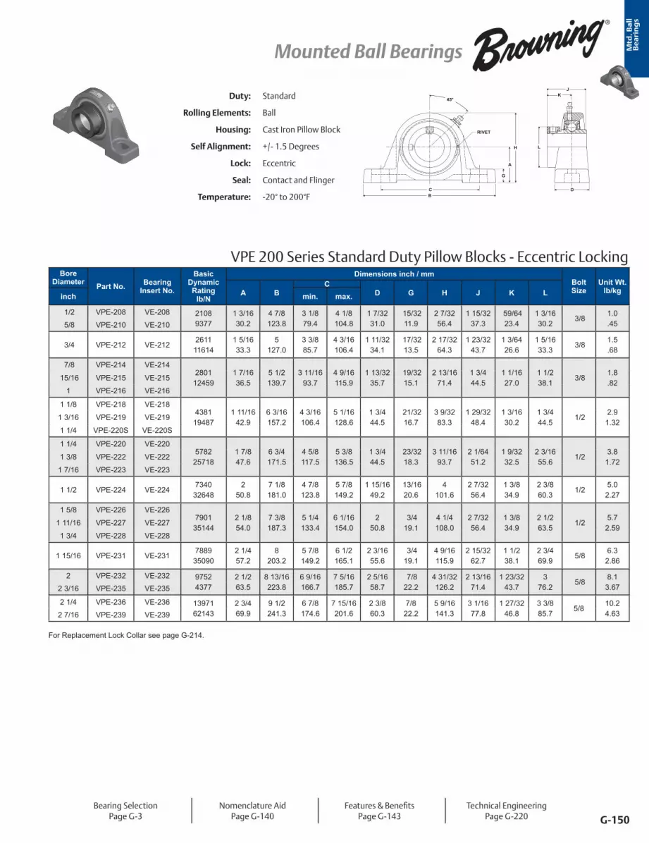
Mtd
. Ba
ll
Be
ari
ng
s
G-150
Mounted Ball Bearings
VPE 200 Series Standard Duty Pillow Blocks - Eccentric Locking
L
DB
G
A
H
C
45°K
J
RIVET
Duty: Standard
Rolling Elements: Ball
Housing: Cast Iron Pillow Block
Self Alignment: +/- 1.5 Degrees
Lock: Eccentric
Seal: Contact and Flinger
Temperature: -20° to 200°F
Bore Diameter Part No. Bearing
Insert No.
Basic Dynamic Rating
lb/N
Dimensions inch / mmBolt Size
Unit Wt. lb/kgA B
CD G H J K Linch min. max.
1/2 VPE-208 VE-208 21089377
1 3/1630.2
4 7/8 123.8
3 1/879.4
4 1/8104.8
1 7/3231.0
15/3211.9
2 7/3256.4
1 15/3237.3
59/6423.4
1 3/1630.2
3/8 1.0.45 5/8 VPE-210 VE-210
3/4 VPE-212 VE-2122611
116141 5/1633.3
5 127.0
3 3/885.7
4 3/16106.4
1 11/3234.1
17/3213.5
2 17/3264.3
1 23/3243.7
1 3/6426.6
1 5/1633.3
3/8 1.5.68
7/8 VPE-214 VE-2142801
124591 7/1636.5
5 1/2 139.7
3 11/1693.7
4 9/16115.9
1 13/3235.7
19/3215.1
2 13/1671.4
1 3/4 44.5
1 1/1627.0
1 1/2 38.1
3/8 1.8.82
15/16 VPE-215 VE-215
1 VPE-216 VE-216
1 1/8 VPE-218 VE-2184381
194871 11/16
42.96 3/16157.2
4 3/16106.4
5 1/16128.6
1 3/4 44.5
21/3216.7
3 9/3283.3
1 29/3248.4
1 3/1630.2
1 3/4 44.5
1/2 2.9
1.321 3/16 VPE-219 VE-219
1 1/4 VPE-220S VE-220S
1 1/4 VPE-220 VE-2205782
257181 7/8 47.6
6 3/4 171.5
4 5/8117.5
5 3/8136.5
1 3/4 44.5
23/3218.3
3 11/1693.7
2 1/6451.2
1 9/3232.5
2 3/1655.6
1/2 3.8
1.721 3/8 VPE-222 VE-222
1 7/16 VPE-223 VE-223
1 1/2 VPE-224 VE-2247340
326482
50.87 1/8 181.0
4 7/8 123.8
5 7/8 149.2
1 15/1649.2
13/1620.6
4 101.6
2 7/3256.4
1 3/8 34.9
2 3/8 60.3
1/2 5.0
2.27
1 5/8 VPE-226 VE-2267901
351442 1/8 54.0
7 3/8 187.3
5 1/4133.4
6 1/16154.0
2 50.8
3/4 19.1
4 1/4 108.0
2 7/3256.4
1 3/8 34.9
2 1/2 63.5
1/2 5.7
2.591 11/16 VPE-227 VE-227
1 3/4 VPE-228 VE-228
1 15/16 VPE-231 VE-2317889
350902 1/4 57.2
8 203.2
5 7/8149.2
6 1/2165.1
2 3/1655.6
3/4 19.1
4 9/16115.9
2 15/3262.7
1 1/2 38.1
2 3/4 69.9
5/8 6.3
2.86
2 VPE-232 VE-232 97524377
2 1/2 63.5
8 13/16223.8
6 9/16166.7
7 5/16185.7
2 5/1658.7
7/8 22.2
4 31/32126.2
2 13/1671.4
1 23/3243.7
3 76.2
5/8 8.1
3.672 3/16 VPE-235 VE-235
2 1/4 VPE-236 VE-236 1397162143
2 3/469.9
9 1/2241.3
6 7/8174.6
7 15/16201.6
2 3/860.3
7/822.2
5 9/16141.3
3 1/1677.8
1 27/3246.8
3 3/885.7
5/810.24.632 7/16 VPE-239 VE-239
Bearing SelectionPage G-3
Nomenclature AidPage G-140
Features & BenefitsPage G-143
Technical EngineeringPage G-220
For Replacement Lock Collar see page G-214.

Mtd
. Ba
ll
Be
ari
ng
s
G-151
Mounted Ball Bearings
Duty: Medium
Rolling Elements: Ball
Housing: Cast Iron Pillow Block
Self Alignment: +/- 1.5 Degrees
Lock: Setscrew
Seal: Contact and Flinger
Temperature: -20° to 200°F
VPS 300 Series Medium Duty Pillow Blocks - Setscrew Locking
G
A
H L
JK
DCB
RIVET
45°
Bore Diameter Part No.
Bearing Insert
No.
Basic Dynamic Rating
lb/N
Dimensions inch / mmBolt Size
Unit Wt. lb/kgA B
CD G H J K Linch min. max.
1 VPS-316 VS-3164381
194871 3/4 44.5
6 3/16157.2
4 3/16106.4
5 1/16128.6
1 3/4 44.5
23/3218.3
3 11/3284.9
1 1/2 38.1
7/8 22.2
1 19/3240.5
1/2 3.6
1.63
1 3/16 VPS-319 VS-3195782
257181 7/8 47.6
6 3/4 171.5
4 5/8117.5
5 3/8136.5
1 3/4 44.5
23/3218.3
3 11/1693.7
1 11/1642.9
1 25.4
1 55/6447.2
1/2 4.8
2.18
1 7/16 VPS-323 VS-3237340
326482 1/8 54.0
7 1/4 184.2
5 5/16134.9
5 3/4146.1
2 50.8
13/1620.6
4 3/16106.4
1 15/1649.2
1 3/1630.2
2 1/1652.4
1/2 6.2
2.81
1 1/2 VPS-324 VS-3247901
351442 5/1658.7
7 13/16198.4
5 19/32142.1
6 11/32161.1
2 3/1655.6
13/1620.6
4 9/16115.9
1 15/1649.2
1 3/1630.2
2 19/6458.3
5/8 8.0
3.63
1 11/16 VPS-327 VS-327 788935090
2 5/1658.7
7 15/16201.6
5 3/4 146.1
6 1/2 165.1
2 1/4 57.2
13/1620.6
4 5/8 117.5
2 1/3251.6
1 9/3232.5
2 15/3262.7
5/8 8.0
3.631 3/4 VPS-328 VS-328
1 15/16 VPS-331 VS-331 788935090
2 1/2 63.5
8 13/16223.8
6 9/16166.7
7 5/16185.7
2 5/1658.7
7/8 22.2
4 31/32126.2
2 3/1655.6
1 5/1633.3
2 23/3269.1
5/8 10.54.762 VPS-332 VS-232
2 3/16 VPS-335 VS-335 1178952437
2 3/4 69.9
9 1/2 241.3
6 7/8174.6
7 15/16201.6
2 3/8 60.3
7/8 22.2
5 9/16141.3
2 9/1665.1
1 9/1639.7
2 63/6475.8
5/8 14.36.492 1/4 VPS-336 VS-236
Bearing SelectionPage G-3
Nomenclature AidPage G-140
Features & BenefitsPage G-143
Air Handling OptionPage G-144
Technical EngineeringPage G-220
Metric dimensions for reference only.

Mtd
. Ba
ll
Be
ari
ng
s
G-152
Mounted Ball Bearings
VPB 300 Series Medium Duty Pillow Blocks - BOA Concentric Locking
RIVET
K
J
L
C
B
G
A
H
D
45°Duty: Medium
Rolling Elements: Ball
Housing: Cast Iron Pillow Block
Self Alignment: +/- 1.5 Degrees
Lock: BOA Concentric
Seal: Contact and Flinger
Temperature: -20° to 200°F
Bore Diameter Part No. Bearing
Insert No.
Basic Dynamic Rating
lb/N
Dimensions inch / mmBolt Size
Unit Wt. lb/kgA B
CD G H J K Linch min. max.
1 VPB-316 VB-3164381
194871 3/4 44.5
6 3/16157.2
4 3/16106.4
5 1/16128.6
1 3/4 44.5
23/3218.3
3 11/3284.9
1 9/1639.7
15/1623.8
2 1/1652.4
1/23.1
1.41
1 3/16 VPB-319 VB-319 578225718
1 7/8 47.6
6 3/4 171.5
4 5/8 117.5
5 3/8 136.5
1 3/4 44.5
23/3218.3
3 11/1693.7
1 3/4 44.5
1 1/1627.0
2 7/1661.9
1/23.1
1.411 1/4 VPB-320 VB-220
1 7/16 VPB-323 VB-3237340
326482 1/8 54.0
7 1/4 184.2
5 5/16 134.9
5 3/4146.1
2 50.8
13/1620.6
4 3/16106.4
2 50.8
1 1/4 31.8
2 11/1668.3
1/23.9
1.77
1 1/2 VPB-324 VB-3247901
351442 5/1658.7
7 13/16198.4
5 19/32142.1
6 11/32161.1
2 3/1655.6
13/1620.6
4 9/16115.9
2 50.8
1 1/4 31.8
2 13/1671.4
1/24.8
2.18
1 11/16 VPB-327 VB-327 788935090
2 5/1658.7
7 15/16201.6
5 3/4 146.1
6 1/2 165.1
2 1/4 57.2
13/1620.6
4 5/8 117.5
2 3/3253.2
1 11/3234.1
3 1/4 82.6
5/85.8
2.631 3/4 VPB-328 VB-328
1 15/16 VPB-331 VB-331 975243377
2 1/2 63.5
8 13/16223.8
6 9/16166.7
7 5/16185.7
2 5/1658.7
7/8 22.2
4 31/32126.2
2 1/4 57.2
1 3/8 34.9
3 1/2 88.9
5/88.1
3.672 VPB-332 VB-232
2 3/16 VPB-335 VB-3351178952437
2 3/4 69.9
9 1/2 241.3
6 7/8 174.6
7 15/16201.6
2 3/8 60.3
7/8 22.2
5 9/16141.3
2 5/8 66.7
1 5/8 41.3
4 1/16103.2
5/810.44.72
Bearing SelectionPage G-3
Nomenclature AidPage G-140
Features & BenefitsPage G-143
Air Handling OptionPage G-144
Technical EngineeringPage G-220
For Replacement Lock Collar see page G-214.

Mtd
. Ba
ll
Be
ari
ng
s
G-153
Mounted Ball Bearings
Duty: Intermediate
Rolling Elements: Ball
Housing: Cast Iron Pillow Block – Low Base
Self Alignment: +/- 1.5 Degrees
Lock: Setscrew
Seal: Contact
Temperature: -20° to 200°F
VPLS 100 Series Intermediate Duty Low Base Pillow Blocks - Setscrew Locking
KJ
D
LH
A
G
45°
RIVET
BC
Bore Diameter Part No. Bearing
Insert No.
Basic Dynamic Rating
lb/N
Dimensions inch / mmBolt Size
Unit Wt. lb/kgA B
CD G H J K Linch min. max.
1/2 VPLS-108 VS-108 21089377
1 1/1627.0
4 7/8 123.8
3 1/879.4
4 1/8104.8
1 7/3231.0
11/328.7
2 3/3253.2
15/1623.8
5/8 15.9
31/3224.6
3/8 .7
.32 5/8 VPLS-110 VS-110
3/4 VPLS-112 VS-1122611
116141 1/4 31.8
5 127.0
3 15/3288.1
4 9/32108.7
1 11/3234.1
15/3211.9
2 15/3262.7
1 1/1627.0
23/3218.3
1 3/1630.2
3/8 1.3.59
7/8 VPLS-114 VS-114
280112459
1 5/1633.3
5 1/2 139.7
3 11/1693.7
4 9/16115.9
1 13/3235.7
15/3211.9
2 11/1668.3
1 7/6428.2
49/6419.4
1 3/8 34.9
3/8 1.4.64
15/16 VPLS-115 VS-115
1 VPLS-116 VS-116
1 1/8 VPLS-118 VS-118
438119487
1 9/1639.7
6 3/16157.2
4 3/16106.4
5 1/16128.6
1 3/4 44.5
17/3213.5
3 5/3280.2
1 5/3229.4
25/3219.8
1 19/3240.5
1/2 2.4
1.091 3/16 VPLS-119 VS-119
1 1/4 VPLS-120S VS-120S
1 1/4 VPLS-120 VS-120
578225718
1 13/1646.0
6 3/4 171.5
4 5/8117.5
5 3/8136.5
1 3/4 44.5
21/3216.7
3 5/8 92.1
1 9/3232.5
55/6421.8
1 55/6447.2
1/2 3.5
1.591 3/8 VPLS-122 VS-122
1 7/16 VPLS-123 VS-123
1 1/2 VPLS-124 VS-1247340
326481 15/16
49.27 1/8 181.0
4 7/8 123.8
5 7/8 149.2
1 15/1649.2
3/4 19.1
3 15/16100.0
1 27/6436.1
15/1623.8
2 1/1652.4
1/2 4.5
2.04
1 11/16 VPLS-127 VS-127 790135144
2 1/1652.4
7 3/8 187.3
5 7/16138.1
5 7/8149.2
2 50.8
11/1617.5
4 3/16106.4
1 7/1636.5
61/6424.2
2 19/6458.3
1/2 5.5
2.491 3/4 VPLS-128 VS-128
1 15/16 VPLS-131 VS-131 788935090
2 3/1655.6
8 203.2
5 7/8149.2
6 1/2165.1
2 3/1655.6
11/1617.5
4 1/2 114.3
1 35/6439.3
1 3/6426.6
2 15/3262.7
5/8 5.9
2.682 VPLS-132S VS-132S
2 VPLS-132 VS-132 975243377
2 7/1661.9
8 13/16223.8
6 9/16166.7
7 5/16185.7
2 5/1658.7
13/1620.6
4 29/32124.6
1 21/3242.1
1 7/6428.2
2 23/3269.1
5/8 7.6
3.452 3/16 VPLS-135 VS-135
Metric dimensions for reference only.
Not all parts are available from stock. Please contact customer service for availability (800) 626-2120.
For more information on bearing capabilities outside of our standard offering, please contact Application Engineering (800) 626-2093.
Bearing SelectionPage G-3
Nomenclature AidPage G-140
Features & BenefitsPage G-143
Technical EngineeringPage G-220

Mtd
. Ba
ll
Be
ari
ng
s
G-154
Mounted Ball Bearings
VPLE 100 Series Intermediate Duty Low Base Pillow Blocks - Eccentric Locking
K
D
J
B
G
A
H
45°
C
RIVET
L
Duty: Intermediate
Rolling Elements: Ball
Housing: Cast Iron Pillow Block – Low Base
Self Alignment: +/- 1.5 Degrees
Lock: Eccentric
Seal: Contact
Temperature: -20° to 200°F
Bore Diameter Part No. Bearing
Insert No.
Basic Dynamic Rating
lb/N
Dimensions inch / mmBolt Size
Unit Wt. lb/kgA B
CD G H J K Linch min. max.
1/2 VPLE-108 VE-108 21089377
1 1/1627.0
4 7/8 123.8
3 1/879.4
4 1/8104.8
1 7/3231.0
11/328.7
2 3/3253.2
1 3/1630.2
7/8 22.2
1 3/1630.2
3/8 .8
.36 5/8 VPLE-110 VE-110
3/4 VPLE-112 VE-1122611
116141 1/4 31.8
5 127.0
3 15/3288.1
4 9/32108.7
1 11/3234.1
15/3211.9
2 15/3262.7
1 17/6432.1
59/6423.4
1 5/1633.3
3/8 1.4.64
7/8 VPLE-114 VE-114
280112459
1 5/1633.3
5 1/2 139.7
3 11/1693.7
4 9/16115.9
1 13/3235.7
15/3211.9
2 11/1668.3
1 17/6432.1
59/6423.4
1 1/2 38.1
3/8 1.7.77
15/16 VPLE-115 VE-115
1 VPLE-116 VE-116
1 1/8 VPLE-118 VE-118
438119487
1 9/1639.7
6 3/16157.2
4 3/16 106.4
5 1/16128.6
1 3/4 44.5
17/3213.5
3 5/3280.2
1 27/6436.1
1 3/6426.6
1 3/4 44.5
1/2 2.8
1.271 3/16 VPLE-119 VE-119
1 1/4 VPLE-120S VE-120S
1 1/4 VPLE-120 VE-120
578225718
1 13/1646.0
6 3/4 171.5
4 5/8117.5
5 3/8136.5
1 3/4 44.5
21/3216.7
3 5/8 92.1
1 37/6440.1
1 5/3229.4
2 3/1655.6
1/2 3.7
1.681 3/8 VPLE-122 VE-122
1 7/16 VPLE-123 VE-123
1 1/2 VPLE-124 VE-1247340
326481 15/16
49.27 1/8 181.0
4 7/8123.8
5 7/8149.2
1 15/1649.2
3/4 19.1
3 15/16100.0
1 49/6444.8
1 9/3232.5
2 3/8 60.3
1/2 4.8
2.18
1 11/16 VPLE-127 VE-127 790135144
2 1/1652.4
7 3/8 187.3
5 7/16138.1
5 7/8149.2
2 50.8
11/1617.5
4 3/16106.4
1 49/6444.8
1 9/3232.5
2 1/2 63.5
1/2 5.6
2.541 3/4 VPLE-128 VE-128
1 15/16 VPLE-131 VE-131 788935090
2 3/1655.6
8 203.2
5 7/8149.2
6 1/2165.1
2 3/1655.6
11/1617.5
4 1/2 114.3
1 25/3245.2
1 9/3232.5
2 3/4 69.9
5/8 6.2
2.812 VPLE-132S VE-132S
2 VPLE-132 VE-132 975243377
2 7/1661.9
8 13/16223.8
6 9/16166.7
7 5/16185.7
2 5/1658.7
13/1620.6
4 29/32124.6
1 63/6450.4
1 7/1636.5
3 76.2
5/8 7.9
3.582 3/16 VPLE-135 VE-135
Bearing SelectionPage G-3
Nomenclature AidPage G-140
Features & BenefitsPage G-143
Technical EngineeringPage G-220
For Replacement Lock Collar see page G-214.

Mtd
. Ba
ll
Be
ari
ng
s
G-155
Mounted Ball Bearings
Duty: Standard
Rolling Elements: Ball
Housing: Cast Iron Pillow Block – Low Base
Self Alignment: +/- 1.5 Degrees
Lock: Setscrew
Seal: Contact and Flinger
Temperature: -20° to 200°F
VPLS 200 Series Standard Duty Low Base Pillow Blocks - Setscrew Locking
45°
G
A
H L
J
K
DC
B
RIVET
Bore Diameter Part No. Bearing
Insert No.
Basic Dynamic Rating
lb/N
Dimensions inch / mmBolt Size
Unit Wt. lb/kgA B
CD G H J K Linch min. max.
1/2 VPLS-208 VS-208 21089377
1 1/1627.0
4 7/8 123.8
3 1/879.4
4 1/8104.8
1 7/3231.0
11/328.7
2 3/3253.2
1 1/3226.2
5/8 15.9
31/3224.6
3/8 .7
.32 5/8 VPLS-210 VS-210
3/4 VPLS-212 VS-2122611
116141 1/4 31.8
5 127.0
3 3/885.7
4 3/16106.4
1 11/3234.1
15/3211.9
2 15/3262.7
1 7/3231.0
23/3218.3
1 3/1630.2
3/8 1.3.59
7/8 VPLS-214 VS-2142801
124591 5/1633.3
5 1/2 139.7
3 11/1693.7
4 9/16115.9
1 13/3235.7
15/3211.9
2 11/1668.3
1 3/8 34.9
13/1620.6
1 3/8 34.9
3/8 1.4.64
15/16 VPLS-215 VS-215
1 VPLS-216 VS-216
1 1/8 VPLS-218 VS-2184381
194871 9/1639.7
6 3/16157.2
4 3/16106.4
5 1/16128.6
1 3/4 44.5
17/3213.5
3 5/3280.2
1 1/2 38.1
7/8 22.2
1 19/3240.5
1/2 2.4
1.091 3/16 VPLS-219 VS-219
1 1/4 VPLS-220S VS-220S
1 1/4 VPLS-220 VS-2205782
257181 13/16
46.06 3/4 171.5
4 5/8117.5
5 3/8136.5
1 3/4 44.5
21/3216.7
3 5/8 92.1
1 11/1642.9
1 25.4
1 55/6447.3
1/2 3.5
1.591 3/8 VPLS-222 VS-222
1 7/16 VPLS-223 VS-223
1 1/2 VPLS-224 VS-2247340
326481 15/16
49.27 1/8 181.0
4 7/8 123.8
5 7/8 149.2
1 15/1649.2
3/4 19.1
3 15/16100.0
1 15/1649.2
1 3/1630.2
2 1/1652.4
1/2 4.5
2.04
1 5/8 VPLS-226 VS-2267901
351442 1/1652.4
7 3/8 187.3
5 1/4133.4
6 1/16154.0
2 50.8
11/1617.5
4 3/16106.4
1 15/1649.2
1 3/1630.2
2 19/6458.3
1/2 5.5
2.491 11/16 VPLS-227 VS-227
1 3/4 VPLS-228 VS-228
1 15/16 VPLS-231 VS-231 788935090
2 3/1655.6
8 203.2
5 7/8149.2
6 1/2165.1
2 3/1655.6
11/1617.5
4 1/2 114.3
2 1/3251.6
1 9/3232.5
2 15/3262.7
5/8 5.9
2.682 VPLS-232S VS-232S
2 VPLS-232 VS-232 975243377
2 7/1661.9
8 13/16223.8
6 9/16166.7
7 5/16185.7
2 5/1658.7
13/1620.6
4 29/32124.6
2 3/1655.6
1 19/6432.9
2 23/3269.1
5/8 7.6
3.452 3/16 VPLS-235 VS-235
2 1/4 VPLS-236 VS-236 1178952437
2 11/1668.3
9 1/2 241.3
6 7/8174.6
7 15/16201.6
2 3/8 60.3
13/1620.6
5 1/2 139.7
2 9/1665.1
1 9/1639.7
2 63/6475.8
5/8 9.7
4.402 7/16 VPLS-239 VS-239
Bearing SelectionPage G-3
Nomenclature AidPage G-140
Features & BenefitsPage G-143
Air Handling OptionPage G-144
Technical EngineeringPage G-220
Metric dimensions for reference only.

Mtd
. Ba
ll
Be
ari
ng
s
G-156
Mounted Ball Bearings
Duty: Standard
Rolling Elements: Ball
Housing: Cast Iron Pillow Block – Low Base
Self Alignment: +/- 1.5 Degrees
Lock: BOA Concentric
Seal: Contact and Flinger
Temperature: -20° to 200°F
VPLB 200 Series Standard Duty Low Base Pillow Blocks - BOA Concentric Locking
KJ
L
G
A
H
CB
D
45°
RIVET
Bore Diameter Part No. Bearing
Insert No.
Basic Dynamic Rating
lb/N
Dimensions inch / mmBolt Size
Unit Wt. lb/kgA B
CD G H J K Linch min. max.
3/4 VPLB-212 VB-2122611
116141 1/4 31.8
5 127.0
3 3/8 85.7
4 3/16106.4
1 11/3234.1
15/3211.9
2 15/3262.7
1 9/3232.5
25/3219.8
1 3/4 44.5
3/8 1.4.64
7/8 VPLB-214 VB-2142801
124591 5/1633.3
5 1/2 139.7
3 11/1693.7
4 9/16115.9
1 13/3235.7
15/3211.9
2 11/1668.3
1 7/1636.5
7/8 22.2
1 15/1649.2
3/8 1.6.73
15/16 VPLB-215 VB-215
1 VPLB-216 VB-216
1 1/8 VPLB-218 VB-2184381
194871 9/1639.7
6 3/16157.2
4 3/16106.4
5 1/16128.6
1 3/4 44.5
17/3213.5
3 5/3280.2
1 9/1639.7
15/1623.8
2 3/1655.6
1/2 2.6
1.181 3/16 VPLB-219 VB-219
1 1/4 VPLB-220S VB-220S
1 1/4 VPLB-220 VB-2205782
257181 13/16
46.06 3/4 171.5
4 5/8 117.5
5 3/8 136.5
1 3/4 44.5
21/3216.7
3 5/8 92.1
1 3/4 44.5
1 1/1627.0
2 7/1661.9
1/2 3.8
1.72
1 3/8 VPLB-222 VB-222 578225718
1 13/1646.0
6 3/4 171.5
4 5/8 117.5
5 3/8 136.5
1 3/4 44.5
21/3216.7
3 5/8 92.1
1 3/4 44.5
1 1/1627.0
2 9/1665.1
1/2 3.8
1.721 7/16 VPLB-223 VB-223
1 1/2 VPLB-224 VB-2247340
326481 15/16
49.27 1/8 181.0
4 7/8 123.8
5 7/8 149.2
1 15/1649.2
3/4 19.1
3 15/16100.0
2 50.8
1 1/4 31.8
2 11/1668.3
1/2 4.8
2.18
1 5/8 VPLB-226 VB-2267901
351442 1/1652.4
7 3/8 187.3
5 1/4 133.4
6 1/16154.0
2 50.8
11/1617.5
4 3/16106.4
2 50.8
1 1/4 31.8
2 13/1671.4
1/2 5.8
2.63
1 11/16 VPLB-227 VB-227 790135144
2 1/1652.4
7 3/8 187.3
5 1/4 133.4
6 1/16154.0
2 50.8
11/1617.5
4 3/16106.4
2 50.8
1 1/4 31.8
2 15/1674.6
1/2 6.5
2.951 3/4 VPLB-228 VB-228
1 15/16 VPLB-231 VB-231 788935090
2 3/1655.6
8 203.2
5 7/8 149.2
6 1/2 165.1
2 3/1655.6
11/1617.5
4 1/2 114.3
2 3/3253.2
1 11/3234.1
3 3/8 85.7
5/8 6.5
2.952 VPLB-232S VB-232S
2 VPLB-232 VB-2329752
433772 7/1661.9
8 13/16223.8
6 9/16166.7
7 5/16185.7
2 5/1658.7
13/1620.6
4 29/32124.6
2 1/4 57.2
1 3/8 34.9
3 1/2 88.9
5/8 8.2
3.72
2 3/16 VPLB-235 VB-2359752
433772 7/1661.9
8 13/16223.8
6 9/16166.7
7 5/16185.7
2 5/1658.7
13/1620.6
4 29/32124.6
2 1/4 57.2
1 3/8 34.9
3 5/8 92.1
5/8 10.94.94
2 1/4 VPLB-236 VB-2361178952437
2 11/1668.3
9 1/2 241.3
6 7/8 174.6
7 15/16201.6
2 3/8 60.3
13/1620.6
5 1/2 139.7
2 5/8 66.7
1 5/8 41.3
4 1/16103.2
5/8 10.94.94
2 7/16 VPLB-239 VB-2391178952437
2 11/1668.3
9 1/2 241.3
6 7/8 174.6
7 15/16201.6
2 3/8 60.3
13/1620.6
5 1/2 139.7
2 5/8 66.7
1 5/8 41.3
4 1/8 104.8
5/8 10.94.94
Bearing SelectionPage G-3
Nomenclature AidPage G-140
Features & BenefitsPage G-143
Air Handling OptionPage G-144
Technical EngineeringPage G-220
For Replacement Lock Collar see page G-214.

Mtd
. Ba
ll
Be
ari
ng
s
G-157
Mounted Ball Bearings
VPLE 200 Series Standard Duty Low Base Pillow Blocks - Eccentric Locking
K
D
J
B
G
A
H
45°
C
RIVET
L
Duty: Standard
Rolling Elements: Ball
Housing: Cast Iron Pillow Block – Low Base
Self Alignment: +/- 1.5 Degrees
Lock: Eccentric
Seal: Contact and Flinger
Temperature: -20° to 200°F
Bore Diameter Part No. Bearing
Insert No.
Basic Dynamic Rating
lb/N
Dimensions inch / mmBolt Size
Unit Wt. lb/kgA B
CD G H J K Linch min. max.
1/2 VPLE-208 VE-208 21089377
1 1/1627.0
4 7/8 123.8
3 1/879.4
4 1/8104.8
1 7/3231.0
11/328.7
2 3/3253.2
1 15/3237.3
59/6423.4
1 3/1630.2
3/8 .8
.36 5/8 VPLE-210 VE-210
3/4 VPLE-212 VE-2122611
116141 1/4 31.8
5 127.0
3 3/885.7
4 3/16106.4
1 11/3234.1
15/3211.9
2 15/3262.7
1 23/3243.7
1 3/6426.6
1 5/1633.3
3/8 1.4.64
7/8 VPLE-214 VE-2142801
124591 5/1633.3
5 1/2 139.7
3 11/1693.7
4 9/16115.9
1 13/3235.7
15/3211.9
2 11/1668.3
1 3/4 44.5
1 1/1627.0
1 1/2 38.1
3/8 1.7.77
15/16 VPLE-215 VE-215
1 VPLE-216 VE-216
1 1/8 VPLE-218 VE-2184381
194871 9/1639.7
6 3/16157.2
4 3/16106.4
5 1/16128.6
1 3/4 44.5
17/3213.5
3 5/3280.2
1 29/3248.4
1 3/1630.2
1 3/4 44.5
1/2 2.8
1.271 3/16 VPLE-219 VE-219
1 1/4 VPLE-220S VE-220S
1 1/4 VPLE-220 VE-2205782
257181 13/16
46.06 3/4 171.5
4 5/8117.5
5 3/8136.5
1 3/4 44.5
21/3216.7
3 5/8 92.1
2 1/6451.2
1 9/3232.5
2 3/1655.6
1/2 3.7
1.681 3/8 VPLE-222 VE-222
1 7/16 VPLE-223 VE-223
1 1/2 VPLE-224 VE-2247340
326481 15/16
49.27 1/8 181.0
4 7/8 123.8
5 7/8 149.2
1 15/1649.2
3/4 19.1
3 15/16100.0
2 7/3256.4
1 3/8 34.9
2 3/8 60.3
1/2 4.8
2.18
1 5/8 VPLE-226 VE-2267901
351442 1/1652.4
7 3/8 187.3
5 1/4133.4
6 1/16154.0
2 50.8
11/1617.5
4 3/16106.4
2 7/3256.4
1 3/8 34.9
2 1/2 63.5
1/2 5.6
2.541 11/16 VPLE-227 VE-227
1 3/4 VPLE-228 VE-228
1 15/16 VPLE-231 VE-2317889
350902 3/1655.6
8 203.2
5 7/8149.2
6 1/2165.1
2 3/1655.6
11/1617.5
4 1/2 114.3
2 15/3262.7
1 1/2 38.1
2 3/4 69.9
5/8 6.2
2.81
2 VPLE-232 VE-232 975243377
2 7/1661.9
8 13/16223.8
6 9/16166.7
7 5/16185.7
2 5/16188.9
13/1658.7
4 29/3220.6
2 13/16124.6
1 23/3271.4
3 43.7
5/8 7.9.282 3/16 VPLE-235 VE-235
2 1/4 VPLE-236 VE-236 1178952437
2 11/1668.3
9 1/2 241.3
6 7/8174.6
7 15/16201.6
2 3/8 60.3
13/1620.6
5 1/2 139.7
3 1/1677.8
1 27/3246.8
3 3/8 85.7
5/8 10
4.542 7/16 VPLE-239 VE-239
Metric dimensions for reference only.
Not all parts are available from stock. Please contact customer service for availability (800) 626-2120.
For more information on bearing capabilities outside of our standard offering, please contact Application Engineering (800) 626-2093.
Bearing SelectionPage G-3
Nomenclature AidPage G-140
Features & BenefitsPage G-143
Air Handling OptionPage G-144
Technical EngineeringPage G-220
For Replacement Lock Collar see page G-214.

Mtd
. Ba
ll
Be
ari
ng
s
G-158
Mounted Ball Bearings
VPDS 200 Series Standard Duty Pillow Blocks - Setscrew Locking
Duty: Standard
Rolling Elements: Ball
Housing: Cast Iron Pillow Block - Alternate Base
Self Alignment: +/- 1.5 Degrees
Lock: Setscrew
Seal: Contact
Temperature: -20° to 200°F
Bore Diameter Part No. Bearing
Insert No.
Basic Dynamic Rating
lb/N
Dimensions inch / mmBolt Size
Unit Wt. lb/kgA B
CD G H J K L
inch min. max.
1 3/16 VPDS-219 VS-219 438119487
1 5/8 41.3
6 3/16157.2
4 3/16106.4
5 1/16128.6
1 3/444.5
19/3215.1
3 9/3283.3
1 1/238.1
7/8 22.2
1 19/3240.5
1/2 2.8
1.271 1/4 VPDS-220S VS-220S
1 1/2 VPDS-224 VS-2247340
326482 1/8 54.0
7 1/4 184.2
5 7/32132.6
5 27/32148.4
2 50.8
13/1620.6
4 3/16106.4
1 15/1649.2
1 3/1630.2
2 1/1652.4
1/25.3
2.40
45°
G
A
H L
J
K
DC
B
RIVET
Bearing SelectionPage G-3
Nomenclature AidPage G-140
Features & BenefitsPage G-143
Technical EngineeringPage G-220
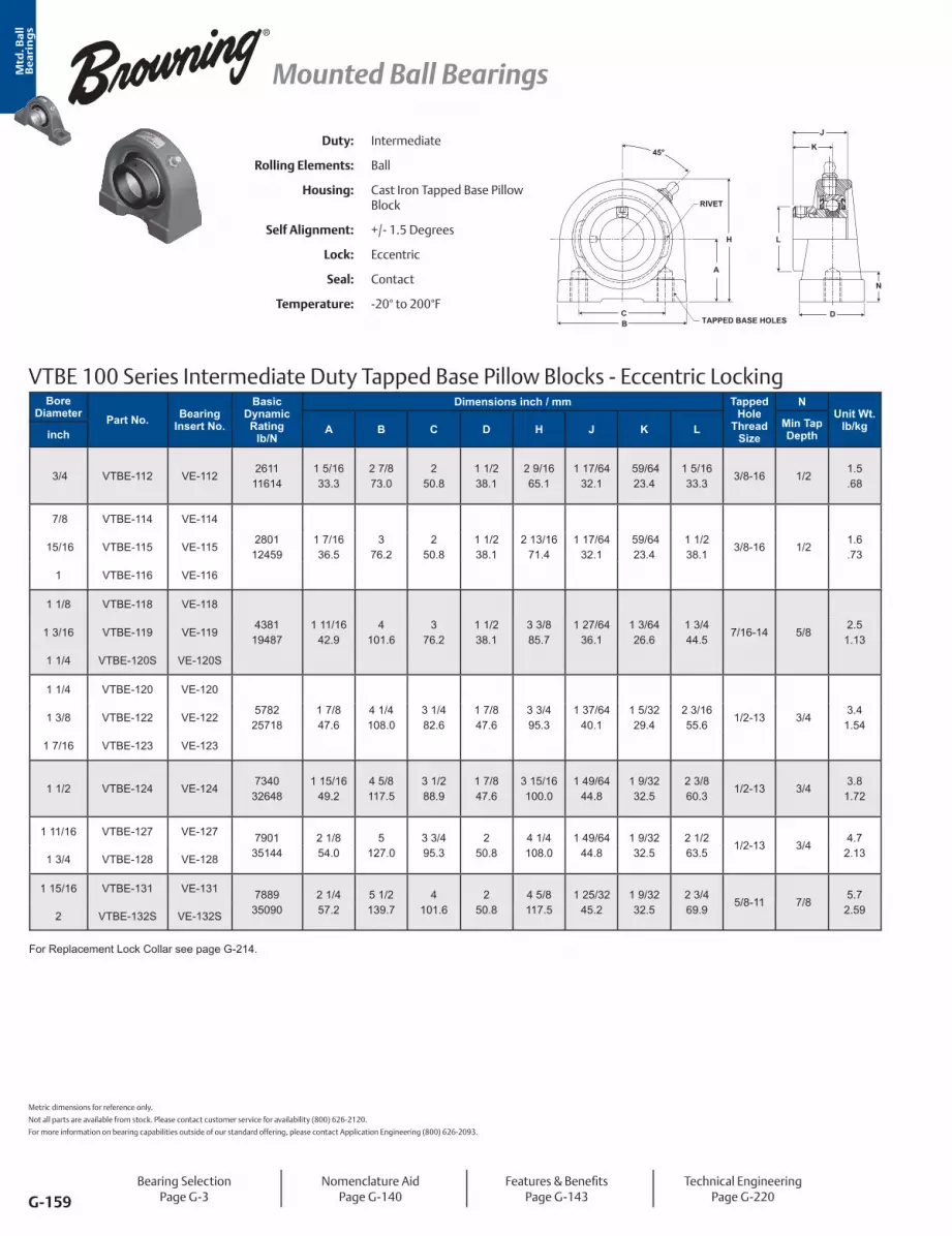
Mtd
. Ba
ll
Be
ari
ng
s
G-159
Mounted Ball Bearings
Duty: Intermediate
Rolling Elements: Ball
Housing: Cast Iron Tapped Base Pillow Block
Self Alignment: +/- 1.5 Degrees
Lock: Eccentric
Seal: Contact
Temperature: -20° to 200°F
VTBE 100 Series Intermediate Duty Tapped Base Pillow Blocks - Eccentric Locking
B
A
H
N
D
L
K
J
C
RIVET
TAPPED BASE HOLES
45°
Bore Diameter Part No. Bearing
Insert No.
Basic Dynamic Rating
lb/N
Dimensions inch / mm Tapped Hole
Thread Size
NUnit Wt.
lb/kgA B C D H J K L Min Tap Depthinch
3/4 VTBE-112 VE-1122611
116141 5/1633.3
2 7/8 73.0
2 50.8
1 1/2 38.1
2 9/1665.1
1 17/6432.1
59/6423.4
1 5/1633.3
3/8-16 1/2 1.5.68
7/8 VTBE-114 VE-114
280112459
1 7/1636.5
3 76.2
2 50.8
1 1/2 38.1
2 13/1671.4
1 17/6432.1
59/6423.4
1 1/2 38.1
3/8-16 1/2 1.6.73
15/16 VTBE-115 VE-115
1 VTBE-116 VE-116
1 1/8 VTBE-118 VE-118
438119487
1 11/1642.9
4 101.6
3 76.2
1 1/2 38.1
3 3/8 85.7
1 27/6436.1
1 3/6426.6
1 3/4 44.5
7/16-14 5/8 2.5
1.131 3/16 VTBE-119 VE-119
1 1/4 VTBE-120S VE-120S
1 1/4 VTBE-120 VE-120
578225718
1 7/8 47.6
4 1/4 108.0
3 1/4 82.6
1 7/8 47.6
3 3/4 95.3
1 37/6440.1
1 5/3229.4
2 3/1655.6
1/2-13 3/4 3.4
1.541 3/8 VTBE-122 VE-122
1 7/16 VTBE-123 VE-123
1 1/2 VTBE-124 VE-1247340
326481 15/16
49.24 5/8 117.5
3 1/2 88.9
1 7/8 47.6
3 15/16100.0
1 49/6444.8
1 9/3232.5
2 3/8 60.3
1/2-13 3/4 3.8
1.72
1 11/16 VTBE-127 VE-127 790135144
2 1/8 54.0
5 127.0
3 3/4 95.3
2 50.8
4 1/4 108.0
1 49/6444.8
1 9/3232.5
2 1/2 63.5
1/2-13 3/4 4.7
2.131 3/4 VTBE-128 VE-128
1 15/16 VTBE-131 VE-131 788935090
2 1/4 57.2
5 1/2 139.7
4 101.6
2 50.8
4 5/8 117.5
1 25/3245.2
1 9/3232.5
2 3/4 69.9
5/8-11 7/8 5.7
2.592 VTBE-132S VE-132S
Metric dimensions for reference only.
Not all parts are available from stock. Please contact customer service for availability (800) 626-2120.
For more information on bearing capabilities outside of our standard offering, please contact Application Engineering (800) 626-2093.
Bearing SelectionPage G-3
Nomenclature AidPage G-140
Features & BenefitsPage G-143
Technical EngineeringPage G-220
For Replacement Lock Collar see page G-214.

Mtd
. Ba
ll
Be
ari
ng
s
G-160
Mounted Ball Bearings
VTBS 200 Series Standard Duty Tapped Base Pillow Blocks - Setscrew Locking
CB
A
H
D
N
L
KJ
TAPPED BASE HOLES
RIVET
45°Duty: Standard
Rolling Elements: Ball
Housing: Cast Iron Tapped Base Pillow Block
Self Alignment: +/- 1.5 Degrees
Lock: Setscrew
Seal: Contact and Flinger
Temperature: -20° to 200°F
Bore Diameter Part No. Bearing
Insert No.
Basic Dynamic Rating
lb/N
Dimensions inch / mm Tapped Hole
Thread Size
NMin Tap Depth
Unit Wt. lb/kg
A B C D H J K Linch
1/2 VTBS-208 VS-208 21089377
1 5/1633.3
2 7/8 73.0
2 50.8
1 1/2 38.1
2 9/1665.1
1 1/3226.2
5/8 15.9
31/3224.6
3/8-16 1/2 1.3.59 5/8 VTBS-210 VS-210
3/4 VTBS-212 VS-2122611
116141 5/1633.3
2 7/8 73.0
2 50.8
1 1/2 38.1
2 9/1665.1
1 7/3231.0
23/3218.3
1 3/1630.2
3/8-16 1/2 1.5.68
7/8 VTBS-214 VS-2142801
124591 7/1636.5
3 76.2
2 50.8
1 1/2 38.1
2 13/1671.4
1 3/8 34.9
13/1620.6
1 3/834.9
3/8-16 1/2 1.6.73
15/16 VTBS-215 VS-215
1 VTBS-216 VS-216
1 1/8 VTBS-218 VS-2184381
194871 11/16
42.94
101.63
76.21 1/2 38.1
3 3/8 85.7
1 1/2 38.1
7/8 22.2
1 19/3240.5
7/16-14 5/82.5
1.131 3/16 VTBS-219 VS-219
1 1/4 VTBS-220S VS-220S
1 1/4 VTBS-220 VS-2205782
257181 7/8 47.6
4 1/4 108.0
3 1/4 82.6
1 7/8 47.6
3 3/4 95.3
1 11/1642.9
1 25.4
1 55/6447.2
1/2-13 3/43.4
1.541 3/8 VTBS-222 VS-222
1 7/16 VTBS-223 VS-223
1 1/2 VTBS-224 VS-2247340
326481 15/16
49.24 5/8 117.5
3 1/2 88.9
1 7/8 47.6
3 15/16100.0
1 15/1649.2
1 3/1630.2
2 1/1652.4
1/2-13 3/4 3.8
1 5/8 VTBS-226 VS-2267901
351442 1/8 54.0
5 127.0
3 3/4 95.3
2 50.8
4 1/4 108.0
1 15/1649.2
1 3/1630.2
2 19/6458.3
1/2-13 3/44.7
2.131 11/16 VTBS-227 VS-227
1 3/4 VTBS-228 VS-228
1 15/16 VTBS-231 VS-231 788935090
2 1/4 57.2
5 1/2 139.7
4 101.6
2 50.8
4 5/8 117.5
2 1/3251.6
1 9/3232.5
2 15/3262.7
5/8-11 7/8 5.7
2.592 VTBS-232S VS-232S
Bearing SelectionPage G-3
Nomenclature AidPage G-140
Features & BenefitsPage G-143
Technical EngineeringPage G-220

Mtd
. Ba
ll
Be
ari
ng
s
G-161
Mounted Ball Bearings
VTBS 200 Series Standard Duty Tapped Base Pillow Blocks - Setscrew Locking - Metric
CB
A
H
D
N
L
KJ
TAPPED BASE HOLES
RIVET
45°Duty: Standard
Rolling Elements: Ball
Housing: Cast Iron Tapped Base Pillow Block
Self Alignment: +/- 1.5 Degrees
Lock: Setscrew
Seal: Contact and Flinger
Temperature: -20° to 200°F
Bore Diameter Part No. Bearing
Insert No.
Basic Dynamic Rating
N/lb
Dimensions mm / inch Tapped Hole
Thread Size
NMin Tap Depth
Unit Wt. kg/lb
A B C D H J K Lmm
20 VTBS-20 MM VS-20 MM116142611
33.31 5/16
73.02 7/8
50.82
38.11 1/2
65.12 9/16
31.01 7/32
18.3 23/32
30.21 3/16
M8 12.7.681.5
25 VTBS-25MM VS-25MM124592801
36.51 7/16
76.23
50.82
38.11 1/2
71.42 13/16
34.91 3/8
20.6 13/16
34.91 3/8
M25 12.7.731.6
30 VTBS-30MM VS-30MM194874381
42.91 11/16
101.64
76.23
38.11 1/2
85.73 3/8
38.11 1/2
22.2 7/8
40.51 19/32
M10 15.91.132.5
35 VTBS-35MM VS-35MM257185782
47.61 7/8
108.04 1/4
82.63 1/4
47.61 7/8
95.33 3/4
42.91 11/16
25.41
47.21 55/64
M10 19.11.53.4
40 VTBS-40MM VS-40MM326487340
49.21 15/16
117.54 5/8
88.93 1/2
47.61 7/8
100.03 15/16
49.21 15/16
30.21 3/16
52.42 1/16
M12 19.11.723.8
45 VTBS-45MM VS-45MM351447901
54.02 1/8
127.05
95.33 3/4
50.82
108.04 1/4
49.21 15/16
30.21 3/16
58.32 19/64
M12 19.12.134.7
50 VTBS-50MM VS-50MM350907889
57.22 1/4
139.75 1/2
101.64
50.82
117.54 5/8
51.62 1/32
32.51 9/32
62.72 15/32
M16 22.22.595.7
Metric dimensions for reference only.
Not all parts are available from stock. Please contact customer service for availability (800) 626-2120.
For more information on bearing capabilities outside of our standard offering, please contact Application Engineering (800) 626-2093.
Bearing SelectionPage G-3
Nomenclature AidPage G-140
Features & BenefitsPage G-143
Technical EngineeringPage G-220

Mtd
. Ba
ll
Be
ari
ng
s
G-162
Mounted Ball Bearings
VTBB 200 Series Standard Duty Tapped Base Pillow Blocks - BOA Concentric Locking
Duty: Standard
Rolling Elements: Ball
Housing: Cast Iron Tapped Base Pillow Block
Self Alignment: +/- 1.5 Degrees
Lock: BOA
Seal: Contact and Flinger
Temperature: -20° to 200°F
45°
RIVET
CB
A
H
D
L
KJ
N
TAPPED BASE HOLES
Bore Diameter Part No. Bearing
Insert No.
Basic Dynamic Rating
lb/N
Dimensions inch / mm Tapped Hole
Thread Size
NMin Tap Depth
Unit Wt. lb/kgA B C D H J K Linch
3/4 VTBB-212 VB-2122611
116141 5/1633.3
2 7/8 73.0
250.8
1 1/2 38.1
2 9/1665.1
1 9/3232.5
25/3219.8
1 3/444.5
3/8-16 1/2 1.7.77
7/8 VTBB-214 VB-214
280112459
1 7/1636.5
376.2
250.8
1 1/2 38.1
2 13/1671.4
1 7/1636.5
7/8 22.2
1 15/1649.2
3/8-16 1/2 1.8.82
15/16 VTBB-215 VB-215
1 VTBB-216 VB-216
1 1/8 VTBB-218 VB-218
438119487
1 11/1642.9
4101.6
376.2
1 1/2 38.1
3 3/8 85.7
1 9/1639.7
15/1623.8
2 3/1655.6
7/16-14 5/8 2.8
1.271 3/16 VTBB-219 VB-219
1 1/4 VTBB-220S VB-220S
1 1/4 VTBB-220 VB-2205782
257181 7/8 47.6
4 1/4 108.0
3 1/4 82.6
1 7/8 47.6
3 3/4 95.3
1 3/444.5
1 1/1627.0
2 7/1661.9
1/2-13 3/4 4.0
1.81
1 3/8 VTBB-222 VB-222 578225718
1 7/8 47.6
4 1/4 108.0
3 1/4 82.6
1 7/8 47.6
3 3/4 95.3
1 3/444.5
1 1/1627.0
2 9/1665.1
1/2-13 3/4 4.0
1.811 7/16 VTBB-223 VB-223
1 1/2 VTBB-224 VB-2247340
326481 15/16
49.24 5/8 117.5
3 1/2 88.9
1 7/8 47.6
3 15/16100.0
250.8
1 1/4 31.8
2 11/1668.3
1/2-13 3/4 4.5
2.04
1 5/8 VTBB-226 VB-2267901
351442 1/8 54.0
5127.0
3 3/4 95.3
250.8
4 1/4 108.0
250.8
1 1/4 31.8
2 13/1671.4
1/2-13 3/4 5.6
2.54
1 11/16 VTBB-227 VB-227 790135144
2 1/8 54.0
5127.0
3 3/4 95.3
250.8
4 1/4 108.0
250.8
1 1/4 31.8
2 15/1674.6
1/2-13 3/4 5.6
2.541 3/4 VTBB-228 VB-228
1 15/16 VTBB-231 VB-231 788935090
2 1/4 57.2
5 1/2 139.7
4101.6
250.8
4 5/8 117.5
2 3/3253.2
1 11/3234.1
3 3/885.7
5/8-11 7/8 6.9
3.132 VTBB-232S VB-232S
Bearing SelectionPage G-3
Nomenclature AidPage G-140
Features & BenefitsPage G-143
Technical EngineeringPage G-220
For Replacement Lock Collar see page G-214.

Mtd
. Ba
ll
Be
ari
ng
s
G-163
Mounted Ball Bearings
VF4S 100 Series Intermediate Duty Four Bolt Flanges - Setscrew Locking
BA
GD
LM
NJH
RIVET
T
Duty: Intermediate
Rolling Elements: Ball
Housing: Cast Iron Four Bolt Flange
Self Alignment: +/- 1.5 Degrees
Lock: Setscrew
Seal: Contact and Flinger
Temperature: -20° to 200°F
Bore Diameter Part No. Bearing
Insert No.
Basic Dynamic Rating
lb/N
Dimensions inch / mmBolt Size
Unit Wt. lb/kgA B* D G H J L M N T
Coredinch
1/2 VF4S-108 VS-108 21089377
3 76.2
2 1/8 54.0
23/3218.3
3/8 9.5
1 5/6427.4
15/1623.8
31/3224.6
2 1/8 54.0
5/167.9
1 3/4 44.5
3/8 1.0.45 5/8 VF4S-110 VS-110
3/4 VF4S-112 VS-1122611
116143 3/885.7
2 1/2 63.5
57/6422.6
7/1611.1
1 9/3232.5
1 1/1627.0
1 3/1630.2
2 1/2 63.5
11/328.7
2 50.8
3/8 1.3.59
7/8 VF4S-114 VS-114
280112459
3 3/4 95.3
2 3/4 69.9
61/6424.2
1/2 12.7
1 25/6435.3
1 7/6428.2
1 3/8 34.9
2 3/4 69.9
11/328.7
2 1/2 63.5
7/161.7.77
15/16 VF4S-115 VS-115
1 VF4S-116 VS-116
1 1/8 VF4S-118 VS-118
438119487
4 1/4 108.0
3 1/4 82.6
1 5/6427.4
17/3213.5
1 15/3237.3
1 5/3229.4
1 19/3240.5
3 1/8 79.4
3/8 9.5
2 7/8 73.0
7/162.4
1.091 3/16 VF4S-119 VS-119
1 1/4 VF4S-120S VS-120S
1 1/4 VF4S-120 VS-120
578225718
4 5/8 117.5
3 5/8 92.1
1 5/3229.4
19/3215.1
1 39/6440.9
1 9/3232.5
1 55/6447.2
3 5/8 92.1
27/6410.7
3 1/4 82.6
1/2 3.4
1.541 3/8 VF4S-122 VS-122
1 7/16 VF4S-123 VS-123
1 1/2 VF4S-124 VS-1247340
326485 1/8 130.2
4 101.6
1 19/6432.9
5/8 15.9
1 49/6444.8
1 27/6436.1
2 1/1652.4
4 1/8 104.8
31/6412.3
3 1/2 88.9
1/2 4.4
2.00
1 11/16 VF4S-127 VS-127 790135144
5 3/8 136.5
4 1/8 104.8
1 21/6433.7
5/8 15.9
1 13/1646.0
1 7/1636.5
2 19/6458.3
4 3/8 111.1
31/6412.3
3 7/8 98.4
9/164.7
2.131 3/4 VF4S-128 VS-128
1 15/16 VF4S-131 VS-131 788935090
5 5/8 142.9
4 3/8 111.1
1 23/6434.5
5/8 15.9
1 59/6448.8
1 35/6439.3
2 15/3262.7
4 9/16115.9
1/2 12.7
4 101.6
9/165.4
2.452 VF4S-132S VS-132S
2 VF4S-132 VS-132 975243377
6 3/8 161.9
5 1/8 130.2
1 33/6438.5
13/1620.6
2 7/6453.6
1 21/3242.1
2 23/3269.1
5 1/4 133.4
35/6413.9
4 1/4 108.0
5/8 7.7
3.492 3/16 VF4S-135 VS-135
* To obtain bolt circle multiply B x 1.414”.
Metric dimensions for reference only.
Not all parts are available from stock. Please contact customer service for availability (800) 626-2120.
For more information on bearing capabilities outside of our standard offering, please contact Application Engineering (800) 626-2093.
Bearing SelectionPage G-3
Nomenclature AidPage G-140
Features & BenefitsPage G-143
Technical EngineeringPage G-220

Mtd
. Ba
ll
Be
ari
ng
s
G-164
Mounted Ball Bearings
Duty: Intermediate
Rolling Elements: Ball
Housing: Cast Iron Four Bolt Flange
Self Alignment: +/- 1.5 Degrees
Lock: Eccentric
Seal: Contact
Temperature: -20° to 200°F
VF4E 100 Series Intermediate Duty Four Bolt Flanges - Eccentric Locking
B
A
L T
DG
RIVET
NJ
H
M
Bore Diameter Part No. Bearing
Insert No.
Basic Dynamic Rating
lb/N
Dimensions inch / mmBolt Size
Unit Wt. lb/kgA B* D G H J L M N T
Coredinch
1/2 VF4E-108 VE-108 21089377
3 76.2
2 1/8 54.0
23/3218.3
3/8 9.5
1 21/6433.7
1 3/1630.2
1 3/1630.2
2 1/8 54.0
5/167.9
1 3/4 44.5
3/8 1.1.50 5/8 VF4E-110 VE-110
3/4 VF4E-112 VE-1122611
116143 3/8 85.7
2 1/2 63.5
57/6422.6
7/1611.1
1 31/6437.7
1 17/6432.1
1 5/1633.3
2 1/2 63.5
11/328.7
2 50.8
3/8 1.4.64
7/8 VF4E-114 VE-114
280112459
3 3/4 95.3
2 3/4 69.9
61/6424.2
1/2 12.7
1 35/6439.3
1 17/6432.1
1 1/2 38.1
2 3/4 69.9
11/328.7
2 1/2 63.5
7/161.8.82
15/16 VF4E-115 VE-115
1 VF4E-116 VE-116
1 1/8 VF4E-118 VE-118
438119487
4 1/4 108.0
3 1/4 82.6
1 5/6427.4
17/3213.5
1 47/6444.1
1 27/6436.1
1 3/4 44.5
3 1/8 79.4
3/8 9.5
2 7/8 73.0
7/162.6
1.181 3/16 VF4E-119 VE-119
1 1/4 VF4E-120S VE-120S
1 1/4 VF4E-120 VE-120
578225718
4 5/8 117.5
3 5/8 92.1
1 5/3229.4
19/3215.1
1 29/3248.4
1 37/6440.1
2 3/1655.6
3 5/8 92.1
27/6410.7
3 1/4 82.6
1/2 3.6
1.631 3/8 VF4E-122 VE-122
1 7/16 VF4E-123 VE-123
1 1/2 VF4E-124 VE-1247340
326485 1/8 130.2
4 101.6
1 19/6432.9
5/8 15.9
2 7/6453.6
1 49/6444.8
2 3/8 60.3
4 1/8 104.8
31/6412.3
3 1/2 88.9
1/2 4.7
2.13
1 11/16 VF4E-127 VE-127 790135144
5 3/8 136.5
4 1/8 104.8
1 21/6433.7
5/8 15.9
2 9/6454.4
1 49/6444.8
2 1/2 63.5
4 3/8 111.1
31/6412.3
3 7/8 98.4
9/165.0
2.271 3/4 VF4E-128 VE-128
1 15/16 VF4E-131 VE-131 788935090
5 5/8 142.9
4 3/8 111.1
1 23/6434.5
5/8 15.9
2 5/3254.8
1 25/3245.2
2 3/4 69.9
4 9/16115.9
1/2 12.7
4 101.6
9/165.6
2.542 VF4E-132S VE-132S
2 VF4E-132 VE-132 975243377
6 3/8 161.9
5 1/8 130.2
1 33/6438.5
13/1620.6
2 7/1661.9
1 63/6450.4
3 76.2
5 1/4 133.4
35/6413.9
4 1/4 108.0
5/8 7.7
3.492 3/16 VF4E-135 VE-135
* To obtain bolt circle multiply B x 1.414”.For Replacement Lock Collar see page G-214.
Bearing SelectionPage G-3
Nomenclature AidPage G-140
Features & BenefitsPage G-143
Technical EngineeringPage G-220

Mtd
. Ba
ll
Be
ari
ng
s
G-165
Mounted Ball Bearings
Bore DiameterPart No. Bearing
Insert No.
Basic Dynamic Rating
lb/N
Dimensions inch / mmBolt Size
Unit Wt. lb/kgA B* D G H J L M N T
Coredinch mm
1/2 12.7 VF4S-208 VS-208 21089377
3 76.2
2 1/8 54.0
23/3218.3
3/8 9.5
1 5/6427.4
1 1/3226.2
31/3224.6
2 1/8 54.0
13/3210.3
1 3/4 44.5
3/8 1.1.50 5/8 15.9 VF4S-210 VS-210
3/4 19.1 VF4S-212 VS-2122611
116143 3/8 85.7
2 1/2 63.5
57/6422.6
7/1611.1
1 9/3232.5
1 7/3231.0
1 3/1630.2
2 1/2 63.5
1/2 12.7
2 50.8
3/8 1.4.64
7/8 22.2 VF4S-214 VS-2142801
124593 3/4 95.3
2 3/4 69.9
61/6424.2
1/2 12.7
1 7/1636.5
1 3/8 34.9
1 3/8 34.9
2 3/4 69.9
9/1614.3
2 1/2 63.5
7/161.6.73
15/16 23.8 VF4S-215 VS-215
1 25.4 VF4S-216 VS-216
1 1/8 28.6 VF4S-218 VS-2184381
194874 1/4 108.0
3 1/4 82.6
1 5/6427.4
17/3213.5
1 9/1639.7
1 1/2 38.1
1 19/3240.5
3 1/8 79.4
5/8 15.9
2 7/8 73.0
7/162.6
1.181 3/16 30.2 VF4S-219 VS-219
1 1/4 31.8 VF4S-220S VS-220S
1 1/4 31.8 VF4S-220 VS-2205782
257184 5/8 117.5
3 5/8 92.1
1 5/3229.4
19/3215.1
1 3/4 44.5
1 11/1642.9
1 55/6447.2
3 5/8 92.1
11/1617.5
3 1/4 82.6
1/2 3.6
1.631 3/8 34.9 VF4S-222 VS-222
1 7/16 36.5 VF4S-223 VS-223
1 1/2 38.1 VF4S-224 VS-2247340
326485 1/8 130.2
4 101.6
1 19/6432.9
5/8 15.9
2 1/6451.2
1 15/1649.2
2 1/1652.4
4 1/8 104.8
3/4 19.1
3 1/2 88.9
1/2 4.9
2.22
1 5/8 41.3 VF4S-226 VS-2267901
351445 3/8 136.5
4 1/8 104.8
1 21/6433.7
5/8 15.9
2 3/6452.0
1 15/1649.2
2 19/6458.3
4 3/8 111.1
3/4 19.1
3 7/8 98.4
9/165.2
2.361 11/16 42.9 VF4S-227 VS-227
1 3/4 44.5 VF4S-228 VS-228
1 15/16 49.2 VF4S-231 VS-231 788935090
5 5/8 142.9
4 3/8 111.1
1 23/6434.5
5/8 15.9
2 5/3254.8
2 1/3251.6
2 15/3262.7
4 9/16115.9
3/4 19.1
4 101.6
9/165.6
2.542 50.8 VF4S-232S VS-232S
2 50.8 VF4S-232 VS-232 975243377
6 3/8 161.9
5 1/8 130.2
1 33/6438.5
13/1620.6
2 5/1658.7
2 3/1655.6
2 23/3269.1
5 1/4 133.4
7/8 22.2
4 1/4 108.0
5/8 7.9
3.582 3/16 55.6 VF4S-235 VS-235
2 1/4 57.2 VF4S-236 VS-236 1178952437
6 7/8 174.6
5 5/8 142.9
1 11/1642.9
13/1620.6
2 11/1668.3
2 3/1655.6
2 63/6475.8
5 7/16138.1
1 25.4
5 127.0
5/8 9.6
4.352 7/16 61.9 VF4S-239 VS-239
* To obtain bolt circle multiply B x 1.414”.
VF4S 200 Series Standard Duty Four Bolt Flanges - Setscrew Locking - Inch
BA
GD
LM
N
JH
RIVET
T
Duty: Standard
Rolling Elements: Ball
Housing: Cast Iron Four Bolt Flange
Self Alignment: +/- 1.5 Degrees
Lock: Setscrew
Seal: Contact and Flinger
Temperature: -20° to 200°F
Metric dimensions for reference only.
Not all parts are available from stock. Please contact customer service for availability (800) 626-2120.
For more information on bearing capabilities outside of our standard offering, please contact Application Engineering (800) 626-2093.
Bearing SelectionPage G-3
Nomenclature AidPage G-140
Features & BenefitsPage G-143
Air Handling OptionPage G-144
Technical EngineeringPage G-220

Mtd
. Ba
ll
Be
ari
ng
s
G-166
Mounted Ball Bearings
Bore Diameter Part No. Bearing
Insert No.
Basic Dynamic Rating
N/lb
Dimensions mm / inchBolt Size
Unit Wt. kg/lbA B* D G H J L M N T
Coredmm
20 VF4S-20 MM VS-20 MM11614 85.7
3 3/8 63.52 1/2
22.6 57/64
11.1 7/16
32.51 9/32
31.01 7/32
30.21 3/16
63.52 1/2
12.7 1/2
50.82
M10.641.42611
25 VF4S-25 MM VS-25 MM12459 95.3
3 3/4 69.92 3/4
24.2 61/64
12.7 1/2
36.51 7/16
34.91 3/8
34.91 3/8
69.92 3/4
14.3 9/16
63.52 1/2
M10.731.62801
30 VF4S-30 MM VS-30 MM19487 108.0
4 1/4 82.63 1/4
27.41 5/64
13.5 17/32
39.71 9/16
38.11 1/2
40.51 19/32
79.43 1/8
15.9 5/8
73.02 7/8
M101.182.64381
35 VF4S-35 MM VS-35 MM25718 117.5
4 5/8 92.13 5/8
29.41 5/32
15.1 19/32
44.51 3/4
42.91 11/16
47.21 55/64
92.13 5/8
17.5 11/16
82.63.25
M121.633.65782
40 VF4S-40 MM VS-40 MM32648 130.2
5 1/8 101.6
432.9
1 19/6415.9 5/8
51.22 1/64
49.21 15/16
52.42 1/16
104.84 1/8
19.1 3/4
88.93 1/2
M122.224.97340
45 VF4S-45 MM VS-45 MM35144 136.5
5 3/8 104.84 1/8
33.71 21/64
15.9 5/8
52.02 3/64
49.21 15/16
58.32 19/64
111.14 3/8
19.1 3/4
98.43 7/8
M142.365.27901
50 VF4S-50 MM VS-50 MM35090 142.9
5 5/8 111.14 3/8
34.51 23/64
15.9 5/8
54.82 5/32
51.62 1/32
62.72 15/32
115.94 9/16
19.1 3/4
101.64
M162.545.67889
55 VF4S-55 MM VS-55 MM43377 161.9
6 3/8 130.25 1/8
38.51 33/64
20.6 13/16
58.72 5/16
55.62 3/16
69.12 23/32
133.45 1/4
22.2 7/8
108.04 1/4
M163.587.99752
60 VF4S-60 MM VS-60 MM52437 174.6
6 7/8 142.95 5/8
42.91 11/16
20.613/16
68.32 11/16
55.62 3/16
75.82 63/64
138.15 7/16
25.41
127.05
M164.359.611789
* To obtain bolt circle multiply B x 1.414”.
VF4S 200 Series Standard Duty Four Bolt Flanges - Setscrew Locking - Metric
BA
GD
LM
N
JH
RIVET
T
Duty: Standard
Rolling Elements: Ball
Housing: Cast Iron Four Bolt Flange
Self Alignment: +/- 1.5 Degrees
Lock: Setscrew
Seal: Contact and Flinger
Temperature: -20° to 200°F
Bearing SelectionPage G-3
Nomenclature AidPage G-140
Features & BenefitsPage G-143
Air Handling OptionPage G-144
Technical EngineeringPage G-220

Mtd
. Ba
ll
Be
ari
ng
s
G-167
Mounted Ball Bearings
Duty: Standard
Rolling Elements: Ball
Housing: Cast Iron Four Bolt Flange
Self Alignment: +/- 1.5 Degrees
Lock: BOA Concentric
Seal: Contact and Flinger
Temperature: -20° to 200°F
VF4B 200 Series Standard Duty Four Bolt Flanges - BOA Concentric Locking
RIVET
BA
LM
NJH
GD
T
Bore Diameter Part No. Bearing
Insert No.
Basic Dynamic Rating
lb/N
Dimensions inch / mmBolt Size
Unit Wt. lb/kgA B* D G H J L M N T
Coredinch
3/4 VF4B-212 VB-2122611 3 3/8
85.72 1/2 63.5
57/6422.6
7/1611.1
1 11/3234.1
1 9/3232.5
1 3/4 44.5
2 1/2 63.5
1/2 12.7
2 50.8
3/8 1.5.6811614
7/8 VF4B-214 VB-2142801
124593 3/4 95.3
2 3/4 69.9
61/6424.2
1/212.7
1 1/2 38.1
1 7/1636.5
1 15/1649.2
2 3/4 69.9
9/1614.3
2 1/2 63.5
7/161.8.82
15/16 VF4B-215 VB-215
1 VF4B-216 VB-216
1 1/8 VF4B-218 VB-2184381
194874 1/4 108.0
3 1/4 82.6
1 5/6427.4
17/3213.5
1 5/8 41.3
1 9/1639.7
2 3/1655.6
3 1/8 79.4
5/8 15.9
2 7/8 73.0
7/162.8
1.271 3/16 VF4B-219 VB-219
1 1/4 VF4B-220S VB-220S
1 1/4 VF4B-220 VB-2205782 4 5/8
117.53 5/8 92.1
1 5/3229.4
19/3215.1
1 13/1646.0
1 3/4 44.5
2 7/1661.9
3 5/8 92.1
11/1617.5
3 1/4 82.6
1/2 3.9
1.7725718
1 3/8 VF4B-222 VB-222 5782 4 5/8 117.5
3 5/8 92.1
1 5/3229.4
19/3215.1
1 13/1646.0
1 3/4 44.5
2 9/1665.1
3 5/8 92.1
11/1617.5
3 1/4 82.6
1/2 3.9
1.771 7/16 VF4B-223 VB-223 25718
1 1/2 VF4B-224 VB-2247340 5 1/8
130.24
101.61 19/64
32.9 5/8 15.9
2 5/6452.8
2 50.8
2 11/1668.3
4 1/8 104.8
3/4 19.1
3 1/2 88.9
1/2 5.2
2.3632648
1 5/8 VF4B-226 VB-2267901 5 3/8
136.54 1/8 104.8
1 21/6433.7
5/8 15.9
2 7/6453.6
2 50.8
2 13/1671.4
4 3/8 111.1
3/4 19.1
3 7/8 98.4
9/165.5
2.4935144
1 11/16 VF4B-227 VB-227 7901 5 3/8 136.5
4 1/8 104.8
1 21/6433.7
5/8 15.9
2 7/6453.6
2 50.8
2 15/1674.6
4 3/8 111.1
3/4 19.1
3 7/8 98.4
9/165.5
2.491 3/4 VF4B-228 VB-228 35144
1 15/16 VF4B-231 VB-231 7889 5 5/8 142.9
4 3/8 111.1
1 23/6434.5
5/8 15.9
2 7/3256.4
2 3/3253.2
3 3/8 85.7
4 9/16115.9
3/4 19.1
4 101.6
9/166.2
2.812 VF4B-232S VB-232S 35090
2 VF4B-232 VB-2329752 6 3/8
161.95 1/8 130.2
1 33/6438.5
13/1620.6
2 3/8 60.3
2 1/4 57.2
3 1/2 88.9
5 1/4 133.4
7/8 22.2
4 1/4 108.0
5/8 8.5
3.8643377
2 3/16 VF4B-235 VB-2359752 6 3/8
161.95 1/8 130.2
1 33/6438.5
13/1620.6
2 3/8 60.3
2 1/4 57.2
3 5/8 92.1
5 1/4 133.4
7/8 22.2
4 1/4 108.0
5/8 8.5
3.8643377
2 1/4 VF4B-236 VB-23611789 6 7/8
174.65 5/8 142.9
1 11/1642.9
13/1620.6
2 3/4 69.9
2 5/8 66.7
4 1/16103.2
5 7/16138.1
1 25.4
5 127.0
5/8 10.84.9052437
2 7/16 VF4B-239 VB-23911789 6 7/8
174.65 5/8 142.9
1 11/1642.9
13/1620.6
2 3/4 69.9
2 5/8 66.7
4 1/8 104.8
5 7/16138.1
1 25.4
5 127.0
5/8 10.84.9052437
* To obtain bolt circle multiply B x 1.414”.For Replacement Lock Collar see page G-214.Metric dimensions for reference only.
Not all parts are available from stock. Please contact customer service for availability (800) 626-2120.
For more information on bearing capabilities outside of our standard offering, please contact Application Engineering (800) 626-2093.
Bearing SelectionPage G-3
Nomenclature AidPage G-140
Features & BenefitsPage G-143
Air Handling OptionPage G-144
Technical EngineeringPage G-220

Mtd
. Ba
ll
Be
ari
ng
s
G-168
Mounted Ball Bearings
VF4E 200 Series Standard Duty Four Bolt Flanges - Eccentric Locking
AB
TM L
DG
H
RIVET
NJDuty: Standard
Rolling Elements: Ball
Housing: Cast Iron Four Bolt Flange
Self Alignment: +/- 1.5 Degrees
Lock: Eccentric
Seal: Contact and Flinger
Temperature: -20° to 200°F
Bore Diameter Part No. Bearing
Insert No.
Basic Dynamic Rating
lb/N
Dimensions inch / mmBolt Size
Unit Wt. lb/kgA B* G D H J L M N T
Coredinch
1/2 VF4E-208 VE-208 2108 3 76.2
2 1/8 54.0
1/2 12.7
7/8 22.2
1 33/6438.5
1 15/3237.3
1 3/1630.2
2 1/8 54.0
35/6413.9
1 3/4 44.5
3/8 1.2.54 5/8 VF4E-210 VE-210 9377
3/4 VF4E-212 VE-2122611 3 3/8
85.72 1/2 63.5
1/2 12.7
1 5/6427.4
1 51/6445.6
1 23/3243.7
1 5/1633.3
2 1/2 63.5
43/6417.1
2 50.8
3/8 1.5.6811614
7/8 VF4E-214 VE-2142801
124593 3/4 95.3
2 3/4 69.9
9/1614.3
1 7/6428.2
1 27/3246.8
1 3/4 44.5
1 1/2 38.1
2 3/4 69.9
11/1617.5
2 1/2 63.5
7/162.0.91
15/16 VF4E-215 VE-215
1 VF4E-216 VE-216
1 1/8 VF4E-218 VE-2184381
194874 1/4 108.0
3 1/4 82.6
5/8 15.9
1 13/6430.6
2 50.8
1 29/3248.4
1 3/4 44.5
3 1/8 79.4
23/3218.3
2 7/8 73.0
7/163.0
1.361 3/16 VF4E-219 VE-219
1 1/4 VF4E-220S VE-220S
1 1/4 VF4E-220 VE-2205782
257184 5/8 117.5
3 5/8 92.1
21/3216.7
1 1/4 31.8
2 1/8 54.0
2 1/6451.2
2 3/1655.6
3 5/8 92.1
3/4 19.1
3 1/4 82.6
1/2 3.8
1.721 3/8 VF4E-222 VE-222
1 7/16 VF4E-223 VE-223
1 1/2 VF4E-224 VE-2247340 5 1/8
130.24
101.6 11/1617.5
1 13/3235.7
2 5/1658.7
2 7/3256.4
2 3/8 60.3
4 1/8 104.8
27/3221.4
3 1/2 88.9
1/2 5.1
2.3132648
1 5/8 VF4E-226 VE-2267901
351445 3/8 136.5
4 1/8 104.8
11/1617.5
1 13/3235.7
2 5/1658.7
2 7/3256.4
2 1/2 63.5
4 3/8 111.1
27/3221.4
3 7/8 98.4
9/165.4
2.451 11/16 VF4E-227 VE-227
1 3/4 VF4E-228 VE-228
1 15/16 VF4E-231 VE-2317889 5 5/8
142.94 3/8 111.1
23/3218.3
1 39/6440.9
2 5/8 66.7
2 15/3262.7
2 3/4 69.9
4 9/16115.9
31/3224.6
4 101.6
9/165.9
2.6835090
2 VF4E-232 VE-232 9752 6 3/8 161.9
5 1/8 130.2
25/3219.8
1 49/6444.8
2 31/3275.4
2 13/1671.4
3 76.2
5 1/4 133.4
1 3/3227.8
4 1/4 108.0
5/8 8.2
3.722 3/16 VF4E-235 VE-235 43377
2 1/4 VF4E-236 VE-236 11789 6 7/8 174.6
5 5/8 142.9
13/1620.6
1 31/3250.0
3 1/4 82.6
3 1/1677.8
3 3/8 85.7
5 7/16138.1
1 7/3231.0
4 7/8 123.8
5/8 9.9
4.492 7/16 VF4E-239 VE-239 52437
* To obtain bolt circle multiply B x 1.414”.For Replacement Lock Collar see page G-214.
Bearing SelectionPage G-3
Nomenclature AidPage G-140
Features & BenefitsPage G-143
Air Handling OptionPage G-144
Technical EngineeringPage G-220

Mtd
. Ba
ll
Be
ari
ng
s
G-169
Mounted Ball Bearings
Duty: Medium
Rolling Elements: Ball
Housing: Cast Iron Four Bolt Flange
Self Alignment: +/- 1.5 Degrees
Lock: Setscrew
Seal: Contact and Flinger
Temperature: -20° to 200°F
VF4S 300 Series Medium Duty Four Bolt Flanges - Setscrew Locking
B
A
GD
LM
NJH
RIVET
T
Bore Diameter Part No. Bearing
Insert No.
Basic Dynamic Rating
lb/N
Dimensions inch / mmBolt Size
Unit Wt. lb/kgA B D G H J L M N T
Coredinch
1 VF4S-316 VS-3164381 4 1/4
108.03 1/4 82.6
1 5/6427.4
17/3213.5
1 9/1639.7
1 1/2 38.1
1 19/3240.5
3 1/8 79.4
5/8 15.9
2 7/8 73.0
7/162.9
1.3219487
1 3/16 VF4S-319 VS-3195782 4 5/8
117.53 5/8 92.1
1 5/3229.4
19/3215.1
1 3/4 44.5
1 11/1642.9
1 55/6447.2
3 5/8 92.1
11/1617.5
3 1/4 82.6
1/2 2.9
1.3225718
1 7/16 VF4S-323 VS-3237340 5 1/8
130.24
101.61 19/64
32.9 5/8 15.9
2 1/6451.2
1 15/1649.2
2 1/1652.4
4 1/8 104.8
3/4 19.1
3 1/2 88.9
1/2 5.0
2.2732648
1 1/2 VF4S-324 VS-3247901 5 3/8
136.54 1/8 104.8
1 21/6433.7
5/8 15.9
2 3/6452.0
1 15/1649.2
2 19/6458.3
4 3/8 111.1
3/4 19.1
3 7/8 98.4
9/165.0
2.2735144
1 11/16 VF4S-327 VS-327 7889 5 5/8 142.9
4 3/8 111.1
1 23/6434.5
5/8 15.9
2 5/3254.8
2 1/3251.6
2 15/3262.7
4 9/16115.9
3/4 19.1
4 101.6
9/165.8
2.631 3/4 VF4S-328 VS-328 35090
1 15/16 VF4S-331 VS-331 9752 6 3/8 161.9
5 1/8 130.2
1 33/6438.5
13/1620.6
2 5/1658.7
2 3/1655.6
2 23/3269.1
5 1/4 133.4
7/8 22.2
4 1/4 108.0
5/8 8.0
3.632 VF4S-332 VS-232S 43377
2 3/16 VF4S-335 VS-335 11789 6 7/8 174.6
5 5/8 142.9
1 11/1642.9
13/1620.6
2 11/1668.3
2 9/1665.1
2 63/6475.8
5 7/16138.1
1 25.4
5 127.0
5/8 9.9
4.492 1/4 VF4S-336 VS-236 52437
* To obtain bolt circle multiply B x 1.414”.
Bearing SelectionPage G-3
Nomenclature AidPage G-140
Features & BenefitsPage G-143
Technical EngineeringPage G-220
Metric dimensions for reference only.

Mtd
. Ba
ll
Be
ari
ng
s
G-170
Mounted Ball Bearings
VF4B 300 Series Medium Duty Four Bolt Flanges - BOA Concentric Locking
RIVET
BA
L
GD
M
HJ
N
T
Duty: Medium
Rolling Elements: Ball
Housing: Cast Iron Four Bolt Flange
Self Alignment: +/- 1.5 Degrees
Lock: BOA Concentric
Seal: Contact and Flinger
Temperature: -20° to 200°F
Bore Diameter Part No. Bearing
Insert No.
Basic Dynamic Rating
lb/N
Dimensions inch / mmBolt Size
Unit Wt. lb/kgA B* D G H J L M N T
Coredinch
1 VF4B-316 VB-3164381 4 1/4
108.03 1/4 82.6
1 5/6427.4
17/3213.5
1 5/8 41.3
1 9/1639.7
2 1/1652.4
3 1/8 79.4
5/8 15.9
2 7/8 73.0
7/163.0
1.3619487
1 3/16 VF4B-319 VB-319 5782 4 5/8 117.5
3 5/8 92.1
1 5/3229.4
19/3215.1
1 13/1646.0
1 3/4 44.5
2 7/1661.9
3 5/8 92.1
11/1617.5
3 1/4 82.6
1/2 3.0
1.361 1/4 VF4B-320 VB-220 25718
1 7/16 VF4B-323 VB-3237340 5 1/8
130.24
101.61 19/64
32.9 5/8 15.9
2 5/6452.8
2 50.8
2 11/1668.3
4 1/8 104.8
3/4 19.1
3 1/2 88.9
1/2 5.1
2.3132648
1 8/16 VF4B-324 VB-3247901 5 3/8
136.54 1/8 104.8
1 21/6433.7
5/8 15.9
2 7/6453.6
2 50.8
2 13/1671.4
4 3/8 111.1
3/4 19.1
3 7/8 98.4
9/165.1
2.3135144
1 11/16 VF4B-327 VB-327 7889 5 5/8 142.9
4 3/8 111.1
1 23/6434.5
5/8 15.9
2 7/3256.4
2 3/3253.2
7 3/4 196.9
4 9/16115.9
3/4 19.1
4 101.6
9/165.9
2.681 3/4 VF4B-328 VB-328 35090
1 15/16 VF4B-331 VB-331 9752 6 3/8 161.9
5 1/8 130.2
1 33/6438.5
13/1620.6
2 3/8 60.3
2 1/4 57.2
3 1/2 88.9
5 1/4 133.4
7/8 22.2
4 1/4 108.0
5/8 8.2
3.72 2 VF4B-332 VB-232S 43377
2 3/16 VF4B-335 VB-33511789 6 7/8
174.65 5/8 142.9
1 11/1642.9
13/1620.6
2 3/4 69.9
2 5/8 66.7
4 1/16103.2
5 7/16138.1
1 25.4
5 127.0
5/8 10.24.6352437
* To obtain bolt circle multiply B x 1.414”.For Replacement Lock Collar see page G-214.
Bearing SelectionPage G-3
Nomenclature AidPage G-140
Features & BenefitsPage G-143
Technical EngineeringPage G-220
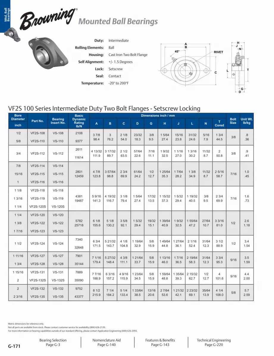
Mtd
. Ba
ll
Be
ari
ng
s
G-171
Mounted Ball Bearings
Duty: Intermediate
Rolling Elements: Ball
Housing: Cast Iron Two Bolt Flange
Self Alignment: +/- 1.5 Degrees
Lock: Setscrew
Seal: Contact
Temperature: -20° to 200°F
VF2S 100 Series Intermediate Duty Two Bolt Flanges - Setscrew Locking
BA
C L
H
NJ
45°
GD
RIVET
T
Bore Diameter Part No. Bearing
Insert No.
Basic Dynamic Rating
lb/N
Dimensions inch / mmBolt Size
Unit Wt. lb/kgA B C D G H J L N T
Coredinch
1/2 VF2S-108 VS-108 2108 3 7/8 98.4
3 76.2
2 1/8 54.0
23/3218.3
3/8 9.5
1 5/6427.4
15/1623.8
31/3224.6
5/167.9
1 3/4 44.5
3/8 .8
.36 5/8 VF2S-110 VS-110 9377
3/4 VF2S-112 VS-1122611 4 13/32
111.93 17/32
89.72 1/2 63.5
57/6422.6
7/1611.1
1 9/3232.5
1 1/1627.0
1 3/1630.2
11/328.7
2 50.8
3/8 .9
.4111614
7/8 VF2S-114 VS-114
280112459
4 7/8 123.8
3 57/6498.8
2 3/4 69.9
61/6424.2
1/2 12.7
1 25/6435.3
1 7/6428.2
1 3/8 34.9
11/328.7
2 5/1658.7
7/161.0.45
15/16 VF2S-115 VS-115
1 VF2S-116 VS-116
1 1/8 VF2S-118 VS-118
438119487
5 9/16141.3
4 19/32116.7
3 1/8 79.4
1 5/6427.4
17/3213.5
1 15/3237.3
1 5/3229.4
1 19/3240.5
3/8 9.5
2 3/4 69.9
7/161.6.73
1 3/16 VF2S-119 VS-119
1 1/4 VF2S-120S VS-120S
1 1/4 VF2S-120 VS-120
578225718
6 1/8 155.6
5 1/8 130.2
3 5/8 92.1
1 5/3229.4
19/3215.1
1 39/6440.9
1 9/3232.5
1 55/6447.2
27/6410.7
3 3/1681.0
1/22.6
1.181 3/8 VF2S-122 VS-122
1 7/16 VF2S-123 VS-123
1 1/2 VF2S-124 VS-1247340 6 3/4
171.55 21/32143.7
4 1/8 104.8
1 19/6432.9
5/8 15.9
1 49/6444.8
1 27/6436.1
2 1/1652.4
31/6412.3
3 1/2 88.9
1/2 3.4
1.5432648
1 11/16 VF2S-127 VS-127 7901 7 1/16179.4
5 27/32148.4
4 3/8 111.1
1 21/6433.7
5/8 15.9
1 13/1646.0
1 7/1636.5
2 19/6458.3
31/6412.3
3 3/4 95.3
9/163.5
1.591 3/4 VF2S-128 VS-128 35144
1 15/16 VF2S-131 VS-131 7889 7 7/16188.9
6 3/16157.2
4 9/16115.9
1 23/6434.5
5/8 15.9
1 59/6448.8
1 35/6439.3
2 15/3262.7
1/2 12.7
4 101.6
9/164.4
2.002 VF2S-132S VS-132S 35090
2 VF2S-132 VS-132 9752 8 1/2 215.9
7 1/4 184.2
5 1/4 133.4
1 33/6438.5
13/1620.6
2 7/6453.6
1 21/3242.1
2 23/3269.1
35/6413.9
4 1/4 108.0
5/8 5.7
2.592 3/16 VF2S-135 VS-135 43377
Metric dimensions for reference only.
Not all parts are available from stock. Please contact customer service for availability (800) 626-2120.
For more information on bearing capabilities outside of our standard offering, please contact Application Engineering (800) 626-2093.
Bearing SelectionPage G-3
Nomenclature AidPage G-140
Features & BenefitsPage G-143
Technical EngineeringPage G-220

Mtd
. Ba
ll
Be
ari
ng
s
G-172
Mounted Ball Bearings
VF2E 100 Series Intermediate Duty Two Bolt Flanges - Eccentric Locking
BA
45°
LC T
GD
N
HJ
RIVET
Duty: Intermediate
Rolling Elements: Ball
Housing: Cast Iron Two Bolt Flange
Self Alignment: +/- 1.5 Degrees
Lock: Eccentric
Seal: Contact
Temperature: -20° to 200°F
Bore Diameter Part No. Bearing
Insert No.
Basic Dynamic Rating
lb/N
Dimensions inch / mmBolt Size
Unit Wt. lb/kgA B C D G H J L N T
Coredinch
1/2 VF2E-108 VE-108 2108 3 7/8 98.4
3 76.2
2 1/8 54.0
23/3218.3
3/8 9.5
1 21/6433.7
1 3/1630.2
1 3/1630.2
5/167.9
1 3/4 44.5
3/8 1.0.45 5/8 VF2E-110 VE-110 9377
3/4 VF2E-112 VE-1122611 4 13/32
111.93 17/32
89.72 1/2 63.5
57/6422.6
7/1611.1
1 31/6437.7
1 17/6432.1
1 5/1633.3
11/328.7
2 50.8
3/8 1.1.5011614
7/8 VF2E-114 VE-114
280112459
4 7/8 123.8
3 57/6498.8
2 3/4 69.9
61/6424.2
1/2 12.7
1 35/6439.3
1 17/6432.1
1 1/2 38.1
11/328.7
2 5/1658.7
7/161.5.68
15/16 VF2E-115 VE-115
1 VF2E-116 VE-116
1 1/8 VF2E-118 VE-118
438119487
5 9/16141.3
4 19/32116.7
3 1/8 79.4
1 5/6427.4
17/3213.5
1 47/6444.1
1 27/6436.1
1 3/4 44.5
3/8 9.5
2 3/4 69.9
7/161.9.86
1 3/16 VF2E-119 VE-119
1 1/4 VF2E-120S VE-120S
1 1/4 VF2E-120 VE-120
578225718
6 1/8 155.6
5 1/8 130.2
3 5/8 92.1
1 5/3229.4
19/3215.1
1 29/3248.4
1 37/6440.1
2 3/1655.6
27/6410.7
3 3/1681.0
1/2 2.8
1.271 3/8 VF2E-122 VE-122
1 7/16 VF2E-123 VE-123
1 1/2 VF2E-124 VE-1247340 6 3/4
171.55 21/32143.7
4 1/8 104.8
1 19/6432.9
5/8 15.9
2 7/6453.6
1 49/6444.8
2 3/8 60.3
31/6412.3
3 1/2 88.9
1/2 3.6
1.6332648
1 11/16 VF2E-127 VE-127 7901 7 1/16179.4
5 27/32148.4
4 3/8 111.1
1 21/6433.7
5/8 15.9
2 5/3254.8
1 49/6444.8
2 1/2 63.5
31/6412.3
3 3/4 95.3
9/163.8
1.721 3/4 VF2E-128 VE-128 35144
1 15/16 VF2E-131 VE-131 7889 7 7/16188.9
6 3/16157.2
4 9/16115.9
1 23/6434.5
5/8 15.9
2 5/3254.8
1 25/3245.2
2 3/4 69.9
1/2 12.7
4 101.6
9/164.5
2.042 VF2E-132S VE-132S 35090
2 VF2E-132 VE-132 9752 8 1/2 215.9
7 1/4 184.2
5 1/4 133.4
1 33/6438.5
13/1620.6
2 7/1661.9
1 63/6450.4
3 76.2
35/6413.9
4 1/4 108.0
5/8 6.1
2.772 3/16 VF2E-135 VE-135 43377
Bearing SelectionPage G-3
Nomenclature AidPage G-140
Features & BenefitsPage G-143
Technical EngineeringPage G-220
For Replacement Lock Collar see page G-214.

Mtd
. Ba
ll
Be
ari
ng
s
G-173
Mounted Ball Bearings
Bore Diameter Part No. Bearing
Insert No.
Basic Dynamic Rating
lb/N
Dimensions inch / mmBolt Size
Unit Wt. lb/kgA B C D G H J L N T
Coredinch
1/2 VF2S-208 VS-208 2108 3 7/8 98.4
3 76.2
2 1/8 54.0
23/3218.3
3/8 9.5
1 5/6427.4
1 1/3226.2
31/3224.6
13/3210.3
1 3/4 44.5
3/8 .9
.41 5/8 VF2S-210 VS-210 9377
3/4 VF2S-212 VS-2122611 4 13/32
111.93 17/32
89.72 1/2 63.5
57/6422.6
7/1611.1
1 9/3232.5
1 7/3231.0
1 3/1630.2
1/2 12.7
2 50.8
3/8 1.0.4511614
7/8 VF2S-214 VS-2142801
124594 7/8 123.8
3 57/6498.8
2 3/4 69.9
61/6424.2
1/2 12.7
1 7/1636.5
1 3/8 34.9
1 3/8 34.9
9/1614.3
2 5/1658.7
7/161.1.50
15/16 VF2S-215 VS-215
1 VF2S-216 VS-216
1 1/8 VF2S-218 VS-2184381
194875 9/16141.3
4 19/32116.7
3 1/8 79.4
1 5/6427.4
17/3213.5
1 9/1639.7
1 1/2 38.1
1 19/3240.5
5/8 15.9
2 3/4 69.9
7/161.7.77
1 3/16 VF2S-219 VS-219
1 1/4 VF2S-220S VS-220S
1 1/4 VF2S-220 VS-2205782
257186 1/8 155.6
5 1/8 130.2
3 5/8 92.1
1 5/3229.4
19/3215.1
1 3/4 44.5
1 11/1642.9
1 55/6447.2
11/1617.5
3 3/1681.0
1/2 2.7
1.221 3/8 VF2S-222 VS-222
1 7/16 VF2S-223 VS-223
1 1/2 VF2S-224 VS-2247340 6 3/4
171.55 21/32143.7
4 1/8 104.8
1 19/6432.9
5/8 15.9
2 1/6451.2
1 15/1649.2
2 1/1652.4
3/4 19.1
3 1/2 88.9
1/2 3.6
1.6332648
1 5/8 VF2S-226 VS-2267901
351447 1/16179.4
5 27/32148.4
4 3/8 111.1
1 21/6433.7
5/8 15.9
2 3/6452.0
1 15/1649.2
2 19/6458.3
3/4 19.1
3 3/4 95.3
9/163.7
1.681 11/16 VF2S-227 VS-227
1 3/4 VF2S-228 VS-228
1 15/16 VF2S-231 VS-231 7889 7 7/16188.9
6 3/16157.2
4 9/16115.9
1 23/6434.5
5/8 15.9
2 5/3254.8
2 1/3251.6
2 15/3262.7
3/4 19.1
4 101.6
9/164.6
2.092 VF2S-232S VS-232S 35090
2 VF2S-232 VS-232 9752 8 1/2 215.9
7 1/4 184.2
5 1/4 133.4
1 33/6438.5
13/1620.6
2 5/1658.7
2 3/1655.6
2 23/3269.1
7/8 22.2
4 1/4 108.0
5/8 5.9
2.682 3/16 VF2S-235 VS-235 43377
2 1/4 VF2S-236 VS-236 11789 9 1/4 235.0
7 15/16201.6
5 7/16138.1
1 11/1642.9
13/1620.6
2 11/1668.3
2 9/1665.1
2 63/6475.8
1 25.4
4 3/4 120.7
5/8 9.6
4.352 7/16 VF2S-239 VS-239 52437
Duty: Standard
Rolling Elements: Ball
Housing: Cast Iron Two Bolt Flange
Self Alignment: +/- 1.5 Degrees
Lock: Setscrew
Seal: Contact and Flinger
Temperature: -20° to 200°F
VF2S 200 Series Standard Duty Two Bolt Flanges - Setscrew Locking - Inch
RIVET
BA
TLC
GD
NJH
45°
Metric dimensions for reference only.
Not all parts are available from stock. Please contact customer service for availability (800) 626-2120.
For more information on bearing capabilities outside of our standard offering, please contact Application Engineering (800) 626-2093.
Bearing SelectionPage G-3
Nomenclature AidPage G-140
Features & BenefitsPage G-143
Air Handling OptionPage G-144
Technical EngineeringPage G-220

Mtd
. Ba
ll
Be
ari
ng
s
G-174
Mounted Ball Bearings
Bore Diameter Part No. Bearing
Insert No.
Basic Dynamic Rating
N/lb
Dimensions mm / inchBolt Size
Unit Wt. kg/lbA B C D G H J L N T
Coredmm
20 VF2S-20MM VS-20MM11614 111.9
4 13/3290.0
3 17/3263.52 1/2
22.6 57/64
11.1 7/16
32.51 9/32
31.01 7/32
30.21 3/16
12.7 1/2
50.82
M10.451.02611
25 VF2S-25MM VS-25MM12459 123.8
4 7/8 99.0
3 79/8869.92 3/4
24.2 61/64
12.7 1/2
36.51 7/16
34.91 3/8
34.91 3/8
14.3 9/16
58.72 5/16
M10.501.12801
30 VF2S-30MM VS-30MM19487 141.3
5 9/16116.5
4 44/7579.43 1/8
27.41 5/64
13.5 17/32
39.71 9/16
38.11 1/2
40.51 19/32
15.9 5/8
69.92 3/4
M10.771.74381
35 VF2S-35MM VS-35MM25718 155.6
6 1/8 130.0
5 11/9392.13 5/8
29.41 5/32
15.1 19/32
44.51 3/4
42.91 11/16
47.21 55/64
17.5 11/16
81.03.1875
M121.222.75782
40 VF2S-40MM VS-40MM32648 171.5
6 3/4 143.5
5 63/97104.84 1/8
32.91 19/64
15.9 5/8
51.22 1/64
49.21 15/16
52.42 1/16
19.1 3/4
88.93 1/2
M121.633.67340
45 VF2S-45MM VS-45MM35144 179.4
7 1/16148.5
5 11/13111.14 3/8
33.71 21/64
15.9 5/8
52.02 3/64
49.21 15/16
57.22 1/4
19.1 3/4
95.33 3/4
M141.683.77901
50 VF2S-50MM VS-50MM35090 188.9
7 7/16157.0
6 17/94115.94 9/16
34.51 23/64
15.9 5/8
54.82 5/32
51.62 1/32
62.72 15/32
19.1 3/4
101.64
M162.094.67889
55 VF2S-55MM VS-55MM43377 215.9
8 1/2 184.0
7 21/86133.45 1/4
38.51 33/64
20.6 13/16
58.72 5/16
55.62 3/16
69.12 23/32
22.2 7/8
108.04 1/4
M162.685.99752
60 VF2S-60MM VS-60MM52437 235.0
9 1/4 202.0
7 81/85138.15 7/16
42.91 11/16
20.6 13/16
68.32 11/16
65.12 9/16
75.82 63/64
25.41
120.74.75
M164.359.611789
Duty: Standard
Rolling Elements: Ball
Housing: Cast Iron Two Bolt Flange
Self Alignment: +/- 1.5 Degrees
Lock: Setscrew
Seal: Contact and Flinger
Temperature: -20° to 200°F
VF2S 200 Series Standard Duty Two Bolt Flanges - Setscrew Locking - Metric
RIVET
BA
TLC
GD
NJH
45°
Bearing SelectionPage G-3
Nomenclature AidPage G-140
Features & BenefitsPage G-143
Air Handling OptionPage G-144
Technical EngineeringPage G-220

Mtd
. Ba
ll
Be
ari
ng
s
G-175
Mounted Ball Bearings
Bore Diameter Part No. Bearing
Insert No.
Basic Dynamic Rating
lb/N
Dimensions inch / mmBolt Size
Unit Wt. lb/kgA B C D G H J L N T
Coredinch
3/4 VF2B-212 VB-2122611 4 13/32
111.93 17/32
89.72 1/2 63.5
57/6422.6
7/1611.1
1 11/3234.1
1 9/3232.5
1 3/4 44.5
1/2 12.7
2 50.8
3/8 1.1.5011614
7/8 VF2B-214 VB-214
280112459
4 7/8 123.8
3 57/6498.8
2 3/4 69.9
61/6424.2
1/2 12.7
1 1/2 38.1
1 7/1636.5
1 15/1649.2
9/1614.3
2 5/1658.7
7/161.3.59
15/16 VF2B-215 VB-215
1 VF2B-216 VB-216
1 1/8 VF2B-218 VB-218
438119487
5 9/16141.3
4 19/32116.7
3 1/8 79.4
1 5/6427.4
17/3213.5
1 5/8 41.3
1 9/1639.7
2 3/1655.6
5/8 15.9
2 3/4 69.9
7/162.0.91
1 3/16 VF2B-219 VB-219
1 1/4 VF2B-220S VB-220S
1 1/4 VF2B-220 VB-2205782 6 1/8
155.65 1/8 130.2
3 5/8 92.1
1 5/3229.4
19/3215.1
1 13/1646.0
1 3/4 44.5
2 7/1661.9
11/1617.5
3 3/1681.0
1/2 3.0
1.3625718
1 3/8 VF2B-222 VB-222 5782 6 1/8 155.6
5 1/8 130.2
3 5/8 92.1
1 5/3229.4
19/3215.1
1 13/1646.0
1 3/4 44.5
2 9/1665.1
11/1617.5
3 3/1681.0
1/2 3.0
1.361 7/16 VF2B-223 VB-223 25718
1 1/2 VF2B-224 VB-2247340 6 3/4
171.55 21/32143.7
4 1/8 104.8
1 19/6432.9
5/8 15.9
2 5/6452.8
2 50.8
2 11/1668.3
3/4 19.1
3 1/2 88.9
1/2 3.3
1.5032648
1 5/8 VF2B-226 VB-2267901 7 1/16
179.45 27/32148.4
4 3/8 111.1
1 21/6433.7
5/8 15.9
2 7/6453.6
2 50.8
2 13/1671.4
3/4 19.1
3 3/4 95.3
9/164.0
1.8135144
1 11/16 VF2B-227 VB-227 7901 7 1/16179.4
5 27/32148.4
4 3/8 111.1
1 21/6433.7
5/8 15.9
2 7/6453.6
2 50.8
2 15/1674.6
3/4 19.1
3 3/4 95.3
9/164.0
1.811 3/4 VF2B-228 VB-228 35144
1 15/16 VF2B-231 VB-231 7889 7 7/16188.9
6 3/16157.2
4 9/16115.9
1 23/6434.5
5/8 15.9
2 7/3256.4
2 3/3253.2
3 3/8 85.7
3/4 19.1
4 101.6
9/164.2
1.912 VF2B-232S VB-232S 35090
2 VF2B-232 VB-2329752 8 1/2
215.97 1/4 184.2
5 1/4 133.4
1 33/6438.5
13/1620.6
2 3/8 60.3
2 1/4 57.2
3 1/2 88.9
7/8 22.2
4 1/4 108.0
5/8 7.1
3.2243377
2 3/16 VF2B-235 VB-2359752 8 1/2
215.97 1/4 184.2
5 1/4 133.4
1 33/6438.5
13/1620.6
2 3/8 60.3
2 1/4 57.2
3 5/8 92.1
7/8 22.2
4 1/4 108.0
5/8 7.1
3.2243377
VF2B 200 Series Standard Duty Two Bolt Flanges - BOA Concentric Locking
D
NJH
G
45°BA
RIVET
TC L
Duty: Standard
Rolling Elements: Ball
Housing: Cast Iron Two Bolt Flange
Self Alignment: +/- 1.5 Degrees
Lock: BOA Concentric
Seal: Contact and Flinger
Temperature: -20° to 200°F
Metric dimensions for reference only.
Not all parts are available from stock. Please contact customer service for availability (800) 626-2120.
For more information on bearing capabilities outside of our standard offering, please contact Application Engineering (800) 626-2093.
Bearing SelectionPage G-3
Nomenclature AidPage G-140
Features & BenefitsPage G-143
Air Handling OptionPage G-144
Technical EngineeringPage G-220
For Replacement Lock Collar see page G-214.

Mtd
. Ba
ll
Be
ari
ng
s
G-176
Mounted Ball Bearings
Duty: Standard
Rolling Elements: Ball
Housing: Cast Iron Two Bolt Flange
Self Alignment: +/- 1.5 Degrees
Lock: Eccentric
Seal: Contact and Flinger
Temperature: -20° to 200°F
VF2E 200 Series Standard Duty Two Bolt Flanges - Eccentric Locking
G
BA
LC T
NJ
D
H
45° RIVET
Bore Diameter Part No. Bearing
Insert No.
Basic Dynamic Rating
lb/N
Dimensions inch / mmBolt Size
Unit Wt. lb/kgA B C D G H J L N T
Coredinch
1/2 VF2E-208 VE-208 2108 3 7/8 98.4
3 76.2
2 1/8 54.0
1 1/3226.2
1/2 12.7
1 43/6442.5
1 15/3237.3
1 3/1630.2
35/6413.9
1 3/4 44.5
3/8 1.0.45 5/8 VF2E-210 VE-210 9377
3/4 VF2E-212 VE-2122611 4 13/32
111.93 17/32
89.72 1/2 63.5
1 5/6427.4
1/2 12.7
1 51/6445.6
1 23/3243.7
1 5/1633.3
43/6417.1
2 50.8
3/8 1.1.5011614
7/8 VF2E-214 VE-2142801
124594 7/8 123.8
3 57/6498.8
2 3/4 69.9
1 5/6427.4
17/3213.5
1 13/1646.0
1 3/4 44.5
1 1/2 38.1
11/1617.5
2 5/1658.7
7/161.5.68
15/16 VF2E-215 VE-215
1 VF2E-216 VE-216
1 1/8 VF2E-218 VE-2184381
194875 9/16141.3
4 19/32116.7
3 1/8 79.4
1 13/6430.6
17/3213.5
2 50.8
1 29/3248.4
1 3/4 44.5
23/3218.3
2 3/4 69.9
7/162.1.95
1 3/16 VF2E-219 VE-219
1 1/4 VF2E-220S VE-220S
1 1/4 VF2E-220 VE-2205782
257186 1/8 155.6
5 1/8 130.2
3 5/8 92.1
1 1/4 31.8
5/8 15.9
2 1/8 54.0
2 1/6451.2
2 3/1655.6
3/4 19.1
3 3/1681.0
1/2 2.9
1.321 3/8 VF2E-222 VE-222
1 7/16 VF2E-223 VE-223
1 1/2 VF2E-224 VE-2247340 6 3/4
171.55 21/32143.7
4 1/8 104.8
1 13/3235.7
5/8 15.9
2 5/1658.7
2 7/3256.4
2 3/8 60.3
27/3221.4
3 1/2 88.9
1/2 3.8
1.7232648
1 5/8 VF2E-226 VE-2267901
351447 1/16179.4
5 27/32148.4
4 3/8 111.1
1 13/3235.7
5/8 15.9
2 5/1658.7
2 7/3256.4
2 1/2 63.5
27/3221.4
3 3/4 95.3
9/163.9
1.771 11/16 VF2E-227 VE-227
1 3/4 VF2E-228 VE-228
1 15/16 VF2E-231 VE-2317889 7 7/16
188.96 3/16157.2
4 9/16115.9
1 39/6440.9
11/1617.5
2 5/8 66.7
2 15/3262.7
2 3/4 69.9
31/3224.6
4 101.6
9/164.8
2.1835090
2 VF2E-232 VE-232 9752 8 1/2 215.9
7 1/4 184.2
5 1/4 133.4
1 49/6444.8
13/1620.6
2 31/3275.4
2 13/1671.4
3 76.2
1 3/3227.8
4 1/4 108.0
5/8 6.2
2.812 7/16 VF2E-235 VE-235 43377
2 1/4 VF2E-236 VE-236 11789 9 1/4 235.0
7 15/16201.6
5 7/16138.1
1 31/3250.0
13/1620.6
3 1/4 82.6
3 1/1677.8
3 3/8 85.7
1 7/3231.0
4 3/4 120.7
5/8 9.6
4.352 7/16 VF2E-239 VE-239 52437
Bearing SelectionPage G-3
Nomenclature AidPage G-140
Features & BenefitsPage G-143
Air Handling OptionPage G-144
Technical EngineeringPage G-220
For Replacement Lock Collar see page G-214.

Mtd
. Ba
ll
Be
ari
ng
s
G-177
Mounted Ball Bearings
VF2S 300 Series Medium Duty Two Bolt Flanges - Setscrew Locking
45°BA
TL
GD
NJH
RIVET
C
Duty: Medium
Rolling Elements: Ball
Housing: Cast Iron Two Bolt Flange
Self Alignment: +/- 1.5 Degrees
Lock: Setscrew
Seal: Contact and Flinger
Temperature: -20° to 200°F
Bore Diameter Part No. Bearing
Insert No.
Basic Dynamic Rating
lb/N
Dimensions inch / mmBolt Size
Unit Wt. lb/kgA B C D G H J L N T
Coredinch
1 VF2S-316 VS-3164381 5 9/16
141.34 19/32116.7
3 1/8 79.4
1 5/6427.4
17/3213.5
1 9/1639.7
1 1/2 38.1
1 19/3240.5
5/8 15.9
2 3/4 69.9
7/162.7
1.2219487
1 3/16 VF2S-319 VS-319 5782 6 1/8 155.6
5 1/8 130.2
3 5/8 92.1
1 5/3229.4
19/3215.1
1 3/4 44.5
1 11/1642.9
1 55/6447.2
11/1617.5
3 3/1681.0
1/2 2.7
1.221 1/4 VF2S-320 VS-220 25718
1 7/16 VF2S-323 VS-3237340 6 3/4
171.55 21/32143.7
4 1/8 104.8
1 19/6432.9
5/8 15.9
2 1/6451.2
1 15/1649.2
2 1/1652.4
3/4 19.1
3 1/2 88.9
1/2 4.8
2.1832648
1 1/2 VF2S-324 VS-3247901 7 1/16
179.45 27/32148.4
4 3/8 111.1
1 21/6433.7
5/8 15.9
2 3/6452.0
1 15/1649.2
2 19/6458.3
3/4 19.1
3 3/4 95.3
9/164.8
2.1835144
1 11/16 VF2S-327 VS-327 7889 7 7/16188.9
6 3/16157.2
4 9/16115.9
1 23/6434.5
5/8 15.9
2 5/3254.8
2 1/3251.6
2 15/3262.7
3/4 19.1
4 101.6
9/167.6
3.451 3/4 VF2S-328 VS-328 35090
1 15/16 VF2S-331 VS-331 9752 8 1/2 215.9
7 1/4 184.2
5 1/4 133.4
1 33/6438.5
13/1620.6
2 5/1658.7
2 3/1655.6
2 23/3269.1
7/8 22.2
4 1/4 108.0
5/8 9.6
4.352 VF2S-332 VS-232S 43377
Metric dimensions for reference only.
Not all parts are available from stock. Please contact customer service for availability (800) 626-2120.
For more information on bearing capabilities outside of our standard offering, please contact Application Engineering (800) 626-2093.
Bearing SelectionPage G-3
Nomenclature AidPage G-140
Features & BenefitsPage G-143
Technical EngineeringPage G-220

Mtd
. Ba
ll
Be
ari
ng
s
G-178
Mounted Ball Bearings
Duty: Medium
Rolling Elements: Ball
Housing: Cast Iron Two Bolt Flange
Self Alignment: +/- 1.5 Degrees
Lock: BOA Concentric
Seal: Contact and Flinger
Temperature: -20° to 200°F
VF2B 300 Series Medium Duty Two Bolt Flanges - BOA Concentric Locking
D
NJH
G
45°BA
RIVET
TC L
Bore Diameter Part No. Bearing
Insert No.
Basic Dynamic Rating
lb/N
Dimensions inch / mmBolt Size
Unit Wt. lb/kgA B C D G H J L N T
Coredinch
1 VF2B-316 VB-3164381 5 9/16
141.34 19/32116.7
3 1/8 79.4
1 5/6427.4
17/3213.5
1 5/8 41.3
1 9/1639.7
2 1/162.1
5/8 15.9
2 3/4 69.9
7/162.0.9119487
1 3/16 VF2B-319 VB-319 5782 6 1/8 155.6
5 1/8 130.2
3 5/8 92.1
1 5/3229.4
19/3215.1
1 13/1646.0
1 3/4 44.5
2 7/1661.9
11/1617.5
3 3/1681.0
1/2 3.0
1.361 1/4 VF2B-320 VB-220 25718
1 7/16 VF2B-323 VB-3237340 6 3/4
171.55 21/32143.7
4 1/8 104.8
1 19/6432.9
5/8 15.9
2 5/6452.8
2 50.8
2 11/1668.3
3/4 19.1
3 1/2 88.9
1/2 3.3
1.5032648
1 1/2 VF2B-324 VB-3247901 7 1/16
179.45 27/32148.4
4 3/8 111.1
1 21/6433.7
5/8 15.9
2 7/6453.6
2 50.8
2 13/1671.4
3/4 19.1
3 3/4 95.3
9/164.0
1.8135144
1 11/16 VF2B-327 VB-327 7889 7 7/16188.9
6 3/16157.2
4 9/16115.9
1 23/6434.5
5/8 15.9
2 7/3256.4
2 3/3253.2
3 1/4 82.6
3/4 19.1
4 101.6
9/165.2
2.361 3/4 VF2B-328 VB-328 35090
1 15/16 VF2B-331 VB-331 9752 8 1/2 215.9
7 1/4 184.2
5 1/4 133.4
1 33/6438.5
13/1620.6
2 3/8 60.3
2 1/4 57.2
3 1/2 88.9
7/8 22.2
4 1/4 108.0
5/8 7.1
3.222 VF2B-332 VB-232S 43377
Bearing SelectionPage G-3
Nomenclature AidPage G-140
Features & BenefitsPage G-143
Technical EngineeringPage G-220
For Replacement Lock Collar see page G-214.

Mtd
. Ba
ll
Be
ari
ng
s
G-179
Mounted Ball Bearings
Duty: Standard
Rolling Elements: Ball
Housing: Cast Iron Flange Bracket
Self Alignment: +/- 1.5 Degrees
Lock: Setscrew
Seal: Contact and Flinger
Temperature: -20° to 200°F
VFBS 200 Series Standard Duty Flange Brackets - Setscrew Locking
CB
D
F
A
45°M
G
L
E
NJ
HR
Bore Diameter Part No. Bearing
Insert No.
Basic Dynamic Rating
lb/N
Dimensions inch / mmBolt Size
Unit Wt.
lb/kgA B C D E F G H J L M N Rinch
3/4 VFBS-212 VS-2122611 3
76.22 3/8 60.3
1 1/2 38.1
1 11/1642.9
4 3/16106.4
7/8 22.2
5/167.9
1 11/3234.1
1 7/3226.2
1 3/1630.2
2 3/8 60.3
1/2 12.7
61/6424.2
3/8 1.1.5011614
7/8 VFBS-214 VS-214
280112459
3 3/8 85.7
2 1/2 63.5
1 5/8 41.3
1 13/1646.0
4 3/4 120.7
1 1/8 28.6
3/8 9.5
1 1/2 38.1
1 3/834.9
1 3/8 34.9
2 3/4 69.9
9/1614.3
1 1/6425.8
3/8 1.9.86
15/16 VFBS-215 VS-215
1 VFBS-216 VS-216
1 1/8 VFBS-218 VS-218
438119487
3 3/4 95.3
2 3/4 69.9
1 7/8 47.6
2 1/1652.4
5 23/64136.1
1 1/4 31.8
3/8 9.5
1 5/8 41.3
1 1/238.1
1 19/3240.5
3 7/3281.8
5/8 15.9
1 9/6429.0
3/8 2.8
1.271 3/16 VFBS-219 VS-219
1 1/4 VFBS-220S VS-220S
1 1/4 VFBS-220 VS-220
578225718
4 1/4 108.0
3 1/4 82.6
2 50.8
2 3/8 60.3
6 1/8 155.6
1 1/4 31.8
1/2 12.7
1 7/8 47.6
1 11/1642.9
1 55/6447.2
3 3/4 95.3
11/1617.5
1 9/3232.5
1/2 2.6
1.181 3/8 VFBS-222 VS-222
1 7/16 VFBS-223 VS-223
1 15/16 VFBS-231 VS-231 7889 5 3/16131.8
4 101.6
2 3/4 69.9
2 15/1674.6
7 15/32189.7
1 5/8 41.3
1/2 12.7
2 5/3254.8
2 1/3251.6
2 15/3262.7
4 9/16115.9
3/4 19.1
1 23/6434.5
1/2 4.2
1.912 VFBS-232S VS-232S 35090
Metric dimensions for reference only.
Not all parts are available from stock. Please contact customer service for availability (800) 626-2120.
For more information on bearing capabilities outside of our standard offering, please contact Application Engineering (800) 626-2093.
Bearing SelectionPage G-3
Nomenclature AidPage G-140
Features & BenefitsPage G-143
Technical EngineeringPage G-220

Mtd
. Ba
ll
Be
ari
ng
s
G-180
Mounted Ball Bearings
VFBB 200 Series Standard Duty Flange Brackets - BOA Concentric Locking
45°M
D
F
A
CB
L
E
G
NJ
HR
Duty: Standard
Rolling Elements: Ball
Housing: Cast Iron Flange Bracket
Self Alignment: +/- 1.5 Degrees
Lock: BOA Concentric
Seal: Contact and Flinger
Temperature: -20° to 200°F
Bore Diameter Part No. Bearing
Insert No.
Basic Dynamic Rating
lb/N
Dimensions inch / mmBolt Size
Unit Wt.
lb/kgA B C D E F G H J L M N Rinch
3/4 VFBB-212 VB-2122611 3
76.22 3/8 60.3
1 1/2 38.1
1 11/1642.9
4 3/16106.4
7/8 22.2
5/167.9
1 13/3235.7
1 9/3232.5
1 3/4 44.5
2 3/8 60.3
1/2 12.7
61/6424.2
3/8 1.2.5411614
7/8 VFBB-214 VB-214
280112459
3 3/8 85.7
2 1/2 63.5
1 5/8 41.3
1 13/1646.0
4 3/4 120.7
1 1/8 28.6
3/8 9.5
1 9/1639.7
1 7/1636.5
1 15/1649.2
2 3/4 69.9
9/1614.3
1 1/6425.8
3/8 2.1.95
15/16 VFBB-215 VB-215
1 VFBB-216 VB-216
1 1/8 VFBB-218 VB-218
438119487
3 3/4 95.3
2 3/4 69.9
1 7/8 47.6
2 1/1652.4
5 23/64136.1
1 1/4 31.8
3/8 9.5
1 11/1642.9
1 9/1639.7
2 3/1655.6
3 7/3281.8
5/8 15.9
1 9/6429.0
3/8 2.8
1.271 3/16 VFBB-219 VB-219
1 1/4 VFBB-220S VB-220S
1 1/4 VFBB-220 VB-2204381 4 1/4
108.03 1/4 82.6
2 50.8
2 3/8 60.3
6 1/8 155.6
1 1/4 31.8
1/2 12.7
1 15/1649.2
1 3/444.5
2 7/1661.9
3 3/4 95.3
11/1617.5
1 9/3232.5
3/8 2.9
1.3219487
1 3/8 VFBB-222 VB-222 5782 4 1/4 108.0
3 1/4 82.6
2 50.8
2 3/8 60.3
6 1/8 155.6
1 1/4 31.8
1/2 12.7
1 15/1649.2
1 3/444.5
2 9/1665.1
3 3/4 95.3
11/1617.5
1 9/3232.5
1/2 2.9
1.321 7/16 VFBB-223 VB-223 25718
1 15/16 VFBB-231 VB-231 7889 5 3/16131.8
4 101.6
2 3/4 69.9
2 15/1674.6
7 15/32189.7
1 5/8 41.3
1/2 12.7
2 7/3256.4
2 3/3252.2
3 3/8 85.7
4 9/16115.9
3/4 19.1
1 23/6434.5
1/2 4.8
2.182 VFBB-232S VB-232S 35090
Bearing SelectionPage G-3
Nomenclature AidPage G-140
Features & BenefitsPage G-143
Technical EngineeringPage G-220
For Replacement Lock Collar see page G-214.

Mtd
. Ba
ll
Be
ari
ng
s
G-181
Mounted Ball Bearings
Duty: Standard
Rolling Elements: Ball
Housing: Cast Iron Piloted Flange Cartridge
Self Alignment: +/- 1.5 Degrees
Lock: Setscrew
Seal: Contact and Flinger
Temperature: -20° to 200°F
VFCS 200 Series Standard Duty Piloted Flange Cartridges - Setscrew Locking
LA
BC
NH
J
GO
D
P +.000-.002
RIVET
Bore Diameter Part No. Bearing
Insert No.
Basic Dynamic Rating
lb/N
Dimensions inch / mmBolt Size
Unit Wt. lb/kgA BC D G H J L N O Pinch
1 1/8 VFCS-218 VS-218
438119487
4 3/8 111.1
3 5/8 92.1
1 63/6450.4
13/32 10.3
1 1/4 31.8
1 1/2 38.1
1 19/3240.5
5/8 15.9
7/325.6
3.00076.20
5/162.4
1.091 3/16 VFCS-219 VS-219
1 1/4 VFCS-220S VS-220S
1 1/4 VFCS-220 VS-220
578225718
5 127.0
4 1/8 104.8
1 1/1627.0
13/3210.3
1 5/1633.3
1 11/1642.9
1 55/6447.2
11/1617.5
11/328.7
3.375 85.73
3/8 3.2
1.451 3/8 VFCS-222 VS-222
1 7/16 VFCS-223 VS-223
1 1/2 VFCS-224 VS-2247340 5 1/4
133.44 3/8 111.1
1 3/1630.2
13/3210.3
1 1/2 38.1
1 15/1649.2
2 1/1652.4
3/4 19.1
13/3210.3
3.625 92.08
3/8 3.6
1.6332648
1 5/8 VFCS-226 VS-226
790135144
6 1/8 155.6
5 1/8 130.2
1 3/1630.2
13/3210.3
1 1/2 38.1
1 15/1649.2
2 19/6458.3
3/4 19.1
13/3210.3
4.250 107.95
7/164.9
2.221 11/16 VFCS-227 VS-227
1 3/4 VFCS-228 VS-228
1 15/16 VFCS-231 VS-231 7889 6 1/8 155.6
5 1/8 130.2
1 15/6431.4
13/3210.3
1 19/3240.5
2 1/1652.4
2 15/3262.7
3/4 19.1
7/1611.1
4.250 107.95
7/165.7
2.592 VFCS-232S VS-232S 35090
2 VFCS-232 VS-232 9752 6 3/8 161.9
5 3/8 136.5
1 3/834.9
13/3210.3
1 37/6440.1
2 13/6456.0
2 23/3269.1
7/8 22.2
19/3215.1
4.500 114.30
7/166.0
2.722 3/16 VFCS-235 VS-235 43377
2 1/4 VFCS-236 VS-236 11789 7 1/8 181.0
6 152.4
1 27/32 46.8
17/3213.5
2 50.8
2 7/8 73.0
2 63/6475.8
1 25.4
23/3218.3
5.000127.00
1/2 7.1
3.222 7/16 VFCS-239 VS-239 52437
Metric dimensions for reference only.
Not all parts are available from stock. Please contact customer service for availability (800) 626-2120.
For more information on bearing capabilities outside of our standard offering, please contact Application Engineering (800) 626-2093.
Bearing SelectionPage G-3
Nomenclature AidPage G-140
Features & BenefitsPage G-143
Technical EngineeringPage G-220

Mtd
. Ba
ll
Be
ari
ng
s
G-182
Mounted Ball Bearings
Bore Diameter Part No. Bearing
Insert No.
Basic Dynamic Rating
lb/N
Dimensions inch / mmBolt Size
Unit Wt. lb/kgA BC D G H J L N O Pinch
1 1/8 VFCB-218 VB-218 4381 4 3/8 111.1
3 5/8 92.1
63/6425.0
13/3210.3
1 5/1633.3
1 9/1639.7
2 3/1655.6
5/8 15.9
7/325.6
3.00076.20
3/8 2.6
1.181 3/16 VFCB-219 VB-219 19487
1 1/4 VFCB-220 VB-2205782 5
127.04 1/8 104.8
1 1/1627.0
13/3210.3
1 3/8 34.9
1 3/4 44.5
2 7/1661.9
11/1617.5
11/328.7
3.375 85.73
3/8 3.5
1.5925718
1 3/8 VFCB-222 VB-222 5782 5 127.0
4 1/8 104.8
1 1/1627.0
13/3210.3
1 3/8 34.9
1 3/4 44.5
2 9/1665.1
11/1617.5
11/328.7
3.37585.73
3/8 3.5
1.591 7/16 VFCB-223 VB-223 25718
1 1/2 VFCB-224 VB-2247340 5 1/4
133.44 3/8 111.1
1 3/1630.2
13/3210.3
1 9/1639.7
2 50.8
2 11/1668.3
3/4 19.1
13/3210.3
3.625 92.08
3/8 3.9
1.7732648
1 5/8 VFCB-226 VB-2267901 6 1/8
155.65 1/8 130.2
1 3/1630.2
13/3210.3
1 9/1639.7
2 50.8
2 13/1671.4
3/4 19.1
13/3210.3
4.250 107.95
7/165.2
2.3635144
1 11/16 VFCB-227 VB-227 7901 6 1/8 155.6
5 1/8 130.2
1 3/1630.2
13/3210.3
1 9/1639.7
2 50.8
2 15/1674.6
3/4 19.1
13/3210.3
4.250 107.95
7/165.2
2.361 3/4 VFCB-228 VB-228 35144
1 15/16 VFCB-231 VB-231 7889 6 1/8 155.6
5 1/8 130.2
1 15/6431.4
13/3210.3
1 21/3242.1
2 3/3253.2
3 3/8 85.7
3/4 19.1
7/1611.1
4.250 107.95
7/166.3
2.862 VFCB-232S VB-232S 35090
2 VFCB-232 VB-2329752 6 3/8
161.95 3/8 136.5
1 3/834.9
13/3210.3
1 41/6441.7
2 1/4 57.2
3 1/2 88.9
7/8 22.2
19/3215.1
4.500 114.30
7/166.6
2.9943377
2 3/16 VFCB-235 VB-2359752 6 3/8
161.95 3/8 136.5
1 3/834.9
13/3210.3
1 41/6441.7
2 1/4 57.2
3 5/8 92.1
7/8 22.2
19/3215.1
4.500 114.30
7/166.6
2.9943377
2 1/4 VFCB-236 VB-23611789 7 1/8
181.06
152.41 27/32
46.817/3213.5
2 1/1652.4
2 5/8 66.7
4 1/16103.2
1 25.4
23/3218.3
5.000127.00
1/2 8.3
3.7652437
2 7/16 VFCB-239 VB-23911789 7 1/8
181.06
152.41 27/32
46.817/3213.5
2 1/1652.4
2 5/8 66.7
4 1/8 104.8
1 25.4
23/3218.3
5.000127.00
1/2 8.3
3.7652437
VFCB 200 Series Standard Duty Piloted Flange Cartridges - BOA Concentric Locking
LA
BC
N
JH
GO
D
RIVET
P +.000-.002
Duty: Standard
Rolling Elements: Ball
Housing: Cast Iron Piloted Flange Cartridge
Self Alignment: +/- 1.5 Degrees
Lock: BOA Concentric
Seal: Contact and Flinger
Temperature: -20° to 200°F
Bearing SelectionPage G-3
Nomenclature AidPage G-140
Features & BenefitsPage G-143
Technical EngineeringPage G-220
For Replacement Lock Collar see page G-214.

Mtd
. Ba
ll
Be
ari
ng
s
G-183
Mounted Ball Bearings
Duty: Medium
Rolling Elements: Ball
Housing: Cast Iron Piloted Flange Cartridge
Self Alignment: +/- 1.5 Degrees
Lock: Setscrew
Seal: Contact and Flinger
Temperature: -20° to 200°F
VFCS 300 Series Medium Duty Piloted Flange Cartridges - Setscrew LockingBore
Diameter Part No.Bearing Insert
No.
Basic Dynamic Rating
lb/N
Dimensions inch / mmBolt Size
Unit Wt. lb/kgA BC D G H J L N O Pinch
1 VFCS-316 VS-3164381 4 3/8
111.13 5/8 92.1
63/6425.0
13/3210.3
1 1/4 31.8
1 1/2 38.1
1 19/3240.5
5/8 15.9
7/325.6
3.00076.20
5/162.5
1.1319487
1 3/16 VFCS-319 VS-319 5782 5 127.0
4 1/8 104.8
1 1/1627.0
13/3210.3
1 5/1633.3
1 11/1642.9
1 55/6447.2
11/1617.5
11/328.7
3.375 85.73
3/8 3.2
1.451 1/4 VFCS-320 VS-220 25718
1 7/16 VFCS-323 VS-3237340 5 1/4
133.44 3/8 111.1
1 3/1630.2
13/3210.3
1 1/2 38.1
1 15/1649.2
2 1/1652.4
3/4 19.1
13/3210.3
3.625 92.08
3/8 3.7
1.6832648
1 1/2 VFCS-324 VS-3247901 6 1/8
155.65 1/8 130.2
1 3/1630.2
13/3210.3
1 1/2 38.1
1 15/1649.2
2 19/6458.3
3/4 19.1
13/3210.3
4.250 107.95
7/165.0
2.2735144
1 11/16 VFCS-327 VS-327 7889 6 1/8 155.6
5 1/8 130.2
1 15/6431.4
13/3210.3
1 19/3240.5
2 1/3251.6
2 15/3262.7
3/4 19.1
7/1611.1
4.250 107.95
7/165.8
2.631 3/4 VFCS-328 VS-328 35090
1 15/16 VFCS-331 VS-331 9752 6 3/8 161.9
5 3/8 136.5
1 3/834.9
13/3210.3
1 37/6440.1
2 3/1655.6
2 23/3269.1
7/8 22.2
19/3215.1
4.500 114.30
7/166.0
2.722 VFCS-332 VS-232 43377
2 3/16 VFCS-335 VS-335 11789 7 1/8 181.0
6 152.4
1 27/3246.8
17/3213.5
2 50.8
2 7/1661.9
2 63/6475.8
1 25.4
27/3221.4
5.000127.00
1/2 6.1
2.772 1/4 VFCS-336 VS-236 52437
LA
BC
NH
J
GO
D
P +.000-.002
RIVET
Bearing SelectionPage G-3
Nomenclature AidPage G-140
Features & BenefitsPage G-143
Technical EngineeringPage G-220
Metric dimensions for reference only.

Mtd
. Ba
ll
Be
ari
ng
s
G-184
Mounted Ball Bearings
VFCB 300 Series Medium Duty Piloted Flange Cartridges - BOA Concentric Locking
Duty: Medium
Rolling Elements: Ball
Housing: Cast Iron Piloted Flange Cartridge
Self Alignment: +/- 1.5 Degrees
Lock: BOA Concentric
Seal: Contact and Flinger
Temperature: -20° to 200°F
Bore Diameter Part No. Bearing
Insert No.
Basic Dynamic Rating
lb/N
Dimensions inch / mmBolt Size
Unit Wt. lb/kgA BC D G H J L N O Pinch
1 VFCB-316 VB-3164381 4 3/8
111.13 5/8 92.1
63/6425.0
13/3210.3
1 5/1633.3
1 9/1639.7
2 1/1652.4
5/8 15.9
7/325.6
3.00076.20
3/162.7
1.2219487
1 3/16 VFCB-319 VB-319 5782 5 127.0
4 1/8 104.8
1 1/1627.0
13/3210.3
1 3/8 34.9
1 3/4 44.5
2 7/1661.9
11/1617.5
11/328.7
3.37585.73
3/8 3.7
1.681 1/4 VFCB-320 VB-220 25718
1 7/16 VFCB-323 VB-3237340 5 1/4
133.44 3/8 111.1
1 3/1630.2
13/3210.3
1 9/1639.7
2 50.8
2 11/1668.3
3/4 19.1
13/3210.3
3.62592.08
3/8 4.2
1.9132648
1 1/2 VFCB-324 VB-3247901 6 1/8
155.65 1/8 130.2
1 3/1630.2
13/3210.3
1 9/1639.7
2 50.8
2 13/1671.4
3/4 19.1
13/3210.3
4.250107.95
7/165.8
2.6335144
1 11/16 VFCB-327 VB-327 7889 6 1/8 155.6
5 1/8 130.2
1 15/6431.4
13/3210.3
1 23/3243.7
2 3/3253.2
3 1/4 82.6
3/4 19.1
7/1611.1
4.250107.95
7/166.8
3.081 3/4 VFCB-328 VB-328 35090
1 15/16 VFCB-331 VB-331 9752 6 3/8 161.9
5 3/8 136.5
1 3/8 34.9
13/3210.3
1 51/6445.6
2 1/4 57.2
3 1/2 88.9
7/8 22.2
19/3215.1
4.500114.30
7/167.1
3.222 VFCB-332 VB-232 43377
2 3/16 VFCB-335 VB-33511789 7 1/8
181.06
152.41 27/32
46.813/3210.3
2 1/1652.4
2 5/8 66.7
4 1/16103.2
1 9/3232.5
27/3221.4
5.000127.00
1/2 7.7
3.4952437
LA
BC
N
JH
GO
D
RIVET
P +.000-.002
Bearing SelectionPage G-3
Nomenclature AidPage G-140
Features & BenefitsPage G-143
Technical EngineeringPage G-220
For Replacement Lock Collar see page G-214.

Mtd
. Ba
ll
Be
ari
ng
s
G-185
Mounted Ball Bearings
Duty: Intermediate
Rolling Elements: Ball
Housing: Cast Iron Wide Slot Take Up
Self Alignment: +/- 1.5 Degrees
Lock: Setscrew
Seal: Contact
Temperature: -20° to 200°F
VTWS 100 Series Intermediate Duty Wide Slot Take Ups - Setscrew Locking
CS
A B
JK
L N
T
PRIVET
30°
R
H G F
D
O
Bore Diameter Part No. Bearing
Insert No.
Basic Dynamic Rating
lb/N
Dimensions inch / mm Unit Wt.
lb/kgA B C D F G H Core J K L N O P
Hub R S Tinch
3/4 VTWS-112 VS-1122611 3
76.2 5/8 15.9
2 1/4 57.2
4 101.6
1 7/8 47.6
1 1/4 31.8
3/4 19.1
1 1/1627.0
23/3218.3
1 3/1630.2
3 76.2
3 1/2 88.9
1 3/8 34.9
1 7/1636.5
1 1/8 28.6
17/3213.5
1.6.7311614
7/8 VTWS-114 VS-114 2801
3 5/6478.2
5/8 15.9
2 1/4 57.2
4 3/32104.0
1 7/8 47.6
1 1/4 31.8
3/4 19.1
1 7/6428.2
49/6419.4
1 3/8 34.9
3 76.2
3 1/2 88.9
1 1/2 38.1
1 9/1639.7
1 1/8 28.6
17/3213.5
1.7.77
15/16 VTWS-115 VS-115 12459
1 VTWS-116 VS-116
1 1/8 VTWS-118 VS-118 4381
3 3/8 85.7
3/4 19.1
2 1/2 63.5
4 5/8 117.5
2 1/8 54.0
1 7/1636.5
7/8 22.2
1 5/3229.4
25/3219.8
1 19/3240.5
3 1/2 88.9
4 101.6
1 3/4 44.5
1 25/3245.2
1 1/4 31.8
17/3213.5
2.41.09
1 3/16 VTWS-119 VS-119 19487
1 1/4 VTWS-120S VS-120S
1 1/4 VTWS-120 VS-120 5782
3 3/4 95.3
3/4 19.1
2 3/4 69.9
5 127.0
2 1/8 54.0
1 7/1636.5
7/8 22.2
1 9/3232.5
55/6421.8
1 55/6447.2
3 1/2 88.9
4 101.6
1 3/4 44.5
2 50.8
1 3/8 34.9
17/3213.5
3.11.41
1 3/8 VTWS-122 VS-122 25718
1 7/16 VTWS-123 VS-123
1 1/2 VTWS-124 VS-1247340 4 7/32
107.2 3/4 19.1
3 1/4 82.6
5 19/32142.1
2 3/4 69.9
1 15/1649.2
1 1/8 28.6
1 27/6436.1
15/1623.8
2 1/1652.4
4 101.6
4 1/2 114.3
2 1/8 54.0
2 3/1655.6
1 5/8 41.3
11/1617.5
4.72.1332648
1 11/16 VTWS-127 VS-127 7901 4 3/8 111.1
3/4 19.1
3 1/4 82.6
5 3/4 146.1
2 3/4 69.9
1 15/1649.2
1 1/8 28.6
1 7/1636.5
61/6424.2
2 19/6458.3
4 101.6
4 1/2 114.3
2 1/8 54.0
2 1/4 57.2
1 5/8 41.3
11/1617.5
5.22.361 3/4 VTWS-128 VS-128 35144
1 15/16 VTWS-131 VS-131 7889 4 17/32115.1
3/4 19.1
3 3/8 85.7
5 29/32150.0
2 3/4 69.9
1 15/1649.2
1 1/8 28.6
1 35/6439.3
1 3/6426.6
2 15/3262.7
4 101.6
4 1/2 114.3
2 1/8 54.0
2 5/1658.7
1 11/1642.9
11/1617.5
5.42.452 VTWS-132S VS-132S 35090
2 VTWS-132 VS-132 9752 5 3/32129.4
1 25.4
3 3/4 95.3
6 27/32173.8
3 5/8 92.1
2 1/2 63.5
1 3/8 34.9
1 21/3242.1
1 7/6428.2
2 23/3269.1
5 1/8 130.2
5 3/4 146.1
2 1/2 63.5
2 9/1665.1
1 7/8 47.6
1 1/1627.0
8.03.632 3/16 VTWS-135 VS-135 43377
Refer to page G-190 for Frames.
Bore Size Frame Series
3/4” to 1” 10
1 1/8” to 1 7/16” 23
1 1/2” to 2” 31
2” to 2 3/16” 39
Bearing SelectionPage G-3
Nomenclature AidPage G-140
Features & BenefitsPage G-143
Technical EngineeringPage G-220
Metric dimensions for reference only.
OBSOLETE!
Please use VTWS 200
Series on page G-187

Mtd
. Ba
ll
Be
ari
ng
s
G-186
Mounted Ball Bearings
VTWE 100 Series Intermediate Duty Wide Slot Take Ups - Eccentric Locking
30°
CR S
A BD
H G F
KJ
L
T
N
P
RIVET
O
Duty: Intermediate
Rolling Elements: Ball
Housing: Cast Iron Wide Slot Take Up
Self Alignment: +/- 1.5 Degrees
Lock: Eccentric
Seal: Contact
Temperature: -20° to 200°F
Bore Diameter Part No.
Bearing Insert
No.
Basic Dynamic Rating
lb/N
Dimensions inch / mm Unit Wt.
lb/kgA B C D F G H Core J K L N O P
Hub R S Tinch
3/4 VTWE-112 VE-1122611 3
76.2 5/8 15.9
2 1/4 57.2
4 101.6
1 7/8 47.6
1 1/4 31.8
3/4 19.1
1 17/6432.1
59/6423.4
1 5/1633.3
3 76.2
3 1/2 88.9
1 3/8 34.9
1 7/1636.5
1 9/1639.7
17/3213.5
1.8.8211614
7/8 VTWE-114 VE-114 2801
3 5/6478.2
5/8 15.9
2 1/4 57.2
4 3/32104.0
1 7/8 47.6
1 1/4 31.8
3/4 19.1
1 17/6432.1
59/6423.4
1 1/2 38.1
3 76.2
3 1/2 88.9
1 1/2 38.1
1 9/1639.7
1 17/3238.9
17/3213.5
1.9.86
15/16 VTWE-115 VE-115 12459
1 VTWE-116 VE-116
1 1/8 VTWE-118 VE-118 4381
3 3/8 85.7
3/4 19.1
2 1/2 63.5
4 5/8 117.5
2 1/8 54.0
1 7/1636.5
7/8 22.2
1 27/6436.1
1 3/6426.6
1 3/4 44.5
3 1/2 88.9
4 101.6
1 3/4 44.5
1 25/3245.2
1 19/3240.5
17/3213.5
2.81.27
1 3/16 VTWE-119 VE-119 19487
1 1/4 VTWE-120S VE-120S
1 1/4 VTWE-120 VE-120
578225718
3 3/4 95.3
3/4 19.1
2 3/4 69.9
5 127.0
2 1/8 54.0
1 7/1636.5
7/8 22.2
1 37/6440.1
1 5/3229.4
2 3/1655.6
3 1/2 88.9
4 101.6
1 3/4 44.5
2 50.8
1 3/4 44.5
17/3213.5
3.51.59
1 3/8 VTWE-122 VE-122
1 7/16 VTWE-123 VE-123
1 1/2 VTWE-124 VE-1247340 4 7/32
107.2 3/4 19.1
3 1/4 82.6
5 19/32142.1
2 3/4 69.9
1 15/1649.2
1 1/8 28.6
1 49/6444.8
1 9/3232.5
2 3/8 60.3
4 101.6
4 1/2 114.3
2 1/8 54.0
2 3/1655.6
2 1/3251.6
11/1617.5
5.22.3632648
1 11/16 VTWE-127 VE-127 7901 4 3/8 111.1
3/4 19.1
3 1/4 82.6
5-3/4146.1
2 3/4 69.9
1 15/1649.2
1 1/8 28.6
1 49/6444.8
1 9/3232.5
2 1/2 63.5
4 101.6
4 1/2 114.3
2 1/8 54.0
2 1/4 57.2
2 1/8 54.0
11/1617.5
5.82.631 3/4 VTWE-128 VE-128 35144
1 15/16 VTWE-131 VE-131 7889 4 17/32115.1
3/4 19.1
3 3/8 85.7
5 29/32150.0
2 3/4 69.9
1 15/1649.2
1 1/8 28.6
1 25/3245.2
1 9/3232.5
2 3/4 69.9
4 101.6
4 1/2 114.3
2 1/8 54.0
2 5/1658.7
2 7/3256.4
11/1617.5
6.12.772 VTWE-132S VE-132S 35090
2 VTWE-132 VE-132 9752 5 3/32129.4
1 25.4
3 3/4 95.3
6 27/32173.8
3 5/8 92.1
2 1/2 63.5
1 3/8 34.9
1 63/6450.4
1 7/1636.5
3 76.2
5 1/8 130.2
5 3/4 146.1
2 1/2 63.5
2 9/1665.1
2 17/3264.3
1 1/1627.0
8.73.952 3/16 VTWE-135 VE-135 43377
Refer to page G-190 for Frames. For Replacement Lock Collar see page G-214.
Bore Size Frame Series
3/4” to 1” 10
1 1/8” to 1 7/16” 23
1 1/2” to 2” 31
2” to 2 3/16” 39
Bearing SelectionPage G-3
Nomenclature AidPage G-140
Features & BenefitsPage G-143
Technical EngineeringPage G-220
Metric dimensions for reference only.

Mtd
. Ba
ll
Be
ari
ng
s
G-187
Mounted Ball Bearings
Duty: Standard
Rolling Elements: Ball
Housing: Cast Iron Wide Slot Take Up
Self Alignment: +/- 1.5 Degrees
Lock: Setscrew
Seal: Contact and Flinger
Temperature: -20° to 200°F
VTWS 200 Series Standard Duty Wide Slot Take Ups - Setscrew Locking
30°
CR S
A BD
H G F
T
NL
P
KJ
O
Bore Size Frame Series
1/2” to 1” 10
1 1/8” to 1 7/16” 23
1 1/2” to 2” 31
2” to 2 7/16” 39
Bearing SelectionPage G-3
Nomenclature AidPage G-140
Features & BenefitsPage G-143
Technical EngineeringPage G-220
Metric dimensions for reference only.
Bore Diameter Part No.
Bearing Insert
No.
Basic Dynamic Rating
lb/N
Dimensions inch / mm Unit Wt.
lb/kgA B C D F G H Core J K L N O P
Hub R S Tinch
1/2 VTWS-208 VS-208 2108 2 11/1668.3
5/8 15.9
2 50.8
3 11/1693.7
1 7/8 47.6
1 1/4 31.8
3/4 19.1
1 1/3226.2
5/8 15.9
31/3224.6
3 76.2
3 1/2 88.9
1 3/8 34.9
1 5/1633.3
1 3/8 34.9
17/3213.5
1.5.68 5/8 VTWS-210 VS-210 9377
3/4 VTWS-212 VS-2122611 3
76.2 5/8 15.9
2 1/4 57.2
4 101.6
1 7/8 47.6
1 1/4 31.8
3/4 19.1
1 7/3231.0
23/3218.3
1 3/1630.2
3 76.2
3 1/2 88.9
1 3/8 34.9
1 7/1636.5
1 9/1639.7
17/3213.5
1.7.7711614
7/8 VTWS-214 VS-2142801
124593 5/6478.2
5/8 15.9
2 1/4 57.2
4 3/32104.0
1 7/8 47.6
1 1/4 31.8
3/4 19.1
1 3/834.9
13/1620.6
1 3/8 34.9
3 76.2
3 1/2 88.9
1 1/2 38.1
1 9/1639.7
1 17/3238.9
17/3213.5
1.6.73
15/16 VTWS-215 VS-215
1 VTWS-216 VS-216
1 1/8 VTWS-218 VS-2184381
194873 3/8 85.7
3/4 19.1
2 1/2 63.5
4 5/8 117.5
2 1/8 54.0
1 7/1636.5
7/8 22.2
1 1/238.1
7/8 22.2
1 19/3240.5
3 1/2 88.9
4 101.6
1 3/4 44.5
1 25/3245.2
1 19/3240.5
17/3213.5
2.41.09
1 3/16 VTWS-219 VS-219
1 1/4 VTWS-220S VS-220S
1 1/4 VTWS-220 VS-2205782
257183 3/4 95.3
3/4 19.1
2 3/4 69.9
5 127.0
2 1/8 54.0
1 7/1636.5
7/8 22.2
1 11/1642.9
1 25.4
1 55/6447.2
3 1/2 88.9
4 101.6
1 3/4 44.5
2 50.8
1 3/4 44.5
17/3213.5
3.31.50
1 3/8 VTWS-222 VS-222
1 7/16 VTWS-223 VS-223
1 1/2 VTWS-224 VS-2247340 4 7/32
107.2 3/4 19.1
3 1/4 82.6
5 19/32142.1
2 3/4 69.9
1 15/1649.2
1 1/8 28.6
1 15/1649.2
1 3/1630.2
2 1/1652.4
4 101.6
4 1/2 114.3
2 1/8 54.0
2 3/1655.6
2 1/3251.6
11/1617.5
5.02.2732648
1 5/8 VTWS-226 VS-2267901
351444 3/8 111.1
3/4 19.1
3 1/4 82.6
5 3/4 146.1
2 3/4 69.9
1 15/1649.2
1 1/8 28.6
1 15/1649.2
1 3/1630.2
2 19/6458.3
4 101.6
4 1/2 114.3
2 1/8 54.0
2 1/4 57.2
2 1/8 54.0
11/1617.5
5.62.54
1 11/16 VTWS-227 VS-227
1 3/4 VTWS-228 VS-228
1 15/16 VTWS-231 VS-231 788935090
4 17/32115.1
3/4 19.1
3 3/8 85.7
5 29/32150.0
2 3/4 69.9
1 15/1649.2
1 1/8 28.6
2 1/3251.6
1 9/3232.5
2 15/3262.7
4 101.6
4 1/2 114.3
2 1/8 54.0
2 5/1658.7
2 7/3256.4
11/1617.5
5.82.632 VTWS-232S VS-232S
2 VTWS-232 VS-232 9752 5 3/32129.4
1 25.4
3 3/4 95.3
6 27/32173.8
3 5/8 92.1
2 1/2 63.5
1 3/8 34.9
2 3/1655.6
1 5/1633.3
2 23/3269.1
5 1/8 130.2
5 3/4 146.1
2 1/2 63.5
2 9/1665.1
2 17/3264.3
1 1/1627.0
8.43.812 3/16 VTWS-235 VS-235 43377
2 7/16 VTWS-239 VS-23911789 5 1/2
139.71
25.44
101.67 1/4 184.2
3 5/8 92.1
2 1/2 63.5
1 3/8 34.9
2 9/1665.1
1 9/1639.7
2 63/6475.8
5 1/8 130.2
5 3/4 146.1
2 1/2 63.5
2 27/3272.2
2 21/3267.5
1 1/1627.0
9.34.2252437
Refer to page G-190 for Frames.

Mtd
. Ba
ll
Be
ari
ng
s
G-188
Mounted Ball Bearings
VTWE 200 Series Standard Duty Wide Slot Take Ups - Eccentric Locking
KJ
H
A
T
RIVET
FG
CR S
DB
N
P
30°
LO
Duty: Standard
Rolling Elements: Ball
Housing: Cast Iron Wide Slot Take Up
Self Alignment: +/- 1.5 Degrees
Lock: Eccentric
Seal: Contact and Flinger
Temperature: -20° to 200°F
Bore Diameter Part No.
Bearing Insert
No.
Basic Dynamic Rating
lb/N
Dimensions inch / mm Unit Wt.
lb/kgA B C D F G H Core J K L N O P
Hub R S Tinch
3/4 VTWE-212 VE-2122611 3
76.2 5/8 15.9
2 1/4 57.2
4 101.6
1 7/8 47.6
1 1/4 31.8
3/4 19.1
1 23/3243.7
1 3/6426.6
1 5/1633.3
3 76.2
3 1/2 88.9
1 3/8 34.9
1 7/1636.5
1 9/1639.7
17/3213.5
1.8.8211614
7/8 VTWE-214 VE-2142801
124593 5/6478.2
5/8 15.9
2 1/4 57.2
4 3/32104.0
1 7/8 47.6
1 1/4 31.8
3/4 19.1
1 3/4 44.5
1 1/1627.0
1 1/2 38.1
3 76.2
3 1/2 88.9
1 1/2 38.1
1 9/1639.7
1 17/3238.9
17/3213.5
1.9.86
15/16 VTWE-215 VE-215
1 VTWE-216 VE-216
1 1/8 VTWE-218 VE-218 4381 3 3/8 85.7
3/4 19.1
2 1/2 63.5
4 5/8 117.5
2 1/8 54.0
1 7/1636.5
7/8 22.2
1 29/3248.4
1 3/1630.2
1 3/4 44.5
3 1/2 88.9
4 101.6
1 3/4 44.5
1 25/3245.2
1 19/3240.5
17/3213.5
2.81.271 3/16 VTWE-219 VE-219 19487
1 1/4 VTWE-220 VE-2205782
257183 3/4 95.3
3/4 19.1
2 3/4 69.9
5 127.0
2 1/8 54.0
1 7/1636.5
7/8 22.2
2 1/6451.2
1 9/3232.5
2 3/1655.6
3 1/2 88.9
4 101.6
1 3/4 44.5
2 50.8
1 3/4 44.5
17/3213.5
3.51.59
1 3/8 VTWE-222 VE-222
1 7/16 VTWE-223 VE-223
1 1/2 VTWE-224 VE-2247340 4 7/32
107.2 3/4 19.1
3 1/4 82.6
5 19/32142.1
2 3/4 69.9
1 15/1649.2
1 1/8 28.6
2 7/3256.4
1 3/8 34.9
2 3/8 60.3
4 101.6
4 1/2 114.3
2 1/8 54.0
2 3/1655.6
2 1/3251.6
11/1617.5
5.22.3632648
1 5/8 VTWE-226 VE-2267901
351444 3/8 111.1
3/4 19.1
3 1/4 82.6
5 3/4 146.1
2 3/4 69.9
1 15/1649.2
1 1/8 28.6
2 7/3256.4
1 3/8 34.9
2 1/2 63.5
4 101.6
4 1/2 114.3
2 1/8 54.0
2 1/4 57.2
2 1/8 54.0
11/1617.5
5.82.63
1 11/16 VTWE-227 VE-227
1 3/4 VTWE-228 VE-228
1 15/16 VTWE-231 VE-2317889 4 17/32
115.1 3/4 19.1
3 3/8 85.7
5 29/32150.0
2 3/4 69.9
1 15/1649.2
1 1/8 28.6
2 15/3262.7
1 1/2 38.1
2 3/4 69.9
4 101.6
4 1/2 114.3
2 1/8 54.0
2 5/1658.7
2 7/3256.4
11/1617.5
6.12.7735090
2 VTWE-232 VE-232 9752 5 3/32129.4
1 25.4
3 3/4 95.3
6 27/32173.8
3 5/8 92.1
2 1/2 63.5
1 3/8 34.9
2 13/1671.4
1 23/3243.7
3 76.2
5 1/8 130.2
5 3/4 146.1
2 1/2 63.5
2 9/1665.1
2 17/3264.3
1 1/1627.0
8.73.952 3/16 VTWE-235 VE-235 43377
2 7/16 VTWE-239 VE-23911789 5 1/2
139.71
25.44
101.67 1/4 184.2
3 5/8 92.1
2 1/2 63.5
1 3/8 34.9
3 1/1677.8
1 27/3246.8
3 3/8 85.7
5 1/8 130.2
5 3/4 146.1
2 1/2 63.5
2 27/3272.2
2 21/3267.5
1 1/1627.0
9.64.3552437
Refer to page G-190 for Frames. For Replacement Lock Collar see page G-214.
Bore Size Frame Series
3/4” to 1” 10
1 1/8” to 1 7/16” 23
1 1/2” to 2” 31
2” to 2 7/16” 39
Bearing SelectionPage G-3
Nomenclature AidPage G-140
Features & BenefitsPage G-143
Technical EngineeringPage G-220
Metric dimensions for reference only.

Mtd
. Ba
ll
Be
ari
ng
s
G-189
Mounted Ball Bearings
Duty: Medium
Rolling Elements: Ball
Housing: Cast Iron Wide Slot Take Up
Self Alignment: +/- 1.5 Degrees
Lock: Setscrew
Seal: Contact and Flinger
Temperature: -20° to 200°F
VTWS 300 Series Medium Duty Wide Slot Take Ups - Setscrew Locking
RIVET
30°
CR S
A BD
H G F
T
NL
P
KJ
O
Bore Diameter Part No.
Bearing Insert
No.
Basic Dynamic Rating
lb/N
Dimensions inch / mm Unit Wt.
lb/kgA B C D F G H Core K J
D L N O P Hub R S Tinch
1 VTWS-316 VS-3164381 3 3/8
85.7 3/4 19.1
2 1/2 63.5
4 5/8 117.5
2 1/8 54.0
1 7/1636.5
7/8 22.2
7/8 22.2
1 1/2 38.1
1 19/3240.5
3 1/2 88.9
4 101.6
1 3/4 44.5
1 25/3245.2
1 19/3240.5
17/3213.5
3.11.4119487
1 3/16 VTWS-319 VS-3195782 3 3/4
95.3 3/4 19.1
2 3/4 69.9
5 127.0
2 1/8 54.0
1 7/1636.5
7/8 22.2
1 25.4
1 11/1642.9
1 55/6447.2
3 1/2 88.9
4 101.6
1 3/4 44.5
2 50.8
1 3/4 44.5
17/3213.5
4.01.8125718
1 7/16 VTWS-323 VS-3237340 4 7/32
107.2 3/4 19.1
3 1/4 82.6
5 19/32142.1
2 3/4 69.9
1 15/1649.2
1 1/8 28.6
1 3/1630.2
1 15/1649.2
2 1/1652.4
4 101.6
4 1/2 114.3
2 1/8 54.0
2 3/1655.6
2 1/3251.6
11/1617.5
5.72.5932648
1 1/2 VTWS-324 VS-3247901 4 3/8
111.1 3/4 19.1
3 1/4 82.6
5 3/4 146.1
2 3/4 69.9
1 15/1649.2
1 1/8 28.6
1 3/1630.2
1 15/1649.2
2 19/6458.3
4 101.6
4 1/2 114.3
2 1/8 54.0
2 1/4 57.2
2 1/8 54.0
11/1617.5
5.72.5935144
1 11/16 VTWS-327 VS-327 7889 4 17/32115.1
3/4 19.1
3 3/8 85.7
5 29/32150.0
2 3/4 69.9
1 15/1649.2
1 1/8 28.6
1 9/3232.5
2 1/3251.6
2 15/3262.7
4 101.6
4 1/2 114.3
2 1/8 54.0
2 5/1658.7
2 7/3256.4
11/1617.5
6.22.811 3/4 VTWS-328 VS-328 35090
1 15/16 VTWS-331 VS-331 9752 5 3/32129.4
1 25.4
3 3/4 95.3
6 27/32173.8
3 5/8 92.1
2 1/2 63.5
1 3/8 34.9
1 5/1633.3
2 3/1655.6
2 23/3269.1
5 1/8 130.2
5 3/4 146.1
2 1/2 63.5
2 9/1665.1
2 17/3264.3
1 1/1627.0
9.54.312 VTWS-332 VS-232 4337
2 3/16 VTWS-335 VS-335 11789 5 1/2 139.7
1 25.4
4 101.6
7 1/4 184.2
3 5/8 92.1
2 1/2 63.5
1 3/8 34.9
1 9/1639.7
2 9/1665.1
2 63/6475.8
5 1/8 130.2
5 3/4 146.1
2 1/2 63.5
2 27/3272.2
2 21/3267.5
1 1/1627.0
11.04.992 1/4 VTWS-336 VS-236 52437
Refer to page G-190 for Frames.
Bore Size Frame Series
1” to 1 3/16” 23
1 7/16” to 1 3/4” 31
1 15/16” to 2 1/4” 39
Bearing SelectionPage G-3
Nomenclature AidPage G-140
Features & BenefitsPage G-143
Technical EngineeringPage G-220
Metric dimensions for reference only.

Mtd
. Ba
ll
Be
ari
ng
s
G-190
Mounted Ball Bearings
SF Series Standard Duty Center Pull Take-Up Frame
BW
CA
D
H = K value shown + K for individual bearing assembly
GT
K
AdjustmentNote 24 Bolt Hole View 3 Bolt Hole View
LA
D
L
Note: 1. Bearing sold separately. 2. Dimension variable based on housing. To calculate use G in table above + D - R from housing tables shown on prior pages. Metric dimensions for reference only. Not all parts are available from stock. Please contact customer service for availability (800) 626-2120. For more information on bearing capabilities outside of our standard offering, please contact Application Engineering (800) 626-2093.
Bore Diameter RangeFrame
Part No. Adjustment Dimensions inch / mm
Bolt Holes Unit Wt. lb/kg100 Series 200 Series 300 Series L A W B C D G K T
No. Size
3/4 - 1” 1/2 - 1” N/A
1SF101 1/2 38.1
7 177.8
6 152.4
4 1/16103.2
3 3/1681.0
1/2 12.7
1/2 12.7
1 1/2 38.1
1 3/8 34.9
1/4 6.4
3 9/1614
3.31.50
3SF163
76.28 1/2 215.9
7 1/2 190.5
4 1/16103.2
3 3/1681.0
1/2 12.7
1/2 12.7
1 1/2 38.1
1 3/8 34.9
1/4 6.4
3 9/1614
3.91.77
6SF166
152.411 1/2 292.1
10 1/2 266.7
4 1/16103.2
3 3/1681.0
1/2 12.7
1/2 12.7
1 1/2 38.1
1 3/8 34.9
1/4 6.4
3 9/1614
5.12.31
9SF169
228.614 1/2 368.3
13 1/2 342.9
4 1/16103.2
3 3/1681.0
1/2 12.7
1/2 12.7
1 1/2 38.1
1 3/8 34.9
1/4 6.4
3 9/1614
6.22.81
1 1/8 - 1 7/16”
1 1/8 - 1 7/16” 1 -1 3/16“
3SF23 3
76.29 3/8 238.1
8 3/8 212.7
4 11/16119.1
3 11/1693.7
1/2 12.7
1/2 12.7
1 1/2 38.1
1 3/8 34.9
1/4 6.4
3 9/1614
5.42.45
6SF23 6
152.412 3/8 314.3
11 3/8 288.9
4 11/16119.1
3 11/1693.7
1/2 12.7
1/2 12.7
1 1/2 38.1
1 3/8 34.9
1/4 6.4
3 9/1614
6.75.1
9SF23 9
228.615 3/8 390.5
14 3/8 365.1
4 11/16119.1
3 11/1693.7
1/2 12.7
1/2 12.7
1 1/2 38.1
1 3/8 34.9
1/4 6.4
3 9/1614
8.13.67
12SF23 12
304.818 3/8 466.7
17 3/8 441.3
4 11/16119.1
3 11/1693.7
1/2 12.7
1/2 12.7
1 1/2 38.1
1 3/8 34.9
1/4 6.4
3 9/1614
9.54.31
1 1/2 - 2”
1 1/2 - 2”
1 7/16 - 1 3/4”
3SF31 3
76.211
279.49 7/8 250.8
5 1/16128.6
3 1/1677.8
1/2 12.7
5/8 15.9
1 1/2 38.1
1 5/8 41.3
1/4 6.4
4 9/1614
7.43.36
6SF31 6
152.414
355.612 7/8 327.0
5 1/16128.6
3 1/1677.8
1/2 12.7
5/8 15.9
1 1/2 38.1
1 5/8 41.3
1/4 6.4
4 9/1614
9.14.13
9SF31 9
228.617
431.815 7/8 403.2
5 1/16128.6
3 1/1677.8
1/2 12.7
5/8 15.9
1 1/2 38.1
1 5/8 41.3
1/4 6.4
4 9/1614
10.85.1
12SF31 12
304.820
508.018 7/8 479.4
5 1/16128.6
3 1/1677.8
1/2 12.7
5/8 15.9
1 1/2 38.1
1 5/8 41.3
1/4 6.4
4 9/1614
12.55.67
18SF31 18
457.226
660.424 7/8 631.8
5 1/16128.6
3 1/1677.8
1/2 12.7
5/8 15.9
1 1/2 38.1
1 5/8 41.3
1/4 6.4
4 9/1614
15.97.21
2 - 2 3/16” 2 - 2 7/16” 1 15/16 - 2 1/4”
9SF39 9
228.618 1/4 463.6
16 7/8 428.6
6 3/8 161.9
4 1/8 104.8
5/8 15.9
3/4 19.1
2 50.8
1 7/8 47.6
5/8 15.9
4 11/16
17205.1
12SF39 12
304.821 1/4 539.8
19 7/8 504.8
6 3/8 161.9
4 1/8 104.8
5/8 15.9
3/4 19.1
2 50.8
1 7/8 47.6
5/8 15.9
4 11/16
1722.85.1
18SF39 18
457.227 1/4 692.2
25 7/8 657.2
6 3/8 161.9
4 1/8 104.8
5/8 15.9
3/4 19.1
2 50.8
1 7/8 47.6
5/8 15.9
4 11/16
1728.25.1
Bearing SelectionPage G-3
Nomenclature AidPage G-140
Features & BenefitsPage G-143
Technical EngineeringPage G-220

Mtd
. Ba
ll
Be
ari
ng
s
G-191
Mounted Ball Bearings
Bearing SelectionPage G-3
Nomenclature AidPage G-140
Features & BenefitsPage G-143
Technical EngineeringPage G-220
TF and TFS Series Standard Duty Top Mount Take-Up Frame
G
B1
J2
W
A
B2L
H R
G
T
S
J1
BoltSize
Adjustment
Metric dimensions for reference only.
Not all parts are available from stock. Please contact customer service for availability (800) 626-2120.
For more information on bearing capabilities outside of our standard offering, please contact Application Engineering (800) 626-2093.
Bore Diameter Range
Frame Part No. Adjustment
Dimensions Inch / Mm Bolt Size
Unit Wt.
lb/kg L B1 B2 W A G MIN H J1 J2 R S T
3/4 - 1”
6TF16 6
152.417 1/8 435.0
13 7/8 352.4
15 7/8 403.2
3 1/4 82.6
2 1/4 57.2
3 5/1684.1
2 3/8 60.3
7/1611.1
9/1614.3
9/1614.3
5/8 15.9
3/164.8
3/8 10
6.02.72
9TF16 9
228.620 1/8 511.2
16 7/8 428.6
18 7/8 479.4
3 1/4 82.6
2 1/4 57.2
3 5/1684.1
2 3/8 60.3
7/1611.1
9/1614.3
9/1614.3
5/8 15.9
3/164.8
3/8 10
6.73.04
1 1/16 - 1 15/16”
6TF31 6
152.418 3/16462.0
15 7/16392.1
16 15/16430.2
3 1/2 88.9
2 1/2 63.5
3 3/8 85.7
2 13/1671.4
7/1611.1
9/1614.3
7/8 22.2
3/4 19.1
3/164.8
1/2 13
8.94.04
9TF31 9
228.622 5/8 574.7
19 7/8 504.8
21 3/8 542.9
3 1/2 88.9
2 1/2 63.5
3 3/8 85.7
2 13/1671.4
7/1611.1
9/1614.3
7/8 22.2
3/4 19.1
3/164.8
1/2 13
10.34.67
12TF31 12
304.824 3/16614.4
21 7/16544.5
22 15/16582.6
3 1/2 88.9
2 1/2 63.5
3 3/8 85.7
2 13/1671.4
7/1611.1
9/1614.3
7/8 22.2
3/4 19.1
3/164.8
1/2 13
10.94.94
18TF31 18
457.231 5/8 803.3
28 7/8 733.4
30 3/8 771.5
3 1/2 88.9
2 1/2 63.5
3 3/8 85.7
2 13/1671.4
7/1611.1
9/1614.3
7/8 22.2
3/4 19.1
3/164.8
1/2 13
13.36.03
2 - 2 7/16”
12TF39 12
304.828
711.224 3/4 628.7
26 3/4 679.5
4 1/2 114.3
376.2
4101.6
3 5/1684.1
9/1614.3
11/1617.5
15/1623.8
125.4
1/4 6.4
5/8 16
18.38.30
18TF39 18
457.234
863.630 3/4 781.1
32 3/4 831.9
4 1/2 114.3
376.2
4101.6
3 5/1684.1
9/1614.3
11/1617.5
15/1623.8
125.4
1/4 6.4
5/8 16
21.209.62
2 1/4 - 2 7/16”
12TFS39 12 304.8
31 787.4
30 762 -
4 1/2 114.3
376.2
3 1/2 88.9
3 76.2
5/8 16 - -
125.4
1/3 8.5
3/4 16
25.66 11.64
18TFS39 18 457.2
37 939.8
36 914.4 -
4 1/2 114.3
376.2
3 1/2 88.9
3 76.2
5/8 16 - -
125.4
1/3 8.5
3/4 16
29.18 13.24

Mtd
. Ba
ll
Be
ari
ng
s
G-192
Mounted Ball Bearings
VPS 100-M Series Intermediate Duty Ductile Iron Pillow Blocks - Setscrew Locking
L
KJ
D
G
A
H
CB
45°
RIVET
Duty: Intermediate
Rolling Elements: Ball
Housing: Ductile Iron Pillow Block
Self Alignment: +/- 1.5 Degrees
Lock: Setscrew
Seal: Contact
Temperature: -20° to 200°F
Bore Diameter Part No. Bearing
Insert No.
Basic Dynamic Rating
lb/N
Dimensions inch / mmBolt Size
Unit Wt. lb/kgA B
CD G H J K Linch min. max.
1/2 VPS-108M VS-108 2108 1 3/1630.2
4 7/16112.7
3 5/3280.2
3 23/3294.5
1 25.4
11/328.7
2 5/3254.8
15/1623.8
5/8 15.9
31/3224.6
3/8 .7
.32 5/8 VPS-110M VS-110 9377
3/4 VPS-112M VS-1122611 1 5/16
33.34 3/4 120.7
3 15/3288.1
4 1/32102.4
1 1/1627.0
3/8 9.5
2 7/1661.9
1 1/1627.0
23/3218.3
1 3/1630.2
3/8 0.9.4111614
15/16 VPS-115M VS-115 2801 1 7/1636.5
5 127.0
3 21/3292.9
4 7/32107.2
1 1/8 28.6
13/3210.3
2 11/1668.3
1 7/6428.2
49/6419.4
1 3/8 34.9
3/8 1.1.501 VPS-116M VS-116 12459
1 3/16 VPS-119M VS-119 4381 1 11/1642.9
5 15/16150.8
4 3/8111.1
5 1/16128.6
1 5/1633.3
13/3210.3
3 5/3280.2
1 5/3229.4
25/3219.8
1 19/3240.5
1/2 1.6.731 1/4 VPS-120SM VS-120S 19487
1 1/4 VPS-120M VS-1205782
25718
1 7/8
47.6
6 1/4
158.8
4 21/32
118.3
5 11/32
135.7
1 3/8
34.9
7/16
11.1
3 9/16
90.5
1 9/32
32.5
55/64
21.8
1 55/64
47.2 1/2
2.4
1.091 3/8 VPS-122M VS-122
1 7/16 VPS-123M VS-123
Bearing SelectionPage G-3
Nomenclature AidPage G-140
Features & BenefitsPage G-143
Technical EngineeringPage G-220

Mtd
. Ba
ll
Be
ari
ng
s
G-193
Mounted Ball Bearings
VF2S 100-M Series Intermediate Duty Ductile Iron Two Bolt Flanges - Setscrew Locking
D
H
LCF
NJ
G
BA
45° RIVET
Duty: Intermediate
Rolling Elements: Ball
Housing: Ductile Iron Two Bolt Flange
Self Alignment: +/- 1.5 Degrees
Lock: Setscrew
Seal: Contact
Temperature: -20° to 200°F
Bore Diameter Part No. Bearing
Insert No.
Basic Dynamic Rating
lb/N
Dimensions inch / mmBolt Size
Unit Wt. lb/kgA B C D F
Square G H J L Ninch
1/2 VF2S-108M VS-108 2108 3 3/1681.0
2 1/2 63.5
1 15/1649.2
5/8 15.9
19/647.5
13/3210.3
31/3224.6
15/1623.8
31/3224.6
5/167.9
1/4 .6
.27 5/8 VF2S-110M VS-110 9377
3/4 VF2S-112M VS-1122611 3 9/16
90.52 13/16
71.42 1/4 57.2
23/3218.3
23/649.1
7/1611.1
1 7/6428.2
1 1/1627.0
1 3/1630.2
11/328.7
5/16.9
.4111614
7/8 VF2S-114M VS-114
280112459
3 3/4 95.3
3 76.2
2 1/2 63.5
25/3219.8
23/649.1
7/1611.1
1 3/1630.2
1 7/6428.2
1 3/8 34.9
11/328.7
5/161.0.45
15/16 VF2S-115M VS-115
1 VF2S-116M VS-116
1 1/8 VF2S-118M VS-118
438119487
4 7/16112.7
3 9/1690.5
2 15/1674.6
29/3223.0
27/6410.7
15/3211.9
1 17/6432.1
1 5/3229.4
1 19/3240.5
3/8 9.5
3/8 1.5.68
1 3/16 VF2S-119M VS-119
1 1/4 VF2S-120SM VS-120S
1 1/4 VF2S-120M VS-120
578225718
4 13/16122.2
3 15/16100.0
3 3/8 85.7
31/3224.6
27/6410.7
1/2 12.7
1 25/6435.3
1 9/3232.5
1 35/6439.3
27/6410.7
3/8 1.9.86
1 3/8 VF2S-122M VS-122
1 7/16 VF2S-123M VS-123
Metric dimensions for reference only.
Not all parts are available from stock. Please contact customer service for availability (800) 626-2120.
For more information on bearing capabilities outside of our standard offering, please contact Application Engineering (800) 626-2093.
Bearing SelectionPage G-3
Nomenclature AidPage G-140
Features & BenefitsPage G-143
Technical EngineeringPage G-220

Mtd
. Ba
ll
Be
ari
ng
s
G-194
Mounted Ball Bearings
VF3S 100-M Series Intermediate Duty Ductile Iron Three Bolt Flanges - Setscrew Locking
A
BC
30°
M L
H
D
N
G
JF
Duty: Intermediate
Rolling Elements: Ball
Housing: Ductile Iron Three Bolt Flange
Self Alignment: +/- 1.5 Degrees
Lock: Setscrew
Seal: Contact
Temperature: -20° to 200°F
Bore Diameter Part No. Bearing
Insert No.
Basic Dynamic Rating
lb/N
Dimensions inch / mmBolt Size
Unit Wt. lb/kgA BC D F
Square G H J L M Ninch
1/2 VF3S-108M VS-108 2108 3 3/1681.0
2 1/2 63.5
5/8 15.9
19/647.5
13/3210.3
31/3224.6
15/1623.8
31/3224.6
1 15/1649.2
5/167.9
1/4 .60.27 5/8 VF3S-110M VS-110 9377
3/4 VF3S-112M VS-1122611 3 9/16
90.52 13/16
71.4 23/3218.3
23/649.1
7/1611.1
1 7/6428.2
1 1/1627.0
1 3/1630.2
2 1/4 57.2
11/328.7
5/16.81.3711614
7/8 VF3S-114M VS-114
280112459
3 3/4 95.3
3 76.2
25/3219.8
23/649.1
7/1611.1
1 3/1630.2
1 7/6428.2
1 3/8 34.9
2 1/2 63.5
11/328.7
5/161.05.48
15/16 VF3S-115M VS-115
1 VF3S-116M VS-116
1 1/8 VF3S-118M VS-118
438119487
4 7/16112.7
3 9/1690.5
29/3223.0
27/6410.7
15/3211.9
1 17/6432.1
1 5/3229.4
1 19/3240.5
2 15/1674.6
3/8 9.5
3/8 1.50.68
1 3/16 VF3S-119M VS-119
1 1/4 VF3S-120SM VS-120S
1 1/4 VF3S-120M VS-120
578225718
4 13/16122.2
3 15/16100.0
31/3224.6
27/6410.7
1/2 12.7
1 25/6435.3
1 9/3232.5
1 55/6447.2
3 3/8 85.7
27/6410.7
3/8 2.00.91
1 3/8 VF3S-122M VS-122
1 7/16 VF3S-123M VS-123
Bearing SelectionPage G-3
Nomenclature AidPage G-140
Features & BenefitsPage G-143
Technical EngineeringPage G-220

Mtd
. Ba
ll
Be
ari
ng
s
G-195
Mounted Ball Bearings
Duty: Light
Rolling Elements: Ball
Housing: Stamped Steel Pillow Block
Self Alignment: +/- 1.5 Degrees
Lock: Setscrew
Seal: Contact
Temperature: -20° to 200°F
Relube: No
SSPS 100 Series Light Duty Stamped Steel Pillow Blocks - Setscrew Locking
CB
G
A
H L
D
KE
J
Bore Diameter Max Radial
Load lb/N
Part No. Bearing Insert No.
Dimensions inch / mmBolt Size
Unit Wt. lb/kgA B C D E G H J K Linch
7/8
4001779
SSPS-114 LRS-114
1 1/8 28.6
4 1/4 108.0
3 3/8 85.7
1 1/4 31.8
27/3221.4
1/8 3.2
2 13/6456.0
1 3/8 34.9
7/8 22.2
1 3/8 34.9
3/8 .6
.27 15/16 SSPS-115 LRS-115
1 SSPS-116 LRS-116
1 1/8
6002669
SSPS-118 LRS-118
1 5/1633.3
4 5/8 117.5
3 3/4 95.3
1 3/8 34.9
61/6424.2
5/324.0
2 19/3265.9
1 19/32 40.5
7/8 22.2
1 19/3240.5
3/8 1.0.45
1 3/16 SSPS-119 LRS-119
1 1/4 SSPS-120S LRS-120S
Metric dimensions for reference only.
Not all parts are available from stock. Please contact customer service for availability (800) 626-2120.
For more information on bearing capabilities outside of our standard offering, please contact Application Engineering (800) 626-2093.
Bearing SelectionPage G-3
Nomenclature AidPage G-140
Features & BenefitsPage G-143
Technical EngineeringPage G-220

Mtd
. Ba
ll
Be
ari
ng
s
G-196
Mounted Ball Bearings
Duty: Light
Rolling Elements: Ball
Housing: Stamped Steel with Rubber Grommet Pillow Block
Self Alignment: +/- 1.5 Degrees
Lock: Setscrew
Seal: Contact
Temperature: -20° to 200°F
Relube: No
SSRPS 100 Series Light Duty Stamped Steel with Rubber Grommet Pillow Blocks - Setscrew Locking
CB
GA
H L
D
KJ
E
Bore Diameter Max Radial
Load lb/N
Part No. Bearing Insert No.
Dimensions inch / mmBolt Size
Unit Wt. lb/kgA B C D E G H J K Linch
3/4 250
SSRPS-112 LRS-1121 1/8 28.6
4 1/4 108.0
3 3/8 85.7
1 1/4 31.8
27/3221.4
1/8 3.2
2 13/6456.0
1 7/3231.0
13/1620.6
1 3/1630.2
3/8 0.6.271112
7/8 300
1334
SSRPS-114 LRS-114
1 5/1633.3
4 5/8 117.5
3 3/4 95.3
1 3/8 34.9
61/6424.2
5/324.0
2 19/3265.9
1 3/8 34.9
55/6421.8
1 3/8 34.9
3/8 0.8.36
15/16 SSRPS-115 LRS-115
1 SSRPS-116 LRS-116
Bearing SelectionPage G-3
Nomenclature AidPage G-140
Features & BenefitsPage G-143
Technical EngineeringPage G-220

Mtd
. Ba
ll
Be
ari
ng
s
G-197
Mounted Ball Bearings
Duty: Light
Rolling Elements: Ball
Housing: Stamped Steel Four Bolt Flange
Self Alignment: +/- 1.5 Degrees
Lock: Setscrew
Seal: Contact
Temperature: -20° to 200°F
Relube: No
SSF4S 100 Series Light Duty Stamped Steel Four Bolt Flanges - Setscrew Locking
LF A
NH
J
BC
K
G
DO
Bore Diameter Max Radial
Load lb/N
Part No. Bearing Insert No.
Dimensions inch / mmBolt Size
Unit Wt. lb/kgA BC F
Square G H J L M N Oinch
1 1/2 1700
SSF4S-124 LS-1245 13/16147.6
4 11/16119.1
17/3213.5
17/646.7
1 5/6427.4
1 27/6436.1
2 1/1652.4
3 7/1687.3
31/6412.3
11/328.7
1/2 3.5
1.597562
1 11/16 1700 SSF4S-127 LS-127 5 7/8 149.2
4 3/4 120.7
17/3213.5
17/646.7
1 3/3227.8
1 7/1636.5
2 19/6458.3
3 5/8 92.1
31/6412.3
11/328.7
1/2 3.9
1.771 3/4 7562 SSF4S-128 LS-128
1 15/161900
SSF4S-131 LS-1316 1/8 155.6
5 127.0
17/3213.5
19/647.5
1 3/1630.2
1 35/6439.3
2 15/3262.7
3 27/3297.6
1/2 12.7
23/649.1
1/2 4.0
1.818451
Metric dimensions for reference only.
Not all parts are available from stock. Please contact customer service for availability (800) 626-2120.
For more information on bearing capabilities outside of our standard offering, please contact Application Engineering (800) 626-2093.
Bearing SelectionPage G-3
Nomenclature AidPage G-140
Features & BenefitsPage G-143
Technical EngineeringPage G-220

Mtd
. Ba
ll
Be
ari
ng
s
G-198
Mounted Ball Bearings
SSF3S 100 Series Light Duty Stamped Steel Three Bolt Flanges - Setscrew Locking
A
BC
J
F
G
LM
D
HN
O
Duty: Light
Rolling Elements: Ball
Housing: Stamped Steel Three Bolt Flange
Self Alignment: +/- 1.5 Degrees
Lock: Setscrew
Seal: Contact
Temperature: -20° to 200°F
Relube: No
Bore Diameter Steady
Radial Load lb/N
Part No. Bearing Insert No.
Dimensions inch / mmBolt Size
Unit Wt. lb/kgA BC D F
Square G H J L M N Oinch
3/4 700
SSF3S-112 LS-1123 9/1690.5
2 13/1671.4
43/64 17.1
11/378.7
11/644.4
13/1620.6
1 1/1627.0
1 3/1630.2
2 1/6451.2
11/328.7
1/4 6.4
5/161.0.453114
7/8 800
3558
SSF3S-114 LS-114
3 3/4 95.3
3 76.2
43/64 17.1
11/328.7
11/644.4
55/6421.8
1 7/6428.2
1 3/8 34.9
2 7/3256.4
11/328.7
1/4 6.4
5/161.3.59
15/16 SSF3S-115 LS-115
1 SSF3S-116 LS-116
1 1/8 1100
4893
SSF3S-118 LS-118
4 7/16112.7
3 9/1690.5
17/2318.8
13/3210.3
13/645.1
57/6422.6
1 5/3229.4
1 19/3240.5
2 21/3267.5
3/8 9.5
17/646.7
3/8 1.5.68
1 3/16 SSF3S-119 LS-119
1 1/4 SSF3S-120S LS-120S
1 1/4 1400
6227
SSF3S-120 LS-120
4 13/16122.2
3 15/16100.0
53/6421.0
13/3210.3
13/645.1
31/3224.6
1 9/3232.5
1 55/6447.2
3 1/1677.8
27/6410.7
5/167.9
3/8 1.8.82
1 3/8 SSF3S-122 LS-122
1 7/16 SSF3S-123 LS-123
Bearing SelectionPage G-3
Nomenclature AidPage G-140
Features & BenefitsPage G-143
Technical EngineeringPage G-220

Mtd
. Ba
ll
Be
ari
ng
s
G-199
Mounted Ball Bearings
SSF3TS 100 Series Light Duty Stamped Steel Three Bolt Flanges - Setscrew Locking
A
K
BCG
D
JF
LM
H
Duty: Light
Rolling Elements: Ball
Housing: Stamped Steel Three Bolt Triangular Flange
Self Alignment: +/- 1.5 Degrees
Lock: Setscrew
Seal: Contact
Temperature: -20° to 200°F
Relube: No
Bore Diameter
Max Radial Load lb/N
Part No. Bearing Insert No.
Dimensions inch / mmBolt Size
Unit Wt. lb/kgA BC D F
Square G J H K L Minch
3/4 700
SSF3TS-112 LS-1123
76.22 13/16
71.4 21/3216.7
11/328.7
11/644.2
1 1/1627.0
23/3218.3
1 5/1633.3
1 3/1630.2
2 1/6451.2
5/161.0.453114
7/8 800
3558
SSF3TS-114 LS-1143 1/8 79.4
3 76.2
21/3216.7
11/328.7
11/644.2
1 7/6428.2
49/6419.4
1 3/834.9
1 3/8 34.9
2 7/3256.4
5/161.1.50
15/16 SSF3TS-115 LS-115
1 SSF3TS-116 LS-116
1 1/8 1100
4893
SSF3TS-118 LS-1183 11/16
93.73 9/1690.5
3/4 19.1
11/328.7
13/645.2
1 5/3229.4
25/3219.8
1 1/238.1
1 19/3240.5
2 21/3267.5
3/8 1.3.59
1 3/16 SSF3TS-119 LS-119
1 1/4 SSF3TS-120S LS-120S
Metric dimensions for reference only.
Not all parts are available from stock. Please contact customer service for availability (800) 626-2120.
For more information on bearing capabilities outside of our standard offering, please contact Application Engineering (800) 626-2093.
Bearing SelectionPage G-3
Nomenclature AidPage G-140
Features & BenefitsPage G-143
Technical EngineeringPage G-220

Mtd
. Ba
ll
Be
ari
ng
s
G-200
Mounted Ball Bearings
SSF2S 100 Series Light Duty Stamped Steel Two Bolt Flanges - Setscrew Locking
BA
C
KJ
L
DG
M
Duty: Light
Rolling Elements: Ball
Housing: Stamped Steel Two Bolt Flange
Self Alignment: +/- 1.5 Degrees
Lock: Setscrew
Seal: Contact
Temperature: -20° to 200°F
Relube: No
Bore Diameter Max Radial
Load lb/N
Part No. Bearing Insert No.
Dimensions inch / mmBolt Size
Unit Wt. lb/kgA B C D G J L K Minch
1/2 6002669
SSF2S-108 LS-108 3 3/1681.0
2 1/2 63.5
2 1/4 57.2
9/1614.3
5/324.0
15/1623.8
31/3224.6
5/815.9
1 47/6444.1
1/4 .6
.27 5/8 SSF2S-110 LS-110
3/4 600
2669SSF2S-112 LS-112
3 9/1690.5
2 13/1671.4
2 5/8 66.7
21/3216.7
11/644.3
1 1/1627.0
1 3/1630.2
23/3218.3
2 1/6451.2
5/16.8
.36
7/8 800
3558
SSF2S-114 LS-1143 3/4 95.3
3 76.2
2 13/1671.4
21/3271.4
11/644.3
1 7/6428.2
1 3/8 34.9
49/6419.4
2 7/3256.4
5/16.9
.41 15/16 SSF2S-115 LS-115
1 SSF2S-116 LS-116
1 1/8 11004893
SSF2S-118 LS-1184 7/16112.7
3 9/1690.5
3 5/1684.1
3/4 19.1
13/645.2
1 5/3229.4
1 19/3240.5
25/3219.8
2 21/3267.5
3/8 1.0.45
1 3/16 SSF2S-119 LS-119
1 1/4 SSF2S-120S LS-120S
Bearing SelectionPage G-3
Nomenclature AidPage G-140
Features & BenefitsPage G-143
Technical EngineeringPage G-220

Mtd
. Ba
ll
Be
ari
ng
s
G-201
Mounted Ball Bearings
RUBRS 100 Series Light Duty Rubber Grommets - Setscrew Locking
RADIUSL A
G ED
JDuty: Light
Rolling Elements: Ball
Housing: Cylindrical O.D. Rubber Grommet
Lock: Setscrew
Seal: Contact
Temperature: -20° to 200°F
Relube: No
Bore Diameter Steady Radial Load
lb/NPart No. Bearing
Insert No.
Dimensions inch / mmUnit Wt.
lb/kgA D E G J Linch
1/2
2501112
RUBRS-108 SLRS-108
2 17/3264.3
7/8 22.2
1 25.4
3/164.8
1 9/3232.5
1 3/1630.2
.5.23
5/8 RUBRS-110 SLRS-110
3/4 RUBRS-112 SLRS-112
15/16 300 RUBRS-115 SLRS-115 2 17/3264.3
7/8 22.2
1 25.4
3/164.8
1 3/8 34.9
1 3/8 34.9
.6.271 1334 RUBRS-116 SLRS-116
Metric dimensions for reference only.
Not all parts are available from stock. Please contact customer service for availability (800) 626-2120.
For more information on bearing capabilities outside of our standard offering, please contact Application Engineering (800) 626-2093.
Bearing SelectionPage G-3
Nomenclature AidPage G-140
Features & BenefitsPage G-143
Technical EngineeringPage G-220

Mtd
. Ba
ll
Be
ari
ng
s
G-202
Mounted Ball Bearings
RUBRB 100 Series Light Duty Rubber Grommets - BOA Concentric Locking
RUBRB 100 Series Light Duty Rubber Grommets - BOA Concentric Locking - Metric
RADIUS
JD
E
L A
M
Duty: Light
Rolling Elements: Ball
Housing: Cylindrical O.D. Rubber Grommet
Lock: BOA Concentric
Seal: Contact
Temperature: -20° to 200°F
Relube: No
Bore Diameter Steady
Radial Load lb/N
Part No. Bearing Insert No.
Dimensions inch / mmTorx Cap
ScrewUnit Wt.
lb/kg Collar No.A D E J L Minch
5/8 2501112
RUBRB-112 SLRB-1122 17/32
64.3 7/8 22.2
1 25.4
11/3299.1
1 3/4 44.5
1 3/1630.2
T-25.5
.23B-12B
1 300
1334RUBRB-116 SLRB-116
2 17/3264.3
15/1623.8
1 25.4
1 7/1636.5
1 15/1649.2
1 3/834.9
T-25.6
.27B-15A
Duty: Light
Rolling Elements: Ball
Housing: Cylindrical O.D. Rubber Grommet
Lock: Eccentric
Seal: Contact
Temperature: -20° to 200°F
Relube: No
RUBRE 100 Series Light Duty Rubber Grommets - Eccentric Locking
L RADIUS A
E
JD
M
Bore Diameter Steady
Radial Load lb/N
Part No. Bearing Insert No.
Dimensions inch / mmSetscrew
TapUnit Wt.
lb/kgA D E J L Minch
3/4 2501112
RUBRE-112 SLE-1122 17/32
64.3 59/6423.4
1 25.4
1 17/6432.1
1 5/16.60
1 3/16.54
1/4-28.5
.23 15/16 300
1334RUBRE-115 SLE-115 2 17/32
64.3 59/6423.4
1 25.4
1 17/6432.1
1 1/2 .68
1 3/8 .62
1/4-28.6
.271 RUBRE-116 SLE-116
For Replacement Lock Collar see page G-214.
Bearing SelectionPage G-3
Nomenclature AidPage G-140
Features & BenefitsPage G-143
Technical EngineeringPage G-220
Bore Diameter Part No. Bearing
Insert No.
Dimensions inch / mmTorx Cap
ScrewUnit Wt.
lb/kg Collar No.A D E J L Mmm
20 VPB-20MM SLRB-20MM2 17/32
64.3 7/8 22.2
1 25.4
11/3299.1
1 3/4 44.5
1 3/1630.2
T-25.5
.232-012B
25 VPB-25MM SLRB-25MM2 17/32
64.3 15/1623.8
1 25.4
1 7/1636.5
1 15/1649.2
1 3/834.9
T-25.6
.27B-15A
30 RUBRB-30MM SLRB-30MM3 3/3278.6
125.4
1 7/3230.7
1 19/3240.6
2 3/1655.6
1 19/3240.4
T-251.3.59
B-19B

Mtd
. Ba
ll
Be
ari
ng
s
G-203
Mounted Ball Bearings
SLS 100 Series Light Duty Straight OD Inserts - Setscrew Locking
E
RADIUSL
G
D
J
A
Duty: Light
Rolling Elements: Ball
Outer: Cylindrical O.D.
Self Alignment: +/- 1.5 Degrees
Lock: Setscrew
Seal: Contact
Temperature: -20° to 200°F
Relube: No
Bore Diameter Part No.
Basic Dynamic Rating
lb/N
Dimensions inch / mmMax. Rad. To Clear
Setscrew Thread
Unit Wt. lb/kgA D E G J L
inch
1/2 SLS-108 2108 1.574840
5/8 15.9
33/6413.1
5/324.0
15/1623.8
31/3224.6
.0551.4
10-32.4
.18 5/8 SLS-110 9377
3/4 SLS-1122611 1.8504
47 23/3218.3
19/3215.1
3/164.8
1 1/1627.0
1 3/1630.2
0.071.8
1/4-28.5
.2311614
7/8 SLS-114
280112459
2.04252
49/6419.4
19/3215.1
3/164.8
1 7/6428.2
1 3/8 34.9
0.071.8
1/4-28.6
.27 15/16 SLS-115
1 SLS-116
1 1/8 SLS-118
438119487
2.440962
25/3219.8
45/6417.9
7/325.6
1 5/3229.4
1 19/3240.5
0.082.0
1/4-281.0.45
1 3/16 SLS-119
1 1/4 SLS-120S
1 1/4 SLS-120
578225718
2.834672
55/6421.8
3/4 19.1
1/4 6.4
1 9/3232.5
1 55/6447.2
0.082.0
5/16-241.6.73
1 3/8 SLS-122
1 7/16 SLS-123
1 1/2 SLS-1247340 3.1496
80 15/1623.8
55/6421.8
9/327.1
1 27/6436.1
2 1/1652.4
0.0952.4
5/16-241.8.8232648
Outside diameter may be oversized due to seal press fit.
Metric dimensions for reference only.
Not all parts are available from stock. Please contact customer service for availability (800) 626-2120.
For more information on bearing capabilities outside of our standard offering, please contact Application Engineering (800) 626-2093.
Bearing SelectionPage G-3
Nomenclature AidPage G-140
Features & BenefitsPage G-143
Technical EngineeringPage G-220

Mtd
. Ba
ll
Be
ari
ng
s
G-204
Mounted Ball Bearings
LS 100 Series Light Duty Inserts - Setscrew Locking
RADIUSL
G ED
J
A
Duty: Light
Rolling Elements: Ball
Outer: Spherical O.D.
Lock: Setscrew
Seal: Contact
Temperature: -20° to 200°F
Relube: No
Bore Diameter Part No.
Basic Dynamic Rating
lb/N
Dimensions inch / mmMax. Rad. To Clear
Setscrew Thread
Unit Wt. lb/kgA D E G J Linch
1/2 LS-108 21089377
1.574840
5/8 15.9
33/6413.1
5/324.0
15/1623.8
31/3224.6
.0551.4
10-32.4
.18 5/8 LS-110
3/4 LS-1122611
116141.8504
47 23/3218.3
19/3215.1
3/164.8
1 1/1627.0
1 3/1630.2
.0701.8
1/4-28.5
.23
7/8 LS-114
280112459
2.047252
49/6419.4
19/3215.1
3/164.8
1 7/6428.2
1 3/8 34.9
.0701.8
1/4-28.6
.27 15/16 LS-115
1 LS-116
1 1/8 LS-118
438119487
2.440962
25/3219.8
45/6417.9
7/325.6
1 5/3229.4
1 19/3240.5
.0802.0
1/4-281.0.45
1 3/16 LS-119
1 1/4 LS-120S
1 1/4 LS-120
578225718
2.834672
55/6421.8
3/4 19.1
1/4 6.4
1 9/3232.5
1 55/6447.2
.0802.0
5/16-241.6.73
1 3/8 LS-122
1 7/16 LS-123
1 1/2 LS-1247340
326483.1496
80 15/1623.8
55/6421.8
9/327.1
1 27/6436.1
2 1/1652.4
.0952.4
5/16-241.8.82
1 11/16 LS-127 790135144
3.346585
61/6424.2
55/6421.8
5/167.9
1 7/1636.5
2 19/6458.3
.1102.8
5-16-241.4.641 3/4 LS-128
1 15/16 LS-1317889
350903.5433
901 3/6426.6
29/3223.0
3/8 9.5
1 35/6439.3
2 15/3262.7
.1102.8
3/8-241.6.73
Bearing SelectionPage G-3
Nomenclature AidPage G-140
Features & BenefitsPage G-143
Technical EngineeringPage G-220

Mtd
. Ba
ll
Be
ari
ng
s
G-205
Mounted Ball Bearings
LRS 100 Series Light Duty Inserts - Setscrew Locking
RADIUSL A
G ED
JDuty: Light
Rolling Elements: Ball
Outer: Spherical O.D.
Lock: Setscrew
Seal: Contact
Temperature: -20° to 200°F
Relube: No
Bore Diameter Part No.
Basic Dynamic Rating
lb/N
Dimensions In InchesMax. Rad. To Clear
Setscrew Thread
Unit Wt. lb/kgA D E G J Linch
3/4 LRS-1122611
1161447MM1.8504
13/16 20.6
19/32 15.1
3/16 4.8
1 7/3231.0
1 3/1630.2
.041.0
1/4-28.4
.18
7/8 LRS-114
280112459
52MM2.0472
55/64 21.8
19/32 15.1
7/32 5.6
1 3/834.9
1 3/834.9
.041.0
1/4-28.5
.23 15/16 LRS-115
1 LRS-116
1 1/8 LRS-118
438119487
62MM2.4409
7/8 22.2
45/64 17.9
7/32 5.6
1 1/238.1
1 19/3240.5
.041.0
1/4-28.9
.411 3/16 LRS-119
1 1/4 LRS-120S
Metric dimensions for reference only.
Not all parts are available from stock. Please contact customer service for availability (800) 626-2120.
For more information on bearing capabilities outside of our standard offering, please contact Application Engineering (800) 626-2093.
Bearing SelectionPage G-3
Nomenclature AidPage G-140
Features & BenefitsPage G-143
Technical EngineeringPage G-220

Mtd
. Ba
ll
Be
ari
ng
s
G-206
Mounted Ball Bearings
Duty: Intermediate
Rolling Elements: Ball
Outer: Spherical O.D.
Lock: Setscrew
Seal: Contact
Temperature: -20° to 200°F
VS 100 Series Intermediate Duty Inserts - Setscrew Locking
RADIUS
L
GE
DJ
A
H
Bore Diameter Part No.
Basic Dynamic Rating
lb/N
Dimensions In InchesMax. Rad. To Clear
Setscrew Thread
Unit Wt. lb/kgA D E G H J Linch
1/2 VS-108 21089377
1.574840
5/8 15.9
.51213
5/324.0
9/643.6
15/1623.8
31/3224.6
.0551.4
10-32.3
.14 5/8 VS-110
3/4 VS-1122611
116141.8504
47 23/3218.3
.59115
3/164.8
5/324.0
1 1/1627.0
1 3/1630.2
.0701.8
1/4-28.4
.18
7/8 VS-114
280112459
2.047252
49/6419.4
.59115
3/164.8
5/324.0
1 7/6428.2
1 3/8 34.9
.0701.8
1/4-28.5
.23 15/16 VS-115
1 VS-116
1 1/8 VS-118
438119487
2.440962
25/3219.8
.70918
7/325.6
13/645.2
1 5/3229.4
1 19/3240.5
.0802.0
1/4-28.7
.321 3/16 VS-119
1 1/4 VS-120S
1 1/4 VS-120
578225718
2.834672
55/6421.8
.74819
1/4 6.4
15/646.0
1 9/3232.5
1 55/6447.2
.0802.0
5/16-241.0.45
1 3/8 VS-122
1 7/16 VS-123
1 1/2 VS-1247340
326483.1496
80 15/1623.8
.86622
9/327.1
17/646.7
1 27/6436.1
2 1/1652.4
.0952.4
5/16-241.2.54
1 11/16 VS-127 790135144
3.346585
61/6424.2
.86622
5/167.9
17/646.7
1 7/1636.5
2 19/6458.3
.1102.8
5/16-241.4.641 3/4 VS-128
1 15/16 VS-131 788935090
3.543390
1 3/6426.6
.90623
3/8 9.5
9/327.1
1 35/6439.3
2 15/3262.7
.1102.8
3/8-241.6.732 VS-132S
2 VS-132 975243377
3.9370100
1 7/6428.2
.98425
3/8 9.5
5/167.9
1 21/3242.1
2 23/3269.1
.1253.2
3/8-242.2
1.002 3/16 VS-135
Bearing SelectionPage G-3
Nomenclature AidPage G-140
Features & BenefitsPage G-143
Technical EngineeringPage G-220

Mtd
. Ba
ll
Be
ari
ng
s
G-207
Mounted Ball Bearings
Bore Diameter Part No.
Basic Dynamic Rating
lb/N
Dimensions inch / mmMax. Rad. To Clear
Setscrew Thread
Unit Wt. lb/kgA C D E H J L Minch
1/2 VE-108 21089377
1.574840
5/167.9
1/2 12.7
.51213
9/643.6
1 3/1630.2
1 3/1630.2
31/3224.6
.0551.4
1/4-28.4
.18 5/8 VE-110
3/4 VE-1122611
116141.8504
47 11/32
8.7 35/6413.9
.59115
5/324.0
1 17/6432.1
1 5/1633.3
1 3/1630.2
.0701.8
1/4-28.4
.18
7/8 VE-114
280112459
2.047252
11/328.7
35/6413.9
.59115
5/324.0
1 17/6432.1
1 1/2 38.1
1 3/8 34.9
.0701.8
1/4-28.5
.23 15/16 VE-115
1 VE-116
1 1/8 VE-118
438119487
2.440962
3/8 9.5
37/6414.7
.70918
13/645.2
1 27/6436.1
1 3/4 44.5
1 19/3240.5
.0802.0
5/16-24.7
.321 3/16 VE-119
1 1/4 VE-120S
1 1/4 VE-120
578225718
2.834672
27/6410.7
5/8 15.9
.74819
15/646.0
1 37/6440.1
2 3/1655.6
1 55/6447.2
.0802.0
3/8-241.1.50
1 3/8 VE-122
1 7/16 VE-123
1 1/2 VE-1247340
326483.1496
80 31/6412.3
3/4 19.1
.86622
17/646.7
1 49/6444.8
2 3/8 60.3
2 1/1652.4
.0952.4
3/8-241.4.64
1 11/16 VE-127 790135144
3.346585
31/6412.3
3/4 19.1
.86622
17/646.7
1 49/6444.8
2 1/2 63.5
2 19/6458.3
.1102.8
3/8-241.6.731 3/4 VE-128
1 15/16 VE-131 788935090
3.543390
1/2 12.7
3/4 19.1
.90623
9/327.1
1 25/3245.2
2 3/4 69.9
2 15/3262.7
.1102.8
3/8-241.8.822 VE-132S
2 VE-132 975243377
3.937100
35/6413.9
13/1620.6
.98425
5/167.9
1 63/6450.4
3 76.2
2 23/3269.1
.1253.2
7/16-202.5
1.132 3/16 VE-135
Replacement collar part numbers can be found on page G-214.
VE 100 Series Intermediate Duty Inserts - Eccentric Locking
L A
HE
DJ
C
M
RADIUS
Duty: Intermediate
Rolling Elements: Ball
Outer: Spherical O.D.
Lock: Eccentric
Seal: Contact
Temperature: -20° to 200°F
Metric dimensions for reference only.
Not all parts are available from stock. Please contact customer service for availability (800) 626-2120.
For more information on bearing capabilities outside of our standard offering, please contact Application Engineering (800) 626-2093.
Bearing SelectionPage G-3
Nomenclature AidPage G-140
Features & BenefitsPage G-143
Technical EngineeringPage G-220

Mtd
. Ba
ll
Be
ari
ng
s
G-208
Mounted Ball Bearings
Duty: Standard
Rolling Elements: Ball
Outer: Spherical O.D.
Lock: Setscrew
Seal: Contact and Flinger
Temperature: -20° to 200°F
VS 200 Series Standard Duty Inserts - Setscrew Locking - Inch
GH
E
DJ
L A
RADIUS
Bore Diameter Part No.
Basic Dynamic Rating
lb/N
Dimensions inch / mmMax. Rad. To Clear
Setscrew Thread
Unit Wt. lb/kgA D E G H J Linch
1/2 VS-208 21089377
1.574840
5/8 15.9
.51213
5/324.0
9/643.6
1 1/3226.2
31/3224.6
.0401.0
10-32.4
.18 5/8 VS-210
3/4 VS-2122611
116141.8504
47 23/3218.3
.59115
3/164.8
5/324.0
1 7/3231.0
1 3/1630.2
.0401.0
1/4-28.4
.18
7/8 VS-2142801
124592.0472
52 13/1620.6
.59115
7/325.6
5/324.0
1 3/834.9
1 3/834.9
.0401.0
1/4-28.6
.27 15/16 VS-215
1 VS-216
1 1/8 VS-2184381
194872.4409
62 7/8 22.2
39/5518
7/325.6
13/645.2
1 1/238.1
1 19/3240.5
.0401.0
1/4-28.9
.411 3/16 VS-2191 1/4 VS-220S
1 1/4 VS-2205782
257182.8346
721
25.4.74819
1/4 6.4
15/646.0
1 11/1642.9
1 55/6447.2
.0401.0
5/16-241.2.54
1 3/8 VS-2221 7/16 VS-223
1 1/2 VS-2247340
326483.1496
801 3/1630.2
.86622
5/167.9
17/646.7
1 15/1649.2
2 1/1652.4
.0621.6
5/16-241.5.68
1 5/8 VS-226 790135144
3.346585
1 3/1630.2
.86622
5/167.9
17/646.7
1 15/1649.2
2 19/6458.3
.0621.6
5/16-241.6.73
1 11/16 VS-2271 3/4 VS-228
1 15/162
VS-231VS-232S
788935090
3.543390
1 9/3232.5
.90623
3/8 9.5
9/327.1
2 1/3251.6
2 15/3262.7
.0621.6
3/8-241.8.82
2 2 3/16
VS-232VS-235
975243377
3.9370100
1 5/1633.3
.98425
3/8 9.5
5/167.9
2 3/1655.6
2 23/3269.1
.0802.0
3/8-242.3
1.04
2 1/4 2 7/16
VS-236VS-239
1178952437
4.3307110
1 9/1639.7
1.06327
7/1611.1
11/328.7
2 9/1665.1
2 63/6475.8
.0802.0
3/8-243.1
1.41
Bearing SelectionPage G-3
Nomenclature AidPage G-140
Features & BenefitsPage G-143
Technical EngineeringPage G-220

Mtd
. Ba
ll
Be
ari
ng
s
G-209
Mounted Ball Bearings
Duty: Standard
Rolling Elements: Ball
Outer: Spherical O.D.
Lock: Setscrew
Seal: Contact and Flinger
Temperature: -20° to 200°F
VS 200 Series Standard Duty Inserts - Setscrew Locking - Metric
GH
E
DJ
L A
RADIUS
Bore Diameter Part No.
Basic Dynamic Rating
N/lb
Dimensions mm / inchMax. Rad. To Clear
Setscrew Thread
Unit Wt. kg/lbA D E G H J Lmm
20 VS-20MM116142611
47.0001.8504
18.3 23/32
15.0.591
4.8 3/16
4.0 5/32
31.01 7/32
30.21 3/16
1.0.040
M6.18.4
25 VS-25MM124592801
52.0002.0472
20.6 13/16
15.0.591
5.6 7/32
4.0 5/32
34.91 3/8
34.91 3/8
1.0.040
M6.27.6
30 VS-30MM194874381
62.0002.4409
22.2 7/8
18.0.709
5.6 7/32
5.2 13/64
38.11 1/2
40.51 19/32
1.0.040
M6.41.9
35 VS-35MM257185782
72.0002.8346
25.41
19.0.748
6.4 1/4
6.0 15/64
42.91 11/16
47.21 55/64
1.0.040
M8.541.2
40 VS-40MM326487340
80.0003.1496
30.21 3/16
22.0.866
7.9 5/16
6.7 17/64
49.21 15/16
52.42 1/16
1.6.062
M8.681.5
45 VS-45MM351447901
85.0003.3465
30.21 3/16
22.0.866
7.9 5/16
6.7 17/64
49.21 15/16
58.32 19/64
1.6.062
M8.731.6
50 VS-50MM350907889
90.0003.5433
32.51 9/32
23.0.906
9.5 3/8
7.1 9/32
51.62 1/32
62.72 15/32
1.6.062
M10.821.8
55 VS-55MM433779752
100.0003.9370
33.31 5/16
25.0.984
9.5 3/8
7.9 5/16
55.62 3/16
69.12 23/32
2.0.080
M101.042.3
60 VS-60MM5243711789
110.0004.3307
39.71 9/16
27.01.063
11.1 7/16
8.7 11/32
65.12 9/16
75.82 63/64
2.0.080
M101.413.1
Metric dimensions for reference only.
Not all parts are available from stock. Please contact customer service for availability (800) 626-2120.
For more information on bearing capabilities outside of our standard offering, please contact Application Engineering (800) 626-2093.
Bearing SelectionPage G-3
Nomenclature AidPage G-140
Features & BenefitsPage G-143
Technical EngineeringPage G-220

Mtd
. Ba
ll
Be
ari
ng
s
G-210
Mounted Ball Bearings
Bore Diameter Part No.
Basic Dynamic Rating
lb/N
Dimensions inch / mmMax. Rad. To Clear
Torx Cap Screw
Unit Wt. lb/kgA D E H J L Minch
3/4 VB-2122611
116141.8504
47 25/3219.8
.59415
5/324.0
1 9/3232.5
1 3/4 44.5
1 3/1630.2
0.041.0
T-250.5.23
7/8 VB-2142801
124592.0472
52 7/8 22.2
.59415
5/324.0
1 7/1636.5
1 15/1649.2
1 3/8 34.9
0.041.0
T-250.8.36
15/16 VB-215
1 VB-216
1 1/8 VB-2184381
194872.4409
62 15/1623.8
.70918
13/645.2
1 9/1639.7
2 3/1655.6
1 19/3240.5
0.041.0
T-251.1.50
1 3/16 VB-219
1 1/4 VB-220S
1 1/4 VB-2205782
257182.8346
721 1/1627.0
.75019
15/646.0
1 3/4 44.5
2 7/1661.9
1 55/6447.2
0.041.0
T-271.5.68
1 3/8 VB-222 578225718
2.834672
1 1/1627.0
.75019
15/646.0
1 3/4 44.5
2 9/1665.1
1 55/6447.2
0.041.0
T-271.5.681 7/16 VB-223
1 1/2 VB-2247340
326483.1496
801 1/4 31.8
.87522
17/646.7
2 50.8
2 11/1668.3
2 1/1652.4
0.0621.6
T-271.8.82
1 5/8 VB-2267901
351443.3465
851 1/4 31.8
.87522
17/646.7
2 50.8
2 13/1671.4
2 19/6458.3
0.0621.6
T-271.9.86
1 11/16 VB-227 790135144
3.346585
1 1/4 31.8
.87522
17/646.7
2 50.8
2 15/1674.6
2 19/6458.3
0.0621.6
T-271.9.861 3/4 VB-228
1 15/16 VB-231 788935090
3.543390
1 11/3234.1
.90623
9/327.1
2 3/3253.2
3 3/8 85.7
2 15/3262.7
0.0621.6
T-302.4
1.092 VB-232S
2 VB-2329752
433773.9370
1001 3/8 34.9
.98425
5/167.9
2 1/4 57.2
3 1/2 88.9
2 23/3269.1
0.082.0
T-302.9
1.32
2 3/16 VB-2359752
433773.9370
1001 3/8 34.9
.98425
5/167.9
2 1/4 57.2
3 5/8 92.1
2 23/3269.1
0.082.0
T-302.9
1.32
2 1/4 VB-23611789 52437
4.3307110
1 5/8 41.3
1.06327
11/328.7
2 5/8 66.7
4 1/16103.2
2 63/6475.8
0.082.0
T-454.3
1.95
2 7/16 VB-23911789 52437
4.3307110
1 5/8 41.3
1.06327
11/328.7
2 5/8 66.7
4 1/8 104.8
2 63/6475.8
0.082.0
T-454.3
1.95
VB 200 Series Standard Duty Inserts - BOA Concentric Locking
L A
E
D
J
H
M
RADIUS
Duty: Standard
Rolling Elements: Ball
Outer: Spherical O.D.
Self Alignment: +/- 1.5 Degrees
Lock: BOA Concentric
Seal: Contact and Flinger
Temperature: -20° to 200°F
Bearing SelectionPage G-3
Nomenclature AidPage G-140
Features & BenefitsPage G-143
Technical EngineeringPage G-220
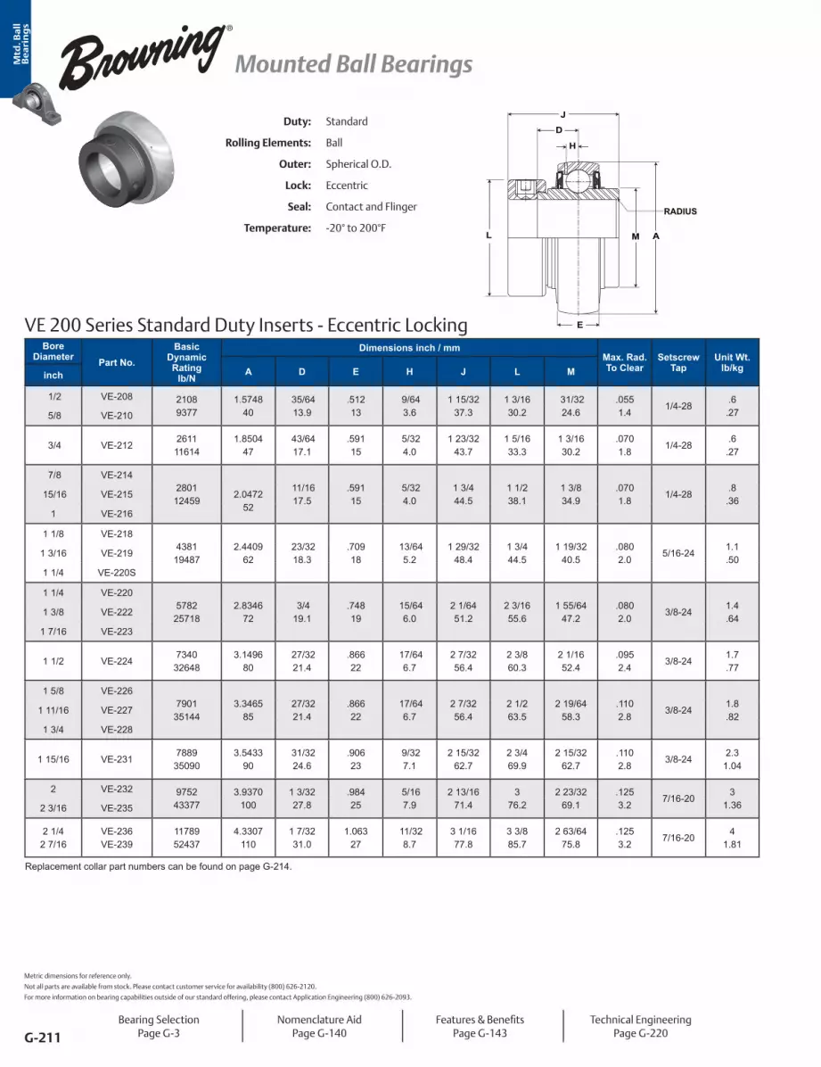
Mtd
. Ba
ll
Be
ari
ng
s
G-211
Mounted Ball Bearings
Bore Diameter Part No.
Basic Dynamic Rating
lb/N
Dimensions inch / mmMax. Rad. To Clear
Setscrew Tap
Unit Wt. lb/kgA D E H J L Minch
1/2 VE-208 21089377
1.574840
35/6413.9
.51213
9/643.6
1 15/3237.3
1 3/1630.2
31/3224.6
.0551.4
1/4-28.6
.27 5/8 VE-210
3/4 VE-2122611
116141.8504
47 43/6417.1
.59115
5/324.0
1 23/3243.7
1 5/1633.3
1 3/1630.2
.0701.8
1/4-28.6
.27
7/8 VE-2142801
12459
2.0472
52
11/1617.5
.59115
5/324.0
1 3/4 44.5
1 1/2 38.1
1 3/8 34.9
.0701.8
1/4-28.8
.36 15/16 VE-215
1 VE-216
1 1/8 VE-2184381
194872.4409
62 23/3218.3
.70918
13/645.2
1 29/3248.4
1 3/4 44.5
1 19/3240.5
.0802.0
5/16-241.1.50
1 3/16 VE-219
1 1/4 VE-220S
1 1/4 VE-2205782
257182.8346
72 3/4 19.1
.74819
15/646.0
2 1/6451.2
2 3/1655.6
1 55/6447.2
.0802.0
3/8-241.4.64
1 3/8 VE-222
1 7/16 VE-223
1 1/2 VE-2247340
326483.1496
80 27/3221.4
.86622
17/646.7
2 7/3256.4
2 3/8 60.3
2 1/1652.4
.0952.4
3/8-241.7.77
1 5/8 VE-2267901
351443.3465
85 27/3221.4
.86622
17/646.7
2 7/3256.4
2 1/2 63.5
2 19/6458.3
.1102.8
3/8-241.8.82
1 11/16 VE-227
1 3/4 VE-228
1 15/16 VE-2317889
350903.5433
90 31/3224.6
.90623
9/327.1
2 15/3262.7
2 3/4 69.9
2 15/3262.7
.1102.8
3/8-242.3
1.04
2 VE-232 975243377
3.9370100
1 3/3227.8
.98425
5/167.9
2 13/1671.4
3 76.2
2 23/3269.1
.1253.2
7/16-203
1.362 3/16 VE-235
2 1/4 2 7/16
VE-236VE-239
1178952437
4.3307110
1 7/3231.0
1.06327
11/328.7
3 1/1677.8
3 3/8 85.7
2 63/6475.8
.1253.2
7/16-204
1.81
Replacement collar part numbers can be found on page G-214.
Duty: Standard
Rolling Elements: Ball
Outer: Spherical O.D.
Lock: Eccentric
Seal: Contact and Flinger
Temperature: -20° to 200°F
VE 200 Series Standard Duty Inserts - Eccentric Locking E
D
J
L A
H
M
RADIUS
Metric dimensions for reference only.
Not all parts are available from stock. Please contact customer service for availability (800) 626-2120.
For more information on bearing capabilities outside of our standard offering, please contact Application Engineering (800) 626-2093.
Bearing SelectionPage G-3
Nomenclature AidPage G-140
Features & BenefitsPage G-143
Technical EngineeringPage G-220

Mtd
. Ba
ll
Be
ari
ng
s
G-212
Mounted Ball Bearings
VS 300 Series Medium Duty Inserts - Setscrew Locking
L A
G HE
DJ
RADIUS
Duty: Medium
Rolling Elements: Ball
Outer: Spherical O.D.
Lock: Setscrew
Seal: Contact and Flinger
Temperature: -20° to 200°F
Bore Diameter Part No.
Basic Dynamic Rating
lb/N
Dimensions inch / mmMax. Rad. To Clear
Setscrew Tap
Unit Wt. lb/kgA D E G H J Linch
1 VS-3164381
194872.4409
62 7/8 22.2
.70918.0
7/325.6
13/645.2
1 1/2 38.1
1 19/3240.5
.0401.0
1/4-28.9
.41
1 3/16 VS-3195782
257182.8346
721
25.4.74819.0
1/4 6.4
15/646.0
1 11/1642.9
1 55/6447.2
.0401.0
5/16-241.2.54
1 7/16 VS-3237340
326483.1496
801 3/1630.2
.86622.0
5/167.9
17/646.7
1 15/1649.2
2 1/1652.4
.0621.6
5/16-241.6.73
1 1/2 VS-3247901
351443.3465
851 3/1630.2
.86622.0
5/167.9
17/646.7
1 15/1649.2
2 19/6458.3
.0621.6
5/16-241.6.73
1 11/16 VS-327 788935090
3.543390
1 9/3232.5
.90623.0
3/8 9.5
9/327.1
2 1/3251.6
2 15/3262.7
.0621.6
3/8-241.8.821 3/4 VS-328
1 15/16 VS-3319752
433773.9370
1001 5/1633.3
.98425.0
3/8 9.5
5/167.9
2 3/1655.6
2 23/3269.1
.0802.0
3/8-242.3
1.04
2 3/16 VS-3351178952437
4.3307110
1 9/1639.7
1.06327.0
7/1611.1
21/648.3
2 9/1665.1
2 63/6475.8
.0802.0
3/8-243.1
1.41
Bearing SelectionPage G-3
Nomenclature AidPage G-140
Features & BenefitsPage G-143
Technical EngineeringPage G-220
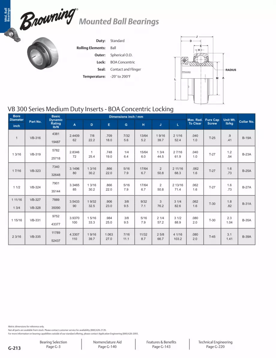
Mtd
. Ba
ll
Be
ari
ng
s
G-213
Mounted Ball Bearings
VB 300 Series Medium Duty Inserts - BOA Concentric Locking
JD
EH
L AM
RADIUS
Duty: Standard
Rolling Elements: Ball
Outer: Spherical O.D.
Lock: BOA Concentric
Seal: Contact and Flinger
Temperature: -20° to 200°F
Bore Diameter Part No.
Basic Dynamic Rating
lb/N
Dimensions inch / mmMax. Rad. To Clear
Furx Cap Screw
Unit Wt. lb/kg Collar No.
A D E G H J Linch
1 VB-3164381 2.4409
62 7/8 22.2
.70918.0
7/325.6
13/645.2
1 9/1639.7
2 1/1652.4
.0401.0
T-25.9
.41B-19A
19487
1 3/16 VB-3195782 2.8346
721
25.4.74819.0
1/4 6.4
15/646.0
1 3/444.5
2 7/1661.9
.0401.0
T-271.2.54
B-23A25718
1 7/16 VB-3237340 3.1496
801 3/1630.2
.86622.0
5/167.9
17/646.7
250.8
2 11/1668.3
.0621.6
T-271.6.73
B-25A32648
1 1/2 VB-3247901 3.3465
851 3/1630.2
.86622.0
5/167.9
17/646.7
250.8
2 13/1671.4
.0621.6
T-271.6.73
B-27A35144
1 11/16 VB-327 7889 3.543390
1 9/3232.5
.90623.0
3/8 9.5
9/327.1
376.2
3 1/482.6
.0621.6
T-301.8.82
B-31A1 3/4 VB-328 35090
1 15/16 VB-3319752 3.9370
1001 5/1633.3
.98425.0
3/8 9.5
5/167.9
2 1/457.2
3 1/288.9
.0802.0
T-302.3
1.04B-35A
43377
2 3/16 VB-33511789 4.3307
1101 9/1639.7
1.06327.0
7/1611.1
11/328.7
2 5/866.7
4 1/16103.2
.0802.0
T-453.1
1.41B-39A
52437
Metric dimensions for reference only.
Not all parts are available from stock. Please contact customer service for availability (800) 626-2120.
For more information on bearing capabilities outside of our standard offering, please contact Application Engineering (800) 626-2093.
Bearing SelectionPage G-3
Nomenclature AidPage G-140
Features & BenefitsPage G-143
Technical EngineeringPage G-220

Mtd
. Ba
ll
Be
ari
ng
s
G-214
Mounted Ball Bearings
Bearing SelectionPage G-3
Nomenclature AidPage G-140
Features & BenefitsPage G-143
Technical EngineeringPage G-220
BOA Locking Collar Table
Bore Diameter Standard Duty Medium Dutyinch mm Insert Collar Insert Collar
3/4-
-20
VB-212 VB-20MM 2-012B Lock Collar - -
7/8 - VB-214 2-015 Lock Collar - -
15/16 - VB-215 2-015 Lock Collar - -
1-
-25
VB-216 VB-25MM 2-015 Lock Collar VB-316 2-13A Lock Collar
1 1/8 - VB-218 2-13A Lock Collar - -
1 3/16 30 VB-219 VB-30MM 2-13B Lock Collar VB-319 2-17A Lock Collar
1 1/4* - VB-220S 2-13B Lock Collar - -
1 1/4 - VB-220 2-17A Lock Collar VB-220 2-17A Lock Collar
1 3/8 - VB-222 2-17B Lock Collar - -
1 7/16 35 VB-223 VB-35MM 2-17B Lock Collar VB-323 2-19A Lock Collar
1 1/2 40 VB-224 VB-40MM 2-19A Lock Collar VB-324 2-111A Lock Collar
1 5/8 - VB-226 2-111A Lock Collar - -
1 11/16 - VB-227 2-111B Lock Collar VB-327 2-115A Lock Collar
1 3/4 45 VB-228 VB-45MM 2-111B Lock Collar VB-328 2-115A Lock Collar
1 15/16 50 VB-231 VB-50MM 2-115B Lock Collar VB-331 2-23A Lock Collar
2* - VB-232S 2-115B Lock Collar VB-232S 2-115B Lock Collar
2 - VB-232 2-23A Lock Collar VB-232 2-23A Lock Collar
2 3/16 - VB-235 2-23B Lock Collar VB-335 2-27A Lock Collar
2 1/4 - VB-236 2-27A Lock Collar - -
2 3/8 60 VB-60MM 2-27B Lock Collar - -
2 7/16 - VB-239 2-27B Lock Collar - -
*Reduced Housing
Eccentric Locking Collar Table
Bore Diameter
(inch)
SeriesCollar No.
VE-100 VE-200 SLE-100 RUBRE-100
1/2 VE-108 VE-208 SLE-108 - ELC-08
5/8 VE-110 VE-210 SLE-110 - ELC-10
3/4 VE-112 VE-212 SLE-112 RUBRE-112 ELC-12
7/8 VE-114 VE-214 SLE-114 - ELC-14
15/16 VE-115 VE-215 SLE-115 RUBRE-115 ELC-15
1 VE-116 VE-216 SLE-116 RUBRE-116 ELC-16
1 1/8 VE-118 VE-218 SLE-118 - ELC-18
1 3/16 VE-119 VE-219 SLE-119 - ELC-19
1 1/4S VE-120S VE-220S SLE-120S - ELC-20S
1 1/4 VE-120 VE-220 SLE-120 - ELC-20
1 3/8 VE-122 VE-222 SLE-122 - ELC-22
1 7/16 VE-123 VE-223 SLE-123 - ELC-23
1 1/2 VE-124 VE-224 SLE-124 - ELC-24
1 5/8 - VE-226 - - ELC-26
1 11/16 VE-127 VE-227 - - ELC-27
1 3/4 VE-128 VE-228 - - ELC-28
1 15/16 VE-131 VE-231 - - ELC-31
2 VE-132S - - - ELC-32S
2 VE-132 VE-232 - - ELC-32
2 3/16 VE-135 VE-235 - - ELC-35
2 1/4 - VE-236 - - ELC-36
2 7/16 - VE-239 - - ELC-39
Locking Collar Replacement Tables

Mtd
. Ba
ll
Be
ari
ng
s
G-215
Cylindrical OD Insert Bearings
Browning VER Style Ball Bearings Browning VER bearings feature black oxide treated inner and outer rings, and extended inner race bearing with ball riding nylon retainer. Shaft lock is achieved by 120° spaced diamond faceted setscrew locking. The contact seal, with black oxide treated flinger provides a good balance between contaminant resistance, grease loss and friction.
Nylon Retainer
Zone Hardened Inner Ring
Lube Groove with Lube Hole
Contact Seal and Flinger
Contact Seal and Flinger
Cylindrical O.D. Ring
Snap (Locating)Ring
Diamond Faceted Setscrew 120°
Position
Snap Ring Groove
Grade 10 Balls

Mtd
. Ba
ll
Be
ari
ng
s
G-216
Cylindrical OD Insert Bearings
Browning VER Style Ball Nomenclature
VER - Cylindrical O.D. Bearing WithSnap Ring
Duty 2 - Standard Duty - 200 SeriesBore Size Inch - ##/16 (ex. 20/16 = 1 1/4”) S for 1 1/4” and 2” Reduced Options S### # - Special Design
VER - 2 24 S####

Mtd
. Ba
ll
Be
ari
ng
s
G-217
Cylindrical OD Insert Bearings
Setscrew Locking120° spaced, balanced three point contact minimizes inner ring distortion vibration, reduces noise, and improves reliability. Precision manufactured diamond faceted setscrews contribute to improved clamping and resistance to back out.
Zone Hardened Inner RaceBrowning incorporates a unique heat treat process that hardens the inner race only where it is needed...under the ball path. The zone hardened inner race results in improved lock reliability as a result of less distortion at setscrew location and improved thread conformity resulting in improved clamping and resistance to setscrew back-out.
Identification MarkingBrowning VER bearings have the part number laser marked on the inner ring for easy verification of the part number during installation and for replacement.
Features and Benefits
SealingPositive contract molded nitrile rubber contact seal with an auxiliary flinger element standard. The contact seal allows grease purge and helps keep contamination out of the bearing while the flinger provides a rotating shield that directs contamination away from the seal.

Mtd
. Ba
ll
Be
ari
ng
s
G-218
Cylindrical OD Insert Bearings
Duty: Standard
Rolling Elements: Ball
Outer: Cylindrical O.D. Outer
Lock: Setscrew
Seal: Contact Seal and Flinger
Temperature: -20° to 200°F
Relube: Through Groove In O.D.
VER 200 Series Standard Duty Cylindrical O.D. Inserts - Setscrew Locking
D
H
J
L A
RADIUS
G
K OE
NP
M
Bearing SelectionPage G-3
Nomenclature AidPage G-216
Features & BenefitsPage G-217
Technical EngineeringPage G-220
Bore Diameter Part No.
Basic Dynamic Rating
lb/N
Dimensions inch / mmMax.
Rad. To Clear
Unit Wt. lb/kgA D G E H J K L N O Pinch
1/2 VER-2082611
116141.8504
47 23/3218.3
11/644.4
5/8 15.9
3/641.2
1 7/3231.0
31/6412.3
1 3/1630.2
1 19/3240.5
3/164.8
2 1/1652.4
.0401.02
.6.27
5/8 VER-210
3/4 VER-212
7/8 VER-2142801
124592.0472
52 13/1620.6
13/645.2
3/4 19.1
3/641.2
1 3/8 34.9
39/6415.5
1 3/8 34.9
1 53/6446.4
3/164.8
2 17/6457.5
.0401.02
.7.32
15/16 VER-215
1 VER-216
1 1/16 VER-217
438119487
2.440962
7/8 22.2
7/325.6
7/8 22.2
1/161.6
1 1/2 38.1
11/1617.5
1 19/3240.5
2 3/3253.2
3/164.8
2 21/3267.5
.0401.02
.9.41
1 1/8 VER-218
1 3/16 VER-219
1 1/4 VER-220S
1 1/4 VER-2205782
257182.8346
721
25.4 7/325.6
15/1623.8
1/161.6
1 11/1642.9
3/4 19.1
55/6421.8
2 7/1661.9
7/325.6
3 5/6478.2
.0401.02
1.4.64
1 3/8 VER-222
1 7/16 VER-223
1 1/2 VER-224 734032648
3.149680
1 3/1630.2
1/4 6.4
1 3/3227.8
1/161.6
1 15/1649.2
29/3223.0
2 1/1652.4
2 47/6469.5
13/645.2
386.5
.0621.57
2.911 9/16 VER-225
1 5/8 VER-2267901
351443.3465
851 3/1630.2
1/4 6.4
1 3/3227.8
1/161.6
1 15/1649.2
29/3223.0
2 19/6458.3
376.2
13/645.2
3 19/3291.3
.0621.57
2.31.04
1 11/16 VER-227
1 3/4 VER-228
1 15/16 VER-2317889
350903.5433
901 9/3232.5
19/647.5
1 1/8 28.6
3/322.4
2 1/3251.6
29/3223.0
2 15/3262.7
3 5/3280.2
3/164.8
3 25/3296.0
.0621.57
2.41.09
2 VER-232 975243377
3.9370100
1 5/1633.3
19/647.5
1 3/1630.2
3/322.4
2 3/1655.6
31/3224.6
2 23/3269.1
3 15/3288.1
9/327.1
4 3/16106.4
.0802.03
31.362 3/16 VER-235
2 1/4 VER-2361178952437
4.3307110
1 9/1639.7
19/647.5
1 1/4 31.8
3/322.4
2 9/1665.1
1 1/3226.2
2 63/6475.8
3 13/1696.8
3/8 9.5
4 19/32116.7
.0802.03
41.81
2 3/8 VER-238
2 7/16 VER-239
Outside diameter may be oversized due to seal press fit. Metric dimensions for reference only.

Mtd
. Ba
ll
Be
ari
ng
s
G-219
® Mounted Ball Bearing Engineering Section
For more information on bearing capabilities outside of our standard offering, please contact Application Engineering (800) 626-2093.
Mounted Ball Bearing Engineering see page G-220.

Mtd
. Ba
ll
Be
ari
ng
s
G-220
®Mounted Ball Bearing Engineering Section
Table of ContentsLoad Ratings and Life ............................................................................ G-221Table 1 - Life Adjustment Factor for ReliabilityTable 2 - Shock / Vibration FactorsTable 3 - Equivalent Load Calculation Data - Ball BearingTable 4 - Sealmaster Ball Bearing Load RatingsTable 5 - Browning Ball Bearing Load Ratings
Load and Speed .................................................................................... G-230Table 6 - Sealmaster Ball Bearing Load / Speed ChartTable 7 - Browning Ball Bearing 200 & 300 Series Load / Speed ChartTable 8 - Browning Ball Bearing 100 Series Load / Speed Chart
Speed Rating (Limit) Tables ................................................................... G-235Table 9 - Sealmaster Gold Standard Duty Maximum Speed RatingTable 10 - Sealmaster Gold Medium Duty Maximum Speed RatingTable 11 - Sealmaster Material Handling Maximum Speed RatingTable 12 - Browning 100 and 200 Series Maximum Speed RatingTable 13 - Browning 300 Series Maximum Speed Rating
Locking Types ....................................................................................... G-244
Installation and Lubrication .................................................................. G-246Sealmaster Gold Mounting Housed Units (G-246) Mounting Sealmaster Gold Cylindrical O.D. Inserts and Cylindrical O.D. Housings (G-248) Replacing Existing Sealmaster Gold Inserts (G-250)
Material Handling Mounting Housed Units (G-251) Replacing Existing Sealmaster MH Inserts (G-253)
Sealmaster Gold and Material Handling Bearing Lubrication (G-254)
Browning Mounted Ball Bearing Installation and Relubrication Mounting Housed Units (G-255) Mounting Cylindrical O.D. (VER) Inserts (G-256) Replacing Existing Browning Inserts (G-256) Browning Mounted Ball Lubrication (G-257)
Cylindrical OD Housing Fit Guidelines ................................................... G-259Table 14 - ER, VER and Cylindrical OD Insert Bearing Housing/Roll Bore (G-259)Table 15 - Sealmaster SC and MSC Housing Bore (G-261)
Vibration Analysis................................................................................. G-263Table 16 – Vibration and Geometry Information

Mtd
. Ba
ll
Be
ari
ng
s
G-221
® Mounted Ball Bearing Engineering Section
Life CalculationsThe L10 (rating) life for any given application and bear-ing selection can be calculated in terms of millions of revolutions by using the bearing Basic Dynamic Rating and applied radial load (or, equivalent radial load in the case of radial bearing applications having combined radial and thrust loads). The L10 life for any given application can be calculated in terms of hours, using the bearing Basic Dynamic Rating, applied load (or equivalent radial load) and suitable speed factors, by the following equation:
L10 = x = x
Where: L10 = The # of hours that 90% of identical bearings under ideal conditions will operate at a specific speed and condition before fatigue is expected to occur. C = Basic Dynamic Rating (lbs) 1,000,000 Revolutions P = Constant Equivalent Radial Load (lbs) n = Speed (RPM)
Additionally, the ABMA provides application factors for all types of bearings which need to be considered to determine an adjusted Rated Life (Lna). L10 life rat-ing is based on laboratory conditions yet other factors are encountered in actual bearing application that will reduce bearing life. Lna life rating takes into account reliability factors, material type, and operating condi-tions. Lna = a1 x a2 x a3 x L10 Where: Lna = Adjusted Rated Life. a1 = Reliability Factor. Adjustment factor applied where estimated fatigue life is based on reliability other than 90% (See Table 1).
a2 = Material Factor. Life adjustment for bearing race material. Regal Power Transmission Solutions bearing races are manufactured from bearing quality steel. Therefore the a2 factor is 1.0.a3 = Life Adjustment Factor for Operating Conditions. This factor should take into account the adequacy of lubricant, presence of foreign matter, conditions causing changes in material properties, and unusual loading or mounting conditions. Assuming a properly selected and mounted bearing having adequate seals and lubricant operating below 250°F and tight fitted to the shaft, the a3 factor should be 1.0.
Mounted bearings are typically “slip fitted” to the shaft and rely on design features such as the inner race length and locking device for support. ABMA recom-mends an a3 factor of .456 for “slip fit” ball bearings. See sample calculations on page G-224.
Vibration and shock loading can act as an additional loading to the steady expected applied load. When shock or vibration is present, an a3 Life Adjustment Factor can be applied. Shock loading has many vari-ables which often are not easily determined. When shock or vibration is present, the following a3, Life Ad-justment Factors are recommended. The shock factor is used in combination with the “slip fit” factor.
The a3 factor takes into account a wide range of ap-plication and mounting conditions as well as bearing features and design. Accurate determination of this factor is normally achieved through testing and in-field experience. Regal Power Transmission Solutions offers a wide range of options which can maximize bearing performance. Consult Application Engineer-ing for more information. See sample calculations on page G-224.
Table 1 Life Adjustment Factor for Reliability
Reliability % Lna a1
90 L10 195 L5 0.6296 L4 0.5397 L3 0.4498 L2 0.3399 L1 0.2150 L50 5
Table 2 Shock/Vibration FactorType a3 Factor
Steady Loading 1.0
Light Shock/Vibration .5
Moderate Shock/Vibration .3
Load Ratings and Life
CP( ) C
P( )1,000,00060 x n
16667n
33

Mtd
. Ba
ll
Be
ari
ng
s
G-222
®Mounted Ball Bearing Engineering Section
Combined Load - Ball BearingsFor applications where a combination of both radial and thrust loads are applied to the bearing the equiva-lent radial load must be calculated and applied to the L10 life formula.
1. Use Table 3 (below) and Table 4 (page G-228) to identify the relative axial load factor (ND2).2. Determine the relative axial load (RAL):
3. Match the nearest relative axial load value in Table 3 to the corresponding “e” value. For precise calcula-tion, linearly interpolate the values for “e” for your exact relative axial load value.
4. Calculate Fa/Fr and compare value to the “e” value found in step #3 above.5. Choose values for “X” and “Y” based on step #3 & 4 and from Table 3. Linear interpolation is recommend-ed for exact calculations.6. Calculate equivalent radial load using the following equation: P = XFr + YFa7. Calculate the adjusted life (Lna) using the life calcu-lation formula above.
Variable Load FormulaRoot mean load (RML) is to be used when a number of varying loads are applied to a bearing for varying time limits. Maximum loading still must be considered for bearing size selection.
RML* = Where: RML = Root Mean Load (lbs.) L1, L2, etc. = Load in pounds N1, N2, etc. = Percent of total time operated at loads L1, L2, etc.
*Apply RML to rating at mean speed to determine resultant life.
Mean Speed FormulaThe following formula is to be used when operating speed varies over time.
High Load ApplicationsApplications where the loading approaches the load listed in the rating tables on pages G-230 to G-233 at 5000 hours life and 150/250 RPM, should be reviewed and given special consideration.
Modifications to consider Include: • Shafting size should be closely controlled for a line to line to a light press fit. • Skwezloc® Locking Collar or double lock is the preferred lock. • Lubricants with “EP” extreme pressure additives may be required. • Care in housing selection, load direction, and mounting techniques should be exercise
RAL = - applied thrust load- relative axial load factor
Fa
ND2
Table 3 Equivalent Load Calculation Data - Ball Bearings
Relative Axial Load e
Fa / Fr ≤ e Fa / Fr > e
x y x y24.92 0.19
1 0 0.56
2.3050.03 0.22 1.9999.91 0.26 1.71
149.35 0.28 1.55200.10 0.30 1.45300.15 0.34 1.31500.25 0.38 1.15749.65 0.42 1.04999.05 0.44 1.00
S1N1 + S2N2 + S3N3
100Mean Speed =
S1S2, etc = Speeds in RPM N1N2, etc = Percentage of total time operated at speeds S1S2, etc
Load Ratings and Life Continued
(L1 3 N1) + (L2
3 N2) + (L3 3 N3)
100
3

Mtd
. Ba
ll
Be
ari
ng
s
G-223
® Mounted Ball Bearing Engineering Section
High Speed Applications Applications where the speed is in the range of 80-100% of the maximum speeds listed in the rating tables on pages G-230 to G-233, should be reviewed and given special consideration.
Modifications to consider include: • Shaft size should be controlled to specifications listed in the installation section. See tables above. • SKWEZLOC Locking Collar and double lock are the preferred lock systems for high speed appli- cations. • High quality lubricants should be used. • Grease should be added more frequently and in small amounts. See Page G-254. • Care in mounting techniques should be exer- cised. See Page G-246 to G-253.
Bearing Life In Oscillating ApplicationsThe equivalent rotative speed (ERS) is used in life cal-culations when the bearing does not make complete revolutions during operation. The ERS is then used as the bearing operating speed in the calculation of the L10 (Rating) Life. The formula is based on sufficient angular rotation to have roller paths overlap.
ERS = Equivalent Rotative Speed
N = Total number of degrees per minute through which the bearing will rotate.
ERS =
In the above formula, allowance is made for the total number of stress applications on the weakest race per unit time, which, in turn, determines fatigue life and the speed factors. The theory behind fretting corro-sion is best explained by the fact that the rolling ele-ments in small angles of oscillation retrace a path over an unchanging area of the inner or outer races where the lubricant is prevented by inertia from flowing in behind the roller as the bearing oscillates in one direc-tion. Upon reversal, this small area of rolling contact is traversed by the same roller in the dry state. The fric-tion of the two unlubricated surfaces causes fretting corrosion and produces failures which are unpredict-able from a normal life standpoint.
With a given bearing selected for an oscillating appli-cation, the best lubrication means is a light mineral oil under positive flow conditions. With a light oil, there is a tendency for all areas in the bearing load zone to be immersed in lubricant at all times. The full flow lubri-cation dictates that any oxidized material which may form is immediately carried away by the lubricant, and since these oxides are abrasive, further wear tends to be avoided. If grease lubrication must be used, it is best to consult with either the bearing manufacturer or the lubricant manufacturer to determine the best possible type of lubricant. Greases have been com-pounded to resist the detrimental effect of fretting corrosion for such applications.
Static Load RatingThe “static load rating” for rolling element bearings is that uniformly distributed static radial load acting on a non-rotating bearing, which produces a contact stress of 580,000 psi at the center of the most heavily loaded rolling element. At this stress level, plastic deforma-tion begins to be significant. Experience has shown that the plastic deformation at this stress level can be tolerated in most bearing applications without impair-ment of subsequent bearing operation. In certain ap-plications where subsequent rotation of the bearing is slow and where smoothness and friction requirements are not too exacting, a higher static load limit can be tolerated. Where extreme smoothness is required or friction requirements are critical, a lower static load limit may be necessary.
Minimum Bearing LoadSkidding, or sliding, of the rolling elements on the raceway instead of a true rolling motion can cause excessive wear. Applications with high speeds and light loading are particularly prone to skidding. As a general guideline, rolling element bearings should be radially loaded at least 1% of Basic Dynamic Rating for ball bearings. For applications where load is light relative to the bearings dynamic load rating, consult Application Engineering for assistance.
Load Ratings and Life Continued
N360

Mtd
. Ba
ll
Be
ari
ng
s
G-224
®Mounted Ball Bearing Engineering Section
CASE #1Drive Load Calculation
P =
HP = horsepower RPM = revolutions per minute d = pitch of pulley in inches K = constant for type of drive used K = 1.5 for V-belts K = 2 to 3 for flat transmission belts K = 1.1 for chain drives
x K = Apply P to Case 2, 3 or 4 if applicable
126,000 x HPRPM x d
x
z
y
Brg. 1 Brg. 2
CASE #2Cantilever and Drive
4”
9”
a
k
b2”
Brg. B
Brg. A
P1200#
P280#
Load on Bearing A = P1 x (a + k) - (P2 x b)
k
= 200 x (4 + 9) - (80 x 2)
9
Load on Bearing B = P2 x (k + b) - (P1 x a)
k
= 80 x (9 + 2) - (200 x 4)
9
= 9 lbs.
= 271 lbs.
CASE #3Straddle, Cantilever Drive
Load on Bearing A = P1 x (k + a) + (P2 x c) - (P3 x d)
k
= 60 x (12 + 2) + (180 x 6) - (70 x 4)
12
Load on Bearing B = -(P1 x a) + (P2 + b) +P3 x (k + d)
k
= -(60 x 2) + (180 x 6) + 70 x (12 + 4)
12
= 137 lbs.
= 173 lbs.
12”
2”a
6”b
k
Brg. BBrg. A
P160#
P2180#
P370#
6”c
4”d
CASE #4Straddle Mount, Cantilever Drive
7”
11”
a
k
4”b
3”Brg. BBrg. A
P2150#
P11000#
c
Load on Bearing A = (P1 x b) - (P2 x c)
k
= (1000 x 4) - (150 x 3)
11
Load on Bearing B = (P1 x a) + (c + k) x (P2)
k
= (1000 x 7) + (3 + 11) x (150)
11
= 827 lbs.
= 323 lbs.
CASE #5Vibrating Drives
Load due to Centrifugal and Inertial Forces - In a shaker or gyrating screen bearing application, the load on the bearings is increased by
sudden stopping, starting, and reversing of typically large loads. This can be expressed as a basic physical law:
Force = Mass x Accelerations In order to use this law, we develop from it the following equation:
F = .000341 x WR(RPM)2
Where: F = Load of force in lbs.
W = Weight of rotating mass in lbs.R = Radius of rotation or throw in feet
RPM = Shaft rotation in revolutions per minute What is the centrifugal bearing load on a shaker screen which weighs 2,500 lbs., has a throw of 1/4 in. and whose shaft speed is 500 RPM?
F = .000341 x 2,500 x x (500)2 = 4,440 lbs..25012
R
WEIGHT
Load Ratings and Life Continued
Computing Bearing LoadsIn the computation of bearing loads in any applica-tion of a Regal Power Transmission Solutions unit, the principal factor determining the selection of the unit is the equivalent radial load to which the bearing will be subjected. These radial loads result from any one or any combination of the following sources:
1. Weights of machine parts supported by bearings.2. Tension due to belt or chain pull.3. Centrifugal force from out of balance, eccentric or cam action.
The resulting load from any one, or any combination of the above sources is further determined by know-ing:
1. The magnitude of the load.2. Direction of the load.3. The point of load application.4. The distance between bearing centers.
Bearing loads are the result of force acting on the shaft. Direction, magnitude, and location with respect to the bearings must be considered when calculating bearing loads. The following cases are typical exam-ples of loads encountered and methods of calculating bearing loads.

Mtd
. Ba
ll
Be
ari
ng
s
G-225
® Mounted Ball Bearing Engineering Section
Mounted Ball Bearing Selection - New Applications:Using variations of the life formulas and application information, it is possible to select bearings based on desired life, load applied, and shaft speed. This method can only be applied where axial load is less than or equal to 1/2 the radial load.
1. Determine required application hours (Lna).
2. Calculate L10 using adjustment factors:
L10 =
3. Calculate Basic Dynamic Radial Rating (Creq).
Creq = P x
P = Constant Equivalent Radial Load (lbs) N = Speed (RPM)
4. Use Table No. 4 and 5 on page G-227 to G-229, find a basic Dynamic Radial Rating Value greater than or equal to Creq calculated in step # 3.
5. Select any bearing from the row in step # 4 or larger. If Creq is greater than the largest Basic Dynamic Radial Rating Value of Table No. 4 or 5, go to the Mounted Roller Bearing Section H and I.
6. If Ball bearing is selected, proceed with housing, seal, and lock selection.
Typical operating temperature range for standard bearings is -20° to 200° F for Browning and -20°F to 220°F for Sealmaster Gold. For operating tempera-tures outside this range, contact Application Engineer-ing. For Maximum speed information, see tables on pages G-235 and G-243
Application Examples:
Example #1 - Pure Radial Load
Question #1: What is the adjusted bearing life (Lna hours) for an NP-39 Sealmaster Ball Bearing with no shock conditions and the following application criteria?
Design Load (P) = 1300 lbs. Speed (n) = 1000 RPM Shaft Size = 2 7/16 in. Operating Temp. = 125°F
Solution:1. Begin with the L10 life formula:
L10 = (C/P)3 x
Look up the insert of an NP-39 on page G-31. From Table No. 4 on page G-228, the Basic Dynamic Radial Rating is 11,789 lbs.
L10 = x = 12,430 hours
2. Apply the life adjustment factors:
Lna hours = L10 x a1 x a2 x a3
Lna hours = 12,430 x 1 x 1 x 0.456 Lna hours = 5,700 hours
166671000
La
a1 x a2 x a3
L10 x N16,667( 1/3(
Load Ratings and Life Continued
16667n
117891300( 3(

Mtd
. Ba
ll
Be
ari
ng
s
G-226
®Mounted Ball Bearing Engineering Section
166671000
Question #2: What is the adjusted bearing life (L10 hours) for an NP-39 Sealmaster Ball Bearing with moderate shock conditions and the same applications criteria from above?
Solution: 1. From Table 2 on page G-221:
a3 = 0.5 x 0.456
2. Re-Apply the life adjustment factors to the previ-ously calculated L10 life:
Lna hours = L10 x a1 x a2 x a3
Lna hours = 12,430 x 1 x 1 x (0.5 x 0.456) Lna hours = 2,830 hours
Example #2 - Combined Radial and Thrust Load
Question #1: What is the adjusted bearing life (Lna hours) for an NP-39 Sealmaster Ball Bearing with no shock conditions and the following application criteria?
Design Radial Load (Fr) = 500 lbs. Design Thrust Load (Fa) = 1000 lbs. Speed (n) = 1000 RPM Shaft Size = 2 7/16 in. Operating Temperature = 125°F
Solution:1. Calculate Fa/ Fr = 1000/500 = 22. Look up the insert of an NP-39 on page G-31. From Table 4 on page G-228, ND2 is 3.969 lbs and Basic Dynamic Rating is 11,789 lbs.3. Begin by calculating the Relative Axial Load (RAL):
RAL = = = 251 lbs.
4. From Table 3 on page G-222, interpolate RAL be-tween 200.10 and 300.15 and “e” between 0.30 and 0.34 to obtain “e” value:
=
Therefore e = .32
5. From Table 3 on page G-222, determine the value of “X” and “Y” through interpolation. Interpolate “e” between 0.30 and 0.34 and “Y” between 1.45 and 1.31 because Fa/ Fr > e
=
Therefore Y = 1.38 and X = .56
6. Determine the equivalent radial load (P)
P = (X Fr) + (Y Fa) = (0.56 x 500) + (1.38 x 1000) = 1660 lbs. L10 = (C/P)3 x
Look up the insert of an NP-39 on page G-31. From Table 4 on page G-228, the Basic Dynamic Rating is 11,789 lbs.
Lna = .456 x x = 2722 hours117891660( 3(
Fa
ND2
10003.9690
251 - 200.10300.15 - 200.10
0.32 - 0.300.34 - 0.30
e - 0.300.34 - 0.30
Y - 1.451.31 - 1.45
16667n
Load Ratings and Life Continued

Mtd
. Ba
ll
Be
ari
ng
s
G-227
® Mounted Ball Bearing Engineering Section
Bearing Load Rating Tables
Series
Standard Duty, ER and Material Handling Medium Duty Basic Dynamic Rating
Basic Static Rating
Relative Axial Load Factor
(ND2)Thrust Rating
Bore DiameterUnit Size
Standard Duty
ER
Material Handling Bore Diameter Medium
Duty
inch mm Insert Insert inch mm Insert lb N lb N lb N lb N
2-012
1/2 - 8 2-08 ER-8 - - - -
2611 11614 1444 6423 .706 3.1 741 3296
9/16 - 9 2-09 ER-9 - - - -
5/8 - 10 2-010 ER-10 - - - -
11/16 - 11 2-011 ER-11 - - - -
3/4 - 12 2-012 ER-12 MH-12 - - -
- 20 204 5204 ER-204 MH-204 - - -
2-015
13/16 - 13 2-013 ER-13 - - - -
2801 12459 1651 7344 .784 3.5 490 2180
7/8 - 14 2-014 ER-14 - - - -
15/16 - 15 2-015 ER-15 - - - -
- 25 205 5205 ER-205 MH-205 - - -
1 - 16 2-1 ER-16 MH-16 - - -
2-13
1 1/16 - 17 2-11 ER-17 - 15/16 - 3-015
4381 19488 2567 11419 1.300 5.8 1177 5236
1 1/8 - 18 2-12 ER-18 - - 25 5305
- 30 206 5206 ER-206 MH-206 1 - 3-1
1 3/6 - 19 2-13 ER-19 MH-19 - - -
1 1/4 - 20R 1-14 ER-20R MH-20R - - -
2-17
1 1/4 - 20 2-14 ER-20 MH-20 - 30 5306
5782 25719 3493 15538 1.742 7.8 1709 7602
1 5/16 - 21 2-15 ER-21 - 1 3/16 - 3-13
1 3/8 - 22 2-16 ER-22 - - - -
- 35 207 5207 ER-207 - - - -
1 7/16 - 23 2-17 ER-23 MH-23 - - -
2-19
1 1/2 - 24 2-18 ER-24 MH-24 - 35 5307
7340 32650 4467 19870 2.250 10.0 2254 100261 9/16 - 25 2-19 ER-25 - 1 7/16 - 3-17
- 40 208 5208 ER-208 - - - -
2-111
1 5/8 - 26 2-110 ER-26 - 1 1/2 - 3-18
7901 35145 5139 22859 2.500 11.1 2350 104531 11/16 - 27 2-111 ER-27 MH-27 - 40 5308
1 3/4 - 28 2-112 ER-28 - - - -
- 45 209 5209 ER-209 - - - -
2-115
1 13/16 - 29 2-113 ER-29 - 1 11/16 - 3-111
7889 35092 5216 23202 2.500 11.1 2350 10453
1 7/8 - 30 2-114 ER-30 - 1 3/4 - 3-112
1 15/16 - 31 2-115 ER-31 MH-31 - 45 5309
- 50 210 5210 ER-210 MH-210 - - -
2 - 32R 1-2 ER-32R - - - -
Table 4 - Sealmaster Ball Bearing Load Ratings
Setscrew locking standard duty, ER cylindrical O.D., Material Handling and Medium Duty bearing are shown.For Skwezloc and Double Setscrew Locking use the equivalent setscrew lock rating in the table. Example:. 2-1, 2-1D and 2-1T all use the 2-015 series ratingFor RB inserts use the equivalent ER series bearing listed to determine the capacity. Ex: RB-16, use ER-1

Mtd
. Ba
ll
Be
ari
ng
s
G-228
®Mounted Ball Bearing Engineering Section
Table 4 - Sealmaster Ball Bearing Load Ratings continued
Series
Standard Duty, ER and Material Handling Medium Duty Basic Dynamic Rating
Basic Static Rating
Relative Axial Load Factor
(ND2)Thrust Rating
Bore DiameterUnit Size
Standard Duty
ER
Material Handling Bore Diameter Medium
Duty
inch mm Insert Insert inch mm Insert lb N lb N lb N lb N
2-23
2 - 32 2-2 ER-32 MH-32 1 15/16 - 3-115
9752 43379 6601 29363 3.316 14.8 2886 128382 1/8 - 34 2-22 ER-34 - - 50 5310
- 55 211 5211 ER-211 - - - -
2 3/16 - 35 2-23 ER-35 MH-35 - - -
2-27
2 1/4 - 36 2-24 ER-36 - - 55 5311
11789 52440 8150 36253 3.969 17.7 4105 18260- 60 212 5212 ER-212 - 2 3/16 - 3-23
2 3/8 - 38 2-26 ER-38 - - - -
2 7/16 - 39 2-27 ER-39 MH-39 - - -
2-211
2 1/2 - 40 - ER-40 - 2 7/16 - 3-27
13971 62146 10063 44762 4.761 21.2 4503 200302 11/16 - 43 2-211 ER-43 - 2 1/2 - 3-28
- 70 214 5214 ER-214 - - 65 5313
2-215
2 7/8 - 46 2-214 ER-46 - 2 11/16 - 3-211
14839 66007 11224 49927 5.237 23.3 5207 231622 15/16 - 47 2-215 ER-47 - - 70 5314
- 75 215 5215 ER-215 - - - -
2-33
3 - 48 - ER-48 - 2 15/16 - 3-215
17412 77452 13174 58601 6.188 27.5 6032 26832- 80 216 5216 ER-216 - - 75 5315
3 3/16 - 51 2-33 ER-51 - 3 - 3-3
2-37
3 1/4 - 52 2-34 ER-52 - - 80 5316
18681 83097 14496 64481 6.692 29.8 7474 332463 3/8 - 54 2-36 ER-54 - 3 3/16 - 3-33
3 7/16 - 55 2-37 ER-55 - - - -
2-383 1/2 - 56 2-38 - - 3 7/16 - 3-37
21566 95930 16301 72510 7.744 34.4 7839 34869- 90 218 5218 - - - -
2-43
3 15/16 - 63 - ER-63 - 3 15/16 - 3-315
29905 133023 23553 104768 11.236 50.0 11097 49362- 100 - - - - - 100 5320
4 - 64 - ER-64 - 4 - 3-4
3-47- - - - - - 4 7/16 - 3-47
37482 166727 33267 147978 15.625 69.5 16697 74272- - - - - - 4 15/16 - 3-415
Setscrew locking standard duty, ER cylindrical O.D., Material Handling and Medium Duty bearing are shown.For Skwezloc and Double Setscrew Locking use the equivalent setscrew lock rating in the table. Example:. 2-1, 2-1D and 2-1T all use the 2-015 series ratingFor RB inserts use the equivalent ER series bearing listed to determine the capacity. Ex: RB-16, use ER-16

Mtd
. Ba
ll
Be
ari
ng
s
G-229
® Mounted Ball Bearing Engineering Section
Table 5 - Browning Ball Bearing Load Ratings
Series
100, 200 & VER100 Series 200 Series
VER
300 SeriesBasic Dynamic
RatingBasic
Static RatingRelative Axial Load Factor
(ND2)Thrust Rating
Bore Diameter Bore Diameter Insert
inch mm Insert Insert inch lb N lb N lb N lb NL-10
1/2 - VS-108 VS-208 - - - 2108 9377 1117 4969 .563 2.5 320 1423
2-012 - - - VER-208 - - 2611 11614 1444 6423 .706 3.1 741 3296
L-10 5/8
- VS-110 VS-210 - - - 2108 9377 1117 4969 .563 2.5 320 1423
2-012 - - VER-210 - - 2611 11614 1444 6423 .706 3.1 741 3296
2-012 3/4 - VS-112 VS-212 VER-212 - -
2611 11614 1444 6423 .706 3.1 741 3296- 20 - VS-20MM - - -
2-015
7/8 - VS-114 VS-214 VER-214 - -
2801 12459 1651 7344 .784 3.5 490 2180 15/16 - VS-115 VS-215 VER-215 - -
- 25 - VS-25MM - - -
1 - VS-116 VS-216 VER-216 - -
2-13
1 1/8 - VS-118 VS-218 VER-217
1 VS-316 4381 19488 2567 11419 1.300 5.8 1177 5236- 30 - VS-30MM -
1 3/16 - VS-119 VS-219 VER-219
1 1/4S - VS-120S VS-220S VER-220S
2-17
1 1/4 - VS-120 VS-220 VER-220
1 3/16 VS-319 5782 25719 3493 15538 1.742 7.8 1709 76021 3/8 - VS-122 VS-222 VER-222
- 35 - VS-35MM -
1 7/16 - VS-123 VS-223 VER-223
2-19
1 1/2 - VS-124 VS-224 VER-224
1 7/16 VS-323 7340 32650 4467 19870 2.250 10.0 2254 100261 9/16 - - - VER-225
- 40 - VS-40MM -
2-111
1 5/8 - VS-126 VS-226 VER-226
1 1/2 VS-324 7901 35145 5139 22859 2.500 11.1 2350 104531 11/16 - VS-127 VS-227 VER-227
1 3/4 - VS-128 VS-228 VER-228
- 45 VS-45MM VS-45MM -
2-115
1 15/16 - VS-131 VS-231 VER-2311 11/16 VS-327
7889 35092 5216 23202 2.500 11.1 2350 10453- 50 - VS-50MM -
2 - VS-132S VS-232S - 1 3/4 VS-328
2-23
2 VS-132 VS-232 VER-232
1 15/16 VS-331 9752 43379 6601 29363 3.316 14.8 2886 1283855 - VS-55MM -
2 3/16 VS-135 VS-235 VER-235
2-27
2 1/4 - - VS-236 VER-236
2 3/16 VS-335 11789 52440 8150 36253 3.969 17.7 4105 18260- 60 - VS-60MM -
2 3/8 - - - VER-238
2 7/16 - - VS-239 VER-239
Setscrew locking 100, 200, 300 series and VER’s shown.For VE-100, RUBRE-100, RUBRS-100, SLS-100, LE-100, LR-100, LRS-100, LS-100 use equivalent ratings and factors for respective 100 series bore.For VB-200, VE-200 equivalent ratings and factors for respective 200 series bore.For VB-300 equivalent ratings and factors for respective 300 series bore.

Mtd
. Ba
ll
Be
ari
ng
s
G-230
®Mounted Ball Bearing Engineering Section
Load and Speed1. Table 6 displays the Sealmaster Gold and Material Handling ball bearing load capacities for a given L10 life, speed and shaft size.
2. Values in Table 6 represent radial loads at ideal conditions with press fit mounting to the shaft. ABMA recommends de-rating of slip fit mounted bearings. Elevated operating temperatures can reduce the load capacity of bearing steel where a material de-rating is also recommended. a. For operating temperatures up to 200°F, divide the value in the load table by 1.3 to obtain the slip fit derated value. b. For units designed for operating temperatures 200°F to 400°F, divide the value in the load table by 1.5 to obtain the slip fit/elevated temperature de-rate value. c. Values in Table 6 represent equivalent radial loads only. For combined radial/thrust loads see page G-222.
3. The gray shaded area indicates the maximum speed ratings for Skwezloc concentric locking collar and double setscrew lock bearings (applicable on sizes available). All speeds listed are for the standard felt seal. For speed ratings using alternate seals, see pages G-235 to G-240.
4. The double line indicates the maximum speed ratings of material handling bearings.
5. The blue shaded area represents maximum recommended load for given operating speed based on load of 25% BDR. It is NOT recommended to exceed these loads in general industrial applications. See note on page G-222 for high load applications.
6. Areas designated by “-” exceed maximum value for standard bearings. See note on page G-223.
7. Consult Application Engineering for load and speed applications not covered in this table.
Table 6 - Load/Speed Chart – Sealmaster Ball Bearings
Series L10 Hours
Revolutions Per Minute
50 150 500 1000 1250 1500 1750 2000 2500 3000 3500 4000 4500 5000 5500 6000 6500 7500 8000 10000
2-012
5000 652 652 491 390 362 341 324 310 287 270 257 246 236 228 221 215 209 199 195 18110000 652 583 390 310 287 270 257 246 228 215 204 195 188 181 175 170 166 158 155 14430000 583 404 270 215 199 188 178 170 158 149 141 135 130 126 122 118 115 110 107 10050000 491 341 228 181 168 158 150 144 133 126 119 114 110 106 103 100 97 92 91 84
100000 390 270 181 144 133 126 119 114 106 100 95 91 87 84 81 79 77 73 72 67
2-015
5000 700 700 527 418 388 366 347 332 308 290 276 264 253 245 237 230 224 214 209 -10000 700 625 418 332 308 290 276 264 245 230 219 209 201 194 188 183 178 170 166 -30000 625 433 290 230 214 201 191 183 170 160 152 145 139 135 130 127 123 118 115 -50000 527 366 245 194 180 170 161 154 143 135 128 122 118 114 110 107 104 99 97 -
100000 418 290 194 154 143 135 128 122 114 107 102 97 93 90 87 85 83 79 77 -
2-13
5000 1,095 1,095 825 654 608 572 543 519 482 454 431 412 396 383 371 360 351 334 327 -10000 1,095 978 654 519 482 454 431 412 383 360 342 327 315 304 294 286 278 265 260 -30000 978 678 454 360 334 315 299 286 265 250 237 227 218 211 204 198 193 184 180 -50000 825 572 383 304 282 265 252 241 224 211 200 191 184 178 172 167 163 155 152 -
100000 654 454 304 241 224 211 200 191 178 167 159 152 146 141 137 133 129 123 121 -
2-17
5000 1,446 1,446 1,088 864 802 755 717 686 636 599 569 544 523 505 489 475 463 - - -10000 1,446 1,290 864 686 636 599 569 544 505 475 452 432 415 401 388 377 367 - - -30000 1,290 895 599 475 441 415 394 377 350 330 313 299 288 278 269 262 255 - - -50000 1,088 755 505 401 372 350 333 318 295 278 264 253 243 234 227 221 215 - - -
100000 864 599 401 318 295 278 264 253 234 221 210 200 193 186 180 175 171 - - -
2-19
5000 1,835 1,835 1,381 1,096 1,018 958 910 870 808 760 722 691 664 641 621 - - - - -10000 1,835 1,638 1,096 870 808 760 722 691 641 603 573 548 527 509 493 - - - - -30000 1,638 1,136 760 603 560 527 501 479 445 418 397 380 365 353 342 - - - - -50000 1,381 958 641 509 472 445 422 404 375 353 335 321 308 298 288 - - - - -
100000 1,096 760 509 404 375 353 335 321 298 280 266 254 245 236 229 - - - - -
2-111
5000 1,975 1,975 1,487 1,180 1,096 1,031 979 937 870 818 777 744 715 690 - - - - - -10000 1,975 1,763 1,180 937 870 818 777 744 690 650 617 590 567 548 - - - - - -30000 1,763 1,222 818 650 603 567 539 516 479 450 428 409 393 380 - - - - - -50000 1,487 1,031 690 548 509 479 455 435 404 380 361 345 332 320 - - - - - -
100000 1,180 818 548 435 404 380 361 345 320 301 286 274 263 254 - - - - - -How to Read the Table Example A: For a 1” standard duty ball bearing operating at 1000 RPM and desired 100,000 hours L10 life, 154 Lbs is the maximum allowable radial load. Example B: If 230 lbs of radial load is applied to a 1” standard duty shaft operating at 1000 RPM, the resulting L10 life is 30,000 hours.

Mtd
. Ba
ll
Be
ari
ng
s
G-231
® Mounted Ball Bearing Engineering Section
Table 6 - Load/Speed Chart – Sealmaster Ball Bearings continued
Series L10 Hours
Revolutions Per Minute
50 150 500 1000 1250 1500 1750 2000 2500 3000 3500 4000 4500 5000 5500 6000 6500 7500 8000 10000
2-115
5000 1,972 1,972 1,485 1,178 1,094 1,029 978 935 868 817 776 742 714 689 - - - - - -10000 1,972 1,760 1,178 935 868 817 776 742 689 649 616 589 567 547 - - - - - -30000 1,760 1,221 817 649 602 567 538 515 478 450 427 409 393 379 - - - - - -50000 1,485 1,029 689 547 508 478 454 434 403 379 360 345 331 320 - - - - - -
100000 1,178 817 547 434 403 379 360 345 320 301 286 273 263 254 - - - - - -
2-23
5000 2,438 2,438 1,835 1,457 1,352 1,273 1,209 1,156 1,073 1,010 959 918 882 - - - - - - -10000 2,438 2,176 1,457 1,156 1,073 1,010 959 918 852 802 762 728 700 - - - - - - -30000 2,176 1,509 1,010 802 744 700 665 636 591 556 528 505 486 - - - - - - -50000 1,835 1,273 852 676 628 591 561 537 498 469 445 426 410 - - - - - - -
100000 1,457 1,010 676 537 498 469 445 426 395 372 353 338 325 - - - - - - -
2-27
5000 2,947 2,947 2,219 1,761 1,635 1,538 1,461 1,398 1,298 1,221 1,160 1,109 - - - - - - - -10000 2,947 2,631 1,761 1,398 1,298 1,221 1,160 1,109 1,030 969 921 881 - - - - - - - -30000 2,631 1,824 1,221 969 900 847 804 769 714 672 638 611 - - - - - - - -50000 2,219 1,538 1,030 817 759 714 678 649 602 567 538 515 - - - - - - - -
100000 1,761 1,221 817 649 602 567 538 515 478 450 427 409 - - - - - - - -
2-211
5000 3,493 3,493 2,629 2,087 1,937 1,823 1,732 1,656 1,538 1,447 1,375 - - - - - - - -10000 3,493 3,118 2,087 1,656 1,538 1,447 1,375 1,315 1,220 1,149 1,091 - - - - - - - - -30000 3,118 2,162 1,447 1,149 1,066 1,003 953 912 846 796 756 - - - - - - - - -50000 2,629 1,823 1,220 969 899 846 804 769 714 672 638 - - - - - - - - -
100000 2,087 1,447 969 769 714 672 638 610 567 533 506 - - - - - - - - -
2-215
5000 3,710 3,710 2,793 2,217 2,058 1,936 1,839 1,759 1,633 1,537 - - - - - - - - - -10000 3,710 3,311 2,217 1,759 1,633 1,537 1,460 1,396 1,296 1,220 - - - - - - - - - -30000 3,311 2,296 1,537 1,220 1,132 1,066 1,012 968 899 846 - - - - - - - - - -50000 2,793 1,936 1,296 1,029 955 899 854 817 758 713 - - - - - - - - - -
100000 2,217 1,537 1,029 817 758 713 678 648 602 566 - - - - - - - - - -
2-33
5000 4,353 4,353 3,277 2,601 2,415 2,272 2,158 2,064 1,916 1,803 - - - - - - - - - -10000 4,353 3,885 2,601 2,064 1,916 1,803 1,713 1,639 1,521 1,431 - - - - - - - - - -30000 3,885 2,694 1,803 1,431 1,329 1,250 1,188 1,136 1,055 992 - - - - - - - - - -50000 3,277 2,272 1,521 1,207 1,121 1,055 1,002 958 890 837 - - - - - - - - - -
100000 2,601 1,803 1,207 958 890 837 795 761 706 664 - - - - - - - - - -
2-37
5000 4,670 4,670 3,516 2,791 2,591 2,438 2,316 2,215 2,056 1,935 - - - - - - - - - -10000 4,670 4,169 2,791 2,215 2,056 1,935 1,838 1,758 1,632 1,536 - - - - - - - - - -30000 4,169 2,890 1,935 1,536 1,426 1,342 1,274 1,219 1,132 1,065 - - - - - - - - - -50000 3,516 2,438 1,632 1,295 1,202 1,132 1,075 1,028 954 898 - - - - - - - - - -
100000 2,791 1,935 1,295 1,028 954 898 853 816 757 713 - - - - - - - - - -
2-38
5000 5,392 5,392 4,059 3,222 2,991 2,814 2,673 2,557 2,374 - - - - - - - - - - -10000 5,392 4,812 3,222 2,557 2,374 2,234 2,122 2,029 1,884 - - - - - - - - - - -30000 4,812 3,337 2,234 1,773 1,646 1,549 1,471 1,407 1,306 - - - - - - - - - - -50000 4,059 2,814 1,884 1,495 1,388 1,306 1,241 1,187 1,102 - - - - - - - - - - -
100000 3,222 2,234 1,495 1,187 1,102 1,037 985 942 874 - - - - - - - - - - -
2-43
5000 7,476 7,476 5,628 4,467 4,147 3,902 3,707 3,546 - - - - - - - - - - - -10000 7,476 6,673 4,467 3,546 3,291 3,097 2,942 2,814 - - - - - - - - - - - -30000 6,673 4,627 3,097 2,458 2,282 2,148 2,040 1,951 - - - - - - - - - - - -50000 5,628 3,902 2,612 2,074 1,925 1,811 1,721 1,646 - - - - - - - - - - - -
100000 4,467 3,097 2,074 1,646 1,528 1,438 1,366 1,306 - - - - - - - - - - - -
3-47
5000 9,371 9,371 7,054 5,599 5,198 4,891 4,646 - - - - - - - - - - - - -10000 9,371 8,364 5,599 4,444 4,125 3,882 3,688 - - - - - - - - - - - - -30000 8,364 5,799 3,882 3,081 2,860 2,692 2,557 - - - - - - - - - - - - -50000 7,054 4,891 3,274 2,599 2,413 2,270 2,157 - - - - - - - - - - - - -
100000 5,599 3,882 2,599 2,063 1,915 1,802 1,712 - - - - - - - - - - - - -
See notes on top of page G-230.How to Read the TableExample A: For a 1” standard duty ball bearing operating at 1000 RPM and desired 100,000 hours L10 life, 154 Lbs is the maximum allowable radial load. Example B: If 230 lbs of radial load is applied to a 1” standard duty shaft operating at 1000 RPM, the resulting L10 life is 30,000 hours.

Mtd
. Ba
ll
Be
ari
ng
s
G-232
®Mounted Ball Bearing Engineering Section
Load and Speed continued1. Table 7 displays the Browning 200 (VS-200) and 300 (VS-300) Series ball bearing load capacities for a given L10 life, speed and shaft size. For VB-200 and VE-200 use equivalent ratings for respective 200 series bore. For VB-300 use equivalent ratings for respective 300 series bore.
2. Values in Table 7 represent radial loads at ideal conditions with press fit mounting to the shaft. ABMA recommends de-rating of slip fit mounted bearings. Elevated operating temperatures can reduce the load capacity of bearing steel where a material de-rating is also recommended.
a. For operating temperatures up to 200°F, divide the value in the load table by 1.3 to obtain the slip fit derated value.b. For units designed for operating temperatures 200°F to 400°F, divide the value in the load table by 1.5 to obtain the slip fit/elevated temperature de-rate value.c. Values in Table 7 represent equivalent radial loads only. For combined radial/thrust loads see page G-222.
3. The blue shaded area represents maximum recommended load for given operating speed based on load of 25% BDR. It is NOT recommended to exceed these loads in general industrial applications. See note on page G-222 for high load applications.
4. Areas designated by “-” exceed maximum value for standard bearings. See note on page G-223.
5. Consult Application Engineering for load and speed applications not covered in this table.
Table 7 - Load/Speed Chart – Browning 200 and 300 Series Ball BearingsSeries L10
HoursRevolutions Per Minute
50 150 250 500 750 1000 1250 1500 1750 2000 2500 3000 3500 4000 4500 5000 5500 6000 6500 7500
L-10
5000 527 527 500 397 347 315 292 275 261 250 232 218 207 198 191 184 178 173 169 16110000 527 470 397 315 275 250 232 218 207 198 184 173 165 157 151 146 142 138 134 12830000 470 326 275 218 191 173 161 151 144 138 128 120 114 109 105 101 98 95 93 8950000 397 275 232 184 161 146 136 128 121 116 108 101 96 92 89 85 83 80 78 75
100000 315 218 184 146 128 116 108 101 96 92 85 80 76 73 70 68 66 64 62 59
2-012
5000 652 652 619 491 429 390 362 341 324 310 287 270 257 246 236 228 221 215 209 -10000 652 583 491 390 341 310 287 270 257 246 228 215 204 195 188 181 175 170 166 -30000 583 404 341 270 236 215 199 188 178 170 158 149 141 135 130 126 122 118 115 -50000 491 341 287 228 199 181 168 158 150 144 133 126 119 114 110 106 103 100 97 -
100000 390 270 228 181 158 144 133 126 119 114 106 100 95 91 87 84 81 79 77 -
2-015
5000 700 700 664 527 461 418 388 366 347 332 308 290 276 264 253 245 237 - - -10000 700 625 527 418 366 332 308 290 276 264 245 230 219 209 201 194 188 - - -30000 625 433 366 290 253 230 214 201 191 183 170 160 152 145 139 135 130 - - -50000 527 366 308 245 214 194 180 170 161 154 143 135 128 122 118 114 110 - - -
100000 418 290 245 194 170 154 143 135 128 122 114 107 102 97 93 90 87 - - -
2-13
5000 1095 1095 1,039 825 720 654 608 572 543 519 482 454 431 412 396 - - - - -10000 1095 978 825 654 572 519 482 454 431 412 383 360 342 327 315 - - - - -30000 978 678 572 454 396 360 334 315 299 286 265 250 237 227 218 - - - - -50000 825 572 482 383 334 304 282 265 252 241 224 211 200 191 184 - - - - -
100000 654 454 383 304 265 241 224 211 200 191 178 167 159 152 146 - - - - -
2-17
5000 1,446 1,446 1,371 1,088 951 864 802 755 717 686 636 599 569 544 - - - - - -10000 1,446 1,290 1,088 864 755 686 636 599 569 544 505 475 452 432 - - - - - -30000 1,290 895 755 599 523 475 441 415 394 377 350 330 313 299 - - - - - -50000 1,088 755 636 505 441 401 372 350 333 318 295 278 264 253 - - - - - -
100000 864 599 505 401 350 318 295 278 264 253 234 221 210 200 - - - - - -
2-19
5000 1835 1,835 1,741 1,381 1,207 1,096 1,018 958 910 870 808 760 722 - - - - - - -10000 1,835 1,638 1,381 1,096 958 870 808 760 722 691 641 603 573 - - - - - - -30000 1,638 1,136 958 760 664 603 560 527 501 479 445 418 397 - - - - - - -50000 1,381 958 808 641 560 509 472 445 422 404 375 353 335 - - - - - - -
100000 1,096 760 641 509 445 404 375 353 335 321 298 280 266 - - - - - - -
2-111
5000 1,975 1,975 1,874 1,487 1,299 1,180 1,096 1,031 979 937 870 818 - - - - - - - -10000 1,975 1,763 1,487 1,180 1,031 937 870 818 777 744 690 650 - - - - - - - -30000 1,763 1,222 1,031 818 715 650 603 567 539 516 479 450 - - - - - - - -50000 1,487 1,031 870 690 603 548 509 479 455 435 404 380 - - - - - - - -
100000 1,180 818 690 548 479 435 404 380 361 345 320 301 - - - - - - - -
2-115
5000 1,972 1,972 1,871 1,485 1,297 1,178 1,094 1,029 978 935 868 817 - - - - - - - -10000 1,972 1,760 1,485 1,178 1,029 935 868 817 776 742 689 649 - - - - - - - -30000 1,760 1,221 1,029 817 714 649 602 567 538 515 478 450 - - - - - - - -50000 1,485 1,029 868 689 602 547 508 478 454 434 403 379 - - - - - - - -
100000 1,178 817 689 547 478 434 403 379 360 345 320 301 - - - - - - - -
2-23
5000 2,438 2,438 2,312 1,835 1,603 1,457 1,352 1,273 1,209 1,156 1,073 - - - - - - - - -10000 2,438 2,176 1,835 1,457 1,273 1,156 1,073 1,010 959 918 852 - - - - - - - - -30000 2,176 1,509 1,273 1,010 882 802 744 700 665 636 591 - - - - - - - - -50000 1,835 1,273 1,073 852 744 676 628 591 561 537 498 - - - - - - - - -
100000 1,457 1,010 852 676 591 537 498 469 445 426 395 - - - - - - - - -
2-27
5000 2,947 2,947 2,795 2,219 1,938 1,761 1,635 1,538 1,461 1,398 1,298 - - - - - - - - -10000 2,947 2,631 2,219 1,761 1,538 1,398 1,298 1,221 1,160 1,109 1,030 - - - - - - - - -30000 2,631 1,824 1,538 1,221 1,067 969 900 847 804 769 714 - - - - - - - - -50000 2,219 1,538 1,298 1,030 900 817 759 714 678 649 602 - - - - - - - - -
100000 1,761 1,221 1,030 817 714 649 602 567 538 515 478 - - - - - - - - -

Mtd
. Ba
ll
Be
ari
ng
s
G-233
® Mounted Ball Bearing Engineering Section
Load and Speed continued1. Table 8 displays the Browning 100 setscrew locking ball bearing (VS-100) load capacities for a given L10 life, speed and shaft size. For VE-100, RUBRE-100, RUBRS-100, SLS-100, LE-100, LR-100, LRS-100, LS-100 use equivalent ratings for respective 100 series bore.
2. Values in Table 8 represent radial loads at ideal conditions with press fit mounting to the shaft. ABMA recommends de-rating of slip fit mounted bearings. Elevated operating temperatures can reduce the load capacity of bearing steel where a material de-rating is also recommended.
a. For operating temperatures up to 200°F, divide the value in the load table by 1.3 to obtain the slip fit derated value.b. For units designed for operating temperatures 200°F to 400°F, divide the value in the load table by 1.5 to obtain the slip fit/elevated temperature de-rate value.c. Values in Table 8 represent equivalent radial loads only. For combined radial/thrust loads see page G-222.
3. The blue shaded area represents maximum recommended load for given operating speed based on load of 17% BDR. It is NOT recommended to exceed these loads in general industrial applications. See note on page G-222 for high load applications.
4. Areas designated by “-” exceed maximum value for standard bearings. See note on page G-223.
5. Consult Application Engineering for load and speed applications not covered in this table.
Table 8 - Load/Speed Chart – Browning 100 Series Ball BearingsSeries L10
HoursRevolutions Per Minute
50 150 250 500 750 1000 1250 1500 1750 2000 2500 3000 3500 4000 4500 5000
L-10
5000 351 351 351 351 347 315 292 275 261 250 232 218 207 198 191 18410000 351 351 351 315 275 250 232 218 207 198 184 173 165 157 151 14630000 351 326 275 218 191 173 161 151 144 138 128 120 114 109 105 10150000 351 275 232 184 161 146 136 128 121 116 108 101 96 92 89 85
100000 315 218 184 146 128 116 108 101 96 92 85 80 76 73 70 68
2-012
5000 435 435 435 435 429 390 362 341 324 310 287 270 257 246 236 22810000 435 435 435 390 341 310 287 270 257 246 228 215 204 195 188 18130000 435 404 341 270 236 215 199 188 178 170 158 149 141 135 130 12650000 435 341 287 228 199 181 168 158 150 144 133 126 119 114 110 106
100000 390 270 228 181 158 144 133 126 119 114 106 100 95 91 87 84
2-015
5000 466 466 466 466 461 418 388 366 347 332 308 290 276 - - -10000 466 466 466 418 366 332 308 290 276 264 245 230 219 - - -30000 466 433 366 290 253 230 214 201 191 183 170 160 152 - - -50000 466 366 308 245 214 194 180 170 161 154 143 135 128 - - -
100000 418 290 245 194 170 154 143 135 128 122 114 107 102 - - -
2-13
5000 730 730 730 730 720 654 608 572 543 519 482 454 - - - -10000 730 730 730 654 572 519 482 454 431 412 383 360 - - - -30000 730 678 572 454 396 360 334 315 299 286 265 250 - - - -50000 730 572 482 383 334 304 282 265 252 241 224 211 - - - -
100000 654 454 383 304 265 241 224 211 200 191 178 167 - - - -
2-17
5000 963 963 963 963 951 864 802 755 717 686 636 - - - - -10000 963 963 963 864 755 686 636 599 569 544 505 - - - - -30000 963 895 755 599 523 475 441 415 394 377 350 - - - - -50000 963 755 636 505 441 401 372 350 333 318 295 - - - - -
100000 864 599 505 401 350 318 295 278 264 253 234 - - - - -
2-19
5000 1,223 1,223 1,223 1,223 1,207 1,096 1,018 958 910 870 808 - - - - -10000 1,223 1,223 1,223 1,096 958 870 808 760 722 691 641 - - - - -30000 1,223 1,136 958 760 664 603 560 527 501 479 445 - - - - -50000 1,223 958 808 641 560 509 472 445 422 404 375 - - - - -
100000 1,096 760 641 509 445 404 375 353 335 321 298 - - - - -
2-111
5000 1,316 1,316 1,316 1,316 1,299 1,180 1,096 1,031 979 937 - - - - - -10000 1,316 1,316 1,316 1,180 1,031 937 870 818 777 744 - - - - - -30000 1,316 1,222 1,031 818 715 650 603 567 539 516 - - - - - -50000 1,316 1,031 870 690 603 548 509 479 455 435 - - - - - -
100000 1,180 818 690 548 479 435 404 380 361 345 - - - - - -
2-115
5000 1,314 1,314 1,314 1,314 1,297 1,178 1,094 1,029 978 935 - - - - - -10000 1,314 1,314 1,314 1,178 1,029 935 868 817 776 742 - - - - - -30000 1,314 1,221 1,029 817 714 649 602 567 538 515 - - - - - -50000 1,314 1,029 868 689 602 547 508 478 454 434 - - - - - -
100000 1,178 817 689 547 478 434 403 379 360 345 - - - - - -
2-23
5000 1,625 1,625 1,625 1,625 1,603 1,457 1,352 1,273 1,209 - - - - - - -10000 1,625 1,625 1,625 1,457 1,273 1,156 1,073 1,010 959 - - - - - - -30000 1,625 1,509 1,273 1,010 882 802 744 700 665 - - - - - - -50000 1,625 1,273 1,073 852 744 676 628 591 561 - - - - - - -
100000 1,457 1,010 852 676 591 537 498 469 445 - - - - - - -How to Read the Table Example A: For a 1” standard duty ball bearing operating at 1000 RPM and desired 100,000 hours L10 life, 154 Lbs is the maximum allowable radial load. Example B: If 230 lbs of radial load is applied to a 1” standard duty shaft operating at 1000 RPM, the resulting L10 life is 30,000 hours.

Mtd
. Ba
ll
Be
ari
ng
s
G-234
®Mounted Ball Bearing Engineering Section
For more information on bearing capabilities outside of our standard offering, please contact Application Engineering (800) 626-2093.
Mounted Ball Bearing Engineering see page G-220.

Mtd
. Ba
ll
Be
ari
ng
s
G-235
® Mounted Ball Bearing Engineering Section
Ball Bearing Maximum Speed Rating Tables Tables 9-13 display the maximum speed rating for various ball bearing seals and locking devices. Values in the table represent speeds at ideal conditions. Other application factors may reduce the speed rating of a bearing.
Table 9 – Sealmaster Gold Standard Duty Maximum Speed Rating
MAX SEAL SPEED REVOLUTIONS PER MINUTE MAX SEAL SPEED REVOLUTIONS PER MINUTE
Standard Sealmaster Gold Custom Select Suffix
Standard Duty and ER BearingsLocking Setscrew
Skwezloc Locking Collar or Double Setscrew
Setscrew, Skwezloc Locking Collar and Double Setscrew Setscrew, Skwezloc Locking Collar and Double Setscrew Setscrew
Skwezloc Locking Collar or Double
Setscrew
Skwezloc Locking Collar
All LockingStandard Duty and ER Bearings
Suffix Standard, A, AS, X C 2C 3C F SF U, BF VA, VS H HT, HTA, HI HTC LO XLO CXU HS DRT Suffix
Series
Bore Diameter
Standard Duty
ERStandard Felt
Backed off Felt (AS) Nomex (A) No Felt (X)
ContactDouble Contact
Seal (Progard)
Triple Contact
Seal (Safegard)
High Temp Contact Seal -
Fiberglass (Heatgard)
High Temp Double
Contact Seal - Fiberglass
(Heatgard Plus)
Spring Seal
(UltaGard)
High Temp Spring Seal
(HeatGard Ultra)
High Performance
SealHigh Temperature
Options Low Drag Options Air Handling High Speed
High Contamination
Bore Diameter Standard Duty
ER Seriesinch mm Insert inch mm Insert
2-012
1/2 - 2-08 ER-8
7300 10200 6450 1600 N/A 1600 N/A 2800 N/A 3100 3200 800 5800 2900 7300 10200 11700 1600
1/2 - 2-08 ER-8
2-012
9/16 - 2-09 ER-9 9/16 - 2-09 ER-9
5/8 - 2-010 ER-10 5/8 - 2-010 ER-10
11/16 - 2-011 ER-11 11/16 - 2-011 ER-11
3/4 - 2-012 ER-12 3/4 - 2-012 ER-12
- 20 5204 ER-204 - 20 5204 ER-204
2-015
13/16 - 2-013 ER-13
6350 9000 6350 N/A 550 1400 N/A 2500 2500 2700 2750 800 5000 2500 6350 9000 10200 550
13/16 - 2-013 ER-13
2-015
7/8 - 2-014 ER-14 7/8 - 2-014 ER-14
15/16 - 2-015 ER-15 15/16 - 2-015 ER-15
- 25 5205 ER-205 - 25 5205 ER-205
1 - 2-1 ER-16 1 - 2-1 ER-16
2-13
1 1/16 - 2-11 ER-17
5450 7600 5450 N/A 500 1050 500 2200 2200 2300 2400 700 4300 2150 5450 7600 8700 500
1 1/16 - 2-11 ER-17
2-13
1 1/8 - 2-12 ER-18 1 1/8 - 2-12 ER-18
- 30 5206 ER-206 - 30 5206 ER-206
1 3/6 - 2-13 ER-19 1 3/6 - 2-13 ER-19
1 1/4 - 1-14 ER-20R 1 1/4 - 1-14 ER-20R
2-17
1 1/4 - 2-14 ER-20
4650 6500 4650 N/A 450 1000 450 N/A 1900 2000 2200 600 3700 1850 4650 6500 7450 450
1 1/4 - 2-14 ER-20
2-17
1 5/16 - 2-15 ER-21 1 5/16 - 2-15 ER-21
1 3/8 - 2-16 ER-22 1 3/8 - 2-16 ER-22
- 35 5207 ER-207 - 35 5207 ER-207
1 7/16 - 2-17 ER-23 1 7/16 - 2-17 ER-23
2-19
1 1/2 - 2-18 ER-24
4150 5850 4150 N/A 400 925 400 N/A 1700 1750 1800 500 3300 1650 4150 5850 6700 400
1 1/2 - 2-18 ER-24
2-191 9/16 - 2-19 ER-25 1 9/16 - 2-19 ER-25
- 40 5208 ER-208 - 40 5208 ER-208
2-111
1 5/8 - 2-110 ER-26
3800 5300 3800 N/A 350 850 350 N/A 1500 1600 1650 500 3000 1500 3800 5300 6050 350
1 5/8 - 2-110 ER-26
2-1111 11/16 - 2-111 ER-27 1 11/16 - 2-111 ER-27
1 3/4 - 2-112 ER-28 1 3/4 - 2-112 ER-28
- 45 5209 ER-209 - 45 5209 ER-209
If seal max speed in this chart exceeds bearing max speed from rating tables or speed that is deemed acceptable for the application, lowest applicable speed applies.

Mtd
. Ba
ll
Be
ari
ng
s
G-236
®Mounted Ball Bearing Engineering Section
MAX SEAL SPEED REVOLUTIONS PER MINUTE MAX SEAL SPEED REVOLUTIONS PER MINUTE
Standard Sealmaster Gold Custom Select Suffix
Standard Duty and ER BearingsLocking Setscrew
Skwezloc Locking Collar or Double Setscrew
Setscrew, Skwezloc Locking Collar and Double Setscrew Setscrew, Skwezloc Locking Collar and Double Setscrew Setscrew
Skwezloc Locking Collar or Double
Setscrew
Skwezloc Locking Collar
All LockingStandard Duty and ER Bearings
Suffix Standard, A, AS, X C 2C 3C F SF U, BF VA, VS H HT, HTA, HI HTC LO XLO CXU HS DRT Suffix
Series
Bore Diameter
Standard Duty
ERStandard Felt
Backed off Felt (AS) Nomex (A) No Felt (X)
ContactDouble Contact
Seal (Progard)
Triple Contact
Seal (Safegard)
High Temp Contact Seal -
Fiberglass (Heatgard)
High Temp Double
Contact Seal - Fiberglass
(Heatgard Plus)
Spring Seal
(UltaGard)
High Temp Spring Seal
(HeatGard Ultra)
High Performance
SealHigh Temperature
Options Low Drag Options Air Handling High Speed
High Contamination
Bore Diameter Standard Duty
ER Seriesinch mm Insert inch mm Insert
2-012
1/2 - 2-08 ER-8
7300 10200 6450 1600 N/A 1600 N/A 2800 N/A 3100 3200 800 5800 2900 7300 10200 11700 1600
1/2 - 2-08 ER-8
2-012
9/16 - 2-09 ER-9 9/16 - 2-09 ER-9
5/8 - 2-010 ER-10 5/8 - 2-010 ER-10
11/16 - 2-011 ER-11 11/16 - 2-011 ER-11
3/4 - 2-012 ER-12 3/4 - 2-012 ER-12
- 20 5204 ER-204 - 20 5204 ER-204
2-015
13/16 - 2-013 ER-13
6350 9000 6350 N/A 550 1400 N/A 2500 2500 2700 2750 800 5000 2500 6350 9000 10200 550
13/16 - 2-013 ER-13
2-015
7/8 - 2-014 ER-14 7/8 - 2-014 ER-14
15/16 - 2-015 ER-15 15/16 - 2-015 ER-15
- 25 5205 ER-205 - 25 5205 ER-205
1 - 2-1 ER-16 1 - 2-1 ER-16
2-13
1 1/16 - 2-11 ER-17
5450 7600 5450 N/A 500 1050 500 2200 2200 2300 2400 700 4300 2150 5450 7600 8700 500
1 1/16 - 2-11 ER-17
2-13
1 1/8 - 2-12 ER-18 1 1/8 - 2-12 ER-18
- 30 5206 ER-206 - 30 5206 ER-206
1 3/6 - 2-13 ER-19 1 3/6 - 2-13 ER-19
1 1/4 - 1-14 ER-20R 1 1/4 - 1-14 ER-20R
2-17
1 1/4 - 2-14 ER-20
4650 6500 4650 N/A 450 1000 450 N/A 1900 2000 2200 600 3700 1850 4650 6500 7450 450
1 1/4 - 2-14 ER-20
2-17
1 5/16 - 2-15 ER-21 1 5/16 - 2-15 ER-21
1 3/8 - 2-16 ER-22 1 3/8 - 2-16 ER-22
- 35 5207 ER-207 - 35 5207 ER-207
1 7/16 - 2-17 ER-23 1 7/16 - 2-17 ER-23
2-19
1 1/2 - 2-18 ER-24
4150 5850 4150 N/A 400 925 400 N/A 1700 1750 1800 500 3300 1650 4150 5850 6700 400
1 1/2 - 2-18 ER-24
2-191 9/16 - 2-19 ER-25 1 9/16 - 2-19 ER-25
- 40 5208 ER-208 - 40 5208 ER-208
2-111
1 5/8 - 2-110 ER-26
3800 5300 3800 N/A 350 850 350 N/A 1500 1600 1650 500 3000 1500 3800 5300 6050 350
1 5/8 - 2-110 ER-26
2-1111 11/16 - 2-111 ER-27 1 11/16 - 2-111 ER-27
1 3/4 - 2-112 ER-28 1 3/4 - 2-112 ER-28
- 45 5209 ER-209 - 45 5209 ER-209

Mtd
. Ba
ll
Be
ari
ng
s
G-237
® Mounted Ball Bearing Engineering Section
Table 9 – Sealmaster Gold Standard Duty Maximum Speed Rating continued
MAX SEAL SPEED REVOLUTIONS PER MINUTE MAX SEAL SPEED REVOLUTIONS PER MINUTE
Standard Sealmaster Gold Custom Select Suffix
Standard Duty and ER BearingsLocking Setscrew
Skwezloc Locking Collar or Double Setscrew
Setscrew, Skwezloc Locking Collar and Double Setscrew Setscrew, Skwezloc Locking Collar and Double Setscrew Setscrew
Skwezloc Locking Collar or Double
Setscrew
Skwezloc Locking Collar
All LockingStandard Duty and ER Bearings
Suffix Standard, A, AS, X C 2C 3C F SF U, BF VA, VS H HT, HTA, HI HTC LO XLO CXU HS DRT Suffix
Series
Bore Diameter
Standard Duty
ERStandard Felt
Backed off Felt (AS) Nomex (A) No Felt (X)
ContactDouble Contact
Seal (Progard)
Triple Contact
Seal (Safegard)
High Temp Contact Seal -
Fiberglass (Heatgard)
High Temp Double
Contact Seal - Fiberglass
(Heatgard Plus)
Spring Seal
(UltaGard)
High Temp Spring Seal
(HeatGard Ultra)
High Performance
SealHigh Temperature
Options Low Drag Options Air Handling High Speed
High Contamination
Bore Diameter Standard Duty
ER Seriesinch mm Insert inch mm Insert
2-115
1 13/16 - 2-113 ER-29
3550 5000 3550 N/A 325 775 325 1400 N/A 1500 1550 400 2800 1400 3550 5000 5700
325
1 13/16 - 2-113 ER-29
2-115
1 7/8 - 2-114 ER-30 1 7/8 - 2-114 ER-30
1 15/16 - 2-115 ER-31 1 15/16 - 2-115 ER-31
- 50 5210 ER-210 - 50 5210 ER-210
2 - 1-2 ER-32R 2 - 1-2 ER-32R
2-23
2 - 2-2 ER-32
3250 4500 3250 700 300 700 300 1300 N/A 1350 1400 350 2500 1250 3250 45005150
300
2 - 2-2 ER-32
2-232 1/8 - 2-22 ER-34 2 1/8 - 2-22 ER-34
- 55 5211 ER-211 - 55 5211 ER-211
2 3/16 - 2-23 ER-35 2 3/16 - 2-23 ER-35
2-27
2 1/4 - 2-24 ER-36
3000 4100 2550 650 N/A 650 250 1200 N/A 1250 1250 325 2300 1150 3000 4100 4700 650
2 1/4 - 2-24 ER-36
2-27- 60 5212 ER-212 - 60 5212 ER-212
2 3/8 - 2-26 ER-38 2 3/8 - 2-26 ER-38
2 7/16 - 2-27 ER-39 2 7/16 - 2-27 ER-39
2-211
2 1/2 - - ER-40
2500 3600 2225 550 N/A 550 225 N/A N/A 1050 1100 275 2000 1000 2500 3600 N/A 550
2 1/2 - - ER-40
2-2112 11/16 - 2-211 ER-43 2 11/16 - 2-211 ER-43
- 70 5214 ER-214 - 70 5214 ER-214
2-215*
2 7/8 - 2-214 ER-46
2450 3400 2100 525 N/A 525 200 N/A N/A 2500* 1050 250 1900 950 2450 3400 N/A 525
2 7/8 - 2-214 ER-46
2-2152 15/16 - 2-215 ER-47 2 15/16 - 2-215 ER-47
- 75 5215 ER-215 - 75 5215 ER-215
2-33
3 - - ER-48
2250 3150 1950 500 N/A 500 N/A N/A N/A N/A 950 250 1750 900 2250 3150 N/A 500
3 - - ER-48
2-33- 80 5216 ER-216 - 80 5216 ER-216
3 3/16 - 2-33 ER-51 3 3/16 - 2-33 ER-51
2-37
3 1/4 - 2-34 ER-52
2125 3000 1850 450 N/A 450 N/A N/A N/A N/A 900 225 1650 800 2125 3000 N/A 450
3 1/4 - 2-34 ER-52
2-373 3/8 - 2-36 ER-54 3 3/8 - 2-36 ER-54
3 7/16 - 2-37 ER-55 3 7/16 - 2-37 ER-55
2-383 1/2 2-38 -
2000 2800 1725 425 N/A 425 N/A N/A N/A N/A 850 200 1550 750 2000 2800 N/A 4253 1/2 - 2-38 -
2-38- 90 5218 - - 90 5218 -
2-43
3 15/16 - ER-63
1700 2400 1450 375 N/A 375 N/A N/A N/A N/A 700 200 1300 650 1700 2400 N/A 375
3 15/16 - - ER-63
2-43- 100 - - 100 -
4 - ER-64 4 - - ER-64
If seal max speed in this chart exceeds bearing max speed from rating tables or speed that is deemed acceptable for the application, lowest applicable speed applies.*2-215 series uses a double lip seal vs. our triple lip high performance seal (HPS).

Mtd
. Ba
ll
Be
ari
ng
s
G-238
®Mounted Ball Bearing Engineering Section
MAX SEAL SPEED REVOLUTIONS PER MINUTE MAX SEAL SPEED REVOLUTIONS PER MINUTE
Standard Sealmaster Gold Custom Select Suffix
Standard Duty and ER BearingsLocking Setscrew
Skwezloc Locking Collar or Double Setscrew
Setscrew, Skwezloc Locking Collar and Double Setscrew Setscrew, Skwezloc Locking Collar and Double Setscrew Setscrew
Skwezloc Locking Collar or Double
Setscrew
Skwezloc Locking Collar
All LockingStandard Duty and ER Bearings
Suffix Standard, A, AS, X C 2C 3C F SF U, BF VA, VS H HT, HTA, HI HTC LO XLO CXU HS DRT Suffix
Series
Bore Diameter
Standard Duty
ERStandard Felt
Backed off Felt (AS) Nomex (A) No Felt (X)
ContactDouble Contact
Seal (Progard)
Triple Contact
Seal (Safegard)
High Temp Contact Seal -
Fiberglass (Heatgard)
High Temp Double
Contact Seal - Fiberglass
(Heatgard Plus)
Spring Seal
(UltaGard)
High Temp Spring Seal
(HeatGard Ultra)
High Performance
SealHigh Temperature
Options Low Drag Options Air Handling High Speed
High Contamination
Bore Diameter Standard Duty
ER Seriesinch mm Insert inch mm Insert
2-115
1 13/16 - 2-113 ER-29
3550 5000 3550 N/A 325 775 325 1400 N/A 1500 1550 400 2800 1400 3550 5000 5700
325
1 13/16 - 2-113 ER-29
2-115
1 7/8 - 2-114 ER-30 1 7/8 - 2-114 ER-30
1 15/16 - 2-115 ER-31 1 15/16 - 2-115 ER-31
- 50 5210 ER-210 - 50 5210 ER-210
2 - 1-2 ER-32R 2 - 1-2 ER-32R
2-23
2 - 2-2 ER-32
3250 4500 3250 700 300 700 300 1300 N/A 1350 1400 350 2500 1250 3250 45005150
300
2 - 2-2 ER-32
2-232 1/8 - 2-22 ER-34 2 1/8 - 2-22 ER-34
- 55 5211 ER-211 - 55 5211 ER-211
2 3/16 - 2-23 ER-35 2 3/16 - 2-23 ER-35
2-27
2 1/4 - 2-24 ER-36
3000 4100 2550 650 N/A 650 250 1200 N/A 1250 1250 325 2300 1150 3000 4100 4700 650
2 1/4 - 2-24 ER-36
2-27- 60 5212 ER-212 - 60 5212 ER-212
2 3/8 - 2-26 ER-38 2 3/8 - 2-26 ER-38
2 7/16 - 2-27 ER-39 2 7/16 - 2-27 ER-39
2-211
2 1/2 - - ER-40
2500 3600 2225 550 N/A 550 225 N/A N/A 1050 1100 275 2000 1000 2500 3600 N/A 550
2 1/2 - - ER-40
2-2112 11/16 - 2-211 ER-43 2 11/16 - 2-211 ER-43
- 70 5214 ER-214 - 70 5214 ER-214
2-215*
2 7/8 - 2-214 ER-46
2450 3400 2100 525 N/A 525 200 N/A N/A 2500* 1050 250 1900 950 2450 3400 N/A 525
2 7/8 - 2-214 ER-46
2-2152 15/16 - 2-215 ER-47 2 15/16 - 2-215 ER-47
- 75 5215 ER-215 - 75 5215 ER-215
2-33
3 - - ER-48
2250 3150 1950 500 N/A 500 N/A N/A N/A N/A 950 250 1750 900 2250 3150 N/A 500
3 - - ER-48
2-33- 80 5216 ER-216 - 80 5216 ER-216
3 3/16 - 2-33 ER-51 3 3/16 - 2-33 ER-51
2-37
3 1/4 - 2-34 ER-52
2125 3000 1850 450 N/A 450 N/A N/A N/A N/A 900 225 1650 800 2125 3000 N/A 450
3 1/4 - 2-34 ER-52
2-373 3/8 - 2-36 ER-54 3 3/8 - 2-36 ER-54
3 7/16 - 2-37 ER-55 3 7/16 - 2-37 ER-55
2-383 1/2 2-38 -
2000 2800 1725 425 N/A 425 N/A N/A N/A N/A 850 200 1550 750 2000 2800 N/A 4253 1/2 - 2-38 -
2-38- 90 5218 - - 90 5218 -
2-43
3 15/16 - ER-63
1700 2400 1450 375 N/A 375 N/A N/A N/A N/A 700 200 1300 650 1700 2400 N/A 375
3 15/16 - - ER-63
2-43- 100 - - 100 -
4 - ER-64 4 - - ER-64

Mtd
. Ba
ll
Be
ari
ng
s
G-239
® Mounted Ball Bearing Engineering Section
Table 10 – Sealmaster Gold Medium Duty Maximum Speed
MAX SEAL SPEED REVOLUTIONS PER MINUTE MAX SEAL SPEED REVOLUTIONS PER MINUTE
Standard Sealmaster Gold Custom Select Suffix
Medium DutyLocking Setscrew
Skwezloc Locking Collar or Double
SetscrewSetscrew, Skwezloc Locking Collar and Double Setscrew Setscrew, Skwezloc Locking Collar and Double
Setscrew SetscrewSkwezloc
Locking Collar or Double Setscrew
Skwezloc Locking Collar All
Medium DutyLocking
SeriesSuffix Standard, AS, X C 2C 3C SF U, BF VA, VS H HT, HTA, HI HTC LO XLO CXU HS DRT Suffix
Series
Bore Diameter Unit
Size InsertStandard Felt
Backed off Felt (AS) Nomex (A) No Felt (X)
ContactDouble Contact
Seal (Progard)
Triple Contact
Seal (Safegard)
High Temp Double Contact Seal - Fiberglass (Heatgard Plus)
Spring Seal
(UltaGard)
FKM Spring Seal (HeatGard
Ultra)
High Performance
SealHigh Temperature
Options Low Drag Air Handling High Speed High Contamination
Bore Diameter Unit
Size Insertinch mm inch mm
2-13
15/16 - 15 3-015
5450 7600 5450 N/A 500 500 2200 2200 2300 2400 400 4300 2150 5450 7600 8700 500
15/16 - 15 3-015
2-13- 25 305 5305 - 25 305 5305
1 - 16 3-1 1 - 16 3-1
2-17- 30 306 5306
4650 6500 4650 N/A 450 450 N/A 1900 2000 2200 350 3700 1850 4650 6500 7450 450- 30 306 5306
2-171 3/16 - 19 3-13 1 3/16 - 19 3-13
2-19- 35 307 5307
4150 5850 4150 N/A 400 400 N/A 1700 1750 1800 350 3300 1650 4150 5850 6700 400- 35 307 5307
2-191 7/16 - 23 3-17 1 7/16 - 23 3-17
2-1111 1/2 - 24 3-18
3800 5300 3800 N/A 350 350 N/A 1500 1600 1650 350 3000 1500 3800 5300 6050 3501 1/2 - 24 3-18
2-111- 40 308 5308 - 40 308 5308
2-115
1 11/16 - 27 3-111
3550 5000 3550 N/A 325 325 1400 N/A 1500 1550 350 2800 1400 3550 5000 5700 325
1 11/16 - 27 3-111
2-1151 3/4 - 28 3-112 1 3/4 - 28 3-112
- 45 309 5309 - 45 309 5309
2-231 15/16 - 31 3-115
3250 4500 3250 700 300 300 1300 N/A 1350 1400 350 2500 1250 3250 4500 5150 3001 15/16 - 31 3-115
2-23- 50 310 5310 - 50 310 5310
2-27- 55 311 5311
3000 4100 2550 650 N/A 250 1200 N/A 1250 1250 325 2300 1150 3000 4100 4700 650- 55 311 5311
2-272 3/16 - 35 3-23 2 3/16 - 35 3-23
2-211
2 7/16 - 39 3-27
2500 3600 2250 550 N/A 225 N/A N/A 1050 1100 275 2000 1000 2500 3600 N/A 550
2 7/16 - 39 3-27
2-2112 1/2 - 40 3-28 2 1/2 - 40 3-28
- 65 313 5313 - 65 313 5313
2-2152 11/16 - 43 3-211
2450 3400 2100 525 N/A 200 N/A N/A 2500* 1050 250 1900 950 2450 3400 N/A 5252 11/16 - 43 3-211
2-215- 70 314 5314 - 70 314 5314
2-33
2 15/16 - 47 3-215
2250 3150 1950 500 N/A N/A N/A N/A N/A 950 250 1750 900 2250 3150 N/A 500
2 15/16 - 47 3-215
2-33- 75 315 5315 - 75 315 5315
3 - 48 3-3 3 - 48 3-3
2-37- 80 316 5316
2125 3000 1850 450 N/A N/A N/A N/A N/A 900 225 1650 800 2125 3000 N/A 450- 80 316 5316
2-373 3/16 - 51 3-33 3 3/16 - 51 3-33
2-38 3 7/16 - 55 3-37 2000 2800 1725 425 N/A N/A N/A N/A N/A 850 200 1550 750 2000 2800 N/A 425 3 7/16 - 55 3-37 2-38
2-43
3 15/16 - 63 3-315
1700 2400 1450 375 N/A N/A N/A N/A N/A 700 200 1300 650 1700 2400 N/A 375
3 15/16 - 63 3-315
2-43- 100 320 5320 - 100 320 5320
4 - 64 3-4 4 - 64 3-4
3-474 7/16 - 71 3-47
1375 1950 N/A N/A N/A N/A N/A N/A N/A 600 N/A 1050 525 1375 1950 N/A N/A4 7/16 - 71 3-47
3-474 15/16 - 79 3-415 4 15/16 - 79 3-415
If seal max speed in this chart exceeds bearing max speed from rating tables or speed that is deemed acceptable for the application, lowest applicable speed applies.

Mtd
. Ba
ll
Be
ari
ng
s
G-240
®Mounted Ball Bearing Engineering Section
MAX SEAL SPEED REVOLUTIONS PER MINUTE MAX SEAL SPEED REVOLUTIONS PER MINUTE
Standard Sealmaster Gold Custom Select Suffix
Medium DutyLocking Setscrew
Skwezloc Locking Collar or Double
SetscrewSetscrew, Skwezloc Locking Collar and Double Setscrew Setscrew, Skwezloc Locking Collar and Double
Setscrew SetscrewSkwezloc
Locking Collar or Double Setscrew
Skwezloc Locking Collar All
Medium DutyLocking
SeriesSuffix Standard, AS, X C 2C 3C SF U, BF VA, VS H HT, HTA, HI HTC LO XLO CXU HS DRT Suffix
Series
Bore Diameter Unit
Size InsertStandard Felt
Backed off Felt (AS) Nomex (A) No Felt (X)
ContactDouble Contact
Seal (Progard)
Triple Contact
Seal (Safegard)
High Temp Double Contact Seal - Fiberglass (Heatgard Plus)
Spring Seal
(UltaGard)
FKM Spring Seal (HeatGard
Ultra)
High Performance
SealHigh Temperature
Options Low Drag Air Handling High Speed High Contamination
Bore Diameter Unit
Size Insertinch mm inch mm
2-13
15/16 - 15 3-015
5450 7600 5450 N/A 500 500 2200 2200 2300 2400 400 4300 2150 5450 7600 8700 500
15/16 - 15 3-015
2-13- 25 305 5305 - 25 305 5305
1 - 16 3-1 1 - 16 3-1
2-17- 30 306 5306
4650 6500 4650 N/A 450 450 N/A 1900 2000 2200 350 3700 1850 4650 6500 7450 450- 30 306 5306
2-171 3/16 - 19 3-13 1 3/16 - 19 3-13
2-19- 35 307 5307
4150 5850 4150 N/A 400 400 N/A 1700 1750 1800 350 3300 1650 4150 5850 6700 400- 35 307 5307
2-191 7/16 - 23 3-17 1 7/16 - 23 3-17
2-1111 1/2 - 24 3-18
3800 5300 3800 N/A 350 350 N/A 1500 1600 1650 350 3000 1500 3800 5300 6050 3501 1/2 - 24 3-18
2-111- 40 308 5308 - 40 308 5308
2-115
1 11/16 - 27 3-111
3550 5000 3550 N/A 325 325 1400 N/A 1500 1550 350 2800 1400 3550 5000 5700 325
1 11/16 - 27 3-111
2-1151 3/4 - 28 3-112 1 3/4 - 28 3-112
- 45 309 5309 - 45 309 5309
2-231 15/16 - 31 3-115
3250 4500 3250 700 300 300 1300 N/A 1350 1400 350 2500 1250 3250 4500 5150 3001 15/16 - 31 3-115
2-23- 50 310 5310 - 50 310 5310
2-27- 55 311 5311
3000 4100 2550 650 N/A 250 1200 N/A 1250 1250 325 2300 1150 3000 4100 4700 650- 55 311 5311
2-272 3/16 - 35 3-23 2 3/16 - 35 3-23
2-211
2 7/16 - 39 3-27
2500 3600 2250 550 N/A 225 N/A N/A 1050 1100 275 2000 1000 2500 3600 N/A 550
2 7/16 - 39 3-27
2-2112 1/2 - 40 3-28 2 1/2 - 40 3-28
- 65 313 5313 - 65 313 5313
2-2152 11/16 - 43 3-211
2450 3400 2100 525 N/A 200 N/A N/A 2500* 1050 250 1900 950 2450 3400 N/A 5252 11/16 - 43 3-211
2-215- 70 314 5314 - 70 314 5314
2-33
2 15/16 - 47 3-215
2250 3150 1950 500 N/A N/A N/A N/A N/A 950 250 1750 900 2250 3150 N/A 500
2 15/16 - 47 3-215
2-33- 75 315 5315 - 75 315 5315
3 - 48 3-3 3 - 48 3-3
2-37- 80 316 5316
2125 3000 1850 450 N/A N/A N/A N/A N/A 900 225 1650 800 2125 3000 N/A 450- 80 316 5316
2-373 3/16 - 51 3-33 3 3/16 - 51 3-33
2-38 3 7/16 - 55 3-37 2000 2800 1725 425 N/A N/A N/A N/A N/A 850 200 1550 750 2000 2800 N/A 425 3 7/16 - 55 3-37 2-38
2-43
3 15/16 - 63 3-315
1700 2400 1450 375 N/A N/A N/A N/A N/A 700 200 1300 650 1700 2400 N/A 375
3 15/16 - 63 3-315
2-43- 100 320 5320 - 100 320 5320
4 - 64 3-4 4 - 64 3-4
3-474 7/16 - 71 3-47
1375 1950 N/A N/A N/A N/A N/A N/A N/A 600 N/A 1050 525 1375 1950 N/A N/A4 7/16 - 71 3-47
3-474 15/16 - 79 3-415 4 15/16 - 79 3-415

Mtd
. Ba
ll
Be
ari
ng
s
G-241
® Mounted Ball Bearing Engineering Section
Table 11 – Sealmaster Material Handling Bearing Maximum Speed Rating
SeriesBore Diameter
Unit SizeInsert Max. Seal Speed
Revolutions Per Minuteinch mm Setscrew Skwezloc Locking
Collar
2-012 3/4 - 12 MH-12 MH-12T
6500- 20 204 MH-204 MH-204T
2-015- 25 205 MH-205 MH-205T
55001 - 16 MH-16 MH-16T
2-13
- 30 206 MH-206 MH-206T
45001 3/6 - 19 MH-19 MH-19T
1 1/4S - 20S MH-20R MH-20RT
2-171 1/4 - 20 MH-20 MH-20T
40001 7/16 - 23 MH-23 MH-23T
2-19 1 1/2 - 24 MH-24 MH-24T 3500
2-111 1 11/16 - 27 MH-27 MH-27T 3000
2-1151 15/16 - 31 MH-31 MH-31T
3000- 50 210 MH-210 MH-210T
2-232 - 32 MH-32 MH-32T
25002 3/16 - 35 MH-35 MH-35T
2-27 2 7/16 - 39 MH-39 MH-39T 2500

Mtd
. Ba
ll
Be
ari
ng
s
G-242
®Mounted Ball Bearing Engineering Section
Table 12 – Browning 100 and 200 Maximum Speed Rating
Series
100 Series, 200 Series and VER Bearings Max. Seal Speed Revolutions Per Minute
Bore Diameter 100 Series 200 SeriesVER
100 Series 200 Series VER
inch mm Insert Insert Contact Contact + Flinger
Contact + Flinger
L-10 1/2 -
VS-108 VS-208 - 5000 7500 -
2-012 - - VER-208 - - 6500
L-10 5/8 -
VS-110 VS-210 - 5000 7500 -
2-012 - - VER-210 - - 6500
2-012 3/4 - VS-112 VS-212 VER-212
4000 6500 6500- 20 - VS-20 MM -
2-015
7/8 - VS-114 VS-214 VER-214
3500 5500 5500 15/16 - VS-115 VS-215 VER-215
- 25 - VS-25 MM -
1 - VS-116 VS-216 VER-216
2-13
1 1/16 - - - VER-217
3000 4500 4500
1 1/8 - VS-118 VS-218 VER-218
- 30 - VS-30 MM -
1 3/6 - VS-119 VS-219 VER-219
1 1/4 - VS-120S VS-220S VER-220S
2-17
1 1/4 - VS-120 VS-220 VER-220
2500 4000 40001 3/8 - VS-122 VS-222 VER-222
- 35 - VS-35 MM -
1 7/16 - VS-123 VS-223 VER-223
2-19
1 1/2 - VS-124 VS-224 VER-224
2500 3500 35001 9/16 - - - VER-225
- 40 - VS-40 MM -
2-111
1 5/8 - - VS-226 VER-226
2000 3000 30001 11/16 - VS-127 VS-227 VER-227
1 3/4 - VS-128 VS-228 VER-228
- 45 - VS-45 MM -
2-115
1 7/8 - - - VER-230
2000 3000 30001 15/16 - VS-131 VS-231 VER-231
- 50 - VS-50 MM -
2 - VS-132S VS-232S VER-232S
2-23
2 - VS-132 VS-232 VER-232
1750 2500 2500- 55 - VS-55 MM -
2 3/16 - VS-135 VS-235 VER-235
2-27
2 1/4 - - VS-236 VER-236
- 2500 25002 3/8 - - - VER-238
2 7/16 - - VS-239 VER-239
Setscrew locking 100, 200, 300 series and VER’s shown.For VE-100, RUBRE-100, RUBRS-100, SLS-100, LE-100, LR-100, LRS-100, LS-100 use equivalent limits respective 100 series bore.For VB-200, VE-200 equivalent limits for respective 200 series bore.

Mtd
. Ba
ll
Be
ari
ng
s
G-243
® Mounted Ball Bearing Engineering Section
Table 13 – Browning 300 Maximum Speed Rating
300 Series Bearing Max. Seal Speed Revolutions Per Minute
Bore Diameter 300 Series 300 Series
inch mm Insert Contact + Flinger
1 25.4 VS-316 4500
1 3/16 30.2 VS-3194000
1 1/4 31.8 VS-220
1 7/16 36.5 VS-323 3500
1 1/2 38.1 VS-324
30001 11/16 42.9 VS-327
1 3/4 44.5 VS-328
1 15/16 49.2 VS-3312500
2 3/16 55.6 VS-335
For VB-300 equivalent limits for respective 300 series bore.

Mtd
. Ba
ll
Be
ari
ng
s
G-244
®Mounted Ball Bearing Engineering Section
“Slip Fit” MountingMounted Ball Bearings are designed to slip fit onto the shaft. Slip fit means that the shaft is usually slightly smaller, and the inner ring bore is slightly larger than the nominal shaft sizes listed in the bearing tables. Slip fit mounting is very popular and economical as it does not require specialized equipment or tooling to mount the bearing on the shaft. Re-liability of the lock is still dependent on the proper mounting techniques and proper shaft size control.
Shaft Locking System SelectionSelection of the shaft locking system may be dependent on some or all of the following application criteria: • Lock Reliability • Shaft Run-Out • Vibrating Systems • Vibration Reduction (Isolation Devices) • Shaft Fretting • Distress On The Shaft Surface • Shafting Material • Space On The Shaft • Shaft Orientation (Vertical, Horizontal) • Ease Of Installation
Single Sided (Single Lock) Setscrew Locking SystemSingle sided setscrew lock has an extended inner ring on one side of the bearing. This locking system is held to the shaft by two setscrews. Single lock is the most popular bear-ing mounting method for Mounted
Ball Bearings. It is easy to mount because it requires tighten-ing only two setscrews and takes up minimal space along the shaft. Sealmaster and Browning Mounted Ball Bearings have a unique package of features including: wide inner ring design, zone hardened inner rings, specially designed setscrews and 120° setscrew position. These features are un-matched in the mounted bearing industry and are designed to maximize lock reliability.
Single lock setscrew design is specified in a wide range of applications for moderate loads and speeds. This lock is sometimes specified in flange block and cartridge hous-ings because of inaccessibility of back side setscrews. Upset setscrew marks on the shaft can be minimized for removal of the bearing by removing the setscrews and using a flat punch, tapping the upset shaft material flat onto the shaft. For high speed, heavy load (radial or thrust), vibration, ec-centric loading, stainless steel or hollow shafting, reduction of fretting, vibration or marking of the shafting, review alternate locks below or consult Application Engineering.
Double Sided (Double Lock) Setscrew Locking SystemDouble sided setscrew lock is extended on both sides of the inner ring. The inner race is locked to the
shaft by four screws. This design is the preferred lock for the heavy duty Sealmaster Gold Mounted Ball Bearings with double lock incorporate the same unique package of lock-ing features included in the single lock design: wide inner ring design, zone hardened inner rings, specially designed setscrews, and 120° setscrew position.
The double lock design is specified for demanding applica-tions or where shaft lock reliability is critical. This design is often specified on high load applications, high thrust load applications, vertical shafts where extra holding power is required, eccentric drive applications, high vibration applica-tions, and high speed applications. It also helps to reduce fretting corrosion on the shaft. Upset setscrew marks on the shaft can be minimized for removal of the bearing by remov-ing the setscrews and, using a flat punch, tapping the upset shaft material flat onto the shaft. For stainless steel shafting, or where vibration reduction is required, refer to Skwezloc® or BOA Concentric locking collar below or consult Applica-tion Engineering.
Eccentric Locking Eccentric locking design incorpo-rates a precision eccentric collar that mates with the inner ring extension for shaft hold. The inner ring is ex-tended and has an eccentric profile machined on the outer diameter at the end. The inner diameter of
the collar has an eccentric profile machined that mates with the inner ring extension. The eccentric collar is placed on the inner ring extension and rotated in the direction of shaft rotation. This rotation forces the collar and inner ring ec-centric profiles to lock by creating a friction grip. The collar makes contact with the shaft and a setscrew on the collar is then tightened to lock the collar in place. This design is available on Browning Mounted Ball Bearings only.
Note: The eccentric is designed for single direction of rota-tion and should not be used when two direction rotation is present.
Lock Types

Mtd
. Ba
ll
Be
ari
ng
s
G-245
® Mounted Ball Bearing Engineering Section
The Concentric Locking SystemSealmaster Skwezloc® and Browning BOA concentric locking system for ball bearings has an inner ring extension which is slit into 6 tangs. The split concentric collar is tight-ened over the inner ring extension, gripping the bearing to the shaft. The concentric design friction grips to the shaft with 360° of holding.
• Centers the shaft in the bore of the bearing, reducing vibration and shaft runout. • Maintains manufactured ball path roundness reducing vibration and enhances bearing life. • Excellent for high speed applications • Does not mark the shaft like set screw or eccentric lock. • Is easy to install, requiring tightening only one Torx head capscrew.
Concentric is often specified in air handling, HVAC, fan and blower applications where noise and vibration reduction is essential. High speed applications such as saws and routers or high speed spindles are common applications for concen-tric locking. Coating roll and sanding applications are also good applications for the concentric where runout control of the rotating system is essential. Concentric is recommended for stainless steel or hardened shafting. In vertical shaft or high thrust load applications, a thrust collar or axial locating device is required to insure safety of the friction grip lock.
Note: Premium locking systems are not intended to be a fix for worn, damaged or undersized shafting or poor mounting practices. Consult Installation Instructions for proper instal-lation.
Lock Types continued
Shaft Lock Comparison
Characteristic Single Lock Double Lock Concentric Eccentric
High Speeds 3 3 3 3 3 3 3 3 3 3 3
Heavy Loads 3 3 3 3 3 3 3 3 3 3 3
Radial Loads 3 3 3 3 3 3 3 3 3 3 3 3 3 3 3 3
Thrust Loads 3 3 3 3 3 3 3 3 3 W 3 W
Fretting Control 3 3 3 3 3 3 3 3 3 3 3
Run out Control 3 3 3 3 3 3 3 3 3 3
Reliability of Lock 3 3 3 3 3 3 3 3 3 3 3 3 3
Vertical Shaft 3 3 3 3 3 3 3 3 3 W 3 W
Eccentric Loads 3 3 3 3 3 3 3 3 3 3
Hardened/Stainless Shafts 3 3 3 3 3 3 3 3 3 3 3 3
Legend: Excellent 3 3 3 3, Good 3 3 3, Fair 3 3, Poor 3W Review use of thrust device.
90
000180
270
Typical Roundness ofManufactured Bearing
Typical Roundness of 90° Competitor Setscrew
90
000180
270
Roundness of 65° Competitor
Setscrews
90
000180
270
Roundness of 45° Competitor Setscrews
90
000180
270
Typical Roundness of Sealmaster and
Browning 120° Setscrew
000180
270
90
Roundness of Skwezloc® Concentric Lock Collar and Browning BOA Bearing with 360° Locking
270
90
000180

Mtd
. Ba
ll
Be
ari
ng
s
G-246
®Mounted Ball Bearing Engineering Section
NOTICE• These bearings are designed for maximum permissible static misalignment of ± 2 degrees. Installation, handling or operation of the bearing in excess of the maximum of ± 2 degrees can cause reduction in bearing performance and may lead to equipment failure.
• Do not strike or hammer on any component of the bearing and/or shaft. Impact can result in damage to the bearing that may cause reduction in bearing performance and may lead to equipment failure.
Step 1: Inspect Shaft and BoreShaft should be within tolerance range shown in table, clean and free of nicks and burrs. Mount bearings on unused section of shafting or repair/replace shafting as required. In-spect both the shaft and bearing bore for debris or contami-nants. Wipe clean as necessary.
Step 2: Check Support SurfacesMake sure the base of the housing and the support surfaces are clean and free from burrs. If the housing elevation is adjusted with shims these must cover the entire contact area between the housing and the support surface.
Step 3: Install UnitTo aid installation, keep weight off bearing during mounting. Slide unit onto shaft by pushing on the inner ring. If it is dif-ficult to mount bearing on shaft, use a piece of emery cloth to reduce any high spots on the shaft.
Step 4: Fasten Unit in PlaceInstall housing mounting bolts and check bearing alignment. Align the bearing units as closely as possible. Tighten mount-ing bolts to recommended fastener torques. Check the shaft for freedom of rotation by rotating shaft with hand in both directions.
Step 5: Position InsertIf expansion units are used, the insert must be located in the housing to allow for axial shaft expansion and/or contrac-tion. Position bearing insert to obtain the required axial ex-pansion in desired directions. It may be necessary to unload the bearing while moving the assembly.
SM Gold Table 1Recommended Shaft Tolerances
Nominal Bore Diameter Tolerance (inch)
1/2 - 1 15/16 +0.0000 / -0.0005
2 - 3 3/16 +0.0000 / -0.0010
3 1/4 - 4 15/16 +0.0000 / -0.0015
Sealmaster Gold Mounted Ball Bearing Housed Units Installation

Mtd
. Ba
ll
Be
ari
ng
s
G-247
® Mounted Ball Bearing Engineering Section
Step 6: Tighten Locking Mechanisma. Setscrew Locking Inserts
Setscrews in multiple bearing applications should be aligned as shown.
Tighten bearing units to the shaft as follows: i. Torque the first setscrew “A” to one half of the recom- mended torque in Table 2.
ii. Torque the second setscrew “B” to the full recom mended torque. Go back to the first setscrew “A” and tighten to the full recommended torque.
If the bearing unit has setscrew locking on both sides of the inner ring (Double Lock Setscrew), repeat the same proce-dure for the second pair of setscrews. Check shaft again for freedom of rotation and then tighten the second bearing unit in the same fashion. When all bearings are tightened, perform a final check to the shaft for freedom of rotation.
b. Skwezloc Locking Inserts i. Be sure that the Skwezloc collar is fitted square and snug against the shoulder on the inner ring as shown.
ii. Torque the Skwezloc collar cap screw to the full recommended torque in Table 3.
Check shaft again for freedom of rotation and then tighten the second bearing unit in the same fashion. When all bear-ings are tightened, perform a final check to the shaft for freedom of rotation.
Sealmaster Gold Mounted Ball Bearing Housed Units Installation continued
Push Locking Collar Tightly Against Inner Ring Shoulder
SM Gold Table 2 Setscrew Torque
Screw Size Hex Size Inch-Pounds
1/4-28 1/8 65 - 85
5/16-24 5/32 125 - 165
3/8-24 3/16 230 - 300
7/16-20 7/32 350 - 450
1/2-20 1/4 500 - 650
5/8-18 5/16 1100 - 1440
SM Gold Table 3 Skwezloc Concentric Locking Collar Cap
Screw Torque
Screw Size Torx Size Inch-Pounds
# 8-32 T-25 70
# 10-24 T-27 100
1/4-20 T-30 240
5/16-18 T-45 495

Mtd
. Ba
ll
Be
ari
ng
s
G-248
®Mounted Ball Bearing Engineering Section
NOTICE• Do not strike or hammer on any component of the bearing and/or shaft. Impact can result in damage to the bearing that may cause reduction in bearing performance and may lead to equipment failure.
Step 1: Inspect and Prepare HousingTo achieve proper bearing fit, the housing should be ma-chined to the correct bore size. For recommended housing bore sizes, refer to page G-259. The housing bearing seat should be wiped clean and free of debris.
Step 2: Install Unit in HousingPress bearing into housing by applying force to the face of the housing, or the face of the outer ring for ER style bear-ings.
Do not hammer on any component of the bearing or apply force to the inner ring.
Step 3: Refer to Steps 1 - 6 from the “Mounting Housed Bearing Units” Section Pages G-246 to G-247
Mounting Sealmaster Gold Cylindrical O.D. (ER Style) Inserts and Cylindrical O.D. Housings (AR & SC Style):

Mtd
. Ba
ll
Be
ari
ng
s
G-249
® Mounted Ball Bearing Engineering Section
Sealmaster Gold Expansion Bearings:Expansion bearings allow for linear shaft expansion or contraction caused by temperature variations. Without this expansion capability, bearings may be subjected to exces-sive thrust loads and misalignment which could damage the bearing, mounting surfaces, and frameworks. Sealmaster offers two types of expansion (float) bearings:
1. In Sealmaster Gold mounted units where the bearing is installed into an AR ring then into a housing assembly as shown on page G-29. This design allows the bearing to move axially in the housing assembly. Table 4 below shows the allowable expansion by size.
2. In Sealmaster Cylindrical O.D. bearings (ER style) and some Sealmaster Gold mounted units expansion is achieved by utilizing a special half-dog & wire and keyway in the shaft by specifying a “HIY” suffix. The bearing then floats along the shaft. Table 5 shows the shaft slot dimensions required.
Notes: •Before installation, make certain proper expansion is accounted for. Expansion units should be placed in a location where relative movement between the bearing insert and the housing can be tolerated.
•When using an expansion bearing, always use a fixed bearing as the second support bearing.
•Half-dog setscrew and lock wire systems are not recommended for high speed or vibration applications. Application Engineering can be contacted for specifics. Only one half-dog setscrew should be used in this arrangement. No other setscrew should be installed. The half-dog setscrew’s nub is engaged within the shaft slot, but not tightened into the shaft.
When shafting is heated, it grows longer. This growth in shaft length is particularly problematic when shafts are long and temperature differentials are large. The difference in linear expansion between the shaft (shaft length between bearing centers) and the bearing mounting structure must be taken in consideration in high tempera-ture applications. For example, in the case where the shaft, bearings and bearing support structure are all in a heated environment, the effect of thermal expansion on the bear-ings can be insignificant (assuming that all components are made of steel).
The shaft expansion concern arises when the shaft is in a heated environment but the bearings and bearing support structure are not. In this case the slot length in the shaft should be machined so as to accommodate the amount of linear shaft expansion.
Calculate the minimum slot length (rL) as follows:
rL = α • X rTEMPsys
Where:rL = differential linear expansion (inches)α = coefficient of thermal expansion (inch/inch/°F)(α = 7x10⁻⁶ inch/inch/°F for most carbon steel shafting)(α = 1x10⁻⁵ inch/inch/°F for most stainless steel shafting)X = length of shaft (inches)rTEMPsys = operating shaft temperature (°F) - installed shaft temperature (°F)
B rL
SM Gold Table 5Bore Sizes Slot Width (C) Min. Slot
Depth (B)1/2 Dog
Point Dia. (P)inch inch inch inch
1/2 to 1/4R 13/64 3/32 5/32
1 1/4 to 1 3/4 9/32 3/32 13/64
1 7/8 to 2 7/16 21/64 1/8 1/4
2 /12 to 3 7/16 21/64 1/8 19/64
3 15/16 to 4 33/64 3/16 15/32
rL is calculated below
SM Gold Table 4Bore Diameter Expansion
(inch)Standard Duty Medium Duty
1/2 - 1 N/A 3/32
1 3/16 - 1 3/4 15/16 - 1 1/2 1/8
1 15/16 - 2 15/16 1 11/16 - 2 11/16 3/16
3 - 3 7/16 2 15/16 - 3 3/16 1/4
3 1/2 - 4 3 7/16 - 4 9/32
5 4 7/16 - 4 15/16 7/16
AR Ring

Mtd
. Ba
ll
Be
ari
ng
s
G-250
®Mounted Ball Bearing Engineering Section
Replacing Existing Sealmaster Gold Inserts:Note: Replacement Sealmaster bearing inserts are intended for use in Sealmaster housings only.
NOTICE• These bearings are designed for maximum permissible static misalignment of ± 2 degrees. Installation, handling or operation of the bearing in excess of the maximum of ± 2 degrees can cause reduction in bearing performance and may lead to equipment failure.
• Do not strike or hammer on any component of the bearing and/or shaft. Impact can result in damage to the bearing that may cause reduction in bearing performance and may lead to equipment failure.
Step 1: Loosen and Remove Housing Mounting Bolts
Step 2: Remove Bearing from ShaftLoosen the locking mechanism and slide the bearing off the shaft.
Step 3: Remove the Bearing Insert from the HousingSecure housing in a vise. Remove lubrication fitting and lock pin from the housing. Do not discard the lubrication fitting or lock pin. Remove insert from housing in the following fashion:
a. For Spherical OD Inserts:Using a bar placed in the insert bore as a lever, swing the insert to line up the outer ring with the load slots and remove insert from load slots.
b. For Expansion (AR) Inserts:Slide the insert in the axial direction out of the housing.
Step 4: Inspect and Prepare HousingHousings should be inspected for damage prior to installa-tion. Wipe housing bore clean as necessary and check that the lubrication hole is clean and free of debris. Wetting of the housing bore with oil or grease may be done to ease installa-tion of bearing insert.
Step 5: Load New InsertWith the bearing housing still in the vise, load the insert in the following fashion:a. For Spherical OD Inserts: i. Place the bearing insert into the housing load slots, positioning the insert outer ring dimple and lubrication hole in line with the housing lubrication hole.
ii. Using a bar placed in the insert bore as a lever, swing the insert into place within the housing. Insert should have a snug fit in the housing. If insert can be made to swivel by hand in the housing bore, fit is too lose and entire unit should be replaced. If heavy force is required, fit is too tight and entire unit should be replaced.
iii. Ensure alignment of the outer ring dimple and lubrication hole and housing lubrication hole.
b. For Expansion (AR) Inserts i. Slide bearing insert into the housing.
ii. Ensure alignment of the outer ring dimple and lubrication hole, brass ring lubrication hole, and housing lubrication hole.
Step 6: Install Lock Pin and Lubrication FittingPlace the lock pin in the housing lubrication hole, ensuring that it seats in the outer ring dimple. Tighten the lubrica-tion fitting into the housing lubrication hole until snug, then loosen ¼ turn.
NOTICE:Over tightening or under tightening of the lubrication fitting may lead to reduction in bearing performance.
Step 7: Refer to Steps 1 - 6 from the “Mounting Housed Bearing Units” Section Pages G-246 to G-247
Lock Pin
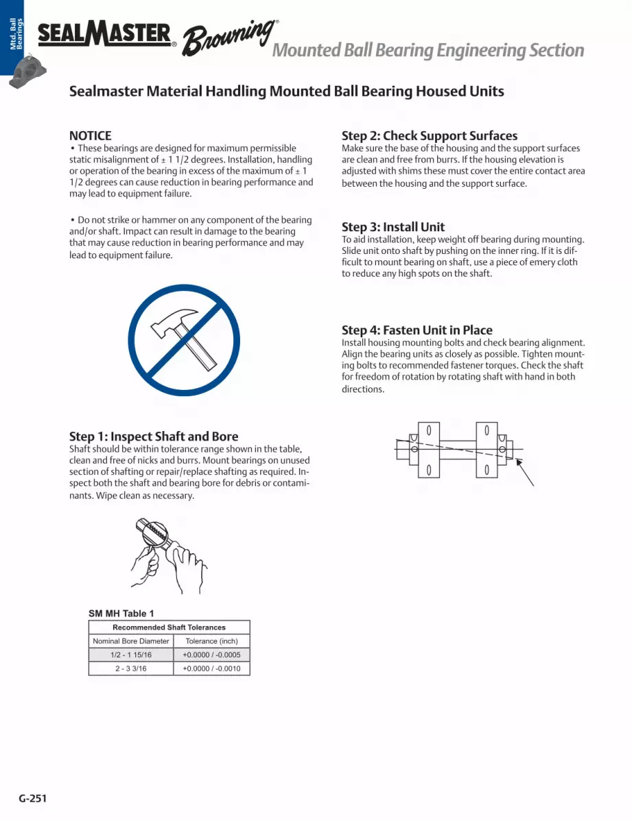
Mtd
. Ba
ll
Be
ari
ng
s
G-251
® Mounted Ball Bearing Engineering Section
Sealmaster Material Handling Mounted Ball Bearing Housed Units
NOTICE• These bearings are designed for maximum permissible static misalignment of ± 1 1/2 degrees. Installation, handling or operation of the bearing in excess of the maximum of ± 1 1/2 degrees can cause reduction in bearing performance and may lead to equipment failure.
• Do not strike or hammer on any component of the bearing and/or shaft. Impact can result in damage to the bearing that may cause reduction in bearing performance and may lead to equipment failure.
Step 1: Inspect Shaft and BoreShaft should be within tolerance range shown in the table, clean and free of nicks and burrs. Mount bearings on unused section of shafting or repair/replace shafting as required. In-spect both the shaft and bearing bore for debris or contami-nants. Wipe clean as necessary.
Step 2: Check Support SurfacesMake sure the base of the housing and the support surfaces are clean and free from burrs. If the housing elevation is adjusted with shims these must cover the entire contact area between the housing and the support surface.
Step 3: Install UnitTo aid installation, keep weight off bearing during mounting. Slide unit onto shaft by pushing on the inner ring. If it is dif-ficult to mount bearing on shaft, use a piece of emery cloth to reduce any high spots on the shaft.
Step 4: Fasten Unit in PlaceInstall housing mounting bolts and check bearing alignment. Align the bearing units as closely as possible. Tighten mount-ing bolts to recommended fastener torques. Check the shaft for freedom of rotation by rotating shaft with hand in both directions.
SM MH Table 1Recommended Shaft Tolerances
Nominal Bore Diameter Tolerance (inch)
1/2 - 1 15/16 +0.0000 / -0.0005
2 - 3 3/16 +0.0000 / -0.0010

Mtd
. Ba
ll
Be
ari
ng
s
G-252
®Mounted Ball Bearing Engineering Section
Sealmaster Material Handling Mounted Ball Bearing Housed Units continued
Step 6: Tighten Locking Mechanisma. Setscrew Locking Inserts
Setscrews in multiple bearing applications should be aligned as shown.
Tighten bearing units to the shaft as follows: i. Torque the first setscrew “A” to one half of the recommended torque in Table 2.
ii. Torque the second setscrew “B” to the full recommended torque. Go back to the first setscrew “A” and tighten to the full recommended torque.
If the bearing unit has setscrew locking on both sides of the inner ring (Double Lock Setscrew), repeat the same proce-dure for the second pair of setscrews. Check shaft again for freedom of rotation and then tighten the second bearing unit in the same fashion. When all bearings are tightened, perform a final check to the shaft for freedom of rotation.
b. Skwezloc Locking Insertsi. Be sure that the Skwezloc collar is fitted square and snug against the shoulder on the inner ring as shown. ii. Torque the Skwezloc collar cap screw to the full recom-
mended torque in Table 3.
Check shaft again for freedom of rotation and then tighten the second bearing unit in the same fashion. When all bear-ings are tightened, perform a final check to the shaft for freedom of rotation.
Step 7: End Cover InstallationPosition the cap so it is flush with the housing, and align the removal nub in the 12 o’clock position. Press evenly on end of cap by hand to install in the machined housing groove.
Push Locking Collar Tightly Against Inner Ring Shoulder
SM MH Table 2 Setscrew Torque
Screw Size Hex Size Inch-Pounds
1/4-28 1/8 65 - 85
5/16-24 5/32 125 - 165
3/8-24 3/16 230 - 300
SM MH Table 3 Skwezloc Concentric Locking Collar Cap
Screw Torque
Screw Size Torx Size Inch-Pounds
# 8-32 T-25 70
# 10-24 T-27 100
1/4-20 T-30 240

Mtd
. Ba
ll
Be
ari
ng
s
G-253
® Mounted Ball Bearing Engineering Section
Replacing Existing Sealmaster Material Handling Inserts:Note: Replacement Sealmaster bearing inserts are intended for use in Sealmaster housings only.
NOTICE• These bearings are designed for maximum permissible static misalignment of ± 1 1/2 degrees. Installation, handling or operation of the bearing in excess of the maximum of ± 1 1/2 degrees can cause reduction in bearing performance and may lead to equipment failure.
• Do not strike or hammer on any component of the bearing and/or shaft. Impact can result in damage to the bearing that may cause reduction in bearing performance and may lead to equipment failure.
Step 1: Loosen and Remove Housing Mounting Bolts
Step 2: Remove Bearing from ShaftRemove the end cover. Loosen the locking mechanism and slide the bearing off the shaft.
Step 3: Remove the Bearing Insert from the HousingSecure housing in a vise. Using a bar placed in the insert bore as a lever, swing the insert to line up the outer ring with the load slots and remove insert from load slots.
Step 4: Inspect and Prepare HousingHousings should be inspected for damage prior to installa-tion. Wipe housing bore clean as necessary and check that the lubrication groove and hole are clean and free of debris. Wetting of the housing bore with oil or grease may be done to ease installation of bearing insert.
Step 5: Load New InsertWith the bearing housing still in the vise, load the insert in the following fashion:
a. Place the bearing insert into the housing load slots, posi-tioning the anti rotation rivet on the outer ring in the load slot as to not shear it off when the swinging insert into place. Also, position the outer ring lubrication hole so it will install in line with the housing lubrication hole.
b. Using a bar placed in the insert bore as a lever, swing the insert into place within the housing. Insert should have a snug fit in the housing. If insert can be made to swivel by hand in the housing bore, fit is too lose and entire unit should be replaced. If heavy force is required, fit is too tight and entire unit should be replaced.
c. Ensure alignment of the anti rotation rivet in the load slot and outer ring lubrication hole in the housing lubrication hole.
Step 6: Refer to Steps 1 - 6 from the “Mounting Housed Bearing Units” SectionPages G-251 to G-252

Mtd
. Ba
ll
Be
ari
ng
s
G-254
®Mounted Ball Bearing Engineering Section
Sealmaster Gold and Material Handling Bearing Lubrication:
All Sealmaster Gold and Material Handling Ball Bearings are delivered with a high quality lithium complex grease with an EP additive. The bearing is ready for use with no initial lubrication required. The grease consists of a lithium complex thickener, mineral oil, and NLGI grade 2 consistency. Compat-ibility of grease is critical; therefore consult with Application Engineering and your grease supplier to insure greases are compatible. For best performance it is recommended to relu-bricate with lithium complex thickened grease with a compa-rable NLGI consistency and base oil properties.
Relubricatable Sealmaster bearings are supplied with grease fittings or zerks for ease of lubrication with hand or automaticgrease guns. Always wipe the fitting and grease nozzle clean.
Note: Sealmaster bearings with the RM suffix are Reduced Maintenance Bearings (ex. NP-16 RM). Sealmaster Reduced Maintenance Bearings are designed to operate with the standard factory fill of grease and are designed not to be lubricated.
CAUTION: If possible, it is recommended to lubricate the bearing while rotating, until grease purge is seen from the seals. If this is not an option due to safety reasons, follow the alternate lubrication procedure below.
Re-Lubrication Procedure:Stop rotating equipment. Add one half of the recommended amount shown in Table 1. Start the bearing and run for a few minutes. Stop the bearing and add the second half of the recommended amount. A temperature rise after lubrication, sometimes 30°F (17°C), is normal. Bearing should operate at temperatures less than 200°F (94°C) and should not exceed 250° (121°C) for intermittent operation. For lubrication guide-lines, see Tables 2 and 3.
Note: Tables 2 and 3 are general recommendations. Experi-ence and testing may be required for specific applications.
Note: Grease charges in Table 1 are based on the use of lithium complex thickened grease with a NLGI grade 2 consis-tency.
Note: The Maximum Operational Speeds listed in Table 2 and 3 are based on the use of a single lock setscrew insert with felt seals. For maximum operational speeds of other locking mechanisms and seals, refer to speed rating section or consult Application Engineering.
LO and XLO Relubrication FrequencyLO and XLO bearings are designed for applications which require the bearing to operate with less torque or drag than a standard bearing.
Note: Addition of lubricant to the bearing will increase bear-ing drag.
If relubrication is necessary:1. Add a very small amount of lubricant2. Check bearing rotational torque (be sure that the bearing still rotates freely enough for the application.)
Sealmaster Ball Lube Table 1 / Grease Charge for Relubrication
SeriesBore Diameter Grease
Charge (Mass - Ounces)
Bore Diameter Grease Charge (Mass - Ounces)
Gold - Performance Material Handling BearingStandard Duty Medium Duty
2-012 1/2 - 3/4 - 0.03 - -2-015 13/16 - 1 - 0.04 1 0.032-13 1 1/16 - 1 1/4R 15/16 - 1 0.09 1 1/16 - 1 1/4R 0.062-17 1 1/4 - 1 7/16 1 3/16 0.13 1 1/4 - 1 7/16 0.092-19 1 1/2 - 1 9/16 1 7/16 0.18 1 1/2 - 1 9/16 0.142-111 1 5/8 - 1 3/4 1 1/2 0.20 1 5/8 - 1 3/4 0.162-115 1 13/16 - 2R 1 11/16 - 1 3/4 0.22 1 13/16 - 2R 0.182-23 2 - 2 3/16 1 15/16 0.30 2 - 2 3/16 0.252-27 2 1/4 - 2 7/16 2 3/16 0.38 - -2-211 2 1/2 - 2 11/16 2 7/16 - 2 1/2 0.53 - -2-215 2 13/16 - 2 15/16 2 11/16 0.62 - -2-33 3 - 3 3/16 2 15/16 0.88 - -2-37 3 1/4 - 3 7/16 3 3/16 1.11 - -2-38 3 1/2 3 7/16 1.37 - -2-43 3 15/16 - 4 3/16 3 15/16 - 4 2.50 - -2-47 5 4 7/16 - 4 15/16 3.91 - -
Sealmaster Ball Lube Table 2Environment Temperature (°F) Speed
(% Catalog Max) Frequency
Dirty -20 to 250 0 - 100% Daily to 1 Week
Clean
-20 to 125
0 - 25% 4 to 10 Months26 - 50% 1 to 4 Months51 - 75% 1 Week to 1 Month
76 - 100% Daily to 1 Week
125 to 175
0 - 25% 2 to 6 Weeks26 - 50% 1 Week to 1 Month51 - 75%
Daily to 1 Week76 - 100%175 to 250 0 - 100%
Sealmaster Ball Lube Table 3
Environment Temperature (°F)
Speed (% Catalog
Max)HT / HTC / HTA
Suffix (1)HI Suffix
(2)
Dirty -20 to 400 0 - 100% Daily to 1 Week Daily to 1 Week
Clean
200 to 300
0 - 25% 1 to 3 Months 6 to 12 Months26 - 50% 2 to 6 Weeks 2 to 6 Months51 - 75% Daily to 1 Week 2 Weeks to 2 Months
76 - 100% Daily to 1 Week Daily to 1 Week
300 to 400
0 - 25% 2 Weeks to 1 Month 3 to 6 Months26 - 50% 1 to 2 Weeks 1 to 3 Months51 - 75% Daily to 1 Week 1 Week to 1 Month
76 - 100% Daily to 1 Week Daily to 1 Week(1) Use high quality lithium complex grease, NLGI#2 and synthetic hydrocarbon oil with ISO 220 viscosity(2) Use Krytox GPL-226, no substitutions
*DuPont is a registered trademark of E.I. du Pont de Nemurs and Company. This trade name, trademark and/or registered trademark is property of their respective owner and is not owned or controlled by Regal Power Transmission Solutions.
Sealmaster Relubrication Frequency
Sealmaster High Temperature Suffix Modified Bearing Relubrication Frequency

Mtd
. Ba
ll
Be
ari
ng
s
G-255
® Mounted Ball Bearing Engineering Section
Browning Mounted Ball Bearing Housed Units
NOTICE• These bearings are designed for maximum permissible static misalignment of ± 1 1/2 degrees. Installation, handling or operation of the bearing in excess of the maximum of ± 1 1/2 degrees can cause reduction in bearing performance and may lead to equipment failure.
• Do not strike or hammer on any component of the bearing and/or shaft. Impact can result in damage to the bearing that may cause reduction in bearing performance and may lead to equipment failure.
Step 1: Inspect Shaft and BoreShaft should be within tolerance range shown in the table, clean and free of nicks and burrs. Mount bearings on unused section of shafting or repair/replace shafting as required. In-spect both the shaft and bearing bore for debris or contami-nants. Wipe clean as necessary.
Step 2: Check Support SurfacesMake sure the base of the housing and the support surfaces are clean and free from burrs. If the housing elevation is adjusted with shims these must cover the entire contact area between the housing and the support surface.
Step 3: Install UnitTo aid installation, keep weight off bearing during mounting. Slide unit onto shaft by pushing on the inner ring. If it is dif-ficult to mount bearing on shaft, use a piece of emery cloth to reduce any high spots on the shaft.
Step 4: Fasten Unit in PlaceInstall housing mounting bolts and check bearing alignment. Align the bearing units as closely as possible. Tighten mount-ing bolts to recommended fastener torques. Check the shaft for freedom of rotation by rotating shaft with hand in both directions.
BMD Table 1Recommended Shaft Tolerances
Nominal Bore Diameter Tolerance (Inches)
1/2 - 1 15/16 +0.0000 / -0.0005
2 - 2 7/16 +0.0000 / -0.0010
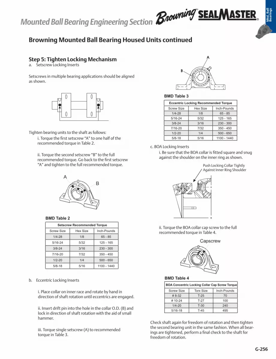
Mtd
. Ba
ll
Be
ari
ng
s
G-256
®Mounted Ball Bearing Engineering Section
Step 5: Tighten Locking Mechanisma. Setscrew Locking Inserts
Setscrews in multiple bearing applications should be aligned as shown.
Tighten bearing units to the shaft as follows: i. Torque the first setscrew “A” to one half of the recommended torque in Table 2.
ii. Torque the second setscrew “B” to the full recommended torque. Go back to the first setscrew “A” and tighten to the full recommended torque.
b. Eccentric Locking Inserts
i. Place collar on inner race and rotate by hand in direction of shaft rotation until eccentrics are engaged.
ii. Insert drift pin into the hole in the collar O.D. (B) and lock in direction of shaft rotation with the aid of small hammer.
iii. Torque single setscrew (A) to recommended torque in Table 3.
c. BOA Locking Inserts i. Be sure that the BOA collar is fitted square and snug against the shoulder on the inner ring as shown.
ii. Torque the BOA collar cap screw to the full recommended torque in Table 4.
Check shaft again for freedom of rotation and then tighten the second bearing unit in the same fashion. When all bear-ings are tightened, perform a final check to the shaft for freedom of rotation.
BMD Table 3Eccentric Locking Recommended TorqueScrew Size Hex Size Inch-Pounds
1/4-28 1/8 65 - 855/16-24 5/32 125 - 1653/8-24 3/16 230 - 300
7/16-20 7/32 350 - 4501/2-20 1/4 500 - 6505/8-18 5/16 1100 - 1440
Browning Mounted Ball Bearing Housed Units continued
Push Locking Collar Tightly Against Inner Ring Shoulder
BMD Table 4 BOA Concentric Locking Collar Cap Screw Torque
Screw Size Torx Size Inch-Pounds# 8-32 T-25 70
# 10-24 T-27 1001/4-20 T-30 240
5/16-18 T-45 495
BMD Table 2 Setscrew Recommended Torque
Screw Size Hex Size Inch-Pounds
1/4-28 1/8 65 - 85
5/16-24 5/32 125 - 165
3/8-24 3/16 230 - 300
7/16-20 7/32 350 - 450
1/2-20 1/4 500 - 650
5/8-18 5/16 1100 - 1440
A
B

Mtd
. Ba
ll
Be
ari
ng
s
G-257
® Mounted Ball Bearing Engineering Section
Step 1: Inspect and Prepare HousingTo achieve proper bearing fit, the housing should be ma-chined to the correct bore size. For recommended housing bore sizes, refer to the Browning bearing catalog or consult Application Engineering. The housing bearing seat should be wiped clean and free of debris.
Step 2: Install Unit in HousingPress bearing into housing by applying force to the face of the outer ring. Do not hammer on any component of the bearing or apply force to the inner ring.
Step 3: Refer to Steps 1 - 5 from the “Mounting Housed Bearing Units” SectionPages G-255 to G-256
Replacing Existing Browning Inserts:
Note: Replacement Browning bearing inserts are intended for use in Browning housings only.
Step 1: Loosen and Remove Housing Mounting Bolts
Step 2: Remove Bearing from ShaftLoosen the locking mechanism and slide the bearing off the shaft.
Step 3: Remove the Bearing Insert from the HousingSecure housing in a vise. Using a bar placed in the insert bore as a lever, swing the insert to line up the outer ring with the load slots and remove insert from load slots.
Step 4: Inspect and Prepare HousingHousings should be inspected for damage prior to installa-tion. Wipe housing bore clean as necessary and check that the lubrication groove and hole are clean and free of debris. Wetting of the housing bore with oil or grease may be done to ease installation of bearing insert.
Step 5: Load New InsertWith the bearing housing still in the vise, load the insert in the following fashion:
a. Place the bearing insert into the housing load slots, posi-tioning the anti rotation rivet on the outer ring in the load slot as to not shear it off when the swinging insert into place. Also, position the outer ring lubrication hole so it will install in line with the housing lubrication hole.
b. Using a bar placed in the insert bore as a lever, swing the insert into place within the housing. Insert should have a snug fit in the housing. If insert can be made to swivel by hand in the housing bore, fit is too lose and entire unit should be replaced. If heavy force is required, fit is too tight and entire unit should be replaced.
c. Ensure alignment of the anti rotation rivet in the load slot and outer ring lubrication hole in the housing lubrication hole.
Step 6: Refer to Steps 1 - 5 from the “Mounting Housed Bearing Units” Section Pages G-255 to G-256
Mounting Cylindrical O.D. (VER Style) Inserts:

Mtd
. Ba
ll
Be
ari
ng
s
G-258
®Mounted Ball Bearing Engineering Section
Browning Mounted Ball Lubrication:
All Browning Ball Bearings are delivered with a high quality lithium complex grease with an EP additive. The bearing is ready for use with no initial lubrication required. The grease consists of a lithium complex thickener, mineral oil, and NLGI grade 2 consistency.
Compatibility of grease is critical; therefore consult with Appli-cation Engineering and your grease supplier to insure greases are compatible. For best performance it is recommended to relubricate with lithium complex thickened grease with a com-parable NLGI consistency and base oil properties.
Relubricatable Browning bearings are supplied with grease fittings or zerks for ease of lubrication with hand or automatic grease guns. Always wipe the fitting and grease nozzle clean.
CAUTION: If possible, it is recommended to lubricate the bearing while rotating, until grease purge is seen from the seals. If this is not an option due to safety reasons, follow the alternate lubrication procedure below.
Re-Lubrication Procedure:Stop rotating equipment. Add one half of the recommended amount shown in Table 1. Start the bearing and run for a few minutes. Stop the bearing and add the second half of the recommended amount. A temperature rise after lubrication, sometimes 30°F (17°C), is normal. Bearing should operate at temperatures less than 200°F (94°C) and should not exceed 250° (121°C) for intermittent operation. For lubrication guide-lines, see Table 2.
Note: Table 2 is general recommendations. Experience and testing may be required for specific applications.
Note: Grease charges in Table 1 are based on the use of lithium complex thickened grease with a NLGI grade 2 consis-tency.
Browning Lube Table 1 Grease Charge for Relubrication
Series
Shaft Size
Grease Charge (Mass - Ounces)
100 & 200 Series 300 Series
Intermediate & Standard Duty Medium Duty
L-10 1/2 - 5/8 x 0.022-012 3/4 x 0.032-015 13/16 - 1 x 0.032-13 1 1/16 - 1 1/4S 15/16 - 1 0.062-17 1 1/4 - 1 7/16 1 3/16 0.092-19 1 1/2 - 1 9/16 1 7/16 0.142-111 1 5/8 - 1 3/4 1 1/2 0.162-115 1 13/16 - 2 1 11/16 - 1 3/4 0.182-23 2 - 2 3/16 1 15/16 0.252-27 2 1/4 - 2 7/16 2 3/16 0.352-211 2 1/2 - 2 11/16 2 7/16 - 2 1/2 0.462-215 2 13/16 - 2 15/16 2 11/16 0.482-33 x 2 15/16 - 3 0.652-38 x 3 7/16 - 3 1/2 1.052-43 x 3 15/16 1.77
Browning Lube Table 2 Relubrication Recommendations
Environment Temperature (°F) Speed (% Catalog Max) Frequency
Dirty -20 to 250 0 - 100% Daily to 1 Week
Clean
-20 to 125
0 - 25% 4 to 10 Months26 - 50% 1 to 4 Months51 - 75% 1 Week to 1 Month
76 - 100% Daily to 1 Week
125 to 175
0 - 25% 2 to 6 Weeks26 - 50% 1 Week to 1 Month51 - 75%
Daily to 1 Week76 - 100%
175 to 250 0 - 100% Daily to 1 Week

Mtd
. Ba
ll
Be
ari
ng
s
G-259
® Mounted Ball Bearing Engineering Section
Cylindrical OD Housing Fit GuidelinesTables 14-15 list fit up guidelines for light load conveyor roll application per ABMA J6 fit. Testing and experience is needed to verify if this fit is sufficient for specific operation conditions. If tighter press fit is needed, contact Application Engineering to review if the standard bearing internal clearance is sufficient or a modified clearance is needed to prevent reduction or elimination of internal clearance.
For best reliability, bearings and housings should be selectively matched to reduce variation in fit up due to manufacturing tolerances of the bearing outside diameter and housing bore. Roll pockets should be machined parallel with the axis of the shaft and both sides should be on the same centerline to minimize potential for misalignment.
Table 14 - ER, VER and Cylindrical OD Insert Bearing Housing/Roll Bore
Dimensions inch / mm
Bore Diameter Sealmaster ER
Browning VER
Nominal Outside
Diameter
Outside Diameter*
Stationary Housing Revolving Housing
Diameters Theoretical Fit Diameters Theoretical Fit
inch mm Max Min Max Min Tight Loose Max Min Tight Loose
1/2 - ER-8 VER-208
9/16 - ER-9 -
5/8 - ER-10 VER-210 1.8504 1.8504 1.8499 1.8509 1.8503 .0001 .0010 1.8504 1.8498 .0006 .0005
11/16 - ER-11 - 47 47.002 46.9875 47.0129 46.9976 .0025 .0254 47.002 46.9848 .0152 .0127
3/4 - ER-12 VER-212
- 20 ER-204 -
7/8 - ER-14 VER-214
15/16 - ER-15 VER-215 2.0472 2.0472 2.0466 2.0476 2.0471 .0001 .0010 2.0471 2.0466 .0006 .0005
1 - ER-16 VER-216 52 51.9989 51.9836 52.0090 51.9963 .0025 .0254 51.9963 51.9836 .0152 .0127
- 25 ER-205 -
1 1/16 - ER-17 VER-217
2.4409
62
2.4409 61.9989
2.4403 61.9836
2.4413 62.0090
2.4408 61.9963
.0001 .0025
.0010 .0254
2.4408 61.9963
2.4403 61.9836
.0006 .0152
.0005 .0127
1 1/8 - ER-18 VER-218
1 3/16 - ER-19 VER-219
1 1/4 - ER-20R VER-220S
- 30 ER-206 -
1 1/4 - ER-20 VER-220
2.8364
72
2.8346 71.9988
2.8340 71.9836
2.8350 72.0090
2.8345 71.9963
.0001 .0025
.0010 .0254
2.8345 71.9963
2.8340 71.98836
.0006 .0152
.0005 .0127
1 5/16 - ER-21 -
1 3/8 - ER-22 VER-222
1 7/16 - ER-23 VER-223
- 35 ER-207 -
1 1/2 - ER-24 VER-2243.1496
80 3.1496 79.9998
3.1490 79.9846
3.1500 80.0100
3.1495 79.9973
.0001 .0025
.0010 .0254
3.1495 79.9973
3.1490 79.9846
.0006 .0152
.0005 .0127
1 9/16 - ER-25 VER-225
- 40 ER-208 -
1 5/8 - ER-26 VER-226
1 11/16 - ER-27 VER-227 3.3465 3.3465 3.3459 3.3470 3.3464 .0001 .0013 3.3464 3.3458 .0007 .0007
1 3/4 - ER-28 VER-228 85 85.0011 84.9808 85.0138 84.9986 .0025 .0330 84.9986 84.9833 .0178 .0178
- 45 ER-209 -
This chart displays the recommended housing dimensions for Sealmaster ER and Browning VER ball bearings at the various bore diameters and nominal Outer Diameter. For Sealmaster ER with Skwezloc Concentric locking use the similar size ER with setscrew locking as shown. For other Browning Cylindrical O.D. bearings use the similar nominal dimensioned bearing. * Outside diameter may be slightly oversized due to seal press fit, dimensions listed are as measured prior to seal assembly.

Mtd
. Ba
ll
Be
ari
ng
s
G-260
®Mounted Ball Bearing Engineering Section
Dimensions inch / mm
Bore Diameter Sealmaster ER
Browning VER
Nominal Outside
Diameter
Outside Diameter*
Stationary Housing Revolving Housing
Diameters Theoretical Fit Diameters Theoretical Fit
inch mm Max Min Max Min Tight Loose Max Min Tight Loose
1 13/16 - ER-29 -
3.5433
90
3.5433 89.998
3.5425 89.9795
3.5438 90.0125
3.5432 89.9972
.0001 .0025
.0013 .0330
3.5432 89.9973
3.5426 89.9820
.0007 .0178
.0007 .0178
1 7/8 - ER-30 -
1 15/16 - ER-31 VER-231
2 - ER-32R VER-232S
- 50 ER-210 -
2 - ER-32 VER-232
2 1/8 - ER-34 - 3.937 3.9370 3.9362 3.9375 3.9369 .0001 .0013 3.9369 3.9363 .0007 .0007
2 3/16 - ER-35 VER-235 100 99.9998 99.9795 100.0125 99.9973 .0025 .0330 99.9973 99.9820 .0178 .0178
- 55 ER-211 -
2 1/4 - ER-36 VER-236
2 3/8 - ER-38 VER-238 4.3307 4.3307 4.3299 4.3312 4.3306 .0001 .0013 4.3306 4.3300 .0007 .0007
2 7/16 - ER-39 VER-239 110 109.9998 109.9795 110.0125 109.9972 .0025 .0330 109.9972 109.9820 .0178 .0178
- 60 ER-212 -
2 1/2 - ER-40 -4.9213
125 4.9213
125.0010 4.9203
124.9756 4.9219
125.0163 4.9211
124.9959 .0002 .0051
.0016 .0406
4.9212 124.9985
4.9204 124.9782
.0009 .0229
.0009 .0229
2 11/16 - ER-43 -
- 70 ER-214 -
2 7/8 - ER-46 - 5.1181
130 5.1181
129.9997 5.1171
129.9743 5.1187
130.0150 5.1179
129.9947 .0002 .0051
.0016 .0406
5.1180 129.9972
5.1172 129.9769
.0009 .0229
.0009 .0229
2 15/16 - ER-47 -
- 75 ER-215 -
3 - ER-48 - 5.5118
140 5.5118
139.9997 5.5108
139.9743 5.5124
140.0150 5.5116
139.9946 .0002 .0051
.0016 .0406
5.5117 139.9972
5.5109 139.9769
.0009 .0229
.0009 .0229
3 3/16 - ER-51 -
- 80 ER-216 -
3 1/4 - ER-52 - 5.9055
150 5.9055
148.9997 5.9045
149.9743 5.9061
150.0149 5.9053
149.9946 .0002 .0051
.0016 .0406
5.9054 149.9972
5.9046 149.9768
.0009 .0229
.0009 .0229
3 3/8 - ER-54 -
3 7/16 - ER-55 -
3 15/16 - ER-63 - 7.4803 7.4803 7.4791 7.4815 7.4801 .0002 .0024 7.4805 7.4791 .0012 .0014
4 - ER-64 - 190 189.9996 189.9691 190.0301 189.9945 .0051 .0610 190.0047 189.9691 .0305 .0356
Table 14 - ER, VER and Cylindrical OD Insert Bearing Housing/Roll Bore cont.
This chart displays the recommended housing dimensions for Sealmaster ER and Browning VER ball bearings at the various bore diameters and nominal Outer Diameter. For Sealmaster ER with Skwezloc Concentric locking use the similar size ER with setscrew locking as shown. For other Browning Cylindrical O.D. bearings use the similar nominal dimensioned bearing. * Outside diameter may be slightly oversized due to seal press fit, dimensions listed are as measured prior to seal assembly.

Mtd
. Ba
ll
Be
ari
ng
s
G-261
® Mounted Ball Bearing Engineering Section
Table 15 - Sealmaster SC and MSC Housing Bore
Standard Duty Medium Duty Nominal Outside
Diameter
Housing Dimension Recommendations inch/mm
Bore DiameterPart No.
Bore DiameterPart No.
Outside Diameter Stationary Housing Revolving Housing
inch mm
Diameters Diameters Diameters
inch mm inch mm Max Min Max Min Max Min
1/2 - SC-8 - - -
2 11/1668.26
9/16 - SC-9 - - - 2.6885 2.6865 2.6905 2.6885 2.6875 2.6855
5/8 - SC-10 - - - 68.288 68.237 68.339 68.288 68.263 68.212
11/16 - SC-11 - - -
3/4 - SC-12 - - - 2 15/1674.61
2.9385 2.9365 2.9405 2.9385 2.9375 2.9355
- 20 SC-204 - - - 74.638 74.587 74.689 74.638 74.613 74.562
13/16 - SC-13 - - -
3 1/879.38
3.1260 79.400
3.1240 79.350
3.1280 79.451
3.1260 79.400
3.1250 79.375
3.1230 79.324
7/8 - SC-14 - - -
15/16 - SC-15 - - -
1 - SC-16 - - -
- 25 SC-205 - - -
1 1/16 - SC-17 - - -
3 1/288.90
3.5010 88.925
3.4990 88.875
3.5030 88.976
3.5010 88.925
3.5000 88.900
3.4980 88.849
1 1/8 - SC-18 15/16 - MSC-15
1 3/16 - SC-19 1 - MSC-16
1 1/4 - SC-20R - 25 MSC-305
- 30 SC-206 - - -
1 1/4 - SC-20 - - -
3 7/898.43
3.8760 98.450
3.8740 98.400
3.8780 98.501
3.8760 98.450
3.8750 98.425
3.8730 98.374
1 5/16 - SC-21 1 3/16 - MSC-19
1 3/8 - SC-22 1 1/4 - MSC-20
1 7/16 - SC-23 - 30 MSC-306
- 35 SC-207 - - -
1 1/2 - SC-24 1 3/8 - MSC-224 3/16106.36
4.1885 106.388
4.1865 106.337
4.1905 106.439
4.1885 106.388
4.1875 106.363
4.1855 106.312
1 9/16 - SC-25 1 7/16 - MSC-23
- 40 SC-208 - 35 MSC-307
1 5/8 - SC-26 - - -
4 3/8111.13
1 11/16 - SC-27 1 1/2 MSC-24 4.3760 4.3740 4.3780 4.3760 4.3750 4.3730
1 3/4 - SC-28 - 40 MSC-308 111.150 111.100 111.201 111.150 111.125 111.074
- 45 SC-209 - - -
1 13/16 - SC-29 - - -
4 9/16115.89
4.5635 115.913
4.5615 115.862
4.5655 115.964
4.5635 115.913
4.5625 115.888
4.5605 115.837
1 7/8 - SC-30 1 11/16 - MSC-27
1 15/16 - SC-31 1 3/4 - MSC-28
2 - SC-32R - 45 MSC-309
- 50 SC-210 - - -
This chart displays the recommended housing dimensions for Sealmaster SC and MSC ball bearings at the various bore diameters and nominal Outer Diameter. For Sealmaster SC and MSC with Skwezloc Concentric locking use the similar size SC or MSC with setscrew locking as shown.
For additional assistance contact Application Engineering at (800) 626-2093.

Mtd
. Ba
ll
Be
ari
ng
s
G-262
®Mounted Ball Bearing Engineering Section
Table 15 - Sealmaster SC and MSC Housing Bore cont.
This chart displays the recommended housing dimensions for Sealmaster SC and MSC ball bearings at the various bore diameters and nominal Outer Diameter. For Sealmaster SC and MSC with Skwezloc Concentric locking use the similar size SC or MSC with setscrew locking as shown.
For additional assistance contact Application Engineering at (800) 626-2093.
Standard Duty Medium Duty Nominal Outside
Diameter
Housing Dimension Recommendations inch/mm
Bore DiameterPart No.
Bore DiameterPart No.
Outside Diameter Stationary Housing Revolving Housing
inch mm
Diameters Diameters Diameters
inch mm inch mm Max Min Max Min Max Min
2 - SC-32 1 15/16 - MSC-31
4 15/16125.41
4.9385 125.438
4.9365 125.387
4.9405 125.489
4.9385 125.438
4.9375 125.413
4.9355 125.362
2 1/8 - SC-34 2 - MSC-32
2 3/16 - SC-35 - 50 MSC-310
- 55 SC-211 - - -
- - - - - -
2 1/4 - SC-36 2 3/16 - MSC-35
5 7/8149.23
5.8750 149.225
5.8730 149.174
2 3/8 - SC-38 2 1/4 - MSC-36 5.8760 149.250
5.8740 149.200
5.8780 149.301
5.8760 149.2502 7/16 - SC-39 - 55 MSC-311
- 60 SC-212 - - -
2 1/2 - SC-40 2 7/16 - MSC-39
6 1/4 6.2510 158.775
6.2490 158.725
6.2530 158.826
6.2510 158.775
6.2500 158.750
6.2480 158.699
2 11/16 - SC-43 2 1/2 - MSC-40
- 70 SC-214 - 65 MSC-313
2 7/8 - SC-46 2 11/16 - MSC-436 5/8
168.28 6.6260 168.300
6.6240 168.250
6.6280 168.351
6.6260 168.300
6.6250 168.275
6.6230 168.224
2 15/16 - SC-47 2 3/4 - MSC-44
- 75 SC-215 - 70 MSC-314
- - - 2 15/16 - MSC-477
158.75 7.0010 177.825
6.9990 177.775
7.0030 177.876
7.0010 177.825
7.0000 177.800
6.9980 177.749
- - - 3 - MSC-48
- - - - 75 MSC-315
- - - 3 3/16 - MSC-51
7 7/16168.28
- - - 3 1/4 - MSC-52 7.4385 188.938
7.4365 188.887
7.4405 188.989
7.4385 188.938
7.4375 188.913
7.4355 188.862- - - 3 3/8 - MSC-54
- - - - 80 MSC-316
- - - 3 7/16 - MSC-55 8 3/16177.80
8.1885 207.988
8.1865 207.937
8.1905 208.039
8.1885 207.988
8.1875 207.963
8.1855 207.912- - - 3 1/2 - MSC-56
- - - 3 15/16 - MSC-639 1/2
188.91 9.5010 241.325
9.4990 241.275
9.5030 241.376
9.5010 241.325
9.5000 241.300
9.4980 241.249
- - - 4 - MSC-64
- - - - 100 MSC-320

Mtd
. Ba
ll
Be
ari
ng
s
G-263
® Mounted Ball Bearing Engineering Section
Vibration Analysis
BALL BEARINGS VIBRATION ANALYSISThe following equations are used to calculate the fundamental frequencies for Sealmaster and Browning Ball Bearings.
1. If the insert number is known, proceed to step 2. For housed units, identify the bearing insert number by look-ing up the unit in the dimension tables, then proceed to step 2.
2. Find the Sealmaster or Browning insert number in Table 16 below and identify the series.
3. Select the vibration geometry information (O, I, B, F) from Table 16.
4. Use this information to calculate the fundamental bearing frequencies:• Outer Ball Pass Frequency (Hz) = O x RPM• Inner Ball Pass Frequency (Hz) = I x RPM• Ball Spin Frequency (Hz) = B x RPM• Fundamental Train Frequency (Hz) = F x RPM
Symbol Description Units RPM = Revolutions per Minute RPM O = Outer Race Frequency Factor I = Inner Race Frequency Factor B = Ball Spin Frequency Factor F = Fundamental Train Frequency Factor
SeriesStandard Duty Bore Diameter Medium Duty Bore Diameter
Pitch Diameter
(inch) dM
Number Of Balls
N
Size of Balls (inch)
D
Factor For Outer
RaceO
Factor For Inner
Race I
Factor For Ball
Spin B
Factor for F.T.F.
Finch mm inch mm
*L-10 *1/2 to 5/8 N/A - - 1.138 9 1/4 0.0585 0.0915 0.0361 0.0065
2-012 1/2 to 3/4 20mm - - 1.345 9 9/32 0.0593 0.0907 0.0381 0.0066
2-015 13/16 to 1 25mm - - 1.544 10 9/32 0.0682 0.0985 0.0442 0.0068
2-13 1 1/16 to 1 1/4R or S 30mm 15/16 to 1 25mm 1.812 9 3/8 0.0595 0.0905 0.0385 0.0066
2-17 1 1/4 to 1 7/16 35mm 1 3/16 30mm 2.115 9 7/16 0.0595 0.0905 0.0386 0.0066
2-19 1 1/2 to 1 9/16 40mm 1 7/16 35mm 2.362 9 1/2 0.0591 0.0909 0.0376 0.0066
2-111 1 5/8 to 1 3/4 45mm 1 1/2 40mm 2.596 10 1/2 0.0673 0.0994 0.0417 0.0067
2-115 1 13/16 to 2R 50mm 1 11/16 to 1 3/4 45mm 2.763 10 1/2 0.0683 0.0984 0.0445 0.0068
2-23 2 to 2 3/16 55mm 1 15/16 50mm 3.051 10 9/16 0.0680 0.0987 0.0437 0.0068
2-27 2 1/4 to 2 7/16 60mm 2 3/16 55mm 3.356 10 5/8 0.0678 0.0989 0.0432 0.0068
2-211 2 1/2 to 2 11/16 70mm 2 7/16 to 2 1/2 65mm 3.846 10 11/16 0.0684 0.0982 0.0451 0.0068
2-215 2 7/8 to 2 15/16 75mm 2 11/16 70mm 4.045 11 11/16 0.0761 0.1072 0.0476 0.0069
2-33 3 to 3 3/16 80mm 2 15/16 to 3 75mm 4.362 11 3/4 0.0759 0.1074 0.0470 0.0069
2-37 3 1/4 to 3 7/16 - 3 3/16 80mm 4.627 11 25/32 0.0762 0.1071 0.0479 0.0069
2-38 3 1/2 90mm 3 7/16 - 4.922 10 7/8 0.0685 0.0981 0.0454 0.0069
2-43 3 15/16 to 4 - 3 15/16 to 4 100mm 5.808 10 1 1/16 0.0681 0.0986 0.0440 0.0068
3-47 5 - 4 7/16 to 4 15/16 - 7.087 10 1 1/4 0.0686 0.0980 0.0458 0.0069
For specific bearing insert, refer to load rating page G-227 to G-229 to determine series*L-10 series only applies to Browning units for the Bore Diameters shown. For VER-208 and 210 units use the 2-012 series values
Table 16 - Vibration Geometry Information

Mtd
. Ba
ll
Be
ari
ng
s
G-264
®Mounted Ball Bearing Engineering Section
For more information on bearing capabilities outside of our standard offering, please contact Application Engineering (800) 626-2093.
Mounted Ball Bearing Engineering see page G-220.


![SIP Handbook R1[1]](https://img.pdfslide.net/doc/110x75/631b35fc665120b3330b4208/sip-handbook-r11.jpg)