Embed Size (px)
Citation preview

Microscope ComponentsGuide
Microscope Components for OEM Integration

Contents
1. Welcome to UIS2 Optics 1-12. System Diagram
BX53M System Diagram (for Refl ected and Combination Refl ected/Transmitted Light) 2-1BXFM System Diagram 2-3BX63 System Diagram 2-4BX53 System Diagram 2-6BX43 System Diagram 2-8BX3 Series Basic Motorized System Diagram 2-10BX2 Series Motorized Unit System Diagram 2-11BXFM-A System Diagram 2-11
3. UIS2 Objectives
UIS2 Objectives (for Industrial Microscopes) 3-1M Plan Apochromat MPLAPON series 3-2M Plan Apochromat Oil MPLAPON100XO2 3-2M Plan Semi Apochromat MPLFLN series 3-3Long Working Distance M Plan Semi Apochromat
LMPLFLN series 3-4M Plan Achromat MPLN series 3-5LCD Long Working Distance M Plan Semi Apochromat
LCPLFLN-LCD series 3-6Super Long Working Distance M Plan Achromat
SLMPLN series 3-7IR Long Working Distance M Plan Achromat
LMPLN-IR series 3-8IR M Plan Achromat LCPLN-IR series 3-9M Plan Semi Apochromat BD MPLFLN-BD series 3-10M Plan Semi Apochromat BDP MPLFLN-BDP series 3-11Long Working Distance M Plan Semi Apochromat BD
LMPLFLN-BD series 3-12M Plan Achromat BD MPLN-BD series 3-13White Light Interferometry Objective
WLI100XMRTC 3-14UIS2 Objectives (for Life Science Microscope) 3-15Extended Apochromat Objectives UPLXAPO series 3-16
Universal Plan Super Apochromat UPLSAPO series 3-17
Plan Apochromat PLAPON series 3-18Universal Plan Semi Apochromat/Plan Semi Apochromat
UPLFLN, PLFLN series 3-19Plan Achromat PLN series 3-21Universal Plan Semi Apochromat for Phase Contrast
UPLFLN-PH series 3-23Plan Achromat for Phase Contrast PLN-PH series 3-24Universal Plan Semi Apochromat for Polarizing
UPLFLN-P series 3-25Achromat for Polarizing PLN-P, ACHN-P series 3-26Plan Achromat (ND) PLN-CY series 3-27Long Working Distance Universal Plan Semi Apochromat
LUCPLFLN series 3-28Long Working Distance Universal Plan Semi Apochromat for Relief Contrast
CPLFLN-RC, LUCPLFLN-RC series 3-29Long Working Distance Universal Plan Semi Apochromat for Phase Contrast
CPLFLN-PH, LUCPLFLN-PH series 3-30Culture Specimen Objectives for Phase Contrast
CPLN-PH, LCACHN-PH series 3-31Culture Specimen Objectives for Relief Contrast
CPLN-RC, LCACHN-RC series 3-32No Cover Water Immersion for Fixed Stage Upright Microscope
UMPLFLN-W, LUMPLFLN-W series 3-33No Cover Water Immersion for Fixed Stage Upright Microscope
XLUMPLFLN20XW 3-34Universal Apochromat UAPON 340 series 3-35Tube Lens Unit SWTLU-C 3-36
4. Microscope Frames
BX53M: Upright Transmitted and Refl ected Light Microscope FrameBX53MTRF-S 4-1
BX53M: Upright Refl ected Light Microscope FrameBX53MRF-S 4-2
BX3: Automated Transmitted Light Microscope FrameBX63F 4-3
BX3: Semi-Motorized Fluorescence Transmitted Light Microscope FrameBX53F 4-4
BX3: Manual System Transmitted Light Microscope FrameBX43F 4-5
BX3: Transmitted Ergonomic Microscope FrameBX46F 4-6
BXFM Frame BXFM-F 4-8BXFM System Confi guration Example 1
BXFM-F + BXFM-ILH + BXFM-ILHSPU 4-9BXFM System Confi guration Example 2
BXFM-F + BXFM-ILHS 4-10Stands for BXFM 4-11
5. Illumination Units
Refl ected Light Illuminator for BX53M 5-1Coded Refl ected Light Illuminator for BX53M Frame 5-2Refl ected Light Illuminator for BX3 Series 5-3Mounting Dimensions of Illuminator (BX3M-RLA-S, BX3M-RLAS-S, BX3M-URAS-S, BX3M-KMA-S, BX3-RFAS, BX3-URA) 5-4Compact Refl ected Light Illuminator for BF 5-5
6. Light Source Units
LED Lamp Housing for BX53M 6-1LED Lamp Housing for BX3 Series 6-2MIX Slider for Refl ected Illumination 6-3Lamp Housings 6-4Halogen Illumination 6-5Halogen Fiber Illumination Accessories 6-6Lamp Housing Accessory 6-7
7. Condenser Units
Universal Condenser 7-1Condenser 7-2
8. Observation Tubes
Super Widefi eld Trinocular Observation Tubes 8-1Widefi eld Trinocular Observation Tubes 8-2Single Port Tube with Lens 8-2Tilting Binocular Tube 8-3Binocular Tube 8-4
9. Intermediate Tubes Accessories
Intermediate Tubes 9-1Dual Port Tube with C Mounts 9-3
10. Eyepieces
Eyepieces 10-111. Revolving Nosepieces
Revolving Nosepieces for BF Objectives 11-1Revolving Nosepieces for BF/DF Objectives 11-2Coded Sextuple Revolving Nosepiece 11-3
12.Video Camera Adaptors
C-Mount Video Camera Ports 12-1Video Camera Mount Adaptors 12-2Video Camera Port 12-2
13. Motorized Units
Control Box for BX53M/BXFM 13-1Motorized Universal Refl ected Illuminator for BX2 Series 13-2Motorized Units 13-3Control Box for BX2 Series 13-4Motorized Units for BX2 Series 13-5Motorized Modular Microscope 13-6Motorized Units for BX3 Series 13-7Control Box for BX3 Series 13-8
14. Optical Terminology 14-1

or task-specifi c optical systems. To establish real
fl exibility with such a system, it is necessary to
eliminate coma aberration. **
** In UIS2 objectives, the parfocal distance is designed at
45 mm and the focal length of the tube lens is 180 mm.
Basic Dimensions in the UIS2 Optical System
The UIS2 optical system corrects aberration with a
dedicated telan lens and eyepiece; coma aberration
and fl atness are not degraded even when the telan
lens’ exit pupil position is modifi ed by changing the
objective and telan distance. This makes it possible
to use a distance of 50 mm to 170 mm from the
objective mounting position to the single port tube
with lens.
* See defi nition in the optical terminology section.
What are infi nity-corrected optics?
The UIS2 infi nity-corrected optical system is
designed so that light passes from the specimen
through the objectives without forming an image
along the way. Instead, light travels in the form of
parallel rays to the tube lens, is focused by the tube
lens, and forms an intermediate image. In fi nite-
corrected optics, the intermediate image is formed
by the objective without a tube lens.
Advantages of Infi nity-corrected Optics
Infi nity-corrected optics offer a number of
advantages:
• There is no change in magnifi cation, even when
the distance between the objective and tube lens
is altered.
• Because the total magnifi cation remains constant,
there is no image aberration — even when prisms
or sliders are interposed between the objectives
and the tube lens.
The advantages of UIS2 infi nity-corrected optics are
important when designing the ideal microscope
optical system. With infi nity-corrected optics, users
can freely insert or remove intermediate attachments
in the parallel rays of light between the objectives
and tube lens, enabling the creation of user-specifi c
Figure 1. Infinity-Corrected and Finite-Corrected Optical System Principles
Infinity-Corrected Optical System
Finite-Corrected Optical System
Parallel Light BeamEyepiece
Eyepiece
UIS/UIS2 Objective
Objective
Tube Lens Intermediate Image
IntermediateImage
UIS2: Maximize the Advantage of Infi nity-Corrected Optics
Figure 3. Basic Dimensions of UIS2 Optical System
Objective
U-TLU
(Single Port Tube with Lens)
Image
Recommended Distance
50–170 mm
*40 mm
45 mm
*84 mm
57.6 mm 102 mm
*Basic dimensions when our revolving nosepiece and illuminator are
combined. When the position of the illuminator is changed,
the illuminator's performance cannot be maintained.
Figure 2. Advantages of Infinity-corrected Optical System
Infinity-Corrected Optical System Finite-Corrected Optical System
Objective Tube Lens Objective
Welcome to UIS2 Optics
1-1

4. Reduced WeightUIS2 objectives (MPLFLN and LMPLFLN series)
feature an aluminum objective barrel cover,
reducing their weight to approximately 2/3 that of
conventional objectives. This lightens the load on
devices when the objectives are moved up and
down, suppressing vibrations by lowering the
inertia generated when users switch objectives.
5. Lead and Cadmium FreeUIS2 objectives are made from lead- and
cadmium-free eco-glass.
Features of UIS2 Objectives
UIS2 objective lenses are compatible (in both screw
diameter and optical performance) with the UIS
optical system and offer the following features as
compared to conventional objectives.
1. Wavefront Aberration Control Olympus UIS2 objectives push the boundaries of
performance with wavefront aberration control,
high numerical apertures (NA), and long working
distances. Our objectives are designed to
provide splendid performance by minimizing the
aberrations that reduce resolution.
***See defi nition in the optical terminology section.
2. Objective Lenses with Splendid ImageParcentricitySemi Apochromatic UIS2 objectives have
splendid parcentricity. When a user changes
objectives by rotating the nosepiece, the center
of the fi eld of view does not change on the digital
camera (50X magnifi cation or higher in the
MPLFLN and LMPLFLN series objectives).
3. Improved Color ReproducibilityUIS2 objectives realize true color reproduction
without chromatic shifts using specially selected
high-transmittance glass and advanced coating
technology. These features provide high
transmittance that is fl at over a wide-band
wavelength. Because the entire optical system,
including the tube lens, is designed to reproduce
a true color users know that they can obtain
realistic images of the specimen even without
using a digital microscope camera.
1-2

2-1
BX53M System Diagram (for Refl ected and Combination Refl ected/Transmitted Light
System Diagram
Camera adapters
Tubes and eyepieces
Intermediate tubes
Illumination
NosepiecesObjectives and sliders
Controller for BX3M
Frames
Stages
Condensers
Digital cameras
Mirror unitsU-FFU-FBFU-FDFU-FBFL
U-FDICRU-FWBSU-FWGSU-FWUS
Height adapterBX3M-ARMAD
U-CMAD3 + U-TV1X-2U-TV1XCU-TV0.63XC
EyepiecesWHN10XWHN10X-HCROSSWHN10X
Digital cameras
×2 ×2
U-TV0.5XC-3U-TV0.35XC-2U-TV0.25XC
EyepiecesSWH10X-HCROSSSWH10X
Rotatable analyzer U-AN360-3
Polarizer sliderfor reflectedlightU-PO3
PolarizerU-POTP3 Filters
U-25LBDU-25LBAU-25IF550U-25L42U-25Y48U-25FRU-25
ND filtersU-25ND25U-25ND6
Coded reflectedLED light for BF/DF/POLBX3M-RLAS-S
BX53M frame for reflected/transmitted lightBX53MTRF-SOption:HP-2*2 COVER-018*2
Transmitted LED lamp housingBX3M-LEDT
BX53M frame for reflected lightBX53MRF-SOption:HP-2*2 COVER-018*2
Controller for BX3M
Control boxBX3M-CB
MagnificationchangerU-CA
Eye point adjusterU-EPA2 Trinocular camera adapter
U-TRU + Camera adapters
LED light sourceBX3M-LEDR
Mercury light sourceU-LH100HGAPO +U-RFL-TU-LH100HG + U-RFL-TOption:U-RCV*2
LED light sourceBX3M-LEDROption:U-RCV*2
Light guide sourceU-LLGAD + U-LLG150+ U-HGLGPSOption:U-RCV*2
BF objectives
MIX sliderU-MIXR
BF/DF objectives
BD-M-AD
DIC slidersU-DICR
DIC slidersU-DICR
For BFU-5RE-2U-5RES-ESD
For BF with slider slotU-D6REU-D6REMC
For BF/DF with slider slotU-D6BDREU-D5BDREMCU-D5BDRES-ESDU-D6BDRES-SU-D6BDREMC
Stage plateU-MSSP
Rotatable stageU-SRG2U-SRP
Mechanical stageU-FMP
Mechanical right hand control stageU-SVRMOption: U-SHG/U-SHGT*2
Specimen holdersU-HLD-4*1
U-HLDT-4*1
U-HRD-4*1
U-HRDT-4*1
CondenserU-AC2*1 U-SC3*1
U-POC-2*1
Long working distance condenserU-LWCD*1
Filter (Ø45)U-POT*1 43IF550-W45*1
45-IF546*1
Reflected LED light for BFBX3M-KMA-S
Reflected lightfor BF/DFBX3M-RLA-S
Coded universal reflected light BX3M-URAS-S
Standalone connection kitDP2-SAL
Hand switchBX3M-HSREBX3M-HS
PC with OLYMPUS Stream Software
Wide-fieldtrinocular tubeU-TR30-2U-ETR-4U-TTR-2
Super-wide-fieldtrinocular tubeU-SWTR-3U-SWETTR-5
Single tubeU-TLU
Right hand control large-size stageU-SIC4R2
Stage plateU-MSSP4
PlateU-WHP2
Stage glass plateU-MSSPG*1
Wafer holder plateBH2-WHR43
Stage plateU-SP64
Wafer holder plateU-WHP64
Stage glass plateU-SPG64*1
Right hand control 150 mm × 100 mm stageU-SIC64Option: U-SHG U-SHGT*2
Wafer holder plateBH2-WHR43BH2-WHR54BH2-WHR65
BF objectives
BF/DF objectives
DIC slidersU-DICR
BF objectives
*For transmitted light combination only

2-2
Control box and cable connection diagram
BF/DF with slider slot forDIC/MIX nosepiece
Reflected LED lamp housingBX3M-LEDR
Motorized nosepieceU-D6REMCU-D5MDREMCU-D6BDREMC
MIX slider for reflected light observationU-MIXR
Cable for motorized nosepieceBX3M-RMCBL
Reflected LED lamp housingBX3M-LEDR
Coded IlluminatorBX3M-RLAS-SBX3M-URAS-S
Coded nosepieceU-5RES-ESDU-D5BDRES-ESDU-D6RESU-D6BDRES-S
Cable for U-MIXRU-MIXRCBL
Control boxBX3M-CB + Power supply cable*
Hand switchBX3M-HS
Hand switch for motorized nosepieceBX3M-HSRE
Transmitted LED lamp housingBX3M-LEDT
Stand-alone light manager configuration
Reflected light or transmitted light
Manual nosepiece
U-P4REU-5RE-2U-D6REU-5BDREU-D6BDRE
OR
OR
OR
Motorized nosepieceU-D6REMCU-D5BDREMCU-D6BDREMC
Cable for motorized nosepieceBX3M-RMCBL
Hand switch for motorized nosepiceBX3M-HSRE
Control boxBX3M-CB
BX53M frame for reflected lightBX53MRF-S
Transmitted LED lamp housingBX3M-LEDT
BX53M frame for reflected/transmitted lightBX53MTRF-S
Coded IlluminatorBX3M-RLAS-S
Coded IlluminatorBX3M-URAS-S
OR
Manual IlluminatorBX3M-KMA-S
Reflected LED lamp housingBX3M-LEDR
Manual IlluminatorBX3M-RLA-S
MIX observation configuration
Illumination and cable connection diagram
Nosepiece and sliderFrame, control box and hand switch
U-D6BDREU-D6BDRES-SU-D5BDREMCU-D6BDREMC
FrameBX53MRF-SBX53MTRF-S
Cable for U-MIXRU-MIXRCBL
MIX slider for reflected light observationU-MIXR
Control boxBX3M-CB
Hand switchBX3M-HS
FrameBX53MRF-SBX53MTRF-S +Power supply cable*
Coded nosepiece
U-5RES-ESDU-D5BDRES-ESDU-D6RESU-D6BDRES-S
PC with OLYMPUS Stream Software
PC with OLYMPUS Stream Software
OR
Standalone connection kitDP2-SAL
*This is a local item.
No LIM function
No LIM function
LIM function for contrast methods
LIM function for magnification
Light sourceU-HGLGPS*2 + Power supply cable*1
Power supply unit for mercury lampU-RFL-T + Power supply cable*1
Liquid light guide (1.5 m)U-LLG150
Mercury light sourceU-LH100HGAPO*2
U-LH100HG*2
Light guide sourceU-LLGAD
*1 This is a local item.*2 Bulbs are required for these light sources.

2-3
BXFM System Diagram
System Diagram
Camera adapters
Tubes and eyepieces
Intermediate tubes
Illumination
Nosepieces
Frame
Digital cameras
Mirror unitsU-FFU-FBFU-FDFU-FBFL
U-FDICRU-FWBSU-FWGSU-FWUS
×2 ×2 ×2
Coded reflectedLED light for BF/DF/POLBX3M-RLAS-S
Wide-field trinocular tubeU-TR30-2U-ETR-4U-TTR-2
Super-wide-field trinocular tubeU-SWTR-3U-SWETTR-5
Single tubeU-TLU
MagnificationchangerU-CA
EyepointadjusterU-EPA2
LED light sourceBX3M-LEDR
Mercury light sourceU-LH100HGAPO +U-RFL-TU-LH100HG +U-RFL-TOption: U-RCV*2
LED light sourceBX3M-LEDROption:U-RCV*2
Light guide sourceU-LLGAD +U-LLG150+ U-HGLGPSOption: U-RCV*2
For BFU-5RE-2U-5RES-ESD
For BF with slider slotU-D6REU-D6REMC
For BF/DF with slider slotU-D6BDREU-D5BDREMCU-D5BDRES-ESDU-D6BDRES-SU-D6BDREMC
Reflected LED light for BFBX3M-KMA-S
Reflected lightfor BF/DFBX3M-RLA-S
Coded universal reflected light BX3M-URAS-S
Standalone connection kitDP2-SAL
PC with OLYMPUS Stream Software
LED light sourceBX3M-LEDR
Standalone connection kitDP2-SAL
PC with OLYMPUS Stream Software
U-CMAD3 + U-TV1X-2U-TV1XCU-TV0.63XC
U-TV0.5XC-3U-TV0.35XC-2U-TV0.25XC
Reflected lightfor BFU-KMAS
Illuminator holder for BXFMBX3M-ILHOption: BXFM-ILHSPU*2
lluminator holder BXFMBXFM-ILHS
Power supply for LEDBX3M-PSLED
Power supply for LEDBX3M-PSLED
Power supply for LEDBX3M-PSLED
BXFM frameBXFM-F
StandU-ST*1
SZ-STL
BXFM control boxBX3M-CBFM
Control box for coded functionU-CBS
Rotatable analyzer U-AN360-3
FiltersU-25LBDU-25LBAU-25IF550U-25L42U-25Y48U-25FRU-25
ND filtersU-25ND25U-25ND6
Polarizer slider for reflected lightU-PO3
PolarizerU-POTP3
Hand switchBX3M-HSREBX3M-HS
Digital cameras
Trinocular camera adapterU-TRU + Camera adapters
Objectives and sliders
BF objectives
BF/DF objectives
U-MIXR U-DICR
BF/DF objectives
U-DICR
BF objectives
BD-M-AD
U-DICR
BF objectives
Controller for BXFM
Controller for BXFM
*1 U-ST is not available with BX3M-ILH.*2 Please select as necessary
EyepiecesWHN10XWHN10X-HCROSSWHN10X
EyepiecesSWH10X-HCROSSSWH10X
Control box and cable connection diagram
BF/DF with slider slot for DIC/MIX
Motorized nosepieceU-D6REMCU-D5BDREMCU-D6BDREMC
MIX slider for reflected light observationU-MIXR
Coded IlluminatorBX3M-RLAS-SBX3M-URAS-S
Coded nosepieceU-5RES-ESDU-5BDRES-ESDU-D6RESU-D7RESU-D6BDRES-S
Hand switch for motorized nosepieceBX3M-HSRE
PC with OLYMPUS Stream Software
MIX observation configuration
Nosepiece and slider
Frame, control box and hand switch
U-D5BDREU-P5BDREU-D6BDRE
U-D5BDRES-ESDU-D6BDRES-SU-D5BDREMCU-D6BDREMC
Extension cable for U-MIXRU-MIXRMCBL
MIX slider for reflected light observationU-MIXR
Control box for coded functionU-CBS + Power supply cable*
BXFM control boxBX3M-CBFM + Power supply cable*
Extension cable for U-MIXRU-MIXRCBL/U-MIXRECBL
Extension cable for motorized nosepieceBX3M-RMECBL
Note:DP2-SAL is available only with either the coded system or the motorized system, but not with both.
BXFM control boxBX3M-CBFM
Hand switchBX3M-HS
Hand switchBX3M-HS
Standalone connection kitDP2-SAL
*This is a local item.
Illumination and cable connection diagram
Light sourceU-HGLGPS*2 + Power supply cable*1
Power supply unit for mercury lampU-RFL-T + Power supply cable*1
Liquid light guide (1.5 m)U-LLG150
Mercury light sourceU-LH100HGAPO*2
U-LH100HG*2
Light guide sourceU-LLGAD
LED light sourceBX3M-LEDR*2
Power supply for LEDBX3M-PSLED + Power supply cable*1
*1 This is a local item.*2 Bulbs are required for these light sources.

2-4
System Diagram
BX63 System Diagram
D
B
F
A
AAA
A
C
E
E
B
U-FCFilter cassette
Filter (ø45)
U-TV1X-2TV adaptor
U-TV0.5XC-30.5X C-mountadaptor
U-TV0.35XC-20.35X C-mountadaptor
U-TV0.63XB0.63X B4-mountadaptor
U-CMAD3C-mount adaptor
U-BMADBayonet-mountadaptor
U-LH100-3100 W halogen lamp housing
U-D7REAMotorized 7-position nosepiece
U-IFCBL50Interface cable, 50 cm
U-ANTAnalyzer fortransmitted light
U-DICTDIC slider fortransmitted light
OBJECTIVES
U-D7RESCoded 7-position nosepiece
U-D6RESCoded 6-position nosepiece
U-HLS-4,U-HLST-4Specimen holder
U-HLD-4, U-HLDT-4Specimen holder
U-HRD-4, U-HRDT-4Specimen holder
U-POTPolarizer
BX63FBX63 frame
Touch panel controller(attached to BX63F)
U-MCZController
U-LH100ADPLH100 adaptor
U-LHLEDCLED lamp housing
BX3-ARMStandard arm
U-TR30-2Trinocular tube
U-BI30-2Binocular tube
U-TBI-3*1
Tilting binocular tube
U-FMTF-mount adaptor
TR-Adaptor
U-TMADT-mount adaptor
U-SMADSony-mountadaptor
U-CSTCentering target
U-SVRB-4Mechanical stage withright-handcontrol
U-SVLB-4Mechanical stage withleft-handcontrol
BX3-STADStage adaptor
U-ETR-4*1
Erect imagetrinocular tube
U-TTR-2Tilting trinoculartube
U-GANAnalyzer for urate crystals observation
*1 Slight vignetting may occur in combination with an additional intermediate attachment or fluorescence illuminator. *2 Require an additional intermediate attachment or fluorescence illuminator.
U-DPCADDual port tube with C-mounts
U-AWMotorized attenuator wheel
U-IFCBL15Interface cable, 15 cmU-IFCBL200Interface cable, 200 cm
U-IFCBL200Interface cable, 200 cm
Control box(attached to BX3-SSU)
XY-controller(attached to BX3-SSU)
BX3-SSUUltrasonic Stage
U-RMTExtension cord
WHN10X-H, CROSS WHN10X Eyepieces U-CT30-2 Centering telescope
* WHN10X, WHN10X-H, CROSS WHN10X Eyepieces U-CT30-2 Centering telescope
U-SHGRubber grip U-SHGTRubber grip
BX3-SHEAStage handle extention adaptor
U-SPPlain stage

2-5
Mirror units
LIFE TIME
BURNER ON
D
E
E
B
B
C
F
A
A
A
A
PC (software)
U-TV0.63XC0.63X C-mountadaptor
U-TV1XCC-mountadaptor 1X(XY adjustment)
U-AN-2Analyzer slider
BX3-RFASCoded fluorescence illuminator
U-AACAchromatic/Aplanaticcondenser
U-SC3Swing-out condenser
U-DCDDarkfieldcondenser, dry
U-DCWDarkfieldcondenser, oil
U-TBI-3-CLI*1
Tilting binocular tube
U-TTLBI*2
Tilting, telescopic, lifting binocular tube
U-TTBIErgonomic binocular tube
U-CAMagnification changer
U-KPAIntermediate attachment forsimple polarizing observation
U-ANTAnalyzer for transmitted light
U-EPA2Eyepoint adjuster
U-EPAL-2Eyepoint adjuster
U-TLDDry top lens
U-UCD8-28-position universalcondenser
BX3-UCD8AMotorized universal condenser
Optical elements
BX3-RFAAMotorized fluorescence illuminator
*3 Cannot be used with BX3-UCD8A and U-UCD8-2
U-DULHADouble lamp housing adaptor
U-LHEADExtension adaptor for lamp housing
U-AWMotorized attenuator wheel
BX3-CBH Control box
IX-SVL2*3
Cross stage with short left handle
IX2-GCPGlass stage insert plate
IX-CP50Insert plate
IX-SCLSlide clip
U-IFCBL15Interface cable, 15 cmU-IFCBL200Interface cable, 200 cm
U-IFCBL15Interface cable, 15 cm
U-IFCBL15Interface cable, 15 cm
C1394AInterface cable
U-LLGADLiquid light guide adapter
U-LLG150/U-LLG300Liquid light guide (1.5 m/3 m)
U-HGLGPSLight source
U-LH100HG100 W mercury lamp housing
U-LH100HGAPO100 W mercury apo lamp housing
U-RFL-TPower supply unit for mercury lamp
CAMERAS

2-6
System Diagram
BX53 System Diagram
* * *
U-SRPPrecision rotatable stage
B BA
ACC
C
C
G
BD
F
U-HLS-4,U-HLST-4Specimen holder
U-HLD-4, U-HLDT-4Specimen holder
U-HRD-4, U-HRDT-4Specimen holder
U-CST Centeringtarget
U-SPPlain stage
U-FMPMechanical stage
U-SVRB-4Mechanical stages withright-handcontrol
U-SVLB-4Mechanical stages withleft-handcontrol
U-SHGRubber grip U-SHGTRubber grip
*1 Slight vignetting may occur in combination with an additional intermediate attachment or observation method. *2 Require an additional intermediate attachment or fluorescence illuminator.*3 Cannot be used with U-TTLBI. *4 Compatible with FN 22. *5 Cannot be used with BX3-URA. *6 Stand is a standard equipment of the U-MDOSV, BX3-MDO18R, and U-MDO10R3.
U-SWETTR-5Super widefield erect image tilting trinocular observation tube
U-CMAD3C-mountadaptor
U-BMADBayonet-mountadaptor
U-FMTF-mount adaptor
U-TMADT-mount adaptor
U-SMADSony-mountadaptor
U-TV1X-2TV adaptor
U-TV0.35XC-20.35XC-mountadaptorU-DPCAD
Dual port tube with C-mounts
U-TTR-2Tilting trinocular tube
U-SWTR-3Super widefieldtrinocular tube
U-TR30-2Trinocular tube
U-BI30-2Binocular tube
U-ETR-4*1
Erect imagetrinocular tube
TR-Adaptor
U-D7RESCoded 7-positionnosepiece
U-D6RESCoded 6-positionnosepiece
U-D7REAMotorized 7-positionnosepiece
U-ANTAnalyzer fortransmitted light
U-DICTDIC slider fortransmitted light
U-DICTSShift DIC slider fortransmitted light
U-GANAnalyzer for urate crystals observation
U-TADPlate adaptor
COMPENSATORS
U-ANTAnalyzer fortransmitted light
OBJECTIVES
U-POTPolarizer
Filter (ø45)
BX53F2BX53 frame
U-LHLEDC100High powerLED lamp housing
46S-LBA4LBA filter
BX3-SHTShutter for transmitted light
BX3-SHEAStage handle extention adaptor
BX3-ARMStandard arm
U-AN-2Analyzer slider
U-AN-2Analyzer slider
U-AN-2Analyzer slider
BX3-URAUniversal reflected illuminator
BX3-RFAS*4
Coded fluorescence illuminator
BX3-RFAA*4
Motorized fluorescence illuminator
BX3-25ND6ND filterBX3-25ND25ND filter
Mirror units
WHN10X-H,CROSS WHN10XEyepiecesU-CT30-2Centering telescope
WHN10X, WHN10X-H,CROSS WHN10XEyepiecesU-CT30-2Centering telescope
SWH10X-H,CROSS SWH10X,MICRO SWH10XEyepiecesU-CT30-2Centering telescope
U-TV0.63XB0.63XB4-mountadaptor
g

2-7
* *
*
LIFE TIME
BURNER ON
U-RFL-T
A
A
A
C
B F
D E
EBG
U-PCD2Phase/darkfield condenser
U-AACAchromatic/Aplanaticcondenser
U-AC2Abbe condenser
U-SC3Swing-out condenser
U-DCDDarkfieldcondenser,dry
U-DCWDarkfieldcondenser,oil
U-TLDDry top lens
U-UCD8-28-positionuniversal condenser
Optical devices
BX3-UCD8AMotorized universal condenser
U-LC*7
Low magnificationcondenser
U-CBSControl box forcoded function
U-HSEXPHand switch forexposure
BX3-CBMControl box
CBSIFCBL200Interface cab le, 200cm
U-HSCBMHand switch for CBM
*7 An auxiliary lens is equipped.
U-TRUS*1 Trinocular intermediate unit
U-IFCBL200Interface cable, 200 cm
U-TBI-CLI*1
Tilting binocular tube
U-TV1XCC-mountadaptor 1X(XY adjustment)
U-TV0.63XC0.63XC-mountadaptor
U-TV0.5XC-30.5XC-mountadaptor
U-TTLBI*2
Tilting, telescopic, lifting binocular tube
U-TTBIErgonomic binocular tube
U-TBI-3*1
Tilting binocular tube
U-D6RESextuple revolvingnosepiece forDIC/simple POL
U-5RE-2Quintuplerevolvingnosepiece
U-AWMotorized attenuator wheel
U-TRU*1*3
Trinocular intermediate unit
U-CAMagnification changer
U-KPAIntermediate attachment for simple polarizing observation
U-ANTAnalyzer for transmitted light
U-EPA2Eyepoint adjuster
U-EPAL-2Eyepoint adjuster
U-DP*1*3
Dual port U-DP1XCDual port 1X
U-CPAIntermediate attachment for conoscopic andorthoscopic observation
U-AN360PRotatable analyzer
U-OPAIntermediate attachment for orthoscopic observation
U-DO3Dual observation attachment
U-SDO3Side by side observationattachment
U-MDO10B3Multi-observation body for 10 persons
U-MDOB3Multi-observation body
U-MDOSV*6
Multi-observation side viewer
Stand*6
U-MDO10R3*6
Multi-observation body for 10 persons
BX3-MDO18RMulti-observation body for 18 persons
BX3-MDOEMulti-observation extension
U-DULHADouble lamp house adaptor
U-LHEAD*5
Extension adaptor for lamp housing
PC (Software)
DP2-SALStandalone Connection Kit
BX3M-HSREHand switch
U-LLGADLiquid light guide adaptor
U-LLG150/U-LLG300Liquid light guide (1.5 m/3 m)
U-HGLGPSLight source
U-LH100HG100 W mercury lamp housing
U-LH100HGAPO100 W mercury apo lamp housing
U-RFL-TPower supply unit for mercury lamp
U-IFRESInterface for coded nosepiece
CAMERAS
2-8
System Diagram
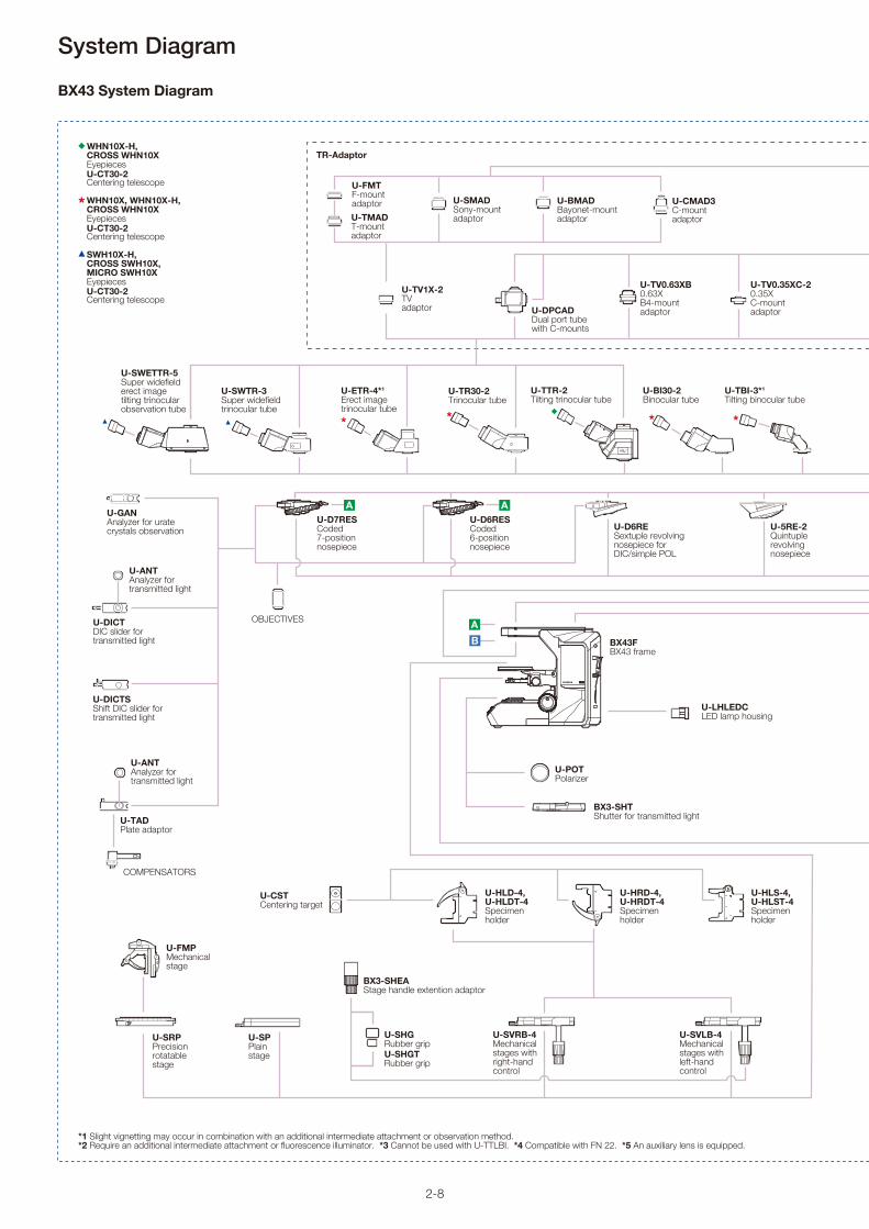
BX43 System Diagram
*1 Slight vignetting may occur in combination with an additional intermediate attachment or observation method. *2 Require an additional intermediate attachment or fluorescence illuminator. *3 Cannot be used with U-TTLBI. *4 Compatible with FN 22. *5 An auxiliary lens is equipped.
WHN10X-H,CROSS WHN10XEyepiecesU-CT30-2Centering telescope
WHN10X, WHN10X-H,CROSS WHN10XEyepiecesU-CT30-2Centering telescope
SWH10X-H,CROSS SWH10X,MICRO SWH10XEyepiecesU-CT30-2Centering telescope
** * *
A A
AB
U-LHLEDCLED lamp housing
U-D7RESCoded 7-positionnosepiece
TR-Adaptor
U-CMAD3C-mountadaptor
U-BMADBayonet-mountadaptor
U-FMTF-mount adaptorU-TMADT-mount adaptor
U-SMADSony-mountadaptor
U-TV1X-2TV adaptor
U-ANTAnalyzer fortransmitted light
U-DICTDIC slider fortransmitted light
U-DICTSShift DIC slider fortransmitted light
U-GANAnalyzer for urate crystals observation
U-TADPlate adaptor
COMPENSATORS
U-ANTAnalyzer fortransmitted light
U-D6RESextuple revolvingnosepiece forDIC/simple POL
U-5RE-2Quintuplerevolvingnosepiece
OBJECTIVES
U-POTPolarizer
BX43FBX43 frame
U-HLS-4,U-HLST-4Specimen holder
U-HLD-4, U-HLDT-4Specimen holder
U-HRD-4, U-HRDT-4Specimen holder
U-CST Centering target
U-SRPPrecision rotatable stage
U-SPPlain stage
U-FMPMechanical stage
U-SVRB-4Mechanical stages withright-handcontrol
U-SVLB-4Mechanical stages withleft-handcontrol
U-TV0.35XC-20.35XC-mountadaptorU-DPCAD
Dual port tube with C-mounts
U-SWETTR-5Super widefield erect image tilting trinocular observation tube
U-SWTR-3Super widefieldtrinocular tube
U-TR30-2Trinocular tube
U-BI30-2Binocular tube
U-ETR-4*1
Erect imagetrinocular tube
U-TBI-3*1
Tilting binocular tube
U-D6RESCoded 6-positionnosepiece
U-TV0.63XB0.63XB4-mountadaptor
BX3-SHTShutter for transmitted light
U-SHGRubber grip U-SHGTRubber grip
BX3-SHEAStage handle extention adaptor
U-TTR-2Tilting trinocular tube

2-9
LIFE TIME
BURNER ON
U-RFL-T
*
*
A
EB
A
D
C
C
C
D
EAD
CAMERAS
U-TRUS*3 Trinocular intermediate unit
U-AN-2Analyzer slider
BX3-URAUniversal reflected illuminator
BX3-RFAS*4
Coded fluorescence illuminator
BX43-5RESCoded 5-positionnosepiece for BX43
U-LC*5
Low magnificationcondenser
BX3-6ND6ND filterBX3-25ND25ND filter
U-CBSControl box forcoded function
U-IFRESInterface for coded nosepiece
U-HSEXPHand switch forexposure
DP2-SALStandalone Connection Kit
PC (Software)
U-POPolarizer
U-TRU*1*3
Trinocular intermediate unit
U-CAMagnification changer
U-KPAIntermediate attachment forsimple polarizing observation
U-ANTAnalyzer fortransmitted light
U-EPA2Eyepoint adjuster
U-EPAL-2Eyepoint adjuster
U-LLGADLiquid light guide adaptor
U-LLG150/U-LLG300Liquid light guide (1.5 m/3 m)
U-HGLGPSLight source
U-DP*1*3
Dual port U-DP1XCDual port 1X
U-CPAIntermediate attachment for conoscopic and orthoscopic observation U-AN360P
Rotatable analyzer
U-OPAIntermediate attachment fororthoscopic observation
U-DO3Dual observation attachment
U-SDO3Side by side observationattachment
U-LH100HG100 W mercury lamp housing
U-LH100HGAPO100 W mercury apo lamp housing
U-PCD2Phase/darkfield condenser
U-AACAchromatic/Aplanaticcondenser
U-AC2Abbe condenser
U-SC3Swing-out condenser
U-DCDDarkfieldcondenser,dry
U-DCWDarkfieldcondenser,oil
U-TLDDry top lens
U-UCD8-28-positionuniversal condenser
Optical devices
U-DULHADouble lamp house adaptor
Mirror units
U-TV1XCC-mountadaptor 1X(XY adjustment)
U-TV0.63XC0.63XC-mountadaptor
U-TV0.5XC-30.5XC-mountadaptor
U-TBI-CLI*1
Tilting binocular tube
U-TTLBI*2
Tilting, telescopic, lifting binocular tube
U-TTBIErgonomic binocular tube
U-RFL-TPower supply unit for mercury lamp

2-10
System Diagram
BX3 Series Basic Motorized System Diagram
Full Motorized System Basic Configuration for BX3 series
BX63FBX63 frame
Touch-panel controller(attached to BX63F)
U-MCZController
U-IFCBL200Interface cable, 200 cm
U-D7REAU-D7RESU-D6RESMotorized 7-position nosepiece
U-IFCBL50Interface cable, 50 cm
BX3-RFAABX3-RFASMotorized fluorescence illuminator
PC (software)BX3-CBH Control box
C1394AInterface cable
BX3-UCD8AMotorized universal condenser
U-IFCBL15Interface cable, 15 cm
Semi-Motorized System Basic Configuration for BX3 series
U-IFCBL200Interface cable, 200 cm
U-D7REAMotorized 7-position nosepiece
U-IFCBL50Interface cable, 50 cm
BX3-RFAAMotorized fluorescence illuminator
PC (software)
BX3-UCD8AMotorized universal condenser
U-IFCBL15Interface cable, 15 cm
BX43FBX43 frameBX53F2BX53 frame
U-CBMControl box
U-HSCBMHand switch for CBM
Coded System Basic Congratulation for BX3 series
PC (software)
BX43FBX43 frameBX53F2BX53 frame
U-CBSControl box forcoded function
BX3-RFASCoded fluorescence illuminator
U-D7RESCoded 7-positionnosepiece
*Please refer to "Section 13 Motorized Unit" for each motorized unit in the detail.
**Please consult your nearest Olympus representative for details about motorized system confi gurations and combinations.

2-11
System Diagram
BX2 Series Motorized Unit System Diagram
BXFM-A System Diagram
See manual
TH4-100 TH4-HS
U-D5BDREMCU-D6BDREMC
U-D6REMC
U-AFA2M-VIS
BX-RLAA
U-LH100-3U-LH100L-3
U-FWR
Intermediate tubes(refer to pages 9-1 – 9-3)
Observation tubes(refer to pages 8-1 – 8-4)
U-DICRHC
U-DICR
U-DICRH
U-AN360-3
U-25ND6U-25ND25U-25LBDU-25IF550U-25L42U-25FR
U-PO3
U-AN
U-HSTR2BX-UCB*
U-ZPCBZ-Board
U-POTP3
PC
OLYMPUS StreamControl Software
BF/DF Objectives
BF Objectives
BD-M-AD
(refer to pages 6-1 – 6-6)
(refer to pages 11-1 – 11-8)
(refer to pages 3-1 – 3-36)(refer to page 11-2)
*BX-REMCB is also available for BX-RLAA + motorized revolving nosepiece control (refer to page 13-3).
**These illuminators can only attach to the MX51 or BX61 frames.
MX-AFDIC U-AN
See manual
U-D6REMCU-P5REMCU-D5BDREMCU-D6BDREMCU-P5BDREMC
U-AFA2M-VIS
U-LH100-3U-LH100L-3
U-FWR
Objectives
BXFMA-F
U-IFFH
U-FH
U-RMT
ø32 FilterVideo system(refer to pages 12-1 – 12-2)
Observation tubes(refer to pages 8-1 – 8-4)
U-LGADLG-SF
(refer to page 6-4)
(refer to page 6-5)
MX-AFDIC U-AN
U-HSTR2
BX-UCB
PC
OLYMPUS StreamControl Software
U-ZPCBZ-Board
(refer to page 13-1 – 13-8)
LG-LSLEDLED light source

3-1
■ Objective Series List
M PL(Plan) F L N 1 0 0 B D-■ Defi nition for Objective Abbreviations
■ Objective Notation
■ Features of Each Objective Series
None: Brightfi eld
BD: Brightfi eld/Darkfi eld
BDP: Brightfi eld/Darkfi eld/ Polarizing
IR: Infrared
LCD: Obervation Through LCD Panels
Number:Objective Magnifi cation
Series Magnifi cation BF DF DIC*1 POL FL OFN (Field Number) Remarks
MPLAPON 50/100 U 26.5
MPLAPON O 100 26.5
MPLFLN1.25/2.5 1.25X: 22/2.5X: 26.5 We recommend using a polarizer and analyzer
5/10/20/40*2/50/100 U 26.5
LMPLFLN 5/10/20/50/100 L 26.5
MPLN 5/10/20/50/100 22
LCPLFLN-LCD 20/50/100 L 26.5 For LCD
SLMPLN 20/50/100 26.5
LMPLN-IR 5/10 22 For near-IR observation
LCPLN-IR 20/50/100 22 For near-IR observation
MPLFLN-BD 5/10/20/50/100/150 U *3 26.5
MPLFLN-BDP 5/10/20/50/100 U *3 26.5
LMPLFLN-BD 5/10/20/50/100 L 26.5
MPLN-BD 5/10/20/50/100 22
WLI100XMRTC 100X 22 Mirau objective
*1 DIC Prism U-DICR: UM/LM Position, U-DICRHC: LM Position Fixed, U-DICRH: UM Position Fixed. *2 40X: BF Only *3 5–20X: U Excitation Also Possible. : Responds; : Optimally Responds; BF: Brightfi eld; DF: Darkfi eld; DIC: Differential Interference Contrast; POL: Polarized light; FL: Fluorescence
M: Metallurgical (no cover)
LM: Long Working Distance Metallurgical Use
SLM: Super Long Working Distance Metallurgical Use
LC: Observation Through Substrate
None: Achromat/Effectively corrects chromatic aberration at 486 nm and 656 nm wavelengths
FLN: SemiApochromat/Corrects chromatic aberration that is in the middle of apochromat and achromat
APON: Apochromat/Effectively corrects chromatic aberration in the entire visible range (435-656 nm)
PL: Plan:Corrects Field Curvature on the Periphery of the Image Plane
Magnifi cation Objectives Series Abbreviation (PL: Plan)
NA (Numerical Aperture)
OFN (Field Number)
For Brightfi eld Observation
Infi nity-Corrected Optical System
Cover Glass Thickness (no cover)
MPLAPON series: M Plan Apochromat — p. 3-2This series of Plan Apochromat objectives corrects chromatic aberrations at optimal levels. Olympus guarantees* the optical performance (correction for wavefront aberration) with a Strehl ratio** of 95% or better. These objectives can be used with Olympus’ U-AFA2M active auto focus unit.
MPLAPON100XO2: M Plan Apochromat — p. 3-2This Plan Apochromat objective is designed for oil immersion*** and features a numerical aperture of 1.45. The objective provides excellent chromatic aberration correction and high resolving power.
MPLFLN series: M Plan Semi Apochromat — p. 3-3This series of Plan Semi Apochromat objectives delivers high-level correction for chromatic aberration. The eight objectives in this series offer magnifi cations ranging from 1.25X to 100X and a minimum working distance of 1 mm (except 40X). Since the exit pupil position of the 5X–100X objectives is standardized, the position of the DIC prism does not have to be switched when changing the magnifi cation (40X is not applicable to DIC observation). For very low magnifi cations (1.25X, 2.5X), use the objectives with an analyzer, polarizer, and refl ected light illuminator.
LMPLFLN series: Long Working Distance M Plan Semi Apochromat — p. 3-4This series of long working distance Plan Semi Apochromat objectives delivers high-level correction for chromatic aberration. Because of the long working distance, these objectives are suitable for observing larger samples. Since the exit pupil position of the 5X–100X objectives is standardized, the position of the DIC prism does not have to be switched when changing the magnifi cation.
MPLN series: M Plan Achromat — p. 3-5Plan Achromat objectives provide excellent image fl atness up to FN 22.
LCPLFLN-LCD series: LCD Long Working Distance M Plan Semi Apochromat — p. 3-6These objectives are designed for making observations through LCD panels and other samples that have a glass substrate. The correction collar provides aberration correction that can be matched to the thickness of the glass.
SLMPLN series: Super Long Working Distance M Plan Achromat — p. 3-7These are high-magnifi cation Plan Achromat objectives with a super long working distance. Three magnifi cations, 20X, 50X, and 100X, are available. For 5X or 10X objectives, select from the LMPLFLN series.
LMPLN-IR series: IR Long Working Distance M Plan Achromat — p. 3-8This series is designed for near-infrared microscopy, which is typically used to view the internal structure of silicon wafers.
LCPLN-IR series: IR Long Working Distance M Plan Achromat — p. 3-9This series is designed for near-infrared microscopy, which is typically used to view the internal structure of silicon wafers. These objectives have a correction collar to correct for aberrations based on the thickness of the silicon or glass substrate.
MPLFLN-BD series: M Plan Semi Apochromat BD — p. 3-10This series of Plan Semi Apochromat objectives provides high-level correction for chromatic aberration with a minimum working distance of 1 mm. Since the exit pupil position of the 5X–150X objectives is standardized, the position of the DIC prism does not have to be switched when changing the magnifi cation.
MPLFLN-BDP series: M Plan Semi Apochromat BDP — p. 3-11This series of Plan Semi Apochromat objectives provides high-level correction for chromatic aberrations with a minimum working distance of 1 mm. Since the exit pupil position of the 5X–100X objectives is standardized, the position of the DIC prism does not have to be switched when changing the magnifi cation. This series is optimized for brightfi eld, darkfi eld, and polarized light observations and can be used with differential interference contrast.
LMPLFLN-BD series: Long Working Distance M Plan Semi Apochromat BD — p. 3-12This series of long working distance Plan Semi Apochromat objectives provides high-level correction for chromatic aberration and are suitable for observing samples with height or varying topography. Since the exit pupil position of the 5X–100X objectives is standardized, the position of the DIC prism does not have to be switched when changing the magnifi cation.
MPLN-BD series: M Plan Achromat BD — p. 3-13This series of Plan Achromat objectives provides excellent image fl atness up to FN 22.
WLI100XMRTC series: White Light Interferometry Objective — p. 3-14This objective is designed to be used with Mirau-style white light interferometers and tolerates high temperatures. The objective has a working distance of 0.7 mm and an optimized NA of 0.8 that provides improved light gathering.
* Measurement guarantee assessed with an Olympus interferometer for transmitted wavefront measurement under the following conditions: a temperature of 23 °C + 1 °C; measurements made within the 97% range of the pupil diameter.
** Strehl ratio: Indicates in percent (%) the ratio of the proportion of light that an actual optical system can concentrate with respect to the proportion of light concentrated in the image plane (central intensity) by an ideal, aberration-free optical system, with the latter serving as 100%. A higher percentage indicates a higher quality optical system.
*** Specifi ed oil: IMMOIL-F30CC
Objectives (for Industrial Applications)
3-2
ø26.1ø23.07
ø20.32
ø28.5
ø19.1
ø7.5
ø20.4
ø30.5
4.8
45
(44.
87)
41.6 37
.46 28
.94
W.D
.=0.
13
Unit: mm
Unit: mm
MPLAPON100X
MPLAPON100XO2
MPLAPON50X
Screw: W 20.32 mm × 0.706 mm (0.8 in. × 1/36 in.)
Screw: W 20.32 mm × 0.706 mm (0.8 in. × 1/36 in.)
* Measurement guarantee assessed with an Olympus interferometer for transmitted wavefront measurement under the following conditions: a temperature of 23 °C + 1 °C; measurements made within the 97% range of the pupil diameter.
** Strehl ratio: Indicates in percent (%) the ratio of the proportion of light that an actual optical system can concentrate with respect to the proportion of light concentrated in the image plane (central intensity) by an ideal, aberration-free optical system, with the latter serving as 100%. A higher percentage indicates a higher quality optical system.
*** Specifi ed Oil: IMMOIL-F30CC
Objectives
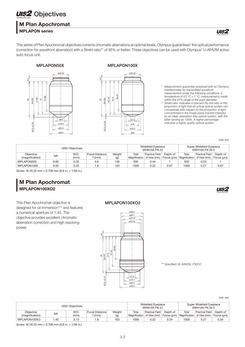
This series of Plan Apochromat objectives corrects chromatic aberrations at optimal levels. Olympus guarantees* the optical performance
(correction for wavefront aberration) with a Strehl ratio** of 95% or better. These objectives can be used with Olympus’ U-AFA2M active
auto focus unit.
This Plan Apochromat objective is
designed for oil immersion*** and features
a numerical aperture of 1.45. The
objective provides excellent chromatic
aberration correction and high resolving
power.
M Plan ApochromatMPLAPON series
M Plan ApochromatMPLAPON100XO2
ø20.32
ø28.5
ø20.3
ø18.9
ø8.8
4.5
45
(44.
65)
41.6
2
41 37.9
8
W.D
.=0.
35
ø5.5
ø16
ø20.2
ø28
4.5
ø20.32
45
(44.
65)
42.7
8
42.4 38
.43
W.D
.=0.
35
UIS2 Objectives Widefi eld Eyepiece WHN10X FN 22
Super Widefi eld Eyepiece SWH10X FN 26.5
Objective(magnifi cation) NA W.D.
(mm)Focal Distance
f (mm)Weight
(g)Total
Magnifi cationPractical Field of View (mm)
Depth of Focus (μm)
Total Magnifi cation
Practical Field of View (mm)
Depth of Focus (μm)
MPLAPON50X 0.95 0.35 3.6 139 500 0.44 1 500 0.53 1MPLAPON100X 0.95 0.35 1.8 125 1000 0.22 0.67 1000 0.27 0.67
UIS2 Objectives Widefi eld Eyepiece WHN10X FN 22
Super Widefi eld Eyepiece SWH10X FN 26.5
Objective(magnifi cation) NA W.D.
(mm)Focal Distance
f (mm)Weight
(g)Total
Magnifi cationPractical Field of View (mm)
Depth of Focus (μm)
Total Magnifi cation
Practical Field of View (mm)
Depth of Focus (μm)
MPLAPON100XO 1.45 0.13 1.8 163 1000 0.22 0.34 1000 0.27 0.34

3-3
MPLFLN20X MPLFLN40X MPLFLN50X MPLFLN100X
Objectives
MPLFLN1.25X MPLFLN2.5X MPLFLN5X MPLFLN10X
This series of Plan Semi Apochromat objectives delivers high-level correction for chromatic aberration. The eight objectives in this series
offer magnifi cations ranging from 1.25X to 100X and a minimum working distance of 1 mm (except 40X). Since the exit pupil position
of the 5X–100X objectives is standardized, the position of the DIC prism does not have to be switched when changing the magnifi cation
(40X is not applicable to DIC observation). For very low magnifi cations (1.25X, 2.5X), use the objectives with an analyzer, polarizer, and
refl ected light illuminator.
ø28
ø20.32
ø30
ø29
ø28.6
4.9
45 (41.
5)
41.2
W.D
.=3.
5
ø20.32
ø26
ø12.1
W.D
.=3.
1
4.5
(41.
9)
45
35.1
ø28
ø20.32
ø30
ø29
ø24.5
454.
9
(34.
3)W
.D.=
10.7
31.6
ø20.32
ø8.5
ø14.4
ø16
ø25.8
4.5
45
W.D
.=0.
63(4
4.37
)
41.4
40.5 35
.6
ø20.32
ø26
ø20.945
4.5
W.D
.=20
(25)
22.5
5
ø20.32
ø10.7
ø15.2
ø17.8
ø26
4.8
45
W.D
.=1
(44) 41
.78
40.8 36
.8
ø20.32
ø26
ø14.5
W.D
.=11
(34)
4.5
45
28.4
1
ø20.32
ø7.8
ø15.2
ø17.8
ø26
W.D
.=1
454.
8
(44) 38
.4
42.4
42.6
1
M Plan Semi ApochromatMPLFLN series
Unit: mm
Screw: W 20.32 mm × 0.706 mm (0.8 in. × 1/36 in.)
UIS2 Objectives Widefi eld Eyepiece WHN10X FN 22
Super Widefi eld Eyepiece SWH10X FN 26.5
Objective(magnifi cation) NA W.D.
(mm)Focal Distance
f (mm)Weight
(g)Total
Magnifi cationPractical Field of View (mm)
Depth of Focus (μm)
Total Magnifi cation
Practical Field of View (mm)
Depth of Focus (μm)
MPLFLN1.25X 0.04 3.5 145 122 12.5 17.6 870 — — —MPLFLN2.5X 0.08 10.7 72 106 25 8.8 220 25 10.6 220MPLFLN5X 0.15 20 36 51.5 50 4.4 59 50 5.3 59MPLFLN10X 0.3 11 18 68.1 100 2.2 15 100 2.7 15MPLFLN20X 0.45 3.1 9 70.4 200 1.1 5.2 200 1.3 5.1MPLFLN40X 0.75 0.63 4.5 120 400 0.55 1.66 400 0.66 1.66MPLFLN50X 0.8 1 3.6 89.9 500 0.44 1.3 500 0.53 1.3MPLFLN100X 0.9 1 1.8 90.9 1000 0.22 0.73 1000 0.27 0.73

3-4
LMPLFLN5X LMPLFLN10X LMPLFLN20X
LMPLFLN50X LMPLFLN100X
Objectives
This series of long working distance Plan Semi Apochromat objectives delivers high-level correction for chromatic aberration. Because
of the long working distance, these objectives are suitable for observing larger samples. Since the exit pupil position of the 5X–100X
objectives is standardized, the position of the DIC prism does not have to be switched when changing the magnifi cation.
Long Working Distance M Plan Semi ApochromatLMPLFLN series
Unit: mm
Screw: W 20.32 mm × 0.706 mm (0.8 in. × 1/36 in.)
UIS2 Objectives Widefi eld Eyepiece WHN10X FN 22
Super Widefi eld Eyepiece SWH10X FN 26.5
Objective(magnifi cation) NA W.D.
(mm)Focal Distance
f (mm)Weight
(g)Total
Magnifi cationPractical Field of View (mm)
Depth of Focus (μm)
Total Magnifi cation
Practical Field of View (mm)
Depth of Focus (μm)
LMPLFLN5X 0.13 22.5 36 50 50 4.4 70 50 5.3 70LMPLFLN10X 0.25 21 18 54 100 2.2 18 100 2.7 18LMPLFLN20X 0.4 12 9 73 200 1.1 6.1 200 1.3 6.1LMPLFLN50X 0.5 10.6 3.6 77 500 0.44 2.5 500 0.53 2.5LMPLFLN100X 0.8 3.4 1.8 94 1000 0.22 0.87 1000 0.27 0.87
ø26
45
W.D
.=22
.5
4.9
(22.
5)
ø25.4
22.2
ø20.32
ø26
ø18.2
ø20.32
45
W.D
.=10
.6(3
4.4)
4.9
30.4
454.
5
W.D
.=21
(24)
ø22.4
ø26
22.1
ø15.2
ø20.32
W.D
.=3.
4(4
1.6)
454.
7
ø20.32
ø12.5
ø15
ø18.1
41.1 37
.26
ø26
ø26
ø17
4.8
(33)
W.D
.=12
45
29.3
1
ø20.32

3-5
MPLN5X MPLN10X MPLN20X
MPLN50X MPLN100X
Objectives
Plan Achromat objectives provide excellent image fl atness up to FN 22.
M Plan AchromatMPLN series
Unit: mm
Screw: W 20.32 mm × 0.706 mm (0.8 in. × 1/36 in.)
UIS2 Objectives Widefi eld Eyepiece WHN10X FN 22
Objective(magnifi cation) NA W.D.
(mm)Focal Distance
f (mm)Weight
(g) Total Magnifi cation Practical Field of View (mm)
Depth of Focus (μm)
MPLN5X 0.1 20 36 64 50 4.4 98MPLN10X 0.25 10.6 18 80 100 2.2 18MPLN20X 0.4 1.3 9 111 200 1.1 6.1MPLN50X 0.75 0.38 3.6 13 500 0.44 1.4MPLN100X 0.9 0.21 1.8 116 1000 0.22 0.73
ø20.32
ø21
ø24
454.
5
23.4
(25)
W.D
.=20
ø20.32
ø6
ø11.9
ø15.8
ø24
(44.
62)
W.D
.=0.
38
4.5
45
37.2
41.3
42.6
2
ø20.32
ø4.4
ø11.6
ø15.6
ø24
W.D
.=0.
21(4
4.79
)
454.
5
38.7
42.8
43.1
6
ø20.32
ø6
ø11.9
ø15.8
ø24
4.5
(43.
7)
45
W.D
.=1.
3
37.2
41.3
42.4
ø20.32
ø24
ø16
ø12
ø10.5
W.D
.=10
.6(3
4.4)
4.5
45
32.7 28
.8
33.5
3-6
LCPLFLN20XLCD LCPLFLN50XLCD LCPLFLN100XLCD
Objectives
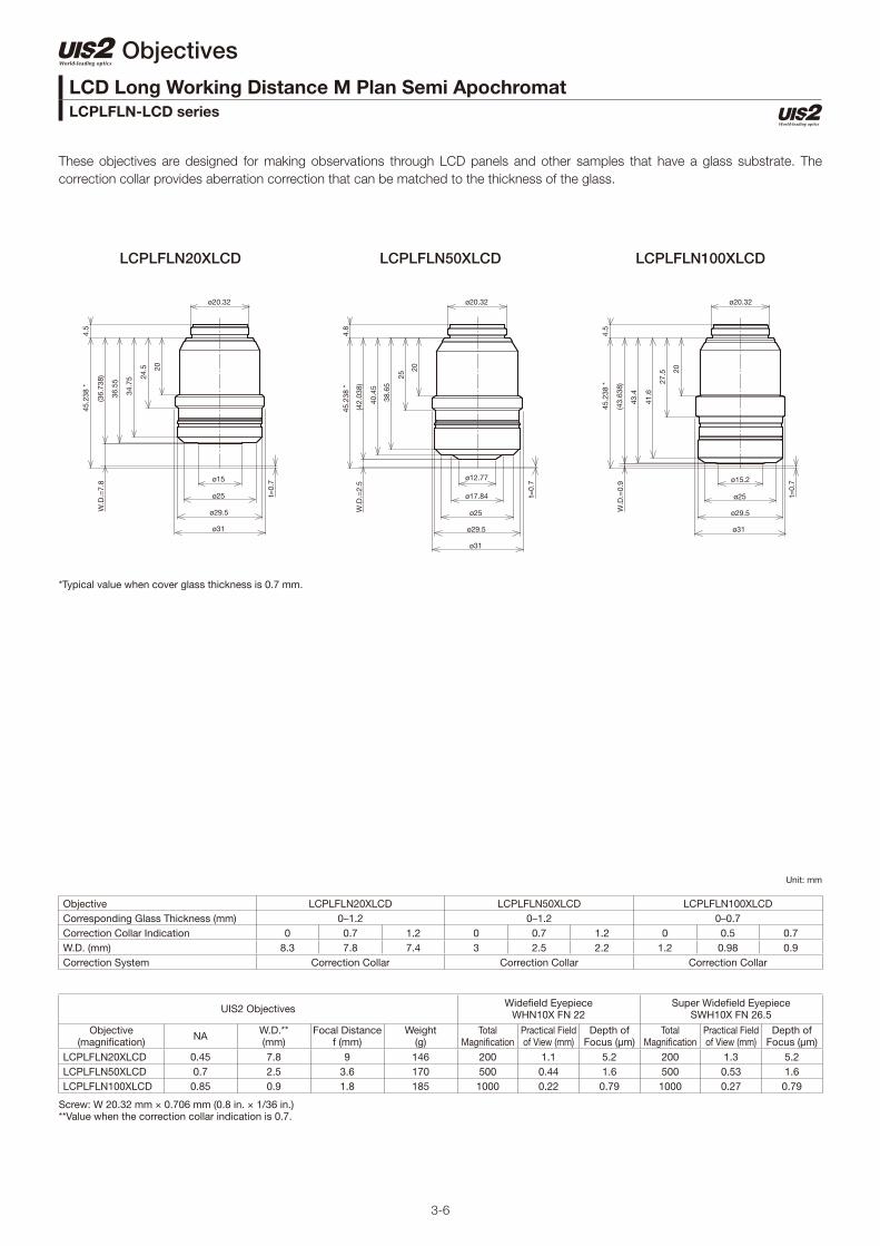
These objectives are designed for making observations through LCD panels and other samples that have a glass substrate. The
correction collar provides aberration correction that can be matched to the thickness of the glass.
LCD Long Working Distance M Plan Semi ApochromatLCPLFLN-LCD series
Unit: mm
Screw: W 20.32 mm × 0.706 mm (0.8 in. × 1/36 in.)**Value when the correction collar indication is 0.7.
UIS2 Objectives Widefi eld Eyepiece WHN10X FN 22
Super Widefi eld Eyepiece SWH10X FN 26.5
Objective(magnifi cation) NA W.D.**
(mm)Focal Distance
f (mm)Weight
(g)Total
Magnifi cationPractical Field of View (mm)
Depth of Focus (μm)
Total Magnifi cation
Practical Field of View (mm)
Depth of Focus (μm)
LCPLFLN20XLCD 0.45 7.8 9 146 200 1.1 5.2 200 1.3 5.2LCPLFLN50XLCD 0.7 2.5 3.6 170 500 0.44 1.6 500 0.53 1.6LCPLFLN100XLCD 0.85 0.9 1.8 185 1000 0.22 0.79 1000 0.27 0.79
Objective LCPLFLN20XLCD LCPLFLN50XLCD LCPLFLN100XLCDCorresponding Glass Thickness (mm) 0–1.2 0–1.2 0–0.7Correction Collar Indication 0 0.7 1.2 0 0.7 1.2 0 0.5 0.7W.D. (mm) 8.3 7.8 7.4 3 2.5 2.2 1.2 0.98 0.9Correction System Correction Collar Correction Collar Correction Collar
(36.
738)
45.2
38 *
W.D
.=7.
8
t=0.
7
4.5
ø20.32
ø15
ø25
ø29.5
ø31
36.5
5
34.7
5 24.5 20
t=0.
7
W.D
.=2.
5
45.2
38 *
4.8
(42.
038)
ø20.32
ø12.77
ø17.84
ø25
ø29.5
ø31
40.4
5
38.6
5
25
20
W.D
.=0.
9(4
3.63
8)
45.2
38 *
43.4
41.6
27.5 20
ø25
ø20.32
ø15.2
ø29.5
4.5
t=0.
7
ø31
*Typical value when cover glass thickness is 0.7 mm.

3-7
SLMPLN20X SLMPLN50X SLMPLN100X
Objectives
These are high-magnifi cation Plan Achromat objectives with a super long working distance. Three magnifi cations, 20X, 50X, and 100X,
are available. For 5X or 10X objectives, select from the LMPLFLN series.
Super Long Working Distance M Plan AchromatSLMPLN series
Unit: mm
Screw: W 20.32 mm × 0.706 mm (0.8 in. × 1/36 in.)
19.3
19.8
(20)
45
ø20.32
ø16.1
ø25
ø26W.D
.=25
4.9
ø20.32
24.1
26.3
(27)
45
ø16.9
ø17.3
ø21.4
ø26
4.9
W.D
.=18
36.2
37.2
(37.
4)
45
ø20.32
ø14.7
ø26
ø23.8
4.9
W.D
.=7.
6
UIS2 Objectives Widefi eld Eyepiece WHN10X FN 22
Super Widefi eld Eyepiece SWH10X FN 26.5
Objective(magnifi cation) NA W.D.
(mm)Focal Distance
f (mm)Weight
(g)Total
Magnifi cationPractical Field of View (mm)
Depth of Focus (μm)
Total Magnifi cation
Practical Field of View (mm)
Depth of Focus (μm)
SLMPLN20X 0.25 25 9 56 200 1.1 11.4 200 1.3 11.4SLMPLN50X 0.35 18 3.6 74 500 0.44 4.2 500 0.53 4.2SLMPLN100X 0.6 7.6 1.8 100 1000 0.22 1.3 1000 0.27 1.3

3-8
LMPLN5XIR LMPLN10XIR
Objectives
This series is designed for near-infrared microscopy, which is typically used to view the internal structure of silicon wafers.
IR Long Working Distance M Plan AchromatLMPLN-IR series
Unit: mm
Screw: W 20.32 mm × 0.706 mm (0.8 in. × 1/36 in.)
UIS2 Objectives
Objective(magnifi cation) NA W.D.
(mm)Focal Distance
f (mm)Weight
(g)LMPLN5XIR 0.1 23 36 55LMPLN10XIR 0.3 18 18 78
ø20.32
4.5
18
(21.
5)W
.D.=
23
45
ø20.6
ø24
4.5
20
(27.
05)
45
W.D
.=18
ø20.32
ø14.4
ø22
ø26

3-9
LCPLN20XIR LCPLN50XIR LCPLN100XIR
Silicon thickness correction
Silicon thickness correction
Objectives
This series is designed for near-infrared microscopy, which is typically used to view the internal structure of silicon wafers. These
objectives have a correction collar to correct for aberrations based on the thickness of the silicon or glass substrate.
IR M Plan AchromatLCPLN-IR series
Unit: mm
4.5
19.8
8
24.3
8
(36.
62)
45
W.D
.=8.
3
34.4
ø20.32
ø14.64
ø14.94
ø25
ø29.5
ø31
4.5
19.8
25
29.5
31.2
(40.
5)
45
W.D
.=4.
5
ø20.32
ø17.7
ø25
ø29.5
ø31
4.5
19.8
27.5
43.4
43.8
45
W.D
.=1.
2
ø20.32
ø15.2
ø17.82
ø25
ø29.5
ø31
Screw: W 20.32 mm × 0.706 mm (0.8 in. × 1/36 in.)*Value when the correction collar indication is 0.
*Using a 1064 nm laser.
*Using a 1100 nm laser.
UIS2 Objectives
Objective(magnifi cation) NA* W.D.*
(mm)Focal Distance
f (mm)Weight
(g)LCPLN20XIR 0.45 8.3 9 149LCPLN50XIR 0.65 4.5 3.6 169LCPLN100XIR 0.85 1.2 1.8 184
Objective LCPLN20XLCD LCPLN50XLCD LCPLN100XLCDCorresponding Glass Thickness (mm) 0–1.2 0–1.2 0–0.7Correction Collar Indication 0 0.7 1.2 0 1.2 0 0.7W.D.* (mm) 8.3 7.9 7.6 4.5 3.7 1.2 0.9Correction System Correction Collar Correction Collar Correction Collar
Objective LCPLN20XIR LCPLN50XIR LCPLN100XIRCorresponding Silicon Thickness (mm) 0–1.2 0–1.2 0–1.0Correction Collar Indication 0 0.7 1.2 0 0.6 1.2 0 0.5 1W.D.* (mm) 8.3 8.2 8 4.5 4.3 4.1 1.2 1.1 1Correction System Correction Collar Correction Collar Correction Collar
3-10
MPLFLN5XBD MPLFLN10XBD MPLFLN20XBD
MPLFLN50XBD MPLFLN100XBD MPLFLN150XBD
Objectives
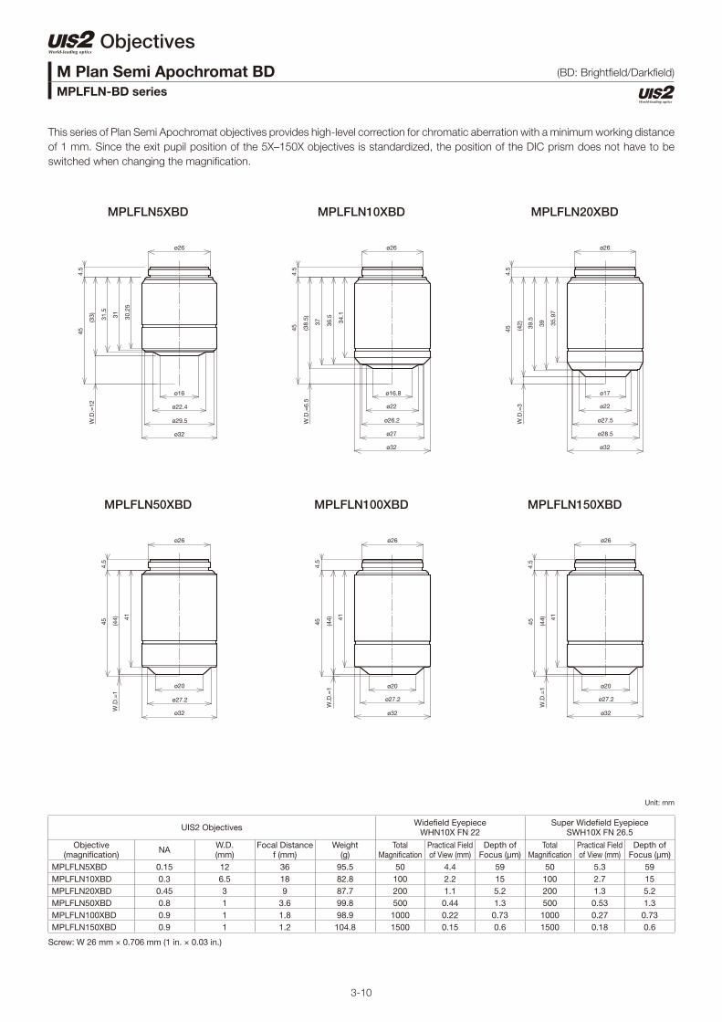
This series of Plan Semi Apochromat objectives provides high-level correction for chromatic aberration with a minimum working distance
of 1 mm. Since the exit pupil position of the 5X–150X objectives is standardized, the position of the DIC prism does not have to be
switched when changing the magnifi cation.
M Plan Semi Apochromat BDMPLFLN-BD series
Unit: mm
Screw: W 26 mm × 0.706 mm (1 in. × 0.03 in.)
UIS2 Objectives Widefi eld Eyepiece WHN10X FN 22
Super Widefi eld Eyepiece SWH10X FN 26.5
Objective(magnifi cation) NA W.D.
(mm)Focal Distance
f (mm)Weight
(g)Total
Magnifi cationPractical Field of View (mm)
Depth of Focus (μm)
Total Magnifi cation
Practical Field of View (mm)
Depth of Focus (μm)
MPLFLN5XBD 0.15 12 36 95.5 50 4.4 59 50 5.3 59MPLFLN10XBD 0.3 6.5 18 82.8 100 2.2 15 100 2.7 15MPLFLN20XBD 0.45 3 9 87.7 200 1.1 5.2 200 1.3 5.2MPLFLN50XBD 0.8 1 3.6 99.8 500 0.44 1.3 500 0.53 1.3MPLFLN100XBD 0.9 1 1.8 98.9 1000 0.22 0.73 1000 0.27 0.73MPLFLN150XBD 0.9 1 1.2 104.8 1500 0.15 0.6 1500 0.18 0.6
ø26
ø16
ø22.4
ø29.5
ø32
4.5
W.D
.=12
45
(33) 31
.5
31 30.2
5
ø26
ø27.2
ø20
ø32
(44)
4.5
W.D
.=1
45
41
ø26
ø22
ø16.8
ø26.2
ø27
ø32
W.D
.=6.
5(3
8.5)
4.5
45
37 36.5
34.1
ø26
ø20
ø27.2
ø32
4.5
W.D
.=1
45 (44) 41
ø26
ø22
ø17
ø27.5
ø28.5
ø32
4.5
(42)
45 39.5
39 35.9
7
W.D
.=3
ø26
ø20
ø27.2
ø32
W.D
.=1
4.5
45 (44) 41
(BD: Brightfi eld/Darkfi eld)

3-11
MPLFLN5XBDP MPLFLN10XBDP MPLFLN20XBDP
MPLFLN50XBDP MPLFLN100XBDP
Objectives
This series of Plan Semi Apochromat objectives provides high-level correction for chromatic aberrations with a minimum working
distance of 1 mm. Since the exit pupil position of the 5X–100X objectives is standardized, the position of the DIC prism does not have
to be switched when changing the magnifi cation. This series is optimized for brightfi eld, darkfi eld, and polarized light observations and
can be used with differential interference contrast.
M Plan Semi Apochromat BDPMPLFLN-BDP series
Unit: mm
Screw: W 26 mm × 0.706 mm (1 in. × 0.03 in.)
UIS2 Objectives Widefi eld Eyepiece WHN10X FN 22
Super Widefi eld Eyepiece SWH10X FN 26.5
Objective(magnifi cation) NA W.D.
(mm)Focal Distance
f (mm)Weight
(g)Total
Magnifi cationPractical Field of View (mm)
Depth of Focus (μm)
Total Magnifi cation
Practical Field of View (mm)
Depth of Focus (μm)
MPLFLN5XBDP 0.15 12 36 95.5 50 4.4 59 50 5.3 59MPLFLN10XBDP 0.25 6.5 18 83.3 100 2.2 18 100 2.7 18MPLFLN20XBDP 0.4 3 9 88.5 200 1.1 6.1 200 1.3 6.1MPLFLN50XBDP 0.75 1 3.6 100.5 500 0.44 1.4 500 0.53 1.4MPLFLN100XBDP 0.9 1 1.8 101.5 1000 0.22 0.73 1000 0.27 0.73
ø26
ø22.4
ø16
ø29.3
ø32
45
W.D
.=12
4.5
(33)
31.5
31 30.2
5
ø26
ø32
ø27.5
ø20
W.D
.=1
(44)
4.5
45
41
ø26
ø26
ø22
ø16.8
ø27
ø32
W.D
.=6.
5(3
8.5)
4.5
45
37 36.5
34.1
ø26
ø32
ø27.5
ø20
W.D
.=1
4.5
45 (44) 41
ø26
ø27.5
ø22
ø17
ø28.5
ø32
W.D
.=3
4.5
(42) 39
.5
39 35.9
7
45
BDP: Brightfi eld/Darkfi eld/Polarized

3-12
LMPLFLN5XBD LMPLFLN10XBD LMPLFLN20XBD
LMPLFLN50XBD LMPLFLN100XBD
Objectives
This series of long working distance Plan Semi Apochromat objectives provides high-level correction for chromatic aberration and are
suitable for observing larger samples. Since the exit pupil position of the 5X–100X objectives is standardized, the position of the DIC
prism does not have to be switched when changing the magnifi cation.
Long Working Distance M Plan Semi Apochromat BDLMPLFLN-BD series
Unit: mm
Screw: W 26 mm × 0.706 mm (1 in. × 0.03 in.)
UIS2 Objectives Widefi eld Eyepiece WHN10X FN 22
Super Widefi eld Eyepiece SWH10X FN 26.5
Objective(magnifi cation) NA W.D.
(mm)Focal Distance
f (mm)Weight
(g)Total
Magnifi cationPractical Field of View (mm)
Depth of Focus (μm)
Total Magnifi cation
Practical Field of View (mm)
Depth of Focus (μm)
LMPLFLN5XBD 0.13 15 36 81 50 4.4 70 50 5.3 70LMPLFLN10XBD 0.25 10 18 84 100 2.2 18 100 2.7 18LMPLFLN20XBD 0.4 12 9 86 200 1.1 6.1 200 1.3 6.1LMPLFLN50XBD 0.5 10.6 3.6 85 500 0.44 2.5 500 0.53 2.5LMPLFLN100XBD 0.8 3.3 1.8 102 1000 0.22 0.87 1000 0.27 0.87
45
W.D
.=15
(30)
ø26
ø16.2
ø22.4
ø28
ø29.5
ø32
26.6
26.2 24
5
ø26
ø23
ø20.7
ø28
ø32
W.D
.=10
.6
454.
8
(34.
4)
33 32.7
31.8
W.D
.=10
(35)
45
ø26
ø15.5
ø21.9
ø28.2
ø30
ø32
32.3
32 30.2
4.5
W.D
.=3.
3(4
1.7)
454.
7
ø26
ø21
ø29
ø32
37.7
37.3
36.5
ø30.3
W.D
.=12
(33)
454.
5
ø26
ø22
ø23
ø28
ø30
ø32
32.5
32.2
31.3
(BD: Brightfi eld/Darkfi eld)
3-13
MPLN10XBD MPLN20XBD
MPLN100XBD
MPLN5XBD
MPLN50XBD
Objectives
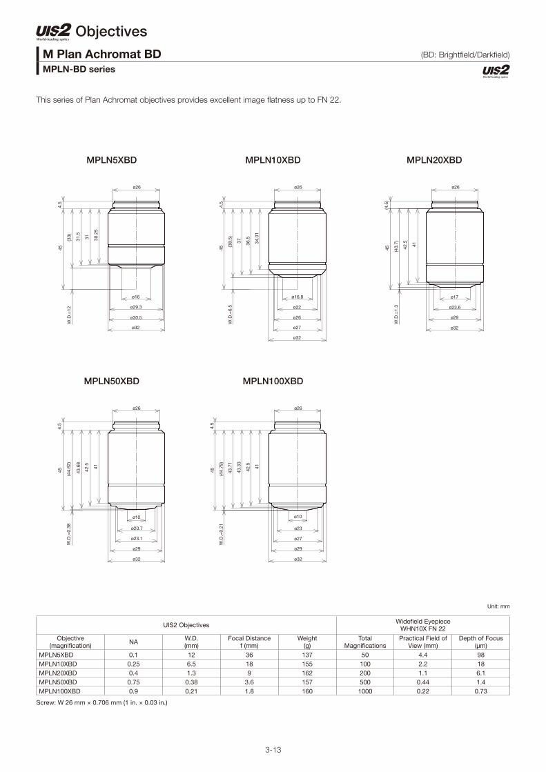
This series of Plan Achromat objectives provides excellent image fl atness up to FN 22.
M Plan Achromat BDMPLN-BD series
Unit: mm
Screw: W 26 mm × 0.706 mm (1 in. × 0.03 in.)
UIS2 Objectives Widefi eld Eyepiece WHN10X FN 22
Objective(magnifi cation) NA W.D.
(mm)Focal Distance
f (mm)Weight
(g)Total
Magnifi cationsPractical Field of
View (mm)Depth of Focus
(μm)MPLN5XBD 0.1 12 36 137 50 4.4 98MPLN10XBD 0.25 6.5 18 155 100 2.2 18MPLN20XBD 0.4 1.3 9 162 200 1.1 6.1MPLN50XBD 0.75 0.38 3.6 157 500 0.44 1.4MPLN100XBD 0.9 0.21 1.8 160 1000 0.22 0.73
ø26
ø32
ø30.5
ø29.3
ø16
4.5
W.D
.=12
45
(33)
31.5
31 30.2
5
ø26
ø29
ø32
ø23.1
ø20.7
ø10
W.D
.=0.
38(4
4.62
)
454.
5
43.6
8
42.5 41
ø26
ø32
ø27
ø26
ø22
ø16.8
45
(38.
5)W
.D.=
6.5
4.5
37 36.5
34.0
1
ø26
ø29
ø32
ø27
ø23
ø10
W.D
.=0.
21(4
4.79
)
454.
5
43.7
1
42.5 41
43.3
3
ø26
ø32
ø29
ø23.6
ø17
(4.5
)
W.D
.=1.
3(4
3.7)
45 42.5 41
(BD: Brightfi eld/Darkfi eld)

3-14
Microscope Objectives
WLI100XMRTC
This objective is designed to be used with Mirau-style white light interferometers and tolerates high temperatures. The objective has a
working distance of 0.7 mm and an optimized NA of 0.8 that provides improved light gathering.
Objective(magnifi cation) NA W.D.
(mm) *Cover Glass
Thickness (mm) Immersion Spring Fluorescence ** FN
WLI100XMRTC 0.8 0.7 0 — — — 22.0
Screw: W 20.32 mm × 0.706 mm (0.8 in. × 1/36 in.)
ø8.9
ø25.5
ø29
ø29
ø20.32
4.9
44.
98
W.D
.=0.
7(4
4.28
)
39.7 32
.6 26.3
White Light Interferometry ObjectiveWLI100XMRTC
unit: mm

3-15
U P L ( P l a n ) F L N 6 0 X O I P H
■ Objective series List
■ Defi nition for Objective Abbreviations
■ Objective Notation
Objectives (for Life Science Applications)
Objective series for standard biological samples
Series Magnifi cation BF DF DIC* POL FLOFN (Field Number)
Remarks
UPLXAPO 4X/10X/20X/40X/40XO/60XO/100XO 10X/20X (except 4X) 26.5
UPLSAPO 4X/10X/20X/20XO/40X/60XO/60XW/100XO 10X/20X/20XO (except 4X) 26.5
PLAPON 1.25X/2X 26.5
UPLFLN 4X/10X/20X/40X/40XO/60X/60XOI/100XO/100XOI 10X/20X/40X/60XOI/100XOI (except 4X) 26.5
PLFLN 100X 26.5
PLN 2X/4X/10X/20X/40X/50XOI/100XO 10X/20X/40X/50XOI 10X/20X/40X/50XOI 22
UPLFLN-PH 4XPH/10XPH/20XPH/40XPH/60XOIPH/100XOPH 10XPH/20XPH/40XPH/60XOIPH 26.5
PLN-PH 10XPH/20XPH/40XPH/100XOPH (excpet 100XOPH) 22
UPLFLN-P 4XP/10XP/20XP/40XP/100XOP 10XP/20XP/40XP (except 4XP) 26.5
PLN-P/ACHN-P 4XP/10XP/20XP/40XP/100XOP 10XP/20XP/40XP 22
PLN-CY 10XCY 22
*These objectives are suitable for standard biological samples embeded on a glass slide with a 0.17 mm cover slip and are mainly used with upright microscopes.
Objective series for cultured samples
Series Magnifi cation BF DF DIC POL FLOFN (Field Number)
Remarks
LUCPLFLN 20X/40X/60X 22
LUCPLFLN-RC/UCPLFLN-RC
10XRC/20XRC/40XRC 22
LUCPLFLN-PH/UCPLFLN-PH
10XPH/20XPH/40XPH/60XPH 22
CPLN-PH/LCACHN-PH
10XPH/20XPH/40XPH 22
CPLN-RC/LCACHN-RC
10XRC/20XRC/40XRC 22
These objectives are suitable for cultured tissue/cell observation in a dish, bottle, or micro plate and are mainly used with inverted microscopes.
Objective series for special applications
Series Magnifi cation BF DF DIC POL FLOFN (Field Number)
Remarks
LUMPLFLN/UMPLFLN
10XW/20XW/40XW/60XW 10XW/20XW 26.5
XLUMPLFLN 20XW 22 Perocal length 75 mm
APON 340 20XW/40XO/40XW 20XW/40XW 22
UPLXAPO: Extended Apochromat — p. 3-16
UPLSAPO: Universal Plan Super Apochromat — p. 3-17
PLAPON: Plan Apochromat — p. 3-18
UPLFLN: Universal Plan Semi Apochromat/Plan Semi Apochromat — p. 3-19
PLN: Plan Achromat — p. 3-21
UPLFLN-PH UPlanFl-P Universal Plan Semi Apochromat for Phase Contrast — p. 3-23
PLN-PH: Plan Achromat for Phase Contrast — p. 3-24
UPLFLN-P: UPlanFl-P Universal Plan Semi Apochromat for Polarizing. — p. 3-25
PLN/ACHN-P: Achromat for Polarizing. — p. 3-26
PLN-CY: Plan Achromat (ND) — p. 3-27
LUCPLFLN, UCPLFLN: Long Working Distance Universal Plan Semi Apochromat — p. 3-28
LUCPLFLN/UCPLFLN-RC: Long Working Distance Universal Plan Semi Apochromat for Relief Contrast — p. 3-29
LUCPLFLN/UCPLFLN-PH: Long Working Distance Universal Plan Semi Apochromat for Phase Contrast — p. 3-30
CPLN/LCACHN-PH: Culture Specimen Objectives for Phase Contrast — p. 3-31
CPLN/LCACHN-RC: Culture Specimen Objectives for Relief Contrast — p. 3-32
LUMPLFLN/UMPLFLN: No Cover Water Immersion for Fixed Stage Upright Microscope — p. 3-33
XLUMPLFLN: No Cover Water Immersion for Fixed Stage Upright Microscope — p. 3-34
APON 340: Universal Apochromat — p. 3-35
■ Features of Each Objective Series (please refer to the following pages for details on each objective.)
U: Universal objectives for fl uorescence (U/BG) and DIC
L: Long working distance C: Tissue culture observations
through bottles and dishesM: For no cover observation *XL: Extra large; parfocal length
exceeds 45 mm (e.g. XLUMPLFL20XW 75 mm)
PL (or PLN): Plan: Corrects fi eld curvature of the periphery on the image planeNone: Non-Plan
ACHN: Achromat/Effectively corrects chromatic aberration at 486 nm and 656 nm wavelengths
FLN: SemiApochromat/Corrects chromatic aberration that is in the middle of apochromat and achromat
APON: Apochromat/Effectively corrects chromatic aberration in the entire visible range (435-656 nm)
SAPO: Super Apochromat/Effectively corrects chromatic aberration in the visible to near infrared range (435-1000 nm)
XAPO: Extended Apochromat/Effectively corrects chromatic aberration in the visible to infrared range (400 to 1000 nm)
None: DryO: Oil immersionW: Water immersionS: Silicone immersionOI: Oil immersion with iris
None: Brightfi eldP: PolarizingPH: Phase contrastPHP: Pre-centered phase contrastRC: Relief contrastCY: Equiped with ND fi lter340 : High-transmission at 340
nm wave length
Number: Objective magnifi cation
220.170.1700 11
Magnifi cation Magnifi cationObjective series abbeviation (PL: Plan) Objective series abbeviation (PL: Plan)
OFN (Field Number)
OFN (Field Number)
NA (numerical aperture) NA (numerical aperture)
For immersion (dry if blank)
For observation methodInfi nity-corrected optical system
Infi nity-corrected optical system
Cover glass thickness (no cover)
Cover glass thickness (no cover)

3-16
Microscope Objectives
The UPLXAPO extended apochromat objectives have a high numerical aperture (NA), wide homogeneous image fl atness, and an
extended range of chromatic aberration compensation from 400 nm to 1000 nm. These features enable you to acquire high-resolution,
bright images for a wide range of applications from brightfi eld/fl uorescence microscopy to confocal /super resolution microscopy.
Objectives(magnifi cation) NA W.D.
(mm) *Cover Glass
Thickness (mm) Immersion Spring Fluorescence ** FN
UPLXAPO4X 0.16 13.0 — — — U/BG/IR 26.5
UPLXAPO10X 0.40 3.1 0.17 — — U/BG/IR 26.5
UPLSAPO20X 0.8 0.6 0.17 — — U/BG/IR 26.5
UPLXAPO40X 0.95 0.18 0.11-0.23 — Yes U/BG/IR 26.5
UPLXAPO40XO 1.40 0.13 0.17 Oil Yes U/BG/IR 26.5
UPLXAPO60XO 1.42 0.15 0.17 Oil Yes U/BG/IR 26.5
UPLXAPO100XO 1.45 0.13 0.17 Oil Yes U/BG/IR 26.5
Screw: W 20.32 mm × 0.706 mm (0.8 in. × 1/36 in.) *Defi ned with cover glass thickness shown as “CG” in the above drawings.**U: UV Excitation, BG: Visible Excitation, IR: Near IR. "( )" indicates that fl uorescence might be slightly darker.
Extended Apochromat ObjectivesUPLXAPO series
unit: mm
UPLXAPO4X UPLXAPO20XUPLXAPO10X
ø28
ø16.2
ø9.6
ø19.4
ø20.32
ø25
ø23
CG
=0.
17W
D=
3.1
4.6
45.0
6
37.5 33
.8
(41.
78)
ø28
ø20.32
ø23.14
ø25
ø15.4
CG
=0.
1713
45.0
64.
7
(31.
89
)
ø17.4
ø18.6
ø28
ø25.5
ø23
ø20.32
ø10.2
45.0
6
CG
=0.
17W
D=
0.61 (4
4.28
)
4.8
41.4
38.0
1
UPLXAPO40X
UPLXAPO40XO UPLXAPO60XO
ø15.8
ø20.3
ø30
ø31.5
ø20.32
ø23
ø25.4
ø28
ø7.5
WD
=0.
18C
G=
0.17
45.0
6
20.9
27.7
38.3
9
42.6
(44.
71)
4.9
ø20.32
ø22.6
ø25.9
ø28.5
ø9.01
ø18.5
ø22.2
ø30.5
WD
=0.
13C
G=
0.17
45.0
6
29.0
8
40.8
9
(44.
77)
4.9
ø20.32
ø23
ø27.2
ø29.3
CG
=0.
17W
D=
0.15
39.8
29
41.9
(44.
74)
4.9
ø19.3
ø25.7
ø10
ø31.5
45.0
6
UPLXAPO100XO
ø20.32
ø23
ø26.1
ø28.5
ø7.5
ø19.1
ø24.7
ø30.5
4.8
29
(44.
76)
41.7 39
.5
45.0
6
WD
=0.
135
CG
=0.
17

3-17
Objectives(magnifi cation) NA W.D.
(mm) *Cover Glass
Thickness (mm) Immersion Spring Fluorescence ** FN
UPLSAPO60XW 1.20 0.28 0.13-0.21 Water Yes U/BG/IR 26.5
Screw: W 20.32 mm × 0.706 mm (0.8 in. × 1/36 in.) *Defi ned with cover glass thickness shown as “CG” in the above drawings.**U: UV Excitation, BG: Visible Excitation, IR: Near IR. "( )" indicates that fl uorescence might be slightly darker.
UPLSAPO60XW
ø15.8
ø24.5
ø31.5
ø20.32
ø28
ø7.5
42.5
CG
=0.
17W
.D.=
0.28
4.7
45.0
6
( 44.
61 )
39.9 36
.3
24.5 19
.4
unit: mm
Microscope Objectives
Universal Plan Super ApochromatUPLSAPO series
The UPLSAPO Super Apochromat objective fully compensate for both spherical and chromatic aberrations from the UV to the near-
infrared region. This enables the acquisition of sharp, clear images without color shift in brightfi eld, Nomarski DIC, and fl uorescence
observations. For quality and performance, this objective series is a splendid solution for numerous digital imaging applications.

3-18
Microscope Objectives
Plan ApochromatPLAPON series
The PLAPON Apochromat objectives display fl at images from violet to the near-infrared region of the spectrum. For quality and
performance, this objective series is a splendid solution for numerous digital imaging applications.
Objectives(magnifi cation) NA W.D.
(mm) *Cover Glass
Thickness (mm) Immersion Spring Fluorescence ** FN
PLAPON1.25X 0.04 5.0 — — — (BG)(/IR) 26.5
PLAPON2X 0.08 6.2 — — — (BG)(/IR) 26.5
Screw: W 20.32 mm × 0.706 mm (0.8 in. × 1/36 in.) *Defi ned with cover glass thickness shown as “CG” in the above drawings. **U: UV Excitation, BG: Visible Excitation, IR: Near IR. "( )" indicates that fl uorescence might be slightly darker.***IR excitation might cause the objective to go slightly out of focus.
PLAPON1.25X PLAPON2X
W.D
.=6.
2
33.8
ø18.5
ø20.32
ø28
ø18.3
(38.
69)
4.5
45.0
6
CG
=0.
17
ø27.2
CG
=0.
17W
.D.=
545.0
6
ø20.32
ø28
4.7
(39.
89)
38.2
unit: mm

3-19
Microscope Objectives
The UPLFLN and PLFLN objectives display fl at images from violet up to the near-infrared region of the spectrum. With their high signal-
to-noise (S/N) ratio, high resolution, and splendid contrast, they are especially effective in brightfi eld and Nomarski DIC observations.
For quality and performance, this objective series is a splendid solution for numerous digital imaging applications.
Objectives(magnifi cation) NA W.D.
(mm) *Cover Glass
Thickness (mm) Immersion Spring Fluorescence ** FN
UPLFLN4X 0.13 17 — — — (U)(/BG)(/IR) 26.5
UPLFLN10X2 0.30 10 — — — U/BG/IR *** 26.5
UPLFLN20X 0.50 2.1 0.17 — — U/BG/IR *** 26.5
UPLFLN40X 0.75 0.51 0.17 — Yes U/BG/IR *** 26.5
Screw: W 20.32 mm × 0.706 mm (0.8 in. × 1/36 in.) *Defi ned with cover glass thickness shown as “CG” in the above drawings. **U: UV Excitation, BG: Visible Excitation, IR: Near IR. "( )" indicates that fl uorescence might be slightly darker.***IR excitation might cause the objective to go slightly out of focus.
Universal Plan Semi Apochromat/Plan Semi ApochromatUPLFLN, PLFLN series
unit: mm
UPLFLN4X
UPLFLN40X
UPLFLN10X2 UPLFLN20X
CG
=0.
17W
.D.=
17
45.0
6
24.8
(27.
89)
4.5
ø18
ø24
ø20.32
CG
=0.
17W
.D.=
10
45.0
6
24.8
(34.
89)
4.5
ø13.6
ø24
ø20.32
ø9.4
CG
=0.
17W
.D.=
2.145
.06
ø20.32
ø15.8
4.5
(42.
79)
40.5 35
.2
ø26
ø16
ø8.5
CG
=0.
17W
.D.=
0.51
45.0
6
ø20.32
ø26
(44.
38)
40.5 35
.3
4.5

3-20
Objectives(magnifi cation) NA W.D.
(mm) *Cover Glass
Thickness (mm) Immersion Spring Fluorescence ** FN
UPLFLN60X 0.90 0.2 0.11–0.23 — Yes U/BG/IR *** 26.5
UPLFLN60XOI 1.25–0.65 0.12 0.17 Oil Yes U/BG/IR *** 26.5
UPLFLN100XO2 1.30 0.2 0.17 Oil Yes U/BG/IR *** 26.5
UPLFLN100XOI2 1.3–0.6 0.2 0.17 Oil Yes U/BG/IR *** 26.5
PLFLN100X 0.95 0.2 0.14–0.2 — Yes BG 26.5
Screw: W 20.32 mm × 0.706 mm (0.8 in. × 1/36 in.) *Defi ned with cover glass thickness shown as “CG” in the above drawings. **U: UV Excitation, BG: Visible Excitation, IR: Near IR. "( )" indicates that fl uorescence might be slightly darker.***IR excitation might cause the objective to go slightly out of focus.
PLFLN100X
unit: mm
Microscope Objectives
The UPLFLN and PLFLN objectives display fl at images from violet up to the near-infrared region of the spectrum. With their high S/N
ratio, high resolution, and splendid contrast, they are especially effective in brightfi eld and Nomarski DIC observations. For quality and
performance, this objective series is a splendid solution for numerous digital imaging applications.
Universal Plan Semi Apochromat/Plan Semi ApochromatUPLFLN, PLFLN series
UPLFLN60X
UPLFLN100XO2
UPLFLN60XOI
UPLFLN100XOI2
ø6
ø31
4.8
ø29
ø19.5
40.3 35
.5
24.3 19
.9
ø20.32
ø28
45.0
6
W.D
.=0.
23C
G=
0.17
(44.
66)
ø7
ø26
ø28
ø17.2
4.5
(44.
69)
41.7 36
.2
ø20.32
45.0
6
W.D
.=0.
2C
G=
0.17
WD
=0.
12
ø3.7
CG
=0.
17
45.0
64.
7
ø28
ø20.32
ø31.5
ø30.5
ø20.1
(44.
77)
41.8 38
.7
26.5 20
37
ø8.5
ø17
ø31.5
ø29
4.7
(44.
69)
42.2
24.4 19
.4
ø20.32
ø28
45.0
6
WD
=0.
2C
G=
0.17
ø7
ø26
ø29
ø31.5
ø18.2
4.5
(44.
69)
41 37.1
26.5 20
ø20.32
45.0
6
WD
=0.
2C
G=
0.17

3-21
Microscope Objectives
PLN2X
PLN10X
PLN4X
PLN20X
The PLN standard objectives provide excellent fi eld fl atness during fl uorescence, darkfi eld, and brightfi eld observation in transmitted
light. These objectives are well-suited to clinical laboratory and examination work.
Objectives(magnifi cation) NA W.D.
(mm) *Cover Glass
Thickness (mm) Immersion Spring Fluorescence ** FN
PLN2X 0.06 5.8 — — — (BG) 22.0
PLN4X 0.10 18.5 — — — (BG) 22.0
PLN10X 0.25 10.6 — — — (BG) 22.0
PLN20X 0.40 1.2 0.17 — Yes (BG) 22.0
Screw: W 20.32 mm × 0.706 mm (0.8 in. × 1/36 in.) *Defi ned with cover glass thickness shown as “CG” in the above drawings.**U: UV Excitation, BG: Visible Excitation, IR: Near IR. "( )" indicates that fl uorescence might be slightly darker.
ø24
ø15.8
ø20.32
4.5
( 26.
39 )
22
45.0
6
W.D
.=18
.5C
G=
0.17
ø15.6
ø24
ø6
ø20.32
CG
=0.
17W
.D.=
1.2
45.0
6 36.9
41.3
( 43.
69
)
4.8
ø24
ø16.8
ø20.32
CG
=0.
17W
.D.=
5.8
45.0
6 35.4
( 39.
09
)
4.5
ø16
ø24
ø12
ø20.32
CG
=0.
17W
.D.=
10.6
45.0
64.
5
( 34.
29 )
32.7 28
.6
Plan AchromatPLN series
unit: mm

3-22
Objectives(magnifi cation) NA W.D.
(mm) *Cover Glass
Thickness (mm) Immersion Spring Fluorescence ** FN
PLN40X 0.65 0.6 0.17 — Yes (BG) 22.0
PLN50XOI 0.9–0.5 0.2 — Oil Yes (BG) 22.0
PLN100XO 1.25 0.15 — Oil Yes (BG) 22.0
Screw: W 20.32 mm × 0.706 mm (0.8 in. × 1/36 in.) *Defi ned with cover glass thickness shown as “CG” in the above drawings.**U: UV Excitation, BG: Visible Excitation, IR: Near IR. "( )" indicates that fl uorescence might be slightly darker.
PLN40X
PLN100XO
PLN50XOI
ø18.2
ø29
ø26
ø6
ø20.32
CG
=0.
17W
.D.=
0.2
45.0
64.
8
( 44.
69
)
41 37.2
26.5 20
ø15.6
ø24
ø7.5
ø20.32
CG
=0.
17W
.D.=
0.6
45.0
6 36.9
41.3
( 44.
29 )
4.5
ø15.6
ø24
ø6.6
ø20.32
4.5
( 44.
74 )
42.8 38
.4
45.0
6
W.D
.=0.
15C
G=
0.17
unit: mm
Microscope Objectives
The PLN standard objectives provide excellent fi eld fl atness during fl uorescence, darkfi eld, and brightfi eld observation in transmitted
light. These objectives are well-suited to clinical laboratory and examination work.
Plan AchromatPLN series

3-23
Microscope Objectives
The UPLFLN-PH objectives are especially effective in phase contrast observations with their high S/N ratio, high resolution, and splendid
contrast. These objectives display fl at images from violet up to the near-infrared region of the spectrum.
Objectives(magnifi cation) NA W.D.
(mm) *Cover Glass
Thickness (mm) Immersion Spring Fluorescence ** FN
UPLFLN4XPH 0.13 17 — — — U/BG/IR *** 26.5
UPLFLN10X2PH 0.30 10 — — — U/BG/IR *** 26.5
UPLFLN20XPH 0.50 2.1 0.17 — — U/BG/IR *** 26.5
UPLFLN40XPH 0.75 0.51 0.17 — Yes U/BG/IR *** 26.5
UPLFLN60XOIPH 1.25–0.65 0.12 0.17 Oil Yes U/BG/IR *** 26.5
UPLFLN100XO2PH 1.30 0.2 0.17 Oil Yes U/BG/IR *** 26.5
Screw: W 20.32 mm × 0.706 mm (0.8 in. × 1/36 in.) *Defi ned with cover glass thickness shown as “CG” in the above drawings. **U: UV Excitation, BG: Visible Excitation, IR: Near IR. "( )" indicates that fl uorescence might be slightly darker.***IR excitation might cause the objective to go slightly out of focus.
Universal Plan Semi Apochromat for Phase ContrastUPLFLN-PH series
unit: mm
UPLFLN4XPH
UPLFLN40XPH
UPLFLN10X2PH
UPLFLN60XOIPH UPLFLN100XO2PH
UPLFLN20XPH
ø20.1
ø30.5
ø31.5
ø20.32
ø28
ø3.7
WD
=0.
12C
G=
0.17
45.0
6
4.7
(44.
77)
41.8 38
.7
26.5
20
ø24
ø20.32
ø18
CG
=0.
17W
.D.=
17
45.0
6
4.5
( 27.
89
)
24.8
ø24
ø20.32
ø13.6
24.8
( 34.
89
)
4.5
45.0
6
W.D
.=10
CG
=0.
17
ø15.8
ø26
ø20.32
ø9.4
CG
=0.
17W
.D.=
2.1
45.0
6
4.5
( 42.
79 )
40.5 35
.2
ø16
ø26
ø8.5
ø20.32
CG
=0.
17W
.D.=
0.51
45.0
6
4.5
( 44.
38 )
40.5 35
.3
ø17.2
ø28
ø20.32
ø26
ø7
W.D
.=0.
2
36.2
41.7
( 44.
69
)
4.5
45.0
6
CG
=0.
17

3-24
Microscope Objectives
PLN10XPH
PLN40XPH
PLN20XPH
PLN100XOPH
The PLN-PH standard objectives provide excellent fi eld fl atness during phase contrast observation in transmitted light.
Objectives(magnifi cation) NA W.D.
(mm) *Cover Glass
Thickness (mm) Immersion Spring Fluorescence ** FN
PLN10XPH 0.25 10.6 — — — (BG) 22.0
PLN20XPH 0.40 1.2 0.17 — Yes (BG) 22.0
PLN40XPH 0.65 0.6 0.17 — Yes (BG) 22.0
PLN100XOPH 1.25 0.15 — Oil Yes (BG) 22.0
Screw: W 20.32 mm × 0.706 mm (0.8 in. × 1/36 in.) *Defi ned with cover glass thickness shown as “CG” in the above drawings.**U: UV Excitation, BG: Visible Excitation, IR: Near IR. "( )" indicates that fl uorescence might be slightly darker.
ø15.6
ø24
ø6
ø20.32
CG
=0.
17W
.D.=
1.2
45.0
64.
8
( 43.
69
)
41.3 36
.9
ø15.6
ø24
ø7
ø20.32
38.4
42.8
( 44.
74 )
4.5
45.0
6
W.D
.=0.
15C
G=
0.17
ø16
ø24
ø10.5
ø20.32
45.0
6
CG
=0.
17W
.D.=
10.6
28.6
32.7
( 34.
29 )
4.5
ø15.6
ø24
ø7.5
ø20.32
CG
=0.
17W
.D.=
0.6
45.0
6 36.9
41.3
( 44.
29 )
4.5
Plan Achromat for Phase ContrastPLN-PH series
unit: mm
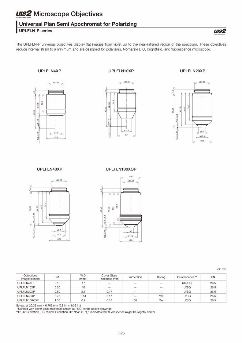
3-25
Microscope Objectives
The UPLFLN-P universal objectives display fl at images from violet up to the near-infrared region of the spectrum. These objectives
reduce internal strain to a minimum and are designed for polarizing, Nomarski DIC, brightfi eld, and fl uorescence microscopy.
Objectives(magnifi cation) NA W.D.
(mm) *Cover Glass
Thickness (mm) Immersion Spring Fluorescence ** FN
UPLFLN4XP 0.13 17 — — — (U)(/BG) 26.5
UPLFLN10XP 0.30 10 — — — U/BG 26.5
UPLFLN20XP 0.50 2.1 0.17 — — U/BG 26.5
UPLFLN40XP 0.75 0.51 0.17 — Yes U/BG 26.5
UPLFLN100XOP 1.30 0.2 0.17 Oil Yes U/BG 26.5
Screw: W 20.32 mm × 0.706 mm (0.8 in. × 1/36 in.) *Defi ned with cover glass thickness shown as “CG” in the above drawings.**U: UV Excitation, BG: Visible Excitation, IR: Near IR. “( )” indicates that fl uorescence might be slightly darker.
Universal Plan Semi Apochromat for PolarizingUPLFLN-P series
unit: mm
UPLFLN4XP
UPLFLN40XP
UPLFLN10XP
UPLFLN100XOP
UPLFLN20XP
ø24
ø18
ø20.32
CG
=0.
17W
D=
17
45.0
64.
5
(27.
89
)
24.8
ø24
ø13.6
ø20.32
24.8
( 34.
89
)
4.5
45.0
6
CG
=0.
17W
.D.=
10
ø17.2
ø28
ø7
ø20.32
ø26
CG
=0.
17W
.D.=
0.2
( 44.
69
)
36.2
41.7
4.5
45.0
6
ø15.8
ø26
ø9.4
ø20.32
CG
=0.
17W
.D.=
2.1
45.0
6
4.5
( 42.
79 )
40.5 35
.2
ø16
ø26
ø8.5
ø20.32
CG
=0.
17W
.D.=
0.51
45.0
64.
5
( 44.
38 )
40.5 35
.3

3-26
Microscope Objectives
PLN4XP
ACHN40XP
ACHN10XP
ACHN100XOP
ACHN20XP
The PLN-P and ACHN-P are cost-effi cient objectives designed for transmitted polarized light observations.
Objectives(magnifi cation) NA W.D.
(mm) *Cover Glass
Thickness (mm) Immersion Spring Fluorescence ** FN
PLN4XP 0.10 18.5 — — — (BG) 22.0
ACHN10XP 0.25 6 — — — (BG) 22.0
ACHN20XP 0.40 3 0.17 — — (BG) 22.0
ACHN40XP 0.65 0.45 0.17 — Yes (BG) 22.0
ACHN100XOP 1.25 0.13 — Oil Yes (BG) 22.0
Screw: W 20.32 mm × 0.706 mm (0.8 in. × 1/36 in.) *Defi ned with cover glass thickness shown as “CG” in the above drawings.**U: UV Excitation, BG: Visible Excitation, IR: Near IR. "( )" indicates that fl uorescence might be slightly darker.
ø18
ø24
ø7.1
ø20.32
CG
=0.
17W
.D.=
645.0
6
34 30.8
4.5
( 38.
89
)
ø15.6
ø24
ø3.3
ø20.32
( 44.
76 )
4.5
38.4
42.8
W.D
.=0.
13C
G=
0.17
45.0
6
ø24
ø9.6
ø20.32
CG
=0.
17W
.D.=
3
45.0
6 34.6
4.5
( 41.
89
)
ø15.6
ø24
ø7.5
ø20.32
CG
=0.
17W
.D.=
0.6
45.0
6 36.9
41.3
( 44.
29 )
4.5
ø15.6
ø24
ø5.6
ø20.32
36.9
41.3
CG
=0.
17W
.D.=
0.45
45.0
6
( 44.
44
)
4.5
Achromat for PolarizingPLN-P, ACHN-P series
unit: mm

3-27
Microscope Objectives
PLN10XCY
The PLN-CY standard objective provide excellent fi eld fl atness. This objective, equipped with neutral density (ND) fi lters, provide the
same level of brightness, even if the magnifi cation is changed, thereby removing the need for brightness adjustment.
Objectives(magnifi cation) NA W.D.
(mm) *Cover Glass
Thickness (mm) Immersion Spring Fluorescence ** FN
PLN10XCY 0.25 10.6 — — — (BG) 22.0
Screw: W 20.32 mm × 0.706 mm (0.8 in. × 1/36 in.) *Defi ned with cover glass thickness shown as “CG” in the above drawings.**U: UV Excitation, BG: Visible Excitation, IR: Near IR. "( )" indicates that fl uorescence might be slightly darker.
ø16
ø24
ø10.5
ø20.32
CG
=0.
17W
.D.=
10.6
45.0
64.
5
( 34.
29 )
32.7 28
.6
Plan Achromat (ND)PLN-CY series
unit: mm

3-28
Microscope Objectives
LUCPLFLN20X LUCPLFLN40X LUCPLFLN60X
The LUCPLFLN long working distance, universal objectives display fl at images from violet up to the near-infrared region of the spectrum.
These objectives are dedicated to tissue culture observations through bottles and dishes, offering high contrast and splendid resolution
in brightfi eld, DIC, and fl uorescence observations.
Objectives(Magnifi cation) NA W.D.
(mm) *Cover Glass
Thickness (mm) Immersion Spring Fluorescence ** FN
LUCPLFLN20X 0.45 7.8–6.6 0–2 — — U/BG/IR *** 22.0
LUCPLFLN40X 0.60 4–2.7 0–2 — — U/BG/IR *** 22.0
LUCPLFLN60X 0.70 2.2–1.5 0.1–1.3 — — U/BG/IR *** 22.0
Screw: W 20.32 mm × 0.706 mm (0.8 in. × 1/36 in.) *Defi ned with cover glass thickness shown as “CG” in the above drawings. **U: UV excitation, BG: Visible Excitation, IR : Near IR. "( )" indicates that fl uorescence might be slightly darker.***IR excitation might cause the objective to go slightly out of focus.
ø19
ø26
ø29
ø20.32
ø26
CG
=1
W.D
.=3.
445.3
4
( 40.
94 )
39 35.3
24.3 17
.5
4.5
ø9.5ø9.5
ø17.4
ø26
ø29
ø9
ø20.32
ø26
CG
=1
W.D
.=1.
7
45.3
44.
5
17.5
24.3
36
39.9
( 42.
64
)
ø21.8
ø20.32
ø26
ø27
ø12.1
4.7
( 36.
9 )
33.1 24
.4 17.4
35.5
45.3
4
W.D
.=7.
44
CG
=1
Long Working Distance Universal Plan Semi ApochromatLUCPLFLN series
unit: mm

3-29
Microscope Objectives
CPLFLN10XRC LUCPLFLN20XRC LUCPLFLN40XRC
The CPLFLN-RC and LUCPLFLN-RC long working distance, universal objectives display fl at images from violet up to the near-infrared
region of the spectrum. These objectives are designed for the observation of living cells, including oocytes. Plastic
vessels can be used with these objectives for relief contrast observations.
Objectives(magnifi cation) NA W.D.
(mm) *Cover Glass
Thickness (mm) Immersion Spring Fluorescence ** FN
CPLFLN10XRC 0.30 9 *** — — — BG 22.0
LUCPLFLN20XRC 0.45 7.8–6.6 0–2 — — U/BG/IR **** 22.0
LUCPLFLN40XRC 0.60 4.2–3.0 0–2 — — U/BG/IR **** 22.0
Screw: W 20.32 mm × 0.706 mm (0.8 in. × 1/36 in.) *Defi ned with cover glass thickness shown as “CG” in the above drawings. **U: UV Excitation, BG: Visible Excitation, IR: Near IR. "( )" indicates that fl uorescence might be slightly darker. ***Defi ned by 1 mm bottom thickness of a plastic container and 0.5 mm bottom thickness of a glass heat plate (depends on the shape of container).****IR excitation might cause the objective to go slightly out of focus.
ø21.8
ø27
ø29
ø26
ø12.1
ø20.32
45.3
7
CG
=1
W.D
.=7.
47
17.4
24.5
33.2
35.5
( 36.
9 )
4.5
ø19
ø26
ø29
ø26
ø9.5
ø20.32
4.5
( 40.
71 )
39 35.3
24.3 17
.5
45.3
7
W.D
.=3.
66
CG
=1
ø26
ø13.6
ø20.32
( 35.
04 )
4.5
29.4
45.5
4
W.D
.=9
CG
=1.
5
Long Working Distance Universal Plan Semi Apochromat for Relief ContrastCPLFLN-RC, LUCPLFLN-RC series
unit: mm

3-30
Microscope Objectives
CPLFLN10XPH
LUCPLFLN60XPH
LUCPLFLN20XPH LUCPLFLN40XPH
The CPLFLN-PH and LUCPLFLN-PH long working distance, universal objectives display fl at images from violet up to the near-infrared
region of the spectrum. These objectives are specifi cally designed for culture specimens and are optimized to produce splendid phase
contrast images, regardless of the thickness and material of the culture vessel.
Objectives(magnifi cation) NA W.D.
(mm) *Cover Glass
Thickness (mm) Immersion Spring Fluorescence ** FN
CPLFLN10XPH 0.30 9.5 *** 1 — — BG 22.0
LUCPLFLN20XPH 0.45 7.8–6.6 0–2 — — U/BG/IR **** 22.0
LUCPLFLN40XPH 0.60 4.2–3.0 0–2 — — U/BG/IR **** 22.0
LUCPLFLN60XPH 0.70 2.2–1.5 0.1–1.3 — — U/BG/IR **** 22.0
Screw: W 20.32 mm × 0.706 mm (0.8 in. × 1/36 in.) *Defi ned with cover glass thickness shown as “CG” in the above drawings. **U: UV Excitation, BG: Visible Excitation, IR: Near IR. "( )" indicates that fl uorescence might be slightly darker. ***Defi ned by 1 mm bottom thickness of a plastic container.****IR excitation might cause the objective to go slightly out of focus.
ø21.8
ø27
ø29
ø12.1
ø20.32
ø26
45.3
7
CG
=1
W.D
.=7.
47
4.7
( 36.
9 )
35.5
33.2 24
.5 17.4
ø19
ø26
ø29
ø20.32
ø26
39 35.3
24.3 17
.5
4.5
( 40.
71 )
45.3
7
W.D
.=3.
66
CG
=1 ø9.5ø9.5
ø24
ø13.6
ø20.32
4.5
( 34.
87 ) 24
.8
45.3
7
W.D
.=9.
5C
G=
1
ø17.4
ø26
ø29
ø8.5
ø20.32
ø26
45.3
7
CG
=1
W.D
.=1.
74
4.5
( 42.
63
)
40.1 36
.1
24.3 17
.5
Long Working Distance Universal Plan Semi Apochromat for Phase ContrastCPLFLN-PH, LUCPLFLN-PH series
unit: mm

3-31
Microscope Objectives
LCACHN20XPH LCACHN40XPH
The CPLN-PH and LCACHN-PH standard objectives provide excellent fi eld fl atness during phase contrast observation in transmitted
light.
Objectives(magnifi cation) NA W.D.
(mm) *Cover Glass
Thickness (mm) Immersion Spring Fluorescence ** FN
CPLN10XPH 0.25 10 *** — — — BG 22.0
LCACHN20XPH 0.40 3.2 *** 1 — — BG 22.0
LCACHN40XPH 0.55 2.2 *** 1 — — BG 22.0
Screw: W 20.32 mm × 0.706 mm (0.8 in. × 1/36 in.) *Defi ned with cover glass thickness shown as “CG” in the above drawings. **U: UV Excitation, BG: Visible Excitation, IR: Near IR. "( )" indicates that fl uorescence might be slightly darker.***Defi ned by 1 mm bottom thickness of a plastic container.
ø14.2
ø24
ø20.32
ø8
4.5
( 41.
17 )
38 32.9
45.3
7
W.D
.=3.
2C
G=
1
ø14.2
ø24
ø20.32
ø6.9
CG
=1
W.D
.=2.
2
45.3
7 34.5
39.6
( 42.
17 )
4.5
Culture Specimen Objectives for Phase ContrastCPLN-PH, LCACHN-PH series
unit: mm
CPLN10XPH
ø12
ø5.8
ø24
ø20.32
CG
=1
WD
=10
45.3
7
32.7 28
.5
(34.
37)
4.5
ø10.5

3-32
Microscope Objectives
CPLN10XRC LCACHN20XRC LCACHN40XRC
The CPLN-RC and LCACHN-RC standard objectives provide excellent fi eld fl atness during relief contrast observation in transmitted
light. These objectives are designed for the observation of living cells, including oocytes, in plastic vessels.
Objectives(magnifi cation) NA W.D.
(mm) *Cover Glass
Thickness (mm) Immersion Spring Fluorescence ** FN
CPLN10XRC 0.25 9.7 *** — — — BG 22.0
LCACHN20XRC 0.40 2.8 *** 1.5 — — BG 22.0
LCACHN40XRC 0.55 1.9 *** 1.5 — — BG 22.0
Screw: W 20.32 mm × 0.706 mm (0.8 in. × 1/36 in.) *Defi ned with cover glass thickness shown as “CG” in the above drawings. **U: UV Excitation, BG: Visible Excitation, IR: Near IR. "( )" indicates that fl uorescence might be slightly darker.***Defi ned by 1 mm bottom thickness of a plastic container and 0.5 mm bottom thickness of a glass heat plate (depends on the shape of container).
ø17
ø25.6
ø24
ø8
ø20.32
4.8
( 41.
24 ) 32
.6
36.9
45.5
4
W.D
.=2.
8C
G=
1.5
ø17
ø25.6
ø24
ø6.9
ø20.32
34.5
CG
=1.
5W
.D.=
1.945
.54 38
.8
( 42.
14 )
4.8
ø26
ø13.6
ø20.32
( 35.
04 )
4.5
29.4
45.5
4
W.D
.=9
CG
=1.
5
Culture Specimen Objectives for Relief ContrastCPLN-RC, LCACHN-RC series
unit: mm

3-33
Microscope Objectives
UMPLFLN10XW
LUMPLFLN60XW
UMPLFLN20XW LUMPLFLN40XW
The UMPLFLN, LUMPLFLN-W, and LUMFLN series of long working distance, water immersion objectives display fl at images from high
transmission factors up to the near-infrared region of the spectrum. These objectives achieve splendid DIC and fl uorescence from the
visible range to infrared and are ideal for fl uorescence imaging of brain tissue, as well as other tissue and specimens.
Objectives(magnifi cation) NA W.D.
(mm) *Cover Glass
Thickness (mm) Immersion Spring Fluorescence ** FN
UMPLFLN10XW 0.30 3.50 0 Water — U/BG 26.5
UMPLFLN20XW 0.50 3.50 0 Water — U/BG 26.5
LUMPLFLN40XW 0.8 3 0 Water — U/BG 26.5
LUMPLFLN60XW 1.00 2 0 Water — U/BG 26.5
Screw: W 20.32 mm × 0.706 mm (0.8 in. × 1/36 in.) *Defi ned with cover glass thickness shown as “CG” in the above drawings.**U: UV Excitation, BG: Visible Excitation, IR: Near IR. "( )" indicates that fl uorescence might be slightly darker.
ø15.7
ø21
ø24
ø7
ø20.32
4.5
45
W.D
.=3.
5( 4
1.5
)
36.7
ø15.8
ø21
ø7.2
ø24
ø20.32
W.D
.=3.
3
45
37.3
( 41.
69
)
4.5
ø15.7
ø21
ø7
ø24
ø20.32
4.5
45
W.D
.=3.
5( 4
1.5
)
36.7
ø20
ø22
ø24
ø6.6
ø20.32
W.D
.=2
45 42.7
37.8
4.5
( 42.
95 )
No Cover Water Immersion for a Fixed Stage Upright MicroscopeUMPLFLN-W, LUMPLFLN-W series
unit: mm

3-34
Microscope Objectives
XLUMPLFLN20XW ***
The XLUMPLFLN-W high NA, long working distance objectives display fl at images from high transmission factors up to the near-infrared
region of the spectrum. These objectives achieve splendid DIC and fl uorescence from the visible range to infrared. These objectives
enable the measurement of cell membrane electric potential since the design of the objectives provides easy access to patch clamp
electrodes.
Objectives(magnifi cation) NA W.D.
(mm) *Cover Glass
Thickness (mm) Immersion Spring Fluorescence ** FN
XLUMPLFLN20XW *** 1.00 2 0 Water — U/BG/IR **** 22.0
Screw: W 25 mm × 0.75 mm (1 in. × 0.03 in.) *Defi ned with cover glass thickness shown as “CG” in the above drawings. **U: UV Excitation, BG: Visible Excitation, IR: Near IR. "( )" indicates that fl uorescence might be slightly darker. ***Special dedicated nosepiece needed (WI-SNPXLU).****IR excitation might cause the objective to go slightly out of focus.
ø25
ø10.5
ø23.9
ø30
( 2.0
3 )
75
W.D
.=2.
02
5.8
65.6
( 70.
95 )
No Cover Water Immersion for a Fixed Stage Upright MicroscopeXLUMPLFLN20XW
unit: mm

3-35
Microscope Objectives
UAPON20XW340 UAPON40XO340-2 UAPON40XW340
The UAPON340 objectives feature high transmission of 340 nm wavelength light, providing maximum performance in fl uorescence
microscopes using UV excitation.
Objectives(magnifi cation) NA W.D.
(mm) *Cover Glass
Thickness (mm) Immersion Spring Fluorescence ** FN
UAPON20XW340 0.70 0.35 0.17 Water Yes U/BG 22.0
UAPON40XO340-2 1.35 0.1 0.17 Oil Yes U/BG 22.0
UAPON40XW340 1.15 0.25 0.13-0.25 Water Yes U/BG 22.0
Screw: W 20.32 mm × 0.706 mm (0.8 in. × 1/36 in.) *Defi ned with cover glass thickness shown as “CG” in the above drawings.**U: UV Excitation, BG: Visible Excitation, IR: Near IR. "( )" indicates that fl uorescence might be slightly darker.
ø22
ø28
ø30
ø7
ø20.32
4.5
( 44.
79 )
41.7 36
.9
45.0
6
W.D
.=0.
1C
G=
0.17
ø22.5
ø28.5
ø30
ø31
ø6
ø20.32
36.5 29
.5
CG
=0.
17W
.D.=
0.25
4.7
( 44.
64
)
40.3
24.7 19
.7
45.0
6
ø22
ø28
ø30
ø8.1
ø20.32
4.5
( 44.
54 )
41.7 36
.9
45.0
6
W.D
.=0.
35C
G=
0.17
Universal ApochromatUAPON 340 series
unit: mm

3-36
Tube Lens Unit
Olympus’ SWTLU-C compact, super-wide tube lens and super-wide UIS2 objectives meet that demand with homogenous, fl at images with negligible aberration across a fi eld of view up to 26.5 mm. Compact and lightweight, the SWTLU-C tube lens is easy to integrate into your optical system.Mount the tube lens unit (SWTLU-C) using a standard M41 x 0.5 thread.
SWTLU-C
Specifications
Product Name SWTLU-C
Dimension φ 45 × 33.6 mm
Weight 94 g
Projection Area 26.5 mm *1)
Focal length f 180 mm
Magnification 1X *2)
Focal Plane Position151.3 mm from
the reference plane
Mounting Thread M41 x 0.5 mm
Mounting Method Screw In
*1) In combinations with FN26.5 Objectives
*2) In combination with UIS2 Objectives (designed for f180 mm tube
lens)
(2.8) 2.3
1.5
1.5
9
4
Ø 45
151.350 to 170
33.6M41×0.5
Ø 37
.5
Ø 39
-0
.025
-0.
05
19.5
Reference plane
Focal
planeMounting surface of
objective
unit: mm

4-1
Microscope Frame
BX53MTRF-S
Designed with modularity in mind, the BX3M series provide versatility for a wide variety of material science and industrial applications.
The frames are outfi tted with electro-static discharge (ESD) capability to help protect electronic samples.
BX53M: Upright Transmitted and Refl ected Light Microscope FrameBX53MTRF-S
Weight: 7.6 kg Unit: mm
192
81.5
362.2
91.4
274.4
90
290.
5

4-2
Microscope Frame
BX53MRF-S
Designed with modularity in mind, the BX3M series provide versatility for a wide variety of material science and industrial applications.
The frames are outfi tted with ESD capability to help protect electronic samples.
BX53M: Upright Refl ected Light Microscope FrameBX53MRF-S
Weight: 7.4 kg Unit: mm
192
81.5
362.2
91.4
274.4
90
290.
5

4-3
Microscope Frame
BX63F
This fully motorized system enables automation of complex multidimensional experiments and features a precise motorized Z-drive and
splendid stability thanks to the fi xed stage design.
359
90
429.2
152.5
294.4
110
BX3: Automated Transmitted Light Microscope FrameBX63F
Weight: 14.1 kg Unit: mm

4-4
Microscope Frame
BX53F2
The entire optical path of the BX53 is designed for optimal fl uorescence imaging and uses UIS2 optical components that set a new
standard in precision and clarity. The modular concept enables motorization of individual components.
BX3: Semi-Motorized Fluorescence Transmitted Light Microscope FrameBX53F2
Weight: 8.3 kg Unit: mm
319
97
362.2
91.4
274.4
90

4-5
Microscope Frame
BX43F
The BX43 microscope offers a wide range of features, splendid optical performance, and is the ideal platform for digital imaging. This
fl exible microscope offers various contrast methods and leading-edge optics combined with true-color LED illumination for true-to-life
color rendering.
192
319
81.5
362.2
91.4
274.4
90
BX3: Manual System Transmitted Light Microscope FrameBX43F
Weight: 9.1 kg Unit: mm
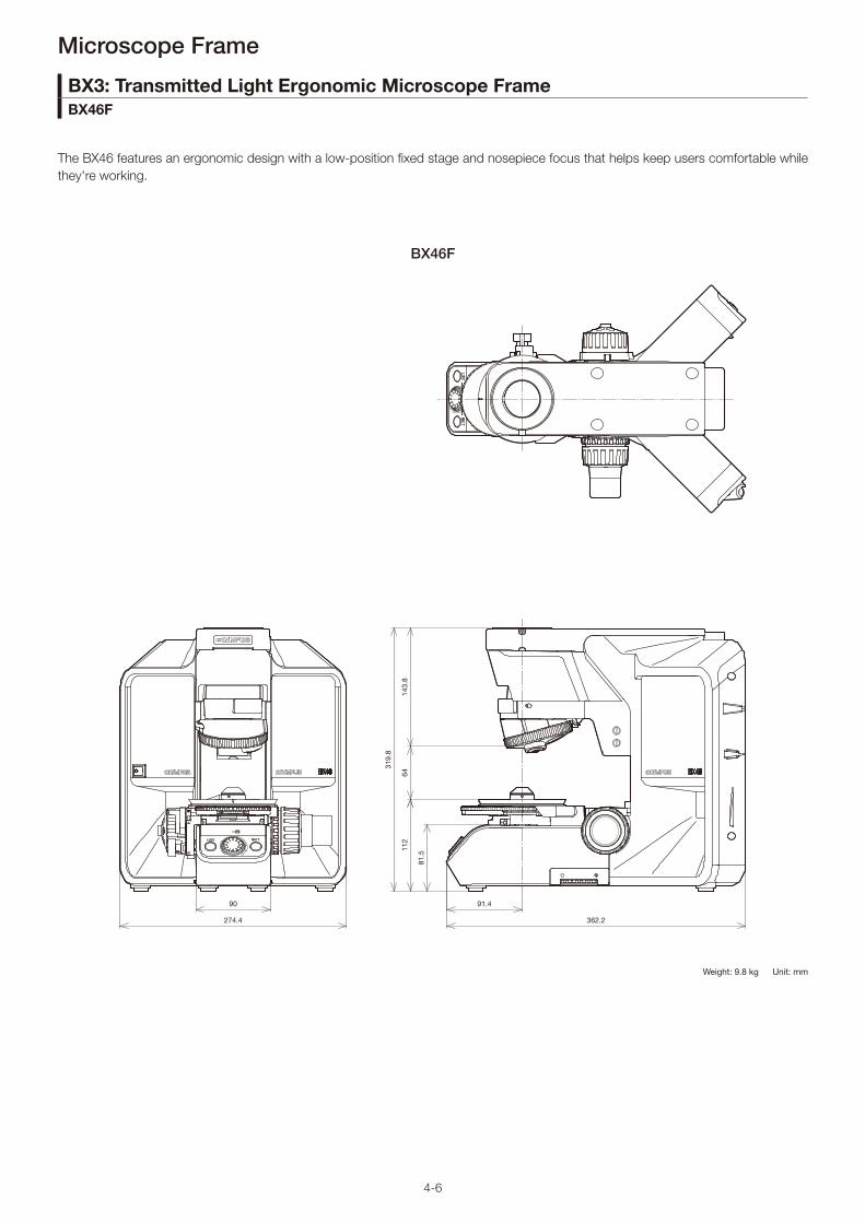
4-6
Microscope Frame
BX46F
The BX46 features an ergonomic design with a low-position fi xed stage and nosepiece focus that helps keep users comfortable while
they're working.
319.
8
143.
864
112
91.4
81.5
362.2274.4
90
BX3: Transmitted Light Ergonomic Microscope FrameBX46F
Weight: 9.8 kg Unit: mm

4-7
Weight: 1.9kg Unit: mm
98 110
80
58.5
0.5
(13)
(13)
55
237
4–M4 Depth 9
4–M4 Depth 7Pillar Mount Hole Center
66.2
1617
1734
36
35
82
4-M8 Depth 8Bolt Mount Screw
0.5
1710
0
124
36
ø32H8Pillar Mount Hole
84
Str
oke
2A00002
Microscope System BXFM
This popular microscope frame can be used with fi ber illumination, a motorized nosepiece, and a telan lens unit. The frame can easily
be integrated into other equipment, which can be attached by a rear bolt mounting screw or pillar mounting hole.
BXFM FrameBXFM-F

4-8
130 Pillar Axis
3.5
4540
21
Light Axis
Light Axis
11
180
72
165
83 Holder Mounting Position
17-4
7 S
trok
eRevolving Nosepiece Mounting Position
Objective Mounting Position
Specimen Position
BXFM Combination SampleBXFM-F + BXFM-ILH + BXFM-ILHSPU + TR30-2 + BX-RLA2 + U-LH100L-3
Weight: 8.2kg (excludes objectives) Unit: mm*For installation dimensions, refer to the BXFM-F diagram.
Microscope System BXFM
This example accommodates refl ected light brightfi eld/darkfi eld and fl uorescence illuminators.
BXFM System Confi guration Example 1BXFM-F + BXFM-ILH + BXFM-ILHSPU
ø32
124.
7
290.
1
165
13087.583
11
40
3.5
45
137 180
502.1
17-4
7 S
trok
e
Specimen Surface
Weight: 3.2kg Unit: mm

4-9
ø32
169
124
84
208
207.4
2040
45
106 187.9
93
Stroke19-49
Specimen Surface
20
Str
oke7
23
Light Axis 45
4084
141
59
106 Holder Mounting PositionPillar Axis
Revolving NosepieceMounting Position
Objective Mounting Position
Specimen Position
BXFM-S Combination SampleBXFM-F + BXFM-ILHS + TR30-2 + U-KMAS + U-LH100L-3
Weight: 5.5 kg (excludes objectives) Unit: mm*For installation dimensions, refer to the BXFM-F diagram.
Microscope System BXFM
This system example contains a compact focusing unit that is suitable for being integrated into existing equipment.
BXFM System Confi guration Example 2BXFM-F + BXFM-ILHS
Weight: 2.4kg Unit: mm

4-10
U-STCompact Stand
10673 143
88
ø110
133
ø32
4913
3
20
35
ø40130
503
ø25
Ø32
214~435622
350300
180º
90
50.5
30º
250
300
SZ2-STU2
SZ-STLLarge Stand
Microscope System BXFM
A wide variety of stands are available to suit different applications and purposes.
Stands for the BXFM
Weight: 5 kg
Unit: mm
Weight: 1.8 kg
*The rotation angle of the horizontal arm can be restricted to 90 degrees with a stopper.
160
320
400
ø32
17.5
45
46
267
Major Specifi cations
Item Specifi cations
1Diameter of Focusing Arm or Fixing Section of Tube
ø32 mm
2 Vertical Pole Diameter ø40 mm
3 Diameter of Horizontal Polesø25 mm (both upper and lower poles)
4 StrokeHorizontal: 234 mmVertical: 205 mm
5 Movement RangeHorizontal: 541 (435 + 106) mm max. (vertical pole — BXFM-S optical axis)
6 Maximum Specimen Weight
Forward: 10 kg (within 90-degree area) Transverse Direction: 6 kg Backward Direction: 7 kg (at maximum stroke)
7 Weight 30 kg
Universal Stand Type 2

5-1
Refl ected Light Illuminator for BF/DF for the BX53M Microscope
BF Refl ected LED Light Illuminator for the BX53M Microscope
45
327.5338.1
265
38.756.829.4
ø75
88
843.
5
41
Illuminator Mounting Position
Revolving Nosepiece MountingPosition
54(1
08)
127
Illumination Units
Manual illuminators for brightfi eld, darkfi eld, and fl uorescence applications.
Refl ected Light Illuminators for the BX53M Microscope
Weight: 3.0 kg
BX3M-RLA-S
5410
8
ø75
88
16
298.5236
843.
5
41
Illuminator Mounting Position
Revolving Nosepiece MountingPosition
Weight: 2.4 kg
BX3M-KMA-S
Unit: mm
Accessories
Accessories
Unit Name Description Weight (g)
U-25LBD Daylight Color Filter 20
U-25LBA Halogen Color Filter 20
U-25IF550 Green Filter 20
U-25L42 UV-Cut Filter 20
U-25Y48 Yellow Filter 20
U-25FR Frost Filter 20
U-25Empty Filter (for use with user's ø25 mm fi lters)
<20
U-25ND50 ND Filter 20
U-25ND25 ND Filter 20
U-25ND6 ND Filter 20
Unit Name Description Weight (g)
U-AN-2 Fixed Analyzer 50
U-AN360-3 Rotatable Analyzer 79
U-PO3 Fixed Polarizer 71
U-POTP3 Fixed Polarizer (use with U-DICRH) 71
U-25LBD Daylight Color Filter 20
U-25LBA Halogen Color Filter 20
U-25IF550 Green Filter 20
U-25L42 UV-Cut Filter 20
U-25Y48 Yellow Filter 20
U-25FR Frost Filter 20
U-25Empty Filter (for use with user's ø25 mm fi lters)
<20
U-25ND50 ND Filter 20
U-25ND25 ND Filter 20
U-25ND6 ND Filter 20

5-2
Coded Refl ected Light Illuminator for BF/DF for the BX53M Frame
Coded Universal Refl ected Illuminator for the BX53M Frame
Unit: mm
75(1
50)
161.
4
ø78.
888
37.489.1
285394.7
64
843.
5
38
Illuminator Mounting Position
Revolving Nosepiece MountingPosition
Illumination Units
Coded Refl ected Light Illuminator for the BX53M Frame
Weight: 3.6 kg
BX3M-RLAS-S
261371
40
843.
5
38
Illuminator Mounting Position
Revolving Nosepiece MountingPosition
75(1
50)
151.
2
ø84
88
26.887.1
Weight: 3.2 kg
BX3M-URAS-S
Accessories
Accessories
Unit Name Description Weight (g)
U-AN-2 Fixed Analyzer 50
U-AN360-3 Rotatable Analyzer 79
U-PO3 Fixed Polarizer 71
U-POTP3 Fixed Polarizer (use with U-DICRH) 71
U-25LBD Daylight Color Filter 20
U-25LBA Halogen Color Filter 20
U-25IF550 Green Filter 20
U-25L42 UV-Cut Filter 20
U-25Y48 Yellow Filter 20
U-25FR Frost Filter 20
U-25Empty Filter (for use with user's ø25 mm fi lters)
<20
U-25ND50 ND Filter 20
U-25ND25 ND Filter 20
U-25ND6 ND Filter 20
Coded illuminators require users to physically change the device's settings, but the microscope's software automatically recognizes
these changes.

5-3
Universal Refl ected Illuminator for the BX3 Series
Coded Fluorescence Illuminator for the BX3 Series
402.5
26140
86.2 28.9
90(1
80)
ø84
88
843.
5
38
Illuminator Mounting Position
Revolving Nosepiece MountingPosition
Illumination Units
Manual illuminators for brightfi eld, darkfi eld, and fl uorescence applications.
Refl ected Illuminator for the BX3 Series
BX3-URA
BX3-RFAS
402.5
26140
86.2 42.8
90(1
80)
ø84
88
843.
5
38
Illuminator Mounting Position
Revolving Nosepiece MountingPosition
Weight: 3.9 kg
Unit: mm
A total of eight fl uorescence mirror units can be attached for multi color fl uorescence observations.
The eight fl uorescence mirror units feature coded functionality.
Weight: 3.8 kg
Accessories
Unit Name Description Weight (g)
U-AN-2 Fixed analyzer 50
U-AN360-3 Rotatable analyzer 79
U-PO3 Fixed polarizer 71
U-POTP3 Fixed polarizer (use with U-DICRH) 71
U-25LBD Daylight color fi lter 20
U-25LBA Halogen color fi lter 20
U-25IF550 Green fi lter 20
U-25L42 UV-cut fi lter 20
U-25Y48 Yellow fi lter 20
U-25FR Frost fi lter 20
U-25Empty fi lter, for use with user's ø25 mm fi lters
<20
U-25ND50 ND fi lter 20
U-25ND25 ND fi lter 20
U-25ND6 ND fi lter 20
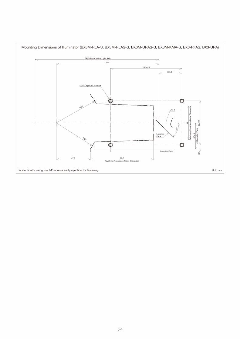
5-4
Unit: mmFix illuminator using four M5 screws and projection for fastening.
Location Face
Location Face
凸3.5
48R
evol
ving
Nos
epie
ce R
elie
f Dim
ensi
on
89.2Revolving Nosepiece Relief Dimension
47.3
144
174 Distance to the Light Axis
37±
045
Loc
atio
n Fa
ce
32±0.1
100±0.1
R60
R62
4-M5 Depth 12 or more
45°
62±
0.1
(6)
Mounting Dimensions of Illuminator (BX3M-RLA-S, BX3M-RLAS-S, BX3M-URAS-S, BX3M-KMA-S, BX3-RFAS, BX3-URA)

5-5
Unit: mm
U-KMAS
ø75
88
198155
21
646
21
Illumination Units
Very compact refl ected light illuminator with reduced depth.
Compact Refl ected Light Illuminator for BFU-KMAS
Accessories
Unit Name Description Weight (g)
U-25LBD Daylight Color Filter 20
U-25IF550 Green Filter 20
U-25ND6 ND Filter 20
U-25ND25 ND Filter 20
U-25FR Frost Filter 20
U-25L42 UV-Cut Filter 20
U-PO3 Fixed Polarizer 71
U-POTP3 Fixed Polarizer (use with U-DICRH) 71
U-AN360-3 Rotatable Analyzer 79
U-AN Analyzer Slider for Refl ected Light 50
U-DICR DIC Slider for Refl ected Light 130
U-DICRHDIC Slider for Refl ected Light (Resolution Type)
130
U-DICRHCDIC Slider for Refl ected Light (Contrast Type)
130
Weight: 1.2 kg

6-1
Light Source Units
BX3M-LEDR
The BX3M microscope utilizes a high-intensity white LED light source for both refl ected and transmitted light. High-intensity light
support various observation modes such as BF, DF, DIC, and polarizing.
63.5
52
ø79
ø59
LED Lamp Housing for the BX53M Microscope
Weight: 0.5 kg
Unit: mm
LED Lamp Housing for BX3M Refl ected
BX3M-LEDTLED Lamp Housing for BX3M Transmitted
77
65.5
ø68
ø59
Weight: 0.5 kg
BX3M-PSLEDPower Supply for LED Lamp House (required with the BXFM)
124.2
11142.6
85
82
Weight: 0.36 kg

6-2
86.5
41.5
16.5
57ø54
ø48
ø68
Unit: mm
LED Lamp Housing for BX3M Transmitted
External Power Supply for U-LHLEDC
Light Source Units
U-LHLEDC
U-LEDPS
The BX3M microscope utilizes a high-intensity white LED light source for both refl ected and transmitted light. High-intensity light
support various observation modes such as BF, DF, DIC, and polarizing.
LED Lamp Housing for the BX3 Series
Weight: 0.5 kg
The BX3 utilizes LED illumination that provides true color reproduction and an optimized
color temperature, enabling consistent color reproduction for brightfi eld stains.
48 45
185
129.5
120
Weight: 0.78 kg

6-3
Light Source Units
The MIX slider provides illumination fl exibility with a segmented LED source in the dark fi eld path.
MIX observation technology combines bright fi eld and dark fi eld illumination methods. The LEDs in the MIX slider shine directional dark
fi eld on the sample, which is similar to traditional dark fi eld, but with more fl exibility. This combination of bright fi eld and directional dark
fi eld is called MIX illumination, and is especially helpful to highlight defects and differentiate raised surfaces from depressions.
MIX Slider for Refl ected IlluminationU-MIXR
Unit: mm
MIX Slider Specifi cations
MIX slider cable specifi cations
MIX slider cable specifi cations
U-MIXR
U-MIXRECBL (for BX3M-CBFM)
U-MIXRCBL (for BX3M-CB)
Illumination LED Light SourceIndicate Power ON/OFF, Cable connected/unconnectedDimension/weight 34mm×120mm×13.5mm 85g
Length 0.54m Weight 20gOuter Dimension
Length 2.9m Weight 95gOuter Dimension
3413
.5
120
540
2900

6-4
(30.2)(148.5)
93
169 (depth dimension for installation)
180.5
130 18.5
8
83.565
25
65
40.8
30
115
75
20
Lamp Housings
U-LH100HGAPO
U-LH100HG
U-RFL-T
U-LH75XEAPO
Cable Length : 2,000 mm Accepted Lamp: USH-103OL Weight: 2.7 kg
* Power supply unit (U-RFL-T) and power cable (UYCP) are required for the 100 W mercury lamp housings. These items are sold separately.
100 W Mercury Apo Lamp Housing
100 W Mercury Lamp Housing
Power Supply Unit for Mercury Lamp
75 W Xenon Apo Lamp Housing
Unit: mm
Light Source Units
8
115
75
180.5
169 (depth dimension for installation)
93
25
556
30.2
3040
.820
(148.5)
83.5
6565
70130
* Power supply unit (U-RX-T) and power cable (UYCP) are required for the 75 W xenon lamp housing. These items are sold separately.
Cable Length : 2,000 mm Accepted Lamp: USH-103OL Weight: 2.7 kg
90
270 31
58.2
31.2
53
12215
0
186
180
115
31
65.7
Weight: Approximately 3 kg
A variety of different lamp housings are available for use with different light sources, enabling users to choose the most appropriate
housing for their application. For customers who use these units in a production line, please consult your nearest Olympus representative to discuss your specifi c needs.

6-5
100 W Halogen Lamp Housings
External Power Supply Hand Switch
Extension Cord
Unit: mm
U-LH100-3/U-LH100IR/U-LH100L-3
TH4-100/200 TH4-HS
U-RMT
Weight: 880 g
Light Source Units
The external power supply for the 100 W halogen lamp (TH4-100/200) features an intensity adjustment knob and an on/off switch, both
located close to the operator’s hand for splendid comfort.
For customers who use these units in a production line, please consult your nearest Olympus representative to discuss your specifi c needs.
Illumination devices for microscopes have suggested lifetimes. Periodic inspections are required. Please visit our website for details.
Halogen Illumination
135 Depth Dimension for Installation
146.5
85.5
107
37
Cable Length U-LH100-3: 290 mmU-LH100IR: 290 mmU-LH100L-3: 800 mm
Accepted Lamp: 12V100WHAL (high-intensity lamp)12V100WHAL-L (long-life lamp)
* External power supply (TH4-100 or TH4-200) and power cable (UYCP) are required for 100 W halogen lamp housings. These items are sold separately.
1,700
Weight: 200 g
Weight: 2.2 kg Weight: 140 g
42 38
18.5
77
Cable Length:2,000 mm
14.575 200
120
125

6-6
Groove: Width 3, Depth 110
ø10.
1
ø13
ø12
ø25
ø15
3031
61
25 20
1,000
Weight: 210 g
Weight: 1.6 kg
Light Source Units
All Olympus refl ected light illuminators can be used with fi ber illumination.
For customers who use these units in a production line, please consult your nearest Olympus representative to discuss your specifi c needs.
Illumination devices for microscopes have suggested lifetimes. Periodic inspections are required. Please visit our website for details.
Halogen Fiber Illumination Accessories
U-RCV
LG-LSLED
LG-SF
U-LGADDF Converter for BX-URA2
LED Light Source
Light Guide
Fiber Adaptor for Refl ected Light Observation
31.5 Dimensions for installation
Tube to exclude darkfield light(built into the BX-URA2). (42.5)
2137.5
ø59
ø75
43
51 Dimension for installation62.5
ø67
ø59
ø32
Weight: 315 g Light Guide Mount Hole ø12; Weight: 390 g
*The types of models in use varies by country.
Unit: mm
114
110
221
230
119
129
137

6-7
Double Lamp House Adaptor
Unit: mm
202
171
82
88
ø140
Light Source Units
Two lamp housings can be attached simultaneously.
For customers who use these units in a production line, please consult your nearest Olympus representative to discuss your specifi c needs.
Lamp Housing Accessory
U-DULHA
Weight: 1.2 kg

8-1
55.6
79.6
180.
8
49.968.6
98.8
173.8220.8
82.3
*
63.1
14
117.
223
61.9
81
139.
400
88.0
00
2.83
770
.330
149.
081
20 0
' 0"
42 0
' 0"
95.9
2910
1.92
9
318.527
328.338337.718
72.200
Observation Tubes
Super Widefi eld Trinocular Observation Tubes
Unit: mm
*Length marked with an asterisk (*) may vary according to interpupillary distance. The distance for the fi gure shown is 62 mm.
Name FN Inclination Angle(degrees)
Interpupillary Distance(mm)
Light Path Selector(eyepiece/video port) Observation Image Weight
(g)U-SWTR-3 26.5 24 50–76 100/0, 20/80, 0/100 Inverted 2300MX-SWETTR 26.5 0–42 50–76 100/0, 0/100 Erect 4200
Trinocular observation tubes with a super-wide fi eld of view. These tubes are compatible with objectives up to FN 26.5.
U-SWTR-3
MX-SWETTR
Super Widefi eld Trinocular Tube
Super Widefi eld Erect Image Tilting Trinocular Tube
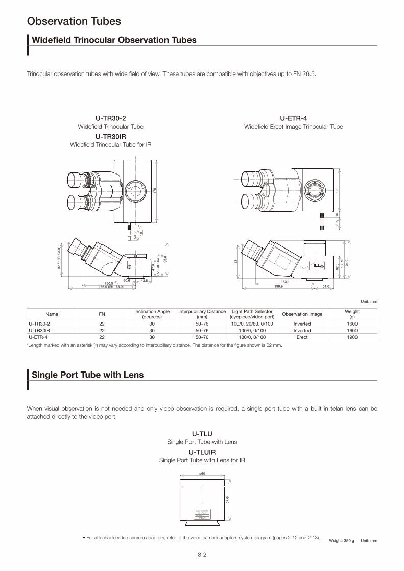
8-2
U-TR30-2
U-TLU
U-TR30IR
U-TLUIR
U-ETR-4Widefi eld Trinocular Tube
Single Port Tube with Lens
Widefi eld Trinocular Tube for IR
Single Port Tube with Lens for IR
Widefi eld Erect Image Trinocular Tube
33.5
1612
0
199.9163.1
103.
992
104.
9
51.6
62.5
175
47.9
62.5
(IR
: 64.
5)
43.5
186.6 (IR: 188.9)
92.5
* (IR
: 93.
9)
95.8
60.6150.5
18
59.6
5
ø60
57.6
Observation Tubes
Widefi eld Trinocular Observation Tubes
Single Port Tube with Lens
Unit: mm
*Length marked with an asterisk (*) may vary according to interpupillary distance. The distance for the fi gure shown is 62 mm.
• For attachable video camera adaptors, refer to the video camera adaptors system diagram (pages 2-12 and 2-13).
Name FN Inclination Angle(degrees)
Interpupillary Distance(mm)
Light Path Selector(eyepiece/video port) Observation Image Weight
(g)U-TR30-2 22 30 50–76 100/0, 20/80, 0/100 Inverted 1600U-TR30IR 22 30 50–76 100/0, 0/100 Inverted 1600U-ETR-4 22 30 50–76 100/0, 0/100 Erect 1900
Trinocular observation tubes with wide fi eld of view. These tubes are compatible with objectives up to FN 26.5.
When visual observation is not needed and only video observation is required, a single port tube with a built-in telan lens can be
attached directly to the video port.
Weight: 350 g Unit: mm

8-3
Observation Tubes
Tilting Binocular Tube
*When combined with the CX-RFA-2, the fi eld number is reduced to 18.
Name FN Inclination Angle (degrees)
Interpupillary Distance (mm)
Light Path Selecter (eyepiece/video port) Observation Image Weight
(g)U-TTBI 22 0–25 50–76 NA Inverted 3800U-TTR-2 22 5–35 50–76 100/0, 0/100, 50/50 Inverted 3200U-TBI-3 22 5–35 50–76 NA Inverted 1300
25º
178
130
104.
4
234.
519
149.545
167.7
201.240.8
219.545
62
110.
8
317.2
Unit: mm
U-TTBI
U-TBI-3
U-TTR-2Telescopic Tilting Binocular Tube
Tilting Binocular Tube
Tilting Trinocular Tube
1622
5°–3
5°62
40.1136.2
111
35º
5º
66
178.6
203
218
142.
5
82
180
160
220
23662
118.
3
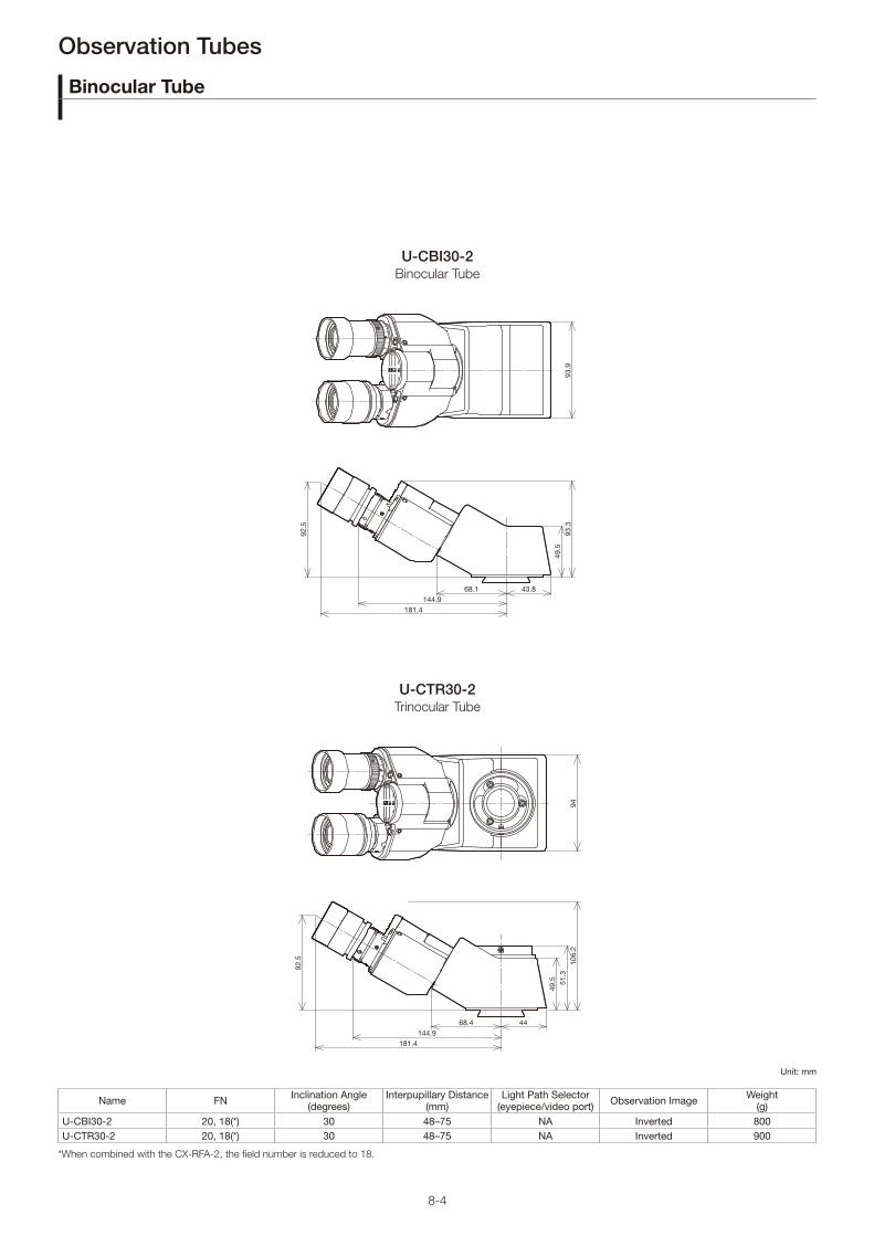
8-4
Unit: mm
49.5
93.3
93.9
43.868.1144.9
181.4
92.5
51.3
49.5
106.
294
4468.4144.9
181.4
92.5
Observation Tubes
Binocular Tube
*When combined with the CX-RFA-2, the fi eld number is reduced to 18.
Name FN Inclination Angle (degrees)
Interpupillary Distance (mm)
Light Path Selector (eyepiece/video port) Observation Image Weight
(g)U-CBI30-2 20, 18(*) 30 48–75 NA Inverted 800U-CTR30-2 20, 18(*) 30 48–75 NA Inverted 900
U-CBI30-2
U-CTR30-2
Binocular Tube
Trinocular Tube

7-1
Condenser Units
U-UCD8-2
The universal condenser contains 8 optical element slots.
*Optical elements are required. Please consult your local Olympus representative for information about different optical element combinations.
112
149.8
128.
5
131
44.1
67.6
Universal CondenserU-UCD8-2
Unit: mm
Weight: 700 g

7-2
Condenser Units
Condenser
Unit: mm
U-AC2-7
WI-OBCD
U-LWCDAbbe Condenser
Long Working Distance Oblique Condenser
Long Working Distance Condenser
Condensers for different applications: brightfi eld, darkfi eld, and long working distance.
(0.1
19)
4.3
25.3
42.8
50.3
51.8
59.8
ø16
ø62
ø38
ø47
ø62
ø68
79.8
43.3
41.834
.317.2
ø68
ø62
ø47
ø62
ø36
34
41.4 34
45
(56.
2)
5648.1
26
10.5
(0.2
)47.528
ø66
ø47
ø66
ø45
ø24
30
16
ø8
Weight: 174 g Weight: 380 g
Weight: 530 g

9-1
4542
ø75
ø70
ø138
96 42
ø140
150
88
5237
Weight: 1.3 kgWeight: 1.3 kg
Intermediate Tubes and Accessories
Intermediate Tubes
Olympus makes various accessories to satisfy a wide variety of observation needs.
183.9
106.9
5237
150
ø140
58.2
Provides 1X, 1.2X, 1.6X, and 2X intermediate magnifi cations.
The intermediate attachment divides the light path,
enabling users to attach both digital and video cameras.
Provides 1X and 2X intermediate magnifi cations.
U-CA
U-TRU
U-ECAMagnifi cation Changer
Trinocular Intermediate Attachment
Magnifi cation Changer 2C
BI:PT=100:0/20:80 Weight: 1.3 kg
Unit: mm
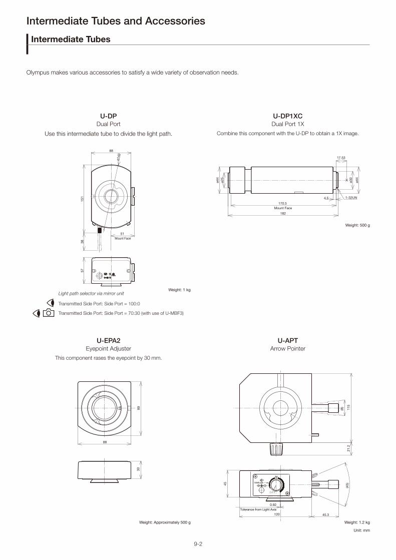
9-2
88
38
51 Mount Face
151
57
ø140
Transmitted Side Port: Side Port = 100:0
Transmitted Side Port: Side Port = 70:30 (with use of U-MBF3)
Light path selector via mirror unit
Combine this component with the U-DP to obtain a 1X image.
This component rases the eyepoint by 30 mm.
Use this intermediate tube to divide the light path.
U-DP1XC
U-EPA2
U-DP
U-APT
Dual Port 1X
Eyepoint Adjuster
Dual Port
Arrow Pointer
Weight: 1 kg
Unit: mm
1-32UN
17.53
4.5
170.5 Mount Face
182ø4
4ø2
5
ø44
ø30
8930
88
0.92Tolerance from Light Axis
120
(45)
45.3
15V0.2A
21.2
115
(8)
45Weight: 500 g
Weight: Approximately 500 g Weight: 1.2 kg
Intermediate Tubes and Accessories
Intermediate Tubes
Olympus makes various accessories to satisfy a wide variety of observation needs.

9-3
U-DPCAD
Intermediate Tubes and Accessories
Dual port tube with C-mountsU-DPCAD
The dual camera port enables the user to attach two cameras.
35
n25.
4
n34
n45
50
41.47
41.5
43
(94.
5)
23
52.5
ø25.4
ø45
ø42.3
ø54
79
116.47
111
119
31.5
Weight: 0.9 kg Unit: mm
Dual port tube with C mounts

10-1
Eyepieces
Eyepieces
Eyepieces for the UIS2 optical system.
*EP=eyepoint
Name FN Diopter Adjustment Range(1/m)
Micrometer Diameter (mm)
Weight(g) Remarks
WHN10X 22 — 24 90WHN10X-H 22 -8–+5 24 170 With adjustable diopterCROSSWHN10X 22 -8–+5 — 170 With cross lines and adjustable diopterWH15X 14 — 24 90SWH10X-H 26.5 -8–+2 — 210 With adjustable diopter MICROSWH10X 26.5 -8–+2 — 210 With micrometer and adjustable diopterCROSSSWH10X 26.5 -8–+2 — 210 With cross lines and adjustable diopter
unit: mm
ø39
EP
ø43.2
ø46.2
ø30
(28.
5)
53.2
41.4
69.9
60.2
ø41
ø38.5
39.4 48
.6
62.6
27.8
(23.
2)
ø30
(25)
18.7
43.7
29.6
ø36.5
ø41
36.8
EP
ø30
ø41
ø38.5
39.6
51.2
48.6
28(2
3.1)
ø30
WHN10X WH15X
SWH10X-HMICROSWH10XCROSSSWH10X
WHN10X-HCROSSWHN10XWidefi eld Eyepiece Widefi eld Eyepiece
Super Widefi eld Eyepieces
Widefi eld Eyepieces

11-1
40
ø116.5
(125.6)
38 87.6
47.2
(114.4)
38
4048.2
76.4
ø102.4
4047.2
(125.6)
38 87.6
ø116.5
83
ø84
40.8
26.5 60.9
(87.4)
40
104
ø102.4
40
48.2
(114.4)
38 76.4
104
38 76.1
(114.1)
48.2 40
ø102
116.
5
104
116.
5
unit: mmInsert the DIC dummy when not using the DIC slider.
U-5RE-2
U-D7RE
U-D6RE
U-P4RE
U-D6RE-ESD
U-P6RE
Quintuple Revolving Nosepiece
Sextuple Revolving Nosepiece
with Slider Slot for DIC
Septuple Revolving Nosepiece
with Slider Slot for DIC
ESD-Resistant Sextuple Revolving
Nosepiece with Slider Slot for DIC
Centerable Quadruple Revolving
Nosepiece with Slider Slot for DIC
Centerable Sextuple Revolving
Nosepiece with Slider Slot for DIC
Revolving Nosepieces
Revolving Nosepieces for BF Objectives
Users can choose from the 6 revolving nosepieces for BF objectives shown below. For motorized nosepieces, please refer to the
motorized unit page.
Weight: 520 g Weight: 800 g Weight: 0.7 kg
Weight: 980 g Weight: 1 kg Weight: 1 kg

11-2
40
48.2
ø102.4
38 76.4
(114.4)
104
W 26 mm × 0.706 mm (1 in. × 0.03 in.)
W 20.32 mm × 0.706 mm (0.8 in. × 0.03 in.)
(4) 4
8
ø28.
2+
0.2
0
ø30
ø102.4
40
48.2
34.8 76.4
104
(111.2)
JAP
AN
2A00002
JAPAN
U-D
6B
DR
E
116.
5
40
Ø116.5
(125.6)
38 87.6
47.2
Insert the DIC dummy when not using the DIC slider.
unit: mm
U-5BDRE U-D5BDRE
BD-M-AD
U-P5BDRE
U-D6BDRE
Quintuple Revolving Nosepiece for BF/DF Quintuple Revolving Nosepiece for
BF/DF with Slider Slot for DIC
Adaptor to Mount BF Objectives
Centerable Quintuple Revolving
Nosepiece with Slider Slot for DIC
Sextuple Revolving Nosepiece for
BF/DF with Slider Slot for DIC
Revolving Nosepieces
Revolving Nosepieces for BF/DF Objectives
Users can choose from the following 3 types of revolving nosepieces for BF/DF objectives. To attach brightfi eld objectives, users must
use the BF adaptor (BD-M-AD). For motorized nosepieces, please refer to the motorized unit page.
Weight: 800 g Weight: 800 g Weight: 1 kg
Weight: 10 kg

11-3
Revolving Nosepieces
Coded Sextuple Revolving Nosepiece
Coded nosepieces for BF, DF, and DIC applications.
ø104
40
38.1
48.2
(126.1)
76
88
34
116.
4
87.5
86.438
47.4
(134.5)
96.5
34
116.
4
47.2 40
ø116.4
(134.5)
96.5
87.638
ø104
3848
.5 40
(126.1)
88.1
76.1
34
unit: mm
U-D6RES U-D6BDRES-S
U-D7RES
U-D5BDRES-ESDCoded Sextuple Revolving Nosepiece
with Slider Slot for DIC
Coded Sextuple BF/DF Revolving
Nosepiece with Slider Slot for DIC
ESD-Resistant Coded Quintuple BF/DF
Revolving Nosepiece with Slider Slot for
DIC
Coded Septuple Nosepiece with Slider Slot for DIC
Weight: 0.7 kg Weight: 0.9 kg Weight: 0.75 kg
weight 1.1 kg

12-1
Video Camera Adaptors
C-Mount Video Camera Ports
Enables users to directly attach a C-mount video camera. Five types are provided: 1X, 0.63X, 0.5X, 0.35X and 0.25X. All models feature
a focus adjustment function.
Unit: mm
Weight: 1.2 kg
Weight: 430 g
Weight: 100 g
Weight: 300 g
Weight: 200 g
ø36
ø64
147.
3
17.5
3
1–32 UN
156.
84
3.5
ø60
Image Plane
73.7
64.2
3.5
ø30
17.5
3
ø60
1-32UNFImage Plane
1–32 UN
ø60
17.5
3
12.4
4
22.4
Image Plane
17.5
ø66.5
SN 3 G 0 0 7 0 7TOKYO, JAPAN
84.5
4
94.5
Image Plane
ø60
17.5
3
ø30 3.5
32.8
5
30.3
42.3
1-32UNFImage Plane
U-TV0.25XC
U-TV0.63XC
U-TV0.35XC-2
U-TV1XC
U-TV0.5XC-3C-Mount Video Port with 0.25X Lens
C-Mount Video Port with 0.63X Lens
C-Mount Video Port with 0.35X Lens
C-Mount Video Port with 1X Lens
C-Mount Video Port with 0.5X Lens
2/3" CCD
1/2" CCD
Field of View (FN)
Projection Area
Adjust the focus on the video camera adaptor to help keep the eyepiece image in focus when switching magnifi cation.Typically, the video camera adaptor is focused by switching to a low magnifi cation after focusing at a high magnifi cation.
Practical Field of View (mm) =Projection Area (FN)
Objective Magnifi cation
Video Camera Adaptor(projection lens)
Projection Magnifi cation
Projection Area (FN)2/3" CCD 1/2" CCD 1/3" CCD
U-TV1X-2 1X 11 8 6
U-TV1XC 1X 11 8 6
U-TV0.63XC 0.63X 17.5 12.7 9.5
U-TV0.5XC-3 0.5X 22 16 12
U-TV0.35XC-2 0.35X — 22 17.1
U-TV0.25XC 0.25X — — 24

12-2
U-CMAD3
U-TMAD
U-BMAD
U-FMT
U-TV1X-2
U-SMADC-Mount Adaptor
T-Mount Adaptor
Bayonet Mount Adaptor
F/T-Mount Adaptor *
Video Port 1X
Sony Mount Adaptor
*This adaptor must be combined with U-TMAD.
Image Plane
17.5
3
M56X2
1-32UN
ø30
ø44.5
ø64.4
80.5
60.5
48.7
20
4
Image Plane
423
43
ø64
ø42
M42X0.75
M56X2
55
Image Plane
M56X2 49
ø42
ø64
48
303
22
ø60
28
ø64
ø54.7
ø45.7
13
46.5
Image Plane
ø64
ø48
60
38
404
Image Plane
M56X2
Unit: mm
Video Camera Adaptors
Video Camera Mount Adaptors
Video Camera Port
These video camera mount adaptors enable users to attach cameras with C, bayonet, Sony, and F-mounts. Use these adaptors with
the U-TV1X-2. Focus by amount of screwing into U-TV1X-2.
This port can be attached directly to the trinocular observation tube as well as to the single port tube with lens.
Weight: 165 g
Weight: 70 g
Weight: 80 g
Weight: 80 g
Weight: 30 g
Weight: 90 g

13-1
Unit: mm
Control Box for the BXFM Microscope
Motorized Units
Control Box for the BX53M/BXFM Microscope
The control box can be connected to a PC using an RS232 or USB2.0 cable (attached to the microscope frame).
*Please consult your local Olympus representative for detailed system confi guration and combination information.
Hand Switch
BX3M-HS
MIX observation control, indicator of coded hardware, programmable function button of software.
Hand Switch
BX3M-HSRE
Motorized nosepiece rotation
BX3M-CB
Weight: 0.67 kg
115
105.
8
66
55.8
109.
2
58.1116
46
2431
100
40
1036°
102
26
Control Box for the BX53M Frame
BX3M-CBFM
The control box can be connected to a PC using an RS232 or USB2.0 cable (attached to the microscope frame).
*Please consult your local Olympus representative for detailed system confi guration and combination information.
Weight: 0.49 kg
Weight: 200g Weight: 60g
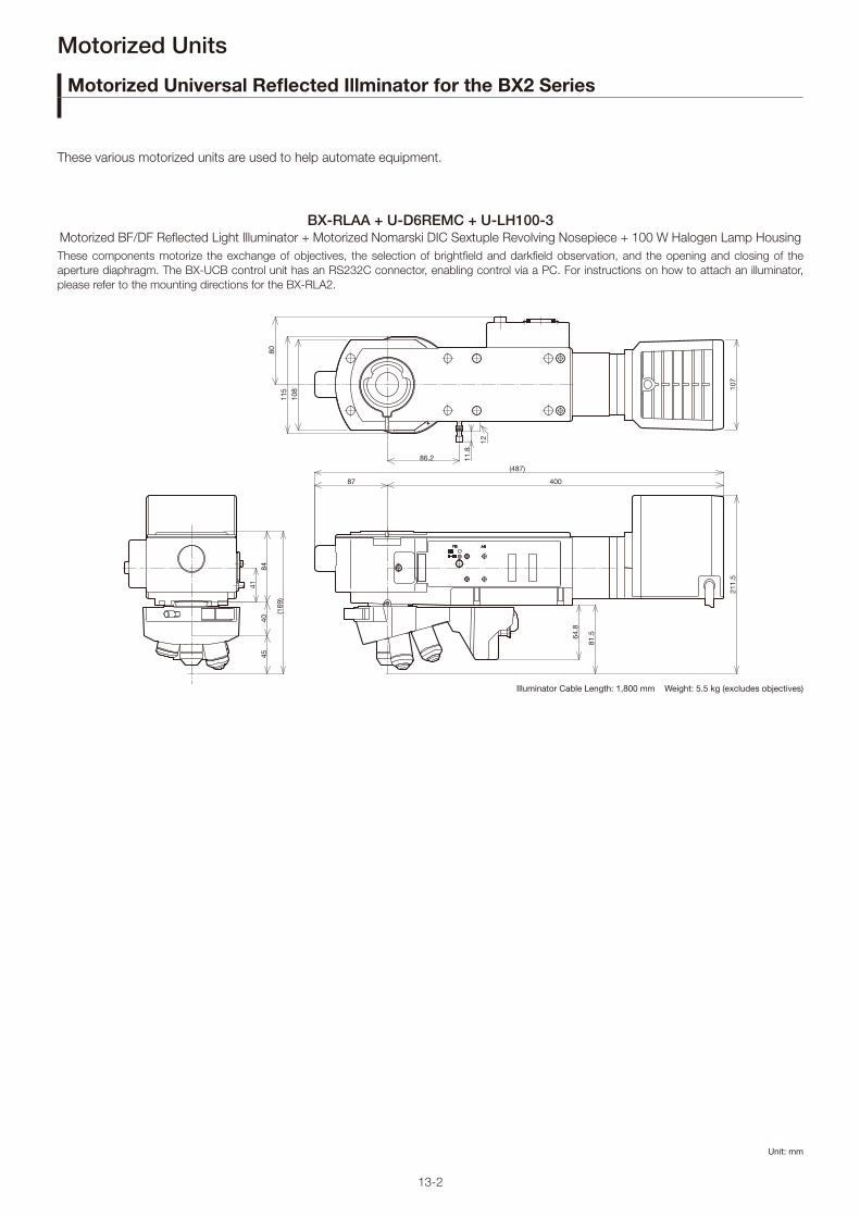
13-2
(169
)
8440
45
41
87
(487)
400
64.8
81.5
211.
5
86.2
115
80
108
11.8
12
107
Unit: mm
Motorized Units
Motorized Universal Refl ected Illminator for the BX2 Series
These various motorized units are used to help automate equipment.
Motorized BF/DF Refl ected Light Illuminator + Motorized Nomarski DIC Sextuple Revolving Nosepiece + 100 W Halogen Lamp Housing
These components motorize the exchange of objectives, the selection of brightfi eld and darkfi eld observation, and the opening and closing of the
aperture diaphragm. The BX-UCB control unit has an RS232C connector, enabling control via a PC. For instructions on how to attach an illuminator,
please refer to the mounting directions for the BX-RLA2.
BX-RLAA + U-D6REMC + U-LH100-3
Illuminator Cable Length: 1,800 mm Weight: 5.5 kg (excludes objectives)

13-3
115.
5
34
50
83.5
103.5
150 40.5
46
135
51.140
69.8
1425
.5
Unit: mm
Motorized Units
Weight: 1.4 kg
Weight: 1.1 kg
U-P5BDREMC
U-D5BDREMC
U-D6BDREMC
U-D6REMC
U-P5REMC
Motorized Units
These various motorized units are used to help automate equipment.
Motorized Centerable Quintuple BD Revolving Nosepiece with Slider Slot for DIC
Motorized Quintuple BD Revolving Nosepiece with Slider Slot for DIC
Motorized Sextuple BD Revolving Nosepiece with Slider Slot for DIC
Motorized Sextuple Revolving Nosepiece with Slider Slot for DIC
Motorized Centerable Quintuple Revolving Nosepiece with Slider Slot for DIC
115
40.5
34
14
4650
74
75
105
134
150
25.4
68.2
40
50.3
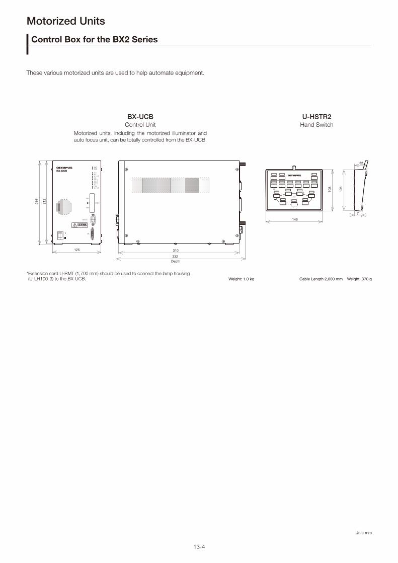
13-4
Unit: mm
146
32
7
105
108
332 Depth
310125
212
216
Motorized Units
Control Box for the BX2 Series
These various motorized units are used to help automate equipment.
Control Unit Hand Switch
BX-UCB U-HSTR2
Motorized units, including the motorized illuminator and
auto focus unit, can be totally controlled from the BX-UCB.
* Extension cord U-RMT (1,700 mm) should be used to connect the lamp housing (U-LH100-3) to the BX-UCB. Weight: 1.0 kg Cable Length 2,000 mm Weight: 370 g

13-5
Unit: mm
2000
147.9
180.5
130
58.5
24.542
30.5
*Consult your local Olympus dealer about the motorized focus.
Cable AFA2M-CBL2M Weight: 0.23 kg Length: 2 mAFA2M-CBL3M Weight: 0.36 kg Length: 3 m
Motorized Units
Motorized Units for the BX2 Series
These various motorized units are used to help automate equipment.
Weight: 2.6 kg
Weight: 1.0 kg
Active Auto Focus Unit
Motorized Refl ected Filter Wheel
U-AFA2M-VIS
U-FWR
This unit features a 785 nm auto focus laser light source. The multiple-spot sensor
enables fast, stable focusing on specimens with variable height differences.
*Class 1 laser product
With this fi lter wheel, quickly switch between 6 different fi lters.
313
108
62
4551

13-6
206
310.
5
77
133
342.1
334
32.5
5645
169
2
36
7
92
5177
Unit: mm
210
70
100
214
104
33.6
3
5470 475.5 82.3
5091
.5
Weight: 13 kg (BXFMA-F frame 7.6 kg)
Weight: 1450 gWeight: 760 g
*Please consult your local Olympus representative for information about the mounting dimensions.
Motorized Units
Motorized Modular Microscope
With these components, users can integrate motorized microscope units into their equipment. Motorized operations, such as moving
the nosepiece up and down, changing objectives, opening and closing the aperture diaphragm, and changing between brightfi eld and
darkfi eld observation modes, are made possible using these components. Several of these operations can be totally controlled from an
external unit by adding an auto focus (AF) unit.
Motorized Illumination with Power Focus
Focus Adjustment Knob Unit Focus Adjustment Knob Interface
BXFMA-F
U-FH U-IFFH
This confi guration combines the active auto focus unit (U-AFA2M-VIS), a single port tube with lens (U-TLU), a lamp housing, a
motorized nosepiece, and objectives.

13-7
Unit: mm
Motorized Units
Motorized Units for the BX3 Series
Motorized Fluorescence Illuminator
Motorized Universal Condenser Motorized Septuple Revolving Nosepiece with Slider Slot for DIC
BX3-RFAA
BX3-UCD8A U-D7REA
ø84
88
86.2 42.8
90
(180
)
40
261
402.5
155.
657 91
.5
178
174.4
142.1
96
84.4
ø121
50.8
47
42
72
40
44.4
34
The fl exibility of the motorized fl uorescence illuminator accommodates multi color stained specimens. The 8-position mirror unit permits
quick changeover of fl uorescence colors.
Weight: 4.2 kg
The motorized universal condenser integrates a variety of optical
elements to accommodate transmitted light techniques including
brightfi eld, DIC, and phase contrast observation.
* Optical elements are required. Please consult your local Olympus representative about optical elements combinations.
Weight: 1.6 kg Weight: 1.5 kg

13-8
Unit: mm
Motorized Units
Control Box for the BX3 Series
The control box can be connected to a PC via the IEEE1394 cable.
The control box can be connected to a PC via a RS232 cable.
*Please consult your local Olympus representative for a detailed system chart.
Weight: 4.2 kg
280
288.8
210
214
100
Control Box for Fully-Motorized Function
Control Box M for Motorized Function
Control Box for Coded Function
BX3-CBH
U-CBM
U-CBS
Weight: 0.82 kg
The control box can be connected to a PC via a RS232 cable (attached onto the microscope frame).
*Please consult your local Olympus representative for a detailed system chart.
Weight: 0.5 kg
125
120185
48 45
37
16.5
163
117.
5
30.5

1. FN and Practical Field of View
The field number (FN) is the size (in mm) of the eyepiece
diaphragm, which defines the viewable area of a specimen.
The diameter on the sample plane that can actually be viewed
through the eyepiece is known as the practical field of view
(FOV) and is determined by the following formula:
2. Working Distance
The working distance (W.D.) is the distance between the front
edge of the objective and the specimen surface (or the
surface of the cover glass when using a cover glass objective)
when the specimen is in focus.
3. Parfocal Distance
The parfocal distance is the distance between the objective
mounting plane and the specimen. In UIS2/UIS objectives, the
parfocal distance is designed to be 45 mm.
For the parfocal distance of the LCPLFLN-LCD series
objectives, refer to the appropriate objective page.
4. Relationship Between the Objective's Focal Length and Magnifi cation
The magnification indicated for a UIS2/UIS objective is the
value when the focal length of the tube lens is 180 mm.
M(ob): Objective magnification
f: Objective's focal length
5. Total Magnifi cation
5.1 Observation Through Eyepiece (binocular observation)
M(bino)=M(ob)×M(oc)
M(bino): Total magnification for binocular observation
M(ob): Objective magnification
M(oc): Eyepiece magnification
5.2 Video Monitor Observation
Total Magnification for Video Monitor
M(video monitor)= M(ob)×M(video camera adaptor)×Monitor Magnification*
M(video monitor): Total Magnification on the Video Monitor
M(ob): Objective Magnification
M(video camera adaptor): Projected magnification for video camera
adaptor including photo eyepiece
(refer to Figure 1)
*Refer to Figure 3 for "monitor magnification"
Practical Field of View for Video Monitor Observation
M(ob): Objective Magnification
M(video camera adaptor): Projected magnification for video camera
adaptor including photo eyepiece
(refer to Figure 1 for projected magnifications)
*Refer to Figure 2 for image device size
Working Distance and Parfocal Distance
W.D.
Parfocal Distance
Objective
Mounting Position
Focal Plane
Optical Terminology
FOV =Eyepiece FN
(mm)Objective Magnification
M(ob)= Focal Length of Tube Lens
f
Practical Field of View for
Video Monitor Observation=
Image Device Size *
M(ob)×M(video camera adaptor)
ExampleWhat is the total magnifications for a video monitor when a
objective is 50X, a video camera adaptor U-TV0.5XC, a 2/3"
video camera, and a 21" monitor are used ?
Figure 1 Video Camera Adaptor and Projection MagnificationsVideo Camera Adaptor (projection lens) Projection Magnification
U-TV1X-1 +
Video Camera Mount Adaptors 1X
U-TV1XC 1X
U-TV0.63XC 0.63X
U-TV0.5XC-3 0.5X
U-TV0.35XC-2 0.35X
U-TV0.25XC 0.25X
Figure 2 Imaging Device SizeCamera Format Diagonal Horizontal Vertical
1/3" 6.0 mm 4.8 mm 3.6 mm
1/2" 8.0 mm 6.4 mm 4.8 mm
2/3" 11.0 mm 8.8 mm 6.6 mmThe above table is for standard image device sizes.Check your device size for precise calculation.
Figure 3 Imaging Device Size and Monitor Magnifications
Camera FormatMonitor Size (diagonal)
10" 15" 17" 19" 21"
1/3" 42.3X 63.5X 72.0X 80.4X 88.9X
1/2" 31.8X 47.6X 54.0X 60.3X 66.7X
2/3" 23.1X 34.6X 39.3X 43.9X 48.5X
14-1

Optical Terminology
•Total magnification on the video monitor:
m(ob)=50X, M(video camera adaptor) is 0.5X from Figure 1, and the
monitor magnification is 48.5× from Figure 3.
M(monitor observation)=M(ob)×M(video camera adaptor)×monitor magnification
=50×0.5×48.5=1213X
•Practical filed of view for video observation (horizontal side):
M(ob)=50X, M(video camera adaptor) is 0.5X (from Figure 1), and
the horizontal side of a 2/3" imaging device is 8.8 mm (from
Figure 2)
6. NA
The numerical aperture is a key factor to the performance of
an objective (resolving power, focal depth, and brightness).
The NA is determined by the following formula:
NA= n × sinθ
n= The refraction rate of the medium between the specimen
and objective. (Air: n=1, oil: n=1.515)
θ: The angle made by the optical axis and refraction of the
light farthest from the center of the lens.
The visual field brightness (B) of the microscope is determined
by the following formula in relation to the objective
magnification (M). The larger the NA and the lower the
objective magnification, the brightness will increase by a factor
of the second power.
7. Resolving Power
The resolving power of an objective is measured by its ability
to differentiate two lines or points in an object. The greater the
resolving power, the smaller the minimum distance between
two lines or points that can still be distinguished. The larger
the NA, the higher the resolving power.
Resolving Power FormulaThe following formula is generally used for determing resolution.
λ: Wavelength or radiation in use
(λ=0.55 μm is used for visible light.)
NA: Objective NA
ExampleMPLFLN100X (NA=0.90), λ=0.55 μm
8. Focal Depth of Microscope
The focal depth refers to the depth of the specimen layer that
is in sharp focus at the same time, even if the distance
between the objective and the specimen plane is changed
when observing and imaging the specimen plane using the
microscope. Because human eyes are individually different in
the ability to adjust their focus, each person's perception of
the focal depth varies.
At present, the Berek formula is generally used because it
gives a focal depth value that often coincides with the focal
depth obtained through experiments.
Focal Depth Formula
Visual Observation (Berek formula)
DOF: Depth of Focus
ω: Resolving Power of Eyes 0.0014
(when the optical angle is 0.5 degrees)
M: Total Magnification
(objective magnification x eyepiece magnification)
This indicates that the focal depth becomes smaller as the
numerical aperture becomes larger.
Example
With MPLFLN100X (NA=0.90), WHN10X:
Video CameraIn the case of a video camera, the focal depth will vary
according to the number of pixels of the CCD, optical
magnification, and numerical aperture. The above-mentioned
formula is used as a rough guide only.
Objective
NA
Sample Surface
n=1(air)
θ
=8.8 (mm)
=352 μm50 × 0.5
Practical Field of View
for Video Observation=
Image Device Size
M(ob)×M(video camera adaptor)
B∝ NA2
M2
ε =0.61×λ
(Reyleigh formula)NA
ε = 0.61 ×λ
=0.3355
=0.3355
= 0.37 μmNA NA 0.90
± DOF=ω × 250,000
+λ
(μm)NA × M 2 (NA) 2
± DOF =350
+0.275
= 0.39 + 0.34 = 0.73 μm0.90 × 1,000 0.81
➔ ± DOF =350
+0.275
(λ=0.55 μm)NA × M NA2
14-2

9. Aberrations
A difference between an ideal image and the actual image that
passes through an optical system is called an “aberration.”
9.1 Requirements for Ideal Image Formation
The following three requirements must be satisfied to form an
image with no aberrations, or an ideal image.
(i) All the light rays coming from a single point and passing
through an image formation optical system converge on a
single point.
(ii) Image points, which correspond to object points on the
same plane perpendicular to the optical axis, are present
on the same plane.
(iii) The planar shape of an object and the planar shape of
an image that are on the same plane perpendicular to
the optical axis have a similar relation.
In an actual optical system, however, it is very difficult to
strictly meet the requirements for ideal image formation, and
this causes “aberrations” that interfere with image-forming
performance.
9.2 Classifi cation of Aberrations
Aberrations that interfere with image-forming performance are
classified as shown below in Figure 9-2.
Seidel’s Aberration = “Expansion of a Point Image” +
“Curvature of the Image Plane” + “Deformation”
Types (1) to (3) correspond to “expansion of a point image”
that goes against requirement (i) for ideal image formation in
Figure 9-1. Type (4) corresponds to “curvature of image plane”
that goes against requirement (ii) in Figure 9-1.
Type (5) corresponds to “deformation” that goes against
requirement (iii) in Figure 9-1.
Types (6) and (7) correspond to the “color blur” of images
caused by characteristics of glass materials used for the
optical system. “Expansion of a point image” can also be
expressed by “wavefront aberration” that regards the light as
“waves” and takes into account the phase to include the
influence of diffraction.
(1) Spherical AberrationWhen light rays coming out of an axial object point enter a
lens, the light rays with a larger numerical aperture (NA) are
subjected to stronger refraction power and cross the optical
axis in positions further away from the ideal image formation
position. The aberration caused by different image forming
positions due to the differences in NA of axial light rays is
called “spherical aberration.” (“Spherical aberration” is
proportional to NA to the third power.)
Typically, objectives with a larger NA have better resolution but
worse spherical aberration. Our advanced design and
manufacturing techniques have realized good optical
performance even with a large numerical aperture.
(2) Coma AberrationEven though spherical aberration is compensated to be very
small, there are cases where light rays coming out of an off-
axis object point are not condensed to a single point on the
image plane but, instead, generate asymmetric blur that looks
like a comet leaving traces. This is called coma aberration.
Figure 9-1 Requirements for Ideal Image Formation
Object(i) (ii) (iii)
Image Plane
Figure 9-2 Classification of Aberrations
Aberration
Seidel's Aberration
Chromatic Aberration
(1) Spherical Aberration
(2) Coma Aberration
(3) Astigmatism
(4) Field Curvature
(5) Distortion
(6) Longitudinal (axial) Chromatic Aberration
(7) Chromatic Aberration of Magnification
Figure 9-3 Spherical Aberration
Specimen
Objective with Spherical Aberration
Aplanatic Tube Lens Image Plane
Outer Light Ray (with a larger NA)
Inner Light RayFocal Position
Inner Light Ray (with a smaller NA)
Outer Light RayFocal Position
Figure 9-4 Coma Aberration and Spot Shape on the Image Plane
Specimen Aplanatic Tube Lens
Objective with Coma Aberration
Image Plane
14-3
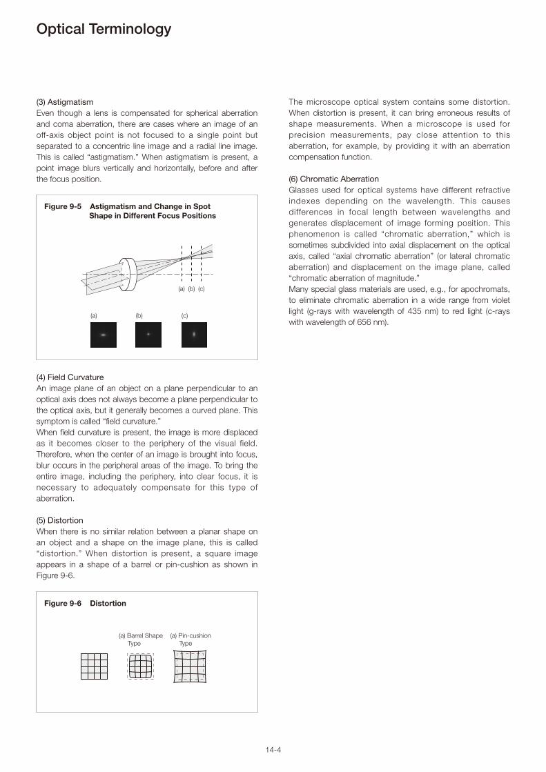
Optical Terminology
The microscope optical system contains some distortion.
When distortion is present, it can bring erroneous results of
shape measurements. When a microscope is used for
precision measurements, pay close attention to this
aberration, for example, by providing it with an aberration
compensation function.
(6) Chromatic Aberration Glasses used for optical systems have different refractive
indexes depending on the wavelength. This causes
differences in focal length between wavelengths and
generates displacement of image forming position. This
phenomenon is called “chromatic aberration,” which is
sometimes subdivided into axial displacement on the optical
axis, called “axial chromatic aberration” (or lateral chromatic
aberration) and displacement on the image plane, called
“chromatic aberration of magnitude.”
Many special glass materials are used, e.g., for apochromats,
to eliminate chromatic aberration in a wide range from violet
light (g-rays with wavelength of 435 nm) to red light (c-rays
with wavelength of 656 nm).
(3) AstigmatismEven though a lens is compensated for spherical aberration
and coma aberration, there are cases where an image of an
off-axis object point is not focused to a single point but
separated to a concentric line image and a radial line image.
This is called “astigmatism.” When astigmatism is present, a
point image blurs vertically and horizontally, before and after
the focus position.
(4) Field CurvatureAn image plane of an object on a plane perpendicular to an
optical axis does not always become a plane perpendicular to
the optical axis, but it generally becomes a curved plane. This
symptom is called “field curvature.”
When field curvature is present, the image is more displaced
as it becomes closer to the periphery of the visual field.
Therefore, when the center of an image is brought into focus,
blur occurs in the peripheral areas of the image. To bring the
entire image, including the periphery, into clear focus, it is
necessary to adequately compensate for this type of
aberration.
(5) DistortionWhen there is no similar relation between a planar shape on
an object and a shape on the image plane, this is called
“distortion.” When distortion is present, a square image
appears in a shape of a barrel or pin-cushion as shown in
Figure 9-6.
(a) Barrel Shape
Type
(a) Pin-cushion
Type
Figure 9-6 Distortion
Figure 9-5 Astigmatism and Change in Spot Shape in Different Focus Positions
(a) (b) (c)
(a) (b) (c)
14-4

9.4 Strehl Ratio
When a point light source is observed with an aberration-free
optical system and an aberrated optical system, the former
concentrates the focal point to a point at the image formation
position. In contrast, the latter fails to produce a focal point,
instead causing a spread in the intensity distribution of the
point image (this is known as “point spread”). The specific
appearance of such a point image (i.e. point spread) is shown
in Figure 9-9.
With the proportion of light concentrated in the image plane
(intensity of light concentrated in the Airy disk) by an
aberration-free optical system serving as 100%, the
proportion of light concentrated by an aberrated optical
system is known as the Strehl ratio (SR). When graphed, the
Strehl ratio reveals peaks in intensity as shown in Figure 9-10.
The higher the SR, the closer an optical system is to being
aberration-free.
A Strehl ratio of 80% is typically called the diffraction limit, and
lenses with a lower ratio lack the performance required to
serve as an objective. A ratio of over 95% means that the
lens’ performance in general observations is comparable to
that of an aplanatic lens (which is corrected for spherical
aberrations and coma).
Note: A laser interferometer is used to assess optical performance,
so assessment is done at a single wavelength. Unless otherwise
noted, Strehl ratio measurements are at the e-line (544 nm).
9.3 Wavefront Aberration
For a long time, aberrations have been used in “geometric
optics,” which considers light as “light rays.” Microscope
optical systems are often used to observe very small
specimens at the wavelength level and sometimes adopt
“wave optics,” which regards light as “waves” and handles the
phase information, accounting for the influence of diffraction.
In such a case, “wavefront aberration” is used for evaluation.
As shown below, when requirements for ideal imaging are
satisfied in a microscope optical system, the spherical
wavefront (spherical waves) coming from a single point on an
object (specimen) is converted to plane waves through an
ideal objective. The plane waves are converted to spherical
waves through an ideal tube lens and condensed to a single
point. The wavefront of these waves is called the “ideal
wavefront.”
Based on the figure indicated for (1) spherical aberration, the
behavior of the wavefront in an optical system that has an
aberration is described below.
A difference (a degree of disagreement) between the ideal
wavefront and the actual wavefront shown above is called
“wavefront aberration.”
Figure 9-7 Ideal Microscope Optical System
Spherical Wave
Plane Wave
Spherical Wave
Specimen Ideal Tube Lens
Ideal Objective
Image Plane
Figure 9-8 Illustration of Wavefront Aberration
Objective with Spherical Aberration
Ideal Wavefront
Actual Wavefront
Specimen
Figure 9-9 Appearance of Condensed Light in the Image Plane (point spread)
Aberration-Free Optical System Aberrated Optical System
Figure 9-10 Strehl Ratio (SR)
Intensity
Aberration-Free Optical System
Aberrated Optical System
Image Plane
100%
SR
14-5

Memo

Memo

M1703E-062020
http://www.olympus-ims.com/component/
Shinjuku Monolith, 2-3-1 Nishi-Shinjuku, Shinjuku-ku, Tokyo 163-0914, Japan
• All company and product names are registered trademarks and/or trademarks of their respective owners.
• Illumination devices for microscope have suggested lifetimes. Periodic inspections are required.