Embed Size (px)
Citation preview
2016/7/5 v9.3.2
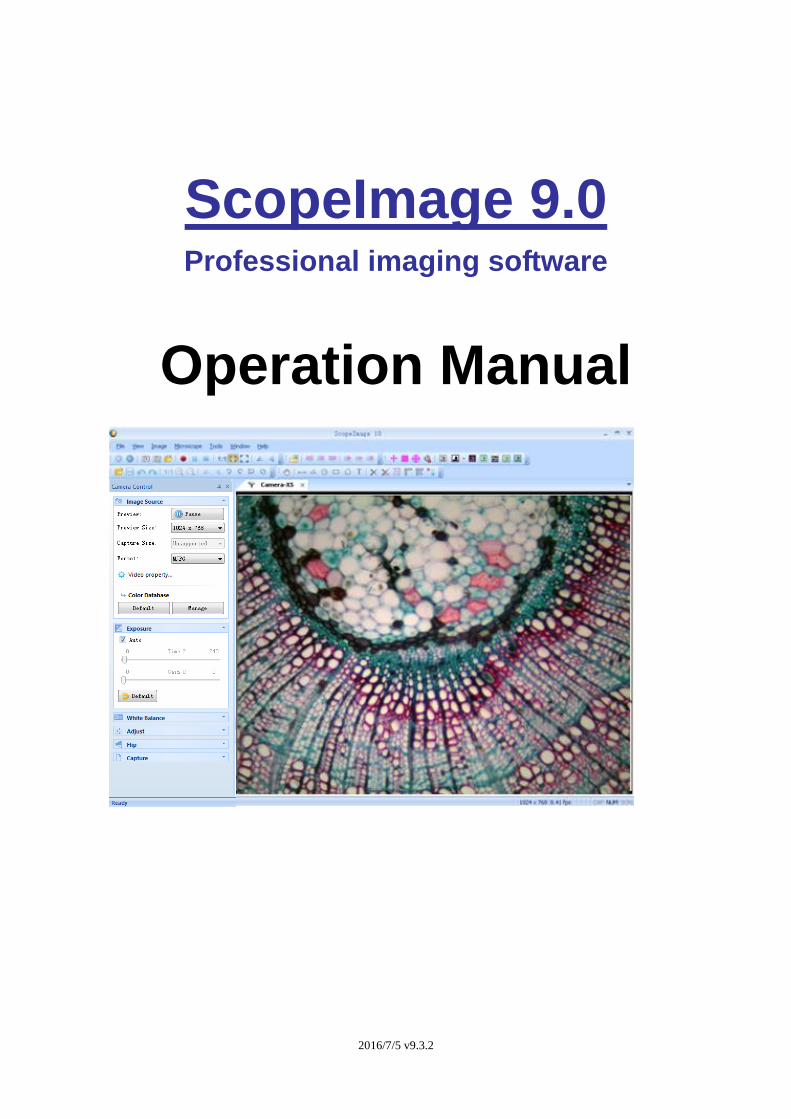
ScopeImage 9.0 Professional imaging software
Operation Manual
2016/7/5 v9.3.2
Contents
1. Introduction .................................................................................................. 3
2. Installation Instruction .................................................................................. 4
2.1 Minimum System Requirements .......................................................... 4
2.2 Install Instruction ................................................................................. 4
3. Start to Use ScopeImage 9.0 ....................................................................... 8
3.1 Start ScopeImage 9.0 .......................................................................... 8
3.2 Open the Camera ................................................................................ 8
4. ScopeImage 9.0 Windows GUI .................................................................. 10
4.1 Function GUI ..................................................................................... 10
4.1.1 Menu Bar ........................................................................................ 10
4.1.2 Tools Bar .........................................................................................11
4.1.3 Control Pane .................................................................................. 13
5. Image Process Modules ............................................................................ 14
5.1 Video mode ....................................................................................... 14
5.1.1 Video Preview .......................................................................... 14
5.1.2 Exposure .................................................................................. 14
5.1.3 White Balance .......................................................................... 16
5.1.4 Video Adjustment ..................................................................... 17
5.1.5 Flip ........................................................................................... 18
5.1.6 Video Capture .......................................................................... 19
5.1.7 Image Stitching Tool ................................................................. 21
5.2 Image mode ...................................................................................... 23
5.2.1 Image Process ......................................................................... 23
5.2.2 Image Flip ................................................................................ 25
5.2.3 Image Calibration ..................................................................... 26
5.2.3 Image Calibration ..................................................................... 26
5.2.4 Image Measurement ................................................................ 34
5.2.5 The measurement data processing .......................................... 38
6. Trouble Shooting ....................................................................................... 39
6.1 Attention ............................................................................................ 39
2016/7/5 v9.3.2
1.Instruction
ScopeImage 9.0 is a powerful software that is provided with image
analysis and processing. Its application has spread all over optical
microscope fields, which are involved in scientific research,manufacture,
education and so on. Its friendly operation interface and stable
performance has provided convenience for users.
★ supported language:
1. Chinese 2. English 3. Arabic 4. French 5. German
6. Japanese 7. Polish
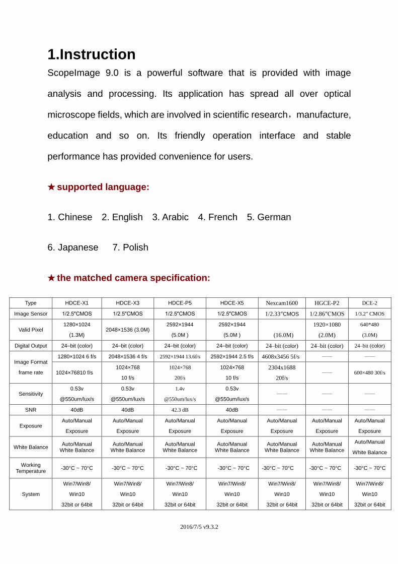
★ the matched camera specification:
Type HDCE-X1 HDCE-X3 HDCE-P5 HDCE-X5 Nexcam1600 HGCE-P2 DCE-2
Image Sensor 1/2.5″CMOS 1/2.5″CMOS 1/2.5″CMOS 1/2.5″CMOS 1/2.33″CMOS 1/2.86″CMOS 1/3.2" CMOS
Valid Pixel 1280×1024
(1.3M) 2048×1536 (3.0M)
2592×1944
(5.0M )
2592×1944
(5.0M )
(16.0M)
1920×1080
(2.0M)
640*480
(3.0M)
Digital Output 24–bit (color) 24–bit (color) 24–bit (color) 24–bit (color) 24–bit (color) 24–bit (color) 24–bit (color)
Image Format
frame rate
1280×1024 6 f/s 2048×1536 4 f/s 2592×1944 13.6f/s 2592×1944 2.5 f/s 4608x3456 5f/s —— ——
1024×76810 f/s 1024×768
10 f/s
1024×768
20f/s
1024×768
10 f/s
2304x1688
20f/s —— 600×480 30f/s
Sensitivity 0.53v
@550um/lux/s
0.53v
@550um/lux/s
1.4v
@550um/lux/s
0.53v
@550um/lux/s —— —— ——
SNR 40dB 40dB 42.3 dB 40dB —— —— ——
Exposure Auto/Manual
Exposure
Auto/Manual
Exposure
Auto/Manual
Exposure
Auto/Manual
Exposure
Auto/Manual
Exposure
Auto/Manual
Exposure
Auto/Manual
Exposure
White Balance Auto/Manual
White Balance Auto/Manual
White Balance Auto/Manual
White Balance Auto/Manual
White Balance Auto/Manual
White Balance Auto/Manual
White Balance
Auto/Manual
White Balance
Working Temperature
-30°C ~ 70°C -30°C ~ 70°C -30°C ~ 70°C -30°C ~ 70°C -30°C ~ 70°C -30°C ~ 70°C -30°C ~ 70°C
System
Win7/Win8/
Win10
32bit or 64bit
Win7/Win8/
Win10
32bit or 64bit
Win7/Win8/
Win10
32bit or 64bit
Win7/Win8/
Win10
32bit or 64bit
Win7/Win8/
Win10
32bit or 64bit
Win7/Win8/
Win10
32bit or 64bit
Win7/Win8/
Win10
32bit or 64bit
2016/7/5 v9.3.2
2.Installation Instruction
2.1 Minimum System Requirements
System Requirements
- Video adapter supports 24bit color or more and 1280*1024 or
1024*768 resolution
- CPU with 2.0GHz or more
- System Memory 256MB or more, Display Memory 128MB or more.
- USB2.0 interface
- Hard Disk Space 1GB for installation plus additional space for ca
ptured images
Since video processing is hardware intensive, a faster computer with a
fast hard disk drive and extra memory will yield better results.
2.2 Install Instruction
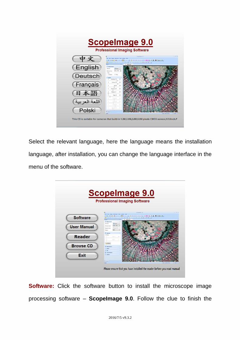
Put the CD into the CD driver, it will pop out an installation wizard, just
click the relevant button and follow the clue to finish the installation, and
then we can use the camera.
2016/7/5 v9.3.2
Select the relevant language, here the language means the installation
language, after installation, you can change the language interface in the
menu of the software.
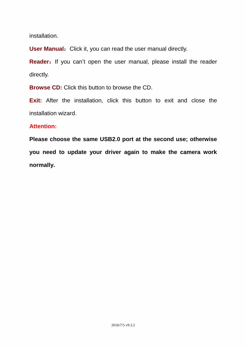
Software: Click the software button to install the microscope image
processing software – ScopeImage 9.0. Follow the clue to finish the
2016/7/5 v9.3.2
installation.
User Manual:Click it, you can read the user manual directly.
Reader:If you can’t open the user manual, please install the reader
directly.
Browse CD: Click this button to browse the CD.
Exit: After the installation, click this button to exit and close the
installation wizard.
Attention:
Please choose the same USB2.0 port at the second use; otherwise
you need to update your driver again to make the camera work
normally.
2016/7/5 v9.3.2
3.Start to Use ScopeImage 9.0
3.1 Start ScopeImage 9.0
Double click icon on the desktop, running ScopeImage 9.0;
3.2 Open the Camera
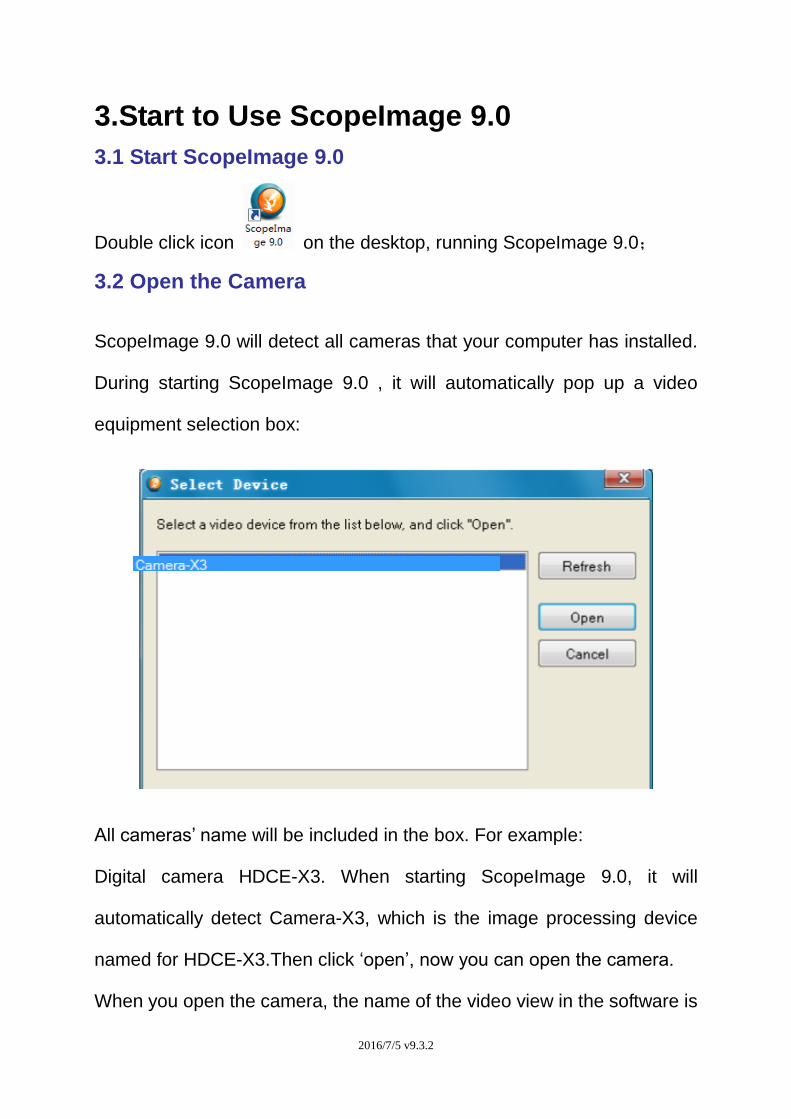
ScopeImage 9.0 will detect all cameras that your computer has installed.
During starting ScopeImage 9.0 , it will automatically pop up a video
equipment selection box:
All cameras’ name will be included in the box. For example:
Digital camera HDCE-X3. When starting ScopeImage 9.0, it will
automatically detect Camera-X3, which is the image processing device
named for HDCE-X3.Then click ‘open’, now you can open the camera.
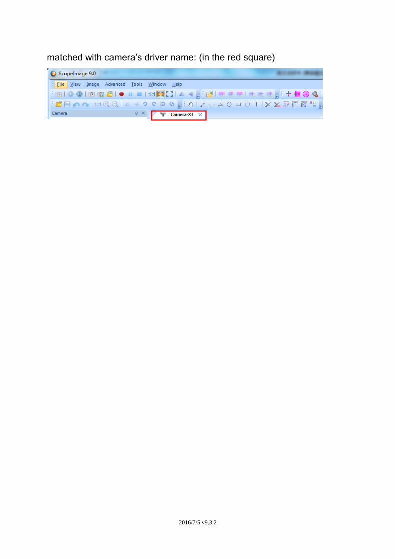
When you open the camera, the name of the video view in the software is
2016/7/5 v9.3.2
matched with camera’s driver name: (in the red square)
2016/7/5 v9.3.2
4 ScopeImage 9.0 Windows GUI
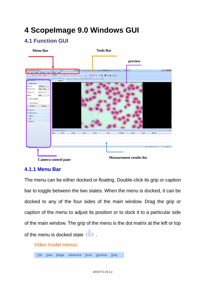
4.1 Function GUI
4.1.1 Menu Bar
The menu can be either docked or floating. Double-click its grip or caption
bar to toggle between the two states. When the menu is docked, it can be
docked to any of the four sides of the main window. Drag the grip or
caption of the menu to adjust its position or to dock it to a particular side
of the main window. The grip of the menu is the dot matrix at the left or top
of the menu is docked state( ).
Video model menus:
Menu Bar Tools Bar
Camera control pane
preview
Measurement results list
2016/7/5 v9.3.2
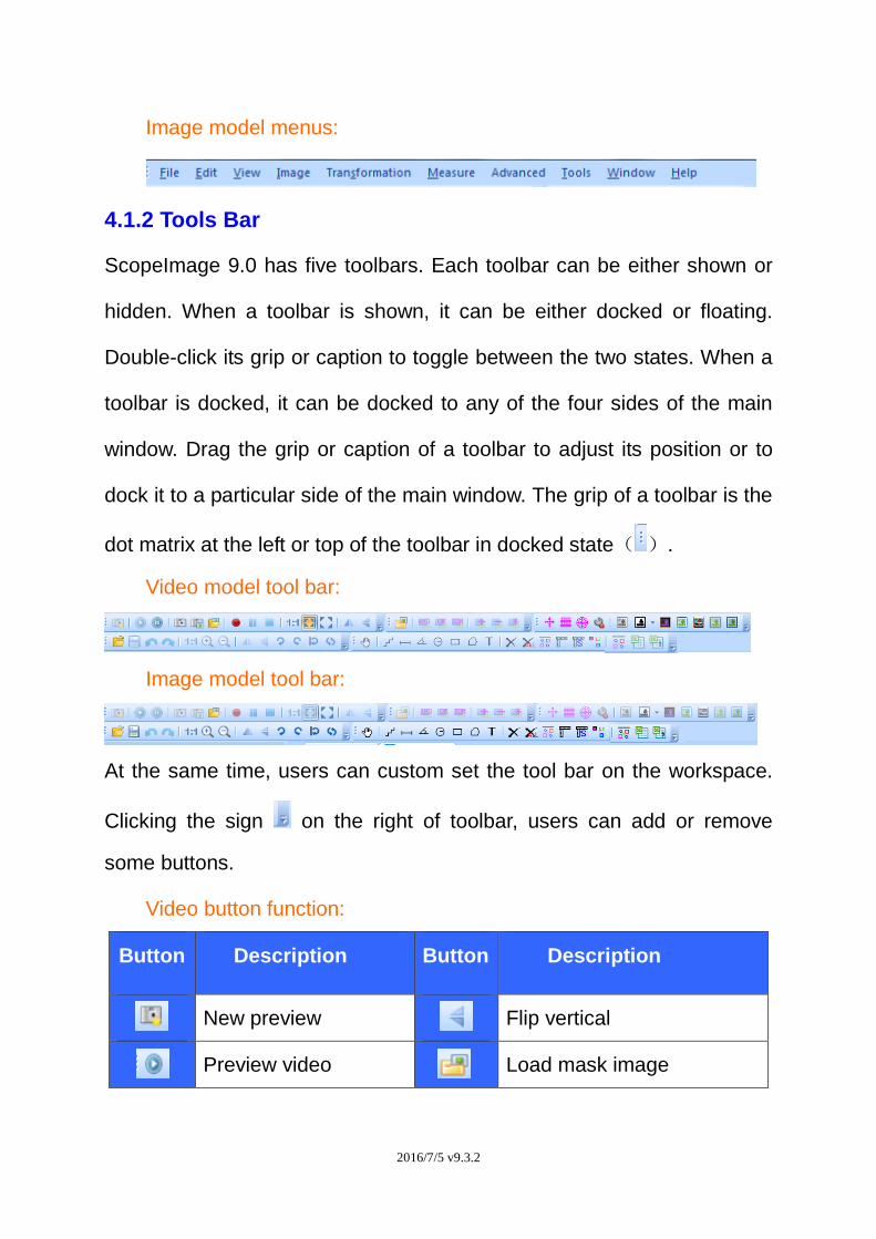
Image model menus:
4.1.2 Tools Bar
ScopeImage 9.0 has five toolbars. Each toolbar can be either shown or
hidden. When a toolbar is shown, it can be either docked or floating.
Double-click its grip or caption to toggle between the two states. When a
toolbar is docked, it can be docked to any of the four sides of the main
window. Drag the grip or caption of a toolbar to adjust its position or to
dock it to a particular side of the main window. The grip of a toolbar is the
dot matrix at the left or top of the toolbar in docked state( ).
Video model tool bar:
Image model tool bar:
At the same time, users can custom set the tool bar on the workspace.
Clicking the sign on the right of toolbar, users can add or remove
some buttons.
Video button function:
Button Description Button Description
New preview Flip vertical
Preview video Load mask image
2016/7/5 v9.3.2
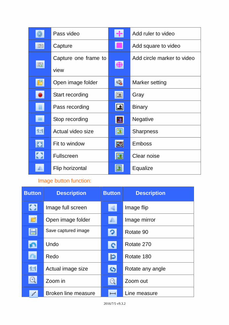
Pass video Add ruler to video
Capture Add square to video
Capture one frame to
view
Add circle marker to video
Open image folder Marker setting
Start recording Gray
Pass recording Binary
Stop recording Negative
Actual video size Sharpness
Fit to window Emboss
Fullscreen Clear noise
Flip horizontal Equalize
Image button function:
Button Description Button Description
Image full screen Image flip
Open image folder Image mirror
Save captured image Rotate 90
Undo Rotate 270
Redo Rotate 180
Actual image size Rotate any angle
Zoom in Zoom out
Broken line measure Line measure
2016/7/5 v9.3.2
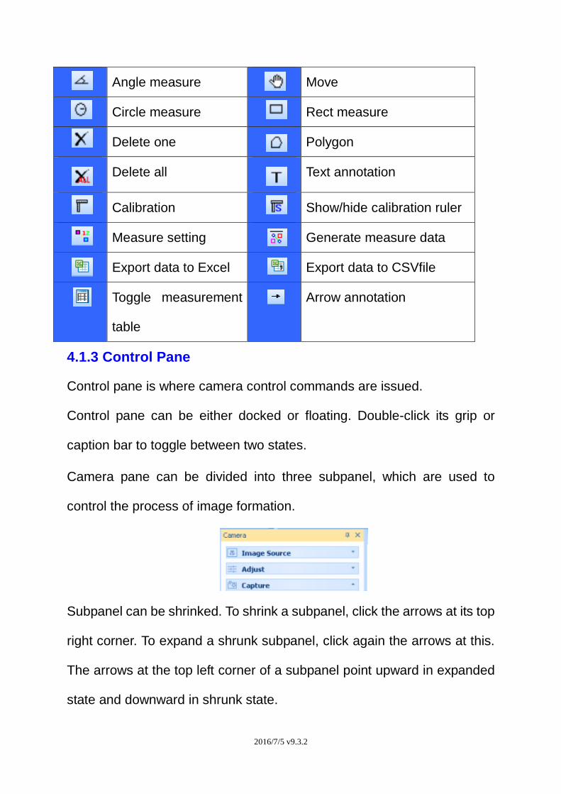
Angle measure Move
Circle measure Rect measure
Delete one Polygon
Delete all Text annotation
Calibration Show/hide calibration ruler
Measure setting Generate measure data
Export data to Excel Export data to CSVfile
Toggle measurement
table
Arrow annotation
4.1.3 Control Pane
Control pane is where camera control commands are issued.
Control pane can be either docked or floating. Double-click its grip or
caption bar to toggle between two states.
Camera pane can be divided into three subpanel, which are used to
control the process of image formation.
Subpanel can be shrinked. To shrink a subpanel, click the arrows at its top
right corner. To expand a shrunk subpanel, click again the arrows at this.
The arrows at the top left corner of a subpanel point upward in expanded
state and downward in shrunk state.
2016/7/5 v9.3.2
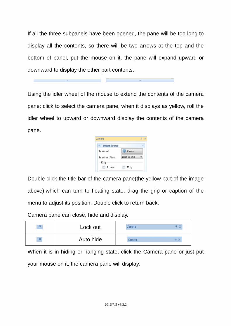
If all the three subpanels have been opened, the pane will be too long to
display all the contents, so there will be two arrows at the top and the
bottom of panel, put the mouse on it, the pane will expand upward or
downward to display the other part contents.
Using the idler wheel of the mouse to extend the contents of the camera
pane: click to select the camera pane, when it displays as yellow, roll the
idler wheel to upward or downward display the contents of the camera
pane.
Double click the title bar of the camera pane(the yellow part of the image
above),which can turn to floating state, drag the grip or caption of the
menu to adjust its position. Double click to return back.
Camera pane can close, hide and display.
Lock out
Auto hide
When it is in hiding or hanging state, click the Camera pane or just put
your mouse on it, the camera pane will display.
2016/7/5 v9.3.2
5. Image Process Modules
5.1 Video mode
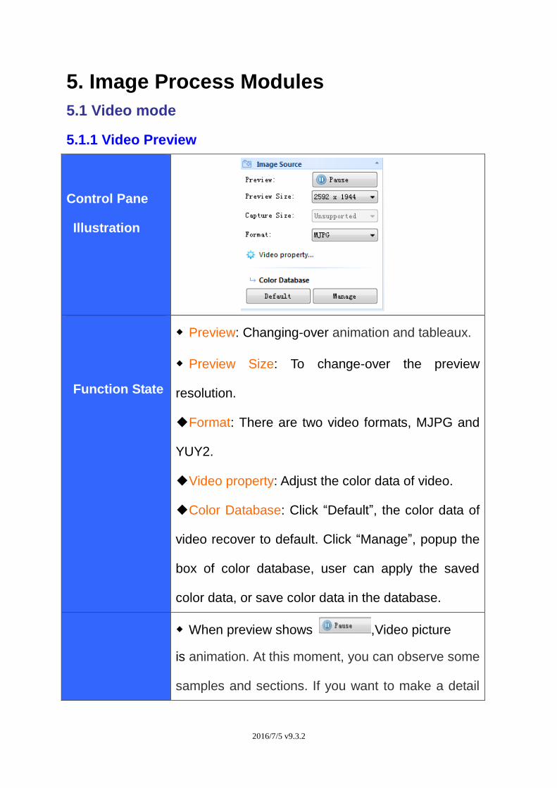
5.1.1 Video Preview
Control Pane
Illustration
Function State
◆ Preview: Changing-over animation and tableaux.
◆ Preview Size: To change-over the preview
resolution.
◆Format: There are two video formats, MJPG and
YUY2.
◆Video property: Adjust the color data of video.
◆Color Database: Click “Default”, the color data of
video recover to default. Click “Manage”, popup the
box of color database, user can apply the saved
color data, or save color data in the database.
◆ When preview shows ,Video picture
is animation. At this moment, you can observe some
samples and sections. If you want to make a detail
2016/7/5 v9.3.2
Initialization
observation for a video picture part,
click ,then it will show .
◆ Configure Preview Size Combobox: In order to
make a full use of display’s resolution, you can
choose a resolution matched with displays’ to
preview. Furthermore, choosing an lower resolution
will get a fast Video refresh rate.
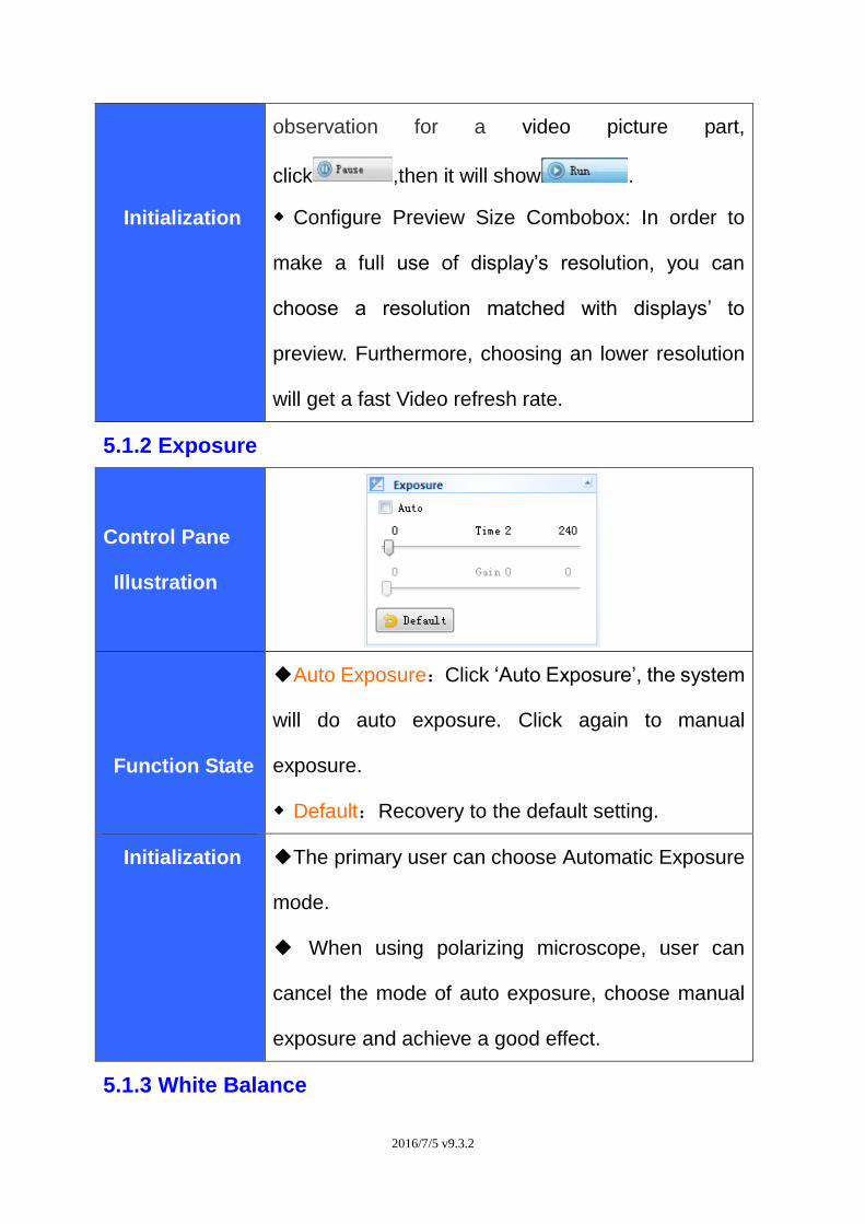
5.1.2 Exposure
Control Pane
Illustration
Function State
◆Auto Exposure:Click ‘Auto Exposure’, the system
will do auto exposure. Click again to manual
exposure.
◆ Default:Recovery to the default setting.
Initialization ◆The primary user can choose Automatic Exposure
mode.
◆ When using polarizing microscope, user can
cancel the mode of auto exposure, choose manual
exposure and achieve a good effect.
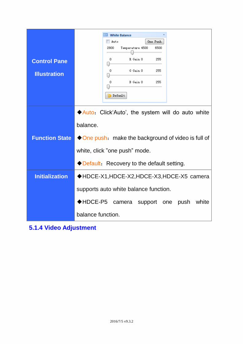
5.1.3 White Balance
2016/7/5 v9.3.2
Control Pane
Illustration
Function State
◆Auto:Click‘Auto’, the system will do auto white
balance.
◆One push:make the background of video is full of
white, click ”one push” mode.
◆Default:Recovery to the default setting.
Initialization ◆HDCE-X1,HDCE-X2,HDCE-X3,HDCE-X5 camera
supports auto white balance function.
◆HDCE-P5 camera support one push white
balance function.
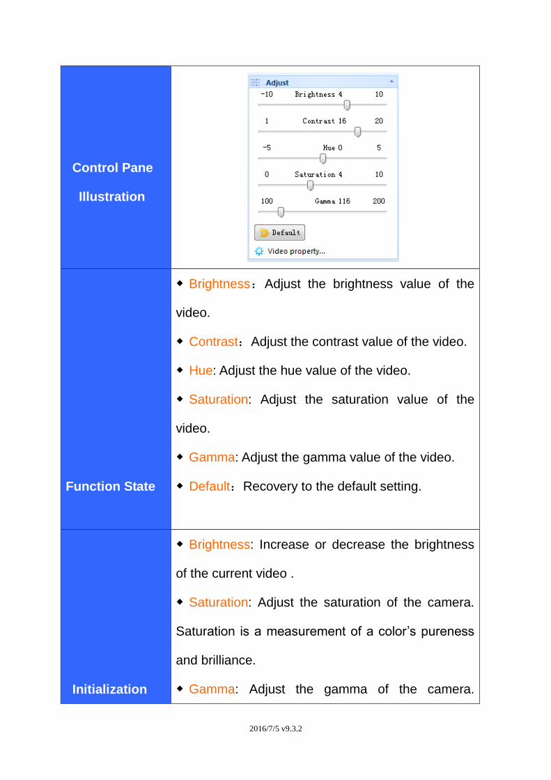
5.1.4 Video Adjustment
2016/7/5 v9.3.2
Control Pane
Illustration
Function State
◆ Brightness:Adjust the brightness value of the
video.
◆ Contrast:Adjust the contrast value of the video.
◆ Hue: Adjust the hue value of the video.
◆ Saturation: Adjust the saturation value of the
video.
◆ Gamma: Adjust the gamma value of the video.
◆ Default:Recovery to the default setting.
Initialization
◆ Brightness: Increase or decrease the brightness
of the current video .
◆ Saturation: Adjust the saturation of the camera.
Saturation is a measurement of a color’s pureness
and brilliance.
◆ Gamma: Adjust the gamma of the camera.
2016/7/5 v9.3.2
Gamma is an image quality enhancement function
that offers a richer image by brightening the darker
portions of the image without altering the brightness
of the brighter portions.
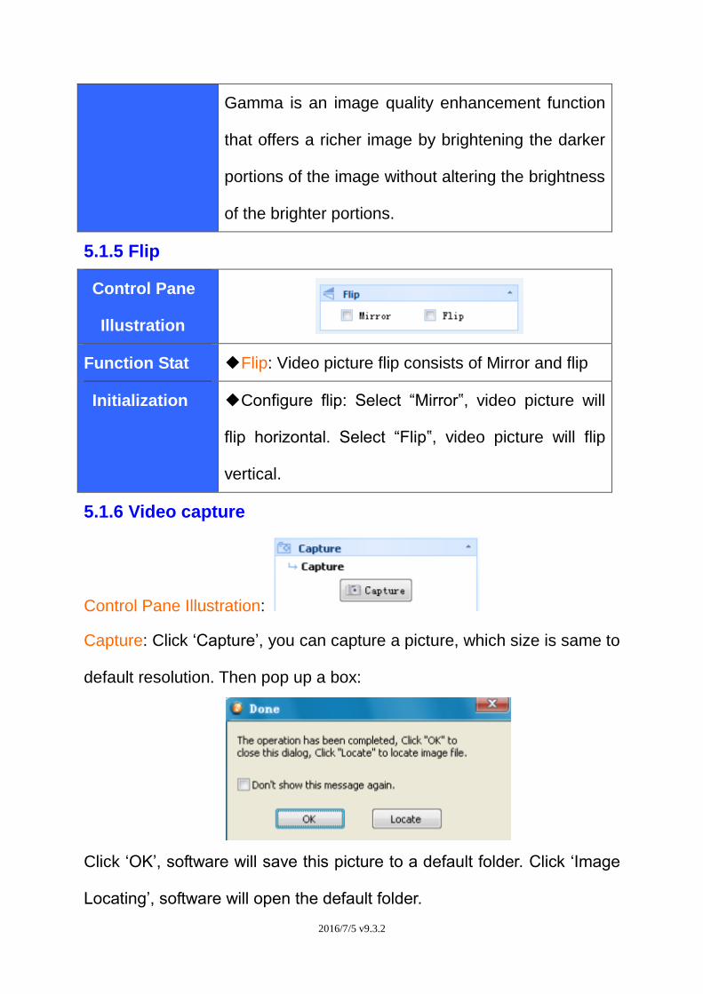
5.1.5 Flip
Control Pane
Illustration
Function Stat ◆Flip: Video picture flip consists of Mirror and flip
Initialization ◆Configure flip: Select “Mirror‟, video picture will
flip horizontal. Select “Flip‟, video picture will flip
vertical.
5.1.6 Video capture
Control Pane Illustration:
Capture: Click ‘Capture’, you can capture a picture, which size is same to
default resolution. Then pop up a box:
Click ‘OK’, software will save this picture to a default folder. Click ‘Image
Locating’, software will open the default folder.
2016/7/5 v9.3.2
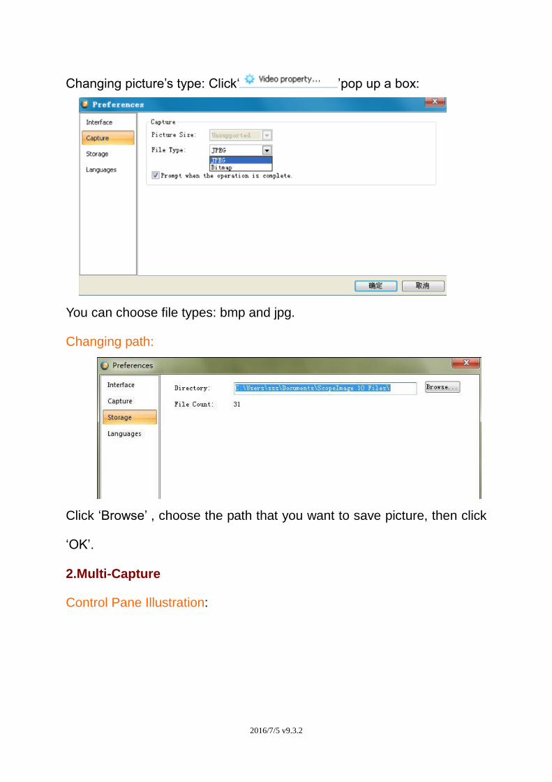
Changing picture’s type: Click‘ ’pop up a box:
You can choose file types: bmp and jpg.
Changing path:
Click ‘Browse’ , choose the path that you want to save picture, then click
‘OK’.
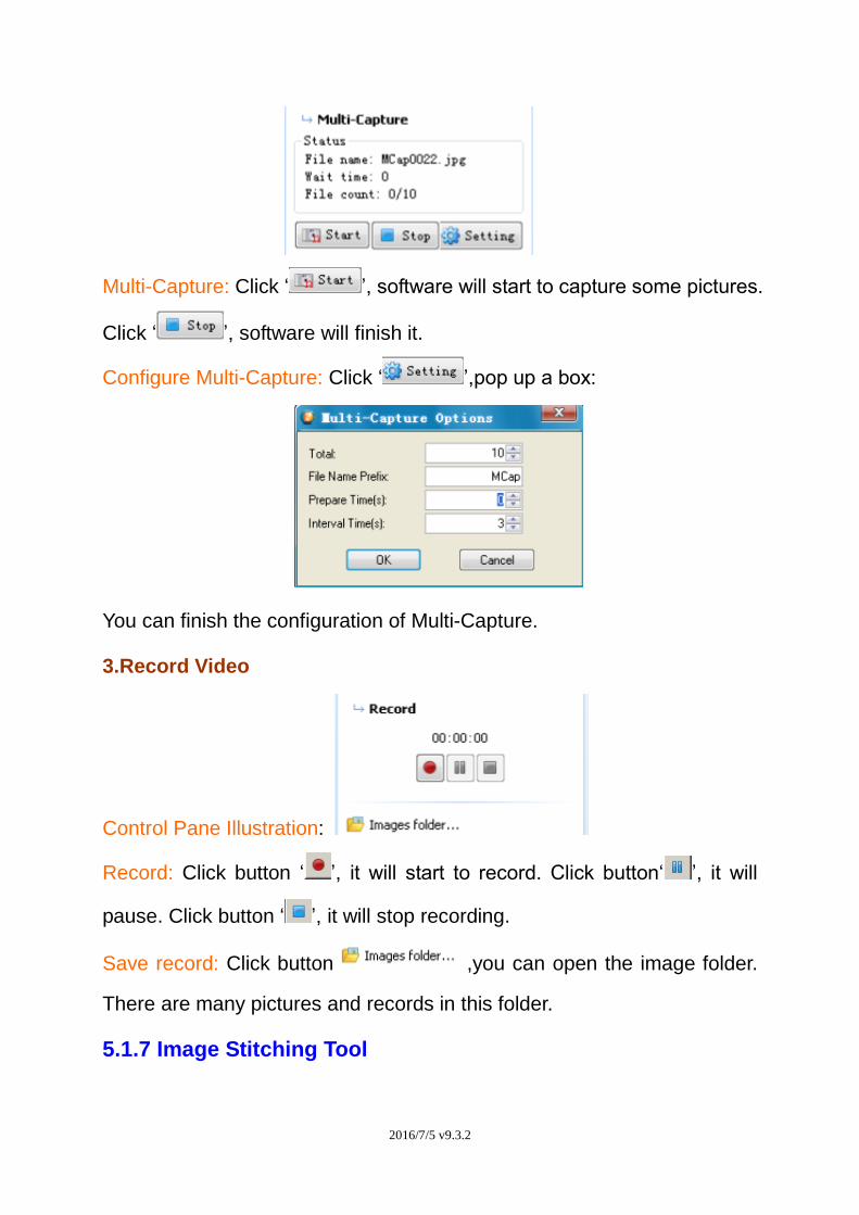
2.Multi-Capture
Control Pane Illustration:
2016/7/5 v9.3.2
Multi-Capture: Click ‘ ’, software will start to capture some pictures.
Click ‘ ’, software will finish it.
Configure Multi-Capture: Click ‘ ’,pop up a box:
You can finish the configuration of Multi-Capture.
3.Record Video
Control Pane Illustration:
Record: Click button ‘ ’, it will start to record. Click button‘ ’, it will
pause. Click button ‘ ’, it will stop recording.
Save record: Click button ,you can open the image folder.
There are many pictures and records in this folder.
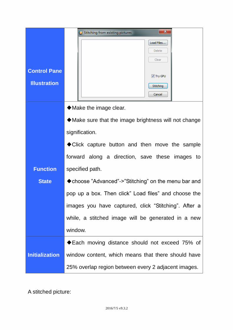
5.1.7 Image Stitching Tool
2016/7/5 v9.3.2
Control Pane
Illustration
Function
State
◆Make the image clear.
◆Make sure that the image brightness will not change
signification.
◆Click capture button and then move the sample
forward along a direction, save these images to
specified path.
◆choose ”Advanced”->”Stitching” on the menu bar and
pop up a box. Then click” Load files” and choose the
images you have captured, click “Stitching”. After a
while, a stitched image will be generated in a new
window.
Initialization
◆Each moving distance should not exceed 75% of
window content, which means that there should have
25% overlap region between every 2 adjacent images.
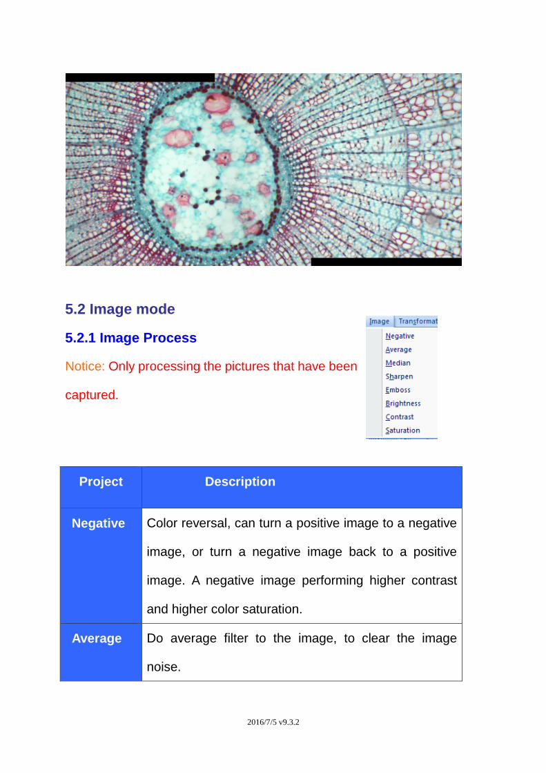
A stitched picture:
2016/7/5 v9.3.2
5.2 Image mode
5.2.1 Image Process
Notice: Only processing the pictures that have been
captured.
Project Description
Negative Color reversal, can turn a positive image to a negative
image, or turn a negative image back to a positive
image. A negative image performing higher contrast
and higher color saturation.
Average Do average filter to the image, to clear the image
noise.
2016/7/5 v9.3.2
Median
Do mediate filter to the image, the median filter is
much better at preserving sharp edges than the
average filter.
Sharpen
All digital photographs lose a certain amount of
sharpness. That means that most photographs will
look a bit blurred and their details won’t be as
prominent. Basically, sharpening makes the edges of a
photographed object appear most distinct.
Emboss
The Emboss filter makes a selection appear raised or
stamped by suppressing the color within the selection
and tracing its edges with black.
Brightness Change the brightness of the image.
Contrast Change the contrast of the image.
Saturation Change the saturation of the image.
2016/7/5 v9.3.2
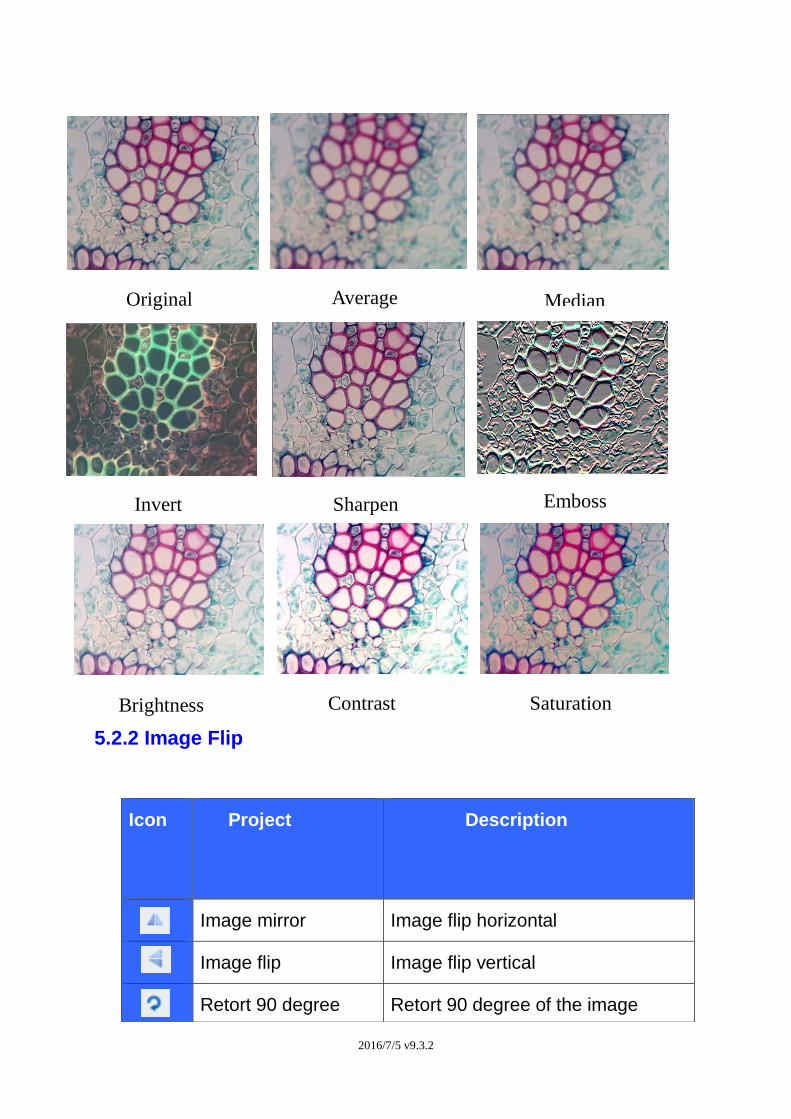
5.2.2 Image Flip
Icon Project Description
Image mirror Image flip horizontal
Image flip Image flip vertical
Retort 90 degree Retort 90 degree of the image
Invert Sharpen Emboss
Brightness Contrast Saturation
Original
oOrigina
l
Median Average
2016/7/5 v9.3.2
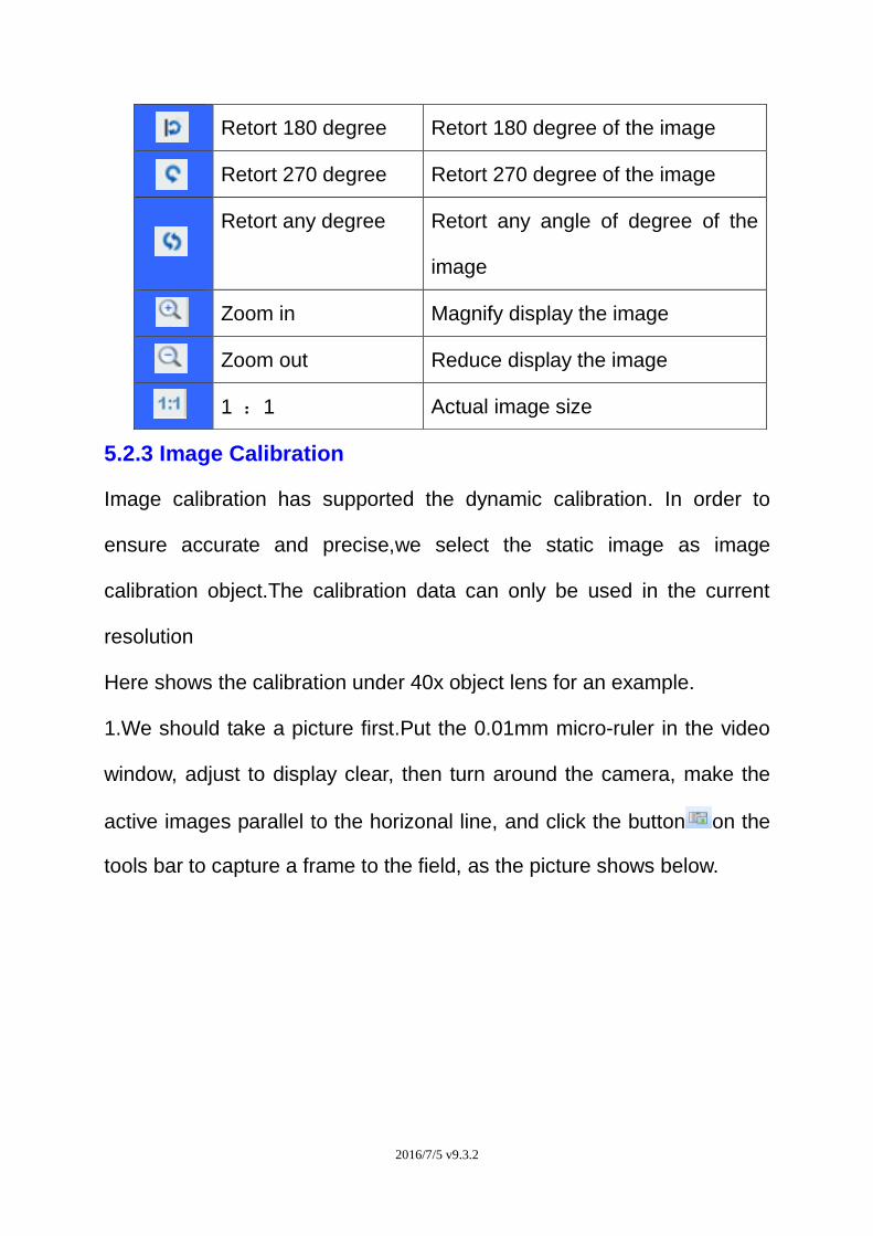
5.2.3 Image Calibration
Image calibration has supported the dynamic calibration. In order to
ensure accurate and precise,we select the static image as image
calibration object.The calibration data can only be used in the current
resolution
Here shows the calibration under 40x object lens for an example.
1.We should take a picture first.Put the 0.01mm micro-ruler in the video
window, adjust to display clear, then turn around the camera, make the
active images parallel to the horizonal line, and click the button on the
tools bar to capture a frame to the field, as the picture shows below.
Retort 180 degree Retort 180 degree of the image
Retort 270 degree Retort 270 degree of the image
Retort any degree Retort any angle of degree of the
image
Zoom in Magnify display the image
Zoom out Reduce display the image
1 :1 Actual image size
2016/7/5 v9.3.2
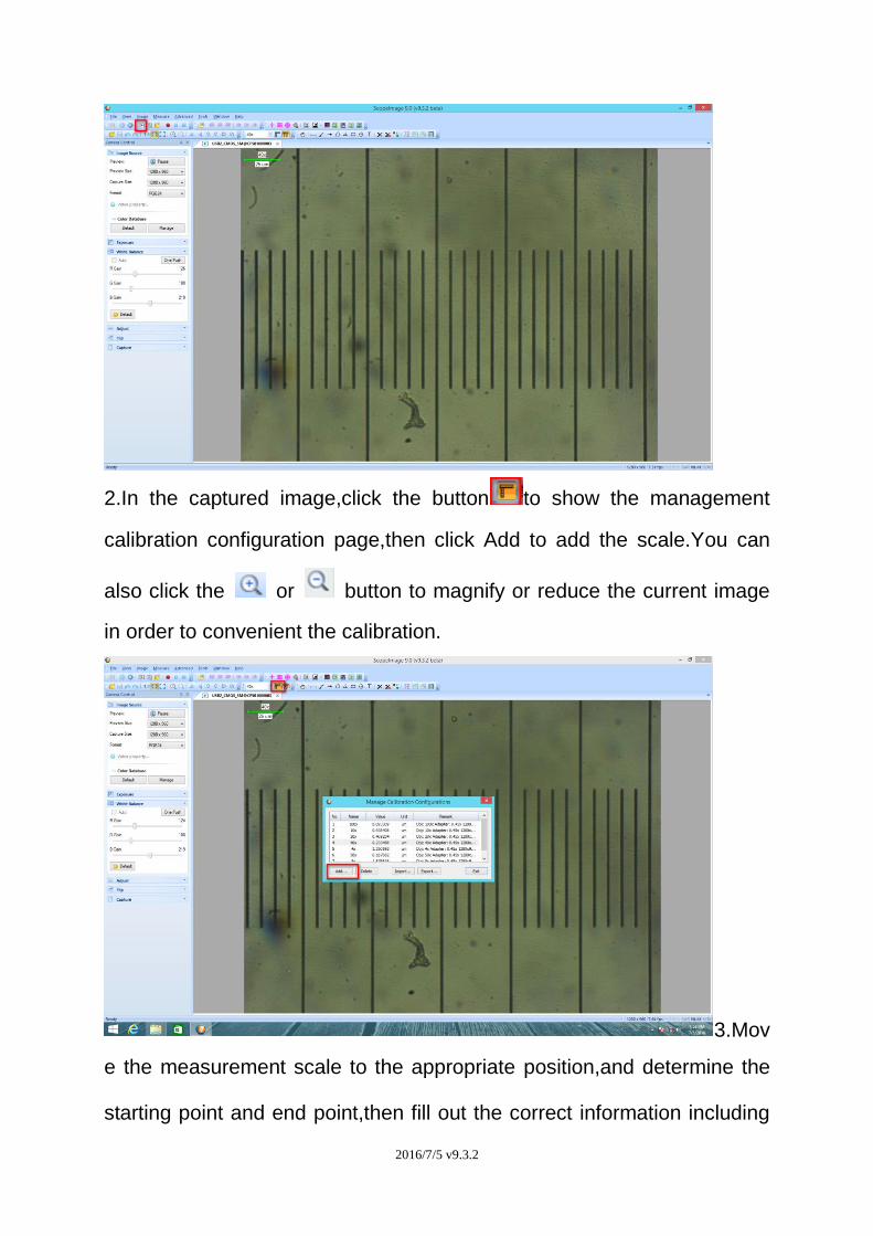
2.In the captured image,click the button to show the management
calibration configuration page,then click Add to add the scale.You can
also click the or button to magnify or reduce the current image
in order to convenient the calibration.
3.Mov
e the measurement scale to the appropriate position,and determine the
starting point and end point,then fill out the correct information including
2016/7/5 v9.3.2
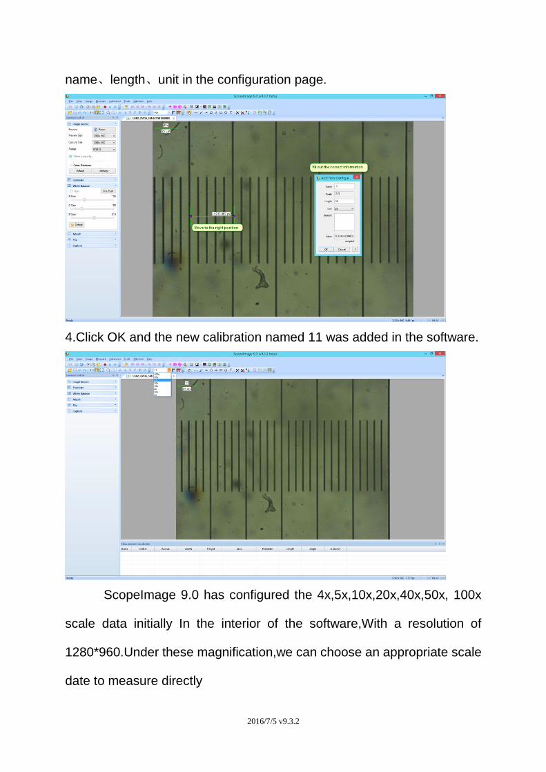
name、length、unit in the configuration page.
4.Click OK and the new calibration named 11 was added in the software.
ScopeImage 9.0 has configured the 4x,5x,10x,20x,40x,50x, 100x
scale data initially In the interior of the software,With a resolution of
1280*960.Under these magnification,we can choose an appropriate scale
date to measure directly
2016/7/5 v9.3.2
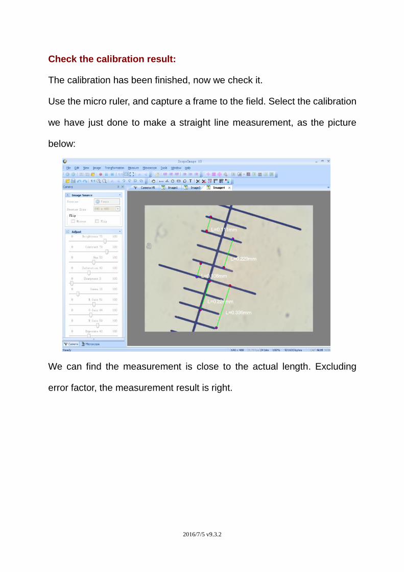
Check the calibration result:
The calibration has been finished, now we check it.
Use the micro ruler, and capture a frame to the field. Select the calibration
we have just done to make a straight line measurement, as the picture
below:
We can find the measurement is close to the actual length. Excluding
error factor, the measurement result is right.
2016/7/5 v9.3.2
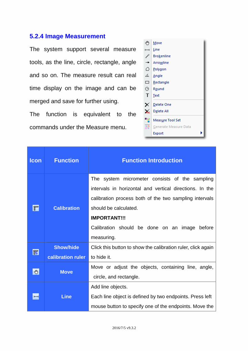
5.2.4 Image Measurement
The system support several measure
tools, as the line, circle, rectangle, angle
and so on. The measure result can real
time display on the image and can be
merged and save for further using.
The function is equivalent to the
commands under the Measure menu.
Icon Function Function Introduction
Calibration
The system micrometer consists of the sampling
intervals in horizontal and vertical directions. In the
calibration process both of the two sampling intervals
should be calculated.
IMPORTANT!!!
Calibration should be done on an image before
measuring.
Show/hide
calibration ruler
Click this button to show the calibration ruler, click again
to hide it.
Move Move or adjust the objects, containing line, angle,
circle, and rectangle.
Line
Add line objects.
Each line object is defined by two endpoints. Press left
mouse button to specify one of the endpoints. Move the
2016/7/5 v9.3.2
mouse to the other endpoint, while keeping the left
mouse button pressed, to draw the line. Release the left
mouse button to complete the line drawing.
The above procedure may be repeated to create more
lines.
A line object has two resizing handles, located at the
two endpoints。
The length of the line will appear over the image at the
same time.
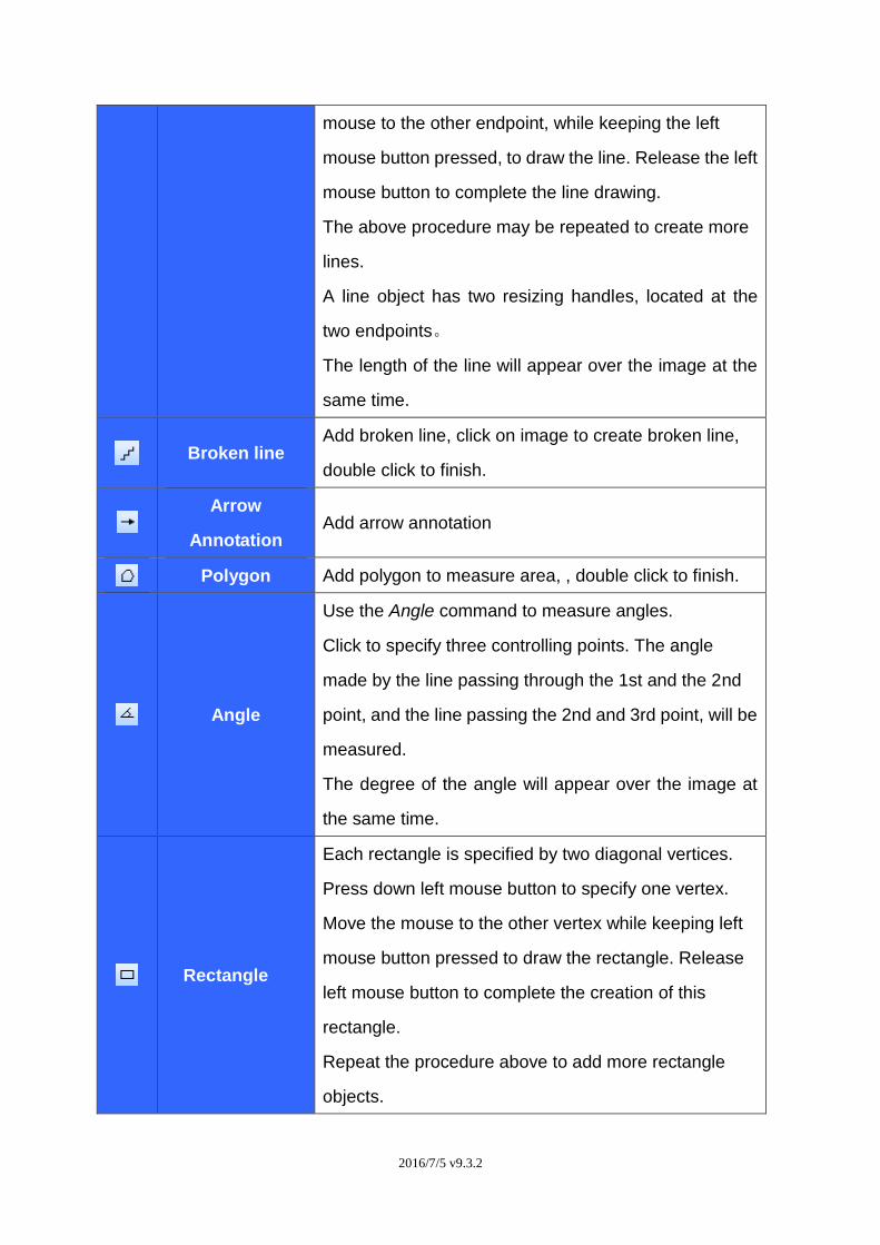
Broken line Add broken line, click on image to create broken line,
double click to finish.
Arrow
Annotation Add arrow annotation
Polygon Add polygon to measure area, , double click to finish.
Angle
Use the Angle command to measure angles.
Click to specify three controlling points. The angle
made by the line passing through the 1st and the 2nd
point, and the line passing the 2nd and 3rd point, will be
measured.
The degree of the angle will appear over the image at
the same time.
Rectangle
Each rectangle is specified by two diagonal vertices.
Press down left mouse button to specify one vertex.
Move the mouse to the other vertex while keeping left
mouse button pressed to draw the rectangle. Release
left mouse button to complete the creation of this
rectangle.
Repeat the procedure above to add more rectangle
objects.
2016/7/5 v9.3.2
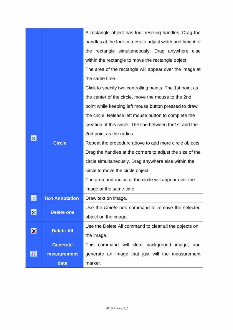
A rectangle object has four resizing handles. Drag the
handles at the four corners to adjust width and height of
the rectangle simultaneously. Drag anywhere else
within the rectangle to move the rectangle object.
The area of the rectangle will appear over the image at
the same time.
Circle
Click to specify two controlling points. The 1st point as
the center of the circle, move the mouse to the 2nd
point while keeping left mouse button pressed to draw
the circle. Release left mouse button to complete the
creation of this circle. The line between the1st and the
2nd point as the radius.
Repeat the procedure above to add more circle objects.
Drag the handles at the corners to adjust the size of the
circle simultaneously. Drag anywhere else within the
circle to move the circle object.
The area and radius of the circle will appear over the
image at the same time.
Text Annotation Draw text on image.
Delete one Use the Delete one command to remove the selected
object on the image.
Delete All Use the Delete All command to clear all the objects on
the image.
Generate
measurement
data
This command will clear background image, and
generate an image that just will the measurement
marker.
2016/7/5 v9.3.2
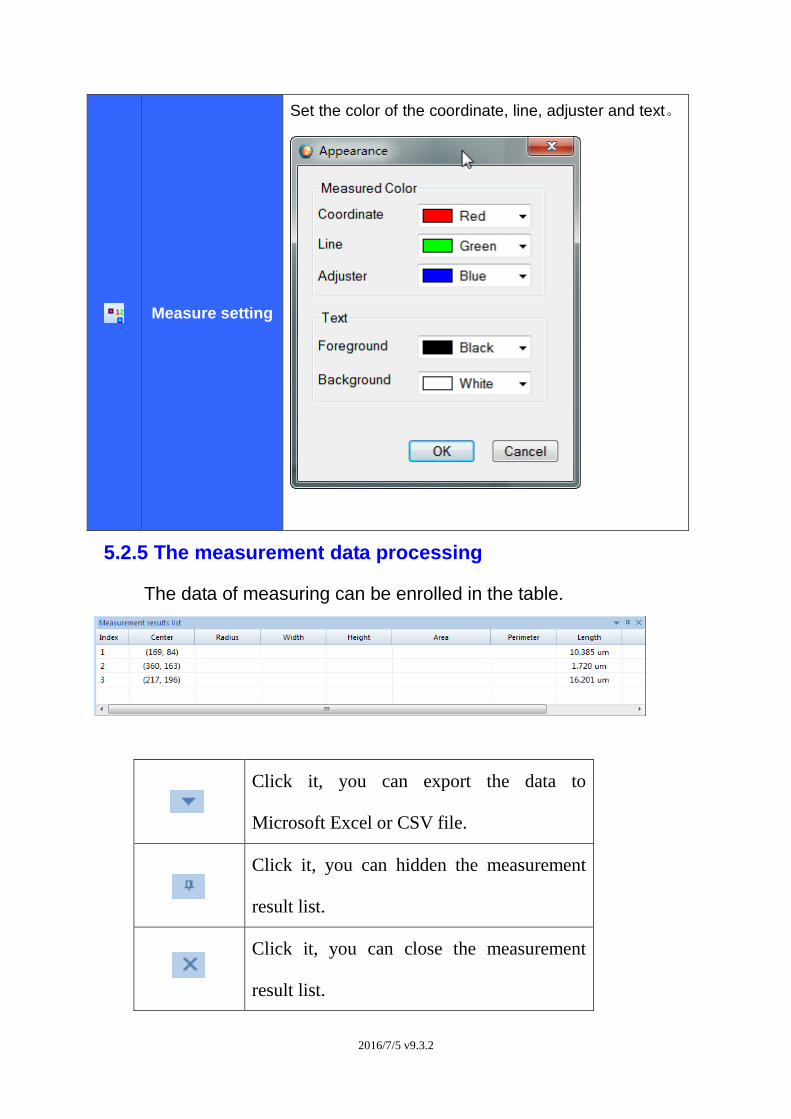
Measure setting
Set the color of the coordinate, line, adjuster and text。
5.2.5 The measurement data processing
The data of measuring can be enrolled in the table.
Click it, you can export the data to
Microsoft Excel or CSV file.
Click it, you can hidden the measurement
result list.
Click it, you can close the measurement
result list.
2016/7/5 v9.3.2
6.TroubleShooting
6.1 Attention
1. Can not record or record error. Please check whether you have
installed the ‘Video Codec’
in the CD.
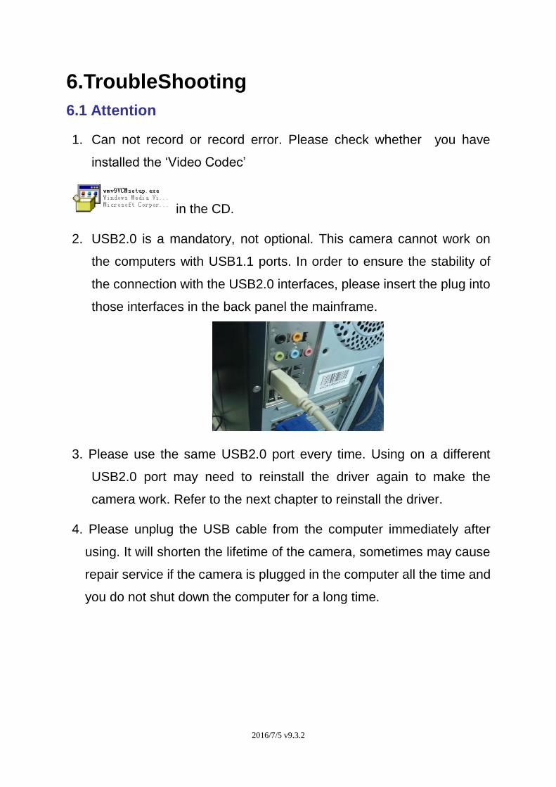
2. USB2.0 is a mandatory, not optional. This camera cannot work on
the computers with USB1.1 ports. In order to ensure the stability of
the connection with the USB2.0 interfaces, please insert the plug into
those interfaces in the back panel the mainframe.
3. Please use the same USB2.0 port every time. Using on a different
USB2.0 port may need to reinstall the driver again to make the
camera work. Refer to the next chapter to reinstall the driver.
4. Please unplug the USB cable from the computer immediately after
using. It will shorten the lifetime of the camera, sometimes may cause
repair service if the camera is plugged in the computer all the time and
you do not shut down the computer for a long time.


