Embed Size (px)
Citation preview

B 3. 1 REACTIVITY CONTROL SYSTEMS
B 3. 1. 1 SHUTDOWN MARGIN (SDM)
BASES
SDM8 3.1.1
8 i 1.6-l
BACKGROUND According to GDC 26 (Ref. 1). the reactivity control systems must beredundant and capable of holding the reactor core subcritical when shutdown under cold conditions. Maintenance of the SDM ensures thatpostulated reactivity events will not damage the fuel.SDM requirements provide sufficient reactivity margin to ensure thatacceptable fuel design limits will not be exceeded for'ormal shutdownand anticipated operational occurrences (AOOs). As such. the SDM definesthe degree of subcriticality that would be obtained irmediately followingthe insertion of all shutdown and control rods, assuming that the singlerod cluster assembly of highest reactivity worth is fully withdrawn.
The system design requires that two independent reactivity controlsystems be provided. and that one of these systems be capable ofmaintaining the core subcritical under cold conditions. Theserequirements are provided by the use of movable control assemblies andsoluble boric acid in the Reactor Coolant System (RCS). The Rod ControlRed System can compensate for the reactivity effects of the fue7 andwater temperature changes accompanying power level changes over the rangefrom full load to no load. In addition, the Ro'd Control Red System,together with the boration system, provides the "SDM during poweroperation and is capable of making the core subcritical rapidly enough to
revent exceeding acceptable fuel damage limits, assuming that the rod of'2. i"i i f11 ih
Chem'$'ca'.I.:;-'.:i'nd':NNume„":.Coiiti'07: System can RnViol/the=soliibli"..boronconcenti.,itic',':.":.to compensat'e for fuel deplet't'on dOring op'strati'on hnd allxen'on"'b'urnoot 'r'eactivity changes and can maintain the reactor subcriticalunder cold conditions.
During Pov(er operation„ S95 cotgro3..is ..egsured„ assuming'>that''''„";coreieactiviti4>'s,::.'.:withiii5'fesiit4gi@it:;;."::Of::,'.',LC9,,'3g'.'?:".;. by op'er'a6iig with"'the'shutdown 1)anks fuT'1y'"w1'tiara'wn 'an8 the control banks within the limits ofLCO 3.1.76, "Control Bank Insertion Limits." When the unit is in theshutdown and refueling modes, the SDM requirements are met by means ofadjustments to the RCS boron concentration
APPLICABLESAFETY ANALYSIS
The 'minimum required SDM is assumed as an initial conditionin safety analyses. The safety analysis ref-S establishes an SDM thatensures specified acceptable fuel design limits are not exceeded fornormal operation and AOOs, with the,assumption of,the highest worth rodstuck,out on scram „.Farl~5'9:;".%he.::.pijpia'ri~afet'<gina„Iysis.'-.',''t'hit.':,:.reliesos'''the,:-';:50H::,:Ilail&'::."::il:-:,':.:th8";.':bOron,';5k<],upon"„iria~818':;:
q808<'30 ~ 0500027~ q80805PDR AD pDR
l
P
DCPP Mark-up of NUREG-1431, Rev. 1 Bases B 3.1-1


BASES
SDMB 3.1.1
APPLICABLESAFETY ANALYSIS(continued)
aR@~,FQR QRefs. 2 and":::3),,;":::.:;"'pri;",addftTon~to.;;%he,.";.",Ii'milking';:HSLB.ti';ancient'-:,'~'the'=SDN:g.;equ'creme'it'=::i'::,"Hso;wed".::::SA)the.",a'nalys'es:."'i'''::.the
I'Y~,",:::„'l[fiifdiie!ti:"cri"".bo'i'o'riFdilg'15ii:.:
c~s,;:."'"..,":.'Start<of"'in>ina&kve macfoi~coo,l3nt„:::, pump~{RCP),'.«:;:;.a'nd
d-."'.':": «"-"('Rod"%gec@NnMA4YsviYiv'.iAAv~Ml...avNvrA$>livRh
The increased steam flow resulting from a pipe break in the main steamsystem causes an increased energy removal from the affected steamenerator (SG) ~ and consequently the RCS. This results in a reduction ofhe reactor coolant temperature. The resultant coolant shrinkage causes
a reduction in pressure. In the presence of a negative moderatortemperature coefficient, this cooldown causes an increase in corereactivity. As RCS temperature decreases, the severity of an HSLBdecreases until the MODE 5 value is reached. The most limiting MSLB,with respect to potential fuel damage before a reactor trip occurs's aguillotine break pf. a,,maiq steaII) .l,ice, inside containment initiated at theend of core life judith)RC5..:".,7@-l'',equal'jto,.„:,'5'47.'.F,;. The positive reactivityaddition from the™iiioder'ato'r'Re'mperat'ur'e decrease will terminate when theaffected SG boils dry, thus terminating RCS heat removal and cooldown.Following the HSLB. a post trip return to power may occur: however, nofuel damage occurs as a result of the post trip return to power, andTHERMAL POWER does not violate the Safety Limit (SL) requirement ofSL 2.1.1.
graf ig -DPf
DCPP Hark-up of NUREG-1431, Rev. 1 Bases B 3.1-2


BASES
SDMB 3.1.1
APPLICABLESAFETY ANALYSIS
(continued)
In the boron dilution analysis. the required SDM defines the reactivitydifference between an initial subcritical boron concentration and thecorresponding critical boron concentration. These values. in conjunctionwith the configuration of the RCS and the assumed dilution flow rate.directly affect the results of the analysis. This event is most limitingat the beginning of core life, when critical boron concentrations arehighest.
Depending on the system initial conditions and reactivity insertion rate.the uncontrolled rod withdrawal transient is terminated by either a highpower level trip or a high pressurizer pressure trip.. In all cases.power level. RCS pressure, linear heat rate, and the DNBR do not exceedallowable limits.The ejection of a control rod rapidly adds reactivity to the reactorcore. causing both the core power level and heat flux to increase withcorresponding increases in reactor coolant temperatures and pressure.The ejection of a rod also produces a time dependent redistributiocore power. r edlinc p,],g
e tart i in MOD or DE 3t r o a in can o resu in a 'co water"cri ica i y. even i e maximum ifference in temperature exists betweenthe SG and the core. The maximum positive reactivity addition that canoccur due to an inadvertent start is less than half the minimum required
(Continued)
DCPP Mark-up of NUREG-1431. Rev. 1 Bases 89,I-26.


BASES
SDMB 3.1.1
APPLICABLESAFETY ANALYSIS
(continued)
SDM. Startup of an idle RCP cannot, therefore, produce a return to powerfrom the hot standby condition. g 3.I-QSDM satisfies Criterion 2 of ~ 10CFRSO;.36Lc)'(2)(u'):. Even though it isnot directly observed from the control"srouri; SDM is considered an initialcondition process variable because it is periodically monitored to ensurethat the unit is operating within the bounds of accident analysisassumption.
LCO SDM is a core design condition that can be ensured during operationthrough control rol positioning (control and shutdown banks) and throughthe soluble boron concentration.
The MSLB (Ref. 2) Md the boron dilution (Ref. 3) accidents are e moslimiting analyses hat establish the SDM value ot the LCO. For MSLBaccidents'f the LCO is violated. there is a potential to exceed theDNBR limit and to exceed 10 CFR 100, "Reactor Site Criteria." limits(Ref. 4). For the boron dilution accident, if the LCO is violated. theminimum required time assumed„for,.operator,actjop.,to termi,na.ate,di.lution,.may no longer be eeeaaembae se5fxiie'nb. The!'reqo'iredi'sBHNi's,esp'ebi'rie'e'!in
APPLICABILITY
ACTIONS
In MODE 2 with k,« < 1.0 and in MODES 3, aqd 4,j~argf)5 the SDM requirementsare applicable to provide sufficient negative rea'ctlVity to meet thepi «1 «g 1 di ~00-l~ In MODE 6.the shutdown reactivity requirements are given in 20 3.9.1. 'BoronConcentration." In MODES 1 and 2, SDM is ensured by complyin
3 5 "Sh ank Insertion Limits," and LCO 3.1.74, Con rolBan nse ion amass
eS i.c-/A.1
If the SDM requirements are not met, boration must be initiated promptly.A Completion Time of 15 minutes is adequate for an operator to correctlyalign and start the required systems and components. It is assumed thatboration will be continued until the SDM requirements are met.
In the determination of the required combination of boration flow rateand boron concentration. there is no unique requirement that must besatisfied. Since it is imperative to raise the boron concentration ofthe RCS as soon as possible, the borated water source should be a highlyconcentrated solution, such as that normally found in the boric acidstorage tank, or the refueling water storage tank. The operator shouldborate with the best source available for the plant conditions.
DCPP Mark-up of NUREG-1431, Rev. 1 Bases 8 3.1-3


BASES
SDM
B 3.1.1
SURVEILLANCEREQUIREMENTS
SR 3.1.1.1
In MODES 1 and . SDM is verified by observing that the requirements ofLCO 3. 1.65 and CO 3. 1.7$ are met. In the event that a rod is own tobe untrippabl , however, SDM
(Continued)
DCPP Mark-up of NUREG-1431, Rev. 1 Bases 89/-A )9 ~./- EL)


Core ReactivityB Q-.4-.3 3'.ll'.;"'2
APPLICABLESAFETY ANALYSIS
(continued)
against, available test data, operating plant data. and analyticalbenchmarks. Monitoring r '
balance additionally ensures that thenuclear methods provide continued an accurate representation of e c ereactivity. bC 9.1- ED
Design calculations are performed for each fuel cycle for the purpose ofpredetermining reactivity behavior and the RCS boron concentrationrequirements for reactivity control during fuel depletion as well asproviding inputs to the safety analysis.
The comparison between measured and predicted initial core reactivityprovides a validation of the calculational models used to predict corereactivity. If the measured and predicted RCS boron concentrations foridentical core conditions at beginning of cycle (BOC) do not agree, thenthe assumptions used in the reload cycle design analysis or thecalculational models used to predict soluble boron requirements may notbe accurate. If reasonable agreement between measured and predicted corereactivity exists at BOC, then the prediction may be normalized to themeasured boron concentration. Thereafter, any significant deviations inthe measured boron concentration from the predicted boron letdown curvethat develop during fuel depletion may be an indication that. thecalculational mode1 is not adequate for core burnups beyond BOC. or thatan unexpected change in core conditions has occurred.
fedl)nC CPS I,<.IThe normalization of predicted RCS c entra n tvalue when eeme necessar s aperformed after reaching RTP follow> s ar up outage.with the control rods in their normal positions for power operation. Thenormalization is performed at BOC conditions so that core reactivityrelative to predicted values can be continually monitored and evaluatedas core conditions change during the cycle
Core reactivity satisfies Criterion 2 of 1OCREOXGSCc)N2)'(i1i)..
LCO Long term core reactivity behavior is a result of the core physics designand cannot be easily altered once the core design is fixed. Duringoperation. therefore, the LCO can only be ensured through measurement andtracking. and appropriate actions taken as necessary. Large differencesbetween actual and predicted core reactivity may indicate that theassumptions of the l3BA and transient analyses are no longer valid, orthat the uncertainties in the Nuclear Design Methodology are larger thanexpected. A limit on the reactivity balance of + 1X hk/k has beenestablished based on engineering judgment. A 1X deviation in reactivityfrom that predicted is larger than expected for normal operation andshould therefore be evaluated.
(Continued)
DCPP Mark-up of NUREG-1431, Rev. 1 Bases B 3.1-7


BASES
MTCB Q-.k-4 3,"'1:".".'3
A Y f
AP PLICA
(Ref. 2
(Continued)
~ 9'./-EDBLE The consequences of accidents that cause core overheating mus e
NALYSIS ~evaluated when the is positive. Such accidents include the rodContinued)I 'awal transient from either zero r RTP. loss of main feedwaterf ow. an oss o orce reac or coo ant flow. The consequences of
accidents that cause core overcooling must be evaluated when the MTCis negative. Such accidents include sudden feedwater flow increaseand sudden decrease in feedwater temperature.
In order to ensure a bounding accident analysis. the MTC.is assumed tobe its most limiting value for the analysis conditions appropriate toeach accident. The bounding value is determined by considering roddedand unrodded conditions. whether the reactor is at full or zero power,and whether it is the BOC or EOC life. The most conservativecombination appropriate to the accident is then used for the analysis(Ref. 2).
HTC values are bounded in reload safety evaluations assuming steadystate conditions at BOC and EOC. An EOC measurement is conducted atconditions w the RCS boron concen ration reach a oron «~~i~c.
en ra s n en 300 ppm a an e u» rium. all rods out'on
s son. e measured value ma e ex rapo a e o pro ec eEOC value, in order to confirm reload design predictions.
Theisost': ahioe,:.im!~val~oe,,egoga,len'0~A~'Khehsoseo':,~give:,"soderha~hordeisiti,'.,'coe,;f1~i nt'b(NX>,:,',ie8~obtaknedhhg~int'remental.",lg:.:.'coij:eCi:iWthikr .""GsefhiiXtfe:,FEAR>anil st>tgmtIrinN.'~~rxt~r@'lconditions5The'se,:.cor,;wctu'eis"-".j'ftvelv'e'd::-„".-(k)gsi':;;:convert'io'n':."'of/the'~:K6sedglijgheFSARj'accidertt''.,analyses'/to:::,".its':.':;eefus'valent'<%9~~bis&i6rgt&'!rateeof:Chancre".;:pf,:.,:.mOderitoor,';,beni'ityi4th~t'emp8rittir84t;--'.'RATgD'hTHERMAL'.;PQHERceidvtions'.Xandg'(g3i,",addirig,.magic,:"Xogthis!::val'ue'to.',.'acceint-'Xoi".th';lawe'standi'ffere(iceX$ n.;."NC.',ob'ser.;,v'ed'.;:betweerr~jn',',"KC "".;51jlgi;ods'''";Mith'drag/pA'KD":~THERMAL'~;,:PQMER;;";:can'diff''„".i'd,.-'aj:<envy],opi~wf.„.;those'„most:.,::".adv'eirei:eiidltiojsao fb~deritor".temperature)hand-'j'r'essurezeods~lis'cited,:",totheir".'"lrisei',tjon':'."-.;liiiiits<~axfal> '-igsk~m::~~and~uenejMoncentratioqth'it:;-';car'nhoccojjln,'jitormal, Cperatlon","withe'nXFechiiicN%554cf ficatliohIT~m'its~hinadÃleadkto';a~::s49o'nl:fi'cantlyy~morem'egagvegEGC> Clat:,.RATED„3HERHALs."-.PNER~Y~„TlieSi..'lCOr'ieCtiOiiaib~anSforhmed'«:the."..MOt.'-::~balue)iiSed~iathe,';FSAR".:zccideiitganjl jse('",'Onto.".,thegliimiting'ROC '.fffG~vNue'..~":,':.'Th'.''.800" pjii'":survei"..Ihlsancegl;imit';',NK~v'a lue'i.@pres'sents~a'~'conseriva&ie~va1ue..:(kith,';@firectsorIs~for,:.,";Krnusp".':~ad':::;:sÃiibleg&ron)~sat~ga,"jorejcoindit;'fan,';of.800)'ppm~3', ugly'.,'i'ul.„'b'OriOn!i'COACeitra'tiej',::Ref.,":,i:Sh>'Oebtiined >5y','':adding'<aiihiieeaiihei fOri%;:biirrihnra'ndiiiAhlAeghnerOniOOnoeiioraoiei'idiiingesS.".:tO'::She"'isilli:tingÃgggsNK'iVBilia!
DCPP Mark-up of NUREG-1431, Rev. 1 Bases B 3.1-11


BASES
HTCB Q-.k-4 3"'9',"„3
QP.I. Cj- J
b3. The Surveillance limit for RTP boron concentrat f 6 isconservative. If the measured HTC at 60 ppm is ss n a ithan the 60 ppm Surveillance limit. the EDC limit wi no eexceeded because of the gradual manner in which HTC changes withcore burn .
bc%-EDREFERENCES 1.
2.
3.
10 CFR 50, Appendix A, GDC 11.
FSAR. Chapter 2'5.
WCAP-9273-A . Westinghouse Reload Safety EvaluationHethodology," July 1985.
DCPP Hark-up of NUREG-1431, Rev. 1 Bases $ 9 I-~>~r
g g,l-EO


BASES
Rod Group Alignment LimitsB Q-.k-S O'P,4
BACKGROUNDposition (continued)
roup all receive the same signal to move and should. therefore, alle at the same indicated by the group step counter for that group.
The Bank Demand Position Indication System is considered highlyprecise (+ 1 step or + Vs inch). If a rod does not move one step foreach demand pulse, the step counter will still count the pulse aincorrectly reflect the position of the rod. <S.i.~-lThe DRPI System provides a highly accurate indication of actualcontrol rod positions but at a lower precision than the step counters.This system is based on inductive analog signals from a series ofoi l s s aced al low tub To increase the.reliabilit of the
sys em, e n uc sve cos s are onnected alternately to data system Aor B. Thus, if one data system fails, the DRPI will go on halfaccuracy.
APPLICABLESAFETY ANALYSIS
afe,-ares;,, The';:,DRPT:,",sjsfeiii,;,is=:: ca jab] e.':c'f:,',:.'ec'sitar>'iie;: riid„.'posi~efi>nSTiChicsea Tace'tsV Q~'2 >acpe :s:s:. ieti'h:,:ieTther'::,'!fiick,:I~a'ccTTrecy! cr.;,-:half:"":::aceiiraCT=-
Control rod misalignment accidents are analyzed in the safety analysis(Ref. 3). The acceptance criteria for addressing rod inoperability ormisalignment are that:a. There be no violations of:
1. Specified acceptable fuel design limits. or
2. Reactor Coolant System (RCS) pressure boundary integrity:and
b. The core remains subcritical after accident transients.Two types of misalignment are distinguished. During movement of acontrol or shutdown rod group, one rod may stop mov>ng, while theother rods in the group continue. This condition may cause excessivepower peaking. The second type of misalignment occurs if one rodfails to insert upon a reactor trip and remains stuck fully withdrawn.This condition requires an evaluation to determine that sufficientreactivity worth is held in the rods to meet the SDM requirement. withthe maximum worth rod stuck fully withdrawn.
(Continued)
DCPP Mark-up of NUREG-1431, Rev. 1 Bases B 3. 1-15


BASES
Rod Group Alignment LimitsB Q-.k-& 3"."1".".'"4
APPLICABILITY
ACTIONS
lant. In MODES 3. 4. 5. and.,6 ..the..al, hami do not apply 3.I.ecause the control rods are,'jacal'.;4".' y inser e and the rea
is shut down and not producing-ftssi'on . n e shutdown MODES,the OPERABILITY of the shutdown and con rol rods has the potential toaffect the required SDM. but this effect can be compensated for by anincrease in the boron concentration of the RCS. See LCO 3,1. 1,",SHUTDOWN MARGIN (SDM)~ ~@M." for SDM in MODES 2,'withk:,-,«1.0, 3. 4. and 5 and L55 3.9.1. "Boron Concentration." for boronconcentration requirements during refuelin~g
A.l, 1 and A.1.2 fPd IKCum c ~~le Q Ne(-l5
When one or more ro s are no rab e ~ ther aossibility that the require may e a verse y a ected. Underhese conditions. it is important to determine the SDM. and if it is
less than the required value, initiate boration until the required SDMis recovered. The Completion Time of 1 hour is adequate fordetermining SDM and, if necessary, for initiating emergency borationand restoring SDM.
lfituPen;;;,inngoerbabl~::.,rOlFS)"':;,,:;,lb':.:ACT1'gg:::.gruvVfdee::,:e'er'..-,uuerffj~at'<On;:OfSONi".::.;this':,.~s",::,inst.'.;"s1mp'jy~accomp'f'bshed'.:;bj:,: v~ijfyiiig-,':rod,';:unsex'tion,tl,::iiiiftss;:,"aieIiijiet'::'..':,:.:,',::Additea'iialg j.';:-„':actions'::..:c'o9ld''',""jricludtegcalculat'0'on';:=of,the,'::curr,,'sar';SEMI'aiid,:hoi';at1@i;-:;:t0'.",gieet:':::1::;imits~iiiecif $ ed.'...„'::vari':.thee".::CKRssor'roc
The requirements on RCCA OPE ILITY and alignm nt 'are applicable inMODES 1 and 2 because these a the only MODES n which neutron (orfission) power is generated. d the OPERABILI (i.e.. triopability)and alignment of rods have th potential to aff ct the safety of th
G-I
(Continued)
OCPP Mark-up of NUREG-1431, Rev. 1 Bases 8 9./-l(o4- y 9.I-Eb


BASES
Rod Group Alignment LimitsB Q-.k4 3
ACTION(continued)
g~bn6
vkVAAAWYAWNA"?AAAA CAwwlCAWhV7
A,",-',radon:,;-',cons fdevedgrijFpa51'e-.:$ f,.'~ft~was„'demonstr'ated;:;OPERABL'E'::dur'mg „the'::,'-;1:a'st:;~rformaiice, of< SR.=.3„':-.3! 4".'2kand."'.met~the'~rodsdrop:.",time:,criteipadill.;!Ag::::.tN&73ilStiip&lgot%8ACB" '" "::-" ~ '- ~~~,„<*
verif on mus t for the absence ofv'f the untrippab e ro s , w erod of maximum wort .
A.2 ~].n4If the no erabl rod(s) cannot be restored to OPERABLE status. theplant mus e rought to a MODE or condition in which the LCOrequirements are not applicable. To achieve this status, the unitmust be brought to at least MODE 3 within 6 hours.
The allowed Completion Time is reasonable, based on operatingexperience, for reaching MODE 3 from full power conditions in anorderly manner and without challenging plant systems.
peed/s n~B.lcy z.>.6-1
When a rod ned. it can usually be moved and is s itrippable i . BL . If the rod can be realigned within theCompletion mme o our, local xenon redistribution during thisshort interval will not be significant. and operation may proceedwithout further restriction.An alternative to realigning a single misaligned RCCA to the groupdemand position is to align the remainder of the group to the positionof the misaligned RCCA. However, this must be done without violatingthe bank sequence. overlap, and insertion limits specified inLCO Q-.4-.6 SQP5, "Shutdown Bank Insertion Limits." and LCO ~Bp;:.".6.. "Control'ank Insertion Limits." The Completion Time of 1 hourgi'v'es'he operator sufficient time to adjust the rod positions in anorderly manner.
8.2. 1.1 and B.2. 1.2
With a misaligned rod. SDM must be verified to be within limit orboration must be initiated to restore SDM to within limit.
(Continued)
DCPP Mark-up of NUREG-1431, Rev. 1 Bases B 3. 1-17


BASES
Rod Group Alignment LimitsB Q-.k-S 3:.2~A
~~(cCi a~i o-I
When Required Actions cannot be completed within their CompletionTime. the unit must be brought to a MODE or Condition in which the LCOrequirements are not aoplicable. To achieve this status. the unitmust be brought to at least MODE 3 within 6 hours. which obviatesconcerns about the development of undesirable xenon or powerdistributions. The allowed Completion Time of 6 hours is reasonable,based on operating experience. for reaching NODE 3 from full powerconditions in an orderly manner and without challenging the plantsystems. ~l:nC
.1.1 and 0.1.2 GB.I.<-I
More„than one-ee4wA rod becoming misaligned from its groudemand position is not expected, and has the potential to reduce S M.There'fore, SDM must be evaluated. One hour allows the operatoradequate time to determine SDM. Restoration of the required SOME ifnecessary. requires increasing the RCS boron concentration to providenegative reactivity. as described in the Bases 0f: LCO 3. 1. 1. Therequired Completion Time of 1 hour for initiati'rig'oration isreasonable. based on the time required for potential xenonredistribution. the low probability of an accident occurring, and thesteps required to
(Continued)
DCPP Hark-up of NUREG-1431. Rev. 1 Bases GSI-/8a- )G3./- 6'Q


BASES
Rod Group Alignment LimitsB Q-.4-.S 3'='1'.,'4
~J/one
e 3.I. ci- I
SR '~4-4 O'Ql:4':.'":2
Verifying each rod is OPERABLE would require that each rod be tripped.However. in MODES 1 and 2. tripping each rod would result in radial oraxial power tilts. or osci llations. Exercising each individual rodevery 92 days provides confidence that all rods continue to beOPERABLE without exceeding the alignment limit. even if they are notregularly tripped. Moving each rocl by 10 steps will not cause radialor axial power tilts. or oscillations, to occur. The 92 day Frequencytakes into consideration other information available to the operatorin the control room and SR Q-. k4-.4 3-"1:,'.4".3;. which is performed morere uent ds to the determina'tion"'of OPERABILITY of„-the rods cX < <->
Be wee r urban equired performances of SR 3-.+AM GY'1<4.;2(determinatson o rod OPE ILITY by movement). if a rod "''"idiscovered to be iamovable, but remains trippabl . the o s isconsidered to be OPERABLE. At any time. if a rod ) is iomovable, adetermination of the trippabi lity (OPERABILITY) o the rod(s) must bemade, and appropriate action taken.
~t~W 3!'I!i i!H A/9./-/S
Verification of rod drop times allows the operator to determine thatthe maximum rod drop time permitted is consistent with the assumed roddrop time used in the safety analysis. Measuring rod drop times priorto reactor criticality. after reactor vessel head removal, ensuresthat the reactor internals and rod drive mechanism will not interferewith rod motion or rod drop time, and that no degradation in thesesystems has occurred that would adversely affect rod motion or droptime. This testing is performed with all RCPs o rating and theaverage moderator temperature a 500'F to simulate a reactor trip underactual conditions.
QB / 4-l
(Continued)
DCPP Mark-up of NUREG-1431, Rev. 1 Bases B3. ( - l9 o. W 3,/-8)


8 3.1 ACTIVITY CONT L SYSTEMS
B . . 3M@ Shutd Bank Inserti n Limits
BASES
Shutdown Bank Insertion LimitsB Q-.4-.6 3"'1~5
~ 7./-ED
cga,i.s-l
ACTIONS(continued)
f Additionally. the requirements ofCO Q-.4-.S 8".;:1':.',,
"o roup Alignment Limits," apply if one or more
shutdown rods"'are not within the required alignment limits.B.l
If the shutdown banks cannot be restored to within their insertionlimits within 2 hours. the unit must be brought to a MODE where theLCO is not applicable. The allowed Completion Time of 6 hours isreasonable, based on operating experience. for reaching the requiredMODE from full power conditions in an orderly manner and withoutchallenging plant systems.
SURVEILLANCEREQUIREMENTS
SR
Verification that the shutdown banks are within their insertion limitsprior to an approach to criticality ensures that when the reactor iscritical, or being taken critical, the shutdown banks will beavailable to shut down the reactor, and the required SDM will bemaintained following a reactor trip. This SR and Frequency ensurethat the shutdown banks are withdrawn before the control banks arewithdrawn during a unit startup.Since the shutdown banks are positioned manually by the control roomoperator, a verification of shutdown bank position at a Frequency of12 hours, after the reactor is taken critical, is adequate to ensurethat they are within their insertion limits. Also, the 12 hourFrequency takes into account other information available in thecontrol room tor the purpose of monitoring the status of shutdownrods.
REFERENCES 1. 10 CFR 50, Appendix A. GDC 10, GDC 26. and GDC 28.
2. 10 CFR 50.46.
3. FSAR. 6La i'.er,':..15-::;::.:',:;Sectfei.JSQ:"'3::28:;:
DCPP Mark-up of NUREG-1431, Rev. 1 Bases B 3.1-23


8 3.1 REACTIVITY CONTROL SYSTEMS
B Q-.k-7 3B.";-".6 Control Bank Insertion Limits
Shutdown Bank Insertion LimitsB Q-.kP 8Q"."';6
BASES
ps.i.g-/Tl i!CUL!II
moved in an overlap'"p'attern. Ov rlap is the distance traveledtogether by two control banks.
Thecon rol banks are used for precise
' contr actor.The positions of the control banks can be con ro e manua or'cally by the Rod Control Sys em. ey are capa e o redone'vity v (compared to borating or diluting).~4in Dc,3. I- 8The powe en y at »n the core must be limited. so..thatthe fuel design criteria are maintained. Together. LCO Q-.4-.6 3'3L'-„''.4,"Rod Group Alignment Limits." LCO 0+4 8::L.':5. "Shutdown Bank
"
Insertion Limits," LCO Q-.k4 BM.'6, "Cont'r'ol"Bank Insertion Limits,"LCO 3.2.3. "AXIAL FLUX DIFFERENCE (AFD) ~
"and LCO 3.2.4 ~ "QUADRANT
POWER TiLT RATIO (QPTR) ~
" provide limits on control componentoperation and on monitored process variables, which ensure that thecore operates within the fuel design criteria.The shutdown and control bank insertion and alignment limits'FD, andQPTR are process variables that together characterize and control thethree dimensional power distribution of the reactor core.Additionally, the control bank insertion limits control the reactivitythat could be added in the event of a rod ejection accidents and theshutdown and control, bank, insertion limits,ensure, the reauired,„SDM ismajgCjj.ned 5ssu@i "KM:;:„:,3M%;:::;,:::.-,"'LorhNeact>:i'it-",":.:".:::";ss)'met:;:for.:-'.";coref~'88<(; 'v.a
Operation within the subject LCO limits will prevent fuel claddingfailures that would breach the primary fission product barrier andrelease fission products to the reactor coolant in the
(Continued)
DCPP Mark-up of NUREG-1431. Rev. 1 Bases 3 9. I-ggn. N ~~, I.E?)


( C
0
I I~
~
I
II 'I
~ ~
I I
I
I
I l 0 ~
0 0
~ ~
I I
~ 0 ~
I o ~ ~
~ s
I I


BASES
Rod Position IndicationB 3-.4-.8 8!'1':-'7.
APPLICABLESAFETY ANALYSIS
LCO
Control and shutdown rod position accuracy is essential during poweroperation. Powerpeaking. ejected rod worth. or SDN limits may beviolated in the event of a Design Basis Accident (Ref. 2). withcontrol or shutdown rods operating outside their limits undetected.Therefore. the acceptance criteria for rod position indication is thatrod positions must be known with sufficient accuracy in order toverify the core is operating within the bank sequence. overlap.design Deaking limits. ejected rod worth. and with minimum SDN.(LCO . . 3„"-1.".':5. "Shutdown Bank Insertion Limits." and LCO ~3Q'.':."6, "Control Bank Insertion Limits"). The rod positions mist alsobe known in order to verify the alignment limits are reserved(LCO Q-. k-S 8"=::1.:"4. "Rod Group Alignment Limits"). odpositions ar"e 'continuously monitored to provide operators withinformation that ensures the plant is operating within the bounds ofthe accident analysis assumptions.
The-ceo~..rod .position indicator channels satisfy Criterion 2 of10CFRSQl36('c)('2)('i j'):. The eenN~rod position indicators monitori~A-'"rod pos'1't'i'on. which is an initial condition of the accident.
, I.c-/LCO 0-. k4 8Q:"::7, specifies that:::t e DRPI System and t', Bank DemanPosition Indi'ca'tion System be OPERABLE for each meit@-rod. For thecent~rod position indicators to be OPERABLE requires meeting the SRof the LCO and the following:
T W I S * =::::: Ct~."11;:,:, W; !IIF:>-',indicates within l2't'ep's'"of'-the g'r'oup"st'e'p"'c'o'utter 'demandosition as. required by LCO Q-.kk BB~ 4. "Rod Group Alignment
@(~ lmits ;8fld
b. The Bank Demand In i stem bee ese in the u yinserted position u y wi rawn os»on or o the DRPISystem. Mdiv~
The 12 step agreement limit between the Bank Demand PositionIndication System and the DRPI System indicates that the Bank DemandPosition Indication System is adequately calibrated, and can be usedfor indication of the measurement of sea~rod bank position.
A,,deviation of less than the allowable limit, driven in LCO Q-. k-63@'::.4. in position indication for a single ro6, ensures highconfidence that the position uncertainty of the corresponding eeaC+Nrod group is within the assumed values used in the analysis (thatspecified ee~Wrod group insertion limits).
(Continued)
DCPP Nark-up of NUREG-1431. Rev. 1 Bases B 3.1-29


Enclosure 2PG8 E Letter DCL 98-107
ADDITIONALINFORMATIONCOVER SHEET
ADDITIONALINFORMATIONNO: Q 3.1-2
REQUEST:
APPLICABILITY: DC, CP
3.1.1 Shutdown Margin (SDM) (Comanche Peak and Diablo Canyon)DOC 01-06-ACTS 3/4.1.1 ApplicabilityITS 3.1.1 Applicability
Comment: According to the Conversion Comparison Table, "MODE 2 with Keff < 1.0"and "MODE 5" are added to the Applicability section of TS 3.1.1 for Comanche Peakand Diablo Canyon. All of the FLOG ITS Sections 3.1.1 have these applicabilityrequirements included in the ITS and not in the CTS. Provide a discussion forComanche Peak and Diablo Canyon explaining/justifying these changes.
FLOG RESPONSE: In the CTS, shutdown margin is controlled via LCO 3.1.1.1 for MODES 1,2, 3 and 4, and LCO 3.1.1.2 for MODE 5. Rod insertion limits are controlled by LCO 3.1.3.5 forshutdown rods, MODES 1 and 2, and LCO 3.1.3.6 for control rods, MODES 1 and 2. When thereactor is critical (MODE 1 and MODE 2 with Keff > 1.0), shutdown margin is assured, via theCTS, by assuring that rod insertion limits are met (see SR 4.1.1.1.16.) When the reactor is riotcritical (MODE 2 with Keff < 1.0, MODE 3, MODE 4 and MODE 5), shutdown margin is assuredby assessing boron concentration, temperature, etc. (see SR 4.1.1.1.1e and 4.1.1.2). The CTSrequirements have been clarified and reorganized such that the rod insertion limits andshutdown margin requirements for MODES 1 and 2 with Keff> 1.0 from CTS 3.1.1.1, 3.1.3.5and 3.1.3.6 are converted to ITS 3.1.5 and 3.1.6. The shutdown margin requirements forMODE 2 with Keff< 1.0, MODE 3, MODE 4, and MODE 5 from CTS 3.1.1.1 and 3.1.1.2 areconverted to ITS 3.1.1. This reorganization does not change requirements but presents them ina more logical manner, and therefore is a purely administrative change.
DOC 1-06-A will be revised to add the following:
"In the ITS format, the SHUTDOWN MARGIN in MODE 1 and MODE 2 with k,„h1.0 iscontrolled through compliance with control rod insertion limits (ITS LCO 3.1.5 and LCO 3.1.6).For those modes or conditions in which compliance with control rod insertions limits is notrequired, the SHUTDOWN IVIARGINis verified in the more traditional manner by considerationof such factors as Reactor Coolant System boron concentration, coolant temperature, xenonand samarium concentrations, etc. Thus, the applicability of CTS 3.1.1.1 is modified by thischange to be applicable to MODE 2 with k,„< 1.0 as well as the current MODES 3 and 4. Thischange is considered to be administrative in nature, because, when the reactor was critical(MODE 1 and MODE 2 with k„>1.0), the SHUTDOWN MARGINwas determined, inaccordance with SR 4.1.1.1.1.b, by verifying compliance with the control rod insertion limits.
In addition, the SHUTDOWN MARGIN requirement, surveillances, and actions are the same foroperation in MODE 5 as for operation in MODES 3 and 4. Therefore, the specifications havebeen combined to include MODE 5 with MODES 3 and 4. The change is considered to be

Enclosure 2PG8E Letter DCL 98-107
administrative in nature, because there is no change in the LCO, ACTIONS, orSURVEILLANCEREQUIREMENTS. See also Change 2-01-A."
ATTACHEDPAGES'ncl.
3A 2

DESCRIPTION OF CHANGES TO TS SECTION 3I4.1(Continued)
CHANGENUMBER
01-05
01-06
01-07
01-08
01-09
01-10
02-01
03-01
03-02
NSHC
LG
LS16
A
LS3
DESCRIPTION
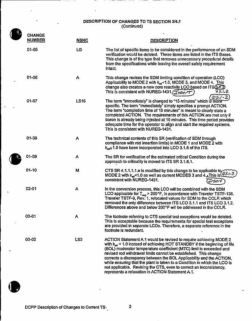
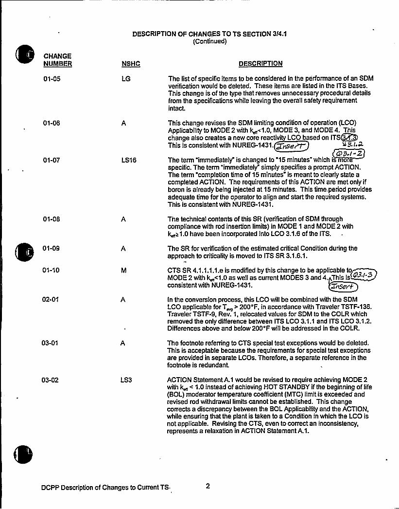
The list of specific items to be considered in the performance of an SDMverification would be deleted. These items are listed in the ITS Bases.This change is of the type that removes unnecessary procedural detailsfrom the specifications while leaving the overall safety requirementintact.
This change revises the SDM limiting condition of operation (LCO)Applicabilityto MODE 2 with k ~1.0, MODE 3, and MODE 4. Thischange also creates a new core reactivi LCO based on ITSThis is consistent with NUREG-1431. ~~~~ 9 p.i.k
cP9-/-2The term "immediately" is changed to "15 minutes" which is mospecific. The term "immediately" simply specifies a prompt ACTION.The term "completion time of 15 minutes" is meant to clearly state acompleted ACTION. The requirements of this ACTION are met only ifboron is already being injected at 15 minutes. This time period providesadequate time for the operator to align and start the required systems.This is consistent with NUREG-1431.
The technical contents of this SR (verification of SDM throughcompliance with rod insertion limits) in MODE 1 and MODE 2 withk ~1.0 have been incorporated into LCO 3.1.6 of the ITS.
The SR for verification of the estimated critical Condition during theapproach to criticality is moved to ITS SR 3.1.6.1.
CTS SR 4.1.1.1.1.e is modified by this change to be applicable toMODE2withk <1.0aswellascurrentMODES3and4. Thisis ~
'onsistentwith NUREG-1431. ZnSeek
In the conversion process, this LCO willbe combined with the SDMLCO applicable for T > 200'F, in accordance with Traveler TSTF-136.Traveler TSTF-9, Rev. 1, relocated values for SDM to the COLR whichremoved the only difference between ITS LCO 3.1.1 and ITS LCO 3.1.2.Differences above and below 200'F willbe addressed in the COLR.
The footnote referring to CTS special test exceptions would be deleted.This is acceptable because the requirements for special test exceptionsare provided in separate LCOs. Therefore, a separate reference in thefootnote is redundant.
ACTION Statement A.1 would be revised to require achieving MODE 2with k < 1.0 instead of achieving HOT STANDBY if the beginning of life(BOL) moderator temperature coefficient (MTC) limit is exceeded andrevised rod withdrawal limits cannot be established. This changecorrects a discrepancy between the BOL Applicabilityand the ACTION,while ensuring that the plant is taken to a Condition in which the LCO isnot applicable. Revising the CTS, even to correct an inconsistency,represents a relaxation in ACTION Statement A.1.
DCPP Description of Changes to Current TS


Enclosure 3A Page 2Insert for Q 3.1-2
DOC 01-06-A In the ITS format, the SHUTDOWN MARGIN in MODE 1 and MODE 2with k,„a1.0 is controlled through compliance with control rod insertionlimits (ITS LCO 3.1.5 and LCO 3.1.6). For those modes or conditions inwhich compliance with control rod insertions limits is not required, theSHUTDOWN MARGIN is verified in the more traditional manner byconsideration of such factors as Reactor Coolant System boronconcentration, coolant temperature, xenon and samarium concentrations,etc. Thus, the applicability of CTS 3.1.1.1 is modified by this change tobe applicable to MODE 2 with k,„< 1.0 as well as the current MODES 3and 4. This change is considered to be administrative in, because, whenthe reactor was critical (Mode 1 and 2 with k„)1.0), the SHUTDOWNMARGINwas determined, in accordance with SR 4.1.1.1.1.b, by verifyingcompliance with the control rod insertion limits.
In addition, the SHUTDOWN MARGIN requirement, surveillances, andactions are the same for operation in MODE 5 as for operation in MODEs3 and 4. Therefore, the specifications have been combined to includeMODE 5 with MODEs 3 and 4. The change is considered to beadministrative in nature, because there is no change in the LCO,ACTIONS, or SURVEILLANCEREQUIREMENTS. See also Change 2-01-A.


Enclosure 2PG8E Letter DCL 98-107
ADDITIONALINFORMATIONCOVER SHEET
ADDITIONALINFORNIATIONNO: Q 3.1-3
REQUEST:
APPLICABILITY: DC, CP, WC, CA
3.1.1 Shutdown Margin (SDM) (All FLOG Plants)DOC 01-10-MCTS SR 4.1.1.1.1ITS SR 3.1.1.1
Comment: The justification for modifying applicability of SR 3.1.1.1 is inadequate; itonly refers to consistency with NUREG-1431. Also, it is not apparent why this change isnot applicable to WolfCreek and Callaway.
FLOG RESPONSE: For DCPP and CPSES, DOC 01-10-M is revised to add the following: "Inthe ITS format, the SHUTDOWN MARGIN in MODE 1 and MODE 2 with +a1.0 is controlledthrough compliance with control rod insertion limits. For those modes or conditions in whichcompliance with control rod insertion limits is not required, the SHUTDOWN MARGIN is verifiedin the more traditional manner by consideration of such factors as Reactor Coolant Systemboron concentration, coolant temperature, xenon and samarium concentrations, etc. Thus, theapplicability of CTS SR 4.1.1.1.1.e is modified by this change to be applicable to MODE 2 withk,„< 1.0 as well as the current MODES 3 and 4. This change is more restrictive, in that CTS4.1.1.1.1.b addresses MODES 1 and 2 with k,„h1.0, and CTS 4.1.1.1.1.e addresses MODES 3and 4. MODE 2 with k,„< 1.0 is not specifically addressed in the CTS. See also revisedChange 01-06-A, which provides a broad discussion of how the applicabilities for CTS 3.1.1.1,3.1.1.2, 3.1.3.5, and 3.1.3.6 have been revised."
The WolfCreek and Callaway Technical Specifications were modified by Amendment 89 and103 respectively, to contain MODE 3, 4, and 5 Specifications for "Shutdown Margin" and aseparate MODE 1 and 2 Specification for "Core Reactivity." This eliminated the need forindividual MODE applications under the Surveillance Section. WolfCreek and Callaway usedDOC 01-02-M to make the MODE 2 with K,p1.0 change to both the LCO and the SR. Thismakes DOC 01-10-M not applicable to WolfCreek and Callaway (see Enclosure 3B).
ATTACHED PAGES:
Encl. 3A 2

DESCRIPTION OF CHANGES TO TS SECTION 3I4.1(Continued)
CHANGENUMBER NSHC DESCRIPTION
01-05
01-06
01-07
01-08
01-09
01-10
02-01
03-01
03-02
LG
A
LS16
A
LS3
The list of specific items to be considered in the performance of an SDMverification would be deleted. These items are listed in the ITS Bases.This change is of the type that removes unnecessary procedural detailsfrom the specifications while leaving the overall safety requirementintact.
This change revises the SDM limiting condition of operation (LCO)Applicabilityto MODE 2 with k ~1.0, MODE 3, and MODE 4. Thischange also creates a new core reactivi LCO based on ITSThis is consistent with NUREG-1431. ~~~~ 43,lr*
CP9 /-2The term "immediately" is changed to "15 minutes" which is mo especific. The term "immediately" simply specifies a prompt ACTION.The term "completion time of 15 minutes" is meant to clearly state acompleted ACTION. The requirements of this ACTION are met only ifboron is already being injected at 15 minutes. This time, period providesadequate time for the operator to align and start the required systems.This is consistent with NUREG-1431.
The technical contents of this SR (verification of SDM throughcompliance with rod insertion limits) in MODE 1 and MODE 2 withk >1.0 have been incorporated into LCO 3.1.6 of the ITS.
The SR for verification of the estimated critical Condition during theapproach to criticality is moved to ITS SR 3.1.6.1.
r
CTS SR 4.1.1.1.1.e is modified by this change to be applicable toMODE 2 with k <1.0 as well as current MODES 3 and 4. This is @
'onsistentwith NUREG-1431. Sneer'k
In the conversion process, this LCO willbe combined with the SDMLCO applicable forT~ > 200'F, in accordance with Traveler TSTF-136.Traveler TSTF-9, Rev. 1, relocated values for SDM to the COLR whichremoved the only difference between ITS LCO 3.1.1 and ITS LCO 3.1.2.Differences above and below 200'F willbe addressed in the COLR.
The footnote referring to CTS special test exceptions would be deleted.This is acceptable because the requirements for special test exceptionsare provided in separate LCOs. Therefore, a separate reference in thefootnote is redundant.
ACTION Statement A.1 would be revised to require achieving MODE 2with k < 1.0 instead of achieving HOT STANDBY ifthe beginning of life(BOL) moderator temperature coefficient (MTC) limit is exceeded andrevised rod withdrawal limits cannot be established. This changecorrects a discrepancy between the BOL Applicabilityand the ACTION,while ensuring that the plant is taken to a Condition in which the LCO isnot applicable. Revising the CTS, even to correct an inconsistency,represents a relaxation in ACTION Statement A.1.
DCPP Description of Changes to Current TS


Enclosure 3A . Page 2Insert for Q 3.1-3
DOC 01-10-M In the ITS format, the SHUTDOWN MARGIN in MODE 1 and MODE 2with k,„a1.0 is controlled through compliance with control rod insertionlimits. For those modes or conditions in which compliance with controlrod insertions limits is not required, the SHUTDOWN MARGIN is verifiedin the more traditional manner by consideration of such factors asReactor Coolant System boron concentration, coolant temperature,xenon and samarium concentrations, etc. Thus, the applicability of CTSSR 4.1.1.1.1.e is modified by this change to be applicable to MODE 2with k,„< 1.0 as well as the current MODES 3 and 4. This change ismore restrictive, in that CTS 4.1.1.1.1.b addresses MODES 1 and 2 withk,„a1.0, and CTS 4.1.1.1.1.e addresses MODES 3 and 4. MODE 2 withk,„< 1.0 is not specifically addressed in the CTS. See also revisedChange 01-06-A, which provides a broad discussion of how theapplicability for CTS 3.1.1.1, 3.1.1.2, 3.1.3.5 and 3.1.3.6 has beenrevised."


Enclosure 2PG8E Letter DCL 98-107
ADDITIONALINFORMATIONCOVER SHEET
ADDITIONALINFORMATIONNO: Q 3.1-4REQUEST'PPLICABILITY:DC, CP
3.1.2 Core Reactivity (Comanche Peak 8 Diablo Canyon)DOC 05-06-AJFD 3.1-2CTS SR 4.1.1.1.2ITS SR 3.1.2.1
Comment: The note to the core reactivity SR in the STS states that ".. predictedreactivity values may be adjusted (normalized) ...", while the note in the ITS states, "..predicted reactivity values shall be adjusted (normalized) ...". The ITS use of the word"shall" is based upon the CTS use of the word. The Bases supporting this SR adds aparenthetical phrase stating "...normalization (adjustment, only ifnecessary)...",indicating that the STS wording is preferable. Using the word "shall" implies that anadjustment must always be may, regardless of the necessity. Adopt the STS wording tothe SR 3.1.2.1 Note.
FLOG RESPONSE: Consistent with the STS wording, the ITS and CTS have been revised touse the word "may" instead of "shall." DOC 05-06-A is used as the justification for the CTSchange.
ATTACHED PAGES:
Encl. 2Encl. 3AEncl. 3BEncl. 5AEncl. 6AEncl. 6B
3/4 1-2, 3/4 1-8543.1-31
1


REACTIVITY CONTROL SYSTEMS
SURVEILLANCE REQUIREMENTS (Continued)
e. When in NODES gpss'""3 or 4, at least once per 24 hours 01-10-M
01-05-LG
4.1.1.1.2 The overall core reactivity balance shall be compared to predictedvalues to demonstrate agreement within + 1X hk/k
onion,-,:::pA'or:,:.'.to::..:ioter'i'iig::-:.R)DE","'.:1''fkerjpeach,"..:,:,r'efuHljng~.".,and
at least once per 31 Effect'i'v'e Ful"t 'PowerDay's'KFPD)'oer.,'.;.burnup':,.:"',>::'„60.',,EFPD.
The predicted reactivity valuesbe adjusted (normalized) to correspond to the actual core conditions prior
o exceedin a fuel burnu of 60 EFPD after each oadin . Yf,,;;the
05-01-M
05-03-LG
05-02-LS7
05-05-LS'l7
P$ I ~ QcP3)/
rn
'Dii!':bilks'::.'ai.":.;::1'e'aid';NOÃi'3,::jii'thi'iiktii.":;::;.:~'ega:;:6'ihoii'is.".''3.l-co3 5 % AI dcNS '
01-10-M
pc 9. I-E3
DIABLO CANYON - UNITS 1 & 2TABB.4A
3/4 1-2


SURVEILLANCE REQUIREMENTS
SURVEILLANCE FREQUENCY
3~!.""'':;:."-:"..-:.::rnB
-NOTE-' * 'The predicted reactivity values beadjusted (normalized) to correspon to themeasured core reactivity prior to exceeding afuel burnup of 60 effective full power days(EFPD) after each fuel loading.
Verify measured core reactivity is within+ ll hk/k of predicted values.
01~A
05-03-LG
05-04-A
0541-M
CPS I-Q
05-02-LS7
Once prior toentering MODE 1
after eachrefuel ing
-----NOTE------Only requiredafter 60 EFPD
31 EFPDthereatter
DIABLO CANYON - UNITS 1 5 2TABB.4A
3/4 1-8


DESCRIPTION OF CHANGES TO TS SECTION 3I4.1(Continued)
CHANGENUIIBER NSHC DESCRIPTION
05-04
05-05
05-06
o5-o706-01
07-01
07-02
08-01
08-02
08-03
OS-0(09-01
10-01
11-01
LS17
i 52$R
LS19
CTS SR requires a SDM verification prior to operation above 5 percentpower after each refueling with the control rod banks at maximuminsertion limits. SDM in MODES 1 and 2 is determined by shutdownand control rods maintained at their insertion limits. The relevantrequirements regarding the adequacy of the SDM with rods at theirinsertion limits is determined through compliance with ITS 3.1.2, whichrequires a reactivity balance prior to entering MODE 1.after eachrefueling; and ITS SR 3.1.6.1, which requires a verification of controlbank position within insertion limits within 4 hours prior to criticality.Therefore, the requirements of this SR would be performed by otherspecifications in the ITS. []
ACTIONS to be taken should the reactivity balance not be within limitsare provided, in lieu of a T 0.3 shu wn. This is thNUREG-143 wed Vi~d- 6/ 7577=-/V2 7 4 9 I-cfog
geeo a ica eto P. See nversion om iso ab
En osure3Bc+PPP f f LCM SeeCcnversen5vn~rf'~7>~ ~ C<~~ft'- >>).
The CTS 3.1.2.1, "Boration Flow Path Shutdown," and associated SR4.1.2.1 are relocated outside of the TS.~This is consiste 'thNUREG-1431. InSCf > C'est,l- rd,
The CT .1.2.2, "Bo on Flow Path pe ting, and ass iatedSR 4.1 .2 are relo ed outside of the T . This is consi ent withNUR G-1431.
. Re Cue vers cfsh Gw parish'.eh ~g(~ .Not applicable to DCPP. See Conversion Comparison able(Enclosure 3B).
The CTS 3.1.2.3, Charging Pump Shutdown," and associated SRs4.1.2.3.1 and 4.1.2.3.2 are relocated outside of the TS.<This isconsistent with NUREG-1431. X Inser6
Not applicable to DCPP. See Conversion Comparison Table(Enclosure 3B).
Not applicable to DCPP. See Conversion Comparison Table(Enclosure 3B).ref.rq 4~ I 9The CTS 3.1.2.4, "Charging Pump Operating," and associated SRs4.1.2.4.1 and 4.1.2.4.2 are relocated outside of the TS.~This isconsistent with NUREG-1431. I„~,~ 03I-iO
The CTS 3.1.2.5, "Borated Water Source Shutdown," and associatedCTS SR 4.1.2.5 are relocated outside of the TS.g This is consi t nt withNUREG-1431. tinsel QB,I II
The CTS 3.1.2.6, Borated Water Source Operating," and associatedCTS SR 4126 are relocated outside of the TS. This is consistent withNUREG-1431. tnser4 ~ftt3.t- t2
DCPP Description of Changes to Current TS ~


Enclosure 3AInsert for Q 3.1X
05-06-A CTS SR 4.1.1.5.1 requires that the predicted reactivity values "shall" beadjusted (normalized) at 60 EFPD after refueling. ITS SR 3.1.2.1 statesthe normalization requirement as "may" be adjusted. This is to recognizethat normalization is not necessary ifpredicted and measured coreactivity are within acceptable tolerance. The scheduling of thenormalization of predicted and measured core reactivity continues to berequired at 60 EFPD. Therefore, this change reflects clarification ofexisting intent and is considered administrative.


CONVERSION COMPARIS BLE - CURRENT TS 3/4.1 P of 10
TECH SPECH CHANGE APPLICABILITY
NUMBER
05-05LS17
DESCRIPTION
ACTIONS to be taken should the reactivity balance not bewithin limits are provided, in lieu of a TS 3.0.3 shutdown.
DIABLOCANYON
Yes
COIIANCHEPEAK
Yes
WOLF CREEK
No, already inCTS.
CALLAWAY
No, already inCTS.
05-06A
06-01R
07-01R
07-02A
08-01R
08-02M
08-03LS19
CTS SRt4.1.1.5.1grequires that the predicted reactivityvalues 'shall'e adjusted (normalized) at 60 EFPD afterrefueling. ITS SR 3.1.2.1 states the normalizationrequirement as "may" be adjusted: This is to recognizethat normalization is not necessary ifpredicted andmeasured core reactivity are within acceptance tolerance.The scheduling of predicted and measured core reactivitycontinues to be required at 60 EFPD. Therefore, thischange reflects cIarification of existing intent and isconsidered administrative.
Relocates "Boration Flow Path - Shutdown" TS tolicensee controlled document.
Relocates Boration Flow Path - Operating" TS tolicensee controlled document.
Moves limitation on charging pumps in MODE 4 to ITSSR 3.4.12.2.
Relocates "Charging Pumps - Shutdown" TS to licenseecontrolled document.
Moves charging pump SR when below 350'F to ITS SR3.4.12.2 and decreases surveillance frequency to 12hours from 31 days.
Deletes the method of verificating that charging pumpsare incapable of injecting into the RCS.
Q main ininGT8 wordi
Yes, seeAttachment 21Page 1. rel
,se R07 ated
10/ 5,L95 2.
No, not in CTS.
Yes, seeAttachment 21Page . -reft
No, already inCTS.
No notin CTS.
maigaininT wor8qg.
Yes
Yes
See k r~//~citsad////
Yes
Yes
Yes
Yes
Yes
No, seeAmendment 89.
tp9./- 4
No, seeAmendment 89.
cP> /-7
No, seeAmendment 89.
No, seeAmendment 89.4R/ //
No, seeAmendment 89.
No, seeAmendment 89.
Yes
No, seeAmendment 103.
No, seeAmendment 103.
No, seeAmendment 103.
No, seeAmendment 103.
No, seeAmendment 103.
No, seeAmendment 103.
d5'-o7 Ense%LS2$GB-o4 z'nor 8A
DCPP Conversion Comparison Table - Current TS
n/O, Sc.c Col05.C-Ls/T
pcs
neo,Me CMo5-cs Ls/7
m, see c/JIr-02- jvf
y~T4 ~ /-c/o3
bio, see. Arnce&r& A/u see


Core Reactivity8."::':1~a 3.1-
SURVEILLANCE REQUIREMENTS
SURVEILLANCE FREQUENCY
SR ~k4 8"-'1'::l2:.:".''T<,';.":;-:i- -NOTEun5MKQ.
The predicted reactivity values s ,:: beadjusted (normalized) to correspond o emeasured core reactivity prior to exceeding afuel burnup of 60 effective full power days(EFPD) after each fuel loading.
cp9./-03 -2
Verify measured core reactivity is within+ 1K hk/k of predicted values.
Once prior toentering NODE 1
after eachrefuel ing
AND
-----NOTE------
.Only requiredafter 60 EFPD
31 EFPDthereafter
DCPP Nark-up of NUREG-1431, Rev. 1 3.1-3


JUSTIFICATION FOR DIFFERENCES FROM NUREG-1431
NUREG-1431 Section 3/4.1
This Enclosure contains a brief discussion/justification for each marked-up technical change to NUREG-1431, tomake them plant-specific or to incorporate generic changes resulting from the Industry/NRC generic changeprocess. The change numbers are referenced directly from the NUREG-1431 mark-ups (Enclosure 5A). ForEnclosures 3A, 3B, 4, 6A, and 6B text in brackets "[ ] indicates the information is plant specific and is not commonto all the JLS plants. Empty brackets indicate that other JLS plants may have plant specific information in thatlocation.
CHANGENUMBER
3.1-1
3.1-2
3.1-3
3.1X
3.1-5
3.1
3.1-7
JUSTIFICATION
In accordance with TSTF-9, Rev. 1, this change would relocate the specified limitforSDM from ITS to the COLR. This change occurs in several specifications including thespecification for SDM and those specifications with ACTIONS that require verifying SDMwithin limits.
The Note for S .1.2.1 indicates at predicted reacti ty values ~ma be adjus d(normalized) correspond to th easured core re tivityprior to exceedin fuelbumup of 6 EFPD after each fueling. However, oth the Bases for Spe 'cation3.1.3 an e CTS requireme in Specification .1.1.5 state that the no alization shallbe do rior to exceedin fuel bumup of 60 PD after each refuelin,
hb/~jlQSR 3.1.4.2 of NUREG-1431, Rev. 1 would be deleted. In accordance with TSTF-13
the intent of this SR is only to determine the next frequency for SR 3.1.4.3. ~g,/-cege ormance of SR 3.1.4.2 is not necessary to assure that the LCO is met; SR 3.1..
fulfillsthat purpose. Therefore, SR 3.1.4.2 may be deleted. In addition, the note in thefrequency column of SR 3.1.4.2 would be moved to become Note 1 in the surveillancecolumn of SR 3.1.4.3. This is for clarification purposes. As discussed in CN 3.1-9,section renumbering results in SR 3.1.4.3 of NUREG-1431, Rev. 1 becoming ITSSR 3.1.3.2.
Per CTS [3.1.3.1], the words "with all have been removed from ITS LCO 3.1.4. This is aclanfication that ensures the proper interpretation of the LCO. The change makes itclear that only one channel of DRPI is necessary to meet the alignment accuracyrequirement of the LCO. With the word "all" in the statement, it may be possible forthose unfamiliar with the DRPI design to interpret the LCO as applying to all channels ofDRPI.
LCO 3.1.4 would be split into two separate statements to clarify that the alignment limit isseparate from OPERABILITYof the control rod. The Condition Awording is broadenedfrom "untrippable" to "inoperable to ensure the Condition encompasses all causes ofinoperability. Previous wording was ambiguous for rods that, for instance, had slow droptimes but were still trippable. These slow rods are inoperable rods, and the changeclarifies the appropriate ACTIONS. The Bases are changed to reflect the changes to theLCO and Condition A. These changes are based on TSTF-107.
This change to the ISTS would incorporate, into LCO 3.1.7, an ACTION statement thatwas previously approved as part of the Callaway and WolfCreek licensing basis asrevised in Enclosure 2. The ACTION statement would permit continued POWEROPERATION for up to 24 hours with more than one DRPI channel per rod groupinoperable. The ACTION statement specifies additional Required ACTIONS beyondthose applicable to the Condition of 1 DRPI channel per group inoperable. The Basesfor this change also would be incorporated into the Bases for the plant ITS. Thesechanges are consistent with Traveler . The note under the ACTIONS ischanged to be consistent with the new equired Actions.
NP. 23$ 1 g,9,i CAP
DCPP Description of Changes to Improved TS


CONVERSION COMPARISON TABLEFOR D NCES FROM NUREG-1431, SECTION 3I4.1
TECHNICALSPECIFICATION CHANGE APPLICABILITY
NUMBER
3.1-1
3.1-2
3.1-3
DESCRIPTION
In accordance with industry Traveler TSTF-9, Rev. 1,thischange would relocate the specified limits for SDM fromseveral TS to the COLR.
Changes t e note o ..., w ic ea s tverifying ore reactivity in limits, to state at thenormal'tion of predict reactivity values correspontome sured values s llbe done prior to xceeding aue umupof60EF 0aftereachrefue'.
he olfCreek IT 3.1.6 Reqyfred Action p.'1 isrevi d from "Be 'ODE3." to POin MOQE+withk
u~ u~g
DIABLOCANYON
Yes
Noh UScd
COMANCHEPEAK
Yes
WOLF CREEK
Yes
Yes-iVA
CALLAWAY
Yes
+krhJA @ F./- 23
3.14
3.1-5
3.14
3.1-7
In accordance with industry Traveler TSTF-13SR 3.1.4.2, which requires verifying MTC within the 00ppm boron limit, is deleted and the note in that SR ismoved to the SR that requires the tower MTC limitto beverified. The deleted SR is not a requirement separatefrom the lower MTC verification SR, but is essentially aclarification of when the SR for the lower MTC limitshouldbe performed.
Per CTS [3.1.3.1), the words "with all are removed fromthe LCO for control rod alignment limits. This ensuresthat the number of channels of DRPI required to beOPERABLE willnot be misconstrued.
In accordance with TSTF -107, the change providesadditional clarification that the alignment limits in the LCOare separate from the OPERABILITYof a control rod.
An ACTION statement that was previously approved aspart of the current licensing basis of Callaway and WolfCreek would be added to ITS 3.1.7, as revised inEnclosure 2. The ACTION statement would permitoperation for up to 24 hours with more than one digitalrod position indicator per group Inoperable.
Yes
Yes
Yes
Yes
~k F. I-osYes
Yes
Yes
Yes
Yes
Yes
Yes
Yes
Yes
Yes
Yes
Yes
DCPP Conversion Comparison Table - Improved TS


Enclosure 2PG8 E Letter DCL 98-107
ADDITIONALINFORMATIONCOVER SHEET
ADDITIONALINFORMATIONNO: Q 3.1-6REQUEST'PPLICABILITY:DC, CP
CTS 3/4.1.2 Boration Systems (Comanche Peak and Diablo Canyon)DOC 06-01-R
Comment: The Discussion of Change (DOC) needs to specify where the CTSspecification is being relocated. Correct the DOC.
FLOG RESPONSE: DOC 06-01-R is revised and Technical Specification Screening Form forCTS 3.1.2.1 prepared to provide additional justification for the relocation. This justificationshows that the boration system is not assumed to operate to mitigate any accident. Themaintenance of SDM provides all required reactivity margin. Since the system does notmitigate an accident, there is no installed instrumentation which is used to detect or indicate asignificant degradation of the RCS boundary. This system is also not associated with anyvariable, design feature, or operating limit that is the initial condition of an event whichchallenges a fission product boundary. The boration system is not a part of, nor does it supporta system requiring that support, to function as part of the success path to mitigate a designbases accident.
The format for specifying the location of relocated requirements (in Enclosure 3B of theconversion submittal) was found to be acceptable by the NRC technical specifications branchreviewers during telephone calls on June 25 and June 30, 1998.
ATTACHED PAGES:
Encl. 3A 5Encl. 3B 4


DESCRIPTION OF CHANGES TO TS SECTION 3/4.1(Continued)
CHANGENUMBER NSHC DESCRIPTION
05-04 CTS SR requires a SDM verification prior to operation above 5 percentpower after each refueling with the control rod banks at maximuminsertion limits. SDM in MODES 1 and 2 is determined by shutdownand control rods maintained at their insertion limits. The relevantrequirements regarding the adequacy of the SDM with rods at theirinsertion limits is determined through compliance with ITS 3.1.2, whichrequires a reactivity balance prior to entering MODE 1.after eachrefueling; and ITS SR 3.1.6.1, which requires a verification of controlbank position within insertion limits within 4 hours prior to criticality.Therefore, the requirements of this SR would be performed by otherspecifications in the ITS. []
05-05
05-06
o5-o'706-01
LS17
A
iSzgR
ACTIONS to be taken should the reactivity balance not be within limitsare provided, in lieu of a 0.3 shu own. This is 'thNUREG-1431. s mad'fi'ed by yaw ffyg gg 9, I-oo9
Tnto a ica e o P. See nversion om iso ab
En osure3Bc be& SeeCueerSffiTThvnparr'~TiI2re Ce~~ft'- ~a).
The CTS 3.1.2.1, "Boration Flow Path Shutdown," and associated SR4.1.2.1 are relocated outside of the TS.this is consiste 'thNUREG-1431. ~ Insert @B.I- r
07-01
07-02
08-01
08-02
The CT .1.2.2, "Bo on Flow ath Ope ting, and asspbiatedSR 4.1 .2 are relo ed outside of the T . This is consjii(ent withNUR G-1431.
frag~ . Re Canvvsi42rs Gmp.rr'66os Thlg(~Not applicable to DCPP. See Conversion Comparison able(Enclosure 3B).
The CTS 3.1.2.3, 'Charging Pump Shutdown," and associated SRs4.1.2.3.1 and 4.1.2.3.2 are relocated outside of the TS.<This isconsistent with NUREG-1431. Xfns"c
Not applicable to DCPP. See Conversion Comparison Table(Enclosure 3B).
08-03
0B-otf09-01
10-01
11-01
LS19 Not applicable to DCPP. See Conversion Comparison Table(Enclosure 3B).e'er eThe CTS 3.1.2.4, "Charging Pump Operating," and associated SRs4.1.2.4.1 and 4.1.2.4.2 are relocated outside of the TS.this isconsistent with NUREG-1431.
The CTS 3.1.2.5, "Borated Water Source Shutdown," and associatedCTS SR 4.1.2.5 are relocated outside of the TS.qThis is consi t nt withNUREG-1431. X lhmf'Q g~>f I I
The CTS 3.1.2.6, "Borated Water Source Operating," and associatedCTS SR 4.1.2.6 are relocated outside of the TS. This is consistent udthNUREG-1431.
tnser4 ~rtta.l-t2.
DCPP Description of Changes to Current TS


Enclosure 3A Page 5Inset for Q 3.1-6
DOC 06-01-R The boration subsystem of the chemical and volume control system(CVCS) provides the means to meet one of the functional requirements ofthe CVCS, i.e., to control the chemical neutron absorber (boron)concentration in the RCS and to help control the boron concentration tomaintain shutdown margin (SDM). To accomplish this functionalrequirement, the boration systems TS require a source of borated water,one or more flow paths to inject this borated water into the reactorcoolant system (RCS), and appropriate charging pumps to provide thenecessary charging head.
This proposed TS revision relocates requirements, which do not meet theTS criteria in 10CFR50.36 (c) (2) (ii), to documents with establishedcontrol programs. This regulation addresses the scope and purpose ofthe TS. In doing so, It sets forth a specific set of objective criteria fordetermining which regulatory requirements and operating restrictionsshould be included in the TS. Relocation of these requirements allow theTS to be reserved only for those conditions or limitations upon reactoroperation which are necessary to obviate the possibility of an abnormalsituation or event giving rise to an immediate threat to the public healthand safety thereby focusing the scope of the TS. An evaluation of theapplicability of these criteria to this specification is provided in Attachment21.
To ensure an appropriate level of control, these requirements will berelocated to 1) documents that are subject to the provisions of10CFR50.59, 2) other licensee documents which have similar regulatorycontrols (e.g., the Quality Assurance Plan, as described in FSAR which iscontrolled by 10CFR50.54a), or3) to programs that are controlled via theAdministrative Controls section of the improved TS. The identification ofthe specific licensee controlled document containing this requirement isprovided in Enclosure 3B of the conversion submittal. This format forspecifying the location of relocated requirements was found to beacceptable to the NRC technical specification branch reviewers duringtelephone calls on June 25 and June 30, 1998.
Compliance with the relocated requirements will not be affected by thisproposed change to the current Technical Specifications. The requiredperiodic surveillances willcontinue to be performed to ensure the limitson parameters are maintained. Therefore, relocation of theserequirements will have no impact on system operability or themaintenance of controlled parameters within limits.


CONVERSION COIIPARIS BLE - CURRENT TS 3/4.1 P of 10
TECH SPECH CHANGE APPLICABILITY
NUIIBER
05-05LS17
DESCRIPTION
ACTIONS to be taken should the reactivity balance not bewithin limits are provided, in lieu of a TS 3.0.3 shutdown.
DIABLOCANYON
Yes
COMANCHEPEAK
Yes
WOLF CREEK
No, already inCTS.
CALLAWAY
No, already inCTS.
05-06A
06-01R
07-01R
CTS SRt4.1.1.5.1jrequires that the predicted reactivityvalues "shall" be adjusted (normalized) at 60 EFPD afterrefueling. ITS SR 3.1.2.1 states the normalizationrequirement as "may" be adjusted: This is to recognizethat normalization is not necessary ifpredicted andmeasured core reactivity are within acceptance tolerance.The scheduling of predicted and measured core reactivitycontinues to be required at 60 EFPD. Therefore, thischange refiects cIarification of existing intent and isconsidered administrative.
Relocates "Boration Flow Path - Shutdown'S tolicensee controlled document.
Relocates "Boration Flow Path - Operating" TS tolicensee controlled document.
4, mai ininCT8 wordi
(vQ
Yes, seeAttachment 21Page . re
,se R07 ated
10/ 5,L95 2.
maigaininT wor8gg.
~Yes
Yes
Yes
gee kre~d~eifr/la/a8
Yes
No, seeAmendment 89.
+9./- 0
No, seeAmendment 89.
cj)P.I 7
Yes
No, seeAmendment 103.
No, seeAmendment 103.
07-02A
Moves limitation on charging pumps in MODE 4 to ITSSR 3.4.12.2.
No, not in CTS. Yes No, seeAmendment 89.
No, seeAmendment 103.
08-01R
08-02M
Relocates "Charging Pumps - Shutdown" TS to licenseecontrolled document.
Moves charging pump SR when below 350'F to ITS SR3.4.12.2 and decreases surveillance frequency to 12hours from 31 days.
Yes, seeAttachment 21Page . -re/o
No, already inCTS.
Yes
Yes
No, seeAmendment 89.cPR/ $
'o,
seeAmendment 89.
No, seeAmendment 103.
No, seeAmendment 103.
08-03LS19
Deletes the method of verificating that charging pumpsare incapable of injecting into the RCS.
No not in CTS. Yes No, seeAmendment 89.
No, seeAmendment 103.
dS-o7 ZnserWLS2$GB-o4 Whee 8A
DCPP Conversion Comparison Table - Current TS
p/o, sc.c, Col05-C5-LSi7
Po,Sec cMo5-o5-LSI7
les, see cg//-o2-q
y~ <4 > I-oo3
bio, see. Arn~~ A/n see%PI


Enclosure 2PG8 E Letter DCL 98-107
ADDITIONALINFORMATIONCOVER SHEET
ADDITIONALINFORMATIONNO: Q 3.1-7
REQUEST:
APPLICABILITY: DC, CP
CTS 3.1.2.2 Flow Parth - Operating (Comanche Peak 8 Diablo Canyon)DOC 07-01-R
Comment: The DOC needs to specify where the CTS specification is being relocated.Correct the DOC. A relocated screening form is not provided for this relocatedspecification.
FLOG RESPONSE: For CPSES, DOC 07-01-R has also been revised to provide additionaljustification for the relocation.
The format for specifying the location of relocated requirements (in Enclosure 3B of theconversion submittal) was found to be acceptable by the NRC technical specifications branchreviewers during telephone calls on June 25 and June 30, 1998.
For Diablo Canyon, License Amendment (LA) 120/118 (dated 2/3/98) eliminates this RAI. LA120/118 relocated ten TSs in accordance with 10 CFR 50.36. Thus, CTS 3.1.2.2 no longerexists and DOC 07-01-R is not applicable to DCPP. CTS 3.1.2.2 was relocated to ECG 8.4,which is part of an NRC approved program controlled by 10 CFR 50.59, and discussed in FSARChapter 16.
ATTACHEDPAGES'ncl.
2 3/4 1-8Encl. 3A 5Encl. 3B 4


07 -R
DIABLO CANYON - UNITS 1 8 2TABS.4A
3/4 1-8


DESCRIPTION OF CHANGES TO TS SECTION 3/4.1(Continued)
CHANGENUMBER NSHC DESCRIPTION
05-04 A CTS SR requires a SDM verification prior to operation above 5 percentpower after each refueling with the control rod banks at maximuminsertion limits. SDM in MODES 1 and 2 is determined by shutdownand control rods maintained at their insertion limits. The relevantrequirements regarding the adequacy of the SDM with rods at theirinsertion limits is determined through compliance with ITS 3.1.2, whichrequires a reactivity balance prior to entering MODE 1.after eachrefueling; and ITS SR 3.1.6.1, which requires a verification of controlbank position within insertion limits within 4 hours prior to criticality.Therefore, the requirements of this SR would be performed by otherspecifications in the ITS. []
05-05
05-06
O5-O706-01
LS17
A
i529R
ACTIONS to be taken should the reactivity balance not be within limitsare provided, in lieu of a 0.3 shu own. This is 'thNUREG-1431 +>f'f>'~4 b/ 15&-I4'2
gfl5P'a ica e o P. See nversion om iso ab ~g,i-k
En osure 3B T8 3.I-003C gCPP 5ga4~t~f~~Part'~Tnbl6 CGndOSaC, 3B).
The CTS 3.1.2.1, "Boration Flow Path Shutdown," and associated SR4.1.2.1 are relocated outside of the TS.this is consisteNUREG-1431. Insf r+ CPP.I-4
07-01
07-02
08-01
The CT .1.2.2, "Bo on Flow ath Ope ting, and ass iatedSR 4.1 .2 are relo ed outside of the T . This is consi ent withNUR G-1431.pH itcgf2fc, . ~Qmwsisfss Cue ref".rf'66as ~g(~Not applicable to DCPP. See Conversion Comparison able(Enclosure 3B).
The CTS 3.1.2.3, Charging Pump Shutdown," and associated SRs4.1.2.3.1 and 4.1.2.3.2 are relocated outside of the TS.<This isconsistent with NUREG-1431. 4 Inserk
08-02 M Not applicable to DCPP. See Conversion Comparison Table(Enclosure 3B).
08-03
08-OLf
09-01
10-01
11-01
LS19 Not applicable to DCPP. See Conversion Comparison Table(Enclosure 3B).Z.~er eThe CTS 3.1.2.4, Charging Pump Operating," and associated SRs4.1.2.4.1 and 4.1.2.4.2 are relocated outside of the TS.+This isconsistent with NUREG-1431. (fnscvq 0 I-0
The CTS 3.1.2.5, "Borated Water Source Shutdown," and associatedCTS SR 4.1.2.5 are relocated outside of the TS.g This is cons' nt withNUREG-1431. t Inset/ g3./-II
The CTS 3.1.2.6, "Borated Water Source Operating," and associatedCTS SR 4126 are reiooated outside of the TS. This is oonsistent withNUREG-1431. inner 4 ~rtta.l-t2.
DCPP Description of Changes to Current TS.


~ ~ ~
~ ~
~ ~ ~ - - ~ ~ ~ ~
~ ~ ~ ~ I ~ ~
~ ~ ~ ~
~ ~
~-
~ -s ~ . -~ ~ I ~ ~ '
~ I ~ ~ ~
~ ~ ~ ~ ~ ~
~ ~
~ ~ ~ ~
~ ~- -
~-
~ . ~ I~ ~
~ ~
~ ~ ~
o ~ ~ ~ ~ ~
~ ~ I I ~
4RRK2KS~
~
MRf~ ~
~ s ~ ~ ~
~ ~ I ~ ~
~ ~- . ~
I :. -~
~ ~
~~
CÃb~ ~
~ ~ ~ ~ ~ ~ ~ ) ~ ~
~~
~ ~
~ ~ ~ ~ ~
~ ~ ~ ~ ~
~ ~ ~ ~ ~-
~ I'azMKRHHB
~ ~
~~
CS&~
~ I
~~
~ ~ ~
~ 0 ~
~ ~
~ ~ ~ ~ ~
~ ~~ ~
~ I
~ ~
) I ~ I I 5 ~ ~
44%i


Enclosure 2PG8 E Letter DCL 98-107
ADDITIONALINFORMATIONCOVER SHEET
ADDITIONALINFORMATIONNO: Q 3.1-8
REQUEST:
APPLICABILITY: DC, CP
CTS 3.1.2.3 Charging Pump - Shutdown (Comanche Peak 8 Diablo Canyon)DOC 08-01-R
Comment: The DOC needs to specify where the CTS specification is being relocated.Correct the DOC.
FLOG RESPONSE: DOC 08-01-R is revised and Technical Specification Screening Form forCTS 3.1.2.3 prepared to provide additional justification for the relocation. This justificationshows that the charging pump system is not assumed to operate to mitigate any accident. Theresponse for a boron dilution event would be to secure appropriate valves prior to loss of SDM.Since the system does not mitigate an accident, there is no installed instrumentation which isused to detect or indicate a significant degradation of the RCS boundary. This system is alsonot associated with any variable, design feature, or operating limit that is the initial condition ofan event which challenges a fission product boundary. The boration system is not a part of, nordoes it support a system requiring that support, to function as part of the success path tomitigate a design bases accident.
The format for specifying the location of relocated requirements (in Enclosure 3B of theconversion submittal) was found to be acceptable by the NRC technical specifications branchreviewers during telephone calls on June 25 and June 30, 1998.
ATTACHEDPAGES'ncl.
3A 5Encl. 3B 4


DESCRIPTION OF CHANGES TO TS SECTION 3/4.1(Continued)
CHANGENUMBER
05-04
05-05
05-06
o5-o706-01
NSHC
LS17
i 52$R
DESCRIPTION
CTS SR requires a SDM verification prior to operation above 5 percentpower after each refueling with the control rod banks at maximuminsertion limits. SDM in MODES 1 and 2 is determined by shutdownand control rods maintained at their insertion limits. The relevantrequirements regarding the adequacy of the SDM with rods at theirinsertion limits is determined through compliance with ITS 3.1.2, whichrequires a reactivity balance prior to entering MODE 1.after eachrefueling; and ITS SR 3.1.6.1, which requires a verification of controlbank position within insertion limits within 4 hours prior to criticality.Therefore, the requirements of this SR would be performed by otherspecifications in the ITS. []
ACTIONS to be taken should the reactivity balance not be within limitsare provided, in lieu ofa 0.3 shu own. This is 'thNUREG-1431 rnid 7i'~d- b/ &7%-'/ffI2 TÃ 9 I -cS
~nSe'a ica eto P. See nversion om iso ab
En osure3BC+~ f gCPP SeeCuet rSarn~~i'~7ni2ia (end~ PS).+~
~'he
CTS 3.1.2.1, Boration Flow Path Shutdown," and associated SR4.1.2.1 are relocated outside of the TS.this is consisteNUREG-1431. InSCf 4 Cp3.I- rss
07-01
07-02
08-01
08-02
08-03
08-0$09-01
LS19
The CT .1.2.2, "Bo on Flow Path Ope ting, and ass iatedSR 4.1 .2 are relo ed outside of the T . This is consi ent withNUR G-1431.
ACy62ff, RC CCSnVuS'fsffT GVnPCri SW ~g+Not applicable to DCPP. See Conversion Comparison able(Enclosure 3B).
The CTS 3.1.2.3, "Charging Pump Shutdown," and associated SRs4.1.2.3.1 and 4.1.2.3.2 are relocated outside of the TS.<This isconsistent with NUREG-1431. X Inse(e
Not applicable to DCPP. See Conversion Comparison Table(Enclosure 3B).
Not applicable to DCPP. See Conversion Comparison Table(Enclosure 3B).ZnSeieThe CTS 3.1.2.4, "Charging Pump Operating," and associated SRs4.1.2.4.1 and 4.1.2.4.2 are relocated outside of the TS.~This isconsistent with NUREG-1431.
10-01
11-01
The CTS 3.1.2.5, Borated Water Source Shutdown," and associatedCTS SR4.1.2.5 are relocated outside of the TS.gThis is cons' ntwithNUREG-1431. ~ Inset~ qw I-Ii
The CTS 3.1.2.6, "Borated Water Source Operating," and associatedCTS SR 4.1.2.6 are relocated outside of the TS. This is consistent tstthNUREG-1431. tnser4
~curtal-i2.
DCPP Description of Changes to Current TS ~


Enclosure 3A Page 5Insert for Q 3.1-8
DOC 08-01-R The charging pumps are components within the Boration System. Thefunction of the Boration System is to ensure that negative reactivitycontrol is available during each mode of facility operation.
This proposed TS revision relocates requirements, which do not meet theTS criteria in 10CFR50.36 (c) (2) (ii), to documents with establishedcontrol programs. This regulation addresses the scope and purpose ofthe TS. In doing so, It sets forth a specific set of objective criteria fordetermining which regulatory requirements and operating restrictionsshould be included in the TS. Relocation of these requirements allow theTS to be reserved only for those conditions or limitations upon reactoroperation which are necessary to obviate the possibility of an abnormalsituation or event giving rise to an immediate threat to the public healthand safety thereby focusing the scope of the TS. An elevation of theapplicability of these criteria to this specification is provided in Attachment21.
To ensure an appropriate level of control, these requirements will berelocated to 1) documents that are subject to the provisions of10CFR50.59, 2) other licensee documents which have similar regulatorycontrols (e.g., the Quality Assurance Plan, as described in FSAR which iscontrolled by 10CFR50.54a), or3) to programs that are controlled via theAdministrative Controls section of the improved TS. The identification ofthe specific licensee controlled document containing this requirement isprovided in Enclosure 3B of the conversion submittal. This format forspecifying the location of relocated requirements was found to beacceptable to the NRC technical specification branch reviewers duringtelephone calls on June 25 and June 30, 1998.
Compliance with the relocated requirements will not be affected by thisproposed change to the current Technical Specifications. The requiredperiodic surveillances willcontinue to be performed to ensure the limitson parameters are maintained. Therefore, relocation of theserequirements will have no impact on system operability or themaintenance of controlled parameters within limits.


CONVERSION COMPARIS BLE - CURRENT TS 314:I P f10
TECH SPECH CHANGE APPLICABILITY
NUMBER DESCRIPTION DIABLOCANYON
COMANCHEPEAK
WOLF CREEK CALLAWAY
05-05LS17
05-06A
06-01R
07-01R
07-02A
08-01R
08-02M
08-03LS19
ACTIONS to be taken should the reactivity balance not bewithin limits are provided, in lieu of a TS 3.0.3 shutdown.
CTS SR/4.1.1.5.grequires that the predicted reactivityvalues "shall" be adjusted (normalized) at 60 EFPD afterrefueling. ITS SR 3.1.2.1 states the normalizationrequirement as "may" be adjusted: This is to recognizethat normalization is not necessary ifpredicted andmeasured core reactivity are within acceptance tolerance.The scheduling of predicted and measured core reactivitycontinues to be required at 60 EFPD. Therefore, thischange reflects clarification of existing intent and isconsidered administrative.
Relocates "Boration Flow Path - Shutdown" TS tolicensee controlled document.
Relocates "Boration Flow Path - Operating" TS tolicensee controlled document.
Moves limitation on charging pumps in MODE 4 to ITSSR 3.4.12.2.
Relocates "Charging Pumps - Shutdown" TS to licenseecontrolled document.
Moves charging pump SR when below 350'F to ITS SR3.4.12.2 and decreases surveillance frequency to 12hours from 31 days.
Deletes the method of verilicating that charging pumpsare incapable of injecting into the RCS.
Yes
mai ininCT wordi
~yes
Yes, seeAttachment 21Page 1. rel
,se R07 ated
10/ 5,L95 2.
No, not in CTS.
Yes, seeAttachment 21Page . -relo
No, already inCTS.
No, not in CTS.
Yes
malgaininT wor g.
~Yes
Yes
Yes
~e k p~z~fs/1%IS
Yes
Yes
+on.EA
Yes
Yes
No, already inCTS.
Yes
No, seeAmendment 89.
tP9./- 4
No, seeAmendment 89.
q9. I-7
No, seeAmendment 89.
No, seeAmendment 89.a7.)-8
No, seeAmendment 89.
No, seeAmendment 89.
No, already inCTS.
Yes
No, seeAmendment 103.
No, seeAmendment 103.
No, seeAmendment 103.
No, seeAmendment 103.
No, seeAmendment 103.
No, seeAmendment 103
d5- o7 ZnseefLSZgQB~ Z A5el tA
DCPP Conversion Comparison Table - Current l",
pJ0, Sc.c CM05-<yf-Lsiy
iso, Sec C~05-o5 L517
hb, See CnJ8-oz-q
y~<g 3 I-oo3
hfo, see, Arnexberf Ale see


Enclosure 2PG8E Letter DCL 98-107
ADDITIONALINFORMATIONCOVER SHEET
ADDITIONALINFORMATIONNO: Q 3.1-9
REQUEST:
APPLICABILITY: DC
DCPP SR (on charging pump operability verification) (Diablo Canyon)DOC 08-02-M
Comment: Conversion Comparison Table indicates that the SR on charging pumpoperability verification is "already in CTS," and the DOC does not specify where.Identify in an updated DOC where the SR is in the CTS and where it will appear in theITS.
FLOG RESPONSE: DCPP CTS SR 4.1.2.3.2 already contains the conditions revised by DOC08-02-M. DCPP CTS SR 4.1.2.3.2 has been unstruck and DOC 08-04-A will be issued toaddress the administrative change of moving CTS SR 4.1.2.3.2 to ITS SR 3.4.12.2. DOC 08-04-A states: "The MODE 5 and 6 requirements of CTS SR 4.1.2.3.2 are moved by this changeto ITS SR 3.4.12.2. Since there are no technical changes (either actual or interpretational)being made, this change is considered administrative (A) in nature."
ATTACHED PAGES:
Encl. 2 3/4 1-10Encl. 3A 5Encl. 3B 4


08%1-R
un@ii k,v
c8-oV-A
DIABLO CANYON - UNITS 1 & 2TABB.4A
3/4 1-10


DESCRIPTION OF CHANGES TO TS SECTION 3I4:I(Continued)
CHANGENUMBER NSHC DESCRIPTION
05-04
05-05
05-06
O5-o706-01
07-01
07-02
08-01
08-02
08-03
08-og09-01
10-01
11-01
A
LS17
i52$R
LS19
CTS SR requires a SDM verification prior to operation above 5 percentpower after each refueling with the control rod banks at maximuminsertion limits. SDM in MODES 1 and 2 is determined by shutdownand control rods maintained at their insertion limits. The relevantrequirements regarding the adequacy of the SDM with rods at theirinsertion limits is determined through compliance with ITS 3.1.2, whichrequires a reactivity balance prior to entering MODE 1.after eachrefueling; and ITS SR 3.1.6.1, which requires a verification of controlbank position within insertion limits within 4 hours prior to criticality.Therefore, the requirements of this SR would be performed by otherspecifications in the ITS. []
ACTIONS to be taken should the reactivity balance not be within limitsare provided, in lieu of a 0.3 shu wn. This is 'thNUREG-1431 ~ ITi~Vi~d-Q T5~-/V2 7N > >
gnSeo a ica eto P. See nversion om iso ab
En osure3Bc+CCP t c SeA? See CanvCrsenCan~rs'~70I2I6 C<~~ >8).
The CTS 3.1.2.1, "Boration Flow Path Shutdown," and associated SR4.1.2.1 are relocated outside of the TS.this is consiste 'thNUREG-1431. ~ Insert cp8./- 0
The CT .1.2.2, "Bo on Flow ath Ope ting, and ass iatedSR4.1 .2arerelo edoutsideofthe T . Thisisconsi entwithNUR G-1431.pH irw~ . Re Cvn~isTsh Crnpcrisw Sblg(~Not applicable to DCPP. See Conversion Comparison able(Enclosure 3B).
The CTS 3.1.2.3, Charging Pump Shutdown," and associated SRs4.1.2.3.1 and 4.1.2.3.2 are relocated outside of the TS.~This isconsistent with NUREG-1431. 4 Inserk
Not applicable to DCPP. See Conversion Comparison Table(Enclosure 3B).
Not applicable to DCPP. See Conversion Comparison Table(Enclosure 3B).ZWere ~ I-0The CTS 3.1.2.4, "Charging Pump Operating," and associated SRs4.1.2.4.1 and 4.1.2.4.2 are relocated outside of the TS.~This isconsistent with NUREG-1431.
The CTS 3.1.2.5, "Borated Water Source Shutdown," and associatedCTS SR 4.1.2.5 are relocated outside of the TS.g This is cons' nt withNUREG-1431. ~ Inset gP I-I]
The CTS 3.1.2.6, "Borated Water Source Operating," and associatedCTS SR 4126 are relocated outside of the TS. This is consistent withNUREG-1431.
inser4 ~ti3.i-i2.
DCPP Description of Changes to Current TS ~

Enclosure 3A Page 5Insert for 3.1-9
DOC 08-04-A The MODE 5 and 6 requirements of CTS SR 4.1.2.3.2 are moved by thischange to ITS SR 3.4.12.2. Since there are not technical changes (eitheractual or interpretational) being made, this change is consideredadministrative (A) in nature."


CONVERSION COMPARIS BLE - CURRENT TS 3/4.1 Pa f10
TECH SPECH CHANGE APPLICABILITY
NUMBER
05-05LS17
DESCRIPTION
ACTIONS to be taken should the reactivity balance not bewithin limits are provided, in lieu of a TS 3.0.3 shutdown.
DIABLOCANYON
Yes
COMANCHEPEAK
Yes
WOLF CREEK
No, already inCTS.
CALLAWAY
No, already inCTS.
05-06A
06-01R
07-01R
CTS SR/4.1.1.5.$1requires that the predicted reactivityvalues "shall" be adjusted (normalized) at 60 EFPD afterrefueling. ITS SR 3.1.2.1 states the normalizationrequirement as may" be adjusted: This is to recognizethat normalization is not necessary ifpredicted andmeasured core reactivity are within acceptance tolerance.The scheduling of predicted and measured core reactivitycontinues to be required at 60 EFPD. Therefore, thischange reflects clarification of existing intent and isconsidered administrative.
Relocates "Boration Flow Path - Shutdown" TS tolicensee controlled document.
Relocates "Boration Flow Path - Operating" TS tolicensee controlled document.
mai ininCT wordi
O>"
Yes, seeAttachment 21Page 1. rel
,se R07 ated
10/ 5,L95 2.
maigaininT wor8gg.
Yes
Yes
See ~e~~c.>fSa%i8
Yes
No, seeAmendment 89.
$9./- rc
No, seeAmendment 89.
cp9./ 7
Yes
No, seeAmendment 103.
No, seeAmendment 103.
07-02A
Moves limitation on charging pumps in MODE 4 to ITSSR 3.4.12.2.
No, not in CTS. Yes No, seeAmendment 89.
No, seeAmendment 103.
08-01R
08-02M
Relocates "Charging Pumps - Shutdown TS to licenseecontrolled document.
Moves charging pump SR when below 350'F to ITS SR3.4.12.2 and decreases surveillance frequency to 12hours from 31 days.
Yes, seeAttachment 21Page . -rein
No, already inCTS.
Yes
Yes
No, seeAmendment 89.Ps/-$
'o,
seeAmendment 89.
No, seeAmendment 103.
No, seeAmendment 103.
08-03LS19
Deletes the method of verificating that charging pumpsare incapable of injecting into the RCS.
C)5'-o7 ZnseifL$2$oB-o4 z'nate/ 0A
DCPP Conversion Comparison Table - Current T>
do, ~e, Cnl05-o5 -Ls/7
/o,See cnJo5-o5-/-S/7
Ivh, see crV//-oz- q
No, not in CTS. Yes No, seeAmendment 89.
No, seeAmendment 103.
y~ 7< 8 /-oo3
h/o, see.~~+sf h/n see


Enclosure 3B Page 4Insert for 3.1-9
DOC 08-04-A The MODE 5 and 6 requirements of CTS SR 4.1.2.3.2 are moved by thischange to ITS SR 3.4.12.2. Since there are not technical changes (eitheractual or interpretational) being made, this change is consideredadministrative (A) in nature."
Applicability:DC YesCP No, See CN 8-02-MWC No, See Amendment 89CA No, See Amendment 103

Enclosure 2PG8E Letter DCL 98-107
ADDITIONALINFORMATIONCOVER SHEET
ADDITIONALINFORMATIONNO: Q 3.1-10
REQUEST:
APPLICABILITY: DC, CP
CTS 3.1.2.4 Charging Pump -Operating (Comanche Peak 8 Diablo Canyon)DOC 09-01-R
Comment: The DOC needs to specify where the CTS specification is being relocated.Correct the DOC.
FLOG RESPONSE: DOC 09-01-R is revised and Technical Specification Screening Form forCTS 3.1.2.4 prepared to provide additional justification for the relocation. CTS 3.1.2.4 isprovided to assure negative reactivity control during MODES 1, 2, 3, and 4 operation. Thisjustification shows that the charging pump system is not assumed to operate to providenegative reactivity control to mitigate any accident. The response for a boron dilution eventwould be to secure appropriate valves in the reactor makeup system. Since the system doesnot mitigate an accident, there is no installed instrumentation which is used to detect or indicatea significant degradation of the RCS boundary. This system is also not associated with anyvariable, design feature, or operating limit that is the initial condition of an event whichchallenges a fission product boundary. This subsystem in the boration system is not a part of,nor does it support a system requiring that support, to function as part of the success path tomitigate a design bases accident.
The format for specifying the location of relocated requirements (in Enclosure 3B of theconversion submittal) was found to be acceptable by the NRC technical specifications branchreviewers during telephone calls on June 25 and June 30, 1998.
ATTACHEDPAGES'ncl.
3A 5Encl. 3B 5


DESCRIPTION OF CHANGES TO TS SECTION 3/4.1(Continued)
CHANGENUMBER NSHC DESCRIPTION
05-04
05-05
05-06
o5-o706-01
07-01
07-02
08-01
08-02
08-03
08-Oit09-01
10-01
11-01
A
LS17
i 529R
LS19
CTS SR requires a SDM verification prior to operation above 5 percentpower after each refueling with the control rod banks at maximuminsertion limits. SDM in MODES 1 and 2 is determined by shutdownand control rods maintained at their insertion limits. The relevantrequirements regarding the adequacy of the SDM with rods at theirinsertion limits is determined through compliance with ITS 3.1.2, whichrequires a reactivity balance prior to entering MODE 1.after eachrefueling; and ITS SR 3.1.6.1, which requires a verification of controlbank position within insertion limits within 4 hours prior to criticality.Therefore, the requirements of this SR would be performed by otherspecifications in the ITS. []
ACTIONS to be taken should the reactivity balance not be within limitsare provided, in lieu ofa 0.3 shu own. This is 'thNUREG-143 m&Vi~d-b/ W~-/92
2'nSeo agpica e o P. See nversion om iso ab
En osure3BCd f bC4? SeeCanvcrsenhvnPar '~7>bre Ce~~ ~S).
The CTS 3.1.2.1~"Boration Flow Path Shutdown," and associated SR
4.1.2.1 are relocated outside of the TS.this is consiste 'thNUREG-1431. ~ Insert CPP./- /4
The CT .1.2.2, "Bo on Flow ath Ope ting, and ass iatedSR 4.1 .2 are relo ed outside of the T . This is consi ent withNUR G-1431.
, Shg~~isfnQyv p riscss ~g(~Not applicable to DCPP. See Conversion Comparison able(Enclosure 3B).
The CTS 3.1.2.3, Charging Pump Shutdown," and associated SRs4.1.2.3.1 and 4.1.2.3.2 are relocated outside of the TS.~This isconsistent with NUREG-1431. X Inserk
Not applicable to DCPP. See Conversion Comparison Table(Enclosure 3B).
Not applicable to DCPP. See Conversion Comparison Table(Enclosure 3B).e'er tThe CTS 3.1.2.4, "Charging Pump Operating," and associated SRs4.1.2.4.1 and 4.1.2.4.2 are relocated outside of the TS.q This isconsistent with NUREG-1431.
The CTS 3.1.2.5, "Borated Water Source Shutdown," and associatedCTS SR 4.1.2.5 are relocated outside of the TS.g This is cons' nt withNUREG-1431. t Inset q3,/-/I
The CTS 3.1.2.6, "Borated Water Source Operating," and associatedCTS SR 4.1.2,6 are relocated outside of the TS. This is consistent withNUREG-1431. tnserf ~ftt3.t-g.
DCPP Description of Changes to Current TS


Enclosure 3A Page 5Insert for Q 3.1-10
DOC 09-01-R The chanrging pumps are componenets within the Boration System. Thefunction of the Boration System is to ensure that negative reactivitycontrol is available during each mode of facility operation.
This proposed TS revision relocates requirements, which do not meet theTS criteria in 10CFR50.36 (c) (2) (ii), to documents with establishedcontrol programs. This regulation addresses the scope and purpose ofthe TS. In doing so, It sets forth a specific set of objective criteria fordetermining which regulatory requirements and operating restrictionsshould be included in the TS. Relocation of these requirements allow theTS to be reserved only for those conditions or limitations upon reactoroperation which are necessary to obviate the possibility of an abnormalsituation or event giving rise to an immediate threat to the public healthand safety thereby focusing the scope of the TS. An elevation of theapplicability of these criteria to this specification is provided in Attachment21.
To ensure an appropriate level of control, these requirements will berelocated to 1) documents that are subject to the provisions of10CFR50.59, 2) other licensee documents which have similar regulatorycontrols (e.g., the Quality Assurance Plan, as described in FSAR which iscontrolled by 10CFR50.54a), or3) to programs that are controlled via theAdministrative Controls section of the improved TS. The identification ofthe speciTic licensee controlled document containing this requirement isprovided in Enclosure 3B of the conversion submittal. This format forspecifying the location of relocated requirements was found to beacceptable to the NRC technical specification branch reviewers duringtelephone calls on June 25 and June 30, 1998.
Compliance with the relocated requirements will not be affected by thisproposed change to the current Technical SpeciTications. The requiredperiodic surveillances will continue to be performed to ensure the limitson parameters are maintained. Therefore, relocation of theserequirements will have no impact on system operability or themaintenance of controlled parameters within limits.


CONVERSION COMPARIS BLE - CURRENT TS 3/4.1-i e,loca,+ed A cn 8'Cg
Pa of 10
TECH SPECH CHANGE APPLICABILITY
NUMBER DESCRIPTION DIABLOCANYON
COMANCHEPEAK
WOLF CREEK CAI LAWAY
09-01R
10-01R
Relocates "Charging Pumps - Operating" TS to licenseecontrolled document.
Relocates "Borated Water Source - Shutdown" TS tolicensee controlled document.
Yes, seeAttachment 21,Page
Yes, seeAttachment 21,Page .
Yes
CPS. (-so
Yes
No, seeAmendment 89.
No, seeAmendment 89.
No, seeAmendment 103.
No, seeAmendment 103.
11-01R
Relocates 'Borated Water Source - Operating" TS tolicensee controlled document.
Yes, seeAttachment 21,Page
Yes
gR I-!2No, seeAmendment 89.
No, seeAmendment 103.
12-01A
The reference to "full-length" rods would be deleted. Yes No, not in CTS. Yes Yes
12-02M
12-03A
12-04A
12-05
12-06A
12-07A
12-08LS9
The ACTIONS required for more than one misaligned, butoperable, rod would be changed to be identical to thosefor inoperable rods.
The requirement to include an increased allowance in theSDM calculation for the untrippable control rod is inherentin the SDM Definition.
ACTION for a misaligned rod would be modified toeliminate the notion that a misaligned rod is, by definition,inoperable.
Not used.
ACTION for a misaligned rod would be modified torequire boration to restore SDM ifnot within limits.
Table 3.1-1, "Accident Analyses Requiring Reevaluationin the Event of an "Inoperable [Full-Length] Rod" wouldbe eliminated.
The requirement to reduce the high neutron flux set pointto ~ 85% of RTP would be deleted.
Yes
Yes
Yes
Yes
Yes
Yes
Yes
Yes
Yes
N/A
Yes
Yes
Yes
Yes
Yes
Yes
NIA
Yes
Yes
Yes
Yes
Yes
Yes
NlA
Yes
Yes
Yes
DCPP Conversion Comparison Table - Current TS

0

Enclosure 2PG8 E Letter DCL 98-107
ADDITIONALINFORMATIONCOVER SHEET
ADDITIONALINFORMATIONNO: Q 3.1-11
REQUEST:
APPLICABILITY: DC, CP
CTS 3.1.2.5 Borated Water Source - Shutdown (Comanche Peak 8 DiabloCanyon)DOC 10-01-R
Comment: The DOC needs to specify where the CTS speciTication is being relocated.Correct the DOC.
FLOG RESPONSE: DOC 10-01-R is revised and Technical Specification Screening Form forCTS 3.1.2.5 prepared to provide additional justification for the relocation. This justificationshows that the boric acid storage system is not assumed to operate to provide negativereactivity control to mitigate any accident. The response for a boron dilution event would be tosecure appropriate valves in the reactor makeup system. Since the system does not mitigatean accident, there is no installed instrumentation which is used to detect or indicate a significantdegradation of the RCS boundary. This system is also not associated with any variable, designfeature, or operating limit that is the initial condition of an event which challenges a fissionproduct boundary. This subsystem in the boration system is not a part of, nor does it support asystem requiring that support, to function as part of the success path to mitigate a design basesaccident.
The format for specifying the location of relocated requirements (in Enclosure 3B of theconversion submittal) was found to be acceptable by the NRC technical specifications branchreviewers during telephone calls on June 25 and June 30, 1998.
ATTACHED PAGES:
Encl. 3A 5Encl. 3B 5


DESCRIPTION OF CHANGES TO TS SECTION 3/4.1(Continued)
CHANGENUMBER NSHC DESCRIPTION
05-04 A CTS SR requires a SDM verification prior to operation above 5 percentpower after each refueling with the control rod banks at maximuminsertion limits. SDM in MODES 1 and 2 is determined by shutdownand control rods maintained at their insertion limits. The relevantrequirements regarding the adequacy of the SDM with rods at theirinsertion limits is determined through compliance with ITS 3.1.2, whichrequires a reactivity balance prior to entering MODE 1.after eachrefueling; and ITS SR 3.1.6.1, which requires a verification of controlbank position within insertion limits within 4 hours prior to criticality.Therefore, the requirements of this SR would be performed by otherspecifications in the ITS. f ]
05-05
05-06
o5-o706-01
LS17
i 52$R
ACTIONS to be taken should the reactivity balance not be within limitsare provided, in lieu of a T 0.3 shu own. This is 'thNUREG-1431 Inca fi'ed- b/ 1ST'-IV2 7R 9 > "oo>
2'nSeo a ica e to P. See nversion om iso abl ~3.I ~
En osure3BC+Cpascan c bC4? SeeCnrivCrsgnhmpar~'~7>be C<rci~~ >8).
The CTS 3.1.2.1, "Boration Flow Path Shutdown," and associated SR4.1.2.1 are relocated outside of the TS.this is consiste 'thNUREG-1431. ~ Instr ~ cpp.l- r
07-01
07<2
08-01
08-02
08-03
08-0$09-01
10-01
11-01
A
M
LS19
The CT .1.2.2, "Bo on Flow ath Ope ting, and ass iatedSR 4.1 .2 are relo ed outside of the T . This is consi ent withNUR G-1431.
hcglnn, ~CcmutrJ'i'amp.risdn ~IC(~Not applicable to DCPP. See Conversion Comparison able(Enclosure 3B).
The CTS 3.1.2.3, Charging Pump Shutdown, and associated SRs4.1.2.3.1 and 4.1.2.3.2 are relocated outside of the TS.>This isconsistent with NUREG-1431. I /nserk
Not applicable to DCPP. See Conversion Comparison Table(Enclosure 3B).
Not applicable to DCPP. See Conversion Comparison Table(Enclosure 3B).ZnSeitThe CTS 3.1.2.4, "Charging Pump Operating," and associated SRs4.1.2.4.1 and 4.1.2.4.2 are relocated outside of the TS.>This isconsistent with NUREG-1431.
qeW I-io
The CTS 3.1.2.5, "Borated Water Source Shutdown," and associatedCTS SR 4.1.2.5 are relocated outside of the TS.g This is consi t ntwithNUREG-1431. t Inset g3 I-II
The CTS 3.1.2.6, Borated Water Source Operating," and associatedCTS SR 4.1.2.6 are relocated outside of the TS. This is consistent withNUREG-1431.
l~se<4 ~$ 3 I-I2.
DCPP Description of Changes to Current TS


Enclosure 3A Page 5Insert for Q 3.1-11
DOC 10-01-R The borated water source is a component within the Boration System.The function of the Boration System is to ensure that negative reactivitycontrol is available during each mode of facility operation.
This proposed TS revision relocates requirements, which do not meet theTS criteria in 10CFR50.36 (c) (2) (ii), to documents with establishedcontrol programs. This regulation addresses the scope and purpose ofthe TS. In doing so, It sets forth a specific set of objective criteria fordetermining which regulatory requirements and operating restrictionsshould be included in the TS. Relocation of these requirements allow theTS to be reserved only for those conditions or limitations upon reactoroperation which are necessary to obviate the possibility of an abnormalsituation or event giving rise to an immediate threat to the public healthand safety thereby focusing the scope of the TS. An elevation of theapplicability of these criteria to this specification is provided in Attachment21.
To ensure an appropriate level of control, these requirements will berelocated to 1) documents that are subject to the provisions of10CFR50.59, 2) other licensee documents which have similar regulato'rycontrols (e.g., the Quality Assurance Plan, as described in FSAR which iscontrolled by 10CFR50.54a), or3) to programs that are controlled via theAdministrative Controls section of the improved TS. The identification ofthe speciTic licensee controlled document containing this requirement isprovided in Enclosure 3B of the conversion submittal. This format forspecifying the location of relocated requirements was found to beacceptable to the NRC technical specification branch reviewers duringtelephone calls on June 25 and June 30, 1998.
Compliance with the relocated requirements will not be affected by thisproposed change to the current Technical Specifications. The requiredperiodic surveillances will continue to be performed to ensure the limitson parameters are maintained. Therefore, relocation of theserequirements will have no impact on system operability or themaintenance of controlled parameters within limits.


CONVERSION COMPARIS LE - CURRENT TS 3/4.1-ye./ocg+ed + c~ 8CC
Pa f10
TECH SPECH CHANGE APPLICABILITY
NUMBER DESCRIPTION DIABLOCANYON
COMANCHEPEAK
WOLF CREEK CALLAWAY
09-01R
10-01R
Relocates "Charging Pumps - Operating" TS to licenseecontrolled document.
Relocates "Borated Water Source - Shutdown TS tolicensee controlled document.
Yes, seeAttachment 21,Page
Yes, seeAttachment 21,Page .
Yes
Yes
No, seeAmendment 89.
No, seeAmendment 89.
No, seeAmendment 103.
No, seeAmendment 103.
11-01R
Relocates Borated Water Source - Operating TS tolicensee controlled document.
Yes, seeAttachment 21,Page
Yes
g9; /-/2No, see No, seeAmendment 89. Amendment 103.
12-01A
The reference to "full-length" rods would be deleted. Yes No, not in CTS. Yes Yes
12-02M
The ACTIONS required for more than one misaligned, but Yesoperable, rod would be changed to be identical to thosefor inoperable rods.
Yes Yes Yes
12-03A
12-04A
12-05
12-06A
12-07A
12-08LS9
The requirement to include an increased allowance in theSDM calculation for the untrippabie control rod is inherentin the SDM Definition.
ACTION for a misaligned rod would be modified toeliminate the notion that a misaligned rod is, by definition,inoperable.
Not used.
ACTION for a misaligned rod would be modified torequire boration to restore SDM ifnot within limits.
Table 3.1-1, "Accident Analyses Requiring Reevaluationin the Event of an "Inoperable [Full-Length) Rod" wouldbe eliminated.
The requirement to reduce the high neutron flux set pointto s 85% of RTP would be deleted.
Yes
Yes
N/A
Yes
Yes
Yes
Yes
Yes
N/A
Yes
Yes
Yes
Yes
Yes
N/A
Yes
Yes
Yes
Yes
Yes
N/A
Yes
Yes
Yes
DCPP Conversion Comparison Table - Current TS


Enclosure 2PG8 E Letter DCL 98-107
ADDITIONALINFORMATIONCOVER SHEET
ADDITIONALINFORMATIONNO: Q 3.1-12
REQUEST:
APPLICABILITY: DC, CP
CTS 3.1.2.5 Borated Water Source - Operating (Comanche Peak 8 DiabloCanyon)DOC 11-01-R
Comment: The DOC needs to specify where the CTS specification is being relocated.Correct the DOC.
FLOG RESPONSE: DOC 11-01-R is revised and Technical SpeciTication Screening Form forCTS 3.1.2.6 prepared to provide additional justification for the relocation. This justificationshows that the boric acid storage system is not assumed to operate to provide negativereactivity control to mitigate any accident. The response for a boron dilution event would be tosecure appropriate valves in the reactor makeup system. The SDM requirements providesufficient reactivity margin to mitigate any anticipated event. Since the system does notmitigate an accident, there is no installed instrumentation which is used to detect or indicate asignificant degradation of the RCS boundary. This system is also not associated with anyvariable, design feature, or operating limit that is the initial condition of an event whichchallenges a fission product boundary. This subsystem in the boration system is not a part of,nor does it support a system requiring that support, to function as part of the success path tomitigate a design bases accident.
The format for specifying the location of relocated requirements (in Enclosure 3B of theconversion submittal) was found to be acceptable by the NRC technical specifications branchreviewers during telephone calls on June 25 and June 30, 1998.
ATTACHED PAGES:
Encl. 3A 5Encl. 3B 5


DESCRIPTION OF CHANGES TO TS SECTION 3I4.1(Continued)
CHANGENUMBER NSHC DESCRIPTION
05-04
05-05
05-06
Q5-o706-01
LS17
A
i 52/R
CTS SR requires a SDM verification prior to operation above 5 percentpower after each refueling with the control rod banks at maximuminsertion limits. SDM in MODES 1 and 2 is determined by shutdownand control rods maintained at their insertion limits. The relevantrequirements regarding the adequacy of the SDM with rods at theirinsertion limits is determined through compliance with ITS 3.1.2, whichrequires a reactivity balance prior to entering MODE 1.after eachrefueling; and ITS SR 3.1.6.1, which requires a verification of controlbank position within insertion limits within 4 hours prior to criticality.Therefore, the requirements of this SR would be performed by otherspecifications in the ITS. []
ACTIONS to be taken should the reactivity balance not be within limitsare provided, in lieu of a 0.3 shu own. This is 'hNUREG 1431. s rncdigie& g 75~-/gg 7Ã 9. I-009
o a@fice eto P. See nversion om iso abEnolosure 3BCH-~»C bCA? SeeCCnuerSf~kn ~ri~T>t2 ~ CG~4MTf'- P~).
The CTS 3.1.2.1, "Boration Flow Path Shutdown," and associated SR4.1.2.1 are relocated outside of the TS.this is consisteNUREG-1431. Insf.r 4 pP. I- r
07-01
07-02
08-01
08-02
08-03
06-og09-01
10-01
LS19
The CT .1.2.2, "Bo on Flow Path Ope ting, and asspbiatedSR4.1 .2arerelo edoutsideofthe T . ThisisconsipfentwithNUR G-1431.Nf21~irmf2ff . ReQrn~rCSnGrnPf:riSCn ~g(~~Not applicable to DCPP. See Conversion Comparison able(Enclosure 3B).
The CTS 3.1.2.3, "Charging Pump Shutdown," and associated SRs4.1.2.3.1 and 4.1.2.3.2 are relocated outside of the TS.+This isconsistent with NUREG-1431. 'L Insf'.r 4
Not applicable to DCPP. See Conversion Comparison Table(Enclosure 3B).
Not applicable to DCPP. See Conversion Comparison Table(Enclosure 3B).ZnSeieThe CTS 3.1.2A, "Charging Pump Operating," and associated SRs4.1.2.4.1 and 4.1.2.4.2 are relocated outside of the TS.<This isconsistent with NUREG-1431. ~ lrisc/+
The CTS 3.1.2.5, "Borated Water Source Shutdown," and associatedCTS SR 4.1.2.5 are relocated outside of the TS.g This is consi t nt withNUREG-1431. t Inseif
11-01 The CTS 3.1.2.6, "Borated Water Source Operating," and associatedCTS SR 4.1.2.6 are relocated outside of the TS. This is consistent withNUREG-1431. tnser4 ~ttta.l- t2.


Enclosure 3A Page 5Insert for Q 3.1-1 2
DOC 11-01-R The borated water source is a component within the Boration System.The function of the Boration System is to ensure that negative reactivitycontrol is available during each mode of facility operation.
This proposed TS revision relocates requirements, which do not meet theTS criteria in 10CFR50.36 (c) (2) (ii), to documents with establishedcontrol programs. This regulation addresses the scope and purpose ofthe TS. In doing so, It sets forth a specific set of objective criteria fordetermining which regulatory requirements and operating restrictionsshould be included in the TS. Relocation of these requirements allow theTS to be reserved only for those conditions or limitations upon reactoroperation which are necessary to obviate the possibility of an abnormalsituation or event giving rise to an immediate threat to the public healthand safety thereby focusing the scope of the TS. An elevation of theapplicability of these criteria to this specification is provided in Attachment21.
To ensure an appropriate level of control, these requirements will berelocated to 1) documents that are subject to the provisions of10CFR50.59, 2) other licensee documents which have similar regulatorycontrols (e.g., the Quality Assurance Plan, as described in FSAR which iscontrolled by 10CFR50.54a), or3) to programs that are controlled via theAdministrative Controls section of the improved TS. The identification ofthe specific licensee controlled document containing this requirement isprovided in Enclosure 3B of the conversion submittal. This format forspecifying the location of relocated requirements was found to beacceptable to the NRC technical specification branch reviewers duringtelephone calls on June 25 and June 30, 1998.
Compliance with the relocated requirements will not be affected by thisproposed change to the current Technical Specifications. The requiredperiodic surveillances will continue to be performed to ensure the limitson parameters are maintained. Therefore, relocation of theserequirements will have no impact on system operability or themaintenance of controlled parameters within limits.

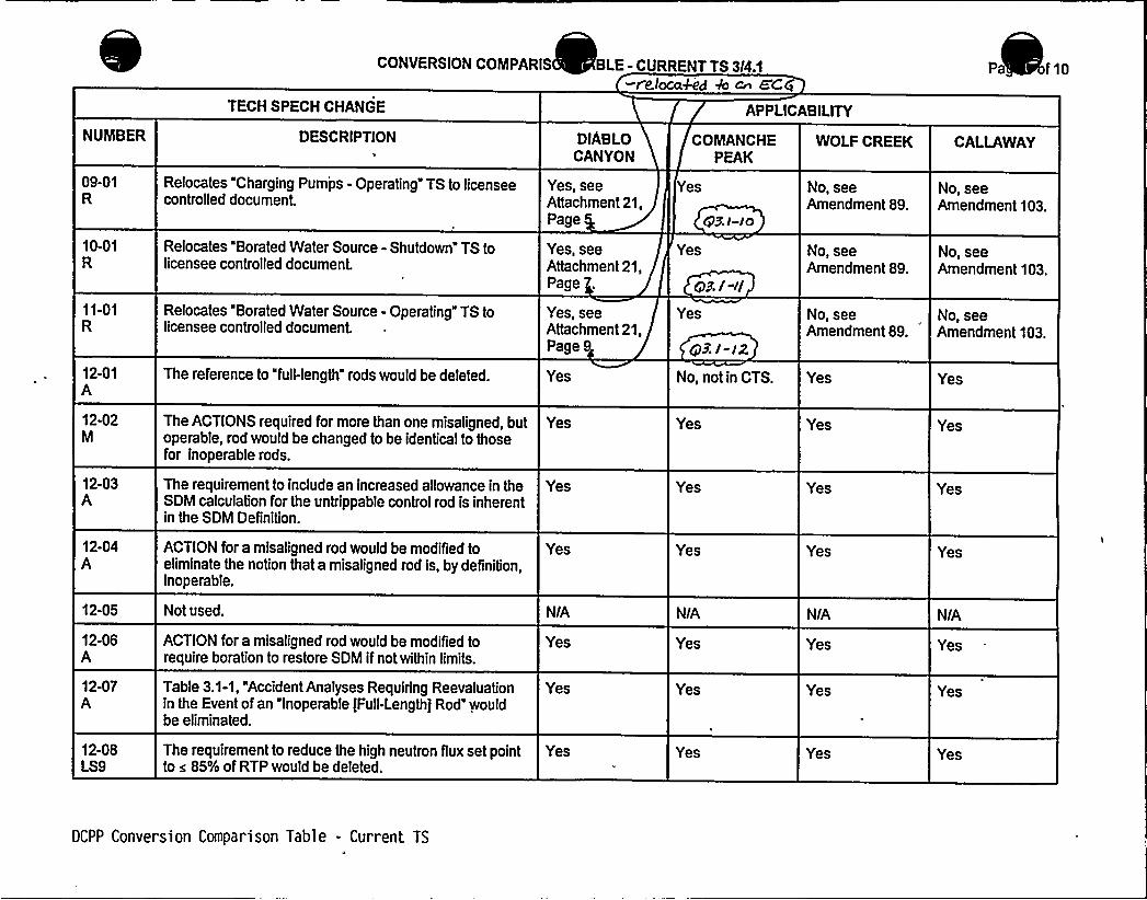
CONVERSION COMPARIS BLE - CURRENT TS 3/4.1-re./ocaked + cn 8'Cg
Pa f10
TECH SPECH CHANGE APPLICABILITY
NUMBER DESCRIPTION DIABLOCANYON
COMANCHEPEAK
WOLF CREEK CALLAWAY
09-01R
10-01R
Relocates "Charging Pumps - Operating" TS to licenseecontrolled document.
Relocates "Borated Water Source - Shutdown" TS tolicensee controlled document.
Yes, seeAttachment 21,Page
Yes, seeAttachment 21,Page .
Yes
Yes
eel-i]
No, seeAmendment 89.
No, seeAmendment 89.
No, seeAmendment 103.
No, seeAmendment 103.
11-01R
Relocates "Borated Water Source - Operating" TS tolicensee controlled document.
Yes, seeAttachment 21,Page 9
Yes
gR/-/2
No, see No, seeAmendment 89. Amendment 103.
12-01A
12-02M
12-03A
12-04A
12-05
12-06A
12-07A
12-08LS9
The reference to "full-length" rods would be deleted.
The ACTIONS required for more than one misaligned, butoperable, rod would be changed to be identical to thosefor inoperable rods.
The requirement to include an increased allowance in theSDM calculation for the untrippable control rod is inherentin the SDM Definition.
ACTION for a misaligned rod would be modified toeliminate the notion that a misaligned rod is, by definition,inoperable.
Not used.
ACTION for a misaligned rod would be modified torequire boration to restore SDM ifnot within limits.
Table 3.1-1, "Accident Analyses Requiring Reevaluationin the Event of an "Inoperable tFull-Length) Rod" wouldbe eliminated.
The requirement to reduce the high neutron flux set pointto s 85% of RTP would be deleted.
Yes
Yes
Yes
Yes
N/A
Yes
Yes
Yes
No, not in CTS.
Yes
Yes
Yes
N/A
Yes
Yes
Yes
Yes
Yes
Yes
Yes
N/A
Yes
Yes
Yes
Yes
Yes
Yes
Yes
N/A
Yes
Yes
Yes
DCPP Conversion Comparison Table - Current TS


Enclosure 2PG8 E Letter DCL 98-107
ADDITIONALINFORMATIONCOVER SHEET
ADDITIONALINFORMATIONNO: Q 3.1-13
REQUEST:
APPLICABILITY: DC, CP, WC, CA
ITS 3.1.4 Rod Group Alignment Limits (Comanche Peak)DOC 12-07-AITS 3.1.4 Bases
Comment: The DOC states, for Required Action B.2.6, that "the ITS Bases discuss theaccident analysis affected by rod misalignment." The associated Bases do not list theaccident analyses that require re-evaluation, similar to that provided by the other FourLoop Group plants. List in the Bases the accident analyses that require re-evaluation.
FLOG RESPONSE: The APPLICABLE SAFETY ANALYSES section of ITS 3.1.4 Basesprovides an appropriate description of the various manners in which a misaligned rod can affectthe safety analyses. The requirement in ITS 3.1.4 REQUIRED ACTION B 2.6 is to evaluate thesafety analyses; the affected analyses are described more fully by the APPLICABLE SAFETYANALYSES than by the list transported from the CTS. In fact, many of the analyses listed (e.g.,Decrease in Reactor Coolant Inventory in USAR Section 15.6) are not affected by reasonablerod misalignments; whereas some transients that are sensitive to misaligned rods (most of thePower Distribution and Reactivity Anomaly accidents described in USAR Section 15.4) are notlisted. Because of the potential conflicts between the APPLICABLE SAFETY ANALYSESsection and the list of CTS Table 3.1-1, it is preferable to not add the list, but refer to theAPPLICABLE SAFETY ANALYSES section. The ITS Bases ACTIONS B.2.2, B.2.3, B.2.4,B.2.5, and B.2.6 are revised to indicate that the accident analysis presented in USAR Chapter15 that may be adversely affected will be evaluated to ensure that the analyses results remainvalid for the duration of continued operation.
Callaway, WolfCreek, and Diablo Canyon have reviewed this Comment and concur with theabove discussion. Their ITS Bases have been revised to delete the list of accident analysesthat require re-evaluation and refer to FSAR Chapter 15.
ATTACHEDPAGES'ncl
5B B 3.1-18


BASES
ACTIONreduction(continued)
~ggCg,dan< Ar rig+'PSALM Ggprer >5'w +be.td>af W iclfnh'fyWt+/gap i F dd„dezyify
anras em vs red:gf e-eetur,S C~.
Rod Group Alignment LimitsB Q-.4-S 8':''j.'-"4
f eduCd'o~ ~ ~.l- EDTi& of 2 hours gives the operator sufficient time to accomplish anorderly power ithout challenging the Reactor Protection System.
When a rod is known to be misaligned. there is a potential to impactthe SDM. Since the core conditions can change with time. periodicverification of SDM is required. A Frequency of 12 hours issufficient to ensure this requirement continues to be met.
Verifying that Fo(2) and F" are within the required limits ensuresthat current operation at15X RTP with a rod misaligned is notresulting in power distributions that may invalidate safety analysisassumptions at full power. The Completion Time of 72 hours allowssufficient time to obtain flux maps of the core power distributiqpusing the incore flux mapping system and to calculate F d F „.
Bel l3Once current conditions have been verified accep ble,available to perform evaluations of accident anal sis to determinethat core limits will not be exceeded during a De ign Basis Event forthe duration of operation under these conditions. A Com letion Timeof 5 days is sufficient time to obtain the required input data and toperform the analysis.
cP9'/- 13
pe,,'fofITouJnuq"ac deiitnaualyses!~rages".",.re„-";eu,aluati'unior~ ntinued'OPerataun,",Iii~th':»'llliaal fg .:".rfudt
Rodildludtar.: ''~>to F!Assembjy~anseion,;.:,"gharaacterusttcs
Rod'Gluite .;.,CojitroI':phssembRyzLII"h'gamer'os/~Pi:
~et~or;;:,Coolant.";;,,Fram;:: JilFRuptuned,-,,p pesmir.",:sfrtom.:Cracker@L'ag'esp�'@hich'~ActuatiWct
'farci gehcyi'Core:"Cooldt !Sy'stems
:,ingj", odrd~u~ser-:Co rp.-'"Assem5ly'slit'hei ~ul".a FN~l;:;Powe~r
ar:!% e:":0 'I'W::: ~t:.PT:,.mp! .. II!L': ':,: fe 1.%.:::,d 0')i
'ur,: sdeconda~.: CaMO dt":Sgitm~pipe::,Ruptui e
Ru'pture o .::"Pa„-.:Coiitr I RodNFf'se.:Hie'chanfs~m.i sing ipodfCl'ii ,e". r"'Contlrco
assembly!Cacti ori,-:..
(Continued)
DCPP Mark-up of NUREG-1431, Rev. 1 Bases B 3.1-18


Enclosure 2PG8 E Letter DCL 98-107
ADDITIONALINFORMATIONCOVER SHEET
ADDITIONALINFORMATIONNO: Q 3.1-15 APPLICABILITY: DC, CP, WC, CA
REQUEST:ITS 3.1.4 Rod Group Alignment LimitsCTS 3/4.1.3 Movable Control Assemblies (All FLOG Plants)DOC 12-14-M
Comment: The ITS has changed the wording of the TS from "trippability" to"operability," and references TSTF-107 which is not yet approved (though it is expectedto be approved with the WOGs next revision of TSTF-107. The@result is that the FLOGplants have inconsistently incorporated generic changes into the Bases (i.e., the Basesparagraphs for B.2.1.1 and B.2.1.2). This change is a less restrictive change in that itprecludes LCO 3.0.3 entry for unforeseen inoperabilities. TSTF-107 needs to bediscussed/approved at the next TSTF OG/NRC Meeting, and the FLOG will then needto incorporate the resulting generic TS requirements.
FLOG RESPONSE: It is the FLOG's understanding that EXCEL Services Corporation met withthe NRC on May 23, 1998, to discuss TSTF-107. The result of that meeting has been reportedto be agreement to approve TSTF-107 with a minor Bases change. Revision 1 of TSTF-107has been incorporated into the FLOG submittals.
In the ITS, rod operability is addressed in the Bases as trippability within the drop timerequirements of ITS SR 3.1A.3. Ifnot met, Condition A would be entered which requires SDMverification and shutdown to MODE 3 in 6 hours, which then exits the LCO.
In the CTS, the action for an untrippable rod is essentially the same as the ITS. No action isprovided in the CTS for discovering in MODE 1 or 2 that a rod would not meet insertion timerequirements; therefore, CTS LCO 3.0.3 would be entered. LCO 3.0.3 allows 1 hour to initiate ashutdown and 6 additional hours to reach MODE 3. Because the ITS only allows 6 hours toreach MODE 3 (instead of up to 7 as allowed by LCO 3.0.3), the change from "untrippable" to"inoperable" in CTS 3.1.3.1 is more restrictive.
ATTACHEDPAGES'ncl.
5AEncl. 5B
Traveler Status SheetB 3.1-14, B 3.1-16, B 3.1-16a, B3.1-17, B,3.1-17a, B 3.1-1 9a


Industry Travelers Applicable to Section 3.1
TRAVELER¹TSTF-9, Rev. 1
TSTF-12, Rev. 1
TSTF-13, Rev. 1
TSTF-14, Rev.$
TSTF-15, Rev. 1
TSTF-89
TSTF-107, Rev. 1
TSTF-108, Rev. 1
TSTF-110, Rev. ZTSTF-136
TSTF-141
TSTF-142
WOG-105
STATUS
Incorporated
Incorporated
Incorporated
Incorporated
Incorporated
Incorporated
Incorporated
ncorporated
Incorporated
Incorporated
Not Incorporated
~Incorporated
Incorporated
Incorporated
3.1-1
3.1-15
3.1-4
3.1-13
NIA
3.1-8
3.1-10
3.1-9, 3.1-15
NIA
3.1-7
3.1-16
DIFFERENCE ¹ COMMENTS
NRC approved.
NRC approved. ITSSpecial Test Exception3.1.10 is retained and re-numbered as 3.8.1,consistent with thistraveler and TSTF-136.
NRC ap proved.
NRC approved W3.t-oo
NRC approved.
NRC approved.
+SAN-
l5
bNRC approTiZ S. I-ool
NRc happ~ %3,(-~
Disagree with change;traveler issued after cut-offdate
%Mete.~zC, ~~~.7 u.B.I-ao4
DCPP Mark-up of NUREG-1431, Rev. 1


B 3.1 REACTIVITY CONTROL SYSTEMS
B Q-.4-4 8„:.'1"""'$ 'Pod gmgp- Alignmrn& Li'rn",~s
BASES
Rod Group Alignment LimitsB Q-.4-.S 3'.'"1;.4
)C P.>" ED
BACKGROUND
g(,'n+gZ. /- l5
The OPERABILITY ( i.e., trippability) of the shutdown and control rodsis an initial ass on in all safety analyses that assume rodinsertion upon reac or trip. Maximum rod misalignment is an initialassumption in the safety analysis that directly affects core powerdistributions and assumptions of available SDM.
The applicable criteria for these reactivity and power distributiondesign requirements are 10 CFR 50, Appendix A, GDC 10. "ReactorDesign "
GDC 26. "Reactivity Control System Redundancy andCapabiiity" (Ref. 1). and 10 CFR 50.46, "Acceptance Criteria forEmergency Core Cooling Systems for Light Water Nuclear Power Plants"(Ref. 2).
Mechanical or electrical failures may cause a control rod to becomeinoperable or to become misaligned from its group. Contr"l rodinoperability or misalignment may cause increased power peaking, dueto the asymoetric reactivity distribution and a reduction in the totalavailable rod worth for reactor shutdown. Therefore, control rodalignment and OPERABILITY are related to core operation in designpower peaking limits and the core design requirement of a minimum SDM.
Limits on control rod alignment have been established, and all rodpositions are monitored and controlled during power operation toensure that the power distribution and reactivity limits defined bythe design power peaking and SDM limits are preserved.
Rod cluster control assemblies (RCCAs), or rods. are moved by theircontrol rod drive mechanisms (CRDMs). Each CROM moves its RCCA onestep (approximately Ys inch) at a time. but at varying rates (stepser minute) depending on the signal output from the Rod Controlystem.
(Continued)
DCPP Mark-up of NUREG-1431, Rev. 1 Bases B 3.1-14


BASES
Rod Group Alignment LimitsB Q-.k-S 3'.-'.4
ACTION(continued)
fo:.':HOOE>3'.':':,:;these:;wctims.',;„'.ire;.mnsistent';.vite'h)ihh~osewpeRcA'ed<~njl".."CO~~r~
'A',::rod pi"".;;"coiisidevedCrippabl'e73 fjs'0":,.'was"'.;de'mo'nstratYd~OPERAB'LE+dui',ing „the.'::;,;:last',,,performance-';:::,of';:.:le;"3 ';3:::4.':.":-P':and-met~the>rod,:,dry'<tine'icriter'~a'dbr<i'nghe,'.,9.ast~perform'ance:,::6 "': '-" "': "=4".
"-"'erif
a ion mus t for the absence ofivi of the untrippab e ro s , w erod of maximum wort .
A.2 ~).n4.If the no erabl rod(s) cannot be restored to OPERABLE status. theplant mus e rought to a MODE or condition in which the LCOrequirements are not applicable. To achieve this status. the unitmust be brought to at least MODE 3 within 6 hours.
The allowed Completion Time is reasonable. based on operatingexperience, for reaching MODE 3 from full power conditions in anorderly manner and without challenging plant systems.
p+linc.B.l~ 8.t.G-J
When a rod ned. it can usually be moved and is s itrippable i. BL . If the rod can be realigned within theCompietion ime o our, local xenon redistribution during thisshort interval will not be significant'nd operation may proceedwithout further restriction.An alternative to realigning a single misaligned RCCA to the groupdemand position is to align the remainder of the group to the positionof the misaligned RCCA. However. this must be done without violatingthe bank sequence. overlap, and insertion limits specified inLCO Q-.4-.4 8-;Ql.'.5, "Shutdown Bank Insertion Limits," and LCO ~B'g:::6. "Contr'ol'ank Insertion Limits." The Completion Time of 1 hourgimme's'he operator sufficient time to adjust the rod positions in anorderly manner.
B.2.1.1 and B.2.1 2
With a misaligned rod. SDM must be verified to be within limit orboration must be initiated to restore SDM to within limit.
(Continued)
DCPP Hark-up of NUREG-1431, Rev. 1 Bases 8 3. 1-17


BASES
Rod Group Alignment LimitsB ~ SQ'.:".'4
mered-
In many cases, realigning the remainder of the group to e misalignedrod may not be desirable. For example. realignsng contro ank B to arod that is misaligned 15 steps from the top of the core wo ld requirea significant power reduction. since control bank D must be fulli e~ed and control bank C must be inserted to approximately 5p /~l
~
~
P er operation may continue with one RCCAmlsaligned. provided that SDM ls verifl 'l n
" '. h ses.l-Ebompletion Time of I hour represents the time necessary for
determining the actual unit SDN and, if necessary, aligning andstarting the necessary systems and components to initiate oration.
B.2.2 B.2.3 B.2.4 B.2.5 and B.2.6
For continued operation with a misaligned rod, $pP v,:eac'for.,;"power,,mustbe reduced, SDN must periodically be verified within liiNt's. hotchannel factors (Fo(Z) and F«) must be verified within limits. and thesafety analyses must be re-evaluated to confirm continued operation ispermissible. Reduction of power to 75K RTP ensures that local LHRincreases due to a misaligned RCCA will not cause the core designcriteria to be exceeded (Ref. 3). The Completion
(Continued)
DCPP Nark-up of NUREG-1431, Rev. 1 Bases


BASES
Rod Group Alignment LimitsB Q-.kS 3':ll;4
~3olig- J
SR ~W SM'''4"."'2
Verifying each rod is OPERABLE would require that each rod be tripped.However. in MODES 1 and 2. tripping each rod would result in radial oraxial power tilts. or oscillations. Exercising each individual rodevery 92 days provides confidence that all rods continue to beOPERABLE without exceeding the alignment limit. even if they are notregularly tripped. Moving each ro6 by 10 steps will not cause radialor axial power tilts. or oscillations, to occur. The 92 day Frequencytakes into consideration other information available to the operatorin the control room and SR Q-.44-.4 P$1".4'.::,1. which is performed morere uent ds to the determination"of OPERABILITY„,of the rods <% < <->
Be wee r urban equired performances of SR 3-+-S-.R 3."'.1/4.:.'":2(determina ion o rod OPE ILITY by movement). if a ro'd' ""idiscovered to be iamovable. but remains trippabl . the o s isconsidered to be OPERABLE. At any time. if a rod ) is immovable, adetermination of the trippability (OPERABILITY) o the rod(s) must bemade. and appropriate action taken.
SR l~4-3 8-%~~4:;9 g3.I-IS
Verification of rod drop times allows the operator to determine thatthe maximum rod drop time permitted is consistent with the assumed roddrop time used in the safety analysis. Measuring rod drop times priorto reactor criticality, after reactor vessel head removal. ensuresthat the reactor internals and rod drive mechanism will not interferewith rod motion or rod drop tive, and that no degradation in thesesystems has occurred that would adversely affect rod motion or droptime. This testing is performed with all RCPs o rating and theaverage moderator temperature a 500'F to simulate a reactor trip underactual conditions:
cpa.s.w-l
(Continued)
DCPP Mark-up of NUREG-1431, Rev. 1 Bases B3. i-I lo 2'.I-E


Enclosure 2PG8E Letter DCL 98-107
ADDITIONALINFORMATIONCOVER SHEET
ADDITIONALINFORMATIONNO: Q 3.1-16
REQUEST:
APPLICABILITY: DC, CP, WC, CA
ITS 3.1.4 Rod Group Alignment Limits (AII FLOG Plants)ITS 3.1.4 BasesGeneric Changes
Comment: Generic Bases changes need to be discussed/justified. For example, theBases Background discussion on the DRPI system has been revised and needs to beexplained.
FLOG RESPONSE: As discussed during a telecon with NRC Staff on June 25, 1998, thescope of this RAI will be limited to the ITS 3.1.4 Background Bases. Changes fall into one offive categories:
1. Specification re-numbering.2. Inclusion of shutdown rods.3. Addition of plant-specific design information (e.g., number of control banks and
shutdown banks).4. Editorial corrections (e.g., the correct title for GDC-26); and5. Changes to the last paragraph.
Changes to the last paragraph were made since it was felt that this text went beyond the levelof detail required for the ITS Bases. Coil spacing dimensions are not critical to operatorunderstanding of this system. In addition, statements in the last paragraph in the ISTSconcerning position indication accuracies are incorrect.
ATTACHED PAGES:
None


Enclosure 2PG&E Letter DCL 98-107
ADDITIONALINFORMATIONCOVER SHEET
ADDITIONALINFORMATIONNO: Q 3.1-20
REQUEST:
APPLICABILITY: DC, CP
ITS 3.1.7 Rod Position IndicationCTS 3.1.3.2 Position Indication Systems - Operating (Comanche Peak 8 DiabloCanyon)DOC 13-08-LS-20 8 13-09-LS-23 8 13-06-AJFD 3.1-7 8 3.1-12
Comment: The ITS adopts Conditions and associated Required Actions from theCallaway's CTS, addressing more than one inoperable digital rod position indicator(DRPI) per group, which is not addressed in either the STS or the CTS. Furthermore,not all associated CTS Required Actions have been retained in the ITS; the RequiredActions to take manual control of the rods and to record reactor coolant temperatureevery hour have not been retained. These actions, in one case affect rod movementand in the other case provide an indication that the rod(s) position may have changed,and therefore have a bearing on SDM and therefore should not be deleted if theCallaway condition of more than DRPI per group inoperable is retained. Either retainthe CTS requirements and adopt the STS requirements, or provide a better justificationfor the ITS proposals of adopting the Callaway CTS requirements. This change isbased upon proposed change WOG-73, Rev 1; which eventually may become a TSTFchange request. What is the status of WOG-73, Rev 1? The STS wording of the notepermitting separate condition entry should be retained with the STS Conditions andRequired Actions.
FLOG RESPONSE: DCPP and CPSES continue pursuing this change pending NRC review ofWOG-73, Revision 1, which has been submitted to the NRC as TSTF-234. This proposedchange provides a specific set of compensatory actions and a 24 hour AOT for a situationpreviously unaddressed. Thus, the requirements of LCO 3.0.3 would be applicable and a plantshutdown would be required within 1 hour.
However, the partial loss of RCCA position indication is not an assumed initiating event, nordoes it affect the outcome of any analyzed accident. Therefore, a 1 hour shutdown response isconsidered unnecessary when compared to other situations of similar severity where guidancewas provided.
The contribution to plant safety of a well-balanced approach in avoiding unnecessaryshutdowns is sufficient to warrant prompt NRC review and approval of TSTF-234. It would alsobe sufficient to warrant a separate License Amendment Request were the TSTF to bewithdrawn from this submittal.
ATTACHED PAGES:
None


Enclosure 2PGBE Letter DCL 98-107
ADDITIONALINFORMATIONCOVER SHEET
ADDITIONALINFORMATIONNO: Q 3.1-21REQUEST'PPLICABILITY:DC, CP
CTS 3.1.3.3 Position Indication Systems - Shutdown (Comanche Peak 8 DiabloCanyon)DOC 14-01-R
Comment: The DOC needs to specify where the CTS specification is being relocated.Correct the DOC. A relocated screening form is not provided for this relocatedspecification.
FLOG RESPONSE: For CPSES, DOC 14-01-R has also been revised to provide additionaljustification for the relocation and to reference new Attachment 21 containing relocationscreening forms.
The format for specifying the location of relocated requirements (in Enclosure 3B of theconversion submittal) was found to be acceptable by the NRC technical specifications branchreviewers during telephone calls on June 25 and June 30, 1998.
For Diablo Canyon, License Amendment (LA) 120/118 (dated 2/3/98) eliminates this RAI. LA120/118 relocated ten TSs in accordance with 10 CFR 50.36. Thus, CTS 3.1.3.3 no longerexists and DOC 14-01-R is not applicable to DCPP. CTS 3.1.3.3 was relocated to ECG 41.1which is part of an NRC approved program controlled by 10CFR50.59 and discussed in FSARChapter 16.
ATTACHED PAGES:
Encl. 2 3/4 1-18 and 3/4 1-19Encl. 3A 10Encl. 38 8


REACTIVITY CONTROL SYSTEMS
POSITION INDICATION SYSTEMS - OPERATING
LIMITING CONDITION FOR OPERATION
3. 113.2 The Digital Rod Position Indication ystem and the Demand PositionIndication S stem shall be OPERABLE 13-01-LG
APPLICABILITY: MODES l~+ and P~.
ACTION:a. With a maximum of one dj.gi,tal„.rad positi.on, i.ndicator per
bable group inoperable ff6r,":.",orie". orarttore~gprouILs''~either:
13-08-LS20
13-02-LS15
1. Determine the position of the nonindicating rod(s)indirectly by the movable incore detectors. at, least 1303 LS12
p d~ .idp. i'i':-ldany motion of the nonindicating rod-whircsh"eexceeds 24steps in one d rection since the last determination of the rod'sposition. or
2. Reduce THERMAL POWER to„.l.cusp q,than„50%, of,',.RATED„.THERMALPOWER. witbipn 8 hours ar:,..'-:',.be)gii.;::„Hot.".;::.".Standbj::".'.with'in",,the
b:::;,,:;:::::::::.",gjtjieoria:."-:,tbanioneidi'g tÃl~ro'd,:, osft!Ton!OnbicQa'or:::;dp!fer,':;.'g~rouj:"::iO!operable
~'ndi'rect] j',:.:::'5j,.':the.",."mwovab3i"~;>r'icore~detectori',:ata::keawst-':o'cepper;.,"!8:i)our..i-::::,:arete'th>AXE(hours'-.'aftei.,'arany,qioti6nI;;;o f-.-.the.,oon1nd>caping,'::-re~-:Wadi:-",::exceeds';.':Pogsteps:,";:,'m:;,'one~.d>-rectionSlnuerbth8:::!%eat:::::.'deLefifainatgP~I":Of.',:i!the:."!rod~tPOSI t1ondg and"
~Y",-::,',1'-'.~53":,;Rester;.eche:,:,,NliWa::,: md ~pos'f Goo':,:,'IndfcaSrs'-.:to.'PK L'K&tatus:':rWithiig';24e'hciira'Veh>t al',:"ap."-.:;ma)gmum"',:Of;.:'.:::,age„.'O'Ig'Ifilll@rOd i pos ltfiOn!!el flu I'Cat~or."'p~er; groups"„."In',;;i nop'eraN er';ll!Of!
f;:,:~:„,:::,.2.:::.;-,,::,.ge:dnfliigfYgSTANISYWa'thTn:,.the.:nlext„.~g"hours+„13-08-LS20
b c. With a maximum of one demand position indicator per bankinoperable either:
13-08-LS20
1. Verify that all digital rod position indicators for the affectedbank are OPERABLE and that the most withdrawn rod and the leastwithdrawn rod of the bank are within a maximum of 12 steps of eachother at least once per 8 hours'r
2. Reduce THERMAL POWER,to„,less.. than 50Xdd.of„,RAdTED...THE .„PO(ER within 8 hours or,':be;,::;::,1niflotwp!Stan'dbjiwfthfpithe'inedxt
SURVEILLANCE RE UIREMENTS
4.113.2 Each digital rod positiverifying that tfie Demand PositiIndication S stem agree within 1
on indicator shall be determined to be OPERABLE byon Indication S stem and the Digital Rod Position2 steps 13-07-M
d
., „Whe'n;iXderC'Z '::a'Oier'ghe:-",fU„;:.N~i',.ange,'. i~f:.drOd.:,"":::traVeI'n'e.,pr',or',.ato'",ci'iX:.'ca:;itj:;:::.ilier:',.".',each''emov@.,,074th'el':abactor.'"head".
s
r
r
e
KPu"„.,'::.,~gfF~Wgepana'te:;;condftoon:,,:,;eiitsg;.As~iplg 6;to r e:acfbd dp!Oouerabte drhopdrd:;,,::::: d:.: p" .:.ll ..d, '.p'pl I dd'Ip':: pp p d:)i'0"" !it 'd.":.
fi.!.'a.'b inoart IPuf giDIABLO CANYON - UNITS 1 & 2 3/4 1-18TABS.4A
12-16-LG


Insert for Q 3.1-21
Enclosure 2 Page 3/4 1-18
4.1.3.3 Each of the above required digital rod position indicator(s) shall be determined tobe OPERABLE by verifying that the digital rod position indicators agree with thedemand position indicators within 12 steps when exercised over the full range ofrod travel at least once prior to criticality aftereach removal of the reactor head. 13-07-M

0

4. 1.3.3 Each of the above requ ed digital rod position indicator(s) shall bedetermined to be OPERABLE by vers ying tha the di ital rod position indicatorsagree with the demand position in cator w steps .when exercised over,thefull range of rod travel at least o ce pi'i.~F.:,,"::t'~.",cgtjc'alj'Cy,:"..'~f
te~r'ach
. r'eiiioval:"'..of,::,,the''"reactor.,:,.':.:h'cad.
DIABLO CANYON - UNITS 1 Im 2TABB.4A
3/4 1-19


DESCRIPTION OF CHANGES TO TS SECTION 3I4 1
(Continued)
CHANGENUIIBER
13-06
13-07
NSHC DESCRIPTION
Not applicable to DCPP. See Conversion Comparison Table.(Enclosure 3B)
The proposed modifications to the SR would require a verification ofagreement between digital and demand indicator systems prior tocriticalityafter each removal of the reactor vessel head, instead of every12 hours. This reflects a reorganization of SRs in the ITS. Therequirement for a 12 hour comparison would be moved to SR 3.1.4.1 inthe ITS. The post-vessel head removal requirement would be a newspecification that demonstrates rod position system OPERABILITYbased on a comparison of indicating systems throughout the full rangeof rod travel. The Frequency requirement of prior to criticality after eachremoval of the reactor vessel head would permit this comparison to beperformed only during plant outages that involve plant evolutions (vesselhead removal) that could affect the OPERABILITYof the rod positionindication systems. The Frequency change is based on TravelerTSTF-89.
13-08
13-09
14-01
LS20
LS23
Adds provision from Callaway's current specifications which would,under certain conditions, allow continued operation with more than oneinoperable DRPI per group. A separate Condition entry allowance ispermitted for each inoperable rod position indicator per group and eachdemand position indicator per bank. A proposed Traveler 7Sw- Ug
is in proce i ocover this issue. 7R 3. /-QC4
'
Not applicable to DCPP. See Conversion Comparison Table(Enclosure 3B).
The hutdown P sition Indi 'on System S cification 3.1..3 isrel catedoutsi eofthe TS This isconsi entwithNUR -1431.
15-01
15-02
16-01 LS14
he Rod D p Time Spe fication 3.1.3.4 is relo ed outside of the S.The RCS emperature mit and reactor coolan umps operatingrequire ent for rod op testing are combin with CTS Suiveill ce4.1.3, then inco rated into ITS SR 3.1... This is consist t withNU EG-1431. phd Ms'eo g3,/-22
he R Drop Time 4.1.3.4.a is m ed to the Contro od ITS 0.1. as SR 3.1.4.. This chan e is nsistent wi -143 .~ ctpplic cdc * b~P, 5je~Arsi~Co~~r is~7ci ~c(e~iruue 88). QZ, I ~
This TS would be revised to apply to shutdown "banks" instead oshutdown "rods;" this is consistent with NUREG-1431. The currentACTION statement permits one rod to be inserted beyond the limits; theproposed ITS Condition Awould allow one or more banks to be insertedbeyond the limit.
DCPP Description of Changes to Current TS . 10


CONVERSION COMPARIS BLE - CURRENT TS 3/4.1 Pa of 10
TECH SPECH CHANGE APPLICABILITY
NUMBER DESCRIPTION DIABLOCANYON
COMANCHEPEAK
WOLF CREEK CALLAWAY
13-04M
13-05A
13-06A
13-07M
13-08LS20
A requirement would be added to bring the plant toMODE 3 within 6 hours ifthe required ACTIONS andCompletion Times are not met.
The proposed change would retain an ACTIONstatement, currently in the plant TS, that permitscontinued POWER OPERATION with more than 1 digitalrod position indicator per group inoperable.
The change would allow separate Condition entry foreach inoperable DRPI per group or each demandindicator per bank.
The proposed modifications to the SR would verifyagreement between digital and demand indicator systemsprior to criticality after the reactor vessel head wasremoved instead of every 12 hours. The Frequencychange is based on Traveler TSTF-89.
Adds provision in Callaway's current specifications whichwould, under certain Conditions, allow continuedoperation with more than one ino ergrou .
This is consistent with Travelei
Yes
No, not in CTS-see 13-08-LS20.
No, not in CTS-see 13-08-LS20.
Yes
Yes
Yes
No, not in CTS-see 13-08-LS20.
No, not in CTS-see 13-08-LS20.
Yes
Yes
Yes
Yes
Yes
Yes
No, already inCTS.
Yes
Yes
Yes
Yes
No, already inCTS.
13-09LS23
CTS ACTIONS b.1.b) and b.1.c) of LCO 3.1.3.2 aredeleted. SDM is ensured in MODES 1 and 2 by rodposition. Multiple inoperable DRPls willhave no impacton SDM In MODES 1 and 2 ifthe control rod positions areverified by alternate means and rod motion is limitedconsistent with the accident analyses. Deletion of theserequirements is consistent with traveler
No, not in CTS. No, not in CTS. Yes
7 ST@'-2,3g
Yes
14-01R
Relocates CTS 3.1.3.3 to licensee controlled documents,consistent with NUREG-1431.
es ee 95- Yes, relocated to07 ated /4/95, TRM.
2.
p gy, see~Wana'gO///Q
No, seeAmendment 89.
No, seeAmendment 103.
DCPP Conversion Comparison Table - Current TS


Enclosure 2PG8E Letter DCL 98-107
ADDITIONALINFORMATIONCOVER SHEET
ADDITIONALINFORMATIONNO: Q 3.1-22
REQUEST:
APPLICABILITY'C
CTS 3.1.3.4 Rod Drop Time (Diablo Canyon)DOC 15-01-R
Comment: The DOC needs to specify where the CTS specification is being relocated.Correct the DOC. A relocated screening form is not provided for this relocatedspecification.
FLOG RESPONSE: License Amendment (LA) 120/118 (dated 2/3/98) eliminates this RAI.LA 120/118 relocated ten TSs in accordance with 10CFR50.36. Thus, CTS 3.1.3.4 no longerexists and DOC 15-01-R is not applicable to DCPP. CTS 3.1.3.4 was relocated to CTS SR4.1.3.1.3 (New).
ATTACHED PAGES:
Encl. 2 3/4 1-16, 3/4 1-20Encl. 3A 8, 10Encl. 3B 7, 9


REACTIVITY CONTROL SYSTEMS
LIMITING CONDITION FOR OPERATION
~bid C tf 4
12-08-LS9
12-22-M
c) A power distribution map„is obtained from the movable incoredetectors and F (Z) and F ~ are verified to be within theirlimits within 75 hours: and
d) The THERMAL POWER level is reduced to less than orequal to 75'f RATED THERMAL POWER within thenext hour
iuii"::::LIT:::8TAiiDBY~%fthsrf".:.":6th'auradhh'3 Vd ed
12-12-LS13
hem~d. With more than one rod misaligned from its group demand
position by more than + 12 steos (indicated position) ~
ditemlpj:,;';,Chat<":;the;:::,'SHUVQQMN',:;-:;H'Ak81'Ngs;.ef'thTri':.':;t5e:.;Q)LR~ar,ti:ii::ti':.ati:',%rat':i'i'.''o,:::bjeitore;:-,,':th(gH211iiitts'.::w!th'Sn',"'::oi'neihroi'ir:.=',", a'nd be fn HOT"STANDBY'Wi'thin 6hours.
SURVEILLANCE REQUIREMENTS
01-01-LG
12-02-M
4..3.1.1 Th 3 4 1 f 3~ d h 11 b d 1 d b tthtthe group demand limit by verifying the individual rod positions at least onceper 12 hours 12-16-LG
.312 1 h~ d f11 1 tdt h h11bdetermined to be OPERABLE by movement of at least 10 steps in any one directionat least once per 92 days.
12-01-A
ps s-Dp
pumps''.'0" ratin'g':,"."."','.',"jr.';;i'ir,::;to,"::c'r'ithacaf5'10 S10
I' « „,n, ff~g gag'ol fo~5 i5 ar Q,7 5eccesds g~ bee'cnnanr Q decay og ssaso oner@ ar ijoper /S IO C.SIQ-Coi/ ssolSere + o(g5>peep en*y w'Sh. 7asc~ ) ~sc ~04 C'od. ca~ r'WHh Qoc»«< p>~W ~M
d, d'or sc,cs rctss pair'ovid ec..el remce'I aj'se reocs~ ver'e'I he4Z,~1 2 fl Ts?a--
DIABLO CANYON - UNITS 1 8 2TABB.4A
3/4 1-16


12-10-LS10
;k-44-.4 The in vidual full-length shutdown and control rod dr time fr'om the fullywithdrawn positio shall be less than or equal to 2.7 seconds om beginning of decay ofstationary gripper il voltage to dashpot entry with:
a. vg greater than or equal to 644 6 'F, and
b. All eactor coolant pumps operat g.
With the drop time de rmined to exceed the above limit.restore the,rod, drop time to within e ab e limit prior toer-4 iiactoi,'„;::,ir:itjcal)Xj,'.
12-01-A
A
shall be demonstrated through4-. k 'kA The rod drop timemeasurement prior to reactor cri cali y:
a. For all ods following eac removal of the reactor vesselhead.
12-01-A
1 2-A
12-11-TR3
ecch RKP'VELIQ rvrWA| X-ALL-CO/
DIABLO CANYON - UNITS 1 8 2TABB.4A
3/4 1-20

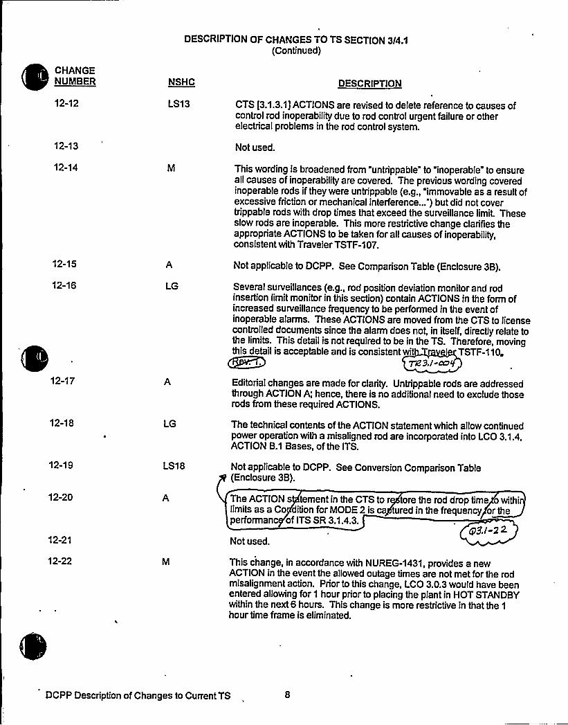
DESCRIPTION OF CHANGES TO TS SECTION 3/4.1(Continued)
CHANGENUINBER NSHC DESCRIPTION
12-12 LS13 CTS [3.1.3.1] ACTIONS are revised to delete reference to causes ofcontrol rod inoperability due to rod control urgent failure or otherelectrical problems in the rod control system.
12-13 Not used.
12-14 This wording is broadened from "untrippable" to "inoperable" to ensureall causes of inoperability are covered. The previous wording coveredinoperable rods if they were untrippable (e.g., "immovable as a result ofexcessive friction or mechanical interference...") but did not covertrippable rods with drop times that exceed the surveillance limit. Theseslow rods are inoperable. This more restrictive change clarifies theappropriate ACTIONS to be taken for all causes of inoperability,consistent with Traveler TSTF-107.
12-15
12-16 LG
Not applicable to DCPP. See Comparison Table (Enclosure 3B).
Several surveillances (e.g., rod position deviation monitor and rodinsertion limitmonitor in this section) contain ACTIONS in the form ofincreased surveillance frequency to be performed in the event ofinoperable alarms. These ACTIONS are moved from the CTS to licensecontrolled documents since the alarm does not, in itself, directly relate tothe limits. This detail is not required to be in the TS. Therefore, movingthis detail is acceptable and is consistent wit I TSTF-110.
pg9,/-ce
12-17
12-18
12-19
12-20
12-21
LG
LS18
Editorial changes are made for clarity. Untrippable rods are addressedthrough ACTION A; hence, there is no additional need to exclude thoserods from these required ACTIONS.
The technical contents of the ACTION statement which allow continuedpower operation with a misaligned rod are incorporated into LCO 3.1.4,ACTION B.1 Bases, of the ITS.
Not applicable to DCPP. See Conversion Comparison Table(Enclosure 3B).
The ACTION s tementin the CTS to r tore the rod drop time owithilimits as a Co dition for MODE 2 is tured in the frequency or theperformanc of ITS SR 3.1.4.3.
gj/ 22Not used.
12-22 This change, in accordance with NUREG-1431, provides a newACTION in the event the allowed outage times are not met for the rodmisalignment action. Prior to this change, LCO 3.0.3 would have beenentered allowing for 1 hour prior to placing the plant in HOT STANDBYwithin the next6 hours. This change is more restrictive in that the 1
hour time frame is eliminated.
DCPP Description of Changes to Current TS


DESCRIPTION OF CHANGES TO TS SECTION 3/4 1
(Continued)
CHANGENUMBER NSHC DESCRIPTION
13-06 Not applicable to DCPP. See Conversion Comparison Table.(Enclosure 3B)
13-07 The proposed modifications to the SR would require a verification ofagreement between digital and demand indicator systems prior tocriticalityafter each removal of the reactor vessel head, instead of every12 hours. This reflects a reorganization of SRs in the ITS. Therequirement for a 12 hour comparison would be moved to SR 3.1.4.1 inthe ITS. The post-vessel head removal requirement would be a newspecification that demonstrates rod position system OPERABILITYbased on a comparison of indicating systems throughout the full rangeof rod travel. The Frequency requirement of prior to criticalityafter eachremoval of the reactor vessel head would permit this comparison to beperformed only during plant outages that involve plant evolutions (vesselhead removal) that could affect the OPERABILITYof the rod positionindication systems. The Frequency change is based on TravelerTSTF-89.
13-08
13-09
14-01
LS20
LS23
Adds provision from Callaway's current specifications which would,under certain conditions, allow continued operation with more than oneinoperable DRPI per group. A separate Condition entry allowance ispermitted for each inoperable rod position indicator per group.and eachdemand position indicator per bank. A proposed Traveler vs-794
is in pro e ocover this issue. 72 3. )-ax
Not applicable to DCPP. See Conversion Comparison Table(Enclosure 3B). a9J-alThe hutdown P sition Indi on System S cification 3.1..3 isel cated outsi e of the TS This is consi ent with NUR -1431.
15-01
15-02
16-01 LS14
he Rod D p Time Spe fication 3.1.3.4 is relo ed outside of the S.The RCS emperature mit and reactor coo!an umps operatingrequire ent for rod op testing are combin with CTS Surveill ce4.1.3, then inco rated into ITS SR 3.1... This is consist t withNU EG-1431. plo+ Q5ect @3.I-ZZ
he R Drop Time 4.1.3.4.a is m ed to the Contro od ITS 0.1. as SR 3.1.4.. This chan e is nsistent wit -143 .
nppliec&e *b&P, ~Conv'r~~Cb~~ris'~7+ ~<(encinsun 88). g3, I~
This TS would be revised to apply to shutdown "banks" instead oshutdown "rods this is consistent with NUREG-1431. The currentACTION statement permits one rod to be inserted beyond the limits; theproposed ITS Condition Awould allow one or more banks to be insertedbeyond the limit.
DCPP Description of Changes to Current TS 10


~ I
~ ~ ~
I ~ ) I a )~ ~
~ ~ ~ ~
~ I ~ ~ ~
4 ~ ~ ~ ~
~ ~ ~
~ a
~ ~ ~ ~
~ ~ ~ ~ ~ ~ ~ ~ ~
~ ~ - ~ ~
~- '
0 ~ ~ 0 a ~ ~ ~
~ ~ ~ ~ ~ e ~ ~ a a ~
I ~ ~ ~
~ ~ ~ ~
I ~ ~ I
~ ~ ~ ~
~ ~
~ ~ ~ I
~ ~ ~ ~ ~ ~
~ 0 ~ ~
a~
~~ I
a ~
~ ~ ~
~ ~ ~ ~
~ ~
~ ~ ~
~ s
~ ~ ~ ~
~ ~ ~ ~ ~ ~
~ ~ I- ~- ) ~ I
~ ~ ~ ~ ~ ~ ~ ~ ~ ~
~ ~ ~ ~ ~ I
~ ~ ~ ~ ~ ~ I ~ ~ ~
~ ~ ~ ~ ~ ~ ~ ~ ~ ~
~ ~ ~ ~ ~
I '' I . ~ ~ I ~ .I

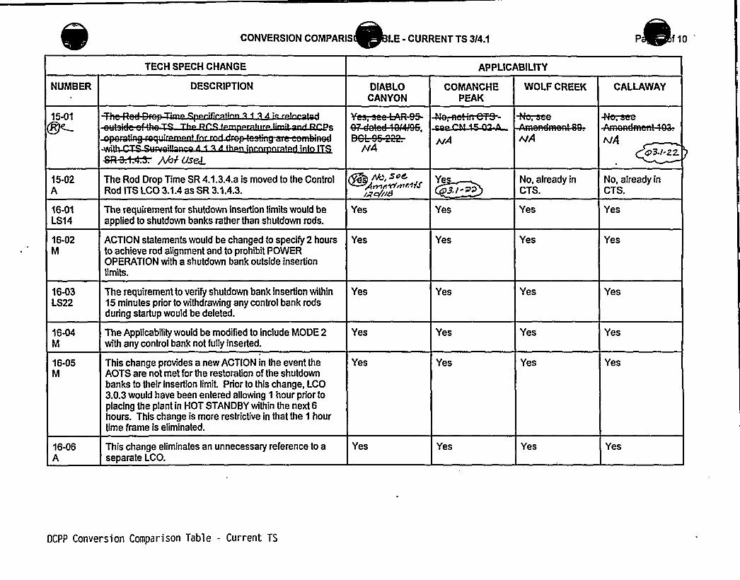
CONVERSION COMPARIS LE - CURRENT TS 3/4.1 P f10
'ECH
SPECH CHANGE APPLICABILITY
NUMBER
15-01
DESCRIPTION
Sft-e+ ~ Abfus~
DIABLOCANYON
COMANCHEPEAK
WOLF CREEK CAI LAWAY
+b~eeA
15-02A
16-01LS14
16-02M
16-03LS22
16-04M
16-05M
16-06A
The Rod Drop Time SR 4.1.3.4.a is moved to the ControlRod ITS I CO 3.1.4 as SR 3.1.4.3.
The requirement for shutdown insertion limits would beapplied to shutdown banks rather than shutdown rods.
ACTION statements would be changed to specify 2 hoursto achieve rod alignment and to prohibit POWEROPERATION with a shutdown bank outside insertionlimits.
The requirement to verify shutdown bank insertion within15 minutes prior to withdrawing any control bank rodsduring startup would be deleted.
The Applicabilitywould be modified to include MODE 2with any control bank not fullyinserted.
This change provides a new ACTION in the event theAOTS are not met for the restoration of the shutdownbanks to their insertion limit. Prior to this change, LCO3.0.3 would have been entered allowing 1 hour prior toplacing the plant in HOT STANDBYwithin the next 6hours. This change is more restrictive in that the 1 hourtime frame is eliminated.
This change eliminates an unnecessary reference to aseparate LCO.
~, S~Cg~rWmir1fSia<ii8
Yes
Yes
Yes
Yes
Yes
Yes
Ye$./
Yes
Yes
Yes
Yes
Yes
Yes
No, already inCTS.
Yes
Yes
Yes
Yes
Yes
Yes
No, already inCTS.
Yes
Yes
Yes
Yes
Yes
Yes
DCPP Conversion Comparison Table - Current TS


Enclosure 2PG8E Letter DCL 98-107
ADDITIONALINFORMATIONCOVER SHEET
ADDITIONALINFORMATIONNO: Q 3.1-24
REQUEST:
APPLICABILITY: DC, CP, WC, CA
ITS 3.1.4 Rod Group Alignment Limits (All FLOG Plants)JFD 3.1-5 8 3.1-6
Comment: Rewording of LCO and Condition A approved, contingent upon OGresubmittal of change request TSTF-107 (revision) as discussed with TSTF.
FLOG RESPONSE: See the response to Comment Number 3.1-15. The FLOG hasincorporated TSTF-1 07, Revision 1.
ATTACHEDPAGES'one


Enclosure 2PG&E Letter DCL 98-107
ADDITIONALINFORMATIONCOVER SHEET
ADDITIONALINFORIIATIONNO: Q 3.1-25
REQUEST:
APPLICABILITY: DC, CP, WC, CA
ITS 3.1.4 Rod Group Alignment Limits (All FLOG Plants)JFD 3.1-16
Comment: Inclusion of SR 3.2.1.2 to Required Action B.2.4 is approved; ensure OGsubmit WOG-105 as a TSTF change request.
FLOG RESPONSE: At the June 23-24, 1998, meeting of the Westinghouse Owners GroupMERITS Mini-Group, traveler WOG-105 was discussed. The remaining action on this travelerwas assigned to Westinghouse to expand this change to also apply to ISTS 3.2.1A, "Fa (Z) (F~Methodology)." However, this additional work has no impact on the manner in which the FLOGhas incorporated this traveler's additional restriction. A TSTF will be submitted to NRCexpeditiously.
ATTACHED PAGES:
None


Enclosure 2PG8E Letter DCL 98-107
ADDITIONALINFORMATIONCOVER SHEET
ADDITIONALINFORMATIONNO: Q 3.1-27
REQUEST:
APPLICABILITY: DC, CP, WC, CA
ITS 3.1.1 Shutdown Margin (All FLOG Plants)JFD 3.1-18
Comment: This modification adds a Mode change restriction from Mode 6 to Mode 5,as discussed in CN 1-02-LS-1 of 3.0. The discussion provided is inadequate to evaluatethe necessity of the mode change restriction. In general, throughout the submittal,justifications for notes prohibiting mode changes are inadequate. Provideexplanations/justifications that present specific conditions that would necessitate thenote.
FLOG RESPONSE: A Reviewer's Note in STS LCO 3.0.4 states: "LCO 3.0.4 has beenrevised so that changes in MODES or other specified conditions in the Applicability that are partof a shutdown of the unit shall not be prevented. In addition, LCO 3.0.4 has been revised sothat it is only applicable for entry into a MODE or other specified conditions in the Applicability inMODES 1, 2, 3, and 4. The MODE change restrictions in LCO 3.0.4 were previously applicablein all MODES. Before this version of LCO 3.0.4 can be implemented on a plant-specific basis,the licensee must review the existing technical specifications to determine where specificrestrictions on MODE changes or Required Actions should be included in individual LCOs tojustify this change; such an evaluation should be summarized in a matrix of all existing LCOs tofacilitate NRC staff review of a conversion to the STS." Based on this Reviewer's Note, amatrix of this evaluation was placed in the NSHC LS-1 in Enclosure 4 of the Section 3.0package (Attachment No. 6).
JFD 3.1-18 has been revised to incorporate additional justification from NSHC LS-1 fromEnclosure 4 of the Section 3.0 package (Attachment No. 6). JFD 3.1-18 has been revised toinclude: "LCO 3.0.4 has been revised so that changes in MODES or other specified conditionsin the Applicability that are part of a shutdown of the unit shall not be prevented. In addition,LCO 3.0.4 has been revised so that it is only applicable for entry into a MODE or other specifiedconditions in the Applicability in MODES 1, 2, 3, and 4. The MODE change restrictions in LCO3.0.4 were previously applicable in all MODES. ITS LCO 3.1.1 was modified by a Note stating:"While this LCO is not met, entry into MODE 5 from MODE 6 is not permitted." Entering MODE5 without SDM limits being met implies that boron concentration in MODE 6 is not met. Underthese conditions, a transition to MODE 5 should not be attempted until MODE 5 SDM limits aremet. Inadvertent boron dilution events are precluded in MODE 6 via administrative controls[and instrumentation which would promptly identify and terminate an event], whereas dilutionevents are not [subject to the same controls and monitoring] in MODE 5. Therefore, thetransition from MODE 6 to MODE 5 should not be allowed in the SDM initial condition for aMODE 5 dilution event is not met."
ATTACHED PAGES:
Encl 6A


JUSTIFICATION FOR DIFFERENCES FROM NUREG-1431
NUREG-1431 Section 3/4.1
CHANGENUMBER JUSTIFICATION
3.1-8 The frequency for SR 3.1.7.1 for comparing DRPI and group demand position over the full rangeof travel would be changed from 18 months to "Once prior to criticality after each removal of thereactor vessel head." This change makes it clear that the surveillance must be performed eachtime the head is removed and that it is not tied to an absolute time interval. This change isbased on TSTF-89.
3.1-9
3.1-10
3.1-11
3.1-12
3.1-13
3.1-14
3.1-15
This change would eliminate ISTS 3.1.2 because the SDM requirements for MODE 5 have beenincorporated into Specification 3.1.1 in accordance with traveler TSTF-136. Traveler TSTF-9,Rev. 1, relocated values for SDM to the COLR which removed the only difference between ITSLCO 3.1.1 and ITS LCO 3.1.2. Differences above and below 200'F will be addressed in theCOLR. Subsequent sections have been renumbered.
Several surveillances (e.g., rod position deviation monitor and rod insertion limitmonitor in thissection) contain ACTIONS in the form of increased surveillance frequency to be performed in theevent of inoperable alarms. These ACTIONS are relocated from the TS to licensee controlleddocuments since the alarms do not themselves directly relate to the limits. This detail is notrequired to be in the TS to provide adequate protection of the public health and safTherefore, relocation of this detail is acceptable and is consistent with TSTF-11, v.
Not Used. TiZ. P. I -~'k
The Required ACTIONS for inoperable DRPI in ITS 3.1.7 are revised per the CTS to note thatthe use of movable incore detectors for rod position verification is an indirect assessment at best.The position of some rods can not be ascertained by this method.
This change adds an LCO requirement and SR to MODE 2 PHYSICS TESTS Exceptions, STS3.1.8 to verify that THERMALPOWER is less than or equal to 5 percent RTP. The LCOrequirement and SR were added to verify that THERMALPOWER is within the defined powerlevel for MODE 2 during the performance of PHYSICS TESTS, since there is an ACTION thataddresses thermal power not within limityet there was no corresponding LCO or SR. Thesurveillance frequency of 1 hour is retained from the CTS. Thses chan es r sed on TSTF-
7g 3,/-Ct)SNot used.
8Q&Consistent with TSTF-12, . 1 Special Test Exception LCOs 3.1.9 n ..1 are deleted.The physics tests contained in CO 3.1.9 were only contained in some plant initial plant startuptesting programs. The physics test can be deleted since these physics tests are neverperformed during post-refueling outages. The physics test that LCO 3.1.11 required was the rodworth measurement in the N-1 condition. The use of other rod worth measurement techniqueswill maintain the shutdown margin during the entire measurement process and still provide thenecessary physics data verification. Since the N-1 measurement technique is no longer used,the SDM test exception can be deleted. This change and traveler TSTF-136 renumbers ITS3.1.10 to 3.1.8.
3.1-16
3.1-17
3.1-18
This change adds the requirement to perform SR 3.2.1.2 in addition to SR 3.2.1.1 duringperformance of ITS 3.1.4, Required Action B 2.4. The intent of Required Action B 2.4 is to verifythat F~gz) is within ITS limits. F>(z) is approximated by F~ (z) (which is obtained via SR 3.2.1.1)and F~ (z) (which is obtained via SR 3.2.1.2). Thus, both F (z) and F~ (z) must be establishedto verify F~(z). This change is consistent with Traveler WOS-105.
Consistent with CTS LCO 3.1.3.2, ITS 3.1.7, Condition C is clarified to state that the inoperableposition indicators are inoperable DRPls.
A MODE change restriction has been added to ITS 3.1.1, in LCO Applicability, per the matrixdiscussed in CN 01-02-LS1 of 3.0 Package (See LS - 1 NSHC in the CTS Section 3/4.0, ITSSection 3.0 package). 3'usey 1
DCPP Description of Changes to Improved TS/


Enclosure 6A Page 2Insert for Q 3.1-27
JFD 3.1-18 LCO 3.0.4 has been revised so that changes in MODES or otherspecified conditions in the Applicability that are part of a shutdown of theunit shall not be prevented. In addition, LCO 3.0.4 has been revised sothat it is only applicable for entry into a MODE or other specifiedconditions in the Applicability in MODES 1, 2, 3, and 4. The MODEchange restrictions in LCO 3.0.4 were previously applicable in allMODES. ITS LCO 3.1.1 was modified by a Note stating: "While this LCOis not met, entry into MODE 5 from MODE 6 is not permitted." EnteringMODE 5 without SDM limits met implies that boron concentration inMODE 6 is not met. Under these conditions, a transition to MODE 5should not be attempted until MODE 5 SDM limits are met. Inadvertentboron dilution events are precluded in MODE 6 via administrative controls[ and instrumentation which would promptly identify and terminate anevent], whereas dilution events are not [subject to the same controls andmonitoring] in MODE 5. Therefore, the transition from MODE 6 to MODE5 should not be allowed in the SDM initial condition for a MODE 5 dilutionevent is not met."

Enclosure 2PG8E Letter DCL 98-107
ADDITIONALINFORMATIONCOVER SHEET
ADDITIONALINFORMATIONNO: Q 3.1-28
REQUEST'elocatedSpecifications (All FLOG Plants)
APPLICABILITY: DC, CP, WC, CA
Comment: Comanche Peak, Wolf Creek, and Callaway have not provided relocatedscreening evaluations/forms for any of their specifications relocated to licenseecontrolled documents. Diablo Canyon has not provided relocated screening forms for allof their specifications relocated to licensee controlled documents. Provide necessaryrelocation screening evaluations/forms.
FLOG RESPONSE: All relocated specifications have been provided the necessary relocationscreening evaluations/forms which are contained in Attachment 21.
This RAI is not applicable to Callaway or Wolf Creek. No relocated specification DOCs wereused by those plants in Section 3.1.
ATTACHEDPAGES'one


Enclosure 2PG8 E Letter DCL 98-107
ADDITIONALINFORNIATIONCOVER SHEET
ADDITIONALINFORINATIONNO: DC 3.1-ED
REQUEST:
APPLICABILITY: DC
Various changes that do not impact the technical content of the submittal orother FLOG members.
Changes are noted with DC 3.1-ED in the margin and noted below:
2)3)4)
Ill
ATTACHED PAGES:
1) During the review performed for General Comment 3.1.G-1, it wasidentified that some headers were improperly placed and page numberingwas missing due to word processing pagination effects in Enclosure 58.PG8 E verified that Attachment 20 to the ITS conversion submittal (cleancopy of the ITS Bases) properly shows the placement of the headers and
~ page numbering in ITS 3.1. An example of these pagination issues isattached (8 3.1-5a); however, not every page was included since the cleancopy of the ITS Bases is in the appropriate format.Misspelled words.Missing word or use of another word with same meaning.Enclosure 2 typos on LCO 3.1.1.1 which show "greater than" rather
then'ss
than."
Encl. 2Encl. 58
3/4 1-1, 3/4 1-28 3.1-1a, 8 3.1-4, 8 3.1-5a, 8 3.1-7a, 8 3.1-9, 8 3.1-10a, 8 3.1-11a, 8 3.1-12,8 3.1-13, 8 3.1-14, 8 3.1-15a, 8 3.1-16, 8 3.1-17a, 8 3.1-18,8 3.1-21, 8 3.1-22, 8 3.1-22a, 8 3.1-24, 8 3.1-25


3/4. 1 REACTIVITY CONTROL SYSTEMS
3/4. 1. 1 BORATION CONTROL
SHUTDOWN MARGIN ~~LIMITING CONDITION FOR OPERATION
3. 1. 1.1 The SHUTDOWN MARGIN shall beth'.":.,15mitcs"~pr.'ov7ded~!1Ynjt'he::;,MLA.
APPLICABILITY: MODES 4. 2*, 3. a+$ 4. bnd;":.,5
ACTION
Ktlthln
02-01-A
01-01-LG
02-01-A
01-06-A
With the SHUTDOWN MARGINRithsn;::;.15'„-.",minutes initiate boration
io':'vestoi5 SHUTDOWN MARGIN Ra'.-,.NIthITi
01-01-LG
01-07-LS16
01-03-LS1
SURVEILLANCE REQUIREMENTS
4. 1.1. 1.1 The SHUTDOWN MARGIN shall be determined to bet-.tttttt '::.tlt:.!:: 't:::~i:::. t'ai!'" t':,,::.".: tt'.t~i": 01-01-LG
If the inoperable control rod is imoyable or untrippable, the aboverequired SHUTDOWN MARGIN shall be verified acceptable with anincreased allowance for the withdrawn worth of the imovable oruntrippable control rod(s);
When in MODES 1 or 2 with Keff greater than or equal to 1, at leastonce per 12 hours by verifying that control bank withdrawal is withinthe limits of Specification 3. 1.3.6:
When in MODE 2 with Keff less than 1, within 4 hours prior toachieving reactor criticality by verifying that the predictedcritical control rod position is within the limits of Specification
- 3.1.3.6;
Prior to initial operation above 5K RATED THERMAL POWER after eachfuel loading, by consideration of the factors of Specification4. 1. 1. 1. 1e. ~ below, with the control banks at the maximum insertionlimit of Specification 3.1.3.6; and
01-04-LS212-03-A
01-08-A
01-09-A
05-04-A
03-01-A
01-06-A
DIABLO CANYON - UNITS 1 & 2TABB.4A
3/4 1-1


REACTIVITY CONTROL SYSTEMS
SURVEILLANCE REQUIREMENTS (Continued)
e. When in MODES 2,",."..53 or 4. at least once per 24 hours 01-10-M
01-05-LG
4. 1. 1. 1.2 The overall core reactivity balance shall be compared to predictedvalues to demonstrate agreement within + 1R hk/k ooce>.'pi',ior~to„'"',eriterigg:;.,RODE::,'::1after;;.each„:refuel,:~ng:;.and at least once per 31 Effective Ful'l Power Days (EFPD)ifti'i::;..b'urIiiip;::,::>.-::,60.'.::EFPQ.
The predicted reactivity valuesbe adjusted (normalized) to correspond to the actual core conditions prior
to exceedin a fuel burnu of 60 EFPD after each oadin . KMhe
0541-M
05-03-LG
0542-LS7
05-05-LS17
reac't),vi't j,AiiiljsDt,".:,bi'.:iiii:.!i~t-:!lb)i'::::HOOK::3'!:t.Iii%4'h'ei iext-"6~hj'iver'i~
7 dcqs Tjz 'B.l oo3cp$ . / ~ Q
PPgl-9
01-10-M
~c S. j-G3
DIABLO CANYON - UNITS 1 & 2TABB.4A
3/4 1-2


8 3. 1 REACTIVITY CONTROL SYSTEMS
B 3.1.1 SHUTDOWN MARGIN (SDM)
BASES
SDM8 3.1.1
The acceptance criteria for the SDM requirements are that specifiedacceptable fuel design limits are not exceeded. This is done byensuring that:
a. The reactor can be made subcritical from all operatingconditions'ransients,and Design Basis Events;
b. The reactivity transients associated with postulated accidentconditions are controllable within acceptable limits (departurefrom nucleate boiling ratio...(DNBR), fuel centerline tempej„oadture,, Og .. d '.IglgM I!'fuel,'.,Pellet:.te'nothaiPP!at;:the'cahot:,::sPog!i'ii'%rrga'dfate'dofue'1. ::foi-the rodedoeotfcho aC'C'>rdeiit. tie'fi'5')";,aged
c. The reactor will be maintained sufficiently subcritica', to precludeinadvertent criticality in the shutdown condition.
III I I g I « II,IN,,II.oog.g,g,.t.tie main.,steam leone break (MSLB) arid:;:ji@4ve'rtent,:.":tQron~di'lotionacc'i'daiits. as described in the ae'c'ideifi:='
DCPP Mark-up of NUREG-1431, Rev. 1 Bases

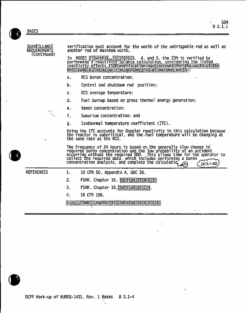
BASES
SDMB 3.1.1
SURVEILLANCEREQUIREMENTS
(Continued)
verification must account for the worth of the untrippable rod as well asanother rod of maximum worth.
In MODES 2;-",'C@thg,«V<,-,,2~0)~M. 4, and 5. the SDM is verified byperforming"a""reactiv>tv''a'lance calculation considering the listed ,reactivitz. effects CSDN~veri',:fica'tio>'niaiust',=;.ac'co'unt","",for''-'.':th'".."worth,"::o',';.;the6nti::$jYpablK:.:i;od:::'as'.:.we'1.:;1 ~s::: another:.">rod:;-'"'of--,- aximum'.-wor>th):>~see~> ~ avo <ov«e.~ w%> Cene '~~%4ce~eoA4e ~4~ wwww ~'>r
a. RCS boron concentration;
Control and shutdown rod position;
RCS average temperature;
Fuel burnup based on gross thermal energy generation:
Xenon concentration;
Samarium concentration; and
g. Isothermal temperature coefficient (ITC).
Using the ITC accounts for Doppler reactivity in this calculation becausethe reactor is subcritical, and the .fuel temperature will be changing atthe same rate as the RCS.
The Frequency of 24 hours is based on the generally slow change inrequired boron concentration and the low probability of an accidentoccurring without the required SDM. This allows time for the operator tocollect the required data, which includes performing a boronconcentration analysis, and complete the calculatio~
REFERENCES
2.
3.
4.
10 CFR 50, Appendix A, GDC 26.
FSAR, Chapter 15. FectfeA~KSA~R.,'i%>
FSAR, Chapter 15. i'cd'oo~gB.':.'2„'. 4.
10 CFR 100.
6,."':-:,;;"'::,:,:;:,:.'.-::..::FSAR~:,Ch'a" t"';g6~,,:Si.cti~rj,',"1574,:":,::,6P:.65
DCPP Mark-up of NUREG-1431. Rev. 1 Bases 8 3.1-4


BA~
Q4ekC aouV)i(can+inuc 6)
APPLICABLESAFETY ANALYSIS
Core ReactivityB Q-.k-R 3'1"".:2
M 3J-MIn order to achieve the required fuel cycle energy output. the uraniumenrichment, in the new fuel loading and in the fuel remaining from the~
~revious cycle, provides excess positive reactivity beyond that requiredo sustain steady state operation throughout the cycle. When the reactor
is critical at RTP and moderator temperature. the excess positivereactivity is compensated by burnable absorbers (if any), control
rods'hateverneutron poisons (mainly xenon and samarium) are present in thefuels and the RCS boron concentration.
When the core is producing THERNL POWER. the fuel is being depleted andexcess reactivity is decreasing. As the fuel depletes. the RCS boronconcentration is reduced to decrease negative reactivity and maintainconstant THERNL POWER. The boron letdown curve is based on steady stateoperation at RTP. Therefore. deviations from the predicted boron letdowncurve may indicate deficiencies in the design analysis, deficiencies inthe calculational models'r abnormal core conditions, and must beevaluate. de~The acceptance criteria for are that the reactivitybalance limit ensures plant operation is maintainedwithin the assumptions of the sa e y ana yses.
Accurate prediction of core reactivity is either an explicit or implicitassumption in the accident analysis evaluations. Every accidentevaluation (Ref. 2) is, therefore, dependent upon accurate evaluation ofcore reactivity. In particular. SDH and reactivity transients'uch ascontrol rod withdrawal accidents or rod ejection accidents, are verysensitive to
(Continued)
DCPP Hark-up of NUREG-1431, Rev. 1 Bases 6> I-5 C~ g,/- ED


'BA5ES
LCO
(grani nuu)
APPLICABILITY
Core ReactivityB Q-.k4 351;2
iX9./-E3
When measured core reactivity is within 1X hk/k of the predicted value atsteady state thermal conditions, the core is considered to be operatingwithin acceptable design limits. Since deviations from the limit arenormally detected by comparing predicted and measured steady state RCScritical boron concentrations. the difference between measured andpredicted values would be approximately 100 ppm (depending on the boronworth) before the limit is reached. These values are well within theuncertainty limits for analysis of boron concentration samples'o thatspurious violations of the limit d to uncertainty in measuri R Sboron concentration are unlikel. ~ 9./
The limits on core reactivity must be maintained during NODES 1 and 2because a reactivity balance must exist when the reactor is critical orproducing THERNAL POWER. As the fuel depletes. core conditions arechanging, and confirmation of the reactivity balance ensures the core isoperating as designed. This Specification does not apply in NODES 3, 4.and 5 because the reactor is shut down and the reactivity balance is notchanging.
In NODE 6, fuel loading results in a continually changing corereactivity. Boron concentration requirements (LCO 3.9. 1. "BoronConcentration" ) ensure that fuel
(Continued)
DCPP Nark-up of NUREG-1431. Rev. 1 Bases 53.t-ga. yg 3,I-E3)


Qg WEIL.LANcEgQ@u >gElHHUTS
(cmnu>')
REFERENCES
Core ReactivityB ~ 8-:|":.:"':2
20C 3./- Eb
60 EFPD after entering NODE 1, is acceptable. based on the slow rate ofcore changes due to fuel depletion and the presence of other indicators(QPTR, AFD. etc.) for prompt indication of an anomal~ Le3.1-m
1. 10 CFR 50, Appendix A, GDC 26, GDC 28. and GDC 29.
2. FSAR. Chapter 15.
DCPP Hark-up of NUREG-1431. Rev. 1 Bases B 3.1-9


8 3. 1 REACTI TY CONTROL SYSTEMS
B 3.1.4 3. .3 Moderator Temperat re Coefficient (MTC)
BASES
MTCB Q-.kA 3,".1'.",3
DC r.>-Eb
BACKQRouQQ
(avenues )
APPLICABLESAFETY ANALYSES
The SRs for measurement of the MTC at the beginning and near the end ofthe fuel cycle are adequate to confirm that the MTC remains within itslimits'ince this coefficient changes slowly. due principally to thereduction in RCS boron concentration associated with fuel burn~~s,j @>
The acceptance criteria for the specified NTC are:
a. The MTC values must remain within the bounds of those used in theaccident analysis (Ref. 2); and
b. The MTC must be such that inherently stable power operations resultduring normal operation and accidents'uch as overheating andovercooling events.
The FSAR, Chapter 15 (Ref. 2). contains analyses of accidents that resultin both overheating and overcooling of the reactor core. MTC is one ofthe controlling parameters for core reactivity in these accidents. Boththe most positive value and most negative value of the MTC are importantto safety. and both values must be bounded. Values used in the analysesconsider worst case conditions to ensure that the accident results arebounding (Ref. 3).
(Continued)
OCPP Mark-up of NUREG-1431, Rev. 1 Bases S3. I-ioc, Qc3.t- E5


BASES
APiZI(4atFSAFETY QHAI.QSES
@anWnu ea)
LCO
Ã7/- w>
HTC satisfies Criterion 2 of+he 3'(ICFR59.":.:;366@)'(2)A$ ),:. Even though itis not directly observed and contr'oTled fr'om'"th'e'"c'ontrol room. HTC isconsidered an initial condition process variable because ofdependence on boron concentratio~n ~ 9./- E2>
LCO 3.1.43 requires the HTC to be within specified limits of the COLRto ensure"that the core operates within the assumptions of theaccident analysis. During the reload core safety evaluation. the HTCis analyzed to determine that its values remain within the bounds ofthe original accident analysis during operation.
Assumptions made in safety analyses require that the HTC be lessositive than a given upper bound and more positive than a given loweround. The HTC ss most positive near BOC when core reactivity and
required boron concentration are at their maximum values; this upperbound must not be exceeded. This maximum upper limit is evaluatednear BOC. all rods out (ARO). hot zero power conditions. At EOC theHTC takes on its most negative value. when the lower bound becomesimportant. This LCO exists to ensure that both the upper and lowerbounds are not exceeded.
During operation. therefore, the conditions of the LCO can only beensured through measurement. The Surveillance checks at BOC and EOCon HTC provide confirmation that the HTC is behaving as anticipated sothat the acceptance criteria are met.
The LCO establishes a maximum positive value that cannot be exceeded.The BOC positive limit and the EOC negative limit are established inthe COLR to allow specifying limits for
(Continued)
DCPP Hark-up of NUREG-1431, Rev. 1 Bases 8 ~' >~0- g 9,/- Eb


BASES
LCO
(Continued)
APPLICABILITY
ACTIONS
MTCB Q-.4-.4 Si'1:".:3
~g I-EDeach particular cycle. This permits the unit to take advantage ofimproved fuel management and changes in unit operating schedul~~
C~e
Technical Specifications place both LCO and SR values on NTC. based onthe safety analysis assumptions described above.
In MODE 1. the limits on HTC must be maintained to ensure that anyaccident initiated from THERMAL POWER operation will not violate thedesign assumptions of the accident analysis. In NODE 2 with thereactor critical'he upper limit must also be maintained to ensurethat startup and subcritical accidents (such as the uncontrolledcontrol rod assembly or group withdrawal) will not violate theassumptions of the accident analysis. The lower MTC limit must bemaintained in MODES 2 and 3, in addition to NODE I, to ensure thatcooldown accidents will not violate the assumptions of the accidentanalysis. In MODES 4, 5, and 6. this LCO is not applicable. since noDesign Basis Accidents using the HTC as an analysis assumption areinitiated from these HOD~Q~ zx- 88
~/i'e~ ~ Z./-EDIf the p e NTC limit is violated, administrative withdrawal limitsfor cont anks must be established to maintain the NTC within itslimits. The NTC becomes more negative with control bank insertion anddecreased boron concentration. A Completion Time of 24 hours providesenough time for evaluating the NTC measurement and computing therequired bank withdrawal limits.As cycle burnup is increased, the RCS boron concentration will bereduced. The reduced boron concentration causes the NTC to becomemore negative. Using physics calculations, the time in cycle life atwhich the calculated C will meet the LCO requirement can bedetermined. At this point in core life Condition A no longer exists.The unit is no longer in the Required Action. so the administrativewithdrawal limits are no longer in effect.
R I-EZ>
If the required administrative withdrawal limits are not establishedwithin 24 hours, the unit must be brought to NODE 2 with k „ < 1.0 toprevent operation with an NTC that is more positive than tffat assumedin safety analyses.
(Continued)
DCPP Mark-up of NUREG-1431, Rev. 1 Bases B 3. 1-12


BASES
NTCB 3-4-4 3"".1gB
SURVEILLANCEREQUIREMENTS
SR'~4-'P5"''X%8''I'his
SR requires measurement of the HTC at BOC prior to enteringMODE 1 in order to demonstrate compliance with the most positive MTCLCO. Meeting the BOC limit prior to entering MODE 1 ensures that thelimit will also'e met at higher power levels.The BOC NTC value for ARO will be inferred from isothermal temperaturecoefficient measurements obtained during the physics tests afterrefueling. The ARO value can be directly compared to the BOC NTClimit of the LCO. If required. measurement results and predicteddesign values can be used to establish administrative withdrawallimits for control banks.
SR ~4-4In similar fashion, the LCO demands that the HTC be less negative thanthe specified value for EOC full power conditions. This measurementmay be performed at any THERMAL POWER. but its results must beextrapolated to the conditions of RTP and all banks withdrawn in orderto make a proper comparison with the LCO value. Because the RTP NTCvalue will gradually become more negative with further core depletionand boron concentration reduction. a 300 ppm SR value of NTC shouldnecessarily be less negative than the EOC LCO limit. The 300 ppm SRvalue is sufficiently less negative than the EOC LCO limit value toensure that the LCO limit will be met when the 300 ppm Surveillancecriterion is met.
SR 3.1.4-.NQ is modified by e Pith8 Notes that include the followingrequirements:
8ff~iVC::.'f03;:ljjgiji8'r~'jla$8:.:.i'(EFP9$ 3:';5fier:.,::-:::,:r955ikrjg',':..ah&'::''iquiva'lentor':"::aorgiiqiiilatiraomlRTp'olg~rioda',:::'oat l<ARO):-:„:biiioiiiooea'ioi5i atiai:,oaf
aPF~RIf the 300 ppm Surveillance limit is exceeded, it is possiblethat the EOC limit on NTC could be reached before the plannedEOC. Because th C changes slowlv with core depletion'heFrequency of 14 F is sufficient to avoid exceeding the EOClimit. CEdlang
(Continued)
DCPP Hark-up of NUREG-1431, Rev. 1 Bases B 3.1-13


B 3. 1 REACTIVITY CONTROL SYSTEMS
B ~ g~g'~4 pQ J QCQJj'ltCjA&tR~ L,I/Vl k5
BASES
Rod Group Alignment LimitsB Q-4-.S 3~"1-:4
C
)C P.I-GD
BACKGROUND
~t>'nc'pI i5
The OPERABILITY ( i.e., trippability) of the shutdown and control rodsis an initial assu ion in all safety analyses that assume rodinsertion upon reac or trip. Maximum rod misalignment is an initialassumption in the safety analysis that directly affects core powerdistributions and assumptions of available SDM.
The applicable criteria for these reactivity and power distributiondesign requirements are 10 CFR 50, Appendix A. GDC 10. "ReactorDesign." GOC 26, "Reactivity Control System Redundancy andCapability" (Ref. 1), and 19 CFR 50.46. "Acceptance Criteria forEmergency Core Cooling Systems for Light Water Nuclear Power Plants"(Ref. 2).
Mechanical or electrical failures maz cause a control rod to becomeinoperable or to become misaligned from its group. Contr 1 rodinoperability or misalignment may cause increased power peaking. dueto the asymetric reactivity distribution and a reduction in the totalavailable rod worth for reactor shutdown. Therefore, control rodalignment and OPERABILITY are related to core operation in designpower peaking limits and the core design requirement of a minimum SDM.
Limits on control rod alignment have been established, and all rodpositions are monitored and controlled during power operation toensure that the power distribution and reactivity limits defined bythe design power peaking and SDM limits are preserved.
Rod cluster control assemblies (RCCAs), or rods. are moved by theircontrol rod drive mechanisms (CRDMs). Each CRDM moves its RCCA onestep (approximately Ve inch) at a time. but at varying rates (stepser minute) depending on the signal output from the Rod Controlystem.
(Continued)
DCPP Mark-up of NUREG-1431, Rev. 1 Bases B 3.1-14


BASES
Rod Group Alignment LimitsB Q-.4-.S 3";1'-„4
Two types of analysis are performed in regard to static rodmisalignment (Ref. 3). With control banks at their insertion limits.one type of analysi's'onsiders the case when any one rod is completelyinserted into the core. The second type of analysis considers thecase of a completely withdrawn single rod from-a bank>!9 inserted toits insertion limit. Satisfying i>mits on departure from nucleateboiling ratio in both of these cases bounds the situation when a rodis misaligned from its group by 12 steps.
Another type of misalignment occurs if one RCCA fails to insert upon areactor trip and remains stuck fully withdrawn. This condition isassumed in the evaluation to determine that the reaui red SDM is metwith the maximum worth RCCA also fully withdrawn (Ref. '4).
The Required Actions in this LCO ensure that either deviations fromthe alignment limits will be corrected or that THERMAL POWER will beadjuste5 so that excessive local linear heat rates (LKRs) will notoccurs and that the requirements on SDM and ejected rod worth arepreserved.
Continued operation of the reactor with a misaligned rod is allowed ifthe heat flux hot channel factor ( F<(Z)) and the nuclear enthalpy hot
(FhN) are verified to be within their limits in the COLRand the safety analysis is verified to remain valid. When a controlrod is misaligned, the assumptions that are used to determine the rod
(Continued)
DCPP Mark-up of NUREG-1431, Rev. 1 Bases 8 S


BASES
Rod Group Alignment LimitsB Q-.k-S 8."1'.".'4
In many cases, realigning the remainder of the group to e misalignedrod may not be desirable. For example. realignsng contro ank B to arod that is misaligned 15 steps from the top of the core wo ld requirea significant power reduction. since control bank 0 must be fulli '8~ed and control bank C must be inserted to approximately 5p )~l
~
~
P er operation may continue with one RCCAmisaligned provided that SDM 15 verlfi wl 1n
'r. h De3.I-Eb
ompletion Time of 1 hour represents the time necessary fordetermining the actual unit SDM and. if necessary. aligning andstarting the necessary systems and components to initiate oration.
B.2.2 B.2.3 B.2.4 B.2.5 and B.2.6
For continued operation with a misaligned rod. fpP eeac'd'or,,::,';power: mustbe reduced, SOM must periodjcally be verified withiii l'imits.'-hotchannel factors (F~(2) and F,„) must be verified within limits. and thesafety analyses must be re-evaluated to confirm continued operation ispermissible. Reduction of power to 75K RTP ensures that local LHRincreases due to a misaligned RCCA will not cause the core designcriteria to be exceeded (Ref. 8). The Completion
(Continued)
OCPP Mark-up of NUREG-1431, Rev. 1 BasesP

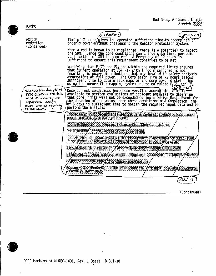
BASES
ACTIONreduction(continued)
We AeC,iden~ Ar.lqe esf
FSAiio ChCpkr i5'~ ~by
WW~iam me~i~<ehv+s evv yg y„is E-CeC1ugyps<,
Rod Group Alignment Limits*8 ~ 8".:"'2'-4
AVAAV
i educ%'o~ ~ ~.l- EDTimd of 2 hours gives the operator sufficient time to accomplish anorderly power ithout challenging the Reactor Protection System.
When a rod is known to be misaligned. there is a potential to impactthe SDM. Since the core conditions can change with time. periodicverification of SDM is required. A Frequency of 12 hours issufficient to ensure this requirement continues to be met.
Verifying that Fo(2) and F" are within the required limi,ts ensuresthat current operation ati5$ RTP with a rod misaligned is notresulting in power distributions that may invalidate safety analysisassumptions at full power. The Completion Time of 72 hours allowssufficient time to obtain flux maps of the core power distributiqpusing the incore flux mapping system and to calculate F d F „.
9 ~ i i3Once current conditions have been verified accep ble.available to pertorm evaluations of accident anal sis to determinethat core limits will not be exceeded during a De ign Basis Event forthe duration of operation under these conditions. A Com letion Time
pertorm the analysis.
Tt'ie:.;:f/1'iojiiooi':."eo" devot~'eche ivies,::i!equi!":ie:,'e'veioe'|1Vii '!fbi",,:::,„: 'iiiViiiie'dopeeeti xiiiA'xli-'::,,iiilseli'giiee':::cod::.:
Roi.':iCl'i'@',Coit'i.'.g,~Fe53,,::;:Hf'g"reN5
I"'arae:,-':Ph's"::,,Mhi'ch'::;Atua''::'.4 ';::;:Em'erienc'i,'.:Core'::..":Cml,:i .:.':::Sv'stemAVAWhV~ NW V VAYhkVAYAYAWhVAVA~WCAVWhVW Wh'AWNG AYAVAY AYs W Yhyheh'YAWkh4Vsss AYAVV.~ M'WA4(
9'igl",-::Rod,'..;.C'.laster.'.«,'::,:C'esCi;o ~A'sseebl',:.Athdr'walFi,,::Fil::1~;:fbi
'yhwh.~" 'e ' '~ ykvn%0%dvhPYYv "'h 'wsvvwhvk" SH 4hw. "' '' Y'Yesv ~~ .«Yi
, 20r:,.":;58coAH&$',~',.Ce™g't.S,8t:„eI„-':Pip&':.:::,Ru&p, Kf:t.
Rtjphtui'.e.-,:Of::,',"a,':.g~iiti." l.':,.sRNf!9'rfye.".:HeNiaN'sm,::.'s~ng";;".'%Rod.:;:CTu'" er,".!C6iit're::6..
CPS./- i3
(Continued)
DCPP Mark-up of NUREG-1431, Rev. 1 Bases B 3.1-18


B 3.1 REACTIVITY CONTROL SYSTEMS
B Q-.k-6 3:.1~5 Shutdown Bank Insertion Limits
BASES
Shutdown Bank Insertion LimitsB Q-.4-.6 3.:1 5
BACKGROUND The insertion limits of the shutdown and control rods are initialassumptions in all safety analyses that assume rod insertion uponreactor trip. The insertion limits directly affect core power andfuel burnup distributions and assumptions of avai lable ejected rodworth, SDM and initial reactivity insertion rate.The applicable criteria for these reactivity and Power distributiondesign requirements are 10 CFR 50, Appendix A, GDC 10, "ReactorDesign "
GDC 26. "Reactivity Control System Redundancy andCapabiiity." GDC 28, "Reactivity Limits" (Ref. 1), and 10 CFR 50.46,"Acceptance Criteria for Emergency Core Cooling Systems for LightWater Nuclear Power Reactors" (Ref. 2). Limits on rod insertion havebeen established. and all rod positions are monito ed and controlledduring power operation to ensure that the power di tribution andreactivity limits defined by the design power peak n SDM limitsare preserved. ~l(ng/gal I nCThe rod cluster con ol assemblies (RCCAs) are divided among ourcontrol banks and ou shutdown banks. Each bank may be furt er M~'~subdivided into two groups to provide for precise reactivity contro .A group consists of two or more RCCAs that are electrically paralleledto step simultaneously. A bank of RCCAs consists of two groups thatare moved in a stag ered fashion, but always within one step of eachother„. 1„„.,bapksfouf;::.'..":cantr012::inks',contain'5two,":rodlgi.oups'";.~:."Two':-",ihiitdo'wnjbinks'.."i':($aml:;,...B),,":,::conthiyj~'o~i",od~grou'jsi'pjdp>her'emNnie'jkwoahiitdown'„:,jmnks l.".(Cand@)~c'iesfit.': Of.'avjiijgle'(jjap""..~~See-LCO"Q~ 3~1': 4
—.Ro'd"Group''1'i'gniikntLim'i't's. fo''ontrol"'afYd shutdown rod OPERABILITY andalignment requirements, and LCO Q;4-.8 3",.'1.'7;:, "Rod PositionIndication." for position indication re'j'Oi'rements.
(Continued)
DCPP Mark-up of NUREG-1431, Rev. 1 Bases B 3.1-21


B 3.1 REACTIVITY CONTROL SYSTEMS
B Q-.4-.6 3."';1:.5 Shutdown Bank Insertion Limits
Shutdown Bank Insertion LimitsB Q-.4-.6 3"..1< 5
BASES
APPLICABLESAFETY ANALYSIS(Continued)
maintain the required SDM at rated no load temperature (Ref. 3). Theshutdown bankinsertion limit also limits the reactivity worth of anejected shutdown rod.
The acceptance criteria for addressing shutdown and control rod bankinsertion safety limits and inoperability or misalignment is that:a. There be no violations of:
1. Specified acceptable fuel design limits, or2. RCS pressure boundary integrity: and
b. The core remains subcritical after accident transients.As such, the shutdown bank insertion limits affect safety analysisinvolving core reactivity and SDM (Ref. 3).
The shutdown bank insertion limits preserve an initial conditionassumed .in Q.e safety analyses and. as such. satisfy Criterion 2 of
;RBQ '
LCO The shutdown banks must be within their insertion limits any time thereactor is critical or approaching criticality. This ensures that asufficient amount of negative reactivity is available to shut down thereactor and maintain the required SDM following a reactor trip.The shutdown bank insertion limits are defined in the COLR.
(Continued)
DCPP Mark-up of NUREG-1431, Rev. 1 Bases B 3.1-22


B 3.1 CTIVITY CONTRO SYSTEMS
B . . 8;X.""'5 Shutdown ank Insert n Limits
Shutdown Bank Insertion LimitsB Q-.k-6 P:1"'lS
BASES
APPLICABILITY The shutdown banks must be within their insertion limi s i the ~pi,nc.reactor in MODES 1 and 2. The applicability in MODE 2 e insinitial control bank withdrawal, during an approach to cri ica ity.and continues throughout NODE 2, until all control bank rods are againfully inserted by reactor trip or by shutdown. This ensures that asufficient amount of negative reactivity is available to shut down thereactor and maintain the required SDN following a reactor trip. Theshutdown banks do not have to be within their insertion limits inMODE 3, unless an approach to criticality, is,„being made. In NODE 3,4, 5, or 6, the shutdown banks are5"':::tjjica*71'j'.':>awfully inserted in the
d ib «h SD,, "5„,:'i',':,,L'CO'3,,l~fSDN requirements in MODES Kiwith;,.k,-«~X':".';0 .'. 4. and 5. LCO 3.9. 1,"Boron Concentration." ensu'r'es=adequate SUN in NODE 6.
The Apblicability requirements have been modified by, a Note indicatingthe LCO requirement is suspended during SR 3.1.6-.24,:''2. This SRverifies the freedom of the rods to move. and requi'r'es the shutdownbank to move below the LCO limits, which would normally violate theLCO.
ACTIONS A.l.l A.1.2 and A.2
Mhen one or more shutdown banks is not within insertion limits.2 hours is allowed..to restore the shutdown banks to within theinsertion limits. This is necessary because the available SDN may besignificantly reduced, with one or more of the shutdown banks notwithin their insertion. limits. Also. verification of SDN orinitiation of boration within 1 hour is required. since the SDN inNODES 1 and 2 is ensured by adhering to the control and shutdown bankinsertion limits (see LCO 3. 1. 1). If shutdown banks are not withintheir insertion limits, then SDN will be verified by performing areactivity balance calculation, considering the effects listed in theBases for SR 3.1.1.1.
The allowed Completion Time of 2 hours provides an acceptable time forevaluating and repai ring minor problems without allowing the plant toremain in an unacceptable condition
(Continued)
DCPP Mark-up of NUREG-1431, Rev. 1 Bases 8 3 I-2'24 ~ 3.I- EG


B 3.1 REACTIVITY CONTROL SYSTEMS
B ~ 8"';1' Control Bank Insertion Limits
Shutdown Bank Insertion LimitsB ~ 8".':1','6
BASES
BACKGROUND The insertion limits of the shutdown and control rods are initialassumptions in all safety analyses that assume rod insertion uponreactor trip. The insertion limits directly affect core power andfuel burnup distributions and assumptions of available SDH. andinitial reactivity insertion rate. I
The applicable criteria for these reactivity and power distributiondesign requirements are 10 CFR 50, Appendix A. GDC 10. "ReactorDesign "
GDC 26, "Reactivity Control System Redundancy andCapability." GDC 28, "Reactivity Limits" (Ref. 1). and 10 CFR 50.46."Acceptance Criteria for Emergency Core Cooling Systems for LightMater Nuclear Power Reactors" (Ref. 2). Limits on rod insertion havebeen established. and all rod positions are monitored and controlledduring power operation to ensure that the power distribution andreactivity limits defined by the design power peaking and SDM limitsare preserved. n& e- ~i>ne.The rod cluster co 1 assemblies (RCCAs) are divided among9jjgb da I-<rcontrol banks and shutdown banks. Each bank may be furthersubdivided into two groups to provide for recise reactivity control.
, A'."::%rhode:.'.:.'i:ons'i:stsof-,;::two'go'i',::~tiioii,'ACCT."-Niit~$i'.0'>pie'clerical',1'j',.''-.pai;a'ill,i''l'ed,":::to,pkep ". '..s'im'ul&iieous>y)and"ai'e)movedgj'n,;,a'--sti jgei:".ed,:;4ashioiiC::but!,":a,fwa'js..'%ithinone) stej",",ofgeach;.";Other""'.:-.FT~~hutdow'n.:banveks".':.(C,'::~nd,;:9) ':c'ansi'st':.'::of~-aEiiiile~ji,.e'ij;:;"...'Se'e L'CO Q~'3":.:l".4. Rod"Graaiip Al'ignment Limi'tss." forC'Osvnt'rtOJ-"asn'd„S|iotdOWn rad OPERABILTTY and alignment requirementS. andLCO Q-. k-8 3„"-';:1<.':.,7,. "Rod Position Indication," for position indicationrequirementse.
"'he
control bank insertion limits are specified in the COLR.. The
control ban s are required to be at or above t e insertion limitlines.
(Continued)
DCPP Mark-up of NUREG-1431, Rev. 1 Bases B 3.1-24

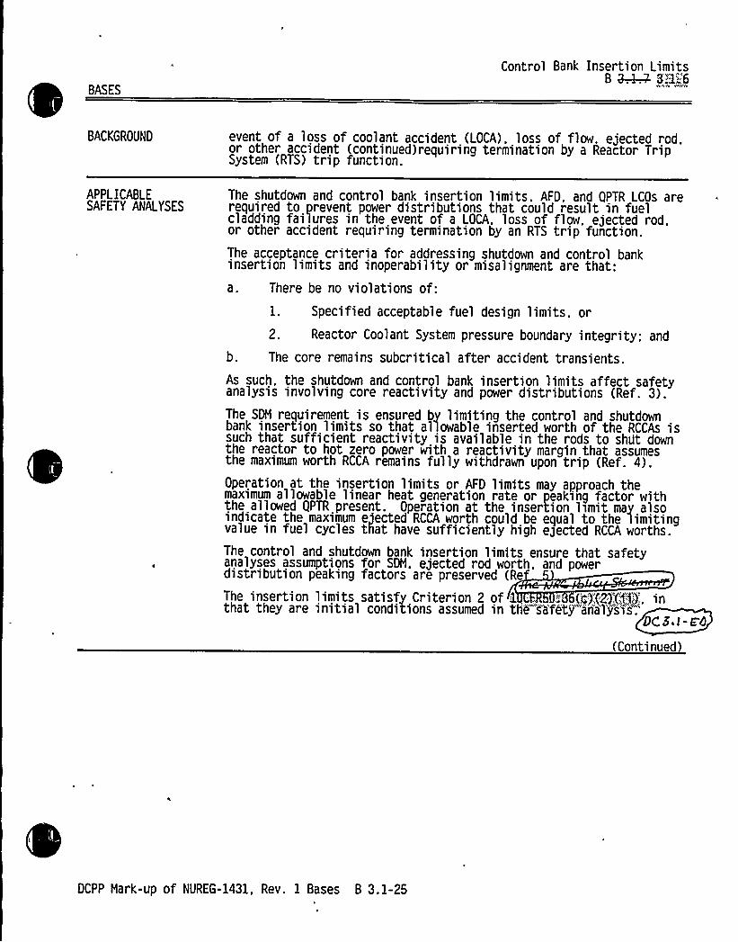
BASES
Control Bank Insertion LimitsB ~ 3'3.'"'6
BACKGROUND event of a loss of coolant accident (LOCA), loss of flow. ejected rod,or other accident (continued)requiring termination by a Reactor TripSystem (RTS) trip function.
APPLICABLESAFETY ANALYSES
The shutdown and control bank insertion limits'FD. and QPTR LCOs arerequired to prevent power distributions that could result in fuelcladding failures in the event of a LOCA. loss of flow. ejected rod.or other accident requiring termination by an RTS trip function.The acceptance criteria for addressing shutdown and control bankinsertion limits and inoperability or misalignment are that:a. There be no violations of:
1. Specified acceptable fuel design limits. or
2. Reactor Coolant System pressure boundary integrity; and
b. The core remains subcritical after accident transients.As such, the shutdown and control bank insertion limits affect safetyanalysis involving core reactivity and power distributions (Ref. 3).The SDH requirement is ensured by limiting the control and shutdownbank insertion limits so that allowable inserted worth of the RCCAs issuch that sufficient reactivity is available in the rods to shUt downthe reactor to hot zero power with a reactivity margin that assumesthe maximum worth RCCA remains fully withdrawn upon trip (Ref. 4).Operation at the insertion limits or AFD limits may approach themaximum allowable linear heat generation rate or peaking factor withthe allowed QPTR present. Operation at the insertion lsmit may alsoindicate the maximum ejected RCCA worth could be equal to the limitingvalue in fuel cycles that have sufficiently high egected RCCA worths.
The control and shutdown bank insertion limits ensure that safetyanalyses assumptions for SDM, ejected rod worth, and powerdistribution peaking factors are preserved (Re
The insertion limits satisfy Criterion 2 of 1 . "''C'}.'.(2)'.(Xf):,. inthat they are initial conditions assumed in the s'a'fag ana'Ty's1's".'CS,t-c'4
(Continued
DCPP Mark-up of NUREG-1431, Rev. 1 Bases B 3.1-25


Enclosure 2PG8E Letter DCL 98-107
ADDITIONALINFORMATIONCOVER SHEET
ADDITIONALINFORMATIONNO: DC 3.1-001
REQUEST:
APPLICABILITY: DC, CP
Revise DOC 12-11-TR3 in enclosure 3A to reflect lead plant wording.
ATTACHEDPAGES'ncl
3A 7


DESCRIPTION OF CHANGES TO TS SECTION 3I4.1(Continued)
CHANGENUMBER NSHC DESCRIPTION
12-08
12-09
LS9 Consistent with NUREG-1431, the requirement to reduce the highneutron flux set point to s 85 percent of RTP would be deleted. This isacceptable because the underlying safety limits are not of a nature thatrequires immediate shutdown of the plant if they are exceeded. This isevidenced by the allowance of 72 hours to verify peaking factors. It isassumed that during this 72-hour period an event willnot occur whichwill raise the power level and cause a high neutron flux trip at 100percent RTP. Ifa power excursion would occur from the 75 percentRTP ACTION statement limit, the initial peaking factors would not becritical to the analysis, since the analysis is based on the peakingfactors at 100 percent RTP. Therefore, the risk of a reactor trip causedby adjusting the power range trip set points is not justified by thepotential consequences of failing to reduce the trip set points.
Not applicable to DCPP. See Conversion Comparison Table.(Enclosure 3B)
12-10
12-11
LS10
TR3
+loweve c, +hcse. ~- tran:inIe~+q pe~pi~i,nrnwS cire
nc+'jpayc
. cim~e. Tenn>'cd Speci jic<+~5
The requirement to maintain RCS T~ ~541'F during rod drop testingwould be revised to maintain T~ ~500 F. NUREG-1431, allows thetests to be performed at temperatures as low as 500'F. Because theRCS coolant is more dense at lower temperatures, the rod drop timewould be greater at the lower temperatures than at the higher .
temperatures. In addition, the RCS is borated such that the SDMremains within its limits at the Conditions existing during these tests.Nevertheless, this change, which allows more flexibilityof plantconditions for conducting rod drop testing, is a relaxation in plantoperations in the CTS.
It is proposed to move the requirement to perfo rod drop testing onindividual rods following maintenance that could affect the drop tim~
fand to delete the monthrequirement]. The requirement to perform drop time testing folloviingeach removal of the reactor vessel head would not be modified. Theproposed change is justified, because in addition to being consistent
th NUREG-1431, Rev. 1, good maintenance practices would require aretest following any maintenance on a rod or its drive system that couldaffect drop time. urthermore, it is difficultto postulate any maintenanceon a ro a could affect its drop time without requiring the reactorvessel head to be removed in the process. The components of the rodand rod drive system that affect drop time (as defined in TS) are allinside the reactor coolant pressure boundary. Therefore, moving thisrequirement outside the TS would have essentially no impact on rodOPERABILITY. [Measuring rod drop time following each removal of thereactor vessel head is considered equivalent ifnot more restrictive thanan month frequency requirement; therefore, deleting the monthrequir ent where it exists (not all plants have it in the C is anadminis tive change.]
E)C-Ai.i,-oo I
DCPP Description of Changes to Current TS .

0

Enclosure 2PGLE Letter DCL 98-107
ADDITIONALINFORMATIONCOVER SHEET
ADDITIONALINFORMATIONNO: DC ALL-001
REQUEST:
APPLICABILITY'C
LAs 119/117 and 118/116 were issued 7/13/97 and addressed CTS surveillance intervalincreases due to 24-month fuel cycles. These changes on pages affected by NRC commentnumbers are indicated with "DC-ALL-001." These changes were previously submitted to theNRC in an errata to LAR 97-09 via DCL-98-003 (dated January 8, 1998).
ATTACHEDPAGES:
See notations on applicable pages for each comment number.


Enclosure 2PG8 E Letter DCL 98-107
ADDITIONALINFORMATIONCOVER SHEET
ADDITIONALINFORMATIONNO: DC ALL-002
REQUEST:
APPLICABILITY'C
An errata to LAR 97-09 was submitted to the NRC January 8, 1998, inDCL-98-003. Errata changes on pages affected by NRC comment numbers areindicated with "DC-ALL-002."
ATTACHED PAGES:
See notations on applicable pages for each comment number.


Enclosure 2PG8E Letter DCL 98-107
ADDITIONALINFORMATIONCOVER SHEET
ADDITIONALINFORMATIONNO: TR 3.1-001
REQUEST:
APPLICABILITY: DC, CP, WC, CA
Incorporate NRC-approved traveler TSTF-108, Revision 1, to delete the words"within 12 hours" from the Frequency of CTS SR 4.10.3.2 and ITS SR 3.1.8.1.
ATTACHEDPAGES'ection
3.1Encl. 5AEncl ~ 5BEncl. 6AEncl. 6B
Traveler Status Sheet, 3.1-18B 3.1-3733
Section 3.10Encl. 2 3/4 10-3Encl. 3A 2Encl. 3B 1
Encl. 4 14, 15


Industry Travelers Applicable to Section 3.1
TRAVELER¹TSTF-9, Rev. 1
STATUS
Incorporated 3.1-1
DIFFERENCE ¹ COMMENTS
NRC approved.
TSTF-12, Rev. 1
TSTF-13, Rev. 1
TSTF-14, Rev.$
TSTF-15, Rev. 1
Incorporated
Incorporated
Incorporated
Incorporated
3.1-15
3.1-4
3.1-13
N/A
NRC approved. ITSSpecial Test Exception3.1.10 is retained and re-,:numbered as 3.8.1,consistent with thistraveler and TSTF-136.
NRC approved.
NRC approved &3.t-oo
NRC approved.
TSTF-89
TSTF-107, Rev. l
Incorporated
Incorporated
3.1-8
3.1-6
NRC approved.
g3,/-/5
TSTF-108, Rev. 1
TSTF-110, Rev. 2TSTF-136
TSTF-141
TSTF-142
WOG-105
ncorporated
Incorporated
Incorporated
Not Incorporated
tlititnoorporated
Incorporated
Incorporated
3.1-10
3.1-9, 3.1-'I 5
N/A
3.1-7
3.1-16
(QbNRC appro~i S,i-oo/
AC HAPP~ 1|d'b,l-~
Disagree with change;traveler issued after cut-off date
7 A ~ rr CXQ
&Mete.NRC 4p<~.Qp 3.i-mr
DCPP Mark-up of NUREG-1431, Rev. 1


BASES
PHYSICS TESTS Exceptions - MODE 2B Q-.k~ 3"1'::8
SURVEILLANCEREQUIREMENTS
If the Required Actions cannot be completed within the associatedCompletion Time., the plant must be brought to a MODE in which therequirement does not apply. To achieve this status. the plant must bebrought to at least MODE 3 within an additional 15 minutes. TheCompletion Time of 15 additional minutes is reasonable. based onoperating experience, for reaching MODE 3 in an orderly manner andwithout challenging plant systems.
wu 3.1-~IThe eequfrei power range and intermediate range neutron detectors mustbe ve'rsfie'd to be OPERABLE in MODE 2 by LCO 3.3. 1. "Reactor TripSystem (RTS) Instrumentation." A CHANNEL OPERATIONAL TEST is
on ach OPERABL'Empower range and intermediate range channelIprTot''0'riitiation of the PHYSICS TESTS. This will "nsure a e RTS is properly aligned to provide the required deqree
of core rotection durin the performance of the PHYSICS TESTS. -Re-
~N ZO 2..'.Verification that the RCS lowest opegahTgg„":«loop T,„ is ~ 531 F willensure that the unit is not operatin'g i'n a"conditi8n that couldinvalidate the safety analyses. Ver~fication of the RCS temperatureat a Frequency of 30 minutes during the performance of the PHYSICSTESTS will ensure that the initial conditions of the safety analysesare not violated.g~+<; g~s,8%3
Verffj~~tgeiy&at<heeHERHAI:."-:::,'Ii08ER'"..xs:.:~.":8f,:,';RA!;.m'!Il;:.:%~sum-,t%t:;-'t'e,.ala<'j~$ s:,":,:riot'":,'".~jitfig."'$o'~conaditi8ri.':Chat-:,'coN'd~,":;i'tv'alldat'~';:the:.-'sachet j
i n
an
s
8'nal: $'ei!."':~gVer3 fpm8ori'of~4he!".,THERMAL',::;PQER..;::::at:-":a".-.'6; susen''.;;.".:af~. Be.hourÃdur,':..frig,"'::tl'e!,:per'fiorsmagce':~o fj&e$PHYSIGs'.:;:: ... !@jgi,.
enS'iine';i 6at!ithe'~iiiit'1.a'IadOnsdtta'OnS"-'"af::tnhi@Saf fits':iiii1jaeS@i',ii:::nntvidieted',.
SR 3. 1.448. 4
ensulres,that:,-:,.';:!f0j,::.::the4beci;f i'c:,",RCCA'::,''and:.':RCS;:Tereei:atore~majispjiIit,peCJo'rm'ea'@>du>''$ ijgPHYS'ICS;::.:TESTS::",::.'. tW:;.::;p]ant'::;js:;Mt.:.hei;:at: ng.'~rj.'"i,,oond1t ion'!theet.':,ooh'fdiiinaala date .:thi, Wiifetj",,"::::aiia3jsi s:;:,'assviiipthons,'-,
(Continued)
DCPP Mark-up of NUREG-1431, Rev. 1 Bases B 3.1-37


JUSTIFICATION FOR DIFFERENCES FROII NUREG-1431
NUREG-1431 Section 3/4.1
CHANGENUMBER
3.1-19
3.1-20
JUSTIFICATION
Not used.
Consistent with CTS 3/4.10.3, "Physics Tests," ITS LCO 3.1.8 and its Condition C and SR3.1.8.2 are modified to refer to "operating" RCS loops. Ifan operating loop were secured whileoperating in MODE 2, Required Action A.1 of ITS 3.4.4 directs the plant to be in MODE 3 within6 hours. However, depending on initial power level and plant Conditions, securing an RCS loopmay result in a loop's average temperature of [531J'F fairly quickly due to the reverse flowthrough the secured loop and the cooling achieved by the steam generator. In this scenario, itwould not be appropriate to invoke Required Action C.1 of ITS 3.1.8 with its 15 minuteCompletion Time to restore loop average temperature to within limits since the flow in thesecured loop is not passing through the core and ITS LCO 3.4.4 provides appropriate correctiveACTION, consistent with CTS.
9./- 2I
3./-22
Insert
Insert V'l2, 3./-AD3
DCPP Description of Changes to Improved TS

Enclosure 6A Page 3Inserts for TR 3.1-001
JFD 3.1-21 The ISTS SR 3.1.8.1 requirement to perform a CHANNELOPERATIONALTEST(COT) on the intermediate and power range NIS channels within 12 hours priorto initiating PHYSICS TESTS is revised to delete phrase "within 12 hours." COTtesting is performed on these channels prior to reactor startup per LCO 3.3.1.This change is consistent with traveler TSTF-108.


CONVERSiON COMPARISON TABLEFOR D NCES FROM NUREG-1431, SECTION 3/4.1 of 3
TECHNICALSPECIFICATION CHANGE APPLICABILITY
NUMBER
3.1-16
DESCRIPTION
This change adds the requirement to perform SR 3.2.1.2in addition to SR 3.2.1.1 during performance of ITS 3.1.4Required Action B 2.4, consistent with travefer WOG-105.
DIABLOCANYON
Yes
COMANCHEPEAK
Yes
WOLF CREEK
Yes
CALLAWAY
Yes
3.1-17 Consistent with CTS LCO 3.1.3.2 and the wording of ITS Yes3.1.7, Condition A and B, ITS 3.1.7, Condition C isclarified to state that the inoperable position indicators areinoperable position indicators are inoperable DRIPs.
Yes Yes Yes
3.1-18
3.1-19
3.1-20
A MODE change restriction has been added to ITS 3.1.1,in LCO Applicability, per the matrix discussed in CN 01-02-LS1 of the 3.0 Package.
Not used.
Consistent with CTS 3/4.10.3, 'Physics Tests," ITS LCO3.1.8 and its Condition C and SR 3.1.8.2 are modified torefer to "operating" RCS loops.
Yes
N/A
Yes
Yes
NIA
Yes
Yes
NIA
Yes
Yes
N/A
Yes
/neer +8 I-2Z /nor 8
Yes
Qes
Yes
$8$
Tg 3./-OOI
Yes <4 Z.I -OO3
DCPP Conversion Comparison Table - Improved TS


Enclosure 68 Page 3Inserts for TR 3.1-001
JFD 3.1-21 The ISTS SR 3.1.8.1 requirement to perform a CHANNELOPERATIONALTEST(COT) on the intermediate and power range NIS channels within 12 hours priorto initiating PHYSICS TESTS is revised to delete phrase "within 12 hours." COTtesting is performed on these channels prior to reactor startup per LCO 3.3.1.
Applicability:
DC YesCP YesWC YesCA Yes


SPECIAL TEST EXCEPTIONS
3/4.10.3 PHYSICS TESTS
LIMITING CONDITION FOR OPERATION
3. 10.3 The limitations of Specifications 3. 1. 1.3, 3. 1. 1.4. 3. 1.3. 1. 3. 1.3.5. and 3. 1.3.6may be suspended during the performance of PHYSICS TESTS provided:
a. The THERMAL POWER does not exceed 5X of RATED THERMAL POWER.
03-02-A
the,':.COLOR'::,'"':::;":::::a'nd
sHOTGONN';NRGHILt.;:::~i.;.,".",'witfiin7jh~e:../jest":,.ts.;::;.: rovided;;:Xri
c. The Reactor Coolant System lowest operating loop temperature (T,„,) is greaterthan or equal to 531'F.
APPLICABILITY: MON.:Rgui„.....|:ns "':.'PHYSEILS!."TESTS.
ACTION:
03-04-A
a. With the THERMAL POWER greater than SX of RATED THERMAL POWER, iranediatelyopen the Reactor trip breakers.
b. With a Reactor Coolant System operating loop temperature (Tave) less than531'F. restore Tavg to within its limit within 15 minutes or 6e in at leastHOT STANDBY within the next 15 minutes.
:;".,:Ne&'<'„.:;,„:Mith~SHOPTDmOMN:::.NRHGIN"':nat>eIthfn":".;i't%.:1'fmi'O'S.':,",.WithLn'..15-.~fns tEePS,"'-,
"jinni:ts-i'aPt'ejborati.oons';.-."to'"''-','resstoi,':e'.'.SHUTDOWN;MARGIN~::to'n'd'<>,'.w'i%hi'ii!o'n'e':,".':ho'u'r''>s'ustiie'ndi'PHYS'ICS";.TESTS''eP-xcveot'>own;:-',"'""" Pm '""7rs>EEw'w'w'ÃmHvmsvpp~mvpEvpp>pmwpEvmQhcvsvmvRAommmsv~'PHpdrxw&4wppppwppMREw'wpHvmPHEopwmHHHwc'URVEILLANCE
REQUIREMENTS
03-01-M
4. 10.3. 1 The THERMAL POWER shall be determined to be less than or equal to 5C of RATEDTHERMA POWER at least once per hour during PHYSICS TESTS.
03 -05 LOS
4. 10.3.2 Each Int r and Power Range channel shall be subjected to a CHANNELOPER TEETER TEST~ PP T E T EET E E PRESSES TESTS.
4. 10.3.3 The Reactor Coolant System temperature (T,„ ) shall be determined to be greaterthan or equal to 531'F at least once per 30 minutes luring PHYSICS TESTS.
(HEM); Yerif'V7SHUTQOWN'':,'HARGIN'-,".tO'::-;-:be.-.Within77ili'tS..".:j'r'OVided On"'Oie',"'.COIR::,OnvCF:-':""e'r...'24H
nout;s .
DIABLO CANYON - UNITS 1 8 2 3/4 10-3 Unit 1 - Amendment No. 103Unit 2 - Amendment No. 102
July 2, 1995


DESCRIPTION OF CHANGES TO TS SECTION 3/4.10(Continued)
CHANGE
NUMBER09-o504-01
05-01
5-02
NSHCas/M
DESCRIPTION/nse~t Tk 3. i - db lNot applicable to Diablo Canyon Power Plant (DCPP). See ConversionComparison Table (Enclosure 38).
STE LCO 3.10.4,"Position Indication System - Shutdown," would berelocated based on relocation of LCO 3.1.3.3, "Position IndicatingSystems - Shutdown." NRC application of TS Criteria concluded thatthe STE LCOs could be included with corresponding LCOs remaining inTS and that LCO 3.10.4 could be relocated with LCO 3.1.3.3.
Not applicable to DCPP. See Conversion Comparison Table(Enclosure 3B).
DCPP Description of Changes to Current TS


, ITS Section 3.10:Inserts for TR 3.1-001
Encl. 3A
3-05 LS1
Page 2
The current SR requiring the performance of [an ANALOG]CHANNELOPERATIONALTEST on each intermediate and power range NIS channel within12 hours prior to initiating PHYSICS TESTS is revised to delete the phrase"within 12 hours." [A]COTtesting is performed on these channels prior toreactor startup per LCO 3.3.1. Current TS LCO 3.3.1, Reactor Trip System(RTS) Instrumentation, requires the performance of an [A]COTon the powerrange low setpoint and intermediate range NIS channels prior to each reactorstartup, if not performed within the previous 31 days (revised to 92 days in theconversion to ITS 3.3). These RTS SRs must be performed prior to entering theLCO 3.3.1 Applicabilities for these RTS trip functions since there are no CTS SR4.0.4 exceptions. Current SR 4.10.3.2 requires an arbitrary estimate of when theplant is within 12 hours of intiating PHYSICS TESTING. This has no basis fromthe accident analyses, which are satisfied as long as the surveillances arecurrent prior to entering plant MODES where these trip functions provideprotection. When these surveillances are current, they have previously beendetermined to remain valid for 92 days. The initiation of PHYSICS TESTINGdoes not impact the ability of. the channels to perform their required function,does not affect the trip setpoints or trip capability of these channels and does notinvalidate the previous surveillances. This change is consistent with travelerTSTF-108.


CONVERSION COMPARI ABLE - CURRENT TS 3/4.10 e1of2
TECHNICALSPECIFICATION CHANGE APPLICABILITY
NUMBER DESCRIPTION DIABLOCANYON COIIANCHEPEAK
WOLF CREEK CALLAWAY
01-01M
02-01M
03-01M
03-02A
03-03
LCO 3.10.1 would be deleted consistent withTraveler TSTF-12. The SDM STE requires rodworth measurement in the N-1 condition. Otherrod worth measurements techniques will maintainthe SDM during the measurement process andprovide the necessary physics data. The N-1measurement technique is no longer used.
The MODE 1 STE LCO 3.10.2 would be deletedin accordance with Traveler TSTF-12. TSTF-12would delete ITS LCO 3.1.9, which contains theSTEs for MODE 1 because the tests implementedby ITS LCO 3.1.9 were contained in some initialplant startup test programs and are not performedduring post-refueling startup testing. Post-refueling tests may be performed in accordancewith other LCOs.
Consistent with NUREG-1431, Rev. 1, the SDMparameter is added to the list of preconditionsrequired prior to invoking this STE. The actualvalue of the SDM is located in the COLR.Associated ACTION statements and surveillancesare also added.
The requirement to ensure that the reactor tripsetpoints are operable already exists in thereactor trip system LCO, Table 3.3.1-1, functionalitems 3 and 4 of the ITS.
Not Used.
Yes, seeAttachment 21,page 29
Yes
Yes
Yes
NA
Yes
Yes
Yes
Yes
NA
No, Amendment 89previously deletedthis STE.
Yes
Yes
Yes
NA
No, Amendment103 previously .
deleted this STE.
Yes
Yes
Yes
Znseit'S/
le~ WZXI-oui
DCPP Conversion Comparison Table - Current TS


Encl. 38 Page 1
Inserts for TR 3.1-001
3-05-LS1 The current SR requiring the performance of [an ANALOG]CHANNELOPERATIONALTEST on each intermediate and power range NIS channel within12 hours prior to initiating PHYSICS TESTS is revised to delete the phrase"within 12 hours.
Applicability:
DC YesCP YesWC YesCA Yes


. ITS Section 3.10:Encl. 4 Page 14
Insert for TR 3.1-001
IV. SPECIFIC NO SIGNIFICANTHAZARDS CONSIDERATIONS
NSHC LS-110 CFR 50.92 EVALUATIONFOR
TECHNICALCHANGES THAT IMPOSE LESS RESTRICTIVEREQUIREMENTS WITHINTHE TECHNICALSPECIFICATIONS
The current SR requiring the performance of [an ANALOG)CHANNELOPERATIONALTEST on eachintermediate and power range NIS channel within 12 hours prior to initiating PHYSICS TESTS is revisedto delete the phrase "within 12 hours." This change is consistent with traveler TSTF-108.
This proposed TS change has been evaluated and it has been determined that it involves no significanthazards consideration. This determination has been performed in accordance with the criteria set forth in10 CFR 50.92(c) as quoted below:
"The Commission may make a final determination, pursuant to the procedures in 50.91, that aproposed amendment to an operating license for a facilitylicensed under 50.21 (b) or 50.22 or fora testing facilityinvolves no significant hazards consideration, ifoperation of the facilityinaccordance with the proposed amendment would not:
involve a significant increasein the probabi%ty or consequences ofan accident previouslyevaluated; or
2. Create the possibility ofa new or different kind ofaccident from any accident previouslyevaluated; or
3. involve a significant reduction in a margin of safety."
The following evaluation is provided for the three categories of the significant hazards considerationstandards:
1. Does the change involve a significant increase in the probability or consequences of an accidentpreviously evaluated?
Overall protection system performance will remain within the bounds of the previously performed accidentanalyses since no hardware changes are proposed. Current TS LCO 3.3.1, Reactor Trip System (RTS)Instrumentation, requires the performance of an [A]COTon the power range low setpoint and intermediaterange NIS channels prior to each reactor startup, ifnot performed within the previous 31 days (revised to92 days in the conversion to ITS 3.3). These RTS SRs must be performed prior to entering the LCO 3.3.1Applicabilities for these RTS trip functions since there are no CTS SR 4.0.4 exceptions. Current SR4.10.3.2 requires an arbitrary estimate ofwhen the plant is within 12 hours of initiating PHYSICSTESTING. This has no basis from the accident analyses, which are satisfied as long as the surveillancesare current prior to entering plant MODES where these trip functions provide protection. When thesesurveillances are current, they have previously been determined to


IV. SPECIFlC NO SIGNIF)CANT HAZARDS CONSlDERATIONS
NSHC LS-1(continued)
remain valid for 92 days. The initiation of PHYSICS TESTING does not impact the ability of the channelsto perform their required function, does not affect the trip setpoints or trip capability of these channels anddoes not invalidate the previous surveillances. The proposed change will not affect the probability of anyevent initiators nor will the proposed change affect the ability of any safety-related equipment to performits intended function. There will be no degradation in the performance of nor an increase in the number ofchallenges imposed on safety-related equipment assumed to function during an accident situation.Therefore, the proposed change does not involve a significant increase in the probability or consequencesof an accident previously evaluated.
2. Does the change create the possibility of a new or different kind of accident from any accidentpreviously evaluated?
There are no hardware changes nor are there any changes in the method by which any safety-relatedplant system performs its safety function. The change to the SR willnot affect the normal method of plantoperation. No new accident scenarios, transient precursors, failure mechanisms, or limiting single failuresare introduced as a result of this change. Therefore, the proposed change does not create the possibilityof a new or different kind of accident from any previously evaluated.
3 Does this change involve a significant reduction in a margin of safety?
The proposed change does not affect the acceptance criteria, analysis assumptions, methodologies, orcredited equipment for any analyzed event. There willbe no effect on the manner in which safety limits orlimiting safety system settings are determined nor will there be any effect on those plant systemsnecessary to assure the accomplishment of protection functions. There willbe no impact on any margin ofsafety.
NO SIGNIFICANTHAZARDS CONSIDERATION DETERMINATION
Based on the above evaluation, it is concluded that the activities associated with NSHC "LS-1" resultingfrom the conversion to the improved TS format satisfy the no significant hazards consideration standardsof 10 CFR 50.92(c); and accordingly, a no significant hazards consideration finding is justified.


Enclosure 2PG8 E Letter DCL 98-107
ADDITIONALINFORMATIONCOVER SHEET
ADDITIONALINFORMATIONNO: TR 3.1-003 APPLICABILITY: DC, CP, WC, CA
REQUEST'ncorporate NRC-approved traveler TSTF-142 to increase the [CTS 3.1.1.5 AOTand] ITS 3.1.2 Required Actions A.1 and A.2 Completion Time from 72 hours to7 days when the core reactivity balance is not within its limit.
ATTACHED PAGES:
Encl. 2Encl. 3AEncl. 3BEncl. 4Encl. 5AEncl. 6AEncl. 6B
3/4 1-2, 3/4 1-754Table of Contents, 42, 43Traveler Status Sheet, 3.1-233


REACTIVITY CONTROL SYSTEMS
SURVEILLANCE REQUIREMENTS (Continued)
e. When in MODES g+.'."":,N3 or 4, at least once per 24 hours 01-10-M
0145-LG
05-03-LG
4. 1. 1. 1.2 The overall core reactivity balance shall be compared to predicted 0~1 Mvalues to demonstrate agreement within + lR hk/k AY@(prjoi,':,to'„"'::eoX'ei!1jij:":,HODE51:Kft'er~eaeh.;;:r'efueel)ng".'''a7Yd at least once per 31 EffexctVye Ful'l Power Days
(EFPDa)'ee'r;.
bui;nuap:-:>':,".60,'"!EFPD"."05%2-LS7
The predicted reactivity valuesbe adjusted (normalized) to correspond to the actual core conditions prior 05-05-L817
to exceeding a fuel burnup of,6D EFPD, after each oading., Zf,"::-thereaotduitygbaienoeiuez~nat;:,'m'tnii lianta.:-,".uiirthiri~agee ",:,:eVa hiate',thxe.,%f'etyA
01-10-M
Pc 9. I-G3
DIABLO CANYON - UNITS 1 8 2TABB.4A
3/4 1-2

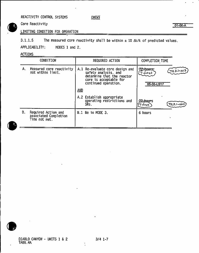
REACTIVITY CONTROL SYSTEMS
Core Reactivity
LIMITING CONDITION FOR OPERATION
0146-A
3. 1. 1.5 The measured core reactivity shall be within + ll hk/k of predicted values.
APPLICABILITY: MODES 1 and 2.
ACTIONS
CONDITION
A. Measured core reactivitynot within limit.
B. Required Action andassoci ated Compl eti onTime not met.
REQUIRED ACTION
A.l Re-evaluate core design andsafety analysis, anddetermine that the reactorcore is acceptable forcontinued operation.
AND
A.2 Establish appropriateoperating restrictions andSRs.
B.l Be in MODE 3.
COMPLETION TIME
05-05-LS17
adcys
6 hours
Wa,3 I-~~
TL3. I -ca 3
DIABLO CANYON - UNITS 1 8 2TABB.4A
3/4 1-7

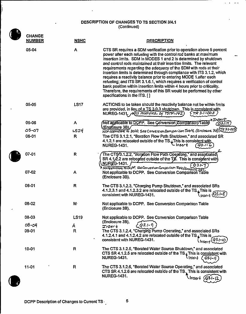
DESCRIPTION OF CHANGES TO TS SECTION 3I4:I(Continued)
CHANGENUIIBER NSHC DESCRIPTION
05-04
05-05
05-06
O5-o706-01
LS17
A
i52$R
CTS SR requires a SDM verification prior to operation above 5 percentpower after each refueling with the control rod banks at maximuminsertion limits. SDM in MODES 1 and 2 is determined by shutdownand control rods maintained at their insertion limits. The relevantrequirements regarding the adequacy of the SDM with rods at theirinsertion limits is determined through compliance with ITS 3.1.2, whichrequires a reactivity balance prior to entering MODE 1.after eachrefueling; and ITS SR 3.1.6.1, which requires a verification of controlbank position within insertion limits within 4 hours prior to criticality.Therefore, the requirements of this SR would be performed by otherspecifications in the ITS. []
ACTIONS to be taken should the reactivity balance not be within limitsare provided, in lieu of a 0.3 shu wn. This is 'thNUREG-1431 rncdiVi'ed- Ey 75rS=-/92 Wic' I
enseo a ica e o P. See nversion om iso ab
En osure3BC lnM See Cf2fTtlerSffJTthmParr'~ Tabid CerdOSu~ PB).
The CTS 3.1.2.1, "Boration Flow Path Shutdown," and associated SR4.1.2.1 are relocated outside of the TS.this is consiste 'thNUREG-1431. ~ IhDf'f"5 Cp3.I- rss
07-01
07-02
08-01
08-02
08-03
oS-ale09-01
10-01
11-01
A
LS19
The CT .1.2.2, "Bo on Flow Path Ope ting, and assp|;iatedSR 4.1 .2 are relo ed outside of the T . This is conspifent withNUR G-1431.
. Ra Can~ csn Ccmp.res~ ~gp~~Not applicable to DCPP. See Conversion Comparison able(Enclosure 3B).
The CTS 3.1.2.3, 'Charging Pump Shutdown, and associated SRs4.1.2.3.1 and 4.1.2.3.2 are relocated outside of the TS.<This isconsistent with NUREG-1431. X/nark
Not applicable to DCPP. See Conversion Comparison Table(Enclosure 3B).
Not applicable to DCPP. See Conversion Comparison Table(Enclosure 3B).ZnS~r eThe CTS 3.1.2.4, "Charging Pump Operating," and associated SRs4.1.2.4.1 and 4.1.2.4.2 are relocated outside of the TS.~This isconsistent with NUREG-1431. (Inst:fq I"0
The CTS 3.1.2.5, "Borated Water Source Shutdown," and associatedCTS SR4.1.2.5 are relocated outside of the TS.gThis is cons' nt withNUREG-1431. < Insert 93I-I]
The CTS 3.1.2.6, "Borated Water Source Operating," and associatedCTS SR 4.1.26 are retooated outside of the TS. This is oonsistent withNUREG-1431. tnserf ~ftt3.t-g.
DCPP Description of Changes to Current TS.


CONVERSION COMPARIS BLE - CURRENT TS 3l4.1 Pa of 10
TECH SPECH CHANGE APPLICABILITY
NUMBER DESCRIPTION DIABLOCANYON
COMANCHEPEAK
NfOLF CREEK CALLA%AY
05-05LS17
05-06A
06-01R
07-01R
07-02A
08-01R
08-02M
08-03LS19
ACTIONS to be taken should the reactivity balance not bewithin limits are provided, in lieu of a TS 3.0.3 shutdown.
CTS SRI4.1.1.5. jirequires that the predicted reactivityvalues "shall" be adjusted (normalized) at 60 EFPD afterrefueling. ITS SR 3.1.2.1 states the normalizationrequirement as may" be adjusted: This is to recognizethat normalization is not necessary ifpredicted andmeasured core reactivity are within acceptance tolerance.The scheduling of predicted and measured core reactivitycontinues to be required at 60 EFPD. Therefore, thischange reflects clarification of existing intent and isconsidered administrative.
Relocates "Boration Flow Path - Shutdown" TS tolicensee controlled document.
Relocates "Boration Flow Path - Operating" TS tolicensee controlled document.
Moves limitation on charging pumps in MODE 4 to ITSSR 3.4.12.2.
Relocates "Charging Pumps - Shutdown" TS to licenseecontrolled document.
Moves charging pump SR when below 350'F to ITS SR3.4.12.2 and decreases surveillance frequency to 12hours from 31 days.
Deletes the method of verificating that charging pumpsare incapable of injecting into the RCS.
Yes
mai ininCT wordi
Yes, seeAttachment 21Page1. re
,se R07 ated
10/ 5,L95 2.
No, not in CTS.
Yes, seeAttachment 21Page . -reio
No, already inCTS.
No, not in CTS.
Yes
maigaininT wor g.
~Yes
Yes
Yes
gag her~/~w~fSaoJ»S
Yes
Yes
Yes
Yes
No, already inCTS.
Yes
No, seeAmendment 89.
tp9./- 4
No, seeAmendment 89.
Q 9. /-7
No, seeAmendment 89.
No, seeAmendment 89.g7/~ g
No, seeAmendment 89.
No, seeAmendment 89.
No, already inCTS.
Yes
No, seeAmendment 103.
No, seeAmendment 103.
No, seeAmendment 103.
No, seeAmendment 103.
No, seeAmendment 103.
No, seeAmendment 103.
dS-o7 2 nserfLS2$Ca~ Z'mer 0A
DCPP Conversion Comparison Table - Current TS
Afg, Sec CM05-C5-CS/ T
go,Gee cVo5-o5-/-S/ lhto, see c/J8-o2-g
y~ <4 ~ /-oe 3
bio, see. An~fW h/n sw


Encl. 3B Page 4DOC 05-07-LS24:
Insert for TR 3.1-003
The Allowed Outage Time (AOT) in the ACTION Statement of current TS LCO3.1.1.5 is increased from 72 hours to 7 days.
Applicability:
DC No - See CN 05-05 LS-17.CP No - See CN 05-05 LS-17.WC YesCA Yes


NO SIGNIFICANTHAZARDS CONSIDERATION (NSHC)
PAGE
I. Organization ..
II. Description of NSHC Evaluations......
III. Generic NSHCs
"A"- Administrative Changes ..
"R" - Relocated Technical Specifications
"LG"- Less Restrictive (moving information out of the TS) ~ ~ ~ ~ ~ ~ 1 0
"M"- More Restrictive... .... 12
IV. Specific NSHCs - "LS"
LS-1 .
LS-2 ..LS-3.......LSQ .
LS-5LS-6 .
LS-7 .
LS-8LS-9LS-'I 0LS-11LS-12LS-13LS-14LS-15LS-16LS-17LS-18LS-19LS-20LS-21LS-22LS-23LS-29
Recurring NSHCs
~ ~ ~ ~ ~ ~ ~ ~ ~ ~ ~ ~ ~ ~ 14~ ~ ~ ~ ~ ~ ~ ~ 16~ ~ ~ ~ ~ ~ ~ ~ ~ ~ ~ ~ ~ 1 8
... 20. 22
... 24~ ~ ~ ~ ~ ~ ~ 26
... Not applicable to DCPP28
o
~ ~ ~ ~ ~ ~ ~ ~ ~ ~ ~ ~ ~ ~ ~ ~ ~ ~ ~ ~ ~ ~ ~ ~ ~ 30... Not applicable to DCPP.................... 32
~ ~ ~ ~ ~ ~ ~ ~ ~ ~ ~ ~ ~ ~ ~ ~ ~ ~ ~ ~ 40. 42
... Not applicable to DCPP
... Not applicable to DCPP... 44
. 47..... 49
. Not applicable to DCPPgaP yppli'cable ~ iYHP 77z p,/-003
TR-2TR-3
51.. 52


IV. SPECIFIC NO SIGNIFICANTHAZARDS CONSIDERATIONS
NSHC LS1710 CFR 50.92 EVALUATIONFOR
TECHNICALCHANGES THAT IMPOSE LESS RESTRICTIVEREQUIREMENTS WITHINTHE TECHNICALSPECIFICATIONS
The proposed activity would add required ACTIONS ifthe overall core reactivity balance was not within a1 percent~k/k of the predicted values. In the CTS, there are no Required ACTIONS; thus LCO 3.0.3 would be entered. LCO3.0.3 requires, that within 1 hour, ACTIONS be initiated to place the plant in a condition in which the LCO did notapply. Because this particular SR is only required in MODES 1 and 2, LCO 3.0.3 would further require that the plantbe placed in HOT STANDBY MODE 3) within the following 6 hours. The proposed change, consistent withNUREG-1431, would allow to evaluate the safety anal ses and establish appropriate operating restrictionsand/or SRs. f these activities were corn thin the period, then the plant would be laced inMODE 3 with'he folio 7
Qs flxxlIf)ed hy MTi-W2 Tiz, 'B, I cQ3
The requirement to periodically compare the measured and predicted overall core reactivity balances providesassurance that the analytical predictions upon which the safety analyses are based accurately represent the actualcore response. Should an anomaly develop between measured and predicted core reactivity, an evaluation of thecore design.and safety analysis must be performed. Core conditions are evaluated to determine their consistencywith input to design calculations. Measured core and process parameters are evaluated to determine that they arewithin the bounds of the safety analysis, and safety analysis calculational models are reviewed to verify that they areadequate for representation of the core conditions. The required Completion Time of is based on the lowprobability of a DBAoccurring during this period, and allows sufficient time to assess th physical Condition of thereactor and complete any required evaluations of the core design and safety analyses. vs ~3,I. cci3
Following evaluations of the measurement, the core design, and the safety analysis, the cause of the reactivityanomaly may be resolved. If it is concluded that the reactor core is acceptable for continued operation, then thepredicted core reactivity balance may be renormalized and Power Operation may continue. Ifoperation restrictionor additional SRs are necessary to ensure the reactor core is acceptable for continued operation, then they must bedefined.
~~vs ~pl-OOPThe Required Completion time of is adequate or prepanng whatever operating restrictions or surveillancethat may be required to allow continue reactor operation.
This proposed TS change has been evaluated and it has been determined that it involves NSHC. Thisdetermination has been performed in accordance with the criteria set forth in 10 CFR 50.92(c) as quoted below:
The Commission may make a final determination, pursuant to the procedures in 50.91, that a proposedamendment to an operating license fora facilitylicensed under 50.21 (b) or 50.22 or fora testing facilityinvolves NSHC, ifoperation of the faci%tyin accordance with the proposed amendment would not:
1. Involve a signiTicantincreasein the probabi%ty or consequences ofan accident previouslyevaluated; or
2. Create the possibility ofa new or different kind ofaccident from any accident previously evaluated;oi'.
Involve a significant reductionin a margin ofsafety."
DCPP No Significant Hazards Evaluations 42


IV SPECIFIC NO SIGNIFICANTHAZARDS CONSIDERATIONS
The following evaluation is provided for the three categories of the significant hazards consideration standards:
1. Does the change involve a significant increase in the probability or consequences of an accident previouslyevaluated?
The proposed change does not involve any new operating activities or hardware changes; thus theproposed changes has no effect on the probability of an accident. Although a small effect, the proposedchange may slightly reduce the probability of an accident by allowing additional time to resolvediscrepancies, and thus avoid an unnecessary plant transient (shutdown).
Satisfaction of the SR acceptance criterion provides assurance that the core-related reactivity parametersused in the safety analysis adequately represent the actual core conditions. During the 72 hour action timefollowing an initial failure of the SR acceptance criterion, ACTIONS are established which would ensurecontinued agreement between the safety analysis and the actual core conditions; thereby, maintaining thevalidity of the safety analyses. Therefore, there is no effect on the consequences of an accident previouslyevaluated.
4 7~vs ~ P.l OO
Because the available time is increased from1, the probability o an accident occurring duringthe time period when the plant condition is under review is slightly increased; however, the increase is smalland has been previously found to be acceptable by the NRC staff through the approval of NUREG-1431.
2. Does the change create the possibility of a new or different kind of accident from any accident previouslyevaluated?
Operation for a period of time with a discrepancy between the measured and predicted core reactivitybalances is allowed by the CTS; therefore, there is no possibility of a new or different kind of accident.
Does this change involve a significant reduction in a margin of safety?
The accident analyses are assumed to be initiated from conditions which are consistent with the TS LCO.Thus, for the purposes of the accident analyses, it assumed that the agreement between the predicted andmeasured core reactivity balance is within an acceptable range. These assumptions remain valid sincethere is no design, operation, maintenance, or testing revision associated with this change. Therefore,there is no significant reduction in margin of safety.
'O SIGNIFICANTHAZARDS CONSIDERATION DETERMINATION
Based upon the preceding information, it has been determined that the proposed changes associated with NSHC"LS17" do not involve a significant increase in the probability or consequences of an accident previously evaluated,create the possibility of a new or different kind of accident from any accident previously evaluated, or involve asignificant reduction in a margin of safety. Therefore, it is concluded that the proposed change meets therequirements of 10 CFR 50.92(c), and does not involve a significant hazards consideration.
DCPP No Significant Hazards Evaluations 43


Industry Travelers Applicable to Section 3.1
TRAVELER0
TSTF-9, Rev. 1
STATUS
Incorporated 3.1-1
DIFFERENCE 0 COMMENTS
NRC approved.
TSTF-12, Rev. 1
TSTF-110, Rev. ZTSTF-136
TSTF-141
TSTF-142
WOG-105
'TST~ 23)
TSTF-13, Rev. 1
TSTF-14, Rev.4
TSTF-15, Rev. 1
TSTF-89
TSTF-107, Rev. 1
TSTF-108, Rev. 1
Incorporated
Incorporated
Incorporated
Incorporated
Incorporated
Incorporated
ncorporated
Incorporated
Incorporated
Not Incorporated
(Iitrlncorporated
Incorporated
Incorporated
3.1-15
3.1P
3.1-13
NIA
3.1-8
3.1-6
9. I- Bl
3.1-10
3.1-9, 3.1-15
N/A
3.1-7
3.1-16
NRC approved. ITSSpecial Test Exception3.1.10 is retained and re-numbered as 3.8.1,consistent with thistraveler and TSTF-136.
NRC approved.
NRC approved W B.t-oo
NRC approved.
NRC approved.
gZ.I-/5
bNRC approTiZ S, I-ool
AC Appn~ %3,I-~
Disagree with change;traveler issued after cut-offdate
7 ~ I-CC9
%Mete.NRC 4m<~.7z3,l-AC
DCPP Mark-up of NUREG-1431, Rev. 1


Core Reactivity9".'.I";::":2.
3.1 REACTIVITY CONTROL SYSTEMS
Q-.k4 8~1'.::2 Core Reacti vity
LCO '~ 3'.",1'!2l!„::."4:,:,,The measured core reactivity shall be within + 1X dk/k of predictedvalues.
APPLICABILITY: MODES 1 and 2.
ACTIONS
CONDITION
A. Measured core reactivitynot within limit.
REQUIRED ACTION
A.1 Re-evaluate core design andsafety analysis, anddetermine that the reactorcore is acceptable forcontinued operation.
COMPLETION TIME
AND
B. Required Action andassociated CompletionTime not met.
A.2 Establish appropriateoperating restrictions andSRs.
B.l Be in MODE 3.
1dc, g
6 hours
DCPP Mark-up of NUREG-1431, Rev. 1 3.1-2


JUSTIFICATION FOR DIFFERENCES FROM NUREG-1431
NUREG-1431 Section 3/4.1
CHANGENUMBER
3.1-19
3.1-20
JUSTIFICATION
Not used.
Consistent with CTS 3/4.10.3, "Physics Tests," ITS LCO 3.1.8 and its Condition C and SR3.1.8.2 are modified to refer to "operating" RCS loops. Ifan operating loop were secured whileoperating in MODE 2, Required Action A.1 of ITS 3.4.4 directs the plant to be in MODE 3 within6 hours. However, depending on initial power level and plant Conditions, securing an RCS loopmay result in a loop's average temperature of [531]'F fairlyquickly due to the reverse flowthrough the secured loop and the cooling achieved by the steam generator. In this scenario, itwould not be appropriate to invoke Required Action C.1 of ITS 3.1.8 with its 15 minuteCompletion Time to restore loop average temperature to within limits since the flow in thesecured loop is not passing through the core and ITS LCO 3.4.4 provides appropriate correctiveACTION, consistent with CTS.
9./- 2 I
5 /-22
In serif
/nser 4 7 iZ, 3./-003
DCPP Description of Changes to Improved TS


Inserts for TR 3.1-003
Enclosure 6A Page 3
JFD 3.1-22 The Completion Times for ITS 3.1.2, Required Actions A.1 and A.2 are increasedfrom 72 hours to 7 days, consistent with traveler TSTF-142.


CONVERSION COMPARISON TABLEFOR D NCES FROM NUREG-1431, SECTION 3/4.1
TECHNICALSPECIFICATION CHANGE APPLICABILITY
NUMBER
3.1-16
3.1-17
3.1-18
3.1-19
3.1-20
DESCRIPTION
This change adds the requirement to perform SR 3.2.1.2in addition to SR 3.2.1.1 during performance of ITS 3.1.4Required Action B 2.4, consistent with traveler WOG-105.
Consistent with CTS LCO 3.1.3.2 and the wording of ITS3.1.7, Condition A and B, ITS 3.1.7, Condition C isclarified to state that the inoperable position indicators areinoperable position indicators are inoperable DRIPs.
A MODE change restriction has been added to ITS 3.1.1,in LCO Applicability, per the matrix discussed in CN 01-02-LS1 of the 3.0 Package.
Not used.
Consistent with CTS 3/4.10.3, Physics Tests," ITS LCO3.1.8 and its Conditio'n C and SR 3.1.8.2 are modified torefer to "operating" RCS loops.
DIABLOCANYON
Yes
Yes
Yes
N/A
Yes
COMANCHEPEAK
Yes
Yes
Yes
N/A
Yes
WOLF CREEK
Yes
Yes
Yes
N/A
Yes
CALLAWAY
Yes
Yes
Yes
N/A
Yes
Inkier63, I- g g. /4Ser 8
Pes
Qes
Yes
Yes
DCPP Conversion Comparison Table - Improved TS

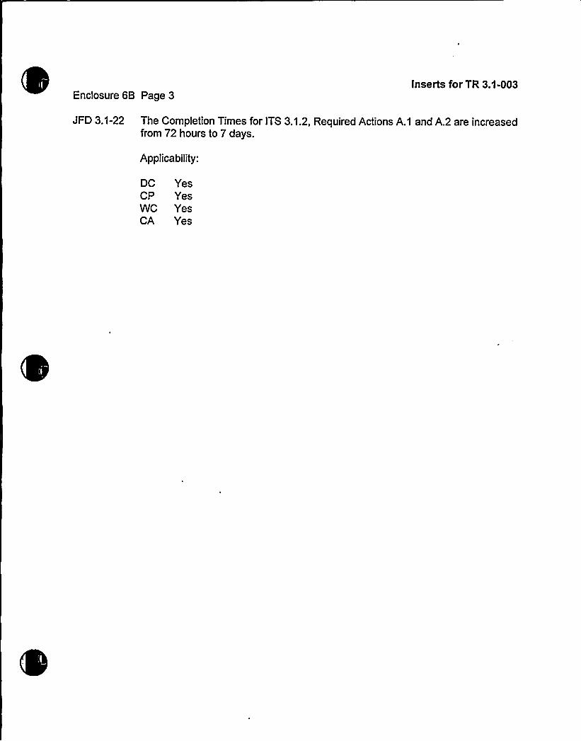
Enclosure 6B Page 3Inserts for TR 3.1-003
JFD 3.1-22 The Completion Times for ITS 3.1.2, Required Actions A.1 and A.2 are increasedfrom 72 hours to 7 days.
Applicability:
DC YesCP YesWC YesCA Yes


Enclosure 2PG8 E Letter DCL 98-107
ADDITIONALINFORMATIONCOVER SHEET
ADDITIONALINFORMATIONNO: TR 3.1-004 Thru TR 3.1-006 APPLICABILITY: DC, CP, WC, CA
REQUEST:Revise Traveler Status Sheet to reflect NRC approval and latest revision numberof travelers TSTF-14, Revision 4, TSTF-110, Revision 2, and TSTF-136. ChangeWOG-73, Revision. 1 to TSTF-234 (still under NRC review). Remove travelerrevision numbers everywhere except on the Traveler Status Sheet. There nochanges involved to any CTS mark-ups, ITS mark-ups, DOCs, or JFDs.
ATTACHED PAGES:
Encl. 3AEncl. 3BEncl. 4Encl. 5AEncl. 6AEncl. 6B
4,8,101,3,6,824, 25Traveler Status Sheet1,21,2


CHANGENUMBER NSHC DESCRIPTION
DESCRIPTION OF CHANGES TO TS SECTION 3/4 1
(Continued)
04-02 LS6Q 3,i~oX
The proposed change would revise the conditional SR for verifying thatreactor coolant system (RCS) temperature (T~) is within limits bychanging the frequency to once per 12 hours in accordance withTSTF-27,~Res.-g- The original frequency requirements were within 15minutes prior to achieving reactor criticalityand at least once per 30minutes when the reactor is critical and the (T~-T~) deviation alarm isnot reset. The RCS temperature is maintained within limit: (1) to assurethat the MTC is within the limits assured in the accident analysis, (2) toassure that the neutron detectors are not adversely affected byattenuation caused by low RCS temperature, (3) to assure that the RCSand pressurizer response to thermal hydraulic transients is as predicted,and (4) to assure that the reactor vessel temperature is above thenilMuctilitytransition reference temperature.
The plant design incorporates monitoring ofT~ and provides an alarm,the (T -T~) deviation alarm, as T approaches its limit This alarmCondition requires a response by the operating staff. Therefore, at anytime that T~ is approaching its limiting value, the plant operators wouldreceive an alarm and initiate corrective ACTION.
04-03 The LCO for Minimum Temperature For Criticality, CTS 3/4.1.1.4, ismoved to ITS 3.4.2 in the RCS section. This is consistent withNUREG-1431.
05-01
05-02 LS7
The CTS SR that requires a comparison of measured reactivity withpredicted would be modified to add the requirement for performanceprior to entry into MODE 1 after refueling outages. This is a newrequirement from the ITS that is not in CTS. The CTS Bases indicatethat the comparison should be made at RATED THERMALPOWER(RTP) after startup from a refueling outage.
This proposed change would specify that the overall core reactivitybalance comparison shall be done every 31 effective full power days(EFPD) after bumup exceeds 60 EFPD. This clarifies when the 31EFPD surveillance should start The current SR specifies a frequencyof 31 EFPD. The delay in initiating the monthly surveillance isacceptable because of the slow rate of changes in the core due to fueldepletion and the presence of other indicators for prompt determinationof an anomaly. As noted in the Bases for Specification 3.1.2, thereactivity balance comparison must be done within the first 60 EFPDsafter each fuel loading. This allows sufficient time for core conditions toreach steady state, but prevents operation for a large fraction of the fuelcycle without establishing a benchmark for the design calculations.
05-03 LG The list of specific items to be considered in the performance of areactivity balance verification is moved to the Bases for ITS 3.1.2. Thischange is of the type that moves unnecessary details from thespecifications while leaving the overall safety requirement intact. Seealso CN 01-05-LG.
DCPP Description of Changes to Current TS ~
r


DESCRIPTION OF CHANGES TO TS SECTION 314.1(Continued)
CHANGENUMBER NSHC DESCRIPTION
12-12
12-13
LS13 CTS [3.1.3.1) ACTIONS are revised to delete reference to causes ofcontrol rod inoperability due to rod control urgent failure or otherelectrical problems in the rod control system.
Not used.
12-14 This wording is broadened from "untrippable" to "inoperable" to ensureall causes of inoperability are covered. The previous wording coveredinoperable rods if they were untrippable (e.g., "immovable as a result ofexcessive friction or mechanical interference... ) but did not covertrippable rods with drop times that exceed the surveillance limit. Theseslow rods are inoperable. This more restrictive change clarifies theappropriate ACTIONS to be taken for all causes of inoperability,consistent with Traveler TSTF-107.
12-15 A Not applicable to DCPP. See Comparison Table (Enclosure 3B).
12-16 LG Several surveillances (e.g., rod position deviation monitor and rodinsertion limitmonitor in this section) contain ACTIONS in the form ofincreased surveillance frequency to be performed in the event ofinoperable alarms. These ACTIONS are moved from the CTS to licensecontrolled documents since the alarm does not, in itself, directly relate tothe limits. This detail is not required to be in the TS. Therefore, movingthis detail is acceptable and is consistent wi I TSTF-110.
783,/-oc
12-17
12-18 LG
Editorial changes are made for clarity. Untrippabie rods are addressedthrough ACTION A; hence, there is no additional need to exclude thoserods from these required ACTIONS.
The technical contents of the ACTION statement which allow continuedpower operation with a misaligned rod are incorporated into LCO 3.1.4,ACTION B.1 Bases, of the ITS.
12-19 LS18 Not applicable to DCPP. See Conversion Comparison Table(Enclosure 3B).
12-20
12-21
The ACTION s tementin the CTS to r tore the rod drop time o withilimits as a Co dition for MODE 2 is tured in the frequency or theperformanc of ITS SR 3.1.4.3.
gP/ 22Not used.
12-22 This change, in accordance with NUREG-1431, provides a newACTION in the event the allowed outage times are not met for the rodmisalignment action. Prior to this change, LCO 3.0.3 would have beenentered allowing for 1 hour prior to placing the plant in HOT STANDBYwithin the next 6 hours This change is more restrictive in that the 1
hour time frame is eliminated.
DCPP Description of Changes to Current TS


DESCRIPTION OF CHANGES TO TS SECTION 314 1
(Continued)
CHANGENUMBER NSHC DESCRIPTION
13-06 Not applicable to DCPP. See Conversion Comparison Table.(Enclosure 3B)
13-07 The proposed modifications to the SR would require a verification ofagreement between digital and demand indicator systems prior tocriticalityafter each removal of the reactor vessel head, instead of every12 hours. This reflects a reorganization of SRs in the ITS. Therequirement for a 12 hour comparison would be moved to SR 3.1.4.1 inthe ITS. The post-vessel head removal requirement would be a newspecification that demonstrates rod position system OPERABILITYbased on a comparison of indicating systems throughout the full rangeof rod travel. The Frequency requirement of prior to criticality after eachremoval of the reactor vessel head would permit this comparison to beperformed only during plant outages that involve plant evolutions (vesselhead removal) that could affect the OPERABILITYof the rod positionindication systems. The Frequency change is based on TravelerTSTF-89.
13-08 LS20 Adds provision from Callaway's current specifications which would,under certain conditions, allow continued operation with more than oneinoperable DRPI per group. A separate Condition entry allowance ispermitted for each inoperable rod position indicator per group and eachdemand position indicator per bank. A proposed Traveler v5~-794
isinpro e'
cover this issue. 723./-Q4
13-09
14-01
LS23 Not applicable to DCPP. See Conversion Comparison Table(Enclosure 3B). a9.>-PI
The hutdown P sition Indi on System S cification 3.1..3 isel cated outsi e of the TS This is consi ent with NUR -1431.
15-01
15-02
16-01 LS14
he Rod D p Time Spe fiication 3.1.3.4 is relo ed outside of the S.The RCS emperature mit and reactor coolan umps operatingrequire ent for rod op testing are combin with CTS Surveill ce4.1.3, then inco rated into ITS SR 3.1... This is consist withNU EG-1431. pic+ Qs'e.d @3.I-ZZ
he R Drop Time 4.1.3.4.a is m ed to the Contro od ITS 03.1. asSR3.1.4.. Thischan eis nsistentwit -143 .~ appliec&e * bGPP, SeConv'rrn~C'n~pc'r r~7a ~<(e~ln-'~a 38). QS, I ~
This TS would be revised to apply to shutdown "banks" instead oshutdown "rods;" this is consistent with NUREG-1431. The currentACTION statement permits one rod to be inserted beyond the limits; theproposed ITS Condition Awould allow one or more banks to be insertedbeyond the limit.
DCPP Description of Changes to Current TS 10

0-
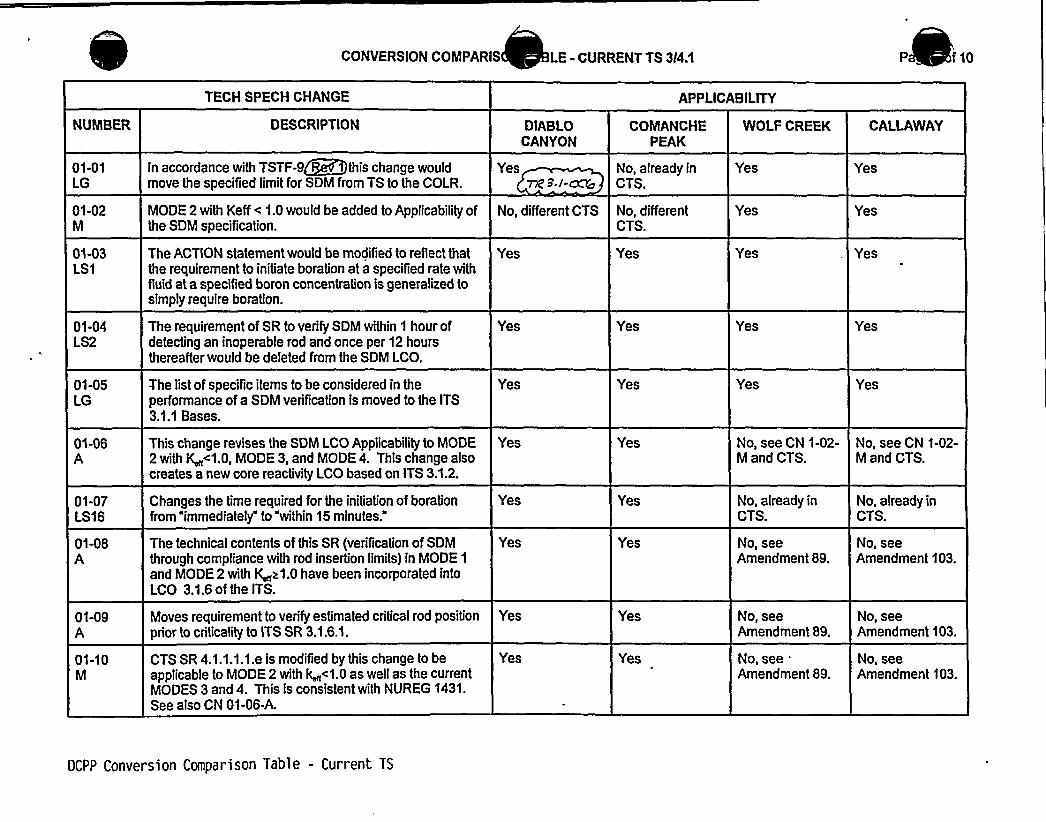
CONVERSION COMPARIS LE - CURRENT TS 314.1 P f10
TECH SPECH CHANGE APPLICABILITY
NUMBER DESCRIPTION DIABI0CANYON
COMANCHEPEAK
WOLF CREEK CALLAWAY
01-01LG
01-02M
01-03LS1
01-04LS2
01-05LG
01-06A
01-07LS16
01-08A
01-09A
01-10M
In accordance with TSTF-9~+this change wouldmove the speciTied limitfor SDM from TS to the COLR.
MODE 2 with Keff < 1.0 would be added to Applicabilityofthe SDM specification.
The ACTION statement would be modified to reflect thatthe requirement to initiate boration at a specified rate withfluid at a specified boron concentration is generalized tosimply require boration.
The requirement of SR to verify SDM within 1 hour ofdetecting an inoperable rod and once per 12 hoursthereafter would be deleted from the SDM LCO.
The list of specific items to be considered in theperformance of a SDM verification is moved to the ITS3.1.1 Bases.
This change revises the SDM LCO Applicability to MODE2 with K <1.0, MODE 3, and MODE4. This change alsocreates a new core reactivity LCO based on ITS 3.1.2.
Changes the time required for the initiation of borationfrom immediately" to "within 15 minutes."
The technical contents of this SR (verification of SDMthrough compliance with rod insertion limits) in MODE 1
and MODE 2 with K z1.0 have been incorporated intoLCO 3.1.6 of the ITS.
Moves requirement to verify estimated critical rod positionprior to criticality to ITS SR 3.1.6.1.
CTS SR 4.1.1.1.1.e is modified by this change to beapplicable to MODE 2 with k <1.0 as well as the currentMODES 3 and 4. This is consistent with NUREG 1431.See also CN 01-06-A.
Yesrg 8./-~
No, different CTS
Yes
Yes
Yes
Yes
Yes
Yes
Yes
Yes
No, already inCTS.
No, differentCTS.
Yes
Yes
Yes
Yes
Yes
Yes
Yes
Yes
Yes
Yes
Yes
Yes
Yes
No, see CN 1-02-M and CTS.
No, already inCTS.
No, seeAmendment 89.
No, seeAmendment 89.
No, see.Amendment 89.
Yes
Yes
Yes
Yes
Yes
No, see CN 1-02-M and CTS.
No, already inCTS.
No, seeAmendment 103.
No, seeAmendment 103.
No, seeAmendment 103.
OCPP Conversion Comparison Table - Current TS


CONVERSION COMPARIS LE - CURRENT TS 3I4.1 Pa f10
TECH SPECH CHANGE APPLICABILITY
NUMBER
04-01LS5
DESCRIPTION
This change would alter the ACTION statement shutdownrequirement time limitfrom a combination of 15 minutesto restore T~ to within limits followed by 15 minutes to bein MODE 3, ifT~ could not be restored, to a single 30minute limitto exit the ApplicabilityifT~ were not withinits limit. In addition, the ACTION statement would bechanged to require achieving MODE 2 with k < 1.0instead of achieving HOT STANDBY if the LCO is notmet (refer to TSTF-26).
DIABLOCANYON
Yes
COMANCHEPEAK
Yes
WOLF CREEK
Yes
CALLAWAY
Yes
04-02LS6
04-03A
05-01M
05-02LS7
05-03LG
05-04A
The SR interval to measure RCS loop averagetemperature is revised to 12 hours in accordance withindustry Traveler TSTF-27.$~The LCO for Minimum Temperature for Criticality, CTS3.1.1.4, is moved to ITS 3.4.2 in the RCS Section.
The SR that requires a comparison of measured reactivityto predicted would be modified to add the requirement tocompare core reactivity against the predicted prior toentry into MODE 1 after refueling outages.
This proposed change would specify that the overall corereactivity balance comparison shall be done every 31EFPD after bumup exceeds 60 EFPD.
The list of specific items to be considered in theperformance of a reactivity balance verification is movedto the ITS 3.1.2 Bases.
The SR requiring SDM to be verified prior to initialoperation in MODE 1 after each refueling is effectivelyperformed under other specifications. This SR required aSDM verification prior to operation above 5 percent powerafter each refueling with the control rod banks atmaximum insertion limits and is being deleted since it isredundant.
Yes
rp 3/-ow
Yes
Yes
Yes
Yes
Yes
Yes
Yes
Yes
Yes
Yes
Yes
Yes
Yes
Yes
Yes
Yes
Yes
Yes
Yes
Yes
Yes
Yes
Yes
OCPP Conversion Comparison Table - Current TS


CONVERSION COMPARIS LE - CURRENT TS 3/4.'I Pa f10
TECH SPECH CHANGE APPLICABILITY
NUMBER DESCRIPTION DIABLOCANYON
COMANCHEPEAK
WOLF CREEK CALLAWAY
12-09M
12-10LS10
12-11TR3
12-12LS13
12-13
12-14M
.12-15A
12-16LG
This proposed change would reinstate an SDM.verification requirement that had been eliminated in aprevious license amendment.
The requirement to maintain RCS T~ ~[541]'F during roddrop testing would be revised to maintain T~ >500'F.
The requirement to perform drop testing on rods followingmaintenance would be removed from the CTS.
CTS [3.1.3.1] ACTIONS are revised to delete referencecauses of control rod inoperability due to rod controlurgent failure or other electrical problems in the rodcontrol system.
Not used.
This wording is broadened from "untrippable" to"inoperable" to ensure all causes of inoperability arecovered. This more restrictive change ciariTies theappropriate ACTIONS to be taken for all causes ofinoperability, consistent with Traveler TSTF-107.
Rod misalignment is determined based on a comparisonbetween the rod's DRPI and its group step counterdemand position, not on a rod to rod position verification.This change is administrative in nature in that there is noeffect on the manner in which the operating staff woulddetermine whether a misalignment event had occurred.
Several surveillances (e.g., rod position deviation monitorand rod insertion limitmonitor in this section) containACTIONS in the form of increased surveillance frequencyto be performed in the event of inoperable alarms. TheseACTIONS are relocated from the TS to licenseecontrolled documents. This is consistent with TSTF-110.Wev. M
No, already inCTS.
Yes
Yes, also deletesredundant ~Vmonth interval.
Yes
N/A
Yes
No, already inCTS.
Yes, moved tothe FSAR.
<u3 I -Cog
No, already inCTS.
Yes
Yes, also deletesredundant 18month interval.
Yes
N/A
Yes
No, already inCTS.
Yes, moved toTRM.
Yes
Yes
Yes
N/A
Yes
Yes
Yes, moved tothe USAR.
Yes
Yes
Yes
No, CTS alreadyrevised toincorporate.
N/A
Yes
Yes
Yes, moved tothe FSAR,Section 16.1.
DCPP Conversion Comparison Table - Current TS

0

CONVERSION COMPARIS BLE - CURRENT TS 3/4.1 Pa of 10
TECH SPECH CHANGE APPLICABILITY
NUMBER DESCRIPTION DIABLOCANYON
COMANCHEPEAK
WOLF CREEK CALLAWAY
13-04M
13-05A
13-06A
13-07M
13-08LS20
13-09LS23
14-01R
A requirement would be added to bring the plant toMODE 3 within 6 hours ifthe required ACTIONS andCompletion Times are not met.
The proposed change would retain an ACTIONstatement, currently in the plant TS, that permitscontinued POWER OPERATION with more than 1 digitalrod position indicator per group inoperable.
The change would allow separate Condition entry foreach inoperable DRPI per group or each demandindicator per bank.
The proposed modifications to the SR would verifyagreement between digital and demand indicator systemsprior to criticality after the reactor vessel head wasremoved instead of every 12 hours. The Frequencychange is based on Traveler TSTF-89.
Adds provision in Callaway's current specifications whichwould, under certain Conditions, allow continuedoperation with more than one ino b ergrou .
This is consistent with Traveler
CTS ACTIONS b.1.b) and b.1.c) of LCO 3.1.3.2 aredeleted. SDM is ensured in MODES 1 and 2 by rodposition. Multiple inoperable DRPls viillhave no impacton SDM in MODES 1 and 2 ifthe control rod positions areverified by alternate means and rod motion is limitedconsistent with the accident analyses. Deletion of theserequirements is consistent with traveler
Relocates CTS 3.1.3.3 to licensee controlled documents,consistent with NUREG-1431.
Yes
No, notin CTS-see 13-08-LS20.
No, not in CTS-see 13-08-LS20.
Yes
Yes
No, not in CTS.
rSTC-gag
es ee 95-07 ated /4/95,
2.
Yes
No, not in CTS-see 13-08-LS20.
No, notin CTS-see 13-08-LS20.
Yes
Yes
7 gS/-Wo
No, not in CTS.
7/R 3./- osYes, relocated toTRM.
Yes
Yes
Yes
Yes
No, already inCTS.
Yes
No, seeAmendment 89.
Yes
Yes
Yes
Yes
No, already inCTS.
Yes
No, seeAmendment 103.
) Ng, See~~snfS R/ 2//20///8.
DCPP Conversion Comparison Table - Current TS


IV. SPECIFIC NO SIGNIFICANTHAZARDS CONSIDERATIONS
NSHC LS610 CFR 50.92 EVALUATIONFOR
TECHNICALCHANGES THAT IMPOSE LESS RESTRICTIVEREQUIREMENTS WITHINTHE TECHNICAL P I TIONS
N S.l-oc6The proposed change would revise the SR for verifying that RCS temperature is within limits by changing thefrequency to once per 12 hours in accordance with TSTF-27, . The current frequency requirements werewithin 15 minutes prior to achieving reactor criticality, which is redundant and unnecessary since T~ must be withinits limitprior to entering the LCO Applicability, and at least once per 30 minutes when the reactor is critical and the(T~-T~) deviation alarm is not reset. The RCS temperature is maintained within limit: (1) to assure that the MTC iswithin the limits assumed in the accident analyses, (2) to assure that the neutron detectors are not adverselyaffected by neutron attenuation caused by low coolant temperature, (3) to assure that the RCS and pressurizerresponse to thermal-hydraulic transients is as predicted, and (4) to assure that the reactor vessel temperature isabove the nilMuctilitytransition reference temperature.
The plant design incorporates monitoring of T~ and provides an alarm, the (T~-T~) deviation alarm, as T~approaches its limit. This alarm Condition requires a response by the operating staff. Therefore, at any time thatT is approaching its limiting value, the plant operators would receive an alarm and initiate corrective ACTION .
This proposed TS change has been evaluated and it has been determined that it involves NSHC. Thisdetermination has been performed in accordance with the criteria set forth in 10 CFR 50.92(c) as quoted below:
"The Commission may make a final determination, pursuant to the proceduresin 50.91, that a proposedamendment to an operating license fora facilitylicensed under 50.21 (b) or 50.22 or fora testing facilityinvolves NSHC, ifoperation ofthe facilityinaccordance with the proposed amendment would not:
1. Involve a significantincreasein the probability or consequences ofan accident previouslyevaluated; or
2. Create the possibility ofa new or different kind ofaccident fiom any accident previously evaluated;or
3. Involve a signfficant reductionin a margin ofsafety.
The following evaluation is provided for the three categories of the significant hazards consideration standards:
Does the change involve a significant increase in the probability or consequences of an accident previouslyevaluated'he
CTS requires that the RCS average temperature is required to be verified within 15 minutes prior toreactor criticality. No additional verification is required during reactor criticality unless the (T~-T~) deviationalarm actuated. Therefore, the CTS relies on the (T~-T~) deviation alarm to assure T~ is within limitsduring reactor operation. The proposed change would introduce a 12 hour requirement to verifyT~independent of the (T -T~) deviation alarm. Therefore, the proposed change would provide additionalassurance beyond the CTS SR requirement that T was within the limits assumed in accident andtransient analyses.
With regard to the requirement to verify temperature within 15 minutes of achieving reactor criticality, the(T~-T~) deviation alarm willstill provide warning that RCS temperature is not within limit. In addition,during an approach to criticality, the plant is operated such that rapid or significant temperature changes inthe RCS are avoided. Since the specification has no CTS4.0.4 exception, T~ must still be within limitpriorto entering the LCO Applicability, i.e. prior to criticality.
Based on the foregoing discussion, the proposed change would provide additional assurance that RCS T~would remain within limits assumed in accident analyses during reactor operation. Therefore, the proposedchange would not involve a significant increase in the probability or consequences of a previously evaluatedaccident.
DCPP No Significant Hazards Evaluations 24

4

IV. SPECIFIC NO SIGNIFICANTHAZARDS CONSIDERATIONS
NSHC LS6(Continued)
2. Does the change create the possibility of a new or different kind of accident from any accident previouslyevaluated?
The proposed change deals with the frequency of monitoring a parameter (RCS temperature) that is aninitial Condition of accident and transient analyses. Changes in SR frequency would not lead to changes inplant system operations or other conditions that could cause an accident of a new or different type.Therefore, the proposed change would not create the possibility of a new or different kind of accident.
3. Does this change involve a significant reduction in a margin of safety?
As noted in the evaluation of Criterion 1 above, the main method of monitoring RCS temperature, duringnormal plant operation and during approach to criticality, is via the (T~-T~) deviation alarm. This situationwould not be altered by the proposed changes. However, the proposed change would add an additionalrequirement to verify RCS temperature every 12 hours. The minimum T~ for criticality is not changed norare there any changes to accident analysis assumptions, methodologies, credited protection/mitigationequlpynent, or event acceptance criteria. There willbe no effect on the manner in which safety limits orlimiting'safety system settings are determined nor willthere be any effect on those plant systems necessaryto assure the accomplishment of protection functions. There willbe no impact on the overpower limits,DNBR limits, F~,F,"„, LOCA PCT, peak local power density, or any other margin of safety.
NO SIGNIFICANTHAZARDS CONSIDERATION DETERMINATION
Based upon the preceding information, it has been determined that the proposed changes associated with NSHC"LS6" do not involve a significant increase in the probability or consequences of an accident previously evaluated,create the possibility of a new or different kind of accident from any accident previously evaluated, or involve asignificant reduction in a margin of safety. Therefore, it is concluded that the proposed change meets therequirements of 10 CFR 50.92(c), and does not involve a significant hazards consideration.
DCPP No Significant Hazards Evaluations 25


Industry Travelers Appiicable to Section 3.1
TRAVELER¹TSTF-9, Rev. 1
STATUS
Incorporated 3.1-1
DIFFERENCE ¹ COMMENTS
NRC approved.
TSTF-12, Rev. 1
TSTF-13, Rev. 1
TSTF-14, Rev.lI
TSTF-15, Rev. 1
TSTF-89
TSTF-107, Rev. 1
TSTF-108, Rev. 1
TSTF-110, Rev. ZTSTF-136
TSTF-141
TSTF-142
WOG-105
Incorporated
Incorporated
Incorporated
Incorporated
Incorporated
Incorporated
ncorporated
Incorporated
Incorporated
Not Incorporated
(gfIncorpowted
Incorporated
Incorporated
3.1-15
3.1-4
3.1-13
N/A
3.1-8
3.1W
3. I- 8/3.1-10
3.1-9, 3.1-15
N/A
3m I~22
3.1-7
3.1-16
NRC approved. ITSSpecial Test Exception3.1.10 is retained and re-numbered as 3.8.1,consistent with thistraveler and TSTF-136.
NRC approved.
NRC approved &3 I-oo5
NRC approved.
NRC approved.
g9,/- /5
bNRC approMi 3,1-oo/
hll2C Appn>W 723,I-~
Disagree viith change;traveler issued after cut-offdate
effete.NRC ~~oved.
| 48./ COCA
DCPP Mark-up of NUREG-1431, Rev. 1


JUSTIFICATION FOR DIFFERENCES FROM NUREG-1431
NUREG-1431 Section 3/4.1
This Enclosure contains a brief discussion/justification for each marked-up technical change to NUREG-1431, tomake them plant-specific or to incorporate generic changes resulting from the Industry/NRC generic changeprocess. The change numbers are referenced directly from the NUREG-1431 mark-ups (Enclosure 5A). ForEnclosures 3A, 3B, 4, 6A, and 6B text in brackets "[ ]" indicates the information is plant specific and is not commonto all the JLS plants. Empty brackets indicate that other JLS plants may have plant specific information in thatlocation.
CHANGENUMBER
3.1-1
3.1-2
3.1-3
3.1A
3.1-5
3.1W
3.1-7
JUSTIFICATION
In accordance with TSTF-9, Rev. 1, this change would relocate the specified limitforSDM from ITS to the COLR. This change occurs in several specifications including thespecification for SDM and those specifications with ACTIONS that require verifying SDMwithin limits.
The Note for S .1.2.1 indicates at predicted reacti ty values~ma be adjus d(normalized) correspond to th easured core re tivityprior to exceedin fuelbumup of 6 EFPD after each fueling. However, oth the Bases for Spe 'cation3.1.3 an e CTS requireme in Specification .1.1.5 state that the no alization shallbe do rior to exceedin fuel bumup of 60 PD after each refuelin,
ikS dad3.I Q
~
~
~
SR 3.1.4.2 of NUREG-1431, Rev. 1 would be deleted. In accordance with TSTF-13the intent of this SR is only to determine the next frequency for SR 3.1.4.3. ~z./-ca@
e ormance of SR 3.1.4.2 is not necessary to assure that the LCO is met; SR 3.1..fulfillsthat purpose. Therefore, SR 3.1.4.2 may be deleted. In addition, the note in thefrequency column of SR 3.1.4.2 would be moved to become Note 1 in the surveillancecolumn of SR 3.1.4.3. This is for clarification purposes. As discussed in CN 3.1-9,section renumbering results in SR 3.1.4.3 of NUREG-1431, Rev. 1 becoming ITSSR 3.1.3.2.
Per CTS [3.1.3.1], the words "with all" have been removed from ITS LCO 3.1.4. This is aclarification that ensures the proper interpretation of the LCO. The change makes itclear that only one channel of DRPI is necessary to meet the alignment accuracyrequirement of the LCO. With the word "all" in the statement, it may be possible forthose unfamiliar with the DRPI design to interpret the LCO as applying to all channels ofDRPI.
LCO 3.1.4 would be split into two separate statements to clarify that the alignment limit isseparate from OPERABILITYof the control rod. The Condition Awording is broadenedfrom "untrippable to "inoperable'o ensure the Condition encompasses all causes ofinoperability. Previous wording was ambiguous for rods that, for instance, had slow droptimes but were still trippable. These slow rods are inoperable rods, and the changeclarifies the appropriate ACTIONS. The Bases are changed to reflect the changes to theLCO and Condition A. These changes are based on TSTF-107.
This change to the ISTS would incorporate, into LCO 3.1.7, an ACTION statement thatwas previously approved as part of the Callaway and WolfCreek licensing basis asrevised in Enclosure 2. The ACTION statement would permit continued POWEROPERATION for up to 24 hours with more than one DRPI channel per rod groupinoperable. The ACTION statement specifies additional Required ACTIONS beyondthose applicable to the Condition of 1 DRPI channel per group inoperable. The Basesfor this change also would be incorporated into the Bases for the plant ITS. Thesechanges are consistent with Traveler . The note under the ACTIONS ischanged to be consistent with the new equired Actions.
N7. Z3) 1 g,9,I
DCPP Description of Changes to Improved TS

0-

JUSTIFICATION FOR DIFFERENCES FROM NUREG-1431
NUREG-1431 Section 3/4.1
CHANGENUMBER JUSTIFICATION
3.1-8 The frequency for SR 3.1.7.1 for comparing DRPI and group demand position over the full rangeof travel would be changed from 18 months to "Once prior to criticalityafter each removal of thereactor vessel head." This change makes it clear that the surveillance must be performed eachtime the head is removed and that it is not tied to an absolute time interval. This change isbased on TSTF-89.
3.1-9
3.1-10
3.1-11
3.1-12
3.1-13
3.1-14
3.1-15
This change would eliminate ISTS 3.1.2 because the SDM requirements for MODE 5 have beenincorporated into Specification 3.1.1 in accordance with traveler TSTF-136. Traveler TSTF-9,Rev. 1, relocated values for SDM to the COLR which removed the only difference between ITSLCO 3.1.1 and ITS LCO 3.1.2. Differences above and below 200'F will be addressed in theCOLR. Subsequent sections have been renumbered.
Several surveillances (e.g., rod position deviation monitor and rod insertion limitmonitor in thissection) contain ACTIONS in the form of increased surveillance frequency to be performed in theevent of inoperable alarms. These ACTIONS are relocated from the TS to licensee controlleddocuments since the alarms do not themselves directly relate to the limits. This detail is notrequired to be in the TS to provide adequate protection of the public health and safTherefore, relocation of this detail is acceptable and is consistent with TSTF-11, v.
Not Used. 7fz.3. /-~V
The Required ACTIONS for inoperable DRPI in ITS 3.1.7 are revised per the CTS to note thatthe use of movable incore detectors for rod position verification is an indirect assessment at best.The position of some rods can not be ascertained by this method.
This change adds an LCO requirement and SR to MODE 2 PHYSICS TESTS Exceptions, STS3.1.8 to verify that THERMALPOWER is less than or equal to 5 percent RTP. The LCOrequirement and SR were added to verify that THERMALPOWER is within the defined powerlevel for MODE 2 during the performance of PHYSICS TESTS, since there is an ACTION thataddresses thermal power not within limityet there was no corresponding LCO or SR. Thesurveillance frequency of 1 hour is retained from the CTS. Thses chan es sed on TSTF-
7 4 3./-CGSNot used.
7 R 3f I ->> +Consistent with TSTF-12, . 1 Special Test Exception LCOs 3.1.9 n ..1 are deleted.The physics tests contained in CO 3.1.9 were only contained in some plant initial plant startuptesting programs. The physics test can be deleted since these physics tests are neverperformed during post-refueling outages. The physics test that LCO 3.1.11 required was the rodworth measurement in the N-1 condition. The use of other rod worth measurement techniqueswill maintain the shutdown margin during the entire measurement process and still provide thenecessary physics data verification. Since the N-1 measurement technique is no longer used,the SDM test exception can be deleted. This change and traveler TSTF-136 renumbers ITS3.1.10 to 3.1.8.
3.1-16
3.1-17
3.1-18
This change adds the requirement to perform SR 3.2.1.2 in addition to SR 3.2.1.1 duringperformance of ITS 3.1.4, Required Action B 2.4. The intent of Required Action B 2.4 is to verifythat FQ(z) is within ITS limits. F>(z) is approximated by F~'(z) (which is obtained via SR 3.2.1.1)and F~ (z) (which is obtained via SR 3.2.1.2). Thus, both F (z) and F0 (z) must be establishedto verify F0(z). This change is consistent with Traveler WOS-105.
Consistent with CTS LCO 3.1.3.2, ITS 3.1.7, Condition C is clarified to state that the inoperableposition indicators are inoperable DRPls.
A MODE change restriction has been added to ITS 3.1.1, in LCO Applicability, per the matrixdiscussed in CN 01-02-LS1 of 3.0 Package (See LS -1 NSHC in the CTS Section 3/4.0, ITSSection 3.0 package). 7vsgv T i'/-p7
DCPP Description of Changes to Improved TS


CONVERSION COMPARISON TABLEFOR D NCES FROM NUREG-1431, SECTION 3/4.1
TECHNICALSPECIFICATION CHANGE APPLICABILITY
NUMBER
3.1-1
3.1-2
3.1-3
DESCRIPTION
In accordance with industry Traveler TSTF-9, Rev. 1,thischange would relocate the specified limits for SDM fromseveral TS to the COLR.
Changes t note o ..., w ic ea s tverifying ore reactivity in limits, to state at thenormal'tion of predict reactivity values corresponto me sured values s II be done prior to xceeding aue urnupof60EF Daftereachrefue'.
he olf Creek IT/' 3.1.6 Retg/red Action g.'1 isrevi d from "Be irk MODE 3." to "P5 in MODE/with k
Pc& PSe J
DIABLOCANYON
Yes
Sak Osc~
COMANCHEPEAK
Yes
WOLF CREEK
Yes
AIA
CALLAWAY
Yes
R&verding.wA P I-0
IVA (P3./ 2g
3.14
3.1-5
3.14
3.1-7
In accordance with industry Traveler TSTF-13SR 3.1.4.2, which requires verifying MTC within the 00ppm boron limit, is deleted and the note in that SR ismoved to the SR that requires the lower MTC limitto beverified. The deleted SR is not a requirement separatefrom the lower MTC verification SR, but is essentially aclarification of when the SR for the lower MTC limitshouldbe performed.
Per CTS [3.1.3.1), the words "with all are removed fromthe LCO for control rod alignment limits. This ensuresthat the number of channels of DRPI required to beOPERABLE willnot be misconstrued.
In accordance with TSTF -107, the change providesadditional clarification that the alignment limits in the LCOare separate from the OPERABILITYof a control rod.
An ACTION statement that was previously approved aspart of the current licensing basis of Callaway and WolfCreek would be added to ITS 3.1.7, as revised inEnclosure 2. The ACTION statement would permitoperation for up to 24 hours with more than one digitalrod position indicator per group inoperable.
Yes
Yes
Yes
Yes
TC 3. l-oQb
Yes
Yes
Yes
Yes
Yes
Yes
Yes
Yes
Yes
Yes
Yes
Yes
DCPP Conversion Comparison Table - Improved TS


CONVERSION COMPARISON TABLEFOR D NCES FROM NUREG-1431, SECTION 3/4.1 of 3
TECHNICALSPECIFICATION CHANGE APPLICABILITY
NUMBER
3.1-&
3.1-9
3.1-10
3.1-11
3.1-12
DESCRIPTION
In accordance with TSTF - 89, the requirement tocompare DRPI against group demand position would berequired whenever the reactor vessel head is removed,not every 18 months.
This change would eliminate ITS 3.1.2 because the SDMrequirements for MODE 5 have been incorporated intoSpecification 3.1.1 in accordance with Traveler TSTF-136.
Several surveillances (e.g., rod position deviation monitorand rod insertion limitmonitor in this section) containACTIONS in the form of increased surveillance frequencyto be performed in the event of inoperable alarms. TheseACTIONS are relocated from the TS to licenseeco oiled documents. This is consistent with TSTF-110,R
Not Used.
The required ACTIONS for inoperable DRPI are revisedper the current licensing basis to note that the use ofmovable incore detectors for rod position verification is anindirect assessment at best. The position of some rodscan not be ascertained by this method.
DIABLOCANYON
Yes
Yes
Yes
TR 9./- cu9
'N/A
Yes
COMANCHEPEAK
Yes
Yes
Yes
N/A
Yes
WOLF CREEK
Yes
Yes
Yes
N/A
Yes
CALLAWAY
Yes
Yes
Yes
N/A
Yes
3.1-13
3.1-14
3.1-15
ln accordance with traveler TSTF-1 . e LCOand SR are modified to verify that T L POWERs 5% RTP. This provides an LCO requirement tocorrespond to Condition B which requires RTP to bewithin limit.
Not used.
In accordance with TSTF-12, . this change woulddelete its LCOs 3.1.9 and 3.1- . is change andTSTF-136 renumbers ITS 3.1;10 to
ITS 3.1.8.
Yes
N/A
Yes
723/- e)05
~ 3.l-ccrc
Yes
N/A
Yes
Yes
N/A
Yes
Yes
N/A
Yes
DCPP Conversion Comparison Table - Improved TS

Enclosure 2PG8 E Letter DCL-98-107
JLS CONVERSION TO IMPROVED TECHNICALSPECIFICATIONS
CTS 3/4.2 - POWER DISTRIBUTION SYSTEMSITS 3.2 - POWER DISTRIBUTION SYSTEMS
RESPONSE TO REQUEST FOR ADDITIONALINFORMATIONAND LICENSEEINITIATEDADDITIONALCHANGES


Enclosure 2PG8 E Letter DCL-98-107
INDEX OF ADDITIONALINFORIIATION
ADDITIONALINFORMATIONNUMBER
APPLICABILITY 'ENCLOSED
3.2.G-1
3.2-13.2-23.2-33.2-43.2-53.2-63.2-73.2-83.2-93.2-10
CA 3.2-001CA 3.2-002
CP 3.2-EDCP 3.2-001
DC 3.2-001DC 3.2-EDDC ALL-005 (3.2 changes only)
TR 3.2-004
WC 3.2-001
DC, CP, WC, CA
CPDCDC, CP, WC, CADC, CP, WC, CACADC, CP, WC, CAWC, CAWCWCDC, CP, WC, CA
DC, WC, CADC, WC, CA
CPDC, CP, WC, CA
DCDCDC
DC, CP, WC, CA
WC, CP
YES
NAYESYESYESNAYESNANANAYES
YESYES
NAYES
YESYESYES
YES
NA


Enclosure 2PG8E Letter DCL-98-107
JOINT LICENSING SUBCOMMITTEE METHODOLOGYFORPROVIDING ADDITIONALINFORMATION
The following methodology is followed for submitting additional information:
1. Each licensee is submitting a separate response for each section.
2. Ifan RAI does not apply to a licensee (i.e., does not actually impact the informationthat defines the technical specification change for that licensee), "NA"has beenentered in the index column labeled "ENCLOSED" and no information is provided inthe response for that licensee.
3. If a licensee initiated change does not apply, "NA"has been entered in the indexcolumn labeled "ENCLOSED" and no information is provided in the response for thatlicensee.
4. The common portions of the "Additional Information Cover Sheets" are identical,except for brackets, where applicable (using the same methodology used inenclosures 3A, 3B, 4, 6A and 6B of the conversion submittals). The list of attachedpages willvary to match the licensee specific conversion submittals. A licensee'sFLOG response may not address all applicable plants ifthere is insufficient similarityin the plant specific responses to justify their inclusion in each submittal. In thosecases, the response will be prefaced with a heading such as "PLANTSPECIFICDISCUSSION."
5. Changes are indicated using the redline/strikeout tool of WordPerfect or by using ahand markup that indicates insertions and deletions. If the area being revised is notclear, the affected portion of the page is circled. The markup techniques vary asnecessary, based on the specifics of the area being changed and the complexity ofthe changes, to provide the clearest possible indication of the changes.
6. A marginal note (the Additional Information Number from the index) is added in theright margin of each page being changed, adjacent to the area being changed, toidentify the source of each change.
7. Some changes are not applicable to one licensee but still require changes to theTables provided in Enclosures 3A, 3B, 4, 6A, and 6B of the original licenseamendment request to reflect the changes being made by one or more of the otherlicensees. These changes are not included in the additional information for thelicensee to which the change does not apply, as the changes are only forconsistency, do not technically affect the request for that licensee, and are beingprovided in the additional information being provided by the licensees for which thechange is applicable. The complete set of changes for the license amendmentrequest will be provided in a licensing amendment request supplement to beprovided later.


Enclosure 2PGRE Letter DCL-98-107
8. The item numbers are formatted as follows:
[Source] [ITS Section]-[nnn]
Source = Q - NRC QuestionCA - AmerenUEDC - PG8EWC - WCNOCCP - TU ElectricTR - Traveler
ITS Section = The ITS section associated with the item (e.g., 3.3). Ifall sectionsare potentially impacted by a broad change or set of changes, "ALL"is used forthe section number.
nnn = a three digit sequential number


Enclosure 2PG&E Letter DCL-98-107
ADDITIONALINFORMATIONCOVER SHEET
ADDITIONALINFORMATIONNO: Q3.2.G-1 APPLICABILITY:CA, CP, DC, WC
REQUEST:ITS 3.2.x Bases
General
There have been a number of instances that the specific changes to the STSBases are not properly identified with redline or strikeout marks.
Comment: Perform an audit of all STS Bases markups and identify instanceswhere additions and/or deletions of Bases were not properly identified in theoriginal submittal.
FLOG response: The submitted ITS Bases markups for Section 3.2 have beencompared to the STS Bases. Some differences that were identified were in accordancewith the markup methodologies (e.g., deletion of brackets and reviewer's notes). Mostof the differences were editorial in nature and would not have affected the review.Examples of editorial changes are:
2)
3)
4)
5)
6)
7)
Capitalizing a letter with only a "redline" but not striking out the lower caseletter that it replaced.Changing a verb from singular to plural by adding an "s" without "redlining" thells II
Deleting instead of striking-out the A, B, C, etc., following a specification title(e.g., SR3.6.6A.7).Changing a bracketed reference (in the reference section) with only a "redline"for the new reference but failing to include the strike-out of the old reference.In some instances, the brackets were retained (and struck-out) but theunchanged text within the brackets was not redlined.Not redlining a title of a bracketed section. The methodology calls for thesection title to be redlined when an entire section was bracketed.Additional text not contained in the STS Bases was added to the ITS Bases bythe lead FLOG member during the development of the submittal. Once it wasdetermined to not be applicable, the text was then struck-out and remains inthe ITS Bases mark-up.
Differences of the above editorial nature will not be provided as attachments to thisresponse. The pages requiring changes that are more than editorial and are notconsistent with the markup methodology are attached.
ATTACHED PAGES:
Encl 5B B3.2-10, 83.2-11, B3.2-13, B3.2-16, B3.2-20


F (2)B 3.).18
10
I I I I
IDO NOT OPERATE IN THIS AREA
I
I ! i I I
I I
0.6
12.0 0.65
0.2
THIS FIGURE FOR
DO NOT USE FOR0 P E R AT I 0 N
FT. 10 12
For core height of 12 feet
hMer fo
FNhex'C.
B 3.2.~ 3.2,ta- I
B 3.2 pO'tIER OISTRIBUTION L B 3.2-"B-~ (Page «f t)orma Ized Fa(Z) as a Function of Core Height
(continued)
DCPP Hark-up or HURD-1431. Rev. 1 Bases


P„3e 2. A)v/cl vi~c)&4.,cl LJIYl, fsB 3.2.2 Nuclear Enthalpy Rise Hot Channel Factor (F"„)
BASESR2.4- t
BACKGROUND The purpose of this LCO is to establish limits on thepower density at any point in the core so that the fueldesign criteria are not exceeded and the accidentanalysis assumptions remain valid. The design limits onlocal (pellet) and integrated fuel rod peak power densityare expressed in terms of hot channel factors. Controlof the core power distribution with respect to thesefactors ensures that local conditions in the fuel rodsand coolant channels do not challenge core integrity atany location during ~ normal operation"".': er-a
i W'i!ieh!.'ransient':,':.cond1tson'";:ari'sing':::,from:"evnents$ 'of::.;moderate
frequency 'analyzed in "th'e"'sa fe'ty "ari'a lynse's.'w'Ivh n Nnn
F" is defined as the ratio of the integral of the linearpower along the fuel rod with the highest integrated
ower to the average integrated fuel rod power.herefore. F",„ is a measure of the maximum total power
produced in a fuel rod. F",„ is sensitive to fuel loadingpatterns, bank insertion. and fuel burnup. F-"~p44'Wy
F",„ is not directly measurable but is inferred from apower distribution map obtained with the movable incoredetector system. Specifically, the results of the ~44aevAea& power distribution map are analyzed by-acempu4er- to determine F",„. This factor is calculated atleast every 31 EFPD. However. during power operation.the global power distribution is monitored by LCO 3.2.3."AXIAL FLUX DIFFERENCE (AFD)." and LCO 3.2.4. "QUADRANTPOMER TII.T RATIO (QPTR)," which address directly andcontinuously measured process variables, eampli'8nnce,.:.,yi'thtbesen:.''LCGs'.::gNo'ngjVii th:: theNL'CO'sFgoverninj~<'shutdown:I.:ind'""--i onvti:.'ol'-::M':,"1'j'ser'tj'ari'i'ttji>'ale'gnm'eij5:";::;ma'jytaiiIs.:': alii'."!co're::hiiiits'i':o'n',"pownver',:."distiiibiItl'ori'.".'o8$'ai'co'n't'Qu'aU'8'''.ibvnasi's:i':
"nnv'nnrnv ~ 4'tube'bvnv~nnvnnn wnvnv 'XnvA4Cvnv nvnn nv.«v n v nvn n'n
The COLR provides peaking factor limits that ensure thatthe design basis value of the departure from nucleateboiling (DNB) is met for normal oper ation. operationaltransients'nd any transient condition arising fromevents of moderate frequency.
eer+e4a44eR-. All DNB limited transient events areassumed to begin with an F"~ value that satisfies the LCOrequirements.
(continued)
OCPP Hark-up of NUREG-1431. Rev. 1 Bases B 3.2-11


BASES
APPLICABLESAFETY ANALYSES(continued)
FN
B 3.2.'3
this variable value of F" in the analyses. Likewise. alltransients that may be Oll limited are assumed to beginwith aA limit1n'g'--ini 1 F",„ as a function of power leveldefined by" the "GUS ,„ limit equation in,'.ttiejCOLR.
racLIina.
as an input parameter. The Nuclear Heat Flux Hot"'ChannelFactor (Fo(Z)) and the axial peaking factors are inserteddirectly into the LOCA safety analyses that verify theacceptability of the resulting peak cladding temperature[Ref. 33.
The fuel is protected in part by compJiance,;.,~ithTechnical Specifications. which en'sur'e 'tha't"the"initialconditions assumed in the safety and accident analysesremain valid. The following LCOs ensure this:LCO 3.2.3, "AXIAL FLUX DIFFERENCE (AFO)," LCO 3.2.4."QUAORANT POWER TILT RATIO (QPTR)." LCO 3. 1.4 6. "ControlBank Insertion Limits "
LCO 3.2.2. "Nuclear Enthalpy RiseHot Channel Factor (F,„)." and LCO 3.2. 1. "Heat Flux HotChannel Factor (Fo(Z))."
F",„ and F (Z) are measured periodically using the movableincore detector system. Heasurements are generally takenwith the core at, or near. steady state conditions. Coremonitoring and control under transient conditions(Condition 1 events) are accomplished by operating thecore within the limits of the LCOs on AFO. QPTR. and BankInsertion Limits.
F" satisfies Criterion 2 ofCN=.M"."36(cT(g):gii'):.
3.2.4- I
LCO F" shall be maintained within the limits of therefationship provided in the COLR.
The F" „ limit 44Ien~~ ii,'::.repr'es'eiit'it'ive":.'"':of. the coolantflow channel with the maxiinu'm'enth'al'py "rise." Thischannel hasthe highest probability for a ONB Condt5iotI.~AY A
The limiting value of F".„. described by the equationcontained in the COLR ~ is the design radial peakingfactor used in the unit safety analyses.
A power multiplication factor in this equation includesan additional mme aaIlowance for higher radial peakingfactoii from reduced
(continued)
OCPP Hark-uo of NUREG-1431. Rev. 1 Bases B 3.2-13


BASES
Fll
B 3.2.N
ACTIONS A.2 (continued)
is obtained at lower power leyelse and the lowrobabi lity of having a DNB limiting event within this4 hour period. Additionally. operating experience has
indicated that this Completion Time is sufficient toobtain the incore flux map. perform the requiredcalculations. and evaluate F
~I>'neVerification that F",„ is within its specified limits afteran out of lipit occurrence ensure hat the cause that,led to-Vie-F-exceeding ~the. , -.limit is,jdenti:fiedi:.to".,the 'extentynecessary'-'';.aid':;-";corr ed. and thatsubseq'u'ent"'operation"proceedssm within the LCO limit. ThisAction demonstrates that the F" limit is within the LCOlimits prior to exceeding 50K R5. again prior toexceeding 75K RTP. and within 24,hours after THERNLPOWER i.s,~ 95K RTP,,SR":3!2"..'2::".-1'emu'st;,:::be":::5a'tisfie'd",.'pn(i'r„":,"to'i'iicreasfng',.pow'er,;:abov'e::thn'e'extrapolsated,:,'al:Towable-pow'er.'"':1e'vel"Orjrestora» ':: .'':'re'duc'ed»iReasto»i":.T.i '-".8 stem»s'et oiiitns':i'" en si 's measure a re uce power eve I.
e a w le power IIevel is determined by evaluating (F,„for higher power levels.
This Required Action is modified by a Note that statesthat THERNL POWER does not have to be reduced prior toperforming this Action.
B.I
When Required Actions A. l. l.through A.3 cannot becompleted within their required Completion Times. theplant must be placed in a mode in which the LCOrequirements are not applicable. This is done by placinqthe plant in at least MODE 2 within 6 hours. The allowedCompietion Time of 6 hours is reasonable. based onoperating exper ence regarding the time required to reachNuDE 2 from full power conditions in an orderly mannerand without challenging plant systems.
r ~(set C
Q2,g- I
SURVEILLANCEREQUIREMENTS
SR 3.2.2.1
SR"'.;"3"::2":;2:.".3'".2fs:"",moIh'fied::-bÃa':Wote:„'::::.".:,"'::The,:;.Note.':.,@pl'ies:during'„".porwser;:i'scensionsi:;foIk owing;::a;!plant'':.'sh'utdown" .
:(:;:leav'sng.'MODE '1)'."<.(he IIote'::allews',-'..'',for,,::-:,pow'e'r..;.;:i''ensionsi
f2nthe»su6iei::I::lan»'ces'arern'ot.:;:;caur'rent"=::<:,',.',.,'',Jt",.'statessithat"'HERMAL.-,POWER':may,'be,';:,inicreased~gintis,i-::;;:a'':,evil;ibr'ium!ipower,.
'levelghats'."been;achfevse'dl'at.;w'hlch';:i:-':p'owei,,'-;:,distributio»n;:ima jc'an::bee',obtained':,'":.,': Equilibriiim,'ror'iditio'ns",'are:."'a'chi'evedWhen':;the'iCai,'e'.-'';i.S~Suf AC'jentli-"MabIe,'3SiiCh",etliamtnntertil at tfeie:,,asSSnnIaten:anth., tee,:merae'nremmenteare ya lidjThe value of F",„ is determined by using the movable incoredetector system™to obtain a flux distribution map. Adata reduction computer program then calculates themaximum value of F,„ from the measured flux distributions.The measured value 'of F",„ must be multiplied by 1.04 toaccount for
F"B 3.2.0
(continued)
DCPP MARK-UP OF NUREG-1431. REV. 1 BASES 8 3.2-16 11/14/96


AFD
8 3.2.38
BASES
(continued)o t e contro ban s >s 1n response to temperaturedeviations resulting from manual operation of theChemical and Volume Control System to change, boronconcentration or from pewe~~ t'urbi'ne,,boa'd changes.
VAWAVW '' A
Signals are available to the operator from the NuclearInstrumentation System (NIS) excore neutron detectors(Ref. 3),, Separate signals are taken from the top andbottom pOwer.:,::,::.ran'ge detectors. The AFD is defined as thedifferen'ce""in n'ormalized flux signals between the top andbottom excore detectors in each detector well. Forconvenience. this flux difference is converted to provideflux difference units expressed as a percentage andlabeled as Ch flux or Ml.The AFD limits are rovided in the COLR.-
The AFDlimits for RAOC do not depend on the tar et fluxdifference. However. the target AFD maybe used to minimize changes in the axial powerdistribution. redline
Violating this LCO on the AFD could produce unaccqptableconsequences if a Condition 2. '1-.4~ U.';'IT1'.:"..'o',:-:IVevent occurs while the AFD is outside it's 'sp'eci'fied "
limits.
APPLICABILITY The AFD requirements are applicable in NODE I greaterthan or equal to 50$ RTP when the combination of THERHALPOWER and core peaking factors are of primary importancein safety analysis.
For AFO limits developed using RAOC methodology. thevalue of the AFD does not affect the limiting accidentconsequences with THERMAL POWER < 504 RTP and for loweroperating power NODES.
ACTIONS A.l
As an alternative to restoring the AFD to within itsspecified limits. Required Action A.l requires a THERHALPOWER reduction to < 50K RTP. This places the core in acondition for which the value of the AFD is not importantin the applicable safety analyses. A Completion Time of
(continued)
I
DcPP $8K-UP 0F HUREG.1431. REV. 1 BAsEs B 3.2-20 11/14/96


Enclosure 2PG8 E Letter DCL-98-107
ADDITIONALINFORMATIONCOVER SHEET
ADDITIONALINFORMATIONNO: Q 3.2-2
REQUEST:
APPLICABILITY: DC
ITS 3.2.3 Axial Flux DifferenceCTS 3/4.2.1 Axial Flux Difference (Diablo Canyon)DOC 01-07-LG
Comment: The DOC/Conversion Comparison Table needs to specify where theCTS requirement is being relocated. Correct the DOC.
FLOG RESPONSE: The additional surveillance frequency when an alarm is notoperable will be moved to DCPP's ECGs. DCPP has ECGs that are controlled byDCPP Department-Level Administrative Procedure (DLAP) OP1.DC16, "Control of PlantEquipment Not Required by the Technical Specifications." DCPP ECGs are similar toother plants'RM. Changes to ECGs are made under the provisions of 10 CFR 50.59,as required by DLAP OP1.DC16 and FSAR Chapter 16. The NRC has accepted ECGsas a licensee-controlled document. This is confirmed most recently on page 2 of theNRC's safety evaluation for License Amendment 120/118 dated February 3, 1998.
ATTACHED PAGES:
Encl 3B 1

0

CONVERSION COMP bON TABLE - CTS 3t4.2
TECH SPEC CHANGE APPLICABILITY
NUMBER
01-01A
01-02LS1
01-03LG
01-04M
01-05M
0146LS2
01-07LG
01-08
01-09A
DESCRIPTION
Removes reference to the special test exception inaccordance with the format of NUREG-1431..
The CTS allow 15 minutes to either restore AFD orreduce THERMALPOWER to less than 90% RTP. TheITS allow 15 minutes to restore AFD and an additional 15minutes for the reduction in the THERMALPOWER ifAFD cannot be restored within the original 15 minutes.
In accordance with WolfCreek ITS for AFD, the detailsregarding how AFD is measured would be moved to theBases.
The CTS allows the 16 hours of operation outside of thetarget band for surveillance testing of the power rangeneutron fluxchannels. In the ITS, the practicalapplication is identified, and the defined surveillancetesting only includes the incore/excore calibration.
Additional requirements are imposed in the event reactorpower is required to be reduced to less than or equal to50% RTP due to accumula'ted AFD penalty minutes.
Eliminates the requirement to reduce the power rangeneutron flux - high reactor Trip Setpoints.
Moves additional surveillance frequencies, ifan alarm isnot OPERABLE, to licensee controlled documents. Thischange is consistent with TSTF 110.
Not Used.
The description of when the AFD is considered to beoutside its ]limits]willbe a note to the ITS LCO, insteadof the CTS SR.
DIABLOCANYON
Yes
No, this is a CAOCrequirement not inCTS.
No
No, this is a CAOCrequirement not inCTS.
No, theserequirements arenot in CTS.
No, refer to 01-16-LS9.
Yes, to EC&end-MAR~N/A
Yes
COMANCHEPEAK
Yes
Yes
No
Yes
Yes
Yes
Yes, to TRM
N/A
Yes
WOLF CREEK
Yes
No, this is a CAOCrequirement not inCTS.
Yes
No, this is a CAOCrequirement not inCTS.
No, theserequirements arenot in CTS.
No, refer to 01-16-LS9.
Yes, to USARChapter 16.
N/A
Yes
CAI LAWAY
Yes
No, this is a CAOCrequirement not inCTS.
No, this is a CAOCrequirement not inCTS.
No, theserequirements arenot in CTS.
No, refer to 01-16-LS9.
Yes, to FSARChapter 16.
N/A
Yes
DCPP Conversion Comparison Table


Enclosure 2PG8 E Letter DCL-98-107
ADDITIONALINFORMATIONCOVER SHEET
ADDITIONALINFORMATIONNO: Q 3.2-3
REQUEST:
APPLICABILITY: DC, CP, WC, CA
ITS 3.2.1 Heat Flux Hot Channel FactorCTS 3/4.2.2 Heat Flux Hot Channel Factor (All FLOG Plants)DOC 02-06-AJFD 3.2-12ITS SR 3.2.1.1 8 3.2.1.2 Frequency
Comment: The ITS SR frequency has been changed from the STS frequencyof 12 hours to 24 hours. This is based upon the incorrect justification that theCTS would allow 24 hours based upon ITS SR 3.0.3, since the CTS does notspecify a frequency. Adopt the STS SR frequency of 12 hours.
FLOG RESPONSE: The change descriptions (DOC 2-06-A 8 JFD 3.2-12) will berevised to provide a basis for the 24 hours that is predicated on the time required toperform the surveillance.
Callaway and WolfCreek are incorporating this change (DOC 02-06-A, JFD 3.2-12) inlieu of maintaining CTS which did not specify any completion time. DOC 02-13-LG(applicable to Callaway only) and JFD 3.2-17 are no longer used.
ATTACHEDPAGES'ncl
2Encl 3AEncl 3BEncl 6AEncl 6B
3/4 2-72,33,4
"2
2


POWER DISTRIBUTION LIMITS
SURVEILLANCE REQUIREMENTS
4.2.2.2 F,(Z) shall be evaluated to determine if Lt"':::5,4Q is within its limits
:(newr)".'„Ver';;i typing:F, ('7').land„::F, ('Z)isavtisfj~)She;: re I a'b'oosh'i'ps:::~jn th'".,'COL'R":I
02-07-A
02-01-LG
02-01-LG
02-07-A
02-12-AMeasuring s,)He) Fmc'(Z)."",:and:,::Pma(Z)'Paccording to the fol lowing
Lb'ew).'::)sgnc'e waft'er,;:,;:ea'ch refu )i'g;npru r:::;o,toEIRERHRL'-POMERi~g,Xc edei'n'g og-os.M7$ X~RTP.R
l. Onue!Wj't'hvn::,tgug4vhuurceaafte~V~Ueen aChieVing equilibriumcond'i'tions after exceedirp by 20K or more of RATED THERMAL POWER, theTHERHAL~POMER at w~h~ich Pa-.{Z). j~ was last determined.* er- anj ~d)RE-5
2. At least once per 31 Effective Full Power Days (EFPD)~t|Ler'e'after.-.
With measurements indicating
maximumover z
has increased since the previous determination of F ,~(Z) either of thefollowing actions shall be taken:
*During power escalation fol':.leRng,",shutdown. power 02 07 Alevel may be increased until a a'";-:,'iqOi'::lj 'r,xiii«power level for extended'perationhas been achieved and a power d'ss'tribut'i'on m'ap obtained.
l
DIABLO CANYON - UNITS 1 & 2 3I4 2-7 Amendment Nos. ?1 & 70July 1. 1992


CHANGENUMBER NSHC DESCRIPTION
01-13 The ACTION statement regarding restoring AFD to within limits within 15minutes would be deleted . This has no effect on the time allowed forcompletion of required actions and restoring AFD to within limits is implicit inrequirements for exiting the ACTION statement. Therefore, this change isadministrative.
01-14
01-15
01-16
02-01
02-02
LS9
LG
LS3
Not used.
Not applicable to DCPP. See Conversion Comparison Table (Enclosure 3B).
Eliminates the requirement to reduce the power range neutron flux - high reactortrip setpoints when AFD is outside the RELAXEDAXIALOFFSET CONTROL(RAOC) limits.
In accordance with NUREG-1431, the proposed change moves the details of theentire CTS LCO of the allowable F~(Z) values, including the K(Z) and W(Z)parameters to the CORE OPERATING LIMITSREPORT (COLR) and/or Bases.Previously, only the full power value of Fi,(Z), in addition to K(Z}and W(Z) hadbeen in the COLR. Now, the dependence of Fii(Z) on THERMALPOWER isalso located in the COLR. Details of the F~(Z} measurement, including thetreatment of uncertainties, are moved to the Bases. The Required Actions arerewritten for consistency with NUREG-1431. The specific changes include themore appropriate use of F~ (Z) and Fo (Z) versus Fii(Z).
The Required Actions are rewritten for consistency with NUREG-1431 andindustry Traveler TSTF-95. The specific changes include the relaxation of theCompletion Time requirement to reduce the high neutron flux reactor TripSetpoints [from 4 hours) to 72 hours. The reduction of the setpoints is aconservative action for protection against the consequences of severe transientswith unanalyzed power distributions. The Completion Time of 72 hours issufficient considering the amount of work required to be done to reduce thesetpoints, the small likelihood of a severe transient in this time period, and theprompt reduction in THERMALPOWER required upon discovery of the out-of-limitcondition.
02-03
02-04
02-05
02-06
For consistency with NUREG-1431, the requirement is added to be in at leastMODE 2 within 6 hours should any of the ACTIONS not be completed within therequired time. This requirement is more restrictive than the previousrequirement to enter CTS 3.0.3, which allowed 1 hour before the 6 hourshutdown requirement became effective.
Not applicable to DCPP. See Conversion Comparison Table (Enclosure 3B).
Consistent with NUREG-1431, F~ (Z) and F~ (Z) must be verified to be withinlimits prior to exceeding 75 percent RTP after each refueling. This requirementis not explicit in the CTS. The TS are made more restrictive by stating thisrequirement.
onsiste with the Bases of C S4.0.3, which allows 24 h rs for corn etingSRs tha ecome applicable w en an exception to Specifi ation 4.0.4 i
allowed'he
fre ency for assessing ~(Z) is clarified by requirin hat the me suremenbe e ormed within 24 hou after reaching equilibrium onditions.
g nse~P
QCPP Description of Changes to Current TS


Insert for Q3.2-3
Enclosure 3a —page 2
INSERT for 02-06-M:
02-06 M ln the ITS SR 3.2.1.1 and SR 3.2.1.2, a time limit for assessing F~(Z) after reachingequilibrium conditions is specified. Because the CTS does not have such a time restriction,this change is more restrictive. The time limitfor completion of this surveillance, 24 hoursfollowing the establishment of equilibrium conditions, has been selected based on plantexperience. Twenty-four hours is a reasonable time for obtaining and evaluating a flux mapand then completing the required procedural steps associated with this surveillance. Further,the 24 hour time limitdoes not allow for plant operation in an uncertain condition for aprotracted time period. The time limitof 24 hours is consistent with Amendment No. 116 forWolfCreek in which the NRC approved allowing the performance of a flux map 24 hoursafter achieving equilibrium conditions from a Thermal Power reduction required with QPTRdetermined to exceed 1.02.

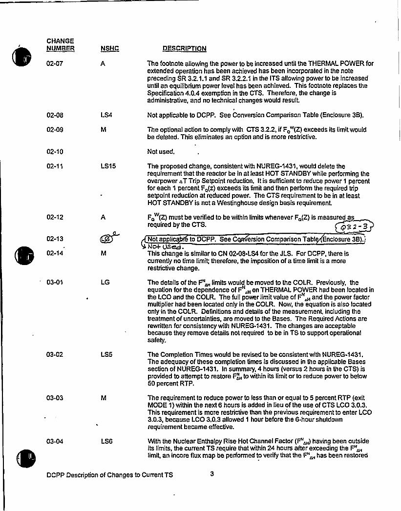
CHANGENUMBER
02-07
NSHC DESCRIPTION
The footnote allowing the power to be increased until the THERMALPOWER forextended operation has been achieved has been incorporated in the notepreceding SR 3.2.1.1 and SR 3.2.2.1 in the ITS allowing power to be increaseduntil an equilibrium power level has been achieved. This footnote replaces theSpecification 4.0.4 exemption in the CTS. Therefore, the change isadministrative, and no technical changes would result.
02-08
02-09
LS4 Not applicable to DCPP. See Conversion Comparison Table (Enclosure 3B).
The optional action to comply with CTS 3.2.2, if Fo (Z) exceeds its limitwouldbe deleted. This eliminates an option and is more restrictive.
02-10 Not used.
02-1 1
02-12
02-13
02-14
LS15
A
The proposed change, consistent with NUREG-1431, would delete therequirement that the reactor be in at least HOT STANDBYwhile performing theoverpower ~T Trip Setpoint reduction. It is sufficient to reduce power 1 percentfor each 1 percent F~(z) exceeds its limitand then perform the required tripsetpoint reduction at reduced power. The CTS requirement to be in at leastHOT STANDBYis not a Westinghouse design basis requirement.
F~ (Z) must be verified to be within limits whenever Fa(Z) is measured asw
required by the CTS. A/32 3
Not a li to DCPP. See C ersion Comparison Tab! Enclosure 3B).:0+ Vied.
This change is similar to CN 02-08-I S4 for the JLS. For DCPP, there iscurrently no time limit; therefore, the imposition of a time limitis a morerestrictive change.
03-01 LG The details of the F"~ limits would be moved to the COLR. Previously, theequation for the dependence of F",„on THERMALPOWER had been located inthe LCO and the COLR. The full power limitvalue of F,„and the power factormultiplier had been located only in the COLR. Now, the equation is also locatedonly in the COLR. Definitions and details of the measurement, including thetreatment of uncertainties, are moved to the Bases. The Required Actions arerewritten for consistency with NUREG-1431. The changes are acceptablebecause they remove details not required to be in TS to support operationalsafety.
03-02 LS5 The Completion Times would be revised to be consistent with NUREG-1431.The adequacy of these completion times is discussed in the applicable Basessection of NUREG-1431. In summary, 4 hours (versus 2 hours in the CTS) isprovided to attempt to restore F~N to within its limitor to reduce power to below50 percent RTP.
03-03
03-04 LS6
The requirement to reduce power to less than or equal to 5 percent RTP (exitMODE 1) within the next 6 hours is added in lieu of the use of CTS LCO 3.0.3.This requirement is more restrictive than the previous requirement to enter LCO3.0.3, because LCO 3.0.3 allowed 1 hour before the 6-hour shutdownrequirement became effective.
With the Nuclear Enthalpy Rise Hot Channel Factor (F"~) having been outsideits limits, the current TS require that within 24 hours after exceeding the F"~limit, an incore flux map be performed to verify that the F"~ has been restored
DCPP Description of Changes to Current TS


CONVERSION COMPARISON TABLE - CTS 3/4.2 rage 3 of 8
TECH SPEC CHANGE APPLICABILITY
NUMBER
01-16LS9
02-01LG
02-02LS3
02-03M
02-04M
02-05M
02-06
DESCRIPTION
'liminatesthe requirement to reduce the power rangeneutron flux - high reactor Trip Setpoints when AFD isoutside the RAOC limits.
The details of the entire CTS LCO of the allowable F~(Z)values, including the K(Z) and W(Z) parameters, wouldbe moved to the COLR and/or Bases.
Consistent with Traveler TSTF-95, the Required Actionsare relaxed to extend the time allowed to reduce the highneutron flux reactor Trip Setpoints [from 4 hours) to 72hours.
The required ACTIONS are revised to include theaddition of a requirement to be in at least MODE 2 within6 hours should any of the ACTIONS not be completedwithin the required time.
F~i (Z) must be verified to be within limits wheneverF~(Z) is measured, not just at the time of target fluxdetermination, as required by the CTS.
F~'(Z) and Fo (Z) must be verified to be within limitsprior to exceeding 75% RTP after each refueling.
DIABLOCANYON
Yes
Yes
Yes
Yes
No, requirementnot in CTS.
Yes
Yes
COMANCHEPEAK
No, CPSES usesCAQCmethodology;change applies toRAOCmethodology.
Yes
Yes
Yes
Yes
Yes
Yes
WOLF CREEK
Yes
Yes
Yes
Yes
No, requirementnot in CTS.
Yes
CALLAWAY
Yes
Yes
Yes
Yes
No, requirementnot in CTS.
Yes
frequency for assessing F~(Z) isthe measurement be performedreaching equilibrium Conditions
$ et
raving
by requinng thathin 24 hours after
~ainedL
Yc5
retained:
DCPP Conversion Comparison Table


CONVERSION COINP SON TABLE - CTS 3/4.2,
TECH SPEC CHANGE APPLICABILITY
NUMBER
02-07A
02-08LS4
02-09M
02-10
DESCRIPTION
The.footnote allowing power to be increased until theTHERMALPOWER for extended operation has beenachieved has been incorporated in the notes precedingITS SR 3.2.1.1 and SR 3.2.2.1 for achieving equilibriumpower level. This footnote replaces the Specification4.0.4 exemption in the CTS.
The time allowed to reduce the acceptable operationlimits on AFD is changed to 4 hours, consistent withTraveler TSTF- 99.
The optional ACTION to comply with CTS 3.2.2 if F~ (Z)exceeds its limitwould be deleted. This eliminates anoption and is more restrictive.
Not Used.
DIABLOCANYON
Yes
No, refer to 02-14-M.
Yes
N/A
COMANCHEPEAK
Yes
Yes
No, identifiedoption not in CTS.
N/A
WOLF CREEK
Yes
Yes
Yes
N/A
CALLAWAY
Yes
Yes
Yes
N/A
02-11LS15
02-12A
02-13
02-14M
03-01LG
03-02LS5
The ACTION requirement, with F~(Z) exceeding its limit,that the overpower Delta-T Trip Setpoint reduction beperformed in at least HOT STANDBYwould be deleted.
F~ (Z) must be verified to be within limits wheneverF~(Z) is measured as required by the CTS.
s, got VM.Similar to CN 02-08-LS4. For DCPP, there is currentlyno time limit; therefore, the imposition of a time limit is amore restrictive change.
Moves the details of the F"~ limits to the COLR and/orBases.
Revises the completion time to 4 hours (versus 2 hoursin the CTS to attempt to restore F,"„ to within its limitor toreduce power to below 50% RTP.
Yes
Yes
Yes
Yes
Yes
No, requirementnot in CTS.
No, not required byCTS.
4TS:NA
No
Yes
Yes
No, requirementnot in CTS.
Yes
Yes
No, 4 hours alreadyin CTS.
No, requirementnot in CTS.
Yes
No
Yes
Yes
DCPP Conversion Comparison Table


JUSTIFICATION FOR DIFFERENCES FROII NUREG-1431
NUREG-1431 Section 3/4.2
3.2-08
3.2-09
3.2-10
3.2-11
3.2-12
3.2-13
3.2-14
3.2-15
3.2-16
3.2-17
3.2-18
Consistent with Traveler TSTF-99, the LCO 3.2.1 (Fo Methodology), Required ACTION B.1.Completion Time for the reduction of the AFD limits if F o(Z) is not within limits is increasedfrom 2 hours to 4 hours. This makes it consistent with the Completion Time associated withRequired ACTION A.2. of LCO 3.2.1 (F«methodology). The change is acceptable because iteliminates an inconsistency in the ITS.
For consistency with CTS 3.2.4 and ITS 3.3.1, Condition D, the breakpoints for the Applicabilityofthe surveillances in the notes in ITS SR 3.2.4.1 and SR 3.2.4.2 are modified to be applicable atless than or equal to 75 percent RTP, and greater than 75 percent RTP, respectively. Tadministrative change that retains CTS requirements
Q ard '~s Cons'ie0cci4 ~'l% TSTF-Zcil,Consistent with Traveler TSTF-110, this change moves requirements for increased surveillancefrequencies in the event of inoperable alarms to licensee controlled documents. This change isacceptable because it removes requirements regarding alarms and alarm responses that arenot necessary to be in the TS to protect public health and safety.
Not applicable to DCPP. See Conversion Comparison Table (Enclosure 6B).'T ~Q o~ pion c<pcc cence i, he required time for completion a flux ma for determination of the
heat flux hot channel factor is changed from 12 hours to hours a r achieving equilibriumConditions. The proposed change affects SR 3.2.1.1 and S .... he proposed time (24hours is a reasonable time eriod for the compl ion o e survei an oes not ow orpant oper on in anunce n con iion fora rotracted time peri . This change is Iconsis t with the TS r uirements of Sp ification 3.0.4 (and ssociated Bases) t t allow24 urs for the corn etion of a surveill ce after prerequisi plant conditions ar attained
ce tion to S ci tion 4.0.4 was rov'dZnmr'7
This change retains the CTS for the performance of peaking factor determinations followingplant shutdowns. The CTS, through the exemption to Specification 4.0.4, allows prerequisiteplant conditions to be obtained prior to requiring that the surveillance be completed.g
Not applicable to DCPP. See Conversion Comparison Table (Enclosure 6B).3.2.-'I
This change incorporates Traveler TSTF-109. ACTION A.2. would require the QPT bdetermined rather than performing a specific surveillance because more than one surveillancecan be used to determine QPTR. SR 3.2.4.1 was revised to retain allowance that SR 3.2.4.2may be'performed in lieu of SR 3.2.4.1. ~ Q3.c-IOI
. Thesechanges are acceptable because they clarify the ITS regarding frequency and us of incoreflux monitoring for QPTR measurement. The changes reflect that incore detectors rovide anacceptable QPTR determination during all plant Conditions.
This change would require both transient and static Fo measurements be determined whenperformed for Required ACTIONS 3.2.4 A.3 and A.6. The intent of the Required ACTIONS isto verify that Fo(Z) is within its limit. Fo(Z) is approximated by Fo(Z) (which is obtained via S3.2.1.1) and Fo(Z) (which is obtained via SR 3.2.1.2). Thus, both Fo(Z) and Po(Z) must beestablished to verify Fo(Z). This change is consistent with Traveler WOG-105.
Not a licab o DCPP, S Conversion C parison Tabl Enclos e 6B). cy3.2-3of cj~
Not applicable to DCPP. See Conversion Comparison Table (Enclosure 6B).
3.2-1 9 Not a licable to DCPP. Co rsio risonnote o~ rccqucnc.q Woe'R 2.'l. o.re ~evised corn'csYcnt ~'Bn,
p'~i +c~i~ron + ~~s ~++~ ~e. ~or ~ pern fl
o ~ f 2 0 jot o ppllc4Llbte ~ QcPP, sc8 Cohvc('@ion Cnc pac cocle ~'ie (Fnd~~cGt $ .2.-t


Insert for Q3.2-3
Enclosure 6a —page 2
INSERT for 3.2-12:
obtaining and evaluating a flux map and then completing the procedural steps associated with thissurveillance. Further, the 24 hours time period does not allow for plant operation in an uncertaincondition for a protracted time period.


CONVERSION COMPARISON TABLEFO i.c=RENCES FROM NUREG-1431, SECTION 3/4.2 Page2o ~
TECH SPEC CHANGE APPLICABILITYNUMBER
3.2-11
DESCRIPTION
This change rearranges the notes applicable toLCO 3.2.3. AFD (Constant Axial Offset Control plantsonly, CPSES specific) from three separate notesaffecting different portions of the LCO into a commonnote block. This change is consistent with TSTF-164.
DIABLOCANYON COMANCHE PEAK
Yes
WOLF CREEK CALLAWAYNo
3.2-12
3.2-13
3.2-14
3.2-15
Consis ith,t e uire e orco petioof a map r deter nation the heat x hotc nelf orisc gedfr 12hour o24h
ffer ieving ilibrium ondition The pr osecha e affec SR 3.2.1 and SR .2.2.1.
This change retains the CTS for the performanceof peaking factor determinations following plantshutdowns.
This change retains the WolfCreek current licensingbasis (License Amendment 61) for RequiredACTION 3.2.2 A.2.
This change partially incorporates the industry .traveler TSTF-109. ACTIONA.2 now requires theQPTR be determined rather than performing aspecific surveillance because more than 1
surveillance can be used to determine QPTR.-7he-
Yes
Yes
No
Yes
Yes
Q S.2.-5
Yes
No
Yes
YB5
Yes
Yes
Yes
Yes
No
Yes
3.2-16Requires both transient and static Fo measurementswhen performed for Required ACTIONS 3.2.4 A.3and A.6.
Yes Yes Yes Yes
3.2-17
3.2-1 &
This change modifies the QPTR requirements inNUREG-1431, Rev. 1, for WolfCreek, to retain sePie-CTS requirements ap Amc.ed
No
eat Ho. uh
Yes
DCPP Conversion Comparison Table - Improved TS

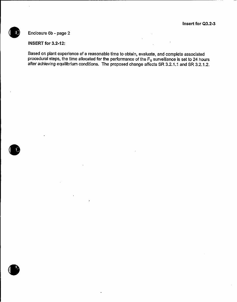
Insert for Q3.2-3
Enclosure 6b - page 2
INSERT for 3.2-12:
Based on plant experience of a reasonable time to obtain, evaluate, and complete associatedprocedural steps, the time allocated for the performance of the F~ surveillance is set to 24 hoursafter achieving equilibrium conditions. The proposed change affects SR 3.2.1.1 and SR 3.2.1.2.


Enclosure 2PG8E Letter DCL-98-107
ADDITIONALINFORMATIONCOVER SHEET
ADDITIONALINFORMATIONNO: Q 3.2-4 APPLICABILITY: DC, CP, WC, CA
REQUEST:ITS 3.2.2 Nuclear Enthalpy Rise Hote Channel FactorCTS 3/4.2.3 Nuclear Enthalpy Rise Hot Channel (All FLOG Plants)DOC 02-07-AJFD 3.2-13SR 3.2.2.1 NOTE and related Bases.
Comment: Justify the need for the note related to permitting power ascensionafter shutdown to a level at which a power distribution map is obtained. Itappears that this note is unnecessary, considering the phraseology of the SRFrequency ("Once after each refueling prior Thermal Power exceeding 75%RTP"). Explain the need for this note. The SR 3.2.2.1 Bases also mentions"(leaving Mode 1)" which appears to be the incorrect mode.
FLOG RESPONSE: The Note, as described in JFD 3.2-13, was incorporated to addressthe rare situation where, during a mid-cycle shutdown, through further review of theprevious surveillance, it was determined that the surveillance was invalid; or the requiredsurveillance frequency is not met due to the shutdown. The amended Note would berequired to return the reactor to a power level at which a new surveillance could beperformed.
The "leaving MODE 1" clarification is based on the Applicabilityof the LCO (MODE 1,only) and is intended to avoid confusion in a scenario where the plant may be taken off-line (typically, MODE 2), but not "shutdown" (commonly considered to be MODE 3 orlower).
ATTACHEDPAGES'ncl
6A


JUSTIFICATION FOR DIFFERENCES FROM NUREG-1431
NUREG-1431 Section 3/4.2
3.2-08
3.2-09
3.2-10
3.2-11
3.2-12
3.2-13
3.2-14
3.2-15
3.2-16
3.2-17
3.2-18
Consistent with Traveler TSTF-99, the LCO 3.2.1 (Fo Methodology), Required ACTION B.1.Completion Time for the reduction of the AFD limits if F 0(Z) is not within limits is increasedfrom 2 hours to 4 hours. This makes it consistent with the Completion Time associated withRequired ACTION A.2. of LCO 3.2.1 (F„„methodology). The change is acceptable because iteliminates an inconsistency in the ITS.
For consistency with CTS 3.2.4 and ITS 3.3.1, Condition D, the breakpoints for the Applicabilityofthe surveillances in the notes in ITS SR 3.2.4.1 and SR 3.2.4.2 are modified to be applicable atless than or equal to 75 percent RTP, and greater than 75 percent RTP, respectively. T
'dministrativechange that retains CTS requirementsQ Olhd is ClA8MhtCr4 mi% t STF,»/ail.
Consistent with Traveler TSTF-110, this change moves requirements for increased surveiliancefrequencies in the event of inoperable alarms to licensee controlled documents. This change isacceptable because it removes requirements regarding alarms and alarm responses that arenot necessary to be in the TS to protect public health and safety.
Not applicable to DC P. See Conversion Comparison Table (Enclosure 6B).T 3,2 .1,2„~+ on p)ar t c,<pc( i etcC
>
e required time for completion a flux ma for determination of theheat flux hot channel factor is changed from 12 hours to hours a r achieving equilibriumConditions. The proposed change affects SR 3.2.1.1 and S .... he proposed time (24hours is a reasonable time eriod for the compl ion o e survei c an oes not ow orpantoper onin anunce n con iion fora rotracted time peri . This change is iconsis t with the TS r uirements of Sp ification 3.0.4 (and ssociated Bases) t t allow24 urs for the corn etion of a surveill ce after prerequisi plant conditions ar attained
ce tion to S ecif tion 4.0.4 was rov'dZrilrg
This change retains the CTS for the performance of peaking factor determinations followingplant shutdowns. The CTS, through the exemption to Specification 4.0.4, allows prerequisiteplant conditions to be obtained prior to requiring that the surveillance be completed.g
Not applicable to DCPP. See Conversion Comparison Table (Enclosure 6B).3.2.-"(
This change incorporates Traveler TSTF-109. ACTION A.2. would require the QPT bdetermined rather than performing a specific surveillance because more than one surveillancecan be used to determine QPTR. SR 3.2.4.1 was revised to retain allowance that SR 3.2.4.2may be'performed in lieu of SR 3.2.4.1. Q"..c-10
. Thesechanges are acceptable because they clarify the ITS regarding frequency and us of incoreflux monitoring for QPTR measurement. The changes reflect that incore detectors rovide anacceptable QPTR determination during afl plant Conditions.
This change would require both transient and static Fo measurements be determined whenperformed for Required ACTIONS 3.2.4 A.3 and A.6. The intent of the Required ACTIONS isto verify that Fo(Z) is within its limit. Fo(Z) is approximated by Fo(Z) (which is obtained via S3.2.1.1} and F <(Z} (which is obtained via SR 3.2.1.2). Thus, both Fo(Z) and Po(Z) must beestablished to verify F<(Z). This change is consistent with Traveler WOG-105.
Not a licab o DCPP. S Conversion C parison Tabl Encfos e 6B). cp3.2-3df UJEgf
Not applicable to DCPP. See Conversion Comparison Table (Enclosure 6B).
3.2-19 Not a licable to DCPP. Co rsion m risonnote o r~~e>c.> %or aa 2..4. are .ev ised u ~'iaaf t ~'i+,
4glpicoh pc~tori~ ~t'maWs ~+@r'ide. <oc' peril o$ 1'l~g
fl
3.2.-20 Not appal'icabiz +QCpp. Sb'onverSion Co>par is~ Tchte (6nc(gsegg &).Q, S.2.-l


Insert for Q3.2-4
Enclosure 6A - page 2
Insert for JFD 3.2-13
The note was incorporated to address the rare situation where, during a mid-cycle shutdown,through further review of the previous surveillance, it was determined that the surveillance wasinvalid; or the required surveillance frequency is not met due to the shutdown.. The amendedNote would be required to return the reactor to a power level at which a new surveillance could beperformed.


Enclosure 2PG8 E Letter DCL-98-107
ADDITIONALINFORMATIONCOVER SHEET
ADDITIONALINFORMATIONNO: Q 3.2-6REQUEST'PPLICABILITY:DC, CP, WC, CA
ITS 3.2.4 Quadrant Power Tilt RatioCTS 3/4.2.4 Quadrant Power Tilt Ratio (All FLOG Plants)DOC 04-01-AJFD 3.2-05ITS Required Action A.5
Comment: The ITS proposes to change the STS wording for Required ActionA.5 from "Calibrate excore detectors to show zero QPTR," to "Normalize excoredetectors to eliminate tilt," based upon WOG-95 (and rejected TSTF-25). Apreferred wording would be that proposed in the Comanche Peak CTS mark-up,"Calibrate excore detectors to show zero Quadrant Power Tilt." What is status ofWOG-95?
FLOG RESPONSE: Traveler WOG-95 was transmitted to the NRC in February 1998 asTSTF-241. The FLOG is incorporating TSTF-241 including the latest revisionsdiscussed at the June 1998 WOG MERITS Mini-Group meeting. These revisionscorrected errors made during the development of TSTF-241.
Additionally, WolfCreek submitted a License Amendment Request to CTS 3/4.2.4,Quadrant Power Tilt Ratio, on February 4, 1998, which was approved on April 27, 1998,in Amendment No. 116. This amendment incorporated the changes proposed in TSTF-241.
The FLOG believes that it is appropriate to incorporate the proposed TSTF-241 changesbased on the NRC approval of the Wolf Creek amendment request.
ATTACHEDPAGES:
Encl 2Encl 3AEncl 3BEncl 4Encl 5AEncl 5BEncl 6AEncl 6B
3/4 2-184 and 65 and 6Table of ContentsTraveler status page, 3.2-10, and 3.2-11B 3.2-25, B 3.2-26, B3.2-271 and 21and2


POWER DISTRIBUTION LIMITS
3/4.2.4 UADRANT POWER TILT RATIO
LIMITING CONDITION FOR OPERATION
3.2.4 THE QUADRANT POWER TILT RATIO shall not exceed 1.02.
APPLICABILITY: NODE 1 ABOVE 50X OF RATED THERMAL POWER~.
ACTION:
a. With the QUADRANT POMER TILT RATIO determined to exceed 1.02 44 04-06-LS13
s. 'a
04-02-LS10
C eko~rnfne& On2. Within 2 hour
b) Reduce THERMAL POWER at least 3X from RATED THERMAPOWER for each 1X of indicated QUADRANT POWER TILTRATIO in excess of 1
4-heum.:(net:-':,",),":;::,:,'Atleastronce'r.,'r =.'ours ca1cuTate::
i"''; I
C
""... f+Q'':,an'd
'(nm) --thth'in."24"-;h'oTjrs:;.".:ar'td"ohceTjer,,".'7;:.;days$ therea'fte'r"'onfirm:."Athat"'thi,".,HeattFlux:HoFt-",'",Channel':Factor-';F ".(Z);; "
ijsthin'.-".its,=l'i|nit,';0j)performinggirvei;l,:Iaence::.iRequirement4-:-:2"'2.":.2':fand'.:confi pi'~that Ni'iclear'Enthial'py':Rise, Hot """Channel,"'act'or.;":„:F,.„~~ q isiiithin': Its::: 1iiiht';„iby~peri'ormi'ngEiirveilTance Reqiiid'~nt~l4:2:,3..:2';:
:"::::,':,'„'('nai'~~>':.:;-;:P'r'i'or!toffncrea'sf'ng.':fiiERRAL:.PRREROaboVe,::,the:::1i ftoi:df."Actioiisfa::2>b':and!ne'n+g
"::i',:":::"':;:; .!p.'-'':i;-::ji:: :::Re=e:v:aT"-:d-„'ateLthe''afiitVfa'n'aiy'ses:-:and.'c'dn'fi'ria":that':the"""-'""' " "= riesults'.-remain; u'a:l:id;:,Toir,".the:;.duration''under.,-.athi'sf condition',:,land';.then" "" f-f..~~ " mz + w ~ ~
;",:."„':v;i'';:",.!i!.'NOrmal;1Ze,'-eXCO're"deteCt'Or'S'.-"tO".
'After,':.".Action'v(ne~iI....)';'is':.''.i'TeIIIentedgari'1Qith'i'rt',".24 ho'urs 'after
'each'ing- RTP.",or.'i'thin.",.48, our,s;.af ter,:;-"incr easing.: THERMAL POWERabove. pe 'l hami tiof'.,Re xiiir; yActions. a".:2';b",and .(net+). -'confirmthat,',F, {Z)".::is':,'@ithunn;cits limity".by.'performing Surveys;Uance
"'equir'Rent::4-.'2:.'2::P.;andthat::F, . is'wthin:;.:itgs'imits:by '"perfor'ming,.'.sui:veil,'i ance',"RequireIIIIent'.,4; 2E 3.';.2".„'.and'-
If';the"'requirements above:";are..not;.met Freduce:sthermal". pokier, to'.5DX. RATED:;THERMAL.POWER.within;the next".,4;.hours.,""*'"'''" ""s a T
C+av
04-05-LS11
04-06-LS13
Q3.2-Eo
04-05-LS11a~sf=cTi='
04-06-LS13
04-05-LS11
04-05-LS11
04-06-LS1 3
$ 3.2-(
04-01-A04-05-LS11
04-05-LS11
04-06-LS13
04-05-LS11
DIABLO CANYON - UNITS 1 & 2TS32.4A
3/4 2-18 Amendment Nos. 37 and 36Effective at end of Unit 1 Cycle 3


CHANGENUMBER
03-05
NSHC DESCRIPTION
to within its limits. Ifthis activity is not completed, the CTS require that the plantbe taken to MODE 2 within the next 2 hours. The proposed change, revises thetime allowed to reduce the reactor power to a Condition where the LCO does notapply (MODE 2, < 5 percent RTP) to be consistentwith NUREG-1431. Theadequacy of these Completion Times are discussed in the applicable Basessection of NUREG-1431. In summary, 6 hours (versus 2 hours in the CTS) isprovided to perform an orderly shutdown of the plant. The proposed change isacceptable based on operational experience regarding performance of anorderly plant shutdown together with the negligible probability of an accidentoccurring during the extended shutdown interval.
Ifthe enthalpy rise hot channel factor ACTION statements requiring fluxmapping and correction of the cause or power reductions are entered, they mustbe completed, evenif compliance with the LCO is restored. These requirementsfrom NUREG-1431 are more restrictive than the corresponding requirementsfrom CTS.
03-06
03-07
03-08
03-09
03-10
04-01
04-02
LG
Ar~red ~~ l~sh
IIIH<4'S10
Consistent with NUREG-1431, a note would be added to state that THERMALPOWER does not need to be reduced below the power required by ACT(ON A.in order to comply with the series of flux maps required by ACTION C. This is aclarification of the CTS in that ifcompliance with the LCO is restored prior toreducing power level below 50 percent, fluxmaps need only be performed forthose plateaus traversed. Ifpower level did not drop below 95 percent, no fluxmap would be required. No flux map would be required by ACTION C, butwould be required by ACTION [B].
The Parameter R, which is a derived value based on P~, would be deleted.Using a combination of reactor coolant system (RCS) total flow rate and R todetermine operation in the acceptable region of CTS Figures 3.2-3a and 3.2-3bwould be deleted. RCS total flowwould be moved to the departure fromnucleate boiling (DNB) parameters specification. P~ would be a separatespecification from the requirements of RCS flow.
This is an administrative change since the limitfor R in Figures 3.2-3a and 3.2-3b is a constant value (1.00); therefore, the equation deriving the Parameter Rcan be reduced and shown in terms of F~.
Figures 3.2-3a and 32-3b would be revised to display only parameters RCSflowand power level in tables. The tables show required reduction in power
silevel to account for reduced RCS total flow. The parameter R would be del t d
nce it is a constant value. This is an administrative change since the onlye eee
, change is in the presentation of these figures.
The allowed ACTIONS for reduced RCS flowwould be deleted and replacedwith the more restrictive ITS requirement to restore RCS flowwithin 2 hours.
The note on measurement uncertainty for flow is moved to the Bases.
C lari ies that when the excore detectors are calibrated, the quadrant power lt s9-'-ro
(The QUADRANTPOWER TILTRATIO (QPTR) is normalized to glunity.) This requirement from NUREG-1431 as modified by Traveler TSTFconsistent with the CTS ACTION requirements for verifying QPTR is within limitduring power escalation subsequent to identifying and correcting the cause ofQPTR out of limit.addi+ chic iiq,Wc ~ttohS ~ ~u. fiat + pe~'de, +c. oppn pr'om~~Ko 4r suesr~uihr ~ rc'gucwmf ~d on subsr~m~t Why~ ncrrm rf gp~.The required CTS ACTION to calculate QPTR once per hour until THERMAL
DCPP Description of Changes to Current TS


CHANGENUMBER NSHC DESCRIPTION
04-07
04-08
04-09
04-10
05-02
05-03
05-04
05-05
05-06
05-07
05-08
05-09
cR-'l>
S14
LG
LS7
LG
LG
LG
LS8
LG
violated; and (3) the ITS required ACTIONS prior to and subsequent to powerascension provide assurance that POWER OPERATION at or near RTP willbe inaccordance with the safety analyses, and therefore acceptable.
The statement that Specification 3.0.4 does not apply is no longer needed asrevised ACTIONS permit continued operation for an unlimited period of time.
Not used. MK S.2-oo
Consi nt wi EG-143, ote is adde o permit 3 ERABLE corech elstob edtocalc eQPTRwh 1channe 'no erable ndpoweris
5 perce
ot ue esignation of how instrument uncertainties are treated (nominal, in the
analysis or in the development of the TS limit) is moved to the Bases. Themovement of this level of detail out of the specification is consistent with NUREG-1431 and is an example of removing unnecessary details from the TS inaccordance with 10 CFR 50.36.
Not applicable to DCPP. See Conversion Comparison Table (Enclosure 3B).
Consisten 'th NUREG- 431, the requirem t to perform a CH NELCALIB ION on the S flow meters at I ast once per 18 m ths and therequir ent to norma e the channels ar oved to the Bas for the RCS flowlowr ctortrip fun 'in ITS Section 3..1.
Not applicable to DCPP. See Conversion Comparison Table (Enclosure 3B).
Not applicable to DCPP. See Conversion Comparison Table (Enclosure 3B).
In accordance with NUREG-1431, ifany of the DNB related parameters ofpressure, temperature, or RCS floware found to be outside their limits, the timeperiod required to perform a power reduction would be extended to 6 hours. TheDNB related parameters of RCS average temperature, pressurizer pressure, andRCS flow rate are maintained within specified limits in order to ensure consistencywith the assumed initial conditions of the accident analyses. The limits placed onthe RCS temperature, pressure, and flowensure that the minimum departure fromnucleate boiling ratio (DNBR) willbe met for each of the transients analyzed.Compliance with the above limits is verified every 12 hours. Ifa parameter isfound to be outside the required limit, 2 hours are allowed in order to restore theparameter to within the limit. Ifthe parameter is not restored to compliance withinthe required time, the plant must be shut down. The revised Completion Time of 6hours is acceptable to allow transition to the required plant Conditions in an orderlymanner without unnecessarily initiating any undue plant transients and on thesmall likelihood of a severe event occurring during the extended time period.
Not applicable to DCPP. See Conversion Comparison Table (Enclosure 3B).
Not used.
Not applicable to DCPP. See Conversion Comparison Table (Enclosure 3B).
gpent
I~btg $o 9('.P'p. ScC Cb<vccS<o Compe.<lm> Tolo(e,
(C ~~~e SS). WCS.E-OOI'CPP
Description of Changes to Current TS


Insert for Q3.2-6
Enclosure 3a —page 6
INSERT for 04-09-A:
04-09 A Consistent with NUREG-1431, Rev. 1, a Note is added to permit threeOPERABLE excore channels to be used to calculate QPTR when one channel isinoperable and power is s 75% RTP. This is consistent with operations permittedby the combination of the CTS definition of QPTR and the CTS surveillancerequirement for verifying QPTR by use of the incore detectors when an excorechannel is inoperable.


-CONVERSION COMPARISON TABLE - CTS 3/4.2 r ~ge5of8
TECH SPEC CHANGE APPLICABILITY
NUMBER
03-03M
03-04LS6
03-05M
0346A
03-07A
03-08A
03-09M
03-10LG
DESCRIPTION
The requirement to reduce power to less than or equalto 5% RTP (exit MODE 1) within the next 6 hours isadded in lieu of the use of CTS 3.0.3.
Revises the time allowed to reduce the reactor power toa Condition where the LCO does not apply (MODE 2, <5% RTP) to 6 hours (versus 2 hours in the CTS).
Requires F,„ACTIONStatements to be completed ifentered.
A note would be added to state that THERMALPOWERdoes not need to be reduced in order to comply with theseries of flux maps that must be taken upon a return topower.
The DCPP specific parameter R, which is a derivedvalue based on F~~, would be deleted.
Revise DCPP specific Figures 3.2-3a and 3.2-3b todisplay only parameters RCS flowand power level. TheParameter R would be deleted since it is a constantvalue.
The DCPP specific allowed ACTIONS for reduced RCSflowwould be deleted and replaced with the morerestrictive ITS requirement to restore RCS flowwithin 2hours.
The DCPP note on measurement uncertainty for flow ismoved to the Bases.
DIABLOCANYON
Yes
Yes
Yes
Yes
Yes
Yes
Yes
Yes
COMANCHEPEAK
Yes
Yes
Yes
Yes
No
No
No
WOLF CREEK
Yes
No, 6 hours alreadyin CTS.
Yes
Yes
No
No
No
GALLAWAY
Yes
Yes
Yes
Yes
No
No
No
No
04-01A
Clarifies that when the excore detectors are calibrated,the quadrant power tilt is zeroed out. (The QPTR isnormalized to unity.)
Yes Yes bio, Ireorporkc)
by A~menh I4y.
Yes
S.R-b
DCPP Conversion Comparison Table


-CONVERSION COMPARISON TABLE - CTS 3/4.2
-i .>e6of8
TECH SPEC CHANGE APPLICABILITY
NUMBER
04-02LS10
04-03LG
0444LS12
0445LS11
04-06LS13
0447A
04-08A
04-09A
04-10t844L
DESCRIPTION
The required CTS ACTION to calculate QPTR once perhour until THERMALPOWER was within limitor reducedto less than 50% RTP would be eliminated and replacedby new requirements from NUREG-1431. Thisrepresents a reduction in requirements for monitoringand reducing power.
The details regarding obtaining QPTR using the incoredetectors would be moved to the Bases.
The requirements and capabilities for measuring QPTRwhen 1 or more excore detector channels are inoperableare clarified.
CTS ACTIONS requiring QPTR to be restored within 24hours, QPTR to be verified during return to power, andpower range neutron flux-high trip setpoint to be reset tos 55% would be eliminated.
CTS ACTIONS involving QPTR exceeding 1.09 would beeliminated in conformance with NUREG-1431.
The statement that Specification 3.0.4 does not apply isno longer needed as revised ACTIONS permit continuedoperation for unlimited period of time.
Not Used.
Consistent with NUREG-1431, a note is added to permit3 OPERABLE excore channels to be used to calculateQPTR when 1 channel is inoperable and power is5 75
he wed 'forth requirem ttoreset epowerra e neu n flux-h setpoin uring pow reduction
quire yQPT CTIONS ouldbeex ndedto72our or Wolf e
DIABLOCANYON
Yes
Yes
Yes
Yes
Yes
Yes
NIA
Yes
COMANCHEPEAK
No, requirementnot in CTS.
No, details not inCTS.
Yes, see alsochange 01-29-LS inSection 1.0.
No, requirementnot in CTS.
No, actions not inCTS.
No, exception notin CTS.
N/A
No, already in CTS
WOLF CREEK
(~rpor2eh
by A~~tneni ll4.
Yes
No, see CN0440-~ Ow-It-A
pmcndmerhIl> maanlabneL eelWta<kw SL
o,det~~ I'ig,
Yes
Ye
CALLAWAY
Yes
Q 8.2.-s
Yes
Yes
AC. Q2-ool
Yes3.2.-b
in'$.2. -k
Yes
NIA
Yes
C 3.Z-QOl
In~| C
DCPP Conversion Comparison Table
Ho-See. CN ou ~I2. Ho-Set ~~ Oq-LSi2 Mo-See CN oqMI2.


Enclosure 3B - Page 6
INSERT for 04-11-A
Insert for Q3.2-6
TECH SPEC CHANGE APPLICABILITYNUMBER04-11A
DESCRIPTION
A note its added to Wolf Creek CTS SR 4.2.4.2 toindicate that the surveillance is not required to beperformed until 12 hours after input from one PowerRange Neutron Flux channel is inoperable withTHERMALPOWER > 75% RTP. Additionally, a noteis added to CTS SR 4.2.4.1 to indicate that CTS SR4.2.4.2 may be performed in lieu of this surveillancerequirement to confirm the indication of the remainingthree excore channels.
DIABLOCANYONNo-See CN04-04-LS-12
COMMANCHEPEAKNo - See CN 04-04-LS-12
WOLF CREEK
Yes
GALLAWAY
No - See CN 04-04-LS-12


NO SIGNIFICANTHAZARDS CONSIDERATION (NSHC)
PAGE
I. Organization
II. Description of NSHC Evaluations.
III. Generic NSHCs
"A"- Administrative Changes .
R" - Relocated Technical Specifications
"LG" - Less Restrictive (moving information out of the TS)
"M"- More Restrictive
IV. Specific NSHCs -"LS
... 2
7
10
12
LS-1
LS-2
LS-3
LSA
LS-5
LSW
LS-7
LS-8
LS-9
LS-10
LS-11
LS-12
(not applicable to DCPP)
.(not applicable to DCPP)
13
(not applicable to DCPP)
15
17
.. (not applicable to DCPP)
19
21
23
25
27
LS-13
LS-14
LS-15
Plot Used.. 29


industry Travelers Applicable to Section 3.2
TRAVELER¹ STATUS DIFFERENCE ¹ COMMENTS
TSTF-24 Not Incorporated NA Not NRC approved as oftraveler cut-off date
TSTF-95
TSTF-97
TSTF-98, R1
TSTF-99
TSTF-109
TSTF-110,PK
TSTF-112, R1
TSTF-136
TSTF-164
T5TF -241
WOG-105
Incorporated
Incorporated
Incorporated
Incorporated
Incorporated
Incorporated
ncorporated
Incorporated
Incorporated
Incorporated
Incorporated
3.2-06
3.2-07
3.2-03
3.2-08
3.2-15
3.2-10
NA 5,2.-2Q
NA
3.2-11
3.2-05~3.2,-0 l
3.2-16
Approved by NRC.
Approved by NRG.
Approved by NRC.
Approved by NRC.
~gg TR 3.T-
4pp~vch b~ 0&. ~ 3.2- oos
Applicable to CAOC only.(CPSES)
Appm~ + N~. ~;~~ko CAN. Ylorho (CPSES ONLY)
8 S,R-[


QPTR3.2.4
3. 2 POWER DISTRIBUTION LIMITS
3.2.4 QUADRANT POWER TILT RATIO (QPTR)
LCO 3.2.4 The QPTR shall be ~ 1.02.
APPLICABILITY: MODE 1 with THERMAL POWER > 50K RTP.
ACTIONS
CONDITION REQUIRED ACTION COMPLETION TIME
A. QPTR not within limit. A. 1 Reduce THERMAL POWER ~ 3Rfrom RTP for each ll ofQPTR > 1.00.
AND
2 hours Qw~ zz-~edDi ~
A.2 Determfiie.<QPTRNPerfe~W-R44"~Onceper12 hours
3.2-15
Q "Qr omah'«*n]
e~yu libido~ cond kan5
RB2l4+ ~~rgQgw~ pm~gpr girth. @t>dn
AND
A.3 Perform SR 3.2.1.1~'SR3."2"..l''."2 and SR 3.2;"2.1.
AND
A.4 Reevaluate safety analysesand confirm results remainvalid for duration ofoperation under thiscondition.
AND
24 hour 3.2-16
sA.
ANDg3. 2-Co
Once per 7 daysthereafter
Prior toincreasingTHERHAIPOWER
above thelimit ofRequiredActionA.l and .2
(continued)
DCPP MARKUP OF NUREG-1431. Rev. 1 3.2-10

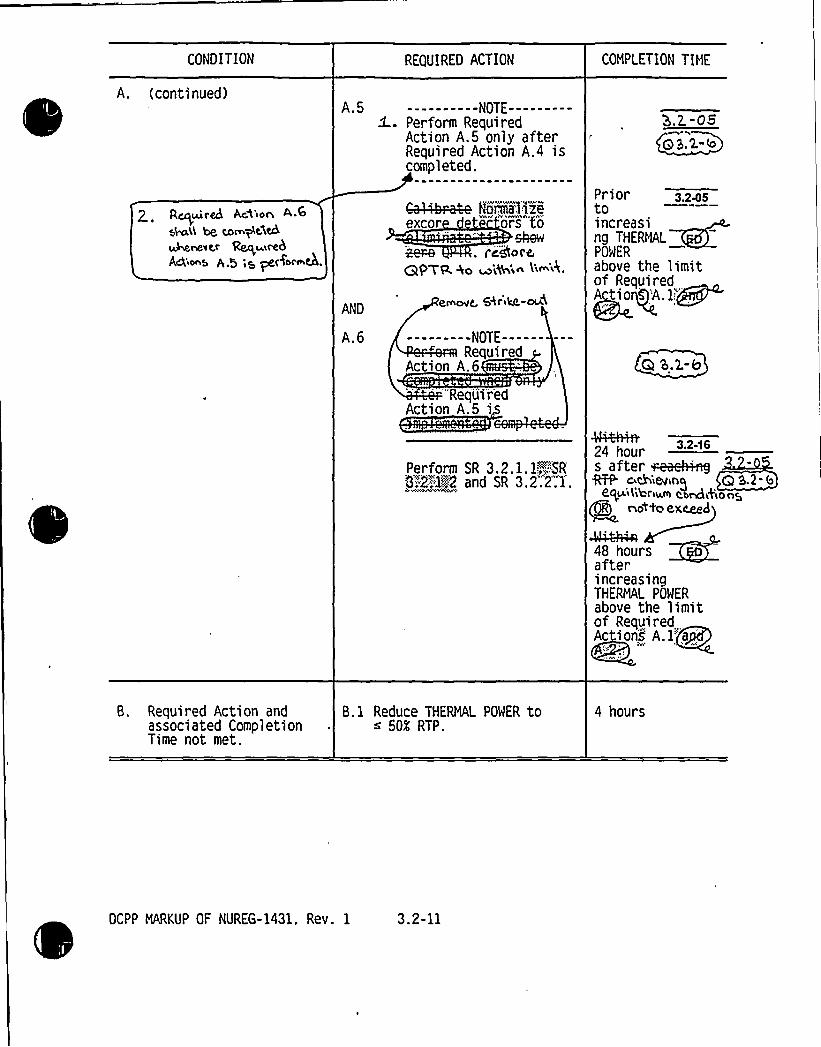
CONDITION REQUIRED ACTION COMPLETION TIME
A. (continued)
Qcruired Ac% ion~46( ~ com$ tAtbuberevcr ~mid!dAdios A.5;r ~Horme.
A.5 ----------NOTE---------<- Perform Required
Action A.5 only afterRequired Action A.4 iscompleted.
Norm@Beexcor ors'to
skewI i@ot'e
(3PTP. Ao ~'i%'i~ ~'~'
ANDemovg Qrita-~i
Perform SR 3.2.1.1~".SR0"":2:.:1<::::2 and SR 3.2'.2.1
A.6 ---------NOTE---------Required
Action A.6
'"Requ'iredAction A.5 i
3.E-08Q3 2."b
Pri or 3 245toincreasing THERMALPOWER
above the limit
Action.1
Q $ .2.-b
4MH+A24 hours after ~~@RTP'uChibling Q 3.2
egv'iVibriu.m c.o~<f<o ngnocto exceed
afterincreasingTHERMAL POWER
above the limitof RequiredActions A. 1Yaa)
B. Required Action andassociated CompletionTime not met.
B. 1 Reduce THERMAL POWER tos 50K RTP.
4 hours
OCPP MARKUP OF NUREG-1431. Rev. 1 3.2-11

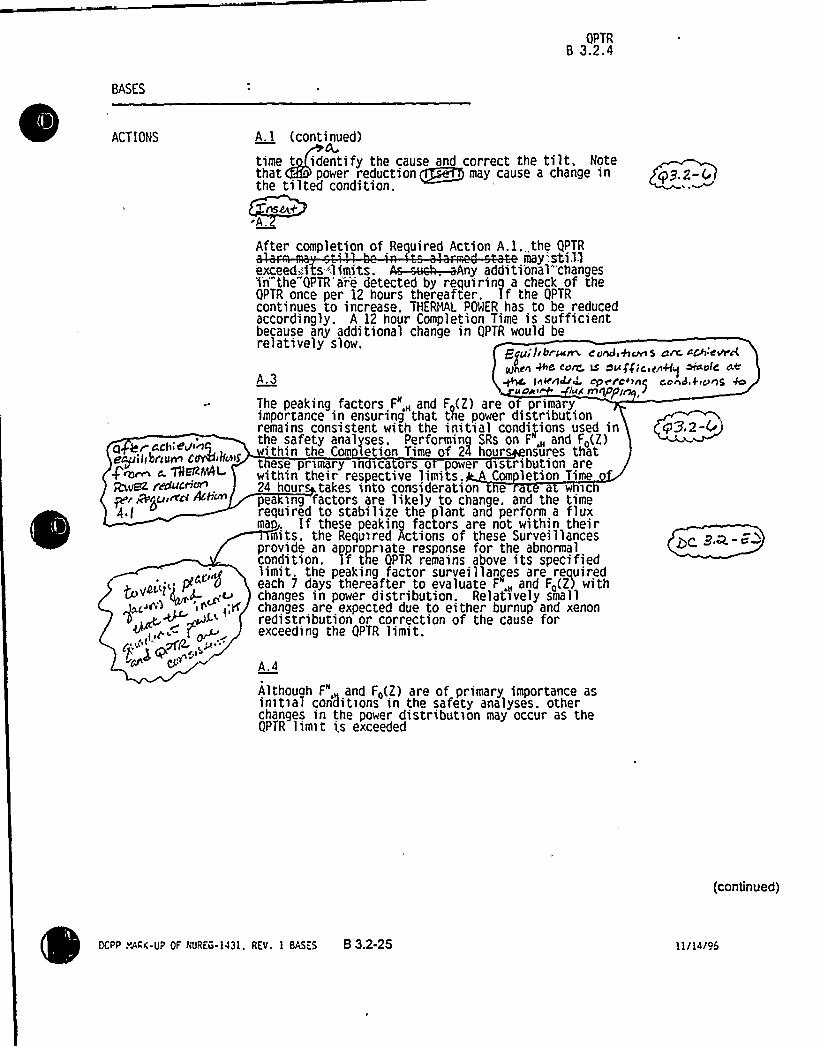
QPTRB 3.2.4
BASES
ACTIONS A. 1 (continued)CA
time t identify the cause and correct the tilt. Notethat power reduction ~ may cause a change inthe tilted condition.
nsew+
q3.2-(
ct ~rrd»eÃncIe~i Ii briUrn COV4lku~S
g~~ e. THelZahlRruPz reducHcn
p r r8 r~uIn'N At;vn4I
The peaking factors F,„ and F (2) are o primaryimportance in ensuring that tLe power distributionremains consistent with the initial condi)ions used inthe safety analyses. Performing SRs on F,„ and F,(E)ithin the Com letion Time of 24 hour nsures that
t ese primary in ica ors o power is ribution are
Qq9~z-(
'ithin
their respective limits. Com letion Tim24 hour takes into consideration e a w icpea ing factors are likely to change. and the timerequired to stabilize the plant and perform a fluxma . If these peaking factors are not within their
mits. the Required Actions of these Survei llancesprovide an appropriate response for the abnormalcondition. lf the QPTR remains above its specifiedlimit. the peaking factor survei llanges are reaui redeach 7 days thereafter to evaluate F,„ and F,(2) withchanges in power distribution. Relatively smallchanges are expected due to either burnup and xenonredistribution or correction of the cause forexceeding the OPTR limit.
After completion of Required Action A.l. the QPTRmay'.sti.ll
exceed»'i s-'limits. A~4 —. aAny additi'onal*'changes'i'n'"the"QPTR'ar'e detected by requirinq a check of theOPTR once per 12 hours thereafter. If the OPTRcontinues to increase. THERNL POWER has to be reducedaccordingly. A 12 hour Completion Time is sufficientbecause any additional change in QPTR would berelatively slow.
grani IIbrmm c'c!+,*cars S a~ cA:@wc(
pe We co~ v oufgici<nRq ~ale atA.3 ~ In'&~ cp~rc<~n~ cc~d &icons WI
~PiN
A.4
Although F", and F~(Z) are of primary importance asinitial con3itions in the safety analyses. otherchanges in the power distribution may occur as theOPTR limit i.s exceeded
(continued)
ocPP PARK-UP 0F NUREG.1431. REv. 1 BAs.s 8 3.2-25 ll/14/45


Insert for Q3.2-6
Enclosure 5B - page B3.2-25
INSERT for A.1
The maximum allowable THERMALPOWER level initiallydetermined by Required Action A.1 maybe affected by subsequent determinations of QPTR. Increases in QPTR would require aTHERMALPOWER reduction within 2 hours of QPTR determination, ifnecessary to comply withthe decreased maximum allowable THERMALPOWER level. Decreases in QPTR would allowraising the maximum allowable THERMALPOWER level and increasing THERMALPOWER up tothis revised limit.


QPTR8 3.2.4
BASES
ACTIONS
e~ Bey~0/t'oh vcr~;y~W~ qPpgW Ntkhin ti~k
A5fnC~iwikKn lie '4
dc/tM/Qu'I /ISr/irmMndlAWs
A.4 (continued)
and may have an impact on the validity of the safetyanalysis. A change in the power distribution canaffect such reactor parameters as bank wor ths andcaking factors for rod malfunction accidents. Whenhe QPTR exceeds its limit. it does not necessarily
mean a safety concern exists. It does mean that thereis an indication of a change in the gross radial powerdistribution that requires an investigation andevaluation that is accomplished by examining theincore power distributio ecifi all the corepeaking factors and the qua ran ti t musevaluated because they are the factors that bestcharacterize the core power distribution. This
valuation is required to ensure that. beforeincreasing THERHg, POW -a ove the limit ofRequired Aetio~. 1 an ; ".. the reactor coreconditions are consi's with the assumptions in thesafety analyses.
5 rC~W q~ > ~<An I n.'0
If the PTR A~eeek4 rema67s;:,above e . 2 limit .2-trand a evaluation of the'safety'-anal sis iscomple ed and shows that„.safety, reau
ectors are.:".pormaÃze'd:pr r
o increasing" DERMAL t above the imit ofRequired Action@ A. 1 . ; . his is done to detectany subsequent signi changes in P ~
. NOAE 4Required Action A.5 is modified b statesthat the
un i a er t e '~va ua ion-'o the safetyanalysis has determined that core conditions at RTPare within the safety analysis assumptions (i.e..Required Action A.4). 'ntended toprevent any ambiguity about th r uired se uence ofactions. 4~A.6
nce e exCore.'," e "ec "os.'ar'e'"normal; zed"',to;.44~~ate'''".e'.", '"""Requi'red "A'etio'n'"A":5 is performed), it is acceptable toreturn to full power operation. However. as an addedcheck that the core power distribution at RTP isconsistent with the safety analysis assumptions.Required Action A.6 requires verification that F4(7.) ~~~ 8ana F",„ are 'pecified limits withi24 h rs of re chin T , , s an a e precau ion. i f
e,pea ing c ,- erifit:action:cannot'/be perfo'rmedwithin-24'ours:.du'e'to'~non-equilibrium. core. ,"," M 3 2- E5'conditions,.:;".a.:,maximum-t4me":of';48 hours".-'.fs,;allowed-"forthe.,completion;of the-verification.".""*-""'"'-"""""
'"'continued}
ocPP HARK UP 0F m/REG ]43], REY. 1 OAsEs B 3.2-26 ]]/]4/96


Insert for Q3.2-6
Enclosure 58 - page 83.2-26
INSERT A for A.5
Note 2 states that if Required Action A.5 is performed, then Required Action A.6 shall beperformed. Required Action A.5 normalizes the excore detectors to restore QPTR to within limit,which restores compliance with LCO 3.2.4. Thus, Note 2 prevents exiting the Actions prior tocompleting flux mapping to verify peaking factors per Required Action A.6.
INSERT 8 for A.6
Equilibrium conditions are achieved when the core is sufficiently stable at the intended operatingconditions to support flux mapping.


QPTRB 3.2.4
BASES
ACTIONS A.6 (continued)
I".'
SURVEILLANCEREQUIREMENTS
T)118Completion Times-are 'is%>ntqnded to a low adequate
'imeto increase THE OW to above the limit ofRequired Actions A. ll - 'hile not permitting theore to remain w'ith uncon armed power distributionsor extended periods of time.
Required Action A.6 is modified by a Note that statesthat the...peaking...factor„s rvei llances~,.musi"-:be:;:,'comp) '" 'he excore detec ors havebe n'.normalized~to '" 1".e;.Action A.5). The inteot of this Note is to have thepeaking factor survei'11ances erformed at operating„„...power„., levels., „which areonly::.'":required"';if: the tors
: *I! 'i ':,.AW AWt NA
8.1
If Required Actions A. 1 through A.6 are not completedwithin their associated Completion Times'he unitmust be brought to a MODE or condition in which thereguirements do not apply. To achieve this status.THERMAL POWER must be reduced to ~ < 50X RTP within4 hours. The allowed Completion Time of 4 hours isreasonable. based on operating experience regardingthe amount of time required to reach the reduced powerlevei without challenging plant systems.
SR 3.2.4.1
SR 3.2.4. 1 is modified by two Notes. Note 1 allowsQPTR to be calculated..with three power range channelsif THERMAL POWER -is ~ 75X RTP and the input from onePower Range Neutron Flux channel is in~perable. Note
3.2.4.1.2 allows performance of SR 3.2.4.2 in ieu of SR
QS.Z-C
~c.s~m PMW~ vviMin limni+
Input'+fr'oiii/a>Powei'".Ra'nge'NeRron ~FTuxTc'h'an'iiel:::"''isconsidered,~to-''.be;:QPERABLFQ):fgt;he',„'upper~'and:lowerdetector.'currents:.~are.':obtainable.::~The>remaininq, ...portion-'of'.the'.channel-.(the!;electro'nicsYrequiretI'.to ..I1rovide"the..„channel - input~to'>the„'..gp.:. Rlalarm)kneed".not
I
This Surveillance verifies that the QPTR as indicatedby the Nuclear Instrumentation System (NfS) excorechannels. is
(continued)
KPP tQRK.UP 0F RUREG-1431. REV, 1 BAsEs B 3.2-27 11/14/96


JUSTIFIGATION FQR DIFFERENCES FROM NUREG-1431
NUREG-1431 Section 3/4.2
This Enclosure contains a brief discussion/justifiication for each marked-up technical change to NUREG-1431, tomake them plant-specific or to incorporate generic changes resulting from the Industry/NRC generic changeprocess. The change numbers are referenced directly from the NUREG-1431 mark-ups (Enclosure 5A). ForEnclosures 3A, 3B, 4, 6A, and 6B text in brackets "[ ] indicates the information is plant specific and is notcommon to all the JLS plants. Empty brackets indicate that other JLS plants may have plant specific informationin that location.
CHANGENUMBER
3.2-01
3.2-02
3.2-03
3.2-04
3.2-05
3.2-06
3.2-07
JUSTIFICATION
Not applicable to DCPP. See Conversion Comparison Table (Enclosure 6B)
Consistent with the CTS, retain the requirement for performing Fo after a 20 percent change inpower (versus the 10 percent, value specific in the ITS).
Consistent with Traveler TSTF-98, Rev. 1, the factor by which the F~ must be adjusted onincreasing F~ measurements is moved to the COLR. This change is acceptable because thefactor is normally contained in the COLR, and it removes detail not required to be contained inTS.
Not applicable to DCPP. See Conversion Comparison Table (Enclosure 6B).
n a ance with T veler TSTF-, clarify tha e excore de ctors are no ized to in catz 'lt This is ya clarificatio f NUREG- 31 wording a dis acceptab .
En&c,~~ ~ ~ ~
5 2,-bconsistent with Traveler TSTF-95, the time allowed for resetting the power range neutron flux- high setpoint if F~ or F"~ is outside their limits is extended from 8 hours to 72 hours. Aswritten, the Completion Time of 8 hours to reduce the power range neutron flux-high TripSetpoints presents an unjustified burden on the operation of the plant. A Completion Time of72 hours will allow time to perform a second flux map to confirm the results, or determine thatthe Condition was temporary, without implementing an unnecessary Trip Setpoint change,during which there is increased potential for a plant transient and human error. Following asignificant power reduction, at least 24 hours are required to reestablish steady state xenonprior to taking a flux map, and approximately 8 to 12 hours to obtain a flux map, and analyzethe data. A significant potential for human error can be created through requiring the TripSetpoints to be reduced within the same time frame that a unit power reduction is taking place,and within the current.8 hour period. Setpoint adjustment is estimated to take approximately,4 hours per channel (review of plant Condition. supportive of removing channels from service,tripping of bistables, setpoint adjustments, and channel restoration), adding 2 hours fornecessary initial preparations (procedure preps, calibration equipment checks, obtaining tools,and approvals); it is reasonable to expect a total of 18 hours. Further, setpoint changesshould only be required for extended operation in this Condition. Finally, the Bases for makingthis setpoint change is the same as the NUREG Bases provided for the 72 hour CompletionTime of LCO 3.2.1 Required Action A.4, which is also a setpoint reduction. In summary, thischange is acceptable because it would permit time to perform required flux mapping, permitorderly resetting of the high flux Trip Setpoints, and reduce the chances of an inadvertentreactor trip during the required power reduction.
Consistent with Traveler TSTF-97, the Note in SR 3.2.1.2 is revised by removing the phrase "iswithin limits and" to clarify that the actions to be taken if Fo (Z) is increasing are requiredregardless of whether Fo (Z) is within its limits.
DCPP Description of Changes to Improved TS


Insert for Q3.2-6
Enclosure 6A - page 1
INSERT for 3.2-05
3.2-05 Consistent with TSTF-241, ISTS 3.2.4, Quadrant Power Tilt Ratio, is revised toprovide more appropriate Actions. Required Action A.2 contains a redundant actionto reduce THERMALPOWER. This redundant action is deleted and the THERMALPOWER limit of Required Action A.1 is revised to provide the appropriate allowancefor subsequent power reductions based on subsequent determination of QPTR. []The Completion Time of Required Action A.3 requires the peaking factors to beverified within 24 hours of achieving equilibrium conditions with THERMALPOWERreduced by Required Action A.1. In the current Required Action, a significantfraction of the 24 hours could be spent waiting for the plant to stabilize at the newpower level leaving insufficient time to measure and analyze the peaking factors orresulting in the peaking factors being measured when the plant is not stable yieldinginaccurate information. Since the peaking factors are of prime importance, theproposed change will allow sufficient time to obtain an accurate measurement. [ ]
Required Action [A.5) is revised to add a new Note stating "Required Action [A.6]shall be completed if Required Action [A.5] is performed." As discussed in Section1.3 of the ITS, an Actions Condition remains in effect and the Required Actionsapply until the Condition no longer exists or the unit is not with the LCOApplicability. Therefore, when Required Action [A.5] is completed, QPTR should beback within limit and the LCO may be exited. Adding this Note ensures that thepeaking factors are verified after normalization of the excore detectors.Additionally, Required Action [A.5] is revised to state "Normalize excore detectors torestore QPTR to within limit." Normalization is accomplished in such a manner thatthe indicated QPTR following normalization is near 1.00. Thus, the absence of a tiltwill manifest itself as QPTR=1.00 rather than zero since quadrant power tilt isexpressed as a ratio. Also, from a literal compliance standpoint, the tilt cannot berestored to exactly 1.00. [ ]


JUSTIFICATION FOR DIFFERENCES FROM NUREG-1431
NUREG-1431 Section 3/4.2
3.2-08
3.2-09
3.2-10
3.2-11
3.2-12
3.2-13
3.2-14
3.2-15
3.2-16
3.2-17
3.2-18
Consistent with Traveler TSTF-99, the LCO 3.2.1 (Fa Methodology), Required ACTION B.1.Completion Time for the reduction of the AFD limits if F 0(Z) is not within limits is increasedfrom 2 hours to 4 hours. This makes it consistent with the Completion Time associated withRequired ACTION A.2. of LCO 3,2 1 (Fxy methodology). The change is acceptable because iteliminates an inconsistency in the ITS.
For consistency with CTS 3.2.4 and ITS 3.3.1, Condition D, the breakpoints for the Applicabilityofthe surveillances in the notes in ITS SR 3.2.4.1 and SR 3.2.4.2 are modified to be applicable atless than or equal to 75 percent RTP, and greater than 75 percent RTP, respectively. Tadministrative change that retains CTS requirements
t+ ckAB I& C0As'id'eat ~i< TSTF-2WI.Consistent with Traveler TSTF-110, this change moves requirements for increased surveillancefrequencies in the event of inoperable alarms to licensee controlled documents. This change isacceptable because it removes requirements regarding alarms and alarm responses that arenot necessary to be in the TS to protect public health and safety.
Not applicable to DC P. See Conversion Comparison Table (Enclosure 6B).T 3,2, I,2„~Q on ptat4 eq ec'i em,
e required time for completion a flux ma for determination of theheat flux hot channel factor is changed from 12 hours to hours a r achieving equilibriumConditions. The proposed change affects SR 3.2.1.1 and S .... he proposed time (24hours is a reasonable time eriod for the comp ion o e survei c an oes not ow orpant oper on in an unce n con i ion for a rotracted time peri . This change isconsis t with the TS r uirements of Sp ification 3.0.4 (and ssociated Bases) t t allow24 urs for the corn etion of a surveill ce after prerequisi plant conditions ar attained
ce tion to S ecif tion 4.0.4 was rov'dZnMrg
This change retains the CTS for the performance of peaking factor determinations followingplant shutdowns. The CTS, through the exemption to Specification 4.0A, allows prerequisiteplant conditions to be obtained prior to requiring that the surveillance be completed.p
Not applicable to DCPP. See Conversion Comparison Table (Enclosure 6B).3.2.-'(
This change incorporates Traveler TSTF-109. ACTION A.2. would require the QPT bdetermined rather than performing a specific surveillance because more than one surveillancecan be used to determine QPTR. SR 3.2A.1 was revised to retain allowance that SR 3.2.4.2may be'performed in lieu of SR 3.2.4.1. QS,2-to
. Thesechanges are acceptable because they clarify the ITS regarding frequency and us of incoreflux monitoring for QPTR measurement. The changes reflect that incore detectors rovide anacceptable QPTR determination during all plant Conditions.
This change would require both transient and static F~ measurements be determined whenperformed for Required ACTIONS 3.2.4 A.3 and A.6. The intent of the Required ACTIONS isto verify that Fo(Z) is within its limit. F<(Z) is approximated by FQ(Z) (which is obtained via S3.2.1.1) and Fa(Z) (which is obtained via SR 3.2.1.2). Thus, both F~(Z) and P~(Z) must beestablished to verify Fa(Z). This change is consistent with Traveler WOG-105.
Not a licab o DCPP. S Conversion C parison Tabl Enclos e 6B). g3.2-3~U
Not applicable to DCPP. See Conversion Comparison Table (Enclosure 6B).
3.2-19 Not a licable to DCPP. Co rsio risonrche o r~ueog~ %or SR 2.. t. ate, revised co~'igtn~i ~'Hn
'topi~~ P'<~~~4~ %r~%5 ~+p~ide. <ar 0 pet'i'd ~g t'ice, a+et.
ri
Nc t aqqticahte Wccpp. Sep- Co~v<c&on Congas isola ~te (pr,ch~~e H),Ch $ .2.-I


CONVERSION CONIPAR)SON TABLEFO s cRENCES FROM NUREG-1431, SECTION 3/4.2 Page1~, 8
TECH SPEC CHANGE APPLICABILITYNUMBER DESCRIPTION DIABLOCANYON COMANCHE PEAK WOLF CREEK CALLAWAY
3.2-01Substitute overpower CPSES N-16 for overpower hTreactor trip function.
No Yes
3.2-02Retain CTS requirement for performing Fa after a 20% Yeschange in power (versus the 10% value specific inthe ISTS).
Yes No, CTSspecifies 10%.
No, CTS specifies10%
3.2-03
3.2-04
3.2-05
3.2-06
3.2-07
3.2-08
3.2-09
Consistent with TSTF-98, Rev. 1, the factor by whichthe F~ must be adjusted on increasing FQmeasurements is moved to the COLR.
SR is applicable to plants using the WestinghouseConstant Axial Offset Control methodology. TUElectric uses the methodology described inRXE-90-006-P-A, described in CTS 6.9.1.6b, whichties the target flux difference surveillance frequencyto the frequency at which the Fii"(Z)peaking factoris verified.
Per a ose ision Is cc 'es t e e e detec are no ized toindi zero ti .
Consistent with TSTF-95, increases time to resetHi Flux setpoints from 8 to 72 hours.
Consistent with TSTF-97, clarifies the ACTIONS forincreasing F"0(Z).
Consistent withTSTF-99, increases the allowance forAFD restrictions from 2 hours to 4 hours.
The breakpoints for the Applicabilityof thesurveillances in the notes in ITS SR 3.2.4.1 andSR 3.2.4.2 are modified to be applicable at less thanor equal to 75% RTP and greater than 75% RTP,respectively.
Yes
No
Yes
G 3.2.-S
Yes
Yes
Yes
Yes
Yes
Yes
Yes
Yes
Yes
Yes
Yes
Yes
No
Yes
Yes
Yes
Yes
Yes
Yes
Yes
Yes
Yes
Yes
Yes
3.2-10Consistent with TSTF-110, moves requirements Yes, to ECG andfor increased surveillance frequencies in the event FSAR.of ino erable alarms to licensee controlled documents
Yes, to TRM. Yes, to FSAR. Yes, to FSAR.
DCPP Conversion Comparison Table - Improved TS


Enclosure 6B - page 1
Insert for Q3.2-6
INSERT for 3.2-05
TECH SPEC CHANGE APPLICABILITYNUMBER DESCRIPTION DIABLO
CANYONCOMMANCHEPEAK
WOLF CREEK CALLAWAY
3.2-05 Consistent with TSTF-241, ISTS 3.2.4, QuadrantPower Tilt Ratio, is revised to provide moreappropriate Actions.
Yes Yes Yes Yes


CONVERSION COMPARISON TABLEFO t -FENCES FROM NUREG-1431, SECTION 314.2 Page2o ~
TECH SPEC CHANGE APPLICABILITYNUMBER DESCRIPTION DIABLOCANYON COMANCHE PEAK WOLF CREEK CALLAWAY
3.2-11
3.2-12
3.2-13
3.2-14
3.2-15
This change rearranges the notes applicable toLCO 3.2.3. AFD (Constant Axial Offset Control plantsonly, CPSES specific) from three separate notesaffecting different portions of the LCO into a commonnote block. This change is consistent with TSTF-164.
Consis ith,t e uire e orco petioof a map r deter nation the heat x hotc nelf orisc gedfr 12hour o24h
fter ieving ilibrium ondition The pr osecha e affec SR 3.2.1 and SR .2.2.1.
This change retains the CTS for the performanceof peaking factordeterminations following plantshutdowns.
This change retains the WolfCreek current licensingbasis (License Amendment 61) for RequiredACTION 3.2.2 A.2.
This change partially incorporates the industry .traveler TSTF-109. ACTION A.2 now requires theQPTR be determined rather than performing aspecific surveillance because more than 1
surveillance can be used to determine QPTR.~
Yes
Yes
No
Yes
QS,Z-IO
Yes
Yes
9 5.2.-5
Yes
Yes
No
YBS
Yes
Yes
Yes
No
Yes
Yes
Yes
3.2-16Requires both transient and static F~ measurementswhen performed for Required ACTIONS 3.2.4 A.3and A.6.
Yes Yes Yes Yes
3.2-17
3.2-18
This change modifies the QPTR requirements inNUREG-1431, Rev. 1, for WolfCreek, to retainseke-CTS requirements ap
No No
A~t&4 ~i lloyd
Yes No
DCPP Conversion Comparison Table - Improved TS


Enclosure 2PG8 E Letter DCL-98-107
ADDITIONALINFORMATIONCOVER SHEET
ADDITIONALINFORMATIONNO: Q 3.2-10
REQUEST:
APPLICABILITY: DC, CP, WC, CA
ITS 3.2.4 Quadrant Power Tilt RatioCTS 3/4.2.4 Quadrant Power Tilt Ratio (All FLOG Plants)JFD 3.2-15ITS SR 3.2.4.2
Comment: JFD 3.2-15 justifies numerous changes to the STS one of which isunacceptable. JFD 3.2-15 is based upon TSTF-109, which has been rejected.The unacceptable STS change is: The modification of the note to SR 3.2.4.2,and in particular the addition of the 12 hour allowance in the Note to SR 3.2 4.2.Provide adequate justification for this change or adopt the STS version of theNote.
FLOG RESPONSE: The latest status report from the TSTF industry database, datedJune 16, 1998, indicates that the NRC has approved TSTF-109. The FLOG continuesto pursue the changes approved in TSTF-109.
JFD 3.2-15 is revised to delete the sentence: "The note for SR 3.2.4.2 is changed torequire performance ifone 'or more'PTR inputs are inoperable." and added: "Thenote and Frequency for SR 3.2.4.2 are revised consistent with typical presentationformats that provide for a period of time after establishing conditions." NUREG-1431,Revision 1 currently has "or more" in the Note and TSTF-109 did not modify thiswol'ding.
ATTACHEDPAGES'ncl
6A 2Encl 6B 2


JUSTIFICATION FOR DIFFERENCES FROM NUREG-1431
NUREG-1431 Section 3/4.2
3.2-08
3.2-09
3.2-10
3.2-11
3.2-12
3.2-13
3.2-14
3.2-15
3.2-16
3.2-17
3.2-18
Consistent with Traveler TSTF-99, the LCO 3.2.1 (Fo Methodology), Required ACTION 8.1.Completion Time for the reduction of the AFD limits if F o(Z) is not within limits is increasedfrom 2 hours to 4 hours. This makes it consistent with the Completion Time associated withRequired ACTION A.2. of LCO 3.2.1 (F„„methodology). The change is acceptable because iteliminates an inconsistency in the ITS.
For consistency with CTS 3.2.4 and ITS 3.3.1, Condition D, the breakpoints for the Applicabilityofthe surveillances in the notes in ITS SR 3.2.4.1 and SR 3.2A.2 are modified to be applicable atless than or equal to 75 percent RTP, and greater than 75 percent RTP, respectively. T
'dministrativechange that retains CTS requirementsQ afd i& COASld31eht mid V5+F-2cII.
Consistent with Traveler TSTF-110, this change moves requirements for increased surveillancefrequencies in the event of inoperable alarms to licensee controlled documents. This change isacceptable because it removes requirements regarding alarms and alarm responses that arenot necessary to be in the TS to protect public health and safety.
Not applicable to DC P. See Conversion Comparison Table (Enclosure 68).9aaQ on pitoc'i ecpeciectce
>
e required time for completion f a flux ma for determination of theheat flux hot channel factor is changed from 12 hours to hours a r achieving equilibriumConditions. The proposed change affects SR 3.2.1.1 and S .... he proposed time (24hours is a reasonable time eriod for the compl ion o e survei ~c an oes not ow orpant oper on in an unce n con i ion for a rotracted time periotI. This change isconsis t with the TS r oirements of Sp ificadon 3.0.4 (and/annotated Bases) t t aitow24 urs for the corn etion of a surveill ce after prerequisite plant conditions ar attained
ce tion to S ecif tion 4.0.4 was rovicfedT.nM,r7
This change retains the CTS for the performance of peaking factor determinations followingplant shutdowns. The CTS, through the exemption to Specification 4.0.4, allows prerequisiteplant conditions to be obtained prior to requiring that the surveillance be completed.g
Not applicable to DCPP. See Conversion Comparison Table (Enclosure 6B).3.2.-'t
This change incorporates Traveler TSTF-109. ACTION A.2. would require the QPT bdetermined rather than performing a specific surveillance because more than one surveillancecan be used to determine QPTR. SR 3.2.4.1 was revised to retain allowance that SR 3.2.4.2may be performed in lieu of SR 3.2.4.1. Q0 h-l0
. Thesechanges are acceptable because they clarify the ITS regarding frequency and us of incoreflux monitoring for QPTR measurement. The changes reflect that incore detectors rovide anacceptable QPTR determination during all plant Conditions.
This change would require both transient and static Fo measurements be determined whenperformed for Required ACTIONS 3.2.4 A.3 and A.6. The intent of the Required ACTIONS isto verify that Fo(Z) is within its limit. Fo(Z) is approximated by Fo(Z) (which is obtained via S3.2.1.1) and F <(Z) (which is obtained via SR 3.2.1.2). Thus, both F~~(Z) and Po(Z) must beestablished to verify F<(Z). This change is consistent with Traveler WOG-105.
Not a licab o DCPP. S Conversion C parison Tabl Enclos e 68). (p3.2-3of cJ~
Not applicable to DCPP. See Conversion Comparison Table (Enclosure 68).
3.2-19 Not a licable to DCPP. Co rsion risonno1e r~uec c.+ %or SR 2,.4. a.re elf ised cone'csYmY m'+
<qpiaxi ix'e~~arsort Qc'ma4is ~+prohfide. <or a period o$ t'arne, oRer
DCPP Description of C
~
~
o.L-2.0 Mol aqpvscaic31e ~ccPP. &e8 co~v<rs~on coopar'tsa ~te (E~dciscttro, w),Ch S.2.-I


CONVERSION COMPARISON TABLEFO I-a:rtENCES FROM NUREG-1431, SECTION 3I4.2 Page2o <
NUMBER DESCRIPTION
TECH SPEC CHANGE
DIABLOCANYON
APPLICABILITYCOMANCHE PEAK WOLF CREEK CALLAWAY
3.2-11
3.2-12
3.2-13
3.2-14
3.2-15
This change rearranges the notes applicable toLCO 3.2.3. AFD (Constant Axial Offset Control plantsonly, CPSES specific) from three separate notesaffecting different portions of the LCO into a commonnote block. This change is consistent with TSTF-164.
Consis th,t e uire e orco petioof a map r deter nation the heat x hotc nelf orisc gedfr 12hour o24h
fter ieving ilibrium ondition The pr osecha e affec SR 3.2.1 and SR .2.2.1.
This change retains the CTS for the performanceof peaking factor determinations following plantshutdowns.
This change retains the WolfCreek current licensingbasis (License Amendment 61) for RequiredACTION 3.2.2 A.2.
This change partially incorporates the industry,traveler TSTF-109. ACTIONA.2 now requires theQPTR be determined rather than performing aspecific surveillance because more than 1
surveillance can be used to determine QPTR.-Tee.
No
Yes
Yes
No
Yes
QS,K-IO
Yes
Yes
9 5.2.-5
Yes
Yes
Yes
Yes
Yes
No
Ves
Yes
Yes
3.2-16Requires both transient and static Fo measurementswhen performed for Required ACTIONS 3.2.4 A.3and A.6.
Yes Yes Yes Yes
3.2-17
3.2-18
This change modifies the QPTR requirements inNUREG-1431, Rev. 1 ~
for WolfCreek, to retain se4e-CTS requirements ap ~<d i~ Acne.ad
No
Ho. nh
Yes
DCPP Conversion Comparison Table - Improved TS


Enclosure 2PG8 E Letter DCL-98-107
ADDITIONALINFORMATIONCOVER SHEET
ADDITIONALINFORMATIONNO: CA 3.2-001
REQUEST:
APPLICABILITY: DC, WC, CA
Revise last sentence of Bases 3.2.1, Action B.1 to read: "Reducing boththe positive and negative AFD limits by ...." This change makes it clearthat both positive and negative limits must be reduced when F~ (Z) is notwithin limits.
ATTACHEDPAGES'ncl
5B B3.2-5


F(Z)(I'o
B 3.2.18
BASES
ACTIONS(continued)
A,Z
A reduction of the Power Range Neutron Flux-High tripsetpoints by ~ lK for each 14 by which F'o(7.) exceeds itslimit. is a conservative action for protection againstthe consequences of severe transients with unanalyzedpower distributions. The Completion Time of s.,72~4 hoursis sufficient considering the small likelihood of asevere transient in this time period and the precedingprompt reduction in THERHAL POMER in accordance withRequired Action A. l.
A.3
Reduction in the Overpower hT trip setpoints by ~ ll foreach lR by which F'o(2) exceeds its limit. is aconservative action for protection against theconsequences of severe transients with unanalyzed powerdistributions. The Completion Time of 72 hours issufficient considering the small likelihood of a severetransient in this time period. and the preceding promptreduction in THERHAL PQMER in accordance with RequiredAction A.l.
A.4
Verification that F',(Z) has been restored to within itslimit. by performing SR 3.2.1. 1 prior to increasingTHERHAI. POMER above the limit imposed by RequiredAction A. 1. ensures that core conditions during operationat higher power levels are consistent with safetyanalyses assumptions. Inherent'':!tIh"s..-,ac6on'gsi'dents fi'cati'on!if,.th''™causejofithe'.,o'utkof;,:1)miti:onditfon',",,'„.arid)the"corre'ctixon.:,aof-.;the,'.'caus»„".:::to)the.,extent4rie'csess'ary,":t'otalIowRafe„"opxeratio'n'catI:,:the",.,higher.power„'.!Tev'el'.-.".,';,':.Th'e;::allowrable',:~pow'er.„',„,le+el.,"-,;1's~;:determined::! by,extratpo) ating,".;Fto~(Z).'.:,'::i"':5R,';.3,::2 1'".1":m'ust';;;be„'s'atisf ied,'prior'tto,":: ctr'rneasf g,"n'joiner,"ao be vixi'.t-eexvt apr'actea(jfal16wableFewer.',:1'eve'I„-'.o'i;,;r iistor'atl onto'fianj;::;::re((aced:.-SeantbraTr(O
B.l b>)h ~ ~'t)'av|. ~h ~egch'«t'. A'FD >a~'s'ts
a(co(ates( value of F (Z)uvers. F,(Zl. excee ss a potential for F a(Z)ormal operational
b ~ 1R for each ll
If it is found that the maximumthat can occur during normal manits specified limits. there existo become excessively high if atransient ccurs. Reduc>nby which F (Z) exceeds its limit within the allowed9 g... y.
Completion Rime ofL4 8 hours. restricts the axial flux
CA $ Q 00(
(continued)
iDCPP Mark-up of NUREG-1431. Rev, 1 Bases B 3.2-5

0
Enclosure 2PG&E Letter DCL-98-107
ADDITIONALINFORMATION COVER SHEET
ADDITIONALINFORINATIONNO: CA 3.2-002
REQUEST:
APPLICABILITY: DC, WC, CA
Insert in ITS Bases 3.2.1 the expression from CTS SR 4.2.2.2.f for how tocalculate the percent by which both F~ and F~ exceed their limits. Thisprovides more readily available information to Operations andEngineering personnel.
ATTACHED PAGES:
Encl 2Encl 5B
3/4 2-8B3.2-4


POWER DISTRIBUTION LIMITS
SURVEILLANCE REQUIREMENTS (Continued)
1) F,~(2) shall be increasedby aR th''';:appropriate factor
specified in the COLR. or
02-01-LG
2) F, (Z) shall be measured at least once per 7 EFPD until two successivemaps indicate that
maximum ~F- ~Z is not increasing.
over 7. K(2)
VI It,*'iF,'!jl: I
CA. 3.2.-002.
~,,F II i i I I
a)
02-14-M
02-03-M':.Qi.th'n:;.",4
hours".'„::,':,reduce AFD limits of Spec~ificatiori 3:2".1" '~&ee4 at1'e'also'1X""A'FDv"fort each percent F,"-(1) exceeds its limit, or be inNode',:!2'.":Qfthin;"the!:::nevxt('6."'haurT'.":,,IACAlhVA AFVAtVQCACV VAACYCCV, CCA IIVVCCA AVVAVCCCAVAXV&CCCCFACCAAV
DIABLO CANYON - UNITS 1 8 2 3/4 2-8 Amendment Nos. 96 8 95December 31. 1994


B 3.2.18
BASES
LCO(continued)
The expression for F;(Z) is:
F",(2) - F',(2) W<2)
CA 3.2.-oo>
Dc. 8 2-ooj
where W(2) is a cycle dependent function that accountsfor power distribution transients encountered duringnormal operation. W(Z) is included in the COLR.
Zag~$The F,(2) limits define limiting values for core powerpeaking tha preclude@ peak cladding temperatures above2200'F durin either a large or small break LOCA.
tu'ilh a, h'icsh level oW prohandi'l>%gThis LCO requires operation within the bounds assumed inthe safety analyses.
f Fo(2) cannot bemaintained within the tCO limits. reduction of the corepower is required.
Violating the LCO limits for F,(2) may,;;producesunacceptable consequences if a design'basis event occurswhile Fe(2) is outside its specified limits.
Tf,:::."':,the:::;power! di's'L'j:".,ibut'ion:."meas'ui'erne'n'ts":;";"a'r'e'j'e'r'fo'rm'e'd'."at!'a'jowe'r',::.:::lev'el'ss';:.."'th'an',:::;:100%";:RTP,,';::.::ith'e'n.'„'..:;the lFI,",(Z)7aIid:;:.';F4"
(2)'alues',,'that':;.461d:;:.;res'ult"froidmeas'urements,:.'.3 f'tthe,;";core'"'""
alas':.':at',:.',:100x,;RTP,:-';shou,td,be',:".infe'r'red':..'fr'om'::,the.'.ave'1able;,.„1qfarmatioii','',,"A'''comp'ai',i s'on!of:,,.::':the's'e.',.: infe'i'red:lvailu'es; w'i't'h
F --':~'::a'ss'u're's'.:::::,.'co" 'I1ance'.'::w'i'O'Ii:.',".the';.:-LC'o.':;at!:al:l5'oow'er:.:lev'els"..
APPLICABILITY The Fo(2) limits must be maintained in NODE 1 to preventcore power distributions from exceeding the limitsassumed in the safety analyses. Applicability in otherNODES is not required because there is eitherinsufficient stored energy in the fuel or insufficientenergy being transferred to the reactor coolant torequire a limit on the distribution of core power.
ACTIONS A,I
Rpducing THERMAL POWER by ~ IR RTP for each IR by whichF,(2) exceeds its, limit. maintains an acceptable absolutepower density. F'2) is F",(2) multiplied by a factorswhich account~ for manufacturing tolerances andmeasurement uncertainties. F",(Z) is the measured valueof F,(2). The Completion Time of 15 minutes provides anacceptable time to reduce power in an orderly manner andwithout allowing the plant to remain in an unacceptablecondition for an extended period of time.
(continued)
KPP Mark-uP of NUREG-1431. Rev. 1 Bases B 3.2-4


Insert for CA 3.2-002
Insert for Enclosure 5B, page B3.2-4:
Calculate the percent F~(z) exceeds its limit by the following expression:
maximum
over z FRYx K(z)
Pc
x 100 for P >0.5
(maximum
over z FR~x Z(z)
05
x 100 for P <05


Enclosure 2PG8 E Letter DCL-98-107
ADDITIONALINFORIIATIONCOVER SHEET
ADDITIONALINFORIIATIONNO: CP 3.2-001
REQUEST:
APPLICABILITY: DC, CP, WC, CA
The mark-up of CTS SR 4.2.5.3 (4.2.3.4 for DCPP) was revised asfollows. This SR requires a CHANNEL CALIBRATIONon the RCS loopflow rate once per 18 months (refueling interval for DCPP). The CTS SRis equivalent to ITS SR 3.3.1.10 and the Reactor Coolant Flow - Lowfunctional unit. DOC 5-12-A was initiated to address that CTS SR 4.2.5.3(4.2.3.4 for DCPP) is equivalent to ITS SR 3.3.1.10. For CPSES andDCPP, the strikeout is removed consistent with the FLOG markupmethodology.
For CPSES, the CTS SR 4.2.5.3 statement "The channels shall benormalized based on the RCS flow rate determination of SurveillanceRequirement." is struck through and DOC 5-03-LG applied. DOC 5-03-LG is revised in Enclosures 3A and 3B to indicate the DOC is applicableto CPSES only and that this information is moved to ITS Bases 3.4.1.
ATTACHEDPAGES'ncl
2Encl 3AEncl 3B
3/4.2-1768 778 8


POWER DISTRIBUTION LIMITS
LIMITING CONDITION FOR OPERATION
tb. Within 24 hours of initially being outside the above limits,
veri fy that',:;":F-."@='...;i's'";hwithin;l,imi.ts,'
M~ . or reduce THERMAL POWER to less than 5R of RATEDTHERMAL POWER within the next 6 8 hours.
03-07-A
03-01-I G
03-04-LS6
withinr'ljmifsprior to exceeding the following
THERMAL POWER level s:.'",::.g
1. A nominal.50K of RATED THERMAL POWER. 03-06-A
Z. A nominal 75K of RATED THERMAL POWER. and
3. Within 24 hours of attaining greater than or equal to 95K of RATEDTHERMAL POWER.
03-03-M
Identify and correct the cause of the out-of-limit conditionprior to increasing THERMAL POWER above the reduced THERMALPOWER limit required by ACTION a.2 ad@~...above: subsequent p3-07 AOl Ol ll 3 'dd«ip,:
is '..'demonstrated,. to be
SURVEILLANCE REQUIREMENTS
4.2.3.1 The provisions of Specification 4.0.4 are not applicable.
4.2.3.2 F;"( shall be
determined Ko be within limits™;:::.-':C
02-07-A
03-07-A
05-10-Aa. Prior to operation above 75K of RATED THERMAL POWER after each
fuel loading, and
b. At least once per 31 Effective Full Power Days.
~~th(e, ctrl( e - ah
R6'F cvvg gyr~dAL O'-Al L-005j.d,"t>h i<$ 2t A<:::~~m
.'!',","-:.ll,'ill, 3m ittll id:i!wi!O,i't ip ='.M did'-" pi FF')'ltlti'"'t on:::.'
4.2.3.3 The~ea4ed RCS total flow rate shall be verified to be within the 03 08 A3 ol rI',"ll!"am'r~ «dll, ""i
':2-2~i 22""""2 ""' ''
'.' -*C, P 3.2-00 I
C- G
I 2 4
oe-l2 - A
4.2.3.S The RCS total flow rate shall be determined by measurement at least once pe 43~Whs.
U
d ddt d m. WAW
DIABLO CANYON - UNITS 1 8 2TS32.4A
3/4 2-17 Amendment Nos. 60 8 59March 12, 1991


CHANGENUMBER
04-07
04-08
04-09
04-100 -I
NSHC
A
S14
LG
DESCRIPTiON
violated; and (3) the ITS required ACTIONS prior to and subsequent to powerascension provide assurance that POWER OPERATION at or near RTP willbe inaccordance with the safety analyses, and therefore acceptable.
The statement that Specification 3.0.4 does not apply is no longer needed asrevised ACTIONS permit continued operation for an unlimited period of time.
Not used. cuL 3.2-0o
Consi nt wi EG-143, ote is adde o permit 3 ERABLE corech elstob edtocalc teQPTRwh 1channe 'no erable ndpoweris
5 perce
Not Uee esignation of how instrument uncertainties are treated (nominal, in the
analysis or in the development of the TS limit) is moved to the Bases. Themovement of this level of detail out of the specification is consistent with NUREG-1431 and is an example of removing unnecessary details from the TS inaccordance with 10 CfR 50.36.
05-02
05-03
05-04
05-05
05-06
05-07
05-08
05-09
LS7
LG
LG
LG
LS8
LG
Not applicable to DCPP. See Conversion Comparison Table (Enclosure 3B).
Consisten th NUREG- 431, the requirem t to perform a CH NELCALIB ION on the S flow meters atl astonce per18 m ths and therequir ent to norma
'the channels ar oved to the Bas for the RCS flow
lowr ctor trip fun'
in ITS Section 3..1.
Not applicable to DCPP. See Conversion Comparison Table (Enclosure 3B).
Not applicable to DCPP. See Conversion Comparison Table (Enclosure 3B).
In accordance with NUREG-1431, ifany of the DNB related parameters ofpressure, temperature, or RCS floware found to be outside their limits, the timeperiod required to perform a power reduction would be extended to 6 hours. TheDNB related parameters of RCS average temperature, pressurizer pressure, andRCS flow rate are maintained within specified limits in order to ensure consistencywith the assumed initial conditions of the accident analyses. The limits placed onthe RCS temperature, pressure, and flowensure that the minimum departure fromnucleate boiling ratio (DNBR) will be met for each of the transients analyzed.Compliance with the above limits is verified every 12 hours. Ifa parameter isfound to be outside the required limit, 2 hours are allowed in order to restore theparameter to within the limit. Ifthe parameter is not restored to compliance withinthe required time, the plant must be shut down. The revised Completion Time of 6hours is acceptable to allow transition to the required plant Conditions in an orderlymanner without unnecessarily initiating any undue plant transients and on thesmall likelihood of a severe event occurring during the extended time period.
Not applicable to DCPP. See Conversion Comparison Table (Enclosure 3B).
Not used.
Not applicable to DCPP. See Conversion Comparison Table (Enclosure 3B).
got ~ppti~btg fo ~PP. ScC Cb~Vi'-c'&'>cm ComPa<iso~ rate,(C ~~~e. SS). WC
3.L-Ool'CPP
Description of Changes to Current TS


CHANGENUMBER NSHC
05-10 A
05-11
DESCRIPTION
The CTS requirement to verify RCS flow rate within limits prior to operationabove 75 percent RTP after each fuel loading and at least every 31 effectivefull power days (EFPDs) would be eliminated from the ITS SRs for DNBparameters. This is acceptable based on the requirement to verify F~N„withinlimits prior to operation above 75 percent RTP after each fuel loading andevery 31 EFPDs. Since the LCO, ACTION and SRs for F~„would addressany RCS flow rate problems, the RCS flow rate SR can be™considered toduplicate the requirements of the F~N„ ITS SR.
Not applicable to DCPP. See Conversion Comparison Table (Enclosure 3B).
~e. req,u.iree en) +c perfo~~ t2Aj r on~h GHhHAEIC,ALIBRktlONS o4 ~ gag loop glo~~4t„ ind'ica4org
is ~<4 O4 ZTS M S.&.l. IQ 4o~ 'R~oc Ti 'p9qg%e~ End'<~~tn4c4i~ Wurst,'tion iO (Reac.los Coo)an(
Fla~ - Low) ~
cP-S.Z -oo>
DCPP Description of Changes to Current TS


CONVERSION COMP IbON TABLE - CTS 3/4.2
TECH SPEC CHANGE APPLICABILITY
NUMBER
05-01LG
05-02LS7
05-03LG
05-04LG
05-05LG
05-06LSB
05-07M
05-08
Q5-Q9
LG
DESCRIPTION
The designation of how instrument uncertainties aretreated (nominal, in the analysis, or in the development ofthe CTS limit) is moved to the Bases.
The CPSES specific requirement to verify that the totalRCS flow is within limits using the plant computer orelbow tap output voltage on a monthly basis is deleted.
The requirement tto
normalize the shannel~e moved to the Bases for theITS 5.'l.l
C.5 too i'h~ roke, 'ndicchors ib
Consistent with industry Traveler TSTF-105, the explicitrequirements that the RCS flowbe measured through theuse of a precision heat balance measurement and thatthe instrumentation used in the performance of thecalorimetric flowmeasurement be calibrated within aspecified time period of performing the measurement ismoved to the Bases.
The WolfCreek Required ACTIONS would be modifiedto move details regarding identification of the cause forlow flow rate to the Bases.
The time to reduce power to less than 5% RTP would berevised from within 4 hours to within the next 6 hours.
This surveillance is modified for Callaway to require thatit be performed within 7 days of achieving 95% RTP.
Not Used.
The requirements for inspecting and cleaning thefeedwater flowventuri would be moved to licensee-controlled documents.
DIABLOCANYON
Yes
No
Ves-Ho,ra% in C-TS.
No, requirementnot in CTS.
Yes
No, see ITSSection 3.4, CN3.4-51.
N/A
No, requirementnot in CTS.
COMANCHEPEAK
Yes
Yes
Yes
Yes
No
Yes
No, see CN 5-11-A.
N/A
No, requirementnot in CTS.
WOLF CREEK
Yes
Ho,no% 'in C.Tg
Yes
Yes
Yes
Yes
N/A
Yes, to USAR,Chapter 16.
CALLAWAY
Yes
No
Na,no"i in C,w
CP 3.2-0gl
Yes
Yes
Yes
N/A
Yes, toFSAR,Chapter 16.
DCPP Conversion Comparison Table


I
CONVERSION COMP IbON TABLE - CTS 3/4.2
TECH SPEC CHANGE APPLICABILITY
NUMBER
05-10A
05-11A
05 -lkA
DESCRIPTION
The CTS requirement to verify RCS flow rate within limitsprior to operation above 75% RTP after each fuel loadingand at least every 31 EFPDs would be eliminated fromthe SRs for departure from nucleate boiling (DNB)parameters.
The change is specific to Comanche Peak. An ACTIONis added to clarify that the accident analyses supportoperation below 85% RTP with a reduced flow rate, andthis Condition is not affected by the failure of a precisionRCS flowmeasurement to verify that the required flowexists.
In addition, the parameters to be verified per the LCO areclarified. Failure of the precision flowmeasurementwhen below 85% RTP following a refueling outage doesnot result in the violation of the LOC; it only prohibitsPOWER ASCENSION above 85% RTP.
The. re(~'ii e~grjW to 9.rfoi~ $2'Ij ~bn"ih
CHANNEL CALlMAgt5 oi +g, Rt'5 loop
<i~r~he, iM;Woes i~ ~A A Z.Zg Sq, S.k.t.IO
for 'Reactor 'Tc"ap System Irgrru~~kchioe
Patios ia (9aadac Ccokch i-lorn —~~/.
DIABLOCANYON
Yes
No
Yes
COMANCHEPEAK
No, requirementnot in CTS.
Yes
'les
WOLF CREEK
No, requirementnot in CTS.
No
CALLAWAY
Yes
No
'les
CP S.2.-0OI
DCPP Conversion Comparison Table

0

Enclosure 2PG8 E Letter DCL-98-107
ADDITIONALINFORMATIONCOVER SHEET
ADDITIONALINFORMATIONNO: DC 3.2-001 APPLICABILITY: DC
REQUEST:Due to approval of LA 121/119 dated February 13, 1998 which addressedthe use of best estimate LOCA, the ITS Bases are revised. Specifically,the appropriate sections of the Bases refer to "high level of probability."
ATTACHED PAGES:
Encl 5B B3.2-2, B3.2-4, B3.2-12, and B3.2-23


8 3.2.1Q
BASES
BACKGROUND
(continued)the appropriate LCOs. including the limits onAFD, QPTR. and control rod insertion.
APPLICABLESAFETY ANALYSES
This LCO!s pi:incipal,':.effect;";:;.'is4to precluded core powerdistributi'ons'"tliat'@el~ 'could!le'ad4Q"iv'i'olihTori''of.the following fuel design e44e74'"criteri'on: "'""""*"
chert'. ia 0, bkqW LCMC.'1 o% gK'oba4'elite 4444During(a large break loss of coolant accidd'nt(LOCA) the peak cladding temperature epsC notexceed 2200'F (Ref. 1)-:.- i II
~ V@%VVAVA'AW
Limits on F (2) ensure that the value of the initial totalpeaking factor assumed in the accident analyses remainsvalid. Other criteria must also be met (e.g.. maximumcladding oxidation. maximum hydrogen generation, eoolablegeometry. and long term cooling). However. the LOCA peakcladding temperature is typically most limiting.
Fo(2) -limits assumed in the LOCA analysis are typicallylimiting relative to (i.e.. lower than) the F,(Z) limitassumed in safety analyses for other postulatedaccidents. Therefore, this LCO provides conservativelimits for other postulated accidents.
F. (l) satisfies Criterion 2 of l0 CFR...60"'."36<c')(2)'.(i'i;)".;tee
DCPP Hark-up of NUREG-1431. Rev. 1 Bases 8 3.2-2


F(Z)($'
3.2.18
BASES
t. 0(continued)
The expression for F"q( ) is:
F"q(2) F q(2) W(1)
~here W(2) is a cycle dependent function that accountsfor power distribution transients encountered duringnormal operation. W(2) is included in the COLR.
The F,(1) limits define limiting values for core powerpeaking tha preclude@ peak cladding temperatures above2200'F durin either a large or small break LOCA.
coi(h o.h'gb leva.t aC probe'(it~This LCO requires operation within the bounds assumed inthe safety analyses.
CA ~~ oo>
Dc. 3 2-ool
f Fq(2) cannot bemaintained within the [CO limits, reduction of the corepower is required.
Violating the LCO limits for F,(2) waj,'::producesunacceptable consequences if a design'basis event occurswhile Fq(2) is outside its specified limits.
7 f,.":the';.jower:,:.:.distr'3'bufion„:measurements":.:are~per'formed;: aU'5power,"'keveljlesS,'.',than'.':lOOX':RTP.,;",;thenjthe<'Fz".(Z).";and,'...:~Fq-.(2).jaltjes;;:that;::;would<res'Nt,'from';::measu'r'emeiits;,:;:5f$ th'e-.:.'coretwas'.-';,at,";.:,1OOX,'::RTPgihoii1d„":bi.'.-',infer'red":fr'om";:::the.",'availabl e'1gformatjon"'','''Ai'compari son'",ofjthe5e~inferredjva'1ues~withF.'-'-'i'a'ssures ':',.co'mol,1ance'::~w'1th'i'the'~LCOFat:
5l,t'i6ikr:,':.'1ev'els'PPLICABILITY
The F,(2) limits must be maintained in HODE 1 to preventcore power distributions from exceeding the limitsassumed in the safety analyses. Applicability in otherHODES is not required because there is eitherinsufficient stored energy in the fuel or insufficientenergy being transferred to the reactor coolant torequi re a limit on the distribution of core power.
ACTIONS A.l
Rpducing THERHAL POWER by ~ ll RTP for each 1X by whichF,(2) exceeds its limits maintains an acceptable absolutepower density. F'2) is F q(2) multiplied by a factor'swhich account@@ for manufacturing tolerances andmeasurement uncertainties. F",(2) is the measured valueof F,(2). The Completion Time of 15 minutes provides anacceptable time to reduce power in an orderly manner andwithout allowing the plant to remain in an unacceptablecondition for an extended period of time.
(continued)
OCPP Hark-up of NUREG-1431. Rev. 1 Bases 8 3.2<


BASES
BACKGROUND(continued)
FN
B 3.2.$
Operation outside the LCO limits may produce unacceptableconsequences if a ONB limiting event occurs. The ONB
design basis ensures that there is no overheating of thefuel that results in possible cladding perforation withthe release of fission products to the reactor coolant.
APPLICABLE
SAFETY ANALYSES
Limits on F",„ preclude core power distributions thatexceedthe following fuel design limits:
There must be at least 95K probability at the 95Kconfidence level (the 95/95 ONB criterion) that thehottest fuel rod in the core does not experience aDNB condition:
15 0 Rgb, Leld og ~w~'A~~~ADuring(a large break loss of coolant accident(LOCA)>peak cladding temperature (PCT) notexceed 2200'F: 4 ~illDuring an ejected rod accident,the eaepp!!I'!!:,,Ii ''
the','.'ho'tjipot:.,iK;::i'i:ia'diated "fuel "mus't not"exceed"280 cal'/gm [R'ef. IJ: and
d. Fuel design limits required by GDC 26 (Ref. 2) forthe condition when control rods must be capable ofshutting down the reactor with a minimum requiredSDH with the highest worth control rod stuck fullywithdrawn.
S.2.-0ol
The lim>ts on F"~ ensure that the DNBdesign asis is met for normal operation. operationaltransients. and any transients arising from events ofmoderate frequency. The ONB design basis is met bylimiting the minimum ONBR to the 95/95 DNB criterion ef-
'ip'pl'icable~to,,",.ar'sp'eci:fiiPGNBRcorrelation. This value prov'ide's''"high deg'ree of"""assurance that the hottest fuel rod in the core does notexperience a ONB con'dition.
The allowable F", limit increases with decreasing power',,!,!,,!!!!!',,','!,:and'-F",„ is included in the anal'y'ses" that'provide theRea'ctor Core Safety Limits (SLs) of SL 2. 1. 1. Therefore;any ONB events in which the calculation of the corelimits is modeled implicitly use
(continued)
KPP Hark-op of NuREG.1431. Rev. 1 aases


QPTR8 3.2.4
B 3.2 POMER DISTRIBUTION LIHITS
B 3.2.4 QUADRANT VOWER TILT RATIO (QPTR)
BASES
BACKGROUND The QPTR limit ensures that the gross radial powerdistribution remains consistent with the design valuesused in the safety analyses. Precise radial powerdistribution measurements are made during startuptesting. after refueling. and periodically duringpower operation.
The power density at any point in the core must belimited so that the fuel design criteria aremaintained. Together. LCO 3.2.3. "AXIAL FLUXDIFFERENCE (AFD)." LCO 3.2.4. and LCO 3. 1.4 6."Control Bank Insertion Limits," provide limits onrocess variables that characterize and control thehree dimensional power distribution of the reactor
core. Control of these variables ensures that thecore operates within the fuel design criteria and thatthe power distribution remains within the bounds usedin the safety analyses.
APPLICABLE
SAFETY ANALYSES
This LCO precludes core power distributions thatviolatethe following fuel design criteria: ce. S.2.-oo<
a. During a large break loss of coolant accident4~(t-ocA1,We(e 1~ o.the peak cladding temperature~ not exceed h;~| tBvci gkprobabH1~g2200 F (Ref. 1): fl khc6eel I 1
b. During a th',:;;Condi't'i'oIi~H~paQi'aT: loss of forcedreactor coo1arit fl'ow a'ccide'rit'here must be atleast 95K probability at the 95K confidencelevel (the 95/95 departure from nucleate boiling(DNB) criterion) that the hot fuel rod in thecore does not experience a DNB condition:
c. During an ejected rod accident„ the eve.-gy
at'.the'.-,':hot-:;.spot„!in".:.ir,radiat'ed"fuel mu'st not "exceed'2SO"ca1'1gm'"(Ref. 2) "'and
d. The control rods must be capable of shuttingdown the reactor with a minimum required SDHwith the highest worth control rod stuck fullywithdrawn (Ref. 3).
The LCO limits on the AFD. the QPTR, the Heat Flux HotChannel Factor (F~(2)). the Nuclear Enthalpy Rise Hot
(continued)
KPP NRK-UP OF NUREG-)431. REV. 1 BASES B3.2-23 11/14/96


Enclosure 2PG8 E Letter DCL-98-107
ADDITIONALINFORMATIONCOVER SHEET
ADDITIONALINFORMATIONNO: DC 3.2-ED
REQUEST:
APPLICABILITY: DC
Various editorial changes that do not impact the technical content of thesubmittal or other FLOG members.
Changes are noted with DC-3.2-ED in the right margin and noted below:
1. Enclosure 5B, page B3.2-25: Condition A.3.....adds "to verify peakingfactors and that the incore quadrant power tilt and QPTR areconsistent."
2. Enclosure 5B, page B3.2-26: Condition A.4....adds "incore."3. Enclosure 5B, page B3.2-22, "for information only" Figure B3.2.3B-1
is deleted consistent with mark-up on page B3.2-20.4. Enclosure 5B, several pages revised for clarification.
ATTACHED PAGES:
Encl 5B B3.2-13, B3.2-14, B3.2-16, B3.2-17, B3.2-18, B3.2-22, B3.2-25, B3.2-26


BASES
APPLICABLESAFETY ANALYSES(continued)
F"
B 3.2.')
1) g-a.z- EDthis variable value of F" in the analygs. Likewise. alltransients that may be Dtl limited are assumed to beginwith an,:limits'nj''':ini 1 F",„as a function of power leveldefined by 'them'C44R,„ limit equati on:.iii".-the,'::COL'R.
an/
as an input parameter. The Nuclear Heat Flux "Hot'ChannelFactor (Fq(2)) and the axial peaking factors are inserteddirectly into the LOCA safety analyses that verify theacceptability of the resulting peak cladding temperature[Ref. 33.
The fuel is protected in part by compliance:."with*Technical Specifications. which ensunrnen that "the "initialconditions assumed in the safety and accident analysesremain valid. The following LCOs ensure this:LCO 3.2.3. "AXIAL FLUX DIFFERENCE (AFD)." LCO 3.2.4."QUADRANT POWER TILT RATIO (QPTR)," LCO 3.1.4 6. "ControlBank Insertion Limits "
LCO 3.2.2. "Nuclear Enthalpy RiseHot Channel Factor (F",<}." and LCO 3.2.1. "Heat Flux HotChannel Factor (Fq(Z)).
F",„ and F (l) are measured periodically using the movableincore detector system. Heasurements are generally takenwith the core at. or near, steady state conditions. Coremonitoring and control under transient conditions(Condition 1 events) are accomplished by operating thecore within the limits of the LCOs on AFD. QPTR. and BankInsertion
Limits'"
satisfies Criterion 2 ofCN".:,.50":36(c')'(2):(,i'ii):~ "n~av "em.'~w w
LCO F" shall be maintained within the limits of therelationship provided in the COLR.
The F"„ limit WMA4~ ]s,"!represei'it'at'ivewf; the coolant
flow channel with the max'im'unm enthaTpy'*rise'".m Thischannel hasthe highest probability for a DNB coridit'fabri.
The limiting value of F",„. described by the equation hC 3,'dt Ebcontained in the COLR. is the design radial peakingfactor used in the unit safety analyses
A power multiplication factor in this equation includesan additional m~ a1loNirice for higher radial peakingfactorn fr'om reduced
(continued)
0$ PP Hara-up of NURM-1431. Rev. 1 Bases B 3.2«13


BASES
LCO(continued)
Fat
B 3.2.N
thermal feedback and greater control rgd insertion at lowpower levels. .jhe„.,limitiIig value,otf,.j.. ..is allowed...to .....increase ~ byji'cjcl'e'.", endent'::.:,'.:fa'ct8r.":,'.::PF- --;sgecifjedin".the!COL'R:,"'for'~', "'rediicti'on"3n'TCRNAL ""'"=.
1 ":t e 'power.:":distrib'utI'IIII"mjyii'r'eon't's'i'ia'rj„''"p'ei';fair'med"::"a't".apaatn'::,Iasa '::loess,:;than::; si,:::::.:I aii:.::thai:,:„: s'a nas-,tnat-
- assures'compliafice,";.wjtti;;the:,.tCU,."::at".af1:;~power<.-,levels;:: Ec.9 2-~
APPLICABILITY The F",„ limits must be maintained in NODE 1 to precludecore power distributions from exceeding the fue1 designlimits for DNBR and PCT. Applicabi lity in other modes isnot required because there is either insufficient storedenergy in the fuel or insufficient energy beingtransferred to the coolant to require a limit on thedistribution of core power.
ACTIONS A.1.1
With F",„ exceeding its limit. the unit is allowed 4 hoursto restore F".„ to within its limits. This restorationmay, for example. involve realigning any misaligned rodsor reducing power enough to )ring F,„ within its powerdependent limit. When, the F limitHis exceeded. the DNBRlimit is not likely .to::;be vioIIated in steady stateoperation. because eVe'nt's'hat could significantlyperturb the F,„ value (e.g.. static control rodmisalignment) are considered in the safety analyses.However. the DNBR limit may be violated if a DNB limitingevent occurs.. Thus. the allowed. completion Timekof4 hours provides an acceptable time to restore F",„ towithin its limits without allowing the plant to remain inan,unacceptable, condition for an,extended„period,of, time.The;:res%orat fo'n'.'",'o'f!::the; peaked'ng:;,-faop;to;:::wsithi;n't'ia'ts',l imits',:.;by'ower;;:::,r'eChction 'or:',,':.control;::.,';:rod':;:iiIovement',"'.,'do'esnot;:>'rsestorste.::co'mplian'ce',,::with';.":,the'sLCOj;."';.:Thus's..'.j'thiscondition"..'caII:.<riot"..'be'-,e'xi't'ed:.'.'un''ll:."a"."valid:,.ii'ii;ver'1'.1aiic'edemonsst'rat'es:,comtian'ce,;:.iit3ii.'the'".,'LCO'..
Condition A is modified by a Note that requires thatRequired Actions A.2 and A.3 must be completed wheneverCondition A is entered. Thus, if power is not reducedbecause this Required Action is completed within the4 hour time period. Required Action A.Z neverthelessrequires another measurement and calculation of F",„ within24 hours in accordance with SR 3.2.2.1.
However, if power is reduced below 50K RTP. RequiredAction A.3 requires that another determination of F"„„ mustbe done prior to exceeding 50K RTP. prior to exceeding
(continued)
B 3.2-14


BASES
F"
B 3.2.'2
ACTIONS A.2 (continued)
is obtained at lower power leyels, and the lowrobabi lity of having a DNB limiting event within this4 hour period. Additionally. operating experience has
indicated that this Completion Time is sufficient toobtain the incore flux map. perform the requiredcalculations. and evaluate F ~.
~li'neVerification that F",„ is within its specified limits afteran out of lipit occurrence ensure hat the cause. thatled to-44m-F-exceeding ~the"; , "limit is ideiits:fied";.:to".,'the".extent:;nec'ess'arj:;:i'and cor'r ed. and
that'ubseq'uent'"operatio'n"'proc'ee'dswithin the LCO limit. ThisAction demonstrates that the F" limit is within the LCOlimits prior to exceeding 50K R5. again prior toexceeding 75K RTP. and within 24 hours after THERMALPOWER„i,s.~,„95K RTP., SR-".::3'",:::2"'.':2":.3;must;;bi""satisfi'ed":.;jiijoi.."'":,toi'r'icreasing';":.p'ower.'.::abov'e'':th'ejektrapolated:,:al::lowab1'e 'power'..'"":.1'e'veljor,".,.restora'- "': "::::'r- uc'ed:.~Re "t'o'r" .i':S stemset oiht'si'n ",':-;
" is'easure a re uce power eve ~.e a ow le power Ievel is determined by evaluating FF,„
for higher power levels.
This Required Action is modified by a Note that statesthat THERMAL POWER does not have to be reduced prior toperforming this Action.
B.1
When Required Actions A. 1.1 through A.3 cannot becompleted within their required Completion Times. theplant must be placed in a mode in which the LCOrequirements are not applicable. This is done by placingthe plant in at least MODE 2 within 6 hours. The allowedCompietion Time of 6 hours is reasonable. based onoperating experience regarding the time required to reachMODE 2 from full power conditions in an orderly mannerand without challenging plant systems.
(-~(i'n c
SURVEILLANCEREQUIREMENTS
SR 3.2.2.1
SR'.3:2::;:2.',1:':Ts:",':moCh'.f~fid:5y.;a;.Note".'y;.,The::!N'ote.,";a'apl:.ies'd0r'ing'-:,'power!::.'as'c'eiisions%fo~llowin'g':.',ai':pliny":.!shutdown„,',,„ .,:.I;leaving."MODE:.';1':),! ".:,''ThigNote'.":al::lows',.for::mower,":„as'censionsif"the;su'rveil:lan'c'e's.„'a'e.":riot.:";:current.'gjt''states".';that.",„.„„.THERMAL";-":.POWER;-',:,mjj':;.be'..',irmreasedit'intig',.::aj~,;:;eqgilibr'i'um':::.power,:level::;.',has'.:::bee'n(::achiev'e'd;:at~which,',:8;:.stowe'r.,'„,"distr'..ibuti'an mapc'',.be',obtain'ed',g"Equi;librium',conditmi)s':",'::.'are<achfiied'"
'hen'he.'score.",,i,s';:"sufficient'ly,';:stable(su'ch".''that,...„"„.,""„.„un'certaiit';)is':.«'".'a'ssog'atedjwithithe.:.me'a'sure'ment~~are,",.~iliad""..:
The value of F".„ is determined by using the movable incoredetector system to obtain a flux distribution map. Adata reduction computer program then calculates the
um value of fr the measured flux distri tihe mea e va ue o .„ mu e m ip ie y . t
accoun forF"
8 3.2.i
i)C 3.2-EO
(continued)
DCPP MARK-UP OF NUREG-1431. REV. 1 BASES B 3.2-16 11/14/96


BASES
SURVEILLANCE"REQUIREMENTS
SR 3.2.2.1 (cnntinned3
mpasur ent uncert y e ore ma 1 comparison to theF,„ l >t.
After each refueling. F" must be determined in NOOE 1prior Jo exceeding 75K 8P. This requirement ensuresthat F limits are met at the beginning of each fuelcycle...tIe'r'formfng';"this'!:::SorveilIanc'e,';j'n;:.80DE:;:8'pr'ior:,<t'oexceedi'ng 7'TP,"=.,:,'or;: a'.":,'a': re'duced.''''pm'"'r;,', le'vellseat,aij",„other.".'.;ctime:'.:.~''and:,::me'et)'nng'sth'e.';;:100K.;:.gTP,:F,. "";-:.l'imittkjprovides „assurance",thsat:;:theSF.'"~,',:limit',,is,.-met lvhenjRTP."„'i s:"sachieved."because.peakingn-factorsjjenera'Oy,,decrea'se'::ta's„'. power;;levelis;:increased.',
The 31 EFPO Frequency is acceptable because the powerdistribution changes relatively slowly over this amountof fuel burnup. )ccordingly. this Frequency is shortenough that the F „ limit cannot be exceeded for anysignificant period of operation.
~3.2-Eb
REFERENCES 1. Regulatory Guide 1.77. Rev. Qg 0, Hay 1974.
2. 10 CFR 50. Appendix A. GOC 26.
3. 10 CFR 50.46.
(continued)
KPP MARK-UP OF WREG-1431. REV. 1 BASES B 3.2-17 11/14/9t3


AFOB 3.2.
B 3.2 POWER DISTRIBUTION LIHITS
B 3.2.3Q AXIAL FLUX DIFFERENCE (AFD)%4AekWgy4
BASES
BACKGROUND The purpose of this LCO is to establish limits on thevalues of the AFD in order to limit the amount of axialpower distribution skewing to either the top or bottom ofthe core. By limiting the amount of power distributionskewing. core peaking factors are consistent with theassumptions used in the safety analyses. Limiting powerdistribution skewing over time also minimizes the xenondistribution skewing. which is a significant factor inaxial power distribution control.
Relaxed",Axi~ljGff'set'::,:,Control:;(RAOC): is a calculational'roce'dUre"that""defin'es the allowednoperational space ofhe AFO versus THERHAL POWER. The AFD limits are
selected by considering a range of axial xenondistributions that may occur as a result of largevariations of the AFD. Subsequently, power peakingfactors and power distributions are examined to ensurethat the loss of coolant accident (LOCA) ~ loss of flowaccident. and anticipated transient limits are met.Violation of the AFD limits invalidate the conclusions ofthe accident and transient analyses with regard to fuelcladding integrity.The7AFG,.":eisTm'onitore'd,onYanfaiiteiiatic:,':bas'is.,uiiiig'jth'e'.;".:~c s
e
as
-lant:",'.process''omputer'i~:,which".:has "an(AFED,',,monitor,.:.",,alarm!sg": e.'-'cohmIIuter',,'determiness..",''thi.'glj'„minute)pve'r'age,of: each! of:"the.«:.:OPENBLEj'exco'r'e'.":.dete'cto'r''<outputs',.",'and: prov'ide's~'aIi "alarm'~emeSSage '4mmed~j;;";:$ f<th'r'AFO's fOsr.';,'.tWO-':Or: mOreOPe REHALE!eXCnrei':Charms'':la-,.1aacnhtSi'desit !SPSeClfil~d:<lifnd'ta".,
Although the RAOC defines limits that must be met tosatisfy safet analyses, typicall an operating scheme., is used to control
axial power distribution in day to day operation(Ref. 1). "-' '1 i res that the AFD be controlledwithin a band around a burnup dependent K - "target to minimize e variation of axial peaking factorsand axial xenon distribution during unit maneuvers.
W~QQ Th'is~eoperating space is typically smaller andlies within"the RAOC operating space. Control within @heQCG thvspoperating space constrains the variation ofaxial x'enon distributions and axial power distributions.RAOC calculations assume a wide range of xenondistributions and then confirm that the resulting powerdistributions satisfy the requirements of the accidentanalyses.
(continued)
OCPP HARK-UP OF NUREG-1431. REV. 1 BASES B 3.2-18 11/14/96


AFB 3.2. p~~2~Q
100UNACCEPTABLE
OPERATION
(-15,1 (6,100)
NACCEPTAU BLEOPERATION
80
ACC ABLEE RATION
o%4 40 -31, 20,5
20 THIS FIGURE IS FORILLUSTRATION ONLY.DO NOT USE FOR
OPERATION.
-50 -30 . -10-40 -20
100
3 5020 40
AXIAL FLUX DIFFERENCE
Figure B 3.2.3B-1 age 1 of 1)AXIAL FLUX DIFFERENCE Acc table Operation Limits
as a Function of TED THERMAL POWER(continued)
OCPP MARK-UP OF RUREG-1431. REV. 1 BASES B 3.2-22 11/14/96


QPTRB 3.2.4
BASES
ACTIONS
ct Qr yah',E'Jinge@H<bnum c~iba~fgW~ c. THHzhI/tlRN82 f85QC~~p I'Fv<~cf Act7~4l
vie, omah c'vro(o/o.ole cLC
cond.novns w
QC 3R-ED
A. l (continued)0
time t identify the cause and correct the tilt. Notethat power reduction ~~ may cause a change in qy.Z- (.the tilted condition.
After completion of Required Action A. 1. the„QPTRtmy'":st;ill'xceed,f
s": lfmits. As-suett —.BAnyadditional 'changes'in the QPTR're'etected by requiring a check of theQPTR once per 12 hours thereafter. If the QPTRcontinues to increase. THERHAL POMER has to be reducedaccordingly. A 12 hour Completion Time is sufficientbecause any additional change in QPTR would berelatively slow.
g u;lsbr~m. cond/*~s
A.3ui en &e use. ts suffice~ >narc'n~d. cp<nt>nouzi /uzi <ning/
The peaking factors F",„ and F (Z) are o primaryimportance in ensuring that the power distributionremains consistent with the initial condit;ions used in g9,2-(the safety analyses. Performing SRs on F ~ and F,(Z)ithin the Com letion Time of 24 hour nsures that
t ese primary in ica ors o power is ribution arewithin their respective limits. Com letion Time24 hour takes into consideration e w icpea ing factors are likely to change. and the timerequired to stabilize the plant and perform a fluxma . If these peaking factors are not within their
mits. the Required Actions of these Survei llancesprovide an appropriate response for the abnormalcondition. lf the QPTR remains above its specifiedlimit. the peaking factor survei llanges are reauiredeach 7 days thereafter to evaluate F,„ and F,(2) withchanges in power distribution. Relatively smallchanges are expected due to either burnup and xenonredistribution or correction of the cause forexceeding the QPTR limit.
A.4
Although F", and Fo(l) are of primary importance asinitiat con3itions in the safety analyses. otherchanges in the power distribution may occur as theQPTR limit i.s exceeded
(continued)
ocPP eLR(-UP 0F NUREG-1431. REV. 1 BAsEs B 3.2-25 11/14/96


QPTR8 3.2.4
BASES
*~
ACTIONS
e~ 4y~AYhlgfiyQWrt%vC q~~
W Vs&in Rmh
iesMpm*i/iW'/i tim 4.
pchcA+ir'i/I&l'/imam
condldms
A.4 (continued)
and may have an impact on the validity of the safetyanalysis. A change in the power distribution canaffect such reactor parameters as bank worths and
caking factors for rod malfunction accidents. Whenhe OPTR exceeds its limit. it does not necessarily
mean a safety concern exists. It does mean that thereis an indication of a change in the gross radial powerdistribution that requires an investigation andevaluation that is accomplished by examining theincore power distributio ecifi all the corepeaking factors and the qua ran ti musevaluated because they are the factors that bestcharacterize the core .power distribution. This
valuation is required to ensure that. beforeincreasing THER+) POM - ove the limit ofRequired Aetio~. 1I an '. ' he reactor coreconditions are consis with the assumptions in thesafety analyses.
A.5 6 rcmp'If the PTR haG-t~ded Fe~mzs.",.ibove e . 2 limitand a evaluation of the'safety'nal sis iscomple ed and shows that~afety..reau
ectors are'tior'mazed:pr r
o increasing EfNAI. .t above the imit ofRequired Action A. l . :: . his is done to detectany subsequent signi changes in P ~
, goR4Required. Action A.5 is modified b statesthat the
un i a er't e ~va ua ion-'of the safetyanalysis has determined that core conditions at RTPare within the safety analysis assumptions (i.e..Required Action A.4). intended toprevent any ambiguity about th r uired se uence ofactions.
ZnsAA.6
Once the excor~e. detector",,'ave.normYl':1:zed,'";to-::~~M~" " '- i'.'e.. "'""Req'u'ired-Action'A"".5 is performed). it is acceptable toreturn to full power operation. However. as an addedcheck that the core power distribution at RTP isconsistent with the safety analysis assumptions.Required Action A.6 requires verification that FR(Z)ana F"~ are 'pecified limits withi24 h urs of re chin T . s an a e precau )on, if
e-.pea ing-', ,; rifiigaXi'on',:cannotYbe".performedwithin'24~hours''due'to 4',;non'-.equi,l.ibrium.coreconditions::,'a'maximum.time,',of",48 hours~is.'..'a11owed'-:".forthe completion:,of."the: verifiicatlon.". "'"
<Pg. 2-Co
R 3e2
@7,2-(o
(continued)
KPP NRK-UP 0F ROREG.1431, REV. 1 BAsfs 8 3.2-26 11/14/96


Enclosure 2PG8 E Letter DCL-98-107
ADDITIONALINFORMATIONCOVER SHEET
ADDITIONALINFORMATIONNO: DC ALL-005REQUEST'PPLICABILITY:DC
LAs 123/121 were issued February 27, 1998, and addressed CTSsurveillance interval increases due to 24-month fuel cycles.
ATTACHEDPAGES'ncl
2 3/4 2-17


POWER DISTRIBUTION LIMITS
LIMITING CONDITION FOR OPERATION
b. Within 24 hours of initially being outside the above limits,veri fy thh'aht,"',F,"<'-":is.withe'n;".;1,hami.ts.'
or reduce THERMAL POWER to less than 5R of RATEDTHERMAL POWER within the next 6 3 hours.
03-07-A
03-01-LG
03-04-LS6
Identify and correct the cause of the out-of-limit conditionprior to increasing THERMAL POWER above the reduced THERMAL ,03-05-MPOWER limit required by ACTION a.2 war-4.. above: subsequent 03.07 A"
QIIER Q E I Ip p id d:,F,'~is;.'.'demonstrated.
. tobewi thin"..::'l:fmit's:
prior to exceeding the followingTHERMAL POWER levels:%g
l. A nominal.50K of RATED THERMAL POWER. 03-06-A
2. A nominal 75'I of RATED THERMAL POWER. and
3. Within 24 hours of attaining greater than or equal to 95K of RATEDTHERMAL POWER.
03-03-Mw 'Iw hhAYQA AEAAAAAYhdw 4 YwhhsmhYAAwhwAA h hwAYREAYhw EAQREYAYE
SURVEILLANCE REQUIREMENTS
4.2.3. 1 The provisions of Specification 4.0.4 are not applicable.
4.2.3.2 F,"- shall bedetermined Yo be within 1:,1'mits:."m
02-07-A
03-07-A
05-10-Aa. Prior to operation above 75K of RATED THERMAL POWER after each
fuel loading, and
b. At least once per 31 Effective Full Power Days.
Re'F uavvf g~r~l<L(DC,- ALL-OD5
2,:,::"!~'lia: ERA!!!Itdld n:f ' '.:2'"'::h 'md r iil„,*: i'!liat!'ti
ori'i':.2 WARY
DIABLO CANYON - UNITS 1 Im 2TS32.4A
3/4 2-17 Amendment Nos. 60 8 59March 12. 1991
4.2.3.3 The~l+&B4W RCS total flow rate shall be verified to be within the 03-06 A+'FE Q\'id",i,' I dill
"Q!"'lt-2FWWhh «2 I"" ""-"p
e, ~r~e-m Zp s.2-ooi
Oa-13 -A4.2.3.S The RCS total flow rate shall be determined by measurement at least once pe 48
~NAs..1


Enclosure 2PG8 E Letter DCL-98-107
ADDITIONALINFORMATIONCOVER SHEET
ADDITIONALINFORMATIONNO: TR 3.2-004 APPLICABILITY: DC, CP, WC, CA
REQUEST:Revise Traveler Status page to reflect NRC approval and latest revisionnumber of travelers TSTF-110 Revision 2 and TSTF-136. There are nochanges involved to any CTS mark-ups, ITS mark-ups, DOCs, or JFDs.
ATTACHEDPAGES'ncl
5A traveler status page

0

Industry Travelers Applicable to Section 3.2
TRAVELER¹ STATUS DIFFERENCE ¹ COMINENTS
TSTF-24 Not Incorporated NA Not NRC approved as oftraveler cut-off date
TSTF-95
TSTF-97
TSTF-98, R1
TSTF-99
Incorporated
incorporated
Incorporated
Incorporated
3.2-06
3.2-07
3.2-03
3.2-08
Approved by NRC.
Approved by NRC.
Approved by NRC.
TSTF-109 Incorporated
TSTF-1 10,PH Incorporated
3.2-1 5
3.2-10
Approved by NRC.
Approved tr~ NR|'
TSTF-112, R1
TSTF-1 36
TSTF-164
YSTF -24 I
WOG-105
ncorpo rated
Incorporated
Incorporated
Incorporated
Incorporated
NA
3.2-11
3.2-05~3.2.-09
3.2-16
PF pwvch b~ QV.. ~ 3.2- oos
Applicable to CAOC only.(CPSES)
Approvch + NQ('„. ~l~gko CAOC plarits (CPSES OlJLY)
8 3,2-)


Enclosure 2PG8 E Letter DCL 98-107
JLS CONVERSION TO IMPROVED TECHNICALSPECIFICATIONS
CTS 3/4.5 - EMERGENCY CORE COOLING SYSTEMSITS 3.5 - EMERGENCY CORE COOLING SYSTEMS
RESPONSE TO REQUEST FOR ADDITIONALINFORMATIONAND LICENSEEINITIATEDADDITIONALCHANGES


Enclosure 2PG8E Letter DCL 98-107
INDEX OF ADDITIONALINFORMATION
ADDITIONALINFORMATIONNUMBER
APPLICABILITY ENCLOSED
3.5.G-1
3.5.1-13.5.1-23.5.1-33.5.1-43.5.1-53.5.1-6
3.5.2-13.5.2-23.5.2-33.5.2-43.5.2-53.5.2-63.5.2-73.5.2-83.5.2-9
3.5.3-13.5.3-23.5.3-33.5.3-43.5.3-5
3.5.4-1
3.5.5-13.5.5-2
CA 3.5-001CA 3.5-002CA 3.5-003
DC, CP, WC, CA
CPWCCPDCDC
, DC, CP, WC, CA
DC, CP, WC, CADC, CP, WC, CADC, CP, WC, CADC, CP, WC, CADC, CP, WC, CADC, CP, WC, CACPWC, CADC
DC, CP, WC, CADC, CP, WC, CADC, CP, WC, CADC, CP, WC, CADC, CP, WC, CA
DC
DC, CPWC, CA
DC, WC, CADC, CP, WC, CACA
YES
NANANAYESYESYES
YESYESYESYESYESYESNANAYES
YESYESYESYESYES
YES
YESNA
YESYESNA
CP 3.5-002CP 3.5-003CP 3.5-004
DC 3.5-EDDC ALL-002 (3.5 changes only)DC 3.5-001
CPCPCP
DCDCDC, WC, CA
NANANA
YESsee DCL-98-003YES


Enclosure 2PG&E Letter DCL 98-107
INDEX OF ADDITIONALINFORMATION(cont.)
ADDITIONALINFORMATIONNUMBER
DC 3.5-002DC 3.5-003DC 3.5-005DC 3.5-006
APPLICABILITY
DCDCDCDC
ENCLOSED
YESYESYESYES
TR 3.5-001
WC 3.5-EDWC 3.5-001WC 3.5-002WC 3.5-003
DC, CP, WC, CA
WCWCWCWC
YES
NANANANA


Enclosure 2PG8 E Letter DCL 98-107
JOINT LICENSING SUBCOMMITTEE METHODOLOGYFORPROVIDING ADDITIONALINFORMATION
The following methodology is followed for submitting additional information:
1. Each licensee is submitting a separate response for each section.
2. Ifan RAI does not apply to a licensee (i.e., does not actually impact theinformation that defines the technical specification change for that licensee),"NA"has been entered in the index column labeled "ENCLOSED" and noinformation is provided in the response for that licensee.
3. If a licensee initiated change does not apply, "NA"has been entered in the indexcolumn labeled "ENCLOSED" and no information is provided in the response forthat licensee.
4. The common portions of the "Additional Information Cover Sheets" are identical,except for brackets, where applicable (using the same methodology used inenclosures 3A, 3B, 4, 6A and 6B of the conversion submittals). The list ofattached pages willvary to match the licensee specific conversion submittals. Alicensee's FLOG response may not address all applicable plants ifthere isinsufficient similarity in the plant specific responses to justify their inclusion ineach submittal. In those cases, the response will be prefaced with a headingsuch as "PLANTSPECIFIC DISCUSSION."
5. Changes are indicated using the redline/strikeout tool of WordPerfect or by usinga hand markup that indicates insertions and deletions. Ifthe area being revisedis not clear, the affected portion of the page is circled. The markup techniquesvary as necessary, based on the specifics of the area being changed and thecomplexity of the changes, to provide the clearest possible indication of thechanges.
6. A marginal note (the Additional Information Number from the index) is added inthe right margin of each page being changed, adjacent to the area beingchanged, to identify the source of each change.
7. Some changes are not applicable to one licensee but still require changes to theTables provided in Enclosures 3A, 3B, 4, 6A, and 6B of the original licenseamendment request to reflect the changes being made by one or more of theother licensees. These changes are not included in the additional information forthe licensee to which the change does not apply, as the changes are only forconsistency, do not technically affect the request for that licensee, and are beingprovided in the additional information being provided by the licensees for whichthe change is applicable. The complete set of changes for the licenseamendment request will be provided in a licensing amendment requestsupplement to be provided later.


Enclosure 2PG&E Letter DCL 98-107
JOINT LICENSING SUBCOMMITTEE METHODOLOGYFORPROVIDING ADDITIONALINFORMATION
(cont)
8. The item numbers are formatted as follows:
[Source] [ITS Section]-[nnn]
Source = Q - NRC QuestionCA - AmerenUEDC - PG8EWC - WCNOCCP - TU ElectricTR - Traveler
ITS Section = The ITS section associated with the item (e.g., 3.3). Ifallsections are potentially impacted by a broad change or set of changes, "ALL"is used for the section number.
nnn = a three digit sequential number


Enclosure 2PG8 E Letter DCL 98-107
ADDITIONALINFORMATIONCOVER SHEET
ADDITIONALINFORMATIONNO: Q3.5.G-1
REQUEST:ITS 3.5.x Bases
APPLICABILITY:CA, CP, DC, WC
General
There have been a number of instances that the specific changes to the STSBases are not properly identified with redline or strikeout marks.
Comment: Perform an audit of all STS Bases markups and identify instanceswhere additions and/or deletions of Bases were not properly identified in theoriginal submittal.
FLOG response: Some differences that were identified were in accordance with themarkup methodologies (e.g., deletion of brackets and reviewer's notes). Most of thedifferences were editorial in nature and would not have affected the review. Examplesof editorial changes are:
1) Capitalizing a letter with only a "redline" but not striking out the lower caseletter that it replaced.
2) Changing a verb from singular to plural by adding an "s" without "redlining" theIls II
3) Deleting instead of striking-out the A, B, C, etc., following a speciTication title(e.g., SR3.6.6A.7).
4) Changing a bracketed reference (in the reference section) with only a "redline"for the new reference but failing to include the strike-out of the old reference.
5) In some instances, the brackets were retained (and struck-out) but theunchanged text within the brackets was not redlined.
6) Not redlining a title of a bracketed section. The methodology calls for thesection title to be redlined when an entire section was bracketed.
7) Additional text not contained in the STS Bases was added to the ITS Basesby the lead FLOG member during the development of the submittal. Once itwas determined to not be applicable, the text was then struck-out and remainsin the ITS Bases mark-up.
Differences of the above editorial nature will not be provided as attachments to thisresponse. The pages requiring changes that are more than editorial and are notconsistent with the markup methodology are attached.
ATTACHED PAGES:
Encl. 5B B3.5-1, B3.5-2, B3.5-3, B3.5-7, B3.5-9, B3.5-10, B3.5-12, B3.5-13,B3.5-15, B3.5-18, B3.5-30, B3.5-33, B3.5-36, B3.5-37


8 3.5 EMERGENCY CORE COOLING SYSTEMS (ECCS)
B 3.5. 1 Accumulators
AccumulatorsB 3.5.1
BASES
BACKGROUND
~e laHMr +Se. + bhNIdoun + WC
bc'Jinni phaSC oP refleod.
The functions of th ECCS accumulators are to supplySi%t'e'd(water to Le'ice'.:::" "entomb@'gn".„:the reactor vesselduriiig"the ~wdekp a
'' 'fa loss of coolantaccident (LOCA).
The EPICS injectorAXde. gollowin~ o lar$ C
breAK LCCA constsfs ofWren. phasesI) blowdowh, Q verdi ll>and
)
s) reyaog,
3,5;c -i~ ~
ordergw istic d
ZC B.PoolThe blowdown phase of a large break LOCA is the initialperiod of the transient during which the RCS departs fromequilibrium conditions, and heat from fission productdecay. hot internals, and the vessel continues to betransferred to the reactor coolant. The blowdown phase ofthe transient ends when the RCS pressure falls to'a valueapproaching that of the containment atmosphere.
In the refill phase of a LOCA, which immediately followsthe blowdown phase. reactor coolant inventory has vacatedthe core through steam flashing and ejee4ieA st:3;;1joutthrough the break. The core is essentially iri"ad~iabatic ~3>.~,heatup. The balance of accumulator inventory is thenavailable to help fill voids in the lower plenum andreactor vessel downcomer so as to establish a recoverylevel at the bottom of the core and ongoin reflood of thecore with the addition of w
CCS bC3. -EbThe accumulators are pressure vessels partially fillewith borated water and pressurized with nitrogen gas. Theaccumulators are passive components, since no operator orcontrol actions are required in order for them to performtheir function. Internal accumulator tank pressure issufficient to discharge the accumulator contents to theRCS, if RCS pressure decreases below the accumulatorpressure.
~line.Each accumulator is piped into an RCS cold leg via anaccumulator line an is isolated from the RCS by two checkvalves in series and an o ""'otor o lationval ve:".(8'868A~8".::.,',,C:~an,:"(9)!8 'e o or oper ed i so ionva ves e i er c e y -ll ith h r ssurizer
ress e measur ent channels
C6ggecel:,v, .;a0!:;;;;,.opefi':.";~„
s~g, g,:+e,.perpiss e;:prcui:,, e,, T;-'„:4's":-'."cl,'e'a", O':.':"':PHIIw'ev'e"... ~
"'ji:.i':;:.:""',."is~i":,~i:,':;,, i",:;cuit!::.":P,:;-'.:lZ):.j)'.
, r8'-,'maA,::.f,':I'y,",'.'Open 0,;,";Bethel,.'r:,",of>j .Bp,;, oijjbpeak8p; ',::N>956a,:le'd" pen,-:,4'o,:,:::: 'j$:fbi::::!.SR;:l3.',": .,:..:1,5i:" @hei'ore',"~',$ n'::.'.''t
&vent'.of!'5:,","LX .".„-":<occu%0'1k'.48ctUQHQA."'„','8"p)$81 ve~,'":.'fgA
'ARK-UP
OF NUREG-1431. REV. 1 BASES B 3.5-1 (continued)


BASES
BACKGROUND(continued)
AccumulatorsB 3.5.1
This in lock also revents inadv rtent closure thevalve during norm operation or to an acci nt.Howe er. if thes valves were c osed. they wou beau matically o ened as a res t of an SI sig al. Thes
atures ensur that the val es meet the req rementsthe Institut of Electrical and Electronic ngineers( IEEE) Sta ard 279-1971 ef. 1) for "op ating by sses"and that e accumulator will be availa e for in ctionwithout eliance on op ator action
The accumulator size. water volume, and nitrogen coverpressure are selected so that three of the fouraccumulators are sufficient to partially cover the corebefore significant clad melting or zirconium waterreaction can occur following a LOCA. The need to ensurethat three accumulators are adequate for this function isconsistent with the LOCA assumption that the entirecontents of one accumulator will be lost via the RCS pipebreak during the blowdown phase of the LOCA.
APPLICABLESAFETY ANALYSES
9 O'r- I
~is para~4me~+ ~~in hlui|.Gb-l4~l
AS.5-OolThe accumulators are assumed OPERABLE in both the largand small break LOCA analyses at full power (Ref. ajd
These are the Design Basis Accidents (DBAs) that'stablishthe acceptance limits for the accumulators.
Reference to the analyses for these DBAs is used to assesschanges in the accumulators as they relate to theacceptan limit
in Me ipaiThe',;;X]fAN4-'.'.::la-, e":- rea "'..TiONff Ãdkible::;:;:::i%fed':-:;::TN,:l.othe
bijak.''uri)ij':tPl~y~evenj,;':.:,::, e,:."':accumu, a rs::.,: >s aerie;;;,,a'::,the.';:RCSaSii SOO Oi aeaiRCS:::j'resaeaii acid eeiedaaeatb'.:biles ai ~iiiii.'i::il'aSOS"
In performing the LOCA calculations, conservativeassumptions are made concerning the availability of ECCS
effect),:verdi.3'~~ha's::,:H'its'e'd". 'l'n"the"easrly stages "of'LOCA', wi't'ai or without a los's of offsite power. theaccumulators provide the sole source of makeupwater to the RCS. The assumption of loss of offsite poweris required by regulations and conservatively imposes adelay wherein the ECCS pumps cannot deliver flow until theemergency diesel generators start, come to rated speed.and go through their timed loading sequence. The::::::,Celery4)me,'::jsjznoservy$ $Wve, $.::,:sit;;:sj th;,:,pi;::-:,::ad@'t~oWga,.g.:".sicoiids-:.,'4oiccount'C~:ir~~I":,'.:iigr'i'i'3g'j)iier)4)oii'~,';:,"I'n 'cold '1 eg br eak=scenai fos, t'e entire cone'tents"of"osne accumulator areassumed to be lost throuqh the break. No:.',:,ojerjMj.';.wjtwnfs!>ass~d du~a, ogÃhe~bTosdoeoastfiie.::::of~8":4'a'i: ji"::4'iieakk",Oe'.,':.
NRK-UP OF NUREG-1431. REV. 1 BASES B 3.5-2 (continued)


BASES
AccumulatorsB 3.5.1
APPLICABLE SAFETYANALYSES (continued)
p~l(ne.9 5.8- l
, s.cj- I~ ~
pl;,8$'sor'8$ ':;the:.'.EPICS',,';Centf-':l',f Uga::Ic&QW'IPg",'.'PUmps„.";."2nd,;::;6 Ii:."pumps.:iiiject''i'0'r'i':';"-':,:becomes'','ilica'j,,":.,".,':.ries'"."r'is~5l'i';.:Scil.:.::::-:::ter'tiiiriatirij,':!the
'""empera ViI''';eke"micr:".'eisa"':
""'his
LCO helps to ensure that the following acceptance2.
criteria established for the ECCS by 10 CFR 50.46 (Ref.Chit;:ii'.e":,:,''i'apl'jcabl~e';:::::::fj'i:::,the:g'~cu'ijiu,l.at'o'i',s':;:,wi 1 l be met'o ow'iiig a" '":=a. Maximum fuel element cladding temperature is
s 2200'F;
b. Maximum cladding oxidation is ~ 0. 17 times the totalcladding thickness before oxidation;
c. Maximum hydrogen generation from a zirconium-waterreaction is ~ 0.01 times the hypothetical amountthat would be generated if all of the metal in thecladding cylinders surrounding the fuel, excludingcladding surrounding the plenum volume. were toreact; and +'3,l'Pl
d. Core is maintained in a eoolable geometry.hand refkQJ
Since the accumulators discharge during the blowdown hasesof a LOCA, they do not contrib te to the lo 'ng
uirem eir ~/er yolu~C. iSQr i 4-" ~f Of WC w 4%~ cmhnr ulv/n~
or both the large an sma rea na yses. anominal contained accumulator water volume is used. Thecontained water volume is the same as the deliverablevolume for the accumulators'ince the accumulators areem tied. once dischar ed. For small breaks. an increase
The worst case small break LOCA analyses also assume a
time delay before pumped flow reaches the core. For thelarge ran4ha4 the I um s be in RCS in ection however the
re se in ue c a emperature is termina e [email protected]'1jgby the accumulators. with pumped flow thenprovi'd'ing continued cooling. As break size decreases, the
><~ ccumul ators and 'thei:."EKS.".""centri fugal charging and;'";.51:
umps ~play a part in terminating the rise in cladtemperature. As break size continues to decrease'. therole of the accumulators continues to decreas . Theaccumu,. a or::s::,-':, o;:",not':;: iso ar...ge:-:::.'e ve:::;„, e„.:pressui:e30f-,'Ch8,r.,:iiiti',eji.'rj-;,~ov~r„.;...ga%.{595-..6.,to-:..847„:.;-;5:,"js!Fj-",',:)~'-,'.:At:.:highi~6.—
—
'ARK-UP
OF NUREG-1431. REV. 1 BASES B 3.5-3 (continued)


BASES
SURVEILLANCEREQUIREMENTS(continued)
AccumulatorsB 3.5.1
analyses assumptions. This Frequency is consideredreasonable in view of other administrative controls thatensure a mispositioned isolation valve is unlikely.
SR 3.5.1.2 and SR 3.5.1.3
Every 12 hours. borated water volume and nitrogen coverpressure are verified for each accumulator. ThisFrequency is sufficient to ensure adequate injectionduring a LOCA. Because of the static design of theaccumulator. a 12 hour Frequency usually allows theoperator to identify changes before limits are reached.Operating experience has shown this Frequency to beappropriate for early detection and correction of offnormal trends.
g,5;6-1
SR 3.5.1.4
The boron concentration should be verified to be withinrequired limits for each accumulator every 31 days sincethe static design of the accumulators limits the ways inwhich the concentration can be changed. The 31 dayFrequency is adequate to identify changes that could occurfrom mechanisms such as in-leakage.Sam lin the affected accumulator within 6 hours after a
o u ion yo ume increas 'Of;.",'5'.::O'-,".'P ('1'01,,:gal'l'on)',',,"-::Iiarr'ow
ca'used"a" reduction in boron concentration to below therequired limit. It is not necessary to verify boronconcentration if the added water inventory is from therefueling water storage tank (RWST) g8ridithi;",,:-RASTER,"":hasinotbeengdh:,liitg,"sjiice'','-:v(rite':~og;:thaf~gits'.."":b'or'o'i4ior'icent~a'ti'on
RWST i's wi'thin 'the accumulator boron concentrationrequirements as::.:.:'.ie'i's':fke'd:;by~ÃR78::.5.'4;:Q~ Thi s i sconsistent with the recomendation of GL 93".'»,',06~(Ref.
gAS. s'-or<
SR 3.5.1.53.54- r
Verification every 31 days that power is removed from eachaccumulator isolation valve operator:(8808A"',$ 8.',-:,'.:"':.'0:;"::,:,:and;':',9)',
p Its%:,p ~I00";::,J''"!Xti'"i'000 psig ensures that"a'n active failure could riot. r'esult'in the undetected closure of an accumulator motor operatedisolation valve. If this were to occur, only twoaccumulators would be available for injection given asingle failure coincident with a LOCA. Since power isremoved under administrative control, the 31 day Frequencywill provide adequate assurance that power is removed.
This SR allows power to be supplied to the motor operated~ Ill%!p i '4%I
HARK-UP OF NUREG-1431. REV. 1 BASES B 3.5-7 (continued)


ECCS —OperatingB 3.5.2
B 3.5 EMERGENCY CORE COOLING SYSTEMS (ECCS)
B 3.5.2 ECCS —Operating
BASES
BACKGROUND
9.5;g- g
cr Jeiaythese. ~end. nexa~ P<e o3d- lo
(t75~Kla Vd!0h $) j5C-~qed f~
gU~-if'he
function of the ECCS is to provide core cooling andnegative reactivity to ensure that the reactor core isprotected after any of the following accidents:
a. Loss of coolant accident (LOCA). nori„-:,".,isorablecoolant leakage greater than the capalbVlity'f thenormal charging system;
b. Rod ejection accident:
c. Loss of secondary coolant accident. includinguncontrolled steam release or loss of feedwater: and
d. Steam generator tube rupture (SGTR).
The addition of negative reactivity is designed primarilyfor the loss of secondary coolant accident where primarycooldown could add enough positive reactivity to achievecriticality and return to significant power.
The-:,.-.,ECCS:;.::cons)stsFD'fgthree,,-se parti,;pobsyjtems;"',,ce'rii:r'i'VugNgch'arj)'ng":::(hi'gh".;head)F@a fe5j.„:.:':4n')ection..::.:.(S1();4,'~ntermediate'!
hea'd):,",;jane„:j'.'esidoa'3pheat.:.„':reiiiova'.Ijj.(RH/l),.',(lfw'e'a'd),~%4Each~jubs
jstem'",::","cmsi,:sos~<';.'if~beI";i'e'diiridar'it,$100X="capacity.tra)ns".."""""Thi."",EPICS„:":;:)ccumu'I'atgrs.'."a'nd,'the'.'',Ref ural)'nj
Stlass;:;,.:rStea,bra'!STSiik>(IEISTO;.~er'ei::a1:S'O'..'.OeertIOf'!the'd'ECCSg:biit'e're',."iform';;lc'ai'is'1'deere'd,;Isar'ti!o~f~%iikErCCS::::.~fliN!P'atII%~i':::deso'rsbed
fhe;;.:ECCL"."-,,compojenfs.:',.;are,:,:d)vjdedg~yto,':tao,-tga$ ns;-,::,-:A':",aiid;B."''.";"
The;:Isolde'sftogi":EreNhe;'-'.t'ies'osas'sl'Si'w'eiit's .:fdr~lie",":ECCSIL,Ils."':
*
'": -"-"''sd""l~-::Mram-'A:~WE"pgsp::2":i'"-r'""'::><Trolls.8e"Whif'ofsp":t'I
The ECCS flow paths consist of piping, valves, heatexchangers. and pumps such that water from the RWST can beinjected into the RCS following the accidents described inthis LCO. The major compone of each subsystem are the
, CCPs, the RHR um s, heatexchangers, and the SI pumps. ac o e t ree red,tin<-subsystems consists of two lOOX capacity trains that areinterconnected and redundant such that either train iscapable of supplying 100K of the flow required to mitigatethe accident consequences. This interconnecting andredundant subsystem design provides the operators with the
MARK-UP OF NUREG-1431, REV. 1 BASES B 3.5-9 (continued)


BASES
ECCS -- OperatingB 3.5.2
APPLICABLE SAFETYSAFETY ANALYSES(continued)
e. Adequate long term core cooling capability ismaintained.
The LCO also limits the potential for a post-trip returnto power following an NSLB event and ensures thatcontainment temperature limits a met.
Each ECCS subsystem is taken cre it for in a large breakLOCA event at full power (Re s. 3 and 4). This eventestablishes the requirement . o"""~15mitarunout flow. for theECCS pumps, as well as the maximumPresponse time for theiractuation. The centrifugal charging pumps and SI pumpsare credited 5n,".!the:".'gii'jection'-„':pha)e:;:for'lmVtigat'ion„.':".,of:::asmall break LOCA"'event'. This"-eve'nt"'"e's'tab1'ish'e's the'"fl'owand discharge head for, the design point of, the CCPs
The SGTR and H eventsalso credit the CCPsg TheOPERABILITY requi'rement for the ECCS are ased on the >
~'"'ollowing
LOCA analysis assum ions:
a. A large break LOCA event. with loss of offsite owerand a single failure disabling one RHR pump'„:.-.'.,:.,(5)., EDGtrains are assumed to operate due to requirements formodeling full active containment heat removal systemoperation): and
b. A small break LOCA event, with a loss of offsite powerand a single failure disabling one ECCS train.
During the blowdown stage of a LOCA, the RCS depressurizesas primary coolant is ejected through the break into thecontainment. The nuclear reaction is terminated either bymoderator voiding during large breaks or control rodinsertion for small breaks. Following depressurization,emergency cooling water is injected into the cold
legs'lowsinto the downcomer, fills the lower plenum. andrefloods the core.
The effects on containment mass and energy releases areaccounted for in appropriate analyses (Refs. 3 and 4).The LCO ensures that an ECCS train will deliver sufficientwater to match boi loff rates soon enough to minimize theconsequences of the core being uncovered following a largebieak<~LOCA. It also ensures that the centrifugal chargingand SI pumps will deliver sufficient water and boronduring a small br'jakgLOCA to maintain core subcriticality.For smaller break" L'OCAs. the centrifugal charging pumpdelivers sufficient fluid to maintain RCS inventory. Fora small break LOCA, the steam generators continue to serveas the heat sink, providing part of the required corecooling.
The ECCS trains satisfy Criterion 3 of~mene-. >'9-,.„:-CFR:-",:B0:..36(c'),'„<2)'.jii);,
NRK-UP OF NUREG-1431, REV. 1 BASES 8 3.5-12 (continued)


BASES
REQUIREMENTS(continued)
~ billowing EC<~ Mrnae iree ~ dave/oP ~der qu
in'aW d g&'«~'~ pre~r<~r Issued on recircuic.~em.
fleur:eeP W z~ ~,dSl PlNP + ig p„~f
RN. pump 7 lb% psid.
ECCS -- OperatingB 3.5.2
h *E E P . !l f!EET!ii!I l Ptesting may be accomplished by measu'ring the pump developedhead at only one point of the pump characteristic curve.This verifies both that the measured performance is withinan acceptable tolerance of the original pump baselineperformance and that the performance at the test flow isP d ~ "ihh'l3 h P dthe plant safety analysis".'SRs are specified in ~~
the a jul'scab],.ed":,.p'ortioris',::.':.~f,',::,'theT l P . hh ll"'"" 'p"'"'"'""~'"
jr't,'::,'6gofthe ASHE Code.for,:,':.':.-Dpi r'it'",ori:;:~ahd;;;:Ha'i nKeaaiiee,,"'Of;„"','Hu'elei'i'.„.'::'.,"".:'-",„'.";..
Power.'".,"-,P,.lants::.".",':„.P(Rd.ef,:.'.'::;:-".:8)". Seethe~ TAis i'edct|in=off'the'SIDE""Codedprovides the activities and'"fr'Eequenc'i'es necessary
to satisfy the requirements.N8. -OO~
SR 3.5.2.5 and SR 3.5.2.6
These Survei llances demonstrate that each automatic ECCSvalve actuates to the required position on an actual orsimulated SI signal and that each ECCS pump starts onreceipt of an actual or simulated SI signal. ThisSurveillance is not required for valves that are locked,sealed'r otherwise secured i the required position underadministrative controls. The month Fre uenc is basedon the need to perform these Survei ances under t econditions that apply during a plant outage and thepotential for unplanned plant transients if the
N-A~-~'urv
'llances were performed with the reactor at power.The month Frequency is also acceptable based on
nsideration of the design reliability (and confirming~ operating experience) of the equipment. The actuation
logic is tested as part of ESF Actuation System testing,and equipment performance is monitored as part of theInservice Testing Program.
SR 3.5.2.7
proper ECCS per formance. These a@ij~~'fgthro44$ &f'unoutf ~d'<""val ves a're.; pvsfi)os'd.'de'™r,'-.'iiq',;f1ow~b'9aiicirij ao'0 hav'e
=me'@harl'eN'',".'i:."I';k's":-'.""iid:,:":::s'i'aN ~ps to ~" nsur '. N th
E
''oper posit>'onfng for restricted flow to a red coeg—.erep~9 js::Feria)'iitasaeid:::,',:,.PhKver~f$ >cat'lofti,«.ef.,::::.:::.:.pr.,'iper,
posRiOAjof/8>throttkei,'%Roti':;,';va] V&~44j'-:lb&jaccoiiiplished.;:::.':by,.co'A'fA'rjiijg',:.'„':th':,=.-:.','sealsjwd,"-",,44".'.ihaveijot'gabe'eiNa1'teie'd':':;s'~ii'c'e
'h''-:.',:3Xst:I::,"p'ergo'im)ric''e.„."of~ih'ii,,Yl'Wi:,baliiici''est,'.":.'.i'-.,:.':0'e'hi':,'fil'0@+t~04.:i'j'.;:iiptof
ed~mld53'eLi:eiistir'ii'~3that 'the othercold legs rec'eave at lheast the ~requfred'minimum flow.
MARK-UP OF NUREG-1431, REV. 1 BASES B 3.5-18 (continued)


BASES
ESTB 3.5.4
ACTIONS (continued) the RWST is not required. The short time limit of 1 hourto restore the RWST to OPERABLE status is based on thiscondition simultaneously affecting redundant trains and
boigiiÃf4ii'ciiiit'ig~t1'aii';o'ri>'te'tiip~ei,'i'tiiie~,.-
C.l and C.2
If the RWST cannot be returned to OPERABLE status withinthe associated Completion Time, the plant must be broughtto a MODE in which the LCO does not apply. To achieve thisstatus, the plant must be brought to at least MODE 3 within6 hours and to MODE 5 within 36 hours. The allowedCompletion Times are reasonable. based on operatingexperience. to reach the required plant conditions fromfull power conditions in an orderly manner and withoutchallenging plant systems.
SURVEILLANCEREQUIREMENTS
SR 3'.5.4.1
The RWST borated water tern erature should be verified every24 hours to b abo~iNe,:;"..e~njmmi:::'assumedin the accident analyses ~~This Frequency 'issufficient to identify a temperature change that wouldapproach e84er- 5ie~~limit and has been shown to beacceptable through operating experience.,
The SR is modified by a Note that eliminates therequirement to perform this Surveillance when ambient air
re'mperaiure' " ', 8'n0ve;';ihe:;:,:m>o]'muji,.:."iemperai;'ore,
the RWST tern erature should n'ot"'exceed'the limi't. '*
9.5.a- i
SR 3.5.4.2
The RWST water volume should be verified very 7 days to beabove the required minimum level in order to ensure that asufficient initial sup 1 is available fo CGS!::nY'@Cionhand';,CS<pump'„-:;0perR10n: :an to su or con inue on ~reci rciilation". Since e vo ume is norma y s a eand fheYcootcgfoedgvog'uigi~r',ejuiFef~is protected by an alarm,a 7 day Frequency is appropriate and has been shown to beacceptable through operating experience.
MARK-UP OF NUREG-1431. REV. 1 BASES B 3.5-33 (continued)

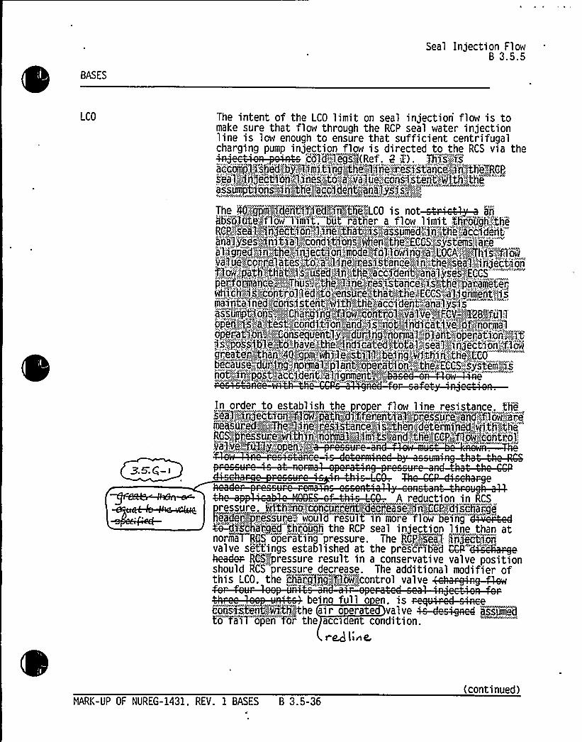
BASES
Seal Injection Flow8 3.5.5
LCO The intent of the LCO limit on seal injection flow is tomake sure that flow through the RCP seal water injectionline is low enough to ensure that sufficient centrifugal
p pt ', l ll t h p,,ll Rtt
s'ia'l.;;-':~j)ect'ion'.'1j'ries,",',to".;:::a;":,:.'0'ash'e';".~ioris4ite'nt~41th'.:",the"'"'"'-''s's"".'.","tiortig~ii",''.:ttie)!a'cfideitpt'-:.'inali jsj's","''"ll",-'"""'"w
'Rl
WAASwhASA VAOAROA%WWiRVAWRVARNARARPPRjhVAVhAS(wkkwApwhitmhWAOAR4whw
RCP.,is'8'al,':;:::inject'tj'ophn.:':."''1„:~.ai~tfiat,,;:,.:4:smasSumed";::;in$ thi.";.;a'c'pdirita'nt'a'1 uses"„":;.in~'tj'a'1,:"","c)iidi't),'o'n'si,''wh'en'l:,'thse",,.'ECCS'::is'yswt'eemhs'ia're-'"
a'l~gried'.;:;,:~$ ,":,;the"';:inje'Cti'on;",,mode~,":'foAow'liigja')LOCA'l<.'/This':.";1l'ow'a'll'ute'.:.'co"J:re)test",;:;,t'o)'a)::::;l.::jiie!iresj
st)nc''e,".';:~.ii':;;.„::tP'~.:.j'iath'jtha't..":,i:s,'~b'sid!iiii::;:,th~!:a'e'c)'de'nt~aiialp.:yose):",:,!.Epee'rftorm'aii'ii":='.::;@Thus''si;;,'th);;:,:))'iie':„:res'~'itartice;:<n>i'thet''p)'i:atmt"eter',whi'cht,::is':,"'i'ijit'r'olplefditt'o'.,"en'suprhe ~th'a'tv'ith'e'.,:"':EAC'CS~'a'ljg'nment(j,"srnwai)itai"np"ed!:,"earis'~ssitehnt'.kith„':.'.,::the';:atsCC'i'derIIt)'a'n'a'ly's'is""" ' '"aSS0'mptWnSpg'Chargi'rt'g''fl&~C)rtr'Ol..:.',Vahl Ve"„::;I::FCV,'e!':128!",.-:fill,:1:
opte'r'i.:.":;,:;is,'.:i'..'test~.,"conditi'oA'i,'a5d,'.".:js"-:,"not,g'ndicat'ivejpgj<normalosp'eration';"'::,,-":,::";Qonswewjtien'tly'.,"':.".dmus<.,ng:;.:.:'noorsmval
<p1arit-".,::o'peratiownh'.N.$ t
5s::;jess'lb''i:.;Co.":,.hive;.;,:.the, 4iid$cated>'t'otal,',:;seal':«.':„"''i'rgectm'i';flowgr'eatei;:,.";;:Chan:,-.'40,:,'"gpm,,'Aj'.le,:";i''Tl,:,'be~1iig."',wi'thi'nh,.-~the„':.,L'COXca'ii)i',;:::„'d~i,'in'g'.,""i'd'or'mealjjlar'it',::".:j'ieri'0i:in,'-,'~:.the;ECCS; system..",>.sno ':::,''':«ii':"ptos '-,'acti: can ".a:):igmieit.'.".,::.'".,:::,.;
~,5.Q- >
In order to establish the prooer flow line resistance. the.
measii'r'H:,;i:::i,:::Th';RCS;"pj..'.es's'us™m'jm'th)r))'iiorI'I'I:-:)lIliiii'esp'4and',"::theo'~CCP<lflm.":,e'onwtrok'::vB,', &a-,'.,Q: ~ g„-:"„'-Open:."'.":!''
A reduction in RCS
v sh
v Aressure,w1'S'h~';.oonourrieidgFgl'eoreaswe-,enhCCP.„='disohargesad~sea...:,.Orepss'sur'ev: would resuTf, in more flow heitng d'sees'aed
N-"iifs8ha'rje'dt througjt the RCP seal injection line than atnorm~ia RCS"opera'tin'g pressure. The RGP)',seal. sVr7jectloqvalve settings established at the pres'cribed CQP"'~h;H.-gehe 4e.- RC$~ressure result in a conservative valve positionshould RCS pressure decrease. The additional modifier ofltt. t l,ii!,AP":::tl,,t
bein full o en. is. -R,ttpitt P
to fail open for the acct en condition.r~ lI~e.
NARK-UP OF NUREG-1431. REV. 1 BASES B 3.5-36(continued)


BASES
Seal Injection FlowB 3.5.5
LCO(continued)
With the e~~RCS5pressure and control valve pos nas s ecified b theTCO. a flow limit is establishe hichassures t at t e sea ingection ine resis ance isconsistent with the anal sis assum tions.
V.;n.iRCS.';:dept:jssii".::izesm fÃg.m>Fig';:!at'.:::
sealsk'increases.;::::,..th&(! res U1tiiigl,essfthan';'the,:,.'.:,l:",iieet'kassumedBn$NAVhtCCVttVthW CVX'MDht (h4 'N'h CWhVQhtYWVhYNt W IVN%%h
OVCA'':i::an'd,::,'.::the':<'f3'ow..;Iso:,:::th'et'uhmp
If l,'Ohhwt'";:::.gOh'.!tfie'..'".'isa'1 S.":,::w'i'.:l'tl',':::.:,:bi."h*'t%
'C1d80t;::-;:~8nd''1yS15;."C<~<'hW )h8kN htVtCCWVh +W V N@lttVW
APPLICABILITY In NODES 1. 2. and 3, the seal injection flow limit isdictated by ECCS flow requirements. which are specified forNODES 1, 2. 3. and 4. The seal injection flow limit is notapplicable for NODE 4 and lower. however. because high sealinjection flow is less critical as a result of the lowerinitial RCS pressure and decay heat removal requirements in~a)~ MODE 4. Therefore, RCP seal injection flow must belimited in'ODES 1 ~ 2, and 3 to ensure adequate ECCSperformance.
ACTIONS
With the seal injection flow exceeding its limit. theamount of charging flow available fbi'.:,.':EGGS'1iijec6Yon:::,to theRCS may be reduced. Under this Cond'i'tion, a'chion must betaken to restore the seal'Pih$ eit$ 'ont"'.,"flow to below its1 imit. 8Fq'Oji';::A'ct~'Ottn>'A':-:.:1;:,'-::.:ensures'".'-:that;.'~%'i'tIi gnat'4::,:::,::hours;thei!emaddif ice@i';,",fate'ure).:<is;!>%3;ON".,of''tahe''aRsumed':post-:.-'L(EAch'a@'irig';-"'::.fl'mi:-,'::::i';.30'0'lgl'ow,capab'Pity',";iiiay,,".b'e'i".:;v'er'H$'ed"::by':
Sssiiijm":::,both'--„:::CCPi,!'are'~6.,6fV.BLF,",";:::~.,:Rej'ui:relet."on:.-"A4:.".,theoa'klo'ws the operaht'or"~ 7Z hour's frohm the"'time the flowis known to be above the lihmit but<iiY~lljg~llevjfg:;:.,::100XTOf,
posi'tion"the- mtanual valves and"thiis be iii compliance with, the accident analysis. The Completion Time minimizes the
potential exposure of the plant to a LOCA with insufficientinjection flow and provides a reasonable time to restoreseal injection flow within limits. This time is
t*'tt tt itWWWVtt tTimes f~r~KCC~S:.) j.:.-'.:36:!P:~AC'fLOH.,.ANN
NARK-UP OF NUREG-1431, REV. 1 BASES B 3.5-37(continued)


Enclosure 2PG8E Letter DCL 98-107
ADDITIONALINFORMATIONCOVER SHEET
ADDITIONALINFORMATIONNO: Q 3.5.1-4
REQUEST:DOC 1-04 LS-8CTS 3.5.1 Action aITS 3.5.1 Action A
APPLICABILITY: DC
The referenced DOC describes the change to the CTS but does not provide anyjustification for making the change other than that it is consistent with the STS.
Comment: The NSHC for this change appears to provide the neededjustification. Therefore, please incorporate the information contained in theNSHC into the subject DOC.
FLOG RESPONSE: The information from NSHC LS-8 has been incorporated into DOC1-04 LS-8. The revised justification is based on the continued OPERABILITYof theremaining accumulators and avoiding an unnecessary plant transient and shutdown.The replacement of the required ACTION of going to HOT SHUTDOWN with a requiredreduction in pressure is consistent with the Applicability.
ATTACHEDPAGES'ncl.
3A 1


DESCRIPTION OF CHANGES TO CURRENT TS (CTS) SECTION 3/4.6
This Enclosure contains a brief description/justification for each marked-up change to existing currentplant Technical Specifications (CTS). The changes are keyed to those identified in Enclosure 2 (mark-upof the CTS). The referenced No Significant Hazards Considerations (NSHC) are contained in Enclosure4. Allproposed technical changes to the CTS are discussed below; however, some administrativechanges (i.e., format, presentation, and editorial changes made to conform to the Improved TechnicalSpecifications (ITS)) may not be discussed. For Enclosures 3A, 3B, 4, 6A, and 6B, text in brackets "[]"indicates the information is specific and is not common to all the Joint Licensing Subcommittee (JLS)Plants. Empty brackets indicate that other JLS plants may have plant specific information in that location.
x
CHANGENUMBER NSHC DESCRIPTION
01-01 Not applicable to Diablo Canyon Power Plant (DCPP). SeeConversion Comparison Table (Enclosure 3B).
01-02/1/OF USe
' 9.5./-/
01-03
01~
01-05
01-06
LS8
pnsm iC,
gnSr r!.
LS9
>rl5c'/! 0
an&.r! 5
Wnsc r4 E
A
Replaces reference to the "pressurizer pressure" with a reference tothe "RCS pressure." ACTIONS A. and B. require reducing pressurizerpressure to less than 1000 psig. However, pressurizer pressureinstrumentation does not have the range to read that pressure.Consequently, reactor coolant system (RCS) pressure instrumentationis used. For the purposes of this limiting condition of operation (LCO),the use of RCS pressure is equivalent.
The ACTION statement is restructured in agreement with NURE-143 The CTS ACTION time (within 1 hour ) for restoration of 4U.5./-'/ iaccumulator OPERABILITYfor conditions other than a closed Zs.j--isolation valve has been replaced. The replacement ACTION requiresthat an accumulator inoperable due to boron concentration not withinlimits must be restored within 72 hours. Also, the requirement to go toHOT SHUTDOWN within the following 6 hours is replaced by theACTION to reduce RCS pressure to less than or equal to 1000 psigwithin the following 6 hours.> These changes are considered to beralaxationa. ~wnsc,
The ACTION statement is restructured in agreement with NUR G-1431. The CTS ACTION time (immediately) for restoration of ~>.~-'-<accumulator OPERABILITYdue to the isolation valve closed i es.5.I -5re lace The replacement ACTION requires that for reasons ot erthan boron concentration, the accumulator must be restored within 1
hour. Also, the requirement to go to HOT SHUTDOWN within thefol owing 6 hours is replaced by the ACTION to reduce RCS pressureto fess than or equal to 1000 psig. These changes are considered tobe relaxations.
The words "with three accumulators OPERABLE and" are added toboth ACTION statements to make entry into LCO 3.0.3 mandatorywith two or more accumulators inoperable. This change is consistentwith NUREG-1431 and is considered administrative in nature since itreflects current plant practice, i.e., current ACTION Statements A. andB. are not entered at the same time on different accumulators.
DCPP Description of Changes to Current TS 1


Inserts for Q3.5.1-4 & Q3.5.1-5
Enclosure 3a —page 1
Insert A for 01-04 LS-8
A 1-hour ACTION to initiate plant shutdown compromises the opportunity for verification,diagnosis, and restoration of the condition of the accumulator to within limits. Changesin boron concentration are slow and the ACTION change provides a more reasonabletime in which to restore limits. Increasing the AOT from 1 hour to 72 hours could avoidunnecessary plant transients and plant shutdowns ifOPERABILITYcannot be restoredwithin 1 hour but could be restored within 72 hours, thus improving plant safety andincreasing plant availability.
The boron in the accumulator water contributes to the analysis assumption that thecombined ECCS water in the partially recovered core during the early reflood phase of alarge break LOCA is sufficient to keep that portion of the core subcritical. Core coolingduring the ECCS injection mode is not affected by the accumulator water boronconcentration being outside limits because the accumulator water remains available forinjection throughout the duration of the AOT.
The condition of 1 accumulator not within the boron concentration limits does not affectthe other 3 accumulators, as the accumulators are mutually isolated. One accumulatorbelow the minimum boron concentration will have no effect on available ECCS waterand an insignificant effect on core subcriticality during reflood. Consequently, althoughthe accumulator may be inoperable in accordance with TS requirements due to boronconcentration outside of limits, it still retains capability to contribute in satisfying itssafety function. If2 or more accumulators are inoperable for any reason, ITS 3.5.1,ACTION D requires immediate entry into TS 3.0.3.
Insert B for 01-04 LS-8
Replacing the ACTION requirement to go to HOT SHUTDOWN within the following 6hours with the requirement to reduce RCS pressure to less than or equal to 1000 psigwithin the following 6 hours makes the ACTION consistent with the Applicability.Reducing the RCS pressure to less than or equal to 1000 psig results in theaccumulators no longer being required, and TS Applicability can be exited. At pressuresless than or equal to 1000 psig, the rate of RCS blowdown is reduced and the ECCSpumps can provide adequate injection to ensure the peak clad temperature remainsbelow the acceptance limit of 10 CFR 50.46.
Insert C for 01-04 LS-8 8 01-05 LS-9
and is consistent with NUREG-1024


Inserts for Q3.5.1-4 8 Q3.5.1-5 (continued)
Insert D for 01-05 LS-9
Accumulator OPERABILITYis important to satisfy the analyses assumption that thecontents of 3 of the 4 accumulators reach the core following a LOCA. However, animmediate ACTION to initiate plant shutdown denies the opportunity for verification,diagnosis, and restoration of the condition of the accumulator to within limits. Theadditional time proposed will reduce the probability of unnecessary plant transients andplant shutdowns, thus improving plant safety and increasing plant availability. If2 ormore accumulators are inoperable for any reason, ITS 3.5.1 ACTION D requiresimmediate entry into TS 3.0.3.
Insert E for 01-05 LS-9
Replacing the ACTION requirement to go to HOT SHUTDOWN within the following 6hours with the requirement to reduce RCS pressure to less than or equal to 1000 psigwithin the following 6 hours makes the ACTION consistent with the Applicability.Reducing the RCS pressure to less than or equal to 1000 psig results in theaccumulators no longer being required for TS Applicability. At pressures less than orequal to 1000 psig, the rate of RCS blowdown is reduced and the ECCS pumps canprovide adequate injection to ensure the peak clad temperature remains below theacceptance limit of 10 CFR 50.46.


Enclosure 2PG8E Letter DCL 98-107
ADDITIONALINFORMATIONCOVER SHEET
ADDITIONALINFORMATIONNO: Q 3.5.1-5
REQUEST:DOC 1-05 LS-9CTS 3.5.1 Action bITS 3.5.1 Action B
APPLICABILITY'C
The referenced DOC describes the change to the CTS but does not provide anyjustification for making the change other than that it is consistent with the STS.
Comment: The NSHC for this change appears to provide the neededjustification. Therefore, please incorporate the information contained in theNSHC into the subject DOC.
FLOG RESPONSE: The information from NSHC LS-9 has been incorporated into DOC1-05 LS-9. The revised justification is based on the continued OPERABILITYof theremaining accumulators and avoiding an unnecessary plant transient and shutdown.The replacement of the required ACTION of going to HOT SHUTDOWN with a requiredreduction in pressure is consistent with the Applicability.
ATTACHED PAGES
Encl. 3A 1


DESCRIPTION OF CHANGES TO CURRENT TS (CTS) SECTION 3/4 5
This Enclosure contains a brief description/justification for each marked-up change to existing currentplant Technical Specifications (CTS). The changes are keyed to those identified in Enclosure 2 (mark-upof the CTS). The referenced No Significant Hazards Considerations (NSHC) are contained in Enclosure4. Allproposed technical changes to the CTS are discussed below; however, some administrativechanges (i.e., format, presentation, and editorial changes made to conform to the Improved TechnicalSpecifications (ITS)) may not be discussed. For Enclosures 3A, 3B, 4, 6A, and 6B, text in brackets "[ j"indicates the information is specific and is not common to all the Joint Licensing Subcommittee (JLS)Plants. Empty brackets indicate that other JLS plants may have plant specific information in that location.
r
CHANGENUMBER NSHC DESCRIPTION
01-01 Not applicable to Diablo Canyon Power Plant (DCPP). SeeConversion Comparison Table (Enclosure 3B).
01-02nfl Used g 9.5./-I
01-03
01~
01-05
01-06
LS8Xnso kC.
Dna'r+
LS9
instr< Q,
3n~rw 5
Wns'r rV E
Replaces reference to the "pressurizer pressure" with a reference tothe "RCS pressure." ACTIONS A. and B. require reducing pressurizerpressure to less than 1000 psig. However, pressurizer pressureinstrumentation does not have the range to read that pressure.Consequently, reactor coolant system (RCS) pressure instrumentationis used. For the purposes of this limiting condition of operation (LCO),the use of RCS pressure is equivalent.
The ACTION statement is restructured in agreement with NURE-143 The CTS ACTION time (within 1 hour ) for restoration of g9.5./-4)accumulator OPERABILITYfor conditions other than a closed >5.1-5isolation valve has been replaced. The replacement ACTION requiresthat an accumulator inoperable due to boron concentration not withinlimits must be restored within 72 hours. Also, the requirement to go toHOT SHUTDOWN within the following 6 hours is replaced by theACTION to reduce RCS pressure to less than or equal to 1000 psig
. within the following 6 hours. These changes are considered to berelaxations. ~nor<
The ACTION statement is restructured in agreement with NUR G-1431. The CTS ACTION time (immediately) for restoration of ~> 5'-<accumulator OPERABILITYdue to the isolation valve closed i ez.s./-Zre lace The replacement ACTION requires that for reasons ot erthan boron concentration, the accumulator must be restored within 1
hour. Also, the requirement to go to HOT SHUTDOWN within thefol owing 6 hours is replaced by the ACTION to reduce RCS pressureto less than or equal to 1000 psig. These changes are considered tobe relaxations.
The words "with three accumulators OPERABLE and" are added toboth ACTION statements to make entry into LCO 3.0.3 mandatorywith two or more accumulators inoperable. This change is consistentwith NUREG-1431 and is considered administrative in nature since itreflects current plant practice, i.e., current ACTION Statements A. andB. are not entered at the same time on different accumulators.
DCPP Description of Changes to Current TS 1


Inserts for Q3.5.1% 8 Q3.5.1-5
Enclosure 3a —page 1
Insert A for 01-04 LS-8
A 1-hour ACTION to initiate plant shutdown compromises the opportunity for verification,diagnosis, and restoration of the condition of the accumulator to within limits. Changesin boron concentration are slow and the ACTION change provides a more reasonabletime in which to restore limits. Increasing the AOT from 1 hour to 72 hours could avoidunnecessary plant transients and plant shutdowns ifOPERABILITYcannot be restoredwithin 1 hour but could be restored within 72 hours, thus improving plant safety andincreasing plant availability.
The boron in the accumulator water contributes to the analysis assumption that thecombined ECCS water in the partially recovered core during the early reflood phase of alarge break LOCA is sufficient to keep that portion of the core subcritical. Core coolingduring the ECCS injection mode is not affected by the accumulator water boronconcentration being outside limits because the accumulator water remains available forinjection throughout the duration of the AOT.
The condition of 1 accumulator not within the boron concentration limits does not affectthe other 3 accumulators, as the accumulators are mutually isolated. One accumulatorbelow the minimum boron concentration will have no effect on available ECCS waterand an insignificant effect on core subcriticality during reflood. Consequently, althoughthe accumulator may be inoperable in accordance with TS requirements due to boronconcentration outside of limits, it still retains capability to contribute in satisfying its .
safety function. If2 or more accumulators are inoperable for any reason, ITS 3.5.1,ACTION 0 requires immediate entry into TS 3.0.3.
Insert 8 for 01-04 LS-8
Replacing the ACTION requirement to go to HOT SHUTDOWN within the following 6hours with the requirement to reduce RCS pressure to less than or equal to 1000 psigwithin the following 6 hours makes the ACTION consistent with the Applicability.Reducing the RCS pressure to less than or equal to 1000 psig results in theaccumulators no longer being required, and TS Applicability can be exited. At pressuresless than or equal to 1000 psig, the rate of RCS blowdown is reduced and the ECCSpumps can provide adequate injection to ensure the peak clad temperature remainsbelow the acceptance limit of 10 CFR 50.46.
Insert C for 01-04 LS-8 & 01-05 LS-9
and is consistent with NUREG-1024


Inserts for Q3.5.1% & Q3.5.1-5 (continued)
Insert D for 01-05 LS-9
Accumulator OPERABILITYis important to satisfy the analyses assumption that thecontents of 3 of the 4 accumulators reach the core following a LOCA. However, animmediate ACTION to initiate plant shutdown denies the opportunity for verification,diagnosis, and restoration of the condition of the accumulator to within limits. Theadditional time proposed will reduce the probability of unnecessary plant transients andplant shutdowns, thus improving plant safety and increasing plant availability. If2 ormore accumulators are inoperable for any reason, ITS 3.5.1 ACTION D requiresimmediate entry into TS 3.0.3.
Insert E for 01-05 LS-9
Replacing the ACTION requirement to go to HOT SHUTDOWN within the following 6hours with the requirement to reduce RCS pressure to less than or equal to 1000 psigwithin the following 6 hours makes the ACTION consistent with the Applicability.Reducing the RCS pressure to less than or equal to 1000 psig results in theaccumulators no longer being required for TS Applicability. At pressures less than orequal to 1000 psig, the rate of RCS blowdown is reduced and the ECCS pumps canprovide adequate injection to ensure the peak clad temperature remains below theacceptance limit of 10 CFR 50.46.


Enclosure 2PG&E Letter DCL 98-107
ADDITIONALINFORMATIONCOVER SHEET
ADDITIONALINFORMATIONNO: Q 3.5.1-6
REQUEST:DOC 1-07 LGCTS 4.5.1.1.b (DC, CA, WC)CTS 4.5.1.b (CP)ITS SR 3.5.1.4
APPLICABILITY: DC, CP, WC, CA
The referenced DOC describes the change to the CTS but does not provide anyjustification for making the change other than that it is consistent with the STS.
Comment: Please revise the DOC to include additional justification as to whythis detail is not necessary in the ITS.
FLOG RESPONSE: DOC 1-07 LG has been revised to provide additional justificationfor the proposed change by adding the following information:
"The RWST has its own LCO and SRs to verify OPERABILITYand cross-referencesto other specifications are generally inconsistent with the ITS format and are notrequired to impose OPERABILITYon the referenced equipment. The RWST boronconcentration is maintained between [2300] ppm and [2500] ppm which is higherthan the minimum boron concentration required to be maintained in theaccumulators. If there were reason to doubt the RWST boron concentration, ITS3.5.4 Condition A would be entered with its 8 hour Completion Time. In addition, ITSSR 3.5.4.3 verifies the boron concentration of the RWST every 7 days. Therefore, itis unlikely that the boron concentration being added to the accumulators would bebelow [2300] ppm. Additionally, plant procedures implementing the SR 3.5.1.4Bases specify that ifthe RWST has been diluted since its last boron concentrationsample per SR 3.5.4.3, the boron concentration in the accumulators must be verifiedwithin 6 hours after adding [101] gallons or more to the accumulators from theRWST. The moving of this detail to the ITS Bases maintains consistency withNUREG-1431 and is not necessary to adequately protect the health and safety ofthe public. Details for performing surveillance requirements are more appropriatelyspecified in the plant procedures required by ITS 5.4.1 and the ITS Bases. Control ofthe plant conditions appropriate to perform a surveillance test is an issue forprocedures and scheduling and has been previously determined by the NRC to beunnecessary as a TS restriction. As indicated in Generic Letter 91-04, allowing thislicensee control is consistent with the vast majority of other surveillancerequirements that do not dictate plant conditions for surveillances. Any change tothis detail will be made in accordance with the Bases Control Program described inITS Section 5.5.14."
ATTACHED PAGES:
Encl. 3A 2


CHANGENUMBER NSHC DESCRIPTION
01-07
01-08
02-01
02-02
LG
A
LG
LS1
The Surveillance Requirement (SR) currently requires a 6 hoursurveillance if the makeup source is the refueling water storage tank(RWST) and the RWST has not been diluted since verifying its boronconcentration per the RWST LCO. The proposed change would movethe statement "and the RWST has not been diluted since verifying ..."
from the accumulator SR to the ITS SR 3.5.1.4 Bases. This level ofdetail is not included in the ISTS and is consistent with tinformation contained in the Bases~Tns~r+ dte.5. i dr-
In accordance with NUREG-1431, the LCO accumulator containedsolution volume expressed in cubic feet is replaced by percent (%).Also, the surveillance solution volume increase is revised from 1
percent tank volume (101 gallons) to 5.6 percent of narrow rangeindicated level, equivalent of 1 percent tank volume. This value canbe read from control room indicators. This change in terms isadministrative and does not result in a change in the measuredvolume. IZ'nSeee
Consistent with NUREG-1431, the LCO and CTION a. are revised toreplace the word "subsystem" with the word "train." The descriptiveinformation in the LCO is moved to the Bases. Whereas there is notechnical change associated with the replacement of the term"subsystem, "train" better describes that all parts of the requiredsystem (e.g., piping, instruments, controls, etc.) must be OPERABLEto support the required safety function.
Consistent with NUREG-1431, a Note with respect to RCS pressureisolation valve (PIV) testing is added to the LCO. Plant designrequires closure of certain valves in the safety injection (Sl) paths toperform PIV testing. Isolation of the injection paths in MODE 3 iscurrently prohibited as it would constitute entering TS 3.0.3 since bothSl trains would be made administratively inoperable. The flow pathsare readily restorable from the control room and a single active failureis not likely in the short term (2 hours). The new Note willallowclosing these valves for testing without declaring either Sl traininoperable. This change is consistent with Industry Traveler TSTF-153.
02-03 LS2 This change revises ACTION a. to allow for increased flexibilityinplant operations under circumstances where components in oppositetrains are inoperable, but at least 100 percent of the emergency corecooling system (ECCS) flowequivalent to a single OPERABLE ECCStrain is available. Due to the design of the ECCS subsystems, theinoperable condition of one or more components in each train doesnot necessarily render the ECCS inoperable for performing its safetyfunction. The allowed outage time (AOT) of 72 hours is unchanged;but it is to be contingent on being capable of providing 100 percent ofthe ECCS flowequivalent to a single OPERABLE ECCS train. Thischange is consistent with NUREG-1431.
DCPP Description of Changes to Current TS 2


Enclosure 3A, page 2
Insert for 1-07 LG
Insert for Q 3.5.1-6
The RWST has its own LCO and SRs to verify OPERABILITYand cross-references toother specifications are generally inconsistent with the ITS format and are not requiredto impose OPERABILITYon the referenced equipment. The RWST boronconcentration is maintained between [2300] ppm and [2500) ppm which is higher thanthe minimum boron concentration required to be maintained in the accumulators. Ifthere were reason to doubt the RWST boron concentration, ITS 3.5.4 Condition A wouldbe entered with its 8 hour Completion Time. In addition, ITS SR 3.5.4.3 verifies theboron concentration of the RWST every 7 days. Therefore, it is unlikely that the boronconcentration being added to the accumulators would be below [2300] ppm.Additionally, plant procedures implementing the SR 3.5.1.4 Bases specify that iftheRWST has been diluted since its last boron concentration sample per SR 3.5.4.3, theboron concentration in the accumulators must be verified within 6 hours after adding[101] gallons or more to the accumulators from the RWST. The moving of this detail tothe ITS Bases maintains consistency with NUREG-1431 and is not necessary toadequately protect the health and safety of the public. Details for performingsurveillance requirements are more appropriately specified in the plant proceduresrequired by ITS 5.4.1 and the ITS Bases. Control of the plant conditions appropriate toperform a surveillance test is an issue for procedures and scheduling and has beenpreviously determined by NRC to be unnecessary as a TS restriction. As indicated inGeneric Letter 91-04, allowing this licensee control is consistent with the vast majority ofother surveillance requirements that do'not dictate plant conditions for surveillances.Any change to this detail will be made in accordance with the Bases Control Programdescribed in ITS Section 5.5.14.


Enclosure 2PG8 E Letter DCL 98-107
ADDITIONALINFORMATIONCOVER SHEET
ADDITIONALINFORMATIONNO: Q 3.5.2-1
REQUEST:DOC 2-01 LGCTS 3.5.2 LCOITS 3.5.2 LCO
APPLICABILITY: DC, CP, WC, CA
The referenced DOC describes the change to the CTS but does not provide anyjustification for making the change other than that it is consistent with the STS.
Comment: Please revise the DOC to include additional justification as to whythis detail is not necessary in the ITS.
FLOG RESPONSE: DOC 2-01-LG has been revised to provide additional justificationfor the proposed change by adding the following information:
"The proposed change is consistent with NUMARC 93-03, "Writer's Guide for theRestructured Technical Specifications," and the philosophy of NUREG-1431 in whichthe LCO describes as simply as possible the lowest functional capability of thesystem and relegates the details of what constitutes an OPERABLE system to theBases. Therefore, the details of what constitutes an OPERABLE subsystem (train)such as required pumps, heat exchangers, and flow paths, are more appropriatelydiscussed in the Bases than in the LCO. These details are not necessary to ensureECCS OPERABILITYor that the ECCS can perform its intended safety function.Therefore, the proposed change moves to the Bases details that are not necessaryto provide operational safety while retaining in the technical specifications the basicrequirements for maintaining OPERABILITY."
ATTACHEDPAGES'ncl.
3A 2


CHANGENUMBER NSHC DESCRIPTION
01-07
01-08
02-01
02-02
LG
LG
LS1
The Surveillance Requirement (SR) currently requires a 6 hoursurveillance ifthe makeup source is the refueling water storage tank(RWST) and the RWST has not been diluted since verifying its boronconcentration per the RWST LCO. The proposed change would movethe statement "and the RWST has not been diluted since verifying ..."
from the accumulator SR to the ITS SR 3.5.1.4 Bases. This level ofdetail is not included in the ISTS and is consistent with tinformation contained in the Bases.~Tnsers ci>-5. I a-In accordance with NUREG-1431, the LCO accumulator containedsolution volume expressed in cubic feet is replaced by percent (%).Also, the surveillance solution volume increase is revised from 1
percent tank volume (101 gallons) to 5.6 percent of narrow rangeindicated level, equivalent of 1 percent tank volume. This value canbe read from control room indicators. This change in terms isadministrative and does not result in a change in the measuredvolume. -lZnsei~ P~ < >
Consistent with NUREG-1431, the LCO and CTION a. are revised toreplace the word "subsystem" with the word "train." The descriptiveinformation in the LCO is moved to the Bases. Whereas there is notechnical change associated with the replacement of the term"subsystem," "train" better describes that all parts of the requiredsystem (e.g., piping, instruments, controls, etc.) must be OPERABLEto support the required safety function.
Consistent with NUREG-1431, a Note with respect to RCS pressureisolation valve (PIV) testing is added to the LCO. Plant designrequires closure of certain valves in the safety injection (Sl) paths toperform PIV testing. Isolation of the injection paths in MODE 3 iscurrently prohibited as it would constitute entering TS 3.0.3 since bothSl trains would be made administratively inoperable. The flow pathsare readily restorable from the control room and a single active failureis not likely in the short term (2 hours). The new Note willallowclosing these valves for testing without declaring either Sl traininoperable. This change is consistent with Industry Traveler TSTF-153.
02-03 LS2 This change revises ACTION a. to allow for increased flexibilityinplant operations under circumstances where components in oppositetrains are inoperable, but at least 100 percent of the emergency corecooling system (ECCS) flowequivalent to a single OPERABLE ECCStrain is available. Due to the design of the ECCS subsystems, theinoperable condition of one or more components in each train doesnot necessarily render the ECCS inoperable for performing its safetyfunction. The allowed outage time (AOT) of 72 hours is unchanged;but it is to be contingent on being capable of providing 100 percent ofthe ECCS flowequivalent to a single OPERABLE ECCS train. Thischange is consistent with NUREG-1431.
DCPP Description of Changes to Current TS 2


Enclosure 3A —page 2
Insert for 2-01-LG
Insert for Q3.5.2-1
The proposed change is consistent with NUMARC 93-03, "Writer's Guide for theRestructured Technical Specifications" and the philosophy of NUREG-1431 in which theLCO describes as simply as possible the lowest functional capability of the system andrelegates the details of what constitutes an OPERABLE system to the Bases.Therefore, the details of what constitutes an OPERABLE subsystem (train) such asrequired pumps, heat exchangers and flow paths, are more appropriately discussed inthe bases than in the LCO. These details are not necessary to ensure ECCSOPERABILITYor that the ECCS can perform its intended safety function. Therefore,the proposed change moves to the Bases details that are not necessary to provideoperational safety while retaining in the technical specifications the basic requirementsfor maintaining OPERABILITY.


Enclosure 2PG8E Letter DCL 98-107
ADDITIONALINFORMATIONCOVER SHEET
ADDITIONALINFORMATIONNO: Q 3.5.2-2
REQUEST:DOC 2-09 LGCTS 4.5.2.c
APPLICABILITY: DC, CP, WC, CA
The referenced DOC describes the change to the CTS but does not provide anyjustification for making the change other than that it is consistent with the STS.
Comment: Please revise the DOC to include additional justification as to whythis surveillance is not necessary in the ITS.
FLOG RESPONSE: DOC 2-09 LG has been revised to provide additional justificationfor the proposed change by adding the following information:
"CTS SR 4.5.2.c requires a visual inspection to verify that no loose debris is present inthe containment which could be transported to the containment sump and causerestriction to the pump suction during LOCA conditions at the frequency specified. Thisensures that during the process of performing maintenance or other work insidecontainment that debris is appropriately discarded. Existing procedures restrictcontainment entries and assure accountability of items entering containment such thatthey are removed at the completion of the containment entry. ITS SR 3.5.2.8 continuesto require a visual inspection every 18 months on each of the ECCS train containmentsump suction inlets to ensure that the sump suction inlet is not restricted by debris.Therefore, this detail is not required to be in the technical specifications and moving thisrequirement maintains consistency with NUREG-1431."
ATTACHEDPAGES'ncl.
3A 3


CHANGENUMBER NSHC DESCRIPTION
02-04 TR2 Consistent with NUREG-1431, the requirement to submit a specialreport within 90 days of an ECCS actuation and injection event isdeleted. This change is acceptable because the requirement tosubmit a report is sufficiently addressed by the reporting requirementscontained in 10 CFR 50.73.
02-05 LS3 Not applicable to DCPP. See Conversion Comparison Table(Enclosure 3B).
02-06 Not used.
02-07
02-08
Consistent with NUREG-1431, this change revises the surveillance tomake it clear that "listed" valve position is the concern and notindicated position in the control room. The surveillance can besatisfied using indicated position in the control room but may also besatisfied using local observation. This is an administrative changesince the surveillance acceptance criteria are not changed.
Not applicable to DCPP. See Conversion Comparison Table(Enclosure 3B).
02-09 LG The visual inspection surveillance performed when establishingcontainment integrity is moved to a licensee controll u nt,
. Insert ~ 2-202-10 Not applicable to DCPP. See Conversion Comparison Table
(Enclosure 3B).
02-11
02-12
02-13
TR1
LG
TR 3
Consistent with NUREG-1431, the ECCS pump and valve actuationSR is changed to allow the use of an actual signal, ifand when oneoccurs, to satisfy SRs. The specific signals used to actuate thpumps and valves have been moved to the Bases. gnser ~
The ECCS pump performance is revised to be consistent withNUREG-1431. The test method and specific data required to verifypump performance is relocated to the Bases. CTS 4.0.5 no longerexists in the ITS. However, the requirement for an Inservice Testing(IST) Program is moved to Section 5.5.8 of the ITS. The ISTis referenced directly for the frequency of testing. insert PS,5 2-'I
The CTS allowance, which permits the ECCS throttle valves to bedeclared OPERABLE without verifying ECCS throttle valve positionfor four hours following stroke valve testing or maintenance isdeleted from the CTS consistent with NUREG-1431. The ECCSthrottle valves are manual valves and plant procedures governingthe restoration of equipment after maintenance specify verificationof correct throttle position prior to declaring the valves OPERABLE.This requirement is inherent to post-maintenance OPERABILITYrequirements and removal from the specifications does not affectTS requirements for testing scope or frequency.
DCPP Description of Changes to Current TS 3


Enclosure 3A - page 3
Insert for 2-09 LG
Insert for Q 3.5.2-2
CTS SR 4.5.2.c requires a visual inspection to verify that no loose debris is present inthe containment which could be transported to the containment sump and causerestriction to the pump suction during LOCA conditions at the frequency specified. Thisensures that during the process of performing maintenance or other work insidecontainment that debris is appropriately discarded. Existing procedures restrictcontainment entries and assure accountability of items entering containment such thatthey are removed at the completion of the containment entry. ITS SR 3.5.2.8 continuesto require a visual inspection every 18 months on each of the ECCS train containmentsump suction inlets to ensure that the sump suction inlet is not restricted by debris.Therefore, this detail is not required to be in the technical specifications and moving thisrequirement maintains consistency with NUREG-1431.


Enclosure 2PG8E Letter DCL 98-107
ADDITIONALINFORMATIONCOVER SHEET
ADDITIONALINFORMATIONNO: Q 3.5.2-3
REQUEST:DOC 2-11 TR-1CTS 4.5.2.eITS SR 3.5.2.5 8 SR 3.5.2.6
APPLICABILITY: DC, CP, WC, CA
The referenced DOC describes the change to the CTS but does not provide anyjustification for making the change other than that it is consistent with the STS.
Comment: The NSHC for this change appears to provide the neededjustification. Therefore, please incorporate the information contained in theNSHC into the subject DOC.
FLOG RESPONSE: The CTS requires the use of a test signal for initiation of validtests. The unintentional result was to require the performance of the verification even ifan actual signal has already verified proper operation of equipment. TR-1 allows eitheran actual or test signal. DOC 2-11 TR-1 has been revised to provide additionaldiscussion to allow the use of an actual signal to meet this surveillance requirement.
ATTACHED PAGES:
Encl. 3A 3


CHANGENUMBER NSHC DESCRIPTION
02-04 TR2 Consistent with NUREG-1431, the requirement to submit a specialreport within 90 days of an ECCS actuation and injection event isdeleted. This change is acceptable because the requirement tosubmit a report is sufficiently addressed by the reporting requirementscontained in 10 CFR 50.73.
02-05 LS3 Not applicable to DCPP. See Conversion Comparison Table(Enclosure 3B).
02-06 Not used.
02-07
02-08
A
A
Consistent with NUREG-1431, this change revises the surveillance tomake it clear that "listed" valve position is the concern and notindicated position in the control room. The surveillance can besatisfied using indicated position in the control room but may also besatisfied using local observation. This is an administrative changesince the surveillance acceptance criteria are not changed.
Not applicable to DCPP. See Conversion Comparison Table(Enclosure 3B).
02-09 LG The visual inspection surveillance performed when establishingcontainment integrity is moved to a licensee controll u nt
. X'nsert es,s:2-z02-10 A Not applicable to DCPP. See Conversion Comparison Table
(Enclosure 3B).
02-11
02-12
02-13
TR1
LG
TR3
Consistent with NUREG-1431, the ECCS pump and valve actuationSR is changed to allow the use of an actual signal, ifand when oneoccurs, to satisfy SRs. The specific signals used to actuate thpumps and valves have been moved to the Bases.~nser ~ 4~ >. > -"
The ECCS pump performance is revised to be consistent withNUREG-1431. The test method and specific data required to verifypump performance is relocated to the Bases. CTS 4.0.5 no longerexists in the ITS. However, the requirement for an Inservice Testing(IST) Program is moved to Section 5.5.8 of the ITS. The ISTis referenced directly for the frequency of testing. insert tP3.5:2-~
The CTS allowance, which permits the ECCS throttle valves to bedeclared OPERABLE without verifying ECCS throttle valve positionfor four hours following stroke valve testing or maintenance isdeleted from the CTS consistent with NUREG-1431. The ECCSthrottle valves are manual valves and plant procedures governingthe restoration of equipment after maintenance specify verificationof correct throttle position prior to declaring the valves OPERABLE.This requirement is inherent to post-maintenance OPERABILITYrequirements and removal from the specifications does not affectTS requirements for testing scope or frequency.
DCPP Description of Changes to Current TS 3


Enclosure 3A- page 3
Insert for 2-11 TR-1:
Insert for Q3.5.2-3
In several specifications throughout the CTS, OPERABILITYof certain equipment isdemonstrated by ensuring that the equipment performs its safety function upon receiptof a simulated test signal. The intent of a 'simulated'ignaI was to be able to performthe required testing without the occurrence (or without causing) an actual signalgenerating event. However, the unintended effect was to require the performance of thesurveillance (using a test signal) even if an actual signal had previously verified theoperation of the equipment. This change allows credit to be taken for actual eventswhen the required equipment actuates successfully.
While the occurrence of events that cause actuation of accident mitigation equipment isundesirable, the actuation of mitigation equipment on an actual signal is a betterdemonstration of its OPERABILITYthan an actuation using a test signal. Thus, thechange does not reduce the reliability of the equipment tested. The change alsoimproves plant safety by reducing the amount of time the equipment is taken out ofservice for testing, and thereby increasing its availability during an actual event, and byreducing the wear of the equipment caused by unnecessary testing.


CHANGENUIIBER NSHC DESCRIPTION
02-04 TR2 Consistent with NUREG-1431, the requirement to submit a specialreport within 90 days of an ECCS actuation and injection event isdeleted. This change is acceptable because the requirement tosubmit a report is sufficiently addressed by the reporting requirementscontained in 10 CFR 50.73.
02-05 LS3 Not applicable to DCPP. See Conversion Comparison Table(Enclosure 3B).
02-06 Not used.
02-07
02-08
Consistent with NUREG-1431, this change revises the surveillance tomake it clear that "listed" valve position is the concern and notindicated position in the control room. The surveillance can besatisfied using indicated position in the control room but may also besatisfied using local observation. This is an administrative changesince the surveillance acceptance criteria are not changed.
Not applicable to DCPP. See Conversion Comparison Table(Enclosure 3B).
02%9 LG The visual inspection surveillance performed when establishingcontainment integrity is moved to a licensee controll u nt
. Insert P3 < 2-202-10 Not applicable to DCPP. See Conversion Comparison Table
(Enclosure 3B).
02-11
02-12
02-13
TR1
LG
TR 3
Consistent with NUREG-1431, the ECCS pump and valve actuationSR is changed to allow the use of an actual signal, ifand when oneoccurs, to satisfy SRs. The specific signals used to actuate thpumps and valves have been moved to the Bases.2nser 0
The ECCS pump performance is revised to be consistent withNUREG-1431. The test method and specific data required to verifypump performance is relocated to the Bases. CTS 4.0.5 no longerexists in the ITS. However, the requirement for an Inservice Testing(IST) Program is moved to Section 5.5.8 of the ITS. The ISTis referenced directly for the frequency of testing. insert 49.5:2-'I
The CTS allowance, which permits the ECCS throttle valves to bedeclared OPERABLE without verifying ECCS throttle valve positionfor four hours following stroke valve testing or maintenance isdeleted from the CTS consistent with NUREG-1431. The ECCSthrottle valves are manual valves and plant procedures governingthe restoration of equipment after maintenance specify verificationof correct throttle position prior to declaring the valves OPERABLE.This requirement is inherent to post-maintenance OPERABILITYrequirements and removal from the specifications does not affectTS requirements for testing scope or frequency.
DCPP Description of Changes to Current TS 3


Enclosure 3A - page 3
Insert for 2-12 LG
Insert for Q 3.5.2Q
ITS SR 3.5.2.4 retains the SR requirement and references the Inservice TestingProgram (IST), discussed in ITS 5.5.8, for the surveillance Frequency. The speciTic SRacceptance criteria for the pumps have been moved to the ITS SR 3.5.2.4 Bases.Although this may make the ECCS pump performance testing more flexible in the future,in regard to licensee control over the numerical values of the acceptance criteria, thistesting must continue to conform to the IST program requirements. Revisions to theacceptance criteria will have to meet the requirements of the Bases Control
Program'iscussed
in ITS 5.5.14. Details for performing surveillance requirements are moreappropriately specified in the plant procedures required by ITS 5.4.1 and the ITS Bases.Control of the acceptance criteria for a surveillance test is an issue for the ISTprocedures and has been previously determined by NRC to be unnecessary as a TSrestriction. As indicated in Generic Letter 91-04, allowing this licensee control isconsistent with the vast majority of other surveillance requirements that do not dictateplant conditions for surveillances.


Enclosure 2PG8E Letter DCL 98-107
ADDITIONALINFORMATIONCOVER SHEET
ADDITIONALINFORMATIONNO: Q 3.5.2-5
REQUEST:DOC 2-15 LGCTS 4.5.2.h
APPLICABILITY: DC, CP, WC, CA
The referenced DOC describes the change to the CTS but does not provide anyjustification for making the change other than that it is consistent with the STS.
Comment: Please revise the DOC to include additional justification as to whythis surveillance is not necessary in the ITS.
FLOG RESPONSE: DOC 2-15 LG has been revised to include additional justificationas to why this surveillance is not necessary in the ITS.
ATTACHEDPAGES'ncl.
3A 4


CHANGENUMBER
02-14
NSHC
A
DESCRIPTION
Not applicable to DCPP. See Conversion Comparison Table(Enclosure 3B).
02-15 LG The SR for the flow balance test following ECCS modifications ismoved to a licensee controlled document. This r
'not
included in NUREG-1431. pnsm+ cp p.52-$
02-16 LG The specific means by which the ECCS piping is assured to be fullofwater is moved to the Bases. This level of detail is not included in theISTS and is consistent with 'mation contained in theBases. Ense~~ g3.5i 2 4
02-17
02-18 LG
This change adds the phrase "that is not locked, sealed, or otherwisesecured in position" with regard to which valves require actuationtesting. This change is merely a clarification. Valves that are securedin place, are secured in the position required to meet their safetyfunction. The actuation testing ensures that valves can move to theposition that meets their safety function. If the valves are secured inthe position that meets their safety function, no testing is necessary.
Not applicable to DCPP. See Conversion Comparison Table(Enclosure 3B).
02-19
03-01
03-02
03-03
LG
LG
LS4
LS5
Not applicable to DCPP. See Conversion Comparison Table(Enclosure 3B).
'fnspi '6 (PE.5 9
Consistent with NUREG-1431 the LCO is revised to replace the word"subsystem with the word" in" and the descriptive information in theLCO is moved to the Bases. hereas, there is no technical changeassociated with the replacement of the term "subsystem," "train" betterdescribes that all parts of the required system (e.g., piping,instruments, controls, etc.) must be OPERABLE to support therequired safety functions.
Consistent with NUREG-1431, the LTOP limitation on ECCS pumpsand related surveillances are moved to ITS 3.4.12. The prescriptivewording related to pump OPERABILITYis changed to wordingspecifically addressing the pump's capability to inject into the RCS.This change is less restrictive on the configuration of the centrifugalcharging pump (CPP) and Sl pumps but is acceptable because it isconsistent with the cold overpressure analysis requirements and stillprecludes flow to the RCS.
TheACTION a. Comp ebon ime or S OWN due to CCPinoperability is increased by 4 hours, from 20 hours to 24 hours. Thistime is reasonable based on operating experience to reach MODE 5in an orderly manner, without challenging plant systems or operators,andisconsistentwithothershutdownACTIONComple 'toreach MODE 5 from MODE 4. Ense/ p QS53-2
DCPP Description of Changes to Current TS 4


Enclosure 3A —page 4
Insert for 2-15 LG
Insert for Q 3.5.2-5
Plant procedures governing the restoration of equipment after maintenance specify therequirements for determining the appropriate post-maintenance testing. Any time theOperability of a system or component has been affected by repair, maintenance, orreplacement of a component, post-maintenance testing is required to demonstrateOperability of the system or component. As such, the requirement to perform a flowbalance test after modifications that alter ECCS subsystem flow characteristics is notrequired to be in the TS to provide adequate protection of the public health and safety.This requirement has been moved to the [F)SAR (for Callaway, Diablo Canyon, andWolfCreek) or TRM (Comanche Peak). These licensee controlled documents containingthe moved requirements will be maintained using the provisions of 10 CFR 50.59.Therefore, the descriptive information that has been moved continues to be maintainedin an appropriately controlled manner.


Enclosure 2PG8 E Letter DCL 98-107
ADDITIONALINFORMATIONCOVER SHEET
ADDITIONALINFORMATIONNO: Q 3.5.2-6
REQUEST'OC2-16 LG
CTS 4.5.2.iITS SR 3.5.2.3
APPLICABILITY: DC, CP, WC, CA
The referenced DOC describes the change to the CTS but does not provide anyjustification for making the change other than that it is consistent with the STS.
Comment: Please revise the DOC to include additional justification as to whythis detail is not necessary in the ITS.
FLOG RESPONSE: DOC 2-16 LG has been revised to include additional justificationas to why this detail is not necessary in the ITS.
ATTACHED PAGES:
Encl. 3A 4


CHANGENUMBER
02-14
NSHC
A
DESCRIPTION
Not applicable to DCPP. See Conversion Comparison Table(Enclosure 3B).
02-15 LG The SR for the flow balance test following ECCS modifications ismoved to a licensee controlled document. This r 'otincluded in NUREG-1431. Ense + cP P. S, 2-5
02-16 LG The specific means by which the ECCS piping is assured to be fullofwater is moved to the Bases. This level of detail is not included in theISTSandisconsistentwith '
rmationcontainedintheBases. ~~~«4 g3i 5i 2
02-17
02-18 LG
This change adds the phrase "that is not locked, sealed, or otherwisesecured in position" with regard to which valves require actuationtesting. This change is merely a clarification. Valves that are securedin place, are secured in the position required to meet their safetyfunction. The actuation testing ensures that valves can move to theposition that meets their safety function. Ifthe valves are secured inthe position that meets their safety function, no testing is necessary.
Not applicable to DCPP. See Conversion Comparison Table(Enclosure 3B).
02-19
03-01
LG
LG
Not applicable to DCPP. See Conversion Comparison Table(Enclosure 3B).
XnSert COB.S;9- I
Consistent with NUREG-1431 the LCO is revised to replace the word"subsystem" with the word" in" and the descriptive information in theLCO is moved to the Bases. hereas, there is no technical changeassociated with the replacement of the term "subsystem," "train" betterdescribes that all parts of the required system (e.g., piping,instruments, controls, etc.) must be OPERABLE to support therequired safety functions.
03-02
03-03
LS4
LS5
Consistent with NUREG-1431, the LTOP limitation on ECCS pumpsand related surveillances are moved to ITS 3.4.12. The prescriptivewording related to pump OPERABILITYis changed to wordingspecifically addressing the pump's capability to inject into the RCS.This change is less restrictive on the configuration of the centrifugalcharging pump (CPP) and Sl pumps but is acceptable because it isconsistent with the cold overpressure analysis requirements and stillprecludes flow to the RCS.
I
TheACTION a. Comp ebon ime or S OWN due to CCPinoperability is increased by 4 hours, from 20 hours to 24 hours. Thistime is reasonable based on operating experience to reach MODE 5in an orderly manner, without challenging plant systems or operators,and is consistent with other shutdown ACTION Comple
's to
reach MODE 5 from MODE 4. gnser P $ 9.5: 9 -2
DCPP Description of Changes to Current TS 4


Enclosure 3A —page 4
Insert for 2-16 LG
Insert for Q 3.5.2-6
The requirements of ITS LCO 3.5.2 and the associated Surveillance Requirements areadequate to ensure the ECCS are maintained OPERABLE. As a result, the methods ofperforming Surveillances are not necessary to ensure the ECCS can perform theirintended safety function and the details are not required to be in the TS to provideadequate protection of the public health and safety. The ITS Bases containing themoved requirements will be maintained using the provisions of 10 CFR 50.59, asrequired by Bases Control Program described in ITS Section 5.5.14. Therefore, thedescriptive information that has been moved continues to be maintained in anappropriately controlled manner.


Enclosure 2PG8E Letter DCL 98-107
ADDITIONALINFORMATIONCOVER SHEET
ADDITIONALINFORMATIONNO: Q 3.5.2-9
REQUEST'TSB3.5.2 Bases SR 3.5.2.3
APPLICABILITY: DC
The Diablo Canyon STS Bases markup appears to be a markup of theComanche Peak markup of the STS Bases, rather than a direct markup of theSTS Bases. See the referenced section for an example.
Comment: Please confirm that the STS Bases are the starting point for the 3.5Bases markup and not the Comanche Peak ITS Bases.
FLOG RESPONSE: As part of the response to the General Comment Q3.5.G-1, PG8 Eperformed a review of the ITS Bases markup compared to NUREG-1431, Revision 1.Any deviations beyond the criteria stated in the response to the General CommentQ3.5.G-1 is identified. In several areas, text was inserted from the Comanche Peak(lead FLOG plant for that ITS section) mark-up of the STS but was not used as indicatedwith the strike-out feature. If the added text was used, then it was highlighted with thered-line feature (or indicated as such).
ATTACHEDPAGES'ee
attached pages to General Comment Q3.5.G-1.


Enclosure 2PG8E Letter DCL 98-107
ADDITIONALINFORMATIONCOVER SHEET
ADDITIONALINFORMATIONNO: Q 3.5.3-1
REQUEST:DOC 3-01 LGCTS LCO 3.5.3ITS LCO 3.5.3
APPLICABILITY: DC, CP, WC, CA
The referenced DOC describes the change to the CTS but does not provide anyjustification for making the change other than that it is consistent with the STS.
Comment: Please revise the DOC to include additional justification as to whythis detail is not necessary in the ITS.
FLOG RESPONSE: DOC 3-01-LG has been revised to provide additional justificationfor the proposed change by adding the following information:
"The proposed change is consistent with NUMARC 93-03, "Writer's Guide for theRestructured Technical Specifications," and the philosophy of NUREG-1431 in whichthe LCO describes as simply as possible the lowest functional capability of thesystem and relegates the details of what constitutes an OPERABLE system to theBases. Therefore, the details of what constitutes an OPERABLE subsystem (train)such as required pumps, heat exchangers, and flow paths, are more appropriatelydiscussed in the bases than in the LCO. These details are not necessary to ensureECCS OPERABILITYor that the ECCS can perform its intended safety function.Therefore, the proposed change moves to the Bases details that are not necessaryto provide operational safety while retaining in the technical specifications the basicrequirements for maintaining OPERABILITY."
ATTACHED PAGES:
Encl. 3A


CHANGENUMBER
02-14
NSHC
A
DESCRIPTION
Not applicable to DCPP. See Conversion Comparison Table(Enclosure 3B).
02-15 LG The SR for the flowbalance test following ECCS modifications ismoved to a licensee controlled document. This r 'otincluded in NUREG-1431. ense.+ cP 3,5;2-5
02-16 LG The specific means by which the ECCS piping is assured to be fullofwater is moved to the Bases. This level of detail is not included in theISTS and is consistent with
'rmation contained in the
Bases. S~>«4 g3i 5. 2- 4
02-17
02-18 LG
This change adds the phrase "that is not locked, sealed, or otheiwisesecured in position" with regard to which valves require actuationtesting. This change is merely a clarification. Valves that are securedin place, are secured in the position required to meet their safetyfunction. The actuation testing ensures that valves can move to theposition that meets their safety function. Ifthe valves are secured inthe position that meets their safety function, no testing is necessary.
Not applicable to DCPP. See Conversion Comparison Table(Enclosure 3B).
02-19
03-01
03-02
03-03
LG
LG
LS4
LS5
Not applicable to DCPP. See Conversion Comparison Table(Enclosure 3B).
Consistent with NUREG-1431 the LCO is revised to replace the word"subsystem" with the word" in" and the descriptive information in theLCO is moved to the Bases. hereas, there is no technical changeassociated with the replacement of the term "subsystem," "train" betterdescribes that all parts of the required system (e.g., piping,instruments, controls, etc.) must be OPERABLE to support therequired safety functions.
Consistent with NUREG-1431, the LTOP limitation on ECCS pumpsand related surveillances are moved to ITS 3.4.12. The prescriptivewording related to pump OPERABILITYis changed to wordingspecifically addressing the pump's capability to inject into the RCS.This change is less restrictive on the configuration of the centrifugalcharging pump (CPP) and Sl pumps but is acceptable because it isconsistent with the cold overpressure analysis requirements and stillprecludes flow to the RCS.
I
TheACTION a. Competion ime or S OWN duetoCCPinoperability is increased by 4 hours, from 20 hours to 24 hours. Thistime is reasonable based on operating experience to reach MODE 5in an orderly manner, without challenging plant systems or operators,and is consistent with other shutdown ACTION Comple
'to
reach MODE5fromMODE4. Ense' Lp9i5 3-2
DCPP Description of Changes to Current TS 4


Enclosure 3A —page 4
Insert for 3-01-LG
Insert for Q3.5.3-1
The proposed change is consistent with NUMARC 93-03, "Writer's Guide for theRestructured Technical Specifications" and the philosophy of NUREG-1431 in which theLCO describes as simply as possible the lowest functional capability of the system andrelegates the details of what constitutes an OPERABLE system to the Bases.Therefore, the details of what constitutes an OPERABLE subsystem (train) such asrequired pumps, heat exchangers and flow paths, are more appropriately discussed inthe bases than in the LCO. These details are not necessary to ensure ECCSOPERABILITYor that the ECCS can perform its intended safety function. Therefore,the proposed change moves to the Bases details that are not necessary to provideoperational safety while retaining in the technical specifications the basic requirements'or maintaining OPERABILITY.


Enclosure 2PG8E Letter DCL 98-107
ADDITIONALINFORMATIONCOVER SHEET
ADDITIONALINFORMATIONNO: Q 3.5.3-2
REQUEST:DOC 3-03 LS-5CTS 3.5.3 Action aITS 3.5.3 Actions A 8 C
APPLICABILITY: DC, CP, WC, CA
DOC 3-03 LS-5 discussed two distinct changes. The first change involvesmovement of the descriptive information to the Bases. The second change is anincrease in the completion time to reach Mode 5 from 20 to 24 hours.
Comment: The first change, movement of the descriptive information to theBases, should be separated out and justified as an "LG" change, consistent withother similar changes in this section. The increase in the completion time toreach Mode 5 from 20 to 24 hours is correctly justified as an "LS" change andthe justification provided in DOC 3-03 LS-5 is acceptable.
FLOG RESPONSE: DOC 3-03 LS-5 has been separated into two DOCs (DOC 3-03-LS-5 and DOC 3-13-LG). DOC 3-03 LS-5 has been revised to address only theincrease in completion time. DOC 3-03 LS-5 has been enhanced to include additionaljustification by noting that due to the stable conditions associated with MODE 4operation, the probability of a Design Basis Accident is low. New DOC 3-13 LG hasbeen created to address movement of information to the Bases.
ATTACHED PAGES:
Encl. 2 3/4 5-7Encl. 3A 4 and 6Encl. 3B 4 and 6


MER ENY R IN YTM
CS S
LIMITING CONDITI N F R PERATI N
3.5.3 . Oje,::-:ECCSti',airi"'sha11 be OPERABLE.Q"
0341-LG
0346-A
0342-LS4
APPLICABILITY: MODE 4.
~ACTI II:
a. With ~,'%he,'~i',,eqiVired ECCS,cejtrjfigaf':,::chargsnj-":,.jump-."::.:(CCP3,. 0343-LS5
:-':Aemo@l':-"':NHR)'33&5~ouI -A
requi'red",;Eccs RIIRi!subsystem to ~ms e s-eww-. i"m -::,:::ml i:-::,:i
OPERABL'E s'tmaet'us ..seqtediKCNy.',:','-:.>".'3
I s- Le
, restore ee Cease-eee requs'r'ed <vs e e-sECCS CCPi~subsystem to OPERABLE status within I hour or be in
'COL'0'HUTDt1ttlfwithin the next~ 24.:'!hours.
su sys em"
0 R2
"A maximum of one centrifugal charging pump shall be QPKAABK',eipabre~.of..jtigect>iig":giiitojthejRCS whenever the tern erature of one or more of'the RCSco1 egs is "'e .ow':;;." e.-.."":. capers. urF,:: "ereLATUvj',,l:s::,reqU3::r80$
0342-LS4
03-11-LG
DIABLO CANYON - UNITS 1 & 2TS35.4A
3/4 5-7


CHANGENUNIBER
02-14
NSHC
A
DESCRIPTION
Not applicable to DCPP. See Conversion Comparison Table(Enclosure 3B).
02-15 LG The SR for the fiow balance test following ECCS modifications ismoved to a licensee controlled document. This r 'otincluded in NUREG-1431. Znser + cP 3.5 2-5
02-16 LG The specific means by which the ECCS piping is assured to be fullofwater is moved to the Bases. This level of detail is not included in theISTS and is consistent with 'mation contained in theBases. Xnoer< g3 5i2-4r
02-17
02-18 LG
This change adds the phrase "that is not locked, sealed, or otherwisesecured in position" with regard to which valves require actuationtesting. This change is merely a clarification. Valves that are securedin place, are secured in the position required to meet their safetyfunction. The actuation testing ensures that valves can move to theposition that meets their safety function. Ifthe valves are secured inthe position that meets their safety function, no testing is necessary.
Not applicable to DCPP. See Conversion Comparison Table(Enclosure 3B).
02-19
03-01
LG
LG
Not applicable to DCPP. See Conversion Comparison Table(Enclosure 3B).
Snser4 CP3.-9- I
Consistent with NUREG-1431 the LCO is revised to replace the word"subsystem with the word" in" and the descriptive information in theLCO is moved to the Bases. hereas, there is no technical changeassociated with the replacement of the term "subsystem," "train" betterdescribes that all parts of the required system (e.g., piping,instruments, controls, etc.) must be OPERABLE to support therequired safety functions.
03-02 LS4 Consistent with NUREG-1431, the LTOP limitation on ECCS pumpsand related surveillances are moved to ITS 3.4.12. The prescriptivewording related to pump OPERABILITYis changed to wordingspecifically addressing the pump's capability to inject into the RCS.This change is less restrictive on the configuration of the centrifugalcharging pump (CPP) and Sl pumps but is acceptable because it isconsistent with the cold overpressure analysis requirements and stillprecludes flow to the RCS.
03-03 LS5The
ACTION a. Comp etion ime or S OWN due to CCPinoperability is increased by 4 hours, from 20 hours to 24 hours. Thistime is reasonable based on operating experience to reach MODE 5in an orderly manner, without challenging plant systems or operators,and is consistent with other shutdown ACTION Comple
's to
reach MODE 5 from MODE 4. 5nser{.. gS5:3 2
DCPP Description of Changes to Current TS 4


Enclosure 3A, page 4
Insert for 3-03 LS-5
Insert for Q 3.5.3-2
Due to stable conditions associated with operation in MODE 4, the probability ofoccurrence of a Design Basis Accident is low. As a result, the ECCS operationalrequirements are reduced with only one train of the ECCS CCP Subsystem required tobe OPERABLE. The required action ifthe CCP Subsystem is inoperable is to proceedto cold shutdown.


the PTLR.
CHANGENUMBER
03-12o3- I KC)3-I 404%1
NSHC
ALGAg
LS4
DESCRIPTION
Not applicable to DCPP. See Conversion Comparison Table(Enclosure 3B). ~g,s, 3-2.Zn5eid
X n Serg a r.5.'3—Not applicable to DCPP. ee o ersion Comparison Table(Enclosure 3B).
Not applicable to DCPP. See Conversion Comparison Table(Enclosure 38).
04-03 Not applicable to DCPP. See Conversion Comparison Table(Enclosure 3B).
This change is not applicable to DCPP. See Conversion ComparisonTable (Enclosure 3B).
04-05 This change is not applicable to DCPP. See Conversion ComparisonTable (Enclosure 3B).
04-06
05-01 LS7
This change is not applicable to DCPP. See Conversion ComparisonTable (Enclosure 3B).
Not applicable to DCPP. See Conversion Comparison Table(Enclosure 3B).
05-02 LS 10 Not applicable to DCPP. See Conversion Comparison Table(Enclosure 3B).
05-03 'This change converts the RWST volume requirement from gallons tothe equivalent percent of tank water level, in accordance withNUREG-1431. This change in method of indicating tank volume isadministrative and does not result in a change in volume of the tankcontents.
05-04 LS 12 This change modifies 3.5.5 ACTION a. to include the requirement forRWST borated water temperature to be above the minimum requiredtemperature and ACTION b. to reference ACTION a. The ACTION forwater temperature was in ACTION b with a Completion Time of 1
hour. With the water temperature included in ACTION a. theCompletion Time is 8 hours. This change is consistent with NUREG-143 . This change from 1 to hours is a relaxation.
and. plumy Ioz '~y QB,<4-/
o5-o5 p/of Qpp/'cop/c, * ~. See Ca ~mrs~ 4 par s~ 7o~e(EnclosurC. 38), C'P 3. 5- os.
DCPP Description of Changes to Current TS 6


Insert for Q 3.5.3-2
Enclosure 3A, page 6
Insert for 3-1 3 LG
03-13 LG CTS LCO 3.5.3 Action a. terminology is revised and thedescriptive information is moved to the ITS Bases. These detailsare not necessary to ensure the ECCS Required Actions are met.The requirements of ITS 3.5.3 LCO and Conditons are adequatefor ensuring the ECCS are OPERABLE. These details are notnecessary to ensure the ECCS can perform their intended safetyfunction. As such, these details are not required to be in the TS toprovide adequate protection of the public health and safety.Moving these details maintains consistency with NUREG-1431.Any change to these details will be made in accordance with10CFR50.59 and the Bases Control Program described in ITSSection 5.5.14.


CONVERSION COMPARISON TABLE - CURRENT TS 3/4.5 Page 4 of 7
NUMBER
TECHNICALSPECIFICATION CHANGE
DESCRIPTION
APPLICABILITYDIABLOCANYON COMANCHE WOLF CREEK CALLAWAY
PEAK
02-17A
This change adds the phrase "that is not locked, Yessealed, or otherwise secured in position" with regard towhich valves require actuation testing.
Yes Yes Yes
02-18LG
02-19LG
03-01LG
03-02LS4
03-03LS5
03-04LG
The CPSES requirement for venting the ECCS pumpcasing and piping following maintenance or activity-which drains portions of the system is moved out ofthe TS.
This change moves the requirement that the 18 monthverification of automatic ECCS valve actuation andECCS pump actuation be performed during shutdownto the Bases.
The LCO is revised from subsystem to train and thed scriptive information moved to the Bases.
The LTOP limitation on ECCS pumps and relatedsurveillances are moved to Section 3.4.12 in the ITS.The prescriptive wording related to pumpOPERABILITY is changed to wording specificallyaddressing the pump's capability to inject into theRCS.
SHUTDOWN due to CCP inoperability is increasedfrom 20 to 24 hours.
The L 0 ACTION ter 'logy is revised a thedes iptive informatio moved to the Bas
TnSec<
No, not in CTS.
No, DCPP doesnot have thisrestriction.
Yes
Yes
Yes
$ 9.5'. 9-2
Yes
qK5 9-9
Yes
No, CPSES doesnot have thisrestriction.
Yes
Yes
Yes
Yes
No, not in CTS.
Yes
Yes
Yes
Yes
Yes
No, not in CTS.
Yes
Yes
Yes
Yes
Yes
DCPP Conversion Comparison Table - Current TS


CONVERSION COMPARISON TABLE - CURRENT TS 3/4.5 Page6of7
NUMBER
TECHNICALSPECIFICATION CHANGE
DESCRIPTION
APPLICABILITY
DIABLOCANYON COMANCHE WOLF CREEK CALLAWAYPEAK
03-11LG
03-12A
04-01LS4
04-02M
04-03M
The minimum RCS temperature limit for DCPP belowwhich the CCPs and the Sl pumps must bedemonstrated not capable of injecting into the RCS isreplaced by the statement "below the temperaturewhere LTOP is required as specified in the PTLR."
The SR to verify that no more than one CCP and no Slpumps are capable of injecting into the RCS and the SRexception for 4 hours after entering MODE 4 fromMODE 3 or until the temperature of one or more RCScold legs decreases below 325'F, whichever comes firstare moved to ITS SR 3.4.12.1, SR 3.4.12.2, and LCO3.4.12, Note 2.
The requirement for having ECCS pump injectionsources in excess of that allowed by cold overpressureanalysis assumptions be rendered inoperable, has beenrevised to preclude those pumps from injecting into theRCS.
The ACTION required ifECCS pumps in violation of thecold overpressure analyses are capable of injecting intothe RCS has been changed to require immediateACTION initiation. Otherwise, ifprecluded fromcompliance, to depressurize the RCS and establish thenecessary vent path within 8 hours.
This change requires the veriTication that the disallowedECCS pumps are not capable of injecting to the RCS ona 12 hour frequency. Previously a 31 day veriTication onbreaker position was required.
Yes
No, not in CTS.
No, DCPP does nothave this TS.
No, DCPP does nothave this TS.
No, DCPP does nothave this TS.
No, see ChangeNo. 04-06-A.
Yes
Yes
Yes
No
Yes
Yes
Yes
Yes
No
Yes
Yes
Yes
Yes
&3-/3 Zw~i 4 g3.5. 3-2
AWnse C .9 3-5
DCPP Conversion Comparison Table - Current TS


Enclosure3B INSERTInserts for Q 3.5.3-2 and Q 3.5.3-3
TECH SPEC CHANGE APPLICABILITYNUMBER DESCRIPTION DIABLO
CANYONCOMMANCHEPEAK
WOLF CREEK CALLAWAY
3-13LG
3-14A
The CTS LCO 3.5.3 Action a. terminology is revisedand descriptive information moved to the ITS Bases.These details are not necessary to ensure the ECCSRequired Actions are met.CTS LCO 3.5.3 Action b. provides, with no ECCSRHR subsystem OPERABLE, the option to eitherrestore at least one ECCS RHR subsystem toOPERABLE status or to maintain the RCS T,„, <
350'F by use of alternate heat removal methods. TheCTS Action is revised to immediately initiate actionsthat would restore at least one ECCS RHRsubsystem to OPERABLE status to ensure thatprompt action is taken to restore the required coolingcapacity.
Yes
Yes
Yes
Yes
Yes
Yes
Yes
Yes


Enclosure 2PG8 E Letter DCL 98-107
ADDITIONALINFORMATIONCOVER SHEET
ADDITIONALINFORMATIONNO: Q 3.5.3-3
REQUEST:DOC 3-04 LGCTS 3.5.3 Action bITS 3.5.3 Action B
APPLICABILITY: DC, CP, WC, CA
DOC 3-04 LG discussed two distinct changes. The first change involves achange in the wording of the Action requirement. The second change ismovement of the instructions to maintain temperature using alternate heatremoval methods to the Bases.
Comment: The first change to the wording of the Action requirement should beseparated out and justified as an "A" change. The movement of the instructionsto the Bases is correctly justified as an "LG" change, but the justification providedin DOC 3-03 LS-5 is not adequate.
Please revise the DOC to include additional justification as to why this detail isnot necessary in the ITS.
FLOG RESPONSE: DOC 3-04 LG has been separated into two DOCs (DOC 3-04 LGand DOC 3-14-A). DOC 3-04 LG now contains only the information related to themovement of information to the Bases. DOC 3-04 LG has been enhanced to providethe requested additional justification. New DOC 3-14-A was created to address thechange to the wording in the Action requirement.
ATTACHED PAGES:
Encl. 2 3/4 5-7Encl. 3A 5 and 6Encl. 3B 4 and 6


EHRENY R IN YTM
3 EC
LIMITING CONDITI N FOR PERATI N
3,5. 3 . On~e:;: ECCStz:p'ri>shal 1 be OPERABLE.
+g"'3-01-LG0346-A
0342-LS4
APPL ICABILITY: MODE 4.
~ACTI N:
a. With Regkhe;::,'i',,equ~Fed ECcwCS,centrlfsvga.'I..:'::char,;;gag",:;:poli'p.;.::,(CCP)'. 0343-LS5
EEs Es ue
, restore eb Amass-ane re7julire'd con.e.s-sECCS OCPEIsubsystem to OPERABLE status within I hour or be in COL'O""""
SHUTDOttNce within the next-R P4:::,'.,hours.
b.su system
3,3 Ell,.'i!(:;iQPERABl:E status j~edifNj::;-,'.
USZ&5
QTI-EWI:A
reRui redwaECCS RHRVESub system to ~aES.e S-b
0345-TR2
+A maximum of one centrifugal charging pump shall be QPKAABLI.,"hcaphb'le,:::;:ofs;ji'jectirTg",„'.,iiitojthe~RCS whenever the tern erature of one or more" of the"RECYS
'9, Iw'.:, e..":: eaiperl. ure:,'. er%EAAVhYCwVACCAWAVAY SAA W LhYhVhWhYAsnehYCAVVE4'.i,.UY!'::4's':Ac.,'f,.'"8063 r80 '.
33<a:VYECV'BCRY'ACYhsaiY'AY9AWW
0342-LS4
03-11-LG
DIABLO CANYON - UNITS 1 & 2TS35.4A
3/4 5-7


CHANGENUMBER NSHC DESCRIPTION
03-04 LG Consistent 'UREG-1431 he ACTION b te inology is revis d.The requi ment to restore Ieastone ECCSs systemis rev'd to"immed'ely initiate action o restore" a residu heat removal HR)subs tern. With both R pumps and heat xchangers ino erable,itw uldbe unwise tore uirethe plant togo MODE5,wh n the
ly available heat re oval system is the R. Therefor, theppropriate ACTIO s to initiate measur to restore o ECCS RHR
subsystem and to ntinue the ACTION until the sub stem isrestored to OPE LE status.
03-05 TR2
Also, the alte ate requirement(if R cannot be r stored ) tomaintain T8 <350'F by use of alt ate heat re oval methods isdescriptiv n ormation and is mo d to the Bas s. The transition tMODE 3 'lready prohibited in is scenario the ECCSspecifi tionforMODES1,2, nd3. ~„~~ @> g g g
Consistent with NUREG-1431, the requirement to submit a specialreport within 90 days of an ECCS actuation and injection event isdeleted. This change is acceptable because the requirement tosubmit a report is sufficiently addressed by the reporting requirementscontained in 10 CFR 50.73.
03-06
03-07
Consistent with TSTF-90, a Note is added to the LCO that clarifies anRHR train's ECCS function is operable if it is capable of beingmanually realigned to the ECCS mode of operation. This is anadministrative change to provide clarification.
Not applicable to DCPP. See Conversion Comparison Table(Enclosure 3B).
03-08 Not applicable to DCPP. See Conversion Comparison Table(Enclosure 3B).
03-09 This change is not applicable to DCPP. See Conversion ComparisonTable (Enclosure 3B).
03-10
03-11 LG
LS6 Consistent with NUREG-1431, the requirement to demonstrate ECCStrain OPERABILITYin MODE 4 in SR [4.5.3.1] has been revised todelete the 31 day surveillance to verify the correct position of eachvalve in the ECCS flow path which is not already locked in place, and
~th~emonth surveillance to verify automatic ac a ion f ECCSpumps and automatic valves. Znseef q3.5'9- 5
The minimum RCS temperature limitbelow which the CCP and Slpumps must be demonstrated not capable of injecting into the RCS isreplaced by the statement "below the temperature where LTOP isrequired as specified in the pressure temperature limits report(PTLR)." The minimum temperature is a plant specific requirementbased on the reactor vessel material characteristics documented inthe PTLR and is periodically reviewed and adjusted as required.Referring to the PTLR for the current value is consistent with therelocation of the pressure temperature limits from ITS Section 3.4.3 to
DCPP Description of Changes to Current TS 5

Enclosure 3A, page 5
Insert for 3-04 LG
Insert for Q 3.6.3-3
CTS 3.5.3 Action b provides an alternate requirement (if RHR cannot be restored) tomaintain T~< 350'F by use of alternate heat removal methods. These details aremoved to the ITS Bases. These details are not necessary to ensure the ECCS areOPERABLE. The requirements of ITS 3.5.3 LCO and Conditions are adequate forensuring that the ECCS are OPERABLE. These details are not necessary to ensure theECCS can perform their intended safety function. As such, these details are notrequired to be in the TS to provide adequate protection of the public health and safety.Moving these details maintains consistency with NUREG-1431. Any change to thesedetails will be made in accordance with 10CFR50.59 and the Bases Control Programdescribed in ITS Section 5.5.14.


the PTLR.
CHANGENUMBER NSHC DESCRIPTION
03-12Q3- I KO3-if04-01
ALG
LS4
Not applicable to DCPP. See Conversion Comparison TableEnclosure 3B). ~g. g, ~znsc.~+
Ense~ Q3.5.3-Not applicable to DCPP. ee o ersion Comparison Table(Enclosure 3B).
Not applicable to DCPP. See Conversion Comparison Table(Enclosure 3B).
04-03 Not applicable to DCPP. See Conversion Comparison Table(Enclosure 3B).
This change is not applicable to DCPP. See Conversion ComparisonTable (Enclosure 3B).
This change is not applicable to DCPP. See Conversion ComparisonTable (Enclosure 3B).
This change is not applicable to DCPP. See Conversion ComparisonTable (Enclosure 3B).
05-01 LS7 Not applicable to DCPP. See Conversion Comparison Table(Enclosure 3B).
05-02 LS 10 Not applicable to DCPP. See Conversion Comparison Table(Enclosure 3B).
05-03 This change converts the RWST volume requirement from gallons tothe equivalent percent of tank water level, in accordance withNUREG-1431. This change in method of indicating tank volume isadministrative and does not result in a change in volume of the tankcontents.
0544 LS 12 This change modifies 3.5.5 ACTION a. to include the requirement forRWST borated water temperature to be above the minimum requiredtemperature and ACTION b. to reference ACTION a. The ACTION forwater temperature was in ACTION b with a Completion Time of 1
hour. With the water temperature included in ACTION a. theCompletion Time is 8 hours. This change is consistent with NUREG-143 . This change from 1 to hours is a relaxation.
and. PluRE4-gozg '~Q Q3 54'-f
p/of Qppficrp/c * ~. Se8 Qdnlrrsi~ Compr fls~ ~Gee('Encicsure. 88), C'P 3. 5'- oO2.
DCPP Description of Changes to Current TS 6


Insert for Q 3.5.3-3
Enclosure 3A, page 6
Insert for 3-14 A
03-14 A CTS LCO 3.5.3 Action b. provides, with no ECCS RHR subsystemOPERABLE, the option to either restore at least one ECCS RHRsubsystem to OPERABLE status or to maintain the RCS T, <350'F by use of alternate heat removal methods. Condition A ofITS LCO 3.5.3 requires that with no ECCS RHR subsystemsOPERABLE that immediate action be initiated to restore an ECCSRHR subsystem to OPERABLE status. While the CTS does notspecify a time frame to initiate action to restore one ECCS RHRsubsystem, the current operational philosophy is that this action isinitiated immediately. The Completion Time of "immediately" toinitiate actions that would restore at least one ECCS RHRsubsystem to OPERABLE status ensures that prompt action istaken to restore the required cooling capacity. Revising the CTSAction to immediately initiate action is considered anadministrative change and is consistent with NUREG-1431.


CONVERSION COMPARISON TABLE- CURRENT TS 3/4.5 Page 4 of 7
NUMBER
TECHNICALSPECIFICATION CHANGE
DESCRIPTION
APPLICABILITY
DIABLO CANYON COMANCHE WOLF CREEK CALLAWAYPEAK
02-17A
This change adds the phrase "that is not locked, Yessealed, or otherwise secured in position"- with regard towhich valves require actuation testing.
Yes Yes Yes
02-18LG
The CPSES requirement for venting the ECCS pumpcasing and piping following maintenance or activitywhich drains portions of the system is moved out ofthe TS.
No, not in CTS. Yes No, not in CTS. No, not in CTS.
02-19LG
This change moves the requirement that the 18 monthverification of automatic ECCS valve actuation andECCS pump actuation be performed during shutdownto the Bases.
No, DCPP doesnot have
this'estriction.
No, CPSES does Yesnot have thisrestriction.
Yes
03-01LG
03-02LS4
03-03LS5
03-04LG
The LCO is revised from subsystem to train and thed scriptive information moved to the Bases.
The LTOP limitation on ECCS pumps and relatedsurveillances are moved to Section 3.4.12 in the ITS.The prescriptive wording related to pumpOPERABILITY is changed to wording specificallyaddressing the pump's capability to inject into theRCS.
SHUTDOWN due to CCP inoperability is increasedfrom 20 to 24 hours.
The L 0 ACTION ter ology is revised a thedes iptive informatio moved to the Bas
Yes
Yes
Yes+9.5.9-2
Yes
q8.5 3-9
Yes
Yes
Yes
Yes
Yes
Yes
Yes
Yes
Yes
Yes
Yes
Yes
DCPP Conversion Comparison Table - Current TS


Insert for Q 3.5.3-3
Enclosure 3B - page 4
Insert for 03-04-LG:
CTS 3.5.3 Action b provides an alternate requirement (if RHR cannot be restored) tomaintain T,„, < 350 F by use of alternate heat removal methods. These details aremoved to the ITS Bases.


CONVERSION COMPARISON TABLE- CURRENT TS 3/4.5 Page6of7
NUMBER
TECHNICALSPECIFICATION CHANGE
DESCRIPTION
APPLICABILITY
DIABLOCANYON COMANCHE WOLF CREEK CALLAWAYPEAK
03-11LG
03-12A
The minimum RCS temperature limit for DCPP belowwhich the CCPs and the Sl pumps must bedemonstrated not capable of injecting into the RCS isreplaced by the statement 'below the temperaturewhere LTOP is required as specified in the PTLR."
The SR to verify that no more than one CCP and no Slpumps are capable of injecting into the RCS and the SRexception for 4 hours after entering MODE 4 fromMODE 3 or until the temperature of one or more RCScold legs decreases below 325'F, whichever comes firstare moved to ITS SR 3.4.12.1, SR 3.4.12.2, and LCO3.4.12, Note 2.
Yes
No, not in CTS.
No
No, see ChangeNo. 04-06-A.
Yes
No
Yes
04-01LS4
04-02M
The requirement for having ECCS pump injectionsources in excess of that allowed by cold overpressureanalysis assumptions be rendered inoperable, has beenrevised to preclude those pumps from injecting into theRCS.
The ACTION required ifECCS pumps in violation of thecold overpressure analyses are capable of injecting intothe RCS has been changed to require immediateACTION initiation. Otherwise, ifprecluded fromcompliance, to depressurize the RCS and establish thenecessary vent path within 8 hours.
No, DCPP does not Yeshave this TS.
No, DCPP does not Yeshave this TS.
Yes
Yes
Yes
Yes
04-03M
This change requires the verification that the disallowedECCS pumps are not capable of injecting to the RCS ona 12 hour frequency. Previously a 31 day verification onbreaker position was required.
No, DCPP does nothave this TS.
Yes Yes Yes
&p-I3 ZrSEYC
A X~s<eC
g3 5.3-2
35 3-5
DCPP Conversion Comparison Table - Current TS


Fnclosure3B INSERTInserts for Q 3.5.3-2 and Q 3.5.3-3
TECH SPEC CHANGE APPLICABILITYNUMBER DESCRIPTION DIABLO
CANYONCOMMANCHEPEAK
WOLF CREEK CALLAWAY
3-13LG
3-14A
The CTS LCO 3.5.3 Action a. terminology is revisedand descriptive information moved to the ITS Bases.These details are not necessary to ensure the ECCSRequired Actions are met.CTS LCO 3.5.3 Action b. provides, with no ECCSRHR subsystem OPERABLE, the option to eitherrestore at least one ECCS RHR subsystem toOPERABLE status or to maintain the RCS T,~ <350'F by use of alternate heat removal methods. TheCTSActionis revised to immediately initiate actionsthat would restore at least one ECCS RHRsubsystem to OPERABLE status to ensure thatprompt action is taken to restore the required coolingcapacity.
Yes
Yes
Yes
Yes
Yes
Yes
Yes
Yes


Enclosure 2PG8 E Letter DCL 98-107
ADDITIONALINFORMATIONCOVER SHEET
ADDITIONALINFORNIATIONNO: Q 3.5.3-4
REQUEST'OC3-06 A
CTS LCO 3.5.3ITS LCO 3.5.3 Note
APPLICABILITY: DC, CP, WC, CA
This change is categorized as an administrative change even though it providesan exception to the LCO requirements that does not exist in the CTS. The DOCstates that the note is only to "provide clarification."
Comment: Despite licensees'ndividual interpretations of the CTS, the CTSthemselves do not contain the allowance provided in the ITS Note. Therefore,this change should be reclassified as a less restrictive change and anappropriate justification provided.
FLOG RESPONSE: As discussed during a telecon with NRC Staff on June 25, 1998,the FLOG takes exception to this RAI. The NRC accepted the same change at Vogtleas an administrative change, as discussed in Section 3.1.3.5 item (4) of the Vogtle SERwherein it was stated that this Note "is a necessary clarification when using the RHRsystem for cooling the RCS, when transitioning between MODES 4 and 5. Because thisclarification constitutes existing operating practices, this change is administrative and isacceptable." In addition, the wording of CTS LCO 3.5.3.d, which refers to the RWSTfiow path "being manually realigned," supports the position that the new LCO Note,moved from the SR to the LCO per NRC-approved TSTF-90, Revision 1, is anadministrative change.
ATTACHED PAGES:
None


Enclosure 2PG8 E Letter DCL 98-107
ADDITIONALINFORMATIONCOVER SHEET
ADDITIONALINFORMATIONNO: Q 3.5.3-5
REQUEST:
APPLICABILITY: DC, CP, WC, CA
DOC 3-10 LS-6CTS 4.5.3.1.1 (DC), CTS 4.5.3.1 (AII others)ITS 3.5.3
The referenced DOC describes the change to the CTS but does not provide anyjustification for making the change other than that it is consistent with the STS.
Comment: The NSHC for this change appears to provide the neededjustification. Therefore, please incorporate the information contained in theNSHC into the subject DOC.
FLOG RESPONSE: DOC 3-10 LS-6 has been revised to provide additional justificationfor the proposed change by adding the following information:
"This change is acceptable because the ECCS operational requirements can bereduced due to the stable conditions associated with operation in MODE 4 and thedecreased probability of occurrence of a Design Basis Accident (DBA). ECCSoperational requirement reductions mean that certain automatic safety injection (Sl)actuation signals are not available. However, in MODE 4 sufficient time exists formanual actuation of the required ECCS to mitigate the consequences of a DBA."
ATTACHED PAGES:
Encl. 3A 5


CHANGENUMBER NSHC DESCRIPTION
03-04 LG Consistent 'UREG-1431 the ACTION b te inology is revis d.The requi ment to restore least one ECCS s systemis rev ed to"immed'ely initiate action o restore" a residu heat removal HR)subs tern. With both R pumps and heat xchangers ino erable,itw uldbe unwise to re uire the plant togo MODE5, wh n the
lyavailable heat re oval systemis the R. Therefor, theppropriate ACTIO s to initiate measur to restore o ECCS RHR
subsystem and to ntinue the ACTION until the sub stem isrestored to OPE BLE status.
03-05 TR2
Also, the alte ate requirement (ifR cannot be r stored ) tomaintain T~ <350'F by use of alt ate heat re oval methods isdescriptiv n ormation and is mo d to the Bas s. The transition tMODE 3 'lready prohibited in is scenario the ECCSspecifi tion for MODES1,2, nd3. ~„~<p yy 5 g 3
Consistent with NUREG-1431, the requirement to submit a specialreport within 90 days of an ECCS actuation and injection event isdeleted. This change is acceptable because the requirement tosubmit a report is sufficiently addressed by the reporting requirementscontained in 10 CFR 50.73.
03-06
03-07
Consistent with TSTF-90, a Note is added to the LCO that clarifies anRHR train's ECCS function is operable if it is capable of beingmanually realigned to the ECCS mode of operation. This is anadministrative change to provide clarification.
Not applicable to DCPP. See Conversion Comparison Table(Enclosure 3B).
03-08 Not applicable to DCPP. See Conversion Comparison Table(Enclosure 3B).
03-09 This change is not applicable to DCPP. See Conversion ComparisonTable (Enclosure 3B).
03-10
03-1 1 LG
LS6 Consistent with NUREG-1431, the requirement to demonstrate ECCStrain OPERABILITYin MODE 4 in SR f4.5.3.1] has been revised todelete the 31 day surveillance to verify the correct position of eachvalve in the ECCS flowpath which is not already locked in place, and
~tahe Qonthsurveillancetoverifyautomaticac ation fECCSpumps and automatic valves. 2nserg q3.5'3- 5
The minimum RCS temperature limitbelow which the CCP and SIpumps must be demonstrated not capable of injecting into the RCS isreplaced by the statement "below the temperature where LTOP isrequired as specified in the pressure temperature limits report(PTLR)." The minimum temperature is a plant specific requirementbased on the reactor vessel material characteristics documented inthe PTLR and is periodically reviewed and adjusted as required.Referring to the PTLR for the current value is consistent with therelocation of the pressure temperature limits from ITS Section 3.4.3 to
DCPP Description of Changes to Current TS 5


Enclosure 3A, page 5
Insert for 3-10 LS-6
Insert for Q 3.5.3-5
This change is acceptable because the ECCS operational requirements can be reduced due tothe stable conditions associated with operation in MODE 4 and the decreased probability ofoccurrence of a Design Basis Accident (DBA). ECCS operational requirement reductions meanthat certain automatic safety injection (Sl) actuation signals are not available. However, inMODE 4, sufficient time exists for manual actuation of the required ECCS to mitigate theconsequences of a DBA.


Enclosure 2PG8E Letter DCL 98-107
ADDITIONALINFORMATIONCOVER SHEET
ADDITIONALINFORMATIONNO: Q 3.5.4-1
REQUEST:DOC 5-04 LS-12CTS 3.5.5 Actions a 8 bITS 3.5.4 Action A
APPLICABILITY: DC
The referenced DOC describes the change to the CTS but does not provide anyjustification for making the change other than that it is consistent with the STS.
Comment: The NSHC for this change appears to provide the neededjustification. Therefore, please incorporate the information contained in theNSHC into the subject DOC.
FLOG RESPONSE: The information from NSHC LS-12 has been incorporated intoDOC 5-04 LS-12. The revised justification is based on the fact that RWST temperaturechanges would be slow to occur and recognizes that the deviation from the analysistemperature assumption would probably be minor due to the moderate site temperatureand that the contents of the tank are still available for injection. The additional timeproposed will allow time to restore conditions and reduce the possibility of unnecessaryplant transients and plant shutdowns, thus improving plant safety and increasing plantavailability.
ATTACHED PAGES:
Encl. 3A 6


the PTLR.
CHANGENUIIBER
03-12+3- I KD3-l404-01
NSHC
ALG
LS4
DESCRIPTION
Not applicable to DCPP. See Conversion Comparison TableEnclosure 38). ~g, g, ~z.neer+
X nSerg Q 3.5.'3—Not applicable to DCPP. ee o ersion Comparison Table(Enclosure 38).
Not applicable to DCPP. See Conversion Comparison Table(Enclosure 38).
04-03 Not applicable to DCPP. See Conversion Comparison Table(Enclosure 38).
This change is not applicable to DCPP. See Conversion ComparisonTable (Enclosure 38).
04-05
04-06
05-01 LS 7
This change is not applicable to DCPP. See Conversion ComparisonTable (Enclosure 38).
This change is not applicable to DCPP. See Conversion ComparisonTable (Enclosure 38).
Not applicable to DCPP. See Conversion Comparison Table(Enclosure 38).
05-02 LS 10 Not applicable to DCPP. See Conversion Comparison Table(Enclosure 38).
05-03 This change converts the RWST volume requirement from gallons tothe equivalent percent of tank water level, in accordance withNUREG-1431. This change in method of indicating tank volume isadministrative and does not result in a change in volume of the tankcontents.
05-04 LS 12 This change modifies 3.5.5 ACTION a. to include the requirement forRWST borated water temperature to be above the minimum requiredtemperature and ACTION b. to reference ACTION a. The ACTION forwater temperature was in ACTION b with a Completion Time of 1
hour. With the water temperature included in ACTION a. theCompletion Time is 8 hours. This change is consistent with NUREG-143 . This change from 1 to hours is a relaxation.
and, pluRE<-Ioz >nor p 82.5 4-I
o5-05 p/of Qpp/I'~$ /< * ~. SeE'onf@'@sion Compci'is~ Tcee(Enclosure. 38), i"P S. 5- oo2.
DCPP Description of Changes to Current TS 6

Enclosure 3A- page 6
Insert for 05-04 LS-12
Insert for Q3.5.4-1
Changes in water temperature are slow and the change provides a more reasonable time inwhich to restore limits. The increase in allowed time to restore conditions to within limits prior torequiring a unit shutdown recognizes that the deviation from the analysis temperatureassumption would probably be minor (if they ever occur) due to the moderate site temperatureand that the contents of the tank are still available for injection. Also, the occurrence of anevent requiring injection of the RWST contents during the increased Completion Time isextremely unlikely. The additional time proposed will reduce the possibility of unnecessaryplant transients and plant shutdowns, thus improving plant safety and increasing plantavailability.
The contents of the tank are still available for injection during the Completion Time and theextent of temperature outside the limit is not likely to be significant to safety.


Enclosure 2PG8E Letter DCL 98-107
ADDITIONALINFORMATIONCOVER SHEET
ADDITIONALINFORMATIONNO: Q 3.5.5-1
REQUEST:Section 3.4 DOC 6-21 LS-35Section 3.5 JFD 3.5-4CTS 3.4.5.2 Action b (CP)CTS 3.4.6.2 Action b (DC)ITS 3.5.5 Action A
APPLICABILITY: DC, CP
This change is a change to both the CTS and the STS and is beyond the scopeof the conversion review and is generic. DOC 6-21 states that this change isconsistent with WOG-84.
Comment: Please provide the current status of WOG-84. IfWOG-84 is notapproved by the TSTF, then this change should be withdrawn from theconversion submittal at the time of the TSTF rejection. IfWOG-84 has not beenacted on by the TSTF, or is approved by the TSTF but not approved by the NRCby the time the draft safety evaluation is being prepared, then it should bewithdrawn from the conversion submittal at that time. This change will not bereviewed on a plant-specific basis.
FLOG RESPONSE: DCPP and CPSES will continue to pursue the revisions proposedby this change. WOG-84 is now TSTF-236 which was approved by the TSTF onFebruary 5, 1998. The NRC has requested that the WOG provide additional justificationto support the extended Completion Time and changes to Required Action A. TheWOG is preparing that information in addition to proposed changes to the 3.5.5 LCOand SRs. The revised traveler will be issued in the near future to the NRC.
ATTACHED PAGES:
None

.~

Enclosure 2PG8 E Letter DCL 98-107
ADDITIONALINFORINATIONCOVER SHEET
ADDITIONALINFORNIATIONNO: CA 3.5-001
REQUEST:
APPLICABILITY: DC, WC, CA
Revise the ITS 3.5.1 Bases to address Westinghouse NSAL 97-003 withregard to the relationship of permissive P-11 to the accumulator isolationvalves. The discussion of P-11 is not relevant to this LCO which isapplicable above 1000 psig. Nor is the IEEE 279-1971 "operatingbypass" discussion relevant or correct per the current licensing basis.
ATTACHED PAGES:
Encl. 5B B 3.5-1 thru B 3.5-5, B 3.5-7, and B 3.5-8

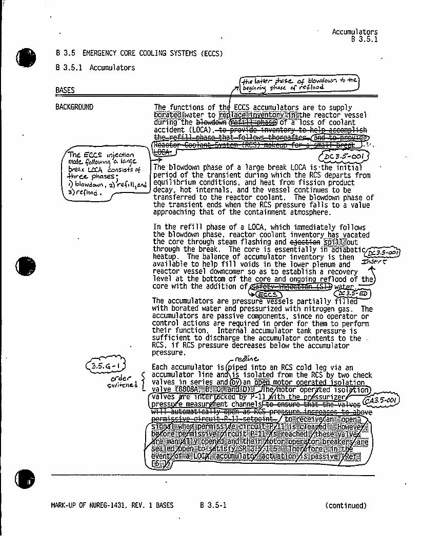
8 3.5 EMERGENCY CORE COOLING SYSTEMS (ECCS)
B 3.5. 1 Accumulators
BASES
Accumulators8 3.5.1
~e lager +se. af btavloo~ + ~<beeinni phase, ol'egloocL
BACKGROUND The functions of th ECCS accumulators are to supplyhei.,ated~water to i;e l'ice% ento'..-:jiihthe reactor vesseldiiri'ng"the ~wdeQ' " of a loss of coolantaccident (LOCA).
~Z 5'~S rnjeeWanMp- follows) a
~ac LcCA consis45 g&red. phasesi) blowdown, g vega ll,and
)
3) f'cfIcog,
or Jergwt~c,L
DC 3 P-OOl
The blowdown phase of a large break LOCA is the initialperiod of the transient during which the RCS departs fromequilibrium conditions'nd heat from fission productdecay, hot internals, and the vessel continues to betransferred to the reactor coolant. The blowdown phase ofthe transient ends when the RCS pressure falls to a valueapproaching that of the containment atmosphere.
In the refill phase of a LOCA, which immediately followsthe blowdown phase, reactor coolant inventory has vacatedthe core through steam flashing and e8e4Aea jji'3::f;:,,'outthrough the break. The core is essentially in'di"abatic ~z>.~,heatup. The balance of accumulator inventory is then '„~™available to help fill voids in the lower plenum andreactor vessel downcomer so as to establish a recoverylevel at the bottom of the core and ongoin reflood of thecore with the addition of wSCCA'3. -EbThe accumulators are pressure vessels partially fillewith borated water and pressurized with nitrogen gas. Theaccumulators are passive components, since no operator orcontrol actions are required in order for them to performtheir function. Internal accumulator tank pressure issufficient to discharge the accumulator contents to theRCS. if RCS pressure decreases below the accumulatorpressure.
~lineEach accumulator is piped into an RCS cold leg via anaccumulator line an is isolated from the RCS by two checkvalves in series and an o 'otor o r lationvalve .('8808A::';-,,O'FCB'an SD)F'' he o or oper ed iso ionva ves e sn er c e y -11 ith h r ssurizerress e measur ent channels
06j'g&C'e|'.V .iaA".,'.:<Qp8$$'%'g
„:pH48 „!ip8f%4;SS::,,,8'>;rGQ3. $ ''. 1".;;:g S~C1M,,d.".;::';;:.:;HowBV8,,'',:."0i",e:-.',;""", "jjii'.:.'vi:.":;.'"'.I;:.'i',.t-'.!P::-''.:1'1";, '.s,",'reacj'ed;='„,
'h'equi;-'',v'al'j"';re.::,,~'i""'''.Ij:;:."...o'p'eii"',dh<biidhthii,I',:'tor~:" ij„''-" oi'.;:.';;:::.b'rial'r,'':;ir,.iiialjd'": pen;-:;t~g''1'"::;:%';::.:3.'."",.':1/6,':;.:$.«:."Th'er'Pj i''::",,:,':.'ii;:;::;."t-
kiieit"';.of,':."-;'a;:,LOC,"~'ei"„gimlJ:ii; '....,wctu)tYiii'".N.:'.::::jail:vi,";;:" . i$.~
MARK-UP OF NUREG-1431. REV. 1 BASES 8 3.5-1 (continued)

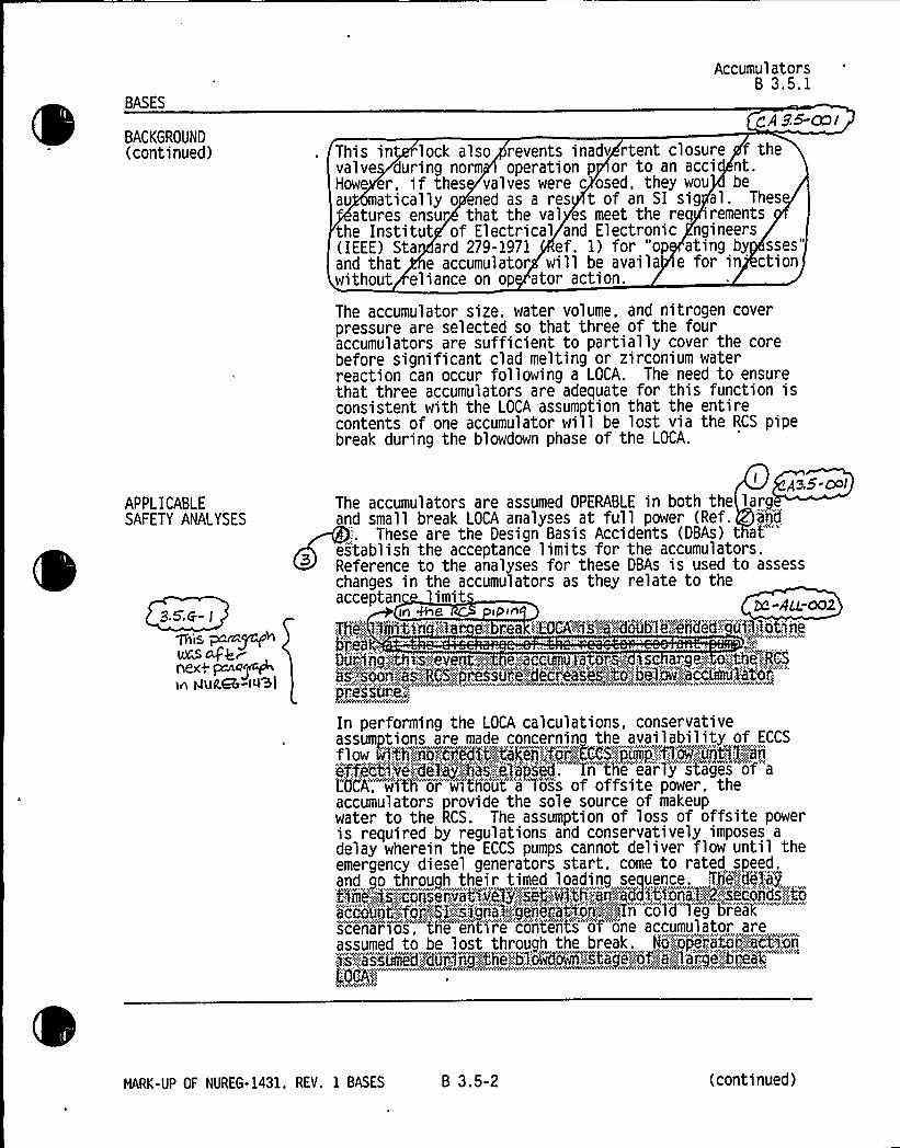
BASES
BACKGROUND(continued)
AccumulatorsB 3.5.1
gA Z5-cnl
~ This in lock also revents inadv rtent closure f thevalve during norm operation p or to an acci nt.Howe er ~ if thes valves were c osed, they wou beau matically o ened as a res t of an SI sig al. Thes
atures ensur that the val es meet the req rementsthe Institut of Electrical and Electronic ngineers( IEEE) Sta ard 279-1971 ef. 1) for "op ating by sses"and that e accumulator will be avai la e for in ctionwithout eliance on op ator action
The accumulator size, water volume, and nitrogen coverpressure are selected so that three of the fouraccumulators are sufficient to partially cover the corebefore significant clad melting or zi rconium waterreaction can occur following a LOCA. The need to ensurethat three accumulators are adequate for this function isconsistent with the LOCA assumption that the entirecontents of one accumulator will be lost via the RCS pipebreak during the blowdown phase of the LOCA.
APPLICABLESAFETY ANALYSES
9 5'Ci- I
~ic pan~hVIS cLjkrpe~> ~~~~ln htUCGb ><~l
Aa.S-volThe accumulators are assumed OPERABLE in both the largand small break LOCA analyses at full power (Ref. and
These are the Design Basis Accidents (DBAs)that"'stablishthe acceptance limits for the accumulators.
Reference to the analyses for these DBAs is used to assesschanges in the accumulators as they relate to theacceptan limit
In Me. ipse
~Thi."..:,', Ufili:t;i ':;Ra-:. e::. rea ';:!KCA'%Y'::.:"'a':ldoubl@:erided;":.""'u'ilgotjne
Dui';;;jjij'::th~s:;::::.eve g~g::, e„,',;.accumu,, a,. rag, >sr, ange,':~:, o'.',:th'i':;,:.RCS
i''.'.":soak;:.;is(RCSFj'res)iiij...:!die(xiii'i::,CYR,bjlmlacj'umuk'it'Or;""''r8ssUf!@"::
A~MVMPS
In performing the LOCA calculations, conservativeassumptions are made concerning the availability of ECCS
flow pijt'ti.".yfeg..',edit":;:;::;;:;4'akeg!",,:fij'lgCCS.rpujj-";fg,:,,:iiritj!LI,efficHVe::;:.":dt's,:;hai,',;8'apsed. T'noh'e early s'tage's"'of"aLOCA; wi'th'r wi'shout"a Toss of offsite power, theaccumulators provide the sole source of makeupwater to the RCS. The assumption of loss of offsite poweris required by regulations and conservatively imposes a
delay wherein the ECCS pumps cannot deliver flow until theemergency diesel generators start. come to rated speed,and go through their timed loading sequence. [email protected] „...'8—..:.eopservyyivegXN~C.;.,„wjthyq--,edqC„'t~onaT'~;-.Mcojds--XoKiiiiiiit;:'Ãi'i:,.':M::.;.":i)j))').,',-'j'i'.ierah)ori'";',~>',,IT'n"col'd"'1'eg b'i'eak
""'cenaiios, the e'nt'ire 'contents"'ot"one accumulator areassumed to be lost through the break. Np.,':opera%i"::,.',::jetjjii5's:,;:,."aYsiimed.::~dui„;m~'jthe~::blaaju'ea~hXj~e"":.of~5i! la'rg'e';.,':b'ilk'': "'" "
me4v" vS
HARK-UP OF NUREG-1431. REV. 1 BASES B 3.5-2 (continued)


BASES
AccumulatorsB 3.5.1
APPLICABLE SAFETYANALYSES (continued)
p~linC.3 5.8- I
~ ~.5.6- >
a. Maximum fuel element cladding temperature iss 2200'F.
b. Maximum cladding oxidation is ~ 0. 17 times the totalcladding thickness before oxidation:
c. Maximum hydrogen generation from a zirconium-waterreaction is ~ 0.01 times the hypothetical amountthat would be generated if all of the metal in thecladding cylinders surrounding the fuel, excludingcladding surrounding the plenum volume, were toreact; and + 3,5'-cP I
d. Core is maintained in a eoolable geometry.and reflcud
Since the accumulators discharge during the blowdown hasesof a LOCA. they do not contrib te to the lo 'ng
uir em eli ~A'r volte. isQr i G" if Of WC M 4rrno coo/inJi invin~
or both the large an sma rea na yses, a
nominal contained accumulator water volume is used. Thecontained water volume is the same as the deliverablevolume for the accumulators, since the accumulators areem tied. once dischar ed. For small breaks. an increase
The worst case small break LOCA analyses also assume a
time delay before pumped flow reaches the core. For thelarge ran4ha4 the I um s be in RCS in ection however the
re se in ue c a emperature is termina e eA~jria*iarei'.ly,:,:,by the accumulators. with pumped flow thenpr'ovidinhg "continued cooling. As break size decreases, theA h
A h hw
~
><~ ccumul ators and thi::.:EKS:::,:~centri fugal charging arid<51:umps ~ play a part'n terminating the rise in"cl'awd
temperature. As break size continues to decrease'. therole of the accumulators continues to decreas . iceaCCuhmmeu:.,y. ore;:.':,:. mo'„:::yO:„::::..iSC arge':a Ve,:,,:,,
e:,::,preSSure";::.,'.'Of,,::::;%he'i,"r.'ib'feet'im".':.'.become'i:,.::;,:sjl.el'j..''.",."..":rees'jIo'nsiIble':,":.:'fo'..',",',"'term.'...na
"'ehm'mr'a't6'i'e':-.":.i'ftcr.',ease:;:'YAYhhmAIWWAAAIYA e emY 'AwIAWh AY IY<
This LCO helps to ensure that the following acceptance2.
criteria established for the ECCS by 10 CFR 50.46 (Ref.tbe'tYViYi le'pepi','. toebTi:etooYtTbh'ehooTiml ot~eoi8 will be met'follow'iris' TOCA:
HARK-UP OF NUREG-1431. REV. 1 BASES B 3.5-3 (continued)


BASES
APPLICABLE SAFETYANALYSES (continued)
AccumulatorsB 3.5.1
in water volume is a peak clad temperature penalty.~ ii'i ii ii!i"!Ai.:;iiRfiiii(::,. diRig.":iW'i'sed!";to'raflal'jieg~large',,breaks,'nincr'ease in wale'r"v'oTume~ maj::;;be" result'j~iripei'ther a peak clad temperature
penal'ty"or benefit. depending on downcomer filling andsubsequent spill through the break during the corereflooding portion of the transient. The analysis makes aconservative assumption with respect to ignoring or takingcredit for line water volume from the accumulator to thecheck valve. The safety analysis assumes values of~9%43 60.8X (836 cubic feet) ~as and -9jQP-.'472.6X(864 cubic feet) gA-'4rep'as:.:,:,ileadjoii.:;:..11'ar,'i;,vier:.'aj'ge;;"gevel:::iast'r jimiits''."';~jno't.';g'rrBudlngjjastn'iiiie'ni:.'::.'-:unc'ei''ta'jnty.="W
The minimum boron concentration setpoint is used in thepost LOCA boron concentration calculation. Thecalculation is performed to assure reactor subcriticalityin a post LOCA environment. Of particular interest is thelarge break LOCA, since no credit is taken for control rodassembly insertion. A reductio~ be:l,.er><he accumulatorLCO minimum boron concentration would™produce a subsequentreduction in the available containment recirculation sumpboron concentration for post LOCA shutdown and an increasein the m~aea sump pH. The maximum boron concentrationis used in determining the cold leg to hot legrecirculation injection switchover time and minimum sumppH.
The large and small break LOCA analyses are performed atthe minimum nitrogen cover pressure)(6L'~~)',(595'.5siN.:. since sensitivity analyses have demonstrat'ed"that
"igher nitrogen cover pressure results in a computed peakclad temperature benefit. The maximum nitrogen coverpressure 1 imit (693-p~)I(647::.'"8"„~pail,'~
i',os'aes:":.Itta,. j:n:,;:.io,".;,;assaje3 AgV8Q~j "gk]i'1 9'f,''.:lVBV&~8'CF95flOA~does";:":YIOE'';QCCUr::..':I
Thesemrialjj'$i;-))gomedi'pi:".es)iiei:;,:;aje.:.:."'ipec)Vied!qfIjthe.,';!SRs„';"'.':~:-;.|Ib'I,::~s':a5'i',:i'-',.'::s'h'~f'',eaNAgs,':<.'..QA;,.:":;:::8'ccUNU3840f'Ij'„:AERY(&$3;.',faAQB„.:geve1„';";,"lfIstglNeAts."
'$,''dj'ii)'tnien'Ls'::::Kn'.jtp'i',",''aj);
4A'8ccvplcles'.;"',Qrj~Otheg~jrea'sopdj~clre~'Bp'gled.::".'49',",'dBtepmlnB~ t4'8a'c'."e'pl::a'inc'ekcrit4i')5",,'"sei$ .;5'i':.":.ith'e':;.plhnh:. s'i'harv'e)'',.ll'arjq'e
"" "'
'pi'.oi;:e'dure's.".::",:!:':;;-'::Th'i.)ip'.'ad j'i'stmeiits"::,:::aiiiii~MriiNte'i'.si'xiii",;iiia'i'ii't51fiedf~~
The effects on containment mass and energy releases fromthe accumulators are accounted for in t e appropriateanalyses (Refs. 2 and . CA35.ool
i 3Tt 1 !,Ci i 3 f~
KB:.'::CFIISii%f(-.!K: i
MARK-UP OF NUREG-1431, REV. 1 BASES B 3.5-4 (continued)


BASES
LCO
AccumulatorsB 3.5.1
The LCO establishes the minimum conditions required toensure that the accumulators are available to accomplishtheir core cooling safety function following a LOCA. Fouraccumulators are required to ensure that 100K of thecontents of three of the accumulators will reach the coreduring a LOCA. This is consistent with the assumptionthat the contents of one accumulator spill through thebreak. If less than three accumulators are injected duringthe blowdown phase of a LOCA. the ECCS acceptance criteriaof 10 CFR 50.46 (Ref. could be violated.
2 ~p 5'~Qgi
For an accumulator to be considered OPERABLE. theisolation valve must be fully open. power removed aboveQQ@9 8:,'.romana'1,:,:RCS:„".:,'P'i,'eisure~of,',1000 psig. and the limitsestablished in"th'e'Rs"for con'tained" volume. boronconcentration, and nitrogen cover pressure must be met.
APPL ICABIL'ETY In MODES 1 and 2. and in MODE 3 with RCS. pressure> 1000 psig, the accumulator OPERABILITY requirements arebased on full power operation. Although coolingrequirements decrease as power decreases. the accumulatorsare still required to provide core cooling as long aselevated RCS pressures and temperatures exist.
This LCO is only applicable at RCS:>pressures > 1000 psig.At pressures ~ 1000 psig, the rate of RCS blowdown is suchthat the ECCS pumps can provide adequate injection toensure that peak cl d temperature remains below the10 CFR 50.46 (Ref. limit of 2200 F. ch9.5-ml
In MODE 3, with RCS pressure s 1000 psig, and in MODES 4.5, and 6. the accumulator motor operated isolation valvesare par~ma,.;:ly'.'<closed to isolate the accumulators from the
~ RCS." This allows RCS cooldown and depressurizationwithout discharging the accumulators into the RCS orrequi ring depressurization of the accumulators.X&9C~+ CA 3.5-ooi
ACTIONS A. 1
If the boron concentration of one accumulator is notwithin limits, it must be returned to within the limitswithin 72 hours. In this Condition. l:hejaability tomaintain subcriticality or minimum boron precipitationtime may be reduced. The boron in the accumulatorscontributes to the assumption that the combined ECCS waterin the partially recovered core during the earlyreflooding phase of a large break LOCA is sufficient tokeep that portion of the core subcritical. Oneaccumulator below the minimum boron concentration limit.however, will have no effect on available ECCS water andan insignificant effect on core subcriticality duringreflood. Boiling of ECCS water in the core during refloodconcentrates boron in the saturated li uid that remains in
NARK-UP OF NUREG-1431, REV. 1 BASES 8 3.5-5 (contitiued)


Insert for CA3.5-001
Enclosure 5B Page B3.5-5 (Applicability)
Accumulator may be unisolated when accumulator pressure is less than the maximum RCSpressure for the existing RCS cold leg temperature allowed by the P/T limit curves provided inthe PTLR. This condition is in agreement with the TS 3.4.12 LCO requirement.


BASES
AccumulatorsB 3.5.1
SURVEILLANCEREQUIREMENTS(continued)
analyses assumptions. This Frequency is consideredreasonable in view of other administrative controls thatensure a mispositioned isolation valve is unlikely.
SR 3.5.1.2 and SR 3.5.1.3
Every 12 hours, borated water volume and nitrogen coverpressure are verified for each accumulator. ThisFrequency is sufficient to ensure adequate injectionduring a LOCA. Because of the static design of theaccumulator, a 12 hour Frequency usually allows theoperator to identify changes before limits are reached.Operating experience has shown this Frequency to beappropriate for early detection and correction of offnormal trends.
g,5:6-i
SR 3.5.1.4
The boron concentration should be verified to be withinrequired limits for each accumulator every 31 days sincethe static design of the accumulators limits the ways inwhich the concentration can be changed. The 31 dayFrequency is adequate to identify changes that could occurfrom mechanisms such as in-leakage.Sam lin the affected accumulator within 6 hours after a
o u ion vo ume increas 5f',.::6,':::6'-"p (I01..;:gal::leo)Pnar'rN
c'au's'ed a""r'e'diicti'oii"'in boron concentration to below therequired limit. It is not necessary to verify boronconcentration it the added water inventory is from therefueling water storage tank (RWST),r„:Arid,.:".'::t'0&,":,::AUST;,'..'-":.has''',:,;004
6eii:.:'",:dj,l.'used:,'si,iice';",':,viri'fgjnj':::,that-:,":,i'::;,"".bo'ron'iiii'iinti',.
RtlST is within the accumulator boron concentrationrequirements Ksjiei"'.,s",fred',':bj'.;::SA,„:;3,.;5'4:-,::3,:,::~ This isconsistent with the recomiendation of GL 93L06.'."'(Ref.
QA3. 5-OOI
SR 3.5.1.5$,5,gr J
Verification every 31 days that power is removed from eachaccumul ator isol ati on va1 ve operator,(8868A":.,.'.8,.:'y'6'j.„:.:and;: 6):
IIE5'imp i ~NO"'!5",:i(1'""
XLIOO psig ensures that an active failure could not resultin the undetected closure of an accumulator motor operatedisolation valve. If this were to occur. only twoaccumulators would be available for injection given a
single failure coincident with a LOCA. Since power isremoved under administrative control, the 31 day Frequencywill provide adequate assurance that power is removed.
This SR allows power to be supplied to the motor operated~ II%A!ip i ~ig
HARK-UP OF NUREG-1431. REV. 1 BASES B 3.5-7 (continued)


BASES
AccumulatorsB 3.5.1
~~;::.i„-::,:-::::,:":::::„.'-!!~.::;;:,::,:".„::i'ass';:than::,:ar!„,agua f*;::,:to'!1ggj ps ig, thus allowing
..,:t e.val vis',-'.:to":.-:,:bi".:,::":;cl'osed;„';to:;:enable„'"''plantY)hMdow'n'" 'ion @35.ooldi."schai"."i'nw -::-''.:tkies'.~:;;acciiiiRil at'ors43rito,.!the.:":;.RCS Z~ Ev'en wi
o supp i o e v . na ver n closure is
SURVEILLANCEREQUIREMENTS (continued)
prevent by. the RCS ressure inter ock (P,.=.':13~)'-"'as ociatedwith t valves.
Sh d closure of valve occur in spite of th interl k.t SI signal pr ided to the alves would op n a clo dalve in the ev nt of a LOCA
REFERENCES
~g
Qqql.
Qr
FSAR, Chapter 9Q.
10 CFR 50.46.
FSAR, Chapter 91Q.
BL%93'='9s:"'."%I$8a.';7';g$
CA3.5'ia~
NRK-UP OF NUREG-1431, REV. 1 BASES B 3.5-8


Enclosure 2PG&E Letter DCL 98-107
ADDITIONALINFORMATIONCOVER SHEET
ADDITIONALINFORMATIONNO: CA 3.5-002
REQUEST:
APPLICABILITY: DC, CP, WC, CA
Revise ITS 3.5A Bases to indicate that the RWST LCO, by virtue of itstemperature, volume, and boron concentration limits, also satisfiesCriterion 2 (initial conditions of accident analyses).
ATTACHED PAGES:
Enclosure 5B B 3.5-31


BASES
RWSTB 3.5.4
APPLICABLE SAFETYANALYSES am'::. n ra r"."''8 " .:R= 'ural'' TR(continued)
Vo'fumeb'rAYNAVc
jf},::;;,a,:::ip u,j,.:re ". y,:.',::,'a,:.:.,:'.'AAYAveseAN'EYANYAYPAYNNN:%AN.N,.NA'NOSY'avNNAAY s'ww'4Y DYA AYAsststsvk
85rat).07iYA V VAVAM
e'veer'ea'ctiNt j;.:,"prodded;.-,;bj;:'::th'e-'lii'ject'ed;:RWSTj,'.soj~ff~'cieiltdDDH~'diirjnsgY;.tlie.::;:,i')pj:a::Ijj;ecof,;.:.':.:th'.'":,'-hei'iti'a3:..":,.oE.'"'"r'ato'i';:l::recov~'rj''.:::,'iitj.'o'nt
t'o„":lequeal;:i'z'edith'e:::„.'ACS',.'proc'ssure,:;:hand,'l':th'e';,'Ãa'usted)st'eiiii="'enerato'rj.":piness'iir'e:.":.::to.'::"i'i'ii)mjji';:,:or'..".:s'top':
th'';:,'jr''diary;-"ti';.,:5'econdari,'Itube',:,",ru'ptur'ega'ow',;:j'rid'-';:4e'r'mjriat'e",si'fitD j„",i'joe'ct'i'on".>Forth'er'pt, CS,':::;boretteo'o'Eiiv'i::;,",,":btee':,'i5'itbebtseed,:biitli1!ioperet'or,'! bj
ri er iO, Z.nrd. CA 3,5-re 2.
The RWST satisfies 3 ofxg,':,''.GFR':.","50;86I@)X2)'.(:n'',:.::.AW WACYhVAAAC'AeA Y VA'VAVA 1'' AV4CAVA(
ense'4 3 bc. 3. ~-a~>~
LCO The RWST ensures that an adequate supply of borated wateris available to cool and depressurize the containment inthe event of a Design Basis Accident (DBA), to cool andcover the core in the event of a LOCA, to maintain thereactor subcritical following a DBA, and to ensure adequatelevel in the containment recirculation sump to support ECCSaced pump operation in therecirculation mode.
To be considered OPERABLE. the RWST must meet the watervolume, boron concentration, and temperature limitsestablished in the SRs.
APPLICABILITY In MODES 1, 2, 3, and 4, RWST OPERABILITY requirements areOI OO EOOS POE'~SOPERABILITY requirements. Since both the ECCS and the CSE
S ee I O ONE YSIE NODES I. PE .DA3, and 4, the RWST must also be OPERABLE to support theiroperation. Core cooling requirements in MODE 5 areaddressed by LCO 3.4.7. "RCS Loops —MODE 5, Loops Filled,"and LCO 3.4.8, "RCS Loops - NODE 5. Loops Not Filled."MODE 6 core cooling requirements are addressed byLCO 3.9.5, "Residual Heat Removal (RHR) and CoolantCirculation-High Water Level." and LCO 3.9.6. "Residual
MARK-UP OF NUREG-1431, REV. 1 BASES B 3.5-31 (continued)


Enclosure 2PG8 E Letter DCL 98-107
ADDITIONALINFORMATIONCOVER SHEET
ADDITIONALINFORMATIONNO: DC 3.5-EDREQUEST'PPLICABILITY'CVarious editorial changes that do not impact the technical content of thesubmittal or other FLOG members.
Changes are noted with DC-3.6-ED in the right margin and noted below:
2)
3)4)
5)
ATTACHED PAGES:
Encl. 5AEncl. 5B
Enclosure 5B, page B3.5-1, safety injection (Sl) changed toECCS to be consistent with FSAR languageEnclosure 5A, page 3.5-9, JFD 3.5-8 does not apply to DiabloCanyon. "B-PS" should be used.Enclosure 5B, page B3.5-31, singular versus plural use.Enclosure 5B, page B3.5-3, the word "both" is deleted sincethree items are listed.Enclosure 5B, page B3.5-14, paragraph on Notes is revised tobe consistent with Enclosure 5A mark-up.
3.5-9B3.5-1, B3.5-3, B3.5-14, B3.5-31


RWST3.5.4
SURVEILLANCE REQUIREMENTS
SURVEILLANCE FREQUENCY
SR 3.5.4.1 ) ))'<nw< v ~ <'N.~.A ~ <<R)w~v~<4,<)'<, <yY
Orily,'".require'd.:::.t)o',:,::be"',,jer'fo'rm<ed:,:"''ihin;':.,am)bi eIit; '",.
a;.r'„'t'e<mp'er'a)tur'ei'~s.-'.8;-":F35'j..'„F.'"
<vvAK))h)), ))gA"'ri)w)"))<')'cmcr4Ãw~ Mr4- A)"B-PS
erify RWST borated water temperature is—~fK3+~Fgaad ~~~ 24 hours
3 8 /PS3X,'3.5'- ED
SR 3.5.4.2 Verify RWST borated water volume is ~466-,400400:.:,000",g'al:'lons'81:"::,':lX:,''.;iftdi'cated:::,"::)elean,'<
7 days B-PS
. SR 3.5.4.3 Veri fy RWST boron concentration is ~~0002300$ ppm and «(gBKQ—250~ ppm.
7 days B-PS
DCPP Mark-up of NUREG-1431. Rev. 1
3.5-9


8 3.5 EMERGENCY CORE COOLING SYSTEMS (ECCS)
B 3.5.1 Accumulators
BASES
AccumulatorsB 3.5.1
~< loper Qse. ~ btowdo~ 4&~beginner phatic Q reglood
BACKGROUND The functions of th ECCS accumulators are to supplygi;;akedpwater to re face;-":i entYT rj',4j7lkthe reactor vesseldii'ring 'the ~wde~" '" of a loss of coolantaccident (LOCA).
'Tlirt 5~s rnjecffongate. goll0winri o laNj C
AWK ~ conS1sCS ofkhrce. phaseS-<) &lowdown, Q re(( ll,a~)
3) r efloog,
35.6-Ior oer
qvriwhc L
pC B.> oolThe blowdown phase of a large break LOCA is the initialperiod of the transient during which the RCS departs fromequi librium conditions'nd heat from fission productdecay. hot internals. and the vessel continues to betransferred to the reactor coolant. The blowdown Dhase ofthe transient ends when the RCS pressure falls to'a valueapproaching that of the containment atmosphere.
In the refill phase of a LOCA, which imediately followsthe blowdown phase, reactor coolant inventory has vacatedthe core through steam flashing and ejMAea sp'i':,1;:l,'.-":.';out
through the break. The core is essentially iri-"adiabatic ~zz.~,heatup. The balance of accumulator inventory is then '„~™available to help fill voids in the lower plenum andreactor vessel downcomer so as to establish a recoverylevel at the bottom of the core and ongoin reflood of thecore with the addition of w
ECCL K3, -EbThe accumulators are pressure vessels partially fillewith borated water and pressurized with nitrogen gas. Theaccumulators are passive components, since no operator orcontrol actions are required in order for them to performtheir function. Internal accumulator tank pressure issufficient to discharge the accumulator contents to theRCS, if RCS pressure decreases below the accumulatorpressure.
~line.Each accumulator is piped into an RCS cold leg via anaccumulator line an is isolated from the RCS by two checkvalves in series and an o 'otor o r olationvalve:.'(8868A'-"':,::;:,'.8,";:,.;,::.,C.::,';::::an,'::I))!;-'- 'e o or oper ed iso ionva ves e in er c e y -ll ith h r ssurizer
ress e measur ent channels
tGjjf~ec'Ql,v ~aA',".'z /pen'„''1s~g:: pwhe ..;:.:.:permissi. s'."ci:re>,. ~,:;:1<'-:isgc3ea, dgFHowev'e,»"'ill;:',",,"4i'i:v'e'.,'::..'"';,i;,coi:;;hmP,,-'.",;:X'1;:.'"..sj)'r'ea'shed~,, he'ii'jv'a)'v","'"'-re,'::.'jiiaii""':Ilj''c p'Pe" 0„'':!and:;ithei'."i!
" ot'oi'jap'e'ii"" orIlibi:iakei.s'e'aled: ~i).:;-40,:;:-" ti:.~fj,"',::'.:%'-;.:;;3.',: .;.':1.'''.::5.'IP~7her'.$ oi:',i,,.~~-:1jijt
"
e'v'eiit',o'frigLtX .':.'accetmjl'it"",. ~i8ctiat)on'''„j'jp)'sp,':vi<':., ef!(
.g'ARK-UP
OF NUREG-1431. REV. 1 BASES 8 3.5-1 (continued)


BASES
AccumulatorsB 3.5.1
APPLICABLE SAFETYANALYSES (continued)
i ~lgn<9.5.6- I
,5,Q~ J
The worst case small break LOCA analyses also assume a
time delay before pumped flow reaches the core. For thelarge ran4ha4 the I um s be in RCS in ection however the
re se in ue c a emperature is termina e eA~pi".imarTly„'.',by the accumulators, with pumped f ow thenpr'ov'idling continued cooling. As break size decreases. the
~ ccumulators and t'e'.':.EKSjcentrifugal charging and:,:SIumps @Q play a" part iti terminating the rise iin cl'ad
temperature. As break size continues to decrease', therole of the accumulators continues to decreas . Theyccuimu:.,a ops;; o;„«not'::;:. isc argepa ve,;.::.. e„:::;pressurI'e.:'::;.'0'their;
r,,'ess~i,iithe',.::.EBS:;'.:Centi9'fIi1ga3:.::;Nisi:.;-$ ng:.,",piiN'-S',:,"8'nd,':.8'I~.,': um spi.., ...,,........,,,.....,...,,...,,. „,.„,..., ...,...,.....,.. 9,,,...,...p....,....,...,,,,,...p,, p„i'hajj'ect ion':;::„.becomes:,::,".,:::so)'i''.','r'ejsoo'npbleP~frii~t'immi'naming",';.::the"tempi'itui,e%$cr..easi.'.:":Nvwvi.@vow,~Z " ~rriM~~Ãiiw
This LCO helps to ensure that the following acceptanceL
criteria established for the ECCS by 10 CFR 50.46 (Ref.that';",:-af eYipfA5'cab'1'e>..:'-fof'.,:@he.-.".VTccumN,'AN's%wi 1 1 be met'f 1T= "'L0CA==
a. Maximum fuel element cladding temperature is~ 2200'F:
b. Maximum cladding oxidation is ~ 0. 17 times the totalcladding thickness before oxidation:
c. Maximum hydrogen generation from a zirconium-waterreaction is ~ 0.01 times the hypothetical amountthat would be generated if all of the metal in thecladding cylinders surrounding the fuel. excludingcladding surrounding the plenum volume, were toreact; and +3,5'Pl
d. Core is maintained in a eoolable geometry.and regkud
Since the accumulators discharge during the blowdown hasesof a LOCA, they do not contrib te to the lo 'ng
ui rem ~oui) elr ~A'r y'Qumc. jsCr ~ i'~ 4f MC ldll 4rrm coolin>r invcn~
or both the large an sma rea na yses, a
nominal contained accumulator water volume is used. Thecontained water volume is the same as the deliverablevolume for the accumulators. since the accumulators areem tied, once dischar ed. For small breaks'n increase
MARK-UP OF NUREG-1431, REV. 1 BASES B 3.5-3 (continued)


BASES
APPLICABILITY(continued)
gn-str'XQ
ECCS -- OperatingB 3.5.2
This LCO is only applicable in NODE 3 and above. BelowNODE 3, the SI signal setpoint is manually bypassed byoperator control, and system functional requirements arrelaxed as described in LCO 3.5.3. "ECCS - Shutdown."
+he.
In NODES 5 and 6. plant conditions are such that theprobabi lity of an event requi ring ECCS injection isextremely low. Core cooling requirements in MODE 5 areaddressed by LCO 3.4.7. "RCS Loops -NODE 5 ~ Loops Filled,"and LCO 3.4.8. "RCS Loops —NODE 5, Loops Not Filled."NODE 6 core cooling requirements are addressed by LCO3.9.5, "Residual Heat Removal (RHR) and CoolantCirculation —High Water Level," and LCO 3.9.6, "ResidualHeat Removal (RHR) and Coolant Circulation —Low WaterLevel."
ACTIONS A.l
With one or more trains inoperable and at least 100X ofthe ECCS flow equivalent to a single OPERABLE ECCS trainavail able (capa'blue::4f..-„,:.:in)i')ogj~nto~thigRCS+i,'f:hc'tuated):-,: th'e inopera'ble compon'ents must'be returned toOPERABLE status within 72 hours. The 72 hour CompletionTime is based on an NRC reliability evaluation (Ref. 5)and is a reasonable time for repair of many ECCScomponents.
An ECCS train is inoperable if it is not capable ofdelivering design flow to the RCS. Individual componentsare inoperable if they are not capable of performing theird~a s'afety'qfunction or supporting systems are notavailable.
The LCO requires the OPERABILITY of a number ofindependent subsystems. Due to the redundancy of trainsand the diversity of subsystems, the inoperability of onecomponent in a train does not render the ECCS incapable ofperforming its function. Neither does the inoperabilityof two different components. each in a different train,necessarily result in a loss of function for the ECCS.The intent of this Condition is to maintain a combinationof equipment such that 100K of the ECCS flow equivalent to
NARK-UP OF NUREG-1431, REV. 1 BASES 8 3.5-14 (continued)


Enclosure 2PG8E Letter DCL 98-107
ADDITIONALINFORMATIONCOVER SHEET
ADDITIONALINFORMATIONNO: DC ALL-002REQUEST'PPLICABILITY'CAn errata to LAR 97-09 was submitted to the NRC January 8, 1998 inDCL-98-003. Errata changes on pages affected by NRC commentnumbers are indicated with "DC-ALL-002." Errata changes that dealt withissuance of LAs 119/117 and 118/116 (issued 7/1 3/97) that addressedCTS surveillance interval increases due to 24-month fuel cycles areindicated with "DC-ALL-001."
ATTACHED PAGES
See notations on applicable pages for each comment number.


Enclosure 2PG8E Letter DCL 98-107
ADDITIONALINFORMATIONCOVER SHEET
ADDITIONALINFORMATIONNO: DC 3.5-001
REQUEST:
APPLICABILITY: DC, WC, CA
Revise the Bases 3.5.1, Background, to discuss the three phases forlarge break LOCA (blowdown, refill, and reflood) as discussed in FSARChapter 15. The revision clarifies that reflood is accomplished initially byaccumulator discharge and by ECCS pump flow.
ATTACHED PAGES:
Encl. 5B B 3.5-1 and B 3.5-3

0

B 3.5 EMERGENCY CORE COOLING SYSTEMS (ECCS)
B 3.5.1 Accumulators
BASES
AccumulatorsB 3.5.1
~g 4HVr +s~ Q biowdo~ *~Lbey>igni phase, oP i egloock
BACKGROUND The functions of th ECCS accumulators are to supplygii.ated$ water to i';e'ice!''.:i"'ent7Yry;.''.::withe reactor vesseldur'iiig the ~wdem '- o'f'a'oss of coolantaccident (LOCA).
The EMS injectionmale gollowini) o l«~)i'-~4K ~ COhSiSCS g~ri e. phnseSi) blowdown, g re)i Iliad
]
S)refjoo~.
35.4 - I
cii Jetgvli~cL
pc 3.> dolThe blowdown phase of a large break LOCA is the initialperiod of the transient during which the RCS departs fromequilibrium conditions ~ and heat from fission productdecay. hot internals. and the vessel continues to betransferred to the reactor coolant. The blowdown phase ofthe transient ends when the RCS pressure falls to a valueapproaching that of the containment atmosphere.
In the refill phase of a LOCA, which immediately followsthe blowdown phase. reactor coolant inventory has vacatedthe core through steam flashing and e~ct4ea spi',:l:;V'outthrough the break. The core is essentially in"adiabatic ~zz.~,heatup. The balance of accumulator inventory is then '„~™available to help fill voids in the lower plenum andreactor vessel downcomer so as to establish a recoverylevel at the bottom of the core and ongoin reflood of~thecore with the addition of w
ECCL bC3. -85The accumulators are pressure vessels partially fillewith borated water and pressurized with nitrogen gas. Theaccumulators are passive components, since no operator orcontrol actions are required in order for them to performtheir function. Internal accumulator tank pressure issufficient to discharge the accumulator contents to theRCS, if RCS pressure decreases below the accumulatorpressure.
redline.Each accumulator is piped into an RCS cold leg via anaccumulator line an is isolated from the RCS by two checkvalves in series and an 'o=' motor o r olationvalve ':('8868A„',:,',:8',.:..0;::::,;;an,'.,:'..9):::;. 'e o or oper ed iso ionva ves e > er c e y -11 ith h r ssurizer
ress e measur ent channels
to,~j.eCe>:V,arl..";:;;,;;:,operi„,"
s~g, pwhe jperrrl~ss,,e,:::c~;:rex -:;,,; . 1;,:.'js'.-',,'cl'ea, d.'";,.;:"„.:";:;,",Hweve ~~"";,oi'.,'e".-"'..""""."'isij,'igg-"-.i'cur;t";.'.'„.:P,,:-',.;:::il".:;"".Pj) ..'each'ed,.:" „'h'es'e,-:::v'a1'i":„'e;"''m'an" .fjlj'.open'mhiid'::.th6)'rP 'otoijop'er 'i>,bi,';eaker.:." ~ar:.esealed pen'-'toN tisfy<:%'!3-'1:"; 5'~~ 'Ther fore%in"tFieiit';a'f&%,,'LiL'aipmibi,:.'ii~tii'at:.aiii'Yp&ii%i,",,ef,:„;
zP
MARK-UP OF NUREG-1431, REV. 1 BASES B 3.5-1 (continued)

0

Insert for DC 3.5-001
Insert in Enclosure 5B, page B3.5-1
The refill phase is complete when the injection of ECCS water has filled the reactor vesseldowncomer and the lower plenum of the reactor vessel, which is bounded by the bottom of thefuel rods.
The reflood phase follows the refill phase and continues until the reactor vessel has been filledto the extent that core temperature rise has been terminated.
The accumulators function in the later stage of blowdown to the beginning of reflood to fill thedowncomer and lower plenum. The injection of the ECCS pumps aid during refill. Reflood andthe following long term heat removal is accomplished by water pumped into the core by theECCS pumps.


BASES
APPLICABLE SAFETYANALYSES (continued)
AccumulatorsB 3.5.1
p~)>n <
9.5.6- t
a. Maximum fuel element cladding temperature iss 2200'F;
b. Maximum cladding oxidation is ~ 0. 17 times the totalcladding thickness before oxidation:
c. Maximum hydrogen generation from a zirconium-waterreaction is ~ 0.01 times the hypothetical amountthat would be generated if all of the metal in thecladding cylinders surrounding the fuel. excludingcladding surrounding the plenum volume, were toreact: and 'jg 3. 8'cs l
d. Core is maintained in a eoolable geometry.and i zgl&d
Since the accumulators discharge during the blowdown hasesof a LOCA. they do not contrib te to the lo 'ng
uirem ~Cog err Cu"u'r V&s~C. iSCr '-s i Of We oo 4cprr ccsa fin~/'nvrnW
For both the large an sma rea na yses ~ a
nominal contained accumulator water volume is used. Thecontained water volume is the same as the deliverablevolume for the accumulators, since the accumulators areem tied. once dischar ed. For small breaks, an increase
The worst case small break LOCA analyses also assume a
time delay before pumped flow reaches the core. For thelarge ran4ha4 the I um s be in RCS in ection, however the
re se in ue c a emperature is termina e eA~pi;jmai':.,i'::lj~by the accumulators, with pumped flow thenpreosv'idVnsg continued cooling. As break size decreases, them s
~
><~ ccumulators and tLt e,",'.",ECCSjcentrifugal charging an5;.:::.SI:.:
umps @Q play a"part''n terminating the rise i'n cladtemperature. As break size continues to decrease, therole of the accumulators continues to decreas . JThe
accumu,,o os.;! ogp0,':,', i:sc ar~r!a,vej,. e.,:;;pressure.,';..'OfjXh~eir,iiit8g'equi'8'cove'i,.::.":gas:':.(595',"5,"'No''.!547::;5!i'ps:i'j'-:>3';";At'.-:::::hYjhii',p'r'essoi;'es':.':.,'tle~<ECC5;,''cent'r")':;fiigi3!',"OIiam)'i'',-:;:Pumps::",:,.'.."and,':;Qj'pumpsiiije'cs1aiiIbecoiiies>,"sei'el j~~resim~iisiblk",fbi,;";:t'i*.rmLeeeLeglitl'i'"'emir,'"a i'ie~".~f'id'r',":eiR.i".,
'-A ~~~WVAVfCvpA'~Av
This LCO helps to ensure that the following acceptance2.
criteria established for the ECCS by 10 CFR 50.46 (Ref.that:,"',:iris''j}pl:.",ical.e~~'firgthe~accumuLBt'Or's'.:,",:will be met'o 'ow"ing a"
MARK-UP OF NUREG-1431, REV. 1 BASES B 3.5-3 (continued)

0

Enclosure 2PGLE Letter DCL 98-107
ADDITIONALINFORMATIONCOVER SHEET
ADDITIONALINFORMATIONNO: DC 3.5-002REQUEST'PPLICABILITY'CRevise ITS SR 3.5.5.1 by adding a second note that states: "Theprovisions of specification SR 3.0.4 are not applicable for entry intoMODE 3." This note is equivalent to the current technical specification4.4.6.2.1 c. note except that it does not apply to MODE 4 entry since ITS3.5.5 does not apply to MODE 4.
ATTACHED PAGES
Encl. 5A 3.5-11Encl. 5B B 3.5-38


SURVEILLANCE REQUIREMENTS
SURVEILLANCE
Seal Injection Flow3.5.5
FREQUENCY
SR 3.5.5.1 --- NOTES-I. Not required to be per ormed until 4 hours
after the Reactor Coolant System pressurestabilizes at ~-$2215'!psig'::and '~":;.2255;":.ps~g.9
Q2, 'The. P~i5ionS Of Sly 3.0.$ aie no+ ~pl.«PIe.'$~ DC 3,5 oo2,
Verify manual seal injection throttle valvesare adjusted to give a flow within limit with
RCS.pressure -5 245 '2215 psig and<'!'g25&3:,.'",ps'nd the-f charglng~flo g-controlva ve™ u
"open.
31 days
3.5-5
OCPP Nark-up of NUREG-1431, Rev. 13.5-11


BASES
Seal Injection FlowB 3.5.5
ACTIONS(continued)
B.1 and B.2
When the Required Actions cannot be completed within therequired Completion Time a controlled shutdown must beinitiated. The Completion Time of 6 hours for reachingMODE 3 from MODE 1 is a reasonable time for a controlledshutdown, based on operating experience and normal cooldownrates. and does not challenge p)ant safety systems oroperators. .Continuing the plant shutdown begun in RequiredAction B. 1, an additional 6 hours is a reasonable time.based on operating experience and normal cooldown rates, toreach MODE 4. where this LCO is no longer applicable.
SURVEILLANCEREQUIREMENTS
SR 3.5.5.1
Verification every 31 days that the manual seal injectionthrottle valves are adjusted to give a flow ~~~belowthe limit ensures 4ha4 proper manual seal injection=throttle valve position. and hence. proper seal injectionflow, is maintained. The Frequency of 31 days is based onengineering judgment and is consistent with other ECCSvalve Surveillance Frequencies. The Frequency has provento be acceptable through operating experience.
,d, h,,S F11 i ~ b p~~ eeimpLeted~jftQ'n-:4 hours after the RCS pressure has<;the
sjecifiedjpressure l.;:knits.:) The RCS pressure requirement isspeci"fied 'since this confi'guration will produce therequired pressure conditions necessary to assure that themanual valves are set correctly. The exception is limitedto 4 hours to ensure that the Survei "ance is timely.
Ã9 5'eo2,
REFERENCES 1, FSAR, Chapter 6 and Chapter 15.
2. 10 CFR 50.46.
~j5 $4f 4CI Ilcflc~ is gus +her modi /edoQ Q ~ck S~as &o,h We prov slav: oP
5g, 3, g,p pr< ~+ nppl cchlC Pr an+In+ IMoaE, 3,
MARK-UP OF NUREG-1431, REV. 1 BASES B 3.5-38


Enclosure 2PG8E Letter DCL 98-107
ADDITIONALINFORNIATIONCOVER SHEET
ADDITIONALINFORMATIONNO: DC 3.5-003REQUEST'PPLICABILITY:DC
Revise the Bases of SR 3.5.2.4 to include information on the differentialpressure that was inadvertently left out. Specifically, the following text isadded: "The following ECCS pumps are required to develop theindicated differential pressure on recirculation flow: 1) CCP a 2400 psid,2) Sl pump a 1455 psid, and 3) RHR pump a 165 psid."
ATTACHED PAGES
Encl. 5B B 3.5-18


BASES
REQUIREMENTS(continued)
~ QlIouu ng 8-<~ P™Ppre r.egu>reX ~ daveloP ~<inpiuPA p;perry'~L pres~«e
Nvr, Asied on recirodcetu
glcaU,'cp p &ca ~igSl pump > gag
p,;~'N.
pump >~ I&5ps> J.
ECCS -- OperatingB 3.5.2
! .:i!,8'.l!!)!".!!! ! !testing may be accomplished by measuring the pump developedhead at only one point of the pump characteristic curve.This verifies both that the measured performance is withinan acceptable tolerance of the original pump baselineperformance and that the performance at the test flow is! !' ''!!!i!"'i!
p ! ! !the plant safety analysis". "SRs are specified in Web~
the 'appl,>cable)po'r tiajs:,-:.,:o',:;;%he! ! . ! !"''!"'~'-'*
:5'rC!6'';of
ASME Code pr'ov+des the activities and"frequen'cies necessaryto satisfy the requirements.
g 8 t N ~ QQ ~~
SR 3.5.2.5 and SR 3.5.2.6
These Survei llances demonstrate that each automatic ECCS
valve actuates to the required position on an actual orsimulated SI signal and that each ECCS pump starts onreceipt of an actual or simulated SI signal. ThisSurveillance is not required for valves that are locked,sealed, or otherwise secured i the required position underadministrative controls. The month Fre uen is basedon the need to perform these Survei ances under t econditions that apply during a plant outage and tHepotential for unplanned plant transients it the
M-Au--oo'urv
llances were performed with the reactor at power.The month Frequency is also acceptable based on
nsideration of the design reliability (and confirming~ operating experience) of the equipment. The actuation
logic is tested as part of ESF Actuation System testing,and equipment performance is monitored as part of theInservice Testing Program.
SR 3.5 2.7 .~a-i
proper ECCS per formance, These manes;.fp"thrOQ.,",I&i';unouC red""val ves Ki,':.e'>~positjojed„':,:-:,durjrig,-:,flm".bi)'a'n'ci'jj'"aiid haveLLtechanfia3."'"",,".Ocks:.';."and:.:'.s~Ã8 Cate~ to ~"'sur.,g th'oper positioiiin!g""for'estricted flow to a red co
eg—.ex~9) s:::;ja'interned:.':,:"::.::::;.;:;The:,:„:,':ver'$fj'i''i'Oj;:;:gift":[email protected]:.,Of4@,:.":.tIirOttl,e!pinOLC.'.:.';:V8 I~V&:.'.Cali:.'.;::.be'".8CCOIpl:i8hed'.,::by,d'or'if'":,r'iiij'nkh'e',"~;3'est,""p'e"i;-'for'm
the":.:ifI'ef)'to~i'~;iiiptU'red cold:,":=':;:l'e'glair'isi'ires'~~"- a 'theot'her'old
legs rec'eive at I'east the-required minimum flow.
MARK-UP OF NUREG-1431. REV. 1 BASES B 3.5-18 (continued)


Enclosure 2PG8E Letter DCL 98-107
ADDITIONALINFORMATIONCOVER SHEET
ADDITIONALINFORMATIONNO: DC 3.5-005
REQUEST:
APPLICABILITY: DC
Revise Bases 3.5.4 to include additional information on RWSTtemperature requirements. The ITS Bases for ITS 3.5.4 currentlydiscusses the basis of the RWST temperature surveillance. However,the temperature is not discussed in the Applicable Safety Analysissection in the same level of detail as other RWST parameters. Thisdifference in the level of detail resulted from a previous PGB E request todelete the RWST temperature requirement. The deletion was notapproved. Therefore, this enhancement will make information on RWSTtemperature more consistent with the description of other RWSTparameters.
ATTACHED PAGES
Encl. 5B B 3.5-30 and B 3.5-31


Insert for DC 3.5-005
Inserts in Enclosure 5B, pages 30 and 31
Insert 1: Temperature
The primary reason for the TS minimum RWST temperature is to ensure the water willbe above freezing. In addition, the LOCA analysis SATAN code assumes thecontainment spray temperature to be equal to the RWST TS temperature limit of 35degrees F. Low water temperature can affect the analysis model of containment sprayto result in a reduction of containment pressure, which affects core reflood andincreases peak clad temperature.
Insert 2: Temperature
Minimum temperature is assumed in the MSLB core response analysis.Assuming minimum temperature for the MSLB is conservative as a MSLBcauses substantial RCS cooling due to uncontrolled steam release andincreases core reactivity. Cold water adds positive reactivity, however this effectis covered by the negative reactivity provided by the boron in the RWST water.
Minimum RWST temperature is not assumed for the feedwater line break, sincewarmer RWST temperatures are more limiting. However, since RCS pressureremains high during this event, there is very little RWST water injected and thetemperature does not have a significant effect.
Insert 3: Temperature
Minimum RWST water temperature is not a factor in SGTR. The heat capacityof RWST water injected into the RCS is small relative to the RCS inventory andheat sources.


Enclosure 2PG8 E Letter DCL 98-107
ADDITIONALINFORMATIONCOVER SHEET
ADDITIONALINFORMATIONNO: DC 3.5-006
REQUEST:
APPLICABILITY'C
Revise the SR Bases 3.5.2.3 to clarify what is required to verify that theECCS piping is full of water.
ATTACHED PAGES
Encl. 5B 8 3.5-17


Enclosure 1
PG&E Letter DCL-98-107
ACRONYM LISTt
ADVCFCUCIVCPSES
CTSDBADLAP
DOCECCS
ECGEQFLOGFSARGDCIEEE
ISTITSJFDL'A
LARLCOLERLGLOCAMFIVMFRV
MSSVPAMS
RAI
Atmospheric Dump ValveContainment Fan Cooling UnitContainment isolation ValveComanche Peak SteamElectric StationCurrent Tech SpecDesign Basis AccidentDepartment LevelAdministrative ProcedureDescription of ChangeEmergency Core CoolingSystemEquipment Control GuidelineEnvironment QualificationFour Loop Owner's GroupFinal Safety Analysis ReportGeneric Design CriteriaInstitute of Electrical andElectronic EngineersIn-service TestImproved Tech SpecJustification For DifferencesLicense AmendmentLicense Amendment RequestLimiting Condition of OperationLicensee Event ReportLess RestrictiveLoss of Coolant AccessMain Feedwater Isolation ValveMain Feedwater RegulatingValvesMain Steam Safety ValvePost Accident MonitoringSystem
'equired ActionsRequest for additionalinformation
RCSRGRHRSER
SRSTSTRM
TSTFUSAR
WCGSWOG
Reactor Coolant SystemRegulatory GuideResidual Heat RemovalSafety Evaluation Report
Surveillance RequirementStandard Tech SpecTechnical RequirementsManualTech Spec Task ForceUpdated Safety AnalysisReportWolfCreek Generating StationWestinghouse Owners Group


Document Control DeskAugust 5, 1998Page 2
PG&E Letter DCL 98-107
This letter and the Enclosures are not a supplement to Reference 3, and thus have notbeen reviewed and approved by DCPP's Plant Staff Review Committee. A supplementto Reference 3 will be provided at a later date. Any deviations from the responsesprovided in this letter will be discussed in the supplement.
Si cerely,
G eg ry M. ueger
Subscribed and sworn to before me this 5'" day of August 1998State of CaliforniaCounty of San Luis Obispo
'ta ublic
cc: Edgar Bailey, DHSSteven D. BloomDennis F. KirschEllis W. MerschoffDavid L. ProulxHoward J. WongDiablo Distribution
DANLOPEZCOMM. 8096594
("NOTARYPUBUC CAUFORNIA ~,, 4iSANLUISOBI~~JCOUNTY'"MyComm. F~ires May 5,2000
EnclosuresMRZ/

f h 4 Ih
". ~
H
i
lw (
/4
( '\

Enclosure 2PG8E Letter DCL 98-107
JLS CONVERSION TO IMPROVED TECHNICALSPECIFICATIONS
CTS 3/4.1 - REACTIVITYCONTROL SYSTEMSITS 3.1 - REACTIVITYCONTROL SYSTEMS
RESPONSE TO REQUEST FOR ADDITIONALINFORMATIONAND LICENSEE INITIATEDADDITIONALCHANGES

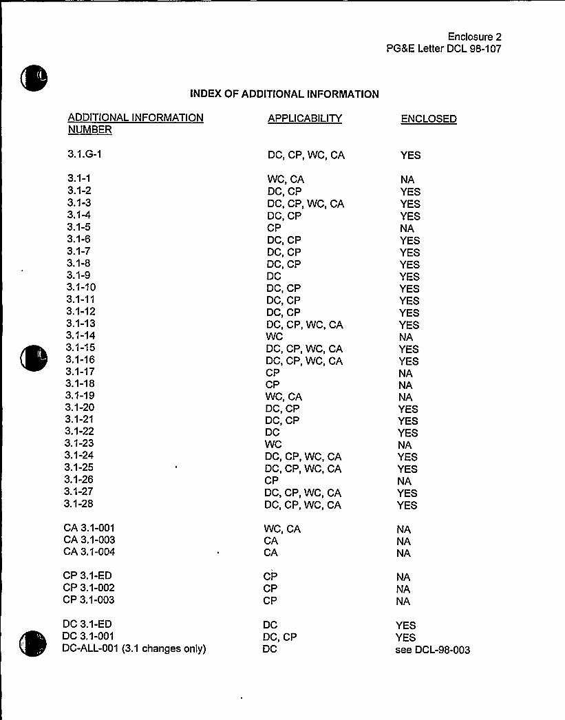
Enclosure 2PGLE Letter DCL 98-107
INDEX OF ADDITIONALINFORMATION
ADDITIONALINFORMATIONNUMBER
APPLICABILITY ENCLOSED
3.1.G-1
3.1-13.1-23.1-33.1-43.1-53.1-63.1-73.1-83.1-93.1-103.1-113.1-123.1-133.1-143.1-153.1-163.1-173.1-183.1-193.1-203.1-213.1-223.1-233.1-243.1-253.1-263.1-273.1-28
CA 3.1-001CA 3.1-003CA 3.1-004
CP 3.1-EDCP 3.1-002CP 3.1-003
DC, CP, WC, CA
WC, CADC, CPDC, CP, WC, CADC, CPCPDC, CPDC, CPDC, CPDCDC, CPDC, CPDC, CPDC, CP, WC, CAWCDC, CP, WC, CADC, CP, WC, CACPCPWC, CADC, CPDC, CPDCWCDC, CP, WC, CADC, CP, WC, CACPDC, CP, WC, CADC, CP, WC, CA
WC, CACACA
CPCPCP
YES
NAYESYESYESNAYESYESYESYESYESYESYESYESNAYESYESNANANAYESYESYESNAYESYESNAYESYES
NANANA
NANANA
DC 3.1-EDDC 3.1-001DC-ALL-001 (3.1 changes only)
DCDC, CPDC
YESYESsee DCL-98-003


Enclosure 2PG8E Letter DCL 98-107
INDEX OF ADDITIONALINFORMATION(cont.)
ADDITIONALINFORMATIONNUMBER
APPLICABILITY ENCLOSED
DC ALL-002 (3.1 changes only)
TR 3.1-001TR 3.1-003TR 3.1-004TR 3.1-005TR 3.1-006
WC 3.1-ED
DC
DC, CP, WC, CADC, CP, WC, CADC, CP, WC, CADC, CP, WC, CADC, CP, WC, CA
WC
see DCL-98-003
YESYESYESYESYES
NA


Enclosure 2PG8E Letter DCL 98-107
JOINT LICENSING SUBCOMMITTEE METHODOLOGYFORPROVIDING ADDITIONALINFORMATION
The following methodology is followed for submitting additional information:
1. Each licensee is submitting a separate response for each section.
2. Ifan RAI does not apply to a licensee (i.e., does not actually impact the information thatdefines the technical specification change for that licensee), "NA"has been entered inthe index column labeled "ENCLOSED" and no information is provided in the responsefor that licensee.
3. Ifa licensee initiated change does not apply, "NA"has been entered in the index columnlabeled "ENCLOSED" and no information is provided in the response for that licensee.
4. The common portions of the "Additional Information Cover Sheets" are identical, exceptfor brackets, where applicable (using the same methodology used in enclosures 3A,3B, 4, 6A and 6B of the conversion submittals). The list of attached pages willvary tomatch the licensee specific conversion submittals. A licensee's FLOG response maynot address all applicable plants if there is insufficient similarity in the plant specificresponses to justify their inclusion in each submittal. In those cases, the response willbe prefaced with a heading such as "PLANTSPECIFIC DISCUSSION."
5. Changes are indicated using the redline/strikeout tool of WordPerfect or by using a handmarkup that indicates insertions and deletions. Ifthe area being revised is not clear, theaffected portion of the page is circled. The markup techniques vary as necessary,based on the specifics of the area being changed and the complexity of the changes, toprovide the clearest possible indication of the changes.
6. A marginal note (the Additional Information Number from the index) is added in the rightmargin of each page being changed, adjacent to the area being changed, to identify thesource of each change.
7. Some changes are not applicable to one licensee but still require changes to the Tablesprovided in Enclosures 3A, 3B, 4, 6A, and 6B of the original license amendment requestto reflect the changes being made by one or more of the other licensees. Thesechanges are not included in the additional information for the licensee to which thechange does not apply, as the changes are only for consistency, do not technicallyaffect the request for that licensee, and are being provided in the additional informationbeing provided by the licensees for which the change is applicable. The complete set ofchanges for the license amendment request will be provided in a licensing amendmentrequest supplement to be provided later.


Enclosure 2PG8E Letter DCL 98-107
JOINT LICENSING SUBCOMMITTEE METHODOLOGYFORPROVIDING ADDITIONALINFORMATION
(cont.)
8. The item numbers are formatted as follows:
Source =
[Source] [ITS Section]-[nnn]
Q - NRC QuestionCA - AmerenUEDC- PGBEWC - WCNOCCP - TU ElectricTR - Traveler
ITS Section = The ITS section associated with the item (e.g., 3.3). Ifall sections arepotentially impacted by a broad change or set of changes, "ALL"is used for thesection number.
nnn = a three digit sequential number


Enclosure 2PG8E Letter DCL 98-107
ADDITIONALINFORNIATIONCOVER SHEET
ADDITIONALINFORNIATIONNO: Q 3.1.G-1
REQUEST:ITS 3.1.x Bases
APPLICABILITY: CA, CP, DC, WC
General
There have been a number of instances that the specific changes to the STS Bases arenot properly identified with redline or strikeout marks.
Comment: Perform an audit of all STS Bases markups and identify instances whereadditions and/or deletions of Bases were not properly identified in the original submittal.
FLOG response: The submitted ITS Bases markups for Section 3.1 have been compared tothe STS Bases. Some differences that were identified were in accordance with the markupmethodologies (e.g., deletion of brackets and reviewer's notes). Most of the differences wereeditorial in nature and would not have affected the review. Examples of editorial changes are:
1) Capitalizing a letter with only a "redline" but not striking out the lower case letter that itreplaced.
2) Changing a verb from singular to plural by adding an "s" without "redlining" the "s."3) Deleting instead of striking-out the A, B, C, etc., following a specification title (e.g.,
SR3.6.6A.7).4) Changing a bracketed reference (in the reference section) with only a "redline" for the
new reference but failing to include the strike-out of the old reference.5) In some instances, the brackets were retained (and struck-out) but the unchanged text
within the brackets was not redlined.6) Not redlining a title of a bracketed section. The methodology calls for the section title to
be redlined when an entire section was bracketed.7) Additional text not contained in the STS Bases was added to the ITS Bases by the lead
FLOG member during the development of the submittal. Once it was determined to notbe applicable, the text was then struck-out and remains in the ITS Bases mark-up.
Differences of the above editorial nature will not be provided as attachments to this response.The pages requiring changes that are more than editorial and are not consistent with themarkup methodology are attached.
ATTACHEDPAGES'ncl.
5B B 3.1-1, B 3.1-2, B 3.1-2a, B 3.1-3, B 3.1-3a, B 3.1-7, B 3.1-11, B 3.1-13a,B 3.1-15, B 3.1-16a, B 3.1-17, B 3.1-18a, B 3.1-19, B 3.1-19a,B 3.1-23, B 3.1-24a, B 3.1-27, B 3.1-29


Enclosure 2PG&E Letter DCL 98-107
ADDITIONALINFORMATIONCOVER SHEET
ADDITIONALINFORMATIONNO: Q 3.5.2-4
REQUEST:DOC 2-12 LGCTS 4.5.2.fITS SR 3.5.2.4
APPLICABILITY: DC, CP, WC, CA
The referenced DOC describes the change to the CTS but does not provide anyjustificatio for making the change other than that it is consistent with the STS.
Comment: Please revise the DOC to include additional justification as to whythis detail is not necessary in the ITS.
FLOG RESPONSE: DOC 2-12-LG has been revised to provide additional justificationfor the proposed change by adding the following information:
"ITS SR 3.5.2.4 retains the SR requirement and references the Inservice Testing(IST) Program, discussed in ITS 5.5.8, for the surveillance Frequency. The specificSR acceptance criteria for the pumps have been moved to the ITS SR 3.5.2.4Bases. Although this may make the ECCS pump performance testing more flexiblein the future, in regard to licensee control over the numerical values of theacceptance criteria, this testing must continue to conform to the IST Programrequirements. Revisions to the acceptance criteria will have to meet therequirements of the Bases Control Program discussed in ITS 5.5.14. Details forperforming surveillance requirements are more appropriately specifie in the plantprocedures required by ITS 5.4.1 and the ITS Bases. Control of the acceptancecriteria for a surveillance test is an issue for the IST procedures and has beenpreviously determined by the NRC to be unnecessary as a TS restriction. Asindicated in Generic Letter 91-04, allowing this licensee control is consistent with thevast majority of other surveillance requirements that do not dictate plant conditionsfor surveillances."
ATTACHED PAGES:
Encl. 3A 3


Enclosure 2PG8E Letter DCL 98-107
ADDITIONALINFORMATIONCOVER SHEET
ADDITIONALINFORMATIONNO: TR 3.5-001REQUEST'PPLICABILITY:DC, CP, WC, CA
Revise Traveler Status Sheet to: 1) reflect NRC approval of threetravelers: TSTF-90, Revision 1; TSTF-117; and TSTF-153; 2) deletereference to TSTF-155, which was rejected by TSTF and notincorporated by the FLOG, and 3) change WOG-84 to TSTF-236. Thereare no changes involved to any CTS mark-ups, ITS mark-ups,DOCs, or JFDs.
ATTACHED PAGES:
Encl. 5AEncl. 6A
Traveler Status Sheet


Industry Travelers Applicable to Section 3.5 wa 8.>-NI
TRAVELER¹ STATUS DIFFERENCE ¹ COMMENTS
TSTF-90, Rev. 1 Incorporated
TSTF-117, Rev. 2 Incorporated
3.5-6
3.5-1
Agprz~ Q NQG.
AppreraL Q NW
TSTF-153 Incorporated 3.5-8 Approved. h~ WaC..
C5<C-23teIncorporated 3.5-4 DCPP and CPSES
only.

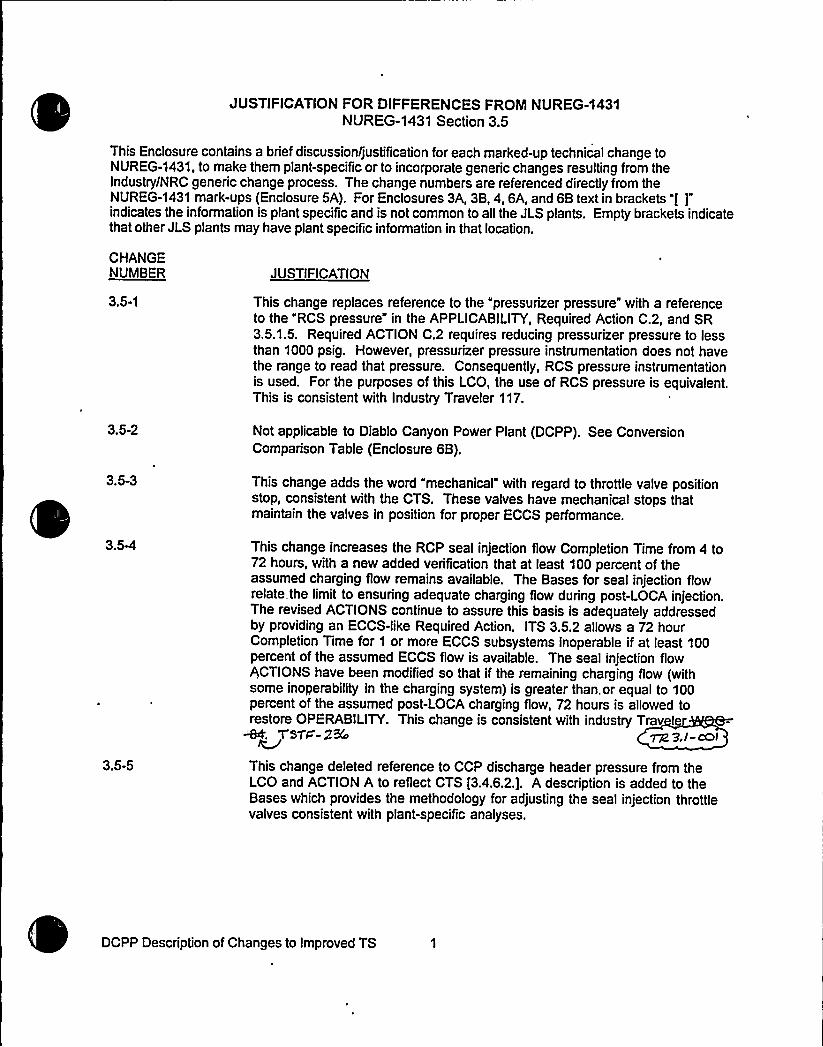
JUSTIFICATION FOR DIFFERENCES FROM NUREG-1431NUREG-1431 Section 3.5
This Enclosure contains a brief discussionfjustification for each marked-up technical change toNUREG-1431. to make them plant-specific or to incorporate generic changes resulting from theIndustry/NRC generic change process. The change numbers are referenced directly from theNUREG-1431 mark-ups (Enclosure 5A). For Enclosures 3A, 3B, 4, 6A, and 6B text in brackets "f ]"indicates the information is plant specific and is not common to all the JLS plants. Empty brackets indicatethat other JLS plants may have plant specific information in that location.
CHANGENUMBER JUSTIFICATION
3.5-1 This change replaces reference to the "pressurizer pressure" with a referenceto the "RCS pressure" in the APPLICABILITY,Required Action C.2, and SR3.5.1.5. Required ACTION C.2 requires reducing pressurizer pressure to lessthan 1000 psig. However, pressurizer pressure instrumentation does not havethe range to read that pressure. Consequently, RCS pressure instrumentationis used. For the purposes of this LCO, the use of RCS pressure is equivalent.This is consistent with Industry Traveler 117.
3.5-2 Not applicable to Diablo Canyon Power Plant (DCPP). See ConversionComparison Table (Enclosure 6B).
3.5-3 This change adds the word "mechanical" with regard to throttle valve positionstop, consistent with the CTS. These valves have mechanical stops thatmaintain the valves in position for proper ECCS performance.
3.S4
3.5-5
This change increases the RCP seal injection flow Completion Time from 4 to72 hours, with a new added verification that at least 100 percent of theassumed charging flow remains available. The Bases for seal injection flowrelate the limit to ensuring adequate charging flow during post-LOCA injection.The revised ACTIONS continue to assure this basis is adequately addressedby providing an ECCS-like Required Action. ITS 3.5.2 allows a 72 hourCompletion Time for 1 or more ECCS subsystems inoperable if at least 100percent of the assumed ECCS flow is available. The seal injection flowACTIONS have been modified so that if the remaining charging fiow (withsome inoperability in the charging system) is greater than. or equal to 100percent of the assumed post-LOCA charging flow, 72 hours is allowed torestore OPERABILITY. This change is consistent with industry Trav I
T'sT'i=- 2Ro ~ 3,/-cOI
This change deleted reference to CCP discharge header pressure from theLCO and ACTION A to reflect CTS [3.4.6.2.]. A description is added to theBases which provides the methodology for adjusting the seal injection throttlevalves consistent with plant-specific analyses.
DCPP Description of Changes to Improved TS


Enclosure 2PG8 E Letter DCL 98-107
JLS CONVERSION TO IMPROVED TECHNICALSPECIFICATIONS
CTS 3/4.9 -REFUELING OPERATIONSITS 3.9 - REFUELING OPERATIONS
RESPONSE TO REQUEST FOR ADDITIONALINFORMATIONAND LICENSEE INITIATEDADDITIONALCHANGES


Enclosure 2PG8E Letter DCL 98-107
INDEX OF ADDITIONALINFORNIATION
ADDITIONALINFORMATIONNUMBER
APPLICABILITY ENCLOSED
3.9.G-1
3.9-i3.9-1a3.9-1b3.9-23.9-33.9-43.9-53.9-63.9-73.9-83.9-93.9-103.9-113.9-123.9-133.9-143.9-153.9-163.9-173.9-183.9-193.9-203.9-213.9-223.9-233.9-243.9-25
CP 3.9-001CP 3.9-002CP 3.9-003CP 3.9-004
DC, CP, WC, CA
DC, CP, WC, CADC, CP, WC, CACACPCP, WC, CADC, CP, WC, CADC, CP, WC, CACADC, CP, WC, CADC, CP, WC, CADC, CPDC, CPDC, CPDC, CP, WC, CADC, CP, WCDC, WC, CADC, WC, CADC, WC, CADC, CPDC, CPCAWCDC, CP, WC, CADC, CP, WC, CADC, CP, WC, CADC, CP, WC, CADC
CPCPCPCP
YES
YESYESNANANAYESYESNAYESYESYESYESYESYESYESYESYESYESYESYESNANAYESYESYESYESYES
NANANANA
DC 3.9-EDDC ALL-001 (3.9 changes only)DC ALL-003 (3.9 changes only)
TR 3.9-001TR 3.9-002TR 3.9-003
DCDCDC
DC, CP, WC, CADC, CP, WC, CADC
YESsee DCL-98-003YES
YESYESYES


Enclosure 2PG8E Letter DCL 98-107
INDEX OF ADDITIONALINFORINATION(cont.)
WC 3.9-EDWC 3.9-001WC 3.9-002WC 3.9-003WC 3.9-004WC 3.9-006
WCWCWCWCWCCP, WC
NANANANANANA


Enclosure 2PGRE Letter DCL 98-107
JOINT LICENSING SUBCOMMITTEE METHODOLOGYFORPROVIDING ADDITIONALINFORMATION
The following methodology is followed for submitting additional information:
1. Each licensee is submitting a separate response for each section.
2. Ifan RAI does not apply to a licensee (i.e., does not actually impact the information thatdefines the technical specification change for that licensee), "NA"has been entered inthe index column labeled "ENCLOSED" and no information is provided in the responsefor that licensee.
3. Ifa licensee initiated change does not apply, "NA"has been entered in the index columnlabeled "ENCLOSED" and no information is provided in the response for that licensee.
4. The common portions of the "Additional Information Cover Sheets" are identical, exceptfor brackets, where applicable (using the same methodology used in enclosures 3A,38, 4, 6A and 68 of the conversion submittals). The list of attached pages willvary tomatch the licensee specific conversion submittals. A licensee's FLOG response maynot address all applicable plants ifthere is insufficient similarity in the plant specificresponses to justify their inclusion in each submittal. In those cases, the response willbe prefaced with a heading such as "PLANTSPECIFIC DISCUSSION."
5. Changes are indicated using the redline/strikeout tool of WordPerfect or by using a handmarkup that indicates insertions and deletions. If the area being revised is not clear, theaffected portion of the page is circled. The markup techniques vary as necessary,based on the specifics of the area being changed and the complexity of the changes, toprovide the clearest possible indication of the changes.
6. A marginal note (the Additional Information Number from the index) is added in the rightmargin of each page being changed, adjacent to the area being changed, to identify thesource of each change.
7. Some changes are not applicable to one licensee but still require changes to the Tablesprovided in Enclosures 3A, 38, 4, 6A, and 68 of the original license amendment requestto reflect the changes being made by one or more of the other licensees. Thesechanges are not included in the additional information for the licensee to which thechange does not apply, as the changes are only for consistency, do not technicallyaffect the request for that licensee, and are being provided in the additional informationbeing provided by the licensees for which the change is applicable. The complete set ofchanges for the license amendment request will be provided in a licensing amendmentrequest supplement to be provided later.


Enclosure 2PG8 E Letter DCL 98-107
JOINT LICENSING SuBCOMMITTEE METHODOLOGYFORPROVIDING ADDITIONALINFORMATION
(cont)
8. The item numbers are formatted as follows:
[Source] [ITS Section]-[nnn]
Source = Q - NRC QuestionCA - AmerenUEDC-PG8EWC - WCNOCCP - TU ElectricTR - Traveler
ITS Section = The ITS section associated with the item (e.g., 3.3). Ifall sections arepotentially impacted by a broad change or set of changes, "ALL"is used for thesection number.
nnn = a three digit sequential number


Enclosure 2PG8E Letter DCL 98-107
ADDITIONALINFORINATIONCOVER SHEET
ADDITIONALINFORINATIONNO: Q3.9.G-1
REQUEST:ITS 3.9.x Bases
APPLICABILITY:CA, CP, DC, WC
General
There have been a number of instances that the specific changes to the STSBases are not properly identified with redline or strikeout marks.
Comment: Perform an audit of all STS Bases markups and identify instances whereadditions and/or deletions of Bases were not properly identified in the original submittal.
FLOG response: T he submitted ITS Bases markups for Section 3.9 have been compared tothe STS Bases. Some differences that were identified were in accordance with the markupmethodologies (e.g., deletion of brackets and reviewer's notes). Most of the differences wereeditorial in nature and would not have affected the review. Examples of editorial changes are:
2)3)
4)
5)
6)
7)
Capitalizing a letter with only a "redline" but not striking out the lower case letter that itreplaced.Changing a verb from singular to plural by adding an "s" without "redlining" the "s."Deleting instead of striking-out the A, B, C, etc., following a specification title (e.g.,SR3.6.6A.7).Changing a bracketed reference (in the reference section) with only a "redline" for thenew reference but failing to include the strike-out of the old reference.In some instances, the brackets were retained (and struck-out) but the unchanged textwithin the brackets was not redlined.Not redlining a title of a bracketed section. The methodology calls for the section titleto be redlined when an entire section was bracketed.Additional text not contained in the STS Bases was added to the ITS Bases by thelead FLOG member during the development of the submittal. Once it was determinedto not be applicable, the text was then struck-out and remains in the ITS Bases mark-up.
Differences of the above editorial nature will not be provided as attachments to this response.The pages requiring changes that are more than editorial and are not consistent with themarkup methodology are attached.
ATTACHED PAGES:
Encl. 5B B 3.9-1, B 3.9-11, B 3.9-17, B 3.9-18NUREG-1431, Rev. 1 B 3.9-5 to B 3.9-7

0

sivtaV.moat Boron Concentration3.9.1
B 3.9 REFUELING OPERATIONS
B 3.9. 1 Boron Concentration
BASES
BACKGROUNDGAQ voh~ cot%\ c i gp'i
T limit on the boron concentrations of the Rea ystem (RCS)Ft e refueling canal. and the refueling cavity during refueling ensures thatt reactor remains subcritical during MODE 6. Refueling boronco centration is the soluble boron concentration in the coolant in each ofth e volumes having direct access to the reactor core during refueling.
The oluble boron concentration offsets the core reactivity and is measuredhy ch mical analysis of a representative sample of the coolant in each of Ctig,q,is-lthe v 1 es. The refuelin boron concentration limit is s e ifiCOLR. he refueling boron concentration ss su iclent to maintain shutdownmargin (SDM) with the most adverse conditions of fuel assembly and control
g ~'od position allowed by plant procedures. The boron concentration that is
rgaintained in Mode 6 is sufficient to maintain k„, ~ 0.95 with the mostreactive rod control assembly completely removed from its fuel assembly.
GDC 26 of 10 CFR 50. Appendix A. requires that two independent reactivitycontrol systems of different design principles be provided (Ref. 1). Oneof these systems must be capable of holding the reactor core subcriticalunder cold conditions. The Chemical and Volume Control System (CVCS) isthe. principle system capable of maintaining the reactor subcritical in coldconditions 'by maintaining the boron concentration.
The reactor is brought to shutdown conditions before beginning operationsto open the reactor vessel for refueling. After the RCS is cooled anddepressurized and the vessel head is unbolted, the head is slowly removedto form the refueling cavity. The refueling canal and the refueling cavityare then flooded with 'refu'elf'.,-,gr'ade~iborated water from the:1'iquid hold:uptanks =:or,'.the'nrefuel ing'ater'torage'tank
C
The pumping action of the RHR System in the RCS and the natural circulationdue to thermal driving heads in the reactor vessel and refueling cavity mixthe added concentrated boric acid with the water in the refueling canal.The RHR System is in operation during refueling (see LCO 3.9.5. "ResidualHeat, Removal (RHR) and Coolant Circulation —High Water Level." andLCO 3.9.6. "Residual Heat Removal (RHR) and Coolant Circulation —Low WaterLevel" ) to provide forced circulation cooling in the RCS and assist inmaintaining the boron concentrations uniformity .in the RCS. the refuelingcanal. and the refueling cavity above the 'COLR 'limit.
(Continued)

0

BASES
Containment penetrati onsB 3.9.4
L.+
SURVEILLANCEREQUIREHENTS
(continued)
performed. The system actuation response time is demons ated every18 months. during refueling'n a STAGGERED TEST BASIS. SR 3.6.3.5demonstrates that the isolation time of each valve is - )i QZ ~ ~-)accordance with the In service Testing Program requirements. TheseSurvei llances performed during HOOE 6 will ensure that the valves arecapable of closing after a postulated fuel handling accident to limita release of fission product radioactivity from the containment.
REFERENCES
D,iii,,C!t,i"ii!!'"',"I""!T,,—,',!6!!C," !',,!':F,,!!Z. FSAR. Section ~IS.''4.'";GQ.
Wb, A% C Ohio!A
3. NUREG-0800. Section 15.7.4, Rev. 1. July 1981.
Hark-up of NUREG-1431. Rev. 1 Bases 8 3.9-11

0

BASES
RHR and Coolant Circulation —Low Water Level4n op.~ob~t R'AQ Loap ~<~A M ca~i5g af be,icy rm$ [gned
path.and to determine the low end temperature. The flow path startsin one of the RCS hot le s and is returned to the RCS cold le s.
QK~.~-~ ~(„~m rws~g-s
APPLICABILITY
TR 3i i 00)Two RHR loops are required to be OPERABLE, and one RHR loop must be inoperation in NODE 6 ~ with the water level < 23 ft above the top of thereactor vessel flange, to provide decay heat removal. Requirementsfor the RHR System in other NODES are covered by LCOs in Section 3.4.Reactor Coolant System (RCS), and Section 3.5, Emergency Core CoolingSystems (ECCS). RHR loop requirements in MODE 6 with the water level~ 23 ft are located in LCO 3.9.5, "Residual Heat Removal (RHR) andCoolant Circulation - High Water Level." p':,'Hote'gis'jadded.:,:t'o':!the'appf~lei5'fjl 3'i;jRo.::assisi,':e;:;;that:.:.''.NMF.,::;,:6~ipei'.itionjw'iti.s'::::not;:.'peA'iiitte'd vuv'n'1'e'ss::,,'two,';.".RHR'-,'.-.:l,ooos(a'r'Km'er,.abler>AÃvCvwwvw4w'wvKh8'vitriwvwXw~Qwv~w'w~W'w'w'.vpWw'7rAdwAv.'8 vow'VwVwwv AY.
ACTIONS A,l and A.2
If less than the required number of RHR loops are OPERABLE ~ actionshall be immediately initiated and continued until the RHR loop isrestored to OPERABLE status and to operation or until ~ 23 ft of waterlevel is established above the reactor vessel flange. When the waterlevel is ~ 23 ft above the reactor vessel flange, the Applicabilitychanges to that of LCO 3.9.5 ~ and only one RHR loop is required to beOPERABLE and in operation. An immediate Completion Time is necessaryfor an operator to initiate corrective actions.
B.l
If no RHR loop is in operations there will be no forced circulation toprovide mixing to establish uniform boron concentrations. -Reduced
~ TM ~pM<io~ cR any opga5i~'w'vo>vinq o. c.gh~son in ~Woe'onc 4 Koran C~enkcxhim xiii recta~B.2 i'iggvs~ood o$ ~gn 94eaAAicchian i~ ~ g<g,
If no RHR loop is in operation, actions shall be initiatedimmediately, and continued, to restore one RHR loop to operation.Since the unit is in Conditions A and B concurrently. the restorationof two OPERABLE RHR loops and one operating RHR loop should beaccomplished expeditiously.
B.3
If no RHR loop is in operation. all containment penetrations providingdirect access from the containment atmosphere to the outsideatmosphere must be closed within 4 hours. With the RHR loop
(Continued)
Nark-up of NUREG-1431. Rev. 1 Bases B 3.9-17

0


WOG STS B 3.9-5 Rev 1, 04/07/95


Unborated Water Source Isolation ValvesB 3.9.2
BASES (continued)
WOG STS B 3.9-6 Rev 1, 04I07I95

0
0

Unborated Water Source Isolation ValvesB 3.9.2
BASES
WOG STS B 3.9-7 Rev I, 04/07/95

0

Enclosure 2PG8 E Letter DCL 98-107
ADDITIONALINFORMATIONCOVER SHEET
ADDITIONALINFORMATIONNO: Q 3.9-i
REQUEST:General
APPLICABILITY: DC, CP, WC, CA
A great majority of the DOCs state that the reasons for the relocation and for theproposed changes including deletions, additions, and revisions, are made to beconsistent with NUREG-1431. While this is a valid statement, additional justificationsare still required in order to support the proposed relocations and the CTS changes.The DOCs should be expanded to include additional justifications for the relocationand/or changes.
Comment: Revise those DOCS which do not provide technical justifications for theproposed relocations and changes, and indicate which DOCs are being revised underthis comment.
FLOG RESPONSE: The statement that the changes are made to be consistent with NUREG-1431 in a number of the DOCs was not intended to be a justification for the proposed changebut an indication that changes were being made to make the Technical Specifications similar toNUREG-1431. The DOCs were developed (specifically the Less Restrictive DOCs) with theintent that the No Significant Hazards Consideration would contain more detail justifying thechange. The conversion license amendment application was developed using as a guide theVogtle application for determining the level of detail needed for the DOCs. During thedevelopment of the conversion license amendment application in late 1996, several issues wereidentified with impact on the conversion process including "literal compliance," Generic Letter96-01, and feedback from NRC concerning the acceptability of the submittals made by someother licensees. On January 24, 1997, senior managers from the FLOG met with the NRC (theTechnical Specification Branch and Project Management) to discuss these and other issues.The utilities took additional time to review the conversion license amendment application tomake sure that these issues were being properly addressed.
On June 25, 1998, a discussion was held with the NRC staff, in which it was believed thatcomments provided in Section 3.9 addressed those DOCs and JFDs that required additionaljustification. The FLOG has agreed to revise those DOCs, as identified by the NRC, by eitherbringing forward information from the No Significant Hazards Consideration (Enclosure 4) orproviding additional justification as requested. No additional DOCs or JFDs have been revisedunless indicated in the response to a specific Comment Number.
ATTACHEDPAGES'one

0

Enclosure 2PG8 E Letter DCL 98-1 07
ADDITIONALINFORMATIONCOVER SHEET
ADDITIONALINFORMATIONNO: Q 3.9-1
REQUEST:CTS 3.9.1DOC 1-01-AITS 3.9.1, LCO 3.9.1JFD 3.9-15
APPLICABILITY: DC, CP, WC, CA
a. (Comanche Peak, Callaway, and WolfCreek)
The CTS and ITS are proposed to be revised by adding "when connected" preceding"Reactor Coolant System." The DOC provides a generic explanation, but it does notprovide any specific technical justification for this addition. This revision is consideredan administrative enhancement and a generic change to the ITS. Therefore, it must bereviewed and approved via the TSTF process before it may be adopted as the standardITS language. Furthermore, Diablo Canyon does not include the proposed addition,"when connected,'n its CTS markup.
Comment: Either remove this item from the submittal and adopt the ITS language, orsubmit a TSTF for this generic change. Also, provide explanation why Diablo Canyon isnot adopting the proposed language, "when connected."
FLOG Response: The proposed changes to CTS 3.9.1 and ITS 3.9.1 were based on travelerWOG-103, Revision 1. WOG-103, Revision 1, has recently been designated TSTF-272 andtransmitted to the NRC in May 1998. The proposed wording in TSTF-272 was modified fromWOG-103, Revision 1, and these modifications have been incorporated into the ITS and ITSBases.
During preparation of the conversion license amendment request, WOG-103, Revision 1, wasinadvertently omitted by Diablo Canyon. Diablo Canyon will incorporate TSTF-272 into the ITSand ITS Bases.
ATTACHEDPAGES'ncl.
2Encl. 3AEncl. 3BEncl. 5AEncl. 5BEncl. 6AEncl. 6B
3/4 9-11
1
Traveler Status page, 3.9-1B 3.9-1, B 3.9-2, B 3.9-322


3/4.9 REFUELING OPERATIONS
3/4.9. 1 BORON CONCENTRATION
LIMITING CONDITION FOR OPERATION
ganne 4.d Ot t iong Q S.'I-)o3.9. 1 The b on oncen r n 'fthe Reactor CoolanSystem -'he refueling canals.::,:;.-:;and',:-'.-.:thi~~re'fuel'1ng;.":cavi'ty shall be maintained
:..;::rrr'thrn'lithe;Bimini'i;spec$teed,-;rn,":,th':.C LR:;=':!
ED
01-01-A
01-02-LG
01-04-LG
01-02-LG
APPLICABILITY: NODE %.
ACTION:
With the requirements of the above specification not satisfied.immediately suspend all operations involving CORE ALTERATIONS orpositive reactivity changes and initiate
01-05-A
01-06-LS1
1',if'.ts.jecti'oMns oft'enter eÃ5ocon~corrcentcet>on":tea~A>t'n
SURVEILLANCE REQUIREMENTS
01-09-LS2
4.9. 1.2 The boron concentration of the Reactor Coolant System and the refuelingcanal 'and the";:refuel'ing',"cavity shall be determined ti.::::beH'fthin,'the',. limit.';:;spen''f(ed:.".::;>i:::,the:-:;:COL'R at least once each pig 72 hours.
'"=""01-10-LG
01-02-LG
01-05-A
DIABLO CANYON - UNITS 1 & 2TS39.4A
3/4 9-1 Amendment Nos. 72 & 71August 6, 1992

0

DESCRIPTION OF CHANGES TO TS SECTION 3/4.9
This Enclosure contains a brief description/justification for each marked-up change to existing current plantTechnical Specifications (CTS). The changes are keyed to those identified in Enclosure 2 (mark-up of the CTS).The referenced No Significant Hazards Considerations (NSHC) are contained in Enclosure 4. AIIproposedtechnical changes to the CTS are discussed below; however, some administrative changes (i.e., format,presentation, and editorial changes made to conform to the Improved Technical Specifications (ITS)) may not bediscussed. For Enclosures 3A, 3B, 4, 6A, and 6B, text in brackets "[]"indicates the information is specific and isnot common to all the Joint Licensing Subcommittee (JLS) Plants. Empty brackets indicate that other JLS plants
CHANGENUMBER
lac~ >~ 'g5 fYQdr r0&o -Q. l-
t e i e po onoftherefuelingcavitytotheloca onsinwhichthe boron concentration must be maintained and specifies that theconcentration must be maintained in locations connected to the RCS.
01-01
may have plant specific information in that location. Tgr„~ ~s ow s equi ~'i+ Cx rr pa~iceMCu,r('e,nh CS ~i~~~~,~y Mm r o tecbieai:>&1jOOI,+i Ck Q, '>s4cer. re<.NSHC DE TIO
A
01-02
01-03
01-04
01-05
LG
LG
LG
Specifies that the required limits for the boron concentration willbemoved to the Core Operating Limits Report, in accordance withNUREG-1431. This change removes details that are not required tobe in the TS to protect the health and safety of the public whileretaining the basic limiting conditions for operation.
Not applicable to Diablo Canyon Power Plant (DCPP). SeeConversion Comparison Table (Enclosure 3B).
The specified limiton k s 0.95 is moved to the Bases; however, thelimit is effectively maintained by the requirement to keep boronconcentration within limits which remains in the LCO. As noted in1-02-LG above, the boron concentration limitwillbe maintained in theCOLR. This change removes details that are not required to be inthe TS to protect the health and safety of the public while retainingthe basic limiting conditions for operation.
The footnote defining the "REFUELING"condition is not necessarybecause it duplicates the definition of MODE 6 in ITS Table 1.1-1.This change does not result in a change to technical requirementsand is consistent with NUREG-1431.
01-06
01-07
LS1 The requirements to initiate boration at a specified flow rate having aspecified boron concentration is replaced by the more generalrequirement to initiate boration to restore the required boron .
concentration. The reactor operators are expected to select the bestmethod of increasing the boron concentration to the required valuespecified in the COLR. The proposed change clarifies that action isapplicable only to restoring boron concentration to within limit. Thischange is acceptable because it is an example of removingprocedural details while maintaining the actual limiting condition as aTS requirement.
Not applicable to DCPP. See Conversion Comparison Table(Enclosure 3B).
01-08 Not applicable to DCPP. See Conversion Comparison Table(Enclosure 3B).

0

CONVERSION COMPARISO LE - CURRENT TS 3/4.9
TECH SPEC CHANGE APPLICABILITY
NUMBER
01-01A
01-02LG
01-03LG
01-04LG
01-05A
01-06LS1
01-07M
01-08M
DESCRIPTION
Adds the filled portion of the refueling cavity to thelocations in which the b ron concentration must bemaintained. a epee >eS Mcon~eht
Specifies that the required limits for the boronconcentration willbe in the Core Operating LimitsReport (COLR). In addition, the provision to maintaina uniform concentration Is discussed in the ITSBases.
Instead of providing the tag numbers of the valvesused to isolate unborated water sources, the functionof the valves is used. The valve tag numbers aremoved to the Bases.
The specified limiton k~ ~ 0.95 is moved to theBases.
The footnote defining the "REFUELING"condition isnot necessary because it duplicates the definition ofMODE 6.
The requirements to initiate boration at a specifiedflow rate having a specified boron concentration isreplaced by the more general requirement to initiateboration to restore the required boron concentration.Additionally, the ACTION statement is revised toclarify that action is applicable only to boronconcentration.
A new ACTION statement is incorporated thatspecifies the appropriate activities ifthe isolationvalves for unborated water sources are not securedin the closed position.
Separate entry into the ACTION is allowed for eachunborated water source isolation valve.
DIABLOCANYON
Yes
MuS h4,~%~ OA
Yes
No, CurrentTechnicalSpecifications(CTS) based uponlicensed dilutionaccident.
Yes
Yes
Yes
No, CTS basedupon LicensedDilution Accident.
No, CTS basedupon LicensedDilution Accident.
COMANCHEPEAK
Yes
sA b (b~ Cbtlri
Yes
Yes
Yes
No, not in CTS
Yes
No
Yes
WOLF CREEK
Yes
Yes
g5 ~iritQjphAgva4e niA.~bee'sin CT5.
Yes
Yes
Yes
Yes
Yes
CALLAWAY
Yes
Yes
No, Maintainingvalve numbers inCTS
we 5q-oo~
Yes
Yes
Yes
Yes
Yes
DCPP Conversion Comparison Table - Current TS

0

TRAVELER¹ STATUS DIFFERENCE ¹
Industry Travelers Applicable to Section 3.9 ~Z.o<cd ~ VeC.
COMMENTS
TSTF-20
TSTF-21 Rev. 1
TSTF-22
TSTF-23, Rev. 2
Aek/ 5
TSTF-51
TSTF<6, P.e.w. <
TSTF-92, R~
Incorporated
IncorporatedIkiot
Not incorporated
Incorporated
Not incorporated
Not incorporated
Not incorporated
3.9-2
None
N/A
3.9-3
Appecgeh '~ NR,4.
N/A
N/A
N/A
oved'~('ngem
e o3.9.6 ct- ho l
Changes not applicablfor the specific plantapplication.
reveler racketed IT3.9.2 and revised th
es r TS3.9.3 +RE ~x(DCPP maintaining CTS).
Minimal impact on plantspecific applications.
Similar changes wereincorporated into the ITSbased on currentlicensing basis. Seechange description 3.9-1.(Not Appl to DCPP)
The proposed changesdid not significantly affectcurrent surveillancepractices to warrantinclusion.
TSTF-96, Re@. 5
OGW3
Incorporated 3.9P App~a S wee. > "m
WOG-76
7B'g -ISIo'TQTF - I'bR
TS~ 6vG TF' 272.
Incorporated
Induc
~~Min~~o~~h(nc rp m-'ed
I rkcb~rehed
3.9-11
lkI/A
Nits,
H/A+.9- I5
Containment penetrationsallowed to be open underadministrative control.
A~~a~ b„gWg
Q S.c(-I a.
~~ ER-oo2.EcVikkkr'k<6. chang. 4c 3.9 5~ hQQe~ q
rikQ~~ SR.~ movCknc .

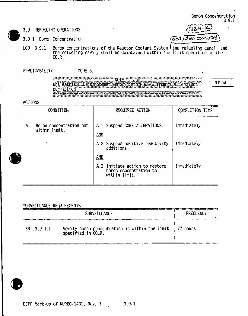
Boron Concentration3.9.1
3.9 REFUELING OPERATIONS
3.9. 1 Boron Concentration
LCO 3.9. 1 Boron concentrationsthe refueling cavityCOLR.
~~, Men COn~~<
of the Reactor Coolant System. the refueling canal. andshall be maintained within the limit specified in the
APPLICABILITY: MODE 6.)hvphv V.'.hrvr )Whl'lphrhvrlivhlirQVhh%+)Qhv igVhiii'g+rrvri)h'r.)II.)i'rg~ih rag(gPhV(lphi . 'llVrhlIvhW*Wi+girlvhvvvp+Vppg (igggvhVglwlVrhvpVir
rrmtte-: '"" "" "" *
h .I .)g~)y l ivhigvhiw+ v.ghlg+Avr)vrih(pig Iwr{/hiiihvf ~ivrrh~p iiwhi@~iwg Ivhiwrvrhhv(,iillh)v v whvvAv 'rr lv lvrvI
CMihar, irriwi."iwviNlvlriÃv5iwihh4Slrhvhv'hh ih'h& 'INK%VN iiirrAhvhhhvwlvihv&NrNkiihv&rArr ri'rrih'ikvC4V'AIZiiwrii'W'ANrr%M".irhhiiih<
ACTIONS
3.9-14
CONDITION REQUIRED ACTION COMPLETION TIME
A. Boron concentration notwithin limit.
A.1 Suspend CORE Al TERATIONS.
AND
Imedi ately
A.2 Suspend positive reactivityadditions.
AND
A.3 Initiate action to restoreboron concentration towithin limit.
Iamediately
Immediately
SURVEILLANCE REQUIREMENTS
SURVEILLANCE FREQUENCY
SR 3.9.1.1 Verify boron concentration is within the limitspecified in COLR.
72 hours
DCPP Mark-up of NUREG-1431, Rev. 1 3.9-1

0

Boron Concentration3. i. 1
8 3.9 REFUELING OPERATIONS
B 3.9. 1 Boron Concentration
BASES
BACKGROUNDGad wher C,om ) gg.q-I
T limit on the boron concentrations of the Rea ystem (RCS)l'.t e refueling canal. and the refueling cavity during refueling ensures thatt reactor remains subcritical during NODE 6. Refueling boronco centration is the soluble boron concentration in the coolant in each ofth e volumes having direct access to the reactor core during refueling.
The oluble boron concentration offsets the core reactivity and is measuredby ch mical analysis of a representative sample of the coolant in each of @ yq,Ia-lthe v 1 es. The refuelin boron concentration limit is s e ifCOI R. he refueling boron concentration is su icient to maintain shutdownmargin (SDN) with the most adverse conditions of fuel assembly and control
g > ~' rod position allowed by plant procedures. The boron concentration that is
maintained in Mode 6 is sufficient to maintain k„, ~ 0.95 with the most~. reactive rod control assembly completely removed from its fuel assembly.
GDC 26 of 10 CFR 50. Appendix A. requires that two independent reactivitycontrol systems of different design principles be provided (Ref. 1). Oneof these systems must be capable of holding the reactor core subcriticalunder cold conditions. The Chemical and Volume Control System (CVCS) isthe..p in*cijle system capable of maintaining the reactor subcritical in coldconditio'ns by maintaining the boron concentration.
The reactor is brought to shutdown conditions before beginning operationsto open the reactor vessel for refueling. After the RCS is cooled anddepressurized and the vessel head is unbolted, the head is slowly removedto form the refueling cavity. The refueling canal and the refueling cavityare then flooded with refuel~fng,"„'gr'ade'.borated water from the:l',iquid hoId*uptanks:or.;,the':refueling water storage'ank
'a 4 A' 4
The pumping action of the RHR System in the RCS and the natural circulationdue to thermal driving heads in the reactor vessel and refueling cavity mixthe added concentrated boric acid with the water in the refueling canal.The RHR System is in operation during refueling (see LCO 3.9.5. "ResidualHeat Removal (RHR) and Coolant Circulation —High Water Level." andLCO 3.9 .6. "Residual Heat, Removal (RHR) and Coolant Circulation —Low MaterLevel" ) to provide forced circulation cooling:in the RCS and assist inmaintaining the boron concentrations uniformity;:in the RCS. the refuelingcanal. and the refueling cavity above the COL'R'limit.
(Continued)
8 3.9-1

0
0
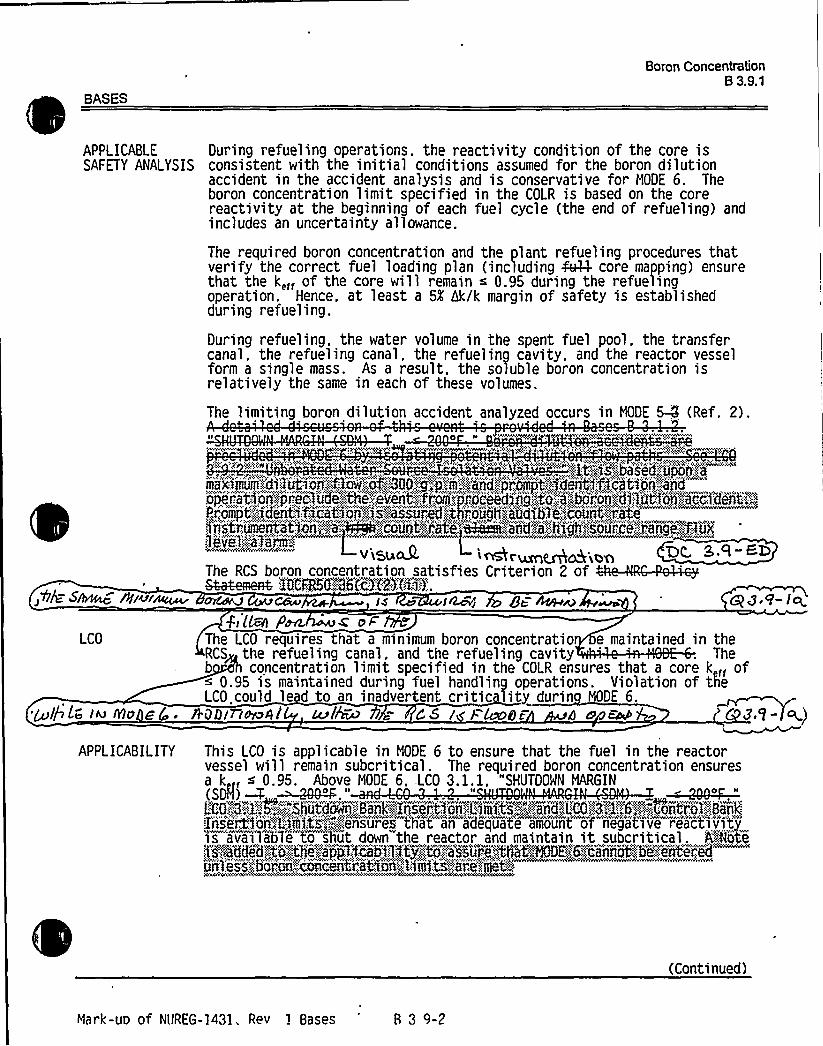
BASES
Boron Concentration8 3.9.1
APPLICABI E
SAFETY ANALYSIS
~O/E S~ 8Si~r~
During refueling operations. the reactivity condition of the core isconsistent with the initial conditions assumed for the boron dilutionaccident in the accident analysis and is conservative for NODE 6. Theboron concentration limit specified in the COLR is based on the corereactivity at the beginning of each fuel cycle (the end of refueling) andincludes an uncertainty allowance.
The required boron concentration and the plant refueling procedures thatverify the correct fuel loading plan (including ~ core mapping) ensurethat the k,« of the core will remain ~ 0.95 during the refuelingoperation. Hence. at least a 5K hk/k margin of safety is establishedduring refueling.
During refueling. the water volume in the spent fuel pool, the transfercanal, the refueling canal, the refueling cavity, and the reactor vesselform a single mass. As a result, the soluble boron concentration isrelatively the same in each of these volumes.
wwwv<CRW vy yfv w<<w<www!, 'wSRRWy v<f, w t« ~. v .. Ry«~e< w' VW.Wy~v2 . ~: '<',<e 2 'v "< " !2: I<';.y:.V 've . ". ~;..>g.'+<<..mwg w,
"y ny'Rr<ec" ", 'O ''i++g'y&RRyi'Vnywe <e ' ''e<,',OS<<wc'" t " RN Qjf'<:.t v ';. 2"OVnei" ': VOY"'n~n'»: yVVCy!ARRCVN<
'.,:;:;:it~::is'..'.::oa sea;."..iij~ii'.;:i.
'o'cneret:,j'o'n"';,.'jrecio iid'e'--,,."thp''eyenft,";::.,
,jfroept:;:i!dventlf!CetoOII;,,'I<ey!OSSored<tj!r'onglTI! eTod'fdic,,GOROCI!t<iretedlitleuriiieiite'1tous e Ijejeje COI!nctSrect!eil8iii~i:..'Odniii!'li1jj!';.SoiirC<e:::"renge:,::::t ug
i-ORsuak I- Mr 'erIIIG<;ooTR RCRR...,, ",2,, ff2 Cf 2 2 TRV<RCTWVS~~~ L'ONNO-.:36'(c'):('2)4~35.
ca <8'7- I
The limiting boron dilution accident analyzed occurs in NODE 5-Q (Ref. 2).
z>s'CO
The LCO requires that a minimum boron concentratio e maintained in theRCS the refueling canal, and the refueling cavity Theb concentration limit specified in the COLR ensures that a core k « of~ 0.95 is maintained during fuel handling operations. Violation of tIIeLCO could lead to an inadvertent critic lity durin NODE 6.
'+JQLtd lu Nu Eg ~ A.t)D/ IAO4/ LCPlhu7 C S I /. Lee)8F 8 N FAD Z9- w)
APPLICABILITY This LCO is applicable in NODE 6 to ensure that the fuel in the reactorvessel will remain subcritical. The required boron concentration ensuresa k ~ 0.95. Above MODE 6, .LCO 3.1. 1, "SHUTDOWN NARGIN
Z'riseit$ a'n,"Umicti,"'":;",:;v'!efenwsure'sv th'at an "adequa'te amaount" of'eg'ati"ve reactiy'i'ty'is alai"lable'o shut downwthe reactor and maintain it subcritical. 'A@Re
IIIIjess'2'jjcoron:":.OcodGentr'etdofvn''jc '1 eli te~cienef lled-.
(Continued)
Mark-uo of Nt/REG-1431, Rev 1 Bases 8 3 9-2

0
0

BASES
Boron ConcentrationB 3.9.1
ACTIONS A.1 and A.2 naia icp IWC o MMucivgp
SURVEILLANCEREQUIREHENTS
Continuation of CORE ALTERATIONS or positive re ctivity additions(including actions to reduce boron concentratio ) is contingent uponmaintaining the unit in compliance with the LCO If the boronconcentration of any coolant volume in the RCS. the refueling canal orthe refueling cavity is less than its limit., all operations involving COREALTERATIONS or positive reactivity additions must e suspendedimedi ately.
Suspension of CORE ALTERATIONS and positive reactivity additions shall notpreclude moving a component to a safe position.
A.3I
In addition to immediately suspending CORE ALTERATIONS or positivereactivity additions, boration to restore the concentration must beinitiated imnediately.
In determining the required combination of boration flow rate andconcentration, no unique Design Basis Event must be satisfied. The onlyrequirement is to restore the boron concentration to its required value assoon as possible. In order to raise the boron concentration as soon aspossible. the operator should begin boration with the best sourceavai lable for unit conditions.
Once actions have been initiated, they must be continued until the boronconcentration is restored. The restoration time depends on the amount ofboron that must be injected to reach the required concentration.
~ffFu Cgguu J.c,, hav ~Bi ~caz4 <wa p~~ wl(~SR 3.9,1.1 p,) ~ PerL ~s oP
.Ak F (LRl oAfl~ dP g 3 ~ 9-IcThis SR ensures that the coo an oron concentration in he RCS. therefueling canal. and the refueling cavity is within the COLR limits. Theboron concentration of the coolant in each volume is determinedperiodically by chemical analysis.
ga- QA4 I IRAQ
A minimum Frequency of once every 72 hours is a reasonable amount of timeto verify the boron concentration of representative samples. TheFrequency is based on operating experience, which has shown 72 hours to beadequate.
REFERENCES 1.10 CFR 50, Appendix A. GDC 26.
2.IMI ~5%!iivvn",ill'Bl'@HI",
i'1'8'4!"-,'ark-uo
of NUREG-1431. Rev 1 Bases B 3.9-3


JUSTIFICATION FOR DIFFERENCES FROM NUREG-1431
NUREG-1431 Section 3.9
CHANGENUMBER JUSTIFICATION
8 P.cI-Q3.9-10 Consistent wi the CTS, I 3.9.7 ApplicaSfity is be g revised to del " unng CORE
ALTERATI S, except ring latching d unlatc ng of control ro rive shafts." THeApplicab's being ised becaus is requir ment is duplicativ6 of a reiocatepfechnispecif tion requi ment for reactoi vessel wafer level during m6vement of coritlol rods(rel ted tech
'specificatiorf 3.9.10.2).,She relocated specification plac& a lower li
o e amount of water aboydthe top of the fuel assembjlds in the reactorp6ssel durinovemen f control rodsThe Bases {CTS 3/4.9.10)states that this ensures the wa r
remove 9% of the assured 10% iodine gap activi eleased from the rupture of airradi ed fuel assembly in the event of a fuel han ng accident(FHA). However, emo ement of control rods is not associated wi e initial conditions of a FHA, d the
see do notaddressanycortsemregardin 'dvertentcrittcaitttr whichcoci lead tonreach of the jdel rod
claddin'n~A~3.9-11 In accordance with a proposed traveler WOG-76, LCO is modified to permit a penetration
flow path that provides direct access from the containment to the outside atmosphere to beunisolated under administrative controls. The allowance to have containment flow pathswith direct access from the containment atmosphere to the outside atmosphere unisolatedunder administrative controls is based on confirmatory dose calculations of a fuel handlingaccident which indicate acceptable radiological consequences and to implementadministrative controls that ensure that the flowpenetrations will be promptly closedfollowing a fuel handling accident, to provide a defense-inMepth approach to meetacceptable dose consequences. The administrative control requirements are defined in theBases.
3.9-12
3.9-13
3.9-14
A note is added to the Applicabilityof LCO 3.9.6 indicating that entry into a MODE or otherspecified condition in the Applicability is not permitted while the LCO is not met. Theaddition of this note is based on the performance of a plant-specific LCO 3.0.4 matrix whichidentified where the requirements of 3.0.4 are still applicable in MODES 5 and 6 and inMODES 1, 2, 3, and 4 when the MODE is descending (i.e., from MODE 1 to MODE 2, etc.).This matrix was specified in the NUREG-1431 reviewer's note in LCO 3.0.4.
In accordance with DCPP CTS, LCO 3.9.2 would not be used. This new requirement is notapplicable to DCPP which has a licensed dilution accident. The current licensing bases inaccordance with NUREG 0800, Section 15.4.6 provides adequate assurance that a dilutionevent will recognized and arrested in a timely fashion
A Note is added to the Applicabilityof LCO 3.9.1 indicating that entry into MODE 6 fromMODE 5 is not permitted while the LCO is not met. The addition of this Note is based onthe performance of a plant-specific LCO 3.0.4 matrix which identified where therequirements of 3.0.4 are still applicable in MODES 5 and 6 and in MODES 1, 2, 3, and 4when the MODE is descending (i.e., from MODE 1 to MODE 2, etc.). This ma
'pecifiedin the NUREG-1431 reviewer's note in LCO 3.0.4. gypper'p Q3,7-2$
DCPP Description of Changes to Improved TS

0

Enclosure 6A Page 2Insert for Q 3.9-1a
JFD 3.9-15 LCO 3.9.1 has been revised in accordance with traveler TSTF-272 toclarify that boron concentration limits do not apply to the refueling[cavity and refueling canal] or other flooded areas when these areasare not connected to the RCS. This change is acceptable because theboron concentration limit is intended to ensure that the reactor remainssubcritical in MODE 6. However, when areas containing boron solutionare isolated from the RCS, no potential for boron dilution exists.Therefore, there is no need to place a limit on boron concentration inthese areas when they are not connected to the RCS. This change isconsistent with the intent of the Specification, as described in theBases, and eliminates restrictions that have no effect on safety.

0

CONVERSION COMPARISON TABLEFOR Dl NCES FROM NUREG-1431, SECTION 3.9 Pag 2
TECH SPEC CHANGE APPLICABILITY
NUMBER DESCRIPTION DIABLOCANYON
COMANCHEPEAK
WOLF CREEK CALLAWAY
3.9-8
3.9-9
The Note of ITS 3.9.5 is expanded to incorporate CTSallowing the required RHR pump to be removed fromservice for less than or equal to 2 hours per 8 hours forleak testing of the RHR suction isolation valves.
The Surveillances of ITS 3.9.5 and 3.9.6 are modified toincorporate CTS of two RHR flow rates dependent uponthe number of hours the reactor has been subcritical.
Yes
Yes, See LAR88-01 dated4/21/88 andDCL 88-067
No, not In CTS No, not in CTS No, not in CTS
No, not in CTS No, not in CTS No, not in CTS
3.9-10 ITS 3.9.7 Applicabilityis being revised to delete "DuringCORE ALTERATIONS, except during latching andunlatching of control rod drive shafts."
I ator
Yes Yes Yes~eleeeted Yes~leeatad
89- %8
3.9-11
3.9-12
3.9-13
3.9-14
In accordance with traveler WOG-76, LCO is modified topermit a penetration flowpath that provides direct accessfrom the containment to the outside atmosphere to beunisolated under administrative controls.
A Note is added to the Applicabilityof LCO 3.9.6indicating that entry into a MODE or other specifiedcondition in the Applicabilityis not permitted while theLCO is not met.
In accordance with DCPP CTS, LCO 3.9.2 would not beUsed
A Note is added to the Applicabilityof LCO 3.9.1indicating that entry into MODE 6 from MODE 5 is notpermitted while the LCO is not met.
Yes
Yes
Yes
Yes
Yes
Yes
No
Yes
Yes
Yes
Yes
Yes
Yes
Yes
9.Q-I5 2nser p
DCPP Conversion Comparison Table - Improved TS

0
0

Insert for Q 3.9-1 a
Enclosure 6B
JFD 3.9-15
Page 2
LCO 3.9.1 has been revised to clarify that boron concentration limits donot apply to flooded areas that are not connected to the RCS.
Applicability:
DC YesCP YesWC YesCA Yes

0

Enclosure 2PG8E Letter DCL 98-107
ADDITIONALINFORMATIONCOVER SHEET
ADDITIONALINFORMATIONNO: Q 3.9-4 APPLICABILITY: DC, CP, WC, CA
REQUEST'TS4.9.2 b and c
CTS 4.9.2 b, c and Footnote * (Diablo Canyon)DOC 2-03-LS3
Surveillance requirements 4.9.2 b and c for Analog Channel Operational Test areproposed to be deleted in CTS to be consistent with NUREG-1431, Rev. 1. ITS doesnot include these requirements. DOC 2-03-LS3 discusses the reasons for deletion, butit does not address the associated impact in regard to plant operation and design basis,and whether these surveillances would be moved to plant procedures or relocated to theUFSAR.
Comment: Revise DOC to justify as to why this is acceptable based on licensing anddesign basis. Ifthese SRs should be relocated, identify the plant document thatincludes the CTS requirements.
FLOG RESPONSE: Additional information supporting this DOC is in NSHC LS-3 inEnclosure 4. As discussed with the NRC technical specification branch reviewers on June 25,1998, DOC 2-03-LS-3 is revised to include the following information:
"During REFUELING, the source range monitors provide visual [and audible] indication ofneutron count rate to plant operators. Core reactivity is maintained primarily by therequirements of ITS 3.9.1 []which assure that the boron concentration in refueling water iswithin limit and that dilution of the boron will [be identified promptly]. Thus, the neutronmonitoring channels provide further assurance that criticality will not occur. The proposeddeletion of ACOTs for these channels would be offset by the CHANNELCHECK andCHANNEL CALIBRATIONrequirements. The addition of a CHANNELCALIBRATIONto beperformed every 18 months provides assurance that the instruments can provide the visualindication. There are no alarms, interlocks, or trip setpoints associated with these channelsthat are required to be OPERABLE during MODE 6. In addition, in MODE 6 the sourcerange instruments provide no automatic actuation function used for mitigation of accidents,and they would have no effect on the outcome of an accident. Furthermore, themodification of SRs for these indicators does not imply that they will be unavailable whenrequired. The CHANNELCHECKS and CHANNELCALIBRATIONSR that remain in effectprovide the necessary assurance of OPERABILITY."
ATTACHED PAGES:
Encl 3AEncl 4
218, 19

0

DESCRIPTION OF CHANGES TO TS SECTION 3/4.9(Continued)
CHANGENUMBER NSHC DESCRIPTION
01-09 LS2 The SR to verify reactivity conditions is deleted, as it is generallydescriptive of the MODE 6 conditions, as defined in NUREG-1431 ~
and is addressed by SR 4.9.1.2. This change is acceptable becausethe boron concentration is required to be within limitprior to entry intoMODE 6 in accordance with the ApplicabilityNote for ITS 3.9.1.Thus, the deleted SR is redundant to other requirements that remainin TS.
01-10
01-11
LG
LS19
Moves the description in the SR to determine the boron concentrationby chemical analysis to the Bases. This change is consistent withNUREG-1431, and removes details that are not required to be in theTS to protect the health and safety of the public while retaining thebasic limiting conditions for operation.
Not applicable to DCPP. See Conversion Comparison Table(Enclosure 3B).
01-12
Of-I902-01
LG
ALS21
Not applicable to DCPP. See Conversion Comparison Table(Enclosure 3B). ere-ibNot applicable to DCPP. See Conversion Companson Table(Enclosure 3B).
i 02-02 The ACTION statement is revised to require that restoration of onemonitor is immediately initiated. This change adds a more stringentTS requirement which is appropriate and consistent withNUREG-1431.
02-03 LS3
LG
The ANALOGCHANNELOPERATIONALTEST (ACOT)requirements are deleted and a Channel Calibration is added, inaccordance with NUREG-1431. In Mode 6, the source rangemonitors are required for indication only and there are no precise setpoints associated with these instruments. In this capacity, the sourcerange instrumentation is typically used to read a relative change incount rate. The source range instrumentation is monitored forsignificant changes in count rate which are important to evaluate thechange in core status. Even the accepted convention definingcriticalityonly requires a slowly increasing count rate be verified.Consistent with NUREG-1431, indicating instruments only requirechannel checks and channel calibrations. The more frequent ACOTsare applied only to those channels with operational interlocks or otherset point actuations. Therefore, the MODE 6 channel checks andchannel calibration requirements for the source range monitors areadequate to assure their operability, considering the more frequentACOTs performed on this instrumentation in other Modes, theeffectiveness of these surveillance requirements in maintaining otherindicating instruments operable, and the accuracy required of theseinstruments in MODE 6.
Q $ Q~QConsistent with NUREG-1431, the requirements related to in icationprovided by the source range detectors would be moved to theBases.

0
0
Enclosure 3A
DOC 02-03-LS3
Page 2Insert for Q 3.9Q
During REFUELING, the source range monitors provide visual [andaudible] indication of neutron count rate to plant operators. Corereactivity is maintained primarily by the requirements of ITS 3.9.1 []which assure that the boron concentration in refueling water is withinlimit and that dilution of the boron will [be identified promptly]. Thus theneutron monitoring channels provide further assurance that criticalitywill not occur. The proposed deletion of ACOTs for these channelswould be offset by the CHANNELCHECK and CHANNELCALIBRATIONrequirements. The addition of a CHANNELCALIBRATIONto be performed every 18 months provides assurancethat the instruments can provide the visual indication. There are noalarms, interlocks, or trip setpoints associated with these channels thatare required to be OPERABLE during MODE 6. In addition, in MODE 6the source range instruments provide no automatic actuation functionused for mitigation of accidents, and they would have no effect on theoutcome of an accident. Furthermore, the modification of SRs for theseindicators does not imply that they will be unavailable when required.The CHANNEL CHECKS and CHANNELCALIBRATIONSR thatremain in effect provide the necessary assurance of OPERABILITY.

0

IV. SPECIFIC NO SIGNIFICANTHAZARDS CONSIDERATIONS
NSHC LS310CFR 50.92 EVALUATION
FORTECHNICALCHANGES THAT IMPOSE LESS RESTRICTIVE
REQUIREMENTS WITHINTHE TECHNICALSPECIFICATIONS
Consistent with NUREG-1431, the requirements of SR 4.9.2 b. and c. to perform ANALOGCHANNELOPERATIONALTESTS (ACOTs) would be deleted and a SR to perform a Channel Calibration is added, inaccordance with NUREG-1431. In MODE 6, the source range monitors are required for indication only and thereare no precise setpoints associated with these instruments. In this capacity, the source range instrumentation istypically used to read a relative change in count rate. The source range instrumentation is monitored forsignificant changes in count rate which are important to evaluate the change in core status. The acceptedconvention defining criticalitydoes not require precise or specific set points or indication, but only requiresverification of a slowly increasing count rate. Consistent with NUREG-1431, indicating instruments only requirechannel checks and channel calibrations. The more frequent ACOTs are applied only to those channels withoperational interlocks or other setpoint actuations. Therefore, the MODE 6 channel checks and channelcalibration requirements for the source range monitors are adequate to assure their operability considering theaccuracy required of these instruments in MODE 6.
This proposed TS change has been evaluated and it has been determined that it involves no significant hazardsconsideration. This determination has been performed in accordance with the criteria set forth in 10CFR 50.92as quoted below:
"The Commission may make a final determination, pursuant to the proceduresin 50.91, that a proposedamendment to an operating license for a facilitylicensed under 50.21(b) or 50.22 or fora testing facilityinvolves no significant hazards consideration, ifoperation of the facilityinaccordance with the proposedamendment would not:
1. Involve a significantincreasein the probability or consequences ofan accident previouslyevaluated; or
2. Create the possibi%'ty ofa new or different kind ofaccident from any accident previously evaluated;oi'.
Involve a significant reductionin a margin ofsafety."
The following evaluation is provided for the three categories of the significant hazards consideration standards:
1. Does the change involve a significant increase in the probability or consequences of an accidentpreviously evaluated?
Gt'd,st-rt Dudng REFUELING, the source range monitors provide/tenet and audibgeindtcation of neutron countrate to plant operators. The proposed deletion of ACOTs for these channels would be offset by theCHANNEL CHECK and CHANNELCALIBRATIONrequirements. The addition of a CHANNELCALIBRATIONto be performed every 18 months provides assurance that the instruments can providethe visual gnd audible indications There are no alarms, interlocks, or trip setpoints associated with thesechannels that are required to be OPERABLE during MODE 6. Thus, the proposed change would haveno effect on the probability of an accident occurring. In addition, in Mode 6 the source range instrumentsprovide no automatic actuation function used for mitigation of accidents, and they would have no effecton the outcome of an accident. Furthermore, the modification of SRs for these indicators does not implythat they will be unavailable when required. The CHANNELCHECKS and CHANNELCALIBRATIONSR that remain in effect provide the necessary assurance of OPERABILITY. Therefore, there would beno increase in the probability or consequences of a previously evaluated accident as a result of makingthe proposed change.

0

lV. SPECIFIC NO SIGNIFICANTHAZARDS CONSIDERATIONS
NSHC LS3(Continued)
2. Does the change create the possibility of a new or different kind of accident from any'accident previouslyevaluated?
The proposed change would not create the possibility of a new or different accident, because the plant orits systems would not be operated any differently. The proposed change has to do with the type of SRapplied to source range instrument channels. Therefore, there would be no operational changes tocontribute to the possibility of a new accident resulting from the proposed change. Therefore, thischange would not create the possibility of a new or different kind of accident.
0.'~ 446 ditaWlbw o% BOTCH ~A) Ewe 'ident'ilia ~rb~ti>3Does this change 'olve a significant reduction in a margin of safety'? Qg.Q -g
t:3The margins o safety in question are those volved with preventing criticality during REFUELINGoperations. T e monitors provide visual a audible indication of neutron count rate, and. therefore,provide ass rance that the core reactivity 'eing maintained. However, reactivity is maintainedprimarily b the requirements of ITS 3.9.1 which assure that the boron concentration in refueling water iswithin limit Thus the neutron monitoring channels provide further assurance that criticalitywillnot occur.In addition, deletion of certain channel tests (ACOTs) would not prevent the channels from performingwhen required. The CHANNELCHECK and CHANNELCALIBRATIONSRs for this equipment areappropriate for the function of the source range channels during REFUELING. Therefore, the deletion ofACOTs for the source range neutron monitoring channels during MODE 6 would have an insignificanteffect on margins of safety.
NO SIGNIFICANTHAZARDS CONSIDERATION DETERIIIIINATION
~
~Based on the above evaluation, it is concluded that the activities associated with NSHC "LS3" resulting from theconversion to the ITS format satisfy the no significant hazards consideration standards of 10CFR 50.92(c); andaccordingly, a no significant hazards consideration finding is justified.

0
0
0

Enclosure 2PGB E Letter DCL 98-107
ADDITIONALINFORMATION COVER SHEET
ADDITIONALINFORINATIONNO: Q 3.9-5 APPLICABILITY: DC, CP, WC, CA
REQUEST:CTS 3/4.9.3DOC 3-01-R
The CTS requirements in 3/4.9.3 have been entirely relocated to an unspecified licenseecontrolled document. Though Conversion Comparison Table provides the new locationof this item, it is still necessary to address where the CTS requirements have beenrelocated to in the DOC. In addition, the specific technical justification for the relocationis not addressed in the DOC.
Comment: Revise DOC by providing justification as to why the relocation is acceptableand identify the licensee controlled document to which the CTS requirements would berelocated.
i
FLOG RESPONSE: DOC 3-01-R has been revised to provide justification as to why therelocation is acceptable. The justification shows that this LCO ensures the decay of short livedfission products prior handling irradiated fuel. The associated decay time is not an installedinstrument nor is it used to detect an abnormal degraded condition. This decay time is an initialcondition of a DBA which assumes the failure of fission product barrier. The industry/NRC did,however, agree during development of NUREG-1431 that this LCO could be relocated and onlyincluded it in the Bases of NUREG-1431 (B 3.9.7). The decay time is not a structure, system,or component of the primary success path to mitigate a DBA.
The format for specifying the location of relocated requirements (in Enclosure 3B of theconversion submittal) was found to be acceptable by the NRC technical specifications branchreviewers during telephone calls on June 25 and June 30, 1998.
ATTACHED PAGES:
Encl 3A 3Encl 3B 2

0

DESCRIPTION OF CHANGES TO TS SECTION 3/4.9(Continued)
CHANGENUMBER NSHC DESCRIPTION
3-01
04-01
04-02
04-03
04-04
'Knee@LG
LS4
LS5
| n~%
TR1
Consistent with NUREG-1431, the subcriticality requirement prior toirradiated fuel movement is relocated to a licensee controlleddocument. This change is acceptable based on the schedulerequirements following shutdown to attain plant conditions formovement of irradiated fuel. These schedule requirements provideassurance that the requirements of the decay time LCO would not beexceeded.
a S.cl-oThis change removes the word "automatic" from the re uir ment thateach penetration be capable of being closed by an OPERABLEautomatic containment purge isolation valve. The requirement for anautomatic valve would be stated in the Bases. This change isconsistent with NUREG-1431, and removes details that are notrequired to be in the TS to protect the health and safety of the publicwhile retaining the basic limiting conditions for operation.
Removes Surveillance requirement to perform verification within 100hours prior to the start of core alteration or movement of irradiatedfuel. This is consistent with NUREG-1431, and is acceptablebecause the deleted requirement is redundant with the requirementto meet the LCO at the time that CORE ALTERATIONSor fuelmovement begins.
5R -8The frequency of verifying that the [Containment haustisolation] occurs is changed from 7 days to 18 months. This isconsistent with NUREG-1431. This change is acceptable becausethe revised fre uen re uirement willcontinue to assure theOPERA ITYof the va ves. The new frequency is consistent withthose SRs applicable to ESFAS-type functions and in service valvetesting which are appropriate for the containment isolation function.
Revised Surveillance requirement to allow for increased flexibilityinusing an actual or simulated actuation signal. Identification ofspecific signals is moved to the Bases.
04-05
04-06
LG
LS23
Not applicable to DCPP. See Conversion Comparison Table(Enclosure 3B).
Not applicable to DCPP: See Conversion Comparison Table(Enclosure 3B).
04-07
04-08
LG
LG
Not applicable to DCPP. See Conversion Comparison Table(Enclosure 3B).
Relocate the references to Heavy Loads in the ApplicabilityandACTION section of LCO 3.9.4 to the FSAR.
04-.09 LS14 LCO 3.9.4 would be modified to permit an approved functionalequivalent of a valve or blind flange to isolate containmentpenetrations. This is consistent with NUREG-1431.

0

Enclosure 3A Page 3Insert for Q 3.9-5
DOC 03-01-R Consistent with NUREG-1431, Rev. 1, the subcriticality requirementprior to irradiated fuel movement is relocated to a licensee controlleddocument. This CTS requirement ensured that sufficient time hadelapsed to allow the radioactive decay of short-lived fission productsprior to movement of irradiated fuel. This change is acceptable basedon the schedule requirements following shutdown to attain plantconditions for movement of irradiated fuel. These schedulerequirements provide assurance that the requirements of the decaytime LCO would not be exceeded.
This proposed TS revision relocates requirements, which do not meetthe TS criteria in 10CFR50.36(c)(2)(ii), to documents with establishedcontrol programs. This regulation addresses the scope and purpose ofTS. In doing so, it sets forth a specific set of objective criteria fordetermining which regulatory requirements and operating restrictionsshould be included in the TS. Relocation of these requirements allowsthe TS to be reserved only for those conditions or limitations uponreactor operation which are necessary to obviate the possibility of anabnormal situation or event giving rise to an immediate threat to thepublic health and safety thereby focusing the scope of the TS. Anevaluation of the applicability of these criteria to this specification isprovided in Attachment 21.
To ensure an appropriate level of control, these requirements will berelocated to 1) documents that are subject to the provisions of 10 CFR50.59, 2) other licensee documents which have similar regulatorycontrols (e.g., the Quality Assurance Plan, as described in the FSAR,which is controlled by 10CFR50.54a), or 3) to programs that arecontrolled via the Administrative Controls section of the improved TS.The identification of the specific licensee controlled documentcontaining this requirement is provided in Enclosure 3B of theconversion submittal.
Compliance with the relocated requirements will not be affected by thisproposed change to the current Technical Specifications. The requiredperiodic sur veillances willcontinue to be performed to ensure that limitson parameters are maintained. Therefore, relocation of theserequirements will have no impact on system operability or themaintenance of controlled parameters within limits.


CONVERSION COMPARISO LE - CURRENT TS 314.9 Page
TECH SPEC CHANGE APPLICABILITY
NUMBER
01-09LS2
01-10LG
01-11LS19
01-12LG
02-01LS21
02-02M
02-03LS3
02-04LG
03-01R
04-01LG
DESCRIPTION
The SR to verify reactivity conditions is deleted.
Moves the description in the SR to determine theboron concentration by chemical analysis to theBases.
The time required to verify that the boronconcentration is within its limits has been relaxedfrom 1 hour to 4 hours.
Generalizes the requirement to verify the dilutionisolation valves are closed by mechanical stops orremoval of motive power.
The requirements related to indication provided bythe source range detectors would be deleted from theLCO.
The ACTION statement is revised to require thatrestoration of one monitor is immediately initiated.
The ANALOGCHANNELOPERATIONALTESTrequirements are deleted and a channel calibration isadded.
The OPERABILITYrequirements for the sourcerange detectors in MODE 6 are moved to the Bases.
The subcriticality requirement prior to irradiated fuelmovement is relocated to a licensee controlleddocument.
This change removes the word "automatic" from therequirement that each penetration be capable ofbeing closed by an OPERABLE automaticcontainment purge isolation valve. The requirementfor an automatic valve would be stated in the Bases.
DIABLOCANYON
Yes
Yes
No, CTS basedupon LicensedDilution Accident.
No, CTS basedupon LicensedDilution Accident.
No, See 02-04-LG
Yes
Yes
Yes
Yes, Seeattachment 21page 17 —<go
Yes
COMANCHEPEAK
Yes
Yes
Yes
Yes
Yes
Yes
Yes
No, see02-01-LS21
Yes, relocated toTRM% ar
E.t'es
WOLF CREEK
Yes
Yes
No, not in CTS
No, not in CTS
Yes
Yes
Yes
No, see02-01-LS21
Yes, relocated toUSAR CH 16
Yes
CALLAWAY
Yes
Yes
No, not in CTS
No, not in CTS
Yes
Yes
Yes
No, see02-01-LS21
Yes, relocated toFSA C 16Q88-.5
Yes
oI-l3 Inmr4 in ~.K, suLrniHr( Q~ 9- I 4A
DCPP Conversion Comparison Table - Current TS

0

Enclosure 2PG&E Letter DCL 98-107
ADDITIONALINFORMATIONCOVER SHEET
ADDITIONALINFORMATIONNO: Q 3.9-7REQUEST'PPLICABILITY:DC, CP, WC, CA
CTS 3.9.4 c 1) Footnote ** (Comanche Peak)CTS 3.9.4 c 1) Footnote **and 4.9.4.1 Footnote ** (Callaway)CTS 3.9.4.c and 4.9.4 Footnote * (Diablo Canyon)CTS 3.9.4.c Footnote **and 4.9.4 Footnote ** (WolfCreek)DOC 4-1 0-LS-20ITS 3.9.4 NOTE and SR 3.9.4.1JFD 3.9-11
In DOC 4-10-LS-20 and JFD 3.9-11, it was stated that this change is consistent withtraveler WOG-76.
Comment: Revise DOC by providing the TSTF number associated with WOG-76 andwhen the associated TSTF was approved. IfWOG-76 has not made it to the TSTFprocess or the TSTF has not yet been approved, remove this item from the submittalsince the inclusion of this footnote will be pending on the approval of the TSTF change.
FLOG RESPONSE: WOG-76 was initiated by the WOG Mini-Group in October 1996. Whilewe recognize that this is a generic change to the STS, the change was approved by theWestinghouse Owners Group over 18 months ago and was expected to have been approvedby this time. We expect the TSTF committee to complete their review of WOG-76 in the verynear future. We believe the technical merits of the change are consistent with travelerTSTF-68 which should justify rapid approval by the NRC. This traveler is of sufficient value inprecluding confusion, LERs, and inspection findings that should we be required to remove itfrom our submittal, an LAR would be submitted upon NRC approval of the TSTF. We believethat it would be cost effective for all concerned to retain this change within the submittalpending NRC review of the proposed traveler.
Additional information su'pporting this DOC is in NSHC LS-8 in Enclosure 4. DOC 9-03-LS-8 isrevised to include the following information:
"A note is added to LCO 3.9.4.c and the 7-day SR to state that containment penetrationsthat provide direct access from the containment atmosphere to the outside atmosphere maybe open under administrative controls. The note would allow these penetrations to beunisolated during CORE ALTERATIONSand movement of irradiated fuel assemblies withincontainment provided that specified administrative controls were employed. The proposedNote is acceptable based on administrative controls that consist of written procedures thatrequire designated personnel having knowledge of the open status of the valves in questionand specified persons designated and readily available to isolate the open penetration in theevent of a fuel handling accident. These administrative controls provide protectionequivalent to that afforded by the administrative controls used to establish containmentclosure for a containment personnel airlock. The NRC staff has allowed changes to therequirements for airlocks that allow both doors of an airlock to be open during COREALTERATIONSand during movement of irradiated fuel inside containment provided that


Enclosure 2PG&E Letter DCL 98-107
administrative controls are in place to quickly close one door and establish containmentclosure.
The isolation valve, or temporary closure device, serves to limit the consequences ofaccidents. The proposed change would ensure the isolation valves, or functionalequivalent, will perform their required containment closure function and will serve to limit theconsequences of a fuel handling accident as described in the Safety Analysis Report suchthat the results of the analyses in the Safety Analysis Report remain bounding. Inconsidering the consequences of a design basis fuel handling accident inside containment,the assumptions in the analyses take no credit for the containment as a barrier to preventthe postulated release of radioactivity. For events that would occur during COREALTERATIONS or movement of irradiated fuel assemblies, containment closure isconsidered a defense-in-depth boundary to prevent uncontrolled release of radioactivity."
For DCPP, a preliminary dose calculation has been completed in accordance with theReviewer's Note added by traveler WOG-76. This calculation shows sufficient time forclosure with acceptable dose consequences.
ATTACHED PAGES:
Encl 3A


DESCRIPTION OF CHANGES TO TS SECTION 3/4.9(Continued)
CHANGENUMBER NSHC DESCRIPTION
04-1 0
05-01
06-01
07-01
08-01
08-02
LS20
R
X~ (R
~~9eAWR
Adds a footnote stating that penetration flow paths that provide directaccess from the containment atmosphere to the outside atmospheremay be unisolated under administrative controls. This change isconsistent with traveler WOG-76 and with previously approvedadministrative controls for personnel air locks.
e S.'I-VThis change relocates the CTS section dealing with main indirect communication between the control room and the refuelingstation to Licensee controlled documents as part of the conversion ofthe CTS to the format and expanded Bases of the ITS.
SR-This change relocates the CTS section for the Manipu a r ne toLicensee controlled documents as part of the conversion of the CTSto the format and expanded Bases of the ITS.
QS.R-iThis change relocates the current section dealing wi r ravel toLicensee controlled documents as part of the conversion of the CTSto the format and expanded Bases of the ITS.
SR -IIThis change, consistent with NUREG-1431, provides c icaguidance and clarification that loading irradiated fuel assemblies inthe core is the specific activity of concern that could increase thereactor decay heat load. This is nota technical change because,under these conditions, the only activity that could increase reactordecay heat load is loading irradiated fuel into the reactor vessel.
Not applicable to DCPP. See Conversion Comparison Table(Enclosure 3B).
08-03
08-04
08-05
LS6 This change allows the removal of the RHR loop from operation foradditional purposes other than the performance of core alterations inthe vicinityof the hot legs. This allows increased flexibilityfor coremapping and isolation valve testing. No operations are permitted thatwould cause a reduction of the RCS boron concentration. Thischange is consistent with NUREG-1431.
Q ER-llThischangeeliminatestheoptionofsecuring RH
'i al
criticality since initial criticality has already occurred. +Zo
Not Used Gi, R-I)08-06
09-01 A
This change adds an additional surveillance requirement to verifycorrect breaker alignment and indicated power available at least onceper 7 days. This change adds a more stringent TS requirementwhich is appropriate and consistent with NUREG-1431.
ost of requiremen of this LCO wo d be incorpo d into ITS3.9A " ontainment netrations" or uld be addres d by ITSLC 3.0.3 and 3 .4. This change oes not result i a change to
chnical re u'ents and is sistent with NU G-1431.

0
0

Enclosure 3A
DOC4-10-LS20
Page 4Insert for Q 3.9-7
A note is added to LCO 3.9.4.c and the 7-day SR to state thatcontainment penetrations that provide direct access from thecontainment atmosphere to the outside atmosphere may be open underadministrative controls. The note would allow these penetrations to beunisolated during CORE ALTERATIONSand movement of irradiatedfuel assemblies within containment provided that specifiedadministrative controls were employed. The proposed Note isacceptable based on administrative controls that consist of writtenprocedures that require designated personnel having knowledge of theopen status of the valves in question and specified persons designatedand readily available to isolate the open penetration in the event of afuel handling accident. These administrative controls provide protectionequivalent to that afforded by the administrative controls used toestablish containment closure for a containment personnel airlock. TheNRC staff has allowed changes to the requirements for airlocks thatallow both doors of an airlock to be open during CORE ALTERATIONSand during movement of irradiated fuel inside containment providedthat administrative controls are in place to quickly close one door andestablish containment closure.
The isolation valve, or temporary closure device, serves to limit theconsequences of accidents. The proposed change would ensure theisolation valves, or-functional equivalent, will perform their requiredcontainment closure function and willserve to limit the consequences ofa fuel handling accident as described in the Safety Analysis Reportsuch that the results of the analyses in the Safety Analysis Reportremain bounding. In considering the consequences of a design basisfuel handling accidents inside containment, the assumptions in theanalysis take no credit for the containment as a barrier to prevent thepostulated release of radioactivity. For events that would occur duringCORE ALTERATIONSor movement of irradiated fuel assemblies,containment closure is considered a defense-in-depth boundary toprevent uncontrolled release of radioactivity."


Enclosure 2PG8 E Letter DCL 98-107
ADDITIONALINFORMATIONCOVER SHEET
ADDITIONALINFORMATIONNO: Q 3.9-8REQUEST'PPLICABILITY:DC, CP, WC, CA
CTS 4.9.4 a (Diablo Canyon and WolfCreek)CTS 4.9.4 a.1 (Comanche Peak)CTS 4.9.4.1 (Callaway)DOC 4-03-LS-5ITS SR 3.9.4.2
The frequency to verify the occurrence of containment ventilation isolation is proposedto be changed from 7 days to 18 months. Other than the statement that this change isconsistent with NUREG-1431, Rev. 1, the DOC does not address any specific technicaljustifications associated with this change.
Comment: Revise the DOC to include specific technical justifications for this change.
FLOG RESPONSE: DOC 4-03-LS-5 has been revised to include specific technicaljustifications for this change.
ATTACHED PAGES:
Encl 3A

0

DESCRIPTION OF CHANGES TO TS SECTION 3/4.9(Continued)
CHANGENUMBER NSHC DESCRIPTION
3-01
04-01
04-02
04-03
04-04
04-05
04-06
'EnmeshLG
LS4
LS5
'Zn~t
TR1
LG
LS23
Consistent with NUREG-1431, the subcriticality requirement prior toirradiated fuel movement is relocated to a licensee controlleddocument. This change is acceptable based on the schedulerequirements following shutdown to attain plant conditions formovement of irradiated fuel. These schedule requirements provideassurance that the requirements of the decay time LCO would not beexceeded.
9 S-'I" 5This change removes the word "automatic" from the re uirement thateach penetration be capable of being closed by an OPERABLEautomatic containment purge isolation valve. The requirement for anautomatic valve would be stated in the Bases. This change isconsistent with NUREG-1431, and removes details that are notrequired to be in the TS to protect the health and safety of the publicwhile retaining the basic limiting conditions for operation.
Removes Surveillance requirement to perform verification within 100hours prior to the start of core alteration or movement of irradiatedfuel. This is consistent with NUREG-1431, and is acceptablebecause the deleted requirement is redundant with the requirementto meet the LCO at the time that CORE ALTERATIONSor fuelmovement begins.
SR -8The frequency of verifying that the [Containment xhaustisolation) occurs is changed from 7 days to 18 months. This isconsistent with NUREG-1431. This change is acceptable becausethe revised fre uenc re uirement willcontinue to assure theOPERA ITYof the va ves. The new frequency is consistent withthose SRs applicable to ESFAS-type functions and in service valvetesting which are appropriate for the containment isolation function.
Revised Surveillance requirement to allow for increased flexibilityinusing an actual or simulated actuation signal. Identification ofspecific signals is moved to the Bases.
Not applicable to DCPP. See Conversion Comparison Table(Enclosure 3B).
Not applicable to DCPP: See Conversion Comparison Table(Enclosure 3B).
04-07
04-08
LG
LG
Not applicable to DCPP. See Conversion Comparison Table(Enclosure 3B).
Relocate the references to Heavy Loads in the ApplicabilityandACTION section of LCO 3.9.4 to the FSAR.
04-.09 LS14 LCO 3.9.4 would be modified to permit an approved functionalequivalent of a valve or blind flange to isolate containmentpenetrations. This is consistent with NUREG-1431.

0

Enclosure 3A
DOC 04-03-LS5
Page 3Insert for Q 3.9-8
The proposed change to 18 months would apply the same frequency oftesting to containment purge isolation valves as is applied to othercontainment isolation valves that must be OPERABLE during reactoroperations. The 18-month frequency has been found adequate for thetype of testing applied to instrumentation and valves that must mitigateevents much more sever and much more challenging to thecontainment boundary (e.g., LOCA, MSLB) than the FHA."

0

Enclosure 2PG8E Letter DCL 98-107
ADDITIONALINFORMATIONNO: Q 3.9-9
REQUEST:
CTS 3/4.9.5DOC 5-01-R
APPLICABILITY: DC, CP, WC, CA
ADDITIONALINFORMATIONCOVER SHEET
CTS 3/4.9.5 is proposed to be relocated to an unspecified licensee controlled document.The DOC does not provide any technical justification supporting this relocation.
Comment: Revise the DOC by providing additional justification for the relocation andidentify the licensee controlled document containing this requirement. This requirementshall be relocated to a licensee controlled document controlled by 10 CFR 50.59.
FLOG RESPONSE: DOC 5-01-R has been revised and a Technical Specification ScreeningForm for CTS 3.9.5 has been prepared to provide justification as to why the relocation isacceptable. This justification shows that this LCO provides for the ability to communicate anyabnormal changes to the facility or core reactivity to the refueling bridge during COREALTERATIONS. This communication is not applicable to any instrumentation used to detect asignificant abnormal condition. It does not apply to any initial condition of a DBA or transientanalysis. It is not a part of the primary success path in mitigating a DBA or a transient.
The format for specifying the location of relocated requirements (in Enclosure 3B of theconversion submittal) was found to be acceptable by the NRC technical specifications branchreviewers during telephone calls on June 25 and June 30, 1998. The document indicated inEnclosure 3B is controlled by 10 CFR 50.59.
ATTACHEDPAGES'ncl
3AEncl 3B

0
0

DESCRIPTION OF CHANGES TO TS SECTION 3/4.9(Continued)
CHANGENUMBER NSHC DESCRIPTION
04-10
05-01
06-01
07-01
08-01
08-02
LS20
+wser4 ~R
R
Zn~4R
Z~gex"tA
Adds a footnote stating that penetration flow paths that provide directaccess from the containment atmosphere to the outside atmospheremay be unisolated under administrative controls. This change isconsistent with traveler WOG-76 and with previously approvedadministrative controls for personnel air locks.
e S.'I-VThis change relocates the CTS section dealing with main indirect communication between the control room and the refuelingstation to Licensee controlled documents as part of the conversion ofthe CTS to the format and expanded Bases of the ITS.
SR-This change relocates the CTS section for the Manipu a r ne toLicensee controlled documents as part of the conversion of the CTSto the format and expanded Bases of the ITS.
QS.Q-iThis change relocates the current section dealing wi r ravel toLicensee controlled documents as part of the conversion of the CTSto the format and expanded Bases of the ITS.
SR -IIThischange,consistentwithNUREG-1431,provides c icaguidance and clarification that loading irradiated fuel assemblies inthe core is the specific activity of concern that could increase thereactor decay heat load. This is not a technical change because,under these conditions, the only activity that could increase reactordecay heat load is loading irradiated fuel into the reactor vessel.
Not applicable to DCPP. See Conversion Comparison Table(Enclosure 3B).
08-03
08-04
08-05
LS6 This change allows the removal of the RHR loop from operation foradditional purposes other than the performance of core alterations inthe vicinityof the hot legs. This allows increased flexibilityfor coremapping and isolation valve testing. No operations are permitted thatwould cause a reduction of the RCS boron concentration. Thischange is consistent with NUREG-1431.
G SR-I~Thischangeeliminatestheoptionofsecuring RH i i alcriticality since initial criticality has already occurred. ~
ZnNot Used Q R-I)
08-06 This change adds an additional surveillance requirement to verifycorrect breaker alignment and indicated power available at least onceper 7 days. This change adds a more stringent TS requirementwhich is appropriate and consistent with NUREG-1431.
09-01 Most of requiremen of this LCO wo d be incorpor d into ITS3.9.4 " ontainment netrations" or uld be addres ed by ITSLC 3.0.3and3 .4. Thischange oesnotresulti achangeto
chnical re u ments and is sistent with NU G-1431.

0
0
Enclosure 3A
DOC 05-01-R
Page 4Insert for Q 3.9-9
This change relocates the current TS section dealing with maintainingdirect communication between the control room and the refuelingstation to a licensee controlled document as part of the conversion ofthe current Technical Specification to the format and expanded Basesof the improved Standard Technical Specifications. The specificationrequires communication between the control room and the, refuelingstation to ensure that any abnormal change in the facility status or corereactivity observed on the control room instrumentation can becommunicated to the refueling station personnel during core alterations.
This proposed TS revision relocates requirements, which do not meetthe TS criteria in 10CFR50.36(c)(2)(ii), to documents with establishedcontrol programs. This regulation addresses the scope and purpose ofTS. In doing so, it sets forth a specific set of objective criteria fordetermining which regulatory requirements and operating restrictionsshould be included in the TS. Relocation of these requirements allowsthe TS to be reserved only for those conditions or limitations uponreactor operation which are necessary to obviate the possibility of anabnormal situation or event giving rise to an immediate threat to thepublic health and safety thereby focusing the scope of the TS. Anevaluation of the applicability of these criteria to this specification isprovided in Attachment 21.
To ensure an appropriate level of control, these requirements will berelocated to 1) documents that are subject to the provisions of 10 CFR50.59, 2) other licensee documents which have similar regulatorycontrols (e.g., the Quality Assurance Plan, as described in the FSAR,which is controlled by 10CFR50.54a), or 3) to programs that arecontrolled via the Administrative Controls section of the improved TS.The identification of the specific licensee controlled documentcontaining this requirement is provided in Enclosure 3B of the'conversion submittal.
Compliance with the relocated requirements will not be affected by thisproposed change to the current Technical Specifications. The requiredperiodic surveillances will continue to be performed to ensure that limitson parameters are maintained. Therefore, relocation of theserequirements will have no impact on system operability or themaintenance of controlled parameters within limits.


CONVERSION COMPARISO LE - CURRENT TS 3/4.9 Page
TECH SPEC CHANGE APPLICABILITY
NUMBER
05-01R
06-01R
07-01R
08-01A
08-02A
0843LS6
08-04A
08-05
08-06M
09-01A
DESCRIPTION
This change relocates the CTS section dealing withmaintaining direct communication between thecontrol room and the refueling station.
This change relocates the CTS section for theManipulator Crane.
This change relocates the CTS section dealing withcrane travel.
This change provides clarification that loadingirradiated fuel assemblies is the activity that couldincrease the reactor decay heat load.
This change removes a limiton Reactor CoolantSystem temperature.
This change allows the removal of the Residual HeatRemoval (RHR) loop from operation for additionalpurposes other than the performance of corealterations in the vicinityof the hot legs.
This change eliminates the option of securing RHRprior to initial criticalitysince initial criticality hasalready occurred.
Not Used
This change adds an additional surveillancerequirement to verify correct breaker alignment andindicated power available at least once per 7 days.
The requirements of this LCO would be incorporateinto ITS 3.9.4, Containment Penetrations" or wouldbe addressed by ITS LCO 3.0.3 and 3.0.4.
DIABLOCANYON
Yes, seeAttachment 21page 19
Yes, seeAttachment 21
page 21—Yes, seeAttachment 21page 23—Yes
No, not in CTS.
Yes
Yes
N/A
Yes
Yes
COMANCHEPEAK
Yes, relocated toTRM
<LQca(4Yes, relocated toTRM
Yes, relocated toTRM
Yes
No, not in CTS
Yes
Yes
N/A
Yes
No - CPSES doesnot havecontainmentventilation specsin CTS 3/4.9.
WOLF CREEK
No, relocated perAmendment 89
No, relocated perAmendment 89
No, relocated perAmendment 89
Yes
Yes
Yes
Yes
N/A
Yes
Yes
GALLAWAY
No, relocated perAmendment 103
No, relocated perAmendment 103
No, relocated perAmend 03
Yes
Yes
Yes
No
N/A
Yes
Yes
QL 3,Q-)g
DCPP Conversion Comparison Table - Current TS

0

Enclosure 2PG8E Letter DCL 98-107
ADDITIONALINFORMATIONCOVER SHEET
ADDITIONALINFORMATIONNO: Q 3.9-10
REQUEST:CTS 3/4.9.6DOC 6-01-R
APPLICABILITY: DC, CP
CTS 3/4.9.6 would be entirely relocated to an unspecified licensee controlled document.The DOC does not have sufficient justification to support the relocation.
Comment: Provide additional justification as to why this relocation is acceptable andidentify the name of the licensee controlled document containing this requirement. Thisrequirement shall be relocated to a licensee controlled document controlled by 10 CFR50.59.
FLOG RESPONSE: DOC 6-01-R has been revised and a Technical Specification ScreeningForm for CTS 3.9.6 has been prepared to provide justification as to why the relocation isacceptable. This justification shows that this LCO provides the ability to lift and manipulate fuelassemblies. It is not associated with installed instrumentation used to detect a significantabnormal condition in the reactor coolant pressure boundary. It is not associated with anyvariable 'or condition which is the initial condition of a DBA or transient which may challenge afission product boundary. The manipulator crane is not a part of the primary success path formitigating a DBA or transient.
The format for specifying the location of relocated requirements (in Enclosure 3B of theconversion submittal) was found to be acceptable by the NRC technical specifications branchreviewers during telephone calls on June 25 and June 30, 1998. The document indicated inEnclosure 3B is controlled by 10CFR50.59.
ATTACHED PAGES:
Encl 3AEncl 3B


DESCRIPTION OF CHANGES TO TS SECTION 3/4.9(Continued)
CHANGENUMBER
04-10
05-01
06-01
07-01
08-01
I
08-02
08-03
08-04
08-05
08-06
09-01
NSHC
LS20
R
R
~noeeCR
A
A
LS6
DESCRIPTION
Adds a footnote stating that penetration flow paths that provide directaccess from the containment atmosphere to the outside atmospheremay be unisolated under administrative controls. This change isconsistent with traveler WOG-76 and with previously approvedadministrative controls for personnel air locks.
e s.'l-VThis change relocates the CTS section dealing with main indirect communication between the control room and the refuelingstation to Licensee controlled documents as part of the conversion ofthe CTS to the format and expanded Bases of the ITS.
SR-This change relocates the CTS section for the Manipu a r ne toLicensee controlled documents as part of the conversion of the CTSto the format and expanded Bases of the ITS.
QSR-tThis change relocates the current section dealing wi r vel toLicensee controlled documents as part of the conversion of the CTSto the format and expanded Bases of the ITS.
35( - IIThischange,consistentwithNUREG-1431,provides c icaguidance and clarification that loading irradiated fuel assemblies inthe core is the specific activity of concern that could increase thereactor decay heat load. This is not a technical change because,under these conditions, the only activity that could increase reactordecay heat load is loading irradiated fuel into the reactor vessel.
Not applicable to DCPP. See Conversion Comparison Table(Enclosure 3B).
This change allows the removal of the RHR loop from operation foradditional purposes other than the performance of core alterations inthe vicinityof the hot legs. This allows increased flexibilityfor coremapping and isolation valve testing. No operations are permitted thatwould cause a reduction of the RCS boron concentration. This.change is consistent with NUREG-1431.
G SR-I~This change eliminates theoption ofsecuring RH i i alcriticalitysince initial criticalityhas already occurred. ~
nNot Used 8 R-I)This change adds an additional surveillance requirement to verifycorrect breaker alignment and indicated power available at least onceper 7 days. This change adds a more stringent TS requirementwhich is appropriate and consistent with NUREG-1431.
ost of requiremen of this LCO wo d be incorpo d into ITS3.9.4 ontainment netrations or uld be addres d by ITSLC 3.0.3and3 .4. Thischange snotresulti achangeto
chnical u'ents and is sistent with NU G-1431.


Enclosure 3A
DOC 06-01-R
Page 4Insert for Q 3.9-10
This change relocates the current TS section for the Refueling Machineto a licensee controlled document as part of the conversion of thecurrent Technical Specification to the format and expanded Bases ofthe improved Standard Technical Specifications. The OPERABILITYrequirements for the refueling machine main hoist and auxiliarymonorail hoist ensure that: (1) the main hoist will be used for movementof fuel assemblies, (2) the auxiliary monorail hoist will be used forlatching, unlatching and movement of control rod drive shafts, (3) themain hoist has sufficient load capacity to lifta fuel assembly (withcontrol rods), (4) the auxiliary monorail hoist has sufficient load capacityto latch, unlatch and move the control rod drive shafts, and (5) the coreinternals and reactor vessel are protected from excessive lifting force inthe event they are inadvertantly engaged during lifting operations.
This proposed TS revision relocates requirements, which do not meetthe TS criteria in 10CFR50.36(c)(2)(ii), to documents with establishedcontrol programs. This regulation addresses the scope and purpose ofTS. In doing so, it sets forth a specific set of objective criteria fordetermining which regulatory requirements and operating restrictionsshould be included in the TS. Relocation of these requirements allowsthe TS to be reserved only for those conditions or limitations uponreactor operation which are necessary to obviate the possibility of anabnormal situation or event giving rise to an immediate threat to thepublic health and safety thereby focusing the scope of the TS. Anevaluation of the applicability of these criteria to this specification isprovided in Attachment 21.
To ensure an appropriate level of control, these requirements will berelocated to 1) documents that are subject to the provisions of 10 CFR50.59, 2) other licensee documents which have similar regulatorycontrols (e.g., the Quality Assurance Plan, as described in the FSAR,which is controlled by 10CFR50.54a), or 3) to programs that arecontrolled via the Administrative Controls section of the improved TS.The identification of the specific licensee controlled documentcontaining this requirement is provided in Enclosure 3B of theconversion submittal.
Compliance with the relocated requirements will not be affected by thisproposed change to the current Technical Specifications. The requiredperiodic surveillances will continue to be performed to ensure that limitson parameters are maintained. Therefore, relocation of theserequirements will have no impact on system operability or themaintenance of controlled parameters within limits.


CONVERSION COMPARISO LE - CURRENT TS 3/4.9 Page
TECH SPEC CHANGE APPLICABILITY
NUMBER
05-01R
06-01R
07-01R
08-01A
08-02A
0843LS6
08-04A
08-05
08-06M
09-01A
DESCRIPTION
This change relocates the CTS section dealing withmaintaining direct communication between thecontrol room and the refueling station.
This change relocates the CTS section for theManipulator Crane.
This change relocates the CTS section dealing withcrane travel.
This change provides clarification that loadingirradiated fuel assemblies is the activity that couldincrease the reactor decay heat load.
This change removes a limiton Reactor CoolantSystem temperature.
This change allows the removal of the Residual HeatRemoval (RHR) loop from operation for additionalpurposes other than the performance of corealterations in the vicinityof the hot legs.
This change eliminates the option of securing RHRprior to initial criticality since initial criticality hasalready occurred.
Not Used
This change adds an additional surveillancerequirement to verify correct breaker alignment andindicated power available at least once per 7 days.
The requirements of this LCO would be incorporateinto ITS 3.9.4, "Containment Penetrations" or wouldbe addressed by ITS LCO 3.0.3 and 3.0.4.
DIABLOCANYON
Yes, seeAttachment 21page 19
Yes, seeAttachment 21page 21—Yes, seeAttachment 21page 23—Yes
No, not in CTS.
Yes
Yes
N/A
Yes
Yes
COMANCHEPEAK
Yes, relocated toTRM
c.LQ~(4Yes, relocated toTRM
Yes, relocated toTRM
Yes
No, not in CTS
Yes
Yes
N/A
Yes
No - CPSES doesnot havecontainmentventilation specsin CTS 3/4.9.
WOLF CREEK
No, relocated perAmendment 89
No, relocated perAmendment 89
No, relocated perAmendment 89
Yes
Yes
Yes
Yes
N/A
Yes
Yes
CALLAWAY
No, relocated perAmendment 103
No, relocated perAmendment 103
No, relocated perAmendm 03
Yes
Yes
Yes
No
N/A
Yes
Yes
DCPP Conversion Comparison Table - Current TS

0
0

Enclosure 2PG8E Letter DCL 98-107
ADDITIONALINFORMATIONCOVER SHEET
ADDITIONALINFORMATIONNO: Q 3.9-11 APPLICABILITY: DC, CP
REQUEST:
CTS 3/4.9.7DOC 7-01-R
CTS 3/4.9.7 is proposed to be relocated to an unspecified licensee controlled document.The DOC does not provide any technical justification supporting this relocation.
Comment: Provide additional justification as to why this relocation is acceptable andidentify the name of the licensee controlled document containing this requirement. Thisrequirement shall be relocated to a licensee controlled document controlled by 10 CFR50.59.
FLOG RESPONSE: DOC 7-01-R has been revised and a Technical Specification ScreeningForm for CTS 3.9.7 has been prepared to provide justification as to why the relocation isacceptable. This justification shown that the fuel handling building crane travel is used torestrict loads in excess of a fuel assembly from traveling over the spent fuel pool. It is notassociated with any instrumentation used to detect a significant degradation of the reactorcoolant pressure boundary. While it does provide a restriction used to prevent a heavy loaddrop event, it does not apply to initial condition of a DBA or transient analysis. Crane travelover the spent fuel pool does not provide a primary part of the primary success path formitigating a DBA or transient.
The format for specifying the location of relocated requirements (in Enclosure 3B of theconversion submittal) was found to be acceptable by the NRC technical specifications branchreviewers during telephone calls on June 25 and June 30, 1998. The document indicated inEnclosure 3B is controlled by 10 CFR 50.59.
ATTACHEDPAGES'ncl
3A 4Encl3B - 4

0
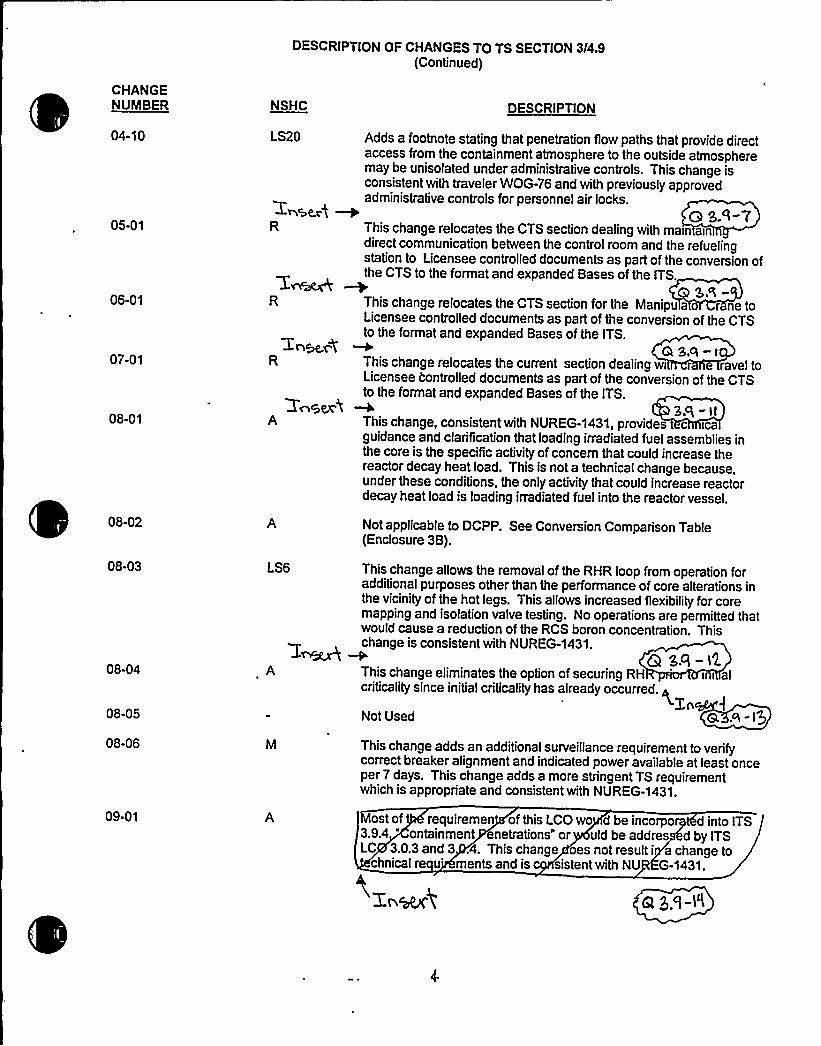
DESCRIPTION OF CHANGES TO TS SECTION 3/4,9(Continued)
CHANGENUMBER
04-10
05-01
06-01
07-01
08-01
08-02
08-03
08-04
08-05
08-06
09-01
NSHC
LS20
+Nscr4 WR
A
LS6
DESCRIPTION
Adds a footnote stating that penetration flow paths that provide directaccess from the containment atmosphere to the outside atmospheremay be unisolated under administrative controls. This change isconsistent with traveler WOG-76 and with previously approvedadministrative controls for personnel air locks.
(3 S.~-7This change relocates the CTS section dealing with main aindirect communication between the control room and the refuelingstation to Licensee controlled documents as part of the conversion ofthe CTS to the format and expanded Bases of the ITS.
SR-This change relocates the CTS section for the Manipu a o r ne toLicensee controlled documents as part of the conversion of the CTSto the format and expanded Bases of the ITS.
QS.e-iThis change relocates the current section dealing wi r ravel toLicensee Controlled documents as part of the conversion of the CTSto the format and expanded Bases of the ITS.
3.Q - llThis change, consistent with NUREG-1431, provides c icaguidance and clarification that loading irradiated fuel assemblies inthe core is the specific activity of concern that could increase thereactor decay heat load. This is not a technical change because,under these conditions, the only activity that could increase reactordecay heat load is loading irradiated fuel into the reactor vessel.
Not applicable to DCPP. See Conversion Comparison Table(Enclosure 3B).
This change allows the removal of the RHR loop from operation foradditional purposes other than the performance of core alterations inthe vicinityof the hot legs. This allows increased flexibilityfor coremapping and isolation valve testing. No operations are permitted thatwould cause a reduction of the RCS boron concentration. Thischange is consistent with NUREG-1431.
G SR-IXThis change eliminates the option of securing RH i i alcriticalitysince initial criticalityhas already occurred. ~
ZnNot Used 9 R I)This change adds an additional surveillance requirement to verifycorrect breaker alignment and indicated power available at least onceper 7 days. This change adds a more stringent TS requirementwhich is appropriate and consistent with NUREG-1431.
Mostof requiremen of this LCOwo d be incorpo d into ITS'.9.4
" ontainment netrations" or uld be addres d by ITSLC 3.0.3and3 .4. Thischange oesnotresulti achangeto
chnical re u'ents and is sistent with NU G-1431.

Qi

Enclosure 3A Page 4Insert for Q 3.9-11
DOC 07-01-R This change relocates the TS section dealing with crane travel to alicensee controlled document as part of the conversion of the currentTechnical Specification to the format and expanded Bases of theimproved Standard Technical Specifications. The restriction onmovement of loads in excess of the nominal weight of a fuel and controlrod assembly and associated handling tool over other fuel assembliesin a storage pool ensures that in the event this load is dropped: (1) theactivity release will be limited to that contained in a single fuelassembly, and (2) any possible distortion of fuel in the storage rackswill not result in a critical array. This assumption is consistent with theactivity release assumed in the safety analyses.
This proposed TS revision relocates requirements, which do not meetthe TS criteria in 10CFR50.36(c)(2)(ii), to documents with establishedcontrol programs. This regulation addresses the scope and purpose ofTS. In doing so, it sets forth a specific set of objective criteria fordetermining which regulatory requirements and operating restrictionsshould be included in the TS. Relocation of these requirements allowsthe TS to be reserved only for those conditions or limitations uponreactor operation which are necessary to obviate the possibility of anabnormal situation or event giving rise to an immediate threat to thepublic health and safety thereby focusing the scope of the TS. Anevaluation of the applicability of these criteria to this specification isprovided in Attachment 21.
To ensure an appropriate level of control, these requirements will berelocated to 1) documents that are subject to the provisions of 10 CFR50.59, 2) other licensee documents which have similar regulatorycontrols (e.g., the Quality Assurance Plan, as described in the FSAR,which is controlled by 10CFR50.54a), or 3) to programs that arecontrolled via the Administrative Controls section of the improved TS.The identification of the specific licensee controlled documentcontaining this requirement is provided in Enclosure 3B of theconversion submittal.
Compliance with the relocated requirements will not be affected by thisproposed change to the current Technical Specifications. The requiredperiodic surveillances will continue to be performed to ensure that limitson parameters are maintained. Therefore, relocation of theserequirements will have no impact on system operability or themaintenance of controlled parameters within limits.


CONVERSION COMPARISO LE - CURRENT TS 3/4.9 Page
TECH SPEC CHANGE APPLICABILITY
NUMBER
05-01R
06-01R
07-01R
08-01A
08-02A
0843LS6
08-04A
08-05
08-06M
09-01A
DESCRIPTION
This change relocates the CTS section dealing withmaintaining direct communication between thecontrol room and the refueling station.
This change relocates the CTS section for theManipulator Crane.
This change relocates the CTS section dealing withcrane travel.
This change provides clarification that loadingirradiated fuel assemblies is the activity that couldincrease the reactor decay heat load.
This change removes a limiton Reactor CoolantSystem temperature.
This change allows the removal of the Residual HeatRemoval (RHR) loop from operation for additionalI urposo.~ other than the performance of corealterations in the vicinityof the hot legs.
This change eliminates the option of securing RHRprior to initial criticalitysince initial criticality hasalready occurred.
Not Used
This change adds an additional surveillancerequirement to verify correct breaker alignment andIndicated power available at least once per 7 days.
The requirements of this LCO would be incorporateinto ITS 3.9.4, "Containment Penetrations" or wouldbe addressed by ITS LCO 3.0.3 and 3.0.4.
DIABLOCANYON
Yes, seeAttachment 21page 19
Yes, seeAttachment 21page 21—Yes, seeAttachment 21page 23—Yes
No, not in CTS.
Yes
Yes
N/A
Yes
Yes
COMANCHEPEAK
Yes, relocated toTRM
Z.LQca04
Yes, relocated toTRM
Yes, relocated toTRM
Yes
No, not in CTS
Yes
Yes
N/A
Yes
No - CPSES doesnot havecontainmentventilation specsin CTS 3/4.9.
WOLF CREEK
No, relocated perAmendment 89
No, relocated perAmendment 89
No, relocated perAmendment 89
Yes
Yes
Yes
Yes
N/A
Yes
Yes
CALLAWAY
No, relocated perAmendment 103
aNo, relocated perAmendment 103
'l - ID
No, relocated perAmendm 03
Yes
Yes
Yes
No
N/A
Yes
Yes
DCPP Conversion Comparison Table - Current TS

Enclosure 2PG8 E Letter DCL 98-107
ADDITIONALINFORMATIONCOVER SHEET
ADDITIONALINFORMATIONNO: Q 3.9-12 APPLICABILITY: DC, CP, WC, CA
REQUEST:CTS 3.9.8.1 Footnote * (Comanche Peak and Callaway)CTS 3.9.8.1 Footnote * and ** (Diablo Canyon)CTS 4.9.8.1 Footnote * (WolfCreek)DOC 8-03-LS-6
The CTS requirement, which allows RHR loop to be removed from operation during theperformance of CORE ALTERATIONS in the vicinity of the reactor vessel hot leg, isproposed to be deleted. The DOC does not address any technical justification butstates that this change would allow increased flexibilityfor core mapping and isolationvalve testing, and that this change is consistent with NUREG-1431, Rev. 1. In addition,there is not any discussions on the possible increase in risk associated with decay heatremoval.
Comment: Revise the DOC by providing the justification as to why this deletion isacceptable and how it relates to the current licensing and design bases. Was there anyrisk assessment performed in regards to this issue? Ifso, what were the conclusionsthat would support the proposed change?
FLOG RESPONSE: DOC 8-03-LS-6 is revised to provide the following additional justificationas to why the deletion of the restriction on the 1 hour per 8 hour removal of operation of theRHR loop is acceptable: "The proposed change would permit the securing of RHR flow throughthe reactor vessel for up to 1 hour in every eight hours [and 2 hours in every 8 hours for testingof the RHR pump to RCS suction valves] provided that no operations involving a reduction inboron concentration were performed. The current TS already permit these interruptions in RHRoperation but under more limited conditions. During this interruption, decay heat removal isassured by natural convection within the large amount of water in the refueling cavity (a 23 feetabove the reactor vessel flange). Boron concentration concerns are avoided by prohibitingevolutions that would reduce the boron concentration. During MODE 6 operation with waterlevels t 23 feet above the reactor vessel flange, the reactor coolant temperature is maintainedsignificantly below boiling with the typical time-to-boil significantly in excess of [2 hours]. Decayheat removal is provided and inadvertent criticality is avoided."
ATTACHEDPAGES'ncl
3A


DESCRIPTION OF CHANGES TO TS SECTION 3/4.9(Continued)
CHANGENUMBER
04-10
05-01
06-01
07-01
08-01
08-02
08-03
08-04
08-05
08-06
09-01
NSHC
LS20
R
LS6
DESCRIPTION
Adds a footnote stating that penetration flow paths that provide directaccess from the containment atmosphere to the outside atmospheremay be unisolated under administrative controls. This change isconsistent with traveler WOG-76 and with previously approvedadministrative controls for personnel air locks.
<3 S.'~-7This change relocates the CTS section dealing with main indirect communication between the control room and the refuelingstation to Licensee controlled documents as part of the conversion ofthe CTS to the format and expanded Bases of the ITS.
This change relocates the CTS section for the Manipu a r ne toLicensee controlled documents as part of the conversion of the CTSto the format and expanded Bases of the ITS.
QS.Q-iThis change relocates the current section dealing wi r ravel toLicensee controlled documents as part of the conversion of the CTSto the format and expanded Bases of the ITS.
3.Q - IIThischange,consistentwithNUREG-1431,provides c icaguidance and clarification that loading irradiated fuel assemblies inthe core is the specific activity of concern that could increase thereactor decay heat load. This is not a technical change because,under these conditions, the only activity that could increase reactordecay heat load is loading irradiated fuel into the reactor vessel.
Not applicable to DCPP. See Conversion Comparison Table(Enclosure 3B).
This change allows the removal of the RHR loop from operation foradditional purposes other than the performance of core alterations inthe vicinityof the hot legs. This allows increased flexibilityfor coremapping and isolation valve testing. No operations are permitted thatwould cause a reduction of the RCS boron concentration. Thischange is consistent with NUREG-1431.
Q $ Q->$Thischangeeliminatestheoptionofsecuring RH
'i al
criticalitysince initial criticality has already occurred. ~Zn
Not Used 9 R I)This change adds an additional surveillance requirement to verifycorrect breaker alignment and indicated power available at least onceper 7 days. This change adds a more stringent TS requirementwhich is appropriate and consistent with NUREG-1431.
ostof requiremen of this LCOwo d be incorpor d into ITS3.9.4 " ontainment netrations" or uld be addres d by ITSLC 3.0.3and3 .4. Thischange oesnotresulti achangeto
chnical re u ments and is sistent with NU G-1431.

0
0

Enclosure 3A
DOC 08-03-LS6
Page 4Insert for Q 3.9-1 2
The proposed change would permit the securing of RHR flow throughthe reactor vessel for up [one hour in every eight hours and two hoursin every eight hours for testing of the RHR pump to RCS suction valves]provided that no operations involving a reduction in boron concentrationwere performed. The current TS already permit these interruptions inRHR operation but under more limited conditions. During thisinterruption, decay heat removal is assured by natural convection withinthe large amount of water in the refueling cavity (a 23 feet above thereactor vessel flange). Boron concentration concerns are avoided byprohibiting evolutions that would reduce the boron concentration.During Mode 6 operation with water levels a 23 feet above the reactorvessel flange, the reactor coolant temperature is maintainedsignificantly below boiling with the typical time-to-boil significantly inexcess of [2] hour. Decay heat removal is provided and inadvertentcriticality is avoided.

0
Enclosure 2PG8E Letter DCL 98-107
ADDITIONALINFORMATIONCOVER SHEET
ADDITIONALINFORMATIONNO: Q 3.9-13 APPLICABILITY: DC, CP, WC
REQUEST:CTS 3.9.8.2 Footnote *
DOC 8-04-A
The CTS footnote regarding the option of securing RHR prior to initial criticality isproposed to be deleted entirely. This change is acceptable because it is a relaxationprovided in the guidance of NUREG-1431, Rev. 1. However, the categorization is inerror. This change is not an administrative change, but it is a more restrictive change.
Comment: Provide a revised "L" DOC.
FLOG RESPONSE: This note is applicable to "initial criticality"only. All start ups includingthose occurring after refueling outages may not apply to this note since initial criticality hasalready occurred. This note is no longer applicable for plant operations and is obsolete cycledependent information. This type of information may be removed under an administrative (A)change since no technical changes (either actual or interpretational) are being made.
DOC 08-04-A is revised to add the following statement: "This note is no longer applicable forplant operations and is obsolete cycle dependent information. This type of information may beremoved under an administrative (A) change since no technical changes (either actual orinterpretational) are being made."
ATTACHEDPAGES'ncl
3A


DESCRIPTION OF CHANGES TO TS SECTION 3/4.9(Continued)
CHANGENUMBER
04-10
05-01
06-01
07-01
08-01
08-02
08-03
08-04
08-05
NSHC
LS20
R
Zn~4R
'Z~gexhA
LS6
DESCRIPTION
Adds a footnote stating that penetration flow paths that provide directaccess from the containment atmosphere to the outside atmospheremay be unisolated under administrative controls. This change isconsistent with traveler WOG-76 and with previously approvedadministrative controls for personnel air locks.
e s.~-vThis change relocates the CTS section dealing with main indirect communication between the control room and the refuelingstation to Licensee controlled documents as part of the conversion ofthe CTS to the format and expanded Bases of the ITS.
This change relocates the CTS section for the Manipu a r ne toLicensee controlled documents as part of the conversion of the CTSto the format and expanded Bases of the ITS.
QS.ct -iThis change relocates the current section dealing wi r ravel toLicensee Controlled documents as part of the conversion of the CTSto the format and expanded Bases of the ITS.
3.Q "llThischange,consistentwithNUREG-1431,provides c icaguidance and clarification that loading irradiated fuel assemblies inthe core is the specific activity of concern that could increase thereactor decay heat load. This is not a technical change because,under these conditions, the only activity that could increase reactordecay heat load is loading irradiated fuel into the reactor vessel.
Not applicable to DCPP. See Conversion Comparison Table(Enclosure 3B).
This change allows the removal of the RHR loop from operation foradditional purposes other than the performance of core alterations inthe vicinityof the hot legs. This allows increased flexibilityfor coremapping and isolation valve testing. No operations are permitted thatwould cause a reduction of the RCS boron concentration. Thischange is consistent with NUREG-1431.
Q SR -I2.Thischangeeliminatestheoptionofsecuring RH i i alcriticality since initial criticalityhas already occurred. ~
ZiNot Used Q R-1$
08-06
09-01
This change adds an additional surveillance requirement to verifycorrect breaker alignment and indicated power available at least onceper 7 days. This change adds a more stringent TS requirementwhich is appropriate and consistent with NUREG-1431.
ost of requiremen of this LCO wo d be incorpor d into ITS3.9.4 " ontainment netrations" or uld be addres d by ITSLC 3.0.3and3 .4. Thischange oesnotresulti achangeto
chnical re u'ents and is sistent with NU G-1431.

0

Enclosure 3A Page 4Insert for Q 3.9-13
DOC 08-04-A This note is no longer applicable for plant operations and is obsoletecycle dependent information. This type of information may be removedunder an administrative (A) change since no technical changes (eitheractual or interpretational) are being made.


Enclosure 2PG8 E Letter DCL 98-107
ADDITIONALINFORMATIONCOVER SHEET
ADDITIONALINFORMATIONNO: Q 3.9-14 APPLICABILITY: DC, WC, CA
REQUEST:
CTS 3.9.9DOC 9-01-A
It is stated in the DOC that the requirements of this LCO would be incorporated into ITS3.9.4, "Containment Penetrations" or would be addressed by ITS LCO 3.0.3 and 3.0.4.It is not clear exactly which one of these designations would address the requirements.
Comment: Revise the DOC to identify where, specifically, the requirements would beaddressed in the ITS and provide the justification for the incorporation
FLOG RESPONSE: DOC 09-01-A is revised as follows: "CTS LCO 3.9.9 requires thecontainment ventilation system to be OPERABLE during CORE ALTERATIONSor duringmovement of irradiated fuel, assemblies. NUREG-1431 reformats these requirements into ITSLCO 3.9.4.c for each penetration providing direct access from the containment atmosphere tothe outside atmosphere. The ITS requires the penetration to be closed by the isolation valve orbe capable of being closed by an OPERABLE containment purge isolation valve. CTS Action3.9.9.b specifically denotes that the provisions of LCO 3.0.3 fis] not applicable. NUREG-1431does not contain reference to this provision, but rather reformats the presentation of thisrequirement within the requirements denoted in ITS 3.0.3 [). Specifically, ITS LCO 3.0.3 [is)only applicable in MODES 1, 2, 3, and 4. During this reformatting, no technical changes (eitheractual or interpretational) to the TS were made unless they were identified and justified. Thischange is consistent with NUREG-1431."
ATTACHED PAGES:
Encl 3A 4Encl 3B 5

0
DESCRIPTION OF CHANGES TO TS SECTION 3/4.9(Continued)
CHANGENUMBER
04-10
05-01
06-01
07-01
08-01
08-02
08-03
08-04
08-05
08-06
09-01
NSHC
LS20
~4SCx4 WR
LS6
A
DESCRIPTION
Adds a footnote stating that penetration flowpaths that provide directaccess from the containment atmosphere to the outside atmospheremay be unisolated under administrative controls. This change isconsistent with traveler WOG-76 and with previously approvedadministrative controls for personnel air locks.
(3 S.'I-7This change relocates the CTS section dealing with main indirect communication between the control room and the refuelingstation to Licensee controlled documents as part of the conversion ofthe CTS to the format and expanded Bases of the ITS.
This change relocates the CTS section for the Manipu a r ne toLicensee controlled documents as part of the conversion of the CTSto the format and expanded Bases of the ITS.
@S.ct-iThis change relocates the current section dealing wi r ravel toLicensee Controlled documents as part of the conversion of the CTSto the format and expanded Bases of the ITS.
3.Q - IIThis change, consistent with NUREG-1431, provides c icaguidance and clarification that loading irradiated fuel assemblies inthe core is the specific activity of concern that could increase thereactor decay heat load. This is not a technical change because,under these conditions, the only activity that could increase reactordecay heat load is loading irradiated fuel into the reactor vessel.
Not applicable to DCPP. See Conversion Comparison Table(Enclosure 3B).
This change allows the removal of the RHR loop from operation foradditional purposes other than the performance of core alterations inthe vicinityof the hot legs. This allows increased flexibilityfor coremapping and isolation valve testing. No operations are permitted thatwould cause a reduction of the RCS boron concentration. Thischange is consistent with NUREG-1431.
G SR-I~This change eliminates the option of securing RH i i alcriticalitysince initial criticalityhas already occurred. ~
ZnNot Used 8, R-lg
This change adds an additional surveillance requirement to verifycorrect breaker alignment and indicated power available at least onceper 7 days. This change adds a more stringent TS requirementwhich is appropriate and consistent with NUREG-1431.
Most of requiremen of this LCO wo d be incorpor d into ITS3.9.4 ontainment netrations" or uld be addres d by ITSLC 3.0.3and3 .4. Thischange oesnotresulti achangeto
chnical re u ments and is sistent with NU G-1431.

0

Enclosure 3A
DOC 09-01-A
Page 4Insert for Q 3.9-14
CTS LCO 3.9.9 requires the containment ventilation system to beOPERABLE during CORE ALTERATIONSor during movement ofirradiated fuel assemblies. NUREG-1431 reformats these requirementsinto ITS LCO 3.9.4.c for each penetration providing direct access fromthe containment atmosphere to the outside atmosphere. The ITSrequires the penetration to be closed by the isolation valve or becapable of being closed by an OPERABLE containment purge isolationvalve. CTS Action 3.9.9.b specifically denotes that the provisions ofLCO 3.0.3 [] are not applicable. NUREG-1431 does not containreference to this provision, but rather reformats the presentation of thisrequirement within the requirements denoted in ITS 3.0.3 [].Specifically, ITS LCO 3.0.3 [] is only applicable in Mode 1, 2, 3, and 4.During this reformatting no technical changes (either actual orinterpretational) to the TS were made unless they were identified andjustified. This change is consistent with NUREG-1431.


CONVERSION COMPARISON I ABLE- CURRENT TS 3I4.9 Page~ of 8
TECH SPEC CHANGE APPLICABILITY
NUMBER
05-01R
06-01R
07-01R
08-01A
08-02A
08-03LS6
08-04A
08-05
08-06M
09-01A
DESCRIPTION
This change relocates the CTS section dealing withmaintaining direct communication between thecontrol room and the refueling station.
This change relocates the CTS section for theManipulator Crane.
This change relocates the CTS section dealing withcrane travel.
This change provides clarification that loadingIrradiated fuel assemblies is the activity that couldincrease the reactor decay heat load.
This change removes a limiton Reactor CoolantSystem temperature.
This change allows the removal of the Residual HeatRemoval (RHR) loop from operation for additionalpurposes other than the performance of corealterations in the vicinityof the hot legs.
This change eliminates the option of securing RHRprior to initial criticalitysince initial criticality hasalready occurred.
Not Used
This change adds an additional surveillancerequirement to verify correct breaker alignment andindicated power available at least once per 7 days.
The requirements of this LCO would be incorporateinto ITS 3.9.4, Containment Penetrations" or wouldbe addressed by ITS LCO 3.0.3 and 3.0.4.
DIABLOCANYON
Yes, seeAttachment 21page 19
Yes, seeAttachment 21page 21—Yes, seeAttachment 21page 23—Yes
No, not in CTS.
Yes
Yes
NIA
Yes
Yes
COMANCHEPEAK
Yes, relocated toTRM
e.lacahe.
Yes, relocated toTRM
Yes, relocated toTRM
Yes
No, not in CTS
Yes
Yes
NIA
Yes
No - CPSES doesnot havecontainmentventilation specsin CTS 3/4.9.
WOLF CREEK
No, relocated perAmendment 89
No, relocated perAmendment 89
No, relocated perAmendment 89
Yes
Yes
Yes
Yes
N/A
Yes
Yes
CALLAWAY
No, relocated perAmendment 103
Gt
No, relocated perAmendment 103
No, relocated perAmend 03
Yes
Yes
Yes
No
N/A
Yes
Yes
Ql 5 ct
DC:PP CnrivaAinn Cnmnarison Table -. Ciirrent TS

Insert for Q 3.9-14
Enclosure 3B
DOC 09-01-A CTS Action 3.9.9.b is moved to ITS 3.0.3 []. The remainingrequirements of this LCO are incorporated into ITS LCO 3.9.4,"Containment Penetrations."


Enclosure 2PG8 E Letter DCL 98-107
ADDITIONALINFORMATIONCOVER SHEET
ADDITIONALINFORMATIONNO: Q 3.9-15 APPLICABILITY: DC, WC, CA
REQUEST'TS3.9.9 Action a
DOC 9-02-LS-7
The CTS requirement to close each purge valve when the containment ventilationsystem is inoperable is proposed to be deleted. The only statement made in the DOCrelated to this deletion is that "The ITS only requires that core alterations and irradiatedfuel movement be suspended." There was not any technical discussion with respect tothis proposed deletion, or how the deletion affects plant operation, licensing and designbases, and why it is acceptable.
Comment: Revise the DOC by providing technical justification to support why it isacceptable.
FLOG RESPONSE: Additional information supporting this DOC is in NSHC LS-7 inEnclosure 4. As discussed with the NRC technical specification branch reviews on June 25,1998, DOC 9-02-LS7 is revised to include the following information:
"The containment ventilation TS requirements would be integrated into ITS 3.9.4. This hasthe effect of changing the actions required when the ventilation system is inoperable fromclosing the purge valves to suspending core alterations and irradiated fuel movement. Theapplicability of the LCO and required actions for both the current TS and ITS 3.9.4 areidentical, i.e., during CORE ALTERATIONSor movement of irradiated fuel assemblieswithin containment. Therefore, neither of these LCOs would be in effect ifCOREALTERATIONSor movement of irradiated fuel were suspended. The function of the purgevalves is to close following a FHA. In addition, the change from requiring the valves to beclosed to prevent radioactivity release to suspending activities which could lead to a FHA(and radioactivity release) would reduce the effect with regard to consequences of theaccident since the accident would be prevented."
ATTACHEDPAGES'ncl
3A


DESCRIPTION OF CHANGES TO TS SECTION 3/4.9(Continued)
CHANGENUMBER
09-02
09-03
09-04
~NSH
LS7
LS8
LS15
DESCRIPTIONggq- Ig
Deletes the requirement to close each purge valve when eContainment Ventilation System is inoperable. The ITS only requiresthat core alterations and irradiated fuel movement be suspended.~
The containment ventilation TS requirements would be integrated intoITS 3.9.4. This has the effect of changing the SR frequency fromonce per 7 days and within 100 hours prior to CORE ALTERATIONSto once per 18 months. This change is acceptable because it wouldapply the same 18-month frequency to the containment ventilationvalves as applied to other containment isolation valves that must beOPERABLE for accidents more severe than an FHA.
3.cI - IbNot applicable to DCPP. See Conversion Comparison(Enclosure 3B).
10-01
10-02
R This change relocates the CTS requirements concerning reactorvessel water level for movement of control rods.En~i a SR-I7
LS22 This change deletes the surveillance requirement to veri water levelwithin 2 hours prior to the start of movement of [irradiated) fuelassemblies. This is acceptable because the LCO must be met at thetime that movement of [irradiated] fuel assemblies is performed.
10-03
IO-cR
11-01
LS18 Revises Applicabilitysuch that it applies only when irradiated fuel ismoved. The CTS also applies to movement of un-irradiated fuelwhen there is irradiated fuel in the core. p
zr6erAhis c ange mo es the Applica m veme o
'rradiated fue semblies in uel sto e pool to be nsistenth the F Handling Acc't (FHA he portions this
require nt applicable wheneve diated fuel in the fuesto epoolwillbe vedtoa 'seecontro ddocume . Thisc nge isconsis twith NU G-1431, and movesde 'sthatarnot required t in the TS protect the alth and safe of the
ublic whi etaining the sic limiting ditions for op ration.
11-02 LS10 This change modifies the ACTION statement by eliminating the 4hour time requirement to restore water level. This change, which isconsistent with NUREG-1431, is acceptable because the ITSRequired Action would suspend movement of irradiated fuelimmediately which would establish conditions outside theApplicabilityof the LCO.
11-03
IQ-O4
Not applicable to DCPP. See Conversion Comparison Table(Enclosure 3B).
ps,q-2o

0

Enclosure 3A Page 5Insert for Q 3.9-15
DOC 09-02-LS7 "The containment ventilation TS requirements would be integrated intoITS 3.9.4. This has the effect of changing the actions required whenthe ventilation system in inoperable from closing the purge valves tosuspending core alterations and irradiated fuel movement. Theapplicability of the LCO and required actions for both the current TSand ITS 3.9.4 are identical, i.e., During CORE ALTERATIONSormovement of irradiated fuel assemblies within containment. Therefore,neither of these LCOs would be in effect if CORE ALTERATIONSormovement of irradiated fuel were suspended. The function of the purgevalves is to close following a FHA. In addition, the change fromrequiring the valves to be closed to prevent radioactivity release tosuspending activities which could lead to a FHA (and radioactivityrelease) would reduce the effect with regard to consequences of theaccident since the accident would be prevented."

0

Enclosure 2PG8E Letter DCL 98-107
ADDITIONALINFORMATIONCOVER SHEET
ADDITIONALINFORMATIONNO: Q 3.9-16 APPLICABILITY: DC, WC, CA
REQUEST:CTS 4.9.9DOC 9-03-LS-8DOC 9-03-LS-8 and 9-03-LS-5 (Callaway)ITS 3.9.4.1 and 3.9.4.2See also question 3.9-8
The CTS requirement is proposed to be incorporated into ITS 3.9.4. The DOC statesthat this has the effect of changing the SR frequency from once per 7 days and within100 hours prior to CORE ALTERATIONS to once per 18 months. However, there is noprovision added in ITS 3.9.4, including 3.9.4.1 and 3.9.4.2, to change the SR frequencywithin 100 hours as it is stated in CTS 4.9.9. The same question in 3.9-8 also applies tothis question.
Comment: Revise the DOC by providing justification and explanation as to why thewithin 100 hours provision is not included. Also, incorporate the response to question3.9-8 as well.
FLOG RESPONSE: Additional information supporting this DOC is in NSHC LS-8 in Enclosure 4.As discussed with the NRC technical specification branch reviewers on June 25, 1998, DOC 9-03-LS-8 is revised to include the following information:
"The purpose of the SR is to assure the OPERABILITYof the containment penetrations thatmust be closed or capable of closing to prevent the release of radioactivity in the event of aFuel Handling Accident. So, the SR is intended to assure that mitigation features areavailable and has no impact on the probability of an accident occurring. In addition, thechange involves a revision in the frequency of testing accident (Fuel Handling Accident)mitigating equipment.
The Applicabilitystatement for this LCO is "During CORE ALTERATIONSor movement ofirradiated fuel within the containment." Thus, the surveillance requirement to verify the LCOis met within 100 hours of starting the evolutions for which the LCO is applicable isredundant, because the Applicability states the LCO must be met at the time the evolutionsoccur. Also, the proposed change to 18 months would apply the same frequency of testingto containment purge isolation valves as applied to other containment isolation valves thatmust be OPERABLE during reactor operations. The 18-month frequency has been foundadequate for the type of testing applied to instrumentation and valves that must mitigateevents much more severe and much more challenging to the containment boundary (e.g.,LOCA, MSLB) than the FHA."
The Comment includes a reference to Callaway for DOC 9-03-LS-5 in CTS 4.9.9 and ITS3.9.4.2. It appears the reference for the DOC is incorrect and was intended to be DOC 4-03-LS-5. The response to Comment Number 3.9-8 and revision to DOC 4-03-LS-5addresses the portion of Comment Number 3.9-16 for Callaway's use of DOC 4-03-LS-5 inCTS 4.9.9 and ITS 3.9.4.2.

Cl

Enclosure 2PG8 E Letter DCL 98-107
ATTACHEDPAGES'ncl.
3A 5

0

DESCRIPTION OF CHANGES TO TS SECTION 3I4.9(Continued)
CHANGENUMBER
09-02
09-03
09-04
~NSH
LS7
LS8
LS15
DESCRIPTIONggq- l5
Deletes the requirement to close each purge valve when theContainment Ventilation System is inoperable. The ITS only requiresthat core alterations and irradiated fuel movement be suspended.
The containment ventilation TS requirements would be integrated intoITS 3.9.4. This has the effect of changing the SR frequency fromonce per 7 days and within 100 hours prior to CORE ALTERATIONSto once per 18 months. This change is acceptable because it wouldapply the same 18-month frequency to the containment ventilationvalves as applied to other containment isolation valves that must beOPERABLE for accidents more severe than an FHA. 3' IbNot applicable to DCPP. See Conversion Comparison(Enclosure 3B).
10-01
10-02
R This change relocates the CTS requirements concerning reactorvessel water level for movement of control rods.Z&~\ g gR I'7
LS22 This change deletes the surveillance requirement to veri water levelwithin 2 hours prior to the start of movement of [irradiated) fuelassemblies. This is acceptable because the LCO must be met at thetime that movement of [irradiated) fuel assemblies is performed.
10-03
11-01
LS18 Revises Applicabilitysuch that it applies only when irradiated fuel ismoved. The CTS also applies to movement of un-irradiated fuelwhen there is irradiated fuel in the core. p 3. I-8zraesl
his c ange mo es the Applica m veme o'rradiated fuel semblies in uel sto e pool to be nsisten
'th the F Handling Acc't (FHA he portions thisrequire nt applicable wheneve diated fuel in the fuesto epoolwillbe vedtoa 'nseecontr ddocume . Thisc nge is consis twith NU G-1431, and moves de 's that arnot required t e in the TS protect the alth and safe of the
ublic whi etaining the sic limiting ditions for op ration.
11-02
11-03
l0-O4
LS10 This change modifies the ACTION statement by eliminating the 4hour time requirement to restore water level. This change, which isconsistent with NUREG-1431, is acceptable because the ITSRequired Action would suspend movement of irradiated fuelimmediately which would establish conditions outside theApplicabilityof the LCO.
Not applicable to DCPP. See Conversion Comparison Table((Enclosure 3B).

0

Enclosure 3A
DOC 9-03-LS8
Page 5Insert for Q 3.9-16
The purpose of the SR is to assure the OPERABILITYof thecontainment penetrations that must be closed or capable of closing toprevent the release of radioactivity in the event of a Fuel HandlingAccident. So, the SR is intended to assure that mitigation features areavailable and has no impact on the probability of an accident occurring.In addition, the change involves a revision in the frequency of testingaccident (Fuel Handling Accident) mitigating equipment.
The Applicabilitystatement for this LCO is "During COREALTERATIONSor movement of irradiated fuel within the containment."Thus the requirement to verify the LCO is met within 100 hours ofstarting the evolutions for which the LCO is applicable is redundant;because the LCO must be met at the time that the evolutions occur.Also, the proposed change to 18 months would apply the samefrequency of testing to containment purge isolation valves as applied toother containment isolation valves that must be OPERABLE duringreactor operations. The 18-month frequency has been found adequatefor the type of testing applied to instrumentation and valves that mustmitigate events much more severe and much more challenging to thecontainment boundary (e.g., LOCA, MSLB) than the FHA."


Enclosure 2PG8E Letter DCL 98-107
ADDITIONALINFORMATIONCOVER SHEET
ADDITIONALINFORMATIONNO: Q 3.9-17 APPLICABILITY: DC, CP
REQUEST:CTS 3/4.9.9, Control RodsDOC 10-01-R
According to the DOC, the CTS requirements in 3/4.9.7 would be entirely relocated toan unspecified licensee controlled document. In addition, the DOC does not addressadequate justification as to why the relocation is acceptable.
Comment: Provide additional justification as to why this relocation is acceptable andidentify the name of the licensee controlled document containing this requirement. Thisrequirement shall be relocated to a licensee controlled document controlled by 10 CFR50.59.
FLOG RESPONSE: DOC 10-01-R has been revised and a Technical Specification ScreeningForm has been prepared to provide justification as to why the relocation is acceptable. Thisjustification shows the LCO provides assurance that adequate water will be present for iodineremoval in the event of a FHA. Control rod movement is not associated with FHA and this LCOdoes not address inadvertent criticality. This LCO is not associated with any instrumentationused to detect significant degradation of the reactor coolant pressure boundary. It is notassociated with any variable design feature or restriction which is an initial condition of DBA ortransient analysis. It is not a part of the primary success path for mitigation of a DBA or atransient.
The format for specifying the location of relocated requirements (in Enclosure 3B of theconversion submittal) was found to be acceptable by the NRC technical specifications branchreviewers during telephone calls on June 25 and June 30, 1998. The document indicated inEnclosure 3B is controlled by 10CFR50.59.
ATTACHEDPAGES'ncl
3AEncl 3B

0

DESCRIPTION OF CHANGES TO TS SECTION 3/4.9(Continued)
CHANGENUMBER
09-02
09-03
09-04
~NSH
LS7
LS8
LS15
DESCRIPTIONggq- l5
Deletes the requirement to close each purge valve when theContainment Ventilation System is inoperable. The ITS only requiresthat core alterations and irradiated fuel movement be suspended.z~>The containment ventilation TS requirements would be integrated intoITS 3.9.4. This has the effect of changing the SR frequency fromonce per 7 days and within 100 hours prior to CORE ALTERATIONSto once per 18 months. This change is acceptable because it wouldapply the same 18-month frequency to the containment ventilationvalves as applied to other containment isolation valves that must beOPERABLE for accidents more severe than an FHA.
3/I - IbNot applicable to DCPP. See Conversion Comparison(Enclosure 3B).
10-01
10-02
R This change relocates the CTS requirements concerning'reactorvessel water level for movement of control rods.Zn~h I t
LS22 This change deletes the surveillance requirement to veri water levelwithin 2 hours prior to the start of movement of [irradiated] fuelassemblies. This is acceptable because the LCO must be met at thetime that movement of [irradiated] fuel assemblies is performed.
10-03 LS18
IO-cA
11-01Qt p ~ 21
G
Revises Applicabilitysuch that it applies only when irradiated fuel ismoved. The CTS also applies to movement of un-irradiated fuelwhen there is irradiated fuel in the core. y
Zr6er4his c ange mo es the Applica m veme o
'rradiated fue semblies in el sto e pool to be nsisten'th the F Handling Acc't (FHA he portions this
require nt applicable wheneve diated fuel 'n the fuesto epoolwillbe vedtoa 'seecontr ddocume . Thisc nge is consis twith NU G-1431, and moves de
'that ar
not required t in the TS protect the alth and safe of theublic whi etaining the sic limiting ditions for o ration.
11-02
11-03
IO-g
LS10 This change modifies the ACTION statement by eliminating the 4hour time requirement to restore water level. This change, which isconsistent with NUREG-1431, is acceptable because the ITSRequired Action would suspend movement of irradiated fuelimmediately which would establish conditions outside theApplicabilityof the LCO.
Not applicable to DCPP. See Conversion Comparison Table((Enclosure 3B).


Enclosure 3A
DOC 10-01-R
Page 5Insert for Q 3.9-17,
This specification places a lower limit on the amount of water above thetop of the fuel assemblies in the reactor vessel during movement ofcontrol rods. The Bases state that this ensures the water removes 99percent of the assumed 10 percent iodine gap activity released from therupture of an irradiated fuel assembly in the event of a fuel handlingaccident (FHA) during core alterations. However, the movement ofcontrol rods is not associated with the initial conditions of an FHA, andthe Bases do not address any concerns regarding inadvertent criticalitywhich could lead to a breach of the fuel rod cladding. Inadvertentcriticality during Mode 6 is prevented by maintaining proper boronconcentration in the coolant in accordance with LCO 3.9.1.
This proposed TS revision relocates requirements, which do not meetthe TS criteria in 10CFR50.36(c)(2)(ii), to documents with establishedcontrol programs. This regulation addresses the scope and purpose ofTS. In doing so, it sets forth a specific set of objective criteria fordetermining which regulatory requirements and operating restrictionsshould be included in the TS. Relocation of these requirements allowsthe TS to be reserved only for those conditions or limitations uponreactor operation which are necessary to obviate the possibility of anabnormal situation or event giving rise to an immediate threat to thepublic health and safety thereby focusing the scope of the TS. Anevaluation of the applicability of these criteria to this specification isprovided in Attachment 21.
To ensure an appropriate level of control, these requirements will berelocated to 1) documents that are subject to the provisions of 10 CFR50.59, 2) other licensee documents which have similar regulatorycontrols (e.g., the Quality Assurance Plan, as described in the FSAR,which is controlled by 10CFR50.54a), or 3) to programs that arecontrolled via the Administrative Controls section of the improved TS.The identification of the specific licensee controlled documentcontaining this requirement is provided in Enclosure 3B of theconversion submittal.
Compliance with the relocated requirements will not be affected by thisproposed change to the current Technical Specifications. The requiredperiodic surveillances willcontinue to be performed to ensure that limitson parameters are maintained. Therefore, relocation of theserequirements will have no impact on system operability or themaintenance of controlled parameters within limits.

0

CONVERSiON COMPARISO LE - CURRENT TS 3/4.9
TECH SPEC CHANGE APPLICABILITY
NUMBER
09-02LS7
09-03LS8
09-04LS15
10-01R
10-02LS22
10-03LS18
11-01LG
11-02LS10
DESCRIPTION
This change deletes the requirement to close eachpurge valve when the containment ventilation systemis inoperable.
The containment ventilation TS requirements wouldbe integrated into ITS 3.9.4. This has the effect ofchanging the SR frequency from once per 7 days andwithin 100 hours prior to CORE ALTERATIONStoonce per 18 months.
Removes the requirement for immediate action whenone containment purge monitor is inoperable. ITSLCO 3.3.6 willallow one purge monitor to beinoperable for up to 4 hours during COREALTERATIONSor movement of irradiated fuel incontainment.
This change relocates the CTS requirementsconcerning reactor vessel water level for movementof control rods.
This change deletes the surveillance requirement toverifywater level within 2 hours prior to the start ofmovement of irradiated fuel assemblies.
Revises Applicabilitysuch that it applies only whenirradiated fuel is moved. The CTS also applies tomovement of un-irradiated fuel when there isirradiated fuel in the core.
This change modifies the Applicabilityto duringmovement of irradiated fuel assemblies in the fuelstorage pool to be consistent with the Fuel HandlingAccident (FHA).
This change modifies the ACTION statement andeliminates the time requirement to restore water level.
DIABLOCANYON
Yes
Yes
No, not in CTS.
Yes, seeAttachment 21page 25 —c ego
Yes
Yes
Yes, moved to anECG
Yes
COMANCHEPEAK
No, CPSES doesnot havecontainmentventilation specsin CTS 3/4.9.
No, CPSES doesnot havecontainmentventilation specsin CTS 3/4.9.
No, CPSES doesnot haveContainmentVentilation Spec inCTS 3/4.9
Yes, relocated toTRM
Yes
Yes
Yes
Yes
WOLF CREEK
Yes
Yes
No, Plant designdifferent
No, relocated perAmendment 89
Yes
No, already inCTS
Yes
Yes
CALLAWAY
Yes
Yes
Yes
No, relocated perAmendment 103
a S.e-ilYes
No, already inCTS
Yes
Yes
+yl5+r+ jn ~hKx scl&Hi&(.CPP Conversion Comparison Table - Current TS
Q3.'q-20


Enclosure 2PG8E Letter DCL 98-107
ADDITIONALINFORMATIONCOVER SHEET
ADDITIONALINFORMATIONNO: Q 3.9-18 APPLICABILITY: DC, CP
REQUEST:CTS 3.9.9.1 ApplicabilityDOC 10-03-LS18
CTS requires movement of unirradiated fuel when there is irradiated fuel in the core.The licensee proposes to revise the applicability such that it applies only when irradiatedfuel is moved. There is not any technical discussion provided in the DOC to justify thischange.
Comment: Please provide technical justification in the DOC as to why this is technicallyacceptable and how it applies to current licensing basis.
FLOG RESPONSE: The text of DOC 10-03-LS-18 is revised to add the following statement:"The purpose of [CTS 3.9.10.1] is to assure that sufficient water is present to remove 99% ofthe release of 10% iodine gap activity during a FHA. A FHA could result during movement ofan irradiated assembly due to the drop of the assembly on the floor of the refueling cavity or thedrop of any load on the core. A fuel assembly and its handling tool are the analyzed limitingload for the FHA. However, dropping a new (unirradiated) assembly on the cavity floor wouldnot result in an FHA and dropping a new assembly on the core is no different then dropping anyother load on the core. This condition is already addressed by the programs associated withNUREG-0612, "Control of Heavy Loads at Nuclear Power Plants," and is redundant to this LCOrequirement. The FHA resulting from the drop of a new assembly would occur at the activeirradiated fuel already loaded in the core and maintenance of 23 feet of water above the flange(this LCO) would be unnecessarily conservative.
ATTACHEDPAGES'ncl
3A

0

DESCRIPTION OF CHANGES TO TS SECTION 3/4.9(Continued)
CHANGENUMBER
09-02
09-03
09-04
~NSH
LS7
LS8
LS15
DESCRIPTIONggq- I5
Deletes the requirement to close each purge valve when theContainment Ventilation System is inoperable. The ITS only requiresthat core alterations and irradiated fuel movement be suspended.z~~The containment ventilation TS requirements would be integrated intoITS 3.9.4. This has the effect of changing the SR frequency fromonce per 7 days and within 100 hours prior to CORE ALTERATIONSto once per 18 months. This change is acceptable because it wouldapply the same 18-month frequency to the containment ventilationvalves as applied to other containment isolation valves that must beOPERABLE for accidents more severe than an FHA.
3.cI - IbNot applicable to DCPP. See Conversion Comparison(Enclosure 3B).
10-01
10-02
R This change relocates the CTS requirements concerning reactorvessel water level for movement of control rods.
ZA~A ItLS22 This change deletes the surveillance requirement to veri water level
within 2 hours prior to the start of movement of [irradiated) fuelassemblies. This is acceptable because the LCO must be met at thetime that movement of [irradiated] fuel assemblies is performed.
10-03 LS18
IO-CA
11-01 g pq 2 G
Revises Applicabilitysuch that it applies only when irradiated fuel ismoved. The CTS also applies to movement of un-irradiated fuelwhen there is irradiated fuel in the core. v
zr6eAhis c ange mo es the Applica m veme o
irradiated fue semblies in uel sto e pool to be nsistenth the F Handling Acc nt (FHA he portions this
require nt applicable wheneve diated fuel 'n the fuesto e pool willbe ved to a 'see contro d docume Thisc nge is consis twith NU G-1431, and moves de
'that ar
not required t e in the TS protect the alth and saf of theublic whi etaining the sic limiting ditions for o ration.
11-02 LS10 This change modifies the ACTION statement by eliminating the 4hour time requirement to restore water level. This change, which isconsistent with NUREG-1431, is acceptable because the ITSRequired Action would suspend movement of irradiated fuelimmediately which would establish conditions outside theApplicabilityof the LCO.
11-03
IO-c4
Not applicable to DCPP. See Conversion Comparison Table(Enclosure 3B).
qs.q-2o

0

Enclosure 3A Page 5Insert for Q 3.9-18
DOC 10-03-LS18 The purpose of [CTS 3.9.10.1] is to assure that sufficient water ispresent to remove 99% of the release of 10% iodine gap activity duringa FHA. A FHA could result during movement of an irradiated assemblydue to the drop of the assembly on the floor of the refueling cavity orthe drop of any load on the core. A fuel assembly and its handling toolare the analyzed limiting load for the FHA. However, dropping a new(unirradiated) assembly on the cavity floor would not result in an FHAand dropping a new assembly on the core is no different then droppingany other load on the core. The FHA resulting from the drop of a newassembly would occur at the active irradiated fuel already loaded in thecore and maintenance of 23 feet of water above the flange (this LCO)would be unnecessarily conservative.

0

Enclosure 2PG8E Letter DCL 98-107
ADDITIONALINFORMATIONCOVER SHEET
ADDITIONALINFORMATIONNO: Q 3.9-21 APPLICABILITY: DC, CP, WC, CA
REQUEST:CTS 3.9.10 Applicability and 4.9.10 (Comanche Peak)CTS 3.9.11 and 4.9.11 (Callaway)CTS 3.9.11 Applicability and 4.9.11 (Diablo Canyon)CTS 3.9.11 and 4.9.11 (WolfCreek)DOC 11-01-LG
The CTS requirement, applicable to whenever irradiated fuels are in the fuel storageracks, is proposed to be relocated to an unspecified licensee controlled document. TheDOC does not provide any technical justification related to this relocation.
Comment: Revise the DOC by including the justification for the relocation and identifythe licensee controlled document containing this requirement. This requirement shall berelocated to a licensee controlled document controlled by 10 CFR 50.59.
FLOG RESPONSE: Identification of the licensee controlled document containing thisrequirement is identified in Enclosure 3B of the conversion application. This was discussed withthe NRC technical specification branch reviewers on June 25, 1998, and determined that theinformation provided in Enclosure 3B was acceptable.
DOC 11-01-LG has been modified to include the following information: "The Applicability isrevised to require the water level be maintained only when moving irradiated fuel. Thebounding design basis fuel handling accident in the fuel storage [pool] assumes an irradiatedfuel assembly is dropped onto an array of irradiated fuel assemblies seated in the fuel storageracks. The revised Applicability is consistent with this design basis accident (DBA). The waterlevel requirement is necessary to mitigate the consequences of this DBA. Moving therequirement to maintain fuel storage [pool] water level whenever irradiated fuel assemblies arein the fuel storage [pool] provides for conservative plant operations. Moving this informationmaintains consistency with NUREG-1431. The information is moved to a licensee controlleddocument which is controlled by a 10 CFR 50.59 change process."
ATTACHEDPAGES'ncl
3A 5


DESCRIPTION OF CHANGES TO TS SECTION 3/4.9(Continued)
CHANGENUINBER
09-02
09-03
09-04
LS7
LS8
LS15
DESCRIPTIONggg~ I5
Deletes the requirement to close each purge valve when eContainment Ventilation System is inoperable. The ITS only requiresthat core alterations and irradiated fuel movement be suspended.
The containment ventilation TS requirements would be integrated intoITS 3.9.4. This has the effect of changing the SR frequency fromonce per 7 days and within 100 hours prior to CORE ALTERATIONSto once per 18 months. This change is acceptable because itwouldapply the same 18-month frequency to the containment ventilationvalves as applied to other containment isolation valves that must beOPERABLE for accidents more severe than an FHA.
3.ct - IbNot applicable to DCPP. See Conversion Comparison(Enclosure 3B).
10-01
10-02
R This change relocates the CTS requirements concerning reactorvessel water level for movement of control rods.
Za~A g gR-lgLS22 This change deletes the surveillance requirement to veri water level
within 2 hours prior to the start of movement of [irradiated) fuelassemblies. This is acceptable because the LCO must be met at thetime that movement of [irradiated) fuel assemblies is performed.
10-03 LS18
IO-O4
11-01 g pq ~ G
Revises Applicability such that it applies only when irradiated fuel ismoved. The CTS also applies to movement of un-irradiated fuelwhen there is irradiated fuel in the core. pz~4
hisc an emog es the Applica m veme oirradiated fue semblies in uel sto e pool to be nsisten
'th the F Handling Acc't (FHA he portions thisrequire nt applicable wheneve diated fuel 'n the fuesto epoolwillbe vedtoa nseecontr ddocume . Thisc nge is consis t with NU G-1431, and moves de
'that ar
11-02
11-03
IO-c4
not required t in the TS protect the alth and saf of theublic whi etaining the sic limiting ditions for op ration.
LS10 This change modifies the ACTION statement by eliminating the 4hour time requirement to restore water level. This change, which isconsistent with NUREG-1431, is acceptable because the ITSRequired Action would suspend movement of irradiated fuelimmediately which would establish conditions outside theApplicabilityof the LCO.
Not applicable to DCPP. See Conversion Comparison Table((Enclosure 3B).


Enclosure 3A
DOC 11-01-LG
Page 5Insert for Q 3.9-21
The Applicability is revised to require the water level be maintained onlywhen moving irradiated fuel. The bounding design basis fuel handlingaccident in the fuel storage [pool] assumes an irradiated fuel assemblyis dropped onto an array of irradiated fuel assemblies seated in the fuelstorage racks. The revised Applicability is consistent with this designbasis accident (DBA). The water level requirement is necessary tomitigate the consequences of this DBA. Moving the requirement tomaintain fuel storage [pool] water level whenever irradiated fuelassemblies are in the fuel storage [pool] provides for conservative plantoperations. Moving this information maintains consistency withNUREG-1431. The information is moved to a licensee controlleddocument which is controlled by a 10 CFR 50.59 change process.


Enclosure 2PG8E Letter DCL 98-107
ADDITIONALINFORMATIONCOVER SHEET
ADDITIONALINFORMATIONNO: Q 3.9-22 APPLICABILITY: DC, CP, WC, CA
REQUEST:CTS 3.9.11 Action aCTS 3.9.10 Action a (Comanche Peak)DOC 11-04-LG
According to the DOC, the CTS requirement regarding restriction on crane operation isproposed to be moved to an unspecified licensee controlled document. In addition, theDOC does not provide specific justification as to why this relocation is acceptable.
Comment: Revise the DOC to include specific justification to this relocation and identifythe licensee controlled document containing this requirement. This requirement shall berelocated to a licensee controlled document controlled by 10 CFR 50.59.
FLOG RESPONSE: Identification of the licensee-controlled document containing thisrequirement is identified in Enclosure 3B of the conversion application. This was discussed withthe NRC technical specification branch reviewers on June 25, 1998, and determined that theinformation provided in Enclosure 3B was acceptable.
DOC 11-04-LG has been modiTied to include the following information: "The requirement tosuspend crane operations over the spent fuel pool in the event pool water level is <23 feet, hasbeen removed from the ACTION of CTS 3/4.9.11 (CTS 3/4.9.10 for Comanche Peak) incorresponding ITS 3.7.5, for the fuel pool water level. The bounding design basis fuel handlingaccident in the spent fuel pool assumes an irradiated fuel assembly is dropped onto [the floorof] the spent fuel pool. Crane operations that could adversely affect fuel stored in the spent fuelpool are controlled in accordance with plant procedures as analyzed in the review of heavyloads movements. Administrative controls are employed to prevent the handling of loads thathave a greater potential energy than those which have been analyzed. Also see
licensees'esponses
to NRC Bulletin 96-02, "Movement of Heavy Loads Over Spent Fuel, Over Fuel inthe Reactor Core, or Over Safety-Related Equipment." Moving this information maintainsconsistency with NUREG-1431. The information is moved to a licensee controlled documentwhich is controlled by a 10 CFR 50.59 change process.
ATTACHEDPAGES'ncl
3A 6


DESCRIPTION OF CHANGES TO TS SECTION 3/4 9(Continued)
CHANGENUMBER NSHC DESCRIPTION
11-04
12-01
LG This change moves the restriction on crane operation to a licenseecontrolled document. The restriction on crane operations may beremoved because it is not in the assumptions used for the FHA.Crane operations that could adversely affect fuel stored in the spentfuel pool are controlled as analyzed in the review of heavy loadmovements. This change is consistent with NUREG-1431, andmoves requirements that do not meet the criteria for inclusion in theTS.
M~Qxk ~ a s.~-~2LS24 The Applicabilitywould be changed to "During movemen o
irradiated fuel in the fuel building" instead of "Whenever irradiatedfuel is in the spent fuel pool'onsistent with NUREG-1431. Theproposed Applicability is consistent with the assumptions used in theFHA in the Fuel Handling Building which postulates the inadvertentdrop of an irradiated fuel assembly. Potential damage to fuelassemblies due to dropping of heavy loads is addressed by CN12-02-LG.
12-02
12-03
12-04
12-05
LG
TR1
Moves the restriction on crane operations over the spent fuel storageareas when the fuel building air cleanup system was inoperable. Therestriction on crane operations may be removed because it is notconsistent with the assumptions used for the FHA. Crane operationsthat could adversely affect fuel stored in the spent fuel pool isprohibited in accordance with plant procedures as analyzed in thereview of heavy load movements.
Not applicable to DCPP. See Conversion Comparison Table(Enclosure 3B).
The SR regarding filter testing would be moved to a "Ventilation FilterTesting Program" that is called out in the Administrative ControlsSection 5.5.11 of the ITS. This change does not result in a change totechnical requirements.
Revised SR to allow for increased flexibilityin using an actual orsimulated actuation signal. Identification of the specific signal ismoved to the Bases.
12-06 This requirement would have the operability of each train of the [FuelHandling Building Ventilation System (FHBVS)] (includingmaintaining negative pressure in the building) to be demonstrated.This is consistent with current practice. This change does not resultin a change to technical requirements and is consistent withNUREG-1431.
12-07
12-08
LS25
LS16
Not applicable to DCPP. See Conversion Comparison Table(Enclosure 38).
p2Q DC;t LL-Oo)The proposed change would allow the +month testing of e[FHBVS] ability to maintain the required pressure differential betweenthe building and the outside atmosphere to be performed on aSTAGGERED TEST BASIS.

0

Enclosure 3A
DOC 11-04-LG
Page 6Insert for Q 3.9-22
The requirement to suspend crane operations over the spent fuel poolin the event pool water level is <23 feet, has been removed from theACTION of CTS 3/4.9.11 (CTS 3/4.9.10 for Comanche Peak) incorresponding ITS 3.7.5, for the fuel pool water level. The boundingdesign basis fuel handling accident in the spent fuel pool assumes anirradiated fuel assembly is dropped onto [the floor of] the spent fuelpool. Crane operations that could adversely affect fuel stored in thespent fuel pool are controlled in accordance with plant procedures asanalyzed in the review of heavy loads movements. Administrativecontrols are employed to prevent the handling of loads that have agreater potential energy that those which have been analyzed. Alsosee licensees'esponses to NRC Bulletin 96-02, "Movement of HeavyLoads Over Spent Fuel, Over Fuel in the Reactor Core, or Over Safety-Related Equipment." Moving this information maintains consistencywith NUREG-1431. The information is moved to a licensee controlleddocument which is controlled by a 10 CFR 50.59 change process.


Enclosure 2PG8E Letter DCL 98-107
ADDITIONALINFORMATIONCOVER SHEET
ADDITIONALINFORMATIONNO: Q 3.9-23
REQUEST'TS3.9.7 Applicability and Action A
JFD 3.9-10
APPLICABILITY: DC, CP, WC, CA
The licensee is proposing to delete ITS 3.9.7, Applicability, which states, "During COREALTERATIONS, except during latching and unlatching of control rod drive shafts." JFD3.9-10 states, the reason for this revision is that this requirement is a duplication of arelocated technical specification requirement for reactor vessel water level duringmovement of control rods (relocated CTS 3.9.9.2). ITS 3.9.7 Applicability is not anexact duplication of CTS 3.9.9.2; further technical and licensing justifications arerequired for this deletion.
Comment: Provide technical and licensing bases justification for this proposed deletionfrom ITS. Why does the inclusion of the ITS requirement pose a hardship?
FLOG RESPONSE: Diablo Canyon, Comanche Peak, WolfCreek, and Callaway continue topursue this change. ITS 3.9.7 Applicability statement, "During CORE ALTERATIONS, exceptduring latching and unlatching of control rod drive shafts," as applied to fuel movement is limitedto movement of fuel within the reactor vessel. The STS wording does not address themovement of fuel in transit to or from the reactor vessel in containment. "COREALTERATIONS, except during latching and unlatching of control rod drive shafts" as applied toCORE ALTERATIONSother than fuel movement are not associated with the CTS LCO3.9.10.1 and CTS LCO 3.9.9.1 for CPSES. AII control rod movement in MODE 6 (CTS LCO3.9.9.2 for CPSES and CTS LCO 3.9.10.2 for DCPP) is proposed to be relocated to licensee-controlled documents based upon 10 CFR 50.36 (see DOC 10-01-R), for WolfCreek andCallaway, CTS 3.9.10.2 was already relocated by Amendment 89 and 103, respectively.
The purpose of ITS LCO 3.9.7 (CTS LCO 3.9.10.1 (for CPSES CTS LCO 3.9.9.1)) is to providesufficient water to assure removal of 99% of a 10% iodine gap release in the event of a FHA,whereas, ITS LCO 3.9.1, "Boron Concentration," is provided to address reactivity changes andto prevent inadvertent criticality during movement of fuel or control rods.
JFD 3.9-10 is revised to provide the following statement:
"Consistent with the CTS LCO [3.9.10.1], ITS 3.9.7 Applicability is being revised to delete"During CORE ALTERATIONS, except during latching and unlatching of control rod driveshafts." This STS Applicabilitydoes not address the movement of fuel in containment exceptwithin the reactor vessel. It does, however, apply to CORE ALTERATIONSother than fuelmovement. This requirement does not meet the criteria of 10 CFR 50.36 in terms of itsassociation with an FHA. The revised Applicability provides assurance of sufficient water toassure removal of 99% of a 10% iodine gap release in the event of a FHA in the containmentwhile moving irradiated fuel."

0

Enclosure 2PG8 E Letter DCL 98-107
For DCPP and CPSES, the revised applicability is not strictly consistent with CTS, but it iswithin the current licensing bases (See Q 3.9-18).
ATTACHED PAGES:
Encl 6A 2Encl 6B 2


JUSTIFICATION FOR DIFFERENCES FROM NUREG-1431
NUREG-1431 Section 3.9
CHANGENUMBER JUSTIFICATION
3.9-10 Consistent wi the CTS, I 3.9.7 Applicabffityis be g revised to del "unng CORE
ALTERATI S, except ring latching d unlatc ng of control ro rive shafts." QeApplicab's being ised becaus is requir ment is duplica of a relocatepfechnispecif tion requi ment for reac r vessel wa(er level during movement of cobol rods(rel ted tech 'lspecifiicati 3.9.10.2).,<he relocated s cifiication plac& a lower lio e amou of water abovdthe top of the fuel assembl' in the reactor vessel durin
ovemen fcontrolrods The Bases+TS3/4.9.10) tatesthatthisensuresthewa rremove 9% of the assured 10% iogine gap activi eleased from the'rupture of airradi ed fuel assembly in the eveot of a fuel han ng accident (FHA). However, emo ement of control rods is notpssociated wi e initial conditions of a FHA, d the
ses do not address any coi)cern regardin 'dvertent critical which coul lead toreach of thegiel rod
claddin'n~4-+3.9-11 In accordance with a proposed traveler WOG-76, LCO is modified to permit a penetration
flow path that provides direct access from the containment to the outside atmosphere to beunisolated under administrative controls. The allowance to have containment flowpathswith direct access from the containment atmosphere to the outside atmosphere unisolatedunder administrative controls is based on confirmatory dose calculations of a fuel handlingaccident which indicate acceptable radiological consequences and to implementadministrative controls that ensure that the flow penetrations will be promptly closedfollowing a fuel handling accident, to provide a defense-in4epth approach to meetacceptable dose consequences. The administrative control requirements are defined in theBases.
3.9-12
3.9-13
3.9-14
A note is added to the Applicabilityof LCO 3.9.6 indicating that entry into a MODE or otherspecified condition in the Applicabilityis not permitted while the LCO is not met. Theaddition of this note is based on the performance of a plant-specific LCO 3.0.4 matrix whichidentified where the requirements of 3.0.4 are still applicable in MODES 5 and 6 and inMODES 1,2, 3, and 4 when the MODE is descending (i.e., from MODE 1 to MODE 2, etc.).This matrix was specified in the NUREG-1431 reviewer's note in LCO 3.0.4.
In accordance with DCPP CTS, LCO 3.9.2 would not be used. This new requirement is notapplicable to DCPP which has a licensed dilution accident. The current licensing bases inaccordance with NUREG 0800, Section 15.4.6 provides adequate assurance that a dilutionevent will recognized and arrested in a timely fashion
A Note is added to the Applicabilityof LCO 3.9.1 indicating that entry into MODE 6 fromMODE 5 is not permitted while the LCO is not met. The addition of this Note is based onthe performance of a plant-specific LCO 3.0.4 matrix which identified where therequirements of 3.0.4 are still applicable in MODES 5 and 6 and in MODES 1, 2, 3, and 4when the MODE is descending (i.e., from MODE 1 to MODE2, etc.). This maspecified in the NUREG-1431 reviewer's note in LCO 3.0.4. g/1Spi + Q3.9-2$
DCPP Description of Changes to Improved TS


Enclosure 6A
JFD 3.9-10
Page 2Insert for Q 3.9-23
Consistent with the CTS LCO [3.9.10.1], ITS 3.9.7 Applicability is beingrevised to delete "During CORE ALTERATIONS, except during latchingof control rod drive shafts." This Applicabilitydoes not address themovement of irradiated fuel in containment except in the core region ofthe reactor vessel. It does, however, apply to control rod movementother than latching and unlatching of control rods. This requirementdoes not meet the criteria of 10CFR50.36 in terms of its associationwith an FHA. The revised Applicability provides assurance of sufficientwater to assure removal of 99% of a 10% iodine gap release in theevent of a FHA in the containment while moving irradiated fuel.

0
0

CONVERSION COIIPARISON TABLEFOR D NCES FROM NUREG-1431, SECTION 3.9 Pag 2
TECH SPEC CHANGE APPLICABILITY
NUMBER DESCRIPTION DIABLOCANYON
COMANCHEPEAK
WOLF CREEK CALLAWAY
3.9-8
3.9-9
The Note of ITS 3.9.5 is expanded to incorporate CTSallowing the required RHR pump to be removed fromservice for less than or equal to 2 hours per 8 hours forleak testing of the RHR suction isolation valves.
The Surveillances of ITS 3.9.5 and 3.9.6 are modified toincorporate CTS of two RHR flow rates dependent uponthe number of hours the reactor has been subcritical.
Yes
Yes, See LAR88-01 dated4/21/88 andDCL 88-067
No, not in CTS No, not in CTS No, not in CTS
No, not in CTS No, not in CTS No, not in CTS
3.9-10 ITS 3.9.7 Applicabilityis being revised to delete 'DuringCORE ALTERATIONS,except during latching and
i ator
Yes Yes Yes~eted Yes~le6atad
89-
GSR-2$
3.9-11
3.9-12
3.9-13
3.9-14
In accordance with traveler WOG-76, LCO is modified topermit a penetration flowpath that provides direct accessfrom the containment to the outside atmosphere to beunisolated under administrative controls.
A Note is added to the Applicabilityof LCO 3.9.6indicating that entry into a MODE or other specifiedcondition in the Applicabilityis not permitted while theLCO is not met.
In accordance viith DCPP CTS, LCO 3.9.2 would not beused
A Note is added to the Applicabilityof LCO 3.9.1indicating that entry into MODE 6 from MODE 5 is notpermitted while the LCO is not met.
Yes
Yes
Yes
Yes
Yes
Yes
No
Yes
Yes
Yes
Yes
Yes
Yes
Yes
3.9-s5 Zn See f-
DCPP Conversion Comparison Table - Improved TS

Enclosure 2PG8E Letter DCL 98-107
ADDITIONALINFORIIATIONCOVER SHEET
ADDITIONALINFORMATIONNO: Q 3.9-24
REQUEST:ITS 3.9.1 LCO 3.9.1 NoteJFD 3.9-14
APPLICABILITY: DC, CP, WC, CA
A note, "While this LCO is not met, entry into MODE 6 from MODE 5 is not permitted" isadded to LCO 3.9.1. JFD states that this restriction would prevent a transition fromMODE 5 to MODE 6 if boron concentration limit for MODE 6 is not met. While the intentof this note is understandable, why this note is in ITS 3.9, Refueling Operations, is notclear since the plant would already be in MODE 6 for refueling operations.
Comment: Provide detailed technical discussion in JFD addressing the significance ofthis note, and why this note should be included.
FLOG RESPONSE: A Reviewer's Note in STS LCO 3.0.4 states: "LCO 3.0.4 has beenrevised so that changes in MODES or other specified conditions in the Applicability that are partof a shutdown of the unit shall not be prevented. In addition, LCO 3.0.4 has been revised sothat it is only applicable for entry into a MODE or other specified conditions in the Applicability inMODES 1, 2, 3, and 4. The MODE change restrictions in LCO 3.0.4 were previously applicablein all MODES. Before this version of LCO 3.0.4 can be implemented on a plant-specific basis,the licensee must review the existing TS to determine where specific restrictions on MODEchanges or Required Actions should be included in individual LCOs to justify this change. Suchan evaluation should be summarized in a matrix of all existing LCOs to facilitate NRC staffreview of a conversion to the STS." Based on this Reviewer's Note, a matrix of this evaluationwas placed in the NSHC LS-1 in Enclosure 4 of the Section 3.0 package (Attachment No. 6).
JFD 3.9-14 has been revised to incorporate additional justification from NSHC LS-1 fromEnclosure 4 of the Section 3.0 package (Attachment No. 6). JFD 3.9-14 has been revised toinclude: "LCO 3.0.4 has been revised so that changes in MODES or other specified conditionsin the Applicability that are part of a shutdown of the unit shall not be prevented. In addition,LCO 3.0.4 has been revised so that it is only applicable for entry into a MODE or other specifiedconditions in the Applicability in MODES 1, 2, 3, and 4. The MODE change restrictions in LCO3.0.4 were previously applicable in all MODES. ITS LCO 3.9.1 was modified by a Note stating:"While this LCO is not met, entry into MODE 6 from MODE 5 is not permitted." The RequiredActions would prevent a transition from defueled to MODE 6 by suspending COREALTERATIONSand positive reactivity additions. The transition from MODE 5 to MODE 6could occur without adequate boration for MODE 6 requirements."
ATTACHEDPAGES'ncl
6A


JUSTIFICATION FOR DIFFERENCES FRONI NUREG-1431
NUREG-1431 Section 3.9
CHANGENUMBER
3.9-10
JUSTIFICATION
Consistent wi the CTS, I 3.9.7 Applicakdfity is bejrCg revised to dele " unng COREALTERATI S, except ring latchinggKd unlatcpng of control ro&3rive shafts." 'pTeApplicab's being ised because@is requirement is duplicative of a relocatepfechnispecif tion requi ment for reactor vessel wafer level during w6vement of coritrol rods(rel ted tech 'lspecificatiorf 3.9.10.2).,il he relocated s cification plac& a lower lio e amou ofwater above the top of the fuel assembl' in the reactor vessel durin
ovemen f control rods.'The Bases (CTS 3/4.9.10) tes that this ensures the wa rremove 9% of the assured 10% iogine gap activi eleased from the rupture of airradi ed fuel assembly in the event of a fuel han ng accident(FHA). However, emo ement of control rods is not associated wi e initial conditions of a FHA, d the
ses do not address any cogcem regardin 'dvertent cdticafjlywhich cout teed to ttreach of thegiel rod
claddin'.9-11
In accordance with a proposed traveler WOG-76, LCO is modified to permit a penetrationflow path that provides direct access from the containment to the outside atmosphere to beunisolated under administrative controls. The allowance to have containment flow pathswith direct access from the containment atmosphere to the outside atmosphere unisolatedunder administrative controls is based on confiirmatory dose calculations of a fuel handlingaccident which indicate acceptable radiological consequences and to implementadministrative controls that ensure that the flow penetrations willbe promptly closedfollowing a fuel handling accident, to provide a defense-indepth approach to meetacceptable dose consequences. The administrative control requirements are defined in theBases.
3.9-13
3.9-14
A note is added to the Applicabilityof LCO 3.9.6 indicating that entry into a MODE or otherspeciTied condition in the Applicabilityis not permitted while the LCO is not met. Theaddition of this note is based on the performance of a plant-specific LCO 3.0.4 matrix whichidentified where the requirements of 3.0.4 are still applicable in MODES 5 and 6 and inMODES 1, 2, 3, and 4 when the MODE is descending (i.e., from MODE 1 to MODE 2, etc.).This matrix was specified in the NUREG-1431 reviewer's note in LCO 3.0.4.
In accordance with DCPP CTS, LCO 3.9.2 would not be used. This new requirement is notapplicable to DCPP which has a licensed dilution accident. The current licensing bases inaccordance with NUREG 0800, Section 15.4.6 provides adequate assurance that a dilutionevent will recognized and arrested in a timely fashion
A Note is added to the Applicabilityof LCO 3.9.1 indicating that entry into MODE 6 fromMODE 5 is not permitted while the LCO is not met. The addition of this Note is based onthe performance of a plant-speciTic LCO 3.0.4 matrix which identified where therequirements of 3.0.4 are still applicable in MODES 5 and 6 and in MODES 1, 2, 3, and 4when the MODE is descending (i.e., from MODE 1 to MODE2, etc.). This ma
'pecifiedin the NUREG-1431 reviewer's note in LCO 3.0.4. Pq5gr P Q3,9- 2g
DCPP Description of Changes to Improved TS

0

Enclosure 6A Page 2Insert for Q 3.9-24
JFD 3.9-14 LCO 3.0.4 has been revised so that changes in MODES or otherspecified conditions in the Applicability that are part of a shutdown ofthe unit shall not be prevented. In addition, LCO 3.0.4 has beenrevised so that it is only applicable for entry into a MODE or otherspecified conditions in the Applicability in MODES 1, 2, 3, and 4. TheMODE change restrictions in LCO 3.0.4 were previously applicable inall MODES. ITS LCO 3.9.1 was modified by a Note stating: "While thisLCO is not met, entry into MODE 6 from MODE 5 is not permitted."The Required Actions would prevent a transition from defueled toMODE 6 by suspending CORE ALTERATIONSand positive reactivityadditions. The transition from Mode 5 to Mode 6 could occur withoutadequate boration for MODE 6 requirements.

0

Enclosure 2PG8 E Letter DCL 98-107
ADDITIONALINFORMATIONCOVER SHEET
ADDITIONALINFORMATIONNO: Q 3.9-25 APPLICABILITY'C
REQUEST:CTS 3/4.9.13 and Figure 3.9-1DOC 15-01-R
The CTS requirements in 3/4.9.13 are proposed to be entirely relocated to anunspecified licensee controlled document. Though it is addressed in the ConversionComparison Table where this item is being relocated to, it is necessary to address thisin the DOC. In addition, the DOC does not contain any justification as to why therelocation is acceptable.
Comment: Revise the DOC by including the justification for the relocation and identifythe licensee controlled document in which the CTS requirements would be relocated.
FLOG RESPONSE: The format for specifying the location of relocated requirements (inEnclosure 3B of the conversion submittal) was found to be acceptable by the NRC technicalspecification branch reviews during telephone calls June 25 and June 30, 1998.
DOC 15-01-R has been revised and a Technical Specification Screening Form was provided inAttachment 21 to provide justification as to why the relocation is acceptable. This justificationshows that this LCO provide assurance that the spent fuel shipping cask will not inadvertentlybe dropped on irradiated fuel in the spent fuel pool. The dose consequences of the postulatedaccident addressed by the restriction of this specification are less then the 10 CFR 100guidelines. This specification does not contain any requirements for installed instrumentationused to indicate an abnormality in the reactor coolant boundary. It does not containrequirements for process variables, design features, or operating restriction that are monitoredor controlled during power operation nor is it an initial condition of DBA or transient analysis thatassumes the failure of or presents a challenge to the integrity of a fission products barrier.There are no requirements for a structure, system, or component included in this LCO, whichare a part of the primary success path, which actuates to mitigate a DBA or transient that eitherassumes the failure of or presents a challenge to a fission product barrier. Spent fuel shippingcask movement is not modeled in the DCPP individual Plant Examination for power operationand there is no indication this would be identified as a significant risk if it were included in thePRA models.
ATTACHED PAGES:
Encl 3AEncl 3B

0

DESCRIPTION OF CHANGES TO TS SECTION 3/4.9(Continued)
CHANGENUMBER NSHC DESCRIPTION
12-09
12-10
12-11
12-12
14-01
14-02
14-03
14-04
14-05
14-06
14-07
14-08
14-09
14-10
15-01
LG
LS9
LS26
LS11
LS12
LS13
LG
The requirement for an OPERABLE emergency power source for anOPERABLE FHBVS train is moved to the Bases. This is consistentwith NUREG-1431.
The "within 31 days after removal requirement for completion oflaboratory analyses is deleted. This requirement is not contained inthe ITS nor is it contained in the regulatory guide or ANSI standards.
The SR to measure fFHBVS) flow rate is not identified as a separateSR in the ITS because it is verified during the other in-place filtertests (see ITS 5.5.11 a. and b.). This change does not result in achange to technical requirements.
Not applicable to DCPP. See Conversion Comparison Table(Enclosure 3B).
Not applicable to DCPP. See Conversion Comparison Table(Enclosure 3B).
Not applicable to DCPP. See Conversion Comparison Table(Enclosure 3B).
This change would delete the ACTION requirements to suspend allother movement of fuel assemblies and crane operations. Thischange is consistent with NUREG-1431.
Deletes the action statement requirement to verify spent fuel poolboron concentration every S hours while ACTION is being taken torelocate noncomplying spent fuel assemblies from Region 2 toRegion 1. This change is consistent with NUREG-1431.
The requirement to keep records of the bumup analysis for allassemblies in Region 2 would be relocated to a licensee controlleddocument. This change is consistent with NUREG-1431, and movesrequirements that do not meet the criteria for inclusion in the TS.
Not used.
Not used.
Not used.
Not used.
The Statement that 3.0.4 is not applicable is deleted. This isconsistent with NUREG-1431. This change does not result in achange to technical requirements.
The requirement to empty the spent fuel exclusion zone area prior toany spent fuel shipping cask handling operations is relocated to aLicensee controlled document.

0

Enclosure 3A Page 7Insert for Q 3.9-25
DOC 15-01-R This justification shows that this LCO provide assurance that the spent fuelshipping cask will not inadvertently be dropped on irradiated fuel in thespent fuel pool. The dose consequences of the postulated accidentaddressed by the restriction of this specification are less then the 10 CFR100 guidelines. This specification does not contain any requirements forinstalled instrumentation used to indicate an abnormality in the reactorcoolant boundary. It does not contain requirements for process variables,design features, or operating restriction that are monitored or controlledduring power operation nor is it an initial condition of DBA or transientanalysis that assumes the failure of or presents a challenge to the integrityof a fission products barrier. There are no requirements for a structure,system, or component included in this LCO, which are a part of the primarysuccess path, which actuates to mitigate a DBA or transient that eitherassumes the failure of or presents a challenge to a fission product barrier.Spent fuel shipping cask movement is not modeled in the DCPP individualPlant Examination for power operation and there is no indication this wouldbe identified as a significant risk if it were included in the PRA models.
This proposed TS revision relocates requirements, which do not meet theTS criteria in 10CFR50.36 (c) (2) (ii), to documents with established controlprograms. This regulation addresses the scope and purpose of the TS. Indoing so, It sets forth a specific set of objective criteria for determiningwhich regulatory requirements and operating restrictions should beincluded in the TS. Relocation of these requirements allow the TS to bereserved only for those conditions or limitations upon reactor operationwhich are necessary to obviate the possibility of an abnormal situation orevent giving rise to an immediate threat to the public health and safetythereby focusing the scope of the TS. An evaluation of the applicability ofthese criteria to this specification is provided in Attachment 21.
To ensure an appropriate level of control, these requirements will berelocated to 1) documents that are subject to the provisions of10CFR50.59, 2) other licensee documents which have similar regulatorycontrols (e.g., the Quality Assurance Plan, as described in FSAR which iscontrolled by 10CFR50.54a), or3) to programs that are controlled via theAdministrative Controls section of the improved TS. The identification ofthe specific licensee controlled document containing this requirement isprovided in Enclosure 3B of the conversion submittal.
Compliance with the relocated requirements will not be affected by thisproposed change to the current Technical Specifications. The requiredperiodic surveillances will continue to be performed to ensure the limits onparameters are maintained. Therefore, relocation of these requirementswill have no impact on system operability or the maintenance of controlledparameters within limits.

0

CONVERSION COMPARISO LE - CURRENT TS 3/4.9 Page
TECH SPEC CHANGE APPLICABILITY
NUMBER
14-04LS13
14-05LG
14-06
14-07
DESCRIPTION
Deletes the ACTION statement requirement to verifyspent fuel boron concentration every 8 hours whileaction is being taken to relocate noncomplying spentfuel assemblies from Region 1 to Region 2.
The requirement to keep records of the burnupanalysis for all assemblies in Region 1 and 2 wouldbe relocated to a licensee controlled document.
Not Used
Not Used
DIABLOCANYON
Yes
Yes, to the Bases
N/A
N/A
COMANCHEPEAK
No, CPSES doesnot have thisspecification inCTS 3/4.9
No, CPSES doesnot have thisspecification inCTS 3/4.9
NIA
N/A
WOLF CREEK
Yes
Yes, to USAR
N/A
N/A
CALLAWAY
Yes
Yes, to FSAR
N/A
N/A
14-08 Not Used N/A NIA N/A NIA
14-09 Not Used N/A NIA N/A N/A
14-10A
15-01R
The sht ment that 3.0.4 is not applicable would beremoved.
The requirement to empty the spent fuel exclusionzone area prior to any spent fuel shipping caskhandling operations is relocated to Licenseecontrolled document.
Yes
Yes, seeAttachment21page 27-
Vo~ V~Q,.
No, CPSES doesnot have thisspecification inCTS 3/4.9
No, CPSES doesnot have thisspecification inCTS 3/4.9
Yes
No, not in CTS
Yes
No, not in CTS
(Qs 9-25
DCPP Conversion Comparison Table - Current TS


Enclosure 2PG8E Letter DCL 98-107
ADDITIONALINFORMATIONCOVER SHEET
ADDITIONALINFORMATIONNO: DC 3.9-ED
REQUEST:
APPLICABILITY: DC
Various changes that do not impact the technical content of the submittal orother FLOG members.
Changes are noted with DC 3.9-ED in the margin and noted below:
1)2)
3)
4)
5)
6)
7)
Enclosure 2, page 3/4 9-11, text deleted per 10-03-LS18.Enclosure 4, Table of Contents, page 46, and 47 - LS-21 is not applicable toDCPP.Enclosure 5B, page B 3.9-2, replaces the phrase "high count rate alarm" in theApplicable Safety Analysis section with "visual count rate instrumentation."Enclosure 5B, page B 3.9-4, replaces the phrase "high count rate alarm" in theApplicable Safety Analysis section with "visual flux indication."Enclosure 5B, page B 3.9-4, replaces "....visual indication and at least one of thetwo monitors must provide an audible alarm and count rate function in theControl Room. Therefore, with no audible alarm and count rate functions from atleast one monitor, both monitors are inoperable," in the LCO Section with"....visual indication and alarm and at least one of the two monitors must providean audible count rate indication in the Control Room. Therefore, with no audiblecount rate indication from at least one monitor, both monitors are inoperable untilthe audible indication is restored to the operable monitor. ACTION A must alsobe entered with no audible count rate indication in the control room."Enclosure 5B, page 3.9-16 includes a comment that DCPP meets intent of 1971GDC 34.Enclosure 5B, page 3.9-19 sentence deleted per JFD 3.9-10 should also bedeleted in Bases.
ATTACHED PAGES:
Encl. 2 '/49-11Encl. 4 Table of Contents, 46, 47Encl. 5B B 3.9-2, B 3.9-4, B 3.9-16, B 3.9-19


REFUELING OPERATIONS
3/4 .9. 10 WATER LEVEL - REACTOR VESSEL
FUEL ASSEMBLIES
LIMITING CONDITION FOR OPERATION
3.9. 10. 1 At least 23 feet of water shall be maintained over the top of the reactor pressurevessel flange. ce-S.e a~APPLICABILITY: During movement of irradi'at'.ed.'fuel assemblies within containment
ACTION:
With the requirements of the above specification not satisfied, ipaeCkateky.suspend all operations involving movement of lrEad>a%ed~fuel assem51'ies within
e con agnmenQCP~ hW (A>V iWhV
1M)3-LS18
SURVEILLANCE REQUIREMENTS
4.9. 10. 1 The water level shall be determined to be at least its minimumrequired depth at least once per 24hours'0-02-LS22
DIABLO CANYON - UNITS 1 8 2TS39.4A
3/4 9-11 Amendment Nos. 39 and 38June 7, 1989

0

NO SIGNIFICANTHAZARDS 'CONSIDERATION (NSHC)
PAGE
Organization
II. Description of NSHC Evaluations.
III. Generic NSHCs
A
~ ~ ~ ~ ~ ~ ~ 2
"A"- Administrative Changes ~ .
"R" - Relocated Technical Specifications
"LG"- Less Restrictive (moving information out of the TS) ........ ~... 10
"M"- More Restrictive
IV. Specific NSHCs - "LS"
12
'S1
LS2 ...LS3 . ~ ....LS4 .......LS5 ..LS6 ..LS7 ..LS8LS9LS10LS11LS12LS13LS14LS15LS16LS17LS18LS19LS20LS21LS22LS23LS24LS25LS26
Recurring NSHCsTR1
~ ~ ~ ~ ~ ~ ~ ~ ~ ~ ~ ~ ~ ~ ~ ~ ~ ~ ~ ~ ~ ~ ~ ~ ~ ~ ~ ~ ~ ~ ~ ~ ~ ~ ~ ~ 141618
.... 20~ ~ ~ ~ ~ ~ ~ ~ ~ ~ ~ ~ ~ ~ ~ ~ ~ 22
2426
... 28~ ~ ~ ~ ~ ~ ~ ~ ~ ~ ~ ~ 30
..... (Not Applicable)................. 34.. 36................. 38
..... (Not Applicable).. 40
. (Not Used)'42
. (Not Applicable)44
. (Hw'PI~we) 4f48
. (Not Applicable)50
.... (Not Applicable)
.... (Not Applicable)
52

0
0

IV. SPECIFIC NO SIGNIFICANTHAZARDS CONSIDEVc 8 0-zO
NSHC LS2110CFR 50.92 EVALUATION
FORTECHNICALCHANGES THAT IMPOSE LESS RESTRICTIVE
REQUIREMENTS WITHINTHE TECHNICALSPECIFICATIONS
Consistent with NUREG-1431 and TSTF-23, Rev. 2, the requirements related to indication provided by the sourcerange detectors would be deleted from the Limiting Condition for Operation (LCO). In accordance with TSTF-23,Rev. 2, the requirements for visual indication for plants that do not rely on a boron dilution analysis would bediscussed in the Bases; while the requirements for audible indication would be eliminated as a Technical Specificationrequirement. In MODE 6, the source range monitors are required for indication only and there are no precisesetpoints associated with these instruments. In this capacity, the source range instrumentation is typically used toread a relative change in count rate. The source range instrumentation is monitored for significant changes in countrate which are important to evaluate the change in core status. The accepted convention for defining criticalitydoesnot require precise or specific setpoints or indication, but only requires verification of a slowly increasing count rate.
Consistent with NUREG-1431, Rev. 1, the Technical Specification requirements consist of maintaining two sourcerange neutron flux monitors OPERABLE to ensure that redundant monitoring capability is available to detect changesin core reactivity.
This proposed TS change has been evaluated and it has been determined that it involves no significant hazardsconsideration. This determination has been performed in accordance with the criteria set forth in 10CFR 50.92 asquoted below:
"The Commission may make a final determination, pursuant to the procedures in 50.91, that a proposedamendment to an operating license for a facility licensed under 50.21(b) or 50.22 or for a testing facilityinvolves no significant hazards consideration, ifoperation of the facilityin accordance with the proposedamendment would not:
1. Involve a signiticantincieasein the probability orconsequences ofan accident previously evaluated;
oi'.
Create the possibility ofa new or different kind ofaccident fiom any accident previously evaluated;
oi'.
Involve a significant reductionin a margin ofsafety."
The following evaluation is provided for the three categories of the significant hazards consideration standards:
1. Does the change involve a significant increase in the probability or consequences of an accident previouslyevaluated'?
During REFUELING, the source range monitors are designed to provide visual and audible indication ofneutron count rate to plant operators. The proposed move of audible indication for these channels to theBases would not affect the availability of visual or audible indication. There are no alarms, interlocks, or tripsetpoints associated with these channels that are required to be OPERABLE during MODE 6. Thus, theproposed change would have no significant effect on the probability of an accident occurring. In addition,in MODE 6 the source range instruments provide no automatic actuation function used for mitigation ofaccidents, and the change would have no effect on the outcome of an accident. Therefore, there would beno significant increase in the probability or consequences of a previously evaluated accident as a result ofmaking the proposed change.


IV. SPECIFIC NO SIGNIFICANTHAZARDS CONSIDERATIONS
NSHC LS21(Continued)
go4 ~1 ccUe.w Wtr
2. Does the change create the possibility of a new or different kind of accident from a'y accident previouslyevaluated?
The proposed change would not create the possibility of a new or different accident, because the plant orits systems would not be operated any differently. Visual indication in the trend of reactivity would remainavailable to the operating staff. Therefore, there would be no operational changes to contribute to thepossibility of a new accident resulting from the proposed change. Therefore, this change would not createthe possibility of a new or different kind of accident.
Does this change involve a significant reduction in a margin of safety?
The margins of safety in question are those involved with preventing criticality during REFUELINGoperations. The monitors provide visual indication of neutron count rate, and, therefore, provide assurancethat the core reactivity is being maintained. However, reactivity is maintained primarily by the requirementsof ITS 3.9.1 which assure that the boron concentration in refueling water is within limitand that dilution ofthe boron willnot occur. Thus the neutron monitoring channels provide further assurance that criticalitywillnot occur. Therefore, moving of audible indication for the source range neutron monitoring channels to theBases during MODE 6 would have an insignificant effect on margins of safety.
NO SIGNIFICANTHAZARDS CONSIDERATION DETERMINATION
Based on the above evaluation, it is concluded that the activities associated with NSHC "LS21" resulting from theconversion to the ITS format satisfy the no significant hazards consideration standards of 10CFR 50.92(c); andaccordingly, a no significant hazards consideration finding is justified.


BASES
Boron ConcentrationB 3.9.1
APPLICABLESAFETY ANALYSIS
y t//E S~ AIMS~
During refueling operations. the reactivity condition of the core isconsistent with the initial conditions assumed for the boron dilutionaccident in the accident analysis and is conservative for NODE 6. Theboron concentration limit specified in the COLR is based on the corereactivity at the beginning of each fuel cycle (the end of refueling) andincludes an uncertainty allowance.
The required boron concentration and the plant refueling procedures thatverify the correct fuel loading plan (including ~ core mapping) ensurethat the k,« of the core will remain 0.95 during the refuelingoperation. Hence, at least a 5X hk/k margin of safety is establishedduring refueling.
During refueling, the water volume in the spent fuel pool, the transfercanal, the refueling canal, the refueling cavity, and the reactor vesselform a single mass. As a result. the soluble boron concentration isrelatively the same in each of these volumes.
The limiting boron dilution accident analyzed occurs in NODE 5-4 (Ref. 2).~2 WW~ ' VW V+424W V W 'AW 44RTWW WR
JVVRRVWC ' WV QQAW6'' '' WVW4 W CW' W44WhVRRWRQWW' ~ '': .; 4;2, ''''Ow X,''','""...";,;;'"'"',(,'.' 4 4W24RV
'.;,)lt':-,'i'8'..,::.Rba8ed'j)i 0A.',"8
!$ii)t~um'r'itit15ii!';:::!h':i'~:;.;;c'oi7iit
+~is~~ ~'mr~W~S ~aTR RCR 2 , 2 ... 2 ff C 2 2 2 f WRRCTVWs~~:- XoCNM".N6'(. )-:(4)'(8:;~,)..
CAu l4 ICcvJ gE ~Myl~p
LCO The LCO requires that a minimum boron concentratio e maintained in theRCS the refueling canal. and the refueling cavity Theb concentration limit specified in the COLR ensures that a core k « of~ 0.95 is maintained during fuel handling operations. Violation of tfeLCO.could lead to an inadvertent critic lit durin MODE 6.
*~/f L< IM ego et'. A.pnl ru nl ~(6u — CS /<ranee 8.9- w
APPLICABILITY This LCO is applicable in NODE 6 to ensure that the fuel in the reactorvessel will remain subcritical. The required boron concentration ensuresa k ~ 0.95. Above NODE 6, LCO 3.1.1, "SHUTDOWN MARGIN
'is avai"labte"to shut down"the reactor and maintain it subcritical. 'A'l':84ters;":,iddgd,:.toftlie~ijjP,'t'cabi,::,I'ity„::.'t" g0s22ilve;::,the:,, iNOE 6'aniii75:be'erX~,:red"UtilBSS;ibotlGllYCO'ACBJICf'Rit~!i98>': 0l'l:tKj'6I.'O',:".IB8 "',
(Continued)
Nark-uo of NUREG-1431. Rev. 1 Bases B 3,9-2


RHR and Coolant Circulation-Low Water LevelB 3.9.6
8 3.9 REFUELING OPERATIONS
B 3.9.6 Residual Heat Removal (RHR) and Coolant Circulation —Low Water L'evel ~.3 9 -~BASES GCVP mes% 'i~( n4 c%+E'i i DC.
BACKGROUND The pu ose of the RHR System in MODE 6 is to remove decay heat andsensi e heat from the Reactor Coolant System (RCS). as required byGDC 3 . to provide mixing of borated coolant. and to prevent boronstratification (Ref. I). Heat is removed from the RCS by circulatingreactor coolant through the RHR heat exchangers where the heat istransferred to the Component Cooling Water System. The coolant isthen returned to the RCS via the RCS cold leg(s). Operation of theRHR System for normal cooldown decay heat removal is manuallyaccomplished from the control room. The heat removal rate is adjustedby controlling the flow of reactor coolant through the RHR heatexchanger(s) and the bypass lines. Mixing of the reactor coolant ismaintained by this continuous circulation of reactor coolant throughthe RHR System.
APPLICABLESAFETY ANALYSIS
If the reactor coolant temperature is not maintained below 200'F.boiling of the reactor coolant could result. This could lead to aloss of coolant in the reactor vessel. Additionally. boiling of thereactor coolant could lead to
boron plating out on components near the areasof the boiling activity. The loss of reactor coolant and thereduction of boron concentration in the reactor coolant willeventually challenge the integrity of the fuel cladding, which is afission product barrier. Two trains of the RHR System are required tobe OPERABLE, and one train in operation,~~er- to prevent thischallenge.
Although the RHR System does not meet a specific criterion of the NRCPolicy Statement. it was identified inC6CFRSgg36'('e3'.(2):,"(n:)': as an important contributor to risk reduction.Therefore, the RHR System is retained as a Specification.
LCO In MODE 6, with the water level < 23 ft above the top of the reactorvessel flange, both RHR loops must be OPERABLE. Additionally, oneloop of RHR must be in operation in order to provide:
a. Removal of decay heat:
b. Mixing of borated coolant to minimize the possibility ofcriticality: and
c. Indication of reactor coolant temperature. An OPERABLE RHR loopconsists of an RHR pump. a heat exchanger, valves, piping,instruments and controls to ensure an OPERABLE flow
(Continued)
Mark-up of NUREG-1431. Rev. 1 Bases B 3.9-16


Refueling Cavity Water LevelB 3.9.7
B 3.9 REFUELING OPERATIONS
B 3.9.7 Refueling Cavity Water Level
BASES c.3, r-EO
BACKGROUND T5e movemenf of i.u.adiat. fuel assemblier d1 in
containment requires a min m er eve o a ove he top ofthe reactor vessel flange. During refueling'his maintainssufficient water level in the containment, refueling canal, fueltransfer canal, refueling cavity, and spent fuel pool. Sufficientwater is necessary to retain iodine fission product activity in thewater in the event of a fuel handling accident (Refs. 1 and 2).Sufficient iodine activity would be retained to limit offsite dosesfrom the accident to < 25K of 10 CFR 100 limits, as provided by theguidance of Reference 3
":""'wrr
rwwwrr4vr, .wow vrwvrwkrvA'viCww «rvrrN v.dr.vrw'vww .w C
APPLICABLESAFETY ANALYSIS
During CORE ALTERATIONS and movement of irradiated fuel assemblies,the water level in the refueling canal and the refueling cavity is aninitial condition design parameter in the analysis of a fuel handlingaccident in containment, as postulated by Regulatory Guide 1.25(Ref. 1). A minimum water level of 23 ft (Regulatory Position C. l.cof Ref. 1) allows a decontamination factor of 100 (RegulatoryPosition C. l.g of Ref. 1) to be used in the accident analysis foriodine. This relates to the assumption that 99X of the total iodinereleased from the pellet to cladding gap of all the dropped fuelassembly rods is retained by the refueling cavity water. The fuelpellet to cladding gap is assumed to contain 10K of the total fuelrod iodine inventory (Ref. 1).
The fuel handling accident analysis inside containment is describedin Reference 2. With a minimum water level of 23 ft and a minimumdecay time of 100 hours prior to fuel handling. the analysis and testprograms demonstrate that the iodine release due to a postulated fuelhandling accident is adequately captured by the water and offsitedoses are maintained mfa::within allowable limits (Refs. 4~4! and 5.",
N4„.-4).
Refueling cavity water levvel satisfies Criterion 2 of$44emeRO .'i'OCFA50":.':.36'(i3,{2:>Y$i5.
LCO A minimum refueling cavity water level of 23 ft above the reactorvessel flange is required to ensure that the radiologicalconsequences of a postulated fuel handling accident insidecontainment are within acceptable limits, as provided by the guidanceof Reference 3.
(Continued)
Mark-up of NUREG-1431, Rev. 1 Bases B 3.9-19

0

Enclosure 2PG8E Letter DCL 98-107
ADDITIONALINFORMATIONCOVER SHEET
ADDITIONALINFORMATIONNO: DC ALL-001
REQUEST:
APPLICABILITY: DC
LAs 119/117 and 118/116 were issued 7/13/97 and addressed CTS surveillance intervalincreases due to 24-month fuel cycles. These changes on pages affected by NRC commentnumbers are indicated with "DC-ALL-001." These changes were previously submitted to theNRC in an errata to LAR 97-09 via DCL-98-003 (dated January 8, 1998). Other changes in theerrata submittal are noted with "DC-ALL-002."
ATTACHED PAGES:
See notations on applicable pages for each comment number.

0
0

Enclosure 2PG8 E Letter DCL 98-107
ADDITIONALINFORMATIONCOVER SHEET
ADDITIONALINFORMATIONNO: DC ALL-003
REQUEST:
APPLICABILITY: DC
Diablo Canyon submitted the ITS conversion LAR two weeks after the otherFLOG members. Technical reviews were being finalized which resulted in achange to Enclosure 3B (Conversion Comparison Table). This change wasidentified with "( )" to ensure the difference between the other FLOG memberswas noted. Thus, DOC 12-12-LS26 applicability column for Diablo Canyonshould read "No, maintaining CTS" in all FLOG submittals.
ATTACHED PAGES:
Encl 3B page 7

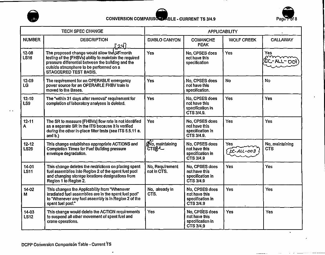
CONVERSION COMPARIS BLE - CURRENT TS 3/4.9 Page f8
TECH SPEC CHANGE APPLICABILITY
NUMBER
12-08LS16
12-09LG
12-10LS9
12-11A
12-12LS26
14-01LS11
14-02M
14-03LS12
DESCRIPTION
The proposed change would allow the -monthtesting of the fFHBVsj ability to maintain the requiredpressure differential between the building and theoutside atmosphere to be performed on aSTAGGERED TEST BASIS.
The requirement for an OPERABI.E emergencypower source for an OPERABLE FHBV train ismoved to the Bases.
The 'within 31 days after removal" requirement forcompletion of laboratory analyses is deleted.
The SR to measure [FHBVs] flow rate is not identifiedas a separate SR in the ITS because it is verifiedduring the other in-place filter tests (see ITS 5.5.11 a.and b.)
This change establishes appropriate ACTIONS andCompletion Times for Fuel Building pressureenvelope degradation.
This change deletes the restrictions on placing spentfuel assemblies into Region 2 of the spent fuel pooland changing storage locations designations fromRegion 1 to Region 2.
This changes the Applicabilityfrom Wheneverirradiated fuel assemblies are in the spent fuel poolto 'Whenever any fuel assembly is in Region 2 of thespent fuel pool."
This change would delete the ACTION requirementsto suspend all other movement of spent fuel andcrane operations.
DIABLOCANYON
Yes
Yes
Yes
Yes
o, maintainingCT~
No, Requirementnot in CTS.
No, already inCTS.
Yes
COMANCHEPEAK
No, CPSES doesnot have thisspecification
No, CPSES doesnot have thisspecification.
No, CPSES doesnot have thisspecification inCTS 3/4.9.
No, CPSES doesnot have thisspecification inCTS 3/4.9.
No, CPSES doesnot have thisspecification inCTS 3/4.9
No, CPSES doesnot have thisspecification inCTS 3/4.9
No, CPSES doesnot have thisspeciTication inCTS 3/4.9
No, CPSES doesnot have thisspecification inCTS 3/4.9
WOLF CREEK
Yes
Yes
Yes
Yes
+-ALC-oo9
Yes
Yes
Yes
GALLAWAY
Yes
Yes
Yes
No, maintainingCTS
Yes
Yes
Yes
DCPP Conversion Comparison Table - Current TS

Enclosure 2PG8 E Letter DCL 98-107
ADDITIONALINFORMATIONCOVER SHEET
ADDITIONALINFORMATIONNO: TR 3.9-001
REQUEST:
APPLICABILITY: DC, CP, WC, CA
It is purposed to "not incorporate" TSTF-21 but rather add a statement to theBases to state our current plant practice. It would be summarized by thefollowing statement: "An operable RHR loop must be capable of being realignedto provide an operable flow path."
ATTACHEDPAGES:
Enc. 5A Traveler Status SheetEncl 5B 8 3.9-17


Industry Travelers Applicable to Section 3.9 pproved Q UPC.
TRAVELER¹TSTF-20
TSTF-21 Rev. 1
TSTF-22
TSTF-23, Rev. 2
Qev 5
TSTF-51
TSTF-66, P,es k
TSTF-92
TSTF-96, Res. 5
OG43
WOG-76
'TUTEE - I~totwrF -ISe
CsTw —
27'TATUS
Incorporated
IncorporatedNot
Not incorporated
Incorporated
Not incorporated
Not incorporated
Not incorporated
Incorporated
Incorporated
'I rv~rp>~QlnC ~o~~h,Inc rp ~eh
I ~porcAe6
DIFFERENCE ¹3.9-2
None
NIA
3.9-3
NIA
N/A
NIA
3.9P
3.9-11
N/AN/AH/A'b.Q (5
COMMENTS
A oMedMR('ngem
e o3.9.6 .ct - 0o I
Changes not applicablefor the specific plantapplication.
raveler bracketed IT3.9.2 and revised th
es rlTS3.9,3 +4@5. ~(DCPP maintaining CTS).
Minimal impact on plantspecific appiications.
Similar changes wereincorporated into the ITSbased on currentlicensing basis. Seechange description 3.9-1.(Not Appl to DCPP)
The proposed changesdid not significantly affectcurrent surveillancepractices to warrantinclusion.
~~ZI vZe. C>q.m
Containment penetrationsallowed to be open underadministrative control.
A~r vcr Q QWC
Q SA-la.
%c~>~ %R-cog


BASES
RHR and Coolant Circulation —Low Water Level4n opt'~)t RVZ loop ~~sK M Ca~riC. of beiog rMiqnCh B 3.9.6
~b
path.and to determine the low end temperature. The flow path startsin one of the RCS hot le s and is returned to the RCS cold le s.
eaSR.b-r ~,„,~ r . ).
APPLICABILITY
TR 3aR.O~(Two RHR loops are required to be OPERABLE. and one RHR loop must be inoperation in NODE 6, with the water level < 23 ft above .the top of thereactor vessel flange, to provide decay heat removal. Requirementsfor the RHR System in other NODES are covered by LCOs in Section 3.4,Reactor Coolant System (RCS). and Section 3.5, Emergency Core CoolingSystems (ECCS). RHR loop requirements in MODE 6 with the water level~ 23 ft are located in LCO 3.9.5. "Residual Heat Removal (RHR) andCoolant Circulation - High Water Level." A,":;:,:Hote@~sjadded.":t:o:."the
apj'troafp'fthm, 'tora'ssUr'e,'hat::,'rrME "'6.i>per ataoo"-,:.w'ith".wite r",:,",1'e el@23! fVl';,
i s;.,'r'roti'jiiinrItttadiiiiif(si;-:.'twao;R~HR:.:'1 oo i':::,ir'eloJerrab1'el::
ACTIONS A. 1 and A2
If less than the required number of RHR loops are OPERABLE. actionshall be immediately initiated and continued until the RHR loop isrestored to OPERABLE status and to operation or until ~ 23 ft of waterlevel is established above the reactor vessel flange. When the waterlevel is ~ 23 ft above the reactor vessel flange, the Applicabilitychanges to that of LCO 3.9.5, and only one RHR loop is required to beOPERABLE and in operation. An immediate Completion Time is necessaryfor an operator to initiate corrective actions.
B.l
It no RHR loop is in operation, there will be no forced circulation toprovide mixing to establish uniform boron concentrations. -Reduced
1
. T4. ~pc~Sao~ cE anq opxa5toni~co>vinq 0 ceh,Moors in ~d'or Gx>>< 4 Boron C~nkcz&am xiii8.2 i'AgVthood o5 Gcrron Araki'>cchion in ~ QQQ, ~ g+ ~7If no RHR loop is in operation. actions shall be initiatedimmediately. and continued. to restore one RHR loop to operation.Since the unit is in Conditions A and B concurrently, the restorationof two OPERABLE RHR loops and one operating RHR loop should beaccomplished expeditiously.
B.3
If no RHR loop is in operation. all containment penetrations providingdirect access from the containm nt atmosphere to the outsideatmosphere must be closed within 4 hours. With the RHR loop
(Continued)
Nark-up of NUREG-1431. Rev. 1 Bases B 3.9-17

0
Enclosure 2PG8 E Letter DCL 98-107
ADDITIONALINFORMATIONCOVER SHEET
ADDITIONALINFORMATIONNO: TR 3.9-002 APPLICABILITY: DC, CP, WC, CA
REQUEST:TSTF-136 is changed to "Approved by NRC." Revise Comment for TSTF-153 toread "Editorial change to 3.9.5 is unnecessary whereas 3.4 and 3.5 were revisedto match 3.9.5 wording."
ATTACHEDPAGES:
Encl 5A Traveler Status Sheet

0

Industry Travelers Applicable to Section 3.9 pproved Q QPC.
TRAVELER¹TSTF-20
TSTF-21 Rev. 1
TSTF-22
STATUS
Incorporated
IncorporatedNot
Not incorporated
DIFFERENCE ¹3.9-2
None
NIA
COMMENTS
A, oWed M<C
angem e o3.9.6 .cl - oo I
Changes not applicablefor the specific plantapplication.
TSTF-23, Rev. 2
Aev.5
TSTF-51
TSTF-68, P.e.v. It
TSTF-92, R~, g
TSTF-96, RC,g. 4
OGW3
WOG-76
'7Q'g - ISIo'T 5TF —I Sct
I/
CBTz —271I
Incorporated
Not incorporated
Not incorporated
Not incorporated
Incorporated
No i
Incorporated
I A~~~+lAco+ocxc 4
~nc cp~ehI~rp rated
3.9-3
4pp~ch ~ NR,4.
N/A
NIA
N/A
3.9X
3.9-11
N/A*
N/AH/A+.9- I5
raveler bracketed IT3.9.2 and revised th
es r ITS 3.9.3 4R K ~(DCPP maintaining CTS).
Minimal impact on plantspecific applications.
Similar changes wereincorporated into the ITSbased on currentlicensing basis. Seechange description 3.9-1.(Not Appl to DCPP)
The proposed changesdid not significantly affectcurrent surveillancepractices to warrantinclusion.
Appian'.8 bi ~BC.
Containment penetrationsallowed to be open underadministrative control.
A~~u~ ~ gag
~T~ ER-oo2.EcVihoc'i &~~p, +c ~. t.)~ haec.es5o c q Mec e. o.and 5Smahch SR'5 ~oqQg~c,

Enclosure 2PG&E Letter DCL 98-107
ADDITIONALINFORMATIONCOVER SHEET
ADDITIONALINFORMATIONNO: TR 3.9-003
REQUEST:
APPLICABILITY: DC
The traveler status page is updated to reflect the following: TSTF-23, Revision 3,is "Approved by NRC" and TSTF-96, Revision 1, has been issued.
ATTACHEDPAGES'ncl
5A Traveler Status Sheet


Industry Travelers Applicable to Section 3.9 pp~ved by QE'C.
TRAVELER¹TSTF-20
TSTF-21 Rev. 1
TSTF-22
TSTF-23, Rev. 2
Aev '5
TSTF-51
TSTFWB P,~q
TSTF-92, f2~, g
TSTF-96, RCV. 5
OGW3
WOG-76
THYME -ISIoTSTF' ISct
r l5+YBVF —27
STATUS
Incorporated
IncorporatedHot
Not incorporated
Incorporated
Not incorporated
Not incorporated
Not incorporated
Incorporated
got'ncorporated
DIFFERENCE¹
3.9-2
None
N/A
3.9-3
rweh ~ NR4.
N/A
NIA
NIA
3.9C
3.9-11
M/A
N/AH/P'b. I- <5
COMMENTS
A, ove4 M~C
angem e o3.9.6 .cl- no
Changes not applicablefor the specific plantapplication.
reveler bracketed IT3.9.2 and revised th
es r ITS 3.9.3 4R L(DCPP maintaining CTS).
Minimal impact on plantspecific applications.
Similar changes wereincorporated into the ITSbased on currentlicensing basis. Seechange description 3.9-1.(Not Appl to DCPP)
The proposed changesdid not significantly affectcurrent surveillancepractices to warrantinclusion.
A~~Z I vZe.
Containment penetrationsallowed to be open underadministrative control.
A~~um b„QWi„
Q S.c(-lo
%R DQQ

Enclosure 2PG8E Letter DCL 98-107
JLS CONVERSION TO IMPROVED TECHNICALSPECIFICATIONS
CTS 5.0 - DESIGN FEATURSITS 4.0 - DESIGN FEATURES
RESPONSE TO REQUEST FOR ADDITIONALINFORMATIONAND LICENSEEINITIATEDADDITIONALCHANGES


Enclosure 2PG8E Letter DCL 98-107
INDEXOF ADDITIONALINFORMATION
ADDITIONALINFORMATIONNUMBER
4.3.2
CP 4.0-002
APPLICABILITY
DC, CP, WC, CA
CP
ENCLOSED
YES
NA

Enclosure 2PG&E Letter DCL 98-107
JOINT LICENSING SUBCOMMITTEE METHODOLOGYFORPROVIDING ADDITIONALINFORMATION
The following methodology is followed for submitting additional information:
1. Each licensee is submitting a separate response for each section.
2. Ifan RAI does not apply to a licensee (i.e., does not actually impact theinformation that defines the technical speciTication change for that licensee),"NA"has been entered in the index column labeled "ENCLOSED" and noinformation is provided in the response for that licensee.
3. If a licensee initiated change does not apply, "NA"has been entered in the indexcolumn labeled "ENCLOSED" and no information is provided in the response forthat licensee.
4. The common portions of the "Additional Information Cover Sheets" are identical,except for brackets, where applicable (using the same methodology used inenclosures 3A, 3B, 4, 6A and 6B of the conversion submittals). The list ofattached pages willvary to match the licensee specific conversion submittals. Alicensee's FLOG response may not address all applicable plants if there isinsufficient similarity in the plant specific responses to justify their inclusion ineach submittal. In those cases, the response will be prefaced with a headingsuch as "PLANTSPECIFIC DISCUSSION."
5. Changes are indicated using the redline/strikeout tool of WordPerfect or by usinga hand markup that indicates insertions and deletions. Ifthe area being revisedis not clear, the affected portion of the page is circled. The markup techniquesvary as necessary, based on the specifics of the area being changed and thecomplexity of the changes, to provide the clearest possible indication of thechanges.
6. A marginal note (the Additional Information Number from the index) is added inthe right margin of each page being changed, adjacent to the area beingchanged, to identify the source of each change.
7. Some changes are not applicable to one licensee but still require changes to theTables provided in Enclosures 3A, 3B, 4, 6A, and 6B of the original licenseamendment request to reflect the changes being made by one or more of theother licensees. These changes are not included in the additional information forthe licensee to which the change does not apply, as the changes are only forconsistency, do not technically affect the request for that licensee, and are beingprovided in the additional information being provided by the licensees for whichthe change is applicable. The complete set of changes for the licenseamendment request will be provided in a licensing amendment requestsupplement to be provided later.

Enclosure 2PG8 E Letter DCL 98-107
JOINT LICENSING SUBCOMMITTEE METHODOLOGYFORPROVIDING ADDITIONALINFORNIATION
(cont)
8. The item numbers are formatted as follows:
[Source] [ITS Section]-[nnn]
Source = Q - NRC QuestionCA - AmerenUEDC- PG8EWC - WCNOCCP - TU ElectricTR - Traveler
ITS Section = The ITS section associated with the item (e.g., 3.3). Ifallsections are potentially impacted by a broad change or set of changes, "ALL"is used for the section number.
nnn = a three digit sequential number


Enclosure 2PG8 E Letter DCL 98-107
ADDITIONALINFORMATIONCOVER SHEET
ADDITIONALINFORMATIONNO: Q 4.3.2
REQUEST:4.3.2 DRAINAGE
The ISTS for this section is as follows:
APPLICABILITY: DC, CP, WC, CA
The spent fuel storage pool is designed and shall be maintained to preventinadvertent draining of the pool below elevation [23 ft].
Comment: This section for all four FLOG plants are the same as the ISTSabove. Each has a plant specific elevation for the bracket instead of the 23 ft.They are: Callaway 2040 ft; WolfCreek 2040 ft; Comanche Peak 845 ft; DiabloCanyon 133 ft. Provide explanations that these elevation levels are at 23 ftabove the spent fuel in the pool.
FLOG RESPONSE: General Discussion - The elevation reported by each of the FLOGplants is based upon reference elevations used in the plant's design and construction.The design feature (plant specific elevation) of CTS 5.6.2 is provided in accordance withRG 1.13, "Fuel Storage Facility Design Basis," C.6. Per RG 1.13, this design feature isrequired to assure that an inadvertent drain down of the Spent Fuel Pool will not "causethe fuel to be uncovered." This RG also states that loss of inventory from the SpentFuel Storage Pool "could cause overheating of spent fuel and resultant damage tocladding integrity." The margin of coverage above the spent fuel is in excess of the 10feet stated in the Standard Review Plan, NUREG-0800, Section 9.1.3.lll.i.e.
Plant Specific Discussion: For DCPP, the top of the active fuel in the spent fuel pool isat the 111'-5" elevation. Consequently, the 133 foot elevation is 21 feet 7 inches overthe top of the active fuel. This elevation is based upon the location of the Spent FuelPool Cooling system suction pipe. The discharge pipe anti-siphon device is located at136'-6. This is consistent with SER 0 (10/16/74) which states that the DCPP Spent FuelPool meets RG 1.13 and GDC 61 and "therefore the design is acceptable." This also isconsistent with the FSAR, Section 9.1.3.2, which states that the bottom of the pumpsuction line is "4 feet below the normal Spent Fuel Pool level" (or 137 feet 8 inchesminus 4 feet) and CTS 5.6.2, which rounded 133 feet 8 inches to elevation 133 feet.
ATTACHED PAGES:
None

I


