Embed Size (px)
Citation preview
• 1n MODEL 225P/230P
ULTRASOUND I
I ~ ~/;;~
----~-:==---- I mPERATmR'S MANUAL • INSTALLATION
• mPERATimN • MAINTENANCE
• PARTS
P.N. 73778 REV C
table of contents
Description Page.
FOREWORD ................................................................... 2
WARRANTY INFORMATION .................................................... 2
SAFETY INSTRUCTIONS ....................................................... 3
SPECIFICATIONS .............................................................. 4
ULTRASOUND THERAPY INDICATIONS ........................................ 5
ULTRASOUND THERAPY CONTRAINDICATIONS ............................... 5
INTELECT 225P/230P OPERATING CONTROLS ................................ 6
OPERATING PROCEDURE ..................................................... 7
DESCRIPTION OF THE UL TRASDUND FIELD ................................... 8
PLOT OF ULTRASOUND FIELD SPATIAL DISTRIBUTIONS ...................... 9
ABBREVIATIONS .............................................................. 9
TROUBLESHOOTING ......................................................... 1 0
MAINTENANCE AND SERVICE INSTRUCTIONS ............................... 11
ULTRASOUND CALIBRATION ................................................. 12
COMPONENT LOCATION, CIRCUIT BOARD ....................... 17, 19, 21, 23
PARTS LIST ..................................................... 18, 20, 22, 24
SCHEMATICS ............................................................ 25-39

foreword
This manual has been prepared for the owners and operators of the lntelect®Model 225P/230P. It contains general instructions on operation. safety practices, maintenance and parts information. In order to obtain maximum life and efficiency from your Model 225P/230P and to aid in the safe operation of the unit, read and understand this manual thoroughly and become totally familiar with the controls on the panel and the applicator that comes with the unit before operating it. The specifications put forth in this manual were in effect at the time of publication. However. owing to Chattanooga Corporation's policy of continuous improvement, changes to these specifications may be made at any time without obligation on the part of Chattanooga Corporation. ·
full one year warranty Chattanooga Corporation ("Company") warrants that lntelect®Model 225P/230P ("Product") is free of defects in material and workmanship.
This warranty shall remain in effect for one ( 1 l year from the date of the original consumer purchase of this Product and extends to any owner of the Product during the warranty period. If this Product fails to function during the one year warranty period because of a defect in material and workmanship, Company or the selling dealer will replace or repair this Product without charge within a period of thirty (30J days from the date on which the defective Product is returned to the Company or the dealer. Company or the dealer will ship the replacement or the repaired Product to the consumer's residence.
THIS WARRANTY DOES NOT COVER:
1. Replacement parts or labor furnished by anyone other than the Company, the dealer or an approved Company service agent.
2. Defects or damage caused by labor furnished by someone other than the Company, the dealer or an approved Company service agent.
3. Any malfunction or failure in the Product while it is in the possession of the owner during the warranty period if the malfunction or failure is not caused by a defect in material and workmanship or if the malfunction or failure is caused by unreasonable use. including the failure to provide reasonable and necessary maintenance.
COMPANY SHALL NOT BE LIABLE FOR INCIDENTAL OR CONSEQUENTIAL DAMAGES TO PROPERTY OR BUSINESS.
Some states do not allow the exclusion or limitation of incidental or consequential damages. so the above limitation or exclusion may not apply to you.
TO OBTAIN SERVICE from the Company or the selling dealer under this warranty, the 1
owner must do or abide by the following:
1 . A written claim must be made within the warranty period to the Company or the selling dealer. If the claim is made to the Company, written claim should be sent to: P.O. Box 4287, 101 Memorial Drive, Chattanooga, Tennessee 37405.
2. The Product must be returned to the Company or the selling dealer by the owner.
This warranty gives you specific legal rights, and you may also have other rights which vary from state to state.
Company does not authorize any person or representative to create for it any other obligation or liability in connection with the sale of this Product. Any representative or agreement not contained in the warranty shall be void and of no effect.
2
safety instructions
1 . WARNING: Explosion hazard if used in the presence of flammable anesthetics.
2. WARNING: For continued protection against fire hazard replace fuses only with ones of the same type and rating.
3. Read, understand and practice the safety and operating instructions. Know the limitations and hazards associated with the Ultrasound. Observe the safety and operational decals placed on the unit.
4. Grounding-Make certain that the unit is electrically grounded by plugging into an electrical outlet with a ground terminal receptacle CU-ground outlet). Follow the National Electric Code.
5. The lntelect Model 225P/230P should not be connected to any other device when in use.
6. CAUTION: Federal law restricts this device to sale by, or on the order of, a physician or licensed practitioner.
7. The generator should be routinely checked before each use to determine that all controls function normally; especially that the INTENSITY control does properly adjust the intensity of the ultrasonic power output in a stable manner. Also determine that the TREATMENT TIME control does actually terminate ultrasonic output power when the timer reaches zero.
8. CAUTION:-Use of controls or adjustments or performance of procedures other than those specified herein may result in hazardous exposure to ultrasonic energy.
3
specifications
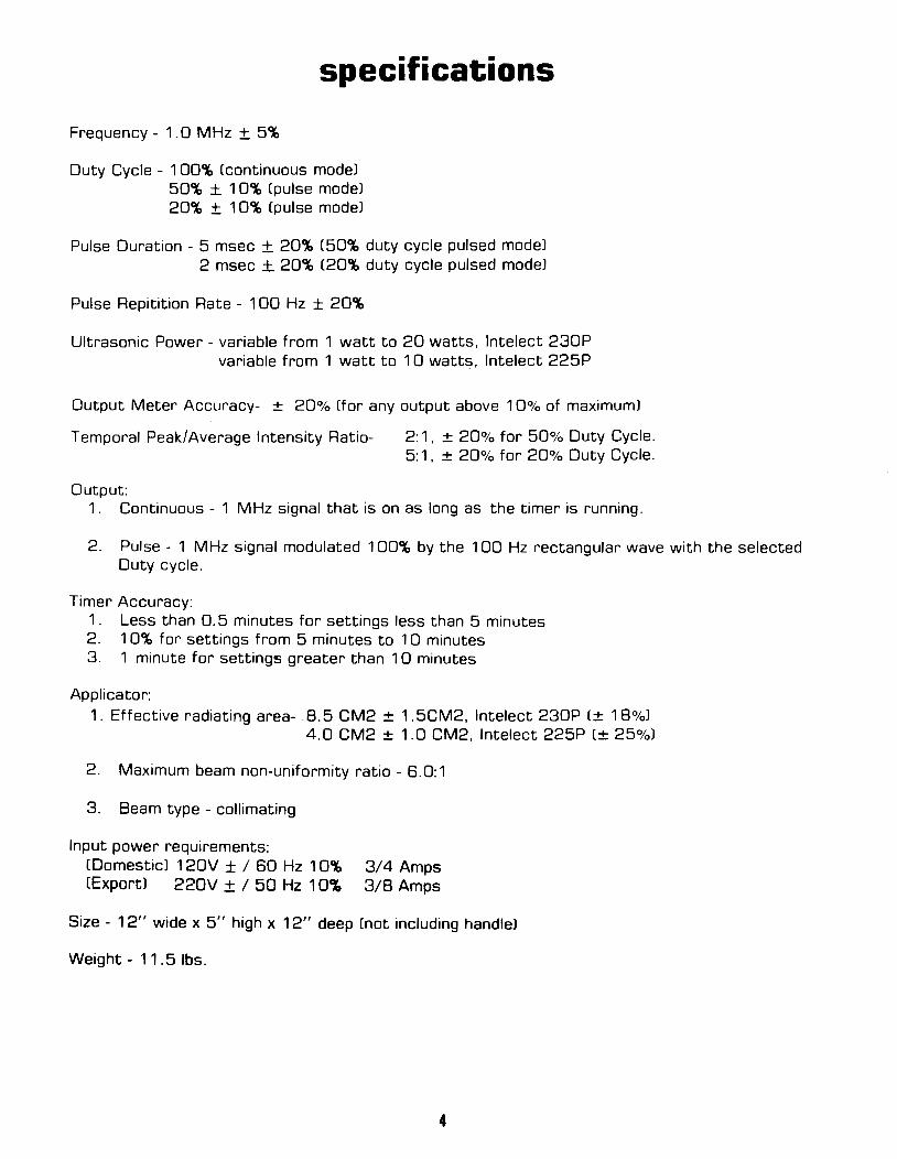
Frequency- 1.0 MHz ± 5%
Duty Cycle - 1 00% (continuous mode) 50% ± 1 0% (pulse model 20% ± 1 0% (pulse model
Pulse Duration - 5 msec ± 20% (50% duty cycle pulsed mode) 2 msec ± 20% £20% duty cycle pulsed model
Pulse Repitition Rate - 1 00 Hz ± 20%
Ultrasonic Power- variable from 1 watt to 20 watts, lntelect 230P variable from 1 watt to 10 watts, lntelect 225P
Output Meter Accuracy- ± 20% (for any output above 1 0% of maximum)
Temporal Peak/Average Intensity Ratio- 2:1, ± 20% for 50% Duty Cycle. 5:1, ± 20% for 20% Duty Cycle.
Output: 1. Continuous- 1 MHz signal that is on as long as the timer is running.
2. Pulse- 1 MHz signal modulated 100% by the 100 Hz rectangular wave with the selected Duty cycle.
Timer Accuracy: 1 . Less than 0. 5 minutes for settings less than 5 minutes 2. 1 0% for settings from 5 minutes to 1 0 minutes 3. 1 minute for settings greater than 1 0 minutes
Applicator: 1. Effective radiating area- . 8. 5 CM2 ± 1. 5CM2, lntelect 230P (± 18%)
4.0 CM2 ± 1.0 CM2, lntelect 225P (± 25%)
2. Maximum beam non-uniformity ratio- 6.0:1
3. Beam type - collimating
Input power requirements: £Domestic) 120V ± I 60 Hz 1 0% £Export) 220V ± 1 50 Hz 1 0%
314 Amps 318 Amps
Size - 12" wide x 5" high x 12" deep (not including handle)
Weight - 11. 5 lbs.
4

indications for ultrasound therapy * Some indications for the use of ultrasound include adhesive capsulitus, bursitis with slight calcification, myositis, soft tissue injuries, shortened tendons due to past injury, healing scar tissue and plantar warts. Ultrasouno is an efficient modality when used for the treatment of all types of joint contractures resulting from capsular tightness and scarring. Ultrasound is the modality of choice to obtain therapeutic levels of heating within body structures covered by thick layers of soft tissue. Neither shortwave or microwave diathermy is able to heat these underlying structures to produce results comparable to ultrasound.
contraindications for ultrasound therapy * Ultrasound SHOULD NOT BE USED over the eyes or the reproductive organs. Also ultrasound SHOULD NOT BE USED over a pregnant uterus. Other contraindications include acute infection or septis, deep vein thrombosis, or arterial disease, and over anesthetized areas or conditions that cause impairment of sensations, such as chemotherapy. Ultrasound IS NOT TO BE USED over cancerous lesions.
REF: Lehmann, J.F., Therapeutic Heat and Cold; 13:367-378, 1972.
5
operating controls
OUTPUT
0
-------------------
ULTRASOUND HEAD I ON M TEMP
2TYCY~E(O) 100% 50% 20%
CONTINUOUS PULSED 100 Hz
0 0
0
30 ®-'···,5 ' /
{ 0 ~10 25 , ' , ' , '
'I I It\'
20 15
MINUTES
CHATTAN~.i?o~!':
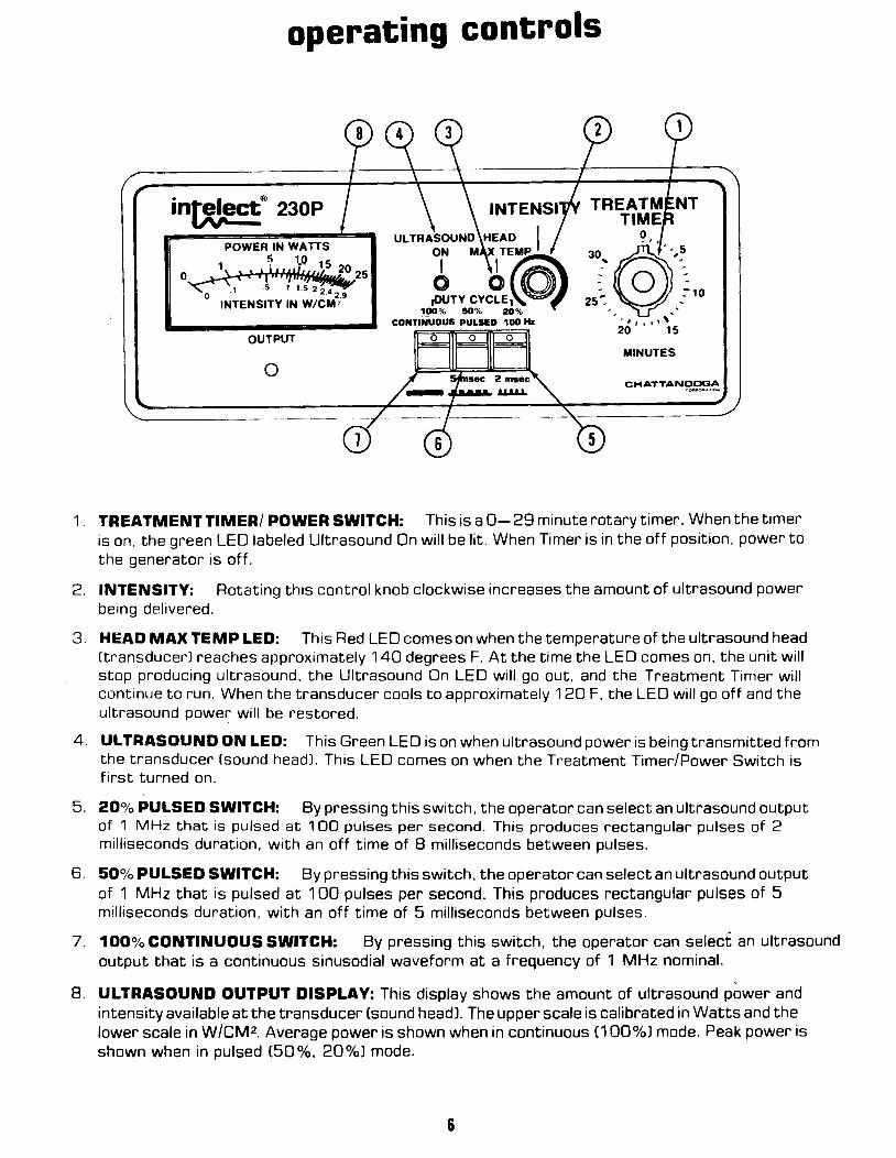
1 . TREATMENT TIMER/ POWER SWITCH: This is a 0-29 minute rotary timer. When the timer is on, the green LED labeled Ultrasound On will be lit. When Timer is in the off position, power to the generator is off.
2. INTENSITY: Rotating this control knob clockwise increases the amount of ultrasound power being delivered.
3. HEAD MAX TEMP LED: This Red LED comes on when the temperature of the ultrasound head (transducer) reaches approximately 140 degrees F. At the time the LED comes on, the unit will stop producing ultrasound, the Ultrasound On LED will go out, and the Treatment Timer will continue to run. When the transducer cools to approximately 1 20 F, the LED will go off and the ultrasound power will be restored.
4. ULTRASOUND ON LED: This Green LED is on when ultrasound power is being transmitted from the transducer (sound head). This LED comes on when the Treatment Timer/Power Switch is first turned on.
5. 20% PULSED SWITCH: By pressing this switch, the operator can select an ultrasound output of 1 MHz that is pulsed at 1 00 pulses per second. This produces rectangular pulses of 2 milliseconds duration, with an off time of 8 milliseconds between pulses.
6. 50% PULSED SWITCH: By pressing this switch, the operator can select an ultrasound output of 1 MHz that is pulsed at 1 00 pulses per second. This produces rectangular pulses of 5 milliseconds duration, with an off time of 5 milliseconds between pulses.
7. 100% CONTINUOUS SWITCH: By pressing this switch, the operator can select an ultrasound output that is a continuous sinusodial waveform at a frequency of 1 MHz nominal.
8. ULTRASOUND OUTPUT DISPLAY: This display shows the amount of ultrasound power and intensity available at the transducer (sound head). The upper scale is calibrated in Watts and the lower scale in W/CM2. Average power is shown when in continuous (1 00%1 mode. Peak power is shown when in pulsed £50%, 20%1 mode.
6
operating procedure
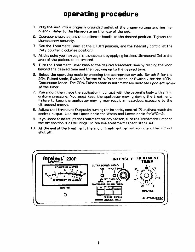
1 . Plug the unit into a properly grounded outlet of the proper voltage and line frequency. Refer to the Nameplate on the rear of the unit.
2. Operator should adjust the applicator handle to the desired position. Tighten the thumbscrew securely.
3. Set the Treatment Timer at the 0 (Qffl position, and the Intensity control at the (fully counter clockwise position).
4. At this point you may begin the treatment by applying lntelect Ultrasound Gel to the area of the patient to be treated.
5. Turn the Treatment Timer knob to the desired treatment time by turning the knob beyond the desired time and then backing up to the desired time.
6. Select the operating mode by pressing the appropriate switch. Switch 5 for the 20% Pulsed Mode, Switch 6 for the 50% Pulsed Mode, or Switch 7 for the 100% Continuous Mode. The 20% Pulsed Mode is automatically selected upon actuation of the timer.
7. You should then place the applicator in contact with the patient's body with a firm uniform pressure. You must keep the applicator moving during the treatment. Failure to keep the applicator moving may result in hazardous exposure to the ultrasound energy.
8. Adjust the Ultrasound Output by turning the Intensity control (2) until you reach the desired output. Use the Upper scale for Watts and Lower scale forW/Cm2.
9. If you need to interrupt the treatment for any reason, turn the Treatment Timer to the off position (Bell will ringl. To resume treatment repeat steps 4-8.
1 0. At the end of the treatment, the end of treatment bell will sound and the unit will shut off.
in~® 230P
POWER IN WATTS 5 10
~. ''f'tl~'f'~s 20 o • 'I"' ·ii:rlpe::.t;,.2s .1 .s 11.5224
0 - . 2.1 INTENSITY IN W/CM2
OUTPUT
0
INTENSITY TREATMENT TIMER
ULTRASOUND HEAD I 0
OIN MAXITE(O)MP 30,@·'··· .. ,5
0 0 0 : 0 ~10 ,OUTY CYCLEt 25":. ,·
100% 10% 10% , , '' CONnNUOUS PULUO 100 Hz ' • ' , • ' '
IEli~El ·~UTE; s-c ·- CHATTANOOGA - ..... ~ c~,..,..
1
description of ultrasonic field
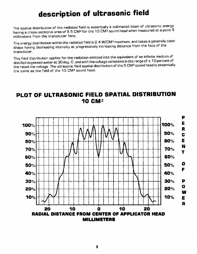
The spatial distribution of the radiated field is essentially a collimated beam of ultrasonic energy having a cross-sectional area of 8.5 CM2 for the 10 CM2 sound head when measured at a point 5
millimeters from the transducer face.
The energy distribution within the radiated field is 2.4 W/CM2 maximum, and takes a generally conic shape having decreasing intensity at progressively increasing distance from the face of the
transducer.
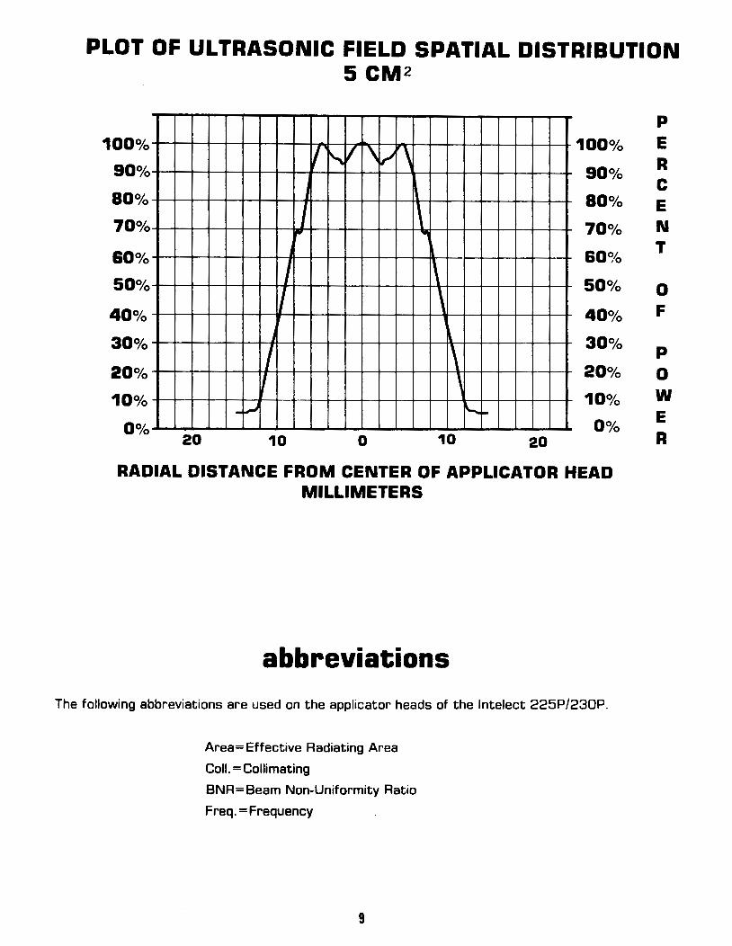
This field distribution applies for the radiation emitted into the equivalent of an infinite medium of distilled degassed water at 30 deg. C. and with line voltage variations in the range of± 1 0 percent of the rated line voltage. The ultrasonic field spatial distribution of the 5 CM 2 sound head is essentially the same as the field of the 10 CM2 sound head.
PLOT OF ULTRASONIC FIELD SPATIAL DISTRIBUTION 10 CM2
90°/o
80°/o
70°/o
&Oo/o
50°/o
40°/o
30°/o
20°/o
10°/o ,...
1\ I I ,, " " 1~ v v \'
t ~ I \j \~ u \ ....
1 ' l I \
J ~
" ) \ /'
/ \ 20 10 0 10 20
100°/o
90°/o
80°/o
70°/o
60°/o
SOo/o
40°/o
30°/o
20°/o
10°/o ....
RADIAL DISTANCE FROM CENTER OF APPUCATOA HEAD MIWMETEAS
8
p E A c E N T
0 F
p 0 w E A
PLOT OF ULTRASONIC FIELD SPATIAL DISTRIBUTION 5 CM 2
100o/o
90°/o
80°/o
70°/o
&Oo/o
50°/o
40°/o
30°/o
20°/o
10°/o
0°/o -~
20
I j
I
I
I ~
10
v ~ v ' ~ ~
fl"
0
., 100°/o
90°/o
80°/o \ 'II 70°/o
1\ \
60~{:,
50°/o
40°/o \
\
' ~ ~ 30°/o
20°/o
10°/o
Qo/o 10 20
RADIAL DISTANCE FROM CENTER OF APPLICATOR HEAD MILLIMETERS
abbreviations
The following abbreviations are used on the applicator heads of the lntelect 225P/230P.
Area= Effective Radiating Area
Call.= Collimating
BNR= Beam Non-Uniformity Ratio
Freq. =Frequency
9
p
E R c E N T
0 F
p
0 w E R
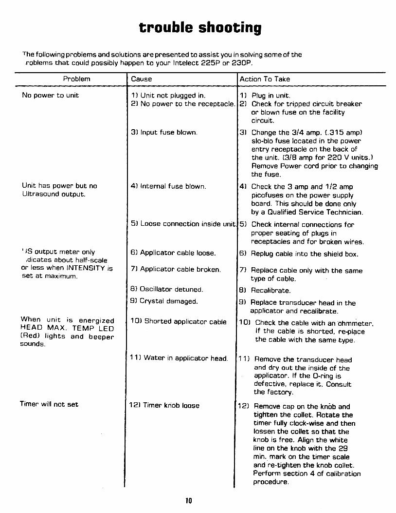
trouble shooting
The following problems and solutions are presented to assist you in solving some of the roblems that could possibly happen to your lntelect 225P or 230P.
Problem
No power to unit
Unit has power but no Ultrasound output.
1 JS output meter only • dicates about half-scale
or less when INTENSITY is set at maximum.
When unit is energized HEAD MAX. TEMP LED (Red) lights and beeper sounds.
Timer will not set
Cause Action To Take
1) Unit not plugged in. 1 J Plug in unit. 21 No power to the receptacle. 2) Check for tripped circuit breaker
or blown fuse on the facility circuit.
3) Input fuse blown.
41 Internal fuse blown.
31 Change the 3/4 amp. £.315 ampl slo-blo fuse located in the power entry receptacle on the back of the unit. (3/8 amp for 220 V units.) Remove Power cord prior to changing the fuse.
41 Check the 3 amp and 1 /2 amp picofuses on the power supply board. This should be done only by a Qualified Service Technician.
51 Loose connection inside unit 51 Check internal connections for proper seating of plugs in receptacles and for broken wires.
6) Applicator cable loose. 61 Replug cable into the shield box .
7) Applicator cable broken.
BJ Oscillator detuned.
91 Crystal damaged.
1 OJ Shorted applicator cable
71 Replace cable only with the same type of cable.
81 Recalibrate.
9J Replace transducer head in the applicator and recalibrate.
1 OJ Check the cable with an ·ohmmeter, If the cable is shorted, re-pl~ce the cable with the same type.
11 J Water in applicator head. 11 1 Remove the transducer head and dry out the inside of the applicator. If the D-ring is defective, replace it. Consult the factory.
121 Timer kriob loose
10
121 Remove cap on the knob and tigtrten the collet. Rotate the timer fully clock-wise and then lassen the collet so that the knob is free. Align the white line on the knob with the 29 min. mark on the timer scale and re-tighten the knob collet. Perform section 4 of calibration procedure.

maintenance and service instructions
1. To fully maintain compliance with Federal Regulation Title 21 (21 CFRl this unit must be
recalibrated annually. It is recommended that all Chattanooga Corporation Ultrasound
Products be returned to the factory or an authorized servicing dealer for repairs or
recalibrations. It is also recommended after the replacement or repair of any major
component. (See Section for Calibration Procedures.)
2. The following items should be checked at least monthly to insure proper operation of this
unit:
. 1 Power cord and plug. Check to make sure the cord is not frayed, kinked or has torn or
cut insulation .
. 2 Transducer (applicator) Cable. Check to make sure the cable is flexible, free of kinks,
not frayed and that insulation is intact .
. 3 Transducer (applicator) Handle. Check to make sure that it is not cracked or broken .
.4 Transducer (applicator) Face. Check to see that there is no build-up of gel of foreign
material on the stainless steel face .
. 5 LED's. Check each function to see if the LED is on when you are using that function.
11
calibration
CAUTION: An Electrical Shock Hazard is present during several portions of the calibration -.procedure. Calibration should be performed by a Qualified Service Technician.
1. TEST EQUIPMENT REQUIRED .1 Power line monitor (expanded scale voltmeter for rated line voltage ± 1 0%), VI~ model
WV-1208 or equivalent for 120VAC line .
. 2 Autotransformer, adjustable from 90% to 11 0% of rated line voltage, 150 watts or greater .
. 3 Ultrasound Power Meter, Ohmic Instruments Model UPM-30 or equivalent .
.4 Oscilloscope, Hameg Hm 204-2 or equivalent .
. 5 Probe, voltate, X1 0, Scope, low capacitance .
. 6 Probe, current, Textronix P6021 AC current probe or equivalent .
. 7 Voltmeter, Digital,, 3~ 1/2 digits, Simpson Model 461 or equivalent .
. 8 Probe, temperature, Fluke Model BOT-150 or equivalent .
. 9 Source of approximately 1/2 gallon of distilled de-oxygenated (<5 PPMJ water at 30 degrees Celsuis for use in UPM-30 power meter (item #3) .
. 10 Counter, frequency, 10 MHz, Triplett 7000 or equivalent .
. 11 Stopwatch, Siliconix Model 705 or equivalent .
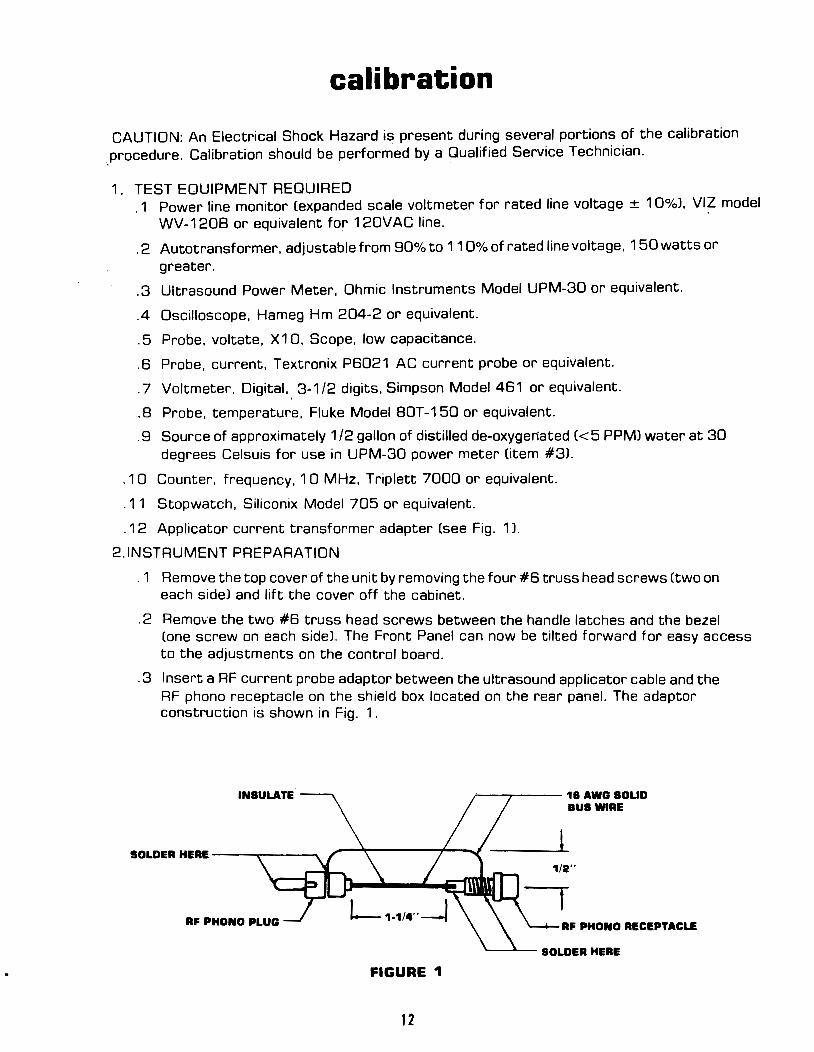
. 12 Applicator current transformer adapter (see Fig. 1 J.
2.1NSTRUMENT PREPARATION
. 1 Remove the top cover of the unit by removing the four #6 truss head screws (two on each side) and lift the cover off the cabinet .
. 2 Remove the two #6 truss head screws between the handle latches and the bezel Cone screw on each sidel. The Front Panel can now be tilted forward for easy access to the adjustments on the control board .
. 3 Insert a RF current probe adaptor between the ultrasound applicator cable and the RF phono receptacle on the shield box located on the rear panel. The adaptor construction is shown in Fig. 1.
r---~----16AWGSOUD
BUS WIRE
l 1/2"
RF PHONO PLUG RF PHONO RECEPTACLE
FIGURE 1
12
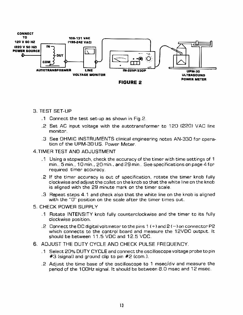
CONNECT TO
120 V 60HZ
1220 V 50 HZJ POWER SOURCE
108-131 VAC ,--------. (198-242 VACJ
J:N
UT
co ls----1 • ·(i) J): O:IJ ... •
AUTOTRANSFORMER LINE IN-225P/230P UPM-30 ULTRASOUND POWER METER
VOLTAGE MONITOR
FIGURE 2
3. TEST SET-UP
. 1 Connect the test set-up as shown in Fig. 2 .
. 2 Set AC input voltage with the autotransformer to 1 20 C220J V AC line monitor .
. 3 See OHMIC INSTRUMENTS clinical engineering notes AN-330 for operation of the UPM-30 US. Power Meter.
4.TIMER TEST AND ADJUSTMENT
.1 Using a stopwatch, check the accuracy of the timer with time settings of 1 min .. 5 min., 10 min., 20 min., and 29 min .. See specifications on page 4 for required timer accuracy .
. 2 If the timer accuracy is out of specification, rotate the timer knob fully clockwise and adjust the collet on the knob so that the white line on the knob is aligned with the 29 minute mark on the timer scale .
. 3 Repeat steps 4. 1 and check also that the white line on the knob is aligned with the "0" position on the scale after the timer times out.
5. CHECK POWER SUPPLY
. 1 Rotate INTENSITY knob fully counterclockwise and the timer to its fully clockwise position .
. 2 Connect the DC digital voltmeter to the pins 1 ( + J and 2 (-Jon connector P2 which connects to the control board and measure the 12VDC output. It should be between 11.5 VDC and 12.5 VDC.
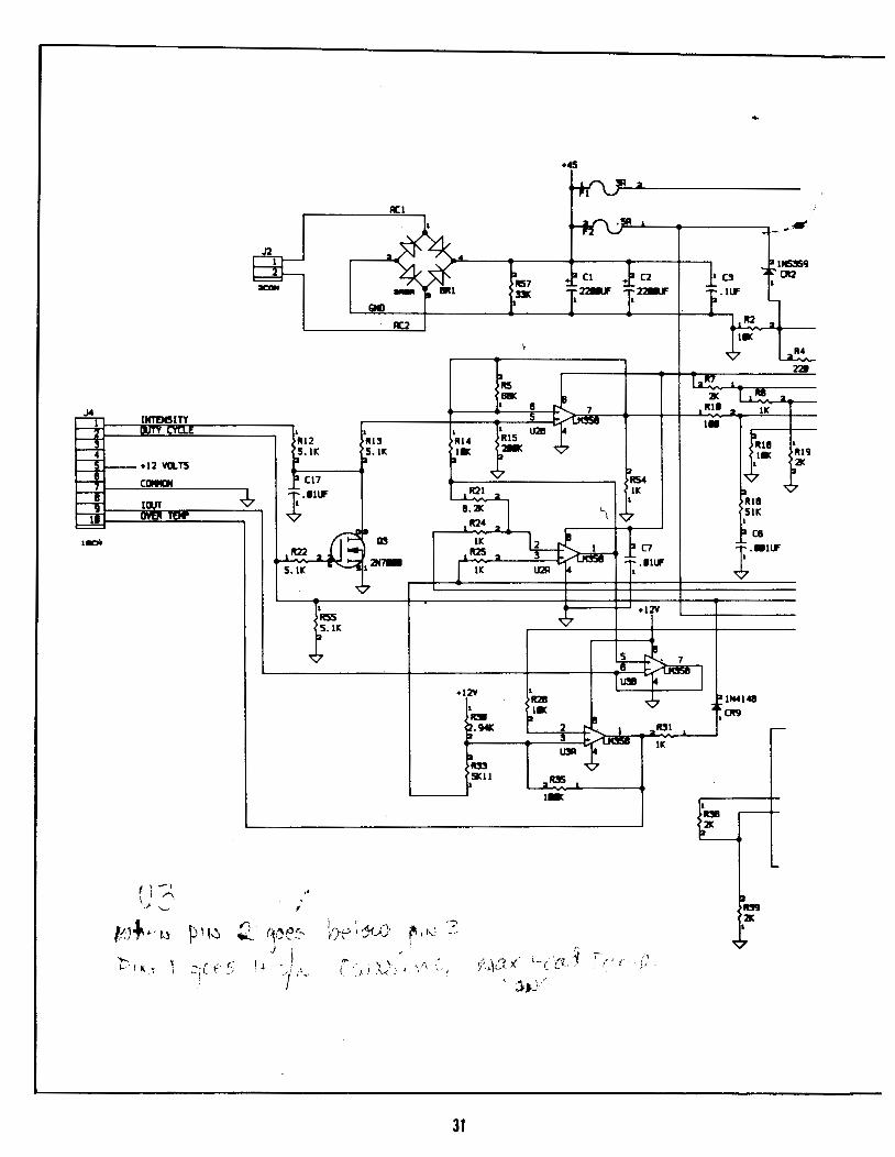
6. ADJUST THE DUTY CYCLE AND CHECK PULSE FREQUENCY .
. 1 Select 20% DUTY CYCLE and connect the oscilloscope voltage probe to pin #3 (signaiJ and ground clip to pin #2 (com. J .
. 2 Adjust the time base of the oscilloscope to 1 msec/div and measure the period of the 1OOHz signal. It should be between 8.0 msec and 12 msec.
13
. 3 Adjust the scope time base for 1 0 divisions of one cycle of the sign.,al. On the control board. adjust RS for a pulse width of 7. 9 divisions .
. 4 Select 50% DUTY CYCLE and adjust R4 on the control board for a pulse width of 4. 7 divisions .
. 5 Select 1 00% DUTY CYCLE and observe that the signal is a DC level less than .5V.
7.CHECK AND ADJUST THE R.F. OSCILLATOR
. 1 Connect the scope current probe around the center conductor of the current probe adaptor and connect the voltage probe to the outside conductor .
. 2 Rotate the INTENSITY control clockwise as you observe the voltage and current waveforms on the dual channel scope. The waveforms should be within 5 degrees of being in phase and oscillation should be stable .
. 3 Repeat step 7. 2 with 50% duty cycle and then with 20% duty cycle selected .
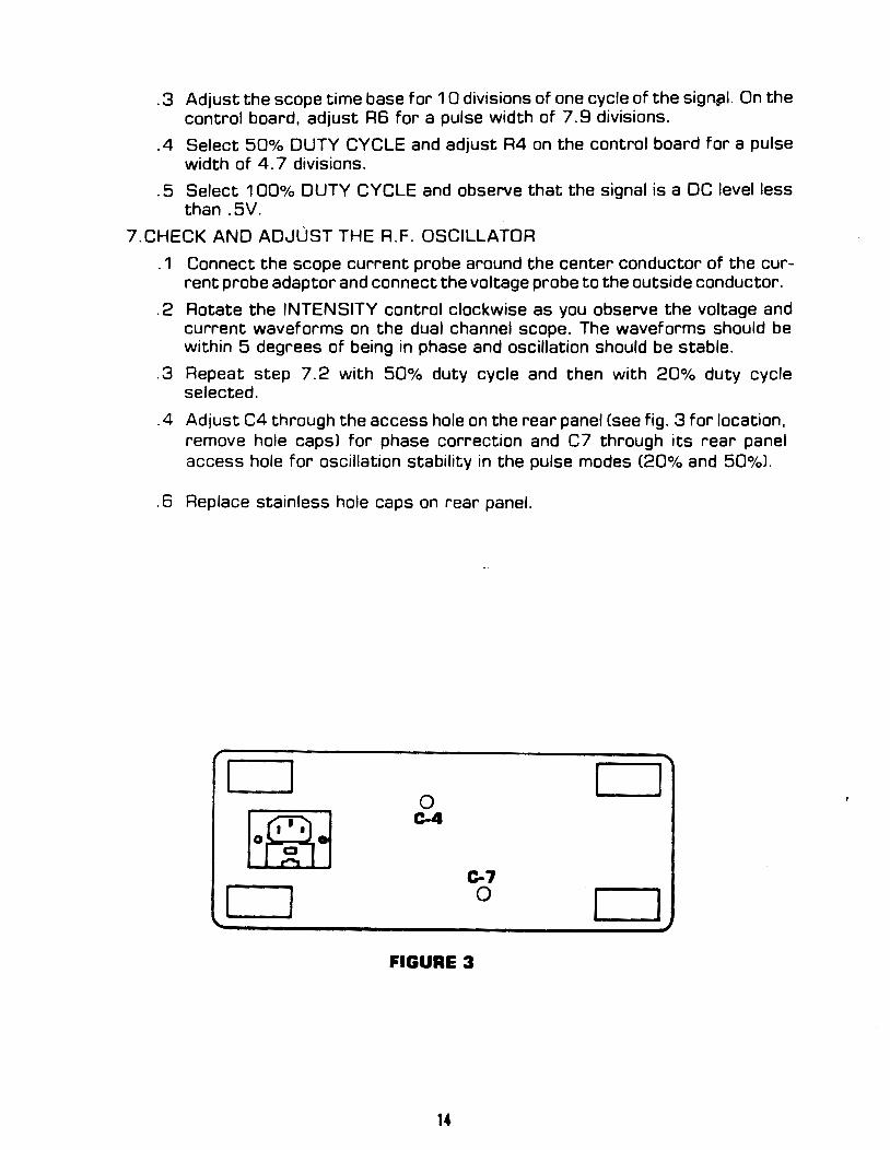
.4 Adjust C4 through the access hole on the rear panel (see fig. 3 for location. remove hole capsJ for phase correction and C7 through its rear panel access hole for oscillation stability in the pulse modes £20% and 50%) .
. 6 Replace stainless hole caps on rear panel.
D D 0
E@j C-4
c-7
CJ 0 D FIGURE 3
14
\ \,
; '
\ ' .... ... ~ ...............
0
.... ,_
,. . ; ' -~ ...... ~ .,_
(
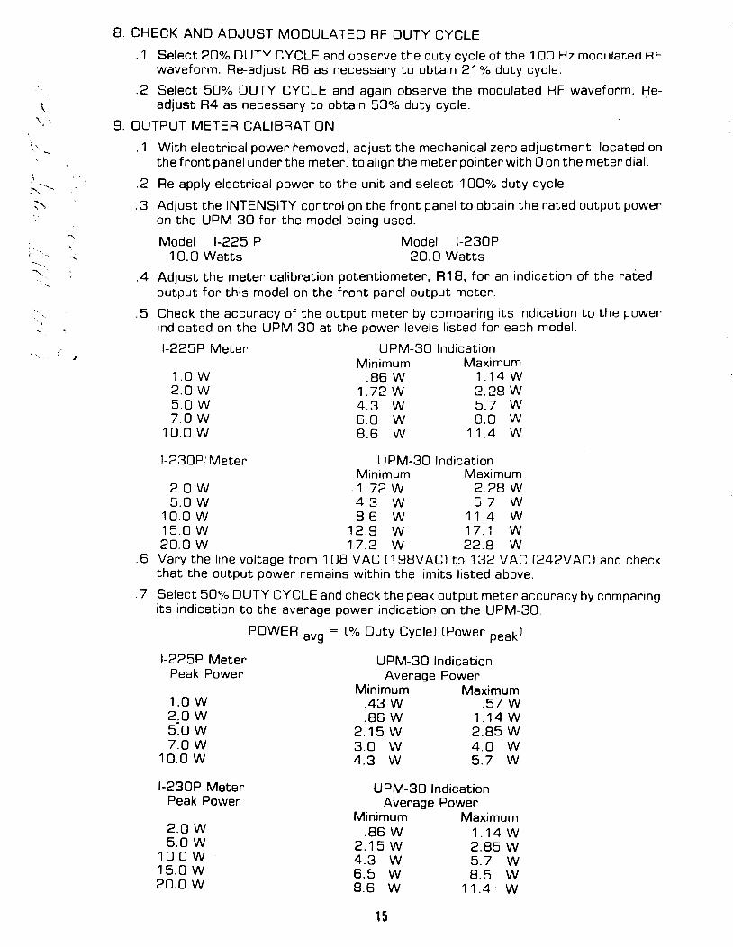
8. CHECK AND ADJUST MODULATED RF DUTY CYCLE
.1 Select 20% DUTY CYCLE and observe the duty cycle of the 100Hz modulated RF
waveform. Re-adjust R6 as necessary to obtain 21% duty cycle .
. 2 Select 50% DUTY CYCLE and again observe the modulated RF waveform. Readjust R4 as necessary to obtain 53% duty cycle.
9. OUTPUT METER CALIBRATION
.1 With electrical power removed, adjust the mechanical zero adjustment, located on the front panel under the meter, to align the meter pointer with 0 on the meter dial.
. 2 Re-apply electrical power to the unit and select 1 00% duty cycle .
. 3 Adjust the INTENSITY control on the front panel to obtain the rated output power on the UPM-30 for the model being used .
Model 1-225 P Model I-230P 10.0 Watts 20.0 Watts
.4 Adjust the meter calibration potentiometer, R18, for an indication of the rated output for this model on the front panel output meter .
. 5 Check the accuracy of the output meter by comparing its indication to the power indicated on the UPM-30 at the power levels listed for each model.
I-225P Meter UPM-30 Indication
1.0 w 2.0W 5.0 w 7.0W
10.0 w
I-230PI Meter
Minimum .86W
1.72 w 4.3 w 6.0 w 8.6 w
Maximum 1.14 w 2.28 w 5.7 w 8.0 w
11.4 w
UPM-30 Indication Minimum Maximum
2.0 w -1.72 w 2.28 w 5.0 w 4.3 w 5. 7 w
10.0 w 8.6 w 11 .4 w 15.0 w 12.9 w 17.1 w 20.0 w 17.2 w 22.8 w
.6 Vary the line voltage from 108 VAC (198VACJ t:::> 132 VAC C242VACJ and check that the output power remains within the limits listed above .
. 7 Select 50% DUTY CYCLE and check the peak output meter accuracy by comparing its indication to the average power indication on the UPM-30.
POWER avg = (% Duty Cycle) (Power peak)
1-225P Meter UPM-30 Indication Peak Power Average Power
1.0 w 2.0W 5:o w 7.0W
10.0 w
1-230P Meter Peak Power
2.0W 5.0W
10.0 w 15.0 w 20.0W
Minimum Maximum .43 w .57 w .86 w 1.14 w
2.15 w 2.85 w 3.0 w 4.0 w 4.3 w 5.7 w
UPM-30 Indication Average Power
Minimum Maximum .86 w 1.14 w
2.15 w 2.85 w 4.3 w 5.7 w 6.5 w 8.5 w 8.6 w 11.4 w
15
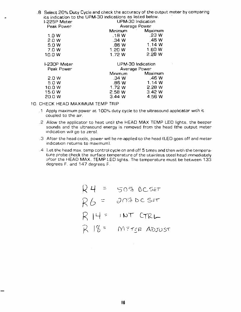
. 8 Select 20% Duty Cycle and check the accuracy of the output meter by comparing its indication to the UPM-30 indications as listed below. I-225P Meter UPM-30 Indication
Peak Power Average Power
1.0 w 2.0W 5.0W 7.0W
10.0 w
I-230P Meter Peak Power
2.0W 5.0W
10.0 w 15.0 w 20.0W
Minimum Maximum .18 w .23 w .34 w .46 w .86 w 1.14 w
1.20 w 1.60 w 1.72 w 2.28 w
UPM-30 Indication Average Power
Minimum Maximum .34 w .46 w .86 w 1.14 w
1.72 w 2.28 w 2.58 w 3.42 w 3.44 w 4.56 w
10. CHECK HEAD MAXIMUM TEMP TRIP
. 1 Apply maximum power at 1 00% duty cycle to the ultrasound applicator w1th it coupled to the air .
. 2 Allow the applicator to heat until the HEAD MAX TEMP LED lights, the beeper sounds and the ultrasound energy is removed from the head (the output meter indication will go to zeroJ .
. 3 After the head cools, power will be re-applied to the head (LED goes off and meter mdication returns to max1mumJ.
. 4 Let the head max. temp control cycle on and off 5 times and then with the temperature probe check the surface temperature of the stainless steel head immediately after the HEAD MAX. TEMP LED lights. The temperature must be between 133 degrees F. and 14 7 degrees F.
RLJ c.::- 0 C'"). (\ ,. c.- - -..) ,-jj u ~..._., .-:;; e 1
Rb R IY ~ I WT C-rRL--
·g 11> :::
16
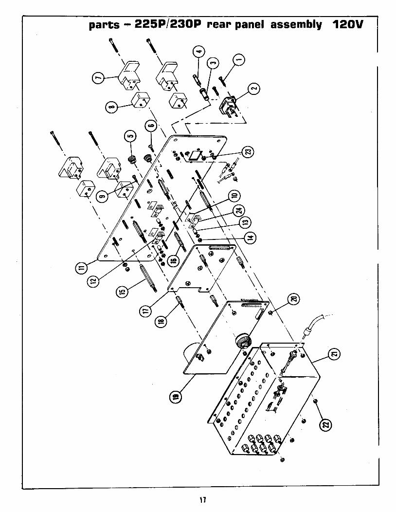
parts~ 225P/230P rear panel assembly 120V
\1
Ref Part No. 1 70398 2 74723 3 70179 4 70316 5 71208 6 72167 7 73604 3 73605 9 70099 10 79118 11 73655 12 73571 13 79119 14 72970 15 73644 16 71368 17 71404
71407 18 72102 19 73436
73824 20 60768 21 73772 22 72970 23 70628 24 72435
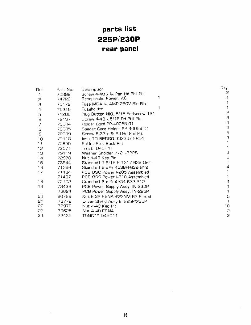
parts list
225P/230P rear panel
Description Screw 4-40 x 3f4 Pan Hd Phil Pit Receptacle, Power, AC Fuse MOA 3f4 AMP 250V Slo-Bio Fuseholder Plug Button NKL 5/16 Fedscrew 121 Screw 4-40 x 5/16 Rd Phil Pit Holder Cord PP-40058-01 Spacer Cord Holder PP-40058-01 Screw 6-32 x 3fs Rd Hd Phil Pit lnsul TO-BERGQ 332307-FR54 Pnl lnt Port Back Pnt Trnstr 045H11 Washer Sholder 7721-7PPS Nut 4-40 Kep Pit Stand-off 1-5/16 B-731 7 -632-0mf Stand-off 6 x 3/4 4538H-632-B12 PCB OSC Power 1-205 Assembled PCB OSC Power 1-210 Assembled Stand-off 6 x 1/2 4534-632-B 12 PCB Power Supply Assy, IN-230P PCB Power Supply Assy, IN-225P Nut 6-32 ESNA #22NM-62 Plated Cover Shield Assy ln-225P/230P Nut 4-40 Kep Pit Nut 4-40 ESNA TRNSTR 045C11
18
Oty. 2
1 1 1
1 1 2 3 4 4 5 3
1 3 3 1 4 1 1 4 1 1 5 1
10 2 2
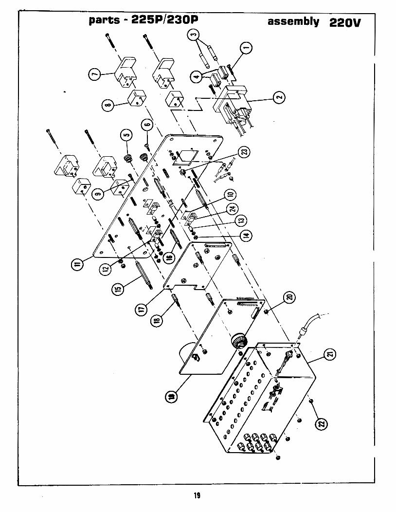
parts - 225P/230P assembly 220V
19
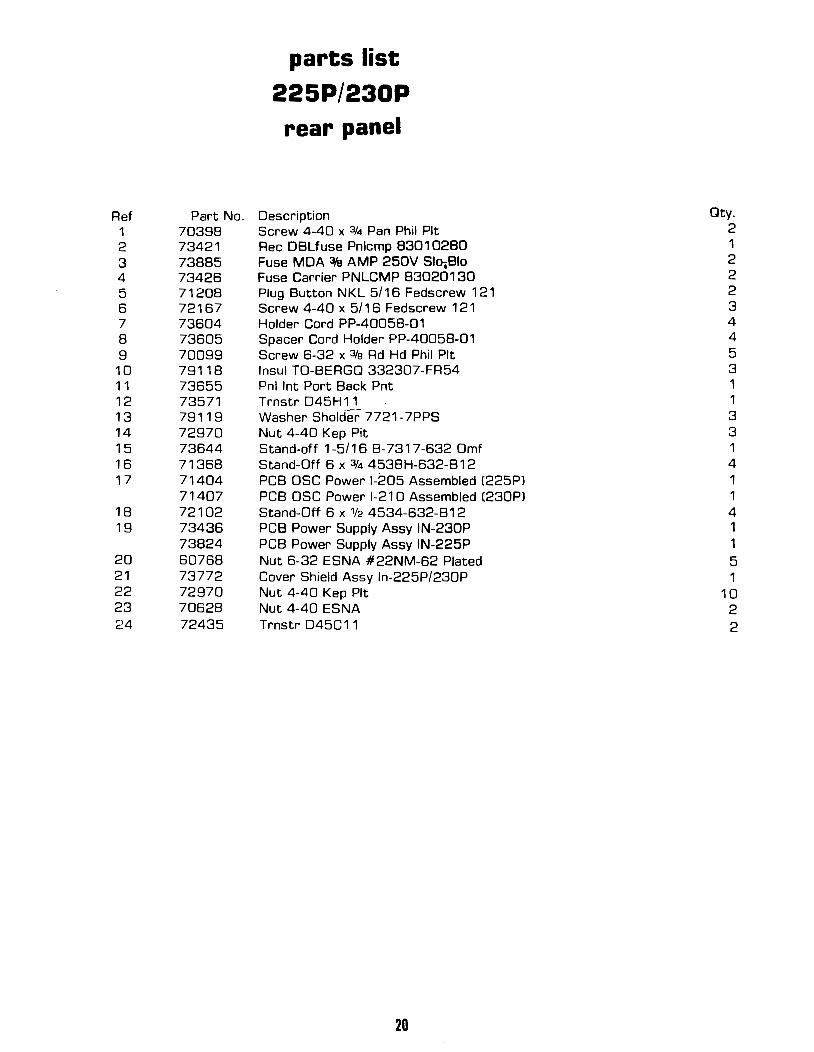
Ref Part No. 1 70398 2 73421 3 73885 4 73426 5 71208 6 72167 7 73604 8 73605 9 70099 10 79118 11 73655 12 73571 13 79119 14 72970 15 73644 16 71368 17 71404
71407 18 72102 19 73436
73824 20 60768 21 73772 22 72970 23 70628 24 72435
parts list 225P/230P rear panel
Description Screw 4-40 x 3f4 Pan Phil Pit Rec DBLfuse Pnlcmp 83010280 Fuse MDA 3fa AMP 250V Slcr.Bio Fuse Carrier PNLCMP 83020130 Plug Button NKL 5/16 Fedscrew 121 Screw 4-40 x 5/1 6 Fedscrew 1 21 Holder Cord PP-40058-01 Spacer Cord Holder PP-40058-01 Screw 6-32 x 3fe Ad Hd Phil Pit lnsul TO-BERGQ 332307~FR54 Pnl lnt Port Back Pnt Trnstr 045H11 Washer Sholder 7721-7PPS Nut 4-40 Kep Pit Stand-off 1-5/16 B-7317-632 Omf Stand-Off 6 x 3f4 4538H-632-B 1 2 PCB OSC Power 1-205 Assembled (225Pl PCB OSC Power 1-210 Assembled (230Pl Stand-Off 6 x 1/2 4534-632-B12 PCB Power Supply Assy IN-230P PCB Power Supply Assy IN-225P Nut 6-32 ESNA #22NM-62 Plated Cover Shield Assy ln-225P/230P Nut 4-40 Kep Pit Nut 4-40 ESNA Trnstr 045C11
20
Qty. 2 1 2 2 2 3 4 4 5 3 1 1 3 3 1 4 1 1 4 1 1 5 1
10 2 2
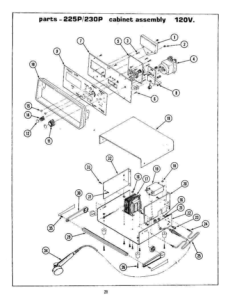
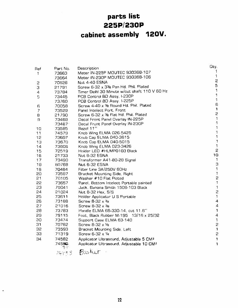
parts- 225P/230P cabinet assembly 120V.
21
Ref Part No. 1 73663
73664 2 70628 3 21791 4 73784 5 73445
73760 6 70058 7 73529 8 21790 9 73468
73467 10 73585 11 74579 12 73607 13 73670 14 73606 15 72519 16 21733 17 73490 18 60768 19 70484 20 73587 21 70105 22 73657 23 79041 24 21024 25 73611 26 73188 27 21016 28 73783 29 79115 30 73474 31 70782 32 73593 33 71319 34 74582
745~ .c... .......
c .
74-'1~' ~ q \, j .../
parts list 225P/230P
cabinet assembly 120V.
Description Meter IN-225P MOUTEC 930368-107 Meter IN-230P MOUTEC 930368-106 Nut 4-40 ESNA Screw 6-32 x 33/e Pan Hd. Phil. Plated Timer Deihl 30 Minute w/cut shaft 11 0 V 60 Hz PCB Control BD Assy, I-230P PCB Control BD Assy. I-225P Screw 4-40 x 3fa Round Hd. Phil. Plated Panel lntelect Port. Front Screw 6-32 x 3fa Flat Hd. Phil. Plated Decal Front Panel Overlay IN-225P Decal Front Panel Overlay IN-230P Bezel 11 '' Knob Wing ELMA 026-5425 Knob Cap ELMA 040-3615 Knob Cap ELMA 040-5015 Knob Wing ELMA 023-3426 Holder LED #HLMP01 03 Black Nut 8-32 ESNA Transformer A41-80-28 Signal Nut 6-32 ESNA Filter Line 3A/250V 60Hz Bracket Mounting Side, Right Washer # 1 0 Flat Plated Panel, Bottom lntelect Portable painted Jack, Banana Smith 1 508-1 03 Black Nut 8-32 Hex, S/S Holder Applicator U S Portable Screw 8-32 x 3f4 Screw 8-32 x 3fs Handle ELMA 66-330-14, cut 11.6" Foot, Black Rubber M-195 13/16 X 25/32 Support Case ELMA 63-140 Screw 8-32 x 5fs Bracket Mounting Side, Left Screw 6-32 x 114
Applicator Ultrasound, Adjustable 5 CM2 Applicator Ultrasound, Adjustable 10 CM2
Yi ~ ,. . ' I-3 ., /, ") Jt'-~r
22
Oty. 1 1 2 5 1 1 1 6 1 2 1 1 1 1 1 1 1 2
10 1 3 1 1 2 1 1 2 1 4 4 1 4 1 2 1 2 1 1
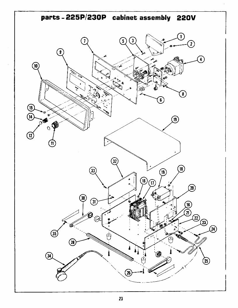
parts - 225P/230P cabinet assembly 220V
23
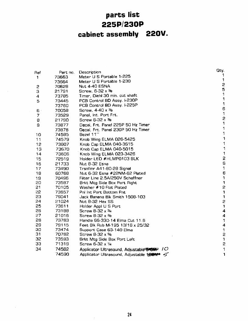
Ref Part no. 1 73663
73664 2 70628 3 21791 4 73785 5 73445
73760 6 70058 7 73529 8 21790 9 73877
73876 10 74585 11 74579 12 73607 13 73670 14 73606 15 72519 16 21733 17 73490 18 60768 19 70496 20 73587 21 70105 22 73657 23 79041 24 21024 25 73611 26 73188 27 21016 28 73783 29 79115 30 73474 31 70782 32 73593 33 71319 34 74582
74590
parts list 225P/230P
cabinet assembly 220V.
Description Meter U S Portable 1-225 Meter U S Portable 1-230 Nut 4-40 ESNA Screw, 6-32 x 3fs Timer, Diehl 30 min. cut shaft PCB Control BD Assy. I-230P PCB Control BD Assy. I-225P Screw, 4-40 x 3/e Panel, Int. Port Frt. Screw 6-32 x 3fs Decal. Frt. Panel 225P 50 Hz Timer Decal, Frt. Panel 230P 50 Hz Timer Bezel 11" Knob Wing ELMA 026-5425 Knob Cap ELMA 040-3615
. Knob Cap ELMA 040-5015 Knob Wing ELMA 023-3426 Holder LED #HLMP01 03 BLK Nut 8-32 Esna Trsnfmr A41-80-28 Signal Nut 6-32 Esna #22NM-62 Plated Filter Line 2.5A/250V Schaffner Brkt Mtg Side Box Port Right Washer # 1 0 Flat Plated Pnl lnt Port Bottom Pnt Jack Banana Blk Smith 1 508-1 03 Nut 8-32 Hex SS Holder Appl U S Port Screw 8-32 x 3f4 Screw 8-32 x 3fs Handle 66-330-14 Elm a Cut 11 . 6 Feet Blk Rub M-1 95 13/16 x 25/32 Support Case 63-140 Elma Screw 8-32 x 5fs Brkt Mtg Side Box Port Left Screw 6-32 x 1f4
Applicator Ultrasound, Adjustable 8 iMP 10 Applicator Ultrasound, Adjustable 1:88fel• ":5'
24
Qty. 1 1 2 5 1 1 1 6 1 2 1 1 1 1 1 1 1 2 6 1 6 1 1 2 1 1 2 1 4 4 1 4 1 2 1 2 1 1
;) t /;:
r 1,.. ' ~ i lr }, '-~~~ {.l! 1
I I I
/) r
GE +i-:2vF-rcc-+12VFIL 2
RFOUT 13
RFOUT 14
OSOUT 4
DSOUT 5
OSCDM 1111
DSCDM 11
~ +IDCF 7 I
\
xu : l J1 :
I . . I
J1
J1
J1
L~_I_~C::f __ !l __ _ ---~
t) •"
J +12VFIL
1.
1 Cl
.li!luf 2
1. 71 : 1 : 1
6 • • 3
2
I It
T1
~Q3 '-4" ~I 1 R6
'p.471!
25
RCIIllll IN5819 2 2
01 02
J3 Rl 2 1~
47
11N5819
2 IN581\
Y"
03 04
1R2 2
IK .& IN5819, IN5819, --,.
05 06
R4 ., J4 1 f---
47
1(3 2RC.,~Illll
r·EU ~
07
.. RS
., +12V,FIL
2.21(
1[J6
~ FRE!l
OS COM
~j2·--:
- -------------------------------------------------------------;r---::=:1: RFOUT L--------':'---l 2 i RFOUT
+IDCF -
J3 3
~· 5(11
31JB-lliJIIIJPF
2 ~(4 2
' J3 1 : 1 : 1
3 4 .. --1..- >-- cp, 2
>-828PF
1 6 05(011 • • T2
J4 2
iu 3
J4
+IOCF
l (2
::-_33uf p
-
r- ---- -:-~ 3 l 05(011 - -----:-~ 4: 05COI1
l (8 ! ______ .,!
;;: ~ .33uf
l l
~l' L3 R7
ta~ :: 39lif
" p
L1 II==== 2 l:Mi
26
05(011
I 3 •I.A.
------------------------ T3 5 : 5111 .. .. • 4 6
R3 _a_
271
~(7 __,. r-r---1..-t'
DESIGNATORS LAST USED 5PAa:
~ R7 (8 (5
<Cali Q3 T3 DB L3 J3
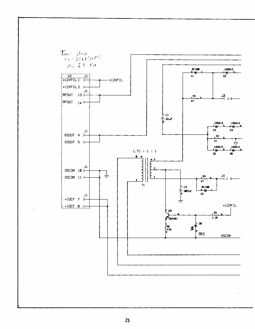
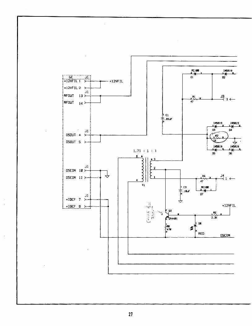
ELECTRICAL SCHEMATIC P.C. BOARD ASSY., OSC. POWER, 5CM 2
E.S. 71404-D
L~~~~~~~~~~~ : +12VFIL 1 ' : +12VFIL 2
iRFOUT ' !RFOUT
' I I
13
14
: OSOUT 4 I
' : OSOUT 5 I I I I
: I I I I I I I I I I
: OSCOM 10 I I
i OSCOM 11 I I I I I I I I I I I I
: +IDCF 7 I I
: +IOCF 8
~I(J : 1 J1
'
J1
Jl
J1
: I
~----------------~
J +12VFIL
~
27
1. 71 : 1 : 1
6 • • 3
2
I 4
Tl
'I '•
- :--;,;_'-; ~
:, < c
..... .....-: ,~ v·)
'"
ftCI8fll INS819 2 -,. 01 02
,IU ., J3
47 1~
1 (I
i2 .IJiuF INS819,_ INS819
2
o{ 04
(~~) ~ ~
INS8192
INS8192
05 00
R4 2
J4 1 ~
47
I (3 ,.ftCI8fll l.l&r 07,...
'~ "--.103 R
RS 2
+12V,FIL
r;44111 2.2K
1 1[)8
R6 ~ p471J p
REO OSCOM
~"j:f" ------------------------------------------------------------~~~·~1 RFOUT
. : '~
+IDCF -~~-·
---<
.... J3 3
-1 --llall'f
11
2 ~42
t'.,.
J3 1 : 1 : 1
3 4 ~L 2
.NhF ____1__..
_~_Cft 2
~ I 6 OS COM
• • T2
J4 2
-1" 3 ' J4
+IDCF
l(2
~:a·33<*
-
l (8
2 .33<*
ll l R7 li' L3 ~~
:: 2tUf
r'' ... ,.
' •.
L1 .~,.
<Uf
I 3 • l.A...
-----------------------. 4
R3 .~
271
~(7 ,; F ~II!IB'F ~2 • ....a....
= 4lliF""
'
OSCOH
T3 3 : 511.1 • 6
.__-----;~ 2 RFOUT ·-·---:-~ 3 OSCOM -·····t~~- OSCOM
~ . j
DESIGNATORS LAST USED SI'IIIE
R7 (8 Q3 T3 011 L3 J3
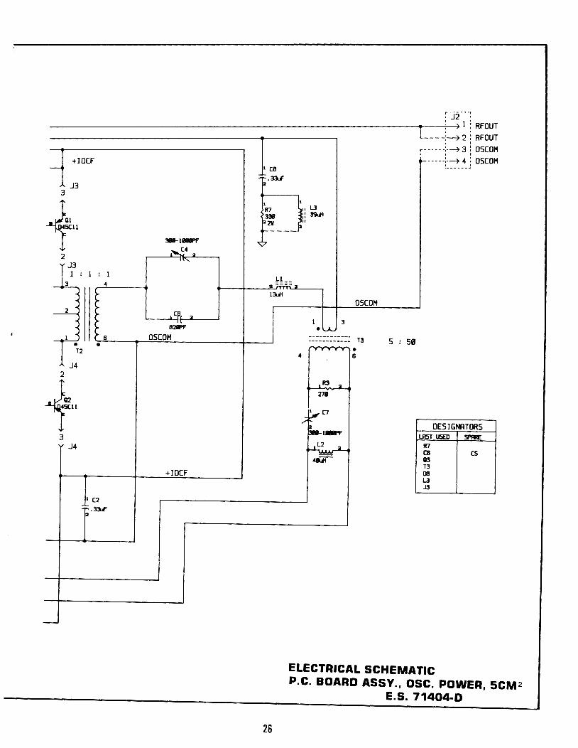
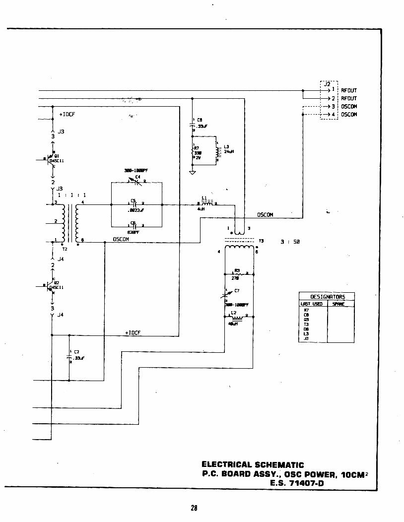
ELECTRICAL SCHEMATIC
28
P.C. BOARD ASSY., OSC POWER, 10CM2 E.S. 71407-D
f \I '~~ f ' f -· f
l -. /
I ';-./. ( ; l '. "', '.:-·
:ICON
IIICH S.lK
} {
'i
' ... \
~ ''
~~ RSS S.lK
29
~c v ,..,
+45
R3S
llliiK
(6
l.llllll.F
lN~l~B
I CR'I
-
-..--"''""'--""-·"---.: ~ '·--
-1 C8
'];. lllSLF
.& .,
·.,"""
'--
~~1N4743 l Cft21 p_
Rl 471
l
.33RlV
+12Y
2
Ll
fa 1'1111745
"a.s l
-,...., , -~RSl
PS.liC b
liC
~
J C4 llU RS ,
IOR2W
I
taRS2 liiC
l
+12 VtLTS
U5QJT
+VOSC:
OSC:CII
Rf'llJT
~Rll 491(9
l
~
._ ____________ _. ____ +-;'~204~-~~~~~ ,·+i~----~,u [2R2S \ !lit..~ ) ~ 734551 L2 15611U1 ._,~INS359
-:;; CR4 1111:: ""'·,"'- / 1 CR8 L-____ _._R,..,2"'7 _.
2L-___.
2R29 l
7.SK
_._~__,_15"'-1 V EB ,..!!_f--f---~16~ +SV CB ~
l
R32 !all(
--~~2~ IN+ CA JL j!l _.__,_I~ IN- ER !-cl!.!.l __ .._.,L...,R3v7.__J._....___..,4V.ill...c;:;,_,...gs~ .----"9~ CIM' GNO ~ IIIC !(',.....,
N/( ..!_ RT CL-~ -+---'-7 CT Cl+ ~
ua524
l U4 lt41
~SIIC
~(11 l.IIILI'
2IC
+ l Cll
IlaaE
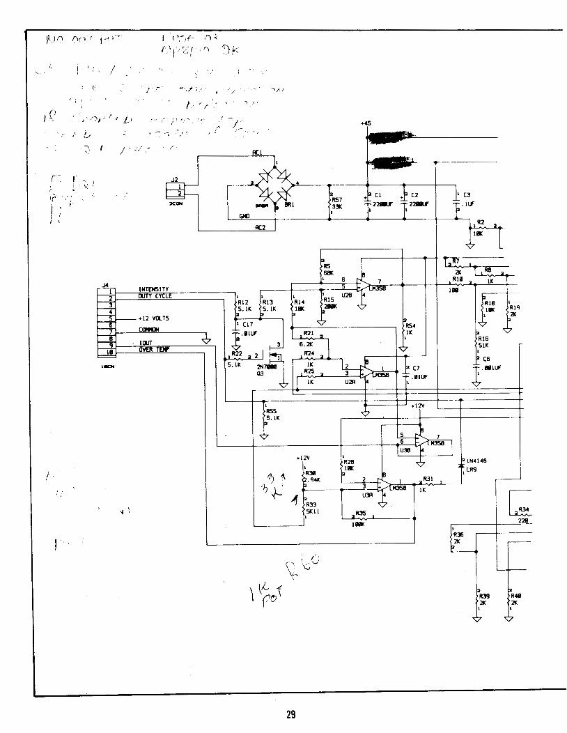
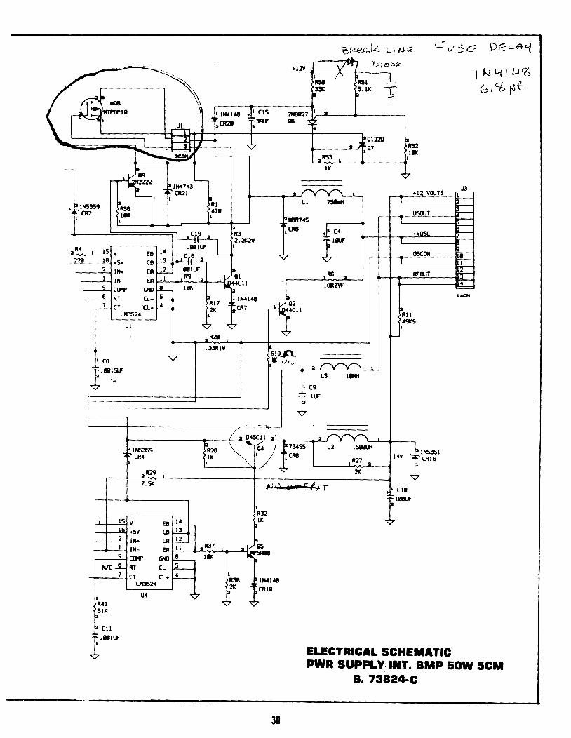
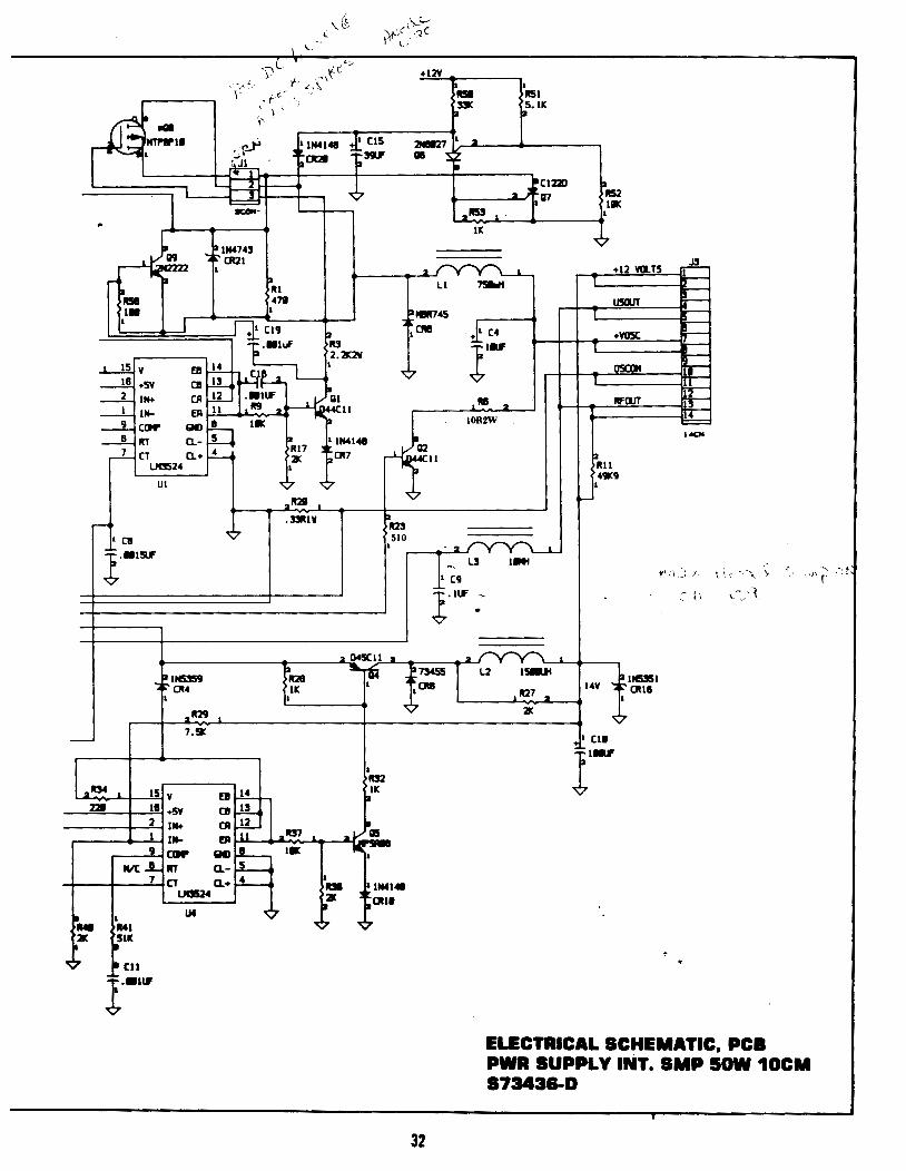
ELECTRICAL SCHEMATIC
~ ~
~ ;--~ ~ ~ :--!"r-F.-\-!.-~ ~ ~ = 1401
1 N L.{t4'6 b• C£ t-1~
PWR SUPPLY. INT. SMP 50W 5CM S. 73824-C
30
~ lNTENSlTY -4- 11m' :T[ .£
q f--.;
-+12 YO..TS r--; --: ClJIDI
___, lOUT
l' OV!R TDP
= t.:N
:;('f' s '
+45
~2 ACI
2A.4
~ . --~· J2
FH= ":~IN5!59 l:a .Ia Cl ~ C2 = t C:!l • CJt2
2CIIN r- lltl 1157 ~ 1 - DC f 22IU' fa 22IU' ~.ll.f'
&Nl 1
AC2 1'12 2.
I t· ~ Ia IlS
23
J TL'. IJIIIC 2IC ,laS 2
1 8 7 IIIII 2. 5
IK
1 U2B 1-uase 1 1 I.
1 R12 111:!1 R14 RIS Ia lUII
!:aS.lK ~S.lK !a IlK p211K 1
IlK 1119 1 p21C
Ia (17 '¢ l:aR54 .'\7
.¢. l.lll.f' t 11121 2 lK 2R18
'¢ 1
8.21C l \ '¢ 51K 1'124 .. 1
;7, ·~ ~ 113 lK i /1 }.~~
12 (8
R25,. 1 .. 1~ l~ I lK U2R ... ~ "l..M!!i8
1
'¢
l +12V R55 '¢
!:aS.lK
il
-t-t. 7
d 1t "'C!!58 1
·' ;
+12V 1
R2tl
31
1 211K 1131 ~-94K 2 .... 1
:!1 I. LIQ:i8
l:aR:!I:!I ~~ SKll
2 R:!l5 1 1
1-
Ql, .. \(::1 ,( \- c /;, y ! (. !
, l•Y
.¢. 211M1411
l(RCJ 2R:!Il ..--
lK
~l;:s --
+12¥
2 ~ ~(12211
PRS2 ,07 I.
21l53 l
IK
..,~IN4743 "¢'
• ~- Clt21 l 2 +12 Yll.TS ,.A.
1.----
Ul
ta,u 471
l
.DUll
ll ,.,. 12111'745
,CIIIII ~ (4 liU "¢'
Rll 2
J .. IOR2W
p
~
f.IR23 ,510 -2~
1- L3 IMI
(9 l.lll' :
U5CliT
+¥05C
OSClJI
II'OJT
131m 4CJC9
l
~
._ ________ ~----~2~~-~ll~~·._ ____ ~LJ2
fllt26 31o.rli fi73455~ L2 ISIUI i:allm5l IK ' l Clllll 14V '<t;;.' (]Uti
l ,~7 2 .___ ___ ~ "¢' L._ __ ..J.......:zK.,.,_iL-~ l
"¢' 7.51C
•' (II -
L..iiL2'104 _ _._~...!15~ v fl ~ r-
--=221_.......__,1~11 +SV C11 rJ..L ----+--'2t.....l IN+ CA ~
..----.._...._1--l l,._ ER u _.llm .&c
.---...!!'-f CCIII' Iiiii ~ I. NIC...!... In CL-~
-+-~~-..:.7-fCT CL+ ~ 1JG524
~-... 1M IMl
lt1/t. ~lK
<~~7 lacu l .. lll'
r---i--
r---r---
lr---II--I
~ "'--"--UCN
"''.~i.~·," ,~": ·,·.,~.\ ( \,J~_·:r >.""'!
:· \; ---:_:~
ELECTRICAL SCHEMATIC, PCB PWR SUPPLY INT. SMP SOW 10CM 573438-D
32
l '\'~ \ .
33
l (2 --' liLIF p
'""'<II, CRl
1cs ~
l~
l lfOl 1 LE02
~~ ~ ~
~ [;] X . -
I> , ... ,<II ,CRS
l (9
1 (13
lBl~
I~
+12 YIJ..T5 ,.n_ l
(QIIQI llJTY OYEA TEll' INTEIISI [llJT ;-
~ J· r£ ' ,.,., ;z.;; Rl3
l
~>'" l11331.f' 2 -LI<l5ll U5ll CR3
~7
l
RlS
lN.l48 ~o'" CRS
Rl7 •
[IIJII( l 6 Rl9 7
2"!/f. ~~:, USB
l ;L.
R22 1 CUI lH p6.8K
lliLIF
-¢- ~
1 ' ~
34
' ce
l'IILIF .. --------I lPTJ(Jrfl..
: '[P I l C
: !!!L.LjHC I I
__ _j l ________
Ql 4111
l
l
2
1!ll-. ~ -
iW!II
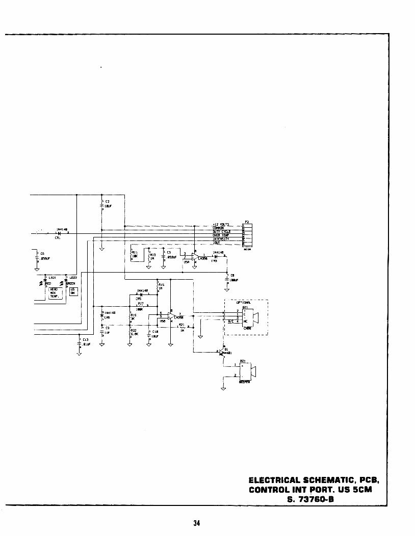
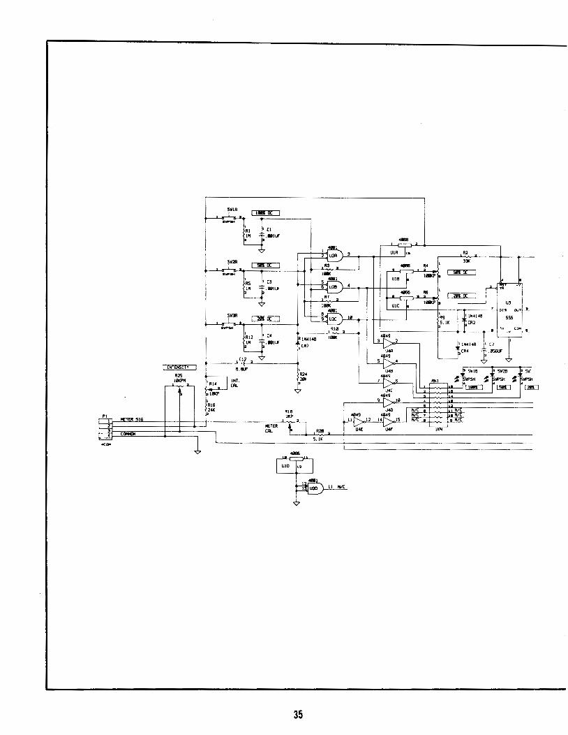
ELECTRICAL SCHEMATIC, PCB, CONTROL INT PORT. US SCM
S. 73760-B
METER S!G
!NTEHSITY
R25 llll<l'll
35
l (2 lillf'
1N4148 01
CRl
' (6 EJ' JCS 4--1: -r- .ll56Uf /3 lB3Y [~1 ~~ J
1 LEOt 1 Lf02
~ ~0 ~ ~EN ' RlS
[;[] p[l[] 21N-4148 ~>'" X . CRS -
Rl7 >
'""" ~ lN<l<B ' 6 Rl9 7
l (R6 3K 5
~·~ USB
1 R2l > l (9 l
R22 1 Clll '" l Cl3 I~ 1>6.81( l'u l"'~ 7 7
36
•12 V(LT5 P-(
OOTY CYCLE OVER TEll' INTENSITY lllJT
~ lN-*148
CR3
' (8
l'Oillf' r--------l Of'TIOIR. I BZl I 2 +
I l (
3 -I N/( • NC I I CHBS L ________
, v'"g, .. , l
l ~ill-
2 ~~ ~
I I I I
__ J
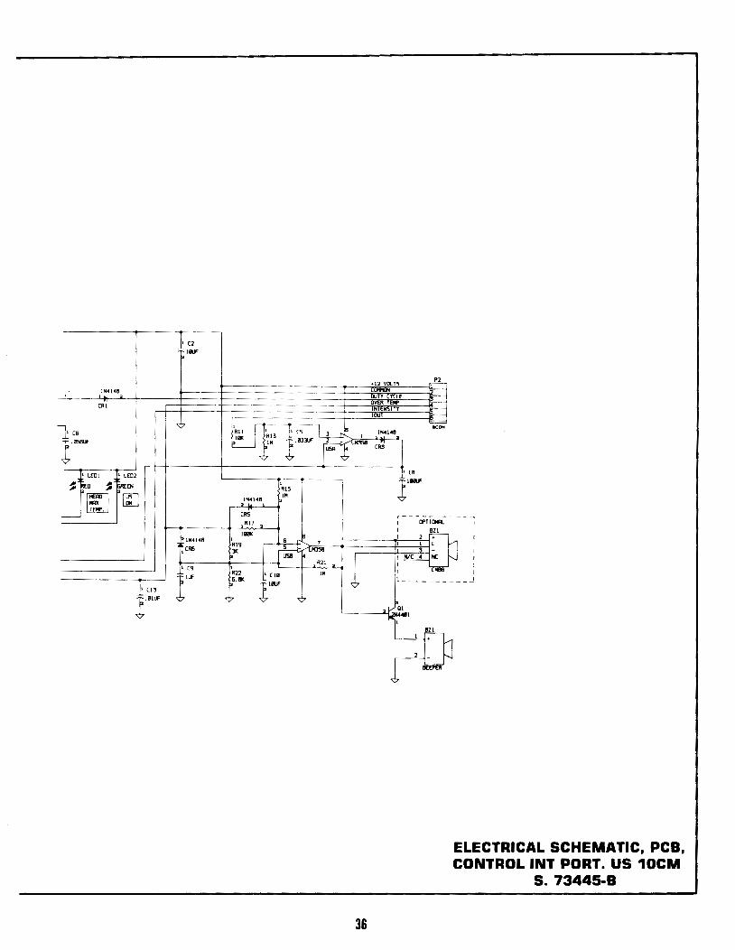
ELECTRICAL SCHEMATIC. PCB. CONTROL INT PORT. US 10CM
S. 73445-B
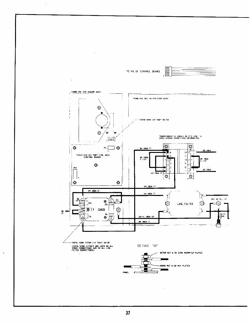
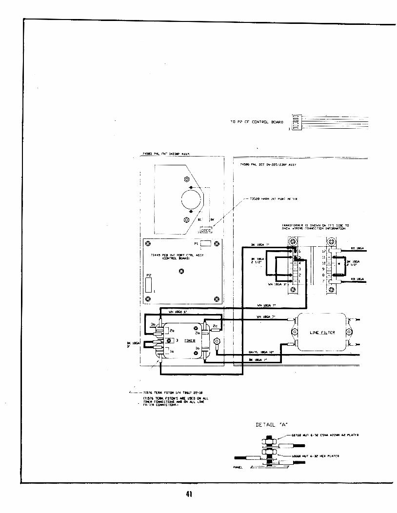
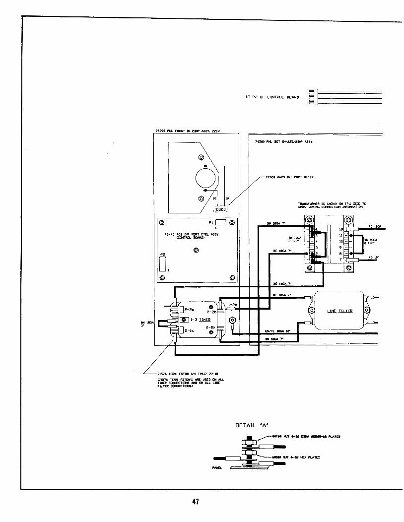
TO P2 OF CONTROL BOARD IJ~ §~~~~~~~~~~~~~ t ~~---------------------_-_-_-__ -_-_-_-_-
7 4588 PN... FNT IN225P ASSY.
c --~ ~ @ .-~-·~-1~ "~ •• '"' •=m• '"'·
0 I j ~- 73528 HARN INT POR1 METER
I I
BK leGAl 3' I
I I
73-44'5 PCB tNT ~T CTRL ASSY. <Ct>o!TRD.... BOARD)
T2617 22-18
<71576 TE.IiM F"S'TON'S ME USED ON ALL TJMER CONNECTIONS AND ~ ALL LINE r(L TER CCNNECTIIJNS.l
II I )/
"/(
DETAIL 'A'
TRANSFORH(R IS SHO'w'N ON IT'S SIIIf TO Sl-IO'w' \/HUNG CONN[CTJON 1,...-!JlMATIDN
LINE FILTER
\
~ I •
j}<
~ 60768 NUT 6-32 ESNA 122NM-62 PLATED
--.r-____ C£;_ ~ •u'"'" PN£L ~
37
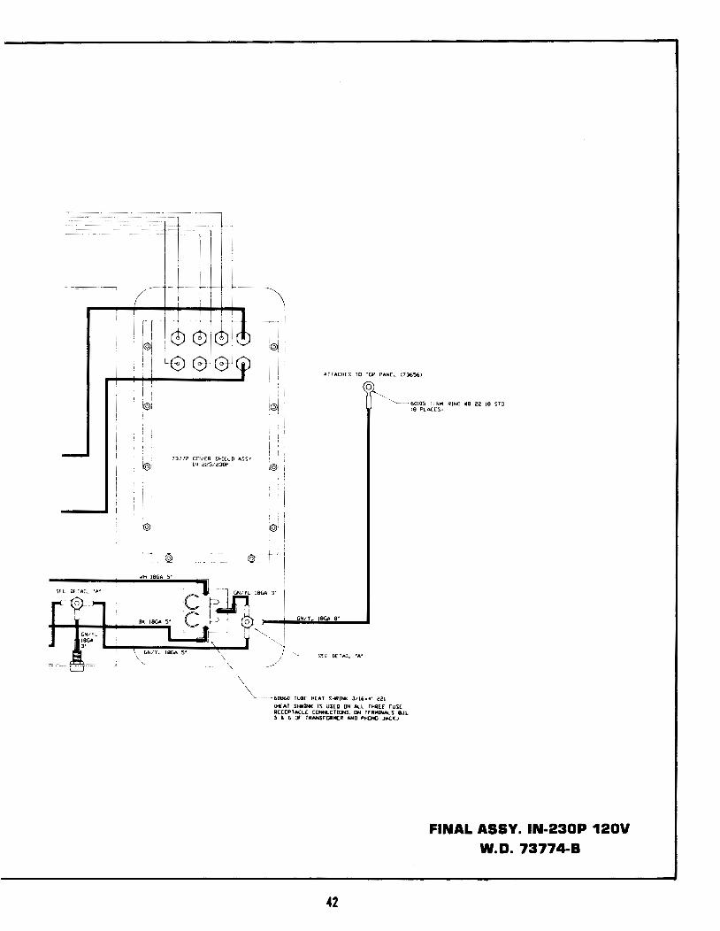
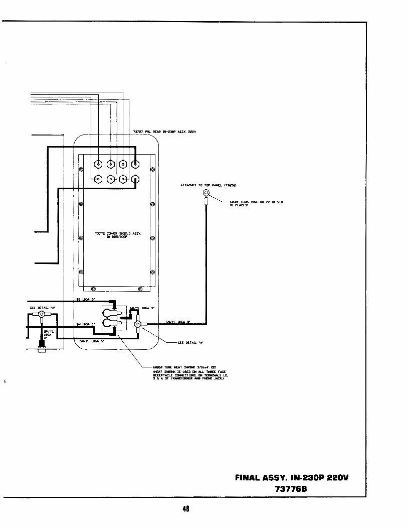
SEE DETAk "A'
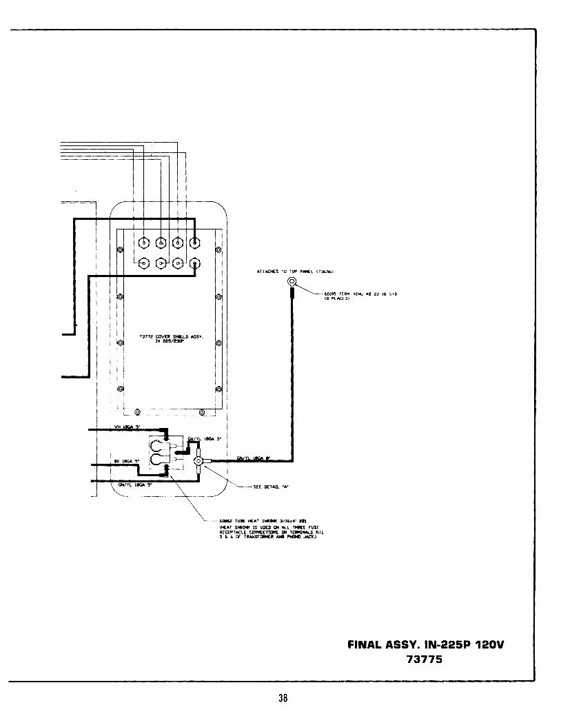
7377Z COVER SHIELD ASSY. IN 225/~
0
ATTACHES TO ToP PANEL <73656)
0
60860 TUIE HEAT SHRINC. 3/16x4' 221
<HEAT SHRINK IS US0 DH ALL T-E rusE RECEPTACLE CliNNECTlllNS. ON TEaMJNALS 8,!L 5 ~ 6 or TRANSrOIIIIER AND I'IOil JACI<)
38
6010'5 TERI'4 RlNG 18 22-18 STD <8 PLACES)
FINAL ASSY. IN-225P 120V 73775
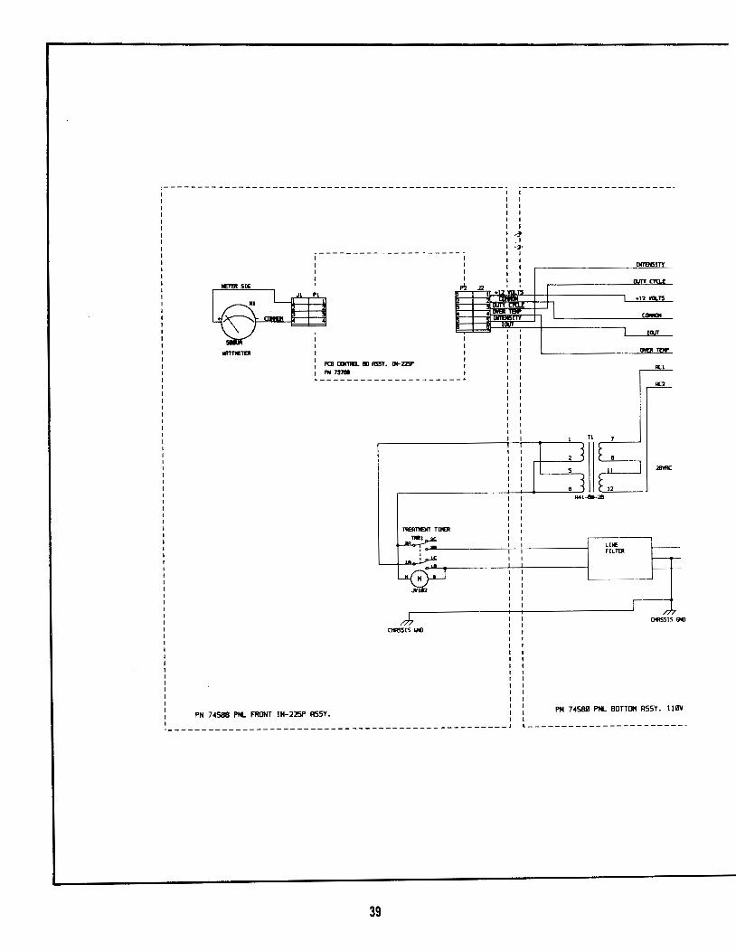
,----------------1
I
PCB llJI1IIL Ill A55Y. IN-ZISI'
I I
1'2
I I I I I I
~---------------------~
Ofl55!5 GICl
PN 7 4588 PNL FRONT IN-225P RSSY.
J2 I
4
i-----------------------
I I
1 I I I I
,Jo ,I .,.
I I I I
I I
+12 'w..is
lliiT
r
l I
LINE FIL'ff:R
INTBI5!TT
11/TY nnE
+12 WLT5
CIJIDt
!!liT
DYER 1'£11'
ACI
AC2
01155!5 GICl
PN 74S88 PNl BOTTOM RSSY. IIBV
-------------------------------------------------- L------------------------
39
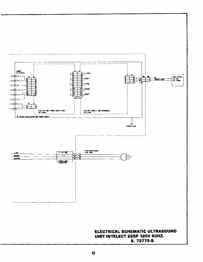
:----- ----------------i ~--- ------------------ ---~
: ; : : :~1 : ..E-.-ll-1 +12'11'1L :
.'!..- I ~
'T' l ,p-~ f-q 05lliT rrli1=t:2t~1 e~~.lll3~-3:=,.,~ill:~=~ II'I'L1CATllt -..;-...J...-~--=l=t::j ~ ]I 1 1
0115515 Qll ~ ~ I i=R r-ri •YOSC ~ ~r=== :r !-R I 1: ll5CIII
I !-R t~ g 'T' I h=f t~ :~ ll'tiJT ..J.... lACON l.cON
~ !! T I PCB 1HT P!J!T PINER 5li'I'L Y A5SY. : : PCB D5C PINER I -215 A5SBII.ED
I PH 7lUl I I PH 71414 .. -------------------- _, .. ------------------------ _,
Af SHIELD DSC!UJmll llll PINER Sli'I'LY
l 0115515 Qll
i------------------------------------1 I I I I I I
ELECTRICAL SCHEMATIC ULTRASOUND UNIT INTELECT 225P 120V 60HZ.
S. 73775-B
40
8K leGAl J'
74583 PNL fNT 1N230P ASSY.
73443 PCI INT PCJtT CTRL ASSY CCC»HRQ... ali\RD)
~~]2Q
..-c:;;:~][] 3
]tQ
L__ 71576 T[IM. rSTON l/4 TK17 Z2-18
C1l576 TtM FSTQirS M[ UUD ON Al-L f!M[O COM£CTII:M - ON Al-L ciNE
• ril ':'[R CCHN£C :'lD'fS >
41
TO P2 OF CONTROL BOARD 1 ~~~~~~~~~~~~~~
7458(1 PNL BOT 1N-2251230P ASSY
WH IB<iA 7'
\IH lMi.A 7'
PORT M(TER
TRANSHlRMU: IS SHOW'N ON IT'S SIDE TO SHOIJ 'w'IRJNG CONN£CTION INr~TJON
i bl. ~-l:Jj -,~ ~ 'I ~e eJel 111
ATTACHES TO TOP PANEL <73656>
0 i 1
1 I i@i !©II "'---~60105 fUolM RING ItS 22 18 STD
(8 PLACES•
@'
l t
737 !2 COVER SHIE.l D ASSY IN 2251230P
@ @
lo{H lBfiA S•
i
:@!
-j--'
SH DEl AIL "A"
- -60860 TUB£ HE.AT SHRINe. 31th•· 221
<HEAT SHRINk IS USED ON ALL THRE£ ruSE. R£C(PTACLE CONNI:CTIONS. ON TE:IIMINALS B.IL '5 &. 6 Of fMANSrORMER AHb PHON[] JACK.>
42
FINAL ASSY. IN-230P 120V W.O. 73774-8
5IUl
IIATTIETER
i------------------
PCB COHTlU.. Ill ASSY. !,._2311'
I I I
~ I I
I I I
~---------------------~
OllSSIS Gill
+12 YCI.TS (OifiiN
I
I
LINE FILTER
INTENSrTY
lliTY (YQ.E
+12 va...rs
IWT_
28VRC
Q4ASSIS QfJ
PN 74583 PNL FRONT IN-2381' RSSY 0
PN 7458il PNL BOTTOM RSSY o llilV
·--------------------------------------------------J ·------------------------
43
I I I I I I I
r------------------------, I I
I F IB..D REPLACfll.£
~=~-: --~~·~~~~~~:·~u~-~--~~ .~'
C I I I I I I I
I I ----------------------------------
44
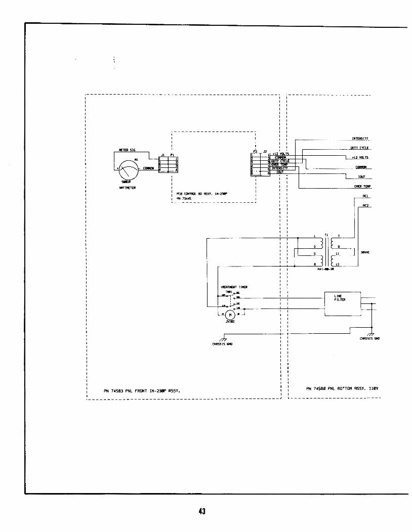
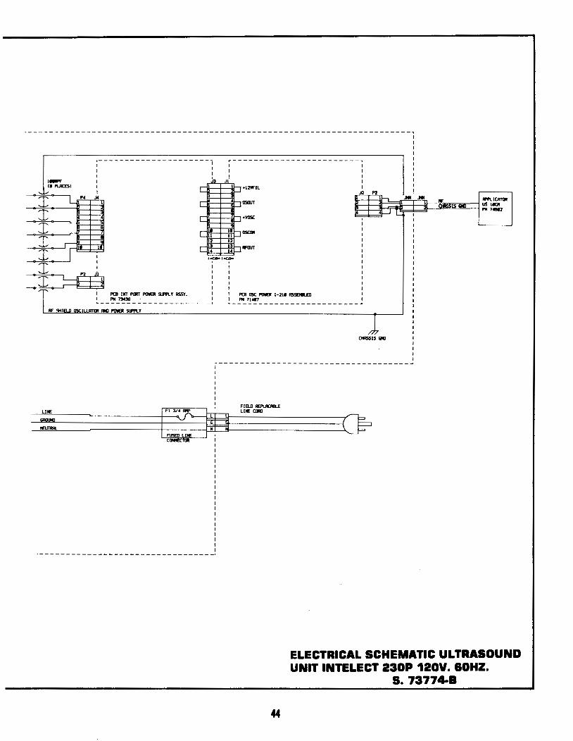
ELECTRICAL SCHEMATIC ULTRASOUND UNIT INTELECT 230P 120V. lOHZ.
S. 73774-B
> ..
------------ --------- -------------------- --------- r----------------------
i------------------
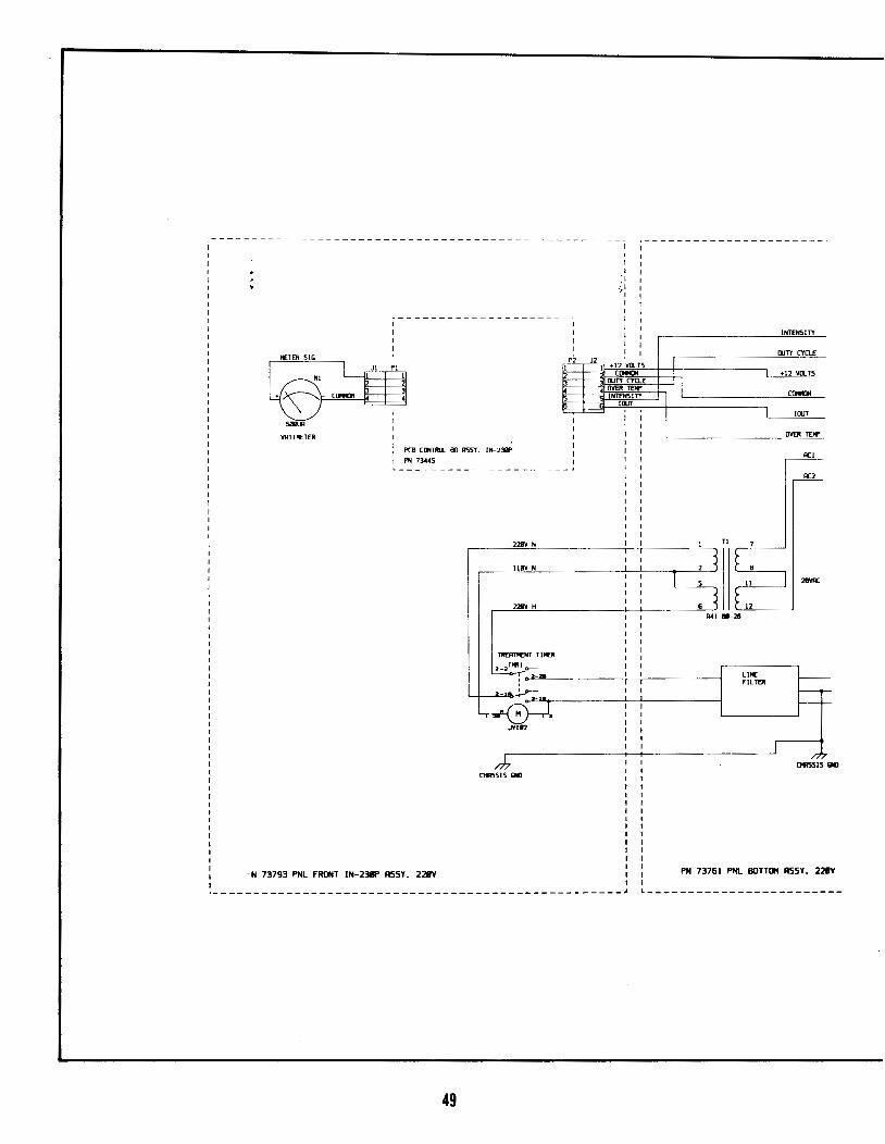
PCB CllfTlO.. fiJ ASSY. IM- Z1!5P 1 PH 73781
1
I I I I
~L I
~ ~1 +12 WLTS ClJIIJI
• 5
=e=d I
I I I I
ITY [IIJT
~---------------------~
TJ!IV •
IllY
TJ!IV H
0Ri515 lKJ
PN 73792 PNL FRONT IN-225P ASSY. 22111V I I
1--------------------------------------------------J
45
I
l
INTEN5ITY
llJTY CYQ.£
+12 YO..TS
l [IIJT
LINE fiLTER
llYEll IDI'
OR5515 Ql)
PN 73761 PNL BOTTOII RSSY. 22111V
-------------------------------------
I'CB lilT PIJIT PIMII SI.Pf'LY A55Y.
"" 731124 .. -------------------- _, RF SHIELD 05CIUJmll Ill) P1J11EJt Sll'f'l.Y
-----------------------------------,
f'(l! 05C - 1-35 ll55fJILfD ""71<84
cms515 IMI
1
,------------------------------------
F2 .315 1M'
fUSfD liNE
F tao REI'UIOILE liNE ((RJ
46
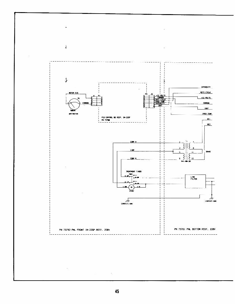
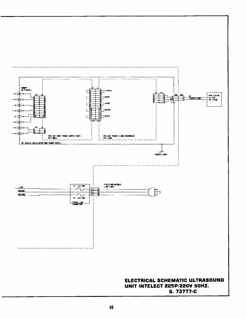
ELECTRICAL SCHEMATIC ULTRASOUND UNIT INTELECT 225P/220V 50HZ.
S. 73777-C
IN 3
IIIGA
73793 PN.. F1UIT IN-2- ASSY 220V
~ 0
@ BE :"/ 1 DODD
0 PIDO I
7344~ PCB !NT P!J!T CTRL ASSY. (CCMIIQ. BllMD>
0 P2
0, 0 0
--g 11:' l-2b J 2-2Q 2!»2b =
~ ]l] 1-3 .IlW. ~ ~ 2-lb = ~ ]2-ln 0 JT, /
'II
TO P2 OF CONTROL BOARD 1 ~~~~~~~~~~~~~
7~ PNl BOT IN-~/230P -'SSY.
v 73528 HARN !NT PIJRT METER
v TRANSFCRMER IS SHO'w'N C»> IT'S SUE TO SHC\1 \ltRING CCJrrKCTION IWIR41\TJON.
IN UIGA 7" @ @)
~~ RD 18GA
12~ nf=leo-IN UIGA
2 1/2' wt:=:r- IN IIIGA ~4 2 1/~ - 3 9 cr-
BE tBGA 7" ~12 ~ Bt-
~~ dT RD 19'
@ @
BE lBGA 7"
BE IIIGA 7"
[ J ~It£ EI~U:R
'----GN/YL liiGA 12"
.. 18GA 7"
L_"_"''~'~" <71.S76 T'I:RM. rsrmn - USED ON ALL TIIOEll CIINNECTDIS - ON ALL LIN[ rn. TER CIIIN:CTlllNS.>
DETAIL 'A'
~-~~--~~~
••c=::Jib~=!!:=>~- 11/T 6-32 1£)( PlATED
,
47
.---t--+--f-t-+-+-7:..:3:.:7.::2:...7..:.PNL-:.:.:...REAR IN-2301' ASSY. ZZJIV
0
73772 COVER SHIELD ASSY. 0 IN 225/2301'
0
0 0
0
ATTACHES TO TI:P PANEL <736S6>
0
0
0
60860 TUIE HEAT SHRINC 3/16x4' 221 <HEAT StiUNC IS USED 1:1\1 M.L TMI£[ F1JS[ RECEPTACLE CDJrN:CTD»>S. ON T£RMIIrMLS U!. ' ' 6 !If' TRMGF'IRIER AND PICNI .JACk.>
48
60105 TERM. RING 18 22-18 STD C8 PLACES>
FINAL ASSY. IN-230P 220V 7377&8
SllilJA
VRTTI'ETER
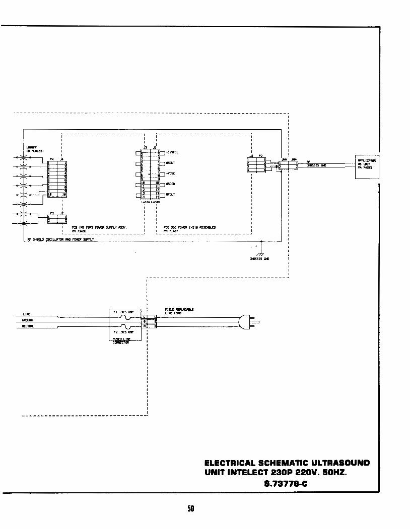
PCB CIJf110. Ill RSSY. IN-23111'
PN 73445
I I I I
~---------------------~
-N 73793 PNL FRONT IN-2381' RSSY. 228Y
49
22BV N
llllV N
TREAllENT Tli£R
:J-:Jntu o--
CHASSIS QIJ
I I
.I
I I I I I I
LINE FILTEJ:
INTENSlTY
I1JTY CYCLE
+12 VCl...TS
lllJT
OVER TEll'
RCl
0115515 QIJ
PN 73761 PNL BOTTOM RSSY. 228Y
L------------------------
;--------------------- i ~------------------------, I
I I I I I
I ~~
~ ~
PCB INT 1'11RT PINEl! Slnl Y ASSY.
.. --~ ..?~--- ----------- -· Rf SHIWJ 05CIW1TIJI 1111 PINEl! Slni.Y
LINE
NEUTIR
f2 .315-
~LINE
+12Yfll
PCB 05C PINEl! 1-211 A55EII!l.EII PN 71487
0115515 (;Ill
~------------------------------------1
FIWI ftEI'I..ACIIILf LINE CIJIII
50
ELECTRICAL SCHEMATIC ULTRASOUND UNIT INTELECT 230P 220V. 50HZ.
8.73778-C
'
\.
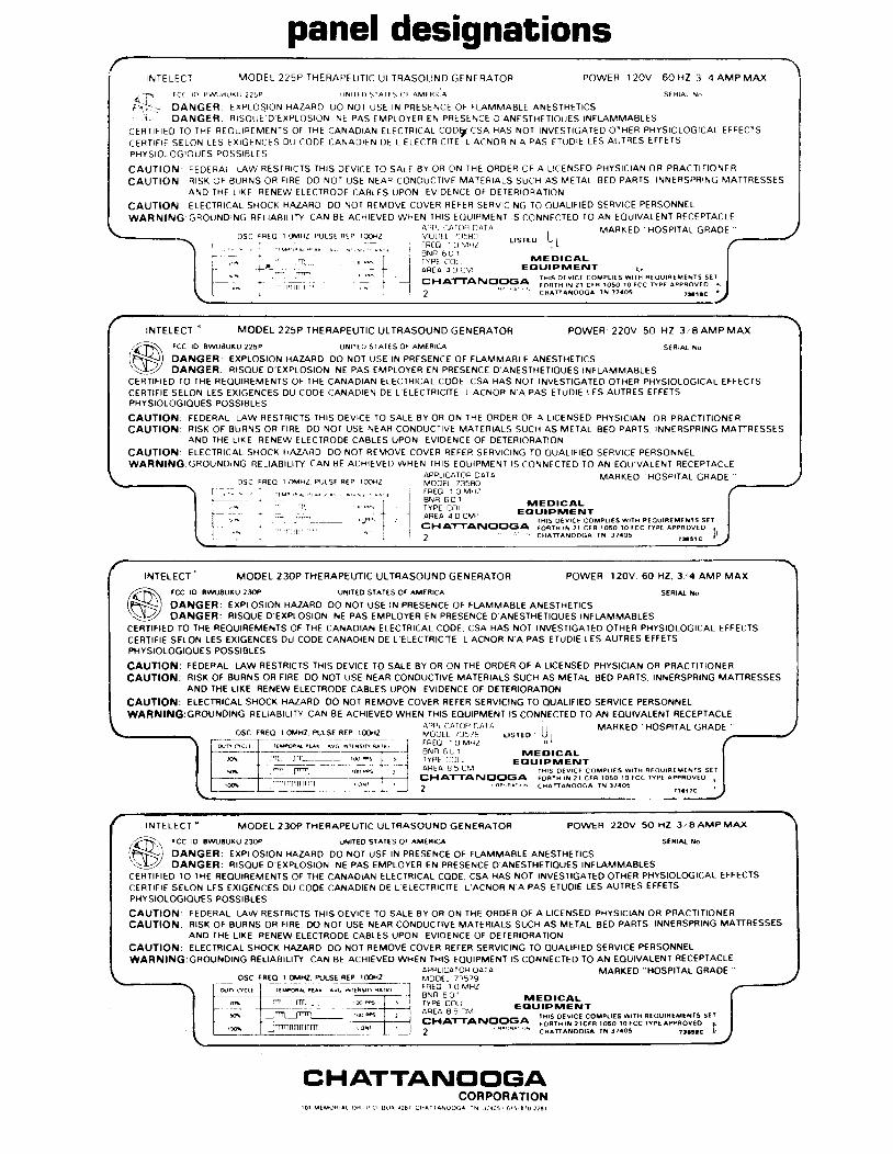
panel designations INTELECT MODEL 225P THERAPEUTIC ULTRASOUND GENERATOR POWER 120V 60HZ 3 4 AMP MAX
SERIAL No ~~ F(( 10 BVV\J8UKU 22~P UNITED STATES OF AMERICA
p~< DANGER EXPLOSION HAZARD DO NOT USE IN PRESENCE OF FLAMMABLE ANESTHETICS l- DANGER RISQUE'D EXPLOSION NE PAS EMPLOYER EN PRESENCE D ANESTHETIQUES INFLAMMABLES
CERTIFIED TO THE REQUIREMENTS OF THE CANADIAN ELECTRICAL CODijt CSA HAS NOT INVESTIGATED OTHER PHYSIOLOGICAL EFFECTS CERTIFIE SELON LES EXIGENCES DU CODE CANADIEN DE L ELECTRICITE L ACNOR N A PAS ETUDIE LES AUTRES EFFETS PHYSIOLOGIQUES POSSIBLES
CAUTION FEDERAL LAW RESTRICTS THIS DEVICE TO SALE BY OR ON THE ORDER OF A LICENSED PHYSICIAN OR PRACTITIONER CAUTION RISK OF BURNS OR FIRE DO NOT USE NEAf' CONDUCTIVE MATERIALS SUCH AS METAL BED PARTS INNERSPRING MATIRESSES
AND THE LIKE RENEW ELECTRODE CABLES UPON EVIDENCE OF DETERIORATION
CAUTION ELECTRICAL SHOCK HAZARD DO NOT REMOVE COVER REFER SERVICING TO QUALIFIED SERVICE PERSONNEL WARNING GROUNDING RELIABILITY CAN BE ACHIEVED WHEN THIS EQUIPMENT IS CONNECTED TO AN EQUIVALENT RECEPTACLE
APPLICATO~ OAT A MARKED ''HOSPITAL GRADE" MCJOEL ll5flll LISTED u,, L _____ _, fREQ 1 0 MHl ,
OSC FREO 1 OMHZ PULSE REP 100HZ
'! BNR 6 U 1
}~-:~ ~~~ r . ·rrllilrlr-,;1
' ""~- } ·~i ~~~~ ~D~~M E~J~~~:~IT , 1 ...,_,.., 1 CHAT"TANQQGA THIS DEVICE COMPliES WITH REQUIREMENTS SET
2 "" .,~·· .. ~~~~~~~~~~RT~O~~.~~FCC TYPE APP:~~~~ l
INTELECT " MODEL 225P THERAPEUTIC ULTRASOUND GENERATOR POWER 220V 50 HZ 3 I 8 AMP MAX
,£-ro~ FCC 10 BWUBUKU 225P UNITED SlATES OF AMERICA
~~ DANGER: EXPLOSION HAZARD DO NOT USE IN PRESENCE OF FLAMMABLE ANESTHETICS ~ DANGER: RISQUE D'EXPLOSION NE PAS EMPLOYER EN PRESENCE D'ANESTHETIQUES INFLAMMABLE$
SERIAL No
CERTIFIED TO THE REQUIREMENTS OF THE CANADIAN ELECTRICAL CODE CSA HAS NOT INVESTIGATED OTHER PHYSIOLOGICAL EFFECTS CERTIFIE SELON LES EXIGENCES DU CODE CANADIEN DE L'ELECTRICfTE L'ACNOR N'A PAS ETUDIE LES AUTRES EFFETS PHYSIOLOGIOUES POSSIBLES
CAUTION: FEDERAL LAW RESTRICTS THIS DEVICE TO SALE BY OR ON THE ORDER OF A LICENSED PHYSICIAN OR PRACTITIONER CAUTION RISK OF BURNS OR FIRE DO NOT USE NEAR CONDUCTIVE MATERIALS SUCH AS METAL BED PARTS INNERSPRING MATIRESSES
AND THE LIKE RENEW ELECTRODE CABLES UPON EVIDENCE OF DETERIORATION CAUTION: ELECTRICAL SHOCK HAZAilD DO NOT REMOVE COVER REFER SERVICING TO QUALIFIED SERVICE PERSONNEL WARNING: GROUNDING RELIABILITY CAN BE ACHIEVED WHEN THIS EQUIPMENT IS CONNECTED TO AN EQUIVALENT RECEPTACLE
OSC FREO 1 OMHZ PULSE REP 100HZ
'T
I' 'II'
APPLICATOR DATA MODEL 73580 FREQ 1 0 MH? BNR 601 TYPE CDLL MEDICAL
EDUIPMENT AREA 4 0 CM·' CHATTANOOGA 2
MARKED "HOSPITAL GRADE
INTELECT MODEL 230P THERAPEUTIC UL TRASOUNO GENERATOR POWER 120V 60HZ. 314 AMP MAX
FCC 10 BWUBUKU 230P UNITED STATES OF AMERICA SERIAL No
DANGER: EXPLOSION HAZARD DO NOT USE IN PRESENCE OF FLAMMABLE ANESTHETICS DANGER: RISQUE D'EXPLOSION NE PAS EMPLOYER EN PRESENCE D'ANESTHETIQUES INFLAMMABLES
CERTIFIED TO THE REQUIREMENTS OF THE CANADIAN ELECTRICAL CODE. CSA HAS NOT INVESTIGATED OTHER PHYSIOLOGICAL EFFECTS CERTIFIE SELON LES EXIGENCES DU CODE CANADIEN DE L'ELECTRICfTE L'ACNOR N'A PAS ETUDIE LES AUTRES EFFETS PHYSIOLOGIQUES POSSIBLES
CAUTION: FEDERAL LAW RESTRICTS THIS DEVICE TO SALE BY OR ON THE ORDER OF A LICENSED PHYSICIAN OR PRACTITIONER CAUTION: RISK OF BURNS OR FIRE DO NOT USE NEAR CONDUCTIVE MATERIALS SUCH AS METAL BED PARTS. INNERSPRING MATIRESSES
AND THE LIKE RENEW ELECTRODE CABLES UPON EVIDENCE OF DETERIORATION
CAUTION: ELECTRICAL SHOCK HAZARD DO NOT REMOVE COVER REFER SERVICING TO QUALIFIED SERVICE PERSONNEL WARNING: GROUNDING RELIABILITY CAN BE ACHIEVED WHEN THIS EQUIPMENT IS CONNECTED TO AN EQUIVALENT RECEPTACLE
./
APPLICATOR OAT A u MARKED "HOSPITAL GRADE " ~~g"1 ~~~i LISTED . "L ,-----' BNR 6 U 1 MEDICAL TYPE COl L EDUIPMENT AREA 8 5 CM THIS DEVICE COMPLIES WITH REGUIREME:.NTS SET
CHATTANOOGA FORTH IN 21 CFR 10!.0 10 FCC TYPE APPROVED ~ 2 ',,~,, ><.o.•,,,., CHATIANOOGA TN 3740!1 ,,.,
1c
INTELECT" MODEL 230P THERAPEUTIC ULTRASOUND GENERATOR POWER 220V 50 HZ JIB AMP MAX ......
FCC 10 BW\.J8UK.U 230P UNITED STATES OF AMERICA SERIAl No
DANGER: EXPLOSION HAZARD DO NOT USE IN PRESENCE OF FLAMMABLE ANESTHETICS DANGER: RISQUE D'EXPLOSION NE PAS EMPLOYER EN PRESENCE D'ANESTHETIQUES INFLAMMABLE$
CERTIFIED TO THE REQUIREMENTS OF THE CANADIAN ELECTRICAL CODE. CSA HAS NOT INVESTIGATED OTHER PHYSIOLOGICAL EFFECTS CERTIFIE SELON LES EXIGENCES DU CODE CANADIEN DE L'ELECTRICfTE L'ACNOR N'A PAS ETUDIE LES AUTRES EFFETS PHYSIOLOGIQUES POSSIBLES
CAUTION: FEDERAL LAW RESTRICTS THIS DEVICE TO SALE BY OR ON THE ORDER OF A LICENSED PHYSICIAN OR PRACTITIONER CAUTION: RISK OF BURNS OR FIRE DO NOT USE NEAR CONDUCTIVE MATERIALS SUCH AS METAL BED PARTS. INNERSPRING MATIRESSES
AND THE LIKE RENEW ELECTRODE CABLES UPON EVIDENCE OF DETERIORATION CAUTION: ELECTRICAL SHOCK HAZARD DO NOT REMOVE COVER REFER SERVICING TO QUALIFIED SERVICE PERSONNEL WARNING: GROUNDING RELIABILITY CAN BE ACHIEVED WHEN THIS EQUIPMENT IS CONNECTED TO AN EQUIVALENT RECEPTACLE
APPLICATOR DATA MARKED "HOSPITAL GRADE" OSC FREQ 1 OMHZ. PULSE REP lOOHZ MODEL 73579 _,1
ourr l~Cl~-r------;;~~-'1._ PU.-:~~T£l<oiSH'I' 1\Af~-- f:REQ 1 u MHZ BNR 6 0 1 MEDICAL
10" I rnt ..ITTL_____- •oo...., .L.::__ TYPE COLe EQUIPMENT ~ 1 ____. ~ ___JTTTT'!~---~ I J AREA 8 5 D\1'1 THIS DEVICE COMPLIES WITH REQUIREMENTS SET
f CHATTANOOGA FORTH IN 21CFA 1050 10FCC TYPE APPROVED f, ~- _. 'Tfl1Tl1JTTITT~---~~~_l_1_ 2 tlAPnAA'"'" CHATIANOOGA. TN 37405 1:JUIC !--'
CHATTANOOGA CORPORATION


