Embed Size (px)
Citation preview
1
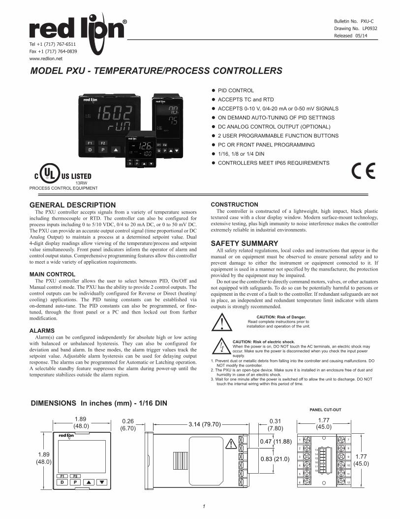
MODEL PXU - TEMPERATURE/PROCESS CONTROLLERS
GENERAL DESCRIPTIONThe PXU controller accepts signals from a variety of temperature sensors
including thermocouple or RTD. The controller can also be configured for process inputs including 0 to 5/10 VDC, 0/4 to 20 mA DC, or 0 to 50 mV DC. The PXU can provide an accurate output control signal (time proportional or DC Analog Output) to maintain a process at a determined setpoint value. Dual 4-digit display readings allow viewing of the temperature/process and setpoint value simultaneously. Front panel indicators inform the operator of alarm and control output status. Comprehensive programming features allow this controller to meet a wide variety of application requirements.
MAIN CONTROLThe PXU controller allows the user to select between PID, On/Off and
Manual control mode. The PXU has the ability to provide 2 control outputs. The control outputs can be individually configured for Reverse or Direct (heating/cooling) applications. The PID tuning constants can be established via on-demand auto-tune. The PID constants can also be programmed, or fine-tuned, through the front panel or a PC and then locked out from further modification.
ALARMSAlarm(s) can be configured independently for absolute high or low acting
with balanced or unbalanced hysteresis. They can also be configured for deviation and band alarm. In these modes, the alarm trigger values track the setpoint value. Adjustable alarm hysteresis can be used for delaying output response. The alarms can be programmed for Automatic or Latching operation. A selectable standby feature suppresses the alarm during power-up until the temperature stabilizes outside the alarm region.
CONSTRUCTIONThe controller is constructed of a lightweight, high impact, black plastic
textured case with a clear display window. Modern surface-mount technology, extensive testing, plus high immunity to noise interference makes the controller extremely reliable in industrial environments.
SAFETY SUMMARYAll safety related regulations, local codes and instructions that appear in the
manual or on equipment must be observed to ensure personal safety and to prevent damage to either the instrument or equipment connected to it. If equipment is used in a manner not specified by the manufacturer, the protection provided by the equipment may be impaired.
Do not use the controller to directly command motors, valves, or other actuators not equipped with safeguards. To do so can be potentially harmful to persons or equipment in the event of a fault to the controller. If redundant safeguards are not in place, an independent and redundant temperature limit indicator with alarm outputs is strongly recommended.
z PID CONTROL
z ACCEPTS TC and RTD
z ACCEPTS 0-10 V, 0/4-20 mA or 0-50 mV SIGNALS
z ON DEMAND AUTO-TUNING OF PID SETTINGS
z DC ANALOG CONTROL OUTPUT (OPTIONAL)
z 2 USER PROGRAMMABLE FUNCTION BUTTONS
z PC OR FRONT PANEL PROGRAMMING
z 1/16, 1/8 or 1/4 DIN
z CONTROLLERS MEET IP65 REQUIREMENTS
Bulletin No. PXU-C
Drawing No. LP0932
Released 05/14
Tel +1 (717) 767-6511
Fax +1 (717) 764-0839
www.redlion.net
C US LISTEDULR
13RWPROCESS CONTROL EQUIPMENT
(48.0)1.89
1.89 (48.0) (45.0)
1.77
1.77(45.0)
6
5
4
3
2
1
12
11
10
9
8
7
151413
161718
0.26(6.70)
3.14 (79.70) 0.31(7.80)
0.47 (11.88)
0.83 (21.0)
DIMENSIONS In inches (mm) - 1/16 DINPANEL CUT-OUT
CAUTION: Risk of electric shock. When the power is on, DO NOT touch the AC terminals, an electric shock may occur. Make sure the power is disconnected when you check the input power supply.
1. Prevent dust or metallic debris from falling into the controller and causing malfunctions. DO NOT modify the controller.
2. The PXU is an open-type device. Make sure it is installed in an enclosure free of dust and humidity in case of an electric shock.
3. Wait for one minute after the power is switched off to allow the unit to discharge. DO NOT touch the internal wiring within this period of time.
CAUTION: Risk of Danger. Read complete instructions prior to
installation and operation of the unit.
2
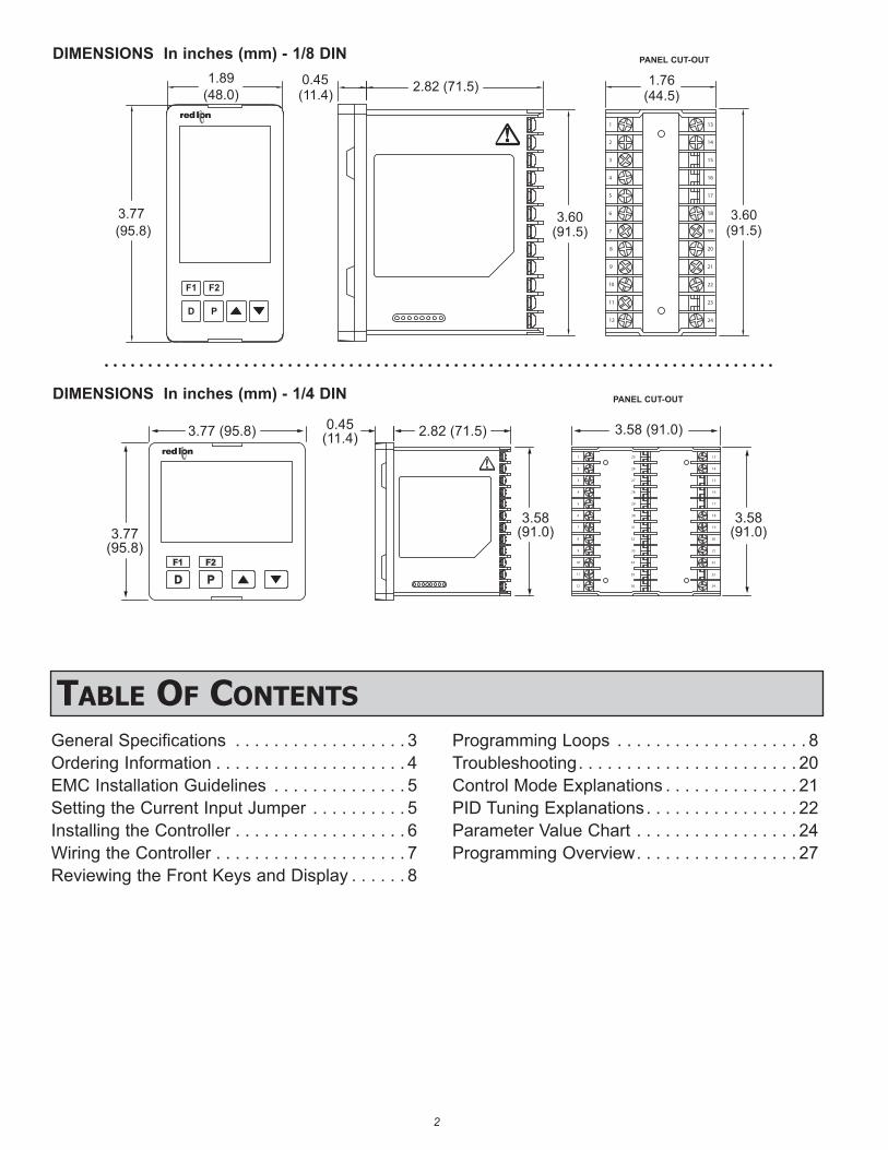
3.77(95.8)
3.77 (95.8) 0.45(11.4) 2.82 (71.5) 3.58 (91.0)
3.58(91.0)
3.58(91.0)
24
22
21
20
19
18
17
16
15
14
13
12
10
9
8
6
7
5
4
3
1
2
11 23
36
35
34
33
32
31
30
29
28
27
26
25
DIMENSIONS In inches (mm) - 1/4 DIN
13
14
16
15
18
17
19
20
21
22
23
24
1
2
3
4
5
6
7
11
10
9
8
12
3.77 (95.8)
(11.4)0.45 2.82 (71.5)
(44.5)1.76
(91.5)3.60 3.60
(91.5)
(48.0)1.89
F1 F2
D P
DIMENSIONS In inches (mm) - 1/8 DIN PANEL CUT-OUT
PANEL CUT-OUT
General Specifications . . . . . . . . . . . . . . . . . . 3Ordering Information . . . . . . . . . . . . . . . . . . . . 4EMC Installation Guidelines . . . . . . . . . . . . . . 5Setting the Current Input Jumper . . . . . . . . . . 5Installing the Controller . . . . . . . . . . . . . . . . . . 6Wiring the Controller . . . . . . . . . . . . . . . . . . . . 7Reviewing the Front Keys and Display . . . . . . 8
Programming Loops . . . . . . . . . . . . . . . . . . . . 8Troubleshooting . . . . . . . . . . . . . . . . . . . . . . . 20Control Mode Explanations . . . . . . . . . . . . . . 21PID Tuning Explanations . . . . . . . . . . . . . . . . 22Parameter Value Chart . . . . . . . . . . . . . . . . . 24Programming Overview . . . . . . . . . . . . . . . . . 27
Table Of COnTenTs
33
GENERAL SPECIFICATIONS1. DISPLAY: LCD negative image transmissive with backlighting. Top
(process) display with orange backlighting, bottom (parameter) display with green backlighting.Line 1 and 2: 4 digits each lineStatus Annunciators:
OUT1 - Control output 1 is active.OUT2 - Control output 2 is active.ALM1 - Alarm 1 output is active.ALM2 - Alarm 2 output is active.ALM3 - Alarm 3 output is active.°F, °C - Temperature units.MAN - Controller is in Manual Mode.AT - Auto-Tune active.
1/4 DIN Model Digit Size: Line 1 - 0.87" (22 mm); Line 2 - 0.55" (14 mm) 1/8 DIN Model Digit Size: Line 1 - 0.47" (12 mm); Line 2 - 0.47" (12 mm)1/16 DIN Model Digit Size: Line 1 - 0.43" (11 mm); Line 2 - 0.27" (7.0 mm)
2. POWER:Line Voltage Models:
100 to 240 VAC -20/+8 %, 50/60 Hz, 5 VALow Voltage Models:
DC Power: 24 VDC, ±10%, 5 W3. KEYPAD: Mylar overlay with 4 program/selection keys and 2 user
programmable function keys. 6 keys total.4. Display Messages: - Measurement exceeds + sensor range - Measurement exceeds - sensor range - Open sensor is detected (TC or RTD) - Shorted sensor is detected (RTD only) . . . - Display value exceeds + display range. .. . - Display value exceeds - display range
5. SENSOR INPUT:Sample Period: 100 msec (10 Hz rate)A/D Converter: 16 bit resolution
Span Drift (maximum): 130 PPM/°CInput Fail Response:
Main Control Output(s): Programmable preset output Display: OPEN, sHrtAlarms: programmable for On or Off
Normal Mode Rejection: >35 dB @ 50/60 HzCommon Mode Rejection: >120 dB, DC to 60 Hz
6. INPUT CAPABILITIES:Temperature/RTD Indication Accuracy:
± (0.3% of span, +1°C) at 25°C ambient after 20 minute warm up. Includes NIST conformity, cold junction effect, A/D conversion errors and linearization conformity.
THERMOCOUPLE INPUTS: Types: T, E, J, K, R, S, B, N, L, U, and TXKInput Impedance: Approximately 4.7 MΩLead Resistance Effect: -0.3 µV/Ω Cold Junction Compensation: Less than ±1.5°C typical (2.5°C max)
error over 0 to 50°C temperature range.Resolution: 1° for types R, S, B and 1° or 0.1° for all other types
TYPE DISPLAY RANGEWIRE COLOR
STANDARDANSI BS 1843
T -200 to +400°C-328 to +752°F
(+) Blue (-) Red
(+) White (-) Blue ITS-90
E 0 to 600°C+32 to +1112°F
(+) Violet (-) Red
(+) Brown (-) Blue ITS-90
J -100 to +1200°C-148 to +2192°F
(+) White (-) Red
(+) Yellow (-) Blue ITS-90
K -200 to +1300°C-328 to +2372°F
(+) Yellow (-) Red
(+) Brown (-) Blue ITS-90
R 0 to +1700°C+32 to +3092°F
No standard
(+) White (-) Blue ITS-90
S 0 to +1700°C+32 to +3092°F
No standard
(+) White (-) Blue ITS-90
B +100 to +1800°C +212 to +3272°F
No standard
No standard ITS-90
N -200 to +1300°C -328 to +2372°F
(+) Orange (-) Red
(+) Orange (-) Blue ITS-90
L -200 to +850°C -328 to +1562°F
(+) Red (-) Blue
(+) Red (-) Blue DIN 43714
U -200 to +500°C -328 to +932°F
No standard
(+) White (-) Blue IPTS68
TXK -200 to +800°C-328 to +1472°F — — —
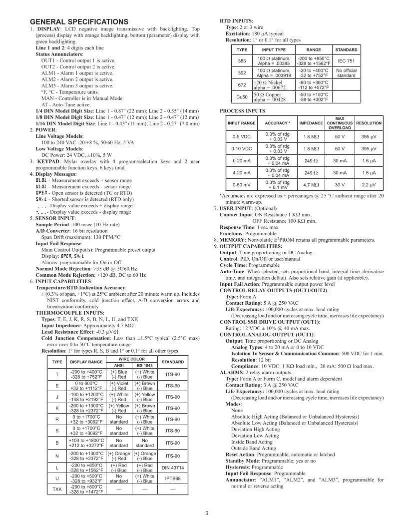
RTD INPUTS: Type: 2 or 3 wireExcitation: 180 µA typicalResolution: 1° or 0.1° for all types
TYPE INPUT TYPE RANGE STANDARD
385 100 Ω platinum, Alpha = .00385
-200 to +850°C -328 to +1562°F IEC 751
392 100 Ω platinum, Alpha = .003919
-20 to +400°C -32 to +752°F
No official standard
672 120 Ω Nickel alpha = .00672
-80 to +300°C -112 to +572°F
Cu50 50 Ω Copper alpha = .00428
-50 to +150°C -58 to +302°F
PROCESS INPUTS:
INPUT RANGE ACCURACY * IMPEDANCEMAX
CONTINUOUS OVERLOAD
RESOLUTION
0-5 VDC 0.3% of rdg + 0.03 V 1.8 MΩ 50 V 395 µV
0-10 VDC 0.3% of rdg + 0.03 V 1.8 MΩ 50 V 395 µV
0-20 mA 0.3% of rdg + 0.04 mA 249 Ω 30 mA 1.6 µA
4-20 mA 0.3% of rdg + 0.04 mA 249 Ω 30 mA 1.6 µA
0-50 mV 0.3% of rdg + 0.1 mV 4.7 MΩ 30 V 2.2 µV
*Accuracies are expressed as ± percentages @ 25 °C ambient range after 20 minute warm-up.
7. USER INPUT: (Optional)Contact Input: ON Resistance 1 KΩ max.
OFF Resistance 100 KΩ min.Response Time: 1 sec max Functions: Programmable
8. MEMORY: Nonvolatile E2PROM retains all programmable parameters.9. OUTPUT CAPABILITIES:
Output: Time proportioning or DC AnalogControl: PID, On/Off or user/manualCycle Time: ProgrammableAuto-Tune: When selected, sets proportional band, integral time, derivative
time, and integration default. Also sets relative gain (if applicable).Input Fail Action: Programmable output power levelCONTROL RELAY OUTPUTS (OUT1/OUT2):
Type: Form AContact Rating: 5 A @ 250 VACLife Expectancy: 100,000 cycles at max. load rating
(Decreasing load and/or increasing cycle time, increases life expectancy)CONTROL SSR DRIVE OUTPUT (OUT1):
Rating: 12 VDC ± 10% @ 40 mA max.CONTROL ANALOG OUTPUT (OUT1):
Output: Time proportioning or DC AnalogAnalog Types: 4 to 20 mA or 0 to 10 VDCIsolation To Sensor & Communication Common: 500 VDC for 1 min.Resolution: 12 bitCompliance: 10 VDC: 1 KΩ load min., 20 mA: 500 Ω load max.
ALARMS: 2 relay alarm outputs.Type: Form A or Form C, model and alarm dependentContact Rating: 3 A @ 250 VACLife Expectancy: 100,000 cycles at max. load rating
(Decreasing load and/or increasing cycle time, increases life expectancy)Modes:
NoneAbsolute High Acting (Balanced or Unbalanced Hysteresis)Absolute Low Acting (Balanced or Unbalanced Hysteresis)Deviation High ActingDeviation Low ActingInside Band ActingOutside Band Acting
Reset Action: Programmable; automatic or latchedStandby Mode: Programmable; yes or noHysteresis: ProgrammableInput Fail Response: ProgrammableAnnunciator: “ALM1”, “ALM2”, and “ALM3”, programmable for
normal or reverse acting
44
10. ISOLATION LEVEL:AC power with respect to all other I/O: 250 V working (2300 V for 1 min.)Sensor input to analog output: 50 V working (500 V for 1 minute)Relay contacts to all other I/O: 250 V working (2300 V for 1 minute)DC power with respect to sensor input and analog output: 50 V working
(500 V for 1 minute)11. CERTIFICATIONS AND COMPLIANCES:
CE ApprovedEN 61326-1 Immunity to Industrial LocationsEmission CISPR 11 Class AEN 61010-1RoHS Compliant
UL Listed: File #E179259IP65 Enclosure rating (Face only)Refer to EMC Installation Guidelines section of the bulletin for additional
information.
12. ENVIRONMENTAL CONDITIONS:Operating Temperature Range: 0 to 50°CStorage Temperature Range: -20 to 65°COperating and Storage Humidity: 80% max relative humidity (non-
condensing) from 0°C to 50°CVibration Resistance: Operational 10 to 55 Hz, 1 gShock Resistance: Operational 30 gAltitude: Up to 2000 meters
13. CONNECTION: Wire-clamping screw terminals14. CONSTRUCTION: Black plastic alloy case and panel latch. Black plastic
textured bezel with transparent display window. Controller meets IP65 requirements for indoor use when properly installed. Installation Category II, Pollution Degree 2.
15. WEIGHT:1/4 DIN: 11.0 oz (312 g) 1/8 DIN: 7.8 oz (221 g) 1/16 DIN: 5.3 oz (150 g)
Do not dispose of unit in trash - Recycle
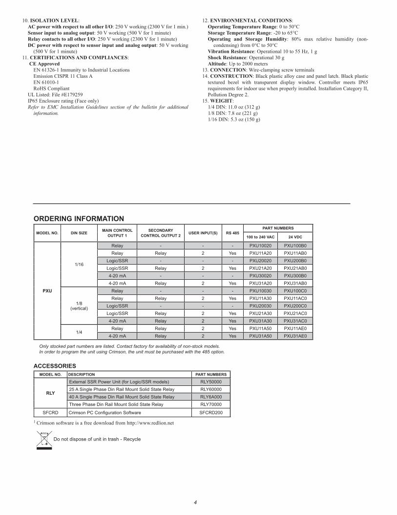
ORDERING INFORMATION
MODEL NO. DIN SIZE MAIN CONTROL OUTPUT 1
SECONDARY CONTROL OUTPUT 2 USER INPUT(S) RS 485
PART NUMBERS
100 to 240 VAC 24 VDC
PXU
1/16
Relay - - - PXU10020 PXU100B0Relay Relay 2 Yes PXU11A20 PXU11AB0
Logic/SSR - - - PXU20020 PXU200B0Logic/SSR Relay 2 Yes PXU21A20 PXU21AB04-20 mA - - - PXU30020 PXU300B04-20 mA Relay 2 Yes PXU31A20 PXU31AB0
1/8(vertical)
Relay - - - PXU10030 PXU100C0Relay Relay 2 Yes PXU11A30 PXU11AC0
Logic/SSR - - - PXU20030 PXU200C0Logic/SSR Relay 2 Yes PXU21A30 PXU21AC04-20 mA Relay 2 Yes PXU31A30 PXU31AC0
1/4Relay Relay 2 Yes PXU11A50 PXU11AE0
4-20 mA Relay 2 Yes PXU31A50 PXU31AE0
Only stocked part numbers are listed. Contact factory for availability of non-stock models.In order to program the unit using Crimson, the unit must be purchased with the 485 option.
ACCESSORIESMODEL NO. DESCRIPTION PART NUMBERS
RLY
External SSR Power Unit (for Logic/SSR models) RLY5000025 A Single Phase Din Rail Mount Solid State Relay RLY6000040 A Single Phase Din Rail Mount Solid State Relay RLY6A000Three Phase Din Rail Mount Solid State Relay RLY70000
SFCRD Crimson PC Configuration Software SFCRD200
1 Crimson software is a free download from http://www.redlion.net
55
EMC INSTALLATION GUIDELINESAlthough Red Lion Controls Products are designed with a high degree of
immunity to Electromagnetic Interference (EMI), proper installation and wiring methods must be followed to ensure compatibility in each application. The type of the electrical noise, source or coupling method into a unit may be different for various installations. Cable length, routing, and shield termination are very important and can mean the difference between a successful or troublesome installation. Listed are some EMI guidelines for a successful installation in an industrial environment.1. A unit should be mounted in a metal enclosure, which is properly connected
to protective earth.2. Use shielded cables for all Signal and Control inputs. The shield connection
should be made as short as possible. The connection point for the shield depends somewhat upon the application. Listed below are the recommended methods of connecting the shield, in order of their effectiveness.a. Connect the shield to earth ground (protective earth) at one end where the
unit is mounted.b. Connect the shield to earth ground at both ends of the cable, usually when
the noise source frequency is over 1 MHz.3. Never run Signal or Control cables in the same conduit or raceway with AC
power lines, conductors, feeding motors, solenoids, SCR controls, and heaters, etc. The cables should be run through metal conduit that is properly grounded. This is especially useful in applications where cable runs are long and portable two-way radios are used in close proximity or if the installation is near a commercial radio transmitter. Also, Signal or Control cables within an enclosure should be routed as far away as possible from contactors, control relays, transformers, and other noisy components.
4. Long cable runs are more susceptible to EMI pickup than short cable runs.5. In extremely high EMI environments, the use of external EMI suppression
devices such as Ferrite Suppression Cores for signal and control cables is
effective. The following EMI suppression devices (or equivalent) are recommended:
Fair-Rite part number 0443167251 (RLC part number FCOR0000)Line Filters for input power cables:
Schaffner # FN2010-1/07 (Red Lion Controls # LFIL0000)6. To protect relay contacts that control inductive loads and to minimize radiated
and conducted noise (EMI), some type of contact protection network is normally installed across the load, the contacts or both. The most effective location is across the load.a. Using a snubber, which is a resistor-capacitor (RC) network or metal oxide
varistor (MOV) across an AC inductive load is very effective at reducing EMI and increasing relay contact life.
b. If a DC inductive load (such as a DC relay coil) is controlled by a transistor switch, care must be taken not to exceed the breakdown voltage of the transistor when the load is switched. One of the most effective ways is to place a diode across the inductive load. Most RLC products with solid state outputs have internal zener diode protection. However external diode protection at the load is always a good design practice to limit EMI. Although the use of a snubber or varistor could be used.RLC part numbers: Snubber: SNUB0000 Varistor: ILS11500 or ILS23000
7. Care should be taken when connecting input and output devices to the instrument. When a separate input and output common is provided, they should not be mixed. Therefore a sensor common should NOT be connected to an output common. This would cause EMI on the sensitive input common, which could affect the instrument’s operation.
Visit RLC’s web site at http://www.redlion.net/Support/InstallationConsiderations.html for more information on EMI guidelines, Safety and CE issues as they relate to Red Lion Controls products.
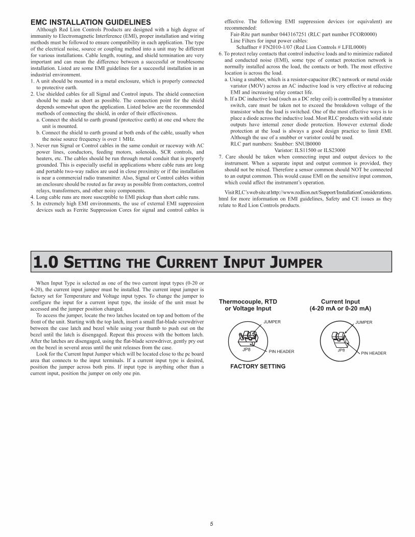
1.0 seTTing The CurrenT inpuT JumperWhen Input Type is selected as one of the two current input types (0-20 or
4-20), the current input jumper must be installed. The current input jumper is factory set for Temperature and Voltage input types. To change the jumper to configure the input for a current input type, the inside of the unit must be accessed and the jumper position changed.
To access the jumper, locate the two latches located on top and bottom of the front of the unit. Starting with the top latch, insert a small flat-blade screwdriver between the case latch and bezel while using your thumb to push out on the bezel until the latch is disengaged. Repeat this process with the bottom latch. After the latches are disengaged, using the flat-blade screwdriver, gently pry out on the bezel in several areas until the unit releases from the case.
Look for the Current Input Jumper which will be located close to the pc board area that connects to the input terminals. If a current input type is desired, position the jumper across both pins. If input type is anything other than a current input, position the jumper on only one pin.
JUMPER
PIN HEADERJP8
FACTORY SETTING
Thermocouple, RTD or Voltage Input
JUMPER
PIN HEADERJP8
Current Input (4-20 mA or 0-20 mA)
6
2.0 insTalling The COnTrOller
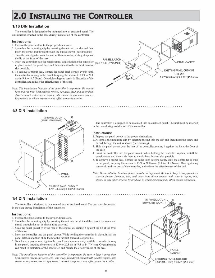
The controller is designed to be mounted into an enclosed panel. The unit must be inserted in the case during installation of the controller.
Instructions:1. Prepare the panel cutout to the proper dimensions.2. Assemble the mounting clip by inserting the nut into the slot and then
insert the screw and thread through the nut as shown (See drawing)3. Slide the panel gasket over the rear of the controller, seating it against
the lip at the front of the case.4. Insert the controller into the panel cutout. While holding the controller
in place, install the panel latch and then slide it to the farthest forward slot possible.
5. To achieve a proper seal, tighten the panel latch screws evenly until the controller is snug in the panel, torquing the screws to 13.9 to 20.8 oz-in (9.8 to 14.7 N-cm). Overtightening can result in distortion of the controller, and reduce the effectiveness of the seal.
Note: The installation location of the controller is important. Be sure to keep it away from heat sources (ovens, furnaces, etc.) and away from direct contact with caustic vapors, oils, steam, or any other process by-products in which exposure may affect proper operation.
(4) PANEL LATCH(SUPPLIED W/UNIT)
PANELGASKET
EXISTING PANEL CUT-OUT3.58" (91.0 mm) X 3.58" (91.0 mm)
7
8
9
10
11
12
PANEL LATCH(SUPPLIED W/UNIT)
EXISTING PANEL CUT-OUT1/16 DIN
1.77” (45.0 mm) X 1.77” (45.0 mm)
PANEL GASKET
1/16 DIN Installation
1/8 DIN Installation
1/4 DIN Installation
20
24
23
22
21
14
17
19
18
15
16
13
(2) PANEL LATCH(SUPPLIED W/UNIT)
PANELGASKET
EXISTING PANEL CUT-OUT1.76" (44.5 mm) X 3.60" (91.5 mm)
The controller is designed to be mounted into an enclosed panel. The unit must be inserted in the case during installation of the controller.
Instructions:1. Prepare the panel cutout to the proper dimensions.2. Assemble the mounting clip by inserting the nut into the slot and then insert the screw and
thread through the nut as shown (See drawing)3. Slide the panel gasket over the rear of the controller, seating it against the lip at the front of
the case.4. Insert the controller into the panel cutout. While holding the controller in place, install the
panel latches and then slide them to the farthest forward slot possible.5. To achieve a proper seal, tighten the panel latch screws evenly until the controller is snug
in the panel, torquing the screws to 13.9 to 20.8 oz-in (9.8 to 14.7 N-cm). Overtightening can result in distortion of the controller, and reduce the effectiveness of the seal.
Note: The installation location of the controller is important. Be sure to keep it away from heat sources (ovens, furnaces, etc.) and away from direct contact with caustic vapors, oils, steam, or any other process by-products in which exposure may affect proper operation.
The controller is designed to be mounted into an enclosed panel. The unit must be inserted in the case during installation of the controller.
Instructions:1. Prepare the panel cutout to the proper dimensions.2. Assemble the mounting clip by inserting the nut into the slot and then insert the screw and
thread through the nut as shown (See drawing)3. Slide the panel gasket over the rear of the controller, seating it against the lip at the front
of the case.4. Insert the controller into the panel cutout. While holding the controller in place, install the
panel latches and then slide them to the farthest forward slot possible.5. To achieve a proper seal, tighten the panel latch screws evenly until the controller is snug
in the panel, torquing the screws to 13.9 to 20.8 oz-in (9.8 to 14.7 N-cm). Overtightening can result in distortion of the controller, and reduce the effectiveness of the seal.
Note: The installation location of the controller is important. Be sure to keep it away from heat sources (ovens, furnaces, etc.) and away from direct contact with caustic vapors, oils, steam, or any other process by-products in which exposure may affect proper operation.
77
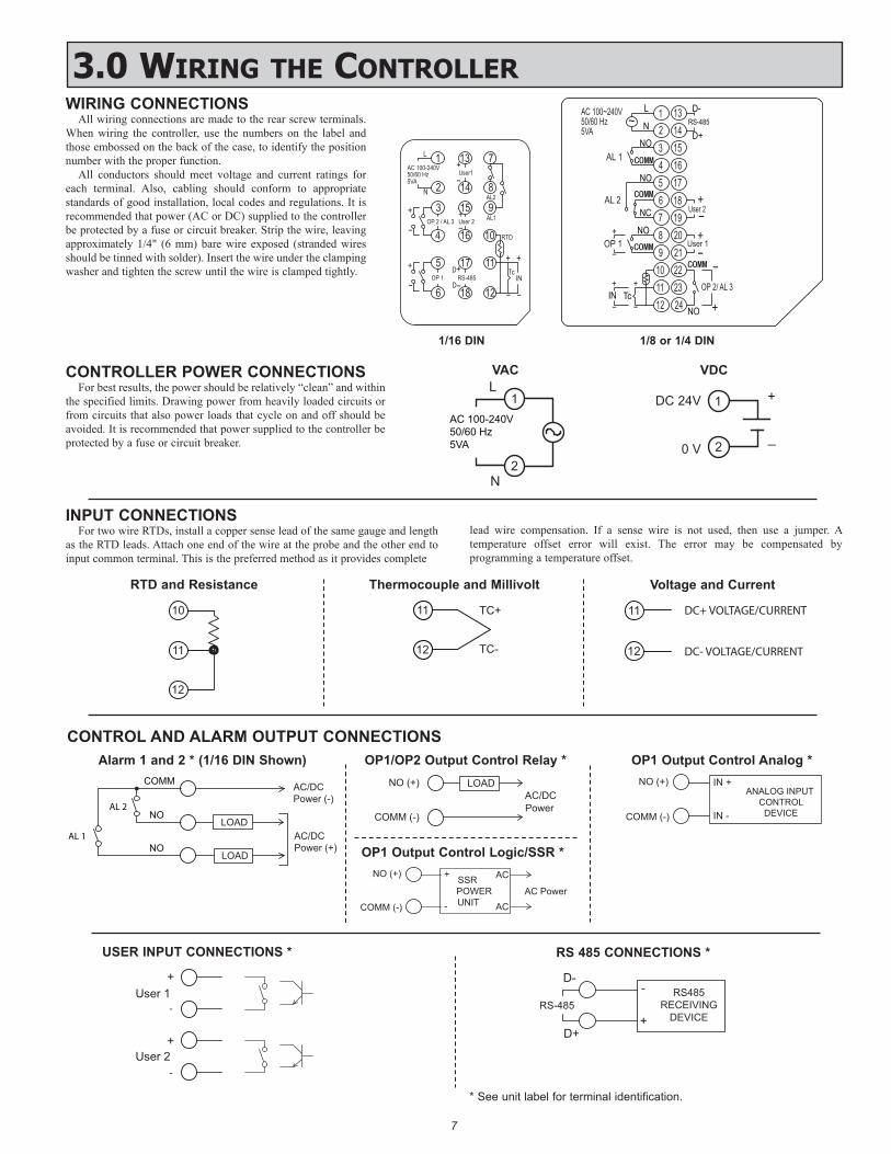
3.0 Wiring The COnTrOllerWIRING CONNECTIONS
All wiring connections are made to the rear screw terminals. When wiring the controller, use the numbers on the label and those embossed on the back of the case, to identify the position number with the proper function.
All conductors should meet voltage and current ratings for each terminal. Also, cabling should conform to appropriate standards of good installation, local codes and regulations. It is recommended that power (AC or DC) supplied to the controller be protected by a fuse or circuit breaker. Strip the wire, leaving approximately 1/4" (6 mm) bare wire exposed (stranded wires should be tinned with solder). Insert the wire under the clamping washer and tighten the screw until the wire is clamped tightly.
1L
50/60 Hz5VA
AC 100-240V
N 2
13
14User1
8
7+-
15 93User 2
4 1016
AL1
AL2
OP 2 / AL 3+-
11175
12186
RTD
OP 1 RS-485D
D-
++
INTc
+
- -
+
-
-
+
AC 100~240V50/60 Hz5VA
1~
132 143 154 165 176 187 198 209 21
10 2211 2312 24
IN TcNO
D-L
N
NOD+
RS-485
NO
NO
NC
AL 1
AL 2
OP 1
User 2
User 1
OP 2/ AL 3
+
+ +
+
+
+- -
--
-
-
1/16 DIN 1/8 or 1/4 DIN
CONTROLLER POWER CONNECTIONSFor best results, the power should be relatively “clean” and within
the specified limits. Drawing power from heavily loaded circuits or from circuits that also power loads that cycle on and off should be avoided. It is recommended that power supplied to the controller be protected by a fuse or circuit breaker.
2
1L
N
AC 100-240V50/60 Hz5VA
INPUT CONNECTIONSFor two wire RTDs, install a copper sense lead of the same gauge and length
as the RTD leads. Attach one end of the wire at the probe and the other end to input common terminal. This is the preferred method as it provides complete
lead wire compensation. If a sense wire is not used, then use a jumper. A temperature offset error will exist. The error may be compensated by programming a temperature offset.
12
11
10
TC-
TC+
12
11 DC+ VOLTAGE/CURRENT
DC- VOLTAGE/CURRENT12
11
CONTROL AND ALARM OUTPUT CONNECTIONS
VAC
RTD and Resistance Thermocouple and Millivolt Voltage and Current
LOAD
AC/DCPower (-)
LOAD
COMM
NO
NOAC/DCPower (+)
AL 2
AL 1
AC/DCPower
LOAD
COMM (-)
NO (+)
AC PowerSSR
COMM (-)
NO (+)
POWERUNIT
+
-
AC
AC
Alarm 1 and 2 * (1/16 DIN Shown) OP1/OP2 Output Control Relay *
OP1 Output Control Logic/SSR *
USER INPUT CONNECTIONS *
User 1+
User 2+
-
-
* See unit label for terminal identification.
RS 485 CONNECTIONS *
D+
D-RS485
RECEIVINGDEVICE+
-RS-485
0 V
DC 24V
2
1 +
_
VDC
ANALOG INPUT CONTROL
DEVICE COMM (-)
NO (+) IN +
IN -
OP1 Output Control Analog *
8
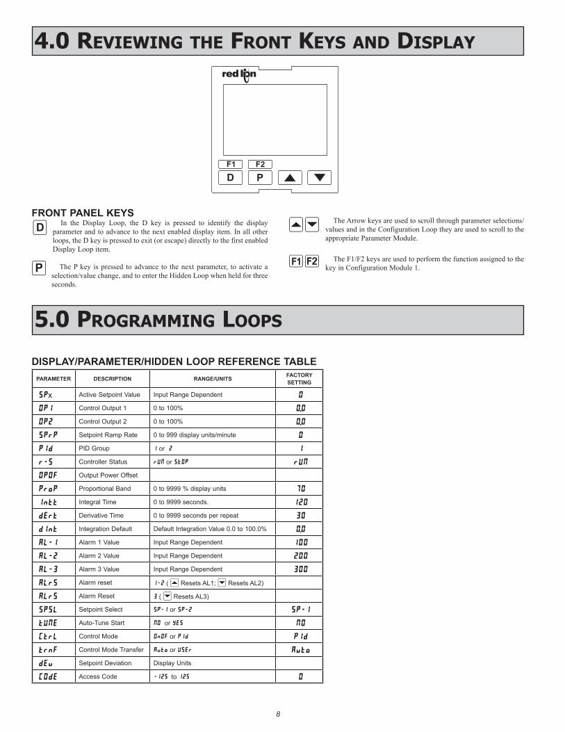
FRONT PANEL KEYSIn the Display Loop, the D key is pressed to identify the display
parameter and to advance to the next enabled display item. In all other loops, the D key is pressed to exit (or escape) directly to the first enabled Display Loop item.
The P key is pressed to advance to the next parameter, to activate a selection/value change, and to enter the Hidden Loop when held for three seconds.
The Arrow keys are used to scroll through parameter selections/values and in the Configuration Loop they are used to scroll to the appropriate Parameter Module.
The F1/F2 keys are used to perform the function assigned to the key in Configuration Module 1.
8
4.0 revieWing The frOnT Keys and display
BJ
F1 F2
D P
5.0 prOgramming lOOps
:
=
12
DISPLAY/PARAMETER/HIDDEN LOOP REFERENCE TABLEPARAMETER DESCRIPTION RANGE/UNITS FACTORY
SETTING
SPx Active Setpoint Value Input Range Dependent 0
OP1 Control Output 1 0 to 100% 0.0
OP2 Control Output 2 0 to 100% 0.0
SPrP Setpoint Ramp Rate 0 to 999 display units/minute 0
PId PID Group 1 or 2 1
r-S Controller Status rUN or StOP rUN
OPOF Output Power Offset
ProP Proportional Band 0 to 9999 % display units 70
Intt Integral Time 0 to 9999 seconds. 120
dErt Derivative Time 0 to 9999 seconds per repeat 30
dInt Integration Default Default Integration Value 0.0 to 100.0% 0.0
AL-1 Alarm 1 Value Input Range Dependent 100
AL-2 Alarm 2 Value Input Range Dependent 200
AL-3 Alarm 3 Value Input Range Dependent 300
ALrS Alarm reset 1-2 ( B Resets AL1; J Resets AL2)
ALrS Alarm Reset 3 ( J Resets AL3)
SPSL Setpoint Select SP-1 or SP-2 SP-1
tUNE Auto-Tune Start NO or YES NO
CtrL Control Mode OnOF or PId PId
trnF Control Mode Transfer Auto or USEr Auto
dEv Setpoint Deviation Display Units
COdE Access Code -125 to 125 0
9
COdE1 to 125
HIDDEN LOOPw/CONFIGURATIONLOOP ACCESSIBLE
PARAMETERLOOP
P
P
P
MAINDISPLAY LOOP
D
* If PLOC is active, the Configuration Loop is not accessible.
DHold
P
Hold
IF Code =1 to 125
IF Code =0
IF Code =-1 to -125
HIDDENLOOP
COdE-1 to -125
P
CONFIGURATIONLOOP
*
*
P
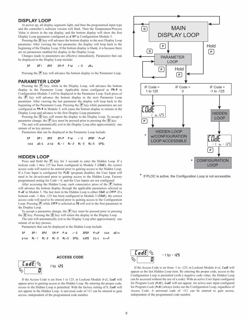
DISPLAY LOOPAt power up, all display segments light, and then the programmed input type
and the controller’s software version will flash. Then the Temperature/Process Value is shown in the top display, and the bottom display will show the first Display Loop parameter configured as dISP in Configuration Module 3.
Pressing the = key will advance the bottom display to the next Display Loop parameter. After viewing the last parameter, the display will loop back to the beginning of the Display Loop. If the bottom display is blank, it is because there are no parameters enabled for display in the Display Loop.
Changes made to parameters are effective immediately. Parameters that can be displayed in the Display Loop include:
SP OP1 OP2 SPrP PId r-S dEv
Pressing the : key will advance the bottom display to the Parameter Loop.
PARAMETER LOOPPressing the : key, while in the Display Loop, will advance the bottom
display to the Parameter Loop. Applicable items configured as PArA in Configuration Module 3 will be displayed in the Parameter Loop. Each press of the : key will advance the bottom display to the next Parameter Loop parameter. After viewing the last parameter the display will loop back to the beginning of the Parameter Loop. Pressing the : key while parameters are not configured as PArA in Module 3, will cause the bottom display to remain in the Display Loop and advance to the first Display Loop parameter.
Pressing the = key will return the display to the Display Loop. To accept a parameter change, the : key must be pressed prior to pressing the = key.
The unit will automatically exit to the Display Loop after approximately one minute of no key presses.
Parameters that can be displayed in the Parameter Loop include:
SP OP1 OP2 SPrP PId r-S OPOF Prop
Intt dErt dInt AL-1 AL-2 AL-3 ALrS SPSL
HIDDEN LOOPPress and Hold the : key for 3 seconds to enter the Hidden Loop. If a
lockout code 1 thru 125 has been configured in Module 3 (COdE), the correct access code will need to be entered prior to gaining access to the Hidden Loop. If a User Input is configured for PLOC (program disable), the User Input will need to be de-activated prior to gaining access to the Hidden Loop. Factory programmed setting for Code = 0, and the User Inputs are not configured.
After accessing the Hidden Loop, each consecutive press of the : button will advance the bottom display through the applicable parameters selected as HidE in Module 3. The last item in the Hidden Loop is either COdE or CNFP. If a lockout code -1 thru -125 has been configured in Module 3 (COdE), the correct access code will need to be entered prior to gaining access to the Configuration Loop. Pressing : while CNFP is selected as NO will exit to the first parameter in the Display Loop.
To accept a parameter change, the : key must be pressed prior to pressing the = key. Pressing the = key will return the display to the Display Loop.
The unit will automatically exit to the Display Loop after approximately one minute of no key presses.
Parameters that can be displayed in the Hidden Loop include:
SP OP1 OP2 SPrP PId r-S OPOF Prop Intt dErt
dInt AL-1 AL-2 AL-3 ALrS SPSL tUNE CtrL trnF
ACCESS CODE
If the Access Code is set from 1 to 125, in Lockout Module 3C, CodE will appear prior to gaining access to the Hidden Loop. By entering the proper code, access to the Hidden Loop is permitted. With the factory setting of 0, CodE will not appear in the Hidden Loop. A universal code of 111 can be entered to gain access, independent of the programmed code number.
C to
9
If the Access Code is set from -1 to -125, in Lockout Module 3C, CodE will appear as the last Hidden Loop item. By entering the proper code, access to the Configuration Loop is permitted (with a negative code value, the Hidden Loop can be accessed without the use of a code). With an active User Input configured for Program Lock (C), CodE will not appear. An active user input configured for Program Lock (C) always locks out the Configuration Loop, regardless of Access Code. A universal code of -111 can be entered to gain access, independent of the programmed code number.
C to
10
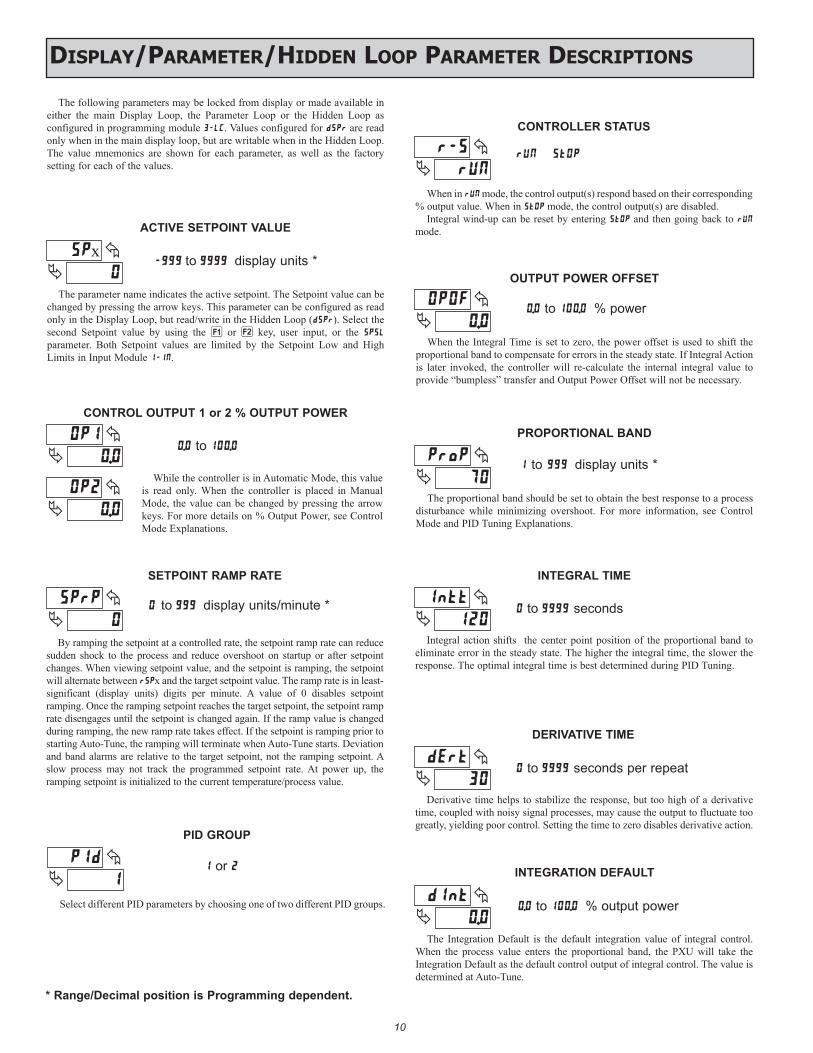
SETPOINT RAMP RATE
to display units/minute *
By ramping the setpoint at a controlled rate, the setpoint ramp rate can reduce sudden shock to the process and reduce overshoot on startup or after setpoint changes. When viewing setpoint value, and the setpoint is ramping, the setpoint will alternate between rSPx and the target setpoint value. The ramp rate is in least-significant (display units) digits per minute. A value of 0 disables setpoint ramping. Once the ramping setpoint reaches the target setpoint, the setpoint ramp rate disengages until the setpoint is changed again. If the ramp value is changed during ramping, the new ramp rate takes effect. If the setpoint is ramping prior to starting Auto-Tune, the ramping will terminate when Auto-Tune starts. Deviation and band alarms are relative to the target setpoint, not the ramping setpoint. A slow process may not track the programmed setpoint rate. At power up, the ramping setpoint is initialized to the current temperature/process value.
ACTIVE SETPOINT VALUE
to display units *
CONTROL OUTPUT 1 or 2 % OUTPUT POWER
. to .
The parameter name indicates the active setpoint. The Setpoint value can be changed by pressing the arrow keys. This parameter can be configured as read only in the Display Loop, but read/write in the Hidden Loop (dSPr). Select the second Setpoint value by using the 1 or 2 key, user input, or the SPSL parameter. Both Setpoint values are limited by the Setpoint Low and High Limits in Input Module 1-IN.
While the controller is in Automatic Mode, this value is read only. When the controller is placed in Manual Mode, the value can be changed by pressing the arrow keys. For more details on % Output Power, see Control Mode Explanations.
CONTROLLER STATUS
When in rUN mode, the control output(s) respond based on their corresponding % output value. When in StOP mode, the control output(s) are disabled.
Integral wind-up can be reset by entering StOP and then going back to rUN mode.
I
PID GROUP
or
Select different PID parameters by choosing one of two different PID groups.
The following parameters may be locked from display or made available in either the main Display Loop, the Parameter Loop or the Hidden Loop as configured in programming module 3-LC. Values configured for dSPr are read only when in the main display loop, but are writable when in the Hidden Loop. The value mnemonics are shown for each parameter, as well as the factory setting for each of the values.
.
OUTPUT POWER OFFSET
When the Integral Time is set to zero, the power offset is used to shift the proportional band to compensate for errors in the steady state. If Integral Action is later invoked, the controller will re-calculate the internal integral value to provide “bumpless” transfer and Output Power Offset will not be necessary.
. to . % power
x
.
.
7
PROPORTIONAL BAND
to display units *
The proportional band should be set to obtain the best response to a process disturbance while minimizing overshoot. For more information, see Control Mode and PID Tuning Explanations.
I
INTEGRAL TIME
to seconds
Integral action shifts the center point position of the proportional band to eliminate error in the steady state. The higher the integral time, the slower the response. The optimal integral time is best determined during PID Tuning.
3
DERIVATIVE TIME
to seconds per repeat
Derivative time helps to stabilize the response, but too high of a derivative time, coupled with noisy signal processes, may cause the output to fluctuate too greatly, yielding poor control. Setting the time to zero disables derivative action.
.
I
INTEGRATION DEFAULT
. to . % output power
The Integration Default is the default integration value of integral control. When the process value enters the proportional band, the PXU will take the Integration Default as the default control output of integral control. The value is determined at Auto-Tune.
display/parameTer/hidden lOOp parameTer desCripTiOns
* Range/Decimal position is Programming dependent.
11
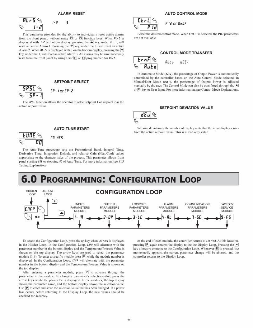
CONTROL MODE TRANSFER
In Automatic Mode (), the percentage of Output Power is automatically determined by the controller based on the Auto Control Mode selected. In Manual/User Mode (), the percentage of Output Power is adjusted manually by the user. The Control Mode can also be transferred through the 1 or 2 key or User Input. For more information, see Control Mode Explanations.
v
SETPOINT DEVIATION VALUE
Setpoint deviation is the number of display units that the input display varies from the active setpoint value. This is a read only value.
AUTO-TUNE START
The Auto-Tune procedure sets the Proportional Band, Integral Time, Derivative Time, Integration Default, and relative Gain (Heat/Cool) values appropriate to the characteristics of the process. This parameter allows front panel starting or stopping of Auto-Tune. For more information, see PID Tuning Explanations.
11
6.0 prOgramming: COnfiguraTiOn lOOp
LOOPHIDDEN DISPLAY
LOOP
PARAMETERSINPUT
MODULE MODULE
OUTPUTPARAMETERS
LOCKOUTPARAMETERS
MODULE
COMMUNICATIONPARAMETERS
MODULE
FACTORYSERVICEMODULE
ALARMPARAMETERS
MODULE
P
CONFIGURATION LOOP
To access the Configuration Loop, press the up key when C/ is displayed in the Hidden Loop. In the Configuration Loop, C will alternate with the parameter number in the bottom display and the Temperature/Process Value is shown on the top display. The arrow keys are used to select the parameter module (1-9). To enter a specific module press : while the module number is displayed. In the Configuration Loop, C will alternate with the parameter number in the bottom display and the Temperature/Process Value is shown on the top display.
After entering a parameter module, press : to advance through the parameters in the module. To change a parameter’s selection/value, press the arrow keys while the parameter is displayed. In the modules, the top display shows the parameter name, and the bottom display shows the selection/value. Use : to enter and store the selection/value that has been changed. If a power loss occurs before returning to the Display Loop, the new values should be checked for accuracy.
At the end of each module, the controller returns to C/. At this location, pressing : again returns the display to the the Display Loop. Pressing the B key allows re-entrance to the Configuration Loop. Whenever = is pressed, momentarily appears, the current parameter change will be aborted, and the controller returns to the Display Loop.
I
C
AUTO CONTROL MODE
PId or OnOF
Select the desired control mode. When OnOF is selected, the PID parameters are not available.
SETPOINT SELECT
or
The SPSL function allows the operator to select setpoint 1 or setpoint 2 as the active setpoint value.
ALARM RESET
This parameter provides for the ability to individually reset active alarms from the front panel, without using 1 or 2 function keys. When ALrS is displayed with 1-2 on bottom display, pressing the B key, under the 1, will reset an active Alarm 1. Pressing the J key, under the 2, will reset an active Alarm 2. When ALrS is displayed with 3 on the bottom display, pressing the J key, under the 3, will reset an active Alarm 3. All alarms may be simultaneously reset from the front panel by using User 1 or 2 programmed for ALrS.
3
s
1212
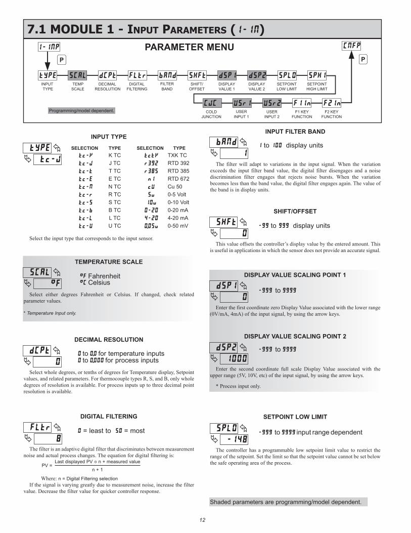
7.1 mOdule 1 - inpuT parameTers (1-IN)
INPUTTYPE
TEMPSCALE
DECIMALRESOLUTION
DIGITALFILTERING BAND
FILTERVALUE 1DISPLAYSHIFT/
OFFSET
VALUE 2DISPLAY
SETPOINTLOW LIMIT
SETPOINTHIGH LIMIT
P P
INPUT 1USER USER
INPUT 2
FUNCTIONF1 KEY
F2 KEY
FUNCTION
COLD
JUNCTIONProgramming/model dependent.
PARAMETER MENU
INPUT TYPE
TEMPERATURE SCALE
FahrenheitC Celsius
Select the input type that corresponds to the input sensor.
Select either degrees Fahrenheit or Celsius. If changed, check related parameter values.
* Temperature Input only.
DECIMAL RESOLUTION
to . for temperature inputs to . for process inputs
Select whole degrees, or tenths of degrees for Temperature display, Setpoint values, and related parameters. For thermocouple types R, S, and B, only whole degrees of resolution is available. For process inputs up to three decimal point resolution is available.
INPUT FILTER BAND
to display units
The filter will adapt to variations in the input signal. When the variation exceeds the input filter band value, the digital filter disengages and a noise discrimination filter engages that rejects noise bursts. When the variation becomes less than the band value, the digital filter engages again. The value of the band is in display units.
SETPOINT LOW LIMIT
to input range dependent
The controller has a programmable low setpoint limit value to restrict the range of the setpoint. Set the limit so that the setpoint value cannot be set below the safe operating area of the process.
DIGITAL FILTERING
= least to = most
The filter is an adaptive digital filter that discriminates between measurement noise and actual process changes. The equation for digital filtering is:
PV =
Where: n = Digital Filtering selectionIf the signal is varying greatly due to measurement noise, increase the filter
value. Decrease the filter value for quicker controller response.
Last displayed PV [ n + measured value
n + 1
DISPLAY VALUE SCALING POINT 1
to
Enter the first coordinate zero Display Value associated with the lower range (0V/mA, 4mA) of the input signal, by using the arrow keys.
DISPLAY VALUE SCALING POINT 2
to
Enter the second coordinate full scale Display Value associated with the upper range (5V, 10V, etc) of the input signal, by using the arrow keys.
* Process input only.
SELECTION TYPE SELECTION TYPEt-K K TC ttK TXK TCt-J J TC r32 RTD 392t-t T TC r35 RTD 385t-E E TC nI RTD 672t-N N TC U Cu 50t-r R TC Su 0-5 Voltt-S S TC 10u 0-10 Voltt-b B TC 0-20 0-20 mAt-L L TC 4-20 4-20 mAt-U U TC 0.05u 0-50 mV
SHIFT/OFFSET
to display units
This value offsets the controller’s display value by the entered amount. This is useful in applications in which the sensor does not provide an accurate signal.
C
C
8
b
48
Shaded parameters are programming/model dependent.
13
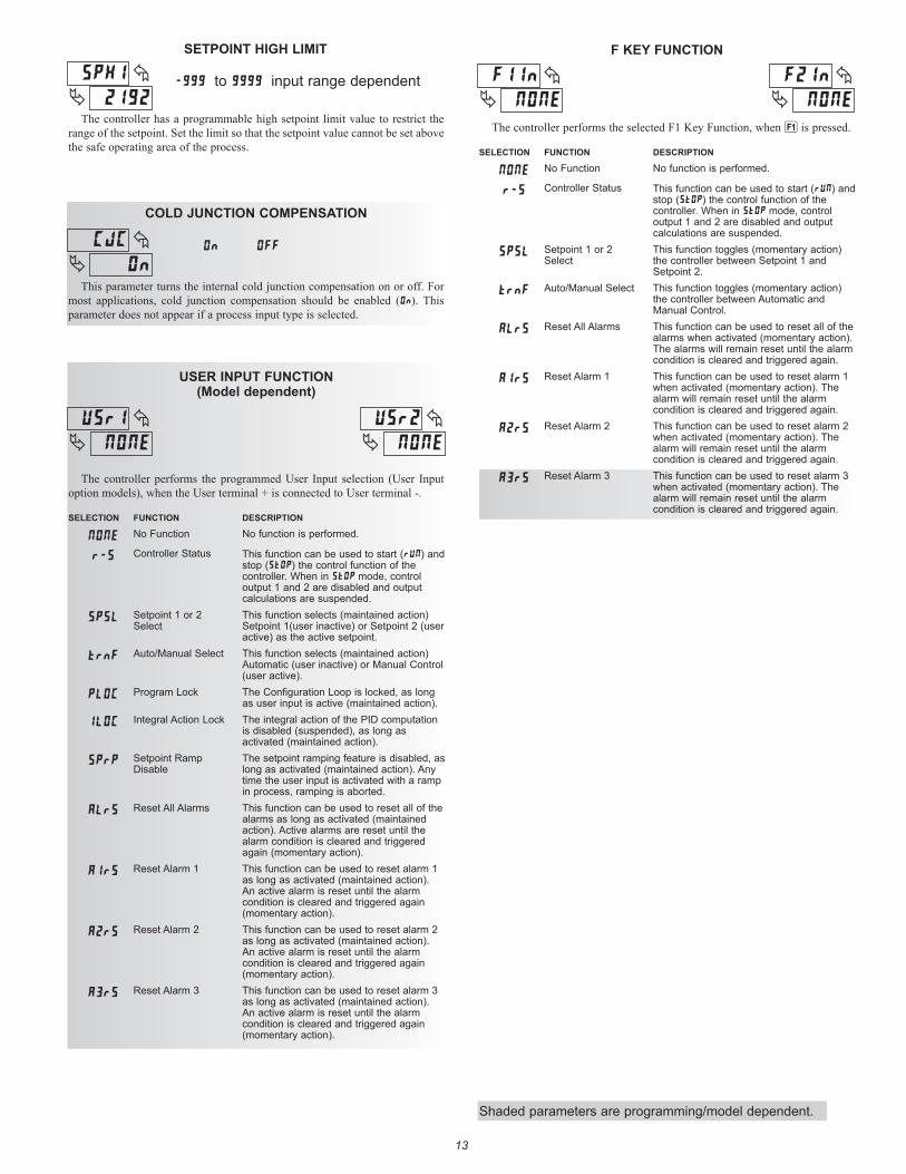
SETPOINT HIGH LIMIT
to input range dependent
The controller has a programmable high setpoint limit value to restrict the range of the setpoint. Set the limit so that the setpoint value cannot be set above the safe operating area of the process.
I
13
USER INPUT FUNCTION(Model dependent)
The controller performs the programmed User Input selection (User Input option models), when the User terminal + is connected to User terminal -.
SELECTION FUNCTION DESCRIPTION
NONE No Function No function is performed.
r-S Controller Status This function can be used to start (rUN) and stop (stOp) the control function of the controller. When in StOp mode, control output 1 and 2 are disabled and output calculations are suspended.
SPSL Setpoint 1 or 2 Select
This function selects (maintained action) Setpoint 1(user inactive) or Setpoint 2 (user active) as the active setpoint.
trnF Auto/Manual Select This function selects (maintained action) Automatic (user inactive) or Manual Control (user active).
PLOC Program Lock The Configuration Loop is locked, as long as user input is active (maintained action).
ILOC Integral Action Lock The integral action of the PID computation is disabled (suspended), as long as activated (maintained action).
SPrP Setpoint Ramp Disable
The setpoint ramping feature is disabled, as long as activated (maintained action). Any time the user input is activated with a ramp in process, ramping is aborted.
ALrS Reset All Alarms This function can be used to reset all of the alarms as long as activated (maintained action). Active alarms are reset until the alarm condition is cleared and triggered again (momentary action).
A1rs Reset Alarm 1 This function can be used to reset alarm 1 as long as activated (maintained action). An active alarm is reset until the alarm condition is cleared and triggered again (momentary action).
A2rS Reset Alarm 2 This function can be used to reset alarm 2 as long as activated (maintained action). An active alarm is reset until the alarm condition is cleared and triggered again (momentary action).
A3rS Reset Alarm 3 This function can be used to reset alarm 3 as long as activated (maintained action). An active alarm is reset until the alarm condition is cleared and triggered again (momentary action).
F KEY FUNCTION
The controller performs the selected F1 Key Function, when 1 is pressed.
SELECTION FUNCTION DESCRIPTION
NONE No Function No function is performed.
r-S Controller Status This function can be used to start (rUN) and stop (stOp) the control function of the controller. When in StOp mode, control output 1 and 2 are disabled and output calculations are suspended.
SPSL Setpoint 1 or 2 Select
This function toggles (momentary action) the controller between Setpoint 1 and Setpoint 2.
trnF Auto/Manual Select This function toggles (momentary action) the controller between Automatic and Manual Control.
ALrS Reset All Alarms This function can be used to reset all of the alarms when activated (momentary action). The alarms will remain reset until the alarm condition is cleared and triggered again.
A1rs Reset Alarm 1 This function can be used to reset alarm 1 when activated (momentary action). The alarm will remain reset until the alarm condition is cleared and triggered again.
A2rS Reset Alarm 2 This function can be used to reset alarm 2 when activated (momentary action). The alarm will remain reset until the alarm condition is cleared and triggered again.
A3rS Reset Alarm 3 This function can be used to reset alarm 3 when activated (momentary action). The alarm will remain reset until the alarm condition is cleared and triggered again.
COLD JUNCTION COMPENSATION
On OFF
This parameter turns the internal cold junction compensation on or off. For most applications, cold junction compensation should be enabled (On). This parameter does not appear if a process input type is selected.
I I
CJC
Shaded parameters are programming/model dependent.
14
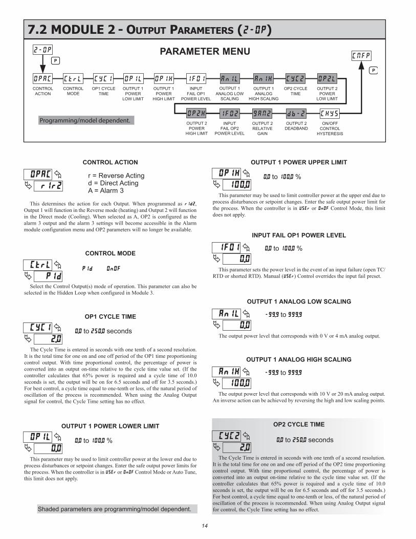
OP1 CYCLE TIME
. to . seconds
OP2 CYCLE TIME
. to . seconds
The Cycle Time is entered in seconds with one tenth of a second resolution. It is the total time for one on and one off period of the OP1 time proportioning control output. With time proportional control, the percentage of power is converted into an output on-time relative to the cycle time value set. (If the controller calculates that 65% power is required and a cycle time of 10.0 seconds is set, the output will be on for 6.5 seconds and off for 3.5 seconds.) For best control, a cycle time equal to one-tenth or less, of the natural period of oscillation of the process is recommended. When using the Analog Output signal for control, the Cycle Time setting has no effect.
CONTROL ACTION
r = Reverse Actingd = Direct ActingA = Alarm 3
This determines the action for each Output. When programmed as r1d2, Output 1 will function in the Reverse mode (heating) and Output 2 will function in the Direct mode (Cooling). When selected as A, OP2 is configured as the alarm 3 output and the alarm 3 settings will become accessible in the Alarm module configuration menu and OP2 parameters will no longer be available.
OUTPUT 1 POWER LOWER LIMIT
. to . %
This parameter may be used to limit controller power at the lower end due to process disturbances or setpoint changes. Enter the safe output power limits for the process. When the controller is in USEr or OnOF Control Mode or Auto Tune, this limit does not apply.
OUTPUT 1 POWER UPPER LIMIT
. to . %
This parameter may be used to limit controller power at the upper end due to process disturbances or setpoint changes. Enter the safe output power limit for the process. When the controller is in USEr or OnOF Control Mode, this limit does not apply.
INPUT FAIL OP1 POWER LEVEL
This parameter sets the power level in the event of an input failure (open TC/RTD or shorted RTD). Manual (USEr) Control overrides the input fail preset.
The Cycle Time is entered in seconds with one tenth of a second resolution. It is the total time for one on and one off period of the OP2 time proportioning control output. With time proportional control, the percentage of power is converted into an output on-time relative to the cycle time value set. (If the controller calculates that 65% power is required and a cycle time of 10.0 seconds is set, the output will be on for 6.5 seconds and off for 3.5 seconds.) For best control, a cycle time equal to one-tenth or less, of the natural period of oscillation of the process is recommended. When using Analog Output signal for control, the Cycle Time setting has no effect.
7.2 mOdule 2 - OuTpuT parameTers (2-OP)
OP1 CYCLETIME
CONTROLACTION
CONTROLMODE
OUTPUT 1POWER ANALOG LOW
SCALING
OUTPUT 1INPUTFAIL OP1
ANALOGHIGH SCALING
OUTPUT 1TIME
OP2 CYCLE
LOW LIMIT HIGH LIMITPOWER
OUTPUT 1
POWER LEVEL
OUTPUT 2POWER
LOW LIMIT
P
P
ON/OFF
CONTROL
INPUTFAIL OP2
POWER LEVEL
OUTPUT 2DEADBANDRELATIVE
GAIN
OUTPUT 2
HYSTERESIS
POWERHIGH LIMIT
OUTPUT 2Programming/model dependent.
PARAMETER MENU
. to . % CONTROL MODE
Select the Control Output(s) mode of operation. This parameter can also be selected in the Hidden Loop when configured in Module 3.
l
C
I
I
C
.
CC
.
.
.
I
.
CC
OUTPUT 1 ANALOG LOW SCALING
The output power level that corresponds with 0 V or 4 mA analog output.
. to .
.
OUTPUT 1 ANALOG HIGH SCALING
The output power level that corresponds with 10 V or 20 mA analog output. An inverse action can be achieved by reversing the high and low scaling points.
. to .
.
Shaded parameters are programming/model dependent.
15
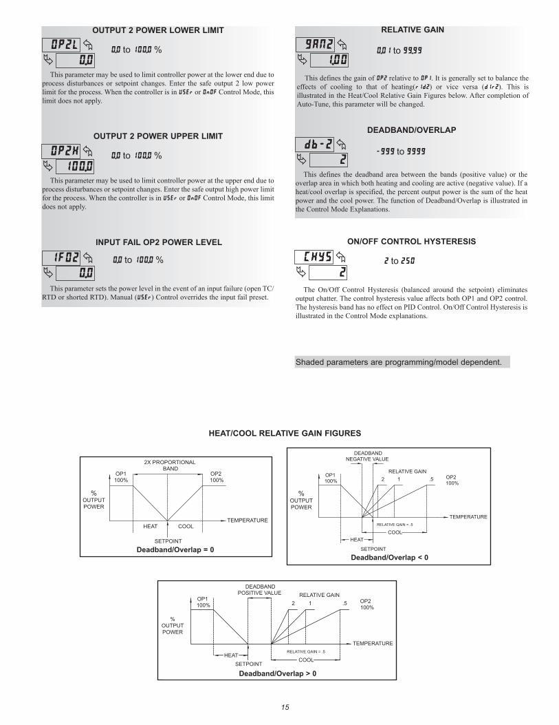
RELATIVE GAIN
. to .
This defines the gain of OP2 relative to OP1. It is generally set to balance the effects of cooling to that of heating(r1d2) or vice versa (d1r2). This is illustrated in the Heat/Cool Relative Gain Figures below. After completion of Auto-Tune, this parameter will be changed.
DEADBAND/OVERLAP
to
This defines the deadband area between the bands (positive value) or the overlap area in which both heating and cooling are active (negative value). If a heat/cool overlap is specified, the percent output power is the sum of the heat power and the cool power. The function of Deadband/Overlap is illustrated in the Control Mode Explanations.
.
b
OUTPUT 2 POWER LOWER LIMIT
. to . %
This parameter may be used to limit controller power at the lower end due to process disturbances or setpoint changes. Enter the safe output 2 low power limit for the process. When the controller is in USEr or OnOF Control Mode, this limit does not apply.
OUTPUT 2 POWER UPPER LIMIT
. to . %
This parameter may be used to limit controller power at the upper end due to process disturbances or setpoint changes. Enter the safe output high power limit for the process. When the controller is in USEr or OnOF Control Mode, this limit does not apply.
INPUT FAIL OP2 POWER LEVEL
This parameter sets the power level in the event of an input failure (open TC/RTD or shorted RTD). Manual (USEr) Control overrides the input fail preset.
. to . %
TEMPERATURECOOLHEAT
SETPOINT
100%OP2
100%OP1
2X PROPORTIONALBAND
%OUTPUTPOWER
OP1 100%
SETPOINT
DEADBANDNEGATIVE VALUE
COOLRELATIVE GAIN = .5
.512RELATIVE GAIN
OP2 100%
TEMPERATURE
HEAT
%OUTPUTPOWER
TEMPERATURE
HEATSETPOINT
100%OP2
100%OP1
DEADBANDPOSITIVE VALUE RELATIVE GAIN
2 1 .5
RELATIVE GAIN = .5
COOL
%OUTPUTPOWER
HEAT/COOL RELATIVE GAIN FIGURES
Deadband/Overlap = 0Deadband/Overlap < 0
Deadband/Overlap > 0
ON/OFF CONTROL HYSTERESIS
to
The On/Off Control Hysteresis (balanced around the setpoint) eliminates output chatter. The control hysteresis value affects both OP1 and OP2 control. The hysteresis band has no effect on PID Control. On/Off Control Hysteresis is illustrated in the Control Mode explanations.
.
.
.
I
C
Shaded parameters are programming/model dependent.

1616
ACCESS CODE
to
7.3 mOdule 3 - lOCKOuT parameTers (3-LC)
SETPOINT OUTPUT 1POWER
OUTPUT 2POWER
CONTROLLERSTATUS
PIDGROUPRAMP RATE
SETPOINT
OUTPUTPOWEROFFSET
PROPORTIONALBAND
INTEGRALTIME
DERIVATIVETIME
INTEGRATIONDEFAULT
ALARM 1VALUE
ALARM 2VALUE
SETPOINTSELECT
ALARMRESETVALUE
ALARM 3
AUTO-TUNESTART
CONTROLMODE
DEVIATIONVALUE
CONTROLMODE
TRANSFER
ACCESSCODE
P P
Programming/model dependent.
PARAMETER MENU
SELECTION DESCRIPTION
dISP Display: accessible in Display Loop.
PArA Parameter: accessible in Parameter Loop
HIdE Hide: accessible in Hidden Loop.
LOC Locked: not accessible in loops.
dSPrDisplay/read: read only in Display Loop, but read/write in Hidden Loop.
The following parameters can be configured for the selections described above. See Programming Loops section for a description of loops and parameters.
PARAMETER SELECTION FACTORY SETTING
SP dISP, PArR, HIdE, LOC, dSPr dISP
OP1 dISP, PArR, HIdE, LOC, dSPr PArR
OP2 dISP, PArR, HIdE, LOC, dSPr PArR
SPrP dISP, PArR, HIdE, LOC, dSPr PArR
PId dISP, PArR, HIdE, LOC, dSPr PArR
r-S dISP, PArR, HIdE, LOC, dSPr dISP
OPOF PArR, HIdE, LOC PArR
ProP PArR, HIdE, LOC PArR
Intt PArR, HIdE, LOC PArR
dErt PArR, HIdE, LOC PArR
dInt PArR, HIdE, LOC LOC
AL-1 PArR, HIdE, LOC PArR
AL-2 PArR, HIdE, LOC PArR
AL-3 PArR, HIdE, LOC PArR
ALrS PArR, HIdE, LOC PArR
SPSL PArR, HIdE, LOC PArR
tUNE HIdE, LOC HIdE
CtrL HIdE, LOC HIdE
trnf HIdE, LOC HIdE
dEv dISP, LOC dISP
Parameters may not appear in selected loop if not applicable to current operating mode.Ex. 1. If At2 = NONE, AL-2 will not be displayed in selected loop.
2. If CtrL = ONOF, PID parameters will not be displayed in selected loop.
0Full access to Display, Hidden, and Configuration Loops
-1 to -125 Code necessary to access Configuration Loop only. *
1 to 125 Code necessary to access Hidden and Configuration Loops. *
* If PLOC is active, Configuration Loop is not accessible.
C
Shaded parameters are programming/model dependent.
1717
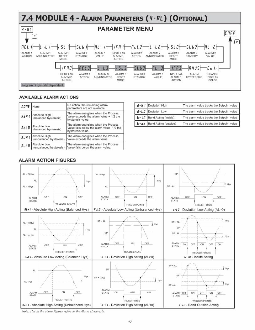
7.4 mOdule 4 - alarm parameTers (4-AL) (OpTiOnal)
ALARM 1RESETMODE
ALARM 1ACTION
ALARM 1ANNUNCIATOR
ALARM 1STANDBY
ALARM 2RESETMODE
ALARM 2ACTION
ALARM 2ANNUNCIATOR
ALARM 2STANDBY
INPUT FAILALARM 1 ACTION
ALARM 1VALUE
ALARM 2VALUE
P
P
CHANGEDISPLAYCOLOR
ALARM 3VALUE
ALARMHYSTERESIS
INPUT FAILALARM 3 ACTION
ALARM 3STANDBY
ALARM 3ACTION
ALARM 3RESETMODE
ALARM 3ANNUNCIATOR
INPUT FAILALARM 2 ACTION
Programming/model dependent.
PARAMETER MENU
OFF ON
AL + ½Hys
AL
AL - ½Hys
OFF
Absolute High Acting (Balanced Hys)
Hys
TRIGGER POINTS
ALARMSTATE
ALARMSTATE
OFF ON
HysSP + AL
SP
OFF
TRIGGER POINTS
Deviation High Acting (AL > 0)
ALARMSTATE
Hys
SP - AL
SP
SP + AL
Hys
TRIGGER POINTS
ON OFF OFFON ON
Band Inside Acting
OFF ON
AL + ½Hys
AL
AL - ½Hys
OFF
Absolute Low Acting (Balanced Hys)
TRIGGER POINTS
Hys
ALARMSTATE
ALARMSTATE
OFF ON
HysSP - AL
SP
OFF
TRIGGER POINTS
Deviation Low Acting (AL > 0)
ALARMSTATE
OFF ON
Hys
AL
AL - Hys
OFF
TRIGGER POINTS
Absolute High Acting (Unbalanced Hys)
ALARMSTATE
OFF ON
Hys
AL + Hys
AL
OFF
TRIGGER POINTS
Absolute Low Acting (Unbalanced Hys)
ALARMSTATE ON OFF
HysSP + (-AL)
SP
ON
TRIGGER POINTS
Deviation High Acting (AL< 0)
ALARMSTATE
ON
Hys
SP - AL
SP
OFF
SP + AL
ON
Hys
OFF OFF
TRIGGER POINTSBand Outside Acting
ALARM ACTION FIGURES
Note: Hys in the above figures refers to the Alarm Hysteresis.
AVAILABLE ALARM ACTIONS
NONE None No action, the remaining Alarm parameters are not available.
AbHIAbsolute High (balanced hysteresis)
The alarm energizes when the Process Value exceeds the alarm value + 1/2 the hysteresis value.
AbLOAbsolute Low (balanced hysteresis)
The alarm energizes when the Process Value falls below the alarm value -1/2 the hysteresis value.
AuHIAbsolute High (unbalanced hysteresis)
The alarm energizes when the Process Value exceeds the alarm value.
AuLOAbsolute Low (unbalanced hysteresis)
The alarm energizes when the Process Value falls below the alarm value.
d-HI Deviation High The alarm value tracks the Setpoint value
d-LO Deviation Low The alarm value tracks the Setpoint value
b-IN Band Acting (inside) The alarm value tracks the Setpoint value
b-ot Band Acting (outside) The alarm value tracks the Setpoint value
AbHI - Absolute High Acting (Balanced Hys)
AbLO - Absolute Low Acting (Balanced Hys)
AuHI - Absolute High Acting (Unbalanced Hys)
AuLO - Absolute Low Acting (Unbalanced Hys)
d-HI - Deviation High Acting (AL>0)
d-HI - Deviation High Acting (AL<0) b-ot - Band Outside Acting
b-IN - Inside Acting
d-LO - Deviation Low Acting (AL>0)
1818
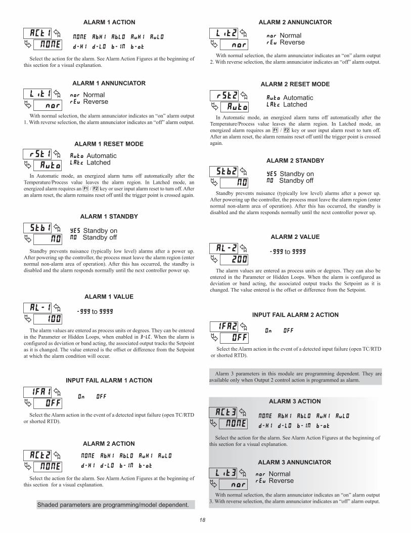
ALARM 2 STANDBY
Standby on Standby off
Standby prevents nuisance (typically low level) alarms after a power up. After powering up the controller, the process must leave the alarm region (enter normal non-alarm area of operation). After this has occurred, the standby is disabled and the alarm responds normally until the next controller power up.
ALARM 2 ANNUNCIATOR
Normalv Reverse
With normal selection, the alarm annunciator indicates an “on” alarm output 2. With reverse selection, the alarm annunciator indicates an “off” alarm output.
ALARM 2 RESET MODE
Automatic Latched
In Automatic mode, an energized alarm turns off automatically after the Temperature/Process value leaves the alarm region. In Latched mode, an energized alarm requires an 1 / 2 key or user input alarm reset to turn off. After an alarm reset, the alarm remains reset off until the trigger point is crossed again.
ALARM 2 VALUE
The alarm values are entered as process units or degrees. They can also be entered in the Parameter or Hidden Loops. When the alarm is configured as deviation or band acting, the associated output tracks the Setpoint as it is changed. The value entered is the offset or difference from the Setpoint.
to
ALARM 2 ACTION
Select the action for the alarm. See Alarm Action Figures at the beginning of this section for a visual explanation.
NONE AbHI AbLO AuHI AuLO
d-HI d-LO b-IN b-ot
C
b
INPUT FAIL ALARM 2 ACTION
I
ALARM 1 ANNUNCIATOR
With normal selection, the alarm annunciator indicates an “on” alarm output 1. With reverse selection, the alarm annunciator indicates an “off” alarm output.
ALARM 1 RESET MODE
In Automatic mode, an energized alarm turns off automatically after the Temperature/Process value leaves the alarm region. In Latched mode, an energized alarm requires an 1 / 2 key or user input alarm reset to turn off. After an alarm reset, the alarm remains reset off until the trigger point is crossed again.
Normalv Reverse
Automatic Latched
ALARM 1 ACTION
Select the action for the alarm. See Alarm Action Figures at the beginning of this section for a visual explanation.
b-otb-INd-LOd-HI
AuLOAuHIAbLOAbHINONE
C
Lit1
ALARM 1 STANDBY
Standby prevents nuisance (typically low level) alarms after a power up. After powering up the controller, the process must leave the alarm region (enter normal non-alarm area of operation). After this has occurred, the standby is disabled and the alarm responds normally until the next controller power up.
ALARM 1 VALUE
The alarm values are entered as process units or degrees. They can be entered in the Parameter or Hidden Loops, when enabled in 3-LC. When the alarm is configured as deviation or band acting, the associated output tracks the Setpoint as it is changed. The value entered is the offset or difference from the Setpoint at which the alarm condition will occur.
Standby on Standby off
to
b
INPUT FAIL ALARM 1 ACTION
I
ALARM 3 ANNUNCIATOR
With normal selection, the alarm annunciator indicates an “on” alarm output 3. With reverse selection, the alarm annunciator indicates an “off” alarm output.
Normalv Reverse
ALARM 3 ACTION
Select the action for the alarm. See Alarm Action Figures at the beginning of this section for a visual explanation.
b-otb-INd-LOd-HI
AuLOAuHIAbLOAbHINONE
C3
Lit3
Alarm 3 parameters in this module are programming dependent. They are available only when Output 2 control action is programmed as alarm.
Select the Alarm action in the event of a detected input failure (open TC/RTD or shorted RTD).
Select the Alarm action in the event of a detected input failure (open TC/RTD or shorted RTD).
Shaded parameters are programming/model dependent.
19
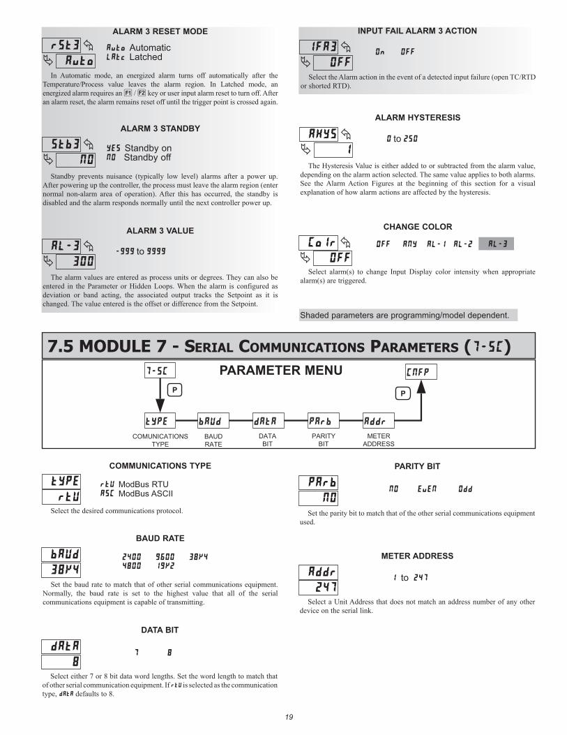
ALARM HYSTERESIS
The Hysteresis Value is either added to or subtracted from the alarm value, depending on the alarm action selected. The same value applies to both alarms. See the Alarm Action Figures at the beginning of this section for a visual explanation of how alarm actions are affected by the hysteresis.
to
CHANGE COLOR
Select alarm(s) to change Input Display color intensity when appropriate alarm(s) are triggered.
AL-3AL-2AL-1ANYOFF
Cl
ALARM 3 STANDBY
Standby prevents nuisance (typically low level) alarms after a power up. After powering up the controller, the process must leave the alarm region (enter normal non-alarm area of operation). After this has occurred, the standby is disabled and the alarm responds normally until the next controller power up.
ALARM 3 VALUE
The alarm values are entered as process units or degrees. They can also be entered in the Parameter or Hidden Loops. When the alarm is configured as deviation or band acting, the associated output tracks the Setpoint as it is changed. The value entered is the offset or difference from the Setpoint.
ALARM 3 RESET MODE
In Automatic mode, an energized alarm turns off automatically after the Temperature/Process value leaves the alarm region. In Latched mode, an energized alarm requires an 1 / 2 key or user input alarm reset to turn off. After an alarm reset, the alarm remains reset off until the trigger point is crossed again.
Automatic Latched
Standby on Standby off
to
19
7.5 mOdule 7 - serial COmmuniCaTiOns parameTers (C)
tYPE dAtAbAUd
COMUNICATIONSTYPE
BAUDRATE
DATABIT
7-SC CNFP
PArb
PARITYBIT
Addr
METERADDRESS
P P
PARAMETER MENU
38K4
8
DATA BIT
NO
PARITY BIT
2400 600400 1K2
3K4
7
NO EvEN Odd
BAUD RATE
Set the baud rate to match that of other serial communications equipment. Normally, the baud rate is set to the highest value that all of the serial communications equipment is capable of transmitting.
Select either 7 or 8 bit data word lengths. Set the word length to match that of other serial communication equipment. If rtU is selected as the communication type, dAtA defaults to 8.
Set the parity bit to match that of the other serial communications equipment used.
247
METER ADDRESS
1 to 247
Select a Unit Address that does not match an address number of any other device on the serial link.
COMMUNICATIONS TYPE
ModBus RTUC ModBus ASCII
Select the desired communications protocol.
3
b3
3
3
INPUT FAIL ALARM 3 ACTION
I3
Select the Alarm action in the event of a detected input failure (open TC/RTD or shorted RTD).
Shaded parameters are programming/model dependent.
20
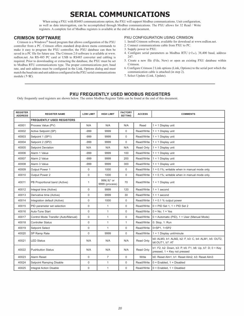
serial COmmuniCaTiOnsWhen using a PXU with RS485 communications option, the PXU will support Modbus communications. Unit configuration,
as well as data interrogation, can be accomplished through Modbus communications. The PXU allows for 32 Read / Write registers. A complete list of Modbus registers is available at the end of this document.
CRIMSON SOFTWARECrimson is a Windows® based program that allows configuration of the PXU
controller from a PC. Crimson offers standard drop-down menu commands to make it easy to program the PXU controller, the PXU database can then be saved in a PC file for future use. The Crimson 2.0 software is available at www.redlion.net. An RS-485 PC card or USB to RS485 converter and cabling is required. Prior to downloading or extracting the database, the PXU must be set to Modbus RTU communications type. The proper communications port, baud rate, and unit address must be configured in the Link, Options dialog and must match the baud rate and unit address configured in the PXU serial communications module (7-SC).
PXU CONFIGURATION USING CRIMSON1. Install Crimson software, available for download at www.redlion.net.2. Connect communications cable from PXU to PC.3. Supply power to PXU.4. Configure serial parameters as Modbus RTU (rtu), 38,400 baud, address
247.5. Create a new file (File, New) or open an existing PXU database within
Crimson.6. Configure Crimson 2 Link options (Link, Options) to the serial port which the
communication cable is attached (in step 2).7. Select Update (Link, Update).
PXU FREQUENTLY USED MODBUS REGISTERSOnly frequently used registers are shown below. The entire Modbus Register Table can be found at the end of this document.
REGISTER ADDRESS REGISTER NAME LOW LIMIT HIGH LIMIT FACTORY
SETTING ACCESS COMMENTS
FREQUENTLY USED REGISTERS
40001 Process Value (PV) N/A N/A N/A Read 1 = 1 Display unit
40002 Active Setpoint (SP) -999 9999 0 Read/Write 1 = 1 Display unit
40003 Setpoint 1 (SP1) -999 9999 0 Read/Write 1 = 1 Display unit
40004 Setpoint 2 (SP2) -999 9999 0 Read/Write 1 = 1 Display unit
40005 Setpoint Deviation N/A N/A N/A Read Only 1 = 1 Display unit
40006 Alarm 1 Value -999 9999 100 Read/Write 1 = 1 Display unit
40007 Alarm 2 Value -999 9999 200 Read/Write 1 = 1 Display unit
40008 Alarm 3 Value -999 9999 300 Read/Write 1 = 1 Display unit
40009 Output Power 1 0 1000 0 Read/Write 1 = 0.1%; writable when in manual mode only.
40010 Output Power 2 0 1000 0 Read/Write 1 = 0.1%; writable when in manual mode only.
40011 PB Proportional band (Active) 1 999(.9)° or 9999 (process) 70 Read/Write 1 = 1 Display unit
40012 Integral time (Active) 0 9999 120 Read/Write 1 = 1 second
40013 Derivative time (Active) 0 9999 30 Read/Write 1 = 1 second
40014 Integration default (Active) 0 1000 0 Read/Write 1 = 0.1 % output power
40015 PID parameter set selection 0 1 0 Read/Write 0 = PID Set 1, 1 = PID Set 2
40016 Auto-Tune Start 0 1 0 Read/Write 0 = No; 1 = Yes
40017 Control Mode Transfer (Auto/Manual) 0 1 0 Read/Write 0 = Automatic (PID), 1 = User (Manual Mode)
40018 Controller Status 0 1 1 Read/Write 0: Stop, 1: Run
40019 Setpoint Select 0 1 0 Read/Write 0=SP1, 1=SP2
40020 SP Ramp Rate 0 9999 0 Read/Write 1 = 1 Display unit/minute
40021 LED Status N/A N/A N/A Read Only b0: ALM3, b1: ALM2, b2: F, b3: C, b4: ALM1, b5: OUT2, b6:OUT1, b7: AT
40022 Pushbutton Status N/A N/A N/A Read Only b1: F2, b2: Down, b3: P, b5: F1, b6: Up, b7: D; 0 = Key pressed, 1 = Key not pressed
40023 Alarm Reset 0 7 0 Write b0: Reset Alm1, b1: Reset Alm2, b3: Reset Alm3
40024 Setpoint Ramping Disable 0 1 0 Read/Write 0 = Enabled, 1 = Disabled
40025 Integral Action Disable 0 1 0 Read/Write 0 = Enabled, 1 = Disabled
21
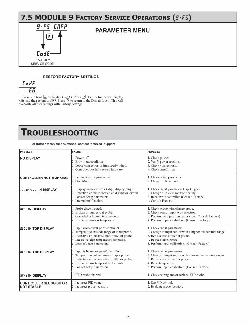
7.5 mOdule 9 faCTOry serviCe OperaTiOns (9-FS)
FACTORY
SERVICE CODE
PPARAMETER MENU
C
RESTORE FACTORY SETTINGS
Press and hold B to display C . Press :. The controller will display and then return to C. Press = to return to the Display Loop. This will overwrite all user settings with Factory Settings.
For further technical assistance, contact technical support.
TrOubleshOOTing
PROBLEM CAUSE REMEDIES
NO DISPLAY 1. Power off. 2. Brown-out condition. 3. Loose connection or improperly wired. 4. Controller not fully seated into case.
1. Check power. 2. Verify power reading. 3. Check connections. 4. Check installation.
CONTROLLER NOT WORKING 1. Incorrect setup parameters.2. Stop Mode.
1. Check setup parameters.2. Change to Run mode.
. . . or . . . IN DISPLAY 1. Display value exceeds 4 digit display range.2. Defective or miscalibrated cold junction circuit.3. Loss of setup parameters.4. Internal malfunction.
1. Check input parameters (Input Type).2. Change display resolution/scaling. 3. Recalibrate controller. (Consult Factory)4. Consult Factory
IN DISPLAY 1. Probe disconnected. 2. Broken or burned-out probe. 3. Corroded or broken terminations. 4. Excessive process temperature.
1. Check probe wire/change probe.2. Check sensor input type selection.3. Perform cold junction calibration. (Consult Factory)4. Perform Input calibration. (Consult Factory)
IN TOP DISPLAY 1. Input exceeds range of controller. 2. Temperature exceeds range of input probe. 3. Defective or incorrect transmitter or probe.4. Excessive high temperature for probe. 5. Loss of setup parameters.
1. Check input parameters. 2. Change to input sensor with a higher temperature range.3. Replace transmitter or probe. 4. Reduce temperature. 5. Perform input calibration. (Consult Factory)
IN TOP DISPLAY 1. Input is below range of controller. 2. Temperature below range of input probe. 3. Defective or incorrect transmitter or probe. 4. Excessive low temperature for probe. 5. Loss of setup parameters.
1. Check input parameters. 2. Change to input sensor with a lower temperature range. 3. Replace transmitter or probe. 4. Raise temperature. 5. Perform input calibration. (Consult Factory)
IN DISPLAY 1. RTD probe shorted. 1. Check wiring and/or replace RTD probe.
CONTROLLER SLUGGISH OR NOT STABLE
1. Incorrect PID values. 2. Incorrect probe location.
1. See PID control. 2. Evaluate probe location.
2222
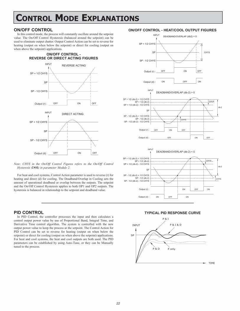
ON/OFF CONTROLIn this control mode, the process will constantly oscillate around the setpoint
value. The On/Off Control Hysteresis (balanced around the setpoint) can be used to eliminate output chatter. Output Control Action can be set to reverse for heating (output on when below the setpoint) or direct for cooling (output on when above the setpoint) applications.
ON/OFF CONTROL - REVERSE OR DIRECT ACTING FIGURES
Note: CHYS in the On/Off Control Figures refers to the On/Off Control Hysteresis (C) in parameter Module 2.
For heat and cool systems, Control Action parameter is used to reverse (r) for heating and direct (d) for cooling. The Deadband/Overlap in Cooling sets the amount of operational deadband or overlap between the outputs. The setpoint and the On/Off Control Hysteresis applies to both OP1 and OP2 outputs. The hysteresis is balanced in relationship to the setpoint and deadband value.
COnTrOl mOde explanaTiOns
ONOutput (d) : ON
SP
OFF
INPUT DEADBAND/OVERLAP (db2) = 0
SP + 1/2 CHYS
SP - 1/2 CHYS
OFFOFFOutput (r) : ON
CHYS
SP
SP + 1/2 (db-2) - 1/2 CHYS
SP + 1/2 (db-2) + 1/2 CHYS
SP - 1/2 (db-2) + 1/2 CHYS
SP - 1/2 (db-2) - 1/2 CHYS
DEADBAND/OVERLAP (db-2) < 0
db-2
CHYS
CHYS
ON
OFF
OFF
ONOutput (r) :
Output (d) :
db-2
Output (r) :
Output (d) :
SP - 1/2 (db-2) + 1/2 CHYS
SP - 1/2 (db-2) - 1/2 CHYS
OFF
SP
ON
OFF
OFF
ON
CHYS
OFF
DEADBAND/OVERLAP (db-2) > 0
SP + 1/2 (db-2) - 1/2 CHYS
SP + 1/2 (db-2) + 1/2 CHYSCHYS
ON
ON
INPUT
INPUT
SP + 1/2 (db-2)
SP - 1/2 (db-2)
SP + 1/2 (db-2)
SP - 1/2 (db-2)
ON/OFF CONTROL - HEAT/COOL OUTPUT FIGURES
PID CONTROLIn PID Control, the controller processes the input and then calculates a
control output power value by use of Proportional Band, Integral Time, and Derivative Time control algorithm. The system is controlled with the new output power value to keep the process at the setpoint. The Control Action for PID Control can be set to reverse for heating (output on when below the setpoint) or direct for cooling (output on when above the setpoint) applications. For heat and cool systems, the heat and cool outputs are both used. The PID parameters can be established by using Auto-Tune, or they can be Manually tuned to the process.
SP
TIME
P & I
P & I & D
P onlyP & D
INPUT
TYPICAL PID RESPONSE CURVE
OFFOutput (d) :
SP
OFF
INPUT DIRECT ACTING
SP - 1/2 CHYS
SP + 1/2 CHYS
ON
OFFOutput (r) :
SP
OFF
INPUT REVERSE ACTING
SP - 1/2 CHYS
SP + 1/2 CHYS
ON
2323
TIME PROPORTIONAL PID CONTROLIn Time Proportional applications, the output power is converted into output
On time using the Cycle Time. For example, with a four second cycle time and 75% power, the output will be on for three seconds (4 × 0.75) and off for one second.
The cycle time should be no greater than 1/10 of the natural period of oscillation for the process. The natural period is the time it takes for one complete oscillation when the process is in a continuously oscillating state.
LINEAR PID CONTROLIn Linear PID Control applications, OP1 provides a linear output signal that
is proportional to the calculated OP1 value (% Output Power). The PXU allows the user to program the analog low and high output signal that will correspond to 0% and 100% output power. The Analog Output will then be proportional to the PID calculated % output power. For example, with 0 to 10 VDC scaled 0 to 100% an OP1 value of 75% provides an analog output of 7.5 VDC.
AUTOMATIC CONTROL MODEIn Automatic Control Mode, the percentage of output power is automatically determined by PID or On/Off calculations based on the setpoint and process feedback. For this reason, PID Control and On/Off Control always imply Automatic Control Mode.
MANUAL CONTROL MODEIn USEr Control Mode, the controller operates as an open loop system, and
does not use the setpoint or process feedback. The user adjusts the percentage of power through the OP1 or OP2 parameter to control the power for each Output. The Low and High Output Power limits are ignored when the controller is in Manual.
MODE TRANSFERWhen transferring the controller mode between Automatic and User/Manual,
the controlling outputs remain constant, exercising true “bumpless” transfer. When transferring from Manual to Automatic, the power initially remains steady, but Integral Action corrects (if necessary) the closed loop power demand at a rate proportional to the Integral Time.
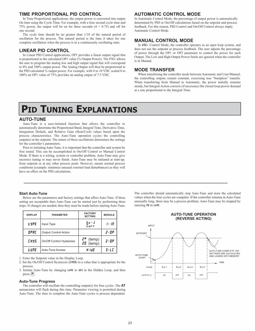
pid Tuning explanaTiOnsAUTO-TUNE
Auto-Tune is a user-initiated function that allows the controller to automatically determine the Proportional Band, Integral Time, Derivative Time, Integration Default, and Relative Gain (Heat/Cool) values based upon the process characteristics. The Auto-Tune operation cycles the controlling output(s) at the setpoint. The nature of these oscillations determines the settings for the controller’s parameters.
Prior to initiating Auto-Tune, it is important that the controller and system be first tested. This can be accomplished in On/Off Control or Manual Control Mode. If there is a wiring, system or controller problem, Auto-Tune may give incorrect tuning or may never finish. Auto-Tune may be initiated at start-up, from setpoint or at any other process point. However, ensure normal process conditions (example: minimize unusual external load disturbances) as they will have an effect on the PID calculations.
Start Auto-TuneBelow are the parameters and factory settings that affect Auto-Tune. If these
setting are acceptable then Auto-Tune can be started just by performing three steps. If changes are needed, then they must be made before starting Auto-Tune.
DISPLAY PARAMETER FACTORY SETTING MODULE
tYpE Input Type t-j Curr
1-IN
OPAC Output Control Action 2-OP
CHYS On/Off Control Hysteresis 2° (temp)20 (temp) 2-OP
tUNE Auto-Tune Access HIdE 3-LC
1. Enter the Setpoint value in the Display Loop. 2. Set the On/Off Control Hysteresis (CHYS) to a value that is appropriate for the
process.3. Initiate Auto-Tune by changing to in the Hidden Loop, and then
press :.
Auto-Tune ProgressThe controller will oscillate the controlling output(s) for four cycles. The AT
annunciator will flash during this time. Parameter viewing is permitted during Auto-Tune. The time to complete the Auto-Tune cycles is process dependent.
The controller should automatically stop Auto-Tune and store the calculated values when the four cycles are complete. If the controller remains in Auto-Tune unusually long, there may be a process problem. Auto-Tune may be stopped by entering in .
TIME
INPUT
Aut1 Aut4
AUTO-TUNESTART
SETPOINT
AUTO-TUNE COMPLETE, PIDSETTINGS ARE CALCULATEDAND LOADED INTO MEMORY
Aut2 Aut3
ON OFF ON OFFOUTPUT (r) :
PHASE
AUTO-TUNE OPERATION(REVERSE ACTING)
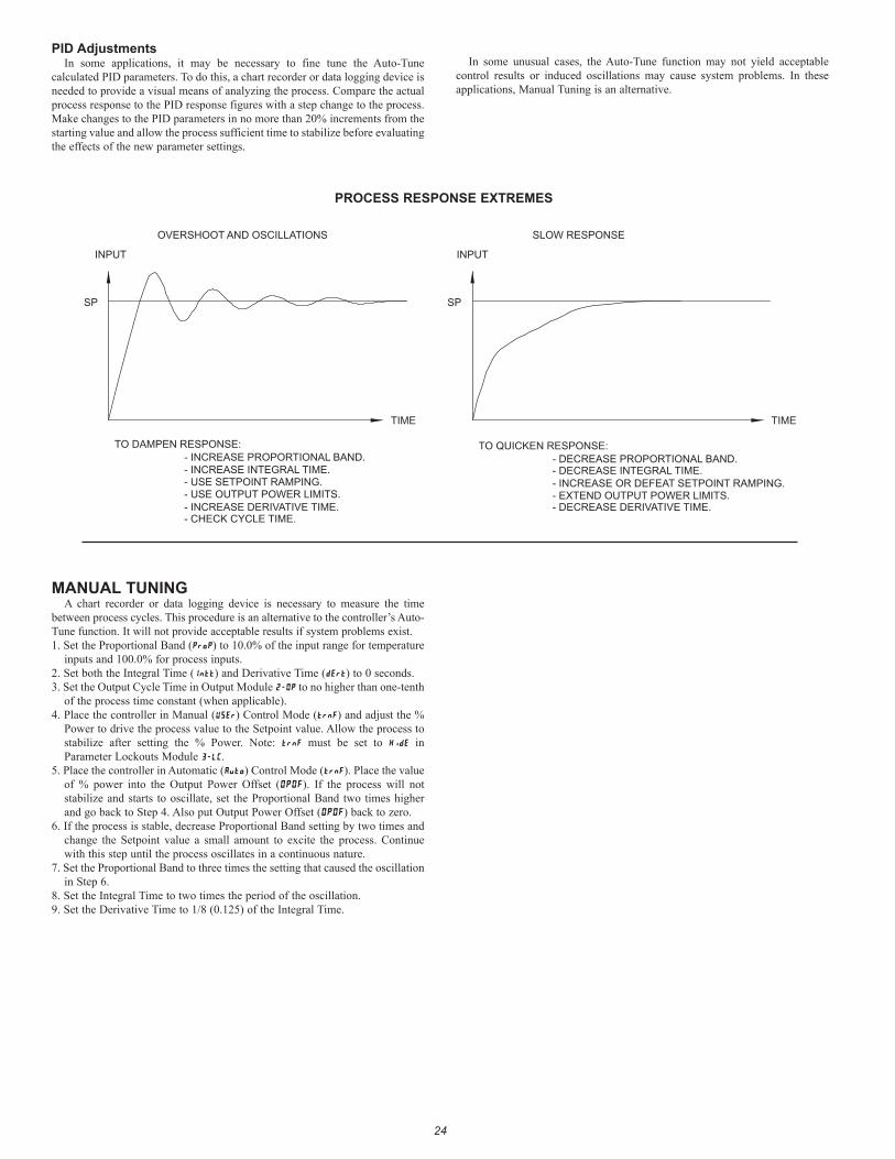
2424
PID AdjustmentsIn some applications, it may be necessary to fine tune the Auto-Tune
calculated PID parameters. To do this, a chart recorder or data logging device is needed to provide a visual means of analyzing the process. Compare the actual process response to the PID response figures with a step change to the process. Make changes to the PID parameters in no more than 20% increments from the starting value and allow the process sufficient time to stabilize before evaluating the effects of the new parameter settings.
In some unusual cases, the Auto-Tune function may not yield acceptable control results or induced oscillations may cause system problems. In these applications, Manual Tuning is an alternative.
TIME
SP SP
TIME
INPUT INPUT
OVERSHOOT AND OSCILLATIONS SLOW RESPONSE
TO DAMPEN RESPONSE:
- USE SETPOINT RAMPING.- USE OUTPUT POWER LIMITS.
- INCREASE PROPORTIONAL BAND.- INCREASE INTEGRAL TIME.
- INCREASE DERIVATIVE TIME.
TO QUICKEN RESPONSE:
- INCREASE OR DEFEAT SETPOINT RAMPING.- EXTEND OUTPUT POWER LIMITS.
- DECREASE PROPORTIONAL BAND.- DECREASE INTEGRAL TIME.
- DECREASE DERIVATIVE TIME.- CHECK CYCLE TIME.
PROCESS RESPONSE EXTREMES
MANUAL TUNINGA chart recorder or data logging device is necessary to measure the time
between process cycles. This procedure is an alternative to the controller’s Auto-Tune function. It will not provide acceptable results if system problems exist.1. Set the Proportional Band () to 10.0% of the input range for temperature
inputs and 100.0% for process inputs.2. Set both the Integral Time (I) and Derivative Time () to 0 seconds.3. Set the Output Cycle Time in Output Module to no higher than one-tenth
of the process time constant (when applicable).4. Place the controller in Manual () Control Mode () and adjust the %
Power to drive the process value to the Setpoint value. Allow the process to stabilize after setting the % Power. Note: must be set to in Parameter Lockouts Module 3C.
5. Place the controller in Automatic () Control Mode (). Place the value of % power into the Output Power Offset (OPOF). If the process will not stabilize and starts to oscillate, set the Proportional Band two times higher and go back to Step 4. Also put Output Power Offset (OPOF) back to zero.
6. If the process is stable, decrease Proportional Band setting by two times and change the Setpoint value a small amount to excite the process. Continue with this step until the process oscillates in a continuous nature.
7. Set the Proportional Band to three times the setting that caused the oscillation in Step 6.
8. Set the Integral Time to two times the period of the oscillation.9. Set the Derivative Time to 1/8 (0.125) of the Integral Time.
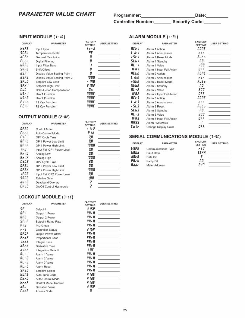
2525
PARAMETER VALUE CHART Programmer:______________________Date:_________Controller Number:_______ Security Code:_______
INPUT MODULE (I )DISPLAY PARAMETER FACTORY
SETTING USER SETTING
typE Input Type t-J
SCAL Temperature Scale °F
dCPt Decimal Resolution 0
FLtr Digital Filtering
bANd Input Filter Band 1
SHFt Shift/Offset 0
dSP1 Display Value Scaling Point 1 0
dSP2 Display Value Scaling Point 2 1000
SPLO Setpoint Low Limit -14
SPHI Setpoint High Limit 212
CJC Cold Juction Compensation On
USr1 User1 Function NONE
USr2 User2 Function NONE
F1In F1 Key Function NONE
F2In F2 Key Function NONE
OUTPUT MODULE ()DISPLAY PARAMETER FACTORY
SETTING USER SETTING
OPAC Control Action r1r2
CtrL Auto Control Mode PId
CYC1 OP1 Cycle Time 2.0
OP1L OP 1 Power Low Limit 0.0
OP1H OP 1 Power High Limit 100.0
IF01 Input Fail OP1 Power Level 0.0
An1L Analog Low 0.0
An1H Analog High 100.0
CYC2 OP2 Cycle Time 2.0
OP2L OP 2 Power Low Limit 0.0
OP2H OP 2 Power High Limit 100.0
IF02 Input Fail OP2 Power Level 0.0
gAN2 Relative Gain 1.00
db-2 Deadband/Overlap 2
CHYS On/Off Control Hysteresis 2
LOCKOUT MODULE (3C)DISPLAY PARAMETER FACTORY
SETTING USER SETTING
SP Setpoint dISP
OP1 Output 1 Power PArA
OP2 Output 2 Power PArA
SPrP Setpoint Ramp Rate PArA
PId PID Group PArA
r-S Controller Status dISP
OPOF Output Power Offset PArA
ProP Proportional Band PArA
Intt Integral Time PArA
dErt Derivative Time PArA
dInt Integration Default LOC
AL-1 Alarm 1 Value PArA
AL-2 Alarm 2 Value PArA
AL-3 Alarm 3 Value PArA
ALrS Alarm Reset PArA
SPSL Setpoint Select PArA
tUNE Auto-Tune Code HIdE
CtrL Auto Control Mode HIdE
trnf Control Mode Transfer HIdE
dEv Deviation Value dISP
CodE Access Code 0
ALARM MODULE (4)DISPLAY PARAMETER FACTORY
SETTING USER SETTING
ACt1 Alarm 1 Action NONE
Lit1 Alarm 1 Annunciator nor
rSt1 Alarm 1 Reset Mode Auto
Stb1 Alarm 1 Standby NO
AL-1 Alarm 1 Value 100
IFA1 Alarm 1 Input Fail Action OFF
ACt2 Alarm 2 Action NONE
Lit2 Alarm 2 Annunciator nor
rSt2 Alarm 2 Reset Mode Auto
Stb2 Alarm 2 Standby NO
AL-2 Alarm 2 Value 200
IFA2 Alarm 2 Input Fail Action OFF
ACt3 Alarm 3 Action NONE
Lit3 Alarm 3 Annunciator nor
rSt3 Alarm 3 Reset Auto
Stb3 Alarm 3 Standby NO
AL-3 Alarm 3 Value 300
IFA3 Alarm 3 Input Fail Action OFF
AHYS Alarm Hysteresis 1
Colr Change Display Color OFF
SERIAL COMMUNICATIONS MODULE (7C)DISPLAY PARAMETER FACTORY
SETTING USER SETTING
tYPE Communications Type rtV
bAUd Baud Rate 3K4
dAtA Data Bit
PArb Parity Bit NO
Addr Meter Address 247
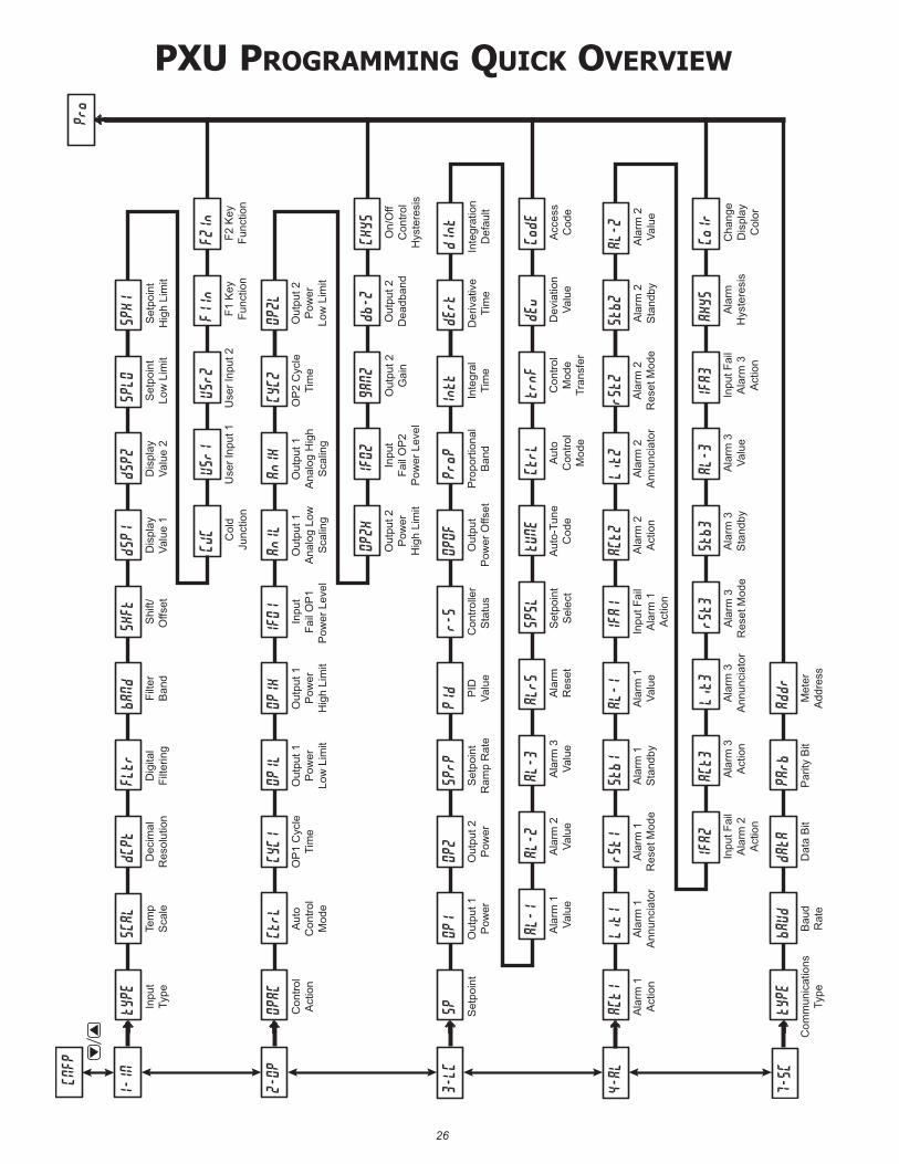
2626
pxu prOgramming QuiCK OvervieW
1-IN
Dec
imal
Res
olut
ion
dCPt
Inpu
tTy
pe
tYPE
Dig
ital
Filte
ring
FLtr
Dis
play
Valu
e 2
dSP2
bANd
Filte
rB
and
SHFt
Shi
ft/O
ffset
D
ispl
ayVa
lue
1
dSP1
Set
poin
tH
igh
Lim
it
SPHI
Set
poin
tLo
w L
imit
SPLO
Pro
3-LC
4-AL
7-SC
CNFP
2-OP
Tem
pS
cale
SCAL
F1 K
eyFu
nctio
n
FIIn
USr1
Use
r Inp
ut 1
USr2
Use
r Inp
ut 2
Col
dJu
nctio
n
CJC
F2 K
eyFu
nctio
n
F2In
OP
1 C
ycle
Tim
e
CYC1
Con
trol
Act
ion
OPAC
Out
put 1
Pow
erLo
w L
imit
OP1L
Out
put 1
Ana
log
Hig
hS
calin
g
An1H
OP1H
Out
put 1
Pow
erH
igh
Lim
it
1FO1
Inpu
tFa
il O
P1
Pow
er L
evel
Out
put 1
Ana
log
Low
Sca
ling
An1L
Out
put 2
Gai
n
gAN2
OP
2 C
ycle
Tim
e
CYC2
Aut
oC
ontro
lM
ode
CtrL
Out
put 2
Pow
erH
igh
Lim
it
OP2H
db-2
Out
put 2
Dea
dban
d
Out
put 2
Pow
erLo
w L
imit
OP2L
On/
Off
Con
trol
Hys
tere
sis
CHYS
Inpu
tFa
il O
P2
Pow
er L
evel
IF02
Out
put 2
Pow
er
OP2
Set
poin
t
SP
Set
poin
tR
amp
Rat
e
SPrP
Pro
porti
onal
Ban
d
ProP
PId PID
Valu
e
r-S
Con
trolle
rS
tatu
s O
utpu
tP
ower
Offs
et
OPOF
Der
ivat
ive
Tim
e
dErt
Inte
gral
Tim
e
Intt
Out
put 1
Pow
er
OP1
Inte
grat
ion
Def
ault
dInt
Con
trol
Mod
eTr
ansf
er
trnF
tUNE
Aut
o-Tu
neC
ode
Aut
oC
ontro
lM
ode
CtrL
Acc
ess
Cod
e
CodE
Dev
iatio
nVa
lue
dEv
Ala
rm 3
Valu
e
AL-3
AL-1
Ala
rm 1
Valu
eA
larm
2Va
lue
AL-2
Set
poin
tS
elec
t
SPSL
Ala
rmR
eset
ALrS
Ala
rm 1
Res
et M
ode
rSt1
Ala
rm 1
Act
ion
ACt1
Ala
rm 1
Sta
ndby
Stb1
Ala
rm 2
Ann
unci
ator
Lit2
AL-1
Ala
rm 1
Valu
e
IFA1
Inpu
t Fai
lA
larm
1A
ctio
n
Ala
rm 2
Act
ion
ACt2
Ala
rm 2
Sta
ndby
Stb2
Ala
rm 2
Res
et M
ode
rSt2
Ala
rm 1
Ann
unci
ator
Lit1
Dat
a B
it
dAtA
Com
mun
icat
ions
Type
tYPE
Par
ity B
it
PArb
Addr
Met
erA
ddre
ssB
aud
Rat
e
bAUd
Ala
rm 2
Valu
e
AL-2
Inpu
t Fai
lA
larm
3A
ctio
n
IFA3
Stb3
Ala
rm 3
Sta
ndby
Ala
rm 3
Valu
e
AL-3
Cha
nge
Dis
play
Col
or
Colr
Ala
rmH
yste
resi
s
AHYS
Ala
rm 3
Act
ion
ACt3
Inpu
t Fai
lA
larm
2A
ctio
n
IFA2
Ala
rm 3
Res
et M
ode
rSt3
Ala
rm 3
Ann
unci
ator
Lit3

27
LIMITED WARRANTYThe Company warrants the products it manufactures against defects in materials and workmanship for a period limited to two years from the date of shipment, provided the products have been stored, handled, installed, and used under proper conditions. The Company’s liability under this limited warranty shall extend only to the repair or replacement of a defective product, at The Company’s option. The Company disclaims all liability for any affirmation, promise or representation with respect to the products.The customer agrees to hold Red Lion Controls harmless from, defend, and indemnify RLC against damages, claims, and expenses arising out of subsequent sales of RLC products or products containing components manufactured by RLC and based upon personal injuries, deaths, property damage, lost profits, and other matters which Buyer, its employees, or sub-contractors are or may be to any extent liable, including without limitation penalties imposed by the Consumer Product Safety Act (P.L. 92-573) and liability imposed upon any person pursuant to the Magnuson-Moss Warranty Act (P.L. 93-637), as now in effect or as amended hereafter.No warranties expressed or implied are created with respect to The Company’s products except those expressly contained herein. The Customer acknowledges the disclaimers and limitations contained herein and relies on no other warranties or affirmations.
Red Lion ControlsHeadquarters20 Willow Springs CircleYork PA 17406Tel +1 (717) 767-6511Fax +1 (717) 764-0839
Red Lion ControlsChina
Unit 302, XinAn PlazaBuilding 13, No.99 Tianzhou Road
ShangHai, P.R. China 200223Tel +86 21 6113 3688Fax +86 21 6113 3683
Red Lion ControlsEurope
Softwareweg 9NL - 3821 BN AmersfoortTel +31 (0) 334 723 225Fax +31 (0) 334 893 793
Red Lion ControlsIndia
201-B, 2nd Floor, Park CentraOpp 32 Mile Stone, Sector-30
Gurgaon-122002 Haryana, IndiaTel +91 984 487 0503
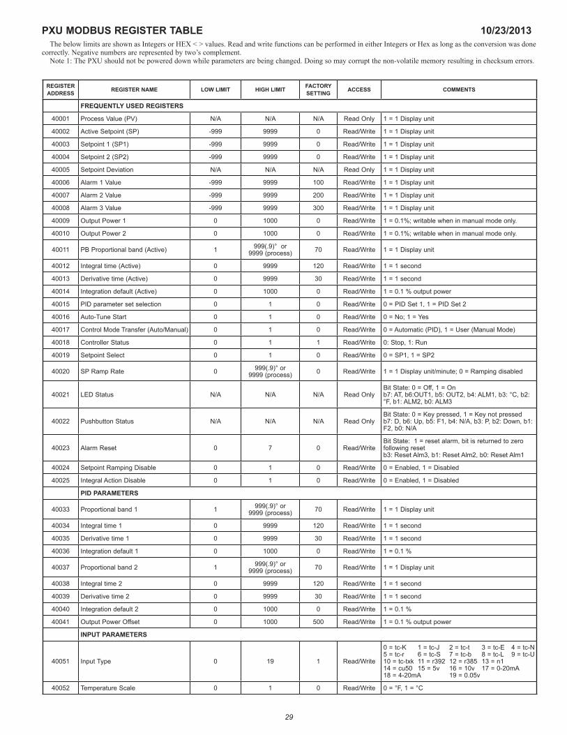
29
PXU MODBUS REGISTER TABLE 10/23/2013The below limits are shown as Integers or HEX < > values. Read and write functions can be performed in either Integers or Hex as long as the conversion was done
correctly. Negative numbers are represented by two’s complement.Note 1: The PXU should not be powered down while parameters are being changed. Doing so may corrupt the non-volatile memory resulting in checksum errors.
REGISTER ADDRESS REGISTER NAME LOW LIMIT HIGH LIMIT FACTORY
SETTING ACCESS COMMENTS
FREQUENTLY USED REGISTERS
40001 Process Value (PV) N/A N/A N/A Read Only 1 = 1 Display unit
40002 Active Setpoint (SP) -999 9999 0 Read/Write 1 = 1 Display unit
40003 Setpoint 1 (SP1) -999 9999 0 Read/Write 1 = 1 Display unit
40004 Setpoint 2 (SP2) -999 9999 0 Read/Write 1 = 1 Display unit
40005 Setpoint Deviation N/A N/A N/A Read Only 1 = 1 Display unit
40006 Alarm 1 Value -999 9999 100 Read/Write 1 = 1 Display unit
40007 Alarm 2 Value -999 9999 200 Read/Write 1 = 1 Display unit
40008 Alarm 3 Value -999 9999 300 Read/Write 1 = 1 Display unit
40009 Output Power 1 0 1000 0 Read/Write 1 = 0.1%; writable when in manual mode only.
40010 Output Power 2 0 1000 0 Read/Write 1 = 0.1%; writable when in manual mode only.
40011 PB Proportional band (Active) 1 999(.9)° or 9999 (process) 70 Read/Write 1 = 1 Display unit
40012 Integral time (Active) 0 9999 120 Read/Write 1 = 1 second
40013 Derivative time (Active) 0 9999 30 Read/Write 1 = 1 second
40014 Integration default (Active) 0 1000 0 Read/Write 1 = 0.1 % output power
40015 PID parameter set selection 0 1 0 Read/Write 0 = PID Set 1, 1 = PID Set 2
40016 Auto-Tune Start 0 1 0 Read/Write 0 = No; 1 = Yes
40017 Control Mode Transfer (Auto/Manual) 0 1 0 Read/Write 0 = Automatic (PID), 1 = User (Manual Mode)
40018 Controller Status 0 1 1 Read/Write 0: Stop, 1: Run
40019 Setpoint Select 0 1 0 Read/Write 0 = SP1, 1 = SP2
40020 SP Ramp Rate 0 999(.9)° or 9999 (process) 0 Read/Write 1 = 1 Display unit/minute; 0 = Ramping disabled
40021 LED Status N/A N/A N/A Read OnlyBit State: 0 = Off, 1 = On b7: AT, b6:OUT1, b5: OUT2, b4: ALM1, b3: °C, b2: °F, b1: ALM2, b0: ALM3
40022 Pushbutton Status N/A N/A N/A Read OnlyBit State: 0 = Key pressed, 1 = Key not pressed b7: D, b6: Up, b5: F1, b4: N/A, b3: P, b2: Down, b1: F2, b0: N/A
40023 Alarm Reset 0 7 0 Read/WriteBit State: 1 = reset alarm, bit is returned to zero following reset b3: Reset Alm3, b1: Reset Alm2, b0: Reset Alm1
40024 Setpoint Ramping Disable 0 1 0 Read/Write 0 = Enabled, 1 = Disabled
40025 Integral Action Disable 0 1 0 Read/Write 0 = Enabled, 1 = Disabled
PID PARAMETERS
40033 Proportional band 1 1 999(.9)° or 9999 (process) 70 Read/Write 1 = 1 Display unit
40034 Integral time 1 0 9999 120 Read/Write 1 = 1 second
40035 Derivative time 1 0 9999 30 Read/Write 1 = 1 second
40036 Integration default 1 0 1000 0 Read/Write 1 = 0.1 %
40037 Proportional band 2 1 999(.9)° or 9999 (process) 70 Read/Write 1 = 1 Display unit
40038 Integral time 2 0 9999 120 Read/Write 1 = 1 second
40039 Derivative time 2 0 9999 30 Read/Write 1 = 1 second
40040 Integration default 2 0 1000 0 Read/Write 1 = 0.1 %
40041 Output Power Offset 0 1000 500 Read/Write 1 = 0.1 % output power
INPUT PARAMETERS
40051 Input Type 0 19 1 Read/Write
0 = tc-K 1 = tc-J 2 = tc-t 3 = tc-E 4 = tc-N 5 = tc-r 6 = tc-S 7 = tc-b 8 = tc-L 9 = tc-U 10 = tc-txk 11 = r392 12 = r385 13 = n1 14 = cu50 15 = 5v 16 = 10v 17 = 0-20mA 18 = 4-20mA 19 = 0.05v
40052 Temperature Scale 0 1 0 Read/Write 0 = °F, 1 = °C
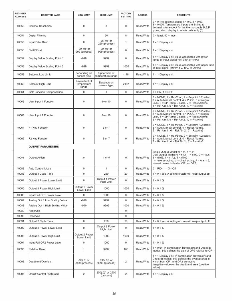
30
REGISTER ADDRESS REGISTER NAME LOW LIMIT HIGH LIMIT FACTORY
SETTING ACCESS COMMENTS
40053 Decimal Resolution 0 3 0 Read/Write0 = 0 (No decimal place) 1 = 0.0, 2 = 0.00, 3 = 0.000. Temperature inputs are limited to 1 decimal point except for the thermocouple B,S,R types, which display in whole units only (0)
40054 Digital Filtering 0 50 8 Read/Write 0 = least, 50 = most
40055 Input Filter Band 0 25(.0)° or 250 (process) 1 Read/Write 1 = 1 Display unit
40056 Shift/Offset -99(.9)° or 999 (process)
99(.9)° or 999 (process) 0 Read/Write 1 = 1 Display unit
40057 Display Value Scaling Point 1 -999 9999 0 Read/Write 1 = 1 Display unit; Value associated with lower range of input signal (0V, 0mA or 4mA)
40058 Display Value Scaling Point 2 -999 9999 1000 Read/Write 1 = 1 Display unit; Value associated with upper limit of input signal (50mV, 5V, 10V, or 20mA)
40059 Setpoint Low Limit depending on sensor type
Upper-limit of temperature range -148 Read/Write 1 = 1 Display unit
40060 Setpoint High LimitLower-limit of temperature
rangeDepends on sensor type 2192 Read/Write 1 = 1 Display unit
40061 Cold Junction Compensation 0 1 0 Read/Write 0 = ON, 1 = OFF
40062 User Input 1 Function 0 9 or 10 0 Read/Write0 = NONE, 1 = Run/Stop, 2 = Setpoint 1/2 select, 3 = Auto/Manual control, 4 = PLOC, 5 = Integral Lock, 6 = SP Ramp Disable, 7 = Reset Alarms, 8 = Rst Alm1, 9 = Rst Alm2, 10 = Rst Alm3
40063 User Input 2 Function 0 9 or 10 0 Read/Write0 = NONE, 1 = Run/Stop, 2 = Setpoint 1/2 select, 3 = Auto/Manual control, 4 = PLOC, 5 = Integral Lock, 6 = SP Ramp Disable, 7 = Reset Alarms, 8 = Rst Alm1, 9 = Rst Alm2, 10 = Rst Alm3
40064 F1 Key Function 0 6 or 7 0 Read/Write0 = NONE, 1 = Run/Stop, 2 = Setpoint 1/2 select, 3 = Auto/Manual control, 4 = Reset Alarms, 5 = Rst Alm1 , 6 = Rst Alm2 , 7 = Rst Alm3
40065 F2 Key Function 0 6 or 7 0 Read/Write0 = NONE, 1 = Run/Stop, 2 = Setpoint 1/2 select, 3 = Auto/Manual control, 4 = Reset Alarms, 5 = Rst Alm1 , 6 = Rst Alm2 , 7 = Rst Alm3
OUTPUT PARAMETERS
40081 Output Action 0 1 or 5 0 Read/Write
Single Output Model: 0 = r1, 1 = d1; Dual Output Model: 0 = r1r2, 1 = d1r2, 2 = r1d2, 3 = d1d2, 4 = r1A2, 5 = d1A2 r = reverse acting, d = direct acting, A = Alarm 3, numeric value indicates OP1 or OP2,
40082 Auto Control Mode 0 1 0 Read/Write 0 = PID, 1 = On-Off
40083 Output 1 Cycle Time 0 250 20 Read/Write 1 = 0.1 sec; A setting of zero will keep output off.
40084 Output 1 Power Lower Limit 0 Output 1 Power High Limit 0 Read/Write 1 = 0.1 %
40085 Output 1 Power High Limit Output 1 Power Lower Limit 1000 1000 Read/Write 1 = 0.1 %
40086 Input Fail OP1 Power Level 0 1000 0 Read/Write 1 = 0.1 %
40087 Analog Out 1 Low Scaling Value -999 9999 0 Read/Write 1 = 0.1 %
40088 Analog Out 1 High Scaling Value -999 9999 1000 Read/Write 1 = 0.1 %
40089 Reserved 0
40090 Reserved 0
40091 Output 2 Cycle Time 0 250 20 Read/Write 1 = 0.1 sec; A setting of zero will keep output off.
40092 Output 2 Power Lower Limit 0 Output 2 Power High Limit 0 Read/Write 1 = 0.1 %
40093 Output 2 Power High Limit Output 2 Power Lower Limit 1000 1000 Read/Write 1 = 0.1 %
40094 Input Fail OP2 Power Level 0 1000 0 Read/Write 1 = 0.1 %
40095 Relative Gain 1 9999 100 Read/Write 1 = 0.01; In combination Reverse(r) and Direct(d) modes, this defines the gain of OP2 relative to OP1.
40096 Deadband/Overlap -99(.9) or -999 (process)
999(.9)° or 9999 (process) 2 Read/Write
1 = 1 Display unit; In combination Reverse(r) and Direct(d) modes, this defines the overlap area in which both OP1 and OP2 are active (negative value) or the deadband area (positive value).
40097 On/Off Control Hysteresis 2 250(.0)° or 2500 (process) 2 Read/Write 1 = 1 Display unit
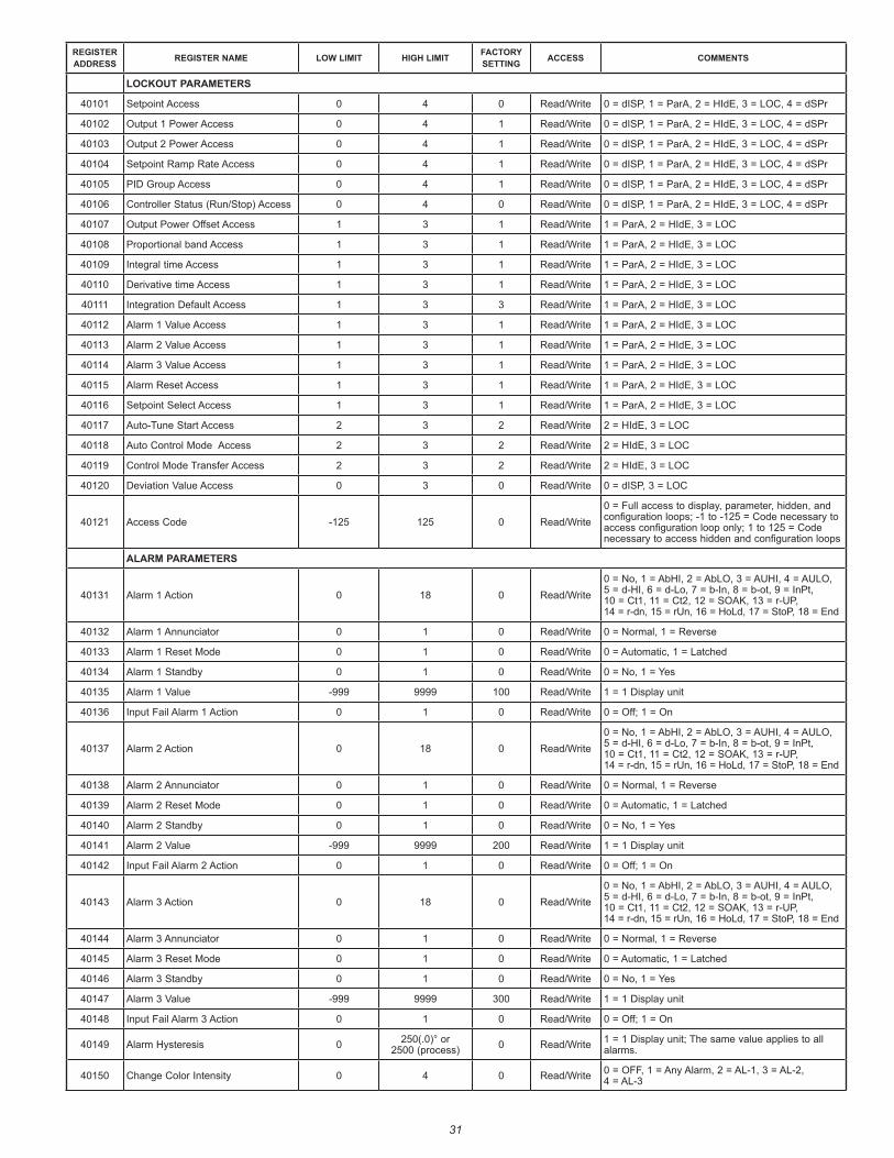
31
REGISTER ADDRESS REGISTER NAME LOW LIMIT HIGH LIMIT FACTORY
SETTING ACCESS COMMENTS
LOCKOUT PARAMETERS
40101 Setpoint Access 0 4 0 Read/Write 0 = dISP, 1 = ParA, 2 = HIdE, 3 = LOC, 4 = dSPr
40102 Output 1 Power Access 0 4 1 Read/Write 0 = dISP, 1 = ParA, 2 = HIdE, 3 = LOC, 4 = dSPr
40103 Output 2 Power Access 0 4 1 Read/Write 0 = dISP, 1 = ParA, 2 = HIdE, 3 = LOC, 4 = dSPr
40104 Setpoint Ramp Rate Access 0 4 1 Read/Write 0 = dISP, 1 = ParA, 2 = HIdE, 3 = LOC, 4 = dSPr
40105 PID Group Access 0 4 1 Read/Write 0 = dISP, 1 = ParA, 2 = HIdE, 3 = LOC, 4 = dSPr
40106 Controller Status (Run/Stop) Access 0 4 0 Read/Write 0 = dISP, 1 = ParA, 2 = HIdE, 3 = LOC, 4 = dSPr
40107 Output Power Offset Access 1 3 1 Read/Write 1 = ParA, 2 = HIdE, 3 = LOC
40108 Proportional band Access 1 3 1 Read/Write 1 = ParA, 2 = HIdE, 3 = LOC
40109 Integral time Access 1 3 1 Read/Write 1 = ParA, 2 = HIdE, 3 = LOC
40110 Derivative time Access 1 3 1 Read/Write 1 = ParA, 2 = HIdE, 3 = LOC
40111 Integration Default Access 1 3 3 Read/Write 1 = ParA, 2 = HIdE, 3 = LOC
40112 Alarm 1 Value Access 1 3 1 Read/Write 1 = ParA, 2 = HIdE, 3 = LOC
40113 Alarm 2 Value Access 1 3 1 Read/Write 1 = ParA, 2 = HIdE, 3 = LOC
40114 Alarm 3 Value Access 1 3 1 Read/Write 1 = ParA, 2 = HIdE, 3 = LOC
40115 Alarm Reset Access 1 3 1 Read/Write 1 = ParA, 2 = HIdE, 3 = LOC
40116 Setpoint Select Access 1 3 1 Read/Write 1 = ParA, 2 = HIdE, 3 = LOC
40117 Auto-Tune Start Access 2 3 2 Read/Write 2 = HIdE, 3 = LOC
40118 Auto Control Mode Access 2 3 2 Read/Write 2 = HIdE, 3 = LOC
40119 Control Mode Transfer Access 2 3 2 Read/Write 2 = HIdE, 3 = LOC
40120 Deviation Value Access 0 3 0 Read/Write 0 = dISP, 3 = LOC
40121 Access Code -125 125 0 Read/Write0 = Full access to display, parameter, hidden, and configuration loops; -1 to -125 = Code necessary to access configuration loop only; 1 to 125 = Code necessary to access hidden and configuration loops
ALARM PARAMETERS
40131 Alarm 1 Action 0 18 0 Read/Write0 = No, 1 = AbHI, 2 = AbLO, 3 = AUHI, 4 = AULO, 5 = d-HI, 6 = d-Lo, 7 = b-In, 8 = b-ot, 9 = InPt, 10 = Ct1, 11 = Ct2, 12 = SOAK, 13 = r-UP, 14 = r-dn, 15 = rUn, 16 = HoLd, 17 = StoP, 18 = End
40132 Alarm 1 Annunciator 0 1 0 Read/Write 0 = Normal, 1 = Reverse
40133 Alarm 1 Reset Mode 0 1 0 Read/Write 0 = Automatic, 1 = Latched
40134 Alarm 1 Standby 0 1 0 Read/Write 0 = No, 1 = Yes
40135 Alarm 1 Value -999 9999 100 Read/Write 1 = 1 Display unit
40136 Input Fail Alarm 1 Action 0 1 0 Read/Write 0 = Off; 1 = On
40137 Alarm 2 Action 0 18 0 Read/Write0 = No, 1 = AbHI, 2 = AbLO, 3 = AUHI, 4 = AULO, 5 = d-HI, 6 = d-Lo, 7 = b-In, 8 = b-ot, 9 = InPt, 10 = Ct1, 11 = Ct2, 12 = SOAK, 13 = r-UP, 14 = r-dn, 15 = rUn, 16 = HoLd, 17 = StoP, 18 = End
40138 Alarm 2 Annunciator 0 1 0 Read/Write 0 = Normal, 1 = Reverse
40139 Alarm 2 Reset Mode 0 1 0 Read/Write 0 = Automatic, 1 = Latched
40140 Alarm 2 Standby 0 1 0 Read/Write 0 = No, 1 = Yes
40141 Alarm 2 Value -999 9999 200 Read/Write 1 = 1 Display unit
40142 Input Fail Alarm 2 Action 0 1 0 Read/Write 0 = Off; 1 = On
40143 Alarm 3 Action 0 18 0 Read/Write0 = No, 1 = AbHI, 2 = AbLO, 3 = AUHI, 4 = AULO, 5 = d-HI, 6 = d-Lo, 7 = b-In, 8 = b-ot, 9 = InPt, 10 = Ct1, 11 = Ct2, 12 = SOAK, 13 = r-UP, 14 = r-dn, 15 = rUn, 16 = HoLd, 17 = StoP, 18 = End
40144 Alarm 3 Annunciator 0 1 0 Read/Write 0 = Normal, 1 = Reverse
40145 Alarm 3 Reset Mode 0 1 0 Read/Write 0 = Automatic, 1 = Latched
40146 Alarm 3 Standby 0 1 0 Read/Write 0 = No, 1 = Yes
40147 Alarm 3 Value -999 9999 300 Read/Write 1 = 1 Display unit
40148 Input Fail Alarm 3 Action 0 1 0 Read/Write 0 = Off; 1 = On
40149 Alarm Hysteresis 0 250(.0)° or 2500 (process) 0 Read/Write 1 = 1 Display unit; The same value applies to all
alarms.
40150 Change Color Intensity 0 4 0 Read/Write 0 = OFF, 1 = Any Alarm, 2 = AL-1, 3 = AL-2, 4 = AL-3
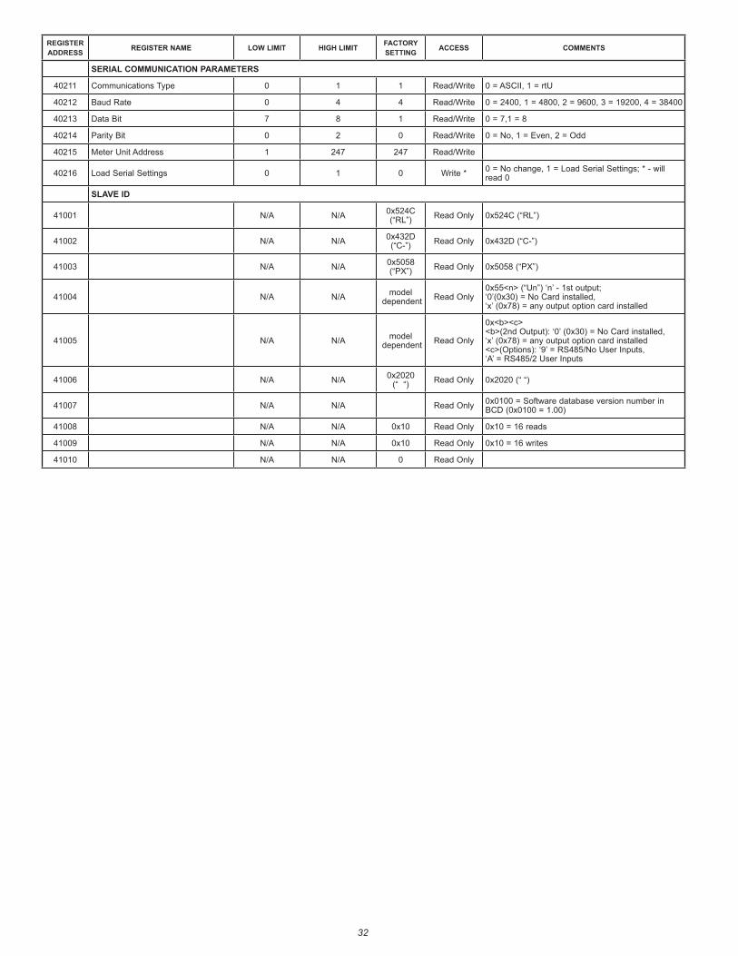
32
REGISTER ADDRESS REGISTER NAME LOW LIMIT HIGH LIMIT FACTORY
SETTING ACCESS COMMENTS
SERIAL COMMUNICATION PARAMETERS
40211 Communications Type 0 1 1 Read/Write 0 = ASCII, 1 = rtU
40212 Baud Rate 0 4 4 Read/Write 0 = 2400, 1 = 4800, 2 = 9600, 3 = 19200, 4 = 38400
40213 Data Bit 7 8 1 Read/Write 0 = 7,1 = 8
40214 Parity Bit 0 2 0 Read/Write 0 = No, 1 = Even, 2 = Odd
40215 Meter Unit Address 1 247 247 Read/Write
40216 Load Serial Settings 0 1 0 Write * 0 = No change, 1 = Load Serial Settings; * - will read 0
SLAVE ID
41001 N/A N/A 0x524C (“RL”) Read Only 0x524C (“RL”)
41002 N/A N/A 0x432D (“C-”) Read Only 0x432D (“C-”)
41003 N/A N/A 0x5058 (“PX”) Read Only 0x5058 (“PX”)
41004 N/A N/A model dependent Read Only
0x55<n> (“Un”) ‘n’ - 1st output; ‘0’(0x30) = No Card installed, ‘x’ (0x78) = any output option card installed
41005 N/A N/A model dependent Read Only
0x<b><c> <b>(2nd Output): ‘0’ (0x30) = No Card installed, ‘x’ (0x78) = any output option card installed <c>(Options): ‘9’ = RS485/No User Inputs, ‘A’ = RS485/2 User Inputs
41006 N/A N/A 0x2020 (“ “) Read Only 0x2020 (“ “)
41007 N/A N/A Read Only 0x0100 = Software database version number in BCD (0x0100 = 1.00)
41008 N/A N/A 0x10 Read Only 0x10 = 16 reads
41009 N/A N/A 0x10 Read Only 0x10 = 16 writes
41010 N/A N/A 0 Read Only


