Embed Size (px)
Citation preview
Modelling form-based interfaces with bipartite
state machines
D. Draheima,*, G. Weberb
aInstitute of Computer Science, Freie Universitat Berlin, Takustr. 9, 14195 Berlin, GermanybDepartment of Computer Science, The University of Auckland, Private Bag 92019, Auckland 1020, New Zealand
Received 6 July 2004; revised 6 September 2004; accepted 12 January 2005
Abstract
This article presents the concept of form storyboarding, a new modelling method for eliciting,
specifying and communicating functional requirements of applications with form-based interfaces.
We identify two-staged interaction as the abstract concept behind form-based interfaces. The method
encompasses a visual language for the documents to be created and a set of proposals for the
activities involved in that. The method fits to different and ubiquitous types of submit/response style
interfaces, i.e. mainframe terminals as well as web-based interfaces. The method yields an abstract
interface model based on bipartite state machines. The model is executable and can be used for
automatic prototype generation. Form storyboarding is first and foremost a feature-driven approach.
The whole form storyboard can be obtained by collecting single system features. Crucial for this
approach is the fact that diagrams can be combined in an easy operation, by building the union of
both diagrams and identifying nodes and edges with the same name.
q 2005 Elsevier B.V. All rights reserved.
Keywords: Requirements elicitation; System specification; Enterprise applications
1. Introduction
The HCI community has naturally believed that over time the crude looking form-based
interfaces will be replaced by advanced GUI-based interfaces. This belief has not reduced
the practical importance and ubiquity of such form-based interfaces. However, it now
Interacting with Computers 17 (2005) 207–228
www.elsevier.com/locate/intcom
0953-5438/$ - see front matter q 2005 Elsevier B.V. All rights reserved.
doi:10.1016/j.intcom.2005.01.002
* Corresponding author. Tel.: C4930 838 75144; fax: C4930 838 75109.
E-mail addresses: [email protected] (D. Draheim), [email protected] (G. Weber).
D. Draheim, G. Weber / Interacting with Computers 17 (2005) 207–228208
seems that many new interface metaphors have been unable to provide real added value to
cases, where form-based interfaces are used. The typical usage of a textual input field, e.g.
the collection of a new user name, apparently cannot be improved in most cases. Hence the
form-based interface seems likely to remain with us in the future.
In this article, we introduce form storyboarding (Draheim and Weber, 2003a), a method
that is an amalgamation of requirements elicitation, specification, and high-level UI
prototyping. Form storyboarding is applicable to systems with form-based interfaces and
addresses requirements for business functionality. It is a domain-specific modelling
technique that is tailored to the development of enterprise systems. Enterprise systems are
a distinct and highly complex class of systems. They are characterized (i) by their
pervasive importance, making them mission critical for enterprises, (ii) by their extreme
multi-user capability, (iii) by their tolerance of heavy loads, and (iv) by their tight
integration with the business processes, which makes every enterprise system installation
unique. In short, they are a fascinating yet demanding discipline in software engineering.
On the one hand, classical mainframe architectures like CICS are still in use and are
constantly being improved. New vendor-neutral and platform-independent enterprise
computing platforms like J2EE have emerged. These technologies are successful because
they guarantee maintainable and scalable software system architectures. On the other
hand, form-based interfaces have advantages for the self-explanatory character of a
system. The difference between temporary input and submission, or ‘sending’, fits with
business semantics: the two classes of interactions correspond both to the work-intensive
preparation of a contract by page interaction and the punctual and atomic interactions of
the ‘serious’ kind, such as agreeing to a contract by submission of a form.
Moreover, it is good practice to model functional requirements in a platform independent
manner. The structure of the requirements specification should fit to the class of application.
This is supported, e.g. by the concepts of the IEEE norm for requirements (IEEE, 1993),
which allows various alternatives for the structure of a requirements specification.
Form storyboarding yields an artifact, the form storyboard, which is a complete
description of the system interface. Form storyboarding encourages the requirements
engineer to create the basic structure for the functional requirements specification
according to the elements of the form storyboard.
In Section 2 of the article, we identify two-staged interaction as the abstract concept
behind form-based, submit/response style interfaces. Section 3 proposes modelling
submit/response style interfaces with bipartite state transition diagrams. Section 4
introduces the notion of screen diagrams. The screen diagram is intended to introduce the
modeller to the notion of submit/response style dialogues in a hands-on fashion. It is
especially suited as a starting point for discussing the intended task of the system with the
domain expert. The conceptual insights of the screen diagrams will be fully expressed in
the form storyboard discussed in Section 5. Section 6 is about dealing with large, ‘real-
size’ web applications. Section 7 provides an outline of the formchart, which is a diagram
that is accompanied by a data model and formal dialogue constraints (Draheim and Weber,
2004b). Screen diagrams and form storyboards can be understood as views on an intended
final formchart. The forward engineering tool Angie is described in Section 8. Systems
generated from the specification language Angie can be considered as simulations of the
models proposed in this article. A discussion of related work follows in Section 9,
D. Draheim, G. Weber / Interacting with Computers 17 (2005) 207–228 209
especially with respect to the domains of user interface modelling and web application
modelling. The article finishes with an outline of further directions in Section 10.
2. Two-staged interaction
Many applications, such as today’s enterprise applications, use a particular form-based
interface type, which we will call submit/response style. Form-based interfaces collect
user input in the style of input forms. Input forms can be understood as a metaphor, namely
as a direct translation of paper forms into human-computer interfaces. Input forms are
composite structures of input elements. ‘Submit/response style interfaces’ is our term for
form-based interfaces with a special screen update policy. On a submit/response style
interface all screen updates have to be triggered by a dedicated user action. The user
actively submits data or a query, instead of watching a constantly updated view.
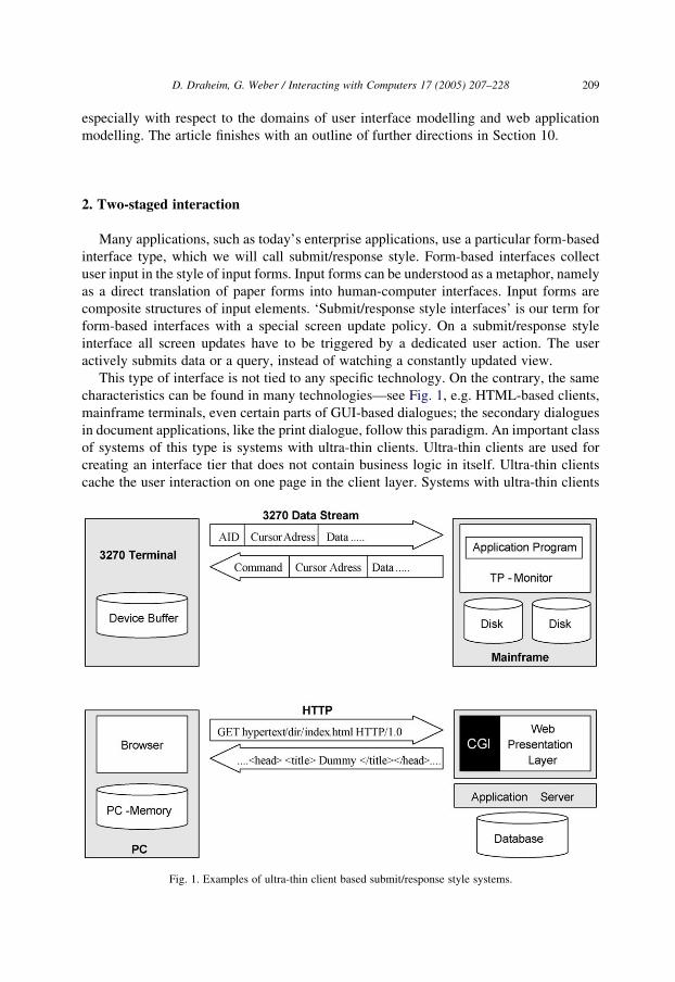
This type of interface is not tied to any specific technology. On the contrary, the same
characteristics can be found in many technologies—see Fig. 1, e.g. HTML-based clients,
mainframe terminals, even certain parts of GUI-based dialogues; the secondary dialogues
in document applications, like the print dialogue, follow this paradigm. An important class
of systems of this type is systems with ultra-thin clients. Ultra-thin clients are used for
creating an interface tier that does not contain business logic in itself. Ultra-thin clients
cache the user interaction on one page in the client layer. Systems with ultra-thin clients
Fig. 1. Examples of ultra-thin client based submit/response style systems.
D. Draheim, G. Weber / Interacting with Computers 17 (2005) 207–228210
are typically multi-user systems. Ultra-thin clients fit neatly into transactional system
architectures.
Submit/response style interfaces show one page for each point in time, which offers the
user a collection of interaction options. Interaction options are input fields of forms and
submit buttons, which trigger a page change. The difference between input fields and
submit buttons leads to a strict two-staged interaction paradigm. User interaction is
separated into interactions appearing on one page and those that result in a page change.
Interaction on one page, called page interaction, consists of filling out input elements,
changing the focus between input elements, resetting the form and other interactions.
These user interactions are only temporal and do not change the system state. This allows
to abstract from page interactions when modelling the complete interface.
On the other hand, page changes do affect the system. Page changes occur when the
user either submits a form or clicks a link. Submitting a form is the more general concept; a
link can be seen as a form consisting solely in the submit button. If the user triggers a page
change, the result of his or her interactions with the respective form is processed by the
system, but his or her interaction with other forms on the page is lost.
In submit/response style interfaces, the submission of a form is an operation that has quite
precisely the semantics indicated by the paper form metaphor. In computer science terms,
the submission can be modelled as a method call (Draheim and Weber, 2002), namely the
submission of an actual parameter list with a method name. The actual parameter list is
given by the contents of the input elements, while the method name is best represented by the
form title. The form itself can therefore be seen as an editable method call. As a result of a
page change, a new page will be presented to the user. This page will contain information
and new interaction options for the user, namely new forms. Many concepts in concrete
technologies can be subsumed under these concepts. For example in HTML, links can be
seen as submit buttons in textual style. If a page contains a list of submit buttons, then the
choice of one of these buttons for submission must be seen as an additional input value: a list
of submit buttons is equivalent to one submit button combined with a choice list.
Form-like interface layout can be found not only for ultra-thin clients but also in other
systems, such as desktop databases typically found in office suites. However, such systems
follow a fundamentally different paradigm from submit/response style interfaces. In
desktop databases, a form-like input mask is an editable view of persistent data. Once a
field is edited, the corresponding field in the persistent data is changed immediately. In
general, therefore, there is no need for a submit procedure, instead there is a concept of
buttons, where a button is a parameter-free command. These kinds of dialogues perform
screen updates in a push style, meaning that the system pushes the new content onto the
screen continuously. An early presentation of such a paradigm can be found in (Hayes,
1985). In these kinds of user interfaces, forms could also be called views.
3. Modelling HCI with bipartite state transition diagrams
The recognition of the two-staged interaction paradigm leads to the following key
insight about requirements specification for submit/response style interfaces: there is no
need to specify the fine-grained interface behaviour on one page. Page interactions are
D. Draheim, G. Weber / Interacting with Computers 17 (2005) 207–228 211
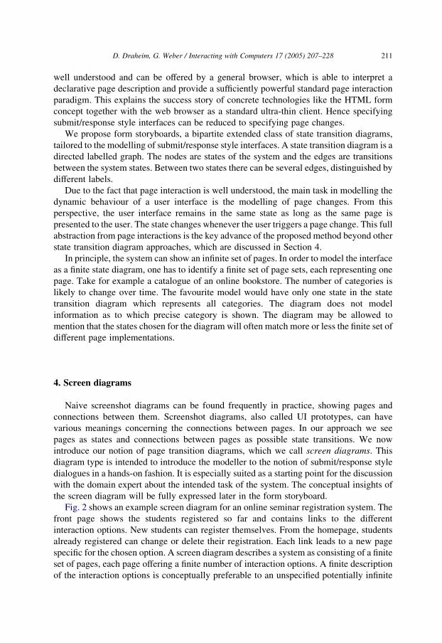
well understood and can be offered by a general browser, which is able to interpret a
declarative page description and provide a sufficiently powerful standard page interaction
paradigm. This explains the success story of concrete technologies like the HTML form
concept together with the web browser as a standard ultra-thin client. Hence specifying
submit/response style interfaces can be reduced to specifying page changes.
We propose form storyboards, a bipartite extended class of state transition diagrams,
tailored to the modelling of submit/response style interfaces. A state transition diagram is a
directed labelled graph. The nodes are states of the system and the edges are transitions
between the system states. Between two states there can be several edges, distinguished by
different labels.
Due to the fact that page interaction is well understood, the main task in modelling the
dynamic behaviour of a user interface is the modelling of page changes. From this
perspective, the user interface remains in the same state as long as the same page is
presented to the user. The state changes whenever the user triggers a page change. This full
abstraction from page interactions is the key advance of the proposed method beyond other
state transition diagram approaches, which are discussed in Section 4.
In principle, the system can show an infinite set of pages. In order to model the interface
as a finite state diagram, one has to identify a finite set of page sets, each representing one
page. Take for example a catalogue of an online bookstore. The number of categories is
likely to change over time. The favourite model would have only one state in the state
transition diagram which represents all categories. The diagram does not model
information as to which precise category is shown. The diagram may be allowed to
mention that the states chosen for the diagram will often match more or less the finite set of
different page implementations.
4. Screen diagrams
Naive screenshot diagrams can be found frequently in practice, showing pages and
connections between them. Screenshot diagrams, also called UI prototypes, can have
various meanings concerning the connections between pages. In our approach we see
pages as states and connections between pages as possible state transitions. We now
introduce our notion of page transition diagrams, which we call screen diagrams. This
diagram type is intended to introduce the modeller to the notion of submit/response style
dialogues in a hands-on fashion. It is especially suited as a starting point for the discussion
with the domain expert about the intended task of the system. The conceptual insights of
the screen diagram will be fully expressed later in the form storyboard.
Fig. 2 shows an example screen diagram for an online seminar registration system. The
front page shows the students registered so far and contains links to the different
interaction options. New students can register themselves. From the homepage, students
already registered can change or delete their registration. Each link leads to a new page
specific for the chosen option. A screen diagram describes a system as consisting of a finite
set of pages, each page offering a finite number of interaction options. A finite description
of the interaction options is conceptually preferable to an unspecified potentially infinite
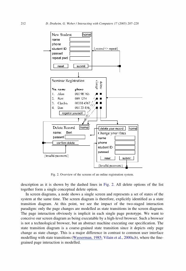
Fig. 2. Overview of the screens of an online registration system.
D. Draheim, G. Weber / Interacting with Computers 17 (2005) 207–228212
description as it is shown by the dashed lines in Fig. 2. All delete options of the list
together form a single conceptual delete option.
In screen diagrams, a node shows a single screen and represents a set of states of the
system at the same time. The screen diagram is therefore, explicitly identified as a state
transition diagram. At this point, we see the impact of the two-staged interaction
paradigm: only the page changes are modelled as state transitions in the screen diagram.
The page interaction obviously is implicit in each single page prototype. We want to
conceive our screen diagram as being executable by a high-level browser. Such a browser
is not a technological browser, but an abstract machine executing our specification. The
state transition diagram is a coarse-grained state transition since it depicts only page
change as state change. This is a major difference in contrast to common user interface
modelling with state transitions (Wasserman, 1985; Vilain et al., 2000a,b), where the fine-
grained page interaction is modelled.
D. Draheim, G. Weber / Interacting with Computers 17 (2005) 207–228 213
But the most crucial observation we have to make, which immediately opens the
conceptual path to form storyboards, is the observation that system response may be
conditional: a single page change triggered by the user can result in different response
pages, depending on the system state. A typical case is that either the regular response
page or an error page is shown. Hence screen diagrams as an interface prototype notation
also offer conditional transitions. An example is the submission of a registration form in
the diagram. The transition has a branching point depicted by a square from which
different branches lead to different response pages. These branches are annotated with the
conditions under which they occur. How such a system can be still seen as a state transition
diagram will be explained in the context of form storyboards (Section 5).
5. Form storyboards
Form storyboards take the understanding of submit/response style applications a step
further; in form storyboards the system is seen as a bipartite state transition diagram. The
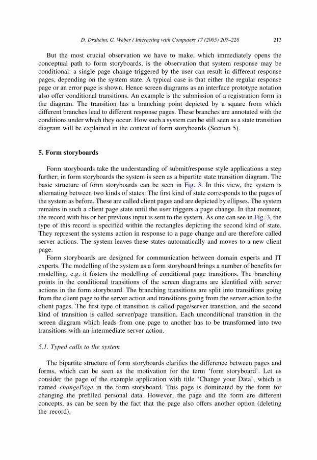
basic structure of form storyboards can be seen in Fig. 3. In this view, the system is
alternating between two kinds of states. The first kind of state corresponds to the pages of
the system as before. These are called client pages and are depicted by ellipses. The system
remains in such a client page state until the user triggers a page change. In that moment,
the record with his or her previous input is sent to the system. As one can see in Fig. 3, the
type of this record is specified within the rectangles depicting the second kind of state.
They represent the systems action in response to a page change and are therefore called
server actions. The system leaves these states automatically and moves to a new client
page.
Form storyboards are designed for communication between domain experts and IT
experts. The modelling of the system as a form storyboard brings a number of benefits for
modelling, e.g. it fosters the modelling of conditional page transitions. The branching
points in the conditional transitions of the screen diagrams are identified with server
actions in the form storyboard. The branching transitions are split into transitions going
from the client page to the server action and transitions going from the server action to the
client pages. The first type of transition is called page/server transition, and the second
kind of transition is called server/page transition. Each unconditional transition in the
screen diagram which leads from one page to another has to be transformed into two
transitions with an intermediate server action.
5.1. Typed calls to the system
The bipartite structure of form storyboards clarifies the difference between pages and
forms, which can be seen as the motivation for the term ‘form storyboard’. Let us
consider the page of the example application with title ‘Change your Data’, which is
named changePage in the form storyboard. This page is dominated by the form for
changing the prefilled personal data. However, the page and the form are different
concepts, as can be seen by the fact that the page also offers another option (deleting
the record).
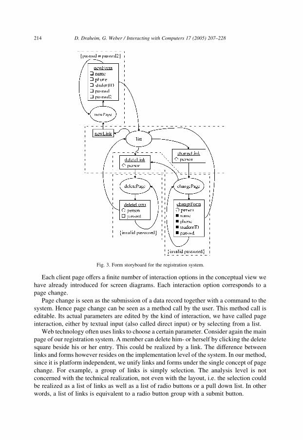
Fig. 3. Form storyboard for the registration system.
D. Draheim, G. Weber / Interacting with Computers 17 (2005) 207–228214
Each client page offers a finite number of interaction options in the conceptual view we
have already introduced for screen diagrams. Each interaction option corresponds to a
page change.
Page change is seen as the submission of a data record together with a command to the
system. Hence page change can be seen as a method call by the user. This method call is
editable. Its actual parameters are edited by the kind of interaction, we have called page
interaction, either by textual input (also called direct input) or by selecting from a list.
Web technology often uses links to choose a certain parameter. Consider again the main
page of our registration system. A member can delete him- or herself by clicking the delete
square beside his or her entry. This could be realized by a link. The difference between
links and forms however resides on the implementation level of the system. In our method,
since it is platform independent, we unify links and forms under the single concept of page
change. For example, a group of links is simply selection. The analysis level is not
concerned with the technical realization, not even with the layout, i.e. the selection could
be realized as a list of links as well as a list of radio buttons or a pull down list. In other
words, a list of links is equivalent to a radio button group with a submit button.
D. Draheim, G. Weber / Interacting with Computers 17 (2005) 207–228 215
As we said earlier, in form-oriented analysis page change is seen as an editable method
call. The server action represents the state of method execution. In form, storyboards each
server action can have more than one ingoing edge, representing calls from different client
pages to the same method. All ingoing edges to the same server action must provide the
same parameters. In form storyboards, the parameters of a server action are specified
within the square representing the server action. The parameters provided by a form and
submitted to a server action are considered as a single record data type which is called the
superparameter of the server action.
Page/server transitions represent the submission options that are offered by the page i.e.
the forms offered by the page. In order to support form storyboards as a tool for efficient
communication with the domain expert, they can be annotated with information about the
interaction type used for submitting the form parameters, as shown in Fig. 3. The type of
interaction is represented by icons preceding the parameters. These icons explain how the
parameter is provided. The rhomb indicates a selection or a link list. The empty square
indicates a text input field. The solid square indicates a text input field with default value.
The circle indicates a hidden parameter.
The form storyboard hence provides a more abstract view of the system interface than
the screen diagram, but can still be seen as an intuitive high-level prototype of the system.
In the form storyboard each client page together with its accessible server actions give a
representation of the page with its interaction options, as it is shown by the dashed lines in
Fig. 3. Therefore, each such sub graph is called a page image. Page images can share
server actions, as can be seen in the example of the deleteLink server action. This server
action is contained in the page image of the main page as well as in the page image of the
change dialogue.
A server/page transition indicates that the server action may produce a response page of
the addressed type as a result of its action. Therefore, the server/page transitions must be
annotated by the condition under which this transition is chosen. These conditions must be
either mutually exclusive or ordered. One outgoing transition of a server action may carry
no condition; this then represents the default case. In the example the transition from the
newForm server action to the home page is the default case and therefore carries no
condition. The other server/page transition carries the condition that the password is not
retyped correctly.
Form storyboards are labelled directed multigraphs. Two states can be connected by
more than one edge in the same direction. In the case of page/server edges, this represents
several distinct submission options. An example may be an online shop that has on each
page two types of offers: featured articles with in-depth information and an article list with
only a short information. The purchase option addresses the same server page, but the
modeller wants to distinguish these two classes of purchases.
5.2. Patterns for submit/response style systems
Before, we introduce the composition mechanism for form storyboards, we here make
some reflections about the overall structure of the system. Our system offers three different
interaction strands in the form storyboard, namely for insertion, deletion and change of
enrolments. Each of these dialogue strands is shown in a column-like fashion in the form
D. Draheim, G. Weber / Interacting with Computers 17 (2005) 207–228216
storyboard. Furthermore, each of these interaction strands consists of three dialogue states,
which with the home page, are connected to an interaction circle. These three interaction
strands follow a typical pattern for submit/response style systems, which we call the link-
page-form pattern. This interaction pattern begins with a server action that represents the
start of the interaction. In the case of the server action changeLink, the user selects the data
record under consideration by choosing his or her own enrolment. The link leads to the page
on which the actual interaction is performed. This client page is typically characterized by
the fact that it is dominated by a single form. The server action representing this form,
therefore is the third dialogue state involved. This pattern is so commonplace, as one can see
in our example system, that a special naming convention for the dialogue states is helpful.
As the example shows, the naming convention is to take the name of the functionality and to
append the role name within the pattern, e.g. changeLink, changePage, changeForm.
This pattern applies for actions which involve two page changes. Simpler interactions
can of course use only a single server action for completion, e.g. if a system has a delete
function which needs only a single click without confirmation dialogue.
5.3. Communicating form storyboards
Form storyboards are designed for communication and joint development between
domain experts and IT professionals. Therefore, they present a self-contained system view
comparable to screen diagrams. At the same time they achieve a much higher level of
abstraction than screen diagrams. Nevertheless they may be easily communicated with the
domain expert.
The client submit/response style metaphor is fundamentally different from other well-
known UI metaphors, like the desktop metaphor. The submit/response style metaphor
implies a precise semantics of user interaction as outlined before: page interaction is
volatile, while page change is data transmission and changes the system state. On the other
hand, desktop, a.k.a. direct manipulation, metaphors give only a vague analogy and no
precise semantics, e.g.: does drag and drop mean ‘copy’ or ‘move’? Domain experts
understand completely the concept of paper forms. Since paper forms can be translated
precisely into system functionality, domain experts can give precise semantics for ultra-
thin clients. Therefore, form storyboarding encourages domain experts and requirements
engineers to discuss system features along the submit/response style metaphor, and the
properties are depicted as form storyboard sub-diagrams by the requirements engineer.
The requirements engineer does not have to translate the semantic concepts of the domain
expert into the semantics of form storyboarding. Instead, he or she only has to mediate the
notational questions. Therefore, form storyboarding has no mismatch between the domain
experts’ view and the specification documents.
6. Model composition
Models quickly become large. A way to partition a model is needed to manage its
complexity and to communicate with colleagues. We will propose a simple yet powerful
composition mechanism called form storyboard union for this purpose. Form storyboard
D. Draheim, G. Weber / Interacting with Computers 17 (2005) 207–228 217
union allows the composition of the complete system form storyboard from partial
descriptions of the system called sub-storyboards. A sub-storyboard is an explicitly-named
form storyboard that describes a part of the system. The graph underlying a form
storyboard is a directed labelled multigraph, and the composition mechanism for form
storyboards is basically graph union. If two form storyboards are combined into a new
resulting form storyboard, the node and edge sets are united. Nodes of same name are
identified, as are edges between the same nodes of the same name. The composition of
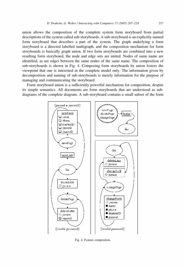
sub-storyboards is shown in Fig. 4. Composing form storyboards by union fosters the
viewpoint that one is interested in the complete model only. The information given by
decomposition and naming of sub-storyboards is merely information for the purpose of
managing and communicating the storyboard.
Form storyboard union is a sufficiently powerful mechanism for composition, despite
its simple semantics. All documents are form storyboards that are understood as sub-
diagrams of the complete diagram. A sub-storyboard contains a small subset of the form
Fig. 4. Feature composition.
D. Draheim, G. Weber / Interacting with Computers 17 (2005) 207–228218
storyboard relating to a special system aspect, system feature, or requirement. The domain
expert or requirements engineer can denote every subset of the system interface as a single
feature in a separate diagram. Even unconnected parts of the form storyboard can be
placed in the same diagram if they are received as expressing the same feature.
Storyboard decomposition can be used to introduce a whole-to-part relationship
between sub-storyboards. Such a hierarchical decomposition should adhere to certain
natural soundness criteria; that is, there should be no model element in one of the sub-
storyboards that is not present in the whole storyboard. Decomposition can also be used to
represent a refinement step or the result of a generalization or specialization.
The modelling of menu-like options is another important case of model decomposition.
Menu-like options are interaction options, which are offered on many, perhaps even all,
pages. A new notation element for this purpose is the state set that is depicted by a double-
lined state icon. It is annotated by a list of state names and serves as shorthand notation for
these states. An edge between two state sets of, say, m client pages and n server actions
represents the complete graph Km,n between the elements of the state sets. In Fig. 4 we use
the state set notation to give a terse description of the fact that a link to the home page is
contained on all pages except the home page itself.
Form storyboarding is not tightly coupled to a specific process for requirements
elicitation. Instead it offers proposals for activities which in themselves increase the
quality of the requirements specification. It is a feature-driven approach, not a use-case-
driven approach. The complete form storyboard is gained by collecting all features of the
system. Use cases, defined as typical usages of the system, may be used as heuristics for
finding features, but are not required. In form storyboards, the basic flow and the
alternative flows of a use case correspond to paths in the diagram. The complete diagram
can be considered as the compact notation of the set of all use cases. In the form
storyboarding approach every use case is a sub-storyboard. The activities relate to the
validation of found features, and to the local systematic search for features. Form
storyboarding starts with the development of a number of feature artifacts. The features to
be depicted can be gained in various ways, e.g. during brainstorming or by reverse
engineering of legacy systems. Each feature can be discussed in its form storyboard
notation. Once informal search for new features is completed, the systematic search for
features is started. Each single activity is a local search on a single node in the form
storyboard. The participants of the requirements process check for a single node, whether
the outgoing edges represent exactly the desired interaction options or not, and check the
server response to these options. If the completeness of the description is assured, the node
may be marked as complete. Global completeness can be assured eventually by traversing
the form storyboard.
7. Formcharts and dialogue constraints
The diagrams presented in this article are integrated with form-oriented analysis, a
holistic approach for engineering form-based, submit/response-style systems.
The approach encompasses screen diagrams, form storyboards and formcharts (Draheim
and Weber, 2003b). The form storyboard already expresses the key elements of
D. Draheim, G. Weber / Interacting with Computers 17 (2005) 207–228 219
the submit/response paradigm. The formchart then has to make the analysis model
amenable to formal constraint writing and coupling to the data model.
Screen diagrams offer a natural conceptual basis for modelling submit/response-style
software systems. Form storyboards are designed with respect to informal communication
between domain experts and system analysts. Formcharts are used for rigorous software
system specification. We explain formcharts in this article because formcharts implicitly
define the semantics of form storyboards and screen diagrams. Once the semantics of
formcharts are rigorously defined, form storyboards and screen diagrams can be
considered as informal views on an intended formchart. While form storyboards address
communication between domain experts and IT experts, formcharts can foster the
communication between interface designers and software developers, i.e. they can be used
to mitigate the HCI-SE design problem (Benyon and Macaulay, 2002).
The formchart is accompanied by other diagrams, first the information model of the
data and second the user message model. Furthermore, a textual document containing
formal constraints has to be seen as attachment to the formchart. Again server actions are
depicted as rectangles and client pages are depicted as ellipses. In the formchart only the
names of the states and transitions appear. Hence the formchart does not contain
the signatures of the server actions as they are depicted in the form storyboard. Instead, the
signatures are contained in the second new artifact type, the user message model. The user
message model contains types and is therefore, a class diagram in the terms of modern
modelling languages like the UML. However, the user message model types are a special
kind of data type, namely algebraic data types. Instances of these types are immutable
values. The types can have structure, but only a hierarchical structure, namely
composition. They represent sent messages, comparable to written and sent documents.
Remaining in that metaphor, once you have sent a letter the content is unchangeable. In the
user message model there must be a message type for each formchart state. The message
represents the signature of the state of same name. Each time this state is entered, a new
message of this type has to be provided. We have already encountered signatures of server
actions in the form storyboard, but in the formchart we also specify signatures for the
client pages. These client page signatures represent the information shown on the page.
The page content is immutable. A page shows the same content until the user triggers a
page change and therefore gets a new page, although possibly from the same type. Page
interaction, i.e. user input in forms, is not considered a change of the page content, but
preparation of a new message. The fact that now the user message model contains the
information shown on pages as well as the information sent back to the system as part of a
page change is important with respect to the specification of so-called dialogue constraints.
Indeed one of the main advantages of formcharts is that they allow more elaborate
constraint writing than the form storyboard. For example, an appropriate extension of OCL
can be used for the purpose of constraint writing. Transitions from client pages to server
actions, page/server transitions for short, host constraints for expressing enabling
conditions and client output constraints. An enabling condition specifies the circumstances
under which this transition is enabled, possibly depending on the current use case (more
precisely, the current dialogue history). Data submitted from a client page is constrained
by a client output constraint. Server actions host server input constraints. They are server
action preconditions in an incompletely specified system. Transitions from server actions
D. Draheim, G. Weber / Interacting with Computers 17 (2005) 207–228220
to client pages host flow conditions and server output constraints. The flow conditions
specify which of several outgoing transitions is actually chosen. The server output
constraint determines which information is presented on the client page that follows in the
sequel.
In (Weber, 2002) rigorous semantics have been given to formcharts by means of a
combined metamodelling and framework approach. The concept of state history diagrams
has been introduced for this purpose. State history diagrams are a semantic unification of
class diagrams and state transition diagrams; in fact they are a restriction of class
diagrams. They can be used in many circumstances in analysis as well as design. They are
especially favourable in cases, where we model a system by a finite state machine in order
to capture a specific aspect, while the system as a whole is modelled by a class diagram as
well. Such models are very widespread. Submit/response style interaction is a very
important instance. Other examples include the state of processes in operating systems or
the life cycle of components in application servers.
8. The forward engineering tool Angie
Angie (Draheim and Weber, 2004a) is a language and tool for the type-safe
specification of web presentation layers and the subsequent generation of an executable
interface prototype. A textual description of this system as a form storyboard can be
directly expressed in Angie, and then automatically mapped onto a system structure in
compliance with currently discussed web design patterns like the Model 2 architecture.
The Angie tool forms a bridge between the specification and implementation levels.
Web interaction based on HTML-forms is untyped. In many common Web presentation
frameworks this leaves the programmer with a considerable number of tasks like type
conversion, which are, moreover, error prone. Angie frees the programmer from these
tasks by introducing a clean abstraction layer and offering a generator tool based on this
abstraction layer. A description of a web interface in the Angie language is independent
from particular target languages or even particular frameworks for this architecture. Angie
focuses on the principles of the HTML interaction model itself, not the platform for
generating dynamic HTML.
In the language called Angie, each Servlet or JSP is seen as a method with the form
parameters as parameter list. Such a method is called a dialogue method. Each result page
offers the user the choice between different calls to dialogue methods as the next step in the
dialogue. Dialogue methods can be called by links or forms. Forms can be seen as editable
method calls offered to the user. The syntax of these declarations is derived from the Java
method syntax. The Angie compiler performs static type checking on this specification and
the code generator generates JSP templates, containing protected regions. Each dialogue
method has a fixed parameter set. The type checking requires that the signatures of method
definition and invocation match, i.e. that the parameter lists match and that the single
parameters have the same type. In the body of Angie’s method construct, the programmer
has to specify all links and forms which will be offered by the result page of this method.
Since links and forms enable calls to dialogue methods, link and form declarations
resemble method calls. They start with the keywords ‘link’ or ‘form’, they obtain a label,
D. Draheim, G. Weber / Interacting with Computers 17 (2005) 207–228 221
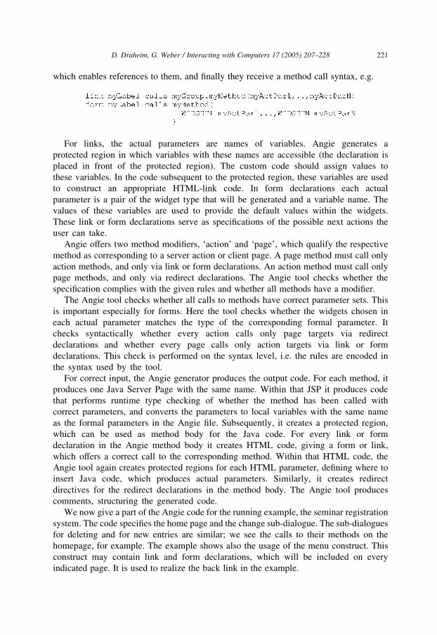
which enables references to them, and finally they receive a method call syntax, e.g.
For links, the actual parameters are names of variables. Angie generates a
protected region in which variables with these names are accessible (the declaration is
placed in front of the protected region). The custom code should assign values to
these variables. In the code subsequent to the protected region, these variables are used
to construct an appropriate HTML-link code. In form declarations each actual
parameter is a pair of the widget type that will be generated and a variable name. The
values of these variables are used to provide the default values within the widgets.
These link or form declarations serve as specifications of the possible next actions the
user can take.
Angie offers two method modifiers, ‘action’ and ‘page’, which qualify the respective
method as corresponding to a server action or client page. A page method must call only
action methods, and only via link or form declarations. An action method must call only
page methods, and only via redirect declarations. The Angie tool checks whether the
specification complies with the given rules and whether all methods have a modifier.
The Angie tool checks whether all calls to methods have correct parameter sets. This
is important especially for forms. Here the tool checks whether the widgets chosen in
each actual parameter matches the type of the corresponding formal parameter. It
checks syntactically whether every action calls only page targets via redirect
declarations and whether every page calls only action targets via link or form
declarations. This check is performed on the syntax level, i.e. the rules are encoded in
the syntax used by the tool.
For correct input, the Angie generator produces the output code. For each method, it
produces one Java Server Page with the same name. Within that JSP it produces code
that performs runtime type checking of whether the method has been called with
correct parameters, and converts the parameters to local variables with the same name
as the formal parameters in the Angie file. Subsequently, it creates a protected region,
which can be used as method body for the Java code. For every link or form
declaration in the Angie method body it creates HTML code, giving a form or link,
which offers a correct call to the corresponding method. Within that HTML code, the
Angie tool again creates protected regions for each HTML parameter, defining where to
insert Java code, which produces actual parameters. Similarly, it creates redirect
directives for the redirect declarations in the method body. The Angie tool produces
comments, structuring the generated code.
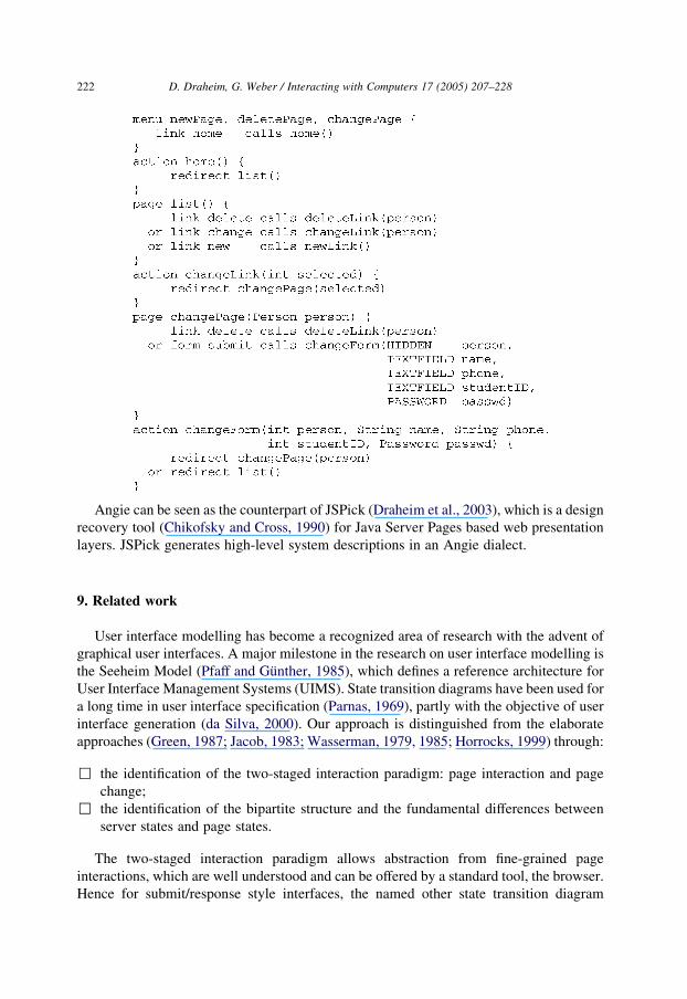
We now give a part of the Angie code for the running example, the seminar registration
system. The code specifies the home page and the change sub-dialogue. The sub-dialogues
for deleting and for new entries are similar; we see the calls to their methods on the
homepage, for example. The example shows also the usage of the menu construct. This
construct may contain link and form declarations, which will be included on every
indicated page. It is used to realize the back link in the example.
D. Draheim, G. Weber / Interacting with Computers 17 (2005) 207–228222
Angie can be seen as the counterpart of JSPick (Draheim et al., 2003), which is a design
recovery tool (Chikofsky and Cross, 1990) for Java Server Pages based web presentation
layers. JSPick generates high-level system descriptions in an Angie dialect.
9. Related work
User interface modelling has become a recognized area of research with the advent of
graphical user interfaces. A major milestone in the research on user interface modelling is
the Seeheim Model (Pfaff and Gunther, 1985), which defines a reference architecture for
User Interface Management Systems (UIMS). State transition diagrams have been used for
a long time in user interface specification (Parnas, 1969), partly with the objective of user
interface generation (da Silva, 2000). Our approach is distinguished from the elaborate
approaches (Green, 1987; Jacob, 1983; Wasserman, 1979, 1985; Horrocks, 1999) through:
,
the identification of the two-staged interaction paradigm: page interaction and pagechange;
,
the identification of the bipartite structure and the fundamental differences betweenserver states and page states.
The two-staged interaction paradigm allows abstraction from fine-grained page
interactions, which are well understood and can be offered by a standard tool, the browser.
Hence for submit/response style interfaces, the named other state transition diagram
D. Draheim, G. Weber / Interacting with Computers 17 (2005) 207–228 223
approaches are identified as being too fine-grained. Furthermore the system view and
dialogue style of these approaches is out of date.
User interface modelling is dominated by the discussion of model-based user interface
development environments (MB-UIDE) (da Silva, 2000). However, again these
approaches, when applied to form-based interfaces, work on the level of page interactions,
which is inadequately fine-grained. Within the UML community the discussion about
dealing with the user interface is still under way (Cunha and Nunes, 2000). In (da Silva and
Paton, 2000) a visual language is proposed for presenting user interfaces. The new artifacts
are basically visualizations of page components. The method is tightly coupled with the
use-case-driven approach.
DENIM and SILK (Landay and Myers, 1995; Newman et al., 2003) are informal
interactive tools that support the early stages of user interface design. They enable the
execution of electronic sketches of user interface prototypes. Rettig describes the working
practice of simulating user interaction with real users and a paper prototype of a system
(Rettig, 1994).
OOHDM (Vilain et al., 2000a,b) is a diagrammatic tool for representing web
interaction. The diagrams are called user interaction diagrams (UID). They resemble page
transition diagrams without server actions. Specific annotations are placed on the
transitions concerning required selections by the user. OOHDM is centred around an
object-oriented modelling metaphor: the system interface is considered as a collection of
objects that are views on classes of a conceptual model.
A stereotype framework specifically for web applications is presented by Conallen
(Conallen, 1999). This approach allows to model the design level concepts appearing
during web site development with a typical web application framework. For this purpose
the Conallen approach uses a set of stereotypes. This approach targets rather design than
analysis.
The conceptual modelling of hypertext is a separate domain, which has been
intensively studied since the beginning of interest in hypertext (Nielsen, 1990). A
reference model for hypertext based on formal specification with Z is (Halasz and
Schwartz, 1994). A complete methodology for hypermedia design called RMM is
presented in (Isakowitz et al., 1995). The conceptual modelling of navigation was also
addressed in the ViewNet approach (Ziegler, 1997). These approaches all model content in
logical collections of information elements. As such the approaches are related to the
modelling of information architectures as they are represented by content management
systems. None of the named hypertext modelling approaches use bipartite transition
descriptions. The system response in these approaches is unconditional. Therefore, these
approaches also have no direct connection to constraint writing.
Statecharts are an extension of state transition diagrams for modelling reactive systems
(Harel, 1987). The StateWebCharts approach (Winckler et al., 2001; Winckler and
Palanque, 2003) extends statecharts in order to model web applications. Consequentially,
the StateWebCharts approach distinguishes between user events and system events. States
are sets of graphic or executable objects. A request form is an instance for a graphic object
as well as a static web page. This approach distinguishes between static, transient,
dynamic, and external states. A submit/response interaction can be modelled by a user
event triggering a transient state and a system event resulting in a dynamic state.
D. Draheim, G. Weber / Interacting with Computers 17 (2005) 207–228224
The aspects of client-side and server-side execution are fully supported by form
storyboards, because they are basic concepts of the approach. In the state machines of
form-oriented analysis, states are parameterised, i.e. they are typed. Server action types
describe input capabilities, while client page types are high-level descriptions of reports
offered to the user. In StateWebCharts, data flow can be described by annotations to the
transitions. Hierarchy and orthogonality of statecharts are exploited by the StateWebChart
approach for modularisation and the modelling of non-modal dialogue and their mutual
interdependencies.
In the early contribution of Zhaneg and Pong (Zheng and Pong, 1992) statecharts are
already employed to give semantics to frame-based, scrolling-based hypertexts. The
approach HMBS (Hypermedia Based on Statecharts) discusses patterns for modelling
advanced concepts such as hierarchical views, access control, versioning and navigational
contexts (Oliveira et al., 2001). However, neither approach goes beyond the modelling of
mere static hypertext, i.e. they are not designed for modelling system state dependent
dialogues.
An early Petri-net based approach to hypertext modelling is presented in (Stotts and
Furuta, 1989). TADEUS (Elwert and Schlungbaum, 1995, 1996; Muller et al., 2001) is
also a Petri-net based approach. However, like form storyboarding, this user interface
modelling technique is technology independent. Moreover, TADEUS is supported by an
MB-UIDE tool that is suited for prototyping coarse-grained dialogues. The automatic
generation is driven by an object model and a dialogue model, which is a Petri-net. Petri-
nets are a state transition formalism based on bipartite graphs. Form storyboards resemble
Petri-nets due to the fact that server actions resemble Petri-net transitions. Petri-nets as a
finite state machine model are classically conceived as being never in a state
corresponding to a transition. The main difference between Petri-nets and bipartite state
diagrams is therefore, that the state of a Petri-net is not necessarily a single bubble, but
possibly a compound state, depending on the type of Petri-net, e.g. a function from bubbles
to numbers for place/transition nets. It is possible to give formcharts a Petri-net semantics,
e.g. by defining client pages as places and introducing a Petri-net transition for every path
of length two to another client page. However, such a Petri-net semantics involves only
trivial transitions, i.e. transitions with one ingoing and one outgoing edge.
WebML is a visual language for conceptual modelling of complex web sites (Ceri et al.,
2000a,b), in which all concepts are defined visually as well as in XML. WebML offers icons
for page elements for composing web sites, e.g. catalogue pages and single item views. The
model of the web sites involves a number of orthogonal divisions, or models (structural,
composition, navigation, presentation and personalization). The structural model is in
principle a semantic data model described in XML. The composition model is a description
of page content based on the data model. The navigation model describes hyperlinks
between the pages, with a distinction between so-called contextual links, which are induced
by the structure of the data model, and non-contextual links, which are freely defined. The
WebML approach can therefore be seen as an advanced and customisable successor of
model-driven interface generators. The basic idea of such systems is to generate all
contextual links from the model. Advanced systems like WebML offer on the other hand the
possibility of choosing between the contextual links as well as of using freely definable
links. Links in WebML are directed edges, which lead typically from page to page and form
D. Draheim, G. Weber / Interacting with Computers 17 (2005) 207–228 225
therefore, a non-bipartite navigation model. WebML also offers a mechanism for accessing
so-called generic external operations by model elements called operation units (Ceri et al.,
2000b). Operation units have conditional output similar to server actions in form-oriented
analysis. However operation units perform asynchronous computations. They are activated
by a designated link after which they can perform operations of arbitrary length. They can
then leave content in other WebML-modelled units.
In comparison with other tools, Angie can be seen to be on the declarative side, while
other tools typically fall on the more operational side. We can see this if we compare
Angie with web presentation frameworks; Angie does not prescribe architecture or design,
even if it works very well with concrete technologies. This is our very aim in making an
abstraction; we want to add value for the concrete technology, yet we do not want to be
tied to a concrete technology. In that sense a high level language like Angie directly
supports an architecture like SUNs Model 2 JSP architecture. Our proposal neither
encourages nor discourages concrete architectures or designs. Instead, it starts as a best
practice for documenting JSP-based systems and ends up as a development discipline for
such systems. This is in contrast to, for example, the Struts framework (Davis 2001),
which leads to very particular Model 2 architectures only. Struts suggest dynamic type
checking. Angie on the other hand consequently performs static type checking and ensures
that the resulting system is statically well-typed.
In comparing tools like Angie one has to be aware of the precise task this tool is
designed for. For example, it has nothing to do with Web authoring tools, which are more
related to content management systems, another important technology class. Such tools
typically also achieve a higher level of abstraction, but this targets questions of
information modularity, as expressed in description languages like WebML. It is
interesting to compare Angie with interactive tools, e.g. Wizards (Borck, 2003) and
graphical IDEs. From the software engineering standpoint the important advantage of
Angie is that you have a specification in the form of the Angie source code, while in the
case of Wizards you have only the resulting system. The functionality of Angie is different
from tools like those described by Nguyen and Srinivasan (1996), which provide an
interconnection between different language paradigms like HTML and SQL. Angie takes
one signature specification and generates code in the different paradigms, Java and HTML,
according to this signature specification.
A current school in requirements engineering is the use-case driven approach. HCI
specifications as defined in the several versions of this approach (Jacobson, 1992; Jacobson
et al., 1999) specifically target the modelling of GUI-based dialogues. The approach does
not yield a clear layering of user interfaces into page interactions and page changes.
A state machine based approach has been recently proposed for modelling workflow
aspects of web applications (Mohan et al., 2002). In this approach, the state of the
application represents the interaction options of a set of users, not a single user. The
approach aims at modelling multi-party dialogues like auctions, and covers the mutual
dependency of the interaction options available to the single parties. The proposal is not
based on a bipartite state machine as is the case with form storyboards. It could be thought
of as combining form storyboarding for modelling single user dialogues with the method
in Mohan et al. (2002) for modelling multi-party aspects of the system under
consideration.
D. Draheim, G. Weber / Interacting with Computers 17 (2005) 207–228226
A recent shift in software processes is the move towards so-called agile methodologies
(Cockburn, 2001). The focus is here on reducing the process overhead in favour of a
strongly iterative development. This approach is also intended to deliver flexibility with
respect to changing requirements. Our method of form storyboarding can be used easily
with agile methodologies due to the similarity between form storyboards and the code
architecture. With the form storyboard union paradigm, form storyboarding can easily
cope with changing requirements.
10. Further directions
Enterprise systems are a type of system, where so-called business rules are automated.
The term ‘business rule’ refers to a high-level data manipulation rule, which is executable
manually or mechanically. Business rules or parts thereof which are not mechanically
executable require human intervention, especially human judgement. This may occur in
the case of primary data input or it may occur at even more obvious decision points.
The notion of submit/response style systems is a framework in which we can model
business rules, and it can be seen as a novel concept for a virtual business machine, i.e. a
machine which is directly able to execute business logic, regardless of whether it includes
human interaction or not. We can now forge the important notion with which to refer to
business logic requirements in their form as executable programs of this virtual machine.
We call the program of this virtual machine the business logic of the application.
These considerations lead to another key concept in our considerations, namely
executable specification. If our business logic can be conceived as the program of a virtual
business machine, then our specification method is nothing less than a high-level
programming language. In fact, some decades ago, the concept of such languages for data-
centric applications appeared so natural that the terminology ‘fourth generation languages’
was coined for these types of languages. This term ‘fourth generation language’ can now
be said to be tied to the even more specialized look-and-feel of such a language, such as
ABAP-4 in the SAP system. Fourth generation languages are typically tightly integrated
into single-vendor platforms. The modelling method presented here can nevertheless be
seen as an integration of practical experiences from fourth generation languages into a
state-of-the-art modelling style. In principle it is therefore conceivable that in future a
business platform running as a virtual machine on common platforms could interpret the
business logic directly.
References
Benyon, D., Macaulay, C., 2002. Scenarios and the HCI-SE design problem, Interacting with Computers, vol. 14.
Elsevier pp. 397–405.
Borck, J.R., March 2003. WebSphere Studio Application Developer 4.0., JavaWorld.
Ceri, S., Fraternali, P., Paraboschi, S., 2000a. Web Modeling Language(WebML): a modeling language
for designing web sites, Proceedings of the Ninth International World Wide Web Conference. Elsevier
pp. 137–157.
D. Draheim, G. Weber / Interacting with Computers 17 (2005) 207–228 227
Ceri, S., Fraternali, P., Bongio, A., Maurino, A., 2000. Modeling data entry and operations in WebML,
Proceedings of WebDB 2000, Dallas 2000.
Chikofsky, E.J., Cross, J.H., 1990. Reverse engineering and design recovery: a taxonomy. IEEE Software 1990,
13–17.
Cockburn, A., 2001. Agile Software Development. Addison-Wesley, Reading, MA.
Conallen, J., 1999. Modeling web application architectures with UML. Communications of the ACM 42 (10), 63–
70.
Cunha, J.F.E., Nunes, N.J., 2000. Towards a UML profile for interaction design: the wisdom approach, Lecture
Notes in Computer Science 1939, Proceedings of UML’2000, York 2000.
da Silva, P.P., 2000. User interface declarative models and development environments: a survey, Proceedings of
Seventh International Workshop on Design, Specification and Verification of Interactive Systems, LNCS, vol.
1946. Springer, Berlin.
da Silva, P.P., Paton, N.W., 2000. UMLi: the unified modeling language for interactive applications, Lecture
Notes in Computer Science 1939, Proceedings of UML’2000, York 2000.
Davis, M., February 2001. Struts—an Open-source MVC Implementation. IBM developerWorks.
Draheim, D., Weber, G., 2002. Strongly typed server pages, Proceedings of the 5th Workshop on Next Generation
Information Technologies and Systems, LNCS 2382. Springer, Berlin.
Draheim, D., Weber, G., 2003a. Storyboarding form-based interfaces, Proceedings of INTERACT 2003-Ninth
IFIP TC13 International Conference on Human–Computer Interaction. IOS Press.
Draheim, D., Weber, G., 2003b. Modeling submit/response style systems with form charts and dialogue
constraints, Proceedings of the Workshop on Human Computer Interface for Semantic Web and Web
Applications, LNCS 2889. Springer, Berlin.
Draheim, D., Weber, G., 2004a. Specification and generation of model 2 web interfaces, Proceedings of APCHI
2004-6th Asia-Pacific Conference on Computer–Human Interaction. LNCS. Springer, Berlin.
Draheim, D., Weber, G., 2004b. Form-Oriented Analysis—A New Methodology to Model Form-Based
Applications. Springer, Berlin.
Draheim, D., Fehr, E., Weber, G., 2003. JSPick-A server pages design recovery tool, Proceedings of the Seventh
European Conference on Software Maintenance and Reengineering. IEEE Press.
Elwert, T., Schlungbaum, E., 1995. Modelling and generation of graphical user interfaces in the TADEUS
approach, in: Palanque, P., Bastide, R. (Eds.), Designing, Specification, and Verification of Interactive
Systems. Springer, Wien, pp. 193–208.
Elwert, T., Schlungbaum, E., 1996. Dialogue graphs—a formal and visual specification technique for dialogue
modelling, Proceedings of the BCS-FACS Workshop on Formal Aspects of the Human Computer Interface.
The British Computer Society, Springer.
Green, M., 1987. A survey of three dialogue models. ACM Transactions on Graphics 5 (3), 244–275.
Halasz, F., Schwartz, M., 1994. The Dexter hypertext reference model. Communications of the ACM 37 (2), 30–
39.
Harel, D., 1987. Statecharts: A Visual Formalism for Complex Systems, Science of Computer Programming.
Elsevier, Amsterdam pp. 231–274.
Hayes, P.J., 1985. Executable interface definitions using form-based interface abstractions. Advances in Human–
Computer Interaction 1.
Horrocks, I., 1999. Constructing the User Interface with Statecharts. Addison-Wesley, Reading, MA.
IEEE Std 830-1993, 1993. Recommended Practice for Software Requirements Specifications. Software
Engineering Standards Committee of the IEEE Computer Society, New York.
Isakowitz, T., Stohr, E.A., Balasubramanian, P., 1995. RMM: a methodology for structured hypermedia design.
Communications of the ACM 38 (8), 34–44.
Jacob, R.J.K., 1983. Using formal specifications in the design of a human–computer interface. Communications
of the ACM 26 (4), 259–264.
Jacobson, I., 1992. Object-Oriented Software Engineering: A Use Case Driven Approach. Addison-Wesley,
Reading, MA.
Jacobson, I., Booch, G., Rumbaugh, J., 1999. The Unified Software Development Process. Addison-Wesley,
Reading, MA.
D. Draheim, G. Weber / Interacting with Computers 17 (2005) 207–228228
Landay, J.A., Myers, B.A., 1995. Interactive sketching for the early stages of user interface design, Proceedings of
Human Factors in Computing Systems. ACM Press pp. 43–50.
Mohan, R., Cohen, M.A., Schiefer, J., 2002. A State Machine Based Approach for a Process Driven Development
of Web-Applications, CAiSE 2002, Toronto, Springer LNCS 2348 2002 pp. 52 ff.
Muller, A., Forbrig, P., Cap, C.H., 2001. Model-based user interface design using markup concepts, Proceedings
of DVS-IS-Conference on Design, Specification, and Verification of Interactive Systems, LNCS 2220.
Springer, Berlin.
Newman, M.W., Lin, J., Hong, J.I., Landay, J.A., 2003. DENIM: an informal web site design tool inspired by
observations of practice. Human–Computer Interaction 18 (3), 259–324.
Nguyen, T., Srinivasan, V., 1996. Accessing relational databases from the World Wide Web, Proceedings of the
1996 ACM SIGMOD 1996.
Nielsen, J., 1990. The art of navigating through hypertext. Communications of the ACM 33 (3), 296–310.
Oliveira, M.C.F., Turine, M.A.S.T., Masiero, P.C., 2001. A statechart-based model for hypermedia applications.
ACM Transactions on Information Systems 19 (1).
Parnas, D., 1969. On the use of transition diagrams in the design of a user interface for an interactive computer
system, Proceedings of the 24th National Conference. ACM Press pp. 379–385.
Pfaff, E., Gunther, 1985. User Interface Management Systems. Springer, Berlin.
Rettig, M., 1994. Prototyping for tiny fingers. Communications of the ACM 37, 21–27.
Stotts, P.D., Furuta, R., 1989. Petri-net-based hypertext: document structure with browsing semantics. ACM
Transactions on Information Systems 7 (1).
Vilain, P., Schwabe, D., Souza, C.S., 2000a. Modeling interactions and navigation in web applications,
Proceedings of Seventh International Workshop on Design, Specification and Verification of Interactive
Systems, LNCS, vol. 1921. Springer, Salt Lake City, UT pp. 115–127.
Vilain, P., Schwabe, D., Souza, C.S., 2000b. A diagrammatic tool for representing user interaction in UML,
Lecture Notes in Computer Science 1939, Proc. UML’2000, York 2000.
Wasserman, A.I., 1979. A specification method for interactive information systems, Proceedings SRS—
Specification of Reliable Software, IEEE Catalog No. 79 CHI1401-9C. IEEE pp. 68–79.
Wasserman, A.I., 1985. Extending state transition diagrams for the specification of human–computer interaction.
IEEE Transaction on Software Engineering SE-11 (8), 699–713.
Winckler, M., Palanque, P., 2003. StateWebCharts: a formal description technique dedicated to navigation
modelling of web applications, Proceedings of DSV-IS 2003: Design, Specification, and Verification of
Interactive Systems, LNCS 2844. Springer, Berlin.
Winckler, M., Farenc, C., Palanque, P., Bastide, R., 2001. Designing navigation for web interfaces. Joint AFIHM-
BCS Conference on Human–Computer Interaction (IHM-HCI’2001), Lille, France.
Weber, G., 2002. Semantics of Form-Oriented Analysis. Freie Universitat Berlin. PhD-Thesis.
Zheng, Y., Pong, M.-C., 1992. Using statecharts to model hypertext, Proceedings of the ACM Conference on
Hypertext. ACM Press pp. 242–250.
Ziegler, J., 1997. ViewNet—conceptual design and modelling of navigation, Proceedings of INTERACT 97
1997.


