Embed Size (px)
Citation preview
ISSN(Online): 2319-8753 ISSN (Print): 2347-6710
International Journal of Innovative Research in Science, Engineering and Technology
(A High Impact Factor, Monthly, Peer Reviewed Journal)
Visit: www.ijirset.com
Vol. 7, Issue 5, May 2018
Copyright to IJIRSET DOI:10.15680/IJIRSET.2018.0705081 4974
Modelling of Three Phase Transformer in MATLAB/Simulink
Harshitha G B 1, Santhosh D S 2, K Uday Bhargav 3
Lecturer, Department of Electrical and Electronics Engineering, UBDT College of Engineering, Davangere,
Karnataka, India1
Assistant Professor, Department of Electrical and Electronics Engineering, Bangalore College of Engineering,
Bengaluru, Karnataka, India2
Department of Electrical and Electronics Engineering, BNM Institute of Technology, Bengaluru, Karnataka, India3
ABSTRACT: The dynamic three phase transformer has been designed and developed in MATLAB/Simulink in this paper. Model has been referred to the circuit of the actual core and windings of the transformer. This design can be used for any multiphase multi-winding transformer. The model consists of three single phase transformers and is assumed to symmetrical in nature. For the easy control and understandable reason the transformer is converted into vector form and back. All the results related to the model has been represented and analysed in this paper. KEYWORDS: Transformer, Simulink.
I. INTRODUCTION A Transformer is a static device which works on the principle of mutual induction. It converts a given AC voltage to a High or Low output voltage depending upon the transformer. Its main purpose relates to the isolation of the system. Transformers are available in wide ranges of sizes and voltages. The dynamic modelling of three phase transformer would be useful in analysing the behaviour of transformer under many conditions. It is the most common model to analyse which can be constructed in MATLAB/Simulink for its analysis. It uses single phase transformer for analysis which can be used in cases of multiphase transformers too. So it eases the simulation with respect to designing and constructing the model. For ease up purposes the voltages are converted to the αβ reference frame which is shown in this paper in form of matrix which is actually equations. The abc frame is converted to αβ reference frame in this model. The core has been neglected and the resistances and the inductances are included for the modelling of the transformers. The final results of the transformer modelled has been shown and analysed in this paper. Whenever a system has to be constructed which consists a transformer, the modelling of a transformer is necessary to determine the analysis of the transformer under steady state and dynamic state. This paper deals with the modelling of a three phase transformer using single phase transformers which are symmetrical in nature. This model can also be used for determining whether the system can be used for multiphase connections or not. This model will determine the performance of the transformer under steady state and dynamic state.
II. LITERATURE SURVEY In dynamic modelling of three phase transformer [1] the author develops a three phase transformer in MATLAB/Simulink. He develops using three single phase transformers in MATLAB/Simulink and compares it with
ISSN(Online): 2319-8753 ISSN (Print): 2347-6710
International Journal of Innovative Research in Science, Engineering and Technology
(A High Impact Factor, Monthly, Peer Reviewed Journal)
Visit: www.ijirset.com
Vol. 7, Issue 5, May 2018
Copyright to IJIRSET DOI:10.15680/IJIRSET.2018.0705081 4975
an actual transformer of 220/55V to compare and determine the characteristics of steady state and transient state. In Analysis of Electric machinery and drive systems [2] the author talks about the development and modelling of the machines generally used in industries. This book tells us about the modelling of the machinery based on the equations related to it. The automatic control of Drives [3] deals with the control of the power electronics components which fed the machinery or the drives used in industries. In all the references author has talked about the modelling of transformer model wise. In this paper, system was done in the MATLAB coding along with the Simulink for ease purpose.
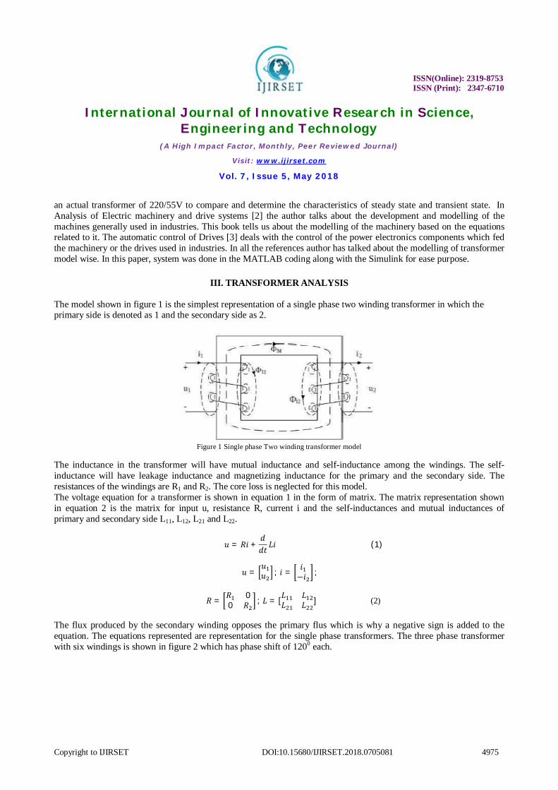
III. TRANSFORMER ANALYSIS The model shown in figure 1 is the simplest representation of a single phase two winding transformer in which the primary side is denoted as 1 and the secondary side as 2.
Figure 1 Single phase Two winding transformer model
The inductance in the transformer will have mutual inductance and self-inductance among the windings. The self-inductance will have leakage inductance and magnetizing inductance for the primary and the secondary side. The resistances of the windings are R1 and R2. The core loss is neglected for this model. The voltage equation for a transformer is shown in equation 1 in the form of matrix. The matrix representation shown in equation 2 is the matrix for input u, resistance R, current i and the self-inductances and mutual inductances of primary and secondary side L11, L12, L21 and L22.
푢 = 푅푖 +푑푑푡 퐿푖
(1)
푢 =푢푢 ; 푖 = 푖
−푖 ;
푅 = 푅 00 푅 ; 퐿 = [퐿 퐿
퐿 퐿 ] (2)
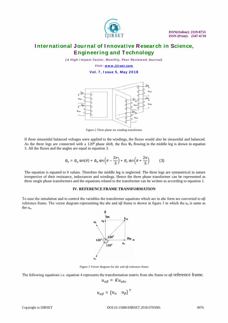
The flux produced by the secondary winding opposes the primary flus which is why a negative sign is added to the equation. The equations represented are representation for the single phase transformers. The three phase transformer with six windings is shown in figure 2 which has phase shift of 1200 each.
ISSN(Online): 2319-8753 ISSN (Print): 2347-6710
International Journal of Innovative Research in Science, Engineering and Technology
(A High Impact Factor, Monthly, Peer Reviewed Journal)
Visit: www.ijirset.com
Vol. 7, Issue 5, May 2018
Copyright to IJIRSET DOI:10.15680/IJIRSET.2018.0705081 4976
Figure 2 Three phase six winding transformer
If three sinusoidal balanced voltages were applied to the windings, the fluxes would also be sinusoidal and balanced. As the three legs are connected with a 120o phase shift, the flux Φ0 flowing in the middle leg is shown in equation 3. All the fluxes and the angles are equal in equation 3.
∅ = ∅ sin(휃) + ∅ sin 휃 −2휋3 + ∅ sin 휃 +
2휋3 (3)
The equation is equated to 0 values. Therefore the middle leg is neglected. The three legs are symmetrical in nature irrespective of their resistance, inductances and windings. Hence the three phase transformer can be represented as three single phase transformers and the equations related to the transformer can be written as according to equation 1.
IV. REFERENCE FRAME TRANSFORMATION
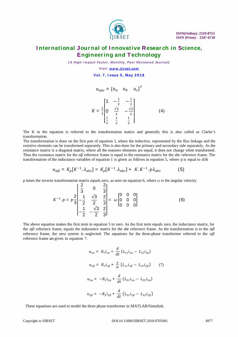
To ease the simulation and to control the variables the transformer equations which are in abc form are converted to αβ reference frame. The vector diagram representing the abc and αβ frame is shown in figure 3 in which the ua is same as the uα.
Figure 3 Vector diagram for abc and αβ reference frame
The following equations i.e. equation 4 represents the transformation matrix from abc frame to αβ reference frame. 푢 = 퐾푢
푢 = [푢 푢 ]
ISSN(Online): 2319-8753 ISSN (Print): 2347-6710
International Journal of Innovative Research in Science, Engineering and Technology
(A High Impact Factor, Monthly, Peer Reviewed Journal)
Visit: www.ijirset.com
Vol. 7, Issue 5, May 2018
Copyright to IJIRSET DOI:10.15680/IJIRSET.2018.0705081 4977
푢 = [푢 푢 푢 ]
퐾 =
⎣⎢⎢⎢⎡1 − −
0 √ − √
⎦⎥⎥⎥⎤ (4)
The K in the equation is referred to the transformation matrix and generally this is also called as Clarke’s transformation. The transformation is done on the first part of equation 1, where the inductive, represented by the flux linkage and the resistive elements can be transformed separately. This is also done for the primary and secondary side separately. As the resistance matrix is a diagonal matrix, where all the nonzero elements are equal, it does not change when transformed. Thus the resistance matrix for the αβ reference frame is equal to the resistance matrix for the abc reference frame. The transformation of the inductance variables of equation 1 is given as follows in equation 5, where p is equal to d/dt
푢 = 퐾 [퐾 . 휆 ] = 퐾 [퐾 .휆 ] + 퐾.퐾 . 푝휆 (5) p times the inverse transformation matrix equals zero, as seen on equation 6, where ω is the angular velocity
퐾 .푝 = 푝23
⎣⎢⎢⎢⎢⎢⎡
23
023
−12
√32
23
−12
−√32
23⎦⎥⎥⎥⎥⎥⎤
= 휔0 0 00 0 00 0 0
(6)
The above equation makes the first term in equation 5 to zero. As the first term equals zero, the inductance matrix, for the αβ reference frame, equals the inductance matrix for the abc reference frame. As the transformation is to the αβ reference frame, the zero system is neglected. The equations for the three-phase transformer referred to the αβ reference frame are given in equation 7.
푢 = 푅 푖 + 푑푑푡
(퐿 푖 −퐿 푖 )
푢 = 푅 푖 + 퐿 푖 −퐿 푖
푢 = −푅 푖 + 푑푑푡
(퐿 푖 −퐿 푖 )
푢 = −푅 푖 + 푑푑푡 퐿 푖 −퐿 푖
These equations are used to model the three phase transformer in MATLAB/Simulink.
(7)
ISSN(Online): 2319-8753 ISSN (Print): 2347-6710
International Journal of Innovative Research in Science, Engineering and Technology
(A High Impact Factor, Monthly, Peer Reviewed Journal)
Visit: www.ijirset.com
Vol. 7, Issue 5, May 2018
Copyright to IJIRSET DOI:10.15680/IJIRSET.2018.0705081 4978
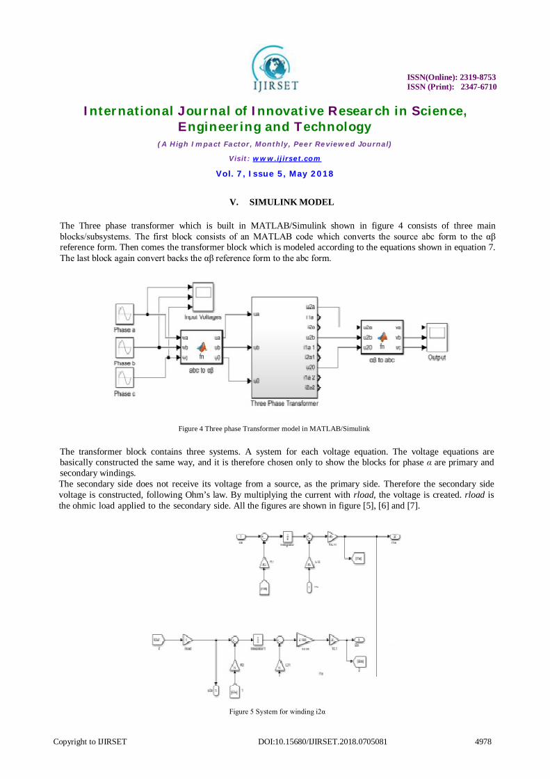
V. SIMULINK MODEL
The Three phase transformer which is built in MATLAB/Simulink shown in figure 4 consists of three main blocks/subsystems. The first block consists of an MATLAB code which converts the source abc form to the αβ reference form. Then comes the transformer block which is modeled according to the equations shown in equation 7. The last block again convert backs the αβ reference form to the abc form.
Figure 4 Three phase Transformer model in MATLAB/Simulink
The transformer block contains three systems. A system for each voltage equation. The voltage equations are basically constructed the same way, and it is therefore chosen only to show the blocks for phase α are primary and secondary windings. The secondary side does not receive its voltage from a source, as the primary side. Therefore the secondary side voltage is constructed, following Ohm’s law. By multiplying the current with rload, the voltage is created. rload is the ohmic load applied to the secondary side. All the figures are shown in figure [5], [6] and [7].
Figure 5 System for winding i2α
ISSN(Online): 2319-8753 ISSN (Print): 2347-6710
International Journal of Innovative Research in Science, Engineering and Technology
(A High Impact Factor, Monthly, Peer Reviewed Journal)
Visit: www.ijirset.com
Vol. 7, Issue 5, May 2018
Copyright to IJIRSET DOI:10.15680/IJIRSET.2018.0705081 4979
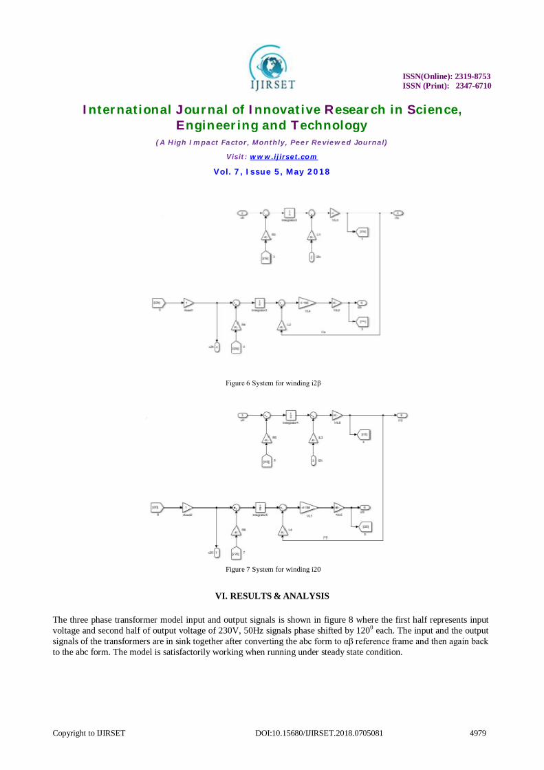
Figure 6 System for winding i2β
Figure 7 System for winding i20
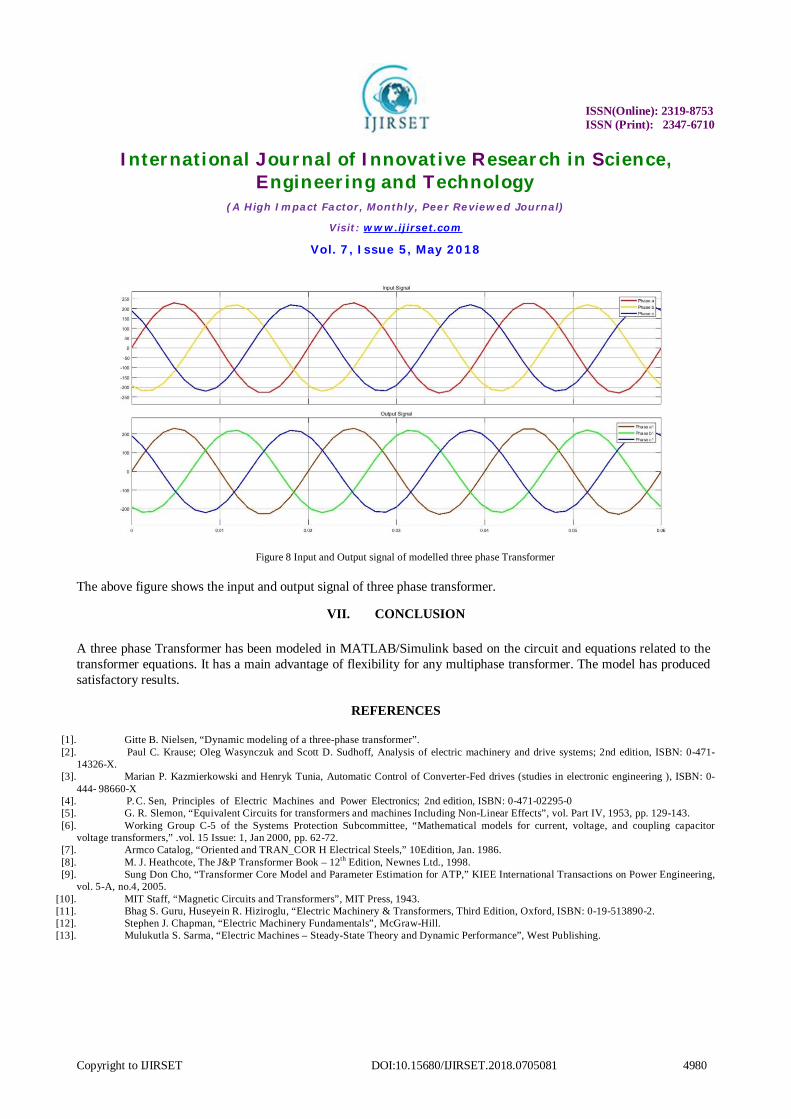
VI. RESULTS & ANALYSIS
The three phase transformer model input and output signals is shown in figure 8 where the first half represents input voltage and second half of output voltage of 230V, 50Hz signals phase shifted by 1200 each. The input and the output signals of the transformers are in sink together after converting the abc form to αβ reference frame and then again back to the abc form. The model is satisfactorily working when running under steady state condition.
ISSN(Online): 2319-8753 ISSN (Print): 2347-6710
International Journal of Innovative Research in Science, Engineering and Technology
(A High Impact Factor, Monthly, Peer Reviewed Journal)
Visit: www.ijirset.com
Vol. 7, Issue 5, May 2018
Copyright to IJIRSET DOI:10.15680/IJIRSET.2018.0705081 4980
Figure 8 Input and Output signal of modelled three phase Transformer The above figure shows the input and output signal of three phase transformer.
VII. CONCLUSION
A three phase Transformer has been modeled in MATLAB/Simulink based on the circuit and equations related to the transformer equations. It has a main advantage of flexibility for any multiphase transformer. The model has produced satisfactory results.
REFERENCES
[1]. Gitte B. Nielsen, “Dynamic modeling of a three-phase transformer”. [2]. Paul C. Krause; Oleg Wasynczuk and Scott D. Sudhoff, Analysis of electric machinery and drive systems; 2nd edition, ISBN: 0-471-
14326-X. [3]. Marian P. Kazmierkowski and Henryk Tunia, Automatic Control of Converter-Fed drives (studies in electronic engineering ), ISBN: 0-
444- 98660-X [4]. P. C. Sen, Principles of Electric Machines and Power Electronics; 2nd edition, ISBN: 0-471-02295-0 [5]. G. R. Slemon, “Equivalent Circuits for transformers and machines Including Non-Linear Effects”, vol. Part IV, 1953, pp. 129-143. [6]. Working Group C-5 of the Systems Protection Subcommittee, “Mathematical models for current, voltage, and coupling capacitor
voltage transformers,” .vol. 15 Issue: 1, Jan 2000, pp. 62-72. [7]. Armco Catalog, “Oriented and TRAN_COR H Electrical Steels,” 10Edition, Jan. 1986. [8]. M. J. Heathcote, The J&P Transformer Book – 12th Edition, Newnes Ltd., 1998. [9]. Sung Don Cho, “Transformer Core Model and Parameter Estimation for ATP,” KIEE International Transactions on Power Engineering,
vol. 5-A, no.4, 2005. [10]. MIT Staff, “Magnetic Circuits and Transformers”, MIT Press, 1943. [11]. Bhag S. Guru, Huseyein R. Hiziroglu, “Electric Machinery & Transformers, Third Edition, Oxford, ISBN: 0-19-513890-2. [12]. Stephen J. Chapman, “Electric Machinery Fundamentals”, McGraw-Hill. [13]. Mulukutla S. Sarma, “Electric Machines – Steady-State Theory and Dynamic Performance”, West Publishing.


