Embed Size (px)
Citation preview
Simulation of a 6/4 SwitchedReluctance Motor Based onMatlab/Simulink Environment
F. SOARES
P. J. COSTA BRANCOInstituto Superior TecnicoPortugal
A Matlab/Simulink environment to simulate a 6/4-switched
reluctance motor is described. From its linear model to the
nonlinear model, its dynamics is described and discussed in
detail. All simulations are completely documented by their
block diagrams and corresponding special Matlab functions and
parameters quickly develop its model to the reader. Based on the
developed model, simulation studies are performed and compared
with measured motor phase currents either for hysteresis and
voltage control strategies, and the steady-state motor operation
to validate the model.
Manuscript received January 18, 2000; revised August 20, 2000 andFebruary 5, 2001; released for publication April 3, 2001.
IEEE Log No. T-AES/37/3/08568.
Refereeing of this contribution was handled by W. M. Polivka.
Authors’ current addresses: F. S. Soares, Alcatel Microelectronics,Belgium; P. J. Costa Branco, Laboratorio de Mecatronica, InstitutoSuperior Tecnico, Av. Rovisco Pais, 1049-01, Lisboa Codex,Portugal, E-mail: ([email protected]).
0018-9251/01/$10.00 c° 2001 IEEE
I. INTRODUCTION
Profits that one can have with a simulation analysistaking account of the complete modeling of a systemis no longer necessary to prove. Indeed, the simulationof a system is important in view of its design andexperimental realization [11].Most studies concerning dynamic simulation
of switched reluctance machines (SRMs) [3] havebeen achieved from the programming, either in Clanguage, Fortran, and also employing differentialequation-based languages such as ACSL [15—17].Even software designed to simulate electric networksystems as the EMTDC and EMTP have been used.These techniques, although very useful, have lackof flexibility if new elements are brought, causingthe increase of cost because of supplementaryprogramming effort. On the other hand, very fewsimulation studies of the SRM have been achievedwith circuit-based languages such as Spice, Simulink,Matrix, Tutsim, Vissim, and even Mathcad. The firstsimulations have been made thanks to the softwareSpice [13]. Unfortunately, this technique is not“elegant” because Spice is especially adapted toelectronic circuit simulation [14]. Lately, there hasbeen considerable progress in simulation softwaresuch as Matlab/Simulink, which allows a high flexiblemodeling environment to electrical machinery, asshown in [18], and in particular for SRMs as shown in[6]. The main benefits to be achieved are as follows.
1) gain of time for the simulation development;2) choice of several techniques of numeric
resolution;3) several available libraries for different domains
as, for example, fuzzy-logic control, neural networks,and signal processing.
The switched reluctance motor is studiedhere using a Matlab/Simulink environment. Allsimulations are completely documented by theirblock diagrams, corresponding special Matlabfunctions and parameters. Section II introduces themain characteristics of the SRM. Its advantages anddisadvantages are indicated and compared with theac motors. The electromagnetic equations are alsopresented as well as its process of torque production.In Section III, the SRM linear model is first
elaborated and used in the Matlab/Simulink simulationof a 6/4 SR machine. The two most frequent SRMenergizing strategies, voltage and hysteresis currentcontrol, are discussed and illustrated.The SRM nonlinear model is presented in Section
IV. By a previous finite element study of the 6/4SRM, we obtained its magnetic characteristic,describing in detail its Matlab/Simulink model. Anextensive set of simulations is then presented, showingthe differences when compared with those obtainedwith the linear model [10].
IEEE TRANSACTIONS ON AEROSPACE AND ELECTRONIC SYSTEMS VOL. 37, NO. 3 JULY 2001 989
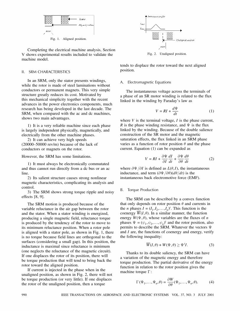
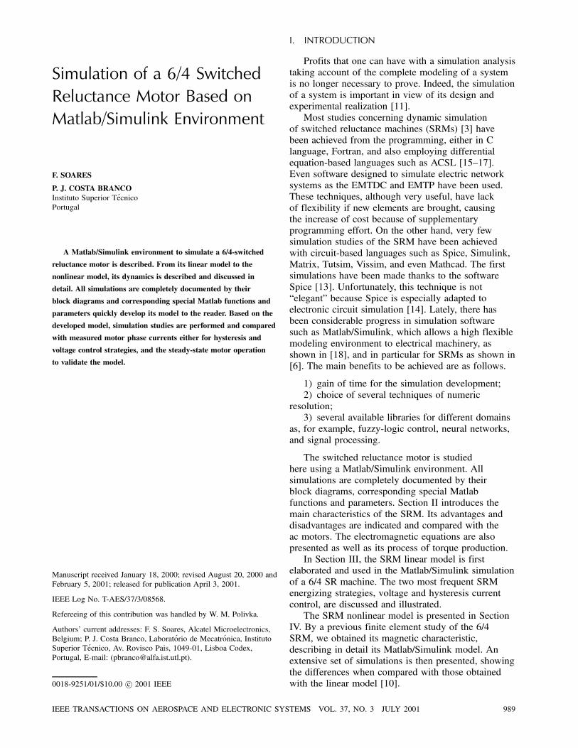
Fig. 1. Aligned position.
Completing the electrical machine analysis, SectionV shows experimental results included to validate themachine model.
II. SRM CHARACTERISTICS
In an SRM, only the stator presents windings,while the rotor is made of steel laminations withoutconductors or permanent magnets. This very simplestructure greatly reduces its cost. Motivated bythis mechanical simplicity together with the recentadvances in the power electronics components, muchresearch has being developed in the last decade. TheSRM, when compared with the ac and dc machines,shows two main advantages.
1) It is a very reliable machine since each phaseis largely independent physically, magnetically, andelectrically from the other machine phases.2) It can achieve very high speeds
(20000—50000 rev/m) because of the lack ofconductors or magnets on the rotor.
However, the SRM has some limitations.
1) It must always be electronically commutatedand thus cannot run directly from a dc bus or an acline.2) Its salient structure causes strong nonlinear
magnetic characteristics, complicating its analysis andcontrol.3) The SRM shows strong torque ripple and noisy
effects [8, 9].
The SRM motion is produced because of thevariable reluctance in the air gap between the rotorand the stator. When a stator winding is energized,producing a single magnetic field, reluctance torqueis produced by the tendency of the rotor to move toits minimum reluctance position. When a rotor poleis aligned with a stator pole, as shown in Fig. 1, thereis no torque because field lines are orthogonal to thesurfaces (considering a small gap). In this position, theinductance is maximal since reluctance is minimum(one neglects the reluctance of the magnetic circuit).If one displaces the rotor of its position, there willbe torque production that will tend to bring back therotor toward the aligned position.If current is injected in the phase when in the
unaligned position, as shown in Fig. 2, there will notbe torque production (or very little). If one displacesthe rotor of the unaligned position, then a torque
Fig. 2. Unaligned position.
tends to displace the rotor toward the next alignedposition.
A. Electromagnetic Equations
The instantaneous voltage across the terminals ofa phase of an SR motor winding is related to the fluxlinked in the winding by Faraday’s law as
V = RI+dª
dt(1)
where V is the terminal voltage, I is the phase current,R is the phase winding resistance, and ª is the fluxlinked by the winding. Because of the double salienceconstruction of the SR motor and the magneticsaturation effects, the flux linked in an SRM phasevaries as a function of rotor position µ and the phasecurrent. Equation (1) can be expanded as
V = RI+@ª
@I
dI
dt+@ª
@µ
dµ
dt(2)
where @ª=@I is defined as L(µ,I), the instantaneousinductance, and term (@ª=@µ)(dµ=dt) is theinstantaneous back electromotive force (EMF).
B. Torque Production
The SRM can be described by a convex functionthat only depends on rotor position µ and currents inthe n phases I = (I1,I2, : : : ,In)
t. This function is thecoenergy W(I,µ). In a similar manner, the functionenergy W(ª ,µ), whose variables are the fluxes of nphases ª = (Ã1,Ã2, : : : ,Ãn)
t and the rotor position, alsopermits to describe the SRM. Whatever the vectors ªand I are, the functions of coenergy and energy, verifythe following inequality:
W(I,µ)+W(ª ,µ)¸ªtI: (3)
Thanks to its double saliency, the SRM can havea variation of the magnetic energy and thereforetorque production. The partial derivative of the energyfunction in relation to the rotor position gives themachine torque ¡ :
¡ (ª1, : : : ,ªn,µ) =@W
@µ(ª1, : : : ,ªn,µ): (4)
990 IEEE TRANSACTIONS ON AEROSPACE AND ELECTRONIC SYSTEMS VOL. 37, NO. 3 JULY 2001
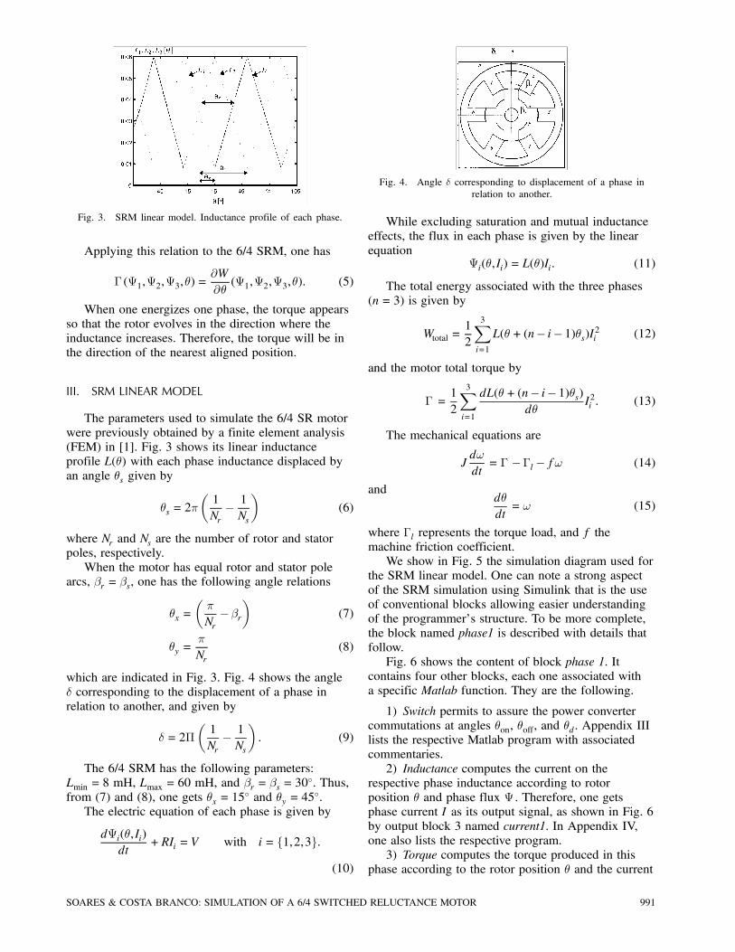
Fig. 3. SRM linear model. Inductance profile of each phase.
Applying this relation to the 6/4 SRM, one has
¡ (ª1,ª2,ª3,µ) =@W
@µ(ª1,ª2,ª3,µ): (5)
When one energizes one phase, the torque appearsso that the rotor evolves in the direction where theinductance increases. Therefore, the torque will be inthe direction of the nearest aligned position.
III. SRM LINEAR MODEL
The parameters used to simulate the 6/4 SR motorwere previously obtained by a finite element analysis(FEM) in [1]. Fig. 3 shows its linear inductanceprofile L(µ) with each phase inductance displaced byan angle µs given by
µs = 2¼µ1Nr¡ 1Ns
¶(6)
where Nr and Ns are the number of rotor and statorpoles, respectively.When the motor has equal rotor and stator pole
arcs, ¯r = ¯s, one has the following angle relations
µx =µ¼
Nr¡¯r
¶(7)
µy =¼
Nr(8)
which are indicated in Fig. 3. Fig. 4 shows the angle± corresponding to the displacement of a phase inrelation to another, and given by
± = 2¦µ1Nr¡ 1Ns
¶: (9)
The 6/4 SRM has the following parameters:Lmin = 8 mH, Lmax = 60 mH, and ¯r = ¯s = 30
±. Thus,from (7) and (8), one gets µx = 15
± and µy = 45±.
The electric equation of each phase is given by
dªi(µ,Ii)dt
+RIi = V with i= f1,2,3g:
(10)
Fig. 4. Angle ± corresponding to displacement of a phase inrelation to another.
While excluding saturation and mutual inductanceeffects, the flux in each phase is given by the linearequation
ªi(µ,Ii) = L(µ)Ii: (11)
The total energy associated with the three phases(n= 3) is given by
Wtotal =12
3Xi=1
L(µ+(n¡ i¡ 1)µs)I2i (12)
and the motor total torque by
¡ =12
3Xi=1
dL(µ+(n¡ i¡ 1)µs)dµ
I2i : (13)
The mechanical equations are
Jd!
dt= ¡ ¡¡l¡f! (14)
anddµ
dt= ! (15)
where ¡l represents the torque load, and f themachine friction coefficient.We show in Fig. 5 the simulation diagram used for
the SRM linear model. One can note a strong aspectof the SRM simulation using Simulink that is the useof conventional blocks allowing easier understandingof the programmer’s structure. To be more complete,the block named phase1 is described with details thatfollow.Fig. 6 shows the content of block phase 1. It
contains four other blocks, each one associated witha specific Matlab function. They are the following.
1) Switch permits to assure the power convertercommutations at angles µon, µoff, and µd. Appendix IIIlists the respective Matlab program with associatedcommentaries.2) Inductance computes the current on the
respective phase inductance according to rotorposition µ and phase flux ª . Therefore, one getsphase current I as its output signal, as shown in Fig. 6by output block 3 named current1. In Appendix IV,one also lists the respective program.3) Torque computes the torque produced in this
phase according to the rotor position µ and the current
SOARES & COSTA BRANCO: SIMULATION OF A 6/4 SWITCHED RELUCTANCE MOTOR 991
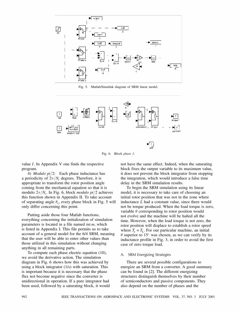
Fig. 5. Matlab/Simulink diagram of SRM linear model.
Fig. 6. Block phase 1.
value I. In Appendix V one finds the respectiveprogram.4) Modulo pi=2: Each phase inductance has
a periodicity of 2¼=Nr degrees. Therefore, it isappropriate to transform the rotor position anglecoming from the mechanical equation so that it ismodulo 2¼=Nr. In Fig. 6, block modulo pi=2 achievesthis function shown in Appendix II. To take accountof separating angle µs, every phase block in Fig. 5 willonly differ concerning this point.
Putting aside those four Matlab functions,everything concerning the initialization of simulationparameters is located in a file named int.m, whichis listed in Appendix I. This file permits us to takeaccount of a general model for the 6/4 SRM, meaningthat the user will be able to enter other values thanthose utilized in this simulation without changinganything in all remaining parts.To compute each phase electric equation (10),
we avoid the derivative action. The simulationdiagram in Fig. 6 shows how this was achieved byusing a block integrator (1/s) with saturation. Thisis important because it is necessary that the phaseflux not become negative since the converter isunidirectional in operation. If a pure integrator hadbeen used, followed by a saturating block, it would
not have the same effect. Indeed, when the saturatingblock fixes the output variable to its maximum value,it does not prevent the block integrator from stoppingthe integration, which would introduce a false timedelay in the SRM simulation results.To begin the SRM simulation using its linear
model, it is necessary to take care of choosing aninitial rotor position that was not in the zone whereinductance L had a constant value, since there wouldnot be torque produced. When the load torque is zero,variable µ corresponding to rotor position wouldnot evolve and the machine will be halted all thetime. However, when the load torque is not zero, therotor position will displace to establish a rotor speedwhere Te = TL. For our particular machine, an initialµ superior to 15± was chosen, as we can verify by itsinductance profile in Fig. 3, in order to avoid the firstcase of zero torque load.
A. SRM Energizing Strategies
There are several possible configurations toenergize an SRM from a converter. A good summarycan be found in [2]. The different energizingstructures distinguish themselves by their numberof semiconductors and passive components. Theyalso depend on the number of phases and the
992 IEEE TRANSACTIONS ON AEROSPACE AND ELECTRONIC SYSTEMS VOL. 37, NO. 3 JULY 2001
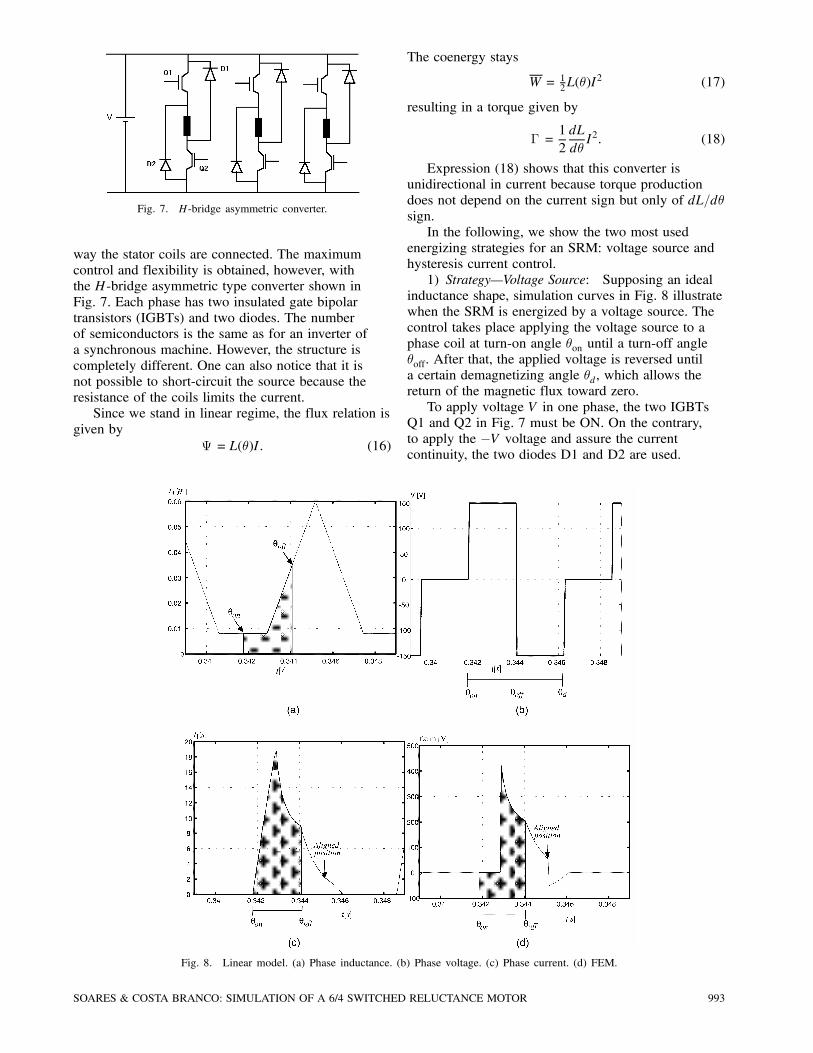
Fig. 7. H-bridge asymmetric converter.
way the stator coils are connected. The maximumcontrol and flexibility is obtained, however, withthe H-bridge asymmetric type converter shown inFig. 7. Each phase has two insulated gate bipolartransistors (IGBTs) and two diodes. The numberof semiconductors is the same as for an inverter ofa synchronous machine. However, the structure iscompletely different. One can also notice that it isnot possible to short-circuit the source because theresistance of the coils limits the current.Since we stand in linear regime, the flux relation is
given byª = L(µ)I: (16)
Fig. 8. Linear model. (a) Phase inductance. (b) Phase voltage. (c) Phase current. (d) FEM.
The coenergy stays
W = 12L(µ)I
2 (17)
resulting in a torque given by
¡ =12dL
dµI2: (18)
Expression (18) shows that this converter isunidirectional in current because torque productiondoes not depend on the current sign but only of dL=dµsign.In the following, we show the two most used
energizing strategies for an SRM: voltage source andhysteresis current control.1) Strategy–Voltage Source: Supposing an ideal
inductance shape, simulation curves in Fig. 8 illustratewhen the SRM is energized by a voltage source. Thecontrol takes place applying the voltage source to aphase coil at turn-on angle µon until a turn-off angleµoff. After that, the applied voltage is reversed untila certain demagnetizing angle µd, which allows thereturn of the magnetic flux toward zero.To apply voltage V in one phase, the two IGBTs
Q1 and Q2 in Fig. 7 must be ON. On the contrary,to apply the ¡V voltage and assure the currentcontinuity, the two diodes D1 and D2 are used.
SOARES & COSTA BRANCO: SIMULATION OF A 6/4 SWITCHED RELUCTANCE MOTOR 993
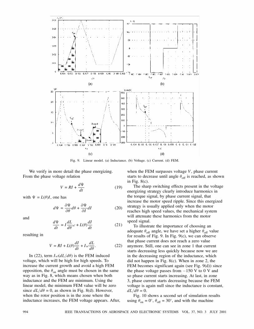
Fig. 9. Linear model. (a) Inductance. (b) Voltage. (c) Current. (d) FEM.
We verify in more detail the phase energizing.From the phase voltage relation
V = RI+dª
dt(19)
with ª = L(µ)I, one has
dª =@ª
@µdµ+
@ª
@IdI (20)
anddª
dt= I
dL
dµ!+L(µ)
dI
dt(21)
resulting in
V = RI+L(µ)dI
dt+ I!
dL
dµ: (22)
In (22), term I!(dL=dµ) is the FEM inducedvoltage, which will be high for high speeds. Toincrease the current growth and avoid a high FEMopposition, the µon angle must be chosen in the sameway as in Fig. 8, which means chosen when bothinductance and the FEM are minimum. Using thelinear model, the minimum FEM value will be zerosince dL=dµ = 0, as shown in Fig. 8(d). However,when the rotor position is in the zone where theinductance increases, the FEM voltage appears. After,
when the FEM surpasses voltage V, phase currentstarts to decrease until angle µoff is reached, as shownin Fig. 8(c).The sharp switching effects present in the voltage
energizing strategy clearly introduce harmonics inthe torque signal, by phase current signal, thatincrease the motor speed ripple. Since this energizedstrategy is usually applied only when the motorreaches high speed values, the mechanical systemwill attenuate these harmonics from the motorspeed signal.To illustrate the importance of choosing an
adequate µoff angle, we have set a higher µoff valuefor results of Fig. 9. In Fig. 9(c), we can observethat phase current does not reach a zero valueanymore. Still, one can see in zone 1 that currentstarts decreasing less quickly because now we arein the decreasing region of the inductance, whichdid not happen in Fig. 8(c). When in zone 2, theFEM becomes significant again (see Fig. 9(d)) sincethe phase voltage passes from ¡150 V to 0 V andso phase current starts increasing. At last, in zone3, phase current starts decreasing because the FEMvoltage is again null since the inductance is constant,dL=dµ = 0.Fig. 10 shows a second set of simulation results
using µon = 0±, µoff = 30
±, and with the machine
994 IEEE TRANSACTIONS ON AEROSPACE AND ELECTRONIC SYSTEMS VOL. 37, NO. 3 JULY 2001
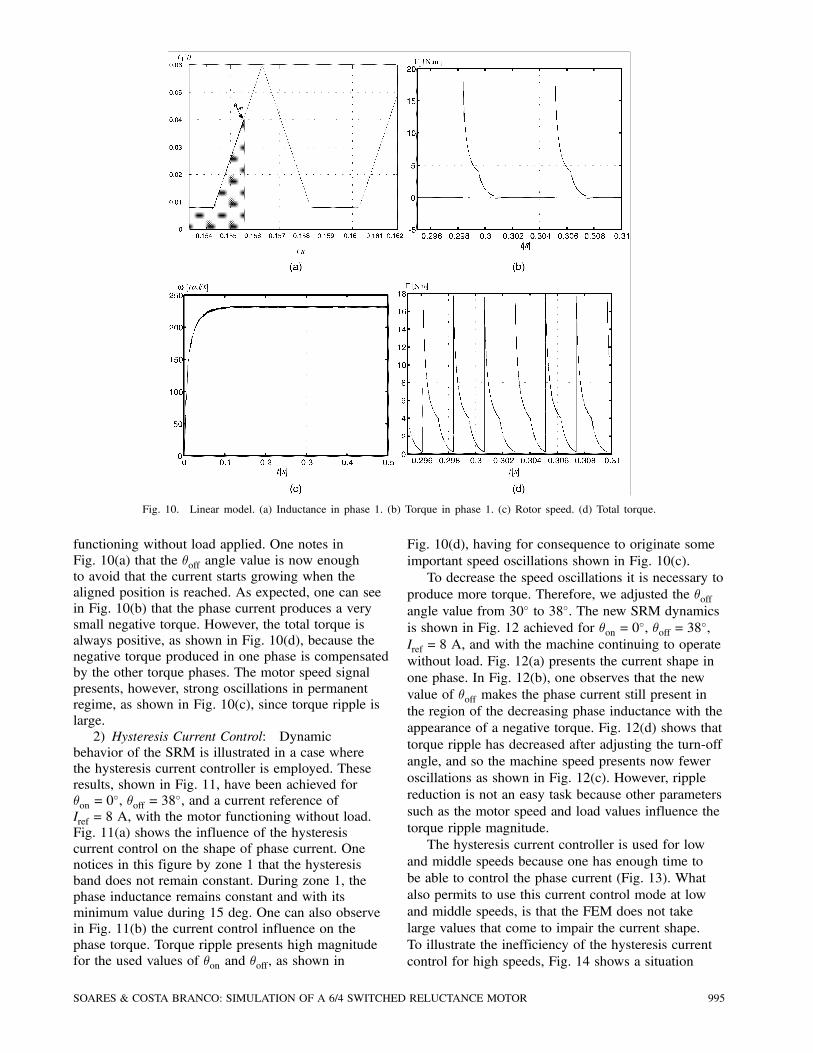
Fig. 10. Linear model. (a) Inductance in phase 1. (b) Torque in phase 1. (c) Rotor speed. (d) Total torque.
functioning without load applied. One notes inFig. 10(a) that the µoff angle value is now enoughto avoid that the current starts growing when thealigned position is reached. As expected, one can seein Fig. 10(b) that the phase current produces a verysmall negative torque. However, the total torque isalways positive, as shown in Fig. 10(d), because thenegative torque produced in one phase is compensatedby the other torque phases. The motor speed signalpresents, however, strong oscillations in permanentregime, as shown in Fig. 10(c), since torque ripple islarge.2) Hysteresis Current Control: Dynamic
behavior of the SRM is illustrated in a case wherethe hysteresis current controller is employed. Theseresults, shown in Fig. 11, have been achieved forµon = 0
±, µoff = 38±, and a current reference of
Iref = 8 A, with the motor functioning without load.Fig. 11(a) shows the influence of the hysteresiscurrent control on the shape of phase current. Onenotices in this figure by zone 1 that the hysteresisband does not remain constant. During zone 1, thephase inductance remains constant and with itsminimum value during 15 deg. One can also observein Fig. 11(b) the current control influence on thephase torque. Torque ripple presents high magnitudefor the used values of µon and µoff, as shown in
Fig. 10(d), having for consequence to originate someimportant speed oscillations shown in Fig. 10(c).To decrease the speed oscillations it is necessary to
produce more torque. Therefore, we adjusted the µoffangle value from 30± to 38±. The new SRM dynamicsis shown in Fig. 12 achieved for µon = 0
±, µoff = 38±,
Iref = 8 A, and with the machine continuing to operatewithout load. Fig. 12(a) presents the current shape inone phase. In Fig. 12(b), one observes that the newvalue of µoff makes the phase current still present inthe region of the decreasing phase inductance with theappearance of a negative torque. Fig. 12(d) shows thattorque ripple has decreased after adjusting the turn-offangle, and so the machine speed presents now feweroscillations as shown in Fig. 12(c). However, ripplereduction is not an easy task because other parameterssuch as the motor speed and load values influence thetorque ripple magnitude.The hysteresis current controller is used for low
and middle speeds because one has enough time tobe able to control the phase current (Fig. 13). Whatalso permits to use this current control mode at lowand middle speeds, is that the FEM does not takelarge values that come to impair the current shape.To illustrate the inefficiency of the hysteresis currentcontrol for high speeds, Fig. 14 shows a situation
SOARES & COSTA BRANCO: SIMULATION OF A 6/4 SWITCHED RELUCTANCE MOTOR 995
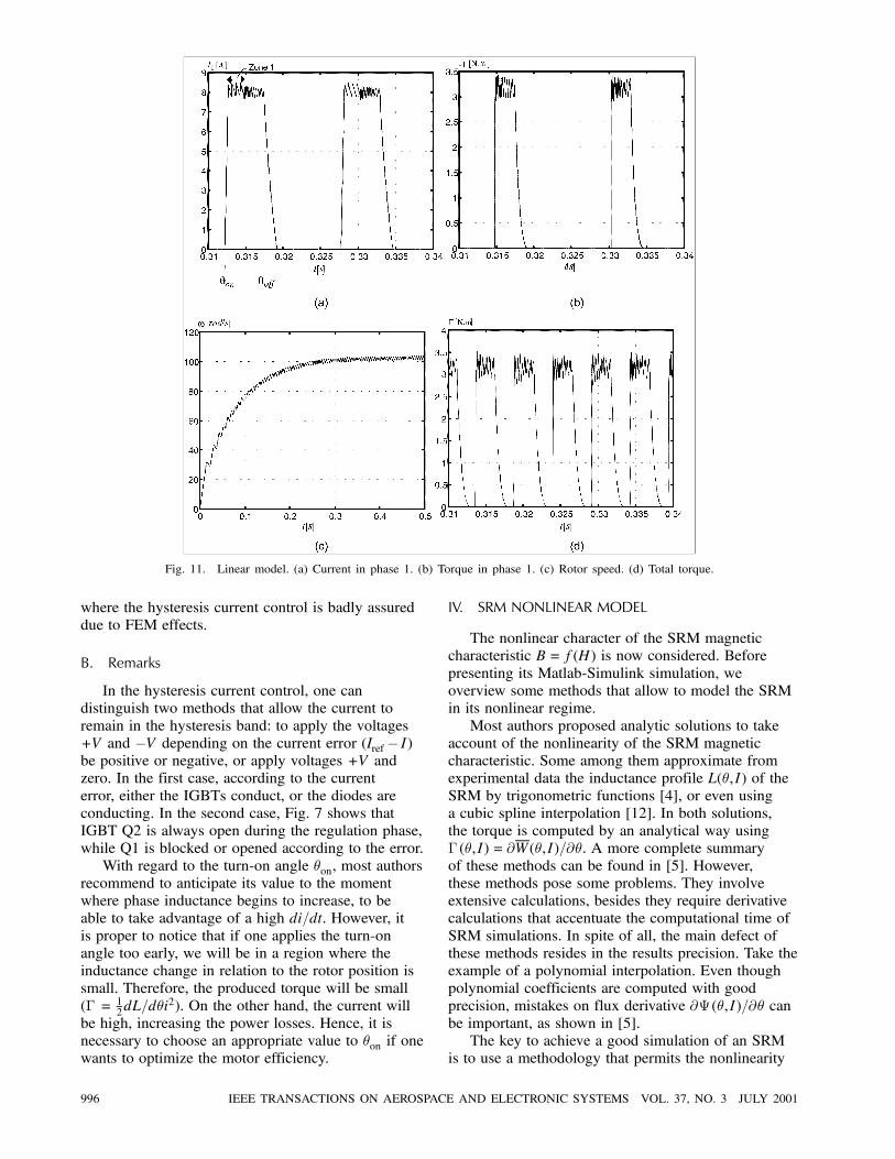
Fig. 11. Linear model. (a) Current in phase 1. (b) Torque in phase 1. (c) Rotor speed. (d) Total torque.
where the hysteresis current control is badly assureddue to FEM effects.
B. Remarks
In the hysteresis current control, one candistinguish two methods that allow the current toremain in the hysteresis band: to apply the voltages+V and ¡V depending on the current error (Iref¡ I)be positive or negative, or apply voltages +V andzero. In the first case, according to the currenterror, either the IGBTs conduct, or the diodes areconducting. In the second case, Fig. 7 shows thatIGBT Q2 is always open during the regulation phase,while Q1 is blocked or opened according to the error.With regard to the turn-on angle µon, most authors
recommend to anticipate its value to the momentwhere phase inductance begins to increase, to beable to take advantage of a high di=dt. However, itis proper to notice that if one applies the turn-onangle too early, we will be in a region where theinductance change in relation to the rotor position issmall. Therefore, the produced torque will be small(¡ = 1
2dL=dµi2). On the other hand, the current will
be high, increasing the power losses. Hence, it isnecessary to choose an appropriate value to µon if onewants to optimize the motor efficiency.
IV. SRM NONLINEAR MODEL
The nonlinear character of the SRM magneticcharacteristic B = f(H) is now considered. Beforepresenting its Matlab-Simulink simulation, weoverview some methods that allow to model the SRMin its nonlinear regime.Most authors proposed analytic solutions to take
account of the nonlinearity of the SRM magneticcharacteristic. Some among them approximate fromexperimental data the inductance profile L(µ,I) of theSRM by trigonometric functions [4], or even usinga cubic spline interpolation [12]. In both solutions,the torque is computed by an analytical way using¡ (µ,I) = @W(µ,I)=@µ. A more complete summaryof these methods can be found in [5]. However,these methods pose some problems. They involveextensive calculations, besides they require derivativecalculations that accentuate the computational time ofSRM simulations. In spite of all, the main defect ofthese methods resides in the results precision. Take theexample of a polynomial interpolation. Even thoughpolynomial coefficients are computed with goodprecision, mistakes on flux derivative @ª (µ,I)=@µ canbe important, as shown in [5].The key to achieve a good simulation of an SRM
is to use a methodology that permits the nonlinearity
996 IEEE TRANSACTIONS ON AEROSPACE AND ELECTRONIC SYSTEMS VOL. 37, NO. 3 JULY 2001
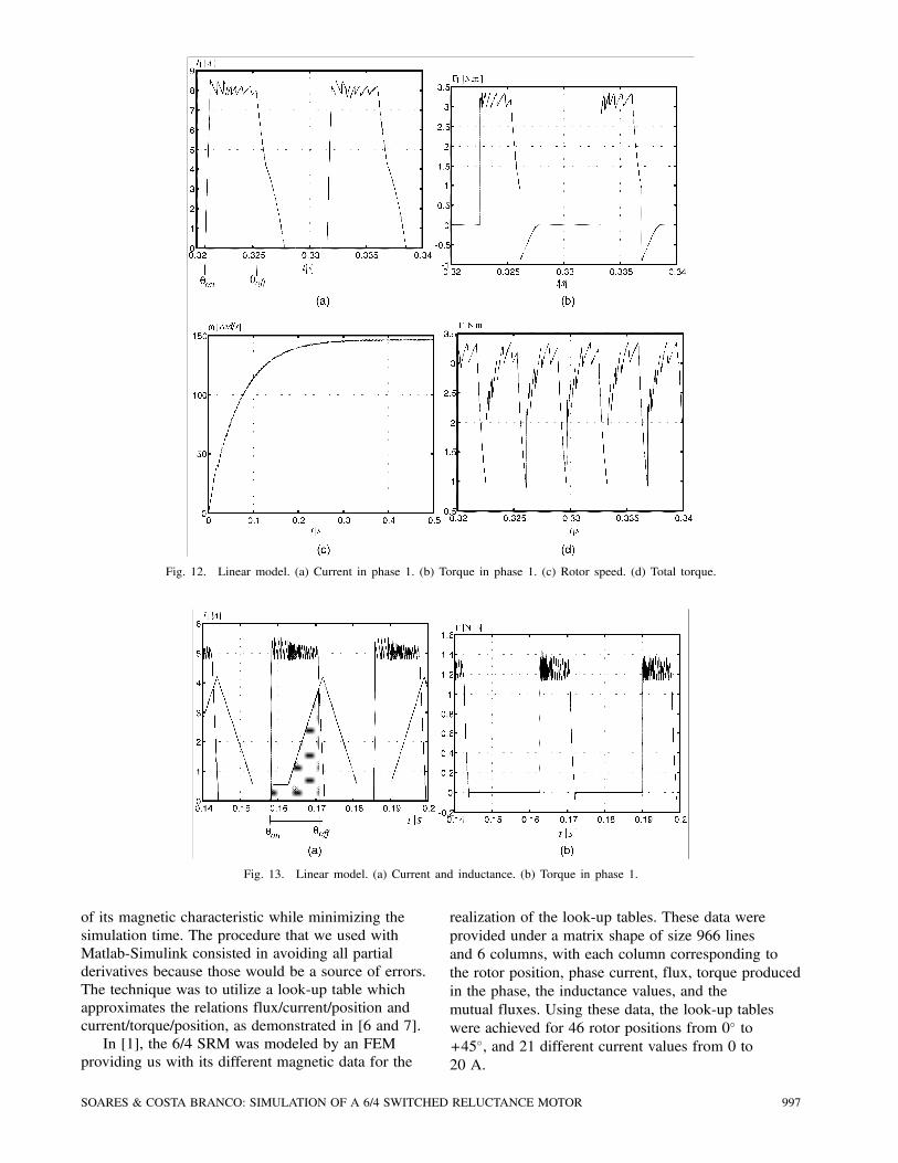
Fig. 12. Linear model. (a) Current in phase 1. (b) Torque in phase 1. (c) Rotor speed. (d) Total torque.
Fig. 13. Linear model. (a) Current and inductance. (b) Torque in phase 1.
of its magnetic characteristic while minimizing thesimulation time. The procedure that we used withMatlab-Simulink consisted in avoiding all partialderivatives because those would be a source of errors.The technique was to utilize a look-up table whichapproximates the relations flux/current/position andcurrent/torque/position, as demonstrated in [6 and 7].In [1], the 6/4 SRM was modeled by an FEM
providing us with its different magnetic data for the
realization of the look-up tables. These data wereprovided under a matrix shape of size 966 linesand 6 columns, with each column corresponding tothe rotor position, phase current, flux, torque producedin the phase, the inductance values, and themutual fluxes. Using these data, the look-up tableswere achieved for 46 rotor positions from 0± to+45±, and 21 different current values from 0 to20 A.
SOARES & COSTA BRANCO: SIMULATION OF A 6/4 SWITCHED RELUCTANCE MOTOR 997
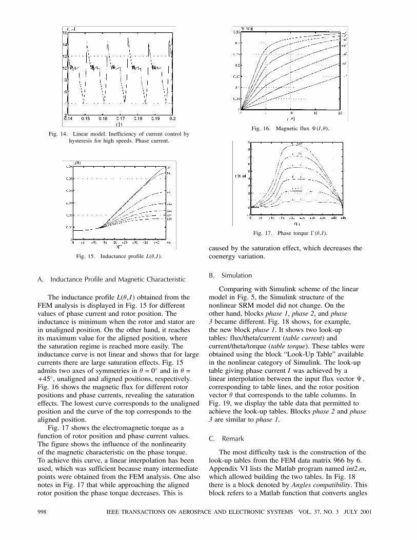
Fig. 14. Linear model. Inefficiency of current control byhysteresis for high speeds. Phase current.
Fig. 15. Inductance profile L(µ,I).
A. Inductance Profile and Magnetic Characteristic
The inductance profile L(µ,I) obtained from theFEM analysis is displayed in Fig. 15 for differentvalues of phase current and rotor position. Theinductance is minimum when the rotor and stator arein unaligned position. On the other hand, it reachesits maximum value for the aligned position, wherethe saturation regime is reached more easily. Theinductance curve is not linear and shows that for largecurrents there are large saturation effects. Fig. 15admits two axes of symmetries in µ = 0± and in µ =+45±, unaligned and aligned positions, respectively.Fig. 16 shows the magnetic flux for different rotorpositions and phase currents, revealing the saturationeffects. The lowest curve corresponds to the unalignedposition and the curve of the top corresponds to thealigned position.Fig. 17 shows the electromagnetic torque as a
function of rotor position and phase current values.The figure shows the influence of the nonlinearityof the magnetic characteristic on the phase torque.To achieve this curve, a linear interpolation has beenused, which was sufficient because many intermediatepoints were obtained from the FEM analysis. One alsonotes in Fig. 17 that while approaching the alignedrotor position the phase torque decreases. This is
Fig. 16. Magnetic flux ª (I,µ).
Fig. 17. Phase torque ¡ (µ,I).
caused by the saturation effect, which decreases thecoenergy variation.
B. Simulation
Comparing with Simulink scheme of the linearmodel in Fig. 5, the Simulink structure of thenonlinear SRM model did not change. On theother hand, blocks phase 1, phase 2, and phase3 became different. Fig. 18 shows, for example,the new block phase 1. It shows two look-uptables: flux/theta/current (table current) andcurrent/theta/torque (table torque). These tables wereobtained using the block “Look-Up Table” availablein the nonlinear category of Simulink. The look-uptable giving phase current I was achieved by alinear interpolation between the input flux vector ª ,corresponding to table lines, and the rotor positionvector µ that corresponds to the table columns. InFig. 19, we display the table data that permitted toachieve the look-up tables. Blocks phase 2 and phase3 are similar to phase 1.
C. Remark
The most difficulty task is the construction of thelook-up tables from the FEM data matrix 966 by 6.Appendix VI lists the Matlab program named int2.m,which allowed building the two tables. In Fig. 18there is a block denoted by Angles compatibility. Thisblock refers to a Matlab function that converts angles
998 IEEE TRANSACTIONS ON AEROSPACE AND ELECTRONIC SYSTEMS VOL. 37, NO. 3 JULY 2001
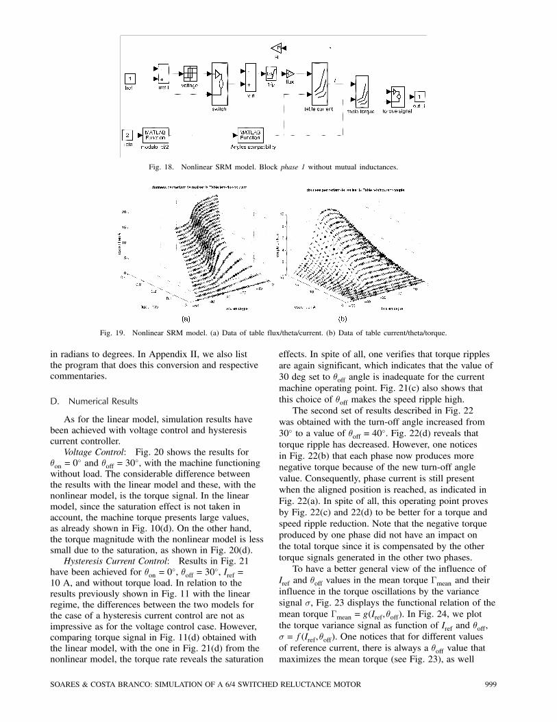
Fig. 18. Nonlinear SRM model. Block phase 1 without mutual inductances.
Fig. 19. Nonlinear SRM model. (a) Data of table flux/theta/current. (b) Data of table current/theta/torque.
in radians to degrees. In Appendix II, we also listthe program that does this conversion and respectivecommentaries.
D. Numerical Results
As for the linear model, simulation results havebeen achieved with voltage control and hysteresiscurrent controller.Voltage Control: Fig. 20 shows the results for
µon = 0± and µoff = 30
±, with the machine functioningwithout load. The considerable difference betweenthe results with the linear model and these, with thenonlinear model, is the torque signal. In the linearmodel, since the saturation effect is not taken inaccount, the machine torque presents large values,as already shown in Fig. 10(d). On the other hand,the torque magnitude with the nonlinear model is lesssmall due to the saturation, as shown in Fig. 20(d).Hysteresis Current Control: Results in Fig. 21
have been achieved for µon = 0±, µoff = 30
±, Iref =10 A, and without torque load. In relation to theresults previously shown in Fig. 11 with the linearregime, the differences between the two models forthe case of a hysteresis current control are not asimpressive as for the voltage control case. However,comparing torque signal in Fig. 11(d) obtained withthe linear model, with the one in Fig. 21(d) from thenonlinear model, the torque rate reveals the saturation
effects. In spite of all, one verifies that torque ripplesare again significant, which indicates that the value of30 deg set to µoff angle is inadequate for the currentmachine operating point. Fig. 21(c) also shows thatthis choice of µoff makes the speed ripple high.The second set of results described in Fig. 22
was obtained with the turn-off angle increased from30± to a value of µoff = 40
±. Fig. 22(d) reveals thattorque ripple has decreased. However, one noticesin Fig. 22(b) that each phase now produces morenegative torque because of the new turn-off anglevalue. Consequently, phase current is still presentwhen the aligned position is reached, as indicated inFig. 22(a). In spite of all, this operating point provesby Fig. 22(c) and 22(d) to be better for a torque andspeed ripple reduction. Note that the negative torqueproduced by one phase did not have an impact onthe total torque since it is compensated by the othertorque signals generated in the other two phases.To have a better general view of the influence of
Iref and µoff values in the mean torque ¡mean and theirinfluence in the torque oscillations by the variancesignal ¾, Fig. 23 displays the functional relation of themean torque ¡mean = g(Iref,µoff). In Fig. 24, we plotthe torque variance signal as function of Iref and µoff,¾ = f(Iref,µoff). One notices that for different valuesof reference current, there is always a µoff value thatmaximizes the mean torque (see Fig. 23), as well
SOARES & COSTA BRANCO: SIMULATION OF A 6/4 SWITCHED RELUCTANCE MOTOR 999
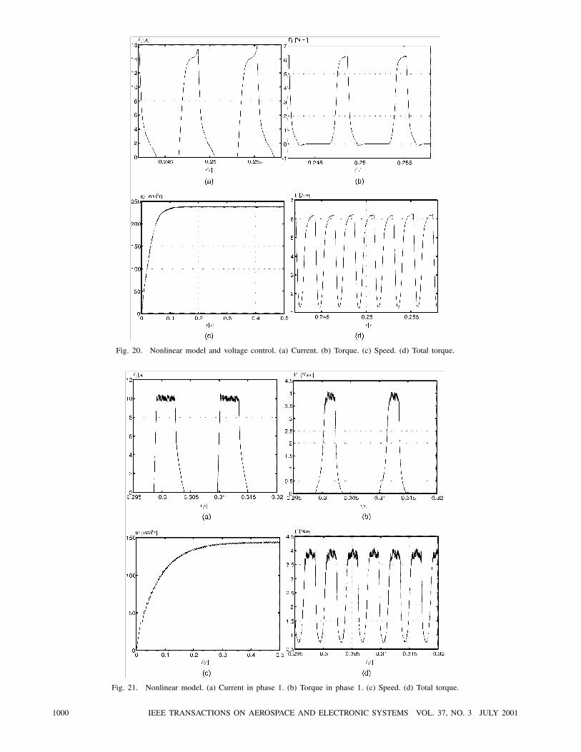
Fig. 20. Nonlinear model and voltage control. (a) Current. (b) Torque. (c) Speed. (d) Total torque.
Fig. 21. Nonlinear model. (a) Current in phase 1. (b) Torque in phase 1. (c) Speed. (d) Total torque.
1000 IEEE TRANSACTIONS ON AEROSPACE AND ELECTRONIC SYSTEMS VOL. 37, NO. 3 JULY 2001
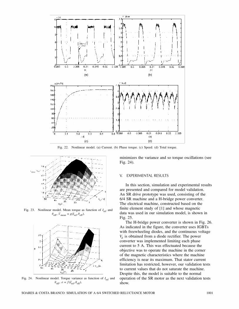
Fig. 22. Nonlinear model. (a) Current. (b) Phase torque. (c) Speed. (d) Total torque.
Fig. 23. Nonlinear model. Mean torque as function of Iref andµoff, ¡mean = g(Iref,µoff).
Fig. 24. Nonlinear model. Torque variance as function of Iref andµoff, ¾ = f(Iref,µoff).
minimizes the variance and so torque oscillations (seeFig. 24).
V. EXPERIMENTAL RESULTS
In this section, simulation and experimental resultsare presented and compared for model validation.An SR drive prototype was used, consisting of the6/4 SR machine and a H-bridge power converter.The electrical machine, constructed based on thefinite element study of [1] and whose magneticdata was used in our simulation model, is shown inFig. 25.The H-bridge power converter is shown in Fig. 26.
As indicated in the figure, the converter uses IGBTswith freewheeling diodes, and the continuous voltageVd is obtained from a diode rectifier. The powerconverter was implemented limiting each phasecurrent to 5 A. This was effectuated because theobjective was to operate the machine in the cornerof the magnetic characteristics where the machineefficiency is near its maximum. That stator currentlimitation has restricted, however, our validation teststo current values that do not saturate the machine.Despite this, the model is suitable to the normaloperation of the SR motor as the next validation testsshow.
SOARES & COSTA BRANCO: SIMULATION OF A 6/4 SWITCHED RELUCTANCE MOTOR 1001
Fig. 25. Stator and rotor elements of built 6/4 SRM.
Fig. 26. H-bridge power converter.
A hysteresis current controller is used with themicrocomputer establishing the energizing anddeenergizing angles, and the reference current signal.With the prototype, tests could be initiated
to verify the developed SRM model. They wereeffectuated with the SR drive system operating inopen-loop mode and for a set of different operatingconditions.Fig. 27(a) shows the SR motor phase current
measured when the machine operates for a currentreference of 2 A, nominal dc voltage, using the µonand µoff parameters listed in Table I. In Fig. 51(b) thesame operating conditions have been simulated using
Fig. 27. Comparison of measured (a) and simulated (b) motor phase currents (Table I).
TABLE IOperating Parameters of SRM Model and Prototype
Vd = 150 V Iref = 2 A µon = 0± µoff = 22
±
the developed model and same sampling time. A closecorrelation simulated with experimental currents canbe observed.In Fig. 28(a) and (b) the experimental and
simulated results are shown when the drive operateswith a lower dc voltage (Vd = 100 V). The otheroperating parameters remained the same, as shownin Table I.In the previous tests, the hysteresis current
controller was considered. For a voltage control test,the motor operated with 30 V of dc voltage, usingthe parameters listed in Table II. By comparing theexperimental measured current shown in Fig. 29(a)with the simulated waveform in Fig. 29(b), it is seenthat the waveforms are almost identical.A commonly applied procedure that can be
considered as a test of the model validity forsimulation is to compare measured and simulatedsteady-state characteristics. For comparison ofthe motor steady-state operation obtained withthe model and the experimental prototype, twotests were effectuated. These tests considered tworeference current values, Iref = 1:5 A and Iref = 2:5 A,and variation of the µoff angle from 40 to 67 deg.Fig. 30(a) and (b) and Table III show the measuredand simulated motor speed obtained for 1.5 A and2.5 A, respectively. From the figures, it is seen thatthe steady-state responses of the model matches themeasured data well.
VI. CONCLUSION
This paper has described and discussed in detailhow from Matlab-Simulink one can achieve thesimulation environment for an SR motor. We verified
1002 IEEE TRANSACTIONS ON AEROSPACE AND ELECTRONIC SYSTEMS VOL. 37, NO. 3 JULY 2001
Fig. 28. Comparison of measured (a) and simulated (b) motor phase currents (Table I with Vd = 100 V).
Fig. 29. Comparison of measured (a) and simulated (b) motor phase currents using the voltage control method with the parameterslisted in Table II.
Fig. 30. Steady-state performance. Measured and simulated motor speeds. (a) Results for Iref = 1:5 A. (b) Iref = 2:5 A using parameterslisted in Table III.
TABLE IIOperating Parameters of SRM Model and Prototype
Vd = 30 V Iref = 2 A µon = 0± µoff = 30
±
TABLE IIIOperating Parameters of SRM Model and Prototype
Vd = 150 V µon = 0±
SOARES & COSTA BRANCO: SIMULATION OF A 6/4 SWITCHED RELUCTANCE MOTOR 1003

that to analyze with precision the torque oscillationsof an SRM, a simulation study using its linear modelis not appropriate. Several simulations have beenachieved in order to study the dynamic behavior ofthe SRM. We mainly verified the influence of theturn-off angle µoff in its dynamic behavior. It wasproved dependent of the machine’s operating pointand that exists a µoff value, which allow torque ripplereduction.
For model validation, phase current either forhysteresis and voltage control strategies, and thesteady-state systems operation data were measuredand compared with the estimated model responses.The validation study indicated that using thedeveloped model, enough accurate results can beobtained with it.
APPENDIX I
1004 IEEE TRANSACTIONS ON AEROSPACE AND ELECTRONIC SYSTEMS VOL. 37, NO. 3 JULY 2001

APPENDIX II
APPENDIX III
SOARES & COSTA BRANCO: SIMULATION OF A 6/4 SWITCHED RELUCTANCE MOTOR 1005

APPENDIX IV
APPENDIX V
1006 IEEE TRANSACTIONS ON AEROSPACE AND ELECTRONIC SYSTEMS VOL. 37, NO. 3 JULY 2001

APPENDIX VI
SOARES & COSTA BRANCO: SIMULATION OF A 6/4 SWITCHED RELUCTANCE MOTOR 1007
REFERENCES
[1] Nascimento, J., Rolim, L., Heidrich, P., et al. (1996)Design and simulation aspects of a switched reluctancedrive.In Proceedings of the 4± Brazilian Power ElectronicsConference (COBEP96), Sao Paulo, 1996, 79—83.
[2] Miller, T. J. E. (1993)Switched Reluctance Motors and Their Control.Oxford, UK: Magma Physics Publishing and ClarendonPress-Oxford, 1993.
[3] Lawrenson, P. J., Stephenson, J. M., Blenkinsop, P. T.,Corda, J., and Fulton, N. N. (1980)Variable-speed switched reluctance motor.IEE Proceedings Inst. Elect. Eng., 127, 4 (June 1980),253—265.
[4] Henao, H., Capolino, G. A., Bassily, E., and Poloujadoff, M.(1997)A new control angle strategy for switched reluctancemotor.In Proceedings of EPE ’97, 3 (1997), 613—618.
[5] Stephenson, J. M., and Corda, J. (1979)Computation torque and current in doubly salientreluctance motors from nonlinear magnetization data.IEE Proceedings, 126, 5 (May 1979), 393—396.
[6] Elliot, C. R., Stephenson, J. M., and McClelland, M. L.(1995)Advances in switched reluctance drive system dynamicsimulation.In Proceedings of EPE ’95, 3 (1995), 622—626.
[7] Rodrigues, M., Suemitsu, W. I., Costa Branco, P. J., Dente,J. A., and Rolim, L. G. (1997)Fuzzy logic control for a switched reluctance motor.IEEE International Symposium on Industrial Electronics(ISIE ’97), 2 (June 1997), 527—531.
[8] Rodrigues, M., Costa Branco, P. J., and Suemitsu, W.Fuzzy logic torque ripple reduction by turn-off anglecompensation for switched reluctance motors.IEEE Transactions on Industrial Electronics, 48, 3 (June2001), 711—715. (Available as a technical report athttp://pbranco.ist.utl.pt).
[9] Henriques, L., Rolim, L., Suemitsu, W., Costa Branco, P. J.,and Dente, J. A.Torque ripple minimization in a switched reluctance driveby neuro-fuzzy compensation.IEEE Transactions on Magnetics, 36, 5 (Sept.2000), 3592—3594. (Available as technical report athttp://pbranco.ist.utl.pt).
[10] Costa Branco, P. J. (2000)Influence of magnetic nonlinearities on simulationaccuracy of switched reluctance motor models.In Systems and Control: Theory and Applications, WorldScientific and Engineering Society Press, 403—408.(Available as technical report at http://pbranco.ist.utl.pt)
[11] Bose, B. K., Miller, T. J. E., and Szczesny, P. M. (1986)Microcomputer control of switched reluctance motor.IEEE Transactions on Industry Applications, IA-22, 4(June 1986), 708—715.
[12] Pulle, D. W. J., and Petersen, I. R. (1997)A generalized approach to torque and currentcomputation.In Proceedings of EPE ’97, 3 (1997), 547—551.
[13] Franceschini, G., Pirani, S., Rinaldi, M., and Tassoni, C.(1991)SPICE assisted simulation of controlled electric drives:An application to switched reluctance drives.IEEE Transactions on Industry Applications, 27, 6(Nov./Dec. 1991), 1103—1110.
[14] Ichinokura, O., Onda, T., Kimura, M., Watanabe, T., Yanada,T., and Guo, H. J. (1998)Analysis of dynamic characteristics of switchedreluctance motor based on SPICE.IEEE Transactions on Magnetics, 34, 4 (1998),2147—2149.
[15] Skvarenina, Wasynczuk, Krause (1996)Simulation of a switched reluctance generator/moreelectric aircraft power system.In Proceedings of 1996 IECEC, paper 96398.
1008 IEEE TRANSACTIONS ON AEROSPACE AND ELECTRONIC SYSTEMS VOL. 37, NO. 3 JULY 2001
[16] Radun, X. (1995)Switched reluctance starter/generator modeling results.In Proceedings of SAE Aerospace Atlantic Conference,1995, paper 951407.
[17] Pekarek, S. D., Wasynczuk, O., and Hegner, H. J. (1998)An efficient and accurate model for the simulation andanalysis of synchronous machine/converter systems.IEEE Transactions on Energy Conversion (Mar. 1998),42—49.
F. Soares graduated in power electronics from the French Engineering School ENSEM Nancy. He did histraining period in the Department of Electrical and Computing Engineering, Section of Electrical Machines andPower Electronics, in the Instituto Superior Tecnico.He is currently working for Alcatel Microelectronics in Belgium. He is currently responsible for the test of a
chip dedicated to power battery management. He is also involved in analog design.
P. J. Costa Branco is currently an Assistant Professor in the Department ofElectrical and Computing Engineering, Section of Electrical Machines and PowerElectronics, in the Instituto Superior Tecnico (IST), Lisbon, Portugal, and hasbeen with the Mechatronics Laboratory/DEEC-IST since 1992. His researchareas are in control of electrical drives, systems modeling and control usingsoft computing techniques, and he is presently engaged in research on advancedlearning control techniques for electromechanical systems.Dr. Costa Branco has been a referee of international scientific journals and
participated in boards of international meetings. He is the author of publishedarticles in international scientific journals such as the IEEE Transactions onMagnetics, IEEE Transactions on System, Man, and Cybernetics, IEEE Transactionson Fuzzy Systems, IEEE Transactions on Industrial Electronics, Pattern RecognitionLetters, Fuzzy Sets and Systems, and European Transactions on Electrical PowerEngineering.
[18] Ong, C-M. (1998)Dynamic Simulation of Electric Machinery usingMatlab/Simulink.Englewood Cliffs, NJ: Prentice-Hall, 1998.
SOARES & COSTA BRANCO: SIMULATION OF A 6/4 SWITCHED RELUCTANCE MOTOR 1009


