Embed Size (px)
Citation preview

This article appeared in a journal published by Elsevier. The attachedcopy is furnished to the author for internal non-commercial researchand education use, including for instruction at the authors institution
and sharing with colleagues.
Other uses, including reproduction and distribution, or selling orlicensing copies, or posting to personal, institutional or third party
websites are prohibited.
In most cases authors are permitted to post their version of thearticle (e.g. in Word or Tex form) to their personal website orinstitutional repository. Authors requiring further information
regarding Elsevier’s archiving and manuscript policies areencouraged to visit:
http://www.elsevier.com/copyright

Author's personal copy
Applied Catalysis A: General 413– 414 (2012) 1– 9
Contents lists available at SciVerse ScienceDirect
Applied Catalysis A: General
j ourna l ho me page: www.elsev ier .com/ locate /apcata
New efficient visible light photocatalyst based on heterojunction ofBiOCl–bismuth oxyhydrate
Sanaa Shenawi-Khalil a, Vladimir Uvarovb,∗, Ella Menesa, Inna Popovb, Yoel Sassona
a Casali Institute of Applied Chemistry, The Institute of Chemistry, The Hebrew University of Jerusalem, Israelb The Unit for Nanoscopic Characterization, The Harvey M. Krueger Center for Nanoscience and Nanotechnology, The Hebrew University of Jerusalem, Israel
a r t i c l e i n f o
Article history:Received 12 July 2011Received in revised form25 September 2011Accepted 18 October 2011Available online 25 October 2011
Keywords:Visible light photocatalysisHeteroconjuctionBismuth oxyhydrateBismuth hydroxideBismuth oxychlorideThermal decomposition
a b s t r a c t
A novel active photocatalyst, which is a heteroconjuction of a bismuth oxyhydrate and BiOCl, has beensynthesized by a simple hydrothermal method. The photocatalytic activity of the new material was mea-sured in the degradation of Rhodamine B (RhB) and Acetophenone (AP) and in the photocatalytic oxidationof iodide in water under UV–vis and visible light irradiations respectively. The heterojunction betweenbismuth oxyhydrate and BiOCl provided exceptional photocatalytic activity, whereas both the individ-ual bismuth oxyhydrate and BiOCl showed a negligible efficiency. Compared to Degussa P25, the newcomposite material demonstrated 5 times higher activity in removing aqueous RhB under visible light(� ≥ 420 nm) irradiation. The chemical composition and crystal structure were investigated using powderX-ray diffraction, scanning and transmission electron microscopy, and thermal methods. The preliminarystudy has revealed the bismuth oxyhydrate has tetragonal crystal structure with unit cell parametersa = b = 5.674 A, c = 10.353 A, unit cell volume V = 333.3 A3 and possible P4/mmm (No. 123) space group.Temperature behavior of new photocatalyst has been investigated. It was found that at heating to 550 ◦Cfor 45 min the new phase transforms into well-known monoclinic Bi2O3.
© 2011 Elsevier B.V. All rights reserved.
1. Introduction
The development of visible light induced photocatalysts is ofgreat importance for the efficient utilization of solar energy orindoor artificial light in the photocatalytic degradation of organicpollutants and splitting of water [1,2]. TiO2 has proven to be themost effective photocatalyst for the oxidative decomposition ofnumerous compounds. However, its photocatalytic activity in vis-ible light is extremely low due to its wide band gap (3–3.2 eV) thatlimits its further applications in the visible region, thus makingimpractical overall technological process based on TiO2 [3,4].
Nowadays, two strategies have been employed in the design ofvisible-light-driven photocatalysts. First strategy employs modifi-cation of TiO2 by doping or by producing heterojunction betweenTiO2 and another material (that is making the interface betweenthe semiconductors with unequal band gaps as opposed to a homo-junction). Doping by foreign elements is one of the most successfulways to alter the structure of the host semiconducting materialand improve its properties. For example, doping by nitrogen ortransition metal cations was used to extend the optical absorp-tion of TiO2-, ZnO- and Bi2O3-based systems to visible-light regionand to improve their photocatalytic properties and structural
∗ Corresponding author. Fax: +972 2 6584809.E-mail address: [email protected] (V. Uvarov).
stability [5–20]. The second approach involves exploration of novelsemiconductor materials capable of absorbing visible light [21].Chemical compounds containing Bi(III), such as BiVO4 [22], Bi2WO6[23], CaBi2O4 [24], PbBi2Nb2O9 [25], Bi4Ti3O12 [26], and others[27–29] have been reported to be promising photocatalysts undervisible light irradiation.
Recently, bismuth oxyhalides also have been established aseffectual photocatalysts for the degradation of aqueous dyes underUV irradiation [30–35]. Bismuth oxyhalides can be applied as chem-ical catalysts [36,37], ferroelectric materials [38,39], and pigments[40]. Bismuth oxychloride is one of the simplest members of theSillen family phases which is expressed either as [Bi2O2][Clm] or[Bi3O4+n][Clm] (m = 1÷3) where bismuth oxide based fluorite-likelayers, [Bi2O2] or [Bi3O4+n], are inter-grown with double chlo-rine layers [41]. Bi-based oxychlorides have drawn considerableattention due to their potential application as novel photocatalystsowing to their unique layered structures and high photocorrosionstability [42–45]. BiOCl was the first oxyhalide to be used as pho-tocatalyst [30]. Many routes have been applied to synthesize thesecompounds. Zhang et al. prepared BiOCl powders by acid hydroly-sis of Bi2O3 in excess HCl and reported the photocatalytic activityfor Methyl Orange degradation under UV light to be higher thanDegussa P25 (TiO2) [41]. Wang and co-workers reported the pho-tocatalytic degradation of RhB over BiOCl and Bi2O3 nano-fibersobtained by electrospinning [45]. However, BiOCl is a wide bandgap (indirect 3.46 eV) semiconductor with a band gap higher than
0926-860X/$ – see front matter © 2011 Elsevier B.V. All rights reserved.doi:10.1016/j.apcata.2011.10.029

Author's personal copy
2 S. Shenawi-Khalil et al. / Applied Catalysis A: General 413– 414 (2012) 1– 9
that of TiO2 (anatase), and thus can only absorb ultraviolet light,which is merely about 3% of the solar energy spectrum [33]. Becauseof this inherent limitation, the abundant solar energy cannot be uti-lized efficiently. Very recently, the novel heterojunction structurebetween Bi2O3 and BiOCl has been proved to give a high photo-catalytic activity in decomposing gaseous 2-propanol and aqueous1,4-terephthalic acid under visible light (� ≥ 420 nm), whereas theindividual BiOCl and Bi2O3 showed a negligible efficiency. In thisBiOCl/Bi2O3 system the BiOCl seems to work as main photocatalyst,while the role of Bi2O3 is a sensitizer absorbing visible light [46].The family of bismuth oxides attracts much attention of researchersin various areas. Numerous experimental data related to Bi oxideswere recently summarized in a comprehensive review authoredby Mehring [47]. Up to date six polymorphs of Bi2O3 [48,49] andseveral non-stoichiometric have been reported [50–53].
In the present study we report on synthesis and properties ofa novel photocatalyst obtained by heterojunction between BiOCland bismuth oxyhydrate. The new composite material showed anextraordinary photocatalytic activity in aqueous RhB photodegra-dation system. The photocatalytic activity of this material was alsostudied in the decomposition of AP and in the photooxidation ofpotassium iodide (KI) under UV–vis and visible light irradiationsrespectively.
2. Experimental
2.1. Synthesis
The powders of new photocatalyst were synthesized by a sim-ple hydrothermal method. All the reagents were purchased fromSigma Aldrich and were used as received without further purifi-cation. In a typical synthesis, Bi(NO3)3·5H2O (99.0%) (10 mmol)and Ca(NO3)2·4H2O (99.0%) (1 mmol) were mixed with distilledwater (40 mL) and stirred at room temperature for 5 min. Subse-quently, NH4OH (30.0%) (17 mL) was added dropwise. An additionof Ca(NO3)2·4H2O was performed to promote formation of dopedBi-based semiconducting structure in the reaction product. Thesuspension solution was poured into a stainless steel Teflon-linedautoclave for the hydrothermal treatment. The autoclave wassealed, heated up to 150 ◦C and held for 14 h, and then cooled toroom temperature naturally. The final solid was separated by fil-tration and washed thoroughly with water. In the final step, thesolid was treated for 3 min with 50 mL water containing adjustedamount of HCl and then dried at air.
Pure bismuth oxyhydrate (hereafter BHO) and BiOCl were pre-pared separately. For preparation of bismuth oxyhydrate the aboveprocedure was repeated without addition of HCl, i.e. after thehydrothermal treatment, the solid was purified by thoroughlywashing in water and then dried at ambient conditions. BiOCl wasprepared using large excess of HCl (≥0.3 M) and without addi-tion of Ca(NO3)2·4H2O. Typically, a yBiOCl–(1 − y)BHO compositewith y = 0.8 was prepared by using 0.15 M of HCl. In order to eluci-date the role of Ca-doping, 0.8BiOCl–0.2BHO was prepared underidentical conditions without using Ca(NO3)2·4H2O and denoted as0.0Ca–0.8BiOCl–0.2BHO.
Particulate TiO2 (particle diameter 30 nm, surface area50 m2 g−1, product name P25) is commercially available fromDegussa Corp. and it was used as a reference photocatalyst.
2.2. Photocatalytic activity test
Photocatalytic activities of the new photocatalyst powders wereevaluated using two types of reactions: the photo-bleaching ofwater organic pollutants: Rhodamine B (RhB) and Acetophenone(AP) and the photocatalytic oxidation of iodide under UV–vis
(385–740 nm) and visible light (� ≥ 420 nm) irradiations. Exper-iments were carried out in a 250 mL cylindrical-shaped-glassreactor at room temperature in air and at neutral pH conditions.A suspension of 100 mg photocatalyst and 200 mL aqueous solu-tion of RhB (15 ppm) or AP (120 ppm) or KI (25 mmol L−1) wasmagnetically stirred for 2 h or more before irradiation to estab-lish an adsorption–desorption equilibrium. The reactor was thenirradiated by a 300 W Xe arc lamp (Max-302, Asahi spectra).Power consumption of Max-302 is 500 VA. The emission spec-trum is shown in Fig. S1a (see Supplementary material). The lampis equipped with visible mirror (Fig. S1b, Supplementary mate-rial). This unit consists of several multicoated filters to blockunwanted energy from Xenon lamp and only desired throughput(385–740 nm) is obtainable. For visible light experiments a 420 nmcutoff filter was used. The light intensity was fixed on 70 mW/cm2
when the reactor was placed 10 cm away from the light’s sourcemirror. At specific time intervals, 4 mL suspensions were sampledand centrifuged at 6000 rpm for 10 min to remove the photocata-lyst powder. The concentration of remnant RhB or AP in solutionafter irradiation was analyzed with a UV–vis spectrophotometer(Varian EL-03097225) by recording the variations of the absorp-tion band maximum at � = 554 nm and � = 235 nm respectively. Thedegradation efficiency (DE) of each catalyst was computed usingthe following equation:
DE (%) = 100 × C0 − C
C0(1)
where C is the concentration of RhB (or AP) at the time interval t andC0 is the concentration after the adsorption equilibrium is reachedbefore irradiation.
The tri-iodide production was also spectrophotochemicallymonitored by measuring the absorbance at 352 nm.
RhB was chosen as a typical model compound since dyes areimportant water pollutants. Most of the dyes are resistant tobiodegradation and direct photolysis, and many N-containing dyessuch as RhB undergo natural reductive anaerobic degradation toyield potentially carcinogenic aromatic amines [53]. Acetophenoneis a common colorless water pollutant. To differentiate from thephotodecomposition of organics which is categorized as a downhillreaction and is thermodynamically preferable, we also studied thephotooxidation of KI which is an uphill reaction (+51 kJ/mol). Pro-duction of energy-carrying materials through thermodynamicallyuphill reactions is an important objective of solar energy conversionand storage.
In experiments requiring radical scavengers, excess amount of1.0 mM benzoquinone (BQ) or KBrO3 and 500 mM isopropanol (IPA)were introduced to RhB solution before the addition of catalyst.
Fluorescence spectra of 2-hydroxyterephthalic acid were mea-sured on Varian Cary Eclipsed fluorescence spestrophotometer-0010075200. The OH• radical trapping experiments were carriedout using the following procedure: terephthalic acid (TA) (16.6 mg)was first dissolved in 200 mL dilute NaOH solution (2 × 10⁻³ M),followed by addition of 100 mg photocatalysts. The suspensionwas irradiated by 300 W Xenon lamp at wavelength range of385–740 nm for 60 min. The fluorescence emission spectrum of thesolution was measured every 10 min during illumination.
2.3. Material characterization
Morphological observations and identification of the chemicalcomposition were performed by the environmental scanning elec-tron microscope (ESEM) Quanta 200 (FEI Company, USA) equippedwith EDS detector (EDAX-TSL, USA). Pure �-Bi2O3 (Aldrich) wasused for checking the accuracy of standardless quantification of EDSresults. For quantitative analysis the EDS spectra were acquired at30 kV accelerating voltage. XRD measurements were performed on
Author's personal copy
S. Shenawi-Khalil et al. / Applied Catalysis A: General 413– 414 (2012) 1– 9 3
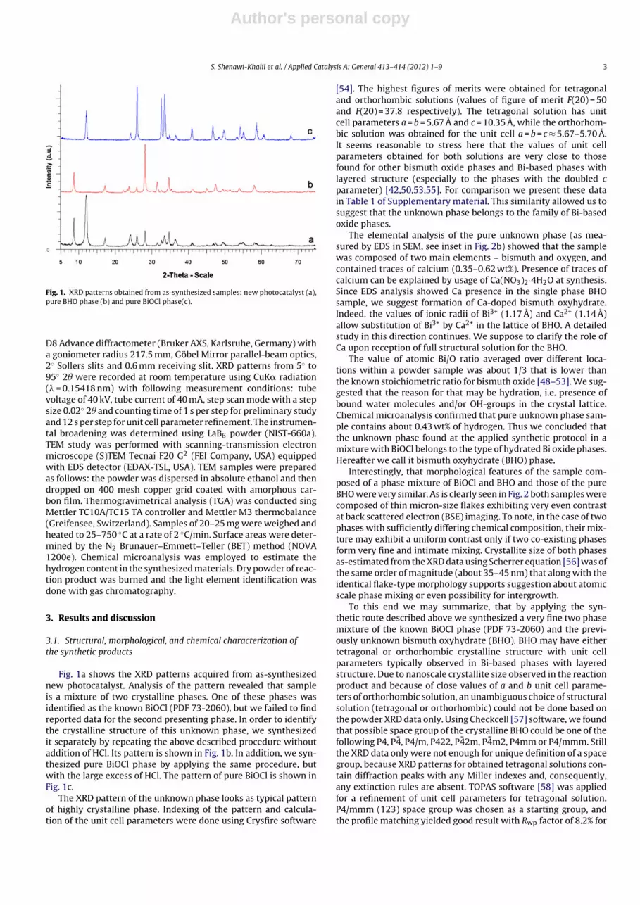
Fig. 1. XRD patterns obtained from as-synthesized samples: new photocatalyst (a),pure BHO phase (b) and pure BiOCl phase(c).
D8 Advance diffractometer (Bruker AXS, Karlsruhe, Germany) witha goniometer radius 217.5 mm, Göbel Mirror parallel-beam optics,2◦ Sollers slits and 0.6 mm receiving slit. XRD patterns from 5◦ to95◦ 2� were recorded at room temperature using CuK� radiation(� = 0.15418 nm) with following measurement conditions: tubevoltage of 40 kV, tube current of 40 mA, step scan mode with a stepsize 0.02◦ 2� and counting time of 1 s per step for preliminary studyand 12 s per step for unit cell parameter refinement. The instrumen-tal broadening was determined using LaB6 powder (NIST-660a).TEM study was performed with scanning-transmission electronmicroscope (S)TEM Tecnai F20 G2 (FEI Company, USA) equippedwith EDS detector (EDAX-TSL, USA). TEM samples were preparedas follows: the powder was dispersed in absolute ethanol and thendropped on 400 mesh copper grid coated with amorphous car-bon film. Thermogravimetrical analysis (TGA) was conducted singMettler TC10A/TC15 TA controller and Mettler M3 thermobalance(Greifensee, Switzerland). Samples of 20–25 mg were weighed andheated to 25–750 ◦C at a rate of 2 ◦C/min. Surface areas were deter-mined by the N2 Brunauer–Emmett–Teller (BET) method (NOVA1200e). Chemical microanalysis was employed to estimate thehydrogen content in the synthesized materials. Dry powder of reac-tion product was burned and the light element identification wasdone with gas chromatography.
3. Results and discussion
3.1. Structural, morphological, and chemical characterization ofthe synthetic products
Fig. 1a shows the XRD patterns acquired from as-synthesizednew photocatalyst. Analysis of the pattern revealed that sampleis a mixture of two crystalline phases. One of these phases wasidentified as the known BiOCl (PDF 73-2060), but we failed to findreported data for the second presenting phase. In order to identifythe crystalline structure of this unknown phase, we synthesizedit separately by repeating the above described procedure withoutaddition of HCl. Its pattern is shown in Fig. 1b. In addition, we syn-thesized pure BiOCl phase by applying the same procedure, butwith the large excess of HCl. The pattern of pure BiOCl is shown inFig. 1c.
The XRD pattern of the unknown phase looks as typical patternof highly crystalline phase. Indexing of the pattern and calcula-tion of the unit cell parameters were done using Crysfire software
[54]. The highest figures of merits were obtained for tetragonaland orthorhombic solutions (values of figure of merit F(20) = 50and F(20) = 37.8 respectively). The tetragonal solution has unitcell parameters a = b = 5.67 A and c = 10.35 A, while the orthorhom-bic solution was obtained for the unit cell a = b = c ≈ 5.67–5.70 A.It seems reasonable to stress here that the values of unit cellparameters obtained for both solutions are very close to thosefound for other bismuth oxide phases and Bi-based phases withlayered structure (especially to the phases with the doubled cparameter) [42,50,53,55]. For comparison we present these datain Table 1 of Supplementary material. This similarity allowed us tosuggest that the unknown phase belongs to the family of Bi-basedoxide phases.
The elemental analysis of the pure unknown phase (as mea-sured by EDS in SEM, see inset in Fig. 2b) showed that the samplewas composed of two main elements – bismuth and oxygen, andcontained traces of calcium (0.35–0.62 wt%). Presence of traces ofcalcium can be explained by usage of Ca(NO3)2·4H2O at synthesis.Since EDS analysis showed Ca presence in the single phase BHOsample, we suggest formation of Ca-doped bismuth oxyhydrate.Indeed, the values of ionic radii of Bi3+ (1.17 A) and Ca2+ (1.14 A)allow substitution of Bi3+ by Ca2+ in the lattice of BHO. A detailedstudy in this direction continues. We suppose to clarify the role ofCa upon reception of full structural solution for the BHO.
The value of atomic Bi/O ratio averaged over different loca-tions within a powder sample was about 1/3 that is lower thanthe known stoichiometric ratio for bismuth oxide [48–53]. We sug-gested that the reason for that may be hydration, i.e. presence ofbound water molecules and/or OH-groups in the crystal lattice.Chemical microanalysis confirmed that pure unknown phase sam-ple contains about 0.43 wt% of hydrogen. Thus we concluded thatthe unknown phase found at the applied synthetic protocol in amixture with BiOCl belongs to the type of hydrated Bi oxide phases.Hereafter we call it bismuth oxyhydrate (BHO) phase.
Interestingly, that morphological features of the sample com-posed of a phase mixture of BiOCl and BHO and those of the pureBHO were very similar. As is clearly seen in Fig. 2 both samples werecomposed of thin micron-size flakes exhibiting very even contrastat back scattered electron (BSE) imaging. To note, in the case of twophases with sufficiently differing chemical composition, their mix-ture may exhibit a uniform contrast only if two co-existing phasesform very fine and intimate mixing. Crystallite size of both phasesas-estimated from the XRD data using Scherrer equation [56] was ofthe same order of magnitude (about 35–45 nm) that along with theidentical flake-type morphology supports suggestion about atomicscale phase mixing or even possibility for intergrowth.
To this end we may summarize, that by applying the syn-thetic route described above we synthesized a very fine two phasemixture of the known BiOCl phase (PDF 73-2060) and the previ-ously unknown bismuth oxyhydrate (BHO). BHO may have eithertetragonal or orthorhombic crystalline structure with unit cellparameters typically observed in Bi-based phases with layeredstructure. Due to nanoscale crystallite size observed in the reactionproduct and because of close values of a and b unit cell parame-ters of orthorhombic solution, an unambiguous choice of structuralsolution (tetragonal or orthorhombic) could not be done based onthe powder XRD data only. Using Checkcell [57] software, we foundthat possible space group of the crystalline BHO could be one of thefollowing P4, P4, P4/m, P422, P42m, P4m2, P4mm or P4/mmm. Stillthe XRD data only were not enough for unique definition of a spacegroup, because XRD patterns for obtained tetragonal solutions con-tain diffraction peaks with any Miller indexes and, consequently,any extinction rules are absent. TOPAS software [58] was appliedfor a refinement of unit cell parameters for tetragonal solution.P4/mmm (123) space group was chosen as a starting group, andthe profile matching yielded good result with Rwp factor of 8.2% for

Author's personal copy
4 S. Shenawi-Khalil et al. / Applied Catalysis A: General 413– 414 (2012) 1– 9
Fig. 2. SEM images of the as-synthesized powders of (a) two phase material (BiOCl and BHO) and pure BHO (b). Insets show EDS spectra acquired from the sample regionsshown on images.
the accepted crystal lattice. The refined values of unit cell param-eters were a = b = 5.674 A, c = 10.353 A. An indexed XRD pattern isshown in Fig. S2 and Table 2 of Supplementary material.
In order to get more details about the structure of BHO weapplied TEM analysis. As is seen in Fig. 3a micron-size plates of BHOhave varying transparency, i.e. varying thickness. Lattice imageof a “standing” thin plate (Fig. 3b) confirms layered structure ofBHO and indicates typical for layered Bi-based phase inter-planardistance of 0.32 nm. Selected area electron diffraction patterns(SAEDs) obtained at two orientations of the same plate of pure BHOare shown in Fig. 3c and d. The SAEDs were indexed as [0 0 1] and[1 1 1] zone axis patterns of BHO phase, respectively for the patternsc and d. The calculated angle between these zone axes is 37.85◦
that perfectly fits the experimentally observed tilt angle of 38◦. Asis seen in Fig. 3c and d, the [0 0 1] zone axis pattern has four mirrorplanes, while the [1 1 1] zone axis has two mirror planes. According
Fig. 3. Bright field TEM image (a) and high resolution lattice image (b) of BHO crys-tallites; (c) and (d) are SAEDs obtained from large BHO crystal oriented along its[0 0 1] (c) and [1 1 1] (d) zone axes.
to [59] this corresponds to 4/mmm point group that fits well theXRD analysis of possible space group of BHO.
TGA curve obtained at heating of the pure BHO is shown inFig. 4. The material was unstable at heating and lost about 9.36%of its initial weight. The observed losses with the highest prob-ability could be attributed to the loss of coordinated water andhydroxyl groups [60,61]. Moreover, the absolute value of weightlosses corresponds to the initial BHO composition of Bi(OH)3, thatmatches perfectly the 1/3 atomic ratio of Bi/O as estimated with EDSin pure BHO. Thus TGA results directly confirm the hydrated natureof the new BHO phase and agree well with the EDS data acquired atthis sample. According to the published data [62–64] the two-stephigh temperature process observed in the temperature intervalsof 450–520 ◦C and 520–590 ◦C corresponds to conversion of dehy-drated BHO into Bi2O3. To prove this explanation we heated pureBHO to 550 ◦C for 45 min and analyzed phase composition of theproduct of heating. As was found by XRD under heating BHO wascompletely transformed into well-known monoclinic Bi2O3 (seeFig. S3 in Supplementary material).
We suppose that atomic structure of the observed hydratedbismuth oxide phase could be best described in terms of Sillenfamily Bi-phases [42] in which [OH]−-groups could be adjustedbetween generic [Bi2O2]2+ layers. Similar to the role of Cl− anionsin BiOCl structure, the OH-groups provide required charge balancewithin atomic lattice of BHO. The suggested BHO crystal chemistry
Fig. 4. Results of thermal analysis of the synthesized material. Upper and lowercurves represent TGA and the first derivative of TGA curve respectively.

Author's personal copy
S. Shenawi-Khalil et al. / Applied Catalysis A: General 413– 414 (2012) 1– 9 5
Fig. 5. Diffuse reflectance spectra of yBiOCl–(1 − y)BHO photocatalysts, the valuesof y were 1.0 (1), 0.8 (2) and 0.0 (3).
may thus be formulated as [Bi2O2](OH)2·2H2O or Bi2O3·3H2O orBi(OH)3.
3.2. Photophysical properties of new photocatalysts
Fig. 5 shows the diffuse reflectance spectra of yBiOCl–(1 − y)BHOphotocatalysts (y = 0.0, 0.8 and 1.0). DRS for the other samples(y = 0.2, 0.5 and 0.7) were also measured but, for simplicity, arenot shown in Fig. 5 The band gaps (Eg) of the samples estimatedfrom the onsets of the absorption edges were 3.31, 2.95, 2.93, 2.9,
2.86 and 2.81 eV for y = 1.0, 0.8, 0.7, 0.5, 0.2 and 0.0 respectively. Asexpected, the band gaps of the samples with higher BiOCl contentare blue-shifted.
3.3. Appraisal of the photocatalytic activity
The photocatalytic activity of yBiOCl–(1 − y)BHO (y = 0.0, 0.2, 0.5,0.7, 0.8 and 1.0) was investigated with respect to the degradationof RhB as the model pollutants in water under different irradiationconditions. Fig. 6a and b presents the variation of RhB concentration(C/C0) as the function of irradiation time for experiments carried outunder UV–vis (385–740 nm) and visible light (� ≥ 420 nm) irradi-ations respectively. For comparison, the photocatalytic activity ofDegussa P25, and the direct non-catalytic photolysis of RhB weretested under the same conditions. The results presented in Fig. 6are obtained under experimental conditions described in Section2.2.
The results show that RhB is fairly stable under UV–vis andvisible irradiations where the RhB degradation by the photol-ysis mechanism is not observable. The dark experiments wereconducted for several hours in order to measure the adsorp-tion of dye on the catalyst’s surface. It was confirmed that theadsorption–desorption equilibrium of all the prepared catalysts canbe achieved within 60 min of stirring at dark. The adsorption per-centages of RhB over yBiOCl–(1 − y)BHO are listed in Table 1. Thesample with 0.8BiOCl–0.2BHO exhibited the highest photocatalyticactivity. The RhB was completely decomposed within less than 1 hof UV–vis irradiation, compared to DE of 65.2% after 1 h for P25.Furthermore, the new composite (with y = 0.8) is superior to the
Fig. 6. Photocatalytic degradation of RhB (15 ppm) in the presence of yBiOCl–(1 − y)BHO (y = 0.0, 0.2, 0.5, 0.7, 0.8 and 1.0), P25 and photolysis of RhB under UV–vis lightirradiation (385–740 nm) (a); under visible light irradiation (� ≥ 420 nm) (b); photocatalytic degradation of RhB (15 ppm) over the heterojunction catalyst (y = 0.8) and a simplemixing of the end members with different molar ratios under UV–vis light irradiation (385–740 nm) (c); photocatalytic degradation of AP (120 ppm) over 0.8BiOCl–0.2BHOunder visible light (� ≥ 420 nm) irradiation (d); photooxidation of KI (25 mmol L−1) over yBiOCl–(1 − y)BHO (y = 0.0, 0.8 and 1.0) and P25 under visible light (� ≥ 420 nm)irradiation (e); effects of BrO3-, BQ, IPA and N2 purging on degradation of RhB (15 ppm) over 0.8BiOCl–0.2BHO (f).

Author's personal copy
6 S. Shenawi-Khalil et al. / Applied Catalysis A: General 413– 414 (2012) 1– 9
Table 1Brunauer–Emmett–Teller (BET) surface area, the adsorption percentages of RhB, and the pseudo-first-order rate constants for photodegradation of RhB over yBiOCl–(1 − y)BOHphotocatalysts.
y value ABET (m2 g−1) % adsorption k (min−1) (385–740 nm) k (min−1) (� ≥ 422 nm)
0 1.350 15 0.0061 0.00170.2 11.023 18 0.0106 0.00310.5 10.665 28 0.0123 0.00570.7 6.935 30 0.0328 0.01080.8 6.188 42 0.0782 0.01761.0 1.469 9 0.0096 0.0076P25 50 7 0.0174 0.0034BiOCl/Bi2O3
a 6.85a
a Data reported by Seung et al. [46].
pure BiOCl and BHO in promoting the decomposition of RhB underUV–vis and visible light irradiations.
The photocatalytic reactivity of the new heterojunctioned pho-tocatalysts strongly depends on their composition, and increaseswith decreasing the y values in the range of 0.2–0.8.
The photocatalytic oxidation of RhB was also tested overBiOCl–BHO that was prepared by a simple mechanical mixing of thetwo pure phases with molar ratios of 9:1, 4:1 and 1:1, respectivelyfor BiOCl:BHO. As shown in Fig. 6c, a simple combination of BiOCland BHO is not effective in promoting the photodecomposition ofRhB. This proves that the new composites prepared in this studyare real heterojunction structures between the bismuth oxide andthe oxyhalide phase. This heterojunction is critical for enhancingthe photodecomposition of the organic pollutant.
The kinetics of RhB degradation was studied quantitatively byapplying the pseudo-first-order model as expressed by Eq. (2),where k is the pseudo-first-order rate constant. The rate con-stants obtained are listed in Table 1. Under UV–vis irradiation, theyBiOCl–(1 − y)BHO (y = 0.8) showed 4.5, 8.1 and 12.8 times higherreactivity in comparison with P25, BiOCl, BHO respectively.
ln(
C0
C
)= kt (2)
For confirming that the visible light induced photocataly-sis, the RhB degradation was measured under irradiation with(� ≥ 420 nm) as shown in Fig. 6b. The order of reactivity ofyBiOCl–(1 − y)BHO (with y = 0.2÷0.8) was similar to the order underUV–vis irradiation. However, this order was not maintained withP25 photocatalyst. Under visible light irradiation, all the tested newheterojunctioned catalysts with y > 0.2 were more reactive thanP25. Based on the kinetic data in Table 1, the sample with y = 0.8is 5.1, 2.3 and 10.3 times more reactive than P25, BiOCl and BHOrespectively.
P25 is known to be activated mainly at illumination with wave-lengths shorter than 390 nm. However, some activity was observedwhen the RhB photocatalytic system was irradiated by visiblelight (� ≥ 420 nm). The photodecomposition of RhB in this casecould proceed via the photosensitization pathway. Namely, the RhBfirst absorbs the incident photon flux. Then the photogeneratedelectrons are transferred to the excited state of the dye and thedye is oxidized. The photoelectrons of the excited state are theninjected into the CB of TiO2. Those electrons can be captured bymolecular oxygen to yield active oxygen radical species. BiOCl issupposed to operate in this mechanism when irradiated at visiblelight (� ≥ 420 nm) if the experimentally obtained band gap valuesare considered. However, the simulated band gap that was reportedin our previous work [36] is much smaller (1.17 eV) and fits thephotocatalytic reactivity data under visible light. The fact that thesimulated Eg of BiOCl differs from the reported values by [30,33,65]may stem directly from different preparation methods. Synthe-sis of BiOCl by the hydrothermal method might yield visible-lightphoton-favored structural defects.
Since it is hard to determine if the decoloration of the dye overvisible-light active photocatalysts is taking place via the photo-catalytic or the photosynthesized mechanisms, Acetophenone, atypical colorless contaminant was selected to further evaluate thephotocatalytic performance of yBiOCl–(1 − y)BHO. Fig. 6d showsthe degradation of AP under visible light irradiation. As a compari-son, direct photolysis of AP, and a dark reaction are also recorded.Unlike RhB, AP is not very stable under visible light irradiation,with about 30% of AP being decomposed within 4 h of irradia-tion even in the absence of a catalyst. The adsorption of AP onthe catalyst surface was measured under dark conditions. Theadsorption–desorption equilibrium was reached after 80 min, withan adsorption of 11.8% of the AP. The sample with y = 0.8 is highlyeffective in accelerating the decomposition of AP under visible lightirradiation, significantly increasing the rate of AP decomposition(71.2% within 4 h).
Fig. 6e presents another set of experiments where the formationof tri-iodide from iodide under visible light irradiation is shown. Tothe best of our knowledge we are the first to study the photoox-idation of KI by bismuth oxyhalide photocatalysts. The potentialof a semiconductor to photooxidize iodide to tri-iodide is directlyrelated to its band gap value. In order to oxidize the iodide thehole should first react with the adsorbed iodide ion to form aniodine atom that can further react with the iodide ion to produceI2−. The I2− is disproportionate to form triiodide and iodide ion[66]. To differentiate from the photosensitization mechanism, inthe KI photooxidation the catalyst must be excited. As indicatedin Fig. 6e, the oxidation of iodide is negligible with P25 undervisible-light (� ≥ 420 nm). This is because holes cannot be gener-ated under visible-light-irradiation in TiO2. Nonetheless, sufficientamounts of tri-iodide were produced when the BiOCl, BHO and0.8BiOCl–0.2BHO were used. Similar to RhB system, the reactivityof the latter was much higher than that of the pure components.While the experimental band gap of BiOCl does not coincide with itsreactivity at visible light, the narrower calculated value of 1.17 eVexplains this result.
The heterojunction Bi2O3–BiOCl photocatalyst was recentlyreported by Seung et al. [46], and used in the present study as a goodbenchmark to our yBiOCl–(1 − y)BHO composite in the decompo-sition of RhB and photoproduction of tri-iodide.
As indicated in Fig. S4 of Supplementary material the efficiencyof the new composite yBiOCl–(1 − y)BHO (y = 0.8) is 3.6 and 5times higher than that of the known heterojunctioned photocat-alyst Bi2O3–BiOCl (15/85) [46] in decomposing RhB and generationof tri-iodide under UV–vis light irradiation respectively. This maystem from different photocatalytic pathways and from a uniqueelectronic structure of our new metastable phase.
Brunauer–Emmett–Teller has been used to characterize thesurface areas of the prepared powders. Results are shown inTable 1. Interestingly, the pure phases of BHO and BiOCl showedthe smallest surface areas. However, after the coupling a signifi-cant increase in the surface area values is observed. It can be seen

Author's personal copy
S. Shenawi-Khalil et al. / Applied Catalysis A: General 413– 414 (2012) 1– 9 7
also that the surface areas are slightly shifted to higher values asthe content of BHO decreases. The results show no correlationbetween the surface areas and the photocatalytic performancesof the prepared catalysts. While all the composite samples (withy = 0.2–0.8) showed approximately similar surface areas, consider-able differences were observed in their photocatalytic activity. Itindicates that the differences observed in the photocatalytic activ-ities are not a question of surface area. The comparison between0.8BiOCl–0.2BHO and Bi2O3–BiOCl (85/15) [46] also confirms thatthe surface area does not play an essential role in determiningthe photocatalytic activity, and evidently, there are other impor-tant factors that lead the former to exhibit a better performance.Among others, the most imperative is the low level of Ca-doping,or the favored separation between the photogenerated holes andelectrons evolved from the heterojunction.
In order to elucidate the role Ca-doping, the photocat-alytic activity of 0.8BiOCl–0.2BHO was compared to that of0.0Ca–0.8BiOCl–0.2BHO and the results are shown in Fig. S5 of Sup-plementary material. The two photocatalysts exhibited comparablephotocatalytic activities on the photodegradation of RhB underUV–vis light irradiation. Apparently, the formation of a heterojunc-tion between BHO and BiOCl is the key factor leading to the superbphotocatalytic activity of the composites. Although doping with Cacan extend the visible-light absorption of the semiconductor, inthe present work its effect on the photoactivity is minor. Conse-quently, the Ca doping and surface area are not the reason whyour composite shows higher activity than Bi2O3–BiOCl. Therefore,the improved photocatalytic activity of 0.8BiOCl–0.2BHO can beexplained by a more effective heterojunction and a better separa-tion of charge carriers during the photocatalytic process.
3.4. The mechanism of photodegradation of RhB under UV–vislight irradiation
3.4.1. Effect of scavengers and N2 purgingThe effect of some radical scavengers and N2 purging on the
degradation of RhB under irradiation at 385–740 nm was exam-ined in an attempt to better understand the reaction mechanism.In order to detect the presence of OH• radical in the presence ofyBiOCl–(1 − y)BHO photocatalyst we used terephthalic acid (TA)as a fluorescent probe. OH• radical is known to be trapped byTA to produce the fluorescent 2-hydroxyterephthalic acid [67].For comparison, the TiO2 system was also monitored under thesame conditions. The results are shown in Fig. S6a (see Supplemen-tary material). There were no observable peaks when the bismuthderived suspensions were irradiated. However, in the case of TiO2(Fig. S6b in Supplementary material) gradual increase in the flu-orescence intensity at ca. 425 nm was observed with increasingillumination time. The generated spectrum has the identical shapeand maximum wavelengths with that of 2-hydroxyterephthalicacid indicating the OH• radical was indeed formed. In anotherexperiment, it was found that the addition of 2-propanol, anotherwell known scavenger of OH• radicals [68], into the photoreactionsystem did not cause any apparent changes in the degradation rateof RhB as shown in Fig. 6f. However, a sharp decrease in the pho-todegradation efficiency was observed when P25 was used (seeFig. S7 in Supplementary material).
In a valence band of Bi3+, holes formed by photoexcitation areregarded as Bi5+ [69]. The standard redox potential of BV/BiIII ismore negative than that of OH•/OH− [70]. Therefore, photogener-ated holes on the surface of yBiOCl–(1 − y)BHO are not expected toreact with OH−/H2O to form OH•, suggesting that the decomposi-tion of RhB and AP could be attributed to a direct reaction with thephotogenerated holes or with superoxide radical (generated by theexcited electron) or both species. Therefore, The RhB molecules tobe degraded should be adsorbed preferentially on the surface of the
photocatalyst. As shown in Table 1, the highest adsorption percent-age of RhB was reached over 0.8BiOCl–0.2BHO, which consequentlyexhibited the highest photocatalytic reactivity. Using P25, the dom-inant species for the degradation of RhB are the OH• radicals, thus,the adsorption of the dye is not critical.
To investigate the role of superoxide radical, N2 purging exper-iment was conducted compared with air-equilibrated condition. Itcan be seen from Fig. 6f that considerable decrease in the decom-position efficiency was obtained as a result of N2 purging. Thisresult suggests that dissolved oxygen is essential to RhB degrada-tion. An additional test was performed to further explore the roleof superoxide radical. The excess of bromate (KBrO3), which is astrong oxidant [71,72] was added to the reaction system. This oxi-dant proved to be an effective electron acceptor replacing oxygen,thus suppressing the production of superoxide radical and accel-erate the separation of eCB
−–hVB+ in the photocatalyst. As can be
seen in Fig. 6f the addition of KBrO3 with or without N2 purginghas a negative effect on the degradation efficacy of RhB, confirm-ing that the superoxide radical is indeed an active species in theRhB photodegradation process over the heterojunctioned catalyst.However, the large excess of bromate could not terminate thedegradation of RhB. This clearly suggests that other active speciesare involved in the decomposition and those are, most likely, theholes in the valence band of BHO. This conclusion was supported bythird test, in which BQ was used as an O2
− quencher. The additionof BQ as seen from Fig. 6f could greatly decrease the photocatalyticefficiency of RhB but could not completely stop the reaction, againsupporting the above conclusions.
3.4.2. Band gap structures and possible degradation mechanismThe determination of CB and VD edge electrochemical potentials
of a semiconductor is essential in order to understand the pho-todegradation mechanism of pollutants. The band edge positionsof yBiOCl–(1 − y)BHO (y = 0.8) photocatalyst were theoretically pre-dicted using atom’s Mulliken electronegativity definition [73]:
EVB = � − Ee +(
12
)Eg (3)
where � is the electronegativity of the semiconductor, Ee is theenergy of free electrons on the hydrogen scale (≈4.5 eV), and Eg
is the band gap energy of the semiconductor. According to thisempirical expression the calculated CB (ECB) and VB (EVB) edge posi-tions for BHO and BiOCl photocatalysts are shown in Fig. 7. It canbe seen that VB edge potential of BHO is more positive than the
Fig. 7. Schematic diagram for band gap structure and flow of electrons ofyBiOCl–(1 − y)BHO systems during the visible light or UV–vis (385–740 nm) lightirradiations.

Author's personal copy
8 S. Shenawi-Khalil et al. / Applied Catalysis A: General 413– 414 (2012) 1– 9
standard redox potential of OH•/OH− (1.99 eV), suggesting that thephoto-generated hole is far more oxidative than OH• radical.
In accordance with the band edge values of both BHO and BiOCl,the heterojunction designed in this work is an A-type structure.The VB and CB levels of the BHO are more negative than that ofBiOCl. Based on the experimental values of Eg for both compo-nents, when this system is irradiated by visible light (� ≥ 420 nm)or UV–vis (385–740 nm) only BHO can be irradiated. Thus it is con-sidered that for the yBiOCl–(1 − y)BHO the BiOCl works as a mainphotocatalyst, while the role of BHO is a sensitizer absorbing theincoming energy. The excited electrons in the CB of BHO can betransferred to the lower CB of BiOCl and react with dissolved oxy-gen to produce a superoxide radical. On the other hand, the VB holesof BHO can effectively decompose the adsorbed RhB molecules. Theexcellent separation of the holes and electron in the heterojunctionof yBiOCl–(1 − y)BHO and the deep VB of BHO are the main reasonsfor the exceptional photocatalytic activity of the studied system.
Based on the photocatalytic reactivities of the new BiOCl–BHOit was observed that a better performance was obtained when theamount of BiOCl is dominant (y = 0.7 or 0.8). We may assume thatwhen the amount of BHO phase is larger than 30% (y = 0.5 or 0.2) arapid recombination of the photogenerated holes and electrons isbecoming the dominant process, thus making the photodegrada-tion ineffective.
4. Conclusion
A novel heterojunctioned structure composed of BiOCl and anew hydrated bismuth oxide was prepared by a simple hydrother-mal method. The new composite is a powerful visible light inducedphotocatalyst, and has shown remarkable activity in visible light(� ≥ 420 nm) of photodegradation of typical organic contaminantsin water such as Rhodamine B and Acetophenone in compari-son with the standard commercial TiO2 (P25). Simple mechanicalmixing of pure BiOCl and bismuth hydroxide was not effectivein promoting the decomposition of RhB, suggesting that the pre-pared yBiOCl–(1 − y)BHO is a tightly contacted heterojunctionstructure between BiOCl and BHO. Photocatalytic studies demon-strated that the degradation of RhB under UV–vis irradiation overyBiOCl–(1 − y)BHO is not taking place via hydroxyl radical mech-anism but rather through direct interaction of RhB with the holeformed at the valence band of the semiconductor. It was foundthat the crystalline new hydrated bismuth oxide has tetragonalsymmetry with unit cell parameters a = b = 5.674 A, c = 10.353 A andpossible P4/mmm (No. 123) space group. It was suggested thatthe minor part of Bi atoms in BHO structure was substituted byCa atoms that apparently provided some minor doping effect. Wesuppose to get more conclusive information about the positioningof Ca inside BHO lattice and the nature of its doping effect afterobtaining full structural solution for BHO containing Ca, which iscurrently under investigation. Although doping with Ca can extendthe visible-light absorption of the semiconductor, in the presentwork its effect on the photoactivity is minor.
Appendix A. Supplementary data
Supplementary data associated with this article can be found, inthe online version, at doi:10.1016/j.apcata.2011.10.029.
References
[1] M.A. Ischa, M.E. Anzovino, J. Du, T.P. Yoon, J. Am. Chem. Soc. 130 (2008)12886–12887.
[2] S. Malato, J. Cáceres, A.R. Fernández-Alba, L. Piedra, M.D. Hernando, A. Agüera,J. Vial, Environ. Sci. Technol. 37 (2003) 2516–2524.
[3] M.A. Fox, M.T. Dulay, Chem. Rev. 93 (1993) 341–357.
[4] M.R. Hoffmann, S.T. Martin, W. Choi, D.W. Bahnemann, Chem. Rev. 95 (1995)69–96.
[5] H. Yamashita, H. Harada, J. Misaka, M. Takeuchi, K. Ikeue, M. Anpo, J. Photochem.Photobiol. A 148 (2002) 257–261.
[6] Y.F. Zhu, L. Zhang, W.Q. Yao, L.L. Cao, Appl. Surf. Sci. 158 (2000) 32–37.[7] R. Georgekutty, M.K. Seery, S.C. Pillai, J. Phys. Chem. B 112 (2008) 13563–13570.[8] J.S. Lee, Catal. Surv. Asia 9 (2005) 217–227.[9] J. Xie, X. Lü, M. Chen, G. Zhao, Y. Song, S. Lu, Dyes Pigments 77 (2008) 43–47.
[10] L. Song, S. Zhang, React. Kinet. Mech. Catal. 99 (2010) 235–241.[11] B. Gao, A.K. Chakraborty, J.M. Yang, W.I. Lee, Bull. Korean Chem. Soc. 31 (2010)
1941–1944.[12] K.A. Michalow, D. Logvinovich, A. Weidenkaff, M. Amberg, G. Fortunato, A. Heel,
T. Graule, M. Rekas, Catal. Today 144 (1–2) (2009) 7–12.[13] K.K. Akurati, A. Vital, J.-P. Dellemann, K. Michalow, T. Graule, D. Ferri, A. Baiker,
Appl. Catal. B 79 (1) (2008) 53–62.[14] A. Braun, K. Akurati, G. Fortunato, F. Reifler, A. Ritter, S. Harvey, A. Vital, T.
Graule, J. Phys. Chem. C 114 (2010) 516–519.[15] Y. Wang, Y. Wen, H. Ding, Y. Shan, J. Mater. Sci. 45 (2010) 1385–1392.[16] H. Yamashita, M. Harada, J. Misaka, M. Takeuchi, B. Neppolian, M. Anpo, Catal.
Today 84 (2003) 191–196.[17] R.L. Putnam, N. Nakagawa, K.M. McGrath, N. Yao, I.A. Aksay, S.M. Gruner, A.
Navrotsky, Chem. Mater. 9 (1997) 2690–2693.[18] X.T. Hong, Z.P. Wang, W.M. Cai, F. Lu, J. Zhang, Y.Z. Yang, N. Ma, Y.J. Liu, Chem.
Mater. 17 (2005) 1548–1552.[19] R. Asahi, T. Morikawa, T. Ohwaki, K. Aoki, Y. Tao, Science 293 (2001)
269–271.[20] S. Sakthivel, H. Kisch, Angew. Chem. Int. Ed. 42 (2003) 4908–4911.[21] M.D. Hernandez-Alonso, F. Fresno, S. Suareza, J.M. Coronado, Energy Environ.
Sci. 2 (2009) 1231–1257.[22] S. Kohtani, S. Makino, A. Kudo, K. Tokumura, Y. Ishigaki, T. Matsunaga, O.
Nikaido, K. Hayakawa, R. Nakagaki, Chem. Lett. 7 (2002) 660–661.[23] J. Tang, Z. Zou, J. Ye, Catal. Lett. 92 (2004) 53–56.[24] J. Tang, Z. Zou, J. Ye, Angew. Chem. 116 (2004) 4563–4566.[25] H.G. Kim, D.W. Hwang, J.S. Lee, J. Am. Chem. Soc. 126 (2004) 8912–8913.[26] W.F. Yao, H. Wang, X.H. Xu, S.X. Shang, Y. Hou, Y. Zhang, M. Wang, Mater. Lett.
57 (2003) 1899–1902.[27] H. Irie, K. Hashimoto, J. Am. Ceram. Soc. 88 (2005) 3137–3142.[28] T. Murase, H. Irie, K. Hashimoto, J. Phys. Chem. B 108 (2004) 15803–15807.[29] J. Tang, J. Ye, Chem. Phys. Lett. 410 (2005) 104–107.[30] K.L. Zhang, C.M. Liu, F.Q. Huang, C. Zheng, W.D. Wang, Appl. Catal. B 68 (2006)
125–129.[31] H. An, Y. Du, T. Wang, C. Wang, W. Hao, J. Zhang, Rare Met. 27 (2008) 243–250.[32] X. Lin, T. Huang, F. Huang, W. Wang, J. Shi, J. Phys. Chem. B 110 (2006)
24629–24634.[33] W. Wang, F. Huang, X. Lin, Scripta Mater. 56 (2007) 669–672.[34] X.P. Lin, F.Q. Huang, W.D. Wang, Z.C. Shan, J.L. Shi, Key Eng. Mater. 368–372
(2008) 1503–1506.[35] W. Wang, F. Huang, X. Lin, J. Yang, Catal. Commun. 9 (2008) 8–12.[36] S. Shenawi-Khalil, V. Uvarov, Y. Kritsman, E. Mennes, I. Popov, Y. Sasson, Catal.
Commun. 21 (2011) 1136–1141.[37] N. Kijima, K. Matano, M. Saito, T. Oikawa, T. Konishi, H. Yasuda, T. Sato, Y.
Yoshimura, Appl. Catal. A 206 (2001) 237–239.[38] A.M. Kusainova, P. Lightfoot, W. Zhou, S.Y. Stefanovich, A.V. Mosunov, V.A.
Dolgikh, Chem. Mater. 13 (2001) 4731–4737.[39] D.O. Charkin, P.S. Berdonosov, A.M. Moisejev, R.R. Shagiakhmetov, V.A. Dolgikh,
P. Lightfoot, J. Solid State Chem. 147 (1999) 527–535.[40] F.J. Maile, G. Pfaff, P. Reynders, Prog. Org. Coat. 54 (2005) 150–163.[41] X. Zhang, Z.H. Ai, F.L. Jia, L.Z. Zhang, J. Phys. Chem. C 112 (2008) 747–753.[42] V.A. Dolgikh, L.N. Kholodkovskaya, Russ. J. Inorg. Chem. 37 (1992) 488–503.[43] S. Shamaila, A.K.L. Sajjad, F. Chen, J. Zhang, J. Colloid Interface Sci. 356 (2011)
465–472.[44] A.M. Kusainova, W. Zhou, J.T.S. Irvine, P. Lightfoot, J. Solid State Chem. 166
(2002) 148–157.[45] C.H. Wang, C.L. Shao, Y.C. Liu, L. Zhang, Scripta Mater. 59 (2008) 332–335.[46] Y.C. Seung, J.K. Yong, H.J. Jung, K.C. Ashok, J. Dongwoon, I.L. Wan, J. Catal. 262
(2009) 144–149.[47] M. Mehring, Coord. Chem. Rev. 251 (2007) 974–1006.[48] N. Cornei, N. Tancret, F. Abraham, O. Mentre, Inorg. Chem. 45 (2006) 4886–4888.[49] R.E. Dinnebier, R.M. Ibberson, H. Ehrenberg, M. Jansen, J. Solid State Chem. 163
(2002) 332–339.[50] A.A. Zav’yalova, R.M. Imamov, Sov. Phys.: Crystallogr. 16 (1971) 437–439.[51] A.A. Zav’yalova, R.M. Imamov, Zhurnal Strukturnoi Khimii 13 (1972) 869–873.[52] S. Yilmaz, O. Turkoglu, I. Belenli, Res. Lett. Mater. Sci. 2007 (2007),
doi:10.1155/2007/97204, Article ID 97204, 5 pp.[53] S. Horikoshi, F. Hojo, H. Hikaka, N. Serpone, Environ. Sci. Technol. 38 (2004)
2198–2208.[54] R. Shirley, The Crysfire 2002 System for Automatic Powder Indexing: User’s
Manual, The Lattice Press, 41 Guildford Park Avenue, Guildford, Surrey GU27NL, England, 2002, Available at: http://www.ccp14.ac.uk/tutorial/crys/.
[55] D.O. Charkin, Russ. J. Inorg. Chem. 53 (2008) 1–20.[56] V. Uvarov, I. Popov, Mater. Charact. 58 (2007) 883–891.[57] J. Laugier, B. Bochu, Checkcell – Graphical Powder Indexing Helper
Tool LMGP-Suite of Programs for the Interpretation of X-ray Exper-iments, ENSP/Laboratoire des Matériaux et du Génie Physique, SaintMartin d’Hères, France, 2001, Available at: http://www.inpg.fr/LMGP, andhttp://www.ccp14.ac.uk/tutorial/imgp/.

Author's personal copy
S. Shenawi-Khalil et al. / Applied Catalysis A: General 413– 414 (2012) 1– 9 9
[58] TOPAS V3: General Profile and Structure Analysis Software for Powder Diffrac-tion Data. User’s Manual, Bruker AXS, Karlsruhe, Germany, 2003.
[59] J.P. Morniroli, J.W. Steeds, Ultramicroscopy 45 (1992) 219–239.[60] Y. Qiu, M. Yang, H. Fan, Y. Zuo, Y. Shao, Y. Xu, X. Yang, S. Yang, Mater. Lett. 65
(2011) 780–782.[61] C. Goia, E. Matijevic, D.V. Goia, J. Mater. Res. 20 (2005) 1507–1514.[62] A. Rhandour, A. Ouasri, P. Roussel, A. Mazzah, J. Mol. Struct. 990 (2011) 95–101.[63] C.G. Macarovici, G. Morar, Z. Anorg. Allg. Chem. 393 (1972) 275–283.[64] H.A. Harwig, A.G. Gerards, Thermochim. Acta 28 (1979) 121–131.[65] X. Lin, Z. Shan, K. Li, W. Wang, J. Yang, F. Huang, Solid State Sci. 9 (2007) 944–949.
[66] K.I. Ishibashi, A. Fujishima, T. Watanabe, K. Hashimoto, J. Photochem. Photobiol.A 134 (2000) 139–142.
[67] C. Karunakaran, P. Anilkumar, J. Mol. Catal. A 265 (2007) 153–158.[68] J. Li, W. Ma, Y. Huang, X. Tao, J. Xu, Appl. Catal. B 48 (2004) 17–24.[69] H. Fu, C. Pan, W. Yao, Y. Zhu, J. Phys. Chem. B 109 (2005) 22432–22439.[70] S. Jim, W. Choi, Environ. Sci. Technol. 36 (2002) 2019–2025.[71] S. Song, L. Xu, Z. He, J. Chen, Environ. Sci. Technol. 41 (2007) 5846–5853.[72] Y. Oosawa, M. Grätzel, J. Chem. Soc., Faraday Trans. 1 (84) (1988) 197–205.[73] A.H. Nethercot Jr., Phys. Rev. Lett. 33 (1974) 1088–1091.


