Embed Size (px)
Citation preview

NOIDA METRO RAIL CORPORATION (NMRC) LIMITED
CONTRACT NO: NGNC-01
E Tender No.: NMRC/Civil/NGNC/149/2021
TENDER DOCUMENTS
VOLUME 4
OUTLINE DESIGN SPECIFICAIONS
Noida Metro Rail Corporation (NMRC) Limited
Block-III, 3rd Floor, Ganga Shopping Complex, Sector-29, Noida -201301,
District Gautam Budh Nagar, Uttar Pradesh, India

NMRC/NGNC-01/Vol. 4/ODS Page 2
Table of Contents
Description Page No.
Introduction 2
Outline Design Specifications for Viaduct 3
Outline Design Specifications for Elevated Stations 36
Outline Design Specifications for Cut & Cover Section 55
Outline Design Criteria for Geotechnical Works 112

NMRC/NGNC-01/Vol. 4/ODS Page 3
INTRODUCTION
With the introduction of NGNC-01 the total length of Noida Metro will exceed 40 Kms. Proposed
route of NGNC-01 are listed below :-
S No. Description of Corridor
1 Noida, Sector 122 to Sec-2 GR. Noida
The Outline Design Specification comprises of Viaduct, Elevated Station for NGNC-01.
The broad parameters covered in this specification are listed below:
General
1) Material Parameters (Concrete, Reinforcement steel, Structural Steel, Prestressing bars, etc.)
2) Design Parameters
3) Loading Consideration (Dead Load, Super imposed Dead Load, Footpath Live Load, Railway
Vehicular Load, Temperature Loads, etc.)
4) Load Combinations
5) Allowable stresses
6) Design Methodology
7) List of Design Codes to be followed
Elevated Structures (Viaduct, Elevated stations)
8) Design Specification for Prestressed Structure
9) Design Specifications for Steel/Composite structure
10) Settlement and Building Protection
11) Design Specifications for Temporary Works

NMRC/NGNC-01/Vol. 4/ODS Page 4
OUTLINE DESIGN SPECIFICATIONS
FOR
VIADUCT

NMRC/NGNC-01/Vol. 4/ODS Page 5
1 INTRODUCTION
This Design Basis Report pertains to Viaduct Portion of the Noida MetroNGNC-01 project.
1.1 SCOPE OF PROJECT
The Viaduct for Noida Metro Project comprises of simply supported Precast Pre-tensioned twin U-
girder (each U-girder supporting one track only)/Post tensioned Segmental Box Girder with RCC sub-
structure and bored cast in situ pile /open foundation. The standard gauge of 1435 mm shall be
followed. The Centre to Centre distance between two tracks shall be as per approved SoD of NMRC.
However, PSC I-Girder / Balanced Cantilever / Steel Composite Girders have been proposed at sharp
curves / special spans /crossover/ turnout / railway crossing / highway crossing.
1.1.1 Scope of Design Basis Report (DBR)
This Design Basis Report is intended to fully satisfy the statutory requirements of Indian Railways for
design of proposed elevated Viaduct of NMRCNGNC-01. This design basis report covers design basis
with design parameters and assumptions to be adopted in design of foundations & substructures
and superstructure of the Viaduct/Bridge based on Model DBR issued by RDSO.
The design basis report shall be read in conjunction with the Outline Construction Specifications
where appropriate.
1.1.2 Site Particular
The project corridor is located in state of U.P.
Maximum Temperature 47.8oC (as per Annexure-F of IRC 6:2017)
Minimum Temperature -0.4oC (as per Annexure-F of IRC 6:2017)
Rainfall season July-August
Average Rainfall 800-1000mm
Seismic Zone IV
1.1.3 Units
The main units used for design shall be: [m], [mm], [t], [KN/m2], [MPa], [°C], [rad].
1.1.4 Codes
All relevant codes as listed in DBR shall be of latest revision including all amendments & corrections.
2 TRACK GEOMETRY, TRACK STRUCTURE AND ROLLING STOCK’
Track Geometry, Track Structure & Rolling Stock should be as per the approved SOD of NMRC.
Summary of Important parameters are given below:
Gauge : Standard Gauge 1435 mm.
Track C/C distance: as per SoD
Rolling stock width: 2900mm.
Maximum Gradient: as per SoD
Track: Ballast less
Traction Power: 1x25 kV (AC)

NMRC/NGNC-01/Vol. 4/ODS Page 6
3 ROADWAY AND RAILWAY CLEARANCES
The viaduct runs along and crosses several existing roadways and existing railways. The following
sections outline the general clearance requirements for these crossings.
3.1 Clearances for Road Traffic
Clearance for road traffic shall be as per clause 104.4.2 of IRC: 5 i.e. 5.50m at 0.250m (0.225m
(width of the crash barrier) + 0.025m (clearance between crash barrier and pier shaft)) from pier
shaft outer line i.e. at face of crash barrier. In all cases 5.5m clearance shall be kept from road level
to soffit level of Metro structure.
Clearance for Railway Traffic should as per Schedule of Dimensions of Indian Railways & for metro
crossings as per SOD of NMRC. General Arrangement Drawing of railway crossing shall be approved
by the relevant Railway Authority
3.2 Clearances for Rolling Stock of NMRC
Clearances for Rolling Stock should be as per the approved Schedule of Dimensions of NMRC.
4 DESIGN LIFE & SERVICEABILITY
The life of main structural systems should be 100 years (as per clause-15.1.3 & 16.1.3 of IRS-CBC &
3.6.5 of IRS steel Bridge code).
5 MATERIALS PARAMETERS
5.1 Concrete
I. Young's Modulus & Modular ratio
A. Young's Modulus
Clause-5.2.2.1 of IRS-CBC shall be followed.
Grade of Concrete (N/mm2)
Modulus of Elasticity (kN/mm2)
M10 18.0
M15 22.0
M20 25.0
M25 26.0
M30 28.0
M35 29.5
M40 31.0
M45 32.5
M50 34.0
M55 35.0
M60 36.0
B. Modular Ratio:
Modular Ratio including long term effects such as creep shall be taken as per clause
5.2.6 of IRS-CBC i.e. m1=280/fck for tensile reinforcement & m2 =420/fck for
compression reinforcement.

NMRC/NGNC-01/Vol. 4/ODS Page 7
II. Grade of Concrete & Cover
Minimum grade of concrete should be as per clause-5.4.4 of IRS-CBC. For exposure
condition referred in Clause-5.4.1 of IRS-CBC. The cover should be as per clause 15.9.2 of
IRS-CBC.
In case of foundation, cover shall be taken as 75mm for all conditions of exposure.
III. Cement
As per Clause 4.1 of IRS-CBC.
The minimum cementitious material content shall be as per clause-5.4.5 & Table-4 (c) of
IRS-CBC.
The maximum water-cement ratio shall be as per clause 5.4.3 & Table-4(a) of IRS-CBC. The
total chloride content by weight of cement shall be as per Clause 5.4.6 of IRS-CBC.
IV. Density
As per IS 875 (Part - I), Density of concrete shall be 25 kN/m3 for PSC and RCC, 24 kN/m3
for Plain concrete and 26 kN/ m3 for Wet concrete.
V. Poisson's Ratio
Poisson's ratio for all grades of concrete shall be 0.15.
VI. Thermal Expansion Coefficient
Coefficient of thermal expansion (a) has been considered as 11.7 x10⁻⁶ oC in accordance
with Clause-2.6.2 of IRS-Bridge Rules.
VII. Time-Dependent Characteristics of Materials
i) Long-term losses should be calculated in accordance with Clause-16.8.2 of IRS-CBC.
ii) The design shall be done according to construction sequence to be adopted in site.
5.2 Prestressing Steel for Tendons
Prestressing steel shall be as per clause 4.6 of IRS-CBC. Characteristic strength of prestressing
tendons shall be as per clause 16.2.4.3 ofIRS-CBC.
i) Prestressing Units (as per Table-2, Class-II of IS 14268)
All Prestressing steel units shall be of 0.6” strands type (Nominal diameter =15.2mm, Area=140
mm2).
ii) Breaking Strength & Breaking Stress(as per Table-1, Class-II of IS 14268)
Breaking strength of strand = 260.7 kN
0.2% Proof Load = 234.6 kN
0.1% proof Load (85% of UTS) = 221.6 kN

NMRC/NGNC-01/Vol. 4/ODS Page 8
Minimum breaking stress = 1860 MPa
iii) Density: =78.5 kN/m3
5.2.1 Young's Modulus
Young's modulus of Prestressing steel shall be taken as 195.0GPa as per § 4.6.2.1 of IRS -CBC 1997
for the Strands confirming to IS: 14268.
5.2.2 Prestressing Unit
Jacking Force shall be as per Clause- 16.8.1 of IRS-CBC.
Other Parameters:
Sheathing: Corrugated HDPE Duct shall be used as per clause-7.2.6.4.2 of IRS-CBC.
Diameter of Sheathing 107mm ID for 19K15 , 86mm ID for 12K15 and 69mm for 7K15 as per
clause 6.2.1 of Technical specifications. Wobble / Curvature shall be 0.0020 /m & 0.170 as per
clause Table 26A of IRS-CBC.
Clear Cover shall be provided from outer diameter of duct. Minimum center to center spacing
between ducts shall be taken w.r.t outer diameter of duct.
Maximum Slip at anchorage = 6mm (to be decided based on pre-stressing anchorage system
adopted).
Prestress Losses: As per clause 16.8.2 and 16.8.3 of IRS CBC
Anchorages: Cl 7.2.6.4.3 and Cl 16.8.3.4 of IRC CBC
5.4 Reinforcement Steel (REBARS)
High strength deformed (HYSD) reinforcement bars of Fe-500D grade (TMT), conforming to IS 1786
and Clause 4.5 & 7.1.5 of IRS-CBC shall be used.
I. Young’s Modulus: E= 200,000Mpa
II. Yield Stress: fy = 500 MPa.
III. Density: 78.5 kN/m3
5.4 STRUCTURAL STEEL (FOR COMPOSITE BRIDGES & OTHER STRUCTURES IF ANY)
I. Introduction
Structural steel shall be used for special composite bridges and for miscellaneous use such
as railing, supporting utilities, coverings etc.
ll. Structural Steel for Miscellaneous Use
The design of miscellaneous structure shall be done as per IS: 800 and related provisions.
Hollow steel sections for structural use shall be as per IS: 4923.
Steel tubes for structural purpose shall be as per IS: 1161.

NMRC/NGNC-01/Vol. 4/ODS Page 9
Steel for General Structural Purposes shall be as per IS: 2062.
III. Structural Steel for Composite Bridges
A. General
Structural steel conforming to IS: 2062 shall be adopted.
Fabrication shall be done as per provisions of IRS B1 (Fabrication Code).
Design of steel structures shall be done as per IRS steel Bridge Code.
IRC Code: 22 shall be referred for steel-RCC composite construction.
Welding shall be done following IRS Steel Bridge Code Provisions and Submerged Arc
Welding (SAW) shall be done. Field welding shall not be done.
Grade# Tensile Strength
(Mpa) Yield Stress (Mpa)
t<20 t=20-40 t>40
E250 B0 410 250 240 230
E350 B0 490 350 330 320
E450 B0 570 450 430 420
*t-thickness
B. Young's Modulus shall be taken as 21,100kg/mm2 as per Clause-A-1.3 of IRS-Steel
Bridge Code.
C. Density: 7850 kg/m3 as per clause 505.2.2.1 of IRC: 24.
D. Poisson’s Ratio: 0.30 as per clause 505.2.2.1 of IRC: 24.
E. Thermal Expansion Coefficient: 12x10-6 as per clause 505.2.2.1 of IRC: 24.
5.5 DESIGN GROUND WATER TABLE
The Ground water table (Base value) shall be considered as maximum (in terms of RL) of Ground
water table data published by (a) Central Ground water board (CGWB), (b) Ground water table
reported in Geotechnical report provided by NMRC in tender documents, (c) Ground water table
reported in Geotechnical report provided by Design & Build contractor.
The design Ground water table shall be taken as 2.0m higher than the Base value for evaluation of
effects for design purposes.
5.6 LIQUEFACTION
Liquefaction shall be considered as per IS 1893-Part-1. The design Ground water table shall be used
for liquefaction potential calculation. The Moment Magnitude Mw to be taken in design shall be 7.0.
The factor of safety shall be more than 1.0 to ascertain that the strata is not liquefiable.
5.7 SOIL PARAMETERS
The values of soil strength parameters (c, etc.) to be used for design purposes shall be lesser of
the following:
1) As per soil investigation report in the tender document.
2) As per soil investigation done by contractor.

NMRC/NGNC-01/Vol. 4/ODS Page 10
The soil investigation report of Bore hole done by contractor shall be compared by soil investigation
report of the nearest Bore hole given in the tender document.
6 LOADS TO BE CONSIDERED FOR DESIGN
Following are the various loads to be taken into consideration for analysis and design of structures
as prescribed in IRS-Bridge Rules up to latest up-to-date correction slip.
6.1 DEAD LOAD
Dead load shall be based on the actual cross section area and unit weights of materials and shall
include the weight of the materials that are structural components of viaduct and permanent in
nature.
6.1.1 SUPER IMPOSED DEAD LOAD (SIDL)
Superimposed dead loads include all the weights of materials on the structure that are not structural
elements but are permanent. It includes weight of track form plinth/rails/ fasteners/ cables/parapet/
hand-rail OHE mast/ cable trough/ Signaling equipment etc. and will be considered in the design as
per following assumptions.
S.No. Element Unfactored
Load
1 Parapet/Railing *
2 Plinth 3.40 t/m
3 Rail+Pads (All 4) 0.30 t/m
4 Cables 0.07 t/m
5 Cable trays# 0.01 t/m
6 Deck drainage concrete (Avg. thk. 62.5mm) 0.24 t/m
7 Miscll. (OHE Mast, Signalling , etc.) 0.40 t/m
8 Solar Panel (wherever applicable) 30kg/sqm
9 Noise Barrier (wherever applicable) 0.2 t/m
*Parapet/Railing weight shall be calculated as per actual. The load due to parapet/railing shall be
considered as fixed type and load factor applicable for dead load shall be consider for this component. All other SIDL shall be considered as variable.
# in case cable through cell is used; its weight will be 0.74 t/m
## In case of cross-over, actual track weight including plinths shall be considered for design.
6.2 SHRINKAGE & CREEP
Shrinkage and Creep effects will be calculated as per Clause 5.2.3 & 5.2.4 of IRS CBC.
6.3 PRE-STRESS FORCE (PR)
The pre-stressing force calculation will be as per Clause-16.8 of IRS-CBC. The loss of pre-stress due
to friction will be calculated as per Clause-16.8.3 of IRS-CBC.
For calculation of long-term effects, the relative humidity to be considered as per Annexure A.7 of
IRC 112 shall be (70(max)+47(min))/2 = 58.5%

NMRC/NGNC-01/Vol. 4/ODS Page 11
6.4 LIVE LOAD (LL)
6.4.1 Vertical Train Live Load
Each component of the structure shall be designed/checked for all possible combinations of these
loads and forces.
All axle loads = 16 tons
Maximum number of successive cars: 6
Configuration (alternate) 1:
a = 2.25m
b = 2.50m
c = 12.60m
(2a+2b+c=22.1m)
Configuration (alternate) 2:
a = 2.605m
b = 2.29m
c = 12.31m
(2a+2b+c=22.1m)
Moving load analysis shall be carried out in order to estimate maximum longitudinal force, max shear
and max BM.
The maximum SF and BM for different span for single track live load of 16T axle load (without
CDA) is attached as Annexure – 2 as an example.
Superstructure, substructure and foundation shall be checked for one track loaded conditions as well
as both track loaded condition (Single span as well as both span loaded condition). However, for any
other configuration (Axle load and axle spacing) of modern Rolling Stock including maintenance,
machinery, crane etc, shall be within the loading envelope of present live load configuration.
6.4.2 Horizontal Train Live Load
Provision of clause 2.8.4 of IRS Bridge Rule be followed, when there are more than one track on
single girder.

NMRC/NGNC-01/Vol. 4/ODS Page 12
6.4.3 Dynamic Augmentation
CDA will be considered as specified in clause 2.4.1.1 of IRS Bridge Rule. No reduction for double
track loading will be considered.
6.4.4 Footpath Live Load
Footpath live load shall be taken as 490 kg/sqm. as per clause 2.3.2 of IRS Bridge Rules. As
footpath live load is to be considered with carriageway live load without impact, this design will not
be critical for any design except the parapet. The parapet will be designed for this loading.
6.4.5 Braking and Traction (BR/TR)
The value of braking and traction forces will be taken as per rolling stock used, to be decided by
Metro. For twin tracked decks carrying traffic in opposite directions, consideration should be given to
braking forces from one train and traction forces from another, acting simultaneously which will be
maximum longitudinal loading on a deck. For more than two tracks, Clause 2.8.4 of IRS Bridge Rules
shall be considered.
As per Clause 2.8.5 of IRS Bridge rules, when considering seismic forces, in transverse/longitudinal
seismic condition, only 50% of gross tractive effort/braking force will be considered.
Dispersion of longitudinal forces is not allowed as per clause 2.8.3.4 of IRS Bridge Rules.
6.4.6 Centrifugal Forces Due to Curvature of Superstructure
The horizontal centrifugal force due to moving load in curved superstructure is to be considered as
per § 2.5 of IRS: BR.
C = 𝑾 𝒗𝟐
𝟏𝟐𝟕 𝐑
Where W is Live load reaction & C is Centrifugal force (unit of C & W shall be same), v is maximum
design speed in km/hand and Ris radius of curvature in m. This force is assumed to act at a height
of 1.830 m above rail top level on safer side.
Design Speed of Live load of 95 km/h will be considered for computation of centrifugal force for
curvature up to 450m radius. For sharper curves, speed restrictions as per SOD shall be followed.
6.4.7 Racking Force
The horizontal transverse loading due to racking specified in IRS-Bridge Rules Clause-2.9 is
applicable to design of lateral bracing.
6.5 TEMPERATURE EFFECTS
6.5.1 A) Overall Temperature (OT)
The loads shall be considered as per Clause-2.6 of IRS-Bridge Rules and Clause-215 of IRC: 6.
Temperature variation of + 35°C will be considered details of which are given below
Maximum Temperature considered as per Annex. F of IRC 6:2017: +47.8°C

NMRC/NGNC-01/Vol. 4/ODS Page 13
Minimum Temperature considered as per Annex. F of IRC 6:2017: -0.4°C
Temperature variation as per clause 215.2 of IRC 6 will be =(47.8-(-0.4)/2+10=+34.1°C say 35OC.
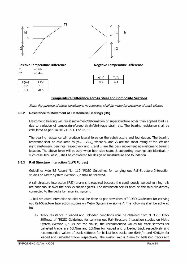
B) Differential Temperature (DT)
The provision given in § 215.4 of IRC 6 – 2017, shall be considered to compute effect of differential
temperature gradient in absence of any provisions in IRS code. The differential gradient of
temperature along depth of superstructure has been reproduced below for ready reference. Short
term modulus of elasticity as per Table given under clause 5.1 of DBR shall be used to calculate the
effects.
Note: For purpose of these calculations no reduction shall be made for presence of track plinths.
Temperature Difference for Concrete Bridge Decks
Positive Temperature Difference
h1 = 0.3h < 0.15m
h2 = 0.3h > 0.1m
< 0.25m
h3 = 0.3h <0.15m
Negative Temperature Difference
h1 = h4 = 0.2h < 0.25m
h2 = h3 = 0.25h < 0.25m
NMRC/NGNC-01/Vol. 4/ODS Page 14
Temperature Difference across Steel and Composite Sections
Note: For purpose of these calculations no reduction shall be made for presence of track plinths.
6.5.2 Resistance to Movement of Elastomeric Bearings (BS)
Elastomeric bearing will resist movement/deformation of superstructure other than applied load i.e.
due to variation of temperature/creep strain/shrinkage strain etc. The bearing resistance shall be
calculated as per Clause-211.5.1.3 of IRC: 6.
The bearing resistance will produce lateral force on the substructure and foundation. The bearing
resistance shall be calculated as (VL.L - VR.R), where VL and VR are the shear rating of the left and
right elastomeric bearings respectively and .L and .R are the deck movement at elastomeric bearing
location. The above force will be zero when both side spans & supporting bearings are identical, in
such case 10% of VL.L shall be considered for design of substructure and foundation
6.5.3 Rail Structure Interaction (LWR Forces)
Guidelines vide BS Report No. 119 “RDSO Guidelines for carrying out Rail-Structure Interaction
studies on Metro System (version-2)” shall be followed.
A rail structure interaction [RSI] analysis is required because the continuously welded running rails
are continuous· over the deck expansion joints. The interaction occurs because the rails are directly
connected to the decks by fastening system.
1. Rail structure interaction studies shall be done as per provisions of “RDSO Guidelines for carrying
out Rail-Structure Interaction studies on Metro System (version-2)”. The following shall be adhered
to:
a) Track resistance in loaded and unloaded conditions shall be obtained from cl. 3.2.6 Track
Stiffness of “RDSO Guidelines for carrying out Rail-Structure Interaction studies on Metro
System (version-2)”. As per the clause, the recommended values for track stiffness for
ballasted tracks are 60kN/m and 20kN/m for loaded and unloaded track respectively and
recommended values of track stiffness for ballast less tracks are 60kN/m and 40kN/m for
loaded and unloaded tracks respectively. The elastic limit is 2 mm for ballasted tracks and
T1
h1 h1 h
4
h2 h2
Positive Temperature Difference Negative Temperature Differenceh1 =0.6h
h2 =0.4m
H(m) T1oc
H(m) T1oc 0.2 4.4
0.2 18
0.3 20.5

NMRC/NGNC-01/Vol. 4/ODS Page 15
0.5 mm for ballast less tracks. No change in track stiffness is permitted on account of actual
track behavior.
b) The temperature variations, to be used for analysis, shall be taken as per provisions of cl.
3.2.8 Temperature Variations of “RDSO Guidelines for carrying out Rail-Structure Interaction
studies on Metro System (version-2)”. The following shall be used for analysis:
-The temperature of the bridge does not deviate from the reference temperature by more
than + 35 0C
-The temperature of the rail does not deviate by more than + 500C.
-The difference in temperature between deck and track does not exceed + 200C.
-The reference temperature is the temperature of the deck and the rail when the rail is
fixed.
c) Maximum additional stresses in rail in tension as well as compression on account of rail-
structure interaction shall be within the permissible limits as prescribed in cl. 3.3.1 Additional
Stresses in Rails of “RDSO Guidelines for carrying out Rail-Structure Interaction studies on
Metro System (version-2)”. The limit prescribed in the document shall be used as it is and
no benefit on account of lesser axle load of actual rolling stock shall be permitted.
d) The provisions of cl. 3.3.2 Displacements of Bridge Elements of “RDSO Guidelines for
carrying out Rail-Structure Interaction studies on Metro System (version-2)” shall be
adhered to.
e) Checks must be performed for break in rail continuity due to unusual conditions such as
fractures or for maintenance purposes. The provisions of cl. 4.8 “Rail Gap Analysis of RDSO
Guidelines for carrying out Rail-Structure Interaction studies on Metro System (version-2)”
shall be followed.
f) Minimum (unfactored) LWR force of 1.6t/m of span length shall be considered for design
irrespective of number of tracks.
2. Software and general methodology to be used for carrying out Rail Structure interaction analysis
must be validated before adopting the same. A well-established document such as UIC 774-3R may
be used for validation.
3. Representative stretches must be chosen for carrying out Rail-Structure interaction which shall
include special spans. The same shall be got approved from the engineer.
4. LWR forces shall be considered in appropriate load combinations as specified in cl. 7.0 Load
Combinations (Ground IIIb) of the DBR.
Wind Load (WL)
The wind load shall be calculated as per § 2.11 of IRS: BR and IS: 875 (Part 3).
As per § 5.3 of IS: 875 (Part 3)
Design Wind Speed, Vz = Vb.k1.k2.k3.k4
Where

NMRC/NGNC-01/Vol. 4/ODS Page 16
Vb = Basic wind speed = 50 m/s for Delhi NCR Zone (as per National Building code).
K1 = 1.07 for class IV type structure (§ table 1 of IS: 875 (Part 3)).
k2 = 1.07 for category 2 (§ table 2 of IS: 875 (Part 3)) for 20m Height.
k2 = 1.12 for category 2 (§ table 2 of IS: 875 (Part 3)) for 30m Height
k3 = 1.0 (§ 6.3.3.1 of IS: 875 (Part 3)).
K4=1.0 (for non-cyclonic zone as per clause 6.3.4)
However, a bridge shall not be considered to be carrying any live load when the wind pressure at
deck level exceeds 150kg/m2 as per clause 2.11.2 of IRS Bridge rule, however as it is a long viaduct
therefore there is fair possibility that once wind pressure exceeds 150kg/m2 train may be standing
static over viaduct due to close of operation therefore in case of wind pressure above 150kg/m2,
train will be considered as static load i.e. no longitudinal loads or impact loads.
Wind load on train in transverse direction will be calculated based on exposed surface & intensity as
per above given values& reference. These are computed for length of train as seen in elevation
normal to longitudinal axis. The transverse load will be applied to train at center of projected area of
the vehicle.
As per clause 209.3.4 of IRC: 6 the longitudinal wind load on Superstructure will be considered as
25%of Transverse load for Beam/Box/ Plate girder bridges. In case of Truss Bridges longitudinal
load on Superstructure will be considered as 50%.
As per clause 209.3.6 of IRC: 6 the longitudinal wind load on Live Load will be considered as 25% of
Transverse Wind load considered on Live load.
In case of Pier & Pier cap full load will be considered.
The longitudinal load will be acted simultaneously with transverse load.
6.7 Seismic Force (EQ)
The purpose of this section is to summarize the methodology and the assumptions that shall be
used for the seismic analysis.
6.7.1 Seismic Design
Seismic design philosophy as stated in “Indian Railway Standard code for Earthquake resistant
design of Railway Bridges 2020” has been considered. The peak ground acceleration denoted as
zone factor is taken as 0.24 since Delhi NCR is situated in zone IV of seismic map of India.
6.7.2 Definition of Seismic Input
Response spectrum (Sa/g vs T) as prescribed in IRS Seismic code 2017, shall be used for seismic
load computation.
6.7.3 Horizontal Seismic Coefficient
The horizontal seismic design coefficient shall be calculated as per following expression
NMRC/NGNC-01/Vol. 4/ODS Page 17
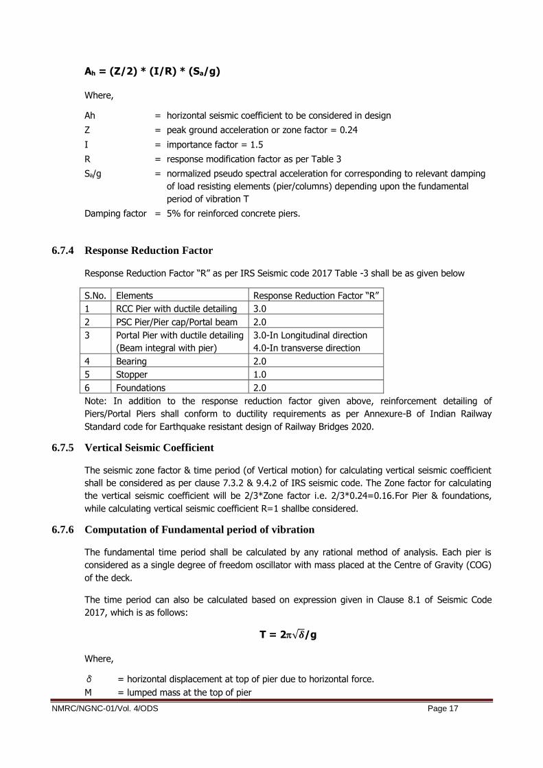
Ah = (Z/2) * (I/R) * (Sa/g)
Where,
Ah = horizontal seismic coefficient to be considered in design
Z = peak ground acceleration or zone factor = 0.24
I = importance factor = 1.5
R = response modification factor as per Table 3
Sa/g = normalized pseudo spectral acceleration for corresponding to relevant damping
of load resisting elements (pier/columns) depending upon the fundamental
period of vibration T
Damping factor = 5% for reinforced concrete piers.
6.7.4 Response Reduction Factor
Response Reduction Factor “R” as per IRS Seismic code 2017 Table -3 shall be as given below
S.No. Elements Response Reduction Factor “R”
1 RCC Pier with ductile detailing 3.0
2 PSC Pier/Pier cap/Portal beam 2.0
3 Portal Pier with ductile detailing
(Beam integral with pier)
3.0-In Longitudinal direction
4.0-In transverse direction
4 Bearing 2.0
5 Stopper 1.0
6 Foundations 2.0
Note: In addition to the response reduction factor given above, reinforcement detailing of
Piers/Portal Piers shall conform to ductility requirements as per Annexure-B of Indian Railway
Standard code for Earthquake resistant design of Railway Bridges 2020.
6.7.5 Vertical Seismic Coefficient
The seismic zone factor & time period (of Vertical motion) for calculating vertical seismic coefficient
shall be considered as per clause 7.3.2 & 9.4.2 of IRS seismic code. The Zone factor for calculating
the vertical seismic coefficient will be 2/3*Zone factor i.e. 2/3*0.24=0.16.For Pier & foundations,
while calculating vertical seismic coefficient R=1 shallbe considered.
6.7.6 Computation of Fundamental period of vibration
The fundamental time period shall be calculated by any rational method of analysis. Each pier is
considered as a single degree of freedom oscillator with mass placed at the Centre of Gravity (COG)
of the deck.
The time period can also be calculated based on expression given in Clause 8.1 of Seismic Code
2017, which is as follows:
T = 2√𝜹/g
Where,
δ = horizontal displacement at top of pier due to horizontal force.
M = lumped mass at the top of pier

NMRC/NGNC-01/Vol. 4/ODS Page 18
a) Mass
Permanent masses (Self Weights, SIDL) of:
(a) Full span longitudinally, which can be resisted by reaction blocks or POT/Spherical
bearings during earthquake, at one side of the pier or half of spans on either side of
pier in case seismic is resisted by bearings (For longitudinal seismic)
(b) Half of spans on either side of pier (For transverse seismic)
Mass of the pier cap
80% mass of the pier
The earth quake acceleration will be considered on full mass and not buoyant mass.
It may be noted that while calculating lateral seismic forces, 50% live load is included in the seismic
weight for transverse direction i.e. Minimum live load among 4 cases i.e. OSOT (one span one
track), OSBT (One span both tracks), BSOT (Both span one track) & BSBT (Both span both tracks)
will be considered, whereas no live load is included for seismic weight in longitudinal direction.
As per clause 2.8.5 of IRS: Bridge Rule, in transverse/ longitudinal seismic condition, only 50% of
gross tractive effort / braking force/centrifugal force/racking force shall be considered.
b) Stiffness
Stiffness shall be calculated with the concrete instantaneous modulus of elasticity, for all
structural elements.
Pier stiffness considering fixed base and free at deck location K = 3EIeff/L3
Ieff=0.75Ig, as per clause 5.2.1 of IRC: SP: 114-2018. In the calculation of fundamental time
period, effective moment of inertia is considered.
Flexibility of foundation soil systemmay be considered while calculating time period i.e.
foundation and soil spring may be modelled while calculating time period.
The static stiffness of soil spring shall be calculated as per Table-3 of Annexure-C of IS
2911 Part-1 (Section 2). While calculating the static soil stiffness, soil shall be considered
as dry granular soil (for time period calculation) with uniform N values of 25 throughout the
depth for all cases. In liquefaction zone no soil spring shall be considered.
Only for calculating the time period, dynamic stiffness (Kdynamic) shall be used and it shall be
taken as 3.5 times the static stiffness (Kstatic) i.e Kdynamic= 3.5*Kstatic.
For calculating seismic forces and its effects the static value of soil springs as per clause
12.4.2 of the DBR shall be used.
Time period of more than 4s shall not be allowed in any case; section needs to be resized
when it exceeds 4s.
6.7.7 Direction Combinations
The seismic forces shall be assumed to come from any horizontal direction. For this purpose, two
separate analyses shall be performed for design seismic forces acting along two orthogonal
horizontal directions. The design seismic force resultant (that is axial force, bending moment, shear
force and torsion) at any cross section of abridge component resulting from the analysis in the two
orthogonal horizontal directions shall be combined according to the expressions given below.
a) ± ELx ± 0.3 ELy b) ± 0.3 ELx ± ELy
Where

NMRC/NGNC-01/Vol. 4/ODS Page 19
ELX = Force resultant due to full seismic force along X direction, and ELY = Force resultant due to full seismic force along Y direction
When vertical seismic forces are also considered, the design seismic force resultants at any cross-
section of a bridge component shall be combined as below:
a) ± ELx ± 0.3 ELy ± 0.3 ELz b) ± 0.3 ELx ± ELy ± 0.3 ELz c) ± 0.3 ELx ± 0.3 ELy ± ELz
Where ELX and ELY are as defined above and ELZ is the force resultant due to full seismic force along vertical direction. As an alternative to the procedure given above, the forces due to the combined effect of two or
three components can be obtained on the basic square root of sum of square (SRSS)
√(ELx2+ ELY
2) or √(ELx2+ ELY
2+ ELZ2)
6.8 Erection Temporary Loads (ETL)
Erection forces and effects shall be considered as per Clause-2.13 of IRS-Bridge Rules.
The weight of all permanent and temporary materials together with all other forces and effects
which can operate on any part of structure during erection shall be considered in design. The loads
arising from most onerous conditions of the construction methods adopted is awaited from the
Contractor.
Special care shall be taken that no damage is caused by the construction contractor to the
permanent structure. In case of any hole etc., drilled in permanent structural element, the same will
be made good by using non-shrink, expansive, high strength grout and its strength shall be better
than the structural element and will have to be demonstrated.
6.9 Derailment Loads (DR)
For vertical considerations, check shall be made in accordance with the IRS-Bridge Rules, Appendix-
XXV with standard gauge in place of Broad gauge. For ULS and stability check, loading shall
proportional as per maximum axle load.This derailment load corresponds to an ULS load for SLS
combinations (Group-V of IRS-CBC) a 1/1.75 coefficient will be applied to the derailment load. The
Sacramento criteria need to be considered for U-Girder.
6.10 Forces on Parapet
The parapets shall be designed to resist lateral horizontal force & a vertical force of 1.50 kN/m
applied simultaneously at the top of the parapet as per Clause 2.10 of IRS Bridge Rules.
6.11 Differential Settlement (DS)
Differential Settlement between two adjacent viaduct piers shall be as follows.
i) 12mm for Long Term Settlement;
ii) 6 mm for Short Term Settlement

NMRC/NGNC-01/Vol. 4/ODS Page 20
The allowable settlement for pile group is 25mm (as per IS 2911-part 4); hence differential
settlement between two foundations is considered as half of 25 mm i.e. 12 mm as long-term
settlement. The short-term settlement of 6mm is considered to cater for bearing replacement
condition.
Differential settlement shall be considered only in the design of continuous structures, if any.
6.12 Buoyancy Loads
The design of the foundation shall be done considering design ground water table as referred in
clause 5.5 of the DBR.
In case of river bridges, stability check and calculation of base pressure, full buoyancy shall be
considered on submerged portion of substructure and foundation up to HFL or LWL as the case may
be, irrespective of the type of soil on which the foundation will rest.
Hydro dynamic forces will be considered as per clause 6 of IRS Seismic code.
6.13 Water Current forces
Water current force in submerged portion of substructures and foundations shall be calculated as
per Clause 5.9 of IRS Bridge Substructure & Foundation Code
6.14 Vehicle Collision Load (VCL)
The vehicle collision load on piers: as per Clause-222 of IRC: 6.
Rules specifying the loads for design of superstructure and sub-structure of bridges and for
assessment of the strength of existing bridges should be done as per IRS: Bridge Rules.
All structure near railway track shall be checked for accidental impact from derailed trains as per
clause 2.16.4 of IRC Bridge Rules as per Addendum & Corrigendum Slip No. 48 dated 22.06.2017.
6.15 Gradient Effect
The bearing shall be sandwiched between two true horizontal surfaces. Steel Wedge shall be
provided to cater longitudinal slope of superstructure.
6.16 Buffer Load
Provision of Buffers is contemplated at the end of temporary terminal stations during stage opening
of the Corridors, at Pocket track ends and at the terminal stations of the corridors (at the end of
turn back/stabling lines). Such buffers will be of friction type. These buffers will be designed to have
stopping performance based on mass of fully loaded train and its declaration to avoid damage to the
train or buffer. Viaduct elements need to be designed for such Buffer load. The exact Buffer loads
need to be interfaced and ascertained during the detailed design.
6.17 Vibration effect
Effect of vibration due to movement of train on Viaduct structure will be taken into consideration.
This will be checked in dynamic analysis.

NMRC/NGNC-01/Vol. 4/ODS Page 21
7 LOAD COMBINATIONS
7.1 Methodology: Provisions of IRS-CBC shall be followed. The partial load factors and load
combinations shall be as per Clause-11 and Table-12 of IRS-CBC as modified and shown below:
Load Abbreviations
Dead load DL
Super imposed dead load SIDL
Prestressing PS
Live Load LL
Live load on footpath LFP
Longitudinal force ( Traction & Braking) LF
Centrifugal force CF
Over all temperature OT
Differential Temperature DT
Long welded rail force LWR
Racking Forces RF
Wind forces WL
Earthquake EQ
Differential settlement DS
Derailment DR
Erection load ER
Limit
state Loads Symbol G I
G II (EQ) G II (WL) G III (a) G III
(b)
G V
G IIa
(EQ)
G II b
(EQ)
G IIa
(WL)
G II b
(WL)
Temper
ature LWR
SLS C
om
bin
ations
Dead Loads DL 1.00 1.00 1.00 1.00 1.00 1.00 1.00 1.00
Prestressing PS 1.00 1.00 1.00 1.00 1.00 1.00 1.00 1.00
Super
Imposed
Loads (fixed)
SIDL-1 1.00 1.00 1.00 1.00 1.00 1.00 1.00 1.00
Super Imposed
Loads (variable) SIDL-2 1.20 1.20 1.20 1.20 1.20 1.20 1.20 1.20
Earthquake EQ
1.00 1.00
Overall T OT
1.00 1.00
LWR 1.00

NMRC/NGNC-01/Vol. 4/ODS Page 22
Differential
DT DT
0.80 0.80
Differential
settlement DS 1.00
Live load LL 1.10
0.50
1.00 1.00 0.50
Live load on
footpath LWP 1.00 0.50 1.00 1.00
0.50/
1.00 (##)
Derailment
Loads DR
1.00(**)
Wind Load
1.00 1.00
ULS C
om
bin
ations
Dead Loads DL 1.25 1.25 1.25 1.25 1.25 1.25 1.25 1.25
Prestressing PS 1.15/0.8
7 (*) 1.40 1.40
1.15/0.87
(*)
1.15/0.
87 (*)
1.15/0.87
(*)
1.15/0.
87 (*)
1.15/0.
87 (*)
Super
Imposed
Loads (fixed)
SIDL-1 1.25 1.25 1.25 1.25 1.25 1.25 1.25 1.25
Super
Imposed
Loads
(variable)
SIDL-2 2.00 2.00 2.00 2.00 2.00 2.00 2.00 2.00
Earthquake EQ
2.00# 2.00#
Overall T OT
1.50 1.50
LWR 1.50
Differential
DT DT
1.15 1.15
Differential
settlement DS
Live load LL 1.75
0.50
1.40 1.40 0.70
Live load on
footpath LWP 1.50 0.50 1.25 1.25 0.6125
Derailment
Loads DR
1.00
Wind Load
1.60 1.25
In each of SLS and ULS cases, 5 basic load combination groups shall be considered, according to the
IRS- CBC.

NMRC/NGNC-01/Vol. 4/ODS Page 23
(*) 1.15/0.87: In accordance with IRS CBC article 11.3.3., when the Prestressing PR increases the
section capacity vs. shear then PR is multiplied by 0.87. When the Prestressing PR decreases the
section capacity vs. shear then PR is multiplied by 1.15.
(**) Refer clause 6.9.
#The calculation for seismic force will be done considering Z/2, however as MCE is proposed to be
used only in ULS case as per IRS seismic code, the load factor is modified to 2.0. This is done for
ease of calculation.
## 0.50 for two or more tracks and 1.0 for single track.
Notes:
1) ULS-Ultimate Limit state.
2) SLS-Serviceability Limit state
3) Wind load and earth quake loads shall not be assumed to be acting simultaneously.
4) Live load shall also include dynamic effect, force due to curvature exerted on tracks, longitudinal
forces, braking forces and forces on parapet.
5) Crack width check shall be done in SLS case for combination G I only.
6) Load combination for Vehicle collision shall be as per IRC 6 but design of members undervehicle
collision load combination shall be carried out as per IRS CBC.
7) Load combination 1.0*DL + 1.0*SIDL + 1.5*EQ is to be followed in ULS case.
8) Load combination 1.5*DL + 1.5*SIDL + 1.5*EQ is to be followed in ULS case.
7.2 The Superstructure/bearing, sub-structure and foundation will be checked for one track loaded
condition as well both track loaded condition, for single span and both spans loaded conditions, as
the case may be.
7.3 Design of viaduct shall be done in accordance with the construction methodology/ construction
sequence to be adopted during execution.
7.4 The analysis and design will be carried out for all possible cases of rolling train loads. All the
supporting structures, such as superstructure, bearings, substructure and foundations shall be
checked for the most onerous cases.

NMRC/NGNC-01/Vol. 4/ODS Page 24
LL4: used for shaft check, Foundation check, Shear Key check
8 DESIGN CHECK FOR CONCRETE STRUCTURE
8.1 Allowable Stresses for concrete at serviceability limit state (SLS)
The stresses at transfer and construction stage during service for prestressed cast in situ and
segmental construction shall be as per Clause-16.4.2.2 (Concrete Compressive stress Limitations),
Clause-16.4.2.3 (Steel stress Limitations), Clause-16.4.2.4 (Cracking), Clause-17.3.3 (Other types of
Connections) and Clause-17.4 (Composite Concrete Constructions) of IRS-CBC.
Clause-10.2 (Serviceability Limit States) of IRS-CBC shall be used for RCC construction (Beams,
Columns and Slabs).
Summary of Permissible Stresses
Precast or Cast-In-Situ Post-Tensioned Structures
No Load
Combination
Allowable
compressive
strength
Reference
Allowable
tensile
stress*
Reference
At transfer and/or construction stage
1 DL +*DS +
App.PR
0.5 fci but <0.4
fck
CI 16.4.2.2(b)
of IRS CBC
1997
1 MPa* CI 16.4.2.4(b)
of IRS CBC
1997
2 Group 1+50%
EL
0.5 fci but <0.4
fck
(CI 16.4.2.2(b)
of IRS CBC
1997
1 MPa* CI 16.4.2.4(b)
of IRS CBC
1997
During Service
3 SLS G I 0.4 fck (CI 16.4.2.2(a)
of IRS CBC
1997
No tension
anywhere
cI 16.4.2.4(b) of
IRS CBC 1997
4 SLS G II 0.4 fck (CI 16.4.2.2(a)
of IRS CBC
1997
No tension
anywhere
cI 16.4.2.4(b) of
IRS CBC 1997
5 SLS G III 0.4 fck (CI 16.4.2.2(a)
of IRS CBC
1997
No tension anywhere

NMRC/NGNC-01/Vol. 4/ODS Page 25
* In case of Segmental structures no tension is permitted under any stage or any SLS Load
combination as clause 17.3.3 of IRS-CBC.
** In case of Uniform compressive stress distribution in PSC structures, permissible stress shall not
be more than 0.3fck.
II RCC Structures
Permissible stress in Concrete (triangular compressive stress distribution) - 0.50fck
Permissible stress in Concrete (Uniform compressive stress distribution) - 0.38fck
Permissible stress in Steel - 0.75fy
8.2 ULS Check for Prestressed Cast-in Situ Concrete/Composite Construction
Clause-16.4.3 (Ultimate Limit State: Flexure) to Clause 16.4.6 (Longitudinal Shear) of IRS-CBC shall
be applicable for cast-in situ Prestressed construction whereas for composite construction Clause-
17.4 (Composite Concrete Construction) shall be used.
8.3 ULS Check for RCC Structure
Section Capacity check for RC beams (ULS) for the superstructure should be conforming to Clause-
15.4 of IRS-CBC. The design of RCC slabs shall conform to Clause 15.5 of IRS-CBC. The design of
column should conform to Clause-15.6 of IRS-CBC.
9 DESIGN CHECK FOR STEEL/COMPOSITE STRUCTURE
The design of steel structure shall be done by IRS Steel Bridge Code/IRS-Welded Bridge Code. In
case of steel structure, IRS-steel bridge code shall be followed and Load combination G1 shall be
used. While Designing for composite action IRC :22 shall be referred with load combinations as
given in table under clause 7.1
10 DURABILITY & CRACK WIDTH
10.1 Durability
Provision of Clause-5.4 of IRS-CBC shall be followed. The exposure condition of present corridor is
Moderate and in case of Nallah crossing the exposure condition may be treated as “Severe”.
10.2 Crack Width Check
For SLS Combination, Group - I, crack width in reinforced concrete members shall be calculated as
per Clause-15.9.8.2.1 of IRS-CBC.
The allowable crack width should be as per Clause 10.2.1 (a) (CS-1-12/2014) based on the exposure
condition defined in Clause 5.4.1 of IRS-CBC and table-10 of IRS-CBC.
For crack control in columns, clause15.6.7 of IRS-CBC will be modified to the extent that actual axial
load will be considered to act simultaneously.

NMRC/NGNC-01/Vol. 4/ODS Page 26
CLEAR COVER AND CMIN FOR CRACK WIDTH CALCULATION
10.3 Deflection
Clause No. 10.4.1, 11.3.4 and 13.3 of IRS: CBC shall be kept in view while calculating vertical
deflection at mid span.The calculation of deflection shall be done in accordance with provisions of
UIC-776 3R.
11 FATIGUE
11.1 General
Fatigue phenomenon shall be analyzed for those structural elements that are subjected to repetition
of significant stress variation (under traffic load). Thus generally the fatigue shall be regarded only
for deck structural part supporting the tracks.

NMRC/NGNC-01/Vol. 4/ODS Page 27
11.2 Prestressed Concrete Structure
The fatigue shall be checked as per Clause-13.4 IRS-CBC. However, fatigue check for prestressed
concrete structures does not need to be performed as long as the whole section (from top to bottom
fiber) remains under compression under SLS load combination 1.
11.3 Reinforced Concrete Structure
The fatigue shall be checked as per Clause-13.4 of IRS-CBC.
Fatigue check for reinforced concrete structures does not need to be performed unless it is a main
structure member (i.e. the deck) supporting the traffic that consists of reinforced concrete. The
permissible stress range in unwelded reinforcement as per clause 13.4.1 of IRS CBC shall be
155Mpa (under Live load) up to 16mm diameter & 120Mpa for bars exceeding 16mm diameter.
11.4 Steel/STEEL COMPOSITE Structures
Clause-3.6 of IRS-Steel Bridge (up to latest correction slip) / Clause-13.2 of IRS-Welded Bridge code
shall govern. If values are required to be used, the train closest to the actual train formation
proposed to be run on the NMRC shall be used. Otherwise, detailed counting of cycles shall be done.
12 DESIGN METHODOLOGY
12.1 Superstructure System of Viaduct
The Superstructure of the viaduct comprises of simply supported Twin U-Girder.
However sharp curvature/ crossovers / turnouts/ railways crossings / highway crossings, PSC I -
Girder/Balanced Cantilever/Steel Composite girders/Steel Truss may be used. The minimum
dimensions shall be considered as per Clause 16.9.6 of IRS-CBC.
Design of superstructure should be done in accordance with construction methodology/ construction
sequence to be adopted during execution by NMRC.
Drainage
The drainage of deck shall be designed to cater the maximum envisaged rainfall intensity and
suitable longitudinal and transverse slope should be provided. Moreover the provisions of Clauses-
10.4.1.1 & 15.2.2 of IRS-CBC shall be followed.
Solid Pier
The drain pipe of double wall HDPE corrugated pipes with water collection box at top, shall be
located within solid pier to avoid unpleasant aesthetics.
Deck
The top of soffit slab will be profiled so as to collect the run-off water at multiple points by providing
a cross slope of 2.5%. Drainage pipes will be provided to collect the run-off.
12.2 Bearing System and its Design Methodology
a) Bearing System

NMRC/NGNC-01/Vol. 4/ODS Page 28
Considering the span configuration and safety aspects of the structural system (in normal and
seismic condition), it is proposed to adopt elastomeric bearings placed underneath the Twin U-
Girder for transfer of vertical forces and in-plane forces. The elastomeric bearings shall not be
designed for seismic forces and seismic forces will be transferred to substructure via shear
key/seismic restrainer. Elastomeric bearings/pads place verticallyshall be used in between the
Seismic stopper/seismic restrainer and the superstructure tomitigate the dynamic effects.
POT -PTFE bearing shall be designed as per IRC: 83 Part-III & Spherical bearing shall be
designed as per IRC: 83 part-IV.
The elastomeric bearing shall be designed in accordance with EN 1337 part 1 and part 3
wherever required.
b) Replaceability of Bearings
While finalizing the proposed bearing system, it shall be kept in mind that accessibility and
replacement of each part of bearing are of paramount importance as the design life of bearings
is shorter than that of the structure. Keeping in view the above cited criteria, all the bearings
and pier caps will be detailed for replacement of bearings in the future. The end diaphragms
shall be designed to facilitate the operations of jacks during maintenance as per clause
15.9.11.3 of IRS-CBC.
Special Low Height jacks shall be employed to replace bearings, if minimum vertical
clearance is less than 400 mm as stipulated in Clause-15.9.11.4 of IRS-CBC.
c) Uplift
If required a holding-down device connecting the deck and the pier head shall be placed in
order to prevent the deck from overturning. The holding-down device may be integrated in the
pot-bearing system or be a separate system constituted of bars embedded in pier cap and
viaduct with appropriate details, permitting translation/rotation. Other systems can also be
foreseen.
Due to the lack of appropriate guidelines in Indian codes, the design criteria for holding down
device (upward force limit requiring holding down device, design formulas) will be taken from
the latest international practice.
12.3 SUBSTRUCTURE SYSTEM
a) Pier Cap
For designing the pier cap as corbel the provisions of Clause-17.2.3 of IRS-CBC should be
followed. In case of shear span to effective depth ratio being more than 0.6, pier cap will be
designed as flexural member.
Height of pedestal should be in between 150mm and 500mm as per clause 710.10.2 of IRC: 78.
The Pier cap shape shall be suitable at transition pier supporting different types of
superstructure instead of providing raised/column pedestal over pier cap.
b) Piers

NMRC/NGNC-01/Vol. 4/ODS Page 29
The effective length of a cantilever pier for the purpose of slenderness ratio calculation will be
taken as per Table-18 of IRS-CBC. In this project most of the columns are isolated columns with
elastomeric bearing supporting the superstructure. In either direction the effective length will be
taken as 2.3L0 (case 7). Here L0 represent height of column from top of footing slab/Pile cap to
top of pier cap. Effective length of portal column in longitudinal direction will be taken similar to
singe column i.e. 2.3L0 and for transverse direction it should be taken as 1.5 L0 (case 6).
The design of pier shall be done as per clause 15.6 of IRS CBC.
Prestressed Cantilever Pier
In case of vertically prestressed piers, minimum longitudinal reinforcement shall be provided as
RCC column as per clause 15.9.4.1 of IRS CBC.
Shear reinforcement & ductile detailing shall be done as that of RCC column.
In all SLS combinations, column shall remain in compression.
Clause 16.6.1 of IRS CBC shall be applicable in case of prestressed piers/columns.
12.4 Foundation SYSTEM
Foundation shall be designed as per IRS Bridge Substructure & Foundation Code, IRS Concrete Bridge Code, IRC-78, Manual on the design and construction of well foundation; IS-2911 should be followed for design of foundations.
12.4.1 Pile Foundation
Foundation analysis and design will be based on IRS Code for Substructure & IRC-78. The forces
applied by the pier are transferred to the bottom of the pile cap for this purpose. Reactions in pile
are calculated using Rivet theory. The various specific assumptions made for the pile and pile cap
design are as follows:
a) Bored-cast-in-situ multiple pile groups will be adopted.
b) Minimum 1.0m diameter bored cast-in-situ vertical piles in soil/rock have been contemplated for
the foundation of piers. Minimum number of pile in each pile cap shall not be less than 4.
c) Open foundation have been contemplated for the pier location with rocky strata at shallow
depth.
d) For piles and pile caps, load combinations shall be considered as per IRS-CBC, Table-12. The
various specific assumptions made for the pile and pile cap design including pile load testing
shall be as per IS: 2911, IRC-78 and IRS-Bridge Sub-structure and Foundation Code.
e) For pile carrying capacity, all SLS Load combinations as per IRS-CBC will be considered.
f) Increase in vertical load capacity of pile shall be done as per Table-1 of IS 1893-Part-1.
g) The lateral load capacity of pile shall be evaluated either by using empirical formulae given in
IS: 2911 (Part-1/ section-2) or by soil structure interaction analysis using Winkler’s spring model
by limiting the lateral deflection as1% of Pile diameter as per Cl. 709.3.5.2 of IRC: 78.
h) Initial load tests (not on working pile) will be conducted as per IS: 2911 - Part IV. Initial test is
proposed to be conducted for a load of 2.5 times as per the safe vertical load based on static
formula.

NMRC/NGNC-01/Vol. 4/ODS Page 30
i) The working load on pile for vertical and horizontal loads shall be verified through routine load
tests during construction.
j) In case of multiple pile system, spacing between the piles shall not be less than 3 times the
diameter of pile in soil and 2.5 times the diameter when founded on rock.
k) In general the top of pile cap shall be kept about min 500mm below the existing ground level
and weight of the earth cover will be applied on top of pile cap when unfavorable. The earth
cover on pile cap for any favorable effect (stability, soil horizontal capacity.) will be neglected.
l) The following limiting values shall not be exceeded for computation of safe load:
o Result of sub-structure investigation will be used for adopting the value of angle of internal
friction “φ” and cohesion of soil “c” as per clause 5.7 of the DBR .
o Angle of wall friction δ shall be taken as equal to φ deg.
o Co-efficient of earth pressure “K‟ shall be taken as 1.0.
o Maximum overburden pressure at bottom of pile for calculation of shaft resistance and
bearing resistance shall be limited to 15 times the diameter of the pile. The maximum depth
shall be considered from existing ground level.
o For calculating the pile capacities, the design ground water table as per clause 5.5 of the
DBR shall be considered.
o Bulk density corresponding to 100% saturation shall be calculated and used for working out
submerged density of soil.
o In case of liquefiable strata, only submerged weight of soil shall be considered as
overburden for vertical pile capacity calculation.
m) While finalizing length of pile, Clause 705.4.1 of IRC: 78 shall also be followed.
n) Live load surcharge needs to be considered for pile group which is outside median and where
live load is moving over pile cap. Normal Pile groups below median or where there is no live load
over pile cap need not to be design for live load surcharge.
o) In case of foundations near railway crossing effect of railway live load surcharge shall be
considered if applicable
Structural Design
a) Pile design shall be done according to § 15.6 of IRS CBC 1997. However, for crack control in
piles, § 15.6.7 of IRS CBC 1997 it will be clarified that actual axial load will be considered to act
simultaneously.
b) Where there is a risk of liquefaction, the lateral soil resistance of the liquefied layer will be taken
as zero.
c) Pile cap shall be designed based on § 15.8.3.1 of IRS –CBC 1997. No support from soil below
pile cap shall be considered.
d) The thickness of the pile cap shall be kept minimum 1.5 times diameter of the piles for multiple-
pile group as per IRC 78.
e) The structural design of the pile cap shall be carried out as per §10.2.2 & §15.4 and §15.8.3 of
IRS CBC. Crack width shall be checked for load combination 1 as per §15.9.8.2 IRS CBC.
f) Minimum reinforcement in pile caps at top shall be at least 0.12% in each direction incase of compression and in case of tension, it shall not be less than 0.2%.

NMRC/NGNC-01/Vol. 4/ODS Page 31
12.4.2 Soil Structure Analysis
When designing element forces or estimating displacements the soil stiffness and other parameters
shall be assessed based on clause 5.7 of the DBR considering the design ground water table as per
clause 5.5 of the DBR.
12.4.3 Well Foundation & Open foundation
Well Foundation& Open foundation shall be designed as per IRS Bridge Substructure & Foundation
Code/ IRC: 78.
13 LIST OF DESIGN CODES AND STANDARDS, APPLICABILITY
The IRS Codes shall be followed in principle. Although main clauses have been mentioned in the
DBR, the other relevant clauses as available in the IRS codes shall also be followed, whenever
applicable. If provisions are not available in IRS, the order of preference shall be as follows, unless
specified otherwise:
For railway loading related issues:
i. UIC Codes
ii. Euro Codes
iii. Any other code, which covers railway loading.
For other Design/ detailing related issues:
i. IS
ii. IRC iii. EURO iv. AASHTO v. Any international code with approval of NMRC.
IRS Codes (With Latest Versions, all ammendments and correction slips up to date of BIDDING)
IRS Bridge Rules
IRS Concrete Bridge Code
IRS Bridge substructure & Foundation Code
IRS Steel Bridge Code
IRS Fabrication Code (B1)
IRS Welded Bridge Code
IRS code for Earthquake resistant design of Railway Bridges 2020
IRC CODES (With Latest Versions and all ammendments up to date of BIDDING)
IRC: 5 Standard Specification & Code of Practice for Road Bridges - General Features
of Designs
IRC:6 Standard Specification & Code of Practice for Road Bridges- Loads and Stresses
IRC: 18 Design Criteria for Pre-stressed Concrete Road Bridges (post Tensioned
Concrete)

NMRC/NGNC-01/Vol. 4/ODS Page 32
IRC: 22 Specification & Code of Practice for Road Bridges, Section VI - Composite
Construction for Road Bridges
IRC: 24 Standard Specification & Code of Practices for Road Bridges, Section V-Steel
Road Bridges
IRC: 78 Standard Specification & Code of Practice for Road Bridges - Section
Foundations & Sub-Structure
IRC: 83(I) Standard Specification & Code of Practice for Road Bridges, Part-l Metallic
Bearings
IRC: 83(II) Standard Specification & Code of Practice for Road Bridges, Part-II Elastomeric
Bearings
IRC: 83 (III) Standard Specification & Code of Practice for Road Bridges, Part-III POT, POT-
cum PT;TE, Pin and Metallic Guide Bearings
IRC: 83 (IV) Standard Specification & Code of Practice for Road Bridges, Part, IV Spherical
and Cylindrical Bearings.
IRC: 112 Code of practice for Concrete Bridges
IRC-SP-71 Guidelines for Design and Construction of Pre-cast Pre-tensioned Girders for
bridges
IS Codes (With Latest Versions and all ammendments up to date of BIDDING)
IS: 269 Specs for Ordinary and Low Head Portland cement
IS: 383 Specs for coarse and fine aggregates from natural sources for concrete
IS: 432 Specs for Mild steel and medium tensile steel bars (Part 1)
ID: 456 Plain and reinforced concrete - code of practice
IS: 800 Code of practice for General Construction Steel
IS: 875 Code of Practice for Design Loads Part 1, 2 3, 4& 5 (Other than Earthquake)
IS: 1080 Design and construction of shallow foundations in soils (other than raft ring and
shell)
IS: 1343 Code of practice for Pre-stressed concrete-based essentially on CP-110
IS: 1364 Hexagon Head Bolts, Screws & nuts of product grades A & B Part 1 (part 1
Hexagon, Head Bolts (size range M 16 to M64)
IS: 13920 Ductile detailing of reinforced concrete structures subjected to seismic forces
code of practice
IS: 1489 Specification for Portland pozzolana cement (Fly ash based)
IS: 1786 High strength deformed steel bars and wires for concrete reinforcement
IS: 1893 Criteria for Earthquake Resistant Design of structures
IS: 1904 Design and construction of 1oundations in soils: general requirements.
IS: 1905 Code of practice for structural use of unreinforced masonry.
IS: 2062 Specifications for weldable Structural steel

NMRC/NGNC-01/Vol. 4/ODS Page 33
IS: 2502 Code of Practice for Bending and Fixing of Bars for Concrete
Reinforcement
IS: 2911 Code of practice for Design and construction of Pile foundation Part 1
(Part I/Sec 1) Concrete Piers Section 2 Board Cast-in-situ-piles (with
amendments)
IS 2911 Code of Practice for Design & construction of Pile foundations Part 4 Load test
on piles
IS: 2950 Design and construction of raft foundations
IS: 3935 Code of Practice for Composite Construction
IS: 4326 Code of practice for Earthquake resistant design and construction of Buildings
IS: 4923 Hollow steel sections for structural use -specification
IS: 8009 Calculation of settlements of shallow foundations
IS: 8112 Specifications for 43 grade ordinary Portland cement
IS: 9103 Specifications of Concrete admixtures
IS: 11384 Code of practice for Composite Construction in Structural Steel and Concrete
IS: 12070 Code of practice for Design and construction of shallow foundation on Rocks
IS: 12269 Specification for 53 grade ordinary Portland cement
IS: 14268 Uncoated Stress Relieved Low relaxation Seven-ply Strands for Prestressed
concrete
IS: 14593 Design and Construction of Bored Cast-in-Situ Piles Founded on Rocks.
BS CODES (With Latest Versions and all ammendments up to date of BIDDING)
BS: 4447 Specifications for the performance of prestressing anchorage for post-tensioned
concrete.
BS: 4486 Specifications for high tensile bars used for prestressing.
BS: 5400 Code of Practice for Design of Concrete Bridges Part 4-1990.
BS: 8006 Code of Practice for strengthened reinforced soils and other fills-1995.
BS: 8007 Design of Concrete structures for retaining liquids.
OTHERS (With Latest Versions and all ammendments up to date of BIDDING)
UIC:776-1R Loads to consider in Railway Bridge Design
UIC:776-3R Deformation of Bridges
UIC: 772 Then International Union Railway Publication
UIC: 774 - 3R Rail structure interaction
CEB_FIB Model Code 1990 for Concrete Structures
The design relating to Fire safety and escape shall be in accordance with the requirements of
NFPA 130 standard for fixed guide way system.

NMRC/NGNC-01/Vol. 4/ODS Page 34
FIP Recommendations for the Acceptance of Post-tensioned systems.
M.O.R.T and Highways specifications.
Euro code 0 Basis of Structural Design.
Euro code I Actions on Structures-Part 2-Traffic Loads on Bridges.
Euro code 2 Design of Concrete Structures- Part 1.1: General Rules and Rules for Building.
Euro code 2 Design of Concrete Structures- Part 2, Concrete Bridges - Design and Detailing
Rules.
ACI 358: IR-92 (American Concrete Institute) for assessment of dynamic impact for transit
Guide ways.
ROSO Guidelines for carrying out RSI (Version 2.0) issued in January 2015 BS-111 version-3
issued in January 2015.
All codes listed above shall be of latest revision including all amendments & corrections.
DESIGN SOFTWARE
Any commercial or proprietary software can be used for analysis/design provided the same is
validated with manual computations or other standard software in multiple scenarios.

NMRC/NGNC-01/Vol. 4/ODS Page 35
OUTLINE DESIGN SPECIFICATIONS
FOR
ELEVATED STATIONS

NMRC/NGNC-01/Vol. 4/ODS Page 36
1 INTRODUCTION
1.1 BRIEF DESCRIPTION OF THE PROJECT
This Design basis report is applicable for elevated metro stations of Noida Metro Rail Project
of NMRC, NGNC-01.
1.2 SCOPE OF DBR
The object of this Design Basis Document is to establish a common procedure for the design
of "Elevated Metro Stations of NMRC,NGNC-01". This is meant to serve as a guide to the
designer but compliance with the rules there-in does not relieve them in any way of their
responsibility for the stability and soundness of the structure designed. The design of Elevated
Metro Stations requires an extensive and thorough knowledge and entrusted to only to
specially qualified engineers with adequate practical experience in structure designs.
Design basis report (DBR) of viaduct shall be followed for following structures/elements of
station:
For single pier station.
Structural elements which support metro live loads.
This design basis report is applicable for following structures/structural elements:
Structural elements of station which do not support metro live loads.
Ancillary structures
Prestressed concrete structures shall be designed as per IS: 1343. RCC Structures shall be
designed by IS: 456. Steel structure design shall be designed by IS: 800. Seismic design shall
generally be governed by IS: 1893 – Part 1
The design basis report shall be read in conjunction with the Outline Construction
Specifications where appropriate.
1.3 SITE PARTICULAR
The project corridor is located in state of Noida U.P
Maximum Temperature : 47.8˚C (as per Annexure-F of IRC 6:2017)
Minimum Temperature : -0.4˚C (as per Annexure-F of IRC 6:2017)
Rainfall season : July-August
NMRC/NGNC-01/Vol. 4/ODS Page 37
Average Rainfall : 800-1000mm
Seismic Zone : IV
1.4 UNITS
The main units used for design will be: [m], [mm], [t], [kN], [kN/m2], [MPa], [⁰C], [rad].
1.5 CODES
All relevant codes as listed in DBR shall be of latest revision including all amendments &
corrections.
2 DESIGN SPECIFICATION
2.1 MATERIALS
2.1.1 Cement
For plain and reinforced concrete structures cement shall be used as per clause 5.1 of IS: 456.
For PSC structures Cl. 5.1 of IS: 1343 shall be used.
2.1.2 Concrete
As per Cl. 6, 7, 8, 9 and 10 of IS: 456 in case of Plain and Reinforced Concrete structures and
Clause 6, 7, 8,9 and 10 of IS: 1343 for Pre-stressed concrete structures.
Short term modulus of elasticity (Ec) shall be taken as per Cl. 6.2.3.1 of IS: 456 for Plain and
Reinforced Concrete structures and IS: 1343 for Pre-stressed concrete structures. The modular
ratio for concrete grades shall be taken as per Annex B of IS: 456.
2.1.3 Prestressing steel for tendons
As per Cl. 5.6.1 of IS: 1343.
2.1.3.1 Young’s Modulus
As per Cl. 5.6 of IS: 1343.
2.1.3.2 Prestressing Units
As per Cl. 13 of IS: 1343.
2.1.3.3 Maximum initial Prestress
As per Cl. 19.5.1 of IS: 1343.
2.1.3.4 Sheathing
As per Cl. 12.2 of IS: 1343.

NMRC/NGNC-01/Vol. 4/ODS Page 38
2.1.4 Density
25 kN/m3 for Reinforced concrete & Prestressed concrete
24 kN/m3 for Plain concrete
26 kN/m3 for wet concrete
For density of strands and all other materials, the densities shall be considered as per IS
Codes.
2.1.5 Structural Steel
Structural steel used shall confirm to following:
a) Hollow steel sections as per IS: 4923
b) Steel for general Structural Purpose as per IS: 2062
c) Steel tubes for structural purpose as per IS: 1161
NOTE:
I. Grade of steel to be used shall be indicated, shall not be less than minimum grade as
applicable, based on whether structure is taking moving loads or not and relevant code
as indicated in (II) and (III) below.
II. Design of steel structure will be governed by IS 800. In case of composite (steel-
concrete) structure it will be governed by IS: 11384 & IS: 3935.
III. Fabrication shall be done in accordance with IS: 800.
Tensile Strength / Yield Strength
Structural steel conforming to IS: 2062 shall be adopted.
Welding shall be done as relevant IS codes for welding.
Where, t = thickness
of steel members
Young's Modulus shall be taken as 20,000kg/mm2 as per Clause 2.2.4 of IS: 800
Grade#
Tensile
Strength
(Mpa)
Yield Stress (Mpa)
t<20 t=20-40 t>40
E250 B0 410 250 240 230
E350 B0 490 350 330 320
E450 B0 570 450 430 420

NMRC/NGNC-01/Vol. 4/ODS Page 39
Density: 7850 kg/m3 as per clause 2.2.4 of IS: 800
Poisson’s Ratio: 0.30 as per clause 2.2.4 of IS: 800
Thermal Expansion Coefficient: 12x10-6 as per clause 2.2.4 of IS: 800
2.1.6 Reinforcement Steel (Rebars)
As per Cl. 5.6 of IS: 456 for Plain and Reinforced concreter structures and as per Cl. 5.6.2 of
IS: 1343 for prestressed concrete structures.
Note: HYSD steel bars having minimum elongation of 14.5% and confirming to requirements
of IS : 1786 shall be used.
2.1.6.1 Reinforcement Detailing
All reinforcement shall be detailed in accordance with Cl. 12 & 26 of IS: 456 & SP: 34 for
plain and reinforced concrete structures and as per Cl. 12.3 & 19.6.3 of IS: 1343 for PSC
structures.
The ductile detailing of seismic resisting RC elements shall comply with ductile requirements
of IS: 13920.
2.2 DURABILITY
Durability of concrete shall be as per Cl. 8 of IS: 456 for Plain & RCC, as per Cl. 8 of IS:
1343 for PSC elements and as per IS: 800 for steel structures.
For foundation & pier design, the exposure condition is Moderate. And in case of Nallah
crossing, the exposure condition may be treated as “Severe”.
2.2.1 Concrete Grades
The minimum grade of concrete shall be as per IS: 456 for Plain and RCC structures and IS:
1343 for PSC structures.
2.2.2 Cover to Reinforcement
As per Cl. 26.4 of IS: 456 for Plain and RCC structures and Cl. 12.3.2 of IS: 1343 for PSC
structures. Cover to Prestressing steel shall be in accordance with Cl. 12.1.6 of IS: 1343.
For the Pile foundations, cover shall be taken as 75mm for all exposure conditions.
2.2.3 Fire Resistance Period
All the structural elements shall be designed for minimum period of fire resistant of 2 hour.
The minimum element thickness for fire resistance shall be as per Cl. 21of IS: 456 for
concrete structures and as per IS: 800 for steel structures.
NMRC/NGNC-01/Vol. 4/ODS Page 40
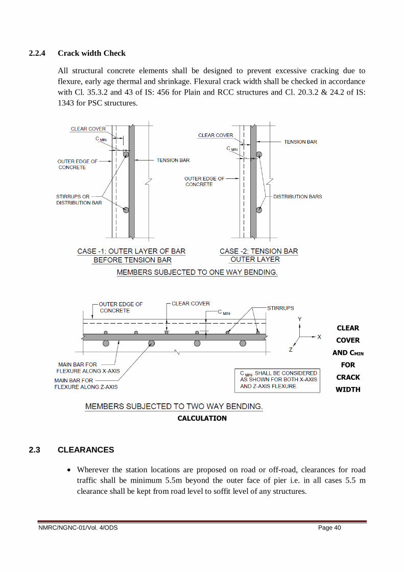
2.2.4 Crack width Check
All structural concrete elements shall be designed to prevent excessive cracking due to
flexure, early age thermal and shrinkage. Flexural crack width shall be checked in accordance
with Cl. 35.3.2 and 43 of IS: 456 for Plain and RCC structures and Cl. 20.3.2 & 24.2 of IS:
1343 for PSC structures.
CLEAR
COVER
AND CMIN
FOR
CRACK
WIDTH
CALCULATION
2.3 CLEARANCES
Wherever the station locations are proposed on road or off-road, clearances for road
traffic shall be minimum 5.5m beyond the outer face of pier i.e. in all cases 5.5 m
clearance shall be kept from road level to soffit level of any structures.
NMRC/NGNC-01/Vol. 4/ODS Page 41
As per schedules of dimensions of Indian Railways, General arrangement drawing in
such cases where viaduct crosses the railway tracks, the same shall be approved by the
concerned Railway administration.
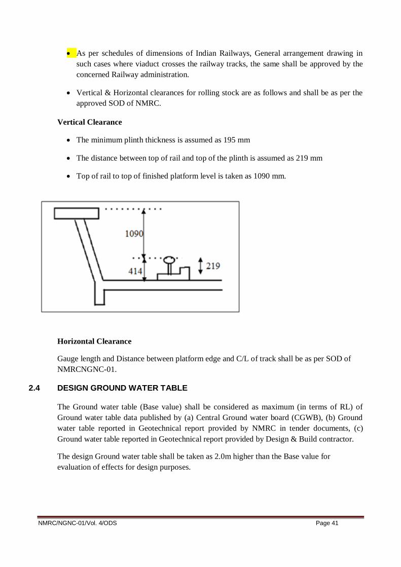
Vertical & Horizontal clearances for rolling stock are as follows and shall be as per the
approved SOD of NMRC.
Vertical Clearance
The minimum plinth thickness is assumed as 195 mm
The distance between top of rail and top of the plinth is assumed as 219 mm
Top of rail to top of finished platform level is taken as 1090 mm.
Horizontal Clearance
Gauge length and Distance between platform edge and C/L of track shall be as per SOD of
NMRCNGNC-01.
2.4 DESIGN GROUND WATER TABLE
The Ground water table (Base value) shall be considered as maximum (in terms of RL) of
Ground water table data published by (a) Central Ground water board (CGWB), (b) Ground
water table reported in Geotechnical report provided by NMRC in tender documents, (c)
Ground water table reported in Geotechnical report provided by Design & Build contractor.
The design Ground water table shall be taken as 2.0m higher than the Base value for
evaluation of effects for design purposes.

NMRC/NGNC-01/Vol. 4/ODS Page 42
2.5 LIQUEFACTION
Liquefaction shall be considered as per IS 1893-Part-1. The design Ground water table shall
be used for liquefaction potential calculation. The Moment Magnitude Mw to be taken in
design shall be 7.0. The factor of safety shall be more than 1.0 to ascertain that the strata are
not liquefiable.
2.6 SOIL PARAMETERS
The values of soil strength parameters (c, ϕ. etc.) to be used for design purposes shall be
lesser of the following:
i) As per soil investigation report in the tender document.
ii) As per soil investigation done by contractor.
The soil investigation report of Bore hole done by contractor shall be compared by soil
investigation report of the nearest Bore hole given in the tender document.
2.7 DESIGN LOAD 2.7.1 Dead Load (DL)
Dead load shall be based on the actual cross sectional area and unit weights of materials and
shall include the weight of structural members of the station building.
2.7.2 Super Imposed Dead Load For Non Track Area (SIDL)
FIXED SIDL (SIDL)
For platform slabs, the following loads in SIDL will be taken
Floor finishes is assumed to be a 3.6 kN/m2 uniform load as per architectural
requirement.
Suspension load is assumed to be 2.0 kN/m2 uniform load (Suspension load will be
considered as the load of false ceiling and services. This load will be considered where
ever is applicable.
Light partition wall load is assumed to be 1.0 kN/m2 uniform load.
For concourse area, the following loads in SIDL will be considered.
Floor finishes is assumed to be a 3.6 kN/m2 uniform load as per architectural
requirement.
Load due to additional fill in the toilets (brick bat) shall be considered as per architectural
drawing.
Suspension load is assumed to be 2.0 kN/m2 uniform load (Suspension load will be
considered as the load of false ceiling and services. This load will be considered where
ever is applicable.
Loads due to escalator / lift will be considered as per manufacturer’s detail.

NMRC/NGNC-01/Vol. 4/ODS Page 43
Light partition wall load should be taken as minimum 1.0 kN/m2 at concourse.
Loads due to Platform screen door (PSD) shall be considered as per actual.
Loads due to solar panel shall be considered as 30 kg/m2.
SIDL for Technical Room shall be as follows:
i) UPS Room* : 25** kN/m2
ii) ASS room* : 15** kN/m2
iii) Other Technical Room* : 10** kN/m2
• Minimum dead load of PEB roof shall be considered as 120Kg/m2. However actual to be
taken as per architecture.
*This should be verified with actual load and its location.
** Values are minimum load to be considered in design. Actual loads will be calculated on
the basis of equipment & machinery which have to be installed at detail design stage. The
concentrated load of 40kN for ASS/UPS room and 20kN for other technical room shall also
be considered in design.
Note:
a) The walls loading will be taken based on actual location shown in architectural drawings.
External wall load/glazing load will be taken as per details provided in architectural
drawings. It is proposed to take 230 mm thick brick wall with 20 mm thick plaster on
either side. However, the same shall not be taken less than 2.4 kN/m2.
Above loads intensities are minimum loads to be considered in design, Actual load may be
higher as per detailed architectural drawings.
2.7.3 Live loads (LL)
Location Distributed load (kN/m2) Concentrated load (kN)
Public/Staff Room
Concourse Floor 5 4.5
Staircase area 5 4.5
Platform 5 4.5
Office Accommodation 5 4.5
Shop 5 4.5
Foot over Bridge (FOB) 5 4.5
2.7.3.1 Vertical Train Live Load
Each component of the structure shall be designed/checked for all possible combinations
of these loads and forces.

NMRC/NGNC-01/Vol. 4/ODS Page 44
All axle loads = 16 tons
Maximum number of successive cars: 6
Configuration (alternate) 1:
a = 2.25m
b = 2.50m
c = 12.60m
(2a+2b+c=22.1m)
Configuration (alternate) 2:
a = 2.605m
b = 2.29m
c = 12.31m
(2a+2b+c=22.1m)
Moving load analysis shall be carried out in order to estimate maximum longitudinal force,
max shear and max BM.
The maximum SF and BM for different span for single track live load of 16T axle load
(without CDA) is attached as Annexure – 2 as an example.
Superstructure, substructure and foundation shall be checked for one track loaded conditions
as well as both track loaded condition (Single span as well as both span loaded condition).
However, for any other configuration (Axle load and axle spacing) of modern Rolling Stock
including maintenance, machinery, crane etc, shall be within the loading envelope of present
live load configuration.
2.7.3.2 Horizontal Train Live Load
Provision of clause 2.8.4 of IRS Bridge Rule be followed, when there are more than one
track on single girder.
2.7.4 Earthquake Loads (EQ)
Earthquake design shall follow the seismic requirement of IS: 1893 (Part1)
Horizontal Seismic Coefficient- The horizontal seismic design coefficient shall be calculated
as per following expression
Ah = (Z/2) * (I/R) * (Sa/g)

NMRC/NGNC-01/Vol. 4/ODS Page 45
Where,
Ah = horizontal seismic coefficient to be considered in design
Z = peak ground acceleration or zone factor = 0.24
I = importance factor = 1.5
R = response modification factor = 5
Sa/g = normalized pseudo spectral acceleration for corresponding to relevant
damping of load resisting elements (pier/columns) depending upon the fundamental period of
vibration T
Damping factor = 5% for RCC structures
Damping factor = 2% for steel structures
2.7.4.1 Drift Limitations
The storey drift in the building shall satisfy the drift limitation specified in IS: 1893.
2.7.4.2 Seismic detailing
i) For RCC structures as per IS: 13920
ii) For other structures as per IS: 4326
2.7.5 Wind Loads (WL)
Wind Loads (longitudinal & transverse) shall be calculated as stated in IS 875: Part 3-2015
(Part-3).
Wind loads will be calculated in accordance with IS 875: Part 3-2015.
Design wind speed Vz = Vb*K1*K2*K3*K4
Vb (basic wind speed) = 50 m / sec (As per NBC)
K1 (risk coefficient) = 1.07 (for 100 years mean probable design
life), Table 1, pg.-7
K2 = as per table2, pg-8 based on terrain
category and structure height
K3 (Topography factor) = 1.0, as per Cl.6.3.3.1, page-8
K4 = 1.0 for Non cyclonic zone as per Cl.6.3.4, pg.-8
Based on the above, Design wind pressure at height z, (Pz) = 0.6 x Vz x Vz Cl. 7.2, pg.-9

NMRC/NGNC-01/Vol. 4/ODS Page 46
Design wind pressure, Pd = Pz * Kd * Ka * Kc = wind directionality factor, pg.9 / 10
Kd = wind directionality factor, page 9 / 10 of IS: 875-3-2015 = 0.9 for buildings
Ka = area averaging factor, pg.9/10 = 0.8 Table 4 (for contributory area > 100 m2)
Kc = combination factor, pg. 9/10 = 0.9 Cl. 7.3.3.13 of IS: 875-2015, Page 16
2.7.6 Construction and Erection Loads (ER)
The weight of all temporary and permanent materials together with all other forces and effects
which can operate on any part of structure during erection shall be taken into account.
Allowances shall be made in the permanent design for any locked in stresses caused in any
member during erection.
2.7.7 Temperature Load (TL)
As per Cl. 19.5 of IS: 456. Temperature gradient shall be considered as per CL. 215 of IRC-6,
if applicable.
2.7.8 Shrinkage
Shrinkage strain shall be evaluated as Cl. 6.2.4 of IS: 456 for plain and RCC structures and
Cl. 6.2.4 of IS: 1343 for prestressed concrete structures.
2.7.9 Creep
Creep strain shall be evaluated as Cl. 6.2.5 of IS: 456 for plain and RCC structures and Cl.
6.2.5 of IS: 1343 for prestressed concrete structures.
2.7.9.1 Earth Pressure (EP) & Water pressure (WP)
In the design of structures or part of structures below ground level, such as retaining walls and
underground pump room/ water tanks etc. the pressure exerted by soil or water or both shall
be duly accounted for. When a portion or whole of the soil is below the free water surface, the
lateral earth pressure shall be evaluated for weight of soil diminished by buoyancy and the
full hydrostatic pressure. (As per IS: 875-part 5).
All foundation slabs / footings subjected to water pressure shall be designed to resist a
uniformly distributed uplift equal to the full hydrostatic pressure. Checking of overturning of
foundation under submerged condition shall be done considering buoyant weight of
foundation.
If any of the structure supporting metro building is subjected to earth pressure, the loads and
effects shall be calculated accordance with 5.7 of IRS substructure code.

NMRC/NGNC-01/Vol. 4/ODS Page 47
2.7.10 Surcharge Load (SL)
In the design of structures or the parts of the structures below ground level, such as retaining
walls & underground pump room/ water tank etc. the pressure exerted by surcharge from
stationary or moving load, shall be duly accounted for. For the area approachable by road
traffic, the minimum live load surcharge shall be taken as 24 kN/m2
2.7.11 Prestressing force (PS)
The prestressing force should be as per IS: 1343.
2.7.12 Settlement (DS)
Maximum and differential settlement shall not exceed, as provided in Table 1 of IS: 1904.
The allowable settlement for pile group is 25mm (as per IS 2911-part 4);
2.7.13 Other Forces and Effects
As per Cl. 19.6 of IS: 456.
2.8 LOAD COMBINATIONS
Load Abbreviations
Dead load DL
Super imposed dead load (Fixed) SIDL
Prestressing PS
Live Load LL
Temperature Load TL
Wind Load WL
Earthquake Load EQ
Differential settlement DS
Earth Pressure EP
Water Pressure WP
Surcharge Load SL
Erection load ER
a) For PSC elements, the load combinations shall be as per table 7 of IS: 1343.
b) For steel structures, the load combinations shall be as per IS: 800.
c) For RCC structures / elements, shall be as per Table 18 of IS: 456 and IS: 1893-1 as follows:

NMRC/NGNC-01/Vol. 4/ODS Page 48
2.9 Deflection Criteria
The deflection limitations as per Cl. 23.2 of IS: 456 for Plain and RCC Structures and Cl.
20.3.1 if IS: 1343 for PSC structures shall be followed.
2.9.1 Lateral Sway
The lateral sway at the top of the building due to wind loads should not exceeds H/500, where
‘H’ is the height of the building.
2.10 FOUNDATION SYSTEM
2.10.1 Type of foundation:
Considering the nature of ground, type of proposed structure, expected loads on foundation,
the following type of foundations are considered practical:
a. Spread or pad footing
b. Raft Foundation
c. Pile foundation
No matter the type of foundation to be adopted, the following performance criteria shall be
satisfied:
1. Foundation must not fail in shear
2. Foundation must not settle by more than the settlements permitted as per table-1 of IS:
1904. The allowable settlement for pile group is 25mm (as per IS 2911-part 4);

NMRC/NGNC-01/Vol. 4/ODS Page 49
2.10.2 Design of Pile Foundation
IS: 2911 shall be followed for design of pile, load capacity etc. Theoretical estimation of
settlement for deep foundation shall be done in accordance with IS: 8009-Part-2.
The forces applied by the pier are transferred to the bottom of the pile cap for this purpose.
Reactions in pile are calculated using Rivet theory. The various specific assumptions made for
the pile and pile cap design are as follows:
a. Bored-cast-in-situ multiple pile groups will be adopted.
b. The various specific assumptions made for the pile and pile cap design including pile
load testing shall be as per IS: 2911.
c. Increase in vertical load capacity of pile shall be done as per Table-1 of IS 1893-Part-1.
d. The lateral load capacity of pile shall be evaluated either by using empirical formulae
given in IS: 2911 (Part-1/ section-2) or by soil structure interaction analysis using
Winkler’s spring model by limiting the lateral deflection as 1% of Pile diameter.
e. Initial load tests (not on working pile) will be conducted as per IS: 2911 - Part IV. Initial
test is proposed to be conducted for a load of 2.5 times as per the safe vertical load based
on static formula.
f. The working load on pile for vertical and horizontal loads shall be verified through
routine load tests during construction.
g. In case of multiple pile system, spacing between the piles shall not be less than 3 times
the diameter of pile in soil and 2.5 times the diameter when founded on rock.
h. The following limiting values shall not be exceeded for computation of safe load:
o Result of sub-structure investigation will be used for adopting the value of angle of internal
friction “φ” and cohesion of soil “c” as per 2.6. of this DBR.
o Angle of wall friction δ shall be taken as equal to φ deg.
o Co-efficient of earth pressure “K‟ shall be taken as 1.0.
o Maximum overburden pressure at bottom of pile for calculation of shaft resistance and
bearing resistance shall be limited to 15 times the diameter of the pile. The maximum depth
shall be considered from existing ground level.
o For calculating the pile capacities, the design ground water table shall be considered as per
Cl. 2.4 of this DBR.
o Bulk density corresponding to 100% saturation shall be calculated and used for working out
submerged density of soil.
i. While finalizing length of pile, Clause 705.4.1 of IRC: 78 shall also be followed.

NMRC/NGNC-01/Vol. 4/ODS Page 50
j. In general the top of pile cap shall be kept about min 500mm below the existing ground
level and weight of the earth cover will be applied on top of pile cap when unfavourable.
The earth cover on pile cap for any favourable effect (stability, soil horizontal capacity.)
will be neglected.
k. Live load surcharge needs to be considered for pile group which is outside median and
where live load is moving over pile cap. Normal Pile groups below median or where
there is no live load over pile cap need not to be design for live load surcharge.
l. In case of foundations near railway crossing effect of railway live load surcharge shall
be considered if applicable
2.10.3 Open foundation
Open foundation shall be designed as per IS: 456, IS: 1904, IS: 6403. Calculation of
settlements shall be done as per IS: 8009-Part-1.
2.11 Design of water retaining structures
The underground tank in a station shall be designed as a water retaining structure based on IS:
3370. Various types of loadings shall be considered in the design of the underground tank.
The side walls shall be subjected to earth pressure. The water table being high in the area,
horizontal pressure due to it shall also be considered. Stability of water tank shall be checked
against buoyancy and foundation raft shall be designed for the worst of buoyant force and soil
pressure. The tank shall also be designed for surcharge loading if any. Water proofing
treatment shall be done on the external surface as well as in the internal surface.
2.12 MASONRY WALLS
All Masonry walls shall be treated as non-structural infill panels and shall be treated as one
way / two way slab panels spanning between adjoining beams and columns to check structural
safety. Masonry walls shall be designed as un-reinforced masonry as per IS: 1905 and IS:
4326. Shear connector reinforcement between walls & upper beams and walls & sides of
columns shall be provided for external walls, while the internal partition walls shall be
connected with roof slabs/beams using dry packing mortar between top of walls and soffit of
slab / beam.
3 LIST OF DESIGN CODES AND STANDARDS
The design shall be carried out as per provision of these design specifications. Reference shall
be made to the following codes for any additional information:
Order of preferences of codes shall be as follows:
i. IS
ii. IRS
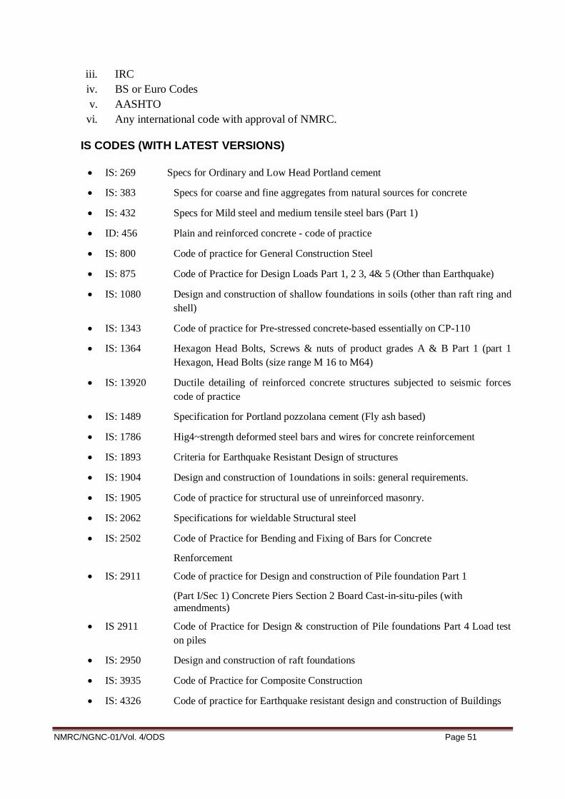
NMRC/NGNC-01/Vol. 4/ODS Page 51
iii. IRC
iv. BS or Euro Codes
v. AASHTO
vi. Any international code with approval of NMRC.
IS CODES (WITH LATEST VERSIONS)
IS: 269 Specs for Ordinary and Low Head Portland cement
IS: 383 Specs for coarse and fine aggregates from natural sources for concrete
IS: 432 Specs for Mild steel and medium tensile steel bars (Part 1)
ID: 456 Plain and reinforced concrete - code of practice
IS: 800 Code of practice for General Construction Steel
IS: 875 Code of Practice for Design Loads Part 1, 2 3, 4& 5 (Other than Earthquake)
IS: 1080 Design and construction of shallow foundations in soils (other than raft ring and
shell)
IS: 1343 Code of practice for Pre-stressed concrete-based essentially on CP-110
IS: 1364 Hexagon Head Bolts, Screws & nuts of product grades A & B Part 1 (part 1
Hexagon, Head Bolts (size range M 16 to M64)
IS: 13920 Ductile detailing of reinforced concrete structures subjected to seismic forces
code of practice
IS: 1489 Specification for Portland pozzolana cement (Fly ash based)
IS: 1786 Hig4~strength deformed steel bars and wires for concrete reinforcement
IS: 1893 Criteria for Earthquake Resistant Design of structures
IS: 1904 Design and construction of 1oundations in soils: general requirements.
IS: 1905 Code of practice for structural use of unreinforced masonry.
IS: 2062 Specifications for wieldable Structural steel
IS: 2502 Code of Practice for Bending and Fixing of Bars for Concrete
Renforcement
IS: 2911 Code of practice for Design and construction of Pile foundation Part 1
(Part I/Sec 1) Concrete Piers Section 2 Board Cast-in-situ-piles (with
amendments)
IS 2911 Code of Practice for Design & construction of Pile foundations Part 4 Load test
on piles
IS: 2950 Design and construction of raft foundations
IS: 3935 Code of Practice for Composite Construction
IS: 4326 Code of practice for Earthquake resistant design and construction of Buildings

NMRC/NGNC-01/Vol. 4/ODS Page 52
IS: 4923 Hollow steel sections for structural use -specification
IS: 8009 Calculation of settlements of shallow foundations
IS: 8112 Specifications for 43 grade ordinary Portland cement
IS: 9103 Specifications of Concrete admixtures
IS: 11384 Code of practice for Composite Construction in Structural Steel and Concrete
IS: 12070 Code of practice for Design and construction of shallow foundation on Rocks
IS: 12269 Specification for 53 grade ordinary Portland cement
IS: 14268 Uncoated Stress Relieved Low relaxation Seven-ply Strands for Prestressed
concrete
IS: 14593 Design and Construction of Bored Cast-in-Situ Piles Founded on Rocks.
IRS CODES (WITH LATEST VERSIONS)
IRS Bridge Rule
IRS Concrete Bridge Code
IRS Bridge substructure & Foundation Code
IRS Steel Bridge Code
IRS Fabrication Code (B1)
IRS Welded Bridge Code
IRS code for Earthquake resistant design of Railway Bridges 2020
IRC CODES (With Latest Versions)
IRC: 5 Standard Specification & Code of Practice for Road Bridges - General Features
of Designs
IRC:6 Standard Specification & Code of Practice for Road Bridges- Loads and
Stresses
IRC: 18 Design Criteria for Pre-stressed Concrete Road Bridges (post Tensioned
Concrete)
IRC: 22 Specification & Code of Practice for Road Bridges, Section VI - Composite
Construction for Road Bridges
IRC: 24 Standard Specification & Code of Practices for Road Bridges, Section V-Steel
Road Bridges
IRC: 78 Standard Specification & Code of Practice for Road Bridges - Section
Foundations & Sub-Structure
IRC: 83(I) Standard Specification & Code of Practice for Road Bridges, Part-l Metallic
Bearings

NMRC/NGNC-01/Vol. 4/ODS Page 53
IRC: 83(II) Standard Specification & Code of Practice for Road Bridges, Part-II Elastomeric
Bearings
IRC: 83 (III) Standard Specification & Code of Practice for Road Bridges, Part-III POT,
POT-cum PT;TE, Pin and Metallic Guide Bearings
IRC: 83 (IV) Standard Specification & Code of Practice for Road Bridges, Part, IV Spherical
and Cylindrical Bearings.
IRC: 112 Code of practice for Concrete Bridges
IRC-SP-71 Guidelines for Design and Construction of Pre-cast Pre-tensioned Girders for
bridges
BS CODES (WITH LATEST VERSIONS)
BS: 4447 Specifications for the performance of prestressing anchorage for post-tensioned
concrete.
BS: 4486 Specifications for high tensile bars used for prestressing.
BS: 5400 Code of Practice for Design of Concrete Bridges Part 4-1990.
BS: 8006 Code of Practice for strengthened reinforced soils and other fills-1995.
BS: 8007 Design of Concrete structures for retaining liquids.
OTHERS (WITH LATEST VERSIONS
UIC:776-1R Loads to consider in Railway Bridge Design
UIC:776-3R Deformation of Bridges
UIC: 772 Then International Union Railway Publication
UIC: 774 - 3R Rail structure interaction
CEB_FIB Model Code 1990 for Concrete Structures
The design relating to Fire safety and escape shall be in accordance with the
requirements of NFPA 130 standard for fixed guide way system.
FIP Recommendations for the Acceptance of Post-tensioned systems.
M.O.R.T and Highways specifications.
Euro code 0 Basis of Structural Design.
Euro code 1 Actions on Structure-Part 2-Traffic Loads on Bridge.
Euro code 2 Design of Concrete Structures- Part 1.1: General Rules and Rules for
Building.
Euro code 2 Design of Concrete Structures- Part 2, Concrete Bridges - Design and
Detailing Rules.

NMRC/NGNC-01/Vol. 4/ODS Page 54
ACI 358: IR-92 (American Concrete Institute) for assessment of dynamic impact for
transit Guide ways.
ROSO Guidelines for carrying out RSI (Version 2.0) issued in January 2015 BS-111
version-3 issued in January 2015.
All codes listed above shall be of latest revision including all amendments & corrections.
DESIGN SOFTWARE
Any commercial or proprietary software can be used for analysis/design provided the same is
validated with manual computations or other standard software in multiple scenarios.

NMRC/NGNC-01/Vol. 4/ODS Page 55
OUTLINE DESIGN SPECIFICATIONS
FOR
CUT & COVER SECTION

NMRC/NGNC-01/Vol. 4/ODS Page 56
1 INTRODUCTION
After the realization of the first phases of Noida Metro, NMRC has started thedevelopment of its NGN
Extension. This report highlights the structural design basis for UG stations, cut & cover tunnel, ramp
on underground section.
2 SCOPE OF DBR
This Design Basis defines the structural design assumptions for Underground Station /Cut & Cover
portion, as described above.The aim is to collect in a unique document for all the design input and
procedures tobe employed for the calculation and design of underground structures.The report gives
the basis for calculations including the applicable codes andstandards, the material properties, the
design method, the loading to be taken intoaccount and the considered load combinations.The present
document will be used as reference for the future calculation notes andstructural drawings.It should be
adopted in conjunction with the Geotechnical Interpretative Reportspecific for each Underground
structure.
3 CUT & COVER STRUCTURES
NMRC/NGNC-01/Vol. 4/ODS Page 57
3.1 Introduction
This section summarizes the Civil, Structural and Geotechnical design philosophy and other
relatedparameters for underground stations, station entrances, vent shafts, subways and cut &
covertunnel. For geotechnical design parameters, reference shall be made to Geotechnical
Interpretative Report and for geotechnical investigations related works refer “Outline Design Criteria for
Geotechnical Works"
3.2 General Principles
1. Cut-and-cover structures include UG station, station entrances/exits, vent shafts, subway, utility duct,
OTE DUCT, Cut & Cover Box tunnels, Cut & Construct Open U Ramp structures linking with Elevated
Ramps andthe structures other than bored tunnels that are required to be constructedbelow ground
surface.
2. The cut-and-cover structure is proposed to be a rigid box section withpermanent walls as external wall
support system and beam-slab & columnforming the internal structural framing. The roof slab shall
support the soiland vehicular LL surcharge while the passenger and plant loads are carried bythe
concourse slab. The track and platform loads shall be supported bythe base slab. The permanent
walls shall resist the lateral earth andhydrostatic pressures in addition to the LL and building
surcharge (horizontal loads) from nearby road and buildings.
3. The completed stations, station entrances, vent shafts shall comply withContract water-tightness
criteria.
4. Where temporary walls are intended as part of the Permanent Works, theContractor shall justify the
feasibility and suitability of such to theEmployers Representative. The durability critaria shall also be
satisfied to ensure 100 years design life.
5. The Contractor shall take into account the following in the design of cut-and cover structures.
a. Method of construction, including temporary works and construction sequence.
b. Ground/structure interaction, including the effects of temporary works.
c. Ground pressure, shear force and bending moment distribution during construction and in
the long-term.
d. Short- and long-term ground and groundwater response.
e. Other static loads changes such as; excavation, surcharge, traffic loadings and the like.
f. Long-term water table level changes
g. dynamic (such as seismic or vibratory plant) loads and displacements.

NMRC/NGNC-01/Vol. 4/ODS Page 58
6. For the purposes of assessing ground and groundwater pressures duringservice stage, the cut-and
cover structures shall be considered to beeffectively impermeable rigid box structures subject to “at
rest” (Ko)earth pressure and “active” (Ka) earth pressure as the case may be.
7. The Contractor shall design to minimize the effects (such as movement,distortion of the ground and
the like) on all Existing Building Structure(EBS) that may be affected by the Works. Where necessary
the Contractorshall provide additional support for these EBS. Building damage assessment reports
along the zone of construction shall be prepared and the type of strengthening required may be
decided based on category of building.
3.3 Design Principles
1. The design of all cut-and-cover structures shall take into account, but notbe limited to the following:
a. The variation in ground conditions along the alignment.
b. The variation in engineering properties of soil or rock within the influence of the proposed
works.
c. All dewatering and groundwater cut-off systems required to maintain dry and stable
conditions within all excavations required for these Works.
d. Any ground treatment before, during or after construction of the Works (e.g. groundwater
recharge) which is required to stabilise the ground and EBS in order to minimise adjacent
ground and EBS movement and distortion.
e. Methods by which the completed structure shall be secured against flotation. Any temporary
dewatering system shall not be turned off till the structure is safe against leakage or flotation
when the ground water returns to the design levels.
f. Differential groundwater pressures due to inside and outside water table
g. Methods of waterproofing the completed structure.
h. Drawdown of the groundwater levels outside the UG station and cut and cover tunnel walls
shall be limited to not more than 2 metres from the existing average groundwater level in
the zone of construction. Recharging pits shall be provided in case there is a danger of
reduction in water table outside area of construction. This is necessary to prevent settlement
of ground outside area of construction. In general, groundwater levels interior to
construction excavations shall not be depressed more than 1.0m below final base slab level.
i. The magnitude of ground and EBS movements and distortions, and changes in loading
conditions on these EBS that might be expected as a result of the works and how these will
be mitigated so as to comply with any imposed constraints or so as to minimise disturbance
to theseEBS.

NMRC/NGNC-01/Vol. 4/ODS Page 59
j. Any difficulties that the Contractor’s intended plant/machinery/methods might meet with in
respect of access, clearances, working space and obstruction to excavation.
k. Maintenance of traffic flows along roads including access to adjoining properties and roads.
l. Noise levels produced during construction.
m. Control of heave, swell, piping and instability of the excavations.
n. The effects of vibration and vibration induced movements – e.g. earthquake.
2. The following methods of construction shall be used either individually orin combination depending
upon the particular requirements of thelocation, size and type of structure.
a. Diaphragm Walls - Particular attention shall be paid to the D wall andpanel alignment, the
stability of excavation, the design mix and condition ofthe slurry, placement of the
reinforcement cage, methods for formingand locating box-outs, waterproofing of the vertical
panel joints,placement of concrete, and the overall integrity and water-tightnessof the
formed wall.
b. Secant Piles/Sheet Piles/Soldier Piles and Horizontal Planks – Particularattention shall be paid
to the construction/installation of the piles andground support systems to ensure their
integrity and water-tightnessand to provide adequate support to the ground during
excavation.
3. Diaphragm walling is the preferred support method for the TBM Shafts,UG station, construction close
to sensitive existing structures, Cut &Cover Box tunnel excavations at large to medium depths close to
existingstructures, cross over structures, etc
4. Soldier Pile wall/ Bored Pile wall methods of support may be used for theother medium excavations
such Cut & Covertunnel, entrances/exits, utilities and services. In case of high underground water
table, soldier pile system with horizontal plans is not allowed.
5. Sheet Pile wall methods of support may be used for the other shallowexcavations such as open U
Ramp, shafts utilities and services.
3.4 Excavation Support
3.4.1 General
a. The Contractor shall prepare and submit a detailed Design Report including calculations,
schedules and drawings for each proposed excavation support wall construction, prior to the
commencement of any such works. This Design Report shall take into account but not be
limited to the following:
i) Earth pressure.

NMRC/NGNC-01/Vol. 4/ODS Page 60
ii) Hydrostatic pressure.
iii) Deck load
iv) Surcharge loads.
v) Seismic and/or vibratory loads
vi) Support types and arrangement.
vii) Temperature loads
viii) Any other incidental/accidental load.
ix) Construction/deconstruction sequence.
x) Calculated ground and adjacent EBS movements and distortions.
xi) Calculated fluctuations in groundwater levels both within and outside of the excavation and
support walls.
xii) Calculated changes in EBS loading conditions.
xiii) For Deep Excavation in rocky strata, Rock bolt and Shotcrete to be used.
3.4.2 Method Statement
a. The Contractor shall prepare a Method Statement giving the full details of materials, plant
and operations involved in the construction of excavation support walls. This Method
Statement shall be incorporated into the Design Report submission for the Employers
Representatives notice and shall include but not be limited to the following details:
i) Formation of the joints between panels and installation of water stops.
ii) Method of producing the workable concrete. iii) Methods of handling within the excavations and disposing of groundwater outside of the
excavations. iv) Sequence of excavation and concreting of panels. v) Methods of instrumenting, monitoring and reporting of the performance of all adjacent EBS
that may be affected by the works. vi) Type and construction of permanent lining wall. vii) Emergency procedures to be implemented in the event that monitoring indicates tolerances
associated with the excavation support wall may be exceeded.
b. Where temporary ground support is to be provided using bentonite slurry, the following
additional information shall be provided in the Method Statement for these works.
i) Mixing, transporting and placing equipment for the bentonite slurry. ii) Method of disposal of contaminated bentonite slurry. iii) Type, source, chemical and physical properties of the bentonite to be used. iv) Stability, dimensions and details of guide walls. v) Cleaning and re-use of the bentonite slurry. vi) Calculations to show that the density of the bentonite and lowest head of slurry are
sufficient to maintain the stability of the trench excavated for the support wall, in the ground conditions envisaged, to its full depth.
3.5 Design Life and Serviceability
3.5.1 General
The design life of a structure or component is that period for which the structural item is required to
fulfil its intended function when maintained in accordance with agreed procedures to meet a required
level of performance. The definition of a design life for a structure or component does not necessarily
mean that the structure will no longer be fit for its intended purpose at the end of that period. Neither

NMRC/NGNC-01/Vol. 4/ODS Page 61
will it be expected to necessarily continue to be serviceable for that length of time without adequate
maintenance to mitigate the demands of degradation.
3.5.2 Civil Engineering Structures
1. The design life of all civil engineering structures shall be a minimum of 100 years unless otherwise
specified or agreed upon.
2. Adequate measures shall be taken to ensure a minimum of 100 years serviceability of civil structures
by producing durable concrete structures. For achieving this suitable property enhancers / blending
materials conforming to relevant BIS codes (or more stringent International Standards/Codes
wherever required) may be used as deemed appropriate and subject to Notice of No Objection from
the Engineer.
3. The design life of the above ground building structures including ancillary buildings, utility support,
structures and vent shafts etc. shall also be 50 years.
4. The design life of non-structural elements shall be 50 years.
5. Durability approach and assessment report (DAAR) to ensure service life of structures shall be
submitted and to be got approved before start of work on site.
3.5.3 Road pavement
The design life of all pavements shall conform to the requirement of relevant codes of IRC and
MORTH.
3.5.4 Serviceability of Civil and Building Works
1. Paint systems for steelwork, wherever permitted by the Engineer, shall ensure a minimum life of 5
years before full maintenance painting is required.
2. The corrosion protection of non-structural steel items shall be appropriate to the accessibility of the
item for inspection and maintenance.
3.6 Units
The main units used for design will be: [t], [m], [mm], [kN], [KN/m2], [MPa], [oC], [rad]
3.7 Material Parameters
3.7.1 Cement
Cement shall be as defined in Outline Construction Specifications for Phase-IV Civil Works.
3.7.2 Concrete
Concrete shall be as defined in Outline Construction Specifications for Phase-IV Civil Works.

NMRC/NGNC-01/Vol. 4/ODS Page 62
The characteristic strengths (fck) and the corresponding mechanical characteristics necessary for
design as per requirements for 100 years of design life of structures are indicated in Table here
below: -
A Characteristics of main construction Materials (structural elements in contact with non-aggressive soil of Delhi)
S. No. Structural Components
Minimum Grade of concrete (cube)
1 Inner slabs, beams &
columns M35
2 Outer slabs M35
3 Outer cast-in-situ walls
against form work M35
4 Diaphragm walls M35
5 Tension Pile, barrettes,
compression piles M35
6 Platform slab, UPE duct, OTE duct, vent shafts etc
M35
B Characteristics of main construction Materials (structural elements in contact with Drain Water ,
chemically aggressive environment and soils)
S. No. Structural
Components
Minimum
Grade of
concrete
(cube)
1 Outer slabs M45
2 Outer cast-in-situ walls
against form work M45
3 Diaphragm walls M45
4 Tension Pile M45
3.7.3 Cover Requirements for 100 years durability of structures
A For Underground structural elements in contact with non-aggressive soil of Delhi
S. No. Structural Components Nominal Cover/clear
cover to any reinf. (mm)

NMRC/NGNC-01/Vol. 4/ODS Page 63
1 Inner slabs, beams & columns 50
2 Outer slabs at roof 50
3 Outer Base slabs 75
4 Outer cast-in-situ walls against form work 50
5 Diaphragm walls 75
6 Tension Pile, barrettes, compression piles 80
7 Platform slabs, internal RCC walls, vent shaft
walls, staircase slabs, UPE and OTE ducts 35
B For Underground structural elements in contact with Drain water, aggressive soil and environment
S. No. Structural Components
Nominal Cover/clear
cover to outermost
reinf. (mm)
1 Outer slabs 65
2 Outer cast-in-situ walls against form work 65
3 Diaphragm walls 90
4 Tension Pile, barrettes, compression piles 95

NMRC/NGNC-01/Vol. 4/ODS Page 64
3.7.4 Density
25 kN/m3 for reinforced concrete (IS:875 Part-1 Table-1 item 22 value rationalized)
23 kN/m3 for plain concrete (IS:875 Part-1 Table-1 item 20)
Actual density to be validated as per actual mix design
3.7.5 Poisson’s Ratio
Poisson’s ratio for all concrete: 0.15
3.7.6 Thermal Expansion Coefficient
As per cl. 6.2.6 of IS: 456
3.7.7 Young’s Modulus
Instantaneous modulus (E) is taken as per clause 6.2.3.1 of IS 456:2000
E =5000 (fck) ^0.5
Where, fck is the Characteristic Compressive Strength of 150mm Cube at 28 days.
3.7.8 Modular Ratio
Modular ratio for all concrete grades shall be taken as per Annex B of IS:456. Modular ratio, for cracked section m = Es/Eeff
Where, Es = Steel Modulus
Eeff = Eff. Modulus of Concrete (Eeff = Ec / (1+))
3.7.9 Reinforcement
Only thermo-mechanically treated reinforcement bars of grade Fe500D with minimum total elongation
of 14.5% conforming to IS 1786 shall be adopted. However, for design of shear stirrups strength
parameters of Fe415 only shall be considered.
The material properties shall be as follows:
Young’s
Modulus
[Mpa]
Yield Stress
[Mpa]
Diameters
[mm]
Density
[kN/m3]
Poisson’s
Ratio
Thermal
Coefficient per oC
200,000
415 for Fe415
500 for Fe
500 D
8, 10, 12, 16,
20, 25, 28, 32,
36, 40
78.5 0.3 12x10-6
3.7.10 Structural Steel: General
(1) DesignofStructuralsteelworkshallcomplywithIS:800.

NMRC/NGNC-01/Vol. 4/ODS Page 65
(2) Two types of structural steel to be used and shall comply with the following standards:
a) IS:4923"HollowsteelsectionsforstructuralusewithYst310".
b) IS: 2062 "Steel for General Structural Purposes (Grade Designation E250 BR).
(3) Hollow steel sections shall be square (SHS) or rectangular (RHS). Other traditional rolled
sections like plates, angles, channels, joists can also be used where required.
(4) The connections within the steel structure shall be designed as direct welded members with
or without gusset plates. The minimum thickness of metal for SHS/RHS sections for main
chord members as well as bracings shall be 4 millimetres as applicable for steel tubes in cl.
6.3 of IS: 806.
(5) IS:800-2007 shall be followed and limit state method od design shall be adopted for steel
structures
Material Properties shall be as follows:
Steel Type Young’s
Modulus
Tensile
Strength Yield Strength
Density
[kN/m3]
Poisson
’s Ratio
Thermal
Expansion
Coefficient
For Hollow
Steel
Sections
(Conforming
to IS: 4923) 200000
Mpa
450
Mpa 310 Mpa
78.5 0.30 1.2x10⁻⁵ Per
oC
Structural
Steel
(Conforming
to IS: 2062)
410 Mpa
250 Mpa (for
t<20mm), 240MPa
(for 20mm < t < 40
mm), 230MPa (for t
> 40mm)
3.8 Durability Criteria
In carrying out structural designs it shall be ensured that both the serviceability and ultimate limit
states have been checked in accordance with the applicable Standards and Codes.
To achieve durability, the design shall take into account the prevailing ground and groundwater
conditions and those predicted to occur at the site within the design life of the Works.

NMRC/NGNC-01/Vol. 4/ODS Page 66
Water permeability in concrete shall not be more than 10 millimetres (at the concrete age of 28 days)
according to DIN 1048 and RCPT value (ability to resist chloride ion penetration) shall not exceed
1000 coulombs at the concrete age of 28 days according to ASTM C-1202.
For all other durability requirements refer Outline Construction Specifications for NGNC-01 Civil Works,
Noida Metro.
3.8.1 Fire Resistance Period
All structures shall be designed for fire protection as specified by the applicable standards and codes.
Materials specified for the Works shall be non-combustible and nor emit toxic fumes when subject to
heat or fire, except where permitted under the Contract. In all cases where there is significant fire
risk, materials shall be self-extinguishing, low flammability, low smoke and low toxicity. All the main
elements of the station structures (Roof Slab, Concourse Slab, Base Slab, Outer Wall, Columns & any
load bearing RCC Walls, ASS -TSS room RCC walls) and including firemen staircase & Public fire
escape underground structures shall be designed for a minimum fire resistance period of 4 hours. All
other element like Platform slab, vent shafts, UPE Walls, OTE Ducts, Stub Columns, other non load
bearing RCC walls etc. shall be designed for 2-hour fire rating.
A nominal cover shall be provided for four hours or two hours of fire resistance respectively as per IS
and NBC codes.
3.8.2 Crack Width
All structural concrete elements shall be designed to prevent excessive cracking due to flexure, early
age thermal and shrinkage. The maximum crack widths shall be as specified below.
a) Flexural Cracking
Formulae for Flexural crack width shall be as mentioned in Annex F of IS 456:2000. The limits
specified shall apply irrespective of whether any additional protection, such as waterproofing
membrane are provided to the members at the exposed face of the structure.
b) Early age Thermal and Shrinkage Cracking
(1) Suitable reinforcement shall be designed to prevent early age thermal and shrinkage
cracking for walls and slabs more than 250 millimetres thick and subjected to internal and
external restraints during construction. The thermal and shrinkage strains due to early age
temperature differences and shrinkage shall be accounted for in the design of reinforcement
for cracking.
(2) It is preferred that smaller diameter bars in any direction are placed at closer intervals to
prevent early age thermal and shrinkage cracks. The limits specified below shall be imposed.
Guidance can be sought from CIRIA C660-latest version on Early Age Thermal Control of

NMRC/NGNC-01/Vol. 4/ODS Page 67
Concrete in this matter.
(3) Minimum reinforcement shall be higher of:
a) 0.125% of cross-sectional area of structural member on each face in each direction.
b) Reinforcement required as per Early Age Thermal (EAT) control of concrete.
c) For Underground structural elements in contact with non-aggressive soil of Delhi
S. No. Structural Components
Min. Cover for crack width calculation
Cmin*
Concrete Grade
M35
Concrete Grade M40
and above
1 Inner slabs, beams & columns 45
40
2 Outer slabs 45 40
3 Outer cast-in-situ walls against
form work 45 40
4 Diaphragm walls, barrettes,
Tension/compression piles 45 40
d) For Underground structural elements in contact with Drain water, aggressive soils or
environment
S. No. Structural Components
Min. Cover for crack width Cmin*
Concrete Grade
M35
Concrete Grade M40
and above
1 Outer slabs 45 40
2 Outer cast-in-situ walls against
form work 45 40
3 Diaphragm walls, barrettes,
Tension/compression piles 45 40

NMRC/NGNC-01/Vol. 4/ODS Page 68
*The cover shall be considered as defined in sketches below.
However, as per durability requirements of 100 years for design life of underground structures and
minimum concrete cover, BS:8500-1-2006 has also to be followed for the exposure condition for the
different members as under:
Corrosion by carbonation criteria
S. No. Structural Components Exposure Class
1 All Structural members (outer/Inner) XC3
Corrosion by Carbonation criteria with hydraulic gradient more than 5 meter
S. No. Structural Components Exposure Class
1 All Outer structural members XC2 / AC-2/DC-2 (FND2)
The parameters such as Grade of Concrete, Concrete cover etc. shall be provided as per worst of both as
mentioned above.
Corrosion by chloride criteria for members in contact with aggressive soil/ Nallah etc.
Where soil is aggressive in addition to above criteria (given in A & B), following criteria shall also
be ensured:
S. No. Structural Components Exposure Class
1 All Outer structural members XD1

NMRC/NGNC-01/Vol. 4/ODS Page 69
e) Permissible crack width
1. For Members in Contact with Soil: -
0.2mm for soil face
0.3 mm for inner face
2. For Members not in Contact with Soil: -
0.3 mm
3. For Water Tanks: -
0.2 mm
4 LOADS AND REQUIREMENTS
4.1 General
Unless specified otherwise the design of concrete and steel elements shall conform to IS 456 and IS
800, respectively.
4.2 Nominal Loads
For the purpose of computing stresses and deformations, the following minimum load types and
consequential effects shall be taken into account as applicable.
Dead loads (including notional loads) DL
Superimposed Dead loads SIDL

NMRC/NGNC-01/Vol. 4/ODS Page 70
Imposed (Live) loads LL
Railway loads RL
Fatigue FG
Dynamic DY
Derailment DR
Wind Loads WL
Temperature loads TE
Seismic Loads EQ
Construction/Erection ER
Shrinkage SH
Creep CP
Movement/ Distortion MD
Earth Pressure EP
Surcharge SR
Hydrostatic WP
Accidental AC
Redundancy R
4.3 Design Loads
Design shall include all of the following loads:
4.3.1 Dead Loads
Self-weight of the materials shall be calculated in accordance with IS 875:1987 Part 1.
4.3.2 Superimposed Dead Loads and Imposed (Live) Load
The minimum distributed and concentrated loads shall be in accordance with following Table, and
Contract specifications.
Superimposed Dead Loads (SIDL) & Imposed (Live) Loads
Description
Superimposed Dead Load Imposed Load
Finishes
(kN/m2)
Partitions
(kN/m2)
Ceiling&
Services
(kN/m2)
U.D.L.
(kN/m2)
Concentrate
d Load
(Note2 & 3)
(kN) Station
Concourse Area 2.4(Note 5) 1.0(Note 6) 1.0(Note 6) 5.0(Note 1) 15.0
Platform Area 2.4(Note 5) 1.0(Note 6) - 5.0(Note 1) 15.0
Track (Note 10) Refer Section 3.3.3

NMRC/NGNC-01/Vol. 4/ODS Page 71
Stairs and
Landings
1.2(Note 4) - 1.0(Note 6) 5.0(Note 1) 15.0
General Plant
Rooms, Pump
Room
2.4(Note 5) - 1.0(Note 6) 7.5(Note 7) 22.5
General Office 2.4(Note 5) 1.0(Note 6) 1.0(Note 6) 2.5 7.5
Staff Rooms 2.4(Note 5) - 1.0(Note 6) 2.5 7.5
Toilets,
changing Room
2.4(Note 5) 1.0(Note 6) 1.0(Note 6) 2.5 7.5
Store 2.4(Note 5) - 1.0(Note 6) 5.0 15.0
Water Tank, Fire
Tank 2.4(Note 5) - - 20.0/ Water
Height+0.3 m -
Chiller Rooms 2.4(Note 5) - 1.0(Note 6) 10.0(Note 7) (Note 7)
Transformer
Rooms, Sub stn 2.4(Note 5) - 1.0(Note 6) 10.0/15.0/20.0(
Note 7) (Note 7)
Switch Gear Plant
Room 2.4(Note 5) - 1.0(Note 6) 7.5 (Note 7) 10.0
Roof Slab - - 1.0(Note 6) Soil Load+
20(Note 9)
-
Notes:
1. Stairs and landings to be designed for the same load as the floors to which they give access with a minimum of 2.5 kN/m2 and a maximum of 10 kN/m2 and public area staircase with minimum 5 kN/m2.
2. Concentrated loads act on a square of 300 mm each side.
3. As specified or wall loads in accordance with layout in architectural plan, whichever is greater.
4. All loads are unfactored.
5. Minimum of 100 mm thick screed on top, unit weight of 24 kN/m3.
6. As specified above or the imposed load from services fixed to the underside of floor whichever is greater.
7. The design loads shall be actual plant/equipment loads or the ones specified above, whichever is maximum. For seismic design plate/machinery loading shall be considered as Super Imposed Dead Load.
8. Backfill / Earth Load Shall be calculated for the available soil depth for a unit weight of soil of 20 kN/m3.
9. Live Load surcharge shall be minimum as 20 kN/m2 at ground level (fill depth greater than 1.3m) or from actual load dispersion in case it gets higher than 20 kN/m2 for the areas under roads etc.
10. The loads due to Track :
a) Track work - UIC rails and other fittings and accessories.
b) Track bed - RCC blocks or concrete pour or precast slabs in RCC with inserts and fittings in case of
unballasted track (450 to 600 mm thick). Other loads -: as per Indian Railway Standards (IRS) and
Bureau of Indian Standards (BIS)
11. Construction Live Load (on c/c box tunnel & station box): 10 kPa on concourse and 20 kPa on roof
level with no finishes.

NMRC/NGNC-01/Vol. 4/ODS Page 72
12. allowance and loads from temporary deck (dead load+ live load) shall be as per actural
4.3.3 Railway Loads
A Vertical Train Live Load
The Train Live Load will have the following axle configuration
a b c b a
22100mm-one car
All axle loads = 17 tons
Maximum number of successive cars = 6
Configuration (alternative -1)
a = 2250 mm
b = 2500 mm
c = 12600 mm (2a+2b+c - 22100 mm)
Configuration (alternative - 2)
a = 2605 mm
b = 2290 mm
c = 12310 mm (2a+2b+c = 22100 mm)
Maximum number of axles shall be loaded on the station to arrive at maximum longitudinal force, max
shear and max BM.
* Details shown above are indicative only. Actual details of the Rolling stock and actual axle load to be
obtained from NMRC.
B Horizontal Train Live Load
Braking load is taken as 18% of the unfactored vertical loads.
Traction load is taken as 20% of the unfactored vertical loads.
C Footpath Live Load
Footpath live load shall be adopted as 5.0 kN/m2.

NMRC/NGNC-01/Vol. 4/ODS Page 73
D Derailment Loads
The Structural elements within 10m of the center line of track, which are at risk from collision by railway vehicles, shall be designed for the following collision loading. Collision loads shall be considered at ultimate limit state only:
i. For Station platform edges a nominal load of 1000kN acting horizontally and normal to the platform slab edge over a length of 2.2m, shall be considered.
ii. For all structural elements (columns in cross over structure) other than platform edges a nominal point load of 1250kN acting horizontally in any direction at the top of the element level, or 1.2m above the adjacent rail level, whichever is less, shall be considered. Where the soffit of the structural element occurs between 1.2m and 4.0m above adjacent rail level, the load shall be applied at soffit level.
E Vehicle Collision Load
The vehicle collision load due to highway loading on Retaining wall/ramp shall be considered as per
IRC-6 Clause no. 222.
5.3.4 Wind Load
Wind Loads (longitudinal & transverse) shall be calculated as stated in IS 875: Part 3-2015.
Wind loads will be calculated in accordance with IS 875: Part 3-2015.
Design wind speed Vz = Vb*K1*K2*K3*K4
Vb (basic wind speed) = 50 m / sec (As per NBC)
K1 (risk coefficient) = 1.07 (for 100 years mean probable design
life), Table 1, pg.-7
K2 = as per table2, pg-8 based on terrain
category and structure height
K3 (Topography factor) = 1.0, as per Cl.6.3.3.1, page-8
K4 = 1.0 for Non-cyclonic zone as per Cl.6.3.4, pg.-8
Based on the above, Design wind pressure at height z, (Pz) = 0.6 x Vz x Vz Cl. 7.2, pg.-9
Design wind pressure, Pd = Pz * Kd * Ka * Kc = wind directionality factor, pg.9 / 10
Kd = wind directionality factor, page 9 / 10 of IS: 875-3-2015 = 0.9 for buildings
Ka = area averaging factor, pg.9/10 = 0.8 Table 4 (for contributory area > 100 m2)
Kc = combination factor, pg. 9/10 = 0.9 Cl. 7.3.3.13 of IS: 875-2015, Page 16

NMRC/NGNC-01/Vol. 4/ODS Page 74
4.3.5 Temperature
For underground structure temperature shall not be used.
For above ground structure:
The loads shall be considered as per Clause-2.6 of IRS-Bridge Rules and Clause-215 of IRC: 6.
Temperature variation of + 35°C will be considered details of which are given below
Maximum Temperature considered as per Annex. F of IRC 6:2017: +47.8°C
Minimum Temperature considered as per Annex. F of IRC 6:2017: -0.4°C
Temperature variation as per clause 215.2 of IRC 6 will be =(47.8-(-0.4)/2+10=+34.1°C say 35OC.
4.3.6 Seismic Loads
A General
Seismic effects shall be considered on all structures, including underground structures. Evaluation of
seismic loads shall conform to the IS 1893 or to other relevant seismic standards or references where
the Indian Standards are either not applicable or do not provide sufficient guidance. Alternatively, the
structural loads can be directly evaluated using a dynamic lateral force (response-spectra) approach.
The structure is required to be evaluated as an ‘important service and community building’ for the
purpose of ’functional use’ as stated in IS 1893.
The effects of load changes and deformation as a result of soil behaviour (e.g., liquefaction) shall be
allowed for in the assessment and design.
B Seismic design for above-ground structures
Earthquake design shall follow the seismic requirements of IS 1893 and the ductile detailing of
reinforced concrete structure shall comply with IS 13920 & IS 4326.
The design base shear shall be calculated based on recommendation given in IS: 1893. The total design
lateral force or design seismic base shear (VB) along any principal direction shall be determined by the
following expression:
VB = AhW
Where:
Ah : Design horizontal acceleration spectrum value, using the fundamental natural period Ta
calculated according to clause 7.6.1 of IS 1893-2016(Part 1) in the considered direction of
vibration, and;

NMRC/NGNC-01/Vol. 4/ODS Page 75
W : Seismic weight of the building calculated according to clause 7.4 of IS1893-2016 Part 1.
The design horizontal seismic coefficient Ah for a structure shall be determined by the following
expression:
gR
SIZA a
h
2
Where,
Z : Zone factor. The project site falls within Zone IV. Zone factor (Z) of 0.24 shall be taken as per
IS 1893-2016 (Part 1).
I : Importance factor shall be taken as 1.5.
R : Response reduction factor shall be as per Table 9 of IS 1893,
Sa/g : Average response acceleration coefficient for rock or soil sites as given by Fig. 2 and clause
6.4.2 of IS 1893 based on appropriate natural periods (Ta) and damping of the structure.
Damping for the concrete structure shall be assumed as 5%. Based on type of foundations provided for
the structure and soil strata type, the appropriate spectral coefficient shall be selected from Fig. 2 of IS
1893-2016 Part 1.
The vertical seismic coefficient will be taken as per clause 6.4.6 of IS 1893-2016 Part 1.
C Seismic design for underground structures
i) General Solutions for Retaining Walls
Wood (“Earthquake Induced Soil Pressures on Structures”) proposed elastic dynamic solutions for
above ground ring degrees of flexibility. Based in this work it has been shown that for very flexible walls
where the deflection exceeds approximately 0.5 % of the height of the wall the solution of dynamic
pressures tends towards those suggested by Mononobe and Okabe which were based on the
assumption that a full active wedge develops behind the wall. For buried structures it is unlikely that
such an active wedge will form and it is therefore recommended that solutions based on rigid retaining
walls as developed by Wood are used. The Bulletin of The New Zealand National Society for Earthquake
Engineering (Vol. 13, No. 3) recommends that for buried structures with depths of fill less than or equal
to the depth of the tunnel that the seismic load increment be calculated based on the pressure
distributions shown in Fig below. The dynamic increment should be added to static earth pressure loads
based on at-rest soil pressures in addition to water pressures and other imposed loads using
appropriate load combinations.

NMRC/NGNC-01/Vol. 4/ODS Page 76
= Weight Density of Soil (kN/m3)
Co = Seismic Coefficient
Elastic Dynamic Earth Pressure Increment for Rigid Retaining Walls
ii) Application to Buried Structures
For seismic design of underground structures, the following method may be adopted, in accordance
with “Hashash, Y. M. A.; Hook, J. J.; Schmidt, B.; Yao, J.i-C. (2001)“Seismic Designand Analysis of
Underground Structures”, Tunnel & Underground Space Technology 16,pp. 247-293”.
a) Load Combinations for ODE (Operating Design Earthquake):
PGA for ODE: 0.18 g
b) Load Combinations for MDE (Maximum Design Earthquake):
PGA for MDE: 0.36 g
Note:-
1. Moment Magnitude (Mw) of 7 and Source to site distance of 50-100 km shall be consider calculating
ratio of peak ground velocity to peak ground acceleration. Value for Magnitude (Mw) of 7 must be
calculated by Interpolation between 6.5 and 7.5 magnitude (Mw) from Hashash et. al, 2001.
2. The shear wave velocity shall be co-related with N-Value in case of soil as per below correlation. The
shear wave velocity for rock shall be calculated based on modulus of elasticity and Poisson’s ratio as per
below empirical formula. These values of soil parameters shall be considered from the approved GIR.
Shear Wave Velocity for Soil:
The following correlation shall be considered for calculation of shear wave velocity upto SPT (corrected)
of 40. The shear wave velocity shall be calculated based on weighted average value of SPT ignoring top
3 m depth from GL.
Vs=79 x N0.434 m/s(for sand) [C Hanumantha Rao & G V Ramana, 2008]
Vs=86 x N0.42 m/s(for silty sand/sandy silt) [C Hanumantha Rao & G V Ramana, 2008]
Vs=94.4 x N0.379 m/s(for clayey soil) [B K Maheshwari et. al, 2016]
The above co-relation are considered from the detailed study and published as follows:

NMRC/NGNC-01/Vol. 4/ODS Page 77
1. Hanumantharao, C.; Ramana, G. V. (2008) “Dynamic soil properties for microzonation of Delhi,
India” J. Earth Syst. Sci. 117, S2, pp. 719-730,
2. Kirar, B.; Maheshwari, B.K.; and Muley, P. (2016). “Correlation between Shear Wave Velocity (Vs)
and SPT resistance (N) for Roorkee region.” Int., J., of Geosynth., and Ground Eng., pp. 1-11
Shear Wave Velocity for Rock (Reference: Technical Manual for Design and Construction of Road
Tunnels — Civil Elements):
Effective shear modulus, Gm = Shear modulus, G (Assuming isotropic rock)
= E/2(1+ν)
Effective shear wave propagation velocity, Cse = (Gm/ρ)½
Where ρ= Mass density of ground, E = Elastic Modulus of rock and v = Poisson’s ratio
The design shear wave velocity shall be considered as weighted average values of different layers of
rocks.
4.3.7 Construction/Erection
The weight of all permanent and temporary materials together with all other forces and effects which
can operate on any part of structure during construction shall be taken into account. Allowances shall
be made in the permanent design for “locked-in” stresses caused in any member during construction.
4.3.8 Shrinkage and Creep
Provisions shall be made for the effects of shrinkage and creep within concrete structures. This includes
interface shear transfer mechanisms as a result of differential creep and residual shrinkage effects from
staged casting of concrete elements. The shrinkage and creep strains shall be included in calculation of
long term deflection of all structural elements in accordance with Annexure C of IS 456-2000 and the
limits specified in clause 23.2 shall be applied.
The above ground structures shall be designed for shrinkage strain as below:
Shrinkage strain shall be evaluated as Cl. 6.2.4 of IS: 456 for plain and RCC structures and Cl. 6.2.4 of
IS: 1343 for prestressed concrete structures.
Creep strain shall be evaluated as Cl. 6.2.5 of IS: 456 for plain and RCC structures and Cl. 6.2.5 of IS:
1343 for prestressed concrete structures.

NMRC/NGNC-01/Vol. 4/ODS Page 78
4.3.9 Differential Settlement
Consideration of the forces resulting from differential settlement shall be made where the nature of the
chosen foundation system and the ground conditions indicate that such a condition may arise but not
more than:
10 mm Long Term Settlement 5 mm Short Term Settlement
4.3.10 Earth Pressure
Underground vertical elements that are in direct contact with the ground shall be designed as
permanent retaining walls to resist the lateral earth pressure. The earth pressure coefficients shall be
calculated based on geotechnical investigations.
4.3.11 Surcharge
(a) Live Load: A vehicular live load surcharge of 24KPa (lateral & vertical) for on road stations shall be
adopted for the design of all underground structures under live load category. Actual calculation
shall be done for vertical live load surcharge on roof slab, in case of soil cover less than 1.5m. For
heavy plants and equipment such as ancillary building, the actual loading shall be determined
individually and considered in the design of station.
(b) Building Surcharge: For existing buildings and other existing structures occupying areas around the
excavation, detailed assessments based on building and foundation type, and loading are to be
carried out to determine the applied loads and other impacts of such building loads on the
proposed structures, for future buildings or planned infrastructure around UG station, the
appropriate authorities and Employers Representative shall be consulted for details.
However, in general the minimum building load surcharge of 60 kN/m2 shall be adopted. In case,
the actual building load surcharge exceeds 60 kN/m2 the actual value is to be considered.
4.3.12 Groundwater
Loads due to water pressure shall be calculated using a unit weight of 10 kN/m3.
The Ground water table (Base value) shall be considered as maximum (in terms of RL) of Ground water
table from
a) data published by Central Ground water board (CGWB) nearest bore holes,
(b) Ground water table reported in Geotechnical report provided by NMRC in tender documents, (c)
Ground water table reported in Geotechnical report provided by Design & Build contractor.
The design Ground water table shall be taken as 2.0m higher than the Base value for evaluation of
effects for design purposes during service stage.
The level of water table for Construction stage analysis shall be adopted as Highest Record Level (HRL)
at site.

NMRC/NGNC-01/Vol. 4/ODS Page 79
Should liquefaction of soils be a potential risk then the design water table level for permanent
structures shall include layers affected by liquefaction if this is above the design groundwater levels.
The effects of temporary drawdown, seepage and base heave effects shall be considered in design of
the temporary works and catered for in the permanent works if there is a “locked-in‟ effect from carry-
over forces. The extent of the temporary walls shall be sufficient to mitigate the effects of such loads
during construction. The effects of flotation loads shall be allowed for in the design both in the
temporary and permanent design stages. The proposed structures (primarily the stations) may act as
obstructions to groundwater movement.
4.3.13 Accidental
The design shall allow for a minimum impact loading of 50 kN acting at any position and at any
direction on temporary works or on partially completed permanent works.
4.3.14 Air Pressure
From Trains entering and leaving stations
1.5 kPa at tunnel entrance and through platform
1.5 kPa in tunnel ventilation shafts and platforms
0.5 kPa elsewhere
4.3.15 One Strut Failure
The temporary structures shall be checked for the effects of a ‘One-Strut failure’ condition. A condition
of Single Strut failing at any location when all strut and Wallers are installed, shall be evaluated in
Ultimate limit state condition with Load factor of 1.05
4.4 Loading Combinations
Each component of the structure shall be designed and checked for all possible combinations of applied
loads and forces. The load factors and load combinations for ultimate and serviceability limit states are
specified as annexure – A.
Same load factors stated above for design of permanent works should be considered for the design of
temporary works also.
Notes: -
1. Structural steel design load combinations and partial factors of safety for the design of structural
steelwork are to be in accordance with IS 800 - Code of Practice for the Structural Use of Steel Work
2. Earthquake loads are reversible.
3. Creep, shrinkage, temperature and differential settlement are not considered in combination with
the lateral loads at ultimate limit state.

NMRC/NGNC-01/Vol. 4/ODS Page 80
For those structural members which are load bearing during the construction stage and subsequently
form part of the Permanent Works, the Serviceability Limit State(SLS) checks shall be carried out both
for ”Construction” and “Service/Operation” stages.
4.5 Deflection Criteria
The deflection limitations imposed in IS 456 and IS 800 shall be followed for Concrete and Structural
Steel elements respectively.
4.5.1 Vertical Deflection Limits
The deflection of a structure or part thereof shall not adversely affect the appearance or efficiency of
the structure or finishes or partitions. The deflection shall be limited to the following.
a) Retaining wall/ Diaphragm walls
The maximum allowed calculated displacement for diaphragm wall in urban environment will be 35 mm
corresponding to 25 mm vertical displacement at ground.
According to CIRIA C517 (Temporary Propping of Deep Excavation – Guidance on design, 1999), the
comparative wall and ground movements of propped walls in deep uniform soils are as shown in the
figure below (after Burland et al., 1979).
Hence, if V2 = 25mm (permissible vertical displacement in adjacent buildings),
H2 = 30 - 40 mm
Anyway, a detailed analysis of the induced effects on buildings will have to be performed depending on
their vulnerability. Accordingly, displacement for Retaining/Diaphragm wall shall be limited.
b) Concrete structures
The final deflection due to all loads including the effects of temperature, creep and shrinkage and
measured from the as-cast level of the, supports of floors, roofs and all other horizontal members,
should not exceed span/250.
The deflection including the effects of temperature, creep and shrinkage occurring after erection of
partitions and the application of finishes should not normally exceed span/350 or 20 millimetres
whichever is less.
c) Steel structures
Designs shall comply with the limits defined in IS 800.

NMRC/NGNC-01/Vol. 4/ODS Page 81
4.6 Flotation
1. Flotation shall be checked considering water table at ground level.
2. For protection against flotation the following shall apply.
a. A load factor of 0.9 shall be applied to the self-weight of the structure, including the first
stage only of the track concrete.
b. A load factor of 0.9 shall be applied to the weight of backfill material over the structure.
c. A load factor of 0.5 shall be applied to the skin friction between the concrete surface and the
soil.
d. The overall factor of safety against flotation shall not be less than 1.05 and 1.10 for any
construction stage and after the completion of the Permanent Works respectively.
3. The Contractor shall check all proposed cut-and-cover structures (including ramps, cut and cover
tunnels, box structures, stations etc) for the possibility of flotation due to differential water
pressure and shall design each and every underground structure such that the factors of safety
against flotation are achieved for all load cases. An additional check, in ULS condition considering
all load factors to be 1.0, shall also be performed to ensure that the structures satisfy the strength
criteria (capacity check) during the flotation condition. Seismic forces shall not be considered in
this case.
4. The Contractor shall ensure that his method and sequence of construction is such that an
adequate resistance to uplift is maintained at all times and shall put forward his proposal to this
effect.
5. Suitable measures such as those listed below to counteract flotation forces for the Permanent
Works shall be incorporated in the Contractor’s design. The measure(s) chosen shall suit the
particular conditions and the method of construction and may include:
a. Integration of D/wall with structure;
b. Toeing-in of the base slab into the surrounding ground;
c. increasing the dead weight of the structure by:
d. thickening of structural members;
e. providing an extra thickness of concrete beneath the base slab tied into the structural base slab;
f. extending the diaphragm walls;
g. providing counterweights in parts of the structure with high density material;
h. The provision of tension piles. For this purpose, the use of secant piled wall can be considered.
NMRC/NGNC-01/Vol. 4/ODS Page 82
6. It will not normally be acceptable to modify the vertical alignment of the tunnels solely to
counteract flotation forces. The use of ground anchors as a permanent measure to counteract
flotation forces will not be permitted.
7. Where the base slab is toed-in to the surrounding ground a partial safety factor of 2.0 shall be
applied to the shear resistance of the ground above the toe and the adhesion factor shall not
apply. The value of the weight of ground above the toe shall be calculated as for the backfill
material.
8. The value of the weight of any additional thickness of concrete shall take account of the increased
volume of water displaced.
9. The Contractor shall ensure that his method and sequence of construction is such that an
adequate resistance to uplift is maintained at all times and shall put forward his proposal to this
effect.
10. Ko shall be consider as considered in wall design.
4.7 Civil Design Works
4.7.1 Excavation Base Stability
The Contractor’s design shall include adequate precautions against base heave, piping and failure of his
excavations during construction. The stability of the excavation bases shall be checked in accordance
with an acceptable method of analysis which shall allow for all reasonable loads within and outside of
the excavation.
The Contractor shall show in his calculations the contribution made to the base stability of the
excavation by his proposed method of construction and shall state the factor(s) of safety used in the
design. The factor(s) of safety shall relate to the method of construction and to the particular location
of the Works and shall be subject to the notice of the Employer’s Representative.
4.7.2 Excavation Toe Stability
Design checks shall be performed to ensure adequate toe stability of retaining structure during
construction. The toe stability shall be checked in accordance with an acceptable method of analysis.
which shall allow for all reasonable loads within and outside of the excavation.
The conventional approach based on active and passive pressures shall be preferred with a minimum
factor of safety shall be 1.3 under SLS condition considering partial safety factor of 1.0 on soil
parameters.
4.7.3 Waterproofing
For Water proofing, reference shall be made to Outline Construction Specification, Noida Metro Phase-
IV Civil Works.

NMRC/NGNC-01/Vol. 4/ODS Page 83
4.7.4 Water Control in Excavations
1. During construction in water-bearing ground, seepage water shall be controlled by suitable means
and the design shall provide for the same. The Contractor shall obtain the Employer’s
Representative’s prior notice to the process he intends to adopt to control groundwater inflow, and
the treatment and disposal of any groundwater collected.
2. Soldier pile/contiguous piles shall not be permitted in case design ground water table is higher
than excavation level.
3. Retractable type or GFRP Rock anchor shall be used in case of anchor is used for temporary
retaining system.
4. The piezometric pressure outside of the excavations shall at all times remain within the normal
expected groundwater variation and permissible safe limits. The Contractor shall be responsible for
all local authority approvals required for his groundwater control methods.
5. Ground water table outside of excavation shall not be lowered more than 2.0 m from existing GWL.
Suitable water recharge shall be done to maintain the water table.
6. Notwithstanding the limits on groundwater leakage rates, the design shall aim to ensure that no
loss of ground or groundwater occurs through any part of the structure.
4.7.5 Underpinning of Existing Building Structures (EBS)
1. Where the construction of bored tunnels or other underground works necessitates the removal of
existing support or foundations to existing buildings, structures, utilities, services, wells,
pavements, road furniture and the like (collectively termed EBS) the Contractor shall carry out
investigations on the extent of the existing works, their design and loading conditions.
2. The Contractor shall design and carry out such works as are necessary to maintain the integrity of
the EBS at all times including its design life. No work shall commence prior to the notice of The
Employer’s Representative being given. Cost of design and provision of any support/strengthening
of such structures will be deemed as included in the Contractor’s Price.
4.7.6 Seepage Barriers
The Contractor shall provide seepage walls or barriers to all external underground walls that lie within
public areas, staffrooms and plant-rooms, except for Pump, Environmental Control System and Tunnel
Ventilation rooms, shafts and plenums. In the public area, the seepage barrier may be provided by
either a finished wall with air gap behind or by architectural finishes mounted on framing attached to
the external wall. In non-public areas a block or brickwork wall shall be provided. In all cases the
Contractor shall design the seepage gap with a seepage drainage channel such that discolouration or

NMRC/NGNC-01/Vol. 4/ODS Page 84
water damage to the seepage walls cannot occur. Access panels to inspect and maintain the drains
shall be included. All such finishes, panels and fixings and the like shall be non-corrodible and comply
with the Contract design life requirements.
At platform level in the stations, the visual aspect of the platform walls must be aesthetically pleasing,
and exposed diaphragm walls must be provided with a surface which will give a uniform finish without
distinct changes in colour or alignment. All external trackside diaphragm walls must be either rendered
or shotcrete or provided with another finish which has Notice of No Objection by the Engineer.
4.7.7 Connection Details
4.7.7.1 Corners
Particular attention shall be paid to corner joints of large structural members. External wall/slab
junctions shall be provided with crack control steel and transverse ties. Radius of bend of main tension
bars shall be increased to cater for the high bearing stresses within the bend.
4.7.7.2 Construction Joints
The design and detailing of construction joints shall be sufficient for the proposed works and the
construction joints shall be minimised to reduce the risk of leakage.
4.7.7.3 Slab to Wall Connections
For top-down construction in particular, attention shall be paid to the practicalities of the design and
detailing of the slab to wall connections and the means by which the integrity of the construction joints
at these connections will be assured. Suitable cover values for slabs shall be adopted, as defined
earlier, to arrive at the centre line of top and bottom bars in various slabs for design purposes.
4.7.7.4 Connections between Bored, NATM and Cut-and-Cover Structures
The design of connection joint shall consider the possibility of differential movement during both
construction and in-service. The differential movement between the bored/NATM tunnel and cut-and-
cover structure shall be sufficiently small so as not to cause overstressing of this joint which shall be
designed to permit an appropriate degree of movement in all directions. Particular attention shall be
paid to the waterproofing detail, to ensure that the water-tightness of this joint is not inferior to the
standard joint between precast tunnel segments.

NMRC/NGNC-01/Vol. 4/ODS Page 85
5. Temporary Works
5.1 General Principles
In general, Temporary Works shall be designed in accordance with the same design
standards/principles as the Permanent Works. However, Earthquake forces shall also be considered for
Temporary structures design. Existing water table shall be used for temporary structure design. Soil
properties shall be same as permanent works.
The design of Temporary Works shall take account of all the applied external forces and imposed
structural deformations and, where applicable, the effects of removal of load from the ground.
5.2 Design of Temporary Excavation Support
Excavations for cut-and-cover structures in soft ground shall be supported by diaphragm walls, secant
piles or similar which may be incorporated into the Permanent Works. Design of these elements shall
include full step-by-step analyses of the progressive change in the loading and required temporary
support conditions as the excavation proceeds and subsequently as these temporary elements are
integrated into the Permanent Works.
Braced excavations shall be analysed by finite element or similar methods in which the changes in
ground stresses are properly related to the deflections which occur in the structural elements, by the
use of appropriate stiffness and other parameters. Relevant empirical evidence from similar excavations
must be referred to in support of the conclusions of the analyses. Simplified analytical models and
methods shall be employed to calibrate and support finite element analyses of the various permutations
of structure geometry and loading.
Temporary works shall be designed as far as possible to be removed when no longer required and shall
not be left in the ground. Temporary works which are viewed as being impossible to remove on
completion of the Permanent Works shall be dismantled to a minimum depth of 2 metres below the
finished ground surface and designed so that there will be no risk of ground settlement or other
deleterious effects as a consequence of decay and/or collapse of these Temporary Works.
5.3 Ground Movements
The Temporary and Permanent Works designs shall limit ground movement and distortions around the
site and to avoid damage to adjacent EBS.

NMRC/NGNC-01/Vol. 4/ODS Page 86
The Contractor shall carry out a risk assessment for all EBS within the influence of the Works in
accordance with the Contract. The analyses for the Temporary Works shall be properly related to the
conclusions of this risk assessment.
5.4 Construction Dewatering
Temporary dewatering of construction excavations will be required to provide an undisturbed, stable
and dry subgrade to permit construction and backfilling of the Permanent Works under dry conditions.
In general, the groundwater within the excavations shall be maintained at a level the permits
achievement of the above and avoids heave, piping or base failure of the excavation.
Temporary dewatering methods and system operations, along with other required temporary works,
shall not lower the groundwater outside the walls supporting the excavations, nor result in settlement,
distortion or loss of ground at adjacent EBS.
The Contractor shall prepare and submit his design of his construction dewatering system to the
Employer’s Representative for his notice. The construction dewatering design shall include
determination of subsurface conditions and geotechnical design parameters, analyses to establish
feasible methods, and system definition in sufficient detail to demonstrate that the general objectives
can be achieved without adverse effect on adjacent EBS. The selected system shall generally provide
for continuous (24-hour-per-day) operation, adequate reserve equipment, and standby power.
5.5 Ground Improvement
Ground-improvement may be required along certain alignment segments of the Metro Rail Corridors to
control ground and EBS movement and distortion that may be induced by excavation and tunnelling
and at tunnel break-in/break-out locations, in advance of bored tunnel excavation.
The Contractor shall prepare and submit his designs and method statements supported by analysis for
all ground improvement to the Employer’s Representative for his notice. These designs shall define
performance objectives for the ground improvement.
Instrumentation, monitoring and reporting details for verifying achievement of ground improvement
performance objectives in accordance with this Contract shall be included in the ground improvement
design submission.
The information and assumptions on which the ground improvement is based shall be shown on the
design drawings.

NMRC/NGNC-01/Vol. 4/ODS Page 87
5.6 Instrumentation
1. The Contractor shall instrument, monitor and report on ground and EBS movement and distortion,
groundwater level, stress and displacement in the excavation and lateral support system, structural
movement during construction to check his predictions.
2. Monitoring shall be carried out on a case-by-case day-to-day or more frequent basis depending upon
the importance of the EBS and/or the risk of damage to that EBS. Special attention shall be paid to
the historical buildings and wells located along the alignment.
3. Monitoring shall begin prior to commencement of the Works to enable instrument base-line values to
be determined accurately and shall continue until all movements and distortions to the ground and
EBS, and changes to the groundwater table that might be attributed to the Works, as shown by the
monitoring, have effectively ceased for a period of three months.
4. The Contractor shall submit a complete comprehensive instrumentation, monitoring and reporting
scheme with his Design and prior to any construction which is designed to achieve the following.
a) To establish typical background movement, distortion, groundwater fluctuation, and noise and
vibration limits for the ground, groundwater and EBS prior to commencement of the Works.
b) Protection to all parties during and after the construction by providing early warning of any
excessive and undue movement and distortion of the adjacent ground and EBS.
c) To provide movement and deformation information for design verification of the Temporary and
Permanent Works.
d) To ensure that the maximum allowable tolerances associated with various structures/elements
within the zone of influence of the Works are not exceeded.
e) To confirm that groundwater drawdown outside of the excavations does not exceed the expected
fluctuation limits
5. Vibration recording devices shall be provided to monitor for vibrations which may cause damage to
the proposed constructions and EBS. These devices shall be installed at intervals and locations to
provide comprehensive coverage of the Works. Unless otherwise directed by the Fire/Life Safety
Committee, these devices shall record ground accelerations generated by the Works to ensure that
these accelerations do not exceed the values set by the relevant Authorities or those determined by
the Contractor for the stability and safety of the Temporary and Permanent Works and adjacent
EBS.
Limiting Construction-Induced Vibrations at adjacentEBS

NMRC/NGNC-01/Vol. 4/ODS Page 88
In the design, the effects of construction-related vibrations shall be considered. Unless otherwise
accepted by the applicable government agencies and the Engineer
peak particle velocities at adjacent EBS shall not exceed the values in the Table below (as per
AASHTHO -1990& DIN 4150 -3,1999):
Peak Particle Velocities in mm/sec (Max. Allowable) at Adjacent EBS
Most structures in “good” condition 25
Most structures in “poor” condition 5
Most structures in “fair” condition 12
Water-supply structures 5
Heritage structures/bridge structures 5
Above limits are maximum permissible, however this may have to restricted further if required to
avoid damage to the adjacent EBS or causing discomfort to the occupants. Along the proposed
alignment, other limitations may be imposed at adjacent EBS, such as hospitals, school buildings,
telephone-exchange structures, special water- supply structures and Heritage structures etc.. In
addition working hours for such equipments causing vibrations may have to restricted, keeping the
convenience and comfort of the occupants in mind.
5.7 Settlement and Building Protection
For settlement and Building Protection refer Chapter 12 of Bored Tunnel DBR.
6. List of Design Codes and Standards
A list of Codes and Standards is given for reference only.
(Note: the years of the codes mentioned below are notional, hence each time the designer shall adopt
latest code with the latest correction slip)
6.1 Indian Railway Standards (IRS) Codes and Manuals
IRS 2008 Bridge Rules
IRS 1997 Concrete bridge Code (Reprint 2014)
IRS 1991 Bridge substructures and foundation code.
IRS 1997 Steel bridge Code

NMRC/NGNC-01/Vol. 4/ODS Page 89
IRS 1998 Indian Railway Bridge Manual
IRS 1985 Manual on the Design and Construction of Well and Pile Foundations
IRS 2017 Earthquake resistant design of Railway Bridges
6.2 Indian Roads Congress Standards (IRC)
IRC 5: 2015 Standard Specifications and Code of Practice for Road Bridges.
Section I – General Features of Design
IRC 6: 2017 Standard Specifications and Code of Practice for Road Bridges,
Section II – Loads and Stresses
IRC 11: 1962 Recommended Practice for the Design of Layout of Cycle Tracks
IRC 19: 1977 Standard Specifications and Code of Practice for Water Bound
Macadam
IRC 22: 2008 Standard Specifications and Code of Practice for Road Bridges,
Section VI – Composite Construction
IRC 24: 2010 Standard Specifications and Code of Practice for Road Bridges,
Section V – Steel Road Bridges
IRC 37: 1984 Guidelines for the Design of Flexible Pavement
IRC 45: 1972 Recommendations for Estimating the Resistance of Soil below the
maximum Scour Level in the Design of Well Foundations of Bridges
IRC 48: 1972 Tentative Specifications for Bituminous Surface Dressing Using Pre-
Coated Aggregates
IRC 78: 2014 Standard Specifications and Code of Practice for Road Bridges,
Section VII Parts 1 and 2, Foundations and Substructure
IRC 87: 1984 Guidelines for the Design and Erection of False Work for Road
Bridges
IRC 89: 1997 Guidelines for Design and Construction of River Training and Control
Works for Road Bridges
IRC: SP 11 1988 Handbook of Quality Control for Construction of Roads and
Runways

NMRC/NGNC-01/Vol. 4/ODS Page 90
IRC:112 2011 Code of Practice for Concrete Road Bridges
6.3 Bureau of Indian Standards Codes
SP 7: 2005 National Building Code
IS 73: 1992 Paving Bitumen
IS 150: 1950 Ready mixed paint brushing, finishing stoving for enamel colour as
required
IS 205: 1992 Non-ferrous metal Butt Hinges
IS 206: 1992 Tee and strap hinge
IS 207: 1964 Gate and shutter hooks and eyes
IS 208: 1987 Door handles
IS 210: 1993 Grey iron castings
IS 215: 1995 Road tar
IS 217: 1988 Cutback Bitumen
IS 269: 1989 33 grade Ordinary Portland Cement.
IS 278: 1978 Galvanised steel barbed wire for fencing
IS 280: 1978 Mild Steel wire for general engineering Purposes
IS 281: 1991 Mild Steel sliding door bolts for use with Padlocks
IS 362: 1991 Parliament hinges
IS 363: 1993 Hasps and staples
IS 383: 1970 Coarse and fine aggregates from natural Sources for concrete
IS 432: 1982 Mild steel and medium tensile steel bars and hard- drawn steel wire
for concrete reinforcement
Part 1 Mild steel and medium tensile steel bars
Part 2 Hard-drawn steel wire
IS 453: 1993 Double-acting spring hinges
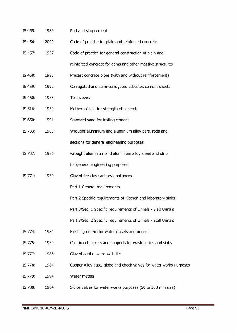
NMRC/NGNC-01/Vol. 4/ODS Page 91
IS 455: 1989 Portland slag cement
IS 456: 2000 Code of practice for plain and reinforced concrete
IS 457: 1957 Code of practice for general construction of plain and
reinforced concrete for dams and other massive structures
IS 458: 1988 Precast concrete pipes (with and without reinforcement)
IS 459: 1992 Corrugated and semi-corrugated asbestos cement sheets
IS 460: 1985 Test sieves
IS 516: 1959 Method of test for strength of concrete
IS 650: 1991 Standard sand for testing cement
IS 733: 1983 Wrought aluminium and aluminium alloy bars, rods and
sections for general engineering purposes
IS 737: 1986 wrought aluminium and aluminium alloy sheet and strip
for general engineering purposes
IS 771: 1979 Glazed fire-clay sanitary appliances
Part 1 General requirements
Part 2 Specific requirements of Kitchen and laboratory sinks
Part 3/Sec. 1 Specific requirements of Urinals - Slab Urinals
Part 3/Sec. 2 Specific requirements of Urinals - Stall Urinals
IS 774: 1984 Flushing cistern for water closets and urinals
IS 775: 1970 Cast iron brackets and supports for wash basins and sinks
IS 777: 1988 Glazed earthenware wall tiles
IS 778: 1984 Copper Alloy gate, globe and check valves for water works Purposes
IS 779: 1994 Water meters
IS 780: 1984 Sluice valves for water works purposes (50 to 300 mm size)
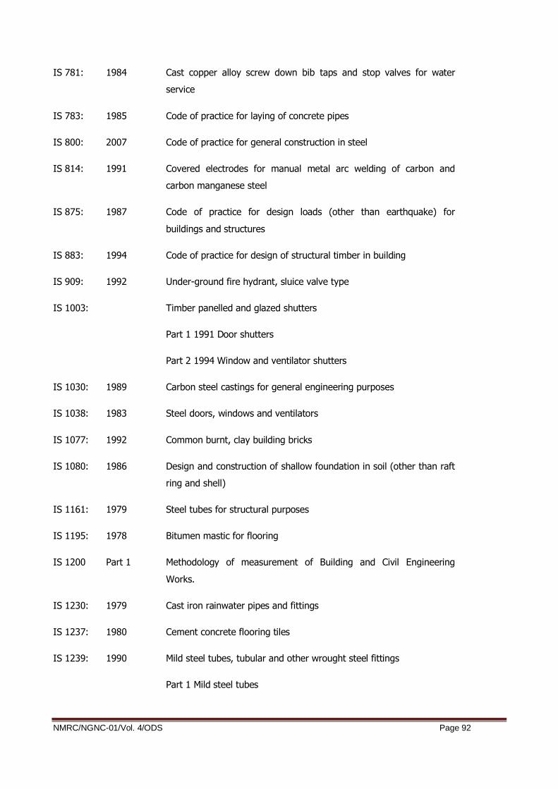
NMRC/NGNC-01/Vol. 4/ODS Page 92
IS 781: 1984 Cast copper alloy screw down bib taps and stop valves for water
service
IS 783: 1985 Code of practice for laying of concrete pipes
IS 800: 2007 Code of practice for general construction in steel
IS 814: 1991 Covered electrodes for manual metal arc welding of carbon and
carbon manganese steel
IS 875: 1987 Code of practice for design loads (other than earthquake) for
buildings and structures
IS 883: 1994 Code of practice for design of structural timber in building
IS 909: 1992 Under-ground fire hydrant, sluice valve type
IS 1003: Timber panelled and glazed shutters
Part 1 1991 Door shutters
Part 2 1994 Window and ventilator shutters
IS 1030: 1989 Carbon steel castings for general engineering purposes
IS 1038: 1983 Steel doors, windows and ventilators
IS 1077: 1992 Common burnt, clay building bricks
IS 1080: 1986 Design and construction of shallow foundation in soil (other than raft
ring and shell)
IS 1161: 1979 Steel tubes for structural purposes
IS 1195: 1978 Bitumen mastic for flooring
IS 1200 Part 1 Methodology of measurement of Building and Civil Engineering
Works.
IS 1230: 1979 Cast iron rainwater pipes and fittings
IS 1237: 1980 Cement concrete flooring tiles
IS 1239: 1990 Mild steel tubes, tubular and other wrought steel fittings
Part 1 Mild steel tubes

NMRC/NGNC-01/Vol. 4/ODS Page 93
Part 2 Mild steel tubular and other wrought steel pipe fittings
IS 1322: 1993 Bitumen felts for water proofing and damp-proofing
IS 1341: 1992 Steel butt hinges
IS 1343: 1980 Code of practice for Pre-Stressed Concrete
IS 1346: 1991 Code of practice Waterproofing of roofs with bitumen felts
IS 1458: 1965 Railway bronze ingots and casting
IS 1489: 1991 Portland Pozzolana Cement
IS 1536: 1989 Centrifugally cast (spun) iron pressure pipes for water, gas and
sewage
IS 1537: 1976 Vertically cast-iron pressure pipes for water, gas and sewage
IS 1538: 1993 Cast iron fittings for pressure pipes for water, gas and sewage
IS 1566: 1982 Hard-drawn steel wire fabric for concrete reinforcement IS
IS 1592: 1989 Asbestos cement pressure pipes
IS 1703: 1989 Copper alloy float values (horizontal plunger type) for water supply
fittings
IS 1726: 1991 Cast iron manhole covers and frames
IS 1729: 1979 Sand cast iron spigot and socket soil waste and ventilating pipes,
fitting and accessories
IS 1732: 1989 Dimensions for round and square steel bars for structural and
general engineering purposes
IS 1785: 1983 Plain hard-drawn steel wire for prestressed concrete
Part 1 Cold-drawn stress – relieved wire
Part 2 As drawn wire
IS 1786: 1985 High strength deformed steel bars and wires for concrete
reinforcement
IS 1791: 1985 Batch type concrete mixers

NMRC/NGNC-01/Vol. 4/ODS Page 94
IS 1795: 1982 Specifications for pillar taps for water supply purposes
IS 1834: 1984 Hot applied sealing compounds for joint in concrete
IS 1838: 1983 Pre-formed fillers for expansion joint in concrete pavements and
structures (non extruding and resilient type)
Part 1 Bitumen impregnated fibre
IS 1888: 1982 Method of load tests on soils
IS 1892: 1979 Code of practice for sub surface investigations for foundations
IS 1893 2016 Criteria for earthquake resistant design of structures,
Part 1 General Provisions and Buildings
IS 1904 1986 Design and construction of foundations in soils General Requirements
IS 1948: 1961 Aluminium doors, windows and ventilators
IS 1949: 1961 Aluminium windows for industrial buildings
IS 1977: 1976 Low Tensile Structural steel
IS 2004: 1991 Carbon steel forgings for general engineering purposes
IS 2062: 2006 Steel for general structural purposes
IS 2074: 1992 Ready mixed paint, air-drying, red oxide-zinc chrome, Priming
IS 2090: 1983 High tensile steel bars used in prestressed concrete
IS 2114: 1984 Code of practice for laying in-situ terrazzo floor finish
IS 2116: 1980 Sand for masonry mortars
IS 2119: 1980 Code of practice for construction of brick-cum-concrete composite
IS 2202: 1991 Wooden flush door shutters
IS 2326: 1987 Automatic flushing cisterns for urinals
IS 2386: 1963 Methods of test for aggregates for concrete
Part 1 Particle size and shape
Part 2 Estimation of deleterious materials and organic impurities

NMRC/NGNC-01/Vol. 4/ODS Page 95
Part 3 Specific gravity, density, voids, absorption and bulking
Part 4 Mechanical properties
Part 5 Soundness
Part 6 Measuring mortar making properties of fine aggregates
Part 7 Alkali – aggregate reactivity
Part 8 Petrographic examination
IS 2430: 1986 Methods of sampling of aggregate for concrete
IS 2548: 1996 Plastic seats and covers for water closets
IS 2681: 1993 Non-ferrous metal sliding door bolts (aldrops) for use with padlocks
IS 2690: 1993 Burnt - clay for flat terracing Tiles
IS 2692: 1989 Ferrules for water services
IS 2720 1972-2002 Methods of Tests for Soils (all Parts)
IS 2751: 1979 Recommended practice for welding of mild steel plain and deformed
bars used for reinforced construction
IS 2906: 1984 Specification for sluice valves for water works purposes (350 to1200
mm size)
IS 2911: 2010 Code of practice for design and construction of pile foundations
Part 1 Concrete piles
Section 1 Driven cast –in-situ concrete piles
Section 2 Bored cast-in-situ concrete piles
Section 3 Driven precast concrete piles
Section 4 Bored precast concrete piles
Part 3 Under-reamed piles
Part 4 Load test on piles
IS 2950: 1981 Code of practice for design and construction of raft foundations.
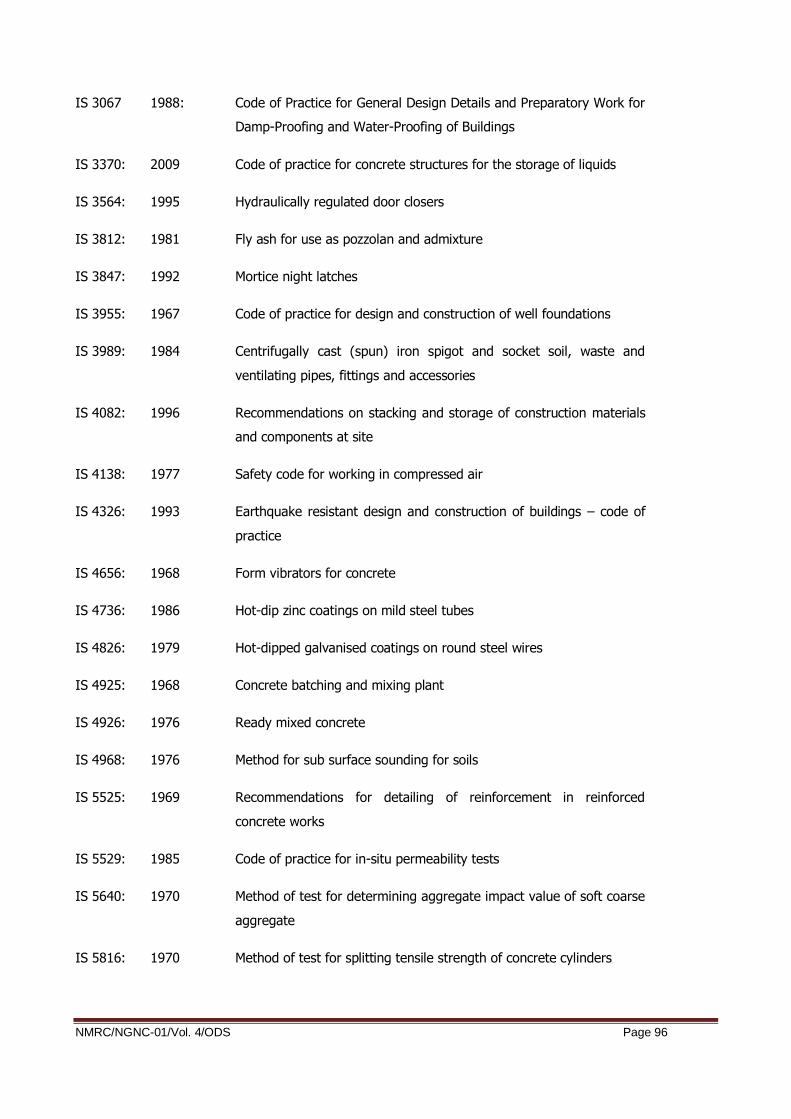
NMRC/NGNC-01/Vol. 4/ODS Page 96
IS 3067 1988: Code of Practice for General Design Details and Preparatory Work for
Damp-Proofing and Water-Proofing of Buildings
IS 3370: 2009 Code of practice for concrete structures for the storage of liquids
IS 3564: 1995 Hydraulically regulated door closers
IS 3812: 1981 Fly ash for use as pozzolan and admixture
IS 3847: 1992 Mortice night latches
IS 3955: 1967 Code of practice for design and construction of well foundations
IS 3989: 1984 Centrifugally cast (spun) iron spigot and socket soil, waste and
ventilating pipes, fittings and accessories
IS 4082: 1996 Recommendations on stacking and storage of construction materials
and components at site
IS 4138: 1977 Safety code for working in compressed air
IS 4326: 1993 Earthquake resistant design and construction of buildings – code of
practice
IS 4656: 1968 Form vibrators for concrete
IS 4736: 1986 Hot-dip zinc coatings on mild steel tubes
IS 4826: 1979 Hot-dipped galvanised coatings on round steel wires
IS 4925: 1968 Concrete batching and mixing plant
IS 4926: 1976 Ready mixed concrete
IS 4968: 1976 Method for sub surface sounding for soils
IS 5525: 1969 Recommendations for detailing of reinforcement in reinforced
concrete works
IS 5529: 1985 Code of practice for in-situ permeability tests
IS 5640: 1970 Method of test for determining aggregate impact value of soft coarse
aggregate
IS 5816: 1970 Method of test for splitting tensile strength of concrete cylinders

NMRC/NGNC-01/Vol. 4/ODS Page 97
IS 5889: 1994 Vibratory plate compactor
IS 5892: 1970 Concrete transit mixers and agitators
IS 6003: 1983 Specification for indented wire for prestressed concrete
IS 6006: 1983 Specification for uncoated stress relieved strands for prestressed
concrete
IS 6051: 1970 Code for designation of aluminium and its alloys
IS 6248: 1979 Specification for metal rolling shutters and rolling grills
IS 6403: 1981 Code of practice for determination of bearing capacity of shallow
foundations
IS 6603: 1972 Stainless steel bars and flats
IS 6760: 1972 Slotted countersunk head wood screws
IS 6911: 1992 Stainless steel plate, sheet and strip
IS 7181: 1986 Horizontally cast-iron double flanged pipes for water,gas and sewage
IS 7196: 1974 Hold fast
IS 7205: 1974 Safety code for erection of structural steel work
IS 7231: 1984 Specifications for plastic flushing cisterns for water closets and
urinals
IS 7273: 1974 Method of testing fusion-welded joints in aluminium andaluminium
alloys
IS 7293: 1974 Safety code for working with construction machinery
IS 7320: 1974 Concrete slump test apparatus
IS 7534: 1985 Sliding locking bolts for use with padlocks
IS 7861: 1975 Code of practice for extreme weather concreting
Part 1 For Hot Weather concreting
Part 2 For Cold Weather concreting
IS 7969: 1975 Safety code for handling and storage of building Materials

NMRC/NGNC-01/Vol. 4/ODS Page 98
IS 8009 1976 Calculation of settlement of foundations
IS 8041: 1990 Rapid – hardening Portland cement
IS 8112: 1989 43 grade ordinary Portland cement
IS 8142: 1994 Method of test for determining setting time of concrete by
penetration resistance
IS 8500: 1991 Structural steel-micro alloyed (medium and high strength qualities)
IS 9013: 1978 Method of making, curing and determining compressive strength of
accelerated cured concrete test specimens
IS 9103: 1979 Admixtures for concrete
IS 9284: 1979 Method of test for abrasion resistance of concrete
IS 9417: 1989 Recommendations for welding cold worked bars for reinforced
concrete construction
IS 9595: 1996 Recommendations for metal arc welding of carbon and carbon
manganese steels
IS 9762: 1994 Polyethylene floats (spherical) for float valves
IS 10262: 2009 Recommended guidelines for concrete mix design
IS 10379: 1982 Code of practice for field control of moisture and compaction of soils
for embankment and subgrade
IS 10500: 1991 Drinking water specification
IS 12269: 1987 53 grade ordinary Portland cement
IS 12894: 1990 Fly ash lime bricks
IS 13630: 1994 Ceramic tiles – methods of tests
IS 13920: 2016 Ductile detailing of reinforced concrete structures subjected to
seismic forces
IS 15388: 2003 Specifications for Silica Fume
SP 36 (Part 1): Compendium of Indian Standards on Soil Engineering

NMRC/NGNC-01/Vol. 4/ODS Page 99
(Laboratory Testing)
SP 36 (Part 2): Compendium of Indian Standards on Soil Engineering (Field Testing)
Indian Standard Hand Book on Steel Sections Part-ICRRI and IOC,
New Delhi Bituminous Road Construction Hand Book
6.4 British Standards
BS 812 Testing Aggregates - Parts 117 to 119.
BS 1377 Methods of Test for Civil Engineering Purposes - Parts 1 thru 9.
BS 4395 Part 2 High strength friction grip bolts and associated nuts andwashers for
Structural Engineering Higher Grade
BS 4447 The performance of pre-stressing anchorages for post-tensioned
construction
BS 4449 Specification for Carbon Steel Bars for the Reinforcement of Concrete
BS 4486 Hot rolled and hot rolled & processed high tensile alloy steel bars for
pre-tensioning of concrete
BS 4550 Methods of testing cement
BS 4592 Industrial Type Metal Flooring, walkways and stair treads
BS 4604 Part 2 The use of high strength friction grip bolts in structural steel work.
Higher grade (parallel shank)
BS 4870 Approval testing of welding procedures
BS 4871 Approval testing of welders working to approved welding Procedures
BS 4872 Approval testing of welders when welding procedure approval is not
required
BS 5075 Concrete admixtures
BS 5135 Process of arc welding of carbon and carbon manganese Steels
BS 5212 Part 2 Cold poured joint sealants for concrete pavements

NMRC/NGNC-01/Vol. 4/ODS Page 100
BS 5328 Methods for specifying concrete, including ready mixed
Concrete
BS 5400 Steel, concrete and composite bridges
BS 5400 Part 4 Code of practice for design of concrete bridges
BS 5400 Part 6 Specification for materials and workmanship, steel
BS 5606 Accuracy in building
BS 5896 High tensile steel wire and stand for the pre-stressing of concrete.
BS 5930: Code of Practice for Site Investigations.
BS 5950 Part 2 Specification for materials, fabrication and erection: hot rolled
sections
BS 6031 Code of Practice for Earthworks.
BS 6105 Corrosion-resistant stainless-steel fasteners
BS 6164 Safety in tunnelling in the construction industry.
BS 6349 Code of Practice for Dredging and Land Reclamation.
BS 6443 Penetrant flaw detection
BS 6681 Specification for malleable cast iron
BS 7079 Preparation of Steel substrates before application of paints and
related products
BS 7385 Part 2 Evaluation and measurement for Vibrations in Buildings – E to
Damage levels from Ground-Borne Vibrations
BS 7542 method of test for curing compound for concreter
BS 8000 Part 4 Code of Practice for Waterproofing
BS 8000 Part 5 Code of Practice for Below Ground Drainage
BS 8002 Code of Practice for Earth Retaining Structures
BS 8004 Code of Practice for Foundations

NMRC/NGNC-01/Vol. 4/ODS Page 101
BS 8007 Design of Concrete Structures for Retaining Aqueous Liquids
BS 8081 Code of Practice for Ground Anchorages
BS 8110 Structural use of concrete
BS 8301 Section 5 Code of practice for building drainage
BS 8550 Concrete – Specification of Materials
BS EN 1997 Eurocode 7: Geotechnical design
BS EN 1998 Eurocode 8: Design of structure for earthquake resistance
CIRIA Report 44 Medical Code of Practice for working in compressed air
CIRIA Report 80 A review of instruments for gas and dust monitoring Underground
CIRIA Report 81 Tunnel water proofing
CIRIA Report
C515
Groundwater Control – Design and Practice
CIRIA Report
C580
Embedded Retaining Walls – Guidance for Economic Design
CIRIA Report
C660
Early Age Thermal Crack Control in Concrete
6.5 ASTM Standards
ASTM C-1202 Test methods for Electrical indication of concrete’s ability to resist
chloride ion penetration.
ASTM C-1240 Micro Silica/Silica fume in concrete
ASTM D-297 Methods for Rubber Products-Chemical Analysis
ASTM D-395 Compression set of vulcanized rubber
ASTM D-412 Tension testing of vulcanized rubber
ASTM D-429 Adhesion of vulcanized rubber to metal
ASTM D-573 Accelerated aging of vulcanized rubber by the oven method

NMRC/NGNC-01/Vol. 4/ODS Page 102
ASTM D-624 Tear resistance of vulcanized rubber
ASTM D-797 Young’s modulus in flexure of elastomer at normal and subnormal
temperature
ASTM D-1075 Effect of water on cohesion of compacted bituminous mixtures
ASTM D-1143 Test method for piles under static axial comp. Test
ASTM D-1149 Accelerated ozone cracking of vulcanized rubber
ASTM D-1556 In-situ density by sand replacement
ASTM D-1559 Test for resistance to plastic flow of bituminous mixtures
usingMarshall apparatus
ASTM D-2172 Extraction, quantitative, of bitumen from bituminous paving mixtures
ASTM D-2240 Indentation hardness of rubber and plastic by means of a Durometer
ASTM D-3689 Testing method of testing individual piles under static axial tensile
load
ASTM D-4945 Test method for high strain dynamic testing of piles
ASTM E-11 Specification for wire cloth sieve for testing purpose
ASTM: Section 4: Construction, Vol. 04.08: Soil and Rock I, and Volume 04.09: Soil and
Rock II,
6.6 AASHTO Standards
AASHTO M6-81 Fine aggregate for Portland cement concrete
AASHTO M31-82 Deformed and plain billet-steel bars for concrete reinforcement
AASHTO M42-81 Rail-steel deformed and plain bars for concrete reinforcement
AASHTO M54-81 Fabricated steel bar or rod mats for concrete reinforcement
AASHTO M 81-75 Cut-back asphalt (rapid-curing type)
AASHTO M 82-75 Cut-back asphalt (medium-curing type)

NMRC/NGNC-01/Vol. 4/ODS Page 103
AASHTO M85-80 Portland cement
AASHTO M 140-80 Emulsified asphalt
AASHTO M 147-67 Materials for aggregate and soil–aggregate sub-base, base and
surface courses
AASHTO M148-82 Liquid membrane-forming compounds for curing concrete
AASHTO M154-79 Air-Entraining admixtures for concrete
AASHTO M173-60 Concrete joint-sealer, hot-poured elastic type
AASHTO M194-82 Chemical admixtures for concrete
AASHTO M213-81 Preformed expansion joint fillers for concrete paving and structural
construction
AASHTO M 282-80 Joints sealants, hot poured, elastomeric-type, for port-land cement
concrete pavements
AASHTO M 294-70 Fine aggregate for bituminous paving mixtures
AASHTO T22-82 Compressive strength of cylindrical concrete specimens
AASHTO T23-80 Making and curing concrete compressive and flexural strength test
specimens in the field
AASHTO T26-79 Quality of water to be used in concrete
AASHTO T96-77 Resistance to abrasion of small size coarse aggregate by use of the
Los Angeles machine
AASHTO T99-81 The moisture-density relations of soils using a 5.5-lb(2.5kg) rammer
and a 12-in (305mm) Drop
ASHTO 104-77 Soundness of aggregate by use of sodium sulphate or magnesium
sulphate
AASHTO T176-73 Plastic fines in graded aggregates and soil by use of the sand
equivalent test
AASHTO T180-74 The moisture density relations of soils using a 10-lb (4.54kg) rammer
and an 18-in (457mm) Drop

NMRC/NGNC-01/Vol. 4/ODS Page 104
AASHTO T182-82 Coating and stripping of bitumen-aggregate mixtures
AASHTO T191-61 Density of soil In-place by the sand-cone method
6.7 Other Publications
American Petroleum Industry (API) Standard 1104
UIC/772-
R
The International Union of Railway Publication
SS 460 48 66 1992 Swedish Standard Vibration and Shock Guidance Levels for Blast-
induced vibration
NS8141 1993 Vibration and Shock in Structure, Guidance Limits for Blasting-
Induced Vibrations
National Fire Protection
Association, NFPA 130-
2010:
Standard for Fixed Guideway Transit and Passenger Rail Systems
International Society for Rock Mechanics (ISRM), Suggested Test Methods, (various dates)
British Tunnelling
Society
Specification for Tunnelling
Austrian Society for
Rock Mechanics:
Geotechnical Ground Structures Design
International Tunnel
Association
Guidelines for the Design and Analysis of Underground Structure
ITA/AITES Accredited
Material
Seismic Design and Analysis of Underground Structures
Muir Wood, A.M. (1975) The Circular Tunnel in Elastic Ground
D.J. Curtis et al (1976) Discussion Paper - Circular Tunnel in Elastic Ground
CG Lai et al (2000) Probabilistic Seismic Hazard Assessment and Stochastic Sire
Response Analysis at the Archaeological Site of Kancheepuram in
Southern India. IUSS Press

NMRC/NGNC-01/Vol. 4/ODS Page 105

NMRC/NGNC-01/Vol. 4/ODS Page 106
7. ANNEXURE A (LOAD COMBINATION) 1
00
11
00
21
00
31
00
41
00
51
00
61
00
71
00
81
00
91
01
01
10
11
10
21
10
31
10
41
10
5
11.5
1.5
11.5
1.5
1.5
1.5
11.5
1.5
1.5
1.5
11.5
1.5
21.5
1.5
11.5
1.5
1.5
1.5
11.5
1.5
1.5
1.5
11.5
1.5
31.5
1.5
11.5
1.5
1.5
1.5
11.5
1.5
1.5
1.5
11.5
1.5
41.5
00
1.5
01.5
00
1.5
01.5
00
1.5
0
51.5
00
1.5
01.5
00
1.5
01.5
00
1.5
0
61.5
1.5
1.5
00
00
00
00
00
00
70
00
11
00
00
00
00
00
80
00
00
1.5
1.5
1.5
00
00
00
0
90
00
00
00
01
10
00
00
10
00
00
00
00
00
1.5
1.5
1.5
00
11
00
00
00
00
00
00
01
1
12
1.5
1,5
01.5
1,5
1.5
1.5
01.5
1.5
1.5
1.5
01.5
1.5
13
00
00
00
00
00
00
00
0
14
00
00
00
00
00
00
00
0
15
1.5
1.5
1.5
00
1.5
1.5
1.5
00
1.5
1.5
1.5
00
16
1.5
1.5
1.5
11
00
00
00
00
00
17
1.5
1.5
11.5
1.5
00
00
00
00
00
18
00
00
01.3
1.3
1.3
11
00
00
0
19
00
00
01.3
1.3
11.3
1.3
00
00
0
20
00
00
00
00
00
00
00
0
21
00
00
00
00
00
00
00
0
22
00
00
00
00
00
00
00
0
23
00
00
00
00
00
00
00
0
24
00
00
00
00
00
00
00
0
25
00
00
00
00
00
00
00
0
26
00
00
00
00
00
00
00
0
27
00
00
00
00
00
00
00
0
( M
AX H
-
MAX V
)
( M
AX H
-
MAX V
)
without
LL
( M
AX H
-
MIN
V)
( M
IN H
-
MAX V
)
( M
AX H
-
MAX V
)
without
LL
L/C
No
.
Sa
tura
ted
So
il
ULS
ST
AT
IC
De
scri
pti
on
s o
f Lo
ad
Ca
se
Wate
r Pre
ssure
(H
RL)
(Late
ral)
0.3
6 g
Rack
ing P
oin
t Forc
e (
Tow
ard
s Left
)
Surc
harg
e load (
Tow
ard
s Left
)
0.3
6 g
Rack
ing D
istr
ibution F
orc
e (
Tow
ard
s Left
)
0.3
6 g
Rack
ing D
istr
ibution F
orc
e (
Tow
ard
s Rig
ht)
SID
L
0.1
8 g
Rack
ing D
istr
ibution F
orc
e (
Tow
ard
s Rig
ht)
0.1
8 g
Rack
ing D
istr
ibution F
orc
e (
Tow
ard
s Left
)
0.1
8 g
Rack
ing P
oin
t Forc
e (
Tow
ard
s Rig
ht)
Late
ral Eart
h P
ress
ure
Sat_
Ka
Late
ral Eart
h P
ress
ure
Sub (
GW
L @
GL)
Ka
Tra
in L
ive L
oad
Late
ral Eart
h P
ress
ure
Sub (
GW
L @
HRL)
K0
0.3
6 g
Rack
ing P
oin
t Forc
e (
Tow
ard
s Rig
ht)
0.1
8 g
Rack
ing P
oin
t Forc
e (
Tow
ard
s Left
)
Surc
harg
e load (
Tow
ard
s Rig
ht)
Late
ral Eart
h P
ress
ure
Sub (
GW
L @
HRL)
Ka
Wate
r Pre
ssure
(H
RL)
(Vert
ical) U
plif
t ca
se
Wate
r Pre
ssure
at
desi
gn w
ate
r ta
ble
level
Wate
r Pre
ssure
at
desi
gn w
ate
r ta
ble
level (u
plif
t)
Surc
harg
e load (
Both
Sid
es)
( M
AX H
-
MIN
V)
Liv
e L
oad o
n c
onco
urs
e &
pla
tform
Late
ral Eart
h P
ress
ure
Sub (
GW
L @
GL)
K0
Self W
eig
ht
Vert
ical Surc
harg
e L
oad
Soil
Back
Fill
Late
ral Eart
h P
ress
ure
Sat_
K0
Su
bm
ere
ge
d W
ate
r @
GL
( M
AX H
-
MAX V
)
( M
AX H
-
MAX V
)
without
LL
( M
AX H
-
MAX V
)
( M
IN H
-
MAX V
)
( M
AX H
-
MIN
V)
without
LL
( M
AX H
-
MAX V
)
( M
AX H
-
MAX V
)
without
LL
( M
IN H
-
MAX V
)
( M
AX H
-
MAX V
)
without
LL

NMRC/NGNC-01/Vol. 4/ODS Page 107
20
01
20
02
20
03
20
04
20
05
20
06
20
07
20
08
20
09
20
10
20
11
20
12
20
13
20
14
( M
AX H
-
MAX V
)
( M
AX H
-
MAX V
)
( M
AX H
- M
IN
V)
( M
AX H
-
MIN
V)
( M
AX H
-
MIN
V)
( M
AX H
-
MIN
V)
( M
AX H
-
MIN
V)
( M
AX H
-
MIN
V)
( M
AX H
-
MAX V
)
( M
AX H
-
MAX V
)
( M
AX H
-
MAX V
)
( M
AX H
-
MAX V
)
( M
AX H
- M
AX
V)
( M
AX H
-
MAX V
)
11.5
1.5
1.5
1.5
1.5
1.5
1.5
1.5
1.2
1.2
1.2
1.2
11
21.5
1.5
1.5
1.5
1.5
1.5
1.5
1.5
1.2
1.2
1.2
1.2
11
31.5
1.5
1.5
1.5
1.5
1.5
1.5
1.5
1.2
1.2
1.2
1.2
11
40
00
00
00
00.6
0.6
0.6
0.6
0.5
0.5
50
00
00
00
01.2
1.2
1.2
1.2
11
61.5
1.5
1.5
1.5
00
00
00
00
00
70
00
00
00
00
00
00
0
80
00
01.5
1.5
1.5
1.5
1.2
1.2
1.2
1.2
11
90
00
00
00
00
00
00
0
10
00
00
00
00
00
00
00
11
00
00
00
00
00
00
00
12
1.5
1.5
1.5
1.5
1.5
1.5
1.5
1.5
1.2
1.2
1.2
1.2
11
13
1.5
01.5
01.5
01.5
01.2
01.2
01
0
14
01.5
01.5
01.5
01.5
01.2
01.2
01
15
00
00
00
00
00
00
00
16
1.5
1.5
1.5
1.5
00
00
00
00
00
17
1.5
1.5
1.5
1.5
00
00
00
00
00
18
00
00
1.3
1.3
1.3
1.3
1.2
1.2
1.2
1.2
11
19
00
00
1.3
1.3
1.3
1.3
1.2
1.2
1.2
1.2
11
20
1.5
00
01.5
00
01.2
00
00
0
21
01.5
00
01.5
00
01.2
00
00
22
00
1.5
00
01.5
00
01.2
00
0
23
00
01.5
00
01.5
00
01.2
00
24
00
00
00
00
00
00
10
25
00
00
00
00
00
00
01
26
00
00
00
00
00
00
00
27
00
00
00
00
00
00
00
0.1
8 g
Rack
ing P
oin
t Forc
e (
Tow
ard
s Rig
ht)
0.1
8 g
Rack
ing P
oin
t Forc
e (
Tow
ard
s Left
)
0.1
8 g
Rack
ing D
istr
ibution F
orc
e (
Tow
ard
s Rig
ht)
0.1
8 g
Rack
ing D
istr
ibution F
orc
e (
Tow
ard
s Left
)
0.3
6 g
Rack
ing P
oin
t Forc
e (
Tow
ard
s Rig
ht)
0.3
6 g
Rack
ing P
oin
t Forc
e (
Tow
ard
s Left
)
0.3
6 g
Rack
ing D
istr
ibution F
orc
e (
Tow
ard
s Rig
ht)
0.3
6 g
Rack
ing D
istr
ibution F
orc
e (
Tow
ard
s Left
)
Surc
harg
e load (
Tow
ard
s Left
)
Surc
harg
e load (
Both
Sid
es)
Wate
r Pre
ssure
(H
RL)
(Late
ral)
Wate
r Pre
ssure
(H
RL)
(Vert
ical) U
plif
t ca
se
Wate
r Pre
ssure
at
desi
gn w
ate
r ta
ble
level
Wate
r Pre
ssure
at
desi
gn w
ate
r ta
ble
level (u
plif
t)
Late
ral Eart
h P
ress
ure
Sub (
GW
L @
GL)
K0
Late
ral Eart
h P
ress
ure
Sub (
GW
L @
GL)
Ka
Late
ral Eart
h P
ress
ure
Sat_
K0
Late
ral Eart
h P
ress
ure
Sat_
Ka
Vert
ical Surc
harg
e L
oad
Surc
harg
e load (
Tow
ard
s Rig
ht)
SID
L
Soil
Back
Fill
Liv
e L
oad o
n c
onco
urs
e &
pla
tform
Tra
in L
ive L
oad
Late
ral Eart
h P
ress
ure
Sub (
GW
L @
HRL)
K0
Late
ral Eart
h P
ress
ure
Sub (
GW
L @
HRL)
Ka
Self W
eig
ht
1.2
DL +
1.2
LL +
1.5
EQ
1.5
DL +
1.5
EQ
Su
bm
ere
ge
d W
ate
r @
GL
L/C
No
.D
escri
pti
on
s o
f Lo
ad
Ca
se
ULS
SE
IS
MIC
(R
AC
KIN
G)
CO
RR
ES
PO
ND
IN
G T
O 0
.18
g

NMRC/NGNC-01/Vol. 4/ODS Page 108
20
15
20
16
20
17
20
18
20
19
20
20
20
21
20
22
20
23
20
24
20
25
20
26
20
27
20
28
( M
AX H
-
MAX V
)
( M
AX H
-
MAX V
)
( M
AX H
-
MIN
V)
( M
AX H
-
MIN
V)
( M
AX H
-
MIN
V)
( M
AX H
-
MIN
V)
( M
AX H
-
MIN
V)
( M
AX H
-
MIN
V)
( M
AX H
-
MIN
V)
( M
AX H
-
MIN
V)
( M
IN H
-
MAX V
)
( M
IN H
-
MAX V
)
( M
IN H
-
MAX V
)
( M
IN H
-
MAX V
)
11
11
11
11
11
11.2
1.2
1.2
1.2
21
11
11
11
11
11.2
1.2
1.2
1.2
31
11
11
11
11
11.2
1.2
1.2
1.2
40.5
0.5
00
00
00
00
0.6
0.6
0.6
0.6
51
10
00
00
00
01.2
1.2
1.2
1.2
60
00
00
00
00
00
00
0
70
00
00
00
00
00
00
0
81
11.2
1.2
1.2
1.2
11
11
00
00
90
00
00
00
00
01
11
1
10
00
00
00
00
00
00
00
11
00
00
00
00
00
00
00
12
11
00
00
00
00
1.2
1.2
1.2
1.2
13
10
1.2
01.2
01
01
00
00
0
14
01
01.2
01.2
01
01
00
00
15
00
00
00
00
00
00
00
16
00
00
00
00
00
00
00
17
00
00
00
00
00
00
00
18
11
1.2
1.2
1.2
1.2
11
11
11
11
19
11
11
11
11
11
1.2
1.2
1.2
1.2
20
00
1.2
00
00
00
01
00
0
21
00
01.2
00
00
00
01
00
22
00
00
1.2
00
00
00
01
0
23
00
00
01.2
00
00
00
01
24
00
00
00
10
00
00
00
25
00
00
00
01
00
00
00
26
10
00
00
00
10
00
00
27
01
00
00
00
01
00
00
0.1
8 g
Rack
ing P
oin
t Forc
e (
Tow
ard
s Rig
ht)
0.1
8 g
Rack
ing P
oin
t Forc
e (
Tow
ard
s Left
)
0.1
8 g
Rack
ing D
istr
ibution F
orc
e (
Tow
ard
s Rig
ht)
0.1
8 g
Rack
ing D
istr
ibution F
orc
e (
Tow
ard
s Left
)
0.3
6 g
Rack
ing P
oin
t Forc
e (
Tow
ard
s Rig
ht)
0.3
6 g
Rack
ing P
oin
t Forc
e (
Tow
ard
s Left
)
0.3
6 g
Rack
ing D
istr
ibution F
orc
e (
Tow
ard
s Rig
ht)
0.3
6 g
Rack
ing D
istr
ibution F
orc
e (
Tow
ard
s Left
)
Surc
harg
e load (
Tow
ard
s Left
)
Surc
harg
e load (
Both
Sid
es)
Wate
r Pre
ssure
(H
RL)
(Late
ral)
Wate
r Pre
ssure
(H
RL)
(Vert
ical) U
plif
t ca
se
Wate
r Pre
ssure
at
desi
gn w
ate
r ta
ble
level
Wate
r Pre
ssure
at
desi
gn w
ate
r ta
ble
level (u
plif
t)
Late
ral Eart
h P
ress
ure
Sub (
GW
L @
GL)
K0
Late
ral Eart
h P
ress
ure
Sub (
GW
L @
GL)
Ka
Late
ral Eart
h P
ress
ure
Sat_
K0
Late
ral Eart
h P
ress
ure
Sat_
Ka
Vert
ical Surc
harg
e L
oad
Surc
harg
e load (
Tow
ard
s Rig
ht)
SID
L
Soil
Back
Fill
Liv
e L
oad o
n c
onco
urs
e &
pla
tform
Tra
in L
ive L
oad
Late
ral Eart
h P
ress
ure
Sub (
GW
L @
HRL)
K0
Late
ral Eart
h P
ress
ure
Sub (
GW
L @
HRL)
Ka
Self W
eig
ht
Su
bm
ere
ge
d W
ate
r @
GL
L/C
No
.D
escri
pti
on
s o
f Lo
ad
Ca
se
ULS
SE
IS
MIC
(R
AC
KIN
G)
co
rre
sp
on
din
g t
o 0
.36
g

NMRC/NGNC-01/Vol. 4/ODS Page 109
21
01
21
02
21
03
21
04
21
05
21
06
21
07
21
08
21
09
21
10
11.5
1.5
1.5
1.5
1.2
1.2
1.2
1.2
11
21.5
1.5
1.5
1.5
1.2
1.2
1.2
1.2
11
31.5
1.5
1.5
1.5
1.2
1.2
1.2
1.2
11
40
00
00.6
0.6
0.6
0.6
00
50
00
01.2
1.2
1.2
1.2
00
60
00
00
00
00
0
70
00
00
00
00
0
80
00
00
00
00
0
90
00
00
00
00
0
10
1.5
1.5
1.5
1.5
1.2
1.2
1.2
1.2
1.2
1.2
11
00
00
00
00
00
12
00
00
1.2
1.2
1.2
1.2
00
13
00
00
1.2
01.2
01.2
0
14
00
00
01.2
01.2
01.2
15
00
00
00
00
00
16
00
00
00
00
00
17
00
00
00
00
00
18
00
00
00
00
00
19
00
00
00
00
00
20
1.5
00
01.2
00
01.2
0
21
01.5
00
01.2
00
01.2
22
00
1.5
00
01.2
00
0
23
00
01.5
00
01.2
00
24
00
00
00
00
00
25
00
00
00
00
00
26
00
00
00
00
00
27
00
00
00
00
00
0.1
8 g
Rack
ing P
oin
t Forc
e (
Tow
ard
s Rig
ht)
0.1
8 g
Rack
ing P
oin
t Forc
e (
Tow
ard
s Left
)
0.1
8 g
Rack
ing D
istr
ibution F
orc
e (
Tow
ard
s Rig
ht)
0.1
8 g
Rack
ing D
istr
ibution F
orc
e (
Tow
ard
s Left
)
0.3
6 g
Rack
ing P
oin
t Forc
e (
Tow
ard
s Rig
ht)
0.3
6 g
Rack
ing P
oin
t Forc
e (
Tow
ard
s Left
)
0.3
6 g
Rack
ing D
istr
ibution F
orc
e (
Tow
ard
s Rig
ht)
0.3
6 g
Rack
ing D
istr
ibution F
orc
e (
Tow
ard
s Left
)
Surc
harg
e load (
Tow
ard
s Left
)
Surc
harg
e load (
Both
Sid
es)
Wate
r Pre
ssure
(H
RL)
(Late
ral)
Wate
r Pre
ssure
(H
RL)
(Vert
ical) U
plif
t ca
se
Wate
r Pre
ssure
at
desi
gn w
ate
r ta
ble
level
Wate
r Pre
ssure
at
desi
gn w
ate
r ta
ble
level (u
plif
t)
Late
ral Eart
h P
ress
ure
Sub (
GW
L @
GL)
K0
Late
ral Eart
h P
ress
ure
Sub (
GW
L @
GL)
Ka
Late
ral Eart
h P
ress
ure
Sat_
K0
Late
ral Eart
h P
ress
ure
Sat_
Ka
Vert
ical Surc
harg
e L
oad
Surc
harg
e load (
Tow
ard
s Rig
ht)
SID
L
Soil
Back
Fill
Liv
e L
oad o
n c
onco
urs
e &
pla
tform
Tra
in L
ive L
oad
Late
ral Eart
h P
ress
ure
Sub (
GW
L @
HRL)
K0
Late
ral Eart
h P
ress
ure
Sub (
GW
L @
HRL)
Ka
Self W
eig
ht
( M
AX H
-
MAX V
)
( M
AX H
-
MAX V
)
( M
AX H
-
MAX V
)
( M
AX H
-
MIN
V)
( M
AX H
-
MIN
V)
( M
AX H
-
MAX V
)
Sa
tura
ted
so
il
L/C
No
.D
escri
pti
on
s o
f Lo
ad
Ca
se
ULS
SE
IS
MIC
(R
AC
KIN
G)
CO
RR
ES
PO
ND
IN
G T
O 0
.18
g

NMRC/NGNC-01/Vol. 4/ODS Page 110
21
11
21
12
21
13
21
14
21
15
21
16
21
17
21
18
21
19
21
20
11
11
11
11.2
1.2
1.2
1.2
21
11
11
11.2
1.2
1.2
1.2
31
11
11
11.2
1.2
1.2
1.2
40
00
00
00.6
0.6
0.6
0.6
50
00
00
01.2
1.2
1.2
1.2
60
00
00
00
00
0
70
00
00
00
00
0
80
00
00
00
00
0
90
00
00
00
00
0
10
1.2
1.2
11
11
00
00
11
00
00
00
11
11
12
00
00
00
1.2
1.2
1.2
1.2
13
1.2
01
01
00
00
0
14
01.2
01
01
00
00
15
00
00
00
00
00
16
00
00
00
00
00
17
00
00
00
00
00
18
00
00
00
00
00
19
00
00
00
00
00
20
00
00
00
1.2
00
0
21
00
00
00
01.2
00
22
1.2
00
00
00
01.2
0
23
01.2
00
00
00
01.2
24
00
10
00
00
00
25
00
01
00
00
00
26
00
00
10
00
00
27
00
00
01
00
00
0.1
8 g
Rack
ing P
oin
t Forc
e (
Tow
ard
s Rig
ht)
0.1
8 g
Rack
ing P
oin
t Forc
e (
Tow
ard
s Left
)
0.1
8 g
Rack
ing D
istr
ibution F
orc
e (
Tow
ard
s Rig
ht)
0.1
8 g
Rack
ing D
istr
ibution F
orc
e (
Tow
ard
s Left
)
0.3
6 g
Rack
ing P
oin
t Forc
e (
Tow
ard
s Rig
ht)
0.3
6 g
Rack
ing P
oin
t Forc
e (
Tow
ard
s Left
)
0.3
6 g
Rack
ing D
istr
ibution F
orc
e (
Tow
ard
s Rig
ht)
0.3
6 g
Rack
ing D
istr
ibution F
orc
e (
Tow
ard
s Left
)
Surc
harg
e load (
Tow
ard
s Left
)
Surc
harg
e load (
Both
Sid
es)
Wate
r Pre
ssure
(H
RL)
(Late
ral)
Wate
r Pre
ssure
(H
RL)
(Vert
ical) U
plif
t ca
se
Wate
r Pre
ssure
at
desi
gn w
ate
r ta
ble
level
Wate
r Pre
ssure
at
desi
gn w
ate
r ta
ble
level (u
plif
t)
Late
ral Eart
h P
ress
ure
Sub (
GW
L @
GL)
K0
Late
ral Eart
h P
ress
ure
Sub (
GW
L @
GL)
Ka
Late
ral Eart
h P
ress
ure
Sat_
K0
Late
ral Eart
h P
ress
ure
Sat_
Ka
Vert
ical Surc
harg
e L
oad
Surc
harg
e load (
Tow
ard
s Rig
ht)
SID
L
Soil
Back
Fill
Liv
e L
oad o
n c
onco
urs
e &
pla
tform
Tra
in L
ive L
oad
Late
ral Eart
h P
ress
ure
Sub (
GW
L @
HRL)
K0
Late
ral Eart
h P
ress
ure
Sub (
GW
L @
HRL)
Ka
Self W
eig
ht
( M
IN H
-
MAX V
)
( M
IN H
-
MAX V
)
( M
IN H
-
MAX V
)
( M
AX H
-
MIN
V)
( M
AX H
-
MIN
V)
( M
AX H
-
MIN
V)
( M
AX H
-
MIN
V)
( M
AX H
-
MIN
V)
( M
IN H
-
MAX V
)
( M
AX H
-
MIN
V)
Sa
tura
ted
so
il
ULS
SE
IS
MIC
(R
AC
KIN
G)
CO
RR
ES
PO
ND
IN
G T
O 0
.36
g
L/C
No
.D
escri
pti
on
s o
f Lo
ad
Ca
se

NMRC/NGNC-01/Vol. 4/ODS Page 111
30
01
30
02
30
03
30
04
30
05
31
01
31
02
31
03
31
04
31
05
11
11
11
11
11
1
21
11
11
11
11
1
31
11
11
11
11
1
41
00
10
10
01
0
51
00
10
10
01
0
60
00
00
00
00
0
70
00
00
00
00
0
81
11
00
00
00
0
90
00
11
00
00
0
10
00
00
01
11
00
11
00
00
00
00
11
12
10
01
01
00
10
13
00
00
00
00
00
14
00
00
00
00
00
15
11
10
01
11
00
16
00
00
00
00
00
17
00
00
00
00
00
18
11
11
10
00
00
19
11
11
10
00
00
20
00
00
00
00
00
21
00
00
00
00
00
22
00
00
00
00
00
23
00
00
00
00
00
24
00
00
00
00
00
25
00
00
00
00
00
26
00
00
00
00
00
27
00
00
00
00
00
0.1
8 g
Rack
ing P
oin
t Forc
e (
Tow
ard
s Rig
ht)
0.1
8 g
Rack
ing P
oin
t Forc
e (
Tow
ard
s Left
)
0.1
8 g
Rack
ing D
istr
ibution F
orc
e (
Tow
ard
s Rig
ht)
0.1
8 g
Rack
ing D
istr
ibution F
orc
e (
Tow
ard
s Left
)
0.3
6 g
Rack
ing P
oin
t Forc
e (
Tow
ard
s Rig
ht)
0.3
6 g
Rack
ing P
oin
t Forc
e (
Tow
ard
s Left
)
0.3
6 g
Rack
ing D
istr
ibution F
orc
e (
Tow
ard
s Rig
ht)
0.3
6 g
Rack
ing D
istr
ibution F
orc
e (
Tow
ard
s Left
)
Surc
harg
e load (
Tow
ard
s Left
)
Surc
harg
e load (
Both
Sid
es)
Wate
r Pre
ssure
(H
RL)
(Late
ral)
Wate
r Pre
ssure
(H
RL)
(Vert
ical) U
plif
t ca
se
Wate
r Pre
ssure
at
desi
gn w
ate
r ta
ble
level
Wate
r Pre
ssure
at
desi
gn w
ate
r ta
ble
level (u
plif
t)
Late
ral Eart
h P
ress
ure
Sub (
GW
L @
GL)
K0
Late
ral Eart
h P
ress
ure
Sub (
GW
L @
GL)
Ka
Late
ral Eart
h P
ress
ure
Sat_
K0
Late
ral Eart
h P
ress
ure
Sat_
Ka
Vert
ical Surc
harg
e L
oad
Surc
harg
e load (
Tow
ard
s Rig
ht)
SID
L
Soil
Back
Fill
Liv
e L
oad o
n c
onco
urs
e &
pla
tform
Tra
in L
ive L
oad
Late
ral Eart
h P
ress
ure
Sub (
GW
L @
HRL)
K0
Late
ral Eart
h P
ress
ure
Sub (
GW
L @
HRL)
Ka
Self W
eig
ht
( M
IN H
-
MAX V
)
( M
IN H
-
MAX V
)
( M
IN H
-
MAX V
)
( M
AX H
-
MAX V
)
( M
AX H
-
MAX V
)
( M
AX H
-
MIN
V)
( M
IN H
-
MAX V
)
( M
AX H
-
MAX V
)
( M
AX H
-
MAX V
)
( M
AX H
-
MIN
V)
Su
bm
ere
ge
d W
ate
r @
GL
Sa
tura
ted
so
il
SLS
L/C
No
.D
escri
pti
on
s o
f Lo
ad
Ca
se
NMRC/NGNC-01/Vol. 4/ODS Page 112
OUTLINE DESIGNCRITERIA
FOR
GEOTECHNICAL WORKS

NMRC/NGNC-01/Vol. 4/ODS Page 113
1.0 GENERAL, STANDARDS AND CODES 1.1 Purpose and Scope
The purpose of this section of these Design Criteria is to establish the minimum requirements for
geotechnical site investigations, studies, analyses, and preparation of geotechnical reports and the
design recommendations for earthworks, foundations, structures, and substructure design, and the
design for bored and cut and cover tunnels.
"Geotechnical works" shall mean foundations, earthworks, deep excavations, slopes, embankments
and earth retaining structures.
The Contractor shall be responsible for determining for his design purposes the Geology and the
Geotechnical parameters of the sub-surface strata along the route.
The Employer will make available to the Contractor, for information only, the Geotechnical
Investigation Report prepared by others. The accuracy or reliability of these reports supplied by the
Employer or Engineer in connection with the contract is not warranted. These shall be supplemented
as necessary by additional boreholes as required by the Contractor. 1.2 Codes, Standards, and Regulations
The principal standards listed below shall be complied with, as amended by these Criteria.
The version of the standards, codes, and regulations shall be the latest version and with latest
amendments.
Indian Standards
SP 36 (Part 1) : Compendium of Indian Standards on Soil Engineering
(Laboratory Testing)
SP 36 (Part 2) : Compendium of Indian Standards on Soil Engineering (Field
Testing)
IS 1080 : Code of Practice for Design and Construction of Shallow
Foundations on Soils.
IS 1200 (Part 1) : Methodology of measurement of Building and Civil
Engineering Works.
IS 1892 : Code of practice for Sub surface investigations for
foundations.
IS 1904 : Design and construction of foundations in soils – General
Requirements
IS 2386 : Methods of Test for Aggregates for Concrete.
(Part 1 to Part 8)
IS 2720 : Method of Test of Soils

NMRC/NGNC-01/Vol. 4/ODS Page 114
IS 2911 (Part 1) : Code of Practice for Design and Construction of Pile
Foundations.
IS 3067 : Code of Practice for General Design Details and Preparatory
Work for Damp-Proofing and Water-Proofing of Buildings.
British Standards Institution
BS 812: 1985/1988 : Testing Aggregates (Parts 117 to 119).
BS 1377 : Method of Test for Civil Engineering Purposes (Parts 1 to 9)
BS 5930 : Code of Practice for Site Investigations.
BS 6031 : Code of Practice for Earthworks.
BS 6349 : Code of Practice for Dredging and Land Reclamation.
BS 8000 (Part 4) : Code of Practice for Waterproofing.
BS 8000 (Part 5) : Code of Practice for Below Ground Drainage.
BS 8002 : Code of Practice for Earth Retaining Structures.
BS 8004 : Code of Practice for Foundations.
BS 8081 : Code of Practice for Ground Anchorages.
Standard Method of Measurement for Civil Engineering Works, Edition 1, 4/92.
Others
American Society for Testing and Materials (ASTM), Section 4 : Construction, Volume 04.08 :
Soil and Rock I, and Volume 04.09 : Soil and Rock II, 1995.
International Society for Rock Mechanics (ISRM), Suggested Test Methods, (various dates).
Tunneling
All aspects of tunneling shall comply with the requirements of:
BS 6164 Safety in tunneling in the construction industry.
CIRIA Report 80A A review of instruments for gas and dust monitoring underground.
CIRIA Report 44 Medical Code of Practice for working in compressed air. 1.3 Design Considerations
In his design the Contractor shall take adequate measures to minimise the amount of local
differential settlement of road surfaces around below ground level works.
The slopes of all permanent cuttings and excavations shall be so designed that they are
capable of supporting vegetation and shall be stabilised where necessary. In particular, soil
slopes shall be hydroseeded or turfed. Where necessary, soil slopes shall be pitched with
stones or brick on edge.

2.0 SITE INVESTIGATIONS AND LABORATORY INVESTIGATIONS
2.1 General Conditions
Subsurface Conditions
Regional engineering geology aspects for the area of the Rail alignments are generally documented
by the Geological Survey of India.
Seismic Conditions
Detailed, seismic loading and ground-acceleration criteria are discussed under Structural, of these
Design Criteria. Consideration of design-level seismic forces in the design of temporary structures is
generally not required, except that such designs shall ensure public safety and cause no loss or
damage to adjacent projects or properties.
The effects of the design seismic event on the stability of slopes and on the potential for liquefaction
of soils shall be taken into account in the design. 2.2 Investigation Requirements
Existing information shall be supplemented with project-specific site investigations (SI). The intent
and objectives of the SI shall be to collect all pertinent and reliable data and information required to
produce a safe and economic design and to meet tender and construction requirements.
For the purpose of these Criteria, the term SI shall be considered to include, but not be limited to, the
following.
a. Compiling and reviewing pertinent existing geologic data.
b. Compiling and reviewing pertinent existing geotechnical data supplied and from adjacent
projects.
c. Compiling and reviewing pertinent existing foundation, structure, substructure, and related data
from adjacent projects.
d. Performing a detailed field reconnaissance.
e. Performing geophysical surveys.
f. Performing ground investigations that include, but are not limited to drilling, soil sampling, rock
coring, groundwater sampling, in-situ field installations and testing, trial pits, geophysical
surveys, slope protection strippings, and coreholes of retaining walls and other existing
manmade structures.
g. Performing laboratory testing of soil, rock, and groundwater samples collected from the ground
investigations (including chemical testing to identify potentially corrosive conditions).
h. As a minimum, the soils investigation programme shall consider the locations and lateral and
vertical extent of:
i. Major structures (viaducts, bridge and crossing structures, bored tunnels, cut-and-cover tunnels,
portal structures, retaining structures, stations, commercial developments, ancillary structures,
etc.).
j. Earthworks (soil and rock excavations, embankment fills, land reclamations, areas requiring
ground improvement, borrow pits and areas, disposal areas, etc.).
k. Existing adjacent structures that may be influenced by proposed construction works (i.e.,
structures – adjacent to, above, or below excavations or tunnels – that may be affected by
construction works such as dewatering or blasting; structures deemed to have poor structural
integrity; structures containing sensitive equipment or materials; structures with historic/cultural
significance, etc.).

Contract NGNC-01: Part Design and Construction of Elevated Viaduct and 5 elevated stations viz NOIDA SEC -
122, NOIDA SEC-123, GR.NOIDA SEC-4, ECOTECH-12,GR.NOIDA SEC-2 , (excluding Architectural
finishing Works and PEB works of stations) from Chainage 0.00 m to Chainage 9605 m of Noida -Greater
Noida Metro Rail Project
NMRC/NGNC-01/Vol. 4/ODS Page 116
l. Significant engineering geology features that may influence the proposed construction works
(i.e., principal faults, shear zones, persistent jointing; mass wasting, landslips).
Ground investigations, as part of a comprehensive soils investigation programme, shall be
conducted according to IS1892 or BS 5930.
The depths of investigation borings shall be consistent with the nature and extent of the proposed
construction works.
All aspects of the work shall be conducted under the direction of qualified geotechnical personnel.
Detailed plans, technical specifications, and standard forms, outlining the proposed staffing and
reporting formats, and indicating the types, locations, and proposed depths of investigations relative
to the proposed construction works shall be prepared and submitted for review and acceptance prior
to undertaking the work. Revisions to the SI programme, if required, shall be submitted for review
and acceptance.
All Consultant-produced ground-investigation data shall be prepared up to internationally accepted
standards using Association of Geotechnical and Geo-environmental Specialists (AGS) format or
equivalent and Geotechnical Integrator (GINT) software, latest versions. All data shall be provided in
both printed and electronic file formats. 2.3 Investigation Methods Geologic Studies
Geologic studies shall include, but not be limited to, a review of pertinent and existing literature,
aerial photographs, and remote-sensing data; a detailed field reconnaissance of the site; and
preparation of project-specific maps and cross-sections.
Project-specific geologic maps shall be prepared at about 1:5,000 scale, and geologic cross-sections
shall be prepared at about 1:5,000 scale, both horizontal and vertical. Suitable base maps for
geologic maps shall be utilised.
Geophysical Surveys
Geophysical surveys shall be accomplished where appropriate to provide additional site-specific
information on depths and characteristics of overburden soils and bedrock.
Geophysical survey methods may be used to obtain subsurface information for planning other
detailed SI studies, and for extending information between investigations.
Exploratory Drill holes
Exploratory drilling in soil and rock, disturbed and undisturbed soil sampling, and rock coring shall be
performed according to procedures outlined in IS 1892 or BS 5930. Full-time monitoring by qualified
geotechnical personnel is required not only to direct the drilling, sampling, and coring, but also to
prepare field drill hole records.
Other Ground-Investigation Methods
Other ground-investigation methods commonly employed include, but are not limited to, the
following:
a. Field testing: Standard Penetration, cone penetration, vane shear, pressuremeter, permeability/water absorption, impression packer/discontinuity survey, acoustic borehole imaging, insitu density, N-Schmidt hammer, plate load testing.
b. Field instrumentation: piezometers, inclinometers.
c. Trial pits with/without block sampling.

Contract NGNC-01: Part Design and Construction of Elevated Viaduct and 5 elevated stations viz NOIDA SEC -
122, NOIDA SEC-123, GR.NOIDA SEC-4, ECOTECH-12,GR.NOIDA SEC-2 , (excluding Architectural
finishing Works and PEB works of stations) from Chainage 0.00 m to Chainage 9605 m of Noida -Greater
Noida Metro Rail Project
NMRC/NGNC-01/Vol. 4/ODS Page 117
d. Inspection pits.
e. Geocore probes.
f. Hand auger borings.
g. Coring through rock, retaining walls or other manmade features.
h. Slope protection stripping.
i. Pumping tests.
j. Groundwater sampling.
For assessing the behavior of underground structure during earthquake event, the contractor shall
conduct cross hole seismic test/shear wave velocity testas per ASTM D4428/D4428M.
Groundwater
Piezometers shall be installed during ground investigations to measure current and seasonal
fluctuations in groundwater levels. The SI programme shall incorporate the details of a groundwater
observation plan, including locations and details of piezometer installations and frequency and
duration of observations. . It should also include chemical analysis of ground water. Full-scale
groundwater pumping tests shall be conducted to develop design parameters for construction
dewatering schemes, where required. For additional Criteria related to construction dewatering refer
to Subsections 2.9.5.
LABORATORY TESTING METHODS
2.4 General Methods
The laboratory testing programme shall be developed considering not only the particular site
conditions and project requirements, but also the applicable design standards, codes, regulations,
and related publications as identified in Subsection 2.1.2. Prior to undertaking the work, detailed
plans/proposals for the laboratory testing programme shall be prepared and submitted for
acceptance along with technical specifications and standard forms, outlining the proposed staffing
and reporting formats and the types and numbers of tests proposed.
Revisions to the laboratory testing programme, if required, shall be submitted for review and
acceptance.
All Consultants-produced laboratory test data shall be prepared using internationally accepted
standards e.g. AGS format, latest version. All data shall be provided in both printed and electronic
file formats. All testing shall be conducted by laboratories holding current accreditation under
International Standards Organisation/Bureau of Indian Standards.
2.5 Index/Classification Testing of Soil Samples
All index/classification test procedures for soils shall comply with the requirements of IS 2720/BS
1377. Tests shall include the determination of natural moisture content, specific gravity, particle size
distribution (with and without hydrometer), Atterberg limits, insitu bulk and dry density, and dry
density and moisture content relationships.

Contract NGNC-01: Part Design and Construction of Elevated Viaduct and 5 elevated stations viz NOIDA SEC -
122, NOIDA SEC-123, GR.NOIDA SEC-4, ECOTECH-12,GR.NOIDA SEC-2 , (excluding Architectural
finishing Works and PEB works of stations) from Chainage 0.00 m to Chainage 9605 m of Noida -Greater
Noida Metro Rail Project
NMRC/NGNC-01/Vol. 4/ODS Page 118
2.6 Strength Testing of Soil Samples
Strength-test procedures for soils shall include single- and multi-stage, consolidated-drained and
consolidated-undrained triaxial tests; unconsolidated undrained triaxial tests; laboratory vane shear
tests; and pocket shearmeter tests, all according to IS 2720 (Part 11). Unconfined compressive
strength testing for soils shall be according to IS 2720 (Part 10)/ASTM D2166, and consolidated
drained direct shear testing shall be according to IS 2720 (Part 13)/ASTM D3080. 2.7 Consolidation Testing of Soil Samples
Consolidation test procedures for soils shall be based on one-dimensional, consolidation methods
according to ARE 2720 (Part 14) or Clause 3 of BS 1377: Part 5, with some minor modifications as
accepted. 2.8 Permeability Testing of Soil Samples
Laboratory test procedures of soil permeability shall include constant-head permeability methods for
granular soils, generally according to IS 2720 (Part 17 or 36) or ASTM D2434, and variable-head
permeability methods for cohesive soils, generally according to Soil Testing for Engineers by T.
William Lambe. Permeability of insitu materials shall be measured by constant-head or variable-
head methods, using standpipe piezometers installed during the ground-investigation programme. 2.9 Chemical Testing of Soil and Groundwater Samples
Chemical test procedures for soils and groundwater shall include, as appropriate: determinations of
resistivity, redox potential, pH, chloride ion content, sulphate ion content, total sulphate content, total
sulphide content, organic content, and carbonate content, according to IS 2720 or BS 1377 or BS
812, or both, and identification of other potentially corrosive conditions. 2.10 Testing of Rock Specimens
All rock testing shall be according to IS or ISRM suggested methods. Tests shall include the
determination of natural moisture content, porosity, density, adsorption, unconfined compressive and
tensile strength, strength of rock joints, mineralogy, and special tunnel boring machine (TBM)
boreability testing.
3.0 Geophysical Investigation
At several locations it would be difficult to carry boreholes along the alignment. Depending upon the
site constraint and requirement, the contractor engaged must carry different methods of geophysical
investigation to find the physical properties of strata underneath along the alignment. Any chances of
encountering abrupt soil strata during construction stage must be avoided by carrying all the
possible geophysical and geotechnical investigation.
Different type of geophysical methods for urban environment prior to construction:-
a) Resistivity Imaging
Electrical resistivity imaging survey determines sub-surface resistivity distribution by taking
measurements on the ground. From these measurements, true resistivity of sub-surface can be
estimated. The resistivity is related to various geological parameters like mineral and fluid content,
porosity and degree of water saturation in rocks.
b) TDEM (time Domain Electro-Magnetic Method)

Contract NGNC-01: Part Design and Construction of Elevated Viaduct and 5 elevated stations viz NOIDA SEC -
122, NOIDA SEC-123, GR.NOIDA SEC-4, ECOTECH-12,GR.NOIDA SEC-2 , (excluding Architectural
finishing Works and PEB works of stations) from Chainage 0.00 m to Chainage 9605 m of Noida -Greater
Noida Metro Rail Project
NMRC/NGNC-01/Vol. 4/ODS Page 119
Electro Magnetic (EM) method is based on the physical effect of electromagnetic induction where an
electrical current is induced in the ground and a secondary magnetic field is created. The secondary
magnetic field is governed by the electrical resistivity of the ground and the resistivity contrast
between various layers is the survey target of EM system (airborne or heliborne). The resistivity
distribution is obtained by inverse modeling of the electromagnetic time decay or frequency
response measured by the EM systems.
c) Seismic Refraction
Seismic refraction consists of recording the time taken for an artificially provoked surface vibration to
propagate through the earth. By processing the data recorded at various sensors, absolute
velocities, velocity contrasts and depths of the underlying layers are determined. These results
provide information about the characteristics of the overburden and the bedrock.
d) Crosshole/Downhole/Uphole Surveys:
Crosshole geophysical testing is generally conducted in the near surface (upper hundred meters) for
site specific engineering applications. The primary purpose of obtaining crosshole data is to obtain
the most detailed in-situ seismic wave velocity profile for site specific investigations and material
characterization, Crosshole velocity data are valuable for assessing man-made materials, soil
deposits or rock formations.
e) Seismic Reflection Method:
Deep seismic reflection surveying is the most advanced technique in geophysics with huge scale
application for oil and gas exploration. Seismic energy is generated at the surface using either
impulsive sources (dynamite) or continuous sources (vibroseis). The returned energy is recorded by
a series of geophones installed along line at the surface. Reflection of the energy is caused by
contrasts in acoustic impedance between the various strata. Data processing is a complex sequence
of operations carried out usually on powerful computers using specialized software. The final product
in a 2D or 3D dataset of seismic reflectors, which can then be correlated to specific geological
interfaced through the use of borehole information. On a smaller scale, such as for civil engineering
project site investigations, the methodology is identical, but the equipment and parameters are
adjusted to provide a higher resolution at shallow depths.
f) Ground Penetrating Radar (GPR) Method:
Ground Penetrating radar, also known as GPR, Georadar, Subsurface Radar, Geoprobing Radar, is
a totally non-destructive technique to produce a cross-section profile of subsurface without any
drilling, trenching or ground disturbances. GPR profiles are used for evaluating the location and
depth of buried objects and to investigate the presence and continuity of natural subsurface
conditions and features.
The GPR operates by transmitting electromagnetic impulses into the ground through transmitter
antenna. The transmitted energy is reflected from various buried objects or distinct contacts between
different earth materials, across which there is a contrast in dielectric constant. The antenna then
receives the reflected waves and displays them in real time on screen. Data is also saved in
appropriate memory for later processing and interpretation.
GPR can detect objects of any material, metallic or non-metallic.
3.1 In addition to the soil investigation carried by geophysical and geotechnical methodology contractor
needs to predict the geological condition ahead of cutter head by adopting below mentioned
technique.

Contract NGNC-01: Part Design and Construction of Elevated Viaduct and 5 elevated stations viz NOIDA SEC -
122, NOIDA SEC-123, GR.NOIDA SEC-4, ECOTECH-12,GR.NOIDA SEC-2 , (excluding Architectural
finishing Works and PEB works of stations) from Chainage 0.00 m to Chainage 9605 m of Noida -Greater
Noida Metro Rail Project
NMRC/NGNC-01/Vol. 4/ODS Page 120
a) Tunnel Seismic Prediction (TSP):
The Tunnel Seismic Prediction (TSP) approach allows a continuous prediction of geological
uncertainties ahead and ground the tunnel face with a prediction range of 100-150 meters ahead of
the face. By the majority, seismic exploration is based on seismic reflection by observing and
evaluating elastic body wave. These waves are excited by artificial sources like detonation charge or
the usage of an impact mass (hammer). The waves are being reflected at interfaces of different
mechanical properties like density or elasticity. Thus, by detection of reflected elastic waves and
their corresponding travel times it is possible to deduct information about the mechanical properties
of the ground. In this way important engineering parameters like elastic modull can be derived. To
perform reliable seismic measurements for tunnel construction, the Tunnel Seismic Prediction (TSP)
system proves to be very efficient.
The major operational advantages include spatial investigation ahead of the face, detection of
hazardous fault zones and cavities, exploration of water bearing formations and discovery of
changes in rock mechanical properties.
b) Geo-Electrical Real-Time Ground Prediction while TBM Boring:
The Bore Tunnelling Electrical Ahead Monitoring (BEAM) is a non-intrusive focused-electrical
induced polarization ground prediction technique, permanently operating during TBM tunnelling.
BEAM is based on advanced in-house developed processing evaluation and visualization software
which shows the measuring data and distribution of percentage frequency effect (PFE) and
resistivity (R) for geological classification and hydro geological characterization. The PFE
characterizes the ability of the ground to store electrical energy. Thus it is reciprocally correlated to
the effective porosity.

Contract NGNC-01: Part Design and Construction of Elevated Viaduct and 5 elevated stations viz NOIDA SEC -122, NOIDA SEC-123, GR. NOIDA SEC-4, ECOTECH-12, GR. NOIDA SEC-2, (excluding Architectural finishing Works and PEB works of stations) from Chainage 0.00 m to Chainage 9605 m of Noida -Greater Noida Metro Rail Project
NMRC/NGNC-01/Vol-4/OCS Page 1
NOIDA METRO RAIL CORPORATION (NMRC) LIMITED
CONTRACT NO: NGNC-01
E Tender No.: NMRC/Civil/NGNC/149/2021
TENDER DOCUMENTS
VOLUME 4
OUTLINE CONSTRUCTION SPECIFICATIONS
FOR CIVIL WORKS
Noida Metro Rail Corporation (NMRC) Limited
Block-III, 3rd Floor, Ganga Shopping Complex, Sector-29, Noida -201301,
District Gautam Budh Nagar, Uttar Pradesh, India

Contract NGNC-01: Part Design and Construction of Elevated Viaduct and 5 elevated stations viz NOIDA SEC -122, NOIDA SEC-123, GR. NOIDA SEC-4, ECOTECH-12, GR. NOIDA SEC-2, (excluding Architectural finishing Works and PEB works of stations) from Chainage 0.00 m to Chainage 9605 m of Noida -Greater Noida Metro Rail Project
NMRC/NGNC-01/Vol-4/OCS Page 2
Table of Contents
DESCRIPTION PAGE NO. S.01 GENERAL ................................................................................................................3 S.02 EARTHWORK ..........................................................................................................32 S.03 CONCRETE: PLAIN & REINFORCED ...................................................................... 41 S.04 FORM WORK ...........................................................................................................73 S.05 REINFORCEMENT ...................................................................................................84 S.06 PRESTRESSED CONCRETE ...................................................................................91 S.07 STRUCTURAL STEEL WORKS ............................................................................. 109 S.08 FOUNDATIONS ........................................................................................................144 S.09 MISCELLANEOUS ...................................................................................................176 S.10 SPECIFICATIONS FOR PRECAST CONST. ............................................................222 S.11 ROOF SHEETING& PRE ENGINEERED STRUCTURES ....................................... .247 S.12 WATER PROOFING ............................................................................................... 303 S.13 ROAD WORK ......................................................................................................... 319 S.14 BUILDING WORK .................................................................................................. 347 APPROVED MANUFACTURER’S / Vendor’s LIST. ............................................................. 351

Contract NGNC-01: Part Design and Construction of Elevated Viaduct and 5 elevated stations viz NOIDA SEC -122, NOIDA SEC-123, GR. NOIDA SEC-4, ECOTECH-12, GR. NOIDA SEC-2, (excluding Architectural finishing Works and PEB works of stations) from Chainage 0.00 m to Chainage 9605 m of Noida -Greater Noida Metro Rail Project
NMRC/NGNC-01/Vol-4/OCS Page 3
SECTION – S.01
GENERAL 1.1 GENERAL: 1.1.1 These Specifications contained herein shall be read in conjunction
with other tender documents.
1.1.2 The Work shall be carried out in accordance with the "Good for
Construction" drawings and designs as would be issued to the
Contractor by the Engineer duly signed and stamped by him. The
Contractor shall not take cognisance of any drawings, designs,
specifications, etc. not bearing Engineer's signature and stamp.
Similarly the Contractor shall not take cognisance of instructions
given by any other Authority except the instructions given by the
Engineer in writing.
1.1.3 The work shall be executed and measured as per metric units given
in the Schedule of Quantities, drawings etc. (FPS units where
indicated are for guidance only).
1.1.4 Absence of terms such as providing, supplying, laying, installing,
fixing etc in the descriptions does not even remotely suggest that the
Contractor is absolved of such providing, supplying etc unless an
explicit stipulation is made in this contract. The Owner shall bear no
costs of materials, labour, equipment, duties, taxes, royalties etc.
1.1.5 The specifications may have been divided into different sections /
sub-heads for convenience only. They do not restrict any cross-
references. The Contractor shall take into account inter-relations
between various parts of works/trades. No claim shall be entertained
on the basis of compartmental interpretations.
1.1.6 The classification of various items of works for purposes of
measurements and payments shall be as per bills of quantities
(BOQ). Except where distinguished by BOQ, the rates apply to all
heights, depths, sizes, shapes and locations. They also cater for all
cuts and wastes. No floor wise separation shall be made for the
rates. Likewise all heights of centering, shuttering, staging, formwork
and scaffolding, launching trusses and other launching methods are
covered by the rates including multi stage propping for heights
greater than one floor as per drawings.
1.1.7 Reference to the Standard Codes of Practice :

Contract NGNC-01: Part Design and Construction of Elevated Viaduct and 5 elevated stations viz NOIDA SEC -122, NOIDA SEC-123, GR. NOIDA SEC-4, ECOTECH-12, GR. NOIDA SEC-2, (excluding Architectural finishing Works and PEB works of stations) from Chainage 0.00 m to Chainage 9605 m of Noida -Greater Noida Metro Rail Project
NMRC/NGNC-01/Vol-4/OCS Page 4
1. The contractor shall make available at site all relevant Codes of
practice as applicable.
Legends Definition
ASCE American Society of Civil Engineers
ASME American Society of Mechanical Engineers
AASTHO American Association of State Highway and Transportation Officials
ASTM American Section of the International Association for Testing and Materials
BS British Standard
ISO International Organization for Standardization
EN European Standard
CPWD Central Public Works Department
DIN Deutsches Institut für Normung e.V.
IRC Indian Road Congress
IRS Indian Railway Standards
IS Indian Standards
JIS Japanese Industrial Standard
MORTH Ministry of Road Transport and Highways
RDSO Research Designs and Standards Organisation
2. Other Publications.
American Petroleum Industry (API) Standard 1104
Indian Standard Hand Book on steel sections Part-I
Indian Railway Manual on Design and Construction of well and pile foundations
UIC/772-R
The International Union of Railways Publication
CIRIA Report 80
A review of instruments for gas and dust monitoring underground
CIRIA Report 81
Tunnel Water proofing
CIRIA Report 44
model code of practice for work in compressed air
CIRIA Repo
Early age thermal crack control in concrete

Contract NGNC-01: Part Design and Construction of Elevated Viaduct and 5 elevated stations viz NOIDA SEC -122, NOIDA SEC-123, GR. NOIDA SEC-4, ECOTECH-12, GR. NOIDA SEC-2, (excluding Architectural finishing Works and PEB works of stations) from Chainage 0.00 m to Chainage 9605 m of Noida -Greater Noida Metro Rail Project
NMRC/NGNC-01/Vol-4/OCS Page 5
rt C660
CIRIA Report 91
Early age thermal crack control in concrete
Swedish standard 05 59 00
PCI STD-112-84
CRRI and IOC, New Delhi Bituminous Road Construction Hand Book
1.1.8 Alternative or additional codes and standards proposed by the
contractor shall be internationally recognised codes and shall be
equivalent to or better than, Indian Standards issued by the Bureau of
Indian Standards or any other Indian professional body or organisation,
subject to being, in the opinion of the Employer’s Representative,
suitable for incorporation or reference into the specifications
1.1.9 Contractor to Provide:
The Contractor shall provide and maintain at site throughout the period
of works the following at his own cost and without extra charge, Except
for the items specified in the Bill of Quantities the cost being held to be
included in the Contract Rates:
a) General works such as setting out, site clearance before setting out
and on completion of works. All weather approach roads to the site
office should also be constructed and maintained in good condition.
b) All labour, materials, plant, equipment and temporary works, Over head
charges as well as general liabilities, obligations, insurance and risks
arising out of GCC, required to complete and maintain the works to the
satisfaction of the Engineer.
c) Adequate lighting for night work, and also whenever and wherever
required by the Engineer.
d) Temporary fences, barricades, guards, lights and protective work
necessary for protection of workmen, supervisors, engineers, General
public and any other persons permitted access to the site. Contractor
shall provide proper signages as directed.
All fences, barricade shall be painted with colour shades as specified
by the Engineer. The barricading should be of adequate height to
ensure visual obstruction of work from public view.
e) All equipment, instruments, labour and materials required by the
Engineer for checking alignment, levels, slopes and evenness of
surfaces measurements and quality etc.

Contract NGNC-01: Part Design and Construction of Elevated Viaduct and 5 elevated stations viz NOIDA SEC -122, NOIDA SEC-123, GR. NOIDA SEC-4, ECOTECH-12, GR. NOIDA SEC-2, (excluding Architectural finishing Works and PEB works of stations) from Chainage 0.00 m to Chainage 9605 m of Noida -Greater Noida Metro Rail Project
NMRC/NGNC-01/Vol-4/OCS Page 6
f) Design mixes and testing them as per relevant clauses of specifications
giving proportion of ingredients, sources of aggregates and binder
along with accompanying trial mixes. Test results to be submitted to the
Engineer for his approval before adoption on works.
g) Cost of Preparation and compliance with provision of a quality
assurance control program.
h) Cost of safe guarding the environment.
i) A testing laboratory as specified by the Engineer equipped with the
following minimum apparatus, materials and competent trained staff
required for carrying out tests, as specified in the relevant sections of
the specifications: -
i. 1 Set of standard sieves for testing grading of sand with
mechanical sieve shaker.
ii. Sieves with openings respectively of 4.75mm, 10mm, 20mm,
25mm, 30mm for testing and grading of aggregates.
iii. Weighing Balance of capacity up to 10 Kg. reading up to 5 gm.
iv. Electric Thermostat controlled oven and pans for drying of sand
and aggregates.
v. Glass measuring flasks of 1/2, 1 liter & 2 liter capacity.
vi. Flask for determining moisture content of sand.
vii. Slump cone with rod and V B Apparatus, flow table to measure
slump or DIN Specifications.
viii. Apparatus to measure permeability of concrete as per
Appendix 1700/II of MOST Specifications.
ix. Minimum 24 Nos. steel moulds for 150mm x 150mm x 150mm
concrete test cubes. It may be necessary to provide more steel
cube moulds depending upon concreting program.
x. 25mm dia vibrator for compaction of concrete in test cubes and
also vibrating table.
xi. Concrete cube testing machine of 200 tonnes capacity with 3
dial gauges electrically operated.
xii. Work benches, shelves, desks, sinks and any other furniture
and lighting as required by the Engineer.
xiii. Abrasion Flakiness & Impact testing Equipment for testing
coarse aggregate.
Contract NGNC-01: Part Design and Construction of Elevated Viaduct and 5 elevated stations viz NOIDA SEC -122, NOIDA SEC-123, GR. NOIDA SEC-4, ECOTECH-12, GR. NOIDA SEC-2, (excluding Architectural finishing Works and PEB works of stations) from Chainage 0.00 m to Chainage 9605 m of Noida -Greater Noida Metro Rail Project
NMRC/NGNC-01/Vol-4/OCS Page 7
xiv. Silt Testing Equipment.
xv. Any other equipment specified by Engineer.
1.1.10 Quality Assurance & Quality Control:
a) The work shall conform to high standards of design and workmanship,
shall be structurally sound and aesthetically pleasing. The Contractor
shall conform to the Quality standards prescribed, which shall form the
backbone for the Quality Assurance and Quality Control system.
b) At the site, the Contractor shall arrange the materials, their
stacking/storage in appropriate manner to ensure the quality. The
Contractor shall provide all the necessary equipment and qualified
manpower to test the quality of materials, assemblies etc., as directed
by the Engineer. The tests shall be conducted at specified intervals and
the results of tests properly documented. In addition the Contractor
shall keep appropriate tools and equipment for checking alignments,
levels, slopes and evenness of the surfaces.
c) The Engineer shall be free to carry out such tests as may be decided
by him at his sole discretion, from time to time, in addition to those
specified in this document. The Contractor may provide the samples
and labour for collecting the samples. Nothing extra shall be payable to
the Contractor for samples or for the collection of the samples.
i. The test shall be conducted at the Site laboratory that may be
established by the Contractor or at any other Standard
Laboratory selected by the Engineer.
ii. The Contractor shall transport the samples to the laboratory for
which nothing extra shall be payable. In the event of the
Contractor failing to arrange transportation of the samples in
proper time the Engineer shall have them transported and
recover two times the actual cost from the Contractor's bills.
iii. All testing shall be performed in the presence of Engineer.
Testing may be witnessed by the Contractor or his authorised
representative if permitted by the Test House. Whether
witnessed by the Contractor or not, the test results shall be
binding on the Contractor.
d) The Engineer shall have the right at all times to inspect all operations
including the sources of materials, procurement, layout and storage of
materials, all equipment including the concrete batching and mixing
equipment, and the quality control system. Such an inspection shall be

Contract NGNC-01: Part Design and Construction of Elevated Viaduct and 5 elevated stations viz NOIDA SEC -122, NOIDA SEC-123, GR. NOIDA SEC-4, ECOTECH-12, GR. NOIDA SEC-2, (excluding Architectural finishing Works and PEB works of stations) from Chainage 0.00 m to Chainage 9605 m of Noida -Greater Noida Metro Rail Project
NMRC/NGNC-01/Vol-4/OCS Page 8
arranged and the Engineer's approval obtained prior to starting of the
particular item of work. This shall however, not relieve the Contractor of
his responsibilities. All materials which do not conform to these
specifications shall be rejected and shall be removed from the site
immediately. The Engineer shall have the powers to cause the
Contractors to purchase and use materials from any particular source,
as Mayin the Engineer's opinion be necessary for the proper execution
of work.
1.1.11 Dimensions:
a) Figured dimensions on drawings shall only be followed and drawings
to a large scale shall take precedence over those to a smaller scale.
Special dimensions or directions in the specifications shall supersede
all others. All dimensions shall be checked on site prior to execution.
b) The dimensions where stated do not allow for waste, laps, joints, etc.
but the Contractor shall provide at his own cost sufficient labour and
materials to cover such waste, laps, joints, etc.
c) The levels, measurements and other information concerning the
existing site as shown on the drawings are believed to be correct, but
the Contractor should verify them for himself and also examine the
nature of the ground as no claim or allowance whatsoever will be
entertained on account of any errors or omissions in the levels or the
description of the ground levels or strata turning out different from
what was expected or shown on the drawings.
1.1.12 Setting out of Works:
The Contractor shall set out the Works indicated in the Conditions of
Contract. The Contractor shall provide suitable stones with flat tops and
build the same in concrete for temporary bench marks. All the pegs for
setting out the Works and fixing the levels required for the execution
thereof shall, if desired by the Engineer, likewise be built in masonry at
such places and in such a manner as the Engineer may direct. The
Contractor shall carefully protect and preserve all bench marks and
other marks used in setting out the works. The contractor will make
overall layout of complete work and get it checked from engineer. The
cost of all operations of setting out including construction of bench
marks is deemed to be included in the quoted rates as per Bill of
Quantities.
(a) All the survey work except leveling work shall be carried out using
total stations with one second accuracy. The leveling work shall be

Contract NGNC-01: Part Design and Construction of Elevated Viaduct and 5 elevated stations viz NOIDA SEC -122, NOIDA SEC-123, GR. NOIDA SEC-4, ECOTECH-12, GR. NOIDA SEC-2, (excluding Architectural finishing Works and PEB works of stations) from Chainage 0.00 m to Chainage 9605 m of Noida -Greater Noida Metro Rail Project
NMRC/NGNC-01/Vol-4/OCS Page 9
carried out using Auto level.
(b) The triangulations point given by concerned organisation before
start of work shall be maintained during execution and handed over
back to concerned organisation after completion of work.
1.1.13 Materials:
a) Source of Materials:
It shall be the responsibility of the contractor to procure all the materials
required for construction and completion of the contract. The contractor
shall indicate in writing the source of materials well in advance to the
Engineer, after the award of the work and before commencing the
work. If the material from any source is found to be unacceptable at any
time, it shall be rejected by the Engineer and the contractor shall
forthwith remove the material immediately from the site as directed by
the Engineer.
b) Quality:
All materials used in the works shall be of the best quality of their
respective kinds as specified herein, obtained from sources and
suppliers approved by the Engineer and shall comply strictly with the
tests prescribed hereafter, or where tests are not laid down in the
specifications, with the requirements of the latest issues of the relevant
Indian Standards.
c) Sampling and Testing:
All materials used in the works shall be subjected to inspection and test
in addition to test certificates. Samples of all materials proposed to be
employed in the permanent works shall be submitted to the Engineer at
least 45 days in advance for approval before they are brought to the
site.
Samples provided to the Engineer for their retention are to be labeled in
boxes suitable for storage. Materials or workmanship not corresponding
in character and quality with approved samples will be rejected by the
Engineer.
Samples required for approval and testing must be supplied sufficiently
in advance if required quality and number to allow for testing and
approval, due allowance being made for the fact that if the first samples
are rejected further samples may be required. Delay to the works
arising from the late submission of samples will not be acceptable as a

Contract NGNC-01: Part Design and Construction of Elevated Viaduct and 5 elevated stations viz NOIDA SEC -122, NOIDA SEC-123, GR. NOIDA SEC-4, ECOTECH-12, GR. NOIDA SEC-2, (excluding Architectural finishing Works and PEB works of stations) from Chainage 0.00 m to Chainage 9605 m of Noida -Greater Noida Metro Rail Project
NMRC/NGNC-01/Vol-4/OCS Page 10
reason for delay in completion of the works.
Materials shall be tested before leaving the manufacturer‟s premises,
quarry or resource, wherever possible. Materials shall also be tested on
the site and they may be rejected if not found suitable or in accordance
with the specification, notwithstanding the results of the tests at the
manufacturer‟s works or elsewhere or test certificates or any approval
given earlier.
The contractor will bear all expenses for sampling and testing, whether
at the manufacturer‟s premises at source, at site or at any testing
laboratory or institution as directed by the Engineer. No extra payment
shall be made on this account.
d) Dispatch of materials:
Materials shall not be dispatched from the manufacturer‟s works to the
site without written authority from the Engineer.
e) Test certificates:
All manufacturer‟s certificates of test, proof sheets, etc showing that the
materials have been tested in accordance with the requirement of this
specification and of the appropriate Indian Standard are to be supplied
free of charge on request to the Engineer.
f) Rejection:
Any materials that have not been found to conform to the specifications
will be rejected forthwith and shall be removed from the site by the
Contractor at his own cost within two weeks or as instructed by the
Engineer.
g) The Engineer shall have power to cause the Contractors to purchase and use such materials from any particular source, as may in his opinion be necessary for the proper execution of the work.
1.1.14 Storing of Materials at site:
All materials used in the works shall be stored on racks, supports, in
bins, under cover etc as appropriate to prevent deterioration or damage
from any cause whatsoever to the entire satisfaction of the Engineer.
The storage of materials shall be in accordance with IS 4082
“Recommendation on stacking and storage or construction materials on
site” and as per IS 7969 “Safety code for handling and storage of
building materials”.

Contract NGNC-01: Part Design and Construction of Elevated Viaduct and 5 elevated stations viz NOIDA SEC -122, NOIDA SEC-123, GR. NOIDA SEC-4, ECOTECH-12, GR. NOIDA SEC-2, (excluding Architectural finishing Works and PEB works of stations) from Chainage 0.00 m to Chainage 9605 m of Noida -Greater Noida Metro Rail Project
NMRC/NGNC-01/Vol-4/OCS Page 11
The materials shall be stored in a proper manner at places at site
approved by the Engineer. Should the place where material is stored by
the Contractor be required by the Employer for any other purpose, the
Contractor shall forthwith remove the material from that place at his
own cost and clear the place for the use of the Employer.
1.1.15 Water:
a) Water from approved source:
Potable water only shall be used for the works. Contractor shall have
his own source of water duly approved by Engineer. The water shall
be free from any deleterious matter in solution or in suspension and
be obtained from an approved source. The quality of water shall
conform to IS 456.
b) Storage:
The Contractor shall make his own arrangements for storing water, if
necessary, in drums or tanks or cisterns, to the approval of the
Engineer. Care shall be exercised to see that water is not
contaminated in any way.
c) Testing:
Before starting any concreting work and wherever the source of water
changes, the water shall be tested for its chemical and other
impurities to ascertain its suitability for use in concrete for approval of
the Engineer. No water shall be used until tested and found
satisfactory. Cost of all such Tests shall be borne by the contractor.
1.1.16 Workmanship:
a) All works shall be true to level, plumb and square and the corners,
edges and arises in all cases shall be unbroken and neat.
b) Any work not to the satisfaction of the Engineer or his representative
will be rejected and the same shall be rectified, or removed and
replaced with work of the required standard of workmanship at no
extra cost.
1.1.17 Load Testing on Completed Structures
1.1.17.1 During the period of construction or within the defect liability period
the Engineer may at his discretion order the load testing of any
completed structure or any part thereof if he has reasonable doubts
about the adequacy of the strength of such structure for any of the

Contract NGNC-01: Part Design and Construction of Elevated Viaduct and 5 elevated stations viz NOIDA SEC -122, NOIDA SEC-123, GR. NOIDA SEC-4, ECOTECH-12, GR. NOIDA SEC-2, (excluding Architectural finishing Works and PEB works of stations) from Chainage 0.00 m to Chainage 9605 m of Noida -Greater Noida Metro Rail Project
NMRC/NGNC-01/Vol-4/OCS Page 12
following reasons :
i. Results of compressive strength on concrete test cubes falling
below the specified strength.
ii. Premature removal of formwork.
iii. Inadequate curing of concrete.
iv. Over loading during the construction of the structure or part
thereof.
v. Carrying out concreting of any portion without prior approval of
the Engineer.
vi. Honey combed or damaged concrete which in the opinion of
the Engineer is particularly weak and will affect the stability of
the structure to carry the design load, more so in important or
critical areas of the structure.
vii. Any other circumstances attributable to alleged negligence of
the contractor which in the opinion of the Engineer may result
in the structure or any part thereof being of less than the
expected strength.
1.1.17.2 All the loading tests shall be carried out by the contractor strictly in
accordance with the instructions of the Engineer, as per IRS:CBCand
IRC:SP-51,as indicated in the Bill of Quantities and as indicated
hereunder. Such tests shall be carried out only after expiry of
minimum 28 days or such longer period as directed by the Engineer.
1.1.17.3 The structure shall be subjected to the load as approved for SLS
condition in the design. This load shall be maintained for a period of
24 hours before removal. During the test, struts strong enough to
take the whole load shall be placed in position leaving a gap under
the members as directed. The deflection due to the superimposed
load shall be recorded by sufficient number of approved
deflectometers capable of reading up to 1/500 of a cm and located
suitably under the structure as directed by the Engineer.
In case the recovery of the structure is not as per codal provisions,
the structure shall be considered to have failed to pass the test and
shall be deemed to be unacceptable.
1.1.17.4 In such cases the portion of the work concerned shall be taken down
or cut out and reconstructed to comply with the specifications. Other

Contract NGNC-01: Part Design and Construction of Elevated Viaduct and 5 elevated stations viz NOIDA SEC -122, NOIDA SEC-123, GR. NOIDA SEC-4, ECOTECH-12, GR. NOIDA SEC-2, (excluding Architectural finishing Works and PEB works of stations) from Chainage 0.00 m to Chainage 9605 m of Noida -Greater Noida Metro Rail Project
NMRC/NGNC-01/Vol-4/OCS Page 13
remedial measures may be taken to make the structure secure at
the discretion of the Engineer. However such remedial measures
shall be carried out to the complete satisfaction of the Engineer.
1.1.17.5 All costs involved in carrying out the tests (except integrity test for
piles) and other incidental expense thereto shall be borne by the
contractor regardless of the result of the tests. The contractor shall
take down or cut out and reconstruct the defective work or shall
make the remedial measures instructed at his own cost.
If the load testing is instructed on any ground other than mentioned
in (i) to (vii) of 1.1.17.1, then the cost of the same shall be
reimbursed if the result of the test are found to be satisfactory.
1.1.17.6 In addition to the above load tests, non-destructive test methods
such as core test and ultrasonic pulse velocity test shall be carried
out by the contractor at his own expense if so desired by the
Engineer. Such tests shall be carried out by an agency approved by
the Engineer and shall be done using only recommended testing
equipment. The acceptance criteria for these tests shall be as per
provisions in the relevant Indian/International standards and as
approved by the Engineer.
1.2 STRUCTURAL WORK:
1.2.1 Unless specified, only controlled concrete with design mix and weigh
batching is to be used for the work.
1.2.2 Minimum cement content specified in CPWD specification is purely
from durability point of view. Larger content of cement shall have to
be provided if demanded by mix design. 1.2.3 Provision of cement slurry to create bond between plain / reinforced
concrete surface and subsequent applied finishes shall not be paid
extra.
1.2.4 Mix design using smaller aggregates of 10mm down shall also be
done in advance for the use in the junction having congested
reinforcement.
1.2.5 Procedure of mixing the admixtures shall be strictly as per the
manufacturer‟s recommendations if not otherwise directed by the
Engineer.
1.2.6 All the water tanks and other liquid retaining concrete structures shall
undergo hydro-testing.
1.2.7 Special benches shall be provided at site for stacking reinforcement
bars of different sizes.
1.2.8 Formwork for beams of RCC areas shall be designed in such a way
that the formwork of the adjacent slabs can be removed without

Contract NGNC-01: Part Design and Construction of Elevated Viaduct and 5 elevated stations viz NOIDA SEC -122, NOIDA SEC-123, GR. NOIDA SEC-4, ECOTECH-12, GR. NOIDA SEC-2, (excluding Architectural finishing Works and PEB works of stations) from Chainage 0.00 m to Chainage 9605 m of Noida -Greater Noida Metro Rail Project
NMRC/NGNC-01/Vol-4/OCS Page 14
disturbing the props / supports of the beams.
1.2.9 Wherever there are tension / suspended concrete members which
are suspended from upper level structural members, the shuttering /
scaffolding of such members at lower level shall have to be kept in
place till the time the upper level supporting members gain minimum
required strength. Cost of such larger duration of keeping in place the
shuttering/scaffolding shall be deemed to be included in the price
quoted for respective structural members.
1.2.10 Formwork is required for full height at all locations. Special precaution
for such tall formwork shall be taken to ensure its safety. Extra costs
for such formwork shall be deemed to have been included in the price
quoted against relevant items.
1.2.11 In the mobilization period, the contractor shall carry out expeditiously
and without delay the following works:
i. Material testing and mix designs of concrete as contemplated
in the specifications.
ii. Setting up of full fledged site laboratory as per the
requirements of these specifications.
iii. Any other pre-requisite items required for final execution.
iv. Site office for the use of the Engineer staff.
v. Casting yard with full facilities.
1.2.12 Casting yard to have following minimum facilities:
i. Casting beds as required.
ii. All handling facilities for precast elements.
iii. Curing arrangements as required.
iv. Stacking arrangements for precast elements.
v. Storing of materials.
vi. Proper drainage and approach roads.
1.3 SUPPLY OF PROGRESS PHOTOGRAPHS AND ALBUMS (DIGITAL):
The work covers the supply of digital photographs to serve as a
permanent record of various stages/facets of work needed for an
authentic documentation as approved by the Engineer.
The photographs shall be of acceptable quality and they shall be
taken by a professionally competent photographer with camera
having the facility to record the date of the photographs taken in the
soft copy. Each photograph in the album shall be suitably captioned
and dated.
The photographs and materials shall form a part of the records of

Contract NGNC-01: Part Design and Construction of Elevated Viaduct and 5 elevated stations viz NOIDA SEC -122, NOIDA SEC-123, GR. NOIDA SEC-4, ECOTECH-12, GR. NOIDA SEC-2, (excluding Architectural finishing Works and PEB works of stations) from Chainage 0.00 m to Chainage 9605 m of Noida -Greater Noida Metro Rail Project
NMRC/NGNC-01/Vol-4/OCS Page 15
concerned organisation and same cannot be supplied to anybody
else or published without the written permission of concerned
organisation.
1.4 SUPPLY OF VIDEO CDS:
The work consists of taking video films of important activities of the
works as directed by the Engineer during the currency of the Project
and editing them to a video film of playing time not less than 60
minutes. It shall contain narration of the activities in English by a
competent narrator. The edition of the film and script of the narration
shall be approved by the Engineer.
Robotic Inspection
Remotely Operated vehicle’s (ROV’s) data collection technology
provides safe and relatively accurate inspection and monitoring of
structures. Camera, sensors, lights and other devices are commonly
included on the platform of the robot to increase its usability and
accuracy while inspection. It can even be set up to be operated by
remote control.
There are numerous applications of ROV’s such as drones for
inspection and monitoring of structures. Infrared technologies can
also be added to these devices. ROV shall also be used monitoring
of physical progress of works.
The record of progress (photographs and videos) shall be submitted
to the engineer on monthly basis or as directed by engineer.
1.5 SURVEY WORK:
The said work involves at the very start of work taking-over of
reference point from the Engineer, establishment of control points,
triangulation points, bench marks, grid layout for all the piers and
other structures maintaining horizontal and vertical control with in the
permissible limits, incorporating changes (if any), submission of full
data in the tabulation form and survey drawings including setting and
layout of various works during the progress of work and matching of
the station area track alignment with the alignment of the approaches
at station ends and incorporating the changes (if any).
1.6 BARRICADING
The work covers barricading for the work done along the median and
areas affecting road traffic. Barricading for the other areas like
casting yard, batching plant, storage and other working area shall be

Contract NGNC-01: Part Design and Construction of Elevated Viaduct and 5 elevated stations viz NOIDA SEC -122, NOIDA SEC-123, GR. NOIDA SEC-4, ECOTECH-12, GR. NOIDA SEC-2, (excluding Architectural finishing Works and PEB works of stations) from Chainage 0.00 m to Chainage 9605 m of Noida -Greater Noida Metro Rail Project
NMRC/NGNC-01/Vol-4/OCS Page 16
done at own cost by the contractor. The detailed scope of work is as
follows:
i. Providing and installing the barricade of the design and type as
shown in the Tender Drawings furnished as per the approved
plan firmly to the ground and maintaining it during the during
the progress of work.
ii. Dismantling of barricading and other temporary installations
from the site and cleaning the site as per direction of Engineer
upon completion and acceptance of work.
iii. Providing earthing of Barricades.
iv. Providing Lighting on the periphery of Barricades for Direction
illumination.
v. Arrangement of CCTv for dust control.
vi. Providing adequate road safety devices. A tentative list given
hereunder identifies minimum items, which may be required.
However, actual numbers required will be as per approved plan
by the Engineer and clearance from the traffic department,
Delhi. The contractor shall not be paid extra for any addition to
this list if required during the execution of works.
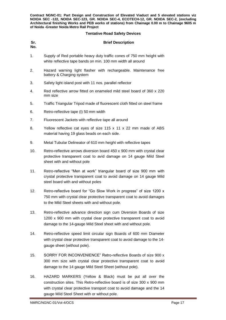
Contract NGNC-01: Part Design and Construction of Elevated Viaduct and 5 elevated stations viz NOIDA SEC -122, NOIDA SEC-123, GR. NOIDA SEC-4, ECOTECH-12, GR. NOIDA SEC-2, (excluding Architectural finishing Works and PEB works of stations) from Chainage 0.00 m to Chainage 9605 m of Noida -Greater Noida Metro Rail Project
NMRC/NGNC-01/Vol-4/OCS Page 17
Tentative Road Safety Devices
Sr. Brief Description No.
1. Supply of Red portable heavy duty traffic cones of 750 mm height with
white reflective tape bands on min. 100 mm width all around
2. Hazard warning light flasher with rechargeable. Maintenance free battery & Charging system
3. Safety light island post with 11 nos. parallel reflector
4. Red reflective arrow fitted on enameled mild steel board of 360 x 220 mm size
5. Traffic Triangular Tripod made of fluorescent cloth fitted on steel frame
6. Retro-reflective tape (I) 50 mm width
7. Fluorescent Jackets with reflective tape all around
8. Yellow reflective cat eyes of size 115 x 11 x 22 mm made of ABS
material having 19 glass beads on each side.
9. Metal Tubular Delineator of 610 mm height with reflective tapes
10. Retro-reflective arrows diversion board 450 x 900 mm with crystal clear
protective transparent coat to avid damage on 14 gauge Mild Steel
sheet with and without pole
11. Retro-reflective “Men at work” triangular board of size 900 mm with
crystal protective transparent coat to avoid damage on 14 gauge Mild
steel board with and without poles
12. Retro-reflective board for “Go Slow Work in progress” of size 1200 x
750 mm with crystal clear protective transparent coat to avoid damages
to the Mild Steel sheets with and without pole.
13. Retro-reflective advance direction sign cum Diversion Boards of size
1200 x 900 mm with crystal clear protective transparent coat to avoid
damage to the 14-gauge Mild Steel sheet with and without pole.
14. Retro-reflective speed limit circular sign Boards of 600 mm Diameter
with crystal clear protective transparent coat to avoid damage to the 14-
gauge sheet (without pole).
15. SORRY FOR INCONVENIENCE‟ Retro-reflective Boards of size 900 x
300 mm size with crystal clear protective transparent coat to avoid
damage to the 14 gauge Mild Steel Sheet (without pole).
16. HAZARD MARKERS (Yellow & Black) must be put all over the
construction sites. This Retro-reflective board is of size 300 x 900 mm
with crystal clear protective transport coat to avoid damage and the 14
gauge Mild Steel Sheet with or without pole.

Contract NGNC-01: Part Design and Construction of Elevated Viaduct and 5 elevated stations viz NOIDA SEC -122, NOIDA SEC-123, GR. NOIDA SEC-4, ECOTECH-12, GR. NOIDA SEC-2, (excluding Architectural finishing Works and PEB works of stations) from Chainage 0.00 m to Chainage 9605 m of Noida -Greater Noida Metro Rail Project
NMRC/NGNC-01/Vol-4/OCS Page 18
17. “CAUTION‟ tape which is normally yellow tape of special Polythene
Material having 75 mm width “CAUTION‟ is written all over with Black
colour in rolls of 300 meter.
18. Heavy Duty Glass Reinforced Plastic Temporary Barricade
Providing Heavy Duty Glass Reinforced Plastic Temporary Barricad of
2.0m m high,1.5m length with base width of 430 mm as a provision to
accept water ballasting of 101 ltrs approx.. and arrangement for traffic
diversion such as traffic signals during construction at site, for day and
night as per requirement. The raw material shall be UV stabilized
Linear Low Density Polyethylene and should meet the requiremnts
stipulated in standard IS:10146-1982, IS:10141-1982 and should also
comply to FDA:CFR Title 21.177.1520. Olefin Polymers, with specific
FRP Grade 300-104 reinforced during moulding process to the
permissible extent for improved impact strength, Qualification Criteria:
For qualifying the sample, few tests shall be performed at Government
Lab OR NABL Accredited Lab on site safety Fence sample, failure or
Deviation in test results of sample shall be disqualified. The tests and
qualifying results are as under, (a) tensile strength at yield by ASTM D
638=20.93 Mpa, (b) Elongation at break ASTM D 638= 121.66 Mpa (c)
Flexural Modulus ASTM D 790 = 633.76 Mpa (d) Izad Impact Strength
(Notched) ASTM D 256= 4.41 Kg/Sqm (e) Izad Impact strength(Un-
Notched) ASTM D 256 = 67.04Kg/Sqm (f) Drop Impact Strength 25 Kg
Load from 1m, 2m & 5m height the weight of empty single
Rotomoulded Plastic Barricade Without to fix two brackets at both end
in corner for anchoring purpose each rear bracket is constructed
throught rod of Dia 60 mm with curvature welded with MS strip of 3mm
thick, 50mm width and 90mm length at its top and base, effective
bracket shall be 410mm approx.. the anchoring hole in each Bracket
shall be 18mm dia. For routine the MS bolt of 16mm thickness and
15mm length with sharp pointed edge at one end. The upper part of
each bracket shall have a slot size of 30mm x 10mm for connecting it
with barricade model through bolts. Similarly front bracket for site safety
fence is 3mm thick, 50mm width, feective height after single bend is
230 mm and anchoring in each bracket shall be dia 18mm unique
safety feature for firm gripping to prevent from displacement and falling
when inter connected even without water filling. There shall be 7 no’s
premoulded inserts on site safety Fence for following application: 2no’s
for safety latches interconnectivity, 2 no’s for fixing rear brackets for
anchoring. One no. at front side for fixing the front bracket for higher
stability, and 2 nos on Extension top for holding light bracket/RRod for

Contract NGNC-01: Part Design and Construction of Elevated Viaduct and 5 elevated stations viz NOIDA SEC -122, NOIDA SEC-123, GR. NOIDA SEC-4, ECOTECH-12, GR. NOIDA SEC-2, (excluding Architectural finishing Works and PEB works of stations) from Chainage 0.00 m to Chainage 9605 m of Noida -Greater Noida Metro Rail Project
NMRC/NGNC-01/Vol-4/OCS Page 19
cloth holding. The plastic barricades has a stron vertical rib of 1740 mm
length at the rear centre& 72 No’s of kiss offs spread on entire rear
surface, the water container (bottom)
Site Safety Fence (2.00 mtrs(H)) (Efficient Substitution to sheet Metal
Barricade), Empty Weight : 1700 Kg/Rgm Full : 70.00 Kg/Rgm
approx..(After Water/Sand Filling)
Measurement
lThe barricading including all the required safety devices as listed
above shall be measured as per relevant item in BOQ.(Payment of
the item shall be made on monthly basis over contract period
including extended period, if any. No extra payment shall be made for
the extended period, if any. Payment shall be deducted for the period
during which the barricading and arrangements for traffic diversion
are not satisfactory to the Engineer. The payment and deduction (if
any) for the item shall be on pro-rata basis). No extra payment will be
made for any lateral shifted barricading required for satisfactory
execution of work.
1.7 TRANSPLANTATION OF TREES
The item shall be carried out as per the approved plan by the
Noida Metro Rail Corporation

Contract NGNC-01: Part Design and Construction of Elevated Viaduct and 5 elevated stations viz NOIDA SEC -122, NOIDA SEC-123, GR. NOIDA SEC-4, ECOTECH-12, GR. NOIDA SEC-2, (excluding Architectural finishing Works and PEB works of stations) from Chainage 0.00 m to Chainage 9605 m of Noida -Greater Noida Metro Rail Project
NMRC/NGNC-01/Vol-4/OCS Page 20
Engineer after the identification of the trees to be transplanted. The
actual number of trees shall be finalized after the necessary
clearances by the concerned departments. The item is complete and
including all expenditures for carrying out all operations i.e.
excavation, watering, feeding of chemicals, back filling, lifting of trees
by crane and transporting to the designated site where it is to be
transplanted and all necessary care to be taken for the specified
initial period till the tree gets settled at new site and up to the full
satisfaction of the Engineer.
Measurements
The item shall be measured in numbers according to size of the tree
as specified in the item and the full payment shall be released only
when the item is executed fully as per the Scope of Work detailed out
in the approved plan for transplantation of trees.
The rate shall include all required operations during the
transplantation and specified duration afterwards, clearances from
the concerned authorities.
1.8 FINISHING WORK:
1.8.1 The Contractor shall incorporate seismic considerations of anchoring
and isolation in the design and detailing of the finishes as directed by
the Engineer. The element to be anchored shall have its motion
suitably restrained whilst at the same time it shall be suitably isolated
so as not to be affected by the deformations/ vibrations of the building
during Construction.
1.8.2 Sub-Contractor:
Works as listed below and those dealing with proprietary materials/
products may be carried out by the Contractor through the Sub-
Contractors as may be approved by the Engineer in writing. The Sub-
Contractors must be firms of repute and long standing, having
adequate experience and complete facilities to carry out all items of
work required for completion as per Specifications and expected
quality to the satisfaction of the Engineer. The Sub-Contractor must
also have personnel experienced in preparing shop drawings. All
such works shall be carried out under the direct supervision of the
manufacturers of the proprietary materials/ products or their trained
and accredited licensee.

Contract NGNC-01: Part Design and Construction of Elevated Viaduct and 5 elevated stations viz NOIDA SEC -122, NOIDA SEC-123, GR. NOIDA SEC-4, ECOTECH-12, GR. NOIDA SEC-2, (excluding Architectural finishing Works and PEB works of stations) from Chainage 0.00 m to Chainage 9605 m of Noida -Greater Noida Metro Rail Project
NMRC/NGNC-01/Vol-4/OCS Page 21
i. Waterproofing
ii. Caulking & Sealants
iii. Seismic Joints
iv. Expansion joints
v. Application of Silicone water repellent solution where
specified.
vi. Bearings 1.8.3 Guarantees and Building Maintenance for Finishes:
The Contractor shall guarantee and undertake to maintain and rectify
the various components of the Civil Works for their successful
performance for the periods as specified below. The Contractor shall
indemnify the Engineer for a similar period against any damage to
property and injury to persons on account of any defective work or
maintenance carried out by the Contractor. The format and text of the
Guarantee and the Indemnity Bond shall be as followed in CPWD or
as approved by the Engineer.
i. Waterproofing for underground structures (which include raft,
retaining walls, and expansion/separation joints in retaining walls)
and roofs shall be guaranteed for 10 years. The waterproofing
shall include all allied works on the roof such as concrete screed
and the China Mosaic roof finish/ stone cladding on the parapet
between which the waterproofing treatment shall be sandwiched.
ii. Waterproofing for the other areas such as toilets, kitchens,
chhajjas etc. shall also be guaranteed for 10 years. The
waterproofing shall include all allied works on the slab etc. such
as concrete/ mortar screeding, if any, floor finish between which
the waterproofing treatment shall be sandwiched.
Contractor shall submit Performance Bank Gyarantee for
water proofing works (for 10% of the cost of water proofing
item only) which shall be valid for the entire guarantee
period.
1.8.4 Responsibility for Shop drawings, Samples and Mock-ups:
Approval of shop drawings, samples and mock-ups for the various
components shall not absolve the Contractor of his responsibility of
completing the work to the specifications, standards, tests for
performance and guarantees given in these documents and to a
quality of finish as desired by the Engineer.
1.8.5 Cleaning:
Surfaces on which finishes are to be provided shall be cleaned with
Contract NGNC-01: Part Design and Construction of Elevated Viaduct and 5 elevated stations viz NOIDA SEC -122, NOIDA SEC-123, GR. NOIDA SEC-4, ECOTECH-12, GR. NOIDA SEC-2, (excluding Architectural finishing Works and PEB works of stations) from Chainage 0.00 m to Chainage 9605 m of Noida -Greater Noida Metro Rail Project
NMRC/NGNC-01/Vol-4/OCS Page 22
water jets or oil free compressed air or power tools with wire brushes
and detergents all as approved by the Engineer.
1.8.6 Expansion bolts/ fasteners:
i. Unless specified otherwise all expansion bolts/ fasteners
shall be fabricated from austenitic stainless steel sheet, strip
or plate conforming to ASTM A 240 Gr 304 or bar to ASTM A
479 Gr 304 of approved make and design. The material of
the bolt shall not cause any bimetallic corrosion with the
reinforcing bars of the RCC/ brickwork or with any other
fixings or doors or windows or skylights etc.
ii. For steel backings the fasteners shall be prevented from
contact with other metals, which would lead to bimetallic
corrosion.
iii. For brick masonry backing the sleeves of the expansion bolts
shall be fixed in wedge shaped pockets having an area of
75mm x 75mm at the surface and 100mm x 100mm at the
inner surface and shall be 125mm deep. The wedge could
also be as a truncated cone of 75mm dia/ 100mm dia. The
dimensions shall be reviewed by the Engineer during
execution of the work. The wedge shall be filled with PCC
1:1:2 (1 Cement, 1 Sand and 2 Coarse Aggregate) mixed
with non-Shrink Compound in the proportion as
recommended by the manufacturer.
iv. The holes drilled for the expansion fasteners shall be cleaned
of all ground material, dust, etc. before inserting the
expansion sleeves.
v. All expansion bolts fixed into soffits shall be bonded to the
backing with epoxy/ polyester resin of approved make.
vi. Allexpansion bolt fixings shall be tightened in accordance
with the recommended torque figures by the manufacturer.
Where such values are not available the Contractor shall test
at least 6 samples to determine the safe torque values. All
bolts shall be tightened using torque spanner/ wrenches. All
bolts shall be checked 24 hours (minimum) after installation
and retightened if necessary.
1.8.7 No walls, terraces shall be cut for making any opening after water

Contract NGNC-01: Part Design and Construction of Elevated Viaduct and 5 elevated stations viz NOIDA SEC -122, NOIDA SEC-123, GR. NOIDA SEC-4, ECOTECH-12, GR. NOIDA SEC-2, (excluding Architectural finishing Works and PEB works of stations) from Chainage 0.00 m to Chainage 9605 m of Noida -Greater Noida Metro Rail Project
NMRC/NGNC-01/Vol-4/OCS Page 23
proofing has been done without written approval of the Engineer.
Cutting of waterproofing when authorised by the Engineer in writing
shall be done very carefully so that no other portion of the
waterproofing is damaged. On completion of the work at such places,
the water proofing membrane shall be made good and ensured that
the opening / cutting is made fully water proof as per specifications
and details of water proofing approved by the Engineer at no extra
cost. No structural member shall be cut or chased without the written
permission of the Engineer.
1.8.8 Provision of grooves in plaster, drip courses etc, if directed, at
junction of walls-ceilings, columns-walls, frames-plaster and such
other generally typical locations shall not be paid extra, including
grooves in concrete, masonry, stonework.
1.8 Applicable Codes, Standards & Publications for Structural & Architectural Work :
The more important Codes, Standards and Publications to Contract
are listed here under:
Any other code/publication, if found necessary by the engineer,may
be referred to for such works.
The latest revision along with all corrections slip & amendments shall
only be followed
A General
IS: 875 Code of practice for design loads (other than
earthquake) for buildings and structures
IS: 1200 (Part 4) Methods of measurement of building and Civil engineering
works-Stone masonry
IS: 1237 Specification for cement concrete flooring tiles
IS: 1322 Bitumen felts for water proofing and damp-proofing IS: 1893 Criteria for earthquake resistant design of structures
IS: 2185 (Part 1) Concrete masonry units: Hollow and solid concreteBlocks
IS: 2185 (Part 2) Concrete masonry units: Hollow and solid light weightconcrete blocks
IS: 2185 (Part 3) Concrete masonry units: Autoclaved cellular aeratedconcrete blocks
IS: 2572 Code of Practice for construction of hollow concrete blockMasonry
IS: 3414 Code of practice for design and installation of joints inBuildings
IS: 3462 Specification for unbacked flexible PVC flooring
IS: 5318 Code of practice for laying of flexible PVC sheet and tileFlooring
IS: 6408 (Parts 1,2) Recommendations for modular co-ordination in buildingindustry –
tolerances
IS: 8183 Bonded mineral wool
IS:10958 General check list of functions of joints in building
IS:11817 Classification of joints in buildings for accommodation ofdimensional
deviations during construction
IS:11818 Method of test for laboratory determination of airpermeability of
joints in buildings

Contract NGNC-01: Part Design and Construction of Elevated Viaduct and 5 elevated stations viz NOIDA SEC -122, NOIDA SEC-123, GR. NOIDA SEC-4, ECOTECH-12, GR. NOIDA SEC-2, (excluding Architectural finishing Works and PEB works of stations) from Chainage 0.00 m to Chainage 9605 m of Noida -Greater Noida Metro Rail Project
NMRC/NGNC-01/Vol-4/OCS Page 24
IS:12440 Precast concrete stone masonry blocks
CPWD Specifications with up-to-date correction slips
BS:476 (Part 7) Method for classification of the surface spread of flame ofProducts
BS:476 (Part 20) Method of determination of the fire resistance ofelements of
construction (general principles)
BS:476 (Part 22) Methods for determination of the fire resistance of non-load bearing
elements of construction
BS: 1245 Specification for metal door frames (steel)
BS: 3261 Specification for unbacked flexible PVC flooring
BS:3261:Part 1 Homogeneous flooring
BS:5215 Specification for one-part gun grade polysulphide-basedSealants
BS:5606 Guide to accuracy in building
BS:5725 (Part 1) Specification for panic bolts and panic latchesmechanically
operated by a horizontal push-bar
BS:6093 Code of practice for the design of joints and jointing inbuilding
construction
BS:8200 Code of practice for the design of non-load bearingexternal vertical
enclosure of building
ASTM C 332 Specification for light weight aggregate for insulatingConcrete
ASTM C 635 Specification for the manufacture, performance andtesting of metal
suspension systems for acoustical tileand lay-in panel ceilings
SP 7 National Building Code of India
SP 23 (S&T) Hand Book on Concrete Mixes
B Bitumen
IS:702 Industrial Bitumen
IS:3384 Specification for bitumen primer for use in waterproofingand damp-
proofing
C Building Construction Practices
IS: 1838 Parts I and II. Specifications for preformed fillers for expansion joint inconcrete
pavements and structures
IS: 1946 Code of Practice for use of fixing devices in walls,ceilings, and
floors of solid construction
IS: 3414 Code of Practice for design and installation of joints inbuildings.
IS: 6509 Code of Practice for installation of joints in concretepavements.
IS: 11134 Code of Practice for setting out of buildings.
IS: 11433 Parts I and II. Specifications for one part Gun gradepolysulphide
based joint sealant
IS: 12200 Code of Practice for provision of water stops at transverse contraction
joints in masonry and concrete dams
D Cement
IS: 269 33 grade ordinary Portland cement
IS: 455 Portland Slag Cement
IS: 650 Specification for standard sand for testing cement.
IS: 1489 (Part 1) Portland pozzolana cement: Fly ash based
IS: 1489 (Part 2) Portland pozzolana cement: Calcined clay based
IS: 3535 Method of Sampling Hydraulic Cements
IS: 4031 (Parts 1 to 13) Methods of physical tests for hydraulic cement.
IS: 4032 Method of chemical analysis of hydraulic cement.
IS: 6925 Methods of test for determination of water soluble chlorides in concrete
admixtures.
IS: 8042 White Portland Cement

Contract NGNC-01: Part Design and Construction of Elevated Viaduct and 5 elevated stations viz NOIDA SEC -122, NOIDA SEC-123, GR. NOIDA SEC-4, ECOTECH-12, GR. NOIDA SEC-2, (excluding Architectural finishing Works and PEB works of stations) from Chainage 0.00 m to Chainage 9605 m of Noida -Greater Noida Metro Rail Project
NMRC/NGNC-01/Vol-4/OCS Page 25
IS: 8112 Specification for 43 grade ordinary Portland cement.
IS: 12269 Specification for 53 grade ordinary Portland cement.
IS: 12330 Specification for sulphate resistant Portland cement.
IRS: T 40 Indian Railways standard specifications for special grade cement for
use in concrete sleepers E Concrete
IS:456 Code of practice for plain and reinforced concrete.
IS:457 Code of practice for general construction of plain and reinforced
concrete for dams and other massive structures.
IS:460 (Part I to III) Specification for Test Sieves
IS:516 Methods of test for strength of concrete.
IS:1199 Methods of sampling & analysis of concrete.
IS:1200 Method of measurement of building and civil engineering
IS:1343 Code of practice for prestressed concrete
IS:1607 Method of Test Sieving
IS:2386 Parts I-VIII. Methods of tests for aggregates for concrete.
IS:2430 Methods of Sampling of Aggregates of Concrete
IS:2438 Specification for roller pan mixer
IS:2514 Specification for concrete vibrating tables
IS:2571 Code of practice for laying in-situ cement concreteFlooring
IS:2645 Specifications for integral cement water proofingCompounds
IS:2722 Specifications for portable swing batchers for concrete(double bucket
type)
IS:2770 Methods of testing bond in reinforced concrete part I pullout test
IS:3025 Methods of sampling and test (physical and chemical) forwater & waste
water
IS:3370 Code of practice for concrete structures for storage ofLiquids
IS:3935. Code of practice for composite construction
IS:4326 Code of practice for earthquake resistant construction ofBuilding
IS:6925. Methods of test for determination of water solublechlorides in
concrete Admixtures
IS:7242 Specifications for concrete spreaders
IS:7251 Specifications for concrete finishers
IS:7861 Parts I& II. Code of practice for extreme weatherconcreting
IS:7969 Safety code for handling and storage of buildingMaterials
IS:8989 Safety code for erection of concrete framed structures
IS:8142 Methods of test for determining setting time of concrete bypenetration
resistance
IS:9103 Specifications for admixtures for concrete
IS:9013 Method of making, curing and determining compressive strengths of
accelerated cured concrete test specimens
IS:9284 Method of test for abrasion resistance of concrete
IS:10262 Recommended guidelines for concrete mix design.
IS:4926 Code of Practice ready mixed concrete needs to be included in list
MORTH Specifications for Road and Bridge Works, Ministry of Road Transport
and Highways (Roads Wing)
SP 34 Handbook on Concrete Reinforcement and Detailing
IRS Concrete Bridge Code
IRC 112 Code of Practice for Concrete Road Bridges
IRC 83 (Part 4) Statndard Sepcifications and code of practice for road bridges Section
IX Bearings (Spherical & Cylindrical)

Contract NGNC-01: Part Design and Construction of Elevated Viaduct and 5 elevated stations viz NOIDA SEC -122, NOIDA SEC-123, GR. NOIDA SEC-4, ECOTECH-12, GR. NOIDA SEC-2, (excluding Architectural finishing Works and PEB works of stations) from Chainage 0.00 m to Chainage 9605 m of Noida -Greater Noida Metro Rail Project
NMRC/NGNC-01/Vol-4/OCS Page 26
ASTM -C -94 Ready Mix Concrete F Construction Plant and Machinery.
IS:1791 Specification for batch type concrete mixers.
IS:2505 General requirements for concrete vibrators: Immersiontype.
IS:2506 General requirements for screed board concretevibrators
IS:3366 Specification for pan vibrators.
IS:3558
Code of Practice for use of immersion vibrators forconsolidating
concrete.
IS:4656 Specifications for form vibrators for concrete.
IS:4925 Specification for concrete batching and mixing plant.
IS:11993 Code of Practice for use of screed board concretevibrators.
G Formwork
IS:4990 Specifications for plywood for concrete shuttering work.
IRC:87 Guidelines for the design and erection of false work forroad bridges.
IS:806 Code of practice for use of steel tubes in general buildingconstruction.
IS:1161 Specification of steel tubes for structural purposes.
IS:1239
Specification for mild steel tubes, tubular and otherwrought steel
fittings.
H Gypsum and Gypsum Board
IS:2095 Gypsum plaster boards
IS:2542 (Part 1/Sec to
12)
Methods of test for gypsum plaster, concrete andproducts: plaster
and concrete
IS:2542 (Part 2/Sec 1
to 8)
Methods of test for gypsum plaster, concrete and products: Gypsum
products
IS:2547 (Part 1) Gypsum building plaster: Excluding premixed lightweight plaster IS:2547 (Part 2) Gypsum building plaster: Premixed lightweight plaster
I Handling and Storage
IS:4082
Recommendation of Stacking and Storage ofconstruction
materials
IS:8348
Code of practice for stacking and packing of stone slabsfor
transportation
IS:8759
Code of practice for maintenance and preservation ofstones in
building
J Instruments For Testing Cement and Concrete
IS:5513 Specification for vicat apparatus.
IS:5514 Specification for apparatus used in Le-Chaterlier test.
IS:5515 Specification for compaction factor apparatus.
IS:7320 Specification for concrete slump test apparatus.
IS:7325 Specification for apparatus to determine constituents offresh concrete.
IS:10080 Specification for vibration machine.
IS:10086 Specification for moulds for use in tests of cement andconcrete.
IS:10510 Specification for vee-bee consistometer.
K Joint Fillers
IS:1838 (Part 1)
Preformed fillers for expansion joint in concretepavements and
structures (non extruding and resilient type): Bitumen impregnated fibre
L Paints and Coatings
IS:102 Ready mixed paint, brushing, red lead, non-setting,priming
IS:109
Ready mixed paint, brushing, priming, plaster, to IndianStandard Colour
No. 361 and 631 white and off white.
IS:218 Creosote and anthracene oil for use as woodpreservatives
IS:347 Varnish, shellac, for general purpose.
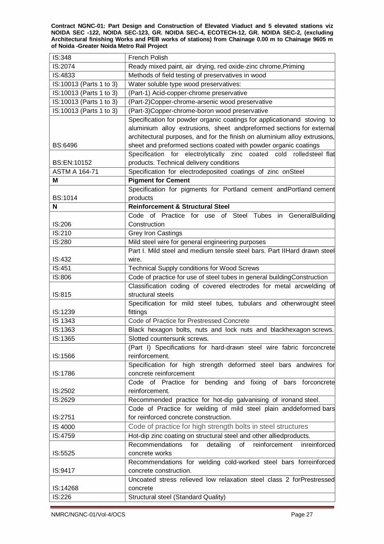
Contract NGNC-01: Part Design and Construction of Elevated Viaduct and 5 elevated stations viz NOIDA SEC -122, NOIDA SEC-123, GR. NOIDA SEC-4, ECOTECH-12, GR. NOIDA SEC-2, (excluding Architectural finishing Works and PEB works of stations) from Chainage 0.00 m to Chainage 9605 m of Noida -Greater Noida Metro Rail Project
NMRC/NGNC-01/Vol-4/OCS Page 27
IS:348 French Polish
IS:2074 Ready mixed paint, air drying, red oxide-zinc chrome,Priming
IS:4833 Methods of field testing of preservatives in wood
IS:10013 (Parts 1 to 3) Water soluble type wood preservatives:
IS:10013 (Parts 1 to 3) (Part-1) Acid-copper-chrome preservative
IS:10013 (Parts 1 to 3) (Part-2)Copper-chrome-arsenic wood preservative
IS:10013 (Parts 1 to 3) (Part-3)Copper-chrome-boron wood preservative
BS:6496
Specification for powder organic coatings for applicationand stoving to
aluminium alloy extrusions, sheet andpreformed sections for external
architectural purposes, and for the finish on aluminium alloy extrusions,
sheet and preformed sections coated with powder organic coatings
BS:EN:10152
Specification for electrolytically zinc coated cold rolledsteel flat
products. Technical delivery conditions
ASTM A 164-71 Specification for electrodeposited coatings of zinc onSteel
M Pigment for Cement
BS:1014
Specification for pigments for Portland cement andPortland cement
products
N Reinforcement & Structural Steel
IS:206
Code of Practice for use of Steel Tubes in GeneralBuilding
Construction
IS:210 Grey Iron Castings
IS:280 Mild steel wire for general engineering purposes
IS:432
Part I. Mild steel and medium tensile steel bars. Part IIHard drawn steel
wire.
IS:451 Technical Supply conditions for Wood Screws
IS:806 Code of practice for use of steel tubes in general buildingConstruction
IS:815
Classification coding of covered electrodes for metal arcwelding of
structural steels
IS:1239
Specification for mild steel tubes, tubulars and otherwrought steel
fittings
IS 1343 Code of Practice for Prestressed Concrete
IS:1363 Black hexagon bolts, nuts and lock nuts and blackhexagon screws.
IS:1365 Slotted countersunk screws.
IS:1566
(Part I) Specifications for hard-drawn steel wire fabric forconcrete
reinforcement.
IS:1786
Specification for high strength deformed steel bars andwires for
concrete reinforcement
IS:2502
Code of Practice for bending and fixing of bars forconcrete
reinforcement.
IS:2629 Recommended practice for hot-dip galvanising of ironand steel.
IS:2751
Code of Practice for welding of mild steel plain anddeformed bars
for reinforced concrete construction.
IS 4000 Code of practice for high strength bolts in steel structures
IS:4759 Hot-dip zinc coating on structural steel and other alliedproducts.
IS:5525
Recommendations for detailing of reinforcement inreinforced
concrete works
IS:9417
Recommendations for welding cold-worked steel bars forreinforced
concrete construction.
IS:14268
Uncoated stress relieved low relaxation steel class 2 forPrestressed
concrete
IS:226 Structural steel (Standard Quality)

Contract NGNC-01: Part Design and Construction of Elevated Viaduct and 5 elevated stations viz NOIDA SEC -122, NOIDA SEC-123, GR. NOIDA SEC-4, ECOTECH-12, GR. NOIDA SEC-2, (excluding Architectural finishing Works and PEB works of stations) from Chainage 0.00 m to Chainage 9605 m of Noida -Greater Noida Metro Rail Project
NMRC/NGNC-01/Vol-4/OCS Page 28
IS:800
Code of practice for use of structural steel in generalbuilding
construction.
IS:813 Scheme of symbols for welding.
IS:814
Covered electrodes for metal arc welding of structuralsteel. (Part I &
Part II)
IS:816
Code of practice for use of metal arc welding for generalconstruction in
mild steel.
IS:822 Code of practice for inspection of welds.
IS:961 Structural steel (High Tensile)
IS:1024
Code of practice for use of welding in bridges andstructures
subject to dynamic loading.
IS:1030 Carbon steel casting for General Engineering Purposes
IS:1120 Coach Screws
IS:1367 Technical Supply Conditions for Threaded Fasteners
IS:1161 Steel tubes for structural purposes.
IS:1182
Recommended practice for radiographic examination offusion welded
butt joints in steel plates.
IS:1915 Code of Practice for Steel Bridges
IS:2016 Plain Washers
IS:2062 Structural steel (Fusion welding quality)
IS:3063
Single Coil Rectangular Section Sprint Washers for Nuts,Bolts and
Screws
IS:3443 Crane Rail Sections
IS:3757 Specification for high tensile friction grip bolts.
IS:5624 Specification for foundation bolts.
IS:3600
Code of practice for testing of fusion welded (Part I) jointsand weld metal
in steel.
IS:4923 Hollow steel sections for structural use.
IS:6227 Code of practice for use of metal arc welding in tubularstructure.
IS:801
Code of practice for use of cold formed light gauge steelstructural
members in general building construction.
O Sand
IS:383 Coarse and fine aggregates from natural sources forconcrete.
P Scaffolding
IS:2750 Specification for steel scaffoldings
IS:3696 (Part 1) Safety Code of scaffolds and ladders: Scaffolds
IS:3696 (Part 2) Safety Code of scaffolds and ladders: Ladders
IS:4014 (Part 1) Code of practice for steel tubular scaffolding: Definitionand materials
IS:4014 (Part 2)
Code of practice for steel tubular scaffolding: Safetyregulations for
scaffolding
IRC:87 Guidelines for the design and erection of falsework for Road bridge
IS:811 Specifications for cold formed light gauge structural steel sections.
IS:8500 Structural steel Micro alloyed (Medium and high strength qualities)
IS:8910 General requirements of supply of weldable structural steel
IS:9595
Recommendations for metal arc welding of carbon & carbon-
manganese steels.
IS 16172 Reinforced Couplers for Mechanical Splices of Bars in Concrete
Q Sealants
IS:10959 Glossary of terms for sealants for building purposes
IS:11433 (Part 1) One part grade polysulphide base joint sealant: General requirements
IS:11433 (Part 2) One part grade polysulphide base joint sealant: Methods of test

Contract NGNC-01: Part Design and Construction of Elevated Viaduct and 5 elevated stations viz NOIDA SEC -122, NOIDA SEC-123, GR. NOIDA SEC-4, ECOTECH-12, GR. NOIDA SEC-2, (excluding Architectural finishing Works and PEB works of stations) from Chainage 0.00 m to Chainage 9605 m of Noida -Greater Noida Metro Rail Project
NMRC/NGNC-01/Vol-4/OCS Page 29
IS:13055 Methods of sampling and test for anaerobic adhesives and sealants
BS:5889 Specification for one part gun grade silicone-based sealants.
R Wood
IS:303 Plywood for General Purposes
IS:848 Synthetic resin adhesives for plywood (phenolic and aminoplastic)
IS:1141 Seasoning of Timber – Code of Practice
IS:1328 Veneered decorative plywood
IS:1659 Block Boards
IS:2046 Decorative thermosetting synthetic resin bonded laminated sheets
IS:2202 (Part 1) Wooden flush door shutters (solid core type): Plywood face panels
IS:2202 (Part 2) Wooden flush door shutters (solid core (type): Particle face panels and
hardboard face panels
S Bearing
IRC:83Part-II Standard specifications and code of practice for road bridges
Elastomeric Bearings
IRC:83 Part-III Standard specifications and code of practice for road bridges Pot
Bearings
T PILING
IS :2911(All Parts) Bored Cast in-situ Concrete Piles
IRC:78 Standard specifications and code of practice for road bridges
Foundation And Substructure
U All Indian Railway & RDSO Standards, any other code or
publication as approved by engineer in-charge
V Metal
IS:276 Austenitic manganese steel castings
IS:733 Wrought aluminium and aluminium alloy bars, rods and sections for
general engineering purpose.
IS:737 Specifications for wrought aluminium and aluminium alloy sheet and
strip for general engineering purpose.
IS:3614 (Part 1) Specification for fire check doors: Plate metal covered and rolling type
IS:3614 (Part 2) Specification for metallic and non-metallic fire check doors: Resistance
test and performance criteria
IS:7196 Specification for Hold Fasts
ASME Sect 2 Part A Ferrous Material Specifications
ASTM B 221 Specification for aluminum-alloy extruded bars, rods, wires, shapes, and
tubes
BS: 4873 Specification for Aluminum alloy windows
BS: 7352 Specification for strength and durability performance of metal hinges for
side hanging applications and dimensional requirements for template
drilled hinges
BS EN:10143 Specification for continuously hot-dip metal coated steel sheet and strip.
Tolerances on dimensions and shape
W Glazing
BS:952 (Part 1) Glass for glazing: classification
BS:952 (Part 2) Glass for glazing: Terminology for work on glass
BS:4315 (Part 2) Methods of Test for Resistance to Air and water penetration: Permeable
walling constructions (water penetration)
BS:5368 (Part 1) Method of testing Windows: Air permeability test
BS:5368 (Part 2) Method of testing Windows: Water tightness test under static pressure
BS:5368 (Part 3) Method of testing Windows: Wind resistance tests
BS:5368 (Part 4) Method of testing Windows: Form of test report

Contract NGNC-01: Part Design and Construction of Elevated Viaduct and 5 elevated stations viz NOIDA SEC -122, NOIDA SEC-123, GR. NOIDA SEC-4, ECOTECH-12, GR. NOIDA SEC-2, (excluding Architectural finishing Works and PEB works of stations) from Chainage 0.00 m to Chainage 9605 m of Noida -Greater Noida Metro Rail Project
NMRC/NGNC-01/Vol-4/OCS Page 30
BS:5713 Specification for Hermetically sealed flat double glazing units
BS:6262 Code of practice for glazing for buildings
BS:6262 (Part 4) Glazing for buildings: Code of practice for safety, Human impact
BS: 6375 (Parts 1) Performance of windows: Classification for weather tightness
(including guidance on selection and Specification)
BS:6375 (Parts 2) Performance of windows: Specification for operationand strength
characteristics
DIN:1249 (Part 12) Glass for use in building construction; toughened glass;dimensions,
working and requirements
JIS:R 3203 Float and Polished Plate Glasses
ASTM E 283 Test method for determining the rate of air leakagethrough exterior
windows, curtain walls, and doorsunderspecified pressuredifferences
across thespecimen
ASTM E 330 Test method for structural performance of exteriorwindows, curtain
walls, and doors by uniform static airpressure difference
ASTM E 331 Test method for water penetration of exterior windows,
curtain walls, and doors by uniform static air pressure
difference
X Stone and Facings/ Linings
IS:1121-(Parts 1 to 4) Methods of test for determination of strength properties
of natural building stones
IS:1121-(Parts 1 to 4) (Part-1 Compressive strength)
IS:1121-(Parts 1 to 4) (Part-2 Transverse strength)
IS:1121-(Parts 1 to 4) (Part-3 Tensile strength)
IS:1122 (Part-4 Shear strength)
IS:1123 Method of test for determination of true specific gravityof natural building
stones.
IS:1124 Method of identification of natural building stones
IS:1125 Method of test for determination of water absorption,apparent specific
gravity and porosity of natural buildingstones.
IS:1126 Method of test for determination of weathering of natural building
stones.
IS:1127 Recommendations for dimensions and workmanship ofnatural building
stones for masonry work.
IS:1128 Specification for Limestone (Slabs and Tiles)
IS:1129 Recommendation for dressing of natural building
stones.
IS:1130 Specification for marble (blocks, slabs and tiles).
IS:1597 (Part 2) Code of practice for construction of stone masonry:
Ashlar masonry
IS:1706 Method for determination of resistance to wear by
abrasion of natural building stones
IS:1805 Glossary of terms relating to stones, quarrying and
Dressing
IS:3620 Specification for laterite stone block for masonry
IS:3622 Specification for Sandstone (slab & tiles)

Contract NGNC-01: Part Design and Construction of Elevated Viaduct and 5 elevated stations viz NOIDA SEC -122, NOIDA SEC-123, GR. NOIDA SEC-4, ECOTECH-12, GR. NOIDA SEC-2, (excluding Architectural finishing Works and PEB works of stations) from Chainage 0.00 m to Chainage 9605 m of Noida -Greater Noida Metro Rail Project
NMRC/NGNC-01/Vol-4/OCS Page 31
IS:4101 (Part 1) Code of practice for external facing and veneers: stone
Facing
IS:4101 (Part 2) Code of practice for external facing and veneers:
Cement concrete facing
IS:4101 (Part 3) Code of practice for external facing and veneers: Wall
tiling and mosaics
IS:4121 Method of test for determination of water transmission
rate by capillary action through natural building stones
IS:4122 Method of test for surface softening of natural building
stones by exposure to acidic atmospheres
IS:4348 Method of test for determination of permeability of
natural building stones
IS:5218 Method of test for toughness of natural building stones
IS:8381 Recommended practice for quarrying stones for
construction purposes
IS:14223 (Part 1) Polished building stones: Granite
BS: 8298 Code of practice for design and installation of natural
stone cladding and lining

Contract NGNC-01: Part Design and Construction of Elevated Viaduct and 5 elevated stations viz NOIDA SEC -122, NOIDA SEC-123, GR. NOIDA SEC-4, ECOTECH-12, GR. NOIDA SEC-2, (excluding Architectural finishing Works and PEB works of stations) from Chainage 0.00 m to Chainage 9605 m of Noida -Greater Noida Metro Rail Project
NMRC/NGNC-01/Vol-4/OCS Page 32
SECTION – S.02
EARTH WORK 2.1 EXCAVATION
2.1.1 Site Clearance
The Contractor shall clear the Site as required by demolishing and removing vegetation,
debris, trees alongwith their roots, buildings etc. and the like to approved locations either
on or off the site as agreed by the Employer's Representative.
Stumps and major roots shall be grubbed up and disposed of off the site or burnt as
directed. The Contractor shall take precautions to prevent the spread of fire to adjacent
areas.
2.1.2 Top Soil Stripping
Top soil shall be removed as required, deposited in separate heaps at locations approved
by Employer’s Representative.
2.1.3 Removal of Unsuitable Material
The Contractor shall remove unsuitable material as ordered or agreed by the Employer's
Representative and shall dispose of it on or off the site as directed in the required manner.
Boulders, stones and other materials of value or usable again on the works shall be neatly
stacked and graded as directed by Employer's Representative.
2.1.4 Excavation – General- (soil and rock)
a) Excavation shall be carried out to the lines, levels and profiles shown on the Drawings.
The work shall be carried out by the Contractor in such a way as to avoid soil erosion,
ground water pollution, accidents in habitational or frequented places, disturbance to the
surrounding ground or structures, accident to workmen and any other untoward incident.
Particular care shall be taken to maintain stability when excavating in close proximity to
existing works. Fencing, caution signages with red lights and other safety measures shall
be employed to avoid accidents. Where necessary, signal men shall be employed to
guide the movement of people, vehicles and equipment.
b) The work shall be carried out in a careful manner to ensure that the exposed surfaces are
as sound as the nature of the material permits and that no point shall protrude inside the
lines shown on the Drawings except as otherwise specified or agreed by the Employer's
Representative. In soft soil excavation which is to remain open permanently, exposed
faces shall be formed accurately to the required slopes and profiles and properly
protected by turfing or pitching as required by Employer's Representative.

Contract NGNC-01: Part Design and Construction of Elevated Viaduct and 5 elevated stations viz NOIDA SEC -122, NOIDA SEC-123, GR. NOIDA SEC-4, ECOTECH-12, GR. NOIDA SEC-2, (excluding Architectural finishing Works and PEB works of stations) from Chainage 0.00 m to Chainage 9605 m of Noida -Greater Noida Metro Rail Project
NMRC/NGNC-01/Vol-4/OCS Page 33
c) The Contractor shall dispose of all material arising from excavations either off the site or
to approved tips on the site, as required.
d) The Contractor shall be responsible for keeping all excavations free from water from
whatever cause arising and shall provide such pumping capacity and other measures as
may be necessary for this purpose.
e) The Contractor shall properly support the sides of excavations and shall be responsible
for their safety. In case of any slips or blows in the excavation, the same shall be cleared
by the Contractor at his own cost.
f) The Contractor shall notify the Employer's Representative without delay of any
permeable strata, joints, faults, fissures or unusual ground conditions encountered during
excavation.
g) The contractor shall ensure that no air pollution takes place during excavation, storage
and transportation of earth by providing suitable measures like cover etc.
h) The Contractor shall provide to the Employer’s Representative full details of the proposed
rock excavation methods for his approval. Excavation should be carried out by such
manual/mechanical means or methods, so as to eliminate noise and dust upto the
prescribed limits and without using any blasting and/ or any expansive chemicals.
Similarly, the Contractor shall submit his plans for methods for monitoring vibration
adjacent to residential area.
i) The Contractor shall carry out rock stabilisation measures with minimum delay after the
excavation of each round. In order to facilitate this, the Contractor shall request that the
Employer’s Representative always accompanies him when inspecting the existing
structures and excavated rock surfaces revealed after excavation operations.
2.1.5 Excavation beyond True Lines and Levels
If from any cause whatsoever excavations are carried out beyond their true line and level
other than as per existing approved drawings then the Contractor shall make good at his
own cost to the required line and level with the appropriate grade of filling to be contained
in the true excavation, or with concrete or other approved material in such a manner as the
Employer's Representative shall require.
2.1.6 Approval of Excavation
When excavations have been taken out accurately to the profiles or dimensions required
for the work, the Contractor shall inform the Employer's Representative so that he may
carry out an inspection. If Dead man is used, it should be offered for inspection to the
Employer’s representative.
If, after his inspection the Employer's Representative requires additional excavation to be
carried out, the Contractor shall do so to such new profiles or dimensions as the
Employer's Representative may direct.

Contract NGNC-01: Part Design and Construction of Elevated Viaduct and 5 elevated stations viz NOIDA SEC -122, NOIDA SEC-123, GR. NOIDA SEC-4, ECOTECH-12, GR. NOIDA SEC-2, (excluding Architectural finishing Works and PEB works of stations) from Chainage 0.00 m to Chainage 9605 m of Noida -Greater Noida Metro Rail Project
NMRC/NGNC-01/Vol-4/OCS Page 34
2.1.7 Excavations for Structures
a) Open excavation to lay a foundation for a structure shall be carried out to the lines and
dimensions necessary to permit the proper construction of the structure.
b) Where a structure is to be founded on soft ground, the excavation shall be taken down
until the required suitable soil formation is exposed and prepared to the satisfaction of the
Employer's Representative.
c) If required, before any concrete for a foundation is placed, the bottom of the excavation
shall be re-compacted to achieve a dense smooth and level surface both longitudinally
and transversely or stepped. Subject to the satisfaction of the Employer’s Representative,
sand layers not exceeding 150 mm thick shall be placed and compacted tominimum 95%
of the maximum dry density over the same.
d) In the event of excavation having been made deeper than that shown on the drawings or
as ordered by the Employer’s Representative, the extra depth shall be made up with
concrete of the foundation grade at the cost of the contractor. Ordinary filling shall not be
used for the purpose to bring the base of foundation to required level.
e) Surfaces of excavations or filling which are to receive reinforced concrete work shall,
where indicated, be prepared with a blinding layer of concrete as shown on the Drawings
or in such other manner as will provide a suitable surface at the correct lines and levels to
the satisfaction of the Employer's Representative.
2.1.8 Trench Excavation
a) Trench excavation shall be performed by the use of suitable hand tools or mechanical
equipment, in such manner as to minimise disturbance of the sides and bottom of the
excavation.
b) Trenches for pipes shall be excavated to a sufficient depth and width to enable the pipe
and the specified joint, bedding, haunching and surrounding to be accommodated.
2.1.9 Trenches
a) The Contractor shall carry out excavation in a safe manner such that the sides of the
trench are adequately supported and stable till the completion of work.
b) The Contractor shall leave a clear adequate space between the edge of the excavation
and the inner toes of the spoil banks.
c) Trenches shall be excavated to the lines and levels shown on the Drawings.
d) Trenches shall not be excavated too far in advance of pipe laying and shall be sufficiently
wide to allow proper and efficient jointing to be carried out in clean and dry conditions.
Due allowance shall be made for bedding and surrounds where these are specified.
e) The bottoms of all trenches shall be trimmed to grade and level and compacted before any
bedding is placed or pipes are laid.

Contract NGNC-01: Part Design and Construction of Elevated Viaduct and 5 elevated stations viz NOIDA SEC -122, NOIDA SEC-123, GR. NOIDA SEC-4, ECOTECH-12, GR. NOIDA SEC-2, (excluding Architectural finishing Works and PEB works of stations) from Chainage 0.00 m to Chainage 9605 m of Noida -Greater Noida Metro Rail Project
NMRC/NGNC-01/Vol-4/OCS Page 35
f) The widths of trenches crossing roads or at other locations as directed shall be as narrow
as is practicably possible. The maximum width measured between undisturbed soil in the
trench sides shall not exceed the outside diameter of the pipe being laid plus 550 mm for
pipes up to and including 800 mm in diameter and plus 750 mm for pipes over 800 mm in
diameter. The depth of excavation shall be such as to provide adequate cover / cushion to
the pipe.
g) Trenches for pipes carrying water under pressure shall, except where otherwise described
in the Contract, be excavated to a sufficient depth to ensure a minimum cover of 900mm
to the top of the pipes.
2.1.10 Road Crossings
The Contractor shall close-sheet and adequately support all trenches across existing
roads. Great care shall be taken by the Contractor to ensure that existing roads and
services are not damaged by road crossing operations. The trenches on roads shall be
back filled and roads repaired on utmost priority taking all safety precautions.
2.1.11 Channels
a) Channels shall be excavated by methods which do not endanger the stability of the side
slopes.
b) Existing channels, which are to be reshaped, cleared and trimmed, shall be cleared of all
weeds and growth and the beds graded to the required levels. The sides of channels
shall be trimmed to the required safe limits of slope and width.
c) Side banks of channels shall be trimmed to a neat appearance and even surfaces.
d) Any channels, streams, drains or pipes taking water to or from cultivated land shall be
diverted so as to maintain their flow before being moved or broken into. All diversions
and their subsequent reinstatement shall be carried out to the satisfaction of the
Employer's Representative.
e) The Contractor shall control the rates of filling and draw-down of water in channels so as
not to endanger the stability of earthworks.
2.1.12 Approval of Excavations prior to Backfilling
The Contractor shall obtain approval of excavations prior to placing pavement layers, fill or
concrete. The Contractor shall maintain open excavations in an approved condition, and
shall rectify the effects of deterioration due to weather.
2.2 FILL

Contract NGNC-01: Part Design and Construction of Elevated Viaduct and 5 elevated stations viz NOIDA SEC -122, NOIDA SEC-123, GR. NOIDA SEC-4, ECOTECH-12, GR. NOIDA SEC-2, (excluding Architectural finishing Works and PEB works of stations) from Chainage 0.00 m to Chainage 9605 m of Noida -Greater Noida Metro Rail Project
NMRC/NGNC-01/Vol-4/OCS Page 36
2.2.1 Fill - General
Prior to commencement of filling, the Contractor shall submit in writing to the Employer's
Representative for ‘Notice of No Objection’ his proposals for carrying out the work such
that the optimum use may be made of excavated material. The proposals shall include
details of the compaction plant and methods for adjusting the moisture content of the
material. Filling shall not commence until the ‘Notice of No Objection’ proposals and the
material intended to be used are put up for review by the Employer’s Representative and
finally his observations are carried out.
2.2.2 Fill Material
Fill material, other than for roadworks, shall be evenly graded granular material. Material
with more than 20% passing a 75 micron sieve or more than 10% in excess of 75 mm size
is unlikely to be suitable for use. Clods or hard lumps of earth over 75 mm in greatest
dimension shall be broken up before compacting the material in embankment.
Following types of material are considered unsuitable and shall not be used for fill or
embankment:
a) Materials brought from swamps, marshes or bogs;
b) Peat, loam, fine silt, log, stump or organic or perishable materials;
c) Material susceptible to spontaneous combustion;
d) Clay of liquid limit exceeding 80 and plasticity index exceeding 55;
e) Materials containing salts prone to inducing leaching in the embankment.
The Contractor shall carry out the following initial tests on the proposed material
1) Wet sieve analysis
2) Dry density/moisture content relationship
Thereafter, one set of tests shall be carried out for each 2000 cum of fill, supplied to Site
or as required by Employer's Representative.
Fill material shall be obtained only from the approved source.
2.2.3 Backfill - General
Except around structures, excavations shall be backfilled with approved material
compacted in layers of 300 mm maximum thickness to achieve a density of at least 95% of
the maximum dry density.
2.2.4 Backfill to Structures
The Contractor shall not backfill around structures until the structural elements have
attained adequate strength and the consent of the Employer's Representative to proceed
for type of fill material has been obtained. Unless otherwise directed, the backfill material
shall be sand, thoroughly compacted in layers not exceeding 200 mm deep to achieve a
density of at least 95% of the maximum dry density.

Contract NGNC-01: Part Design and Construction of Elevated Viaduct and 5 elevated stations viz NOIDA SEC -122, NOIDA SEC-123, GR. NOIDA SEC-4, ECOTECH-12, GR. NOIDA SEC-2, (excluding Architectural finishing Works and PEB works of stations) from Chainage 0.00 m to Chainage 9605 m of Noida -Greater Noida Metro Rail Project
NMRC/NGNC-01/Vol-4/OCS Page 37
2.2.5 Preparation of Base/ Foundation for Embankment
(a) Prior to placing any embankment upon any area all clearing and grubbing operations shall
have been completed in accordance with Clauses 2.1.1 to 2.1.3 and got approved by the
Engineer's Representative for starting of filling operations. Where the height of
embankment is 1 meter or less all sod, grass and vegetable matter shall be removed from
the ground surface and the top 15 centimetres shall be processed as necessary and
compacted to 95% of the maximum dry density.
(b) Where embankments are to be constructed on slopes, the existing slopes shall be
loosened by scarifying or ploughing to a depth of not less than 10 centimetres, to ensure a
good bond between the embankment and the embankment foundation, or where this is
impracticable, steps in vertical and horizontal face shall be cut in the existing slope and the
embankment built up in successive layers. Material which has been loosened shall be
recompacted simultaneously with the first level of embankment material placed.
(c) Where an embankment is to be placed against sloping ground, having slopes steeper than
4 horizontal to 1 vertical, continuous horizontal benches, each at least 300 mm wide, shall
be cut in to the old slope for ensuring adequate bond with fresh embankment being added.
(d) Where existing embankments are to be widened or included in new embankment, the
slopes of the exiting embankment shall be ploughed or scarified to a depth of not less than
10 centimetre or, where this is impracticable, steps in horizontal and vertical faces shall be
cut in existing slopes and the embankment built up in successive layers to the level of the
old road, before its height is increased.
Unless otherwise shown on the Drawings, where existing unpaved roads are to be
covered with less than 30 centimetre of fill, excluding pavement, the top of the old road
bed shall be scarified and recompacted with the next layer of the new embankment. The
total depth of the scarified and added material shall not exceed the permissible depth of
layer.
(e) Embankments in swamps or water shall be constructed by sand embankment. The
Contractor shall excavate or displace swamp ground and backfill with suitable material.
Backfill will be in accordance with the same provisions as for embankment.
(f) Fill material shall not be placed against any abutment or wing wall unless permission has
been granted by the Employer's Representative.
2.2.6 Placing Embankment
Embankment shall be placed in accordance with the following requirements:
(a) General:

Contract NGNC-01: Part Design and Construction of Elevated Viaduct and 5 elevated stations viz NOIDA SEC -122, NOIDA SEC-123, GR. NOIDA SEC-4, ECOTECH-12, GR. NOIDA SEC-2, (excluding Architectural finishing Works and PEB works of stations) from Chainage 0.00 m to Chainage 9605 m of Noida -Greater Noida Metro Rail Project
NMRC/NGNC-01/Vol-4/OCS Page 38
Except as otherwise required all embankments shall be constructed in layers
approximately parallel to the finished grade of the track/ road bed. During construction of
embankment, a smooth grade having an adequate crown or superelevation shall be
maintained to provide drainage. Embankments shall be constructed to the required grade,
and completed embankments shall correspond to the shape of the typical sections as
shown on the Drawings.
During construction of embankment, it should be ensured that any work, which is to be
done during the course of laying the fill material shall not be leftout.
(b) Earth Embankment:
Earth embankments shall be defined as those principally of material other than rock, and
shall be constructed of approved material brought from designated or other approved
sources.
Except as specified for embankment in swamps, earth embankments shall be constructed
in successive layers, for the full width of the cross section and in such lengths as are
suited to the compaction and watering methods used.
(c) Placing over swamp ground:
Embankment in or over swamps or in water shall be placed by dumping sand in a
uniformly distributed layer of a thickness not greater than that necessary to support the
equipment while placing subsequent layers, after which the remainder of the embankment
should be constructed in layers and compacted as specified.
(d) Preparation of subgrade:
The surface of the finished subgrade shall be neat and workmanlike and shall have the
required form, super elevation, levels, grades, and cross section. The surface shall be
constructed to sufficient accuracy to permit the construction of subsequent layers of
material to the thickness, surface tolerance, and compaction specified.
2.2.7 Compaction of Embankments
(a) When necessary each layer, before being compacted, shall be processed as required to
bring the moisture content sufficiently close to optimum to make possible its compaction to
the required density. The material shall be worked as to have uniform moisture content
through the entire layer.
(b) Each layer of material shall be compacted uniformly by use of adequate and appropriate
compaction equipment. The compaction shall be done in a longitudinal direction along the
embankment and shall generally being at the outer edges and progress towards the
centre in such a manner that each section receives equal compactive effort.

Contract NGNC-01: Part Design and Construction of Elevated Viaduct and 5 elevated stations viz NOIDA SEC -122, NOIDA SEC-123, GR. NOIDA SEC-4, ECOTECH-12, GR. NOIDA SEC-2, (excluding Architectural finishing Works and PEB works of stations) from Chainage 0.00 m to Chainage 9605 m of Noida -Greater Noida Metro Rail Project
NMRC/NGNC-01/Vol-4/OCS Page 39
Hauling equipment shall be operated over the full width of each layer in so far as
practicable. There should be a minimum overlap of 150 mm between each run of the
rollers.
(c) Embankment or backfill compaction shall be carried out in one of the following two ways:-
Either the top 15 centimetres of the finished embankment shall be compacted to a dry
density equal to at least 95% of the maximum dry density. Other embankment layers more
than 15 centimetres below finished surface or the underside of the lowest layer of base
sub-base and shoulder shall be compacted to a dry density equal to at least 95% of the
maximum dry density.
OR the embankment shall be compacted to a dry density equal to at least 95% of the
maximum dry density. In the case of embankment exceeding 70 cm in height, layers more
than 50 cm below finished surface or the underside of the lowest layer of base sub-base
and shoulder shall be compacted to a dry density equal to at least 95% of the maximum
dry density. The method to be adopted shall be directed by Employer's Representative.
2.2.8 Inverted Filter
An inverted filter consisting of stone boulders and coarse aggregates to accepted grading
shall be constructed behind the earth retaining structures up to the height as shown in the
drawings.
It shall be constructed simultaneously with the filling work. Care shall be taken during
laying of filter media that it does not cause damage to structural members or application of
excessive pressure against the structure.
2.3 TESTS
2.3.1 Testing of Fill – General
Classification tests as per relevant Standards to which the Engineer’s Representative has
given his consent shall be carried out to ensure that true comparisons can be made
between in-situ densities, laboratory compaction densities and field trial densities i.e. that
variations in properties of materials being used in the tests are not affecting the results.
Tests shall be carried out on fill to determine the degree of compaction achieved, at the
rate of one test for either each 1,200 cum or each layer whichever is more frequent.
Compacted layers shall not be covered without approval.
The density of individual compacted layers shall be determined by a method acceptable to
the Engineer’s Representative.
The in-situ dry density of fill shall average 95% of the maximum reached in trials. No single
result shall be less than 92% and no more than 25% of the results on any one layer shall

Contract NGNC-01: Part Design and Construction of Elevated Viaduct and 5 elevated stations viz NOIDA SEC -122, NOIDA SEC-123, GR. NOIDA SEC-4, ECOTECH-12, GR. NOIDA SEC-2, (excluding Architectural finishing Works and PEB works of stations) from Chainage 0.00 m to Chainage 9605 m of Noida -Greater Noida Metro Rail Project
NMRC/NGNC-01/Vol-4/OCS Page 40
fall between 92% and 95%. The average shall be computed from the total number of tests
on any one layer where the extent of the layer is defined by the Contractor in submitting
same for inspection
2.3.2 Materials for Top Layer of Fill
In addition to the general requirements for fill material, the material in the top layer shall
not exceed the following test values:
Plasticity Index : 6
Liquid Limit : 35
Total fine shall not exceed 15%,
Uniformity Coefficient (Cu) shall not be less than 4.
The laboratory California Bearing Ratio (CBR) value, at 95% of the maximum dry density
achieved after soaking for 96 hours, shall not be less than 30%.
2.3.3 Testing of Top Layer
Tests shall be carried out on the top layer of fill as follows:
Test Frequency of test (not less
than one test per...)
A. Laboratory tests to monitor the consistency of
the approved material during construction:
Maximum dry density 1500 sqm
Optimum moisture content 1500 sqm
Grading 1500 sqm
Plasticity index 1500 sqm
Linear shrinkage 1500 sqm
CBR Value 3500 sqm
B. In situ tests to confirm that the required degree
of compaction is being achieved during
construction:
Dry density 500 sqm
CBR Value 2500 sqm
Tests shall be carried out as required by the accepted test procedures.

Contract NGNC-01: Part Design and Construction of Elevated Viaduct and 5 elevated stations viz NOIDA SEC -122, NOIDA SEC-123, GR. NOIDA SEC-4, ECOTECH-12, GR. NOIDA SEC-2, (excluding Architectural finishing Works and PEB works of stations) from Chainage 0.00 m to Chainage 9605 m of Noida -Greater Noida Metro Rail Project
NMRC/NGNC-01/Vol-4/OCS Page 41
SECTION – S.03
CONCRETE: PLAIN & REINFORCED
These specifications shall be read in conjunction with the CPWD specifications
1996/2002 with upto date correction slips, MOST/MORTH Specifications and other
relevant specifications described in the Section 1.1 of these Specifications. 3.1 MATERIALS
Before bringing to the site, all materials for concrete shall be approved by the Engineer.
All approved samples shall be deposited in the office of the Engineer before placing
orders for the materials with suppliers. The materials brought on to the works shall
conform in every respect to their approved samples.
Fresh samples shall be deposited with Engineer whenever type or source of any
material changes. The contractor shall check fresh consignment of materials as it is
brought on to the works to ensure that they conform to the specifications and/or
approved samples.
The Engineer shall have the option to have any of the materials tested to find whether
they are in accordance with specifications at the contractor's expense. All bills vouchers
and test certificates which in the opinion of the Engineer are necessary to convince him
as to the quality of materials or their suitability shall be produced for his inspection when
required.
If fly ash is used in concrete, the contractor shall demonstrate the quality control
procedure including source of fly ash, its properties, handling as per the relevant IS &
international codes etc. and shall use in slabs and walls only after “no objection” to the
same has been obtained from the Engineer.
Any materials which have not been found to conform to the specifications and not
approved by the Engineer shall be rejected forthwith and shall be removed from the site
by the contractor at his own cost within the time stipulated by the Engineer. The
Engineer shall have the powers to cause the contractors to purchase and use materials
from any particular source, as may in his opinion be necessary for the proper execution
of work.
Contractor shall also ensure that all constituents of exposed concrete shall be taken
from same sources to achieve a uniform colour and texture. 3.1.1 Cement 3.1.1.1 The cement used shall be of the following types :
a) 53 grade Ordinary Portland Cement conforming to IS:12269.
b) Portland Slag Cement (PSC) conforming to IS: 455.
c) IRST-40 Indian Railway standard specifications for special grade cement for

Contract NGNC-01: Part Design and Construction of Elevated Viaduct and 5 elevated stations viz NOIDA SEC -122, NOIDA SEC-123, GR. NOIDA SEC-4, ECOTECH-12, GR. NOIDA SEC-2, (excluding Architectural finishing Works and PEB works of stations) from Chainage 0.00 m to Chainage 9605 m of Noida -Greater Noida Metro Rail Project
NMRC/NGNC-01/Vol-4/OCS Page 42
use in concrete sleepers
3.1.1.2 Whenever possible all cements of each type shall be obtained from one constant source
throughout the contract, cement of different types shall not be mixed together. Different
brands of cement, or the same brand of cement from different sources, shall not be used
without prior approval of the Engineer- in-Charge.
3.1.1.3 Packaged cement shall be delivered to the site in original sealed bags or bulker which
shall be labeled with the weight, name of manufacturer, brand and type. Cement
received in torn bags shall not be used. Cement shall be used in the order in which it is
received. Cement in bags in storage for more than 3 months shall be retested before
use. A sample taken once for every 1000 bags shall be tested. The sampling from bulker
shall be increased as decided by the Engineer.
Contractor may obtain cement in bulk through bags or bulker and store it in suitable silos
of adequate capacity. Each type of cement shall be stored in a separate silo and it shall
be ensured, that cements of different quality are not mixed up. 3.1.1.4 All cement shall be fresh when delivered and at ambient atmospheric temperature. 3.1.1.5 In fair faced elements, the cement used in the concrete for any complete element shall
be from a single consignment. All cement for exposed concrete shall be from the same
approved source and uniform in colour.
3.1.1.6 With each and every delivery of cement the contractor shall provide manufacturers
certificate that the cement conforms to the relevant Indian standard. The contractor shall
provide complete facilities at site for carrying out the following tests :
a) Setting time by vicat's apparatus as per IS:5513 and IS:4031.
b) Compressive strength on cement as per IS: 4031, IS:650, IS:10080. 3.1.1.7 Total chloride content in cement shall in no case exceed 0.05 percent by mass of
cement. Also, total sulphur content calculated as sulphuric anhydride (SO3), shall in no
case exceed 2.5 percent and 3.0 percent when tri-calcium aluminate per cent by mass is
upto 5 or greater than 5 respectively. 3.1.2 Aggregate
Aggregates from natural sources shall be in accordance with IS:383. The contractor
shall submit to the Engineer certificates of grading and compliance for all consignments
of aggregate. In addition at site from time to time, the contractor shall allow for carrying
out such tests and for supplying test records to the Engineer. The aggregates shall be
procured from approved sources only as directed by the Engineer from time to time.
For fair faced concrete, the contractor shall ensure that aggregates are free from iron
pyrites and impurities, which may cause discoloration. Aggregates shall be stored on
paved areas in different compartments according to their nominal size.
3.1.2.1 Fine Aggregate

Contract NGNC-01: Part Design and Construction of Elevated Viaduct and 5 elevated stations viz NOIDA SEC -122, NOIDA SEC-123, GR. NOIDA SEC-4, ECOTECH-12, GR. NOIDA SEC-2, (excluding Architectural finishing Works and PEB works of stations) from Chainage 0.00 m to Chainage 9605 m of Noida -Greater Noida Metro Rail Project
NMRC/NGNC-01/Vol-4/OCS Page 43
The contractor shall provide complete facilities at site for determining grading of
aggregates by sieves as per IS: 383, IS: 460, IS: 1607, and IS: 2386. The fine aggregate
shall be river sand pit sand, stone dust or other approved sand. It shall be free from clay,
loam, earth or vegetable matter, salt or other harmful chemical impurities. It shall be
clean, sharp, strong, angular and composed of hard siliceous material. If considered by
the Engineer as necessary, the sand shall be washed in screw type mechanical washers
in potable water to remove silt, clay and chlorides. This shall be done at least one day
before using it in concrete. The washed sand shall be stored on a sloping concrete
platform and in such a manner as to avoid contamination. Such sand washing, storing,
etc. shall be at the Contractor‟s cost. The grading of fine aggregate when determined as
described in IS: 2386 (part I), shall be within the grading zones I, II, III.Water absorption
shall be less than 3% by weight (ASTM C 117)
The contractor shall provide complete facilities at site for carrying out the following tests:
A) Proportion of clay, silt and fine dust by sedimentation method as per IS:2386 part II.
B) Moisture content in fine aggregate as per IS: 2386 Part III.
C) Bulk density/ Bulkage.
3.1.2.2 Coarse Aggregate
The coarse aggregate shall be crushed stone, crushed gravel, natural gravel or a
suitable combination thereof. Coarse aggregate obtained from crushed or broken stone
shall be angular, hard, strong, dense, durable, clean and free from soft, friable, thin plate,
elongated or flaky pieces and any deleterious material.
River gravel or pit gravel shall be sound, hard, clean, non porous, suitably graded in size
with or without broken fragments and free from flat particles of shale, clay, silt, loam, and
other impurities.
Except where it can be shown to the satisfaction of the Engineer that a supply of properly
graded aggregate of uniform quality can be maintained over the said period of the works,
the grading of aggregate shall be controlled by obtaining the coarse aggregate in
different sizes and blending them in correct proportions as and when required. Aggregate
shall be stored in such a way as to prevent segregation of sizes and avoid contamination
with fines.
All coarse aggregate shall conform to IS: 383 and tests for conformity shall be carried out
as per IS: 2386, Parts I to VIII.
The maximum size of coarse aggregate shall be such that the concrete can be placed
without difficulty so as to surround all reinforcement thoroughly and fill the corners of
formwork. The grading of coarse aggregate shall be such that not more than 5% shall be
larger than the maximum size and not more than 10% shall be smaller than the smallest
size. Between these sizes the coarse aggregate shall be well graded. Unless otherwise

Contract NGNC-01: Part Design and Construction of Elevated Viaduct and 5 elevated stations viz NOIDA SEC -122, NOIDA SEC-123, GR. NOIDA SEC-4, ECOTECH-12, GR. NOIDA SEC-2, (excluding Architectural finishing Works and PEB works of stations) from Chainage 0.00 m to Chainage 9605 m of Noida -Greater Noida Metro Rail Project
NMRC/NGNC-01/Vol-4/OCS Page 44
permitted by the Engineer the nominal maximum size shall not exceed 20 mm.
Water absorption shall be less than 3% by weight (ASTM C 117)
3.1.2.3 Chloride Content
The chloride content of aggregates shall be within the recommended limits stated in IS:
383 or BS 882 and the chloride content of the concrete mix shall be within the
recommended limit of IS: 456 or BS 8110. Chloride levels shall be determined daily in
accordance with the methods described in BS 812.
3.1.2.4 Alkali-Silica Reactivity
If aggregates contain any materials which are reactive with alkalis in any of the
constituents of the concrete, or in water which will be in contact with the finished work,
then the Contractor shall take samples of these materials every week. The Contractor
shall ensure that the concrete mix complies with the requirements of this Specification
regarding "Minimising risk of alkali-silica reaction in concrete", Vide sub section 3.3.1.
The results of the Contractor's weekly monitoring tests shall be submitted in writing to the
Engineer-in-charge.
3.1.2.5 Sulphate Content
The total acid soluble sulphate content of the concrete mix, expressed as SO3, shall not
exceed the recommended limit in IS: 456 or BS 8110.
3.1.3 Water
Water used in the works shall be potable water and free from deleterious materials.
Water used for mixing concrete as well as for cooling and/or washing aggregate shall be
fresh and clean free from injurious amounts of oil, salts, acids, alkali, sugar other
chemicals and organic matter.
Water shall be from the source approved by the Engineer and shall be in accordance
with clause 5.4 of IS: 456 and/or BS 3148. However, chloride content in water for R.C.C.
shall not exceed 500 mg/litre.
Before starting any concreting work and wherever the source of water changes, the
water shall be tested in accordance with IS: 3025 for its chemical and other impurities to
ascertain its suitability for use in concrete for approval of the Engineer. No water shall be
used until tested and found satisfactory. Cost of all such Tests shall be borne by the
contractor. 3.2 BLENDING OF AGGREGATES:
In order to obtain optimum workability, individual aggregates of nominal size 20mm,
10mm, 4.75mm and 2.36mm will be blended in such a way that the grading curve for all

Contract NGNC-01: Part Design and Construction of Elevated Viaduct and 5 elevated stations viz NOIDA SEC -122, NOIDA SEC-123, GR. NOIDA SEC-4, ECOTECH-12, GR. NOIDA SEC-2, (excluding Architectural finishing Works and PEB works of stations) from Chainage 0.00 m to Chainage 9605 m of Noida -Greater Noida Metro Rail Project
NMRC/NGNC-01/Vol-4/OCS Page 45
aggregates will be a smooth curve from size 0.15mm to 25mm falling within the
established envelop grading curve. Contractor shall establish envelop grading curve for
each grade of concrete for given maximum size of aggregates and get it approved by
Engineer-in-Charge before finalising the mix design. 3.3 ADMIXTURES:
a) Chemical admixtures are not to be used until permitted by the Engineer. In case
their use is permitted, the type, amount and method of use of any admixtures
proposed by the Contractor shall be submitted to the Engineer-in-charge for
approval. The minimum cement content specified shall not be reduced on
account of the use of the Admixtures.
b) The contractor shall further provide the following information concerning each
admixture to the Engineer
i. Normal dosage and detrimental effects if any of under dosage and over dosage.
ii. The chemical names of the main ingredients in the admixtures.
iii. The chloride content, if any, expressed as a percentage by weight of
admixture.
iv. Whether or not the admixture leads to the entrainment of air when used in
the manufacturer's recommended dosage.
v. Where two or more admixtures are proposed to be used in any one mix, the
manufacturer's written confirmation of their compatibility.
c) In reinforced concrete, the chloride content of any admixture used shall not
exceed 2 percent by weight of the admixture as determined in accordance with
IS:6925 and the total chloride and sulphate contents in concrete mix shall not
exceed 0.15 and 4.0 percent respectively by weight of cement.
d) The admixtures when used shall conform to IS: 9103 or BS 5075 and BS 1014.
The suitability of all admixtures shall be verified by trial mixes.
e) The addition of calcium chloride to concrete containing embedded metal will not
be permitted under any circumstances.
f) Retarding admixtures when used shall be based on ligno-sulphonates with due
consideration to clause 5.2 and 5.3 of IS: 7861.
g) Fibre reinforcement will be Propex (Fibermesh 300-e3 / Fibermesh 150-e3) or
equivalent make polypropylene fibres, shall be added to ready-mixed concrete
wherever the material is to be used for parapet, box girder. Bar reinforcement is
still considered primary reinforcement. Under normal condition, add to the
ready-mix at the plant in the quantity recommended by the manufacturer
subjected to the approval of Engineer-in-Charge. If job conditions warrant,fiber
reinforcement may be added at the jobsite provided that fibers are evenly

Contract NGNC-01: Part Design and Construction of Elevated Viaduct and 5 elevated stations viz NOIDA SEC -122, NOIDA SEC-123, GR. NOIDA SEC-4, ECOTECH-12, GR. NOIDA SEC-2, (excluding Architectural finishing Works and PEB works of stations) from Chainage 0.00 m to Chainage 9605 m of Noida -Greater Noida Metro Rail Project
NMRC/NGNC-01/Vol-4/OCS Page 46
distributed in the mix.
h) Miicrosilica (Silica fume) when used as mineral admixture in to concrete shall be
conforming to ASTM C 1240 latest standards to establish specified strengths,
durability and to meet special design objectives.
3.3.1 Minimising the Risk of Alkali-Silica Reaction (ASR) in Concrete
a) Precautions against ASR in Concrete
Concrete mixes for use in the Permanent Works shall comply with one of the
Subsections (b), (c) or (d). The Contractor shall notify the Engineer of his proposals for
complying with this requirement.
b) The cementitious material shall have a reactive alkali content not exceeding a maximum
value of 0.6% by mass when defined and tested in accordance with Subsections 3.3.1
((e) to (k) inclusive).
To combat the ASR, Microsilica shall be used in minimum 5% cement and shall not
exceed 10% by the wt of cement in order to bind free alkalis early in plastic concrete and
to reduce the permeability of concrete to prevent the moisture and external alkalis
penetration.
OR
c) The total mass of reactive alkali in the concrete mix shall not exceed 3.0 kg/m3 of
concrete when defined, tested and calculated in accordance with Subsections 3.3.1 ((e)
to (k) inclusive) and 3.3.1 ((l) to (o) inclusive).
OR
d) The aggregate shall be classed as non-reactive in accordance with the definition in
Subsection (n).
e) Cementitious Material (Hydraulic and Latent Hydraulic Binders):
f) The term alkali refers to the alkali metals sodium and potassium expressed as their
oxides. The reactive alkali content of Portland cements shall be defined as the
percentage by mass of equivalent sodium oxide (Na2O) calculated from:-
% equivalent Na2O = % acid soluble Na2O + 0.658 x (% acid soluble K2O)
g) The method used in determining the acid soluble alkali content of the materials shall be
in accordance with BS 4550: Part 2: Subsection 16.2.
h) The Contractor shall make available the certified average acid soluble alkali content of
Portland cement on a weekly basis.
i) The Contractor shall give immediate notice of any change which may increase the
certified average acid soluble alkali content above the level used in the mix design for
the concrete. A revised mix design for any concrete which would be affected by the
increased alkali content shall be submitted for consent with notification of the change.
j) Minimising the Risk by Using Cementitious material Containing less than 0.6% Reactive
Alkali
The requirements of Subsection (b) will be met by Subsection (k) provided that the
contribution of alkalis from other sources does not exceed 0.2 kg/m3 (see Subsections
(n) and (u)). Where alkalis exceed 0.2 kg/m3 the requirements of Subsections (l) to (o)
shall apply.

Contract NGNC-01: Part Design and Construction of Elevated Viaduct and 5 elevated stations viz NOIDA SEC -122, NOIDA SEC-123, GR. NOIDA SEC-4, ECOTECH-12, GR. NOIDA SEC-2, (excluding Architectural finishing Works and PEB works of stations) from Chainage 0.00 m to Chainage 9605 m of Noida -Greater Noida Metro Rail Project
NMRC/NGNC-01/Vol-4/OCS Page 47
k) The cementitious material shall be Portland cement complying with Indian Standard and
shall have additionally a certified maximum acid soluble alkali content not exceeding
0.6%.
The Contractor shall provide on request weekly certificates which name the source of
the cement and confirm compliance with the Specification.
l) Minimising the Risk by Limiting the ReactiveAlkali content of the concrete to 3.0 kg/m3.
The requirements of Subsection (c) will be met provided that Subsections (m), (n) and
(o) are satisfied.
m) The reactive alkali content of the concrete contributed by the Portland cement to the
concrete shall be calculated from:
Portland cement
A = C x a , 100
Where,
A = reactive alkali content of the concrete to the nearest 0.1 (kg/m3)
C = target mean Portland cement content of the concrete (kg/m3)
a = certified average acid soluble alkali content of the Portland cement (%).
n) Where reactive alkalis in excess of 0.2kg/m3 are contributed to the concrete from
sources other than the cementitious material the limit of 3.0 kg/m3 from the cementitious
material shall be reduced by the total amount so contributed.
The reactive alkali contributed by sodium chloride contamination of aggregates shall be
calculated from:
H = 0.76x (NFxMF)+(NCxMC) (kg/m3)
100
Where H = equivalent alkali contribution made to the concrete by the sodium chloride
NF = chloride ion content of the fine aggregate as a percentage by mass of dry
aggregates and measured according to BS 812: Part 4
MF = fine aggregate content (kg/m3)
NC = chloride ion content of the coarse aggregate as a percentage by mass of dry
aggregate and measured according to BS 812: Part 4: 1976 (now in draft as Part 117)
MC = coarse aggregate content (kg/m3).
The factor 0.76 is obtained from a consideration of the composition of sea water.
The chloride ion content of aggregate sources containing 0.01% of chloride ion by mass
or more shall be determined weekly in accordance with BS 812 or another approved
method. When the chloride ion level is less than 0.01% it shall be regarded as nil.
o) The Contractor shall provide certificates on request confirming compliance with the
Specification and stating:
i. The target mean cementitious material content of the concrete.
ii. The names of the works manufacturing the cement.
iii. A weekly report of the cement alkali determinations in accordance with Subsection
(f).

Contract NGNC-01: Part Design and Construction of Elevated Viaduct and 5 elevated stations viz NOIDA SEC -122, NOIDA SEC-123, GR. NOIDA SEC-4, ECOTECH-12, GR. NOIDA SEC-2, (excluding Architectural finishing Works and PEB works of stations) from Chainage 0.00 m to Chainage 9605 m of Noida -Greater Noida Metro Rail Project
NMRC/NGNC-01/Vol-4/OCS Page 48
iv. The certified average acid soluble alkali content of the Portland cement.
p) Minimising the Risk by Using Selected Aggregates
Fine and coarse aggregate material shall comply with the requirements of IS:383 (and/or
AASHTO Standard Specifications M6 and M80 respectively) to be taken out to conform
to 512(2).
q) Water
Water for use in the manufacture of concrete shall be obtained from a public utility
undertaking supply or from a source approved by Engineer and shall be of potable
quality, and comply with the requirement of IS:456 and or BS 3148
r) Where a potable mains supply is not available the Contractor shall obtain confirmation of
the quality and reliability of the proposed source from the appropriate water authority
and shall thereafter seek consent from the Engineer to use the proposed source.
s) Water other than from a public utility undertaking supply shall be sampled at a frequency
to be determined by the Engineer and tested in accordance with the relevant provisions
of IS:3025 or BS 3148. The sodium oxide and potassium oxide content shall be
declared and expressed as equivalent Na2O and shall be taken into account when
calculating the total reactive alkali content of the concrete mix.
t) Admixtures and Pigments
Admixtures and pigments shall comply with the requirements of IS 9103 and IS:6925 or
BS 5075 and BS 1014. The manufacturer's declared equivalent acid soluble alkali
content and the dosage rate of any admixture or pigment to be incorporated shall be
included with details of all concrete mixes submitted for consent.
u) The alkali content of admixtures shall be taken into account when determining the total
equivalent alkali content of the concrete mix.
v) Microsilica (silica fume) shall be used in 5% by the weight of cement and shall not
exceed 15% by the weight of cement.
3.4 BATCHING PLANTS, MIXERS AND VIBRATORS:
a) Unless specified in the schedule of items, for all structural concreting work the
Contractor shall provide automatic weigh-batching plant of suitable capacity. The plant
used shall conform to IS: 4925.
b) The Contractor shall provide Concrete mixers (IS: 1791 – Batch type concrete mixers,
IS: 2438 – Roller Pan Mixer) and Vibrators (IS: 2505 – Concrete Vibrators Immersion
Type, IS: 2506 – Screed board concrete vibrators, IS: 4656 – Form Vibrators for Concrete) supplied by recognised manufacturers.
3.5 GRADE OF CONCRETE:
The concrete is designated as follows:
a) Concrete M25/20
b) The letter M refers to the mix
c) The number 25 represents the characteristic compressive strength of 15cm cubes at

Contract NGNC-01: Part Design and Construction of Elevated Viaduct and 5 elevated stations viz NOIDA SEC -122, NOIDA SEC-123, GR. NOIDA SEC-4, ECOTECH-12, GR. NOIDA SEC-2, (excluding Architectural finishing Works and PEB works of stations) from Chainage 0.00 m to Chainage 9605 m of Noida -Greater Noida Metro Rail Project
NMRC/NGNC-01/Vol-4/OCS Page 49
28days in MPa (Mega Pascal: 1 MPa: 10 kg/cm2 approximately). M25 concrete thus
has a characteristic strength of 250 kg/cm2. Other mix design will also be denoted in
same way.
d) The number 20 represents the nominal size of the aggregate in mm.
3.6 MIX DESIGN:
It is the complete responsibility of the Contractor to design the concrete mixes by
approved standard methods and to produce the required concrete conforming to the
specifications and the strength, workability requirements approved by the Engineer.
Mix Design Once approved must not be altered without prior approval of Engineer.
However, should the contractor anticipate any change in quality of future supply of
materials than that used for preliminary mix design, he should inform the Engineer quite
in advance and bring fresh samples sufficiently in advance, to carry out fresh trial mixes.
Design mix will indicate by means of graphs and curves etc., the extent of variation in
the grading of aggregates which can be allowed. 3.6.1 Limits of Water and Cement Contents
Maximum water/cement ratio
a) For RCC members including piles - 0.40
b) For PSC members - 0.40 3.6.2 Cement Content
Minimum Cementitious content in concrete shall be as per IRS CBC. In case of piling
work minimum cementitious content shall be as specified under Pile Foundations.
However, this shall be limited to 500 kg/ cum of concrete. Ordinary Portland cement
(OPC) conforming to IS: 12269 shall be used. For pre-stressed concrete, cement
conforming to codal specifications for OPC 53 grade cement shall be used. However for
nominal mixes, CPWD specification and DSR will be followed.
As regards trial mixes, acceptance criteria, acceptance specification, lot size, sampling
and testing and sampling size for piling work, PSC girders (cast-in-situ and precast post-
tensioned) and general work, the requirement of the relevant codes, standards and
directions of the Engineer shall be followed. 3.7 ADDITIONAL TESTS FOR CONCRETE:
As frequently as the Engineer may require, additional testing shall be carried out for
concreting in addition to mandatory test specified in CPWD specifications 1996/2002 /
relevant IS Code / MOST/MORTH Specifications.
3.7.1 Non Destructive tests for concrete
1. Ultra sonic pulse velocity test 2. Rebound hammer test

Contract NGNC-01: Part Design and Construction of Elevated Viaduct and 5 elevated stations viz NOIDA SEC -122, NOIDA SEC-123, GR. NOIDA SEC-4, ECOTECH-12, GR. NOIDA SEC-2, (excluding Architectural finishing Works and PEB works of stations) from Chainage 0.00 m to Chainage 9605 m of Noida -Greater Noida Metro Rail Project
NMRC/NGNC-01/Vol-4/OCS Page 50
In order to determine the following properties of concrete, non destructive tests for
concrete (ultra sonic pulse velocity test and rebound hammer test)in accordance with IS
13311(Part 1 and Part 2) shall be carried out.
i. the homogeneity of concrete
ii. the presence of cracks,voids and other imperfections
iii. changes in the structure of the concrete which may occur with time
iv. the quality of the concrete in relation to the standard requirements
v. the quality of one element of concrete in relation to the another, and
vi. the values of dynamic elastic modulus of the concrete
In view of the limitations of each method of the non destructive testing of the concrete,it is essential that the results of tests obtained by one method should be complemented by other tests and each method should be adopted very carefully.
3.7.2 Permeability test for Concrete:
The concrete will be verified for permeability by the following procedure and shall
confirm to IS: 3085-1965 – „Permeability of Cement Mortar & Concrete‟, Section
1717.7..5 of MOST Specification and DIN 1048.
a) The Engineer shall select random batches of concrete for examination at his
discretion and sampling will generally be done at the point of discharge from the
mixer and at placing point.
b) From the batches thus selected two concrete cylinders shall be made in
accordance DIN 1048.
c) All cylinders shall be made, cured, stored, transported and tested in accordance
with clause 1717.7..5 of MOST Specifications. The tests shall be carried out in a
laboratory approved by the Engineer.
d) At least two cylinders shall be made on each day‟s concreting until 60 cylinders
have been made for each grade of concrete. The cylinders will be tested as per
the procedure, given in Clause (e) next.
e) Test Procedure:
The permeability of concrete will be verified by the following procedure:
i. Prepare a cylindrical test specimen 150 mm dia and 160mm high.
ii. After 28 days of curing, test specimen will be fitted in a machine such
that the specimen can be placed in water under pressure up to 7 bars.
The typical machine shall be similar to one shown in Appendix 1700/II
of MOST.
iii. At first a pressure of one bar is applied for 48 hours, followed by 3
bars for 24 hours and 7 bars for next 24 hours.

Contract NGNC-01: Part Design and Construction of Elevated Viaduct and 5 elevated stations viz NOIDA SEC -122, NOIDA SEC-123, GR. NOIDA SEC-4, ECOTECH-12, GR. NOIDA SEC-2, (excluding Architectural finishing Works and PEB works of stations) from Chainage 0.00 m to Chainage 9605 m of Noida -Greater Noida Metro Rail Project
NMRC/NGNC-01/Vol-4/OCS Page 51
iv. After the passage of the above period, the specimen is taken out
and split in the middle by compression applied on two round bars on
opposite sides above and below.
v. The water penetration in the broken core is measured with scale and
the depth of penetration assessed in mm (max permissible limit 25
mm).
f) Acceptability Criteria:
The concrete shall pass the permeability test if it is properly compacted and is not
considered permeable when tested as per DIN, and the water penetration in the
broken core is less than 25mm.
No extra payment shall be made for this test and cost of the same will be included
in his rate for concrete work.
3.7.3 Chlorides in Concrete
The levels of equivalent acid-soluble chlorides as NaCl (Cl x 1.65 = NaCl) in the
constituents of concrete as stated elsewhere are indicative and are subject to the over-
riding limits for the mixes.
The total estimated content as a percentage by weight of the cement in the mix shall not
exceed the following limits:-
(a) For reinforced concrete
0.5% if made with Ordinary Portland Cement (OPC)
0.1% if made with Sulphate Resistant Portland Cement (SRPC)
(b) For mass concrete
1.0% if made with OPC
0.2% if made with SRPC
The Contractor shall test the constituents of the concrete to establish these contents as
provided for elsewhere in this Specification.
In addition, regular tests to BS 1881: Part 6 for chloride content shall be made on the
hardened concrete. The following values are acceptable:-
(i) For reinforced concrete made with OPC
95% of the test results less than 0.40% NaCl by weight of cement and no result
greater than 0.50% NaCl by weight of cement.
(ii) For reinforced concrete made with SRPC
95% of the test results less than 0.1% NaCl by weight of cement and no result
greater than 0.14% NaCl by weight of cement.
(iii) For mass concrete made with OPC
95% of the test results less than 1.0% NaCl by weight of cement, and no result
greater than 1.30% NaCl by weight of cement.
Contract NGNC-01: Part Design and Construction of Elevated Viaduct and 5 elevated stations viz NOIDA SEC -122, NOIDA SEC-123, GR. NOIDA SEC-4, ECOTECH-12, GR. NOIDA SEC-2, (excluding Architectural finishing Works and PEB works of stations) from Chainage 0.00 m to Chainage 9605 m of Noida -Greater Noida Metro Rail Project
NMRC/NGNC-01/Vol-4/OCS Page 52
(iv) For mass concrete made with SRPC
95% of the test results less than 0.2% NaCl by weight of cement and no result
greater than 0.25% NaCl by weight of cement.
In the event that the SRPC used contains a proportion by weight of tri-calcium aluminate
which approaches 4 - 8%, then consent may be sought for an appropriate adjustment of
the relevant chloride content limits.
Sulphates in Concrete
The level of acid-soluble sulphates (SO3) in the mix shall be no greater than:
Coarse aggregate 0.4% by weight
Fine aggregate 0.4% by weight
Water 500 mg/l
The total estimated sulphate content (SO3) of the mix including that present in the
cement shall not exceed 3.7% by weight of cement in the mix.
In addition, regular tests to BS 1881: Part 6 shall be made on the hardened concrete to
determine the total sulphate content, which shall not exceed 4% by weight of cement in
the mix.
Permissible Level of Chloride and Sulphates
The permissible level of chlorides and sulphates quoted in the above Subsections shall
not be considered as mean values for the whole of the Works, but shall apply to any
concrete.
Concrete for water-retaining structures shall in addition be as per IS: 3370.
3.8 BATCHING OF CONCRETE INGREDIENTS:
Unless permitted by the Engineer, all concreting shall be either produced in automatic
weigh batching plant installed at site or Ready Mix Concrete manufactured in automatic
weigh batching plant. 3.9 PLACING TEMPERATURES:
During extreme hot or cold weather, the concreting shall be done as per procedures set
out in IS: 7861, Parts I & II.
In hot weather with temperature exceeding 40 degree C, the stock piles of fine and
coarse aggregates for concreting shall be kept shaded from direct rays of sun and the
concrete aggregates sprinkled with water for a sufficient time before concreting in order
to ensure that the temperature of these ingredients is as low as possible prior to
batching. The mixer and batching equipment shall be also shaded and if necessary
painted white in order to keep their temperatures as low as possible. The placing
temperature of concrete shall be as low as possible in warm weather and care shall be
taken to protect freshly placed concrete from overheating by sunlight in the first few
hours of its laying. The time of day selected for concreting shall also be chosen so as to
minimise placing temperatures. In case of concreting in exceptionally hot weather the

Contract NGNC-01: Part Design and Construction of Elevated Viaduct and 5 elevated stations viz NOIDA SEC -122, NOIDA SEC-123, GR. NOIDA SEC-4, ECOTECH-12, GR. NOIDA SEC-2, (excluding Architectural finishing Works and PEB works of stations) from Chainage 0.00 m to Chainage 9605 m of Noida -Greater Noida Metro Rail Project
NMRC/NGNC-01/Vol-4/OCS Page 53
Engineer may in his discretion specify the use of ice either flaked and used directly in
the mix or blocks used for chilling the mixing water. In either case, the Contractor shall
not be paid extra for cost of ice, additional labour involved in weighing and mixing etc. All
salt and saw dust shall be removed from ice before use. Quality of water used for
making ice shall confirm to IS: 456.
3.10 TRANSPORTING, PLACING, COMPACTING AND CURING:
Transporting, placing, compacting and curing of concrete shall be in accordance with IS:
456. 3.10.1 Transporting:
The mix after discharging from the mixer shall be transported by transit mixers, buckets,
pumps etc. or as approved by the engineer without causing segregation and loss of
cement slurry and without altering its desired properties with regard to water cement
ratio, slump, air content, cohesion and homogeneity. It should be ensured that the
concrete is moved to its final destination before it attains an initial set. The transportation is to be done by agitating transit mixers, pumps or other approved
methods.
3.10.2 Placing :
a) Placing General
Concrete shall be placed in the position and sequence indicated on the Drawings, or as
directed. Placing shall not be commenced until the fixing and condition of reinforcement
and items to be embedded and the condition of the containing surfaces or formwork has
been approved. 24 hours written notification shall be given of the intention to place
concrete.
Concrete shall be transported by means which prevent contamination (by dust, rain etc.)
segregation or loss of ingredients, and shall be transported and placed without delay.
Concrete shall be placed directly in its final position without segregation or displacement
of the reinforcement, embedded items and formwork. Concrete shall not be placed in
water, except as specified. Concrete shall not be dropped through a height greater than
1.5 metres.
b) Extent of Pours
The limit of individual pours and the height of lifts shall be as approved.
For walls, the length of panel placed at one time shall not exceed 6m; adjacent panels
shall not be placed within 2 days, but shall be placed as soon as practicable thereafter.
Subsequent vertical lifts shall not be poured within 2 days.
For piers and pier heads, portal columns the concreting is to be carried out in single
stage i.e. in first stage concreting will be from kicker to just below pier head bottom and
second stage of concreting will be pier head including shear key and cross girder (in

Contract NGNC-01: Part Design and Construction of Elevated Viaduct and 5 elevated stations viz NOIDA SEC -122, NOIDA SEC-123, GR. NOIDA SEC-4, ECOTECH-12, GR. NOIDA SEC-2, (excluding Architectural finishing Works and PEB works of stations) from Chainage 0.00 m to Chainage 9605 m of Noida -Greater Noida Metro Rail Project
NMRC/NGNC-01/Vol-4/OCS Page 54
station zone stages as given in drawings for all heights by using tremie/ pumps at the
rate not more than 1.5m / hr or as approved by the Engineer.
Floors, roofs and ground slabs shall be placed in a sequence of pours to the approval of
the Designer and the consent of the Engineer’s Representative.
If the use of slip-forms or paving trains is permitted, these limits may be revised.
The sequence of pours shall be arranged to minimise thermal and shrinkage strains.
c) Placing Equipment
Concrete shall generally be placed without segregation by pumping or bottom-opening
skips. If chutes are used their slopes shall not cause segregation and spouts
or baffles shall be provided.
d) Time for Placing
Concrete and mortar must be placed and compacted within 30 minutes of water being
added to the mix or otherwise included via damp aggregates, unless admixtures are in
use. Partially-set concrete shall not be used in the Works.
e) Continuity of Placing
Placing in each section of work shall be continuous between construction joints. The
Contractor shall make provision for standby equipment. If the placing of concrete is
delayed due to breakdown then the Contractor shall erect vertical stop-ends and form a
construction joint or remove the concrete already placed and restart after repair of the
breakdown, as directed.
f) Placing in Inclement Weather
Placing shall not take place in the open during storms or heavy rains. If such conditions
are likely to occur the Contractor shall provide protection for the materials, plant and
formwork so that work may proceed. If strong winds are prevalent protection from
driving rain and dust shall be provided.
g) Placing in High Temperature and Low Temperature
The temperature of concrete shall not exceed 32o nor below 5oC or the temperature
stated in the table of Mixes whichever is the lower at the time of placing concrete. Also
the maximum concrete temperature after placing shall not exceed temperature 50oC or
30oC above the concrete temperature at the time of placing whichever is the lower.
"Concrete in hot countries" published by FIP congress at New Delhi 1986 shall be
complied with. The procedures the Contractor wishes to employ shall be subject to the
Engineer consent
The Contractor shall supply suitable maximum/minimum thermometers and record the
shade and sun temperatures at locations where concrete is being placed.
Recommendations for cold weather concrete can be had from IS: 7861 (Part 2).
h) Placing at Night
If consent has been given for placing at night or in dark interiors, adequate lighting shall
be provided where mixing, transportation and placing are in progress.

Contract NGNC-01: Part Design and Construction of Elevated Viaduct and 5 elevated stations viz NOIDA SEC -122, NOIDA SEC-123, GR. NOIDA SEC-4, ECOTECH-12, GR. NOIDA SEC-2, (excluding Architectural finishing Works and PEB works of stations) from Chainage 0.00 m to Chainage 9605 m of Noida -Greater Noida Metro Rail Project
NMRC/NGNC-01/Vol-4/OCS Page 55
i) Placing Under Water
Underwater concrete shall be placed with minimum disturbance of the water. Running
water and wave wash shall be controlled. The specified concrete grade shall be used
and the mix design shall provide for good flowing ability.
Tremie pipes, bottom-dump skips or other approved placing equipment shall be used.
Segregation shall be avoided.
Placing shall be commenced in approved sections and continued to completion.
The tremie pipe shall be buried in the concrete for at least 1.5m and the pipe must not
be emptied until the pour is complete. If a bottom-dump skip is used, the contents shall
be covered by canvas or similar before lowering into the water. The doors shall be
opened when the skip is resting on the bottom with no tension in the support cable, and
the skip shall be lifted gradually so that the concrete flows out steadily.
j) Preparation Before Placing
Before placing concrete for reinforced work on the ground, the formation shall be
compacted as specified and a screed of blinding concrete shall be applied to form a
surface for construction.
Before placing concrete on or against rock, masonry, brickwork or old concrete, loose
material shall be removed and the surface washed down; water seepage shall be
stopped or channelled away from the work.
For mass concrete placed against masonry or brickwork the following shall apply:-
The mortar joints in the facework shall have fully hardened.
The water-cement ratio of the concrete shall be increased to compensate for the
absorption of moisture by the existing work.
The surface shall be soaked prior to placing.
The concrete shall be worked around ties and bond stones and into open joints.
3.10.3 Compaction :
Internal (needle) and surface (screed board) vibrators of approved make shall be used
for compaction of concrete.
Internal vibrators shall be used for compaction of concrete in foundations, columns,
buttresses arch section, slabs etc, and if required surface vibrators shall also be used.
Depending on the thickness of layer to be compacted, 25 mm, 40 mm, 60 mm and 75
mm dia internal vibrators will be used. The concrete shall be compacted by use of
appropriate diameter vibrator by holding the vibrator in position until:
a) Air bubbles cease to come to surface.
b) Resumption of steady frequency of vibrator after the initial short period of drop in the
frequency, when the vibrator is first inserted.

Contract NGNC-01: Part Design and Construction of Elevated Viaduct and 5 elevated stations viz NOIDA SEC -122, NOIDA SEC-123, GR. NOIDA SEC-4, ECOTECH-12, GR. NOIDA SEC-2, (excluding Architectural finishing Works and PEB works of stations) from Chainage 0.00 m to Chainage 9605 m of Noida -Greater Noida Metro Rail Project
NMRC/NGNC-01/Vol-4/OCS Page 56
c) The tone of the vibrated concrete becomes uniform.
d) Flattened, glistening surface, with coarse aggregates particles blended into it appears
on the surface.
e) Use of curing compounds may be permitted with specific approval of Engineer.
After the compaction is completed, the vibrator should be withdrawn slowly from the
concrete so that concrete can flow in to the space previously occupied by the vibrator.
To avoid segregation during vibration the vibrator shall not be dragged through the
concrete nor used to spread the concrete. The vibrator shall be made to penetrate, into
the layer of fresh concrete below if any for a depth of about 150mm. The vibrator shall
be made to operate at a regular pattern of spacing. The effective radii of action will
overlap approximately half a radius to ensure complete compaction.
f) To secure even and dense surfaces free from aggregate pockets, vibration shall be
supplemented by tamping or rodding by hand in the corners of forms and along the form
surfaces while the concrete is plastic.
g) A sufficient number of spare vibrators shall be kept readily accessible to the place of
deposition of concrete to assure adequate vibration in case of breakdown of those in
use.
h) Form vibrators whenever used shall be clamped to the sides of formwork and shall not
be fixed more than 450 mm above the base of the new formwork and concrete shall be
filled not higher than 230mm above the vibrator. The formwork must be made specially
strong and watertight where this type of vibrator is used. Care must be taken to guard against over vibration especially where the workability of
the concrete mix is high since this will encourage segregation of the concrete.
i) Plain concrete in foundations shall be placed in direct contact with the bottom of the
excavation, the concrete being deposited in such a manner as not to be mixed with the
earth. Plain concrete also shall be vibrated to achieve full compaction.
3.10.4 Concrete placed below the ground shall be protected from falling earth during and after
placing. Concrete placed in ground containing deleterious substances shall be kept free
from contact with such ground and with water draining there from during placing and for
a period of seven days or as otherwise instructed thereafter. Approved means shall be
taken to protect immature concrete from damage by debris, excessive loading, abrasion,
vibrations, deleterious ground water, mixing with earth or other materials, and other
influences that may impair the strength and durability of the concrete. 3.10.5 Curing:
a) Use of Curing compounds is mandatory. The compound material should be clear, water
based, non toxic, non film forming, reactive silicate treatment with indefinite shelf life
suitable as a complete replacement to any water curing procedures such as water soak,
ponding, blankets and plastic sheets for all horizontal and vertical surfaces.

Contract NGNC-01: Part Design and Construction of Elevated Viaduct and 5 elevated stations viz NOIDA SEC -122, NOIDA SEC-123, GR. NOIDA SEC-4, ECOTECH-12, GR. NOIDA SEC-2, (excluding Architectural finishing Works and PEB works of stations) from Chainage 0.00 m to Chainage 9605 m of Noida -Greater Noida Metro Rail Project
NMRC/NGNC-01/Vol-4/OCS Page 57
Manufacturer shall supply written proof of completed, successful projects for upto 30
years. After completion of curing process, there should not be any requirement of
removal or special preparation for surface applied adhesives, flooring, coatings,
patching, concrete stains, etc. Curing compound should have been successfully tested
by CRRI as a replacement for water curing and accredited by IRC also. Material test
result should be in compliance with ASTM C 309 and ASTM 1315. No curing compound
is allowed for segmental box superstructure, U-Girder & precast I girder.
b) Method of curing and their duration shall be such that the concrete will have satisfactory
durability and strength and members will suffer a minimum distortion, be free from
excessive efflorescence and will not cause undue cracking in the works by shrinkage.
c) Steam curing with approved methodology can be adopted if required, for precast
components subject to the approval of Engineer-in-Charge. No extra payment will be
made for adopting steam curing. Before concrete products are subjected to any
accelerated method of curing, the cement to be used shall be tested in accordance with
accepted standards (relevant IS codes) especially for soundness, setting time and
suitability for steam curing. In the case of elements manufactured by accelerated curing
methods, concrete admixtures to reduce the water content may be allowed to be as
permitted by applicable codes of practice subject to the approval of the Engineer-in-
Charge. The normal aeration agents used to increase the workability of concrete shall
not be allowed. The steam curing of concrete products shall take place under hoods,
under chambers or in tunnels. Use of insulated tarpaulin may be permitted. The steam
shall have a uniform quality throughout the length of the member. The precast elements
shall be stacked with sufficient clearance between each other and the bounding
enclosure, so as to allow proper circulation of steam. The surrounding walls, the top
cover and the floor of steam curing chamber or tunnel or hood shall be so designed as
not to allow more than 1 kcal/m2/h/ deg C. The inside face of the steam curing chamber,
tunnel or hood shall have a damp-proof layer to maintain the humidity of steam.
Moreover, proper slope shall be given to the floor and the roof to allow the condensed
water to be easily drained away. At first, when steam is let into the curing chambers, the
air inside shall be allowed to go out through openings provided in the hoods or side
walls which shall be closed soon after moist steam is seen jetting out. Preferably, steam
should be let in at the top of the chamber through perforated pipelines to allow uniform
entry of steam throughout the chamber. In no case shall steam impinge directly on
concrete products. The fresh concrete in the moulds shall be allowed to get the initial set
before allowing the concrete to come into contact with steam. The regular heating up of
fresh concrete product from 20 °C to 35 °C shall start only after a waiting period ranging
from 2 to 5 hours depending on the setting time of cement used. The second stage in
steam curing process shall be to heat up the concrete elements, moulds and the
surroundings in the chamber. The air-space around the member shall be heated up to a
temperature maximum to 70°C at a gradual rate, not faster than 10° per hour. This

Contract NGNC-01: Part Design and Construction of Elevated Viaduct and 5 elevated stations viz NOIDA SEC -122, NOIDA SEC-123, GR. NOIDA SEC-4, ECOTECH-12, GR. NOIDA SEC-2, (excluding Architectural finishing Works and PEB works of stations) from Chainage 0.00 m to Chainage 9605 m of Noida -Greater Noida Metro Rail Project
NMRC/NGNC-01/Vol-4/OCS Page 58
process shall continue 1 1/2 to 2 1/2 hours depending upon the outside temperature.
The third stage of steam curing shall be to maintain the uniform temperature and
pressure for a duration depending upon thickness of the section. This may vary from 3
to 5 1/2 hours. The fourth stage of steam curing shall be the gradual cooling down of
concrete products and surroundings in the chamber and normalization of the pressure to
bring it at par with the outside air. The maximum cooling rate, which is dependent on the
thickness of the member, shall not exceed 30° per hour. In all these cases, the
difference between the temperature of the concrete product and the outside temperature
shall not be more than 60°C for concrete up to M 30 and 75°C for concrete greater than
M 45. In the case of light weight concrete, the difference in temperature shall not be
more than 60°C for concrete less than M 25. For concrete greater than M 50, the
temperature differences may go up to 75°C. After the steam curing is completed, the
elements shall be further water cured for about 3 to 7 days.
3.11 JOINTS:
a) Construction Joints
Construction joints shall be located and the sequence of placing arranged as approved,
to minimise shrinkage and thermal strains in the concrete.
Concrete placing shall not be interrupted except where joints occur, and shall continue
after normal hours if necessary to achieve this.Joints shall be formed square to the work
with keyways included.
Before placing is resumed at a joint the set surface shall be roughened to remove
laitance and expose the aggregate; the aggregate shall not be damaged. If damaging
materials have come into contact with the surface of the joint the concrete shall be cut
back and the roughened surface cleaned by compressed air or water jets and brushed
and watered immediately before placing. If required the surface shall be coated with a
layer of stiff cement-grout prior to placing the new concrete.
Chemical surface-retarders shall not be used.Construction joints shall be sealed with an
approved sealant at external and liquid-contact faces. Construction joints in
water-retaining structures shall incorporate an approved waterstop.
b) Expansion, Contraction and Movement Joints
Expansion, contraction and other movement joints shall be incorporated in the works as
shown on the Drawings.
Where shown on the Drawings approved, expansion joint fillers shall be supplied and
installed. Filler material shall be stored flat on a dry surface adequately protected from
rain or moisture in such a way that the material does not deteriorate. Filler material
which has been damaged or has started to deteriorate shall not be incorporated in the
works.

Contract NGNC-01: Part Design and Construction of Elevated Viaduct and 5 elevated stations viz NOIDA SEC -122, NOIDA SEC-123, GR. NOIDA SEC-4, ECOTECH-12, GR. NOIDA SEC-2, (excluding Architectural finishing Works and PEB works of stations) from Chainage 0.00 m to Chainage 9605 m of Noida -Greater Noida Metro Rail Project
NMRC/NGNC-01/Vol-4/OCS Page 59
Movement joints shall be sealed with an approved sealant applied in strict accordance
with the manufacturer's instructions to the dimensions shown on the Drawings. The
surface of the concrete to which the sealant is to adhere shall be straight and cleaned of
all filler material, dirt, oil, grease and other matter. The sealant shall be applied by
methods recommended by the manufacturer so that the sealant is brought flush to the
surface of structure and a smooth surface is achieved. Excess material and spillage
shall be properly cleaned off and removed.
Dowel bars shall be installed and cast in across the movement joint where shown on the
Drawings. The bars shall be straight with clean cut ends of the diameters and lengths as
shown on the Drawings or in the Schedules. Cutting and cleaning of the dowel bars shall
comply with the requirements of this Specification.
The bars shall be firmly supported in the positions shown on the Drawings so that they
remain accurately parallel and are not displaced during the casting of the concrete in the
first part of the structure. After the concrete has hardened and the formwork removed,
the projecting ends shall be cleaned of all concrete spillage and painted with two coats
of an approved bituminous paint and caps shall be fitted to the free ends of the bars.
Dowel bar end caps shall be of cardboard or other material, of correct diameter for the
dowel bar and of sufficient length to allow the specified movement of the two adjacent
concrete structures. They shall be manufactured expressly for this purpose by an
approved manufacturer.
The Contractor shall take care to protect the projecting ends of dowel bars from bending
or other damage prior to concreting the succeeding bay. The bituminous paint shall be
applied as soon as practicable, but end caps shall not be fitted until immediately prior to
the succeeding concreting operations.
c) Water-stops
The layout and installation of the water-stops shall be in accordance with the
manufacturer's recommendation and shall be subject to the approval of Designer and
consent of Engineer-in-Charge.
d) Bolts, Inserts and Openings –
All fixing blocks, brackets, built in bolts, holes, chases, etc., shall be accurately set out
and formed and carefully sealed prior to the concrete being placed. No cutting away of
concrete for any of these items shall be done without the permission of the Engineer-in-
Charge.

Contract NGNC-01: Part Design and Construction of Elevated Viaduct and 5 elevated stations viz NOIDA SEC -122, NOIDA SEC-123, GR. NOIDA SEC-4, ECOTECH-12, GR. NOIDA SEC-2, (excluding Architectural finishing Works and PEB works of stations) from Chainage 0.00 m to Chainage 9605 m of Noida -Greater Noida Metro Rail Project
NMRC/NGNC-01/Vol-4/OCS Page 60
Bolts and other inserts to be cast into the concrete shall be securely fixed to the
formwork in such a way that they are not displaced during the concreting operations,
and that there is no loss of materials from the wet concrete through holes in the
formwork.
Unless shown otherwise on the Drawings or the Engineer has given
consent,reinforcement shall be locally moved so that the minimum specified cover is
maintained at the locations of inserts, holes, chases, etc.
Temporary plugs shall be removed and the threads of cast in bolts shall be proved to be
free and shall be greased before handing over any part of the Works.Construction joints
in all concrete work shall be made as directed by the Engineer. Where vertical joints are
required, these shall be shuttered as directed and not allowed to take the natural slope
of the concrete.
3.12 CRACKS:
If cracks, which in the opinion of the Engineer may be detrimental to the strength of the
construction, develop in concrete construction, the Contractor at his own expense shall
test the structure as specified in “Loading Tests” of these Specifications.
If under such test loads the cracks develop further, the Contractor shall dismantle the
construction, carry away the debris, replace the construction and carry out all
consequential work thereto.
If any cracks develop in the concrete construction, which in the opinion of the Engineer-
in-Charge, are not detrimental to the stability of the construction, the Contractor at his
own expense shall grout the cracks with neat cement grout or with other composition as
directed by Engineer-in-Charge and also at his own expense and risk shall make good
to the satisfaction of the Engineer all other works such as plaster, moulding, surface
finish, which in the opinion of the Engineer have suffered damage either in appearance
or stability owing to such cracks. The Engineer's decision as to the extent of the liability
of the Contractor in the above matter shall be final and binding.
External crack width shall be as per IRS: CBC with latest addendums.
3.13 DEFECTIVE CONCRETE:
Should any concrete be found honeycombed or in any way defective, such concrete
shall be cut out partially or wholly by the Contractor and made good at his own expense.
If Engineer feels that repaired structure will not be having same strength or shape or
uniformity with other exposed surface as original desired structure / original structure,
the same shall be rejected by Engineer and required to be dismantled and disposed by
contractor at his own cost as instructed by Engineer-in-Charge. Decision of the Engineer
shall be final and binding in this regard.

Contract NGNC-01: Part Design and Construction of Elevated Viaduct and 5 elevated stations viz NOIDA SEC -122, NOIDA SEC-123, GR. NOIDA SEC-4, ECOTECH-12, GR. NOIDA SEC-2, (excluding Architectural finishing Works and PEB works of stations) from Chainage 0.00 m to Chainage 9605 m of Noida -Greater Noida Metro Rail Project
NMRC/NGNC-01/Vol-4/OCS Page 61
3.14 EXPOSED FACES, HOLES AND FIXTURES:
On no account shall concrete surfaces be patched or covered up or damaged concrete
rectified or replaced until the Engineer or his representative has inspected the works and
issued written instructions for rectification. Failure to observe this procedure will render
that portion of the works liable to rejection.
Holes for foundation or other bolts or for any other purposes shall be moulded, and steel
angles, holdfasts or other fixtures shall be embedded, according to the drawing or as
instructed by the Engineer.
3.15 FINISHES:
Unless otherwise instructed the face of exposed concrete placed against formwork shall
be rubbed down immediately on removal of the formwork to remove irregularities. The
face of concrete for which formwork is not provided other than slabs shall be smoothed
with a float to give a finish equal to that of the rubbed down face, where formwork is
provided. The top face of a slab which is not intended to be covered with other materials
shall be leveled and floated to a smooth finish at the levels or falls shown on the
drawings or as directed. The floating shall be done so as not to bring an excess of
mortar to the surface of the concrete. The top face of a slab intended to be surfaced with
other material shall be left with a spaded finish. Faces of concrete intended to be
plastered shall be roughened by approved means to form key.
3.16 CONCRETE FOR FLOORING ON GRADE:
Concrete for flooring on grade shall be placed in alternate bays not exceeding more than
4m x 6m or as specified in the drawings including forming the joints or adjacent bays.
The stiff mix shall be thoroughly vibrated and finished to receive the floor finish.
3.17 GROUTING OF BASE PLATES & BOLT HOLES:
a) Mixing :
Dry grout should be mixed in a mechanical mixer: the conventional 200/400-litre
capacity concrete mixer can be used to mix four bags of dry grout; alternatively, paddle
type mortar mixers can be used. The quantity of grout to be mixed at one time should
not exceed that amount which can be placed in approximately 10 to 15 minutes.
b) Batching :
Batching of grout by fraction of a bag is not allowed. The quantity of mixing water should
be the minimum commensurate with workability, compaction, and filling of the grout in all
corners and crevices. Mixing should be done for a minimum of three minutes to obtain a
fluid grout of uniform consistency.
c) Cleaning and preparation of the surface :
Contract NGNC-01: Part Design and Construction of Elevated Viaduct and 5 elevated stations viz NOIDA SEC -122, NOIDA SEC-123, GR. NOIDA SEC-4, ECOTECH-12, GR. NOIDA SEC-2, (excluding Architectural finishing Works and PEB works of stations) from Chainage 0.00 m to Chainage 9605 m of Noida -Greater Noida Metro Rail Project
NMRC/NGNC-01/Vol-4/OCS Page 62
The base concrete should be clean and strong, and its surface should be properly
hacked; all dust should be removed suction or compressed air. The surface should be
thoroughly wetted with water for several hours. Before the grout is poured, all free water
should be removed and the flat surfaces coated with a thin cement slurry.
d) Restraint :
Heavy back-up blocks of timber or concrete should be fixed on all sided of the base
plate to prevent escape of the grout, when poured through the openings provided in the
base plate. Adequate restraint must be ensured on all the sides for a period of 7 days to
obtain effective expansion and shrinkage compensation.
e) Curing :
The grout should not dry out where external restraint is provided in the form of form-
work, the top opening and all stray openings should be covered with wet sack for at
least 7 days.
f) Placing and Compaction :
The grout should be placed quickly and continuously either through the holes in the
base plates or from one side only to ensure complete filling without entrapment of air.
Grout should be properly spread and compacted by rodding. Excessive vibration should
be avoided.
Below the bed plates the grout should be compacted using long pieces of doubled-over
flexible steel strapping or chains. The forward and backward movement of the strap or
chain will assist in the flow of the grout into place. Steps must be taken to keep the grout
in full contact with the underside of the bedplate until the grout sets; maintaining a small
head of fresh grout in the forms.
g) Shrinkage Compensated Grout:
Shrinkage compensated grout or non-shrinkable grout of Associated Cement
Companies Limited or any other approved manufacturer (Fosroc, Roff, Sikka) should be
used. The batching shall be as per the manufacturer's specifications, other procedures
being as above.
3.18 PRECAST CONCRETE:
3.18.1 Manufacture off the Site
i. Casting of members shall not begin until consent to the shop drawings, required
computation, prestressing system (if required) and method of manufacture has been
given and is approved by Engineer.
ii. When the drawings and method of manufacture have been approved, no changes shall
be made without the approval of designer and consent of the Engineer
iii. The Contractor shall inform the Engineer in advance of the date of commencement of

Contract NGNC-01: Part Design and Construction of Elevated Viaduct and 5 elevated stations viz NOIDA SEC -122, NOIDA SEC-123, GR. NOIDA SEC-4, ECOTECH-12, GR. NOIDA SEC-2, (excluding Architectural finishing Works and PEB works of stations) from Chainage 0.00 m to Chainage 9605 m of Noida -Greater Noida Metro Rail Project
NMRC/NGNC-01/Vol-4/OCS Page 63
manufacture and casting of each type of member Concrete reinforcement and
workmanship shall be as per IS:456.
iv. A copy of all cube test results to the work shall be sent to the Engineer as soon as they
become available.
v. Where the Engineer requires tests to be carried out, no members to which the tests
relate shall be dispatched to the Site until the tests have been satisfactorily completed
and accepted.
vi. All members shall be indelibly marked to show the Member Mark as described in the
Contract, the production line on which they were manufactured, the date on which the
concrete was cast and, if they are of symmetrical section, the face that will be
uppermost when the member is in its correct position in the works. The markings shall
be so located that they are not exposed to view when the member is in its permanent
position.
3.18.2 Forms
i. The design and engineering of the forms and falsework as well as their construction
shall be the responsibility of the Contractor. Design of the falsework for all concrete shall
be done under the direction of a registered engineer. All exposed surfaces of each
element of the structure shall be formed with similar material to produce similar concrete
surface textures, colour, and appearance. Forms shall be inspected and approved by
the Engineer prior to authorizing casting operations. Details shown on the Drawings
shall be built into the forms. Worn, damaged, or otherwise unacceptable forms shall be
repaired before casting of any member will be authorised.
ii. The forms may be made either of steel or plywood. If the Contractor elects to use
plywood forms, it shall be a high quality plywood, 19mm minimum thickness, marine
grade and it shall be subject to the consent of the Engineer.
iii. Forms shall be structurally adequate to support the members within permissible
tolerances. The form design shall incorporate the method and the necessary hardware
to adjust and maintain grade and alignment. Details of the hardware and adjustment
procedure shall be included in the required plans.
iv. Forms shall be coated with form release agent prior to use. Form release agent shall be
a commercial quality form oil or other equivalent coating which will permit the ready
release of forms and will not discolour the concrete. Excess form release agent shall not
be allowed to stand in puddles in the forms nor shall coating be allowed to come in
contact with reinforcing steel or hardened concrete.
v. Anchor devices may be cast into the concrete for later use in supporting forms, provided
the arrangement is approved by the designer and consented by Engineer. The use of
driven or drilled types of anchorages for fastening forms or form supports to concrete will
not be permitted.

Contract NGNC-01: Part Design and Construction of Elevated Viaduct and 5 elevated stations viz NOIDA SEC -122, NOIDA SEC-123, GR. NOIDA SEC-4, ECOTECH-12, GR. NOIDA SEC-2, (excluding Architectural finishing Works and PEB works of stations) from Chainage 0.00 m to Chainage 9605 m of Noida -Greater Noida Metro Rail Project
NMRC/NGNC-01/Vol-4/OCS Page 64
3.18.3 Storage
When members are stored, they shall be firmly supported only at the points specified by
the Designer. The accumulation of trapped water and deleterious matter in the units
shall be prevented. Care shall be taken to avoid rust staining and efflorescence.
3.18.4 Handling and Transport
i. Members shall be lifted or supported only at points specified by the Designer or
otherwise agreed by the Engineer and shall be handled and placed without impact.
ii. The method of lifting, the type of equipment and transport to be used, and the minimum
age of the members to be handled shall be subject to the Designer's requirements.
3.18.5 Assembly and Erection
The method of assembly and erection described in the Contract shall be as practicable
and be strictly adhered to on site. Immediately after a unit is in position, and before the
lifting equipment is removed, temporary supports or connections between members, as
necessary, shall be provided. The final structural connections shall be completed as
soon as possible.
3.18.6 Forming Structural Connections
i. No structural connections shall be made until the Engineer's consent has been given.
ii. Unless otherwise agreed by the Engineer, the composition and water/cement ratio of the
in situ concrete or mortar used in any connection and the packing of joints shall be in
accordance with the assembly instructions.
iii. Levelling devices shall only be released or removed with the consent of Engineer.
3.18.7 Epoxy Grout for Structural Connections (if required)
i. Description
Epoxy shall be furnished as 2 components which shall be mixed together at the Site.
ii. Sampling and Testing
All tests will be conducted in accordance with the latest test methods of the American
Society for Testing and Materials, Federal Test Method Standard No. 141 or equivalent
British Standard.
iii. Packaging, Labelling and Storing
Each component shall be packaged in steel containers not larger than 20 litres in volume.
When the components are to be mixed at a ratio of 2 parts A to one part B, by volume, the
container containing component B shall be one half the volume of the container containing
component A. The containers shall have lug type crimp lids with ring seals, shall be new,
not less than 0.6 mm nominal thickness, and shall be of such character as to resist any
action by the components. Each container shall be clearly labeled with the designation
(Component A or B), type (Standard or Rapid) if applicable, manufacturer's name, date of
manufacture, batch number (a batch shall consist of a single charge of all components in a

Contract NGNC-01: Part Design and Construction of Elevated Viaduct and 5 elevated stations viz NOIDA SEC -122, NOIDA SEC-123, GR. NOIDA SEC-4, ECOTECH-12, GR. NOIDA SEC-2, (excluding Architectural finishing Works and PEB works of stations) from Chainage 0.00 m to Chainage 9605 m of Noida -Greater Noida Metro Rail Project
NMRC/NGNC-01/Vol-4/OCS Page 65
mixing chamber), lot number, all directions for use specified elsewhere and the following
warning
"CAUTION”
"This material will cause severe dermatitis if it is allowed to come in contact with the skin
or eyes. Use gloves and protective creams on the hands. Should this material contact the
skin, wash thoroughly with soap and water. Do not attempt to remove this material from
the skin with solvents. If any gets in the eyes, flush for 10 minutes with water and secure
immediate medical attention."
Attention is directed to the characteristic of some epoxy components to crystallize or
thicken excessively prior to use when stored at temperatures below 2C. Any material
which shows evidence of crystallization or a permanent increase in viscosity or settling of
pigments which cannot be readily redispersed with a paddle shall not be used.
iv. Directions for Use
At the time of mixing, components A and B shall be at a temperature between
16C and 29C, unless otherwise specified. Any heating of the adhesive components shall
be done by application of indirect heat. Immediately prior to mixing, each component shall
be thoroughly mixed with a paddle. Separate paddles shall be used to stir each
component. Immediately prior to use, the 2 components shall be thoroughly mixed
together in the specified ratios. When mixed, all adhesives shall have an uniformly gray
colour without black or white streaks. No solvent shall be added to any epoxy.
After mixing, all epoxies shall be placed in the work and any overlaying or inserted be
cleaned and it shall have moisture content of not more than 0.50% when tested. The
maximum size of the aggregate shall not exceed that of material which is to be bonded to
the work by the epoxy. It shall also be placed before thickening of the epoxy has begun.
Surfaces upon which epoxy is to be placed shall be free of rust, paint, grease, asphalt,
moisture and loose and deleterious material. When epoxy is used as a binder to make
epoxy concrete or grout, the 2 components of epoxy shall be thoroughly mixed together
before the aggregate is added and, unless otherwise specified, the mix proportions shall
consist of one part of binder to approximately 4 parts of aggregate, by volume. Aggregate
for use in epoxy concrete and grout shall one-fourth of the thickness of the joint to be
grouted. All surfaces against which epoxy concrete and grout are to be placed shall be
primed with a coat of the epoxy used just prior to placing the grout.
No more material shall be mixed than can be used within 20 minutes from the time mixing
operations are started. Pot life of the epoxy mixture shall be 45 minutes.
v. Epoxy Grout Strength Requirements
The compressive strength of 38 mm cubes of epoxy grout tested in accordance with
ASTM C39 after 10 hours of curing at 20C shall be not less than the design strength of
the precast number.
Temporary Supports and Connections:
Temporary supports provided during erection should take into account all construction
loads likely to be encountered during the completion of joints between any combination of
precast and in-situ concrete structural elements. The supports should be arranged in a

Contract NGNC-01: Part Design and Construction of Elevated Viaduct and 5 elevated stations viz NOIDA SEC -122, NOIDA SEC-123, GR. NOIDA SEC-4, ECOTECH-12, GR. NOIDA SEC-2, (excluding Architectural finishing Works and PEB works of stations) from Chainage 0.00 m to Chainage 9605 m of Noida -Greater Noida Metro Rail Project
NMRC/NGNC-01/Vol-4/OCS Page 66
manner that will permit the proper finishing and curing of any in-situ concreting and
grouting associated with the precast member being supported when the gaps of joints
have to be filled with concrete or mortar. They should first be cleaned and faces of the
joints should be wetted. The mixing, placing and compacting of cement and mortar should
be done with special care. Mortar of a dry consistency should be in the proportion of 1:1½
(1 part of cement to 1½ parts of sand) and should be placed in stages and packed hard
from both sides of the joint.
Tolerances:
The following tolerances apply to finished precast products at the time of placement in the
structure. The forms must be constructed to give a casting well within these limits:
1 Overall dimensions of members should not vary more than + 6mm per 3m length with a
maximum variation of + 20mm.
2 Cross-sectional dimensions should not vary more than the following:
+ 3mm for sections less than 150mm thick
+ 4mm for sections over 150mm & less than 450mm
+ 6mm for sections over 450mm to 1000mm
+ 10mm for sections over 1000mm
3 Deviation from straight line in long sections should not be more than + 6mm up to 3m,
+10mm for 3m to 6m, + 12mm for 6m to 12m.
o For tolerances on precast components, standard documents shall be followed o Structural steel inserts/bolts for connecting precast concrete elements (Parapet to
Box Girder)
Connection of precast concrete parapet with segmental box girder: Square rods with internal threading and base plate/stiffener, shall be firmly fixed in the
mould to the true line, level and alignment as shown in drawings. If required by engineer
MS template may use for above purpose. The threaded hole/pipe shall be properly
protected so as to prevent ingress of mortar etc (by providing dummy bolts, PVC cover,
cotton waste etc).
For connection of parapet with segmental box girder bolts of required length having
threads at both ends shall be provided as shown in drawings. Grade of steel will be in
accordance with the values specified in the drawing. Welding to bolts is not permitted .
Grade of nuts will be same as grade of respective bolts. It is imperative to verify that that
bolts can be threaded smoothly at all times. Dummy blots shall be used in the stacking
yard as a protection measure to keep the threads clean free of dust / rust. Threading,
bolts materials, tests etc shall be as per IS: 1367 part 1 to 16,18, IS: 1821-1987, IS:
4206.
Levelling bolts as shown in tender drawings are for facilitating alignment of the precast

Contract NGNC-01: Part Design and Construction of Elevated Viaduct and 5 elevated stations viz NOIDA SEC -122, NOIDA SEC-123, GR. NOIDA SEC-4, ECOTECH-12, GR. NOIDA SEC-2, (excluding Architectural finishing Works and PEB works of stations) from Chainage 0.00 m to Chainage 9605 m of Noida -Greater Noida Metro Rail Project
NMRC/NGNC-01/Vol-4/OCS Page 67
parapet.
3.19 READY MIX CONCRETE AND PUMPING:
i. Ready-mixed concrete may be manufactured in a central automatic weigh Batching
plant and transported to the place of work in agitating transit mixers.
The maximum size of coarse aggregate shall be limited to one-third of the smallest
inside diameter of the hose or pipe used for pumping. Provision shall be made for
elimination of over-sized particles by screening or by careful selection of aggregates. To
obtain proper gradation it may be necessary to combine and blend certain fractional
sizes of aggregates. Uniformity of gradation throughout the entire job shall be
maintained.
The quantity of coarse aggregate shall be such that the concrete can be pumped,
compacted and finished without difficulty.
ii. Fine aggregates:
The gradation of fine aggregate shall be such that 15 to 30 percent should pass the 0.30
mm screen and 5 to 10 percent should pass 0.15 mm screen so as to obtain pumpable
concrete. Sands, which are deficient in either of these two sizes, should be blended with
selected finer sands to produce these desired percentages. With this gradation, sands
having a fineness modulus between 2.4 and 2.8 are generally satisfactory. However, for
uniformity, the fineness modulus of the sand should not vary more than 0.2 from the
average value used in proportioning.
iii. Water, Admixtures and Slump:
The amount of water required for proper concrete consistency shall take into account
the rate of mixing, length of haul, time of unloading, and ambient temperature
conditions.
Additions of water to compensate for slump loss should not be resorted to nor should the
design maximum water-cement ratio be exceeded. Additional dose of retarder be used to
compensate the loss of slump at contractor‟s cost, when permitted by Engineer.
Retempering water shall not be allowed to be added to mixed batches to obtain desired
slump.
iv. Transportation:
The method of transportation used should efficiently deliver the concrete to the point of
placement without significantly altering its desired properties with regard to water-cement
ratio, slump, and homogeneity.
The revolving-drum truck bodies of approved make shall be used for transporting the
concrete. The numbers of revolutions at mixing speed, during transportation, and prior to
discharge shall be specified and agreed upon. Reliable counters shall be used on

Contract NGNC-01: Part Design and Construction of Elevated Viaduct and 5 elevated stations viz NOIDA SEC -122, NOIDA SEC-123, GR. NOIDA SEC-4, ECOTECH-12, GR. NOIDA SEC-2, (excluding Architectural finishing Works and PEB works of stations) from Chainage 0.00 m to Chainage 9605 m of Noida -Greater Noida Metro Rail Project
NMRC/NGNC-01/Vol-4/OCS Page 68
revolving-drum truck units. Standard mixer uniformity tests, conforming to ASTM
standards C 94-69 “Standard
Specifications for Ready Mix Concrete”, shall be carried out to determine whether mixing
is being accomplished satisfactorily.
vi. Pumping of concrete:
Only approved pumping equipment, in good working condition, shall be used for pumping
of concrete. Concrete shall be pumped through a combination of rigid pipe and heavy-duty
flexible hose of approved size and make. The couplings used to connect both rigid and
flexible pipe sections shall be adequate in strength to withstand handling loads during
erection of pipe system, misalignment, and poor support along the lines. They should be
nominally rated for at least 3.5 MPa pressure and greater for rising runs over 30 m.
Couplings should be designed to allow replacement of any section without moving other
pipe sections, and should provide full cross section with no construction or crevices to
disrupt the smooth flow of concrete.
All necessary accessories such as curved sections of rigid pipe, swivel joints and rotary
distributors, pin and gate valves to prevent backflow in the pipe line, switch valves to
direct the flow into another pipe line, connection devices to fill forms from the bottom up,
extra strong couplings for vertical runs, transitions for connecting different sizes of pipe,
air vents for downhill pumping, clean-out equipment etc, shall be provided as and where
required. Suitable power controlled booms or specialized crane shall be used for
supporting the pipe line.
vii. Field control:
Sampling at both truck discharge and point of final placement shall be employed to
determine if any changes in the slump and other significant mix characteristics occur.
However, for determining strength of concrete, cubes shall be taken from the placement
end of line. viii. Planning:
Proper planning of concrete supply, pump locations, line layout, placing sequence, and the
entire pumping operation shall be made and got approved. The pump should be as near
the placing area as practicable, and the entire surrounding area shall have adequate
bearing strength to support concrete delivery pipes. Lines from pump to the placing area
should be laid out with a minimum of bends. For large placing areas, alternate lines should
be installed for rapid connection when required. Standby power and pumping equipment
should be provided to replace initial equipment, should breakdown occur. The placing rate
should be estimated so that concrete can be ordered at an appropriate delivery rate.
As a final check, the pump should be started and operated without concrete to be certain
that all moving parts are operating properly. A grout mortar should be pumped into the
lines to provide lubrication for the concrete, but this mortar shall not be used in the
placement. When the form is nearly full, and there is enough concrete in the line to

Contract NGNC-01: Part Design and Construction of Elevated Viaduct and 5 elevated stations viz NOIDA SEC -122, NOIDA SEC-123, GR. NOIDA SEC-4, ECOTECH-12, GR. NOIDA SEC-2, (excluding Architectural finishing Works and PEB works of stations) from Chainage 0.00 m to Chainage 9605 m of Noida -Greater Noida Metro Rail Project
NMRC/NGNC-01/Vol-4/OCS Page 69
complete the placement the pump shall be stopped and a go-devil inserted and shall be
forced through the line by water under pressure to clean it out. The go-devil should be
stopped at a safe distance from the end of the line so that the water in the line will not spill
into the placement area. At the end of placing operation, the line shall be cleaned in the
reverse direction.
3.20 ADDITIONAL SPECIFICATIONS FOR CONCRETE (M50 & Above)
a) Mineral admixture in the form of micro silica or condensed silica fume shall be
permitted in the design mix. It shall comply with ASTM C 1240 “Specifications
for Silica Fume for use in Hydraulic Cement Concrete and Mortar”. It shall be
obtained from proven and reliable manufacturer/supplier to the satisfaction of
the Engineer.
b) Adequate and complete dispersal of the micro silica during the concrete mixing
shall be ensured.
c) When micro silica is used in powder form the contractor shall take all
precautions against potential health hazards during handling of the material.
d) Chilled water and/ or ice shall be used in the concrete mix depending on the
ambient temperature, dimensions of the concrete element, rate of pouring and
design mix constituents.
e) Special profuse curing arrangements shall be made for dissipation of the heat
of hydration. The water curing shall be continued for a period of 21 days.
f) The concrete design mix and arrangement for mixing, transportation, and
curing of concrete shall be subject to the approval of the Engineer.
3.21 SPECIFICATION FOR CRYSTALLINE DURABILITY ADMIXTURE
Apart from the regular workability admixtures, Integral Crystalline Durability admixtures
shall be added in the Concrete to enhance the Concrete Durability. It shall be used for
structural concrete for all Underground structures (including shortcrete inside tunnel but
excluding foundations of elevated structures such as pile , pile cap, etc). The Crystalline
Admixture shall be added either at the time of batching at the batching plant or in the drum
of the transit mixer, when the concrete arrives the point of pouring.
The crystalline durability admixture must confirm to theAnnexure-A ofS.12.
Whereverthe use of crystalline durability admixture (as per Annexure-A of S.12) is
provided to reduce the carbonation/corrosion in the structure, the waterproofing over the
same structure (if any) is achieved byproviding crystalline slurry (as per Annexure-B of
S.12) in addition to the already added crystalline durability admixture (as per Annexure-A
of S.12).

Contract NGNC-01: Part Design and Construction of Elevated Viaduct and 5 elevated stations viz NOIDA SEC -122, NOIDA SEC-123, GR. NOIDA SEC-4, ECOTECH-12, GR. NOIDA SEC-2, (excluding Architectural finishing Works and PEB works of stations) from Chainage 0.00 m to Chainage 9605 m of Noida -Greater Noida Metro Rail Project
NMRC/NGNC-01/Vol-4/OCS Page 70
3.22 TESTING CONCRETE STRUCTURES FOR WATER TIGHTNESS & ACCEPTANCE CRITERIA
a) Underground Structures, Pump Rooms and Sumps
In the case of structures whose external faces are submerged and are not
accessible for inspection, such as underground structures, the structures shall
be filled with water and after the expiry of seven days after the filling, the level of
the surface of the water shall be recorded. The level of water shall be recorded
again at subsequent intervals of 24 hours over a period of seven days.
Backfilling shall be withheld till the tanks are tested. The total drop in surface
level over a period for seven days shall be taken as an indication of the water
tightness of the structure.
A structure shall be deemed to be water tight if the total drop in the surface level
over a period of seven days does not exceed 40 mm.
b) Roofs
The roofs of liquid-retaining structures shall be water-tight and shall be tested on
completion by flooding the roof with water to a minimum depth of 25 mm for 24
hrs. Where it is impracticable, because of roof falls or otherwise, to contain a 25
mm depth of water, the roof shall have water applied by a continuous hose of
sprinkler system to provide a sheet flow of water over the entire area of the roof
for not less than 6 hrs. In either case the roof shall be considered satisfactory if
no leaks or damp patches show on the soffit. Should the structure not satisfy
either of these tests, then after completion of the remedial work it should be re-
tested in accordance with this clause. The roof insulation and covering should
be completed as soon as possible after satisfactory testing. Contractor shall give
warranty for leak tightness of joints for 10 years.
3.23. MEASUREMENT:
Concrete, formwork and reinforcement shall be paid separately unless otherwise
specified. The volume of concrete measured shall include that occupied by:
a) Reinforcement and other metal sections.
b) Cast in components each less than 0.01 m3 in volume.
c) Rebates fillets or internal splays each less than 0.005 m2 in cross sectional area.
d) Pockets and holes not exceeding 0.01 m3 in volume.
e) For M-10 concrete no payment shall be made for any shuttering used.
6 Rates for precast concrete shall include demoulding, handling, storing, transporting

Contract NGNC-01: Part Design and Construction of Elevated Viaduct and 5 elevated stations viz NOIDA SEC -122, NOIDA SEC-123, GR. NOIDA SEC-4, ECOTECH-12, GR. NOIDA SEC-2, (excluding Architectural finishing Works and PEB works of stations) from Chainage 0.00 m to Chainage 9605 m of Noida -Greater Noida Metro Rail Project
NMRC/NGNC-01/Vol-4/OCS Page 71
and erecting at site, including all clamping, bracing that may be required during
erection including erection equipment.
3.24 CONCRETE CUBE TESTS:
The quality of hardened concrete will be verified by the following procedure:
a) The Engineer shall select random batches of concrete for examination without warning the
Contractor and sampling will generally be done at the point of discharge from the mixer. b) From the batches thus selected 6 concrete cubes shall be made in accordance with Indian
Standards. However not more than 2 cubes may be made from any single batch. Of these
6 cubes thus made 3 cubes (each cube representing concrete of different batches) shall
be tested at 7 days and the remaining 3 cubes shall be tested at 28 days. c) All cubes shall be made, cured, stored, transported and tested in accordance with Indian
Standards. The tests shall be carried out in a laboratory approved by the Engineer. d) At least 6 cubes shall be made on each day's concreting until 60 cubes have been made
for each grade of concrete. This is the initial period. e) After the initial period, subject to the acceptance of the Engineer, the frequency at which
the cubes shall be made may be reduced as follows :
(1 set = 6 cubes, each pair of cubes representing concrete from a different batch.)
At least 1 set for each day's concreting consisting of :
i. 1 set for every 10m3 or part thereof of concrete for critical structural elements like
columns, parapet, segments, larger cantilever, plus .
ii. 1 set for every 40m3 or part thereof for all other elements.
If concrete is batched at more than one point simultaneously the above frequency of
making cubes shall be followed at each point of batching. 3 of the cubes of each set shall
be tested at 7 days and the remaining 3 cubes shall be tested at 28 days from the day of
the casting the cubes.
3.25. FAILURE TO MEET SPECIFIED REQUIREMENTS :
a) If from the cube test results it appears that some portion of the Works has not attained the
required strength, the Engineer may order that portion of the structure be subjected to
further testing of any kind whatsoever as desired by the Engineer, including, if so desired
by him, full load testing of the suspected as well as adjacent portions; of the structure as
specified in the Conditions of Contract. Such testing shall be at the Contractor's cost. The
Engineer may also reject the work and order its demolition and reconstruction at the
Contractor's cost.
b) If the strength of concrete in any portion of the structure is lower than the required
strength, but is considered nevertheless adequate by the Engineer so that demolition is
not necessary, the Contractor shall be paid a lower rate for such lower strength concrete

Contract NGNC-01: Part Design and Construction of Elevated Viaduct and 5 elevated stations viz NOIDA SEC -122, NOIDA SEC-123, GR. NOIDA SEC-4, ECOTECH-12, GR. NOIDA SEC-2, (excluding Architectural finishing Works and PEB works of stations) from Chainage 0.00 m to Chainage 9605 m of Noida -Greater Noida Metro Rail Project
NMRC/NGNC-01/Vol-4/OCS Page 72
as determined by the Engineer.
3.26. PROTECTIVE COATING ON CONCRETE STRUCTURES OF VIADUCT &
ELEVATED STATIONS:
a) Water based, UV resistant, dust pick up resistant, algae and fungus proof anti carbonation
protective paint on Concrete surface/porous exposed surfaces which penetrate into the
surface to make the surface water repellent and provides anti carbonation barrier (CO2 &
SO2 diffusion) and allow surface to breathe.
b) After cleaning and preparation of the surface application of one coat of penetrative clear
primer followed by two coats of pigmented Anti-carbonation coating in approved colour
and shade applied by brush/roller or spray gun, as per manufacturer’s specification with
the direction of Engineer-in-Charge.
c) Protective coating shall be applied on elevated structures (excluding pile foundations,
open foundations, etc.) as directed by engineer in charge (if indicated in the Scope of
Work).

Contract NGNC-01: Part Design and Construction of Elevated Viaduct and 5 elevated stations viz NOIDA SEC -122, NOIDA SEC-123, GR. NOIDA SEC-4, ECOTECH-12, GR. NOIDA SEC-2, (excluding Architectural finishing Works and PEB works of stations) from Chainage 0.00 m to Chainage 9605 m of Noida -Greater Noida Metro Rail Project
NMRC/NGNC-01/Vol-4/OCS Page 73
SECTION – S.04
FORM WORK 4.1 These specifications shall be read in conjunction with the CPWD specifications
1996/2002 with upto date correction slips, MOST/MORTH Specifications and other
relevant specifications described in the section 1.1 of these specifications. 4.2 MATERIALS:
Formwork shall be of timber, plywood (including marine plywood), steel or any other
suitable material capable of resisting damage to the contact faces under normal
conditions of erecting forms, fixing steel and placing concrete. The selection of materials
suitable for formwork shall be made by the Contractor based on the quality consistent
with the specified finishes and safety. For designated areas prominently in public view
like piers, piers caps, portals, viaduct (cast-in-situ or pre-cast), parapet etc., only steel
shuttering shall be used. Steel material shall be in good condition. It should not be
corroded. Condition of material shall be decided by engineer and If find not as per Indian
standards or not as per requirement it shall be replaced. Number of uses for steel
shuttering shall be between 50 and 100. Uses shall be decided by engineer as per the
condition of steel shuttering. Special finishes like grooves, logos, floral designs,
engraving in inset and outset shall be provided by fixing monolithic rubber forms fixed on
entire surface of the formwork. The minimum shore hardness of rubber shall be A-55 to
ensure strength, flexibility & elasticity. The contours, design and edges of rubber form
should be smooth to ensure minimal deposition of grime or dust. The material shall be
approved by the Engineer before erected at site. However, the entire responsibility of
planning, designing, erection, dismantling, shifting and safety of false work lies with the
contractor.
All formwork and formwork supports (centering, props, scaffolds etc.) shall only be in
structural steel and preferably of pipes conforming to IS:806, IS:1161, IS:1239, IS:2750.
Wooden ballies shall not be permitted as props/formwork supports. All props shall be
properly braced using x & k bracings.
Timber:
Timber used for formwork shall be easily workable with nails without splitting. It shall be
stable and not liable to warp when exposed to sun and rain or wetted during concreting.
Plywood:
Plywood used for formwork shall be minimum 12 mm thick. Shuttering quality plywood
complying with IS: 4990 and of make approved by the Engineer. Suitable stiffeners and
walers shall be provided depending on the shuttering design.
Steel:
Steel formwork shall be made of minimum 4 mm thick black sheets stiffened with angle

Contract NGNC-01: Part Design and Construction of Elevated Viaduct and 5 elevated stations viz NOIDA SEC -122, NOIDA SEC-123, GR. NOIDA SEC-4, ECOTECH-12, GR. NOIDA SEC-2, (excluding Architectural finishing Works and PEB works of stations) from Chainage 0.00 m to Chainage 9605 m of Noida -Greater Noida Metro Rail Project
NMRC/NGNC-01/Vol-4/OCS Page 74
iron frame made out of M.S. angles 40mmx 40 mm x 6 mm minimum supported at
suitable spacing. 4.3 DESIGN & DRAWINGS:
All temporary works such as formwork, false work, staging, launching girder, cantilever
form traveller scheme etc. shall be designed by the Contractor. The permissible stresses
in materials of formwork, false work, staging, launching girder & cantilever form traveller
shall be limited as same as for permanent structure. All calculations and drawings of the
same including construction sequence shall be checked and verified by independent
agency appointed by contractor. Only after the checking of the same, the calculations
and drawings (along with soft copy in CD ROM) shall be submitted to Engineer for no
objection certificate(NOC)l well in advance of work. All temporary works shall be also
inspected by the independent agency and independent report shall be submitted to
Engineer. All temporary works shall be constructed so that the concrete can be properly
placed and thoroughly compacted to obtain the required shape, position and level
subject to specified tolerances. It is the responsibility of the Contractor to obtain the
results required by the Engineer, whether or not some of the work is sub-contracted.
NOC of the temporary works by the Engineer shall not diminish the Contractor's
responsibility for the satisfactory performance of the same, nor for the safety and co-
ordination of all operations.
For pier formwork, it shall be ensured that total deflection (taking account of combined
deflection of plate, stiffeners, walers or any other supporting arrangement) shall not be
more than 3mm.All the formwork, launching truss and cantilever form traveller and other
selected temporary works shall be tested for the load including factor of safety for which
the truss/formwork is designed before use in works.
The design of false work should be such as to facilitate easy and safe access to all parts
for proper inspection.
Methodology for removal of form should be planned as a part of total form work design.
In case of pre-stressing concrete, careful consideration shall be given to re-distribution
of loads due to pre-stressing. 4.4 FORMWORK FOR EXPOSED CONCRETE SURFACES:
The facing formwork, unless indicated otherwise on drawings, or specifically approved
by the Engineer in writing, shall generally be made with materials not less than the
thickness mentioned below for different elements of the structure:
a) Plain slab soffit and sides of beams, girders, joists and ribs and side of walls,
fins, parapets, pardis, sun-breakers, etc shall be made with:
i. Steel plates not less than 4mm thick of specified sizes stiffened with a
suitable structural framework, fabricated true to plane

Contract NGNC-01: Part Design and Construction of Elevated Viaduct and 5 elevated stations viz NOIDA SEC -122, NOIDA SEC-123, GR. NOIDA SEC-4, ECOTECH-12, GR. NOIDA SEC-2, (excluding Architectural finishing Works and PEB works of stations) from Chainage 0.00 m to Chainage 9605 m of Noida -Greater Noida Metro Rail Project
NMRC/NGNC-01/Vol-4/OCS Page 75
ii. Timber planks of 20mm actual thickness and of specified surface finish,
width and reasonable length,
iii. Plywood not less than 12mm thick (IS:4990 - Specification for Plywood for
Concrete Shuttering Work) or 3mm thick plywood with a 20mm timber plank
backing, of specified sizes stiffened with a suitable timber framework. At
joints 6mm/10mm sponge to be provided.
b) Bottoms of beams, girders and ribs, sides of columns shall be made with:
i. Steel plates not less than 5mm thick of specified sizes stiffened with a
suitable structural framework, fabricated true to plane
ii. Timber planks of 35mm actual thickness and of specified surface finish,
width and reasonable length,
iii. Plywood plates not less than 12mm thick, of specified sizes stiffened with a
suitable timber framework.
c) For Precast segments, piers,pier caps,cross-arms, pier heads, portals etc. suitable
steel form work is to be used unless as specified by Engineer.
4.5 FORMWORK FOR SLOPED SURFACES:
a) Forms for sloped surfaces shall be built so that the formwork can be placed board-
by-board immediately ahead of concrete placement so as to enable ready access
for placement, vibration inspection and finishing of the concrete.
b) The formwork shall also be built so that the boards can be removed one by one
from the bottom up as soon as the concrete has attained sufficient stiffness to
prevent sagging. Surfaces of construction joints and finished surfaces with slopes
steeper than 2 horizontal: 1 vertical shall be formed as required herein.
4.6 Formwork for Curved Surfaces:
a) The contractor shall interpolate intermediate sections as necessary and shall
construct the forms so that the curvature will be continuous between sections.
Where necessary to meet requirements for curvature, the form lumber shall be
built up of laminated splices cut to make tight, smooth form surfaces.
b) After the forms have been constructed, all surface imperfections shall be corrected
and all surface irregularities at matching faces of form material shall be dressed to
the specified curvature.

Contract NGNC-01: Part Design and Construction of Elevated Viaduct and 5 elevated stations viz NOIDA SEC -122, NOIDA SEC-123, GR. NOIDA SEC-4, ECOTECH-12, GR. NOIDA SEC-2, (excluding Architectural finishing Works and PEB works of stations) from Chainage 0.00 m to Chainage 9605 m of Noida -Greater Noida Metro Rail Project
NMRC/NGNC-01/Vol-4/OCS Page 76
4.7 FORMWORK FOR WAFFLE SLAB :
Shuttering for Waffle Slab/ Coffered Slab shall be with Fibre Glass moulds of approved
design. They can also be of Precast concrete unit as per design to form as part of
structural concrete. The moulds shall be of uniform shape and dimension to give the
desired shape of Coffered slab. 4.8 ERECTION OF FORMWORK:
The following shall apply to all formwork:
a) To avoid delay and unnecessary rejection, the Contractor shall obtain the approval of
the Engineer for the design of forms and the type of material used before fabricating the
forms. (Ref. ACI 347 Formwork for Concrete or equivalent I.S. Code).
b) All shuttering planks and plates shall be adequately backed to the satisfaction of the
Engineer by sufficient number and size of walers or framework to ensure rigidity during
concreting. All shutters shall be adequately strutted, braced and propped to the
satisfaction of the Engineer to prevent deflection under deadweight of concrete and
superimposed live load of workmen, materials and plant, and to withstand vibration.
c) Vertical props shall be supported on wedges or other measures shall be taken where the
props can be gently lowered vertically during removal of the formwork. Props for an
upper level shall be placed directly over those in the level immediately below, and the
lowest props shall bear on a sufficiently strong area. Care shall be taken that all
formwork is set plumb and true to line and level or camber or better where required and
as specified by the Engineer-in-Charge.
d) Provision shall be made for adjustment of supporting struts where necessary. When
reinforcement passes through the formwork care should be taken to ensure close fitting
joints against the steel bars so as to avoid loss of fines during the compaction of
concrete. e) If the formwork is held together by bolts, these shall be so fixed that no iron will be
exposed on surfaces against which concrete is to be laid. In any case wires shall not be
used with exposed concrete formwork. The Engineer-in-Charge may at his discretion
allow the Contractor to use tie-bolts running through the concrete and the Contractor
shall decide the location and size of such tie-bolts in consultation with the Engineer-in-
Charge. Holes left in the concrete by these tie-bolts shall be filled as specified by the
Engineer-in-Charge at no extra cost. These tie-bolts are not to be provided in structures
with exposed surfaces.
f) Provision shall be made in the shuttering for beams, columns, and walls for a port hole
of convenient size so that all extraneous materials that may be collected could be
removed just prior to concreting.
g) Formwork shall be so arranged as to permit removal of forms without jarring the
concrete. Wedges, clamps and bolts shall be used wherever practicable instead of nails.

Contract NGNC-01: Part Design and Construction of Elevated Viaduct and 5 elevated stations viz NOIDA SEC -122, NOIDA SEC-123, GR. NOIDA SEC-4, ECOTECH-12, GR. NOIDA SEC-2, (excluding Architectural finishing Works and PEB works of stations) from Chainage 0.00 m to Chainage 9605 m of Noida -Greater Noida Metro Rail Project
NMRC/NGNC-01/Vol-4/OCS Page 77
The formwork for beams and slabs shall be so erected so that forms on the sides of the
beams and the soffit of slabs can be removed without disturbing the beam bottoms or
props under beams.
h) Surfaces of forms in contact with concrete shall be oiled with a mould oil of approved
quality, form releasing agent or clean diesel oil. If required by the Engineer the
contractor shall execute different parts of the work with different mould oils to enable the
Engineer to select the most suitable. The use of oil which results in blemishes on the
surface of the concrete shall not be allowed. Oil shall be applied before reinforcement
has been placed and care shall be taken that no oil comes in contact with the
reinforcement while it is being placed in position. The formwork shall be kept thoroughly
wet during concreting and the whole time that is left in place. Nothing extra shall be paid
to contractor for oiling.
i) Immediately before concreting is commenced, the formwork shall be carefully examined
to ensure the following:
1 Removal of all dirt, shavings, sawdust and other refuse by brushing and washing.
2 The tightness of joints between panels of sheathing and between these and any
hardened core.
3 The correct location of tie bars, bracing and spacers, and especially connections of
bracing. 4 That all wedges are secured and firm in position. 5 That provision is made for traffic on formwork not to bear directly on reinforcing
steel.
j) The Contractor shall obtain the Engineer's approval for dimensional accuracies of the
work and for the general arrangement of propping and bracing. (IS: 3696 - Safety Code
of Scaffolds and Ladders, IS: 4014 Steel Tubular Scaffolding I & II). All scaffolding and
staging shall be either of steel tubes or built up section of rolled steel with adequate
bracing at several levels in each perpendicular direction connecting each prop. In
addition to this diagonal bracing should be provided in elevation ideally at 45 degrees or
between 30 and 60 degree. The Contractor shall be entirely responsible for the
adequacy of propping, and for keeping the wedges and other locking arrangements
undisturbed through the decentering period. (IS: 8989 Safety code for erection of
concrete framed structures)
k) Formwork shall be continuously watched during the process of concreting. If during
concreting any weakness develops and formwork shows any distress the work shall be
stopped and remedial action as directed by the engineer shall be taken.
l) Staging for portal girder and cross girder (in station zone) shall be in the form of portal
frame. It shall be ensured that minimum two lanes of traffic with a restricted height of
5.5m can ply underneath it with adequate protection to portal legs.
Contract NGNC-01: Part Design and Construction of Elevated Viaduct and 5 elevated stations viz NOIDA SEC -122, NOIDA SEC-123, GR. NOIDA SEC-4, ECOTECH-12, GR. NOIDA SEC-2, (excluding Architectural finishing Works and PEB works of stations) from Chainage 0.00 m to Chainage 9605 m of Noida -Greater Noida Metro Rail Project
NMRC/NGNC-01/Vol-4/OCS Page 78
m) For concourse floor over road, the contractor shall design and fabricate prefabricated
type of staging and shuttering which can be erected in very short duration. Such erection
will be only permitted in the night. In such case staging has to span the full width of the
road in a portal shaped profile. The portal frame shall have 4.5m (min) traffic clearance
from the road for allowing safe movement of traffic below. In case no road runs beneath
the concourse zone of station, the bidder may decide whether to use the above form of
staging or any normal staging arrangement from the ground itself.
4.9 CONCRETE FINISHES:
This section deals with the surface of concrete on which forms had been fixed while
concreting.
a) Formed Surface :
Allowable deviation from plumb or level and from the alignment profile, grades and
dimensions shown on the drawings is defined as "tolerance" and is to be distinguished
from irregularities in finishes as described herein. Tolerances in concrete construction
are specified elsewhere.
The classes of finish and requirements for finishing of concrete surface shall be as
shown on the drawings or as hereinafter specified. In the event of finishing not being
definitely specified herein or in the drawings, finishes to be adopted shall be as directed
by the Engineer-in-Charge.
Completed concrete surface shall be tested, where necessary to determine whether
surface irregularities are within the limits specified hereinafter.
Surface irregularities are classified as "Abrupt" or "Gradual". Offsets caused by
displaced or misplaced form sheathing, or form sections or by loose knots or otherwise
defective timber form will be considered as abrupt irregularities, and shall be tested by
direct measurements. All other irregularities shall be considered as gradual irregularities
and will be tested by use of template, consisting of a straight edge or the equivalent
thereof for curved surfaces. The length of the template shall be 150 cm for testing of
formed surfaces and 300 cm for testing of unformed surfaces.
The classes of finish for formed concrete surfaces are designated by one of the symbols
F1, F2, F3 and F4. Unless otherwise specified or indicated on drawings, these classes
of finish shall apply as follows:
Finish F1: This finish applies to surfaces where roughness is not objectionable,or
surface that will otherwise be permanently concealed. Surface treatment shall be the
repair of defective concrete, correction of surface depressions deeper than 25 mm and
filling of tie rod holes. Form sheathing will not leak mortar when concrete is vibrated.
Forms may be manufactured with a minimum of refinement.
Finish F2: This finish is required on surfaces permanently but not prominentlyexposed

Contract NGNC-01: Part Design and Construction of Elevated Viaduct and 5 elevated stations viz NOIDA SEC -122, NOIDA SEC-123, GR. NOIDA SEC-4, ECOTECH-12, GR. NOIDA SEC-2, (excluding Architectural finishing Works and PEB works of stations) from Chainage 0.00 m to Chainage 9605 m of Noida -Greater Noida Metro Rail Project
NMRC/NGNC-01/Vol-4/OCS Page 79
to public view for which other finishes are not specified except F1. Forms shall be
manufactured in a workmanlike manner to the required offsets or bulges. Surface
irregularities shall not exceed 5mm for abrupt and 8mm for gradual irregularities
measured with a 1.5 m template.
Finish F3: This finish is required for coarse textured concrete surfaces intendedto
receive plaster, stucco or wainscoting. Surface irregularities shall not exceed 5mm for
both abrupt and gradual irregularities.
Finish F4: This finish is designated for surfaces prominently exposed to publicview
where appearance is also of special importance. This shall include piers of bridges,
viaducts, beams, parapets, railings and decorative features on the structure and on the
bridges. To meet with requirements for F4 finish, forms shall be manufactured in a
skilful, workmanlike manner, accurately to dimensions. There should be no visible
offsets, bulges or misalignment of concrete. At construction joints, the forms shall be
rightly set and securely anchored close to the joint. Abrupt and gradual irregularities
shall not exceed 3mm. Irregularities exceeding this limit shall be reduced by grinding to
a level of 1:20 ratio of height to length. Jute bag subbing or sand blasting shall not be
used.
b) Unformed Surfaces :
The classes of finish for unformed surfaces are designated by symbols U1, U2, U3 and
U4. Unless otherwise specified or indicated on drawings, these classes of finish shall
apply as follows: Finish U1: This finish applies to unformed surfaces that will be concealedpermanently
or otherwise where a screeded surface finish meets the functional requirements. Finish
U1 is also used as the stage of finishes for U2 and U3. Finishing operations shall consist
of sufficient levelling and screeding to produce an even uniform surface. Surface
irregularities shall not exceed 10mm.
Finish U2: This is floated finish, and used on all outdoor, unformed surfaces.Finish U2
is also used as the second stage of finish for U3. Floating to be performed manually or
mechanically on stiffened screed surface shall be minimum to produce textured surface.
If finish U3 is to be applied, floating shall be continued till a small amount of mortar
without excess water is brought to the surfaces so as to permit effective trowelling.
Surface irregularities shall be removed as directed by the Engineer.
Finish U3: This is a trowelled finish and shall be used for tops of parapets,
etcprominently exposed to view. When the floated surface has hardened sufficiently,
steel trowelling shall be started. Steel trowelling on hardened, floated surface shall be
performed with firm pressure to produce a dense uniform surface free from blemishes
and trowel marks and having slightly glossy appearance. Surface irregularities shall not
exceed 5mm.

Contract NGNC-01: Part Design and Construction of Elevated Viaduct and 5 elevated stations viz NOIDA SEC -122, NOIDA SEC-123, GR. NOIDA SEC-4, ECOTECH-12, GR. NOIDA SEC-2, (excluding Architectural finishing Works and PEB works of stations) from Chainage 0.00 m to Chainage 9605 m of Noida -Greater Noida Metro Rail Project
NMRC/NGNC-01/Vol-4/OCS Page 80
Finish U4: This is a steel-trowelled finish, similar to finish U3, except that lightsurface
pitting and light trowel marks such as obtained from the use of machine trowelling will be
acceptable, provided that surface irregularities do not exceed the limits specified for
finish U3.
Unformed surfaces which are nominally level shall be sloped for drainage as shown on
drawings or as directed by Engineer unless the use of other slopes or level surface is
indicated on drawings. Narrow surface such as tops of parapets, walls and kerbs shall
be sloped approximately 1cm per 30cm of width. Broader surface such as roadways,
platform and decks, shall be sloped approximately half centimeter per 30cm of width.
Finishes of floor and roof slabs shall be sloped, if required, by the Engineer. 4.10 EXPOSED CONCRETE WORK:
Exposed concrete surfaces shall be smooth and even originally as stripped without any
finishing or rendering. Where directed by the Engineer, the surface shall be rubbed with
Carborundum stone immediately on striking the forms. The Contractor shall exercise
special care and supervision of formwork and concreting to ensure that the cast
members are made true to their sizes, shapes and positions and to produce the surface
patterns desired. No honeycombing shall be allowed. Honeycombed parts of the
concrete shall be removed by the Contractor as directed by the Engineer and fresh
concrete placed without extra cost, as instructed by the Engineer. Contractor shall
ensure that no air bubbles are formed on the exposed surface. Concrete pouring
sequence, vibration methodology etc shall be planned to avoid air bubbles. All materials,
sizes and layouts of formwork including the locations for their joints shall have prior
approval of the Engineer. 4.11 AGE OF CONCRETE AT REMOVAL OF FORMWORK:
Age of Concrete at Removal of Formworks shall be in accordance with CPWD
Specifications 96 or IS: 456. The Engineer-in-Charge may vary the periods specified if
he considers it necessary. Immediately after the forms are removed, they shall be
cleaned with a jet of water and a soft brush. 4.12 STRIPPING OF FORMWORK:
The work of form work removal should be planned and a definite scheme of operation
worked out. Formwork shall be removed carefully without jarring the concrete, and
curing of the concrete shall be commenced immediately. Concrete surfaces to be
exposed shall, where required by the Engineer, be rubbed down with Carborundum
stone or bush-hammer to obtain a smooth and even finish. Where the concrete requires
plastering or other finish later the concrete surface shall be immediately hacked lightly all
over as directed by the Engineer. No extra charge will be allowed to the Contractor for
such work on concrete surfaces after removal of forms. 4.13 REUSE OF FORMS:

Contract NGNC-01: Part Design and Construction of Elevated Viaduct and 5 elevated stations viz NOIDA SEC -122, NOIDA SEC-123, GR. NOIDA SEC-4, ECOTECH-12, GR. NOIDA SEC-2, (excluding Architectural finishing Works and PEB works of stations) from Chainage 0.00 m to Chainage 9605 m of Noida -Greater Noida Metro Rail Project
NMRC/NGNC-01/Vol-4/OCS Page 81
The Contractor shall not be permitted reuse of timber facing formwork brought new on
the works more than 5 times for exposed concrete formwork and 8 times for ordinary
formwork. 5 or 8 uses shall be permitted only if forms are properly cared for, stored and
repaired after each use. The Engineer may in his absolute discretion order rejection of
any forms he considers unfit for use for a particular item irrespective of no of items the
shuttering has been used and order removal from the site of any forms he considers
unfit for use in the Works. Used forms brought on the site will be allowed proportionately
fewer uses as decided by the Engineer. Use of different quality boards or the use of old
and new boards in the same formwork shall not be allowed. If any other type of special
or proprietary form work is used, the no. of times they can be used will be determined by
the Engineer. 4.14 FORMWORK FOR PRECAST/ PRESTRESSED CONCRETE:
a) The provisions in this section shall be considered supplementary to the general
provisions stated above and additional Technical Specifications for pre cast segments.
Precast concrete members and panels shall be made in accurately constructed moulds,
on a properly prepared casting bed. All aspects of the making, curing and erection of
precast units shall be subject to the approval of the Engineer-in-Charge. the contractor
shall submit detailed drawings of formwork for the approval of the Engineer. Finishing
with cement mortar shall not be allowed.
b) The formwork should be so designed that it does not restrain the shrinkage movements
and possible shortening due to prestress of the concrete. The formwork shall be of
sturdy construction with special considerations to shutter vibrators when used. All edges
and joints of the formwork should be designed and sealed so that no cement grout can
escape and there is no wedging or keying to the concrete. The effect of curing on the
formwork should be given special consideration. Depending on care, curing erection and
maintenance after stripping, the following number of uses can be made with different
types of formwork. Plywood with timber backed formwork - As per satisfaction of Engineer-in-Charge Steel moulds -do- No of uses of shuttering be as per approval of the Engineer-in-Charge In cases concrete moulds can be satisfactorily provided by the contractor, the Engineer's
approval shall be obtained before use on the works.
c) Stripping:
As soon as the precast units have attained sufficient strength, the formwork shall be
stripped. The precast unit shall be lifted uniformly out of the formwork without being
subjected to tilting or restraint effects.
If proprietary system of form work is used, detailed information as given in clause 4.16
shall be furnished to Engineer for approval before use.

Contract NGNC-01: Part Design and Construction of Elevated Viaduct and 5 elevated stations viz NOIDA SEC -122, NOIDA SEC-123, GR. NOIDA SEC-4, ECOTECH-12, GR. NOIDA SEC-2, (excluding Architectural finishing Works and PEB works of stations) from Chainage 0.00 m to Chainage 9605 m of Noida -Greater Noida Metro Rail Project
NMRC/NGNC-01/Vol-4/OCS Page 82
4.15 MEASUREMENTS :
a) Where formwork is paid for separately, measurements shall be of the area of finally
exposed surface requiring shuttering including curves, angles, splays, mitres, bevels,
etc. for which no special rate shall be allowed. The rates shall be inclusive of all work
connected with provision of formwork, its erection and removal and treatment of the
concrete surface immediately after removal of the formwork.
b) No extra payment shall be made for holes to be made in formwork for inserting electrical
conduits, grout, earth wiring etc.
c) Where boxes or pockets are required to be formed in the concrete, they will be paid for
separately at the Contract Rates, but in measuring the area of concrete surfaces
shuttered, no deduction will be made for openings up to 0.4m2. For voids larger than
0.4m2 the surface of formwork forming the voids shall be paid at rates of formwork set
out in the Schedule and the area of voids deducted from the face area of shuttering.
d) No payment shall be made for temporary formwork used in concreting, nor for formwork
required for joints or bulkheads, in floors, or elsewhere, whether such joints are to be
covered later with concrete or mastic or other material.
4.16 INFORMATION TO BE SUPPLIED BY MANUFACTURERS OF
PROPRIETARY SYSTEMS OF FORM WORK a) General
i. The information which the manufacturer is required to supply shall be in such detail as to
obviate unsafe erection and use of equipment due to the intention of the manufacturer
not having been made clear or due to wrong assumptions on the part of the user.
ii. The user shall refer unusual problems of erection/assembly not in keeping with intended
use of equipment, to the manufacturer of the equipment.
b) Information Required
The manufacturers of proprietary systems shall supply the following information;
i. Description of basic functions of equipment.
ii. List of items of equipment available, giving range of sizes, spans and such like, with
manufacturer‟s identification number or other references.
iii. The basis on which safe working loads have been determined and whether the factor of
safety given applies to collapse or yield.
iv. Whether the supplier‟s data are based on calculations or tests. This shall be clearly
stated as there may be wide variations between results obtained by either method.

Contract NGNC-01: Part Design and Construction of Elevated Viaduct and 5 elevated stations viz NOIDA SEC -122, NOIDA SEC-123, GR. NOIDA SEC-4, ECOTECH-12, GR. NOIDA SEC-2, (excluding Architectural finishing Works and PEB works of stations) from Chainage 0.00 m to Chainage 9605 m of Noida -Greater Noida Metro Rail Project
NMRC/NGNC-01/Vol-4/OCS Page 83
v. Instructions for use and maintenance, including any points which require special
attention during erection, especially where safety is concerned.
vi. Detailed dimensional information, as follows :
1 Overall dimensions, depths and widths of members.
2 Line drawings including perspectives and photographs showing normal uses.
3 Self weight.
4 Full dimensions of connections and any special positioning and supporting
arrangements.
5 Sizes of members, including tube diameters and thicknesses of material.
6 Any permanent camber built into the equipment.
7 Sizes of holes and dimensions giving their positions.
8 Manner of fixing including arrangements for sealing joints.
vii. Data relating to strength of equipment as follows:
1 Average failure loads as determined by tests. 2 Recommended maximum working loads for various conditions of use. 3 Working resistance moments derived from tests. 4 Working shear capacities derived from tests. 5 Recommended factors of safety used in assessing recommended loads and
deflections based on test results.
6 Deflections under load together with recommended pre-camber and limiting
deflections.
7 If working loads depend on calculations, working stresses should be tested. If
deflections depend on theoretical moments of inertia or equivalent moments of
inertia rather than tests, this should be noted.
8 Information on the design of sway bracing against wind and other horizontal
loadings. 9 Allowable loading relating maximum extension of bases and/or heads. 10 Any restrictions regarding usage of any component or full assembly with regard
to spans, heights and loading conditions.

Contract NGNC-01: Part Design and Construction of Elevated Viaduct and 5 elevated stations viz NOIDA SEC -122, NOIDA SEC-123, GR. NOIDA SEC-4, ECOTECH-12, GR. NOIDA SEC-2, (excluding Architectural finishing Works and PEB works of stations) from Chainage 0.00 m to Chainage 9605 m of Noida -Greater Noida Metro Rail Project
NMRC/NGNC-01/Vol-4/OCS Page 84
SECTION S.05
REINFORCEMENT 5.1 These specifications shall be read in conjunction with the CPWD specifications
1996/2002 with upto date correction slips, MOST/MORTH Specifications and other
relevant specifications described in the section 1.1 of these specifications.
Any steel specified for reinforcement shall conform in every respect to the latest relevant
Indian Standard Specifications and shall be of tested quality under the ISI Certification
Scheme.
All reinforcement work shall be executed in conformity with the drawings supplied and
instructions given by the Engineer and shall generally be carried out in accordance with
the relevant Indian Standard Specifications IS: 2502- Bending and Fixing of Bars for
Concrete Reinforcement.
The reinforcement steel shall be from primary producers as per approved vendor list and
no re-rolled steel shall be supplied.
5.1.1 Mechanical couplers of threaded type with enlargement at connection by cold forging
maybe used at appropriate locations after prior approval of engineer
5.1.2 Coupler Specifications
a) Introduction
Only cold-forged, parallel threaded mechanical coupler system are recommended. All
mechanical couplers shall be of Type 2 (or Class H as specified in IS-16172) and should
be simple to install and which can be confirmed by quick visual inspection to have been
correctly installed and to have achieved the required full strength connection. Any other
types of mechanical coupler systems are not permitted provided the same meet the
specification indicated below.
The couplers shall be of standard parallel thread type. Ends of the reinforcement bars,
which are to be joined, shall be enlarged by cold forging/upsetting, threaded in such a
way that root thread diameter is not lesser than the parent bar to be joined. The coupler
shall be of TYPE – II and qualified/Certified as per UK CARES, IS code 16172:2014,
ACI 318, ASME, Section III, and Div.2, Caltrans.
Couplers installed shall be strictly in accordance with the manufacturer’s
recommendations. Couplers shall preferably be located away from high stress zones in
the various structural elements and shall be staggered.
All the couplers should be manufactured in a factory which is ISO 9001:2008 (or higher
revision) certified for “Manufacturing of Mechanical Steel Rebar Couplers & Accessories”
and also be certified for “Site Management of Threading & Processing of Rebar
including Sales and Distribution”. All the couplers shall undergo quality checks on
uniformity of threads, dimensional accuracy etc. Each coupler shall be clearly stamped
indicating batch number and diameter. This number shall be traceable to the original
cast. The relevant material mill certificate shall be submitted with supply of a particular

Contract NGNC-01: Part Design and Construction of Elevated Viaduct and 5 elevated stations viz NOIDA SEC -122, NOIDA SEC-123, GR. NOIDA SEC-4, ECOTECH-12, GR. NOIDA SEC-2, (excluding Architectural finishing Works and PEB works of stations) from Chainage 0.00 m to Chainage 9605 m of Noida -Greater Noida Metro Rail Project
NMRC/NGNC-01/Vol-4/OCS Page 85
lot. The certificate shall give salient material properties. The coupler manufacturer shall
operate at least an ISO 9000 approved quality assurance programme or equivalent for
the manufacture of couplers.
b) Threadingof ends ofthe reinforcingbars:
This threading activity shall preferably be done at Site. The various stages involved in
threading are as given below:
i. Cutting (Rebar End Préparation):
The ends of reinforcement bars shall be cut by mechanical means to get a
perfect plain and surface perpendicular to the axis of the bar.
ii. Coldforging& threading:
After cutting the ends of the bar shall be enlarged by cold forging such that the area of
cross section after threading shall not be less than the area of cross section of the
parent bar. The length of cold forging shall be adequate for proposed thread length as
per manufacturer's design. Threading shall be done preferably on threading machine.
The threads shall be square parallel type to suit the couplers. The thread length and
depth shall be as per manufacturer's design. After threading is completed, the threaded
length of the bars shall be protected by providing plastic end caps before taking the bars
out of the shop.
c) Quality controlinmakingofthreads:
Double forging of bars is not permitted. In case of improper cold forging the forged of the
bar shall be square cut and fresh cold forging shall be undertaken. 100% threading at
threaded rebars shall be checked with 'go' and “no go' gauges for the correctness of the
thread profile on the rebar. A proper record for same shall be maintained at site.
d) Qualfication tests
The coupler shall be qualified as per IS code 16172:2014, ACI 318, ASME - Section III,
and Div.2, Caltrans and must have conducted & qualified for the following tests :
i. Statictensiletest
Mechanical connections shall be tested for all reinforcing rebar sizes. For each rebar
size, a minimum of three connections (3 joints + 1 Parent bar) in each load direction
shall be tested in accordance with ASTM A370 test method to meet code requirement. A
tensile test on an unsliced specimen from the same bar used for the spliced specimens
shall be performed to establish actual tensile strength. The tensile strength of an
individual splice system shall not be less than the 125% of the specified minimum yield
strength (fy of rebar) of the spliced bar.
ii. Cyclic tension and compression test
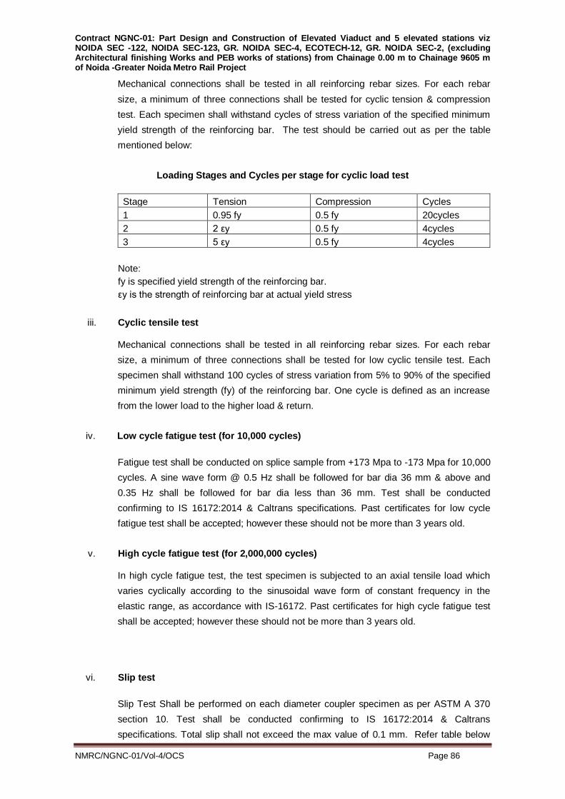
Contract NGNC-01: Part Design and Construction of Elevated Viaduct and 5 elevated stations viz NOIDA SEC -122, NOIDA SEC-123, GR. NOIDA SEC-4, ECOTECH-12, GR. NOIDA SEC-2, (excluding Architectural finishing Works and PEB works of stations) from Chainage 0.00 m to Chainage 9605 m of Noida -Greater Noida Metro Rail Project
NMRC/NGNC-01/Vol-4/OCS Page 86
Mechanical connections shall be tested in all reinforcing rebar sizes. For each rebar
size, a minimum of three connections shall be tested for cyclic tension & compression
test. Each specimen shall withstand cycles of stress variation of the specified minimum
yield strength of the reinforcing bar. The test should be carried out as per the table
mentioned below:
Loading Stages and Cycles per stage for cyclic load test
Stage Tension Compression Cycles
1 0.95 fy 0.5 fy 20cycles
2 2 εy 0.5 fy 4cycles
3 5 εy 0.5 fy 4cycles
Note:
fy is specified yield strength of the reinforcing bar.
εy is the strength of reinforcing bar at actual yield stress
iii. Cyclic tensile test
Mechanical connections shall be tested in all reinforcing rebar sizes. For each rebar
size, a minimum of three connections shall be tested for low cyclic tensile test. Each
specimen shall withstand 100 cycles of stress variation from 5% to 90% of the specified
minimum yield strength (fy) of the reinforcing bar. One cycle is defined as an increase
from the lower load to the higher load & return.
iv. Low cycle fatigue test (for 10,000 cycles)
Fatigue test shall be conducted on splice sample from +173 Mpa to -173 Mpa for 10,000
cycles. A sine wave form @ 0.5 Hz shall be followed for bar dia 36 mm & above and
0.35 Hz shall be followed for bar dia less than 36 mm. Test shall be conducted
confirming to IS 16172:2014 & Caltrans specifications. Past certificates for low cycle
fatigue test shall be accepted; however these should not be more than 3 years old.
v. High cycle fatigue test (for 2,000,000 cycles)
In high cycle fatigue test, the test specimen is subjected to an axial tensile load which
varies cyclically according to the sinusoidal wave form of constant frequency in the
elastic range, as accordance with IS-16172. Past certificates for high cycle fatigue test
shall be accepted; however these should not be more than 3 years old.
vi. Slip test
Slip Test Shall be performed on each diameter coupler specimen as per ASTM A 370
section 10. Test shall be conducted confirming to IS 16172:2014 & Caltrans
specifications. Total slip shall not exceed the max value of 0.1 mm. Refer table below

Contract NGNC-01: Part Design and Construction of Elevated Viaduct and 5 elevated stations viz NOIDA SEC -122, NOIDA SEC-123, GR. NOIDA SEC-4, ECOTECH-12, GR. NOIDA SEC-2, (excluding Architectural finishing Works and PEB works of stations) from Chainage 0.00 m to Chainage 9605 m of Noida -Greater Noida Metro Rail Project
NMRC/NGNC-01/Vol-4/OCS Page 87
for more details:
Bar diameter TOTAL Slip (µ m)
8 mm to 20 mm 250
25 mm to 28 mm 350
32 mm to 40 mm 450
45 mm 600
56 mm 750
vii. Proof loading test
Every cold-forged, threaded bar end shall undergo a proof load test prior to leaving
system supplier’s workshop. Every threaded bar must be subjected to proof load testing
to a minimum test loading of 75% of the characteristic strength (theoretical fy). The
system supplier shall essentially install a proof load tester equipment within its threading
workshop premises and ensure to test each and every threaded bar. A positive
indication shall be marked on the rebar to indicate that this operation has been carried
out.
INSTALLATIONOFCOUPLERS INTHEFIELD:
The installation of couplers in the field, for joining reinforcing bars shall be undertaken by
trained manpower and as per manufacturer's instructions. Threads of both the couplers
and the bars shall be thoroughly cleaned just before installation.Where couplers are
cast-in the concrete, but connection is not to be completed immediately, the couplers
shall be internally greased and plastic capped to a protection detail acceptable to the
engineer. This cap shall be removed only when next bar is to be attached, then the
same to be cleaned before joining the next bar.
The contractor shall arrange for a suitably qualified manufacturer's representative
experienced in mechanically connecting reinforcement to be present at site before the
start of work for initial training of personnel, and also to demonstrate the equipment and
techniques as necessary. The threading workshop is to be fully supervised by the
manufacturer's representative.
The contractor shall submit to the Engineer-in-Charge, for his acceptance a method
statement for mechanically connecting the reinforcement and for the installation and
verification in the field. This shall take into account any special requirements for
horizontal, vertical and inclined couplers and shall include a rectification procedure,
if the connection is incorrectly made. It shall also cover the correct methodology for
handling of tools and equipment for mechanical connection on site. The following
information shall also be included:
1 Requirementsfor cleanliness
2 Equipmentfor threading bars
3 Methodoflocking theconnectionsonbothrebars

Contract NGNC-01: Part Design and Construction of Elevated Viaduct and 5 elevated stations viz NOIDA SEC -122, NOIDA SEC-123, GR. NOIDA SEC-4, ECOTECH-12, GR. NOIDA SEC-2, (excluding Architectural finishing Works and PEB works of stations) from Chainage 0.00 m to Chainage 9605 m of Noida -Greater Noida Metro Rail Project
NMRC/NGNC-01/Vol-4/OCS Page 88
4 Methodofverificationoffinalrebarsalignmentand couplerintegrity
Each coupler shall be visually examined prior to use to ensure the absence of rust and
of any foreign material on the inside surface. All completed couplers shall be inspected
and verified in accordance with the approved QAP. The Contractor shall ensure the
acceptance of the Engineer for a procedure for documenting the inspection of the
couplers. The contractor shall retain inspection records and shall submit copies to the
Engineer-in-Charge within 7 days. The Couplers that do not meet the acceptance shall
be completely removed and the bars re-connected as required.
5.2 REINFORCEMENT COATING
Reinforcement bars used for elevated structures shall not be coated as per IRS CBC
clause 7.1.5,as the resistance against corrosion is provided by the use of anti
carbonation coating for elevated strutures as stipulated in clause 3.26 of this
specification.
For underground structures,the resistance against carbonation/corrosion is being
provided by the use of crystalline durability admixture as stipulated in clause 3.21 of this
specification. 5.3 INSPECTION & TESTING:
Every bar shall be inspected before assembling on the works and any defective, brittle,
excessively rusted or burnt bars shall be removed. Cracked ends of bars shall be cut
out.
No work shall be commenced without the Engineer‟s approval of the bar bending
schedule.
Manufacturer's Certificate shall be supplied for each lot of supply.
Specimens sufficient for three Tensile Tests for each different size of bar for each
consignment delivered, or for 10 tonnes of supply of that size, whichever is less shall be
sampled and tested by the Contractor. Batches shall be rejected if the average results of
each batch are not in accordance with the specifications. 5.4 BAR BENDING AND BAR BENDING SCHEDULE:
All bars will be carefully and accurately bent by approved means in accordance with IS:
2502, and relevant drawings. It shall be ensured that depth of crank is correct as per the
bar cutting and bending schedule and bent bars are not straightened for use in any
manner that will injure the material.
Prior to starting bar bending work, the Contractor shall prepare bar bending schedule
from the structural drawings supplied to him and get the same approved by Engineer.
Any discrepancies and inaccuracies found by the Contractor in the drawings shall be
immediately reported to the Engineer whose interpretation and decision there to, shall

Contract NGNC-01: Part Design and Construction of Elevated Viaduct and 5 elevated stations viz NOIDA SEC -122, NOIDA SEC-123, GR. NOIDA SEC-4, ECOTECH-12, GR. NOIDA SEC-2, (excluding Architectural finishing Works and PEB works of stations) from Chainage 0.00 m to Chainage 9605 m of Noida -Greater Noida Metro Rail Project
NMRC/NGNC-01/Vol-4/OCS Page 89
be accepted.
5.5 LAPPING & WELDING/MECHANICAL SPLICING
a) As far as possible bars of the maximum length available shall be used. Laps shown
on drawings or otherwise specified by the Engineer will be based on the use by the
Contractor of bars of maximum length. In case the Contractor wishes to use shorter
bars, laps/couplers (approved make with permission of concerned organisation)
shall be provided in the manner and at the locations approved by the Engineer.
b) Bars having butt or lap welds shall be provided as specified in the drawings or as
instructed by the Engineer. 5.6 SPACING, SUPPORTING AND CLEANING:
a) All reinforcement shall be placed and maintained in the positions shown on the
drawings to be prepared by contractor.
b) The Contractor shall provide approved types of supports for maintaining the bars in
position and ensuring required spacing and correct cover of concrete to the
reinforcement as specified on the drawings. Cover blocks of required shape and
size, M.S. Chairs and spacer bars shall be used to ensure accurate positioning of
reinforcement. Cover blocks shall be cast well in advance and shall consist of
approved proprietary pre-packaged free flowing mortars (Conbextra HF of Fosroc or
equivalent). They shall be circular in shape for side cover and square for bottom
cover. The cost of cover block shall be deemed to have been included in the rates.
The strength of cover block shall be same or higher than the strength of concrete
used.
c) Bars must be cleaned, before concreting commences, of all scale, rust or partially
set concrete which may have been deposited there during placing of previous lift of
concrete. d) Only Fe500D TMT bars complying to IS:1786 shall be provided . e) G.I. wire shall be used for binding reinforcement.
5.7 WELDING:
a) Wherever specified all lap and butt welding of bars shall be carried in accordance
with IS: 816:1989. Only qualified welders shall be permitted to carry out such
welding.
b) For cold twisted reinforcement welding operations must be controlled to prevent a
supply of large amounts of heat larger than that can be dissipated. The extreme non
twisted end portion shall be cut off before welding. Electrodes with rutile coating
should be used.
c) For welding on TMT bars shall be only allowed for special welding grade
Contract NGNC-01: Part Design and Construction of Elevated Viaduct and 5 elevated stations viz NOIDA SEC -122, NOIDA SEC-123, GR. NOIDA SEC-4, ECOTECH-12, GR. NOIDA SEC-2, (excluding Architectural finishing Works and PEB works of stations) from Chainage 0.00 m to Chainage 9605 m of Noida -Greater Noida Metro Rail Project
NMRC/NGNC-01/Vol-4/OCS Page 90
reinforcement as per 1606.2 of MORTH specifications. d) Bars shall be free from rust at the joints to be welded. e) Slag produced in welding after alternative run should be chipped and removed by
brush. f) Electrode should not be lighted by touching the hot bar. g) The welding procedure shall be approved by the Engineer and tests shall be made
to prove the soundness of the welded connection.
h) E8018 electrode shall be used for Fe500D above as per AWS (American Welding
Society) standards.
5.8 MEASUREMENT:
a) The weight of steel to be paid for at the contract rates shall be the weight of bars as
mentioned on the drawings or as instructed by the Engineer including stirrups, ties,
spacer bars, specified as reinforcement but excluding binding wire and cover blocks.
b) The weight of any stirrup, tie bar shall be computed from the dimensions given on
the drawings or bending schedules. The weight in kg/metre shall be taken as 0.785
kg/metre per 100mm2 of cross section. The rate shall take into account the rolling
margin.

Contract NGNC-01: Part Design and Construction of Elevated Viaduct and 5 elevated stations viz NOIDA SEC -122, NOIDA SEC-123, GR. NOIDA SEC-4, ECOTECH-12, GR. NOIDA SEC-2, (excluding Architectural finishing Works and PEB works of stations) from Chainage 0.00 m to Chainage 9605 m of Noida -Greater Noida Metro Rail Project
NMRC/NGNC-01/Vol-4/OCS Page 91
SECTION – S.06
PRESTRESSED CONCRETE
Structural concrete containing prestressed steel reinforcement to introduce pre-
compression is termed as prestressed concrete. 6.1 GENERAL
The work shall be carried out in accordance with the drawing and these specifications or
as approved by the Engineer.
Concrete and untensioned steel for the construction of prestressed concrete members
shall conform to the requirements of sections respectively in so far as the requirements
of these Sections apply and are not specifically modified by requirements set forth
herein.
Contractor shall ensure that different components of prestressing such as jacks, bearing
plates, wedges, anchorages, strands and HDPE ducts are compatible to each other and
the same shall be exchanged in between all the suppliers to ensure the same.
6.2 MATERIALS
6.2.1 Sheathing
Material for all pre-stressing sheathing duct shall be HDPE in the form of corrugated.
The Thickness of the HDPE sheathing ducts shall be as per conforming to IRS Concrete
Bridge Code-1997 & IRC -112:2011 , with modifications as stated below).
For Anchorage system 19 K 15, HDPE ducts of 124mm OD/ 107mm ID ( tolerance +
1mm ) with minimum thickness of ducts 3.00 mm
For Anchorage system 12 K 15, HDPE ducts of 100 mm OD/ 85 mm ID ( tolerance +
1mm ) with minimum thickness of ducts 2.50 mm
For Anchorage system 7 K 15, HDPE ducts of 84 mm OD/ 69 mm ID (tolerance +
1mm ) with minimum thickness of ducts 2.50 mm
The material for the ducts shall be high-density polyethylene with more than 2 percent
carbon black to provide resistance to ultra-violet degradation and shall have the
following properties:
Density (IS 2530) : 0.94 – 0.96 g/cm3 at 230C
Tensile Strength at yield (BS EN ISO 527-3) : 20-26 N/mm2
Shore Hardness D (BS EN ISO 2039-1) : 55-65
Elongation at Yield (BS EN ISO 527-3) : 7 % (min) Melt Flow Index (MFI) (IS:2530 ) : 0.5-1.2 g / 10 minutes

Contract NGNC-01: Part Design and Construction of Elevated Viaduct and 5 elevated stations viz NOIDA SEC -122, NOIDA SEC-123, GR. NOIDA SEC-4, ECOTECH-12, GR. NOIDA SEC-2, (excluding Architectural finishing Works and PEB works of stations) from Chainage 0.00 m to Chainage 9605 m of Noida -Greater Noida Metro Rail Project
NMRC/NGNC-01/Vol-4/OCS Page 92
(Temperature 190 oC under a mass of 5 kg) Charpy Impact strength of notched specimen (BS EN ISO 179)
At 230C :1 kJ/m2
-400C : 4 kJ/m2 Coefficient of Thermal Expansion for 200C – 800C (DIN 53 752): 1.50 x 10⁻⁴/ oC
Environmental Stress Crack Resistance (ASTM D-1693) at 70o C: 192 Hrs
The residual wall thickness after loss (wear resistance) shall not be less then 1.5mm for
ducts upto 85mm diameter and 2.mm for ducts diameter above 85mm as per IRC –
112:2011.
The ducts shall be corrugated on both sides. The duct shall transmit full tendon strength
from the tendon to the surrounding concrete over a length not greater than 40 duct
diameters. Material and formulation of sheathing ducts shall conform to test and
acceptance criteria of IRC-112:2011. These ducts shall be joined by adopting any one or more of the following methods, as
convenient to suit the individual requirements of the location, subject to satisfactory
pressure tests, before adoption.
Screwed together with male and female threads
Joining with thick walled HDPE shrink couplers with glue. This can also be
used for connection with trumpet, etc
Welding with electro fusion couplers. The joints shall be able to withstand an internal pressure of 0.5 bar for 5 minutes as per
water loss test procedure given in Appendix-B of IRS Concrete Bridge Code-1997 The initial acceptance tests such as bond test, compression test are required to be
performed as acceptance criteria for system. In addition to above , the HDPE ducts supplier
must have conducted friction test at least once as given in FIB bulletinNo-7 to
establish/confirm the friction values ( K &µ ) using the HDPE ducts produced by them ,
submit the test details and obtain approval prior to commencing supplies .
The routine test such as workability test, transverse load rating test, tension load test and
water loss test shall be applicable for both post threading and pre – threading system of
cables. Loads to be imparted on the 107mm ID sheathing during transverse load rating test
and tension load test shall be extrapolated from values given for smaller dia sheathing as
per IRC 112:2011. At least 3 samples for one lot of supply (not exceeding 7000 meter
length) shall be tested.

Contract NGNC-01: Part Design and Construction of Elevated Viaduct and 5 elevated stations viz NOIDA SEC -122, NOIDA SEC-123, GR. NOIDA SEC-4, ECOTECH-12, GR. NOIDA SEC-2, (excluding Architectural finishing Works and PEB works of stations) from Chainage 0.00 m to Chainage 9605 m of Noida -Greater Noida Metro Rail Project
NMRC/NGNC-01/Vol-4/OCS Page 93
6.2.1.3 In viaduct constructed by precast segmental construction, cables shall be threaded after
application of temporary prestressing. In continuous unit, constructed by cantilever
construction techniques the cantilever cables will be stressed as various segments are cast
progressively. Such cables shall be threaded after concreting. In such cases a temporary
flexible PVC tube of 90 mm O.D shall be homed through sheathing which will provide
adequate stiffness to sheathing during concreting and also prevent blockage of sheathing in
case of possibility of leakage. The temporary PVC tube shall be pulled out before threading
of the permanent cables.
6.2.2 Anchorages
6.2.2.1 Anchorages shall be procured from authorized manufacturers only. Anchorages shall
conform to BS: 4447.
Load transfer test and anchorage efficiency shall be conducted as defined in FIP-1993.
Engineer in-charge shall select at random, the required anchorage / wedges sample from
completed lots for testing by the manufacturer. The concrete unit of required size/R/F will be
made by contractor using same design mix of concrete which will be required for the load
transfer test. The load transfer test shall be conducted at the strength of concrete at which
stressing are proposed in the drawings.
No damaged anchorages shall be used. Steel parts shall be protected from corrosion at all
times. Threaded parts shall be protected by greased wrappings and tapped holes shall be
protected by suitable plugs until used. The anchorage components shall be kept free from
mortar and loose rust and any other deleterious coating.
After completion of pre-stressing and grouting of cable in PSC girders, the extra length pre-
stressing strands projecting outside the anchorage are required to be cut and an
anchoredend are to be sealed.
6.2.2.2 Swages of prestressing strand shall develop strength of at least 95 per cent of the specified
breaking load of the strand.
6.2.2.3 Untensioned Steel reinforcements, around anchorages shall be furnished by prestressing
system supplier. Requirement of the same should be job specific and based on edge
distance of anchorage and strength of concrete at the time of stressing of cables as defined
in drawings. The same R/F shall be provided in unit required for load transfer test.
Minimum 3 tests each are required to be conducted for load transfer test and anchorage
efficiency test. The manufacturer shall complete the required testing and determine
compliance the result with FIP-1993 recommendations before transporting the lot to site.
6.2.3 Prestressing Steel
Uncoated stress relieved low relaxation steel conforming to IS: 14268, class – 2 shall be
used. Nominal dia shall be 15.2 mm with minimum breaking strength of 260.7 KN and
minimum 0.2 % proof load of 234.6 KN various test as recommended in IS: 14268 shall be

Contract NGNC-01: Part Design and Construction of Elevated Viaduct and 5 elevated stations viz NOIDA SEC -122, NOIDA SEC-123, GR. NOIDA SEC-4, ECOTECH-12, GR. NOIDA SEC-2, (excluding Architectural finishing Works and PEB works of stations) from Chainage 0.00 m to Chainage 9605 m of Noida -Greater Noida Metro Rail Project
NMRC/NGNC-01/Vol-4/OCS Page 94
conducted before transporting the lot to site. Apart from 1000 hrs relaxation test conducted
by manufacturer, at least two such tests are required to be conducted by independent
agency in the beginning of project. 6.2.4 Prestressing Strands/Wires Storage
All high tensile steel for prestressing work shall be stored about 30cm above the ground in a
suitably covered and closed space to protect it from dampness. It shall also be invariably
wrapped in gunny cloth or tar paper or any other suitable materials, as per approval of
Engineer. Even if it is to be stored in an area at the site for short time during transit it shall
be suitably covered. Protection during storage and repacking or application of washable
protective coating to the H.T. steel shall be given by the contractor at no extra cost if the
packing of H. T. Strand/wire during unloading and storage / handling in the stores gets
damaged.
Stock piling of H. T. Steel on the work site shall not be allowed any time, especially before
and during the monsoon.
Engineer-in-Charge or his authorized representative shall always have an easy access to
the store-yard for inspecting the H. T. Wire/strands/Bars and satisfying themselves
regarding the condition thereof. Any modifications regarding storage suggested by Engineer
shall scrupulously be followed by the contractor. During monsoon days, H.T wires/strands
shall be kept in reasonable air tight store, if required by the Engineer, at no extra cost. 6.3 TESTING OF PRESTRESSING STEEL AND ANCHORAGES
All materials specified for testing shall be furnished free of cost and shall be delivered in
time for tests to be made well in advance of anticipated time of use.
All strands to be transported to the site shall be assigned a lot number and tagged for
identification purposes. Anchorage assemblies to be transported shall be like-wise
identified.
All samples submitted shall be representative of the lot to be furnished and in the case of
strand, shall be taken from the same master roll. The Contractor shall furnish samples of at
least 5.0m length selected from each lot for testing. Also, two anchorage assemblies,
complete with distribution plates of each size or types to be used, shall be furnished along
with short lengths of strands as required.
6.4 WORKMANSHIP 6.4.1 Cleaning
Tendons shall be free from loose rust, oil, grease, tar, paint, mud or any other deleterious
substance.
Cleaning of the steel may be carried out by immersion in suitable solvent solutions, wire
brushing or passing through a pressure box containing Carborundum powder. However, the
tendons shall not be brought to a polished condition.

Contract NGNC-01: Part Design and Construction of Elevated Viaduct and 5 elevated stations viz NOIDA SEC -122, NOIDA SEC-123, GR. NOIDA SEC-4, ECOTECH-12, GR. NOIDA SEC-2, (excluding Architectural finishing Works and PEB works of stations) from Chainage 0.00 m to Chainage 9605 m of Noida -Greater Noida Metro Rail Project
NMRC/NGNC-01/Vol-4/OCS Page 95
6.4.2 Straightening
High tensile strand shall be supplied in coils of sufficiently large diameter such that tendons
shall retain their physical properties and shall be straight as it unwinds from the coil.
Tendons of any type that are damaged, kinked or bent shall not be used.
The packing of prestressing strand shall be removed only just prior to making of cable for
placement. Suitable stands shall be provided to facilitate uncoiling of strands without
damage to steel. Care shall be taken to avoid the possibility of steel coming into contact
with the ground. 6.4.3 Positioning 6.4.3.1 Post-Tensioning
Prestressing tendons shall be accurately located and maintained in position, both vertically
and horizontally, as per drawings.
Tendons shall be so arranged that they have a smooth profile without sudden bends or
kinks.
The location of prestressed cables shall be such as to facilitate easy placement and
vibration of concrete in between the tendons.
Sheathing shall be placed in correct position and profile by providing suitable ladders and
spacers. Such ladders may be provided at intervals of approximately 1.0 m. Sheathing shall
be tied rigidly with such ladders/spacer bars so that they do not get disturbed during
concreting.
The method of supporting and fixing shall be such that profile of cables is not disturbed
during vibrations, by pressure of wet concrete, by workmen or by construction traffic.
6.4.3.2 Each anchorage device shall be set square to the line of action of the corresponding
prestressing tendon and shall be positioned securely to prevent movement during
concreting.
The anchorage devices shall be cleaned to the satisfaction of the Engineer prior to the
placing of concrete. After concreting, any mortar or concrete which adheres to bearing or
wedging surfaces shall be removed immediately.
6.4.4 Cutting
Cutting and trimming of wires or strands shall be done by suitable mechanical or flame
cutters. When a flame cutter is used, care shall be taken to ensure that the flame does not
come in contact with other stressed steel. The location of flame cutting of strand shall be
kept beyond 75 mm of where the tendon will be gripped by the anchorage or jacks.
In post-tensioning the ends of prestressing steel projecting beyond the anchorages, shall
be cut after the grout has set.

Contract NGNC-01: Part Design and Construction of Elevated Viaduct and 5 elevated stations viz NOIDA SEC -122, NOIDA SEC-123, GR. NOIDA SEC-4, ECOTECH-12, GR. NOIDA SEC-2, (excluding Architectural finishing Works and PEB works of stations) from Chainage 0.00 m to Chainage 9605 m of Noida -Greater Noida Metro Rail Project
NMRC/NGNC-01/Vol-4/OCS Page 96
6.4.5 Protection of Prestressing Steel
Prestressing steel shall be continuously protected against corrosion, until grouted. 'The
corrosion protector shall have no deleterious effect on the steel or concrete or on the bond
strength of steel to concrete. Grouting shall conform to these specifications or as directed
by the Engineer. 6.4.6 Sheathing
The joints of all sheathings shall be water-tight. Special attention shall be paid to the
junction at the anchorage end, where the sheathing must tightly fit on the protruding
trumpet end of anchorage and thereafter sealed preferably with adhesive water proof tape
as per approved manufacturer.
The sheathing and all joints shall be water tight. Any temporary opening in the sheathing
shall be satisfactorily plugged and all joints between sheathing and any other part of the
prestressing system shall be effectively sealed to prevent entry of mortar, dust, water or
other deleterious matter. Sheathing shall be neatly fitted at joints without internal projection
or reduction of diameter. Sheathing shall be firmly tied so that while concreting they should
not float up. Sheathing shall be aligned accurately with respect to vertical and horizontal
coordinate.
Enlarged portions of the sheathing at couplings or anchorages shall be of sufficient length
to provide for the extension of the tendons. 6.4.7 Grout Vents
Grout vents of at least 20 mm diameter shall be provided at both ends of the sheathing and
at all valleys and crests along its length. Additional vents with plugs shall also be provided
along the length of sheathing such that the spacing of consecutive vents does not exceed
20 m. Each of the grout vents shall be provided with a plug or similar device capable of
withstanding a pressure of 1.0 MPa without the loss of water, air pressure or grout. 6.4.8 Anchorages
All bearing surfaces of the anchorages shall be cleaned prior to concreting and tensioning.
Anchor cones, blocks and plates shall be securely positioned and maintained during
concreting such that the centre line of the duct passes axially through the anchorage
assembly.
The anchorages shall be recessed from the concrete surface as per drawings.
After the prestressing operations are completed and prestressing strands are cut, the
surface shall be painted with two coats of epoxy of suitable formulation having a dry film
thickness of 80 microns per coat and entire recess shall be filled with concrete or non-
shrink/pre-packaged mortar or epoxy concrete.
6.4.9 Handling and Storage
Care shall be taken to avoid mechanically damaging, work-hardening or heating

Contract NGNC-01: Part Design and Construction of Elevated Viaduct and 5 elevated stations viz NOIDA SEC -122, NOIDA SEC-123, GR. NOIDA SEC-4, ECOTECH-12, GR. NOIDA SEC-2, (excluding Architectural finishing Works and PEB works of stations) from Chainage 0.00 m to Chainage 9605 m of Noida -Greater Noida Metro Rail Project
NMRC/NGNC-01/Vol-4/OCS Page 97
prestressing tendons while handling. All prestressing tendons shall be stored clear of the
ground and protected from the weather, from splashes from any other materials, and from
splashes from the cutting operation of an oxy-acetylene torch, or arc-welding processes in
the vicinity.
In no circumstances shall prestressing tendons after manufacture be subjected to any
welding operation, or 'on-site' heat treatment or metallic coating such as galvanising. This
does not preclude cutting as specified.
All wires, strands or bars stressed in one operation shall be taken, where possible, from the
same parcel. Each cable shall be tagged with its number from which the coil numbers of the
steel used can be identified. Cables shall not be kinked or twisted. Individual wires and
strands for which extensions are to be measured shall be readily identifiable at each end of
the member. No strand that has become unraveled shall be used.
6.5 SUPERVISION
All prestressing and grouting operations shall be undertaken by trained personnel only. A
representative of supplier of the prestressing system shall be present during all tensioning
and grouting operations and shall ensure, monitor and certify their correctness. 6.6 TENSIONING EQUIPMENT
The tensioning apparatus shall meet the following general requirements:-
a) The means of attachment of the tendon to the jack or tensioning device shall be safe and
secure.
b) Where two or more wires or strands are stressed simultaneously, they shall be approximately
of equal length between anchorage points at the datum of load and extension measurement.
The degree of variation shall be small compared with the expected extension.
c) The tensioning apparatus shall be such that a controlled total force is imposed gradually and
not dangerous secondary stresses are induced in the tendons, anchorage or concrete.
d) The force in the tendons during tensioning shall be measured by direct-reading load cells or
obtained indirectly from gauges fitted in the hydraulic system to determine the pressure in the
jacks. Facilities shall be provided for the measurement of the extension of the tendon and of
any movement of the tendon in the gripping devices. The load-measuring device shall be
calibrated to an accuracy within ± 2% and checked at intervals to the approval of the
Engineer. Elongation of the tendon shall be measured to an accuracy within 2% or 2 mm,
whichever is the more accurate.
e) The tensioning equipment shall be calibrated before the tensioning operation and at intervals
of the months or as approved by the Engineer.
Any indication in the loss of strength in tendons during the tensioning operation shall be
brought to the attention of the Engineer. Any corrective measures which may be required in
procedures and/or material shall be approved by the Engineer.
When friction must be reduced, water soluble oil may be used subject to the approval of the
Engineer. This oil may be flushed from the duct as soon as possible after stressing is
completed by use of water pressure. These ducts shall be flushed again just prior to the
grouting operations. Each time the ducts are flushed, they shall be immediately blown dry with

Contract NGNC-01: Part Design and Construction of Elevated Viaduct and 5 elevated stations viz NOIDA SEC -122, NOIDA SEC-123, GR. NOIDA SEC-4, ECOTECH-12, GR. NOIDA SEC-2, (excluding Architectural finishing Works and PEB works of stations) from Chainage 0.00 m to Chainage 9605 m of Noida -Greater Noida Metro Rail Project
NMRC/NGNC-01/Vol-4/OCS Page 98
oil-free air.
6.7 TESTING BY CONTRACTOR
For the purpose of accurately determining the tendon elongations while stressing, the
Contractor shall bench test two samples of each size and type of strand tendon to determine
the modulus of elasticity prior to stressing the initial tendon. The bench should be at least 6
metres long, with concrete anchorage blocks having a constant area end section of at least
four times that of the anchorage assembly area. The tendon shall be straight and centered on
the cross-sectional area of the bench. The test procedure shall consist of stressing the tendon
at an anchor assembly with the dead end consisting of a load cell. The test specimen shall
be tensioned to 80 percent of ultimate to 0 in 10 increments. For each increment, the gauge
pressure, elongation and load cell force shall be recorded. The data shall be furnished to the
Engineer. The theoretical elongations shown on the post-tensioning working drawings shall
be reevaluated by the Contractor using the results of the tests and corrected as necessary.
Revisions to the theoretical elongations shall be submitted to the Engineer for approval.
Apparatus and methods used to perform the tests shall be proposed by the Contractor and be
subject to the approval of the Engineer. After the initial testing, five more tests shall be
performed. These tests shall be spaced evenly throughout the duration of the Contract.
6.8 PRETENSIONING
Where pretensioning methods are used, the tension shall be fully maintained by some
positive means during the period between tensioning and transfer. The transfer of stress shall
take place slowly to minimize shock.
a) Straight Tendons
In the long line method of pretensioning, sufficient locator plates shall be distributed
throughout the length of the bed to ensure that the wires or strands are maintained in their
proper position during concreting. Where a number of units are made in the line, they shall
be free to slide in the direction of their length and thus permit transfer of the prestressing force
to the concrete along the whole line.
In the individual mould system the moulds shall be sufficiently rigid to provide the reaction to
the prestressing force without distortion.
b) Deflection Tendons
Where possible the mechanisms for holding down or holding up tendons shall ensure that the
part in contact with the tendon is free to move in the line of the tendon so that frictional losses
are nullified. If, however, a system is used that develops a frictional force, this force shall be
determined by test and due allowance made as agreed by the Engineer.
For single tendons the deflector in contact with the tendon shall have a radius of not less than
5 times the tendon diameter for wire or 10 times the tendon diameter for a strand, and the
total angle of deflection shall not exceed 15o. Where the radius is less than 5 times the
diameter of the tendon and the angle of deflection exceeds 15o, the loss of strength of the
tendon shall be determined by test and due allowance made.
The transfer of the prestressing force to the concrete shall be effected in conjunction with the
release of hold-down and hold-up forces as approved by the Engineer-in-Charge.

Contract NGNC-01: Part Design and Construction of Elevated Viaduct and 5 elevated stations viz NOIDA SEC -122, NOIDA SEC-123, GR. NOIDA SEC-4, ECOTECH-12, GR. NOIDA SEC-2, (excluding Architectural finishing Works and PEB works of stations) from Chainage 0.00 m to Chainage 9605 m of Noida -Greater Noida Metro Rail Project
NMRC/NGNC-01/Vol-4/OCS Page 99
6.9 POST-TENSIONING
a) Arrangement of Tendons
Where wires, strands or bars in a tendon are not stressed simultaneously, the use of spacers
shall be in accordance with the recommendations of the system manufacturer.
b) Anchorages
i. Anchorages shall be tested in accordance with the requirements of BS 4447.
ii. For each anchorage system used in the Works, the characteristic value for anchorage
efficiency shall be not less than 90%.
iii. Proprietary anchorages shall be handled and used strictly in accordance with the
manufacturer's instructions and recommendations.
c) Deflected Tendons
The deflector in contact with the tendon shall, have a radius of not less than 50 times the
diameter of the tendon, and the total angle of deflection shall not exceed 15 degrees unless
otherwise agreed by the Engineer.
d) Tensioning Procedure
Before tensioning, the Contractor shall demonstrate that all tendons are free to move in the
ducts unless the geometry of the ducts makes this impracticable as agreed by the Engineer.
Tensioning shall be carried out in such a manner that the stress in the tendons increases at a
gradual and steady rate.
Unless otherwise described in the Contract, concrete shall not be stressed until it has reached
at least the age at which 2 test cubes taken from it attain the specified transfer strength. The
test cubes shall be made and tested as described in BS 1881. They shall be cured in similar
conditions to the concrete to which they relate in a manner approved by the Engineer.
The Contractor shall cast sufficient cubes to demonstrate that the required strength of the
concrete at transfer has been reached.
The Contractor shall ensure that those carrying out the stressing are provided with particulars
of the required tendon loads, order of stressing and extensions. Allowance shall be made
during stressing for the friction in the jack and in the anchorage, although the former is not
necessary when using load cells.
Any allowance for draw-in of the tendon during anchoring shall be in accordance with the
Engineer-in-Charge instructions.
Stressing shall continue until the required extension and tendon load are reached or are
approved by the Engineer-in-Charge.
The extension shall allow for any draw-in of the tendon occurring at the non-jacking end, but
measurement shall not commence until any slack in the tendon has been taken up.
Immediately after anchoring, the forces in the prestressing tendons shall not exceed 70% of
their characteristic strength. During stressing the value may exceed 70% of their
characteristic strength, with the approval of the Engineer, but shall not exceed 80%.
After the tendons have been anchored, the force exerted by the tensioning apparatus shall be
decreased gradually and steadily so as to avoid shock to the tendon or the anchorage. Full
records shall be kept of all tensioning operations, including the measured extensions,

Contract NGNC-01: Part Design and Construction of Elevated Viaduct and 5 elevated stations viz NOIDA SEC -122, NOIDA SEC-123, GR. NOIDA SEC-4, ECOTECH-12, GR. NOIDA SEC-2, (excluding Architectural finishing Works and PEB works of stations) from Chainage 0.00 m to Chainage 9605 m of Noida -Greater Noida Metro Rail Project
NMRC/NGNC-01/Vol-4/OCS Page 100
pressure-gauge or load-cell readings, and the amount of draw-in at each anchorage. Copies
of these records shall be supplied to the Engineer-in-Charge within 24 hours of each
tensioning operation.
Unless otherwise agreed by the Engineer-in-Charge tendons shall not be cut less than 3 days
after grouting.
6.10 PRESTRESSING TENDONS - PROTECTION AND BOND
The prestressing tendons shall be protected in their permanent positions from both
mechanical damage shall be applied to all unbonded prestressing tendons within 28 days of
installation of the tendon in the duct.
The tendon protection compound applied to the and corrosion as described in the Contract
and the following sub-clauses.
The exposed tendons at the anchorages and the anchorages themselves shall be sealed
within a closed box and protected from both mechanical damage and corrosion. Suitable
access shall be left for jacking equipment for the later removal of the strands of unbonded
tendons. The means of protection shall be designed by the prestress supplier and approved
by the Engineer.
A tendon protection compound tendons shall be a micro-crystalline wax (petrolatum) base
material containing additives to enhance the corrosion inhibiting, wetting, and moisture
displacing properties, as well as the ability to form a polar bond with the tendon steel.
The compound Manufacturer shall provide test data verifying that the following properties are
met for the service life of 100 years and temperature range of 0oC to 50oC evaluation and
acceptance by the Engineers:
i. Freedom from cracking and brittleness;
ii. Continuous self-healing film over the coated surfaces;
iii. Chemical and physical stability;
iv. Non reactivity with the surrounding and adjacent materials such as concrete, tendons,
and ducts;
v. Moisture displacing characteristics.
Additionally it shall remain flexible to allow removal and replacement of the tendons. The
tendon protection compound and its method of installation shall be approved by the Engineer.
Provision shall be made for expansion of the tendon protection compound during the
lifetime of the structure.
Before installing the tendon protection compound it shall be demonstrated that the ducts, U-
bend anchorage and anchorages are clean and free of water and chlorides.
The tendons, internal face of the steel u-bend anchorage, stressing anchorages and any
other metallic components of the prestressing system shall additionally be pre-treated with a
protection compound before delivery to site. The protection compound shall be applied to
each strand of the tendon and shall be compatible with the tendon protection compound
injected into the ducts. The protection compound shall be approved by the Engineer-in-
Charge.
The supplier of the tendon protection compound shall submit for the Engineer's approval
Contract NGNC-01: Part Design and Construction of Elevated Viaduct and 5 elevated stations viz NOIDA SEC -122, NOIDA SEC-123, GR. NOIDA SEC-4, ECOTECH-12, GR. NOIDA SEC-2, (excluding Architectural finishing Works and PEB works of stations) from Chainage 0.00 m to Chainage 9605 m of Noida -Greater Noida Metro Rail Project
NMRC/NGNC-01/Vol-4/OCS Page 101
proposals which shall describe how the tendon protection compound can be removed and re-
injected into ducts, including buried ducts, within the permanent works.
All materials used in the prestressing systems shall not give off toxic fumes at temperatures
below 50oC and shall not support combustion.
6.11 DUCTS FOR BONDED TENDONS
6.11.1 Ducts
Ducts for longitudinal, transverse or vertical tendons embedded into the concrete may be of
flexible, semi-rigid, or rigid galvanized, ferrous metal capable of withstanding concrete
pressures without deforming or permitting the entrance of cement paste during casting of the
member. They must retain their shape and be capable of transferring bond stresses. The
semi-rigid duct must be rigid enough to remain straight when supported at 1200 mm
maximum intervals but flexible enough to allow 3600 mm radius curves. Flexible duct shall be
secured or supported at not more than 300 mm intervals.
6.11.2 Grouting of Prestressing Tendons
a) General
The Contractor shall undertake grouting trials when required by the Engineer.
b) Materials
Unless otherwise directed or agreed by the Engineer as a result of grouting trials, the grout
shall consist only of Ordinary Portland
Cement and water. The water/cement ratio shall be as low as possible consistent with the
necessary workability, and under no circumstances shall the W/C ratio exceed 0.45 by
weight.
The grout shall not be subject to bleeding in excess of 2% after 3h or 4% maximum when
measured at 25oC or such other temperature as may be approved by the Engineer, in a
covered cylinder approximately 100 mm diameter with a height of grout of approximately 100
mm, and the water shall be reabsorbed by the grout during the 24h after mixing.
Admixtures may be used with the written permission of the Engineer and shall be applied
strictly in accordance with the manufacturer's instructions. Admixtures shall not contain
chloride ions in excess of 0.25 percent by weight.
Dry materials shall be measured by weight.
c) Ducts
Air vents shall be provided at any crests in the duct profile and elsewhere as specified.
All ducts shall be thoroughly clean before grouting. Ducts formed without metal sheathing
shall be provided with effective drainage and, unless otherwise directed by the Engineer, shall
be flushed with water before grouting. All surplus water shall be removed by compressed air
injection. All anchorages shall be sealed or fitted with grouting connections.
d) Grouting Equipment
The mixing equipment shall produce a grout of homogeneous consistency and shall be
capable of providing a continuous supply to the injection equipment.
Contract NGNC-01: Part Design and Construction of Elevated Viaduct and 5 elevated stations viz NOIDA SEC -122, NOIDA SEC-123, GR. NOIDA SEC-4, ECOTECH-12, GR. NOIDA SEC-2, (excluding Architectural finishing Works and PEB works of stations) from Chainage 0.00 m to Chainage 9605 m of Noida -Greater Noida Metro Rail Project
NMRC/NGNC-01/Vol-4/OCS Page 102
The injection equipment shall be capable of continuous operation with little variation of
pressure and shall include a system for recirculating the grout while actual grouting is not in
progress. Compressed air shall not be used.
The equipment shall have a sensibly constant delivery pressure not exceeding 1 N/mm2. All
piping to the grout pumps shall have a minimum of bends, valves and changes in diameter.
All baffles to the pump shall be fitted with 1.18 mm sieve strainers. All equipment, especially
piping, shall be thoroughly washed through with clean water after every series of operations
and at the end of use for each day. The interval between washing shall not exceed 3h.
The equipment shall be capable of maintaining pressure on completely grouted ducts and
shall be fitted with a valve that can be locked off without loss of pressure in the duct.
e) Mixing
Water shall be added to the mixer first, then the cement. When these are thoroughly mixed,
the admixture, if any, shall be added. Mixing shall continue until a uniform consistency is
obtained. Mixing shall not be by hand.
f) Injecting Grout
Grouting shall be carried out as soon as is practicable after the tendons in them have been
stressed and anchors trimmed and the Engineer's permission to commence has been
obtained. Injection shall be continuous, and it shall be slow enough to avoid producing
segregation of the grout. The method of injecting grout shall ensure complete filling of the
ducts and complete surrounding of the steel. Grout shall be allowed to flow from the free end
of the duct until its consistency is equivalent to that of the grout injected. The opening shall
then be firmly closed. Any vents shall be closed in a similar manner one after another in the
direction of the flow. After an appropriate time, further injections shall be carried out to fill any
possible cavities.
The injection tubes shall then be sealed off under pressure until the grout has set.The filled
ducts shall not be subjected to shock or vibration within 1 day of grouting.
Not less than 2 days after grouting, the level of grout in the injection and vent tubes shall be
inspected and made good as necessary.
The Contractor shall keep full records of grouting including the date each duct was grouted,
the proportion of the grout and any admixtures used, the pressure, details of any interruptions
and topping up required. Copies of these records shall be supplied to the Engineer-in-Charge
within 3 days of grouting.
Where required by the Engineer-in-Charge, the Contractor shall provide facilities and
attendance for the radiographic testing of duct.
g) Strength of Grout
The compressive strength of 100 mm cubes made of the grout shall exceed 17 N/mm2 at 7
days. Cubes shall be cured in a moist atmosphere for the first 24h, and subsequently in
water.
6.12 DUCTS FOR UNBONDED TENDONS
Unless shown otherwise on the Drawings, ducts and injection tubes in the superstructure and
substructure shall be formed from high density polyethylene (HDPE) which shall incorporate a

Contract NGNC-01: Part Design and Construction of Elevated Viaduct and 5 elevated stations viz NOIDA SEC -122, NOIDA SEC-123, GR. NOIDA SEC-4, ECOTECH-12, GR. NOIDA SEC-2, (excluding Architectural finishing Works and PEB works of stations) from Chainage 0.00 m to Chainage 9605 m of Noida -Greater Noida Metro Rail Project
NMRC/NGNC-01/Vol-4/OCS Page 103
stabilizing agent to prevent Ultra Violet Light (UVL) degradation.
The minimum wall thickness of the ducts shall be such that the ducts are capable of resisting
the pressures developed during installation of the protection compound. The ducts shall be
smooth bore.
Ducts with external diameters greater than 70 mm shall be transported and stored in straight
lengths. The distance between supports shall be limited to 3m and the height of storage to 1.5
m. Alternatively, ducts may be transported and stored in coils provided that they are fixed to
the tolerances required by the Designer.
Damaged ducts shall not be used in the Works.
No boring of any No boring holes in the ducts shall be permitted once the tendons are
installed.
U-bend anchorages shall be formed from smooth-bore unwelded steel tubes and shall comply
with the requirements of BS 4360.
Joints between ducts, ducts and anchorages and ducts and U-bend anchorages shall be
formed by a coupling device using thermo-fusion techniques which shall provide a watertight
seal to the ducts and shall be capable of resisting the pressure developed during installation
of the tendon protection compound. The inner surfaces of the joints shall form a smooth
transition between ducts and U-bend anchorages to allow satisfactory installation of the
tendons. All coupling devices shall be approved by the Engineer-in-Charge.
Injection tubes shall be provided at the U-bend anchorages, the stressing anchorages and at
any other positions on the length of the ducts which are required to achieve satisfactory
installation of the tendon protection compound. The injection tubes at the U-bend anchorages
shall also be used as drainage points for the U-bend. The connection between the ducts and
the injection tubes shall be watertight and capable of resisting the pressure developed during
installation of the tendon protection compound.
All injection tubes shall be sealed after use to prevent the ingress of water to the satisfaction
of the Engineer-in-Charge.
After completion of all duct joints and before completion of the insitu joints between precast
segments and before installation of the tendons, all ducts shall be air tested to an equivalent
100 mm water gauge unless otherwise directed by the Engineer. The test shall be performed
in accordance with BS 8301 Section 5.
Any ducts which do not contain tendons shall remain empty and shall be sealed at each end
to prevent the ingress of water.
6.13 PRESTRESSING TENDONS - TRIAL CONSTRUCTION-UNBONDED TENDONS
Before commencing construction of the precast segments a trial shall be carried out which
shall demonstrate the satisfactory installation, removal and replacement of a prestressing
strand together with the proposed techniques for duct jointing, duct testing and installation of
the tendon protection compound.
i. The tendons shall be stressed in accordance with this Specification.
ii. The ducts shall be filled with a tendon protection compound in accordance with the
specification as detailed in relevant sub-sectionsand the tendon extension and anchorage
shall be protected as if they were to be included in the permanent works.
Contract NGNC-01: Part Design and Construction of Elevated Viaduct and 5 elevated stations viz NOIDA SEC -122, NOIDA SEC-123, GR. NOIDA SEC-4, ECOTECH-12, GR. NOIDA SEC-2, (excluding Architectural finishing Works and PEB works of stations) from Chainage 0.00 m to Chainage 9605 m of Noida -Greater Noida Metro Rail Project
NMRC/NGNC-01/Vol-4/OCS Page 104
iii. The trial shall demonstrate that any one strand may be destressed, removed, inspected,
replaced and re-stressed and that no voids are created within the tendon protection
compound, all to the satisfaction of the Engineer.
iv. The trial shall also demonstrate that all of the strands in a duct may be removed and that
the tendon protection compound can be removed from the ducts and U-bend anchorage
to the satisfaction of the Engineer.
v. The trial shall be undertaken using the prestressing system to be used in the permanent
works and shall be approved by the Engineer-in-Charge.
6.14 PRESTRESSING TENDONS - TEMPORARY TENDONS
Temporary tendons may be re-used as temporary tendons elsewhere provided special
precautions are incorporated at the anchorages to ensure tendons are not damaged. These
precautions shall be approved by the Engineer-in-Charge.
The tendons shall be enclosed within a duct throughout their length.
The tendons shall be pre-treated in accordance with the specifications as detailed in relevant
subsections and the protection compound shall be applied to the outer surfaces of the tendon
after each use.
The maximum jacking force for the re-usable temporary tendons shall not exceed 70 percent
of their guaranteed minimum breaking load.
After removal of the tendons the ducts shall be sealed at each end to prevent the ingress of
water.
6.15 PREPARATION FOR CASTING
a) The Contractor shall submit for approval, in accordance with the provisions of the
Employer's Requirements, working drawings of the prestressing system proposed for
use. For initial review, 3 sets of such drawings shall be submitted.
b) After review, between 6 and 12 sets, as requested by the Engineer-in-Charge, shall
be submitted for final approval and for use during construction.
c) The working drawings of the prestressing system shall show complete details and be
accompanied by substantiating calculations of the method and materials the
Contractor proposes to use in the prestressing operations, including any additions or
rearrangement of reinforcing steel from that shown on the Drawings. Such details
shall outline the method and sequence of stressing and shall include complete
specifications and details of the prestressing steel and anchoring devices, working
stresses, anchoring stresses, type of ducts, and all other data pertaining to the
prestressing operation, including the proposed arrangement of the prestressing steel
in the members.
d) Working drawings shall be A1 size and each drawing and calculation sheet shall
include the job site, name of the structure as shown on the Contract Drawings and
Contract name.
e) Working drawings shall be submitted sufficiently in advance of the start of the affected
work to allow time for review by the Engineer-in-Charge and correction by the
Contractor of the drawings without delaying the work. Such time shall be proportional
to the complexity of the work but in no case shall such time be less than eight (8)
Contract NGNC-01: Part Design and Construction of Elevated Viaduct and 5 elevated stations viz NOIDA SEC -122, NOIDA SEC-123, GR. NOIDA SEC-4, ECOTECH-12, GR. NOIDA SEC-2, (excluding Architectural finishing Works and PEB works of stations) from Chainage 0.00 m to Chainage 9605 m of Noida -Greater Noida Metro Rail Project
NMRC/NGNC-01/Vol-4/OCS Page 105
weeks.
f) At the completion of each structure, one set of reproducible mylars of the corrected
original tracing of all working drawings for said structure shall be furnished to the
Engineer-in-Charge. Drawings which are common to more than one structure shall
be provided for each structure. An index prepared specifically for the drawings for
each structure containing sheet numbers and titles shall be included.
g) Reinforcing steel shall be fabricated and placed in accordance with the Drawings and
as required herein. No reinforcing steel shall be cut and removed to permit proper
alignment of stressing ducts. Any bar that cannot be fabricated to clear the conduits
shall be replaced by additional bars with adequate lap lengths and shall be submitted
to the Engineer-in-Charge for approval. In the plane of the steel parallel to the
nearest surface of concrete, bars shall not vary from plan placement by more than 12
mm or one-tenth (1/10) of the spacing between bars, whichever is less.
h) All prestressing steel shall be protected against physical damage and rust or other
results of corrosion at all times from manufacture to grouting or encasing in concrete.
Prestressing steel that has sustained physical damage at any time shall be rejected.
The development of visible rust or other results of corrosion shall be cause for
rejection, when ordered by the Engineer-in-Charge.
i) Prestressing steel shall be packaged in containers or shipping forms for the protection
of the steel against physical damage and corrosion during shipping and storage. A
corrosion inhibitor which prevents rust or other results of corrosion shall be placed in
the package or form, or shall be incorporated in a corrosion inhibitor carrier type
packaging material, or when permitted by the Engineer-in-Charge, may be applied
directly to the steel. The corrosion inhibitor shall have no deleterious effect on the
steel or concrete or bond strength of steel to concrete. packaging or forms damaged
from any cause shall be immediately replaced or restored to original condition.
j) The shipping package or form shall be clearly marked with a statement that the
package contains high-strength prestressing steel, and the care to be used in
handling; and the type, kind and amount of corrosion inhibitor used, including the date
when placed, safety orders and instructions for use.
k) Prestressing steel for post-tensioning which is installed in members prior to placing
and curing of the concrete, shall be continuously protected against rust or other
corrosion, until grouted, by means of a corrosion inhibitor placed in the ducts or
applied to the steel in the duct. The corrosion inhibitor shall conform to the
requirements specified herein.
l) When steam curing is used, prestressing steel for post-tensioning shall not be
installed until the steam curing is completed.
m) All water used for flushing ducts shall contain either quick lime (calcium oxide) or
slaked lime (calcium hydroxide) in the amount of 13g. per litre. All compressed air
used to blow out ducts shall be oil free.
n) When acceptable prestressing steel for post-tensioning is installed in the ducts after
completion of concrete curing, and if stressing and grouting are completed within 10
calendar days after the installation of the prestressing steel, rust which may form
during said 10 days will not be cause for rejection of the steel. Prestressing steel
installed, tensioned and grouted in this manner, all within 10 calendar days, will not

Contract NGNC-01: Part Design and Construction of Elevated Viaduct and 5 elevated stations viz NOIDA SEC -122, NOIDA SEC-123, GR. NOIDA SEC-4, ECOTECH-12, GR. NOIDA SEC-2, (excluding Architectural finishing Works and PEB works of stations) from Chainage 0.00 m to Chainage 9605 m of Noida -Greater Noida Metro Rail Project
NMRC/NGNC-01/Vol-4/OCS Page 106
require the use of a corrosion inhibitor in the duct following installation of the
prestressing steel. Prestressing steel installed as above but not grouted within 10
calendar days shall be subject to all the requirements in this section pertaining to
corrosion protection and rejection because of rust.
o) Any time acceptable prestressing steel for pretensioning is placed in the stressing bed
and is exposed to the elements for more than 36 hours prior to encasement in
concrete, adequate measures shall be taken by the Contractor, as approved by the
Engineer, to protect said steel from contamination or corrosion.
p) All ducts shall be located within 5 mm of the locations given on approved fabrication
plans. Method and spacing of supports for ducts shall be shown on the working
drawings. After installation in the forms, the end of the ducts shall at all times be
sealed to prevent entry of water and debris. Following each pour of concrete, the
Contractor will be required to demonstrate that all empty ducts are free of water and
are unobstructed and undamaged. Immediately prior to installation of the
prestressing steel, the Contractor shall again demonstrate to the satisfaction of the
Engineer that all ducts are unobstructed and that they are free of water and debris.
Where tendons are described in the Contract as debonded from the concrete they
shall be covered with sleeves approved by the Engineer. The ends of the sleeves
shall be taped to the tendon to prevent the ingress of grout.
q) Concrete shall not be deposited into forms until the entire set-up of the forms,
reinforcement, ducts, and anchorage has been thoroughly inspected and checked.
The placing of concrete will not be permitted until the Engineer is satisfied that the
rate of producing and placing concrete will be sufficient to complete the proposed
pour and finishing operations within the scheduled time, that experienced concrete
finishers are available where required for finish work and all necessary finishing tools
and equipment are on hand at the site of the work and are in satisfactory condition for
use.
r) Conveying equipment shall be of a size and design that will permit the placing of
concrete within the time limits specified. Conveying equipment shall be cleaned at the
end of each operation or work day and just prior to reuse shall again be checked and
cleaned of hardened concrete and foreign materials. Belt conveyors shall be
horizontal or at a slope which will not cause excessive segregation of loss of
ingredients. Concrete shall be protected against undue drying or rise in temperature.
An approved arrangement shall be used at the discharge end to prevent aggregate
segregation. Mortar shall not be allowed to adhere to the return length of the belt.
Concrete shall be discharged into a hopper or through a baffle.
s) The concrete shall be first placed in the web forms followed by placement at the
bottom slab and then in the top form. Any alternate sequence shall be submitted to
the Engineer for approval.
t) All concrete shall be consolidated by means of approved vibrators together with any
other equipment necessary to perform the work as specified. Internal vibrators shall
have a minimum frequency of 8,000 vibrations per minute and sufficient amplitude to
consolidate the concrete effectively. At least two (2) stand-by vibrators in working
condition shall be provided for emergency use in case of malfunction. The use of
external vibrators for consolidating concrete will be permitted and may be required

Contract NGNC-01: Part Design and Construction of Elevated Viaduct and 5 elevated stations viz NOIDA SEC -122, NOIDA SEC-123, GR. NOIDA SEC-4, ECOTECH-12, GR. NOIDA SEC-2, (excluding Architectural finishing Works and PEB works of stations) from Chainage 0.00 m to Chainage 9605 m of Noida -Greater Noida Metro Rail Project
NMRC/NGNC-01/Vol-4/OCS Page 107
when the concrete is inaccessible for adequate consolidation. When external vibration
is used, the forms shall be constructed sufficiently rigid to resist displacement or
damage. Vibrating of concrete shall be done with care and in such a manner as to
avoid displacement of reinforcing, conduits, and other items to be fixed in place.
6.16 SAFETY PRECAUTIONS DURING TENSIONING
Care shall be taken during tensioning to ensure the safety of all persons in the vicinity.
Jacks shall be secured in such a manner that they will be held in position, should they lose
their grip on the tendons.No person shall be allowed to stand behind the jacks or close to
the line of the tendons while tensioning is in progress.
The operations of the jacks and the measurement of the elongation associated operations
shall be carried out in such a manner and such a position that the safety of all concerned is
ensured.
A safety barrier shall be provided at both ends to prevent any tendon, which might become
loose from recoiling unchecked.
During actual tensioning operation, warning sign shall be displayed at both ends of the
tendon.After prestressing, concrete shall neither be drilled nor any portion cut nor chipped
away nor disturbed, without express approval of the Engineer-in-Charge.
No welding shall be permitted on or near tendons nor shall any heat be applied to tendons.
Any tendon which has been affected by welding, weld spatter or heat shall be rejected. 6.17 TOLERANCES
Permissible tolerances for positional deviation of Prestressing tendons in cast-in-situ
construction shall be limited to the following
a) Variation from the specified horizontal profile : 5 mm
b) Variation from the specified vertical profile : 5 mm
c) Variation from the specified position in member : 5 mm
Permissible tolerances for positional deviation of prestressing tendons in precast segmental
construction shall be limited as defined in Clause 10.2.8 6.18 Transportation and Storage of Unit:
Precast members shall be transported in an upright position. Points of support and the
direction of reactions with respect to the girder shall approximately be the same during
transportation, and storage as when the girder is placed in final position.
When members are to be stacked, they shall be firmly supported at such bearing positions
as will ensure that the stresses induced in them are always less than the permissible design
stresses. Further, inclined side supports shall be provided at the ends and along the length
of a precast girder to prevent lateral movements or instability.

Contract NGNC-01: Part Design and Construction of Elevated Viaduct and 5 elevated stations viz NOIDA SEC -122, NOIDA SEC-123, GR. NOIDA SEC-4, ECOTECH-12, GR. NOIDA SEC-2, (excluding Architectural finishing Works and PEB works of stations) from Chainage 0.00 m to Chainage 9605 m of Noida -Greater Noida Metro Rail Project
NMRC/NGNC-01/Vol-4/OCS Page 108
Care shall be taken during storage, hoisting and handling of the precast units to prevent
their cracking or being damaged. Units damaged by improper storing or handling shall be
replaced by the Contractor at his expense 6.19 TESTS AND STANDARDS OF ACCEPTANCE
The materials shall be tested in accordance with these Specifications and shall meet the
prescribed criteria.
The work shall conform to these Specifications and shall meet the prescribed standards of
acceptance.
6.20 MEASUREMENT:
The measurement for prestressing steel wires shall be made on the actual length of wires
from end to end of cut-face of anchorages for post tensioned concrete as per the profile
drawing and shall not include the extra length of wires at both ends. For pretensioned
concrete the measurements of high tensile steel wires shall be measured from end to end
of concrete faces and shall not include extra length of wires at both ends. The rates for high
tensile steel work shall include formation of cables in position including cost of spacers,
transporting, anchorages, sheathing, grouting, stressing and all other relevant work
including staging etc.

Contract NGNC-01: Part Design and Construction of Elevated Viaduct and 5 elevated stations viz NOIDA SEC -122, NOIDA SEC-123, GR. NOIDA SEC-4, ECOTECH-12, GR. NOIDA SEC-2, (excluding Architectural finishing Works and PEB works of stations) from Chainage 0.00 m to Chainage 9605 m of Noida -Greater Noida Metro Rail Project
NMRC/NGNC-01/Vol-4/OCS Page 109
SECTION – S.07
STRUCTURAL STEEL WORKS
7.1 STRUCTURAL STEELWORK SPECIFICATIONS- GENERAL
7.1.1 Scope of Specification
This specification covers the scope of work of structural steel works, submittals by the
Contractor, applicable codes of practice for structural steel work and the specifications for the
materials to be used, including steel, bolts & nuts, washers etc and the storage thereof. These
specifications shall be read in conjunction with the CPWD specifications 1996 / 2002, MORTH
Specifications and other relevant reference specifications described in the section 1.1 of
these specifications.
7.1.2 Scope of Work
The scope of work for the contractor in respect of structural steel work shall cover, but shall
not be limited to the following:
a) Preparation of complete detailed fabrication drawings and erection marking drawing based on
the design drawings, required for all the permanent and temporary structures b) Submittal of revised design, with calculations and detailed fabrication drawings, in case any
substitution of the designed sections is required. c) Submittal of design calculations for joints and connections to be developed by the contractor
along with detailed fabrication drawings. d) Supply of all raw steel materials for fabrication, taking into account wastage margin, including
storage and upkeep of the materials. e) Furnishing of all materials, labour, tools and plant and all consumable required for fabrication
and supply of all necessary bolts, nuts, washers, tie roads and welding electrodes for field
connections, with necessary wastage margins. f) Fabrication of the steel works in accordance with the approved fabrication drawings, including
all shop assembling, matching and marking. Design, manufacture / fabrication and provision
of all jigs, fixings, manipulators etc. required for the fabrication. g) Provision of shop painting and requisite site painting to all fabricated steelwork, as per
requirements of the related specification of the painting.
h) Suitability marking, bundling and packing for transport of all fabricated materials.
i) Preparing and furnishing detailed bill of materials, drawing Office dispatch lists, Bolts Lists
and any other lists of bought out items required in connection with the fabrication and erection
of the structural steelwork.

Contract NGNC-01: Part Design and Construction of Elevated Viaduct and 5 elevated stations viz NOIDA SEC -122, NOIDA SEC-123, GR. NOIDA SEC-4, ECOTECH-12, GR. NOIDA SEC-2, (excluding Architectural finishing Works and PEB works of stations) from Chainage 0.00 m to Chainage 9605 m of Noida -Greater Noida Metro Rail Project
NMRC/NGNC-01/Vol-4/OCS Page 110
j) Loading, Transportation and unloading of all fabricated structural steel materials from site
storage yard to erection site , handling, assembling, bolting, welding and satisfactory
installation of all fabricated structural steel materials in proper location, according to approved
erection drawings and/or as directed by the Engineer.
k) The contractor shall submit, for examination by the Engineer, detailed particulars of his
proposed methods of erection of the superstructure steelwork, together with complete
calculations relating to strength and deflection. If the erection scheme necessitates the
attachment of strength steelwork to the permanent steel work, the contractor shall submit, for
approval of the Engineer, the methods he proposes for making good the permanent steelwork
after removing the temporary work. The contractor shall also submit the design and
fabrication drawings of all temporary support, staging, braces etc. required for safe erection,
for approval of the Engineer. All the enabling works,erection schemes,design and drawings of
temporary structures shall be approved by an independent agency appointed by the
contractor.
l) The contractor shall provide all construction and transport equipment, tools, tackle, and
consumables, materials, labour and supervision required for the erection of the structural
steelwork.
m) Receiving, unloading, checking and moving to storage yard, storage, guarding and upkeep of
fabricated steelwork and other consumable materials and fasteners at site.
n) Transportation of all fabricated structural steel materials from site storage yard, handling,
assembling, bolting, welding and satisfactory installation of all fabricated structural steel
materials in proper location, according to approved erection drawings and/or as directed by
the Engineer-in-Charge.
o) Setting out, aligning, plumbing, leveling, bolting, welding and securely fixing the fabricated
steel structures in accordance with the erection scheme, or as directed by the Engineer-in-
Charge.
p) Provision of requisite site painting to all fabricated steelwork, as per requirements of related
specifications of the painting.
q) Providing protective treatment to the erected steel structures, as per Specification.
r) All major modifications of the fabricated steel structures, as directed by the Engineer-in-
Charge, including but not limited to the following:
i) Removal of bends, kinks, twists etc. for parts damaged during transport and handling. ii) Cutting, chipping, filling, grinding etc. if required or preparation and finishing of site
connections. iii) Reaming of holes for use of higher size bolt if required. iv) Re-fabrication of parts damaged beyond repair during transport and handling or re-
fabrication of parts which are incorrectly fabricated. v) Fabrication of parts omitted during fabrications by error, or subsequently found
necessary. vi) Drilling of holes which are either not drilled at all or are drilled in incorrect location

Contract NGNC-01: Part Design and Construction of Elevated Viaduct and 5 elevated stations viz NOIDA SEC -122, NOIDA SEC-123, GR. NOIDA SEC-4, ECOTECH-12, GR. NOIDA SEC-2, (excluding Architectural finishing Works and PEB works of stations) from Chainage 0.00 m to Chainage 9605 m of Noida -Greater Noida Metro Rail Project
NMRC/NGNC-01/Vol-4/OCS Page 111
during fabrication. vii) Carry out tests in accordance with the related Specification.
s) Preparing and furnishing detailed bill of materials of fabricated parts received from concerned
organisation or its authorized fabricator.
t) The Contractor shall observe all safety requirements for erection of structural steelwork as
covered in IS: 7205.
7.1.3 Submittals
a) On commencement of the Project, the Contractor shall submit the following:
i) Prior to the technical submittals, the contractor shall submit the proposed overall
schedule for documentation such as calculations, shop/ working drawings, plan/
procedures and records. Submission of samples, process of fabrication / delivery /
erection for the approval of the Engineer-in-Charge.
ii) Complete fabrication drawings, materials lists, cutting lists, bolt lists, welding schedules
and QC schedules, based on the design drawing furnished to him and in accordance
with the approved schedule. It is highlighted that structural steel members dimensions
indicated in tender drawings are tentative only, and may be modified during final design
stage.
iii) Results of any tests, as and when conducted and as required by the Engineer-in-Charge.
iv) Manufacturers mill test reports in respect of steel materials, bolts, nuts and electrodes,
as may be applicable.
v) A detailed list of all constructional Plant & Equipment, such as cranes, derricks,
winches, welding sets, erection tools etc. their make, model, present condition and
location, available to the contractor and the ones he will employ on the job to maintain
the progress of work in accordance with the contract.
vi) The total number of experienced personnel of each category, like fitters, welders,
riggers etc., which he intends to deploy on the project.
b) The contractor shall submit a detailed erection programme for completion of the work in time
and in accordance with contract. This will show, in a performa approved by the Engineer-in-
Charge, the target programme, with details of erection proposed to be carried out in each
week, details of major equipment required and an assessment of required strength of various
categories of workers.
c) The contractor shall submit complete design calculations for any alternative sections
proposed by him, for approval of the Engineer. Use of any alternative section shall be subject
to approval of the Engineer. However, no escalation in unit rates of work shall be allowed for

Contract NGNC-01: Part Design and Construction of Elevated Viaduct and 5 elevated stations viz NOIDA SEC -122, NOIDA SEC-123, GR. NOIDA SEC-4, ECOTECH-12, GR. NOIDA SEC-2, (excluding Architectural finishing Works and PEB works of stations) from Chainage 0.00 m to Chainage 9605 m of Noida -Greater Noida Metro Rail Project
NMRC/NGNC-01/Vol-4/OCS Page 112
such cases.
7.1.4 Furnishing of Information
a) Design drawings shall be furnished to the contractor and all such drawings shall form part
of these Specifications.
b) The Engineer-in-Charge reserves the right to make changes in the design drawings even
after release for preparation of shop drawings to reflect addition, omission & modifications
in data/details and requirements. Contractor shall consider such changes as part of these
Specifications and the contract, and no extra claims shall be entertained on this account.
c) Design drawings, approved by the Engineer-in-Charge, will show as appropriate the
salient dimensions, design loads, sizes of members, location of openings at various levels
and other necessary information required for the preparation of fabrication drawings,
designs and erection details.
d) It shall be clearly understood that the drawings of the Engineer-in-Charge are design
drawings. The typical details of connection, cuts, notches, bends, etc. where shown in the
design drawings are only for general guidance of the contractor. The contractor shall
design and develop all such details based on the design forces and functional
requirements.
e) In case of variations in design drawings and specifications, the decision of the Engineer –
in-Charge shall be final. Should the contractor, find any discrepancy in the information
furnished by the Engineer-in-Charge, same shall be immediately brought to the notice of
Engineer for resolution. The contractor shall obtain clarifications on discrepancies from
Engineer before proceeding with the work.
f) No detailed shop drawings, erection plants, enabling structures,lifting plants,temporary
structures etc will be accepted for examination by the Engineer-in-Charge unless the
same, have first been completely checked by the contractor's qualified structural engineer
(independent agency to be appointed by contractor) and are accompanied by an erection
plan showing the location of all pieces detailed. The contractor shall check and ensure
that detailing of connections is carefully planned to obtain ease in erection of structures,
including field-welded connections and/or bolting.
g) No fabrication work shall be started by the contractor without having obtained approval of
Engineer-in-Charge on the relevant drawings. Approval by the Engineer-in-Charge of any
of the drawings shall not relive the contractor of his responsibility to provide correct
design of connections, workmanship, fit of parts, details, materials and errors or
omissions of all work shown thereon. The approval of Engineer-in-Charge shall constitute
approval of the size of members, dimensions and general arrangement, but shall not
constitute approval of the connections between members and other details.

Contract NGNC-01: Part Design and Construction of Elevated Viaduct and 5 elevated stations viz NOIDA SEC -122, NOIDA SEC-123, GR. NOIDA SEC-4, ECOTECH-12, GR. NOIDA SEC-2, (excluding Architectural finishing Works and PEB works of stations) from Chainage 0.00 m to Chainage 9605 m of Noida -Greater Noida Metro Rail Project
NMRC/NGNC-01/Vol-4/OCS Page 113
h) Drawings, for approval, shall be submitted by the contractor in an orderly manner
commensurate with erection sequence and approved construction programme.
i) The contractor shall furnish ten prints of all approved final drawings for field use and
record purpose.
j) The drawings prepared by the Contractor, and all subsequent revisions thereof shall be at
the cost of the Contractor, and no separate payments shall be made for the same.
Revisions shall incorporate all modifications, field changes, substitutions etc. effected.
The rates/prices quoted for fabrication work shall be deemed to include the cost of such
drawing work.
k) The Contractor shall give due consideration to the need of trial assemblage at shop,
weight and size limitation of elements for transportation from shop to construction site,
temperature variation of 25 degree centigrade between the fabrication shop and site, site
measurements of the as-built dimensions and avoidance of site welding except for
fixtures. All the drawings shall be prepared in metric units. The drawings should
preferably be of A-1 standard size, and the details shown therein shall be clear and
legible. These drawings shall include but shall not be limited to the following:
i) Assembly drawings, giving exact sizes of the sections to be used and identification
marks of the various sections.
ii) Dimensional drawings of base plans, anchorages details in foundation, foundation
bolts location etc.
iii) Complete Bills of Materials and detailed drawings of all sections including their billing
weights.
iv) Shop details of temporary structures together with detailed calculations duly approved by an independent agency.
v) Detailed shop drawings for proper co-ordination with the concrete components to
which the steel members shall be connected, as required.
vi) Any other drawings or calculations that may be required for proper completion of the
works and clarification of the works or substituted parts thereof.
vii) All 'as-built' drawings.
7.1.5 Applicable Codes of Practice
The following specifications, standards and codes are included as part of this Specification.
All Standards, specifications, codes of practice current on the date of signing of agreement
and referred to herein shall be applicable
1. IS: 800 Code of Practice for General Construction in Steel. 2. IS: 808 Dimensions for Hot Rolled Steel Beam, Column, Channel and Angle

Contract NGNC-01: Part Design and Construction of Elevated Viaduct and 5 elevated stations viz NOIDA SEC -122, NOIDA SEC-123, GR. NOIDA SEC-4, ECOTECH-12, GR. NOIDA SEC-2, (excluding Architectural finishing Works and PEB works of stations) from Chainage 0.00 m to Chainage 9605 m of Noida -Greater Noida Metro Rail Project
NMRC/NGNC-01/Vol-4/OCS Page 114
Sections. 3. IS: 814 Covered Electrodes for Manual Metal Arc Welding of Carbon & Carbon
Manganese Steel. 4. IS: 816 Code of Practice for Use of Metal Arc Welding for General Construction in
Mild Steel. 5. IS: 817 Code of Practice for Training and Testing of Metal Arc Welders. 6. IS: 919 ISO System of Limits & Fits (Part 1 & Part 2) 7. IS: 1148 Hot Rolled Rivet Bars (upto 40mm) for Structural Purposes. 8. IS:1182 Recommended Practice for Radio Graphic Examination of Fusion Welded
Butt Joints in Steel Plates. 9. IS: 1363 Hexagon Head Bolts, Screws and Nuts of Product grade C. (Part 1 to
Part 3) 10. IS: 1364 Hexagon Head Bolts, Screws and Nuts of Product Grades A &B (Part 1 to
5) 11. IS: 1367 Technical Supply Conditions for Threaded Steel Fasteners. 12. IS: 1821 Dimensions for Clearance Holes for Bolts and Screws. 13. IS: 4206 Dimensions for Nominal Lengths and Thread Lengths for Bolts, Screws and
Studs.
14. IS: 1852 Rolling& Cutting Tolerances for Hot-Rolled Steel Product. 15. IS: 15911 Structural Steel (Ordinary Quality). 16. IS: 2016 Specification of Plain Washers. 17. IS: 2062 Hot Rolled Medium and high Tensile Structural Steel. 18. IS: 2595 Code of Practice for Radio Graphic Testing. 19. IS: 3600 Methods of Testing Fusion Welding Joints.
(Part 1 to Part 9) 20. IS: 3613 Acceptance Tests for Wire Flux Combinations for Submerged Arc Welding. 21. IS: 3658 ( Code of Practice for Liquid Penetrant Flow, Detection. 22. IS: 3757 High Strength Structural Bolts. 23. IS:4000 High Strength Bolts In Steel Structures-Code of Practice 24. IS: 4353 Recommendations for Submerged Arc Welding of Mild Steel and
Low Alloy Steel. 25. IS: 4943 Assessment of Butt and Fillet Fusion Welds in Steel Sheet, Plate and Pipe. 26. IS: 5334 Code of Practice for Magnetic Particle Flow Detection of Welds 27. IS: 5369 General Requirements for Plain Washers and Lock Washers.
28. IS: 5372 Taper Washers for Channels
29. IS: 5374 Taper Washers for I Beams.
30. IS: 6623 Specification for High Strength Structural nuts 31. IS:6649 Specifications for hardening and tempering washers for high strength
structural nuts

Contract NGNC-01: Part Design and Construction of Elevated Viaduct and 5 elevated stations viz NOIDA SEC -122, NOIDA SEC-123, GR. NOIDA SEC-4, ECOTECH-12, GR. NOIDA SEC-2, (excluding Architectural finishing Works and PEB works of stations) from Chainage 0.00 m to Chainage 9605 m of Noida -Greater Noida Metro Rail Project
NMRC/NGNC-01/Vol-4/OCS Page 115
32. IS: 6755 Double Coil Helical Spring Washers. 33. IS: 7215 Tolerances for Fabrication of Steel Structure. 34. IS: 7318 (Part I)Approval Tests for Welders When Welding Procedure Approval is not
required -fusion Welding of Steel. 35. IS:8500 Structural steel -Micro alloyed (Medium and High Strength Qualities) .
36. IS:891O General requirements of Supply of Weldable Structural Steel. 37. IS: 9595 Recommendations for Metal Arc Welding of Carbon & Carbon- Magnese
Steels.
7.1.6 Products 7.1.6.1 Materials
a) All materials to be supplied by the Contractor shall conform to relevant Indian Standards or
equivalent, as approved by the Engineer.
b) Steel materials required for the work shall be free from imperfections, mill scales, slag
intrusions, laminations, pittings, rusts etc. that may impair strength, durability and
appearance. All materials shall be of tested quality only. If desired by the Engineer test
Certificates in respect of each consignment shall be submitted in triplicate. Whenever the
materials are permitted for procurement from identified stocks, a random sample shall be
tested at an approved laboratory, as directed by the Engineer-in-Charge.
7.1.6.2 Structural Steel
All structural steel shall be of tested quality and shall conform to one of the following
standards:
i. IS: 2062 Grade –BR (with mandatory impact test) Structural steel (Fusion welding
quality)
ii. IS: 961 High Tensile Structural Steel (Ordinary)
iii. IS: 1161 Steel Tubes for Structural purposes specifications
iv. IS: 4923 Hollow steel section for stuctural use specification
The Contractor shall supply to the Engineer copies of the manufacturer certificate that the
steel brought to the site for incorporation in the works is of a quality fully complying with the
specification. If required by the Engineer, the Contractor shall arrange for testing of the steel
samples as per IS: 1608/ IS: 1599. 7.1.6.3 Bolts and Nuts
For splicing of any structural member wherever required HSFG bolts and nuts of property
grade-8.8 and aboveconforming to IS:3757 and IS:6623 (2004) respectively shall be used.
Unless specified otherwise, the bolts shall be hexagonal.
All anchor bolts shall be of property class of 8.8 and above and nuts shall conform to
IS:1363(1992), IS:1364 (1992) and IS:1367, as applicable, and unless specified otherwise,

Contract NGNC-01: Part Design and Construction of Elevated Viaduct and 5 elevated stations viz NOIDA SEC -122, NOIDA SEC-123, GR. NOIDA SEC-4, ECOTECH-12, GR. NOIDA SEC-2, (excluding Architectural finishing Works and PEB works of stations) from Chainage 0.00 m to Chainage 9605 m of Noida -Greater Noida Metro Rail Project
NMRC/NGNC-01/Vol-4/OCS Page 116
shall be hexagonal. All nuts shall conform to property class compatible with the property class
of the bolt used.
7.1.6.4 Washers
For HSFG bolts , washer shall be conforming to IS:6649 (1985). Plain washers shall be
conforming to IS:5369 , unless otherwise specified. One washer shall be supplied with each
bolt and, in case of special types of bolts, more than one washer as needed for the purpose
shall be supplied. An additional double coil helical spring washer, conforming to IS:6755 ,
shall be provided for bolts carrying dynamic or fluctuating loads and those in direct tension.
Tapered washers, conforming to IS:5372 and IS:5374 , shall be used for channels and
beams respectively wherever required.
7.1.7 Storage of Materials
7.1.7.1 General
All materials shall be so stored as to prevent deterioration, and to ensure the preservation of
their quality and fitness for the work. If required by the Engineer-in-Charge, the materials shall
be stored under cover and suitably painted for the protection against weather. Any material,
which has deteriorated or has been damaged shall be removed from site and replaced by
new members, as directed by the Engineer-in-Charge at no extra cost and time.
a) The steel to be used in fabrication shall be a stored in separate stack clear of the ground
section wise and lengthwise.
b) The storage area shall be kept clean and properly drained. Structural steel shall be so
stored and handled in such a manner that members are not subjected to excessive
stresses and damage. Girders and beams shall be placed in upright position. Long
members shall be supported on closely spaced skids to avoid unacceptable deflection.
7.1.7.2 Yard
a) The Contractor shall be required to establish a suitable yard, in an approved location at
site for storing the fabricated steel structures and other materials which will be delivered
to site. The yard shall have proper facilities such as drainage and. lighting including
access for cranes, trailers and other heavy equipments.
b) The Contractor shall have been deemed to have visited the site, prior to submission of his
tender, to acquaint himself with the availability of land and the development necessary by
way of filling, drainage, access roads, fences, sheds etc., all of which shall be carried out
by the Contractor at his own cost and as directed by the Engineer-in-Charge
7.1.7.3 Covered Store
All field connection materials, paints etc. shall be stored on racks and platforms, off the

Contract NGNC-01: Part Design and Construction of Elevated Viaduct and 5 elevated stations viz NOIDA SEC -122, NOIDA SEC-123, GR. NOIDA SEC-4, ECOTECH-12, GR. NOIDA SEC-2, (excluding Architectural finishing Works and PEB works of stations) from Chainage 0.00 m to Chainage 9605 m of Noida -Greater Noida Metro Rail Project
NMRC/NGNC-01/Vol-4/OCS Page 117
ground in a properly covered building by the contractor.
7.2 STRUCTURAL STEELWORK SPECIFICATION -WELDED STRUCTURE 7.2.1 General
Scope of Specification
This Specification covers the supply, fabrication and delivery to Site of welded structural
Steelwork, including the supply of all consumables, electrodes and other materials required
for fabrication and field connections of all structural steelwork covered under the scope of the
Specification.
7.2.2 Products
Ref. Specification 7.1.6 for Structural Steel
7.2.3 Execution
7.2.3.1 Workmanship
7.2.3.1.1 General
All workmanship shall be in accordance with the best practices in modern structural shops.
Greatest accuracy shall be maintained in the manufacture of every part of the work and
similar parts shall be strictly interchangeable. The contractor shall not proceed with any
welding until the Engineer-in-Charge has approved his welding plan, which shall include.
i. All information‟s on welding procedures, equipment, additives and preheating during
welding operation.
ii. Details of non destructive testing methods
iii. Precautions with regard to welding shrinkage
iv. Possible treatment of completed welds by grinding
v. Procedure and programme of welding sequence 7.2.3.1.2 Templates
Templates used throughout the work shall be of steel In cases where actual materials have
been used as templates for drilling similar pieces, the Engineer shall decide whether such
materials are fit to be used as parts of the finished structure.
7.2.3.1.3 Straightening
All materials shall be straight and free from twists, and if necessary, before being worked, shall be straightened and/or flattened by pressure, unless required to be ofcurvilinear form.
7.2.3.1.4 Clearance
The clearance between fraying surface of bolted connections shall not be greater than 1mm

Contract NGNC-01: Part Design and Construction of Elevated Viaduct and 5 elevated stations viz NOIDA SEC -122, NOIDA SEC-123, GR. NOIDA SEC-4, ECOTECH-12, GR. NOIDA SEC-2, (excluding Architectural finishing Works and PEB works of stations) from Chainage 0.00 m to Chainage 9605 m of Noida -Greater Noida Metro Rail Project
NMRC/NGNC-01/Vol-4/OCS Page 118
at each end. If separation is between 1 to 3mm, the surface should be tapered to eliminate
the separation. Over 3mm separation shall be filled with filler plates.
7.2.3.1.5 Shearing, Cutting and Planning
Cutting shall be done automatically. Cutting by shearing machine may be used for plates
not exceeding 10 mm in thickness provided that the plate edges be fully enclosed in a weld.
Oxygen cutting may be used provided a smooth and regular surface free from cracks and
notches is secured.
i. Chipping of angle flanges and edges of plates, wherever necessary, shall be done
without damaging the parent metal. Chipped edges shall be ground to a neat finish and
sharp corners and hammered rough faces shall be rounded off.
ii. The edges and ends of all cut/sheared plates members, flange plates, web plates of plate
girders, and all cover plates, and the ends of all angles, tees, channels and other sections
forming the flanges of plate girders, shall be planed/ground. Edge preparation for welding
may be done by machine controlled flame cutting, with edges free from burrs should be
clean and straight.
The butting surfaces at all joints of girders shall be planed so as to butt in closecontact throughout the finished joint.
iii. All flame cut surfaces shall be ground to remove the burned/ hardened portion of the
material for flame cut surfaces.
7.2.3.1.6 Assembly
a) All parts assembled for welding shall be in as close contact as practicable over the whole
surface.
b) The component parts shall be so assembled that they are neither twisted nor otherwise
damaged. Specified cambers, if any, shall be provided.
c) All parts of bolted and welded members shall be held firmly in position by means of jigs or
clamps while bolting or welding. No drifting of holes shall be permitted, except to draw the
parts together and no drift used shall be larger than the nominal diameter of the bolt.
Drifting done during assembling shall not distort the metal or enlarge the holes.
d) Trial assemblies shall be carried out at the fabrication stage to ensure accuracy of
workmanship. These checks shall be witnessed by the Engineer-in-Charge and such trial
assemblies shall be at the cost of the Contractor.
7.2.3.2 Welding 7.2.3.2.1 General
The welding and the welded work shall conform to welded bridge code, IS:816 (1969) and
1S:9595 (1980), unless otherwise specified. As much work as possible shall be welded in

Contract NGNC-01: Part Design and Construction of Elevated Viaduct and 5 elevated stations viz NOIDA SEC -122, NOIDA SEC-123, GR. NOIDA SEC-4, ECOTECH-12, GR. NOIDA SEC-2, (excluding Architectural finishing Works and PEB works of stations) from Chainage 0.00 m to Chainage 9605 m of Noida -Greater Noida Metro Rail Project
NMRC/NGNC-01/Vol-4/OCS Page 119
shops and the layout and sequence of operations shall be so arranged as to eliminate
distortion and shrinkage stresses.
7.2.3.2.2 Electrodes
All electrodes shall be kept under dry conditions. Any electrode damaged by moisture
shall not be used unless it is guaranteed by the manufacturer that, when it is properly
dried, there will be no detrimental effect. Any electrode, which has part of its flux coating
broken away or is otherwise damaged, shall be rejected. Any electrode older than six (6)
months from the date of manufacture shall not be used. Batch certificates for electrodes
shall be submitted by the Contractor.
Manual Metal Arc Welding electrodes shall be adopted as per following details :
S Classification Remarks No. 1 E-6013 For Structural Steelhaving thickness upto15mm
2 E-7018 For Structural Steelhaving thickness morethan 15mm
For MIG and SAW welding the suitable product/brand of above mentioned
manufacturer shall be used.
7.2.3.2.3 Preparation of Joints
The edges shall be prepared, with an automatically controlled flame cutting
torch, correctly to the shape, size and dimensions of the groove, prescribed in the design
and fabrication drawings. In case of U-groove joints, the edges shall be prepared with an
automatic false cutting torch in two phases, following a bevel out with a gouging pass, or by
machining.
The welding surfaces shall be smooth, uniform and free from fins, tears,notches or any
other defects, which may adversely affect welding, and shall be free of loose scale, slag,
rust, grease, paint, moisture or any other foreign material.
7.2.3.2.4 Welding Procedure
a) All welding procedures shall be submitted to the Engineer for approval, well before starting
fabrication.
b) The welding procedures shall be arranged by the Contractor to suit the details of the joints,
as indicated in the drawings and the position at which welding has to be carried out. Welding
procedure shall cover the following:
1 Type and size of electrodes
2 Current and (for automatic welding) arc voltage
Contract NGNC-01: Part Design and Construction of Elevated Viaduct and 5 elevated stations viz NOIDA SEC -122, NOIDA SEC-123, GR. NOIDA SEC-4, ECOTECH-12, GR. NOIDA SEC-2, (excluding Architectural finishing Works and PEB works of stations) from Chainage 0.00 m to Chainage 9605 m of Noida -Greater Noida Metro Rail Project
NMRC/NGNC-01/Vol-4/OCS Page 120
3 Length of run per electrode; or (for automatic welding) speed of travel
4 Number and arrangement of runs in multirun welds
5 Position of welding
6 Preparation and set-up of parts
7 Welding sequence
8 Pre or post heating
9 Any other relevant information.
c) The welding procedures shall be so arranged that distortion and shrinkage stresses
are reduced to the minimum, and that the welds meet the requirement of quality
specified.
d) Any weld found defective shall be removed, by using either chipping hammer or
gouging torch, in such a manner that parent material is not injured in any way.
7.2.3.2.5 Fusion Faces and Surrounding Surfaces
a) Fusion faces and the surrounding surfaces within 50mm of the welds shall be free from all mill
scale and free from oil, paint or any substance which might affect the quality of the welds or
impede the quality/progress of welding. These shall be free from irregularities, which would
interfere with the deposition of the specified size of weld or be the cause of defects.
b) All mill scale within 50mm of welds shall be removed prior to welding, either by pickling
followed by thorough power wire brushing, or by other approved methods.
c) If preparation or cutting of the fusion faces is necessary, the same shall be carried out by
shearing, chipping, gas cutting or flame gouging.
d) Where hand gas cutting or hand gouging is employed, the blowpipe or gouging blowpipe shall
be properly guided.
7.2.3.2.6 Assembly for Welding
Parts to be welded shall be properly assembled and held firmly in position by means of jigs
and clamps prior to and during welding.
7.2.3.2.7 Welded Girders and Other Plate Construction
Automatic submerged arc welding shall be employed for fabrication of welded girders and
other plate construction, wherever specified. Metal inert gas welding (CO2) may be done for
short length where access to the location of the weld does not permit submerged arc welding
subject to approval of Engineer-in-Charge.
7.2.3.2.8 Accuracy of Fit-Up
Parts to be fillet welded shall be brought into as close contact as practicable, and the gap due

Contract NGNC-01: Part Design and Construction of Elevated Viaduct and 5 elevated stations viz NOIDA SEC -122, NOIDA SEC-123, GR. NOIDA SEC-4, ECOTECH-12, GR. NOIDA SEC-2, (excluding Architectural finishing Works and PEB works of stations) from Chainage 0.00 m to Chainage 9605 m of Noida -Greater Noida Metro Rail Project
NMRC/NGNC-01/Vol-4/OCS Page 121
to faulty workmanship or incorrect fit-up shall not exceed 1.5mm. If greater separation occurs
at any position, the size of fillet weld shall be increased at such positions by the amount of the
gap.
7.2.3.2.9 Jigs and Manipulators
Jigs and manipulators shall be used, where practicable, and shall be designed to facilitate
welding and to ensure that all welds are easily accessible to the operators.
7.2.3.2.10 Ends of Butt Welded Joints
The ends of butt joints shall be welded so as to provide full throat thickness. This may be
done by the use of extension pieces, cross-runs or other approved means.
7.2.3.2.11 Weld Face and Reinforcement of Butt welds
The weld face shall, at all places, be deposited projecting the surface of the parent metal.
Where a flush surface is required, the surplus metal shall be dressed off.
7.2.3.2.12 Testing of Butt Welds
Butt-welded joints are to be 25% radiographically tested by the Contractor at his own cost. If
such tests indicate the joints to be defective, the cost of rectification of defective welds shall
also be borne by the Contractor.
7.2.3.2.13 Minimum Leg Length & Throat Thickness in Fillet Welds
The minimum leg length of a fillet weld as deposited shall be not less than the specified size.
In no case shall a concave weld be deposited, unless specifically permitted. Where permitted,
the leg length shall be increased above that specified length, so that the resultant throat
thickness is as great as would have been obtained by the deposition of a flat-faced weld of
the specified leg length.
7.2.3.2.14 Dislodging
After making each run of welding, all slag shall be thoroughly removed and the surface
cleaned.
7.2.3.2.15 Quality of Welds
The weld metal, as deposited (including tack welds), shall be free from-cracks, slag
inclusions, porosity, cavities and other deposition faults. The weld metal shall be properly
fused with the parent metal without under cutting or overlapping at the toes of the weld. The
surface of the weld shall have a uniform consistent contour and regular appearance.
7.2.3.2.16 Weather Conditions
Welding shall not be done under weather conditions, which might adversely affect the
efficiency of welding.

Contract NGNC-01: Part Design and Construction of Elevated Viaduct and 5 elevated stations viz NOIDA SEC -122, NOIDA SEC-123, GR. NOIDA SEC-4, ECOTECH-12, GR. NOIDA SEC-2, (excluding Architectural finishing Works and PEB works of stations) from Chainage 0.00 m to Chainage 9605 m of Noida -Greater Noida Metro Rail Project
NMRC/NGNC-01/Vol-4/OCS Page 122
7.2.3.2.17 Qualification and Testing of Welders
The Contractor shall satisfy the department that the welders are suitable for the work for
which they will be employed, and shall produce evidence to the effect that welders, have
satisfactorily completed appropriate tests, as described in IS:817 Part I (1992). The Engineer-
in-Charge may, at his own discretion, order periodic tests of the welders and/or of the welds
produced by them. Such tests shall be at the expense of the Contractor.
7.2.3.2.18 Supervision
The Contractor shall employ competent welding supervisors to ensure that the standard of
workmanship and the quality of the materials comply with the requirements laid down in this
Specification.
7.2.3.2.19 Machining of Butts and Bases
Splices and butt joints of compression members, depending on contact for stress
transmission, shall be accurately machined over the whole section. In column bases, the ends
of shafts together with the attached gussets, angles.channels etc., after bolting and/or welding
together as the case may be, shall be accurately machined so that the parts connected butt
over the entire surface of contact. Care shall be taken that connecting angles or channels are
fixed with such accuracy that they are not reduced in thickness by machining by more than
0.8mm.
7.2.3.2.20 Requirement of Welded Joints
Apart from the requirements of welding specified under the above sub clauses, sections
above, the Contractor shall ensure the following requirements in the welded joints.
i) Strength-quality with parent metal. ii) Absence of defects iii) Corrosion resistance of the weld shall not be less than that of parent material in an
aggressive environment.
7.2.3.3 Shop Assembly
a) The steelwork shall be temporarily shop assembled, as necessary, so that the accuracy
of fit may be checked before dispatch. The parts shall be shop assembled with a sufficient
number of parallel drifts to bring and keep the parts in place
b) Since parts drilled or punched, with templates having steel bushes shall be similar and, as
such, interchangeable, such steelwork may be shop erected in part only, as agreed by the
Engineer.
7.2.3.4 Erection Marking

Contract NGNC-01: Part Design and Construction of Elevated Viaduct and 5 elevated stations viz NOIDA SEC -122, NOIDA SEC-123, GR. NOIDA SEC-4, ECOTECH-12, GR. NOIDA SEC-2, (excluding Architectural finishing Works and PEB works of stations) from Chainage 0.00 m to Chainage 9605 m of Noida -Greater Noida Metro Rail Project
NMRC/NGNC-01/Vol-4/OCS Page 123
a) Each fabricated member, whether assembled prior to dispatch or not so assembled, shall
bear an erection mark, which will help to identify the member and its position in respect of
the whole structure, to facilitate re-erection at site.
b) These erection marks shall be suitably incorporated in the shop detail and erection
drawings.
7.3 STRUCTURAL STEELWORK SPECIFICATION BOLTED STRUCTURE
7.3.1 General
7.3.1.1 Scope of Specifications
This specifications cover the supply, fabrication and delivery to site of bolted structural
steelwork, including the supply of all consumables and other materials required for fabrication
and field connections of all structural steelwork covered under the scope of the Specification.
7.3.2 Products
Ref. Specification 7.1.6 for Structural Steelwork -General
7.3.3 Execution 7.3.3.1Workmanship
7.3.3.1.1 General
All workmanship shall be in accordance with the best practice in modern structural shops.
Greatest accuracy shall be maintained in the manufacture of every part of the work and all
similar parts shall be strictly interchangeable.
7.3.3.1.2 Templates
Templates used throughout the work shall be of steel. In cases where actual materials have
been used as templates for drilling similar pieces, the Engineer-in-Charge shall decide
whether such materials are fit to be used as parts of the finished structure.
7.3.3.1.3 Straightening
All materials shall be straight and free from twists, and if necessary, before being worked,
shall be straightened and/or flattened by pressure, unless required to be of curvilinear form.
7.3.3.1.4 Clearance

Contract NGNC-01: Part Design and Construction of Elevated Viaduct and 5 elevated stations viz NOIDA SEC -122, NOIDA SEC-123, GR. NOIDA SEC-4, ECOTECH-12, GR. NOIDA SEC-2, (excluding Architectural finishing Works and PEB works of stations) from Chainage 0.00 m to Chainage 9605 m of Noida -Greater Noida Metro Rail Project
NMRC/NGNC-01/Vol-4/OCS Page 124
The clearance between fraying surface of bolted connections shall not be greater than 1 mm
at each end. If the separation is between 1 to 3 mm the surface should be tapered to
eliminate the separation. Over 3mm separation shall be filled with filler plates.
7.3.3.1.5 Shearing, Cutting and planning
a) Cutting shall be done automatically. Cutting by sheathing machine may be used for plates not
exceeding 10mm in thickness provided that the plate edges be fully enclosed in a weld.
Oxygen cutting may be used provided a smooth and regular surface free from cracks and
notches is secured.
b) Chipping of angle flanges and edges of plates, wherever necessary, shall be done without
damaging the parent metal. Chipped edges shall be ground to a neat finish and sharp and
sharp corners and hammered rough faces shall be rounded off.
c) The edges and ends of all cut/sheared flange plates, web plates of plate girders, and all cover
plates, and the ends of all angles, tees, channels and other sections forming the flanges of
plate girders, shall be planed/ground.
d) The butting surfaces at all joints of girders shall be planed so as to but in close contact
throughout the finished joint.
e) The ends of all build up girders and of all columns shall be faced in an end-milling machine
after the members have been completely assembled. Bearing edges for girder bearing
stiffeners and column bases shall be machined.
f) Unless clean, square and true to sharp, all flame-cut edges shall be planed. Cold sawn ends,
if reasonably clean and flame-cut ends of sections not inferior to sawn ends in appearance
need not be planned, except for butting ends.
7.3.3.1.6 Drilling
a) Holes for bolts shall be drilled to conform to Clause 10 of IS:7215-1974. Punching of holes
shall not be permitted. All holes, except as stated hereunder, shall be drilled to the required
size, 3mm less in diameter and reamed thereafter to the required size. All matching holes for
bolts shall register with each other so that a gauge of 0.8mm less in diameter than the hole
cab pass freely through the members assembled for bolting, in the direction at tight angle to
such members.

Contract NGNC-01: Part Design and Construction of Elevated Viaduct and 5 elevated stations viz NOIDA SEC -122, NOIDA SEC-123, GR. NOIDA SEC-4, ECOTECH-12, GR. NOIDA SEC-2, (excluding Architectural finishing Works and PEB works of stations) from Chainage 0.00 m to Chainage 9605 m of Noida -Greater Noida Metro Rail Project
NMRC/NGNC-01/Vol-4/OCS Page 125
b) All drilling shall be free burrs.
c) No holes shall be made by gas cutting process.
7.3.3.1.7 Assembly
a) All parts assembled for bolting shall be in close contact over the whole surface
b) The component parts shall be so assembled that they are neither twisted nor otherwise
damaged. Specified cambers, if any, shall be provided.
c) All parts of bolted and welded members shall be held firmly in position by means of jigs or
clamps while bolting or welding. No drifting of holes shall be permitted, except to draw the
parts together and no drift used shall be larger than the nominal diameter of the bolt.
Drifting done during assembling shall not distort the metal or enlarge the holes.
d) Trial assemblies shall be carried out at the fabrication stage to ensure accuracy of
workmanship, and these checks shall be witnessed by the Engineer-in-Charge. Such trial
assemblies shall be at the cost of the contractor.
7.3.3.1.8 Field Bolts
a) Requirements stipulated under bolting shall apply for field bolts. Field bolts nuts and
washers shall be furnished by the Contractor in excess of the nominal numbers required.
He shall supply the full number of bolts, nuts and washers and other necessary fittings
required completing the work, together with the additional bolts, nuts and washers totaling
to 10% of the requirement subject to minimum of 10 Nos. Only HSFG bolts of class 8.8
shall be used.
b) At the time of assembly, the surfaces in contact shall be free of paint or any other applied
finish, oil, dirt, loose rust, loose scale, burrs and other defects which would prevent solid
seating of the parts or would interfere with the development of friction between them.
c) If any other surface condition, including a machined surface, is specified, it shall be the
responsibility of the Contractor to work within the slip factor specified for the particular
case.
d) Each bolt and nut shall be assembled with washers of appropriate shape, quality and
number in cases where plane parallel surfaces are involved. Such washers shall be
placed under the bolt head or the nut, whichever is to be rotated during the tightening
operation. The rotated nut or bolt head shall be tightened against a surface normal to the

Contract NGNC-01: Part Design and Construction of Elevated Viaduct and 5 elevated stations viz NOIDA SEC -122, NOIDA SEC-123, GR. NOIDA SEC-4, ECOTECH-12, GR. NOIDA SEC-2, (excluding Architectural finishing Works and PEB works of stations) from Chainage 0.00 m to Chainage 9605 m of Noida -Greater Noida Metro Rail Project
NMRC/NGNC-01/Vol-4/OCS Page 126
bolt axis, and the appropriate tapered washer shall be, used when the surfaces are not
parallel. The angle between the bolt axis and the surface under the non-rotating
component (i.e. the bolt head or the nut) shall be 90 + 3 degree. For angles outside these
limits, a tapered washer shall be placed under the non-rotating component. Tapered
washers shall be correctly positioned.
e) No gasket or other flexible material shall be placed between the holes. The holes in parts
to be joined shall be sufficiently well aligned to permit bolts to be freely placed in position.
Driving of bolts is not permitted. The nuts shall be placed so that the identification marks
are clearly visible after tightening. Nut and bolts shall always be tightened in a staggered
pattern and where there are more than four bolts in any one joint, they shall be tightened
from the centre of the joint outwards.
f) If, after final tightening, a nut or bolt is slackened off for any reason, the bolt, nut and
washer or washers shall be discarded and not used again.
7.3.3.2 Shop Assembly
The steelwork shall be temporarily shop assembled, as necessary, so that the accuracy
of fit may be checked before dispatch. The parts shall be shop assembled with a
sufficient number of parallel drifts to bring and keep the parts in place.
7.3.3.3 Erection Marking
Each fabricated member, whether assembled prior to dispatch or not so assembled, shall
bear an erection mark, which will help to identify the member and its position in respect of
the whole structure, to facilitate re-erection at site.
This erection mark shall be suitably incorporated in the shop detail and erection drawings.
7.4 STRUCTURAL STEEL SPECIFICATIONS -PAINTING WORKS
7.4.1 General
7.4.1.1 Scope of Specification
This Specification covers the scope of painting, methods for the surface preparation,
application of paints and precautions to be taken for the painting of structural steel work.
It covers the supply and delivery of all necessary materials, labour, scaffolding tools,
equipment and everything that is necessary for the job completion on schedule.
7.4.1.2 Applicable Codes
The following Specifications, Standards and Codes are included as part of this

Contract NGNC-01: Part Design and Construction of Elevated Viaduct and 5 elevated stations viz NOIDA SEC -122, NOIDA SEC-123, GR. NOIDA SEC-4, ECOTECH-12, GR. NOIDA SEC-2, (excluding Architectural finishing Works and PEB works of stations) from Chainage 0.00 m to Chainage 9605 m of Noida -Greater Noida Metro Rail Project
NMRC/NGNC-01/Vol-4/OCS Page 127
Specification. All standards and codes of practice referred to herein shall be the current
editions during the currency of project including all applicable official amendments and
revisions.
In case of discrepancy between this Specification and those referred to herein, this
specification shall govern. In case of discrepancy between Contract drawings and this
specification, the Contract drawings shall govern.
a) IS: 102 : Ready Mixed Paint, Brushing, Red lead, Non Setting, Priming.
b) IS: 159 : Ready Mixed Paint, Brushing, Acid Resisting for .Protection
against Acid Fumes, Colour as Required.
c) IS: 341 : Black Japan, Types A, B & C.
d) IS: 384 : Brushes, Paints and Varnishes, Flat.
e) IS: 487 : Brush, Paint and Varnish i) Oval Ferrule Bound ii) Round
Ferrule Bound.
f) IS: 958 : Temporary Corrosion Preventive Grease, Soft Film, Cold
Application.
g) IS: 1153 : Temporary Corrosion Preventive, Fluid, Hard Film,
Solvent Deposited.
h) IS: 1477 : Code of Practice for Painting of Ferrous Metals in Building.
Part I -Pretreatment Part II -Painting
i) IS: 1674 : Temporary Corrosion Preventive Fluid, Soft Film, Solvent
Deposited.
j) IS: 2074 : Ready Mixed Paints, Red Oxide -Zinc Chrome, Priming.
7.4.2 Products
7.4.2.1 Materials
7.4.2.1.1 Paint
a) All paint delivered to the fabrication shop/Site shall be ready mixed, in original sealed
containers, as packed by the paint manufacturers, and no thinners shall be permitted.
b) Paint shall be stirred frequently to keep the pigment in suspension
7.4.2.1.2 Storage of Paints
a) All paints shall be stored strictly in accordance with the requirements laid down by the
paint manufacturers. The storage area shall be well ventilated and protected from
sparks, flame, direct exposure to sun or excessive heat, preferably located in an isolated
room or in a separate building. b) All paint containers shall be clearly labelled to show paint identification, date of

Contract NGNC-01: Part Design and Construction of Elevated Viaduct and 5 elevated stations viz NOIDA SEC -122, NOIDA SEC-123, GR. NOIDA SEC-4, ECOTECH-12, GR. NOIDA SEC-2, (excluding Architectural finishing Works and PEB works of stations) from Chainage 0.00 m to Chainage 9605 m of Noida -Greater Noida Metro Rail Project
NMRC/NGNC-01/Vol-4/OCS Page 128
manufacture, batch number, order number and special instructions in legible form.
The containers shall be opened only at the time of use. Paints which have liveried,
gelled or otherwise deteriorated during storage, shall not be used. Paints for which
the shelf life specified by the supplier has expired shall not be used without
inspection and approval by the Engineer.
7.4.3 Execution
7.4.3.1 Paint System
a) Sand blasting where specified shall be carried out in accordance with IS:1477. b) Painting work shall be carried out as follows:
DESCRIPTION GENERAL SURFACE
FABRICATION EXTERNAL SURFACES INTERNAL SURFACES SHOP Surface Treatment Abrasive blast cleaning to minimum SA-2.5 Abrasive blast cleaning to
SIS-055900 near – white blast cleaning minimum SA-2.5 SIS-055900 near – white blast cleaning
1st Under–Coat Inorganic zinc silicate primer (self curing Epoxy zinc phosphate primer solvent type) DFT – 75 m shall be Berger polyamide cured DFT35 m Zinc Anode 11 or approved equivalent. The primer should be applied by spray only.
2nd Under-Coat Epoxy zinc phosphate primer polyamide Epoxy zinc phosphate primer cured DFT-35 m shall be Berger Epilux 610 polyamide cured DFT35 m Primer or approved equivalent. The primer shall be Berger Epilux 610 should be applied by spray or brush only. Primer or approved equivalent. The primer should be applied by spray or brush only.
3rd Under-Coat Epoxy zinc phosphate primer polyamide Polyamide cured coaltar epoxy cured DFT-35 m shall be Berger Epilux 610 coating DFT100 m Primer or approved equivalent. The primer should be applied by spray or brush only.
4th Under-Coat Epoxy high build micaceous iron oxide Polyamide cured coaltar epoxy coating polyamide cured DFT90 m shall be coating DFT -100 m
Berger Epilux 4 High Build MIO OR aaproved equivalent. The primer
should be applied by spray or brush only
ERECTION SITE EXTERNAL SURFACES INTERNAL SURFACES
Intermediate Coat Acrylic polyurethane finish aliphatic NA
isocyanate cured DFT30 m shall be Berger thane or approved equivalent applied by spray or brush in approved colour.
Finish Coat Acrylic polyurethane finish aliphatic NA
isocyanate cured DFT30 m shall be Berger thane or approved equivalent applied by spray or brush in approved colour.
INTERNAL SURFACE = Internal surface are those which will become inaccessible after
fabrication.

Contract NGNC-01: Part Design and Construction of Elevated Viaduct and 5 elevated stations viz NOIDA SEC -122, NOIDA SEC-123, GR. NOIDA SEC-4, ECOTECH-12, GR. NOIDA SEC-2, (excluding Architectural finishing Works and PEB works of stations) from Chainage 0.00 m to Chainage 9605 m of Noida -Greater Noida Metro Rail Project
NMRC/NGNC-01/Vol-4/OCS Page 129
EXTERNAL SURFACE = All other surfaces which are prone to humidity and moisture from
the atmosphere.
The following precautions must be taken:
i. After abrasive blast cleaning, the first undercoat (primer coat) should be applied well
before surface deterioration.
ii. At least EPOXY MIO coating application should be completed before giving any long
overcoating interval for external surface.
iii. At least up to one coat of coaltar epoxy shall be completed before giving any long
overcoating interval for internal surface.
iv. Overcoating intervals, application parameters shall conform to manufacturer‟s instruction
manual.
v. The DFT (Dry film thickness) shall be measured after completion of each coat.
7.4.3.2 Surface Preparation
7.4.3.2.1 General
All surfaces shall be cleaned of loose substances and foreign materials. e. g. dirt.rust, scale,
oil, grease, welding flux etc so that the prime coat adheres to the original metal surface. The
work shall be carried out in accordance with IS: 1477 (1971) (Part I). Any oil.grease, dust or
foreign matter deposited on the surface after preparation shall be removed and care shall be
taken to ensure that the surface is not contaminated with acids, alkalis or other corrosive
chemicals. The primer coat shall he applied immediately after the surface preparation is
completed. .
Before the application of any paint the surfaces to be treated shall be thoroughly cleaned
freed from all scale, loose paint, rust and other deleterious matters. Oil and grease shall be
removed from the surface by washing with solvents or with a detergent solution before blast
cleaning operation of metal polish with metal pellets. If any traces of oil or grease remain after
blasting they shall be removed by solvent cleaning and the area will be re-blasted thereafter.
All welding areas shall be given special attention for removal of weld flux slag, weld metal
splatter weld head oxides, weld flux fumes silvers and other foreign objects before blasting. If
deemed necessary by the Engineer, acid washing and subsequent washing with clean water
shall be used.
Any rough seams will have to be ground and must be inspected and approved by the
Engineer-in-Charge before application of the coatings.
All structural steel to be painted shall be cleaned blast cleaning in accordance with SA 2 1/2
Near- White Blast cleaning (equivalent Swedish Standard SIS 055900). For SA 2 1/2 the
profile should be in the range of 40-70 microns and shall be measured with comparator. Mill
scale, rust and foreign matter shall be removed to the extent that the only traces remaining
are light stains in the form of spots or stripes. Finally the surface shall be cleaned with a

Contract NGNC-01: Part Design and Construction of Elevated Viaduct and 5 elevated stations viz NOIDA SEC -122, NOIDA SEC-123, GR. NOIDA SEC-4, ECOTECH-12, GR. NOIDA SEC-2, (excluding Architectural finishing Works and PEB works of stations) from Chainage 0.00 m to Chainage 9605 m of Noida -Greater Noida Metro Rail Project
NMRC/NGNC-01/Vol-4/OCS Page 130
vacuum cleaner or clean dry compressed air.
The blast cleaning shall produce a surface roughness complying with the one specified by the
paint manufacturer for the primer concerned. If, cleaned surfaces are rusted or are
contaminated with foreign material before painting is accomplished they shall be re-cleaned
by the Contractor at his expenses.
The surface shall be cleaned by impingement of abrasive materials, such as grit of cast iron,
malleable iron, steel or synthetic material, at high velocity created by clean and dry
compressed air blast. Prior to application of the blast, heavy deposits of oil and grease shall
be removed by solvent cleaning and excessive surface scale removed by hand tool or power
tool cleaning.
The last finish paint shall be applied after structural steel erection and slab construction.
7.4.3.3 Mixing and Thinning
a) All ingredients in a paint container shall be thoroughly mixed to break-up lumps and
disperse pigments, before use and during application, to maintain homogeneity. All
pigmented paints shall be strained after mixing to remove skins and other undesirable
matters.
b) Dry pigments, pastes, tinting pastes and colours shall be mixed and/or made into paint so
that all dry powders get wetted by vehicles and lumps and particles are uniformly
dispersed.
c) Additives that are received separate such as curing agents, catalysts, hardeners etc. shall
be added to the paint as per the manufacturers instructions. These shall be promptly
used within the pot life specified by the manufacturers and unused paint thereafter shall
be discarded.
d) Thinners shall not be used unless essential for proper application of the paint. Where
thinners are used, they shall be added during the mixing process and the type and
quantity of thinner shall be in accordance with the instructions of paint manufacturer.
7.4.3.4 Paint Application
7.4.3.4.1 General
a) Paint shall be applied in accordance with the manufacturer recommendations, as
supplemented by these Specifications. The work shall generally follow IS:1477 (1971)
(Part II). Prior approval of the Engineer-in-Charge shall be taken in respect of all primers
and/or paints, before their use in the works.
b) Paint shall generally be applied by brushing except that spraying may be use for finish
coats only when brushing may damage the prime coats. Roller coat or other method of

Contract NGNC-01: Part Design and Construction of Elevated Viaduct and 5 elevated stations viz NOIDA SEC -122, NOIDA SEC-123, GR. NOIDA SEC-4, ECOTECH-12, GR. NOIDA SEC-2, (excluding Architectural finishing Works and PEB works of stations) from Chainage 0.00 m to Chainage 9605 m of Noida -Greater Noida Metro Rail Project
NMRC/NGNC-01/Vol-4/OCS Page 131
paint application shall not be used unless specifically authorized.
c) Spraying paint shall not be adopted on red lead or zinc rich paints. Daubers may be used
only when no other method is practicable for proper application in difficult accessible
areas.
d) Paint shall not be applied when the ambient temperature is 10°C and below. For paints
which dry by chemical reaction the temperature requirements specified by the
manufacturer shall be met with. Also, paint shall not be applied in rain, wind, fog or at
relative humidity of 80% and above or when the surface temperature is below dew point,
resulting in condensation of moisture. Any wet paint exposed to damaging weather
conditions shall be inspected after drying and the damaged area repainted after removal
of the paint.
e) Each coat of paint shall be continuous, free of pores and of even film thickness without
thin spots. The film thickness shall not be so great as to detrimentally affect either the
appearance or the service life of the paint.
f) Each coat of paint shall be allowed to dry sufficiently before applicalion of the next coat,
to avoid damages such as lifting or loss of adhesion. Undercoats having glossy surface
shall be roughened by mild sand papering to improve adhesion of subsequent coats.
Successive coats of same colour shall be tinted. Whenever practical, to produce
contrasts and help in identifying the progress of the work.
7.4.3.4.2 Brush Application
a) Proper brushes shall be selected for a specific work piece. Round or oval brushes which
conform to IS:487( 1985) are better suited for irregular surfaces, whereas flat brushes
which conform to IS:384( 1979) are convenient for large flat areas. The width of flat
brushes shall not generally exceed 1.25mm.
b) Paint shall be applied in short strokes depositing a uniform amount of paint in each stroke
followed by brushing the paint into all surface irregularities, crevices and corners and
finally smoothening or leveling the paint film with long and light strokes at about right
angles to the first short strokes. All runs and sags shall be brushed out. The brush marks
left in the applied paint shall be as few as practicable.
7.4.3.4.3 Spray Application
a) The spraying equipments shall be compatible with the paint material and provided with
necessary gauges and controls. The equipment shall be cleaned of dirt, dried paint,
foreign matter and solvent before use.
b) The paint shall be applied by holding the gun perpendicular to the surface at a suitable

Contract NGNC-01: Part Design and Construction of Elevated Viaduct and 5 elevated stations viz NOIDA SEC -122, NOIDA SEC-123, GR. NOIDA SEC-4, ECOTECH-12, GR. NOIDA SEC-2, (excluding Architectural finishing Works and PEB works of stations) from Chainage 0.00 m to Chainage 9605 m of Noida -Greater Noida Metro Rail Project
NMRC/NGNC-01/Vol-4/OCS Page 132
distance and moved in a pattern so as to ensure deposition of a uniform wet layer of
paint. All runs and sags shall be brushed out immediately. Areas not accessible to spray
shall be painted by brush or dauber.
c) Watertrap acceptable to Engineer-in-Charge shall he furnished and installed on all
equipment used in spray painting.
7.4.3.5 Shop Painting
a) The painting system specified in Table shall be followed. b) Surfaces in contact during shop assembly shall not be painted. Surfaces which can not
be painted but require protection shall be given a rust inhibitive grease conforming to
IS:958-1975 or solvent deposited compound conforming to IS: 1153 (1975) or IS: 1674
(1960) or treated as specified in the drawing.
c) Surface to be in contact with concrete shall not be painted.
d) The shop coats shall be continuous over all edges, including ends meant for jointing at
site by bolting, except where the paint could be detrimental to bolting. In such cases, no
paint shall be applied within 50mm, and the unprotected surface shall be given a coat of
corrosion inhibiitive compound.
e) The unpainted area shall be cleaned prior to welding. The welded joint shall be cleaned
and deslagged, and immediately after covered by the same paint as has been used for
the remaining surface.
7.4.3.6 Protection of Paintwork
a) The Contractor shall provide measures as necessary to prevent damage to the work and to
other property or persons from all cleaning and painting operations. Paint or paint stains
which result in other unsightly appearance on surfaces not designated to be painted shall
be removed or obliterated by the contractor at his cost.
b) All painted surfaces that in the opinion of the Engineer are damaged in anyway, shall be
repaired by the contractor at his cost with materials and to a condition equal to that of the
requirements specified in these specifications.
c) Upon painted surfaces that in the opinion of any other work that would cause dust, grease
or foreign materials to be deposited upon the painted surfaces, the painted surfaces shall
be thoroughly cleaned. At the time of opening the flyovers to public traffic, the painting shall
be completed and the surfaces shall be undamaged and clean.
d) The areas for high-strength bolts shall be protected by masking tape against undercoat
application at the fabrication shop. Immediately prior to erection any rust in the paint area
Contract NGNC-01: Part Design and Construction of Elevated Viaduct and 5 elevated stations viz NOIDA SEC -122, NOIDA SEC-123, GR. NOIDA SEC-4, ECOTECH-12, GR. NOIDA SEC-2, (excluding Architectural finishing Works and PEB works of stations) from Chainage 0.00 m to Chainage 9605 m of Noida -Greater Noida Metro Rail Project
NMRC/NGNC-01/Vol-4/OCS Page 133
shall be removed by power wire brushing to a standard equivalent to SA3.
7.4.3.7 Site Painting
a) After the erection of structures at the site, the contractor shall provide the necessary
treatment as specified in Table "PAINTING SPECIFICATIONS".
b) Surfaces which have not been shop coated, but require surface treatment shall be given
necessary surface preparation and coats at site as specified in Table.
7.5 STRUCTURAL STEEL WORK -QUALITY CONTROL & TESTING REQUIREMENTS
7.5.1 General
7.5.1.1 Scope of Specification
The scope of work of these specifications is to establish the norms for ensuring the required
Quality Control through established testing norms of the welded structural steelwork.
7.5.1.2 Codes / Standards
Relevant IS codes for tolerance and tests of welding procedures as specified in the
specification for Structural Steelwork -General.
7.5.1.3 Submittals
The Contractor shall submit the followings :
a) Proposed overall schedule for documentation of calculations, shop drawings, plan/procedures
and records, submission of procedure of fabrication.
b) The contractor shall himself inspect all materials, shop work and field work to satisfy the
specified tolerance limits and Quality norms before the same are inspected by Engineer or his
authorized representative.
7.5.2 Products
Make of approved manufacturer 7.5.3 Execution 7.5.3.1 Tolerances
The contractor shall through appropriate planning and continuous measurements in the
workshop and the erection at site, ensure that the tolerance specified below are strictly
adhered to.

Contract NGNC-01: Part Design and Construction of Elevated Viaduct and 5 elevated stations viz NOIDA SEC -122, NOIDA SEC-123, GR. NOIDA SEC-4, ECOTECH-12, GR. NOIDA SEC-2, (excluding Architectural finishing Works and PEB works of stations) from Chainage 0.00 m to Chainage 9605 m of Noida -Greater Noida Metro Rail Project
NMRC/NGNC-01/Vol-4/OCS Page 134
7.5.3.1.1 Dimensional & Weight Tolerance
The dimensional and weight tolerance for rolled shapes shall be in accordance with IS: 1852.
The acceptable limits of straightness for rolled or fabricated members as per IS: 7215 are:
Struts and columns: 1/1000 or 10 mm whichever is smaller where L is the length of finished
member A limit for distortion in transverse direction δ from the true axis of plate and box
girder shall not be more than L/1000 where L is the length of diagonal of profile.
Tolerance in specified camber of members shall be 3mm in 12m length
Tolerance in specified lengths shall be as follows:
- Column finished for contact bearing + 1 mm
- Other members (cols.) upto and over 10 m + 5 mm
- Including 10 m L/2000 sub to max of + 8 mm - Other members (beams) upto 12 m + 3 mm
- Over 12m L/4000 sub max. of + 5 mm
7.5.3.1.2 End of Members
Beam to beam and beam to column connection -Where the abutting parts are to be jointed by
butt welds, permissible deviation from the squareness of the end is :
Beam upto 600 mm in depth : 1.5 mm
Beam over 600 mm in depth: 1.5 mm for increase in depth of every 600 mm subjected to max
of 3 mm.
Where abutting parts are to be jointed by bolting through cleats or end plates, the connections
require closer tolerance, permissible deviation from the squareness of the end is:
Beams upto 600 mm in depth 1mm per 600mm of depth subject to a max of 1.5 mm.
For full bearing, two abutting ends of columns shall first be aligned to within 1 in 1000 of there
combined length and then the following conditions shall be met :
i. Over atleast 80% of the bearing surface the clearance between the surfaces does
not exceed 0.1mm.
ii. Over the remainder of the surfaces the clearance between the surfaces does not
exceed 0.3 mm.
Where web stiffeners are designed for full bearing on either the top flange or the bottom
flange or both, atleast half the stiffener shall be in positive contact with the flange. The
remainder of the contact face could have a max. gap of 0.25 mm.

Contract NGNC-01: Part Design and Construction of Elevated Viaduct and 5 elevated stations viz NOIDA SEC -122, NOIDA SEC-123, GR. NOIDA SEC-4, ECOTECH-12, GR. NOIDA SEC-2, (excluding Architectural finishing Works and PEB works of stations) from Chainage 0.00 m to Chainage 9605 m of Noida -Greater Noida Metro Rail Project
NMRC/NGNC-01/Vol-4/OCS Page 135
7.5.3.1.3 Depth of Members
Acceptable deviation from the specified overall depth as per 1S:7215 (1974) is:
Upto and including 1000mm : 1.0 mm
Over 1000 mm : 2.0mm
7.5.3.1.4 Web Plates
An acceptable deviation from flatness in girder webs in the length between the stiffeners or in
a length equal to the girder depth shall be:
Upto 500 mm depth : 0.5 mm Over 500 mm & including 1000 mm : 1.0 mm
Over 1000 mm : 2.0 mm
7.5.3.1.5 Flange Plates
A reasonable limit for combined warpage and tilt on the flanges of a built-up member is
1/200 of the total width of flange or 2 mm whichever is smaller measured with respect to
centerline of flange.
Lateral deviation between centreline of web plate and centreline of flange plate at contact
surfaces measured as the difference δ between diagonals of nominal length L shall not be
greater than L/1000.
7.5.3.1.6 End Milling
Column ends bearing on each other or resting on base plates and compression joints
designed for bearing shall be milled true and square to ensure proper bearing and
alignment. Base plates shall also have their surfaces milled true and square.
7.5.3.2 Quality Control
In order to exercise proper control of the quality of the welding, Contractor shall enforce methods of control as tabulated below:
Purpose Control subjects Methods of control
1 2 3 1.
Control of welding Quality control of electrodes, Weldability test to determine
materials and basic metal welding wire, flux and the technological properties if
quality protective gases materials.
Checking of quality and Mechanical test of weld metal
Weldability of the basic metal
and welded members
Metalographical investigations of welds macro- structure and microstructure
Checking of weld metal resistance for intercrystalline corrosion. Study if weld metal solidity by physical control methods.
2. Checking of welders Welding of specimens for Mechanical tests, metalographical

Contract NGNC-01: Part Design and Construction of Elevated Viaduct and 5 elevated stations viz NOIDA SEC -122, NOIDA SEC-123, GR. NOIDA SEC-4, ECOTECH-12, GR. NOIDA SEC-2, (excluding Architectural finishing Works and PEB works of stations) from Chainage 0.00 m to Chainage 9605 m of Noida -Greater Noida Metro Rail Project
NMRC/NGNC-01/Vol-4/OCS Page 136
qualifications quality determination investigation & checking of welded joints by physical control methods
3.
Control of welded joint quality
Control of assembly accuracy and technological welding process
Checking of assembly quality & centering of welded members Checking of welding equipment conditions. Checking correctness of welding procedure. Visual examination of welds
7.5.3.3 Tests & Testing Procedures
Agency for testing of weld shall be approved by the Engineer-in-Charge prior to testing.
7.5.3.3.1 Visual Examination
The contractor shall conduct visual examination and measurement of the external
dimensions of the weld for all joints. Before examining the welded joints, areas close to it on
both sides of the weld for a width not less than 20 mm shall be cleaned of slag and other
impurities. Examination shall be done by a magnifying glass which has a magnification
power of ten (10) and measuring instrument which has an accuracy of + 0.1 mm or by weld
gauges. Welded joints shall be examined from both sides. The contractor shall examine the
following during the visual checks.
i) Correctness and shape of the welded joints
ii) Incomplete penetration of weld metal.
iii) Influx
iv) Burns
v) Unwelded craters
vi) Undercuts
vii) Cracks in welded spots and heat affected zones
viii) Porosity in welds and spot welds
ix) Compression in welded joints as a result of electrode impact while carrying out
contact welding
x) Displacement of welded element
The contractor shall, document all data as per sound practices.
7.5.3.3.2 Mechanical Test
The Contractor shall carry out various mechanical tests to determine weldability, metal
alloyability, nature of break, correct size and type of electrodes, degree of pre-heat and post-
heat treatment. The type, scope and sample of various mechanical tests shall be determined
in agreement with the purchaser. The number of tests conducted shall depend on the result
obtained to satisfy the Engineer that the correct type and size of electrode, degree of pre-

Contract NGNC-01: Part Design and Construction of Elevated Viaduct and 5 elevated stations viz NOIDA SEC -122, NOIDA SEC-123, GR. NOIDA SEC-4, ECOTECH-12, GR. NOIDA SEC-2, (excluding Architectural finishing Works and PEB works of stations) from Chainage 0.00 m to Chainage 9605 m of Noida -Greater Noida Metro Rail Project
NMRC/NGNC-01/Vol-4/OCS Page 137
heating and post-heating and weldability of metal are being followed.
7.5.3.3.3 Dye Penetration Test
All welds shall be tested by “Dye Penetration test” as per current practices.
7.5.3.3.3 Radiography Test
Radiography test shall be conducted by the contractor to determine gas inclusion (blow holes,
hollows) slag inclusion, shallow welds and cracks for 50% lengths at all butt joints.
Before conducting the examination the welded joints shall be cleaned of slag and scales and
visually examined. The welds shall be marked into separate portions depending on the length
of photograph. The length of photograph shall be such as to ensure that there are no
distortions and shall reveal the defect correctly. The length shall not be more than 0.75 of the
focal distance and the width of the photograph would depend on the width of the welded joint
plus 20 mm on either side of the weld. The cassette with film shall be protected by sheet of
lead or equivalent of proper thickness against incidental, diffused and secondary radiation.
The direction of the ray with relation to the film shall be as specified hereunder.
Welds of butt joints without edge slopes with edge processing shall be examined by central
ray directed at right angles to the weld.
In special cases examination of welds with inclined rays directed along edge slopes may be
permitted by the Engineer.
Lap joints shall be examined by directing rays at 45 degree to the bottom plate. Welds in T-
joints without any edge preparation shall be examined by rays directed at 45 degree to the
weld. Angle welds in lap and tee-joints shall be examiner by the rays in opposite direction i.e.
the film will be on the side of the weld. Weld in angle joints shall be checked by directing ray
along the bisector of the angle between the welded elements. Opposite direction of the ray
and location of the film may also be permitted by the Employer.
7.5.3.3.4 Ultrasonic Test
Ultrasonic test shall be conducted by the contractor to detect gas inclusion (pores), slag
inclusion, shallow welds, cracks, lamination and friability etc. Prior to starting of ultrasonic test
the welded joint shall be thoroughly cleaned of slag and other material. Surface of the basic
metal adjacent to welded joint on both sides shall be mechanically cleaned by the grinder or a
metal brush to provide the contact of the whole ultrasonic probe surface with surface of basic
metal. The width of the clean surface shall be as directed by the Engineer. The welded joint
then shall be covered with a thin coat of transformer oil, turbine or machine oil to ensure
acoustic contact. The joints so treated shall be marked and the marks shall be entered into
the documentation, subsequent to this, ultrasonic test shall be carried out as directed by the
Engineer. At least 50% of weld shall be tested by ultrasonic testing

Contract NGNC-01: Part Design and Construction of Elevated Viaduct and 5 elevated stations viz NOIDA SEC -122, NOIDA SEC-123, GR. NOIDA SEC-4, ECOTECH-12, GR. NOIDA SEC-2, (excluding Architectural finishing Works and PEB works of stations) from Chainage 0.00 m to Chainage 9605 m of Noida -Greater Noida Metro Rail Project
NMRC/NGNC-01/Vol-4/OCS Page 138
7.6 STRUCTURAL STEEL SPECIFICATIONS -ERECTION
7.6.1 General
7.6.1.1 Scope of Specification
This Specification covers the delivery to site, storage and erection of structural steelwork at
site. This includes plant and equipment requirements, installation of fabricated steel work in
position and grouting all complete as per drawings, specifications and other provisions of the
Contract.
7.6.1.2 Submittals
a) Ref. Specification for Structural Steelwork -General b) The contractor shall submit for approval a full description of his proposed erection
method including sequence of erection, use of temporary supports, connection details
and erection camber diagram and design calculations covering various stages of
erection process.
7.6.2 Execution 7.6.3.1 Delivery, Storage & Handling
a) Before the shop assembling is dismantled, all members and sections shall be
appropriately marked with paint or grooved with their identification numbers as
detailed in shop drawings.
b) The Contractor shall deliver the fabricated structural steel materials to site, with all
necessary field connection materials, in such sequence as will permit the most
efficient and economical performance of the erection work. As per scheduled
programme, the Engineer may, at his discretion prescribe or control the sequence of
delivery of materials.
c) Fabricated parts shall be handled and stacked in such a way-that no damage is
caused to the components. Measures shall be taken to minimize damage to the
protective treatment on the steelwork. All work shall be protected from damage in
transit. Particular care shall be taken to stiffen free ends, prevent permanent
distortion and adequately protect all machined surfaces. All bolts, nuts, washers,
screws, small plates and articles generally shall be suitably packed and identified.
7.6.3.2 Plant and Equipment
All erection tools and plant & equipment proposed to be used shall be efficient, dependable
and in good working condition, and the suitability and adequacy of such shall be determined
by the Engineer. The Contractor shall, in his technical proposal submittal, specify the plant

Contract NGNC-01: Part Design and Construction of Elevated Viaduct and 5 elevated stations viz NOIDA SEC -122, NOIDA SEC-123, GR. NOIDA SEC-4, ECOTECH-12, GR. NOIDA SEC-2, (excluding Architectural finishing Works and PEB works of stations) from Chainage 0.00 m to Chainage 9605 m of Noida -Greater Noida Metro Rail Project
NMRC/NGNC-01/Vol-4/OCS Page 139
and equipment proposed by him for erection of structural steelwork at Site.
7.6.3.3 Storage
Materials to be stored shall be placed on skids above the ground and shall be kept clean and
properly drained.
7.6.3.4 Method and Sequence of Erection
The method and sequence of erection shall have the prior approval of the Engineer. The
contractor shall arrange for the most economic method and sequence consistent with the
drawings and Specifications and such information as may be furnished to him prior to the
execution of the Contract. The erection of steelwork shall be planned so as to ensure safe-
working conditions at all times. The Contractor shall be solely responsible for enhancing the
safety of his construction activities at Site.
7.6.3.5 Assembly & Erection
a) During erection, the members and sections shall be accurately assembled as shown
on the approved shop drawings and any matchmarks shall be followed. The material
shall be carefully handled so that no sections will be bent, broken or otherwise
damaged. Hammering which will damage or distort the members shall not be done.
Bearing surfaces and surfaces to be in permanent contact shall be cleaned before the
members are assembled. Splices and field connections shall have one half of the
holes filled with bolts and cylindrical erection pins (half bolts and half pins) before
bolting with high-strength bolts. Fitting-up bolts shall be of the same nominal diameter
as the high-strength bolts, and cylindrical erection pins shall be 1 mm or larger.
b) The correction of minor misfits involving harmless amounts of reaming, cutting and
chipping will be considered a legitimate part of the erection. However, any error in
the shop fabrication or deformation resulting from handling and transportation which
prevents the proper assembling and fitting up of parts by the moderate use of drift
pins or by a moderate amount of reaming and slight chipping or cutting, shall be
reported immediately to the Engineer and his approval of the method of correction
obtained. The contractor shall be responsible for all misfits, errors and injuries and
shall make the necessary corrections and replacements.
c) The straightening of plates, angles, other shapes and built-up members, when
permitted by the Engineer, shall be done by methods that will not produce fracture or
other damages. Distorted members shall be straightened by mechanical means or, if
approved by the Engineer, by the careful planned and supervised application of a
limited amount of localized heat, each application subject to the approval of the
Engineer.
d) The responsibility in respect of temporary bracing and guys shall rest with the

Contract NGNC-01: Part Design and Construction of Elevated Viaduct and 5 elevated stations viz NOIDA SEC -122, NOIDA SEC-123, GR. NOIDA SEC-4, ECOTECH-12, GR. NOIDA SEC-2, (excluding Architectural finishing Works and PEB works of stations) from Chainage 0.00 m to Chainage 9605 m of Noida -Greater Noida Metro Rail Project
NMRC/NGNC-01/Vol-4/OCS Page 140
Contractor until the structural steel is located, plumbed, leveled, aligned and grouted
within the tolerances permitted under the Specification, and the permanent
bracing/framing system has been installed.
e) The temporary guys, braces, false work and cribbing shall not be the property of the
department and may be removed by the Contractor, with the approval of the
Engineer, without any charge, once the permanent framing system has been installed
to the satisfaction of the Engineer and when the temporary bracing, guys etc. can be
removed without any potential danger/damage to the erected structure.
7.6.3.6 Setting Out
a) Positioning and leveling of all steelwork, plumbing and placing of every part of the
structure, with accuracy, shall be in accordance with the approved drawings and to
the satisfaction of the Engineer. The Contractor shall check the positions and levels
of the anchor bolts etc. before concreting and ensure that they are properly secured
against disturbance during pouring operations. The Contractor shall remain
responsible for correct positioning and shall set proper screed bars to maintain proper
level. No extra payment shall be made on this account.
b) No permanent field connections by bolting shall be carried out until proper alignment
and plumbing guides have been attached.
7.6.3.7 Field Bolting
a) Bolts shall be inserted in such a way that they remain in position under gravity, even
before fixing the nut. Bolted parts shall fit solidly together when assembled and shall
not be separated by gaskets or any other interposed compressible materials. When
assembled all joint surfaces including those adjacent to the washers shall be free of
scales. They shall be free of dirt, loose scales, burns and other defects that would
prevent solid seating of the parts.
b) Holes for turned bolts to be inserted in the field shall be reamed in the field. All drilling
and reaming for turned bolts shall be done only after the parts to be connected are
assembled. Tolerances applicable in the fit of the bolts shall be in accordance with
relevant Indian Standard Specifications.
c) All high tensile bolts shall be tightened to provide when all fasteners in the joint are
tight, the required minimum bolt tension as per relevant Indian
Standard/Specification.
d) The manufacturer and use of high strength friction grip bolts shall comply with the
requirements of IS:3757 .

Contract NGNC-01: Part Design and Construction of Elevated Viaduct and 5 elevated stations viz NOIDA SEC -122, NOIDA SEC-123, GR. NOIDA SEC-4, ECOTECH-12, GR. NOIDA SEC-2, (excluding Architectural finishing Works and PEB works of stations) from Chainage 0.00 m to Chainage 9605 m of Noida -Greater Noida Metro Rail Project
NMRC/NGNC-01/Vol-4/OCS Page 141
e) Load indicating bolts or washers may be used, subject to the approval of the
Engineer.
7.6.3.8 Holes, Cutting and Fitting
a) No cutting of sections, flanges, webs, and cleats, rivets, bolts, welds etc. shall be
done unless specifically approved and / or instructed by the Engineer.
b) The erector shall not cut, drill or otherwise alter the work of other trades, or his
own work to accommodate other trades, unless such work is clearly specified in the
Contract, or directed by the Engineer. Wherever such work is specified, the
Contractor shall obtain complete information as to size, location and number of
alterations, prior to carrying out any work.
7.6.3.9 Drifting
a) Correction of minor misfits will be considered as permissible if approved by the
Engineer. For this, light drifting may be used to draw holes together and drills shall
be used to enlarge holes, as necessary, to make connections. Reaming, that
weakens the member or makes it impossible to fill the holes properly or to adjust
accurately after reaming, shall not be allowed.
b) Any error in shop work which prevents the proper assembling and fitting of parts by
moderate use of drift pins and reamers shall immediately be called to the attention of
the Engineer, and approval of the method of correction obtained. The use of gas
cutting torches at the erection site is prohibited.
7.6.3.10 Grouting
a) The positions to be grouted shall be cleaned thoroughly with compressed air jet and
wetted with water, and any accumulated water shall be removed. Grouting shall be
carried out under expert supervision, takings care to avoid air locks. Edges shall be
finished properly.
b) Whatever method of grouting is employed, the operation shall not be carried out until
the steelwork has been finally leveled. Immediately before grouting, the space under
steel is thoroughly cleaned. Where packing are to be left in place, they shall be
placed such that they are completely covered with grout.
c) The grout to be used shall be Non-shrink grout conbextra GP-2 of M/S Fosroc or
equivalent.
d) All steel in foundations shall be solidly encased in Portland Cement Concrete of
minimum characteristic strength at 28 days as specified in the drawings, subject to a
minimum of 35 N/mm2. A minimum cover of 100mm shall be provided to all steelwork

Contract NGNC-01: Part Design and Construction of Elevated Viaduct and 5 elevated stations viz NOIDA SEC -122, NOIDA SEC-123, GR. NOIDA SEC-4, ECOTECH-12, GR. NOIDA SEC-2, (excluding Architectural finishing Works and PEB works of stations) from Chainage 0.00 m to Chainage 9605 m of Noida -Greater Noida Metro Rail Project
NMRC/NGNC-01/Vol-4/OCS Page 142
where surrounding concrete is in contact with soil.
7.6.3.11. Inserts And Embedments
Various steel inserts and embedments are required under the contract to be
fabricated, positioned and secured firmly into place inside the formwork prior to
concrete being poured. There are also requirements of jointing, threading, bolting and
welding inserts and embedments of different concrete and structural steel elements in
order to establish structural continuity and connection. Great care shall be exercised
by the contractor in executing all aspects of the work related to inserts and
embedments, including tolerances, so that the final assembly of the concrete
elements can meet satisfactorily the continuity and contiguity requirements intended
in the structure.
7.6.3.12. Painting after Erection
a) Steelwork coated with rust inhibitor shall not be left exposed for a period exceeding
15 days otherwise, such steelwork shall be re-cleaned and re-coated with such finish
until encased in concrete.
b) No steelwork with shop paint shall be left exposed at site for a period exceeding that
approved by the Engineer.
c) The surfaces required to remain unpainted at shop, shall be given a protective
coating after the structure is erected, leveled, plumbed, aligned in its final position,
and accepted by the Engineer. However, touch up painting, making good any
damaged shop painting and completion of any unfinished portion of the shop coat
shall be progressively carried out by the Contractor.
d) Painting shall not be done in frost or foggy weather, or when humidity is such as to
cause condensation on the surfaces to be painted. Before, commencing painting of
steel, which is delivered unpainted, all surfaces to be painted shall be dried and
thoroughly cleaned from all loose scale and rust.
e) All field bolts, welds and abrasions to the shop coat, and surfaces delivered
unpainted from fabrication shop, shall receive the full protective treatment as
specified in Table defined in painting specifications before delivery to Site.
f) Surfaces, which will be inaccessible after field assembly, shall receive the full-
specified protective treatment before assembly. Bolts and fabricated steel members,
which are galvanised or otherwise treated, shall not be painted.
g) The contractor shall be responsible for any damage caused to other components of
the structure including the substructure. In particular, he shall take all necessary
precautions to minimise concrete splash onto completed steelwork or rust staining of

Contract NGNC-01: Part Design and Construction of Elevated Viaduct and 5 elevated stations viz NOIDA SEC -122, NOIDA SEC-123, GR. NOIDA SEC-4, ECOTECH-12, GR. NOIDA SEC-2, (excluding Architectural finishing Works and PEB works of stations) from Chainage 0.00 m to Chainage 9605 m of Noida -Greater Noida Metro Rail Project
NMRC/NGNC-01/Vol-4/OCS Page 143
concrete due to erected steel work and clean and/or repair all stains and other
damages to completed work prior to tests on completion.
7.6.3.13. Final Cleaning up
Upon completion of erection, and before final acceptance of the work by the
Engineer, the Contractor shall remove, free of cost, all falsework, rubbish and all
temporary works, resulting from or in connection with the performance of his work.

Contract NGNC-01: Part Design and Construction of Elevated Viaduct and 5 elevated stations viz NOIDA SEC -122, NOIDA SEC-123, GR. NOIDA SEC-4, ECOTECH-12, GR. NOIDA SEC-2, (excluding Architectural finishing Works and PEB works of stations) from Chainage 0.00 m to Chainage 9605 m of Noida -Greater Noida Metro Rail Project
NMRC/NGNC-01/Vol-4/OCS Page 144
SECTION - S.08
FOUNDATION 8.1 PILE FOUNDATION:
8.1.1 General
i) Piling plant and Methods:
Suggested method for piling is cast in situ-bored piles with hydraulic drilling rigs using
partial depth casing with polymer and oscillator arrangement.
a) Not less than 2 weeks before any piling work is commenced the Contractor shall submit
to the Engineer for approval full details of his proposed piling plant and detailed method
statements for carrying out the Works.
Details of casings and concreting methods in respect of bored cast in place concrete
piles are to be provided.
b) The Contractor shall not commence any piling until the plant and methods which he
proposes to use have been approved by the Engineer but such approval shall not relieve
the Contractor from any of his obligations and responsibilities under the Contract. If for
any reason the Contractor wishes to make any change in the plant and methods of
working which have been approved by the Engineer, he shall not make any such change
without having first obtained the Engineer approval thereof.
c) List and nos. of equipments & accessories proposed to be used for the present job shall
be submitted along with the technical bid.
ii) Records:
The Contractor shall keep complete records of all data required by the Engineer covering
the fabrication, driving and installation of each pile and shall submit two signed copies of
these records to the Engineer not later than noon of the next working day after installation
of the piles.
iii) Programme and Progress Report:
a) The Contractor shall inform the Engineer each day of the programme of piling for the
following day and shall give adequate notice of his intention to work outside normal
hours and at weekends, where approved.
b) The Contractor shall submit to the Engineer on the first day of each week, or on such
other date as the Engineer may decide, a progress report showing the rate of progress
to that date and progress during the previous week or period of all main items of piling
works, as required by the Engineer.
iv) Setting Out:

Contract NGNC-01: Part Design and Construction of Elevated Viaduct and 5 elevated stations viz NOIDA SEC -122, NOIDA SEC-123, GR. NOIDA SEC-4, ECOTECH-12, GR. NOIDA SEC-2, (excluding Architectural finishing Works and PEB works of stations) from Chainage 0.00 m to Chainage 9605 m of Noida -Greater Noida Metro Rail Project
NMRC/NGNC-01/Vol-4/OCS Page 145
The Contractor shall establish and maintain permanent datum level points, base lines and
grid lines to the satisfaction of the Engineer and shall set out with a suitable identifiable pin
or marker the position of each pile. The setting out of each pile shall be agreed with the
Engineer at least 8 working hours prior to commencing work on a pile and adequate notice
for checking shall be given by the Contractor.
Notwithstanding such checking and agreement, the Contractor shall be responsible for the
correct and proper setting out of the piles and for the correctness of the positions, levels,
dimensions, and alignment of the piles.
v) After all piles are cast and weak concrete is chipped out the Contractor shall submit the
drawing showing the exact location of piles with respect to the column centre line.
vi) Disturbances and Noise:
a) The Contractor shall carry out the piling work in such a manner and at such times
as to minimise noise and disturbance.
b) The Contractor shall take precautions adequate enough to avoid damage to
existing services and adjacent structures. IS: 2974 (Part 1) – 1982 may be used as
a guide for studying qualitatively the effect of vibration of persons and structures.
In case of deep excavation adjacent to piles, proper shoring or other suitable
arrangement shall be done to guard against the lateral movement of soil stratum
or releasing the confining soil stress. Any such damage shall be repaired by the
contractor to the satisfaction of the Engineer.
c) The Contractor shall ensure that damage does not occur to complete piling works
and shall submit to the Engineer for approval his proposed sequence and timing
for driving or boring piles having regard to the avoidance of damage to adjacent
piles.
vii) Obstructions:
If during the execution of the Works the Contractor encounters obstructions in the ground,
he shall forthwith notify the Engineer accordingly, submit to him details of proposed
methods for overcoming the obstruction and proceed according to the Engineer
instructions. 8.1.2 Scope of Work:
a) These specifications cover the works of providing pile foundations. Work included
consists of all necessary services and furnishing of all labour material, tools, equipment
and related items for the full and satisfactory performance of the contract, conforming to
these specifications and as shown in the Contract Drawings or reasonably implied therein
or any authorised conditions or alterations thereof.
b) The tenderer is advised to visit the site and familiarise himself with the conditions at site.
The Engineer shall not be held responsible for the accuracy of the soil data, furnished in
good faith with the tender.

Contract NGNC-01: Part Design and Construction of Elevated Viaduct and 5 elevated stations viz NOIDA SEC -122, NOIDA SEC-123, GR. NOIDA SEC-4, ECOTECH-12, GR. NOIDA SEC-2, (excluding Architectural finishing Works and PEB works of stations) from Chainage 0.00 m to Chainage 9605 m of Noida -Greater Noida Metro Rail Project
NMRC/NGNC-01/Vol-4/OCS Page 146
c) The construction of piles shall be in accordance with the following Indian Standard Codes
of Practice for Design and Construction of Pile Foundations: IS: 2911 (Part 1/ Section 2) :
2010Bored Cast in-situ Concrete Piles Or IRC:78 Standard specifications and code of
practice for road bridges Foundation And Substructure
d) With the tender the Contractor shall submit the detailed method of construction to be
used. For cast-in-situ concrete piles the Contractor shall indicate the methods he
proposes to concrete the piles in order to prevent necking of piles.
e) The items of work will generally be as follows:
i. Boring/drilling including provision of temporary casing.
ii. Supplying, fabrication, and placement of all reinforcing bars.
iii. Casting of concrete piles as per specifications.
iv. Load testing of piles.
8.1.3 Materials:
i) General:
Unless otherwise specified in this section all materials shall conform to the
requirements specified in separate sections for Concrete, Formwork and
Reinforcement.
ii) Cement:
The cement to be used for piling and all foundation work shall be conforming to
following Indian Standard Specifications:
If the soil and ground water conditions are found satisfactory on chemical testing in
labs, Portland Slag Cement conforming to IS 455 shall be used in all foundations
(including pile cap, open foundations, etc)
Cement shall be free from lumps and caking.
a) Concrete Mix Design:
The minimum grade of concrete shall be M35. The maximum size of coarse
aggregate shall not exceed 20mm. For cast-in-situ piles concrete with a slump of 150
to 175mm (consistent with the method of concreting) will be required. For slumps
more than 150mm the workability should be tested by “determination of flow” as
perIS:9103. Minimum cementitious contents for design mix shall not be less than 400
kg/m3 of concrete in piling. For piling quantity of cement shall be as per the design
mix or the minimum cementitious content whichever is greater shall be used.
The contractor shall submit mix design calculations and get the same approved by
the engineer well before the starting of installation of piles and carry out adequate
numbers of tests to ensure the minimum specified strength as indicated in drawings.

Contract NGNC-01: Part Design and Construction of Elevated Viaduct and 5 elevated stations viz NOIDA SEC -122, NOIDA SEC-123, GR. NOIDA SEC-4, ECOTECH-12, GR. NOIDA SEC-2, (excluding Architectural finishing Works and PEB works of stations) from Chainage 0.00 m to Chainage 9605 m of Noida -Greater Noida Metro Rail Project
NMRC/NGNC-01/Vol-4/OCS Page 147
b) Concrete cube tests :
Concrete cubes shall be cast, tested and evaluated as specified in Section 3.
iii) Reinforcement:
a) The reinforcement shall conform to the requirements specified in Section 5
extending for the full length of the pile and shall project above the cut off level as
specified in the drawing. Only circular concrete cover blocks (of atleast same
grade as of the pile) threaded on to the outermost reinforcement shall be used for
ensuring the specified cover.
b) Joints in main longitudinal bars will be permitted only where, in the opinion of the
Engineer, each bar cannot be supplied in one complete length. Where permitted,
joints shall be provided at agreed centres, designed to develop the full strength of
the bar across the joint, provided with adequate extra links or stirrups and
staggered in position from those of adjacent longitudinal bars, all to the approval of
the Engineer.
c) All main longitudinal bars shall be tack weld at lapping if any and to the pile cap
reinforcement. The last one circle of helical stirrups at each end shall be welded to
main longitudinal bars.
iv) Casings and Tremie Pipes:
The casings and tremie pipes shall be in mild steel. The temporary casing plates
and permanent liners shall have adequate wall thickness and strength to withstand
driving stresses, stresses due to soil pressure, etc. without damage or distortion. All
joints shall be water tight. The internal diameter of the casing shall not be less than
the nominal diameter of pile.
8.1.4 Cast In-Situ Bored Piles:
i) General:
a) Diameters of the piles shall be the concrete shaft diameters and shall not be less than
the diameters specified in the drawing.
b) These shall be formed by boring to the founding strata specified on the drawings or
as directed at site. The sides of the boring shall be prevented from collapsing by one
of the following:
permanent mild steel liner (cased pile)
removable mild steel casing (uncased pile)
c) Piles shall be constructed in a sequence approved by the Engineer. During boring,
the Contractor shall, where required by the Engineer, take soil, rock or ground water
samples and transport them to an approved testing laboratory or carry out soil tests
as directed.

Contract NGNC-01: Part Design and Construction of Elevated Viaduct and 5 elevated stations viz NOIDA SEC -122, NOIDA SEC-123, GR. NOIDA SEC-4, ECOTECH-12, GR. NOIDA SEC-2, (excluding Architectural finishing Works and PEB works of stations) from Chainage 0.00 m to Chainage 9605 m of Noida -Greater Noida Metro Rail Project
NMRC/NGNC-01/Vol-4/OCS Page 148
d) The method adopted shall be chosen giving due consideration to the subsoil data,
ground water conditions and to the other relevant conditions at site as well as to the
presence of adjacent structures.
e) The bottom of the steel lining shall be sufficiently in advance of the boring tool so as
to prevent settlement of outside soil and formation of cavities. d) Removable mild steel casings shall be used only with extreme caution. Individual
casings shall be joined together by screwing or any other approved method and not
by direct butting with external lug connections. The inner surface of casings shall be
smooth and free of all internal projections.
ii) Boring:
a) Boring shall be done using hydraulic drilling rigs with oscillator arrangement suiting to
different kinds of strata encountered. b) As a general guideline, size of cutting tool shall in no case be less than the diameter
of the pile minus 75mm. However, the size of cutting tool shall be chosen by
contractor depending on the type of substrata and equipment employed by contractor
so that executable pile shall not have diameter less than nominal diameter of pile as
specified in drawing. The contractor shall also ensure that there is no reduction in
poured concrete quantities. These calculations shall be based on consumption of
concrete poured in bore (as recorded in pour log) and actual concrete required in
bore on theoretical basis i.e. based on nominal diameter of pile and actual bore hole
length (based on actual sounding of founding level). Although 5% reduction in
consumption of poured concrete quantities in pile may be rejected. In general piling
shall be done by using hydraulic rig with temporary liner. Use of liner for top 4 to 6
metres from ground level or more depth, to protect loose soil falling in bore hole as
directed by engineer, is essential. No extra payment shall be made to the contractor
for using temporary liner, over the item of piling as in BOQ.
c) Polymer Slurry as approved by Engineer-in-Charge shall only be used. Use of
bentonite slurry is strictly prohibited. The polymer slurry shall conform to the following
specifications:
Acceptable Range of Values for Polymer Slurry
Property
In Hole at
Time of Test
Concreting
Method
Density(1)
pounds per cubic foot
(kilograms per cubic meter)
64 max.
(1025 max.)
Density balance
API 13B-1(2), Section 1
Viscosity
Seconds per quart
32-135
Marsh Funnel
AP 13B-1(2),

Contract NGNC-01: Part Design and Construction of Elevated Viaduct and 5 elevated stations viz NOIDA SEC -122, NOIDA SEC-123, GR. NOIDA SEC-4, ECOTECH-12, GR. NOIDA SEC-2, (excluding Architectural finishing Works and PEB works of stations) from Chainage 0.00 m to Chainage 9605 m of Noida -Greater Noida Metro Rail Project
NMRC/NGNC-01/Vol-4/OCS Page 149
(seconds per liter) (34-143) Section 2.2
pH 8-11 pH paper or meter
Sand content,% 1.0 max. API 13B-1(2),Section 5
Density values shown are for fresh water. Increase density values by 2 pounds per
cubic foot (23 kilograms per cubic meter) for salt water. Perform tests when slurry
temperature is above 40F (4.5C).
American Petroleum Institute, API 13B-1, Recommended Practice for Field Testing
Water-based Drilling Fluids.
iii) Concreting :
a) Prolonged delays in the commencement of concreting after the completion of the
boring shall not be permitted. The time interval between the completion of boring and
placing of concrete shall not exceed 6 hour. Measures to prevent collapse of bore
shall continue to be in force duringthe gap between boring completion and concreting.
The depth of bore shallbe ensured before start of concreting.
(b) The concrete shall have a minimum slump of 150mm and maximum 175 mm in case
of concreting in a water-free bore. Suitable precautions shall be taken for prevention
of segregation. Internal vibrators shall not be used unless the Contractor is satisfied
that segregation will not result because of vibration and unless the method of use has
been approved by the Engineer.
(c) The concrete for piles underwater or in drilling mud shall be placed with a tremie pipe.
The tremie pipe shall not be less than 200mm diameter for 20mm aggregate. The
joint between the hopper and tremie pipe as well as the joints in the tremie pipe shall
be water tight and the tremie pipes shall be thoroughly cleaned after each use. The
concrete shall have a minimum slump of 150mm and maximum 175 mm.
It is essential that the water level within the pile bore be in equilibrium before
commencement of concreting. (d) The Contractor shall ensure that heavily contaminated drilling mud has not
accumulated at the base of boring since this could impair free flow of concrete from
the tremie pipe. (e) If the specific gravity of the drilling mud at the base of the bore exceeds 1.20 the
placing of concrete shall not proceed. (f) The first charge of concrete shall be placed in the hopper over a sliding plate of the
bottom of the hopper. The charge should be adequate in volume to ensure flushing
action to prevent mixing of water or drilling mud and concrete. Alternatively, floating
plugs of approved specification may be used before the first charge of concrete.
(g) The tremie pipe shall at all times penetrate the previously placed concrete with
adequate margin against accidental withdrawal. The tremie pipe shall not be

Contract NGNC-01: Part Design and Construction of Elevated Viaduct and 5 elevated stations viz NOIDA SEC -122, NOIDA SEC-123, GR. NOIDA SEC-4, ECOTECH-12, GR. NOIDA SEC-2, (excluding Architectural finishing Works and PEB works of stations) from Chainage 0.00 m to Chainage 9605 m of Noida -Greater Noida Metro Rail Project
NMRC/NGNC-01/Vol-4/OCS Page 150
withdrawn until the completion of concreting. At all times a sufficient quantity of
concrete shall be maintained within the pipe to ensure that the pressure from it
exceeds that from the seepage water.
(h) Spot measurements shall be taken at suitable intervals to check that the tremie pipe
has an adequate penetration into previous concrete. (i) Concreting of the pile shall be in one single and continuous operation. In case of long
piles of large diameter, large size mixers or more mixers shall be used so that the
entire concreting operation is completed in not more than two hours. (j) The top of concrete in a pile shall be brought above the cut-off level since the top
concrete is loose and is weak because of contamination with water/drilling mud. This
ensures good concrete at the cut-off level. (k) Cut off level (COL)
Cut off level of piles (150mm inside the pile cap) shall be indicated in working
drawings or as indicated by Engineer. The top of concrete in pile shall be brought above the cut off level to remove all
laitance & weak concrete and to ensure good concrete at cut off level. As general guidelines, for cut off level up to 1.5m below working level, the concrete
shall be cast of 300mm above COL. For each additional 0.3m increase in depth of
COL an additional coverage of 50mm shall be required. In the circumstance where
COL is below ground water level, the need to maintain a pressure should be
observed & accordingly length of extra concrete above COL shall be determined by
the Contractor and approval of Engineer obtained before concreting.
In case of concrete being placed by tremie method and pile cut off level less than
1.0meter below the ground level, concrete shall be cast to the piling platform level to
permit overflow of concrete for visual inspection. In case COL of pile is more than 1.0
meter below working level then concrete shall be cast to a minimum of one meter
above COL. Before concreting contractor shall obtain the approval of the Engineer of
the height above COL up to which the concrete is to cast.
Any defective concrete in the head of the completed pile shall be cut away and made
good with new concrete.
(l) When a casing is being extracted a sufficient quantity of concrete shall be maintained
within the bore to ensure the pressure from external ground water and soil is
adequately exceeded by the pressure of concrete. Otherwise necking of the pile may
result. A minimum embedment of 1.5 to 1.8 m is required.
(m) No concreting shall be placed in the bore once the bottom of the casing has been
lifted above the top of concrete. (n) After each pile has been cast any empty bore shall be protected and carefully
backfilled as soon as possible with approved materials.

Contract NGNC-01: Part Design and Construction of Elevated Viaduct and 5 elevated stations viz NOIDA SEC -122, NOIDA SEC-123, GR. NOIDA SEC-4, ECOTECH-12, GR. NOIDA SEC-2, (excluding Architectural finishing Works and PEB works of stations) from Chainage 0.00 m to Chainage 9605 m of Noida -Greater Noida Metro Rail Project
NMRC/NGNC-01/Vol-4/OCS Page 151
(o) Complete boring and concreting records shall be submitted to the Engineer for each
pile. The records shall include the duration of concreting, tremie lengths (individual
and cumulative), tremie pipe lengths removed, theoretical sounding, actual
sounding,actual lengths of pile concreted and the volume of concrete placed, cut off
level, founding levels etc. For piles with temporary casings, records of sequence of
casing withdrawal and levels of concrete before and after withdrawal shall also be
included in the reports. Data about used polymner sluury shall also be placed on
record. 8.1.5 Alignment of Piles:
i) Piles shall be installed as accurately as possible according to the drawings either vertically
or to the specified batter. All deviations will be measured at the cut off level of the piles. The
deviation from the true axis shall not be more than 1.5% for vertical piles and 4% for rake
piles. Piles should not deviate in location by more than 75mm when used in groups. For
single or 2 piles used under columns, deviation shall not be more than 50mm.
ii) The Contractor shall maintain a record of actual pile locations in the form of drawing and
submit the information to the Engineer at suitable intervals. 8.1.6 Pile Cap:
Pile caps shall be of reinforced concrete. A minimum offset of 250 mm shall be provided
beyond the outer faces of the outer most piles in the group. If the pile cap is in contact with
earth at the bottom, a leveling course of minimum 75 mm thickness of PCC of grade M15
shall be provided or as shown in the drawings.
The attachment of the pile head to the cap shall be adequate for the transmission of loads
and forces. A portion of pile top may be stripped of concrete and the reinforcement
anchored into the cap. Manual chipping may be permitted after three days of pile casting
while pneumatic tools for chipping shall not be used before seven days after pile casting.
The top of pile after stripping shall project at least 150mm into the pile cap. Concreting of
the pile cap shall be carried out in dry conditions. All the operations and tools required for
making the pile in dry condition is included in the item.
The road surface after casting of pile cap should be repaired immediately. If the surface is
not repaired immediately, penalty will be imposed as decided by the Engineer. 8.1.7 Testing of Piles:
i) The load tests shall be in accordance with the Indian Standard Code of Practice for Design
and Construction of Pile Foundations IS 2911 (Part IV) Load Tests on Piles. For initial load
test, test load will be 2.5 times the theoretical designed capacity of pile. For initial load, test
arrangement to be designed shall also cater for additional 25% above test load and
nothing extra will be paid on this account. Permissible stresses in test arrangement (steel
truss or plate girder) to cater for test load plus additional 25% load shall be within
permissible stresses as per IS: 800 (as for permanent structure). For test frame, steel of
Grade –B conforming to IS: 2062 shall be used.

Contract NGNC-01: Part Design and Construction of Elevated Viaduct and 5 elevated stations viz NOIDA SEC -122, NOIDA SEC-123, GR. NOIDA SEC-4, ECOTECH-12, GR. NOIDA SEC-2, (excluding Architectural finishing Works and PEB works of stations) from Chainage 0.00 m to Chainage 9605 m of Noida -Greater Noida Metro Rail Project
NMRC/NGNC-01/Vol-4/OCS Page 152
ii) Engineer will decide the locations of initial and routine horizontal and vertical load test.
One no. initial load test is to be performed in each km for each diameter of pile being used
in viaduct. The contractor shall undertake test piles required for initial pile load test in the
initial stages of work using the same methodology and equipment‟s which will be
subsequently used for working piles. These tests shall be undertaken well in advance of
working pile. No working pile would be allowed to undertaken till initial satisfactory initial
pile load tests have been completed.
Non-granting of permission for pile/ pile cap by Engineer in such respect will not be
considered as reason for delay or any claim thereof. The test arrangement to be employed
shall be of nature which is quick to install and remove and easily transferable. At every
one KM of viaduct initial load test both vertical and horizontal areto be performed by
the contractor for each type of pile. Also one initial load test both vertical and
horizontal per station areto be performed by the contractorfor each type of pile.
iii) Routine horizontal & vertical load tests are performed as a check on the load carrying
capacity and settlements of the pile foundations. At least one routine test shall be
performed for every 100 piles unless otherwise specified by the Engineer.
iv) The Contractor shall give the Engineer at least 48 hours notice of the commencement of
construction of these piles which are to be subjected to Initial Tests.
v) The load tests shall not normally be conducted unless the concrete is at least 28 days old.
However in special circumstances, permission can be given by Engineer for prior testing.
vi) All testing shall be done under the direction of experienced personnel conversant with the
equipment and the testing procedure.
vii) Before the commencement of the tests all the particulars regarding the test pile including
boring data and concrete cube strengths shall be made available at site and shall form a
part of the test report.
viii) On completion of each load test the Contractor shall submit a report of the load test which
shall include the following information.
a) Description of soil conditions, ground water table, actual boring and installation
records, concrete cube test results.
b) Method of load application
c) Load settlement readings during loading and unloading
d) Time load-settlement curve
e) All other observation relevant to the test being conducted.
ix) Integrity test
Two types of pile integrity tests will be performed:

Contract NGNC-01: Part Design and Construction of Elevated Viaduct and 5 elevated stations viz NOIDA SEC -122, NOIDA SEC-123, GR. NOIDA SEC-4, ECOTECH-12, GR. NOIDA SEC-2, (excluding Architectural finishing Works and PEB works of stations) from Chainage 0.00 m to Chainage 9605 m of Noida -Greater Noida Metro Rail Project
NMRC/NGNC-01/Vol-4/OCS Page 153
Dynamic Integrity Test: The Dynamic Integrity test using pile driving analyser or approved equivalent for pile integrity
shall be performed on all the piles. The top of the pile shall be made accessible, chipped off
up to hard concrete, levelled by trimming it back as far as practicable. The reinforcing bars of
the piles tested shall be bent sideways. The test shall be performed after removal of bad/
weak concrete at top so that the wave propagation is steady through hard concrete. The test
shall be carried out at minimum 3 locations on each pile in such a way that the entire cross
section of the pile is evenly covered. The test shall be conducted with a minimum age of
concrete of 15 days. A specialist approved agency shall be employed for the test and the
tests shall generally be as per recommendations of the agency unless directed by the
Engineer. A complete report indicating the graphical display of wave propagation under each
flow shall be submitted along with interpretation of results showing discontinuities, cross-
sectional changes or material changes if any are to be co-related with Site data.
Cross Sonic Logging Test
'Cross Sonic Logging' test should be conducted to verify the structural integrity of piles by
means of the measurement of the time travel of a sound waveform an emitter to a receiver
through the concrete of a pile. The emitter and the receiver shall generally be at the same
level. Cross-hole Sonic logging testing is compulsory for 25% of piles with 100% of piles
installed with recess tubes and equipped for testing. The Engineer in Chief from client will
randomly select and conduct tests of 25% of piles.
a) Sonic Logging Tubes
Material
Every pile must be provided with sonic logging tubes cast into it. The tubes shall be
manufactured from steel of 50mm ID and 1mm thick. The tubes assembly should be
manufactured in a factory which is ISO 9001.2008 (or higher revision) certified. To form single
tube the pipes to be connected with an enlarged end Bell Mouth – push fit arrangement
provided with rubber gasket only. The bell mouth should have serrations so as to ensure the
proper engagement of joint and avoid any leakages. The bell mouth connection should be
provided strictly with rubber gasket to ensure a concrete-tight joint to maintain the tube integrity
and prevent entry of foreign material. PVC or any kind of plastic material is strictly prohibited
as it cannot resist great compression pressure. The expansion factor between PVC and
concrete is not the same (unlike steel and concrete). When the concrete is setting, its
temperature goes up and leads to the expansion of the PVC. Once the concrete has set and
the temperature goes back to normal there will be a void between the tube and the concrete:
this will lead to bad reading of the test and the rejection of the pile. One tube in each pile

Contract NGNC-01: Part Design and Construction of Elevated Viaduct and 5 elevated stations viz NOIDA SEC -122, NOIDA SEC-123, GR. NOIDA SEC-4, ECOTECH-12, GR. NOIDA SEC-2, (excluding Architectural finishing Works and PEB works of stations) from Chainage 0.00 m to Chainage 9605 m of Noida -Greater Noida Metro Rail Project
NMRC/NGNC-01/Vol-4/OCS Page 154
should be installed of internal diameter 50mm in order to allow for coring of the concrete at the
base of the pile
Tests to be conducted for Sonic Tubes assembly and desired results
The entire lot supplied to site should be batch-tested for following test with pressure test
conducted on 100% of sonic tubes. The supplier should have in-house testing facility so as to
ensure 100% pressure test and batch-test is conducted on sonic tubes before supply to site.
The Sonic Tubes assembly should be tested for following tests -
1. External Pressure Test –
The 50 mm diameter, 1 mm thickness should be applied with external pressure upto 5 Mpa.
Following are the desired results –
Description Pressure in Mpa Hold Time Desired Results
Sonic Tubes
Diameter 50 mm X
1.0 mm Thick
>= 5
Mpa
>= 60
Sec
No Leakages from Inner
Surface of Tubes and No
Distortion of Tubes
100% sonic tubes to be tested prior despatch
2. Pull Out Test for Tubes-
Description Tensile Force to be
applied
Desired Results
Sonic Tubes
Diameter 50 mm X
1.0 mm Thick
>= 0.5 KN
No Distortion found and should
withstand the test load of >=0.5 KN
Minimum 3 samples to be tested of the lot being despatched.
3. Pull Out Test for tubes ‘ Fixing Ears’
Description Tensile Force to be
applied
Desired Results
Sonic Tubes
Diameter 50 mm X
1.0 mm Thick
>= 0.5 KN
No Distortion found and should
withstand the test load of >=0.5 KN
Minimum 3 samples to be tested of the lot being despatched

Contract NGNC-01: Part Design and Construction of Elevated Viaduct and 5 elevated stations viz NOIDA SEC -122, NOIDA SEC-123, GR. NOIDA SEC-4, ECOTECH-12, GR. NOIDA SEC-2, (excluding Architectural finishing Works and PEB works of stations) from Chainage 0.00 m to Chainage 9605 m of Noida -Greater Noida Metro Rail Project
NMRC/NGNC-01/Vol-4/OCS Page 155
4. Crush Test –
For 50 mm diameter and 1 mm tick Tube following is the criteria for Crush test
Sr. No. Descriptions Test Desired Results
1 Direction tube 1500 mm 1. No Cracks
2. After test 30 mm Steel
ball can go through the
tubes.
2 Drop Weight 4000 + 150/-0g
3 Diameter of Drop 50.03 mm
Minimum 3 samples to be tested of the lot being despatched.
Installation
The agency supplying sonic tubes should submit a detailed installation methodology and conduct
a demo for one pile before being implemented for all piles.
Frequency
Four tubes shall be required for each pile, any other configuration is not allowed.
b) Sonic Coring
At least 7 days after the pile has been cast, but before carrying out any sonic logging test, a core
of concrete and soil or rock from the founding material shall be taken. The core shall be taken
from the base of the 50mm diameter sonic logging tube. The core shall be kept in a suitable
wooden box with depths clearly recorded on rigid markers, shall be photographed along with a
scale and colour chart. Thereafter, these shall be delivered to a core store designated by the
Engineer. The scanning of the pile toe for its integrity by measuring the propagation time of
transmitted waves between the vertical tubes and the pile toe/ founding strata shall also be
carried out.
c) Sonic Logging Equipment
The equipment shall be properly maintained and calibrated. Where necessary, means shall be
provided to centralise the probes within the tubes, so that variation in the separation of the
emitter and receiver resulting from clearance between the probes and the tubes does not occur.
d) Test Procedure
The tubes shall be filled with water. The tests shall be repeated for each pair of tubes, i.e. three
runs for a pile with three tubes and six runs for a pile with four tubes.

Contract NGNC-01: Part Design and Construction of Elevated Viaduct and 5 elevated stations viz NOIDA SEC -122, NOIDA SEC-123, GR. NOIDA SEC-4, ECOTECH-12, GR. NOIDA SEC-2, (excluding Architectural finishing Works and PEB works of stations) from Chainage 0.00 m to Chainage 9605 m of Noida -Greater Noida Metro Rail Project
NMRC/NGNC-01/Vol-4/OCS Page 156
e) Analysis of Test Results
A report shall be prepared for each pile tested. The photographic record of the oscilloscope dis
plays shall be analysed in detail. Any deviation from the record to be expected from a pile
constructed entirely of sound concrete and without defect shall be reported. The report shall
indicate the nature, location and severity of the defect and recommendations shall be made for
further testing. The implication of the existence of the defect on the performance of the pile shall
be evaluated.
f) Submission of Results
Immediately after testing, a signed copy of all the raw test data of a pile shall be given to the
Engineer. A test report shall be submitted to the Engineer within 7 days after testing.
g) Anomalous Sonic Logging Test Results
The piles with anomalous sonic logging results shall be rejected at the Engineer discretion
unless the Contractor is able to demonstrate that the pile integrity is acceptable through proof
coring.
h) Grouting of Pile after Testing
Upon completion of sonic logging test, the access tubes and sonic coring holes, if any, shall be
grouted up.
8.2 WELL FOUNDATION:
8.2.1 Description
This work shall consist of construction of well foundation, taking it down to the founding level
through all kinds of sub-strata, plugging the bottom, filling the well approved material,
plugging the top and providing a well cap in accordance with the details shown on the
drawings and as per MORTH Specifications, or as directed by the Engineer.
8.2.2 General
i) Wells may have a circular, rectangular or D-shape in plan and may consist of one, two or
more compartments in plan
ii) In case of well foundations of size larger than 12 m diameter, supplemental construction
specifications will be necessary.
iii) The subsurface geotechnical investigations to be carried out before commencement of work
of well foundation shall be in accordance with relevant clauses of Section 2400 of MORTH
specifications.
iv) In case balasting is anticipated for facilitating sinking through difficult strata such as boulders
and rock, special protective/strengthening measures for the curb and steining of the well will
be required.

Contract NGNC-01: Part Design and Construction of Elevated Viaduct and 5 elevated stations viz NOIDA SEC -122, NOIDA SEC-123, GR. NOIDA SEC-4, ECOTECH-12, GR. NOIDA SEC-2, (excluding Architectural finishing Works and PEB works of stations) from Chainage 0.00 m to Chainage 9605 m of Noida -Greater Noida Metro Rail Project
NMRC/NGNC-01/Vol-4/OCS Page 157
v) Pneumatic sinking may have to be resorted to in cases where the well has to be sunk through
rock/hard strata or where there are obstacles such as tree trunks, large sized boulders etc.,
which cannot be removed by open dredging. In such cases,the decision regarding adoption
of pneumatic sinking shall be taken on the basis of results of confirmatory bores and as
directed by the Engineer.
8.2.3 Setting Out And Preparations For Sinking
i) Necessary reference points shall be accurately fixed to mark x-x axis along the direction of
traffic and y-y axis normal to direction of traffic. Such reference points shall be away from the
zone of blow-ups or possible settlements which may result from well sinking operations and
shall be connected to the permanent stations with the base line on the banks. The center of
the individual wells shall be marked with reference to these stations. The distances between
the wells shall be checked with the help of accurate tapes and precision instrument. .
ii) A temporary bench mark shall also be established near the well foundation, away from the
zones of blow-ups or possible settlement. The bench mark shall be checked regularly with
respect to the permanent bench mark established at the bridge site.
iii) For well located in the banks of the river or in the dry area, the bed may be prepared by
excavating the soil up to 1.5 m followed by leveling and dressing before placing the cutting
edge.
iv) For wells which are to be located in water, a sand island shall be constructed for laying the
cutting edge and well curb. Sand islands are practicable for water depths up to 5 m under
stable bed soil conditions. Where the depth of water is greater than 5m or in fast flowing
rivers or for locations where soil is too weak to sustain sand island, floating caissons may
have to be adopted.
The plan dimensions of sand islands shall be such as to have a working space of at least 2 m
all around the steining. Sand islands shall be maintained to perform their functions, until the
well is sunk to a depth below the bed level at least equal to the depth of water at that location.
The Sand island shall be held in position and protected against scour by means of wooden
ballies properly braced or sheet piles. the top level of sans island to be decided by the
engineer, shall be sufficiently above the prevailing water level so that it is not affected by
wave action.
v) Equipment
Equipment shall be deployed for construction of well foundation as required and as directed
by the Engineer. Generally, the following equipments may be required for the work:
a) Crane with grab buckets - capacity 0.5 to 2.0 cum
b) Submersible pumps
c) Air compressors, air locks and other accessories where pneumatic sinking of well is
anticipated
d) Chisels of appropriate sizes
e) Aqua-header for cutting rocky strata
f) Diving helmets and accessories
g) Batching plants for concrete production

Contract NGNC-01: Part Design and Construction of Elevated Viaduct and 5 elevated stations viz NOIDA SEC -122, NOIDA SEC-123, GR. NOIDA SEC-4, ECOTECH-12, GR. NOIDA SEC-2, (excluding Architectural finishing Works and PEB works of stations) from Chainage 0.00 m to Chainage 9605 m of Noida -Greater Noida Metro Rail Project
NMRC/NGNC-01/Vol-4/OCS Page 158
h) Equipments for transportation, placing and compaction of concrete.
8.2.4 Cutting Edge
i) The cutting edge shall be made from structural steel sections conforming to Section 1900 of
MORTH specifications and shall be strong enough to facilitate sinking of the well through the
type of strata expected to be encountered. The weight of the cutting edge shall not be less
than 40 kg per metre length. It shall be properly anchored into the well curbas shown on the
drawing.
ii) When there are two or more compartments in a well, the bottom of the cutting edge of the
inner walls of such wells shall be kept at about 300 mm above that of outer walls.
iii) In V shaped cutting edge, the inclined plate should meet the vertical plate in such a way that
full strength connection by welding is feasible.
iv) The parts of cutting edge shall be erected on level firm ground about 300mm above the
prevalent water level. Temporary supports shall be provided to facilitate fabrication and
maintaining the assembly in true shape. The fabrication may be carried out in the shop or at
site. Steel sections shall not be heated and forced into shape. However, “V” cuts may be
made in the horizontal portion, uniformly throughout the length, to facilitate cold bending.
After bending, such “V” cuts should be closed by welding. Joints in the lengths of structural
sections, unless otherwise specified shall be filler welded using single cover plate to ensure
the requisite strength of the original section.
8.2.5 Well Curb
i) The well curb shall be such that it will offer minimum resistance while sinking, but will be
strong enough to be able to transmit superimposed loads from the steining to the bottom plug.
The shape and the outline dimension of the curb shall be as shown in IRC:78. The internal
angle of the curb shall be about 30 degree to 37degree depending upon geotechnical data of
strata through which the well is to be sunk..
ii) The well curb shall be in reinforced concrete having concrete mix in accordance with Table
1700-2 & 1700-3 of MORTH specification and with the minimum reinforcement of 72 kg/cum
excluding bond rods. The outer face of the curb shall be vertical. The steel shall be suitably
detailed to prevent spreading and splitting of curb during sinking. The outer face of the curb
shall be vertical. The bottom ends of vertical bond rods of steining shall be fixed securely to
the cutting edge with check nuts or by welds. Concreting of the well curb shall be done in one
continuous operation.
iii) Steel formwork for well curb shall be fabricated strictly in conformity with the drawing. The
formwork on outer face of curb may be removed within 24 hours after concreting. While that
on inner face shall be removed only after 72 hours.
iv) In case blasting is anticipated, the inner faces of the well curb shall be protected with the steel
plates of thickness not less than 10 mm up to the top of the well curb. If it is the considered
necessary, the thiner face of the steining may also be protected with steel plates of 6mm
thickness up to a height of 3m above the top of the well curb or as specified by the engineer.
The curb as well as 3m height of steining above the curb, shall be provided with additional
hoop reinforcement of 10mm diameter bars at 150mm spacing. Additional hoop reinforcement
shall be provided in the steining for the further height of up two times the thickness of steining

Contract NGNC-01: Part Design and Construction of Elevated Viaduct and 5 elevated stations viz NOIDA SEC -122, NOIDA SEC-123, GR. NOIDA SEC-4, ECOTECH-12, GR. NOIDA SEC-2, (excluding Architectural finishing Works and PEB works of stations) from Chainage 0.00 m to Chainage 9605 m of Noida -Greater Noida Metro Rail Project
NMRC/NGNC-01/Vol-4/OCS Page 159
above the plates, so as to avoid the cracking which may arise on account of sudden change
in effective section due 5to curtailment of plate.
8.2.6 Floating Caissons
i) Floating caissons are generally fabricated at or near the banks on dry land or in dry docks
and then towed into position. For floating caissons, a detailed method statement covering
fabrication, floating and sinking operations, shall be prepared and furnished to the Engineer.
Such statement shall include the total tonnage of steel involved, fabrication and welding
specifications, list of materials and plant and a description of operations and man power
required for the work.
ii) Floating caissons shall be of structural steel conforming to Section 1900 of MORTH
Specifications. The joints of the fabricated structure shall be absolutely leak-tight and shall be
checked against leakage before floating and being towed to site. The reinforcement of the
curb and steining of the well shall be fixed inside the shell by welding before the caisson is
floated. Stability of floating caissons shall be ensured against overturning and capsizing under
the action of water current, wave pressure and wind while being towed and kept in position.
To maintain the stability of the shell while being floated, it may be provided with ballast in the
form of water filling up to required level or filling with small amount of concrete. It shall be
ensured that the draught of the floating caisson is always less than the depth of water
available, so as to facilitate its smooth hindrance-free movement while being towed.
iii) Height of caisson shall be planned to ensure that at any given time, at least one metre of the
shell shall be above water level. In case the location is affected by the action of waves, the
height shall be suitably increased to avoid water spilling into the caisson. In case the bed has
soft soil, the caisson shall be provided with 3 to 5 metres of additional height, as it may sink
by itself after grounding in bed. Simultaneous sinking and concreting is required to prevent
caisson from tilting. In sandy stratum especially with strong water current, appropriate
additional height of caisson is necessary for accommodating local scour.
iv) The floating caisson shall be held in position against untoward movement by wire
ropes/chains, using winches mounted on stationary suitable platforms/buoys or similar
anchoring systems. Anchoring in minimum three directions, shall be provided to prevent
unacceptable longitudinal and lateral movement. The anchoring system shall permit small
movements in order to facilitate correct positioning of the caisson at the exact location of the
well and until the stage when it is just getting grounded. Special care is necessary where
variation in water level is frequent, e.g. in tidal zones.
v) After being held in correct position, concreting of the floating caisson shall be commenced.
The concrete mixed in batching plants, shall be carried to the floating caisson on barges and
placed in position through concrete pumps or tremie. When large volumes of concreting are
involved, the batching plant concrete pump, crane etc, may all be mounted on a barge kept in
the vicinity of the caisson. As no vibration is possible inside the shell, it shall be ensured that
the concrete has a slump of 150 to 200; alternatively, self-compacting concrete can be used.
The concrete shall be carefully placed uniformly all around the caisson so that it settles
vertically without any tendency to tilt.
8.2.7 Well Steining
i) The dimensions, shape, concrete strength and reinforcements of the well steining shall strictly
conform to those shown on the drawings. The formwork shall preferably be of M.S. sheets

Contract NGNC-01: Part Design and Construction of Elevated Viaduct and 5 elevated stations viz NOIDA SEC -122, NOIDA SEC-123, GR. NOIDA SEC-4, ECOTECH-12, GR. NOIDA SEC-2, (excluding Architectural finishing Works and PEB works of stations) from Chainage 0.00 m to Chainage 9605 m of Noida -Greater Noida Metro Rail Project
NMRC/NGNC-01/Vol-4/OCS Page 160
shaped and stiffened suitably. In case timber forms are used, they shall be lined with
plywood or M.S. sheets.
ii) The height of first lift of steining to be cast above the well curb shall not be more than 2m and
subsequent lifts shall not exceed the diameter of the well or the depth of well to be sunk
below the bed level at any time . For stability, the first lift of steining shall be cast only after
sinking the curb at least partially. Concreting of steining may be carried out in subsequent
lifts of about 2 to 2.5 m. Attempts should be made to minimize the number of construction
joints. The concreting layers shall be limited to 450 mm restricting the free fall of concrete to
not more than 1.5 m. Laitance formed at the top surface of a lift shall be removed to expose
coarse aggregates before setting of concrete at the proposed construction joint. As far as
possible, construction joints shall not be kept at the location of laps in the vertical steining
bars.
iii) The steining of the well shall be built in one straight line from bottom to top such that if the
well is titled, the next lift of steining will be aligned in the direction of the tilt. The work will be
checked carefully with the aid of straight edges of lengths approved by the Engineer. Plumb
bob or spirit level shall not be used for alignment. After sinking of a stage is complete,
damaged portions if any, of steining at top of the previous stage shall be properly repaired
before constructing the next stage.
iv) For measuring the height of steining, it shall be marked with at least 4 gauges, two in traffic
direction and two normal to traffic direction, distributed equally on outer face of the well. The
marking shall be in form of a 100mm wide strip painted on the steining, with every metre
marked in black paint. Marking of the gauges shall be done carefully and accurately with a
steel tape, starting with zero at bottom of the cutting edge. The marking shall be continued
upwards as each lift of steining is added.
v) After reaching the founding level, the well steining shall be inspected to check for any damage
or cracks. The Engineer will direct and the Contractor will execute the remedial measures is
required, before acceptance of the well steining. In case the well is found to be unacceptable
even after remedial measures are carried out, then the well shall stand rejected.
8.2.8 Well Sinking
8.2.8.1 General
The well shall as far as possible be sunk true and vertical through all types of strata. No well
shall be permitted to be placed in a pre-dredged hole.
Sinking or loading of the well with kentledge shall be commenced only after the steining has
been cured for at least 48 hours or as specified in the drawings.
The well shall be sunk by excavating material uniformly from inside the dredge hole. Using
cranes with grab buckets of appropriate capacity. Use of water jetting, explosives and divers
may be adopted for sinking of wells through difficult strata with prior approval of the Engineer.
Well sinking can also be carried out by jack down method.
Normally dewatering of well should not be permitted as a means for sinking the well. It shall
never be resorted to if there is any danger of sand blowing under the well. Dewatering shall
however be done when well is to be founded in rock. Pneumatic sinking may have to be
resorted to where obstacles such as tree trunks, large size boulders, etc. are met or when

Contract NGNC-01: Part Design and Construction of Elevated Viaduct and 5 elevated stations viz NOIDA SEC -122, NOIDA SEC-123, GR. NOIDA SEC-4, ECOTECH-12, GR. NOIDA SEC-2, (excluding Architectural finishing Works and PEB works of stations) from Chainage 0.00 m to Chainage 9605 m of Noida -Greater Noida Metro Rail Project
NMRC/NGNC-01/Vol-4/OCS Page 161
there is hard strata which cannot be removed by open dredging. The necessity for adopting
pneumatic sinking shall be decided by the Engineer.
Complete history of sinking of each well given details of concreting, sinking and problems
met, if any, shall be maintained in the format given in Appendix 1200/I of MORTH
specification.
8.2.8.2 Sand blows in wells
Dewatering shall be not be carried out, if sand blows are expected. Any equipment or men
working inside the well shall be brought outside the well as soon as there are any indications
of sand blow. Sand blow can often be minimized by keeping the level of water inside the well
higher than the water table and also by adding heavy kentledge.
8.2.8.3 Use of Kentledge as Sinking Load
Kentledge shall be placed in an orderly and safe manner on the loading platform and in such
a way that it does not interfere with the excavation of the material from inside the dredge hole
and also does not in any way damage the steining of the well.
Where tilts has occurred or there is a danger of well developing a tilt, the position of the load
shall be regulated in such a manner as to provide greater sinking effort on the higher side of
the well.
8.2.8.4 Use of Water Jetting
Water jetting can be used to facilitate sinking of wells through clay/hard strata. The decision
regarding use of water jetting shall be taken at the design stage itself, based on geotechnical
investigations which may be indicating presence of hard, clayey strata. For carrying out water
jetting, the required number of steel pipes of 40 to 50 mm diameter shall be embedded in the
steining of the well, spaced evenly around its periphery. The bottom of the steel pipe shall
taper down to a nozzle exiting in the sloping face of the well curb. The diameter of the
nozzle.shall. be 6 mm. The steel pipe shall be kept about 1 m above the top of each lift of
steining, so that It can be extended by means of suitable couplers before the next lift of
steining is cast. When the well reaches the hard strata and the need for water jetting arises,
the tops of the embedded pipes shall be connected to pumps of required capacity for
pumping in water at high pressure. The water jet issuing from the nozzle of the pipe under
high pressure, cuts through the hard material and loosens it, permitting the well to sink at a
faster rate than would otherwise have been possible. When water jetting is to be adopted, the
Contractor shall furnish a method statement for approval of the Engineer covering all aspects
of the work including the number, capacity and location of the high pressure pumps and other
ancillaries required for executing the work.
8.2.8.5 Use of Jack Down Method
The jack down method of sinking shall be adopted as per requirement or as directed by the
Engineer. The first step shall be to install ground anchors outside the periphery of the well.
The number, location and depth of ground anchors are decided based on the properties of the
surrounding soil to develop the necessary resisting force through skin friction. The drill holes
of about 150 mm diameter along with casings shall be taken down to a depth of about 20 m or

Contract NGNC-01: Part Design and Construction of Elevated Viaduct and 5 elevated stations viz NOIDA SEC -122, NOIDA SEC-123, GR. NOIDA SEC-4, ECOTECH-12, GR. NOIDA SEC-2, (excluding Architectural finishing Works and PEB works of stations) from Chainage 0.00 m to Chainage 9605 m of Noida -Greater Noida Metro Rail Project
NMRC/NGNC-01/Vol-4/OCS Page 162
more below the founding level of the well, depending on requirements of design. After the
holes have been drilled to the required depth, prestressing strands of adequate diameter and
capacity are cut to the desired length and lowered into the holes. The holes shall then be
grouted with cement slurry with non-shrink additive. Once the grouting is completed till the
ground level, the casing is removed. The removal of the casing shall be done before the grout
sets. In case rock is met with, the anchors shall be socketed into rock.
Heavy duty pressurization girders fabricated of steel, shall be placed over stools resting on
the steining of the well, against which the hydraulic jacks connected to the ground anchors,
can exert pressure to push the well down. The hydraulic jacks shall be of capacity 500 T or
more as per requirement. Before applying pressure from the jacks, 1 m deep sump is created
inside the well by dredging. Pressure on different jacks is exerted in such a manner as to
neutralize any tendency of the well to tilt. With the use of the jacks and controlled dredging,
high rates of sinking can be achieved and the chances of sand blowing can also be reduced.
For use of jack down method of sinking, the Contractor shall furnish a method statement for
approval of the Engineer, giving full details of construction of ground anchors, fabrication of
pressurizing girder, type, number and capacity of jacks to be used, method of dredging and
application of jack down force and all other relevant aspects for proper execution of the work.
8.2.8.6 Use of Explosives
Mild explosive charges may be used as an aid for sinking of the well. All prevalent laws
Concering handing, storing and using of explosives shall be strictly followed. All safty
precautions shall be taken as per IS:4081 “Safety Code for Blasting and related Drilling
Operations” to the extent applicable, whenever blasting is resorted to.
When the likelihood of restoring to blasting is advance, protection of the bottom portion of the
well shall be done as per Clause 1205.4 of MORTH specification.
Blasting of any sort shall be done only with prior permission and in the presence of the
Engineer. Blasting shall not be done before the concrete in the steining has hardened
sufficiently and is more than 7 days old.
After blasting operations are completed, the well curb and steining should be examined for
any cracks and remedial measures taken if required.
If blasting has been done after the well has reached the design foundation level, normally 24
hours shall be allowed to lapse before the bottom plug is laid.
The charges shall be exploded well below the cutting edge by making a sump so as to avoid
chances of any damage to the curb or to the steining of the well. A minimum sump of 1 m
depth should be made before resorting to blasting. Use of large charges, 0.7 kg or above,
may not be allowed, except under expert direction and with the permission of the Engineer.
The pattern of charges may be suitably arranged with delay detonators so as to reduce the
number of charges fired at a time. The burden of the charge may be limited to 1 m and the
spacing of holes may normally be kept as 0.5 m to 0.6 m.
There should be no equipment inside the well nor shall there be any worker in the close
vicinity of the well at the time of exploding the charges.

Contract NGNC-01: Part Design and Construction of Elevated Viaduct and 5 elevated stations viz NOIDA SEC -122, NOIDA SEC-123, GR. NOIDA SEC-4, ECOTECH-12, GR. NOIDA SEC-2, (excluding Architectural finishing Works and PEB works of stations) from Chainage 0.00 m to Chainage 9605 m of Noida -Greater Noida Metro Rail Project
NMRC/NGNC-01/Vol-4/OCS Page 163
If rock blasting is to be done for seating of the well, the damage caused byflying debris should
be minimised by covering blasting holes with rubber mats before detonating the charge
8.2.8.7 Use of Divers
Divers may be used for removal of obstructions during sinking, carrying out rock blasting and
for inspection. All safety precautions shall be taken as per any acceptable safety code or any
statutory regulations in force, when divers carry out work under water in the well.
Only persons trained in diving operations shall be employed after being certified fit for diving
by an approved doctor. They shall work under expert supervision. The raising of the diver
from the bottom of wells shall be controlled so that decompression rate conforms to the rate
as laid down in relevant regulations.
The diving and other equipment shall be of acceptable standard and certified to this effect by
an approved independent agency. They shall be well maintained as per requirements for safe
use,
Arrangement of ample supply of low pressure clean cool air shall be ensured through an
armoured flexible hose pipe. Standby compressor shall be provided to cover the contingency
of breakdown of the compressor.
Separate high pressure connection shall be made for use of pneumatic tools. Electric lights
where provided shall be at 50 volts (maximum).
8.2.8.8 Use of Pneumatic Sinking
i) General
The Engineer shall familiarize himself with particular reference to caisson diseases and
working of the medical air-lock. A doctor competent to deal with cases of “Caisson Diseases”
or other complications arising as a result of working under high pressure, shall be stationed at
the construction site when pneumatic sinking is under progress.
The contractor shall provide complete facilities including the issuing of orders to ensure strict
enforcement of the requirements outlined as per MORTH Specifications.
Safely provisions as contained in IS:4138/ MORTH Specifications shall be strictly followed.
Pneumatic sinking shall be restricted to a depth of 30.0 m. below ground level
ii) Man-Locks and Shafts
Locks, reducers, and shaft used in connection with caissons shall be of riveted construction
throughout. The material used in their manufacture shall be steel plate with thickness not less
than 6 mm.
Shafts shall be subjected to hydrostatic or air pressure test of at least 0.5 MPa, at which
pressure they shall be tight. The pressure at which testing has been done shall be clearly
and visibly displayed.
The Shaft shall be provided, with a safe, proper and suitable staircase for its entire length
including landing platforms which shall be not more than 6 m apart. Where this is
impracticable due to space constraint, suitable ladders along with landing platforms shall be

Contract NGNC-01: Part Design and Construction of Elevated Viaduct and 5 elevated stations viz NOIDA SEC -122, NOIDA SEC-123, GR. NOIDA SEC-4, ECOTECH-12, GR. NOIDA SEC-2, (excluding Architectural finishing Works and PEB works of stations) from Chainage 0.00 m to Chainage 9605 m of Noida -Greater Noida Metro Rail Project
NMRC/NGNC-01/Vol-4/OCS Page 164
installed. These shall be kept clear and in good condition at all times and shall be
constructed, inspected and maintained to the entire satisfaction of the Engineer.
A 1.0 m wide platform with 1.0 m high railing shall be provided all round the caisson air locks.
Where 15 or more men are employed, caissons shall have two locks, one of which shall be
used as a man lock.
Locks shall be located so that the lowest part of the bottom door shall not be less than 1 m
above high water level.
The supply of fresh air to the working chamber shall at all times be sufficient to permit work to
be done without any danger or excessive discomfort. All air supply lines shall be supplied
with check valves and carried as near to the face as practicable.
A man-lock shall be used solely for the compression or de-compression of persons, and not
for the passage of plant and material and shall be maintained in a reasonably clean and
sufficiently warm state. However, any hand tool or hand instruments used for the purpose of
the work may be carried into the man-lock.
Where is it not reasonably practicable to provide a separate man-lock for use by persons
only, the lock when it is in actual use for compression or decompression of a person or
persons shall not be put, simultaneously, to any other use and shall be in a reasonably clean
and sufficiently warm state.
iii) Valves
Exhaust valves shall be provided, having risers extending to the upper part of the chamber.
These shall be operated, whenever necessary specially after a blast. Precautions shall be
taken that men are not allowed to resume work after a blast until the gas and smoke are
cleared.
iv) Medical supervision and certification
Every employee absent from work for 10 or more consecutive days due to illness or any other
disability, shall be required to pass the regular physical examination by the doctor before
being permitted to return to work.
After a person has been employed continuously in compressed air for a period of 2 months,
he shall be re-examined by the doctor and shall not be permitted to work until such
reexamination has been made and the report is satisfactory.
No person known to be addicted to the excessive use of intoxicants shall be permitted to work
in compressed air.
The doctor shall, at all times, keep a complete and full record of examination made by him,
which shall contain dates of examinations, a clear and full description of the persons
examined, his age and physical condition at the time of examination and a statement as to the
period for which he has been engaged in such work. Records shall be kept at the place where
the work is in progress and shall be subject to inspection by authorized officers.

Contract NGNC-01: Part Design and Construction of Elevated Viaduct and 5 elevated stations viz NOIDA SEC -122, NOIDA SEC-123, GR. NOIDA SEC-4, ECOTECH-12, GR. NOIDA SEC-2, (excluding Architectural finishing Works and PEB works of stations) from Chainage 0.00 m to Chainage 9605 m of Noida -Greater Noida Metro Rail Project
NMRC/NGNC-01/Vol-4/OCS Page 165
Every man lock shall always have a doctor or a responsible person in attendance. In case the
person in charge is not a doctor, he must have positive means of promptly communicating
with and securing the services of a competent doctor in case of emergency. Such
arrangements shall invariably be subject to the approval of the Engineer.
All cases of compressed-air illness shall be reported and copies of all such reports shall be
kept in file at the place of work.
v) Lighting
All lighting in compressed air chambers shall be operated only by electricity. Two independent
electric lighting systems with independent sources of supply shall be used. These shall be so
arranged that the emergency source shall become automatically operative in case of failure of
the regularly used source.
The minimum intensity of light on any walkway ladder, stairway, or lower working level shall
be one-quarter (1/4) candlepower. In all work places, the lighting shall always be such as to
enable workmen to see their way about clearly. All external parts of lighting fixtures and
electrical equipment lying within 2.5 m above the floor shall be constructed of non-
combustible, non-absorbing insulating materials. If metal is used, it must be effectively
earthed. Portable lamp shall have non-combustible, non-absorbing insulating sockets,
approved handles, basket guards and approved cables. The use of worn out or defective
portable and pendant conductors is prohibited.
vi) Safety against fire hazard
No oil, gasoline, or other combustible material shall be stored within 30 m of any shaft,
caisson or tunnel opening. It shall be positively ensured that leaking flammable liquids do not
flow into such areas. Oil may be stored in suitable tanks in isolated fireproof buildings, which
are not less than 15 m away from any shaft, caisson, or tunnel opening or any building
directly connected thereto.
Where feasible, a fire hose connected to a suitable source of water shall be provided at the
top of every caisson. Where fire mains are not accessible, water shall be stored in tanks near
the top of every caisson, provided fire pails or suitable pumps are kept available. Approved
fire extinguishers shall also be provided.
vii) Sanitation
Properly heated, lighted and ventilated dressing rooms shall be provided for all employees
engaged in compressed air work. Such rooms shall contain lockers and benches and be open
and accessible to person during intermissions between shifts. Adequate toilet accommodation
of one for every twenty five employees shall be provided.
Care shall be taken to keep all parts of the caissons and other working compartments,
including locker rooms, dry rooms, rest rooms and other equipment in good sanitary condition
and free from refuse, decaying or other objectionable matter.
Smoking shall be strictly prohibited and matches and smoking materials shall not be allowed
to be brought into the locker rooms.

Contract NGNC-01: Part Design and Construction of Elevated Viaduct and 5 elevated stations viz NOIDA SEC -122, NOIDA SEC-123, GR. NOIDA SEC-4, ECOTECH-12, GR. NOIDA SEC-2, (excluding Architectural finishing Works and PEB works of stations) from Chainage 0.00 m to Chainage 9605 m of Noida -Greater Noida Metro Rail Project
NMRC/NGNC-01/Vol-4/OCS Page 166
A separate dry room shall be provided where working clothes may be dried in a reasonable
time.
viii) Protection against gases
In all cases where release of gas is expected as in the case of sinking through alluvium
impregnated with decayed vegetable matter, the use of Davy Safety Lamp shall be
compulsory.
ix) Additional safety provisions
a) The weight of the pneumatic platform and that of steining and kentlege, if any, shall be
sufficient to resist the uplift from air inside, skin friction being neglected in this case. If
at any section, the total weight acting downwards is less than the uplift pressure of air
inside, additional kentledge shall be placed on the well.
If it is not possible to make the well heavy enough during excavation, "blowing down"
may be used. The men should be withdrawn and air pressure reduced. The well
should then begin to move with small reduction in air pressure. "Blowing down"
should only be used when the ground is such that it will not heave up inside the
chamber when the pressure is reduced. When the well does 110t move with the
reduction in air pressure, kentledge should be added. "Blowing down" should be in
short stages and the drop should not exceed, 0.5 m at any stage. To control sinking
during blowing down, use of packing is recommended.
b) The pneumatic sinking plant and other allied machinery shall not only be of proper
design and make, but also shall be operated by competent and well trained
personnel. Every part of the machinery and its fixtures shall be minutely examined
before installation and use. Availability of appropriate spares, standbys, safety of
personnel as recommended in IS:4138 for working in compressed air must be
ensured at site. Codes for safety and for working in compressed air and other labour
laws and practices prevalent in the country, as specified to provide safe, efficient and
expeditious sinking shall be followed.
c) Inflammable materials shall not be taken into air locks and smoking shall be
prohibited. Wherever gases are suspected to be issuing out of dredge hole, the same
shall be analysed by trained personnel and necessary precautions adopted to avoid
hazard to life and equipment.
d) Where blasting is resorted to, it shall be carefully controlled and all required
precautions shall be observed. Workers shall be allowed inside after blasting only
when a competent and qualified person has examined the chamber and steining
thoroughly and found the same to be safe.
x) Precautions during sinking
a) When the wells have to be sunk close to each other and clear distancebetween them
is less than the diameter of wells, sinking shall be taken up on all wells and they shall
be sunk alternately so that sinking of wells proceeds uniformly. Simultaneous and
even dredging shall be carried out in the wells in such a manner that the difference in
the levels of the sump and cutting edge in the adjacent wells does not exceed half the
clear gap between them. Plugging of all the wells shall be done together.

Contract NGNC-01: Part Design and Construction of Elevated Viaduct and 5 elevated stations viz NOIDA SEC -122, NOIDA SEC-123, GR. NOIDA SEC-4, ECOTECH-12, GR. NOIDA SEC-2, (excluding Architectural finishing Works and PEB works of stations) from Chainage 0.00 m to Chainage 9605 m of Noida -Greater Noida Metro Rail Project
NMRC/NGNC-01/Vol-4/OCS Page 167
b) During sinking of dumb-bell or double D-shaped wells, the excavation in both the
dredge holes should be carried out simultaneously and equally.
c) Bore chart shall be referred to constantly during sinking for taking adequate care
while piercing different types of strata. The type of soil as obtained during the well
sinking should be compared with bore chart so as to take prompt decisions.
d) Before seasonal floods, all wells on which sinking is in progress shall be sunk to
sufficient depths below the designed scour level. Further, they shall be temporarily
filled and plugged so that they do not suffer any tilt or shift during the floods.
e) All necessary precautions shall be taken against any possible damage to the
foundations of existing structures in the vicinity of the wells, prior to commencement
of dredging from inside the well.
f) The dredged material shall not be allowed to accumulate around the well. It shall be
dumped and spread, as far away as possible, and then continuously and
simultaneously removed, as directed by the Engineer. In case the river stream flows
along one edge of the well being sunk, the dredged material shall not be dumped on
the dry side of the bank but on the side on which the river current flows.
g) Very deep sump shall not be made below the well curb, as it entails risk of jumping
(sudden sinking) of the well. The depth of sump shall be generally limited to one-sixth
of the outer diameter/least lateral, dimension of the well in plan. Normally the depth of
sump shall not exceed 3.0 m below the level of the cutting edge unless otherwise
specially permitted by the Engineer.
h) In case a well sinks suddenly with a jerk, the steining of the well shall be examined to
the satisfaction of the Engineer to see that no damage has occurred to it.
i) In pneumatic sinking, the well shall not, at any time, be dropped to a depth greater
than 500 mm by the method of "blowing down".
j) Dewatering shall be avoided if sand blows are expected. Any equipment and men
working inside the well shall be brought out of the well as soon as there are any
indications of a sand-blow.
k) Sand blowing in wells can often be minimized by keeping the level of water inside the
well higher than the water table and also by adding heavy kentledge.
I) In soft strata prone to settlement/creep, the construction of the abutment wells shall be
taken up only after the approach embankment for a sufficient distance near the
abutment, has been completed
8.2.8.9 Tilts and Shifts
Unless otherwise specified, the tilt of any well i.e. its inclination from the vertical, shall not
exceed 1 (horizontal) in 80 (vertical). The shift of the well i.e. the horizontal displacement of
the centre of the well at the founding level from its theoretical position, shall not be more than
150 mm in any resultant direction.
Tilts and shifts shall be carefully checked and recorded regularly during sinking operations in
the format given in Appendix 1200/2 of MORTH specification. For the purpose of measuring
the tilts along the two axes of the bridge, reduced level of the marks painted on the surface of
the steining of the well shall be taken. For determination of shift, locations of the ends of the

Contract NGNC-01: Part Design and Construction of Elevated Viaduct and 5 elevated stations viz NOIDA SEC -122, NOIDA SEC-123, GR. NOIDA SEC-4, ECOTECH-12, GR. NOIDA SEC-2, (excluding Architectural finishing Works and PEB works of stations) from Chainage 0.00 m to Chainage 9605 m of Noida -Greater Noida Metro Rail Project
NMRC/NGNC-01/Vol-4/OCS Page 168
two diameters shall be precisely measured along the two axes, with reference to fixed
reference points.
Whenever any tilt is noticed, adequate corrective measures like placing eccentric kentledge,
pulling, strutting, anchoring or depositing more dredged material outside the tilted face,
water/air jetting, shall be adopted before any further sinking. After correction, the dredged
material shall be removed and disposed of suffiCiently away from the affected well. In case of
sinking by jack down method tilt can be controlled by suitably adjusting jack down pressure on
one side.
A pair of wells close to each other have a tendency to come closer while sinking. Timber
struts may be introduced in between the steining of these wells to prevent such movement.
Tilts occurring in a well during sinking in dipping rocky strata can be controlled by suitably
supporting the curb.
In the event of a well developing tilt or shift beyond the specified permissible values, the
Contractor shall have to carry out, at his own cost, suitable remedial measures to the
satisfaction of the Engineer, to bring the tilt and shift within permissible values.
If the resultant tilt and shift of any well exceeds 1 in 80 or 150 mm respectively the well so
sunk shall be regarded as not conforming to specification and classified as substandard work.
The Engineer in his sole discretion, may consider accepting such a well, provided:
i) Calculations for foundation pressures and steining stresses, accounting for the actual
tilt and shift furnished by the Contractor show that the well is safe. remedial measures
required to bring the stresses within permissible values (such as increase in the
dimension of the well cap, provision of dummy weights on the well cap etc.), shall be
carried out by the Contractor at his own cost.
ii) The Contractor shall be subjected to reduction in rates as a penalty in accordance
with Clause 1215(g) of MORTH specification.
In case the Engineer, in his discretion, rejects the well, the Contractor shall dismantle the
rejected well to the extent directed by the Engineer and remove the debris. Further, the
Contractor shall at his own risk and cost, complete the bridge with modified span arrangement
acceptable to the Engineer.
8.2.8.10 Seating of Wells
The well shall be uniformly seated on the founding strata. It shall be ensured by test borings
that the properties of the soil encountered at the founding level and up to a depth of one and
a half times the well diameter, is identical to that adopted in the design. The procedure for test
boring shall be in accordance with the provisions of MORTH Specifications. In case the soil
encountered is inferior to that adopted in design, the well shall be re-designed by the
Engineer adopting the soil properties actually encountered and the founding level intimated to
the Contractor, who shall carry out the work accordingly.
In case of seating of wells in hard rocky strata, where the rock profile is steeply sloping,
pneumatic methods of sinking may be adopted to seat the well evenly as directed by the
Engineer. The decision of adopting pneumatic sinking shall be taken by the Engineer. The
cutting edge may also be embedded for a suitable depth in the rocky strata, as decided by the

Contract NGNC-01: Part Design and Construction of Elevated Viaduct and 5 elevated stations viz NOIDA SEC -122, NOIDA SEC-123, GR. NOIDA SEC-4, ECOTECH-12, GR. NOIDA SEC-2, (excluding Architectural finishing Works and PEB works of stations) from Chainage 0.00 m to Chainage 9605 m of Noida -Greater Noida Metro Rail Project
NMRC/NGNC-01/Vol-4/OCS Page 169
Engineer keeping in view the quality of rock. A sump of depth 300 mm in hard rock or 600 mm
in ordinary rock shall be made inside the well by chiselling or blasting as approved by
Engineer. Diameter of sump shall be 1.5 m to 2 m less than that of the dredge hole. After the
well has been evenly seated on good hard rock, arrangements shall be made to facilitate
proper inspection in dry and visible conditions before the bottom plug is laid.
8.2.9 Bottom Plug
A bottom plug of concrete shall be provided in all wells, the top level of which shall be kept a
minimum of 300 mm above the top of the curb, as shown in IRC:78. A suitable sump shall be
made below the level of the cutting edge. Before concreting the bottom plug, it shall be
ensured that the inside faces of curb and steining have been cleaned thoroughly.
The concrete mix used in bottom plug shall have a minimum cement content of 330 kg per
cu.m with a slump about 150 mm, to permit easy flow of concrete through tremie to fill up all
cavities. Concrete shall be laid in one continuous operation till the dredge hole is filled to the
required height. For under water concreting, the concrete shall be placed by tremie under still
water condition and the minimum cement content shall not be less than 330 kg/m3 inclusive
of all mineral admixtures, if added.
In case of grouted concrete, the grout mix shall not be leaner than 1 :2. It shall be ensured
that the grout fills up all interstices upto the top of the bottom plug by suitable means such as,
controlling the rate of pumping etc.
Any dewatering required, shall only be done 7 days after casting of bottom plug.
The concrete production and placement equipment should be sufficient to enable under water
concreting within stipulated time. Necessary standby equipment should be available for
emergency situation.
Before commencing plugging, all loose material from the bottom of the well shall be removed.
Concreting shall be done in one continuous operation till the dredge hole is filled up to the
required height and thereafter soundings shall be taken to ensure that the concrete has been
laid to the required height. Least disturbance shall be caused to the water inside the well
while laying concrete in the bottom plug. The concrete after placing, shall not be disturbed in
any way for at least 7 days.
In order to check whether there is any rise in the level of the bottom plug, soundings should
be taken at the close of concreting and once every day for the next 3 days.
The soundness of the bottom plug may be tested by dewatering the well to a level 5 m below
the surrounding water level and checking the rise of water. For foundation subjected to
artesian pressure, the depth of dewatering by 5 m shall be measured form the still water level
created inside the well by the construction of false steining. The rate of rise shall preferably be
less than 10 cm per hour. In case the rate is higher, suitable remedial measures as directed
by the Engineer, shall be taken by the Contractor at his own cost.
8.2.10 Sand Filling
Sand filling shall commence 7 days after laying of bottom plug. The level of the top of the
bottom plug shall be verified before starting sand filling.

Contract NGNC-01: Part Design and Construction of Elevated Viaduct and 5 elevated stations viz NOIDA SEC -122, NOIDA SEC-123, GR. NOIDA SEC-4, ECOTECH-12, GR. NOIDA SEC-2, (excluding Architectural finishing Works and PEB works of stations) from Chainage 0.00 m to Chainage 9605 m of Noida -Greater Noida Metro Rail Project
NMRC/NGNC-01/Vol-4/OCS Page 170
The sand shall be clean and free from earth, clay clods, roots, boulders, shingles, etc. and
shall be compacted as directed. Sand filling shall be carried out up to the level shown on the
drawing or as directed by the Engineer.
8.2.11 Top Plug
After filling sand up to the required level, a top plug of 300 mm thick concrete of grade M 15,
shall be provided over it as shown on the drawing or as directed by the Engineer.
8.2.12 Well Cap
A reinforced cement concrete well cap will be provided over the top of the steining in
accordance with the drawing. Formwork will be prepared conforming to the shape of well cap.
In case sand filling has been carried out up to the top of the well, the concrete of the well cap
may be laid directly on it after it has been suitably levelled. Otherwise, suitable shuttering
supported on the inside of the steining, shall be provided for carrying the weight of the
green concrete of the well cap .
Concreting shall be carried out in dry condition. A properly designed false steining may be
provided where required, to ensure that the well cap is laid in dry condition.
The bottom of the well cap shall be laid preferably as low as possible but above the LWL in
the active channel. Where the bed level is higher than the LWL, the top of the well cap may
be suitably raised and kept 1 m below existing ground level.
Bond rods of steining shall be anchored into the well cap
8.2.13 Tolerances
The permissible tilt and shift shall not exceed 1 (horizontal) in 80 (vertical) and the shift at the
well base shall not be more than 150 mm in any resultant direction.
For the well steining and well cap, the permissible tolerances shall be as follows:
a) Variation in dimension : + 50 mm, -10 mm
b) Misplacement from specified position in plan : 15 mm
c) Surface irregularities measured with 3 m straight edge : 5 mm
d) Variation of level at the top : + 25 mm
8.2.14 Tests and Standards of Acceptance
The materials shall be tested in accordance with MORTH Specifications and shall meet the
prescribed criteria.
The work shall conform to MORTH Specifications and shall meet the prescribed standards of
acceptance.
8.2.15 Measurements for Payment
All quantities shall be measured from the drawing, or as ordered by the Engineer, excepting
those required to be provided by the Contractor at his cost.
a) The structural steel in cutting edge shall be measured in tonnes based on the net weight
of metal used in it, as per Section 1900 of MORTH Specifications.

Contract NGNC-01: Part Design and Construction of Elevated Viaduct and 5 elevated stations viz NOIDA SEC -122, NOIDA SEC-123, GR. NOIDA SEC-4, ECOTECH-12, GR. NOIDA SEC-2, (excluding Architectural finishing Works and PEB works of stations) from Chainage 0.00 m to Chainage 9605 m of Noida -Greater Noida Metro Rail Project
NMRC/NGNC-01/Vol-4/OCS Page 171
b) The concrete in curb, well steining and well cap shall be measured in cubic metres in
each of the items as per Section 1700 of MORTH Specifications.
c) The steel reinforcement shall be measured in tonnes separately in each of the items, as
per Section 1600 of MORTH Specifications.
d) The measurement for well sinking shall be made in running metres for different depths and
in different types of strata (e.g. predominantly sand/clay soil, ordinary rock, hard rock etc.)
as specified in the contract. The depth of sinking shall be measured from the level
specified in the contract. If no level has been specified in the Contract, sinking shall be
measured from the low water level or from the level at which the cutting edge was laid,
whichever is higher.
e) The quantity of concrete in bottom and top plug shall be measured in cubic metres as per
Section 1700 of MORTH Specifications.
f) The quantity of sand filling shall be measured in cubic metres.
g) Pneumatic sinking, where required, shall be paid as a separate item and shall be
measured in cubic metres of material to be excavated.
8.2.16 Rate
a) The contract unit rates of structural steel in cutting edge shall cover all costs of labour,
material, tools, plant and equipment, including placing in position, sampling and testing,
and, supervision, all as per Section 1900 of MORTH Specifications.
b) The contract unit rates for concrete in curb, steining, bottom plug, top plug and well cap,
shall cover all costs of labour, material, tools, plant and equipment, formwork and staging
including placing in position, sampling and testing, and, supervision, all as per Section
1700 of MORTH Specifications and as described in this Section.
c) The contract unit rates for reinforcement in curb, steining, and well cap, shall cover all
costs of labour, material, tools, plant and equipment, including bending to shape, placing
in position, sampling, testing and supervision, all as per respective Section 1600 of
MORTH Specifications and as described in this Section.
d) The contract unit rates for sand filling shall cover all costs of labour, material, tools, plant
and equipment, including placing in position and supervision.
e) The contract unit rates for sinking of well shall cover the costs of labour, tools, and
equipment and plant and for all operations and other incidentals for sinking of well
including seating except pneumatic sinking as described in this Section. The unit rates
shall specify the strata such as types of soil, rock, etc. The rate shall cover all testing and
supervision required for the work.
f) The contract unit rate of material to be excavated by pneumatic sinking shall cover all
costs of labour, material, tOQls, plant and other equipment and other incidentals and
safety provisions and supervision required for pneumatic sinking as per this Section.
g) Reduction in contract unit rates for sinking as a penalty, as required under Clause
1208.10 of MORTH specification.
If any well with tilt and/or shift exceeding the permissible values is accepted by the Engineer,
the Contractor shall be subjected to a reduction in the rates for the sinking of well as follows:

Contract NGNC-01: Part Design and Construction of Elevated Viaduct and 5 elevated stations viz NOIDA SEC -122, NOIDA SEC-123, GR. NOIDA SEC-4, ECOTECH-12, GR. NOIDA SEC-2, (excluding Architectural finishing Works and PEB works of stations) from Chainage 0.00 m to Chainage 9605 m of Noida -Greater Noida Metro Rail Project
NMRC/NGNC-01/Vol-4/OCS Page 172
8.3 SHALLOW FOUNDATIONS
8.3.1 Description
The work shall cover furnishing and providing plain or reinforced concrete foundation placed
in open excavation, In accordance with the drawings and as per MORTH Specifications or as
directed by the Engineer.
8.3.2 Materials
Materials shall conform to Section 1000 of MORTH Specifications.
8.3.3 General
A method statement indicating the following shall be submitted by the Contractor for approval
of the Engineer, well in advance of the commencement of construction of open foundation:
i) Sources of materials ii) Design, erection and removal of formwork iii) Production, transportation, laying and curing of concrete iv) Personnel employed for execution and supervision v) Tests and sampling procedures vi) Equipment details vii) Quality Management System to be adopted including Quality Manual viii) Any other relevant information
Details of necessary arrangements for execution under water wherever necessary, shall be included in the method statement.
Dimensions, lines and levels shall be set out and checked with respect to permanent reference lines and permanent bench mark so that the foundations are located correctly and in accordance with the drawings.
Formwork, steel reinforcement and structural concrete for open foundations shall conform to
Sections 1500, 1600 and 1700 respectively of MORTH Specifications.
S.
No. Amount of Tilt and/or Shift
Percent Reduction on the Rate
(s) for Sinking of Whole Well
1 Tilt exceeding the specified permissible value but
equal to or within 1 in 60 5 percent
2 Tilt exceeding 1 in 60 but equal to or within 1 in 50 10 percent
3 Tilt exceeding 1 in 50 20 percent
4 Shift exceeding the specified permissible value but
equal to or within 200 mm 2 percent
5 Shift exceeding 200 mm but equal to or within 300
mm 5 percent
6 Shift exceeding 300 mm 10 percent

Contract NGNC-01: Part Design and Construction of Elevated Viaduct and 5 elevated stations viz NOIDA SEC -122, NOIDA SEC-123, GR. NOIDA SEC-4, ECOTECH-12, GR. NOIDA SEC-2, (excluding Architectural finishing Works and PEB works of stations) from Chainage 0.00 m to Chainage 9605 m of Noida -Greater Noida Metro Rail Project
NMRC/NGNC-01/Vol-4/OCS Page 173
8.3.4 Workmanship
8.3.4.1 Preparation of Foundations
Excavation for laying the foundation shall be carried out in accordance with Section 300 of MORTH Specifications. The last 300 mm of excavation shall be done just before laying of lean concrete below foundation. Excavation shall be made only to the exact depth as shown on the drawing. In the event of excavation having been made deeper than that shown on the drawing or as ordered by the Engineer, the extra depth shall be made up with M10 concrete in case of foundation resting on soil and with concrete of the same grade as that of the foundation, in case of foundation resting on rock. This shall be done at the cost of the Contractor and shall be considered as incidental to the work.
Open foundations shall be constructed in dry conditions and the Contractor shall provide for adequate dewatering arrangements, wherever required, to the satisfaction of the Engineer.
Where light blasting is required for excavation in rock or other hard strata, the same shall be
carried out in accordance with Clause 302 of MORTH Specifications. Where blasting is likely
to endanger adjacent foundations or other structures, controlled blasting with all necessary
precautions shall be resorted to.
8.3.4.2 Setting Out
The plan dimensions of the foundation shall be set out at the bottom of foundation trench and checked with respect to original reference line and axis.
8.3.4.3 Construction
i) Excavation for open foundations shall be carried out in accordance with Section 300 of MORTH Specifications. For guidance regarding safety precautions to be taken, IS:3764 may be referred.
ii) For foundation resting on soil, a layer of M10 concrete of minimum thickness 100 mm shall be provided above the natural ground to provide an even surface to support the foundation concrete. Before laying of lean concrete layer, the earth surface shall be cleaned of all loose material and wetted. Care shall be taken to avoid muddy surface. If any part of the surface has become muddy due to over-wetting, the same shall be removed. If required, the M10 concrete may be laid to a thickness of more than 100 mm, as per the direction of the Engineer. No construction joint shall be provided in the lean concrete. For foundations resting on rock, the rock surface shall be cleaned of any lose material and then levelled with a layer of concrete of the same grade as that of the foundation, so as to provide an even surface.
iii) No point of the surface of the lean concrete, in the case of foundation on soil or the surface of hard rock, in the case of foundation on hard rock, shall be higher than the founding level shown on the drawing or as ordered by the Engineer. levels of the surface shall be taken at intervals of not more than 3 metres centre-to-centre in each direction, subject to a minimum of nine levels on the surface.
iv) No formwork is necessary for the lean concrete layer. Side formwork shall be used for foundation concrete Work. When concrete is laid in slope without top formwork, the slump of the concrete shall be carefully maintained to ensure that compaction is possible without slippage of freshly placed concrete down the slope. In certain cases it may be necessary to build the top formwork progressively as the concreting proceeds up the slope. Reinforcement shall be laid as shown on the drawing.
v) Before laying foundation concrete, the lean concrete or hard rock surface shall be cleaned of all loose material and lightly moistened. Foundation concrete of required dimensions and shape shall be laid continuously up to the location of construction joint shown on the drawing or as directed by the Engineer.

Contract NGNC-01: Part Design and Construction of Elevated Viaduct and 5 elevated stations viz NOIDA SEC -122, NOIDA SEC-123, GR. NOIDA SEC-4, ECOTECH-12, GR. NOIDA SEC-2, (excluding Architectural finishing Works and PEB works of stations) from Chainage 0.00 m to Chainage 9605 m of Noida -Greater Noida Metro Rail Project
NMRC/NGNC-01/Vol-4/OCS Page 174
vi) The concrete surface shall be finished smooth with a trowel. The location of construction joint and its treatment shall be done as per requirements of Section 1700 of MORTH Specifications. Formwork shall not be removed earlier than 24 hours after placing of concrete. Where formwork has been provided for top surface, the same shall be removed as soon as concrete has hardened. Curing of concrete shall be carried out by wetting of formwork before removal. After its removal, curing shall be done by laying not less than 100 mm thickness of loose moistened sand free from clods or gravel, over the concrete. The sand shall be kept continuously moist for a period of 7 days. Before backfilling is commenced, the loose sand shall be removed and disposed of as directed by the Engineer.
vii) Normally, open foundations shall be laid dry. Where dewatering is necessary for laying of concrete, it shall be carried out adopting anyone of the following methods or any other method, approved by the Engineer:
a) A pit or trench of suitable size, deeper than the founding level as necessary, is dug beyond the foundation excavation so that the water flows into it and the excavated surface at founding level is fully drained.
b) Water table is depressed by well point system or other methods.
c) Steel/concrete caissons or sheet piling are used for creating an enclosure for the foundations, which can subsequently be dewatered. No pumping of water shall be permitted from the time of placing of concrete up to 24 hours after placement.
viii) In situations where foundations cannot be laid dry or where percolation is too heavy to keep foundation strata dry, concrete may be laid under water only by tremie. In case of flowing water or artesian spring, the flow shall be stopped or reduced to the feasible extent at the time of placing the concrete.
ix) Where blasting is required, it shall be carried out in accordance with Section 300 of MORTH Specifications, observing all precautions indicated therein. Where blasting is likely to endanger adjoining foundations or other structures, necessary precautions such as controlled blasting, providing rubber mat cover to prevent flying of debris etc., shall be taken to prevent any damage.
x) All spaces excavated and not occupied by the foundations or other permanent works shall be refilled with earth up to surface of surrounding ground with sufficient allowance for settlement. All backfill shall be thoroughly compacted and in general, its top surface shall be neatly graded. Backfilling shall be in accordance with Section 300 of MORTH Specifications.
xi) In case of excavation in rock, the annular space around the footing shall be filled with M15 concrete up to the level of top of rock. Filling with M 15 concrete shall also be carried out for excavations having depth up to 1.5 m in ordinary rock or 0.6 m in hard rock. In case, the excavations are even deeper so as to require further filling up to the level of top of rock, the same shall be done by boulders grouted with cement.
xii) Protective works, where provided shall be completed before the onset of floods so as to avoid the risk of the foundation getting undermined.
8.3.5 Tests and Standards Of Acceptance
The materials shall be tested in accordance with these Specifications and shall meet the
prescribed criteria.
The work shall conform to these Specifications and shall meet the prescribed standards of acceptance
8.3.6 Tolerances
i) Variation in dimensions : +50 mm, -10 mm

Contract NGNC-01: Part Design and Construction of Elevated Viaduct and 5 elevated stations viz NOIDA SEC -122, NOIDA SEC-123, GR. NOIDA SEC-4, ECOTECH-12, GR. NOIDA SEC-2, (excluding Architectural finishing Works and PEB works of stations) from Chainage 0.00 m to Chainage 9605 m of Noida -Greater Noida Metro Rail Project
NMRC/NGNC-01/Vol-4/OCS Page 175
ii) Misplacement from specified position in plan : 15mm iii) Surface unevenness measured with 3 m straight edge : 5mm iv) Variation of levels at the top : ±25 mm
Contract NGNC-01: Part Design and Construction of Elevated Viaduct and 5 elevated stations viz NOIDA SEC -122, NOIDA SEC-123, GR. NOIDA SEC-4, ECOTECH-12, GR. NOIDA SEC-2, (excluding Architectural finishing Works and PEB works of stations) from Chainage 0.00 m to Chainage 9605 m of Noida -Greater Noida Metro Rail Project
NMRC/NGNC-01/Vol-4/OCS Page 176
SECTION - S.09
MISCELLANEOUS
9.0 BEARINGS, SHEAR KEY DEVICES, HOLD DOWN DEVICES,
EXPANSIONJOINTS
9.1 BEARINGS, SHEAR & EXPANSION JOINT
GENERAL
This work shall consist of design supply and fixing in position of bearings for bridge girders
in accordance with details shown on drawings and to the requirements of these
Specifications, codes and standards quoted therein and as directed by Engineer.
Bearing plates, assemblies and other expansion or fixed devices shall be constructed in
accordance with details shown on drawings.
When bearing assemblies or plates are shown on drawings to be placed (not embedded)
directly on concrete, the concrete bearing area shall be constructed slightly above grade
and shall be finished by grinding.
It shall be ensured that the bearings are set truly level and in exact position as indicated on
drawings so as to have full and even bearing on the seats. This shall be checked with spirit
level in both directions. Thin epoxy mortar pads (not exceeding 5 mm) may be made to
meet with this requirement.
It shall be ensured that the bottoms of girders to be received on the bearings are plane at
the location of these bearings and care shall be taken that the bearings are not displaced
while placing the girders. When elastomeric bearing pads, or preformed fabric pads are to be provided, the concrete surfaces on which pads are to be placed shall be wood float finished to a level plane, which shall not vary by more than 1.5 mm from a straight edge placed in any direction across the area.
9.1.1 Pot Bearing 9.1.1.1 Material specifications of Pot bearing
The material such as PTFE lubrication, Confined elastomer, stainless steel & internal
seal shall conform to requirement of IRC: 83 Part-III. The Pot base, saddle & top plate
shall be of Cast steel conforming to IS: 1030 Gr 280-520 W. The anchor bolts shall
conform to IS: 1364. All welding shall conform to IS: 816 & IS: 9595 with electrode as per
IS: 814. Painting on non-working surface of bearing shall be as per IRC: 83 Part-III. The
mating surface of Piston and cylinder shall be
hardened to 350BHN (Min).

Contract NGNC-01: Part Design and Construction of Elevated Viaduct and 5 elevated stations viz NOIDA SEC -122, NOIDA SEC-123, GR. NOIDA SEC-4, ECOTECH-12, GR. NOIDA SEC-2, (excluding Architectural finishing Works and PEB works of stations) from Chainage 0.00 m to Chainage 9605 m of Noida -Greater Noida Metro Rail Project
NMRC/NGNC-01/Vol-4/OCS Page 177
Guides of sliding pot bearing shall be monolithic to parent component. Design of the bearing and all accessories shall be the responsibility of the Contractor and got approved from the Employer‟s Representative.
9.1.1.2 Permissible stresses in steel component of Pot bearing
All the design requirements for Pot bearing as specified in IRC: 83 Part-III has to
be fulfilled with following modifications.
(a) No increase in permissible stresses in any material of bearing or bearing stress
between concrete and bearing is permitted in seismic condition.
9.1.1.3 Permissible bearing stresses in concrete
The allowable bearing stresses in concrete as defined in IRC: 83 Part-III has to be
followed with following modifications.
a) No increase in permissible bearing stress between concrete and bearing is
permitted in seismic condition.
9.1.1.4 Anchor sleeve
All the part of bearing such as anchor sleeves embedded in concrete shall be hot
dip galvanized @ 300gm/ m^2 . The anchor sleeves have to be designed taking
account of difference in elasticity of steel of sleeve and concrete. The effect of
shifting of center of rotation of sleeve should be also taken into account
9.1.1.5 The contractor shall furnish along with tender documents in technical bid , the
name of the manufacturer of bearings , his qualifications with all details including
proof of satisfactory performance, certification and testing facilities of the bearing
he proposes to use . Products of reputed manufacturers shall only be used. The
design, drawings and detailed method statements for installation and replace
ability of the bearings shall be checked and certified by approved independent
agency before submitting to the Engineer for approval.
9.1.1.6 Pot bearings shall be measured in numbers, Pin Pot Bearing, Longitudinal guide
pot bearing, transverse guide bearing & free pot bearing shall be counted
separately, according to their capacities. The rate shall include the cost of
supplying and fixing the bearing in position. The cost shall also include the cost of
samples and their testing as required and conforming to specification.
9.1.1.7 Testing of Pot Bearing
a) Proof Load Test
A test bearing shall be tested as defined in IRC-83 Part-III.
The bearing will be visually examined both during the test and upon disassembly after the
test. Any resultant visual defects, such as extruded or deformed elastomer or PTFE,
damaged seals, or cracked steel, shall be cause for rejection.

Contract NGNC-01: Part Design and Construction of Elevated Viaduct and 5 elevated stations viz NOIDA SEC -122, NOIDA SEC-123, GR. NOIDA SEC-4, ECOTECH-12, GR. NOIDA SEC-2, (excluding Architectural finishing Works and PEB works of stations) from Chainage 0.00 m to Chainage 9605 m of Noida -Greater Noida Metro Rail Project
NMRC/NGNC-01/Vol-4/OCS Page 178
During the test, the steel bearing plate and steel piston shall maintain continuous and
uniform contact for the duration of the test. Any observed lift-off will be cause for rejection.
b) Sliding Coefficient of Friction
For all guided and non-guided expansion type bearing, the sliding coefficients of
friction shall be measured at the bearing's design capacity.
The sliding coefficient of friction shall be calculated as the horizontal load required to
maintain continuous sliding of one bearing, divided by the bearing's vertical design
capacity. The test result will be evaluated as follows:-
i. The measured sliding coefficients of friction shall not exceed 3%.
ii. The bearing will be visually examined both during and after the test. Any resultant
visual defects, such as bond failure, physical destruction, cold flow of PTFE to the
point of debonding, or damaged components shall be cause for rejection. 9.1.1.8 Sampling and Testing
a) Lot Size
Sampling testing and acceptance consideration will be made on a lot basis. A lot
shall be defined as those bearings presented for inspection at a specific time or
date. A lot shall be further defined as the smallest number of bearings as
determined by the following criteria.
i. A lot shall not exceed a single contract or project quantity;
ii. A lot shall not exceed 25 bearings;
iii. A lot shall consist of those bearing of the same type regardless of load
capacity. (Fixed or expansion bearings types,
Guided and non-guided expansion bearing shall be considered a single
Type). b) SAMPLING AND TESTING REQUIREMENTS
The manufacture shall furnish the required number of samples to perform testing in
accordance with Table Given below:-
Sampling and Testing Requirement
TestSample Required
Proof load One production bearing per lot
Coefficient of Friction One production bearing per lot
Physical Properties of elastomeric rotational elements
One elastomeric element per lot

Contract NGNC-01: Part Design and Construction of Elevated Viaduct and 5 elevated stations viz NOIDA SEC -122, NOIDA SEC-123, GR. NOIDA SEC-4, ECOTECH-12, GR. NOIDA SEC-2, (excluding Architectural finishing Works and PEB works of stations) from Chainage 0.00 m to Chainage 9605 m of Noida -Greater Noida Metro Rail Project
NMRC/NGNC-01/Vol-4/OCS Page 179
Physical properties of PTFE sheet One 10" x 15" sheet of PTFE material per project
A minimum of thirty (30) days shall be allowed for inspection, sampling and testing of
production bearings and component materials.
All exterior surfaces of sampled production bearings shall be smooth and free from
irregularities or protrusions that might interfere with testing procedures.
The manufacturer shall select, at random, the required sample bearing(s) from completed
lots of bearings for testing by the manufacturer. He shall complete the required testing and
determine compliance with this specification before submitting the lot(s) for inspection,
sampling, and acceptance consideration.
The Engineer shall select, at random, the required sample bearing(s) from completed lots
of bearings to be tested by independent agency approved by concerned organisation. The
testing charges shall be borne by contractor. Necessary test certificates for all raw material shall be furnished by manufacturer Test specified in IS: 1030 for cast steel shall be performed. Casting shall be ultrasonically
got tested by approved testing agency.
9.1.1.9 Fabrication Details
The Contractor shall provide the Engineer with written notification thirty (30) days prior to
the start of bearing fabrication. This notification shall include all of the information shown
on the shop drawings which are required as explained in subsequent section.
The finish of the mold used to produce the elastomeric rotational element shall conform to
good machine shop practice.
All steel surfaces exposed to the atmosphere, except stainless steel surfaces and metal
surfaces to be welded, shall be shop painted in accordance with the Contract Plans. Prior
to painting, the exposed steel surfaces shall be cleaned in accordance with the
recommendations of the coating's manufacturer. Metal surfaces to be welded shall be
given a coat of clear lacquer, or other protective coating approved by the Engineer, if the
time of exposure before welding takes place is to exceed three months, the coating shall
be removed at the time of welding. No painting will be done to these surfaces prior to the
completion of welding.
Stainless steel sheet shall be attached to its steel substrate with an approved epoxy to
ensure complete contact and then sealed with a continuous seal weld.
The steel piston and the steel pot shall each be machined from a solid piece of cast steel.
The outside diameter of the piston shall be not more than 1mm less the inside diameter of
the pot at the interface level of the piston and elastomeric rotational element. The sides of
the piston shall be beveled to facilitate rotation. Except as noted all bearing surfaces of

Contract NGNC-01: Part Design and Construction of Elevated Viaduct and 5 elevated stations viz NOIDA SEC -122, NOIDA SEC-123, GR. NOIDA SEC-4, ECOTECH-12, GR. NOIDA SEC-2, (excluding Architectural finishing Works and PEB works of stations) from Chainage 0.00 m to Chainage 9605 m of Noida -Greater Noida Metro Rail Project
NMRC/NGNC-01/Vol-4/OCS Page 180
steel plates shall be finished or machined flat in accordance with tolerance written below:
Tolerances:- Manufacture tolerance shall be as per IRC: 83 Part-III. All these measurements were taken using dial height gauges, vernier caliper , surface
finish measurement instrument etc has to be arrange by manufacturer at the workshop.
Every bearing shall have the Project Identification Number, Lot Number, and individual
bearing number indelibly marked with ink on a side that will be visible after erection.
After assembly bearing components shall be held together with steel strapping, or other
means, to prevent disassembly until the time of installation. Packaging shall be adequate
to prevent damage from impact as well as from dust and moisture contamination during
transportation and storage. 9.1.1.10 Shop Drawings
Along with detailed design of different types of bearing, shop drawings shall be submitted
.The shop drawings shall contain the following information, which is necessary for proper
design and detailing of the bearings.
Quantity, type (fixed, guided expansion, non-guided expansion), and location of all bearing
units.
A table containing maximum and minimum vertical and horizontal loads, design rotation
requirements, and magnitudes and directions of movements.
Allowable contact stresses, maximum dimensions, and anchorage requirements at the
bearing interfaces; grades, bevels, and slopes at all bearings; and allowable coefficients of
friction of all sliding surfaces.
The painting system to be used on the steel components to guard against corrosion.
Any special consideration such as earthquake requirements, uplift details, or temporary
attachments. Installation scheme of pot bearing The Contractor shall submit detailed shop drawings in conformance with the applicable
requirements.
9.1.2 Elastomeric Bearings
The terms “bearing” in this case refers to an elastomeric bearing consisting of one or more
internal layers of elastomer bonded to internal steel laminates by the process of
vulcanisation. The bearing shall cater for translation and/or rotation of the superstructure
by elastic deformation.
a) Raw Material
Chloroprene (CR) only shall be used in the manufacture of bearing.

Contract NGNC-01: Part Design and Construction of Elevated Viaduct and 5 elevated stations viz NOIDA SEC -122, NOIDA SEC-123, GR. NOIDA SEC-4, ECOTECH-12, GR. NOIDA SEC-2, (excluding Architectural finishing Works and PEB works of stations) from Chainage 0.00 m to Chainage 9605 m of Noida -Greater Noida Metro Rail Project
NMRC/NGNC-01/Vol-4/OCS Page 181
Grades of raw elastomer of proven use in elastomeric bearings, with low crystallization
rates and adequate shelf life (e.g. Neoprene with low crystallization rates and adequate
shelf life (e.g. Neoprene WRT, Bayprene 110 Skyprene B- and Denka S-40V) shall be
used. No reclaimed rubber or vulcanized wastes or natural rubber shall be used. The raw elastomer content of the compound shall not be lower than 60 per cent by its
weight. The ash content shall not exceed 5 percent (as per tests conducted in accordance
with ASTM D-297, sub-section 10). EPDM and other similar candidate elastomer for bridge bearing use shall not be permitted.
b) Properties
The elastomer shall conform to the properties specified in Clause 4.3.1 of the IRICEN
publication titled "Bearings for Railway Bridges" and those specified in Table 2000-1 of the
publication titled "Specifications for Road and Bridge Works", published by IRC on behalf
of MORTH (Roads Wing).
c) Fabrication and Tolerances
Fabrication and Dimensional tolerances shall be governed by the specifications laid down
in Clause 4.3.2 of the IRICEN publication & Clause 2005.3 of the MORTH specifications
mentioned above.
d) Acceptance Specifications
For inspection and testing requirement Clause 4.4 of the above mentioned IRICEN
publication shall be referred with modifications of lot size as mentioned below:-
Sampling testing and acceptance consideration will be made on a lot basis. A lot shall be
defined as those bearings presented for inspection at a specific time or date. A lot shall be
further defined as the smallest number of bearings as determined by the following criteria.
i. A lot shall not exceed a single contract or project quantity;
ii. A lot shall not exceed 50 bearings;
iii. A lot shall consist of those bearing of the same type regardless of load capacity.
Accepting and testing requirements shall also conform to the specifications laid down in
Clause 2005.4 of the referred MORTH specifications. In addition to tests mentioned above, all bearings shall be also weight actually and
compared with the theoretical weight. All bearings shall carry a warrantee of not less than 15 years in an approved format. The
contractor shall be responsible for immediate repair or replacement of the bearings in case
of failure / distress to the satisfaction of the owner at no extra cost to the Owner within the
warrantee period. Criteria for Selection of bearing manufacturer shall conform to requirement of Most letter
No-RW/NH-34057(1) / 95-(S & R) dated 2nd November,2000. It is necessarythat all
manufacturers of all elastomeric bearings shall have in house facilities forcarrying

Contract NGNC-01: Part Design and Construction of Elevated Viaduct and 5 elevated stations viz NOIDA SEC -122, NOIDA SEC-123, GR. NOIDA SEC-4, ECOTECH-12, GR. NOIDA SEC-2, (excluding Architectural finishing Works and PEB works of stations) from Chainage 0.00 m to Chainage 9605 m of Noida -Greater Noida Metro Rail Project
NMRC/NGNC-01/Vol-4/OCS Page 182
out Infrared Spectro-Photometry as per ASTM D-3677.
d) Design
The design of elastomeric bearings shall be in accordance with EN1337 Part 1 and Part III.
The design, drgs and detailed method statements for installation and replaceability
of the bearings shall be checked and certified by approved independent agency appointed by the contractor before submitting to the Engineer for approval.
e) Storage and Handling
Each elastomeric bearing shall be clearly labeled or marked. The bearing shall be
wrapped in a cover. They shall be packed in timber crates with suitable
arrangement to prevent movement and to protect comers and edges.
Care shall be taken to avoid mechanical damage, contamination with oil, grease
and dirt, undue exposure to sunlight and weather to the bearings during transport
and handling prior to and during installation.
f) Installation
Installation procedure shall conform to the guidelines listed in Clause 4.5 of the
IRICEN publication and Clause 2005.7 of the MORTH specifications. Cost of Non-
shrink grout above and below the bearing is included in the cost of bearing.
9.1.3 Shear Key Device
a) GENERAL DESCRIPTION OF THE SYSTEM
i) General
The shear key is made of concrete cast in place in second pour after concrete
decks are assembled.
The shear keys shall take all horizontal loads (longitudinal and transverse).
It is equipped with a system of fixation with high strength bars to one end of the
deck, and with 5 vertical bearings taking the transverse horizontal loads and the
rotations.
ii) Description of the proposed system
The system of fixation of the shear key to the deck is performed by high strength
tensile bars installed.
The system shall satisfy with the two main following requirements:
-construction easiness
-maintenance easiness The high strength tensile bars shall have a good resilience and a good resistance to
fatigue because due to the rotation of the deck and the braking/acceleration loads the

Contract NGNC-01: Part Design and Construction of Elevated Viaduct and 5 elevated stations viz NOIDA SEC -122, NOIDA SEC-123, GR. NOIDA SEC-4, ECOTECH-12, GR. NOIDA SEC-2, (excluding Architectural finishing Works and PEB works of stations) from Chainage 0.00 m to Chainage 9605 m of Noida -Greater Noida Metro Rail Project
NMRC/NGNC-01/Vol-4/OCS Page 183
bars are almostcontinuously loaded.The shear key supplier must be a manufacturer
(not a trader, agent, distributor, etc.) having ISO 9001:2008 certification for “Design
and Manufacturing of Threaded Tensile Bars along with Nuts”.
The elastomeric bearings shall be of sufficient quality to avoid premature ageing. All
the external surfaces shall be made of polychloroprene. b) MATERIALS CHARACTERISTICS i) High tensile bars
Quality of steel: the quality of the raw material steel shall be according to the DIN EN
10083-1 or equivalent. The chemical composition shall be such as to guarantee the
following mechanical characteristics:
-Yield stress Fy >1050 MPa -Tensile stress Fu >1200 MPa
-Elongation at breaking >10%
-Relaxation at 1000 hrs < 3.5%
-Resilience at 20°C > 50 Joules;
Due to high fatigue, resilience and ductility requirement for seismic cases, the
properties or mechanical characteristics cannot be lower than as mentioned above.
The threading of the bars shall be made by rolling method (cold plastic deformation of
the metal between two dies). The threads shall have a triangular profile H7 according
to ISO 262 - NFE 03014 and 03053.u
The tolerance of the length of the bars is +/- 5mm
Diameters of bars: the stress in the bar will not exceed 0.85 Fu. The following U.T.S
of bar are contemplated, but may be adjusted during detailed design phase:
U.T.S. of Shear Key Bar Diameter of Shear Key Bar
2436 kN 53mm
2109 kN 49mm
1567 kN 43mm
1171 kN 37mm
Due to the repetitive loading that will be applied to the bars, some tests shall be
carried out to demonstrate the fatigue resistance of the bars. The test criteria shall be
as follows :
-mean stress : 0.57 Fy -stress range : +/- 0.03 Fy
-4 millions cycles
-after 4 millions cycles, no breaking at less than 0.80 Fy.
Ultimate tensile strength test shall be conducted at manufacturer‟s or any other

Contract NGNC-01: Part Design and Construction of Elevated Viaduct and 5 elevated stations viz NOIDA SEC -122, NOIDA SEC-123, GR. NOIDA SEC-4, ECOTECH-12, GR. NOIDA SEC-2, (excluding Architectural finishing Works and PEB works of stations) from Chainage 0.00 m to Chainage 9605 m of Noida -Greater Noida Metro Rail Project
NMRC/NGNC-01/Vol-4/OCS Page 184
approved independent laboratory in presence of Engineer in charge, same test
conducted in the past will not be considered.4 million cycles fatigue test report for
tests conducted in last 5 years to be submitted. The test reports have to be issued
strictly in the name of supplier responsible for supply of shear key bar to the project;
its important to ensure the responsibility of supply and performance of the system. ii) Other materials
The repartition plates shall be of S355 JR steel quality or equivalent, and each shall
include an injection pipe.
The bars end shall be equipped with a protection cap filled up with grease and fixed
on repartition plate by threading.
The nuts at the bars ends shall be spherical in order to ensure that the tensioning is
well axed.
Sheaths shall be made with 2 mm thick steel / 5 mm thick HDPE pipe.
The injection product shall be high-density grease in order to provide a good time-
resistance and to provide flexibility under the deck rotations. The product shall be
equivalent as for use for protecting stay cables.The injection product at end caps
would be wax or grease in order to facilitate site installation and inspection during
service life. iii) Elastomeric bearings system
On the movable side of deck, one sliding elastomeric bearing shall be installed
longitudinally on each side of the shear key. This sliding elastomeric bearing shall be
made of one laminated elastomeric pad and of one sliding plate.
On the fixed side of deck, one laminated elastomeric bearing shall be installed
longitudinally on each side of the shear key. In addition, at the interface between the
shear key, one laminated elastomeric with adequate recesses to allow for
replacement without taking out the high tensile bars shall be installed transversally.
These elastomeric bearings shall be made of polychloroprene, and manufactured
according to Euronorm EN 1337-3 or equivalent.
The sliding plate shall be PTFE, with elongation at break >300% and tensile strength
from 29 to 40 MPa. c) CORROSION PROTECTION i) High tensile bars
The protection against corrosion of the high tensile bars shall be performed by using
high-density grease injected in tube. So, the bars will be protected against corrosion
only for the time of transportation and storage by means of sprayed oil or equivalent
system.

Contract NGNC-01: Part Design and Construction of Elevated Viaduct and 5 elevated stations viz NOIDA SEC -122, NOIDA SEC-123, GR. NOIDA SEC-4, ECOTECH-12, GR. NOIDA SEC-2, (excluding Architectural finishing Works and PEB works of stations) from Chainage 0.00 m to Chainage 9605 m of Noida -Greater Noida Metro Rail Project
NMRC/NGNC-01/Vol-4/OCS Page 185
ii) Other materials
The upper repartition plate and the protection cap shall be sandblasted and shall
receive 3 layers of coating.
The articulation room, the coupler and the lower ring shall be sandblasted and shall
receive 3 layers of coating and a petrolatum tape.
The articulation room and the upper protection cap shall be filled up with grease.
d) TRANSPORTATION & STORAGE
The bars and the accessories shall be transported in wooden cases and in
containers, or equivalent.
The bar threading shall be temporarily protected against shocks by a greased tape
and a steel ring, or equivalent. The protection of the threads shall be taken off only
right before the installation of the bars.
The bars and accessories shall be carefully stored in the jobsite in the following
conditions:
-They shall be protected from rain, and the storage room shall have ventilation.
-If the bars have to be kept stored for a long time, it will be necessary to protect them
with a layer of solvable oil or equivalent in order to protect them against corrosion.
-Before installation of the bars, if there is some corrosion, they shall be cleaned up.
Acceptance of the bars shall be subject to concerned organisation approval.
e) INSTALLATION PROCEDURE
Installation of these shear key high tensile bars must be done under the expert
supervision of the system supplier agency. The agency here means “the direct
manufacturer & supplier or its sister concern (legally affiliated) or holding company or
100% subsidiary”. No agent, other representative or third party nominated by
manufacturer or distributor shall be permitted. The agency supervisor must be
available at site full time during installation. The installation procedure is proposed as
follows. Alternate methods can be submitted by the contractor, subject to concerned
organisation approval.
- Shear Key is poured before precast concrete deck segments are installed .The span
must be assembled on higher level to avoid conflicts with already built concrete key.
- Superstructure should have recess of 20mm for grouting by non-shrinkage grout at
later stage
- Erect the superstructure on temporary bearings/jacks with sliding surface at top at
both ends
- Provide some arrangement to prevent deck sliding (e.g. under seismic load).

Contract NGNC-01: Part Design and Construction of Elevated Viaduct and 5 elevated stations viz NOIDA SEC -122, NOIDA SEC-123, GR. NOIDA SEC-4, ECOTECH-12, GR. NOIDA SEC-2, (excluding Architectural finishing Works and PEB works of stations) from Chainage 0.00 m to Chainage 9605 m of Noida -Greater Noida Metro Rail Project
NMRC/NGNC-01/Vol-4/OCS Page 186
- Move the girder by hand screwing/jacking bar be nearly 20mm
- At this stage vertical faced elastomeric pad is in position (resting on tubes)
- Replace the temporary bearing with the permanent elastomeric bearing
- Grout the gap between the girder (with hacked surface at grouting location) and the
elastomeric bearing
- Bar stressing
- Wax or Grease injection and capping
Notes:
a) The bars are installed after alignment check, and the bars are installed inside the
spherical nut at movable end. Then the bars are prestressed with jack. The bars are
tensioned step by step (50% one bar, then 50% the other, then the remaining 50%). b) Injection is then made from the movable end, with heated wax or grease through
injection tube. Alternatively pre-greased shear key bars can as well be used.
f) MAINTENANCE PROCEDURE
The system shall be such that any device can be replaced without any destruction of
concrete part of the structure. The system shall be such that the maintenance procedures described below can be
undertaken.
i. Lateral elastomeric bearings
For the lateral vertical bearings, a theoretical gap of 2mm shall be provided on each
side of the shear key. If it is needed to change one or all of these lateral bearings,
then, as the deck will not be in contact on each side at a time, the lateral bearings on
the non-compressed side are taken out first. First the sliding plate is taken out, then
the elastomeric bearing. Then the deck may need to be translated laterally to take out
the elastomeric bearings on the compressed side. For this, steel angles can be split
in the concrete on each side of the elastomeric bearings to provide support for jacks
or threaded bars. The needed force to distort the neoprene bearings supporting the
deck will be calculated.
ii. Transversal elastomeric bearings
Thanks to the opening on the bearing, it will only be necessary to un-stress
temporarily the tie-bars to take out the bearings and replace it
iii. Prestressed tie-bars
Bars will be un-stressed, then simply taken out thanks to the device provided at the
movable end. Bars will be taken out easily because the connection between the
spherical nut and the protection cap will not allow the spherical nut to turn. The wax
or grease product will come out with bar. New bars are introduced as per first
installation, then tensioned and wax or grease is injected.
9.1.4 Hold-Down Devices

Contract NGNC-01: Part Design and Construction of Elevated Viaduct and 5 elevated stations viz NOIDA SEC -122, NOIDA SEC-123, GR. NOIDA SEC-4, ECOTECH-12, GR. NOIDA SEC-2, (excluding Architectural finishing Works and PEB works of stations) from Chainage 0.00 m to Chainage 9605 m of Noida -Greater Noida Metro Rail Project
NMRC/NGNC-01/Vol-4/OCS Page 187
9.1.4.1 General Description of the System
a) General
The holds down devices are designed to take the lifting loads between the pier caps
and the girders that may occur mainly during earthquakes in curved sections. The
system of hold down device must take relative horizontal movements between the
pier and the girder without any significant tensile stresses in the bars due to these
movements.
b) Description of the proposed system
i. Movable end of the deck
On the movable end, the system shall be composed of the 3 following devices:
1) A lower high tensile bar embedded in the pier cap concrete.
- The bar is smooth and it is threaded only at its two ends. The bars are only threaded
at their ends and they are smooth on the full length in order to increase the fatigue
performances. The bar is equipped with a repartition plate and a nut.
2) A system of spherical articulation allowing the relative angular rotation between the
lower and the upper bar. This device shall be composed with: - A washer with adequate thickness to permit a good setting of the articulation device.
Between the washer and the concrete shall be installed an elastomeric membrane to
provide the waterproofing of the device.
- A lower nut with an internal threading to be assembled with the lower bar and an
external threading to be assembled with the spherical room.
- An articulation room equipped with a spherical contact surface.
- A spherical nut in contact with the spherical surface of the articulation room.
- A rubber protection skirt installed between the articulation room and the upper bar to
avoid any dust in the upper opening of the articulation.
- A rectangular repartition plate to take into account the oblong recess.
- A spherical nut. - A protection cap that shall be equipped such as to avoid the rotation of the nut and to
adjust precisely the gap between the nut and the repartition plate.
3) A high tensile upper bar installed in an oblong recess provided in the girder.
As for the lower bar, the upper bar shall be smooth and threaded at the two ends.
The threading shall be made by rolling method. The corrosion protection of the bar
shall be done by a heat shrinkable sleeve. In order to ensure that the lower bar will
never break because this lower bar will not be replaceable, the diameter of the lower
bar shall be always greater than the upper bar diameter, so that the upper bar shall
always break (fuse principle) before the lower bar.
The upper threading shall be longer in order to take the variation of distance between
the girder and the pier cap, and the variation of height of the lower part of the girder.

Contract NGNC-01: Part Design and Construction of Elevated Viaduct and 5 elevated stations viz NOIDA SEC -122, NOIDA SEC-123, GR. NOIDA SEC-4, ECOTECH-12, GR. NOIDA SEC-2, (excluding Architectural finishing Works and PEB works of stations) from Chainage 0.00 m to Chainage 9605 m of Noida -Greater Noida Metro Rail Project
NMRC/NGNC-01/Vol-4/OCS Page 188
It shall also take into account the construction tolerance. Important: a) The articulation system will be designed in order to permit a rotation of at least 8° in
all the directions without any tensile stress in the bar.
b) The articulation system will be designed in order to avoid any rotation of any
component under the vibrations.
ii. Fixed end of the deck
In that case, the articulation device can be simplified and replaced by a coupler
having two different threading diameters. The other devices are the same as for the
movable end.
Nevertheless, attention is brought to the fact that the design of the articulations and of
the couplers shall be such that there is the possibility to replace a coupler by an
articulation in case of non-verticality of the lower bar. Therefore the “fixed end” device
may need to be replaced with the more complex “movable end” device if construction
tolerances are not met. 9.1.4.2 Materials Characteristics
High tensile bars
Quality of steel: the quality of the raw material steel shall be according to the DIN EN
10083-1 or equivalent. The chemical composition shall be such as to guarantee the
following mechanical characteristics: - Yield stress Fy >1050 MPa - Tensile stress Fu >1200 MPa - Elongation at breaking >10% - Resilience at 20°C > 50 Joules;
The threading of the bars shall be made by rolling method (cold plastic deformation of
the metal between two dies) in order to give a good resistance to the fatigue. The
threads shall have a triangular profile H7 according to ISO 262 - NFE 03014 and
03053. The tolerance of the length of the bars is +/- 5mm Foreseen Diameters of bars :
The stress in the bar will not exceed 0.85 Fu. The lower bar shall not reach the yield
strength before upper bar is broken. The following upper/lower U.T.S bars are
contemplated, but may be adjusted (+/-) during detailed design phase :
Upper Diameter Lower Diameter
(U.T.S) (U.T.S)

Contract NGNC-01: Part Design and Construction of Elevated Viaduct and 5 elevated stations viz NOIDA SEC -122, NOIDA SEC-123, GR. NOIDA SEC-4, ECOTECH-12, GR. NOIDA SEC-2, (excluding Architectural finishing Works and PEB works of stations) from Chainage 0.00 m to Chainage 9605 m of Noida -Greater Noida Metro Rail Project
NMRC/NGNC-01/Vol-4/OCS Page 189
500kN 700kN
9.1.4.3 Corrosion Protection
a) High tensile bars
The protection against corrosion of the high tensile bars shall be performed by using
a heat shrinkable sleeve in order to give a very good protection against corrosion due
to humidity, ozone, UV rays and shocks.
b) Other materials
The upper repartition plate and the protection cap shall be sandblasted and shall
receive 3 layers of coating.
The articulation room, the coupler and the lower ring shall be sandblasted and shall
receive 3 layers of coating and a petrolatum tape. The articulation room and the upper protection cap shall be filled up with grease.
9.1.4.4 Transportation & Storage
The bars and the accessories shall be transported in wooden cases and in
containers, or equivalent. The bar threading shall be temporarily protected against shocks by a greased tape
and a steel ring, or equivalent. The protection of the threads shall be taken off only
right before the installation of the bars.
The bars and accessories shall be carefully stored in the jobsite in the following conditions:
- They shall be protected from rain, and the storage room shall have ventilation. - If the bars have to be kept stored for a long time, it will be necessary to protect them with a layer of solvable oil or equivalent in order to protect them against corrosion. - Before installation of the bars, if there is some corrosion, they shall be cleaned up. Acceptance of the bars shall be subject to concerned organisation approval.
9.1.4.5 Installation Procedure
The installation procedure is proposed as follows. Alternate methods can be
submitted by the contractor, subject to concerned organisation approval.
a) Installation of the lower bars
- Place the bar with the repartition plate and the nut into the reinforcement of the pier cap.
- Check that the length out of the concrete pier cap concrete is sufficient to install the
articulation or the coupler. - Check that the bar is installed vertically. - Poor the pier cap concrete.

Contract NGNC-01: Part Design and Construction of Elevated Viaduct and 5 elevated stations viz NOIDA SEC -122, NOIDA SEC-123, GR. NOIDA SEC-4, ECOTECH-12, GR. NOIDA SEC-2, (excluding Architectural finishing Works and PEB works of stations) from Chainage 0.00 m to Chainage 9605 m of Noida -Greater Noida Metro Rail Project
NMRC/NGNC-01/Vol-4/OCS Page 190
b) Installation of the articulation (or the coupler) and the upper bar
- Install the lower washer and the elastomeric pad on a plane and horizontal layer of mortar.
- Install the lower ring with the external and internal threading around the lower bar. - Bring the upper bar equipped with the articulation room and the spherical nut and put
in position the nut and the upper bar; the length of the pins installed between the nut
and the ring shall be such to avoid any gap between the lower nut and the spherical
articulation. - Screw the articulation room until it is in contact with the lower washer. - Apply a closing tape or equivalent between the bar end and the spherical nut. - Fill the upper hole of the articulation room with grease or equivalent. - Install the upper repartition plate on a plane and horizontal mortar. - Apply a closing tape or equivalent between the end of the bar and the spherical nut. - Install the upper spherical nut around the bar in order to be in contact with the
spherical surface of the repartition plate. At this stage, there shall be no gap between
the two spherical nuts, the articulation room and the repartition plate.
The installation of the protection cap will allow to give a 2mm gap necessary to let the
system free of rotation when there is any horizontal movement. - Install a tape around the articulation room and the lower ring. - Install the rubber protection skirt between the articulation room and the upper bar (the
rubber skirt shall be filled up with grease).
NOTE: the same procedure can be applied for the fixed end, where the articulation
room is replaced by a coupler. 9.1.4.6 MAINTENANCE PROCEDURE
The system shall be such that the maintenance procedures described below can be undertaken.
a) Periodical inspection
- Every 5 years or after an earthquake, a visual inspection of the articulation room and
the rubber protection skirt will have to be made to check the corrosion protection.
- At the same time, the upper protection cap will be taken off to check if the 2mm gap
is still there and to adjust again this gap if necessary. - The protection against corrosion of the upper bar will also be checked.
b) Maintenance
The system does not need any maintenance if it works in normal conditions.
Nevertheless, if there is an earthquake, a special inspection will be carried out. If it is

Contract NGNC-01: Part Design and Construction of Elevated Viaduct and 5 elevated stations viz NOIDA SEC -122, NOIDA SEC-123, GR. NOIDA SEC-4, ECOTECH-12, GR. NOIDA SEC-2, (excluding Architectural finishing Works and PEB works of stations) from Chainage 0.00 m to Chainage 9605 m of Noida -Greater Noida Metro Rail Project
NMRC/NGNC-01/Vol-4/OCS Page 191
necessary to change the upper bar, the articulation device or the coupler, it will be
necessary to take off the upper bar first, and to change the damaged devices
according to the installation procedure.
9.1.5 Expansion Joints 9.1.5.1 Scope of Work
The scope of work will include:
a) Preparation of detailed engineering and installation drawings, supply and supervision
during fixing of strip seal/compression seal expansion joints conforming to
specifications. The expected expansion/contraction of the superstructure at the
location of expansion joints are shown in relevant drawings. b) Design, manufacture, providing and seating of expansion joints by the specialised
agency and approved by the Engineer. c) Necessary technical supervision for installation of each and every expansion joint
during different stages of installation including rectification of any deficiency or defect
attributable to fixing and installation will be provided by the manufacturer/supplier. d) The expansion joint shall be provided for the full width of viaduct including the railing.
Leak tightness of all joints shall be ensured which shall also carry a warranty of 10
years from the contractor.
The expansion joints provided over elevated structure decks should be so designed
as to be compatible with the bearings wherever provided where the structure passes
through stations, specially designed completely waterproof expansion joints should
be provided.
The contractor shall submit design and drawing of expansion joints based on design
criteria mentioned under “scope of Work” to the Engineer for approval. The design
of expansion joint shall be done as per Revised Highways “Interim Specification for
expansion joint” issued by MOST circular No. RW/NH – 34059/1/96 – S & R dated
30th November 2000 and 20thFebruary 2001, IRC Codes and MORTH Specification for
Roads and Bridges and Sound Engineering practices. Any modification to the design and drawings submitted by the Contractor, if
suggested by the Engineer, shall be incorporated without any reservations. The
design and drawings including changes approved by the Engineer shall form basis of
execution and the Contractor shall undertake all necessary action for ensuring
execution of work on that basis. For design, manufacture, testing and supply of strip seal/modular strip seal
expansion joints, following will be followed in order of preferences:
i) Details in this chapter and elsewhere in tender documents.

Contract NGNC-01: Part Design and Construction of Elevated Viaduct and 5 elevated stations viz NOIDA SEC -122, NOIDA SEC-123, GR. NOIDA SEC-4, ECOTECH-12, GR. NOIDA SEC-2, (excluding Architectural finishing Works and PEB works of stations) from Chainage 0.00 m to Chainage 9605 m of Noida -Greater Noida Metro Rail Project
NMRC/NGNC-01/Vol-4/OCS Page 192
ii) “Revised Interim Specifications for expansion joints” issued by MOST
circular v No. RW/NH – 34059/1/96/ S & R dated. 30.11.2000 and 20th
february 2001
iii) IRC Codes and MORTH specifications for Roads and bridges published by Indian
Road Congress.
iv) Sound Engineering Practice (Decision of Engineer will be final in this case) which
shall include specialized literature as decided by Engineer-in-Charge.
9.1.5.2 Building Expansion Joints
Specialised expansion joints consisting of extruded aluminum frame assemblies of
suitable profile to receive free floating cover plate of required shape and profile / or
elastomer suited to building applications shall be used. These will be provided for
covering the structural gap at expansion joints along the horizontal faces of slabs and
beams, vertical faces of retaining walls, etc. Necessary block-outs as per the
manufacturer's recommendations shall be provided in the structure which shall be
filled in the approved manner after placing the expansion joints. The base of the expansion joint assembly shall be fixed onto the concrete base using
anchor fasteners (not exposed to top surface) as per manufacturer‟s specifications.
The joint shall have and anti-skid serrated top plate with a free floating central plate.
All aluminum in contact with concrete shall have zinc chromate finish. The joint
assembly shall be capable of accommodating the specified movement without loss of
cover and shall include all the necessary accessories, sealant etc as per
manufacture‟s drawings. The joint fixing shall be carried out either by the main
contractor under the supervision of supplier/manufacturing agency of approved
expansion joint . The expansion joint cover assemblies shall withstand a minimum
500lb point load without damage or permanent deformation. The joint should be water
tight and test on same if required on direction of Engineer shall be conducted without
any extra payment for same. 9.1.5.3 Specification For Strip Seal Expansion Joint
Expansion joint type described here-after is the “strip seal” type, but alternate designs
can be proposed for concerned organisation approval (e.g. elastomeric omega-shape
cover joint, or any other suitable joint typ)
a) Components:
Strip seal expansion joint shall comprise the following items:
i. Edge beam:
This shall be either extruded or hot rolled steel section or cold rolled cellular steel

Contract NGNC-01: Part Design and Construction of Elevated Viaduct and 5 elevated stations viz NOIDA SEC -122, NOIDA SEC-123, GR. NOIDA SEC-4, ECOTECH-12, GR. NOIDA SEC-2, (excluding Architectural finishing Works and PEB works of stations) from Chainage 0.00 m to Chainage 9605 m of Noida -Greater Noida Metro Rail Project
NMRC/NGNC-01/Vol-4/OCS Page 193
section with suitable profile to mechanically lock the sealing element in place
throughout the normal movement cycle. Further the configuration shall be such that
the section has a minimum thickness of 10mm all along its cross section (flanges and
web). The minimum height of the edge beam section shall be 80mm.The minimum
cross sectional area of the edge beam shall be 1500mm ^2.
ii. Anchorage:
Edge beams shall be anchored to the deck by reinforcing bars or bolts or anchor
plates cast in concrete or a combination of anchor plate and reinforcing bars. Anchor
bars studs or bolts shall engage the main structural reinforcement of the deck and in
case of anchor plates or loops, this shall be achieved by passing transverse bars
through the loops or plates.
The minimum thickness of anchor plate shall be 12mm. Total cross sectional area of
bar on each side of the joint shall not be less than 1600mm Sq. per meter length of
the joint and the center to center spacing shall not exceed 250mm. The ultimate
resistance of anchoress shall not be less than 600 kN/m in any direction.
b) Material
i. The steel for edge beams shall conform to any of the steel grade corresponding to
RST 37-2 or 37-3 (DIN), ASTM A36 or A588, CAN/CSA Standard G40.21 Grade
300W or equivalent.
ii. Anchorage steel shall conform to IS:2062 or equivalent.
iii. All steel sections shall be protected against corrosion by hot dip galvanizing or any
other approved anticorrosive coating with a minimum thickness of 100 micron.
iv. Chloroprene of strip seal element shall conform to Clause 915.1 of IRC:83 (Part-II).
The properties of chloroprene shall be as specified in Table-1.
c) Fabrication (Pre-installation) i. The strip seal joint system and all its component parts including anchorages shall be
supplied by the manufacturer /system supplier.
ii. The width of the gap to cater for movement due to thermal effect, prestress,
shrinkage and creep, superstructure deformations (if any) and sub-structure
deformations (if any) shall be determined and intimated to the manufacturer.
Depending upon the temperature at which the joint is to be installed, the gap
dimension shall be preset.
iii. Each strip seal expansion joint system shall be fabricated as a single entity unless
stage construction or excessive length prohibits monolithic fabrication. It shall fit the
full width of the structure as indicated on the approved drawing. The system shall be

Contract NGNC-01: Part Design and Construction of Elevated Viaduct and 5 elevated stations viz NOIDA SEC -122, NOIDA SEC-123, GR. NOIDA SEC-4, ECOTECH-12, GR. NOIDA SEC-2, (excluding Architectural finishing Works and PEB works of stations) from Chainage 0.00 m to Chainage 9605 m of Noida -Greater Noida Metro Rail Project
NMRC/NGNC-01/Vol-4/OCS Page 194
pre-set by the manufacturer prior to transportation. Pre-setting shall be done in
accordance with the joint opening indicated on the drawing.
iv. The finally assembled joint shall then be clamped and transported to the work site.
TABLE-1 STRIP SEAL ELEMENT SPECIFICATION
Sealing element is made of chloroprene and must be extruded section. The working movement
range of the sealing element shall be at 70mm.
Property Specified Value
Hardness* 63+ /-5 Shore A
DIN 53505 55 +/- 5 Shore A
ASTM D 2240 (Modified) .
Tensile Strength* Min 11 MPa
DIN 53504 Min 13 .8Mpa
ASTM D 412
Elongation at fracture* Min 350 per cent
DIN 53504 Min 250 per cent
ASTM D 412
Tear Propagation Strength Min 10 N/mm
Longitudinal Min 10 N/mm
Transverse Min 25 per cent
Shock elasticity Min 220 Cu.mm
Abrasion
Residual Compressive Strain Max 28 per cent
(22h/70 deg C/30 per cent Strain))
Aging in hot air
(14days/70 deg C)
Change in hardness Max + 7 Shore A
Change in tensile strength Max –20 per cent
Change in elongation at fracture -20 per cent
Ageing in Ozone
(24 h/50 pphm/25 deg
C/20 per cent elongation) No cracks
Swelling behaviour in Oil (168h/25 deg. C)
ASTM Oil No. 1
Volume Change Max + 5 per cent
Change in hardness Max –10 Shore A

Contract NGNC-01: Part Design and Construction of Elevated Viaduct and 5 elevated stations viz NOIDA SEC -122, NOIDA SEC-123, GR. NOIDA SEC-4, ECOTECH-12, GR. NOIDA SEC-2, (excluding Architectural finishing Works and PEB works of stations) from Chainage 0.00 m to Chainage 9605 m of Noida -Greater Noida Metro Rail Project
NMRC/NGNC-01/Vol-4/OCS Page 195
ASTM Oil No. 3
Volume Change Max + 25 per cent
Change in hardness Max –20 Shore A
Cold Hardening Point Max –35 deg C
Only one set of specification viz. ASTM or DIN shall be followed depending on the source of
supply.
v. Each strip seal expansion joint system shall be fabricated as a single entity unless
stage construction or excessive length prohibits monolithic fabrication. It shall fit the
full width of the structure as indicated on the approved drawing. The system shall be
pre-set by the manufacturer prior to transportation. Presetting shall be done in
accordance with the joint opening indicated on the drawing.
vi. The finally assembled joint shall then be clamped and transported to the work site.
d) Handling and Storage
i. For transportation and storage, auxiliary brackets shall be provided to hold the joint
assembly together.
ii. The manufacturer/supplier shall supply either directly to the Engineer or to the Bridge
Contractor all the materials of strip seal joints including sealants and all other
accessories for the effective installation of the jointing.
iii. Expansion joint material shall be handled with care. It shall be stored under cover on
suitable lumber padding.
e) Supply/Installation:
Components of expansion joint such as edge beam and strip seal shall be imported
from the specified foreign manufacturer / collaborator to ensure quality and
performance. The joint shall be supplied and installed only by the MOST approved
manufacturer . Contractor shall furnish a warranty of trouble free performance for at
least ten years and free rectification of defects / replacement, if any, during this
period. The joints shall be installed by the manufacturer/supplier ( only MOST Approved) or
their authorised representative who will ensure compliance to the manufacture‟s
instructions for installation. Taking the width of gap for movement of the joint into account, the dimensions of the
recess in the decking shall be established in accordance with the drawings or design
data of the manufacturer. The surfaces of the recess shall be thoroughly cleaned and
all dirt and debris removed. The exposed reinforcement shall be suitably adjusted to
permit unobstructed lowering of the joint into the recess. The recess shall be shuttered in such a way that dimensions in the joint drawing are
maintained. The formwork shall be rigid and firm.

Contract NGNC-01: Part Design and Construction of Elevated Viaduct and 5 elevated stations viz NOIDA SEC -122, NOIDA SEC-123, GR. NOIDA SEC-4, ECOTECH-12, GR. NOIDA SEC-2, (excluding Architectural finishing Works and PEB works of stations) from Chainage 0.00 m to Chainage 9605 m of Noida -Greater Noida Metro Rail Project
NMRC/NGNC-01/Vol-4/OCS Page 196
Immediately prior to placing the joint, the presetting shall be inspected. Should the
actual temperature of the structure be different from the temperature provided for
presetting, correction of the presetting shall be done. After adjustment, the brackets
shall be tightened again. The joint shall be lowered in a pre-determined position. Following placement of the
joint in the prepared recess, the joint shall levelled and finally aligned and the
anchorage steel on one side of the joint welded to the exposed reinforcement bars of
the structure. Upon completion, the same procedure shall be followed for the other
side of the joint. With the expansion joint finally held at both sides, the auxiliary
brackets shall be released, allowing the joint to take up the movement of the
structure. High quality concrete shall then be filled into the recess. The packing concrete must
feature low shrinkage and have the same strength as that of the superstructure, but in
any case not less than M40 grade. Good compaction and careful curing of concrete is
particularly important. After the concrete has cured, the movable installation brackets
and shuttering still in place shall be removed. The neoprene seal shall be field installed in continuous length spanning the entire
roadway width. To ensure proper fit of seal and enhance the ease of installation dirt,
spatter or standing water shall be removed from the steel cavity using a brush,
scrapper or compressed air. The seal shall be installed without any damage to the
seal by suitable hand method or machine tools. The deck surfacing shall be finished flush with the top of the steel sections. The
horizontal leg of the edge beam shall be cleaned beforehand. It is particularly
important to ensure thorough and careful compaction of the surfacing in order to
prevent any premature depression forming in it.
f) Acceptance Criteria:
i. All steel elements shall be finished with corrosion protection system.
ii. For neoprene seal, the acceptance test shall conform to the requirements stipulated
in Table-1. The manufacturer/supplier shall produce a test certificate accordingly,
conducted in a recognized laboratory, in India or abroad.
iii. The manufacturer shall produce test certificates indicating that anchorage system had
been tested in recognized laboratory to determine optimum configuration of
anchorage assembly under dynamic loading.
iv. Prior to acceptance 25 percent of the completed and installed joints, subject to a
minimum of one joint, shall be subjected to water tightness test. Water shall be
continuously pounded along the entire length for a minimum period of 4 hours for a
depth of 25mm above the highest point of deck. The width of ponding shall be at least
50mm beyond the anchorage block of the joint on either side. The depth of water
shall not fall below 25mm anytime during the test. A close inspection of the underside
of the joint shall not reveal any leakage.
v. As strip seal type of joint is specialized in nature, generally of the proprietary type, the
manufacturer shall be required to produce evidence of satisfactory performance of
this type of joint.
g) Test and Standards of Acceptance:

Contract NGNC-01: Part Design and Construction of Elevated Viaduct and 5 elevated stations viz NOIDA SEC -122, NOIDA SEC-123, GR. NOIDA SEC-4, ECOTECH-12, GR. NOIDA SEC-2, (excluding Architectural finishing Works and PEB works of stations) from Chainage 0.00 m to Chainage 9605 m of Noida -Greater Noida Metro Rail Project
NMRC/NGNC-01/Vol-4/OCS Page 197
The materials shall be tested in accordance with these specifications and shall meet
the prescribed criteria. The manufacturer/supplier shall furnish the requisite
certificates from the recognized testing laboratory of India or abroad.
h) WATERBARS / WATERSTOPS
Where waterbars are required, the joints shall incorporate PVC water bar such as
"Fixostop" or approved equivalent (conforming to IS: 12200). The water bars shall be
complete with all the necessary moulded or prefabricated intersection pieces
assembled with bends and butt joints in running lengths made by welding in an
electrically heated jig. The fabrication drawing made by the manufacturer shall be
submitted by the Contractor for approval of the Engineer
Jointing and fixing of waterbars shall be carried out strictly in accordance with the
manufacturer's instructions which should be enumerated in a detailed method
statement and submitted for approval / comments of the Engineer-in-Charge. The
following types of waterstops are proposed to be used in the Work.
i. 'FIXOSTOP' Type 230 KD or equivalent – To be used at construction joint in base
slab
ii. 'FIXOSTOP' Type 230 KV or equivalent – To be used at expansion joint in base slab
iii. 'FIXOSTOP' Type 240 RS or equivalent – To be used at construction joint in between wall and base slab
iv. 'FIXOSTOP' Type 240 H or equivalent – To be used at expansion joint in base slab Waterbars shall be of approved and appropriate type obtained from approved
manufacturers.
The waterbars shall be installed so that they are securely held in their correct position
during the placing and compacting of the concrete. Necessary supporting devices to
prevent sagging of the water bars shall be provided.
Where reinforcement is present adjacent to waterbars, adequate clearance shall be
left between the reinforcement and waterbars to facilitate compaction of the concrete.
Double headed nails maybe used in the edge of the waterbar outside the line of the
external grooves for fixing purposes, but no other holes shall be permitted through the
waterbar.
A representative of the manufacturer shall be present at site during the operations of
installing, jointing and embedment of waterstop. He shall monitor and certify that the

Contract NGNC-01: Part Design and Construction of Elevated Viaduct and 5 elevated stations viz NOIDA SEC -122, NOIDA SEC-123, GR. NOIDA SEC-4, ECOTECH-12, GR. NOIDA SEC-2, (excluding Architectural finishing Works and PEB works of stations) from Chainage 0.00 m to Chainage 9605 m of Noida -Greater Noida Metro Rail Project
NMRC/NGNC-01/Vol-4/OCS Page 198
work is being carried out strictly as per specifications and recommended practices.
9.1.6 Specification For Omega Type Expansion Joint
Expansion joint type described here-after is the “OMEGA TYPE EXPANSION JOINT”.
9.1.6.1 Material.
a) Anchorage:The steel plate shall conform to IS: 2062 or equivalent. The bolt and
nutshall be anchored to the deck by welding to the main reinforcement. Steel plate
used for shall be 8 mm thick hot dip galvanized. The center-to-center spacing of bolts
shall not exceed 400 mm.
b) Corrosion Protection: All steel section shall be protected against corrosion by
hot dip galvanising or any other approved anticorrosive coating with a minimum
thickness of 100micron.
c) Joint Seal:
i. The sealing element shall be a preformed chloroprene with high tear strength,
insensitive to soil, gasoline and ozone. It shall have high resistance to ageing and
ensure water tightness. The seal should be vulcanised in a single operation for the
full length of the joint required for carriageway, kerbs and footpaths, if any. The
seal shall cater for a horizontal movement up to 100mmand vertical movement of
3mm.
ii. The physical properties of chloroprene sealing element shall conform to the following: Elastomeric Seal:
It shall be preformed extruded Omega type section of Elastomeric Seal of such a
shape as to promote self removal of foreign material during normal service
operations. Elastomer of joint seal shall conform to clause 915.1 of IRC:83 (Part-II)
and satisfy the properties stipulated in IRC SP 69 which shall be as specified in Cl
9.1.6.1 (c) – (i) above.
9.1.6.2 Handling and Storage:
a) The expansion joint material shall be handled with care and stored under cover. b) All joint material and assemblies shall be protected from damage and assemblies
shall be supported to maintain true shape and alignment during transportation and

Contract NGNC-01: Part Design and Construction of Elevated Viaduct and 5 elevated stations viz NOIDA SEC -122, NOIDA SEC-123, GR. NOIDA SEC-4, ECOTECH-12, GR. NOIDA SEC-2, (excluding Architectural finishing Works and PEB works of stations) from Chainage 0.00 m to Chainage 9605 m of Noida -Greater Noida Metro Rail Project
NMRC/NGNC-01/Vol-4/OCS Page 199
storage.
9.1.6.3 Installation:
a) The expansion joint shall be installed by the manufacturer/supplier or their authorities
representative, who will ensure compliance of installation procedure and instructions.
b) The dimension of the joint recess edge beam above deck slab and the width of the
gap shall conform to the approved drawing.
c) Bolts shall be welded to the main reinforcement in the edge beam deck
maintainingthe level and alignment of the joint.
d) Concreting of pocket/recess edge shall be done with great care using proper mix
conforming to same grade as that of the deck concrete but no less than M30 grade in
any case. The water-cement ratio shall not be more than 0.40. If needed, suitable
admixtures may be used to achieve the workability. The width of pocket shall not be
less than 300mm on either side of the joint. Care shall also be taken to ensure
efficient bonding between already cast/existing deck concrete and the concrete in the
joint recess edge beam.
e) At the time of installation, joint shall be clean and dry and free from spalls and
irregularities, which might impair a proper joint seal.
f) Concrete or metal surfaces shall be clean, free of rust, laitance, oils, dirt, dust or
other deleterious materials.
g) The joint seal shall be compressed to the specified thickness for the rated joint
opening and ambient temperature at the time of installation, which shall be between
+05 to +35 degree C.
h) The joint seal shall be installed without damage to the seal. Loose fitting or open
joints shall not be permitted.
9.1.6.4 Acceptance Criteria:
a) All steel elements shall be furnished with corrosion protection system.
b) For the joint seal the acceptance test shall conform to the requirements stipulated in
para 9.1.6.1 (c) above. The manufacturer/supplier of this type of joint shall produce a
test certificate to thiseffect conducted in a recognized laboratory in India or abroad.
c) Prior to acceptance 25% of the completed and installed joints, subject to a minimum
of one joint, shall be subjected to water tightness test. Water shall be continuously
ponded along the entire length for a minimum period of 4 hours for a depth of 25mm
above the highest point of deck. The width of ponding shall be at-least 50mm beyond
the anchorage block of the joint on either side. The depth of water shall not fall below

Contract NGNC-01: Part Design and Construction of Elevated Viaduct and 5 elevated stations viz NOIDA SEC -122, NOIDA SEC-123, GR. NOIDA SEC-4, ECOTECH-12, GR. NOIDA SEC-2, (excluding Architectural finishing Works and PEB works of stations) from Chainage 0.00 m to Chainage 9605 m of Noida -Greater Noida Metro Rail Project
NMRC/NGNC-01/Vol-4/OCS Page 200
25mm any time during the test. A close inspection of the underside of the joint shall
not reveal any leakage.
9.1.6.5 Tests and Standards of Acceptance:
The materials shall be tested in accordance with these specifications and shall meet
the prescribed criteria. The manufacturer/supplier shall furnish the requisite from the
recognized testing laboratory of India or abroad. The work shall conform to these specifications and shall meet the
prescribed standards of acceptance. 9.1.6.6 Rates:
The contract unit rate shall include the cost of all materials, labour, equipments,
cost of testing including cost of test samples and other incidental charges for
fixing the joints complete in all respects as per specifications.
9.1.7 Specification for Compression Seal Expansion Joint
Expansion joint type described here-after is the “Compression seal” type, but alternate designs can be proposed for the Engineer‟s approval (e.g. elastomeric omega-shape cover joint, or any other suitable joint type)
9.1.7.1 Compression seal joint shall consist of steel armored nosing at two edges of the joint gap suitably anchored to the deck concrete and a preformed chloroprene elastomer or closed cell foam joint sealer compressed and fixed into the joint gap with special adhesive binder.
9.1.7.2 Material
a) Steel Nosing
The steel nosing shall be of angle section ISA 100 x 100 conforming to weldable
structural steel as per IS:2062. The thickness of legs shall not be less than 12mm.
The top face of the angle shall be provided with Bleeder holes of 12mm diameter
spaced at maximum 100mm centre so as to ensure that there are no voided in the
concrete beneath the angle.
b) Anchorage
The anchorage steel shall conform to IS:2062 or equivalent. The steel nosing shall be
anchored to the deck by reinforcing bars or anchor plates cast in concrete or a
combination of anchor plates and reinforcing bars. Anchor plates and anchor loops,
this shall be achieved by passing transverse bars through the loops or plates. The
minimum thickness of anchor plates shall be 12mm. Total cross sectional area of
bars on each side of the joint shall not be less than 1600sq mm per m length of the
joint and the centre to centre spacing shall not exceed 250mm. The ultimate
resistance of each anchorage shall not be less than 600 KN/m in any direction.
c) Corrosion Protection

Contract NGNC-01: Part Design and Construction of Elevated Viaduct and 5 elevated stations viz NOIDA SEC -122, NOIDA SEC-123, GR. NOIDA SEC-4, ECOTECH-12, GR. NOIDA SEC-2, (excluding Architectural finishing Works and PEB works of stations) from Chainage 0.00 m to Chainage 9605 m of Noida -Greater Noida Metro Rail Project
NMRC/NGNC-01/Vol-4/OCS Page 201
All steel section shall be protected against corrosion by hot dip galvanizing or any
other approved anticorrosive coating with a minimum thickness of 100micron.
d) Joint Seal
i. The sealing element shall be a preformed continuous chloroprene or closed cell
foam seal with high tear strength, insensitive to soil, gasoline and ozone. It shall
have high resistance to ageing and ensure water tightness. The seal should be
vulcanized in a single operation for the full length of the joint required for
carriageway, kerbs and footpaths, if any. The seal shall cater for a horizontal
movement up to 40mm and vertical movement of 3mm.
ii. The physical properties of chloroprene/closed cell foam sealing element shall
conform to the following:
a) Chloroprene Seal: It shall be preformed extruded multi-web cellular section of
chloroprene of such a shape as to promote self removal of foreign material
during normal service operations. Chloroprene of joint seal shall conform to clause 915.1 of IRC:83 (Part-II) and satisfy the properties stipulated in Table 2 strip seal element specifications of these specifications except in respect of
the working movement range of the sealing element which shall be as specified above.
b) Closed Cell Foam Seal: It shall be of preformed non-extruded non cellular section made from low density closed cell, cross linked ethylene vinyl acetate, polyethylene copolymer that is physically brown using nitrogen. The material shall possess properties as indicated in the Table below.
Table-I
S.No. Property Special Value
(I) Density 41.7 – 51.3 kg/cum
(ii) Compression set on 25mm 50% compression samples
(ASTM D 3575) for 22 hours at
230 C, 2 hour recovery; 13% set.
(iii) Working temperature -70 to +700C.
(iv) Water Temperature absorptions 0.09766 kg/sqm
(total Immersion for 3 months)
(ASTM3575)
(vi) Tensile strength 0.8 Mpa
(vii) Elongation at break (ASTM D 195 +/-20%
3575)
e) Lubricant cum Adhesive

Contract NGNC-01: Part Design and Construction of Elevated Viaduct and 5 elevated stations viz NOIDA SEC -122, NOIDA SEC-123, GR. NOIDA SEC-4, ECOTECH-12, GR. NOIDA SEC-2, (excluding Architectural finishing Works and PEB works of stations) from Chainage 0.00 m to Chainage 9605 m of Noida -Greater Noida Metro Rail Project
NMRC/NGNC-01/Vol-4/OCS Page 202
This type and application of material used in bonding the preformed joint seal to the
steel nosing and concrete shall be as recommended by the manufacturer/supplier of
the seal system.
9.1.7.3 Handling and Storage
a) The expansion joint material shall be handled with care and stored under cover. b) All joint material and assemblies shall be protected from damage and assemblies
shall be supported to maintain true shape and alignment during transportation and
storage.
9.1.7.4 Installation
a) The expansion joint shall be installed by the manufacturer/supplier or their
authorities representative, who will ensure compliance of installation procedure and
instructions.
b) The dimension of the joint recess and the width of the gap shall conform to the approved drawing.
c) Anchoring steel shall be welded to the main reinforcement in the deck maintaining the level and alignment of the joint.
d) Concreting of pocket/recess shall be done with great care using proper mix
conforming to same grade as that of the deck concrete but no less than M30 grade in
any case. The water-cement ratio shall not be more than 0.40. If needed, suitable
admixtures may be used to achieve the workability. The width of pocket shall not be
less than 300mm on either side of the joint. Care shall also be taken to ensure
efficient bonding between already cast/existing deck concrete and the concrete in the
joint recess. e) At the time of installation, joint shall be clean and dry and free from spalls and
irregularities, which might impair a proper joint seal. f) Concrete or metal surfaces shall be clean, free of rust, laitance, oils, dirt, dust or other
deleterious materials. g) The lubricant cum adhesive shall be applied to both faces of the joint and joint seal
prior to installation in accordance with the manufacturer's instructions. h) The joint seal shall be compressed to the specified thickness for the rated joint
opening and ambient temperature at the time of installation, which shall be between
+05 to +35 degree C. i) The joint seal shall be installed without damage to the seal. Loose fitting or open
joints shall not be permitted.
9.1.7.4 Acceptance Criteria:
a) All steel elements shall be furnished with corrosion protection system. b) For the joint seal the acceptance test shall conform to the requirements stipulated
above. The manufacturer/supplier of this type of joint shall produce a test certificate to
this effect conducted in a recognized laboratory in India or abroad.

Contract NGNC-01: Part Design and Construction of Elevated Viaduct and 5 elevated stations viz NOIDA SEC -122, NOIDA SEC-123, GR. NOIDA SEC-4, ECOTECH-12, GR. NOIDA SEC-2, (excluding Architectural finishing Works and PEB works of stations) from Chainage 0.00 m to Chainage 9605 m of Noida -Greater Noida Metro Rail Project
NMRC/NGNC-01/Vol-4/OCS Page 203
c) Prior to acceptance 25% of the completed and installed joints, subject to a minimum
of one joint, shall be subjected to water tightness test. Water shall be continuously
ponded along the entire length for a minimum period of 4 hours for a depth of 25mm
above the highest point of deck. The width of ponding shall be at-least 50mm beyond
the anchorage block of the joint on either side. The depth of water shall not fall below
25mm any time during the test. A close inspection of the underside of the joint shall
not reveal any leakage.
9.1.7.5 Tests and Standards of Acceptance
The materials shall be tested in accordance with these specifications and shall meet
the prescribed criteria. The manufacturer/supplier shall furnish the requisite from the
recognized testing laboratory of India or abroad.
The work shall conform to these specifications and shall meet the prescribed standards of acceptance.
9.1.7.6 Mode of Measurement
The measurement for expansion joints as a finished work shall be in running meters nearest to a centimeter.
9.1.7.7 Rates
The contract unit rate shall include the cost of all materials (including cast–in-situ
concrete), labor, equipments, cost of testing including cost of test samples and other
incidental charges for fixing the joints complete in all respects as per specifications.
9.2 WEARING COAT 9.2.1 Asphaltic Wearing Coat
Wearing coat shall be provided as indicated on drawings. It shall consist of the
following:
i. A coat of mastic asphalt 6mm thick with prime coat over the top of deck
before the wearing coat is laid. The prime coat of mastic asphalt shall be 30%
straight run 30/40 penetration grade bitumen and 50% light solvent (benzol)
to be laid over the deck slab. The insulation layer of 6 mm thick mastic
asphalt with 75% limestone dust filler and 25% of 30/40 penetration grade
bitumen shall be laid at 375 degree F with broom over the prime coat.
ii. A layer of asphaltic concrete wearing coat of thickness varying from 25 mm to
60 mm to be laid in single layer.
9.2.2 Concrete Wearing Coat 9.2.2.1 Scope
The work shall consist of laying cement concrete layer of required thickness as
Contract NGNC-01: Part Design and Construction of Elevated Viaduct and 5 elevated stations viz NOIDA SEC -122, NOIDA SEC-123, GR. NOIDA SEC-4, ECOTECH-12, GR. NOIDA SEC-2, (excluding Architectural finishing Works and PEB works of stations) from Chainage 0.00 m to Chainage 9605 m of Noida -Greater Noida Metro Rail Project
NMRC/NGNC-01/Vol-4/OCS Page 204
indicated on the drawings, It shall not be laid monolithic with the slab. 9.2.2.2 Materials
Materials shall conform to ISI and / or IRC specifications. 9.2.2.3 Construction Operation
a) For Weather and seasonal limitations shall be as per IRC Standards.
b) The surface shall be thoroughly swept and scraped clean and made free of
dust and other foreign matter. It shall be conditioned to the specified levels,
grade and cross fall (camber) as directed by Engineer.
c) Construction operations such as preparation of mix, laying of concrete, steel
reinforcement shall conform to respective specifications in the relevant
Chapters.
d) Curing of wearing coat earlier than what is generally specified may be
resorted to, so as to avoid formation of shrinkage cracks in hot weather.
e) All carriageway and footpath surfaces shall have non-skid characteristics.
9.3 RAILINGS 9.3.1 General
Prefabricated railing as per approved details shall be erected at site Fixing arrangements with deck shall be carefully designed and incorporated.
Railing on bridge shall not be constructed until the centering or form work for the span
has been released and the span is self supporting. For concrete and steel,
specifications of the items of controlled concrete and reinforcement mentioned under
relevant specifications shall be applicable.
Railing shall be carefully erected true to line and grade. Posts shall be vertical with a
tolerance not exceeding 6 mm in 3 m. The pockets left for posts shall be filled up with
non-shrinkable mortar.
All edges and corners shall be straight and finished to true line and level. Forms shall
either be of single width boards/ plates or shall be lined with suitable materials duly
approved by Engineer. Form joints in plain surface will not be permitted. All
mouldings, panel work and level strips shall be constructed according to the details
shown on drawings.
9.3.2 Metal Railings
9.3.2.1 General
All complete steel/ aluminium railing elements, terminal sections, posts, and other
fittings shall be of shape, size and designation of approved material and make as
given in the item of work or as directed by Engineer. In case of steel railing all these

Contract NGNC-01: Part Design and Construction of Elevated Viaduct and 5 elevated stations viz NOIDA SEC -122, NOIDA SEC-123, GR. NOIDA SEC-4, ECOTECH-12, GR. NOIDA SEC-2, (excluding Architectural finishing Works and PEB works of stations) from Chainage 0.00 m to Chainage 9605 m of Noida -Greater Noida Metro Rail Project
NMRC/NGNC-01/Vol-4/OCS Page 205
elements shall be painted with an approved paint. If straightening is necessary, it
shall be done by methods approved by Engineer.
Aluminium sections shall be of approved quality, designation and free from scratches, stains and discoloration.
The Contractor shall take every precaution against damage of the components during fixing in position.
Damaged galvanised surfaces shall be cleaned and regalvanised. Special care shall be taken to prevent staining of all products rust, mortar, etc. before it is put into use.
9.3.2.2 Fixing
The railing shall be carefully adjusted prior to fixing in place to ensure proper matching at abutting joints, correct alignment and camber throughout their length.
Fixing shall be strictly as per fixing details shown on drawing or as directed by Engineer.
If sections are not galvanised, railing shall be given one shop coat of paint, and three coats of paint after erection. All necessary holes, chases, etc., required in fixing shall be made by the contractor and made good after installation, without any extra charge.
9.4 DRAINAGE SPOUTS AND DRAINAGE PIPE
9.4.1 General
This work shall consist of supply and fixing in position of drainage spouts and
drainage pipes for bridge decks and piers true to lines, levels and position in
accordance with details shown on drawings and to the requirements of these
specifications and drainage plan for structure. Where details are not given on
drawings, contractor should prepare and submit his own drawings for approval of
Engineer before commencement of work.
All drainage pipes to be embedded in pier shall be HDPE corrugated double wall as
approved by engineer-in-charge.
9.4.2 Fabrication
Drainage assembly shall be fabricated to dimensions shown in drawings. All materials
shall be corrosion resistant; steel components shall be of mild steel conforming to
IS:2062. The drainage assembly shall be seam welded for water tightness and then
hot dip galvanised.

Contract NGNC-01: Part Design and Construction of Elevated Viaduct and 5 elevated stations viz NOIDA SEC -122, NOIDA SEC-123, GR. NOIDA SEC-4, ECOTECH-12, GR. NOIDA SEC-2, (excluding Architectural finishing Works and PEB works of stations) from Chainage 0.00 m to Chainage 9605 m of Noida -Greater Noida Metro Rail Project
NMRC/NGNC-01/Vol-4/OCS Page 206
9.4.3 Placement
The galvanised assembly shall be given two coats of bituminous paint before
placement. The whole assembly shall be placed in true position, lines and level as
shown in drawing with necessary cut-out in the shuttering for deck slab and held in
position firmly. Where reinforcement of the deck is required to be cut, equivalent
reinforcement shall be placed at the corners of the assembly. 9.4.4 Finishing
After setting of deck slab concrete, shrinkage cracks around the assembly shall be
totally sealed with polysulphide sealant or bituminous sealant as per IS:1834 and
excess sealant trimmed to receive the wearing coat. After the wearing coat is
completed, similar sealant, finished to cover the wearing coat surface all-around the
drainage assembly, shall be provided at least 50 mm.
9.5 CINDER 9.5.1 General
Cinder to be used for filling in floors shall be obtained from furnace of steam boilers
using coal fuel only. It shall be clean and free from clay dirt, wood ashes or other
deleterious matter. It shall pass through IS Sieve designation 3.35 mm with at least
50% of it passing through IS Sieve designation 1.70 mm. Cinder obtained from brick
kilns shall not be used. At site of work, the cinder shall be protected from dirt
collecting on it and could be used for filling in drops only.
9.6 SEALANTS 9.6.1 General
Joint sealing compounds shall seal joints in concrete against the passage of water,
prevent the ingress of grit or other foreign material and protect the joint filler. The
compound shall have good extensibility and adhesion to concrete surfaces and shall
be resistant to flow and weathering.
Approved Sealant where specified on the drawings shall be provided strictly in
accordance with the manufacturer's written instructions, such joints shall be
formed to the correct dimensions, thoroughly cleaned and treated with
recommended primer strictly in accordance with the manufacturer's written
instructions prior to sealing. Wherever width of gap to be sealed is wide enough to
necessitate the use of backer rod, the same shall be provided at no extra cost. The
contractor shall use only competent personnel experienced in the application of
sealant for such work.
Where specified in the drawings, silicon/ poluurithane/ polysuphide based sealants
shall be of an approved manufacture. The treatment of the joint and the use of

Contract NGNC-01: Part Design and Construction of Elevated Viaduct and 5 elevated stations viz NOIDA SEC -122, NOIDA SEC-123, GR. NOIDA SEC-4, ECOTECH-12, GR. NOIDA SEC-2, (excluding Architectural finishing Works and PEB works of stations) from Chainage 0.00 m to Chainage 9605 m of Noida -Greater Noida Metro Rail Project
NMRC/NGNC-01/Vol-4/OCS Page 207
sealing compound shall be strictly in accordance with the manufacturer's written
instructions. The entire work shall be carried out as per IS:3414, IS:6509, IS:11433.
Sealants shall be as follows:
Silicon sealant shall be one part gungrade type with minimum movement capability of
25% and elongation at break of 450% confirming to BS 5889 or TTS 001543A. This
Sealant shall be of approved color and shall be non-staining to the parent concrete
surface. 9.6.2 Ancillary Materials
The Contractor shall provide all ancillary materials such as cleaning solutions, epoxy
mortar, primer, tool cleaner, bond breaker type, filler boards, back up material,
backing rods, polyethylene foam, masking tapes, sealant slot former etc.
9.6.3 Primer
Primer for sealants shall only be as recommended by the sealant manufacturer,
Primer shall have been tested for compatibility and durability with the sealant to be
used and on samples of the surfaces to be selected. 9.6.4 Backdrop Material
Backdrop material shall be an expanded polyethylene of nominal density 35 kg/cum
as recommended by the sealant manufacturer. It shall be of non-absorbent and non-
staining material compatible with the sealant used. Tube or rod stock shall be rolled
into the joint cavity. 9.6.5 Bond-preventive Materials
Bond-preventive materials shall be pressure-sensitive adhesive polyethylene tape or
aluminium foil. 9.6.6 Equipment
The Contractor shall inter alia provide the following plant and equipment for the work.
T-paddle, follower plate, solid barrel gun, plastic nozzle, wire brush, heavy duty 500
rpm electric drill, palette knife, masking tape and paint brush for priming etc. 9.6.7 Working Life
Care shall be taken to ensure that material with adequate shell life is provided.
Material whose shell life is over shall not be used in the works and shall be removed
from the site forthwith. Depending on the storage, temperature and humidity, only one
unit shall be drawn from the storage. 9.6.8 Curing Period
No portion of the work where sealant has been applied shall be allowed to be
submerged or be wetted by any liquid for a period of 7 days after application of the
sealant. This period may be modified depending on the temperature and humidity
prevalent at the time. 9.6.9 Environmental Requirements

Contract NGNC-01: Part Design and Construction of Elevated Viaduct and 5 elevated stations viz NOIDA SEC -122, NOIDA SEC-123, GR. NOIDA SEC-4, ECOTECH-12, GR. NOIDA SEC-2, (excluding Architectural finishing Works and PEB works of stations) from Chainage 0.00 m to Chainage 9605 m of Noida -Greater Noida Metro Rail Project
NMRC/NGNC-01/Vol-4/OCS Page 208
The ambient temperature shall be within the limits as given by the manufacturer,
when the sealants are applied. The work shall not be carried out in a dusty
atmosphere or when it is raining or when the humidity is high.
Sealants shall not be applied when the ambient temperature is below 4 degree C.
When the ambient temperature is below 10 degree C but greater than 4 degree C,
the sealant containers shall be stored for some hours at 21 degree C, to ease mixing
and application. 9.6.10 Delivery and Storage
Materials shall be delivered to the job site in the manufacturer’s original unopened
containers.
The containers shall include the following information on the label.:
a) Name of supplier,
b) Name of material,
c) Formula,
d) Lot number,
e) Colour
f) Date of manufacture,
g) Mixing instructions
h) Shell life and
i) Curing time
Materials shall be carefully handled and stored to prevent contamination of foreign
materials to exposure to temperatures exceeding 35 degree C.
9.6.11 Joints
The effective width to depth ratio shall be as per the table given below unless
directed otherwise by the Engineer.
Table
Surfaces Joint Width Joint Depth
Minimum Maximum For concrete masonry or 6 mm 6 mm 6 mm stone:
Over 6 mm 6 mm Equal to width upto 12 mm
Over 12 mm ½ of width ½ of width
9.6.12 Surface Preparation
General
The surface of joints to be sealed shall be clean, dry, sound and free of all release

Contract NGNC-01: Part Design and Construction of Elevated Viaduct and 5 elevated stations viz NOIDA SEC -122, NOIDA SEC-123, GR. NOIDA SEC-4, ECOTECH-12, GR. NOIDA SEC-2, (excluding Architectural finishing Works and PEB works of stations) from Chainage 0.00 m to Chainage 9605 m of Noida -Greater Noida Metro Rail Project
NMRC/NGNC-01/Vol-4/OCS Page 209
agents, water repellents, laitance, oil, grease, dirt, chalk, particles of mortar, dust,
loose rust, loose mill scale and other foreign substances. Oil and grease shall be
removed with solvent and the surfaces shall be wiped with clean clothes. 9.6.13 Concrete and Masonry Surfaces
Where surfaces have been treated with curing compounds, oil or other such
materials, the materials shall be removed by sandblasting or wire brushing,
Litance, efflorescence and loose mortar shall be removed from the joint cavity. The
surfaces/edges shall be repaired with epoxy mortar to give smooth and even
surfaces to correct lines and levels with a uniform gap for the length to be sealed. 9.6.14 Application
Masking Tape
Masking tape shall be placed on the finished surface on one or both sides of a joint
cavity to protect adjacent finished surfaces from primer or compound smears. The
masking tape shall be removed within 10 minutes after the joint shall be filled and
tolled.
9.6.15 Bond-preventive materials
Bond-preventive materials shall be installed on the bottom of the joint cavity and other
surfaces to prevent the sealant from adhering to the surfaces covered by the bond-
preventive materials. The materials shall be carefully applied to avoid contamination
of adjoining surfaces or breaking bond with surfaces other than those covered by the
bond-preventive materials.
9.6.16 Backstops
The back or bottom of joints constructed deeper than specified shall be packed tightly
with an approved backstop material to provide a joint of the depth specified.
9.6.17 Primer
The primer shall be used in accordance with the manufacturer‟s instructions. The
primer shall be applied to the joint surfaces to be sealed only and not spill over or be
applied to surfaces adjacent to the joints. 9.6.18 Application of Sealant
The sealant shall be gun-applied with a nozzle of proper size to fit the width of the
joint indicated and shall be forced into grooves with sufficient pressure to expel air
and fill the groove solidly. The sealant shall be uniformly smooth and free of wrinkles.
The plastic nozzles shall be inserted on the gun and cut to appropriate size. The
sealant shall be gunned into joints using an even trigger pressure. The nozzle shall
be cleaned occasionally.
The sealant shall be pressed into joints with a wet spatula and tooled within five
minutes of application. The jointly shall be tooled slightly concave after the sealant is

Contract NGNC-01: Part Design and Construction of Elevated Viaduct and 5 elevated stations viz NOIDA SEC -122, NOIDA SEC-123, GR. NOIDA SEC-4, ECOTECH-12, GR. NOIDA SEC-2, (excluding Architectural finishing Works and PEB works of stations) from Chainage 0.00 m to Chainage 9605 m of Noida -Greater Noida Metro Rail Project
NMRC/NGNC-01/Vol-4/OCS Page 210
installed. The tolled joint shall present a smooth and professional joint giving the
desired finish and shape. The masking tape shall be removed immediately after
tooling.
Application equipment shall be cleaned with a tool cleaner, recommended by the
manufacturer, after wearing PVC or rubber gloves and whist the sealant is still in an
uncured state.
9.6.19 Cleaning
The surfaces adjoining the sealed joints shall be cleaned of smears and other soiling
resulting from the sealing application as the work progresses. Sealant adhering to,
porous surfaces shall be left until is just cured and then removed by abrasion or other
mechanical means.
9.7. FIRE PROOFING OF STEEL STRUCTURES
9.7.1 Scope
This specification covers the general requirements of materials and the method of
application for internal protection of platform structural steel girder (in a limited length
) and steel door where high voltage cable are crossing from track girder to off- road
station building, against fire by vermiculite cementitous coating.
9.7.2 Materials
All materials to be used shall conform to the requirements of respective UL codes / IS
codes. Sample and test results for all the materials shall be submitted to the Engineer
and got approved by him in writing before execution of work. Acceptance criteria of
commonly used materials is given below.
9.7.2.1 Vermiculite Cementitious Coating
Branded product with base as Vermiculite mixed with ordinary portland cement shall
have a max loose dry density of 400kg/m3 while in moulded condition, density shall
not exceed 800kg/m3. Sulphate content in the branded product shall not exceed 1%,
when the sulphate content is expressed as sulphur trioxide.
9.7.2.2 Reinforcement
Welded wire fabric to be used as reinforcement shall conform to IS:1566 and shall be
of approved type. Mesh size shall be 50mm x 50mm and thickness of wire shall be
3mm.
9.7.2.3 Attachments
(a) Tie wire

Contract NGNC-01: Part Design and Construction of Elevated Viaduct and 5 elevated stations viz NOIDA SEC -122, NOIDA SEC-123, GR. NOIDA SEC-4, ECOTECH-12, GR. NOIDA SEC-2, (excluding Architectural finishing Works and PEB works of stations) from Chainage 0.00 m to Chainage 9605 m of Noida -Greater Noida Metro Rail Project
NMRC/NGNC-01/Vol-4/OCS Page 211
Tie wire shall be of mild steel not thinner ahan 16SWG.
(b) Nuts
Nuts shall be made of mild steel and shall conform to IS:1367 and IS:2585 of
required size as recommended by manufacturer.
9.7.3 Surface Preparation 9.7.3.1 Surface cleaning, Welding nuts and application of primer
All steel surface to be in contact with the fire proofing coating materials shall be
cleaned of all oil/grease, loose rust/scales/dust by using detergent and wire brushing.
M-16 or of required size as recommended by manufacturer nuts shall be welded with
all the steel members to be fire proofed. Maximum spacing of nuts shall be 400mm
centre to centre in both directions. Nuts shall be welded to the steel surface in shop.
Epoxy zinc phosphate primer polyamid as specified in table of painting specification
or as recommended by manufacturer‟s shall be also applied to the MS nuts and
effected surfaces of the members due to welding after cleaning.
9.7.3.2 Placement of reinforcement
Reinforcement shall be placed in the middle of coated material thickness. It shall be
bent confirming with outlines of finished encasement and rigidly secured in place by
tie wire with all the nuts. Minimum lap at ends and sides shall be 100mm and lapped
wire fabric shall be tied firmly.
9.7.4 Application
a) Application of fire proofing material coating shall be carried out by skilled and
experienced operators.
b) Before start of application, zone which is not to be fireproofed shall be covered with
polythene/ tarpaulin to protect them against damage.
c) For vertical webs of steel girder, the coating materials shall be applied in horizontal
bands working upwards from the bottom. All outside edges of the fire proofing shall
be champhered by 20mm.
d) Thickness of fire proof coating shall be established by measuring it with electrometer.
The fire proofing material, after application shall be cured by keeping it in moist
condition for a period of at least 14 days or else the surface shall be coated with a
membrane of approved curing compound. Brand name, name of manufacturers, test
results and method of application shall be submitted to and got approved from the
Engineer prior to procurement of curing compound.
9.7.5 Approach Working Platform & Scaffilding

Contract NGNC-01: Part Design and Construction of Elevated Viaduct and 5 elevated stations viz NOIDA SEC -122, NOIDA SEC-123, GR. NOIDA SEC-4, ECOTECH-12, GR. NOIDA SEC-2, (excluding Architectural finishing Works and PEB works of stations) from Chainage 0.00 m to Chainage 9605 m of Noida -Greater Noida Metro Rail Project
NMRC/NGNC-01/Vol-4/OCS Page 212
The contractor shall arrange all approaches, scaffoldings, stairways, ladder, working
platform etc. for carrying out the entire works safely. The working area shall be neatly
maintained and all the facilities required by Engineer for proper supervision of the
work shall be provided. In case, any special precaution is needed for the safety of the
structure till the completion of application, the contractor shall make and provide all
such arrangement to the complete satisfaction of the Engineer and shall remove the
same after completion of works.
9.7.6 Specific Requirement
9.7.6.1 Vermiculite Cementitious Coating
9.7.6.2 Design Requirement
(a) Vermiculite cementitious coating shall restrict the temperature of structure, below the
maximum permissible temperature of 538 C for structural steel members, for a
minimum time period of 2 hours and also it shall not fail till the end of the specified
period.
(b) The coating shall be non corrosive to the steel members & shall not be affected by
environmental conditions. It shall also be asbestos free.
(c) The coating materials shall be durable and easily repairable
(d) Application procedure of the coating shall be easy, non hazardous and also shall not
interfere with working of the adjoining areas.
(e) The contractor shall submit coating thickness based on test results for structural steel
sections to be fire proofed for review/approval of the Engineer for the offered branded
product as per UL-1709 when tested on W10 x 49 steel I-beam. 9.7.6.3 Application
(a) Vermiculite cementitious coating shall be mixed with water on a clean platform or in a
clean mixing box or in a suitable mixer as per manufacturer's specifications. Water
cement shall be adjusted so that vermiculite cementitious coating adheres properly to
steel surface and does not sag or slide upon application. (b) Primer compatible with the vermiculite cement coating as recommended by the
manufacturer's shall be applied over the steel surface after cleaning the shop primer if
required as per the manufacturer's specifications. (c) Mixed vermiculite cementitious coating shall generally be applied, over the steel
surface with the help of spray gun except for small area and inaccessible location,
where application with conventional hand tools shall be permitted. Mixed vermiculite
shall be used within the pot life specified by the manufacturer. Under no
circumstances rebound material shall be used.
(d) The full specified thickness shall be developed in three successive coats.

Contract NGNC-01: Part Design and Construction of Elevated Viaduct and 5 elevated stations viz NOIDA SEC -122, NOIDA SEC-123, GR. NOIDA SEC-4, ECOTECH-12, GR. NOIDA SEC-2, (excluding Architectural finishing Works and PEB works of stations) from Chainage 0.00 m to Chainage 9605 m of Noida -Greater Noida Metro Rail Project
NMRC/NGNC-01/Vol-4/OCS Page 213
renderingcoat, floating coat, finishing coat and thickness of each coat shall be as
manufacture's requirement.
Each successive layer shall only be applied after the preceding layer has developed
its initial set and is also properly scratched with steel brush to developed proper bond.
If the application is interrupted and does not satisfy successive layers criteria, the
coating shall be cut back to the steel surface/preceding layer with a trowel at an
inclined angle. Exposed surface of this coating shall be thoroughly wetted before
resuming the work.
(e) Application of mixed vermiculite shall not be carried out if the air temperature or the
temperature of the surface to be fire proofed 4 C or less. Provision shall be made for
adequate ventilation during and after application, until the coating is dry.
9.7.7 Finishing And Joint Sealing
Fire proof coating shall be finished with 2 coats of microporous exterior top coat as
recommended by manufacturer, compatible to cement surfaces of approved make and colour conforming to IS: specifications.
9.7.8 Test
The contractor shall submit the certificate of test results for the vermiculite
cementitious coating over structural member from a laboratory, approved by the
Engineer. Test shall be performed as per the requirements laid down in UL-1709 for 2
hours duration when tested on W10 x 49 I-beam.
9.7.9 Measurement
Measurement for fire proofing coating of 2hrs shall be in Sqm based on the net
surface of structural steel on which it is applied.
9.7.10 Approved Manufacturers/ Supplier
All materials and products shall conform to the relevant standard specification, IS
codes and other relevant codes etc. and shall be of approved makes and design.
9.8 POLYCARBONATE ROOF/WALL PANELS
The multi-cell polycarbonate panel to be used for Roofing/Wall Panels should have
the following specifications:
a) Two side Co-extrusion for UV rays protection
b) Panels have to be joined together by protected polycarbonate connector/aluminum
connector/any other mechanism that makes joint perfectly water tight.

Contract NGNC-01: Part Design and Construction of Elevated Viaduct and 5 elevated stations viz NOIDA SEC -122, NOIDA SEC-123, GR. NOIDA SEC-4, ECOTECH-12, GR. NOIDA SEC-2, (excluding Architectural finishing Works and PEB works of stations) from Chainage 0.00 m to Chainage 9605 m of Noida -Greater Noida Metro Rail Project
NMRC/NGNC-01/Vol-4/OCS Page 214
c) year warranty
d) Thermal Insulation >/=1.50 W/m^2.K Acoustic Insulation >/=20dB
e) Linear Thermal Expansion=.065mm/m degree C Temperature Range ( -20 degree to
120 degree C) Fire Reaction BS1d0 or better as per EN 13501
9.9 FLY ASH BASED PRODUCTS:
Fly ash based products such as Mechanized Autoclaved Sand Lime Fly ash Bricks/
Fly Ash Lime Gypsum Bricks/Autoclaved Aerated Concrete (AAC) Blocks have to be
used in all construction activities.
9.10 ROOF TOP(SOLAR)
The roof top solar PV system shall be mandatorily implemented at depots and metro stations with the specifications as below.
a)Hot dip galvanized MS mounting structures (with 1000 gm/m2 zinc mass coating)
may be used for mounting the modules/ panels/arrays. Each structure should have
angle of inclination as per the site conditions to take maximum irradiation. However to
accommodate more capacity the angle inclination may be reduced until the plant
meets the specified performance ratio requirements.
b)The Mounting structure shall be so designed to withstand the speed for the wind zone
of the location where a PV system is proposed to be installed (like Delhi-wind speed
of 180 kM/ hour). It may be ensured that the design has been certified by a
recognized Lab/ Institution in this regard and submit wind loading calculation sheet to
NMRC. Suitable fastening arrangement such as clamping should be provided to
secure the installation against the specific wind speed.
c) The mounting structure steel shall be as per latest IS 2062 and as per Contract
condition.
d) Structural material shall be corrosion resistant and electrolytically compatible with the
materials used in the module frame, its fasteners, nuts and bolts. Aluminum
structures also can be used which can withstand the wind speed of respective wind
zone. Necessary protection towards rusting need to be provided either by coating or
iodization.
e)The fasteners used should be made up of stainless steel. The structures shall be
designed to allow easy replacement of any module. The array structure shall be so
designed that it will occupy minimum space without sacrificing the output from the
SPV panels. Installation of solar structure should not damage the roof in any way. If
any concrete or foundation is required, it should be preferably precast type.
f) The bidder needs to take care of the load bearing capacity of the roof and need
arrange suitable structures based on the quality of roof.

Contract NGNC-01: Part Design and Construction of Elevated Viaduct and 5 elevated stations viz NOIDA SEC -122, NOIDA SEC-123, GR. NOIDA SEC-4, ECOTECH-12, GR. NOIDA SEC-2, (excluding Architectural finishing Works and PEB works of stations) from Chainage 0.00 m to Chainage 9605 m of Noida -Greater Noida Metro Rail Project
NMRC/NGNC-01/Vol-4/OCS Page 215
g) The total load of the structure (when installed with PV modules) on the terrace
should be less than 80 kg/m2.
9.11 TEMPORARY GROUND ANCHOR
The temporary ground anchors installed to support the diaphragm wall or secant piles
shall be as follows:
9.11.1 General
This specification deals with temporary ground anchors and shall be read in conjunction
with the conditions of contract and the Specification for Excavation. A temporary ground
anchor means wherein the contractor proposes to use ground anchors as part of his
Temporary Works. A ground anchor is a structural element installed in soil or rock that is
used to transmit an applied tensile load (as a result of horizontal earth pressure) into the
ground. The Contractor shall comply fully with the requirements of this specification in the
design, erection and installation of ground anchors.
Where works are ordered to be performed by the Contractor but are not specified in this
specification, the Contractor must carry them out with full diligence and expedience as
are expected for works of this nature and shall comply with the relevant clauses of the
codes – IS14448, IS10270, FHWA recommendations, BS 8081, ACI440.6, IS456 and PTI
recommendations for prestressed rock and soil anchors (2004).
This contract to be carried out by specialised agency which has capability in following:
1. to design and supply the anchor
2. to assemble, install, grout and stress the anchor.
There can be one specialized agency for both above or there can be two separate
specialized agencies for each of the activities. However, each of the specialized agency
must have completed at least one project in India of similar material, nature and job
application.
9.11.2 Reference Standards
IS14448, IS10270, FHWA recommendations, BS 8081, ACI440.3, ACI440.6, IS456 and
PTI recommendations for prestressed rock and soil anchors (2004).
9.11.3 Design By Specialised Contractor
The Contractor shall include in the submission, for the Engineer's review, his proposed
design of ground anchor with Assembly drawings. Unit rates of ground anchors shall be
based on the allowable anchor forces required for the safe and adequate performance.

Contract NGNC-01: Part Design and Construction of Elevated Viaduct and 5 elevated stations viz NOIDA SEC -122, NOIDA SEC-123, GR. NOIDA SEC-4, ECOTECH-12, GR. NOIDA SEC-2, (excluding Architectural finishing Works and PEB works of stations) from Chainage 0.00 m to Chainage 9605 m of Noida -Greater Noida Metro Rail Project
NMRC/NGNC-01/Vol-4/OCS Page 216
The Contractor's submission of calculations and shop drawings shall include the following
information:
a) Anchor layout
b) Anchor design details
c) Anchor structural and geotechnical design capacity
d) Grade and properties of the tendon material
e) Percent of tendon ultimate load at working load
f) Grout - cement type, strength, additives
g) Anchor load, length, and bond diameter
h) Anchor free stressing length and de-bonding details
i) Initial lock-off load of anchor
j) Anchor bond length or fixed length design details
k) Endorsement by the Contractor's Professional Engineer
l) Any other information required by the Engineer in his review of the Contractor's
design.
The Contractor's design calculations and specifications shall comply fully with the
relevant recommendations of reference codes. In matters not specifically covered by the
reference codes and the Engineer's specifications, the Contractor's design shall be in
accordance with accepted principles of good engineering practice. It shall be the
Contractor's responsibility to clearly itemise those matters.
The review of the Contractor's design by the Engineer does not in any way absolve or
reduce the duties and responsibilities of the Contractor to ensure the safety and
adequacy of his works.
9.11.4 Method Statement For Construction Operations
Prior to commencement of works, the Contractor shall submit to the Engineer a detailed
method statements, for the installation of ground anchors. For the purpose of this Clause,
a method statements shall be a document containing
a) A detailed construction sequence
b) Proposed drilling method
c) Proposed installation method
d) Proposed grouting, stressing method and equipment
e) Material and plant requirements at each construction stage.
f) Shop drawings.
g) Methods of testing.
Contract NGNC-01: Part Design and Construction of Elevated Viaduct and 5 elevated stations viz NOIDA SEC -122, NOIDA SEC-123, GR. NOIDA SEC-4, ECOTECH-12, GR. NOIDA SEC-2, (excluding Architectural finishing Works and PEB works of stations) from Chainage 0.00 m to Chainage 9605 m of Noida -Greater Noida Metro Rail Project
NMRC/NGNC-01/Vol-4/OCS Page 217
The Engineer shall inform the Contractor in writing within 14 days after receipt of the
Contractor's method statement either
a) that the Contractor's proposed methods have the consent of the Engineer; or
b) in what respect, in the opinion of the Engineer, the proposed methods fail to meet the
requirements of the contract
9.11.5 Inspection & Testing
The Engineer shall inspect the installation of anchors and will monitor anchor stressing
acceptance tests to ensure that the Contractor's anchor design and construction method
will produce the suitable anchorage system in the soil/rock conditions encountered on
site.
The testing of concrete and grout shall be in accordance with the provisions for works
concrete in the General Concrete Specification.
9.11.6 Compliance Inspection
The Engineer shall carry out inspection to ensure that the Contractor follows the
approved shop drawings and good engineering practice.
9.11.7 Acceptability
Acceptance test shall be carried out on all temporary ground anchors; in accordance to
EN1537:1999. Failure of any anchor to meet acceptance test criteria will result in
rejection of the anchor in question. Consistent failure of a given anchor type require
reassessment of the anchor design and installation practices.
9.11.8 Materials
9.11.8.1 General Requirments
The temporary ground anchor should be a grouted multi-strand system that is post-
tensioned prior to excavation.
The requirements listed in the following clauses shall apply, wherever relevant, to
materials used in all anchors. The handling, storage and use of materials shall comply
with manufacturers' instructions.
9.11.8.2 Tendons
Post-tensioned tendons shall comply with the following:
a) Hybrid GFRP/Steel system with minimum system ultimate tensile strength of 250 kN
b) GFRP bar shall be solid round bar of 19mm dia conforming to ASTM D2583, nominal

Contract NGNC-01: Part Design and Construction of Elevated Viaduct and 5 elevated stations viz NOIDA SEC -122, NOIDA SEC-123, GR. NOIDA SEC-4, ECOTECH-12, GR. NOIDA SEC-2, (excluding Architectural finishing Works and PEB works of stations) from Chainage 0.00 m to Chainage 9605 m of Noida -Greater Noida Metro Rail Project
NMRC/NGNC-01/Vol-4/OCS Page 218
c/s area 284sqmm, Ultimate tensile load of min 300 KN, modulus of elasticity of 50
GPa and ultimate strain of 2.11%.
c) Stressing tail of not more than 2 metres to be made of high tensile steel strand with a
diameter of 15.2mm and minimum ultimate tensile stress of 1860 MPa, a modulus of
elasticity of 195 GPa, maximum relaxation of 2.5% and c/s area of 140mm2;
conforming to IS14268/1995 class 2.
d) PT steel strand and GFRP bar to be connected with a steel coupler. Usage of glue or
grout for bonding of the couplers with FRP profile is not permitted. The steel
connection should not be more than 350mm in length.
e) In case of GFRP tendon longer than 11.8m, steel coupler to be used. The steel
connection should not be more than 350mm in length.
A manufacturer’s certificate shall be submitted to the Engineer containing all the relevant
information as mentioned above. A full system ultimate loading (FRP+Coupler+PT
Strand) to be submitted for at least 5 samples per lot.
GFRP material is cuttable or breakable in nature, with coherent inert properties, and so
can be left inside the ground. Since both the free length and bond length of the temporary
ground anchor is made of GFRP, it doesn’t need to be removed from the ground once
redundant.
9.11.8.3 Cement Grout
Grout shall consist of ordinary Portland cement OPC43/OPC53 grade or more obtained
from approved manufacturer/supplier.
Admixtures shall comply with the requirements of BS 5075: Part 1: 1982 and BS 5075 :
Part 3: 1985 and shall only be used with the prior agreement of the Engineer.
Grout cubes of 100mm size shall be prepared and cured in accordance with BS 1881 :
Part 3 : 1970, and the strength of grout cubes shall be tested in accordance with BS 1881
: Part 4 : 1970. The grout shall have a minimum compressive strength measured on
100mm cubes 20 N/mm2 at 3 days and 35 N/mm2 at 28 days. Collection of grout shall be
from the grout overflowing from the drillhole unless otherwise agreed by the Engineer.
Admixture, if used, shall be provided at the Contractor's own expense. Admixtures shall
impart to the grout the properties of low water content, good flow ability, minimum
bleeding and controlled expansion. Its formulation shall contain no chlorides or other
chemicals in quantities that may have harmful effects on the cement or prestressing steel.
The Contractor shall submit to the Engineer the manufacturer's literature indicating the
type of admixture and the manufacturer's recommendations for mixing the admixture with

Contract NGNC-01: Part Design and Construction of Elevated Viaduct and 5 elevated stations viz NOIDA SEC -122, NOIDA SEC-123, GR. NOIDA SEC-4, ECOTECH-12, GR. NOIDA SEC-2, (excluding Architectural finishing Works and PEB works of stations) from Chainage 0.00 m to Chainage 9605 m of Noida -Greater Noida Metro Rail Project
NMRC/NGNC-01/Vol-4/OCS Page 219
the grout. All admixtures shall be used in accordance with the instructions of the
manufacturer.
9.11.8.4 Plastics
PVC Pipe – UNBONDED LENGTH
A PVC sleeve encasing individual tendon shall be used as part of the corrosion The PVC
tube shall be conforming to DIN 8074 & DIN 8075 and IRC:18-2000. The ends of the
sleeve shall be sealed with neutral mastic.
9.11.9 Corrosion Protection
Being GFRP (an inert material) used for anchor, no specific corrosion protection is
required for tendons.
9.11.10 System Compenents
9.11.10.1 General
The anchor shall be designed to provide an ultimate load holding capacity of not less than
specified.
9.11.10.1 Free And Fixed Anchor Length
The free anchor length is the distance between the anchor head and the proximal end of
the grout. The fixed anchor length is the length of anchorage over which the tensile load
is capable of being transmitted to the surrounding ground. The fixed anchor length shall
not be less than 3m for all anchors subjected to acceptance tests.
9.11.10.1 Spacers & Centralizers
Spacers shall be provided on multi-tendon anchors to ensure separation between the
individual components, and to ensure individual tendons are positioned uniformly over the
cross-section of the drill hole.
Centralisers shall be provided on multi-tendon anchors to ensure separation between the
individual components, and to ensure individual tendons are positioned uniformly over the
cross-section of the drill hole.
9.11.10.1 Anchor Head Components
The anchor head components which retain the force in the stressed tendon shall comply
with the requirements of BS 4447 : 1973.

Contract NGNC-01: Part Design and Construction of Elevated Viaduct and 5 elevated stations viz NOIDA SEC -122, NOIDA SEC-123, GR. NOIDA SEC-4, ECOTECH-12, GR. NOIDA SEC-2, (excluding Architectural finishing Works and PEB works of stations) from Chainage 0.00 m to Chainage 9605 m of Noida -Greater Noida Metro Rail Project
NMRC/NGNC-01/Vol-4/OCS Page 220
The anchor head shall be designed so as not to induce secondary stresses in the tendon.
Wedges should be fitted between anchor head and support plinth, unless the anchor
head permits compensation for angular deviations of the tendon from the axial position.
The anchor head design for temporary anchorages shall permit in-service tests to be
made as long as such tests are required.
9.11.11 Equipment
All stressing equipment must be used in accordance with the specifications of the
manufacturer and Clause 9 of BS 8081:1989 and must at all times be maintained in good
condition.
The pumps, jacks and all tensioning equipment shall be calibrated. All calibrations must
be conducted by an approved laboratory with the necessary equipment and must be
certified. The calibrations shall be carried out no longer than 3 months prior to using the
equipment on site. If any incident occurs during transportation, handling or tensioning
which may have caused damage, the equipment must be recalibrated.
Anchor stressing shall be in the manner specified in the approved shop drawings and
approved method statement. Stressing shall not be carried out until the grout has reached
its specific strength.
All equipment used for fabrication, handling and placing shall be such that it will not
damage the anchor tendons.
The grouting equipment shall be capable of continuous mechanical mixing to produce a
grout free of lumps and undispersed cement. A manifold system with a series of valves
and calibrated pressure gauge with a capacity of 10 N/mm2 shall permit continuous
circulation and pumping of grouting with accurate control of grout pressure.
Stressing equipment shall be capable of applying at least the specified test load to the
anchor tendon. A calibrated pressure gauge indicating the hydraulic jack pressure should,
as a minimum requirement, comply with class 2 of BS 1780. They should be supplied with
a calibration certificate and shall read to an accuracy of at least ±3% of the load applied.
9.11.12 Anchor Fabrication
Anchors shall be either shop fabricated or field fabricated in accordance with approved
shop drawings, using personnel trained and qualified in this type of work.
9.11.13 Drilling

Contract NGNC-01: Part Design and Construction of Elevated Viaduct and 5 elevated stations viz NOIDA SEC -122, NOIDA SEC-123, GR. NOIDA SEC-4, ECOTECH-12, GR. NOIDA SEC-2, (excluding Architectural finishing Works and PEB works of stations) from Chainage 0.00 m to Chainage 9605 m of Noida -Greater Noida Metro Rail Project
NMRC/NGNC-01/Vol-4/OCS Page 221
Holes for anchors may be formed by drilling method. The drilling method used shall be
subjected to the agreement of the Engineer. Full temporary casing shall be installed to
maintain a clean and open shaft and prevent wash out of fines outside the casing in all
holes. Grouting shall be carried out with the temporary casing inside the hole and after
fresh grout emerge from the hole, then only the temporary casing can be slowly retrieved
while grouting continue. Any alternative method shall be approved by the Engineer.
Drill holes for ground anchors shall be provided in accordance with the Drawings. The drill
hole entry point shall be positioned within a tolerance of ±75mm. Deviation in alignment
shall not exceed 1 in 30.
The Contractor shall keep a record of all drilling procedures and times, which shall be
made available to the Engineer.
9.11.14 Anchor Installation
The installation of the tendons shall be supervised by suitably qualified personnel familiar
with this type of work. All equipment used for handling and insertion of the anchor shall be
such that it will not damage the anchor tendon and corrosion protection.
Grout tubes shall be flushed with water or compressed air to ensure that they are clear.
The anchor bonded lengths as indicated in the approved design submissions shall be
considered the minimum bonded lengths, and shall be located within the specified bond
zone of the anchorage stratum.
The Contractor shall maintain a record showing the anchor type, length, position and
installation date for each anchor.
9.11.15 Anchor Testing
a) Suitability Test
As per EN1537
b) Pull Out Test
As per EN1537
c) Performance Test
100% anchors will be stressed up to 125% of working load during installation and then
reduced to lock-off load of 110% of pre-load (no incremental loading or hold time); such
that all anchors will be subjected to performance test during installation.

Contract NGNC-01: Part Design and Construction of Elevated Viaduct and 5 elevated stations viz NOIDA SEC -122, NOIDA SEC-123, GR. NOIDA SEC-4, ECOTECH-12, GR. NOIDA SEC-2, (excluding Architectural finishing Works and PEB works of stations) from Chainage 0.00 m to Chainage 9605 m of Noida -Greater Noida Metro Rail Project
NMRC/NGNC-01/Vol-4/OCS Page 222
SECTION S.10
SPECIFICATIONS FOR PRECAST CONSTRUCTION
10.0 GENERAL
There are different types of superstructure configurations being used in metro structures,
viz I-Girder, U Girder/Twin U Girder, segmental box girder etc. Some special span
superstructures are of Steel structure, composite steel structures, CLC structures etc.
Some Precast configurations are being used profusely in Metro constructions. The
specifications for the same are being provided herewith.
10.1 U GIRDER
With the huge development of large cities worldwide, the need for efficient grade separated
LRT or MRT systems is increasing significantly. In urban areas, developing countries, and
where the geological conditions are unfavourable, the construction of tunnels leads to very
high infrastructure costs and long construction period, which slows down the development
of these transportation systems. So, LRT/MRT owners often decide to put transit systems
on long viaducts. However, environmental considerations require that great attention is paid
to landscaping, architectural appearance, and noise impact for these infrastructures, which
are built amidst an urban environment. The U shape prestressed concrete deck is an
economically efficient answer to requirement of urban development.
This U deck has many advantages compared to conventional box-girder type deck. But
there are also Constraints to take into account for the design.
10.1.1 Construction Methods
Twin U-Girder
For long viaducts, it is obviously interesting to use precasting.
In the case of a single track section (“small U”), and moderate span lengths (up to 30m), the
weight of a complete span is much reduced (below 220 t), so that full spans can be precast.
In this case, longitudinal pre-tensioning is generally provided, since it is more economical
than post-tensioning (no anchorages, no ducts, no grouting).
Generally, Two spans, i.e. four precast U girders, can be assembled each night, with the
help of two cranes (average 1 hour per U girder including moving and adjustments of the
cranes), subjected to traffic conditions and efficiency of machinery and personnel deployed

Contract NGNC-01: Part Design and Construction of Elevated Viaduct and 5 elevated stations viz NOIDA SEC -122, NOIDA SEC-123, GR. NOIDA SEC-4, ECOTECH-12, GR. NOIDA SEC-2, (excluding Architectural finishing Works and PEB works of stations) from Chainage 0.00 m to Chainage 9605 m of Noida -Greater Noida Metro Rail Project
NMRC/NGNC-01/Vol-4/OCS Page 223
Figure 1: Placing full precast span (with crane)
Alternatively, elements can be transported at the deck level and erected with an overhead
launching girder, particularly if the transport of the elements at grade is a problem
(extremely congested cities).
Figure 2: Placing full precast span (with launching girder)
10.1.2 Material Specifications
10.1.2.1 Cement
Ordinary Portland Cement of 53 grade conforming to IS: 12269 shall be used. For
prestressed concrete, cement conforming to IRS T-40 specification or OPC-53 with flyash or
without flyash Grade shall be used. All other specification will remain same as indicated in
section S.03.
10.1.2.2 Reinforcement
Only TMT bars shall be used. All other specification will remain same as indicated in section
S.05
10.1.2.3 Prestressing Steel
Uncoated stress relieved Low Relaxation Steel conforming to IS: 14268, Class 2, shall be
used. The nominal dia shall be 15.2mm with minimum breaking strength of 260.7 kN and

Contract NGNC-01: Part Design and Construction of Elevated Viaduct and 5 elevated stations viz NOIDA SEC -122, NOIDA SEC-123, GR. NOIDA SEC-4, ECOTECH-12, GR. NOIDA SEC-2, (excluding Architectural finishing Works and PEB works of stations) from Chainage 0.00 m to Chainage 9605 m of Noida -Greater Noida Metro Rail Project
NMRC/NGNC-01/Vol-4/OCS Page 224
minimum 0.2% proof load of 234.6 kN.
The prestressing steel accessories shall be subjected to an acceptance test prior to their
actual use on the works. (Guidance may be taken from BS: 4447). Only multi-strand jacks
shall be used for tensioning of cables. Direct and indirect force measurement device like
Pressure Gauge) shall be attached in consultation with system manufacturer.
10.1.2.4 Concrete
The 28-day concrete strengths measured on 150mm cubes to be adopted for various
structural elements have been indicated in the Bill of Quantities.
The physical and chemical properties of the constituents of concrete and so also of the
green and hardened concrete shall meet the requirements of MORTH Specifications for
Road and Bridge Works, where relevant or where the standard specifications referred to in
the Technical Specifications are silent.
10.1.2.5 Permanent Prestressing
The permanent prestressing (for pre-cast piercap or other type of span where post
tensioning is required cables shall generally be of the type 19K15 and 12K15, as suited to
19 nos. and 12nos. strands of 15.2mm nominal dia. Intermediate numbers of strands may
also be specified in the design, for which suitable anchorage heads shall be used. All
aspects of prestressing including the system proper shall be subject to the approval of the
Engineer. The corrugated sheathing shall be of HDPE.
Maximum anchorage set- in shall be 6mm. Maximum friction ratios shall be 0.0020m-1 and
0.17 rad-1
10.1.3 Shop Drawings And Design Calculations For Construction Procedures
10.1.3.1 General
The Contractor shall submit according to a schedule, complete details and information
concerning the method, materials, equipment and procedures he proposes to use. These
shall be called “Method Statements”. Method Statements shall be submitted sufficiently in
advance of the start of superstructure field construction operations, so as to allow the
Engineer adequate review period, which shall not be less than 30 days. The submittals shall
invariably include step-by-step erection procedure.
The Contractor’s Method Statements shall also include all calculations, drawings and
information as may be relevant.
10.1.3.2 Design Calculations for Construction Procedures
Design assumptions and calculations shall be submitted for temporary prestressing, false
work, erection devices, formwork or other temporary construction which may be required to

Contract NGNC-01: Part Design and Construction of Elevated Viaduct and 5 elevated stations viz NOIDA SEC -122, NOIDA SEC-123, GR. NOIDA SEC-4, ECOTECH-12, GR. NOIDA SEC-2, (excluding Architectural finishing Works and PEB works of stations) from Chainage 0.00 m to Chainage 9605 m of Noida -Greater Noida Metro Rail Project
NMRC/NGNC-01/Vol-4/OCS Page 225
complete the work.
Assumptions and Calculations shall also be submitted to substantiate the system and
method of permanent and temporary prestressing proposed by the Contractor.
10.1.4 Casting, Handling, Transportation And Erection Of Girder
10.1.4.1 General
The Contractor shall submit detailed Method Statements for casting, handling, transportation
and erection of girder. The superstructure shall be erected by the method indicated in the
tender or by alternate method submitted by the Contractor, subject to the approval of the
Engineer. The stressing system, cage of reinforcement and lifting details shall be
successfully demonstrated on sample segment prior to casting any permanent segments.
All handling and erection plant and equipment shall be load tested prior to their use at site or
when specifically asked for by the Engineer. Any additional material required to cater to any
temporary condition including temporary prestressing shall be borne by contractor and
nothing extra will be paid in this account.
10.1.4.2 Casting
Casting bed and forms shall be structurally adequate to support the girders without
settlement or distortion. The casting bed shall be designed for the hardware needed to
adjust and maintain grade and alignment. Special consideration shall be given to those parts
of the forms that have to change in dimensions. To facilitate alignment or adjustment,
special equipment such as wedges, screws or hydraulic jacks shall be provided. Fittings
shall not interfere with stripping of forms. External vibrators shall supplement the internal
vibration if necessary and be attached at locations that will ensure maximum consolidation.
Details for casting bed and hardware for adjustment shall be submitted by the Contractor for
the Engineer's approval. Casting of girders shall be done in a single pour. Construction joint
is not permitted in girder.
Care shall be taken to ensure that deformations due to thermal gradients caused by the heat
of hydration of the new cast concrete are negligible. These deformations shall be prevented
by properly protecting with curing blankets and plastic sheeting.
Reinforcing steel shall be fabricated in cages and placed according to the Execution
Drawing issued by concerned organisation. Any conflict or interference with the proper
location of reinforcement or block-outs shall be promptly resolved and corrections made as
directed by the Engineer/Engineer’s Representative.
All girders shall be marked on the inside with a unique identification at the time of form
removal.

Contract NGNC-01: Part Design and Construction of Elevated Viaduct and 5 elevated stations viz NOIDA SEC -122, NOIDA SEC-123, GR. NOIDA SEC-4, ECOTECH-12, GR. NOIDA SEC-2, (excluding Architectural finishing Works and PEB works of stations) from Chainage 0.00 m to Chainage 9605 m of Noida -Greater Noida Metro Rail Project
NMRC/NGNC-01/Vol-4/OCS Page 226
10.1.4.3 Handling / Erection of Girders
The Contractor shall be responsible for the proper handling, lifting, storing, transporting and
erection of all girders so that they may be placed in the structure without damage. Only HTS
bar shall be used for lifting/handling of girder at any stage of construction, with due care for
fatigue considerations (multiple re-use).
Girders shall be maintained in an upright position at all times and shall be stored, lifted
and/or moved in a manner to prevent torsion and differential deformation other undue
stress. Members shall be lifted, hoisted or stored with lifting devices approved on the shop
drawings.
The Contractor shall furnish calculations to establish that the stresses induced during any
stages of construction shall not exceed 50% of the cube strength achieved at that stage, nor
40% of the specified 28days cube strength. In addition, the following limitations shall be
observed:
a) The girder shall not be lifted from the casting bed till the concrete reaches a minimum
cylindrical strength of 20 MPa (or 25MPa Cube strength).
b) The age of the concrete shall not be less than 14 days at the time of its erection provided it
has achieved its specified strength as per design requirements.
Girders shall be stacked with three point support in curing tank / stacking yard as shown in
tender drawing, or as approved by concerned organisation Curing shall be done using
sprinkler system (assisted by steam curing in the initial stages if adopted) and it has to be
ensured that all parts of girder are water cured during water curing period. Curing compound
as per relevant specifications may be applied after approval of Engineer-In-Charge
10.1.4.4 Cleaning of Girders
Before transportation of girder, surface shall be cleaned by water rinsing or sand blasting as
approved by the Engineer.
10.1.5 Miscellaneous
The entire construction work shall be geared towards minimising disruptions to road traffic.
Also, the occupation of roads during all construction activities shall be reduced to a
minimum and subject to the approval of the Engineer. Reinforcement shall be fabricated in
cages in casting yard for piles, pile caps and piers before being brought into position for
expediting the activities.
All elements of sub-structure below bearing pedestals viz piles, pile caps, piers and pier
caps shall each be cast in single pour.
10.1.6 Load Testing Of Standard Span Of Superstructure
The contractor shall conduct full scale load test for one Girder (simply supported span ,
erected in position , including arrangements for applications of serviceable vertical load for

Contract NGNC-01: Part Design and Construction of Elevated Viaduct and 5 elevated stations viz NOIDA SEC -122, NOIDA SEC-123, GR. NOIDA SEC-4, ECOTECH-12, GR. NOIDA SEC-2, (excluding Architectural finishing Works and PEB works of stations) from Chainage 0.00 m to Chainage 9605 m of Noida -Greater Noida Metro Rail Project
NMRC/NGNC-01/Vol-4/OCS Page 227
measuring deflections and rotations and submit the report ).
The sequence of placement and position of loading on the girder shall be as directed by the
engineer.
10.1.7 Overhead Gantry Specifications For U Girder
10.1.7.1 Nomenclature
The following terms and abbreviations are used in this report:
LG Launching Gantry or Erection Gantry
MT Main Truss
UCB Upper Cross Beam
LB Lifting Beam
CB Connection Beam
(F/R)RS (Front/Rear) Roller Support
(F/R)LCB (Front/Rear) Lower Cross Beam
LSF Lower Support Frame
F/RSL Front/Rear Support Leg
Stress bar Threaded stress bar
LSJ Long Stroke Jack
Long. Longitudinal
Trans. Transverse
Ecc. Eccentricity
-NA- Information Not Available
EJ Expansion Joint
TBA To Be Advised
10.1.7.2 Structural design codes & load factors
The design of the gantry shall be based on a limit state design approach. The design codes
used for the structural design of steelwork include the following:
a) IS800 or any other suitable international code of practice.
b) The load combinations, load factors and material resistance factors will be appropriate
for each of the design code(s).
10.1.7.3 Stability factors of safety
For all possible scenarios of operation, the factor of safety for stability shall be established.

Contract NGNC-01: Part Design and Construction of Elevated Viaduct and 5 elevated stations viz NOIDA SEC -122, NOIDA SEC-123, GR. NOIDA SEC-4, ECOTECH-12, GR. NOIDA SEC-2, (excluding Architectural finishing Works and PEB works of stations) from Chainage 0.00 m to Chainage 9605 m of Noida -Greater Noida Metro Rail Project
NMRC/NGNC-01/Vol-4/OCS Page 228
However, for certain controlled conditions, a reduction in the required factor of safety
against instability can be considered, provided that the potential risks are assessed and it is
deemed sufficiently safe. However, the factor of safety against overturning should not be
less than 1.2.
10.1.7.4 Friction Factors
The following friction factors shall be assumed:
a) Crane wheels (adverse): 1.0%
b) Lateral guide wheels and flanges of crane wheels (adverse): included above
c) Crane wheels (beneficial): zero
d) Lateral guide wheels (beneficial): zero
e) Teflon/stainless steel (adverse): 5%
f) Teflon/stainless steel (beneficial): zero
g) Ecotex (Nylatron)/stainless steel (adverse): 10%
h) Ecotex (Nylatron)/stainless steel (beneficial): 5%
i) Brass (or bronze)/steel – greased (adverse): 20%
j) Brass (or bronze)/steel - greased (beneficial): 5%
k) Steel/steel – greased (adverse): 30%
l) Steel/steel – greased (beneficial): 5%
10.1.7.5 Dynamic factors & launching forces
a) Stationary MT
The following dynamic factors are to be used for consideration of moving loads when the
MT is stationary:
i. Vertical
15% of moving loads
ii. Parallel to movement direction
5% of moving load
iii. Perpendicular to movement direction
3% of moving loads
b) Moving MT
i. Dynamic factors
The following dynamic factors are to be used for consideration of MT launching and
movement:
Vertical
10% of moving loads
Parallel to movement direction

Contract NGNC-01: Part Design and Construction of Elevated Viaduct and 5 elevated stations viz NOIDA SEC -122, NOIDA SEC-123, GR. NOIDA SEC-4, ECOTECH-12, GR. NOIDA SEC-2, (excluding Architectural finishing Works and PEB works of stations) from Chainage 0.00 m to Chainage 9605 m of Noida -Greater Noida Metro Rail Project
NMRC/NGNC-01/Vol-4/OCS Page 229
5% of moving loads
Perpendicular to movement direction
3% of moving loads
ii. Launching forces for equipment
For consideration of longitudinal forces on hydraulic jacks during launching of the MT, the
force is derived considering longitudinal gradient and friction.
iii. Launching forces for structure
For consideration of longitudinal forces on the Roller support during launching of the MT,
the force is derived considering longitudinal gradient and friction.
c) Moving UCB/FSL/RSL
i. Dynamic factors
The following dynamic factors are to be used for consideration of UCB/FSL/RSL movement:
Vertical
10% of moving loads
Parallel to movement direction
5% of moving loads
Perpendicular to movement direction
3% of moving loads
ii. Launching forces for equipment
For consideration of longitudinal forces on chain blocks or other moving devices during
launching of the UCB/FSL/RSL, the force shall be calculated considering longitudinal
gradient and friction.
iii. Launching forces for structure
For consideration of longitudinal forces on the MT/UCB/FSL/RSL during launching of the
UCB/FSL/RSL, the force shall be calculated considering longitudinal gradient and friction.
iv. Longitudinal fixity
During span erection shall have a longitudinal fixity with Roller support and shall be
considered in design and stability of system.
10.1.7.6 Wind loading
All wind speeds referred beneath are based on gust speed.
In service wind (with span erection) ≤ 20 m/s

Contract NGNC-01: Part Design and Construction of Elevated Viaduct and 5 elevated stations viz NOIDA SEC -122, NOIDA SEC-123, GR. NOIDA SEC-4, ECOTECH-12, GR. NOIDA SEC-2, (excluding Architectural finishing Works and PEB works of stations) from Chainage 0.00 m to Chainage 9605 m of Noida -Greater Noida Metro Rail Project
NMRC/NGNC-01/Vol-4/OCS Page 230
Gantry launching wind load ≤ 15m/s
Tropical storm wind (with span erection) ≤ 42m/s
Tropical storm is normally with advance warning and hence it is deemed to be possible that
span under erection shall be completed and load transfer onto span jack prior to arrival of
storm. Effect of gantry stability under self-weight only should be evaluated without any
segment suspended and additional tie down system is to be provided if necessary.
Two types of wind loading shall be considered:
In-service wind loading: wind while handling of span (lifting, lowering, etc)
Out-of-service wind loading: Typhoon wind loading
10.1.7.7 Height Restriction
The gantry has to cross few exiting structures. The height of top of main truss above pier
cap top shall be limited to 6500mm
10.1.7.8 Minimum Horizontal Radius
The gantry shall have adequate functional and structural provisions to launch over spans
with 200m horizontal radius.

Contract NGNC-01: Part Design and Construction of Elevated Viaduct and 5 elevated stations viz NOIDA SEC -122, NOIDA SEC-123, GR. NOIDA SEC-4, ECOTECH-12, GR. NOIDA SEC-2, (excluding Architectural finishing Works and PEB works of stations) from Chainage 0.00 m to Chainage 9605 m of Noida -Greater Noida Metro Rail Project
NMRC/NGNC-01/Vol-4/OCS Page 231
10.1.7.9 Reaction on Piers
The reaction on pier top due to operation of erection gantry, shall be limited to followings:-
RSL [kN] Pier N-1 [kN]
Final Force at deck
Left Right Left Right
3 5 3A 5A 4 6 4A 6A
FV Max -- -- 802 512 145 -145 467 186 145 -145
FT Max -- -- 14 14 14 14 14 14 14 14
FL Max -- -- 33 33 33 33 33 33 33 33
Pier N [kN] FSL [kN]
Final Force at Pier Top
Left Right Left Right
5 7 6 8
FV Max 1149 499 499 1149 -- --
Min -164 486 486 -164 -- --
FT Max 14 14 14 14 -- --
Min 14 14 14 14 -- --
FL Max 33 33 33 33 -- --
Min 33 33 33 33 -- --
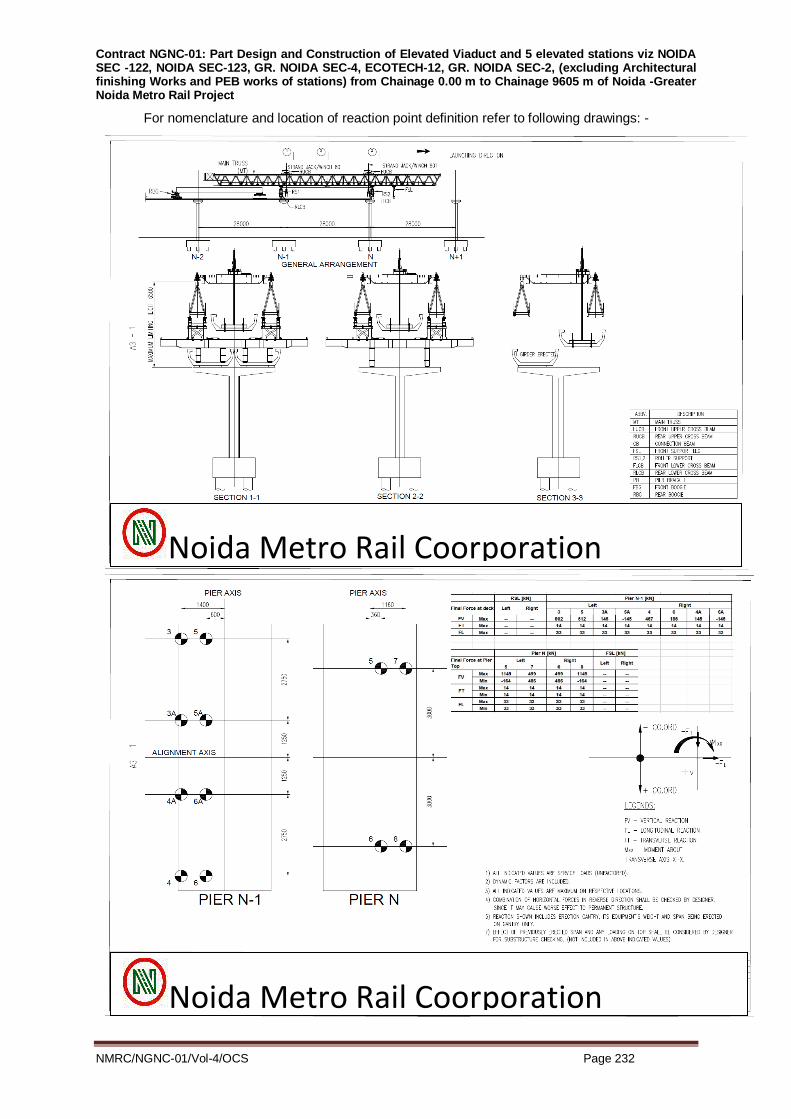
Contract NGNC-01: Part Design and Construction of Elevated Viaduct and 5 elevated stations viz NOIDA SEC -122, NOIDA SEC-123, GR. NOIDA SEC-4, ECOTECH-12, GR. NOIDA SEC-2, (excluding Architectural finishing Works and PEB works of stations) from Chainage 0.00 m to Chainage 9605 m of Noida -Greater Noida Metro Rail Project
NMRC/NGNC-01/Vol-4/OCS Page 232
For nomenclature and location of reaction point definition refer to following drawings: -
Noida Metro Rail Coorporation
Noida Metro Rail Coorporation

Contract NGNC-01: Part Design and Construction of Elevated Viaduct and 5 elevated stations viz NOIDA SEC -122, NOIDA SEC-123, GR. NOIDA SEC-4, ECOTECH-12, GR. NOIDA SEC-2, (excluding Architectural finishing Works and PEB works of stations) from Chainage 0.00 m to Chainage 9605 m of Noida -Greater Noida Metro Rail Project
NMRC/NGNC-01/Vol-4/OCS Page 233
10.1.7.10 Transfer Boogie
The U Girder shall be transported with two numbers of motorised bogies.
The Weight of each bogey, inclusive of all equipment, shall be limited to 5.5 t.
S. Nr Item Specification
1 Max Weight of each boggy 5.5 t
2 Max Speed (Loaded condition) 2 Km/hr
3 Max Speed (Unloaded condition) 3 Km/hr
4 Maximum gradient 4%
10.1.7.11 Specification On Safety
a) Illumination
A lighting system for working area shall be provided to improve visibility in case of scarce
day-light.
Anyway, personnel responsible of safety must make sure that there is a good visibility of
every point, not be create dangerous reflex and allow a clear reading of control boards and
identification of emergency push buttons.
b) Controls
Operating any control that creates a sharp variation in drive direction, such as halting the
winch by engaging the opposite movement, is forbidden. The stresses which may arise are
uncontrollable and may seriously damage the equipment, causing personnel and material
risk.
Such controls may be operated in the event of an imminent danger to persons.
c) Safety devices
The GANTRY shall be provided with electrical and mechanical devices which reduce the
danger that may occur during working phases. The safety devices are located in various
points of the launching machine and can be listed as follows :
i. Protected walkways, ladders and platforms
Main walkways, placed inside the two trusses, allow safe access to working areas and all
control units of supports, legs, winches, cranes. In order to reach walkways and platforms,
protected ladders are mounted on both legs and supports.
ii. Limit switches
Electrical limit switches shall be installed on moving parts of the gantry. If actuated, they
stop the related movement before mechanical stops are reached.
iii. Overspeed detection system
A safety system that monitors operating speed and stops the machinery in case of over
speed shall be installed on winch drums.
iv. Inclination detectors

Contract NGNC-01: Part Design and Construction of Elevated Viaduct and 5 elevated stations viz NOIDA SEC -122, NOIDA SEC-123, GR. NOIDA SEC-4, ECOTECH-12, GR. NOIDA SEC-2, (excluding Architectural finishing Works and PEB works of stations) from Chainage 0.00 m to Chainage 9605 m of Noida -Greater Noida Metro Rail Project
NMRC/NGNC-01/Vol-4/OCS Page 234
Electrical inclination detectors shall be installed on the winch drums.
v. Load cells
Gantry shall be equipped with load cells in order to constantly survey load conditions.
vi. Emergency push buttons
Emergency push buttons shall be installed in the gantry. If actuated by operators, they
stop immediately all running movements.
vii. Safety braking system
Safety braking system shall be installed to stop the rope drum in case of failure of the
control drive, motor, service brake or gearbox.
viii. Encoders
Lifting and lowering stroke shall be defined by an encoder mounted on each hoisting winch
drum connected with a limit switch.
ix. Digital speed gauges
Speed gauge shall be mounted on each hoisting winch drum to continuously check for
rope overspeed.
x. Max relief hydraulic valve
Each hydraulic motor shall be equipped with a hydraulic valve to limit oil pressure in the
circuits.
xi. Hydraulic pressure switch
Winches hydraulic circuit shall be equipped with a hydraulic switch to control lifting
pressure
10.2 BOX GIRDER
10.2.1 Construction Method
The box girder superstructure for almost the entire length shall be constructed by precast
segmental construction with epoxy bonded joints. The prestressing cables will be internal to
the concrete. The methodology of construction will be "span by span". Only one end
prestressing of permanent cables is contemplated, the other end of the cable being pre-
blocked.
The usual segments shall be 3.0m in length except the pier segments which shall be
1.975m each. Standard spans shall be made to either add or subtract usual segments of
3.0m each.
Where this is not possible or advisable for some reason, the segments will be of length
between 1.5m and 3.0m. Hence the mould / casting bed shall be adaptable to cast non-
standard length of segment.
The maximum span length contemplated for precast segmental construction will be of the
order of 37.0m.
Multiple Shear keys shall be provided at segmental joints at the webs as well as at top

Contract NGNC-01: Part Design and Construction of Elevated Viaduct and 5 elevated stations viz NOIDA SEC -122, NOIDA SEC-123, GR. NOIDA SEC-4, ECOTECH-12, GR. NOIDA SEC-2, (excluding Architectural finishing Works and PEB works of stations) from Chainage 0.00 m to Chainage 9605 m of Noida -Greater Noida Metro Rail Project
NMRC/NGNC-01/Vol-4/OCS Page 235
flange and soffit slab of the box girder.
Box girder segments shall be match cast at the casting yard and later transported to
location and erected in position. Post-tensioned cables shall be threaded-in-situ and
tensioned from one end. Box girder shall cater to two tracks.
10.2.2 Material Specifications
a) Cement Same as Cl 10.1.2.1
b) Reinforcement Same as Cl 10.1.2.2
c) Prestressing Steel
Same as Cl 10.1.2.3
d) Concrete Same as Cl 10.1.2.4
e) Permanent Prestressing Same as Cl 10.1.2.5
f) Epoxy Bonded Joints
A minimum compressive stress of 3 kg / sq. cm shall be provided uniformly over the cross-
section for the closure stress on the epoxied joint until the epoxy has set.
This temporary compressive stress can be applied by temporary prestressing bars.
The curing period for application of the compressive stress, method of mixing and
application of epoxy and all related aspects including surface preparation shall be as per
approved manufacturer's specifications.
The Epoxy shall be spread with the help of a stubby brush to a thickness of about 1.5 mm
each on both the joining surfaces.
The purpose of the epoxy joint shall be to serve as lubricant during segment positioning, to
provide water proofing of the joints for durability in service conditions and to provide a seal
to avoid cross-over of grout during grouting of one cable into other ducts.
Prior to grouting, all cables shall be tested with water pressure of 0.3 MPa for approximately
3 minutes, to investigate leakages and connectivity of ducts. Since the epoxied joint is of
paramount importance to ensure long-term durability of prestressing cables, this field test
shall be taken as indication of the Contractor's quality of work in general and effectiveness
of the epoxy joint executed by him. All other aspects of grouting of cables shall be governed
by MORTH Specifications.
The epoxy shall be special purpose proprietary material for the proposed usage with proven
past record. Selection of epoxy shall be subject to the approval of the Engineer. It shall
meet the requirements of relevant provision of FIB (International Federation of Concrete,
previously “FIP - International Federation of Prestressed Concrete”). For selection of epoxy,
all tests which govern the properties of epoxy for its application and subsequently determine
Contract NGNC-01: Part Design and Construction of Elevated Viaduct and 5 elevated stations viz NOIDA SEC -122, NOIDA SEC-123, GR. NOIDA SEC-4, ECOTECH-12, GR. NOIDA SEC-2, (excluding Architectural finishing Works and PEB works of stations) from Chainage 0.00 m to Chainage 9605 m of Noida -Greater Noida Metro Rail Project
NMRC/NGNC-01/Vol-4/OCS Page 236
the durability of joint are required to be done in laboratory temperature controlled condition.
Some tests for evaluating properties of epoxy are critical in the upper limit of specified
application temperature range while other tests are critical for evaluating the properties in
the lower limit of specified application temperature range. The tests shall be conducted in
laboratories equipped to handle controlled temperature conditions. All tests shall conform to
FIB requirements.
After receiving every batch, all tests (except shear modulus, instantaneous and deferred
modulus in compression and water absorption, heat resistance, shear strength and
solubility in water) are required to be done at the site laboratory at prevailing ambient
temperature to conform to the uniformity of standard of supplied product. In case the
received batch is kept at site for a period of more than three months all tests are required to
be re-done.
With every erection, tests for pot life and open time are required to be done at site at
prevailing ambient temperature. Nothing extra shall be payable for providing epoxy and all
related operations.
The uniform compressive stress during the curing period may be applied by approved
external temporary bar prestressing. This shall be accomplished using short HTS bar
connecting the adjoining segments. The bars shall be anchored on temporary steel frame,
passing through dedicated holes within the girder through.. No passing-through holes shall
be used in soffit slab or web. Passing-through holes used in soffit slab should be filled with
free flow, high strength, non-shrink cement grout.
In order to prevent intrusion of epoxy in sheathing, an O-ring with diameter compatible with
the size of HDPE sheathing (10-20mm wide and 4mm thick) of polypropylene shall be
provided on both mating surfaces.
Nothing extra shall be payable for such temporary stress application including all related
works.
g) Epoxy bonding agents
Epoxy bonding agents for match cast joints shall be thermosetting 100 percent solid
compositions that do not contain solvent or any non-reactive organic ingredient except for
pigments required for coloring. Epoxy bonding agents shall be of two components, a resin
and a hardener. The two components shall be distinctly pigmented. So that mixing
produces a third color similar to the concrete in the segments to be joined, and shall be
packaged in proportioned, labeled, ready-to-use containers.
Epoxy bonding agents shall be formulated to provide application temperature ranges that
will permit erection of match cast segments at substrate temperatures from 5oC to 45oC. If
two surfaces to be bonded have different substrate temperatures, the adhesive applicable
at the lower temperature shall be used.
Epoxy bonding agents shall be insensitive to damp conditions during application and after
curing, shall exhibit high bonding strength to cured concrete, good water resistively, low
creep characteristics and tensile strength greater than the concrete. In addition, the epoxy

Contract NGNC-01: Part Design and Construction of Elevated Viaduct and 5 elevated stations viz NOIDA SEC -122, NOIDA SEC-123, GR. NOIDA SEC-4, ECOTECH-12, GR. NOIDA SEC-2, (excluding Architectural finishing Works and PEB works of stations) from Chainage 0.00 m to Chainage 9605 m of Noida -Greater Noida Metro Rail Project
NMRC/NGNC-01/Vol-4/OCS Page 237
bonding agents shall function as a lubricant during the joining of the match cast segments,
as a filler to accurately match the surface of the segments being joined and as a durable
water light bond at the joint.
Epoxy bonding agents shall be tested to determine their workability get time, open time,
bond and compression strength, shear, and working temperature range. The frequency of
the tests shall be as stated in the Special Provisions of the Contract.
The contractor shall furnish the Engineer with samples of the material for quality assurance
testing and a certification from a reputable independent laboratory indicating that the
material has passed the required tests
Specific properties of epoxy and the test procedures to be used to measure these
properties shall conform to FIP requirement.
Mixing and Installation of Epoxy
Instructions furnished by the supplier for the safe storage, mixing and handling of the epoxy
bonding agent shall be followed. The epoxy shall be thoroughly mixed until it is of uniform
color. Use of a proper sized mechanical mixer operating at no more than 600 RPM will be
required. Contents of damaged or previously opened containers shall not be used. Surfaces
to which the epoxy material is to be applied shall be at least 400F and shall be free from oil,
laitance form release agent or any other material that would prevent epoxy from bonding to
the concrete surface. All laitance and other contaminants shall be preferably removed by
water rinsing, or, alternatively, by light sand-blasting. Wet surfaces shall be dried before
applying epoxy bonding agents. The surface shall be at least the equivalent of saturated
surface dry (no visible water).
Mixing shall not start until the segment is prepared for installation. Application of the mixed
epoxy bonding agent shall be according to the manufacturer‟s instructions using trowel
rubber glove or brush on one or both surfaces to be joined. The coating shall be smooth
and uniform and shall cover the entire surface with a minimum thickness of 1/16-inch
applied on both surfaces and 1/8-inch if applied on one surface. Epoxy should not be
placed within 3/8th inch of prestressing ducts to minimise flow into the ducts. A discernible
bead line must be observed in all exposed contact areas after temporary post-tensioning.
Erection operations shall be coordinated and conducted so as to complete the operations of
applying the epoxy bonding agent to the segments erection assembling and temporary
post-tensioning of the newly joined segment within 70% of the open time period of the
bonding agent.
The epoxy material shall be applied to all surfaces to be joined within the first half of the gel
time as shown on the containers. The segments shall be joined within 45 minutes after the
application of the first epoxy material placed and a minimum required temporary prestress
over the cross section should be applied within 70 percent of the open time of the epoxy

Contract NGNC-01: Part Design and Construction of Elevated Viaduct and 5 elevated stations viz NOIDA SEC -122, NOIDA SEC-123, GR. NOIDA SEC-4, ECOTECH-12, GR. NOIDA SEC-2, (excluding Architectural finishing Works and PEB works of stations) from Chainage 0.00 m to Chainage 9605 m of Noida -Greater Noida Metro Rail Project
NMRC/NGNC-01/Vol-4/OCS Page 238
material. The joint shall be checked immediately after the erection to verify uniform joint
width and proper fit. Excess epoxy from the joint shall be removed where accessible. All
tendon ducts shall be swabbed immediately after stressing while the epoxy is still in the
non-gelled condition to remove or smooth out any epoxy in the conduit and to seal any
pockets or air bubble holes that have formed that joint.
If jointing is not completed with 70 percent of the open time, the operation shall be
terminated and the epoxy bonding agent shall be completely removed to the maximum
possible extent from the surfaces. The surface must be prepared again and fresh epoxy
shall be applied to the surface before resuming jointing operations. As general instructions
cannot cover all situations specific recommendations and instructions shall be obtained in
each case from the Engineer.
10.2.3 Shop Drawings And Design Calculations For Construction Procedures
10.2.3.1 General
The Contractor shall submit according to a schedule, complete details and information
concerning the method, materials, equipment and procedures he proposes to use. These
shall be called “Method Statements”. Method Statements shall be submitted sufficiently in
advance of the start of superstructure field construction operations, so as to allow the
Engineer adequate review period, which shall not be less than 30 days. The submittals shall
invariably include step-by-step erection procedure.
The Contractor‟s Method Statements shall also include all calculations, drawings and
information as may be relevant.
10.2.3.2 Design Calculations for Construction Procedures
Design assumptions and calculations shall be submitted for temporary prestressing, false
work, erection devices, formwork or other temporary construction which may be required to
complete the work.
Assumptions and Calculations shall also be submitted to substantiate the system and
method of permanent and temporary prestressing proposed by the Contractor.
In the sections that follow, specific recommendations for precast segmental construction for
superstructure are given apart from certain special aspects of construction.
10.2.3.3 Shop Drawings for Precast Segmental Construction
The Contractor shall submit detailed shop drawings for approval. The shop drawings shall
be based on Execution Drawings issued by concerned organisation to the Contractor and
shall include:
a) Fully and accurately dimensioned views showing the geometry of segments including all
projections, recesses, notches, openings, block-outs, blister if any and where acceptable,
as well as other relevant details.
b) Details of any special reinforcing required for handling of segments or for other purposes.

Contract NGNC-01: Part Design and Construction of Elevated Viaduct and 5 elevated stations viz NOIDA SEC -122, NOIDA SEC-123, GR. NOIDA SEC-4, ECOTECH-12, GR. NOIDA SEC-2, (excluding Architectural finishing Works and PEB works of stations) from Chainage 0.00 m to Chainage 9605 m of Noida -Greater Noida Metro Rail Project
NMRC/NGNC-01/Vol-4/OCS Page 239
Also all bar bending schedules shall be presented based on reinforcement schedules given
in Execution Drawings issued by concerned organisation.
c) Sheathing supports, grout tubes, vents and drains shall be shown including size, type and
locations.
d) Details and locations of all other items to be embedded in the segments such as inserts,
lifting devices and post-tensioning hardware shall be shown.
e) Prestressing system details shall include sizes and properties of tendons, anchorages,
plates, assemblies and stressing procedure, and details and locations of additional
reinforcement necessary to resist anchor block stresses.
f) Graphs, charts or tables showing the theoretical location of each segment, as erected or
placed shall be furnished to the Engineer for his use in checking the erection of the
superstructure. Detailed procedures for making geometry corrections shall be described.
g) Details of grouting equipment, grout mix design and method of mixing and placing grout
shall be provided.
h) Method of installing bearings and expansion joints shall be given including approved
manufacturer's recommendations.
10.2.3.4 Forms for Precast Segmental Construction
Forms for precast segmental construction shall be steel form work only. Shop drawings
shall be submitted for all formwork. The segments during storing /curing shall always be
supported as shown in tender drawings or as approved by Engineer only.
In addition to the requirements of the Standard Specifications, the forms used for precasting
the concrete segments shall be capable of :
a) Match casting for precast segmental construction.
b) Producing the segments within the tolerances permitted in Section 10.2.8.
c) Accommodating block-outs, openings and protrusions. Protruding re-bars will be needed
at least for diaphragm segments and for second-pour plinths. Anchorages and inserts
for OHE poles, signalling equipment and cable routing supports shall also be included
where needed in precast segments.
d) Adjusting to changes in segment geometry as shown in Execution Drawings issued by
concerned organisation, or for correcting previous minor casting errors to prevent
accumulation.
e) Adjusting the profile to take into account design camber values
f) Stripping without damage to the concrete.
g) The form design shall provide a tight leak-proof jointing to the previous segment. The
bulkhead must be capable of connecting the sheathing in a manner to hold their position
and prevent intrusion of grout.
Joints in external formwork shall be avoided as far as possible. Where sections of forms are

Contract NGNC-01: Part Design and Construction of Elevated Viaduct and 5 elevated stations viz NOIDA SEC -122, NOIDA SEC-123, GR. NOIDA SEC-4, ECOTECH-12, GR. NOIDA SEC-2, (excluding Architectural finishing Works and PEB works of stations) from Chainage 0.00 m to Chainage 9605 m of Noida -Greater Noida Metro Rail Project
NMRC/NGNC-01/Vol-4/OCS Page 240
for some reason to be joined on the exterior face of the segment, an offset in excess of
0.5mm for flat surfaces and 1 mm for corners and bends will not be permitted.
Forms shall not be removed until the concrete has attained adequate strength. Care should
be exercised in removing the forms to prevent spalling and chipping of the concrete.
All side, bottom, inside and header forms for precast segmental construction shall be
constructed of steel.
Forms shall be of sufficient thickness, with an adequate external bracing and stiffeners, and
shall be sufficiently anchored to withstand the forces due to placement and vibration of
concrete. Internal bracing and holding devices in forms shall be limited to stay bolts in
webs, which can be removed from the concrete surface to permit patching following form
removal. Joints in the forms shall be designed and maintained for mortar tightness. The
grade and alignment of forms shall be checked each time they are set and shall be
maintained during the casting of concrete.
Metal forms shall be reasonably free from rust, grease or other foreign materials. All forms
shall be cleaned thoroughly prior to each casting operation. End headers shall be
maintained to provide a smooth casting surface.
All formed surfaces for casting members shall be constructed and maintained to provide
segment tolerances in accordance with Section 10.2.8.
The faces of all forms, other than end headers, shall be properly cleaned and treated with
form oil or other bond breaking coating prior to placing concrete. Between adjacent match
cast segments and headers bond breaking materials shall be provided as indicated
elsewhere in these Additional Specifications. The oil or other .materials used shall be of a
consistency and composition to facilitate form removal. Materials which stain or react with
concrete shall not be used. Care shall be exercised to facilitate formwork and segment
removals without damage to the concrete.
10.2.4 Casting, Handling, Transportation And Erection Of Precastsegments
10.2.4.1 General
The Contractor shall submit detailed Method Statements for casting, handling,
transportation and erection of precast segments. The superstructure shall be erected by the
method indicated in the tender or by alternate method submitted by the Contractor, subject
to the approval of the Engineer. The stressing system, cage of reinforcement and lifting
details shall be successfully demonstrated on sample segment prior to casting any
permanent segments.
All handling and erection plant and equipment shall be load tested prior to their use at site
or when specifically asked for by the Engineer. Any additional material required to cater to
any temporary condition including temporary prestressing shall be borne by contractor and

Contract NGNC-01: Part Design and Construction of Elevated Viaduct and 5 elevated stations viz NOIDA SEC -122, NOIDA SEC-123, GR. NOIDA SEC-4, ECOTECH-12, GR. NOIDA SEC-2, (excluding Architectural finishing Works and PEB works of stations) from Chainage 0.00 m to Chainage 9605 m of Noida -Greater Noida Metro Rail Project
NMRC/NGNC-01/Vol-4/OCS Page 241
nothing extra will be paid in this account.
10.2.4.2 Casting of Segments
Casting bed and forms shall be structurally adequate to support the segments without
settlement or distortion. The casting bed shall be designed for the hardware needed to
adjust and maintain grade and alignment Special consideration shall be given to those parts
of the forms that have to change in dimensions. To facilitate alignment or adjustment,
special equipment such as wedges, screws or hydraulic jacks shall be provided. Fittings
shall not interfere with stripping of forms. Grading of the forms and the deck of each
segment shall take into consideration the relative position of the member in the structure.
External vibrators shall supplement the internal vibration if necessary and be attached at
locations that will ensure maximum consolidation.
Details for casting bed and hardware for adjustment shall be submitted by the Contractor for
the Engineer's approval. Casting of segments shall be done in a single pour. Construction
joint is not permitted in segment.
After the first segment of each unit is cast, all succeeding segments shall be cast against
previously cast segments to ensure complete bearing and proper alignment on all mating
surfaces.
The anchorage system shall permit tendons to be inserted in the member after erection of
segments and tensioned from one end only.
Care shall be taken to ensure that deformations of match cast segments due to thermal
gradients caused by the heat of hydration of the new cast concrete are negligible. These
deformations shall be prevented by properly protecting both the match cast and new cast
segments with curing blankets and plastic sheeting. Both the previous segment and the
new segment will be maintained at the same temperature.
Reinforcing steel shall be fabricated in cages and placed according to the Execution
Drawing issued byNMRC. Any conflict or interference with the proper location of sheathing
and / or reinforcement or block-outs shall be promptly resolved and corrections made as
directed by the Engineer.
All segments shall be marked on the inside with a unique identification at the time of form
removal. This identification shall be used to identify each segment on shop plans, post-
tensioning details and calculations and any other document pertaining to the fabrication and
erection of precast concrete segments.
Positive means of holding the sheathing in its correct position shall be provided in all cases
and shall be indicated on the shop drawings submitted for approval. The sheathing shall be
stiffened from the inside by rubber or plastic hoses or by inflatable rubber tubes.
10.2.4.3 Casting Methods
Match cast segments may be cast by the “long line” or “short line” method. TheContractor
Contract NGNC-01: Part Design and Construction of Elevated Viaduct and 5 elevated stations viz NOIDA SEC -122, NOIDA SEC-123, GR. NOIDA SEC-4, ECOTECH-12, GR. NOIDA SEC-2, (excluding Architectural finishing Works and PEB works of stations) from Chainage 0.00 m to Chainage 9605 m of Noida -Greater Noida Metro Rail Project
NMRC/NGNC-01/Vol-4/OCS Page 242
hasto select the option carefully and provide appropriate type of formwork as well as casting
and handling operations. The "short line" method requires much greater precision in the
work as compared to the "long line" method.
10.2.4.4 The "Long Line" Method
The principle of the long line method is the casting of the segments, in their correct relative
position, on a long line casting bed which exactly reproduces the profile of the structure. A
long line is easy to set up, while the geometry of the segments is easily controlled. The
segments shall be cast by long line method for spans curved in plan.
After stripping the forms it is not necessary to take away the segments immediately. Water
curing/curing compound as per relevant specifications shall beapplied to segments
immediately.
Substantial space may be required for the long line. The theoretical length for casting alone
is normally slightly more than the length of the longest span of the structure. It must be
constructed on a firm foundation which will not settle or deflect under the weight of the
segments. In case the structure is curved, the long line must be designed to accommodate
horizontal and vertical curvature as well as twists, if any, because the forms are mobile,
equipment for casting, curing, etc has to move from place to place.
10.2.4.5 The “Short Line” Method
The short line method is mentioned here as a possible alternate.
The segments are cast at the same place in stationary forms and against a neighboring
element. After casting, the neighboring element is taken away and the last element is
shifted to the place of the neighboring element, clearing the space to cast the next element.
The space needed for the short line method is small in comparison to the long line method,
approximately three times the length of a segment for one short line. The entire process is
centralised. Horizontal and vertical curves and twisting of the structure are obtained by
adjusting the position of the neighboring segment and through specified formwork.
To obtain the desired structural configuration, the neighboring segments must be accurately
positioned. Care must be taken that the formwork be sufficiently flexible to allow for
adaptation at the joint with the accurately positioned matching segment.
If short line method is adopted, the deck segments should follow profile as given below:-
Suggested Deck Alignment on Vertical Curves
a) On Vertical Summit Curves
On vertical summit curves, deck will follow the path of straight line joining the two points on adjacent piers. These two points shall have the minimum offset from rail level to deck level as specified by Engineer at all points along the length of girder.
b) On Vertical Valley Curves

Contract NGNC-01: Part Design and Construction of Elevated Viaduct and 5 elevated stations viz NOIDA SEC -122, NOIDA SEC-123, GR. NOIDA SEC-4, ECOTECH-12, GR. NOIDA SEC-2, (excluding Architectural finishing Works and PEB works of stations) from Chainage 0.00 m to Chainage 9605 m of Noida -Greater Noida Metro Rail Project
NMRC/NGNC-01/Vol-4/OCS Page 243
On vertical valley curves, deck will follow the path of straight line joining the two points on adjacent piers. The minimum offset from rail level to deck level as specified by Engineer shall be ensured at all points along the length of girder.
c) Suggested Deck Alignment on Circular / Transition Horizontal Curves
On circular / transition horizontal curves, each segment of the deck will follow the
profile of short chord line. The bottom and side form for segment to be cast are
positioned to span between the stiff fixed end bulkhead and the previously match
cast segment. The previously match cast segment shall be oriented w.r.t. segment
to be cast and it should be ensured that fixed bulkhead always remain
perpendicular to end face of formwork.
Due to orientation of match cast segment, the length of segment towards inner side
of curve will be less and towards outer side of curve will be more than segment
length along centre line. The formwork to be used should have flexibility to adjust
the segment length on both sides by adjusting the position of the match cast
segment without any additional pieces and it shall be ensured that offset of match
cast segment and segment to be cast is limited to value so calculated.
10.2.4.6 Separation of Match-Cast Segments
The Contractor shall provide equipment to be used for uniform separation of match case
segments without damage. The method as well as details of the equipment to be used for
separating match cast segments shall be included in the shop drawings. A bond breaking
material shall be used in the form of wax only on the webs and soffit slab of the previously
cast segment and a newly cast segment, as well as the end headers when required. The
material shall not be injurious to the concrete and shall permit removal of a segment without
adhesion of the concrete.
Any breakage in segment end face during separation / handling shall not be repaired,
unless specifically accepted by the Engineer, in which case repairing at end face of
segment shall be done with epoxy at the time of epoxy application. Segments with
excessive breakage shall be rejected. Decision of the Engineer shall be final binding in this
regard.
10.2.4.7 Handling / Erection of Segments
The Contractor shall be responsible for the proper handling, lifting, storing, transporting and
erection of all segments so that they may be placed in the structure without damage. Only
HTS bar such as Macalloy or Dywidag shall be used for lifting/handling of segment at any
stage of construction, with due care for fatigue considerations (multiple re-use).
Segments shall be maintained in an upright position at all times and shall be stored, lifted
and/or moved in a manner to prevent torsion and differential deformation other undue
stress. Members shall be lifted, hoisted or stored with lifting devices approved on the shop
drawings.
The Contractor shall furnish calculations to establish that the stresses induced during any
stages of construction shall not exceed 50% of the cube strength achieved at that stage,

Contract NGNC-01: Part Design and Construction of Elevated Viaduct and 5 elevated stations viz NOIDA SEC -122, NOIDA SEC-123, GR. NOIDA SEC-4, ECOTECH-12, GR. NOIDA SEC-2, (excluding Architectural finishing Works and PEB works of stations) from Chainage 0.00 m to Chainage 9605 m of Noida -Greater Noida Metro Rail Project
NMRC/NGNC-01/Vol-4/OCS Page 244
nor 40% of the specified 28days cube strength. In addition, the following limitations shall be
observed:
a. The segment shall not be lifted from the casting bed till the concrete reaches a
minimum cylindrical strength of 20 MPa (or 25MPa Cube strength).
b. The age of the concrete shall not be less than 14 days at the time of its erection
provided it has achieved its specified strength as per design requirements.
Segment shall be stacked with three point support in curing tank / stacking yard as shown in
tender drawing, or as approved by concerned organisation Curing shall be done using
sprinkler system (assisted by steam curing in the initial stages if adopted) and it has to be
ensured that all parts of segment are water cured during water curing period. Or curing
compound as per the relevant specifications in this document
10.2.4.8 Cleaning, Transportation and Erection of Segments
Before transportation of segment, mating surface shall be cleaned by water rinsing or sand
blasting as approved by the Engineer.
When sand blasting is employed surface shall be abraded to an extent that:
i. Bond breaker such as wax applied during match casting is removed.
ii. Laitance is removed so that small aggregates are just exposed.
iii. Cleaned surface is neither polished nor excessively rough
Two methods of erection have been suggested: Side beams method, and as an allowed
alternate, the top beams method. .Only the side –beams method is referred to in these
special specifications. The launching girder (or more accurately, the "assembly truss") must
be capable of supporting all the loads with in permissible limits as stipulated in codes and
transferring it to the temporary cross girder, which transfer the loads directly on pier cap
using trestles. The launching girder envisaged is slightly greater than 2 spans. It must also
be able to negotiate curves and accommodate for the camber if any of the structure. As far
as practical, the movement of segments shall be done at the deck level of the already
constructed portion of the continuous length so that the disturbance to traffic at the ground
level is minimised. Mobile crane of adequate capacity and boom length shall be mobilised
by the Contractor for transferring the segment from ground level to deck level for the
purpose. The launching girder should be capable of lifting the segments for the span
to be erected from below and in case required, it should also be capable of feeding
the segments from the rear end over the already erected span.
A suitable number of separate sets of launching girders are essential in order to proceed at
the contemplated pace for completion of project in time. However, Contractor shall furnish
the construction scheme and nos. of launching girders, he proposes to deploy in order to
ensure completion of project within scheduled time.
It is emphasised that for precast segmental construction only one-end prestressing shall be
used. The superstructure shall be constructed "span by span" sequentially.

Contract NGNC-01: Part Design and Construction of Elevated Viaduct and 5 elevated stations viz NOIDA SEC -122, NOIDA SEC-123, GR. NOIDA SEC-4, ECOTECH-12, GR. NOIDA SEC-2, (excluding Architectural finishing Works and PEB works of stations) from Chainage 0.00 m to Chainage 9605 m of Noida -Greater Noida Metro Rail Project
NMRC/NGNC-01/Vol-4/OCS Page 245
The diaphragm segments shall need specific additional temporary supports under the webs
during those various stressing operations. Those temporary supports shall be flexible
enough in rotation. The precise load transfer during the stressing operations between the
various supports shall be monitored at least once with adequate jacks during the destructive
testing of one span in precast yard. It is emphasised that
i. The spans must be assembled on a higher level to avoid conflicts with already built
concrete shear key.
ii. The launching truss supports must be at same location than temporary bearings.
10.2.5 Miscellaneous
The entire construction work shall be geared towards minimising disruptions to road traffic.
Also, the occupation of roads during all construction activities shall be reduced to a
minimum and subject to the approval of the Engineer
All elements of sub-structure below bearing pedestals viz piles, pile caps, piers and pier
caps shall each be cast in single pour.
10.2.6 Load Testing Of Launching Girder
Contractor shall conduct full scale load traveller test of all launching girder prior to using it
for execution purpose. Such tests are required to be done for all the launching girders
engaged for project, even if the similar design of launching is adopted.
Nothing extra will be payable for conducting such test and the rate shall be included in
respective item.
10.2.7 Load Testing Of Standard Span Of Superstructure
The contractor shall conduct full scale load test for one critical span of each category of
superstructure.
The sequence of placement and position of loading on the girder shall be as directed by the
engineer.
NOTE
The provision of 3r Rail to be checked for NMRC Phase-IV.
10.2.8 Completed Segment Tolerance For Segmental Box Girder Bridge Construction.
Finished segment tolerances should not exceed the following:
Length of match-cast segment (not cumulative) …..+ 1/8 in/ft.(10.4 mm/m, + 1 in. max. (25
mm)
Length of totally assembled span……….…….….+ 1/2 in.(12.5 mm)

Contract NGNC-01: Part Design and Construction of Elevated Viaduct and 5 elevated stations viz NOIDA SEC -122, NOIDA SEC-123, GR. NOIDA SEC-4, ECOTECH-12, GR. NOIDA SEC-2, (excluding Architectural finishing Works and PEB works of stations) from Chainage 0.00 m to Chainage 9605 m of Noida -Greater Noida Metro Rail Project
NMRC/NGNC-01/Vol-4/OCS Page 246
Web Thickness……………………………...….…….+3/8 in. (9.5 mm)
Depth of bottom slab…..……………………….…….+3/8 in. (9.5 mm)
Depth of top flange…………………………….……..+1/4 in. ( 6.5 mm)
Overall top flange width……………….……...+1/16 in/ft (5.2 mm/m),+3/4 in. max(25mm)
Top flange width (transverse position on track side) ….+1/5 in (5 mm). max
Diaphragm thickness ………………………………………...+1/2 in. (12.5 mm)
Grade of form edge and soffit………………………………..+1/8 in. in 10 ft (1.0 mm/m)
Tendon hole location…………………………………………+1/8 in. (3.2mm)
Position of shear keys………………………………………. +1/4 in. (6.3 mm)
Tolerance for erection of the span
Horizontal and vertical position of the at-pier-segment shall be within 15mm of the longitudinal
alignment and grade.

Contract NGNC-01: Part Design and Construction of Elevated Viaduct and 5 elevated stations viz NOIDA SEC -122, NOIDA SEC-123, GR. NOIDA SEC-4, ECOTECH-12, GR. NOIDA SEC-2, (excluding Architectural finishing Works and PEB works of stations) from Chainage 0.00 m to Chainage 9605 m of Noida -Greater Noida Metro Rail Project
NMRC/NGNC-01/Vol-4/OCS Page 247
SECTION S.11
ROOF SHEETING & PRE ENGINEERED STRUCTURES
11.1 GENERAL
11.1.1 Description Of Work Site
The location of the work and the general site particulars are shown in the Site Layout
enclosed in the tender drawings.
11.1.2 Scope Of Work
General
The work content in this contract consists of:
i. Design, Fabrication, Supply and erection of PEB buildings for Workshop &Inspection
bay, Blow Down Plant, Pit Wheel Lathe, Interior cleaning, Shed for RGM, S & T Stores,
Cable & Diesel Store, Shedsand Watch Towers including gantry girders wherever
required.
ii. Design, fabricating and erection of hot dipped galvanized Rain Water Gutters
iii. Providing and fixing pre coated galvalume sheets in single and double layer for roofing
and side cladding. Double layer sheeting must be insulated by 50 mm thick glass wool
of 24kg/cum density.
iv. Providing and fixing 3 mm Polycarbonate sheets and 6mm thick toughened glass
v. Design, fabrication, supply and erection of structural steel for roof inspection platforms,
catwalks and cable tray support brackets & hangars.
vi. Providing structural steel for rail track support columns and car/cycle/scootersheds
vii. Supply, Installation and testing of supporting structures for EOT cranes.
viii. Roof structure shall be planned as per solar module installation arrangements.
ix. Providing life line for maintenance / cleaning purpose
x. Providing ladder to acess roof.
The work is to be constructed and maintained as per relevant IS Codes, Relevant International
Standard, CPWD Specifications, Particular Specifications, and Tender Drawings and or as
directed by the Engineer.

Contract NGNC-01: Part Design and Construction of Elevated Viaduct and 5 elevated stations viz NOIDA SEC -122, NOIDA SEC-123, GR. NOIDA SEC-4, ECOTECH-12, GR. NOIDA SEC-2, (excluding Architectural finishing Works and PEB works of stations) from Chainage 0.00 m to Chainage 9605 m of Noida -Greater Noida Metro Rail Project
NMRC/NGNC-01/Vol-4/OCS Page 248
Technical Requirements
Tenderers must have their own fabrication unit with fully computerized and automatic
machineries for cutting, bending, drilling, moulding, welding, grinding etc. with full flagged
facilities of sand blasting, painting and testing equipment complete.
The following requirements are to be followed by the Contractor:
i. All aspects of quality assurance, including procurement & testing of materials and other
components of the work, as specified or as directed;
ii. Clearing of site and handing over of all the Works, as directed;
iii. Maintenance of the completed Work during the maintenance period.
iv. Submission of Design Drawings, Erection Drawings, Fabrication Drawings, completion
(i.e. ‘as-built’) drawings, calculation, analysis and other related documents as specified;
11.1.3 Interfaces
The Scope of Work for the interfaces work for various interfacing Contracts. In brief, the
interfaces include but are not limited to:
i. Supply of anchor bolts to Civil contractor
ii. Interfacing with OHE contractor
iii. Interfacing with E & M contractor
iv. Interfacing with Tracks contractor
11.1.4 Associated Works
Works to be performed shall also include:
i. All general works preparatory to the PEB buildings, OHE arrangements and EOT
Crane arrangements of Depot & Workshop for MRTS project
ii. It is envisaged to provide retractable catenary arrangement in IBL Depot. Civil
contractor should interfere with concerned traction contractor for providing
necessary structural support arrangement OHE and related cabling support after
getting details from the traction contractor.
iii. Works of any kind necessary for the due and satisfactory construction, completion
and maintenance of the works to the intent and meaning of the drawings adopted,
technical specifications, to best Engineering standards and orders that may be
issued by the Engineer from time to time, compliance by the agency with all
Conditions of Contract,
iv. Supply of all materials, apparatus, plants, equipment, tools, fuel, water, strutting,
timbering, transport, offices, stores, workshop, staff, labour and the provision of
proper and sufficient protective works, diversion, temporary fencing, lighting and

Contract NGNC-01: Part Design and Construction of Elevated Viaduct and 5 elevated stations viz NOIDA SEC -122, NOIDA SEC-123, GR. NOIDA SEC-4, ECOTECH-12, GR. NOIDA SEC-2, (excluding Architectural finishing Works and PEB works of stations) from Chainage 0.00 m to Chainage 9605 m of Noida -Greater Noida Metro Rail Project
NMRC/NGNC-01/Vol-4/OCS Page 249
watching required for the safety of the public and protection of works on adjoining
land;
v. First-aid equipment, sanitary accommodation for the staff and workmen, effecting
and maintenance of all insurances,
vi. The payment of all wages, salaries, provident fund, fees, royalties, duties or other
charges arising out of erection of works and regular clearance of rubbish, clearing
up, leaving the site perfect and tidy on completion.
11.2 DESIGN CRITERIA
The Design of temporary works covers all the items pertaining to:
i. Form work, casting and stacking yard, staging, launching Scheme and/or
transportation scheme.
ii. Drawings furnished with the Tender Documents show the level of works based on
available soil investigation data. These may require change at the time of actual
execution of works.
11.3 STANDARD CODES OF PRACTICE
11.4 AVAILABILITY
The contractor shall provide at site all relevant Codes of practice, and CPWD Specifications.
Legend
ASCE American Society of Civil Engineers
ASME American Society of Mechanical Engineers
ASTM American Society for Testing Materials
BS British Standard
CPWD Central Public Works Department
DIN Deutsche Institute for Normunge.V.
IRC Indian Road Congress
IRS Indian Railway Standards
IS Indian Standards

Contract NGNC-01: Part Design and Construction of Elevated Viaduct and 5 elevated stations viz NOIDA SEC -122, NOIDA SEC-123, GR. NOIDA SEC-4, ECOTECH-12, GR. NOIDA SEC-2, (excluding Architectural finishing Works and PEB works of stations) from Chainage 0.00 m to Chainage 9605 m of Noida -Greater Noida Metro Rail Project
NMRC/NGNC-01/Vol-4/OCS Page 250
JIS Japanese Industrial Standard
MOST Ministry of Surface Transport
MORTH Ministry of Road Transport and Highways
11.5 ORDER OF PRECEDENCE
Wherever Indian Standards do not cover some particular aspects of design/construction,
relevant British/European/American Standards will be referred to.
In case of discrepancy among Standard codes of practice, CPWD Specifications, General
and particular Specifications, and Bill of Quantities, the order of precedence will be as
below:
i. Bill of Quantities
ii. Particular Specifications
iii. General Specifications
iv. CPWD Specifications.
v. Standard Codes of Practice.
In case of discrepancy among Standard Codes of Practice, the decision of Engineer will be
final and binding.
11.6 APPLICABLE CODES
The summarized list of codes is applicable to structural and architectural works. This will not
preclude the Engineers right to refer to any other code applicable for the satisfactory
execution of the work.
11.7 DIMENSIONS
i. Figured dimensions on drawings shall only be followed and drawings to a large scale
shall take precedence over smaller scale drawings. All dimensions shall be checked on
site prior to execution.
The dimensions where stated do not allow for waste, laps, joints, etc. but the Contractor
shall provide at his own cost sufficient labour and materials to cover such waste, laps,
joints, etc.
ii. The levels, measurements and other information concerning the existing site as shown
on the drawings are believed to be correct, but the Contractor should verify them for
himself and also examine the nature of the ground as no claim or allowance
whatsoever will be entertained on account of any errors or omissions in the levels or the
description of the ground levels or starts turning out different from what was expected
or shown on the drawings.
Contract NGNC-01: Part Design and Construction of Elevated Viaduct and 5 elevated stations viz NOIDA SEC -122, NOIDA SEC-123, GR. NOIDA SEC-4, ECOTECH-12, GR. NOIDA SEC-2, (excluding Architectural finishing Works and PEB works of stations) from Chainage 0.00 m to Chainage 9605 m of Noida -Greater Noida Metro Rail Project
NMRC/NGNC-01/Vol-4/OCS Page 251
11.8 STEEL STRUCTURES
11.8.1 General
11.8.1.1 This section covers the general requirements of designing, preparing necessary drawings,
and, providing, fabricating, painting, transporting, erecting, fixing in position structural steel
work for buildings, including all necessary temporary works and conducting of associated
tests.
11.8.1.2 Contractor shall ensure that the Technical specifications detailed herein are carefully read
and understood in conjunction with, and related to bill of quantities, and, the contractor in
his rates includes all requirements defined herein and in other parts of the Contract
Document.
11.8.2 Applicable Codes And Standards
The codes and standards generally applicable to the work of this section are listed below.
These are in addition to all relevant Indian Standard Codes as specified in the referenced
documents. Latest revisions of the codes shall only be applicable.
IS: 102 Ready mixed paint, brushing, red lead non-setting, priming
IS: 104 Ready mixed paint, brushing, zinc-chrome, priming
IS: 210 Gray Iron Castings
IS: 451 Technical Supply Conditions for Wood Screws
IS: 800 Code of Practice for General Construction in Steel
IS: 801 Code of Practice for use of Cold Formed Light Gauge Steel Structural
Members in General Building Construction.
IS: 806 Code of Practice for use of Steel Tubes in General Building Construction
IS: 808 Dimensions of Hot Rolled Steel beam, channel and angle sections
IS: 811 Cold Formed Light Gauge Structural Steel Sections
IS: 813 Scheme of Symbols for Welding
IS: 814 Covered Electrodes for Manual Metal Arc Welding of Carbon and
Carbon-Manganese Steel
IS: 816 Code of Practice for use of Metal Arc Welding for General Construction in
Mild Steel

Contract NGNC-01: Part Design and Construction of Elevated Viaduct and 5 elevated stations viz NOIDA SEC -122, NOIDA SEC-123, GR. NOIDA SEC-4, ECOTECH-12, GR. NOIDA SEC-2, (excluding Architectural finishing Works and PEB works of stations) from Chainage 0.00 m to Chainage 9605 m of Noida -Greater Noida Metro Rail Project
NMRC/NGNC-01/Vol-4/OCS Page 252
IS: 818 Code of Practice for Safety and Health requirements in electric and Gas
Welding and Cutting Operations
IS: 822 Code of Procedure for Inspection of Welds
IS: 875 Code of Practice for Structural Safety of Building, Loading Standards.
IS: 1024 Code of Practice for use of Welding in Bridges and Structures Subject to
Dynamic Loading
IS: 1030 Carbon Steel Castings for General Engineering Purposes
IS: 1120 Coach Screws
IS: 1161 Steel Tubes for Structural Purposes
IS: 1182 Recommended Practice for Radiographic Examination of Fusion Welded
Butt Joints in Steel Plates
IS: 1363 Hexagon Head Bolts, Screws and Nuts (Grade-C)
IS: 1364 Hexagon Head Bolts, Screws and Nuts (Grades A & B)
IS: 1365 Slotted Counter-sunk Head Screws
IS: 1367 Technical Supply Condition for Threaded Fasteners
IS: 1852 Rolling and Cutting Tolerances for Hot Rolled Steel Products
IS: 1977 Low Tensile Structural Steel
IS: 2016 Plain Washers
IS: 2062 Steel for General Structural Purposes
IS: 2074 Ready Mixed Paint, Air drying, Red Oxide-Zinc Chrome Priming
IS: 3063 Fasteners- Single Coil Rectangular Section Spring Washers
IS: 3400 Methods of Test for Vulcanized Rubber
IS: 3443 Crane Rail Sections
IS: 3600 Testing Methods of Fusion Welded Joints and Weld Metal in Steel
IS: 3613 Acceptance Tests for Wire Flux combination for submerged, welding
IS: 3757 High Strength Structural Bolts
IS: 4000 Code of Practice for High Strength Bolts in Steel Structures
IS: 4923 Hollow Steel Sections for Structural Use
IS: 5369 General Requirements for Plain Washers and Lock Washers
IS: 5624 Foundation Bolts
IS: 6227 Code of Practice for use of Metal Arc Welding in Tubular Structures

Contract NGNC-01: Part Design and Construction of Elevated Viaduct and 5 elevated stations viz NOIDA SEC -122, NOIDA SEC-123, GR. NOIDA SEC-4, ECOTECH-12, GR. NOIDA SEC-2, (excluding Architectural finishing Works and PEB works of stations) from Chainage 0.00 m to Chainage 9605 m of Noida -Greater Noida Metro Rail Project
NMRC/NGNC-01/Vol-4/OCS Page 253
IS: 6623 High Strength Structural Nuts
IS: 6639 Hexagonal bolts for steel structures.
IS: 8500 Structural Steel Micro-alloyed (Medium and High strength Qualities)
IRC : 83 (Part-II) : Elastomeric Bearings
11.8.3 Design
11.8.3.1 The contractor will be required to carry out detailed design of the structures, prepare
engineering drawings and detailed ‘shop drawings’, get these approved from Engineer, and
then carry out the fabrication work based on approved drawings.
11.8.3.2 Contractor’s designs shall, unless otherwise specified, be based on provisions of relevant
BIS codes. Design guideline and design parameters are mentioned in ANNEXURE - C to
these specifications.
Where corresponding parameters mentioned in BIS codes are different from those
mentioned in ANNEXURE-C, the latter shall take precedence.
11.8.3.3 Contractor’s designs shall be based on general descriptions of buildings given in tender
documents and those shown in Tender Drawings.
Where information given in tender documentsdo not tally with the Tender Drawings,
information given in Tender drawings shall take precedence.
11.8.3.4 Where codes and standards listed in clause 11.8.2do not cover the requirements of
design, only in those cases the contractor may refer to other International Standards of
design. However, such references should be made only with the approval of the Engineer.
11.8.3.5 Contractor shall submit his design calculations and ‘Engineering Drawings’ to the
Engineer for his approval. The contractor is advised to discuss his design philosophy and
design procedure with the Engineer before proceeding with the final design work.
11.8.3.6 It shall be the responsibility of the contractor to obtain all relevant design information
from the Engineer for preparing his designs, including all special loading like loads from
cranes and other utility services supported by the structure.
11.8.4 Drawings
11.8.4.1 ‘Tender Drawings’ shall be the ‘Basic’ drawings for developing design drawings. Design
drawings shall then be developed in to final ‘Shop Drawings’ to be prepared by the
contractor. For preparing shop drawings, the contractor shall obtain written approval
from the Engineer.

Contract NGNC-01: Part Design and Construction of Elevated Viaduct and 5 elevated stations viz NOIDA SEC -122, NOIDA SEC-123, GR. NOIDA SEC-4, ECOTECH-12, GR. NOIDA SEC-2, (excluding Architectural finishing Works and PEB works of stations) from Chainage 0.00 m to Chainage 9605 m of Noida -Greater Noida Metro Rail Project
NMRC/NGNC-01/Vol-4/OCS Page 254
11.8.4..2 Tender drawings furnished to the Contractor shall form a part of these specifications.
The Contractor shall consult these in detail for all the information contained therein,
which pertains to and is required for his work.
11.8.4.3 Revisions to drawings, even after release for preparation of shop drawings, are likely to
be made to reflect additional data, or, additional details defining updated requirements.
Revisions to drawings and any new drawings made to include additional work for the
Contractor shall be considered a part of this specification and contract. Extra claims by
the contractor on this account shall not be entertained.
11.8.4.4 Tender drawings show all relevant dimensions, and if necessary, clearances of
structures, special loading where necessary, general location of openings at various
levels and all other information required to enable the Contractor to prepare drawings for
general engineering / fabrication and erection.
11.8.4.5 It shall be clearly understood that the Tender drawings are only informative drawings
and are not intended to show exact and final information or specific connection details.
11.8.4.6 In case of variations in ‘Drawings’ and ‘Specifications’, the decision of the Engineer shall
be final and binding. Should the Contractor during the execution of his work, find
discrepancies in the information furnished to him, he shall refer such discrepancies to
the Engineer before proceeding with such work.
11.8.4.7 Contractor shall prepare all fabrication and erection drawings necessary for completing
the work satisfactorily.
11.4.8.8 Drawings shall be of one standard size, and shall be clear and legible. Drawings shall be
based on Tender drawings supplied to the contractor, but he shall verify actual
clearances and dimensions from site on works executed by other agencies and from
Engineer
11.8.4.9Shop drawings shall include, but not be limited to:
(a) Detailed marking plans.
(b) Details of member connections and connections to other structures/ components of
buildings.
(c) Detailed dimensions for fabrication indicating dimensional modifications required for
field conditions.
(d) Welding and bolting procedures to be used both at shop and field.
(e) Cambers required to be provided, and permissible tolerances in fabrication.

Contract NGNC-01: Part Design and Construction of Elevated Viaduct and 5 elevated stations viz NOIDA SEC -122, NOIDA SEC-123, GR. NOIDA SEC-4, ECOTECH-12, GR. NOIDA SEC-2, (excluding Architectural finishing Works and PEB works of stations) from Chainage 0.00 m to Chainage 9605 m of Noida -Greater Noida Metro Rail Project
NMRC/NGNC-01/Vol-4/OCS Page 255
(f) Assembly and erection sequences indicating components to be connected at field.
(g) Complete bill of materials for each component (preferably drawing wise).
11.8.4.10 Before submitting of shop drawings and calculations to the Engineer for his approval,
these shall be checked and certified by the contractors own structural engineer. Till such
time shop details of a component are approved by the CM, fabrication work for the
component shall not be started.
11.8.4.11 If necessary and called for by the Engineer, shop drawings shall be revised to suit
modified requirements as mentioned in 11.8.4.3, and these shall be resubmitted for
approval of the Engineer.
11.8.4.12 While the shop drawings prepared by the contractor, and approved by the Engineer
represent the correct interpretation of work to be done, the contractor is not relieved of
his responsibilities for:-
(a) Dimensional accuracy
(b) Correctness of engineering and design of connections
(c) Fit of parts
(d) Details
(e) Errors or omissions
(f) Material and workmanship
(g) Methodology of fabrication and erection
(h) Safety of performance
11.9 SUBMITTALS
On commencement of the Project, the Contractor shall submit the following to the Engineer:
(i) Prior to the technical submittals, the contractor shall submit detailed baseline program
and methodology indicating the proposed overall schedule for documentation such as
calculations, shop/ working drawings, plan/ procedures and records. Submission of
samples, process of fabrication / delivery to site storage yard for the approval of the
Engineer.
ii) Complete fabrication drawings, materials lists, cutting lists, bolt lists, welding
schedules and QC schedules, based on the design drawing furnished to him and in
accordance with the approved schedule. It is highlighted that structural steel

Contract NGNC-01: Part Design and Construction of Elevated Viaduct and 5 elevated stations viz NOIDA SEC -122, NOIDA SEC-123, GR. NOIDA SEC-4, ECOTECH-12, GR. NOIDA SEC-2, (excluding Architectural finishing Works and PEB works of stations) from Chainage 0.00 m to Chainage 9605 m of Noida -Greater Noida Metro Rail Project
NMRC/NGNC-01/Vol-4/OCS Page 256
members, dimensions thereof indicated in tender drawings are tentative only, and
may be modified during final design stage.
iii) Results of any tests, as and when conducted and as required by the Engineer.
iv) Manufacturer’s mill test reports in respect of steel materials, bolts, nuts and
electrodes, wires as may be applicable.
v) A detailed list of all constructional Plant & Equipment, such as cranes, derricks,
winches, welding sets etc. their makes, model, present condition and location,
available to the contractor and the ones he will employ on the job to maintain the
progress of work in accordance with the contract.
vi) The total number of experienced personnel of each category, like fitters, welders,
riggers etc., which he intends to deploy on the project.
vii) The contractor shall submit complete design calculations for any alternative sections
proposed by him, for approval of the Engineer. Use of any alternative section shall be
subject to approval of the Engineer. However, no extra payment will be entertained on
account of this except as specified in BOQ.
11.10 MATERIALS
11.10.1 Structural Steel
(i) All structural components other than purlins and side cladding runners shall be made
from Hot Rolled Sections and plates with Grade-B0 (with mandatory impact testing)
having a minimum yield stress of 250 Mpa conforming to IS:2062. Minimum metal
thickness for Hot Rolled sections shall be 6mm. Such steel shall be procured from
approved manufacturers.
(ii) Whenever high strength steel is specified, it shall be conforming to IS: 8500.
(iii) All steel tubes shall be hot finished seamless steel tubes (HFG) of the specified strength
and as approved by the Engineer, and shall conform to IS: 1161. Tubes made by other
processes and which have been subjected to cold working, shall be regarded as hot
finished if they have subsequently been heat treated and are supplied in the normalized
condition.
(iv) Purlins and side cladding runners only shall be made from cold formed sections and shall
conform to ASTM A570 Gr 50 with minimum yield strength of 345 Mpa. Minimum metal
thickness for cold formed sections shall be 3.15mm UNLESS SPECIFICALLY
PERMITTED by Engineer-in-charge/Structural Consultants.
11.10.1.1 Steel Supplied by the Contractor
(i) The Contractor shall furnish to the Engineer all mill orders covering the material
ordered by him for this project and also the test reports received from the Mills for his
approval and information. It is not intended that all the steel materials to be supplied

Contract NGNC-01: Part Design and Construction of Elevated Viaduct and 5 elevated stations viz NOIDA SEC -122, NOIDA SEC-123, GR. NOIDA SEC-4, ECOTECH-12, GR. NOIDA SEC-2, (excluding Architectural finishing Works and PEB works of stations) from Chainage 0.00 m to Chainage 9605 m of Noida -Greater Noida Metro Rail Project
NMRC/NGNC-01/Vol-4/OCS Page 257
by the Contractor for the work shall be specially purchased from the rolling mills. The
Contractor’s stock material may be used, provided the mill test reports identified with
the materials, satisfactorily demonstrate the specified grade and quality. The
Engineer shall have the right to test random samples to prove authenticity of the test
certificates produced by the Contractor, at the Contractor’s cost.
(ii) All steel materials supplied by the Contractor shall be in a sound condition, of recent
manufacture, free from defects, loose mill scale, slag intrusions, laminations, pitting,
flaky rust, etc. and be of full weight and thickness specified.
(iii) Wherever the Contractor, in order to accommodate his other materials in stock,
desires to substitute structural steels or plates for the sizes shown on drawings, such
substitutions shall be made only after authorization in writing by the Engineer.
(iv) The Engineer may direct that substitution be made, when he considers such
substitutions is necessary.
11.10.2 Threaded Fasteners
i) Technical supply conditions for bolts and nuts shall comply with IS: 1367. Unless
specified otherwise all field connections shall be bolted with high strength bolts of
property class 8.8. Unless specified otherwise, the bolts and nuts shall be hexagonal.
ii) All anchor bolts and nuts shall be of property class 4.6 (Grade-B) of IS: 1367, and
shall conform to IS: 5624. All nuts shall be hexagonal, and shall conform to property
class compatible with the property class of the bolt used.
iii) Plain washers shall conform to IS: 5369, unless otherwise specified. One washer
shall be supplied with each bolt and, in case of special types of bolts, more than one
washer as needed for the purpose shall be supplied. An additional double coil helical
spring washer, conforming to IS: 6755, shall be provided for bolts carrying dynamic or
fluctuating loads and those in direct tension.
11.10.3 Electrodes
11.10.3.1 Electrodes used for metal are welding of mild steel shall be heavy coated type
electrodes conforming to IS : 814 (Part I & II) and shall be of the best quality approved
by the Engineer. All electrodes/ wires / flux shall be kept under dry conditions. Any
electrode / wires /flux damaged by moisture shall not be used unless it is guaranteed by
the manufacturer that, when it is properly dried, there will be no detrimental effect. Any
electrode, which has part of its flux coating broken away or is otherwise damaged, shall
be rejected. Any electrode /wires/ flux older than six (6) months from the date of
manufacture shall not be used. Batch certificates for electrodes/ wires /flux shall be
submitted by the Contractor. Welding consumables for Manual metal arc welding shall

Contract NGNC-01: Part Design and Construction of Elevated Viaduct and 5 elevated stations viz NOIDA SEC -122, NOIDA SEC-123, GR. NOIDA SEC-4, ECOTECH-12, GR. NOIDA SEC-2, (excluding Architectural finishing Works and PEB works of stations) from Chainage 0.00 m to Chainage 9605 m of Noida -Greater Noida Metro Rail Project
NMRC/NGNC-01/Vol-4/OCS Page 258
conform to IRS-M-28, Wire and Flux combination for Submerged Arc welding to IRS-M-
39 and filler wires for CO2 welding to RDSO/ M & C, Specification.
11.10.4Handling And Storage
11.10.4.1 Proper storage of steel (sections and fabricated members) at the job site shall be the
responsibility of the Contractor.
11.10.4.2 Structural steel shall be stored out of mud and dirt. Proper drainage of the storage area
shall be provided. These shall be protected from damage or soiling by adjacent
construction operations.
11.10.4.3 Fabricated steel shall not be handled until the paint has thoroughly dried. Care shall be
taken to avoid paint abrasions and other damage. Steel work shall be transported in
such a way so asnot to over stress the fabricated sections. All pieces bent or otherwise
damaged shall be rejected and shall be replaced by the contractor at his own cost.
11.10.4.4 Checking and inspection of fabricated structural steel work by the Engineer shall be
done at various stages of completion of fabrication work. The contractor is required to
ensure that fabricated steel work is properly stacked such that all joints of all members
are either visible or accessible for inspection at all stages of inspection work. Care
should also be taken to ensure that fabricated members are not subjected to stresses
due to defective stacking.
11.11 FABRICATION
11.11.1 All fabrication work shall be done in accordance with IS: 800, read in conjunction with
relevant codes mentioned therein.
11.11.2 Fabrication shall be done in workshops approved by Engineer, unless specifically
permitted by Engineer that fabrication can be done at site. Under such circumstances
work shall be done on a specially designed and constructed platform. Location, size,
specification and construction of such a platform shall have prior approval of Engineer.
Loads associated with such platforms shall be provided to Engineer.
11.11.3 Mild steel rolled sections and plates shall be cut by shearing/machining and grinding
the surfaces to true sizes and shapes. Gas cutting of mild steel may be permitted by
the Engineer, provided that every cut face and edge is smoothened by grinding
operation. Prior approval of Engineer must be obtained for using gas-cutting
techniques either by mechanized gas cutters or manually operated gas cutters. While,
using gas-cutting methods, proper allowance must be made for grinding to bring the
cut piece to exact required dimensions.

Contract NGNC-01: Part Design and Construction of Elevated Viaduct and 5 elevated stations viz NOIDA SEC -122, NOIDA SEC-123, GR. NOIDA SEC-4, ECOTECH-12, GR. NOIDA SEC-2, (excluding Architectural finishing Works and PEB works of stations) from Chainage 0.00 m to Chainage 9605 m of Noida -Greater Noida Metro Rail Project
NMRC/NGNC-01/Vol-4/OCS Page 259
11.11.4 Extensive use of templates shall be made in doing fabrication work. Templates shall
be clean and should have true surfaces prepared for every successive use.
Reinforcements for the structural steel members if required shall be included. In case
actual members are used as templates for similar pieces, it will be at the discretion of
the Engineer to decide whether such pieces are fit to be incorporated in the finished
structure. Jigs and manipulators shall be used, where practicable, and shall be
designed to facilitate welding and to ensure that all welds are easily accessible to the
operators.
11.11.5 All material shall be straight and free from twist and bends unless required to be
curvilinear in from. If necessary the material shall be straightened and / or flattened /
straightened by pressure. Heating of rolled sections and plates for purpose of
straightening shall not be permitted.
11.11.6 Curvilinear members shall be formed by bending with the help of pneumatic press.
Final shaping, to a very limited extent, however, may be done by local heat
application. This shall be done only on receiving approval from the Engineer.
11.11.7 Holing
11.11.7.1 All holes shall be made at right angles to the surface of the member. Holes shall be
clean cut without any torn or jagged edges. Holes shall be done by drilling. Punching
shall not be resorted to, unless previously approved by the Engineer. In any case,
punching of holes in materials having a thickness in excess of the connector diameter,
or, for materials thicker than 16 mm, the hole shall be punched 3 mm less in diameter
than the required size and then reamed to the full size. Holes shall not be formed or
enlarged by burning or gas cutting under any circumstances.
11.12 WELDING
11.12.1 General
In general only Automatic submerged arc welding will be used for fabrication. Subject
to approval of Engineer, Metal inert gas welding may be done for short length where
access to the location of the weld does not permit submerged arc welding. The
welding and the welded work shall conform to IS: 816, unless otherwise specified. As
much work as possible shall be welded in shops and the layout and sequence of
operations shall be so arranged as to eliminate distortion and shrinkage stresses.
Unless otherwise specified all weld shall be for full contact for all sides.

Contract NGNC-01: Part Design and Construction of Elevated Viaduct and 5 elevated stations viz NOIDA SEC -122, NOIDA SEC-123, GR. NOIDA SEC-4, ECOTECH-12, GR. NOIDA SEC-2, (excluding Architectural finishing Works and PEB works of stations) from Chainage 0.00 m to Chainage 9605 m of Noida -Greater Noida Metro Rail Project
NMRC/NGNC-01/Vol-4/OCS Page 260
11.12.2 Electrodes for shielded-arc manual welds shall comply with the requirements of IS:814
and shall be amenable to radiographic tests and shall be of approved make. The
electrodes for manual arc welding shall be suitable for use in the position and type of
work, as laid down in the above specifications and as recommended by the
manufacturers. Electrodes classification group 1 or 2 as given in IS: 814 shall be used
for welding steel conforming to IS: 2062. Electrodes shall conform to IS-1442 for steel
conforming to IS : 8500. Joints in materials above 20 mm thick, and, all important
connections shall be made with low hydrogen electrodes Electrode flux covering shall
be sound and unbroken. Broken or damaged coating shall cause the electrodes to be
discarded. Covered electrodes for manual arc-welding shall be properly stored in an
oven prior to use in a manner recommended by the Manufacturer and only an hour’s
quota shall be issued to each welder from the oven.
11.12.3 Electrodes larger than 5 mm diameter shall not be used for root-runs in butt-weld.
Welding plant and accessories shall have capacity adequate for the welding procedure
laid down and shall satisfy appropriate standards and be of approved make and
quality, the Contractor shall maintain all welding plant in good working order. All the
electrical plant in connection with the welding operation shall beproperly and
adequately earthed and adequate means of measuring the current shall be provided.
All welds shall be made only by welders and welding operators who have been
properly trained and previously qualified by tests to perform the type of work required
as prescribed in the relevant applicable standards.
All welds shall be free from defects like blow holes, slag inclusions, lack of penetration,
undercutting, cracks etc. All welds shall be cleaned of slag or flux and show uniform
sections, smoothness of weld metal, feather edges without overlap and freedom from
porosity.
11.12.4 Fusion faces and surfaces adjacent to the joint for a distance of at least 50 mm on
either side shall be absolutely free from grease, paint, loose scales, moisture or any
other substance which might interfere with welding or adversely affect the quality of
the weld. Joint surfaces shall be smooth, uniform and free from fins, tears, laminations
etc. Preparation of fusion faces shall be done in accordance with the approved
fabrication drawings by shearing, chipping, machining or machine flame cutting except
that shearing shall not be used for thickness over 8 mm.
11.12.5 In the fabrication of cover-plated beams and built up members all shop splices in each
component part shall be made before such component part is welded to other parts of
the member. Wherever weld re-inforcement interferes with proper fit-up between
Contract NGNC-01: Part Design and Construction of Elevated Viaduct and 5 elevated stations viz NOIDA SEC -122, NOIDA SEC-123, GR. NOIDA SEC-4, ECOTECH-12, GR. NOIDA SEC-2, (excluding Architectural finishing Works and PEB works of stations) from Chainage 0.00 m to Chainage 9605 m of Noida -Greater Noida Metro Rail Project
NMRC/NGNC-01/Vol-4/OCS Page 261
components to be assembled for welding, these welds shall be ground flush prior to
assembly.
11.12.6 Members to be joined by fillet welding shall be brought and held as close together as
possible and in no event shall be separated by more than 3 mm. If the separation is
1.5 mm or greater, the fillet weld size shall be increased by the amount of separation.
This shall only apply in the case of continuous welds. The fit-up of joints at contact
surfaces which are not completely sealed by welds shall be close enough to exclude
water after painting.
11.12.7 The separation between fraying surfaces of lap joints and butt joints with backing plate
shall not exceed 1.5 mm. Abutting parts to be butt welded shall be carefully aligned
and the correct root gap maintained throughout the welding operation. Misalignments
greater than 25 percent of the thickness of the thinner plate or 3 mm whichever is
smaller shall be corrected and in making the correction the parts shall not be drawn
into a slope sharper than 2 degrees (1 in 27.5).
11.12.8 Welding procedures recommended by appropriate welding standards and known to
provide satisfactory welds shall be followed. A welding procedure shall be prepared
by the Contractor and submitted to the Engineer for approval before start of welding.
11.12.9 Approval of the welding procedure by the Engineer shall not relieve the Contractor of
his responsibility for correct and sound welding without undue distortion in the finished
structure.
11.12.10 Voltage and current (and polarity if direct current is used) shall be set according to the
recommendations of the Manufacturer of the electrode being used, and suitable to
thickness of material, joint form etc. The work shall be positioned for flat welding
wherever practicable and overhead weld shall be avoided.
11.12.11 No welding shall be done when the surface of the members is wet, nor during periods
of high wind unless the welding operator and the work are properly protected. In joints
connected by fillet welds, the minimum sizes of single run fillet welds or first runs and
minimum full sizes.of fillet welds shall conform to the requirements of IS: 816 and IS:
823. Fillet welds larger than 8 mm shall be made with two or more passes.
11.12.12 All ‘full penetration butt welds’ made by manual arc-welding, except when produced
with the aid of backing material or welded in flat position, from both sides in square-
edge material, not over 8 mm thick with root opening not less than one-half the
thickness of the thinner part joined, shall have the root of the initial layer gouged out
on the back side before welding is started from that side, and shall be so welded as to
secure sound metal and complete fusion throughout the entire cross section.
Contract NGNC-01: Part Design and Construction of Elevated Viaduct and 5 elevated stations viz NOIDA SEC -122, NOIDA SEC-123, GR. NOIDA SEC-4, ECOTECH-12, GR. NOIDA SEC-2, (excluding Architectural finishing Works and PEB works of stations) from Chainage 0.00 m to Chainage 9605 m of Noida -Greater Noida Metro Rail Project
NMRC/NGNC-01/Vol-4/OCS Page 262
11.12.13 Butt welds shall be terminated at the ends of a joint in a manner that will ensure their
soundness. Where abutting parts are 20 mm or more in thickness, run-on and run-off
plates with similar edge preparation end having a width not less than the thickness of
the thicker part joined shall be used. These extension pieces shall be removed upon
completion of the weld and the ends of the weld made smooth and flush with the
abutting parts. Where the abutting parts are thinner than 20 mm the extension pieces
may be omitted but the ends of the butt welds shall then be chipped or gouged out to
sound metal and side welded to fill up the ends to the required reinforcement.
11.12.14 Each layer of a multiple layer weld except root and surface runs may be moderately
peeled with light blows from a blunt tool. Care shall be exercised to prevent scaling
or flaking of weld and base metal from over-peeling.
11.12.15 Before commencing fabrication of a member or structure in which welding is likely to
result in distortion and/or locked up stresses, a complete programme of fabrication,
assembly and welding shall be made and submitted to the Engineer for his approval.
Such a programme shall, include, besides other appropriate details, full particulars in
regard to the following :
i) Proposed pre-bending of components such as flanges and presetting of joints
to offset expected distortion.
(ii) Make up of sub-assemblies proposed to be welded before incorporation in final
assembly.
(iii) Proposed joint forms, classification of wire and flux or covered electrodes,
welding process including fitting and welding sequence with directions in which
freedom of movement is to be allowed.
(iv) Proposed number, spacing and type of strong details of jigs and fixtures for
maintaining proper fit up and alignment during welding.
(v) Any other special features like assembling similar members back to back or stress
relief.
Suggestive Minimum Preheating Of Metals:
Thickness Of
Thickest
Part At Point Of
Welding
Minimum Preheat & Inter-pass Temperature
Other than low-hydrogen
welding electrodes
Low Hydrogen welding
electrodes
Applicable Codes IS : 226 steel
or IS : 2062
IS : 961 steel IS : 226 steel
or IS : 2062
IS : 961 steel

Contract NGNC-01: Part Design and Construction of Elevated Viaduct and 5 elevated stations viz NOIDA SEC -122, NOIDA SEC-123, GR. NOIDA SEC-4, ECOTECH-12, GR. NOIDA SEC-2, (excluding Architectural finishing Works and PEB works of stations) from Chainage 0.00 m to Chainage 9605 m of Noida -Greater Noida Metro Rail Project
NMRC/NGNC-01/Vol-4/OCS Page 263
steel steel
Upto 20 mm incl. None Welding with
this process
not allowed
None 100C
Over 20 mm to 40
mm incl.
650C 100C 650C
Over 40 mm to 63
mm incl.
1100C 950C 1100C
Over 63 mm 1500C 1100C 1500C
Minimum preheat temperature for metal thickness up to 50 mm shall be 100C.
11.12.16 If so desired by the Engineer, mock up welding shall be carried out at the Contractor’s
cost to establish the efficacy of the proposed programme, with any modification
suggested by the Engineer in limiting distortion or/and residual stress to acceptable
levels. Such modifications will not relieve the Contractor of any of his responsibilities.
11.12.17 The ends of butt joints shall be welded so as to provide full throat thickness. This may be
done by the use of extension pieces, cross-runs or other approved means. The weld face
shall, at all places, be deposited projecting the surface of the parent metal. Where a flush
surface is required, the surplus metal shall be dressed off. Splices and butt joints of
compression members, depending on contact for stress-transmission, shall be accurately
machined over the whole section. In column bases, the ends of shafts together with the
attached gussets, angles. Channels etc., after bolting and/or welding together as the case
may be, shall be accurately machined so that the parts connected butt over the entire
surface of contact. Care shall be taken that connecting angles or channels are fixed with
such accuracy that they are not reduced in thickness by machining by more than 0.8mm.
11.12.18 The minimum leg length of a fillet weld as deposited shall be not less than the specified
size. In no case shall a concave weld be deposited, unless specifically permitted. Where
permitted, the leg length shall be increased above that specified length, so that the resultant
throat thickness is as great as would have been obtained by the deposition of a flat-faced
weld of the specified leg length.
11.12.19 After making each run of welding, all slag shall be thoroughly removed and the surface
cleaned. The weld metal, as deposited (including tack welds), shall be free from-cracks,
slag inclusions, porosity, cavities and other deposition faults. The weld metal shall be
properly fused with the parent metal without under cutting or overlapping at the toes of the
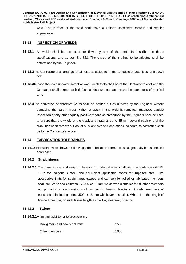
Contract NGNC-01: Part Design and Construction of Elevated Viaduct and 5 elevated stations viz NOIDA SEC -122, NOIDA SEC-123, GR. NOIDA SEC-4, ECOTECH-12, GR. NOIDA SEC-2, (excluding Architectural finishing Works and PEB works of stations) from Chainage 0.00 m to Chainage 9605 m of Noida -Greater Noida Metro Rail Project
NMRC/NGNC-01/Vol-4/OCS Page 264
weld. The surface of the weld shall have a uniform consistent contour and regular
appearance.
11.13 INSPECTION OF WELDS
11.13.1 All welds shall be inspected for flaws by any of the methods described in these
specifications, and as per IS : 822. The choice of the method to be adopted shall be
determined by the Engineer.
11.13.2The Contractor shall arrange for all tests as called for in the schedule of quantities, at his own
cost.
11.13.3In case the tests uncover defective work, such tests shall be at the Contractor’s cost and the
Contractor shall correct such defects at his own cost, and prove the soundness of rectified
work.
11.13.4The correction of defective welds shall be carried out as directed by the Engineer without
damaging the parent metal. When a crack in the weld is removed, magnetic particle
inspection or any other equally positive means as prescribed by the Engineer shall be used
to ensure that the whole of the crack and material up to 25 mm beyond each end of the
crack has been removed. Cost of all such tests and operations incidental to correction shall
be to the Contractor’s account.
11.14 FABRICATION TOLERANCES
11.14.1Unless otherwise shown on drawings, the fabrication tolerances shall generally be as detailed
hereunder.
11.14.2 Straightness
11.14.2.1 The dimensional and weight tolerance for rolled shapes shall be in accordance with IS:
1852 for indigenous steel and equivalent applicable codes for imported steel. The
acceptable limits for straightness (sweep and camber) for rolled or fabricated members
shall be: Struts and columns: L/1000 or 10 mm whichever is smaller for all other members
not primarily in compression such as purlins, beams, bracings & web members of
trusses and latticed girders:L/500 or 15 mm whichever is smaller. Where L is the length of
finished member, or such lesser length as the Engineer may specify.
11.14.3 Twists
11.14.3.1A limit for twist (prior to erection) in :-
Box girders and heavy columns: L/1500
Other members: L/1000

Contract NGNC-01: Part Design and Construction of Elevated Viaduct and 5 elevated stations viz NOIDA SEC -122, NOIDA SEC-123, GR. NOIDA SEC-4, ECOTECH-12, GR. NOIDA SEC-2, (excluding Architectural finishing Works and PEB works of stations) from Chainage 0.00 m to Chainage 9605 m of Noida -Greater Noida Metro Rail Project
NMRC/NGNC-01/Vol-4/OCS Page 265
The twist of the member between any two sections shall be measured with the web
vertical at one of the sections.
11.14.4Camber
11.14.4.1Tolerance in specified camber of structural members shall be + 3 mm.
11.14.5Length
11.14.5.1Tolerance in specified length shall be as follows :
Type of Member Tolerance
A column finished for contact bearing: + 1 mm
Other members (e.g. beams) under 10 m: + 0 and - 3 mm
Other members (e.g. beams) 10 m long and over: + 0 and - 5 mm
11.14.6 Square-Ness at End of Members
11.14.6.1 Beam to beam and beam to column connections where the abutting parts are to be
jointed by butt welds, permissible deviation from the square-ness of the end is :
Beams up to 600 mm in depth : 1.5 mm
Beams over 600 mm in depth : 1.5 mm every 600 mm depth
Up to a max of 3 mm
11.14.6.2 Where abutting parts are to be jointed by bolting through cleats or end plates, the
connections require closer tolerance. Permissible deviation from square ness of the end
is -
Beams up to 600 mm in depth: 1 mm
Over 600 mm in depth: max of 1.5 mm.
11.14.7Butt Joints
11.14.7.1 For full bearing, two abutting ends of columns shall first be aligned to within 1 in 1000 of
their combined length and then the following conditions shall be met:
(a) Over at least 80% of the bearing surface the clearance between the surfaces does not
exceed 0.1 mm.
(b) Over the remainder of the surfaces the clearance between the surfaces does not
exceed 0.3 mm. Where web stiffeners are designed for full bearing on either the top
flange or bottom flange or both, at least half the stiffener shall be in positive contact with
the flange. The remainder of the contact face could have a max. gap of 0.25 mm.
11.14.8 Depth of Member
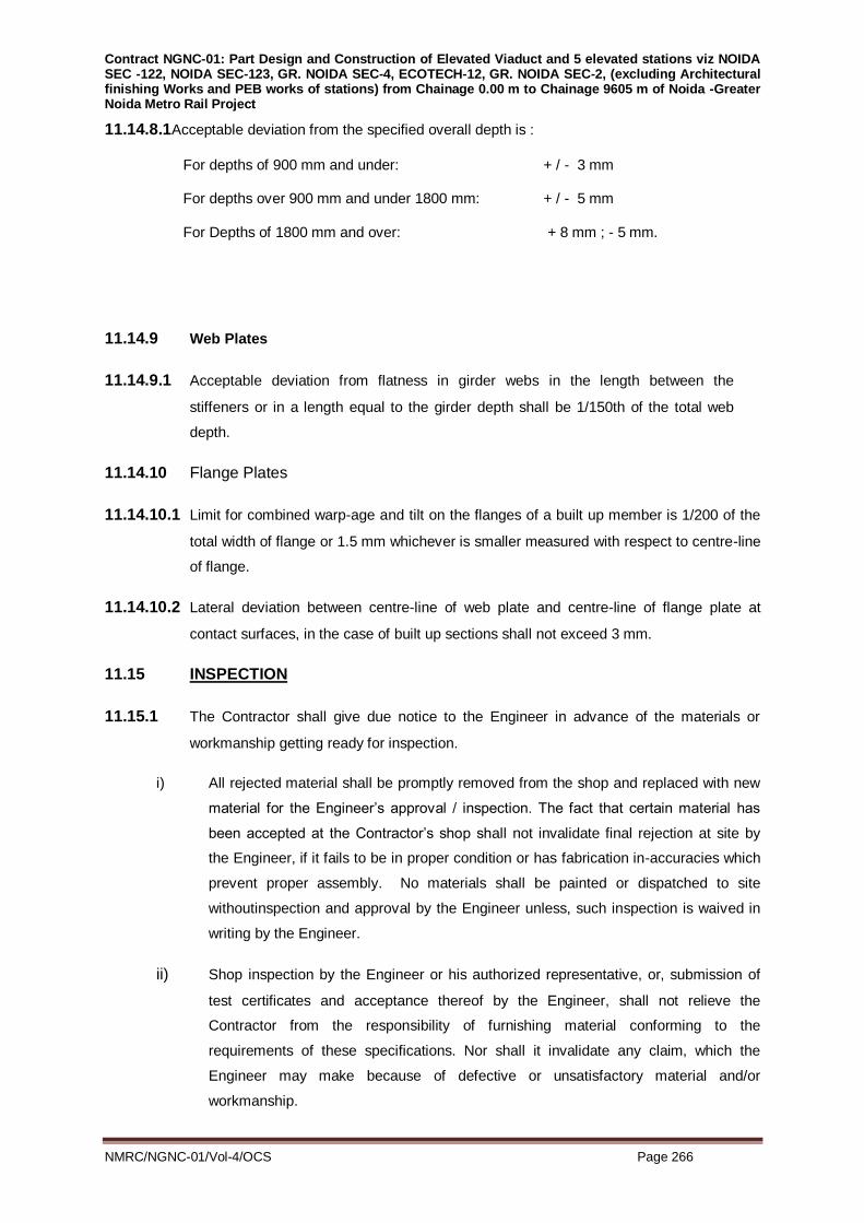
Contract NGNC-01: Part Design and Construction of Elevated Viaduct and 5 elevated stations viz NOIDA SEC -122, NOIDA SEC-123, GR. NOIDA SEC-4, ECOTECH-12, GR. NOIDA SEC-2, (excluding Architectural finishing Works and PEB works of stations) from Chainage 0.00 m to Chainage 9605 m of Noida -Greater Noida Metro Rail Project
NMRC/NGNC-01/Vol-4/OCS Page 266
11.14.8.1Acceptable deviation from the specified overall depth is :
For depths of 900 mm and under: + / - 3 mm
For depths over 900 mm and under 1800 mm: + / - 5 mm
For Depths of 1800 mm and over: + 8 mm ; - 5 mm.
11.14.9 Web Plates
11.14.9.1 Acceptable deviation from flatness in girder webs in the length between the
stiffeners or in a length equal to the girder depth shall be 1/150th of the total web
depth.
11.14.10 Flange Plates
11.14.10.1 Limit for combined warp-age and tilt on the flanges of a built up member is 1/200 of the
total width of flange or 1.5 mm whichever is smaller measured with respect to centre-line
of flange.
11.14.10.2 Lateral deviation between centre-line of web plate and centre-line of flange plate at
contact surfaces, in the case of built up sections shall not exceed 3 mm.
11.15 INSPECTION
11.15.1 The Contractor shall give due notice to the Engineer in advance of the materials or
workmanship getting ready for inspection.
i) All rejected material shall be promptly removed from the shop and replaced with new
material for the Engineer’s approval / inspection. The fact that certain material has
been accepted at the Contractor’s shop shall not invalidate final rejection at site by
the Engineer, if it fails to be in proper condition or has fabrication in-accuracies which
prevent proper assembly. No materials shall be painted or dispatched to site
withoutinspection and approval by the Engineer unless, such inspection is waived in
writing by the Engineer.
ii) Shop inspection by the Engineer or his authorized representative, or, submission of
test certificates and acceptance thereof by the Engineer, shall not relieve the
Contractor from the responsibility of furnishing material conforming to the
requirements of these specifications. Nor shall it invalidate any claim, which the
Engineer may make because of defective or unsatisfactory material and/or
workmanship.

Contract NGNC-01: Part Design and Construction of Elevated Viaduct and 5 elevated stations viz NOIDA SEC -122, NOIDA SEC-123, GR. NOIDA SEC-4, ECOTECH-12, GR. NOIDA SEC-2, (excluding Architectural finishing Works and PEB works of stations) from Chainage 0.00 m to Chainage 9605 m of Noida -Greater Noida Metro Rail Project
NMRC/NGNC-01/Vol-4/OCS Page 267
iii) The Contractor shall provide all the testing and inspection services and facilities for
shop work except where otherwise specified. For fabrication work carried out in the
field, the same standard of supervision and quality control shall be maintained as in
shop fabricated work. Inspection and testing shall be conducted in a manner
satisfactory to the Engineer.
11.15.2 Testing
11.15.2.1 Material Testing
i) If mill test reports are not available for any steel materials, the same shall be got
tested by the Contractor to the satisfaction of Engineer to demonstrate conformity
with the relevant specification.
11.15.2.2 Tests on Welds
Magnetic Particle Test
Only where the Engineer requires that flaw-detection of welds be done by ‘Magnetic
Particle Test’, in such cases the tests are to be done in accordance with IS: 3703. If
heat treatment is performed, the completed weld shall be examined after the heat
treatment. All defects shall be repaired and re-tested. Magnetic particle tests shall
be carried out using alternating current. Direct current may be used with the explicit
written permission of the Engineer.
11.15.2.3 Dye Penetration Test
Where welds are required to be examined by dye penetration inspection method,
such tests shall be carried out in accordance with IS: 3658.
11.15.2.4 Radiographic Inspection
Whether instructed by Engineer, or not, all ‘Butt’ welds shall be fully inspected by
radiographic examination method. Such examination shall be done in accordance with
the recommendations of IS: 1182.
11.15.3 Test Failure
At any stage, in the event of any material or work failing to meet an inspection or test
requirement, which is not overseen by the Engineer, the Contractor shall notify the
Engineer immediately. The Contractor must obtain permission from the Engineer
before repair is undertaken. The quality control procedures to be followed to ensure

Contract NGNC-01: Part Design and Construction of Elevated Viaduct and 5 elevated stations viz NOIDA SEC -122, NOIDA SEC-123, GR. NOIDA SEC-4, ECOTECH-12, GR. NOIDA SEC-2, (excluding Architectural finishing Works and PEB works of stations) from Chainage 0.00 m to Chainage 9605 m of Noida -Greater Noida Metro Rail Project
NMRC/NGNC-01/Vol-4/OCS Page 268
satisfactory repair shall be subject to approval by the Engineer. The Engineer has the
right to specify additional inspection or testing as he deems necessary, and the
additional cost of such testing shall be borne by the Contractor. The Contractor shall
maintain records of all inspection and testing which shall be made available to the
Engineer on demand.
11.15.4 Shop Matching
Some steel work, particularly columns along with tie beams, bracings etc. may have to
be shop assembled to ensure satisfactory fabrication. If the Engineer so desires, he
may order such assembly at shop for verification. The Contractor shall comply with
such instructions without claiming any extra cost.
11.15.5 Shop Assembly
11.15.5.1 The steelwork shall be temporarily shop assembled, as necessary, so that the
accuracy of fit may be checked before dispatch. The parts shall be shop assembled
with a sufficient number of parallel drifts to bring and keep the parts in place.
11.15.5.2 Since parts drilled or punched, with templates having steel bushes shall be similar and,
as such, interchangeable, such steelwork may be shop erected in part only, as agreed
by the Engineer.
11.15.6 Assembly
i) All parts assembled for bolting shall be in close contact over the whole surface.
ii) The component parts shall be so assembled that they are neither twisted nor
otherwise damaged. Specified cambers, if any, shall be provided.
iii) All parts of bolted and welded members shall be held firmly in position by means of
jigs or clamps while bolting or welding. No drifting of holes shall be permitted, except
to draw the parts together and no drift used shall be larger than the nominal
diameter of the bolt. Drifting done during assembling shall not distort the metal or
enlarge the holes.
iv) Trial assemblies shall be carried out at the fabrication stage to ensure accuracy of
workmanship, and these checks shall be witnessed by the Engineer/ Authorised
inspecting agency. Such trial assemblies shall be at the cost of the contractor.
v) Field Bolts
a. Requirements stipulated under bolting shall apply for field bolts also. Field bolts
nuts and washers shall be furnished by the Contractor in excess of the nominal
numbers required. He shall supply the full number of bolts, nuts and washers and
other necessary fittings required completing the work, together with the additional

Contract NGNC-01: Part Design and Construction of Elevated Viaduct and 5 elevated stations viz NOIDA SEC -122, NOIDA SEC-123, GR. NOIDA SEC-4, ECOTECH-12, GR. NOIDA SEC-2, (excluding Architectural finishing Works and PEB works of stations) from Chainage 0.00 m to Chainage 9605 m of Noida -Greater Noida Metro Rail Project
NMRC/NGNC-01/Vol-4/OCS Page 269
bolts, nuts and washers totaling to 10% of the requirement subject to minimum of
10 Nos.
b. At the time of assembly, the surfaces in contact shall be free of paint or any other
applied finish, oil, dirt, loose rust, loose scale, burrs and other defects which
would prevent solid seating of the parts or would interfere with the development
of friction between them.
c. If any other surface condition, including a machined surface, is specified, it shall
be the responsibility of the Contractor to work within the slip factor specified for
the particular case.
d. Each bolt and nut shall be assembled with washers of appropriate shape, quality
and number in cases where plane parallel surfaces are involved. Such washers
shall be placed under the bolt head or the nut, whichever is to be rotated during
the tightening operation. The rotated nut or bolt head shall be tightened against a
surface normal to the bolt axis, and the appropriate tapered washer shall be,
used when the surfaces are not parallel. The angle between the bolt axis and the
surface under the non-rotating component (i.e. the bolt head or the nut) shall be
90 + 3 degree. For angles outside these limits, a tapered washer shall be placed
under the non-rotating component. Tapered washers shall be correctly
positioned.
e. No gasket or other flexible material shall be placed between the holes. The holes
in parts to be joined shall be sufficiently well aligned to permit bolts to be freely
placed in position. Driving of bolts is not permitted. The nuts shall be placed so
that the identification marks are clearly visible after tightening. Nut and bolts shall
always be tightened in a staggered pattern and where there aremore than four
bolts in any one joint, they shall be tightened from the centre of the joint
outwards.
f. If, after final tightening, a nut or bolt is slackened off for any reason, the bolt, nut
and washer or washers shall be discarded and not used again.
11.15.7 Marking of Members
After checking and inspection, all members shall be marked for identification during
erection. This mark shall correspond to distinguishing marks on approved erection
drawings and shall be legibly painted and stamped on it. The erection mark shall be
stamped with a metal dye with figures at least 20 mm high and to such optimum depth
as to be clearly visible, even after a member is galvanized.
All erection marks shall be on the outer surface of all sections and near one end, but
clear of bolt-holes. The marking shall be so stamped that they are easily discernible
when sorting out members. The stamped marking shall be encircled boldly by a

Contract NGNC-01: Part Design and Construction of Elevated Viaduct and 5 elevated stations viz NOIDA SEC -122, NOIDA SEC-123, GR. NOIDA SEC-4, ECOTECH-12, GR. NOIDA SEC-2, (excluding Architectural finishing Works and PEB works of stations) from Chainage 0.00 m to Chainage 9605 m of Noida -Greater Noida Metro Rail Project
NMRC/NGNC-01/Vol-4/OCS Page 270
distinguishable paint to facilitate easy location. Erection marks on like pieces shall be at
identical location. Members having lengths of 7.0 m or more shall have the erection mark
at both ends.
Each fabricated member, whether assembled prior to dispatch or not so assembled,
shall bear an erection mark, which will help to identify the member and its position in
respect of the whole structure, to facilitate re-erection at site. This erection mark shall be
incorporated in the shop detail and erection drawings.
11.15.8 Errors
Any error in shop work which prevents proper assembling and fitting up of parts in the
field by moderate use of drift pins or moderate amount of reaming will be classified by
the Engineer as defective workmanship. All charges incurred by the Engineer either
directly or indirectly because of the poor workmanship will be deducted from the amount
due to the Contractor before payment is made. The amount of such deduction will
consist of the sum total of the costs of labour direct or indirect, material, plant,
transportation, equipment rental and overhead expenses. In case the Engineer chooses
to reject the material because of poor workmanship, the cost of all handling and
returning the material to the Contractor, if he so desires, shall entirely be to the
Contractor’s account. All the replacement materials shall be supplied free and in all
such cases, the cost of handling, transport and delivery to site shall be borne by the
Contractor.
11.15.9 Erection
11.15.9.1 Erection of structural steel fabricated components shall be done generally in accordance
with provisions of IS: 800.
11.15.9.2 Before starting of erection work, the contractor shall ensure the fulfillment of the
following activities:
i) The contractor shall submit, for examination by the Engineer, detailed particulars of his
proposed methods of erection of the superstructure steelwork, together with complete
calculations relating to strength and deflection. If the erection scheme necessitates the
attachment of strength steelwork to the permanent steel work, the contractor shall
submit, for approval of the Engineer, the methods he proposes for making good the
permanent steelwork after removing the temporary work. The contractor shall also
submit the design and fabrication drawings including detailed calculations of temporary
nose, counter weight, all temporary support, staging, braces etc. required for safe
erection, for approval of the Engineer.

Contract NGNC-01: Part Design and Construction of Elevated Viaduct and 5 elevated stations viz NOIDA SEC -122, NOIDA SEC-123, GR. NOIDA SEC-4, ECOTECH-12, GR. NOIDA SEC-2, (excluding Architectural finishing Works and PEB works of stations) from Chainage 0.00 m to Chainage 9605 m of Noida -Greater Noida Metro Rail Project
NMRC/NGNC-01/Vol-4/OCS Page 271
ii) The contractor shall provide all construction and transport equipment, tools, tackle, and
consumables, materials, labour and supervision required for the erection of the
structural steelwork.
iii) Handling, assembling, bolting, welding and satisfactory installation of all fabricated
structural steel materials in proper location, according to approved erection drawings
and/or as directed by the Engineer.
iv) Setting out, aligning, plumbing, leveling, bolting, welding and securely fixing the
fabricated steel structures in accordance with the erection scheme, or as directed by
the Engineer.
11.15.9.3 Grouting under base plates shall be done after erection of the structural steel, unless
otherwise approved by the Engineer. All bearing plates and bearing assemblies shall
be set level and to the elevations shown on drawings. These shall be shimmed with
approved means and grouted to ensure full bearing on the supporting substrate
regardless of the tolerances otherwise permitted. The grout to be used in
superstructure or stanchion bases shall be shrink resistant grouting compound of
approved make and manufacture and shall have a 28 days compressive strength of at
least 30 N/sqmm. The surfaces which have to receive the grout shall be thoroughly
cleaned immediately prior to the grouting operation. The grout shall be carefully worked
under the base plates and shall completely fill the space under the base plates. After
the grout has had its initial set, the grout shall be cut back flush with the base plate as
shown in drawings and surplus grouting material removed. The surplus material thus
removed shall not be re-used. If inserts in concrete are required, the contractor shall
furnish all inserts including any reinforcement required for embedding in the concrete to
the concrete contractor. It should include providing layout drawings to the concrete
contractor for placement of such inserts into concrete.
11.15.9.4 Erection Tolerances
Erection tolerances shall be as per table-1 of ANNEXURE-A.
11.16 QUALITY CONTROL & TESTING REQUIREMENTS
11.16.1 Quality Control through established testing norms of the welded structural
steelwork as per clauses 7.2.2 to 7.2.3 mentioned below or Engineer in charge.
i) The Contractor shall submit the following:
Proposed overall schedule for documentation of shop drawings, plan/procedures and
records, submission of procedure of fabrication.

Contract NGNC-01: Part Design and Construction of Elevated Viaduct and 5 elevated stations viz NOIDA SEC -122, NOIDA SEC-123, GR. NOIDA SEC-4, ECOTECH-12, GR. NOIDA SEC-2, (excluding Architectural finishing Works and PEB works of stations) from Chainage 0.00 m to Chainage 9605 m of Noida -Greater Noida Metro Rail Project
NMRC/NGNC-01/Vol-4/OCS Page 272
The contractor shall himself inspect all materials and shop work to satisfy the
specified tolerance limits and Quality norms before the same are inspected by
Engineer.
ii) The contractor shall through appropriate planning and continuous measurements in the
workshop and the erection at site, ensure that the tolerance specified in ANNEXURE-A
are strictly adhered to.
11.16.2 Fabricating agency shall have in house facilities for all testing of weld.
11.16.3 Visual Examination
The contractor shall conduct visual examination and measurement of the external
dimensions of welds for all joints. Before examining the welded joints, areas close to it
on both sides of the weld for a width not less than 20 mm shall be cleaned of slag and
other impurities. Examination shall be done by a magnifying glass which has a
magnification power of ten (10) and measuring instrument which has an accuracy of +
0.1 mm or by weld gauges. Welded joints shall be examined from both sides. The
contractor shall examine the following during the visual checks.
i) Correctness and shape of the welded joints
ii) Incomplete penetration of weld metal.
iii) Influx
iv) Burns
v) Unwelded craters
vi) Undercuts
vii) Cracks in welded spots and heat affected zones
viii) Porosity in welds and spot welds
ix) Compression in welded joints as a result of electrode impact while carrying out
contact welding
x) Displacement of welded element
The contractor shall, document all data as per sound practices.
11.16.4 In order to exercise proper control of the quality of the welding, Contractor shall enforce
methods of control as tabulated below:
Purpose Control subjects Methods of control
1 2 3
(i) Control of welding
materials and basic
metal quality
Quality control of
electrodes, welding wire,
flux and protective gases.
Checking of quality and
Weldability test to
determine the
technological properties of
materials.

Contract NGNC-01: Part Design and Construction of Elevated Viaduct and 5 elevated stations viz NOIDA SEC -122, NOIDA SEC-123, GR. NOIDA SEC-4, ECOTECH-12, GR. NOIDA SEC-2, (excluding Architectural finishing Works and PEB works of stations) from Chainage 0.00 m to Chainage 9605 m of Noida -Greater Noida Metro Rail Project
NMRC/NGNC-01/Vol-4/OCS Page 273
Weldability of the basic
metal and welded
members
Mechanical test of weld
metal.
Metalographical
investigations of welds
macro-structure and
microstructure.
Checking of weld metal
resistance for
intercrystalline corrosion.
Study if weld metal solidity
by physical control
methods
(ii) Checking of welders
qualifications
Welding of specimens for
quality determination
Mechanical tests,
metalographical
investigation & checking of
welded joints by physical
control methods
Checking of assembly
quality & centering of
welded members
(iii) Control of welded joint
quality
Control of assembly
accuracy and
technological welding
process
Checking of welding
equipment conditions.
Checking correctness of
welding procedure. Visual
examination of welds
11.16.5 Mechanical Test
The Contractor shall carry out various mechanical tests to determine weld-ability, metal
alloy ability, and nature of break, correct size and type of electrodes, degree of pre-heat
and post-heat treatment. The type, scope and sample of various mechanical tests shall
be determined in agreement with the purchaser. The number of tests conducted shall
depend on the result obtained to satisfy the Engineer that the correct type and size of
electrode, degree of pre-heating and post-heating and weld-ability of metal are being
followed.
11.16.6 Dye Penetration Test
All welds (100 %) shall be tested by “Dye Penetration test” as per current practices.
11.16.7 Radiography Test

Contract NGNC-01: Part Design and Construction of Elevated Viaduct and 5 elevated stations viz NOIDA SEC -122, NOIDA SEC-123, GR. NOIDA SEC-4, ECOTECH-12, GR. NOIDA SEC-2, (excluding Architectural finishing Works and PEB works of stations) from Chainage 0.00 m to Chainage 9605 m of Noida -Greater Noida Metro Rail Project
NMRC/NGNC-01/Vol-4/OCS Page 274
Radiography test shall be conducted by the contractor to determine gas inclusion (blow
holes, hollows) slag inclusion, shallow welds and cracks for 100 % lengths all butt
joints. Before conducting the examination the welded joints shall be cleaned of slag and
scales and visually examined. The welds shall be marked into separate portions
depending on the length of photograph. The length of photograph shall be such as to
ensure that there are no distortions and shall reveal the defect correctly. The length
shall not be more than 0.75 of the focal distance and the width of the photograph would
depend on the width of the welded joint plus 20 mm on either side of the weld. The
cassette with film shall be protected by sheet of lead or equivalent of proper thickness
against incidental, diffused and secondary radiation.
The direction of the ray with relation to the film shall be as specified hereunder.
Welds of butt joints without edge slopes with edge processing shall be examined by
central ray directed at right angles to the weld.
In special cases examination of welds with inclined rays directed along edge slopes
may be permitted by the Engineer/ Authorised inspecting agency.
Lap joints shall be examined by directing rays at 45 degree to the bottom plate. Welds
in T-joints, without any edge preparation shall be examined by rays directed at 45
degree to the weld. Angle welds in lap and tee-joints shall be examined by the rays in
opposite direction, i.e. the film will be on the side of the weld. Weld in angle joints shall
be checked by directing ray along the bisector of the angle between the welded
elements. Opposite direction of the ray and location of the film may also be permitted
by the Employer.
11.16.8 Ultrasonic Test
Ultrasonic test shall be conducted by the contractor to detect gas inclusion (pores), slag
inclusion, shallow welds, cracks, lamination and friability etc for the fillet joints. Prior to
starting of ultrasonic test the welded joint shall be thoroughly cleaned of slag and other
material. Surface of the basic metal adjacent to welded joint on both sides shall be
mechanically cleaned by the grinder or a metal brush to provide the contact of the
whole ultrasonic probe surface with surface of basic metal. The width of the clean
surface shall be as directed by the Engineer/ Authorised inspecting agency. The welded
joint then shall be covered with a thin coat of transformer oil, turbine or machine oil to
ensure acoustic contact. The joints so treated shall be marked and the marks shall be
entered into the documentation, subsequent to this, ultrasonic test shall be carried out
as directed by the Engineer. Unless otherwise directed by the Engineer 10% of welds
shall be subjected to ultrasonic testing. Engineer may at his discretion reduce the
frequency of such tests depending on the performance record of earlier tests.
11.16.9 Magnetic particle Test
Based on other test results, or considerations that raises doubts on welded joints at
important locations in the structure, the Engineer may call for Magnetic Particle
Tests of joints. The Contractor shall comply with such requirements, and arrange
for such tests at his own cost.
11.17 PAINTING OF PRE ENGINEERED STRUCTURAL STEEL WORK

Contract NGNC-01: Part Design and Construction of Elevated Viaduct and 5 elevated stations viz NOIDA SEC -122, NOIDA SEC-123, GR. NOIDA SEC-4, ECOTECH-12, GR. NOIDA SEC-2, (excluding Architectural finishing Works and PEB works of stations) from Chainage 0.00 m to Chainage 9605 m of Noida -Greater Noida Metro Rail Project
NMRC/NGNC-01/Vol-4/OCS Page 275
11.17.1 Paint
i) All paint delivered to the fabrication shop shall be ready mixed, in original sealed
containers, as packed by the paint manufacturers. Addition of thinners shall not be
permitted.
ii) Opened containers of Paint shall be stirred frequently to keep the pigment in
suspension
11.17.2 Storage of Paints
i) All paints shall be stored strictly in accordance with the requirements laid down by the
paint manufacturers. The storage area shall be well ventilated and protected from
sparks, flame, direct exposure to sun or excessive heat, preferably located in an
isolated room or in a separate building.
ii) All paint containers shall be clearly labeled to show paint identification, date of
manufacture, batch number, order number and special instructions in legible form. The
containers shall be opened only at the time of use. Paints that have liveried, gelled or
otherwise deteriorated during storage, shall not be used. Paints, for which the shelf life
specified by the supplier has expired, shall not be used without inspection and approval
by the Engineer.
11.17.3 Execution
i) Paint System
a. In general, except where specified otherwise in approved shop drawings Sand
blasting of steel surfaces shall be carried out in accordance with IS:1477.
b. Painting work shall be carried out as follows:
DESCRIPTION GENERAL SURFACE
Fabrication
Shop
External Surfaces Internal Surfaces
Surface
Treatment
Abrasive blast cleaning to minimum SA-
2.5 SIS-055900 near – white blast
cleaning
Abrasive blast
cleaning to minimum
SA-2.5 SIS-055900
near – white blast
cleaning
1st Under–Coat
Inorganic zinc silicate primer (self curing
solvent type) DFT – 75m shall be
Berger Zinc Anode 304 MZ or approved
equivalent. The primer should be
applied by spray only.
Epoxy zinc phosphate
primer polyamide
cured DFT-35m

Contract NGNC-01: Part Design and Construction of Elevated Viaduct and 5 elevated stations viz NOIDA SEC -122, NOIDA SEC-123, GR. NOIDA SEC-4, ECOTECH-12, GR. NOIDA SEC-2, (excluding Architectural finishing Works and PEB works of stations) from Chainage 0.00 m to Chainage 9605 m of Noida -Greater Noida Metro Rail Project
NMRC/NGNC-01/Vol-4/OCS Page 276
2nd Under-Coat
Epoxy zinc phosphate primer polyamide
cured DFT-35m shall be Berger Epilux
610 Primer or approved equivalent. The
primer should be applied by spray or
brush only.
Epoxy zinc phosphate
primer polyamide
cured DFT-35m
shall be Berger Epilux
610 Primer or
approved equivalent.
The primer should be
applied by spray or
brush only.
3rd Under-Coat
Epoxy zinc phosphate primer polyamide
cured DFT-35m shall be Berger Epilux
610 Primer or approved equivalent. The
primer should be applied by spray or
brush only.
Polyamide cured
coaltar epoxy coating
DFT 100m
4th Under-Coat
Epoxy high build micaceous iron oxide
coating polyamide cured DFT-90m
shall be Berger Epilux 4 High Build MOI
or equivallent. The primer should be
applied by spray or brush only
Polyamide cured
coaltar epoxy coating
DFT - 100m
Erection Site External Surfaces
Internal Surfaces
Intermediate
Coat
Acrylic polyurethane finish aliphatic
isocyanate cured DFT-30m shall be
Berger thane or approved equivalent
applied by spray or brush in approved
colour.
NA
Finish Coat
Acrylic polyurethane finish aliphatic
isocyanate cured DFT-30m shall be
Berger thane or approved equivalent
applied by spray or brush in approved
colour.
NA
INTERNAL SURFACE = Internal surface are those which will become inaccessible after
fabrication and are not prone to humidity and moisture from the atmosphere.
EXTERNAL SURFACE = All other surfaces which are prone to humidity and moisture from
the atmosphere.
The following precautions must be taken:
i. After abrasive blast cleaning, the first undercoat (primer coat) should be applied well
before surface deterioration.
ii. At least EPOXY MIO coating application should be completed before giving any long
overcoating interval for external surface.
iii. At least up to one coat of coaltar epoxy shall be completed before giving any long over
coating interval for internal surface.

Contract NGNC-01: Part Design and Construction of Elevated Viaduct and 5 elevated stations viz NOIDA SEC -122, NOIDA SEC-123, GR. NOIDA SEC-4, ECOTECH-12, GR. NOIDA SEC-2, (excluding Architectural finishing Works and PEB works of stations) from Chainage 0.00 m to Chainage 9605 m of Noida -Greater Noida Metro Rail Project
NMRC/NGNC-01/Vol-4/OCS Page 277
iv. Over coating intervals, application parameters shall conform to manufacturer’s
instruction manual.
v. The DFT (Dry film thickness) shall be measured after completion of each coat.
11.17.4 Surface Preparation
11.17.4.1 General
All surfaces shall be cleaned of loose substances and foreign materials. e. g. dirt.rust,
scale, oil, grease, welding flux etc so that the prime coat adheres to the original metal
surface. The work shall be carried out in accordance with IS: 1477 (1971) (Part I). Any
oil.grease, dust or foreign matter deposited on the surface after preparation shall be
removed and care shall be taken to ensure that the surface is not contaminated with
acids, alkalis or other corrosive chemicals. The primer coat shall he applied
immediately after the surface preparation is completed.
Before the application of any paint the surfaces to be treated shall be thoroughly
cleaned freed from all scale, loose paint, rust and other deleterious matters. Oil and
grease shall be removed from the surface by washing with solvents or with a detergent
solution before blast cleaning operation of metal polish with metal pellets. If any traces
of oil or grease remain after blasting they shall be removed by solvent cleaning and the
area will be re-blasted thereafter.
All welding areas shall be given special attention for removal of weld flux slag, weld
metal splatter, weld head oxides, weld flux fumes, silvers and other foreign objects
before blasting. If deemed necessary by the Engineer, acid washing and subsequent
washing with clean water shall be used.
Any rough seams will have to be ground and must be inspected and approved by the
Engineer before application of the coatings.
All structural steel to be painted shall be cleaned. Blast cleaning in accordance with SA
2 1/2 Near- White Blast cleaning (equivalent Swedish Standard SIS 055900). For SA 2
1/2 the profile should be in the range of 40-70 microns and shall be measured with
comparator. Mill scale, rust and foreign matter shall be removed to the extent that the
only traces remaining are light stains in the form of spots or stripes. Finally the surface
shall be cleaned with a vacuum cleaner or clean dry compressed air.
The blast cleaning shall produce a surface roughness complying with the one specified
by the paint manufacturer for the primer concerned. If, cleaned surfaces are rusted or

Contract NGNC-01: Part Design and Construction of Elevated Viaduct and 5 elevated stations viz NOIDA SEC -122, NOIDA SEC-123, GR. NOIDA SEC-4, ECOTECH-12, GR. NOIDA SEC-2, (excluding Architectural finishing Works and PEB works of stations) from Chainage 0.00 m to Chainage 9605 m of Noida -Greater Noida Metro Rail Project
NMRC/NGNC-01/Vol-4/OCS Page 278
are contaminated with foreign material before painting is accomplished they shall be re-
cleaned by the Contractor at his own expenses.
The surface shall be cleaned by impingement of abrasive materials, such as grit of cast
iron, malleable iron, steel or synthetic material, at high velocity created by clean and dry
compressed air blast. Prior to application of the blast, heavy deposits of oil and grease
shall be removed by solvent cleaning and excessive surface scale removed by hand
tool or power tool cleaning.
11.17.5 Mixing and Thinning
a) All ingredients in a paint container shall be thoroughly mixed to break-up lumps and
disperse pigments, before use and during application, to maintain homogeneity. All
pigmented paints shall be strained after mixing to remove skins and other undesirable
matters.
b) Dry pigments, pastes, tinting pastes and colours shall be mixed and/or made into paint
so that all dry powders get wetted by vehicles and lumps and particles are uniformly
dispersed.
c) Additives that are received separate such as curing agents, catalysts, hardeners etc.
shall be added to the paint as per the manufacturer’s instructions. These shall be
promptly used within the pot life specified by the manufacturers and unused paint
thereafter shall be discarded.
d) Thinners shall not be used unless essential for proper application of the paint. Where
thinners are used, they shall be added during the mixing process and the type and
quantity of thinner shall be in accordance with the instructions of paint manufacturer.
11.17.6 Paint Application
a) Paint shall be applied in accordance with the manufacturer recommendations, as
supplemented by these Specifications. The work shall generally follow IS:1477- (Part II).
Prior approval of the Engineer shall be taken in respect of all primers and/or paints
before their use in the works.
b) Paint shall generally be applied by brushing except that spraying may be use for finish
coats only when brushing may damage the prime coats. Roller coat or other method of
paint application shall not be used unless specifically authorized.
c) Spraying paint shall not be adopted on red lead or zinc rich paints. Daubers may be
used only when no other method is practicable for proper application in difficult
accessible areas.
d) Paint shall not be applied when the ambient temperature is 10°C and below. For paints
which dry by chemical reaction the temperature requirements specified by the

Contract NGNC-01: Part Design and Construction of Elevated Viaduct and 5 elevated stations viz NOIDA SEC -122, NOIDA SEC-123, GR. NOIDA SEC-4, ECOTECH-12, GR. NOIDA SEC-2, (excluding Architectural finishing Works and PEB works of stations) from Chainage 0.00 m to Chainage 9605 m of Noida -Greater Noida Metro Rail Project
NMRC/NGNC-01/Vol-4/OCS Page 279
manufacturer shall be met with. Also, paint shall not be applied in rain, wind, fog or at
relative humidity of 80% and above or when the surface temperature is below dew point,
resulting in condensation of moisture. Any wet paint exposed to damaging weather
conditions shall be inspected after drying and the damaged area repainted after removal
of the paint.
Each coat of paint shall be continuous, free of pores and of even film thickness without
thin spots. The film thickness shall not be so great as to detrimentally affect either the
appearance or the service life of the paint.
Each coat of paint shall be allowed to dry sufficiently before application of the next coat,
to avoid damages such as lifting or loss of adhesion. Undercoats having glossy surface
shall be roughened by mild sand papering to improve adhesion of subsequent coats.
Successive coats of same colour shall be tinted. Whenever practical, to produce
contrasts and help in identifying the progress of the work.
11.17.7 Brush Application
i) Proper brushes shall be selected for a specific work piece. Round or oval brushes
which conform to IS: 487 are better suited for irregular surfaces, whereas flat brushes
which conform to IS: 384 are convenient for large flat areas. The width of flat brushes
shall not generally exceed 125mm.
ii) Paint shall be applied in short strokes depositing a uniform amount of paint in each
stroke followed by brushing the paint into all surface irregularities, crevices and
corners and finally smoothening or leveling the paint film with long and light strokes at
about right angles to the first short strokes. All runs and sags shall be brushed out.
The brush marks left in the applied paint shall be as few as practicable.
11.17.8 Spray Application
(i) The spraying equipment shall be compatible with the paint material and provided with
necessary gauges and controls. The equipment shall be cleaned of dirt, dried paint,
foreign matter and solvent before use.
(ii) The paint shall be applied by holding the gun perpendicular to the surface at a
suitable distance and moved in a pattern so as to ensure deposition of a uniform wet
layer of paint. All runs and sags shall be brushed out immediately. Areas not
accessible to spray shall be painted by brush or dauber.

Contract NGNC-01: Part Design and Construction of Elevated Viaduct and 5 elevated stations viz NOIDA SEC -122, NOIDA SEC-123, GR. NOIDA SEC-4, ECOTECH-12, GR. NOIDA SEC-2, (excluding Architectural finishing Works and PEB works of stations) from Chainage 0.00 m to Chainage 9605 m of Noida -Greater Noida Metro Rail Project
NMRC/NGNC-01/Vol-4/OCS Page 280
(iii) Watertrap acceptable to Engineer/ Authorised inspecting agency shall he furnished
and installed on all equipment used in spray painting.
11.17.9 Shop Painting
(i) The painting system specified in Table shall be followed. Surfaces, which will be
inaccessible after field assembly, shall receive the full-specified protective treatment
before assembly.
(ii) Surfaces in contact during shop assembly shall not be painted. Surfaces which can
not be painted but require protection shall be given a rust inhibitive grease conforming
to IS:958-1975 or solvent deposited compound conforming to IS: 1153 (1975) or IS:
1674 (1960) or treated as specified in the drawing.
(iii) Surface to be in contact with concrete shall not be painted.
(iv) The shop coats shall be continuous over all edges, including ends meant for jointing
at site by bolting, except where the paint could be detrimental to bolting. In such
cases, no paint shall be applied within 50mm, and the unprotected surface shall be
given a coat of corrosion inhibitive compound.
(v) The unpainted area shall be cleaned prior to welding. The welded joint shall be
cleaned and deslagged, and immediately after covered by the same paint as has
been used for the remaining surface.
11.17.10 Protection of Paintwork
(i) The Contractor shall provide measures as necessary to prevent damage to the work
and to other property or persons from all cleaning and painting operations. Paint or
paint stains which result in other unsightly appearance on surfaces not designated to
be painted shall be removed or obliterated by the contractor at his cost.
(ii) All painted surfaces that in the opinion of the Engineer/ Authorised inspecting agency
are damaged in anyway, shall be repaired by the contractor at his cost with materials
and to a condition equal to that of the requirements specified in these specifications.
(iii) Upon painted surfaces that in the opinion of any other work that would cause dust,
grease or foreign materials to be deposited upon the painted surfaces, the painted
surfaces shall be thoroughly cleaned.
(iv) The areas for high-strength bolts shall be protected by masking tape against
undercoat application at the fabrication shop. Immediately prior to erection any rust in
the paint area shall be removed by power wire brushing to a standard equivalent to
SA3.
11.17.11 Contractor shall make provision for requisite site painting to all fabricated steelwork,
as per requirements of related specifications of the painting.

Contract NGNC-01: Part Design and Construction of Elevated Viaduct and 5 elevated stations viz NOIDA SEC -122, NOIDA SEC-123, GR. NOIDA SEC-4, ECOTECH-12, GR. NOIDA SEC-2, (excluding Architectural finishing Works and PEB works of stations) from Chainage 0.00 m to Chainage 9605 m of Noida -Greater Noida Metro Rail Project
NMRC/NGNC-01/Vol-4/OCS Page 281
11.17.12 Repair of Paint Defects:
All damage to the previous paint shall be repaired. All loose paints shall be removed
back to firm edge. Surface irregularities and contaminants shall be removed. Hard,
glossy surfaces may require abrading to obtain a suitable surface for painting.
Surfaces, which are to be over coated and which have become contaminated shall be
either be solvent cleaned in accordance with SSPC-SP-1 “Solvent Cleaning” or high
pressure fresh water washed and if required, a suitable detergent may be used.
11.17.13 Inspection :
Testing :
The final paint shall be free from obvious defects and shall be tested by the contractor
as follows :
Film Thickness:
All dry-film thickness limits as specified shall be strictly adhered to. It is recommended
that, in order to achieve the specified dry-film thickness, frequent checks of ET-film
thickness are to be carried during the paint application with wet-film thickness gauges
such as the Elcometer wheel or comb type wheel gauge. The dry film thickness of
individual coats and of the total coating system shall be checked at random over an
area representative of the total work. A minimum of 5 readings shall be taken for each
10 m2 of coated surface. For a surface area less than 10m2a minimum of 3 readings
shall be taken. Additional readings shall be taken if there have been any changes in
application of equipment, spray nozzle size, thinning of paint, etc.
Inspection:
The application work is to be inspected at all stages and finished paint work shall have
the correct shade, degree of gloss and evenness and be free from defects such as
cracks, holidays, runs sags, wrinkles, patches, brush or roller marks, or other defects
that may be detrimental to the quality of the coating. Prior to acceptance of the
paintwork, a final inspection shall be made
11.18 MEASUREMENT
11.18.1.1 Measurement for payment shall be the plan area of the building calculated on the
center lines of peripheral columns.
For variation of height increasing/decreasing by 1 m over the stipulated height of
building, no extra payment shall be made.

Contract NGNC-01: Part Design and Construction of Elevated Viaduct and 5 elevated stations viz NOIDA SEC -122, NOIDA SEC-123, GR. NOIDA SEC-4, ECOTECH-12, GR. NOIDA SEC-2, (excluding Architectural finishing Works and PEB works of stations) from Chainage 0.00 m to Chainage 9605 m of Noida -Greater Noida Metro Rail Project
NMRC/NGNC-01/Vol-4/OCS Page 282
11.19 PRE-COATED STEEL SHEETING FOR ROOFS AND WALLS
11.19.1 Scope Of Work
Coated steel profiled sheet of approved colour shall be installed at roof and side
cladding on steel framing or on any other material at any other location as directed by
the Engineer, and shall be executed as per the details shown on the “Good for
Construction” and approved shop drawings and as per specialist manufacturers
recommendation, complete in all respects. The work shall be executed in flat, tapered,
curved form both in plan and section as required.
11.19.2 Materials
The base material of sheet shall be polyester coated high tensile cold rolled steel as
per AS 1397, coating class AZ 150 (min. 150 gm/m2 zinc aluminium alloy coating
mass, total of both sides) in 0.45 BMT (Base Metal Thickness) with hot-dip metallic
coating of aluminium zinc alloy (ALUMINIUM 55% AND ZINC 45 %) and having a yield
strength not less than 550 Mpa.
11.19.3 Coating
Exterior coating shall be silicone modified polyester (SMP) with 30-50% silicone content
(min.) or Super Polyster XRW quality paint coat of approved colour and 35 microns total
thickness consisting of 20 microns top coat over 5 micron polyester back coat and a 5
micron primer coats on both surfaces including side and end laps.
11.19.4 Sheeting Profile
Sheets shall be profiled with 28-35 mm high crests at 200-300 mm centres, 1000-1015
mm cover width. Lengths up to 12 m shall be in single sheets. Larger lengths, if
practicable should be used in longer slopes. Sheets to have wide pans with
intermediate stiffening ribs for efficient water shedding and strength. Sheets shall be
factory cut and supplied in required sizes based on approved shop drawings. The
panels to possess a curved profile as per the overall profile of the roof.
11.19.5 Single Sheeting

Contract NGNC-01: Part Design and Construction of Elevated Viaduct and 5 elevated stations viz NOIDA SEC -122, NOIDA SEC-123, GR. NOIDA SEC-4, ECOTECH-12, GR. NOIDA SEC-2, (excluding Architectural finishing Works and PEB works of stations) from Chainage 0.00 m to Chainage 9605 m of Noida -Greater Noida Metro Rail Project
NMRC/NGNC-01/Vol-4/OCS Page 283
Single skin trapezoidal profiled sheeting should have 1000-1015mm effective covered
width 28-35 mm crests @ 200-300 mm pitch manufactured out of 0.5 mm TCT (Total
Coated Thickness) Hi-Tensile Galvalume/zincalume steel. The sheets shall have wide
pans with 2-3 nos. stiffening ribs for effective water shedding and special male/female
ends with full return legs on side laps for purlins support and anti-capillary flute in side
lap. The sheets shall have a hot-dip metallic Zinc-Aluminium alloy coating (150
gms/sq.m zinc (45%)/alum (55%). Coating mass total on both sides, AZ-150 or
equivalent as per AS 1397-1993), minimum 550 Mpa yield strength with Silicon
Modified Polyester (SMP) coating (min. silicone content 30%-50%) or Super Polyster
XRW quality paint coat of approved colour. The coating shall be as per AS/NZS-2728
:1997 (category 3). The total coating thickness of 35 microns, comprising of 20 microns
exterior coat of SMP over superpolyster XRW on top surface and 5 micron polyester
reverse on back surface over 5 micron primer coats on both surfaces including side and
end laps. End laps shall not be less than 225 mm.
11.19.6 Double sheeting with Insulation
The top and bottom sheets should be trapezoidal profiled sheeting with 1000-1015mm
effective covered width and 28-35 mm crests @ 200-300 mm pitch manufactured out of
0.45mm BMT (0.5 mm TCT (Total Coated Thickness) excluding paint thickness) Hi-
Tensile Zincalume steel. The sheets shall have subtle flute/wide pans with 2-3 nos.
stiffening ribs for effective water shedding and special male/female ends with full return
legs on side laps for purlins support and anti-capillary flute in side lap. The material shall
be high tensile having 550 Mpa and shall be hot-dip coated with Zinc-Aluminium alloy
(55% Aluminium, 43.5% Zinc, 1.5% Si) as per AS1397/ IS 15961 - AZ150 (minimum
150g/sqm total on both sides) with Silicon Modified Polyester (SMP) coating (minimum
Silicon content 30% - 50%) or Super Polyester XRW quality paint coat of approved
colour. The coating shall be as per AS/NZS-2728:1997 (category 3) and IS 15965. The
total coating thickness of 35 microns, comprising of 20 microns exterior coat of SMP or
super durable polyester XRW on top surface and 5 micron reverse polyester coat on
back surface over 5 micron primer coat on both surfaces including side and end laps for
the top and bottom sheets. End laps shall not be less than 225mm.
The paint system should have stable resin and inorganic pigments for paint durability
and lead free for water harvesting. The fastener size shall be calculated as per the
design for the top and bottom sheet. The sheets shall sandwich a Glass Wool insulation
layer (24kg/cum density) of 50mm thickness with Single side Aluminium Foil facing. GI
Spacer channel/sub girt shall be provided and fixed between the top & bottom sheets as
per the design required and as recommended by the manufacturer. The entire double
skin system shall be installed over the structure purlin.

Contract NGNC-01: Part Design and Construction of Elevated Viaduct and 5 elevated stations viz NOIDA SEC -122, NOIDA SEC-123, GR. NOIDA SEC-4, ECOTECH-12, GR. NOIDA SEC-2, (excluding Architectural finishing Works and PEB works of stations) from Chainage 0.00 m to Chainage 9605 m of Noida -Greater Noida Metro Rail Project
NMRC/NGNC-01/Vol-4/OCS Page 284
11.19.7 Fixing
Sheets shall be fixed to roof purlins and side rails/runners at crest as per manufacturer’s
recommendation and water-tightness provisions using polymer coated galvanized hex
head self-drilling self-tapping (SDST) screws with integral washers and EPDM seals.
The side laps in sheets shall be provided with sealing tapes and screw fasteners with
following properties.
i. Case Hardened Carbon Steel AISI1018/10B21
ii. Screw diameter 5.5mm (In case of Stitching 4.8mm)
iii. Metal Bonded EPDM Washer 2-3mm width 16mm diameter (in case of stitching
14mm diameter)
iv. Organic/Geomet/Dorken/Xylin coating insuring 1000 hour salt spray life
v. EOTA approved
Before laying the sheets the purlin spacing shall be verified. The sheets shall be laid
starting from the eaves or from bottom upward in case of cladding (IS: 3007). The
sheets shall be laid from the end of the building away from prevailing wind so that
exposed edges face down wind. The laps shall be as shown in the approved shop
drawing.
If slope of roof is less than 15 degree, the end lap on roof shall be minimum 225mm and
single length sheets with joint sealed with double sided self-sticking tapes fixed between
two sheets are to be provided.
The contractor shall ensure that panel erector is familiarized with erection procedure and
all the supporting members are straight, level, plumb and true (according to AISC)
before starting panel erection. Panels shall be erected according to approved shop
drawings.
The steel sheet shall be fastened with min. 40 μm zinc coated or min. 20 μm Zinc-Tin
alloy coated, Hex head, self-drilling screw as per AS 3566 Class 3 fasteners of approved
make) with EPDM washer on each crest/ Valley of sheets for connecting with purlin (as
per design).The panels to possess a curved profile as per the overall profile of
the roof (drawings attached).
Approved Sealing tapes shall be used on side laps and end laps of sheets and closers to
be provided at the last end of sheet. Contractor shall give minimum 10 year guarantee
for the sheets against deterioration, disintegration, loss of lustre, variation in color etc.
and leakages across laps, fasteners etc. All types of steel sheets shall be load tested to

Contract NGNC-01: Part Design and Construction of Elevated Viaduct and 5 elevated stations viz NOIDA SEC -122, NOIDA SEC-123, GR. NOIDA SEC-4, ECOTECH-12, GR. NOIDA SEC-2, (excluding Architectural finishing Works and PEB works of stations) from Chainage 0.00 m to Chainage 9605 m of Noida -Greater Noida Metro Rail Project
NMRC/NGNC-01/Vol-4/OCS Page 285
safely carry 1.10 times the design wind loads and coating thickness to the satisfaction of
Engineer-In-charge. Fasteners shall also be load tested. The contractor is to submit
design and shop drawings for approval on the sheet profile, design and details before
installation. The item includes all necessary flashings, trims ridge capping accessories
and fasteners to ensure insulated buildings which is not only functionally compliant but
aesthetically pleasing
Withcontemporary international look.
11.19.8 Shop Drawings and Approvals
Shop drawings shall be prepared for all sheeting work by the contractor and show the
entire installation system including purlin layout, sheet layout, sizes and colour, fixing
details etc. Shop drawings shall be submitted to the Engineer for his approval.
The Contractor shall submit catalogues, design calculations for sheet profile confirming
safe distributed load capacity, samples of all items to be used and samples of
workmanship for approval of the Engineer-in-Charge.
11.19.9 Accessories
The specification for capping, flashing and trims materials shall be same as that for
sheeting and shall be factory formed to required shape and profile based on shop
drawings.
Roofing accessories like flashings (straight or crimp curved), capping etc. shall be
provided from similar coating as used for sheets and shall be fixed by means of self-
drillingself-tapping screws with EPDM washer seals.
11.19.10 Tolerances
Length : +0-10mm
Cover width : + or –6mm
11.19.11 Structural Stability and Guarantee against Rusting/Corrosion
The Contractor shall provide design calculations for sheeting taking into account wind
loads, seismic and other code requirements and guarantee structural stability.
The contractor shall also give guarantee for the sheets against rusting/corrosion,
leakages through laps and fasteners, colour fading etc. for a period of ten years.
11.20 RAIN WATER GUTTER
Rain water gutters shall be fabricated out of 3.15 mm thick galvanized M.S. Sheets. All

Contract NGNC-01: Part Design and Construction of Elevated Viaduct and 5 elevated stations viz NOIDA SEC -122, NOIDA SEC-123, GR. NOIDA SEC-4, ECOTECH-12, GR. NOIDA SEC-2, (excluding Architectural finishing Works and PEB works of stations) from Chainage 0.00 m to Chainage 9605 m of Noida -Greater Noida Metro Rail Project
NMRC/NGNC-01/Vol-4/OCS Page 286
arrangements for incorporating outlets for rainwater down take pipes shall be incorporated in
the fabrication, as per approved drawings and instructions. Gutters shall be Hot-dip
galvanized and painted as per painting specifications of structural steel work. Thickness of
galvanized coating shall not be less than 50 microns. Connections between each section shall
be made water-tight by site seal welding.
11.21 SPECIFICATION FOR LOUVERS
The work for provision of Aluminium Louver pre powder coated for ventilation shall be for
easy escape of hot air which accumulates at the roof of work shop shed to normalize the
ambient temperature in depot shed and result the comfortable feeling of environment for
workmen and normal working of machinery & plants. The work shall comprise :
(i) Design, Fabrication, supply, modification, installation testing and commissioning as
per drawing and BOQ.
(ii) Louver shall consist extruded section of aluminium 4”x1” rectangular pipe frame, c-
channel 2½” x ½ “ with metal framework of 3mm thick sheets, 1.5mm thick S-type
louvers as per drawing enclosed.
(iii) Louver bracket/frame shall be permanently fastened to the existing structure without
damage.
(iv) Any additional support and angle etc. required shall be aluminium and pure polyester
pre powder coated before fabrication/installation.
(v) All friction parts, fastenings or any part remaining, as machined / unpainted shall be
coated with a product to protect them from corrosion until the unit is commissioned.
(vi) The paint (if required) shall be done by two coat of epoxy/polyester paint and one
coat of epoxy primer.
(vii) The contractor shall arrange free of cost supply of resources, scaffolding, materials,
tools, plant, transportation and manpower for fabrication and installation of the
Louver.
(viii) The contractor shall arrange free of cost all material, equipment and accessories
even if not particularly mentioned, necessary to achieve a complete installation in
perfect operating condition.
(ix) The quantity specified in BOQ is approximate and is likely to vary as per site
requirement and performance at the same rate as accepted by competent authority.
Note :
a) Before taking up mass production of louvers, contractor will offer one sample to the
NMRC engineer for inspection and approval.
b) Before taking up fitment of louvers on a large scale, contractor will set up a mock up
free of cost at site and will offer it to NMRC engineer for inspection and approval.

Contract NGNC-01: Part Design and Construction of Elevated Viaduct and 5 elevated stations viz NOIDA SEC -122, NOIDA SEC-123, GR. NOIDA SEC-4, ECOTECH-12, GR. NOIDA SEC-2, (excluding Architectural finishing Works and PEB works of stations) from Chainage 0.00 m to Chainage 9605 m of Noida -Greater Noida Metro Rail Project
NMRC/NGNC-01/Vol-4/OCS Page 287
11.22 POLYCARBONATE SHEETS FOR ROOF LIGHTING
11.22.1 General
11.22.1.1 This section covers the requirements of providing, erecting and fixing of polycarbonate
sheets of approved colour and approved transparency on roofs for the purpose of lighting.
Sheets shall be procured from established and approved manufacturers.
11.22.2 Material
11.22.2.1 Material to be used on roofs shall not be less than 3.0 mm thick, and shall be profiled to
exactly match the profile of pre-coated metal sheets to be used for general roof and side
claddings.
11.22.2.2 Sheets shall be supplied in maximum lengths that can be transported and erected without
causing damage to the sheets, but in any case the lengths shall not be less than 10.0 m.
11.22.2.3 Material shall be free from scratches and other surface damages. These shall be stored
in sheltered places and stacked with intermediate layers of soft puffed plastic sheets.
Stacks shall be covered with and wrapped around with polyethylene sheets to prevent
dust accumulation on the sheets.
11.22.2.4 Material shall be U-V treated and shall be of tested quality. The contractor shall ensure
that the manufacturer provides with the test certificates for the following properties:
Test Procedure Results
Flammability
Self ignition ASTM 1929-3 570 oC
Smoke density ASTM D 2843 54%
Burning extent ASTM D 635 less than 1.0
Weathering
Weathering evaluation ASTM D 4364-84 Successful exposure to
Concentrated Sunlight radiation

Contract NGNC-01: Part Design and Construction of Elevated Viaduct and 5 elevated stations viz NOIDA SEC -122, NOIDA SEC-123, GR. NOIDA SEC-4, ECOTECH-12, GR. NOIDA SEC-2, (excluding Architectural finishing Works and PEB works of stations) from Chainage 0.00 m to Chainage 9605 m of Noida -Greater Noida Metro Rail Project
NMRC/NGNC-01/Vol-4/OCS Page 288
Colour change ASTM D 2244 Not more than 3 units after 60
60 months
Light transmission ASTM D 1003 Shall not decrease more than
10 points after 60 months
-Ditto- -Ditto- Shall not decrease by more than
6% after 10 years
Heat exposure 3000F / 25 mins No darkening effect
Water penetration ASTM E 331 No penetration
Impact ASTM E 822-81 Repels hail storm of 25 mm at
Velocity of 21m/sec
Expansion/contraction Linear thermal change of 0.065
mm / m /oC
U-V Filtration Australian Standard Transmission less than
No. 1067 0.1%
Modulus of Elasticity DIN 53457 24000 kg / sq cm
11.22.3 Submittal
11.22.3.1 Contractor shall submit test reports from manufacturer on all tests.
11.22.3.2 The contractor shall also submit a guarantee that the performance of the sheets supplied
by him shall meet with the requirements of the test certificates to be produced by him.
11.22.4 Installation
11.22.4.1 Sheets shall be installed in sequence as shown in approved shop drawings, and fixed to
purlins with polymer coated, galvanized, hexagon headed self-drilling, self tapping
screws.
11.22.4.2 Side laps shall be as per manufacturers specification. End laps shall be 225 mm. Joints
with metal sheets shall be sealed with Butyl-based adhesive. The edges shall be sealed
with silicone sealant as per manufacturers specification, and then covered with butyl-
based adhesive tapes.
11.22.5 Measurement
11.22.5.1 Contractors quoted rates for sheeting work shall include all materials, tools, plants, all
accessories including fasteners, adhesives, sealants, tapes etc. and labour, all temporary
works complete to the requirement of these specifications and instructions
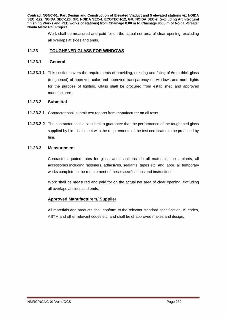
Contract NGNC-01: Part Design and Construction of Elevated Viaduct and 5 elevated stations viz NOIDA SEC -122, NOIDA SEC-123, GR. NOIDA SEC-4, ECOTECH-12, GR. NOIDA SEC-2, (excluding Architectural finishing Works and PEB works of stations) from Chainage 0.00 m to Chainage 9605 m of Noida -Greater Noida Metro Rail Project
NMRC/NGNC-01/Vol-4/OCS Page 289
Work shall be measured and paid for on the actual net area of clear opening, excluding
all overlaps at sides and ends.
11.23 TOUGHENED GLASS FOR WINDOWS
11.23.1 General
11.23.1.1 This section covers the requirements of providing, erecting and fixing of 6mm thick glass
(toughened) of approved color and approved transparency on windows and north lights
for the purpose of lighting. Glass shall be procured from established and approved
manufacturers.
11.23.2 Submittal
11.23.2.1 Contractor shall submit test reports from manufacturer on all tests.
11.23.2.2 The contractor shall also submit a guarantee that the performance of the toughened glass
supplied by him shall meet with the requirements of the test certificates to be produced by
him.
11.23.3 Measurement
Contractors quoted rates for glass work shall include all materials, tools, plants, all
accessories including fasteners, adhesives, sealants, tapes etc. and labor, all temporary
works complete to the requirement of these specifications and instructions
Work shall be measured and paid for on the actual net area of clear opening, excluding
all overlaps at sides and ends.
Approved Manufacturers/ Supplier
All materials and products shall conform to the relevant standard specification, IS codes,
ASTM and other relevant codes etc. and shall be of approved makes and design.

Contract NGNC-01: Part Design and Construction of Elevated Viaduct and 5 elevated stations viz NOIDA SEC -122, NOIDA SEC-123, GR. NOIDA SEC-4, ECOTECH-12, GR. NOIDA SEC-2, (excluding Architectural finishing Works and PEB works of stations) from Chainage 0.00 m to Chainage 9605 m of Noida -Greater Noida Metro Rail Project
NMRC/NGNC-01/Vol-4/OCS Page 290
Annexure-A
Tolerances mentioned below shall be achieved whether the entire structure or part thereof is erected
and made in line, level and in plumb.
S.No. Structure Tolerance
1 Columns
A Deviation of axes at foundation level or at top of anchor
level with respect to true axes: - About both directions
+ 5 mm / - 5 mm
B Deviation in level of bearing surface with respect to true
level at centre line
+ 3 mm / - 3 mm
C Out of plumb-ness of column axis from true vertical,
measured at top of Column: -
For columns up to 15 m in height:
+/- 1/1000 of
column height in
mm -or-
+/- 15 mm
whichever is less.
I For columns up to 15 m in height: 1/1000 of column
height in mm -or-
+/- 15 mm
whichever is less.
Ii For columns exceeding 15 m in height +/- 1/1000 of
column height in
mm-or-
+/- 20 mm
whichever is less.
2. Trusses and Beams
A Shift at the center of span of the top chord member with
respect to vertical plane passing through the center of
bottom chord member
+/- 1/250 of truss
height in mm-or-
+/- 10 mm
whichever is less.
B Lateral shift of top chord of truss / beam at center of span
from the vertical plane passing through the center of
supports of the truss
+/- 1/1500 of span
of truss in mm-or-
+/- 5 mm
whichever is less.
C Lateral shift in location of truss / beam from its true vertical +/- 5 mm

Contract NGNC-01: Part Design and Construction of Elevated Viaduct and 5 elevated stations viz NOIDA SEC -122, NOIDA SEC-123, GR. NOIDA SEC-4, ECOTECH-12, GR. NOIDA SEC-2, (excluding Architectural finishing Works and PEB works of stations) from Chainage 0.00 m to Chainage 9605 m of Noida -Greater Noida Metro Rail Project
NMRC/NGNC-01/Vol-4/OCS Page 291
position
D Lateral shift in in-plane location of beam / purlin from true
position:
+/- 5 mm
E Deviation in difference of bearing levels of trusses or
beams from true levels
+/- 10 mm for
trusses
-and-
+/-5mm for beams

Contract NGNC-01: Part Design and Construction of Elevated Viaduct and 5 elevated stations viz NOIDA SEC -122, NOIDA SEC-123, GR. NOIDA SEC-4, ECOTECH-12, GR. NOIDA SEC-2, (excluding Architectural finishing Works and PEB works of stations) from Chainage 0.00 m to Chainage 9605 m of Noida -Greater Noida Metro Rail Project
NMRC/NGNC-01/Vol-4/OCS Page 292
Annexure – B
A. Approved Manufacturers/ Supplier
All materials and products shall conform to the relevant standard specification, IS codes, IRS
and other relevant codes etc. and shall be of approved makes and design.
The list of approved makes for products and materials is given below. Other equivalent
manufacturers will only be considered with prior approval of the Employer in case of non-
availability or unforeseen difficulties.
B. List of Approved Manufacturers/ Suppliers
AS PER NMRC APPROVED LIST OF MANUFACTURER’S /SUPPLIERS

Contract NGNC-01: Part Design and Construction of Elevated Viaduct and 5 elevated stations viz NOIDA SEC -122, NOIDA SEC-123, GR. NOIDA SEC-4, ECOTECH-12, GR. NOIDA SEC-2, (excluding Architectural finishing Works and PEB works of stations) from Chainage 0.00 m to Chainage 9605 m of Noida -Greater Noida Metro Rail Project
NMRC/NGNC-01/Vol-4/OCS Page 293
Annexure- C
Design Criteria and Material Specifications for Pre- Engineered Buildings (PEB)
1.0 For the purpose of preparing their offers, all bidders are required to follow the general and
special requirements of design criteria and material specifications as laid down in this
Annexure to the particular specifications.
2.0 Requirements given below are in addition to the Particular specifications laid down for the
various items of work.
3.0 NMRC reserves the right to modify these requirements at the final design stage. Suppliers will
not be entitled to claim extra over their quoted prices on account of such changes in
requirements.
Part 1: General Requirements for all Buildings
4.1 General
Pre-Engineered Buildings or building components wherever specified shall be designed,
supplied and erected by a specialist agency called PEB manufacturer approved by the
Engineer. All codes and standards for material, design, fabrication and erection shall
generally be as indicated for structural steel work unless the following specifications call for a
deviation otherwise. PEB manufacturer shall use Submerged Arc Welding for built-up
sections, meeting the applicable requirements of the American Welding Society (A.W.S)
D1.1.98.
The agency responsible for design, fabrication and erection shall not be allowed to sub-let
any of the activities/operations to another sub-agency in anyway unless a prior written
approval of the Engineer is taken. The agency for PEB should have an ISO 9001 certification
for manufacture of PEBs. Contractor shall submit all design drawings, erection drawings,
fabrication design and drawings for approval by NMRC/DDC prior to commencement of
fabrication works.
4.2. Design Specifications for PEB Buildings
The PEB manufacturer shall be responsible for carrying out all the design of PEB’s as per
following relevant IS codes only.
a) IS:800 Code of Practice for general construction in steel
b) IS:801 Cold formed sections
c) IS:811 Cold formed sections
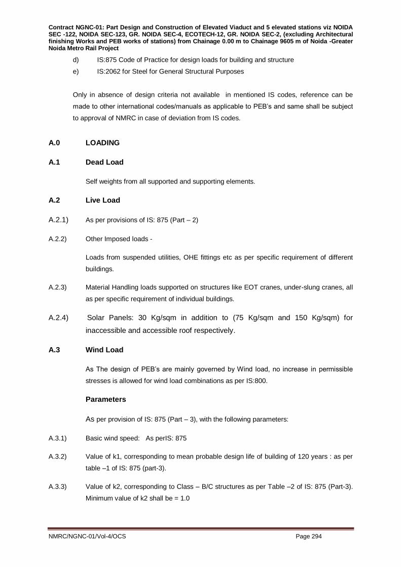
Contract NGNC-01: Part Design and Construction of Elevated Viaduct and 5 elevated stations viz NOIDA SEC -122, NOIDA SEC-123, GR. NOIDA SEC-4, ECOTECH-12, GR. NOIDA SEC-2, (excluding Architectural finishing Works and PEB works of stations) from Chainage 0.00 m to Chainage 9605 m of Noida -Greater Noida Metro Rail Project
NMRC/NGNC-01/Vol-4/OCS Page 294
d) IS:875 Code of Practice for design loads for building and structure
e) IS:2062 for Steel for General Structural Purposes
Only in absence of design criteria not available in mentioned IS codes, reference can be
made to other international codes/manuals as applicable to PEB’s and same shall be subject
to approval of NMRC in case of deviation from IS codes.
A.0 LOADING
A.1 Dead Load
Self weights from all supported and supporting elements.
A.2 Live Load
A.2.1) As per provisions of IS: 875 (Part – 2)
A.2.2) Other Imposed loads -
Loads from suspended utilities, OHE fittings etc as per specific requirement of different
buildings.
A.2.3) Material Handling loads supported on structures like EOT cranes, under-slung cranes, all
as per specific requirement of individual buildings.
A.2.4) Solar Panels: 30 Kg/sqm in addition to (75 Kg/sqm and 150 Kg/sqm) for
inaccessible and accessible roof respectively.
A.3 Wind Load
As The design of PEB’s are mainly governed by Wind load, no increase in permissible
stresses is allowed for wind load combinations as per IS:800.
Parameters
As per provision of IS: 875 (Part – 3), with the following parameters:
A.3.1) Basic wind speed: As perIS: 875
A.3.2) Value of k1, corresponding to mean probable design life of building of 120 years : as per
table –1 of IS: 875 (part-3).
A.3.3) Value of k2, corresponding to Class – B/C structures as per Table –2 of IS: 875 (Part-3).
Minimum value of k2 shall be = 1.0

Contract NGNC-01: Part Design and Construction of Elevated Viaduct and 5 elevated stations viz NOIDA SEC -122, NOIDA SEC-123, GR. NOIDA SEC-4, ECOTECH-12, GR. NOIDA SEC-2, (excluding Architectural finishing Works and PEB works of stations) from Chainage 0.00 m to Chainage 9605 m of Noida -Greater Noida Metro Rail Project
NMRC/NGNC-01/Vol-4/OCS Page 295
A.3.4) Value of k3, as per clause 5.3.3.1 of IS: 875 (Part-3)
A.3.5) Local wind effects to be taken as per provisions of IS: 875 (Part-3), corresponding to
building plan size, height, shape and direction of wind.
The local external wind pressure coefficient shall be taken strictly for the local zones as
shown in relevant tables of IS:875. The internal and local external coefficients shall be
combined for design of roof sheeting, glass panels, individual cladding units, girts and
purlins falling in high local pressure zones shown in relevant tables of IS:875.
A.4 Earthquake Load
As per provisions of IS: 1893 for Zone –IV.
A.5 Temperature Effects:
As per IS: 875 (Part-5).
A.6 Load Combinations: As per IS: 800 (2007)
B.0 DESIGN REFERENCES
B.1 All designs shall be done in accordance with BIS- Standards as per specification of works.
B.2 Only in the case of design criteria not being available in Indian Standard Codes, reference
can be made to other International Codes / Standards / Manuals, as applicable to Design of
Steel structures of the type specified.
Use of standards other than BIS Codes shall be subject to approval of NMRC.
C.0 DEFLECTION LIMITS
Deflection limits of members shall generally be as per relevant clause of IS: 800, but with the
following provison –
ii) Maximum deflection limit for purlins checked under various combinations of dead loads
and imposed loads is to be restricted to span/250.
For combinations of dead, imposed and wind loads, purlin deflection is to be limited to
span / 200.
iii) For columns in a single storey building, maximum horizontal deflection at the cap of
columns due to worst combination of forces should not exceed the following limits:
Load combination For columns not supporting For columns supporting

Contract NGNC-01: Part Design and Construction of Elevated Viaduct and 5 elevated stations viz NOIDA SEC -122, NOIDA SEC-123, GR. NOIDA SEC-4, ECOTECH-12, GR. NOIDA SEC-2, (excluding Architectural finishing Works and PEB works of stations) from Chainage 0.00 m to Chainage 9605 m of Noida -Greater Noida Metro Rail Project
NMRC/NGNC-01/Vol-4/OCS Page 296
(Worst of) crane gantry girders crane gantry girders
DL, LL, WL/EQ l / 325 l / 425
DL, LL, WL/EQ & Temp l / 250 l / 425
‘l’ is the actual length of the column.
iv) Maximum permissible deflection at tip of cantilevers shall be limited to span / 750.. For
deflection of cantilevers at any other locations a limit of Span / 500 shall be followed.
v) For other load combination permissible deflection shall be as per Table 6, IS-800-2007
.For rafter L/750 for Inspection Bay only due to Under Slung Crane.
D.0 GENERAL INSTRUCTION & RESPONSIBILITY
D.1 It’s the responsibility of PEB supplier to account for design loads of the cranes, gantries, OHE
drop arm loads etc. in design of PEB’s. The connection detail and related accessories/fixtures
to fix all above miscellaneous units to PEB frames is also responsibility of PEB supplier.
Sufficient strengthening measures shall be taken in the portals due to these loads.
D.2 The fabrication drawings along with necessary design calculation for connections etc. should
also be submitted by PEB supplier before start of fabrication for NMRC’s approval.
D.3 The cold formed sections shall be designed strictly based on IS: 801-1975. The cold formed
sections should be designed as stiffened /unstiffened section based on lip dimension
satisfying the section requirements of stiffened/unstiffened section.
D.4 The overlapping of two cold formed section to enhance section properties is normally not
permitted. However if PEB contractor wants to use nested purlin then connection of nested
purlin should also be designed to cater for in plane shear and moment so that nested
behaviour can be achieved. At the locations of splicing in the continuous purlins separate
splicing piece, suitably designed, shall be provided.
D.5 Following items shall be reviewed/clarified and clearance obtained by the PEB supplier before
start of design of PEB buildings:-
(i) Plan dimensions of the buildings.
(ii) Height of cladding for buildings.
(iii) Door opening sizes
(iv) Crane load requirement and OHE drop arm loading details.
(v) Specification for painting accounting for exposure condition.
(vi) Steel grade for portals and cold formed sections.
(vii) Minimum thickness requirements for cold formed sections and structural steel

Contract NGNC-01: Part Design and Construction of Elevated Viaduct and 5 elevated stations viz NOIDA SEC -122, NOIDA SEC-123, GR. NOIDA SEC-4, ECOTECH-12, GR. NOIDA SEC-2, (excluding Architectural finishing Works and PEB works of stations) from Chainage 0.00 m to Chainage 9605 m of Noida -Greater Noida Metro Rail Project
NMRC/NGNC-01/Vol-4/OCS Page 297
members.
(viii) Use of stiffener plates for built-up portals.
(ix) Use of HSFG bolts for base connections.
(x) Liberty of using portal spacing to achieve economy providing they satisfy the
architectural/operational requirement and door/window opening sizes.
(xi) Expansion joint requirements for PEB’s.
(xii) Pitch for rafter members.
(xiii) No. of continuous span for design of purlin and roof sheeting.
D.6 Responsibilities
It may be noted that the foundation and pedestal upto plinth level including prior fixing of
anchor bolts for steel column shall be constructed by the main civil contractor. All the steel
work above this level shall be entirely carried out by the PEB manufacturer. All other civil
work e.g. flooring, brickwork etc. shall be carried out by the main civil contractor and paid for
as per the relevant item of BOQ.
D.7 Upon receiving comments on the designs and drawings, PEB manufacturer shall carry out all
modifications within the stipulated time schedule and get the same approved before carrying
out any activity relating to the same.
D.8 Well qualified, approved personnel of the PEB manufacturer shall be available at the site
during all operations relating to the PEBs. Qualified personnel of the PEB manufacturer shall
carry out the necessary assembly and erection at the site.
D.9 All components of PEBs shall be fabricated, manufactured, sand blasted where required and
primed at the PEB manufacturer's works. No site fabrication shall be allowed.
E.0 MATERIAL SPECIFICATION
E.1 All structural components other than purlin /side runners shall be made from Hot Rolled
sections and plates with Grade B0 having a minimum yield stress of 250 Mpa, conforming to
IS 2062.
Minimum plate thickness shall be 6mm..
E.2 Purlin and side runners only, shall be made of from cold form sections out of material shall
conform to ST-34 -1079 of IS 1079/ASTM A570 Gr 50 with min Yield Strength of 345 Mpa or
Equivalent(IS 5986:2009 –Gr Fe 490,Yst 355 Mpa/ IS 1079:2009, Gr HR5, Yst 340 Mpa).
Minimum metal thickness for Cold Formed Sections shall be 3.15 mm, UNLESS
SPECIFICALLY PERMITTED BY Engineer-in-Charge / Structural Consultants.

Contract NGNC-01: Part Design and Construction of Elevated Viaduct and 5 elevated stations viz NOIDA SEC -122, NOIDA SEC-123, GR. NOIDA SEC-4, ECOTECH-12, GR. NOIDA SEC-2, (excluding Architectural finishing Works and PEB works of stations) from Chainage 0.00 m to Chainage 9605 m of Noida -Greater Noida Metro Rail Project
NMRC/NGNC-01/Vol-4/OCS Page 298
E.3 Unless noted otherwise all field connections shall be bolted with high strength bolts of Class
8.8. Close tolerance, or bolts in clearance holes may be used as per requirement of design.
E.4 Holding down bolts shall be of property class 4.6 (Grade-B) conforming to IS: 1367
And shall be in accordance with IS: 5624.
E.5 Cladding on roof and sides of buildings shall be done with pre-formed, polyester coated
galvanized steel sheets of minimum thickness 0.50 mm (TCT) of approved colour.
E.6 Roof lighting sheets shall be out of 3 mm thick, high impact strength, U-V treated,
Polycarbonate sheets of approved colour / transparency, placed at suitable locations on roofs
(in place of metal cladding sheets). Area of such sheets shall be generally limited to a
maximum of 15% of the total roof area.
E.7 Rainwater gutters for all buildings shall be made out of 3.15 mm thick hot dipped galvanized
mild steel sheets, with provision for connecting down-take pipes of appropriate size and at
designed locations.Sizes of rainwater pipes and their locations will be decided at the time of
final design.
F.0 ROOF SLOPE
F.1 All buildings in steel construction shall have normally slopes of 1-vertical to 10 –horizontal or
as per drawing.
Purlins shall be placed normal to the slope.
G.0 LIMITATIONS ON DESIGN ASSUMPTIONS
G.1 Purlins & Side-Cladding Runners
G.1.1 If purlins / runners are assumed to be continuous over supports, continuity shall have to be
developed at supports through proper connections to absorb the continuity moments.
G.1.2 In case of continuous purlins / runners, temperature effects need to be considered, and such
forces need to be transferred down to the foundation through the main structure and
appropriate bracing or other force transfer- systems.
G.1.3 Sag-rods and / or sag-struts may be provided as per requirements of economic design.
G.2 Columns/Portal Frame
G.2.1 Portal Frame Not Supporting Crane Gantry Girder:

Contract NGNC-01: Part Design and Construction of Elevated Viaduct and 5 elevated stations viz NOIDA SEC -122, NOIDA SEC-123, GR. NOIDA SEC-4, ECOTECH-12, GR. NOIDA SEC-2, (excluding Architectural finishing Works and PEB works of stations) from Chainage 0.00 m to Chainage 9605 m of Noida -Greater Noida Metro Rail Project
NMRC/NGNC-01/Vol-4/OCS Page 299
The portal frame shall be analyzed semi fixed base with 70% fixity and 30% release and
hinge base and the combination of load cases which gives maximum forces shall be
considered for design of foundation, holding down bolts, column main rafters and
connections.
G.2.2 Portal Frame Supporting Crane Gantry Girder:
Column supporting crane gantry girder shall be considered as “Fixed Base”.
However portal frame shall be analyze for fixed base & hinge base the combination of load
cases which gives maximum forces shall be considered for design of foundation, holding
down bolts, column main rafters and connections.
G.2.3 All columns shall be of ‘Solid web’ sections. These can be of standard hot rolled sections or
‘built up’ sections. Profiling of the sections is permissible if so desired by the suppliers.
G.3 Roof Rafters
G.3.1 Roof rafters shall also be solid web sections, either standard hot rolled or built-up, depending
on suppliers design. Trusses and castellated sections will not be acceptable.
G.3.2 Connections of rafters to columns shall be through rigid welded/ bolted joints only.
G.4 Other Elements
G.4.1 Eaves beams, other longitudinal beams along column lines shall also be of solid web
sections. These may be connected through bolts or welds as per design requirements of
supplier.
G.4.2 Crane gantry girders shall be of solid-web sections, either compound or single built up.
G.4.3 Foundation and other holding down bolts shall be sized as per design requirement of various
components being connected.
G.4.4 For the purpose of analysis and design of sections, starting level of columns at base shall
generally be considered as 800 mm below floor level. The exact depth of fixity of columns
shall be got clarified from Structural Consultants before the final analysis / design is taken up
by the supplier.
Part 2:Special Requirements for Individual Buildings
A.0 INSPECTIONBAY

Contract NGNC-01: Part Design and Construction of Elevated Viaduct and 5 elevated stations viz NOIDA SEC -122, NOIDA SEC-123, GR. NOIDA SEC-4, ECOTECH-12, GR. NOIDA SEC-2, (excluding Architectural finishing Works and PEB works of stations) from Chainage 0.00 m to Chainage 9605 m of Noida -Greater Noida Metro Rail Project
NMRC/NGNC-01/Vol-4/OCS Page 300
A.1 Roof elements in the bay are required to support runway beams for under-slung EOT cranes.
Deflection limit for these roof rafters shall be restricted to span / 750.Runway beams should
be suspended from roof rafters such that bottom levels of all runway beams are at specified
elevation (to be got confirmed from Engineer-in Charge. All such hangers shall be properly
braced longitudinally and transversely to prevent sway.
A.2 Twounder-slung cranes (lifting capacity of each cranes is 1.5T) are required to operate above
two tracks within the bay. For the purpose of design, all cranes shall be considered to have
wheel- bases of 1600 mm. Maximum wheel load shall be taken as 1.0T and corresponding
minimum wheel load shall be taken as 0.5 T. When the cranes are centrally positioned, all
four wheels should be considered as transferring 0.75 T of reaction on to the runway beams.
Roof rafters and runway beams shall be designed for these specific loads.
A.3 A uniform load of 15 Kg/sqm of plan area shall be considered as load from suspended utilities
to be supported by the structure.
A.4 Inspection bay would have cantilevered elevated inspection platforms made in steel. The
deck of the platform is to be built out of 5 mm thick chequered plates. The central platform is
supported on posts at 8.0 m centers. Side platforms are alternately supported on main
columns for each span and are cantilevered. The platforms shall be provided with handrails
as indicated in Drawings. Design load for these platforms shall include a point load of 1.25 T
that may be placed anywhere on the deck. When one such load is considered at one location,
the other load need not be considered at less than a distance of 10m from the first load. In
addition the platform shall be designed for a uniform imposed load of 250 kg/sqm. A uniform
loading (DL) (Chequered Plate) of 40 Kg/sqm at Inspection Platform.
A.5 Rail tracks in the Inspection bay are to be supported on steel posts spaced 1200 mm centers
along the track as indicated in the drawings. The posts are to be designed for full axle load
from a Standard Gauge [SG] Rail Coach, as given below: -
No. of axles per coach = 4nos.
No. of bogies per coach = 2 nos.
No. of axles per bogie = 2 nos.
Coach axles centre to centre = 15000 mm.
Overall Coach length = 22,500 mm.
Axle load = Maximum 17.0 T; Minimum = 8.0 T.
B.0 WORKSHOP
B.1 The workshop is being planned with a single bay of 21m wide and 212.00 m length.

Contract NGNC-01: Part Design and Construction of Elevated Viaduct and 5 elevated stations viz NOIDA SEC -122, NOIDA SEC-123, GR. NOIDA SEC-4, ECOTECH-12, GR. NOIDA SEC-2, (excluding Architectural finishing Works and PEB works of stations) from Chainage 0.00 m to Chainage 9605 m of Noida -Greater Noida Metro Rail Project
NMRC/NGNC-01/Vol-4/OCS Page 301
B.2 The workshop bay shall have two EOT cranes that would operate in tandem for full length of
shop. Crane rail level for all the bays shall be at an elevation of 8500 mm. from shop floor top
level.(Top of Rail Level)
B.3 Main hoist lifting : One EOT Crane in Workshop bay will have the main hoist capacity as 15T.
and auxiliary hoist capacity shall be of 2T. The second EOT Crane main hoist capacity will be
5T and auxiliary hoist capacity shall be 05./1T.
B.4 Wheel-base for all cranes should be considered as 3900 mm [This dimension of wheel base
shall have to be got confirmed from the Engineer-in Charge before starting ‘Final Design’.
Minimum distance between centers of wheels of two cranes in tandem shall be considered as
600 mm.
B.5 For design of gantry girders and for arriving at maximum and minimum reactions at end and
intermediate columns, wheel reactions for the cranes shall be as follows: -
B.6 Uniform load of 15 Kg/sqm of plan area shall be considered as load from suspended utilities
to be supported by the structure.
C.0 INTERIOR CLEANING BUILDING
C.1 Special imposed load would include one number OHE-Drop arm and a uniform load of 10 Kg /
sqm of plan area to be supported by the structure.
C.2 Interior cleaning bay would have one elevated / roof level inspection platform made in steel.
D.0 PITWHEELLATHEBUILDING
D.1 Wheel base for the Crane to be considered for design shall be 1300 mm.Maximum wheel
reaction of 3.6 T, and corresponding minimum wheel reaction of 1.45 T. shall be considered
for design of gantry girder and Structural Frame work.
D.2 Pit Wheel Lathe would have one EOT Crane of 5.0 T. capacity.
E.0 BLOW DOWN PLANT
E.1 Special imposed load would include one numbers OHE- Drop arms and a uniform load of 10
kg / sqm of plan area to be supported by the structure.
F.0 SHED FOR RGM
F.1 Non-OHE shed to be utilized for parking of Rail Grinding Machine
F.2 Shed would have one 30m long pit for maintenance of Rail Grinding Machine.
G.0 GANTRY FOR ETU BUILDING EOT CRANE

Contract NGNC-01: Part Design and Construction of Elevated Viaduct and 5 elevated stations viz NOIDA SEC -122, NOIDA SEC-123, GR. NOIDA SEC-4, ECOTECH-12, GR. NOIDA SEC-2, (excluding Architectural finishing Works and PEB works of stations) from Chainage 0.00 m to Chainage 9605 m of Noida -Greater Noida Metro Rail Project
NMRC/NGNC-01/Vol-4/OCS Page 302
G.1 Gantry girders to be provided for 5T crane in ETU Building
H.0 CAR PARKING, CYCLE SHED, CABLE STORE SHED (ETU), VANJEX PARKING,
S & T, CABLE STORE AND DIESEL STORE
H.1 These are proposed to be made out of tubular steel pipes/I-Sections. Cantilever structures
supported with central row of built up columns supporting inverted butterfly roof in Metal sheet
with no insulation are to be provided for car and cycle parking. For cable stores and Vanjex
parking the structure is to be supported at all ends with tubular columns &beams/I - Sections
and supporting inclined roof in metal corrugated sheeting.
I.0 WATCH TOWERS
These are proposed to be made out of I-sections. The structure is supported with built up
columns and beams tied at approx. every 3m with overall height of approx. 15m from FFL.
and supporting inclined roof in metal corrugated sheet with no insulation. It should also have a
railing along the staircase and the upper deck level. The railing should have an overall height
of 1200mm with metal sheeting upto a height of 1000mm. The watch towers are 4 in nos.
Contract NGNC-01: Part Design and Construction of Elevated Viaduct and 5 elevated stations viz NOIDA SEC -122, NOIDA SEC-123, GR. NOIDA SEC-4, ECOTECH-12, GR. NOIDA SEC-2, (excluding Architectural finishing Works and PEB works of stations) from Chainage 0.00 m to Chainage 9605 m of Noida -Greater Noida Metro Rail Project
NMRC/NGNC-01/Vol-4/OCS Page 303
SECTION – S.12
WATER PROOFING
Cut and Cover Construction and Under Ground Station Buildings
12 WATERPROOFING
12.1 GENERAL
Submission, Requirements, Method Statement & Working Drawings.
The Contractor shall include details of his intended waterproofing methods in his design
submission for acceptance by the Employer representative.
Manufacturer's literature shall be provided where necessary to confirm the suitability of the
proposed details.
The contractor shall produce and submit comprehensive Working Drawings showing all
details and procedures for Waterproofing of works.
12.2 WATERPROOFING APPLICATION
Waterproofing material shall be installed only by the manufacturer of the products or his
approved applicator. The contractor shall submit a method statement prepared in
conjunction with the applicator and certified by the manufacturer of the material,
describing the details of waterproofing works including protective measures at all
stages.
12.3 STRUCTURAL CONCRETE WORKS
a) Concrete Joints:
Notwithstanding the provision of waterproofing system, the contractor shall construct his
concrete works so as to minimize the likely hood of water penetration. All construction
joints shall be treated in accordance with Annexure D of this specification.
b) Water-stops:
Water-stops used in the work shall be Swell-able type Bentonite- Bitumen based
material. The water-stop shall be installed so that they are securely held in their correct
positions while the concrete is being placed. Further details of the Water-stops are
provided in Annexure D.
c) Fillers and Sealants to Expansion Joints.

Contract NGNC-01: Part Design and Construction of Elevated Viaduct and 5 elevated stations viz NOIDA SEC -122, NOIDA SEC-123, GR. NOIDA SEC-4, ECOTECH-12, GR. NOIDA SEC-2, (excluding Architectural finishing Works and PEB works of stations) from Chainage 0.00 m to Chainage 9605 m of Noida -Greater Noida Metro Rail Project
NMRC/NGNC-01/Vol-4/OCS Page 304
All materials used to fill expansion joints shall be such that they will accept the
calculated movements of the joints without extrusion and shall not shrink away from
either surface of the joints. Backing strips and fillers shall be used in accordance with the
manufacturer's recommendation. Where joints are required to be filled with polysulphide
or polyurethane sealants, the material shall comply with BS 4254 or BS 5212.
The appropriate sealant grade shall be used for horizontal &Vertical joints and the
joints shall be thoroughly cleaned and primed with appropriate primer before applying
sealant . The sealant shall be of colour as nearly as possible to the colour of the
adjoining surface where it is permanently exposed.
The sealing material shall be used and applied strictly in accordance with the
manufacturer's instructions. The Contractor's attention is drawn to undesirability of the
sealant being smeared over the adjacent surface and appropriate precautionary
measures, including the use of masking tape shall be taken to avoid this.
12.4 WATERPROOFING OF UNDERGROUND STRUCTURE.
The following requirements are applicable to all underground structures built by Cut and
cover methods and underground station building where integral crystalline waterproofing
method has been specified.
The complete method statement for the works shall be submitted to the Engineers with
relevant method statement prior to application of the system. The method statement
shall include all QC/QA procedure required to ensure the integrity of system.
Proposed manufacturer and applicator should have similar experience. The proposed
manufacturer shall have an ISO certified andapproved plant of international repute.
a) Base Slab.
Waterproofing shall be done using Integral Crystalline Waterproofing admixture admixed
to the concrete in accordance with Annexure A
b)
i) External Walls to Structure Built in Open Excavation.
Waterproofing shall be done using Integral Crystalline Waterproofing admixture
admixed to the concrete in accordance to Annexure A
ii) ExternalWallsBuiltagainstpiles or Rock orSoilFaces.
Waterproofing shall -be done using Integral Crystalline Waterproofing admixture
admixed to the concrete in accordance to Annexure A.

Contract NGNC-01: Part Design and Construction of Elevated Viaduct and 5 elevated stations viz NOIDA SEC -122, NOIDA SEC-123, GR. NOIDA SEC-4, ECOTECH-12, GR. NOIDA SEC-2, (excluding Architectural finishing Works and PEB works of stations) from Chainage 0.00 m to Chainage 9605 m of Noida -Greater Noida Metro Rail Project
NMRC/NGNC-01/Vol-4/OCS Page 305
iii) Diaphragm Wall
Waterproofing shall -be done using Integral Crystalline Waterproofing admixture
admixed to the concrete in accordance to Annexure A.
For b (i to iii):
Where pipe penetration is required through wall, this shall be treated in accordance with
Annexure E of this specification.
All construction joints shall be treated in accordance with Annexure D of this
specification.
c) Roof/Top-Slab
Waterproofing shall be done using Integral Crystalline Waterproofing admixture admixed
to the concrete in accordance with Annexure A of this specification. Construction joints
shall be treated in accordance with Annexure D of this specification. The roof slab will
be additionally treated with two coats of crystalline slurry. The already casted roof slab
shall be checked by performing pond test for a minimum of 24 hours. At the end of the
pond test, cracks and faulty construction joints shall be marked. The same shall be
treated as per Annexure C. The proposed treatment of applying two coats of crystalline
slurry shall be carried out as per the attached Annexure B. Finally, the roof slab shall be
checked again by performing Pond test.
d) Treatment to Faulty Construction joints, honey combs in the concrete:
The treatment to faulty construction joints, honeycombs in the concrete shall be carried
out as per the methodology described in Annexure E.
(Note: Faulty Construction joints mean such joints where the Swell-able water stop could
not be installed due to unavoidable circumstances or such joints that leak in spite of
laying the Swell-able water-stops.)
All waterproofing system shall be guarantee,i for a minimum period of 10 years from the
date of completion of works against all defects. The warranties ·shall cover the whole of
the waterproofing systems and shall be given jointly and severally by the contractor and
the supplier/ applicator.
Contractor shall submit Performance Bank Gyarantee for water proofing works (for
10% of the cost of water proofing item only) which shall be valid for the entire
guarantee period.

Contract NGNC-01: Part Design and Construction of Elevated Viaduct and 5 elevated stations viz NOIDA SEC -122, NOIDA SEC-123, GR. NOIDA SEC-4, ECOTECH-12, GR. NOIDA SEC-2, (excluding Architectural finishing Works and PEB works of stations) from Chainage 0.00 m to Chainage 9605 m of Noida -Greater Noida Metro Rail Project
NMRC/NGNC-01/Vol-4/OCS Page 306
ANNEXURE A
SPECIFICATION OF CRYSTALLINE PRODUCTS
Product - Integral Crystalline Waterproofing/Durability Admixture
CRYSTALLINE ADMIX
Dosage - minimum 0.8% by weight of cement + cementitious material (OR
such lower dosage as recommended by Manufacturer at which product meets the
product qualification criteria listed in this document- Duly approved by NMRC).
Integral Waterproofing/ Durability admixture should be SINGLE part cementitious
powder consisting of hydrophilic chemicals. When added to plastic mix, will permanently
create impermeable hardened concrete by developing insoluble needle like crystals to
seal the pores, capillaries, micro-cracks in the whole mass of concrete and enhances
the durability of concrete. The crystalline admixture must be compatible with any other
concrete admixture confirming to ASTM D494 and IS 9103. It shall be used for all
underground structures (including shortcrete in tunnel lining). In addition, the
waterproofing admixture must confirm to the following requirements:
i. It shall possess CE approval as per EN934-2.
ii. The crystalline admixture shall be compatible with any other concrete admixture
confirming to ASTM D494. The product shall be approved by MORTH & must
have IRC accreditation for durability enhancement.
iii. At the manufacturer’s recommended dosage, material must fulfil the
requirements of American Concrete Institute Guidelines ACI-212-3R-10 Chapter
15 and fall under PRAH (Permeability reducing Admixtures for HYDROSTATIC
conditions) and must reduce Coefficient of Permeability of concrete by more
than 90%(preferably zero permeability) , when compared to control concrete and
tested as per DIN 1048 Part 5 by carrying out 4 cycles each of 5 bar Hydrostatic
Pressure for 72 hours and drying for 48 hours between the cycles &Coefficient
of Permeability calculated as per Darcy’s Formula/ Valenta equationby
incorporating penetration values obtained at the end of fourth cycle pressure.
iv. At the manufacturer’s recommended dosage rate, the material must reduce
Chloride Diffusion Co-efficient by minimum 45% when tested as per ASTM C
1556 -4 / or its equivalent and compared with the control concrete, thereby
prolonging the durability & service life of the treated concrete structure.
v. At the manufacturer’s recommended dosage rate, the crystalline admixture
treated concrete must be able to withstand high hydrostatic pressure of 16 bar
(156 M of water head) when tested as per DIN 1048

Contract NGNC-01: Part Design and Construction of Elevated Viaduct and 5 elevated stations viz NOIDA SEC -122, NOIDA SEC-123, GR. NOIDA SEC-4, ECOTECH-12, GR. NOIDA SEC-2, (excluding Architectural finishing Works and PEB works of stations) from Chainage 0.00 m to Chainage 9605 m of Noida -Greater Noida Metro Rail Project
NMRC/NGNC-01/Vol-4/OCS Page 307
vi. Must demonstrate minimum reductionof 20% in shrinkage cracks as compared
to control concrete & no internal expansion under sulphate attack, when tested
as per ASTM C-1012-12.
vii. At the manufacturer’s recommended dosage rate, the crystalline admixture must
be capable of self-healing of cracks up to a width of 0.5mm
viii. At the manufacturer’s recommended dosage rate, the performance of the
crystalline admixture must not be restricted by water/cement ratio of the
concrete mix. In other words, the crystalline admixture must perform at any
water / cement ratio of the concrete mix.
ix. The recommended product must possess a third party assurance, confirming
that the product, when used in the concrete, will have no detrimental side effects
in terms of Alkali Silica Reaction(ASR), corrosion of steel re-enforcement etc.,
as per the requirements of DIN 18998 / or its equivalent.
x. It will not be affected by wear abrasion of the treated concrete surface and
crystalline treated concrete shall not require protection layer.
xi. The recommended crystalline admixture must be non-toxic and must confirm to
NSF 61 requirements of NSF USA. It must be certified as per NSF 61
guidelines.
xii. The manufacturer must produce relevant test certificates from reputed
laboratories, confirming that the product when added at the recommended
dosage rate, meets the above requirements.
xiii. NMRC reserves the right to approve or reject the product proposed by the
contractor based upon the credentials of the manufacturer and applicator, as
submitted by the main contractor.
Characteristics: Aggregate State : Powder
Colour : Grey
DryMaterial Content: >99.5%
Chloride Content: <0.1%
Silica Content: < 9.3%
Shelf life: 12 months

Contract NGNC-01: Part Design and Construction of Elevated Viaduct and 5 elevated stations viz NOIDA SEC -122, NOIDA SEC-123, GR. NOIDA SEC-4, ECOTECH-12, GR. NOIDA SEC-2, (excluding Architectural finishing Works and PEB works of stations) from Chainage 0.00 m to Chainage 9605 m of Noida -Greater Noida Metro Rail Project
NMRC/NGNC-01/Vol-4/OCS Page 308
Potable Water Compatibility: CFTRI Tested, Nontoxic and suitable for use in
potable water facilities – NSF Listed as per ANSI
61 listing
Quality Assurance:-
i. Manufacturer Qualifications: A firm with not less than 40 years experience in
manufacturing crystalline waterproofing of the type specified, able to provide test
reports showing compliance with specified performance characteristics, and able
to provide on-site technical representation to advise on installation.
ii. Installer Qualifications: Firm should be ISO 9001-2008 certified with minimum
experience of 10 years in approved crystalline products.
iii. Pre-installation Meeting: Before installation, conduct a meeting with the
waterproofing installer, installers of adjacent work and work penetrating
waterproofing, and waterproofing manufacturer's representative to verify project
requirements, substrate conditions, manufacturer's installation instructions, and
manufacturer' warranty requirements; notify the Owner and Architect/Engineer at
least one week in advance of meeting.
Preparation of mixing:-
Mix 3 parts CRYSTALLINE ADMIX powder with 2 parts water by volume to form a very
thin slurry. Pour the required amount of material into the drum of the ready-mix truck and
mix for at least 5 minutes to ensure even distribution of CRYSTALLINE ADMIX
throughout the concrete.
Application:-
Concrete treated with CRYSTALLINE ADMIX should be placed and finished in
accordance with good concrete practices. ACI guidelines and recommendations should
be observed.
Special Consideration :-
When incorporating CRYSTALLINE ADMIX, the temperature of the concrete mix should
be above 40ºF (4ºC).
Storage / Shelf Life :-
CRYSTALLINE products must be stored dry at a minimum temperature of 45ºF (7ºC).
Shelf life is one year when stored under proper conditions.
Measurement :-
The quantity of Crystalline Admix will be measured as per the dosage i.e. minimum 0.8%
of the weight of cement+ cementitious material or as recommended by the
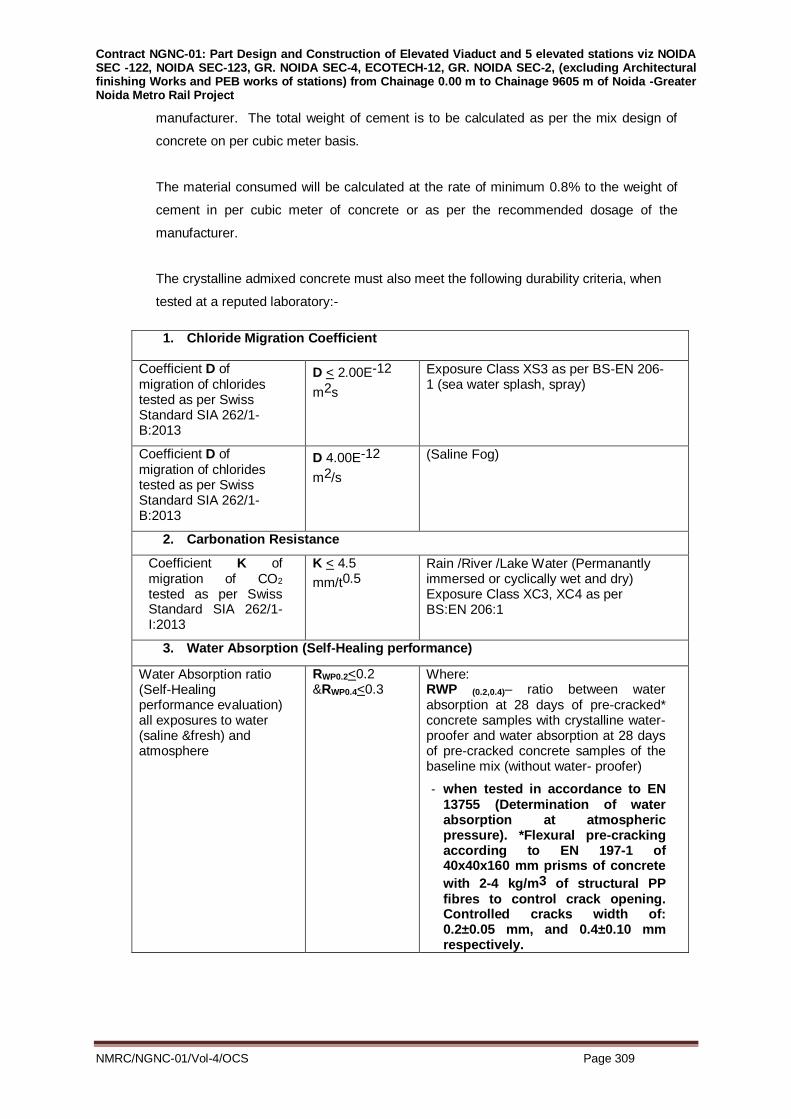
Contract NGNC-01: Part Design and Construction of Elevated Viaduct and 5 elevated stations viz NOIDA SEC -122, NOIDA SEC-123, GR. NOIDA SEC-4, ECOTECH-12, GR. NOIDA SEC-2, (excluding Architectural finishing Works and PEB works of stations) from Chainage 0.00 m to Chainage 9605 m of Noida -Greater Noida Metro Rail Project
NMRC/NGNC-01/Vol-4/OCS Page 309
manufacturer. The total weight of cement is to be calculated as per the mix design of
concrete on per cubic meter basis.
The material consumed will be calculated at the rate of minimum 0.8% to the weight of
cement in per cubic meter of concrete or as per the recommended dosage of the
manufacturer.
The crystalline admixed concrete must also meet the following durability criteria, when
tested at a reputed laboratory:-
1. Chloride Migration Coefficient
Coefficient D of migration of chlorides tested as per Swiss Standard SIA 262/1-B:2013
D < 2.00E-12
m2s
Exposure Class XS3 as per BS-EN 206-1 (sea water splash, spray)
Coefficient D of migration of chlorides tested as per Swiss Standard SIA 262/1-B:2013
D 4.00E-12
m2/s
(Saline Fog)
2. Carbonation Resistance
Coefficient K of migration of CO2 tested as per Swiss Standard SIA 262/1-I:2013
K < 4.5
mm/t0.5
Rain /River /Lake Water (Permanantly immersed or cyclically wet and dry) Exposure Class XC3, XC4 as per BS:EN 206:1
3. Water Absorption (Self-Healing performance)
Water Absorption ratio (Self-Healing performance evaluation) all exposures to water (saline &fresh) and atmosphere
RWP0.2<0.2 &RWP0.4<0.3
Where: RWP (0.2,0.4)– ratio between water absorption at 28 days of pre-cracked* concrete samples with crystalline water- proofer and water absorption at 28 days of pre-cracked concrete samples of the baseline mix (without water- proofer)
- when tested in accordance to EN 13755 (Determination of water absorption at atmospheric pressure). *Flexural pre-cracking according to EN 197-1 of 40x40x160 mm prisms of concrete
with 2-4 kg/m3 of structural PP fibres to control crack opening. Controlled cracks width of: 0.2±0.05 mm, and 0.4±0.10 mm respectively.

Contract NGNC-01: Part Design and Construction of Elevated Viaduct and 5 elevated stations viz NOIDA SEC -122, NOIDA SEC-123, GR. NOIDA SEC-4, ECOTECH-12, GR. NOIDA SEC-2, (excluding Architectural finishing Works and PEB works of stations) from Chainage 0.00 m to Chainage 9605 m of Noida -Greater Noida Metro Rail Project
NMRC/NGNC-01/Vol-4/OCS Page 310
ANNEXURE B
Product - Crystalline Waterproofing Coating
CRYSTALLINE Slurry
Recommended Uses:- CRYSTALLINE Slurry waterproofing can be applied to all structurally sound concrete – new or old. Basement retaining walls & raft Slabs: Parking structures
Concrete slabs (floor/roof/balcony, etc.): Tunnels and subway systems
Construction joints: Foundations
Water retaining structures: Underground vaults
Swimming pools: Sewage and water treatment plants
Channels: Reservoirs
Bridges, dams and roads: Podiums
Characteristics: - Must be supplied from approved manufacturing facility. Aggregate State: Powder
Colour: Cement Grey
Pot Life: 20 Minutes
Setting time: 2 hrs.
Shelf life: 12 months
Speed of penetration: 31 cm. in 56 Days
Water Permeability: More than 90% (preferably zero
permeability) compared to control
concrete when tested as per DIN 1048
part 5 by carryong out 4 cycles each of 5
bar hydrostatic pressure.
Potable Water Compatibility: CFTRI Tested, Nontoxic and suitable for
use in potable water facilities – NSF
Listed as per ANSI 61 listing
i. The manufacturer must produce relevant test certificates from reputed
laboratories, confirming to above requirements.
ii. NMRC reserves the right to approve or reject the product proposed by the
contractor based upon the credentials submitted by the contractor.
Quality Assurance:-
i. Manufacturer Qualifications: A firm with not less than 40 years experience in
manufacturing crystalline waterproofing of the type specified, able to provide test

Contract NGNC-01: Part Design and Construction of Elevated Viaduct and 5 elevated stations viz NOIDA SEC -122, NOIDA SEC-123, GR. NOIDA SEC-4, ECOTECH-12, GR. NOIDA SEC-2, (excluding Architectural finishing Works and PEB works of stations) from Chainage 0.00 m to Chainage 9605 m of Noida -Greater Noida Metro Rail Project
NMRC/NGNC-01/Vol-4/OCS Page 311
reports showing compliance with specified performance characteristics, and able
to provide on-site technical representation to advise on installation.
ii. Installer Qualifications: Firm should be ISO 9001-2008 certified with minimum
experience of 10 years in approved crystalline products.
iii. Pre-installation Meeting: Before installation, conduct a meeting with the
waterproofing installer, installers of adjacent work and work penetrating
waterproofing, and waterproofing manufacturer's representative to verify project
requirements, substrate conditions, manufacturer's installation instructions, and
manufacturer' warranty requirements; notify the Owner and Architect/Engineer at
least one week in advance of meeting.
Surface Preparation:- All concrete to be treated with CRYSTALLINE Slurry must be clean and have an “open”
capillary surface. Remove laitance, dirt, grease, etc. by means of high pressure water
jetting, wet sandblasting or wire brushing. Faulty concrete in the form of cracks,
honeycombing, etc. must be chased out, treated with CRYSTALLINE SLURRY and filled
with CRYSTALLINE MORTAR. Surfaces must be carefully pre-watered prior to the
CRYSTALLINE SLURRY application. The concrete surface must be damp but with no
wet sheen on the surface.
Mixing:- CRYSTALLINE SLURRY is mechanically mixed with clean water to a creamy
consistency or that resembling thick oil, in a mixing ratio as recommended by the
manufacturer. Mix only as much material as can be used within 20 minutes and stir
mixture frequently. If the mixture starts to set do not add more water, simply re-stir to
restore workability.
Application:-
Apply Crystalline Slurry in two coats by masonry brush or appropriate power spray
equipment. The second coat is applied while the first coat is still “green”.
Application Rates:-
One / Two coats of Crystalline Slurry at 0.7kg / sqm as per manufacturer specification.
Post Treatment:
The treated areas should be kept damp for a period of five days and must be protected
against direct sun, wind and frost, by covering with polyethylene sheeting, damp burlap
or similar.
Special Consideration:
Contract NGNC-01: Part Design and Construction of Elevated Viaduct and 5 elevated stations viz NOIDA SEC -122, NOIDA SEC-123, GR. NOIDA SEC-4, ECOTECH-12, GR. NOIDA SEC-2, (excluding Architectural finishing Works and PEB works of stations) from Chainage 0.00 m to Chainage 9605 m of Noida -Greater Noida Metro Rail Project
NMRC/NGNC-01/Vol-4/OCS Page 312
Do not apply CRYSTALLINE SLURRY at temperatures at or below freezing or to frozen
or freezing surfaces. CRYSTALLINE SLURRY cannot be used as an additive to
concrete or plasters. (CRYSTALLINE ADMIX should be considered for these
applications).
Storage / Shelf Life:
When properly stored in a dry place in unopened and undamaged original packaging,
shelf life is 12 months.
Measurement:
The quantity of crystalline slurry coat will be measured on sq.mtr. area basis. The
measurement will be taken by measuring the length and width of the coating area.

Contract NGNC-01: Part Design and Construction of Elevated Viaduct and 5 elevated stations viz NOIDA SEC -122, NOIDA SEC-123, GR. NOIDA SEC-4, ECOTECH-12, GR. NOIDA SEC-2, (excluding Architectural finishing Works and PEB works of stations) from Chainage 0.00 m to Chainage 9605 m of Noida -Greater Noida Metro Rail Project
NMRC/NGNC-01/Vol-4/OCS Page 313
ANNEXURE C
Product - Crystalline Waterproofing Mortar
CRYSTALLINE MORTAR
Recommended Uses:
i. Applied in conjunction with Crystalline waterproofing slurry coat for:
ii. Installation of seal strips, coves at joints to assure water tightness
iii. Patching of tie holes and faulty construction joints
iv. Patching and filling of routed out cracks
v. Repairing of spalled and honeycombed areas
Characteristics:
Must be supplied from approved manufacturing facility.
Aggregate State: Powder
Colour: Cement Grey
Pot Life: 30 Minutes
Setting time: 2 hrs.
Shelf life: 12 months
Potable Water Compatibility: Nontoxic and suitable for use in potable
water facilities – NSF Listed as per ANSI
61 listing
Confirm to: EN 1504-3 (For Structural Repairs – R4,
Compressive Strength > 55 Mpa),
Supplied from an approved
manufacturing unit having CE approval
confirming EN 1504-3 – R4
The product must have been proven track record of minimum 5 years in Indian
conditions.
Quality Assurance:-
i. Manufacturer Qualifications: A firm with not less than 40 years experience in
manufacturing crystalline waterproofing of the type specified, able to provide test
reports showing compliance with specified performance characteristics, and able
to provide on-site technical representation to advise on installation.
ii. Installer Qualifications: Firm should be ISO 9001-2008 certified with minimum
experience of 10 years in approved crystalline products.
iii. Pre-installation Meeting: Before installation, conduct a meeting with the
waterproofing installer, installers of adjacent work and work penetrating

Contract NGNC-01: Part Design and Construction of Elevated Viaduct and 5 elevated stations viz NOIDA SEC -122, NOIDA SEC-123, GR. NOIDA SEC-4, ECOTECH-12, GR. NOIDA SEC-2, (excluding Architectural finishing Works and PEB works of stations) from Chainage 0.00 m to Chainage 9605 m of Noida -Greater Noida Metro Rail Project
NMRC/NGNC-01/Vol-4/OCS Page 314
waterproofing, and waterproofing manufacturer's representative to verify project
requirements, substrate conditions, manufacturer's installation instructions, and
manufacturer' warranty requirements; notify the Owner and Architect/Engineer
at least one week in advance of meeting.
i. The manufacturer must produce relevant test certificates from reputed
laboratories, confirming to above requirements.
ii. NMRC reserves the right to approve or reject the product proposed by the
contractor based upon the credentials submitted by the contractor.
Surface Preparation:
All surfaces to be patched, repaired or sealed with CRYSTALLINE MORTAR must be
clean and sound. Cracks should be routed out to a U-shaped configuration,
approximately 3/4” (20 mm) wide and a minimum of 3/4” (20 mm) deep. Tie holes should
be roughened prior to filling. Spalled and honeycombed areas must be thoroughly
cleaned and chiselled back to sound concrete prior to repair. Remove all dirt, cement
laitance, form release agents, curing compounds, paints, coatings, etc. by means of wet
or dry sandblasting, high pressure water jet or other suitable mechanical means.
Surfaces must be well moistened to a dull dampness at the time of application. The
concrete should be damp with no wet sheen on the surface.
Mixing:
For routed cracks, coves and non-moving joints, add water to CRYSTALLINE MORTAR
until a medium stiff, trowel-able consistency is reached. The texture of the mix should be
pliable enough to be trowelled into the cracks
With some pressure, but not so pliable that it would run out or sag out of the crack.
Approximate mixing ratio (by volume) is 4½ parts powder to 1 part water. Alternatively,
100 ml of water to 450 g of CRYSTALLINE MORTAR powder. For tie holes and pointing
applications, add only a small amount of water. Mixed consistency should be that of “dry
earth”, holding a shape when squeezed in your hand but easily crumbled when pressed
between fingers. Mix only as much material as can be used within 20 minutes.
Application:
Cracks/Seal strips (reglets & coves) and faulty construction joints applications : After
proper surface prime areas to be patched or repaired with a slurry coat of
CRYSTALLINE and while “green” (tacky), fill cavity flush to surface with CRYSTALLINE
MORTAR in mortar consistency. Once CRYSTALLINE Mortar is touch dry then 2 Coats
Crystalline Slurry as final coat.
Spalled and honeycombed areas:

Contract NGNC-01: Part Design and Construction of Elevated Viaduct and 5 elevated stations viz NOIDA SEC -122, NOIDA SEC-123, GR. NOIDA SEC-4, ECOTECH-12, GR. NOIDA SEC-2, (excluding Architectural finishing Works and PEB works of stations) from Chainage 0.00 m to Chainage 9605 m of Noida -Greater Noida Metro Rail Project
NMRC/NGNC-01/Vol-4/OCS Page 315
Prepare surface and chisel back to sound concrete. Prime area to be repairedwith a
slurry coat of CRYSTALLINE Slurry. While still “green” (tacky), apply CRYSTALLINE
MORTAR in layers of 1/2” (12.5 mm) not to exceed 2.5 in (approximately 6.5cm). Each
layer should be allowed to set long enough that it will leave only a slight indent
(approximately 1/16” or 1.6 mm) when pressed with a finger. Where possible, the
surface of the repair should be packed tightly using a hammer and block of wood.
Tie holes and pointing applications:
Prepare surface and chisel back to sound concrete. Prime area to be repaired with a
slurry coat of CRYSTALLINE SLURRY and while still “green” (tacky) apply
CRYSTALLINE MORTAR in “dry earth” consistency. CRYSTALLINE MORTAR should
be tightly rodded into tie holes or packed tightly using a hammer and block of wood.
Curing :-
Provide protection against extreme weather conditions such as heavy rain or freezing
conditions during the setting period. Curing is not normally required except during hot,
low humidity weather. In these conditions a light mist of water approximately 24 hours
after the repair is completed will help to ensure a controlled cure. In extreme dry heat,
water misting may be required more frequently.
Special Consideration:-
DO NOT apply CRYSTALLINE MORTAR at temperatures below 40ºF (4ºC), to a frozen
substrate or if temperatures will drop below freezing during the curing period
(approximately 24 hours). This product is not recommended for use in expansion or
construction joints. CRYSTALLINE MORTAR can be applied in 1/2" (12.5 mm) layers
not exceeding 2.5 in (approximately 6.5 cm) to prevent shrinkage cracks in the mortar.
Storage / Shelf Life:-
CRYSTALLINE MORTAR must be stored in a dry enclosed area off the ground at a
minimum temperature of 45ºF (7ºC). Shelf life when stored in proper conditions in
unopened, undamaged packaging is 12 months.
Measurement:
The consumption of Crystalline Mortar is measured in terms if actual quantity (Kg) of the
material consumed based upon the actual consumption of the material for Faulty
construction joint, repair of honeycombs, formation of coves at joints, seal strips and
filing up of tie rod holes. The main contractor must take in to account the consumption of
this material as part of post construction repairs and the same will not be paid extra.

Contract NGNC-01: Part Design and Construction of Elevated Viaduct and 5 elevated stations viz NOIDA SEC -122, NOIDA SEC-123, GR. NOIDA SEC-4, ECOTECH-12, GR. NOIDA SEC-2, (excluding Architectural finishing Works and PEB works of stations) from Chainage 0.00 m to Chainage 9605 m of Noida -Greater Noida Metro Rail Project
NMRC/NGNC-01/Vol-4/OCS Page 316
ANNEXURE D
Product - SWELLABLE Cold Concrete Joint Water-stop
Recommended Uses:-
Typical Applications for SWELLABLE WATER-STOP include building foundations, slabs,
retaining walls, storage tanks, and similar non-moving cold construction joints.
Characteristics :
Specific Gravity : 1.35
Hydro-carbon Content : 47% Min. Volatile Content: 1% Max.
Colour : Black
Also:
i. The Swell- able water stop must not exert swelling pressure > 5% of the dead
weight of the concrete
ii. The Swell-able water stop must be able to withstand hydrostatic pressure of 6 Bar
for 7 days under lab test conditions
iii. The Swell-able water stop must be manufactured at aapproved manufacturing unit.
iv. Material must be capable of expanding up to 215% in 120 hours, when immersed in
potable water, having hydrocarbon content (ASTM D 297) of not less than 45% and
volatile matter (ASTM D-6) not to exceed 1%.
Swell-able Water-stop Primer:
Colour: Bright Orange
% Solid : Min 20%
Flash Point : 93 deg C
Dry Time @ 25 Deg C: 10 min
Dry Time @4 Deg C : 60 min
i. The manufacturer must produce relevant test certificates from reputed laboratories,
confirming to above requirements.
ii. NMRC reserves the right to approve or reject the product proposed by the
contractor based upon the credentials submitted by the contractor.
Direction for Use:
How to apply SWELLABLE WATER-STOP on poured-in-place construction joints:
i. Carefully brush off all dust and debris and apply a coat of appropriate SWELLABLE
WATER-STOP PRIMER to the area where the SWELLABLE WATER-STOP is to
be placed.
ii. Using the heel of the hand and moderate pressure, press a continuous bead of
SWELLABLE WATER-STOP firmly into position. Check to be certain that the
sealant has bonded to the primed area.

Contract NGNC-01: Part Design and Construction of Elevated Viaduct and 5 elevated stations viz NOIDA SEC -122, NOIDA SEC-123, GR. NOIDA SEC-4, ECOTECH-12, GR. NOIDA SEC-2, (excluding Architectural finishing Works and PEB works of stations) from Chainage 0.00 m to Chainage 9605 m of Noida -Greater Noida Metro Rail Project
NMRC/NGNC-01/Vol-4/OCS Page 317
iii. Splicing the ends to form a continuous, uninterrupted seal. For the best results, cut
each end at opposite 45° angles and position the cut ends together. Gently kneed
the spliced ends creating an uninterrupted seal.
iv. Peel the protective backing from the exposed side of the SWELLABLE WATER-
STOP.
v. Pour the mating structural member into position.
NOTES:
Always use SWELLABLE WATER-STOP PRIMER to avoid displacement of the
SWELLABLE WATER-STOP during concrete pouring. It may be necessary to utilize
masonry nails or other mechanical means to hold the sealant in place on vertical surfaces.
Place SWELLABLE WATER-STOP so that it is not closer than 2” (5 cm) away from the
outer surface of poured structure. If a Keyway is utilized, place the SWELLABLE WATER-
STOP into the bottom of the formed Keyway area.
Special Consideration:
Always use SWELLABLE WATER-STOP PRIMER to ensure tight adhesion and to aid in
preventing SWELLABLE WATER-STOP from moving during the concrete pour. For vertical
surfaces, nails may be used to hold the product in place in conjunction with SWELLABLE
WATER-STOP PRIMER.
SWELLABLE WATER-STOP should be used at a minimum depth of 50 mm (2”) inside the
concrete.
When used on pipes and other structural penetrations, SWELLABLE WATER-STOP should
be cut to measuredlength and placed around the penetration with ends butted.
In all cases, SWELLABLE WATER-STOP should be in direct contact with the substrate
along the entire length of the installation.
Storage / Shelf Life:
When stored in a dry enclosed area off the ground at a minimum temperature of 45°F (7°C)
in unopened, undamaged cartons, shelf life is unlimited.
Measurement:
The measurement will be taken by measuring the length of SWELLABLE WATER-STOP in
linear meter
Contract NGNC-01: Part Design and Construction of Elevated Viaduct and 5 elevated stations viz NOIDA SEC -122, NOIDA SEC-123, GR. NOIDA SEC-4, ECOTECH-12, GR. NOIDA SEC-2, (excluding Architectural finishing Works and PEB works of stations) from Chainage 0.00 m to Chainage 9605 m of Noida -Greater Noida Metro Rail Project
NMRC/NGNC-01/Vol-4/OCS Page 318
Annexure E
Treatment of faulty Construction Joints
Material Specification:
Cementitious based dry crystalline powder capable of creating crystals to seal the pores,
microcracks in the concrete. This system become integral part of concrete and is not
affected by surface wear and abrasion. This will be applied on wet saturated concrete
surfaces. The material should be nontoxic and suitable for application in drinking water
tanks. It should be able to withstand high hydrostatic pressure, stop moisture coming up
through concrete. It should not contain stearates, sodium or silicate and should not be
hydrophobic type. It should be able to grow crystals year after year & should seal micro
cracks (not live/ moving crack) that may occur from subsequent damage to structure.
All along construction joints a groove of size for 20 mm wide and 25 mm depth shall be
made. The construction joints to be treated shall be cleaned by water jet or other
mechanical means and made free from all laitance. The saturated cleaned groove free from
standing water shall be filled with Crystalline Mortar as per manufacturer specification and
as per Annexure C. Treated joints shall be coated with a finishing coat by applying surface
applied Crystalline Slurry coating for a width of 300 mm (150 mm on either side) .
Treatment along the circumference of pipes passing through concrete
Material Specification:
Cementitious based dry crystalline powder capable of creating crystals to seal the pores,
microcracks in the concrete. This system becomes integral part of concrete and is not
affected by surface wear and abrasion. This will be applied on wet saturated concrete
surfaces. The material should be nontoxic and suitable for application in drinking water
tanks. It should be able to withstand high hydrostatic pressure, stop moisture coming up
through concrete 10 de-bond any overlay system. It should not contain stearates. sodium or
silicate and should not be hydrophobic type. It should be able to grow crystals year after
year & should seal micro cracks (not live/ moving crack) that may occur from subsequent
damage to structure.
All along the circumference of pipe 20 mm wide and 25 mm deep rove shall be made.
The joints to be treated shall be cleaned by water jet or other mechanical means and made
free from all laitance. The saturated cleaned groove free from standing water shall be
filled crystalline mortar as -per manufacturer Specification and as per annexure C. The
treated joints shall be coated with a finishing coat by applying surface applied Crystalline
Slurry coating for a width of 300 mm (150 mm on either side).

Contract NGNC-01: Part Design and Construction of Elevated Viaduct and 5 elevated stations viz NOIDA SEC -122, NOIDA SEC-123, GR. NOIDA SEC-4, ECOTECH-12, GR. NOIDA SEC-2, (excluding Architectural finishing Works and PEB works of stations) from Chainage 0.00 m to Chainage 9605 m of Noida -Greater Noida Metro Rail Project
NMRC/NGNC-01/Vol-4/OCS Page 319
Section – S.13
ROADWORK
13.1 CONTROL OF TRAFFIC
The contractor shall take all necessary precautions in co-ordination with and to the
requirements of all the competent authorities concerned to protect the work from damage until
such time as the seal coat or surface treatment has developed sufficient strength to carry
normal traffic without any damage to it.
The new work shall be opened to traffic only after it is authorised by the Engineer.
The contractor shall submit a detailed traffic diversion/or control and regulation plan taking all
safety measures during the course of work permitted by the concerned authorities to the
Engineer for his consent before start of work.
The contractor shall take all precautions to avoid or minimise delays and inconvenience to
road users during the course of the work. Where adequate detours or side tracks are
available, traffic shall be temporarily diverted while the work is in progress depending on
volume of traffic and subject to approval by Traffic Police. Adequate signs, signals, barriers
and lamps for the warning and guidance of traffic shall be provided at all times during the
course of the work till it is opened to traffic.
The Contractor shall take all reasonable precautions to protect traffic against accident,
damage or disfigurement by construction equipment, tools, and materials, splashes and
smirches of bitumen/ bituminous material or any other construction materials and shall be
responsible for any claims arising from such damage or disfigurement.
Traffic signs erected shall be in accordance with the IRC Standards and/or as prescribed and
approved by the Traffic Police Department.
13.2 GRANULAR SUB-BASE (NON-BITUMINOUS)
This work shall consist of laying and compacting well-graded material on prepared subgrade
in accordance with the requirements of these specifications or as per MORTH standards, as
acceptable to Highway authorities & road owing agency. The material shall be laid in one or
more layers according to lines, grades and cross-sections shown on the drawings.
13.2.1 Material
The Material to be used for the work shall be natural sand, moorum, gravel, crushed stone, or
combination thereof depending upon the grading specified in MORTH specifications for
Roads and Bridges. The material shall be free from organic or other deleterious constituents.
13.2.2 Physical requirements
The material shall have a 10 percent fines value of 50 KN or more (for sample in soaked
condition) when tested in compliance with BS:812 (Part III). The water absorption value of the
coarse aggregate shall be determined by IS:2386 (Part 3); if this value is greater than 2
percent, the soundness test shall be carried out on the material delivered to site as per IS:
383. CBR Value shall be determined at the density and moisture content likely to be
developed in equilibrium conditions which shall be taken as being the density relating to a
uniform air voids content of 5 percent.

Contract NGNC-01: Part Design and Construction of Elevated Viaduct and 5 elevated stations viz NOIDA SEC -122, NOIDA SEC-123, GR. NOIDA SEC-4, ECOTECH-12, GR. NOIDA SEC-2, (excluding Architectural finishing Works and PEB works of stations) from Chainage 0.00 m to Chainage 9605 m of Noida -Greater Noida Metro Rail Project
NMRC/NGNC-01/Vol-4/OCS Page 320
13.2.3 Strength of sub-base
It shall be ensured prior to actual execution that the material to be used in the sub-base
satisfies the requirements of CBR and other physical requirements when compacted and
finished.
13.2.4 Construction Operations
a) Preparation of sub-grade
Immediately prior to the laying of sub-base, the sub-grade already finished or existing surface
shall be prepared by removing all vegetation and other extraneous matter, lightly sprinkled
with water if necessary and rolled with two passes of 80 – 100 KN smooth wheeled roller.
Damage to the subgrade shall be made good before sub base is laid.
b) Spreading and compacting
The approved sub-base material shall be spread on the prepared sub-grade by a grader of
suitable type and adequate capacity.
When the sub-base material consists of combination of materials, mixing shall be done
mechanically by the mix-in-place method.
The equipment used for mix-in-place construction shall be approved equipment capable of
mixing the material to the desired degree.
Moisture contents of the loose material at the time of compaction shall be checked in
accordance with IS: 2720 (Part 7) and suitably adjusted.
Rolling procedure shall be as described under relevant Subsection except stated
herein.
Rolling shall be continued till the density achieved is at least 98% of the maximum dry density
for the material determined as per IS:2720 (Part 8).
13.2.5 Control of Traffic
Control of traffic shall be as described under Subsection 15.1.
13.3 WATER-BOUND MACADAM SUB-BASE/ BASE (NON-BITUMINOUS)
13.3.1 Description
The work shall consist of furnishing, placing, watering and compacting sub-base material
mechanically interlocked by rolling and bounded together with screening and/ or binding
material to the required degree on a prepared sub-grade/ sub-base or the existing surface as
the case may be in accordance with these Specifications, and to the lines, levels, grades,
dimensions and cross sections as shown on Drawings and/ or required by the Engineer.
13.3.2 Materials
a) Coarse aggregate

Contract NGNC-01: Part Design and Construction of Elevated Viaduct and 5 elevated stations viz NOIDA SEC -122, NOIDA SEC-123, GR. NOIDA SEC-4, ECOTECH-12, GR. NOIDA SEC-2, (excluding Architectural finishing Works and PEB works of stations) from Chainage 0.00 m to Chainage 9605 m of Noida -Greater Noida Metro Rail Project
NMRC/NGNC-01/Vol-4/OCS Page 321
The coarse aggregates shall be hard and durable crushed stones, free from deleterious
matter conforming to one of the gradings as set forth in Table 13.3.1, the physical
requirements given in Table 13.3.2 subject to the Engineer’s consent.
b) Screenings
Screenings to fill voids in the coarse aggregate shall generally consist of the same material as
the coarse aggregate or of gravel (other than round material) or moorum as approved by
Engineer. However, where permitted non-plastic material such as moorum may be used for
this purpose provided liquid limit and plasticity index of such material are below 20 and 6
respectively and fraction passing through 75 micron sieve does not exceed 10 percent.
c) Binding material
Binding material to be used for water-bound macadam as a filler material meant for
preventing ravelling, shall be a suitable material and having a Plasticity Index (PI) value of
less than 6 as determined in accordance with IS : 2720 (Part-5).
Table 13.3.1
Grading requirements of coarse aggregates
Grading
No.
Size Range IS Sieve
Designation
Percent Passing
by weight
1. 90 mm to 45 mm
125 mm
90 mm
63 mm
45 mm
22.4 mm
100
90-100
25-60
0-15
0-5
2. 63 mm to 45 mm 90 mm
63 mm
53 mm
45 mm
22.4 mm
100
90-100
25-75
0-15
0-5
3. 53 mm to 22.4 mm 63 mm
53 mm
45 mm
22.4 mm
11.2 mm
100
95-100
65-90
0-10
0-5
Note: The compacted thickness for a layer with Grade 1 shall be 100 mm
while for a layer with Grade 2, it shall be 75 mm.
Table 13.3.2

Contract NGNC-01: Part Design and Construction of Elevated Viaduct and 5 elevated stations viz NOIDA SEC -122, NOIDA SEC-123, GR. NOIDA SEC-4, ECOTECH-12, GR. NOIDA SEC-2, (excluding Architectural finishing Works and PEB works of stations) from Chainage 0.00 m to Chainage 9605 m of Noida -Greater Noida Metro Rail Project
NMRC/NGNC-01/Vol-4/OCS Page 322
Physical requirements of coarse aggregates or water-bound macadam sub-base and
base courses
S.No. Test Test Method Requirement (Maximum)
1. * Los Angeles Abrasion value IS :2386 (Part-4)
50 per cent
2. * Aggregate Impact value IS :2386 (Part-4)
40 per cent
3. Flakiness Index IS : 2386
(Part-1) 15 per cent
* Aggregate may satisfy requirements of either of the two tests
13.3.3 Construction Method
a) Preparation of Sub-grade/ sub-base
i. The surface of the sub-grade/ sub-base or existing surface shall be shaped and
prepared to the lines, levels, grades, dimensions and cross sections as shown on the
Drawings. Damage to or deterioration of sub-grade/ sub-base shall be made good
before sub-base/ base is overlaid.
ii. Inverted Choke
If water bound macadam is to be laid directly over the sub grade, without any
intervening pavement or soling course, a 25 mm course of screenings or coarse sand
shall be spread and compacted on the prepared subgrade before application of the
coarse aggregate. In case of fine sand or silty or clayey sub grade, a 100 mm
insulating layer of screenings or coarse sand shall be laid, the gradation of which will
depend on drainage requirements. Alternatively, appropriate geosynthetics
performing functions of separation and drainage layer may be used over the prepared
sub-grade subject to the satisfaction of the Engineer.
b) Spreading coarse aggregates
i. The coarse aggregates of specified size and grading shall be spread uniformly in
layers with each compacted layer thickness not more than 100mm for Grading 1 and
75 mm for Grading 2 and in a manner that prevents segregation into fine and coarse
materials.
ii. Sub-base/ or base material shall contain moisture nearly equalising the optimum
moisture content at the time of compaction.
iii. Immediately after each layer has been spread and shaped satisfactorily, each layer
shall be thoroughly compacted with suitable and adequate compaction equipment.
Rolling operations shall begin from the outer edge of roadbed towards the centre,
gradually in a longitudinal direction; except on super-elevated curves, where rolling
shall begin at the lower edge and progress towards the upper edge.
The rolling shall be continued until the aggregates are thoroughly keyed, well-
bounded and firmly set in its full depth.

Contract NGNC-01: Part Design and Construction of Elevated Viaduct and 5 elevated stations viz NOIDA SEC -122, NOIDA SEC-123, GR. NOIDA SEC-4, ECOTECH-12, GR. NOIDA SEC-2, (excluding Architectural finishing Works and PEB works of stations) from Chainage 0.00 m to Chainage 9605 m of Noida -Greater Noida Metro Rail Project
NMRC/NGNC-01/Vol-4/OCS Page 323
c) Tolerance
The finished sub-base/ base at any point shall not vary more than 15mm below and 12mm
above the planned grade or adjusted grade with 3m straight edge applied to the surface
parallel to the centreline of the road. With the template laid transversely the maximum
permissible variation from specified profile shall be 12mm and 8mm respectively.
The sub-base/ base course completed in each day’s work shall have an average thickness
not less than the required thickness.
Sub-base/ base course which does not conform to the above requirements shall be
reworked.
13.4 BITUMINOUS MATERIALS
13.4.1 Materials
Materials shall meet the requirements of the relevant IS Codes. These shall be of the
following types.
a) Cut back Bitumen
Cut back bitumen shall be Rapid Curing (RC), Medium Curing (MC) or Slow Curing (SC) conforming to IS : 217.
b) Cationic Emulsion
Bitumen emulsions of the cationic type for roads shall conform to IS: 8887. Emulsified
bitumen shall be Rapid Setting (RS), Medium Setting (MS), or Slow Setting (SS).
The physical and chemical requirements of the three types emulsions shall comply with the
requirements specified in Table 1 of IS: 8887.
c) Paving Bitumen
Paving bitumen shall be conforming to IS: 73 and of the following two types:
Type 1 Paving bitumen from non-waxy crude shall satisfy the requirements given in Table 1
of IS: 73.
Type 2 Paving bitumen from waxy crude shall satisfy the requirements given in Table 2 of IS:
73.
The temperature at application of bituminous materials shall be maintained as per
manufacturer’s instructions and/or as directed by the Engineer’s Representative.
An anti-stripping and bonding agent should be used in all final restoration road works.
It should confirm to IS: 14982-2001 Specifications. The percentage can be from 0.5% to
1.25% by weight of bitumen content. The optimum dose can be ascertained using
M.O.S.T. / BIS guidelines.;
13.4.2 Methods of Storage and Handling
Asphaltic material shall be handled and stored with due regard for safety and in such a way
that at the time of use in the work the material conforms to the Specifications. Following
precautions shall be taken while using these materials:
a) Work with these materials shall be carried out in good weather conditions and it shall be
carried out in warm and dry weather, and not in wet or extremely cold weather.
Contract NGNC-01: Part Design and Construction of Elevated Viaduct and 5 elevated stations viz NOIDA SEC -122, NOIDA SEC-123, GR. NOIDA SEC-4, ECOTECH-12, GR. NOIDA SEC-2, (excluding Architectural finishing Works and PEB works of stations) from Chainage 0.00 m to Chainage 9605 m of Noida -Greater Noida Metro Rail Project
NMRC/NGNC-01/Vol-4/OCS Page 324
b) Emulsified asphalt shall be handled with care and not subjected to mechanical shocks or
extremes of temperature likely to cause separation of the asphalt. Emulsified asphalt showing
sign of separation shall not be used.
c) During heating, no water or moisture shall be allowed to enter the boiler.
d) Heating of bitumen shall be done to the correct temperature range, as prescribed by the
manufacturer for the grade used. The temperature shall be controlled with the use of a
suitable thermometer, and the material shall be drawn and used while still at such
temperature as is prescribed by manufacturer or in accordance with MOST specifications.
e) It shall be ensured that mixing of ingredients is through and all particles of aggregates are
coated uniformly and fully.
13.5 PRIME COAT
13.5.1 Description
This work shall consist of the cleaning and preparing of the surface to be primed to specified
lines, grade, and cross-section, booming and clearing thoroughly and applying bituminous
material in accordance with these Specifications.
13.5.2 Materials
The choice of the primer shall depend upon the porosity characteristics of the surface to be
primed. The primer shall be Medium Curing Cutback (MC) and the particular grade to be used
for the work shall have the consent of the Engineer. Slow setting Cationic emulsion
conforming to IS : 8887 may also be used. Sampling and testing of bituminous primer shall be
as per IS : 217, IS : 454 and IS : 8887.
13.5.3 Construction Methods
a) Weather Limitations
Prime coat shall not be applied at a time when the surface is wet or when the weather is
foggy, rainy or windy.
b) Equipment
The equipment used for the work shall include a power broom and primer material distributor
spraying it uniformly at specified rates and temperatures. It shall be equipped with self-
heating arrangement, suitable pump, adequate capacity compressor and spraying bar with
nozzles having constant volume or pressure system.
Spraying by manual methods may be allowed for inaccessible or small areas with the consent
of the Engineer.
c) Cleaning Surface
Immediately prior to applying the prime coat the surface to be primed shall be swept clean
from all loose dirt and other objectionable material and shall be shaped to the required lines,
grades, cross section.
d) Application of bituminous primer
The primer material shall be applied by means of a distributor at rates usually from 0.8 to 1.4
litres per square metre and at a temperature within the allowable range corresponding to the

Contract NGNC-01: Part Design and Construction of Elevated Viaduct and 5 elevated stations viz NOIDA SEC -122, NOIDA SEC-123, GR. NOIDA SEC-4, ECOTECH-12, GR. NOIDA SEC-2, (excluding Architectural finishing Works and PEB works of stations) from Chainage 0.00 m to Chainage 9605 m of Noida -Greater Noida Metro Rail Project
NMRC/NGNC-01/Vol-4/OCS Page 325
material used and porosity condition of surface over which it is laid .The temperature of primer
at time of application may vary from 400 C to 600 C for cutback bitumen and 400 C to 600 C for
bitumen emulsion
Prime coat shall be allowed to penetrate for at least 48 hours to allow penetration into the
base course and aeration of volatile from the primer material, then covered with clean dry
sand or stone screening.
Areas containing an excess or deficiency of priming material shall be corrected by the addition
of sand or primer.
13.6 TACK COAT
13.6.1 Description
This work shall consist of furnishing and applying bituminous material to an existing road
surface or to an existing bituminous prime coat surface which has dried out or preparatory to
laying another bituminous layer over it.
13.6.2 Materials
The material for tack coat shall be a bituminous or cut back emulsion of suitable type and
grade.
13.6.3 Construction Methods
a) Cleaning Surface
The whole surface on which the tack coat is to be applied shall be cleaned of dust and any
extraneous material before the start of application of tack coat by using a power broom or any
other equipment/ method.
b) Application of tack coat material
The tack coat material shall be applied uniformly by means of a distributor at controlled rates
as per MORTH specifications and at the temperature within the allowable range
corresponding to the material used It shall be done with self propelled or towelled bitumen .
Surfaces of structures and trees adjacent to the areas being treated shall be protected in such
a way as to prevent their being spattered or marred.
13.7 BITUMINOUS MACADAM
13.7.1 Description
The work shall consist of one or more applications of compacted crushed aggregates
premixed with bituminous binder (suitable grade) to a primed non-bituminous surface or
previously constructed bituminous surface and in conformity with the lines, grades,
dimensions and cross-sections shown on the Drawings This shall comprise of a single course
of 50mm to 75mm thickness as specified in the approve or as Directed by Engineer.
13.7.2 Materials
a) Bitumen
The bitumen shall be paving bitumen of suitable grade approved by the Engineer and
conforming to IS : 73.

Contract NGNC-01: Part Design and Construction of Elevated Viaduct and 5 elevated stations viz NOIDA SEC -122, NOIDA SEC-123, GR. NOIDA SEC-4, ECOTECH-12, GR. NOIDA SEC-2, (excluding Architectural finishing Works and PEB works of stations) from Chainage 0.00 m to Chainage 9605 m of Noida -Greater Noida Metro Rail Project
NMRC/NGNC-01/Vol-4/OCS Page 326
b) Additives
Adhesion and Ant-stripping agent shall be added to the bitumen subject to Engineer’s consent
at the required percentage of additive. The additive shall be thoroughly mixed with the
bituminous material in accordance with the manufacturer’s instructions.
c) Aggregates
Aggregates shall consist of clean and hard crushed stone free from dust, clay, dirt and any
other deleterious matter. The physical requirements shall be as given in Table 13.7.1.
`Aggregates shall conform to one of the two gradings given in Table 13.7.2 depending on the
compacted thickness; the actual grading shall have the consent of the Engineer.
Table 13.7.1
Physical requirements of aggregates for bituminous macadam
S.No Test Test Method Requirement (maximum)
1. * Los Angeles Abrasion value IS :2386 (Part-4) 40 per cent
2. * Aggregate Impact value IS :2386 (Part-4) 30 per cent 3. Flakiness Index and Elongation
Indices (Total) IS : 2386(Part-1) 30 per cent
4. Coating and Stripping of Bitumen aggregate mixtures
AASHTO T-182 Minimum retained coating 95%
5. Soundness : (i) Loss with Sodium Sulphate 5
cycles (ii) Loss with Magnesium Sulphate
5 cycles
12 percent 18 percent
6. Water absorption IS : 2386(Part-3) 2 per cent
* Aggregates may satisfy requirements for either of the two tests.
Table 13.7.2
Aggregate grading for bituminous macadam
IS Sieve Designation Per cent by weight passing the sieve
Grading 1 Grading 2
45.0mm 100 -
26.5mm 75-100 100
22.4mm 60-95 75-100
11.2mm 30-55 50-85
5.6mm 15-35 20-40
2.8mm 5-20 5-20
90.0 micron 0-5 0-5
Bitumen content for pre mixing shall be 4% by weight of total mix unless otherwise

Contract NGNC-01: Part Design and Construction of Elevated Viaduct and 5 elevated stations viz NOIDA SEC -122, NOIDA SEC-123, GR. NOIDA SEC-4, ECOTECH-12, GR. NOIDA SEC-2, (excluding Architectural finishing Works and PEB works of stations) from Chainage 0.00 m to Chainage 9605 m of Noida -Greater Noida Metro Rail Project
NMRC/NGNC-01/Vol-4/OCS Page 327
approved by Engineer.
13.7.3 Construction Methods
a) Weather and Control of Work
The work of laying shall not be undertaken during rainy or foggy weather or when the base
course is damp or wet, or during dust storm or when the atmospheric temperature in shade is
150C or less.
The Engineer may order work to cease temporarily on account of adverse weather,
unsatisfactory condition of materials, equipment or any conditions which he considers may
affect the work adversely.
b) Cleaning and Preparation of Surface
Prior to the application of binder, loose dirt and other objectionable material shall be removed
from the surface to be treated by means of the power broom or blower or both. If this does not
provide a uniformly clean surface, additional sweeping shall be done by hand, using stiff
brushes or similar brooms. The areas inaccessible to the cleaning means shall be cleaned
manually. The sweeping shall extend 200mm beyond each edge of the area to be treated.
Adherent patches of objectionable material shall be removed from the surface by steel
scraper or other approved method and where the Engineer so directs the scraped area shall
be washed down with water and hand brooms.
No application of bituminous material shall be undertaken until the surface has been cleaned
to the satisfaction of the Engineer.
Before application of the bituminous material any necessary preliminary patching of the
surface of the road (To fill in potholes.) shall be done to the complete satisfaction of the
Engineer.
Tack coat shall be applied in accordance with these Specifications. Prime coat if required,
shall conform to Subsection 15.5.
c) Plant and Equipment
All plant used by the Contractor for the preparation, hauling and placing of asphalt mixtures
shall be subject to the consent of the Engineer and shall minimise smock, dust and noxious
emission and odours. These shall generally meet the following requirements:
i. The mixing plant shall be a batching plant and shall have adequate capacity sufficient to
supply the finisher on the road continuously when spreading the asphaltic mix at normal
speed and required thickness.
ii. Scale for any weigh box shall be designed to be accurate to within 1% of the maximum
load required and shall be fully automatically controlled.
The Contractor shall provide and have at hand not less than ten 25 kilograms weights for
frequent testing of all scales.
iii. Weigh box or hopper shall include a means for accurately weighing each bin size of
aggregate in a weight box or hopper, suspended on scales, ample in size to hold a full
batch without running over.

Contract NGNC-01: Part Design and Construction of Elevated Viaduct and 5 elevated stations viz NOIDA SEC -122, NOIDA SEC-123, GR. NOIDA SEC-4, ECOTECH-12, GR. NOIDA SEC-2, (excluding Architectural finishing Works and PEB works of stations) from Chainage 0.00 m to Chainage 9605 m of Noida -Greater Noida Metro Rail Project
NMRC/NGNC-01/Vol-4/OCS Page 328
iv. The asphaltic materials shall be stored in storage tanks designed to keep the temperature
of the asphaltic material at maximum temperature of 1100 C. The properties of the
asphaltic material kept in that storage tanks shall be in good condition before mixing.
The plant shall be provided with a circulating system to ensure continuous circulation
between the storage tank and the mixer.
v. The plant shall be provided with a cold bin for feeding the aggregates. Bin shall have a
calibration gate and a mechanical means to insure uniform feeding of the aggregates into
the drier as required by the Engineer.
vi. The rotary drier shall be capable of drying and heating the aggregates to the specified
temperature.
vii. The plant shall be provided with plant screens capable of screening all aggregates to the
specified sizes.
viii. The plant shall include at least 3 hot bins for storing the aggregates fed from the drier after
passing through the screen. Each bin shall be provided with an overflow pipe to prevent
any backing up of material into other bins.
ix. The plant shall be provided with asphaltic control unit by weighing to obtain the proper
amount of asphaltic material in the mix within the tolerance specified for the job-mix.
x. The batch mixer shall be an approved twin pugmill type and capable of producing a
continuous uniform mixture within the job-mix tolerances. The mixer capacity shall not be
less than 1,000 kilogram batch.
xi. An armoured thermometer reading from 500 C to 2000 C shall be fixed in the asphaltic feed
line at a suitable location near the discharge valve at the mixer unit.
The plant shall be further equipped with an electric pyrometer, or other approved
thermometric instrument so placed at the discharge chute of the drier as to register
automatically or indicate the temperature of the heated aggregate.
xii. The plant shall be equipped with a dust collector.
xiii. The plant shall be equipped with accurate positive means to govern the time of mixing and
to maintain it constant. The time of mixing shall be divided into two steps, dry mixing and
wet mixing. For dry mixing, the aggregate from hot bins shall be mixed for a period of 5-15
seconds. For wet mixing, the mixing time shall begin with the start of the asphalt spray
after dry mixing. The wet mixing shall take about 30-45 seconds. The mixing time shall be
extended if in the consideration of the Engineer the material obtained is not homogeneous.
d) Equipment for Hauling and placing
i. Trucks for hauling asphaltic mixtures shall have tight, clean, and smooth metal beds that
have been sprayed with soapy water, thinned fuel oil, or lime solution to prevent the mixing
from adhering to the beds (The amount of sprayed fluid shall however be kept to the
practical minimum. Each load shall be covered with a canvas or other suitable material of
such size as to protect the mixture from the weather). Any truck causing excessive
segregation of material by its spring suspension or other contributing factors, or that shows
oil leaks in detrimental amounts, or that causes undue delays, shall upon direction of the
Engineer be removed from the work until such conditions are corrected.

Contract NGNC-01: Part Design and Construction of Elevated Viaduct and 5 elevated stations viz NOIDA SEC -122, NOIDA SEC-123, GR. NOIDA SEC-4, ECOTECH-12, GR. NOIDA SEC-2, (excluding Architectural finishing Works and PEB works of stations) from Chainage 0.00 m to Chainage 9605 m of Noida -Greater Noida Metro Rail Project
NMRC/NGNC-01/Vol-4/OCS Page 329
ii. The equipment for spreading and finishing shall be mechanical, self powered pavers,
capable of spreading and finishing the mixture true to the lines, grades, dimensions and
cross sections.
The pavers shall be equipped with hoppers and distributing screws of the reversing type to
place the mixture evenly.
The pavers shall maintain trueness of grade and confine the edges of the pavement to true
lines without the use of stationary side forms. The equipment shall include blending or joint
levelling devices for smoothing and adjusting longitudinal joints between lanes. The
assembly shall be adjustable to give the cross-section shape prescribed and shall be so
designed and operated as to place the thickness or weight per square metre of material
required.
Pavers shall be equipped with activated screeds and devices for heating the screeds to the
temperature required for the laying of the mixture without pulling or marring.
The term “screed” includes any cutting, crowing, or other practical action that is effective in
producing a finished surface of the evenness and texture specified, without tearing,
shoving, or gouging.
If, during construction, it is found that the spreading and finishing equipment in operation
leaves in the pavement surface tracks or indented areas or other objectionable
irregularities, the use of such equipment shall be discontinued and other satisfactory
spreading and finishing shall be provided by the Contractor forthwith.
e) Preparation and transport of mix
Bituminous macadam mix shall be prepared in a hot-mix plant either owned by the Contractor
or it may be taken from an approved hot mix plant before supply of mix for the work, consent
for the use of the mix shall be taken from the Engineer. The hot-mix plant should be of
adequate capacity of batch mix type with the features as described under Subsection
13.7.3(3) or otherwise approved by Engineer unless some work specific features are required
and capable of yielding a mix of proper and uniform quality with thoroughly coated
aggregates. The plant shall meet the overall requirements through stringent quality control
practices.
The mineral aggregates shall be dried and heated to a temperature between 1500 C and 1630
C. The contractor shall submit for consent the exact temperature to the Engineer. Surfaces of
aggregates shall be clean and free of carbon and unburnt fuel oil. The aggregates,
immediately after heating, shall be screened into three or more fractions and conveyed into
separate bins ready for combining and mixing with asphaltic material.
The dried mineral aggregates prepared as prescribed above, shall be combined in the plant in
the amount of each fraction of aggregate required to meet the job-mix formula for the
particular mixture. The proper amount of asphaltic material shall be distributed over the
mineral aggregate and the whole thoroughly mixed for a period of at least 30 seconds, or
longer if necessary to produce a homogeneous mixture in which all particles of the mineral
aggregates are coated uniformly. The total mixing time shall be regulated by a suitable
locking means.
The mixture shall when emptied from the mixer be at a temperature between 1500 C and 1630
C even for tolerances.
The mixture shall be transported from the mixing plant to the point of use in vehicles

Contract NGNC-01: Part Design and Construction of Elevated Viaduct and 5 elevated stations viz NOIDA SEC -122, NOIDA SEC-123, GR. NOIDA SEC-4, ECOTECH-12, GR. NOIDA SEC-2, (excluding Architectural finishing Works and PEB works of stations) from Chainage 0.00 m to Chainage 9605 m of Noida -Greater Noida Metro Rail Project
NMRC/NGNC-01/Vol-4/OCS Page 330
conforming to the requirements of Subsection 13.7.3 (4)(a) unless otherwise approved by the
Engineer.
f) Application of the Pre-mix
The application of the mix shall proceed immediately after application of tack coat. The mix
shall be spread immediately by means of self-propelled mechanical paver with suitable
screeds capable of spreading, tamping, and finishing the mix true to lines, levels, dimensions
and cross-sections specified. Any bare or insufficiently filled areas shall be re-treated by the
mechanical spreader or covered by hand as necessary to give uniform and complete
coverage. Any aggregate spread in excess of the agreed rate shall be scattered and evenly
distributed on the road or otherwise removed and stockpiled.
The temperature of the mix at the time of laying shall be in the range of 120 or 1600 C.
g) Rolling
After the spreading of the mix, the rolling shall be done by road roller of suitable type and
capacity. Rolling shall start as soon as possible after the material has been spread and it shall
be completed within limited time frame, and to meet this, the Contractor shall deploy a set of
rollers. Rolling shall be done with care to avoid unduly roughening of the pavement surface. It
shall commence at the edges and progress towards the centre longitudinally except that on
super-elevated and unidirectional cambered portions, it shall progress from the lower to the
upper edge parallel to the centre line of the pavement.
The speed of the rollers shall not exceed 5 kilometre per hour for steel wheeled rollers and 7
kilometre per hour for pneumatic tired rollers and shall be at all times slow enough to avoid
displacement of the hot mixture. Any displacements occurring as a result of reversing the
direction of the roller or from any other cause shall at once be corrected with rakes and fresh
mixture where required. Care shall be exercised in rolling not to displace the line and grade of
the edges.
Rolling shall progress continuously as may be necessary to obtain uniform compaction while
the mixture is in a workable condition and until all roller marks are eliminated.
Heavy equipment or rollers shall not be permitted to stand on the finished surface until it has
thoroughly cooled or set.
Any petroleum products dropped or spilled from the vehicles or equipment employed by the
Contractor upon any portion of the pavement under construction is cause for the removal and
replacement of the contaminated pavement by the Contractor.
When the roller has passed over the whole area once, any high spots or depressions which
become apparent shall be corrected by removing or adding premixed material. Rolling shall
then be continued until the entire surface has been rolled to 95 % of the average laboratory
density, and there is no crushing of aggregates. and all roller marks are eliminated. In each
pass of the roller, preceding track shall be overlapped uniformly by at least 1/3rd width. The
roller wheels shall be kept damp to prevent premix from adhering to the wheels and being
picked up. In no case shall fuel/ lubricating oil be used for this purpose.
Along kerbs, man-holes etc., and at any other locations where proper consolidation by rollers
is not practicable, alternative means such as steel rammers shall simultaneously be used to
secure adequate consolidation.
13.7.4 Surface Control

Contract NGNC-01: Part Design and Construction of Elevated Viaduct and 5 elevated stations viz NOIDA SEC -122, NOIDA SEC-123, GR. NOIDA SEC-4, ECOTECH-12, GR. NOIDA SEC-2, (excluding Architectural finishing Works and PEB works of stations) from Chainage 0.00 m to Chainage 9605 m of Noida -Greater Noida Metro Rail Project
NMRC/NGNC-01/Vol-4/OCS Page 331
a) Surface Regularity
Maximum permissible undulation in longitudinal profile with 3m straight edge shall be as
12mm.
Maximum permissible variation from specified cross profile under camber template shall be as
8mm.
Surface evenness requirements in respect of both longitudinal and cross profiles should be
simultaneously satisfied.
Tests for conformity with the specified crown and grade shall be made immediately after initial
compaction, and variations shall be corrected by removing or adding materials as may be
necessary. Rolling shall then be continued as specified. After final rolling, the smoothness of
the course shall be checked again and any irregularity of the surface exceeding the
permissible limits corrected as agreed by the Engineer’s Representative, including removal
and replacement.
b) Surface Finish
The bituminous macadam shall be covered with either the next pavement course or wearing
course, as the case may be, without any delay. If there is to be any delay, the course shall be
covered with the seal coat. The seal coat in such cases shall be considered incidental to the
work and shall not be paid separately.
13.7.5 Control of Traffic
This shall be as described under Subsection 13.1 above.
13.8 OPEN-GRADED PRE-MIX CARPET
13.8.1 Description
This work shall consist of laying and compacting an open-graded carpet generally of 20mm
thickness or as otherwise specified in a single course composed of suitable small sized
aggregates premixed with a bituminous binder on a previously prepared base to serve as a
wearing course.
13.8.2 Materials
a) Binder
Binder shall be bitumen of suitable grade meeting the requirements of the work and other
environmental conditions. This shall be conforming to the requirements of IS : 73, IS : 217
and IS : 454 or other approved cut back bitumen as applicable.
b) Coarse aggregates
Coarse aggregates consist of crushed stones and shall be clean, strong, durable, and free
from organic or other deleterious materials. The aggregates shall be hydrophobic and of low
porosity. If hydrophilic aggregates are to be used, bitumen shall preferably be treated with
anti-stripping agents of approved quality in suitable doses.
The aggregates shall meet the requirements given in Table 13.7.1 except that the water
absorption shall be limited to 1 per cent. The Stone Polishing Value as measured by BS :
812-(Part-114) shall not be less than 55.
c) Proportioning of Materials

Contract NGNC-01: Part Design and Construction of Elevated Viaduct and 5 elevated stations viz NOIDA SEC -122, NOIDA SEC-123, GR. NOIDA SEC-4, ECOTECH-12, GR. NOIDA SEC-2, (excluding Architectural finishing Works and PEB works of stations) from Chainage 0.00 m to Chainage 9605 m of Noida -Greater Noida Metro Rail Project
NMRC/NGNC-01/Vol-4/OCS Page 332
They shall comprise of a mix of stone chipping 13.2mm size (passing 22.4 mm sieve and
retained on 11.2 mm size) and 11.2 mm size (passing 13.2 mm sieve and retained on 5.6 mm
sieve.)
The contractor shall propose material proportions to the Engineer for his consent.
13.8.3 Construction Methods
a) Weather and Control of Work
This shall be as carried out per Subsection 13.7.3(1).
b) Cleaning and Preparation of Surface
This shall be as carried out per Subsection 13.7.3(3).
c) Tack Coat
This shall be applied as per Subsection 13.6.
d) Preparation and transport of Premix
The binder shall be heated to a temperature appropriate to the grade of bitumen in boilers of
suitable design avoiding local overheating and ensuring a continuous supply.
The aggregates shall be dry and suitably pre-heated to the required temperature before they
are placed in a mixer. After about 15 seconds of dry mixing, the heated binder shall be
distributed over the aggregates at the rate specified. Mixing shall be continuous and thorough
to ensure a homogeneous mixture in which all particles are coated uniformly and the
discharge temperature shall be within the specified range.
The mixing of binder with chippings shall be continued until the chippings are thoroughly
coated with binder. The mix shall be discharged and immediately transported from mixer to
the point of use in suitable vehicles or wheel barrows. The vehicles employed for transport
shall be clean and the mix being transported should be covered in transit and protected from
any kind of damage.
e) Spreading and Rolling
Immediately after the application of tack coat, premixed material shall be spread by means of
mechanical paver finisher truly to lines, levels, dimensions and cross section as specified.
The areas not covered by the mechanical means shall be treated with manual means for
which the Engineer has given his consent.
f) Rolling
This shall be carried out as per Subsection 13.7.3(7)
13.8.4 Control of Traffic
Subsection 13.1 shall be followed.
13.9 BITUMINOUS CONCRETE
13.9.1 Description
This work shall consist of a surfacing of single-layer bituminous concrete of specified
thickness on previously prepared bituminous surface to the lines, grades, dimensions and
cross section as shown on Drawings. It shall be 25mm/40mm thick as required by Engineer.

Contract NGNC-01: Part Design and Construction of Elevated Viaduct and 5 elevated stations viz NOIDA SEC -122, NOIDA SEC-123, GR. NOIDA SEC-4, ECOTECH-12, GR. NOIDA SEC-2, (excluding Architectural finishing Works and PEB works of stations) from Chainage 0.00 m to Chainage 9605 m of Noida -Greater Noida Metro Rail Project
NMRC/NGNC-01/Vol-4/OCS Page 333
Materials
a) Bitumen
The bitumen shall be paving bitumen of suitable penetration grade within the range S 35 to S
90 or A 90 to IS: 73. The actual grade of bitumen to be used shall be appropriate to the
requirements of the work and environmental conditions.
b) Coarse aggregates
The aggregates shall satisfy the physical requirements given in Table 13.7.1.Flankiness index
shall not exceed 30% and water absorbed not more than 1%
c) Fine aggregates
Fine aggregates shall be the fraction passing 2.36 mm sieve and retained on 75 micron
sieve, consisting of crushed run screenings, natural sand or a mixture of both. These shall be
clean, hard, durable, uncoated, dry and free from any injurious, soft or flaky pieces and
organic or other deleterious substances.
d) Filler
Filter shall consist of finely divided mineral matter such as rock dust, hydrated lime or
cement. The filter shall be graded within following limits:
IS Sieve Per cent passing by weight
600 micron 100
300 micron 95 – 100
75 micron 85 – 100
The filter shall be free from organic impurities and have a Plasticity Index not greater than 4.
The Plasticity Index requirement shall not apply if filter is cement or lime. When coarse
aggregate is gravel, 2 per cent of mass of total aggregate of Portland cement or hydrated lime
shall be added and percentage of fine aggregate reduced accordingly. Cement or lime is not
required when the gravel is lime stone.
e) Aggregate gradation
Mineral aggregates, including filler shall be so graded or combined as to conform to gradings
set forth in Table 13.9.1 below.
Table 13.9.1
Sieve
Designation
Per cent by weight passing through sieve for
25mm thick
Grade 1
25-40mm thick
Grade 2
>40mm thick
Grade 1
26.5mm -- -- 100
22.4mm -- 100 75-100
13.2mm 100 80-100 --
11.2mm 90-100 75-95 50-85
5.6mm 60-80 55-75 20-40

Contract NGNC-01: Part Design and Construction of Elevated Viaduct and 5 elevated stations viz NOIDA SEC -122, NOIDA SEC-123, GR. NOIDA SEC-4, ECOTECH-12, GR. NOIDA SEC-2, (excluding Architectural finishing Works and PEB works of stations) from Chainage 0.00 m to Chainage 9605 m of Noida -Greater Noida Metro Rail Project
NMRC/NGNC-01/Vol-4/OCS Page 334
2.8mm 40-55 40-55 5-20
710micron 20-30 20-30 --
300micron 15-25 15-25 --
180micron 10-20 10-20 --
90micron 5-11 5-11 0-5
13.9.2 Mix Design
a) Requirement of Mix
Apart from conformity with grading and quality requirements of individual ingredients, the mix
shall also meet the requirements set forth in Table 13.9.2.
Table 13.9.2
Requirements of Bituminous Concrete Mix
S.NO Description Requirements
1. Marshall stability (ASTM Designation
: D-1559) determined on Marshall
specimens compacted by 75 compaction
blows on each end
820 Kg
(1800 pounds)
2. Marshall flow (mm) Minimum 2-4
3. Per cent air voids in mix 3-5
4. Per cent voids in mineral aggregate (VMA) Minimum 11-13
5. Percent voids in mineral aggregates filled
by bitumen (VFB)
65-75
6. Binder content, per cent by weight of mix Minimum 4.5
7. Water sensitivity (ASTM : D-1075) loss of
Stability on immersion in water at 60 deg. C
Minimum 75%
Retained strength
8. Swell Test (Asphalt Instt. MS-2, No. 2) Maximum 1.5%
b) Binder content
Binder content shall be so determined as to achieve the requirements of the mix set forth in
Table 13.9.2. Marshall method for arriving at binder content shall be adopted.
c) Job Mix Formula
Before starting work the Contractor shall submit to the Engineer for his consent. The job mix
formula for the mixture shall fix a single percentage of aggregate passing each required sieve
size, a single percentage of asphalt to be added to the aggregate, and a single temperature at
which the mixture is to be delivered on the road, all of which shall fall within the ranges of the

Contract NGNC-01: Part Design and Construction of Elevated Viaduct and 5 elevated stations viz NOIDA SEC -122, NOIDA SEC-123, GR. NOIDA SEC-4, ECOTECH-12, GR. NOIDA SEC-2, (excluding Architectural finishing Works and PEB works of stations) from Chainage 0.00 m to Chainage 9605 m of Noida -Greater Noida Metro Rail Project
NMRC/NGNC-01/Vol-4/OCS Page 335
composition and the temperature limits. The formula shall give the following details:
I. Source and location of all materials
II. Proportions of all materials as described under :
Binder - - as percentage by weight of total mix
Coarse aggregate/ Fine
aggregate/ Mineral Filler
- - as percentage by weight of total
aggregate including Mineral Filler
III. A single definite percentage passing each sieve for the mixed aggregate
(Vide Table 13.9.1)
IV. The results of test as per specifications obtained by the contractor
V. Test results of physical characteristics of aggregates to be used
VI. Mixing temperature and compacting temperature
d) Application of job-mix formula and Allowable Tolerances
The approved job mix formula shall remain effective unless and until modified. Each day as
many samples of the materials and mixtures shall be taken and tested considers necessary
for checking the required uniformity of the mixture.
All mixture furnished shall conform to the job-mix formula within the range of tolerances set in
forth in Table 13.9.3.
Table 13.9.3
Permissible variations from the job-mix formula
SL No Description of Ingredients Permissible Variation by Weight
of Total mix in Percentage
1 Aggregate passing 13.2mm sieve and
larger
+ 8
2 Aggregate passing 9.5mm sieve and
4.75mm sieve
+ 7
3 Aggregate passing 2.36mm sieve &
1.18mm sieve
+ 6
4 Aggregate passing 600 micron sieve & 300
micron sieve
+ 5
5 Aggregate passing 150 micron sieve + 4
6 Aggregate passing 75 micron sieve + 3
7 Binder + 0.3
8 Mixing Temperature (Centigrade) + 10
When unsatisfactory results or changed conditions make it necessary, a new job mix shall

Contract NGNC-01: Part Design and Construction of Elevated Viaduct and 5 elevated stations viz NOIDA SEC -122, NOIDA SEC-123, GR. NOIDA SEC-4, ECOTECH-12, GR. NOIDA SEC-2, (excluding Architectural finishing Works and PEB works of stations) from Chainage 0.00 m to Chainage 9605 m of Noida -Greater Noida Metro Rail Project
NMRC/NGNC-01/Vol-4/OCS Page 336
be submitted to the Engineer.
Should a change in a material be encountered or should a change in a source of material be
made, a new job mix formula shall be submitted before the mixture containing the new
material is delivered.
13.9.3 Construction Methods
a) Weather Limitation
The control over the weather conditions shall be as described under Subsection 13.7.3 (1)
above.
b) Progress of Work
No work shall be performed when there is insufficient hauling, spreading or finishing
equipment, or labour to ensure progress at a rate not less than 75% of the capacity of the
mixing plant.
c) Preparation of Existing Surface
The surface on which the mix is to be laid shall be swept thoroughly and cleaned of all loose
dirt and other objectionable material using mechanical broom immediately before start of
work. In portions where mechanical means cannot reach, the surface shall be prepared,
shaped and conditioned to specified levels, grade and cross-fall (camber).
d) Preparation of Mix
A Hot-mix plant of adequate capacity and capable of producing a proper and uniform quality
mix shall be used for preparing the mix. The plant may be either a weigh batch type or
volumetric proportioning continuous or drum mix type. The plant shall have co-ordinated set
of essential units capable of producing uniform mix as per the job-mix formula.
The temperature of the binder at the time of mixing shall be in the range of 150 to 163 degree
C and of aggregates in the range of 155 to 163 degree C, provided also that at no time shall
the difference in temperature between the aggregates and binder exceed 14 degree C. The
Contractor shall submit the exact temperatures and total mixing time for the consent of the
Engineer.
Mixing shall be thorough to ensure that a homogeneous mixture is obtained in which all
particle of mineral aggregates are coated uniformly.
e) Transportation and Delivery of Mix.
The mix shall be transported from the mixing plant to the point of use in suitable tipper
vehicles. The vehicles employed for the transport shall be clean and be covered in transit.
f) Spreading and Finishing
The mix transported from the hot mix plant to the site and shall be spread by means of a self-
propelled mechanical paver with suitable screeds capable of spreading, tamping and finishing
the mix to specified grade, elevation, and cross-section. However, in restricted locations and
narrow widths, where available equipment cannot be operated, other suitable means shall be
employed subject to the consent of the Engineer. The mixture shall be laid upon an approved
surface and only when weather conditions are considered suitable. The temperature of the
mix, at the time of laying, shall be in the range of 120 degree C to 160 degree C.

Contract NGNC-01: Part Design and Construction of Elevated Viaduct and 5 elevated stations viz NOIDA SEC -122, NOIDA SEC-123, GR. NOIDA SEC-4, ECOTECH-12, GR. NOIDA SEC-2, (excluding Architectural finishing Works and PEB works of stations) from Chainage 0.00 m to Chainage 9605 m of Noida -Greater Noida Metro Rail Project
NMRC/NGNC-01/Vol-4/OCS Page 337
The prime coat and tack coat to be applied shall be as per Subsections 15.5 and 15.6
respectively.
Spreading, finishing and compacting of the mix shall be carried out during daylight hours only,
unless satisfactory illumination is provided by the Contractor.
g) Compaction of Mixture
Immediately after spreading of mix by paver, it shall be thoroughly and uniformly compacted
by rolling with a set of self-propelled rollers moving at a speed not more than 5 km per hour,
immediately following close to the paver. Generally with each paver, two steel wheeled
tandem rollers and one pneumatic tired roller will be required. The initial or breakdown rolling
shall be with 8 to 10 ton static weight smooth three wheeled steel roller and finish rolling with
6 to 8 ton tandem roller. The breakdown rolling shall preferably be followed by an
intermediate rolling with a smooth wheel pneumatic roller of 10 to 25 ton having a tire
pressure of 7kg/sqcm moving with a speed not more than 7 km per hour and shall be at all
times slow enough to avoid displacement of the hot mixture. Means shall be provided for
checking and adjusting the tire pressure on the job at all times. All compaction operations,
i.e., breakdown rolling can be accomplished by using vibratory roller of 8 to 10 ton static
weight. During initial or breakdown rolling and finished rolling, the vibratory shall be switched
off. The joints and edges shall be rolled with a 8 to 10 ton three wheeled static roller.
No delays in rolling the paved surface shall be tolerated, the breakdown roller must be right
up to the paver at all times and the intermediate pneumatic roller right up to the breakdown
roller. The compaction of the asphaltic concrete shall be controlled by temperature as follows:
Roller Temperature
Breakdown 120C - 135C
Pneumatic 95C - 115C
Finishing < 65C
Rolling procedure shall be as specified under Subsection 13.7.3 (7).
Rolling shall be continued till the density achieved is at least 98% of that of laboratory
Marshall specimen. Rolling operations shall be completed in all respects before the
temperature of the mix falls below 100 degree C.
h) Joints
Both longitudinal and lateral joints in successive courses shall be staggered so as not to be
one above the other. Longitudinal joints and edges shall be constructed true to delineating
lines parallel to the centre line of the road. Longitudinal joints shall be offset by at least
150mm from those in the lower course.
Longitudinal and transverse joints shall be made in a careful manner so that well bonded and
sealed joints are provided for the full depth of the course.
i) Surface regularity
Surface shall be tested for undulations in longitudinal and cross profiles with 3 m straight
edge and crown template respectively. Crown template shall conform to the typical cross
section.
Maximum permissible undulation in longitudinal profile with 3m straight edge shall be as 8mm.

Contract NGNC-01: Part Design and Construction of Elevated Viaduct and 5 elevated stations viz NOIDA SEC -122, NOIDA SEC-123, GR. NOIDA SEC-4, ECOTECH-12, GR. NOIDA SEC-2, (excluding Architectural finishing Works and PEB works of stations) from Chainage 0.00 m to Chainage 9605 m of Noida -Greater Noida Metro Rail Project
NMRC/NGNC-01/Vol-4/OCS Page 338
Maximum permissible variation from specified cross profile under camber template shall be as
4mm.
Surface evenness requirements in respect of both longitudinal and cross profiles should be
simultaneously satisfied.
j) Protection of the pavement from traffic
Subsection 13.1 shall apply except as stated below.
Section of the newly finished works shall be protected from traffic of any kind until the mixture
has cooled to approximately ambient air temperature and well set.
13.10 SEAL COAT
13.10.1 Description
This work shall consist of application of a seal coat for sealing the voids in a bituminous
surface laid to the specified levels, grade, and cross fall. Seal coat used shall be of premix
type unless otherwise approved by the Engineer.
13.10.2 Materials
a) Binder
The binder shall be bitumen of a suitable grade appropriate to the requirements of the work
and other environmental conditions as directed by the Engineer and satisfying the
requirements of IS : 73, 217, 454 or other cut back as applicable.
b) Aggregates
The aggregates shall be sand or grit and shall consist of clean, hard, durable, dry particles
and shall be free from dust, soft or flaky/ elongated material, organic matter or other
deleterious substances. The aggregates shall pass 2.36mm sieve and be retained on 180
micron sieve. The quantity used for premixing shall be 0.06 cum per 10 sq m area.
13.10.3 Construction Methods
a) Preparation of base
The seal coat shall be applied immediately after laying of bituminous course which is required
to be sealed. Before application of seal coat materials, the surface shall be cleaned free of
any dust or other objectionable matter.
b) Preparation and Application of Mix
Mixtures of approved type shall be employed for mixing aggregates with suitable bituminous
binder.
The binder shall be heated in boilers of suitable design, to a temperature appropriate to the
grade of bitumen. The aggregates shall be clean, dry and suitably heated to a temperature
before the same are placed in the mixture. Mixing of binder with aggregates to specified
proportions shall be continued till the latter are thoroughly coated with the former.
The mix shall be immediately transported from the mixing plant to the point of use and spread
uniformly on the bituminous surface to be sealed.
c) Rolling

Contract NGNC-01: Part Design and Construction of Elevated Viaduct and 5 elevated stations viz NOIDA SEC -122, NOIDA SEC-123, GR. NOIDA SEC-4, ECOTECH-12, GR. NOIDA SEC-2, (excluding Architectural finishing Works and PEB works of stations) from Chainage 0.00 m to Chainage 9605 m of Noida -Greater Noida Metro Rail Project
NMRC/NGNC-01/Vol-4/OCS Page 339
As soon as sufficient length has been covered with pre-mixed material, the surface shall be
rolled with 8-10 ton smooth wheeled steel, suitable vibratory or other equipment.
As regards procedure for rolling it shall be as specified under Subsection 13.7.3 (7).
d) Control of Traffic
Subsection 13.1 shall apply.
13.11 CEMENT CONCRETE PAVEMENTS
13.11.1 General
This work shall consist of constructing Plain/ or Reinforced Cement Concrete Pavements as
required in accordance with these Specification and in conformity with the lines, levels,
grades and dimension in accordance with the design.
13.11.2 Materials
a) General
The concrete materials viz. cement, aggregates, water, steel reinforcement, admixtures shall
be in accordance with Section 3(Concrete: Plain and Reinforced) except as specified herein.
b) Dowel and Tie bars
Dowel bars shall be plain round bars. They shall be free from burring or other deformation
restricting slippage in the concrete. Before delivery to the Works, one half of the length of
each dowel bar shall be painted with one coat of bituminous material.
Tie bars shall be deformed bars free from oil, dirt, loose rust and scale.
These shall conform to the requirements of IS : 432, IS : 1139 and IS : 1786 as relevant.
c) Sleeves
The sleeves for dowel bars of expansion joints shall be of plastic material. This shall be
designed to cover the dowels specified by the Designer, with a closed end, and with a
suitable stop to hold the end of the sleeve a distance equal to the thickness of joint filler or at
least 30mm from the end of the dowel bar. These shall be of such design that they do not
deflect or collapse during construction, and the arrangement of sleeves shall be in
accordance with these Specifications.
d) Waterproof Membrane
Where Waterproof membrane is to be provided, it shall be an impermeable polythene plastic
sheeting. Where an overlap of underlay material is necessary this shall be at least 300mm.
Water shall not be allowed to pond on the membrane which shall be completely dry when the
concrete is laid.
e) Jointing Materials
i. Joint Filler
The expansion joint fillers shall conform to the requirements of IS: 1838. They shall be
punched to admit the dowels where called for as specified by the Designer. The filler for
each joint shall be furnished in a single piece for the full depth and width required for the
joint. When the use of more than one piece is authorized for a joint, the abutting ends shall
be fastened closely together securely and accurately to shape by stapling or other
satisfactory positive fastening.

Contract NGNC-01: Part Design and Construction of Elevated Viaduct and 5 elevated stations viz NOIDA SEC -122, NOIDA SEC-123, GR. NOIDA SEC-4, ECOTECH-12, GR. NOIDA SEC-2, (excluding Architectural finishing Works and PEB works of stations) from Chainage 0.00 m to Chainage 9605 m of Noida -Greater Noida Metro Rail Project
NMRC/NGNC-01/Vol-4/OCS Page 340
ii. Joint Primer
Joint primer shall be fully compatible with the joint sealant and shall be applied strictly in
accordance with the manufacturer’s instructions.
iii. Joint Sealing Compound
The Sealing Compound of hot poured, elastomeric type shall conform to AASHTO M282
and cold applied sealant shall be in accordance with BS 5212 (Part 2).
13.11.3 Equipment and Tools
a) General
The concrete paving shall be carried out by use of mechanised method. Equipment and tools
necessary for handling materials and performing the work shall have the consent of the
Engineer as to design, type, capacity and mechanical, condition shall be at the site of the
work before work is started. In special cases like a very short length of road to be laid at a
location, other methods may be approved by Engineer.
b) Batching and Mixing Plant
This shall be of suitable type, capacity and make meeting the requirements of work.
c) Paving Equipment
The concrete shall be placed with an approved fixed form or slip form paver with independent
units designed to (i)spread, (ii)consolidate, screed and float finish, (iii)texture and cure the
freshly placed concrete in one complete pass of the machine in such a manner that a
minimum of hand finishing will be necessary and so as to provide a dense and homogeneous
pavement in conformity with the plans and Specifications.
Vibrators for full width vibration of concrete paving slabs may be either the surface pan type or
the internal type. They may be attached to the spread finisher. They shall not come in contact
with the joint, sub base or side forms.
The frequency of the surface vibrators shall not be less than 3500 impulses per minute and
for the internal type not less than 5000 impulses per minute. The variable vibration setting
shall be provided in the machine.
At least two spare vibrators and one generating unit shall be on hand in case of any
breakdown of the vibrating equipment being used.
d) Concrete Saw for joint cutting
The mechanical saw for cutting concrete shall be adequately powered to cut rapidly with a
water-cooled diamond edge saw blade to the depth required. A water tank with flexible hoses
and pump shall be made available in this activity on priority basis. The Contractor shall have
at least one standby saw in good working condition.
e) Forms
Straight side forms shall be metal forms having a thickness of at least 5mm and have a depth
equal to the prescribed edge thickness of the pavement slab.
Curved forms shall be of the radius called for as specified by the Designer and acceptable
flexible forms shall be installed with that radius. Built-up forms with horizontal joints shall not
be used. Forms shall be free from kinks, bend or wraps. Forms shall not deflect more than 6
mm when tested as a simple beam with a span of three metres under a load equal to that

Contract NGNC-01: Part Design and Construction of Elevated Viaduct and 5 elevated stations viz NOIDA SEC -122, NOIDA SEC-123, GR. NOIDA SEC-4, ECOTECH-12, GR. NOIDA SEC-2, (excluding Architectural finishing Works and PEB works of stations) from Chainage 0.00 m to Chainage 9605 m of Noida -Greater Noida Metro Rail Project
NMRC/NGNC-01/Vol-4/OCS Page 341
which the finishers or other construction equipment will exert on them. The top of the form
shall not vary from a three metre straight edge by more than 3mm at any point and the side
by more than 6mm at any point.
The forms shall contain provision for locking together tightly the ends of abutting from sections
and for secure setting.
f) Curing Compounds
The curing compounds shall have a water retention efficiency index of 90% in accordance
with BS 7542.
13.11.4 Construction Methods
a) Preparation of Sub-base
The sub-base, which shall generally be of water-bound macadam (WBM) conforming to
Subsection 3.3.The sub base shall be wetted adequately or provided with a water proof
membrane so that it dose not absorb any water from the concrete to be laid over it.
Concrete shall not be placed on any portion of the sub-base until the consent of the Engineer
is given.
b) Setting Forms
The sub-base under the forms shall be compacted and cut to grade so that forms, when set to
the position are within + 3mm of a straight line formed by the top of the forms. If the sub-base
is found to be below the required grade at the form line, the grade line shall be lifted by
placing lean concrete mix 1:4:8 beneath the form and setting the form when it is set.
Imperfections and variations above grade shall be corrected by tamping or cutting to the
degree required.
The alignment and grade elevations of the forms shall be checked and the necessary
corrections made by the Contractor immediately before and after placing the concrete. When
any form has been disturbed or any roadbed has become unstable, the form shall be reset
and rechecked.
On final setting of the forms, these shall be checked for at least half the length of pavement to
be concreted in a particular day before concreting commences on that day. While concreting
long lengths, the setting up of forms to the exact grade and alignment shall be in advance of
the concreting operation by at least 60 m.
Forms shall be cleaned and oiled prior to the placing of concrete. The forms shall be removed
not earlier than 24 hours after the concrete has been laid.
c) Preparation of Concrete
i Trial Mix / Mix Design
Subsection 13.2.1 shall be followed Minimum grade of concrete to be used is M25.
ii. Batching, Mixing and Transporting Materials
Subsection 13.2.4 shall apply.
The Ready-Mixed Concrete (RMC) shall conform to Subsection 3.19.
d) Placing Concrete
Concrete shall be placed only on a prepared sub-base as specified in Subsection 13.11.4(1).

Contract NGNC-01: Part Design and Construction of Elevated Viaduct and 5 elevated stations viz NOIDA SEC -122, NOIDA SEC-123, GR. NOIDA SEC-4, ECOTECH-12, GR. NOIDA SEC-2, (excluding Architectural finishing Works and PEB works of stations) from Chainage 0.00 m to Chainage 9605 m of Noida -Greater Noida Metro Rail Project
NMRC/NGNC-01/Vol-4/OCS Page 342
No concrete shall be placed around structures until they have been brought to the required
grade and alignment nor until expansion joint material has been placed around them.
The concrete shall be spread, compacted and finished by a mechanical paver and in
accordance with Subsection 13.11.3 (3). The mixing and placing of concrete shall progress
only at such a rate as to permit proper finishing, protecting and curing of the pavement.
The truck mixers, truck agitators and other approved hauling equipment shall be equipped
with means for discharge of concrete into the hopper of the paver without segregation of the
materials. In all cases, the temperature of the concrete shall be measured at the point of
discharge from the delivery vehicle.
The acceptance criteria regarding level, thickness, surface regularity, texture, finish, strength
of concrete and all other quality control measures for hand laid concrete shall be the same as
in the case of machine laid work.
The concrete shall be thoroughly consolidated against and along the faces of all forms by
means of vibrators inserted in the concrete. Vibrators shall not be permitted to come in
contact with a joint assembly, the sub-base or a side form. In no case shall the vibrator be
operated longer than 30 seconds in any location. The vibrator shall be inserted in the
concrete and worked along the full length and both sides of a joint.
Concrete shall be deposited as near to expansion and contraction joints as possible without
disturbing them, but shall not be dumped from the discharge bucket on to a joint assembly.
Except at construction joints, concrete shall be shovelled against both sides of the joint
simultaneously, maintaining equal pressure on both sides. It shall be deposited to a height of
approximately 5 cm more than the depth of the joint, and shall be vibrated so that all
honeycombing and voids are prevented. The vibrator shall be inserted in the concrete and
worked along the full length and both sides of the joints
e) Initial strike-off and Placement of Reinforcement
Where the concrete is laid in two layers, the bottom layer of concrete shall be struck off for the
full width between longitudinal construction joint true to crown at the required distance below
the finished surface elevation, for placement of reinforcement or for placement of a top layer
of the required thickness.
The striking-off shall be accomplished by use of the finishing machine, unless some other
approved device is allowed. The reinforcement shall be placed as called for by the Designer
and pouring of concrete over it shall only be allowed after placement of reinforcement is
proper in all respects and approved by the Engineer.
f) Joints
i General
Joints shall comply with the design approved for the construction.
A strip of the preformed expansion joint filler shall be placed around each structure which
extends into or through the pavement before concrete is placed.
ii. Transverse Expansion Joints
These shall be formed at the design spacings. The material for a transverse joint shall be
assembled at the roadbed, and placed into position as a unit.
iii. Transverse Contraction Joints

Contract NGNC-01: Part Design and Construction of Elevated Viaduct and 5 elevated stations viz NOIDA SEC -122, NOIDA SEC-123, GR. NOIDA SEC-4, ECOTECH-12, GR. NOIDA SEC-2, (excluding Architectural finishing Works and PEB works of stations) from Chainage 0.00 m to Chainage 9605 m of Noida -Greater Noida Metro Rail Project
NMRC/NGNC-01/Vol-4/OCS Page 343
Transverse Contraction joints shall consist of planes of weakness created by forming or
cutting grooves in the surface of the pavement. Transverse contraction joints shall also
include load transfer dowel-bars where these are specified by the Designer.
The contraction joints shall be cut as soon as the concrete has undergone initial hardening
and is hard enough to take up the load of joint sawing machine without causing damage to
the slab. Grooves shall be at right angles to the centreline of the pavement and shall be
true to line, subject to a tolerance of 5 mm in the width of the slab.
Any procedure for sawing joints that results in premature and uncontrolled cracking shall be
revised immediately by adjusting the sequence of cutting the joints or the time interval
involved between the placing of the concrete and cutting of the joints.
Load transfer assemblies for transverse contraction joints shall consist of dowel bars
without sleeves and an approved auxiliary spacing and supporting element.
The assembly shall be placed into position so that the dowels are parallel to the centreline
and shall be staked into position in such a way as to hold the assembly securely in position
throughout construction.
iv. Longitudinal Joints
Longitudinal joints shall be constructed in conformity with the design. Planes of weakness
shall be created by forming or cutting grooves in the surface of the pavement in accordance
with the applicable provisions of this Section.
When adjacent lanes of pavement are constructed separately, steel side forms shall be
used which will form a keyway along the construction joint. The bars may be bent at angles
against the form of the first lane constructed and straightened into final position before the
concrete of the adjacent lane is poured.
v. Transverse Construction Joint
Transverse construction joints shall be placed whenever concreting is completed after a
day’s work or is suspended for more than duration permissible for continuous pouring of
concrete.
Joints shall be formed by placing installing bars or suitable bulkhead material so that a
vertical face with approved key is formed or shall be butt joints formed with suitable material
so that a vertical face is formed with no key. No tie bars shall be necessary when key joints
are formed but dowel bars of the same dimensions and at the same spacing as for
contraction joints shall be necessary at all butt joints.
g) Finishing
i Machine Finishing
As soon as the concrete has been placed, it shall be struck off and screeded by an
approved finishing machine or tools to the grades and cross sections specified by the
Designer and to a level slightly above grade so that when properly consolidated and
finished the surface of the pavement will be at the exact level and grade. The machine or
tool shall go over each area of pavement as many times and at such intervals as necessary
to give the proper compaction and to leave a surface of uniform texture, true to grade and

Contract NGNC-01: Part Design and Construction of Elevated Viaduct and 5 elevated stations viz NOIDA SEC -122, NOIDA SEC-123, GR. NOIDA SEC-4, ECOTECH-12, GR. NOIDA SEC-2, (excluding Architectural finishing Works and PEB works of stations) from Chainage 0.00 m to Chainage 9605 m of Noida -Greater Noida Metro Rail Project
NMRC/NGNC-01/Vol-4/OCS Page 344
cross section.
Excessive operation over a given area shall be avoided. The tops of the forms shall be
kept clean by an effective device attached to the machine and the travel of the machine on
the forms shall be maintained true without lift, wobble or other variation tending to effect the
precision finish.
After concrete has been placed on both sides of the joint and struck off, the installing bar or
channel cap shall be slowly and carefully withdrawn, the concrete shall be carefully spaded
and additional freshly mixed concrete worked into any depression left by the removal of the
installing bar.
A diagonal finishing machine shall be used if available.
ii. Hand Finishing
A portable screed shall be provided for use. The screed shall be at least 60 cm longer than
the width of the slab to be struck off and consolidated. It shall be of approved shape,
sufficiently rigid to retain its shape and constructed either of metal or of other material shod
with metal. (If necessary, a second screed shall be provided for striking off the bottom layer
of concrete).
The screed shall then be placed on the forms and slip along them, without lifting, in a
combined longitudinal and transverse shearing motion moving always in the direction in
which the work is progressing. If necessary this shall be repeated until the surface is of
uniform texture, true to grade and contour, and free from porous areas.
h) Edging at Forms and Joints
After the concrete’s initial set, the edges of the pavement along each side of each slab, and
on each side of transverse expansion joints, planes of weakness except when sawed
transverse construction joints, and emergency construction joints shall be worked with an
approved tool and rounded to a radius of 5 mm. A well defined and continuous radius shall be
produced and a smooth, dense mortar finish obtained. The surface of the slab shall not be
unduly disturbed by tilting of the tool during use.
All joints shall be tested with a straight edge before the concrete has set, and correction shall
be made if one side of the joint is higher than the other or if they are higher or lower than the
adjacent slabs.
i) Surface Texture
The surface of the carriage-way shall be textured by wire brushing in a direction at right
angles to the longitudinal axis of the carriage-way. The pavement shall be given this broomed
texturing as soon as surplus water has risen to the surface.
The wire brushes shall be either mechanically operated or manual methods may be allowed
depending upon the type of paver being used on the Work. In either case the wire broom shall
be not less than 450 mm wide with two rows of spring steel. At least two brooms in working
order shall be on the site at all times.
The surface texturing shall be completed before the concrete is in such condition that the
surface is torn or unduly roughened by the brooming. The broomed surface shall be free from

Contract NGNC-01: Part Design and Construction of Elevated Viaduct and 5 elevated stations viz NOIDA SEC -122, NOIDA SEC-123, GR. NOIDA SEC-4, ECOTECH-12, GR. NOIDA SEC-2, (excluding Architectural finishing Works and PEB works of stations) from Chainage 0.00 m to Chainage 9605 m of Noida -Greater Noida Metro Rail Project
NMRC/NGNC-01/Vol-4/OCS Page 345
rough areas, porous areas, irregularities, or depressions.
j) Surface Requirements
After the concrete has hardened sufficiently, the surface shall be given a further test for
tureens, using an approved 3 m straight edge laid on the surface. Any portion of the surface,
when tested in the longitudinal direction, which shows a variation or departure from the testing
edge of more than 3.5mm but not exceeding 7mm shall be marked and immediately ground
down with an approved grinding tool until the variation does not exceed 3.5mm.
Whenever the variation or departure from the testing edge is more than 7.0mm the pavement
shall be removed and replaced. Such removal shall be of the full depth and width of the slab
and at least 3m long.
k) Curing
Immediately after the surface texturing, the surface and sides of the slab shall be cured by
approved curing method for not less than 7 days. During this period measures shall be taken
to prevent the loss of moisture.
The concrete shall not be left exposed between stages of curing.
The surface shall be inspected regularly to ascertain the earliest time at which it is able to
withstand the spreading of moisture retaining material. This shall be by ponding of water or
spreading and wetting either two layers of burlap or two mats of cotton / jute or a layer of sand
or other approved highly absorbent material. Whatever material is used it shall be kept
continuously moist for not less than 7 days and to a degree which will ensure that 100%
humidity is maintained adjacent to the concrete surface. A membrane curing compound
meeting the requirements of BS 7542 may be used subject to the consent of the Engineer.
Concrete surfaces which are subjected to heavy rainfall within three hours after the curing
compound has been applied shall be resprayed by the method and the coverage specified
above.
Concrete surfaces to which membrane curing compounds have been applied shall be
adequately protected for the duration of the entire curing period from the pedestrian and
vehicular traffic, except as required for joint sawing operations and surfaces tests, and from
only other cause which will disrupt the continuity of the membrane. The curing membrane so
formed shall be maintained intact for a period of not less than 14 days. The entire surface
shall be protected from the effects of solar radiation and in addition by the use of frames
covered with material with heat and light reflecting properties.
Concrete liable to be affected by running water shall be adequately protected from the
damage during the setting period.
l) Removing Forms
Forms shall be removed only after stipulated period and carefully so as to avoid damage to
the pavement.
m) Protection of Pavement
The Contractor shall erect and maintain suitable barricades and shall employ watchmen to
exclude public traffic and that of his employees and agents from the newly constructed
pavement until opened for use. These barriers shall be arranged as not to interfere with public

Contract NGNC-01: Part Design and Construction of Elevated Viaduct and 5 elevated stations viz NOIDA SEC -122, NOIDA SEC-123, GR. NOIDA SEC-4, ECOTECH-12, GR. NOIDA SEC-2, (excluding Architectural finishing Works and PEB works of stations) from Chainage 0.00 m to Chainage 9605 m of Noida -Greater Noida Metro Rail Project
NMRC/NGNC-01/Vol-4/OCS Page 346
traffic on any lane intended to be kept open and necessary signs and lights shall be
maintained by the Contractor clearly indicating any lanes open to the public.
Where any stipulated public traffic lane is contiguous to the slab or lane being placed, the
Contractor shall provide, erect, and subsequently remove a substantial temporary guard
fence along the prescribed dividing line, which shall be maintained there and protected by
signages until the slab is opened to traffic. The Contractor’s plan of operation shall be such as
to obviate any need for encroachment on the public traffic lane or lanes under use .
The same shall be approved by the local competent authority.
Any part of the pavement damaged by traffic or other cause prior to its final acceptance shall
be repaired or replaced by the Contractor.
n) Sealing Joints
Before the pavement is opened to traffic, and as soon after the curing period as is feasible, all
joints both longitudinal and transverse, shall be filled with the material approved for use as
seal.
Both primer and sealing compound shall be treated and applied strictly in accordance with the
manufacturer’s specifications/ instruction and by use of approved equipment.
The sealing material shall be poured into each joint opening as directed by the Engineer. The
pouring shall be done in such a manner that the material will not be spilled on the exposed
surfaces of the concrete. Any excess material on the surface of the concrete pavement shall
be removed immediately and the pavement surface cleaned.
Contract NGNC-01: Part Design and Construction of Elevated Viaduct and 5 elevated stations viz NOIDA SEC -122, NOIDA SEC-123, GR. NOIDA SEC-4, ECOTECH-12, GR. NOIDA SEC-2, (excluding Architectural finishing Works and PEB works of stations) from Chainage 0.00 m to Chainage 9605 m of Noida -Greater Noida Metro Rail Project
NMRC/NGNC-01/Vol-4/OCS Page 347
Section – S.14
BUILDING WORKS
14.1 General Requirements
14.1.1 Preambles to Outline Construction Specification
General
a) For convenience, this document contains references to a variety of International standards
which are included as indicative information only
Wherever practical Indian Standards [IS], Codes of Practice, etc. shall be utilized and take
precedence
b) The document and the individual clauses contained within it have been included for general
and outline purposes only; - and, in consequence: -
The contents are to be accepted as indicative only; and are to be reviewed, amended
and developed, as deemed appropriate, to suit the formulated designs and site specific
requirements.
The contents, as included, are to be considered as limited in extent and overall scope;
and shall be developed and expanded to specify the entirety and detail of the works.
Items included in this, Outline Document may or may not be finally incorporated into the
Contractor’s working specification.
14.1.2 Technical
a) The final Specification document shall be structured to clearly address both the Material and
the Workmanship [including Protection] aspects of the works.
b) Emphasis shall be placed on the Contractor and all Sub-contractors to abide by the
requirement to take all appropriate site dimensions, as deemed necessary to undertake and
complete the works.
c) Equal emphasis is to be placed on the Contractor and all Sub-contractors, as considered
appropriate, to abide by the requirement to prepare and submit shop drawings for approval by
the Engineer, prior to commencement of any specialist works.
d) It shall be made abundantly clear that the Contractor and all appropriate Sub-contractors /
Suppliers shall be duty bound to furnish the Employer's Representative with a sufficient
quantity of samples, mock-ups and process and the continuance of the works at no additional
cost to the Employer.
e) Wherever deemed appropriate, materials and workmanship shall be in strict accordance with
manufacturer's recommendations.
f) In all given circumstances, sufficient due care and attention shall be paid to prevent
electrolytic corrosion between dissimilar materials and metals, in particular.
g) Similarly all necessary precautions shall be taken to ensure adequate corrosion protection for
all exposed and hidden elements.
14.1.3 General Requirements Materials

Contract NGNC-01: Part Design and Construction of Elevated Viaduct and 5 elevated stations viz NOIDA SEC -122, NOIDA SEC-123, GR. NOIDA SEC-4, ECOTECH-12, GR. NOIDA SEC-2, (excluding Architectural finishing Works and PEB works of stations) from Chainage 0.00 m to Chainage 9605 m of Noida -Greater Noida Metro Rail Project
NMRC/NGNC-01/Vol-4/OCS Page 348
The Contractor will note the requirement to use materials available in India as far as possible.
These materials must meet the requirements of the relevant Indian Standard (IS), or, where
appropriate an equivalent International Standard.
14.1.4 Compliance with Specification
The Contractor shall comply fully with the requirements of the following specifications in
regard to quality of materials, submission of samples for approval prior to commencement of
installation work and methods and procedure of installation.
All proprietary materials or processes submitted by the Contractor and approved by the
Engineer shall be used or carried out strictly in accordance with the manufacturer's
instructions and recommendations and also to comply with this Specification.
Where one or more proprietary materials or processes are named in this specification for
Architectural and Building Works as acceptable materials or workmanship the Contractor shall
still be responsible to ensure that these materials or workmanship comply with the
requirements described in this Specification. In particular all materials shall comply with
appropriate requirements for fire resistance.
Where materials are proposed by the Contractor for any part of the Works that require certain
tests and where no previous test certificates have been issued by any competent authorities
or approved testing laboratory, the Contractor shall at his own cost, submit the material for the
appropriate test at an approved laboratory.
14.2 Materials
Cement and water for mortar shall be as specified under Section 3 "Concrete: Plain & Reinforced".
Lime shall be approved hydrated lime or quick lime to BS 890 delivered to site in sealed bags
bearing the manufacturer's name or brand. Lime shall be prepared to the appropriate
requirements of BS 5628, and shall be soaked in water for not less than 16 hours before
use.
Sand shall be clean and sharp, free from salts, loam and organic matter, complying with the
requirements of BS 1199/1200, as appropriate and be well graded from 5mm down.
Plasticisers shall comply with BS 4887. Integral waterproofing agents for mortar may be
either powder additive or equal approved mixed in accordance with the manufacturer's
instructions.
a) FLY ASH BASED PRODUCTS: Fly ash based products such as Mechanized Autoclaved
Sand Lime Fly ash Bricks/ Fly Ash Lime Gypsum Bricks/Autoclaved Aerated Concrete (AAC)
Blocks have to be used in all construction activities.
Bricks shall be facings from an approved kiln, machine pressed, well burnt, hard, square, or
uniform shape, colour and size with all sharp clean arises and free from all defects. Samples
shall be submitted to the Engineer and approved before placing an order.
Concrete blocks shall be obtained from an approved manufacturer. Concrete blocks shall be
hollow with a minimum average compressive strength of 7.0N/mm2.
Materials for precast concrete lintels shall be as specified under Section 3 "Concrete: Plain &
Reinforced.”

Contract NGNC-01: Part Design and Construction of Elevated Viaduct and 5 elevated stations viz NOIDA SEC -122, NOIDA SEC-123, GR. NOIDA SEC-4, ECOTECH-12, GR. NOIDA SEC-2, (excluding Architectural finishing Works and PEB works of stations) from Chainage 0.00 m to Chainage 9605 m of Noida -Greater Noida Metro Rail Project
NMRC/NGNC-01/Vol-4/OCS Page 349
Horizontal wall reinforcement shall be galvanized steel mesh reinforcement, 22 gauge. Steel
bar reinforcement shall be as specified under Section 3 "Concrete: Plain & Reinforced.”
Movement joint filler shall be as approved by the Designer; [Engineer], sealer shall be
coloured silicone sealant to the approval of the Engineer.
b) Mortar
Mortar shall comprise one part cement, one part lime, and six parts sand, thoroughly mixed
with just sufficient water to provide workability.
Plasticisers may only be used with the approval of the Engineer and shall be added strictly in
accordance with the manufacturer's instructions.
Mixing of mortar shall be done by mechanical batch mixer or by hand on a clean, watertight
platform of adequate size. All constituent materials shall be accurately gauged.
Mortar shall be used within one hour of mixing. Mortar that has started to set shall not be
used. Detempering of hardened or partly hardened mortar will not be permitted.
c) Blockwork Generally
Blockwork shall, unless otherwise described, be built in stretcher bond of hollow cellular or
solid blockwork.
Blocks shall be well wetted before lying and kept wet until laid.
Hollow blocks shall be grouted solid with mortar where required by the Design.
Blocks shall be laid in true and regular courses on a full bed of mortar of 10mm average
thickness, exclusive of any key in the jointing surfaces of the blocks. Sufficient mortar shall
be used in bedding and jointing to ensure that all keys are solidly filled.
All horizontal joints shall be properly level. The vertical joints shall be properly lined and
quoins, jambs and other angles plumbed as the work proceeds. All walls shall be plumbed
vertical.
Standard size blocks shall be used wherever possible. Broken blocks shall not be used
except where required for bonding purposes. Walls and partitions shall be bonded to one
another at angles and junctions.
Joints on faces of block walls which are to be rendered or plastered shall be raked out for a
depth of 10mm as the work proceeds.
Walls shall be carried up regularly without leaving any part more than one metre lower than
another unless the permission of the Engineer is first obtained. Work which is left at different
levels shall be racked back.
Before commencing any blockwork the Contractor shall confer with other trades to ensure
that all pipes, ducts, conduits, sleeves, bolts, frame lugs, etc. or any other materials
necessary to be installed in the blockwork at the time it is built have been fixed or provided
for.
Firepots around ducts, cable trays, waterpipes, drains and the like shall be of an approved
intumescent material.

Contract NGNC-01: Part Design and Construction of Elevated Viaduct and 5 elevated stations viz NOIDA SEC -122, NOIDA SEC-123, GR. NOIDA SEC-4, ECOTECH-12, GR. NOIDA SEC-2, (excluding Architectural finishing Works and PEB works of stations) from Chainage 0.00 m to Chainage 9605 m of Noida -Greater Noida Metro Rail Project
NMRC/NGNC-01/Vol-4/OCS Page 350
d) Blockwork Reinforcement
Blockwork shall be reinforced to BS 5628.
Mesh wall reinforcement is to be built in at every second course. Mesh shall be 100mm wide
for 150mm blockwork and 150mm wide for 200mm blockwork.
Where shown on the Drawings, the block units are to be vertically reinforced through the core
of the block units with high yield steel bars, securely tied to the starter bars left projecting from
concrete structure. The core of block unit is to be grouted solid around bar with mortar or with
a lean mix concrete with 10mm maximum aggregate.
e) Movement Joints
Movement joints shall be sealed by an approved sealer applied in strict accordance with the
manufacturer's instructions. The surface of the concrete or blockwork to which the sealer is to
adhere shall be straight and cleaned of all filler material, dirt, oil, grease and other matter. The
sealer shall be applied by methods recommended by the manufacturer so that the sealer is
brought flush to the surface of structure and a smooth surface is achieved. Excess material
and spillage shall be properly cleaned off and removed.
f) Precast Concrete Units
Precast concrete units shall be cast, reinforced, handled and erected all as specified under
Section 3 "Concrete: Plain & Reinforced.”

Contract NGNC-01: Part Design and Construction of Elevated Viaduct and 5 elevated stations viz NOIDA SEC -122, NOIDA SEC-123, GR. NOIDA SEC-4, ECOTECH-12, GR. NOIDA SEC-2, (excluding Architectural finishing Works and PEB works of stations) from Chainage 0.00 m to Chainage 9605 m of Noida -Greater Noida Metro Rail Project
NMRC/NGNC-01/Vol-4/OCS Page 351
EMPLOYER’S REQUIREMENTS
APPROVED MANUFACTURES/SUPPLIERS
All materials and products shall conform to the Outline Construction Specification (OCS) of NMRC, BIS codes and other relevant codes etc. and shall be of make as approved by NMRC.
The list of approved makes for products and materials is given below. No
Furtherapproval is required to be taken for usage of these makes.Further, the
request of equivalent manufactures shall only be considered as an exception
wherein it is certified by all theapproved manufacturer’s/suppliers that they are not
able to provide the required quantity of products/materials.
S.No. Details of Materials/ Products
Manufacturer’s Name
1. Cement ACC, Ultratech,Ambuja, JK Lakshmi, Lafarge
2. Reinforcement Bars Prequlified Manufacturers as per RDSO’s latest approved list
3. Epoxy FOSROC, SIKA QUALCRETE, BASF, CHRYSO, Vista, TAM, CICO, Pinnacle, MYK Schomburg, Euclid, Hindustan Silicate & Chemical, Thermax, Kunal Conchem, Fairmate, Durabuild
4(a). Expansion Joints for Viaduct
Prequlified Manufacturers as per RDSO’s latest approved list and as approved by NMRC
4(b). Expansion Joints for buildings
MYK Schomburg, Migua, CS, Sanfield, Z tech., Inpro, 3R Joints & Seals
5. Admixtures FOSROC, Sika, Baucheme, Pidilite, CHRYSO, MYK Schomburg, BASF, MAPEI, Kunal Conchem, CICO, Fairmate, Pinnacle
6(a). Low strain Pile Integrity Testing, UPV Test , Rebound Hammer Test
Agencies with NABL accreditation and as approved by NMRC
6(b). Cross hole testing of piles
CBRI, Pile Dynamic, AIMIL, Geo-dynamic,ATL AVANTECH, CENGRS

Contract NGNC-01: Part Design and Construction of Elevated Viaduct and 5 elevated stations viz NOIDA SEC -122, NOIDA SEC-123, GR. NOIDA SEC-4, ECOTECH-12, GR. NOIDA SEC-2, (excluding Architectural finishing Works and PEB works of stations) from Chainage 0.00 m to Chainage 9605 m of Noida -Greater Noida Metro Rail Project
NMRC/NGNC-01/Vol-4/OCS Page 352
S.No. Details of Materials/
Products Manufacturer’s Name
7. Anchor Fastener HILTI, FISHER, Geo-Constech., Pooja Forge, Panchsheel, Pioneer Nuts and Bolts (TUFF Brand), Mungo, Euclid, Kwality Forge, Minova, Canon,UIP,Wuerth(Please note that ETA Certification is mandatory for using/supplying fasteners for load bearing structural members)
8. Structural Steel TATA, SAIL, ESSAR, Maharashtra Pipes, Jindal Steel & Power Ltd., Steel Works & Power Engineers, SKS Ispat & Power, Shamli Steel
9. Pre- stressing Strand (LRPC)
TATA SSL Ltd, USHA Martin, DP Wires,Miki Steel
10. Pot/Elastomeric Bearings
Prequalified Manufactures as per RDSO’s latest approved list and as approved by NMRC
11. Horizontal Tie Bars/Shear Bars
Dextra, Geo-Constech,BBV Systems, Minova, Euroalloy
12. HDPE Sheathing Rex, Gwalior Polypipes Ltd, M/s Tirupati, M/s Dynamic Prestress
13. Formwork Release Agent
FOSROC, MC Baucheme, CICO, CHRYSO, Fibrex, Eucild, BASF, DON, Pinnacle, Fairmate, CAC
14. Prestressing System Freyssinet, BBR, VSL, Dynamic, Kellick Nixon, Tensacciai (India Ltd.), JK Prestressing, Usha Martin
15. Reinforcement Couplers (cold forged paralled threads type only)
Dextra, Moment, Sanfield, Kridhan
16. Hollow Sections, Pipes
Surya Pipes, Hi-Tech Pipes, JSW, Jindal Steel and Power ltd., Bihar, VMC Steel
17. Drainage Pipes Tirupati Plastomatics, Duraline, REX, STIPL, Kriti, Vishal, Eonn
18. Acrylic Textured Coatings
Spectrum, Surfa Nova, Sunanda, Jotun, Asian Paints, Berger, Hempel, DULUX, BIZZAR

Contract NGNC-01: Part Design and Construction of Elevated Viaduct and 5 elevated stations viz NOIDA SEC -122, NOIDA SEC-123, GR. NOIDA SEC-4, ECOTECH-12, GR. NOIDA SEC-2, (excluding Architectural finishing Works and PEB works of stations) from Chainage 0.00 m to Chainage 9605 m of Noida -Greater Noida Metro Rail Project
NMRC/NGNC-01/Vol-4/OCS Page 353
19. Non Shrink Grout Fosroc, SIKA, BASF, Geo constech., MBT, CHRYSO, Don, Fairmate, CICO, Euclid, MYK Schomburg, Pinnacle,ECMAS Const. Chemicals, Minova, Durabuild, CAC, Asian Paints, TAM, STP
20. Bonding Coat CICO, FOSROC, Geo-Constech, Sunanda speciality coating Pvt. Ltd., Euclid, BASF, CHRYSO, MYK Schomburg, Minova, Fairmate, TAM
21. Polysuphide Sealant CICO, Pidilite, BASF, FOSROC, CHRYSO, STP, SIKA, Sunanda, Fairmate,Kunal Conchem, Geo-Constech, Durabuild, Asian Paints.
22. Steel Structural Fasteners
Pooja Forge, Geo-constech., Sundram Fasteners, Pioner Nuts & Bolts, Unbrako, Nelson, Panchsheel, LPSEJOT, UIP, Canon, Trutek, Kwality Forge(Please note that ETA Certification is mandatory for using/supplying fasteners for load bearing structural members)
23. Corrosion Protection Paints
Berger, Johnson Nicholson, Nerolac, Asian, Akzo Nobel, PPG, Jotun, Euclid, Shalimar, 3M Fosroc, Hempel, Universal Paint, Sunanda, Kunal Conchem
24. Micro Silica Sika Elkem, FOSROC, MAPEI, Corniche, Star Silica, CICO, Rockfit, Jaycee Build Corp LLP, Vista, Kunal Conchem, TAM, CAC
25. Fire Resistant Paint Akzo Nobel, PPG, Jotun, Sunanda, BIZZAR
26. Integral Crystalline Waterproofing Method
Penetron, XYPEX, SIKA
27. Water stopper/ Bar Kanta Rubber, Greenstreak, Duron, Sunanda Wall Grip, Asian Paints
28. Liquid Polymer membrane waterproofing
BASF, Geo-Constech, MAPEI, PIDILITE,CICO, Kunal Conchem, MYK Schomburg, Sunanda, ECMAS, Durabuild, Asian Paints
29. Curing Compound Clean Tech Concure, Vista, FOSROC, TAM, STP, Euclid, Kunal Conchem, CHRYSO, CICO, DON, Pinnacle, Geo-Constech, Sunanda, Durabuild
30. Polycarbonate Sheets
M/s Gallina Acroplus,Coxwell, Poly U, Fabic, Lexan, (SABIC Innovative Plastics), DANPALON, GE Plastics, VMI Plastics, Power Chem Plast, Super Disco
31. Fly Ash Thermal Plants, Ashcrete, Ultra Pozz, Star Pozz, Ashtech (the Fly Ash shall be as per NMRC specifications)

Contract NGNC-01: Part Design and Construction of Elevated Viaduct and 5 elevated stations viz NOIDA SEC -122, NOIDA SEC-123, GR. NOIDA SEC-4, ECOTECH-12, GR. NOIDA SEC-2, (excluding Architectural finishing Works and PEB works of stations) from Chainage 0.00 m to Chainage 9605 m of Noida -Greater Noida Metro Rail Project
NMRC/NGNC-01/Vol-4/OCS Page 354
32. Pre-Coated Profiled Metal Sheetings
Blue Scope Steel, Multicolor,Kamdhenu, Essar Steel, Bhushan Steel, Ispat Profile India, Super Disco, Aditya Profiles
33. Sodium Silicate for grouting purposes during TBM operations
BASF, Geo-Constech., Kunal Conchem, SIKA, CHRYSO, Subham Mineral, Minova, Sunanda
34. Fly Ash Block/ AAC Block
Siporex, Ascolite, J.K. Laxmi, Ashtech
35. Tunnel Segment EPDM
FIP, Datwyler, E.S. Rubber, Haida Rubber
36. Rock Bolts/Swellex Bolts
Geo-Constech, DSI, Atlas Copco, FIREP International, Minova
37. Soft eye GFRP Dextra, FIREP International, Geo-Constech, Minova, Hughes Brother


