Embed Size (px)
Citation preview

PHYSICAL REVIEW A 83, 033825 (2011)
Nonconservative electric and magnetic optical forces on submicron dielectric particles
Raquel Gomez-Medina,1,* Manuel Nieto-Vesperinas,1 and Juan Jose Saenz2,3
1Instituto de Ciencia de Materiales de Madrid, Consejo Superior de Investigaciones Cientificas, Campus de Cantoblanco,Madrid E-28049, Spain
2Departamento de Fısica de la Materia Condensada, Universidad Autonoma de Madrid, E-28049 Madrid, Spain3Donostia International Physics Center (DIPC), Paseo Manuel Lardizabal 4, 20018 Donostia-San Sebastian, Spain
(Received 30 November 2010; published 23 March 2011)
We present a study of the total force on a small lossless dielectric particle, which presents both an electric andmagnetic response, in a optical vortex wave field. We show that the force is a simple combination of conservativeand nonconservative steady forces that can rectify the flow of magnetodielectric particles. In a vortex lattice theelectric-magnetic dipolar interaction can spin the particles either in or out of the whirl sites leading to trappingor diffusion. Specifically, we analyze force effects on submicron silicon spheres in the near infrared, provingthat the results previously discussed for hypothetical magnetodielectric particles can be observed for these Siparticles.
DOI: 10.1103/PhysRevA.83.033825 PACS number(s): 42.25.Bs, 42.25.Fx, 42.25.Gy, 41.20.Jb
I. INTRODUCTION
The understanding and control of particle transport and dif-fusion properties is a most relevant issue in fields ranging frombiophysics to material science and chemical processing, withcountless applications which include particle mixing, diffusiveseparation of particles, microrhelogy, or intracellular transportor drug delivery, to mention a few [1–4]. The advances insculpting optical wavefronts and light intensity profiles makeoptical tools ideal for both imaging and manipulation ofparticles. Optical fields are easily tunable in general and affectany polarizable object, from atoms to microscopic colloidalparticles [5,6]. These fields can be used to arrange, guideor deflect particles in appropriate light pattern geometries[7–11]. Intense optical waves can also induce significant forcesbetween particles [12–17].
Light forces on small dielectric particles are traditionallydescribed as the sum of two terms: the dipole or gradientforce and the radiation pressure or scattering force proportionalto the Poynting vector [18–20]. A nonconservative scatteringcurl force appears when the spatial distribution of the fieldpolarization is not uniform [21]. For magnetodielectric par-ticles [22,23], the force presents both electric and magneticgradient and scattering contributions together with an addi-tional term due to the electric-magnetic dipolar interaction,that contributes to both the scattering force and to the gradientforce [23]. The main purpose of this work is to illustrate therelevance of this additional contribution in the particularlysimple case of a two-dimensional (2D) field geometry, arisingat the intersection region of two standing plane waves.
In free space, the calculation of optical forces acting onsmall (Rayleigh) dipolar particles in two-dimensional opticallattices is relatively simple, allowing analytical treatment of theproblem [18,21,24–26]. Even in this simple case, the particledynamics in an optical vortex lattice (arising in the intersectionregion of crossed optical standing waves [27]) presents anumber of interesting properties [25,26]. However, when theparticle size is of the order of or larger than the internal
wavelength, in the so-called “Mie” regime, it is difficult toobtain systematic predictions and most theoretical work in thisregime is based on a numerical approach [28]. An analyticalapproach for the optical forces on particles far beyond theRayleigh limit is still possible provided the scattering canbe described by the first two electric and magnetic Miecoefficients [23]. Here we discuss the strong magnetic andelectric optical forces on submicron dielectric particles withunusual scattering effects. As we will show, the electric-magnetic dipolar interaction plays an active role in spinningthe particles either in or out of the whirl sites of the inter-ference pattern, leading to trapping or diffusion. Specifically,optical forces, previously discussed for hypothetical magne-todielectric particles [23], are now discussed for submicronsilicon spheres, whose magnetodielectric properties in the nearinfrared have been recently pointed out [29]. In contrast withtypical (relatively low-index) polystyrene particles, Si particlespresent strong magnetic and electric resonant scattering crosssections and their scattering properties are well describedby its first two electric and magnetic Mie coefficients [29].To illustrate that they provide a real example and uniquelaboratory to explore nonconservative electric and magneticoptical forces is another of the main outcomes of this work.
Finally, we show that a simple combination of conservativeand nonconservative steady forces can rectify the flow ofmagnetodielectric particles. This may permit the exploration ofnew forms of controlled atom motion in optical lattices [27,30]and may be used to separate and sort small particles withslightly different optical characteristics [10,11].
II. FORCE ON A SMALL PARTICLE WITH ELECTRICAND MAGNETIC RESPONSE IN AN OPTICAL
VORTEX FIELD
Let us consider a magnetodielectric particle immersed ina medium with real relative dielectric permittivity ε andmagnetic permeability µ, illuminated by a time-harmonicelectromagnetic field E(r)e−iωt , B(r)e−iωt with wave numberk = nω/c (c is the speed of light in vacuum, ω is the frequency,and n = √
εµ stands for the refractive index of the surroundingmedium). Thus we shall concentrate on the space-dependent
033825-11050-2947/2011/83(3)/033825(7) ©2011 American Physical Society
GOMEZ-MEDINA, NIETO-VESPERINAS, AND SAENZ PHYSICAL REVIEW A 83, 033825 (2011)
part of the wave field from now on. The time-averaged forceon a dipolar magnetodielectric particle, characterized by itselectric and magnetic polarizabilities αe and αm, is given bythe sum of three terms [23]: 〈F〉 = 〈Fe〉 + 〈Fm〉 + 〈Fem〉. The“electric force” 〈Fe〉 corresponds to the standard optical forcedue to the induced electric dipole [18] and can be writtenas [21]
〈Fe〉 = 4πRe{αe}ε
∇〈Ue〉+ σ exte
{n
c〈S〉
}− σ ext
e
{ c
n∇×〈LSe〉
},
(1)
where σ exte = 4πkIm[ε−1αe] is the electric extinction cross
section and
〈Ue〉 = 1
2
ε
8π|E|2, (2)
〈S〉 = 1
2
c
4πµRe{E × B∗}, (3)
〈LSe〉 = 1
2
ε
8πωiE∗ × E, (4)
are the time-average electric energy density, Poynting vector,and electric spin density of the optical field, respectively.
The first, second, and third terms of the right-hand side ofEq. (1) corresponds to the gradient force (〈F〈U〉
e 〉), radiationpressure (〈F〈S〉
e 〉), and electric spin (〈F〈L〉e 〉) forces, respectively
[21]. The force 〈Fm〉 on the induced magnetic dipole hasan analogous decomposition as the former [23] in termsof a gradient component, a radiation pressure or scatteringcomponent (which is the only one contributing in the case of aplane wave), and a third term that depends on the polarizationof the magnetic field [analogously to its electric counterpartEq. (4)]; namely,
〈Fm〉 = ⟨F〈U〉
m
⟩ + ⟨F〈S〉
m
⟩ + ⟨F〈L〉
m
⟩ = 4πRe{αm}ε
∇〈Um〉
+ σ extm
{n
c〈S〉
}− σ ext
m
{ c
n∇ × 〈LSm〉
}, (5)
where σ extm = 4πkIm[µαm] is the magnetic extinction cross
section and
〈Um〉 = 1
2
1
8πµ|B|2, (6)
〈LSm〉 = 1
2
1
8πµωiB∗ × B. (7)
Finally, the interaction between electric and magnetic dipoles[22,23] leads to an additional force 〈Fem〉 given by [23]
〈Fem〉 = ⟨F〈S〉
em
⟩ + ⟨F〈U,L〉
em
⟩ = −8π
3k4 µ
εRe(αeα
∗m)
{n
c〈S〉
}
+ k4
3
õ
εIm(αeα
∗m){Im(E × B∗)}. (8)
A. Forces in an optical vortex lattice
Let us now consider the electric field in the interferenceregion of two standing plane waves oriented along the x and y
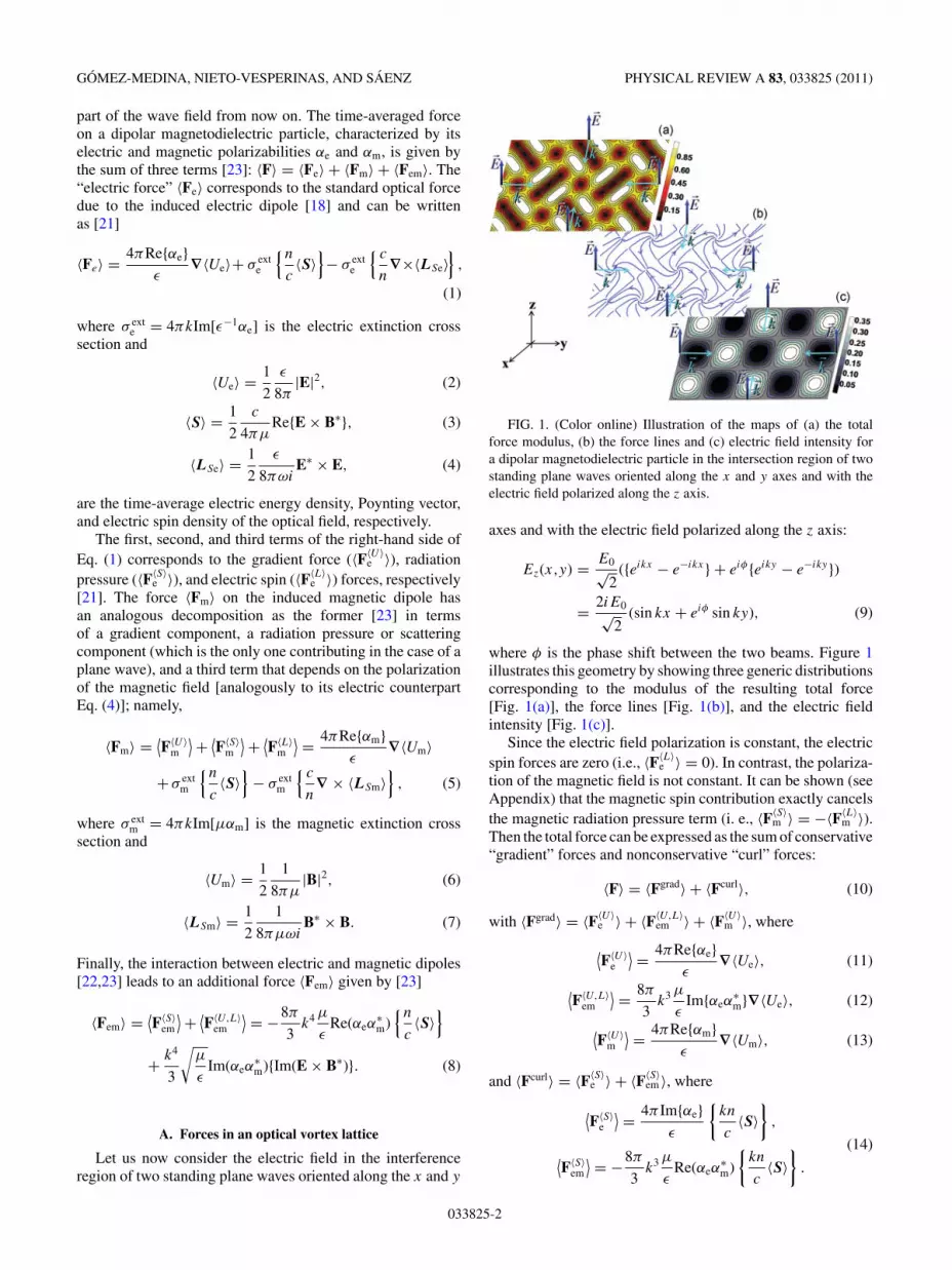
FIG. 1. (Color online) Illustration of the maps of (a) the totalforce modulus, (b) the force lines and (c) electric field intensity fora dipolar magnetodielectric particle in the intersection region of twostanding plane waves oriented along the x and y axes and with theelectric field polarized along the z axis.
axes and with the electric field polarized along the z axis:
Ez(x,y) = E0√2
({eikx − e−ikx} + eiφ{eiky − e−iky})
= 2iE0√2
(sin kx + eiφ sin ky), (9)
where φ is the phase shift between the two beams. Figure 1illustrates this geometry by showing three generic distributionscorresponding to the modulus of the resulting total force[Fig. 1(a)], the force lines [Fig. 1(b)], and the electric fieldintensity [Fig. 1(c)].
Since the electric field polarization is constant, the electricspin forces are zero (i.e., 〈F〈L〉
e 〉 = 0). In contrast, the polariza-tion of the magnetic field is not constant. It can be shown (seeAppendix) that the magnetic spin contribution exactly cancelsthe magnetic radiation pressure term (i. e., 〈F〈S〉
m 〉 = −〈F〈L〉m 〉).
Then the total force can be expressed as the sum of conservative“gradient” forces and nonconservative “curl” forces:
〈F〉 = 〈Fgrad〉 + 〈Fcurl〉, (10)
with 〈Fgrad〉 = 〈F〈U〉e 〉 + 〈F〈U,L〉
em 〉 + 〈F〈U〉m 〉, where
⟨F〈U〉
e
⟩ = 4πRe{αe}ε
∇〈Ue〉, (11)
⟨F〈U,L〉
em
⟩ = 8π
3k3 µ
εIm{αeα
∗m}∇〈Ue〉, (12)
⟨F〈U〉
m
⟩ = 4πRe{αm}ε
∇〈Um〉, (13)
and 〈Fcurl〉 = 〈F〈S〉e 〉 + 〈F〈S〉
em 〉, where
⟨F〈S〉
e
⟩ = 4π Im{αe}ε
{kn
c〈S〉
},
(14)⟨F〈S〉
em
⟩ = −8π
3k3 µ
εRe(αeα
∗m)
{kn
c〈S〉
}.
033825-2

NONCONSERVATIVE ELECTRIC AND MAGNETIC OPTICAL . . . PHYSICAL REVIEW A 83, 033825 (2011)
The expressions (11), (12), and (13) are proportional tothe gradient of the electric and magnetic energy density,respectively; that is,
∇〈Ue〉 = ε
8π|E0|2∇{sin2 kx + sin2 ky
+ 2 cos φ sin kx sin ky}, (15)
∇〈Um〉 = − ε
8π|E0|2∇{sin2 kx + sin2 ky}. (16)
Equations (14) are proportional to the time-averaged Poyntingvector:{
kn
c〈S〉
}= ε
4π|E0|2∇ × {uz sin φ cos kx cos ky}. (17)
FIG. 2. (Color online) Nonconservative forces on a Si sphere ofradius a = 230 nm placed at the intersection region of two standingwaves with a dephasing φ = π/2 in a medium with ε = µ = 1. Thelight field wavelength, λ = 1250 nm, is tuned to the dipolar electricresonance. Arrows in (a) and (b) point along the total force lines.(a) Contour maps of the modulus of the normalized total force,|〈F〉|/F0 with F0 = |E0|2/(ka3). (b) Contour maps of the normalizedelectric field intensity, |E|2/|E0|2. Near the resonance, the radiationpressure force, 〈F〈S〉
e 〉, overcomes the attractive gradient forces anddominates the total force which presents no stable equilibriumpositions. The symbols � and � indicate saddle points in the forcemap.
B. Force fields and beam dephasing
From the discussion above, notice that 〈Fe〉 is conservativeor nonconservative depending on the phase, while 〈Fm〉is always conservative (the opposite holds for p-polarizedfields—with the magnetic field polarized in the z direction).Optical forces resulting from the interference field given byEq. (9) can be tuned by changing the phase between the beams[25,27]. Experimentally, this phase φ between the two crossedstanding waves, can be set to any desired value produced bythe optical path length difference between the beams. This maybe achieved by controlling the position of one of the reflectingmirrors involved in the formation of the four mutually coherentcounterpropagating beams; for example, with the two branchesof a Michelson interferometer setup, as discussed in Ref. [27].
When lasers oscillate synchronously(i.e., for φ = 0,〈Fcurl〉 = 0), therefore, the force is conservative. It is wellknown [31] that, when the electric resonance is tuned,Re{αe} = 0 and Im{αe} = Im{αe}max (for lossless particlesIm{αe} ∝ λ2 and is independent of both particle size and ma-terial). Just at this resonance, the electric force becomes zero,〈Fe〉 = 〈F〈U〉
e 〉 = 〈F〈S〉e 〉 = 0; therefore, the total force would
be zero if we did not take the magnetic and electric-magneticinteraction force into account. However, the magnetic andthe interference term leads to a finite force. This should beobserved in future experiments, in contrast with the previouspredictions that considered only dipolar electric forces.
For φ = π/2 the force has contributions from the conserva-tive and nonconservative forces. The nonconservative forcesarise as a consequence of the rotation of the Poynting vectoraround the field nodes. In this case, when the wavelengthis close to the electric dipolar resonance (i.e., Re{αe} ≈ 0and Im{αe} ≈ Im{αe}max), the large electric extinction crosssection enhances 〈F〈S〉
e 〉 and overcomes the attractive gradientforces so that there are no stable equilibrium positions inthe system, as is the case for a metallic particle when the
FIG. 3. (Color online) Normalized force in the x direction, Fx
along a line defined by ky = π/2 for a Si sphere of radius a = 230 nmin the intersection region of two standing waves with φ = π/2 andfor different wavelengths. Notice that, since the force magnitude F0
is inversely proportional to ka3, this normalization factor is differentfor each of the four plots. The symbols sketch the force fields atseveral positions: � and � correspond to saddle points and � and �correspond to unstable and stable equilibrium (zero-force) positions,respectively.
033825-3
GOMEZ-MEDINA, NIETO-VESPERINAS, AND SAENZ PHYSICAL REVIEW A 83, 033825 (2011)
dissipation dominates [25]. Nevertheless, as the wavelengthgoes away from the electric resonance, a stable equilibriumposition can be found due to 〈F〈S〉
e 〉 being compensated by therest of the force contributions.
Notice that, for φ = π/2, the gradient of the electricand magnetic energy density are equal except for the sign,∇〈Um〉 = −∇〈Ue〉. Therefore it is possible to obtain a purelynonconservative force if the particle polarizabilities fulfillRe{αe} = Re{αm} and Im{αe} = Im{αm} because, in thiscase, 〈F〈U〉
m 〉 = −〈F〈U〉e 〉, 〈F〈U,L〉
em 〉 = 0, and the gradient forcebecomes zero.
III. OPTICAL FORCES ON SUBMICRON Si PARTICLES
A recent work [29] shows that dielectric spheres whoserefractive index is around 3.5 and whose size parameter ka isbetween 0.75 and 1.5 are excellent instances of magnetodi-electric particles whose electric and magnetic polarizabilitiesαe and αm are well described by
αe = i3ε
2k3a1, αm = i
3
2µk3b1, (18)
where a1 and b1 are their two Mie coefficients. In thisconnection, a very illustrative example to test all these new
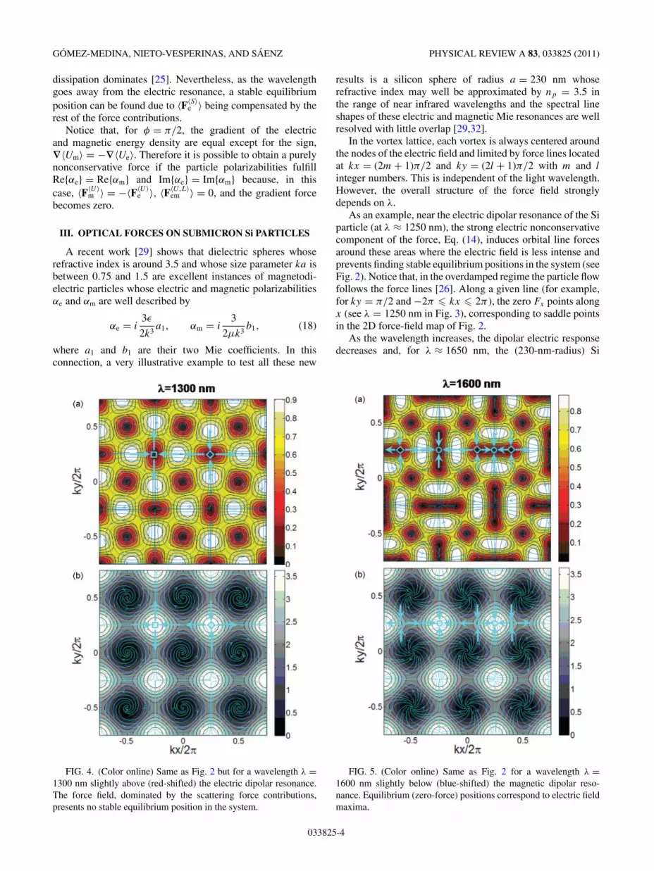
FIG. 4. (Color online) Same as Fig. 2 but for a wavelength λ =1300 nm slightly above (red-shifted) the electric dipolar resonance.The force field, dominated by the scattering force contributions,presents no stable equilibrium position in the system.
results is a silicon sphere of radius a = 230 nm whoserefractive index may well be approximated by np = 3.5 inthe range of near infrared wavelengths and the spectral lineshapes of these electric and magnetic Mie resonances are wellresolved with little overlap [29,32].
In the vortex lattice, each vortex is always centered aroundthe nodes of the electric field and limited by force lines locatedat kx = (2m + 1)π/2 and ky = (2l + 1)π/2 with m and l
integer numbers. This is independent of the light wavelength.However, the overall structure of the force field stronglydepends on λ.
As an example, near the electric dipolar resonance of the Siparticle (at λ ≈ 1250 nm), the strong electric nonconservativecomponent of the force, Eq. (14), induces orbital line forcesaround these areas where the electric field is less intense andprevents finding stable equilibrium positions in the system (seeFig. 2). Notice that, in the overdamped regime the particle flowfollows the force lines [26]. Along a given line (for example,for ky = π/2 and −2π � kx � 2π ), the zero Fx points alongx (see λ = 1250 nm in Fig. 3), corresponding to saddle pointsin the 2D force-field map of Fig. 2.
As the wavelength increases, the dipolar electric responsedecreases and, for λ ≈ 1650 nm, the (230-nm-radius) Si
FIG. 5. (Color online) Same as Fig. 2 for a wavelength λ =1600 nm slightly below (blue-shifted) the magnetic dipolar reso-nance. Equilibrium (zero-force) positions correspond to electric fieldmaxima.
033825-4

NONCONSERVATIVE ELECTRIC AND MAGNETIC OPTICAL . . . PHYSICAL REVIEW A 83, 033825 (2011)
particle presents a strong magnetic resonance (see Fig. 1 inRef. [32] and Fig. 3 in Ref. [29]). The corresponding changes inthe force-field maps are illustrated in Figs. 4–7. These changesmanifest themselves in the x component of the force along theky = π/2 line, as shown in Fig. 3.
For wavelengths slightly above (red-shifted) the electricdipolar resonance, the electric polarizability is larger than zeroand the contribution of the conservative gradient force is notnegligible. As can be seen in Fig. 4, for λ ≈ 1300 nm thecircular “orbits” become “whirls” around the nodes of theelectric field. However, gradient forces are not strong enough toovercome scattering forces and there are no stable equilibriumpositions in the system. The force along the division lines stillpresent the same “saddle” points as in resonance (Fig. 3).
Far enough from electric resonance, but still below (blueshifted) the dipolar magnetic resonance, the gradient forcesdominate, giving rise to stable equilibrium positions in thesystem centered where the electric field is more intensebecause Re{αe} > 0 and Re{αm} < 0 so that 〈F〈U〉
e 〉 and 〈F〈U〉m 〉
contribute to the conservative force with same sign [Eqs. (11)and (13)]. This is illustrated in Figs. 5 and 6 where we plottedthe force map at λ ≈ 1600 nm. Now the stable positionscorrespond to the high-intensity-field regions far from thevortex centers. This can also be seen in Fig. 3, where theoriginal saddle points become equilibrium positions (i.e.,effective potential minima) and new saddle points appearbetween two minima.
Above the magnetic resonance (red-shifted), Re{αm} >
Re{αe} > 0 in such way that 〈F〈U〉m 〉 [Eq. (13)] dominates
FIG. 6. (Color online) (a) Total force lines, (b) scattering forcelines, and (c) conservative force lines for a Si sphere of radiusa = 230 nm placed at the intersection region of two standing waveswith a dephasing φ = π/2 in a medium with ε = µ = 1. The lightfield wavelength, λ = 1600 nm, is slightly below (blue-shifted) themagnetic dipolar resonance (same as Fig. 5). The rotation of thePoynting vector around the field nodes [Fig. 6(b)] induces orbitalscattering force lines around these nodes; however, the conservativeforce [Fig. 6(c)] pushes the particle out from these nodes and towardstable positions at the corners between adjacent orbiting domains.The interplay between these two forces produces the whirls on thetotal forces [Fig. 6(a)].
FIG. 7. (Color online) Same as Fig. 2 for a wavelength λ =1725 nm slightly above (red-shifted) the magnetic dipolar resonance.Although the force has both contributions, conservative and non-conservative, the conservative magnetic force dominates giving riseto stable equilibrium positions centered where the electric field isless intense. The equilibrium (zero-force) positions, correspondingto magnetic field maxima, are now located at the vortex center.
the conservative force and the stable equilibrium positionsin the system become centered around the high-magnetic-fieldregions where the electric field is less intense (see Fig. 7).This is reflected in Fig. 3 where the stable equilibriumpositions (below the magnetic resonance) become unstablezero-force positions (i.e., effective potential maxima) abovethe resonance. Interestingly, the vortices are now centeredaround the effective potential minima leading to vortex linesconverging toward the centers.
Finally, let us mention some results concerning the case ofzero dephasing. For dephasing φ = 0 so the force is alwaysconservative. Interestingly, near the dipolar electric resonancethe electric force is negligible and the effective potentiallandscape is entirely due to the magnetic and electric-magneticinteraction force contribution. The force map is shown inFig. 8.
Finally, we should emphasize that it is possible to obtainequivalent results for p-polarization. In this case the electricforce is always conservative and curl terms appear in themagnetic and electric-magnetic force contribution. The forcemaps near the magnetic resonances will now be similar to that
033825-5

GOMEZ-MEDINA, NIETO-VESPERINAS, AND SAENZ PHYSICAL REVIEW A 83, 033825 (2011)
FIG. 8. (Color online) Same as Fig. 4 when the crossed beamsoscillate synchronously (φ = 0). At the dipolar electric resonance theelectric forces are zero. The force field in this case is entirely givenby magnetic or electric-magnetic forces.
discussed for s-polarized beams near the electric resonanceand viceversa.
IV. CONCLUSION
We have studied the optical forces on real small dielectricparticles made of nonmagnetic materials with magnetodielec-tric response in optical vortex fields. We have demonstratedthat those forces can be written as a sum of conservative andnonconservative components. Also, we have shown that thegeometry of the force lines can be easily tailored by tuningboth the wavelength and the phase shift between the fieldsforming the standing-wave pattern. The vortex-line forcesdepend on the both the chemical nature and the morphologyof the particle through its complex polarizabilities. SubmicronSi particles constitute an excellent laboratory to observe suchnew force effects. Similar effects are predicted for particleshaving large relative refractive indices such as Ge and TiO2
particles. Light vortex fields can offer a number of advantagesto assess the local mechanical properties of cells and biologicalfluids [33]. In turn, the nonconservative forces may be usedas a tunable probe of (nonlinear) properties of viscoelasticfluids or soft solids. The relevance of the electric-magneticdipole interaction suggests possible applications in particleseparation and sorting. We expect that these results will opennew avenues in the controlled transport of polarizable smallparticles.
ACKNOWLEDGMENTS
This work has been supported by the SpanishMEC through the Consolider NanoLight (CSD2007-00046)and FIS2006-11170-C01-C02 and FIS2009-13430-C01-C02research grants. Work by R.G.-M. financed by the MICINN“Juan de la Cierva” Grant.
APPENDIX
The three force terms of the decomposition Eq. (5), of thetotal magnetic force, resulting from the interference field givenby Eq. (9), are expressed as
⟨F〈U〉
m
⟩ = 4πRe{αm}ε
∇〈Um〉 = −Re{αm}2
|E0|2k sin(2kx)ux
− Re{αm}2
|E0|2k sin(2ky)uy, (A1)
⟨F〈S〉
m
⟩ = σ extm
{n
c〈S〉
}= −σ ext
m
4πε|E0|2 sin φ cos kx sin (ky)ux
+ σ extm
4πε|E0|2 sin φ cos ky sin (kx)uy, (A2)
where{n
c〈S〉
}= ε
4πk|E0|2∇ × {sin φ cos kx cos (ky)uz}, (A3)
and ⟨F〈L〉
m
⟩ = −σ extm
{ c
n∇ × 〈LSm〉
}
= σ extm
ε|E0|24π
sin φ sin ky cos (kx)ux
− σ extm
ε|E0|24π
sin φ sin kx cos (ky)uy, (A4)
where
〈LSm〉 = ε|E0|24πω
sin φ cos kx cos (ky)uz. (A5)
Notice that Eqs. (A4) and (A2) cancel each other when sub-stituted into Eq. (5); namely, 〈F〈S〉
m 〉 = −〈F〈L〉m 〉. Therefore the
total magnetic force is always conservative and independentof the phase shift:
〈Fm〉 = ⟨F〈U〉
m
⟩ + ⟨F〈S〉
m
⟩ + ⟨F〈L〉
m
⟩ = ⟨F〈U〉
m
⟩. (A6)
[1] P. Reiman, Phys. Rep. 361, 57 (2002).[2] T. G. Mason, K. Ganesan, J. H. vanZanten, D. Wirtz, and S. C.
Kuo, Phys. Rev. Lett. 79, 3282 (1997).
[3] F. Scheffold and P. Schurtenberg, Soft Mater 1, 139 (2003).[4] V. M. Rotello, Adv. Drug Delivery Rev. 60, 1255 (2008).[5] A. Ashkin, Proc. Natl. Acad. Sci. USA 94, 4853 (1997).
033825-6

NONCONSERVATIVE ELECTRIC AND MAGNETIC OPTICAL . . . PHYSICAL REVIEW A 83, 033825 (2011)
[6] J. E. Curtis, B. A. Koss, and D. G. Grier, Opt. Comm. 207, 169(2002).
[7] M. M. Burns, J.-M. Fournier, and J. A. Golovchenko, Science249, 749 (1990).
[8] M. I. Antonoyiannakis and J. B. Pendry, Europhys. Lett. 40, 613(1997).
[9] R. Gomez-Medina, P. SanJose, A. Garcia-Martin, M. Lester,M. Nieto-Vesperinas, and J. J. Saenz, Phys. Rev. Lett. 86, 4275(2001).
[10] P. T. Korda, M. B. Taylor, and D. G. Grier, Phys. Rev. Lett. 89,128301 (2002).
[11] M. P. MacDonald, G. C. Spalding, and K. Dholakia, Nature(London) 426, 421 (2003).
[12] M. M. Burns, J.-M. Fournier, and J. A. Golovchenko, Phys. Rev.Lett. 63, 1233 (1989).
[13] S. A. Tatarkova, W. Sibbett, and K. Dholakia, Phys. Rev. Lett.91, 038101 (2003).
[14] R. Gomez-Medina and J. J. Saenz, Phys. Rev. Lett. 93, 243602(2004).
[15] M. Guillon, O. Moine, and B. Stout, Phys. Rev. Lett. 96, 143902(2006).
[16] S. Gaugiran, S. Getin, J. M. Fedeli, and J. Derouard, Opt. Express15, 8146 (2007).
[17] K. Dholakia and P. Zemanek, Rev. Mod. Phys. 82, 1767 (2010).[18] P. C. Chaumet and M. Nieto-Vesperinas, Phys. Rev. B 61, 14119
(2000); P. C. Chaumet, A. Rahmani, and M. Nieto-Vesperinas,Phys. Rev. Lett. 88, 123601 (2002); M. Nieto-Vesperinas, P. C.Chaumet, and A. Rahmani, Philos. Trans. R. Soc. London A362, 719 (2004).
[19] B. A. Kemp, T. M. Grzegorczyk, and J. A. Kong, Phys. Rev.Lett. 97, 133902 (2006).
[20] M. Mansuripur, Opt. Express 12, 5375 (2004).[21] S. Albaladejo, M. I. Marques, M. Laroche, and J. J. Saenz, Phys.
Rev. Lett. 102, 113602 (2009).[22] P. C. Chaumet and A. Rahmani, Opt. Express 17, 2224
(2009).[23] M. Nieto-Vesperinas, J. J. Saenz, R. Gomez-Medina, and
L. Chantada, Opt. Express 18, 11428 (2010).[24] P. Zemanek, V. Karasek, and A. Sasso, Opt. Commun. 240, 401
(2004).[25] S. Albaladejo, M. I. Marques, F. Scheffold, and J. J. Saenz, Nano
Lett. 9, 3527 (2009).[26] I. Zapata, S. Albaladejo, J. M. R. Parrondo, J. J.
Saenz, and F. Sols, Phys. Rev. Lett. 103, 130601(2009).
[27] A. Hemmerich and T. W. Hansch, Phys. Rev. Lett. 68, 1492(1992); 70, 410 (1993).
[28] P. Zemanek, M. Siler, V. Karasek, and T. Cizmar, Proc. SPIEInt. Soc. Opt. Eng. 5930, 59301N (2005).
[29] A. Garcıa-Etxarri et al., Opt. Express 19, 4815 (2011).[30] G. Grynberg, B. Lounis, P. Verkerk, J. Y. Courtois, and
C. Salomon, Phys. Rev. Lett. 70, 2249 (1993).[31] H. C. Hulst, Light Scattering by Small Particles (Dover,
New York, 1981).[32] M. Nieto-Vesperinas, R. Gomez-Medina, and J. J. Saenz, J. Opt.
Soc. Am. A 28, 54 (2011).[33] J. C. Crocker and B. D. Hoffman, Methods Cell Biol. 83, 141
(2007).
033825-7


