Embed Size (px)
Citation preview
Mechanics of Advanced Materials and Structures, 13:357–369, 2006Copyright c© Taylor & Francis Group, LLCISSN: 1537-6494 print / 1537-6532 onlineDOI: 10.1080/15376490600777665
On Higher-Order Modelling of Smart Beamswith Embedded Shear-Mode Piezoceramic Actuatorsand Sensors
Marcelo A. TrindadeSao Carlos School of Engineering, University of Sao Paulo, Sao Carlos, Brazil
Ayech BenjeddouInstitut Superieur de Mecanique de Paris, Saint Ouen, France
A refined sandwich beam model is proposed in the present work.The mechanical model is a refinement of the classical sandwichtheory (CST), where the core is modelled with a third-order sheardeformation theory (TSDT). It is shown that the electromechani-cal coupling with the higher-order strains requires a third-orderthrough-thickness model for the electric potential. Using these as-sumptions, a finite element (FE) model is developed considering,through the beam length, electrically: constant electric difference ofpotentials for the piezoelectric facing and core layers and quadraticthird-order variable of the electric potential in the core, whilemechanically: linear axial displacement and quadratic bendingrotation of the core, and cubic transverse displacement of thesandwich beam. The proposed FE model is then compared withanalytical and numerical CST, that use a first-order shear defor-mation theory (FSDT) in the core, and analytical equivalent sin-gle layer (ESL) models for a continuous piezoceramic core. It isshown that even when acting as an actuator, there exists a third-order induced potential in the piezoceramic material which mayyield an overall stiffer structure. A comparison between FSDT andTSDT FE results for a piezoceramic embedded in an elastic coreis also performed to evaluate the electrical and mechanical modelrefinements.
1. INTRODUCTIONPiezoelectric actuators have been widely used for the de-
sign of smart structures over the last two decades. They canbe either surface-mounted or embedded into a host structure.Surface-mounted actuators are normally poled in the thicknessdirection, so that they act as extension actuators. However, thisconfiguration subjects the actuators to high stresses and possiblecontact with foreign objects which are undesired for these brit-tle piezoceramics. These problems can be alleviated by using
Received 15 March 2006; accepted 31 March 2006.Address correspondence to M. A. Trindade, Department of Mechan-
ical Engineering, Sao Carlos School of Engineering, University of SaoPaulo, Av. Trabalhador Sao-Carlense, 400, 13566-590 Sao Carlos-SP,Brazil. E-mail: [email protected]
axially poled piezoceramic actuators sandwiched between twoelastic layers, as proposed by Sun and Zhang [1]. In this case, theapplication of an electric field in the thickness direction inducestransverse shear deformation of the actuator thus generating thedesired transverse deflection of the sandwich structure.
After the pioneer works of Sun and Zhang [1, 2], several re-searchers have been interested in piezoelectric shear actuation.Through the use of a classical sandwich beam theory, Benjeddouet al. [3–5] showed that shear actuators induce distributed actu-ation moments in the structure unlike extension actuators whichinduce boundary forces. Therefore, the shear actuation mech-anism may lead to fewer problems of debonding in actuatorsboundaries and to minor dependence of the control performanceon actuators position and length. Aldraihem and Khdeir [6–8]presented exact solutions for sandwich beams with shear and ex-tension actuators using equivalent single layer models based onfirst-order and third-order shear deformation theories. Trindadeet al. [9] presented a comparison between active control perfor-mances of shear and extension actuation mechanisms using asandwich beam finite element model. They showed that shearactuators are generally more suitable to control bending vibra-tions of stiff structures. Raja et al. [10] also studied active damp-ing performance in composite materials using shear actuatorsas compared to that using the widespread extension actuators.Their results showed that shear actuators have promising fea-tures for vibration control applications, in particular the shearactuator was observed to be more effective in velocity feedbackthan the extension actuator. In a later work [11], Raja et al. havepresented a finite element static analysis of sandwich beamsactuated simultaneously by shear and extension actuators forseveral boundary conditions. Vel and Batra [12] presented anexact 3D solution for the static cylindrical bending of simplysupported laminated plates with embedded shear piezoelectricactuators. Their analysis has shown that both longitudinal andshear stresses within the actuator are significantly smaller forthe shear actuator. Recently, Edery-Azulay and Abramovich[13] presented closed-form solutions for the static analysis of
357
358 M. A. TRINDADE AND A. BENJEDDOU
laminate/sandwich beams with embedded extension and shearactuators. Achievements, trends and perspectives of the use ofshear-mode piezoceramics in smart structures applications haverecently been presented in [14, 15].
Although this so-called shear actuation mechanism seemsquite promising for structural control, its modelling is still anopen issue. Indeed, most of the existing refined models for piezo-electric laminate/sandwich structures focus on extension actu-ators, thus leading at most, to higher-order mechanical modelsbut simple low order electrical models, since extension actua-tors present a simpler electrical behavior [16]. For shear actuatedpiezoelectric sandwich beams, either the classical sandwich the-ory (CST), with a first-order shear deformation (Timoshenko)for the core [2, 17], or first and higher-order equivalent singlelayer (ESL) theories [8, 18] were used. However, on one hand,it is very difficult to model the localized core shear deformationthrough ESL theories, and, on the other hand, the correct esti-mation of the core shear deformation is determinant to evaluatethe sandwich beam induced deflection.
Hence, a refined sandwich beam model is proposed in thepresent work. The mechanical model is a refinement of CST,for which the facing layers respect Euler-Bernoulli assumptionsand the core is modelled with the third-order shear deformationtheory (TSDT) proposed by Reddy [19]. It is shown that the elec-tromechanical coupling with the higher-order strains requires athird-order through-thickness model for the electric potential.Using these assumptions, a finite element (FE) model is devel-oped considering, through the beam length, electrically: constantelectric difference of potentials for the piezoelectric facing andcore layers and quadratic third-order variable of the electric po-tential in the core, while mechanically: linear axial displacementand quadratic bending rotation of the core, and cubic transversedisplacement of the sandwich beam. It is shown that, althoughmore refined models are considered for the mechanical and elec-trical behaviors of the piezoelectric core, the resulting FE modelhas the same number of degrees of freedom (dof) as the pre-vious CST one [17] due to a two-step static condensation ofthe internal dof of the bending rotation and third-order variableof the electric potential in the core. The proposed FE model isthen compared with analytical and numerical CST [2, 17] andanalytical ESL models [6] for a continuous piezoceramic core.Finally, a comparison between FSDT and TSDT FE models fora discontinuous elastic/piezoceramic core is performed to eval-uate the effects of both electrical and mechanical refinements inthe model.
2. THIRD-ORDER ELECTROMECHANICALSANDWICH MODELA multilayer beam made of piezoelectric layers is modelled
using a classical sandwich theory. Therefore, the beam is sup-posed to consist of a core layer sandwiched between top andbottom laminate face layers. The latter respect Euler-Bernoulliassumptions and hence are modelled using the classical lami-
nate theory. On the contrary, the core is allowed to present shearstrains, which are modelled using the TSDT proposed by Reddy[19]. For simplicity, all layers are assumed to be made of or-thotropic piezoelectric materials, perfectly bonded and in planestress state. In addition, the sub-layers of the faces are poled inthe thickness direction while the core is poled in the longitudinaldirection. However, both have electrodes covering completelytheir top and bottom skins. The length, width and thickness ofthe beam are denoted by L , b and h, respectively. Quantities rel-ative to the upper, core and lower layers are represented by thesubscripts a j , c and b j , where the subscript j = {1, . . . , (n, m)}denotes a sub-layer of the laminate faces. n and m are the numberof sub-layers in the faces a and b respectively.
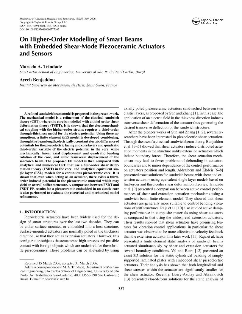
2.1. Displacements and StrainsFrom the assumptions cited previously, the axial and trans-
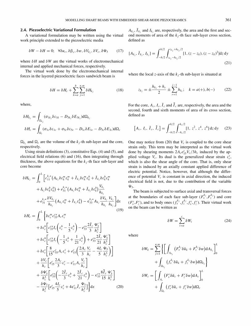
verse displacement fields of faces and core may be written inthe following general form (also see Figure 1)
uk(x, y, z) = uk(x) + (z − zk)βk(x); k = a, b
uc(x, y, z) = uc(x) + (z − zc)βc(x) − 4(z − zc)3
3h2c (1)× [βc(x) + w(x)′]
wi (x, y, z) = w(x); i = a, b, c
Notice that the same displacement fields uk (k = a, b) are con-sidered for all sub-layers k j of the face k. From Euler-Bernoullihypotheses, βk = −w′ (k = a, b), where, •′ is used to denote∂ • /∂x . The mid-plan of the core is set to coincide with theorigin of the z-axis, so that zc = 0.
FIG. 1. Kinematics representation of the multilayer faces sandwich beam withthird-order shear deformation theory for the core.
MODELLING SMART BEAMS WITH EMBEDDED SHEAR-MODE PIEZOCERAMICS 359
Using the displacement continuity conditions between lay-ers, the displacement fields (1) may be written in terms of onlythree main variables. It is chosen then to write the displacementsof the face layers neutral line, ua and ub, in terms of the axialdisplacement and section rotation of the core, uc and βc. Con-sequently, the i-th layer displacement fields may be rewritten interms of the three model independent mechanical variables uc,βc and w as
uk(x, z) =(
uc ± hcβc
3∓ dkw
′)
− (z − zk)w′;
k = a(+), b(−)
uc(x, z) = uc + zβc − 4z3
3h2c
(βc + w′) (2)
wi (x, z) = w(x); i = a, b, c
where
dk = 3hk + hc
6; zk = ±hk + hc
2;
hk =n,m∑j=1
hk j ; k = a(+, n), b(−, m)
The usual strain-displacement relations for each layer yieldthe following axial ε1 and shear ε5 strains for the i-th layer
ε1k = εmk + (z − zk)εb
k
ε1c = εmc + zεb
c − 4z3
3h2c
εhc
(3)
ε5c =(
1 − 4z2
h2c
)εs
c
where
εmk = u′
c ± hcβ′c
3∓ dkw
′′; εbk = −w′′; k = a(+), b(−)
εmc = u′
c; εbc = β′
c; εhc = β′
c + w′′; εsc = βc + w′
Notice that the parameters dk (k = a, b) are membrane-bendingcoupling parameters. Notice also that εh
c = εbc − εb
k = (εsc)′,
meaning that the higher-order strain corresponds to a relativebending deformation between faces and core.
2.2. Reduced Piezoelectric Constitutive EquationsLinear orthotropic piezoelectric materials with material sym-
metry axes parallel to the beam ones are considered here. ci j ,ek j and εkk (i, j = 1, . . . , 6; k = 1, 2, 3) denote their elastic,piezoelectric and dielectric material constants.
The piezoelectric face sub-layers are poled transversely andsubjected to transverse electrical fields only. Hence, the three-dimensional linear constitutive equations of the face sub-layer
k j can be reduced [3] to
{σ1k j
D3k j
}=
c
k j ∗11 −e
k j ∗31
ek j ∗31 ε
k j ∗33
{ε1k
E3k j
}(4)
where,
ck j ∗11 = c
k j
11 − ck j
132
ck j
33
; ek j ∗31 = e
k j
31 − ck j
13
ck j
33
ek j
33;
εk j ∗33 = ε
k j
33 + ek j
332
ck j
33
σ1k j , ε1k , D3k j and E3k j are axial stress and strain, and trans-verse electrical displacement and field. The modification of thematerial constants is due to the plane stress assumption (σ3 = 0).
The piezoelectric core layer is poled in the axial direction. Itsconstitutive equations can be obtained from those of the surfacelayers through a rotation, so that axial and transverse indicesinterchange. Therefore, the reduced constitutive equations ofthe piezoelectric core are
σ1c
σ5c
D1c
D3c
=
cc∗33 0 −ec∗
33 0
0 cc55 0 −ec
15
ec∗33 0 εc∗
33 0
0 ec15 0 εc
11
ε1c
ε5c
E1c
E3c
(5)
where
cc∗33 = cc
33 − cc 213
cc11
; ec∗33 = ec
33 − cc13
cc11
ec31; εc∗
33 = εc33 + ec 2
31
cc11
and σ5c, ε5c, D1c and E1c are transverse shear stress and strain,and axial electrical displacement and field. The material con-stants modification is also due to the plane stress assumption forthe core (σ3 = 0).
Notice the presence in Eq. (5) of both axial and transversecomponents of the electric field and displacement.
2.3. Electric Potentials and FieldsA constant transverse electrical field is assumed for the face
piezoelectric sub-layers and the remaining in-plane componentsare supposed to vanish. Consequently it is, for the k j -th facepiezoelectric sub-layer,
E3k j = − Vk j
hk j
(6)
where Vk j is the difference of electric potential of the k j -th lam-inae, defined by Vk j = V +
k j− V −
k j, with V +
k jand V −
k jbeing the
voltages applied on the upper and lower skins of the k j -th piezo-electric face sub-layer.
360 M. A. TRINDADE AND A. BENJEDDOU
On the contrary, both axial and transverse electrical fieldsare considered for the core piezoelectric layer. In addition, thetransverse one is assumed to be quadratic through thicknessand not constant as for the face sub-layers. Hence, the electricpotential in the core is assumed cubic through thickness and inthe following form,
�(x, z) = �0(x) + z
hc�1(x) + z2
h2c
�2(x) + z3
h3c
�3(x) (7)
It is worthwhile to rewrite the electric potential (7) in termsof the mean and difference of electric potential on the upper andlower skins of the piezoelectric core,
�(x, hc/2) = �+ and �(x, −hc/2) = �− �
�1 + �3
4= Vc and �0 + �2
4= �m
where
Vc = �+ − �−; �m = �+ + �−
2(8)
Notice that for a piezoelectric patch with upper and bottom skinsfully covered by electrodes, the electric potentials �+ and �−,and thus both Vc and �m , are constant in the axial direction.Hence, the electric potential (7) may be rewritten as
�(x, z) = �m + z
hcVc +
(z2
h2c
− 1
4
)�2(x)
+(
z2
h2c
− 1
4
)z
hc�3(x) (9)
The axial E1c = −∂�/∂x and transverse E3c = −∂�/∂zelectrical fields may then be evaluated from the electric potential(9) leading to
E1c = −(
z2
h2c
− 1
4
)� ′
2 −(
z2
h2c
− 1
4
)z
hc� ′
3
(10)
E3c = − Vc
hc− z
hc
2�2
hc−
(3z2
h2c
− 1
4
)�3
hc
Notice that the axial electric field is only due to the electricpotential higher-order terms. Moreover, it vanishes on the upperand lower surfaces of the piezoceramic core (see Eq. (10)). Thechoice of a cubic electric potential is justified by the solution ofthe electrostatic equilibrium equation
D1c,1 + D2c,2 + D3c,3 = 0 (11)
Noting that D2c,2 is assumed to vanish and replacing D1c andD3c, of the core constitutive Eqs. (5), in the last equation lead to
ec∗33
∂ε1c
∂x+ εc∗
33∂E1c
∂x+ ec
15∂ε5c
∂z+ εc
11∂E3c
∂z= 0 (12)
Using the definitions of axial and shear strains (3), in terms of thegeneralized membrane, bending, higher-order and shear strains,and the electric field-potential relations together with Eq. (7),the last equation may be rewritten leading to the relations
εc∗33
1
4� ′′
2 − εc11
2
hc
�2
hc+ ec∗
33εmc
′ = 0
εc∗33
1
4
� ′′3
hc− εc
116
h2c
�3
hc+ ec∗
33εbc′ − ec
158
h2c
εsc = 0
(13)εc∗
33� ′′
2
h2c
= 0
εc∗33
� ′′3
h3c
+ ec∗33
4
3h2c
εhc′ = 0
or, alternatively, writing these conditions in terms of the mainvariables, uc, βc and w, yields
εc∗33
1
4� ′′
2 − εc11
2
hc
�2
hc+ ec∗
33u′′c = 0
εc∗33
1
4
� ′′3
hc− εc
116
h2c
�3
hc+ ec∗
33β′′c − ec
158
h2c
(βc + w′) = 0
(14)εc∗
33� ′′
2
h2c
= 0
εc∗33
� ′′3
h3c
+ ec∗33
4
3h2c
(β′′c + w′′′) = 0
Conditions (13) show that �2 is only coupled to the axialstrain of the core, while �3 is coupled to bending, shear andhigher-order strains. If a linear approximation for uc is consid-ered, (14) yields �2 = 0. On the other hand, as long as thereis shear strain in the core, a cubic electric potential is inducedthrough �3, as shown in (13). Also, in case of a cubic approxima-tion for w, conditions (14) require a quadratic approximation forβc and �3. This justifies the choice of a cubic through-thicknesselectric potential. Although conditions (14) allow the evaluationof the electric potential in the core from the mechanical variablesuc, βc and w, let us assume for now that it is arbitrary as in (9)but with �2 = 0. This leads to the following electric potential
�(x, z) = �m + z
hcVc +
(z2
h2c
− 1
4
)z
hc�3(x) (15)
and hence to the following axial and transverse electrical fields(as in (10) but with �2 = 0)
E1c = −(
z2
h2c
− 1
4
)z
hc� ′
3, E3c = − Vc
hc−
(3z2
h2c
− 1
4
)�3
hc
(16)
From Eqs. (6) and (16), it is clear that the electric modelindependent variables are Vk j , Vc and �3.
MODELLING SMART BEAMS WITH EMBEDDED SHEAR-MODE PIEZOCERAMICS 361
2.4. Piezoelectric Variational FormulationA variational formulation may be written using the virtual
work principle extended to the piezoelectric media
δW − δH = 0; ∀δuc, δβc, δw, δVk j , δVc, δ�3 (17)
where δH and δW are the virtual works of electromechanicalinternal and applied mechanical forces, respectively.
The virtual work done by the electromechanical internalforces in the layered piezoelectric faces sandwich beam is
δH = δHc +b∑
k=a
n,m∑j=1
δHk j (18)
where,
δHk j =∫
�k j
(σ1k j δε1k − D3k j δE3k j )d�k j
δHc =∫
�c
(σ1cδε1c + σ5cδε5c − D1cδE1c − D3cδE3c)d�c
�k j and �c are the volume of the k j -th sub-layer and the core,respectively.
Using strain definitions (3), constitutive Eqs. (4) and (5), andelectrical field relations (6) and (16), then integrating throughthickness, the above equations for the k j -th face sub-layer andcore become
δHk j =∫ L
0
[c
k j ∗11
(Ak j δεm
k εmk + I k j δεm
k εbk + I k j δεb
kεmk
+ Ik j δεbkε
bk
) + ek j ∗31
(Ak j δεm
k + I k j δεbk
) Vk j
hk j
+ ek j ∗31
δVk j
hk j
(Ak j ε
mk + I k j ε
bk
) − εk j ∗33 Ak j
δVk j
hk j
Vk j
hk j
]dx
(19)
δHc =∫ L
0
{δεm
c cc∗33 Acε
mc
+ δεbc
[cc∗
33 Ic
(εb
c − 1
5εh
c
)− ec∗
332 I c
3
� ′3
h3c
]
+ δεhc
[cc∗
33 Ic
(−1
5εb
c + 1
21εh
c
)+ ec∗
332 I c
21
� ′3
h3c
]
+ δεsc
[8
15cc
55 Acεsc + ec
15
(2Ac
3
Vc
hc− 4Ic
5
�3
h3c
)]
+ δVc
hc
[ec
152Ac
3εs
c − εc11 Ac
Vc
hc
]
+ δ� ′3
h3c
[ec∗
33
(−2 I c
3εb
c + 2 I c
21εh
c
)− εc∗
338 ¯I c
15
� ′3
h3c
]
− δ�3
h3c
[ec
154Ic
5εs
c + 4εc11 I c
�3
h3c
]}dx (20)
Ak j , I k j and Ik j are, respectively, the area and the first and sec-ond moments of area of the k j -th face sub-layer cross section,defined as
[Ak j , I k j , Ik j ] =∫ b/2
−b/2
∫ zk j +hk j /2
zk j −hk j /2[1, (z − zk), (z − zk)2]dz dy
(21)
where the local z-axis of the k j -th sub-layer is situated at
zk j = ±hk j + hc
2±
j−1∑r=1
hkr ; k = a(+), b(−) (22)
For the core, Ac, Ic, I c and ¯I c are, respectively, the area and thesecond, fourth and sixth moments of area of its cross section,defined as
[Ac, Ic, I c,
¯I c] =
∫ b/2
−b/2
∫ hc/2
−hc/2[1, z2, z4, z6] dz dy (23)
One may notice from (20) that Vc is coupled to the core shearstrain only. This term may be interpreted as the virtual workdone by shearing moments 2Acec
15Vc/3hc induced by the ap-plied voltage Vc. Its dual is the generalized shear strain εs
c,which is also the shear angle of the core. That is, only shearstrain is induced by an axially constant applied difference ofelectric potential. Notice, however, that although the differ-ence of potential Vc is constant in axial direction, the inducedelectrical field is not, due to the contribution of the variable�3.
The beam is subjected to surface axial and transversal forcesat the boundaries of each face sub-layer (F
k jx ,F
k jz ) and core
(Fcx ,Fc
z ), and to body ones ( fk jx , f
k jz , f c
x , f cz ). Their virtual work
on the beam can be written as
δW =c∑
i=a
δWi (24)
where
δWk =n,m∑j=1
{[ ∫Ak j
(F
k jx δuk + F
k jz δw
)dAk j
]L
0
+∫
�k j
(f
k jx δuk + f
k jz δw
)d�k j
}
δWc =[ ∫
Ac
(Fc
x δuc + Fcz δw
)dAc
]L
0
+∫
�c
(f cx δuc + f c
z δw)d�c
362 M. A. TRINDADE AND A. BENJEDDOU
Using displacement expressions (2), one may write the previousequations for the k-th face and the core, as
δWk =[
Nkδuc ± Nkhc
3δβc − (Mk ± Nkdk)δw′ + Qkδw
]L
0
+∫ L
0
(nkδuc ± nkhc
3δβc − (mk ± nkdk)δw′ + qkδw
)dx ;
k = a(+), b(−) (25)
δWc = [δuc Nc + δβc Mc − δw′ Pc + δwQc]L0
+∫ L
0(δucnc + δβcmc − δw′ pc + δwqc)dx (26)
where the, boundary and distributed, normal, moment and shearresultants are defined as
Nk =∑
j
Nk j ; Mk =∑
j
Mk j ; Qk =∑
j
Qk j
(27)nk =
∑j
nk j ; mk =∑
j
mk j ; qk =∑
j
qk j
with
Nk j =∫
Fk jx dAk j ; Mk j =
∫F
k jx (z − zk)dAk j
Qk j =∫
Fk jz dAk j
nk j =∫
fk jx dAk j ; mk j =
∫f
k jx (z − zk)dAk j
qk j =∫
fk jz dAk j
Nc =∫
Fcx dAc; Mc =
∫Fc
x
(z − 4z3
3h2c
)dAc
Pc =∫
Fcx
4z3
3h2c
dAc; Qc =∫
Fcz dAc
nc =∫
f cx dAc; mc =
∫f cx
(z − 4z3
3h2c
)dAc
pc =∫
f cx
4z3
3h2c
dAc; qc =∫
f cz dAc
Notice that a difference between the axial forces Fk jx and f
k jx
( j = 1, . . . , (n, m)) on each sub-layer of face k may inducebending moments Mk and mk , due to the membrane-bendingcoupling caused by the first moment of area I k j . Notice alsothat when the axial forces Fc
x and f cx applied in the core are
asymmetric through thickness, they induce bending momentsMc and mc and shear moments Pc and pc. The latter aredue to the higher-order terms considered in the displacementfields.
3. THIRD-ORDER PIEZOELECTRIC FINITEELEMENT MODELUsing the expressions of virtual works in the variational
formulation, a finite element model for the piezoelectric sand-wich/multilayer beam is developed. Lagrange linear shape func-tions are assumed for the axial displacement of the core, uc. Theelectrical difference of potentials Vk j of the l and p piezoelec-tric sub-layers of the faces a and b, respectively, and Vc of thepiezoelectric core, are considered to be constant in the element.A quadratic shape function is assumed for the section rotationof the core βc, to avoid shear locking, and for the third-ordercoefficient �3 in the core electric potential, to respect the electro-static equilibrium conditions (13). For the transverse deflectionw, Hermite cubic shape functions are assumed. Hence, the el-ementary degrees of freedom (dof) column vector q is definedas
q = col(
u(1)c , w(1), w′(1), β(1)
c , �(1)3 , u(2)
c , w(2), w′(2), β(2)c , �
(2)3 ,
β(0)c , V (0)
a1, . . . , V (0)
al, V (0)
b1, . . . , V (0)
bp, V (0)
c , �(0)3
)(28)
where the ˆ will be used to define elementary quantities. Usingthis definition in the relations (19) and (20), the discretized vir-tual works of the elementary electromechanical internal forcesof the face sub-layers δH k j and the core δH c are
δH k j = δqt(Kk j m − Kk j me − Kt
k j me + Kk j e)q = δqt Kk j q
(29)δH c = δqt
(Kcm − Kcme − Kt
cme + Kce)q = δqt Kcq
where the elementary mechanical Kk j m , piezoelectric Kk j me anddielectric Kk j e stiffness matrices of k j -th sub-layer of the facesare
Kk j m =∫ Le
0c
k j ∗11
[Ak j B
tkmBkm + I k j
(Bt
kmBkb + BtkbBkm
)+ Ik j B
tkbBkb
]dx
(30)Kk j me = −
∫ Le
0e
k j ∗31
1
hk j
(Ak j B
tkm + I k j B
tkb
)Npk j dx
Kk j e = −∫ Le
0ε
k j ∗33
Ak j
h2k j
Ntpk j Npk j dx
Le is the element length. Bkm and Bkb are the membrane (m) andbending (b) strain operators of the faces. Npk j is the interpolationmatrix used for the difference of electric potential Vk j in the facessub-layers.
MODELLING SMART BEAMS WITH EMBEDDED SHEAR-MODE PIEZOCERAMICS 363
The elementary stiffness matrices of the core Kcm , Kcme andKce are written as
Kcm =∫ Le
0
{cc∗
33
[AcBt
cmBcm + IcBtcbBcb
− Ic
5
(Bt
cbBch + BtchBcb
) + Ic
21Bt
chBch
]
+ 8
15cc
55 AcBtcsBcs
}dx
Kcme = −∫ Le
0
{ec∗
33
(−2 I c
3h3c
BtcbN′
�3 + 2 I c
21h3c
BtchN′
�3
)
+ ec15Bt
cs
(2Ac
3hcNV c − 4Ic
5h3c
N�3
)}dx
Kce = −∫ Le
0
{εc∗
338 ¯I c
15h6c
N′�3
t N′�3
+ εc11
(Ac
h2c
NtV cNV c + 4 I c
h6c
Nt�3N�3
)}dx (31)
where Bcm , Bcb, Bch and Bcs are the membrane (m), bending (b),higher-order (h) and shear (s) strain operators. Notice that bend-ing and higher-order strains of the core are coupled. The piezo-electric stiffness is composed of terms coupling shear strainswith the electric variables Vc and �3 and terms coupling thederivative � ′
3 with bending and higher-order strains. The latterare due to the axial component of the electrical field. The electricvariables Vc and �3 are interpolated by the operators NV c andN�3.
The elementary virtual work of distributed applied mechan-ical forces may be written as
δW = δqT Fm (32)
where Fm defines the vector of generalized distributed mechan-ical nodal forces obtained from (25) and (26),
Fm =∫ Le
0
[Nt
ax na + Ntbx nb + Nt
cx nc + Ntaz(qa + qb + qc)
−Ntar (ma + mb) + Nt
cr mc − Ntcs pc
]dx (33)
Ni x , Nz , Nir and Ncs are the translation in x and z directions, ro-tation and shear interpolation matrices. The point forces contri-butions in (25) and (26) can be added a posteriori to the matricialsystem.
Using discretized expressions, one may obtain the elemen-tary electromechanical internal forces virtual work of the sand-wich/multilayer beam. Then, substituting the expressions of el-ementary discretized virtual works in (17), the discretized vari-ational formulation for an element is written as
(K f + Kc)q = Fm (34)
where K f = ∑k
∑j Kk j . Notice that electric dofs may be elim-
inated from the dofs vector through a static condensation. Sincethere are elemental (V (0)
a j, V (0)
b j, V (0)
c and �(0)3 ) and nodal (� (1)
3and �
(2)3 ) electric dofs, the static condensation will be obtained
in two steps. First, the unknown elemental electric dofs are con-densed at the element level; then, after assembling, the nodalelectric dofs are condensed at the global level. Notice that thestatic condensation at the element level may also be used toeliminate the internal mechanical dof β(0)
c .Therefore, let us decompose the electric dofs in prescribed
elemental ones qa , corresponding to the difference of poten-tials (V (0)
a j, V (0)
b j, V (0)
c ) applied to an actuator; unknown ele-mental ones qs , corresponding to the difference of potentials(V (0)
a j, V (0)
b j, V (0)
c ) induced in a sensor and the unknown �(0)3 for
the piezoelectric core; and nodal ones qe, corresponding to theunknown �
(1)3 and �
(2)3 for the core. Notice that even for an ac-
tuator in the core, for which V (0)c is known and prescribed, the
third-order variable �3 is unknown, that is �(1)3 , �
(2)3 and �
(0)3 ,
since the applied difference of potential only determines �+ and�−, that is Vc. The mechanical dofs vector is also decomposedinto the nodal qm and elemental qmc ones.
For the sake of clarity, the mechanical qmc and electrical qs
elemental dofs to be condensed are assembled to form the vectorqc = col (qmc, qs) of dofs to be condensed at the element level.Then, the elementary dofs vector q in (28) may be rewritten asq = col(qm, qe, qc, qa). Consequently, Eq. (34) may be decom-posed in the following form
Km −Kme −Kmc −Kma
Kee Kec Kea
Kcc Kca
sym Kaa
qm
qe
qc
qa
=
Fm
0Fc
0
(35)
The differences of potential applied to the actuators qa are pre-scribed, hence their virtual variations δqa vanish. Therefore, thefourth line of Eq. (35) is automatically satisfied and may beignored. In addition, the terms in the remaining lines, corre-sponding to qa , can be moved to the right hand side leading,respectively, to the following equivalent electric load vectors
Fma = Kma qa, Fea = −Kea qa, Fca = −Kca qa (36)
Since the stiffness matrix Kcc corresponding to the unknownelemental dofs is non-singular, the third line of (35) can be solvedfor qc in terms of qm and qe, leading to
qc = K−1cc
(Fc + Fca + Kt
mcqm − Ktecqe
)(37)
Equation (35) may then be statically condensed by replacingexpressions (36) and (37) in the first and second lines and
364 M. A. TRINDADE AND A. BENJEDDOU
eliminating the solved third and fourth lines,
[K∗
m −K∗me
−K∗tme K∗
ee
] {qm
qe
}=
{Fm + F∗
ma + Fmc
F∗ea − Fec
}(38)
where the modified stiffness matrices are
K∗m = Km − KmcK−1
cc Ktmc K∗
me = Kme − KmcK−1cc Kt
ec
K∗ee = Kee − KecK−1
cc Ktec (39)
and the generalized forces in the right-hand side are
F∗ma = Fma + KmcK−1
cc Fca Fmc = KmcK−1cc Fc
(40)F∗
ea = Fea − KecK−1cc Fca Fec = KecK−1
cc Fc
This equation allows to solve for the nodal mechanical qm andelectrical qe dofs, when the beam is subjected to mechanicalforces col(Fm, Fc) and/or differences of electric potentials qa ,through the equivalent loads Fma and Fea . The unknown elemen-tal mechanical qmc and electrical qs dofs may then be evaluatedthrough (37) in a post-processing calculation. One may noticethat the second line of Eq. (38) could also be condensed stat-ically. However, this must be done after assembling to ensurecontinuity of the nodal electrical dofs. Hence, the elementarysystem (38) is assembled to get the corresponding global stiff-ness matrices, K∗
m , K∗me, K∗
ee, and mechanical and electrical loadvectors, Fm , F∗
ma , Fmc, F∗ea and Fec, leading to
[K∗
m −K∗me
−K∗tme K∗
ee
] {qm
qe
}=
{Fm + F∗
ma + Fmc
F∗ea − Fec
}(41)
The second line of Eq. (41) allows the static condensation ofthe assembled vector of nodal electrical dofs, qe. This is achievedby solving the second line of (41) for qe, leading to
qe = K∗−1ee
(K∗t
meqm + F∗ea − Fec
)(42)
Then, replacing qe in the first line of (41), it is possible to writethe equilibrium equations for the nodal mechanical dofs qm as
(K∗
m − K∗meK∗−1
ee K∗tme
)qm = Fm + (
Fmc − K∗meK∗−1
ee Fec)
+ (F∗
ma + K∗meK∗
ee−1F∗
ea
)(43)
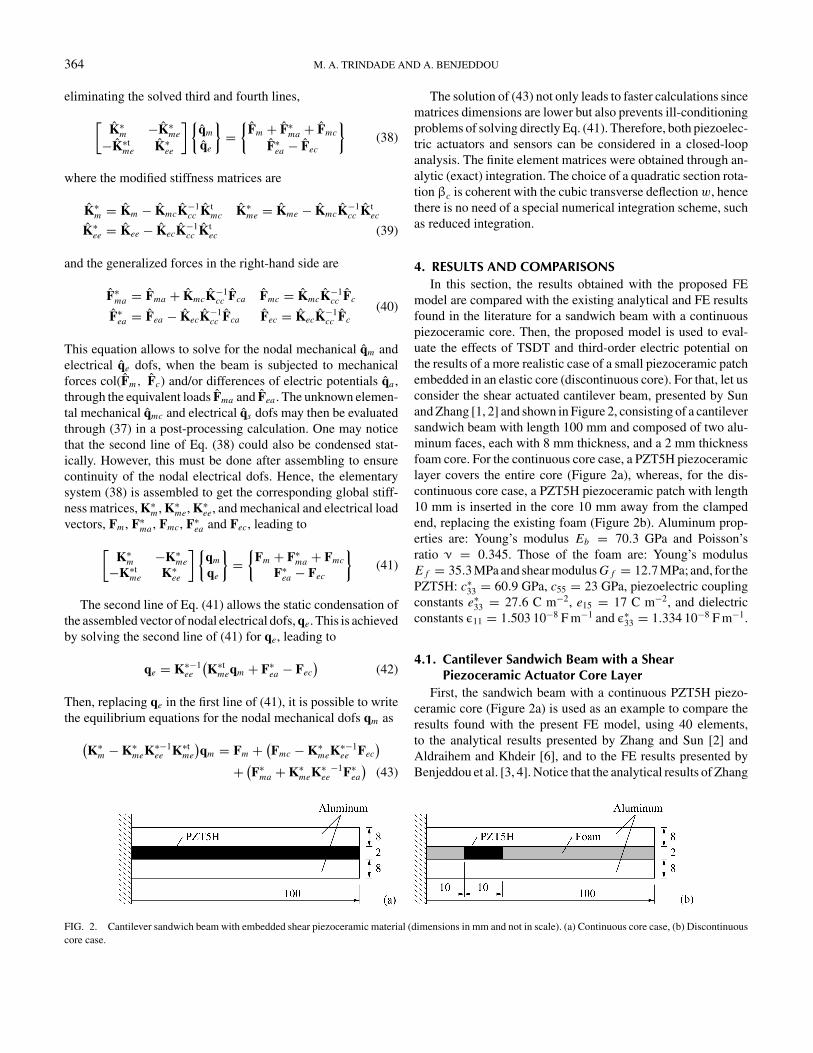
FIG. 2. Cantilever sandwich beam with embedded shear piezoceramic material (dimensions in mm and not in scale). (a) Continuous core case, (b) Discontinuouscore case.
The solution of (43) not only leads to faster calculations sincematrices dimensions are lower but also prevents ill-conditioningproblems of solving directly Eq. (41). Therefore, both piezoelec-tric actuators and sensors can be considered in a closed-loopanalysis. The finite element matrices were obtained through an-alytic (exact) integration. The choice of a quadratic section rota-tion βc is coherent with the cubic transverse deflection w, hencethere is no need of a special numerical integration scheme, suchas reduced integration.
4. RESULTS AND COMPARISONSIn this section, the results obtained with the proposed FE
model are compared with the existing analytical and FE resultsfound in the literature for a sandwich beam with a continuouspiezoceramic core. Then, the proposed model is used to eval-uate the effects of TSDT and third-order electric potential onthe results of a more realistic case of a small piezoceramic patchembedded in an elastic core (discontinuous core). For that, let usconsider the shear actuated cantilever beam, presented by Sunand Zhang [1, 2] and shown in Figure 2, consisting of a cantileversandwich beam with length 100 mm and composed of two alu-minum faces, each with 8 mm thickness, and a 2 mm thicknessfoam core. For the continuous core case, a PZT5H piezoceramiclayer covers the entire core (Figure 2a), whereas, for the dis-continuous core case, a PZT5H piezoceramic patch with length10 mm is inserted in the core 10 mm away from the clampedend, replacing the existing foam (Figure 2b). Aluminum prop-erties are: Young’s modulus Eb = 70.3 GPa and Poisson’sratio ν = 0.345. Those of the foam are: Young’s modulusE f = 35.3 MPa and shear modulus G f = 12.7 MPa; and, for thePZT5H: c∗
33 = 60.9 GPa, c55 = 23 GPa, piezoelectric couplingconstants e∗
33 = 27.6 C m−2, e15 = 17 C m−2, and dielectricconstants ε11 = 1.503 10−8 F m−1 and ε∗
33 = 1.334 10−8 F m−1.
4.1. Cantilever Sandwich Beam with a ShearPiezoceramic Actuator Core Layer
First, the sandwich beam with a continuous PZT5H piezo-ceramic core (Figure 2a) is used as an example to compare theresults found with the present FE model, using 40 elements,to the analytical results presented by Zhang and Sun [2] andAldraihem and Khdeir [6], and to the FE results presented byBenjeddou et al. [3, 4]. Notice that the analytical results of Zhang
MODELLING SMART BEAMS WITH EMBEDDED SHEAR-MODE PIEZOCERAMICS 365
and Sun [2] were found using an assumption of a linear electricpotential through the piezoceramic core thickness combined to aclassical sandwich beam theory (i.e., Euler-Bernoulli faces andTimoshenko core). On the other hand, Aldraihem and Khdeir [6]used an equivalent single layer (ESL) model for the sandwichbeam, for which the shear strain is represented by first-order(FSDT, i.e., Timoshenko) and third-order (TSDT, Reddy [19])theories. Although not stated in their text, it appears that Aldrai-hem and Khdeir [6] also consider a linear through-thicknesselectric potential for the piezoceramic core.
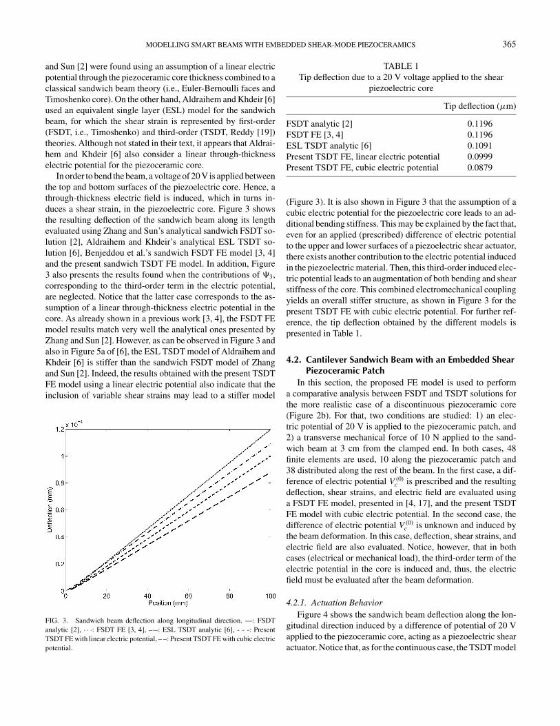
In order to bend the beam, a voltage of 20 V is applied betweenthe top and bottom surfaces of the piezoelectric core. Hence, athrough-thickness electric field is induced, which in turns in-duces a shear strain, in the piezoelectric core. Figure 3 showsthe resulting deflection of the sandwich beam along its lengthevaluated using Zhang and Sun’s analytical sandwich FSDT so-lution [2], Aldraihem and Khdeir’s analytical ESL TSDT so-lution [6], Benjeddou et al.’s sandwich FSDT FE model [3, 4]and the present sandwich TSDT FE model. In addition, Figure3 also presents the results found when the contributions of �3,corresponding to the third-order term in the electric potential,are neglected. Notice that the latter case corresponds to the as-sumption of a linear through-thickness electric potential in thecore. As already shown in a previous work [3, 4], the FSDT FEmodel results match very well the analytical ones presented byZhang and Sun [2]. However, as can be observed in Figure 3 andalso in Figure 5a of [6], the ESL TSDT model of Aldraihem andKhdeir [6] is stiffer than the sandwich FSDT model of Zhangand Sun [2]. Indeed, the results obtained with the present TSDTFE model using a linear electric potential also indicate that theinclusion of variable shear strains may lead to a stiffer model
FIG. 3. Sandwich beam deflection along longitudinal direction. —: FSDTanalytic [2], · · ·: FSDT FE [3, 4], –·–: ESL TSDT analytic [6], - - -: PresentTSDT FE with linear electric potential, – –: Present TSDT FE with cubic electricpotential.
TABLE 1Tip deflection due to a 20 V voltage applied to the shear
piezoelectric core
Tip deflection (µm)
FSDT analytic [2] 0.1196FSDT FE [3, 4] 0.1196ESL TSDT analytic [6] 0.1091Present TSDT FE, linear electric potential 0.0999Present TSDT FE, cubic electric potential 0.0879
(Figure 3). It is also shown in Figure 3 that the assumption of acubic electric potential for the piezoelectric core leads to an ad-ditional bending stiffness. This may be explained by the fact that,even for an applied (prescribed) difference of electric potentialto the upper and lower surfaces of a piezoelectric shear actuator,there exists another contribution to the electric potential inducedin the piezoelectric material. Then, this third-order induced elec-tric potential leads to an augmentation of both bending and shearstiffness of the core. This combined electromechanical couplingyields an overall stiffer structure, as shown in Figure 3 for thepresent TSDT FE with cubic electric potential. For further ref-erence, the tip deflection obtained by the different models ispresented in Table 1.
4.2. Cantilever Sandwich Beam with an Embedded ShearPiezoceramic Patch
In this section, the proposed FE model is used to performa comparative analysis between FSDT and TSDT solutions forthe more realistic case of a discontinuous piezoceramic core(Figure 2b). For that, two conditions are studied: 1) an elec-tric potential of 20 V is applied to the piezoceramic patch, and2) a transverse mechanical force of 10 N applied to the sand-wich beam at 3 cm from the clamped end. In both cases, 48finite elements are used, 10 along the piezoceramic patch and38 distributed along the rest of the beam. In the first case, a dif-ference of electric potential V (0)
c is prescribed and the resultingdeflection, shear strains, and electric field are evaluated usinga FSDT FE model, presented in [4, 17], and the present TSDTFE model with cubic electric potential. In the second case, thedifference of electric potential V (0)
c is unknown and induced bythe beam deformation. In this case, deflection, shear strains, andelectric field are also evaluated. Notice, however, that in bothcases (electrical or mechanical load), the third-order term of theelectric potential in the core is induced and, thus, the electricfield must be evaluated after the beam deformation.
4.2.1. Actuation BehaviorFigure 4 shows the sandwich beam deflection along the lon-
gitudinal direction induced by a difference of potential of 20 Vapplied to the piezoceramic core, acting as a piezoelectric shearactuator. Notice that, as for the continuous case, the TSDT model
366 M. A. TRINDADE AND A. BENJEDDOU
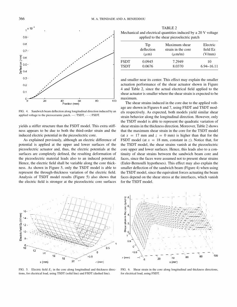
FIG. 4. Sandwich beam deflection along longitudinal direction induced by anapplied voltage to the piezoceramic patch. —: TSDT, - - -: FSDT.
yields a stiffer structure than the FSDT model. This extra stiff-ness appears to be due to both the third-order strain and theinduced electric potential in the piezoelectric core.
As explained previously, although an electric difference ofpotential is applied at the upper and lower surfaces of thepiezoelectric actuator and, thus, the electric potentials at thesurfaces are completely defined, the resulting deformation ofthe piezoelectric material leads also to an induced potential.Hence, the electric field shall be variable along the core thick-ness. As shown in Figure 5, only the TSDT model is able torepresent the through-thickness variation of the electric field.Analysis of TSDT model results (Figure 5) also shows thatthe electric field is stronger at the piezoelectric core surfaces
FIG. 5. Electric field Ez in the core along longitudinal and thickness direc-tions, for electrical load, using TSDT (solid line) and FSDT (dashed line).
TABLE 2Mechanical and electrical quantities induced by a 20 V voltage
applied to the shear piezoelectric patch
Tipdeflection
(µm)
Maximum shearstrain in the core
(µm/m)
Electricfield Ez(V/mm)
FSDT 0.0945 7.2949 10TSDT 0.0676 8.0370 6.94–16.11
and smaller near its center. This effect may explain the smalleractuation performance of the shear actuator shown in Figure4 and Table 2, since the actual electrical field applied to theshear actuator is smaller where the shear strain is expected to bemaximum.
The shear strains induced in the core due to the applied volt-age are shown in Figures 6 and 7, using FSDT and TSDT mod-els respectively. As expected, both models yield similar shearstrain behavior along the longitudinal direction. However, onlythe TSDT model is able to represent the quadratic variation ofshear strains in the thickness direction. Moreover, Table 2 showsthat the maximum shear strain in the core for the TSDT model(at x = 17 mm and z = 0 mm) is higher than that for theFSDT model (at x = 18 mm, constant in z). Notice that, forthe TSDT model, the shear strains vanish at the piezoelectriccore upper and lower surfaces. Hence, this leads also to a con-tinuity of shear strains between the sandwich beam core andfaces, since the faces were assumed not to present shear strains(Euler-Bernoulli hypotheses). This effect may also explain thesmaller deflection of the sandwich beam (Figure 4) when usingthe TSDT model, since the equivalent forces actuating the beamfaces depend on the shear stress at the interfaces, which vanishfor the TSDT model.
FIG. 6. Shear strain in the core along longitudinal and thickness directions,for electrical load, using FSDT.
MODELLING SMART BEAMS WITH EMBEDDED SHEAR-MODE PIEZOCERAMICS 367
FIG. 7. Shear strain in the core along longitudinal and thickness directions,for electrical load, using TSDT.
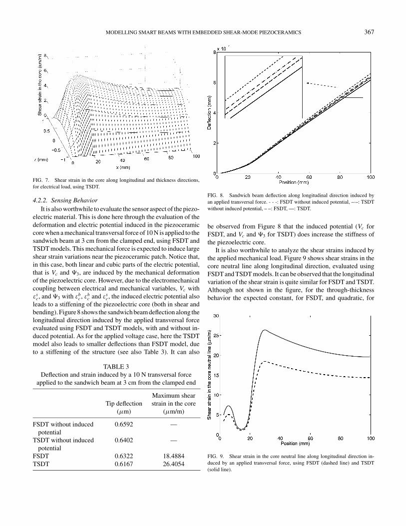
4.2.2. Sensing BehaviorIt is also worthwhile to evaluate the sensor aspect of the piezo-
electric material. This is done here through the evaluation of thedeformation and electric potential induced in the piezoceramiccore when a mechanical transversal force of 10 N is applied to thesandwich beam at 3 cm from the clamped end, using FSDT andTSDT models. This mechanical force is expected to induce largeshear strain variations near the piezoceramic patch. Notice that,in this case, both linear and cubic parts of the electric potential,that is Vc and �3, are induced by the mechanical deformationof the piezoelectric core. However, due to the electromechanicalcoupling between electrical and mechanical variables, Vc withεs
c, and �3 with εbc , εh
c and εsc, the induced electric potential also
leads to a stiffening of the piezoelectric core (both in shear andbending). Figure 8 shows the sandwich beam deflection along thelongitudinal direction induced by the applied transversal forceevaluated using FSDT and TSDT models, with and without in-duced potential. As for the applied voltage case, here the TSDTmodel also leads to smaller deflections than FSDT model, dueto a stiffening of the structure (see also Table 3). It can also
TABLE 3Deflection and strain induced by a 10 N transversal force
applied to the sandwich beam at 3 cm from the clamped end
Tip deflection(µm)
Maximum shearstrain in the core
(µm/m)
FSDT without inducedpotential
0.6592 —
TSDT without inducedpotential
0.6402 —
FSDT 0.6322 18.4884TSDT 0.6167 26.4054
FIG. 8. Sandwich beam deflection along longitudinal direction induced byan applied transversal force. - - -: FSDT without induced potential, –·–: TSDTwithout induced potential, – –: FSDT, —: TSDT.
be observed from Figure 8 that the induced potential (Vc forFSDT, and Vc and �3 for TSDT) does increase the stiffness ofthe piezoelectric core.
It is also worthwhile to analyze the shear strains induced bythe applied mechanical load. Figure 9 shows shear strains in thecore neutral line along longitudinal direction, evaluated usingFSDT and TSDT models. It can be observed that the longitudinalvariation of the shear strain is quite similar for FSDT and TSDT.Although not shown in the figure, for the through-thicknessbehavior the expected constant, for FSDT, and quadratic, for
FIG. 9. Shear strain in the core neutral line along longitudinal direction in-duced by an applied transversal force, using FSDT (dashed line) and TSDT(solid line).
368 M. A. TRINDADE AND A. BENJEDDOU
FIG. 10. Electric potential in the core along longitudinal and thickness direc-tions, for mechanical load, using FSDT.
TSDT, shear strains were observed. Notice that although theoverall deflection of the sandwich beam is smaller when evalu-ated using the TSDT model (Figure 8), the shear strains in theelastic/piezoelectric core are larger (Figure 9 and Table 3).
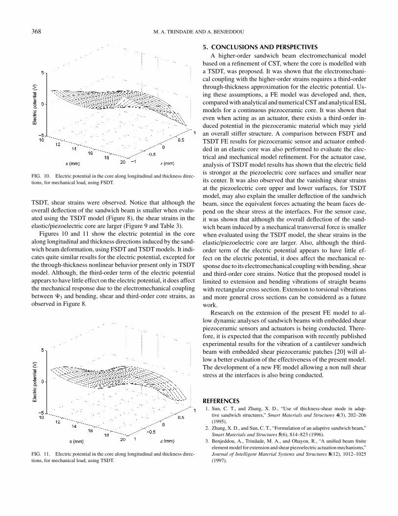
Figures 10 and 11 show the electric potential in the corealong longitudinal and thickness directions induced by the sand-wich beam deformation, using FSDT and TSDT models. It indi-cates quite similar results for the electric potential, excepted forthe through-thickness nonlinear behavior present only in TSDTmodel. Although, the third-order term of the electric potentialappears to have little effect on the electric potential, it does affectthe mechanical response due to the electromechanical couplingbetween �3 and bending, shear and third-order core strains, asobserved in Figure 8.
FIG. 11. Electric potential in the core along longitudinal and thickness direc-tions, for mechanical load, using TSDT.
5. CONCLUSIONS AND PERSPECTIVESA higher-order sandwich beam electromechanical model
based on a refinement of CST, where the core is modelled witha TSDT, was proposed. It was shown that the electromechani-cal coupling with the higher-order strains requires a third-orderthrough-thickness approximation for the electric potential. Us-ing these assumptions, a FE model was developed and, then,compared with analytical and numerical CST and analytical ESLmodels for a continuous piezoceramic core. It was shown thateven when acting as an actuator, there exists a third-order in-duced potential in the piezoceramic material which may yieldan overall stiffer structure. A comparison between FSDT andTSDT FE results for piezoceramic sensor and actuator embed-ded in an elastic core was also performed to evaluate the elec-trical and mechanical model refinement. For the actuator case,analysis of TSDT model results has shown that the electric fieldis stronger at the piezoelectric core surfaces and smaller nearits center. It was also observed that the vanishing shear strainsat the piezoelectric core upper and lower surfaces, for TSDTmodel, may also explain the smaller deflection of the sandwichbeam, since the equivalent forces actuating the beam faces de-pend on the shear stress at the interfaces. For the sensor case,it was shown that although the overall deflection of the sand-wich beam induced by a mechanical transversal force is smallerwhen evaluated using the TSDT model, the shear strains in theelastic/piezoelectric core are larger. Also, although the third-order term of the electric potential appears to have little ef-fect on the electric potential, it does affect the mechanical re-sponse due to its electromechanical coupling with bending, shearand third-order core strains. Notice that the proposed model islimited to extension and bending vibrations of straight beamswith rectangular cross section. Extension to torsional vibrationsand more general cross sections can be considered as a futurework.
Research on the extension of the present FE model to al-low dynamic analyses of sandwich beams with embedded shearpiezoceramic sensors and actuators is being conducted. There-fore, it is expected that the comparison with recently publishedexperimental results for the vibration of a cantilever sandwichbeam with embedded shear piezoceramic patches [20] will al-low a better evaluation of the effectiveness of the present model.The development of a new FE model allowing a non null shearstress at the interfaces is also being conducted.
REFERENCES1. Sun, C. T., and Zhang, X. D., “Use of thickness-shear mode in adap-
tive sandwich structures,” Smart Materials and Structures 4(3), 202–206(1995).
2. Zhang, X. D., and Sun, C. T., “Formulation of an adaptive sandwich beam,”Smart Materials and Structures 5(6), 814–823 (1996).
3. Benjeddou, A., Trindade, M. A., and Ohayon, R., “A unified beam finiteelement model for extension and shear piezoelectric actuation mechanisms,”Journal of Intelligent Material Systems and Structures 8(12), 1012–1025(1997).
MODELLING SMART BEAMS WITH EMBEDDED SHEAR-MODE PIEZOCERAMICS 369
4. Benjeddou, A., Trindade, M. A., and Ohayon, R., “New shear actu-ated smart structure beam finite element,” AIAA Journal 37(3), 378–383(1999).
5. Benjeddou, A., Trindade, M. A., and Ohayon, R., “Piezoelectric actua-tion mechanisms for intelligent sandwich structures,” Smart Materials andStructures 9(3), 328–335 (2000).
6. Aldraihem, O. J., and Khdeir, A. A., “Smart beams with extension andthickness-shear piezoelectric actuators,” Smart Materials and Structures9(1), 1–9 (2000).
7. Khdeir, A. A., and Aldraihem, O. J., “Deflection analysis ofbeams with extension and shear piezoelectric patches using discon-tinuity functions,” Smart Materials and Structures 10(2), 212–220(2001).
8. Aldraihem, O. J., and Khdeir, A. A., “Exact deflection solutions of beamswith shear piezoelectric actuators,” International Journal of Solids andStructures 40(1), 1–12 (2003).
9. Trindade, M. A., Benjeddou, A., and Ohayon, R., “Parametric analysis ofthe vibration control of sandwich beam through shear-based piezoelectricactuation,” Journal of Intelligent Materials Systems and Structures, 10(5),377–385 (1999).
10. Raja, S., Prathap, G., and Sinha, P. K., “Active vibration control of compositesandwich beams with piezoelectric extension-bending and shear actuators,”Smart Materials and Structures 11(1), 63–71 (2002).
11. Raja, S., Sreedeep, R., and Prathap, G., “Bending behavior of hybrid-actuated piezoelectric sandwich beams,” Journal of Intelligent MaterialsSystems and Structures 15(8), 611–619 (2004).
12. Vel, S. S., and Batra, R. C., “Exact solution for the cylindrical bendingof laminated plates with embedded piezoelectric shear actuators,” SmartMaterials and Structures 10(2), 240–251 (2001).
13. Edery-Azulay, L., and Abramovich, H., “Piezoelectric actuation and sensingmechanisms—closed form solutions,” Composite Structures 64(3–4), 443–453 (2004).
14. Benjeddou, A., “Modelling and simulation of adaptive structures and com-posites: Current trends and future directions,” in B. H. V. Topping andC.A. Mota Soares (Eds.), Progress in Computational Structures Technol-ogy, Saxe-Coburg Pub., Stirling, Scotland, pp. 251–280 (2004).
15. Benjeddou, A., “Use of shear-mode piezoceramics in smart structures appli-cations: Achievements and perspectives,” in C. A. Mota Soares et al. (Eds.),II ECCOMAS Thematic Conference on Smart Structures and Materials,Lisbon, Portugal, July 18–21 (2005).
16. Mota Soares, C. A., Mota Soares, C. M., and Franco Correia, V. M., “Mod-elling and design of laminated composite structures with integrated sensorsand actuators,” in B. H. V. Topping (Ed.), Computational Mechanics for theTwenty-First Century, Saxe-Coburg Pub., Edinburg, UK, vol. 9, pp. 165–185(2000).
17. Trindade, M. A., Benjeddou, A., and Ohayon, R., “Finite element model-ing of hybrid active-passive vibration damping of multilayer piezoelectricsandwich beams—part 1: Formulation,” International Journal for Numeri-cal Methods in Engineering 51(7), 835–854 (2001).
18. Abramovich, H., “Piezoelectric actuation for smart sandwich structures—closed form solutions,” Journal of Sandwich Structures and Materials 5(4),377–396 (2003).
19. Reddy, J. N., “A simple higher-order theory for laminated composite plates,”Journal of Applied Mechanics 51(4), 745–752 (1984).
20. Baillargeon, B. P., and Vel, S. S., “Active vibration suppression of sandwichbeams using piezoelectric shear actuators: Experiments and numerical sim-ulations,” Journal of Intelligent Materials Systems and Structures, 16(6),517–530 (2005).


