Embed Size (px)
Citation preview

American Institute of Aeronautics and Astronautics
1
The Force-Deflection Behavior of Functionally Graded Piezoceramic Actuators
Paul W. Alexander*, Diann Brei†, and John W. Halloran ‡ University of Michigan, Ann Arbor, Michigan, 48109
Functionally Graded Piezoceramics (FGP) overcome the current reliability limitations within laminated piezoceramic actuators by eliminating the bond lines and stress discontinuities and lowering the overall internal stress levels. New fabrication methods for FGP, such as the Dual Electro/Piezo Property (DEPP) gradient technique, synergistically couple variations in permittivity and piezoelectric properties yielding more electrically efficient actuators capable of larger displacements. Unfortunately, such FGP approaches naturally introduce complexity into the electric field, stress, and material profiles, making it more difficult to model their performance. This paper develops a Hamiltonian energy-based modeling approach that fully captures the force-deflection performance of a generic multi-dimensionally graded piezoceramic actuator. As demonstration of the approach, two differently graded beams are presented: a two layered gradient that maximizes deflection and a linear gradient that minimizes internal stresses. DEPP graded prototypes were fabricated with a powder-pressed method for the two-layered specimen and micro-fabrication via co-extrusion for the linear gradient. The force-deflection performance of each cantilevered prototype under tip loading conditions was experimentally and numerically validated. The derived analytic model correlates very well with the observed behavior by incorporating the complex electric field variation and continuous stress distribution within the prototype eluded by conventional modeling methods. This comprehensive quasi-static force-deflection model provides designers with an effective and necessary tool for the implementation of FGP as actuators with extended service lifetimes.
Nomenclature a = neutral axis position B = blocked force Ci = piezoelectric performance terms c = material stiffness d = piezoelectric strain coefficient D = electric displacement e = piezoelectric stress coefficient E = electric field fi = generic displacement functions F = applied load G = electrical constant H = electric enthalpy density K = actuator stiffness l = length value li = specimen dimension in the xi direction Oi = constants in the generic displacement functions * PhD Candidate, Mechanical Engineering Department, 2350 Hayward St., Ann Arbor, MI, 48109-2125, AIAA Student Member. † Associate Professor, Mechanical Engineering Department, 2350 Hayward St., Ann Arbor, MI, 48109-2125, AIAA Member. ‡ Professor and Chair, Materials Science and Engineering Department, 2300 Hayward St., Ann Arbor, MI, 48109-2136.
46th AIAA/ASME/ASCE/AHS/ASC Structures, Structural Dynamics & Materials Conference18 - 21 April 2005, Austin, Texas
AIAA 2005-1965
Copyright © 2005 by the American Institute of Aeronautics and Astronautics, Inc. All rights reserved.

American Institute of Aeronautics and Astronautics
2
Pi = constants in the generic displacement functions S = strain t = thickness value T = stress ui = displacements U = internal energy density UTotal = internal energy v = specimen volume Vi = electric potentials w = width value W = work xi = spatial coordinates Y = Young’s modulus ∆ = free deflection ∆V = electric potential difference ε = electric permittivity
I. Introduction HE practical application of many piezoceramic actuation architectures has been limited because of their service lifetimes. For example, conventional piezoceramic benders, composed of multiple material layers bonded
together, have lifetimes on the order of only 105 to 106 cycles in high cycle applications;1,2 several magnitudes less than that typically required by industry. Research has indicated that a key problem is debonding. One potential solution is to establish the gradients required for deformation by varying the material properties in a continuous piezoceramic versus bonding dissimilar materials.3,4 Although this does decrease the performance slightly, there is a more significant increase in reliability because the bond lines have been removed, the stress discontinuities eliminated, and stress levels reduced.4
These Functionally Graded Piezoceramics (FGP) can be created using a number of property grading approaches, including varying the material resistivity or conductivity,5-9 piezoelectric coefficient,4,10,11 permittivity,3,4,12-14 or porosity.15 The Dual Electro/Piezo Property (DEPP) grading technique is a new method that varies both the material permittivity and piezoelectric properties by doping lead zirconate titanate (PZT) with a high permittivity barium titanate (BT) dielectric. This combination synergistically concentrates the applied electric field in the most active piezoceramic region, simultaneously increasing the efficiency and deformation capabilities of the actuator. The DEPP technique can also be utilized to form material gradients in multiple dimensions; promising higher order deformations such as warping or dimpling from FGP actuators. Unfortunately, it is more difficult to analyze and predict the performance of these types of monolithic FGP because of the spatially varying material properties and resulting non-homogenous electric field. These FGP characteristics preclude the use of traditional modeling techniques that assume constant material properties and electric fields per layer or only model material gradients across one spatial coordinate.
In the past, efforts in modeling functionally graded piezoceramics often use classical laminate theory as a basis. This approach assumes homogeneous material properties in a single layer, with multiple layers composing the FGP.16-19 Laminate theory limits the material property variation to a step-wise pattern with the step size dictated by the thickness of the lamina. Other research20,21 has produced models that could account for continuous gradients, yet still model only layered FGP with severe restrictions placed on the variation of the electric field, limiting it to polynomial variation. Zhu and Meng22 have adapted energy based methods to predict the performance of bonded laminate bimorph actuators23 to FGP actuators, but only for discretely layered specimens. Wu with others24 use energy methods and allow for continuously graded specimens, but limit the material gradient to a single direction. All research efforts to date focus specifically on the deflection performance of FGP, completely neglecting the effects of external mechanical loads which the actuator must work against. This severely limits the use of current models for realistic design of any loaded FGP actuator.
This paper presents a comprehensive analytic model for the force-deflection behavior of generic multi-dimensional FGP actuators that accounts for variations in the material stiffness, permittivity, and piezoelectric coefficients as functions of spatial coordinates and predicts the complex electric field distribution within the actuator based upon electrostatics. The model includes external mechanical and internal piezoelectric loads; thereby, capturing the complete quasi-static force-deflection behavior including the internal stresses within the actuator and the forces it can generate. As an example, this modeling theory was applied to the case of FGP cantilever beams
T

American Institute of Aeronautics and Astronautics
3
(benders) that have a generic material gradient in the thickness direction with an external mechanical tip load. The model was compared to experimental results and numerical model predictions for DEPP graded FGP actuators with different material gradients: a two composition gradient that maximizes deflection and a linear material gradient that minimizes internal stress levels. The numerical models provided valuable insight into the design tradeoff between displacement performance and internal stresses as well as illustrating the limitations of layered material gradient modeling. Correlation between models and experimental observations was exceptionally good, allowing for the future expansion of the derived models and DEPP grading technique to multi-dimensional FGP which promise to greatly enhance the capabilities of piezoceramic actuation.
II. Analytic Force-Deflection Model for a Generic FGP Past research efforts sought to capture only the free deflection behavior of FGP,16-21,22,24 yet to be utilized in real
applications; the force-deflection performance must be known. Current deflection models cannot be simply extended to incorporate forcing effects because they employ assumptions that limit the material gradient to discrete steps, resulting in inaccurate predictions of the activating electric field and the internal stresses distribution in an FGP. To predict the force-deflection behavior of FGP, the model must accurately represent the graded material properties and resulting variation in the electric field as well as account for external loads the FGP may experience during actuation in a real applications. A Hamiltonian approach was employed to include these factors into a single modeling methodology that predicts deformations as a function of mechanical and electrical loading along with the resulting stress profile for single and multi-dimensional FGP actuators.
The desired deformations (u) within an FGP can be derived using Hamilton’s principle that states a system will always tend to a state of minimum energy. This state is found by setting the variation of the work due to external loads (δW) and the variation of the internal energy (δUTotal) to zero,
0=− TotalUW δδ . (1)
The work (W) follows the conventional definition as the product of the external forces multiplied by the component of FGP deflection in the same direction. Because of the non-homogenous material profiles, the typical integrals that appear while deriving the internal energy expression cannot be simplified until the material system is known.
A. Internal Energy The internal energy of the FGP (UTotal) can be determined from piezoelectric theory and is the integral of the
FGP internal energy density (U) of a piezoceramic,25
DEHU += , (2)
where H is the electric enthalpy density, D is the electric displacement, and E is the applied electric field. The variation of the internal energy density is defined as:
EDHU δδδ += . (3)
When the FGP is in actuator form, the electric field is prescribed and will not vary (δE =0); thus, the internal energy variation reduces to the variation in electric enthalpy,
HU δδ = . (4)
The electric enthalpy density (H) is defined in terms of the strain (S), electric field (E), material compliance under a constant electric field (cE), piezoelectric stress coefficient (e), and electric permittivity under constant strain (εS),
ji
Sijkkijijklij
Eijkl EEEeSSScH ε
2
1
2
1 −−= . (5)
The resulting variation of the electric enthalpy density (δH), and thus the internal energy, is:

American Institute of Aeronautics and Astronautics
4
kkijijklij
Eijklklij
Eijkl EeSSScSScHU δδδδδ −+==
2
1
2
1 . (6)
To formulate the internal energy (Eq. (6)) in terms of easily measured material properties, the piezoelectric strain coefficient (d) is substituted for the piezoelectric stress coefficient (e) using the equivalence relationship:
Enmijknmkij cde = , (7)
yielding the variation of the internal energy density,
knmjij
Enmijklij
Eijklklij
Eijkl EdScSScSScU δδδδ −+=
2
1
2
1 . (8)
The variation of the total internal energy (δUTotal) of an FGP is the integral of the internal energy density (Eq. (8)) over the FGP volume (v),
dvEdScSScSScUv
knmjijEnmijklij
Eijklklij
Eijkl
Total ∫ ⎭⎬⎫
⎩⎨⎧ −+= δδδδ
2
1
2
1 . (9)
B. Displacement Functions The strain terms present in total internal energy variation (Eq. (9)) are determined using the standard definition,
⎥⎥⎦
⎤
⎢⎢⎣
⎡
∂∂
+∂∂=
i
j
j
iij x
u
x
uS
2
1 . (10)
where the displacement components (ui) are defined as functions (fi) of the spatial coordinates x1, x2, and x3,
( )321 ,, xxxfu ii = . (11)
Using a standard solid mechanics approach, these functions are assumed to have a user-defined form with unknown constants that need to be determined. The appropriate form of these equations is dictated by the actuator shape, gradient characteristics, and mounting conditions.
The unknown constants within the displacement functions are found via the equilibrium equations and boundary conditions generated by applying the Hamiltonian principle to the internal energy of the actuator and the work done by any external loads (Eq. (1)). While this procedure sounds standard, it differs from the norm because the material properties and driving electric field can be complex functions of the spatial coordinates, which makes the unknown constants radically different than those that would describe conventional piezoceramics.
C. Electric Field A prime example of the difference between conventional piezoceramics and FGP is the electric field.
Homogeneous piezoceramics experience a constant electric field across their entire thickness; whereas, an FGP has a nonlinearly varying electric field due to the graded material permittivity. The DEPP gradient technique specifically exploits this variation in electric field for improved motion generation; thus, accurate electric field prediction is critical.
As with conventional piezoelectric actuators, the three direction (x3) denotes the poling direction. It is assumed that a single electric field (E3) is applied in this direction, (E1=E2=0), and any slight discrepancies due to edge effects and material grading are negligible. Because the electric permittivity of the material is allowed to vary with spatial position (ε33(x1,x2,x3)), the electric field also varies with position (E3(x1,x2,x3)). From dielectric theory, it is known that the product of the electric field intensity and the material permittivity anywhere along an electric field line (x1=l, x2=w, x3 varies) must equal a constant value (G) throughout a dielectric,

American Institute of Aeronautics and Astronautics
5
( ) ( ) GxwlxwlE =33333 ,,,, ε . (12)
The integral of the electric field across the thickness direction is directly related to the potential difference applied to the actuator (∆V),
( ){ } 333
3
,, dxxwlEVx∫−=∆ . (13)
The electrical permittivity of the material is dictated by the material composition, which can be experimentally determined. Once the permittivity profile (ε33(x1,x2,x3)) is known, the electric field can be defined for an applied voltage through substitution of Eq. (12) into Eq. (13),
( )( ) ( )∫
⎭⎬⎫
⎩⎨⎧
∆−=
3
3333
333
33
,,
1,,
,,
x
dxxwl
xwl
VxwlE
εε
. (14)
This relationship holds for discretely layered FGP as well as for continuously graded FGP and can be simplified for material gradients in one or two directions. However, the field is never a constant as assumed by conventional theory. Though the derivation of the electric field profile is straight forward, the profile itself can be very complex because it is proportional to the reciprocal of the permittivity gradient, where continuous permittivity gradients can lead to difficulties if trying to analytically solve for the resulting electric field distribution.
III. FGP Beam Model with a One-Dimensional Material Gradient The derived modeling procedure for a general FGP can be employed for a wide range of structural shapes and
material gradients. To demonstrate the procedure, the method is applied here to the case of the widely used beam actuator graded through its thickness. Figure 1 depicts the coordinate system, dimensions, and electrical and mechanical loads used in this derivation. The material stiffness in the length direction is represented using the Young’s modulus (Y) of the material, c1111
E(x3)=Y11(x3). Since the FGP beam is designed to produce bending deformations it is necessary to calculate the position of the beam’s neutral axis (a) in the thickness, accounting for the material variation,
( ){ } ( ){ }∫∫ =3
3311
0
3311
l
a
a
dxxYdxxY (15)
x1
x3
x2
l3
l2
l1
u3
∆V
+
_
Possible Gradient Profiles
x3
x3
Continuous gradient
Y11, d31, or ε33S
Y11, d31, or ε33S Discretely layered
gradient
V2
V1
F
Beam neutral axis, located at x3=a(x3 measured from bottom surface of beam)
x1
x3
x2
l3
l2
l1
u3
∆V
+
_
Possible Gradient Profiles
x3
x3
Continuous gradient
Y11, d31, or ε33S
Y11, d31, or ε33S Discretely layered
gradient
V2
V1
F
Beam neutral axis, located at x3=a(x3 measured from bottom surface of beam)
Figure 1. FGP cantilever beam with thickness-graded material properties.
American Institute of Aeronautics and Astronautics
6
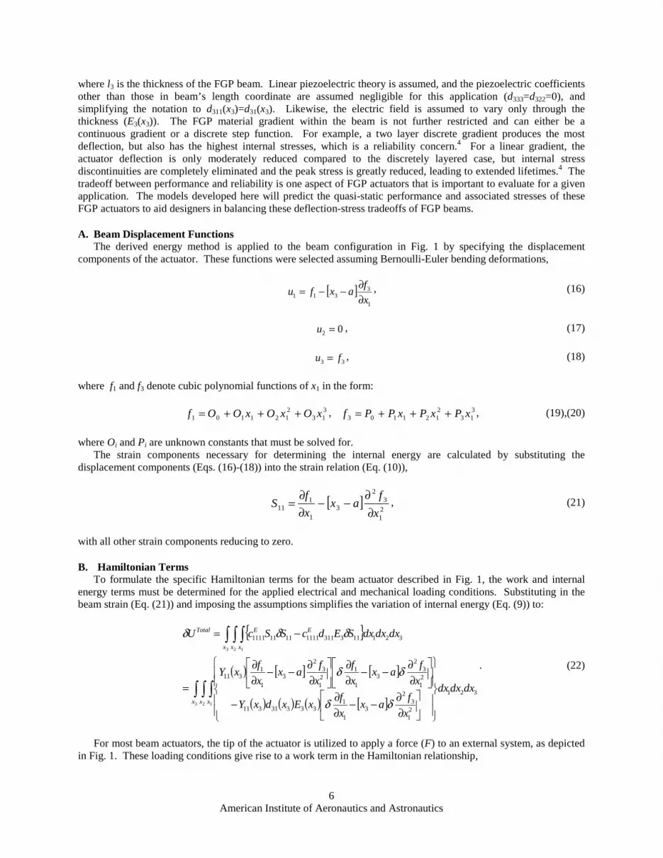
where l3 is the thickness of the FGP beam. Linear piezoelectric theory is assumed, and the piezoelectric coefficients other than those in beam’s length coordinate are assumed negligible for this application (d333=d322=0), and simplifying the notation to d311(x3)=d31(x3). Likewise, the electric field is assumed to vary only through the thickness (E3(x3)). The FGP material gradient within the beam is not further restricted and can either be a continuous gradient or a discrete step function. For example, a two layer discrete gradient produces the most deflection, but also has the highest internal stresses, which is a reliability concern.4 For a linear gradient, the actuator deflection is only moderately reduced compared to the discretely layered case, but internal stress discontinuities are completely eliminated and the peak stress is greatly reduced, leading to extended lifetimes.4 The tradeoff between performance and reliability is one aspect of FGP actuators that is important to evaluate for a given application. The models developed here will predict the quasi-static performance and associated stresses of these FGP actuators to aid designers in balancing these deflection-stress tradeoffs of FGP beams.
A. Beam Displacement Functions The derived energy method is applied to the beam configuration in Fig. 1 by specifying the displacement
components of the actuator. These functions were selected assuming Bernoulli-Euler bending deformations,
[ ]1
3311 x
faxfu
∂∂−−= , (16)
02 =u , (17)
33 fu = , (18)
where f1 and f3 denote cubic polynomial functions of x1 in the form:
313
2121101 xOxOxOOf +++= , 3
132121103 xPxPxPPf +++= , (19),(20)
where Oi and Pi are unknown constants that must be solved for. The strain components necessary for determining the internal energy are calculated by substituting the
displacement components (Eqs. (16)-(18)) into the strain relation (Eq. (10)),
[ ]21
32
31
111
x
fax
x
fS
∂∂
−−∂∂
= , (21)
with all other strain components reducing to zero.
B. Hamiltonian Terms To formulate the specific Hamiltonian terms for the beam actuator described in Fig. 1, the work and internal energy terms must be determined for the applied electrical and mechanical loading conditions. Substituting in the beam strain (Eq. (21)) and imposing the assumptions simplifies the variation of internal energy (Eq. (9)) to:
{ }
( ) [ ] [ ]
( ) ( ) ( ) [ ]∫ ∫ ∫
∫ ∫ ∫
⎪⎪⎭
⎪⎪⎬
⎫
⎪⎪⎩
⎪⎪⎨
⎧
⎥⎦
⎤⎢⎣
⎡∂∂−−
∂∂−
⎥⎦
⎤⎢⎣
⎡∂∂−−
∂∂
⎥⎦
⎤⎢⎣
⎡∂∂−−
∂∂
=
−=
3 2 1
3 2 1
321
21
32
31
133331311
21
32
31
121
32
31
1311
321113311111111111111
x x x
x x x
EETotal
dxdxdx
x
fax
x
fxExdxY
x
fax
x
f
x
fax
x
fxY
dxdxdxSEdcSScU
δδ
δδ
δδδ
. (22)
For most beam actuators, the tip of the actuator is utilized to apply a force (F) to an external system, as depicted in Fig. 1. These loading conditions give rise to a work term in the Hamiltonian relationship,

American Institute of Aeronautics and Astronautics
7
11
33 llfFuFW δδδ == . (23)
C. Equations of Equilibrium To establish the equations of motion, the work and internal energy terms are substituted into the Hamiltonian
expression (Eq. (1)),
0
1
1
1
1
1
3
0
321
12
231
33
32
01
35
1
122
1
32
32
0
141
112
1
32
22
1331
13
241
34
3121
12
131
33
22
=
⎥⎥⎥⎥⎥⎥⎥⎥⎥⎥⎥⎥
⎦
⎤
⎢⎢⎢⎢⎢⎢⎢⎢⎢⎢⎢⎢
⎣
⎡
+⎥⎦
⎤⎢⎣
⎡⎟⎟⎠
⎞⎜⎜⎝
⎛∂∂−
∂∂+
⎥⎦
⎤⎢⎣
⎡
∂∂
⎟⎟⎠
⎞⎜⎜⎝
⎛−
∂∂+
∂∂−+
⎥⎦
⎤⎢⎣
⎡⎟⎟⎠
⎞⎜⎜⎝
⎛+
∂∂−
∂∂+
⎭⎬⎫
⎩⎨⎧
⎟⎟⎠
⎞⎜⎜⎝
⎛∂∂+
∂∂−+⎟⎟
⎠
⎞⎜⎜⎝
⎛∂∂+
∂∂−
=−
∫
l
l
l
lx
Total
fFfx
fC
x
fCl
x
fC
x
fC
x
fCl
fCx
fC
x
fCl
dxfx
fC
x
fCf
x
fC
x
fCl
UW
δδ
δ
δ
δδ
δδ, (24)
where the known terms Ci are included for simplification,
( ){ }∫=3
0
33111
l
dxxYC , [ ] ( ){ }∫ −=3
0
331132
l
dxxYaxC , [ ] ( ){ }∫ −=3
0
33112
33
l
dxxYaxC (25)-(27)
( ) ( ) ( ){ }∫=3
0
3311333314
l
dxxYxExdC , [ ] ( ) ( ) ( ){ }∫ −=3
0
33113333135
l
dxxYxExdaxC , (28),(29)
and would normally be simple coefficients for a homogeneous piezoceramic. The electric field distribution (E3(x3)) in these terms can be solved for using a simplified form of Eq. (14),
( )( ) ( )∫
⎭⎬⎫
⎩⎨⎧
∆−=3
0
3333
333
331
l
dxx
x
VxE
εε
, (30)
with ∆V equal to V2-V1. Clearly this is not a constant but is a function of position. The Hamiltonian expression (Eq. (24)) is integrated by parts, and in conjunction with cantilever end conditions,
gives two coupled equilibrium equations and six boundary conditions,
021
12
131
33
2 =∂∂
−∂
∂x
fC
x
fC , 0
31
13
241
34
3 =∂∂
−∂
∂x
fC
x
fC , (31)-(32)
001 =f , 0
03 =f , 001
3 =∂∂x
f , (33)-(35)
01
41
112
1
32
2 =+∂∂
−∂
∂
l
Cx
fC
x
fC , 0
1
51
122
1
32
3 =−∂∂
−∂
∂
l
Cx
fC
x
fC , 0
1
21
12
2231
33
32 =+∂∂
−∂
∂
l
Fx
fCl
x
fCl . (36)-(37)

American Institute of Aeronautics and Astronautics
8
D. Comprehensive Force-Displacement Model This system of equations is used to solve for the Oi and Pi constants, which are substituted back into the
displacement functions (Eqs. (16)-(18)) to form the displacement relationships as a function of the mechanical and electrical forcing,
[ ] [ ][ ]
[ ]axxCCC
CCCCx
CCC
CCCC
axxlxCCC
Cxlx
CCC
C
l
F
u
−⎟⎟⎠
⎞⎜⎜⎝
⎛
−−−⎟⎟
⎠
⎞⎜⎜⎝
⎛
−−+
⎪⎭
⎪⎬⎫
⎪⎩
⎪⎨⎧
−−⎟⎟⎠
⎞⎜⎜⎝
⎛−
−−⎟⎟⎠
⎞⎜⎜⎝
⎛−
=
31
312
2
42511
312
2
4352
31121
3122
111
21
3122
2
21
63626 , (38)
02 =u , (39)
[ ] 21
312
2
4251211
31
312
2
1
23 2
13
6x
CCC
CCCCxlx
CCC
C
l
Fu ⎟⎟
⎠
⎞⎜⎜⎝
⎛
−−+−⎟⎟
⎠
⎞⎜⎜⎝
⎛
−= . (40)
Simplified versions of force-displacement equations (Eq. (38)-(40)) result in common performance parameters used to evaluate an actuator. The free deflection of the actuator (∆) is the tip displacement in the x3 direction when the applied tip load is absent (F=0),
⎥⎦
⎤⎢⎣
⎡
−−=∆
312
2
42512
1
2 CCC
CCCCl , (41)
and the blocked force (B) is the applied tip load that negates any deflection (u3=0),
⎥⎦
⎤⎢⎣
⎡ −=
1
4251
1
2
2
3
C
CCCC
l
lB , (42)
with the actuator stiffness (K) being the ratio of these values,
⎥⎦
⎤⎢⎣
⎡ −=∆
=1
3122
31
23
C
CCC
l
lBK . (43)
E. Stress Profile Another important relationship that stems from the force-displacement equations is the stress profile. Increased
actuator lifetime is an important benefit of graded piezoceramics over conventional actuators. The continuous stresses within the FGP play a major role to increasing device reliability. The stress (T) profile present within a generic FGP can be determined using the appropriate constitutive equation,
kknmEnmijkl
Eijklij EdcScT −= , (44)
where in this case, the material properties (c, d) and electric field (E) are not constants. In the beam example, the primary stress in the one direction (T11) is calculated from the constitutive equation (Eq. (44)) with the strain (S11) found by substituting the displacements functions (Eq. (38)-(40)) into the strain relation (Eq. (10)),
[ ] [ ][ ]
[ ] )()()()(
33323
)(
33331311331
22
4251
3122
4352311
31131
22
111
3122
2
2
311
11
xExdxYaxCCC
CCCC
CCC
CCCCxY
axlxCCC
Clx
CCC
C
l
xFY
T
−⎪⎭
⎪⎬⎫
⎪⎩
⎪⎨⎧
−⎟⎟⎠
⎞⎜⎜⎝
⎛−−−⎟⎟
⎠
⎞⎜⎜⎝
⎛−−+
⎪⎭
⎪⎬⎫
⎪⎩
⎪⎨⎧
−−⎟⎟⎠
⎞⎜⎜⎝
⎛−
−−⎟⎟⎠
⎞⎜⎜⎝
⎛−
= . (45)

American Institute of Aeronautics and Astronautics
9
The first half of Eq. (45) accounts for the external loads on the beam and varies linearly across the thickness as in non-piezoelectric beams. The last portion of the equation adds the piezoelectric forcing effects that are responsible for stress discontinuities in layered piezoceramic actuators; discontinuities that are eliminated in a continuously graded FGP.
IV. DEPP FGP Beam Prototypes Several FGP beam actuators were fabricated for
experimental testing. The new DEPP material gradient technique, which grades both the permittivity and piezoelectric properties, was chosen because it concentrates more of the electric field within the material that has a higher piezoelectric coefficient, generating larger bending motions while reducing the required driving electric potential for the actuator. For these prototypes, American Piezo Ceramic’s lead zirconate titanate (PZT) based powder, APC 856, and Ferro’s high permittivity barium titanate (BT) based dielectric powder, Z9500 were selected because combining these materials in compositions that range from 100% PZT to 80/20 vol% PZT/BT resulted in a dramatic 140% increase in the material permittivity in
100 vol% PZT
80/20 vol% PZT/BT
a) High displacement specimen
100 vol% PZT 95/5 vol% PZT/BT 90/10 vol% PZT/BT 85/15 vol% PZT/BT 80/20 vol% PZT/BT
b) Low internal stress specimen Figure 2. Initial specimen material compositions.
a) Density
b) Young’s Modulus d) Piezoelectric Strain Coefficients
c) Dielectric Constant and Permittivity
0
2000
4000
6000
8000
10000
75 80 85 90 95 100
% PZT
κ
0.E+00
3.E-08
6.E-08
9.E-08
ε33, F
/m
7.0
7.1
7.2
7.3
7.4
7.5
7.6
75 80 85 90 95 100
% PZT
ρ, g
/cm
3
0
100
200
300
400
500
600
700
75 80 85 90 95 100
% PZT
d33
, pm
/V
-320
-240
-160
-80
0
d3
1, p
m/V
0
20
40
60
80
75 80 85 90 95 100
% PZT
Y1
1, G
Pa
Figure 3. DEPP gradient material property variations with composition.

American Institute of Aeronautics and Astronautics
10
conjunction with a 96% variation in the piezoelectric properties. Two specific material gradient profiles were fabricated to illustrate the capabilities and expected benefits of functionally graded piezoceramics: a two composition specimen that produces large displacements and a five composition linear graded specimen with reduced internal stresses (Fig. 2).4 The actual material compositions present in the test specimens across their thickness (x3) were measured as a function of Barium content using a Cameca SX100 electron microprobe. The associated material property variations (Y11(x3), d31(x3), ε33(x3)) were determined based upon the composition (Fig. 3).
A. High Displacement FGP The high displacement specimen was fabricated from two different material compositions: pure PZT and the
80/20 vol% PZT/BT mixture. The two powders were layered evenly across a 2 in by 1 in die and cold pressed at 15,000 psi. The resulting 2 mm thick plate was embedded in a PZT powder bed and sintered at 1320 oC for two hours. The plate was cut into thin beams and each was sputter coated with a gold-palladium electrode and polled with 2000 V. Figure 4 gives a photograph and schematic of a finished high displacement specimen.
The material composition profile is shown in Fig. 5, displaying the microprobe measurements as well as a curve fit to the data. While the gradient is clearly bimodal, there is a continuous change versus a discrete step between the two modes. This steep gradient will produce large deflections because of the dramatic change in material composition over a small portion of the beam’s thickness; but, this gradient is also responsible for dramatic swings in the internal stress profile. This trend is best illustrated in step-wise graded FGP where the discrete change in composition results in a stress discontinuity lactated where material in compression is adjacent to material in tension. The continuous gradient in the large deflection prototype eliminates this discontinuity and slightly reduces the internal stress levels of the actuator, but the stress levels are still high relative to a linear gradient.
B. Low Internal Stress FGP Production of more complex and precise material gradients, such as the linear gradient, requires the capabilities
of the Micro-Fabrication by Co-eXtrusion (MFCX) process composed of five different steps: media preparation, feedrod formation, co-extrusion, burnout and sintering, and post processing. The extrusion media was prepared by incorporating each of the powder compositions with thermoplastic binders in a 120 oC shear mixer, taking care to match all composition viscosities so there will be no cross-sectional distortion during extrusion. Each batch of
+
_
100 vol%PZT
80/20 vol% PZT/BT
l1
l3
l2
Gradient from 100 vol% PZT to 80/20 vol% PZT/BT
(l1 = 32.66 mm, l2 = 2.29 mm, l3 = 2.31 mm) Figure 4. Photograph and schematic of the high displacement FGP.
Thickness, mm
100 vol% PZT
80/20 vol% PZT/BT
0
5
10
15
20
25
0.0 0.5 1.0 1.5 2.0
% B
T
x3
Figure 5. BT concentration across the high displacement FGP.

American Institute of Aeronautics and Astronautics
11
media was compacted at 120 oC by 770 kg to form a 25 mm square feedrod. The desired low stress FGP prototypes consist of five equal sized layers of the different material compositions, stacking 5 mm thick slices of each and hot pressing them into a single feedrod (Fig. 2). During the next step, co-extrusion, the feedrod was reduced in the layered dimension from 25 mm to a 1 mm thick tape. This single extrusion run produces a large quantity of FGP tape that can be cut into numerous beams and patches. The polymers in the media were removed from the green ceramic through a seven segment burnout process that minimizes warping of the sample. The specimens were sintered at the manufacturer specified temperature of 1320 oC and the resulting ceramic specimens were electroded by sputter coating two surfaces of the actuator with AuPd and poled with 2000 V. The finished low stress test specimen is displayed in Fig. 6.
The MFCX process was used to fabricate a linearly graded FGP initially in the form of a five layered feed rod consisting of 100, 95, 90, 85, and 80 vol% PZT. The microprobe analysis of the finished specimen’s composition (Fig. 7) displays the same smoothing of the compositional variation that was present in the high displacement specimen; but this time, the layered origins are completely erased giving way to a linear gradient that will drastically reduce the internal stress levels.4
V. FGP Beam Force-Deflection Model Validation These prototypes were employed in quasi-static experimental tests to validate the beam models under a variety
of electrical and mechanical loading conditions. In addition, numerical models were constructed to gain insight into the error sources arising from linear assumptions and the displacement-stress tradeoffs in graded piezoceramics as well as the ramifications of a layered modeling approach.
A. Experimental Force-Deflection Procedure The quasi-static behavior of the fabricated test specimens were measured using the experimental set up shown in
Fig. 8. Force-deflection curves were generated by activating the FGP actuator with a set electric potential supplied by a Kepco APH 2000 DC power supply and applying loads to its tip by dialing-in a micrometer on a Newport M462 three-axis stage with a Cooper LPM 620 load cell in-line with the prototype and measuring the resulting displacement with a Philtec A88NE1 fiber optic probe. For each driving potential, the applied force was increased incrementally until the actuator displacement was completely negated, giving the actuator’s blocked force. The procedure was repeated by incrementally reducing the applied load to zero to complete the force deflection curve for a single test. The entire process was repeated for various driving electrical potentials.
+
_
Linear gradient from 100 vol% PZT to 80/20 vol% PZT/BT
l1
l3
l2
(l1 = 24.68 mm, l2 = 2.82 mm, l3 = 0.84 mm)
Figure 6. Photograph and schematic of the low stress FGP.
0
5
10
15
20
25
0.00 0.25 0.50 0.75
% B
T
Thickness, mm
100 vol% PZT
80/20 vol% PZT/BT
x3
Figure 7. BT concentration across the low stress FGP.

American Institute of Aeronautics and Astronautics
12
B. Analytic Quasi-Static FGP Beam Model Validation In addition to the experiments, full three-dimensional numeric models of the FGP beam specimens were
constructed using ABAQUS CAE v6.3. All the various material properties were programmed into the model, including the stiffness, density, dielectric constant, and piezoelectric coefficients of the graded material. The models consist of linear piezoelectric materials meshed with 20-node quadratic piezoelectric brick elements (C3D20E) in a cantilever configuration (Fig. 9). The free deflection of the actuators was obtained by applying an electric potential to the top and bottom surfaces of the models and measuring the deflection in the x3 direction at the midpoint of the beam’s free end. Blocked force conditions were imposed by locking the nodes along the beam tip’s mid-plane in the x3 direction, and summing the resulting reaction forces. The predicted stress distribution across the beam’s thickness was measured through the beam’s center a few elements away from the cantilevered end to avoid end effects yet obtain the highest stress levels present within the beam. The key limitation of numeric modeling, and consequently the impetus for developing analytic solutions, is the fact that
Kepco DC power supply
Voltmeter (for fiber optic probe) Newport 3-axis stages
Vise
Voltmeter (for power supply) Voltmeter
(for load cell)
Cooper load cell
Philco fiber optic displacement probe
FGP test specimen
Fiber optic probe
Specimen
Stage
Power Supply Voltmeter
Voltmeter
Voltmeter
Stage
Vise
Load cell
Figure 8. FGP force-deflection experimental test apparatus, photographs and schematic.
Axis for deflection measurements
Axis for stress measurements
Axis for force measurements
Element type: C3D20E
Figure 9. Finite element model of an FGP beam.

American Institute of Aeronautics and Astronautics
13
material properties cannot by varied continuously across the beam thickness. Instead, the model is limited to discrete material properties that are assigned on a per element basis. Therefore, the resolution which one can express a continuous material gradient is limited by the dimensions of the elements composing the model. Increased model accuracy requires a significant number of elements, even in the simple beam models constructed for this paper. Though the numeric model easily accounts for out-of-plane deformations and all piezoelectric effects, it can not exactly model continuous material gradients.
C. High Displacement FGP Results Figure 10 graphically displays the quasi-static performance of the high displacement prototype with force-
deflection curves for 700, 450, and 200V. Each of the force-deflection tests performed on the actuator and the corresponding model predictions are summarized in Table 1. The maximum deflection of this prototype reached 43.5 µm at 700 V, with a 481 mN blocked force giving a stiffness of 11.3 kN/m. The correlation between the experimental results and analytic model was excellent; with the analytic predictions within 7.6% or less of the experimental results; with the larger discrepancies observed at higher driving potentials because of the limitations of linear piezoelectric theory. Aside from this effect, discrepancies can also be attributed to slight variations in the actuator’s thickness and graded region along its length because of the inaccuracy of powder pressing fabrication methods. In light of these discrepancies, the model is fairly robust and predicts very well the force-displacement behavior.
It is interesting to note though that the analytic model consistently under-predicted the actuator performance; thus, two numeric models were constructed for this actuator to asses the effects of the linear model assumptions and simplifications. One model was composed of just two materials (100% and 80% PZT) and the other included four additional material compositions to more accurately model the 0.464 mm graded region in the middle of the beam’s thickness (Fig. 5). The modeling results from these two numeric simulations were virtually identical (Fig. 10), with the results given as a single value where appropriate (Table 1). The numeric models consistently predicted slightly larger performance values than the analytic results because they are fully three-dimensional, and account for all piezoelectric effects and stress components as well as including the full effects of the mounting conditions. Essentially, the simplifications of the of analytic model result in slightly less predicted deflection, which directly translates to lower blocked forces. However, these factors only contribute barely a one percent improvement in performance prediction, so the assumptions are reasonable.
The differences between the analytic and numeric models are readily apparent in the predicted stress profiles in Fig. 11. Stress levels are generally higher in the
0
100
200
300
400
500
600
0 15 30 45
Deflection, µm
Fo
rce,
mN 700 V
450 V
200 V
Experimental
Analytic
Numeric
Figure 10. High displacement FGP force-deflection curves.
Table 1. High displacement FGP experimental and modeling results.
Free Deflection Blocked Force Stiffness(µm) (mN) (kN/m)
Experimental 43.5 481 11.3Analytic (Error) 40.2 (7.6%) 453 (5.8%) 11.3 (0.0%)
Numeric (Error) 40.7 (6.4%) 459 (4.6%) 11.3 (0.0%)
Experimental 27.4 312 11.6Analytic (Error) 25.8 (5.8%) 292 (6.4%) 11.3 (2.6%)
Numeric (Error) 26.2 (4.5%) 295 (5.4%) 11.3 (2.6%)
Experimental 11.7 133 11.7Analytic (Error) 11.5 (1.7%) 130 (2.3%) 11.3 (3.4%)
Numeric (Error) 11.6 (0.9%) 131 (1.5%) 11.3 (3.4%)200 V
Applied Potential
700 V
450 V

American Institute of Aeronautics and Astronautics
14
numeric predictions, a maximum of 4.95 MPa for the two layer model and 4.19 MPa for the six layer model as opposed to 2.71 MPa for the analytic under free deflection conditions. This is due to the out-of-plane components that the analytic model neglects. The added complexity of the numeric model does not directly translate into improved accuracy in behavioral predictions because of the necessary layered construction of the models. The continuous material gradient measured in Fig. 5 will not produce the discontinuous stress profile of Fig. 11 and driving electric field in Fig. 12, but rather the smooth curves predicted by the analytic model. The results of Table 1 indicate that layered modeling can effectively predict the behavior of FGP actuators like the high displacement prototype where the bulk of the material is either one composition or another, but Figs. 11 and 12 indicate that there are some characteristics that layered models cannot accurately capture that can become more pronounced as the material gradient becomes more complex.
D. Specimen Graded for Low Internal Stresses A good example of where the numerical model breaks down is the linearly graded prototype. The force-
deflection curves and predictions for this prototype at 200 and 100 V are given in Fig. 13. Table 2 gives the experimental and modeling results for the low stress actuator which produced a maximum deflection at 200 V of 34.8 µm with a blocking force of 52.1 mN and a stiffness of 1.51 kN/m. The analytic model captures the behavior of the actuator extremely well, with discrepancies never rising above 4.4%. This slight amount of error is due to some mild warping in the actuator that occurred during burnout that does affect the force-deflection behavior of the low stress prototype, but can be eliminated through refinement of the fabrication process.
The same type of numeric models were created for the low internal stress actuator as for the high displacement
-6.0
-4.0
-2.0
0.0
2.0
4.0
6.0
0.0 0.5 1.0 1.5 2.0
Thickness, mm
Str
ess,
MP
a
-6.0
-4.0
-2.0
0.0
2.0
4.0
6.0
0.0 0.5 1.0 1.5 2.0
Thickness, mm
Str
ess,
MP
a
a) Free Deflection Stress b) Blocked Stress
Analytic
Numeric (2 Layers)
Numeric (6 Layers)
Figure 11. High displacement FGP internal stress profile 1.5 mm from mounted end.
150
200
250
300
350
400
450
0.0 0.5 1.0 1.5 2.0
Thickness, mm
Ele
ctri
c F
ield
, V
/mm
Analytic
Numeric (2 Layers)
Numeric (6 Layers)
Figure 12. High displacement FGP electric field profile for 700 V applied electric potential.
0
10
20
30
40
50
60
70
0 10 20 30 40Deflection, µm
Fo
rce
,mN 200 V
100 V
Experimental
Analytic
Numeric (5 Layers)
Numeric (9 Layers)
Figure 13. Low stress FGP force-deflection curves.

American Institute of Aeronautics and Astronautics
15
specimen except the models included one with five material layers: 100, 95, 90, 85, and 80% PZT, and a second with nine material layers, the original five plus 97.5, 92.5, 87.5, and 82.5% PZT compositions in between them. Even though up to nine material layers were used, the inability of the layered numeric model to capture the behavior of an FGP with gentle grading is still evident in the over prediction of blocking force by as much as 22.8% for the five layer model and 13.6% for the nine layer model. Figure 14 displays the analytic and numeric predicted stress profiles for this FGP with the analytic resulting in a smooth, continuous stress profile without any dramatic peaks (1.65 MPa for the five layer model and 1.09 MPa for the nine layer model) and a maximum stress of only 0.41 MPa in the free case. Again, layered numeric models cannot capture this trend and predict a discontinuous stress profile for both free and blocked conditions with peak stresses over double those predicted by the analytic model during
free deflection. The numerically generated electric field profile for an applied 200 V is also inaccurate (Fig. 15), predicting a constant electric field within each material layer instead of the continuous field that would be experienced by a smoothly graded FGP. Basically, numeric and other models that represent continuous gradients with discrete layers are insufficient for prediction of the behavior of FGP actuators with complex gradients unless an excessive amount of elements and material compositions are included in the model.
Table 2. Low stress FGP experimental and modeling results.
Free Deflection Blocked Force Stiffness(µm) (mN) (kN/m)
Experimental 34.8 52.1 1.51Analytic (Error) 34.8 (0.0%) 53.2 (2.1%) 1.53 (1.3%)
Numeric-5 layer (Error) 41.4 (19.0%) 63.7 (22.3%) 1.54 (2.1%)Numeric-10 layer (Error) 38.4 (10.3%) 59.2 (13.6%) 1.54 (2.1%)
Experimental 17.0 26.4 1.60Analytic (Error) 17.4 (2.4%) 26.6 (0.8%) 1.53 (4.4%)
Numeric-5 layer (Error) 20.7 (21.8%) 31.7 (20.1%) 1.54 (2.1%)Numeric-10 layer (Error) 19.2 (12.9%) 29.6 (12.1%) 1.54 (2.1%)
Applied Potential
200 V
100 V
-2.0
-1.0
0.0
1.0
2.0
0.00 0.25 0.50 0.75
Thickness, mm
Str
ess,
MP
a
-5.0
-4.0
-3.0
-2.0
-1.0
0.0
1.0
2.0
3.0
4.0
0.00 0.25 0.50 0.75
Thickness, mm
Str
ess,
MP
a
a) Free Deflection Stress b) Blocked Stress
Analytic
Numeric (5 Layers)
Numeric (9 Layers)
Figure 14. Low stress FGP internal stress profile 1.1 mm from mounted end.
100
150
200
250
300
350
0.00 0.25 0.50 0.75
Thickness, mm
Ele
ctri
c F
ield
, V
/mm
Analytic
Numeric (5 Layers)
Numeric (9 Layers)
Figure 15. Low stress FGP electric field profile for 200 V applied electric potential.

American Institute of Aeronautics and Astronautics
16
VI. Conclusion This paper presents an energy based modeling methodology for a generic multi-dimensionally graded
piezoceramic actuator. A Hamiltonian approach was utilized that accounts for applied external mechanical loads and non-homogeneous material properties and the resulting complex electric field variation in all three spatial coordinates. While this modeling process can be applied to any structural shape or material gradient, it was applied to FGP beams as means of demonstration of the process and validation with physical prototypes. Two different prototypes were fabricated utilizing a DEPP gradient method. A high displacement actuator with a two material compositions, pure PZT and an 80/20 vol% PZT/BT mixture, was fabricated with standard powder pressing techniques. To reduce the internal stress within FGP beam actuators, a second style of actuator was fabricated with a linear gradient using a Micro-Fabrication by Co-eXtrusion (MFCX) process with material compositions ranging from 100 to 80 vol% PZT. The force-displacement behavior of each prototype was experimentally characterized at several electric potentials and mechanical loads. In addition, numerical models were constructed to gain insight into the error sources and ramifications of layered modeling techniques.
The high displacement FGP actuator generated a maximum deflection of ±43.5 µm, a blocked force of 481 mN, and a stiffness of 11.3 kN/m. These results agreed well with both the analytic (to within 7.6%) and numeric models (to within 6.4%), illustrating that the actuator performs in a predictable manner. While the numerical model in this case has better correlation because it accounts for all of the out-of-plane piezoelectric deformations and stress components, it is less than a 2% difference. An in depth study indicates the layered modeling approach has difficulty accurately capturing the continuous electric field and resulting stress profiles. This is reflected more in the low internal stress actuator that has a linear material gradient. This actuator deflected a maximum of ±34.8 µm with a blocking force of 52.1 mN and a stiffness of 1.51 kN/m with the analytic model correlating to experimental values to within 4.4%. The numeric model performed much more poorly, with errors up to 22.3% because of the inability of discretely layered modeling techniques to accurately simulate a continuous material variation without including an excessive amount of elements in the model; thus, illustrating the usefulness of the analytic modeling methodology in this paper. The modeling approach presented in this paper lays the foundation for the accurate predication and synthesis of FGP for real applications incorporating external loading conditions and paves the path for expansion of the derived models and DEPP grading technique to multi-dimensionally graded FGP, which promise to greatly enhance the capabilities of piezoceramic actuation.
Acknowledgments This research was conducted through the support of the National Science Foundation (NSF) under grant number
CMS-0201031.
References 1 Uchino, K., “Reliability of ceramic actuators”, IEEE International Symposium on Applications of Ferroelectrics, 2, pp.736-766,
1996. 2 Uchino, K., “Recent topics in ceramic actuators – to improve reliability and durability”, IEEE 7th International Symposium on
Applications of Ferroelectrics, pp.153-158, 1990. 3 Qui, J., Tani, J., Ueno, T., Morita, T., Takahashi, H., and Du, H., “Fabrication and high durability of functionally graded
piezoelectric bending actuators”, Smart Materials and Structures, 12, pp. 115-121, 2003. 4 Alexander, P.W., and Brei, D., “The design tradeoffs of linear functionally graded piezoceramic actuators”, Proc. of 2003
ASME Intl. Mechanical Engineering Congress, 68, pp. 171-180, 2003. 5 Heartling, G.H., “Rainbow ceramics - A new type of ultra-high displacement actuator”, Am. Ceramics Soc. Bulletin, 73, [1],
Jan., pp. 93-96, 1994. 6 Wang, Q.M. and Cross, L.E., “Analysis of high temperature reduction processing of rainbow actuator”, Materials Chemistry
and Physics, 58, pp. 20-25, 1999. 7 Wu, C.C.M., Kahn, M., and Moy, W., “Piezoelectric ceramics with functional gradients: A new application in material design”,
J. of the Am. Ceramics Soc., 79, [3], pp. 809-812, 1996. 8 Takagi, K., Li, J.-F., Yokoyama, S., and Watanabe, R., “Fabrication and evaluation of PZT/Pt piezoelectric composites and
functionally graded actuators”, J. of the European Ceramic Society, 23, pp.1577-1583, 2003. 9 Jin, D. and Meng, Z., “Functionally graded PZT/ZnO piezoelectric composites”, J. of Materials Science Letters, 22, pp. 971-
974, 2003. 10 Hudnut, S., Almajid, A., and Taya, M., “Functionally gradient piezoelectric bimorph type actuator”, Proc. of SPIE Smart
Structures and Materials 2000: Behavior and Mechanics, 3992, pp. 376-386, 2000. 11 Li, X., Vartuli, J.S., Milius, D.L., Aksay, I.A., Shih, W.Y., and Shih, W.H., “Electromechanical properties of a ceramic d31-
gradinent flextensional actuator”, J. of the Am. Ceramics Soc., 84, [5], pp. 996-1003, 2001.
American Institute of Aeronautics and Astronautics
17
12 Zhu, X., Wang, Q., and Meng, Z., “A functionally gradient piezoelectric actuator prepared by powder metallurgical process in PNN-PZ-PT system”, J. of Materials Science Letters, 14, pp. 516-518, 1995.
13 Xu, J., Zhu, X., and Meng, Z., “Effect of the interdiffusion reaction on the compatibility in PZT/PNN functionally gradient piezoelectric materials”, IEEE Transactions on Components and Packaging Technology, 22, [1], March, pp. 11-16, 1999.
14 Zhu, X., Zhu, J., Zhou, S., Li, Q., Liu, Z., Ming, N., and Meng, Z., “EPMA and TEM investigations on the interdiffusion layer of the PNN/PZT functionally gradient piezoelectric ceramics”, J. of Materials Science, 35, pp. 1031-1036, 2000.
15 Li, J.-F., Takagi, K., Ono, M., Pan, W., Watanabe, R., Almajid, A., and Taya, M., “Fabrication and evaluation of porous piezoelectric ceramics and porosity-graded piezoelectric actuators”, J. of the Am. Ceramics Soc., 86, [7], pp. 1094-1098, 2003.
16 Almajid, A., Taya, M., Takagi, K., Li, L.-F., and Watanabe, R., “Fabrication and modeling of porous FGM piezoelectric actuators”, Proc. of SPIE Smart Structures and Materials 2002: Smart Structures and Integrated Systems, 4701, pp. 467-476, 2002.
17 Almajid, A., Taya, M., and Hudnut, S., “Analysis of out-of-plane displacement and stress field in a piezocomposite plate with functionally graded microstructure”, Intl. J. of Solids and Structures, 38, pp. 3377-3391, 2001.
18 Almajid, A., Hudnut, S., and Taya, M., “Modeling of finger-like functionally graded microstructure piezoelectric actuator”, Proc. of SPIE Smart Structures and Materials 2000: Smart Structures and Integrated Systems, 3985, pp. 742-749, 2000.
19 Hudnut, S., Almajid, A., and Taya, M., “Functionally gradient piezoelectric bimorph type actuator”, Proc. of SPIE Smart Structures and Materials 2000: Behavior and Mechanics, 3992, pp. 376-386, 2000.
20 Lee, P.C.Y., Yu, J.D., Li, X., and Shih, W.H., “Piezoelectric ceramic disks with thickness-graded material properties”, IEEE Transactions on Ultrasonics, Ferroelectrics, and Frequency Control, 46, [1], Jan., pp. 205-215, 1999.
21 Lee, P.C.Y. and Yu, J.D., “Governing equations for a piezoelectric plate with graded properties across the thickness”, IEEE Transactions on Ultrasonics, Ferroelectrics, and Frequency Control, 45, [1], Jan., pp. 236-250, 1988.
22 Zhu, X. and Meng, Z., “Operational principal, fabrication and displacement characteristics of a functionally gradient piezoelectric ceramic actuator”, Sensors and Actuators A: Physical, 48, pp. 169-176, 1995.
23 Steel, M.R., Harrison, F., and Harper, P.G., “Piezoelectric bimorph: An experimental and theoretical study of its quasi-static response”, J. of Physics D: Applied Physics, 11, [6], pp. 979-989, 1978.
24 Wu, X.-H., Chen, C., Shen, Y.-P., and Tian, X.-G., “A high order theory for functionally graded piezoelectric shells”, Intl. J. of Solids and Structures, 39, pp. 5325-5344, 2002.
25 IEEE Standard on Piezoelectricity, IEEE Std. 176-1987, IEEE, 1988.


