Embed Size (px)
Citation preview
1
OPERATIONALAMPLIFIERS(OP-AMPS)ILAB4INTRO:INTRODUCTIONTOONEOFTWOOFTHEMOSTUSEDOP-AMPCIRCUITS:NON-INVERTINGAMPLIFIERS
GOALSInthislab,youwillcharacterizethegainandfrequencydependenceofop-ampcircuits,oneofthemostusefulcomponentsinelectronics(unlessyoulikeusingvacuumtubes).Youwillalsomeasureinputandoutputimpedancesofthesecircuits.Theop-ampisthemostimportantbuildingblockofanalogelectronics.
Proficiencywithnewequipment:
o Op-amps:Non-invertingampswithfinitegainandunitygain(voltagefollower)
Proficiencywithnewanalysisandplottingtechniques:
o Bodeplots
Modelingthephysicalsystem:
o Frequencydependenceofop-ampcircuitso Inputandoutputimpedancesofop-ampcircuits
DEFINITIONSClosed-loopgain,G–gainoftheop-ampcircuitatallfrequencieswithfeedbackappliedLowfrequencygain,G0–gainoftheop-ampcircuitatDC(f=0Hz)Open-loopgain,A–gainoftheop-ampitselfatallfrequencieswithnofeedbackappliedDCgain,A0–gainoftheop-ampitselfatDC(f=0Hz)withnofeedbackappliedf0–3dBfrequencyforanop-ampitselfwithnofeedbackfB–3dBfrequencyforanop-ampcircuitwithfeedbackappliedfT–unitygainfrequency,frequencywheretheopenloopgainAisequaltoone
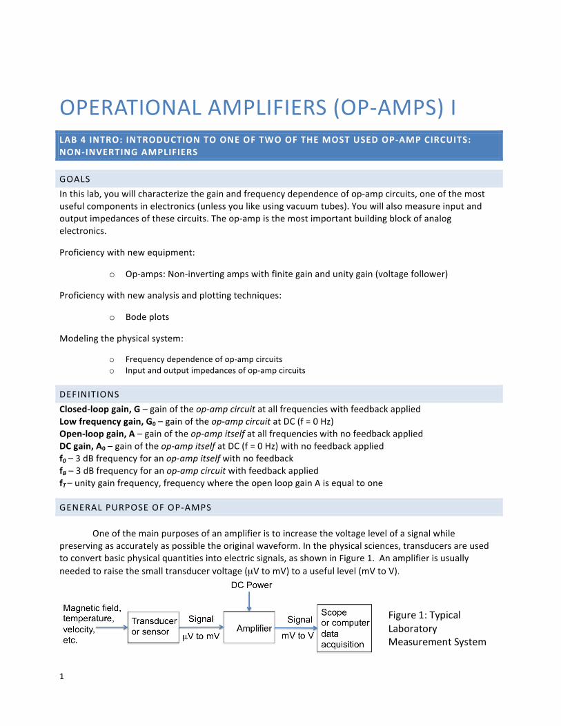
GENERALPURPOSEOFOP-AMPS Oneofthemainpurposesofanamplifieristoincreasethevoltagelevelofasignalwhilepreservingasaccuratelyaspossibletheoriginalwaveform.Inthephysicalsciences,transducersareusedtoconvertbasicphysicalquantitiesintoelectricsignals,asshowninFigure1.Anamplifierisusuallyneededtoraisethesmalltransducervoltage(µVtomV)toausefullevel(mVtoV).
Figure1:TypicalLaboratoryMeasurementSystem
2
Measuringandrecordingequipmenttypicallyrequiresinputsignalsof10mVto10V.Tomeetsuchneeds,atypicallaboratoryamplifiermighthavethefollowingcharacteristics:1. Predictableandstablegain. Themagnitudeofthegain isequaltotheratiooftheoutputsignal
amplitudetotheinputsignalamplitude.2. Linearamplituderesponse,sothattheoutputsignalisdirectlyproportionaltotheinputsignal.3. Accordingtotheapplication,thefrequencydependenceofthegainmightbeaconstant
independentoffrequencyuptothehighestfrequencycomponentintheinputsignal(widebandamplifier),orasharplytunedresonanceresponseifaparticularfrequencymustbepickedout.
4. Highinputimpedanceandlowoutputimpedanceareusuallydesirable.Thesecharacteristicsminimizechangesofgainwhentheamplifierisconnectedtotheinputtransducerandtootherinstrumentsattheoutput.
5. Lownoiseisusuallyimportant.Everyamplifieraddssomerandomnoisetothesignalsitprocesses,andthisnoiseoftenlimitsthesensitivityofanexperiment.
Commerciallaboratoryamplifiersarereadilyavailable,butageneral-purposeamplifierisexpensive(>$1000),andmostofitsfeaturesmightbeunneededinagivenapplication.Often,itispreferabletodesignyourowncircuitusingacheap(<$1)op-ampchip.Op-ampshavemanyothercircuitapplications.Theycanbeusedtomakefilters,limiters,rectifiers,oscillators,integrators,andotherdevices(seeFC12.9–12.15).Wewillbuildsomeofthesecircuitsinthenextlab,Lab5.
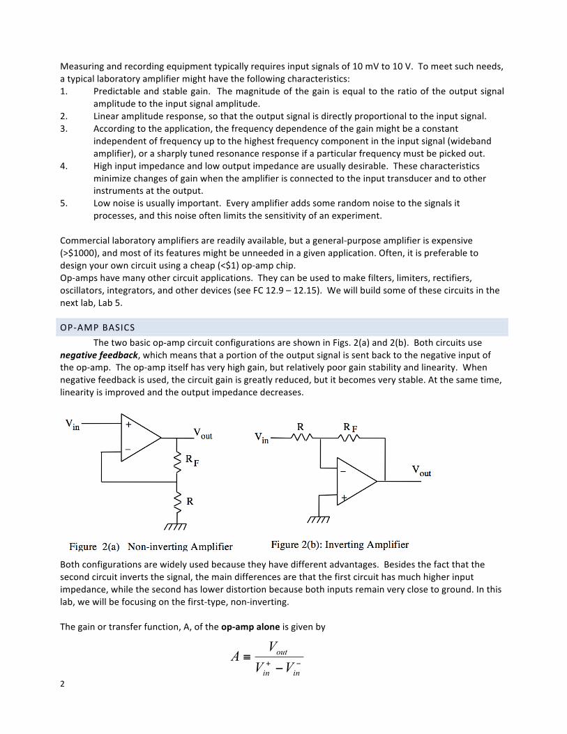
OP-AMPBASICSThetwobasicop-ampcircuitconfigurationsareshowninFigs.2(a)and2(b).Bothcircuitsuse
negativefeedback,whichmeansthataportionoftheoutputsignalissentbacktothenegativeinputoftheop-amp.Theop-ampitselfhasveryhighgain,butrelativelypoorgainstabilityandlinearity.Whennegativefeedbackisused,thecircuitgainisgreatlyreduced,butitbecomesverystable.Atthesametime,linearityisimprovedandtheoutputimpedancedecreases.
Bothconfigurationsarewidelyusedbecausetheyhavedifferentadvantages.Besidesthefactthatthesecondcircuitinvertsthesignal,themaindifferencesarethatthefirstcircuithasmuchhigherinputimpedance,whilethesecondhaslowerdistortionbecausebothinputsremainveryclosetoground.Inthislab,wewillbefocusingonthefirst-type,non-inverting.Thegainortransferfunction,A,oftheop-ampaloneisgivenby
−+ −≡
inin
out
VVV
A
3
wherethedenominatoristhedifferencebetweenthevoltagesappliedtothe+and-inputs.WeusethesymbolGforthegainofthecompleteamplifierwithfeedback:G=Vout/Vin.Thisgaindependsontheresistordividerratio
𝐵 =𝑅
𝑅 + 𝑅%
IfweassumeanidealsituationwhereA=∞,thattheop-ampinputimpedanceisinfinite,andthattheoutputimpedanceiszero,thenthebehaviorofthesecircuitscanbeunderstoodusingthesimple“GoldenRules”:
I. Thevoltagedifferencebetweentheinputsiszero.(“voltagerule”)II. Nocurrentflowsinto(oroutof)eachinput.(“currentrule”)
The“GoldenRule”analysisisveryimportantandisalwaysthefirststepisdesigningop-ampcircuits,sobesureyouunderstanditbeforeyoureadthematerialbelow,whereweconsidertheeffectoffinitevaluesofA,mainlysothatthefrequencydependenceoftheclosedloopgainGcanbeunderstood. Non-invertingamplifierThebasicformulaforthelowfrequencygainofnon-invertingamplifiersisderivedinFC,Section12.5.UsingjusttheGoldenrules,whichassumesA>>1,thegainisgivenby
𝐺' =()*+(,-
= 1 + /0/
FormulasfortheinputandoutputimpedanceoftheentirecircuitarederivedinH&HSection4.26.Theresultsare
𝑅23 = 𝑅2 1 + 𝐴𝐵
𝑅53 = 𝑅5/ 1 + 𝐴𝐵
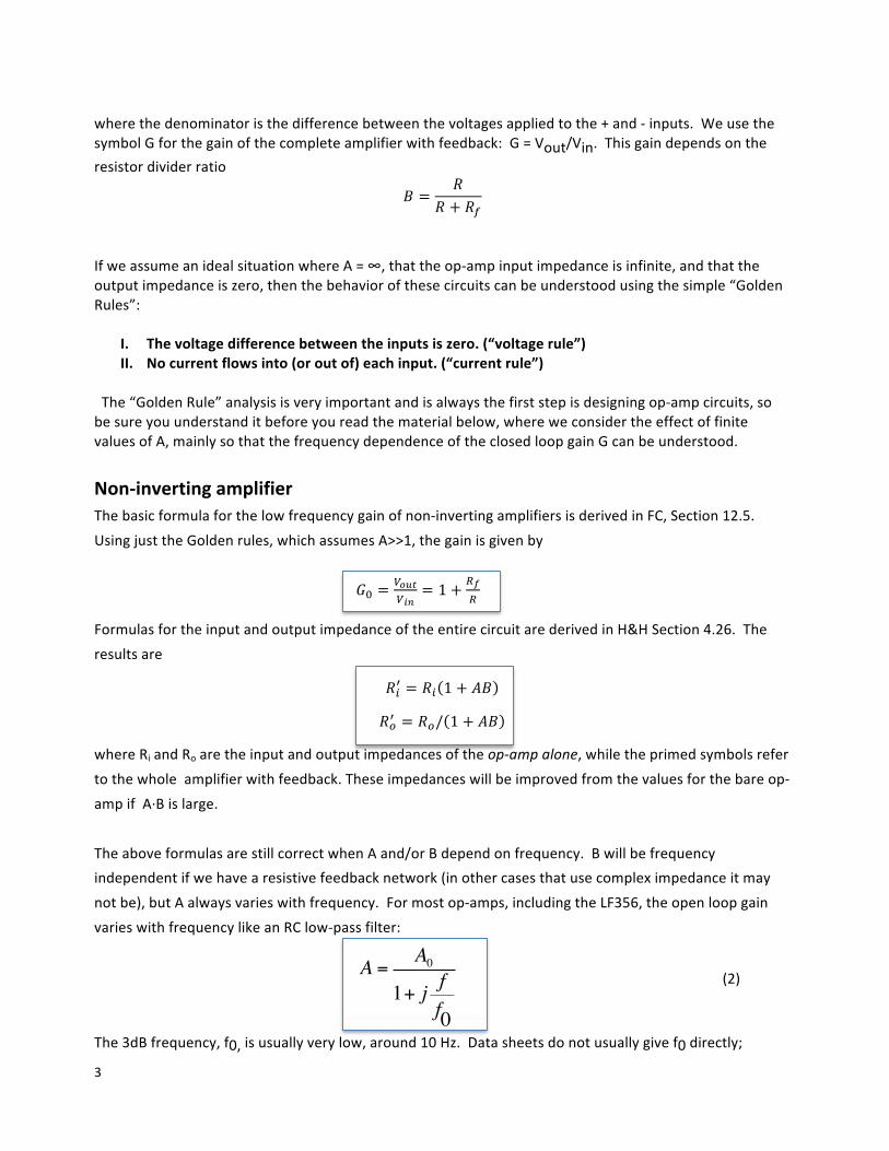
whereRiandRoaretheinputandoutputimpedancesoftheop-ampalone,whiletheprimedsymbolsrefertothewholeamplifierwithfeedback.Theseimpedanceswillbeimprovedfromthevaluesforthebareop-ampifA·Bislarge.TheaboveformulasarestillcorrectwhenAand/orBdependonfrequency.Bwillbefrequencyindependentifwehavearesistivefeedbacknetwork(inothercasesthatusecompleximpedanceitmaynotbe),butAalwaysvarieswithfrequency.Formostop-amps,includingtheLF356,theopenloopgainvarieswithfrequencylikeanRClow-passfilter:
A = A01+ j f
f0
(2)
The3dBfrequency,f0,isusuallyverylow,around10Hz.Datasheetsdonotusuallygivef0directly;
4
insteadtheygivethedcgain,A0,andtheunitygainfrequencyfT,whichisthefrequencywherethemagnitudeoftheopenloopgainAisequaltoone.TherelationbetweenA0,f0,andfTis
𝑓8 = 𝐴'𝑓'
ThefrequencydependenceoftheclosedloopgainGisthengivenby
G =G0
1+ j ffB
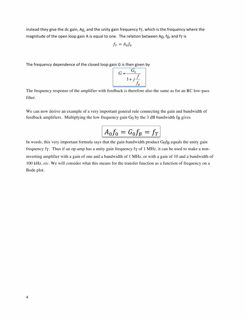
The frequency response of the amplifier with feedback is therefore also the same as for an RC low-pass filter. We can now derive an example of a very important general rule connecting the gain and bandwidth of feedback amplifiers. Multiplying the low frequency gain G0 by the 3 dB bandwidth fB gives
𝐴'𝑓' = 𝐺'𝑓9 = 𝑓8
In words, this very important formula says that the gain-bandwidth product G0fB equals the unity gain frequency fT. Thus if an op-amp has a unity gain frequency fT of 1 MHz, it can be used to make a non-
inverting amplifier with a gain of one and a bandwidth of 1 MHz, or with a gain of 10 and a bandwidth of 100 kHz, etc. We will consider what this means for the transfer function as a function of frequency on a Bode plot.
5
USEFULREADINGS1. FCSections12.2–12.15.Thebasicrulesofop-ampbehaviorandthemostimportantop-ampcircuits.
[NotewhileFCdiscussedbasiccharacteristicsofopampsin12.2itdoesnothavethe“GoldenRule”analysisthatwewilldiscussinclass.]Donotworryrightnowaboutthetransistorgutsofop-amps.WewilllearnabouttransistorsinExperiments7-8.
2. HorowitzandHill,Chapter4.
LABPREPACTIVITIES
AnswerthefollowingquestionsusingMathematicafortheplots.YoucanuseeitherMathematicafortherestthequestionsaswellordothembyhandinyourlabbook.Bringanelectroniccopyofyournotebooktolab,preferablyonyourownlaptop.Youwilluseittoplotyourdataduringthelabsession.
Question1
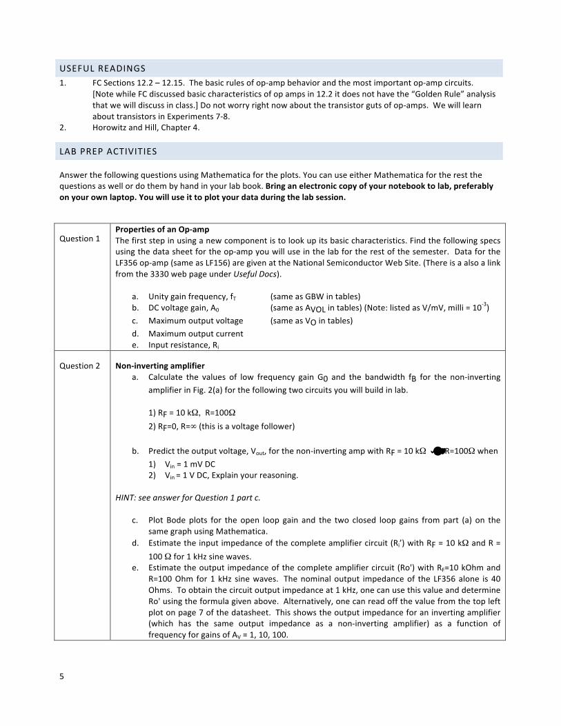
PropertiesofanOp-ampa. Thefirststepinusinganewcomponentistolookupitsbasiccharacteristics.Findthefollowingspecs
usingthedatasheetfortheop-ampyouwilluseinthelabfortherestofthesemester.DatafortheLF356op-amp(sameasLF156)aregivenattheNationalSemiconductorWebSite.(Thereisaalsoalinkfromthe3330webpageunderUsefulDocs).
a. Unitygainfrequency,fT (sameasGBWintables)b. DCvoltagegain,A0 (sameasAVOLintables)(Note:listedasV/mV,milli=10-3)c. Maximumoutputvoltage (sameasVOintables)d. Maximumoutputcurrent e. Inputresistance,Ri
Question2
Non-invertingamplifiera. Calculate the values of low frequency gain G0 and the bandwidth fB for the non-inverting
amplifierinFig.2(a)forthefollowingtwocircuitsyouwillbuildinlab.1)RF=10kΩ, R=100Ω2)RF=0,R=∞(thisisavoltagefollower)
b. Predicttheoutputvoltage,Vout,forthenon-invertingampwithRF=10kΩ andR=100Ωwhen1) Vin=1mVDC2) Vin=1VDC,Explainyourreasoning.
HINT:seeanswerforQuestion1partc.
c. Plot Bode plots for the open loop gain and the two closed loop gains frompart (a) on thesamegraphusingMathematica.
d. Estimatetheinputimpedanceofthecompleteamplifiercircuit(Ri’)withRF=10kΩandR=100Ωfor1kHzsinewaves.
e. Estimatetheoutput impedanceofthecompleteamplifiercircuit(Ro')withRF=10kOhmandR=100Ohm for1 kHz sinewaves. Thenominaloutput impedanceof the LF356alone is40Ohms.Toobtainthecircuitoutputimpedanceat1kHz,onecanusethisvalueanddetermineRo'usingtheformulagivenabove.Alternatively,onecanreadoffthevaluefromthetopleftplotonpage7ofthedatasheet.Thisshowstheoutputimpedanceforaninvertingamplifier(which has the same output impedance as a non-inverting amplifier) as a function offrequencyforgainsofAV=1,10,100.
6
Question3 Labactivitiesa. Readthroughallofthelabstepsandidentifythestep(orsub-step)thatyouthinkwillbethe
mostchallenging.b. Listatleastonequestionyouhaveaboutthelabactivity.
SETTINGUPABASICOP-AMPCIRCUT
Allop-ampcircuitsstartoutbymakingthebasicpowerconnections.Op-ampsareactivecomponents,whichmeanstheyneedexternalpowertofunctionunlikepassivecomponentssuchasresistors.
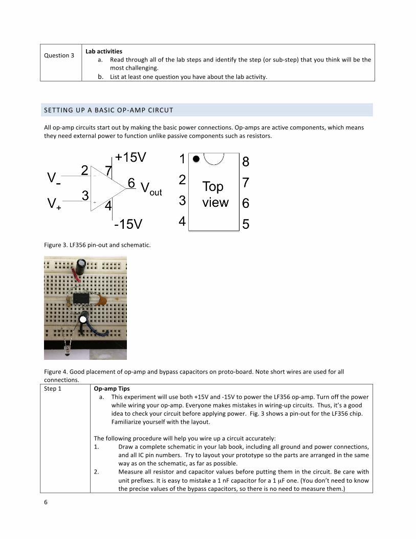
Figure3.LF356pin-outandschematic.
Figure4.Goodplacementofop-ampandbypasscapacitorsonproto-board.Noteshortwiresareusedforallconnections.Step1 Op-ampTips
a. Thisexperimentwilluseboth+15Vand-15VtopowertheLF356op-amp.Turnoffthepowerwhilewiringyourop-amp.Everyonemakesmistakesinwiring-upcircuits.Thus,it’sagoodideatocheckyourcircuitbeforeapplyingpower.Fig.3showsapin-outfortheLF356chip.Familiarizeyourselfwiththelayout.
Thefollowingprocedurewillhelpyouwireupacircuitaccurately:1. Drawacompleteschematicinyourlabbook,includingallgroundandpowerconnections,
andallICpinnumbers.Trytolayoutyourprototypesothepartsarearrangedinthesamewayasontheschematic,asfaraspossible.
2. Measureallresistorandcapacitorvaluesbeforeputtingtheminthecircuit.Becarewithunitprefixes.Itiseasytomistakea1nFcapacitorfora1µFone.(Youdon’tneedtoknowtheprecisevaluesofthebypasscapacitors,sothereisnoneedtomeasurethem.)
7
3. Adheretoacolorcodeforwires.Forexample: 0V(ground) Black +15V Red -15V Blue
b. Theop-ampchipsitsacrossagrooveintheprototypingboard(seeFig4).Beforeinsertingachip,gentlystraightenthepins.Afterinsertion,checkvisuallythatnopinisbrokenorbentunderthechip.Toremovethechip,useasmallscrewdriverinthegroovetopryitout.
c. Youwillhavelesstroublewithspontaneousoscillationsifthecircuitlayoutisneatandcompact,inparticularthefeedbackpathshouldbeasshortaspossibletoreducedunwantedcapacitivecouplingandleadinductance.(seeFig4).Hint:donotwireoverthechipbutaroundit.
d. Tohelppreventspontaneousoscillationsduetounintendedcouplingviathepowersupplies,usebypasscapacitorstofilterthesupplylines.Abypasscapacitorbetweeneachpowersupplyleadandgroundwillprovideaminiaturecurrent“reservoir”thatcanquicklysupplycurrentwhenneeded.Thiscapacitorisnormallyintherange1µF–10µF.Theexactvalueisusuallyunimportant.Compactcapacitorsinthisrangeareusuallyelectrolytic,tantalum,oraluminumandarepolarized,meaningthatoneterminalmustalwaysbepositiverelativetotheother.Thecapacitorsarelabeledwhichsideiswhich,buteachmanufactureusesdifferentmarkings.Ifyouputapolarizedcapacitorinbackwards,itwillburnout.Bypasscapacitorsshouldbeplacedascloseaspossibletotheop-amppins.(seeFig4).
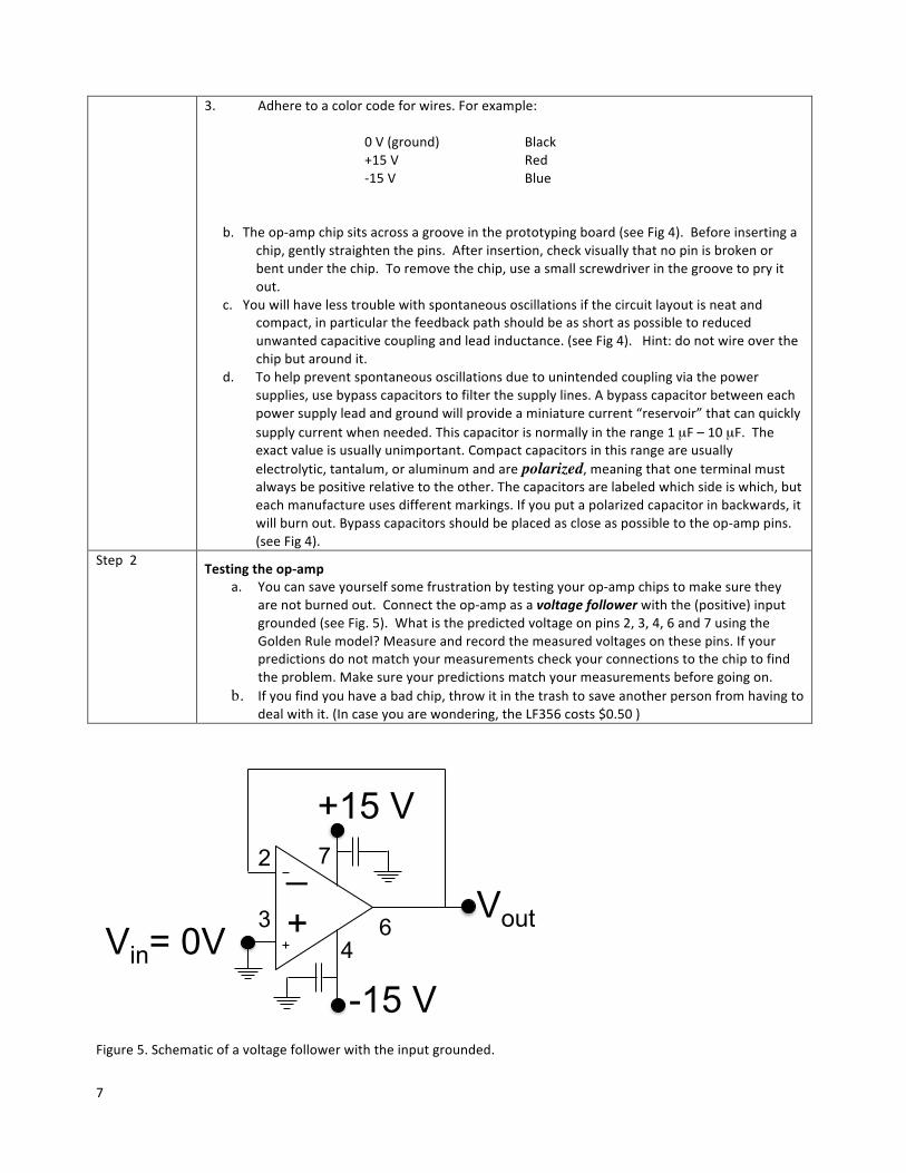
Step2 Testingtheop-ampa. Youcansaveyourselfsomefrustrationbytestingyourop-ampchipstomakesurethey
arenotburnedout.Connecttheop-ampasavoltagefollowerwiththe(positive)inputgrounded(seeFig.5).Whatisthepredictedvoltageonpins2,3,4,6and7usingtheGoldenRulemodel?Measureandrecordthemeasuredvoltagesonthesepins.Ifyourpredictionsdonotmatchyourmeasurementscheckyourconnectionstothechiptofindtheproblem.Makesureyourpredictionsmatchyourmeasurementsbeforegoingon.
b. Ifyoufindyouhaveabadchip,throwitinthetrashtosaveanotherpersonfromhavingtodealwithit.(Incaseyouarewondering,theLF356costs$0.50)
Figure5.Schematicofavoltagefollowerwiththeinputgrounded.
Vin= 0V Vout
_
+
+15 V
-15 V
2
3 6
7
4
8
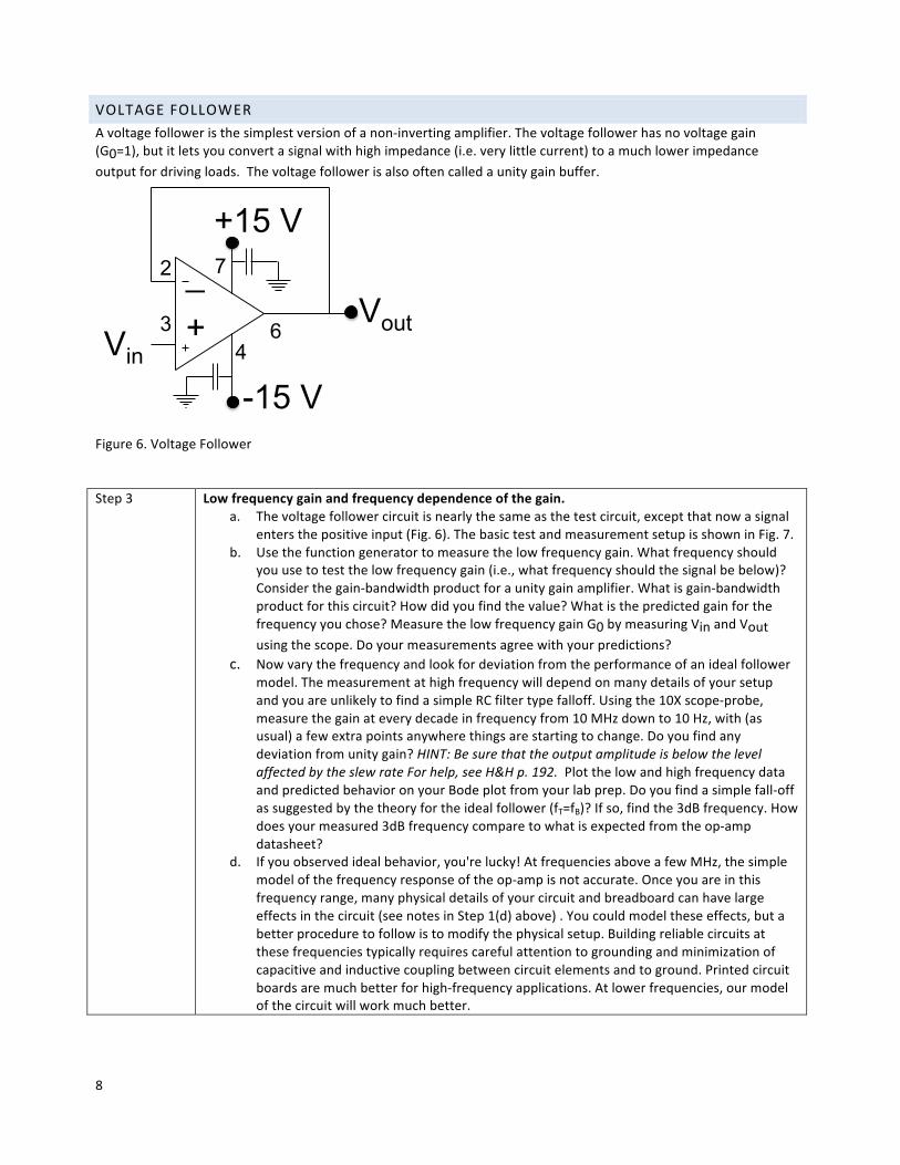
VOLTAGEFOLLOWERAvoltagefolloweristhesimplestversionofanon-invertingamplifier.Thevoltagefollowerhasnovoltagegain(G0=1),butitletsyouconvertasignalwithhighimpedance(i.e.verylittlecurrent)toamuchlowerimpedanceoutputfordrivingloads.Thevoltagefollowerisalsooftencalledaunitygainbuffer.
Figure6.VoltageFollowerStep3 Lowfrequencygainandfrequencydependenceofthegain.
a. Thevoltagefollowercircuitisnearlythesameasthetestcircuit,exceptthatnowasignalentersthepositiveinput(Fig.6).ThebasictestandmeasurementsetupisshowninFig.7.
b. Usethefunctiongeneratortomeasurethelowfrequencygain.Whatfrequencyshouldyouusetotestthelowfrequencygain(i.e.,whatfrequencyshouldthesignalbebelow)?Considerthegain-bandwidthproductforaunitygainamplifier.Whatisgain-bandwidthproductforthiscircuit?Howdidyoufindthevalue?Whatisthepredictedgainforthefrequencyyouchose?MeasurethelowfrequencygainG0bymeasuringVinandVoutusingthescope.Doyourmeasurementsagreewithyourpredictions?
c. Nowvarythefrequencyandlookfordeviationfromtheperformanceofanidealfollowermodel.ThemeasurementathighfrequencywilldependonmanydetailsofyoursetupandyouareunlikelytofindasimpleRCfiltertypefalloff.Usingthe10Xscope-probe,measurethegainateverydecadeinfrequencyfrom10MHzdownto10Hz,with(asusual)afewextrapointsanywherethingsarestartingtochange.Doyoufindanydeviationfromunitygain?HINT:BesurethattheoutputamplitudeisbelowthelevelaffectedbytheslewrateForhelp,seeH&Hp.192.PlotthelowandhighfrequencydataandpredictedbehavioronyourBodeplotfromyourlabprep.Doyoufindasimplefall-offassuggestedbythetheoryfortheidealfollower(fT=fB)?Ifso,findthe3dBfrequency.Howdoesyourmeasured3dBfrequencycomparetowhatisexpectedfromtheop-ampdatasheet?
d. Ifyouobservedidealbehavior,you'relucky!AtfrequenciesaboveafewMHz,thesimplemodelofthefrequencyresponseoftheop-ampisnotaccurate.Onceyouareinthisfrequencyrange,manyphysicaldetailsofyourcircuitandbreadboardcanhavelargeeffectsinthecircuit(seenotesinStep1(d)above).Youcouldmodeltheseeffects,butabetterproceduretofollowistomodifythephysicalsetup.Buildingreliablecircuitsatthesefrequenciestypicallyrequirescarefulattentiontogroundingandminimizationofcapacitiveandinductivecouplingbetweencircuitelementsandtoground.Printedcircuitboardsaremuchbetterforhigh-frequencyapplications.Atlowerfrequencies,ourmodelofthecircuitwillworkmuchbetter.
Vout
_
+
+15 V
-15 V
2
3 6
7
4 Vin
9
Function Generator
Circuit Board
V out V in
V in
Trigger
Trig. Out
Sig. Out
Oscilloscope
Channel 1
Channel 2
Channel 4 Trigger
DC Power Supply
0 +15 –15
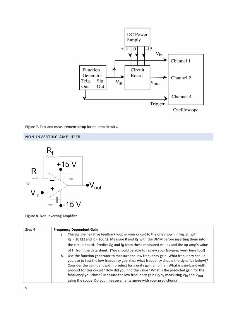
Figure7.Testandmeasurementsetupforop-ampcircuits.
NON-INVERTINGAMPLIFIER
Figure8.Non-invertingAmplifier
Step4
FrequencyDependentGain a. ChangethenegativefeedbackloopinyourcircuittotheoneshowninFig.8.,with
RF=10kΩandR=100Ω.MeasureRandRFwiththeDMMbeforeinsertingthemintothecircuitboard.PredictG0andfBfromthesemeasuredvaluesandtheop-amp'svalueoffTfromthedatasheet.(Youshouldbeabletoreviewyourlab-prepworkheretoo!)
b. Usethefunctiongeneratortomeasurethelowfrequencygain.Whatfrequencyshouldyouusetotestthelowfrequencygain(i.e.,whatfrequencyshouldthesignalbebelow)?Considerthegain-bandwidthproductforaunitygainamplifier.Whatisgain-bandwidthproductforthiscircuit?Howdidyoufindthevalue?Whatisthepredictedgainforthefrequencyyouchose?MeasurethelowfrequencygainG0bymeasuringVinandVoutusingthescope.Doyourmeasurementsagreewithyourpredictions?
10
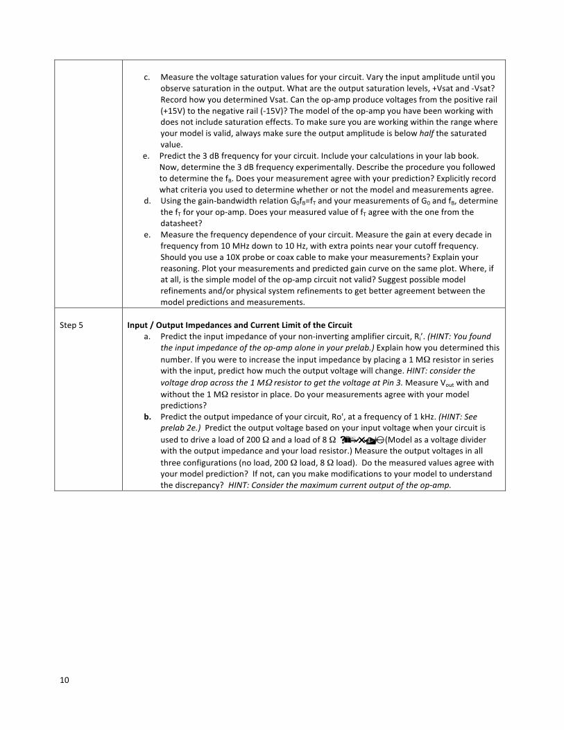
c. Measurethevoltagesaturationvaluesforyourcircuit.Varytheinputamplitudeuntilyou
observesaturationintheoutput.Whataretheoutputsaturationlevels,+Vsatand-Vsat?RecordhowyoudeterminedVsat.Cantheop-ampproducevoltagesfromthepositiverail(+15V)tothenegativerail(-15V)?Themodeloftheop-ampyouhavebeenworkingwithdoesnotincludesaturationeffects.Tomakesureyouareworkingwithintherangewhereyourmodelisvalid,alwaysmakesuretheoutputamplitudeisbelowhalfthesaturatedvalue.
e. Predictthe3dBfrequencyforyourcircuit.Includeyourcalculationsinyourlabbook.Now,determinethe3dBfrequencyexperimentally.DescribetheprocedureyoufollowedtodeterminethefB.Doesyourmeasurementagreewithyourprediction?Explicitlyrecordwhatcriteriayouusedtodeterminewhetherornotthemodelandmeasurementsagree.
d. Usingthegain-bandwidthrelationG0fB=fTandyourmeasurementsofG0andfB,determinethefTforyourop-amp.DoesyourmeasuredvalueoffTagreewiththeonefromthedatasheet?
e. Measurethefrequencydependenceofyourcircuit.Measurethegainateverydecadeinfrequencyfrom10MHzdownto10Hz,withextrapointsnearyourcutofffrequency.Shouldyouusea10Xprobeorcoaxcabletomakeyourmeasurements?Explainyourreasoning.Plotyourmeasurementsandpredictedgaincurveonthesameplot.Where,ifatall,isthesimplemodeloftheop-ampcircuitnotvalid?Suggestpossiblemodelrefinementsand/orphysicalsystemrefinementstogetbetteragreementbetweenthemodelpredictionsandmeasurements.
Step5
Input/OutputImpedancesandCurrentLimitoftheCircuit
a. Predicttheinputimpedanceofyournon-invertingamplifiercircuit,Ri’.(HINT:Youfoundtheinputimpedanceoftheop-ampaloneinyourprelab.)Explainhowyoudeterminedthisnumber.Ifyouweretoincreasetheinputimpedancebyplacinga1MΩresistorinserieswiththeinput,predicthowmuchtheoutputvoltagewillchange.HINT:considerthevoltagedropacrossthe1MΩresistortogetthevoltageatPin3.MeasureVoutwithandwithoutthe1MΩresistorinplace.Doyourmeasurementsagreewithyourmodelpredictions?
b. Predicttheoutputimpedanceofyourcircuit,Ro',atafrequencyof1kHz.(HINT:Seeprelab2e.)Predicttheoutputvoltagebasedonyourinputvoltagewhenyourcircuitisusedtodrivealoadof200Ωandaloadof8Ω separatly.(Modelasavoltagedividerwiththeoutputimpedanceandyourloadresistor.)Measuretheoutputvoltagesinallthreeconfigurations(noload,200Ωload,8Ωload).Dothemeasuredvaluesagreewithyourmodelprediction?Ifnot,canyoumakemodificationstoyourmodeltounderstandthediscrepancy? HINT:Considerthemaximumcurrentoutputoftheop-amp.


