Embed Size (px)
Citation preview

1194 Oak Valley Dr, Ste 20, Ann Arbor MI 48108 USA (800) 959-0329 • (734) 769-0573 • www.gfg-inc.com
Remote Sampling
G450/460 Motorized Pump
Operations ManualMP-2


Table of Contents Page
Introduction......................................................................... 1 For Your Safety .................................................................. 1 Application and Use............................................................ 1 Special Conditions for Safe Use ......................................... 2 General Description and Design ......................................... 2 Sampling Inlet..................................................................... 3 Connecting the Pump.......................................................... 3 Operational Hints................................................................ 4 Turning the Pump On ......................................................... 4 Turning the Pump Off......................................................... 4 Remote Sampling................................................................ 4 Pump Fault.......................................................................... 5 Power Supply...................................................................... 5 Battery Replacement........................................................... 6 Test Battery Capacity.......................................................... 7 System Fault ....................................................................... 7 Appendix............................................................................. 8 Cleaning.............................................................................. 8 Changing the Filter ............................................................. 8 Inspection............................................................................ 8 Maintenance and Regular Function Check ......................... 8 Service ................................................................................ 8 Replacement Parts and Accessories.................................... 9 Technical Data .................................................................. 10


Introduction
For Your Safety Like any piece of complex equipment, the GfG G450/460 motorized pump will do the job it is designed to do only if it is used and serviced in accordance with the manufacturer's instructions. CAUTION: For safety reasons, this equipment must be operated and
serviced by qualified personnel only. Read and understand the instruction manual completely before operating or servicing this device.
The warranties made by GfG with respect to the product are voided if the product is not used and serviced in accordance with the instructions in this manual. Please protect yourself and your employees by following them. The above does not alter statements regarding GfG's warranties and conditions of sale and delivery.
Application and Use The G450/460 motorized pump ensures personal safety in atmospheric conditions in combination with the portable gas detectors of the G400 series.
!
When using the G450/G460 with the motorized pump, instrument calibration must be performed while the pump is attached to the unit and operating.
1
Special Conditions for Safe Use In potentially hazardous areas the G450/460 pump must be used properly; i.e., the pump (with a G400 series gas detector) must be carried with you and must not be laid down unattended (to prevent electrostatic charge). The pump must be attached to the G400 gas detector before entering a potentially hazardous area. It must not be disconnected from the detector in the hazardous area. Always pay attention to the ignition protection and the temperature class of the gas detector.
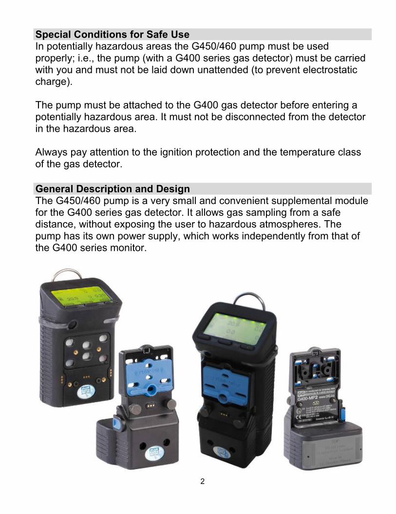
General Description and Design The G450/460 pump is a very small and convenient supplemental module for the G400 series gas detector. It allows gas sampling from a safe distance, without exposing the user to hazardous atmospheres. The pump has its own power supply, which works independently from that of the G400 series monitor.
2

Sampling Inlet The sampling inlet is on the
Sampling inlet
bottom of the pump body.
3
Here you can attach accessories for taking gas samples (hose adapter with sampling line, probe, GfG telescopic probe).
Connection for gas sampling accessories
Connecting the Pump Attach the G450/460 pump to the G400 series gas detector and secure it with the thumbscrews. For permanent attachment to the G400 series gas detector you can attach the pump with 2 additional screws (included). You will find the mounting holes for the additional screws under the blue sensor cover. To access the holes, remove the the Phillips screws from the side, slide the sensor cover upwards – push the lock smoothly with a screw driver – and remove it. Once the screws are in place, replace the sensor cover, slide it downwards and replace side screws. To remove the pump from the G400 series monitor, remove all attached screws.

4
Operational Hints NOTE! If the blue sensor cover is slid upwards forcefully with the two
Phillips screws removed, it may slip over its lock and the diffusion inlets will not be properly covered. This may result in false detection, since ambient air could dilute the concentration of the gas sample. Make sure, therefore, that the diffusion inlets are closed properly if the screws have been removed.
Turning the Pump On Slide the blue sensor cover upwards to turn the pump on. With sufficient battery capacity the pump motor starts after a short delay (approximately 1 second). The battery capacity is indicated on the instruments display. The proper operation of the pump is indicated by an icon on the display.
Turning the Pump Off Slide the blue sensor cover downwards to turn the pump off. The pump should be turned off after detection to prevent unnecessary use of the batteries. Remote Sampling The pump is designed to draw at a rate of 1 foot per second (1 meter per 3 seconds). Allow enough time for the sample to be drawn through the entire length of sample tubing and probe, plus enough time for the readings to stabilize (at least another 20 seconds). Always test the space at different levels as gases may stratify depending on weight. It is recommended that the space be tested at incremental levels of 3 feet or 1 meter. Each time a new level is to be tested, allow enough time for the sample to propagate through the entire length of the sampling system, plus enough time for the sensors to stabilize (at least another 20 seconds).

5
Pump Fault If the sampled gas amount is too low (<0.25 l / min) or if the power supply to the pump motor is interrupted, the instrument’s display flashes an alarm. A pump fault may be caused by a restricted flow in the tubing or sample probe. Make sure that any restriction is eliminated from the tubing and sample probe; this may include a need to replace the in-line filter. ATTENTION: During a low flow alarm, proper detection in connection with
the G400 series monitor cannot be assured. Power Supply The G450/460 pump is powered by an alkaline or NiMH battery module. The power supply module allows continuous operation for up to 10 hours. The operational time may be reduced, however, by a high load on the pump motor (e.g. bent sampling line / blocked filter). The G450/460 pump turns off automatically if the battery voltage falls below the minimum level needed for proper functioning. At least 15 minutes before automatic deactivation, the display icon flashes once per minute to indicate insufficient battery voltage.

Battery Replacement NOTE: The pump must not be opened in explosion endangered
areas. You must not replace the battery module in hazardous areas.
Always turn the pump off before replacing the battery module. Check for the correct polarity of the new 1.5 V AA alkaline batteries (see Battery Holder). The correct battery type is: DURACELL MN1500 LR6 AA. NOTE: The batteries may only be replaced in safe areas. Check for
correct polarity when inserting the batteries (see the picture inside the battery tray). With incorrect polarity the pump will not turn on.
To replace the batteries, separate the battery tray from the pump: unscrew the screws on the front and pull the battery tray out of the unit. Please dispose of batteries properly.
6

7
NOTE: Batteries must not be replaced in EX-areas Check for the correct polarity of the new batteries (see the picture
on inner side of battery tray)! Check for correct insertion of the battery tray (characters on front
must be right side up)! Tighten all screws after inserting the battery tray.
Test Battery Capacity
Once the pump is turned on, the battery capacity is automatically indicated on the instruments display. To activate the battery test, turn the pump on (slide the blue sensor cover upwards). System Fault
The circuitry of the G450/460 pump is continuously monitored. If a fault is recognized, an instrument alarm is triggered. To correct this problem, replace the batteries. If the fault still exists, return the unit to the manufacturer.

Appendix
8
Cleaning Give the G450/460 pump a short visual check after use. Use a damp cloth to remove stains or dirt from the casing. Never use solvents or cleaning agents!
Changing the Filter To change the filter, separate the pump from the G400 series monitor and slide the blue cover down. Use tweezers to remove the filter and replace it with a new one.
Filter Inspection In addition to regular maintenance, the user has to do the following checks at least before every shift:
Visual check for damage Check battery capacity Check sampling performance
Maintenance and Regular Function Check Depending on application conditions and technical requirements, maintenance should be done in intervals required by the application. Maintenance includes measures which retain the operational status of the G450/460 pump.
Visual check for damages Check filter condition Check pump battery capacity Check sampling performance Check low flow alarm
In addition to the above, we recommend getting the pump checked for proper functioning by an expert in combination with the (at least) annual inspection of the G400 series monitor.
Service Service should be done by the manufacturer or authorized service centers. Only genuine spare parts must be used for service and repair.

9
Replacement Parts and Accessories Description Part NumberAlkaline battery (each) 4002-001 Battery pack, Alkaline (batteries not included) (Gray) 1450-202 Battery pack, Rechargeable NiMH (Black) 1450-211 Float probe On request Sampling probe (without tubing) 1000214 Probe filter replacement kit (2 Hydrophobic/8 Particulate) 7740-015 Pump replacement filter (pack of 10) 1450-321 Special dust / water filter (pack of 3) 1000207 Special sampling line 10 feet, anti-static, with dust / water filter 1000208
Special sampling line 10 feet, anti-static, with dust / water filter and flow indicator 1000209
Special sampling line for exotic gases (one foot) 2806-011 Telescopic probe CrNi 1.36 m 1000205

10
Technical Data Type: G450/460 Motorized Pump Pump performance:
0.50 l / min for 0 mm water column 0.35 l / min for 300 mm water column Maximum 100 m hose length (depending on gas and hose)
Gas supply: Sampling inlet during pump mode or diffusion inlet
Power supply:
NiMH battery module, rechargeable Im=1 A (maximum charging current) Um=30 VDC (maximum voltage) or Alkaline battery module, non-rechargeable with 2x size AA Duracell MN1500 LR6
Operational time: Approximately 10 hours
Climate Condition: For operation: -4 to 131°F (-20 to +55°C) / 5 to 95% r. h.
For storage: -13 to 131°F (-25 to +55°C) / 5 to 95% r. h. (recommended: 32 to 86°F (0 to +30°C))
Casing: Material: Rubberized compound
Dimensions: 4.29x2.68x.83 inches (109x68x21 mm) (HxWxD) Weight: 6.35 ounces (180 g) with alkaline battery module
Protection: IP 40

11

GfG Instrumentation, Inc.1194 Oak Valley Dr.Suite 20Ann Arbor, MI 48108USA
US/Canada: (800) 959-0329US/Canada Fax: (734) 769-1888International: +1 734 769 0573International Fax: +1 734 769 1888Website: www.gfg-inc.com
Worldwide Manufacturer of Gas Detection Solutions
7004-MP2 Rev. 2 (04/13)


