Embed Size (px)
Citation preview

PART 02- Works’ Requirement
Landslide Mitigation Works in Between Culvert No. 5/11 and
5/13 Dehiowita- Deraniyagala Noori Road & LHS of Aranayaka
- Hulankapolla Road in Kegalle District, Digana Kundasale &
Dangolla Lower Circular Road in Kandy District
Contract No: RLVMMP/WORKS/04B

STANDARD SPECIFICATION FOR CONSTRUCTION &
MAINTAINCE OF LANDSLIDE MITIGATION WORKS
National Building Research Organization (NBRO) ii
TABLE OF CONTENT
TABLE OF CONTENT
TABLE OF CONTENT .................................................................................................................................... ii
LIST OF TABLES............................................................................................................................................ v
100 GENERAL ................................................................................................................................................ 1
101 Arrangement for traffic with safety precautions during constructions or rehabilitation of existing roads .. 1
102 Control of works .................................................................................................................................... 3
103 Control of materials................................................................................................................................ 5
104 General rules for measurement and payment........................................................................................... 6
105 Sieve designations .................................................................................................................................. 8
106 Facilities for the contractor and general requirements ............................................................................. 8
107 Workmanship and quality control ......................................................................................................... 12
108 Standards ............................................................................................................................................. 12
109 Work executed by the employer or other contractors ............................................................................ 13
110 Services ............................................................................................................................................... 13
111 Maintenance of existing roads .............................................................................................................. 14
112 Protection of the works and requirements to be met before the commencement of construction of new
works on already completed works.............................................................................................................. 14
113 Remedial work ..................................................................................................................................... 15
114 Water supply arrangements .................................................................................................................. 15
115 Setting out, survey and drawings .......................................................................................................... 16
116 Facilities for the Engineer and his staff and Employer- N/A .................................................................. 17
117 Environmental management–Refer Section 2000 .................................................................................. 17
118 Health and safety- Refer SECTION 2000 .............................................................................................. 17
119 Programme of works ............................................................................................................................ 17
120 Construction management and staff ...................................................................................................... 18
200 SITE CLEARING .....................................................................................................................................19
201 Clearing and grubbing .......................................................................................................................... 19
202 Removal of existing structures.............................................................................................................. 21
203 Utility relocation .................................................................................................................................. 23
300 EARTHWORKS .......................................................................................................................................24
301 Side slope excavation or trimming ........................................................................................................ 24
302 Excavation and backfill of structure...................................................................................................... 26
303 Channel excavation .............................................................................................................................. 29
304 Filling work ......................................................................................................................................... 30
305 Non – explosive blasting operations ..................................................................................................... 33
306 Tension crack sealing ........................................................................................................................... 33
400 DRAINAGE CONSTRUCTION ...............................................................................................................35
401 Cut–off drains, cascade drains and surface drains ................................................................................. 35
402 Sub-surface drains (underdrains or trench drains) ................................................................................. 36
403 Catch-pits and inlets ............................................................................................................................. 37
404 Berm sealing ........................................................................................................................................ 38
405 Drainage backfill behind earth retaining structures ............................................................................... 39

STANDARD SPECIFICATION FOR CONSTRUCTION &
MAINTAINCE OF LANDSLIDE MITIGATION WORKS
National Building Research Organization (NBRO) iii
TABLE OF CONTENT
406 Weep-holes for earth retaining structure ............................................................................................... 40
500 INCIDENTIAL CONSTRUCTION ..........................................................................................................41
501 Top soiling ........................................................................................................................................... 41
502 Vegetation Cover ................................................................................................................................. 41
503 Gabion walls and mattresses using wire mesh ....................................................................................... 47
504 Chain link fence ................................................................................................................................... 48
505 Drainage well ....................................................................................................................................... 50
600 CONCRETE AND OTHER STRUCTURES .............................................................................................54
601 Concrete for structures ......................................................................................................................... 54
602 Steel reinforcement for concrete structures ........................................................................................... 61
603 Random rubble masonry....................................................................................................................... 63
604 Plum concrete ...................................................................................................................................... 65
605 Formwork for structures ....................................................................................................................... 65
606 Hot dipped galvanized mild steel-tor or rib steel dowels ....................................................................... 67
700 SOIL NAILING AND HORIZONTAL DRAINS ......................................................................................69
701 Soil nailing........................................................................................................................................... 69
702 Horizontal drains .................................................................................................................................. 88
703 Monitoring ........................................................................................................................................... 91
800 QUALITY CONTROL OF WORK ...........................................................................................................93
801 Quality control plan.............................................................................................................................. 93
802 Quality control tests during construction............................................................................................... 93
803 Material testing .................................................................................................................................... 95
900 MATERIAL DETAILS.............................................................................................................................96
901 Aggregate ............................................................................................................................................ 96
902 Cement ................................................................................................................................................ 97
903 Concrete admixture .............................................................................................................................. 98
904 Soils ..................................................................................................................................................... 98
905 Geotextiles / Geofabric ......................................................................................................................... 98
1000 TESTS FOR QUALITY CONTROL OF MATERIAL AND WORKS .................................................. 101
1001 Aggregates and soil ...........................................................................................................................101
1002 Cement and concrete .........................................................................................................................101
1003 Soils ..................................................................................................................................................102
1004 Coated Metallic Mesh .......................................................................................................................102
1100 GROUND ANCHORS .......................................................................................................................... 103
1101 General .............................................................................................................................................103
1102 Definitions ........................................................................................................................................103
1103 Materials and components .................................................................................................................109
1104 Corrosion Protection .........................................................................................................................112
1105 Supply and Supervision .....................................................................................................................113
1106 Assembly ..........................................................................................................................................114
1107 Installation ........................................................................................................................................116
1108 Grouting............................................................................................................................................119

STANDARD SPECIFICATION FOR CONSTRUCTION &
MAINTAINCE OF LANDSLIDE MITIGATION WORKS
National Building Research Organization (NBRO) iv
TABLE OF CONTENT
1109 Load Testing .....................................................................................................................................122
1110 Stressing ...........................................................................................................................................127
1111 Cutting Off of Stressed Tendons ........................................................................................................129
1112 Monitoring ........................................................................................................................................129
1113 Measurement and Payment ................................................................................................................130
1200 ROCKFALL PROTECTION ................................................................................................................ 132
1201 Rock Fence .......................................................................................................................................132
1300 INSTRUMENTATION AND MONITORING ...................................................................................... 138
1301 Instrumentation .................................................................................................................................138
1302 Landslide warning sign boards ..........................................................................................................148
1303 Monitoring ........................................................................................................................................149
Appendix A Construction Management and Staff ....................................................................................... 150
Appendix B Rerefernced Documents .......................................................................................................... 151
2000 Environmental, Social, Health & Safety Requirements .......................................................................... 153
2001 Environmental and Social Policy .......................................................................................................153
2002 Environmental and Social Monitoring .........................................................................................153
2003 Working Conditions and Community Health and Safety .............................................................168
2004 Construction Contractors’ Requirement To Comply With Site Specific Environmental, Social
Management And Health And Safety During The Construction Phase .................................................174
DRAWINGS ................................................................................................................................................. 177

STANDARD SPECIFICATION FOR CONSTRUCTION &
MAINTAINCE OF LANDSLIDE MITIGATION WORKS
National Building Research Organization (NBRO) v
LIST OF TABLES
LIST OF TABLES
Table 105-1: Sieves used in these Specifications ............................................................................................... 8 Table 502-1: Typical seeds varieties ............................................................................................................... 42 Table 502-2: Material Characteristics for Permanent Erosion Control Product ................................................. 43 Table 502-3: Hydro seeding quality evaluation criteria .................................................................................... 45 Table 502-4:Test methods of permanent erosion control products ................................................................... 46 Table 601-1: Concrete Grades ......................................................................................................................... 54 Table 601-2: Minimum Cement Content and Water / Cement Ratio ................................................................ 54 Table 601-3: Nominal Mixes .......................................................................................................................... 54 Table 601-4: Workability of Concrete ............................................................................................................. 55 Table 601-5: Chloride and Sulphate Contents in Concrete ............................................................................... 55 Table 601-6 : Minimum period before striking formwork ................................................................................ 60 Table 701-1: Performance requirements for Cement Grout .............................................................................. 70 Table 701-2: Coated Metallic Mesh properties for Grid Beam Method ............................................................ 72 Table 701-3: Coated Metallic Mesh properties for Isolated Nail Head Method ................................................ 72 Table 701-4: Grading limits for combinedaggregates ...................................................................................... 73 Table 701-5: Boundary Rope Properties .......................................................................................................... 73 Table 701-6: Coir Mesh Properties.................................................................................................................. 74 Table 701-7: Suitability Test – Load Increments and Minimum Periods of Observation .................................. 82 Table 701-8: Acceptance Test – Load Increments and Minimum Periods of Observation ................................ 83 Table 702-1: Pipe Diameters and Wall Thickness ........................................................................................... 88 Table 901-1: Permissible maximum salt content in aggregate .......................................................................... 96 Table 901-2: Grading Limits for Coarse Aggregate ......................................................................................... 96 Table 901-3: Preferred Grading for Fine Aggregate for Concrete .................................................................... 97 Table 904-1: Material Characteristics for Filling - Type I and Type II ............................................................. 98 Table 905-1: Physical and filtration properties of Geo-textiles .......................................................................100 Table 1001-1: Quality Control Tests for Aggregates and Soil .........................................................................101 Table 1002-1: Quality Control Tests for Cement ............................................................................................101 Table 1002-2: Quality Control Tests for Concrete ..........................................................................................101 Table 1003-1: Quality Control Tests for Soils ................................................................................................102 Table 1004-1: Quality Control Tests for Coated Metallic Mesh ......................................................................102 Table 1103-1: Performance Criteria for Grease/Wax Corrosion Inhibiting Compound ....................................112 Table 1108-1: Performance requirements for Cement Grout ...........................................................................119 Table 1108-2: Minimum Grout Testing Frequency (Only for Anchors) ..........................................................120 Table 1109-1: Minimum Load Testing Frequency (Only for Anchors) ...........................................................122 Table 1109-2: Recommended Load Increments and Minimum Periods of Observation for Proof Tests ...........123 Table 1109-3: Recommended Load Increments and Minimum Periods of Observation for Suitability Tests....124 Table 1109-4: Recommended Load Increments and Minimum Periods of Observation for Acceptance Tests ..124 Table 1109-5: Limiting Values of Load Loss with Time.................................................................................126 Table 1201-1: Properties of Primary Rope Net ...............................................................................................132 Table 1201-2: Properties of Secondary Net ....................................................................................................133 Table 1201-3: Properties of Wire Ropes .........................................................................................................133 Table 1201-4: Properties of Posts ...................................................................................................................133 Table 1201-5: Anchor/Dowel Requirements ..................................................................................................135 Table 1301-1: Specifications for the inclinometer sensor and data logger .......................................................140 Table 1301-2: Specifications for the in-place inclinometer sensor ..................................................................141 Table 1301-3: Specifications for the extensometer cable ................................................................................142 Table 1301-4: Specifications for the data logger and readout device for extensometer ....................................142 Table 1301-5: Specifications for automated rain gauge ..................................................................................143 Table 1301-6: Specifications for night vision long range camera (Wired/Wireless).........................................144


STANDARD SPECIFICATION FOR CONSTRUCTION &
MAINTAINCE OF LANDSLIDE MITIGATION WORKS
National Building Research Organization (NBRO) 1
100 GENERAL
100 GENERAL
101 ARRANGEMENT FOR TRAFFIC WITH SAFETY PRECAUTIONS DURING
CONSTRUCTIONS OR REHABILITATION OF EXISTING ROADS
101.1 General
The Contractor shall provide and maintain for the period of construction, traffic control and safety devices
including Traffic Sings, Barricade Boards, Traffic Cones, Lighting Devices, etc., at all locations where work is in
progress in accordance with Part II of the "Manual of Traffic Control Devices for Road Work Areas, Road
Development Authority (Second Edition, April 2004)" or their latest editions.
Material and equipment temporarily stored on, or adjacent to, the existing roadway shall be so placed, and the
work at all times shall be so conducted as to cause minimum disruption to the traveling public. Warning signs and
barrels will be required to separate the Contractor's material and equipment from the public.
The Contractor will not be permitted to have excavations open on sides of the road at a particular location such that there is a step adjacent to public traffic which may create a danger to traffic, i.e. the excavation/trimming for
slope rectification.
The maximum length of one-way working controlled by stop or go boards for flagmen shall be 100 m. This length
may be further reduced if visibility is reduced at bends on increased where appropriate at the Engineer's discretion.
During construction which requires one-way-traffic, the Contractor shall be responsible for the removal of break
down vehicles including vehicles damaged in accidents and shall maintain one way uninterrupted traffic flow at
all times.
As an alternative or in addition to one-way working, traffic diversions may be arranged where this is feasible.
Such diversions shall be approved by the Engineer in conjunction with the Sri Lanka Traffic Police. The
Contractor shall also arrange for the Traffic Police to be in attendance for traffic management. The Contractor
shall be responsible for the provision and maintenance of adequate signing for the duration of any diversion.
The Contractor shall be responsible for providing the adequate number of flagmen, wherever, temporary
diversions or at sections where part of the road is used for the purpose of carrying out of permanent work.
101.2 Using Part of the Road
Part of the carriageway shall be kept open to traffic, while improvement works such as slope stabilization of the unstable or failed cut slope areas is being carried out in the other part, provided the part kept open to traffic is
adequate for the purpose. Shoulder area of the road shall not be used for traffic diversion during rectification
works.
101.3 Temporary Diversions
The Contractor shall construct temporary diversion ways wherever construction of the Works will interrupt
existing public or private roads or rights-of-ways. Diversions shall be constructed in advance of any interference
with the existing rights-of-way, and the subsequent traffic management, safety and control shall be in accordance
with the paragraphs of this Clause 101 and/or as directed by the Engineer.
Where traffic management schemes are shown in the Contract Drawings they are for guidance and bidding
purposes only. It is Contractor’s role responsibility to plan and design the necessary traffic diversions in the most
efficient way possible in order to enable him to complete the Works within the Contract Period, with the minimum
disruption of normal traffic flow, and absolute minimum impact on the Works, third parties, and environment.
The standard of construction and lighting of diversions shall be suitable in all respects for the volume, size and speed of traffic using the existing way. The level of lighting shall be as indicated on the Drawings or as directed
by the Engineer, and shall satisfy the requirements of the concerned local authorities prior to being approved by
the Engineer. The width and number of lanes shall be sufficient to maintain an acceptable traffic flow commensurate with existing conditions. In any case the minimum width of traffic lane shall be 3.5 m. It is the
responsibility of the Contractor to obtain prior permission of the relevant Local Authority to open detours and the
use of local authority roads.

STANDARD SPECIFICATION FOR CONSTRUCTION &
MAINTAINCE OF LANDSLIDE MITIGATION WORKS
National Building Research Organization (NBRO) 2
100 GENERAL
Permanent roads used as temporary detour roads shall be signed and marked in compliance with detour road
requirements whilst under detour road status. Should this road marking and signing be of a temporary nature the
Contractor shall ensure that its removal will not impair the quality of the Permanent Works.
Under no circumstances will the Contractor be allowed to open any new carriageway for detour traffic with
permanent road markings which are not in compliance with the accepted detour markings.
The minimum pavement construction of any diversion road, unless otherwise specified, shall not be less than 40mm of bituminous paving course on 150 mm of primed granular road base. Paving may be laid directly on
primed subgrade only with the Engineer's prior approval.
The Contractor shall responsible for the maintenance of the diversion roads during the use of them and incase
detour road is an existing road, Contractor shall responsible for maintenance and repair of the pavement in a
satisfactory condition to the Engineer and such local authorities.
In urban areas, the traffic diversions shall be illuminated to a suitable lighting. In rural or other areas, where no
street lighting exists, all signing shall be reflectorized and all changes in direction shall be floodlit at night to an
intensity approved by the Engineer.
101.4 Traffic Safety and Control
The Contractor shall, after consultation with the Engineer, all the concerned Local Authorities and Police prepare
a scheme of traffic management for carrying out the Works. Such proposals shall be submitted to the Engineer
for his approval, together with written approval no objection certificates from the concerned authorities, not less
than 30 days before the planned implementation of each proposal.
The Contractor shall not commence any works affecting any public highway until all approved traffic safety measures conforming to the Engineer's prior approval have been fully implemented to the satisfaction of the
Engineer.
The Contractor shall take necessary measures for the safety of traffic and third parties by providing, erecting and
maintaining all signs, lamps, barriers, traffic control signals, road markings, etc. in a clean and legible condition, and shall position, re-position, cover or remove them as required by the progress of the Works. The barriers shall
be strong. Red lanterns or warning lights shall be mounted on the barriers at nights and shall be kept lit till sunrise.
If the Contractor fails to comply with these requirements; the Engineer shall order a third party to rectify the
shortcomings and shall recover the cost of such works from the Contractor.
101.5 Measurement and payment
a. Measurement
All the costs related to the implementation and execution of the Traffic Safety and Management Plan shall be measured monthly. The quantity of work for payment during the month shall be assessed by the Engineer based
on the Contractor's claim supported with a check list to show key activities carried out. Suitable weightings may
be agreed on key activities between the Engineer and the Contractor to indicate the monthly payment based on
performance.
Maintenance and repair of temporary diversion roads, if any shall be measured for payment as a Provisional Sum.
b. Payment
(i) Payment shall include all costs necessary and required for the proper implementation of the Traffic Safety
and Management Plan in full accordance with the requirements of this Specification Section, including
periodic up to date submittals.
(ii) Payments shall be made monthly according to the Traffic Safety and Management Plan. The Contractor
shall maintain the record book of the monthly activities and prepare a checklist for payment.
(iii) The Engineer may at any time withhold payments if (in the opinion of the Engineer) the Traffic Safety
and Control is not being provided in due compliance with the requirements and procedures of this
Specification.
Provision and maintenance of temporary diversion roads, if any payment shall be made as per a Provisional Sum.

STANDARD SPECIFICATION FOR CONSTRUCTION &
MAINTAINCE OF LANDSLIDE MITIGATION WORKS
National Building Research Organization (NBRO) 3
100 GENERAL
Pay Item Description Pay Unit
101(1) Management, Safety & Control & Temporary Diversion of Traffic,
including provision of a general traffic management plan Month
101(2) Maintenance and Repair of temporary diversion roads, if any Provisional Sum
102 CONTROL OF WORKS
102.1 Authority of the Engineer
The Engineer shall decide on all matters which may arise including the following:
1. The quality and acceptability of materials furnished
2. Rate of progress of work
3. Interpretation of, and change to, Plans and Specifications 4. Acceptable fulfilment of the Contract on the part of the Contractor
5. Type of machinery and equipment to be used
Decisions regarding the above will be based on stipulations given in the Contract Documents and sound
Engineering practice taking into consideration all factors bearing on the issue including all regulations,
instructions and guide lines established by the Employer organization for the administration of the Contract.
In this regard the Engineer shall be free to exercise such powers as are conferred on him by the General Condition
of Contract.
102.2 Conformity with Plans and Specifications
All works performed shall be in accordance with these Specifications and in conformity with lines, grades, Cross-sections and dimensions shown on plans and working drawings. All materials furnished shall also be in conformity
with the Specifications. In the event the work performed and/or the materials furnished are not in conformity with
the Plans and Specifications and have resulted in an inferior or unsatisfactory product, such work or material shall
be removed and replaced or otherwise corrected by and at the expense of the Contractor.
a. Field Controls
Unless otherwise specified, the Contractor shall set out such initial construction stakes and bench marks that will
serve as the field controls for the construction work and obtain the approval of the Engineer for the same. No
work shall begin till such bench marks, stakes, setting out points, reference points and all control points are
certified as corrected by the Engineer or his representatives.
b. Submission
Unless otherwise specified, at least 28 (twenty-eight) days before the commencement of the works, the Contractor
shall submit Working Drawings and Method Statements for the Engineer’s approval.
The Method Statements shall satisfy the requirements of the Contract and the following:
Construction method
Quality control procedure
Measurement method
Safety precautions
Work schedule
Temporary works plan
Plan for disposal of surplus soil
Plan for waste disposal
Environmental protection measures
The plan for disposal of surplus soil, plan for waste disposal and environmental protection measures shall comply
with the laws of Sri Lanka.
c. Temporary Works
The Contractor shall furnish construction yards which shall be flat and suitably graded and covered with gravel to avoid any pooling of water and getting muddied. Construction yards shall be located at every Location and

STANDARD SPECIFICATION FOR CONSTRUCTION &
MAINTAINCE OF LANDSLIDE MITIGATION WORKS
National Building Research Organization (NBRO) 4
100 GENERAL
shall be prepared and facilitated with Contractor’s office with furniture, equipment, consumables, stockyard for
various materials and parking space etc. On completion of the Project, the construction yards including all
facilities shall be demolished and the area shall be properly restored and returned to the legal owner.
Unless otherwise instructed by the Engineer, upon completion of the Works, the Contractor shall remove all
temporary facilities including temporary roads, clean up and restore the land and vegetation to the satisfaction of
the Engineer.
The Contractor shall include the temporary work plan, design calculations and working drawings in the Method
Statements.
102.3 Construction Programming
The Contractor shall program his work so as to reduce as far as is practicable, disruption to all road users during
construction of the Works and maintain traffic control measures for the safety of traffic at all times. The Contractor
shall provide with his time /location program and detailed construction schedule, a list of proposed working area
with relevant location showing where he intends to commence his slope rectification work. The Engineer shall approve these locations without undue delay subject to compliance with this Clause and the Contractor will then
be given access to these sections. Subsequent sections shall be requested and the Engineer shall approve them in
accordance with the above procedure.
Where relevant the Contractor shall also provide with his program, his proposal for soil nailing, indicating the nailing sources and coated metallic mesh, etc., his suppliers of above products, the program of supplying of them
and his resources schedule and their time of availability at site. He shall also provide a complete method statement
explaining as to how be commences and proceeds with all major items of work in his program.
If required, the Contractor shall take into consideration, the works to be completed by him in order to commence
the works of the Service Agencies that would be made available to him by the Employer, in preparing his
Time/Location program.
The Contractor shall ensure that sufficient labour, equipment and material is available to complete the work.
Before any subsequent 100 m section is made available to the Contractor, the Contractor shall demonstrate that
he has sufficient labour, equipment and material available in approved stocks to progress the Works. If in the opinion of the Engineer, this is not demonstrated the Contractor shall not be permitted to start work on the
subsequent section.
102.4 Compaction – General
Compaction of materials shall be carried out in layers of uniform thickness using approved compaction equipment,
including combinations thereof if required by the Engineer to achieve the specified compaction.
During rolling, the top of the layer being rolled shall be checked for levels and any irregularities in these regards
corrected by scarifying the material in the affected area and by removing or adding materials and continuing with
the rolling until the entire area being rolled has been brought to a state of uniform and desired compaction.
102.5 Mixing and Control of Moisture Content before Compaction
Before compaction is commenced, each layer of un-compacted material shall be brought to a state of uniform
composition, texture and moisture content by thorough mixing and addition of water or drying as required. The
Contractor shall be deemed to have taken account of the fact that the materials encountered may vary widely with respect to their in-situ moisture contents and the moisture contents at which the materials are to be compacted is
to be specified separately for each type of material. Accordingly, the materials may have to be wetted by adding
water or dried to the required degree, along with intimate mixing of the entire mass of the materials.
102.6 Compaction Equipment
Mechanical equipment shall be used for compacting materials by rolling, tamping and watering the materials (if
needed) before compaction. For other operations such as spreading, mixing and shaping, mechanical equipment
only or a combination of mechanical equipment and manually operated tools and equipment shall be used. The choice of equipment and the procedure of their use shall be subject to the approval of the Engineer, upon his being
satisfied about their effectiveness on the basis of trial compactions.
It shall be understood by the Contractor that different type of materials are likely to require different kinds of
compaction equipment, including successive applications thereof, to achieve the specified degrees of compaction
and the Contractor shall keep available a fleet of compaction equipment of the requisite kinds, sizes and numbers.

STANDARD SPECIFICATION FOR CONSTRUCTION &
MAINTAINCE OF LANDSLIDE MITIGATION WORKS
National Building Research Organization (NBRO) 5
100 GENERAL
For compacting along narrow strips, for example in structure backfilling such as behind retaining walls,
appropriately sized purpose made compacting equipment will be required and the same shall be provided by the
Contractor.
All equipment shall be of modern construction, by established manufacturers, of proven efficiency, and shall be
operated and maintained at all times by skilled personnel in a manner acceptable to the Engineer.
102.7 Measurement and Payment
No separate payment shall be made for compliance of items under this section. Payments shall be deemed to be
included in the Contractor's rates and prices.
103 CONTROL OF MATERIALS
103.1 Source of Supply and Quality Requirements
The Contractor shall be responsible for the provision of all materials required to construct the Works. All materials
salvaged or removed from the Works remain the property of the Employer, and the Contractor shall be responsible
for the cost of replacement in the event of their unauthorized use or removal.
Quarry and borrow pit (if required) areas identified by the Employer as being likely to provide material shall be
inspected and tested by the Contractor and it is the Contractor's responsibility to satisfy him as to the quality and
quantity of suitable material to be gained from the identified sites. The Contractor is deemed to have checked
carefully the availability of suitable material in sufficient quantities in preparing his bid and to have satisfied himself fully of the characteristics of the materials and the suitability of his equipment and methods of working
on which he has based his rates and prices.
No claims relating to the quantity or quality of material at identified quarry or borrow areas shall be considered
by the Employer.
The Contractor shall be responsible in obtaining at his own cost all permissions and licenses for openings up and operating all quarries and borrow areas and shall organize his method of operations so that only materials of a
type and quality approved by the Engineer shall be selected for use in the Works.
The Contractor is at liberty to select and use material from his own sources provided that the requirements of this
section are fully met.
103.2 Storage of Materials
Materials shall be so stored as to ensure the preservation of their quality and fitness for the work. Stored materials
shall be located so as to facilitate their prompt inspection. Approved locations within site premises may be used
for storage purposes. All storage sites from which the stored materials have been removed shall be restored to
their original condition by the Contractor at his expense.
In case of materials, which need stockpiling for storage and measurements, these shall be stockpiled on level areas
and to standard shapes so as to facilitate easy measurements and computations of volumes.
103.3 Handling of Materials
All materials shall be handled in such a manner as to preserve their quality and fitness for the work.
103.4 Approval of Sources of Materials
The sources of the materials shall be selected by the Contractor but approved by the Engineer before the materials
are used on the Site. For this purpose, the Contractor shall furnish all relevant test data for representative samples
from each source area as desired by the Engineer and also afford opportunities for the Engineer to visit the sources
areas.
Notwithstanding approval of sources of materials, materials brought to Site for use in the Works shall be subject
to acceptance or rejection by the Engineer based on quality control tests to be performed before use in
construction.
The Contractor shall submit mill sheets, test reports or manufacturer's certificates on each material for the
Engineer’s approval at least 21 (twenty-one) days before the commencement of works or procurement of materials whichever occurs earlier. The Contractor shall not commence the work or purchase the material without the
Engineer’s approval. In case the Contractor failed to submit appropriate documents satisfactory to the Engineer

STANDARD SPECIFICATION FOR CONSTRUCTION &
MAINTAINCE OF LANDSLIDE MITIGATION WORKS
National Building Research Organization (NBRO) 6
100 GENERAL
and necessary for the approval by the Engineer by the aforesaid period, the Engineer’s approval will be issued 21
days after receiving satisfactory documents from the Contractor and the consequences of the delay incurred from
such situation shall be borne by the Contractor.
103.5 Stockpiling of Materials
Unless otherwise permitted by the Engineer, natural gravels brought from borrow pits shall not be loaded directly
from the borrow area for use in the Works but shall first be stockpiled. Such stockpiles shall be tested and approved
by the Engineer before the material comprising them may be used in the Works.
All materials brought to site shall be stockpiled and stored carefully at approved locations and in a systematic manner so as to prevent deterioration or mixing of different materials or contamination. Materials which have
suffered contamination or deterioration due to improper storage shall not be used in the Works and shall be
removed from the stockpiling area.
The materials shall be free from foreign, organic or any other deleterious substances such as vegetation and
perishable matters, or any other substance which in the opinion of the Engineer may affect placing, mixing and compaction of the material or adversely affect the future performance of the Works. Material may be tested in
stockpiles by the Engineer to check suitability for use in the Works.
Stockpiling of material is not permitted in the landslide body, head/scar or any area that is decided by the Engineer
or the Employer as at risk of activating landslide or slope failure.
103.6 Temporary Stockpiling of Materials
Where the work program is such that materials cannot be placed directly in their required position, or where
mixing of two or more materials is required to meet the requirements of the Specification for a material, the
Engineer may authorize their removal into temporary stockpiles. Stockpile sites shall be to the Engineer's approval
and shall be prepared by clearing and grading followed by compaction.
The material shall be stockpiled in successive layers of approved thickness over the full stockpile area to the
approximate dimensions required by the Engineer and shall subsequently be reloaded and placed.
103.7 Payment
No separate payment shall be made for items under this section. Payment shall be deemed to be included in the
Contractor's rates and prices.
104 GENERAL RULES FOR MEASUREMENT AND PAYMENT
All measurements shall be recorded in the metric system unless otherwise specified. Different items of work shall
be measured in accordance with the procedures laid down in the relevant sections of Specifications read in
conjunction with the relevant stipulations in the Contract. In respect of lump sum contracts, however, the
procedure specified in the contract shall be adopted.
All measurements, unless otherwise specified, shall be recorded and computed nearest to the following units.
(i) Length and breadth 10 mm
(ii) Areas 0.01 sq.m.
(iii) Cubic contents 0.01 cu.m.
(iv) Height, depth or thickness of structural members 5 mm (v) Height, depth or thickness of earthwork measured by tape 10 mm
(vi) Height, depth or thickness of earthwork measured with level and staff 5 mm
In case of any difference between the above units and those specified under the relevant items of Specifications
the latter shall prevail.
The measurement of materials stock piled shall be recorded for arriving at the cubic volume contents by measuring the length, width and height of piles. The quantity shall be calculated in Cubic meter (m3) corrected to two places
of decimals.
Unless stated to the contrary, any thickness, area or volume in any items of the Works shall be measured only on
finished work after compaction.

STANDARD SPECIFICATION FOR CONSTRUCTION &
MAINTAINCE OF LANDSLIDE MITIGATION WORKS
National Building Research Organization (NBRO) 7
100 GENERAL
The payments for the various items shown in the Bill of Quantities shall constitute full compensation for
performing all of the requirements of the Contract for the item of work as specified including furnishing all
necessary materials, labour, tools, equipment, supplies, testing, and incidentals.
104.1 Lead of Materials
Lead or transport distance where applicable shall be measured over the shortest practicable route and not
necessarily the actual route taken for transport. The decision of the Engineer shall be final in this regard.
(i) Carriage by manual labour shall be measured in units of 30 m.
(ii) Carriage by animal/mechanical transport shall be reckoned in unit of 1.00 km. Distance of 0.50 km. or
more shall be taken as 1.00 km. and distance of less than 0.50 km. shall be ignored. However, when the total lead is less than 0.50 km., it will not be ignored but paid for separately in stages of 30.0 m subject
to the condition that the rate worked on this basis does not exceed the rate for 1.00 km by mechanical
transport.
(iii) The measurements of materials stockpiled and measured as specified at Section 104 above shall be the
basis of payment for arriving at the transport charges, in respect of materials transported unless otherwise
specified.
(iv) The rate for transport is inclusive of all operations including loading, transport, unloading and piling.
a. Haulage
No haulage on materials shall be measured or paid. The cost of haulage is deemed to be included in tendered rates
for supply of materials in accordance with Condition of Contract.
104.2 Measurement for Area and Volume Based Payment
a. Area Basis
When measurement of Clearing, Grubbing, Removing the objectionable material in designated areas is stipulated
to be made on an area basis, the thickness of the layer shall be checked at regular intervals by level and staff or by other approved means, as directed by the Engineer. Dimensions used to determine area shall be measured on
a plan area basis.
b. Volume Basis
The finished thickness of slope cutting or trimming to be paid on a volume basis shall be computed in the following
manner, unless otherwise specified.
Initials levels shall be recorded before the commencement of the work at a grid of points normally not exceeding 5.00 m, Centre to Centre, longitudinally and at the profile changing points not exceeding 2.00 m transversely.
Transverse levels however, shall include full width of the cross-section according to design. Final levels shall be
similarly recorded at the same grid points after completion of each item of work listed separately for payment. The average thickness of the removal in any area shall be the mean of the difference of initial and final levels in
that area but limited to the thickness stipulated in the relevant drawings, designs and Specifications.
104.3 Scope of Rates for Different Items of Works
In the absence of directions or stipulations to the contrary, the rates are to be considered as full compensation for all the operations, and the rates are to be considered as the full inclusive rates for finished work covering all labour,
materials, wastage, temporary works, overhead charges and the obligations and risks arising out of the Condition
of Contract.
104.4 Facilities for Verification of Measurements
The Contractor shall provide all the necessary facilities for checking and verification of the measurements at all
stages of work, to the officers of the Engineer or Employers organization.
104.5 Selection of Pay Items
Selection of pay items given under each section will depend on the method of measurement adopted on the
Contract.

STANDARD SPECIFICATION FOR CONSTRUCTION &
MAINTAINCE OF LANDSLIDE MITIGATION WORKS
National Building Research Organization (NBRO) 8
100 GENERAL
104.6 Sub Divisions within Pay Items
Where sub divisions within pay items become necessary, due to variations of type of material, thickness of layer,
etc., letter suffixes in alphabetical order shall be used in the BOQ to denote the sub divisions within each such pay item. These letter suffixes shall be incorporated alongside the number given within the bracketed portion of
the pay item number.
105 SIEVE DESIGNATIONS
The sieve size that the generally used in this Specification for grading of soils and aggregates are as stipulated in column 1 of Table 105-1, which also conforms to BS. It should be noted that sieves given therein are the metric
equivalents for the original sieves in imperial units given in column 2 of Table 105-1, which conforms, to ASTM
E11.
Table 105-1: Sieves used in these Specifications
Sieve Sizes used in these
Specifications (BS metric sieves)
Corresponding Original sieves in
imperial units Confirming to ASTM
mm (1) μm Inch (2) Sieve number
75 3
63 2 ½
50 2
37.5 1 ½
28 1
20 ¾
14 ½
10 3/8
6.3 ¼
5 4
2.36 8
1.18 16
600 30
300 50
150 100
75 200
Even though some of the above sieves are not in the standard ISO series they are selected for the purpose of these
Specifications due to their common usage in Sri Lanka
106 FACILITIES FOR THE CONTRACTOR AND GENERAL REQUIREMENTS
106.1 Performance Security
The Contractor shall provide a Performance Security for proper performance of the Work, in accordance with the
General Conditions of Contract.
a. Measurement
Performance Security shall be measured as a Lump Sum item for the cost of providing the required Performance
Security.
b. Payment
Payment shall be made as a Lump Sum and shall be payable when the Contractor has provided satisfactory
Performance Security, supported with proof of Premium payment.
Pay Item Description Pay Unit
106.1(1) Allow for Cost of Providing Performance Security Lump Sum

STANDARD SPECIFICATION FOR CONSTRUCTION &
MAINTAINCE OF LANDSLIDE MITIGATION WORKS
National Building Research Organization (NBRO) 9
100 GENERAL
106.2 Insurances
The Contractor shall provide all insurances for the performance of the Work, including at least, those required
under the General Conditions of Contract except where specifically allowed for under other items.
The Contractor shall take all necessary measures such as photographic and other records of the third party
properties adjacent to the work which, in his opinion, may be affected during construction activities.
Insurance policies shall be maintained and valid through the period of performance of the Contract and shall be
extended when and as necessary.
a. Measurement
Insurance shall be measured as a Lump Sum item for the cost of providing all the insurances required during the
period of performance of the Contract.
b. Payment
Payment shall be made as a Lump Sum and shall be payable when the Contractor has provided all acceptable and
satisfactory insurances valid for the Contract period. Payment shall be made on submission of the original
Insurances, policies supported with confirmation of reinsurance if any and proof of payment of premium.
Pay Item Description Pay Unit
106.2(1) Allow for Cost of Providing Insurances Lump Sum
106.3 Advanced Payment Guarantee
The Contractor shall provide an Advanced Payment Guarantee for the purpose of the Work issuing an interest
free advanced payment, in accordance with the General Conditions of Contract.
a. Measurement
Advanced payment guarantee shall be measured as a Lump Sum item for the cost of providing the required Bank
Security.
b. Payment
Payment shall be made as a Lump Sum and shall be payable when the Contractor has provided satisfactory
Advanced Payment Guarantee, supported with proof of Premium payment.
Pay Item Description Pay Unit
106.3(1) Allow for Cost of Providing Advanced Payment Guarantee Lump Sum
106.4 Mobilization, Maintenance and De-mobilization of Contractor's Facilities and
Plant/Equipment
a. Description
The Contractor shall be responsible for leasing or renting any extra land or building for the purpose of establishing
his site offices and establishment of housing, stores, testing laboratory, temporary yards, equipment, plant and
workshops and for all temporary works and for the reinstatement of such land or buildings on completion of the
Contract, to the satisfaction of the Engineer and the owners of such lands / equipment.
The Contractor shall obtain the prior approval of the Engineer for the plans and sitting of his office and site
establishment and for the leasing of any additional land before such land is leased. He shall indemnify the
Employer against all claims and charges in respect of the occupation, use and reinstatement of leased land.
The Contractor’s site establishment shall include all his offices, housing, stores, testing laboratory, plant,
equipment, workshops etc. but not limited to these
Furnish all resources (incl. equipment) required to complete the specified work

STANDARD SPECIFICATION FOR CONSTRUCTION &
MAINTAINCE OF LANDSLIDE MITIGATION WORKS
National Building Research Organization (NBRO) 10
100 GENERAL
Establish offices, testing laboratory as required under, housing, workshops and stores for the Contractor
Provide laboratory equipment
Install electrical power supply with sufficient capacity and a standby generator of similar capacity for use exclusively as a backup unit for this purpose
Install water supply
Provide access roads
Charges not otherwise itemized
The Contractor shall provide and maintain the offices, testing laboratory including their contents, access roads
and hard standing as required by him in order that he may carry out his obligations under the Contract.
On completion of the Project, the following shall become property of the Contractor:
All the furniture in the offices, laboratory, housing, workshops, stores and the standby generator of the
Contractor.
Testing equipment of the laboratory.
b. Measurement
Site establishment of the contractor including his site office and reinstatement of land shall be measured as a lump
sum item as indicated in the Bill of Quantities. Payment shall be made as following order;
1. 35% upon provision or erection of the Contractor’s site establishment including office, testing, laboratory,
housing, workshops, access roads, stores and equipment, etc., with all finishes and fittings.
2. 20% upon furnishing laboratory with equipment and furniture.
3. 45% upon establishment of plant and equipment which is required for the work. For the purpose of
payment certification, the Contractor shall provide his schedule of plant and machineries to be mobilized.
Maintenance of site establishment of the Contractor shall be measured as the number of months during which
maintenance work is carried out.
c. Payment
Payment for the Contractor’s site establishment under 106.4 above shall include for:
Payment for leasing of any land required for his offices, laboratory, hard standing and access roads and
temporary buildings and reinstatement of such land.
Provision and erection of the buildings, including any necessary foundations, refurbishment, improvements and equipping.
Provision of access roads, hard standing, fences and gates.
The connection of telephones, electrical, sewerage and water supply, including all costs associated with
their provision and use.
All furniture, stationery and equipment necessary for the proper execution of the work.
Payment for removal of the offices of the Contractor shall include (if applicable),
The removal of the buildings including its foundations.
The removal of access roads, hard standing, fences and gates.
The disconnection of telephones, electrical, sewerage and water supply including all costs associated with
their use.
The reinstatement to the satisfaction of the Engineer of the land used for the office, laboratory, hard
standing and access road.
Maintenance of the office of the Contractor shall include for labour, materials and equipment necessary to ensure
that they are maintained regularly and properly cleaned.
Pay Item Description Pay Unit
106.4(1) Mobilization of Contractor's Facilities and Plant/Equipment Lump Sum

STANDARD SPECIFICATION FOR CONSTRUCTION &
MAINTAINCE OF LANDSLIDE MITIGATION WORKS
National Building Research Organization (NBRO) 11
100 GENERAL
106.4(2) De-mobilization of Contractor's Facilities and Plant/Equipment Lump Sum
106.4(3) Maintenance of Site Establishment for the Contractor Month
106.5 Progress Reports
Monthly progress report shall be submitted by the Contractor to the Engineer and the Employer.
A minimum of thirty-six (4 sets) photographs shall be taken by the Contractor each month to record the progress
of the Works. Photographs shall be 200 mm x 150 mm, in colour, and shall be marked with date of exposure, and location. Where conventional photography is used, the negatives shall be supplied to the Engineer. High resolution
digital photographs (minimum 10 Mb pixel format) will be acceptable, in which case a digital copy (pen drive)
shall be supplied in lieu of negatives.
a. Measurement
Progress report and photographs shall be measured by the number of months or part thereof.
b. Payment
The rate shall include for:
Taking the photographs;
Preparation of progress report;
Development of the film and prints;
Annotating and binding;
Delivery of the specified number of prints to the Engineer /Employer;
Delivery of electronic copies of the progress report to the Engineer by means of pen drives;
Delivery of negatives or in the case of digital photography, submitting or transferring electronic copies
of the prints to the Engineer by means of pen drives or otherwise.
Pay Item Description Pay Unit
106.5(1) Progress Reports Month
106.6 Project Name Boards/ Inauguration Plaque and Location Indication Plaque
The Name Boards shall be erected to the following requirements;
Face plate size not less than 2.5 m by 2.0 m containing color messages and logos to include project name, name
of the Employer, name of the Engineer, name of the Contractor, name of the Funding Agency and anticipated
completion date in all three languages (Sinhala, Tamil and English). The board shall be erected on double post
supports with concrete foundations. The board shall be made of galvanized steel of gauge 18. The board shall be
erected with the bottom of the board at a minimum of 2.3 m above the adjacent ground and clear of motor traffic.
The Project Inauguration Plaque and Location Information Plaque shall be made of granite and the text will be
decided by the Engineer/Employer.
The Engineer shall issue to the Contractor the text, letter sizes, and details. The Contractor shall remove all name
boards on completion of the Contract Period.
a. Measurement
Project name boards and location indication plaque shall be measured as the number of boards/plaque
satisfactorily provided, installed, maintained throughout the Contract period and removed after completion of
works.
b. Payment
Payment shall be made at the stated unit rate per signboard/plaque. The price shall be full compensation for all
materials and labour required to perform the work described.

STANDARD SPECIFICATION FOR CONSTRUCTION &
MAINTAINCE OF LANDSLIDE MITIGATION WORKS
National Building Research Organization (NBRO) 12
100 GENERAL
Project Inauguration Plaque and related services shall be measured as a provisional sum and payment to the
Contractor for such services shall not exceed the Provisional Sum indicated for this purpose.
Pay Item Description Pay Unit
106.6(1) Provide and Maintain project Name Boards Number
106.6(2) Project Inauguration Plaque and related services Provisional Sum
106.6(3) Location Information Plaque (state number of Locations) Number
107 WORKMANSHIP AND QUALITY CONTROL
107.1 General
The Contractor is responsible for producing work which conforms in quality and accuracy of detail to the requirements of the Contract (see relevant clauses of General Conditions of Contract) and the Contractor shall, at
his own expense, institute a quality control system and provide experienced Engineers, technical officers,
surveyors, materials technicians, other technicians and other technical staff, together with all transport,
instruments and equipment, to ensure adequate supervision and quality control of the Works at all times.
The cost of all supervision and quality control, including testing, carried out by the Contractor shall be deemed to
be included in the rates and prices tendered for the related items of work, except where otherwise specifically
provided for in the Contract.
The Contractor's attention is drawn to the provisions of the various sections of the Specification regarding the
minimum frequency of testing that will be required for quality control. The Contractor shall, at his own initiative,
increase this frequency where necessary to ensure adequate control.
The Engineer shall have the authority to increase the frequency of testing to check the degree of compliance of
works with the Specifications.
On completion of every part of the Works and submission to the Engineer for examination, the Contractor shall
submit to the Engineer the results of all relevant tests and survey checks that he has carried out indicating
compliance with the Specification.
For cement, tor steel bars, mild steel bars, coated metallic mesh, coir net and such materials, the Contractor shall furnish to the Engineer the manufacturer's test certificates of the actual material to be incorporated in the Works.
When required by the Engineer to carry out essential testing at a manufacturer's plants or at laboratories other than
the site laboratory, all costs involved shall be borne by the Contractor.
The methods of sampling and testing of materials shall be required under relevant clauses stipulated in these
Specification or as approved by the Engineer.
The Contractor shall be required to demonstrate the adequacy of the equipment for each operation to establish
its/their capacity to achieve the requirements to the Specification to the satisfaction of the Engineer before
commencement of the Work.
All equipment provided shall be of proven efficiency and purpose made for the required operation and shall be
operated by skilled operators and maintained at all times to perform its proper function in a safe and efficient
manner acceptable to the Engineer.
107.2 Measurement and Payment
No separate payment shall be made for items under this section. Payment shall be deemed to be included in Sub-
section 106.4 .
108 STANDARDS
108.1 General
In the absence of any definite provisions in the Specifications on any particular issue reference shall be made to the latest Codes of SLS, BS, ASTM, or AASHTO in this order of sequence. Where these are unhelpful, the
execution and completion of the Works and relevant tests shall conform to sound engineering practice and, in case

STANDARD SPECIFICATION FOR CONSTRUCTION &
MAINTAINCE OF LANDSLIDE MITIGATION WORKS
National Building Research Organization (NBRO) 13
100 GENERAL
of any dispute arising out of the interpretation of the above, the decision of the Engineer shall be final and binding
on the Contractor.
Where BS tests are stipulated in the Specifications, the equivalent ASTM or AASHTO test method may be
substituted as directed by the Engineer.
108.2 Supply of Codes of Practice, Standards and Materials References
These shall be the latest editions or as stated below or as decided by the Engineer. The documents provided by
the Contractor shall be original publications and not Photostat copies. These shall be the latest edition with all
corrections and incorporations as at 30days before the closing date for bid submission. The publications shall become the property of the Engineer upon completion of the Contract. The type of publications requested may
include:
SLS
BS
AASHTO Publications
ASTM Publications
FIDIC Documents
HMSO Publications
ICTAD Publications
TRL Publications
CIRIA Publication
Australian Standards
JIS
108.3 Measurement and Payment
Payment will be made for this item as a Provisional Sum. The Contractor shall verify with the Engineer the
individual items required and obtain approval from the Engineer prior to purchase.
Pay Item Description Pay Unit
108(1) Allow for provision of standards / technical literatures as required by the
Engineer Provisional Sum
109 WORK EXECUTED BY THE EMPLOYER OR OTHER CONTRACTORS
The Employer reserves the right to execute on Site work not included in the Contract and to employ for this
purpose either his own employees or other contractors.
The Contractor shall ensure that neither his own operations nor the actions of his employees shall interfere with
the operations of the Employer or his contractors on such works, and the same obligations shall be imposed on
the Employer or contractors in respect of work being executed under the Contract.
The Contractor shall provide unhindered access to all parts of the Site to the Employer and authorized representatives of the Employer and of public bodies and corporations and to contractors employed by the
Employer and he shall make available to such authorized persons the use of all temporary access tracks in or about
the Site.
110 SERVICES
In the execution of Works by the Contractor, if any services, public or private may be damaged shall be undertaken by the appropriate Authority or by the Contractor under the supervision of the appropriate Authority, for
reinstatement or repair.
110.1 Existing Services
The Contractor may be ordered to carry out certain works for and on behalf of various statutory service authorities
and he shall also provide, with the prior approval of the Engineer, such assistance to the various bodies as, may
be authorized by the Engineer.

STANDARD SPECIFICATION FOR CONSTRUCTION &
MAINTAINCE OF LANDSLIDE MITIGATION WORKS
National Building Research Organization (NBRO) 14
100 GENERAL
No removal of or alterations to any public utility shall be carried out unless ordered by the Engineer after
authorization by the appropriate Authority.
The Contractor shall take all reasonable precautions to protect, and shall provide temporary support to, existing
services during construction and during reinstatement or repair of damaged services.
Whenever services are encountered that interferes with the execution of the works and requires moving or
relocation, the Contractor shall advise the Engineer who will determine the extent of the work involved.
Any pipe, cable, conduit or other known service of any nature whatsoever, which has been damaged as a result of the Contractor's operations shall be repaired and reinstated forthwith by the Contractor or by the authority
concerned, at all the expense of the Contractor or the authority and to the satisfaction of the Engineer.
The Employer will not be held liable or responsible for any delay in completion of the Works under this Contract
which may occur due to any damage occurring to such services in consequence of the Contractor's operations.
110.2 Measurement and Payment
a. Measurement
The work of temporary supporting and protecting public utility services during execution of the Works shall be
paid under a Provisional Sum.
The amount of work involved in reinstatement or repair to damages of existing services shall be determined on
Site and as instructed by the Engineer.
b. Payment
Payment for repair to damages of existing services shall be made under a Provisional sum.
Pay Item Description Pay Unit
110(1) Temporary supporting and protecting public utility services during
execution of works Provisional Sum
111 MAINTENANCE OF EXISTING ROADS
111.1 General Obligations
The Contractor shall take all reasonable steps to minimize nuisance during the construction of the Works.
All existing highway and roads used by vehicles of the Contractor or any of his sub-contractors or suppliers of
materials or plant, and similarly any new roads which are part of the Works and which are being used by traffic,
shall be kept clean and clear of all dust /mud /extraneous materials dropped by the said vehicles or their tires.
Similarly, all dust / mud /extraneous materials from the Works spreading on these highways shall be immediately
cleared by the Contractor.
Clearance shall be affected immediately by manual sweeping and removal of debris, or, if directed by the
Engineer, by mechanical sweeping and clearing equipment, and all dust, mud and other debris shall be removed
entirely from the road surface. Additionally, if so directed by the Engineer, the road surface shall be hosed or
watered using suitable equipment. The road surface shall be maintained in a better or similar condition at all times.
Any structural damage caused to the existing roads by the Contractor's constructional plant or equipment shall be
made good at Contractor's expense.
a. Payment
All these activities shall be deemed to be included in the Contractor's rates and prices and no separate payment
will be made thereof.
112 PROTECTION OF THE WORKS AND REQUIREMENTS TO BE MET BEFORE THE
COMMENCEMENT OF CONSTRUCTION OF NEW WORKS ON ALREADY
COMPLETED WORKS
(i) The provision of temporary drainage works such as drains, open channels, bank, etc., and the furnishing
and operation of temporary pumps and such other equipment as may be necessary to adequately drain,
protect and dewater the Works and Temporary Works. This will be in addition to any permanent drainage

STANDARD SPECIFICATION FOR CONSTRUCTION &
MAINTAINCE OF LANDSLIDE MITIGATION WORKS
National Building Research Organization (NBRO) 15
100 GENERAL
works specified and installed, and in addition to any temporary drainage works specifically paid for
separately.
(ii) Fill and cut slopes shall be promptly repaired whenever damaged by surface water.
(iii) The Contractor shall inform the Engineer of damage or defects to any work before repair or maintenance
and the Engineer shall instruct the extent and method of repair.
a. Payment
Work performed as part of the above obligations shall not be measured and paid for separately and the cost thereof
is deemed to be included in the Contractor's rates and prices.
113 REMEDIAL WORK
When any part of the Works fails to conform to the Specification, or is at any stage before final acceptance
damaged so that it no longer conforms to the Specification, the Engineer shall instruct its complete removal and
replacement with satisfactory work. In special cases the Engineer may instruct the Contractor to apply remedial measures in order to make good any such defects or damage. The remedial measures taken shall be subject to the
Engineer's approval regarding the details thereof.
In particular, remedial measures shall ensure that the final product is in full compliance with the Specification
shall not endanger or damage any other part of the Works, and shall be carefully controlled and submitted to the
Engineer for examination when completed, or at any inter mediate stage as may be required.
For the guidance of the Contractor an indication of what may be required in the more common cases of defects or
damage is given below, but the Engineer will in no way be bound to approve of or adhere to the measures
indicated, as the actual remedial measures will be dictated by the circumstances of each particular case.
113.1 Earthworks
Where a cut slope has been over-excavated, reinstatement by backfilling will not normally be permitted and the
entire slope may need to be re-trimmed to obtain a uniform slope.
Where erosion has occurred on the surface of cuts or fills, the damage shall be made good by back filling with
suitable material and re-trimming. In more serious cases the slope may have to be cutback and backfilled after
benching, and compacted to the required standard of compaction with suitable small equipment, followed by re-
trimming.
113.2 Concrete
Defective concrete work will normally need the cutting back and complete removal of any weak or honeycombed sections and making good using approved bonding agents to bind fresh concrete to old concrete. Cracks, if
permitted to remain, shall be injected with approved compounds and test cores taken to confirm the efficacy of
the injection process.
113.3 Payment
Work performed as part of the above obligations shall not be measured and paid for separately and the cost thereof
is deemed to be included in the Contractor's rates and prices.
114 WATER SUPPLY ARRANGEMENTS
The Contractor shall make his own arrangements for the procurement, transportation, storage, distribution and
application of water needed for construction and other purposes except where otherwise specified.
Only clean water free from undesirable concentrations of deleterious salts and other materials shall be used. All
sources of water used shall be approved by the Engineer.
Mechanically driven and operated water bowsers with effective spray equipment shall be provided at all times to
ensure that compaction can proceed without any hold up on account of watering.
114.1 Payment
No direct payment shall be made for providing water and the cost thereof shall be included in the rates tendered
for the various items of work for which water is needed.

STANDARD SPECIFICATION FOR CONSTRUCTION &
MAINTAINCE OF LANDSLIDE MITIGATION WORKS
National Building Research Organization (NBRO) 16
100 GENERAL
115 SETTING OUT, SURVEY AND DRAWINGS
115.1 General
The Contractor's attention is drawn to the requirements of the General Conditions of Contract regarding setting
out.
The Contractor shall check the condition of all permanent ground markers and shall satisfy himself they have not
been damaged or disturbed and are true in regard to position and level. Where markers have been destroyed,
damaged or displaced the Contractor shall reinstate a new marker based on the markers which remain. A new
marker shall not be used unless it's true position and level has been established and the new values verified by the
Engineer.
Where a marker is likely to be disturbed during construction operations, the Contractor shall establish suitable
reference markers at locations where they will not be disturbed during construction. No marker shall be covered,
disturbed or destroyed before accurate reference markers have been established and the details of the position and levels of such markers have been submitted to the Engineer and approved by him. The Contractor's reference
markers shall be of least the same quality and durability as that of the existing markers.
The Contractor shall submit to the Engineer the method of setting out he proposes to employ. To ensure beyond
doubt that the complex elements of the road or structure are truly and correctly located and the Contractor shall
check all setting out by a different approved method. The Engineer may at any time request the Contractor to
submit proof that his setting out has been satisfactorily checked.
The Contractor shall make all provisions necessary for the Engineer to check and measure the setting out of the
Works and shall be in attendance to agree measurements and levels before construction works commence.
115.2 Setting Out and Surveying
The Contractor shall set out the based line and establish location reference points which are to be marked out on site and recorded. Level bench markers at locations of structures requiring modification shall be established and
checked regularly and tied into the Permanent Ground Markers.
The Contractor shall survey the original ground levels, which will be jointly checked by the Contractor and the
Engineer prior to the Engineer's approval and commencement of any construction work, and provide a set of cross sections at 5.00 m intervals. The cross sections shall be provided on computer disk in AutoCAD2013 version or
latest version Format on a zip disk. The Contractor shall provide for the use of an AutoCAD technician/computer
operator and a suitable computer and printer to enable the cross sections to be printed. The cross sections will
show the existing ground levels and the finished design levels based on the design.
The cross section once checked and approved by the Engineer shall be the basis for measurement and payment.
The Contractor shall complete the setting out work within two weeks following the date of the Engineer's Notice to Commence the Works. Sufficient survey and drafting staff be available to enable the full setting out of the
Works and for the drawing up of cross sections to be complete such that no delay is caused to the setting out of
the Works.
The Contractor shall employ on the Works sufficient qualified surveyors with at least 2 years’ experience in similar works and have a thorough knowledge and experience of computer methods for calculating quantities.
The surveyors shall have available sufficient modern survey equipment and instruments which shall be to the
Engineer's approval. The Contractor shall assist and supply services of his surveyor and his team to the Engineer
whenever required by the Engineer or his Representatives in checking and measuring the Works.
No construction work shall commence on any section until the cross sections for the whole of that section have
been checked by the Contractor and checked and approved by the Engineer.
115.3 Measurement
The quantity to be measured for cross-sections are detailed on drawings and approved by the Engineer. No
separate measurement for construction ground markers shall be made.

STANDARD SPECIFICATION FOR CONSTRUCTION &
MAINTAINCE OF LANDSLIDE MITIGATION WORKS
National Building Research Organization (NBRO) 17
100 GENERAL
115.4 Payment
The prices shall be full compensation for all labour, materials, equipment and incidentals required to furnish the
required Setting out work, working drawings and cross sections as indicated.
Pay Item Description Pay Unit
115(1) Setting out work, working drawings, as built drawings and cross sections Lump Sum
116 FACILITIES FOR THE ENGINEER AND HIS STAFF AND EMPLOYER- N/A
117 ENVIRONMENTAL MANAGEMENT–REFER SECTION 2000
118 HEALTH AND SAFETY- REFER SECTION 2000
119 PROGRAMME OF WORKS
119.1 General
The Contractor shall submit the program of work mentioned in the Conditions of Contract, to comply with the
following:
(i) The program of work shall be prepared using the scheduling software Microsoft Project or other similar
project management software approved by the Engineer. Notwithstanding the above, the software must
be capable of fulfilling the requirements described below. The Contractor’s program shall be submitted in both hard and soft copies to the Engineer at intervals mentioned in the Conditions of Contract. In
addition, the Contractor shall provide facilities to the Engineer and the Employer to study the submitted
program and to track and monitor the progress of work, and carry out their obligations under the Contract which need the use of such project management software, within 14 days of receiving notice under the
Conditions of Contract. Such facilities shall include, but not limited to, installing the software in the
computers of the personnel handling the progress tracking in the Employer’s and the Engineer’s team and
imparting the required training. Cost of providing such facilities is deemed to be included in the rates.
(ii) The Contractor shall maintain on Site the necessary computing, printing and plotting facilities together
with suitably experienced staff to enable the Program to be reviewed and updated daily and, where
necessary, revised.
(iii) The Program shall be structured to allow the Contractor and the Engineer to appreciate the general
progress of the Works, while also providing sufficient detail for the Contractor to control, and the
Engineer to monitor, day-to-day progress against scheduled progress.
(iv) The Program shall be continually updated by the Contractor to include actual progress of the Works.
(v) The Program shall clearly identify, at whatever level of detail necessary, the order of precedence of the
Works, the interdependencies between the component parts of the Works and the critical path.
(vi) The unit of time for the Program shall be the day and it shall show all rest days and public holidays.
(vii) Each discrete activity shall be made up of tasks of sufficient detail to identify the individual resources
needed for the task.
(viii) In addition to showing the starting dates, finishing dates, and the duration of activities, the Program shall
show or incorporate, amongst other things:
The dates and periods allowed for the design of important Temporary Works.
The quantities and productivities used to calculate the duration of all activities.
Resource histograms showing the daily and cumulative requirements for the major categories of labour, equipment and materials necessary to complete the Works in accordance with the Program.
The cost to the Employer of each activity based upon the rates and prices in the Bill of Quantities.
In the case of a sequential requirement for possession of site, the areas involved, the dates upon which possession will be required and the expected duration of such possession.
Proper allowance for adverse weather conditions and any consequent disruption to the Works.
Proper allowance for any increase in traffic over during week-ends and public rest days.

STANDARD SPECIFICATION FOR CONSTRUCTION &
MAINTAINCE OF LANDSLIDE MITIGATION WORKS
National Building Research Organization (NBRO) 18
100 GENERAL
(ix) The Engineer shall review the program within 7 days, and where required by the Engineer, the Contractor
shall revise and resubmit the program for the consent of the Engineer.
(x) Two copies of the program, in both electronic and printed form, and two copies of associated method
statements are to be submitted each time.
(xi) This version of the program, initially submitted under the Conditions of Contract and consented to by the
Engineer shall be used as a “Baseline Program”. Any revised program shall be presented such that the
Engineer can identify the departures from the Baseline Program and the revised resources necessary to
meet the demands of the revised program.
119.2 Measurement and Payment
No separate payments shall be made for compliance under this Section. Payment shall be deemed to be included
in the Contractor’s rates.
120 CONSTRUCTION MANAGEMENT AND STAFF
120.1 Description
The Contractor shall seek the Engineer’s approval to employ key personals as fulltime engagement for
construction management staff and technical supervisory staff with required qualifications as specified in the
Bidding Document and accordance with these specifications (refer Appendix A).
120.2 Measurement and Payment
a. Measurement
Salaries for the Contractor’s construction management staff shall be measured monthly. The Contractor shall
provide the breakdown of allocated monthly remuneration for each key staff member stated in Appendix. If the Contractor does not provide the breakdown, the Engineer will determine the monthly rate for each member as
necessary.
b. Payment
Payment shall include only for above mentioned key personnel. No separate payment shall be made for other staff
of the Contractor. The Engineer may time to time withhold or deduct in full, the payment under this section in the case of non-employment of key personnel or employment of incompetent and under-qualified personnel consistent
with the details provided details by the Contractor and/ or Appendix A.
Pay Item Description Pay Unit
120(1) Employing all necessary construction management staff and technical
supervisory staff Month

STANDARD SPECIFICATION FOR CONSTRUCTION &
MAINTAINCE OF LANDSLIDE MITIGATION WORKS
National Building Research Organization (NBRO) 19
200 SITE CLEARING
200 SITE CLEARING
201 CLEARING AND GRUBBING
201.1 Description
This work shall consist of clearing and grubbing necessary for the performance of the work covered by the
Contract in accordance with the Specification.
The work shall consist of clearing and grubbing the designated areas within the designated site area including
trees girth less than 300mm, dead wood, snags, vegetation, rubbish, loose boulders and objectionable material and
shall include grubbing stumps and roots and disposing of all material resulting from the clearing and grubbing. It
shall not include the demolition, removal and disposal of structures that obtrude into or encroach upon or obstruct
the work, which are covered under Clause202 .
201.2 Preservation of Property
Existing roads, improvements, facilities, adjacent property, utilities, services, and trees and plants designated for preservation shall be carefully protected from injury or damage, which could result from the Contractor's
operations.
201.3 Construction Methods
a. General
Generally clearing and grubbing shall be performed on the areas designated by staking or detailed in the Contract.
If no areas are so designated the areas, shall in principle be carried out over the entire area covered by the structure
unless otherwise instructed by the Engineer.
b. Clearing and Grubbing
All surface objects, all trees, including stumps and roots, stumps and roots of previously felled trees, overhanging branches, except those trees and objects the Engineer directs to be left undisturbed, shall be cleared and grubbed
subject to the following provisions:
(i) Outside the limits of the earthworks these are allowed to remain provided that the top of the stumps is not
more than 300 mm above ground level. However, trees within these limits shall be cut so that the stumps
are in line with the natural ground level as far as practicable.
(ii) Where lined drains or ditches are to be constructed stumps and roots shall be removed to a minimum
depth of 250 mm below the excavated bottom or into the shaped slope.
(iii) In cut areas removed top soil up to a depth of maximum 0.15 m below the top of the existing ground level.
(iv) All fences, buildings, structures, and encumbrances of any character, except those to be removed by
others, upon or within the limits of proposed structure, shall be removed by the Contractor and carefully
placed on the abutting property or otherwise disposed of as indicated on the drawings or as instructed by the Engineer. Materials so removed, including any existing drain or culvert pipes, which the Engineer
may order salvaged, shall be carefully removed and shall be the property of the Government.
c. Disposal of Cleared Material
(i) Saleable timber as designated by the Engineer shall be neatly stored in an approved accessible place as directed and shall be trimmed and staked in accordance with the requirements of the appropriate
Government agency to which the timber belongs.
(ii) Un-saleable timber may be used by the Contractor for his own purposes in connection with the Contract
always provided that he has ascertained and complied with the requirements of the appropriate
Government Agencies or Authorities.
(iii) All un-saleable timber except that to be used, and all brushes, stumps, roots, logs and other refuse from the clearing and grubbing operations shall be burned or be disposed by other means approved by the
Engineer.
In such cases, the Contractor will be solely responsible for making the necessary agreements and for
paying the resulting expenses.

STANDARD SPECIFICATION FOR CONSTRUCTION &
MAINTAINCE OF LANDSLIDE MITIGATION WORKS
National Building Research Organization (NBRO) 20
200 SITE CLEARING
Piles of material for burning shall be placed either at or near the center of the cleared area, or in adjacent
open spaces where no damage to trees, other vegetation and adjacent property shall occur. All burning
shall be done in conformance with the regulations and at such times and in such a manner as to prevent
the fire from spreading to areas adjoining.
(iv) At the end of such operations, site area and adjacent areas shall be left with a neat and finished appearance.
No accumulation of burnt, half burnt or other material shall remain on or adjacent to the disposal area.
201.4 Back-filling of Holes and Depression Caused by Removal of Stumps or Loose Boulders
As instructed by the Engineer, holes and depressions caused by the removal of stumps or loose boulder shall be back-filled in layers with excavated or other approved materials and compacted at the appropriate moisture
contents with vibrator tampers to required densities as per Section 304 . The control of quality shall be exercised
in accordance with Section 802 .
201.5 Tests and Standards of Acceptance
The materials shall be tested in accordance with these Specifications and shall meet the prescribed criteria. The
work shall conform to these Specifications and shall meet the prescribed standards of acceptance.
201.6 Measurement and Payment
a. Measurement
Clearing and grubbing will be measured on a plan area basis by the square meter (m2), as indicated in Drawing
on the actual work done at site. The work of clearing and grubbing at disposal sites, material sites, and borrow pit
sites shall not be paid for when such areas outside the areas designated for clearing and grubbing.
Any areas occupied by existing asphalt, concrete or sealed road or otherwise maintained area are excluded from
the designated areas and shall not be included in measurement.
Removal of trees, including stumps and roots unless otherwise specified, of girth less than 300mmand
overhanging branches of girth less than 300 mm shall be considered as included in clearing and grubbing.
Removal of trees including stumps and roots, as well as stumps and roots of previously felled trees of girth greater
than 300 mm, shall be measured in numbers and separately assessed according to the size categories given below:
(a) Girth greater than or equal to 300 mm and less than 600 mm
(b) Girth greater than or equal to 600 mm and less than 1,200 mm (c) Girth greater than or equal to 1,200 mm and less than 2,000 mm
(d) Girth greater than or equal to 2,000 mm
Girth shall be measured at a level of 1.0 m above average ground level, or in case of stumps shorter than 1.0 m,
at the highest level of the stumps. Overhanging branches of trees of girth greater than 300 mm shall be measured
as directed by the Engineer. The girth shall be the girth of cut.
b. Payment
(i) Clearing and grubbing
This work measured as provided above shall be paid for at the Contract unit rate. The rates shall be full
compensation for furnishing all labour, materials, tools, equipment and incidentals necessary to do the
work and for doing all the clearing and grubbing in the designated areas and as specified in these Specifications and the Special Provisions and as directed by the Engineer including the removal,
backfilling and compaction, reinstatement and making good, preservation of property, storage,
transporting and disposal of all the resulting material.
(ii) Removal of Trees and Removal of Stumps of previously Felled Trees
Payment for removal of trees and stumps shall be made at the Contract unit rates and shall be the payment
in full for carrying out the required operations including full compensation for all labour, materials, tools,
equipment and incidentals necessary to complete the work.
These will include felling, excavating, backfilling with suitable material in layers and compacting as per
Section 201.4 , handling, transporting, reinstatement and making good, preservation of property, storage
and disposal.

STANDARD SPECIFICATION FOR CONSTRUCTION &
MAINTAINCE OF LANDSLIDE MITIGATION WORKS
National Building Research Organization (NBRO) 21
200 SITE CLEARING
Pay Item Description Pay Unit
201(1) Clearing and grubbing inclusive of backfilling holes and trenches caused
by removal of stumps and boulders Square meter
201(2) Removal of trees: 300 ≤ Girth < 600 mm Number
201(3) Removal of trees: 600 ≤ Girth < 1,200 mm Number
201(4) Removal of trees: 1,200 ≤ Girth < 2,000 mm Number
201(5) Removal of trees: 2,000 ≤ Girth mm Number
201(6) Removal of stumps of previously felled trees; 300 ≤ Girth < 600 mm Number
201(7) Removal of stumps of previously felled trees; 600 ≤ Girth < 1,200 mm Number
201(8) Removal of stumps of previously felled trees; 1,200 ≤ Girth < 2,000 mm Number
201(9) Removal of stumps of previously felled trees; 2,000 ≤ Girth mm Number
202 REMOVAL OF EXISTING STRUCTURES
202.1 Description
This work shall consist of dismantling and removing existing retaining wall structures (i.e. gabion wall, mass & reinforce concrete, masonry and etc.), masonry structures and other structures such as guard rails, manholes, catch
basins, inlets and the like which are in place, but interfere with the Works and are not suitable to remain in place,
and salvaging and disposing of the resulting materials. It shall include the demolition, removal and disposal of buildings or parts thereof necessary to perform the Work where such has not been undertaken or completed by
the Employer or the building owners.
All materials obtained from dismantling shall be the property of the Employer.
Dismantling and removal operations shall be carried out with such equipment and in such a manner as to leave
undisturbed any adjacent pavement, structures or other items specified to be left in place. All operations necessary
for the removal of any existing structure which might endanger new work shall be completed prior to the start of
the new work.
Prior to commencement of the work, the Contractor shall submit his “Disposal Plan” to the Engineer for approval.
202.2 Dismantling of Structures
Structures shall be dismantled carefully and the resulting materials so removed as not to cause any damage to the
serviceable materials to be salvaged, the part of the structure to be retained and any other properties or structures
nearby.
Unless otherwise specified, the superstructure portion of culverts shall be entirely removed and other parts
removed to below the ground level or as necessary depending upon the interference they cause to the new
construction. Removal of overlying or adjacent material if required in connection with the dismantling of the
structures shall be deemed to be included in this item.
Where existing culverts or retaining structures or drains are to be rehabilitated only such part or parts of the
existing structure shall be
removed as are necessary to provide a proper connection to the new work. The connecting edges shall be cut,
chipped and trimmed to the required lines and grades without weakening or damaging any part of the structure to
be retained. Reinforcing bars, which are to be left in place, so as to project into new work as dowels or ties shall
not be damaged during removal of concrete.
Pipe culverts shall be carefully removed in such a manner as to avoid damage to the pipes.
Masonry structures shall be dismantled to the extent shown in the Drawings and as directed by the Engineer.
The serviceable materials shall be transported and stacked at locations approved by the Engineer, and the
unserviceable materials shall be disposed of as directed by the Engineer.
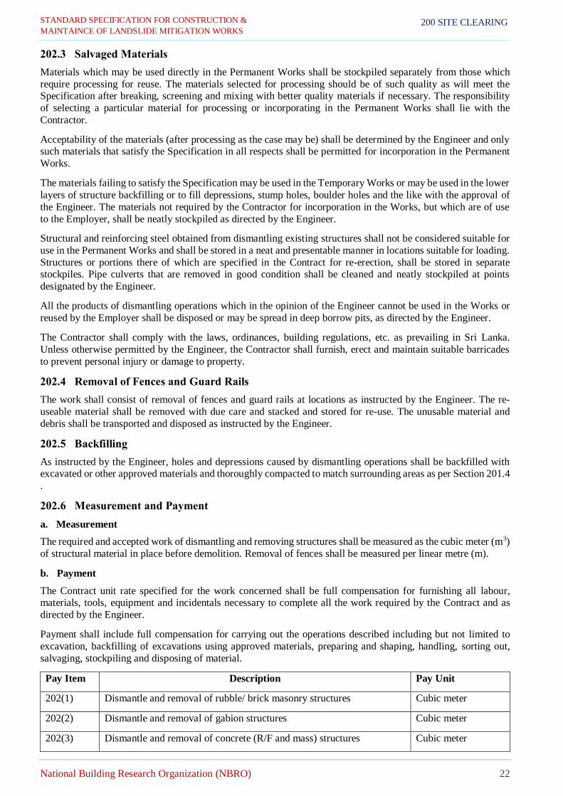
STANDARD SPECIFICATION FOR CONSTRUCTION &
MAINTAINCE OF LANDSLIDE MITIGATION WORKS
National Building Research Organization (NBRO) 22
200 SITE CLEARING
202.3 Salvaged Materials
Materials which may be used directly in the Permanent Works shall be stockpiled separately from those which
require processing for reuse. The materials selected for processing should be of such quality as will meet the Specification after breaking, screening and mixing with better quality materials if necessary. The responsibility
of selecting a particular material for processing or incorporating in the Permanent Works shall lie with the
Contractor.
Acceptability of the materials (after processing as the case may be) shall be determined by the Engineer and only such materials that satisfy the Specification in all respects shall be permitted for incorporation in the Permanent
Works.
The materials failing to satisfy the Specification may be used in the Temporary Works or may be used in the lower
layers of structure backfilling or to fill depressions, stump holes, boulder holes and the like with the approval of
the Engineer. The materials not required by the Contractor for incorporation in the Works, but which are of use
to the Employer, shall be neatly stockpiled as directed by the Engineer.
Structural and reinforcing steel obtained from dismantling existing structures shall not be considered suitable for
use in the Permanent Works and shall be stored in a neat and presentable manner in locations suitable for loading.
Structures or portions there of which are specified in the Contract for re-erection, shall be stored in separate stockpiles. Pipe culverts that are removed in good condition shall be cleaned and neatly stockpiled at points
designated by the Engineer.
All the products of dismantling operations which in the opinion of the Engineer cannot be used in the Works or
reused by the Employer shall be disposed or may be spread in deep borrow pits, as directed by the Engineer.
The Contractor shall comply with the laws, ordinances, building regulations, etc. as prevailing in Sri Lanka.
Unless otherwise permitted by the Engineer, the Contractor shall furnish, erect and maintain suitable barricades
to prevent personal injury or damage to property.
202.4 Removal of Fences and Guard Rails
The work shall consist of removal of fences and guard rails at locations as instructed by the Engineer. The re-
useable material shall be removed with due care and stacked and stored for re-use. The unusable material and
debris shall be transported and disposed as instructed by the Engineer.
202.5 Backfilling
As instructed by the Engineer, holes and depressions caused by dismantling operations shall be backfilled with excavated or other approved materials and thoroughly compacted to match surrounding areas as per Section 201.4
.
202.6 Measurement and Payment
a. Measurement
The required and accepted work of dismantling and removing structures shall be measured as the cubic meter (m3)
of structural material in place before demolition. Removal of fences shall be measured per linear metre (m).
b. Payment
The Contract unit rate specified for the work concerned shall be full compensation for furnishing all labour, materials, tools, equipment and incidentals necessary to complete all the work required by the Contract and as
directed by the Engineer.
Payment shall include full compensation for carrying out the operations described including but not limited to
excavation, backfilling of excavations using approved materials, preparing and shaping, handling, sorting out,
salvaging, stockpiling and disposing of material.
Pay Item Description Pay Unit
202(1) Dismantle and removal of rubble/ brick masonry structures Cubic meter
202(2) Dismantle and removal of gabion structures Cubic meter
202(3) Dismantle and removal of concrete (R/F and mass) structures Cubic meter

STANDARD SPECIFICATION FOR CONSTRUCTION &
MAINTAINCE OF LANDSLIDE MITIGATION WORKS
National Building Research Organization (NBRO) 23
200 SITE CLEARING
202(4) Dismantle and removal of dress stone masonry structures Cubic meter
202(5) Removal of fencing and Guard rail Linear meter
203 UTILITY RELOCATION
203.1 Description
Where utility relocation is encountered in construction work, it shall be executed by the Contractor under the co-
supervision of the Engineer and the utility agency with the consent of the utility agency.
203.2 Measurement and Payment
Payment shall be made as a Provisional Sum and shall be payable when the Contractor has completed the works
to the satisfaction of the Engineer. The Contractor shall also submit relevant proof documents. The Contractor
will be entitled to additional overhead and profit on top of the actual cost, in this regard.
Pay Item Description Pay Unit
203(1) Relocation of utility services as per requirements of the utility service
agency Provisional Sum

STANDARD SPECIFICATION FOR CONSTRUCTION &
MAINTAINCE OF LANDSLIDE MITIGATION WORKS
National Building Research Organization (NBRO) 24
300 EARTHWORKS
300 EARTHWORKS
301 SIDE SLOPE EXCAVATION OR TRIMMING
301.1 Description
Side slope excavation or trimming shall consist of all the required excavation within the limits of the Works except excavation otherwise classified. The work shall include the removal, stockpiling, multiple handling, hauling and
proper utilization in the Works or disposal to spoil tips located by the Contractor and approved by the Engineer
of all excavation materials, and shaping of excavation and preparation of exposed surfaces of excavation on the
entire length of the slopes, in accordance with the Specification and the lines, grades, dimensions and cross-
sections shown on the Drawings and as required by the Engineer.
Slope excavation or trimming shall include the following:
(i) All excavated material indicated on the Drawings within the faces of the cross-sections, excavation of all
materials for approach roads, streets, intersections and all other areas but not including excavation for
ditches, channels, berm ditches, drains and flumes.
(ii) Excavation for stream and channel diversion except where covered under Section303 .
(iii) Excavation not specified elsewhere but nonetheless required for a proper execution of the Works.
301.2 Classification of Materials
a. Soil Suitable for Fill
Soil suitable for fill shall include all suitable materials excavated in accordance with the Specification which meets
the requirements of Section904 :Table 904-1.
b. Hard Rock
Slope or retaining wall foundation excavation classified as hard rock shall include only slope or retaining wall
foundation excavation which, in the judgment of the Engineer, is not practicable without the use of pneumatic
tools or drilling and chemical blasting operations. Hard rock shall not include boulders less than 1cubic meter
(m3) in size. Hard rock shall not include material which, in the judgment of the Engineer, can be loosened or
excavated with equipment equivalent to that of the following description:
(i) Tractor Unit: Equipment with a minimum weight of 17 tones and net horse power rating of 150 HP or
more. The tractor unit is to be in good condition and operated by experienced personnel skilled in the use
of ripping equipment.
The ripper to be attached to the tractor shall be the most efficient parallelogram type recommended by the tractor or ripper manufacturer. The ripper shall have a single shank in first class condition with sharpened
cutting point.
(ii) Bucket Excavator (backhoe): Equipment able to be fitted with a bucket of maximum size 0.30 cubic meter
(m3).
c. Boulders
Boulders shall comprise solid pieces of rock that are weathered on all faces (boulders) that are between 0.25 cubic meter(m3) and 1.0 cubic meter (m3) in volume. Boulders that exceed the stated volume shall be classified as Hard
Rock. Boulders that are less than the stated volume shall be measured as Unsuitable Soil.
Measurement of boulders will take as the maximum dimension along the longest axis of the boulder (length)
multiplied by the area of a circle of a circumference equal to the measured girth of the boulder at its widest point.
d. Unsuitable Soil
Material excavated from within the site meet the followings, those material shall not be used in permanent works.
1. Peat, materials from swamps, mashes and blogs 2. Logs, stumps and perished material
3. Clay having a liquid limit determined pursuant to BS 1377: Part, exceeding 90 or plasticity index
determined in accordance pursuant to BS 1377: Part 2, exceeding 65

STANDARD SPECIFICATION FOR CONSTRUCTION &
MAINTAINCE OF LANDSLIDE MITIGATION WORKS
National Building Research Organization (NBRO) 25
300 EARTHWORKS
4. Material having hazardous chemical or physical properties requiring special measures for its excavation,
handling, storing, transportation, deposition and disposal
No soil shall be classified as unsuitable without the approval of the Engineer. Such unsuitable soil shall be
excavated and disposed of to spoil tips as instructed by the Engineer.
e. Material from Slips/Slides
All the loosened and unstable debris such as soil, rock boulders (any size) and fragments, trees, vegetation shall be cleared and removal from the site prior to commencement of implementing any mitigation measures. However,
since there is a high tendency of slope instabilities followed by them, all such earth removal works shall be
undertaken under full supervision and instructions of the Engineer. Hence in this regard, prior written approval shall be obtained from the Engineer for a clearly described methodology of statement. The material classified as
unsuitable material and disposed of to spoil tips as instructed by the Engineer.
f. De–Watering
If water is met within the cut area due to seepage, springs or rain, it shall be removed by suitable means as and
where required by the Engineer. Care shall be taken to discharge the drain water so as cause no damage to the
works or any adjacent property.
301.3 Construction Requirements
(a) All excavation or trimming work shall be performed as specified required alignment, levels, grades and
cross sections.
(b) Unless otherwise, excavation in hard rock shall as indicated on the Drawings or as instructed by the
Engineer.
(c) Topsoil encountered in excavation and classified as suitable for re-use shall be removed to such a depth
as the Engineer may direct and be neatly stockpiled. The topsoil so stockpiled shall be made available for
the Works without additional charge. No topsoil shall be disposed of without prior written approval of the
Engineer.
(d) All suitable excavated materials shall be deemed to be used in constructing the structure backfilling and
slope rectification work. Unsuitable material and slope excavation in excess of that needed for executing
the Works shall be known as spoil. Spoil shall be removed and disposed of at designated areas or spoil tips located by the Contractor and approved by the Engineer in such a manner as to present a neat
appearance and to avoid obstruction to drainage or drainage to any road or road works or other property.
The final condition of spoil tips shall be to the approval of the Engineer.
(e) All slopes shall be finished in a neat and workman like manner and to accuracy appropriable to the
material and care shall be taken that no material is loosened below the required slopes. Breakages and
slides shall be removed and disposed of as instructed by the Engineer.
(f) All material derived from any excavation required for the Works shall be deemed to be the property of
the Employer and the use of all such materials shall be in accordance with the Contract and to the approval
of the Engineer.
301.4 Measurement and Payment
a. Measurement
Unless otherwise specified, all required and accepted slope excavation/trimming shall be measured in its original
position after clearing and grubbing; wherever applicable and the volume determined in cubic meters by the average end area method as computed from the original and final cross-sections of required and completed work.
No allowance shall be made for bulking or shrinkage. Separate measurements shall be made for each class of
material encountered.
Measurement of rock excavated as required in Section 301.2 herein shall be computed on the basis of excavation
to the specified minimum depth only and no over break shall be included. Interim payment may be made on measured volumes of required excavation actually executed, before final shaping, provided the Contractor's
intention to complete the work is clear. Excavation for removal of slides, breakages and cave-ins as a result of the
Contractor’s work shall not be measured nor paid for and shall be deemed to be included in the Contractor's rates
unless otherwise decided by the Engineer.

STANDARD SPECIFICATION FOR CONSTRUCTION &
MAINTAINCE OF LANDSLIDE MITIGATION WORKS
National Building Research Organization (NBRO) 26
300 EARTHWORKS
b. Payment
The quantities of excavation of soil suitable for fill are measured as specified above will be paid for at the Contract
unit rates per cubic meter for the various types as detailed below. Such rates shall include laboratory and field
test, excavating, chemical blasting, drilling, breaking, uphold the sides, working space, taking precaution to avoid
property damage, compaction, loading, transport and stockpiling.
The quantities of disposal of excess materials; any remainder after using materials, measured as specified above
will be paid for at the Contract unit rates per cubic meter for disposal of all type excess of excavation, to designated
spoil tips or to spoil tips located by the Contractor and approved by the Engineer, for shaping, dressing and completion of all surfaces and for furnishing all labour, materials, tools, equipment and incidentals necessary to
complete the work. The rate for top soil shall include stockpiling or disposal as instructed.
The quantities of excavation of unsuitable materials measured as specified above will be paid for at the Contract
unit rates per cubic meter for the various types as detailed below. Such rates shall include laboratory and field
test, excavating, chemical blasting, drilling, breaking, uphold the sides, working space, taking precaution to avoid property damage, compaction, removal, stockpiling, multiple handling and satisfactory disposal of all type of
excavation of unsuitable materials, to designated spoil tips or to spoil tips located by the Contractor and approved
by the Engineer, for shaping, dressing and completion of all surfaces and for furnishing all labour, materials, tools, equipment and incidentals necessary to complete the work. The rate for top soil shall include stockpiling or
disposal as instructed.
No separate payment for excavation of rock boulders or fragment (any size) in unsuitable material from
slides/slips.
The Contract unit rate specified for the work concerned shall be full compensation for furnishing all labour,
materials, tools, equipment and incidentals necessary to complete the work, including compaction and trimming
to specified tolerances as instructed by the Engineer.
The slides cause due to the Contractor’s less caution will not be measured or pay.
Pay Item Description Pay Unit
301(1) Excavation of slope up to required angle (soil suitable for filling and
unsuitable for filling) Cubic meter
301(2) Excavation and disposal of– Boulders (0.25 m3-1.0 m3) Cubic meter
301(3) Excavation and disposal of – Hard rock, specify the method of blasting Cubic meter
301(5) Disposal of excess soils away from site Cubic meter
301(6) Excavation and disposal– Un-suitable soil (including rock boulders – any
size) from slips/slides away from site Cubic meter
302 EXCAVATION AND BACKFILL OF STRUCTURE
302.1 Description
This work shall consist of necessary excavations for retaining walls, lined drains and other structures. The work shall include the necessary diverting of streams; construction and subsequent removal of necessary cofferdams
and cribs: all necessary sheeting; shoring, bracing, dewatering and pumping: removal of logs, stumps and other
deleterious matter and obstructions for placing foundation; trimming and excavation: backfilling clearing the site
of debris and disposal of excess excavated material.
The work shall be carried out in accordance with these Specifications and with the lines, levels, grades, dimensions
and cross-sections as shown in the drawings or as directed by the Engineer.
Line Drains
Excavation for lined drains shall be measured as excavation for structures and shall be measured to the dimensions
of the drain as shown on the Drawings. Casting of concrete against the excavated earth faces will be permitted
subject to the Engineer's approval.

STANDARD SPECIFICATION FOR CONSTRUCTION &
MAINTAINCE OF LANDSLIDE MITIGATION WORKS
National Building Research Organization (NBRO) 27
300 EARTHWORKS
Drains shall be cleared of all debris prior to backfilling and any structural concrete above the top of bed level of
proposed lined drain shall be removed and disposed of as noted in Section 202 herein. Drains shall be backfilled
with suitable material in layers of appropriate thickness as detailed on the Drawings or as instructed by the
Engineer. Any spaces between the lined drain and over excavation for drains shall be cleared of debris prior to backfill. Such spaces shall be backfilled with suitable material in layers of appropriate thickness as detailed on
the drawings and as directed by the Engineer.
302.2 Classification of Materials
a. Excavated Materials
The classification of excavated material shall be as given in Section 301.2 herein.
b. Backfill Materials
Backfilling shall be with material approved as suitable soil. It shall be obtained from the structure excavation if
the material is approved as suitable for backfilling. Any additional material needed shall be obtained from slope
excavation or trimming unless otherwise instructed by the Engineer.
c. Concrete for Foundation Fill
Concrete shall conform to the general requirements of Section 600 . Concrete to be placed under water shall
conform to the requirements of Section 601.10 and concrete to be used as foundation fill in dry excavation shall be made with aggregate and cement conforming to the requirements of Section 601 . Concrete shall be mixed
and placed in accordance with Section 601.10 , except that minimum cement content shall be 275 kilograms per
cubic meter (kg/m3).
d. Foundation Fill Material
Material for foundation fill shall consist of graded sand, gravel or crushed stone as shown in the Drawings or as
instructed by the Engineer.
302.3 Construction Requirements
a. General
Prior to commencement of excavation operations, the limits of excavation shall be set out as shown in Drawings
and as directed by the Engineer.
The depth/thickness of excavation shall be as shown in the Drawings, unless the hard rock strata encountered is
such as to require changes. In the latter case the depth/thickness of excavation shall be as directed by the Engineer.
Where breaking/chemical blasting is required it shall be carried out under the Engineer’s instructions and all
necessary precautions given therein carefully observed.
After each excavation is completed the Contractor shall notify the Engineer to that effect, and no bedding material
or structure shall be commenced until the Engineer has approved the depth of Excavation and the characteristics
of the foundation material.
b. Excavation for Foundation above Water Table
Unless otherwise directed excavation for foundations above water table shall be carried out to the width of the lowest step of the foundation and the sides left vertical without shoring where the nature of the soil and the depth
of excavation allow it. Where this is not possible the Contractor shall erect all necessary shoring, shuttering and
planking for the safety of personnel and works, subjected to the approval of the Engineer.
c. Excavation for Foundation below Water Table
Where water is encountered within the excavation due to stream flow, seepage, springs etc. the Contractor shall
take adequate measures such as bailing, pumping, construction of diversion channels and bunds, coffer damming
and any other measures to keep the foundation trenches free from water as necessary, however without any adverse
effect to the surroundings due to dewatering operation.
Where coffer damming is required, these shall be constructed to adequate depths and heights with due regard to safety and stability and made as water-tight as necessary to permit work to be carried out inside them. The interior
dimensions of the cofferdams shall be such as to give sufficient clearance for the construction and inspection and
to permit installation of pumping machinery etc., as may be required within the enclosed area.

STANDARD SPECIFICATION FOR CONSTRUCTION &
MAINTAINCE OF LANDSLIDE MITIGATION WORKS
National Building Research Organization (NBRO) 28
300 EARTHWORKS
d. Preparation of Foundation
The bottom of the foundation shall be to the lines and levels as given in the Drawings or as required by the
Engineer. Where this is in soil and above the water table it shall be watered where necessary and rammed and
where it is below the water table it shall be prepared as directed by the Engineer.
Where rock strata are encountered, soft and weathered material shall be removed as necessary and the surface
trimmed and dress as directed by the Engineer.
If the excavation has been carried out deeper than necessary, as given in the Drawings or as otherwise directed by
the Engineer, the extra depth shall be made good with concrete or masonry of the foundation grade or any other
approved material at the cost of the Contractor.
When, in the opinion of the Engineer, the foundation material is soft, contains organic matter, or is otherwise unsuitable, the Contractor shall remove the unsuitable material and insert foundation fill material, sand, rubble or
concrete as specified or shown on the Drawings or instructed by the Engineer. If foundation fills material is
instructed it shall be placed and compacted in layers not more than 200 mm compacted thickness or as instructed
by the Engineer. The degree of compaction shall be the same as for embankment fill.
Rubble used shall confirm to Section 603.2 and sand used shall confirm to Section 901.1 and Table 901-3.
e. Backfilling
Backfilling of the foundation shall be carried out in accordance with sub section 304.3 h. (ii). As stated therein
it shall be noted that the backfilling shall be done only after the foundation concrete or masonry has been in portion
for at least 7 days and in a manner not to cause undue thrust on any part of the foundation. Wherever possible, the sides of the pit to be backfilled should be brought to the straight shapes enabling the use of small compactors or
rollers. A step of 150 mm on every two layers of backfill and as directed by the Engineer shall be maintained, to
avoid differential settlements.
Where backfilling is required to the same level on more than one side of the structure, it shall be maintained at
heights not differing by more than 400 mm on opposing sides of the structure as backfilling proceeds, unless
otherwise agreed by the Engineer.
If backfilling is required on more than one side of the structure, due to over excavation or collapse of sides or due
to any other reason, backfilling shall be carried out in accordance with sub section304.3 h. (ii).
302.4 Test and Standards of Acceptance
The material shall be tested in accordance with these Specifications and shall be prescribed criteria. The work
shall conform to these Specifications and shall meet the prescribed standards of acceptance.
302.5 Measurement and Payment
a. Measurement
All excavation shall be according to dimensions as given in the Drawings prepared for the purposes of excavation
and as directed by the Engineer, in Cu.m, for each class of material encountered. Excavation for working spaces
and the Contractors convenient will not be measured. Excavation shall be measured using undisturbed volume
excavated from the top of the surface after doing necessary excavation, cleaning and grubbing.
Any excavation in excess of above other than what had been allowed by the Engineer shall be considered as
carried out for the convenience of the Contractor in exceeding the work and shall not be measured for payment.
For lined drains, excavation shall be measured as lined drain excavation and shall be measured to the dimensions
of the drain as shown on the Drawings. Excavation for working spaces and the Contractors convenient will not
be measured. Excavation shall be measured using undisturbed volume excavated from the top of the surface after
doing necessary excavation, cleaning and grubbing.
Backfilling shall be measured using undisturbed volume in Cu.m., using the types of materials given in the
Drawings or as directed by the Engineer. Backfill below the design levels and outside the dimensions as given in
the Drawings prepared for the purposes of excavation will not be measured.
b. Payment
The quantities of excavation for structures as measured above will be paid for at the Contract unit rates per cubic metre for each class of material encountered. Such rates shall include full compensation for all labour, materials,

STANDARD SPECIFICATION FOR CONSTRUCTION &
MAINTAINCE OF LANDSLIDE MITIGATION WORKS
National Building Research Organization (NBRO) 29
300 EARTHWORKS
tools, equipment, safety measures, material testing and incidentals necessary to carry out the work to this
Specification. This work shall include;
(i) Setting out
(ii) Removal of all logs, stumps and other deleterious matter and obstructions for placing for foundations
(iii) Cleaning the site and disposal of all surplus material (iv) Shoring, Excavation
(v) Compaction, ramming
(vi) Constructing and disposing all cofferdams, dewatering (vii) All safety precautions
(viii) Preparation of base of foundation
(ix) Diverting of streams.
The quantities of backfilling for structures as measures above will be paid for at the Contract unit rate for filling
for each type of fill material used. Such rates shall include full compensation for all labour, materials, tools,
equipment, safety measures, material testing and incidentals necessary to carry out the work to this Specification.
For line drains, no separate or extra payment shall be made for backfilling which shall be deemed to be included
in the Contractor's rates. No extra or separate payment shall be made for over-excavation and there shall be no
allowance for bulking or shrinkage.
No separate payment shall be made for the excavation for the working space.
Payment for cleaning of site shall be made under Pay Item 201(1) at Section 201 .
Pay Item Description Pay Unit
302(1) Excavation for structures, soil suitable for filling including soft rock for
reuse Cubic meter
302(2) Excavation for structures – Boulders (0.25 m3-1.0m3), specify the method
of blasting Cubic meter
302(3) Excavation for structures – Hard rock, specify the method of blasting Cubic meter
302(4) Excavation for structures, unsuitable soil dispose away from site Cubic meter
302(5) Backfill with crush stone aggregate (20-200mm) Cubic meter
302(6) Backfill with suitable soil for structures Cubic meter
302(7) Disposal of excess soils away from site Cubic meter
303 CHANNEL EXCAVATION
303.1 Description
This work consists of excavation for all channels, drains, ditches and the like both inside and outside the work
limits where shown on the drawings or as instructed by the Engineer. The work shall include the proper utilization
and hauling or disposal of all excavated materials, backfilling where required, constructing, and shaping and
finishing all earthwork involved in conformity with the required alignment, levels, grades and cross-sections.
All drainage works in any section shall be constructed to the satisfaction of the Engineer before approval is given
to commence slope protection works.
303.2 Classification of Materials
Materials excavated shall be classified as noted in Section 301.2 herein.
303.3 Construction Method
The channels, drains, ditches and the like shall be excavated to the alignment, levels, grades and cross sections,
required on the Drawings or as instructed by the Engineer. Any excavation beyond the limits required shall not
be paid for.

STANDARD SPECIFICATION FOR CONSTRUCTION &
MAINTAINCE OF LANDSLIDE MITIGATION WORKS
National Building Research Organization (NBRO) 30
300 EARTHWORKS
303.4 Measurement and Payment
a. Measurement
Channel or unlined drain excavation shall be measured as channel excavation and classified in accordance with
Section 301.2 herein.
Quantities of channel excavation shall be measured in cubic meters determined by the average end area method
computed from the original and the final cross-sections of the authorized and completed excavations. No
allowance shall be made for bulking and shrinkage.
b. Payment
The payment shall be full compensation for all excavation, dewatering, backfilling where required, multiple
handling, hauling and otherwise properly using and disposing of materials in spoil tips, for establishing and
maintaining access to channels and for all labour, materials, tools, equipment and incidentals.
Pay Item Description Pay Unit
303(1) Channel excavation, soil suitable for fill Cubic meter
303(2) Channel Excavation– Boulders, specify the method of blasting Cubic meter
303(3) Channel Excavation – Hard rock, specify the method of blasting Cubic meter
303(4) Channel Excavation, unsuitable soil dispose away from site Cubic meter
303(5) Disposal of excess soils away from site Cubic meter
304 FILLING WORK
304.1 Description
This work shall consist of the construction of filling and other miscellaneous backfill with approved material
obtained either from the excavation of the slope excavation or trimming, borrow pits or other sources in accordance with these Specifications and lines, levels, grades, dimensions and cross-sections shown in the
Drawings or as directed by the Engineer.
304.2 Materials
All materials which are deposited in place prior to compaction shall confirm to Section 904 :Table 904-1herein and shall be evenly spread over the whole of the designated area for the layer concerned and in such quantity that
the thickness of anyone layer, when measured after compaction, shall comply with the requirements specified.
Any new layer less than 75 mm in compacted thickness shall be bonded to the previous layer by scarifying the
previous layer to a depth not less than 25 mm or to such greater depth so that the total compacted thickness of the
new layer plus the scarified portion of the previous layer will not be less than 100 mm.
304.3 Construction Requirements
a. Sources of Supply of Filling Material
All suitable material available from the excavation or trimming shall be used for filling work as directed by the Engineer. Where additional materials are necessary they shall be obtained from approved borrow pits or other
approved sources.
b. Setting Out
The pegs or stakes showing the limits of the filling shall be fixed a suitable distance outside the actual limits of
the fill and such pegs or stakes shall be painted in a distinctive color for vicinity.
c. Removal of Top Soil
Where the height of fill is more than 500 mm and less than 3.0 m, the topsoil shall be removed as described in
Section 201 herein. Topsoil shall also be removed under fill whose height is greater than 3.0 m and where topsoil
is required in other locations or on the instructions of the Engineer. If the in-situ material conforms to Filling Type II material it shall be compacted to a minimum depth of 150 mm to not less than 92% of the maximum dry density
of the material at moisture content within 5% of the predetermined optimum moisture content as determined by

STANDARD SPECIFICATION FOR CONSTRUCTION &
MAINTAINCE OF LANDSLIDE MITIGATION WORKS
National Building Research Organization (NBRO) 31
300 EARTHWORKS
BS1377 Test 13 (Modified Procter) or AASHTO T-180. The degree of compaction shall be checked by field
density measurements (BS1377 Test 15) at the rate of one test for every 50 square metres or as instructed by the
Engineer.
Where the height of fill is less 500 mm, the topsoil shall be removed as described in Section 201 herein. If the
in-situ material conforms to Filling Type I material, it shall be compacted to a minimum depth of 150 mm below formation level, or to such depth as instructed by the Engineer, to not less than 92% of the maximum dry density
of the material at moisture content within 5% of the predetermined optimum moisture content as determined by
BS 1377 Test 13 (Modified Procter) or AASHTO T-180. The degree of compaction shall be checked by field density measurements (BS 1377 Test 15) at the rate of one test for every 50 square meters or as instructed by the
Engineer.
d. Placing and Compaction of Filling Material
The material placed on the filling area shall be thoroughly broken down throughout the layer by means of
equipment suitable for this purpose. The material shall be broken down to a size not exceeding 60% of the compacted layer thickness. The compacted thickness of the layers will be dependent upon the size to which the
material can be broken down by the technique used but shall in general not be greater than 200 mm.
In order that layer thicknesses are not dictated by the presence of isolated larger rocks or stones, the Engineer
shall instruct that the material which cannot be broken down to the size generally achievable for the rest of the
material in the layer be removed from the fill.
Any water required before material is compacted shall be added to the material in successive applications by
means of water bowsers fitted with sprinkler bars or by means of pressure distributors all capable of applying the
water evenly and uniformly over the area concerned.
The water shall be thoroughly mixed with the material to be compacted by suitable equipment. Mixing shall
continue until the required amount of water has been added and until a uniform mixture is obtained. Compaction may proceed when the moisture content of the un-compacted layer is within 5% of the predetermined optimum
moisture content.
If the material is too wet it shall be dried by aeration and if it is too dry the material shall be sufficiently watered
prior to compaction. Compaction shall be carried out as a continuous operation covering the full width of the layer
and to be compacted with the available equipment before drying out.
The types of compaction equipment to be used and the amount of rolling to be done shall be such as to ensure that
specified densities are obtained without damage to the underlying layers or to structures. During compaction the
layer shall be maintained to the required shape and cross section and all holes filled and ruts and laminations shall
be removed.
The Engineer may permit thicker layers than as specified above to be constructed, provided that he is satisfied that the specified densities can be obtained throughout the full depth of each layer and that the layers will be
uniformly compacted by using equipment specifically suited to this purpose. Fill shall be placed in successive
layers whose planes are parallel to the final surface, wherever this is practicable.
Each successive layer shall be placed only after the previous layer has been tested and found satisfactory as
specified in Section 304.3 e. herein.
If at any time after compaction the layer is damaged by drying out or is damaged by rain, it shall be scarified, and
re-compacted to the requirements of the Specifications at the Contractor’s expense and to the approval of the
Engineer.
The Contractor shall ensure that oversize material be disposed of or utilized elsewhere in the construction of the
Works. This shall be avoided by proper selection in excavation in cut or in borrow. In cut such material shall be
taken directly to spoil or shall be utilized as instructed by the Engineer.
Unless otherwise specified, the top 500 mm of the filling shall be constructed using Filling Type I material and
the lower layers of the filling shall be constructed using Filling Type II material, as specified in Section 904 :
Table 904-1herein.
e. Degree of Compaction of Filling
The top 150 mm layer of the filling shall be compacted to not less than 92% of the maximum dry density of the material at a moisture content within 5% of the optimum moisture content as determined by BS1377–Test 13

STANDARD SPECIFICATION FOR CONSTRUCTION &
MAINTAINCE OF LANDSLIDE MITIGATION WORKS
National Building Research Organization (NBRO) 32
300 EARTHWORKS
(Modified Procter) or AASHTO T-180. The degree of compaction shall be checked by field density measurements
(BS1377–Test 15) at the rate of one test for every 50 square meters or as instructed by the Engineer. The top of
the layer shall be trimmed to line and level.
The remainder of the embankment shall be compacted to not less than 92% of the maximum dry density of the
material at a moisture content within 5% of the optimum moisture content as determined by BS1377–Test 13 (Modified Procter) or AASHTO T-180. The degree of compaction shall be checked by field density measurements
(BS1377–Test 15) at the rate specified in Section 802 herein.
f. Drainage of Protection of Filling
All permanent drains shall be constructed at the earliest opportunity, along with any temporary drains that may be necessary to protect the fill, and they shall be maintained in working condition throughout the construction
period.
g. Finishing Operation
The fill shall be finished to levels, grades, slopes and Cross-sections shown on the Drawings and as directed by
the Engineer. Where specified the slopes of fill shall be top soiled and grassed, measured and paid in accordance
with Section 501 .
h. Filling Work under Special Condition
(i) Fill on Hill Slopes
Where filling are to be constructed on hill slopes, adequate bonding between the existing slope and new
filling shall be established by removing the top soil and benching into the existing slope in vertical and
horizontal faces including rock and the fill built in successive layers.
(ii) Filling around Structures
The Contractor shall take special precautions to see that the construction work of structures is not disturbed as a result of the filling operations and that the filling in the vicinity of a structure shall not be
carried out till the concrete or masonry had been in position at least for 7 days, unless otherwise directed
by the Engineer.
Filling around structures shall be carried out using suitable material and compacted to densities given in sub Section 304.3 e. Using special equipment such as mechanically operated hand rammers. The control
on the quality of materials and works damage is done to the structure by these operations.
The filling shall be brought up simultaneously on each side of the structure to avoid unequal pressure
acting on it. Any damage that is caused to the structures by the negligence of the Contractor shall be made
good by him at his own expense.
304.4 Measurement and Payment
a. Measurement
Filling work shall be measured as compacted in Cu.m. The undisturbed volume of fill material within the design area shall be computed by the average end area method on cross-sections given in the Drawings or on actual cross-
sections taken at site before and after the construction of the fill. No measurement should take for the settlements
and voids for such as culverts should be excluded.
Filling work using rock shall be measured in Cu.m. in the same manner as for earth fill. The trimming, leveling
and compaction of original ground shall be measured in Sq.m.
Application of topsoil on filling slopes and verges shall be measured as given in Section 501 .
Filter medium behind earth retaining structures shall be measured separately as given in Section 405 .
b. Payment
Payment will be based on the Contract unit rate for the separate items as measured above and shall include full
compensation for all labour, materials, transport, tools, equipment and other incidentals necessary to complete the
work to the Specification. This work & payment shall include the following where applicable.
(i) Setting out and pegging
(ii) Scarifying and benching slopes of existing fill and hill sides

STANDARD SPECIFICATION FOR CONSTRUCTION &
MAINTAINCE OF LANDSLIDE MITIGATION WORKS
National Building Research Organization (NBRO) 33
300 EARTHWORKS
(iii) Special arrangements and equipment that may be necessary for working under restricted conditions
such as in the vicinity of structures.
(iv) Laying and compaction of suitable material.
(v) Field and laboratory testing.
Pay Item Description Pay Unit
304(1) Fill in slope by using excavated soil including soft rock (Filling Type I
or Type II material) Cubic meter
304(2) Filling work using rock material Cubic meter
305 NON – EXPLOSIVE BLASTING OPERATIONS
305.1 Description
This work shall consist of the breaking of rock or boulders within the sliding mass or unstable slopes using non-
explosive expansive silent cracking agent for removing of unstable boulders, formation of foundation for structures and excavation of hard rock in accordance with these Specifications and lines, grades, levels,
dimensions and cross-sections shown in the Drawings or as directed by the Engineer. The work shall include the
removal, stockpiling, multiple handling, hauling and proper utilization in the Works or disposal to spoil tips
located by the Contractor and approved by the Engineer of all excavation materials.
305.2 Materials
Material used for blasting operation shall be non-explosive expansive silent cracking agent. The Contractor shall
get prior approval for the blasting material.
305.3 Construction Requirements
Design of blasting operation and drilling design shall be done by a Mining Engineer and design shall be submit
to the Engineer for approval at least 21 (twenty-one) days before the commencement of the blasting.
The Contractor shall submit a method statement for the approval of the Engineer. The method statement shall
consist with blasting design, drilling design, safety management etc. and shall submit for the approval of the Engineer. The Contractor shall inform the Engineer 14 days prior to commencing of the blasting operation and
the Work shall be carried out according to the method statement approved by the Engineer. Blasting operation
shall not produce any noise or vibration.
305.4 Measurement and Payment
Measurement and payment shall be made according to the Sections 301 , 302 and 303 .
306 TENSION CRACK SEALING
306.1 Description
Tension cracks and scars are extensional features of the landslide or cutting failures. Tension cracks can be found
throughout a landslide and many landslide features initiate as tension cracks. Scars are generally found near the
top of a landslide, in the zone of extension and generally begin at the surface first as tension cracks, which develop into scars. Tension cracks can also be found along the flanks, outside the main landslide zone. Traverse cracks
are located within the moving mass at the toe of the main slip surface.
Tension crack sealing shall consist of all the required excavation within the designated area. The work shall
include the removal, stockpiling, multiple handling, hauling and proper utilization in the Works or disposal to
spoil tips located by the Contractor and approved by the Engineer of all excavation materials.
306.2 Materials
The materials used for tension crack sealing shall meet the requirements of the following, unless otherwise
specified.
(a) Concrete C30/20 shall conform to requirements of Section 601 of the Specification.
(b) Filling Type I soil used shall conform to requirements of Section 904 of the Specification. (c) Cement used shall conform to requirements of Section 902 of the Specifications.
(d) Bentonite

STANDARD SPECIFICATION FOR CONSTRUCTION &
MAINTAINCE OF LANDSLIDE MITIGATION WORKS
National Building Research Organization (NBRO) 34
300 EARTHWORKS
306.3 Construction Requirements
a. Excavation for Cracks
Crack to be filled up to ground level by Bentonite slurry as directed by the Engineer. After harden
Bentonite slurry; the excavation shall be carried out as shown in drawings or as instructed by the Engineer.
b. Crack Sealing
Excavated trench should be filled by Concrete C30/20 or Filling Type I soil as shown in drawings.
Compaction of Filling Type I soil should be done according to Section 304.3 d.
306.4 Measurement and Payment
a. Measurement
The crack sealing shall be measured in cubic meter.
b. Payment
No separate payment shall be made for compliance of bentonite slurry and trench excavation. Payments shall
deemed to be included in the concrete rates or Filling Type I soil rates and prices.
Pay Item Description Pay Unit
306(1) Tension crack sealing by Concrete C30/20 Cubic meter
306(2) Tension crack sealing by Filling Type I Soil Cubic meter

STANDARD SPECIFICATION FOR CONSTRUCTION &
MAINTAINCE OF LANDSLIDE MITIGATION WORKS
National Building Research Organization (NBRO) 35
400 DRAINAGE CONSTRUCTION
400 DRAINAGE CONSTRUCTION
401 CUT–OFF DRAINS, CASCADE DRAINS AND SURFACE DRAINS
401.1 Description
The construction of drains, un-lined or lined, and covered where required, to dimensions, grades and in positions
shown on the Drawings or instructed by the Engineer.
401.2 Materials
The materials used for lining the drains shall meet the requirements of the following, unless otherwise specified.
(a) Reinforcing steel to SLS 375, SLS 26 or BS 4449
(b) Formwork used shall be of steel, timber or any other material approved by the Engineer conforming the Section 605 .
(c) Cement used shall conform to requirements of Section 902 of the Specifications.
(d) The dowels shall be of mild steel having mechanical and physical properties specified in Section 606 .
(e) PVC pipes and fittings to SLS 147.
401.3 Construction Requirements
a. Excavation for Drains
The excavation shall be carried out as detailed in Section 302 .
b. Line Drains
All drains that are designated to be lined shall be constructed as shown in drawings or as directed by the Engineer.
In-situ construction with concrete C15 and C25 shall be carried out as shown in the Drawings or as instructed.
In cascade drains, the fixing of dowels into the designated depths shall be as shown in Drawings or as directed by
the Engineer.
c. Expansion Joints
10 mm thick expansion joint should be provided as shown in the drawings or as directed by the Engineer. The
Contractor should be get prior approval for joint sealant material applies for expansion joint from the Engineer.
d. Weep holes for Drainage Walls
Weep holes shall be made of PVC pipe (Type 600) for the drainage walls to facilitate the drainage of any water
collected at the back of the structure, as per the drawings or as instructed by the Engineer. When pipes are embedded in the drainage walls, they shall be laid to the slope given in Drawings or required by the Engineer and
shall extend from the rear face to the front face of the structure. They shall be protected from ingress of materials
during construction and shall be cleaned before backfilling is placed behind the structure.
401.4 Measurement and Payment
a. Measurement
The excavation for lined drains shall be measured and paid as provided in Section 302 herein.
Measurement of lining of drains shall be in cubic meters. Reinforcement and Formwork for concrete shall be
measured separately in kilograms and in square meter respectively.
The weep holes for drainage walls shall be measured in linear meters of weep holes.
b. Payment
No separate payment shall be made for compliance of expansion joint works and polythene cover for concrete,
payments shall deem to be included in the concrete rates and prices.
Payment for supply and installation of dowels shall include drilling, grouting, cutting, tying, galvanizing etc., to
complete the works.
The excavation for lined drains shall be paid as provided in Section 302 .

STANDARD SPECIFICATION FOR CONSTRUCTION &
MAINTAINCE OF LANDSLIDE MITIGATION WORKS
National Building Research Organization (NBRO) 36
400 DRAINAGE CONSTRUCTION
Pay Item Description Pay Unit
601(1) Lean Concrete C15/20 Cubic meter
601(3) Concrete C25/20 for walls and base of drains Cubic meter
602(1) Tor – Steel reinforcement Kilograms
605(1) Formwork for concrete sides of drains plain smooth finish Square meter
606(1) Supply and installation of hot dipped galvanized Mild steel dowels
(specify the diameter of the dowels) Linear meter
401(1) 50mm dia. PVC Weep holes (type 600) for drainage walls Linear meter
402 SUB-SURFACE DRAINS (UNDERDRAINS OR TRENCH DRAINS)
402.1 Description
This work shall consist of construction of subsurface drains (under drains or trench drains) and drains outlets
using perforated pipes, non-perforated pips and granular filter material. The work shall be carried out in
accordance with this Specification and in conformity with the Plans or as directed by the Engineer.
402.2 Materials
The non-perforated pipes shall be of concrete, PVC or earthen, conforming to following standards.
Concrete pipes to SLS 452
PVC pipes to SLS 147
Earthen ware pipes to SLS 449
The filter material shall be Geotextile/filter fabrics to requirement given in Section 905 .
Unless otherwise instructed, the perforated pipe to be installed shall be 110mm PVC (Type 600) pipe. The pipe
shall be drilled with 100 mm x 5 mm grooves at 100 mm centers on the bottom half of the perimeter of the pipes
as shown in the Drawings or as directed by the Engineer. The pipe shall be un-slotted for a length of 1 m from the
outlet end, or whatever length as directed by the Engineer.
Granular filter material, for bedding and for surrounding the pipe under-drains, shall be single graded aggregate of maximum size 37.5 mm conforming to the requirements of Section 901 unless or otherwise specified by the
Engineer.
402.3 Construction Requirements
a. Sub-surface drains
Trenches shall be excavated to the dimensions and grades required and a minimum of 150 mm thick bedding layer
of granular filter material shall be compacted in the bottom of the trench for its full width and length.
Care shall be taken to prevent the contamination of the granular filter material with soil or silt or other deleterious
material during construction of the sub surface drains and all filter material contaminated shall be removed and
replaced by the Contractor at his own expense.
Perforated pipes unless otherwise required, shall be laid with the perforations down and the pipe sections shall be
securely jointed as specified or directed.
After the pipe installation has been approved, granular filter material shall be placed to a depth as specified so as
to completely surround the pipe as shown in the Drawings or required by the Engineer. Single sized aggregate of
nominal maximum size of 37.5 mm, instead of granular filter material can be used with the approval of the Engineer. The remaining portion of the trench shall then be filled and compacted in layer of 300 mm with
impervious materials, as specified.
Where specified or ordered by the Engineer, geo-fabric filter as specified in Sub-section 905.6 shall be installed
as shown on the Drawings. Filter fabric shall not be exposed to direct sunlight for prolonged and shall be protected
from mechanical damage during installation and construction.

STANDARD SPECIFICATION FOR CONSTRUCTION &
MAINTAINCE OF LANDSLIDE MITIGATION WORKS
National Building Research Organization (NBRO) 37
400 DRAINAGE CONSTRUCTION
b. Subsurface Drain Outlets
Trenches for the outlets shall be excavated, to the dimensions required by the Engineer. The outlet pipes shall be
laid on approved compacted bedding in the trench with their ends firmly jointed as required. On approval of the
pipe installation the trench shall be back filled with approved suitable material and compacted in layers in
accordance with section 304.3 d.
c. Aggregate Drains
Trenches shall be excavated to the dimensions and grades required and fill with filter material (20mm single
graded aggregate) shall be compacted of the trench for its full width and length.
Care shall be taken to prevent the contamination of the granular filter material with soil or silt or other deleterious
material during construction of the gravel pack drains and all filter material contaminated shall be removed and
replaced by the Contractor at his own expense.
Where specified or ordered by the Engineer, geo-fabric filter as specified in Sub-section 905.6 shall be installed
as shown in drainage drawings.
402.4 Test and standard of acceptance
The materials shall be tested in accordance with these Specifications and shall meet the prescribed criteria. The
work shall conform to these Specifications and shall meet the prescribed standards of acceptance.
402.5 Measurement & Payment
a. Measurement
Excavated and approved soil back fill shall be measured and paid for as provided for Section 302 .
For subsurface drains; perforated and outlet drain pipes shall be measured by the linear meter along the center line
of the pipe for each type and size specified. No separate measurement for granular filter material and filter fabric.
For aggregate drains shall be measured by linear meter along the center line of the drain including filter fabric.
b. Payment
The quantities as determined above will be paid for at the Contract unit price which shall be full compensation
for furnishing and placing of all materials such as geo-fabric, granular filter and PVC perforated pipe and including
all labour, equipment, tools and incidentals necessary to complete the work prescribed.
No separate payment shall be made for outlet preparation of the sub-surface drains and aggregate drains.
The Pay Items and Pay Units shall be as follows:
Pay Item Description Pay Unit
402(1) Sub-surface drain – PVC pipe Dia. 110 mm (type 600) Linear meter
402(2) Aggregate drains Cubic meter
403 CATCH-PITS AND INLETS
403.1 Description
This work shall consist of construction of manholes, catch-pits and inlets for underground drainage systems in
accordance with these Specifications and with the lines and levels as shown on Drawings or as directed by the
Engineer.
The inlets may be of gully type or side entry type or a combination of both as shown in the Drawings.
403.2 Materials
Materials shall conform to the requirements of the following unless otherwise specified.
Reinforcing steel to SLS 375 or SLS 26
Cement mortar for jointing to Section 902
Mastic joint filler shall be of the approved varieties

STANDARD SPECIFICATION FOR CONSTRUCTION &
MAINTAINCE OF LANDSLIDE MITIGATION WORKS
National Building Research Organization (NBRO) 38
400 DRAINAGE CONSTRUCTION
Frames, grating, covers and any other incidental items shall be as given in the Drawings or elsewhere in
the Contract documents
403.3 Construction Requirements
All excavation and backfill required for construction shall be carried out in accordance with the requirements of
Section 302 .
Inlets, catch-pits and manholes shall be constructed in-situ. In-situ construction of catch-pits shall be carried out
using concrete as specified or instructed at site. Depth of the catch-pit as specified or instructed at site.
In-situ construction of inlets shall be carried our using concrete C25. Formwork for in-situ concreting of units
shall conform to the requirements of Section 605 .
403.4 Tests and standards of acceptance
The materials shall be tested in accordance with these Specifications and shall meet the prescribed criteria. The
work shall conform to these Specifications and shall meet the prescribed standards of acceptance.
403.5 Measurement and Payment
a. Measurement
The excavation for inlets and catch-pits new or reconstructed shall be measured and paid as provided in Section
302 herein.
Measurement of Concrete inlets and catch-pits new or reconstructed shall be in cubic meters. Reinforcement and
Formwork for concrete shall be measured separately in kilograms and in square meter respectively.
b. Payment
The excavation for manholes, inlets and catch-pits shall be paid as provided in Section 302 .
Pay Item Description Pay Unit
601(1) Lean Concrete C15/20 Cubic meter
601(3) Concrete C25/20 for walls and base of catch pits Cubic meter
602(1) Tor – Steel reinforcement Kilograms
605(1) Formwork for concrete sides of catch pits plain smooth finish Square meter
404 BERM SEALING
404.1 Description
The work shall consist of construction of berm sealing accordance with these Specifications and locations and
thicknesses as specified in Drawings or as instructed by the Engineer.
404.2 Materials
Materials shall conform to the requirements of the following unless otherwise specified.
Cement used shall conform to requirements of Section 902 of the Specifications.
50 mm x 50 mm (SWG – 14) Welded galvanized mesh (minimum cover 30mm)
Mastic joint filler shall be of the approved varieties
404.3 Construction Requirements
In-situ construction of berm seals with concrete C25/20 shall be carried out. Concrete thickness 100mm with
embedded Welded galvanized mesh unless otherwise shown in the Drawings and instructed by the Engineer.
At every 5 m interval should be maintained 10 mm width expansion joint and sealed the joint with joint sealant
approved by the Engineer.

STANDARD SPECIFICATION FOR CONSTRUCTION &
MAINTAINCE OF LANDSLIDE MITIGATION WORKS
National Building Research Organization (NBRO) 39
400 DRAINAGE CONSTRUCTION
404.4 Measurement and Payment
a. Measurement
Measurement of Concrete for berm sealing shall be in cubic meters.
b. Payment
No separate payment shall be made for expansion joint, welded galvanized mesh and polythene cover for concrete
as per drawings and payments shall deem to be included in the concrete rates and prices.
Pay Item Description Pay Unit
404(1) Berm sealing with Concrete C25/20 Cubic meter
405 DRAINAGE BACKFILL BEHIND EARTH RETAINING STRUCTURES
405.1 Description
This work shall consist of the construction of a permeable layer of aggregate behind retaining structures to facilitate the free drainage of the retained soil layers (including any backfill) through the weep-holes of the
structure.
The layer shall consist of a layer of large sized aggregate backfill immediately behind the wall and a layer of
graded small aggregate, referred to as the filter medium placed along the sloping face of the aggregate backfill.
All works shall be carried out in accordance with the Specification and in conformity with Drawings or as directed
by the Engineer.
405.2 Materials
a. Aggregate Backfill
The aggregate backfill shall be free draining and normally consist of aggregate larger than 20 mm and smaller
than 200 mm, shall consist of hard and durable crushed stone.
b. Filter Medium
The filter medium shall be geotextile/filter fabrics to requirement given in Section 905 .
405.3 Construction Requirements
Prior to placement of the larger size aggregate behind the structure, the soil layer, on which the aggregate is placed, shall be well compacted and made impervious either by constructing a clay puddle or by the application of a
bituminous binder or gauge 1000 polythene as required.
The aggregate backfill shall be placed along the wall and to a stable configuration and dimensions as indicated on
the Drawings or as instructed. The material shall be hand packed using a hand tamper.
405.4 Tests and standards of acceptance
The materials shall be tested in accordance with these Specifications and shall meet the prescribed criteria. The
work shall conform to these Specifications and shall meet the prescribed standards of acceptance.
405.5 Measurement and Payment
a. Measurement
The quantity to be measured shall be the number of Cu.m. placed, compacted and accepted in place, separately
for the aggregate backfill and the filter medium.
b. Payment
The work measured as provided above will be paid for at the unit price per Cu.m. of drainage backfill behind earth retaining structures. The price shall be full compensation for all labour, materials, equipment and incidentals
required to finish and acceptably place the materials. There shall be no separate payment for the impervious layer
and payment shall be deemed to be included in the Contractor's rates.
Pay Item Description Pay Unit

STANDARD SPECIFICATION FOR CONSTRUCTION &
MAINTAINCE OF LANDSLIDE MITIGATION WORKS
National Building Research Organization (NBRO) 40
400 DRAINAGE CONSTRUCTION
405(1) Aggregate backfill – (20-200 mm) Cubic meter
405(2) Geotextile/Filter fabric Square meter
406 WEEP-HOLES FOR EARTH RETAINING STRUCTURE
406.1 Description
This work shall consist of providing opening in earth retaining structures to facilitate the drainage of any water collected at the back of the structure, as given in the Drawings or as directed by the Engineer and in accordance
with these Specifications.
The weep holes may either be cast in-situ or consist of pipes embedded in the structure.
406.2 Materials
Unless otherwise instructed by the Engineer, weep holes shall be made of PVC pipe (Type 600) to SLS 147.
406.3 Construction Requirements
When pipes are embedded in the earth retaining structure, they shall be laid to the slope given in Drawings or
required by the Engineer and shall extend from the rear face to the front face of the structure. They shall be
protected from ingress of materials during construction and shall be cleaned before backfilling is placed behind
the structure.
406.4 Tests and standards of acceptance
The materials shall be tested in accordance with these Specifications and shall meet the prescribed criteria. The
work shall conform to these Specifications and shall meet the prescribed standards of acceptance.
406.5 Measurement and Payment
a. Measurement
The weep holes for earth retaining structures shall be measured in linear meters of weep holes.
b. Payment
Payment shall be based on the Contract unit price for the item and shall include full compensation for all materials,
labour, tools, equipment and incidentals necessary to complete the work to the Specifications.
Pay Item Description Pay Unit
406(1) Weep holes using PVC pipes (Type 600) – diameter to be specified Linear meter

STANDARD SPECIFICATION FOR CONSTRUCTION &
MAINTAINCE OF LANDSLIDE MITIGATION WORKS
National Building Research Organization (NBRO) 41
500 INCIDENTIAL CONSTRUCTION
500 INCIDENTIAL CONSTRUCTION
501 TOP SOILING
501.1 Description
This work shall consist of supply of topsoil furnished and transported from approved sources or stockpiles and spread in conformity with these Specifications at locations shown on Drawings or as directed by the Engineer.
Generally, where top soil is stockpiled adjacent to the Works, filling slopes shall be top soil in accordance with
the Engineer's instructions.
501.2 Materials
Top soil provided by the Contractor or salvaged during clearing and grubbing shall consist of loose friable natural
surface soil free of admixtures of sub soil, stumps, roots, rocks, weeds or other material which would be
conductive to proper development of vegetative growth.
501.3 Construction Requirements
The Contractor shall notify to the Engineer at least 7 days before intends to start collecting top soil from specified
areas.
Unless otherwise specified top soil shall not be spread on slopes steeper than 1:1.5 (1 vertical to 1.5 horizontal).
Slopes steeper than 3:1 shall be scarified to depths indicated in Plans or established by the Engineer, prior to placing top soil. The area shall normally be roughened by hand scarifying, or by any other means approved by the
Engineer, to ensure the stability of top soil spread.
After the Engineer has approved the prepared and graded areas, top soil shall be spread to a thickness after
settlement shall not be less than 75 mm or the depth shown on Drawings or as instructed by the Engineer.
Spreading shall not be done when the ground or the top soil is excessively wet or in a condition considered
detrimental to the work. The topsoil layer shall be leveled off and raked.
The slope surface shall be kept clean during hauling and spreading operations. After spreading has been
completed, large clods, stones larger than about 40 mm in diameter and any roots, stumps and other litter shall be
raked up and removed and disposed of at an approved location.
501.4 Test and standards of acceptance
The materials shall be tested in accordance with these Specifications and shall meet the prescribed criteria. The
work shall conform to these Specifications and shall meet the prescribed standard of acceptance.
501.5 Measurement and Payment
No separate payment shall be made for compliance of items under this section. Payments shall be deemed to be
included in the Section502 .
502 VEGETATION COVER
502.1 Description
This work shall consist of providing grass cover by seeding, sprigging or sodding, including soil preparation,
fertilizing, mulching and watering as required, in conformity with these Specifications and with the Drawings or
as directed by the Engineer. Where the slope hinders natural growth of grass cover, the work shall consist of
application of permanent erosion control product before being vegetated.
502.2 Materials
a. Grass Seeds
The grass seeds shall be of an accepted variety reputed to produce a good grass cover. Seeds shall be furnished
by the Contractor in standard sealed containers along with seed name, weight and other details as necessary.
Where required, a certificate from the vendor stating that the seeds have been tested within a stipulated period of
time, not exceeding 6 months, and prior to the time of delivery shall be furnished.
Types of seeds, proportion of seed mixture, and volume of seed mixture to be applied to the sites shall be
deliberately selected considering the following factors and clarified in the Method Statement:

STANDARD SPECIFICATION FOR CONSTRUCTION &
MAINTAINCE OF LANDSLIDE MITIGATION WORKS
National Building Research Organization (NBRO) 42
500 INCIDENTIAL CONSTRUCTION
Planting plan,
Expected germinating rate and growth rate,
Site condition including fertility of top soil or vegetation bed,
Timing of seeding or planting,
Method and possible period of storage, and
Impact on the environment.
Typical seeds varieties are given in the Table 502-1. However, approval should be obtain from the relevant
authorities before planting any seeds in the mitigation sites.
Table 502-1: Typical seeds varieties
Common Name Botanical Name
Green China grass Ophipogenjpanica
Yellow white china grass Ophipogen intermedium
Heenpegiri Cympogonnardus
Sevendara Vetiver zizanioides
Mahaudupiyaliya Desmodiumheterophyllum
HeenUdupiyaliya Desmodiumtriflorum
b. Grass Sods
Grass sods shall be of living vigorous growth of the type of grass to the size of 200 mm x 150 mm and thickness
specified, having a dense root system, contained in suitable sods and free form noxious weeds and diseases and
shall contain a minimum of 50 mm of topsoil.
c. Fertilizer
Fertilizer shall be from a standard commercial grade conforming to all relevant regulations and shall provide the
minimum percentage of nutrients specified.
The fertilizer shall be evenly applied over all surfaces where grass is to be planted and shall then be thoroughly
mixed with the soil to a depth of 100 mm either mechanically or manually.
Where the type of fertilizer is not specified the Contractor shall obtain the Engineer approval prior to use of a
particular fertilizer.
d. Mulch
Mulch used shall be straw, hay, saw dust or any other similar material specified in the Contract. They shall be
free from material injurious to plant growth.
e. Water
Water used in planting or care of vegetation shall be free from oils, acids, alkalis, salts or any other substance
injurious to plan life.
f. Hydro seeding Vegetation Bed
Material of hydro seeding vegetation bed shall be made of fertile soil, seed mixture, fertilizer, soil improving
agents and adhesive agents. Hydro seeding vegetation bed material shall be blown on a slope for greening. Hydro
seeding vegetation bed material shall be approved by the Engineer prior to the preparation of material.
g. Coir Mesh
Coir mesh used shall conform to requirements of Section 701 of the Specifications. Coir material shall be
approved by the Engineer prior to use of particular coir material.

STANDARD SPECIFICATION FOR CONSTRUCTION &
MAINTAINCE OF LANDSLIDE MITIGATION WORKS
National Building Research Organization (NBRO) 43
500 INCIDENTIAL CONSTRUCTION
h. Anchor Pin
Coir mesh shall be fixed to the ground by anchor pins. Anchor pins shall be firmly installed into the ground in a
manner in which it is not removed by rainfall or wind. Reinforcing bars with a diameter of 10 mm shall be used
as anchor pins. The required embedded length of anchor pins is 400 mm.
i. Permanent Erosion Control Products
Unless otherwise specified, the material used shall be a rolled erosion control product composed of non-
degradable synthetic fibers, filament, nets, wire mesh, and other elements processed into a permanent, three-
dimensional matrix conforming to properties in Table 502-2.
Table 502-2: Material Characteristics for Permanent Erosion Control Product
Property Specification Limit
Minimum Tensile Strength 1.82 kN/m
Minimum thickness 6.35 mm
% Open space/ Porosity 95%
The erosion control product shall be specially manufactured for the purpose of permanent erosion protection and
vegetation reinforcement on geotechnically stable slopes. It shall be made from 100% synthetic material and contain no biodegradable or photodegradable components or materials. The material shall be capable of
supporting a vegetative cover.
The product shall have a minimum 95% open space available for soil and root interaction for effective vegetation.
It shall not lose its structural integrity or performance and shall not unravel or separate when the mat is cut in the
field.
502.3 Construction Requirements
The area to be grassed shall meet the specified finish grades, be free of any weeds or plant growth, stones and
other debris. Where direct grassing is hindered by the nature of the slope, the application of permanent erosion
control blanket product shall precede the grassing work.
If top soiling is required, it shall be done in accordance with the requirements of Section 501 . The surface, where
required, shall be loosened by raking.
a. Planting/Seeding on soil nailed surface
Seed mixtures and volume to be applied shall be clarified in the Method Statement for the Engineer’s approval.
The Method Statement shall also include timing of seeding, expected greening time based on the Contractor’s investigation related to the site condition such as slope gradients, soil properties, climate, water situations and
neighboring plants. Furthermore, based on the investigation, the Contractor shall include the construction schedule
in the Method Statement.
The Contractor shall provide necessary falling prevention measures and other safety measures to the workers for
cleaning slopes. The Contractor shall execute slope treatment including rounding the shoulder of slopes, cleaning the slope, removing unstable boulders and rocks, removing trees and shrubs which may obstruct the work,
removing any harmful substances, and treating ground water and spring.
Coir mesh shall be fixed firmly to the slope by anchor pins. Then the hydro seeding vegetation bed material shall
be carefully measured for each batch and sprayed on the slope with a proper hydro seeder machine. Prior to being sprayed, hydro seeding vegetation bed material shall be stirred well. Hydro seeding vegetation bed shall be
sprayed evenly on the slope with a thickness of approximately 30 mm.
Seeding shall be done just before or during the rainy season or as instructed by the Engineer. The method of
seeding and application of fertilizer, water and mulch shall be subject to the approval of the Engineer. Fertilizing,
watering and mulching shall be done as required and with the Engineer's approval. Unless otherwise specified or
directed, sprigs shall be planted at approximate intervals of 150 mm apart.

STANDARD SPECIFICATION FOR CONSTRUCTION &
MAINTAINCE OF LANDSLIDE MITIGATION WORKS
National Building Research Organization (NBRO) 44
500 INCIDENTIAL CONSTRUCTION
Seeded area where grass has not taken root, shall be made good by the Contractor by suitably replanting before
final acceptance. At the time of acceptance, areas determined by Engineer as poorly grassed shall not be measured
for payment and the Contractor shall correct such areas as required by the Contract/ Engineer.
b. Sodding (Turfing)
Sodding shall be done just before or during the rainy season or as instructed by the Engineer. The Contractor shall notify the Engineer not less than 7 days before cutting of sods begin. Sods shall be approved by the Engineer, in
its original position before cutting and delivery to the site. Areas to be covered with sods shall be given a layer of
top soil 75 mm thick unless, due to the presence of suitable subsoil, the Engineer orders that the topsoil can be
omitted.
The areas to be covered with sods shall be thoroughly watered beforehand so that they are wet to a depth of at
least 150 mm when sodding is done. Sods shall be laid on the prepared sod-bed within 24 hours after cutting
expect where the Engineer has approved their being stored in stacks or piles, grass or root to root, for a period not
exceeding 3 days.
The moving and laying of sods shall be done as far as possible, when weather conditions and soil moisture are favorable. Sodding may be done in one of the following methods as designated in the Drawings or as approved
by the Engineer.
a) Solid sodding
b) Strip sodding
c) Spot sodding
In solid sodding, sods shall be laid edge to edge with staggered joints and the joints where necessary shall be filled
with suitable top soil. After laying and joint filling, sodding shall be tamped in an approved manner to provide
and eve surface. On slopes of 2:1 or steeper sods shall be pegged after tamping, at approximately 0.6 m centers
and close to the center of sods.
Strips sods shall be laid in parallel rows as indicated in Drawings or as required by the Engineer. Each strip of sod shall be of width shown in Drawing or approved by the Engineer and shall be laid in a shallow trench and firmly
tamped until the surface of the sod is approximately level with the adjacent ground.
Spot sodding shall consist of sod blocks laid as shown on Drawings or as required by the Engineer. The piece of
sod shall be firmly tamped so that the surfaces of sod blocks are approximately level with the adjacent ground.
All grassed areas, be it by seeding or by sodding, shall be watered and cared for and maintained for a minimum
period of 3 months in a satisfactory condition until final inspection and acceptance of the work.
Hydro seeded areas where grass has not taken root and sodded areas where grass has died, shall be made good by the Contractor by suitably replanting before final acceptance. At the time of acceptance, areas determined by
Engineer as poorly grassed shall not be measured for payment and the Contractor shall correct such areas as
required by the Contract/ Engineer.
c. Vegetating
Tree planting shall be done just before or during the rainy period or as instructed by the Engineer, in the areas as
specified in the Drawings or as instructed by the Engineer. This work shall include:
i. Supply of plant seedlings/saplings of appropriate sizes or as specified by the Engineer
ii. Ground preparation work, setting out, pitting work
iii. Planting of supplied seedlings/saplings on prepared locations iv. Applying of an appropriate protection method to sustain until a satisfactory level of growth is reached
v. Periodical application of appropriate fertilizer types for each plant type
vi. Any other maintenance work required during the contract period.
Following type of trees shall be used for vegetation unless otherwise instructed.
i. Artocarpusheterophyllus (Common name: Jack tree) ii. Swieteniamahagoni (Common name: Mahogany)
iii. Alstonia macrophylla

STANDARD SPECIFICATION FOR CONSTRUCTION &
MAINTAINCE OF LANDSLIDE MITIGATION WORKS
National Building Research Organization (NBRO) 45
500 INCIDENTIAL CONSTRUCTION
Seed plants of Artocarpus heterophyllus with 1 feet height are suitable for the plantation. If the selected plants are
bud plants, the recommended height is 3 feet. A pit sized 2 feet x 2 feet x 2feet is suitable for plating Artocarpus
heterophyllus. Above plant size and the pit size are same of Swietenia mahagoniplants.
The three types of plants can be used as a combination of vegetation for protecting lands. The Distance between
2 Artocarpus plants should be 7m and distance between an Artocarpus plant and an Alstonia macrophylla plant
should be 3.5m.
7.0m 3.5m
(a) □ (b) □ (c)
7.0m □ (d) □ (e) □
3.5m
(f) □ (g) □ (h)
● -Artocarpus plant
□ -Alstonia plant
The Contactor shall submit a Method Statement specifying the method of carrying out the work listed above for prior approval of the Engineer before commencing above work. The works shall be carried out under strict
guidance of an expert employed by the Contractor for cultivating the specified plant types
d. Application of Permanent Erosion Control Blankets
The slope section to be installed shall be prepared by clearing, grubbing and excavation or filling the area to the
design angle. The slope surface shall be prepared to relatively smooth conditions free of obstructions, rocks, dirt clods, roots, stumps, depressions, debris and soft or low-density pockets of material. Existing erosion features
such as gullies must be graded out of the surface before the product deployment.
Care shall be taken during installation to avoid damage occurring to the TRM as a result of the installation process.
The manufacturer’s installation instructions and recommendations, along with the drawings and specifications
shall be strictly complied with during all installation activities.
502.4 Test and standard of acceptance
The materials shall be tested in accordance with these Specifications and shall meet the prescribed criteria. The
work shall conform to these Specifications and shall meet the prescribed standard of acceptance.
a. Hydro seeding
Hydro seeding quality shall be evaluated based on the Table 502-3 criteria. The timing of evaluation shall be
explained in the Method Statement. The actual timing of evaluation may be proposed by the Contractor based on
the actual growth condition of the vegetation but shall be approved by the Engineer.
Table 502-3: Hydro seeding quality evaluation criteria
Evaluation Greening situation as at 3 months after the seeding
For grass plants
Pass - Green can be seen over the slope from distance of 10m.
The covering ratio is 70% or more.
Pending
- Around 10 plants per square meters are observed to grow but the growth rate is slow. Re-evaluation shall be done
after 1~2 months.
- The covering ratio is about 60~70%.

STANDARD SPECIFICATION FOR CONSTRUCTION &
MAINTAINCE OF LANDSLIDE MITIGATION WORKS
National Building Research Organization (NBRO) 46
500 INCIDENTIAL CONSTRUCTION
Fail
- The vegetation bed is eroded or washed away and no
chance for vegetation to grow.
- The greening cover rate is less than 50%.
- The Contractor shall re-execute the works without any
additional cost.
b. Permanent Erosion Control Product
The materials shall be tested as specified in Table 502-4 and shall meet the prescribed criteria. The work shall
conform to these Specifications and shall meet the prescribed standards of acceptance.
Table 502-4:Test methods of permanent erosion control products
Property Test Method
Minimum Tensile Strength ASTM D 4595
Minimum thickness ASTM D 6525
502.5 Measurement & Payment
a. Measurement
The quantity measured for payment, for application of permanent erosion control blankets and/ or each method
of grassing (i.e. planting/seeding on slope stabilized surface or sodding) shall be the area measured along the slope
in Sq.m. and accepted in place by the Engineer. Transporting to site, soil mixing to improve the soil, miscellaneous
works, such as preparation of temporary working platforms and maintenance will not be measured separately, but their cost shall be deemed to be included in the rate for application of the permanent erosion control blanket and/or
grassing.
b. Payment
The work measured as above will be paid for at the Contractor’s unit rate for the particular method of grassing. The payment shall be full compensation for furnishing of materials, labour, equipment, tools, fertilizer and
incidentals necessary to complete the work and for the supply and placing of timber stakes and top soiling under
Section 501 and for all other incidentals that may be required to establish an acceptable cover and to maintain the
grass.
For hydro seeding payment should be made base on the Table 502-3.
The Pay Items and Pay Units shall be as follows:
Pay Item Description Pay Unit
502(1) Planting/Seeding/Turfingon slope stabilized surface Square meter
502(2) Vegetating (Specify plant type, number and spacing) Numbers
502(3) Application of Permanent Erosion Control Blanket Product Square meter

STANDARD SPECIFICATION FOR CONSTRUCTION &
MAINTAINCE OF LANDSLIDE MITIGATION WORKS
National Building Research Organization (NBRO) 47
500 INCIDENTIAL CONSTRUCTION
503 GABION WALLS AND MATTRESSES USING WIRE MESH
503.1 Description
This section covers the construction of gabion walls and mattresses for the construction of retaining walls, lining of channels, revetments, aprons and other anti-erosion structures to hill slopes, filling slopes, stream banks and
etc.
The Gabions/mattresses shall be flexible, box/mattresses shape with PVC galvanized steel wire mesh cages of
rectangular sides, packed with rock and in constructing the walls/mattresses, as indicated in Drawings or as
directed by the Engineer.
503.2 Materials
Unless otherwise specified the material used shall meet the following requirements.
a) Double twisted hexagonal mesh made of PVC coated galvanized mild steel conforming to BS1052:1980,
BS443:1982.
b) Binding and connecting wire of at least 3.2 mm diameter PVC galvanized to the same standard as the
mesh wire.
c) Broken rock for filling baskets shall preferably be of sizes normally varying from about 100 mm in minimum dimension to about 500 mm in maximum dimension and they shall be clean, hard and durable,
free from weathered pieces and extraneous matter. The rock shall be reasonably well graded between the
two limiting size.
d) Where indicated on the Drawings or ordered by the Engineer, a layer of filter fabric, or approved equivalent material shall be placed on the prepared surface prior to the placing of the gabions. The filter
fabric shall be placed as instructed in vertical strips with a minimum overlap 300 mm and shall be properly
fastened to prevent any movement or slipping during the placing of gabions.
e) The filter medium shall be Geotextile/filter fabrics to requirement given in Section 905 .
503.3 Construction Requirements
The hill slopes, filling slopes or stream banks which the Gabion walls are to abut shall be suitably trimmed and
the ground on which the Base of gabion walls is to be constructed shall be leveled and compacted required.
Where no firm Base layer is specified the ground shall be well compacted and leveled prior to placing of the
gabions as specified in Drawings or as required by the Engineer. A thin layer of Nominal single graded aggregates shall be spread over the compacted base, if required by the Engineer. Basket shall, where appropriate, be
maintained square and with an inclination as specified in Drawings or as instructed by the Engineer during filling.
Internal tie wires shall be inserted and baskets shall be tensioned.
The wire basket for gabions shall be made out of double twisted hexagonal mesh. The size of gabion boxes will
be 1 m x 1 m x 1 m or as instructed by the Engineer. The length shall be multiples of one metre subject to a
maximum of 4.0 m. The gabions shall have diaphragm walls at 1.0 m intervals.
The general Specifications of gabions are as follows:
Thickness
(mm)
Mesh Type
(mm x mm)
Min. Core
Wire Dia.
(mm)
Min. Wire
Dia. With
PVC Coating
(mm)
Stone size
(mm)
D50
(mm)
500
1000
100 x 120
100 x 120
2.70
2.70
3.20
3.20
100 – 500
100 – 500
250
250
The filling of baskets shall be carried out in-situ, unless otherwise directed. This requires that the empty baskets, open on the top, be positioned on the Base or top of the gabions and in-filled with the rock pieces in such a manner
as to completely fill up the baskets leaving only the minimum of voids prior to closing and securely tying the lid
using wire of approved gauge. In building the wall the gabions shall be placed with staggered joints and where so
required they shall be tied together using standard of wire.

STANDARD SPECIFICATION FOR CONSTRUCTION &
MAINTAINCE OF LANDSLIDE MITIGATION WORKS
National Building Research Organization (NBRO) 48
500 INCIDENTIAL CONSTRUCTION
The cut edges of all mesh used in the construction of gabions, except the bottom edge of the diaphragms and end
panels, shall be selvedge with PVC galvanized wire having a diameter of at least 0.5 mm more than that of the
mesh wire.
The diaphragms and end panels shall be selvedge on the top and vertical sides only.
Sufficient binding and connecting wire shall be supplied with the gabion cages to perform the connecting
operations in accordance to these Specifications. The diameter of the wire shall be at least 3.2 mm.
The methods of assembly shall be in accordance with the manufacturer’s instructions but the Contractor shall ensure that sufficient connecting wire braces are provided to prevent deformation of the cages as they are being
filled with stone.
It is essential that the corners of the gabions / cages be securely wired together to provide a uniform surface and
to ensure that the structure does not appear as a series of blocks or panels.
Particular care shall be exercised in filling visible faces of gabion boxes, for which only selected stones of
adequate size shall be used and be so pre-packed that a fair faced finish is obtained. The filling of boxes shall be
done in stages in order to prevent deformation and bulging.
As the wall is being constructed the spaces between the gabions and the slopes shall be backfilled in stages with
granular backfill material after placing the filter behind gabion wall. After which the granular backfill material
shall be compacted well by rolling and other suitable means approved by the Engineer without damaging the filter
fabric.
The filling of mattresses shall be carried out by spreading, random stones on the first layer and using selected
stones for the top layer so as to present a dry stone-pitch surface.
503.4 Test and standards of acceptance
The materials shall be tested in accordance with these Specifications and shall meet the prescribed criteria. The
work shall conform to these Specifications and shall meet the prescribed standards of acceptance.
503.5 Measurement & Payment
a. Measurement
The gabion walls shall be measured in Cu. m, completed and accepted.
The filter fabric and mattresses shall be measured in Sq. m.
The base of the wall shall be measured in Cu. m, completed and accepted.
b. Payment
The quantities determine for gabion walls as provided above shall be paid for at the Contract unit rate which price
shall be full compensation for all labour, materials, tools and incidentals necessary for completion of the work
including mesh, assembling, tying, fixing, staking, tensioning, fill and compacting.
The quantities determine for gabion base preparation as provided above shall be paid for at the Contract unit rate which price shall be full compensation for all labour, materials, tools and incidentals necessary for completion of
the work including rubble compacting, cutting and shaping the slopes and forming the ground and preparing the
base (using rubble) on which the wall was built.
The Pay Items and Pay Units shall be as follows:
Pay Item Description Pay Unit
503(1) Gabion wall (PVC coated galvanized wire) Cubic meter
503(2) Filter fabric/Geotextile Square meter
503(3) Base preparation for gabion wall Cubic meter
504 CHAIN LINK FENCE

STANDARD SPECIFICATION FOR CONSTRUCTION &
MAINTAINCE OF LANDSLIDE MITIGATION WORKS
National Building Research Organization (NBRO) 49
500 INCIDENTIAL CONSTRUCTION
504.1 Description
This work shall consist of construction of safety fences of the type indicated and constructed in accordance with
the Specification and with the dimensions, lines and levels indicated in Drawings or as instructed by the Engineer.
504.2 Materials
Unless otherwise specified the material used shall meet the following requirements.
(a) Medium Series GI pipe post as per SLS 829
(b) Zinc coated and plastic-coated steel chain link fence fabric as per SLS 1148
(c) Anti-corrosive paints and enamel paints for steel section or GI pipes and steel connections as directed by Engineer
504.3 Construction Requirements
Prior to planting the fence posts in the required manner, the ground should be graded where necessary, so as to
provide a neat appearance of the fence line. All the post shall be set vertically. The posts shall be embedded in
concrete and the Contractor shall install temporary supports as may be required to hold the posts in proper positions, until such time as the concrete has set sufficiently to hold the posts. Unless otherwise specified a
minimum period of 7 days shall be allowed before such posts are subjected to any stress. Bracing shall be provided
to posts where specified or where required by the Engineer.
Chain link mesh (core wire – minimum 3.0 mm diameter) of the type and size required, shall be firmly attached
to the fence, a braced in the manner indicated in the Drawings or directed by the Engineer. All Chain link mesh
shall be stretched out and shall be installed to the required elevations.
504.4 Test and standards of acceptance
The materials shall be tested in accordance with these Specifications and shall meet the prescribed criteria. The
work shall conform to these Specifications and shall meet the prescribed standards of acceptance.
504.5 Measurement & Payment
a. Measurement
Unless otherwise specified, fence shall be measured by the linear meters as accepted by the Engineer.
b. Payment
The unit rate of payment for each item of work shall be full compensation for all labour, equipment, tools,
materials, and incidentals necessary to complete the work including painting as specified and concreting works
as shown in the drawings.
The Pay Items and Pay Units shall be as follows:
Pay Item Description Pay Unit
504(1) Chain link fence – minimum 3.0 mm core diameter (specify the height of
fence) Linear meter

STANDARD SPECIFICATION FOR CONSTRUCTION &
MAINTAINCE OF LANDSLIDE MITIGATION WORKS
National Building Research Organization (NBRO) 50
500 INCIDENTIAL CONSTRUCTION
505 DRAINAGE WELL
505.1 Description
This work shall consist of constructing wells and providing associated facilities in order to collect water from the land slide / slope failure prone areas and safely discharge the water so collected into natural or man-made canals
or drains.
Well excavation shall consist of all the required excavation within the well. The work shall include the removal,
stockpiling, handling hauling and proper utilization in the works or disposal to spoil tips, located by the Contractor
and approved by the Engineer, of all excess excavated material.
505.2 Materials
The materials used for drainage well shall meet the requirements of the following, unless otherwise specified.
a) Reinforcing steel to SLS 375, SLS 26 or BS 4449
b) Formwork used shall be of steel, timber or any other material approved by the Engineer conforming the Section 605 .
c) Cement used shall conform to requirements of Section 902 of the Specifications.
d) The dowels shall be of mild steel having mechanical and physical properties specified in Section 606 .
e) PVC pipes and fittings to SLS 147.
505.3 Construction Requirements
a. Method Statement
The Contractor shall submit the Methods Statements and Working Drawings to the Engineer, for his approval, at least 28 days prior to the commencement of the relevant activity. The Method Statement shall clearly spell out
the method the Contractor proposes to carry out the construction / fabrication of the Permanent Works and
Temporary Works including the quality control procedures as per this Specification. The Contractor shall also
provide the details of safety measures, equipment and the personnel to be deployed to carry out the works.
b. Check Boring
Since the drainage wells were designed based on the subsurface conditions. The Contractor shall carry out check
boring with continuous sampling so as to identify the slip surface depth, soil profiles and ground water levels,
prior to the commencement of the works. The location of the check borings shall be the center of the proposed
drainage well approved by the Engineer.
The check borings shall be drilled using rotary type boring machines and wash boring is not allowed. The diameter
of the holes shall be between 50 and 100 mm.
The Contractor shall carry out continuous sampling and standard penetration tests at 1.0m intervals during check
boring as per BS 5930:2015.
Within 07 days of the completion of the drilling of each hole, the Contractor shall submit a drilling report to the
Engineer, accurately describing the boundaries of the geological formations, water level in the drill-hole etc. The
format of the drilling report shall have the prior approval of the Engineer.
The Engineer may change the designs, particularly the depth of the drainage well, based on the results of the check
borings.
c. Well Rings
Well rings of dimensions as per the Drawings, shall be casted within the site premises and rigs cast in a separate
location without the supervision of the Engineer are not accepted. Formwork for the well rings shall accordance with the Section 605 and special attention shall be given to form the circular shape of the rings. Reinforcement
shall accordance with the Section 602 . Concrete for the well rings shall accordance with the Section 601 and all
quality control and quality assurance procedures shall be followed as per this Specification. Concrete should achieve the characteristic strength as show in the Drawings prior to moving from casted location and installation
unless otherwise instruct by the Engineer.
d. Well Digging and Installation of Well Rings
The location where the well as shown on the Drawing shall be cleared as per Section 201 , before the commencement of the excavation. The methodology of excavation shall be selected considering the soil

STANDARD SPECIFICATION FOR CONSTRUCTION &
MAINTAINCE OF LANDSLIDE MITIGATION WORKS
National Building Research Organization (NBRO) 51
500 INCIDENTIAL CONSTRUCTION
properties, design requirements, ground conditions and the site conditions. All exaction works shall accordance
with the Section 302 . Motorized machinery shall be used for excavation, in order to overcome the oxygen
deficiency. If rock or boulders are encountered in the well, chemical blasting method as per Section 305 shall be
used for blasting them. To avoid the collapse of the well walls, before the well rings are installed, the unsupported depth of excavation shall not exceed 0.5 m at any time. The water entering the dug pit shall be removed by suitable
methods, in order to facilitate trouble free excavation.
The installation of well rings shall progress along with the excavation as shown in the Drawings. The ladder shall
be installed after completion of excavation, installation of well rings, horizontal underground drainage installation, discharge drainage installation and removal of all scaffolding and temporary works except those which are needed
for the installation of ladders.
The surplus material resulting from the excavation shall be disposed to the dumping yards as per Section 302 .
Samples of material encountered during excavation shall be collected at every 0.5m from the top of the well and
at places the type of material changes. These samples shall be neatly packed in transparent polythene and
appropriately labelled for easy identification and interpretation. The label shall include information such as identification number, location within the well where the sample was collected etc. Collection of samples and
submission of excavation reports with photographs to the Engineer shall be carried out within 24 hrs after
completion of the excavation work.
In case a type of soil, derived from landslide movement and found at slip surfaces, is encountered, the Contractor shall report it to the Engineer and secure undisturbed sample of that soil for the use of laboratory testing. The
manner to obtain and storage undisturbed sample of that soil shall be proposed by the Contractor and approved
by the Engineer.
Immediately after the excavation is completed for each 0.5 m and before the installation of the well rings, the
Contractor shall make records of excavated walls by taking photographs and sketches. Based on such information, within 24 hrs of the completion of the excavation, the Contractor shall submit an excavation report to the Engineer,
accurately describing the boundaries of the geological formations, seepage of water or volume of groundwater
pumped out from the well. The format of the excavation report shall have the prior approval of the Engineer.
e. Drilling and Installation of Discharge Pipe
The contractor shall use appropriate equipment for drilling the holes, taking into consideration the factors such as
soil properties, ground conditions, design requirements, site conditions etc. The design requirements include,
among other things, the diameter of the non-perforated PVC pipe. The bore hole shall be protected by temporary
casings of appropriate diameter till the non-perforated PVC pipes are in place. No payment shall be made for provision and insertion of these temporary casings and the rate for non-perforated PVC Pipe shall be deemed to
compensate for this.
The Contractor shall pull out the drilling rods, in the presence of the Engineer and the length of the drilling rods
shall be measured by the Engineer and the Contractor, which shall form the basis of deciding the length of the
drill-hole.
The drill holes shall be within the following tolerances:
Category Tolerance (mm)
Length Design length + 100
Displacement 100.0
Direction ±2.5 degrees in any direction
Before the commencement of the installation, the Contractor shall obtain permission from the Engineer to do so.
The non-perforated PVC pipes shall be installed into the whole length of the drill hole. These pipes shall be
inserted through the mouth of the drill hole which is away from the drilling machine and the temporary casing
shall be withdrawn from the mouth of the drill hole which is closer to the drilling machine. If the pipes are to be
connected, the connections shall be sturdy so that there will be no loosening of connections.
STANDARD SPECIFICATION FOR CONSTRUCTION &
MAINTAINCE OF LANDSLIDE MITIGATION WORKS
National Building Research Organization (NBRO) 52
500 INCIDENTIAL CONSTRUCTION
f. Drilling and Installation of Perforated Horizontal Drains
Drilling for horizontal perforated pipes and installation of perforated pipes shall be in accordance with Section
702 of these Specifications.
g. Base Concrete
The Base Concrete for the Well shall be constructed as per the details given in the Drawings or as instructed by
the Engineer. All concrete work shall accordance with the Section 601 .
h. Fence
The Fence for the Well shall be constructed as per the details given in the Drawings or as instructed by the
Engineer.
The fence shall have a name plate giving the relevant details for the easy identification of the drainage well.
Fence shall accordance with the Section 504 .
i. Cover for the Well
The Cover for the Well shall be constructed as per the details given in the Drawings or as instructed by the
Engineer. The door plate of the cover shall have a robust and weather proof locking device.
505.4 Test and standards of acceptance
The materials shall be tested in accordance with these Specifications and shall meet the prescribed criteria. .The
work shall conform to these Specifications and shall meet the prescribed standards of acceptance.
505.5 Measurement & Payment
a. Measurement
Excavation
All excavation shall be measured in cubic meters in accordance with Section 302.4 .
Well Rings
Measurement of Concrete well rings shall be in cubic meters including the ladders within the volume measured
depth. Reinforcement and Formwork for concrete shall be measured separately in kilograms and in square meter
respectively.
Base Concrete
Base concrete shall be measured in cubic meters. Reinforcement and Formwork for concrete shall be measured
separately in kilograms and in square meter respectively.
Discharge Pipe
Discharge pipe shall be measured in linear meters.
Horizontal Drains
Horizontal drains shall be measured in linear meters in accordance with Section 702.4 .
Well Cover
Well cover shall be measured in cubic meters. Reinforcement and Formwork for concrete shall be measured
separately in kilograms and in square meter respectively.
Fence
Fence shall be measured in linear meters in accordance with Section 504.5 .
b. Payment
All prices shall include full compensation for all labour, materials, tools, equipment, incidentals, etc. necessary to
complete the work which includes but not limited to logging, sample collection, storing, report preparation
pursuant to these Specifications and in addition shall include the following where applicable
Setting out

STANDARD SPECIFICATION FOR CONSTRUCTION &
MAINTAINCE OF LANDSLIDE MITIGATION WORKS
National Building Research Organization (NBRO) 53
500 INCIDENTIAL CONSTRUCTION
Planking and any other precautionary measure taken to ensure the stability of adjacent areas.
Removal of excess or unsuitable materials, logs, stumps etc.
Safety measures
Measures required for working under restricted conditions.
Laboratory and field testing
Dewatering
Excavation
All excavations shall be paid in accordance with Section 302.4
Well Rings
The quantities determine for well rings as provided above shall be paid for at the Contract unit rates which price
shall be full compensation for all labour, materials, tools and incidentals necessary for completion of the work
including well rings casting (including formwork, reinforcement and concreting) and installation, ladder
fabrication and installation, fabrication and installation of all accessories of the well rings.
Base Concrete
This shall be paid at the Contract unit rates for the formwork, reinforcement and concrete according to the
Drawings and these Specifications and to the satisfaction of the Engineer.
Discharge Pipe
The quantities determine for discharge pipe as provided above shall be paid for at the Contract unit rate which
price shall be full compensation for all labour, materials, tools and incidentals necessary for completion of the
work including drilling, fabrication and installation of discharge pipe, connecting the well outlet to the pipe and
preparation of pipe outlet.
Horizontal Drains
Horizontal drains shall be paid in accordance with Section 702.4 including connecting the well inlet to the pipe
and preparation of pipe inlet.
Well Cover
The quantities determine for well cover as provided above shall be paid for at the Contract unit rates which price shall be full compensation for all labour, materials, tools and incidentals necessary for completion of the work
including fabrication, transportation to the site and installation.
Fence
Fence shall be paid accordance with Section 504.5 .
The Pay Items and Pay Units shall be as follows:
Pay Item Description Pay Unit
302(1) Excavation for structures, soil suitable for filling including soft rock for
reuse Cubic meter
302(3) Excavation – Hard rock, chemical blasting Cubic meter
302(7) Disposal of excess soils away from site Cubic meter
504(1) Chain link fence – minimum 3.0 mm core diameter (specify the height of
fence) Linear meter
601(3) Concrete C25/20 for well ring, base and well cover Cubic meter
602(1) Tor – Steel reinforcement for well ring, base and well cover Kilograms
605(1) Formwork for concrete sides of drains plain smooth finish Square meter
506(1) Discharge pipe Linear meter
702(1) Horizontal drains of perforated PVC pipe (specify diameter) – Type 1000 Linear meter

STANDARD SPECIFICATION FOR CONSTRUCTION &
MAINTAINCE OF LANDSLIDE MITIGATION WORKS
National Building Research Organization (NBRO) 54
600 CONCRETE AND OTHER STRUCTURES
600 CONCRETE AND OTHER STRUCTURES
601 CONCRETE FOR STRUCTURES
601.1 Concrete Grades
Concrete grades shall be defined per BS 5328as follows;
Table 601-1: Concrete Grades
Grade Characteristic Strength (MPa)
C15 15
C20 20
C25 25
C30 30
C40 40
C50 50
The maximum size of coarse aggregate shall be 20 mm for all grades except for C15 for which 40 mm shall be
permitted.
601.2 Minimum Cement Content and Water/Cement Ratio
The minimum cement content and water / cement ratio for different grades of concrete shall be as follows:
Table 601-2: Minimum Cement Content and Water / Cement Ratio
Type of Concrete Minimum cement
content (kg/ m3)
Maximum free
water/cement ratio
Unreinforced 275 0.65
Reinforced 300 0.60
Pre-stressed 325 0.55
The cement content shall not exceed 550 kg/m3.
601.3 Volume Proportioning of Concrete
The nominal mixes that are in general use along with the grade of concrete shall be as follows;
Table 601-3: Nominal Mixes
Grade Characteristic Strength (MPa) Nominal Mix Proportions
C15 15 1:3:6
C20 20 1:2:4
C25 25 1:1 ½:3
Cement shall be considered to have a nominal weight of 1140 kg/m3. On this basis the equivalent volume of 50
kg bag of cement shall be 0.035 m3 which shall be considered as the unit volume of cement for volume batching.
In batching aggregates, the unit volume of cement shall be considered the unit volume and unit volume boxes
shall be made to internal dimensions of 400 mm x 350 mm x 250 mm which equals 0.035 m3.
The Contractor may use different dimensions for these boxes with the approval of the Engineer provided the
internal volume equals 0.035 m3 or a convenient fraction of this volume.

STANDARD SPECIFICATION FOR CONSTRUCTION &
MAINTAINCE OF LANDSLIDE MITIGATION WORKS
National Building Research Organization (NBRO) 55
600 CONCRETE AND OTHER STRUCTURES
601.4 Workability of Concrete
The concrete shall be of suitable workability for full compaction to be obtained. The slump shall be measured in
accordance with BS 1881.
Table 601-4: Workability of Concrete
Use of Concrete Nominal
Slump
Permitted
Deviation
Reinforced Concrete in slabs, beams, walls,
precast components and columns 75mm 士 25
Reinforced Concrete in slabs, beams, walls,
precast components and columns containing
congested reinforcement
125 mm 士 25
601.5 Chloride and Sulphate Content
The Chloride and Sulphate contents in concrete from all sources shall conform to values as per the Table 601-5.
Table 601-5: Chloride and Sulphate Contents in Concrete
601.6 Trial Mixes
The Contractor shall prepare trial mixes having workability, strength, and surface finish criteria, to satisfy the
Engineer regarding these qualities. The trial mixes shall be made and compacted in the presence of the Engineer; using the same type of plant and equipment as will be used for the works. The concreting plant and means of
transport employed to make the trial mix and to transport them representative distances shall be similar to the
corresponding plant and transport to be used in the Works.
From each trial mix, test cubes shall be taken as follows. For each mix a set of six cubes shall be made from each
of three consecutive batches. Three from each set of six shall be tested at an age of 28 days and three at an earlier age approved by the Engineer. The cubes shall be made, cured, stored, transported and tested in accordance with
BS 1881. The tests shall be carried out in a laboratory approved by the Engineer.
From the same mix as that from which the test cubes are made, the workability of the concrete shall be determined
by the Slump Test in accordance with BS 1881 or other method approved by the Engineer. The remainder of the mix shall be cast in a metal mold and compacted. After 24 hours the sides of the mold shall be struck and the
surface examined in order to satisfy the Engineer that an acceptable surface can be obtained with this mix
A trial mix for a particular grade shall be accepted when the average strength of the nine cubes, tested at 28 days
exceeds the specified characteristic strength by the current margin minus 3.5MPa (It means 10MPa plus target
strength). In addition, the consistency shall be to the satisfaction of the Engineer.
The characteristic strength of the various classes of concrete shall be determined as soon as the first 30 test results
of each class become available.
The characteristic strength shall be calculated by the equation:
X0= X̅ - kS
Type or Use of cement
Maximum total Chloride
content expressed Chloride
ions by mass of cement
Maximum total acid soluble
sulphate content expressed as
SO3 by mass of cement
Pre-stressed concrete or steam cured
reinforced concrete 0.1 % 4%
Concrete made with Sulphate resisting
Portland cement to BS 4027 0.2 % 4 %
All other 0.3 % 4 %

STANDARD SPECIFICATION FOR CONSTRUCTION &
MAINTAINCE OF LANDSLIDE MITIGATION WORKS
National Building Research Organization (NBRO) 56
600 CONCRETE AND OTHER STRUCTURES
Where: X0 : Characteristic strength,
X̅ : Mean or average of the series of results
k : 1.64
S : Standard deviation given by the equation:
S= {Ʃ(X- X̅)2/ (N - 1)}1/2
Where X : the individual result N : the total number of results
When a proposed mix has been approved, no variations shall be made in the mix proportions, or in the type, size, grading zone or source of any of the constituents without the consent of the Engineer who may require further
trial mixes to be made before any such variation is approved. Until the results of trial mixes for a particular grade
have been approved by the Engineer, no concrete of the relevant grade shall be placed in the works.
When the Contractor intends to purchase factory–made precast concrete units, trial mixes may be dispensed with
provided that evidence is given to satisfy the Engineer that the factory regularly produces concrete, which complies with the Specification. The evidence shall include details of mix proportions, water-cement ratios, slump
and strengths obtained at 28 days.
601.7 Sampling and Testing
The Contractor shall take samples of the concrete for testing. The number, frequency, and location shall be decided
by the Engineer.
Unless otherwise requested by the Engineer, cube tests shall be made at the rate of 1 set of cubes per 10m3 of
concrete. The times of day at which samples are taken shall be chosen at random. At least one sample shall be
taken on each day that a particular grade is used.
The procedure for sampling and making cubes and testing shall be carried out strictly in the manner described in BS 1881. In addition, the Engineer may order at his own discretion, additional samples of concrete to be cured at
the job site, in order to verify actual strengths obtained.
For cubes tested at an age of 28 days the cube strength shall conform to the following requirements:
(a) The average strength determined from any group of four consecutive test cubes shall exceed the specified
characteristic strength by at least 0.5 times the current margin
(b) Each individual test result shall be greater than 85% of the specified characteristic strength.
If the average strength of any group of four consecutive test cubes fails to meet the first requirement (a) then all concrete mixed in all batches from the first batch to the last batch from which samples were taken to make the
test cubes, together with all the intervening batches shall be deemed not to comply with the strength requirements.
If only one cube fails to meet the second requirement (b) then that result may be considered to represent only the
particular batch of concrete from which that cube was taken.
The Contractor shall take such remedial action as the Engineer may order, including the removal of the relevant concrete, and shall, before proceeding with the concreting, submit for the Engineer's approval details of the action
proposed to ensure that the concrete complies with the requirements of the Specification.
Acceptance criteria shall be that the average 28 days compressive strength of 3 cubes exceeds the characteristic
strength of the concrete and that the difference between the greatest and least strength is not more than 20 percent
of the average.
The 7 days test results shall generally be made use of as an indicator of the strength at 28 days and unless otherwise
decided by the Engineer, no decision regarding non-acceptance of the concrete shall be made using these results.
601.8 Materials
a. Portland cement
Cement shall conform to the provisions of the following British Standards or the corresponding Sri Lanka
Standard:
BS EN 197-1or SLS 107 – Ordinary Portland Cement (ordinary and rapid hardening)
BS 146 Portland – Blast furnace cement

STANDARD SPECIFICATION FOR CONSTRUCTION &
MAINTAINCE OF LANDSLIDE MITIGATION WORKS
National Building Research Organization (NBRO) 57
600 CONCRETE AND OTHER STRUCTURES
BS 4027 Sulphate–resisting Portland cement
BS 1370 Low heat Portland cement
BRE Special Digest 1:2005 – Sulphate–resisting Portland cement
The Contractor shall provide suitable means of storing and protecting the cement against dampness. Fully covered storage areas with floors protected from rising dampness shall be provided. Bagged or bulk cement which has
become partially set or which contains lumps of caked cement shall be rejected. The use of cement reclaimed
from discarded or used bags will not be permitted.
b. Water
The water used in mixing or curing concrete shall be tested by methods described in BS 3148. All water shall be
clean and free from salt, oil or acid, vegetable or other substance injurious to the finished product. Sources of
water shall be maintained at such a depth and the water shall be withdrawn in such a manner as to exclude silt,
mud, grass or other foreign materials. Water from the sea or tidal rivers shall not be used.
Potable water supplied by the National Water Supply and Drainage Board (NWSDB) shall normally be
acceptable.
c. Admixtures
Admixtures shall not be used without the written approval of the Engineer. The Contractor shall submit technical
data of any admixtures he proposes to use to the Engineer at least 28 days prior to the date of placing orders for
such giving particulars of the structure on which he intends to use such admixtures.
Admixtures containing Calcium Chloride in any form are not permitted.
d. Aggregate
Unless otherwise specified or agreed by the Engineer aggregate shall comply with the requirements given under
Clause 901 (aggregates from natural sources for concrete, including granolithic).
Fine Aggregate
The grading of fine aggregate when determined by a test according to BS 882 shall be within the limits of one of
the grading zones given in the Table 901-3 in Section 900 .
The fine aggregate shall be described as fine aggregate of the grading zone into which it falls - e.g. BS 882,
Grading Zone C, M, F or Overall.
Coarse Aggregate
The grading of coarse aggregate, when determined by a test according to BS 882 shall be within the limits of one of the grading given in Table 901-2 in Section 900 .The nominal maximum size of aggregate shall be 20 mm for
reinforced concrete and 40 mm for un-reinforced concrete.
For the control of Alkali–Silica reaction non–reactive aggregates shall be used. Provided they are not
contaminated with opal, tridymite or cristobiline or contain more than 20% (by weight) of chert, flint or
chalcedony. The following types of aggregate are considered to be non–reactive Dolerite, Dolomite, Feldspar, Gneiss, Granite, Limestone, Schist and Tuff. On no occasion shall the amount of equivalent sodium oxide exceed
3.0 kg in any cubic meter of concrete.
The Engineer will permit hand broken stone to be used as coarse aggregate for Grade C15 concrete.
All aggregates shall be stored in such a way that they shall be kept free from contact with deleterious matter.
Aggregates of different sizes shall be stored separately and in such a way as to avoid segregation in each stockpile.
The Contractor shall provide copies of the results of routine control tests carried out by the aggregate producer
and obtain the Engineer's approval prior to placing orders.
601.9 Equipment and Tools
a. General
Equipment and tools necessary for handling material and performing the work, and satisfactory to the Engineer
as to design, capacity and mechanical condition, shall be at the site of work before work is started.

STANDARD SPECIFICATION FOR CONSTRUCTION &
MAINTAINCE OF LANDSLIDE MITIGATION WORKS
National Building Research Organization (NBRO) 58
600 CONCRETE AND OTHER STRUCTURES
If any equipment is not maintained in full working order or if the equipment as used by the Contractor proves
inadequate to obtain the results prescribed, such equipment shall be improved or other satisfactory equipment
substituted or added at the direction of the Engineer.
b. Mixers
General
All concrete shall be mixed in batch mixers manufactured in accordance with BS 1305 or tested in accordance
with BS 3963. It may be mixed at the site of construction, at a central plant or in transit. Each mixer shall have
attached to it in a prominent place a manufacturer's plate showing the capacity of the drum in terms of volume of
mixed concrete and the speed of rotation of the mixing drum.
Mixers at site of construction
Mixers at the site shall be approved drum-type capable of combining the aggregate, cement and water into a
thoroughly mixed and uniform mass within the specified mixing period and of discharging the mixture without
segregation. The mixer shall be equipped with a suitable charging hopper, water storage, and a water-measuring device, accurate within 1%. Controls shall be so arranged that the water can be applied only while the mixer is
being charged.
The discharge lever shall lock automatically until the batch has been mixed the required time after all materials
are in the mixer. Suitable equipment for discharging the concrete in the form shall be provided. The mixer shall be cleaned at suitable intervals. The pick-up and throw over blades in the drum shall be replaced when they have
lost 10% of their depth. Concrete transport trucks shall not be used to mix concrete.
601.10 Placing Concrete
a. General
Concrete shall be placed in such a manner as to avoid segregation and the displacement of reinforcing bars and
shall be spread in horizontal layers where practicable. Concrete shall be placed where necessary inside forms by
hand shovels and in no instance shall vibrators be so manipulated to transport concrete inside formwork. Care shall be taken to prevent mortar from spattering on forms and reinforcing steel and from drying ahead of the final
covering with concrete. Where spattering has occurred, the forms and steel shall be cleaned with wire brushes or
scrapers before concrete is placed around steel or in forms. Troughs, pipes or short chutes used as aids in placing concrete shall be positioned in such a manner that segregation of the concrete will not occur. All chutes, troughs,
and pipes shall be kept clean and free from coating of hardened concrete or mortar.
Concrete shall be thoroughly compacted by vibration, unless otherwise agreed by the Engineer, during the
operation of placing, and thoroughly worked around the reinforcement, tendons or duct formers, around embedded
fixtures and into corners of the formwork to form a solid mass free of voids. When vibrators are used to compact the concrete, vibration shall be applied continuously during the placing of each batch of concrete until the
expulsion of air has practically ceased and in a manner that does not promote segregation of the ingredients.
Vibration shall not be applied by way of the reinforcement. Where vibrators of the immersion type are used,
contact with reinforcement and all inserts shall be avoided as far as is practicable.
Concrete shall not be subject to disturbance between 4 hours and 24 hours after compaction except with the
agreement of the Engineer. Wherever vibration has to be applied externally, the design of formwork and
disposition of vibrators shall ensure efficient compaction and the avoidance of surface blemishes.
There shall be no excess water on the top surface on completion of compaction.
Concrete shall not be dropped freely over a vertical distance of more than 1.20meters
Concrete shall be placed continuously throughout each section of the structure or between joints if shown on the
Drawings or as directed by the Engineer. If, in an emergency it is necessary to stop placing concrete before a
section is completed, bulkheads shall be placed as the Engineer may direct and the resulting joint shall be deemed
a construction joint.
Concrete shall not be pumped or discharged via Aluminum alloy conduits or chutes.
Concrete shall not be subject to disturbance between 4 hours and 24 hours after compaction except that re-
compaction of the upper layers of deep lifts to prevent or annul settlement cracking may be carried out.

STANDARD SPECIFICATION FOR CONSTRUCTION &
MAINTAINCE OF LANDSLIDE MITIGATION WORKS
National Building Research Organization (NBRO) 59
600 CONCRETE AND OTHER STRUCTURES
b. Concrete Columns
Concrete in columns shall be placed in one continuous operation unless otherwise permitted by the Engineer.
c. Walls
Where walls, columns, struts, posts and other such structural members allow horizontal construction joints,
concrete shall not be placed on top of other concrete which has not been allowed to set for 12 hours or more.
Work shall not be discontinued within 450mm of the top of any face, unless provision has been made for a coping less than 450mm thick, in which case, if permitted by the Engineer, the construction joint may be made at the
underside of the coping.
d. Culverts
The slabs of box culverts shall be placed for their full depth in one layer and allowed to set not less than 12 hours before any additional work is done on them. The entire length of slabs between indicated construction joints shall
be placed for their full depth or layer and allowed to set for not less than 12 hours before any additional work is
done on these lengths.
Before concrete is placed in sidewalls, bottom slabs shall be cleaned of all shavings, sticks, sawdust and other
extraneous material.
The Contractor shall submit to the Engineer for approval his proposals for pouring culvert walls before commencing culvert construction. Concrete shall not be placed in layers more than one metre high relative to the
concrete already placed. Deposition shall proceed in a systematic manner.
e. Depositing Concrete under Water
Concrete shall not be deposited in water except with the approval of the Engineer and with his immediate
supervision and in this case the method of placing shall be by tremie and as defined below.
Concrete deposited in water shall contain 10% by weight extra cement to that approved by the Engineer for the grade of concrete used. To prevent segregation, it shall be carefully placed in a compact mass, in its final position,
by means of a tremie tube or pipe, or a bottom dump bucket and shall not be disturbed after being deposited.
Special care shall be exercised to maintain still water at the point of deposit. Concrete shall not be placed in running water. The method of depositing concrete shall be so regulated as to produce approximately horizontal
surfaces.
Concrete seals shall be placed in one continuous operation. When a tremie tube or pipe is used it shall consist of
a tube or pipe not less than 250 mm in diameter. All joints in the tube shall be watertight. The means of supporting the tremie tube shall be such as to permit free movement of the discharge end over the entire top of the concrete
and to permit it being lowered rapidly when necessary to choke off or retard the flow. The tremie tube shall be
filled by a method that will prevent washing out of the concrete. The discharge end shall be completely submerged
in concrete at all times and the tremie shall be kept full.
When concrete is placed with a bottom dump bucket, the bucket shall have a capacity of not less than one half cubic meter and the top of the bucket shall be open. The bottom door shall open freely downward and outward
when tripped. The bucket shall be completely filled and slowly lowered to avoid backwash. It shall not be dumped
until it rests on the surface upon which the concrete is to be deposited and when empty be withdrawn slowly until
well above the concrete. The slump of the concrete used shall be maintained between 100 and 200 mm.
Dewatering shall proceed only when the concrete seal is considered strong enough to withstand any pressures to
be exerted upon it. This time will be decided by the Engineer. All laitance or other unsatisfactory material shall
be removed from the exposed surface by scraping, jetting, chipping or by other means, which will not injure the
seal unduly.
f. Construction Joints
A concreting schedule shall be prepared for each completed structure and the Engineer shall approve the locations
of construction joint on this concreting schedule. These locations shall not be altered, unless in case of emergency,
when construction joints shall be positioned as directed by the Engineer.
At horizontal construction joints, gauge strips 20 to 30mm square shall be placed inside the forms along all exposed surfaces to give the joints straight lines. Before placing fresh concrete, the surfaces of all construction
joints shall be hammered with a sharp hand tool until the aggregate is exposed, cleaned and bonding agent shall

STANDARD SPECIFICATION FOR CONSTRUCTION &
MAINTAINCE OF LANDSLIDE MITIGATION WORKS
National Building Research Organization (NBRO) 60
600 CONCRETE AND OTHER STRUCTURES
be applied. At the same time forms shall be checked to see that they are tight against the concrete already in place.
Concrete in substructures shall be placed in such manner that all horizontal construction joints will be truly
horizontal.
Where vertical construction joints are necessary, reinforcing bars shall extend across the joint in such a manner
as to make the structure monolithic.
g. Precast Concrete Units
When the method of manufacture has been approved, no further changes shall be made without the approval of
the Engineer.
The Contractor shall inform the Engineer in advance of the date of commencement of manufacture and casting of
each type of unit.
A copy of all 28-day cube test results relating to the work shall be sent to the Engineer as soon as they become
available.
601.11 Curing
All concrete surfaces shall be kept wet for at least 7 days after placing. Newly exposed concreted surface shall be
covered with wet burlap immediately after final finishing of the surface. This material shall remain in place for the full curing period or may be removed and replaced with sand when the concrete has hardened sufficiently to
prevent marring. In both cases the materials shall be kept thoroughly wet for the entire curing period. All other
surfaces if not protected by forms shall be kept thoroughly wet, either by sprinkling or by the use of wet burlap until the end of the curing period. If timber forms are allowed to remain in place during the curing period, they
shall be kept moist at all times to prevent the opening of joints.
The Contractor's proposals for the use of liquid membrane curing compound shall be subject to the approval of
the Engineer.
601.12 Removal of Formwork and False work
a. Time of removal
The minimum period before striking forms shall be as shown in Table 601-6subject to mandatory Engineer's
approval. The Engineer's approval shall not relieve the Contractor of responsibility for the safety of the work.
Blocks and bracing shall be removed at the same time as the forms and in no case shall any portion of the forms
be left in the concrete.
Table 601-6 : Minimum period before striking formwork
Vertical forms of walls, columns, beams and similar components 24 hours
Soffit forms to culvert top slab (props left in) 10 days
Props to culvert top slab 21 days
Forms used on exposed vertical faces shall remain in place for periods, which shall be determined by the Engineer.
False work and forms under slabs and beams shall remain in place for 21days after the day on which placing of
concrete were completed. When high early strength cement is used, forms for all structures may be removed after
less than 14 days but only with the written approval of the Engineer who will decide the time for removal as a result of tests. Formwork and false work for the whole of special structures shall remain in place until such time
as the Engineer will decide after all concrete has been poured.
b. Patching
As soon as the forms are removed, all wire or metal devices used for securing the formwork which project from or appear on the surface of the finished concrete shall be removed or cut back at least 25mm from the finished
surface of the concrete. All holes, honeycombs and pockets so formed shall be filled with construction cement
mortar mixed as per manufacture’s specifications, after the surface to be patched has been thoroughly cleaned and
wetted to receive the patch.

STANDARD SPECIFICATION FOR CONSTRUCTION &
MAINTAINCE OF LANDSLIDE MITIGATION WORKS
National Building Research Organization (NBRO) 61
600 CONCRETE AND OTHER STRUCTURES
c. Cause for rejection
Excessive honeycombing shall be sufficient to cause rejection of portions of the structure containing this
honeycombing. The Contractor, on receipt of written orders from the Engineer, shall remove and rebuild such
portions of the structure to Engineer’s requirements.
601.13 Finishing Concrete
All concrete surfaces exposed in the completed work shall comply with the requirements where the Drawings
indicate otherwise directed by the Engineer.
601.14 Tests and Standards of Acceptance
The materials shall be tested in accordance with these Specifications and shall meet the prescribed criteria. The
work shall conform to these Specifications and shall meet the prescribed standards of acceptance.
601.15 Measurement and Payment
a. Measurement
Concrete shall be measured by the number of cubic meters complete in place and accepted. In computing
quantities the dimensions used shall be those shown in the Drawings or ordered in writing by the Engineer but the
measurement shall not include any concrete used for the construction of temporary works. No deduction from the measured quantity shall be made for holes, pockets, sockets and the like not exceeding 0.15 cubic meters each in
volume, reinforcement or individual fillets, chamfers, splays, drips, rebates, recesses, grooves and the like of
100mm total girth or less when measured over the faces in contact with the formwork.
b. Payment
Concrete work measured as provided above for the grade or grades of concrete specified, shall be paid for at the
Contract unit price per cubic meter for concrete as detailed below. The payment shall be full compensation for
furnishing, testing, placing and curing all materials, including labour, tools, equipment, etc., incidental thereto including the provision and construction of drainage falls and systems and weep holes, the forming of holes,
pockets and sockets and the like not exceeding 0.15 cubic meters each in volume, forming construction joints and
unformed surfaces. Separate payment will not be made for testing of concrete mixes the cost of which shall be
included in the rate for concrete works.
Pay Item Description Pay Unit
601(1) C15 Concrete (specify maximum size of aggregate) Cubic meter
601(2) C20 Concrete(specify maximum size of aggregate) Cubic meter
601(3) C25 Concrete(specify maximum size of aggregate) Cubic meter
602 STEEL REINFORCEMENT FOR CONCRETE STRUCTURES
602.1 Description
This work shall consist of furnishing, fabricating and placing of reinforcement of the specified grade and type in
concrete structures in accordance with these Specifications and in conformity with the details shown in the
Drawings or as approved by the Engineer.
602.2 Materials
Steel reinforcement used shall meet the requirement of the followings:
a. Hot rolled MS bars to SLS 26
b. Tor or Rib steel bars to SLS 375 or BS 4449
c. Steel fabric to SLS95 d. Hot-rolled and cold-worked steel bars shall comply with BS4449 except that no bar shall contain a flash weld.
e. Hard-drawn mild steel wire shall comply with BS4482.
f. Steel fabric reinforcement shall comply with BS4483 and shall be delivered to Site in flat mats or pre-bent.
g. BRC mesh shall comply with BS4483.

STANDARD SPECIFICATION FOR CONSTRUCTION &
MAINTAINCE OF LANDSLIDE MITIGATION WORKS
National Building Research Organization (NBRO) 62
600 CONCRETE AND OTHER STRUCTURES
602.3 Construction Requirements
a. Protection and Storage
Reinforcement shall be clean and free from loose rust and mill scale, dirt, oil, grease and paint at the time of fixing in position and subsequent concreting. Reinforcement for structures shall be handled and stored in a manner that
will prevent deformation.
b. Cutting and Bending
Bars shall be cut and bent cold by applying a slow, even pressure with equipment and methods approved by the
Engineer to the dimensions given in the Bar Bending Schedules given in the relevant Drawings.
Bends and hooks shall conform to the requirements given in the Drawings or established by the Engineer. The
bars shall be cut and bent within the tolerances given in BS EN ISO 3766. The Contractor shall be responsible for
the correct fit of the bars and achieving required cover as given on the Drawings or established by the Engineer.
Any bar that has already been bent shall not be re-bent at the location of the original bend without the approval of
the Engineer.
c. Placing and Fixing of Reinforcement
All reinforcement bars shall be placed in positions shown in Drawings and shall be firmly held in position, with
the specified spacing, prior to concreting operations using necessary wire ties at bar intersections, spacer bars,
steel chairs of approved type or by other approved means. Wire ties shall be black annealed M.S. or G.I. wire, not less than 1.0 mm in diameter and shall be firmly tied and folded so that they do not project into concrete cover
region. The adequacy of supports and ties to secure the reinforcement properly shall be subject to the approval of
the Engineer. Layers of bars shall be separated by spacer bars, pre-cast mortar blocks or other approved devices.
All horizontal and vertical reinforcement shall be supported on motor blocks, of approved shape conforming to cover requirements, with tie wires embedded in them, made out of 1: 1 ½ or 1:2 Cement sand mix. Supports which
are in contact with the external face of the concrete shall all be mortar blocks. The use of small stones or wooden
blocks shall not be permitted. As far as possible, bars of full length shall be used. In case this is not possible splicing of bars shall be done as specified in the Drawings or as directed by the Engineer. (All splices shall have
a lap length at least equal to the anchorage length required to develop the stress in the smaller of the bars to be
lapped). Laps and joints shall be made only where shown on the Drawings or with the approval of the Engineer.
Where welding is specified or approved by the Engineer, as an alternative, the reinforcement shall be butt welded
by the metal arc process using covered electrodes, complying with standard Specifications for such work. Where screwed joints are specified for reinforcement they shall be butt joints made by using screwed coupling boxes of
approved types capable of developing strength at least 10% more than that of the bar which is to be jointed, and
the joint as a whole shall be capable of developing the same strength as the coupling. Before the Engineer approves the welding of reinforcement or screwed joints of reinforcement, the Contractor shall submit such samples as the
Engineer may require for testing.
Substitution with different size of bars or with different type of steel will be permitted only with the prior approval
of the Engineer
No concreting shall commence until the reinforcement have been inspected and approved by the Engineer.
Reinforcement after being placed in position shall be maintained in a clean condition until completely embedded
in concrete. Special care shall be exercised to prevent any displacement of reinforcement in concrete already placed. All bars protruding from concrete and to which bars are to be spliced and which are likely to be exposed
for a considerably long period shall be protected by a thick coat of neat cement grout.
d. BRC mesh
BRC mesh shall be placed as shown in the Drawings and as accepted by the Engineer. Minimum 450mm overlap shall be kept between two meshes unless otherwise specified. Cover to the mesh and binding of two meshes shall
acceptance to the Specification Clause 602.3 c. and as specified in the Drawings or as instructed by the Engineer.
602.4 Tests and Standards of Acceptance
The materials shall be tested in accordance with these Specifications and shall meet the prescribed criteria. The
work shall conform to these Specifications and shall meet the prescribed standards of acceptance.

STANDARD SPECIFICATION FOR CONSTRUCTION &
MAINTAINCE OF LANDSLIDE MITIGATION WORKS
National Building Research Organization (NBRO) 63
600 CONCRETE AND OTHER STRUCTURES
602.5 Measurement and Payment
a. Measurement
The quantity of reinforcement shall be computed by weight in kilogram for each types of material used and accepted as shown in the Drawings, provided that the quantity shall not include the reinforcement in any item of
work the basis of payment for which includes the reinforcement. Lengths shall include hooks at ends. Wastage
over laps, coupling welded joints, spacer bars and annealed steel wire for binding shall not be measured and cost
of these items shall be deemed to be included in the rate for reinforcement.
The quantity of BRC mesh shall be computed by square meters. Over laps, annealed steel wire for binding shall
not be measured and cost of these items shall be deemed to be included in the rate for mesh.
b. Payment
This works measured as provided above, will be paid for at the unit rate per kilogram of reinforcement for each
type and size of steel. The payment shall be full compensation for furnishing and placing of steel and for all labour,
equipment, tools and incidentals necessary to complete the work prescribed in this section.
Quantities measured for BRC mesh as provided above, will be paid for at the unit rate per square meter. The
payment shall be full compensation for furnishing and placing of steel and for all labour, equipment, tools and
incidentals necessary to complete the work prescribed in this section.
The Pay Items and Pay Units will be as follows:
Pay Item Description Pay Unit
602(1) Tor Steel reinforcement (specify the type, size and grade) Kilogram
602(2) BRC mesh (specify the opening size and diameters) Square Meter
603 RANDOM RUBBLE MASONRY
603.1 Description
This work shall consist of construction, in Random Rubble Masonry (RRM), of walls, drains and other structures.
Work shall be carried out in accordance with this Specification and with the lines and dimensions shown in the
Drawings, or as directed by the Engineer.
603.2 Materials
Stones used in Random Rubble Masonry shall be obtained from approved quarries and be approved by the
Engineer. They shall be hard, durable, fresh rock free from fractures, weather and other imperfections, and shall
generally be of maximum dimension not exceeding 300mm.
Through stones shall be specially made approximately to square Cross-section, 150 x 150mm minimum
dimensions, and of minimum length 600mm or the thickness of the wall whichever is less. They may be pre-cast
concrete units, if so specified.
Cement used shall conform to requirements of Section 902 of the specification.
603.3 Construction Requirements
a. Random rubble masonry using cement mortar
All stones, chips and spalls used shall have clean surfaces to facilitate adherence of mortar to them and shall be
wetted before laying. Every stone shall be set flush in cement mortar of 1:5 or any other approved mix proportions,
and there shall be no dry work or hollow spaces left. Smaller stones shall be used to roughly fit the spaces between
the larger stones, and chips and spalls shall be wedged in where necessary to prevent thick beds of mortar. The
stones in each course shall overlay the joints in the preceding course as far as practicable.
A sufficient number of through stones shall be used in building walls. At least one through stone shall be built
into walls at intervals of 2m horizontally and 600mm vertically. They shall run through the full thickness of the
walls which are up to 600mm in thickness. In case of walls exceeding 600mm in nominal thickness, more than one through stone shall be used to run though the full thickness of the wall. In such cases the overlaps shall not
be less than 150mm.

STANDARD SPECIFICATION FOR CONSTRUCTION &
MAINTAINCE OF LANDSLIDE MITIGATION WORKS
National Building Research Organization (NBRO) 64
600 CONCRETE AND OTHER STRUCTURES
Where the faces of walls are to be plastered, their mortar joints shall be raked to depths of 12 to 20mm to form a
key, and the plastering shall be done using cement mortar of specified proportions and to the specified thicknesses.
The faces which are not to be plastered shall be provided with struck off mortar joints unless otherwise specified.
In the latter case selected stones shall be used with straight edges as far as practicable, to provide close fitting mortar joints of uniform width not exceeding 20mm. The brushings of the stones shall not project more than
25mm from the plane of the joints. Where pointing of joints is specified it shall be carried out as given in the
Drawings or as directed.
Vertical construction joints in walls shall be avoided and at horizontal or sloping construction joints, the mortar in the last course at the joint shall be omitted, for at least half the nominal thickness, to be later placed with the
succeeding course of masonry.
When placing rubble masonry on or against construction joints, all laitance shall be removed from exposed
hardened mortar surfaces; and feather edges and hardened mortar shall be removed from exposed stone surfaces.
When rubble masonry is placed against a fill or excavation, surface irregularities in such surfaces shall be filled
with stone chips, spalls or other free draining materials. Drains and formed weep holes shall be constructed as
shown in the Drawings or as directed by the Engineer.
All rubble masonry work shall be maintained in constantly wet condition for a period of at least 3 days
commencing from the time of final setting of the cement.
b. Dry Random Rubble Masonry
Larger stones shall be set in such a manner that they are interlocked with adjacent stones and spalls, and chips shall be wedged into the resulting hollow spaces using a hammer where necessary. Brushings of the stones shall
not project more than 25mm from the face of the walls. The stones in each course shall overlay the joints in the
preceding course as far as practicable. The faces of the wall shall be constructed with stones having straight edges
to provide close fitting edges. Through stones where specified shall be used as indicated in subsection 603.3 a.
603.4 Tests and Standards of Acceptance
The materials shall be tested in accordance with these Specifications and shall meet the prescribed criteria. The
work shall conform to theses Specifications and shall meet the prescribed standards of acceptance.
603.5 Measurement and Payment
a. Measurement
Dry RR masonry shall be measured in Cu.m of completed and accepted work.
RRM using cement mortar and Dry RR masonry shall be measured separately in Cu.m of completed and accepted
work.
Work of plastering shall be measured in Sq.m of completed and accepted work. No separate measurement for
pointing work.
b. Payment
The unit rate of payment for each item of work shall be full compensation for all materials, labour, tools and
incidentals necessary to complete the work. No separate payment will bemade for necessary trimming of local
voids in the excavated or filled surface against which rubble masonry is placed.
The Pay Items and Pay Units shall be as follows;
Pay Item Description Pay Unit
603(1) RR Masonry using cement mortar Cubic meter
603(2) Dry RR Masonry Cubic meter
603(3) Plastering Square meter

STANDARD SPECIFICATION FOR CONSTRUCTION &
MAINTAINCE OF LANDSLIDE MITIGATION WORKS
National Building Research Organization (NBRO) 65
600 CONCRETE AND OTHER STRUCTURES
604 PLUM CONCRETE
604.1 Description
This work shall consist of construction, in Plum Concrete, of walls, drains and other structures. Work shall be carried out in accordance with this Specification and with the lines and dimensions shown in the Drawings, or as
directed by the Engineer.
604.2 Materials
Concrete used shall conform to requirements of Section 601 of the specification.
Stones used in Plum Concrete shall be obtained from approved quarries, and be approved by the Engineer. They
shall be hard, durable, fresh rock free from fractures and other imperfections.
604.3 Construction Requirement
The proportion of plums should not exceed 40 per cent of total volume of concrete. The stone size should be used for plum as per the Drawings or as directed by the Engineer. The length of stone shall not exceed 3 time its height.
It will be sufficient to make up the total volume with plums and fill all the interstices, which should not be less
than 150 mm, with Concrete of grade specified in the Drawings or as Specified by the Engineer. The water cement
ratio shall be adjusted at site to maintain the flow-ability of concrete to fill all the interstices properly. The plums are laid in layers using the cement concrete as mortar. The plum shall be raised uniformly, and no part, at any
time shall be raised more than 900 mm above adjoining work. Double scaffolding shall be provided for
construction and piercing of walls for scaffolding shall not be permitted. The Contactor shall be responsible for
any damage or injury resulting from poor scaffolding. All plum concrete shall be cured for at least 7 days.
604.4 Measurement and Payment
a. Measurement
Plum Concrete shall be measured separately in Cu.m of completed and accepted work.
b. Payment
The unit rate of payment for each item of work shall be full compensation for all materials, labour, tools and
incidentals necessary to complete the work.
No separate payment will be made for necessary trimming of local voids in the excavated or filled surface against
which plum concrete is placed.
The Pay Items and Pay Units shall be as follows;
Pay Item Description Pay Unit
604(1) Plum concrete C15/40 Cubic meter
605 FORMWORK FOR STRUCTURES
605.1 Description
This work shall consist of providing all temporary or permanent forms and molds required casting concrete,
together with all temporary construction required for their support which include props, staging, centering,
scaffolding and temporary construction including piles where necessary.
This work shall be carried out in accordance with these Specifications and with the shape, dimensions and surface
finish as shown on the Drawings or as directed by the Engineer.
605.2 Materials
All formwork shall be of timber, metal or any other material approved by the Engineer
Timber for forms shall generally be of approved quality, well-seasoned and of uniform thickness, sound, free from
warps, loose knots. whist, wavy edges, saps and shakes or other defects affecting the strength of formwork and
appearance of the finished structure, where so required the surface of the timber shall be suitably dressed.
Metal sheets for forms shall be free from rust and dents with no surface blemishes that will impair the concrete
surface finished
STANDARD SPECIFICATION FOR CONSTRUCTION &
MAINTAINCE OF LANDSLIDE MITIGATION WORKS
National Building Research Organization (NBRO) 66
600 CONCRETE AND OTHER STRUCTURES
Supports and scaffolding shall be of metal, sawn timber, round timber or of any other material approved by the
Engineer.
605.3 Construction Requirements
a. Form work
Temporary staging shall be provided by the Contractor to enable the constructional operations to be performed in
the required sequences and in a safe manner.
The false work shall be properly designed and constructed, to provide the necessary rigidity and to carry the loads
which it will be required to support. Where necessary, it shall also include safe walkways to enable the Engineer to inspect the formwork, reinforcement and concreting. Complete details of the arrangements proposed shall be
submitted to the Engineer for his approval.
b. Construction of formwork
All formwork shall be so constructed that there shall be no loss of material from the fresh concrete. Forms shall
be mortar tight and shall be made sufficiently rigid by the use if ties and bracing to prevent any displacement or sagging and shall be capable of withstanding all incidentals loading during concreting. Formwork shall be such
that hardened concrete shall be in the position and of the shape, dimensions and surface finish described in the
Contract.
Where internal ties are permitted they or their removable parts shall be extracted without damage to the concrete to a depth of at least 25 mm from the finished concrete surface and resulting holes filled with mortar. No
permanently embedded metal nuts shall have less than 25 mm cover from the finished concrete surface.
Formwork shall be constructed so that the side shutters of members can be removed without disturbing the soffit
shutters, and if the Contractor wishes to leave some of the props in place when the soffit shutters are removed.
These props shall not be disturbed during the striking. When specified the detailed arrangements of the props shall
be submitted in advance to the Engineer, for his prior approval.
c. Formed surface and finish
Surface shall be finished smooth or rough as specified. Normally, exposed surfaces shall be finished smooth.
Where smooth finish is required, the forms shall be made of dressed timber with or without form liner approved by the Engineer or shall be of metal. Where metal forms are used, all bolts and reverts shall be counter sunk
necessary and well ground to provide a smooth, plane surface. For surfaces that are not designated to be finished
smooth sawn timber without dressing (rough timber) may be used.
d. Re-use of formwork
Where formwork has to be re-used the shape, strength, rigidity water tightness and surface smoothness of the reused forms shall be maintained at all times. Any warped or bulged timber shall be resized before being used.
Formwork which is unsatisfactory in any respect shall not be re-used.
e. Preparation of formwork before concreting
Immediately before concreting, the forms shall be thoroughly cleaned either by water jetting or by any other suitable method, temporary openings being provided for the purpose. The inside surfaces of the forms shall then,
if necessary, be coated with approved materials such as mold oil to prevent adhesion of the concrete. This material
shall not come into contact with the reinforcement.
f. Inspection by Engineer prior to placing concrete
No concrete shall be placed until the Engineer has inspected and approved the formwork, false work and
reinforcement.
g. Removal of formwork
The Engineer shall be informed in advance as to when the Contractor intends to strike any formwork. The
minimum period between concreting and the removal of forms shall be as follows:
Sides of beams, walls, columns - 01 day
Soffit of secondary slabs (Props left in) - 04 days
Soffit of culvert slabs - 10 days

STANDARD SPECIFICATION FOR CONSTRUCTION &
MAINTAINCE OF LANDSLIDE MITIGATION WORKS
National Building Research Organization (NBRO) 67
600 CONCRETE AND OTHER STRUCTURES
Soffit of beams (Props left in) - 10 days
The periods in the above table are given as a guide and based on average weather conditions and the Ordinary
Portland Cement. They shall be increased in areas of extremely cold weather unless otherwise directed by the
Engineer, and may be changed, if other types of cement or additives are used, subject to the Engineer’s approval.
605.4 Measurement and Payment
a. Measurement
Where it is stipulated in the Contract that formwork will be paid for separately, measurement for formwork shall
be taken in sq.m of the area of concrete for each type of finished surface in smooth or rough finish.
Where it is not specifically stated in the description of the items that formwork will be paid for separately, the rate
for reinforced cement concrete items shall be deemed to include the cost of all formwork.
b. Payment
The rate for formwork, where this is provided as a separate item, shall include the cost of all materials, labour,
tools and plant hire required for construction and removal of forms as described above and also for framing
required for properly supporting the members for at least the periods specified under 605.3 g. unless otherwise
specified.
The pay items and pay units will be as follows:
Pay Item Description Pay Unit
605(1) Formwork smooth finish Square meter
605(2) Formwork rough finish Square meter
606 HOT DIPPED GALVANIZED MILD STEEL-TOR OR RIB STEEL DOWELS
606.1 Description
The work shall consist of providing hot dipped galvanized mild steel/tor steel dowels supplied, fixed and grouted
at fixed ends as per these Specifications and Drawings or as instructed by the Engineer.
606.2 Material
The dowels shall be of mild steel having mechanical and physical properties specified in section 602 .
The grouting shall be of Ordinary Portland Cement and shall confirm to Sub-section 902.1 .
Hardened grout shall have a compressive strength of not less than 30 M Pa at 28 days.
606.3 Construction Requirements
The fixing of dowels shall be done as shown in the Drawings. The dowels shall be inserted into the holes to the
depth specified in the drawing and grouted well. Diameter of the drill holes shall be 1.25 – 1.50 times the dowel
diameter unless otherwise specified.
Hot-dip galvanize for dowels in conformance with requirements of AS 1214 (Hot-dip galvanized coatings on
threaded fasteners) or EN ISO 10684 and AS 4680 (Hot-dip galvanized (zinc) coatings on fabricated ferrous
articles) or EN ISO 1461 with minimum average coat thickness of 85μm or 600g per square meter.
606.4 Tests and Standards of Acceptance
The materials shall be tested in accordance with these Specifications and shall meet the prescribed standards of
acceptance.
606.5 Measurement and Payment
a. Measurement
The dowels will be measured for payment by the linear meter length provided in the finished work and as accepted
by the Engineer. The length will be calculated as marked on the Drawings.

STANDARD SPECIFICATION FOR CONSTRUCTION &
MAINTAINCE OF LANDSLIDE MITIGATION WORKS
National Building Research Organization (NBRO) 68
600 CONCRETE AND OTHER STRUCTURES
b. Payment
This work measured as provided above will be paid for at the Contract unit price for this item. Such price and
payment constitute full compensation for all material, galvanizing, drilling, grouting, labour (inclusive of drilling),
tools and equipment, scaffolding work, platforms and incidentals, needed to complete all works. The complete
work includes work associated in the Drawings, Bills of Quantities or elsewhere in the specifications.
The pay item and Pay unit shall be as follows.
Pay Item Description Pay Unit
606(1) Supply and installed (specify dia.) hot dipped galvanized Mild steel/Tor
steel dowels Linear meter

STANDARD SPECIFICATION FOR CONSTRUCTION &
MAINTAINCE OF LANDSLIDE MITIGATION WORKS
National Building Research Organization (NBRO) 69
700 SOIL NAILING AND HORIZONTAL DRAINS
700 SOIL NAILING AND HORIZONTAL DRAINS
701 SOIL NAILING
701.1 Description
This work shall consist of soil nailing, construction of nail heads, laying of protective net, hydro seeding/planting and other associate works. The work shall be carried out in accordance with this Specification and in conformity
with the Drawings or as directed by the Engineer.
Unless otherwise approved by Engineer, the Contractor performing the soil nailing works described in this
Specification shall have experience in soil nailing of a minimum of 5 years. The Contractor’s on-site supervisors
shall have a minimum of 3 years’ experience in installing soil nails with Contractor’s organization.
Full-time supervision by a qualified Engineer or Technician shall be accorded to all soil nailing works especially
all the inspection checks and quality control tests.
701.2 Materials
The materials used for soil nailing shall meet the requirements of the following, unless otherwise specified.
a. Reinforcement for Soil Nailing
Soil Nail (Re-bar)
Unless otherwise shown on Drawings, reinforcement bars (re-bars) for soil nails shall be deformed Y25 or Y32
bars (SLS-375– Ribbed Steel Bars for the Reinforcement of Concrete with minimum yield strength of 500 MPa),
threaded and fully hot-dip galvanized in conformance with requirements of AS 1214 (Hot-dip galvanized coatings on threaded fasteners) or EN ISO 10684 and AS 4680 (Hot-dip galvanized (zinc) coatings on fabricated ferrous
articles)or EN ISO 1461 with minimum average coat thickness of 85μm or 600g per square meter.
Thread
The nail bars or re-bars shall be threaded at the exposed end (nail head) for 300 mm length of nail to facilitate
fixing of galvanized washer, overlap locking washers, nuts, MS bearing plates at the exposed end. Cut thread
properties around steel bars shall be as per ISO metric coarse pitch threads pursuant to EN ISO 898-1. Proper machinery shall be used to cut threads around rebar to the precise dimensions such as the pitch and the diameter
to the satisfaction of the Engineer.
If applicable, the nail bar shall be extended using coupler: coupling end shall be threaded for a length shown in
the drawings or as instructed by the Engineer and fixed of galvanized coupler at the end of the nail bar. The criteria for coupling threads shall be as specified for the nail head threads above. Minimum threaded diameter shall not
be less than 3mm from the soil nail bar diameter.
Nut
Minimum length of nuts shall be 55mm and 45mm for nail bar diameters 32mm and 25mm respectively. The
tightening nuts shall be of minimum strength grade 8 of BS 4190 or EN ISO 898-2 and tested according to the respective standards. The nut shall be tested to ensure it meets the proof load of at least the load corresponding to
the tensile strength of the rebar or150 kN whichever is maximum without failure to BS 4190 or EN ISO 898-2
accordingly.
Bearing Plate
MS bearing plates shall be of Grade 43C to BS4360. The holes in MS bearing plate shall be drilled perpendicular
to the face of MS plate and the center of the hole shall be at a position of within 2 mm from the center of the MS
plate. The total annular clearance between the galvanized rebar diameter and the plate-hole diameter shall not
exceed 1 mm.
Coupler
Only soil nails of more than 12 m long shall have re-bars spliced or coupled. The bar coupler shall be capable of
developing at least 95% of the load corresponding to the tensile strength of the re-bar, tested pursuant to ISO
15835-2, ISO 15835-1 accordingly, and certified by the manufacturer. Test certificates from a reputable or accredited laboratory, approved by the Engineer, to show compliance with the specification shall be submitted to
the Engineer for verification and approval before commencement of works.

STANDARD SPECIFICATION FOR CONSTRUCTION &
MAINTAINCE OF LANDSLIDE MITIGATION WORKS
National Building Research Organization (NBRO) 70
700 SOIL NAILING AND HORIZONTAL DRAINS
The threaded length of coupler shall not be less than 2 times of diameter of soil nail at each end. An additional
5mm unthreaded length shall be kept at the middle of the coupler in between the threaded portions. Threaded nail
shall be fitted at least over a length of two times of diameter of soil nail reinforcement into each reinforce bar at
the splice. Threaded part of nail shall not remain outside of the coupler after tightening. All requirements stated
herein has been illustrated in the detailed drawing of the coupler.
Corrosion Protection
All steel components for soil nails including re-bar, re-bar thread, MS bearing plates, washers, nuts, couplers, etc.,
shall be hot-dip galvanized in conformance with requirements of AS 1214 or EN ISO 10684 (Hot-dip galvanized coatings on threaded fasteners) and AS 4680 or EN ISO 1461 (Hot-dip galvanized (zinc) coatings on fabricated
ferrous articles) with minimum average coat thickness of 85μm or 600g per square meter.
Where the thick protective coating is interfering the coupler/ nut assembly, the coupler/ nut thread shall be over-
tapped pursuant to the tolerances in AS 1214 or EN ISO 10684 accordingly. Where over tapping is carried out,
the next higher grade of coupler/ nut to that specified shall be used.
b. Grout Tube
Grout tubes shall have a minimum internal diameter of 12 mm for the core and outer annulus grouting and shall
be made from high-density polyethylene with a wall thickness of at least 2.0 mm or its equivalent to AS 4131.
Tubing shall be of adequate strength to resist damage during both installation and grouting.
Grout tubes shall extend to the lowest portion of the drilled hole to ensure thorough grout penetration and shall
be securely fixed to the steel reinforcement to prevent displacement or dislodging.
c. Cement Grout
Cement used for grouting shall conform to requirements of Sub-section 902.1 of the Specification and shall be
Ordinary Portland Cement (OPC) complying with (BSEN196 orBSEN197).Only fresh cement, free of lumps and
less than three months old shall be used. Adequate stocks of cement shall be stored at the mixers to ensure
continuous and uninterrupted grouting operations.
Grout shall consist of cement, water and approved grout fluidifier pursuant to ASTM C937. Water cement ratio
shall be 0.40 to 0.45, and unless otherwise stated in the design drawing, minimum cube strength of 7 day strength
and 28 day strength shall be 20MPa and 30MPa respectively (BS 1881/ASTM C942). Sand shall not be used for
drill holes of less than200 mm diameter unless otherwise approved by the Engineer in writing.
Water used in grout shall be clean and free from oil, acid, alkali, organic or vegetable matter and from any
ingredients harmful to steel or cement grout. Water shall not contain more than 500 mg/l of chloride ions.
Additives or admixtures shall not be used without the approval of the Engineer. Suitable additives or admixtures
shall be used to improve flow-ability and to control bleeding or shrinkage problems. Admixtures shall comply
with the requirements of AS 1478/ ASTM C494and shall not be deleterious to the properties of the grout or any other soil nail components. Admixtures containing calcium chloride, methocell, ligno-sulphonate and aluminates
shall not be used. Expansive admixtures where used shall be of the pre-hardening type and not include iron or
aluminium powders. Any chemical reactions between grout constituents or materials in contact with the grout
shall not produce gases.
Grout shall be thoroughly mixed by a suitable high-speed colloidal mixer (> 100 rpm) until a homogeneous grout,
free from un-dispersed cement and lumps and bleeding is obtained. The grout, after mixing for a few minutes,
shall be transferred through a 1.2 mm wire cloth/sieve into a storage tank attached with a paddle agitator to prevent
sedimentation, to remove lumps. Final mixture of this grout shall be high bleed resistance, low shrinkage, and
high fluidity and shall conform to the performance requirements outlined in Table 701-1below.
Table 701-1: Performance requirements for Cement Grout
Property Test Method Criteria Comments
Bleeding ASTM C940 Final bleeding < 2%
Measured when two successive
readings show no further expansion
or bleeding

STANDARD SPECIFICATION FOR CONSTRUCTION &
MAINTAINCE OF LANDSLIDE MITIGATION WORKS
National Building Research Organization (NBRO) 71
700 SOIL NAILING AND HORIZONTAL DRAINS
Volume change
Maximum height change @
1 day & 28 days 0.1% and 0.3%
Early expansion ASTM C940 < 2% at 3 hours Temperature tolerances are
20 °C ± 5 °C
Fluidity ASTM C939
Immediately after mixing: Efflux time < 20 s
45 minutes after mixing:
Change in efflux time < ± 3 s
Target efflux time for the site
conditions shall not vary from nominated value by more than ± 2s.
The total sulphate (SO3), chloride and nitrate contents of the grout shall not exceed 4%, 0.1% and 0.1%
respectively, expressed as a percentage between the respective ion content and the cement content by mass in the grout. The total sulphate (SO3) and chloride contents shall be determined by the method described in AS 1012.20.
The total nitrate content shall be determined by the method described in ASTM D 4327-03.
Submit the grout mix proportions and types of additive or admixture (if used) together with test results at least 14 days for the Engineer’s approval prior to the commencement of grouting work at site. Unless otherwise requested
by the Engineer, cube tests shall be made at the rate of 1 set of cubes with other tests specified as per Section 802
. The times of day at which samples are taken shall be chosen at random. At least one sample shall be taken on
each day.
d. Centralizers
Centralizers shall be manufactured from materials that have no deleterious effects to the reinforcing system and
shall not corrode. The centralizers shall be of a shape that permits the free flow of grout but still performs the
centralizing function acceptable to the Engineer. Centralizers shall not be highly compressible, brittle, bulky or cause decoupling of the grout or de-bonding of the grout/steel-reinforcement interface to the satisfaction of the
Engineer.
Plastic slip-on centralizers shall not use, or rely on the grout tube spirally wound around the soil nail to act as
centralizer. Centralizers shall be firmly fixed to the nails.
Centralizers shall be provided at intervals not exceeding 1 m along the soil nailing bar, with the first and last centralizer fixed 0.3 m from each end of nail to ensure that the rebar is centered within the drill hole. Centralizers
shall be sized to position the rebar within 5 mm of the centre axis of the drill holes and to allow tremie pipe (about
12 mm diameter) insertion to the bottom of the drill hole. The centralizers shall have to be produced by a reputable
manufacturer with PP (Polypropylene) or PVC (Poly Vinyl Chloride).
Suitability of the method of assembly and fixing of the centralizers, grout pipes, etc., shall be determined by carrying out trials at site at the presence of Engineer until no damages and no distortion of centralizers and grout
pipes are observed during inserting and withdrawing of the soil nails. In addition, pull-out checks as specified in
Sub section 701.6 a. shall also be carried out during the installation of working soil nails.
e. Tor / Rib steel
Unless otherwise shown on Drawings, reinforcement bars (re-bars) for nailing, pillows, beams, and other
structures shall be as per Section 602 .
f. Cement
Cement used shall conform to requirements of Section 902 of the Specifications and to the provisions of the
following British Standards or the corresponding Sri Lanka Standard:
BS EN 197-1Ordinary Portland Cement (ordinary and rapid hardening)
BS EN 197-1 Portland –Blast furnace cement
The Contractor shall provide suitable means of storing and protecting the cement against dampness. Fully covered storage areas with floors protected from rising dampness shall be provided. Bagged or bulk cement which has
become partially set or which contains lumps of caked cement shall be rejected. The use of cement reclaimed
from discarded or used bags will not be permitted.

STANDARD SPECIFICATION FOR CONSTRUCTION &
MAINTAINCE OF LANDSLIDE MITIGATION WORKS
National Building Research Organization (NBRO) 72
700 SOIL NAILING AND HORIZONTAL DRAINS
g. Coated Metallic Mesh
The Contractor shall get prior approval for the method for fixing of metallic mesh. The Contractor shall obtain
approval from the Engineer for the manufacturer specification including technical data sheet of Coated Metallic
Mesh acceptable to the Engineer, prior to supplying the material. In addition, the Contractor shall submit Material
Test Certificate (MTC) acceptable to the Engineer during the supply of material.
Test requested by the Engineer for selected samples shall be carried out by the Contractor, on his own cost, to
ensure quality of the material as per Section 802 . Coated Metallic Mesh shall conform to the property
requirements set out in Table 701-2 and Table 701-3 accordingly
Table 701-2: Coated Metallic Mesh properties for Grid Beam Method
Property Requirements
1 Tensile strength of mesh 50 kN/m (min)
2 Tensile strength of wire 800MPa (min)
3 Diameter of steel wire 2 mm (min)
4 Mesh width (opening size) 50 - 85 mm
5 Corrosion protection
HD Galvanized/ Galvanized or Zinc aluminum alloy coated to (Class A) EN
10244-2
6 Coating mass 210 g/m2(min)
Table 701-3: Coated Metallic Mesh properties for Isolated Nail Head Method
Property Requirements
1 Tensile strength of mesh 100 kN/m (min)
2 Tensile strength of wire 800 MPa (min)
3 Diameter of steel wire 3 mm (min)
4 Mesh width (opening size) 50 - 85 mm
5 Bearing resistance of mesh against punching Min 75kN
6 Corrosion protection
HD Galvanized/ Galvanized or Zinc
aluminum alloy coated to (Class A) EN
10244-2
7 Coating mass 250 g/m2(min)
h. Connection Clips1
Hot-dip galvanized connection clips of minimum 3 mm diameter wire of the same material as Coated Metallic
Mesh with a minimum tensile strength of 800MPashall be used to connect two wire mesh sheets.
Test requested by the Engineer for selected samples shall be carried out by the Contractor, on his own cost, to
ensure the quality of the material.
i. Shotcrete
Material used for the shotcrete mix shall be as specified in the “ACI 506R-05 – Guide to Shotcrete” and as
acceptable to the Engineer unless otherwise specified
Aggregate for shotcrete shall comply with the requirements of ASTM C33. The combined aggregate shall meet the gradations given in Table 701-4. Aggregate failing to meet the limits in Table 701-4may be used if
preconstruction testing proves satisfactory results as acceptable to the Engineer.

STANDARD SPECIFICATION FOR CONSTRUCTION &
MAINTAINCE OF LANDSLIDE MITIGATION WORKS
National Building Research Organization (NBRO) 73
700 SOIL NAILING AND HORIZONTAL DRAINS
Table 701-4: Grading limits for combinedaggregates
Sieve Size Confirming
to ASTM (mm)
Percent by weight passing individual sieve
Fine aggregate Course aggregate
20 - -
12.5 - 100
9.5 100 90 to 100
4.75 95 to 100 70 to 85
2.36 80 to 98 50 to 70
1.18 50 to 85 35 to 55
0.600 25 to 60 20 to 35
0.300 10 to 30 8 to 20
0.150 2 to 10 2 to 10
The shotcrete shall have a minimum cement content of 380 kg/m3 as discharged from the nozzle. Special additives
or combination of additives as required for the process may be used subject to their approval by the Engineer.
Cement used shall conform to requirements of Section 902 of the Specifications and to the provisions of the
following British Standards or the corresponding Sri Lanka Standard:
BS EN 197-1 Ordinary Portland Cement (ordinary and rapid hardening)
BS EN 197-1 Portland – Blast furnace cement
The Contractor shall provide suitable means of storing and protecting the cement against dampness. Fully covered
storage areas with floors protected from rising dampness shall be provided. Bagged or bulk cement which has become partially set or which contains lumps of caked cement shall be rejected. The use of cement reclaimed
from discarded or used bags will not be permitted.
j. Nail Heads and Bearing Plates
Where shown on the Drawings, nail heads and bearing plates shall conform to the following:
(i) Nail head and bearing plate components (including nuts, washers, etc.) shall be fabricated from Grade
250 steel in accordance with AS 3678;
(ii) All nail head components and the bearing plates shall be hot-dip galvanized to AS 4680or EN ISO
1461, or galvanized by an alternative process approved by the Engineer, with a minimum coating
thickness of 85 microns.
Where indicated, provide the bearing plate with holes for the secondary grout injection and the return flow which
ensure that no void exists between the primary grout surface and the bearing plate.
k. Boundary Rope
Boundary Rope shall conform to the property requirements set out in Table 701-5. Tests requested by the Engineer
for selected samples shall be carried out by the Contractor, on his own cost, to ensure the quality of the material.
Wires/ropes shall be in accordance with EN 12385-4.
Table 701-5: Boundary Rope Properties
Property Requirements
1 Diameter of the rope Min 10 mm
2 Breaking load Min 60 kN
3 Tensile strength of wire Min 1700 N/mm2
4 Corrosion protection
HD Galvanized/ Galvanized or Zinc
aluminum alloy coated to (Class A) EN
10244-2
5 Coating mass 210 g/m2(min)

STANDARD SPECIFICATION FOR CONSTRUCTION &
MAINTAINCE OF LANDSLIDE MITIGATION WORKS
National Building Research Organization (NBRO) 74
700 SOIL NAILING AND HORIZONTAL DRAINS
l. Coir Mesh
Coir net shall be meshed fabric of strand made of coir fiber. The required mesh size shall approximately 15 x12
mm and the required diameter of the strand shall approximately 4 ~ 7 mm. The requirement of coir net as follows:
Table 701-6: Coir Mesh Properties
Base Material *Tensile
Strength (kN/m)
Unit
Weight(g/m2)
Strand
Thickness(mm)
Eye
Size(mm)
Machine Spun Coir fiber
with inner cotton thread 6~30 300~1500 4~7 15x12
*Tensile Strength: Strength of the 1 m long wire
Test requested by the Engineer for selected samples shall be carried out by the Contractor, on his own cost, to
ensure quality of the material.
m. Dowels
The dowels shall be of mild steel as specified in Sub section 606 and shall be fully hot-dip galvanized in
conformance with AS 4680 or BS EN ISO 1461 to minimum average coating thickness of 85 micro-meters or
600 g per meter square surface.
701.3 Materials Handling and Storage
Cement shall be stored properly to prevent moisture degradation and partial hydration. Cement that has been
caked and lumpy shall be rejected and discarded.
Contractor shall suitably protect steel reinforcement, UPVC pipes, nail head components and bearing plates
against mechanical damage, weld splash, contamination by marine spray and gross industrial atmospheric contamination. Store steel reinforcement and UPVC pipes in straight lengths. All soil nail components shall be
stored in clean and dry conditions.
Galvanized steel reinforcement shall be carefully handled to avoid punctures, fractures or wear of the galvanizing.
Dragging bare or galvanized steel reinforcement across abrasive surfaces or through deleterious materials such as
surface soil shall be avoided.
Damage to the re-bar as a result of abrasion, cuts, nicks, welds and weld splatter shall be causes for rejection. Re-bars shall be clean from dirt, rust and other deleterious substances prior to installation. Heavy corrosion or pitting
of re-bars shall be cause for rejection. Threaded end of re-bars to which bearing plate and nuts will be attached,
shall be protected by some protective wrap during handling, installation, grouting and guniting.
701.4 Method Statement
a. General
The Contractor shall submit Construction Program and Method Statement at least 21 days before the
commencement of the soil nailing works. Contractor shall not start the soil nailing work without an approved
Construction Program and Method Statement.
The Method Statement and Construction Program shall include, but not be limited to, the following information:
(i) Names and resumes of suitably experienced personnel who shall supervise and carry out the work.
(ii) Method of installation of the soil nails, including drilling with or without working platform, cleaning,
supporting the drill holes; and grouting and testing of the nails together with construction/excavation sequence. Only pneumatic, rotary and rotary percussion drilling with air as fluid and flushing agent shall
be permitted.
(iii) Method for installing instrumented soil nails with strain gauges if any, providing conduits for wires and
avoiding damage to wires between soil nails and readout box. (iv) Proposed grout mix proportions and the method of grout production.
(v) Results of the trial grouting mix for anchor bars and soil nails that verify your proposed grout mix
proportions and the method of grout production. (vi) Detailed method of facing construction such as applying shotcrete, grid beam or pillow.
(vii) Detailed method of fixing the coated metallic mesh and bearing plates with or without working platform.
(viii) Coir mesh material laying process and Detailed method of vegetation

STANDARD SPECIFICATION FOR CONSTRUCTION &
MAINTAINCE OF LANDSLIDE MITIGATION WORKS
National Building Research Organization (NBRO) 75
700 SOIL NAILING AND HORIZONTAL DRAINS
(ix) Proposed construction program and construction sequence.
b. Trial or Preliminary Soil Nail (Test Nail)
The Contractor shall be fully responsible of providing all necessary and suitable resources and materials to
complete all the trial soil nails strictly according to this Specification. The Contractor shall install the trial or
preliminary soils nails (test nails) and carry out the verification pull-out test (Sub section701.6 a. ) at locations selected by the Engineer before commencement of installation of working soil nails. Number of pull-out tests
shall be 2 % of the total number of working soil nails subject to a minimum of two.
c. Construction Sequence
Installation of permanent nails shall be commenced once testing of the Test Nails (refer to Section 701.6 a. ) has been completed. Unless otherwise shown on the Drawings or directed by the Engineer, soil nail slopes shall be
constructed in an incremental, “top-down” manner in accordance with the following sequence;
(a) For each construction stage, excavate the face of the cut over the width and depth/height as approved in the
Method Statement.
Unless the context requires otherwise, excavation of each “lift” shall not exceed a total depth of 2 m, and
also shall not be continued more than 0.5 m below the row of soil nails to be installed, or the full depth of
excavation in the case of the lowest row of soil nails.
The exposed slope face after each excavation “lift” shall be inspected by a Geotechnical Engineer attached
to the Engineer before the installation of the soil nail structure.
(b) Installation and testing of soil nails together with installation of horizontal drains shall commence
immediately after excavation is completed. The time the exposed excavated face is left unsupported shall
be kept to a minimum to prevent any deterioration of the excavated face.
(c) Construction of the facing i.e. shotcrete or grid-beam or pillow over the exposed face at the current construction stage (lift) may commence once the soil nails and drainage have been installed. Make
allowance for supporting the facing during placement of concrete/ shotcrete and for lapping of facing
reinforcement to ensure a continuously reinforced face.
(d) Construction of subsequent rows of soil nails and concrete facing shall be carried out in a similar manner,
one row at a time.
(e) Excavation for subsequent rows of soil nails shall not commence until the nail/anchor installation of the
preceding row is fully completed and time has elapsed for the facing to gain sufficient strength to self-
support to permit further excavation to proceed. Excavation of subsequent lifts shall only take place when
the completed facing of the previous lift has achieved sufficient strength to be self-supporting. This time
period shall not be less than 72 hours, unless otherwise approved by the Engineer.
Construction sequence specified in the Contract Documents without the approval of the Engineer.
701.5 Construction Requirement
a. General
Installation of the soil nails shall be carried out by qualified and experienced personnel. Soil nail shall be
assembled in a workshop, or on site under shelter, by trained personnel. Identify the assembled soil nails using
clear markings and handle them with care.
b. Set Out and Drilling
Rotary or rotary-percussion drilling equipment shall be used for drilling to ensure minimal re-molding of in-situ materials within the drill holes. Drilling fluids other than air shall not be used, unless otherwise approved by the
Engineer.
Holes for galvanized soil nails shall be minimum 100 mm in diameter or as shown on the Drawings.
During the drilling operation, the ground conditions encountered on a drill hole log together with all changes in
ground type and notes on water levels encountered and drilling rates shall be recorded. Records shall also be kept on the bearing and inclination of the formed drill hole as well as geometric details and the cleaning procedure in
the drill hole log.

STANDARD SPECIFICATION FOR CONSTRUCTION &
MAINTAINCE OF LANDSLIDE MITIGATION WORKS
National Building Research Organization (NBRO) 76
700 SOIL NAILING AND HORIZONTAL DRAINS
On completion of drilling, the drill hole shall be cleaned of all loose and deleterious material and protect or seal
the drill hole opening to prevent the entry of foreign matter. Cleaning shall be carried out by flushing with air or
compressed air using side jet bits, so as to ensure removal of all drill cuttings from the walls and bottom of the
drill hole while avoiding excessive air pressure. Reinforcement shall only be installed in a clean hole free of debris
and foreign matter.
Unless otherwise approved by the Engineer, no drilling shall be carried out at a place within 10 m radius of any
freshly grouted soil nails including soil nails for pull-out tests, within 12 hours of the completion of grouting.
The drill holes for the soil nails shall have adequate clearance from the nearby structures and shall be constructed
within the following tolerances:
(a) Deviation in alignment of the drill hole shall not exceed 2°. Deviation from straightness shall not exceed 20 mm in any 3.0 m length of hole. Entry point of the drill holes shall be within ±50 mm of its design
position on the cut face.
(b) The depth of the holes as shown in drawings shall be within a tolerance of – 0, +100 mm.
(c) An allowance for over drilling (600 mm maximum) should be added to the depth where debris cannot be
removed from the bottom of the hole.
(d) The maximum deviation of the diameter of the drill holes from the design diameter is –0, +10 mm.
c. Insertion and Grouting
i. Insertion of Soil Nails
Prior to soil nail installation, the drill hole shall be cleaned of debris by air flushing methods as stated above.
Insert soil nails in one careful operation at a controlled rate to avoid dislodgment of material from the wall of the drill hole and to ensure that centralizers and spacers are not displaced. If any damaged soil nail or soil nails with
damaged galvanized coating during installation, shall be replaced. Insertion and grouting shall occur as soon as
practicable following drilling, but in any event shall be completed within 12 hours after completion of drilling.
After inserting about 75 % of the total design length into the drill hole; the rebar shall be withdrawn to check the conditions of the centralizers and contamination of rebar. Such pull-out check shall be carried out on at least 1 %
of the nails especially for those drill holes that have been left for more than 2 hours after completion of drilling.
Grouting shall not be carried out without prior approval of the Engineer.
ii. Grouting Equipment
Grouting equipment for soil nail installation shall be of a type, quantity and size which is suitable for the grouting
required and is approved by the Engineer. Equipment shall be always kept clean and in good working order.
The equipment shall include:
(a) A purpose designed high speed mechanical stirrer capable of producing grout free of lumps within a mixing time of 2 minutes. Mixers shall be fitted with a water volume measuring device for batching
purposes
(b) A holding tank fitted with an agitator to provide continuous agitation of the grout at >100 rpm. The tank
shall be fitted with a dipstick to allow continuous measurement of the volume of grout in the tank;
(c) Flow meter and pressure gauge to check the intake grout volume and the required pressure.
The pump used for grout injection shall be of the positive displacement type (i.e. it shall be actuated by a piston or screw) fitted with a bypass back to the agitator tank to allow a standby pump to be brought into operation
immediately in the event of breakdowns during grouting operations.
iii. Grout Mixing
Batching of the dry materials shall be by weight. Measure the amount of water used with a calibrated flow meter
or a measuring tank.

STANDARD SPECIFICATION FOR CONSTRUCTION &
MAINTAINCE OF LANDSLIDE MITIGATION WORKS
National Building Research Organization (NBRO) 77
700 SOIL NAILING AND HORIZONTAL DRAINS
Grout shall be mixed by adding initially approximately two-thirds of cement to the water, followed by the additive
if any, and then the remaining one-third of cement. Mixing shall be done for a sufficient time to produce a grout
of uniform consistency.
The grout mixing process shall utilize a recirculating system where the grout is continuously discharged and
recharged into the mixing unit during the mixing period. After mixing, grout shall be kept continuously agitated.
Grout shall be passed through a nominal 1.2 mm wire cloth/sieve to ensure a uniformly mixed grout prior to injection. Grout shall be used as soon as possible after mixing and in any case within 30 minutes of adding cement,
unless approved retarding agents are used.
Grout pumps shall be efficient and capable of running continuously for the duration of the grouting operation.
Pump shall be capable of pumping the specified grout at a rate appropriate to that required for the operation.
Any alternative mixing procedures proposed by the Contractor shall be approved by the Engineer before
application.
iv. Grouting
Grouting shall be carried out by use of supply lines directly connecting the pumps to the down-hole grout tubes.
Grout shall be injected through a grout tube to the bottom of the hole, at an injection pressure of not more than
twice the overburden pressure measured at the top of the soil nail. The grout tubes shall have a minimum internal diameter of 12 mm to ensure that blockages shall not occur during grouting operations and shall also be
sufficiently robust to ensure that they are not damaged during handling.
During the grouting operation, the grout shall displace all air and water and fill the hole in a continuous operation
until the emerging grout is of the same consistency as the grout being pumped in. The grout level shall then be checked by sitting for 5 minutes and top-up grout introduced if necessary to ensure that the soil nail is fully
grouted.
Remaining void at the top of the drill hole shall be plugged flush to the slope faces using a dry-packed 1:3 cement:
sand mix. Grout that has overflowed from the hole shall be discarded and disposed as waste to the satisfaction of
the Engineer.
Alternative methods to ensure that soil nails are fully grouted may include over-pouring the grout using a PVC tube extended sufficiently to allow for grout losses and prevent the formation of a horizontal construction joint in
the grout. The choice of method shall be adapted to the geology of the material and the extent of grout loss
encountered. The degree of rock fracturing or presence of fill shall be used to assess the affect grout loss.
Soil nail shall be protected from accidental disturbance after grouting has been completed to ensure that damage
of the grout/soil and grout/nail bond does not occur.
v. Loss or Leakage of Grout
If, during the grouting of any hole, the grout take increases suddenly by a significant amount, Engineer shall be
immediately informed with drilling records and grouting records.
If, during the grouting of any hole, grout is found to flow from adjacent grout holes in quantities which in the
opinion of the Engineer are sufficient to interfere seriously with the grouting operation or to cause appreciable loss of grout, the adjacent holes shall be temporarily capped and the rebar shall be removed from the grouted hole.
Grouting, re-drilling and re-grouting the hole shall be done subsequently.
If, during the grouting of any hole, grout is found to flow from joints in the geological formation at the Site or any
other locations, plugging or caulking the leaks shall be done in a manner agreed by the Engineer.
vi. Fitting of Galvanized Nuts and Bearing Plates
The bearing plate shall be fitted at the head of the soil nail concentrically to the steel reinforcement with a tolerance
of 5 mm and perpendicular to the steel reinforcement with a tolerance of 3°.
The methods used for bedding the bearing plate shall ensure void-free contact over the full area of the plate.
Locking tight the nuts on soil nails shall be done after the grout has attained a minimum compressive strength of
20MPa.

STANDARD SPECIFICATION FOR CONSTRUCTION &
MAINTAINCE OF LANDSLIDE MITIGATION WORKS
National Building Research Organization (NBRO) 78
700 SOIL NAILING AND HORIZONTAL DRAINS
vii. Construction Conformity Record
Submit conformity records for each soil nail installation. The record shall include the following:
(a) Soil nail identification number
(b) Bearing, inclination, position, depth, and diameter of the formed drill hole
(c) Soil/rock type encountered with depth during drilling (d) Water levels
(e) Drilling rates
(f) Cleaning procedure (g) Type and age of cement
(h) Concentration and type of additive (if any)
(i) Water/cement ratio (j) Bleed characteristics of grout
(k) Flowability characteristics of grout
(l) Mixing equipment used
(m) Mixing time (n) Size of grout pipe and length
(o) Method of grouting
(p) Time intervals between completion of soil nail hole drilling and start of grout injection (q) Time of completing grout injection
(r) Volume of grout injected
(s) Average injection pressure
(t) Times and details of any interruptions (u) Test specimens taken and 7 and 28 days grout strength obtained
(v) Estimated elastic extension for Suitability Test and Acceptance Tests
d. Isolated Nail Head Construction
Two types of isolated nail heads, as Bearing Plate Method and Concrete Pillow Method, shall be used with Coated
Metallic Mesh. Properties of Coated Metallic Mesh shall be as specified in Table 701-3.
i. Bearing Plate Method
Nail head consist with Bearing Plate shall be firmly fixed to the Soil Nailing top of coated metallic mesh without
leaving any gaps by a nut, as shown in Drawings.
Nail head with steel plate shall be in a plane normal to the nail axis clamped down with galvanized nut and
washers/wedge washer to the clamping down forces of 5kN (min) or as shown in the design Drawings, using a
calibrated torque wrench. Bearing Plate installation shall only be carried out after the grout have reached at least 7-days strength (> 20 MPa). The galvanized thread of the rebar and the nuts shall be coated with approved zinc-
rich paint before/after tightening. Bearing plate shall be fully touch with coated metallic mesh and ground without
leaving any gap between bearing plate and mesh with ground.
ii. Concrete Pillow Method
Nail head consist with two parts; namely, concrete pillow and steel plate fixed to the pillow by a nut, as shown in
Drawings.
Excavation for soil nail head shall be done to dimensions showing in the Drawings or as instructed by the
Engineer. All necessary accessories as shown in the Drawings to be installed and in-situ construction with
Concrete C30/20 shall be carried out as shown in the Drawings or as instructed by the Engineer.
Nail head with steel plate shall be in a plane normal to the nail axis clamped down with galvanized nut and
washers/wedge washer to the clamping down forces of 5kN (min) or as shown in the design Drawings, using a
calibrated torque wrench. Nail head construction shall only be carried out after the grout have reached at least 7-
days strength (> 20 MPa). The galvanized thread of the rebar and the nuts shall be coated with approved zinc-rich
paint before/after tightening.
Measures to protect the newly constructed nail head against erosion such as cover the nail head with tarpaulin,
etc., shall be carried out until the slope is properly protected (by guniting, etc.)

STANDARD SPECIFICATION FOR CONSTRUCTION &
MAINTAINCE OF LANDSLIDE MITIGATION WORKS
National Building Research Organization (NBRO) 79
700 SOIL NAILING AND HORIZONTAL DRAINS
Where instructed by the Engineer, the Contractor shall uncover a maximum of 3 selected soil nail heads from the
batch of soil nail head cast on any one day for examination to ensure compliance of specifications. If defective
workmanship is found in any one of the 3 selected and examined nail heads, all the nail heads cast in that day
shall be recast to the Engineer’s satisfaction.
e. Grid Beam
Excavation for beam shall be done to dimensions showing in the Drawings or as instructed by the Engineer. All
necessary accessories as shown in the Drawings to be installed and in-situ concrete C30/20 shall be carried out as
per the drawings or as instructed by the Engineer.
Steel plate connected to the nail shall be in a plane normal to the nail axis and clamped down with galvanized nut and washers/wedge washer to the clamping down forces of 5kN (min) or as shown in the design Drawings, using
a calibrated torque wrench. Beam construction shall only be carried out after the grout have reached at least 7-
days strength (> 20MPa). The galvanized thread of the re-bar and the nuts shall be coated with approved zinc-rich
paint if damage the hot dip galvanized paint before/after tightening.
Measures to protect the newly constructed beams against erosion such as cover the beams with tarpaulin, etc.,
shall be carried out until the slope is properly protected.
Where instructed by the Engineer, the Contractor shall uncover selected beams to ensure compliance of
specifications. If defective workmanship is found in selected and examined beams, all the nail beams cast in that
day shall be recast to the Engineer’s satisfaction.
For the desired properties of the Coated Metallic Mesh to be used for the construction of grid beams shall be as
specified in Table 701-2.
Smooth finish formwork shall be used as described in Section 605.3 c. at the places where the grid beam is fully
or partially exposed or constructed on slope surfaces.
f. Coir Mesh
For Isolated Nail Head Methods and Grid Beam Method; a coir mesh shall be laid on the top of the top soil prior
to proceeding with grassing/hydro seeding/planting as approved by the Engineer. The Contractor shall include the
Coir mesh material laying process in method statement for the Engineer’s approval.
g. Coated Metallic Mesh
For Isolated Nail Head Methods and Grid Beam Method; Coated Metallic Mesh shall be installed immediately
after laying of the Coir mesh material with/without vegetation cover, as shown in the Drawings or as instructed by the Engineer. Laying of wire mesh shall be done from top to bottom. Bearing plates shall be tightened to the
nails after laying the wire mesh as specified. The Contractor shall include the wire mesh and bearing plates fixing
procedure in method statement for the Engineer’s approval.
h. Boundary Beam
Boundary beam shall be constructed where Isolated Nail Head Methods and the Grid Beam Method are used as shown in the drawings or as instructed by the Engineer. Excavation for boundary beam shall be done to dimensions
showing in the Drawings or as instructed by the Engineer. In-situ construction with concrete C30/20 shall be
carried out as shown in the Drawings or as instructed by the Engineer.
i. Shotcreting
The surface of the slopes can be shotcreted after soil nail installation to protect the surfaces from weathering and
erosion instead of grassing or hydro-seeding or planting. The shotcrete shall be reinforced with galvanized wire
mesh 50mm x 50mm made of diameter not less than 2mm (SWG–14).
Slope should be prepared appropriately prior to shotcreting by removing loose or shattered rock, rock debris, soil
or other loose material from the surface. Immediately prior to shotcreting, the surface shall be cleaned by an approved method such as brooming. The surface shall be left damp, but all free water shall be removed by an
approved method.
Beams connecting the nail heads shall be provided with reinforcement specified in the drawings and shall be
shotcreted with the same mix. The mesh shall be securely fastened with nails, staples or other types of surface anchors and to the installed soil nail plates and supported with approved spacers so that the mesh is located
centrally within the shotcrete coating. Fiber or needle reinforced concrete is not an acceptable alternative to steel

STANDARD SPECIFICATION FOR CONSTRUCTION &
MAINTAINCE OF LANDSLIDE MITIGATION WORKS
National Building Research Organization (NBRO) 80
700 SOIL NAILING AND HORIZONTAL DRAINS
reinforcing fabric. A cover of minimum 50 mm of shotcrete shall be provided to the mesh at all edges. Laps in
the mesh shall not be less than 200mm.
The shotcrete shall be carried out as specified in the “ACI 506R-05 – Guide to Shotcrete” and guidance of the
Engineer’s representative. The shotcrete shall have a minimum cement content of 380 kg/m3 as discharged from
the nozzle and shall have a minimum compressive strength of 30 MPa at 28 days when tested by means of 75mm diameter cores (BS 1881: Part 120) taken from test panels and from in place shotcrete. Special additives or
combination of additives as required for the process may be used subject to their approval by the Engineer.
Shotcrete shall only be applied by nozzle only using wet mix, men experienced and skilled in the work and in the
presence of the Engineer’s representative. Application shall be built up making several passes of the nozzle over the working area. The nozzle shall be held so that the stream of material shall impinge as nearly as possible
perpendicular to the surface being coated and the velocity of discharge from the nozzle, the distance of the nozzle
from the surface and the amount of water in the mix shall be regulated so as to produce a dense coating with
minimum rebound of the material and no sagging as acceptable to the Engineer’s representative. Rebound
material shall be removed by air jet or other suitable means from the surface as work proceeds and disposed of.
Construction joints shall be kept to a minimum. The joint edge shall not taper more than 45oto the slope face and
shall be cleaned and wetted by air-water jet before continuing application.
Adjoining areas not required to be shotcreted shall be protected from splash and spray rebound. Splash or rebound
material on these adjoining surfaces shall be removed by air-water jet or other suitable means as work proceeds.
Prior to applying any shotcrete the Contractor shall submit to the Engineer for his approval, details of his proposed procedure, plant, materials and mix proportions. Concrete transport trucks shall not be used to mix
shotcrete/concrete.
Curing shall commence within one hour of the application of shotcrete and may be by water or membrane curing
(curing agent). In water curing, the surface of the shotcrete shall be kept continuously wet for at least seven days.
Membrane curing agent shall consist of the application of an approved colorless curing compound to the surface
of the shotcrete acceptable to the Engineer.
Short and long horizontal drains shall be installed in shotcreting area prior to shotcreting as per the Drawings or
as instructed by the Engineer in accordance with the Section 702 of the Specification unless otherwise instructed
by the Engineer.
Integrity of the shotcrete for hollow areas shall be checked by sounding with a hammer not more than 24 hours
after placement. Alternative methods shall be used with the approval of the Engineer.
Defective areas shall be rectified by removal and replacement with fresh material with the area to be treated being a minimum of 300 mm x 300 mm and subject to the approval of the Engineer. Remove and replace shotcrete
which lacks uniformity, exhibits segregation, honeycombing, or lamination or shows evidence of other defects
(e.g. dry patches, sand pockets or sagged slumped material) with fresh shotcrete.
701.6 Test and Standards of Acceptance
a. Soil Nail
General
Soil nails shall undergo two types of testing, namely, Suitability Test for test nails and Acceptance Test for
permanent/working nails.
The purpose of Suitability Test on test nails is to confirm that the bond strength is achieved and that the
reinforcement will perform as designed prior to permanent/working soil nail installation. The Acceptance Test on
permanent/working nails is a measure of quality control. Tests shall be carried out for soil nails under the direction and guidance of the Engineer. Pull-out test arrangement shall be shown in Figure 701-1 with minimum of 3
number of dial gauges.
The number of test nails to be assessed by Suitability Test shall be2 % of the permanent/working nails with a
minimum of 2 tests.
A total of 3% of permanent/working nails shall be subjected to Acceptance Test. The locations of the test nails
shall be approved by the Engineer.

STANDARD SPECIFICATION FOR CONSTRUCTION &
MAINTAINCE OF LANDSLIDE MITIGATION WORKS
National Building Research Organization (NBRO) 81
700 SOIL NAILING AND HORIZONTAL DRAINS
Figure 701-1: Pull-out test arrangement
Suitability (Pull-Out) Test
Prior to the installation of permanent/working nails, Suitability Test nails shall be installed to the satisfaction of
the Engineer. The tests shall establish adequacy of the soil nail installation with respect to bond stresses between the nail and soil for the various ground conditions which apply and shall involve subjecting soil nails to axial pull-
out loads until failure occurs, or to 80% of the ultimate tensile strength (UTS) of the soil nail rebar.
These nails shall have a minimum bond length of 3 m unless otherwise shown on the Drawings. A minimum de-
bonded zone of 1 m length of soil nail shall be provided immediately behind the facing in order to prevent influence on the test result from the load test reaction system. This de-bonded length requirement shall be waived
if the load test reaction system shall not exert any pressure on the slope surface within a metre radius from the
circumference of the test nail drill hole.
The soil nails subject to Suitability Test are additional to the permanent/working nails shown on the Drawings.
The Contractor shall inform to the Engineer, intention to carry out Suitability Test at least 3 days earlier.
Test the soil nails subject to Suitability Test to pull-out failure or to 200% of the design working load, whichever
is lower.
Adjust the reinforced bar diameter or strength grade, if necessary, to ensure that the test load does not exceed 80%
of the UTS of the soil nail bar. The test nails shall be installed in an identical manner, including time delays
between various operations, and at locations with ground conditions representative of that of the
permanent/working nails and as approved by the Engineer.

STANDARD SPECIFICATION FOR CONSTRUCTION &
MAINTAINCE OF LANDSLIDE MITIGATION WORKS
National Building Research Organization (NBRO) 82
700 SOIL NAILING AND HORIZONTAL DRAINS
Injected grout shall have achieved a compressive strength of 30MPa (i.e. 28 days strength) before performing the
Suitability Test.
Soil nails subjected to Suitability Tests shall be loaded in the load increments specified by the Engineer and held
at these loads for the period specified in Table 701-7 at the respective peak loads given by the Engineer unless
otherwise specified by the Engineer.
Table 701-7: Suitability Test – Load Increments and Minimum Periods of Observation
Loading
Cycle
Test Loads
(% of Design Working Load)
Minimum Period of Observation at
Peak Test Load (minutes)
1 10 60 10 10
2 10 100 10 60
3 10 150 10 10
4
and thereafter the load is 200% of the
Design Working Load. The test load
shall be limited to 80% of the ultimate
tensile strength of soil nail rebar.
180
The rate of load application shall be in the range of 3 to 5kN/minute. At each load cycle, the load shall be held at
the peak test load for the period of observation as specified in Table 701-7. The head movement shall be recorded
at 1, 2, 3, 5, 6, 10, 20, 30, 50, 60, 90, 120, 150 and 180 minutes inside each cycle.
The Suitability Test shall be considered successful if all the following are satisfied:
(a) A total creep movement of less than 2 mm between the 6 and 60 minutes readings is measured during Cycle 4; and
(b) A total creep movement of less than 1mm between the 60 and 180 minutes readings is measured in Cycle 4; and
(c) The creep rate is linear or decreasing, when plotted against the logarithm of time throughout Cycle 4.
If the test nail cannot be pulled out within 80% of the ultimate tensile stress of the soil nail rebar, the bar shall be
cut-off flush with the finishing ground and the remaining part of the drill hole shall be grouted.
When directed by the Engineer, the entire test nail shall be extracted from the drill hole for inspection. Unless
otherwise directed by the Engineer, the void caused by the extraction of the soil nail shall be filled with grout.
If the extracted soil nail indicates that full penetration of grout into the drill hole has not been achieved, or any
other test result indicates that the soil nail has not been constructed in accordance with this Specification, the
Contractor shall submit revised soil nail construction procedures (such as drilling method, grout mix design and
grouting techniques) to the Engineer for approval.
In such instances, Suitability Test shall be repeated on a replacement test nail. Any modifications of construction
procedures, replacement nails and associated tests shall be done the Contractor’s own cost.
Acceptance Test
A total of 3% of permanent/working nails, unless otherwise approved by the Engineer, shall be subjected to Acceptance Test. Of these, half shall be in the top row, a quarter in the middle row and a quarter in the bottom
row. The Engineer shall nominate the locations of soil nails subject to Acceptance Test. The Engineer may direct
additional locations for Acceptance Test if necessary.
A minimum de-bonded zone of 1 m length of soil nail shall be provided immediately behind the facing in order
to prevent influence on the test result from the load test reaction system. This de-bonded length requirement shall be waived if the load test reaction system shall not exert any pressure on the slope surface within a metre radius
from the circumference of the test nail drill hole.
Acceptance Test shall be carried out in the presence of the Engineer prior to the application of facing to the
exposed ground. Injected grout shall have achieved a compressive strength of 30MPa (i.e 28 days strength) before

STANDARD SPECIFICATION FOR CONSTRUCTION &
MAINTAINCE OF LANDSLIDE MITIGATION WORKS
National Building Research Organization (NBRO) 83
700 SOIL NAILING AND HORIZONTAL DRAINS
performing Acceptance Test. The maximum applied load during the acceptance test shall not exceed 80% of the
ultimate tensile strength of the soil nail rebar.
Soil nails subject to acceptance tests shall be loaded to the load increments and held for periods specified in Table
701-8 at the respective peak loads.
Table 701-8: Acceptance Test – Load Increments and Minimum Periods of Observation
Load Increment (% of Working Load of
each test nail as shown in Drawings)
Minimum Period of Observation at
Peak Test Load (minutes)
25 5
50 5
100 5
150 180 (creep test)
100 5
50 5
25 5
The above stages constitute one full cycle of testing.
The rate of load application shall be in the range of 3 to 5kN/minute. At each load cycle, the load shall be held at the peak test load for the period of observation as specified in Table 701-8. The displacement shall be recorded at
the beginning and the end of the observation period. For the creep portion of the test, record movements at 1, 2,
3, 5, 6, 10, 20, 30, 50, 60, 90, 120, 150 and 180 minutes.
The acceptance test shall be considered successful if all of the following are satisfied:
(a) A total creep movement of less than 2 mm between the 6 and 60 minutes readings is measured in Creep Test hold period; and
(b) A total creep movement of less than 1 mm between the 60 and 180 minutes readings is measured in Creep Test hold period; and
(c) The creep rate is linear or decreasing, when plotted against the logarithm of time throughout Creep Test hold period.
Where a test nail does not meet the acceptance criteria, test shall be repeated using an additional 2 soil nails in the vicinity of the nonconforming soil nail. If any soil nail fails an Acceptance Test, pertinent nail shall be abandoned
and completely removed from the drill hole by a method acceptable to the Engineer. Unless otherwise instructed
by the Engineer, the drill hole shall be filled by grouting. If the failed soil nail cannot be pulled out within 80% of the UTS of the soil nail bar, the bar shall be cut-off flush with the finishing ground and the remaining part of
the drill hole shall be grouted. An additional soil nail shall be installed adjacent to the abandoned one for additional
test. All additional work resulting from failed Acceptance tests shall be performed at Contractor’s own cost.
Testing and Measuring Equipment
Displacements shall be measured using three dial gauges mounted on a tripod or fixed to a rigid support that is independent of the jacking mechanism and the soil nail. The dial gauge shall be capable of measuring to an
accuracy of 0.01 mm. Dial gauges shall be set up so as to avoid any misalignment and eccentricity to the direction
of movement of the soil nail, and zeroed after alignment and initial load has been applied.
A stable datum shall be established to measure the movement at the bar head. Movements of the bar head shall
be measured relative to the datum to an accuracy of ±0.1 mm.
A hydraulic jack, with a minimum travel of 150 mm, shall be used to apply the load. The load shall be applied to the soil nail via a load bridge to ensure that the surface reaction is clear of the soil nail. The test load shall be
measured with an accuracy of ±1 kN. A centre hole load cell shall be added in series with the jack for use during
tests.

STANDARD SPECIFICATION FOR CONSTRUCTION &
MAINTAINCE OF LANDSLIDE MITIGATION WORKS
National Building Research Organization (NBRO) 84
700 SOIL NAILING AND HORIZONTAL DRAINS
The hydraulic jack, pressure gauge and load cell shall be calibrated as a set. Calibration certificates, which shall
be less than 12 months old, shall be submitted to the Engineer for the jack, pressure gauge and load cell prior to
the soil nail testing. The identification numbers on the field test equipment shall match the identification numbers
on the calibration data sheets. Care shall be taken to ensure that the load cell is properly aligned with the axis of
the soil nail bar and the jack.
The calibration certificate shall be accompanied by the related calibration curve and tabulated record of hydraulic
pressure against jack load. The calibration shall be performed for the loading and unloading operations of the jack
over its full working range.
Details of the installation, load measuring and movement measuring devices shall be submitted to the Engineer
for approval prior to testing.
Records of Tests
Keep records of any Suitability Test and Acceptance Test carried out. These records shall include:
(a) Date
(b) Soil nail number
(c) Number of tests carried out
(d) Load/ extension measurements
(e) Any variations from the specified procedure
(f) Details of test results
(g) Any unforeseen or unusual conditions encountered
(h) Time intervals between completion of test soil nail hole drilling and start of grout injection
The soil nail head and bearing plate movements shall be tabulated and plotted on a graph for assessment together
with all other relevant information.
b. Grout
Cube test strength results (according to ASTM C942and test cube size should be 50 mm) shall be provided prior
to commencement of work to demonstrate that the mix meets the design minimum strength. Cube strength shall be obtained from six grout cubes (after seven days and twenty eight days respectively – three cubes for each test).
Seven days cube strength should be tested in order to confirm 28 days cube strength of 30MPa. Number of test
samples shall be decided by the Engineer. Bleeding <0.5 % when two successive readings show no further expansion or bleeding. In addition, the water shall be re-absorbed within 24 hours (ASTM C940-98), Flow cone
efflux test time < 20 seconds, (ASTM C939-02).
For cubes tested at an age of 28 days the cube strength shall conform to the following requirements:
a) The average strength determined from any group of four consecutive test cubes shall exceed the specified
characteristic strength by at least 0.5 times the current margin
b) Each individual test result shall be greater than 85% of the specified characteristic strength.
If the average strength of any group of four consecutive test cubes fails to meet the first requirement (a) then all
grout mixed in all batches from the first batch to the last batch from which samples were taken to make the test
cubes, together with all the intervening batches shall be deemed not to comply with the strength requirements.
If only one cube fails to meet the second requirement (b) then that result may be considered to represent only the
particular batch of grout from which that cube was taken.
The Contractor shall take such remedial action as the Engineer may order, including the removal of the relevant
cement grout, and shall, before proceeding with the grouting, submit details of the action proposed to ensure that
the cement grout complies with the requirements of the Specification for the Engineer's approval.
Acceptance criteria shall be that the average 28 days compressive strength of 3 cubes exceeds the characteristic strength of the cement grout and that the difference between the greatest and least strength is not more than 20
percent of the average.

STANDARD SPECIFICATION FOR CONSTRUCTION &
MAINTAINCE OF LANDSLIDE MITIGATION WORKS
National Building Research Organization (NBRO) 85
700 SOIL NAILING AND HORIZONTAL DRAINS
The 7 days test results shall generally be made use of as an indicator of the strength at 28 days and unless otherwise
decided by the Engineer, no decision regarding non-acceptance of the concrete shall be made using these results.
c. Shotcrete
Test cube strength results (of 75 mm dia. core) shall be provided prior to commencement of work to demonstrate
that the mix meets the design minimum strength. Cube strength shall be obtained from six shotcrete cores (after seven days and twenty-eight days respectively – three cubes for each test). Seven days cube strength should be
tested in order to confirm 28 days cube strength of 30MPa. Number of test samples shall be decided by the
Engineer.
For cubes tested at an age of 28 days the cube strength shall conform to the following requirements:
a) The average strength determined from any group of four consecutive test cubes shall exceed the specified
characteristic strength by at least 0.5 times the current margin
b) Each individual test result shall be greater than 85% of the specified characteristic strength.
If the average strength of any group of four consecutive test cubes fails to meet the first requirement (a) then all shotcrete mixed in all batches from the first batch to the last batch from which samples were taken to make the
test cores, together with all the intervening batches shall be deemed not to comply with the strength requirements.
If only one cube strength fails to meet the second requirement (b) then that result may be considered to represent
only the particular batch of shotcrete from which that cube was taken.
The Contractor shall take such remedial action as the Engineer may order, including the removal of the relevant shotcrete, and before proceeding with the shotcreting, shall submit details of the action proposed to ensure that
the shotcrete complies with the requirements of the Specification for the Engineer's approval.
Acceptance criteria shall be that the average 28 days compressive strength of 3 cores exceeds the characteristic
strength of the shotcrete and that the difference between the greatest and least strength is not more than 20 percent
of the average.
The 7 days test results shall generally be made use of as an indicator of the strength at 28 days and unless otherwise
decided by the Engineer, no decision regarding non-acceptance of the concrete shall be made using these results.
701.7 Measurement and Payment
a. Measurement
Platform
Temporary works, such as temporary platform preparation prior to soil nailing shall be paid as a Lump sum item
as indicated in the Bills of Quantities. Payment shall be made as;
60% of the lump sum under this item shall be certified upon the establishment of temporary platform for soil
nailing works. 30% of the amount upon progress of soil nailing works as approved by the Engineer and the remaining 10% shall be paid when the temporary platform has been totally removed and site has been cleaned by
the Contractor.
Soil Nails
The measurement shall include for drillings, nail bar and grouting, and the quantity shall be measured in linear meter along the nail starting from interface between facing (i.e. bottom of shotcrete face, grid beam face, pillow
face or bearing plate) and soil to the tip of the nail (i.e. only the grouted length shall be measured for payment).
No payment shall be made for the nail inside the nail head. Payment shall be made only for the grouted length of
the soil nail reinforcement.
Coated Metallic Mesh for Bearing Plate Method
Coated Metallic Mesh shall be measured in Sq.m including bearing plates, dowels, boundary ropes, boundary
rope anchors, nut and washers to be used to fix wire mesh to the nail head and connection clips to be used at
connections of wire meshes. No payment will be given for lapping of the Coated Metallic Mesh.

STANDARD SPECIFICATION FOR CONSTRUCTION &
MAINTAINCE OF LANDSLIDE MITIGATION WORKS
National Building Research Organization (NBRO) 86
700 SOIL NAILING AND HORIZONTAL DRAINS
Concrete Pillow
Soil nail heads including concrete pillow shall be measured in numbers including excavation, form work,
reinforcement bars, fixing of MS bearing plate, nut and washers inside the head, insitu concrete C30/20 and plate,
nut, washer to be used to fix Coated Metallic Mesh to the nail head.
Grid Beam
Concrete and tor steel required for beams in grid beam structure shall be measured in linear meters including nail
heads and reinforcements. No separate payment for excavation, formwork and dowels will be paid and cost shall
be included in beam rate.
Coated Metallic Mesh
Coated Metallic Mesh (excluding Bearing Plate Method) shall be measured in Sq.m including dowels, boundary
ropes (if required), boundary rope anchors (if required) and connection clips to be used at connections of wire
meshes. No payment will be given for lapping of the Coated Metallic Mesh.
Boundary Beam
Concrete and tor steel required for boundary beam shall be measured in linear meter. No separate payment for
excavation and dowels will be paid and cost shall be included in beam rate.
Coir Mesh
Coir mesh shall be measured in Sq.m. No payment of lapping of the Coir mesh.
Shotcrete
Shotcrete face shall be measured in square meters including net and dowels. Area of the nail heads connecting
beams shall be deducted from the total shotcreting area.
Shotcrete – Nail Head Connecting Beam
Nail heads connecting beams in shotcrete face shall be measured in linear meters including nail heads,
reinforcements, dowels and shotcreting.
Pull-out Test
Pull-Out tests shall be measured in numbers and pull out tests are required for test nails prior to the commencement of work for design verification and acceptance of construction work at site. Pull-Out tests shall be performed for
2% as test nails and 3% as acceptance of construction work at site of the total number of working soil nails subject
to a minimum of two and three.
b. Payment
Soil Nails
The quantities determine for soil nails as provided above shall be paid for at the Contract unit rate which price
shall be full compensation for all labour, materials, tools and incidentals necessary for completion of the work
including drilling, drilling through incidental boulders, fabrication and installation of all accessories for soil nails
and grouting.
Coated Metallic Mesh for Bearing Plate Method
The quantities determine for Coated Metallic Mesh for Bearing Plate Method as provided above shall be paid for
at the Contract unit rate which price shall be full compensation for all labour, materials, tools and incidentals necessary for completion of the work including preparation of slope, materials for Coated Metallic Mesh, bearing
plates, dowels, boundary ropes, boundary ropes anchors, fabrication and installation of all accessories of the
Coated Metallic Mesh.
Concrete Pillow
The quantities determine for nail heads including pillow as provided above shall be paid for at the Contract unit rate which price shall be full compensation for all labour, materials, tools and incidentals necessary for completion
of the work including preparation of slope, formwork, reinforcement, concreting required for concrete pillow
construction and fabrication and installation of all accessories of the nail head.

STANDARD SPECIFICATION FOR CONSTRUCTION &
MAINTAINCE OF LANDSLIDE MITIGATION WORKS
National Building Research Organization (NBRO) 87
700 SOIL NAILING AND HORIZONTAL DRAINS
Grid Beam
The quantities determine for grid beams as provided above shall be paid for at the Contract unit rate which price
shall be full compensation for all labour, materials, tools and incidentals necessary for completion of the work
including preparation of slope, formwork, reinforcement, concreting required for grid beam construction and fabrication and installation of all accessories of the grid beams along with dowels. No separate payment shall be
made for the overlapping area of the beams at connections.
Coated Metallic Mesh
The quantities determine for Coated Metallic Mesh (excluding Bearing Plate Method)as provided above shall be paid for at the Contract unit rate which price shall be full compensation for all labour, materials, tools and
incidentals necessary for completion of the work including preparation of slope, materials for Coated Metallic
Mesh, dowels, boundary ropes, boundary ropes anchors, fabrication and installation of all accessories of the
Coated Metallic Mesh.
Boundary Beam
The quantities determine for boundary beams as provided above shall be paid for at the Contract unit rate which
price shall be full compensation for all labour, materials, tools and incidentals necessary for completion of the
work including preparation of slope, formwork, reinforcement, concreting required for boundary beam construction and fabrication and installation of all accessories of the boundary beams along with dowels. No
separate payment shall be made for the overlapping area of the beams at connections.
Coir Mesh
The quantities determine for Coir Mesh as provided above shall be paid for at the Contract unit rate which price shall be full compensation for all labour, materials, tools and incidentals necessary for completion of the work
including preparation of slope, materials for coir mesh, laying of coir mesh.
Shotcrete
The quantities determine for shotcrete as provided above shall be paid for at the Contract unit rate which price
shall be full compensation for all labour, materials, tools and incidentals necessary for completion of the work including preparation of slope, shotcreting, net and construction and fabrication and installation of all accessories
of the shotcrete face along with dowels.
Shotcrete – Nail Head Connecting Beam
The quantities determine for nail heads connecting beams as provided above shall be paid for at the Contract unit rate which price shall be full compensation for all labour, materials, tools and incidentals necessary for completion
of the work including preparation of slope, reinforcements, nail heads, shotcreting and construction, fabrication
and installation of all accessories of the connecting beams along with dowels. No separate payment shall be made
for the overlapping area of the beams at connections.
Pay Item Description Pay Unit
701(1) Temporary working platform for soil nailing works Lump Sum
701(2)a Soil nails (more than 12m length) inserted into bore hole with grouting and
coupling (specify the nail dia. and hole dia.). Linear meter
701(2)b Soil nail (less than or equal to 12m length) inserted into bore hole with grouting
(specify the nail dia. and hole dia.). Linear meter
701(3)
Concrete Pillow method including excavation, form work, reinforcement bars,
fixing of MS bearing plate, nut and washers inside the head, insitu concrete
C30/20 and plate, nut, washer to be used to fix Coated Metallic Mesh to the nail
head.
Numbers
701(4)a Coated Metallic Mesh for Grid Beam method including connecting clips, and
other necessary accessories Square meter

STANDARD SPECIFICATION FOR CONSTRUCTION &
MAINTAINCE OF LANDSLIDE MITIGATION WORKS
National Building Research Organization (NBRO) 88
700 SOIL NAILING AND HORIZONTAL DRAINS
701(4)b
Coated Metallic Mesh for Bearing Plate method including bearing plate, dowels,
boundary ropes, boundary rope anchors, connecting clips, nut, washers and other
necessary accessories
Square meter
701(4)c Coated Metallic Mesh for Concrete Pillow Method including connecting clips,
and other necessary accessories Square meter
701(5) Coir mesh Square meter
701(6) Concrete C30/20 boundary beams including slope preparation, excavation,
formwork, RF and other necessary accessories Linear meter
701(7) Grid beam –concrete C 30/20 grid beams with nail heads including slope
preparation, excavation, formwork, RF and other necessary accessories Linear meter
701(8) Shotcreting (wet mix) with concrete Grade 30 Square meter
701(9) Nail heads connecting beams with nail heads in shotcrete face Linear meter
701(10) Pull-Out test for test nails and working nails Numbers
702 HORIZONTAL DRAINS
702.1 Description
This Specification sets out the requirements for the drilling and installation of horizontal short or long drains in
soil/rock into natural and man-made slopes. The work includes:
(a) The drilling of drain holes at specified locations, orientations and depths
(b) The installation of slotted UPVC pipes of specified diameter, thickness and length, wrapped in a geotextile filter fabric as directed by the Engineer
(c) The connection of the installed horizontal drains to the existing storm water drain network as shown on
the Drawings.
702.2 Materials
The materials used for the horizontal drains shall meet the requirements of the following, unless otherwise
specified.
a) The drain pipe shall be of rigid un-plasticized polyvinyl chloride (UPVC) complying with SLS 147 - Type
1000
Depending on the type used, and as specified in drawings, each drain comprises of an inner and outer pipe, and
the outside diameters and the wall thickness of each nominal pipe size shall be as given in Table 702-1 below
(with reference to Section 702.3 a. – Type 01, 02, 03).
Table 702-1: Pipe Diameters and Wall Thickness
Outer Pipe b
Inner Pipe
Nominal Diameter (mm)a 110 90 75 50
Minimum Mean Outside diameter (mm)
110 90 75 50
Minimum wall thickness
(mm) 6.4 5.2 4.4 2.9
a -Size as in the Drawings, b - Exclusive for type 03 drains
A UPVC cap complying with the same standard shall be fitted to the upstream end of each drain pipe.
The pipes shall be provided with slots of width between 0.90 mm and 1.10 mm, extending to a minimum depth
equal to 3/8 of the outside diameter of the pipe and a maximum depth equal to half the outside diameter of the
pipe, and spaced at 25 mm apart (refer Figure 702-1).
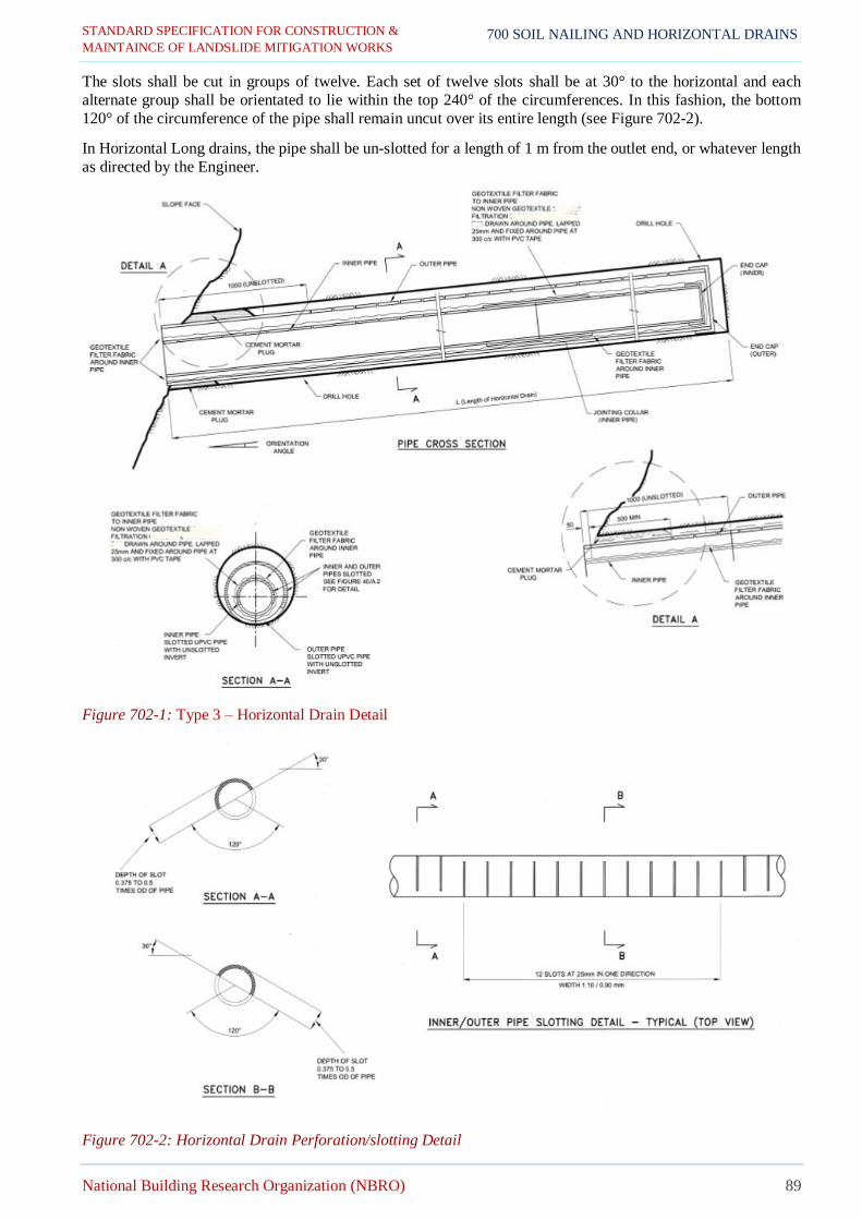
STANDARD SPECIFICATION FOR CONSTRUCTION &
MAINTAINCE OF LANDSLIDE MITIGATION WORKS
National Building Research Organization (NBRO) 89
700 SOIL NAILING AND HORIZONTAL DRAINS
The slots shall be cut in groups of twelve. Each set of twelve slots shall be at 30° to the horizontal and each
alternate group shall be orientated to lie within the top 240° of the circumferences. In this fashion, the bottom
120° of the circumference of the pipe shall remain uncut over its entire length (see Figure 702-2).
In Horizontal Long drains, the pipe shall be un-slotted for a length of 1 m from the outlet end, or whatever length
as directed by the Engineer.
Figure 702-1: Type 3 – Horizontal Drain Detail
Figure 702-2: Horizontal Drain Perforation/slotting Detail

STANDARD SPECIFICATION FOR CONSTRUCTION &
MAINTAINCE OF LANDSLIDE MITIGATION WORKS
National Building Research Organization (NBRO) 90
700 SOIL NAILING AND HORIZONTAL DRAINS
b) Geotextile shall be having physical and filtration properties specified in Section 905 :Table 905-1. The
geotextile forming the filter fabric shall be a non-woven geotextile conforming to Specification,
hydrophically treated to reduce surface tension and shall be abrasion resistant to resist damage during
installation to the satisfaction of the Engineer.
702.3 Construction Requirements
a. General
Horizontal drain shall be constructed as shown in the Drawings or as directed by the Engineer. Following type of
horizontal drains to be selected as per site condition.
1. Perforated pipe without filter fabric
2. Perforated pipe wrapped with filter fabric
3. Outer and inner perforated pipe and only inner pipe wrap with filter fabric
b. Location of Drain Holes
The locations, orientations and lengths of the drain holes shall be in accordance with the Drawings and or as
directed by the Engineer.
The drain holes shall be set out as detailed. The maximum allowable tolerances for locating the position of drain holes shall be ± 100 mm vertically, ± 300 mm horizontally. Facilities shall be provided to enable the inspection
of the drain hole locations by the Engineer.
c. Drilling
Only rotary or rotary-percussion drilling equipment shall be used to carry out drilling. Effective dust suppression
or containment devices shall be provided in accordance with the Construction Safety Plan.
Drilling of holes shall be carried out in a manner which does not affect the stability of the cut batter. In particular, due care shall be taken to avoid the introduction of large volumes of water into the slope. Drilling lubricants other
than air shall not be used. Ground water outflow resulting from the drilling process shall be directed to a holding
tank to enable settlement of the sediment resulting from the drilling.
The holes for the horizontal drains shall be drilled to an inclination of 10° dipping towards the exposed slope face or to the inclinations shown on the Drawings. Drill holes shall be at least 125mm in diameter in the case of Type
03 drains to allow installation of the slotted outer UPVC pipe. For Type 01 and 02drains, drill hole shall beof a
diameter which allows the installation of inner UPVC pipe with or without geotextile wrap as specified without
any obstruction. Holes shall be smooth, clean and true to size.
Holes shall be drilled in a straight alignment. Maximum permissible deviation of the holes shall not exceed 2° (as
measured on a horizontal plane). Deviation from straight shall not exceed 20 mm in any 3 m length of hole.
Any hole which is more than 1° from the specified inclination angle is not acceptable and shall be re-drilled,
unless the Engineer authorizes acceptance of the particular hole.
d. Temporary Casing
In the case of drill holes penetrating through material likely to collapse, temporary casing shall be installed to protect the drill holes from caving in whilst drilling is in progress. The casing shall be retracted after each UPVC
pipe has been successfully installed.
The Contractor shall be responsible for determining whether temporary casing is required. If extraction of the
casing results in damage to an installed UPVC pipe, a new hole shall be drilled and/or another UPVC pipe shall
be re-installed at the discretion of the Engineer and at the Contractor’s own cost.
Any abandoned hole(s) shall be backfilled and properly sealed at the Contractor’s own cost, subject to the approval of the Engineer. The Contractor can propose alternative procedures for supporting collapsible material during
drilling and the installation of the UPVC pipe.
Drill holes shall be cleared of all deleterious material on completion of drilling. Cleaning shall be carried out by
flushing with water, or water in conjunction with air, using side jet bits, so as to ensure removal of all drill cuttings
from the walls and bottom of the drill holes.

STANDARD SPECIFICATION FOR CONSTRUCTION &
MAINTAINCE OF LANDSLIDE MITIGATION WORKS
National Building Research Organization (NBRO) 91
700 SOIL NAILING AND HORIZONTAL DRAINS
An additional drill hole length of 100 mm shall be provided to leave space for the deposition of cuttings that
cannot be flushed out of the end of the drill hole.
e. Installation of Drain Pipes
Unless directed otherwise by the Engineer, when Type 03 is used; an outer and an inner UPVC drain pipe shall
be installed in each drill hole, with the un-slotted 120° of the circumference section of the pipe facing the underside
(refer Figure 702-1). Type 01 and 02 shall be installed as shown in Drawings or as directed by the Engineer.
The pipe shall be jointed either as spigot and socket joints, or as butt joints with a sleeve extending about 50 mm
over the end of each pipe. Sleeve couplers shall not affect the drain installation process. Joints shall be secured
with PVC solvent cement.
The upstream end of each pipe shall be sealed with a UPVC cap secured with PVC solvent cement.
The geotextile filter fabric shall be wrapped around the inner pipe with an overlap length of 25 mm and fixed with
PVC tape at 300 mm centres.
After installation of an outer pipe, the annular space between the drilled hole and the outer pipe shall be tightly
plugged with 1:3 cement: sand mortar for a length of at least 0.5 m at the outlet end of the hole.
Connect all drain pipes to the existing storm water network as shown on the Drawings.
702.4 Measurement and Payment
a. Measurement
For horizontal drains; drillings, PVC perforated pipe (Type 1000), end cap and filter fabric (Geo-textile) (if any)
shall be measured by the linear meter.
b. Payment
The quantities determine for horizontal drains as provided above shall be paid for at the Contract unit rate which
price shall be full compensation for all labour, materials, tools, temporary casing and incidentals necessary for completion of the work including drilling, geotextile rapping (if any), fabrication and installation of horizontal
drains.
703 MONITORING
703.1 Description
This work shall consist of installing maintaining and monitoring of Monitoring Equipment as specified in Section
1300. The work shall be carried out in accordance with this Specification and in conformity with the Drawings or
as directed by the Engineer.
703.2 Measurement and Payment
a. Measurement
Instrumentation shall be measured as a Provisional Sum item for the cost of providing, installation of the
Monitoring Equipment.
Monitoring and testing shall be measured as a Lump Sum item for the cost of maintaining and monitoring of the
Monitoring Equipment.
b. Payment
Payment shall be made as a Provisional Sum and shall be payable when the Contractor has completed the work
Pay Item Description Pay Unit
702(1) Type 01 - Horizontal drains of perforated PVC pipe (specify diameter) Linear meter
702(2) Type 02 - Horizontal drains of perforated PVC pipe with filter fabric
(specify diameter) Linear meter
702(3) Type 03 - Horizontal drains of perforated PVC pipe with outer and inner
pipes wrap with filter fabric (specify diameter) Linear meter

STANDARD SPECIFICATION FOR CONSTRUCTION &
MAINTAINCE OF LANDSLIDE MITIGATION WORKS
National Building Research Organization (NBRO) 92
700 SOIL NAILING AND HORIZONTAL DRAINS
satisfactory as per Section 1300.
Pay Item Description Pay Unit
703(1) Instrumentation as per Section 1300 Provisional Sum
703(2) Monitoring & testing as per Section 1300 Month

STANDARD SPECIFICATION FOR CONSTRUCTION &
MAINTAINCE OF LANDSLIDE MITIGATION WORKS
National Building Research Organization (NBRO) 93
800 QUALITY CONTROL OF WORK
800 QUALITY CONTROL OF WORK
801 QUALITY CONTROL PLAN
The Contractor shall prepare a Quality Control Plan which shall detail quality control procedures such as to
demonstrate that the requirements of the Conditions of Contract in respect of quality are met. The Quality Control
Plan shall provide a formal framework for the approval of the Works by the Engineer.
In particular the Quality Control Plan shall include:
1. Quality control procedures in respect of the selection and control of materials, distinguishing between
approval testing and compliance testing;
2. Quality control procedures in respect of construction operations, identifying procedures for production
control and procedures for survey control;
3. Procedures for the Contractor and Engineer to approve construction works.
In preparing the Quality Control Plan the Contractor shall take into consideration the requirements and obligations
of the Engineer in respect of checking and inspection of the Works.
The Contractor shall appoint a Quality Control Manager who shall be responsible for ensuring that the quality
control procedures set out in the Quality Control Plan are adhered to. The Quality Control Manager shall have
independent control of all quality control activities.
802 QUALITY CONTROL TESTS DURING CONSTRUCTION
The material supplied, and work carried out shall conform to the relevant sections of these Specifications covering
each type of work. For ensuring quality of construction, the materials and work shall be subjected to quality
control tests prescribed in Table 802-1. These tests shall be carried out as specified in the relevant sections of this Specification. The testing frequencies given in Error! Reference source not found.are desirable minimum values a
nd the Engineer may direct the Contractor to carry out tests as frequently as he deems necessary to satisfy himself
that the materials and the work comply with the Specification.
Table 802-1 Testing Frequency
Type of material Type of test Quantity of material or part thereof for
which minimum one test to be carried out
Cement
Acceptance testing of cement such as
- Fineness
- Chemical composition
- Compressive strength
- Setting time
- Soundness
One test per sourcesas directed by the Engineer
Fine aggregates (Sand)
- Sieve analysis
- Water absorption
- Turbidity
One test per 50 m3or as directed by the Engineer
Coarse aggregates
- Sieve analysis
- Aggregate impact value (AIV)
- Water absorption
- Flakiness Index
One test per 50 m3 or as directed by the
Engineer
Concrete - Slump test
- Crushing strength test
One test per 10 m3 or as directed by the Engineer
Tor steel/ribbed steel
reinforcements - Tensile strength
a) One test piece up to 30t with at least three test pieces per test until batch in
accordance to the BS standards.

STANDARD SPECIFICATION FOR CONSTRUCTION &
MAINTAINCE OF LANDSLIDE MITIGATION WORKS
National Building Research Organization (NBRO) 94
800 QUALITY CONTROL OF WORK
b) Five test pieces up to 500 numbers of
bars per test unit/ batch for SLS
standards.
Or as directed by the Engineer. Spot sampling shall be carried out by the
Engineer.
Geo-textile
- Grab strength1
- Sewn seam strength
- Tear strength
- Puncture strength
- Permittivity
- Apparent opening size
As directed by the Engineer
Grout
- Test for bleeding
- Flow cone efflux time test
- Crushing strength test
One test per 120 m or as directed by the
Engineer
Fill/Backfill
- Sieve analysis
- Liquid limit
- Plastic limit
- Modified Proctor test
- Layer thickness at spreading
- Field moisture content
- Degree of compaction
One test per 50 m3 or as directed by the Engineer
Shotcrete
Concrete - Crushing strength test One test per 5 m3or as directed by the Engineer
Soil Nail (Rebar) - Tensile strength
- Galvanized thickness
For testing of tensile strength,
a) One test piece up to 30t with at least three test pieces per test unit/ batch in
accordance to the BS standards;
b) Five test pieces up to 500 numbers of bars per test until/batch for SLS
standards,
Or as directed by the Engineer
For testing of galvanize thickness
One test piece up to 30t with at least
three test piece per test unit/batch or as
directed by the Engineer. Spot sampling shall be carried out by the
Engineer
Coated Metallic
Mesh
- Tensile strength of the wire
- Galvanized thickness
- Diameter of Steel wire
- Mesh/ Net width (opening size)
One test per 500 m2or as directed by the
Engineer
Rock Fence Posts - Post Galvanized thickness
- Section dimension measurement
One test per 2t of posts or as directed by the
Engineer
Rock Fence Mesh
- Tensile strength of the wire
- Galvanized thickness
- Diameter of Steel wire
- Mesh/ Net width (opening size)
One test per 500 m2 or as directed by the
Engineer

STANDARD SPECIFICATION FOR CONSTRUCTION &
MAINTAINCE OF LANDSLIDE MITIGATION WORKS
National Building Research Organization (NBRO) 95
800 QUALITY CONTROL OF WORK
A fresh series of construction control tests shall be undertaken every time there are changes in the sources of the
materials or in the appearance of the materials as visually assessed by the Engineer.
Additional numbers and type of construction control tests shall be carried out if it is considered necessary to do
so by the Engineer for monitoring the variability of materials brought to work site or stockpiled by the Contractor.
803 MATERIAL TESTING
The physical properties and Engineering characteristics of the materials mentioned in the Specification shall be established through appropriate tests on representative samples collected in such a manner and at such a frequency
as specified and instructed by the Engineer. The tests shall be carried out in accordance with test methods
mentioned in the Specification after taking into account the appropriateness of the test methods for particular
applications under consideration.

STANDARD SPECIFICATION FOR CONSTRUCTION &
MAINTAINCE OF LANDSLIDE MITIGATION WORKS
National Building Research Organization (NBRO) 96
900 MATERIAL DETAILS
900 MATERIAL DETAILS
901 AGGREGATE
901.1 Aggregate for Cement Concrete (Section 601 and Others)
Aggregate for concrete shall consist of coarse aggregate (aggregate substantially retained on the 5 mm sieve) and
fine aggregate (aggregate substantially passing the 5 mm sieve).
Unless otherwise specified the coarse aggregate shall be crushed rock from an approval quarry and the fine
aggregate shall either be crusher fines or river sand.
Aggregate from marine sources will not be approved. The aggregate shall be free of salt and organic matter. The
permissible maximum salt content shall be as follows:
Table 901-1: Permissible maximum salt content in aggregate
MATERIAL SODIUM
CHLORIDE
SOLUBLE
SULPHATES
Fine Aggregate 0.10 % 0.25 %
Coarse Aggregate 0.05 % 0.25 %
The aggregate both coarse and fine shall be hard durable and clean and shall be from weathered, soft, laminated
or elongated pieces, deleterious matter, dust and clay.
The Aggregate Impact Value (AIV) of the coarse aggregate determined as given in Section 1001 shall not be
greater than 45. The flakiness index of the coarse aggregate when determined by the sieve method described in
BS-812 shall not exceed 35%.
Where crusher fines are used as fine aggregate, they shall be derived from rock meeting the requirements of coarse
aggregate given above.
The preferred grading for coarse aggregate and fine aggregate given in Table 901-2 and Table 901-3respectively.
The aggregate grading shall be determined as given in Section1001 .
Table 901-2: Grading Limits for Coarse Aggregate
Sieve Size (mm) Percentage by mass passing BS Sieve for
nominal sizes graded-sized aggregate
20 mm-5mm 5 mm
50.0 - -
37.5 100 -
20.0 90 to 100 -
14.0 40 to 80 -
10.0 30 to 60 100
5.0 0 to 10 45 to 100
2.36 - 0 to 30

STANDARD SPECIFICATION FOR CONSTRUCTION &
MAINTAINCE OF LANDSLIDE MITIGATION WORKS
National Building Research Organization (NBRO) 97
900 MATERIAL DETAILS
Table 901-3: Preferred Grading for Fine Aggregate for Concrete
Sieve Size
Percentage by mass passing BS Sieve
Overall limits Additional limits for grading
C M F
10.00 mm 100 - - -
5.00 mm 89 to 100 - - -
2.36 mm 60 to 100 60 to 100 65 to 100 80 to 100
1.18 mm 30 to 100 30 to 90 45 to 100 70 to 100
600 μm 15 to 100 15 to 54 25 to 80 55 to 100
300 μm 5 to 70 5 to 40 5 to 48 5 to 70
150 μm 0 to 15 - - -
NOTE: Individual sands may comply with the requirements of more than one grading.
Alternatively, some sands may satisfy the overall limits but may not fall within any one of the additional limits C, M or F. In this case and where sands do not comply with the above
table an agreed grading envelope may also be used provided that the supplier can satisfy the
Engineer that such materials can produce concrete of the required quality.
902 CEMENT
Cement used shall normally be Ordinary Portland Cement (OPC) complying with the requirements of SLS 107or
Blended Hydraulic Cement complying with the requirements of SLS 1247 given that the other required parameters
are within the limits given in this specification. The cement shall conform to the requirements given therein, in
respect of the following:
a) Fineness
b) Chemical composition
c) Compressive strength d) Setting time
e) Soundness
Tests in respect of the above shall be carried out as specified in Section 902.1 .
Cement shall be brought to Site in quantity not exceeding three months requirements. Each consignment of cement
delivered to Site shall be accompanied by a certificate of testing as per BS, BS ENor SLS standards. Any extra
test instructed by the Engineer whose result proves the material to be out of specification shall be carried out at no extra cost. If for any reason the period of storage of consignment of cement exceeds three months, a
representative sample of the cement shall be retested to confirm its suitability before use at no extra cost.
The Contractor shall provide suitable means of storing and protecting the cement against dampness, Cement
which, for any reason has become partially set or which contains lumps of caked cement shall be rejected.
No additives for cement shall be used unless agreed by the Engineer.
902.1 Cement Grout
Cement grout for grouting dowels shall consist of Ordinary Portland Cement (OPC) and water mixed in the
proportions necessary for the intended purpose.
Cement used for grouting soil nails/ dowels shall be CEM 1, Portland cement complying with (BSEN196 or
BSEN197). Grout material should be non-expansive and non-shrinkage material. Therefore, admixture has to be
added to avoid shrinkage effect of cement. The Contractor should be obtained prior approval for the admixture
before use site at site from the Engineer. The grout should comply with the specifications given in Table 701-1.
The grout shall be mixed until a uniform consistency is obtained and shall normally be used within 45 minutes of
mixing.
902.2 Cement Mortar
Cement mortar shall normally consist of Ordinary Portland Cement, sand and water in the proportions specified.

STANDARD SPECIFICATION FOR CONSTRUCTION &
MAINTAINCE OF LANDSLIDE MITIGATION WORKS
National Building Research Organization (NBRO) 98
900 MATERIAL DETAILS
Mortar shall mix with thoroughly, either by hand or mechanically until its colour and consistency are uniform. It
shall be mixed in small quantities only as and when required and shall normally be used within 45 minutes of
mixing. Mortar which had been mixed for more than 1 hour and shows signs of hardening shall be discarded.
The constituent materials shall normally be volume proportioned as accurately as practicable making allowance
for bulking of sand and also of the cement. Water shall be added in stages until the required consistency is reached.
903 CONCRETE ADMIXTURE
Concrete admixture as retarders, accelerators or as plasticizers shall be used with the prior approval of the
Engineer only and they shall be used strictly in accordance with the manufacturer’s recommendations. In the use
of additives particular attention should be paid to the accurate proportioning of the additive and its homogeneous
introduction in the mix.
904 SOILS
904.1 Filling Material
Soils used as filling materials shall be naturally occurring soils and shall not include highly plastic clay, silt, peat or other organic soils or any soil that is contaminated with top soil vegetable and other deleterious matter. The
material used for the top 500 mm of filling shall conform to the requirements of Filling Type I material, and the
material for lower layers of filling shall conform to the requirements of Filling Type II material as given below.
Testing shall be carried out persua
Table 904-1: Material Characteristics for Filling - Type I and Type II
PROPERTY TEST
METHOD
SPECIFICATION LIMIT
FILLING TYPE I FILLING TYPE II
Liquid Limit (LL) % AASHTO T89 ≤ 50 ≤ 55
Plasticity Index (PI) % AASHTO T90 ≤ 25 ≤ 25
Maximum Dry Density (MDD)
(Modified proctor Test) kg/m3 AASHTO T180 ≥ 1,600 ≥ 1,500
905 GEOTEXTILES / GEOFABRIC
905.1 Referenced Documents
These Specifications:
Section 1003.1 Particle size Analysis of soils
Section 1003.3 Determining the plastic limit and plasticity index of soils
Section 1003.4 Moisture – Density Relations of soils using a 4.5 kg Rammer and 450 mm Drop
ASTM standards:
D 123-00a, Standard terminology Relating to textiles
D276, Test Methods for Identification of fibers in textiles
D4354-99(04), Practice for Sampling of Coir for testing
D4355-05, Test method for Deterioration of Geotextiles from exposure to Ultraviolet light and water
(Xenon-Arc Type Apparatus)
D4439 -04 Terminology for Coir
D4491-99a (04), Test Method for water permeability of Geotextiles by permittivity.
D 4533-04 Test method for trapezoid tearing strength of Geotextiles
D4632-91(2003), Test method for grab breaking load and elongation of Geotextiles
D4751-04, Test Method for determining apparent opening size of geotextiles
D4759-2, practice for determining specification conformance of Coir
D4833-00 Test Method for index puncture resistance of geotextiles, Geomembranes and related products
D4873- 02, Guide for identification, storage and handling of geotextiles
D 5261-92(03), Test method for measuring mass per unit area of geotextiles
D 6140-00(05), Test method for determining the asphalt retention of paving fabrics

STANDARD SPECIFICATION FOR CONSTRUCTION &
MAINTAINCE OF LANDSLIDE MITIGATION WORKS
National Building Research Organization (NBRO) 99
900 MATERIAL DETAILS
905.2 Physical Requirements
a) Fibers utilized in the manufacture of geotextiles and the threads used in joining geotextiles by sewing.
Shall consist of long chain synthetic polymers, composed of at least 95 percent by weight of polyolefin or polyesters. They shall be formed into a stable network such that the filaments or yarns, including
salvages, retain their dimensional stability relative to each other.
b) Subsurface drainage, separation stabilization and permanent erosion control applications, geotextiles
conform to the physical requirements of sub section 905.6 .
c) All values of properties, with the exception of Apparent Opening Size (AOS), in these specifications represent Minimum Average Roll Values (MARV) in the weakest principal direction (i.e., average test
results of any in a lot sampled for conformance or quality assurance testing shall meet or exceed the
minimum values provided here in).Values for AOS represent maximum average roll values (MARV).
905.3 Certification
a) The contractor shall provide to the Engineer, a certificate stating the name of the manufacture, product
name, and style number, chemical composition of the filaments or yarns, and other pertinent information
to describe the geo-textile fully.
b) Contractor shall obtain the supplies of geotextiles from a manufacturer who shall be responsible for
establishing and maintaining a quality control program to assure compliance with the requirements of the specifications. Documentation describing the quality control program shall be made available upon
request from such manufactures.
c) Such manufacture’s certificate shall state that the furnished geo-textile meets MARV requirements of the
specification as evaluated under the manufacturer’s quality control program. A person having legal
authority to bind the manufacturer, shall attest to the certificate.
d) Either misrepresentation of materials or mislabeling shall be a reason to reject those geotextile products
of the manufacturer.
905.4 Sampling, Testing and Acceptance
a) Geotextile materials shall be subject to sampling and testing to verify conformance with these Specifications. Sampling shall be in accordance with the most current ASTM standards D 4354, using the
section titled, “procedure for sampling for purchaser’s specification conformance testing”. In the absence
of purchaser’s testing, verification may be based on manufacturer’s certifications as a result of testing by the manufacturer of quality assurance samples obtained using the procedure for sampling for
Manufacturer’s Quality Assurance (MQA) testing. A lot size shall be considered to be the shipment
quantity of the given product, or a truck load of the given product, whichever is smaller.
b) For the indicated application, testing shall be performed in accordance with the methods referenced in
these specifications. The number of specimens to test per sample is specified by each test method. Geotextile product acceptance shall be based on ASTM D 4759. Product acceptance is determined by
comparing the average test results of all specimens within a given sample to the specimen MARV.
Reference shall be made to ASTM D 4759 for more details regarding geotextile procedures for
acceptance.
905.5 Shipment and Storage
a) Labeling, shipment and storage of geotextile shall follow ASTM D 4873. Product label shall clearly show
the manufacture or supplier name, style name and roll number. Each shipping document shall include a
notation certifying that the material is in accordance with the certificate of the manufacturer.
b) Each roll of geotextiles shall be wrapped with a material that will protect the geotextile, including the
ends of the roll, from damage due to shipment, water sunlight and contaminants. The protective wrapping
shall be maintained during periods of shipment and storage subsequently.
c) During periods of storage, the geotextile rolls shall be elevated off the ground and adequately covered to protect them from the following: site construction damage, precipitation, extended ultraviolet radiation
including sunlight, chemicals that are strong acids or strong bases, flames including welding sparks,
temperatures in excess of 71 0C (1600F) and any other environmental condition that may damage the
geotextile physical property.

STANDARD SPECIFICATION FOR CONSTRUCTION &
MAINTAINCE OF LANDSLIDE MITIGATION WORKS
National Building Research Organization (NBRO) 100
900 MATERIAL DETAILS
905.6 Geotextile Property requirements for Subsurface Drainage and Horizontal Drains
Physical Characteristic – Should be Continuous filament, nonwoven needle punched. Polymer – 100%
Polypropylene, UV stabilized.
Table 905-1: Physical and filtration properties of Geo-textiles
No Code No. Description Property Value
1.0 BS EN ISO
10319:2008
Geo-synthetics. Wide-width
tensile test.
Tensile Strength
Retention
Exceeds 70%
Strength retention after 3 months
outdoor weathering
Tensile Strength
(avg) Exceeds 10 kN/m
2.0 BS EN ISO
11058:2010
Geo-textiles and geo-textile-
related products.
Determination of water permeability characteristics
normal to the plane, without
load.
Vertical Water
Flow 50mm Head
More Than 80
1/m2/s
(mm/s)
3.0 BS EN ISO
12956:2010
Geo-textiles and geo-textile-
related products. Determination of the
characteristic opening size.
Effective Opening
size
(O90)
Less Than 100 µm
4.0 BS EN ISO
12958:2010
Geo-textiles and geo-textile-
related products. Determination of water flow
capacity in their plane
20kPa Exceeds 5.01/m.h
200kPa Exceeds 2.01/m.h
5.0 BS EN ISO 9863-
1:2005
Geo-synthetics.
Determination of thickness at
specified pressures. Single
layers.
Thickness 2kPa Exceeds 1.5 mm
6.0 ASTM D 4491 –
99a (2009)
Standard Test Methods for
Water Permeability of Geo-
textile by Permittivity
Permittivity More Than 2.5 s-1
7.0 ASTM D 4751 -
04
Standard Test Methods for
Determining g Apparent
Opening Size of a Geo-textile
Apparent Opening
Size (O90) Less Than 250 µm

STANDARD SPECIFICATION FOR CONSTRUCTION &
MAINTAINCE OF LANDSLIDE MITIGATION WORKS
National Building Research Organization (NBRO) 101
1000 TESTS FOR QUALITY CONTROL OF
MATERIAL AND WORKS
1000 TESTS FOR QUALITY CONTROL OF MATERIAL AND WORKS
1001 AGGREGATES AND SOIL
Table 1001-1: Quality Control Tests for Aggregates and Soil
Clause No Quality Control Test Reference Standards
1001.1 Sieve Analysis BS EN 932-1-1997 or ASTM C 136-96a or
AASHTO T27-99/ BS 812 Part 103.1
1001.2 Clay, silt and dust fraction (fraction
passing the 0.075 mm sieve)
BS 812:103.2 (2000) or ASTM C 117-95 or
AASHTO T11-97
1001.3 Aggregate Impact Value (AIV) BS EN 1097-2:1998/ BS 812 Part 112
1001.6 Flakiness index BS 812: Part 105.1:2000/ BS EN 933-3
Elongation BS 812: Part 105.2: 2000/ BS EN 933-4
1001.7 Specific Gravity of Coarse
Aggregate
BS 812: Part 2:1975 or ASTM C 127-88 (1993)
or AASHTO T85 – 91 (2000)
1001.8 Specific Gravity of Fine Aggregate BS EN 1097: 5: 1999 or ASTM C 128-97 or BS
812: 2000 or AASHTO T84 – 00
1002 CEMENT AND CONCRETE
1002.1 Cement
Table 1002-1: Quality Control Tests for Cement
Clause No Quality Control Test Reference Standards
1002.1 (a) Standard Consistency SLS 107: 2008 or ASTM C 187-04 or
BS EN 196-3: 2005 or AASHTO T129-01
1002.1 (b) Setting Times SLS 107: 2008 or ASTM C 191-04b or
BS EN 196-3: 2008 or AASHTO T131-01
1002.1 (c) Fineness SLS 107: 2008 or ASTM C 204-00 or
BS EN 196-6: 1992 or AASHTO T152-01
1002.1 (d) Compressive Strength SLS 107: 2008 or ASTM C 109/C109M-05 or
BS EN 196-1: 2005 or AASHTO T106-02
1002.1 (e) Soundness Test BS 4550: Part 3: Sec 3.7 or BS EN 196-3: 2005
1002.2 Concrete
Table 1002-2: Quality Control Tests for Concrete
Clause No Quality Control Test Reference Standards
1002.3 (a) Casting of Concrete Cubes
BS 1881: Part 108: 83, BS EN 12390-1:2000 or
ASTM C31/C31M-03a in field or
ASTM C192C/192M-05 in laboratory
1002.3 (b) Testing of Concrete Cubes BS EN 12390-3: 2002/BS 1881-116
1002.3 (g) Slump Test
ASTM C143/C143M-05a or
BS EN 12504-1-2000 or AASHTO T119-99/ BS
1881-102

STANDARD SPECIFICATION FOR CONSTRUCTION &
MAINTAINCE OF LANDSLIDE MITIGATION WORKS
National Building Research Organization (NBRO) 102
1000 TESTS FOR QUALITY CONTROL OF
MATERIAL AND WORKS
1003 SOILS
Table 1003-1: Quality Control Tests for Soils
Clause No Quality Control Test Reference Standards
1003.1 Sieve Analysis Test BS 1377-Part 2: 1990 or ASTM D422-63 (72) or
AASHTO T88-00
1003.2 Liquid Limit BS 1377-Part 2: 1990 or ASTM D 4318-05 or
AASHTO T89-02
1003.3 Plastic Limit BS 1377-Part 2: 1990 or ASTM D 4318-05 or
AASHTO T90-00
1003.4 Modified Proctor Compaction BS 1377-Part 4: 1990 or ASTM D 1557-02 or
AASHTO T180-01
1003.6 Field Moisture ASTM D 2218-98
1003.7 Field Density BS 1377-Part 9: 1990 or ASTM D 1556-90 or
AASHTO T191-02
1004 COATED METALLIC MESH
Table 1004-1: Quality Control Tests for Coated Metallic Mesh
Clause No Quality Control Test Reference Standards
1004.1 Tensile Strength of the Wire ISO: 6892-1:2009
1004.2 Galvanized Thickness BS 443: 1998

STANDARD SPECIFICATION FOR CONSTRUCTION &
MAINTAINCE OF LANDSLIDE MITIGATION WORKS
National Building Research Organization (NBRO) 103
1100 GROUND ANCHORS
1100 GROUND ANCHORS
1101 GENERAL
This Specification sets out the requirements for the supply, assembly, installation, grouting, stressing and
monitoring of post-tensioned ground anchors including drilling, grouting and water testing, and sealing of the
boreholes. It applies to both temporary and permanent ground anchors with appropriate corrosion protection systems installed into soil or rock. It may also be applied to anchors which are stressed directly to ground and to
unstressed or lightly stressed tie-downs which anchor structures to rock or soil through intervening unsound
stratum.
Unless specified otherwise, such as for temporary anchors, tendons shall be fully encapsulated and placed in
sheaths or ducts before insertion in the borehole. Carry out borehole grouting in a single stage operation, filling
the borehole in such a manner that the hardened grout does not come in contact with the structure.
1102 DEFINITIONS
1102.1 General
The following definitions apply to this Specification:
Anchor Supervisor - Nominated employee of the Ground Anchor System Supplier approved by the Engineer responsible for supervision of Critical Anchor Activities and certification
of installation operations.
Anchorage - The anchor component at the top of a tendon that transfers the tendon load to the ground or structure, comprising the pre-stressing head, bearing plate or anchorage
casting, protective cover and all associated seals, fittings and materials (see Figure
1102-1).
Bleed - The separation of water from the grout paste.
Coupler - A device for joining lengths of bar or strand which comprise an anchor tendon.
Critical Anchor
Activity
- Construction activities including test anchors; anchor assembly; borehole drilling,
cleaning and testing; anchor insertion, grouting and stressing; load testing; cutting off tendon and application of corrosion protection to anchorage and under head
zone.
Duct - A semi-rigid tube generally corrugated both inside and outside to isolate the tendon from the environment and to transfer load between the inner and outer grout annuli
in the tendon bond length. Extensions may be either corrugated or smooth over the
tendon unbonded length (see Figure 1102-1, Figure 1102-3, Figure 1102-4, Figure
1102-5 and Figure 1102-6).
Effective tendon
free length
- The length of tendon between the connection of the tendon to the stressing jack and
a point along the tendon, which acts elastically during stressing. It is calculated from
the load/extension characteristics of the ground anchor.
Fixed anchor length - The design length of borehole over which the load is transferred to the ground (see
Figure 1102-1).
Free anchor length - The design length of borehole between the anchorage and the start of the bonded length along which no pre-stressing force is transferred to the ground (see Figure
1102-1).
Ground Anchor
System Supplier
- The Supplier, or agent of the Supplier, of the Engineer approved ground anchor
system responsible for its supply and control, and for performance of its
components.

STANDARD SPECIFICATION FOR CONSTRUCTION &
MAINTAINCE OF LANDSLIDE MITIGATION WORKS
National Building Research Organization (NBRO) 104
1100 GROUND ANCHORS
Ground or rock
anchor
- An installation that is capable of transmitting an applied tensile load to a load
bearing stratum of rock or soil, comprising an anchorage, free anchor length and
fixed anchor length (see Figure 1102-1).
Grout - Cementitious material that transfers load from the tendon to the ground over the fixed anchor length; it may fill the remainder of the borehole and/or contribute to
corrosion protection of the steel tendon.
Monitorable anchor - A ground anchor assembled and installed to allow inspection and measurement of
anchor loads at some time after completion of stressing.
Multiple anchor - A single borehole containing multiple unit strands or bars with bonded lengths at
staggered depths, to provide ultra-high load capacities in soils and weak rocks (see
Figure 1102-4c).
Non-conforming
anchor
- A ground anchor system or its parts that do not conform to this Specification.
Nose cone - A component at the lower end of the anchor that retains and seals the end of the
duct to assist insertion of the anchor into the borehole.
Overhead zone - The zone of the anchorage lying above the bearing plate and including the protective
cap (see Figure 1102-2).
Permanent ground
anchor
- An installation that ensures the stability and satisfactory performance of the
permanent structure or supported excavation for its design life, usually 100 years.
Pre-stressing head - A steel block with tapered holes and wedges capable of transferring the entire capacity of the tendon to the structure. Bars may use threaded nuts instead of
wedges.
Proof anchor - A ground anchor on which a Proof Test is carried out prior to ground anchor work
commencing at the Project Site.
Protective cap - A non-corroding sealed cap of galvanized steel or strong plastic containing a
corrosion inhibiting compound that surrounds the pre-stressing wedges or nuts and
tendon ends; it may be capable of being removed (see Figure 1102-2 and Figure
1102-3).
Re-stressable pre-
stressing head
- A pre-stressing head similar to a normal pre-stressing head that permits the tendon
force to be measured by lift-off tests throughout the life of the structure. Small load
losses of up to 20% of working load may be recovered by re-stressing and shimming
or thread-turning.
Sheath - A generally smooth flexible tube which isolates each strand or bar and does not
bond with the surrounding grout (see Figure 1102-1, Figure 1102-3, Figure 1102-4
and Figure 1102-5).
Spacer/centralizer - A corrosion proof component that supports the tendon or sheath/duct to ensure
adequate grout cover.
Strand node - The controlled deformation of strand wires to form a tight “birdcage” to enhance
the pull-out capacity of the tendon from the grout.
Suitability anchor - A ground anchor on which a Suitability Test is carried out prior to installation of
the remaining ground anchors it represents.
Temporary ground
anchor
- An installation often used during the construction phase of a project to carry loads
for a known short period of time, usually less than 2 years.

STANDARD SPECIFICATION FOR CONSTRUCTION &
MAINTAINCE OF LANDSLIDE MITIGATION WORKS
National Building Research Organization (NBRO) 105
1100 GROUND ANCHORS
Tendon - That part of a ground anchor that transmits the tensile load from the fixed anchor
length to the anchorage, typically comprising a bundle of identical strands or a
single high tensile steel bar.
Tendon bond length - The length of tendon bonded directly to the grout capable of transmitting the
ultimate tensile capacity of the tendon (see Figure 1102-3).
Tendon node - In multi-strand anchors the strands are spaced apart at tendon nodes and typically
at 1 m to 2m away from these nodes the strands are banded tightly together; this enhances the bond between the tendon and the grout (see Figure 1102-1 and Figure
1102-3).
Tendon un-bonded
length
- The length of tendon between the pre-stressing head and the proximal end of the tendon bond length that is specifically isolated from direct contact with the grout
(see Figure 1102-3).
Underhead zone - The zone of the anchorage lying between the pre-stressing head and the seal which
overlaps the corrosion protection applied to the tendon free length (see Figure
1102-2).
Unit tendon - A tendon component of a multiple anchor that has its own pre-stressing wedge or
nut, free length and bonded length. The bonded lengths of each Unit are located at a staggered depth in the borehole.
1102.2 Loads and Forces
Initial or Datum Load (TA) - Initial load applied to the tendon prior to any testing.
Initial Residual Load (TRI) - Measured load in the tendon immediately after lock-off assessed by a
Lift-off Test.
Jacking Force (TJ) - The jacking force that produces the lock-off load, taking into account
any anchorage friction and draw-in losses.
Lock-off Load (TO) - The load required to be transferred to an anchor head immediately on
completion of a stressing operation.
Minimum Breaking Load (TU) - The product of the number of strands in an anchor and the characteristic
minimum breaking load of the strand, or the minimum characteristic
breaking load of a bar tendon.
Residual Load (TR) - Measured load in the tendon after lock-off assessed by a Lift-off Test.
Test Load (TP) - The maximum load to which a tendon is subjected during Suitability or
Acceptance Tests
Working Load (TD) - Residual load in the tendon after all losses that provides the required
restraint to the structure.
1102.3 Tests
Acceptance Test - A single load cycle to Test Load TP to verify that each working ground anchor
conforms to the anchor acceptance criteria.
Lift-off Test - Determination of the force in a tendon that causes a small lift of the anchor head
away from the bearing plate, generally confirmed using a 0.5 mm thick feeler gauge
Proof Test - A load test carried out in advance of the installation of the working ground anchors to:

STANDARD SPECIFICATION FOR CONSTRUCTION &
MAINTAINCE OF LANDSLIDE MITIGATION WORKS
National Building Research Organization (NBRO) 106
1100 GROUND ANCHORS
Establish for the designer the anchor resistance Ra in relation to the ground conditions
Allow the designer to determine criteria for anchor acceptance
Verify the performance of proposed materials and components e.g. ducts
Prove the competence of the Contractor
Determine the bond capacity of an anchor by inducing a failure at the
grout/ground interface.
Suitability Test - At least six load cycles followed by lock-off to verify the rock anchor design and
installation and to establish reference test values for other anchors represented by the tested anchor.
1102.4 Notation
At = Cross-sectional area of tendon (mm²)
Et = Modulus of elasticity of tendon (MPa)
Lb = Bond length (mm)
Lef = Effective free length (mm)
Lfr = Free length (mm)
Ra = Anchor resistance calculated in accordance with AS 5100.3
S* = Design action loads calculated in accordance with AS 5100.3
T = Anchor load (kN)
TA = Initial Datum Load (kN)
TJ = Jacking Force (kN)
TO = Lock-off Load (kN)
TP = Test Load (kN)
TR = Residual Load (kN)
TRI = Initial Residual Load (kN)
TU = Minimum Breaking Load of tendon (kN)
dL = Measured total extension of tendon relative to a datum (mm)
δLe = Measured elastic extension of tendon at each load stage (mm)
δLr = Calculated elastic extension of tendon at each test load stage (mm)
δLpl = Measured plastic or non-recoverable extension of tendon at each test load stage (mm)
øg = Geotechnical reduction factor selected in accordance with AS 5100.3
øn = Importance category reduction factor selected in accordance with AS 5100.3

STANDARD SPECIFICATION FOR CONSTRUCTION &
MAINTAINCE OF LANDSLIDE MITIGATION WORKS
National Building Research Organization (NBRO) 107
1100 GROUND ANCHORS
1102.5 Figures
Figure 1102-1: Ground Anchor Nomenclature
Figure 1102-2: Monitorable Permanent Anchorage

STANDARD SPECIFICATION FOR CONSTRUCTION &
MAINTAINCE OF LANDSLIDE MITIGATION WORKS
National Building Research Organization (NBRO) 108
1100 GROUND ANCHORS
Figure 1102-3: Tendon Nomenclature
Figure 1102-4: Typical Factory Grouted Tendon Bond Lengths

STANDARD SPECIFICATION FOR CONSTRUCTION &
MAINTAINCE OF LANDSLIDE MITIGATION WORKS
National Building Research Organization (NBRO) 109
1100 GROUND ANCHORS
Figure 1102-5: Grouted In-situ Tendon Bond Length
Figure 1102-6: Split Gun-Barrel Test Arrangement
1103 MATERIALS AND COMPONENTS
1103.1 General
Obtain materials only from suppliers that have implemented quality management systems to ISO 9001, with third-
party certification.
Provide evidence demonstrating that each supplier of pre-stressing components and tendons has the specified
quality management systems in place, and prove the conformity of the supplied materials with the requirements
of this Specification.
1103.2 Tendons
Obtain pre-stressing materials only from suppliers that have implemented quality management systems to ISO
9001, with third-party certification accredited.
Provide evidence demonstrating that each supplier of pre-stressing materials has the specified quality management
systems in place, and provide proof of conformity of the supplied materials with the requirements of this
Specification.
Tendons shall conform to AS/NZS 4672.1 or equivalent. If tendons conform to standards other than AS/NZS 4672
or equivalent, provide to the Project Verifier evidence that the tendons are of equivalent quality.
Strand shall be Relaxation Class 2 unless specified otherwise.
Provide, with each delivery, documentation listing the Lot numbers from which each coil or bar is taken and test
certificates conformity with AS/NZS 4672 or equivalent. Testing shall conform to AS/NZS 4672.2 or equivalent.

STANDARD SPECIFICATION FOR CONSTRUCTION &
MAINTAINCE OF LANDSLIDE MITIGATION WORKS
National Building Research Organization (NBRO) 110
1100 GROUND ANCHORS
Test at least one sample from each coil of wire and strand. Test at least 3 bars from each Lot and each delivery.
Submit the following test reports prior to use at site for the Engineer’s approval.
(a) Breaking force;
(b) Yield strength and elongation;
(c) Load-elongation curve;
(d) Cast analysis of the steel;
(e) Cross-sectional area of tendon; and
(f) 1000 hour isothermal relaxation, with evidence that the tendon tested represents the tendons supplied. The tendon bond length shall be not less than 3 m.
1103.3 Anchorages
Anchorages shall conform to AS 1314 or equivalent accepted by the Engineer.
Submit for all anchorage components certification prior to use at site for the Engineer’s approval.
Anchorage components shall be of adequate size and shape to safely transfer the force from the tendon to the
concrete without overstress, either directly through the anchor head or indirectly through a chair under the
stressing jack.
Bearing plates shall be Grade 250 steel to AS/NZS 3678 or equivalent accepted by the Engineer. Higher strength
steels shall be used, provided that evidence is submitted demonstrating an adequate factor of safety.
Bearing plates for anchors stressed directly to rock shall be the size shown on the Design Drawings, dimensioned
to transfer tendon forces uniformly without overstressing the rock or the bearing plate.
Bearing plates shall not fully covered with concrete and isolated from the environment; those bearing plates hot-
dip galvanize in conformance with requirements of AS 1214 and AS 1650 with minimum coat thickness of 85 μm
or 610 mg per square meter.
The bearing stress at the steel contact surfaces shall not exceed 400MPa.
The bearing stress at the concrete surface shall not exceed 30MPa.
Submit calculations or other evidence from the supplier of the ground anchor system substantiating the design of
the bearing plates supplied for the Project Works.
Manufacturing tolerances for each component shall not impair the gripping efficiency of the assembled anchorage.
Provide a device to centre the anchorage so that the tendon force is applied uniformly to the contact surface
between the pre-stressing head and the bearing plate or anchorage casting.
The pre-stressing head shall permit the monitoring of accurate extension measurements without indeterminate
losses between loading increments.
Draw-in losses associated with the wedges shall be uniform and allow presentation of draw-in versus load plots
where appropriate.
Incorporate injection nipple/s for the Corrosion Inhibiting Compound (CIC) to fill and pressurise cavities above
and around the pre-stressing head.
When stressing the anchorage directly against the rock, include in the quality plan the proposed criteria for a
satisfactory rock surface and procedures for installing the bearing plate on its pad.
For guidelines to good practice in the design of rock and soil anchors with reference to site investigation data see:
(a) British Standard Code of Practice for Ground Anchorages BS8081 published by the British Standards Institute
(b) Geotechnical Engineering Handbook Volume 2 Procedures – Chapter 2.5 Ground Anchors published by Ernst & Sohn 2003.
1103.4 Grout
Fine aggregate if used, shall have maximum nominal size of 1.0 mm and conform to AS 2758.1 for normal weight,
concrete exposure classification B2, and maximum water absorption of 2.0%.

STANDARD SPECIFICATION FOR CONSTRUCTION &
MAINTAINCE OF LANDSLIDE MITIGATION WORKS
National Building Research Organization (NBRO) 111
1100 GROUND ANCHORS
Mixing water shall be clean and free of oil, acid, alkali, organic or vegetable matter, not be harmful to steel or
grout, and have a chloride ion content less than 500 mg/l.
Methocell, ligno-sulphonate based superplasticisers and aluminates shall not be used as admixtures. Expansive
admixtures where used shall be the pre-hardening type and not include iron or aluminium powders. The chemical
reactions between grout constituents or materials in contact with the grout shall not produce gases.
Grout mixes shall be pre-packaged so that only water and admixtures need to be added to the dry mix on-site, or
mixes shall be designed to meet project specifications for site batching.
1103.5 Sheaths and Ducts
Individual strand sheaths and tendon anchor ducts shall be robust, abrasion and corrosion resistant, waterproof, non-biodegradable and sufficiently flexible to allow insertion of the anchor into the borehole without damage.
They shall be strong and provide enough support to prevent excessive deformation or rupture under loads imposed
during anchor installation and grouting.
Maintain and check the integrity of the sheaths and ducts during assembly, installation, grouting and testing.
a. Strand/Bar Sheaths
Provide for both temporary and permanent anchors:
(a) A strong smooth plastic sheath closely surrounding the steel strand/bar over the un-bonded length of the tendon; and
(b) A corrosion inhibiting grease or lubricant conforming to Section 1103.6 completely filling the annulus between the strand/bar and the sheath such that during anchor stressing operations the frictional forces over the un-bonded length of the tendon are minimized.
b. Tendon Un-bonded Length Ducts
Ducts for the tendon un-bonded length shall be smooth or corrugated and shall be one of the following:
(a) HDPE conforming to ASTM D1248
(b) PP conforming to ASTM D4101
c. Bond Length Ducts
Ducts for the bonded length shall be corrugated and shall be HDPE conforming to ASTM D3350.
Corrugations shall be uniform and generally sinusoidal in shape, conforming to the following:
(a) Wall thickness (w) of ducts: w ≥ 2 mm
(b) Pitch of corrugations (p): 12 w ≥ p ≥ 6 w
(c) Amplitude of corrugations (a): a ≥ 3 w
The profile shall not allow voids to be formed in the rising grout column.
The base of the duct shall be sealed and contain a nose cone to assist insertion into the borehole. The nose cone
shall not inhibit grouting of the tendon and shall be robust and corrosion resistant.
Demonstrate using Proof Tests the capability of the duct to:
(i) Provide adequate bond capacity between the inner grout annulus and the tendon equal to the tensile capacity of the tendon
(ii) Provide adequate bond capacity between the duct and the outer grout annulus equal to the tensile
capacity of the tendon (iii) Accommodate the elastic behaviour of the tendon
(iv) Satisfy other anchor acceptance criteria.
1103.6 Corrosion Inhibiting Compound (CIC)
The Corrosion Inhibiting Compound (CIC) used for the sheaths of individual strands or bars and corrosion protection of the
underhead and overhead zones of the anchor shall be a chemically stable, non-reactive grease or wax compatible with tendons,
sheaths and grout conforming to Table 1103-1. In case of doubt performance shall be checked and reported as per ASTM
G170 as directed by Engineer.

STANDARD SPECIFICATION FOR CONSTRUCTION &
MAINTAINCE OF LANDSLIDE MITIGATION WORKS
National Building Research Organization (NBRO) 112
1100 GROUND ANCHORS
Table 1103-1: Performance Criteria for Grease/Wax Corrosion Inhibiting Compound
Property
Grease Wax
Comments Test
Method Requirements
Test
Method Requirements
Consistency ASTM
D217 265 – 295 mm
ASTM
D937 150 – 350 mm
Pumpability & application
compatibility to be confirmed
Corrosion
protection
ASTM
D1743 Pass
ASTM
D1743 Pass
Test substrate to be vertical 7-wire pre-stressing strand
Copper corrosiveness
ASTM D4048
1a ASTM D130
1a
Salt spray corrosion
ASTM B117
1000 h ASTM B117
1000 h
Oil separation
maximum
ASTM
D1742 3 %
ASTM
D6184 0.5 % at 38 ºC Test temp for wax is 38 ºC
Drop point
minimum
ASTM
D566 150 ºC
ASTM
D127 65 ºC
Test temp for wax is 38 ºC Flash point minimum
ASTM D92
200 ºC ASTM
D92 200 ºC
Evaporation maximum
ASTM D972
0.5% ASTM D972
0.5 % at 38 ºC
Saponification ASTM
D94
< 2 mg
KOH/gm
ASTM
D94
< 2 mg
KOH/gm
Water washout ASTM
D1264 < 5% at 38 ºC
ASTM
D1264 0.5 % at 38 ºC
1103.7 Protective Caps
Provide protective caps that are watertight, allow complete draining and refilling of the CIC and cover the pre-
stressing head and protruding tendon ends in accordance with Section 1110 . Caps also shall allow visual
inspection of the CIC level using a watertight inspection lid without removal of the cap.
Unless otherwise approved, the protective cap and inspection lid shall be minimum 7 mm thick steel hot-dipped
galvanized to AS 1214 and AS 1650 with minimum coat thickness of 85μm or 610g per square meter.
Where the anchorage is fully isolated from the environment by a thick dense cover of concrete not subject to
cracking through the life time of the permanent anchor and noted on the Design Drawings, then protective caps
may be omitted.
1104 CORROSION PROTECTION
1104.1 General
The design life of permanent anchors conforming to this Specification is 100 years in typical aggressive
environments.
Where doubt exists with regard to the corrosion protection performance of a ground anchor system in a specific
environment, provide supplementary additional protection.
Take measures to eliminate corrosion and loss of capacity of the load carrying elements of the ground anchor over
the anchor’s design life.
Provide corrosion protection by containing the steel elements of the tendon within anchor sheaths and ducts over
the entire length within the ground or structure. In the fixed anchor length, supplement the isolation provided by the duct with an outer annulus of cementitious grout not less than 20 mm thick; this grout shall not be considered

STANDARD SPECIFICATION FOR CONSTRUCTION &
MAINTAINCE OF LANDSLIDE MITIGATION WORKS
National Building Research Organization (NBRO) 113
1100 GROUND ANCHORS
as providing corrosion protection as the grout may crack during stressing. In the free anchor length, supplement
this isolation with corrosion inhibiting wax or grease compounds, which are an integral part of the ground anchor’s
corrosion protection system.
1104.2 Underhead Zone Protection
The length of tendon between the top of the CIC filled sheath and the base of the pre-stressing head is particularly
vulnerable to corrosion, and on completion of stressing it is rarely possible to inspect the effectiveness of the
protection provided. Special precautions for corrosion protection of this zone are specified in this Specification.
Refer also to BS 8081 for guidance to good ground anchor corrosion protection practice.
Provide a steel duct or trumpet around the tendon in this zone that contains either the CIC or a resinous grout,
both of which shall be fully contained to prevent leakage.
1104.3 Temporary Anchors
Unless environmental conditions are particularly aggressive, cementitious grout alone is appropriate corrosion protection for tendons of temporary anchors with a design life of up to two years in a non-aggressive environment,
provided the tendons are spaced, centralised and have a grout cover of not less than 20 mm.
1105 SUPPLY AND SUPERVISION
1105.1 General
Supply and install each ground anchor at the specified location and alignment in accordance with the Design
Drawings and this Specification using a tendon with the specified minimum breaking load and minimum bond
length pre-stressed to achieve the specified Lock-off Load (TO).
1105.2 Anchor Supervisor
Critical Anchor Activities shall be carried out under the supervision of the Anchor Supervisor. Critical Anchor
Activities include:
(a) Borehole drilling, cleaning and testing (Section 1107 )
(b) Insertion of each anchor into the borehole (Sub Section 1107.5 a. ) (c) Grouting (Section 1108.1 )
(d) Load testing (Section 1109.1 )
(e) Stressing (Section 1110.1 ) (f) Cutting off tendon and applying corrosion protection to the anchorage and under head zone (Section 1111
).
The Anchor Supervisor shall certify that the following items conform to this Specification:
(i) Information to be supplied
The following documents are a summary of documents that shall be included in the quality plan. The
requirements of this Specification and others included in the deed shall be reviewed to determine
additional documentation requirements.
The information to be submitted as part of the quality plan includes, but is not limited to, the following:
(a) Full details proving conformity with the Specification of alternative corrosion protection systems to that specified (Section 1101 )
(b) Criteria for a satisfactory rock surface and procedures for installing the bearing plate on its pad when stressing anchorages directly against rock (Section 1103.3 )
(c) Details of supplementary additional corrosion protection required in a specific environment (Section 1104.1 )
(d) Details of method of sealing base and head of under head zone duct or trumpet (Section 1104.2 )
(e) Fully detailed drawings including cross-sections and longitudinal sections showing all ground anchor components, method of assembly and provisions for monitoring (Section 1106.1 )
(f) Procedure for preventing tendon strands from crossing within the free length (Section 1106.2 )
(g) Demonstration of adequacy of joints in sheaths and ducts (Section 1106.5 )
(h) Details of sheaths at tendon couplers (Section 1106.6 )

STANDARD SPECIFICATION FOR CONSTRUCTION &
MAINTAINCE OF LANDSLIDE MITIGATION WORKS
National Building Research Organization (NBRO) 114
1100 GROUND ANCHORS
(i) Detailed procedures for fixing lower end of tendon to the bottom of corrugated duct and sealing with nose cone (Section 1106.7 )
(j) Full details of proposed drilling procedure and method of supporting the borehole during drilling, installation and grouting when penetrating material other than rock (Section 1107.1 )
(k) Procedures for maintaining and checking the specified borehole alignment and deviation from straight during drilling (Section 1107.2 )
(l) Procedure for dealing with variations in subsoil condition when drilling boreholes (Section 1107.2 )
(m) Methods of cleaning the boreholes (Section 1107.3 )
(n) Procedures for inserting assembled anchors into boreholes (Section 1107.5 a. )
(ii) Each tendon coil or bar (Section 1103.2 )
(iii) Ground anchor system (Section 1103.3 )
(iv) Grout (Section 1103.4 )
(v) Tendons sheaths, anchor sheaths and ducts (Section 1103.5 )
(vi) Corrosion inhibiting compound (Section 1103.6 )
(vii) Assembled anchor (Section 1106 )
(viii) Borehole drilling, cleaning and testing (Section 1107 )
(ix) Anchor insertion and water testing (Section 1107.5 )
(x) Experience and qualifications of all grouting personnel (Section 1108.1 )
(xi) Grouting (Section 1108 )
(xii) Stressing (Section 1110 )
(xiii) Assessment of anchors (Section 1109 )
(xiv) Application of corrosion protection to under head zone and protective cap (Section 1111 )
(xv) Monitoring (Section 1112 )
1106 ASSEMBLY
1106.1 General
For all ground anchor assemblies, submit your comprehensive proposals for the complete assembly to prevent
damage to the anchor components and corrosion protection system during handling.
Include in the quality plan fully detailed proposals, with drawings including cross-sections and longitudinal
sections showing all anchor components, including details of the method of assembly and if applicable the
provisions for monitoring specified in Section 1112 .
Anchors shall not assemble outside the Project Site. Maintain an assembly schedule tracing the source of each
tendon in each anchor e.g. for strand, each coil from which each strand in each anchor was taken.
Prior to commencement, or during the early stages in the anchor works, demonstrate the duct’s resistance to damage during installation by inserting and withdrawing an assembled anchor from the borehole and inspecting
its condition.
Consideration shall be given to systems developed to confirm the total isolation of the tendon from the
environment using electrical conductivity test techniques.
Provide for a minimum of 20 mm grout thickness between the sheath/duct and the borehole wall.
1106.2 Tendons
Supply strands in coils in conformity with AS/NZS 4672 or equivalent. When removing strands from coils the
resulting twisting forces shall not loosen the lay of the strand. The lay of the strand wires may only be modified
with the intent of forming strand nodes.

STANDARD SPECIFICATION FOR CONSTRUCTION &
MAINTAINCE OF LANDSLIDE MITIGATION WORKS
National Building Research Organization (NBRO) 115
1100 GROUND ANCHORS
Reject any damaged or kinked tendons.
Do not carry out welding at a distance less than 3 m from any tendons. Reject any tendon affected by arc strikes.
Cut tendons with high-speed carborundum disk cutters. Do not use flame cutting under any circumstances.
Arrange tendons uniformly without oblique crossing over the anchor cross-section. Include in the quality plan a
procedure for avoiding severe crossing of strands within the tendon un-bonded length.
1106.3 Grout Tubes
Provide for each anchor, a minimum of two independent grout tubes in each annulus extending to the bottom of
the anchor that, if left in place, shall not reduce the bond between the tendon and the grout.
Grout tubes shall be appropriate for the volume of grout and size of anchor with a minimum internal diameter of
16 mm and sufficient wall thickness and strength to prevent damage during handling, installation and grouting.
Assemble tendons so that any external grout tubes shall not be damaged during installation and the specified grout
thickness between the sheaths and duct and the sides of the borehole shall be provided.
Arrange grout tubes, spacers and centralizers so that grout shall flow freely to provide complete grout cover
around all anchor components, without entrapping pockets of grout, bleed water or air. Provide 300 mm above
the bottom of the grout supply tube additional cut-outs, to minimize blockages.
1106.4 Spacers and Centralizers
Provide internal spacers to centralize the tendon and provide the required cover.
Provide spacers at 1 m intervals in the bonded length and 3 m intervals in the unbonded length between the duct
and the borehole wall to ensure complete filling of the outer annulus with grout of the minimum specified
thickness and to prevent damage.
Manufacture centralizers and spacers from materials that can withstand installation forces without damage and
that shall not corrode or damage the anchor components.
External spacers shall be sized and spaced to protect external grout tubes from being damaged.
Do not use grout tubes as spacers.
1106.5 Joints
Where a corrugated duct joins with a smooth duct above the tendon bond length, make the joint sufficiently strong
enough to withstand installation and unbalanced water and grout pressures.
Provide joints at the top and bottom of the corrugated duct, to the smooth free length and to the nose cone
respectively that are strong, watertight and able to withstand loads from all anchor operations without damage.
Joints between lengths of sheaths and ducts shall be made using hot plate welding by experienced operators, unless
approved otherwise. Demonstrate the adequacy of the welds or alternative joints. Include sampling and testing of
field joints in the Inspection and Test Plan and the Proof Tests (refer Section 1109.3 ).
1106.6 Un-bonded Length
Overlap the duct with the corrosion protection at both the connection with the tendon bond length and with the
underhead zone.
Where the use of coupler(s) within the tendon un-bonded length cannot be avoided, then surround the strand or bar coupler with a coupler isolation sheath of sufficient length of equal or better performance than the remainder
of the un-bonded length sheath that allows the coupler to move freely within the surrounding grouted annulus
during cyclic loading of the anchor without damage to the integrity of the un-bonded length.
Pay close attention to the coupler isolation during sheath fusion welding or use bonded heat shrink systems for
watertight overlaps. Since the diameter of the coupler isolation sheath is generally greater than that of the remaining un-bonded length sheath, use sheaths which accommodate strand/bar and coupler movement, maintain
integrity and avoid damage to the un-bonded length, and demonstrate satisfactory performance if required using
Proof Tests.

STANDARD SPECIFICATION FOR CONSTRUCTION &
MAINTAINCE OF LANDSLIDE MITIGATION WORKS
National Building Research Organization (NBRO) 116
1100 GROUND ANCHORS
1106.7 Bond Length
Provide a nominal minimum 5 mm space between adjacent strands of multi-strand tendons at bond length internal
spacers for complete grout penetration. Provide similar grout cover to bar couplers.
At the midpoint between bond length internal spacers, provide minimum 20 mm grout cover between the strands
and the duct wall.
Centralize bar tendons within the duct to provide a minimum 20 mm grout annulus.
Where transition lengths are used, stagger the joints between each un-bonded length and bond length to avoid
abrupt changes in the load transfer mechanism.
Fix the lower end of the tendon to the bottom of the corrugated duct and seal it using a nose cone in accordance
with Sub Section 1103.5 c. ; provide detailed procedures for this in the quality plan.
1106.8 Marking
Clearly mark the upper ends of tendons and sheaths with reference marks prior to installation and provide in the
assembly schedule for each anchor details of the following lengths in metres from the reference marks to an
accuracy of 0.10 m:
(a) Depth of borehole
(b) Location of reference marks
(c) Ends of tendon, duct and sheath
(d) Start of bond length duct
(e) End of bond length duct
(f) Start of de-bonding for each individual strand or bar
(g) End of de-bonding for each individual strand or bar
(h) End of each grout tube
1106.9 Conformity Records
Obtain shop drawings and conformity records for each type of anchor, including tendon materials and anchorage
components and the assembly schedule at least five (5) days before the proposed date of installation.
1107 INSTALLATION
1107.1 General
When anchoring new concrete structures, install the anchor through formed holes constructed to the tolerances
shown on the Design Drawings, unless otherwise specified.
When anchoring existing concrete structures, drill holes in the structure using diamond core drills or the like to a
tolerance of –0, +25 mm on the diameter, unless specified otherwise. Do not use percussion hammer or impact
type drills or the like.
During borehole drilling, cleaning, testing, tendon installation and grouting, ensure that:
(a) the complete tendon bond length is in ground of the specified quality and strength
(b) the complete tendon bond length is filled with grout of the same quality as that pumped to the borehole
(c) the grout does not become diluted by ingress of water into the tendon bond length
(d) the grout does not leak from the borehole prior to setting
(e) the tendons are grouted to the surface then flushed back to a depth to allow for the necessary strand pattern divergence
(f) When required, the grout is not in contact with the back of the anchored structure until after completion
of stressing because the free length grout column in compression can behave like a strut on the back of the structure; provide packers to prevent this if necessary.
When penetrating material other than rock, provide full details in the quality plan of the proposed drilling
procedure and method of supporting the borehole during drilling, installation and grouting.

STANDARD SPECIFICATION FOR CONSTRUCTION &
MAINTAINCE OF LANDSLIDE MITIGATION WORKS
National Building Research Organization (NBRO) 117
1100 GROUND ANCHORS
1107.2 Drilling
Drill boreholes at the locations and to the minimum diameter shown on the Design Drawings, providing for the
minimum grout thicknesses specified in Section 1106.1 . Do not use diamond core drilling for the borehole in the
tendon bond length, as the sides of the hole shall be rough for bond.
Drill boreholes at least to the depths specified on the Design Drawings. Provide an extra length as required by the
tendon size with a minimum of 500 mm below the tendon bond length for deposition of cuttings that cannot be
flushed out.
Use a rigid drilling rig assembly and working platform to achieve the specified borehole alignment. Check the positioning of the rig regularly during drilling to maintain the specified alignment. Use rigid, large diameter drill
rods and associated casings to minimise borehole deviations resulting from obstructions or inclined bedding
planes.
Boreholes shall comply with the following:
(a) Deviation from alignment shall not exceed 1 in 20
(b) Deviation from straight shall not exceed 20 mm in any 3 m length (c) Entry point shall be positioned within a tolerance of ±75 mm for retaining walls and of ±100 mm for
structures
(d) Initial alignment when setting up the drilling rig shall not deviate by more than 2° from the specified
axis of the borehole.
Conform to borehole tolerances to avoid difficult homing, undesirable friction during stressing and interaction
between bonded anchors. Use suitable equipment to facilitate measurement of borehole deviation. Include in the
quality plan procedures for maintaining and checking the specified alignment and deviation from straight.
Conform to the angular tolerances or better to reduce interaction between tendon bond lengths, particularly where
the anchorages are in close proximity and/or anchors are long.
In ground likely to collapse, use temporary or permanent lining tubes or steel casings to support the sides of the tendon bond length of the borehole. Provide in the quality plan, methods of dealing with variations in subsoil
condition.
1107.3 Cleaning
On completion of drilling or reaming, clean and then seal the boreholes to prevent contamination.
Carry out cleaning by flushing the borehole at least three (3) times with water and air until the emerging water is
clear, to remove all smearing and drill cuttings from the borehole walls and bottom.
1107.4 Borehole Testing
Testing of boreholes is a Critical Anchor Activity that shall be carried out under the supervision of the Anchor
Supervisor.
Borehole testing is carried out to ensure that during grouting uncontrolled grout leakage does not take place and
on completion of grouting the bond length is fully grouted.
Borehole testing shall be carried out in conformity with Sub Sections 1107.4 a. or 1107.4 b. or 1107.4 c. or
a combination of the Sub Sections.
Apply the tests over the bond length of the anchor. Apply the tests over the free length also, if required by the
Engineer.
a. Pressure Grouting
Pressure grouting is particularly suited to anchors founded in weak or fissured rocks and soils.
Grout the borehole under a pressure of 1MPa, reduced as necessary to remove the drill casing from the fixed
length.
During grouting, check the efficiency of the grouting by monitoring the response of the ground to further grout
injection and restore the grout pressure quickly if it falls by injecting more grout.
If the grout pressure cannot be maintained, re-drill the borehole after the grout sets.

STANDARD SPECIFICATION FOR CONSTRUCTION &
MAINTAINCE OF LANDSLIDE MITIGATION WORKS
National Building Research Organization (NBRO) 118
1100 GROUND ANCHORS
If required, isolate the borehole length to be tested and control the withdrawal of lining tubes or use a packer or
tube-a-manchette system.
During pressure grouting of fully cased boreholes where casings are progressively removed, such as for anchors
in soil, maintain the casing rotation during the application of the pressure.
b. Falling Head Grout Test
When pressure grouting is not carried out as part of routine anchor construction, the borehole may be filled with
grout prior to insertion of the tendon and the grout level observed until it becomes steady.
If the grout level falls, top it up with more grout and after sufficient stiffening of the grout, re-drill and re-test the
borehole.
c. Water Testing
Subject the borehole to a water test to determine the likelihood of grout loss over the anchor length. Borehole
packers may be used to seal off the length of borehole under test, or fill the complete borehole with water and test.
Test by applying a net pressure of 100kPa and maintain this pressure for at least ten (10) minutes with a water loss in this period of not more than 50 litres. The net pressure is the difference between the applied pressure and
the pressure in the borehole.
If the water loss exceeds 50litres in ten minutes, grout the bond length, re-drill the borehole and test again. Should
the test again fail, repeat the process.
If, after two grouting operations the water test fails, but no grout loss occurred during the second grouting operation, the borehole may be accepted and no further attempt to waterproof the borehole is needed. Where a
grout loss occurs during the second grouting operation, give consideration to multistage grouting and/or use of
sanded mixes, or abandon the borehole for use for drainage or filling with grout.
If any water outflow occurs from the collar into the borehole, waterproof and water test the borehole as above. If,
after two successive grouting operations, outflow of water from the collar continues, implement a means of
providing sufficient backpressure to stop the outflow of water during grouting of the anchor.
d. Conformity Records
Obtain conformity records for the borehole prior to inserting the anchor.
1107.5 Anchor Insertion
a. General
Insertion of each anchor into the borehole shall be carried out under the supervision of the Engineer.
The Engineer and the Anchor Supervisor shall inspect the anchor assemblies prior to insertion and certify the
integrity of the sheaths, duct, tendon and grouting tubes.
Give at least one working day’s notice prior to inserting each anchor. Submit insertion procedures as part of the
quality plan.
b. Insertion of Permanent Anchor Tendons Grouted In-situ
Keep each borehole sealed until the assembled anchor is ready to be inserted.
Before inserting the anchor, clean the walls and bottom of the borehole in accordance with Section 1107.3 and
gauge it to confirm that it is unobstructed and of the required diameter over its full depth.
Just prior to inserting the anchor, completely fill the borehole with water.
The use of a removable funnel with a rounded entrance at the collar of the borehole or at the casing head during
tendon insertion should eliminate damage to the duct and external spacers during insertion.
Fill the duct with water as it is lowered into the water-filled borehole to assist its insertion and to minimise
differential water pressure.
Control the descent of the anchor using a braking device. Suspend the anchor during and after insertion so that it
is not compressed or displaced from the centre of the borehole.

STANDARD SPECIFICATION FOR CONSTRUCTION &
MAINTAINCE OF LANDSLIDE MITIGATION WORKS
National Building Research Organization (NBRO) 119
1100 GROUND ANCHORS
Control the curvature of the anchor during insertion to prevent kinking or crumpling of the sheaths and duct.
Test the integrity of the grout tubes by pumping water through each tube.
Take measures immediately after anchor insertion to protect the borehole from contamination e.g. from waste
grout, that could adversely affect subsequent grouting.
c. Water Testing of Inserted Anchor
After insertion or immediately prior to grouting, water test to demonstrate the integrity of the corrosion protection
system of the assembled anchor by topping up with water and extracting water from the outer annulus. Provide a differential water head between the inner and outer annulus of at least two (2) m for at least thirty (30) minutes.
If any leakage occurs, withdraw the anchor from the borehole, repair or replace it and water test again until it is
watertight.
1108 GROUTING
1108.1 General
All personnel involved in grouting shall be acceptable to the Engineer and the Anchor Supervisor and have
relevant training and experience or be subject to supervision that shall produce conforming grout.
Commence grouting immediately after approval of insertion of the anchor. This time delay should not exceed 12 hours. Where more than 12 hours have passed since insertion, remove the anchor and repeat the operations
specified in Section 1107.5 .
The inner grout annulus inside the duct may be grouted in the borehole with the same grout used in the outer grout
annulus between the duct and wall of the borehole.
Inject the grout with an independent tremie pipe.
Corrosion protection of the prestressing head shall be in accordance with Section 1103.7 of this Specification.
1108.2 Performance
Cementitious grout for grouting of a ground anchor shall:
(a) in permanent anchors that are grouted in-situ, fill the internal and external annuli of the complete bond length and the majority of the free length
(b) after curing, provide adequate strength to prevent bond failure in the bond length between tendon and grout, duct and grout, and borehole and grout
(c) contribute to the protection of the tendon against corrosion, even though it is likely that tensile cracking of the grout will take place during stressing of the tendon
(d) have fluid characteristics to penetrate and fill all voids in the assembled anchor and surrounding ground to protect the tendon and develop the required anchor load capacity
Grouts shall have high bleed resistance, low shrinkage and high fluidity and conform to Table 1108-1 when tested
as specified.
Table 1108-1: Performance requirements for Cement Grout
Property Test Method Criteria Comments
Bleeding ASTM C940(1) Final bleeding < 0.5% Measured when two successive
readings show no further expansion
or bleeding
Volume change ASTM C1090 Maximum height change @ 1 day & 28 days
0.1% and 0.3%
Early expansion ASTM C940 < 2% at 3 hours Temperature tolerances are
20 °C ± 5 °C

STANDARD SPECIFICATION FOR CONSTRUCTION &
MAINTAINCE OF LANDSLIDE MITIGATION WORKS
National Building Research Organization (NBRO) 120
1100 GROUND ANCHORS
Fluidity ASTM C939(2)
Immediately after mixing:
Efflux time < 20 s
45 minutes after mixing:
Change in efflux time < ± 3 s
Target efflux time for the site
conditions shall not vary from
nominated value by more than ± 2s.
Minimum
Compressive
Strength
ASTM C942
20MPa at 7 days
30MPa at 28 days
Use 50 mm cubes
Notes:
(1) The test method shall be modified to simulate wicking of strands as follows: Cut a 1000 mm long piece of 12.7 mm 7-wire pre-stressing strand (wrap strand at cuts with suitable tape to prevent splaying the wires when it is cut). Degrease and clean the cut strand. Insert the piece of strand vertically and centrally into the grout cylinder using a centraliser and secure in position. Introduce the grout into the graduated cylinder as per the test method. Take readings as per the test method.
(2) A modification may be introduced to the test method as follows. Fill the flow cone to the top instead of to the standard level. Measure the efflux time as the time measured to fill the one litre container placed directly under the flow cone.
1108.3 Mix Design and Testing
For grout materials, refer to Clause 1103.4 .
Do not use additives unless you can demonstrate that the additives will not harm grout performance or anchor
components.
Carry out preliminary testing and prove that the grout mix conforms to Table 1108-1 prior to grouting the
Suitability anchor.
Carry out tests for bleeding, fluidity and compressive strength tests conforming to Table 1108-1 at the frequency
specified in Table 1108-2.
In the event of nonconformity, stop grouting and modify operations to achieve the specified bleed and strength.
Table 1108-2: Minimum Grout Testing Frequency (Only for Anchors)
Section Characteristic Analysed Test Method Minimum Frequency of Testing
1108.2 Bleeding ASTM C940 One test or one test each 4 hours,
whichever is the greater
1108.2 Fluidity ASTM C939 One test per batch
1108.2 Compressive Strength Test ASTM C942 Six cubes per anchor or batch, whichever
is the lesser
1108.4 Mixing
Hold adequate stocks of cement or bagged mixes at the grout mixer to ensure continuity of grouting.
Use only fresh cement and bagged mixes less than 1 month old. Use only fresh cement that is free of lumps. Carry
out preliminary low volume mixing and discharge to waste all surplus water from the mixer. Water cement ratio
shall be 0.40 to 0.45.
Batch into mixers by mass for all mix constituents except liquids which shall be by volume. Use whole bags of cement or approved packaged grout mixes clearly marked with the bag mass. Supply additives in individual doses
to suit each batch size.
Keep the grout continuously agitated after mixing. Where required, feed the grout by gravity from the mixer
through a screen with 2.36 mm nominal apertures attached to the grout pump.
Utilise for grout pumping a recirculating system where the grout is continuously discharged back into the agitation
tank. Use the grout as soon as possible after mixing and in any case within 45 minutes of adding cement to the

STANDARD SPECIFICATION FOR CONSTRUCTION &
MAINTAINCE OF LANDSLIDE MITIGATION WORKS
National Building Research Organization (NBRO) 121
1100 GROUND ANCHORS
mixing water. Maintain a continuous supply of grout by mixing the next batch of grout whilst pumping the
previous batch.
Keep the grout temperature between 5°C to 30°C during mixing or pumping. Heat or cool the mixing water if
necessary to achieve this.
1108.5 Pumping Equipment
Grout pumps shall be of a type, quantity and size which is suitable for the grouting required, with an outlet pressure
of at least 1.0MPa and be capable of pumping the grout at a rate appropriate to the required rate of rise. Run the
grout pump continuously for the duration of the grouting of each anchor.
Provide backup grouting equipment and submit procedures for controlling and handling interruptions to grouting
operations i.e. interruptions either to continuous grout injection or to continuous efflux of water from the borehole.
Carry out grouting using supply lines directly connecting the pump to the down-hole tubes. All connections,
valves and lines shall be pressure rated to at least 1.0MPa.
Locate grout fittings and pressure gauges to enable control and monitoring of pressure during injection of the
grout to the down-hole tubes. Pressure gauges shall be calibrated and fittings at the tops of boreholes must allow
discharging to waste.
1108.6 Procedure
a. General
Circulate sufficient water through the grout tubes to ensure all air has been displaced and continue circulating the
water until the emerging water is clear. Keep the outer and inner annulus grout tubes and grout hoses filled with
water at the commencement of grout injection.
Prior to commencing grouting, measure the fluidity which shall not vary from the target fluidity by more than ±
2 sec, and in any case shall not be more than 22 sec. Do not use any grout which is non-conforming.
Inject the grout through the feeder tubes to the bottom of the hole and anchor. Where the bottom of the drill hole
is at a level more than 300 mm below the bottom of the anchor, grout the bottom section of the hole to
approximately the level of the bottom of the anchor and then simultaneously grout both the hole and anchor.
Inject the grout continuously until all the water is displaced from the outlet vents and the emerging grout has the same fluidity as the grout entering the feeder tubes. Continue grouting until the measured fluidity is within ± 20%
of that of the injected grout. Carry out fluidity testing until the emerging grout complies.
Once the emerging grout has reached the fluidity of the injected grout, continue observation of the process by an
experienced operator, and continue discharging the grout until there is no doubt that all zones of low quality grout
have been displaced.
Where ducts are particularly long, ensure that the head of grout within the duct is balanced with the head of grout
in the borehole annulus during grouting.
Within 30 minutes of completion of grouting, flush out the top of the grout column to a depth sufficient to allow
the strands to be spread to accommodate the pre-stressing head. This depth shall be at least equal to the deviation
length specified for the anchorage of the ground anchor system used. Flushing out is also required to avoid excessive compressive stresses in the grout column from strut action between the grout column and the bearing
plate or anchorage and the structure.
Support the anchor for a minimum of 24 hours following completion of grouting.
b. Temporary Grouted Anchors
Carry out grouting of the entire borehole length using a single grout tube that extends to the base of the borehole.
Where end of casing pressure grouting is used, on completion of grouting the borehole, couple the drill head to the drill casing and withdraw the casing gradually. During withdrawal, apply grout pressure of up to 1 MPa at the
drill head flush inlet passage of the drill casing to inject grout into the ground within the bond length.
Where post grouting is used, install supplementary grout pipes alongside the duct with valves at specific locations
and apply between 2MPa and 4MPa of pressure to the grout to break through the in situ grout column into the
ground. Carry out post grouting between 2 hours and 24 hours after borehole grouting.

STANDARD SPECIFICATION FOR CONSTRUCTION &
MAINTAINCE OF LANDSLIDE MITIGATION WORKS
National Building Research Organization (NBRO) 122
1100 GROUND ANCHORS
c. Permanent Anchors With In-situ Grouted Ducts
Install two separate feeder pipes, one to the base of the borehole in the outer grout annulus and the other in the
inner grout annulus to the base of the duct.
Prior to grouting, determine the volumes of the grout required to fill the inner annulus, deducting the volume
occupied by the tendon and other anchor components, and the volume needed to fill the outer annulus. Use these
volumes to assess the effectiveness of the grouting.
During grouting, keep the head differential between the inner and outer grout annuli less than that equivalent to 2
m of grout, unless the sealed duct has adequate capacity to resist this head differential without damage or leaks.
Typically the volume per metre of the outer annulus is greater than that of the inner annulus by a factor of between
2.0 and 2.5. Use these volume differentials to control the grouting, and grout using:
(a) For anchors up to 15 m long - operator estimate
(b) For anchors over 15 m long - calibrated water return tanks.
1108.7 Conformity Records
Maintain conformity records for the grouting of each anchor.
1109 LOAD TESTING
1109.1 General
The Engineer shall approve the test method and the monitoring system used for each test. For each test, load the
anchor in stages in accordance with the specified test procedure.
In this Specification, three types of on-site load tests are specified:
(a) Proof
(b) Suitability
(c) Acceptance
For the definitions of each test, see Section 1102.3 .
Load test at the frequency specified in Table 1109-1 unless specified otherwise.
Table 1109-1: Minimum Load Testing Frequency (Only for Anchors)
Section Type of Test Type of Ground Anchor Minimum frequency of testing for each type of
ground anchor and each ground condition
1109.3 Proof Exploratory or investigation As required by designer or as specified on the Drawings
1109.4 Suitability Low risk and temporary ≥ 1% of installed anchors or 1, whichever is greater
1109.4 Suitability High risk and temporary
Normal risk and permanent ≥ 2% of installed anchors or 2, whichever is greater
1109.4 Suitability Critical and permanent ≥ 2% of installed anchors or 3, whichever is greater
1109.5 Acceptance All All remaining anchors
1109.2 Loading and Monitoring
Apply and release loads smoothly to prevent shock or dynamic loading of the anchor.
During all tests, monitor and record the applied load and tendon extension at each load increment.
To assess the behaviour of the anchor at peak load, monitor performance by measurement of load loss while the
extension is kept constant as verified by measurements i.e. relaxation test.

STANDARD SPECIFICATION FOR CONSTRUCTION &
MAINTAINCE OF LANDSLIDE MITIGATION WORKS
National Building Research Organization (NBRO) 123
1100 GROUND ANCHORS
Monitor anchor performance at lock-off by carrying out accurate lift-off tests at specified periods after lock-off,
i.e. load monitoring.
Where proven accurate load cells are part of the jacking system both these tests may be carried out at Test Load
TP and Lock-off Load TO to verify anchor performance.
1109.3 Proof Tests
Carry out proof Tests in advance of the installation of working anchors to verify for the designer that the failure
load or the bond capacity of an anchor at the grout/ground interface provides the required resistance in the working
anchor.
The resistances achieved relate to the ground conditions, anchor materials used and the construction methods
adopted by the Contractor.
Proof Tests may be specified where anchors are to be used in ground conditions not yet tested by previous Proof
Tests or where greater design loads are to be used than those adopted in similar ground conditions.
At a Project Site where variable ground conditions are expected, Proof Tests may be used to assess the
performance of anchors founded in different strata.
Anchors for Proof Tests are loaded more rigorously than working anchors, so it is generally necessary to increase
the area of the tendon to accommodate the higher load requirements, or to test shorter bonded lengths to induce a
grout/ground interface failure.
Load the anchor to failure or to a maximum test load which shall not exceed 80% for strands or 75% for bars of
the minimum breaking load of the tendon (TU), whichever is lower.
Throughout Proof Tests, investigate the characteristics of load loss at each load cycle peak (refer Table 1109-2).
Failure is deemed to be reached when at constant extension the load loss due to relaxation exceeds 2% of the
maximum test load over a 5 minute period.
Table 1109-2: Recommended Load Increments and Minimum Periods of Observation for Proof Tests
Load Increment (% of TU) Minimum Period of
Observation (Minutes) Cycle 1 Cycle 2 Cycle 3 Cycle 4 Cycle 5 Cycle 6 Cycle 7 & 8
5 5 5 5 5 5 5 1
10 20 30 40 50 60 70 1
15 25 35 45 55 65 75 1
20 30 40 50 60 70 80 5
15 20 30 40 40 50 50 1
10 10 15 20 20 30 30 1
5 5 5 5 5 5 5 1
Note: Plot load-displacements as the test proceeds. At an early stage observe trends and, in particular, yield of the bond length as failure approaches.
Assess the anchorage resistance Ra in accordance with AS 5100.3 or equivalent accepted by the Engineer.
Proof Tests may be extended as required to verify the actual performance of any component of the anchor, these
being typically:
(a) Bond capacity at the tendon to grout interface
(b) Bond capacity of the duct to grout interface
(c) Integrity of corrosion protection system during and after completion of testing
(d) Performance of new anchor systems e.g. multiple anchor, removable anchor or carbon fibre tendon systems etc.
Proof Tests may be carried out on the Project Site or under controlled laboratory conditions using gun-barrel type
tests (see Figure 1102-6) which allow component inspection after testing, this being preferred when the integrity
of the duct of a ground anchor system is being investigated.
Do not use anchors subjected to Proof Tests as working anchors.

STANDARD SPECIFICATION FOR CONSTRUCTION &
MAINTAINCE OF LANDSLIDE MITIGATION WORKS
National Building Research Organization (NBRO) 124
1100 GROUND ANCHORS
1109.4 Suitability Tests
Prior to carrying out a Suitability Test, take into account the results of Proof Tests or of relevant prior published
data that will form the basis of or validate the design of working ground anchors, the required resistance at each
interface and the ability of the anchor to sustain load.
Tendons, drilling, grouting and construction methods for Suitability Tests shall be identical to those proposed for
the working anchors.
Suitability Test objectives shall demonstrate:
(1) Acceptable load/extension behavior of the anchor under cyclic loading and the magnitude of the elastic extension and permanent displacement of the tendon
(2) That tendon extensions, following corrections for head movement etc., lie between 90% and 110% of
the values calculated using design load, tendon area, tendon elastic modulus and design free anchor length (see Section 1109.6 b. )
(3) That the calculated value of apparent tendon free length lies between 90% and 110% of the design free anchor length, calculated using the measured elastic extension values (see Section 1109.6 b. )
(4) That in the event of nonconformity with design values, the repeatability of load/extension characteristics can be verified using extra test cycles (see Section 1109.6 b. )
(5) That relaxation characteristics following Acceptance Testing (see Section 1109.6 b. ) are acceptable.
Use the results of Suitability Tests to verify the performance of represented working anchors constructed in exactly the same way and under identical ground conditions at the frequency specified in Table 1109-1. Where varying
ground conditions are known or are encountered, then install and carry out Suitability Tests on additional anchors.
Suitability anchors, subject to satisfactory performance as assessed by conformity to the relevant acceptance
criteria of Section 1109.6 b. , may be used as working anchors.
The Test Load TP for Suitability anchors shall be selected in accordance to design calculations but shall not exceed
0.8 TU for strands or 0.75 TU for bars.
Loading cycles and minimum periods of observation are given in Table 1109-3.
Table 1109-3: Recommended Load Increments and Minimum Periods of Observation for Suitability Tests
Load Increment (% of Test Load - TP) Minimum Period of
Observation (Minutes) Cycle 1 Cycle 2 Cycle 3 Cycle 4 Cycle 5 Cycle 6
10 10 10 10 10 10 1
25 40 55 70 85 1
25 40 55 70 85 100 5
25 40 55 70 85 1
10 10 10 10 10 10 1
Load suitability anchors to Test Load TP in a minimum of six load cycles.
Where relevant Proof Tests have previously been carried out, load Suitability anchors using one initial
unmonitored cycle and 3 repeat cycles to Test Load TP.
1109.5 Acceptance Tests
Carry out an Acceptance Test on any working anchor not subjected to a Suitability Test.
For anchors up to 15 m long carry out one unmonitored preliminary loading cycle to Test Load TP.
Load in 4 equal increments from Initial or Datum Load TA to Test Load TP and then unload in 4 equal increments
from TP to TA. Loading cycles and minimum periods of observation are given in Table 1109-4.
Table 1109-4: Recommended Load Increments and Minimum Periods of Observation for Acceptance Tests
Load Increment (% of Test
Load - TP)
Minimum Period of
Observation (Minutes)

STANDARD SPECIFICATION FOR CONSTRUCTION &
MAINTAINCE OF LANDSLIDE MITIGATION WORKS
National Building Research Organization (NBRO) 125
1100 GROUND ANCHORS
10 1
40 1
70 1
100 5
70 1
40 1
10 1
Observe and record relaxation test results and relaxation to Lock-off Load TO and apply the relevant acceptance
criteria of Sub Section 1109.6 b. to assess conformity.
1109.6 Assessment and Acceptance Criteria
a. General
Assess all ground anchors covered by this Specification at Test Load TP and Lock-off Load TO. Assess anchor
performance by carrying out Suitability Tests on Suitability anchors before testing the working anchors using
Acceptance Tests.
Anchors shall conform to all the acceptance criteria of Sub Section 1109.6 b. .
Only accept a working load for an anchor that conforms to all the acceptance criteria of Sub Section 1109.6 b. .
b. Assessment Criteria and Mode of Application for all Suitability Anchors and all Acceptance Tests
(a) Load the anchor in a single unmonitored load cycle up to Test Load TP and return to Initial or Datum Load TA.
This preload cycle is intended to:
(i) accommodate wedge draw-in of tendon gripping system
(ii) overcome initial friction forces
(iii) achieve bedding of the bearing plate or cast-in anchorage
(iv) achieve displacement of the structure
(v) reduce the contribution of extraneous displacements
(vi) allow a more accurate determination of elastic extension during the monitored cycle
(b) Calculate the theoretical elastic extension δLr of the tendon at Test Load TP from Initial or Datum Load TA using data from the anchor assembly schedule prepared in conformity with Section 1106.8 :
𝛿𝐿𝑟 =(𝑇𝑃 − 𝑇𝐴)𝐿𝑓𝑟
𝐴𝑡𝐸𝑡
Where,
At = area of steel in the tendon (mm2)
Et = elastic modulus of the tendon (MPa)
Lfr = free length of tendon between top of bond length and wedges at rear of jack (mm)
δLr = calculated elastic extension of tendon (mm)
TA = Initial or Datum Load (N)
TP = Test Load (N)
(c) Calculate values of 90% and 110% elastic extension at Test Load TP from Initial or Datum Load TA to
provide criteria for assessing anchor conformity i.e. measured extensions δLe between 0.9 δLr and 1.1 δLr will be conforming.
(d) When the measured extension is outside these limits, carry out as appropriate, while the stressing equipment is in place, two additional load cycles to verify load/extension repeatability (see Item g).
(e) For Suitability Tests and Acceptance Tests carry out a program of cyclic loading and unloading using load increments and minimum periods of observation given in Table 1109-3 and Table
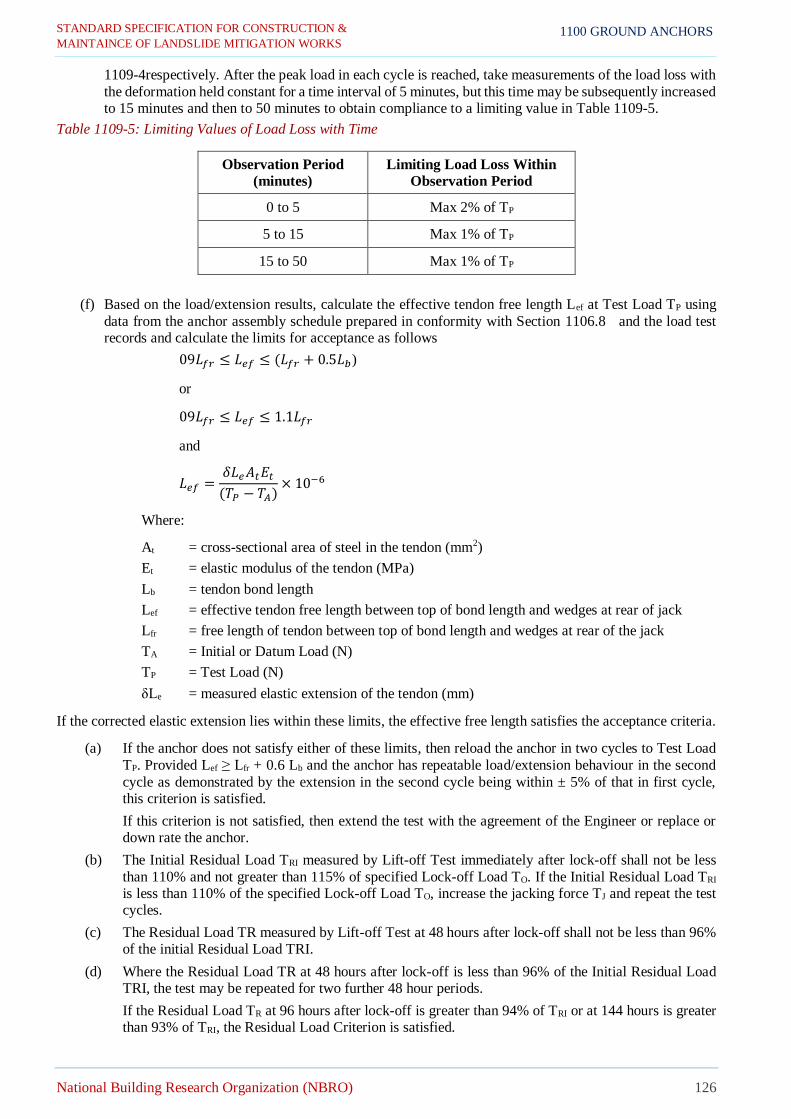
STANDARD SPECIFICATION FOR CONSTRUCTION &
MAINTAINCE OF LANDSLIDE MITIGATION WORKS
National Building Research Organization (NBRO) 126
1100 GROUND ANCHORS
1109-4respectively. After the peak load in each cycle is reached, take measurements of the load loss with
the deformation held constant for a time interval of 5 minutes, but this time may be subsequently increased to 15 minutes and then to 50 minutes to obtain compliance to a limiting value in Table 1109-5.
Table 1109-5: Limiting Values of Load Loss with Time
Observation Period
(minutes)
Limiting Load Loss Within
Observation Period
0 to 5 Max 2% of TP
5 to 15 Max 1% of TP
15 to 50 Max 1% of TP
(f) Based on the load/extension results, calculate the effective tendon free length Lef at Test Load TP using
data from the anchor assembly schedule prepared in conformity with Section 1106.8 and the load test records and calculate the limits for acceptance as follows
09𝐿𝑓𝑟 ≤ 𝐿𝑒𝑓 ≤ (𝐿𝑓𝑟 + 0.5𝐿𝑏)
or
09𝐿𝑓𝑟 ≤ 𝐿𝑒𝑓 ≤ 1.1𝐿𝑓𝑟
and
𝐿𝑒𝑓 =𝛿𝐿𝑒𝐴𝑡𝐸𝑡(𝑇𝑃 − 𝑇𝐴)
× 10−6
Where:
At = cross-sectional area of steel in the tendon (mm2)
Et = elastic modulus of the tendon (MPa)
Lb = tendon bond length
Lef = effective tendon free length between top of bond length and wedges at rear of jack
Lfr = free length of tendon between top of bond length and wedges at rear of the jack
TA = Initial or Datum Load (N)
TP = Test Load (N)
δLe = measured elastic extension of the tendon (mm)
If the corrected elastic extension lies within these limits, the effective free length satisfies the acceptance criteria.
(a) If the anchor does not satisfy either of these limits, then reload the anchor in two cycles to Test Load
TP. Provided Lef ≥ Lfr + 0.6 Lb and the anchor has repeatable load/extension behaviour in the second
cycle as demonstrated by the extension in the second cycle being within ± 5% of that in first cycle, this criterion is satisfied.
If this criterion is not satisfied, then extend the test with the agreement of the Engineer or replace or down rate the anchor.
(b) The Initial Residual Load TRI measured by Lift-off Test immediately after lock-off shall not be less
than 110% and not greater than 115% of specified Lock-off Load TO. If the Initial Residual Load TRI is less than 110% of the specified Lock-off Load TO, increase the jacking force TJ and repeat the test cycles.
(c) The Residual Load TR measured by Lift-off Test at 48 hours after lock-off shall not be less than 96% of the initial Residual Load TRI.
(d) Where the Residual Load TR at 48 hours after lock-off is less than 96% of the Initial Residual Load TRI, the test may be repeated for two further 48 hour periods.
If the Residual Load TR at 96 hours after lock-off is greater than 94% of TRI or at 144 hours is greater than 93% of TRI, the Residual Load Criterion is satisfied.

STANDARD SPECIFICATION FOR CONSTRUCTION &
MAINTAINCE OF LANDSLIDE MITIGATION WORKS
National Building Research Organization (NBRO) 127
1100 GROUND ANCHORS
If this criterion is still not satisfied, extend the test with the agreement of the Engineer or replace or down rate the anchor.
1110 STRESSING
1110.1 Commencement of Stressing Operations
Do not stress anchors until all the grout of the anchor is at least fourteen (14) days old and the average compressive
strength of all the grout in the borehole is at least 25MPa.
1110.2 Safety Precautions
Take care during stressing to ensure the safety of all personnel engaged on the work and of other persons in the
vicinity.
Secure the jack in such a manner that it will be restrained should the grip on the tendon be lost. Do not allow any
person to stand behind the jack while tensioning is in progress. Operate the jacks, measure the extensions and
carry out any associated operations in a manner and from positions which ensure safety.
Erect “stressing in progress” signs and barricade off hazardous areas.
1110.3 Stressing Equipment
The stressing equipment shall have rated load and travel capacities greater than 90% of the specified minimum
breaking load and corresponding extensions of the ground anchor tendon.
The design of the jacking system shall allow the taking of accurate measurements conforming to Section 1110.4
.
Equip the pump with a site-regulated pressure overload relief valve to prevent tendon damage from over
tensioning.
All connections between the pump and the jack shall have a bursting pressure of at least four times the maximum
pump pressure rating.
Pressure gauges shall conform to the requirements of AS 1349 or equivalent. The diameter of the gauge shall not
be less than 150 mm and shall be of such a type which will allow visual reading to the nearest 0.5MPa.
When the tendon is stressed to 75% of its breaking load, the indicator shall be between 50% and 75% of the full-
scale reading.
Fit gauges with a snubber or similar device to protect them against sudden release of pressure.
When required for audit purposes, make available a master gauge for checking the gauge accuracy. Make
provision for attaching this gauge for audit purposes.
Inspect gauges before starting each stressing operation and if defective, replace immediately with another
calibrated gauge. Replace any gauge that has sustained hydraulic or other shock with another calibrated gauge.
Where a discrepancy occurs between the two pressure gauges, identify the defective gauge using the master gauge
and dispatch for re-calibration or replacement.
Alternatively, provide a pressure gauge as above and a digital load readout unit with up-to-date calibration to
safeguard against load monitoring errors.
Provide calibration certificates for each load cell, jack, pump and gauge or their combinations conforming to the
following for the Engineer’s approval before start the test:
(a) Jack, pump, and gauge combinations
i) Not more than six months old
ii) Separate certificates for each combination
iii) Each certificate accompanied with a pressure versus load curve for loading and unloading over the
full operating range.
(b) Load cells
Issued within the last fifty (50) stressing operations or not more 28 days old, whichever is less

STANDARD SPECIFICATION FOR CONSTRUCTION &
MAINTAINCE OF LANDSLIDE MITIGATION WORKS
National Building Research Organization (NBRO) 128
1100 GROUND ANCHORS
(c) Dial gauges
Not more than 12 months old.
(d) Flowmeters and pressure gauges used during water testing or grouting
Issued within the last 200 operations or not more than 90 days old, whichever is less
1110.4 Measurement
Measure movements of the jack relative to a datum within an accuracy of ± 2% of the calculated elastic extension of the tendon δLr at Test Load TP and measure tendon loads within an accuracy of ± 2% of Test Load TP using
instruments graduated or with digital readouts to achieve these accuracies.
Check measurements of extensions using the movement of the jack, both before and after lock-off.
1110.5 Wedges
Wedges shall not damage the tendons during successive loading and unloading of the tendons. Draw-in to the
permanent pre-stressing head shall take place only at lock-off.
During the testing or stressing of working anchors, allow no indents resulting from tendon gripping to form in the
tendon below the pre-stressing head and allow no damage to the corrosion protection.
Seat wedges on each strand prior to commencing stressing. Detect slippage of individual strands within each
anchorage by marking the strands with spray paint after applying the initial load.
1110.6 Preparatory Operations
Fill the cavity in the underhead zone at the top of the anchor with Corrosion Inhibiting Compound (CIC) before
installing the bearing plate.
After positioning the bearing plate, install the pre-stressing head making sure that wire or strand tendons are not
crossed within the free length. The bearing plate and tendon shall not be in contact. Locate the pre-stressing head
and tendon at the centre of the anchorage and borehole.
Where the bearing plate or anchorage has previously been cast in the concrete, compensate for any misalignment
of the plate or anchorage prior to stressing using purpose made shims below the pre-stressing head.
1110.7 Control of Stressing Operations
Stressing operations shall be carried out only by personnel with training and experience in this type of work.
Stress the anchors in the order indicated on the Design Drawings and in accordance with the applicable load test
of Section 1109 .
Stress all strands or wires in a tendon simultaneously and uniformly using a single jack. Apply the tension
smoothly at an even rate. On completion of stressing, release the jack gradually.
For multiple anchors, stress using multiple jacks, one at the head of each unit tendon. Hydraulically synchronise
the multiple jacks so that identical loads are applied simultaneously to each unit anchor. The unit anchor load
shall be the total ground anchor load divided by the number of unit anchors. Each unit anchor shall satisfy the
general anchor acceptance criteria.
Complete all anchor stressing without interruption in as short a time as possible.
Estimate the jacking force TJ from the required Lock-off Load TO based on the summation of:
(a) loss in pre-stress force due to elastic shortening (where applicable)
(b) draw-in; and
(c) anchorage friction.
The jacking force TJ shall not exceed 80% of the nominal minimum breaking load of the tendon for strands or
75% for bars, or the rated capacity of the stressing equipment, whichever is less, under any circumstances.
Complete and make available to stressing forms for each ground anchor, providing the following:
(i) identification of anchor
(ii) identification of jack and gauge
(iii) identification of load readout unit where applicable
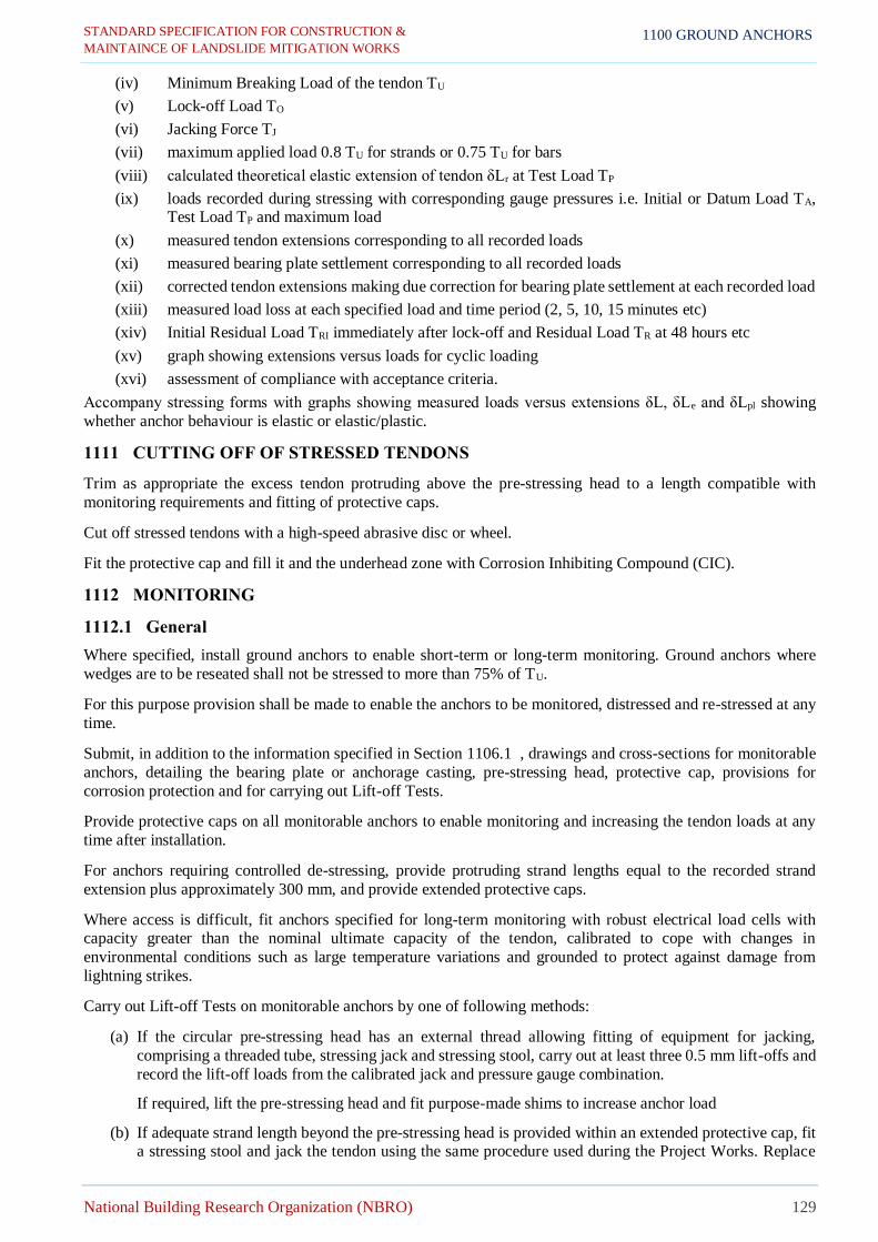
STANDARD SPECIFICATION FOR CONSTRUCTION &
MAINTAINCE OF LANDSLIDE MITIGATION WORKS
National Building Research Organization (NBRO) 129
1100 GROUND ANCHORS
(iv) Minimum Breaking Load of the tendon TU
(v) Lock-off Load TO
(vi) Jacking Force TJ
(vii) maximum applied load 0.8 TU for strands or 0.75 TU for bars
(viii) calculated theoretical elastic extension of tendon δLr at Test Load TP
(ix) loads recorded during stressing with corresponding gauge pressures i.e. Initial or Datum Load TA, Test Load TP and maximum load
(x) measured tendon extensions corresponding to all recorded loads
(xi) measured bearing plate settlement corresponding to all recorded loads
(xii) corrected tendon extensions making due correction for bearing plate settlement at each recorded load
(xiii) measured load loss at each specified load and time period (2, 5, 10, 15 minutes etc)
(xiv) Initial Residual Load TRI immediately after lock-off and Residual Load TR at 48 hours etc
(xv) graph showing extensions versus loads for cyclic loading
(xvi) assessment of compliance with acceptance criteria.
Accompany stressing forms with graphs showing measured loads versus extensions δL, δLe and δLpl showing
whether anchor behaviour is elastic or elastic/plastic.
1111 CUTTING OFF OF STRESSED TENDONS
Trim as appropriate the excess tendon protruding above the pre-stressing head to a length compatible with
monitoring requirements and fitting of protective caps.
Cut off stressed tendons with a high-speed abrasive disc or wheel.
Fit the protective cap and fill it and the underhead zone with Corrosion Inhibiting Compound (CIC).
1112 MONITORING
1112.1 General
Where specified, install ground anchors to enable short-term or long-term monitoring. Ground anchors where
wedges are to be reseated shall not be stressed to more than 75% of TU.
For this purpose provision shall be made to enable the anchors to be monitored, distressed and re-stressed at any
time.
Submit, in addition to the information specified in Section 1106.1 , drawings and cross-sections for monitorable
anchors, detailing the bearing plate or anchorage casting, pre-stressing head, protective cap, provisions for
corrosion protection and for carrying out Lift-off Tests.
Provide protective caps on all monitorable anchors to enable monitoring and increasing the tendon loads at any
time after installation.
For anchors requiring controlled de-stressing, provide protruding strand lengths equal to the recorded strand
extension plus approximately 300 mm, and provide extended protective caps.
Where access is difficult, fit anchors specified for long-term monitoring with robust electrical load cells with capacity greater than the nominal ultimate capacity of the tendon, calibrated to cope with changes in
environmental conditions such as large temperature variations and grounded to protect against damage from
lightning strikes.
Carry out Lift-off Tests on monitorable anchors by one of following methods:
(a) If the circular pre-stressing head has an external thread allowing fitting of equipment for jacking,
comprising a threaded tube, stressing jack and stressing stool, carry out at least three 0.5 mm lift-offs and
record the lift-off loads from the calibrated jack and pressure gauge combination.
If required, lift the pre-stressing head and fit purpose-made shims to increase anchor load
(b) If adequate strand length beyond the pre-stressing head is provided within an extended protective cap, fit a stressing stool and jack the tendon using the same procedure used during the Project Works. Replace

STANDARD SPECIFICATION FOR CONSTRUCTION &
MAINTAINCE OF LANDSLIDE MITIGATION WORKS
National Building Research Organization (NBRO) 130
1100 GROUND ANCHORS
the extended protective cap following the testing to permit continued monitoring or to fit purpose-made
shims or to carry out tendon distressing
(c) If at least 150 mm strand has been left beyond the pre-stressing head beneath the protective cap, check
loads in individual strands using a coupler, stressing stool and calibrated monojack.
Note that controlled de-stressing of anchors is only possible using Method 2.
1112.2 Short Term Monitoring
Until the Date of Construction Completion and during defect liability period, the Contractor shall monitor the anchors which have been subjected to Suitability Testing, anchors fitted with a load cell and 10% of the remaining
anchors. Type and location of the latter anchors will be decided by the Engineer and will depend on Acceptance
Test results and the subsurface conditions revealed during excavation.
The monitoring frequency shall be as follows (after the date of completing the relevant stressing procedure under
Section 1110 for each anchor); 7 days, 14 days, 1 month, 6 months and thereafter at 6 monthly intervals.
Inspect and report on the condition of the ground or structure at the anchor, the protection cap and corrosion
protection, the pre-stressing head and the tendon.
After the inspection, measure the Residual Load TR by Lift-off Test or direct reading of load cells.
Recalibrate, repair or replace at the Contractor’s expense any load cell and associated equipment that is defective
and/or results in unreliable readings. Measure by Lift-off Test the residual load where readings from a load cell
are not reliable.
Reinstate the corrosion protection and replace the protective cap.
Shall the Residual Load TR vary by more than ± 10% of the Initial Residual Load TRI measured immediately after
lock-off, inform the Engineer immediately.
Submit monitoring records for each anchor within three days of completing the monitoring to the Engineer.
1112.3 Long Term Monitoring
For the purpose of long term monitoring one electrical load cell shall be fitted as a part of the anchorage assembly
for at least one anchor in fifty and any anchors considered critical by the Engineer.
The maximum capacity of any individual load cell shall be in excess of the stated ultimate capacity of the anchor
to which it is fitted.
Submit for all the anchors information from load indicators and read-outs, together with measurement units and range, reading accuracy, long-term error, and the calibration procedures and sites for each item of the monitoring
equipment.
1113 MEASUREMENT AND PAYMENT
1113.1 Measurement
Platform
Temporary works, such as temporary platform preparation prior to soil nailing shall be paid as a Lump sum item
as indicated in the Bills of Quantities. Payment shall be made as;
60% of the lump sum under this item shall be certified upon the establishment of temporary platform for soil nailing works. 30% of the amount upon progress of soil nailing works as approved by the Engineer and the
remaining 10% shall be paid when the temporary platform has been totally removed and site has been cleaned by
the Contractor.
Ground Anchors
Ground anchoring work: the measurement shall include for drillings, tendons, ducts, bearing plates, grouting and other accessories. Quantity shall be measured by the linear meter along the anchor starting from bottom face of
the anchor head (commencing ground surface) to the tip of the anchor. No payment shall be made for the anchor
inside the anchor head.

STANDARD SPECIFICATION FOR CONSTRUCTION &
MAINTAINCE OF LANDSLIDE MITIGATION WORKS
National Building Research Organization (NBRO) 131
1100 GROUND ANCHORS
Concrete Facing
Anchor facing made of concrete shall be measured in cubic meter including excavation, form work,
reinforcement bars in-situ concrete C30/20.
Proof Test
Proof tests shall be measured in numbers and proof tests are required for anchors prior to the commencement of
work for design verification and acceptance of construction work at site. Proof tests shall be performed for 1% as
test anchors of the total number of working anchors or subject to a minimum of two and whichever is greater.
Suitability Test
Suitability tests shall be measured in numbers and suitability tests are required for permanent anchors for design
verification and acceptance of construction work at site. Suitability tests shall be performed for 2% as test anchors
of the total number of working soil nails subject to a minimum of three (3) and whichever is greater.
Acceptance Test
Acceptance tests shall be measured in numbers and acceptance tests are required for permanent anchors for design
verification and acceptance of construction work at site. Acceptance tests shall be performed all remaining
anchors.
1113.2 Payment
Ground Anchors
The quantities determine for anchors as provided above shall be paid for at the Contract unit rate which price shall
be full compensation for all labour, materials, tools and incidentals necessary for completion of the work including drilling, drilling through incidental boulders, fabrication and installation of all accessories for anchors nails and
grouting.
Concrete Facing
The quantities determine for anchor facing including as provided above shall be paid for at the Contract unit rate
which price shall be full compensation for all labour, materials, tools and incidentals necessary for completion of the work including preparation of slope, formwork, reinforcement, concreting required for concrete facing
construction and fabrication and installation of all accessories of the anchor head.
Pay Item Description Pay Unit
701(1) Temporary working platform for soil nailing works Lump Sum
1101(2)a Ground anchors (up to 12 m length) inserted into bore hole with grouting and
if required coupling (specify the nail dia. and hole dia.). Linear meter
1101(2)b Ground anchors (12 m - 24 m length) inserted into bore hole with grouting and if required coupling (specify the nail dia. and hole dia.).
Linear meter
1101(2)c Ground anchors (more than 24 m length) inserted into bore hole with grouting
and if required coupling (specify the nail dia. and hole dia.). Linear meter
1101(3) Concrete facing – C30/20 (including form work, reinforcement) Cubic meter
1101(4)a Proof test Number
1101(4)b Suitability test Number
1101(4)c Acceptance test Number

STANDARD SPECIFICATION FOR CONSTRUCTION &
MAINTAINCE OF LANDSLIDE MITIGATION WORKS
National Building Research Organization (NBRO) 132
1200 ROCKFALL PROTECTION
1200 ROCKFALL PROTECTION
1201 ROCK FENCE
1201.1 Description
This work shall consist of construction of barrier fenceto protect the identified vulnerable area at the downslope against falling rock. The fence shall satisfy required strength and heightas specified in the Drawings /
Specification.
All materials shall be accordance with the standards given in this Specification unless otherwise accepted by the
Engineer. Valid Material Test Certificate (MTC) shall be submitted by the Contractor prior to supplying of the
materials.
Contractor shall submit full scale test certificates, MTC, technical data sheets, system drawings and foundation forces to the Engineer 28days before commencement of rock fence work, in case he wishes to use a different
dynamic fence system to what specified in the Drawings/ Specification. Alternative dynamic fence systems with
full scale test certifications from an acceptable source which satisfies the required energy, height and post spacing
requirement may be used as approved by the Engineer.
When an alternative proposal for the fence system is submitted by the Contractor, required foundation details with
calculation shall also be submitted along to the Engineer for approval. Where an alternative fence system is
permitted by the Engineer, Contractor shall adhere to the manufacturers guideline for the installation of the
particular system unless otherwise specified.
1201.2 Materials
Unless otherwise recommended by the manufacturer and accepted by the Engineer, all material shall conform to
the following requirements. The requirements herein may vary as per the manufacturer of the fence components
as approved by the Engineer upon submission of valid MTC and technical data sheets acceptable to the Engineer.
a. Primary Net
Rope net shall satisfy the requirements of Table 1201-1, unless otherwise approved by the Engineer. All components used such as shackles and sewing ropes shall be of the types recommended by the manufacturer of
the net/ mesh unless otherwise specified. Net wires/ropes shall be in accordance with EN 12385-4.
Table 1201-1: Properties of Primary Rope Net
Property Requirement
Mesh opening size (nominal) 150mm (max)
Rope diameter (nominal) 7mm (min)
Lacing rope diameter (nominal) 8mm (min)
Shackle size (nominal) 3/8” (seam), 1/2” (lacing rope) S275JR to EN 10025
Tensile strength of mesh (nominal) 300kN/m (min)
Corrosion protection Zn or ZnAl (Class A), EN 10244-2
Clamps breaking load shall be at least 1.5 times the breaking load of the steel
ropes
b. Secondary Net
In the case where an alternative system is used as approved by the Engineer, and the smallest opening size>250mm
in the proposed alternative net, a secondary net of following criteria shall be used in addition to the primary net.
Twisted hexagonal mesh shall satisfy the following requirements of Table 1201-2, unless otherwise approved by
the Engineer. All components used such as shackles and sewing ropes shall be of the types recommended by the manufacturer of the net/ mesh unless otherwise specified. Mesh shall be in accordance with ASTM A975 (EN
10223-3).

STANDARD SPECIFICATION FOR CONSTRUCTION &
MAINTAINCE OF LANDSLIDE MITIGATION WORKS
National Building Research Organization (NBRO) 133
1200 ROCKFALL PROTECTION
Table 1201-2: Properties of Secondary Net
Property Requirement
Mesh opening size (nominal) 85mm (max)
Wire diameter (nominal) 2.2mm (min)
Tensile strength of mesh 40kN/m (min)
Corrosion protection Galvanized &PVC coated to ASTM A975
c. Ropes
Wire ropes shall be used to hold the mesh in-between the posts as given in the Drawings. Ropes shall be in
accordance with EN 12385-4 or equivalent acceptable to the Engineer. Ropes shall conform to the requirements
of Table 1201-3.
Table 1201-3: Properties of Wire Ropes
Rope Element Nominal Tensile
strength (MPa)
Nominal Rope
Diameter (mm) Corrosion Protection
Top & Bottom support rope
1750(min) 18 (min) Zn or ZnAl (Class A) EN 10244-2
Middle rope 1750(min) 18(min) Zn or ZnAl (Class A) EN 10244-2
Side stabilization rope 1750(min) 12(min) Zn or ZnAl (Class A) EN 10244-2
Brake elements used on each rope shall be selected from products purposefully made for dissipating the energy
of impact exerted in the ropes. Brake elements shall be a model/type produced to be used in rock fences of similar
capacity and rope arrangement as specified.
d. Posts
Posts shall satisfy the properties given in Table 1201-4. All the components required to fix other components such
as ropes, shackles and clamps of the fence shall be connected to the post as shown in the Drawings. All fabricated components where welded shall conform to BS EN 1090-2 and hot dip galvanized to the same standard as the
post as specified to a continuous coating. Welding, where required shall be carried out with suitable manipulators
and sequence for the work, which shall be subject to the Engineer’s approval before welding is commenced.
Surfaces preparation shall be properly carried out in accordance with the specified standards. Approval of welding
procedure shall not relieve the Contractor of his responsibility for delivering proper weld.
Table 1201-4: Properties of Posts
Detail Requirement Detail
Post type HEB 180 (or equivalent) S275JR steel to EN 10025
Corrosion protection Hot-dip galvanized minimum coating thickness of 85 micro-meters or 600 g/m2 to
AS/NZS 4680 or BS EN ISO 1461
Connection to the base plate Fixed Fillet welded both sides 8mm (min) thickness
Fillet welded both sides 8mm thickness to BS EN 1090-2
Spacing 5m (max)
e. Wire rope grips, Clamps or U-bolts
The wire rope grips (U-bolts) shall always be put on over the end of the rope that is not subject to stress, the dead
end of the ropes shall be left unclamped as shown in the drawings. Clamps shall conform to EN 13411-5.The screw bolt material shall be property class 6.8 in accordance with BS EN ISO 898-1. Testing in accordance with
EN ISO 898-1.
f. Shackles
Screw Pin Anchor or Chain Shackles Galvanized, and steel S275JR to EN 10025.
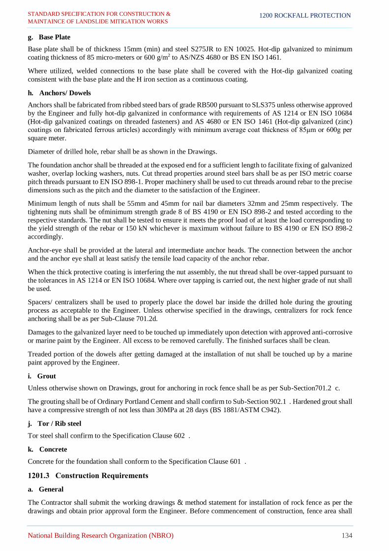
STANDARD SPECIFICATION FOR CONSTRUCTION &
MAINTAINCE OF LANDSLIDE MITIGATION WORKS
National Building Research Organization (NBRO) 134
1200 ROCKFALL PROTECTION
g. Base Plate
Base plate shall be of thickness 15mm (min) and steel S275JR to EN 10025. Hot-dip galvanized to minimum
coating thickness of 85 micro-meters or 600 g/m2 to AS/NZS 4680 or BS EN ISO 1461.
Where utilized, welded connections to the base plate shall be covered with the Hot-dip galvanized coating
consistent with the base plate and the H iron section as a continuous coating.
h. Anchors/ Dowels
Anchors shall be fabricated from ribbed steed bars of grade RB500 pursuant to SLS375 unless otherwise approved
by the Engineer and fully hot-dip galvanized in conformance with requirements of AS 1214 or EN ISO 10684
(Hot-dip galvanized coatings on threaded fasteners) and AS 4680 or EN ISO 1461 (Hot-dip galvanized (zinc) coatings on fabricated ferrous articles) accordingly with minimum average coat thickness of 85μm or 600g per
square meter.
Diameter of drilled hole, rebar shall be as shown in the Drawings.
The foundation anchor shall be threaded at the exposed end for a sufficient length to facilitate fixing of galvanized
washer, overlap locking washers, nuts. Cut thread properties around steel bars shall be as per ISO metric coarse
pitch threads pursuant to EN ISO 898-1. Proper machinery shall be used to cut threads around rebar to the precise
dimensions such as the pitch and the diameter to the satisfaction of the Engineer.
Minimum length of nuts shall be 55mm and 45mm for nail bar diameters 32mm and 25mm respectively. The
tightening nuts shall be ofminimum strength grade 8 of BS 4190 or EN ISO 898-2 and tested according to the
respective standards. The nut shall be tested to ensure it meets the proof load of at least the load corresponding to the yield strength of the rebar or 150 kN whichever is maximum without failure to BS 4190 or EN ISO 898-2
accordingly.
Anchor-eye shall be provided at the lateral and intermediate anchor heads. The connection between the anchor
and the anchor eye shall at least satisfy the tensile load capacity of the anchor rebar.
When the thick protective coating is interfering the nut assembly, the nut thread shall be over-tapped pursuant to
the tolerances in AS 1214 or EN ISO 10684. Where over tapping is carried out, the next higher grade of nut shall
be used.
Spacers/ centralizers shall be used to properly place the dowel bar inside the drilled hole during the grouting
process as acceptable to the Engineer. Unless otherwise specified in the drawings, centralizers for rock fence
anchoring shall be as per Sub-Clause 701.2d.
Damages to the galvanized layer need to be touched up immediately upon detection with approved anti-corrosive
or marine paint by the Engineer. All excess to be removed carefully. The finished surfaces shall be clean.
Treaded portion of the dowels after getting damaged at the installation of nut shall be touched up by a marine
paint approved by the Engineer.
i. Grout
Unless otherwise shown on Drawings, grout for anchoring in rock fence shall be as per Sub-Section701.2 c.
The grouting shall be of Ordinary Portland Cement and shall confirm to Sub-Section 902.1 . Hardened grout shall
have a compressive strength of not less than 30MPa at 28 days (BS 1881/ASTM C942).
j. Tor / Rib steel
Tor steel shall confirm to the Specification Clause 602 .
k. Concrete
Concrete for the foundation shall conform to the Specification Clause 601 .
1201.3 Construction Requirements
a. General
The Contractor shall submit the working drawings & method statement for installation of rock fence as per the
drawings and obtain prior approval form the Engineer. Before commencement of construction, fence area shall

STANDARD SPECIFICATION FOR CONSTRUCTION &
MAINTAINCE OF LANDSLIDE MITIGATION WORKS
National Building Research Organization (NBRO) 135
1200 ROCKFALL PROTECTION
be surveyed to determine the precise path of the fence. Precise fence installation path’s geometric data with
foundation level details shall be submitted to the Engineer for approval.
It may not always be possible to comply with the standard drawings due to the minor variations in the found.
Contractor shall make small adjustments to the cross-section or length of nets, ropes, posts, etc. as approved by
the Engineer to ensure the intended functioning of the fence.
b. Foundation
Prior to planting the fence posts in the required manner, the ground shall be graded where necessary, so as to
provide a neat appearance of the fence line. The foundation for posts shall be prepared as shown in the Drawings
or as instructed by the Engineer. The ground at the foundation shall be graded inclined approximately 5° downslope. The rock fence system shall be installed after the foundation concrete (if any) has reached at least 7-
days strength.
Steps to follow during the construction of post foundation in each soil conditions shall be as follows unless
otherwise approved by the Engineer. In any case the foundation shall be inclined approximately 5° downslope.
On soil ground:
Drill holes for anchors as specified, set out and prepare ground and reinforce the concrete foundations, insert the anchors, spacers, and fastening nuts; anchor length shall be as per the drawings, using grout, fix the anchors in
place in the ground, fill in the concrete foundation, place the base plate/ post and tighten the fastening nuts once
the concrete and grout has reached at least 7-days strength.
On rock ground:
Drill holes for anchors into the rock at a right angle to the base plate, using grout, fix the anchors in place, a thin
grout or C25/20 concrete levelling layer is intended to guarantee that the base plate of the post has a sturdy seat,
position the post and base plate on grout levelling layer, Tighten the fastening nuts once the grout has reached at
least 7-days strength.
c. Ropes
A support rope separation shall contain an intermediate anchoring as per the drawings. In typical terrain conditions
Intermediate anchoring shall be provided after approx. 60m unless otherwise accepted by the Engineer.
The support and lateral bracing ropes shall be connected to the correct anchors. The correct number of wire rope
grips (U-bolts) shall be attached to the ends of the ropes. All ropes shall be installed using thimbles and wire rope grips as per the appended table. The grips shall be put over the end of the rope that is not subject to stress, the
dead end of the ropes shall be left unclamped as shown in the drawings. The wire rope grips shall be fastened as
specified. The bolt of the shackle shall be installed so that the bolt is always on the top.
d. Net
The net shall be correctly fastened to the support ropes via lacing ropes and shackles as per the Drawings to the satisfaction of the Engineer. The nets shall be connected to each other as per the Drawings. The sag of the top
support rope shall be less than 3% of the distance between the posts.
All ropes, nets, shackles and wire rope grips shall be visually inspected for defects prior to their use. Any defective
components should be discarded. Damages to the Hot-dip galvanized layer of any component need to be touched up immediately upon detection with approved anti-corrosive or marine paint by the Engineer. All excess to be
removed carefully. The finished surfaces shall be clean.
e. Anchors/ Dowels
Lateral, intermediate and post foundation anchors shall be as shown in drawings and conform to Table 1201-5.
Table 1201-5: Anchor/Dowel Requirements
Anchor type Bar diameter (mm) Hole diameter (mm) Length (m)
Post foundation anchor (3 nos) 32 100 3(min) into hard rock
Lateral anchor 25 100 3(min) into hard rock
Intermediate anchor 25 100 3(min) into hard rock
For lateral and intermediate anchors, anchor eyes shall be attached if not prefixed.

STANDARD SPECIFICATION FOR CONSTRUCTION &
MAINTAINCE OF LANDSLIDE MITIGATION WORKS
National Building Research Organization (NBRO) 136
1200 ROCKFALL PROTECTION
Reinforcement shall be clean and free from loose rust and mill scale, dirt, oil, grease and paint at the time of fixing
in position and subsequent grouting. Reinforcement shall be handled and stored in a manner that will prevent
deformation.
Drilling for Anchors
All dowels shall be installed in bore holes drilled through the hard rock as identified by the Engineer at Site for a minimum length of 3m to the standard diameter specified in the drawings. Drilling of anchor holes shall be in the
pulling direction, with a minimum angle of > 15° to the horizontal.
Holes for galvanized dowels/ anchors shall be minimum 100 mm in diameter or as shown on the Drawings.
During the drilling operation, the ground conditions encountered on a drill hole log together with all changes in
ground type and notes on water levels encountered and drilling rates shall be recorded.
On completion of drilling, the drill hole shall be cleaned of all loose and deleterious material and protect or seal the drill hole opening to prevent the entry of foreign matter. Cleaning shall be carried out by flushing with air or
compressed air using side jet bits, so as to ensure removal of all drill cuttings from the walls and bottom of the
drill hole while avoiding excessive air pressure. Reinforcement shall only be installed in a clean hole free of debris
and foreign matter.
Unless otherwise approved by the Engineer, no drilling shall be carried out at a place within 10 m radius of any
freshly grouted anchors/ dowels, within 12 hours of the completion of grouting.
The drill holes for the anchors/ dowels shall be constructed within the following tolerances:
(e) Deviation in alignment of the drill hole shall not exceed 2°. Deviation from straightness shall not exceed
20 mm in any 3.0 m length of hole. Entry point of the drill holes shall be within ±10 mm of its design
position on the ground.
(f) The depth of the holes as shown in drawings shall be within a tolerance of – 0, +100 mm.
(g) An allowance for over drilling (600 mm maximum) should be added to the depth where debris cannot be removed from the bottom of the hole.
(h) The maximum deviation of the diameter of the drill holes from the design diameter is –0, +10 mm.
Insertion of Anchors
Dowels/ Anchors shall be installed as shown in drawings. All dowels shall be installed in bore holes drilled
through the hard rock as identified by the Engineer at Site for a minimum length of 3m to the standard diameter
specified in the drawings.
Prior to anchor installation, the drill hole shall be cleaned of debris by air flushing methods as stated above.
Insert anchors in one careful operation at a controlled rate to avoid dislodgment of material from the wall of the
drill hole and to ensure that centralizers and spacers are not displaced. If any damaged anchor or anchor with damaged galvanized coating during installation, shall be replaced. Insertion and grouting shall occur as soon as
practicable following drilling, but in any event shall be completed within 12 hours after completion of drilling.
Grouting shall not be carried out without prior approval of the Engineer.
Grout Mixing
Batching of the dry materials shall be by weight. Measure the amount of water used with a calibrated flow meter
or a measuring tank.
Grout shall be mixed by adding initially approximately two-thirds of cement to the water, followed by the additive if any, and then the remaining one-third of cement. Mixing shall be done for a sufficient time to produce a grout
of uniform consistency.
The grout mixing process shall utilize a recirculating system where the grout is continuously discharged and
recharged into the mixing unit during the mixing period. After mixing, grout shall be kept continuously agitated.

STANDARD SPECIFICATION FOR CONSTRUCTION &
MAINTAINCE OF LANDSLIDE MITIGATION WORKS
National Building Research Organization (NBRO) 137
1200 ROCKFALL PROTECTION
Grout shall be passed through a nominal 1.2 mm wire cloth/sieve to ensure a uniformly mixed grout prior to
injection. Grout shall be used as soon as possible after mixing and in any case within 30 minutes of adding cement,
unless approved retarding agents are used.
Any alternative mixing procedures proposed by the Contractor shall be approved by the Engineer before
application.
Grouting
Grout shall be injected through a grout tube to the bottom of the hole. The grout tubes shall have a minimum
internal diameter of 12 mm to ensure that blockages shall not occur during grouting operations and shall also be
sufficiently robust to ensure that they are not damaged during handling.
During the grouting operation, the grout shall displace all air and water and fill the hole in a continuous operation until the emerging grout is of the same consistency as the grout being pumped in. The grout level shall then be
checked by sitting for 5 minutes and top-up grout introduced if necessary, to ensure that the anchor is fully grouted.
Anchors shall be protected from accidental disturbance after grouting has been completed to ensure that damage
of the grout/soil and grout/anchor bond does not occur.
1201.4 Test and standards of acceptance
The materials shall be tested in accordance with these Specifications and standards prescribed therein accordingly
and shall meet the specified limits for acceptance.
The Contractor shall obtain approval from the Engineer for the full-scale test certificates and manufacturer
specification including technical data sheet of major components including but not limited to posts, ropes, nets,
anchors, and corrosion protection as acceptable to the Engineer, prior to supplying the material.
In addition, the Contractor shall submit valid Material Test Certificate (MTC) for steel sections, ropes, nets,
reinforcement, anchor materials, and connecting accessories acceptable to the Engineer during the supply of
material.
Tests carried out during construction shall conform to this Specification and shall be conducted as per the
prescribed standards and as directed by the Engineer.
1201.5 Measurement & Payment
Rock fence shall be measured in Linear meter along including fabrication, supplying and installation of rock fall
protection fence of specified height, energy criteria and post spacing. Fence length shall be measured from post base to base basis, the length between each post base shall be consider as a straight line and the fence components
that extend beyond the posts and path of the fence shall not be taken into consideration. No separate payment for
excavation, formwork, reinforcement, concrete and anchors will be made and all such costs shall be included in
rock fence rate.
The quantities determine for rock fence as provided above shall be paid for at the Contract unit rate which price
shall be full compensation for all labour, materials, tools and incidentals necessary for completion of the work
including provision of all components of the fence to the site, the Engineer’s inspection, testing, setting out the
location of the fence, excavation, drilling, collection of samples, the extra depth required to accommodate the cut-offs, slime etc., submission of drilling report, anchor installation, foundation construction, concrete and grout
testing, assembling and fixing the fence components to the satisfaction of the Engineer.
Payment shall be made after the Contractor has completed the works to the satisfaction of the Engineer. The
Contractor shall also submit all relevant quality assurance documents when applying for payment. Interim payments based on the proportion of work done maybe authorized by the Engineer provided that the Contractors
intention to complete the task as specified is clear.
The Pay Items and Pay Units shall be as follows:
Pay Item Description Pay Unit
1101(1)
Rock fence (specify the capacity and height parameters of the system)
including interception structure, support structure, connection
components, foundation, anchors and all necessary accessories.
Linear meter

STANDARD SPECIFICATION FOR CONSTRUCTION &
MAINTAINCE OF LANDSLIDE MITIGATION WORKS
National Building Research Organization (NBRO) 138
1300 INSTRUMENTATION AND MONITORING
1300 INSTRUMENTATION AND MONITORING
1301 INSTRUMENTATION
1301.1 General
This work shall consist of implementing of an automated landslide monitoring system at the landslide location by supplying, installing, maintaining and monitoring of monitoring equipment as specified. The centralized
monitoring station at NBRO is to receive and process the remote data and monitor the status of alarm posts
strategically located in the area and issue hazard warning through the alarm posts to the affected community. The
work shall be carried out in accordance with this Specification and in conformity with the Drawings or as directed
and under the technical instruction and inspection of the Engineer.
All supplied instruments shall be in accordance with the requirements given Specifications unless otherwise
accepted by the engineer. Valid technical data sheets of the supplied instruments shall be submitted by the
Contractor prior to supplying of the materials.
The complete landslide monitoring system is consisted of the following components which shall be
procured and installed by the Supplier under the guidance of the Engineer.
1) Central Monitoring and Recoding Station software
2) Network of monitoring instruments consisted of one or more of the following monitoring instrument types: Electronic Extensometers, Inclinometers, Automated Rain Gauges and Water Level Gauges
installed in the selected landslide susceptible area connected to on-site Central Unit or recording station.
The data collected by the Central Unit shall be transferrable Central Monitoring Station via GSM/GPRS
network.
3) Alarm posts with strobe light and buzzer placed at strategic locations connected to Central Monitoring
Station via GSM/GPRS network.
4) Long range night vision surveillance camera system
The instruments shall be supplied with all other auxiliary components required to automatically log and store
monitored data on-site and transmit them to Central Monitoring Station to set off an alarm on-site as well as
remotely through a GPRS/GSM enabled web data monitoring system.
The schematic representation of the required landslide monitoring system is illustrated in Figure 1301-1.
Figure 1301-1: Schematic representation of a landslide monitoring system

STANDARD SPECIFICATION FOR CONSTRUCTION &
MAINTAINCE OF LANDSLIDE MITIGATION WORKS
National Building Research Organization (NBRO) 139
1300 INSTRUMENTATION AND MONITORING
1301.2 Materials
Unless otherwise recommended by the manufacturer and accepted by the Engineer in case of an obsoleting of
inherent technology or similar reason, all supplied instruments shall conform to the following requirements. All monitoring instruments shall be accepted after checking and certifying the accuracy of the function of the unit by
the qualified team appointed by the Engineer.
a. Central Unit
A Central Unit or recording unit shall be installed at each site at the location specified in the Drawings or as specified by the Engineer. The function of this unit is to accumulate the data from each instrument installed at the
site through their respective data loggers and transfer the accumulated data to the Central Monitoring Station
through GPRS/GSM technology. As ground movement can be envisaged at landslide susceptible areas, the
connection between the individual instruments and the Central Unit shall be maintained wireless and unaffected by the elements of weather or loss of connection. Real-time data collected at the site from all instruments shall be
readable and downloadable at the unit. Further, a suitable protective enclosure shall be provided to encase the unit
to prevent effect from adverse weather and vandalism.
b. Insertion-type Inclinometer
The main function of the insertion-type inclinometer is to measure inclination angle at required depth intervals
with the aid of an inclinometer probe.
The insertion-type inclinometer provided by the Supplier shall consist of inclinometer probe, cable, and data read-
out device to read from the sensor as well as compatible software to process data from the read-out for plotting
purposes. The inclinometer probe, cable and data read-out device along with the associated software shall be from
a single manufacturer to avoid compatibility issues.
Inclinometer Casing/ Guide Pipe
The inclinometer casing, through which the inclinometer probe will be driven down to required depth intervals,
shall be of a diameter suitable for landslide monitoring, for long term and higher degrees of deformations having a minimum outer diameter of 48 mm (1.90 inch). Machine-broached grooves shall be present in the casing for
inclinometer probe insertion. Inclinometer casing and all other components shall be made of ABS plastic or
aluminum. Other components shall include top cap and bottom cap, rechargeable battery powered hand drill with
tools to secure guide pipe and socket while sealant tape and vinyl tape or a suitable alternative approved by the
Engineer shall be provided to completely seal off the socketed joints.
ABS and aluminum inclinometer casing and connections are shown in Figure 1301-2 and Figure 1301-3,
respectively.
Figure 1301-2: ABS inclinometer casing, diameter in mm

STANDARD SPECIFICATION FOR CONSTRUCTION &
MAINTAINCE OF LANDSLIDE MITIGATION WORKS
National Building Research Organization (NBRO) 140
1300 INSTRUMENTATION AND MONITORING
Figure 1301-3: Aluminum inclinometer casing and connections
The length of inclinometer casing shall extend to stable ground such as rock or stiff soil beyond the displacement zone to serve as a stable reference datum, a minimum of 5m below the anticipated zone of movement or as directed
by the Engineer. A lockable iron protection box shall be supplied to the exposed portion of casing to prevent
vandalism and accidental damage.
Inclinometer Sensor and Cable
The inclinometer probe shall be capable of providing readings in two mutually perpendicular directions at every
0.5m depth intervals.
The probe cable of minimum 50 m length shall be specially designed to be durable, waterproof, non-stretch, non-
shrink with a high torque resistance.
Data Logger
A data acquisition unit shall be supplied accompanied by data reduction software to display and record the measurement data at each depth interval. The read-out device shall contain a rechargeable power supply and be
capable of storing many data sets and able to perform field checks to verify the validity of the measurements. A
custom-made computer software shall be incorporated to facilitate the communication between the data
acquisition unit and Central Monitoring Station.
Table 1301-1: Specifications for the inclinometer sensor and data logger
Item Description
1 Seismic resistance Approximately 30 ms2
2 Impact resistance Approximately 50 ms2
3 Duration of continuous usage With Alkaline battery approximately 10 hours
4 Temperature 0 – 50 0C

STANDARD SPECIFICATION FOR CONSTRUCTION &
MAINTAINCE OF LANDSLIDE MITIGATION WORKS
National Building Research Organization (NBRO) 141
1300 INSTRUMENTATION AND MONITORING
5 Sensor Weight Approximately 3kg
6 Weight of data logger Approximately 800g
7 Weight of cable Approximately 13kg
8 Software for data analysis Software for the analysis of inclinometer data with
respect to rainfall data.
c. In-place Inclinometer
In-place type inclinometer system shall consist of an inclinometer casing and one or more inclinometer sensors
permanently positioned at depths specified by the Engineer and associated with a suitable automatic data
acquisition system to facilitate continuous monitoring.
Inclinometer Casing/ Guide Pipe
The Specification for guide pipe specified in Section 1301.2 b. applies for the in-place inclinometers supplied.
Inclinometer Sensor and Cable
The housing of the sensor shall be made of stainless steel with diameter compatible with the guide pipe. Other
specifications of the sensor are as tabulated in Table 1301-2.
Table 1301-2: Specifications for the in-place inclinometer sensor
Data Logger
The Specification for Data Logger specified in Section 1301.2 b. shall apply for the in-place inclinometers
supplied.
d. Extensometer
The function of the extensometer is to measure the expansion of surface tension crack of landslides and the
instrument shall include data loggers installed separately at each location, internal automatic data recording
system, extraction of recorded data using external monitoring device, issuing alarm system, manually re-
programmable if required, displaying of current reading and functions.
The instruments shall be wire-line type extensometers. All the required accessories for the installation shall be provided by the Supplier. The instruments shall be battery powered and supplied with a compatible read-out
device and linked to the web-based monitoring system for continued, unattended and real-time monitoring along
with alarm output facility. The Supplier shall install user-friendly software for communication between the instrument and the central server at NBRO Head Office. The sensor type shall be precision potentiometer. The
station shall detect any cable breakage conditions encountered at the site and transmit an alarm to the central
station.
Major components of the instrument shall include fixing plate, data logger, communication port, alarm output,
contact terminal, battery (main & sub batteries) with terminal back cover, battery holder, SD card slot, card slot
cover, liquid crystal display, menu buttons, measurement wire, invar wire connection ring.
The instruments shall be battery powered for a continuous operational capacity with a minimum of 1 year. 48-
hour battery life shall be present without solar power recharge. If battery exhausts within the guaranty period, the
supplier shall replace with new batteries.
The instrument enclosure shall be designed to be suitable for outdoor installation being waterproof and in-built lightning protection system as well as static electricity resistance. A protective cover / fences for the instrument
as well as the housing box including the data logger shall be provided by the Supplier to prevent vandalism.
Resolution + 2 arc sec. or + 0.02 mm/m
Accuracy + 10 arc sec. or + 0.05 mm/m
Operation Temperature 0 - 80 0C

STANDARD SPECIFICATION FOR CONSTRUCTION &
MAINTAINCE OF LANDSLIDE MITIGATION WORKS
National Building Research Organization (NBRO) 142
1300 INSTRUMENTATION AND MONITORING
Extensometer Cable
A suitable mechanism shall be applied to prevent sag of the cable as approved by the Engineer. The cable shall
be made of non-corrosive heat resistant material. The other specifications for the extensometer cable are as
tabulated in Table 1301-3.
Table 1301-3: Specifications for the extensometer cable
Minimum length 30m
Cable diameter Approximately 0.5mm
Heat resistance 0.5 x 10⁻⁶ mm/oC
Wire Tension Approx. (17 – 20) N
Data Logger and Readout Device
All extensometers shall include a suitable and compatible data recording facility either in-built or externally as a data logger. The data recording system will have a minimum storage capacity of 32GB and shall be programmable
to collect data at desired time intervals as defined by the Engineer. The data stored shall be downloadable to a PC
card at site and transferred to the Central Monitoring Station for real-time remote data collection. Additionally, it shall consist of a dial gauge or similar mechanism for visual indication of the amount of displacement of the
stainless-steel cable from the initial setting. The other specification of the data logger is as tabulated in Table
1301-4.
Table 1301-4: Specifications for the data logger and readout device for extensometer
Protection box To protect the extensometer data logger by extreme weather condition. (timber made)
Current consumption Minimum 03 months
External dimension Less than (150 h x 150 w x 250 l) mm
Weight Less than 1700 g
Measurement range (0 – 1000) mm
Display range + (1000 – 2000) mm
e. Water Level Gauge
Internal diameter of the perforated PVC pipe used for the installation shall be 50 mm with the minimum thickness of 4 mm (Type 1000). All the instruments shall be battery powered with a minimum of 2 year battery life without
replacement. The sensor accuracy and resolution shall be 10 mm over 6 m range. Data loggers shall be supplied
to log and store data from each water level gauge. The Supplier shall install user-friendly software for
communication between the instrument and the central server at NBRO Head Office.
f. Piezometer
Internal diameter of the perforated PVC pipe used for the installation shall be 63 mm with the minimum thickness
of 4 mm (Type 1000). Depth of the Piezometer is as specified in the Contract or as instructed by the Engineer.
All the instruments shall be battery powered with a minimum of 2-year battery life without replacement. Data loggers shall be supplied with multiplexers to log and store data from all each water level gauge. The Supplier
shall install user-friendly software for communication between the instrument and the central server at NBRO
Head Office.
g. Automated Rain Gauge
Rain gauge shall consist of a sensor, a logger, and data transmission equipment. Logger and data transmission equipment are stored in a storage box. The Supplier shall install user-friendly software for communication
between the rain gauge and the central server at NBRO Head Office through the central unit installed at each site.
The Supplier shall install the rain gauges with storage capacity to store monitoring data of at least 10 years duration
and downloadable to a computer. The transferred data shall be able to be checked real-time at the NBRO.

STANDARD SPECIFICATION FOR CONSTRUCTION &
MAINTAINCE OF LANDSLIDE MITIGATION WORKS
National Building Research Organization (NBRO) 143
1300 INSTRUMENTATION AND MONITORING
Table 1301-5: Specifications for automated rain gauge
Operating environment Humidity: 0 to 100%,
Temperature: +5 °C to+70 ℃
Aperture φ20cm
Accuracy ± 0.5 mm at 50 mm/hr
Resolution 0.5 mm
General To be compatible with the automated monitoring system central unit Automatic reset with remote access facilities
Data logger
Observation interval: 10 minute during rainy time
Data storage: 10 years or more Interface: USB drive /SD card
Data transmission
Communication method: GSM /GPRS
Transmitting retry: unlimited
Resending function: Data of less than 3 hours
Transmitted data type ASCII
System enclosure
Corrosion free powder coated Aluminum enclosure with sufficient size to
store all sensors, battery and other equipment and protected from dust and humidity as per the manufacture’s recommendation. The box shall be
ventilated to prevent excessive heat build-up during day time.
Supporting pole
100 mm hollow GI pipe with metal fittings etc. to fix Storage box shall be included. The enclosure shall be mounted at 1.2 m height, the rain-gauge
mounted at 1.5 m height. After the installation all metal work shall be
painted with grey color anti-corrosive paint.
Fence and key
galvanized steel wire mesh with core diameter 3.2 mm and mesh opening size 50 mm
1,800 mm(W)×1,800 mm(D)×1,200 mm(H)
Lightning Arrester & grounding 10Ω or less should be common earth
Lightning protection for
common power & GSM modem
The Supplier shall install manufacture recommended lightning
protection accessories.
Solar battery system
The solar panels shall have sufficient capacity (Min. 40w) to operate the
complete system and charge the battery system. The battery system shall have sufficient storage capacity (24A) to interdependently operate the
system for 14 days with solar supply disconnected
The rain gauge shall have the capability to transmit rainfall data in user configurable time intervals to enable real
time monitoring of rainfall data. The transmitting interval of observational data shall be 10 minutes during the rainy time and 30 minutes interval for with no rainfall transmitted using the proposed data communication system.
The operational status of the rain gauge shall be able to be monitored remotely via the server. When transmission
of observational data goes wrong, transmission shall be retried three times. If the retrying fails, it shall be transmitted along with the next transmission of data after 10 minutes. This re-transmission shall include data of
the previous three hours.
Rain gauges shall have battery for data logger to observe and store the data for at least 1 year for cases whereby
transmissions are failed over the long term.
Data Storage
The Supplier shall adopt a newest Data Base Management System (DBMS). The DBMS shall be installed to save all of the observed rainfall data. The retention period of the data shall be more than 10 years. The data shall be
backed up using a backup function of a database. The backed-up data shall be saved to an external hard disk. The
backup shall be carried out automatically once per week. The data shall be stored in the server in such a way that

STANDARD SPECIFICATION FOR CONSTRUCTION &
MAINTAINCE OF LANDSLIDE MITIGATION WORKS
National Building Research Organization (NBRO) 144
1300 INSTRUMENTATION AND MONITORING
hourly, 6 hourly, 12 hourly, 24 hourly, monthly, yearly, etc. can be downloaded in ASCII format for analytical
purposes.
h. Hazard Warning Alarm Post
The alarm output function shall be a built-in system to give out alarms locally on site and remotely via a GSM
network. It shall have the facility to set warning-level threshold values, which shall be as defined by the Engineer. The signal transferring capability of the transmitter shall be so that it is received by a siren located a minimum of
1 km away from the instrument.
The hazard warning alarm posts shall consist of an electronic buzzer alarm, strobe light with green, red, amber
and blue high-power LEDs and modem. The position of buzzer, strobe light, other equipment and solar panel shall not be in a height less than 4 m from the ground level. A 100mm hollow squire GI pipe shall serve as the
equipment-mounting pole, with 300x300x300 mm concrete base. The whole structure shall be securely mounted
as directed by the Engineer.
The alarm post shall be powered with solar charger and battery backup system. The station shall function normally
for minimum of 14-day period with complete loss of power from the solar panel. The system shall acquire and
log the battery voltage and transmit to the central server every 5 minutes.
The system shall use the services of the best available GSM network at the location. The received signal (RSSI)
strength of the GSM/GPRS network shall be logged and transmitted along with battery voltage reading.
Each alarm pattern and strobe color is activated by an automatic or manual command sent from the central
monitoring station. The audio and visual color is coded to indicate the degree of hazard at present.
The alarms shall have a minimum sound radius of 2 km and designed suitable for outdoor operation. The installing locations of the sirens will be as decided by the Engineer at the site. The signal shall be sent to 4 sirens installed
alongside the road and at locations specified by the Engineer at the site.
The alarm post and all the components shall withstand the elements of weather and climate for expected life of
10 years with minimum maintenance. The Supplier shall give full details of how the expected the life is achieved.
The information may include details of material used, manufactures data sheets, test results etc.
i. Long Range Night Vision Camera
The outdoor surveillance cameras shall provide a coverage with an appropriate viewing angle as determined by
the Engineer according to the site conditions to monitor any landslide, slope failure or rock-fall activity real-time.
The viewing angle shall be able to be manually configured to cover the total affected area. The footage shall be of 720p or higher resolution with a compatible HD digital video recorder or other recording device. The camera
shall be incorporated with infrared (IR) technology for nighttime monitoring with a built-in IR cut-switch to
automatically enable or disable depending on the lighting condition. The night vision range shall be adequate to
observe minimum 100m. The camera shall be weatherproof and able to be mounted on a pole or similar arrangement in an angle decided by the Engineer. Appropriate arrangement shall be provided for protection
against vandalism.
Required Specification for Viewing angle, Range and Built-In IR cut switch given in the Table 1301-6 of Night
Vision Long Range Camera.
Table 1301-6: Specifications for night vision long range camera (Wired/Wireless)
Item (1) Required Specification (2)
Viewing Angle Vari-Focal
Range Up to 100 m
Built-In IR cut switch Yes
1301.3 Construction Requirements
The installation of the landslide monitoring system shall be carried out in accordance with the requirements
specified in this section and at locations shown in the Drawings unless otherwise specified by the Engineer.

STANDARD SPECIFICATION FOR CONSTRUCTION &
MAINTAINCE OF LANDSLIDE MITIGATION WORKS
National Building Research Organization (NBRO) 145
1300 INSTRUMENTATION AND MONITORING
a. Method Statement
The Contractor shall submit method statement for check boring and installation of each instrument type and obtain
prior approval from the Engineer for commencement of works at least 28 days prior. The Method Statement shall
clearly specify the method the Contractor proposes to carry out the installation works as per this Specification.
b. Check Boring
The Contractor shall carry out check boring with continuous sampling at locations specified in Drawings so as to
identify the slip surface depth, soil profiles and ground water levels, prior to the commencement of the works
under the supervision of the Engineer.
The check borings shall be drilled using rotary type boring machines and wash boring is not allowed. The diameter
of the holes shall be between 50 and 100 mm.
The Contractor shall carry out continuous sampling, logging and standard penetration tests at 1.0m intervals
during check boring as per BS 5930:2015.
Within 07 days of the completion of the drilling of each hole, the Contractor shall submit a drilling report and
borehole log to the Engineer, accurately describing the boundaries of the geological formations, water level in the
drill-hole etc. The format of the drilling report shall have the prior approval of the Engineer.
Previously specified locations of instruments and depths of installation may then be adjusted by the Engineer
based on the results obtained from the check boring.
c. Installation of instruments
Insertion type (Probe type) inclinometer Installation
At least one inclinometer probe/sensor with data logger complying with the specification requirements shall have to be delivered and available at the site before completion of drilling and installing inclinometer casings. Initial
reading shall be taken using the inclinometer sensor and data logger immediately after the installation of the casing
and settlement of grout mixture.
The depth of the borehole shall extend beyond the depth of shear zone down to the stable ground such as rock or
stiff soil beyond the displacement zone to serve as a stable reference datum, a minimum of 3m into the fresh bedrock as directed by the Engineer. The borehole diameter shall be sufficiently large to allow insertion of the
inclinometer casing and to ensure that the backfill can be accomplished around the entire annulus without leaving
voids or soft zones. The drilling method shall include measures to prevent borehole caving and the drill hole shall be completely flushed and cleaned to remove cuttings before casing installation. The inclinometer casing bottom
end of which fixed with the bottom cap shall be centered in the borehole to allow the backfill to completely
surround and support the casing. The installation shall be carried out so that the casing shall be subjected to
minimum distortion. Prior to backfilling, the casing shall be oriented so that a pair of grooves is in the expected direction of ground movement. The backfilling material shall be non-shrink grout. The borehole and inclinometer
casing shall be made as vertical as possible to minimize reading errors. The guide casing grooves shall be kept
clean during the installation process to avoid potential probe-tracking problems. After backfilling top cap shall be
fixed on the casing.
In-place inclinometer Installation
In-place inclinometers shall be installed once the zone(s) of movement has been identified and confirmed by the
Engineer through check boring and verified through monitored data from insertion type inclinometer data at the
site at least for a period of one rainy season. The installation of casing shall follow the installation process
specified for insertion-type inclinometer casing.
The casing should be installed with one set of the grooves aligned towards expected direction of movement.
Water Level Gauge Installation
Once the drilling works are completed, perforated PVC pipe and water level gauge shall be installed into the
boreholes as denoted in Figure 1301-4.

STANDARD SPECIFICATION FOR CONSTRUCTION &
MAINTAINCE OF LANDSLIDE MITIGATION WORKS
National Building Research Organization (NBRO) 146
1300 INSTRUMENTATION AND MONITORING
Figure 1301-4: Groundwater level gauge (Design view)
Piezometer Installation
After the drilling works are completed, Piezometer shall be installed into the boreholes as denoted in Figure
1301-5. Method of installation shall be as instructed by the Engineer at the site.

STANDARD SPECIFICATION FOR CONSTRUCTION &
MAINTAINCE OF LANDSLIDE MITIGATION WORKS
National Building Research Organization (NBRO) 147
1300 INSTRUMENTATION AND MONITORING
Figure 1301-5: Piezometer (Design View)
Extensometer Installation
The extensometer head shall be securely installed on concrete footings on relatively stable ground or rock
formation proposed by the Engineer. The extensometer steel cable shall be drawn from the meter head end to a
pole mounted on concrete footings on the landslide susceptible soil (tail end). The wire section in between the stationary head end of extensometer and the unstable tail end shall be adequately supported to eliminate cable sag.
The supporting points may be equipped with pulley arrangement for friction free movement of cable.
The cable shall be protected with a suitable protective cover to prevent damage and vandalism as approved by the
Engineer.
Rain Gauge Installation
The Supplier shall conduct a site survey in order to plan to install the rain gauge and propose the accurate location of installation to the Engineer for his approval. The site survey shall be carried out giving due consideration to the
following factors. The place to install shall be outside of the landslide mass. Land use plans shall have to be
checked in order to avoid possible relocation in the future. The selected place shall be a safe place where maintenance and inspection are easy to perform. The rain gauge shall be isolated from buildings, trees and other
observation stations as much as possible. The instrument shall have to be isolated from the nearest obstacle by at
least four times the height of the obstacle.
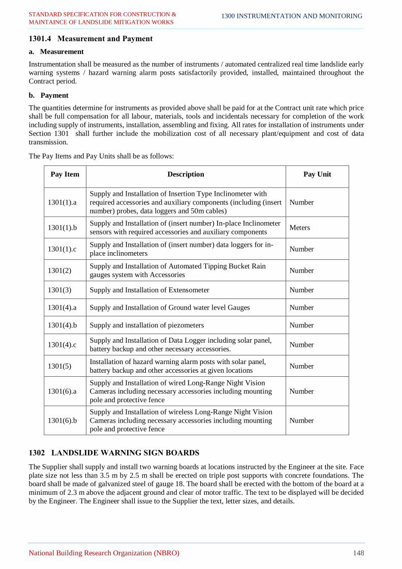
STANDARD SPECIFICATION FOR CONSTRUCTION &
MAINTAINCE OF LANDSLIDE MITIGATION WORKS
National Building Research Organization (NBRO) 148
1300 INSTRUMENTATION AND MONITORING
1301.4 Measurement and Payment
a. Measurement
Instrumentation shall be measured as the number of instruments / automated centralized real time landslide early warning systems / hazard warning alarm posts satisfactorily provided, installed, maintained throughout the
Contract period.
b. Payment
The quantities determine for instruments as provided above shall be paid for at the Contract unit rate which price shall be full compensation for all labour, materials, tools and incidentals necessary for completion of the work
including supply of instruments, installation, assembling and fixing. All rates for installation of instruments under
Section 1301 shall further include the mobilization cost of all necessary plant/equipment and cost of data
transmission.
The Pay Items and Pay Units shall be as follows:
Pay Item Description Pay Unit
1301(1).a
Supply and Installation of Insertion Type Inclinometer with
required accessories and auxiliary components (including (insert
number) probes, data loggers and 50m cables)
Number
1301(1).b Supply and Installation of (insert number) In-place Inclinometer
sensors with required accessories and auxiliary components Meters
1301(1).c Supply and Installation of (insert number) data loggers for in-
place inclinometers Number
1301(2) Supply and Installation of Automated Tipping Bucket Rain
gauges system with Accessories Number
1301(3) Supply and Installation of Extensometer Number
1301(4).a Supply and Installation of Ground water level Gauges Number
1301(4).b Supply and installation of piezometers Number
1301(4).c Supply and Installation of Data Logger including solar panel,
battery backup and other necessary accessories. Number
1301(5) Installation of hazard warning alarm posts with solar panel,
battery backup and other accessories at given locations Number
1301(6).a Supply and Installation of wired Long-Range Night Vision Cameras including necessary accessories including mounting
pole and protective fence
Number
1301(6).b
Supply and Installation of wireless Long-Range Night Vision
Cameras including necessary accessories including mounting pole and protective fence
Number
1302 LANDSLIDE WARNING SIGN BOARDS
The Supplier shall supply and install two warning boards at locations instructed by the Engineer at the site. Face
plate size not less than 3.5 m by 2.5 m shall be erected on triple post supports with concrete foundations. The board shall be made of galvanized steel of gauge 18. The board shall be erected with the bottom of the board at a
minimum of 2.3 m above the adjacent ground and clear of motor traffic. The text to be displayed will be decided
by the Engineer. The Engineer shall issue to the Supplier the text, letter sizes, and details.

STANDARD SPECIFICATION FOR CONSTRUCTION &
MAINTAINCE OF LANDSLIDE MITIGATION WORKS
National Building Research Organization (NBRO) 149
1300 INSTRUMENTATION AND MONITORING
1302.1 Measurement and Payment
a. Measurement
Supplying and installation of landslide warning signboards shall be measured as the number of boards
satisfactorily provided, installed, maintained throughout the Contract period.
b. Payment
Payment shall be made at the stated unit rate per signboard. The price shall be full compensation for all materials
and labour required to perform the work described.
Pay Item Description Pay Unit
1302(1) Supply and installation of Landslide Warning Signboards Number
1303 MONITORING
1303.1 Period and Frequency of Monitoring
Period of monitoring work is the maintenance period according to the Contract. However, the monitoring
work will be initiated by the Supplier with the supervision of the Engineer right after the installation of
instruments is completed. The work will be undertaken by the Client after the maintenance period. The
data shall be collected from all non-automated monitoring equipment once a month during dry seasons
and twice a month during rainy seasons.
1303.2 Collection of Data
The Engineer shall instruct the relevant party regarding the procedure of the monitoring.
1303.3 Arrangement of the Collected Data
The Supplier shall arrange the data collected into tables and graphs with the use of specific software.
1303.4 Maintenance of the Equipment
The monitoring devices shall be regularly cleaned and checked for continuous and smooth functioning of data
recording by the Supplier.
1303.5 Measurement and Payment
No separate payment shall be made for compliance of items under this section. Payments shall be deemed to be
included in the Supplier's rates and prices under Section 1301 .

STANDARD SPECIFICATION FOR CONSTRUCTION & MAINTAINCE OF LANDSLIDE MITIGATION WORKS
National Building Research Organization (NBRO) 150
APPENDIX A CONSTRUCTION MANAGEMENT AND STAFF
The Contractor seek the Engineer’s approval to employ following key personals for construction management
staff and technical supervisory staff with required qualifications as specified in the Bidding document and
accordance with these Specification. Without prior notice to the Engineer, the Contractor can’t transfer / terminate
any Key Staff personal from the site.
Item
No.
Position/
Specialization
Relevant academic
qualifications
Minimum years of relevant work
experience
1
Project
Manager/Contractor’s
representative
B.Sc. Civil Engineering degree or equivalent with
Chartered/Corporate
membership of a recognized
professional institution/Postgraduate
degree in Engineering.
Minimum 10 years of post qualification experience of which
minimum 03 years should be in slope
stabilization work.
2 Geotechnical Engineer
B.Sc. Civil / Earth Resource
Engineering degree or
equivalent
Minimum 3 years of post qualification
experience of which minimum 01 year
should be in slope stabilization work.
3 Site Engineers (02 Nos) B.Sc. Civil Engineering
degree or equivalent
Minimum 3 years of post qualification
experience of which minimum 01 year
should be in slope stabilization work.
4 Technical Officer (04 Nos) NCT/NDES/HNDE Civil or
equivalent
Minimum 1 year of post qualification
experience
5 Surveyor
Bachelor Degree of Sueveying from a recognized
university or equivalent
Minimum 1 year of post qualification
experience
6 QA/QC Engineer B.Sc. Civil Engineering
degree or equivalent
Minimum 3 years of post qualification
experience of which minimum 01 year
should be in slope stabilization work.
7 Quantity Surveyor B.Sc. Degree in the Quantity
Surveying or equivalent
Minimum 1 year of post qualification
in Quantity Surveying
8 Environmental& Social
Officer B.Sc. degree or equivalent
Minimum of 02 years of post qualification in environmental&social,
health and safety field.
9 Health & Safety Officer
B.Sc. degree or equivalent Minimum of 03 years of post
qualification in Health & Safety
NVQ level 05 Minimum of 10 years of post
qualification in Health & Safety
NVQ level 06 Minimum of 05 years of post
qualification in Health & Safety

STANDARD SPECIFICATION FOR CONSTRUCTION & MAINTAINCE OF LANDSLIDE MITIGATION WORKS
National Building Research Organization (NBRO) 151
APPENDIX B REREFERNCED DOCUMENTS
ICTAD SPECIFICATIONS
SCA/5 Standard Specifications for Construction and Maintenance of Roads and Bridges
AMERICAN CONCRETE INSTITUTE
ACI 506R-05 Guide to Shotcrete
ROADS AND MARITIME SERVICES SPECIFICATIONS
RMS R64 Soil Nailing
RMS R40 Horizontal Drains
RMS R63 Geotextiles
RMS R68 Shotcrete Work without Steel Fibers

STANDARD SPECIFICATION FOR CONSTRUCTION & MAINTAINCE OF LANDSLIDE MITIGATION WORKS
National Building Research Organization (NBRO) 152
ENVIRONMENTAL, SOCIAL, HEALTH AND SAFETY (ESHS)
REQUIREMENTS

STANDARD SPECIFICATION FOR CONSTRUCTION & MAINTAINCE OF LANDSLIDE MITIGATION WORKS
National Building Research Organization (NBRO) 153
2000 Environmental, Social, Health & Safety Requirements
2001 Environmental and Social Policy
2001.1 Suggested Content for an Environmental and Social Policy (Statement)
The Works’ policy goal, as a minimum, should be stated to integrate environmental protection, occupational and community health and safety, gender, equality, child protection, vulnerable people (including those with
disabilities), sexual harassment, gender-based violence (GBV), sexual exploitation and abuse (SEA),
HIV/AIDS awareness and prevention and wide stakeholder engagement in the planning processes, programs, and activities of the parties involved in the execution of the Works. The Client is advised to consult the AIIB
to agree with the issues to be included which may also address: climate adaptation, land acquisition and
resettlement, indigenous people, etc. The policy should set the frame for monitoring, continuously improving
processes and activities and for reporting on the compliance with the policy.
The policy shall include a statement that, for the purpose of the policy and/or code of conduct, the term “child” / “children” means any person(s) under the age of 18 years.
The policy should, as far as possible, be brief but specific and explicit, and measurable, to enable reporting
of compliance with the policy and reporting requirement.
As a minimum, the policy is set out to the commitments to:
1. apply good international industry practice to protect and conserve the natural environment and to
minimize unavoidable impacts;
2. provide and maintain a healthy and safe work environment and safe systems of work;
3. protect the health and safety of local communities and users, with particular concern for those who are
disabled, elderly, or otherwise vulnerable;
4. ensure that terms of employment and working conditions of all workers engaged in the Works meet
the requirements of the ILO labour conventions to which the host country is a signatory;
5. be intolerant of, and enforce disciplinary measures for illegal activities and to be intolerant of, and
enforce disciplinary measures for GBV, inhumane treatment, sexual activity with children, and sexual
harassment;
6. incorporate a gender perspective and provide an enabling environment where women and men have
equal opportunity to participate in, and benefit from, planning and development of the Works;
7. work co-operatively, including with end users of the Works, relevant authorities, contractors and local
communities;
8. engage with and listen to affected persons and organizations and be responsive to their concerns, with
special regard for vulnerable, disabled, and elderly people;
9. provide an environment that fosters the exchange of information, views, and ideas that is free of any
fear of retaliation, and protects whistleblowers;
10. minimize the risk of HIV transmission and to mitigate the effects of HIV/AIDS associated with the
execution of the Works;
The policy should be signed by the senior manager of the Client. This is to signal the intent that it will be
applied rigorously.
2002 Environmental and Social Monitoring
2002.1 General
The Contractor shall, during the whole period of project should comply fully with National Environmental
Protection laws and those pertinent to prevent nuisance to public stipulated by the Democratic Socialist
Republic of Sri Lanka and the Environmental and Social Policy of the Asian Infrastructure Investment Bank. This obligation shall extend to the construction sites themselves and all of the Contractor’s installations else ward within the national territories.

STANDARD SPECIFICATION FOR CONSTRUCTION & MAINTAINCE OF LANDSLIDE MITIGATION WORKS
National Building Research Organization (NBRO) 154
The Contractor shall take all reasonable steps to protect the environment on and off the Site and to avoid
damage or nuisance to persons, private and/or public properties or others resulting from pollution, noise,
vibration or other causes arising as a consequence of his methods of operation. The Contractor should be fully aware with the implementation of Environmental and Social Management Plan (ESMP), and the
pollution control facilities should be installed adequately and appropriately before commencement of the
project actions where there is potential to emit pollutants to the environment.
The project activities during site preparation, construction and post construction should comply with but not
limited to the National Environmental Act (NEA) No. 47 of 1980 and amended Act No.1562/22 of 2008 with respect to emission of gaseous, liquid and solid waste, National Environmental Noise Control
Regulations No.01 of 1996 for emission of noise, Interim Standards on Vibration Pollution control for
Central Environmental Authority (CEA) for vibration during construction activities, Fauna and Flora Protection Ordinance (FFPO), Forest ordinance and Forest (Amendment) Act No.65 of 2009 (FO),
Antiquities Ordinance No. 4 of 1940 and subsequent amendment; Ordinance to provide better preservation
of the antiquities of Sri Lanka, and the sites, buildings of the historical or archeological importance in Sri Lanka, Felling of tree (Control) Act No 09 of 1951, and Soil Conservation Act No. 24 of 1996, Geological
Surveys and Mines Bureau (GSMB) Act No.33 of 1992 amended by No.66 of 2009 for excavated material
(earth, rubble and aggregates) as relevant.
Construction contractors’ requirement to comply with Site specific environmental, social management and
health and safety standards during the construction phase is annexed with this document. The contractor is expected to address all sections of ESMP adequately with the indicated level of relevance in his bid response
by referring to given information on the site.
The Engineer under any terms is not responsible either fully or partly for damage caused by the Contractors’
failure to apply necessary pollution control measures, environmental protection measures or measures to
minimize nuisance to public. The Engineer will not appear in courts, pay compensation or engage in public
conflict resolution on behalf of the Contractor under such situations if arise.
The Contractor shall prepare and submit to the Engineer for review and approval, a Site Specific
“Environmental and Social Management Action Plans (SS-ESMAP)” based on the Contractors’
Environmental and Social Management Plan (C-ESMP) to Engineer within one month from the date of
signing the contract and prior to commencing construction.
Information for preparing SS-ESMAPs. Pl. refer section 2004
The contractor shall not commence the work until the resettlement plan is established.
The Contractor shall appoint an Environmental and Social Officer for each package, whose duties throughout
the period of the Contract shall be exclusively connected with the Environmental and Social Management
activities at the Site.
Monthly ESMP performance reports should be prepared and submitted, on-site checklists and log books
should be maintained.
The ESMP implementation and the costs should be included clearly according to the format given under
“Payment schedule”.
2002.2Environmental and Social Management Plan (ESMP)
The Environmental and Social Management Plan (ESMP) prepared for the project outlines the framework
for planning, implementation and monitoring of environment, measures required to ensure that potential adverse environmental impacts from the project activities are eliminated, offset, or reduced to an acceptable
level. At the same time, it is expected that the plan will help the project to enhance environmental
benefitsfrom the project interventions. The ESMP is based on the relevant existing national

STANDARD SPECIFICATION FOR CONSTRUCTION & MAINTAINCE OF LANDSLIDE MITIGATION WORKS
National Building Research Organization (NBRO) 155
policies, legislation, regulations and guidelines and on the Environmental and Social Framework and
standards of the AIIB.
a) All works should be arranged to cause the least possible disturbance to the environment and local
residents/institutions, in particular to prevent soil erosion along the area of intervention and any
access roads that may be required and adjacent area, to the river/stream banks, irrigation canals and
other water ways. Similarly, cutting of trees, tea shrubs and other vegetation of economic, religious
and ecological value found outside of the ROW, whenever possible be avoided; else replacement
planting in a place selected by the owner of the affected tree and/or vegetation should be carried-out
by the Contractor for the damages caused. In this regard initial survey of all houses, structures (drains,
parapet walls, and etc) artifacts of cultural, religious or archeological importance, and environmental
elements (vegetation, water ways) on or adjacent to the site that could potentially be affected by the
works. The survey should be shared with the owner/occupants of the houses/ structures before any
work takes place at the site. A follow- up survey should be carried out once the works have been
completed and/ or at the request of the owner/occupants.
b) Proposals shall be submitted for:
1)Storage on Site
i. Materials and equipment on Site shall be stored in a manner so as to prevent damage to the
Site and adjacent areas, and minimize hazards to persons, materials and equipment and all
Temporary and Permanent Works. Storage areas shall be kept organized, neat and tidy.
ii. Areas assigned for carrying out Permanent Works shall not be used to store materials, plant
and equipment, nor used as access to storage areas without prior approval of the Engineer.
iii. Hazardous materials (including fuel and oil) shall be stored and handled only within an
area set-aside specifically for this purpose. This area shall be enclosed from the remainder
of the Site with waterproof concrete flooring and rainproof roof, so as to contain any
spillage, clearly marked and signs installed at a close distance from the storage area to warn
unauthorized workers and visitors to stay away.
iv. The storage area shall be located away from any natural waterways, drainage lines and
open drains. In case of petroleum fuel and oil, a collection basin is to be installed in the
storage area to gather any spillages, to facilitate the recovery of the petroleum products for
reuse or proper disposal using government licensed recyclers or otherwise.
2)Noise and Vibration
i. The Contractor shall abide by the Central Environmental Authority (CEA) regulations and
other applicable laws and regulations related to noise and vibration levels.
ii. The Contractor shall take all practical precautions to minimize noise and vibration resulting
from work under the Contract, especially Sites adjacent to residential and institutional
areas, from polluting such areas and shall fit all equipment with noise suppressors so that
noise levels are minimized. Similarly, as much as practicable, construction methods that
produce minimal vibration be adopted, most especially in sites adjacent to residential and
institutional areas where possible damage to the structures due to vibration may occur.
3)Cracks and damages to the buildings/ road damages
i. The contractor shall take all practicable measures to prevent cracks in neighboring houses
or buildings.
ii. In case of unconditional cracks, the contractor shall immediately inform to the Engineer and
repair the damage by their own cost.
iii. Crack survey should be done before works starts and after the work is completed

STANDARD SPECIFICATION FOR CONSTRUCTION & MAINTAINCE OF LANDSLIDE MITIGATION WORKS
National Building Research Organization (NBRO) 156
4)Disposal of waste
i. Solid, liquid and gaseous waste shall be disposed in accordance with relevant Sri Lanka
Environmental regulations and contractual requirements.
ii. Non-toxic and/or non-hazardous liquid waste shall be stored in approved containers for
transport and disposal at locations approved by the Engineer and local authorities.
iii. Non-toxic and/or hazardous solid wastes shall be disposed of by removal from site,
transport and depositing in approved locations.
iv. Toxic and hazardous wastes must be temporarily stored using suitable containers at a
designated place authorized by the Engineer and local authorities, and disposed through a
government licensed collection agent or otherwise.
5)Disposal of Refuse
i. The Contractor shall take adequate measures to ensure that the Site and associated areas are
maintained in a clean and orderly condition. Provision shall be made for the daily removal
of rubbish, debris, surplus materials, etc., and for the stacking and storing of materials in
authorized locations.
ii. The excavated materials should be covered and stored safe until removed. The location of
onsite storage should be sufficiently away from stream banks, water ways, runoff paths etc.
iii. The final disposal site should be approved by the Engineer before dumping. The disposed
matter should not pollute water bodies.
iv. The contractor shall obtain approval from relevant Authority such as Pradeshiya Sabha,
Municipal Council and other government agencies (as required), for disposal of spoil at the
specified location, as directed by the Engineer. Private land that will be selected for disposal
should also require written consent from the land owner.
6)Dust Control
i. Dust screens and/or watering of open and unpaved areas shall be used to control dust and
to eliminate public health issues and/or nuisance to adjoining residential and institutional
areas, national highways often travelled by commuters, and natural habitats frequented by
wildlife during the period of the Works.
ii. The on-site piles should be covered securely to prevent particles becoming air-borne.
7) Transport of construction materials and waste
i. Transportation of material should be done covered always using tarpaulin
ii. Precautions should be made to prevent spill of any material on ground during
transportation and minimize damage to ground cover/ vegetation
iii. Transportation of materials should not to be a nuisance to public
iv. Transportation should be done only in the dedicated haul roads. Use of any other access
roads should be strictly avoided.

STANDARD SPECIFICATION FOR CONSTRUCTION & MAINTAINCE OF LANDSLIDE MITIGATION WORKS
National Building Research Organization (NBRO) 157
v. The tyres of the vehicles should be inspected regularly when leaving the sites and
disposal site, and mud in tyres should be cleaned before entering the haul road.
8) Water
i. Water removal
Surplus water shall be promptly removed from the Site by draining off or by mechanical
means to keep the Works reasonably dry and so as not to interfere with construction work.
The water removed from the Site is kept reasonably free of soil, oil/petroleum and other debris, and the discharge shall not adversely affect the adjoining landowner’s residential
and livelihood assets, or to pose as a pollution hazard to waterways and farmlands.
ii. Water quality
The Contractor shall ensure that construction activities do not have a detrimental impact on the water quality of surface or ground water in the areas adjoining the Site. Specific
measures shall be adopted to prevent the discharge of contaminated runoff from the Site.
When necessary, potable water source of local people such as springs located immediately
downslope of the Site shall be provided with protection (“spring box”) from contaminants originating from construction works as appropriate.
i. Contaminated water
The Contractor shall adhere to the regulations of NEA on disposal of wastewater. Wastewater shall not be discharged to ground or waterways in a manner that will cause
unacceptable surface as ground water pollution.
ii. Siltation
All drains, streams, and waterways shall be kept clear from mud, silt and other obstructions
arising from the execution of work under the Contract. Soil and other debris removed from
the drains, streams and waterways are to be deposited by the Contractor in suitable areas subject to the approval of the Engineer and the concerned local authorities. The Contractor
shall ensure that effective construction practices are employed to minimize siltation to the
satisfaction of the Engineer.
iii. Alternation of drainage paths
Contractor shall not close or block existing canals and streams permanently causing nuisance to public. If diversion or blocking of canals and streams is required for the execution of
works, Contractor must obtain the Engineers approval and approval of relevant authorities
where necessary.
iv. If streams or waterways/ community water supplies that are used by neighboring community
are obstructed even temporally, it should be done with the approval of the Engineer, subjected
to consent from the community with alternative sources are arranged.
v. Contractor shall restore drainage paths back to its original status once the need for such
diversion or closure or blockage no longer required.
9) Flora and Fauna
All works shall be carried out in a manner so that the destruction to flora and fauna and their
habitat is minimal. Trees and vegetation shall be felled /removed only if that affect directly on
permanent works or necessary temporary works.
i. Contractor shall take effort to avoid removal/ destruction of religious, cultural, aesthetic
species.

STANDARD SPECIFICATION FOR CONSTRUCTION & MAINTAINCE OF LANDSLIDE MITIGATION WORKS
National Building Research Organization (NBRO) 158
ii. Contractor shall adhere to the regulations of Fauna and Flora Protection Ordinance (FFPO)
and Forest (Amendment) Act No.22 of 2009), Forest ordinance Forest (Amendment) Act
No.65 of 2009 (FO) and pertaining to relevant area declared under Central Environmental
Authority or Mahaweli Authority of Sri Lanka if any with regard to felling of trees and
removal of vegetation.
iii. A list of trees to be removed during construction of site to be marked and forwarded to the
Engineer.
iv. Measures shall be taken to avoid or minimize any adverse impacts on fauna and flora (either
terrestrial/ aquatic) living in natural environments adjacent to the Site during the construction
period.
v. During construction, if a rare/ threatened/ endangered flora and or fauna is found, it shall be
immediately informed to the Engineer. All activities that could destroy such flora/fauna and
its habitat shall be stopped with immediate effect. Contractor shall carry out works again
only after the Engineer’s approval.
vi. Hunting and collection of wildlife and specimens within the Site and adjacent area are strictly
prohibited. The Contractor shall ensure that no damage occurs to any trees, shrubs and other
vegetation with ecological, spiritual and/or economic value that are to be retained at the Site;
and that none of its workers and subcontractors are engaged in wildlife hunting or collection.
vii. Contractor shall take measures to avoid introduction of invasive species during
transportation or refuse or spoil.
viii. Plant or seed if needed for bio Engineered slope mitigation shall be imported into Sri Lanka
under the authority and in accordance with the conditions, of a plant importation permit
issued by the Additional Director National Plant Quarantine Service Katunayake for Director
General of Agriculture under the Plant Protect Act No. 35 of 1999.
ix. Approval from Department of Forest or Wildlife should be taken before introducing plants
to the site for vegetative mititgatory measures.
10) Physical and cultural resources
Whenever chance finds are made during the works, the contractor will immediately inform to the
Engineer and in turn inform the government department concerned with cultural property.
11) Soil Erosion
The Contractor shall take measures to minimize the soil erosion that may result from construction
activities using any of the following suitable control measures. Control measures include but not
limited to.
i. Install sediment filter, fences, hay bale filters drains, and filter strips, grass outlets,
sediment transport basin traps around culverts, drains, soil stockpiles and all other areas
which may have the potential to erode or be affected by soil erosion.
ii. Install catch drains, slope drains and nearby dissipaters in conjunction with sediment traps
installed to divert storm water around the Site.

STANDARD SPECIFICATION FOR CONSTRUCTION & MAINTAINCE OF LANDSLIDE MITIGATION WORKS
National Building Research Organization (NBRO) 159
iii. Stabilize by grass, materials (excluding pavements and screenings) stockpiled for periods
longer than one month.
iv. Stabilize disturbed areas using measures such as drains.
v. Minimize as much as practicable, the removal of existing vegetation within and around
the project area at any time.
vi. Plan the execution of work under the Contract in stages to minimize soil erosion during
continuous periods of rainfall that will cause heavy run-off.
vii. Soil erosion control devices shall be regularly inspected and maintained, especially after
heavy and/or continuous periods of rain.
12) Soil Contamination
The Contractor shall undertake all practicable control measures to prevent the contamination of
the soil in and around the site. Control measures include but not limited to;
i. Acceptance of Clean Fill.
All fill material to be imported and used on the Site shall be free of contamination.
ii. Fuel Chemicals and Other Hazardous Materials
All practicable steps shall be taken to ensure contamination of soil does not occur through: fueling, maintenance of vehicles or equipment; storage of fuel, chemicals, and other hazardous
materials; and spillage of such materials on to the soil, by ensuring all the above activities are
conducted in bounded or sealed areas.
iii. Clean-up of Soil Contamination
All soils contaminated during construction shall be cleaned up by the Contractor to the
satisfaction of the Engineer, and at no cost to the Employer. Any contaminated spoil material (whether or not contaminated by the Contractor) shall be
removed from the Site in an approved manner to prevent further pollution.
iv. Installation of Oil separators
Contractor shall install oil separator to prevent fuel, oil and other petroleum products from
spilling into the existing drainage lines and then into the adjacent soil, resulting in its (soil)
contamination.
13) Borrowing Earth
i. Earth available from construction site excavation works as per design, may be used as
embracement materials, subject to approval by the Engineer
ii. Contractor shall comply with environmental requirements/ guidelines issued by CEA and
the respective local authorities with respect to the locating of borrow areas and with regard
to all operations related to excavation and transportation of earth from such sites.
iii. Contractor can also find suitable soil materials from currently operated licensed borrow pits
in the surrounding area, subject to approval of the Engineer.
iv. Borrow areas shall not be opened without having a valid mining license from the Geological
Survey and Mines Bureau (GSMB).

STANDARD SPECIFICATION FOR CONSTRUCTION & MAINTAINCE OF LANDSLIDE MITIGATION WORKS
National Building Research Organization (NBRO) 160
v. All borrow pits/areas should be rehabilitated at the end of their use by the contractor in
accordance with the requirement/ guidelines issued by the CEA and the respective
Government Authority
14) Quarry operations
i. Utilizing the existing quarry sites available in the project influential area as much as possible
which are approved by GSMB with valid Environmental Protection License (EPL) and
Industrial mining license
ii. If new quarries are to be opened, prior approval should be obtained from GSMB, NBRO (as
applicable), CEA and Local authorities.
iii. Selected quarry sites should have proper safety measures, such as warning, safety nets etc.
iv. Quarry sites should not be established within protected sites under FFPO and FO.
15) Maintenance of vehicles and machinery
i. All maintenance and servicing should be done outside the site.
ii. Waste clothes, wrappings, waste machine oil, rugs etc. should be collected separately and
disposed outside through proper disposal channels
iii. Operation of concrete mixer
Storage of construction materials cement, sand concrete aggregates and any other should be
done in a dedicated place closer to the concrete mixture yard. Materials prone to wash off or
air borne would be covered with impervious material.
iv. Separate places should be kept for cleaning concrete mixers away from storm water drains.
Cleaning should be done with minimum quantity of water and wastewater generated should
be allowed soaked into ground. If extra wastewater is generated, the drain water should be
filtered through check dams and temporary sand mounds before letting to storm water drains.
16) Disruption to public
i. Loss of Access
At all times, the contractor shall provide safe and convenient passage for vehicles,
pedestrians and livestock.
ii. Work that affects the use of existing accesses shall not be undertaken without providing
adequate provisions to the prior satisfaction of the Engineer.
iii. On completion of the works, all temporary obstructions to access shall be cleared away, all
rubbish and piles that obstruct access be cleared to the satisfaction of the Engineer.
iv. Contractor shall make sure that his work team or project actions shall not engage in any
form of dispute with neighboring persons or communities under the Nuisance Ordinance
chapter 230 No. 15of 1862 of Sri Lanka. All contractors’ and subcontractors’ personnel
should act courteously and treat people living in the neighborhood with respect.
17) Utilities and roadside amenities

STANDARD SPECIFICATION FOR CONSTRUCTION & MAINTAINCE OF LANDSLIDE MITIGATION WORKS
National Building Research Organization (NBRO) 161
i. The Contractor shall take care not to damage/destroy or affect the functional purposes of
utilities such as water, electricity, and telephone posts. The arrangements the Contractor
made with those service providers shall be informed to the Engineer.
ii. In case of an unintentional damage cause to a utility, the Contractor shall immediately
inform the service providers and help to restore the service without delay at its own cost.
18) Visual environment enhancement
i. Landscape plantations, re-vegetation and filling slopes and other slopes, edge treatment of
water bodies shall be carried out.
ii. The Contractor shall remove all debris, piles of unwanted earth, spoil material, away from
the roadsides and from other work places and dispose at designated locations acceptable to
the Engineer. iii.On completion of the works, the temporary structures shall be cleared away
in full, all rubbish burnt, waste dumps and septic tanks shall be filled and closed and
roadsides work places and labour camps, cleared and cleaned.
19) Special attention during works in an archaeological site
The contractor shall aware on importance, all potential damage to archaeological site. Whenever chance finds are made during the works, the contractor shall immediately inform
to the Engineer.
20) Labor Management
The contractor shall take all necessary steps to; i. Fair treatment, nondiscrimination and equal opportunity of project workers.
ii. Protect project workers, including vulnerable workers such as women, persons with
disabilities, children and migrant workers, contracted workers, community workers and primary supply workers, as appropriate.
iii. Prevent the use of all forms of forced labor and child labor.
iv. Support the principles of freedom of association and collective bargaining of project workers in a manner consistent with national laws.
v. Provide project workers with accessible means to raise workplace concerns.
2002.3 Environmental and Social Management Action Plan (ESMAP)
i. The selected Contractor shall prepare and submit to the Engineer for review and approval,
the “Site Specific Environmental and Social Management Action Plans (SS-ESMAP) based
on the Contractors’ Environmental and Social Management Plan (C-ESMP) that shall be
implemented during the work execution, and shall be monitored on a daily basis. The
Contractor shall take into account the regulations and all applicable Local Government by-
laws in the preparation of the SS-ESMAPs.
ii. The directions on preparing SS-ESMAPs will be given by Environmental consultant of the
Engineer for selected Contractor. The Contractor should submit the SS-ESMAP statement to
the Engineer within 28 days from the date of signing the contract and prior to commencing
construction.
iii. The contractor shall not commence the work until the resettlement plan is established.
2002.4 The Contractor’s Environmental and Social Officer

STANDARD SPECIFICATION FOR CONSTRUCTION & MAINTAINCE OF LANDSLIDE MITIGATION WORKS
National Building Research Organization (NBRO) 162
Within 28 days before the commencement of the works, the Contractor shall appoint an Environmental and
Social Officer, whose duties throughout the period of the Contract shall be exclusively connected with the
Environmental Management activities on the Package as per ESMP.
The Environmental and Social Officer shall have an acceptable working knowledge of the ruling language
of the Contract as stated in the Conditions of Contract, and shall be a suitably qualified and experienced person who shall prepare, supervise and monitor environmental management activities. The person should
responsible for community liaison and to handle public complaints regarding environmental/social related
matters.
The appointment and designation of the Environmental and Social Officer shall be subject to the Engineer’s
approval.
Unless specifically agreed in writing by the Engineer, the Contractor shall not undertake any work on the
Package, which may affect the environment, until the Environmental and Social Officer has commenced
duties Package, and the Site Specific Environmental and Social Management Action Plans (SS-ESMAP)
have been approved by the Engineer.
The Contractor shall not remove the Environmental and Social Officer from the Package without a written
permission of the Engineer. Within fourteen (14) days of any such removal, or notice of intent of removal,
the Contractor shall nominate a replacement Environmental Officer for the Engineer’s approval.
2002.5 Environmental Monitoring
The contactor shall monitor the compliance of implementation of Environmental Management actions and the emission of pollutants with respect to the environmental regulations. The contractor shall include the
monitoring plan in his SS- ESMAP. The monitoring plan should be prepared in accordance with the
monitoring regulations of National Environmental Act and that of the funding agency, and any other specific
monitoring indicated in Environmental Assessment reports (EIA, IEE) as appropriated. The environmental
monitoring plan should be approved by the Engineers.
The Contractor shall monitor the environmental aspects of the construction according the environmental monitoring plan, and control measures shall be implemented to minimize the environmental impacts.
However, should the control measures put in place be found to be unsatisfactory as a result of monitoring,
then the Contractor shall amend the control measures to provide a satisfactory result.
a) The contractor shall:
i. Prepare monthly and quarterly progress reports in three copies on the implementation of the ESMP
using a report format acceptable to the Engineer.
ii. Participate in coordination meetings called by the Engineer to discuss the progress of the ESMP
implementation, among others, and act on agreements reached during the activity.
iii. Participate in Site Inspections requested by the Engineer, and/or the NBRO, and Authorities (RDA,
Railway Department) to review the ESMP performance.
iv. Keep daily records of environment related incidents (if any), note the details, actions taken, identify
persons responsible for these actions, the results of the actions, and any recommendations for further
work. Also indicate in the record if the Engineer had been informed of the incidents as well as other
local authorities. Complaints and their status will also be included in the record.
b) Monitoring environmental parameters for regulations for pollutant emissions
i. The contractor shall monitor the environmental parameters for regulations for pollutant emissions.
The monitoring parameters should be decided based on the sensitive environmental elements
within the project area and in its proximity. For this, the contractor should obtain the

STANDARD SPECIFICATION FOR CONSTRUCTION & MAINTAINCE OF LANDSLIDE MITIGATION WORKS
National Building Research Organization (NBRO) 163
services of a competent local organization, to decide and conduct environmental monitoring as
baseline and during construction for ambient air quality, surface and ground water quality, noise
and vibration levels at the specific locations of the site.
ii. The monitoring agency shall review environmental data obtained for conduct baseline monitoring
for parameters as per the Table 1. The monitoring agency shall prepare environmental quality
monitoring reports with the results of field sampling and laboratory analysis, interpretations of the
results and recommendations.
iii. And shall set out same monitoring stations for the monitoring during the construction period.
iv. The reports should be analyzed by the environmental consultants of the Engineer to ensure the
effectiveness of the mitigation measures implemented, and that the necessary environmental
regulations are complied, and non-compliances should be acted according to conditions of the
contract.
Table 1 – Guidance to select Environmental Quality Monitoring Parameters
Activity Instructions for contractor Parameters Frequency and
monitoring Agency
*Baseline
surveys
The contractor shall conduct a
baseline environmental assessment for all sites before commencing the construction activities. The assessment should include Ambient Air quality, noise, vibration and water quality at closes streams (reflecting upstream and downstream) as compliance to:
Air quality - The National Ambient Air Quality standards stipulated under the Extraordinary Gazette, No. 1562/22 August 15, 2008 -Central
Environmental Authority of Sri Lanka.
Noise- Extraordinary Gazette, No. 924/1- May 23, 1996 -Central Environmental Authority of Sri Lanka.
Vibration- The interim standards on
Vibration for the Machinery, Construction activities and Vehicular Movements - Central Environmental Authority of Sri Lanka.
Ambient Water Quality-
Ambient water quality standards –
CEA –EAIP-DHV-2000
Air Quality parameters
Carbon Dioxide (CO2), Carbon Monoxide (CO), SO2, NO2, Total Suspended Particulate Matter (TSPM), Respirable Particulate Matter (PM10) & PM (2.5), Particulate Lead (Pb)
Noise
(15 min and 1 hour in Morning, Afternoon, Evening and Night in a day) Leq, L90, L50 & L10
Vibration
(Ground and
Structural) PPV, Hz
Water quality
parameters
pH, temperature,
electricity
Once
From a reputed
laboratory

STANDARD SPECIFICATION FOR CONSTRUCTION & MAINTAINCE OF LANDSLIDE MITIGATION WORKS
National Building Research Organization (NBRO) 164
Crack surveys should be conducted
if necessary on existing buildings or
structures before commencing the
work by the contractor. The reports
should be analyzed by the experts to
identify
conductivity, DO, BOD, TSS, Oil and Grease, FC, Pb, and any other specific parameters deemed necessary
Cracks in each building
within 50 m from the site
and any other structures in
the vicinity that could potentially be affected
cracks that might get aggravated by
some project actions. And necessary precautions should be made during execution of project actions to keep to a minimum such possible aggravation of the cracks if identified sensitive to specific project actions.
by the landslide or by the
works.
Once by
contractor
representative
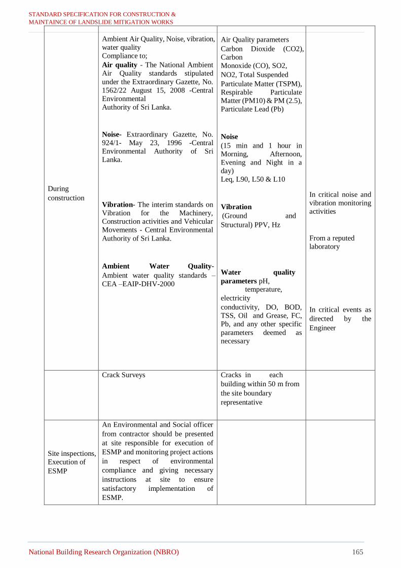
STANDARD SPECIFICATION FOR CONSTRUCTION & MAINTAINCE OF LANDSLIDE MITIGATION WORKS
National Building Research Organization (NBRO) 165
During
construction
Ambient Air Quality, Noise, vibration, water quality Compliance to;
Air quality - The National Ambient Air Quality standards stipulated
under the Extraordinary Gazette, No. 1562/22 August 15, 2008 -Central Environmental Authority of Sri Lanka.
Noise- Extraordinary Gazette, No. 924/1- May 23, 1996 -Central Environmental Authority of Sri Lanka.
Vibration- The interim standards on Vibration for the Machinery, Construction activities and Vehicular Movements - Central Environmental
Authority of Sri Lanka.
Ambient Water Quality-
Ambient water quality standards –
CEA –EAIP-DHV-2000
Air Quality parameters
Carbon Dioxide (CO2), Carbon Monoxide (CO), SO2,
NO2, Total Suspended
Particulate Matter (TSPM), Respirable Particulate Matter (PM10) & PM (2.5), Particulate Lead (Pb)
Noise
(15 min and 1 hour in Morning, Afternoon, Evening and Night in a day) Leq, L90, L50 & L10
Vibration
(Ground and
Structural) PPV, Hz
Water quality
parameters pH, temperature,
electricity
conductivity, DO, BOD, TSS, Oil and Grease, FC, Pb, and any other specific
parameters deemed as necessary
In critical noise and vibration monitoring activities
From a reputed laboratory
In critical events as
directed by the
Engineer
Crack Surveys
Cracks in each
building within 50 m from
the site boundary
representative
Site inspections, Execution of
ESMP
An Environmental and Social officer
from contractor should be presented
at site responsible for execution of
ESMP and monitoring project actions
in respect of environmental
compliance and giving necessary
instructions at site to ensure
satisfactory implementation of
ESMP.

STANDARD SPECIFICATION FOR CONSTRUCTION & MAINTAINCE OF LANDSLIDE MITIGATION WORKS
National Building Research Organization (NBRO) 166
After
completion of
works
Crack Surveys
Cracks in each building
within 50 m from the site
and any other structures in
the vicinity that could
potentially be affected by
the landslide or by the
works.
Once by
contractor
representative
2002.6 Environmental Complaints
The Contractor shall maintain a register of all environmental and social complaints received and shall notify
the Engineer of each complaint. Complaints received by the Engineer shall be referred to the Contractor and
shall be detailed in the complaints register.
The Contractor shall investigate all environmental and social complaints received and, where necessary, adopt measures to address the complaint. All measures undertaken to address the complaints shall be
detailed in the register. A summary of the complaints received, actions taken and the ensuring results; and
further actions needed (if any); are to be included in the regular reports submitted by the Contractor to the
Engineer.
2002.7 Environmental Incidents
Should an environmental incident (being environmental nuisance, medium environmental harm, or serious
environmental damage) occur during the construction phase, the Contractor shall immediately take
appropriate action to minimize any impact or to compensate the impact and inform the Engineer of the
incident. The Contractor shall carry out any instructions received from the Engineer to remedy the situation. The Contractor is responsible for the clean-up of any contamination caused by construction work and no
additional payment will be made in this regard.
2002.8 Environmental Training
The Contractor shall be responsible for ensuring that all employees (including all Sub-Contractors and their
employees) have received training/orientation in relation to the Contractor’s Environmental and Social
Management Plan (C-ESMP) and other related operating guidelines. Posters are to be placed on strategic places, as well as reading materials are to be made available, to remind workers and visitors on how each
one can on a personal basis, help protect the environment. The Contractor will ensure that all machinery on
the Site are operated within the appropriate guidelines in-order to minimize environmental impacts related
to excessive noise and vibration; deteriorated air and water quality; waste and pollution control; as well as damages to the natural ecology in and around the project area. All construction materials used in the Site
shall be utilized in such a manner to minimize negative environmental impacts. Reusable containers no
longer needed at the Site, can be donated to the local schools or government units for use in their community
development projects.
2002.9 Reporting and Maintenance of Records
a) Environmental and Social Management Action Plan (ESMAP)
The Contractor should prepare SS-ESMA Plans obtain approval.
b) Monthly ESMP performance reports should be prepared and submitted
c) On-site checklists maintained regularly
d) Logbooks should be maintained at site with daily inspection entries, issues noticed, action taken
and produced to the Engineer on-site inspections

STANDARD SPECIFICATION FOR CONSTRUCTION & MAINTAINCE OF LANDSLIDE MITIGATION WORKS
National Building Research Organization (NBRO) 167
e) Emission test reports and approvals etc. should be made available to officers of the Engineer at
on-site inspections
2002.10 Attending the Progress Meeting
The Engineer will hold monthly progress meeting at a venue that will be either at the head office or at a pre-
informed location in the proximity of the project site. An authorized officer responsible for ESMP, i.e. the
Contractor’s Environmental and Social Officer should attend the meeting and should present the progress.
2002.11 Performance Monitoring by the Engineer
The Environmental and Social officer (EO) will be appointed by the Engineer to monitor performance of
ESMP at site. The monitoring will include site inspections, checking on-site environmental records,
reviewing ESMP, and raising non-compliances on ESMP where performance is - unsatisfactory. The EO of the Engineer will endorse log entries and on-site checklists, and will prepare monthly performance review
reports including non-compliances and present at the progress meetings. All claims are subjected to approval
of the EO.
2002.12 Measurement and Payment
a. Measurement
(i) Environmental and Social Officer shall not be measured and deemed to be included in the
construction management staff as stated in Annex- B under section 120.1.
(ii) Environmental Management Action Plan shall be measured as Lump Sum.
(iii)Baseline Environmental and Social Monitoring shall be measured as Lump Sum.
(iv) ESMP Progress Reports shall be measured in number of reports (not the number of copies) submitted
as described above.
(v) Environmental Quality Monitoring during construction shall be measured as Provisional Sum.
b. Payment
(i) Environmental and Social Officer shall not be paid and all the expenditure incurred by the
Contractor in keeping the personnel at the Site and all the facilities provided to such personnel to
discharge his duties satisfactorily shall be deemed to be included in Contractor’s staff.
(ii) ESMP Progress Reports shall be paid at the Contract monthly rate and shall include all the
expenditure incurred by the Contractor in preparing the reports (not the number of copies) in three
copies and submitting them to the Engineer.
(iii)Environmental Quality Monitoring shall be paid at the Contract as provisional sum and shall include
all the expenditure incurred by the Contractor in carrying out this work and the Contractor and
(iv) Engineer shall agree on a payment of the provisional sum in a manner that the payment is distributed
across the monitoring period.
(iv)All the other obligations of the Contractor under this Section are deemed to be included in the rates
and no separate payment shall be made in respect of them.
o Submission of claims– All claims regarding the ESMP implementation are subjected to
submission of reports followed by approval by the Engineer. The format for claim form and
authorized signatories should be informed prior to commencement of the project. The
incomplete claims or those with inadequate information will not be paid and the Engineer hold
no responsibility for delays encountered in submission of such claims. All claims are subjected
to approval of the Environmental Officer(EO) certifying satisfactory performance. Full
payment, No or partial payment or payment suspension will be based on the endorsement by
the EO on the claims of Contractor.

STANDARD SPECIFICATION FOR CONSTRUCTION & MAINTAINCE OF LANDSLIDE MITIGATION WORKS
National Building Research Organization (NBRO) 168
o If a large number of NCs are reported in the given month, and are not rectified within the
minimum time needed to address these issues, the unsatisfactory performance of
implementation of ESMP will lead to suspension of payments, disregarding the monthly report
that has been submitted.
o Performance of environmental officer at site and attending the progress meetings–
No or partial payment will be made, or payment will be suspended for unsatisfactory
performance of environmental officer of contractor.
o Performance of on-site ESMP– No or partial payment will be made, or payment will
be suspended for unsatisfactory performance
o Suspend of work – If the contractor is seriously violating the norms of environmental
regulations, the Engineer reserve the right to suspend the project activities until satisfactory
control measures are set in place. The under such situations the Engineer will not pay any delay
claims.
o Damage Surcharge – If substantial damage has resulted to environment or public due
to contractor poor performance of ESMP the contractor will have to remedy it at its own
expense. If the contractor is unable to repair the damage or there is an unacceptable delay in
attending to remediation the Engineer reserves the right to deduct the specified amount from
the payment as remediation cost.
Pay Item Description Pay Unit
2000 (1) Submission of satisfactory Site Specific Environmental and Social Management Action Plans (SS-ESMAP) and on-site arrangement before commencing the project actions
Lump sum
2000(2) Baseline Environmental Monitoring and submission of the
report Lump sum
2000 (3) ESMP Monthly Progress Reports Month
2000(4) Monitoring Environmental Quality Parameters and
Environmental mitigation measures during construction Provisional Sum
2003 Working Conditions and Community Health and Safety
2003.1 General
The Contractor shall, as a priority in all its activities, undertakings and endeavors, ensure the continuous
safety measures of the public and all persons directly or indirectly associated with the Works. The
Contractor shall comply with all safety and industrial health legislation and regulations of Sri Lanka.
The Contractor will be responsible for the safety of the public legitimately passing through or adjacent
to the Site. All excavations, use of explosives (chemical or other), or plant or items of potential danger
to the public must be barricaded and signposted to the satisfaction of the Engineer and the Contractor
must provide sufficient watchmen to ensure the safety of the public at all times. All existing pedestrian
routes shall be maintained in a safe condition unless an alternative route is provided to the satisfaction
of the Engineer.

STANDARD SPECIFICATION FOR CONSTRUCTION & MAINTAINCE OF LANDSLIDE MITIGATION WORKS
National Building Research Organization (NBRO) 169
The Contractor shall appoint a Health and Safety Officer for each package, whose duties throughout the
period of the Contract shall be exclusively connected with the Health and Safety Management activities
at the Sites for workers and the community.
Availability of Safety-related Documents: The Contractor shall comply with the Engineer’s
requirements insofar as displaying in each of its site offices and workshops, copy of such safety and
industry health posters and keeping on the Site copies of such regulations and documents. All
regulations and documents shall be translated into languages which are understood by the workers and
operators engaged by the Contractor or subcontractors and such translations shall be displayed or kept
alongside those in Sinhala, Tamil and English languages.
Assistance to the Engineer: The Contractor shall provide full co-operation and assistance in all safety
surveillance carried out by the Engineer or the Employer.
2003.2 Health and Safety Plan
(a) Submission, Approval and Change
i. Within 28 (twenty-eight) days before the commencement of the works, the Contractor shall
submit his Health and Safety Plan (HSP). The Contractor shall cooperate and comply with
Engineer’s instruction to have HSP approved by Engineer before the start of site works.
ii. The Contractor shall comply with the approved HSP and any of the Engineer’s instructions on
safety.
iii. If the Engineer makes any subsequent recommendation or instructions on the HSP in writing,
the Contractor shall revise the HSP accordingly.
iv. Where the Contractor proposes to change, he shall give at least (7) calendar days’ notice in
writing. Proposed changes are subject to the Engineer’s approval.
(b) Contents of Health and Safety Plan
Main contents of the Health and Safety Plan shall include following:
• Safety Organization and Communication Safety control staff organizational structure, which should identify the personnel to be engaged solely for safety assurance (including Health
and Safety Officer will be responsible for all safety on the Site), their responsibilities and
authorities
• Proposed interaction and communication procedures between the Contractor’s construction
personnel and safety assurance staff
• Frequency and coverage of site safety meetings, and regular site safety reports
• Safety information and training
• Records to be prepared and maintained by the Safety Officer.
ii. Measures for compliance by Subcontractors
iii.Safety equipment and facilities
• Safety equipment, rescue apparatus and protective clothing which will be required for the Works.
Such equipment shall include, but not limited to, eye protectors, hearing protectors, safety
harnesses, safety equipment for working underground and in the confined spaces, rescue
equipment, fire extinguishers, first aid equipment, lanyards, hard hats and, where appropriate,
associated shock absorbers, chest harnesses
• Testing, inspection, and replacement of safety equipment, scaffolds, guardrails, working
platforms, hoists, ladders and other means of access, lifting, lighting, signing, and guarding
equipment
• Operation and equipment of the specified first aid station

STANDARD SPECIFICATION FOR CONSTRUCTION & MAINTAINCE OF LANDSLIDE MITIGATION WORKS
National Building Research Organization (NBRO) 170
• Emergency and rescue procedure and associated equipment
• Any other equipment, gear and facilities necessary for prevention of accidents
v. Protection of authorized and unauthorized visitors to the site (including people from the
vicinity)
vi. Supervision of Safety systems
vii. The means by which the safety systems will be supervised, monitored and audited by the
Safety Officer to ensure due compliance with the principles and objectives of the Health and Safety
Plan; Procedures for updating the Health and Safety Plan
viii. Safety of Construction methods
ix. Proposals to ensure that construction methods do not compromise the Contractor’s commitment
to the Health and Safety Plan or his compliance of regulations
x. Types of Hazards and Emergency Measures
An appreciation of the industrial health hazards, and proposals for minimization of the risks
associated with such hazards.
xi. Personal Health and Sanitation program which focus on measures to be adopted by the
Contractor in the worker’s camp to ensure that the health of every personnel hired in the Project
is properly taken care of. This program includes the following:
a) Installation of a temporary workers’ camp that is provided with sleeping quarters, sanitary
toilet and shower rooms, adequate potable water supply and lighting facilities
Location for worker camps shall be approved by the Engineer and comply with
guidelines recommendations issued by the CEA/local Authority.
Worker camps should be located 200 m away from water ways or site of religious
cultural or archeological importance or near schools
b) Personal hygiene and sanitation training for workers;
c) Orientation on the prevention of communicable diseases, including sexually transmitted
diseases
d) Prevention on vector borne diseases.
e) Prevention of the use of alcohol, drugs, possession of knives or other weapons by the
contractors’ and subcontractors’ employees working or accommodated at the site
f) For foreign workers, an orientation on local customs and traditions.
Worker camps shall be provided with appropriate facilities for disposal of solid
waste and sewerage.
Garbage bins shall be provided in the camps and regularly emptied.
The design and location of the worker’s camp is subject to the approval of the Engineer and local authorities.
2003.3 Safety Officer
(a) The Contractor shall appoint Safety Officer whose duties throughout the period of the Contract shall be
exclusively connected with Safety activities on the Site. (b) The Safety Officer shall be a suitably qualified and experienced person who shall supervise and monitor
compliance with the Health and Safety Plan and shall carry out auditing of the operation of the Health
and Safety Plan in accordance with a rolling program to be submitted, from time to time, to the Engineer for his approval.
(c) The Safety Officer’s selection shall be subject to the Engineer’s approval.
(d) The Contractor shall provide the Safety Officer with supporting staff in accordance with the staffing levels set out in the Health and Safety Plan.
(e) The Contractor shall empower the Safety Officer and his staff to instruct employees of the Contractor and
of its Subcontractors to cease operations and to take urgent and appropriate action to make safe the
Site and prevent unsafe working practices or other infringements of the Health and Safety Plan or
regulations.

STANDARD SPECIFICATION FOR CONSTRUCTION & MAINTAINCE OF LANDSLIDE MITIGATION WORKS
National Building Research Organization (NBRO) 171
2003.4 Child Labor and Forced Labor
In order to protect children from jeopardy to their health, safety or morals, ensure that age
limitations specified in Labor regulations will apply and not limited to; Employment of Women,
Young Persons, and Children Act. Law Nos, 29 of 1973 and amendments.
2003. 5Dengue and COVID -19 preventive measures
The contractor shall follow controlling mechanisms on COVID-19 and Dengue as per the “ Health
and Immunity Enhancement Guidelines for COVID -19 and Dengue –CIDA Health Guidelines for
Construction Industry Version 3 (Revised) -August 2020
2003.6Safety Reports and Notification of Accidents
(a) Safety Reports
The Contractor shall submit regular site safety reports to the Engineer as a requirement of the Project Health and Safety Plan. A summary report shall be submitted as part of the Monthly
Progress Report. Prior to submission, the Contractor’s Representative shall endorse the Report.
Site safety reports shall comprehensively address all relevant aspects of site safety and industrial
health regulations and, in particular, report on all site safety audits undertaken during the period
covered by the report.
(b) Notification of Accidents
The Contractor shall notify the Engineer immediately when any accidents occur whether on-site
or off-site in which the Contractor, his personnel or Contractor’s Equipment, or those of his
Subcontractors are directly or indirectly involved and which result in any injuries to any persons.
6
Such initial notification may be verbal and shall be followed by a written comprehensive report in
the format approved by the Engineer within 24 hours immediately after the accident.
2003.7 Safety Equipment and Clothing
The Contractor shall ensure that safety equipment and protective clothing as described in the Health and
Safety Plan are available on the site at all material times and that measures for the effective enforcement of
proper utilization and necessary replacement of such equipment and clothing are incorporated into the
Health and Safety Plan.
(a) The Contractor shall provide all authorized persons on the Site (including the Employer’s and
Engineer’s personnel) with protective clothing, where the minimum items (Personnel
Protective Equipment-PPE) shall be as follows;
i. protective headgear (hard hat or similar),
ii. a reflective jacket
iii. safety boots (with steel toe caps and steel sole plate)
iv. Other items such as safety glasses, gloves, safety harness, rubber boots etc. will be provided as
necessary to the operation being undertaken.
(b) The Contractor shall provide other necessary safety equipment, clothing and facilities as instructed
by the Engineer.
The contractor shall provide all persons of sub-contractors with Personnel Protective Equipment
(PPE)
2003.8Safety Inspections
The Contractor shall regularly inspect, test and maintain all safety equipment, scaffolds, guardrails, working
platforms, hoists, ladders and other means of access, lifting, lighting, signing and guarding equipment. Lights and signs shall be kept clear of obstacles and legible to read. Equipment, which is damaged, dirty,
incorrectly positioned or not in working order, shall be repaired or replaced immediately.

STANDARD SPECIFICATION FOR CONSTRUCTION & MAINTAINCE OF LANDSLIDE MITIGATION WORKS
National Building Research Organization (NBRO) 172
2003.9 First Aid Facilities
The Contractor shall establish, maintain at least one fully equipped first aid box at each Location prior to
start the any activities at each site. All provided facilities should be maintained during construction at site.
2003.10 Health and Safety Information and Training
The Contractor shall ensure that safety, rescue and industrial health matters are given a high degree of
publicity to all persons regularly or occasionally on the Site. Posters, in Sinhala, Tamil and English
languages, that draw attention to site safety, rescue and industrial health regulation, shall be made or obtained
from appropriate sources, and shall be displayed prominently in strategic areas within the Site.
The Contractor shall carry out regular safety training courses, the frequency, coverage and application of
which, shall be in accordance with the Health and Safety Plan.The Contractor shall require all
Subcontractors’ employees to participate in relevant training courses appropriate to the nature, scale and
duration of the subcontract works.
The Contractor shall carry out monthly general meetings and give out safety awards to deserving laborers
employed in the project, as motivation for all to be more safety conscious.
2003.11 Plant, Equipment, and Qualified Personnel
All construction plants and equipment used on or around the Site shall be fitted with appropriate safety
devices. These shall include but not be limited to:
(a) Effective safety catches for crane hooks and other lifting devices,
(b) Functioning automatic warning devices and, where applicable, an up-to-date test certificate, for
cranes and hoists.
All construction plants and equipment used on or around the Site, shall be operated by suitably qualified
personnel.
2003.11 Measurement and Payment
a) Measurement
Provisional Sum is allocated in the Bill of Quantities for conducting awareness programme for Sexually
Transmitted Diseases (STDs). The amount allocated for this Provisional Sum shall not be exceeded, without
prior approval of the Engineer.
All the costs related to the implementation and execution of Health and Safety shall be measured in months
during which they are carried out to the satisfaction of the Engineer.
b) Payment
Payment to the Contractor for preparation and implementation of STD program shall not exceed the
Provisional Sum indicated for this purpose. Payment shall be based on the rates and sums assessed and
agreed by the Engineer for the completed works to the satisfaction of the Engineer, which shall include full compensation for providing all materials, labour, tools, equipment and incidentals necessary to carry out the
work.
Payment for health and safety measures during the construction period shall include all costs necessary and
required for the proper implementation of the Project Safety and security in compliance with the safety plan, and also in compliance with the requirements of this Specification, including updating, monitoring and
submittals monthly.
The Engineer may at any time withhold payments if, in his opinion, the Project Safety has not been provided
in due compliance with the requirements and procedures of this Specification.
Pay Item Description Pay Unit

STANDARD SPECIFICATION FOR CONSTRUCTION & MAINTAINCE OF LANDSLIDE MITIGATION WORKS
National Building Research Organization (NBRO) 173
2003 (1) Health & Safety measures during construction confirming to the
latest industrial standards Month
2003 (2) Awareness Programme for STDs Provisional Sum

STANDARD SPECIFICATION FOR CONSTRUCTION &
MAINTAINCE OF LANDSLIDE MITIGATION WORKS
National Building Research Organization (NBRO) 174
2004 Construction Contractors’ Requirement To Comply With Site Specific Environmental, Social Management And Health And Safety During The Construction Phase
Given bellow is the construction contractors’ requirement to comply with site specific environmental, social and health and safety management in each site. The contractor should propose measures to mitigate the impacts during the construction phase as
required by the ESMP. The contractor is expected to address all sections of ESMP adequately with the indicated level of relevance in his bid response by referring to given information.
Table 1; Highly site specific ESMP requirements
DehiowitaDeraniyagalaNooriya Road Dangolla Lower Circular road, LHS Aranayaka-Hulankapolla Road Digana, Gonawala
1.Minimize erosional impacts during construction It is recommended that mitigation works involved with site
clearance, slope reshaping, removal of debris etc. are
avoided during rainy season. Therefore, it is imperative that site works in upslope mitigation are carried out in the
dry season and avoid such activities on upslope area in the
wet season as much as possible. This should be considered in project planning stage. Silt traps should be introduced
to cut down sediment laden runoff.
2.Disposal of construction waste The contractor should pay special attention with respect to
disposal of construction waste. Such waste if generated
should store properly without getting washed off and dispose according to approved procedures by the PMU.
Construction waste should not be disposed along road
sides.
3. Dust and aerosol control screens
Special screens etc. should be used if heavy dust or aerosol
generating activities are envisaged
4.Control of noise and ground vibration
As there are houses at immediate downslope, activities
prone to ground vibration should be done under good control respecting recommended norms of CEA. Before ,
cracks in the building should be monitored before, during
and after completion of the project. during and after project
completion crack surveys are recommended to this site.
5.Water for construction
Water for construction works should be obtained only from the approved sites.
6.Impacts on transport infrastructure (especially
temporary loss of road or rail access, risks of traffic
congestion)
A good traffic control should be implemented in the
construction stage. As there is bend on the road adjacent to the site proper road safety measures should be included
with warning signs and permanent trained watchmen,
luminous sign boards indicating slope instability risk and road obstruction notification signs, night lamps etc. are
strongly recommended at this site.
7. Priority Health and Safety Issues
As the workers in the site have to work in high risk
conditions, it is imperative to implement
recommendations given in section 2003 of contractors’ obligation on ESMP under “working conditions and
1.Disposal of construction waste Such waste if generated should store properly without getting
washed off and dispose according to approved procedures of the
PMU. Under no circumstances solid waste should be burned on site.
Contractor’s potential to dispose refuse in an ad-hoc unauthorized
manner should be avoided. Disposal near stream banks, into streams should be avoided.
Depositing refuse near road reservations should be avoided.
Remove construction solid waste at the end of construction.
Make arrangements with Local Authorities on disposal of solid waste generate during construction.
2. Minimize erosional impacts during construction Avoid slope reshaping, removal of debris during rainy season and
avoid such activities on upslope area during wet season as much as
possible.
3.Dust and aerosol
Special screens etc. should be used if heavy dust or aerosol
generating activities are envisaged.
4.Water for construction
Water for construction works, should be obtained only from the approved sites.
5.Cutting trees to get timber for construction work
Under no circumstance contractor shall use local trees for construction support structures: scaffoldings etc. Use of non-
timber materials for scaffoldings and support structures should be
made compulsory to contractor unless in essential cases.
6.Culturally important structures, events and archeological
sites
If culturally sensitive places present, contractor should carry out
work without disturbance to cultural activities.
Construction work may be temporarily suspended on festival days. Noise and vibration prone machinery use should be strictly
controlled on cultural days.
7.Damage to service facilities
Contractor’s obligations should include a proper assessment on
service facilities that may have to be removed. Eg. Telecommunication lines, electricity lines, water lines,
drainage lines.
Necessary early precautions should be made in site preparations to
remove and re-install in secured places.
8.Loss of land
1.Damage to drinking water supply lines The drinking water supply lines for some houses cross the
sections of slope under mitigation. These lines should be
properly installed during the site preparation so that no damage to water lines occurs during the construction
phase. In case if a damage happens, provisions should be
in place for immediate rectification or to provide alternative sources.
2.Disposal of construction waste
The contractor should pay special attention with respect to disposal of construction waste. Such waste if generated
should store properly without getting washed off and
dispose according to approved procedures by the PMU. Under any circumstance construction waste should not be
released to the temple premises or deposit near river banks
etc. Contractor should obtain the approval from the Aranayake UC for disposal of solid waste at approved
locations
3.Landslide safety warnings to risk houses
The occupants in the houses identified as high risk by the
NBRO should be alerted on NBRO warnings during rainy
days. Currently operating warning dissemination procedure should be strengthened to ensure that occupants
are responsive on alerts. The Environmental and Social
unit of PMU should take to step to implement response
mechanism.
4. Minimize erosional impacts during construction
It is recommended that mitigation works involved with
site clearance, slope reshaping, removal of debris etc. are
avoided during rainy season. Therefore, it is imperative that site works in upslope mitigation are carried out in the
dry season before rainy season begins and avoid such
activities on upslope area in the wet season as much as possible. This should be considered in project planning
stage. Effective silt traps should be made to cut down sediment
laden runoff entering the stream in the down slope
5.Workers health and safety i. As the workers in the site have to work in high risk
conditions, it is imperative to implement
recommendations given in section B of contractors’ obligation on ESMP under “working conditions and
community health and safety”. These recommendations
should be followed carefully in a proper organization and safety monitoring system.
1.Disposal of construction waste
Such waste if generated should store properly without
getting washed off and dispose according to approved
procedures of the PMU. Under no circumstances solid waste should be burned on
site.
Contractor’s potential to dispose refuse in an ad-hoc unauthorized manner should be avoided.
Disposal near stream banks, into streams should be
avoided. Depositing refuse near road reservations should be avoided.
Remove construction solid waste at end of construction.
Make arrangements with Local Authorities on disposal
of solid waste generate during construction.
2.Minimize erosional impacts during construction.
Avoid slope reshaping, removal of debris during rainy season and avoid such activities on upslope area during
wet season as much as possible
3.Dust and aerosol Special screens etc. should be used if heavy dust or
aerosol generating activities are envisaged.
4.Water for construction
Water for construction works, should be obtained only from the approved sites.
5.Cutting trees to get timber for construction work
Under no circumstance contractor shall use local trees for construction support structures: scaffoldings etc. Use
of non-timber materials for scaffoldings and support
structures should be made compulsory to contractor unless in essential cases.
6.Culturally important structures, events and
archeological sites If culturally sensitive places present, contractor should
carry out work without disturbance to cultural activities.
Construction work may be temporarily suspended on
festival days. Noise and vibration prone machinery use should be
strictly controlled on cultural days.
7.Damage to service facilities
Contractor’s obligations should include a proper
assessment on service facilities that may have to be
removed.

STANDARD SPECIFICATION FOR CONSTRUCTION &
MAINTAINCE OF LANDSLIDE MITIGATION WORKS
National Building Research Organization (NBRO) 175
community health and safety”. These recommendations should be followed carefully in a proper organization and
safety monitoring system.
i. Additionally, work should be discontinued for sufficient time period during rainy period as working on
unstable slopes will be highly risky in the rainy season.
ii. A good warning system and fulltime watchmen is
highly recommended for this site for both worker and commuter safety.
iii. Safety barriers and safety nets should be installed
at places of risk to protect workers and commuters from boulder falling risk.
8. Working hours The construction activities should be restricted to day time
only. Working after 6.p.m. is not recommended for any
reason due to safety issues.
9. Need for people to enter or cross the site
Possible unauthorized access to the site should be avoided
by awareness, warning signs and vigilance by the contractor’s full time watchmen.
10.Households living in high-risk or medium-risk areas
adjacent or near to the site (up-slope, down-slope,
downstream, etc.)
The high noise, vibration and air pollution activities during
construction phase should be done respecting the national pollution control regulations.
Operations of machinery in off time should be avoided.
Meaningful consultation should be done with the occupants of the houses to avoid any disputes that may
arise during operation of heavy machinery in unavoidable
circumstances.
11.During construction good housekeeping should be
maintained to minimize visual pollution.
12. Workers code of conduct
Possible deputes between the labor force and the villagers should be prevented by maintaining the agreed code of
conduct by the contractor.
Possible disputes between workforce and villagers should
be avoided especially when using shared resources such as common bathing and washing places etc.
There is a possibility of loosing productive lands including damages to crops due to construction.
Also a possibility of remaining portion of the land become
economically non-viable due to construction. The contractor should rebuild the land to original or better
condition when remaining land is sufficient to rebuild according to
approved procedures of the PMU.
Compensation arrangements (Refer section 07 of ESMF for compensation details for loss of land due to project related
activities).
9.Worker’s safety
Design based safety consideration such as safety nets etc. should
be employed to prevent workers risk of falling. Comply with Environmental and Social Health and Safety (ES &
HS) requirement included in contractors’ bid document.
10.Noise and vibration Operations of machinery in off time should be avoided.
Meaningful consultation should be done with the occupants of the
houses avoid any disputes that may arise during operation of heavy machinery in unavoidable circumstances
The high noise and vibration pollution during construction
activities should be monitored with respect to national pollution control regulations.
ii. Additionally, working should be discontinued for sufficient time period during rainy period as working on
unstable slopes will be highly risky in the rainy season.
iii. A good warning system and fulltime watchmen is highly recommended for this site for both worker and
commuter safety.
iv. Safety barriers and safety nets should be installed
at places of risk to protect workers and commuters from boulder falling risk
Onsite sanitary facilities should be made available for the
workers, and sanitary waste should be properly disposed.
6.Working hours
The construction activities should be in accordance with chief incumbent of the temple.
Noise, vibration and dust generation activities should be
carried out not disturbing religious activities of the temple.
If night time operations are required to achieve project targets such works should be carried out with adequate
safety measures
7.Invasive species
As the mitigation site is in a sensitive area use of invasive
species for vegetative erosion control structures should be
avoided. Native plants in the local environment should be
chosen for vegetative control. The species used for
vegetative control measures need approval from the
Department of Wildlife Conservation & Department of
Forest.
8.Removal of structures
Require consent from the land owners for the site works.
9.Care should be taken to minimize
Air pollution, Noise and ground vibration impacts on
nearby houses and commuters on road.
10.Traffic Management
Contractor should make necessary arrangements for traffic
control considering limitation to passage, working
requirement, rush hours, safety during day time, and safety
during night time, large vehicles such as Lorries etc.
Necessary early precautions should be made in site preparations to remove and re-install water supply,
electricity lines and drainage lines run through the
project site.
8.Loss of land
Constructor should rebuild the land to original or better
condition when remaining land is sufficient to rebuild according to approved procedures of the PMU.
Compensation arrangements (Refer section 07 of ESMF
for compensation details for loss of land due to project related activities).
9.Worker’s safety Design based safety consideration such as safety nets
etc. should be employed to prevent workers risk of
falling.
Comply with Environmental and Social Health and Safety (ES & HS) requirement included in contractors’
bid document.
10.Noise and vibration
Operations of machinery in off time should be avoided.
Meaningful consultation should be done with the occupants of the houses avoid any disputes that may
arise during operation of heavy machinery in
unavoidable circumstances.
The high noise and vibration pollution during construction activities should be monitored with respect
to national pollution control regulations.

STANDARD SPECIFICATION FOR CONSTRUCTION &
MAINTAINCE OF LANDSLIDE MITIGATION WORKS
National Building Research Organization (NBRO) 176
Table 2: Site specific monitoring requirements
Monitoring
requirement Parameters
Frequency
DehiowitaDeraniyagalaNooriya Road Circular road, Jumma Masjid
Avenue, LHS Aranayaka-Hulankapolla Road Digana, Gonawala
1.Baseline
monitoring
Stream water quality
Once- Recommended to consider after detailed
evaluation of project actions and local hydrology,
water supplying authority concerns (Thulumulla
water intake)
Once* Once* -
Pre crack survey of the high-risk
houses& buildings Once* Once* - Once*
Ground vibration Once* Once* - Once*
Background noise measurement
Once* Once* Once* Once*
Air quality: particulate matter Once* Once* Once*
2.During
construction
Stream water quality Recommended to consider after detailed evaluation
of project actions and local hydrology and water
supply authority concerns
Once*
During slope excavations, ground soil
boring works
(every month) *
-
Crack survey of the high-risk houses If noticeable displacement is observed during construction ** -
If noticeable displacement is
observed during construction **
Ground vibration
During operation of drilling machinery, boring works, or any works that generate ground
vibrations* -
During operation of drilling
machinery, boring works, or any
works that generate ground
vibrations*
Construction noise Once a month, during heavy noise generation times *
Air quality particulate matter Once a month During high air emissions are generated Once a month Once a month
3.Vehicular
Emission
All machinery/vehicles operational should have the emission control test certificate as applicable - should be checked by the site ES officer of the consultant
4.Monitoring agency * A competent independent monitoring agency with registration of Central Environmental Authority for all parameters except crack surveys
**Crack surveys should be conducted by competent agency acceptable to PMU
5.Reporting
requirements
Stream water quality – Comparison with ambient water quality standards published by the CEA, 2017
Pre-crack survey of the high-risk houses-Professional report
Ground vibration-as per the interim standards on vibration for the Machinery, Construction activities and Vehicular movements, CEA
Background noise measurement –Extraordinary Gazette No.924.1, May 23,1996, CEA
Air quality particulate matter- The National Ambient Air Quality standards stipulated under the Extraordinary Gazette, No. 1562/22 August 15, 2008 -Central Environmental Authority of Sri Lanka.

STANDARD SPECIFICATION FOR CONSTRUCTION &
MAINTAINCE OF LANDSLIDE MITIGATION WORKS
National Building Research Organization (NBRO) 177
DRAWINGS
The following drawings included in the Bidding Document are listed below:
1. Reduction of Landslide Vulnerability by Mitigation Measures Between Culvert No. 5/11 and 5/13 Dehiovita-
Deraniyagala- Noori Road Kegalle District
No. Description Drawing No.
1 Contour Survey Plan RLVMMP/WORKS/NCB/04B/06-Do/DR-01
2 Cross Sections RLVMMP/WORKS/NCB/04B/06-Do/DR-02a
3 Cross Sections RLVMMP/WORKS/NCB/04B/06-Do/DR-02b
4 Cross Sections RLVMMP/WORKS/NCB/04B/06-Do/DR-02c
5 Plan View of The Proposed Mitigation Measures RLVMMP/WORKS/NCB/04B/06-Do/DR-03
6 Cross Section of Proposed Mitigation Measures RLVMMP/WORKS/NCB/04B/06-Do/DR-04a
7 Cross Section of Proposed Mitigation Measures RLVMMP/WORKS/NCB/04B/06-Do/DR-04b
8 Cross Section of Proposed Mitigation Measures RLVMMP/WORKS/NCB/04B/06-Do/DR-04c
9 Cross Section of Proposed Mitigation Measures RLVMMP/WORKS/NCB/04B/06-Do/DR-04d
10 Front elevation of Proposed Mitigation
Measures
RLVMMP/WORKS/NCB/04B/06-Do/DR-05
11 Details of Drains (Surface Drain 1 of 2) RLVMMP/WORKS/NCB/04B/06-Do/DR-06a
12 Details of Drains (Surface Drain 2 of 2) RLVMMP/WORKS/NCB/04B/06-Do/DR-06b
13 Detail of Drains(Subsurface drain and catch pit) RLVMMP/WORKS/NCB/04B/06-Do/DR-06c
14 Detail of Drains (Cascade Drain) RLVMMP/WORKS/NCB/04B/06-Do/DR-06d
15 Details of Gabion wall RLVMMP/WORKS/NCB/04B/06-Do/DR-07
16 Details of Horizontal Long Drain RLVMMP/WORKS/NCB/04B/06-Do/DR-08
17 Details of Soil Nailing with Grid Beam RLVMMP/WORKS/NCB/04B/06-Do/DR-09
2. Rectification of Landslide in Dangolla Lower Circular Road
No. Description Drawing No.
1 Contour Survey Plan RLVMMP/WORKS/NCB/04B/01-Dan/DR -01
2 Survey Cross Sections RLVMMP/WORKS/NCB/04B/01-Dan /DR -02a
3 Survey Cross Sections RLVMMP/WORKS/NCB/04B/01-Dan /DR -02b
4 Survey Cross Sections RLVMMP/WORKS/NCB/04B/01-Dan /DR -02c
5 Design Plan View of The Proposed Mitigation
Measures
RLVMMP/WORKS/NCB/04B/01-Dan /DR -03
6 Cross Section of Proposed Mitigation Measures RLVMMP/WORKS/NCB/04B/01-Dan /DR -04a
7 Cross Section of Proposed Mitigation Measures RLVMMP/WORKS/NCB/04B/01-Dan /DR -04b
8 Front Elevation of Proposed Mitigation Measures RLVMMP/WORKS/NCB/04B/01-Dan /DR -05
9 Details of Drains (Surface Drain 1 of 2) RLVMMP/WORKS/NCB/04B/01-Dan /DR -06a
10 Details of Drains (Surface Drain 2 of 2) RLVMMP/WORKS/NCB/04B/01-Dan /DR -06b
11 Details of Drains (Subsurface Drain & Catch pit) RLVMMP/WORKS/NCB/04B/01-Dan /DR -06c
12 Details of Drains (Cascade Drain) RLVMMP/WORKS/NCB/04B/01-Dan /DR -06d
13 Details of Gabion wall RLVMMP/WORKS/NCB/04B/01-Dan /DR -07
14 Details of soil nailing with Grid Beam RLVMMP/WORKS/NCB/04B/01-Dan /DR -08
15 Details of Retaining Wall (Cantilever) RLVMMP/WORKS/NCB/04B/01-Dan /DR -09
16 Details of Horizontal Drain section RLVMMP/WORKS/NCB/04B/01-Dan /DR -10
17 Details of Chain link Fence RLVMMP/WORKS/NCB/04B/01-Dan /DR -11
3. Reduction of Landslide Vulnerability by Mitigation Measures –Digana -Kundasale
No. Description Drawing No.
1 Contour Survey Plan RLVMMP/WORKS/NCB/04B/02-Dig/DR-01
2 Cross Sections RLVMMP/WORKS/NCB/04B/02-Dig/DR-02a
3 Cross Sections RLVMMP/WORKS/NCB/04B/02-Dig/DR-02b
4 Design Plan of The Proposed Mitigation Measures RLVMMP/WORKS/NCB/04A/20-Dc/DR-03

STANDARD SPECIFICATION FOR CONSTRUCTION &
MAINTAINCE OF LANDSLIDE MITIGATION WORKS
National Building Research Organization (NBRO) 178
5 Design Cross Sections of Proposed Mitigation Measures RLVMMP/WORKS/NCB/04A/20-Dc/DR-04a
6 Design Cross Sections of Proposed Mitigation Measures RLVMMP/WORKS/NCB/04A/20-Dc/DR-04b
7 Design Cross Sections of Proposed Mitigation Measures RLVMMP/WORKS/NCB/04A/20-Dc/DR-04c
8 Design Cross Sections of Proposed Mitigation Measures RLVMMP/WORKS/NCB/04A/20-Dc/DR-04d
9 Details of Drains (Surface Drain 1 of 2) RLVMMP/WORKS/NCB/04A/20-Dc/DR-05a
10 Details of Drains (Surface Drain 2 of 2) RLVMMP/WORKS/NCB/04A/20-Dc/DR-05b
11 Details of Drains (Subsurface Drain & Catch pit) RLVMMP/WORKS/NCB/04A/20-Dc/DR-05c
12 Details of Drains (Cascade Drain) RLVMMP/WORKS/NCB/04A/20-Dc/DR-05d
13 Details of Gabion Wall RLVMMP/WORKS/NCB/04A/20-Dc/DR-07
14 Details of Drainage Well RLVMMP/WORKS/NCB/04A/20-Dc/DR-08a
15 Details of Drainage Well RLVMMP/WORKS/NCB/04A/20-Dc/DR-08b
16 Details of Chain Link Fence RLVMMP/WORKS/NCB/04A/20-Dc/DR-09
4. Reduction of Landslide Vulnerability by Mitigation Measures - LHS of Aranayaka- Hulankapolla Road-
Kegalle District
No. Description Drawing No.
1 Contour Plan RLVMMP/WORKS/NCB/04B/08-Hk/DR-01
2 Survey Cross Sections RLVMMP/WORKS/NCB/04B/08-Hk/DR-02a-I
3 Survey Cross Sections RLVMMP/WORKS/NCB/04B/08-Hk/DR-02a-II
4 Survey Cross Sections RLVMMP/WORKS/NCB/04B/08-Hk/DR-02b-I
5 Survey Cross Sections RLVMMP/WORKS/NCB/04B/08-Hk/DR-02b-II
6 Survey Cross Sections RLVMMP/WORKS/NCB/04B/08-Hk/DR-02b-III
7 Survey Cross Sections RLVMMP/WORKS/NCB/04B/08-Hk/DR-03a-I
8 Survey Cross Sections RLVMMP/WORKS/NCB/04B/08-Hk/DR-03a-II
9 Plan view of Proposed Mitigation Measures RLVMMP/WORKS/NCB/04B/08-Hk/DR-03a
10 Plan view of Proposed Mitigation Measures RLVMMP/WORKS/NCB/04B/08-Hk/DR-03b
11 Plan view of Proposed Mitigation Measures RLVMMP/WORKS/NCB/04B/08-Hk/DR-03c
12 Cross Sections of Proposed Mitigation Measures RLVMMP/WORKS/NCB/04B/08-Hk/DR-04a-I
13 Cross Sections of Proposed Mitigation Measures RLVMMP/WORKS/NCB/04B/08-Hk/DR-04a-II
14 Cross Sections of Proposed Mitigation Measures RLVMMP/WORKS/NCB/04B/08-Hk/DR-04b-I
15 Cross Sections of Proposed Mitigation Measures RLVMMP/WORKS/NCB/04B/08-Hk/DR-04b-II
16 Cross Sections of Proposed Mitigation Measures RLVMMP/WORKS/NCB/04B/08-Hk/DR-04b-III
17 Cross Sections of Proposed Mitigation Measures RLVMMP/WORKS/NCB/04B/08-Hk/DR-04c-I
18 Cross Sections of Proposed Mitigation Measures RLVMMP/WORKS/NCB/04B/08-Hk/DR-04c-II
19 Cross Sections of Proposed Mitigation Measures RLVMMP/WORKS/NCB/04B/08-Hk/DR-04c-III
20 Details of Drains (Surface Drain 1 of 2) RLVMMP/WORKS/NCB/04B/08-Hk/DR-06a
21 Details of Drains (Surface Drain 2 of 2) RLVMMP/WORKS/NCB/04B/08-Hk/DR-06b
22 Details of Drains (Subsurface Drain & Catch pit) RLVMMP/WORKS/NCB/04B/08-Hk/DR-06c
23 Details of Drains (Cascade Drain) RLVMMP/WORKS/NCB/04B/08-Hk/DR-06d
23 Details of Retaining Wall (Cantilever) Type D RLVMMP/WORKS/NCB/04B/08-Hk/DR-07
24 Detail of Gabion Wall RLVMMP/WORKS/NCB/04B/08-Hk/DR-08

STANDARD SPECIFICATION FOR CONSTRUCTION &
MAINTAINCE OF LANDSLIDE MITIGATION WORKS
National Building Research Organization (NBRO) 179
SUPPLIMENTARY INFORMATION
Location Map of Package 04B
Site No. 1,2,8&10 are included in this Package 04B