Embed Size (px)
Citation preview

Transactions of the ASABE
Vol. 50(1): 241−254 2007 American Society of Agricultural and Biological Engineers ISSN 0001−2351 241
PARTICULATE MATTER SAMPLER ERRORS DUE TO THE
INTERACTION OF PARTICLE SIZE AND SAMPLER PERFORMANCE
CHARACTERISTICS: AMBIENT PM2.5 SAMPLERS
M. D. Buser, C. B. Parnell, Jr., B. W. Shaw, R. E. Lacey
ABSTRACT. The National Ambient Air Quality Standards (NAAQS) for particulate matter (PM) in terms of PM2.5 are ambientair concentration limits set by the EPA to protect public health and well-being. Further, some state air pollution regulatoryagencies (SAPRAs) utilize the NAAQS to regulate criteria pollutants emitted by industries by applying the NAAQS asproperty-line concentration limits. Prior to and since the inclusion of the PM2.5 standard, numerous journal articles andtechnical references have been written to discuss the epidemiological effects, trends, regulation, and methods of determiningPM2.5. A common trend among many of these publications is the use of samplers to collect PM2.5 concentration data. Often,the sampler data are assumed to be accurate concentration measures of PM2.5. The fact is that issues such as sampleruncertainties, environmental conditions, and characteristics of the material that the sampler is measuring must beincorporated for accurate sampler measurements. The focus of this article is on the errors associated with particle sizedistribution (PSD) characteristics of the material in the air that is being sampled, the PM2.5 sampler performancecharacteristics, the interaction between these two characteristics, and the effect of this interaction on the regulatory process.Theoretical simulations were conducted to determine the range of errors associated with this interaction for the PM2.5ambient air samplers. Results from the PM2.5 simulations indicated that a source emitting PM characterized by a mass mediandiameter (MMD) of 20 �m and a geometric standard deviation (GSD) of 1.5 could be forced to comply with a PM2.5 standardthat is 14 times more stringent than that required for a source emitting PM characterized by an MMD of 10 �m and a GSDof 1.5, and 59 times more stringent than that required for a source emitting PM characterized by an MMD of 5.7 �m and aGSD of 1.5. Therefore, in order to achieve equal regulation among differing industries, PM2.5 measurements must be basedon true concentration measurements.
Keywords. Air, Environmental impact, Legislation, Mathematical models, Particle size distribution, PM, PM2.5, PM10,Pollution, Samplers.
he Federal Reference Method (FRM) PM2.5 sam-plers are specified by design, unlike the perfor-mance-based FRM criteria for the PM10 samplers.PM2.5 refers to particles with an aerodynamic
equivalent diameter (AED) less than or equal to a nominal2.5 �m. PM10 refers to particles with an AED less than orequal to a nominal 10 �m. An update published by the EPA(USEPA, 2000) states: “The requirement that these instru-ments rely on specific design elements, rather than perfor-mance criteria alone, is structured to produce greater
Submitted for review in January 2006 as manuscript number SE 6309;approved for publication by Structures & Environment Division of ASABEin November 2006.
Mention of a trade name, propriety product or specific equipment doesnot constitute a guarantee or warranty by the USDA and does not implyapproval of a product to the exclusion of others that may be suitable.
The authors are Michael D. Buser, ASABE Member Engineer,Agricultural Engineer, USDA-ARS Cotton Production and ProcessingResearch Unit, Lubbock, Texas; and Calvin B. Parnell, Jr., ASABEFellow Engineer, Regents Professor, Bryan W. Shaw, ASABE MemberEngineer, Associate Professor, and Ronald E. Lacey, ASABE MemberEngineer, Associate Professor, Department of Biological and AgriculturalEngineering, Texas A&M University, College Station, Texas.Corresponding author: Michael D. Buser, USDA-ARS CottonProduction and Processing Research Unit, 1604 E. FM1294, Lubbock, TX79403; phone: 806-746-5353; fax: 806-744-4402; e-mail: [email protected].
measurement reproducibility and to avoid the data measure-ment uncertainties experienced in the PM10 monitoring pro-gram.”
In addition to the FRM PM2.5 sampler designation, theEPA also provides a Federal Equivalent Method (FEM)PM2.5 sampler designation. The EPA defined three FEMclasses (Class I, Class II, and Class III) based on the degreeof dissimilarity between a candidate sampler and the FRMrequirements (CFR, 2001e). An increase in equivalencydesignation, from Class I to Class II to Class III, indicates agreater deviation from the FRM, requiring more extensivetesting for equivalency verification. Class I equivalentmethods correspond to candidate samplers that have onlyminor deviations from the reference method, usually relatingto sample transmission component modifications incorpo-rated to accommodate a sequential sampling mechanism. AClass I FEM candidate sampler must undergo the sametesting as the FRM candidate sampler, with the addition of aninternal aerosol transport test.
Class II equivalent methods are 24-hour integrated filtercollection techniques that rely on gravimetric analysis, buthave significant design or performance deviations from thereference method. For example, substituting a cycloneseparator for the Well-Type Impactor Ninety Six (WINS)(Thermo Electron Corp., Waltham, Mass.) is a deviationfrom the FRM that could be designated as a Class II FEM. A
T

242 TRANSACTIONS OF THE ASABE
Class II FEM candidate sampler must undergo moreextensive testing than the FRM or Class I FEM, with the testsbeing specific to the nature of the modifications in thecandidate method. Additional testing may include all, orsome subset, of the following tests: full wind tunnel test, windtunnel aspiration test, static fractionator test, loading test, andvolatility test.
Class III equivalent methods do not fall under Class I orClass II designations because of further deviations from theFRM, but still provide mass concentration measurements ofPM2.5 comparable to the reference method. The two primarysampling categories that fall into this class are non-filter-based techniques and continuous (or semi-continuous)analyzers. Specific requirements for Class III FEM are notdefined because of the wide range of technologies that mightbe employed for PM2.5 mass measurement. As a result, theEPA develops specific Class III FEM testing and otherrequirements on a case-by-case basis. Class III FEMs may berequired to undergo any or all of the testing required forvalidation as an FRM, Class I FEM, or Class II FEM, as wellas additional testing specific to the sampling technology.
The basic design of the FRM PM2.5 sampler is given in theFederal Register (1997) and 40 CFR Part 50, Appendix L(CFR, 2001e). Performance specifications for FRM PM2.5samplers are listed in 40 CFR Parts 53 and 58 (CFR, 2001a,2001b). According to the EPA’s criteria, the accuracy of FRMPM2.5 samplers is determined through collocated samplerevaluation tests. The performance specifications for FEMPM2.5 Class I samplers are very similar to those required forthe FRM sampler. Detailed performance specifications arelisted in 40 CFR Part 53.
A candidate PM2.5 sampler classified as a Class II FEM isrequired to meet a more rigorous set of performance criteria,as defined in 40 CFR Part 53. Specifically, 40 CFR Part 53,Subpart F, describes the procedures for testing the perfor-mance characteristics of Class II FEM candidate PM2.5ambient air samplers. In the full wind tunnel test, thecandidate sampler’s collection efficiency is determined forseveral mono-disperse particle sizes (i.e., solid particle targetdiameters of 1.5, 2.0, 2.2, 2.5, 2.8, 3.5, and 4.0 �m AED) atwind speeds of 2 and 24 km/h (CFR, 2001a). A smoothcollection efficiency curve is then generated using theindividual collection efficiencies determined in the windtunnel tests. The candidate sampler’s collection efficiencycurve, along with the three idealized ambient particle sizedistributions, i.e., coarse, “typical” coarse, and fine, asdefined by the EPA (CFR, 2001e), is then used to determinethe expected mass concentration for the candidate sampler.The candidate sampler passes the full wind tunnel evaluationif the expected mass concentration calculated for thecandidate sampler, at each wind speed and for each idealizeddistribution, differs by no more than ±5% from that predictedfor the “ideal” sampler. The candidate method passes the50% cutpoint test if the test result at each wind speed fallswithin 2.5 ±0.2 �m. The candidate sampler must also passthe wind tunnel aspiration, static fractionator, loading, andvolatility tests listed in 40 CFR Part 53, Subpart F; however,the full wind tunnel test is the primary test for evaluating thesamplers collection efficiency curve.
Vanderpool et al. (2001b) listed several factors thatinfluence the mass concentration measured by the FRMWINS sampler including: PM concentration and size dis-tribution; chemical composition of the collected aerosol;
sampler volumetric flow rate (affected by the accuracy of thesampler’s ambient temperature, ambient pressure, and flowsensors); sampling time; sampler inlet geometry; perfor-mance of the sampler’s internal size-selective separator;sampler internal particle losses; pre-sampling and post-sam-pling filter conditioning; and all other associated samplingand analysis procedures. In addition, relatively smallchanges in a sampler’s cutpoint can produce significant andhard to predict mass concentration errors (USEPA, 1996a).Therefore, factors that affect sampler concentration errorsshould be identified and the corresponding influencesdetermined as a function of particle size.
According to Vanderpool et al. (2001b), “Regardless ofthe inertial fractionation mechanism (conventional impac-tion, virtual impaction, or cyclonic separation) and theseparator design, all separators overload to some degree ifcontinuously exposed to particle-laden airstreams.” Onemethod of determining the sampler uncertainty attributed tooverloading is to evaluate the elemental composition ofPM2.5 and PM10, or the coarse fraction of PM10 (Vanderpool,2001b). Using this method, elements relating to soil-typematerials have been found in the PM2.5 fraction. In a studyusing dichotomous samplers, the soil-type material found inthe PM2.5 fraction was equivalent to 5% of the coarse modefraction of PM10 (Dzubay et al., 1988). Similar results werereported from the IMPROVE network, which suggested thatthe soil-derived material found in the PM2.5 sample wasequivalent to 20% of the coarse fraction of PM10 (Eldred etal., 1994).
Pitchford (1997) stated that an early concern with theWINS impactor was cleaning to avoid the possibility ofhaving part of the impactor deposit break off and make itsway to the filter, resulting in an over-sampling of PM2.5.Pitchford (1997) also reported that sampling with a dirtyWINS impactor could result in an under-sampling of PM2.5.This under-sampling was attributed to deposits building upon the impaction surface, in effect changing the criticaldimensions of the WINS, resulting in a low cutpoint.Vanderpool et al. (2001a) evaluated the loading characteris-tics of the WINS separator by monitoring the sampler’sperformance after repeated operation in an artificiallygenerated, high concentration, coarse mode aerosol com-posed of Arizona Test Dust, as well as in field tests. In thewind tunnel experiments, the WINS performance was foundto be a monotonic function of loading. A negative 5% errorin the PM2.5 measurement resulted from a coarse particulateloading of approximately 16 mg because of a slight reductionin the separator’s cutpoint. It was also determined that theresults from the laboratory experiments could not beextrapolated to the field settings and that the performance ofthe WINS was more sensitive to impactor loading in the fieldtests than in experiments with the single-component aerosol.
Kenny et al. (2000) evaluated a clean WINS Sharp-CutCyclone (SCC) (Thermo Electron Corp., Waltham, Mass.),GK cyclone (BGI, Inc., Waltham, Mass.), and UniversityResearch Glassware (URG) cyclone (University ResearchGlassware, Chapel Hill, N.C.) using EPA procedures fortesting the performance characteristics of Class II equivalentPM2.5 methods. They reported that the SCC could over-sam-ple “coarse” aerosols by 4% to 5%. The URG cyclone couldoverestimate “coarse” aerosols by more than 13%, and theGK could overestimate “coarse” aerosols by more than 9%.The clean WINS impactor was within 1% of the ideal

243Vol. 50(1): 241−254
concentration, which was expected since the ideal penetra-tion curve is a sigmoid model fit to the WINS impactor data.
The WINS impactor was designed to be deployeddownstream of the Graseby-Anderson 246A PM10 inlet andoperate at a flow rate of 16.7 L/min. Peters and Vanderpool(1996), under contract with the EPA to evaluate the WINSsampler, characterized the WINS penetration curve as alognormal distribution with a cutpoint of 2.48 �m AED anda slope of 1.18. Peters et al. (2001b) evaluated the WINSusing mono-disperse aerosols and reported that the WINScutpoint ranged from 2.44 to 2.48 �m and the slope of thesampler’s penetration curve ranged from 1.17 to 1.22.Vanderpool et al. (2001b) stated that “unlike conventionalgreased flat-plate impactors, the general effect of loading inthe WINS separator is to reduce the cutpoint rather than toincrease it.” Vanderpool et al. (2001b) reported that thecutpoint for 13 archived WINS samplers from the variousfield sites after five days of loading ranged from 2.32 to2.51 �m.
Kenny (1998) conducted an evaluation study on the WINSimpactor, the SCC, the GK4.39 cyclone, and the URG. TheSCC was based on the design of the SRI Cyclone III describedby Smith et al. (1979) and the URG cyclone was based on theStairmand design evaluated by Moore and McFarland(1993). Kenny (1998) reported cutpoints (slopes) of 2.44 �m(1.23), 2.46 �m (1.19), 2.37 �m (1.28), and 2.46 �m (1.45)for the WINS, SCC, GK4.39, and URG samplers, respective-ly, using mono-disperse particles. Kenny et al. (2000)evaluated the WINS and SCC when loaded with Aloxite dust(and no PM10 inlet) and determined that the WINS cutpointshifted steadily downwards to 2.15 �m, whereas the SCCcutpoint did not exhibit a significant downward shift.
Buch (1999) evaluated the WINS and the InteragencyMonitoring of Protected Visual Environments (IMPROVE)PM2.5 samplers in a dust chamber using poly-disperseparticles. Buch (1999) determine that the WINS cutpoint was2.7 ±0.41 �m and the slope was 1.32 ±0.03 when exposedto a dust consisting of 67% PM2.5. The IMPROVE PM2.5sampler was reported to have an average cutpoint of 3.8 �mand an average slope of 1.23 (Buch, 1999). Pargmann (2001)conducted a similar study that evaluated the WINS, the SCC,and the hi-vol PM2.5 sampler (Thermo Electron Corp.,Waltham, Mass.) in a dust chamber using poly-disperseparticles (i.e., alumina, corn starch, and wheat flour). Nocutpoints or slopes were reported for the SCC or hi-vol PM2.5samplers; however, the WINS fractional efficiency curve wasdefined by a cutpoint of 1.95 ±0.10 �m and a slope of1.31 ±0.04 when exposed to a dust consisting of 5.34%PM2.5. Pargmann (2001) also reported the percent errorbetween the sampler measurements and actual PM2.5 con-centrations. The WINS sampler over-sampled by 51%,211%, and 444% when sampling alumina, corn starch, andwheat flour, respectively. The SCC sampler over-sampled by119%, 585%, and 1771% when sampling alumina, cornstarch, and wheat flour, respectively. The hi-vol PM2.5sampler over-sampled by 111%, 467%, and 632% whensampling alumina, corn starch, and wheat flour, respectively.Pargmann (2001) stated that over-sampling increased as themass median diameter (MMD) of the dust being sampledincreased.
BGI Incorporated (Waltham, Mass.) developed the VerySharp-Cut Cyclone (VSCC), which was based on the designof the SCC described by Kenny et al. (2000). The VSCC
differs from the SCC in that it has a longer cone, wider basediameter, and decreased inlet and outlet tube diameters. Theevaluation study conducted by Kenny (2000) consisted oftesting the VSCC and the WINS impactor in a wind tunnelusing solid, spherical glass microspheres (density =2.45 g/cm3) with physical diameters up to 25 �m (MMD =4 �m) at a loading rate of 100 to 200 particles/cm3. Kenny(2000) reported cutpoints (slopes) of 2.48 �m (1.22) and2.5 �m (1.16) for the WINS impactor and VSCC (operated at16.67 L/min), respectively.
Peters et al. (2001a) evaluated the SCC 1.829 (BGI, Inc.,Waltham, Mass.), the SCC 2.141 (Met One Instruments, Inc,Grants Pass, Ore.), and the AN 3.68 (Andersen Instruments,Inc., Smyrna, Ga.) PM2.5 cyclones and a Spiral impactorusing EPA procedures for testing the performance character-istics of Class II equivalent PM2.5 samplers. Each of thesecyclone separators is based on the SRI designs described bySmith et al. (1979). Peters et al. (2001a) reported a cutpointof 2.44 �m and a slope of 1.23 for the SCC 1.829. The SCC2.141 was reported to have a cutpoint of 2.52 �m and 2.35 �mfor flow rates of 6.7 and 7.0 L/min, respectively. The slopeassociated with the SCC 2.141 was reported as 1.24 for bothflow rates tested. Peters et al. (2001a) reported that the SCC2.141 overestimated the idealized “coarse” mass concentra-tion by as much as 6.1% at a flow rate of 6.7 L/min. The AN3.68 was reported to have a cutpoint of 2.72 �m and a slopeof 1.15 when operated at the design flow rate of 24.0 L/min.Peters et al. (2001a) reported that the AN 3.68 overestimatedthe idealized “coarse” mass concentration by 7.4%, whichwas attributed to the sampler’s larger cutpoint. Peters et al.(2001a) reported that the cutpoint associated with the Spiralimpactor was highly variable and ranged from 1.9 to 2.7 �mfor three separate tests when operated at the design flow rateof 7.0 L/min. Peters et al. (2001a) characterized theperformance of the ungreased Spiral impactor by a cutpointof 2.69 �m and a slope of 1.30. Kenny et al. (2000) concludedthat cyclonic separators become more efficient with in-creased loading (i.e., the cutpoint shifts to the left withincreased loading).
The MiniVol (Airmetrics, Eugene, Ore.), which is de-signed to have a 2.5 �m AED cutpoint at a flow rate of5 L/min, does not meet the design specifications required fordesignation as a PM2.5 regulatory monitor (Hill et al., 1999).Based on the data provided by Hill et al. (1999) the MiniVol2.5 �m impactor appeared to have a cutpoint of 2.7 �m anda slope of 1.4 when wind tunnel tested using mono-disperseparticles. Hill et al. (1999) also evaluated a MiniVol PM2.5impactor with various impactor plate grease loadings. TheMiniVol impactor appeared to have a cutpoint ranging from2.66 to 2.82 �m with a slope ranging from 1.25 to 1.37 basedon data provided by Hill et al. (1999) for a wind tunnel studyusing mono-disperse particles and various application rates(defined as light, heavy, and very heavy) of grease on theimpactor plate. Hill et al. (1999) also noted that recentmodifications of the MiniVol PM2.5 impactor design requiredthe use of a PM10 impactor upstream of the PM2.5 impactor(i.e., cascade or tandem impactor configuration). Hill et al.(1999) provided data that were used to estimate the cutpoint(and slopes) associated with the MiniVol PM2.5 impactorusing a flat plate, cup plate, flat plate following a PM10impactor, and a cup plate following a PM10 impactor, whichwere determined to be 2.7 �m (1.48), 2.97 �m (1.29), 2.7 �m(1.65), and 3.1 �m (1.29), respectively.

244 TRANSACTIONS OF THE ASABE
The EPA recommended the use of a sharp 2.5 �m cutpointfor a fine-particle indicator (USEPA, 1996a). However,PM2.5 samplers have some potential for an intrusion of the“tail” of the coarse mode during episodes of fugitive dustconcentrations. The EPA recommends a sharp inlet for theFRM to minimize this potential intrusion of coarse-modeparticles. According to the EPA, “Such intrusions into PM2.5measurement are not anticipated to be significant in mostsituations. Nevertheless, if subsequent data reveal problemsin this regard, this issue can, and should be, addressed on acase-by-case basis in the monitoring and implementationprograms. Because the purpose of a PM2.5 standard is todirect controls toward sources of fine-mode particles, itwould be appropriate to develop analytical procedures foridentifying those cases where a PM2.5 standard violationwould not have occurred in the absence of coarse-modeparticle intrusion. Consideration should be given to a policysimilar to the natural events policy for addressing such cases”(USEPA, 1996a).
The available data show that typically only 5% to 15% (onthe order of 1 to 5 �g/m3) of the PM2.5 mass is attributable tosoil-type sources, even in dusty areas such as the San JoaquinValley, California, and Phoenix, Arizona (USEPA, 1996a).However, this percentage may increase during events such ashigh winds. According to the EPA, “A sharper inlet for theFederal Reference Method may help to minimize theintrusion of coarse-mode particles into the PM2.5 measure-ment” (USEPA, 1996a).
The ultimate goal of a PM sampler is to accuratelymeasure the concentration of specific ranges of particle sizesthat exist in the atmosphere. However, it is not currentlypossible to accurately characterize the material that exists asparticles in the atmosphere because of difficulties in creatinga reference standard for particles suspended in the atmo-sphere. No calibration standards for suspended particle massexist. As a result, the EPA defines accuracy for PMmeasurements in terms of the agreement between a candidatesampler and a reference sampler under standardized condi-tions for sample collection, storage, and analysis (USEPA,1996a, 2001). Therefore, sampler comparisons become veryimportant in determining the reproducibility of samplermeasurements (measurement precision, as defined by theEPA) and how the sampler design influences accuracy(USEPA, 2001).
The National Ambient Air Quality Standards (NAAQS)for PM, in terms of PM2.5, are the concentration limits set bythe EPA that should not be exceeded (CFR, 2001c). Further,some state air pollution regulatory agencies (SAPRAs)utilize the NAAQS to regulate criteria pollutants emitted byindustries by applying the NAAQS as property-line con-centration limits. The regional or area consequences formultiple exceedances of the NAAQS are having an areadesignated as non-attainment, with a corresponding reduc-tion in the permit-allowable emission rates for all sources ofPM in the area. The source-specific consequence of anexceedance of the NAAQS at the property line is the SAPRAdenying an operating permit. The current PM2.5 primary24-hour NAAQS is 65 micrograms per actual cubic meter(�g/acm) (CFR, 2001c).
Buser et al. (2006a) briefly discussed the evolution of thePM2.5 regulation. Prior to and since the inclusion of the PM2.5standard, numerous journal articles and technical referenceshave been written to discuss the epidemiological effects,
trends, regulation, and methods of determining PM2.5. Acommon trend among many of these publications is the useof samplers to collect information on PM2.5. The datacollected from these samplers are commonly used instatistical correlations and statistical comparisons to drawconclusions about PM2.5 emission concentrations. All toooften, the sampler data are assumed to be accurate measuresof PM2.5. The fact is that issues such as sampler uncertainties,concentration reporting basis (dry standard versus actualconditions), and characteristics of the material that thesampler is measuring must be incorporated for accuratesampler measurements. The focus of this article is on theparticle size distribution (PSD) characteristics of the materialin the air that is being sampled, the sampler performancecharacteristics, the interaction between these two character-istics for PM2.5 ambient air samplers, and the effect of theseinteractions on the regulatory process.
METHODS AND PROCEDURESBuser et al. (2006a) provided background information on
mathematically defining PSDs and sampler and true penetra-tion curves. The equation for the lognormal mass densityfunction most commonly used to describe dust particles in theambient air or emitted from urban or agricultural operations,was defined as:
( )
−−
π
=
2
2
)(ln2
lnlnexp
2ln
1
),,(
GSD
MMDd
GSDd
GSDMMDdf
p
p
p
(1)
where MMD, GSD, and dp are the mass median diameter,geometric standard deviation, and particle diameter of thedistribution, respectively (Hinds, 1982). The cumulativesampler penetration efficiency was defined as:
( )
( )[ ]
pp
p
m
ddslope
dd
sloped
slopedP
)ln(2
lnlnexp
2)ln(
11
,
2
250
0
50
−−×
π−
=
∫∞
(2)
where d50 is the particle size at which 50% of the particulatematter (PM) is captured by the pre-separator and 50% of thePM penetrates to the filter, and slope is the slope of the cumu-lative penetration curve. A complete definition of slope isprovided by Buser et al. (2006a). In addition, Buser et al.(2006a) defined a true cumulative penetration curve or cut asa step function, which was defined as:
>≤
=50
5050 0
1),(
ddif
ddifddP
p
ppt (3)
In order to solve equation 2, additional information is neededto define the d50 and slope associated with the PM2.5 ambientair sampler’s PM10 and PM2.5 pre-separators. The PM2.5

245Vol. 50(1): 241−254
ambient air sampler’s PM10 pre-separator d50 and slope weredefined as 10.0 ±0.5 �m and 1.5 ±0.1, respectively. Additionalinformation on the selection of these PM10 performancecharacteristics is discussed by Buser et al. (2006b). The EPAessentially defines the d50 and slope associated with the PM2.5pre-separator in 40 CFR Part 53 in the discussion of testsrequired for a candidate sampler to receive EPA approval. Thed50 for the PM2.5 pre-separator is explicitly stated in the EPAstandards as 2.5 ±0.2 �m AED. No slope values for the samplerare listed in 40 CFR Part 53, nor in any other current EPAstandard; however, penetration data are presented in 40 CFRPart 53. Ideally, the penetration data could be fit to a cumulativelognormal distribution to determine the characteristic d50 andslope for the PM2.5 samplers; however, it was found that nosingle cumulative lognormal curve adequately represented theEPA dataset in 40 CFR Part 53. It should be noted that thesepenetration data, along with EPA-defined interval mass con-centrations and mass penetration tolerances, are used todetermine if proposed samplers meet the EPA’s PM10 perfor-mance criteria.
It appears from the literature that the EPA intended for thePM2.5 sampler to have a “sharp cut” or represent a trueconcentration of PM2.5, which would mean that, ideally, theslope would be equal to 1.0 (USEPA, 1996b). However, froman engineering standpoint, it is not possible to design a samplerwith a true cut. Work by Peters and Vanderpool (1996)suggested that a slope of 1.18 could be achieved with the WINSImpactor, an EPA-approved ambient air sampler. Further workby Buch (1999) suggested that the WINS Impactor slopes werenot as sharp as previously reported and that a more appropriateestimation of the sampler slopes would be 1.3 ± 0.03. Based onBuch’s (1999) work, the primary performance characteristicsfor ambient PM2.5 sampler used in this research were a d50 of2.5 ±0.2 �m and a slope of 1.3 ±0.03. These performancecharacteristic ranges were divided into nine d50 and slopecombinations, i.e., all combinations for d50 values of 2.3, 2.5,and 2.7 �m and slope values of 1.27, 1.30, and 1.33. Thesesampler performance characteristics were evaluated using theEPA criteria defined in 40 CFR Part 53 to determine if theseperformance criteria fall within the EPA’s ambient PM2.5sampler criteria. Further, these performance criteria wereevaluated to determine the uncertainty associated with theseperformance characteristic tolerances and were used to estimatesampler and true concentrations for an array of various PSDcharacteristics.
ESTIMATING SAMPLER AND TRUE CONCENTRATIONS
Sampler and true concentrations can be theoreticallyestimated using PSD and sampler performance characteristicsdefined in equations 1 through 3. The method of determiningsampler concentrations depends on whether the sampler uses asingle or multi-stage pre-separator. For instance, most PM10ambient air samplers are single stage; however, an EPA-ap-proved PM2.5 ambient air sampler consists of a PM10pre-separator and a PM2.5 pre-separator. Some PM2.5 samplersdo not include the PM10 pre-separator. Sampler concentrationsfor single-stage samplers can be estimated by:
( )
ppmpa
m
ddslopeddPdfC
slopedC
∫∞
=
050
50
),,()GSD,MMD,(
,,GSD,MMD
(4)
Sampler concentrations for a two-stage sampler can beestimated by:
( )
ppm
pmpa
m
ddslopeddP
slopeddPdfC
slopedslopedC
),,(
),,()GSD,MMD,(
,,,,GSD,MMD
22502
011501
250150 212
∫∞
=
(5)
For true concentrations, the cumulative penetrationefficiency distribution function is assumed to be equal to 1 forall particle sizes less than or equal to the size of interest, andzero for all other particle sizes, as defined in equation 3.Therefore, using equations 1 and 3, the true concentration canbe estimated by:
( )
p
d
pa
t
dddfC
dC
∫
=
50
0
50
)GSD,MMD,(
,GSD,MMD
(6)
RELATIVE DIFFERENCES BETWEEN SAMPLER AND TRUECONCENTRATIONS
Sampler and true concentrations are not always equal. Anestimate of the differences, E(x), between these two con-centrations can be defined as:
1)(
)( −
=−=
True
Sampler
True
TrueSamplerxE (7)
where Sampler and True are the estimated sampler and trueconcentrations, respectively. Substituting equations 4 and 6into equation 7 and canceling like terms yields:
=+
∫
∫∞
50
0
050
50
)GSD,MMD,(
),,()GSD,MMD,(
1),,GSD,MMD(
d
pp
ppmp
dddf
ddslopeddPdf
slopedE
(8)
for a sampler with a single pre-separator. Equation 8 can befurther expanded for a multistage pre-separator. Throughoutthe remaining sections of this article, E(MMD, GSD, d50,slope) + 1 will be referred to as the ratio of the sampler to trueconcentration.
Mathcad 2000 (Mathsoft, Natick, Mass.) was used for themathematical analyses. Equation 8 was solved for variousPSD and sampler performance characteristics in order toobtain an initial concept of how the interaction of thesecharacteristics impacts the concentration ratio. The PSDcharacteristics included in the evaluation were MMDs of 5and 10 �m with a GSD of 1.5, and MMDs of 15 and 20 �mwith a GSD of 2.0. The sampler performance characteristicsincluded the nine combinations of d50 and slope values for theambient PM2.5 sampler, as previously described. In order tofurther define the differences between the simulated samplermeasurements and true PM10 concentrations, equations 4 and6 were solved for a d50 equal to 2.7 �m, slope of 1.33, GSDof 2.0, and MMDs ranging from 1 to 40 �m.

246 TRANSACTIONS OF THE ASABE
To further describe how the interaction of the PSD andsampler performance characteristics affects the acceptablePM concentrations, a series of calculations was performed tosolve equation 8 over a range of parameters. These PSDparameters included MMD values ranging from 1 to 40 �m(in increments of 1 �m) and GSD values ranging from 1.3 to2.5 (in increments of 0.1). The sampler performancecharacteristics corresponded to the PM2.5 ambient airsampler with no PM10 inlet and the PM2.5 ambient airsampler with a PM10 inlet. The sampler performancecharacteristics also corresponded to the parameters definingthe boundary tolerance ranges for the individual samplers.For example, d50 values of 9.5 and 10.5 �m with slopes of 1.6and 1.4 were used for the PM10 ambient air sampler, asspecified by the EPA. Graphs of the results were created todemonstrate how each of the parameters affects the samplerto true concentration ratio.
RESULTS AND DISCUSSIONAccording to the literature, the EPA’s emphasis on the
2.5 �m cutpoint was more closely associated with separatingthe fine and coarse atmospheric aerosol modes than mimick-ing a respiratory deposition convention (USEPA, 1996b).This emphasis is apparent when the penetration curveassociated with the PM2.5 ambient air sampler is comparedto the American Conference of Governmental IndustrialHygienists (ACGIH) respirable fraction of PM, as shown infigure 1. The EPA’s PM2.5 cumulative penetration data set forClass II PM2.5 candidate samplers produced a relativelysmooth curve; however, the curve appeared to have a largerslope associated with particle sizes less than 2.5 �m AEDthan the slope associated with particle sizes larger than2.5 �m AED.
According to 40 CFR Part 53, a candidate sampler passesthe sampling effectiveness test if the expected mass con-centration calculated for the candidate sampler differs by nomore than ±5% from that predicted for the ideal samplerwhen using the idealized coarse aerosol, idealized “typical”coarse aerosol, and idealized fine coarse aerosol sizedistributions (CFR, 2001e). The results of the comparison ofthe nine sampler performance criteria used in this research tothat of the EPA’s ideal sampler are shown in table 1. All thepenetration curves evaluated passed the sampler effective-ness tests for the “typical” coarse and fine coarse aerosol sizedistributions; however, not all curves passed the test for thecoarse aerosol size distribution. The penetration curvedefined by a d50 of 2.5 �m and a slope of 1.33 and all curvesdefined by a d50 of 2.7 �m failed the sampler effectivenesstest for the coarse aerosol size distribution (i.e., deviatedfrom the EPA idealized sampler by more than 5%). Althoughsome of the penetration curves generated from d50 values of2.5 ±0.2 �m and slope values of 1.3 ±0.03 failed the samplereffectiveness tests, these performance criteria ranges wereused throughout the remainder of this research effort sincethese ranges have been observed in the actual evaluation ofEPA-approved PM2.5 samplers.
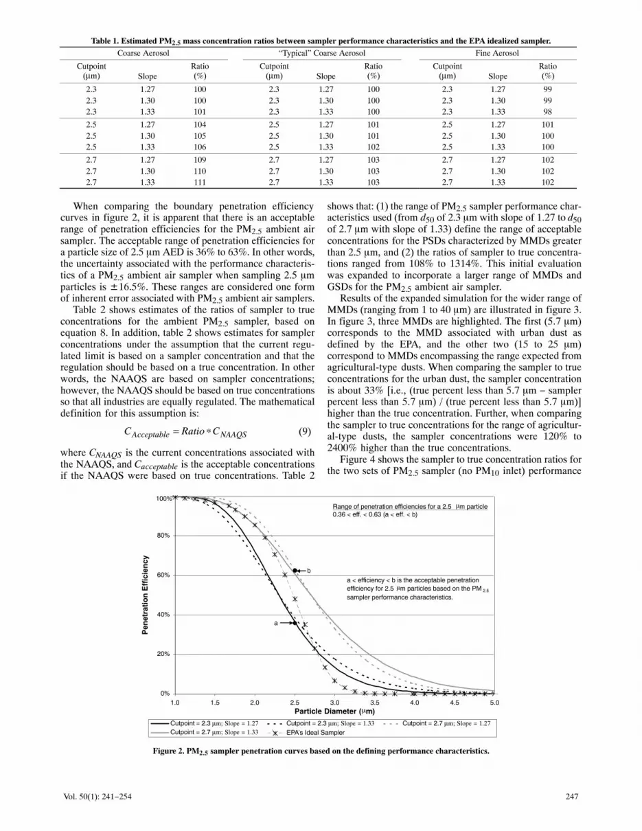
Based on the ambient PM2.5 sampler performance criteriaused in this article, four combinations of d50 and slope valueswere used to define boundary penetration efficiency curves.These penetration curves were defined with d50 values of 2.3and 2.7 �m and slope values of 1.27 and 1.33. Figure 2illustrates the comparison of the boundary penetration curvesand the EPA ideal PM2.5 sampler penetration efficiencycurve. The ideal penetration curve was encompassed by theboundary penetration curves for particle diameters less thanabout 2.7 �m and was outside of the boundary curves forparticle diameters greater than 2.7 �m.
0%
20%
40%
60%
80%
100%
1 10 100
Aerodynamic Diameter (�m)
Cu
mu
lati
ve P
enet
rati
on
Eff
icie
ncy
EPA PM2.5 Sampling Criteria Inhalable Fraction Respirable Fraction
EPA PM10 Sampling Criteria Thoracic Fraction
2.5
Figure 1. EPA ideal PM10 and PM2.5 sampler penetration curves overlaid on the ACGIH sampling criteria for inhalable, thoracic, and respirable frac-tions of PM (ACGIH, 1997; CFR, 2001d, 2001e).
247Vol. 50(1): 241−254
Table 1. Estimated PM2.5 mass concentration ratios between sampler performance characteristics and the EPA idealized sampler.Coarse Aerosol “Typical” Coarse Aerosol Fine Aerosol
Cutpoint(µm) Slope
Ratio(%)
Cutpoint(µm) Slope
Ratio(%)
Cutpoint(µm) Slope
Ratio(%)
2.3 1.27 100 2.3 1.27 100 2.3 1.27 992.3 1.30 100 2.3 1.30 100 2.3 1.30 992.3 1.33 101 2.3 1.33 100 2.3 1.33 98
2.5 1.27 104 2.5 1.27 101 2.5 1.27 1012.5 1.30 105 2.5 1.30 101 2.5 1.30 1002.5 1.33 106 2.5 1.33 102 2.5 1.33 100
2.7 1.27 109 2.7 1.27 103 2.7 1.27 1022.7 1.30 110 2.7 1.30 103 2.7 1.30 1022.7 1.33 111 2.7 1.33 103 2.7 1.33 102
When comparing the boundary penetration efficiencycurves in figure 2, it is apparent that there is an acceptablerange of penetration efficiencies for the PM2.5 ambient airsampler. The acceptable range of penetration efficiencies fora particle size of 2.5 �m AED is 36% to 63%. In other words,the uncertainty associated with the performance characteris-tics of a PM2.5 ambient air sampler when sampling 2.5 �mparticles is ±16.5%. These ranges are considered one formof inherent error associated with PM2.5 ambient air samplers.
Table 2 shows estimates of the ratios of sampler to trueconcentrations for the ambient PM2.5 sampler, based onequation 8. In addition, table 2 shows estimates for samplerconcentrations under the assumption that the current regu-lated limit is based on a sampler concentration and that theregulation should be based on a true concentration. In otherwords, the NAAQS are based on sampler concentrations;however, the NAAQS should be based on true concentrationsso that all industries are equally regulated. The mathematicaldefinition for this assumption is:
NAAQSAcceptable CRatioC ∗= (9)
where CNAAQS is the current concentrations associated withthe NAAQS, and Cacceptable is the acceptable concentrationsif the NAAQS were based on true concentrations. Table 2
shows that: (1) the range of PM2.5 sampler performance char-acteristics used (from d50 of 2.3 �m with slope of 1.27 to d50of 2.7 �m with slope of 1.33) define the range of acceptableconcentrations for the PSDs characterized by MMDs greaterthan 2.5 �m, and (2) the ratios of sampler to true concentra-tions ranged from 108% to 1314%. This initial evaluationwas expanded to incorporate a larger range of MMDs andGSDs for the PM2.5 ambient air sampler.
Results of the expanded simulation for the wider range ofMMDs (ranging from 1 to 40 �m) are illustrated in figure 3.In figure 3, three MMDs are highlighted. The first (5.7 �m)corresponds to the MMD associated with urban dust asdefined by the EPA, and the other two (15 to 25 �m)correspond to MMDs encompassing the range expected fromagricultural-type dusts. When comparing the sampler to trueconcentrations for the urban dust, the sampler concentrationis about 33% [i.e., (true percent less than 5.7 �m − samplerpercent less than 5.7 �m) / (true percent less than 5.7 �m)]higher than the true concentration. Further, when comparingthe sampler to true concentrations for the range of agricultur-al-type dusts, the sampler concentrations were 120% to2400% higher than the true concentrations.
Figure 4 shows the sampler to true concentration ratios forthe two sets of PM2.5 sampler (no PM10 inlet) performance
0%
20%
40%
60%
80%
100%
1.0 1.5 2.0 2.5 3.0 3.5 4.0 4.5 5.0Particle Diameter (�m)
Pen
etra
tio
n E
ffic
ien
cy
Cutpoint = 2.3 µm; Slope = 1.27 Cutpoint = 2.3 µm; Slope = 1.33 Cutpoint = 2.7 µm; Slope = 1.27Cutpoint = 2.7 µm; Slope = 1.33 EPA’s Ideal Sampler
a
b
Range of penetration efficiencies for a 2.5 µm particle0.36 < eff. < 0.63 (a < eff. < b)
a < efficiency < b is the acceptable penetrationefficiency for 2.5 µm particles based on the PM 2.5
sampler performance characteristics.
Figure 2. PM2.5 sampler penetration curves based on the defining performance characteristics.

248 TRANSACTIONS OF THE ASABE
Table 2. Concentration ratios of the theoretical sampler to true concentrationsfor various particle size distributions and sampler performance characteristics.
SamplerCharacteristics
Particle Size Distribution Characteristics
GSD = 1.5 GSD = 2.0
MMD = 5 µm MMD = 10 µm MMD = 15 µm MMD = 20 µm
Cutpoint(µm) Slope
Ratio(%)[a]
PM2.5 Conc.(µg/m3)[b]
Ratio(%)[a]
PM2.5 Conc.(µg/m3)[b]
Ratio(%)[a]
PM2.5 Conc.(µg/m3)[b]
Ratio(%)[a]
PM2.5 Conc.(µg/m3)[b]
2.3 1.27 113.3 73.65 285.3 185.45 108.3 70.40 117.8 76.572.3 1.30 123.5 80.28 372.6 242.19 117.1 76.12 130.4 84.762.3 1.33 134.2 87.23 482.0 313.30 126.9 82.49 144.7 94.062.5 1.27 161.2 104.78 531.3 345.35 149.3 97.05 169.1 109.922.5 1.30 173.1 112.52 652.1 423.87 160.4 104.26 186.0 120.902.5 1.33 185.5 120.58 821.8 534.17 172.7 112.26 204.9 133.192.7 1.27 218.1 141.77 860.1 559.07 198.7 129.16 233.8 151.972.7 1.30 231.2 150.28 1066.9 693.49 212.4 138.06 255.4 166.012.7 1.33 244.8 159.12 1314.0 854.10 227.4 147.81 279.6 181.74
[a] Values are based on the assumption that true concentrations are the correct estimates of the corresponding PM concentrations.[b] Concentrations are based on the corresponding regulations and adjusted by the ratio. Sampler concentrations for PM2.5 are 65 µg/m3.
characteristics that define the acceptable concentrations forPM2.5, GSD = 2.0, and PSD MMDs ranging from 1 to 40 �m.To aid in the interpretation of the graph, an average con-centration ratio is defined as the average of the largest andsmallest ratios for a particular MMD. The information pre-sented in figure 4 shows that: (1) the average ratio is equal to1.0 when the MMD is equal to the d50, (2) the average ratiois greater than 1.0 when the MMD is greater than the d50, and(3) the ratio range increases as the MMD increases. In generalterms, when the ratio is equal to 1.0, the current method ofregulating PM2.5 results in an exact concentration measure-ment of PM less than or equal to 2.5 �m AED, and when theratio is greater than 1.0, the current method overestimates theconcentration of PM less than 2.5 �m AED. For example, ifa PSD were characterized by an MMD of 5.7 �m and a GSDof 2.0, then the acceptable range of PM2.5 sampler concentra-tions to be in compliance with the property-line concentra-tion limits would be 60 to 87 �g/m3 (i.e., ratios of 0.92 and1.34 obtained from figure 4 and multiplied by 65 �g/m3, theproposed NAAQS for PM2.5). In this scenario, the PM2.5sampler uncertainty is ±13.5 �g/m3, and since the EPA es-sentially states that the PM2.5 NAAQS should correspond to
a true concentration, the PM2.5 sampler bias is 8.5 �g/m3. Ifthe PSD were characterized by an MMD of 10 �m and a GSDof 2.0, then the acceptable range of PM2.5 sampler concentra-tions would be 64 to 115 �g/m3, with a corresponding PM2.5sampler uncertainty of ±25.5 �g/m3 and a bias of 24.5�g/m3. Further, if the PSD were characterized by an MMD of20 �m and a GSD of 2.0, then the acceptable range of PM2.5sampler concentrations would be 77 to 182 �g/m3, corre-sponding to a PM2.5 sampler uncertainty of ±52.5 �g/m3 anda bias of 64.5 �g/m3.
The data presented in figure 5 are based on the sameassumptions as figure 4, except the data are based on a GSDof 1.5. When comparing figures 4 and 5, it is obvious that theratios increase much more rapidly as the MMD increaseswhen the GSD is 1.5 as compared to a GSD of 2.0. Forexample, if a PSD were characterized by an MMD of 5.7 �mAED and a GSD of 1.5, then the acceptable range of PM2.5sampler concentrations would be 81 to 193 �g/m3 (i.e., ratiosof 1.24 and 2.96 obtained from figure 6 and multiplied by65 �g/m3, the proposed NAAQS for PM2.5), correspondingto a PM2.5 sampler uncertainty of ±56 �g/m3 and a bias of72 �g/m3. If the PSD were characterized by an MMD of
16%
0.5%
12%
< 0.05%1.1%
0%
2%
4%
6%
8%
10%
12%
14%
16%
18%
20%
0 5 10 15 20 25 30 35 40
Mass Median Diameter ( m)
PM
< 2
.5�
m
True PM < 2.5 µm Sampled PM < 2.5 µm
Urb
an D
ust (
defin
ed b
y E
PA)
Sampler assumptions:1) Cutpoint = 2.7 m2) Slope = 1.33
TypicalAgricultural
Dusts
< 0.002%
µ
�
Figure 3. Comparison of sampler and true PM2.5 percentages for a range of PSD MMDs and GSD = 2.0.

249Vol. 50(1): 241−254
0
1
2
3
4
5
0 5 10 15 20 25 30 35 40
MMD ( m)
Sam
ple
r C
on
cen
trat
ion
Tru
e C
on
cen
trat
ion
Cutpoint = 2.7 µm; Slope = 1.33 Cutpoint = 2.3 µm; Slope = 1.27
Ratio range for a 10 m MMD PSD0.99 < Ratio < 1.77 (c < Ratio < d)Acceptable PM2.5 sampler measurement to meet PLC
64 < x < 115 g/m3 (Ratio * 65 g/m3)
Ratio range for a 20 m MMD PSD1.18 < Ratio < 2.80 (e < Ratio < f)Acceptable PM2.5 sampler measurement to meet PLC
77 < x < 182 g/m3 (Ratio * 65 g/m3)
a < ratio < b, c < ratio < d, and e < ratio < f are the acceptableratio ranges for 5.7, 10 and 20 m particles, respectively basedon the interaction of the PM 2.5 sampler performancecharacteristics and particle size distribution.
Proposed PM2.5 property line
concentration (PLC) = 65 g/m3
d
c
f
e
Ratio range for a 5.7 m MMD PSD0.92 < Ratio < 1.34 (a < Ratio < b)Acceptable PM2.5 sampler measurement to meet PLC
60 < x < 87 g/m3 (Ratio * 65 g/m3)
b
a
µ
µ
µ
µ
�
Figure 4. Theoretical ratios of PM2.5 sampler to true PSD concentrations for a range of MMDs and a GSD = 2.0.
10 �m AED and a GSD of 1.5, then the acceptable range ofPM2.5 sampler concentrations would be 185 to 854 �g/m3,corresponding to a PM2.5 sampler uncertainty of±334.5 �g/m3 and a bias of 454.5 �g/m3. Further, if the PSDwere characterized by an MMD of 20 �m AED and a GSD of1.5, then the acceptable range of PM2.5 sampler concentra-tions would be 963 to 11,929 �g/m3, corresponding to a
PM2.5 sampler uncertainty of ±5,483 �g/m3 and a bias of6,381 �g/m3. Thus, the data presented in figures 4 and 5 indi-cate that the range of acceptable concentrations increases asthe GSD increases.
The data presented in figure 6 are based on the sameassumptions as figure 4, except the sampler performancecharacteristics of a PM10 inlet are incorporated into the
0
40
80
120
160
200
0 5 10 15 20 25 30 35 40
Sam
ple
r C
on
cen
trat
ion
Tru
e C
on
cen
trat
ion
Cutpoint = 2.7 µm; Slope = 1.33 Cutpoint = 2.3 µm; Slope = 1.27
Ratio range for a 10 m MMD PSD2.85 < Ratio < 13.14 (c < Ratio < d)Acceptable PM2.5 sampler measurement to meet PLC
185 < x < 854 g/m3 (Ratio * 65 g/m3)
Ratio range for a 20 m MMD PSD14.81 < Ratio < 183.5 (e < Ratio < f)Acceptable PM2.5 sampler measurement to meet PLC
963 < x < 11,929 g/m3 (Ratio * 65 g/m3)
a < ratio < b, c < ratio < d, and e < ratio < f are the acceptableratio ranges for 5.7, 10 and 20 m particles, respectivelybased on the interaction of the PM 2.5 sampler performancecharacteristics and particle size distribution.
Proposed PM2.5 property line
concentration (PLC) = 65 g/m3
d
c
f
e
Ratio range for a 5.7 m MMD PSD1.24 < Ratio < 2.96 (a < Ratio < b)Acceptable PM2.5 sampler measurement to meet PLC
81 < x < 193 g/m3 (Ratio * 65 g/m3)
b
a
µ
µ
µ
µ
MMD (�m)
Figure 5. Theoretical ratios of PM2.5 sampler to true PSD concentrations for a range of MMDs and a GSD = 1.5.

250 TRANSACTIONS OF THE ASABE
0
1
2
3
4
5
0 5 10 15 20 25 30 35 40
Sam
ple
r C
on
cen
trat
ion
Tru
e C
on
cen
trat
ion
PM2.5 (Cutpoint = 2.7 µm; Slope = 1.33); PM10 (Cutpoint = 10.5 µm; Slope = 1.4)
PM2.5 (Cutpoint = 2.3 µm; Slope = 1.27); PM10 (Cutpoint = 9.5 µm; Slope = 1.6)
Ratio range for a 10 m MMD PSD0.99 < Ratio < 1.77 (c < Ratio < d)Acceptable PM2.5 sampler measurement to meet PLC
64 < x < 115 g/m3 (Ratio * 65 g/m3)
Ratio range for a 20 m MMD PSD1.17 < Ratio < 2.79 (e < Ratio < f)Acceptable PM2.5 sampler measurement to meet PLC
76 < x < 181 g/m3 (Ratio * 65 g/m3)
a < ratio < b, c < ratio < d, and e < ratio < f are the acceptableratio ranges for 5.7, 10 and 20 m particles, respectively basedon the interaction of the PM2.5 sampler performancecharacteristics and particle size distribution.
Proposed PM2.5 property line
concentration (PLC) = 65 g/m3
d
c
f
e
Ratio range for a 5.7 m MMD PSD0.92 < Ratio < 1.36 (a < Ratio < b)Acceptable PM2.5 sampler measurement to meet PLC
60 < x < 88 g/m3 (Ratio * 65 g/m3)
b
a
µ
µ
µ
µ
MMD (�m)
Figure 6. Theoretical ratios of PM2.5 sampler, with PM10 inlet, to true PSD concentrations for a range of MMDs and a GSD = 2.0.
simulation. The d50 and slope values for the PM10 inlet usedin the simulation were based on EPA guidelines and were re-fined through a trial and error process (i.e., determiningwhich PM10 d50 and slope values coupled with the PM2.5boundary performance characteristic generated the PM2.5sampler with PM10 inlet boundary performance characteris-tics). The resulting PM10 performance characteristics were
defined as a d50 of 9.5 �m with a slope of 1.6, and a d50 of10.5 �m with a slope of 1.4. In general, the inclusion of thePM10 inlet on the PM2.5 sampler had very little effect on thesampler to true concentration ratio. For example, if the PSDwere characterized by an MMD of 5.7 �m AED and a GSDof 2.0, then the acceptable concentration range for a PM2.5sampler with a PM10 inlet would be 60 to 88 �g/m3 (fig. 6),
0
40
80
120
160
200
0 5 10 15 20 25 30 35 40
Sam
ple
r C
on
cen
trat
ion
Tru
e C
on
cen
trat
ion
PM2.5 (Cutpoint = 2.7 µm; Slope = 1.33); PM10 (Cutpoint = 10.5 µm; Slope = 1.4)
PM2.5 (Cutpoint = 2.3 µm; Slope = 1.27); PM10 (Cutpoint = 9.5 µm; Slope = 1.6)
Ratio range for a 10 m MMD PSD2.81 < Ratio < 13.05 (c < Ratio < d)Acceptable PM2.5sampler measurement to meet PLC
183 < x < 848 g/m3 (Ratio * 65 g/m3)
Ratio range for a 20 m MMD PSD14.28 < Ratio < 177.8 (e < Ratio < f)Acceptable PM2.5 sampler measurement to meet PLC
928 < x < 11,557 g/m3 (Ratio * 65 g/m3)
a < ratio < b, c < ratio < d, and e < ratio < f are the acceptableratio ranges for 5.7, 10 and 20 m particles, respectivelybased on the interaction of the PM2.5 sampler performancecharacteristics and particle size distribution.
Proposed PM2.5 property line
concentration (PLC) = 65 g/m3
d
c
f
e
Ratio range for a 5.7 m MMD PSD1.27 < Ratio < 3.13 (a < Ratio < b)Acceptable PM2.5sampler measurement to meet PLC
83 < x < 204 g/m3 (Ratio * 65 g/m3)
b
a
µ
µ
µ
µ
MMD (�m)
Figure 7. Theoretical ratios of PM2.5 sampler, with PM10 inlet, to true PSD concentrations for a range of MMDs and a GSD = 1.5.

251Vol. 50(1): 241−254
0.5
2.5
4.5
6.5
8.5
10.5
12.5
0 5 10 15 20 25 30 35 40
Sam
ple
r C
on
cen
trat
ion
Tru
e C
on
cen
trat
ion
GSD=1.3 GSD=1.5 GSD=1.6 GSD=1.7 GSD=1.8 GSD=2.0 GSD=2.5
MMD (�m)
Figure 8. Theoretical ratios of PM2.5 sampler measured to true PSD concentrations (PM2.5 sampler characteristics: cutpoint = 2.5 �m and slope = 1.3).
as compared to 60 to 87 �g/m3 for a PM2.5 sampler with noPM10 inlet (fig. 4). If the PSD were characterized by an MMDof 20 �m AED and a GSD of 2.0, then the acceptable con-centration range for a PM2.5 sampler with a PM10 inlet wouldbe 76 to 181 �g/m3, as compared to 77 to 182 �g/m3 for aPM2.5 sampler with no PM10 inlet.
The data presented in figure 7 are based on the sameassumptions as figure 6, except the GSD = 1.5. Comparisonof figures 4 and 6 shows that the inclusion of the PM10 inlet
on the PM2.5 sampler had very little relative effect on thesampler to true concentration ratio. For example, if the PSDwere characterized by an MMD of 5.7 �m AED and a GSDof 1.5, then the acceptable concentration range for a PM2.5sampler with a PM10 inlet would be 83 to 204 �g/m3 (fig. 7),as compared to 81 to 193 �g/m3 for a PM2.5 sampler with noPM10 inlet (fig. 5). If the PSD were characterized by an MMDof 20 �m AED and a GSD of 1.5, then the acceptableconcentration range for a PM2.5 sampler with a PM10 inlet
0
2
4
6
8
10
1 1.2 1.4 1.6 1.8 2 2.2 2.4 2.6 2.8 3
GSD
Sam
ple
r C
on
cen
trat
ion
Tru
e C
on
cen
trat
ion
Cutpoint = 2.3 µm; Slope = 1.27; MMD = 10 µm Cutpoint = 2.7 µm; Slope = 1.33; MMD = 10 µm
Cutpoint = 2.3 µm; Slope = 1.27; MMD = 20 µm Cutpoint = 2.7 µm; Slope = 1.33; MMD = 20 µm
Ratio boundaries based on defined PM2.5 sampler performance characteristics for
Ratio boundaries based on defined PM2.5 sampler performance characteristics forPSD’s with MMD’s of 10 µm.
PSD’s with MMD’s of 20 µm.
Figure 9. Theoretical PM2.5 sampler measured to true concentration ratio boundaries for varying GSDs with MMDs of 10 and 20 �m.

252 TRANSACTIONS OF THE ASABE
would be 928 to 11,557 �g/m3, as compared to 963 to11,929 �g/m3 for a PM2.5 sampler with no PM10 inlet. Al-though a decrease of 372 �g/m3, when comparing the PM2.5sampler with and without a PM10 inlet for a PSD character-ized by an MMD of 20 �m and a GSD of 1.5, would seem sig-nificant, the relative difference is negligible (i.e., only abouta 3% decrease). Therefore, only the PM2.5 sampler perfor-mance characteristics without the PM10 inlet performancecharacteristics are used in the remainder of the inherent sam-pler errors discussion.
Figure 8 further illustrates the effect of MMD and GSD onthe concentration ratios for a PM2.5 sampler with a d50 of2.5 �m and a slope of 1.3. In general, the concentration ratiosdecrease (ratio approaches 1.0) as the GSD increases and asMMD decreases. Figure 9 further expands on how theconcentration ratios are impacted by GSD. The data present-ed in figure 9 are based on MMDs of 10 and 20 �m, samplerperformance characteristic of a d50 equal to 2.3 �m with aslope of 1.27 and a d50 of 2.7 �m with a slope of 1.33, andvariable GSDs ranging from 1.2 to 3.0. The figure shows that:(1) as the GSD increases, the concentration ratio decreasesand approaches 1.0, and (2) as the GSD decreases, theconcentration ratio increases and approaches infinity.
SUMMARY AND CONCLUSIONSeveral errors are associated with the current air pollution
rules and regulations established by the EPA that should beminimized to ensure equal regulation of air pollutantsbetween and within all industries. Potentially one of the mostsignificant errors is attributed to the interaction of theindustry-specific PSD and sampler performance characteris-tics. Currently, the regulation of PM is based on samplermeasurements and not on true concentrations.
Sampler concentration refers to the concentration col-lected by a PM sampler. This concentration is dependent onthe sampler’s performance characteristics (i.e., d50 and slopeof the sampler penetration curve). Since the concentration isbased on the sampler’s performance characteristics, there aretwo inherent errors associated with the measurement. For aPM2.5 sampler, the first error corresponds to the mass ofparticles less than 2.5 �m that should have been captured onthe filter but was removed from the air stream by thepre-separator. The second error (for a PM2.5 sampler)corresponds to the mass of particles greater than 2.5 �m thatshould have been removed from the air stream by thepre-separator but was allowed to pass through the pre-separa-tor and was captured on the filter. When the MMD of the dustbeing sampled is less than the sampler d50, under-samplingof the mass of particles less than 2.5 �m occurs. When theMMD of the dust being sampled is equal to the d50 of thesampler, the sampler provides a measurement equivalent tothe true mass of particles less than 2.5 �m. When the MMDof the dust being sampled is greater than the d50 of thesampler, over-sampling of the mass of particles less than2.5 �m occurs.
True concentration refers to the mass of particles less thanor equal to the size of interest. In order for a sampler toprovide a true concentration, independent of the MMD of thedust being sampled, the sampler would have to maintain aslope of 1.0 (i.e., the sampler’s penetration curve would berepresented by a step function).
According to the literature, the EPA decided to regulatePM2.5 based on the availability of the dichotomous sample.The PM2.5 regulation was not based on determining therespirable fraction of PM. ACGIH, ISO, and others havedefined the respirable fraction of PM as having a d50 between3.5 and 5 �m. The final justification for using true PM2.5values as opposed to sampler-based concentration comesfrom the literature in the following direct quotation:
“Staff also recommended the use of a sharp 2.5 microncutpoint for a fine particle indicator. PM2.5 does have somepotential for intrusion of the tail of the coarse mode duringepisodes of fugitive dust concentrations. Staff recommendsa sharp inlet for the FRM to minimize this potential intrusionof coarse-mode particles. Such intrusion into PM2.5 measure-ment is not anticipated to be significant in most situations;nevertheless, if subsequent data reveal problems in thisregard, this issue can and should be addressed on acase-by-case basis in the monitoring and implementationprograms. Because the purpose of a PM2.5 standard is todirect controls toward sources of fine-mode particles, itwould be appropriate to develop analytical procedures foridentifying those cases where a PM2.5 standard violationwould not have occurred in the absence of coarse-modeparticle intrusion. Consideration should be given to a policysimilar to the natural events policy for addressing such cases”(USEPA, 1996b).
The NAAQS standards correspond to PM in the ambientair (i.e., not impacted by only one source). Therefore, thequestion becomes, “Is it appropriate to use an EPA-approvedambient PM2.5 sampler to determine emission values fromindividual sources?” In all situations when the source isemitting PM with an MMD larger than 2.5 �m, the answer is“absolutely not.”
So how is this a problem? If a state or air district finds itselfin non-attainment with the PM2.5 NAAQS, then the corre-sponding agencies will, most likely, be required to reducePM2.5 emissions within the air shed. In order to reduceemissions from individual sources, the amount of PM emittedby the sources must be known or estimated. This is typicallyaccomplished through source sampling or the use of emissionfactors, which may have been determined from sourcesampling or interpreted by some other means. In order toillustrate why it is crucial that emission factors, emissionrates, and/or emission concentrations from individualsources be based on true PM2.5 and not PM2.5 samplermeasurements, the following example is provided.
Assume that EPA-approved PM2.5 ambient air samplerswere set up to monitor two commercial operations. Assumealso that the samplers have performance characteristicsdescribed by a d50 of 2.3 �m and a slope of 1.3 (bothparameters are within the performance criteria defined by theEPA). Now assume that one operation is a power plant and isemitting PM (sampled by the PM2.5 sampler) that can bedescribed by a lognormal distribution with an MMD of 5 �mand a GSD of 1.8. Assume that the second operation is anagricultural operation and is emitting PM (sampled by thePM2.5 sampler) that can be described by a lognormaldistribution with an MMD of 20 �m and a GSD of 1.8.Further, assume that the PM2.5 sampler used to monitor eachof the operations measures 50 �g/m3. Now, based on themethods laid out in this article, the true PM (PM less than2.5 �m) emitted from each industry would be defined asfollows:

253Vol. 50(1): 241−254
Based on a PSD analysis, the percent of PM mass less than2.5 �m being emitted by the power plant is 11.9%. Based onthe PSD and sampler performance characteristics, thepercent of total suspended particulate (TSP) captured by thePM2.5 sampler is 11.4%. The TSP concentration emitted bythe power plant is 439 �g/m3 (i.e., 50 �g/m3 (PM measuredby the PM2.5 sampler) / 0.114 (% of TSP captured by thePM2.5 sampler). By multiplying the TSP concentration by thetrue fraction of PM2.5 (i.e., 439 �g/m3 × 0.119), the truePM2.5 concentration is determined to be 52 �g/m3. There-fore, the PM2.5 sampler underestimated the true PM2.5concentration by 3.8%.
For the agricultural operation, using the previous proce-dures, the true percent PM2.5 is 0.02%, and based on the PSDand sampler performance characteristics, the percent of TSPcaptured by the PM2.5 sampler is 0.039%. Therefore, the TSPconcentration is 128,205 �g/m3, resulting in the true PM2.5emitted by the operation being equal to 25.6 �g/m3. In thiscase, the PM2.5 sampler overestimated the true PM2.5 by95%. Based on this scenario, the two operations are not beingequally regulated, and the PM2.5 ambient air samplers areoverestimating the concentration of particles less than 2.5 �mthat are being emitted by the operations.
Looking at the issue from another viewpoint, assume thatthe two operations described previously are emitting60 �g/m3 true PM2.5. If the percent of TSP measured by thePM2.5 sampler (defined as measured PM2.5) is divided by thepercent of true PM2.5, and this ratio is then multiplied by thetrue concentration of PM2.5 being emitted, the PM2.5 samplerconcentrations can be determined. For the power plant, thePM2.5 sampler would measure a concentration of 58 �g/m3.For the agricultural operation, the PM10 sampler wouldmeasure a concentration of 116 �g/m3. What this means forthe agricultural operation is that 60 �g/m3 of the PM beingsampled is less than 2.5 �m and 56 �g/m3 of the PM beingsampled is larger than 2.5 �m. Therefore, regarding thequestion, “Is it appropriate to use PM2.5 samplers todetermine PM2.5 emission values from industries that areemitting PM with an MMD larger than 2.5 �m?,” the answeris “absolutely not.”
Results of the analysis presented in this article show thatall industries are not being equally regulated in terms ofPM2.5 and that all industries should be concerned with thecurrent site-specific regulations implemented by the EPA andenforced by SAPRAs.
REFERENCESACGIH. 1997. 1997 Threshold Limit Values and Biological
Exposure Indices. Cincinnati, Ohio: American Conference ofGovernmental Industrial Hygienists.
Buch, U. M. 1999. Performance analysis of the cascade impactor,the Federal Reference Method PM2.5 sampler, and theIMPROVE PM2.5 sampler. MS thesis. College Station, Texas:Texas A&M University, Department of AgriculturalEngineering.
Buser, M. D., C. B. Parnell, Jr., B. W. Shaw, and R. E. Lacey.2006a. Particulate matter sampler errors due to the interaction ofparticle size and sampler performance characteristics:Background and theory. Trans. ASAE 50(1): 221−228.
Buser, M. D., C. B. Parnell, Jr., B. W. Shaw, and R. E. Lacey.2006b. Particulate matter sampler errors due to the interaction of
particle size and sampler performance characteristics: AmbientPM10 samplers. Trans. ASAE 50(1): 229−240.
CFR. 2001a. Ambient air monitoring reference and equivalentmethods. 40 CFR, Part 53. Washington, D.C.: U.S. GovernmentPrinting Office.
CFR. 2001b. Ambient air quality surveillance. 40 CFR, Part 58.Washington, D.C.: U.S. Government Printing Office.
CFR. 2001c. National primary and secondary ambient air qualitystandards; definitions. 40 CFR, Part 50. Washington, D.C.: U.S.Government Printing Office.
CFR. 2001d. Reference method for the determination of particulatematter as PM10 in the atmosphere. 40 CFR, Part 50, Appendix J.Washington, D.C.: U.S. Government Printing Office.
CFR. 2001e. Reference method for the determination of fineparticulate matter as PM2.5 in the atmosphere. 40 CFR, Part 50,Appendix L. Washington, D.C.: U.S. Government PrintingOffice.
Dzubay, T. G., R. K. Stevens, G. E. Gordon, I. Olmez, A. E.Sheffield, and W. J. Courtney. 1988. A composite receptormethod applied to Philadelphia aerosol. Environ. Sci. Tech.22(1): 46-52.
Eldred, R. A., T. A. Cahill, and R. G. Flocchini. 1994. Comparisonof PM10 and PM2.5 aerosols in the IMPROVE network. J. AirWaste Manage. Assoc. 47(2): 194-203.
Federal Register. 1997. National ambient air quality standards forparticulate matter; final rule. July 18. Federal Register 62: 38,652-38, 752.
Hill, J. S., P. D. Patel, and J. R. Turner. 1999. Performancecharacterization of the MiniVol PM2.5 sampler. AWMA PaperNo. 99-617. Pittsburgh, Pa.: AWMA.
Hinds, W. C. 1982. Aerosol Technology; Properties, Behavior, andMeasurement of Airborne Particles. New York, N.Y.: JohnWiley and Sons.
Kenny, L. C. 1998. Investigation of the effects of loading on PM2.5selectors. Report No. IR/L/EXM/01/01. London, U.K.: Healthand Safety Laboratory.
Kenny, L. C. 2000. Evaluation of VSCC cyclones for BGIIncorporated. London, U.K.: Health and Safety Laboratory.
Kenny, L. C., R. Gussman, and M. Meyer. 2000. Development of asharp-cut cyclone for ambient aerosol monitoring applications.Aerosol Sci. Tech. 32(4): 338-358.
Moore, M. E., and A. R. McFarland. 1993. Performance modelingof single-inlet aerosol sampling cyclones. Environ. Sci. Tech.27(9): 1842-1848.
Pargmann, A. R. 2001. Performance characteristics of PM2.5samplers in the presence of agricultural dusts. MS thesis. CollegeStation, Texas: Texas A&M University, Department ofAgricultural Engineering.
Peters, T. M., and R. W. Vanderpool. 1996. Modification andevaluation of the WINS Impactor. USEPA Report No.68-D5-0040. Research Triangle Park, N.C.: U.S. EnvironmentalProtection Agency, National Exposure Laboratory.
Peters, T. M., R. A. Gussman, L. C. Kenny, and R. W. Vanderpool.2001a. Evaluation of PM2.5 size selectors used in speciationsamplers. Aerosol Sci. Tech. 34(5): 422-429.
Peters, T. M. R. W. Vanderpool, and R. W. Wiener. 2001b.Methodology for measuring PM2.5 separator characteristicsusing an aerosizer. Aerosol Sci. Tech. 34(5): 398-406.
Pitchford, M. 1997. Prototype PM2.5 Federal Reference Methodfield studies report. Research Triangle Park, N.C.: U.S.Environmental Protection Agency, Office of Air and Radiation.Available at: www.epa.gov/ttn/amtic/files/cfr/recent/prototyp.pdf. Accessed 6 February 2004.
Smith, W. B., R. R. Wilson, and D. B. Harris. 1979. A five-stagecyclone system for in-situ sampling. Environ. Sci. Tech. 13(11):1387-1392.
USEPA. 1996a. Air quality criteria for particulate matter, Vols. I, II,and III. Report No. EPA/600/P-95/001 aF-cF.3v. Washington,

254 TRANSACTIONS OF THE ASABE
D.C.: U.S. Environmental Protection Agency, Office ofResearch and Development.
USEPA. 1996b. Review of the national ambient air qualitystandards for particulate matter: Policy assessment of scientificand technical information. Report No. EPA/452/R-96-013.Research Triangle Park, N.C.: U.S. Environmental ProtectionAgency, Office of Air Quality Planning and Standards.
USEPA. 2000. National air pollutant emission trends, 1900-1998.Report No. EPA-454/R-00-002. Research Triangle Park, N.C.:U.S. Environmental Protection Agency, Office of Air QualityPlanning and Standards.
USEPA. 2001. Air quality criteria for particulate matter, Volume Iand II. Report No. EPA600/P-99/002 aB-bB. Research TrianglePark, N.C.: U.S. Environmental Protection Agency, NationalCenter for Environmental Assessment.
Vanderpool, R. W., T. M. Peters, S. Natarajan, D. B. Gemmill, andR. W. Wiener. 2001a. Evaluation of the loading characteristics ofthe EPA WINS PM2.5 separator. Aerosol Sci. Tech. 34(5):444-456.
Vanderpool, R. W., T. M. Peters, S. Natarajan, M. P. Tolocka, D. B.Gemmill, and R. W. Wiener. 2001b. Sensitivity analysis of theUSEPA WINS PM2.5 separator. Aerosol Sci. Tech. 34(5):465-476.


