Embed Size (px)
Citation preview
IEEE JOURNAL OF OCEANIC ENGINEERING, VOL. 32, NO. 3, JULY 2007 603
A Novel Mechanical Gas-Tight Samplerfor Hydrothermal Fluids
Ying Chen, Shijun Wu, Yingjun Xie, Canjun Yang, and Jiafan Zhang
Abstract—A new mechanical gas-tight sampler has been de-signed to collect hydrothermal fluids at the seafloor. A key featureof the sampler is the novel sample valve which is pressure balancedunder deep sea, and actuated by the ram on a submersible’s ma-nipulator. The sampler is designed to be deployed at the seafloor3000 m underwater and can be used to sample hydrothermal fluidwith temperature up to 400 C. Compressed gas is used to compen-sate for pressure reduction of sample fluids. Simulation of the flowsystem was conducted to estimate the fill rate. The sampler hasbeen tested successfully in the first Sino-American CooperativeDeep Submergence Project from August 13 to September 3, 2005.
Index Terms—Deep sea, hydrothermal fluid, sampler,simulation.
I. INTRODUCTION
THE hydrothermal vents are one of the most spectacular fea-tures on the seafloor. They are distributed along the mid-
ocean ridges, with highest frequencies at depths between 2200and 2800 m [1], [2]. Since its first discovery at the mid-oceanridge in the eastern Pacific in 1979 [3], the hydrothermal systemattracts scientists from fields of marine geology, geophysics,geochemistry, and marine biology because of its unique biolog-ical communities as well as hydrothermal activities.
Under the deep sea, hydrothermal fluids can attain tempera-ture up to 400 C, and are highly corrosive. The extreme en-vironments pose considerable engineering challenges for fluidssampling. A variety of devices have been developed to collectsamples from seafloor hydrothermal vents. The most widelyused “major pair” sampler utilizes the ram on a hydraulic ma-nipulator to activate the valve for sampling [4]. An automaticsampler is designed to be self-activated by using shape-memoryalloy [5]. The multichamber sampler and the seamless systemmake use of a pump to collect fluids [6], [7]. Gas-tight fluidsamples have also been collected with “lupton” gas-tight sam-pler and gas-tight isobaric sampler [8]. Moreover, some deviceshave been designed for the purpose of collecting microbial sam-ples from hydrothermal systems [9]–[11].
Manuscript received November 20, 2005; revised February 2, 2006; acceptedAugust 15, 2006. This work was supported by the International Cooperative KeyProject under Grant 2004DFA04900, the Ministry of Sciences and Technologyof the People’s Republic of China, the Zhejiang Province Science Foundationunder Grant Y105501, and the College Doctoral Subject Special Foundationunder Grant 20050335048.
Associate Editor: R. Stern.The authors are with the State Key Lab of Fluid Power Transmis-
sion and Control, Zhejiang University, Hangzhou 310027, China (e-mail:[email protected]; [email protected]; [email protected]; [email protected];[email protected]).
Digital Object Identifier 10.1109/JOE.2007.891887
Although various devices for fluids collection have been de-signed and deployed, only the “major pair,” “lupton,” and gas-tight isobaric samplers are often used by researchers today. The“major pair” sampler has been proven to be extremely reliableand rugged during numerous deployments in the past 20 years,but it is nongas-tight so it is not suitable to determine the abun-dance of dissolved gases. The “lupton” sampler has success-fully collected the gas-tight fluid samples, which is manipulatortriggered and features its compact configurations. However, thecomplicated sample transfer system required during the extrac-tion process reduces analysis efficiency. The gas-tight isobaricsampler is able to maintain the sample at seafloor pressure. It al-lows subsampling without degassing the fluid remaining in thesampler. In addition, the sampler is able to regulate the fill rateto minimize the entrainment of ambient seawater. However, thesampler is electric-motor actuated so it must carry additionalbatteries and heavy electronics pressure case, and it is morecomplicated than the manipulator-triggered system.
In this paper, we describe a new mechanical sampler whichmakes use of a novel sample valve with pressure balancedpoppet. The sample valve is manipulator triggered so it elimi-nates the need for extra power supply and complicated control.Furthermore, the sampler is also able to maintain the sampleunder in situ pressure by compressed gas. Quantitative analysisof dissolved gas components can be achieved. The fill rate isregulated to minimize the entrainment of ambient seawaterwhile collecting fluids.
II. INSTRUMENT DESIGN AND CONSTRUCTION
A. Design
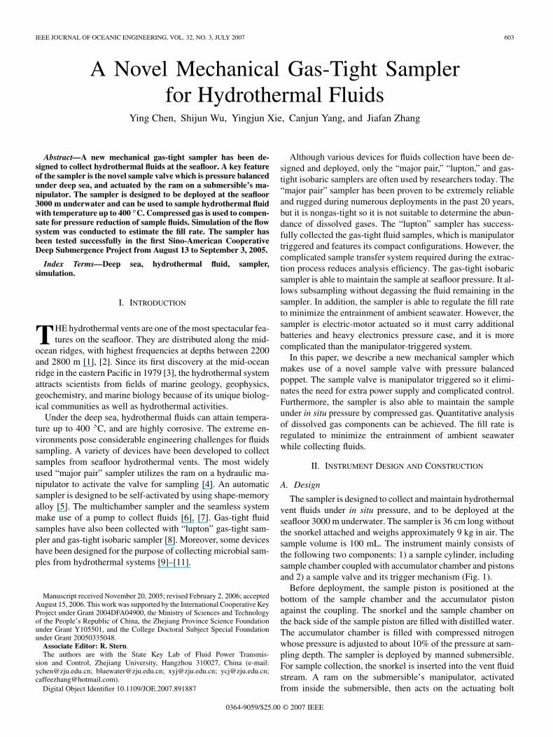
The sampler is designed to collect and maintain hydrothermalvent fluids under in situ pressure, and to be deployed at theseafloor 3000 m underwater. The sampler is 36 cm long withoutthe snorkel attached and weighs approximately 9 kg in air. Thesample volume is 100 mL. The instrument mainly consists ofthe following two components: 1) a sample cylinder, includingsample chamber coupled with accumulator chamber and pistonsand 2) a sample valve and its trigger mechanism (Fig. 1).
Before deployment, the sample piston is positioned at thebottom of the sample chamber and the accumulator pistonagainst the coupling. The snorkel and the sample chamber onthe back side of the sample piston are filled with distilled water.The accumulator chamber is filled with compressed nitrogenwhose pressure is adjusted to about 10% of the pressure at sam-pling depth. The sampler is deployed by manned submersible.For sample collection, the snorkel is inserted into the vent fluidstream. A ram on the submersible’s manipulator, activatedfrom inside the submersible, then acts on the actuating bolt
0364-9059/$25.00 © 2007 IEEE
604 IEEE JOURNAL OF OCEANIC ENGINEERING, VOL. 32, NO. 3, JULY 2007
Fig. 1. Structure of the novel mechanical gas-tight sampler.
to open the sample valve. The hydrothermal fluid fill rate isregulated by the orifice, which restricts the flow of distilledwater through the coupling. The nitrogen in the accumulatorchamber is compressed further, and after it reaches the pressureof the hydrothermal fluid, the ram on the manipulator arm isthen retracted, closing the sample valve and the sampler isracked in the basket.
To address the requirement of gas tight, the sample shouldbe maintained at seafloor pressure. Compressed nitrogen gas inthe accumulator is used to compensate for pressure reductioncaused by cooling of hydrothermal fluid during recovery. How-ever, the sample valve is the most critical component of the sam-pler to ensure gas tightness and it must meet some demands asfollows. First, the sample valve must have bidirectional sealingcapability under high pressure, because any leakage before orafter sampling is not permitted for the sake of sample purityand gas tightness. Second, the valve should be extremely re-sistant to corrosion since the flow media are hot chloride-richacidic fluids. Third, the valve should be able to tolerate hightemperature.
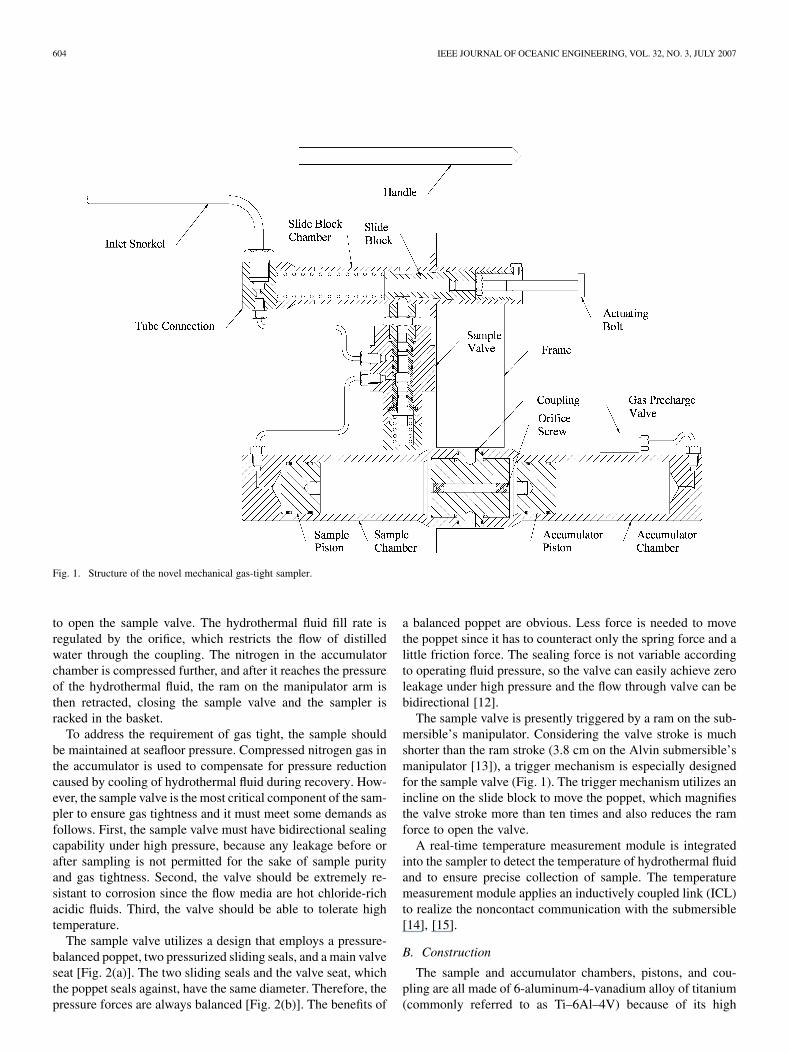
The sample valve utilizes a design that employs a pressure-balanced poppet, two pressurized sliding seals, and a main valveseat [Fig. 2(a)]. The two sliding seals and the valve seat, whichthe poppet seals against, have the same diameter. Therefore, thepressure forces are always balanced [Fig. 2(b)]. The benefits of
a balanced poppet are obvious. Less force is needed to movethe poppet since it has to counteract only the spring force and alittle friction force. The sealing force is not variable accordingto operating fluid pressure, so the valve can easily achieve zeroleakage under high pressure and the flow through valve can bebidirectional [12].
The sample valve is presently triggered by a ram on the sub-mersible’s manipulator. Considering the valve stroke is muchshorter than the ram stroke (3.8 cm on the Alvin submersible’smanipulator [13]), a trigger mechanism is especially designedfor the sample valve (Fig. 1). The trigger mechanism utilizes anincline on the slide block to move the poppet, which magnifiesthe valve stroke more than ten times and also reduces the ramforce to open the valve.
A real-time temperature measurement module is integratedinto the sampler to detect the temperature of hydrothermal fluidand to ensure precise collection of sample. The temperaturemeasurement module applies an inductively coupled link (ICL)to realize the noncontact communication with the submersible[14], [15].
B. Construction
The sample and accumulator chambers, pistons, and cou-pling are all made of 6-aluminum-4-vanadium alloy of titanium(commonly referred to as Ti–6Al–4V) because of its high
CHEN et al.: NOVEL MECHANICAL GAS-TIGHT SAMPLER FOR HYDROTHERMAL FLUIDS 605
Fig. 2. Illustration of the sample valve. (a) Internal structure of sample valve. (b) Pressure-balanced poppet. D1 = D2 = D3—all the pressure forces on thepoppet are balanced by equal and opposite forces.
strength, low density, and special resistance to corrosion.Moreover, the same material prevents potential electrochemicalreactions among the components. There is a tap hole acrossthe coupling, so it is convenient to change the orifice sizejust by replacing the restriction screw. A fluoroelastomer ischosen for the piston o-rings. The sample valve describedpreviously is mainly made of Ti–6Al–4V, except the stainlesssteel spring and polyetheretherketone (PEEK) poppet. PEEK isa kind of plastic material which features high strength, thermaltolerance (260 C for long-term use), and corrosion resistance.The PEEK poppet-to-titanium seating is the highlight of thesample valve design. It causes the valve to achieve zero leakageunder high pressure. All the o-rings of the sample valve aremade of fluoroelastomer. The trigger mechanism is made of431 stainless steel. The gas precharge valve is a commerciallyavailable needle valve.
III. PRECHARGED GAS PRESSURE COMPUTATION AND
SIMULATION OF FLOW SYSTEM
A. Precharged Gas Pressure Computation
Before deployment, the accumulator chamber of the samplermust be precharged with compressed nitrogen whose pressurewill be adjusted according to different sampling depths. Becausethe fill rate is slow, the gas in the accumulator goes through anisothermal process during sampling. So the gas state equationcan be described as follows:
(1)
Subscript “1” represents the presampling state with gas pressureand gas volume , which is equal to the accumulator volume
112 mL. Subscript “2” represents the postsampling state withgas pressure which reaches the seafloor pressure, and gasvolume . The volume of hydrothermal fluid filling into thesampler is worked out as follows:
(2)
The accumulator will be precharged onboard. Because the tem-perature onboard is different from that at the seafloor, the gaspressure changes during descent
(3)
where indicates the precharged pressure onboard and isthe onboard temperature. and are the gas pressure andtemperature at seafloor. The precharged pressure is estab-lished based on (1)–(3)
(4)
The seafloor temperature is usually 2 C–4 C, namely,275–279 K. The temperature onboard is approximately 300 K.When the sample volume is 100 mL, the precharged pressure
is about 10% of the seafloor pressure .
B. Simulation of the Flow System
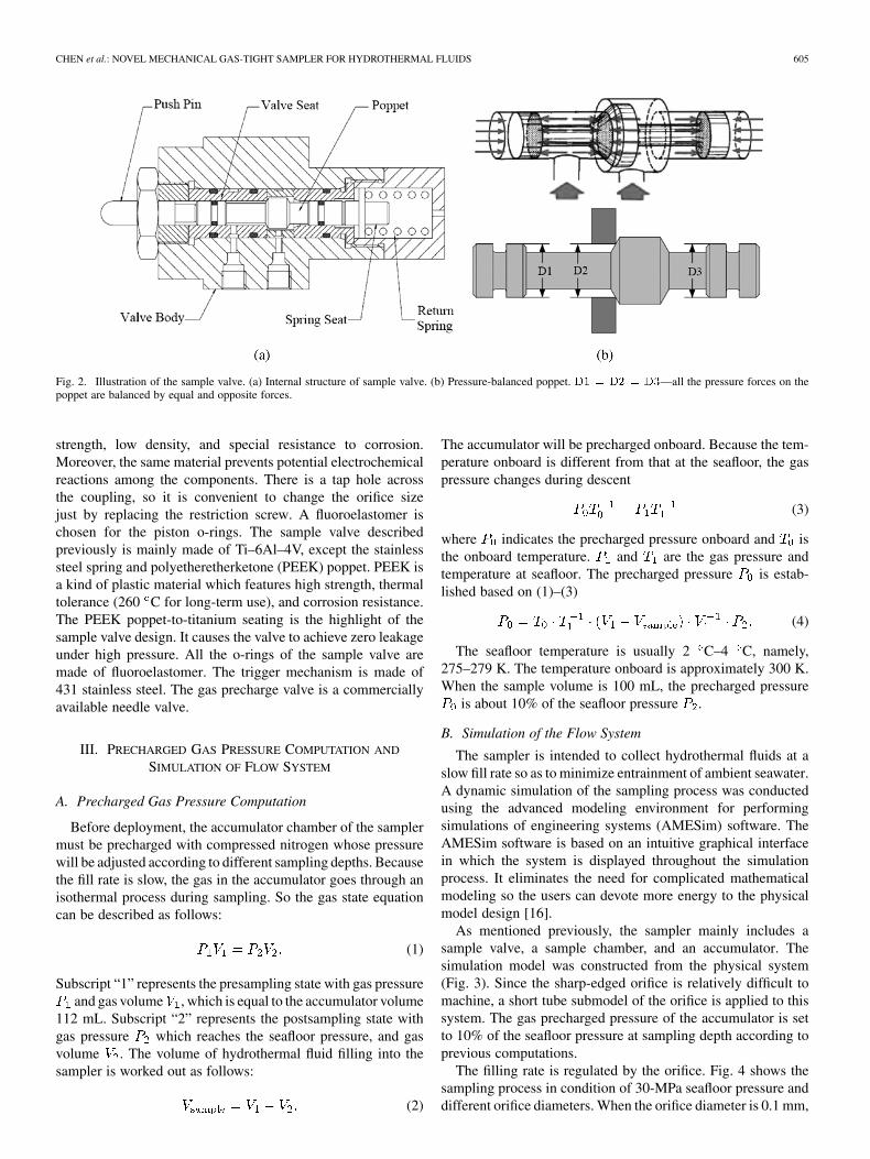
The sampler is intended to collect hydrothermal fluids at aslow fill rate so as to minimize entrainment of ambient seawater.A dynamic simulation of the sampling process was conductedusing the advanced modeling environment for performingsimulations of engineering systems (AMESim) software. TheAMESim software is based on an intuitive graphical interfacein which the system is displayed throughout the simulationprocess. It eliminates the need for complicated mathematicalmodeling so the users can devote more energy to the physicalmodel design [16].
As mentioned previously, the sampler mainly includes asample valve, a sample chamber, and an accumulator. Thesimulation model was constructed from the physical system(Fig. 3). Since the sharp-edged orifice is relatively difficult tomachine, a short tube submodel of the orifice is applied to thissystem. The gas precharged pressure of the accumulator is setto 10% of the seafloor pressure at sampling depth according toprevious computations.
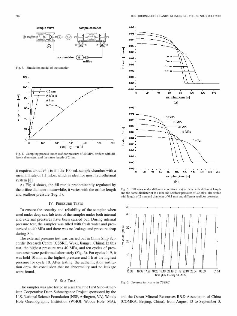
The filling rate is regulated by the orifice. Fig. 4 shows thesampling process in condition of 30-MPa seafloor pressure anddifferent orifice diameters. When the orifice diameter is 0.1 mm,
606 IEEE JOURNAL OF OCEANIC ENGINEERING, VOL. 32, NO. 3, JULY 2007
Fig. 3. Simulation model of the sampler.
Fig. 4. Sampling process under seafloor pressure of 30 MPa, orifices with dif-ferent diameters, and the same length of 2 mm.
it requires about 93 s to fill the 100-mL sample chamber with amean fill rate of 1.1 mL/s, which is ideal for most hydrothermalsystem [8].
As Fig. 4 shows, the fill rate is predominantly regulated bythe orifice diameter; meanwhile, it varies with the orifice lengthand seafloor pressure (Fig. 5).
IV. PRESSURE TESTS
To ensure the security and reliability of the sampler whenused under deep sea, lab tests of the sampler under both internaland external pressures have been carried out. During internalpressure test, the sampler was filled with fresh water and pres-surized to 40 MPa and there was no leakage and pressure dropduring 8 h.
The external pressure test was carried out in China Ship Sci-entific Research Centre (CSSRC, Wuxi, Jiangsu, China). In thistest, the highest pressure was 40 MPa, and ten cycles of pres-sure tests were performed alternately (Fig. 6). For cycles 1–9, itwas held 10 min at the highest pressure and 1 h at the highestpressure for cycle 10. After testing, the authentication institu-tion drew the conclusion that no abnormality and no leakagewere found.
V. SEA TRIAL
The sampler was also tested in a sea trial the First Sino-Amer-ican Cooperative Deep Submergence Project sponsored by theU.S. National Science Foundation (NSF, Arlington, VA), WoodsHole Oceanographic Institution (WHOI, Woods Hole, MA),
Fig. 5. Fill rates under different conditions: (a) orifices with different lengthand the same diameter of 0.1 mm and seafloor pressure of 30 MPa; (b) orificewith length of 2 mm and diameter of 0.1 mm and different seafloor pressures.
Fig. 6. Pressure test curve in CSSRC.
and the Ocean Mineral Resources R&D Association of China(COMRA, Beijing, China), from August 13 to September 3,
CHEN et al.: NOVEL MECHANICAL GAS-TIGHT SAMPLER FOR HYDROTHERMAL FLUIDS 607
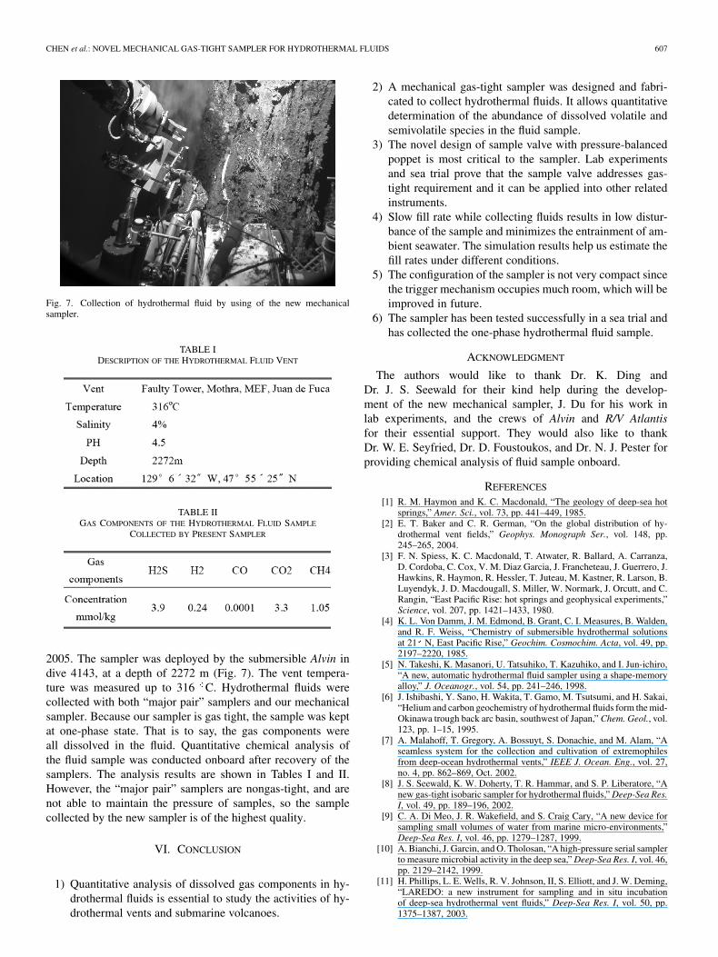
Fig. 7. Collection of hydrothermal fluid by using of the new mechanicalsampler.
TABLE IDESCRIPTION OF THE HYDROTHERMAL FLUID VENT
TABLE IIGAS COMPONENTS OF THE HYDROTHERMAL FLUID SAMPLE
COLLECTED BY PRESENT SAMPLER
2005. The sampler was deployed by the submersible Alvin indive 4143, at a depth of 2272 m (Fig. 7). The vent tempera-ture was measured up to 316 C. Hydrothermal fluids werecollected with both “major pair” samplers and our mechanicalsampler. Because our sampler is gas tight, the sample was keptat one-phase state. That is to say, the gas components wereall dissolved in the fluid. Quantitative chemical analysis ofthe fluid sample was conducted onboard after recovery of thesamplers. The analysis results are shown in Tables I and II.However, the “major pair” samplers are nongas-tight, and arenot able to maintain the pressure of samples, so the samplecollected by the new sampler is of the highest quality.
VI. CONCLUSION
1) Quantitative analysis of dissolved gas components in hy-drothermal fluids is essential to study the activities of hy-drothermal vents and submarine volcanoes.
2) A mechanical gas-tight sampler was designed and fabri-cated to collect hydrothermal fluids. It allows quantitativedetermination of the abundance of dissolved volatile andsemivolatile species in the fluid sample.
3) The novel design of sample valve with pressure-balancedpoppet is most critical to the sampler. Lab experimentsand sea trial prove that the sample valve addresses gas-tight requirement and it can be applied into other relatedinstruments.
4) Slow fill rate while collecting fluids results in low distur-bance of the sample and minimizes the entrainment of am-bient seawater. The simulation results help us estimate thefill rates under different conditions.
5) The configuration of the sampler is not very compact sincethe trigger mechanism occupies much room, which will beimproved in future.
6) The sampler has been tested successfully in a sea trial andhas collected the one-phase hydrothermal fluid sample.
ACKNOWLEDGMENT
The authors would like to thank Dr. K. Ding andDr. J. S. Seewald for their kind help during the develop-ment of the new mechanical sampler, J. Du for his work inlab experiments, and the crews of Alvin and R/V Atlantisfor their essential support. They would also like to thankDr. W. E. Seyfried, Dr. D. Foustoukos, and Dr. N. J. Pester forproviding chemical analysis of fluid sample onboard.
REFERENCES
[1] R. M. Haymon and K. C. Macdonald, “The geology of deep-sea hotsprings,” Amer. Sci., vol. 73, pp. 441–449, 1985.
[2] E. T. Baker and C. R. German, “On the global distribution of hy-drothermal vent fields,” Geophys. Monograph Ser., vol. 148, pp.245–265, 2004.
[3] F. N. Spiess, K. C. Macdonald, T. Atwater, R. Ballard, A. Carranza,D. Cordoba, C. Cox, V. M. Diaz Garcia, J. Francheteau, J. Guerrero, J.Hawkins, R. Haymon, R. Hessler, T. Juteau, M. Kastner, R. Larson, B.Luyendyk, J. D. Macdougall, S. Miller, W. Normark, J. Orcutt, and C.Rangin, “East Pacific Rise: hot springs and geophysical experiments,”Science, vol. 207, pp. 1421–1433, 1980.
[4] K. L. Von Damm, J. M. Edmond, B. Grant, C. I. Measures, B. Walden,and R. F. Weiss, “Chemistry of submersible hydrothermal solutionsat 21 N, East Pacific Rise,” Geochim. Cosmochim. Acta, vol. 49, pp.2197–2220, 1985.
[5] N. Takeshi, K. Masanori, U. Tatsuhiko, T. Kazuhiko, and I. Jun-ichiro,“A new, automatic hydrothermal fluid sampler using a shape-memoryalloy,” J. Oceanogr., vol. 54, pp. 241–246, 1998.
[6] J. Ishibashi, Y. Sano, H. Wakita, T. Gamo, M. Tsutsumi, and H. Sakai,“Helium and carbon geochemistry of hydrothermal fluids form the mid-Okinawa trough back arc basin, southwest of Japan,” Chem. Geol., vol.123, pp. 1–15, 1995.
[7] A. Malahoff, T. Gregory, A. Bossuyt, S. Donachie, and M. Alam, “Aseamless system for the collection and cultivation of extremophilesfrom deep-ocean hydrothermal vents,” IEEE J. Ocean. Eng., vol. 27,no. 4, pp. 862–869, Oct. 2002.
[8] J. S. Seewald, K. W. Doherty, T. R. Hammar, and S. P. Liberatore, “Anew gas-tight isobaric sampler for hydrothermal fluids,” Deep-Sea Res.I, vol. 49, pp. 189–196, 2002.
[9] C. A. Di Meo, J. R. Wakefield, and S. Craig Cary, “A new device forsampling small volumes of water from marine micro-environments,”Deep-Sea Res. I, vol. 46, pp. 1279–1287, 1999.
[10] A. Bianchi, J. Garcin, and O. Tholosan, “A high-pressure serial samplerto measure microbial activity in the deep sea,” Deep-Sea Res. I, vol. 46,pp. 2129–2142, 1999.
[11] H. Phillips, L. E. Wells, R. V. Johnson, II, S. Elliott, and J. W. Deming,“LAREDO: a new instrument for sampling and in situ incubationof deep-sea hydrothermal vent fluids,” Deep-Sea Res. I, vol. 50, pp.1375–1387, 2003.
608 IEEE JOURNAL OF OCEANIC ENGINEERING, VOL. 32, NO. 3, JULY 2007
[12] Marotta. Montville, NJ, 2006 [Online]. Available: http://www.marotta.com
[13] “Alvin User Manual,” 2006, http://www.whoi.edu/marops/vehicles/alvin/.
[14] D. Fornari, A. Bradley, and S. Humphris, “Inductively CoupledLink(ICL) temperature probes for hot hydrothermal fluid samplingfrom ROV Jason and DSV Alvin,” RIDGE Events, vol. 8, pp. 26–31,1997.
[15] Y. Chen, Y. Ye, and C. J. Yang, “Integration of real-time chemicalsensors for deep sea research,” China Ocean Eng., vol. 19, pp. 129–138,2005.
[16] AMESim. Roanne, France, 2006, [Online]. Available: http://www.amesim.com/
Ying Chen was born in Huzhou, China, in 1962. Hereceived the Ph.D. degree in mechatronic engineeringfrom Zhejiang University, Hangzhou, P.R. China, in1989.
Currently, he is a Professor at the State KeyLab of Fluid Power Transmission and Control,Zhejiang University. From 1997 to 2001, he servedas the Director of Institute of Mechatronic ControlEngineering, Zhejiang University. He was a VisitingProfessor at the Laboratory of Integration, Universityof California at Davis in 1998–1999. He has also
served as the Deputy Director of the Center of Oceanographic Sciences andTechnology, Zhejiang University since 2003. In 2001, he worked with thehydrothermal activities research group, University of Minnesota, Minneapolis.He was one of on-board scientists of R/V Atlantis Cruise 07 Leg 06,2002.1-2,and dived with the sub Alvin down to the hydrothermal vent area for samplingand measuring in EPR 9N. His main research has focused on the mechatronicintegration and application of deep-sea devices, many of which are related tothe study of hydrothermal vent under the deep sea.
Shijun Wu was born in Chongqing, China, in1981. He received the B.S. degree in mechatronicengineering from Zhejiang University, Hangzhou,P.R. China, in 2004, where he is currently workingtowards the Ph.D. degree at the State Key Laboratoryof Fluid Power Transmission and Control.
His research emphasizes the hydrothermal fluidssampling and exploring systems.
Yingjun Xie was born in 1969. He received thePh.D. degree in mechatronic engineering fromZhejiang University, Hangzhou, P.R. China, in 1999.
Currently, he is an Associate Professor at the StateKey Laboratory of Fluid Power Transmission andControl, Zhejiang University. His research interestsinclude the hydraulic control and mechatronicengineering.
Canjun Yang was born in 1969. He received thePh.D. degree in mechatronic engineering fromZhejiang University, Hangzhou, P.R. China, in 1997.
Currently, he is a Professor at the State Key Lab-oratory of Fluid Power Transmission and Control,Zhejiang University. His research interests includemechatronic engineering, man–machine system,robotics, and ocean engineering.
Jiafan Zhang was born in 1980. He received the B.S.degree from Shanghai Jiaotong University, Shanghai,China, in 2003. Currently, he is working towards thePh.D. degree in mechatronic engineering at the StateKey Laboratory of Fluid Power Transmission andControl, Zhejiang University, Hangzhou, China.
His research interests include man–machinesystem and intelligent robotics.