Embed Size (px)
Citation preview
Design Automation for Embedded Systems, 2, 283–317 (1997)c© 1997 Kluwer Academic Publishers, Boston. Manufactured in The Netherlands.
Prototyping of Tightly CoupledHardware/Software-Systems
WOLFRAM HARDT [email protected] of Paderborn, Furstenallee 11, 33 102 Paderborn, Germany
WOLFGANG ROSENSTIELUniversity of Tubingen, Sand 13, 72 076 Tubingen, Germany
Received December 8, 1995; Revised November 12, 1996
Abstract. Verification and test issues raise the need for rapid prototyping of complex systems and especiallyhardware/software-systems. We tackle this problem by integration of hardware/software-codesign and prototyp-ing. First we define the concept of the entire system architecture. This concept directs the hardware/software-partitioning process. Our prototyping environment reflects the architecture concept as well. In this overview thearchitecture concept and all important design tasks (hardware/software-partitioning, speed-up estimation beforeHW-synthesis, and prototyping of the entire hardware/software-system) are presented and compared to severalapproaches from literature. Thus a substantial overview over the prototyping problem is given. The latter part ofthis presentation illustrates our approach by a case study and presents the results. Our automated design processgenerates a tightly coupled hardware/software-system with very good performance characteristics. The case studyfocus on the prototyping of a ciphering algorithm. The reported approach leads to a reasonable overall systemspeed-up of 10%. Similar results have been found for further examples as well.
Keywords: Description analysis, Profiling, Hardware/Software-Partitioning, Estimation, Prototyping, Emulation
1. Introduction
The hardware/software-design process today is supported by more and more powerfuldesign methods and tools. This leads to a higher (algorithmic) level of design descriptionand raises the need of prototyping methods for whole systems. This can be easily done forSW-systems by code compilation and execution. If HW-systems are considered, simulationis applied frequently and in recent times also emulation technics are more often used. Whenhardware/software-systems come into view the problem is much more complex because ofthe heterogeneous architecture. In general, system design starts from an abstract systemdescription given in any language (C, C++, StateCharts, VHDL, Verilog, etc.). The gabbetween the system description and the entire implementation can be bridged by threetransformations:
1. Mapping the system description onto asystem architecture concept: In a first stepthe designer composes the system architecture concept out of components taken fromat least three categories. Table 1 to Table 3 present some examples of componentstaken from these categories. At least one element of each category will be instantiated.Thus, the main architecture characteristics are defined because the computation com-ponents and the communication channels are fixed. This is a very important (manual)

284 HARDT AND ROSENTIEL
Table 1. Processing units.
Comonent Category 1
processor core
standard processor
floating point processor
application specific processor
Table 2. Memory units.
Comonent Category 2
ROM
RAM
SRAM
Cache
Table 3. Interface units.
Comonent Category 3
DMA
I/O-interface
AD-converter
DA-converter
design step because the transformation of the system description into the architectureconcept implies the architecture characteristics. Algorithms for system partitioning,hardware/software-partitioning, and speed-up estimation can only compute valuableresults if the architecture characteristics are known.
2. Mapping the system architecture concept onto thesystem prototype: Once the sys-tem description is transformed into the system architecture concept classic high-levelsynthesis can be applied. But before any algorithmic synthesis task can start the newtransformation target must be defined. That is the system prototype. All componentsof the system architecture concept must be embedded into a prototyping environment.Then the synthesis of the application specific parts can be directed by the parametersof the prototyping environment.
3. Mapping the system prototype onto the entiresystem implementation: Design vali-dation is performed on the prototype level. The last transformation converts the appli-cation specific parts from their prototyping base into the entire implementation. Herealso the implementation characteristics, e.g., technology must be defined before thetransformation can be performed.
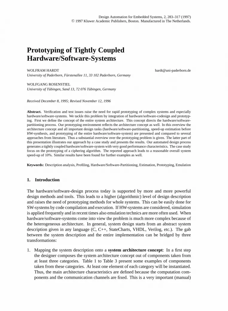
Figure 1 (a) depicts the mentioned levels of system design. If these levels are defined apriori efficient algorithms can be applied to transform design from one level to another. InFigure 1 (b) we show the different classes of algorithms (circles) and one possible definitionof each design level due to our design approach.
This transformational view of the design process proposes that an efficient prototypeimplementation can only be achieved if each transformation is optimized according to thetransformation source and the transformation target. Thus, the design decisions on eachlevel of abstraction must be drawn carefully. In chapter 2 to chapter 5 we give the readeran overview over the different choices on each level of the design process as well as overvarying realizations of the transformations itself. The following chapter presents detailedresults demonstrated by a case study.
1.1. Related Work
The architecture concept can be characterized by the instantiated primary processing unit.Examples for processor core based concepts can be found in [8, 45, 9]. These approaches
PROTOTYPING OF TIGHTLY COUPLED HARDWARE/SOFTWARE-SYSTEMS 285
Figure 1. Levels of system-design (a) and design flow for standard processor based architecture (b).
use fast state-of-the-art processor cores. In [22] DSP-processors are integrated in het-erogeneous IC architectures. Such hardware/software-systems can be embedded into theenvironment via interface ports but there is no direct coupled processing with further envi-ronment components intended. This makes prototyping and simulation easier. Other systemarchitectures are based on standard processors and several components are linked togetherwithin the same environment. The approach presented in [23] starts from a HardwareCsystem description. A standard processor is extended by several ASICs. Communicationis realized via a single bus. The work in [14] is based on the 16 MHz Intel i960 processorwhich communicates with the specific function unit via anAT-businterface. The approachof [46] is also based on a PC platform but communication is implemented byISA-bus. In[30] a Sparc processor is used and extended by specific HW. ASIC and processor commu-nicate viaS-bus. The memory access is realized by DMA. But this interdicts the usage ofcaches or requires the application of complicated mechanism to achieve data consistence.In this approach the main design directive comes from real time constraints which must bemet by the entire hardware/software-system.
The transformation of the system description into the system architecture concept includessystem partitioning, e.g., [39, 40, 43] and hardware/software-partitioning. The approachesto HW/SW-partitioning may be discussed in some more detail because this design phaseinfluences the final design characteristics enormously. The approach of [11] focus on realtime systems. The work in [41] minimizes the HW-partition and [1, 2] start from a UNITYsystem description and partitioning is performed on a cluster tree. The partitioning approachof 23 is hardware-oriented. First a hardware-implementation of the system is generated

286 HARDT AND ROSENTIEL
and afterwards parts with indeterministic runtime are moved to software. Software orientedapproaches extract partitioning information from a software description (C, C++). [14] ap-plies profiling but communication costs and memory access are not explicitly considered.In [30] a two level partitioning based on simulated annealing is presented. Communicationcost are taken into account on the inner level. The outer level provides design informa-tion obtained from system simulation (processor and ASIC). This may become a problembecause turn around times may enormously increase. Within both loops the effects ofhardware/software-partitioning are estimated. The estimation in the inner loop is muchmore rough and therefore faster than the estimation in the outer loop. [5] applies profilingbased hardware/software-partitioning to computer graphic applications. The communica-tion problem is seen and data transfers are manually examined. An advanced algorithm forHW/SW-partitioning is presented in [33]. The algorithm is referred to by GCLP and takesglobal criticality into account as well as constraints which are evaluated during two localphases. In each step the algorithm considers a node which represents a process or tasks andfor each node the objective function is chosen from a set of two objective functions, one forminimization of latency and the other for minimization of area. These objective functionsestimate the partitioning effects.
In our approach the hardware/software-partitioning task and the performance estimationtask are separated from each other. The partitioning task is performed on criteria extracteddirectly from the design description. The partitioned design is analyzed by the performanceestimation task. If any performance constraint is not met a repartitioning can be done. Dueto the separation of partitioning and estimation our approach can be performed very fast.
On the system prototype level a variety of scenarios have been suggested. For integrationof the application specific system part into the prototyping environment emulation technicsare commonly used. A multi FPGA experimentation board is set up by [44]. In [34] apowerful emulation board has been presented. Four FPGAs are placed on one board whichcan be connected via standard interfaces to a host system. For emulation of more complexsystems several boards can be plugged together. Thus, a flexible emulation base is providedfor a wide range of applications. Other approaches use commercial emulation systemswhich are typically based on several FPGAs [32, 48]. A case study based on multi FPGAemulation can be found in [38]. 4 suggest a multi board prototyping environment basedon a micro controller board, a Sparc board, and a FPGA based coprocessor board. Allboards are connected to each other via the system bus and are synchronized by two specialmemories. Each board has to be provided with a system bus interface. The coprocessorboard is preserved for emulation. The architecture of the emulated system part has beenpredefined with respect to the used hardware/software-codesign approach.
The transformation of the design from the system architecture concept into the systemprototype is commonly referred to as high-level synthesis. A lot of automated tools hasbeen offered for this design task. A survey can be found for example in [42]. We will notenter the synthesis and layout generation subject any further because we focus on the higherdesign levels.
Although on all mentioned design levels a lot of research work has been done thereare some difficult problems left. The bottleneck of performance driven design ofhardware/software-systems is the communication overhead. According to our experience

PROTOTYPING OF TIGHTLY COUPLED HARDWARE/SOFTWARE-SYSTEMS 287
this can be only solved if the hardware partition and the software partition are tightlycoupled. We give next a brief overview over our approach.
1.2. Design Approach Overview
In our approach we focus on the overall system performance in order to accelerate oftenused applications by a hardware/software-design. Typical candidates are parts of operat-ing systems, compilers, compression algorithms, and ciphering algorithms. These are noreal time applications an no explicit timing constraint must be met. But these applicationsconsume a large amount of computation time and user time as well. So we focus on theperformance aspect. Our experience with some case studies [25, 26] is that the perfor-mance of such applications is widely influenced by communication costs in between theirmodules. This holds if the modules are implemented in SW. For modules implementedin HW the communication problem becomes even more important. For this reason weuse a Sparc based architecture which is tightly coupled with additional application spe-cific HW. For this is a good chance to eliminate the communication bottleneck. Withina tightly coupled hardware/software-system the features of the standard architecture, e.g.cache can are used as well as the advantages of application specific HW can be obtained[24]. We defined our system architecture concept with respect to our main design aim,the overall system performance. Our hardware/software-partitioning algorithm is based onprofiling. The partitioning maximizes the performance of the entire system. Before synthe-sis the entire system speed-up can be automatically determined. Then the design is mappedonto our prototyping environment which integrates a commercial emulator and a standardSparc board. Figure 2 summarizes the main design tasks. In this article we describean automated design flow from behavioral design description down to system prototypeimplementation.
The rest of this paper is organized as follows. The next two chapters describe the se-lected architecture concept in some detail and our prototyping environment. Chapter 4and Chapter 5 discuss hardware/software-partitioning and speed-up estimation. Emulationis illustrated by a case study in chapter 6. Finally, the article is summarized and someconclusions are drawn.
2. System-Architecture Concept
Our target architecture is based on a Sparc-processor because:
1. This scalable RISC-architecture provides high computational power and for a widerange of applications short computation times are achieved.
2. This architecture (as shown in Figure 3) is build up by several complex units which areimplemented as separate chips. Thus, each unit can be substituted or easily extended.The trend of future system architectures is to implement all units by one single chip.This can be understood as shift from a chip-per-unit technique to macroblock-per-unit

288 HARDT AND ROSENTIEL
Figure 2. Main tasks or our design approach.
design. So, the chip-per-unit technique leads to some kind of a system prototypewhereby the specific function unit (SFU) is plugged in by emulation.
3. Finally, this processor provides sufficient interface support. This is a very importantissue because the communication between the processor and the SFU has often beenmarked as a performance bottleneck. In this section we show how to pick up theprocessor features for efficient implementation of the hardware/software-interface.
Thus, in our approach we concentrate on the Sparc architecture. Nevertheless, the sameconcepts can be applied to other processors as well by adaptation of the hardware/software-interface and analysis of the system description (Chapter 4.1). Next, we describe ourhardware/software-interface because the hardware/software-partitioning tasks is directedby the capability of the interface.
2.1. Hardware/Software-Interface Concept
This subsection presents the required capabilities of the hardware/software-interface andshows how they can be met. We define seven main characteristic of the hardware/software-interface which are important for the overall system performance:
• Parallelism: The standard architecture and the specific HW should work in parallel ifthere are no data dependencies.
• Memory access: Input data of the considered application as well as temporary dataare stored in the main memory. Thus it is necessary to provide a fast access to mainmemory from the SFU.

PROTOTYPING OF TIGHTLY COUPLED HARDWARE/SOFTWARE-SYSTEMS 289
Figure 3. Standard configuration of a Sparc architecture [10].
• CPU access: Due to parallelism mentioned above control and status information mustbe shared between CPU and SFU. Because the SFU extends the standard architecturethe CPU should control the specific HW.
• Cache: The SFU should not restrict the standard architecture in any way. So, if cacheis provided it must be used also if specific HW is introduced.
• Performance: Application execution can be divided into data access (read or write)and computation actions. Obviously, execution time is established by both. As pre-sented in [27] data transfers cannot be neglected. For example, consider a standardFDEW1 processor pipeline. Two stages (fetch and write) handle data transfers and twostages (decode, execute) perform the execution part. So, it is very important that thehardware/software-interface provides data transfer actions which minimize the transfertime.
• Data reusage: Results computed by the SFU may be used as input data for the sameHW. It would be rather time consuming to store this data in the main memory and toload it to the same computational unit again. Thus generated results should be reusableas further input without time wasting memory access.
• Extensions: The specific HW should not be restricted by the hardware/software-interface. Neither the number of parameters nor execution time can be fixed a priori.All these parameters should be extending by the designer.
The Sparc processor [10] allows communication viamemory mapped I/Oand by an ad-ditional coprocessor port. Well known communication protocols areprogrammed I/O,

290 HARDT AND ROSENTIEL
Table 4.Time requirements using MM I/O or coprocessor ports.
Function Direction MM I/O Cycles Coprocessor Cycle
data transfer CPU→ SFU ST 3 ST, LDC 5
SFU→ CPU LD 2 STC, LD 5
Memory→ SFU LD, ST 5 LDC 2
SFU→ Memory LD, ST 5 STC 3
SFU→ SFU LD, ST 5 CPopa 1
control ADD, STb 4 CPop 1
status handling LD, CMP 3 CPop 1
a. coprecessoroperationb. write constant to control register
interrupt based protocols, andDMA. Thus, we give a brief discussion of these communi-cation ports and the communication protocols.
2.1.1. Communication Ports of the Sparc Processor
Communication incorporatesdata transfer,control instruction transfer and transfer ofsta-tus information . Obviously, these tasks are of different complexity and require differentamounts of execution time. In Table 4, we list the execution time found for both commu-nication ports. The coprocessor port provides faster communication in most cases. OnlyCPU/SFU communication is slower. But transfers between memory and the specific HWare the much more frequently used operations. The average execution time per instructionof the coprocessor port is 2.2 cycles (per instruction) and for the memory mapped I/O port3.4 cycles. With respect to the performance requirements we use the additional processorinterface for CPU/SFU communication.
2.1.2. Communication Protocols
The interaction of the master (CPU) and slave unit (SFU) is controlled by some kind ofprotocol. Several protocols are known. We give a short discussion of the applicationof programmed I/O, interrupt based protocols, and direct memory access to our designproblem.
Programmed I/O protocol allows both computational units to be activated and it can beeasily implemented. The coprocessor is started by the SW running on the host processor.Only if the coprocessor is still running while the SW already requests the result, a busywaiting is initiated. This is caused by data dependencies that means by the application notby the communication protocol. If the SFU is implemented as additional coprocessor for

PROTOTYPING OF TIGHTLY COUPLED HARDWARE/SOFTWARE-SYSTEMS 291
the CPU the programmed I/O protocol meets the interface description (host control) quitewell.
Interrupt based protocols introduce an interrupt handling to programmed I/O in orderto avoid busy waiting phases. This leads to a speed-up if the host processor can continueif the coprocessor is still busy. But this does not hold for cases with data dependencies.Furthermore the interrupt handler consumes additional CPU runtime and interrupt routinesimplemented in SW must be provided also.The advantages of interrupt based protocols areonly valuable if CPU and SFU execute different tasks. In our approach the acceleration ofone task is considered and a programmed I/O protocol is sufficient.
Direct memory accessimplements very fast transfer instructions if every unit (CPU,SFU) has access to the memory bus simultaneously. But the Sparc architecture providesonly one data bus which is (almost) always busy because of the pipelined structure of thehost processor. Therefore a separate data bus has to be introduced. This would lead tosignificant modifications in the standard architecture which are not possible. Furthermore,data consistency is rather hard to achieve due to parallel acting computational units. If oneunit has read, modified and not written back a value, a SFU may read the same memoryaddress, getting wrong data. To solve this consistency problem complicated mechanismsare necessary. If memory hierarchy includes cache this problem is even worse. For thesereasons we decided not to use direct memory access to control the interaction of CPU andSFU.
We now introduce the interface concept with respect to the specified requirements.Par-allelism is realized by the programmed I/O data protocol.Memory accesscan be providedby both processor ports implementing the necessary instructions.Cacheusage forbids aDMA implementation. Theperformance requirements are met using the coprocessor portwhich is more efficient due to the CPU-pipeline. Therefore it is necessary, that the interfaceprovides pipelined instruction execution. Features fordata resusageare subject of imple-mentation and provided by the SFU-bus. The specific HW is initiated by the host processorrealizinghost control. The capability of beingextendedis realized by generic (VHDL)interface description. The implementation structure and synthesis results are presented lateron.
2.2. Structure of the Specific Function Unit (SFU)
As mentioned above the hardware/software-interface and the specific HW are combined tothe SFU (Figure 4). We first outline the interface and the interaction with the CPU. Thenwe give the structure of the specific HW.
2.2.1. The Interface
The hardware/software-interface connects the CPU with the specific HW. The instructionexecution of the CPU is accelerated by a four step pipeline (fetch-, decode-, execute- andwrite-stage). The first step fetches the data from memory. An efficient address computa-tion is provided. A memory management unit (MMU) handles cache and main memory

292 HARDT AND ROSENTIEL
Figure 4. SFU structure.
access. If the fetched data is required by the FPU2 (which is also supported by the CPU)or by an additional SFU the CPU activates the destination unit which performs all furtherexecution steps. The activated unit reads the fetched data value from the bus and startsexecution. Obviously the first pipeline step is completely performed within the CPU. Thefollowing three steps (decode, execute, write) must be provided by each computation unit.The hardware/software-interface implements these three pipeline steps. The decode stagecontains two buffers to store the instructions currently handled in the pipeline. If the in-struction execution requires more than one clock cycle internal opcodes are inserted. Theexecution stage checks for data hazards, e.g., a result not yet available is requested. In suchcases the pipeline is stopped until requested data are generated. At least the write stage han-dles the data transfer between the CPU and SFU. Thus, only two clock cycles are necessaryto execute a pipelined data transfer from memory to the specific HW (LDC-instruction) andone more clock cycle for the opposite direction (STC-instruction). The execution timesof the coprocessor implementation are listed in Table 4. Thus, the interface description isfully fulfilled. Note also, that this is the minimum which can be reached using two-busarchitectures multiplexing data and instructions on one bus.
2.2.2. Structure of the specific HW
During the application execution three tasks can be distinguished. Inputread, resultcompu-tation including handling of temporary data and outputwrite are different tasks to perform.Generally, they are not sequentially executed. Nevertheless, each task has its own structure.Due to this we have developed four blocks as depicted in Figure 4:
• Input registers block: All data provided by the interface is stored into the inputregisters. As soon as the input registers contain valid data the computation by thespecific HW is activated.

PROTOTYPING OF TIGHTLY COUPLED HARDWARE/SOFTWARE-SYSTEMS 293
• Datapath block: This blocks implements the application specific function. In ourdesign scenario standard high-level synthesis methods are applied in order to generatea multiplexer based HW-implementation. The synthesis process generates a controllerand a datapath for this block. This block is referred to by SFHW (specific functionhardware).
• Result registers block: The SFHW writes all computed results into special outputregisters called result registers. If a result register contains valid data a status flag isset. The CPU can access the status of each result register.
• Controller block : A simple controller is implemented which controls the interactionof the input register block, the datapath block, and the result register block.
A part of the SFU composed out of these four units is called specific function subunit(SFSU). In Figure 4 we give a high level block diagram. For more details see [29]. Thenumber of input (result) registers can be varied due to the implemented application up to 31(32). The SFSU is connected to the hardware/software-interface via a 46 bit bus. This bushas 32 data bits, two times 5 bit to address input and result registers, and four control andstatus bits. Such a SFSU is complex enough for a variety of applications. In order to modifythe SFSU easily the VHDL description is defined generically in the number of registers.But there may also be applications using more input (result) registers. Furthermore, theremay be independent application parts which are to be implemented in HW. Due to this thespecific HW may defined up generically in the number of SFSUs. The necessary SFSUselection is realized by one additional input register. The number of SFSU is limited to 219
because the binary instruction format allows only constants with maximum width of 19 bitsbut this is sufficient for practical designs. The specific HW structure of the SFU requires nomodification of the external environment. Thus, all definitions given by the environment,e.g., concerning number and bitwidth of signals and the instruction coding schema are notmodified.
The presented architecture concept is a powerful and flexible system architecture fordesign space exploration of hardware/software-systems. Full SW-implementations caneasily be compared to (nearly) pure HW-implementations as well as to hardware/software-implementations. The next chapter briefly describes our prototyping environment.
3. Prototyping Environment for Hardware/Software-Systems
To support system implementation a large number of automated tools is offered. But besidethe implementation task rapid prototyping, test, and verification are very important subjects.In hardware/software-design simulation may become rather slow because of system com-plexity. Especially the complexity of hardware/software-systems causes problems becausehigh performance components are linked together with memory components and specificfunction applications. One approach to handle such complex systems is emulation. Foremulation the system is mapped onto a FPGA structure [7]. This is comparable to realtime tests. If bugs are found the implementation can be easily modified because of thereprogrammable basis. Emulation can be classified as follows:

294 HARDT AND ROSENTIEL
• One FPGA emulation: If the system in view does not use any standard componentsthe HW-implementation can be performed. In many cases the generated netlist canbe mapped onto one FPGA chip, e.g., with 10,000 gates or more. The FPGA can beplugged into a test environment which provides the FPGA with input stimuli. If thedesign becomes more complex a one FPGA solution is not feasible.
• Multi FPGA emulation : In this case the RTL netlist of the system under emulationmust be partitioned with respect to the number of available FPGAs. This increases thecapable design complexity but the latency of the emulated part may decrease. In mostcases the interconnection of the FPGA components is fixed and cannot be changed. Thismay lead to problems if debug information of internal signals is required. One solutioninitiates a re-mapping of the netlist onto the FPGAs in the way that the required signalis routed via a visible pin. Another solution introduces additional debugging signals.
• In circuit emulation (ICE) : If the considered system uses standard components a fur-ther problem occurs. For a mapping of the complete design onto an emulation baserequires at least a netlist of all components linked together. But for most standardcomponents which are available from the shelf the netlist is not available. Thus, sys-tems based on such components cannot be mapped onto an emulation system and alsoseveral approaches were suggested. The main idea is to connect an emulation systemwith the target environment including the necessary standard components. In this waythe emulated components are integrated into the final circuit (or system). The approachof [34] can be used for such a prototyping environment. But because all communica-tion in between the environment and the emulation board is implemented via standardinterfaces (serial and parallel ports) a tight coupling of standard components with em-ulated components causes some problems. Also the scenario presented in [4] if thecommunication via S-bus is fast enough.
In our prototyping approach we use ICE without standard communication interfacesbecause processor (CPU) and additional application specific HW (SFU) are intended towork in parallel in one single pipeline. Therefore, a very tight coupling of CPU and SFUis required (Chapter 2). This cannot be provided by standard interfaces between the targetsystem and the emulated system part. Therefore, we have decided to connect the processordirectly with a commercial standard emulation system [48]. The following steps have to beconsidered:
• Adaptation: We adapted the LSI Sparc processor plugged in a standard SUN Sparcmain board. But only the signals needed by the hardware/software-interface and thedata bus of the processor are connected with the emulator. In this prototyping envi-ronment, CPU and SFU are linked together very tightly. In a first step both units arecompletely synchronized. That means, that CPU, hardware/software-interface, SFSU,and all SFHW modules are provided with the same clock. Obviously, the emulatorlimits the clock rate. The emulation clock rate depends on the complexity of the em-ulated circuit. So, in a second step we will divide the SFU into two parts. The firstpart contains the hardware/software-interface. The SFSU and all SFHW modules buildthe second part. This decreases the complexity of each part and the clock rate can be

PROTOTYPING OF TIGHTLY COUPLED HARDWARE/SOFTWARE-SYSTEMS 295
increased if both parts are mapped to different emulation boards. This is no problembecause the used emulation equipment provides two boards. Now, it will be possible todrive each part with its own clock for both parts communicate via registers. This is aninteresting option if very complex SFUs are considered. In addition, the application ofdifferent clocks to both parts offers the opportunity of further design space exploration.
• Operating system: Beside the HW-adaptation the operating system running on the hostmachine has been modified and a new system kernel was generated. This is necessarybecause the operation system allocates all resources within the whole system. E.g., ifa floating point processor (FPU) is added to the system the operation system kernelmust be updated. The same holds for the added SFU which is handled as additionalcoprocessor. Once these changes have been performed the SFU can be driven by theinstructions implemented by the hardware/software-interface.
• Synthesis: The last step before emulation is the synthesis of the hardware/software-interface. The hardware/software-interface is described hierarchically in VHDL withrespect to the restrictions of the Sparc coprocessor interface, the used bus protocols,and the Sparc pipeline. The number of instantiated operand registers, result registersand SFHW-components can be determined by generic VHDL parameters. This allowsan easy adaptation of the full custom SFHW-component to the hardware/software-interface. The interface is validated by RT-level simulation and the RTL netlist can beautomatically generated with the SYNOPSYS design compiler within 12 minutes on aSparc station 10.
• Emulation: Once the netlist of the hardware/software-interface is available the emula-tion task is performed. The netlist was partitioned due to the used FPGA structure [48].We have found that the number of input and output pins are the main bottleneck. So thewhole interface pipeline is mapped onto two FPGAs with a utilization of only 25% and10%. In a first emulation run test-vectors are given to the emulator. The result-vectorsobtained from the emulator confirm the simulation results.
4. Hardware/Software-Partitioning
The aim of hardware/software-partitioning is the mapping of the system description in agiven architecture concept. Additional constrains may restrict power consumption, size ofsilicon area, or minimum speed-up. This chapter presents a fast partitioning approach forstandard processor based architectures. Our partitioning approach focuses on minimizationof execution runtime of the entire system (UUC3) within the following steps:
• Analysis of the system description: Design characteristics are extracted from thegiven system description in order to direct the partitioning process. This includesstatic criteria, dynamic criteria and communication costs as well as memory accessinformation. For extraction of static criteria the description is compiled into assemblercode of the target processor and analyzed by a parser. Dynamic criteria can be obtainedfrom the description if it is compiled and executed. This approach is much faster than

296 HARDT AND ROSENTIEL
system simulation. The dynamic partitioning criteria covers the runtime behavior aswell as global data handling (access to main memory). Algorithmic hardware/software-partitioning can be performed based on this design characteristics.
• Partitioning : The generated partitioning criteria are saved in a central data base. Themain idea of our approach is based on a graph representation. Each node represents amodule and each edge stands for an access to this module. Each node can be annotatedwith results from the analysis of the system description. The partitioning algorithmcomputes a cost vector for each module from this data. This can be computed in lineartime by graph traversing. On this basis, a set of suitable hardware/software-partitionsis built.
4.1. Analysis of the System Description
This analysis task consists our of four phases which examine the system description. Dueto our SW-oriented codesign approach this is a C or C++program. During the analy-sis a design is thought of as a set of interacting modules. Typically, design descriptionsare structured by hierarchy which may be expressed by different constructs with respectto the programming language. Well-known examples are functions (C), methods (C++)and procedures (VHDL) etc. More abstract terms can be used to identify hierarchy [21].However, the hierarchy within the description can be understood as an initial system mod-ularization and our analysis is based on this modularization. The suitability of each modulfor HW-implementation is examined during four phases. The analysis phases takestaticaspects(SA),parameter transfer costs(PA),dynamic runtime (DA) characteristics, andmain memory access(MA) into account. These analysis phases result in a cost vector9 = (S A, P A, D A,M A) ∈ IR4. Figure 5 presents the analysis scenario.
4.1.1. Static Partitioning Criteria
Static analysis examines assembler code without execution. The number of jump instruc-tions(Jump(mod)) and bitlevel instructions, e.g., AND, EXOR(Bitop(mod)) per moduleare counted because these instructions can be executed in HW much quicker than in SW.E.g., the comparison of two single bits can be done in HW very fast by only one gate. ASW-implementation, e.g., for a pipelined architecture needs one cycle at least. However, inorder to reach a reasonable speed-up the accelerated module must be of appropriate size.Therefore a lower bound on the execution time for a SW-implementation is computed.The features of the architecture concept, e.g., the processor pipeline are considered. Threedifferent approximation algorithms can be chosen:
• Flat: This is the simplest approximation. All instructions are weighted by their (bestcase) execution time and are summarized. No control flow is taken into account. Thisalgorithm results with a very rough runtime approximation.
• Control-oriented: This algorithm determines the minimal and the maximal runtimewith respect to the control flow for each module. Loops are counted once because the

PROTOTYPING OF TIGHTLY COUPLED HARDWARE/SOFTWARE-SYSTEMS 297
Figure 5. Analysis scenario.
number of iterations can be determined only during runtime. This algorithm leads to amore realistic runtime approximation.
• Global: The runtime of a basic block may depend on the previous basic block. So, thethird algorithm considers always two adjacent basic blocks in addition to the featuresof the control-oriented algorithm. Thus a very exact approximation of the SW-runtimeis obtained.
The approximated SW-runtime may be interpreted as a heuristic definition of the modulesize. These aspects determine theS A component of the cost vector9 pointing out thesuitability of this module for HW-implementation found by static analysis:
S A(mod) = Jump(mod)+ Bitop(mod)
Inst(mod)× 100%× RTSW
approx(mod)
We have applied static analysis to a variety of benchmarks. Some are taken from the HW-domain, e.g., well known synthesis benchmarks and others are taken from the SW-domain.For all examples the average and the maximum value for have been computed. For allbenchmarks from the HW- domain these values are close to the maximum but all valuesof the SW benchmarks are below 0.5 (Figure 6). This shows that a HW-implementationresults in a high speed-up for the HW-benchmarks. Because the speed-up can be roughlyapproximated by the following equation wherebyRTSW
rel stands for the relative dynamicruntime of the SW-implementation:
SpeedUp(design) =∑mod
S A(mod)× RTSWrel
298 HARDT AND ROSENTIEL
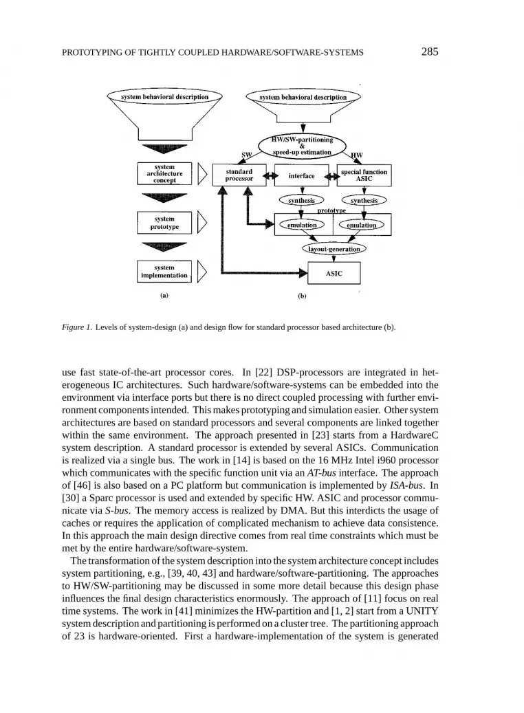
Figure 6. Relation of average and maximum result of static analysis for benchmarks from the HW-domain(vectoradd, atoi, matrixmult, diffeq) and from the SW (foogol, uuencode, uudecode, crypt, grep, cpp, cc1).
If aveSAmaxSA
∼= 1 holds for a design it follows that:SpeedUp(design) ∼= aveSA∼= maxSA.In practice, all modules of these designs are implemented in HW and no hardware/software-
partition is considered.If aveSA
maxSA< 0, 5 holds for a design the characteristics relevant for HW-implementationof the considered modules differ and hardware/software-partitioning should be considered.Therefore, additional analysis phases are applied, before the partitioning is performed.Furthermore, it has been found that static analysis is almost independent from compileroptimizations. E.g., some optimizations which can be enabled by options−O0, −O1,−O2 of theGNU gcccompiler (see Table 12 in Appendix A) are applied andS A(mod)results in qualitatively equal values (Figure 7).
During this analysis phase, the module-graph is generated. Computation time for staticanalysis depends on the size of the design description. The analysis of large design descrip-tions can be performed very quickly:
• Flat: 3000 (1100) lines of assembler code (C code) per second4
• Control-oriented: 2700 (1000) lines of assembler code (C code) per second• Global: 2500 (900) lines of assembler code (C code) per second
Thus, static analysis can be performed very quickly, even for large design descriptions.E.g., the cc1 compiler can be analyzed within less than five minutes.
4.1.2. Parameter Analysis
The second analysis phase determines the size of all parameters passed to or obtained froma module. Obviously, these data must be transferred from SW to HW and vice versa. This

PROTOTYPING OF TIGHTLY COUPLED HARDWARE/SOFTWARE-SYSTEMS 299
Figure 7. Results of static analysis obtained by different compiler optimizations.
may lead to a performance reduction due to data transportation. For this reason, the size ofall parameters is determined from the C/C++ source code. First the description is passedto the preprocessor of the native compiler. Then a specialized parameter parser generatesthe necessary data within the following steps:
• Identification of all complex data types
• Identification of all function declarations
All algorithmic parts and all comments within the description are not interpreted, and thusthe procedure is not too complex and can be performed very quick. Thus the width of allread parameters per module(WidthIN(mod)) and all written parameters(WidthOUT(mod))are evaluated. With respect to the semantics of the description language parameters are notread and written at the same time. And the same interface may be used for both directions.The componentPAof the cost vector9 is defined by:
PA(mod) = max(WidthIN,WidthOUT)
The most important reason for introduction of parameter analysis is to check if the com-plexity of the required hardware/software-interface is feasible.
4.1.3. Dynamic Analysis
The previous analysis phases are based on static source code examination. But the dynamicdesign behavior is highly data dependent and cannot be extracted by static methods. Thisproblem is solved by dynamic analysis. The description is compiled with the GNU compiler[36] for the Sparc processor. Provided with some input data the design is executed andprofiling data is generated. Considering a single module three aspects, the absolute(RTSW
abs),

300 HARDT AND ROSENTIEL
average(RTSWaverage), and relative(RTSW
rel ) runtime of a module are considered:
• RTSWabs(mod): The time consumed by a module during the whole execution
of the SW-implementation of the design.
• RTSWaverage(mod): The average of all execution times of the module collected
during the whole execution of the SW-implementation ofthe design.
• RTSWrel (mod): The percentage of a module’s absolute runtime of the exe-
cution time of the SW-implementation of the design.
Often the designer guides the partitioning process exploring the design space by predefinedrestrictions. Typical examples are maximal or minimal module size. Some approaches passparameters to the design process indicating the optimization priority, e.g., time versus size[12] or many partitions versus few. On the other hand relative directives are not alwayssufficient especially if there are restrictions for all partitions. This can be handled, ifmodule characteristics are normalized. The normalization base defined by the designer asconstant is passed to the partitioning process. Some values for these constants are given inAppendix B. This constants allow a comfortable direction of the design space exploration.All three runtime aspects are extracted from profiling data for each module. As shownin [28] many inputs are considered because in general the control-flow is data dependent.Thus, the runtime behavior differs with respect to the inputs. For one module the profilingvalues may differ slightly or dramatically. The reliability of the profiling result depends onthe found differences. So, we regard the dynamic analysis for one input value as statisticalexperiment and the found profiling value as the result of this experiment. Now, the termsprobability P, the expected valueE and standard deviationσ from statistical theory, e.g.,[35] are used to classify the generated input data. Ifσ grows too much the probability ofa bad profiling result is rather high. This turns out to be a good classification base and theD A component of the cost vector9 is defined as:
DA(mod) = RTSWabs(mod)
SW ABS RT+ RTSW
rel (mod)
SW REL RT+ RTSW
average(mod)
SW AVERAGE RT
4.1.4. Memory Access Analysis
Beside the module parameters (Chapter 4.1.2) there are further data transportations becauseglobal data is used or data is referred to by references. This is typical for SW-orienteddescription languages. These references may refer to local data values or to global datawhich are stored in the main memory. And each access of main memory causes interfacetraffic and may decrease the system performance [31]. This problem is ignored by mostapproaches. However, the number of accesses to main memory can only be evaluatedduring runtime because of data dependencies. In our approach memory access analysis

PROTOTYPING OF TIGHTLY COUPLED HARDWARE/SOFTWARE-SYSTEMS 301
provides detailed information based on memory access profiling. Therefore, the behavioraldescription is automatically modified in order to generate a protocol of all memory accessesduring the application execution. The modified source code can be compiled by the nativecompiler. During the execution a detailed protocol of the number of local and global memoryaccesses, the memory address and the access direction (read or write) is generated. Due tomatters of efficiency an protocol examination function is linked to the original design. Thisfunction computes the memory analysis result and does not influence the memory accessbehavior but it enormously reduces the amount of profiling data.
Execution time of these data accesses varies and depends on the system memory hierarchy.The access time is counted in cpu-cycles and referred to byATt
Read(h) wherebyt standsfor technology (SW or HW) andh indicates the level of memory hierarchy (e.g., local orglobal). The number of read (write) accesses to a distinct level of memory hierarchy isnamedARead(h,mod) (AWrite(h,mod)). This is a critical aspect for system performance.Depending on the integration concept access from the HW to main memory can becomeextremely slow [44, 17].
The costs for all data transportations measured in cpu-cycles can be computed by:
DTt(mod) =∑
dir∈{Read,Write}
∑h∈MH
(Atdir(h,mod)× ATt
dir(h))
wherebyt identifies the technology andh the level of memory hierarchy. This sum weightsthe number of access of one type with the costs of this access for all different accesstypes. Obviously, the value ofAt
dir(h,mod) can only be determined dynamically and thevalue ofATt
dir(h) must reflect the characteristics of the entire system architecture. E.g. theintroduction of an additional bus may reduce the (average) access time of a single type ofmemory access.
The obtained results forDTSW(mod) andDTHW(mod) differ because
• ASWdir (h,mod) 6= AHW
dir (h,mod):
This is due to the fact that in a HW-implementation the number of registers can beadapted to the implemented algorithm. Thus, a lot of data access to main memory in aSW-implementation can be realized by accesses to local registers in HW.
• andATSWdir (h) 6= ATHW
dir (h):
That means, the data access time to given level of memory hierarchy depends on theimplementation technology. E.g., the access to main memory is in many cases slowerfor a HW-implementation (as regarded in this context) than for a SW-implementation.
This demonstrates the differences in data transportation costs between a HW- and a SW-implementation. In practice, the number of main memory accesses per module variesenormously depending on the application in view. Thus, the data transportation aspectmay decrease or increase the system performance. This can be expressed by a efficiencycoefficientηDT derived from data transportation:
ηDT (mod) = DT SW(mod)
DT HW(mod)

302 HARDT AND ROSENTIEL
Figure 8. Evaluation ofηDT for different architectures (a) and evaluation ofηDT for our codesign architecture(b).
Table 5. Different settings of the architecture pa-rameters.
Architecture ASWglob ASW
loc AHWglob AHW
loc
A 5 2 10 1
B 2 2 10 1
C 2 2 20 1
D 2 2 50 1
E 2 1 2 1
The componentM A of the cost vector9 is defined by:
MA(mod) ={ηDT (mod) if ηDT (mod) > 1
0 else.
If holdsηDT(mod) > 1 the data transfer to main memory causes no performance reduction.This depends on the chosen hardware/software-interface (Chapter 2.1). In Figure 8 (a)the influence of the hardware/software-interface is examined by varying the architectureparameters. Figure 8 (b) presents the results found for the presented architecture concept.For several benchmarks we found thatηDT(mod) > 1 holds.
Table 5 presents five different settings for the architecture parametersASWglob, ASW
loc , AHWglob
andAHWloc .
The achieved data transportation characteristics from some benchmarks [3] are depictedin Figure 8 (a) for these architectures. It can be seen, thatηDT depends on the archi-tecture. IfηDT is smaller than 1 data transportation will reduce the system performance(kalman, architecture D). Otherwise a HW-implementation of this module increases systemperformance (kalman, architecture B) because of data transportation. Thus, the system

PROTOTYPING OF TIGHTLY COUPLED HARDWARE/SOFTWARE-SYSTEMS 303
performance can be increased by an architecture (B) or can be decreased (architecture D).Our codesign architecture (Chapter 2) is described by the parameters of architecture B dueto tight coupling of processor and specific HW. Figure 8 (b) shows the detailed resultsfor the applied benchmarks. Depending on the number of global data accesses a systemspeed-up can be achieved (KMP5, gcd, kalman, fibonacci).ηDT is limited by 2 becauseall data which can not be stored in CPU registers must be stored in main memory. Thus,for a SW-implementation for our codesign architectureASW
glob andASWloc are equal andηDT is
limited by the interval [0≤ ηDT ≤ ASWglob].
4.2. Partitioning Algorithm
These four analysis phases result in a cost vector9(mod) = (SA,PA,DA,MA) defin-ing a subset ofI R4. Hardware/software-partitioning divides this subset into two disjunctparts. This hardware/software-cut is performed by comparing each component of thecost vector9(mod) with the corresponding component of the cut vectorCutHW/SW =(VS A,VP A,VD A,VM A) for all modules. A module is qualified for HW-implementation ifthe following condition holds:
9(mod)− CutHW/SW = (α1, α2, α3, α4), and∀i ∈ {1, 2, 3, 4}: αi > 0
As mentioned above, the analysis phases annotates the module graph with the results ofeach phase. The partitioning algorithm traverses the graph and divides the system (UUC)into a SW-part and a HW-part computing9(mod)− CutHW/SW for each module:
UUC = PartSW∪ PartHW; and PartSW∩ PartHW = ∅It can be easily seen that this algorithm (Figure 9) is of linear complexity (O(mod)).The valuesVS A, VP A, VD A, VM A are designer defined parameters. The assignment of
values to these constants is based on experimental case studies, e.g., [26]. This analysishas been implemented in our partitioning tool (COD). We applied the approach to severalapplications of reasonable complexity with good success.
The partitioning phase of our codesign approach terminates with a set of one or moremodules suitable for HW-implementation. If several modules are given to the synthesisphase the entire design may be in conflict with description constraints, e.g., design size.Even if the main focus is on the performance aspect it is interesting to know which moduleleads to which speed-up. For this reason we have developed a speed-up estimation methodwhich allows to identify the possible system speed-up per module before synthesis.
5. Speed-up Estimation for Hardware/Software-Systems
Speed-up estimation is difficult if hardware/software-systems are considered. In additionto the execution time of the SW- and the HW-part all communication overheads must betaken into account. This cannot be done in all detail because computation complexity raisesexponentially. The common way is to define a suitable model of the real system and to

304 HARDT AND ROSENTIEL
Partitioningalgorithm(MG){forall modules
computePart(mod) = 9(mod)− CutHW/SW
for (phase= 1; phase≤ 4; phase++)If Part(mod)(phase) = o
implementation= SWend if
end forif (implementation == SW)
SW partition= SW partition∪ modelse
HW partition= HW partition∪ modend if
end for}
Figure 9. Hardware/software-partitioning algorithm.
estimate the algorithmic transformations performed during the design process. The definedperformance model for hardware/software-systems and the developed speed-up estimationare presented in this chapter.
5.1. Performance Model
The performance model for hardware/software-systems captures:
• the whole hardware/software-system
• all data transports
• and the performance characteristics.
Due to our performance-oriented and module-based codesign approach a hardware/software-system is thought of as set of communication modules. Figure 10 illustrates this systemview. All data transport to main memory is handled by SW. The HW-partition has no directaccess to main memory. For speed-up estimation this simplified system view is sufficient.The performance model describes the behavior of each module in terms of runtime. Inaddition, the communication time is taken into account.
The runtime of a pure SW-system (UUC) is build up by the runtime of all modules:
• RTSW(UUC) =∑
mod∈UUC
RTSWmod

PROTOTYPING OF TIGHTLY COUPLED HARDWARE/SOFTWARE-SYSTEMS 305
Figure 10. Data access of SW-implementation (a) and of a hardware/software-implementation with one HW-moduleMi (b).
Figure 11. Example of a desigin build out of 64 modules. Partitioning maps 40 modules to SW and 24 modulesto HW.
Moving a module from SW to HW decreases the complexity of the SW-partiton. In additionruntime consumed by the SW-partition is reduced. The runtime of the remaining SW-partition (PartSW) is summerized by the runtime of all remaining modules. In formalterms:
•∑
mod∈PartSW
RTSWmod
For all modules which are transfered into HW no SW-runtime is consumed. The runtime ofall remainig modules must be taken into account, that are e.g. 40 SW-moudles in figure 11.
All modules brought to HW cause additional runtime in the HW-partition. In fact theruntime of each HW-module(PartHW) must be taken into account:
•∑
mod∈PartHW
RTHWmod

306 HARDT AND ROSENTIEL
In figure 11 there are 24 HW-modules. The runtime of all HW-module is considered bythis equation.
Now communications costs (DT SW and DT HW) are considered as determined duringthe memory analysis phase of analysis (Chapter 4.1.4). The communication cost of a SW-implementation of the given module is substituted by the communication cost of a HW-implementation for the same module. The communication costs of a hardware/software-implementation of the whole system is approximated by summarizing the difference of theHW- and the SW-communication costs:
• DTHWSW=∑
mod∈PartHW
[DTHW(mod)− DTSW(mod)]
The estimation of the runtime of the whole hardware/software-system can be given basedon the previous definitions:
• RTHWSW(UUC) =∑
mod∈PartSW
RTSWmod+
∑mod∈PartHW
RTHWmod+ DTHWSW
At this point can be seen that the performance of the hardware/software-system is stronglyinfluenced by data transportation(DT HW SW). An implementation as hardware/software-system is only feasible if the runtime reduction by the HW-implemented modules is notpayed by additional runtime for data transportation between the partitions. In formal terms:
•∑
mod∈PartHW
RTSWmod−
∑mod∈PartHW
RTHWmod> DTHWSW
Based on this performance model our estimation method approximates these effects prettygood.
5.2. Estimation Method
The abstract performance model allows the definition of an algorithmic speed-up6 estimationmethod. We consider the speed-up reached by a hardware/software-implementation of theinitial SW-system. The computation of the speed-up gained for a given HW-partition isdefined as:
SpeedUp(UUC,PartHW)=∑
mod∈PartHW
[RTSW
rel ×[
1− RTHWschedule
RTSWapprox
+ (ηDT − 1)× InstSWls
InstSW
]]
This equation is based on three components:
• RTSWrel :
The relative runtime of each module has been determined during dynamic analysisand is used for speed-up estimation. The runtime of the SW-system is reduced by the

PROTOTYPING OF TIGHTLY COUPLED HARDWARE/SOFTWARE-SYSTEMS 307
module which is transferred to HW. This establishes the basis for speed-up estimation.An approximation of the real system acceleration is determined by:
• RTHWschedule
RTSWapprox
:
This quotient compares two static runtime approximations.RTHWschedulerefers to the num-
ber of control-steps on the longest acyclic path through the finite state machine of thecontroller of the HW-implemented module.RTSW
approx denotes the static approximationof the execution time of a SW-implementation. It is important to consider the con-trol flow of the module. Thecontrol-orientedor theglobal approximation algorithm(Chapter 4.1.1) can be used to determine the longest acyclic path. Both approximationsare static and consider every loop only once. The quotient of both approximationsgives an rough idea of the speed-up reached by HW-implementation if no data transfersare considered. Because this is only a static relation neglecting the influence of datadependencies this quotient is related to the dynamic runtime of the regarded module.
The speed-up reduction of data transportation is captured by the following relation:
• (ηDT − 1)× InstSWls
InstSW:
As mentioned above the effect of data transportation costs can be negative (in relativetermsηDT(mod) < 1). But this is only relevant for data transportation instructions(InstSW
ls ). So the relative improvement from data transportation is weighted by therelative number of data transportation instructions(InstSW
ls /InstSW) which is obtainedfrom the SA analysis phase (compare with L/S-Op and Sparc-OP in Table 7).
The presented speed-up estimation method regards dynamic aspects, implementation de-pendent performance effects and communication overheads. All three aspects are corre-lated. Within our codesign environment PMOSS [16, 20] the speed-up estimation can becomputed automatically.
There are two strategies to involve the speed-up estimation result in the partitioningprocess. The first reduces manually the set of modules which was automatically suggestedfor HW-implementation. This strategy is applied if design constraints e.g. chip area areviolated. On the other hand the estimated speed-up may be to small. That means thatadditional modules must be implemented in HW. This can be done by the second strategywhich modifies the parameters of the partitioning task. If these parameters are relaxedmore modules are suggested for HW-implementation by the automatic partitioning tasks.Of coarse both strategies my be combined as well.
6. Case Study
For a case study one algorithm has been analyzed, implemented and examined. The es-timation method has been applied and the estimated system speed-up is compared to theexperimentally determined system performance. For this case study, we have chosen aciphering algorithm [19] because ciphering algorithms require high computation power

308 HARDT AND ROSENTIEL
1 for each pair (n,m) of integer inputs2 compute a pseudorandom integral sequences N, M3 for each value v of sequence N, M4 converted v into a Fibonaccin binary sequence vN, vM
5 for an appropriate t6 perform the bitwise logical sum
of the central portions of vN, vM
7 end for8 end for9 end for
Figure 12.Ciphering algorithm of Filipponi and Montolivio.
and are frequently used on standard platforms. E.g., for security reasons many e-mails areciphered. The acceleration of this application saves a lot of user time. The algorithm con-sidered here belongs to the class of stream ciphering algorithms and is used for encryptionof alpha-numerical messages.
6.1. The Algorithmic Concept
The basic concept of the ciphering algorithm referred to bycrypt is given in Figure 12.Three nested loops are executed. The outer loop (Line 1) is executed for each pair ofinputs. The given pair of integers (input) is transferred into a binary coding, e.g., the ASCIIcode. For each input a sequence of pseudorandom numbers is generated. The length ofthis sequence determines the coding quality and can be set by the designer, e.g.,1000 isa commonly used length. The number of iterations of the first loop depends on the inputlength.
The second loop (Line 3) handles each value of the computed pseudo random sequences.Thus the number of iterations of this loop is fixed by the sequence length. For each valuea representation as binary Fibonacci sequence is computed. This sequence contains onlyFibonacci numbers and the sum of these numbers are equal to the value in view(v). Thus,this sequence can be represented by a binary vector indicating which Fibonacci numbermust be summed up.
The last step is performed by the inner loop (Line 5). The binary Fibonacci sequence ofboth input values are combined by an logical operator.
That means, for the input tuple(h, i ) the integer tuple (104, 105) is generated. Nowthe pseudo random integral sequence (PIS) is computed, e.g., PIS(105) = 59922, 1914249,5398140, 5398269, 5402268, 5526237, 369235, 2502911, 5646580, 4099868, 1152001,8768575,. . . . Each of these values is transformed into the Fibonacci binary sequence(FBS), e.g., FBS(222208) = (1, 0, 0, 0, 0, 1, 0, 1, 0, 0, 0, 1, 0, 0, 1, 0, 1, 0, 0, 0, 0, 0, 1, 0,0, 0). The last step combines a part of these FBSs by a binary operator. It has been shown

PROTOTYPING OF TIGHTLY COUPLED HARDWARE/SOFTWARE-SYSTEMS 309
Figure 13.Result of memory analysis for some modules ofcrypt.
in [6] that a Fibonacci binary sequence is unique and that based on this sequence a fairlysatisfactory ciphering sequence can be generated. See also [6, 18].
6.2. Hardware/Software-Partitioning
We have implemented this algorithm in C++ on an unix workstation. Some general in-formation about the implementation shows Table 6. The SW-implementation consists of104 modules and approx. 7000 lines of (Sparc) assembler code. This shows that the sizeof the algorithm is large enough that a hardware/software-implementation can be consid-ered. A more fine granular analysis, e.g., on data flow graph basis is hardly capable. Butour analysis can be performed rather quickly. The exact execution time is mainly deter-mined by the dynamic analysis phase because the algorithm is executed several times withdifferent inputs. The static analysis phase computes a detailed statistic about the used in-structions as derived in Table 7. These results were automatically computed for the cryptalgorithm and are listed in Table 8 for the most important modules. Some of these resultsare relevant for our speed-up estimation method (Sparc-OP, L/S-OP, SW-MaxRT). Thehardware/software-partitioning is based on the results of all four analysis phases and classi-fies the modulef ibonacci n as suitable for HW-implementation. This module computesthe n-th Fibonacci number. The dynamic analysis points out that this module consumes11% of the system runtime. Figure 8 (b) shows that the memory analysis phase results witha very good value forηDT (1.94). Figure 13 depicts the data transportation characteristicsfor some modules of thecrypt algorithm. Only few modules reach a value forηDT whichis greater than 1. Thus, the partitioning seems to be sufficient and speed-up estimation wasapplied in order to determine the speed-up for the HW/W-system.

310 HARDT AND ROSENTIEL
Table 6.Characteristics of bench-mark crypt.
Characteristic Value
lines of C++ code 578
lines of assembler code 7006
number of modules 104
Table 7.Results computed by static analysis.
Result Note
Jmp-Op number of jump-operations per module
Bitl-Op number of bit-level-operations per modul
L/S-Op number of load/store-operations per modul
Sparc-Op number of operations per modul
C-Dom control-dominance, defined as percentage of jmp and Bitl-operations per module
SW-MinRT approximated minimal runtime for execution of a SW-implementation
SW-MinRT approximated maximal runtime for execution of a SW-implementation
6.3. Speed-up Estimation
All data required for computation of the speed-up(SpeedUp) have been automaticallygenerated. As mentioned above, analysis of the system description, hardware/software-partitioning, and scheduling are previously performed. The obtained data are given inTable 9.
Now the speed-up estimation can be easily computed:
SpeedUp(crypt, fibonacci) = 8%
This is a reasonable speed-up of the whole system. This indicates also that the generatedpartitioning will accelerate the system. This is proved by the following implementation andemulation of the hardware/software-system.
6.4. Implementation and Emulation
After speed-up estimation the modulef ibonacci n has been implemented in HW usingour synthesis toolSY N [15]. This tool generates a multiplexer based RT-level VHDL-description of this module. The RTL-description is composed of a controller and a datapath. The controller is necessary because the number of iterations which are required tocompute then-th Fibonacci number depends on the parametern. So loop unrolling is

PROTOTYPING OF TIGHTLY COUPLED HARDWARE/SOFTWARE-SYSTEMS 311
Table 8.Static Analysis of Benchmark crypt.
Module Jmp-Op Bitl-Op L/S-Op Sparc-Op C-Dom SW-MinRT SW-MaxRT
CompCiphring 53 19 65 272 26 134 176
CompLvalue 12 9 23 97 21 229 229
CompMhList 13 11 18 89 26 44 44
CompNhList 13 12 18 91 27 44 44
CompSL 27 18 32 156 28 68 68
CompTval 12 11 8 72 31 76 76
Convert 2 0 0 10 20 7 7
Copy 2 0 3 12 16 12 12
ReadFrom 13 1 0 58 24 31 41
Read 1 0 0 10 10 9 9
SetLstPos 8 6 9 50 28 44 44
clear 4 2 11 36 16 19 47
contents 4 0 4 20 20 21 21
fibonaccin 4 0 14 31 12 18 18
main 66 50 71 436 26 78 143
next element 5 0 7 29 17 21 31
Table 9.Obtained data for estimation method.
Component of estimation method Obtained data
RTSWrel 11%
RTSWapprox 18 cycles
RTSWschedule 6 clock steps
ηDT 1.73
InstSWls 14
InstSW 31

312 HARDT AND ROSENTIEL
Table 10. Synthesis result for module fi-bonaccin.
Circuit part Inputs Outputs
fibonaccin controller 4 8
fibonaccin datapath 40 33
fibonaccin 35 33
Table 11.Experimental determined speed-up ofalgorithm crypt.
Benchmark Note Result
fibonaccin SW-Implementation 56 us
fibonaccin HW-Implementation 3 us
fibonaccin speed-up 94%
crypt seed-up 10%
not possible. The generated RTL-VHDL description was optimized and mapped to a HWlibrary using the Synopsys design compiler [37]. Synthesis results are given in Table 10.The optimized design was transferred to a EDIF-netlist [13]. This netlist was passed tothe Concept-Silicon-Software of Zycad [48]. This step is needed to partition the netlistfor implementation of the emulator HW. The Zycad emulator is composed of two boards.Each board contains eight daughter boards and each daughter board contains three FPGAcomponents. The designer can choose an automated partitioning process. Furthermore, amanual netlist-partitioning is possible. During the last step the partitioned netlist is mappingto the FPGA components (Xilinx 4010) [47]. The complete circuit used 2500 gates on theemulator and maps to one FPGA.
Once the module is implemented runtime experiments can be performed. For the sameinput data a speed-up of the module by HW-implementation of 94% was reached (Table 11).But this include no data transfers to the SW-partition. Now, the module is integrated intothe codesign architecture and emulation can be performed again. Therefore it is assumed,that the specific function unit and the host processor runs on the same clock rate. It couldbe obtained a speed-up for the whole system of 10% (table 11). This experiment includethe execution of the SW-partition on a Sparc-based workstation, the data /transfers viathe hardware/software-interface, the execution of the HW-partition and all data accessesfrom the HW-partition. The determined speed-up of the hardware/software-systemcrypt is10%. This is very close to the estimated speed-up of 8%. The same experiment for furtherbenchmarks, e.g., a pattern match algorithm is under development.

PROTOTYPING OF TIGHTLY COUPLED HARDWARE/SOFTWARE-SYSTEMS 313
7. Conclusion
This paper addressed the problem of rapid prototyping of hardware/software-systems.Mainly, tightly coupled hardware/software-systems are considered. The presented solu-tion defines first the architecture concept of the target system. Due to this definition, thehardware/software-interface is implemented. A load instruction takes two cycles to trans-fer data from memory to the SFU. The execution of all implemented SFU-instructions ispipelined. The hardware/software-interface minimizes the communication overhead. Theapplication specific design steps are supported by automatic tools, e.g., for analysis of thesystem description, hardware/software-partitioning and speed-up estimation. The analysistask drives the hardware/software-partitioning task and speed-up estimation approximatesthe performance of the entire system. The approximated speed-up of a ciphering algorithmis 8%. All design parts are emulated in a tightly coupled prototyping environment. Theentire speed-up is with 10% very close to the approximated value.
We found that the communication overhead and interface cost are widely determiningthe overall system performance. But these costs can be minimized for tightly coupledhardware/software-systems. Thus, it is very important to verify the entire system perfor-mance early. In our prototyping environment these effects can be studied during in circuitemulation. Future trends in designing hardware/software-systems are towards one chip im-plementations. This leads also to tightly coupled components and to very high performancesystems. The structure of such one chip implementations and of our prototyping environ-ment are very similar. The results obtained from prototyping can be easily transferred toone chip implementations future work will concentrate on.

314 HARDT AND ROSENTIEL
8. Appendix
8.1. Appendix A
Table 12.Optimizations performed by the GNU compiler options -O0, -O1, -O2.
Option Optimization
-O0 no optimization
-O1 • -fthread-jump : If a jump to a location where another comparison sub-summedby the first is found the first branch is redirected to either the destination ofthe send branch or a point immediately following it, depending on whether thecondition is known to be true or false.
(minimizationof code size • -fdefer-pop: The compiler accumulates the arguments on the stack for severaland execu-tion time)
function calls and pops them all at once.
• -delayed-branch: If supported for the target machine, attempt to reorder in-structions to exploit instruction slots available after delayed branch instructions.
-O2 • -strength-reduce: Perform the optimizations of loop strength reduction andelimination of iteration variables.
(maximiza- • -fthread-jumps: see -O1.tion of theperformance • -fcse-follow-jumps: In common subexpression elimination, scan through jumpof the gener- instructions when the target of the jump is not reached by any other path. Forated code) example, when CSE encounters an if statement with an else clause, CSE will
follow the jump when the condition tested is false.
• -fcse-skip-blocks: This is similar to ‘-fcse-follow-jumps’, but causes CSE tofollow jumps which conditionally skip over blocks. When CSE encountersa simple if statement with no else clause, ‘-fcse-skip-blocks’ causes CSE tofollow the jump around the body of the if.
• -frerun-cse-after-loop: Re-run common subexpression elimination after loopoptimizations has been performed.
• -felide-constructors: Elide constructors when this seems plausible (C++ only).With this flag, GNU C++ initializes y directly from the call to foo without goingthrough a temporary in the following code:
• -fexpensive-optimizations: Perform a number of minor optimizations that arerelatively expensive.
• -fdelayed-branch: see -O1.
• -fschedule-insns: If supported for the target machine, attempt to reorder in-structions to eliminate execution stalls due to required data being unavailable.This helps machines that have slow floating point or memory load instructionsby allowing other instructions to be issued until the result of the load or floatingpoint instruction is

PROTOTYPING OF TIGHTLY COUPLED HARDWARE/SOFTWARE-SYSTEMS 315
8.2. Appendix B
Table 13.Definition of normalization constants.
constant value note
SW ABS RT 10 The intended absolute runtime of a given module is set to 10 ms.
SW AVERAGE RT 5 Normalization factor for the average module runtime in ms.
SW REL RT 5 Definition of the intended relative module runtime in percent of thedesign runtime.
Acknowledgement
This work has been partly supported by Deutsche Forschungsgemeinschaft DFG, projectSFB 358.
Notes
1. fetch-decode-execute-write
2. floating-point unit
3. Unit underCodesign
4. on a 60 MHz SUN Sparc station 10
5. Knuth-Morris-Pratt pattern match algorithm
6. We define speed-up as the reduction of system runtime in percent.
References
1. E. Barros and W. Rosenstiel. A method for hardware software partitioning. InProc. of the CompEuro, DenHaag, pp. 580–585, May 1992.
2. E. Barros, W. Rosenstiel, and X. Xiong. A method for partitioning UNITY language in hardware andsoftware. InProc. of the European Design Automation Conference, Grenoble, France, pp. 220–225, IEEE,September 1994.
3. Benchmarks for the 6th International Workshop on High-Level Synthesis. Available through electronic mailat ics.uci.edu, November 2–4 1992.Proc. of the 6th International Workshop on High-Level Synthesis.
4. Th. Benner, R. Ernst, I. K¨onenkamp, P. Sch¨uler, and H.-C. Schaub. A Prototyping System for Verificationand Evaluation in Hardware-Software Cosynthesis. InSixth IEEE International Workshop on Rapid SystemPrototyping, pp. 54–59, June 1995.
5. J. P. Brage and J. Madsen. A codesign case study in computer graphics. InThird International Workshop onHardware/Software Codesign, pp. 132–139, IFIPCODESaddr94, IEEE Computer Society Press, Septem-ber 1994.
6. J. L. Jr. Brown. Zeckendorf’s theorem and some applications. InThe Fibonacci Quaterly2 (1964).7. J. L. Jr. Brown et al.Field Programmable Gate Arrays. Kluwer Academic Publishers, 1992.8. D. Bursky. Alterable RISC core fines tunes ASIC architecture.Electronic Design41(3), 92–94 (1993).9. R. Camposano and J. Wilberg. Embedded system design.Design Automation for Embedded Systems1(1),
5–50 (1995).

316 HARDT AND ROSENTIEL
10. Cypress Semiconductor Ross Technology Subsidiary, 3901 North First Street, San Jose, CA 95134.Sparc:RISC User’s guide, 1990.
11. J. G. D‘Ambrosio and X. S. Hu. Configuration-level hardware/software partitioning for real-time embeddedsystems. InIFIP CODES94, IFIP CODESaddr94, 1994.
12. G. De Micheli, D. C. Ku, F. Mailhot, and T. Troung. The OLYMPUS synthesis system.IEEE Transactionson Design & Test, pp. 37–53. IEEE, 1990.
13. EDIF/EIAL Library od Parameterized Modules, 1993.14. M. D. Edwards and J. Forrest. Hardware/software partitioning for performance enhancement. InIEE Collo-
quium on Partitioning in Hardware-Software Codesigns, London, Great Britain, pp. 2.1–2.2.5, IEE, 1995.15. H.-J. Eikerling, R. Genevriere, W. Hardt, A. Hoffmann, K. Feske, G. Franke, M. Koegst, and H.-G. Martin.
Flexible HW Synthesis and Optimization by Incremental Design Modification. Technical Report SFB - 358- B - 1/94, University of Paderborn, Technical University of Dresden, 1994.
16. Heinz-Josef Eikerling and Wolfram Hardt,PMOSS: Paderborner Modular System for Synthesis and HW/SW-Codesign. University of Paderborn, Warburger Straße 100, 33098 Paderborn, 1995.
17. R. Ernst and J. Henkel. Hardware-software co-design of embedded controllers based on hardware extraction.In Proc. of the 2nd ACM Workshop on Hardware/Software Codesign, October 1992.
18. P. Filipponi.A note on the representtion of integers as a sum of distinct Fibonacci numbers. InThe FibonacciQuaterly24 (1986).
19. P. Filipponi and E. Montolivo.Application of Fibinacci Numbers. Kluwer Academic Publishers,Boston/Dordrecht/London, 1990, pp. 89–99.
20. R. Geneviere and A. Hoffmann. PMOSS—A Modular Synthesis and HW/SW-Codesign System. TechnicalReport No. SFB - 358 - B2 - 2/94, University of Paderborn, Technical University of Dresden, 1994.
21. R. Genevriere and R. Camposano. Partitioning and Restructuring Designs on the Behavioral Level. TechnicalReport No. SFB - 358 - B2 - 11/94, University of Paderborn, Technical University of Dresden, 1994.
22. G. Goossens, F. Catthoor, D. Lanneer, and H. De Man. Integration of Signal Processing Systems on Het-erogeneous IC Architectures. InProc. of the 6th International Workshop on High-Level Synthesis, LagunaNiguel, CA, pp. 16-27, ACM/IEEE, November 2–4 1992.
23. K. R. Gupta and G. De Micheli. Synthesis and simluation of digital systems containing interacting hardwareand software components. InProc. of the 29th Design Automation Conference. ACM/IEEE, 1992.
24. W. Hardt. An automated approach to HW/SW-codesign. InIEE Colloquium: Partitioning in Hardware-Software Codesigns, London, Great Britain, February 13, 1995. Also available as technical report No. SFB358 - B2 - 2/95 at TU Dresden.
25. W. Hardt and R. Camposano. Kriterien zur Hardware/Software-Partitionierung beim Systementwurf. InWorkshop des Sonderforschungsbereiches 358 der TU Dresden und der ITG/GI, Dresden, September 30,October 1 1993. Also available as technical report SFB 358 - B2 - 2/93 at TU Dresden.
26. W. Hardt and R. Camposano. Trade-Offs in HW/SW-Codesign. InProc. of the 3rd ACM Workshop onHardware/Software Codesign, Cambridge, MA, October 7–8 1993. Also available as Technical Report No.SFB 358 - B2 - 3/93 at TU Dresden.
27. W. Hardt and R. Camposano. Specification Analysis for HW/SW Partitioning. Technical Report No. SFB -358 - B2 - 5/94, University of Paderborn, Technical University of Dresden, 1994.
28. W. Hardt and R. Camposano. Specification analysis for hw/sw-partitioning. In W. Grass and M. Mutz,(eds.), 3,GI/ITG Workshop: Anwendung formaler Methoden fur den Hardware-Entwurf, pages 1–10,Passau, March 1995. Shaker-Verlag, Aachen. Also available as technical report SFB 358 - B2 - 3/95 at TUDresden.
29. W. Hardt, A. G¨unther, and R. Camposano. Pipelined Interface for HW/SW Codesign. Technical Report No.SFB - 358 - B2 - 3/94, University of Paderborn, Technical University of Dresden, 1994.
30. J. Henkel, Th. Benner, R. Ernst, W. Ye, N. Serafimov, and G. Glawe, “COSYMA: A software-orientedapproach to hardware/software codesign. InThe Journal of Computer and Software Engineering2(3), 293–314 (1994).
31. J. L. Hennessy and D. A. Pattersopn.Computer Architecture: A Quantititive Approach. Morgan KaufmannPublishers, San Mateo, CA, 1990.
32. Quickturn Systems Inc.,Emulation System User’s Guide, release 4.4 edition, 1993.33. A. Kalavade and E. Lee. A global criticality/local phase driven algorithm for the constrained hard-
ware/software partitioning problem. InIFIP CODES94, IFIP CODESaddr94, September 1994.

PROTOTYPING OF TIGHTLY COUPLED HARDWARE/SOFTWARE-SYSTEMS 317
34. G. Koch, U. Kebschull, and W. Rosenstiel, “Debugging of behavioral VHDL specifications by source levelemulation,” InEuroDAC, EuroDACaddr95, ACM/IEEE, September 1995.
35. B. W. Lindgren,Statistical Theory. Macmillian Publishing Inc., 1962.36. R. M. Stallman,Using and Porting GNU CC. Free Software Foundation Inc., December 1992.37. Synopsys, Inc., Mountain View, CA.VHDL Design Analyzer (tm) Manual, 3.0 edition, 1992.38. Stefan Tamme. Rapid prototyping for DSP circuits using high level desing tools. InProc. of the European
Design Automation Conference, Grenoble, France, IEEE Computer Society Press, September 1994.39. F. Vahid and D. Gajski. Specification partitioning for system design.Proc. of the 29th Design Automation
Conference. ACM/IEEE, 1992.40. F. Vahid and D. Gajski. Closeness metrics for system-level functional partitioning. InEuroDAC, Grenoble,
France, September 1994.41. F. Vahid, J. Gong, and D Gajski. A binary-constraint search algorithm for minimizing hardware during
hardware/software partitioning. InProc. of the European Design Automation Conference, Grenoble, France,pp. 214–219, September 1994.
42. R. A. Walker and R. Camposano, editors.A Survey of High-Level Synthesis Systems. Kluwer AcademicPublishers, Boston/Dordrecht/London, 1991.
43. U. Weinmann, O. Bringmann, and W. Rosenstiel. Device selection for system partitioning. InProc. of theEuropean Design Automation Conference, Brighton, Great Britain, IEEE, September 1995.
44. M. Wendling and W. Rosenstiel, “A hardware environment for prototyping and partitioning based on multipleFPGAs. InProc. of the European Design Automation Conference, Grenoble, France, pp. 77–82, IEEE,September 1994.
45. J. Wilberg, R. Camposano, and W. Rosenstiel. Design flow for hardware/software cosynthesis of a videocompression system. InThird International Workshop on Hardware/Software Codesign, pp. 73–80. IEEEComputer Society Press, September 1994.
46. Wayne Wolf, Andrew Wolfe, S. Chinatti, R. Kahy, G. Slater, and S. Sun. Tigerswitch: A case study inembedded computing system design. InThird International Workshop on Hardware/Software Codesign,Grenoble, pp. 89–96, IEEE Computer Society Press, Sept 1994.
47. Xilinx Corporation.Xilinx Programmable Gate Array Data Book. 1994.48. Zycad Corporation, Inc., USA.Concept Silicon Software (tm) Manual, 6.0 edition. 1994.


