Embed Size (px)
Citation preview

S C I E N C E
Q U A R T E R LY
VISION
COMSATS Headquarters: 4th Floor, Shahrah-e-Jamhuriat,
Opposite Pakistan Broadcasting House, Sector G-5/2, Islamabad, Pakistan.
Tel : (+92 - 51) 920 4892, 921 4515-17 Fax : (+92 - 51) 921 6539
Email : [email protected], Website : http://www.sciencevision.org.pk
Vol. 8 No. 1, July - September 2002ISSN 1027-961X
A Journal of Science for Development
Commission on Science and Technologyfor Sustainable Development in the South

SCIENCE VISIONAn International Quarterly Journal of the Commission on Science and Technology
for Sustainable Development in the South (COMSATS)
EDITORIAL BOARD
(1) Dr. M.M. Qurashi (Chief Editor) (2) Dr. Hameed Ahmed Khan (3) Mr. Parvez Ahmad Butt(4) Prof. Dr. M.N. Azam (5) Dr. Azra Quraishi (6) Dr. Anwar ul Haq (7) Mr. Tajammul Hussain
EDITORIAL ADVISORY COMMITTEE
Prof. Dr. Carmen Miranda Dr. Hany El-Nazer Prof. Dr. Atta-ur-RahmanExecutive Director President DirectorThe Biosphere Reserve National Research Centre HEJ Research InstituteBeni Biology Station (BBS) EGYPT of ChemistryBOLIVIA PAKISTAN
Dr. J.K. BoadiDr. Maria Cristina Prata Neves Coordinator Dr. Omran KoubaDirector Building and Road Research Institute DirectorNational Research Centre Council for Science & Industrial Research Higher Institute of AppliedBRAZIL GHANA Science and Technology (HIAST)
SYRIAProf. Dr. Sixiong Zhao Prof. Dr. Gerald LalorExecutive Director Director Dr. A.P. NanyaroInternational Centre of Climate Cente for Nuclear Sciences Director Generaland Environmental Sciences JAMAICA Tanzania Industrial Research andCHINA Development Organization
Dr. Yaseen Khayyat TANZANIADr. Eduardo Posada F. DirectorDirector Industrial Chemistry Centre Prof. Dr. Naci GorurCentro International de Fisica Royal Scientific Centre PresidentEdificio de Programas Especiales JORDAN Marmara Research CentreCOLOMBIA TURKEY
Prof. Sam O. AleDirector & Chief ExecutiveNational Mathematical CentreNIGERIA
SCIENCE VISION is published by COMSATS as a quarterly journal contains scientific research/review papers relatedto advances in Science and Technology in the North and the South.
The views expressed in the journal are those of the authors and not necessarily of the editorial board of the publisher.The material published in the journal is covered by International copyright law. Permission for reproduction is necessary.For quotation and references, the name of the journal must be mentioned.
Instructions for AuthorsTypescripts: Papers should be typewritten on A4 paper (210x297 mm), with double spacing and 3 cm margins. Eachsection should begin on a new page: title page. 150 words abstract/summary, text, acknowledgements, references,tables, legends for illustrations.
Tables and Illustrations: (i) should be separate from the text; (ii) should be numbered according to the order in whichthey are mentioned in the text; (iii) facts and figures should be carefully revised and any discrepancies removed; (iv)each table should have a short explanatory caption.
References: should be numbered consecutively in the text and indicated preferably by superscript: 1,2 or 1-3 etc.References cited only in tables or figures should be numbered in sequence according to the first mention of the tableor figure in text. The sequence for a standard journal article should be: author(s): title of paper: journal-name abbreviated(written in full if no abbreviation quoted) and year of publication, volume number, page numbers. Final proofs will notbe sent to the author, unless specially requested.
Manuscripts may be sent to the Chief Editor at the following address of COMSATS:-
COMSATS Secretariat: 4th Floor, Shahrah-e-Jamhuriat, Sector G-5/2Opposite Pakistan Broadcasting House, Islamabad - 44000, Pakistan.Tel: 92-51-9204892, 9214515, Fax: 92-51-9216539, Email: [email protected],[email protected] Website: http://www.comsats.org.pk, www.sciencevision.org.pk
Subscription Pakistan Other CountriesAnnual = Rs. 1,000.00 US$ 50.00Single Copy = Rs. 250.00 US$ 12.50
Printed by M/s Prism Graphics: 18-Mezzanine Floor 86-South, Wali Centre, Fazal-e-Haq Road, Blue Area, Islamabad.

Vol.8, No.1July - September 2002
SCIENCE VISION
CONTENTS
SCIENTIFIC AND TECHNOLOGICAL PAPERS
PAGE
(A) Review Articles
Direction for Semiconductor Wafer-Fabrication for Twenty First Century 1--- A.J. Hamdani
Methods of Absolute Laser Measurements of Gravity-Constant “g” 7--- M.M.S. Gualini
Growth-Potential of Pakistan’s Water-Resources and their Impact 19on Development--- Malik M. Nazeer
Geostatistical Techniques and Applications for Managing Degraded Soils 27for Sustianable Production--- Amanullah Bhatti
Effect of Bovine Somatotropin on the Lactational and Reproductive 36Performance of Lactating Dairy Cows - (A Review)--- Tanveer Ahmad and M. Sarwar
1
2
3
4
5
(B) Physical Sciences and Technology
Long Time Characteristics of Ai-Mg-Si Commercial Alloy 48--- S. Khan, M. Farooque, A ul Haq and A.Q. Khan
A Decentralized Process-Orineted Approach for Power System Operation 54--- M. Farooq Aslam, Dr. Tabraiz and Aslam Shami
Surface Structure of a Sandy Loam Soil, as Affected by Long-Term Tillage 59and Fertilizer in the Potowar Plateau of Pakistan--- M. Salim Akhtar, A. Hussain, M.A. Naeem, S. Qureshi
The Effect of Sugar on Setting-Time of Various Types of Cement 71--- Bazid Khan, Bulent Baradan
Prospects of Sequential Biological Concentration for Salinity- 79Management in Pakistan--- M.A. Kahlown, M. Azam and John Blackwell
Understanding the Phenomena of Intelligent Heat-Treatment 87--- S. Khan, R. Qayyume and A. Tauqir
6
7
8
9
10
11
Grazing Fourwing Saltbush (Atriplex Canescens) under different 94Supplemental Feeding-Regimes in Highland Balochistan--- Sarwat N. Mirza, Sarfraz Ahmad, Javed Afzal and M. Islam
Response of Rice to Zinc-Appliation and Different N-Sources in Calcareous Soil 100--- A. Rahman, M. Yasin, M. Akram and Z.I. Awan
Effect of Dicyandiamide (DCD) and Pyrethrum Flower-Waste on Growth and 105Menthol-Contents of Mentha Arvensis L.--- Muhammad Arshad and Audil Rashid
Effect of Nitrification Inhibitors on Nitrogen-Fixing Bacteria 109--- Muhammad Arshad
Seed-Borne Pathogens Associated with Certified Seed Lots of Wheat in Pakistan 112--- Farrukh Javed Bhatti and Abdul Rauf Bhutta
Feasibility of Silvo-Pastoral Model for Saline-Sodic Soils in arid Climate 116--- Ghulam Akbar
The Growth of Tomato Plants in Different Potting Mixes, under Greenhouse 122Conditions--- Ghulam Nabi, Jehangir Khan, Abdul Samad and Noor Rahman
(C) Bio-Sciences and Agriculture
12
13
14
15
16
17
18
1Quarterly SCIENCE VISION Vol.8(1) July - September, 2002
REVIEWSDIRECTIONS FOR SEMICONDUCTOR WAFER-FABRICATIONFOR TWENTY FIRST CENTURY
A.J. Hamdani*
ABSTRACT
Research work carried out in the last decade on theMicroelectronics Manufacturing Science andTechnology (MMST) program sought to address aneed for increased flexibility in IC manufacturingthrough single-wafer processing, with in-situ sensorsand real-time process/factory control has lead to asuccessful demonstration of a novel approach to ICmanufacturing based on flexible process.
To make it possible for modern industry to utilizeMMST program, one can make use of programmableprocess-tool with technology of computer-aided design(T-CAD) and Process Synthesis.
Computer-Integrated Manufacturing (CIM) linksequipment, people, and products in a manufacturingfacility. Today’s manufacturing requires “agility” - theability to thrive in a continuously changing,unpredictable environment [1], which can be achievedby using advanced monolithic CIM systems.
This article presents an overview of strategiesemployed in the MMST program to build a flexible,distributed, CIM system-framework, with applicationsthat exploit new hardware, process-technologies, andProcess-Synthesis for agile and cost-effective waferfabrication.
PROCESS-SYNTHESIS FRAMEWORK (PSF)
The Microelectronics Science and Technology (MMST)approach has successfully demonstrated a novelapproach to IC manufacturing, based on flexibleprocess equipment [2]. The next step is to make itpossible for modern industry to make use of thesedevelopments, applying “Process Synthesis”, makinguse of programmable process-tools with technologyof computer-aided designs (T-CAD) and process-models, within a framework called “ProcessSynthesis”.
* Institute of Business Administration and Technology, Islamabad.
This will allow designers to prepare a manufacturingprocess-flow and to produce an IC in whichperformance, reliability, manufacturability, life-cyclecost, and cycle-ti me have been optimized.
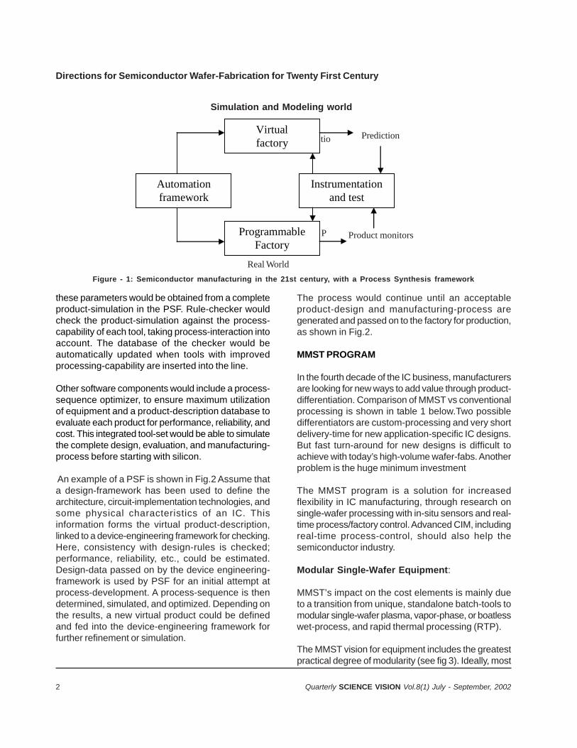
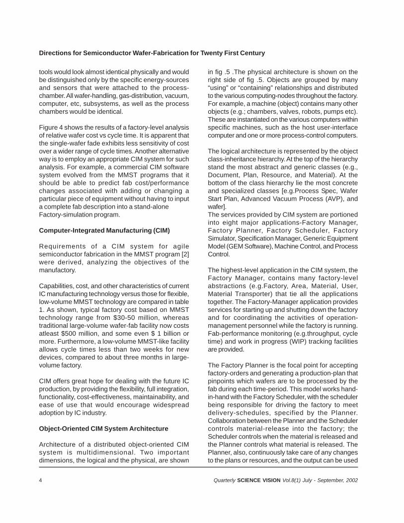
The architecture is shown in Figure-1, as envisagedfor semiconductor manufacturing facility of the future.
The most important part is the tight integration of avirtual (simulated) factory and a programmableproduction-facility. The actual production-line wouldfollow the MMST model, with flexible, microprocessor-equipped process-tools, linked to a host-computer-integrated manufacturing (CIM) computer, which wouldgenerate an optimized use of equipment for eachdevice.
The first step is to create a PSF, so as to simulateand optimize a virtual product from a design. A PSFmight include the following:
• Integrated process and equipment models foreach tool;
• Unit process-specification and product-descriptiondata-base;
• Product simulation;• Manufacturing rule checker;• Process sequence optimizer.
The output of the PSF would then be passed on tothe MMST production-line for execution. T-CAD tools,which provide a model of the unit-process steps andprocess-integration, need to be integrated with theprogrammable factory. Companies will therefore usethese T-CAD models to develop standard and reusableprocess-libraries, which will provide the fundamental“building blocks” of a manufacturing-sequence. Oncethese technologies are developed, the integration ofmanufacturing-process and circuit-design can begin.
PROCESS SYNTHESIS—ITS DESIGN AND WORKA central data-base of unit process specificationswould provide general parameters for a given process;
2 Quarterly SCIENCE VISION Vol.8(1) July - September, 2002
these parameters would be obtained from a completeproduct-simulation in the PSF. Rule-checker wouldcheck the product-simulation against the process-capability of each tool, taking process-interaction intoaccount. The database of the checker would beautomatically updated when tools with improvedprocessing-capability are inserted into the line.
Other software components would include a process-sequence optimizer, to ensure maximum utilizationof equipment and a product-description database toevaluate each product for performance, reliability, andcost. This integrated tool-set would be able to simulatethe complete design, evaluation, and manufacturing-process before starting with silicon.
An example of a PSF is shown in Fig.2 Assume thata design-framework has been used to define thearchitecture, circuit-implementation technologies, andsome physical characteristics of an IC. Thisinformation forms the virtual product-description,linked to a device-engineering framework for checking.Here, consistency with design-rules is checked;performance, reliability, etc., could be estimated.Design-data passed on by the device engineering-framework is used by PSF for an initial attempt atprocess-development. A process-sequence is thendetermined, simulated, and optimized. Depending onthe results, a new virtual product could be definedand fed into the device-engineering framework forfurther refinement or simulation.
The process would continue until an acceptableproduct-design and manufacturing-process aregenerated and passed on to the factory for production,as shown in Fig.2.
MMST PROGRAM
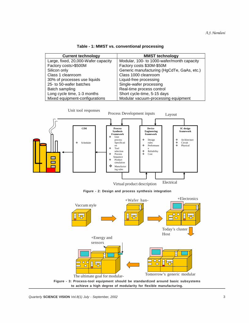
In the fourth decade of the IC business, manufacturersare looking for new ways to add value through product-differentiation. Comparison of MMST vs conventionalprocessing is shown in table 1 below.Two possibledifferentiators are custom-processing and very shortdelivery-time for new application-specific IC designs.But fast turn-around for new designs is difficult toachieve with today’s high-volume wafer-fabs. Anotherproblem is the huge minimum investment
The MMST program is a solution for increasedflexibility in IC manufacturing, through research onsingle-wafer processing with in-situ sensors and real-time process/factory control. Advanced CIM, includingreal-time process-control, should also help thesemiconductor industry.
Modular Single-Wafer Equipment:
MMST’s impact on the cost elements is mainly dueto a transition from unique, standalone batch-tools tomodular single-wafer plasma, vapor-phase, or boatlesswet-process, and rapid thermal processing (RTP).
The MMST vision for equipment includes the greatestpractical degree of modularity (see fig 3). Ideally, most
Instrumentation and test
Automation framework
Virtual factory
Programmable Factory
Predictiontio
P
Real World
Product monitors
Simulation and Modeling world
Figure - 1: Semiconductor manufacturing in the 21st century, with a Process Synthesis framework
Directions for Semiconductor Wafer-Fabrication for Twenty First Century
3Quarterly SCIENCE VISION Vol.8(1) July - September, 2002
Table - 1: MMST vs. conventional processing
Current technology MMST technology Large, fixed, 20,000-Wafer capacity Modular, 100- to 1000-wafer/month capacity Factory costs>$500M Factory costs $30M-$50M Silicon only Generic manufacturing (HgCdTe, GaAs, etc.) Class 1 cleanroom Class 1000 cleanroom 30% of processes use liquids Liquid-free processing 25- to 50-wafer batches Single-wafer processing Batch sampling Real-time process control Long cycle time, 1-3 months Short cycle-time, 5-15 days Mixed equipment-configurations Modular vacuum-processing equipment
Process Synthesis
Framework Unit
process Specification
Tool selection
Process Sequence Product
simulation
Manufacturing rules
CIM Scheduler
Device Engineering framework
Design
rules Performanc
e Reliability Cost
IC design framework
Architecture Circuit Physical
Unit tool responsesProcess Development inputs Layout
Virtual product description Electrical
Figure - 2: Design and process synthesis integration
Vaccum style
+Wafer han- +Electronics
Today’s clusterHost
+Energy andsensors
The ultimate goal for modular- Tomorrow’s generic modular
Figure - 3: Process-tool equipment should be standardized around basic subsystems
to achieve a high degree of modularity for flexible manufacturing.
A.J. Hamdani
4 Quarterly SCIENCE VISION Vol.8(1) July - September, 2002
tools would look almost identical physically and wouldbe distinguished only by the specific energy-sourcesand sensors that were attached to the process-chamber. All wafer-handling, gas-distribution, vacuum,computer, etc, subsystems, as well as the processchambers would be identical.
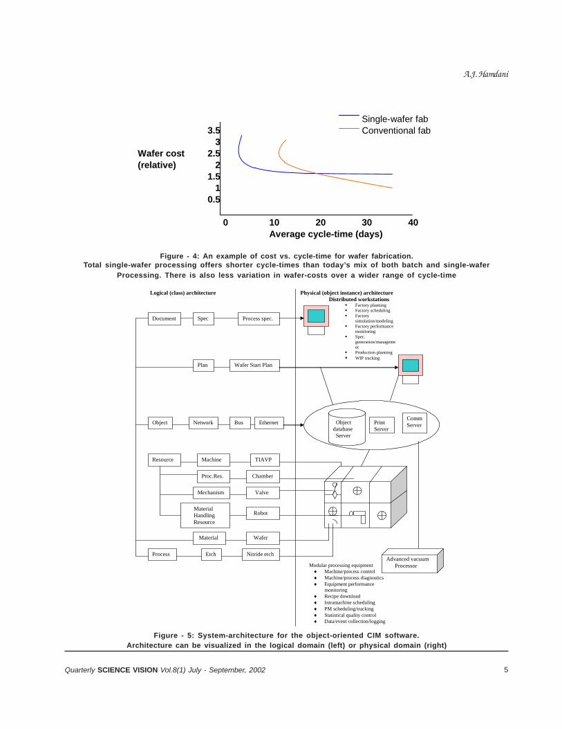
Figure 4 shows the results of a factory-level analysisof relative wafer cost vs cycle time. It is apparent thatthe single-wafer fade exhibits less sensitivity of costover a wider range of cycle times. Another alternativeway is to employ an appropriate CIM system for suchanalysis. For example, a commercial CIM softwaresystem evolved from the MMST programs that itshould be able to predict fab cost/performancechanges associated with adding or changing aparticular piece of equipment without having to inputa complete fab description into a stand-aloneFactory-simulation program.
Computer-Integrated Manufacturing (CIM)
Requirements of a CIM system for agilesemiconductor fabrication in the MMST program [2]were derived, analyzing the objectives of themanufactory.
Capabilities, cost, and other characteristics of currentIC manufacturing technology versus those for flexible,low-volume MMST technology are compared in table1. As shown, typical factory cost based on MMSTtechnology range from $30-50 million, whereastraditional large-volume wafer-fab facility now costsatleast $500 million, and some even $ 1 billion ormore. Furthermore, a low-volume MMST-like facilityallows cycle times less than two weeks for newdevices, compared to about three months in large-volume factory.
CIM offers great hope for dealing with the future ICproduction, by providing the flexibility, full integration,functionality, cost-effectiveness, maintainability, andease of use that would encourage widespreadadoption by IC industry.
Object-Oriented CIM System Architecture
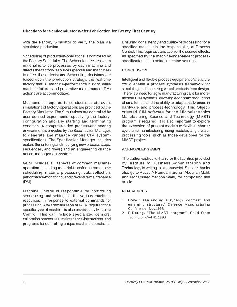
Architecture of a distributed object-oriented CIMsystem is multidimensional. Two importantdimensions, the logical and the physical, are shown
in fig .5 .The physical architecture is shown on theright side of fig .5. Objects are grouped by many“using” or “containing” relationships and distributedto the various computing-nodes throughout the factory.For example, a machine (object) contains many otherobjects (e.g.; chambers, valves, robots, pumps etc).These are instantiated on the various computers withinspecific machines, such as the host user-interfacecomputer and one or more process-control computers.
The logical architecture is represented by the objectclass-inheritance hierarchy. At the top of the hierarchystand the most abstract and generic classes (e.g.,Document, Plan, Resource, and Material). At thebottom of the class hierarchy lie the most concreteand specialized classes [e.g.Process Spec, WaferStart Plan, Advanced Vacuum Process (AVP), andwafer].The services provided by CIM system are portionedinto eight major applications-Factory Manager,Factory Planner, Factory Scheduler, FactorySimulator, Specification Manager, Generic EquipmentModel (GEM Software), Machine Control, and ProcessControl.
The highest-level application in the CIM system, theFactory Manager, contains many factory-levelabstractions (e.g.Factory, Area, Material, User,Material Transporter) that tie all the applicationstogether. The Factory-Manager application providesservices for starting up and shutting down the factoryand for coordinating the activities of operation-management personnel while the factory is running.Fab-performance monitoring (e.g.throughput, cycletime) and work in progress (WIP) tracking facilitiesare provided.
The Factory Planner is the focal point for acceptingfactory-orders and generating a production-plan thatpinpoints which wafers are to be processed by thefab during each time-period. This model works hand-in-hand with the Factory Scheduler, with the schedulerbeing responsible for driving the factory to meetdelivery-schedules, specified by the Planner.Collaboration between the Planner and the Schedulercontrols material-release into the factory; theScheduler controls when the material is released andthe Planner controls what material is released. ThePlanner, also, continuously take care of any changesto the plans or resources, and the output can be used
Directions for Semiconductor Wafer-Fabrication for Twenty First Century
5Quarterly SCIENCE VISION Vol.8(1) July - September, 2002
Single-wafer fab 3.5 Conventional fab 3
Wafer cost 2.5 (relative) 2
1.5 1 0.5 0 10 20 30 40 Average cycle-time (days)
Figure - 4: An example of cost vs. cycle-time for wafer fabrication.Total single-wafer processing offers shorter cycle-times than today’s mix of both batch and single-wafer
Processing. There is also less variation in wafer-costs over a wider range of cycle-time
Logical (class) architecture Physical (object instance) architecture Distributed workstations
Factory planning Factory scheduling Factory
simulation/modeling Factory performance
monitoring Spec.
generation/management
Production planning WIP tracking
Modular processing equipment
Machine/process control Machine/process diagnostics Equipment performance
monitoring Recipe download Intramachine scheduling PM scheduling/tracking Statistical quality control Data/event collection/logging
Document Spec Process spec.
Plan Wafer Start Plan
Object Bus
TIAVP
Mechanism
Machine
Proc.Res.
Process
Material Handling Resource
Resource
Network
Etch
Chamber
Ethernet
Nitride etch
Material Wafer
Robot
Valve
CommServer Print
Server Object database Server
Advanced vacuum Processor
Figure - 5: System-architecture for the object-oriented CIM software.Architecture can be visualized in the logical domain (left) or physical domain (right)
A.J. Hamdani
6 Quarterly SCIENCE VISION Vol.8(1) July - September, 2002
with the Factory Simulator to verify the plan viasimulated production.
Scheduling of production-operations is controlled bythe Factory Scheduler. The Scheduler decides whenmaterial is to be processed by each machine anddirects the factory-resources (people and machines)to effect those decisions. Scheduling-decisions arebased upon the production strategy, the real-timefactory status, machine-performance history, whilemachine failures and preventive maintenance (PM)actions are accommodated.
Mechanisms required to conduct discrete-eventsimulations of factory-operations are provided by theFactory Simulator. The Simulations are controlled byuser-defined experiments, specifying the factory-configuration and any starting and terminatingcondition. A computer-aided process-engineeringenvironment is provided by the Specification Manager,to generate and manage various CIM system-specifications. The Specification Manager includeseditors (for entering and modifying new process-steps,sequences, and flows) and an engineering changenotice management-system.
GEM includes all aspects of common machine-operation, including material-transfer, intramachinescheduling, material-processing, data-collection,performance-monitoring, and preventive maintenance(PM).
Machine Control is responsible for controllingsequencing and settings of the various machine-resources, in response to external commands forprocessing. Any specialization of GEM required for aspecific type of machine is also provided by MachineControl. This can include specialized sensors,calibration procedures, maintenance-instructions, andprograms for controlling unique machine operations.
Ensuring consistency and quality of processing for aspecified machine is the responsibility of ProcessControl. This requires translation of the desired effects,as specified by the machine-independent process-specifications, into actual machine settings.
CONCLUSION
Intelligent and flexible process equipment of the futurecould enable a process synthesis framework forsimulating and optimizing virtual products from design.There is a need for agile manufacturing calls for more-flexible CIM systems, allowing economic productionof smaller lots and the ability to adapt to advances inhardware and process-technology. This Object-oriented CIM software for the MicroelectronicsManufacturing Science and Technology (MMST)program is required. It is also important to explorethe extension of present models to flexible, shortercycle-time manufacturing, using modular, single-waferprocessing tools, such as those developed for theMMST project.
ACKNOWLEDGEMENT
The author wishes to thank for the facilities providedby Institute of Business Administration andTechnology in writing this manuscript. Sincere thanksalso go to Assad A Hamdani ,Suhail Abdullah Malikand Mohammed Yaqoob Wani, for composing thisarticle.
REFERENCES
1. Dove “Lean and agile synergy, contrast, andemerging structure.” Defence ManufacturingConference. Nov.1998.
2. R.Doring. “The MMST program”. Solid StateTechnology.Vol.41.1998.
Directions for Semiconductor Wafer-Fabrication for Twenty First Century
7Quarterly SCIENCE VISION Vol.8(1) July - September, 2002
METHODS OF ABSOLUTE LASER MEASUREMENTSOF GRAVITY-CONSTANT “g”
M.M.S. Gualini*
ABSTRACT
We propose a modified Michelson’s interferometer,with some applications in dimensional metrology. Theconfiguration of a Michelsons’ interferometer, usingcorner cubes instead of plane mirrors, is furthermodified in a rectangular parallelogram. A doubleprism is introduced in one of the branches of thedevice, in order to obtain a precision of /4 and anaccuracy of ±/8. The same scheme can be appliedto develop absolute portable gravimeters. We presentan interferometer-version, enabling us to reduce thefree-fall dropping height to less than 25 cm, which isthat size of any available device of the same class.Another version of the same interferometer enablesa theoretical doubling of the dropping-rate and areduced dropping-length, with an effectiveimprovement of the measurement-precision of g. Thissolution may lead to a portable absolute dynamicgravimeter. The paper discusses the mathematicalmodel, in terms of transfer-function of “g”, anddescribes the modified Michelson’s interferometer witha ‘futuristic’ solution for a dynamic portable absolutegravimeter.
Keywords: thickness, refraction index, gravityconstant “g”, laser absolute portable gravimeter,Michelson’s interferometer.
INTRODUCTION
We had proposed the use of a modified Michelson’sInterferometer for fast and accurate alignment of U-fold high-power gas laser cavities1, hinting at a possiblefurther modification. Theoretical work in the lattermodification has enabled consideration of someapplications in metrology. Infact, the modifiedMichelson’s Interferometer (MMI) presented here canbe used to measure rotations with small angles andthickness of transparent components like “opticalflats”, with ± /8 accuracy. It can be used also to testand measure the backlash and motion-linearity oftranslation stages. But we found a quite interestingapplication to develop a new absolute laser gravimeter,with improved precision, accuracy and reduceddimensions. Studies27 on previous portable laser
gravimeters have shown that reduction of the free-fallheight8 and rise and fall9 configurations may lead tothe design of portable laser gravimeters of improvedperformances and, above all, enable us to realize alsoportable absolute dynamic laser gravimeters.
2. GENERAL AND THEORETICAL DISCUSSION
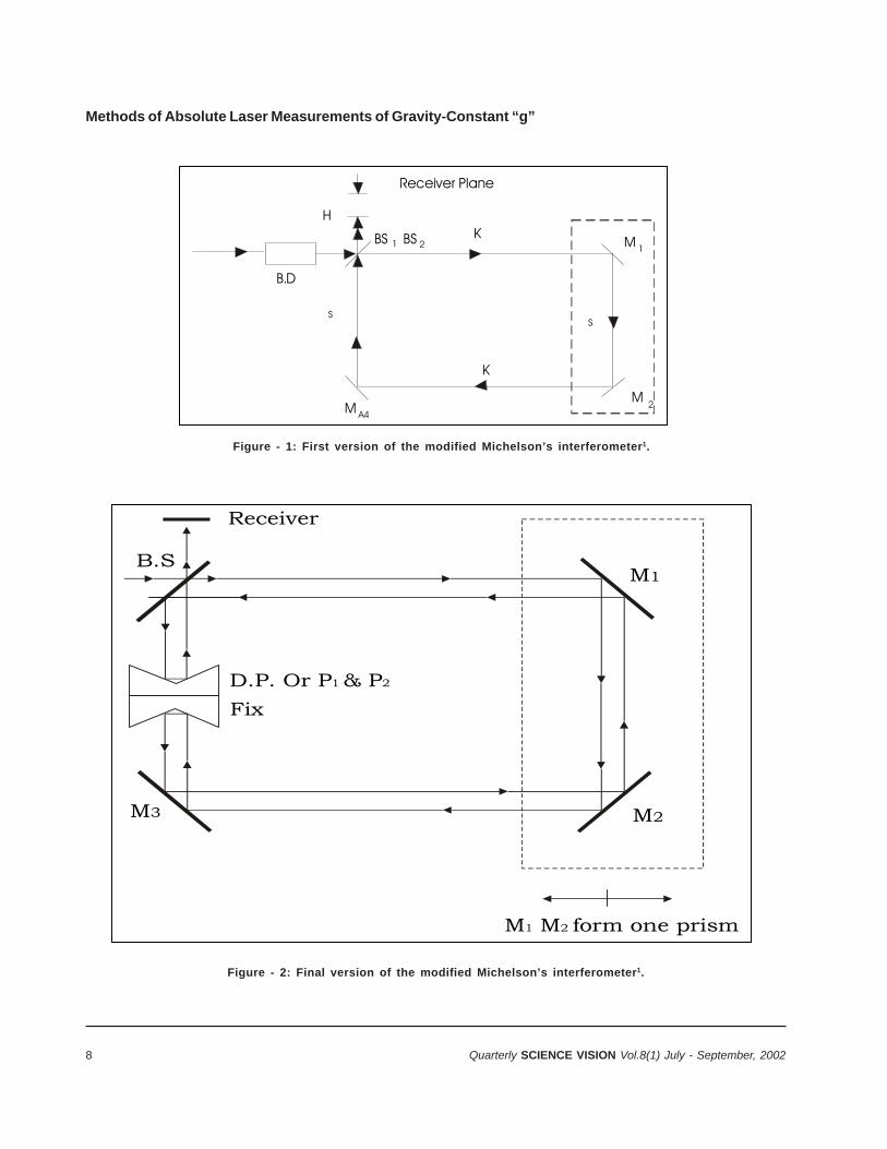
2.1 The two versions of the modified Michelson’sinterferometer
The two versions of the modified Michelson’sinterferometer are shown in figures 1 and 2. We willconcentrate the discussion on the version with adouble prism DPMMI (Double Prism ModifiedMichelson’s Interferometer), owing to its advantages,including a /4 precision and ± /8 accuracy. Figure1 shows the original scheme proposed for accuratefast alignment of U-fold laser cavities1. From thissimple design, we derived the DPMMI of figure 2.
A Double Prism is introduced in the scheme of figure1 and is fixed in its position, once properly aligned.Thus, typical Michelson’s fringes can be observedwhen the displacement, p (M1 and M2, part of thesame prism, move simultaneously), is equivalent to:
p = (1/2)(Mp + ½)0 = (2Mp + 1) 0/4@ Mp= 0, 1, 2,…(1)
where 0 is the stabilized wavelength of the lasersource. Beside the advantages of improved precisionand accuracy, the insertion of the double prismenables a direct control of the misalignments. Infact,a double spot detected by the receiver, a CCD camera,instead of the fringes, will be the direct informationthat the interferometer has lost its alignment. Thisinformation can be quantified after proper calibrationand the distance between the two spots on the CCDwill be proportional to the misalignments. The relativedisplacement of the two beams on the CCD surfacewill also enable us to determine the orientation of themisalignments, so that error-compensation can becarried out automatically.
Beside the development of a quite compact, absolutelaser gravimeter, the DPMMI has some other
* Pakistan Institute of Lasers and Optics, P.O.Box 1384, Islamabad.
8 Quarterly SCIENCE VISION Vol.8(1) July - September, 2002
B.D
Receiver Plane
HK
K
M
M
BS BS
M
S
2
1
S
1 2
A4
B.SM1
M2M3
D.P. Or P & P1 2
M M form one prism1 2
Fix
Receiver
Figure - 1: First version of the modified Michelson’s interferometer1.
Figure - 2: Final version of the modified Michelson’s interferometer1.
Methods of Absolute Laser Measurements of Gravity-Constant “g”
9Quarterly SCIENCE VISION Vol.8(1) July - September, 2002
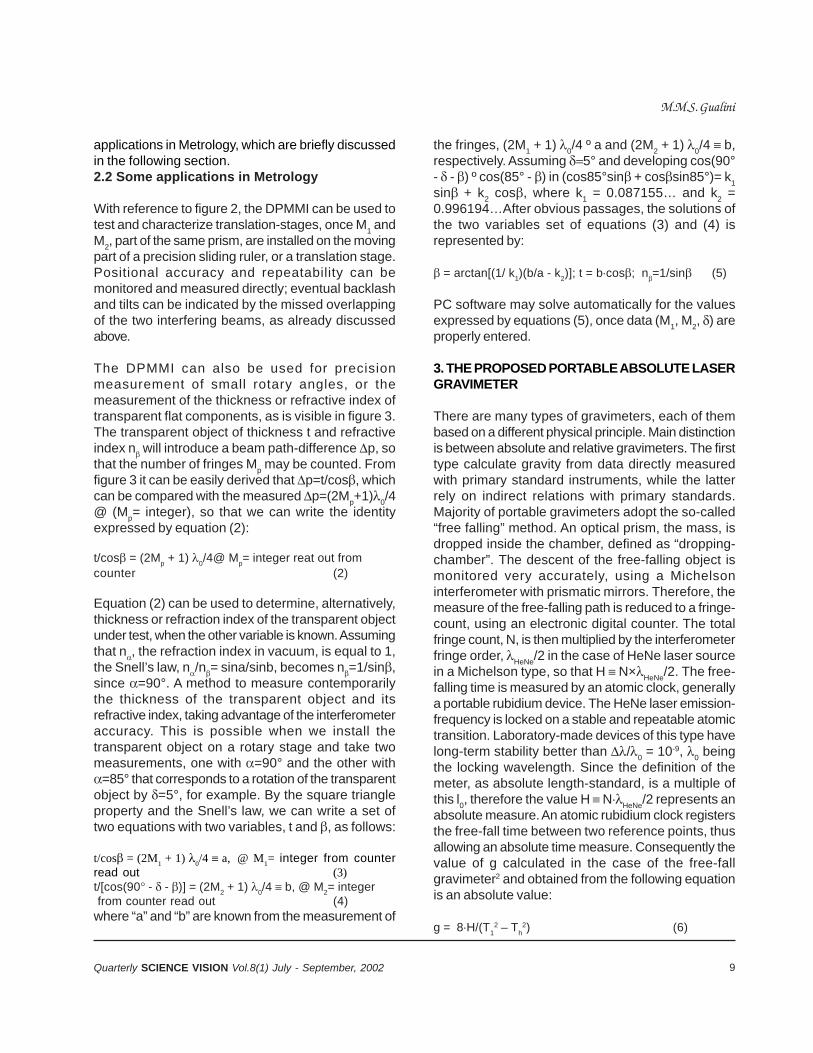
applications in Metrology, which are briefly discussedin the following section.2.2 Some applications in Metrology
With reference to figure 2, the DPMMI can be used totest and characterize translation-stages, once M1 andM2, part of the same prism, are installed on the movingpart of a precision sliding ruler, or a translation stage.Positional accuracy and repeatability can bemonitored and measured directly; eventual backlashand tilts can be indicated by the missed overlappingof the two interfering beams, as already discussedabove.
The DPMMI can also be used for precisionmeasurement of small rotary angles, or themeasurement of the thickness or refractive index oftransparent flat components, as is visible in figure 3.The transparent object of thickness t and refractiveindex n will introduce a beam path-difference p, sothat the number of fringes Mp may be counted. Fromfigure 3 it can be easily derived that p=t/cos, whichcan be compared with the measured p=(2Mp+1)0/4@ (Mp= integer), so that we can write the identityexpressed by equation (2):
t/cos = (2Mp + 1) 0/4@ Mp= integer reat out fromcounter (2)
Equation (2) can be used to determine, alternatively,thickness or refraction index of the transparent objectunder test, when the other variable is known. Assumingthat n, the refraction index in vacuum, is equal to 1,the Snell’s law, n/n= sina/sinb, becomes n=1/sin,since =90°. A method to measure contemporarilythe thickness of the transparent object and itsrefractive index, taking advantage of the interferometeraccuracy. This is possible when we install thetransparent object on a rotary stage and take twomeasurements, one with =90° and the other with=85° that corresponds to a rotation of the transparentobject by =5°, for example. By the square triangleproperty and the Snell’s law, we can write a set oftwo equations with two variables, t and , as follows:
t/cos = (2M1 + 1)
0/4 a, @ M
1= integer from counter
read out (3)t/[cos(90 - - )] = (2M2 + 1) 0/4 b, @ M2= integer from counter read out (4)where “a” and “b” are known from the measurement of
the fringes, (2M1 + 1) 0/4 º a and (2M2 + 1) 0/4 b,respectively. Assuming 5° and developing cos(90°- - ) º cos(85° - ) in (cos85°sin + cossin85°)= k1sin + k2 cos, where k1 = 0.087155… and k2 =0.996194…After obvious passages, the solutions ofthe two variables set of equations (3) and (4) isrepresented by:
= arctan[(1/ k1)(b/a - k2)]; t = bcos; n=1/sin (5)
PC software may solve automatically for the valuesexpressed by equations (5), once data (M1, M2, ) areproperly entered.
3. THE PROPOSED PORTABLE ABSOLUTE LASERGRAVIMETER
There are many types of gravimeters, each of thembased on a different physical principle. Main distinctionis between absolute and relative gravimeters. The firsttype calculate gravity from data directly measuredwith primary standard instruments, while the latterrely on indirect relations with primary standards.Majority of portable gravimeters adopt the so-called“free falling” method. An optical prism, the mass, isdropped inside the chamber, defined as “dropping-chamber”. The descent of the free-falling object ismonitored very accurately, using a Michelsoninterferometer with prismatic mirrors. Therefore, themeasure of the free-falling path is reduced to a fringe-count, using an electronic digital counter. The totalfringe count, N, is then multiplied by the interferometerfringe order, HeNe/2 in the case of HeNe laser sourcein a Michelson type, so that H N×HeNe/2. The free-falling time is measured by an atomic clock, generallya portable rubidium device. The HeNe laser emission-frequency is locked on a stable and repeatable atomictransition. Laboratory-made devices of this type havelong-term stability better than /0 = 10-9, 0 beingthe locking wavelength. Since the definition of themeter, as absolute length-standard, is a multiple ofthis l0, therefore the value H NHeNe/2 represents anabsolute measure. An atomic rubidium clock registersthe free-fall time between two reference points, thusallowing an absolute time measure. Consequently thevalue of g calculated in the case of the free-fallgravimeter2 and obtained from the following equationis an absolute value:
g = 8H/(T12 – Th
2) (6)
M.M.S. Gualini
10 Quarterly SCIENCE VISION Vol.8(1) July - September, 2002
Where H is the free-fall length, T1 and Th are the startand stop times, respectively, corresponding to thesame free-fall length. General scheme of thisgravimeter is shown in figure 4, from reference 6. Amotor drives a cart that falls with the corner-cube -prism. The laser beam back-reflected by the referencecorner cube prism combines with the beam back-reflected from the free-falling corner-cube-prism on thesurface of the photo detector, generating classicMichelson fringe patterns. An oscilloscope monitorsand records the interference fringes, while, in parallel,a counter counts them. Reference photo-detectorsautomatically start and stop fringes-count and time-measure.
In order to appreciate the improvements of theproposed solution with respect to the current availableportable absolute gravimeters, we briefly recall herebelow the state-of-the-art of this class of instruments.
3.1 First generation free-fall absolute gravimeters
Drawbacks of the first-generation free-fall absolutegravimeters are their size and weight. Despite theclaimed portability, the devices were quite heavy andcumbersome, requiring separate vacuum-pump anda rack holding all the basic instruments and the serviceelectronics. Also, the laser would have been installedseparately, eventually complicating alignmentprocedures. For example, the first prototype of thedevice described in reference2 was almost 1.5 m talland ~300 kg total weight. The commercially availableFG5-L8 has a weight of 57 kg and is 0.75 m tall. Butthe absolute gravimeter recently introduced anddescribed in reference4 is basically one fifth of thesize of the FG5-L, which makes it a possible candidatefor absolute dynamic measurements. Reduction insize of lasers, PC’s, electronic boards and vacuumpumps will be the determinant to further reduce thesize of future devices of the same type.
Easy transportability is not the only reason behindthe continuous trend to reduce the size of absolutegravimeters. In fact, as pointed out by Marson andFaller9, the slow acquisition-time was assumed asbeing the main limitation of the R&F free-fall absolutegravimeters. Quite obviously, longer is the ballistictrajectory, H, the longer is the total time ofmeasurement, including the time to invert the path,as is quite evident from figure 5, showing the
characteristic transfer-function of a rise-and-falldevice2. Shorter acquisition-time means higherprecision. For example, the latest device describedin reference4 has a throw-rate of 100 cycles/minuteand a best-case single-throw precision of ± 4.0 Gal(1 Gal = 1 Galileo = 1 cm/sec2 - in these units g =980 Gal). The precision of the early prototype ofreference 2 was ± 20.0 Gal and its throw-rate in therange of 2 –5 per minute, which was preventing a fullfield operation, due to the effects of perturbations likewind and temperature changes. The total free-fall timeper minute of observation has increased almost oneorder of magnitude, compared to other previousdevices4.
Therefore, size-reduction is extremely important toimprove the performances of absolute free-fallgravimeters, leading towards full field dynamicabsolute, g, and measurements. Figure 6 shows thesurface graphic of the total height, H =1.22625 (TI
2 -TH
2), in case of R&F-systems. Figure 6 shows that,in order to have measurement periods of 200 ms, thechamber height has to be approximately 50 cm.Similarly, for the single drop in free-fall, the authors ofreference 4 report a limit of 20 cm for the drop height,for the same measurement period. Obviously it is amatter of trade-off between period of measurementand height of drop. It is worth noticing that an heightof 35 cm is reasonably comparable to a portabledynamic gravimeter, but in the case of spring-typemeters, the typical filter duration is 120 s or more,while free-fall devices show measurement-periodsshorter than 200 ms.
The advantage of short drop-heights is double, gain inthe form of size-reduction and increasing themeasurement-time or duty cycle9. In fact, therepetition-rate directly influences the measurement-precision, this precision is usually given in Gal/Hz.From equation (6), figure 4 and 5, it is quite evidentthat the shorter the stop time, TH, the higher will bethe repetition-rate and, consequently the precision inGal/Hz. A value reported from reference4 is of 3 Gal/Hz.
3.2 The Drop method versus Rise and Fall (R&F)
Practical realization of an absolute gravimeter is nota simple task, especially from a mechanical point ofview. Beside the necessary design that may grant
Methods of Absolute Laser Measurements of Gravity-Constant “g”

11Quarterly SCIENCE VISION Vol.8(1) July - September, 2002
B.SM1
M2M3
D.P. Fix t
Transparent object under measure
Receiver
Figure 3: DPMMI setup to measure thickness and refraction index of transparent objects.
Motor
Photocell
Vacuumchamber
Coacceleratingchamber
Servoamplifier
Falling cubecorner
Oscilloscope
SapphiresphereReference
mirrorisolation
spring
Referencecube
corner
LED
Beamsplitter
Laser
AvalanchePhotodiode
Lig
ht In
tensi
ty
Apex
DOWNWARDUPWARD
TH
T1T
H = N H = N2 2
Figure 4: Diagram of the free-fall apparatus from reference6.
Figure 5: Characteristictransfer function of a R&Fabsolute gravimeter2
M.M.S. Gualini
12 Quarterly SCIENCE VISION Vol.8(1) July - September, 2002
reasonable insulation from various source of vibrations,the key point is the mechanism to launch or drop themass, i.e. an optical prism protected by a cart. Thecart has the function to offer the necessary friction tothe retaining system used to launch or drop the prism,without disturbing the optical alignment of the latter.
But it offers also the possibility to reduce the effectsof the buoyant residual force, since the normaloperating vacuum condition is 10-6 Torr. Authors2 havereported correction-factor of buoyant force in the orderof 5 Gal/Pa, partially compensated by the correctionrequired for the wavelength-reduction in the operatingvacuum conditions, 3 Gal/Pa. Thus the measurerequires a total correction in the range of ~ 2 Gal/Pa. Moreover, the cart protects also against residualinfluences of the magnetic fields and other sources ofnoise for the measurements. The above mechanicalproblems are more complicated in case of R&Frespect drop-devices. In fact the majority of absolutefree-fall gravimeters are designed in drop-configurationto simplify the launching mechanics. But also to takeadvantage of the minimal errors produced by apractically zero value of the vertical component of itsspeed, which would influence the measure, but notthe alignment of the interferometer, owing to thepropriety of an optical prism indicated in figure 7.
R&F absolute gravimeters offer better performances,although these are more complicated to be realizedfrom a mechanical point of view. In fact, R&F deviceshave a symmetric behavior, as visible in theircharacteristic curve reported in figure 5. Thesymmetric behavior has the benefit of compensatingmany errors9 owing to opposite actions from upward(rise) and downward (fall) motion. Resistance of theresidual air in the dropping chamber, magnetic fieldsand position errors will be also eliminated by thedouble directionality of the design.
The benefits of shorter dropping chambers andconsequent increase of the measurement-time havebeen already underlined above. A drop only gravimeter,like the FG5-L, operates at a best-case rate of onedrop every 2 s with a best-case duty cycle of 0.2s/2sor one tenth.
4. DESCRIPTION OF THE PROPOSED NEWGRAVIMETER
We propose in the following a possible improvementto the latest generation of portable absolutegravimeters, adopting a R&F configuration, reducingconsequently the size while contemporarily increasingthe measurement-period. We have also devised someextra features, in the attempt to improve the single-drop figure, trying to attain, at least theoretically, aglobal value better than ± 0.5 Gal/drop.
The device here proposed has essentially the followinginnovations:
1. Higher optical fringes-resolution, owing to apeculiar modification of the classic Michelson’sInterferometer configuration
2. New design-concepts, minimizing the droppingheight
3. New design concepts, reducing the “stop time”and increasing the “throw-rate”.
4.1 Higher optical fringes resolution of themodified classic Michelson’s Interferometer
The scheme of figure 2 is proposed, in order to developa third-generation of laser gravimeters. The advantageof this configuration is that the displacement HNcorresponds to:
HN = (1/2)(M + ½)0 = (2M + 1) 0/4 (7)
Where M is an integer (= 0, 1, 2, 3…). The fringe-order in this case is 0/4, and its accuracy ± 0/8.This represents an effective advantage because, withthe same number of counted fringes, i.e. N (2M+1), we find that HN = H/2. In other words we havereduced the drop height of a Michelson’s interferometerin half, without compromising in measurement-precision. Basically, if we have a drop-height of 35cm with a R&F system, using a conventionalMichelson’s interferometer, then with the proposedsolution we have a theoretical 17.5 cm dropping pathwith a considerable reduction of the related chamber.It is possible to consider feasible dropping-heights of10 to 15 cm, thus matching with the size oftransportable dynamic gravimeters. The advantagesof shorter drop-height will be also beneficial to themeasurement period rate and the instrument-precision,expressed in Gal/Hz, as discussed above. Thus,the first claim that we propose a more precise andaccurate gravimeter is satisfied, since in the DPMMI
Methods of Absolute Laser Measurements of Gravity-Constant “g”

13Quarterly SCIENCE VISION Vol.8(1) July - September, 2002
00.01
0.02
0.03
0.04
TH
0
0.1
0.2
0.3
0.4
TI
00.050.1
0.150.2
H
00.01
0.02
0.03
0.04
TH
Figure 6: Surface graphic of H, drop height, infunction of the total, T
I, and stop, T
H, times.
a = 45°
90° 90° 90°
a < 45° - a a > 45° + a
Figure 7: The propriety of the optical prism reduces misalignment errors.
B.S.
M1M2
M3
D.P. Fix100%R
100%R
One Prism
100%R
R & F
Receiver
To bi-directional counter
Laser
Figure 8: First gravimeter version based on the DPMMI.
M.M.S. Gualini
14 Quarterly SCIENCE VISION Vol.8(1) July - September, 2002
case, the precision is 0/4, and accuracy is ± 0/8.
4.2 New design concepts minimizing the droppingheight
The adoption of the DPMMI introduces the possibilityto reduce the effective height of the dropping chamberby half of the current devices, as demonstrated abovewith equation (7). The intrinsic accuracy of fringe-countof the proposed interferometer improves (by 1/8 factor)the figure of a classic Michelson’s interferometer, thusgiving an expectancy of ± 0.5 Gal/drop accuracy andprecision of ± 1.0 Gal/drop.
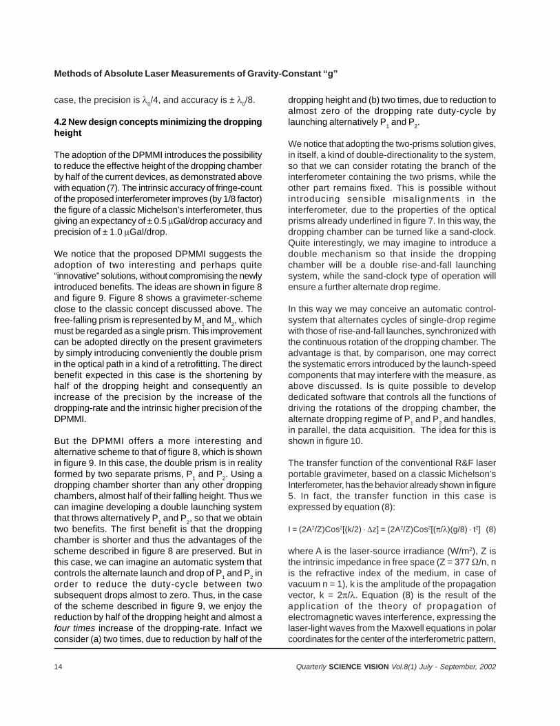
We notice that the proposed DPMMI suggests theadoption of two interesting and perhaps quite“innovative” solutions, without compromising the newlyintroduced benefits. The ideas are shown in figure 8and figure 9. Figure 8 shows a gravimeter-schemeclose to the classic concept discussed above. Thefree-falling prism is represented by M1 and M2, whichmust be regarded as a single prism. This improvementcan be adopted directly on the present gravimetersby simply introducing conveniently the double prismin the optical path in a kind of a retrofitting. The directbenefit expected in this case is the shortening byhalf of the dropping height and consequently anincrease of the precision by the increase of thedropping-rate and the intrinsic higher precision of theDPMMI.
But the DPMMI offers a more interesting andalternative scheme to that of figure 8, which is shownin figure 9. In this case, the double prism is in realityformed by two separate prisms, P1 and P2. Using adropping chamber shorter than any other droppingchambers, almost half of their falling height. Thus wecan imagine developing a double launching systemthat throws alternatively P1 and P2, so that we obtaintwo benefits. The first benefit is that the droppingchamber is shorter and thus the advantages of thescheme described in figure 8 are preserved. But inthis case, we can imagine an automatic system thatcontrols the alternate launch and drop of P1 and P2 inorder to reduce the duty-cycle between twosubsequent drops almost to zero. Thus, in the caseof the scheme described in figure 9, we enjoy thereduction by half of the dropping height and almost afour times increase of the dropping-rate. Infact weconsider (a) two times, due to reduction by half of the
dropping height and (b) two times, due to reduction toalmost zero of the dropping rate duty-cycle bylaunching alternatively P1 and P2.
We notice that adopting the two-prisms solution gives,in itself, a kind of double-directionality to the system,so that we can consider rotating the branch of theinterferometer containing the two prisms, while theother part remains fixed. This is possible withoutintroducing sensible misalignments in theinterferometer, due to the properties of the opticalprisms already underlined in figure 7. In this way, thedropping chamber can be turned like a sand-clock.Quite interestingly, we may imagine to introduce adouble mechanism so that inside the droppingchamber will be a double rise-and-fall launchingsystem, while the sand-clock type of operation willensure a further alternate drop regime.
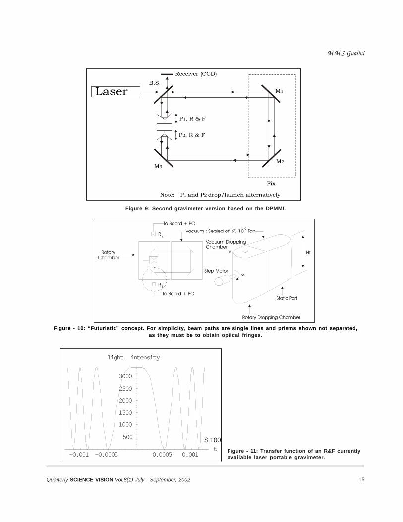
In this way we may conceive an automatic control-system that alternates cycles of single-drop regimewith those of rise-and-fall launches, synchronized withthe continuous rotation of the dropping chamber. Theadvantage is that, by comparison, one may correctthe systematic errors introduced by the launch-speedcomponents that may interfere with the measure, asabove discussed. Is is quite possible to developdedicated software that controls all the functions ofdriving the rotations of the dropping chamber, thealternate dropping regime of P1 and P2 and handles,in parallel, the data acquisition. The idea for this isshown in figure 10.
The transfer function of the conventional R&F laserportable gravimeter, based on a classic Michelson’sInterferometer, has the behavior already shown in figure5. In fact, the transfer function in this case isexpressed by equation (8):
I = (2A2/Z)Cos2[(k/2) z] = (2A2/Z)Cos2[(/)(g/8) t2] (8)
where A is the laser-source irradiance (W/m2), Z isthe intrinsic impedance in free space (Z = 377 /n, nis the refractive index of the medium, in case ofvacuum n = 1), k is the amplitude of the propagationvector, k = 2/. Equation (8) is the result of theapplication of the theory of propagation ofelectromagnetic waves interference, expressing thelaser-light waves from the Maxwell equations in polarcoordinates for the center of the interferometric pattern,
Methods of Absolute Laser Measurements of Gravity-Constant “g”
15Quarterly SCIENCE VISION Vol.8(1) July - September, 2002
B.S.M1
M2M3
Note: P and P drop/launch alternatively1 2
P , R & F1
P , R & F2
Fix
Receiver (CCD)
Laser
Figure 9: Second gravimeter version based on the DPMMI.
Static Part
3
-9
To Board + PC
To Board + PC
ChamberRotary
R1
2R
Rotary Dropping Chamber
Vacuum DroppingChamber
Step Motor
Vacuum : Sealed off @ 10 Torr
HT
Figure - 10: “Futuristic” concept. For simplicity, beam paths are single lines and prisms shown not separated,as they must be to obtain optical fringes.
-0.001 -0.0005 0.0005 0.001t
500
1000
1500
2000
2500
3000
light intensity
S 100Figure - 11: Transfer function of an R&F currentlyavailable laser portable gravimeter.
M.M.S. Gualini
16 Quarterly SCIENCE VISION Vol.8(1) July - September, 2002
r = 0. More particularly, equation (8) is obtained fromthe standard relation of the light-intensity of a classicMichelson’s interferometer, available from literature10,which is an acceptable approximation. In details, wehave imposed in equation (8) that the beam path-difference, z, that generates the phase-shift toproduce the fringes, is coincident with the droppingheight, H z, and solving equation (1) in H, H = g ×(t2/8), assuming for simplicity t2 = T1
2 – Th2, which
means not considering the inversion motion time, Th2
= 0, basically not of interest in a theoretical approach.After substitutions and manipulations, equation (8) isobtained. Equation (8) can be adopted to simulatethe transfer-function of real cases, by simplysubstituting experimental data. Assuming an R&Fdevice operating with a conventional Michelson’sinterferometer, we can substitute real parameters andvalues in equation (8) and then compare it with thetransfer-function of the devices proposed in figure 8and 9. For example, assuming working with afrequency-stabilized HeNe laser of 5 mW output power,with a 632 nm vacuum wavelength and a beamdiameter at the source of 2 mm, a dropping height of0.30 m, we find a transfer-function expressed byequation (9), whose behavior is reproduced here infigure 11 below.
I=3362.86445Cos2[(3.149.8)/(8.0 632.010-9)(t2)] (9)
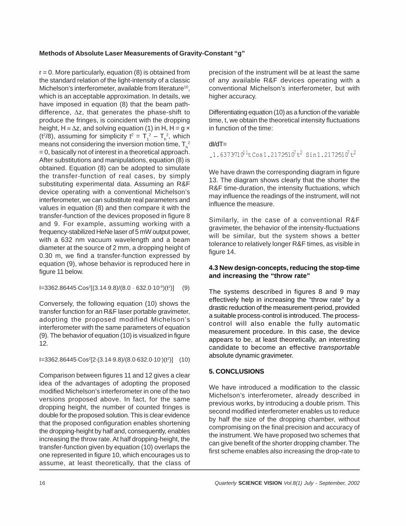
Conversely, the following equation (10) shows thetransfer function for an R&F laser portable gravimeter,adopting the proposed modified Michelson’sinterferometer with the same parameters of equation(9). The behavior of equation (10) is visualized in figure12.
I=3362.86445Cos2[2(3.149.8)/(8.0632.010-)(t2)] (10)
Comparison between figures 11 and 12 gives a clearidea of the advantages of adopting the proposedmodified Michelson’s interferometer in one of the twoversions proposed above. In fact, for the samedropping height, the number of counted fringes isdouble for the proposed solution. This is clear evidencethat the proposed configuration enables shorteningthe dropping-height by half and, consequently, enablesincreasing the throw rate. At half dropping-height, thetransfer-function given by equation (10) overlaps theone represented in figure 10, which encourages us toassume, at least theoretically, that the class of
precision of the instrument will be at least the sameof any available R&F devices operating with aconventional Michelson’s interferometer, but withhigher accuracy.
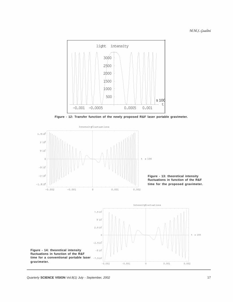
Differentiating equation (10) as a function of the variabletime, t, we obtain the theoretical intensity fluctuationsin function of the time:
dI/dT=
- 1.63737 ´ 10 11 t Cos 1.21725 ´ 10 7 t 2 Sin 1.21725 ´ 10 7 t 2
We have drawn the corresponding diagram in figure13. The diagram shows clearly that the shorter theR&F time-duration, the intensity fluctuations, whichmay influence the readings of the instrument, will notinfluence the measure.
Similarly, in the case of a conventional R&Fgravimeter, the behavior of the intensity-fluctuationswill be similar, but the system shows a bettertolerance to relatively longer R&F times, as visible infigure 14.
4.3 New design-concepts, reducing the stop-timeand increasing the “throw rate”
The systems described in figures 8 and 9 mayeffectively help in increasing the “throw rate” by adrastic reduction of the measurement-period, provideda suitable process-control is introduced. The process-control will also enable the fully automaticmeasurement procedure. In this case, the deviceappears to be, at least theoretically, an interestingcandidate to become an effective transportableabsolute dynamic gravimeter.
5. CONCLUSIONS
We have introduced a modification to the classicMichelson’s interferometer, already described inprevious works, by introducing a double prism. Thissecond modified interferometer enables us to reduceby half the size of the dropping chamber, withoutcompromising on the final precision and accuracy ofthe instrument. We have proposed two schemes thatcan give benefit of the shorter dropping chamber. Thefirst scheme enables also increasing the drop-rate to
Methods of Absolute Laser Measurements of Gravity-Constant “g”
17Quarterly SCIENCE VISION Vol.8(1) July - September, 2002
-0.001 -0.0005 0.0005 0.001t
500
1000
1500
2000
2500
3000
light intensity
s 100
Figure - 12: Transfer function of the newly proposed R&F laser portable gravimeter.
-0.002 -0.001 0 0.001 0.002
-1.5 ´ 10 8
-1 ́ 10 8
-5 ́ 10 7
0
5 ́ 10 7
1 ́ 10 8
1.5 ´ 10 8
t s 100
Intensity fluctuations
Figure - 13: theoretical intensityfluctuations in function of the R&F
time for the proposed gravimeter.
-0.002 -0.001 0 0.001 0.002
-7.5 ´ 10 7
-5 ́ 10 7
-2.5 ´ 10 7
0
2.5 ´ 10 7
5 ́ 10 7
7.5 ´ 10 7
t s 100
Intensity fluctuations
Figure - 14: theoretical intensityfluctuations in function of the R&Ftime for a conventional portable lasergravimeter.
M.M.S. Gualini

18 Quarterly SCIENCE VISION Vol.8(1) July - September, 2002
further improve the final precision of the instrumenton the averaged values.
The second scheme, with two prisms launchedalternatively, enables us to increase the launching ratetheoretically by four times. In order to get benefit fromthe advantages of the R&F and drop configuration andthe alternate launch of the two prisms, combinedtogether, we have proposed a “futuristic” scheme whererise-and-fall launches are alternate to simple drops,thus enabling mutual compensation of the systematicerrors typical to each of the two configurations.
It is finally expected that improved frequency-stabilityschemes of laser sources and corresponding size-reduction will enable one to build very compact andtransportable absolute gravimeters candidate, to beused in dynamic measurement conditions.
ACKNOWLEDGEMENTS
The author is particularly thankful to the Chairman ofPakistan Institute of Lasers and Optics (PILO) for hisco-operation to allow the presentation of this work.The author feels deeply indebted to Prof. Dr. Ing. SergioSartori (formerly director of the Istituto di MetrologiaColonnetti of Turin, Italy) for providing usefulsuggestions and encouraging this publication. Also,particular thanks to the never-failing support of myfamily.
REFERENCES
1. M. M. S. Gualini, “Two Beams Laser Ranging,Leveling and Aligning System”, ICALEO’98
Proceedings Volume 85a, Orlando (November 16-19, 1998)
2. G. Cerutti, L. Cannizzo, A. Sakuma, J. Hostache, “Atransportable apparatus for absolute gravitymeasurement”, VDI Berichte Nr 212, 1974
3. F. Alasia, L. Cannizzo, G. Cerutti, I. Marson, “Absolutegravity acceleration measurements: Experienceswith a transportable gravimeter”, Metrologia 18(4),221-229, 1982
4. J.M Brown, T. M. Niebauer, B. Richter, F.J. Klopping,J.G. Valentine and W.K. Buxton, “Miniaturizedgravimeter may greatly improve measurements”,from http://www.agu.org./eos_elec/99144e.html
5. J. M. Brown, T.M. Niebauer, F.J. Klopping, A. T. Herring,“A new differential fiber optic gradiometer for 4-Dabsolute differential gravity”, Geophysical ResearchLetters, Vol.27, No. 1, pages 33 – 36, January 1,2000. Also see J. Wallace, “INTERFEROMETRY:Fiber coupling improves gravimeters”. Laser FocusWorld, 36(3), March 2000
6. J.E. Faller, I. Marson, “Ballistic methods ofmeasuring g: the direct free fall and symmetricalrise and fall methods compared”, Metrologia (1),25, 49-55, 1988. Also in Resnick, Haliday, Krane,Physics, Volume 1, J. Wiley & Sons, Inc. 1992, 4th
Edition, page 277. M. M. Gualini, “Portable Laser Gravimeter”,
Proceedings (to be published) 2nd InternationalSymposium on Mechanical Vibrations, Islamabad(September 2000)
8. Web page of Micro-g Solutions, Inc. http://www.microgsolutions.com/ and particularly the sitededicated to the FG5-L, http://www.microgsolutions.com/fg5l.htm
9. I. Marson, J.E. Faller, “The acceleration of gravity: Itsmeasurement and importance”, J.Phys. E. Sci.Instrum., 19, pages 22-32, 1986
10. J.T. Luxon, D.E. Parker, Industrial Laser Applications,Prentice-Hall (1984)
Methods of Absolute Laser Measurements of Gravity-Constant “g”
19Quarterly SCIENCE VISION Vol.8(1) July - September, 2002
GROWTH-POTENTIAL OF PAKISTAN’S WATER-RESOURCES AND THEIR IMPACT ON DEVELOPMENT
Malik MuhammadNazeer*
* Dr. A.Q. Khan Research Laboratories, P.O.Box 502, Rawalpindi.
ABSTRACT
Pakistan has ideal and matchless God-giftedresources for its own overall development and a verydecisive role in grabbing the earth globe out of themouth of twenty-first century’s environmental dragons,ready to swallow the entire life on it. Its location onthe globe and its geographic position in thesubcontinent, having the world’s highest and biggestsnow glaciers, containing the mountains, Himalayasand Karakoram, along with special pattern structureof mountain-wall on the north and the Indian Ocean,bay of Bengal and Arabian Sea around the Equator,led and followed respectively by largest recipients ofsolar-heat, the continents of Australia and Africa, onthe its south has no match throughout the world. Themechanism having above- stated component partscauses heavy monsoon rains.
A sizeable share of these rain waters is received byPakistan, which has the potential to store all or mostof this water and use it not only for its agricultural andpower requirements, but also for safely leading theworld out of the crunching grip of environmentaldragons of twenty-first century. Before highlightingthe role of Pakistan in ameliorating deadly Globalissues of exponentially rising global warming,environmental pollution, hole in the stratosphericozone layer, droughts and resulting social andeconomic problems, it is worthwhile to properlyestimate the size and mechanism of its resourcesand their direct impact on its local development. Thisaspect is fully discussed in the present work, as apreface to its real and ideal roles, which will behighlighted in the subsequent attempts.
INTRODUCTION
The earth’s rotation, supported by the enormousamounts of solar energy received by Australia andAfrica with large temperature and pressure-gradientbetween these main-lands and the Oceans, producelarge wind currents, resulting in monsoons which carrywater-vapors from the Indian Ocean, Bay of Bengaland the Arabian sea towards the Indian sub-continent.The high Himalaya mountains in the north of the sub-
continent and the Karakoram range in the north-westof Pakistan enable these winds to form loops anddischarge water-contents, as rain, and provide hugewater-storage for the sub-continent in the form of snow.Although Pakistan is very lucky to have numerousdam-sites to store large quantities of this two-to-threemonth supply of monsoon rain-water and regulate itfor its perennial irrigation and electric power generationpurposes, but unfortunately these water-resources arenot being fully utilized. Proper planning and executioncould help increase the water-resources more thantwice, the agricultural product by four to five timesand hydro-electric power-generation capacity by afactor of about ten. These resources, their location,their size and mutual compatibility, when viewed inthe perspective of Pakistan’s development andparticularly in that of global challenges, at once bringinto mind the position that Nature has intentionallycreated this entire system for the (complete) solutionof Mankind’s deadly problems of 21st Century. Thesystem is ready to work, but it needs the effort ofMankind to start it. Its starting key, however, is thewell planned construction of its water-storage, power-generation, irrigation and drainage systems, andMankind has to do it collectively at any cost, puttingaside all the differences, whatsoever, for its safeexistence on the globe. Naturally, the industrialcountries and producers and user of fossil fuels havea large share in contributing to and fuelling the globalproblem and they should, accordingly, be the majorcontributors of the cost involved in remedial operations.The UNO have the opportunity to do the most-wantedrole of planning, supervising, financing this activity andcollection of the due contributions.
MECHANISM OF WATER-RESOURCES
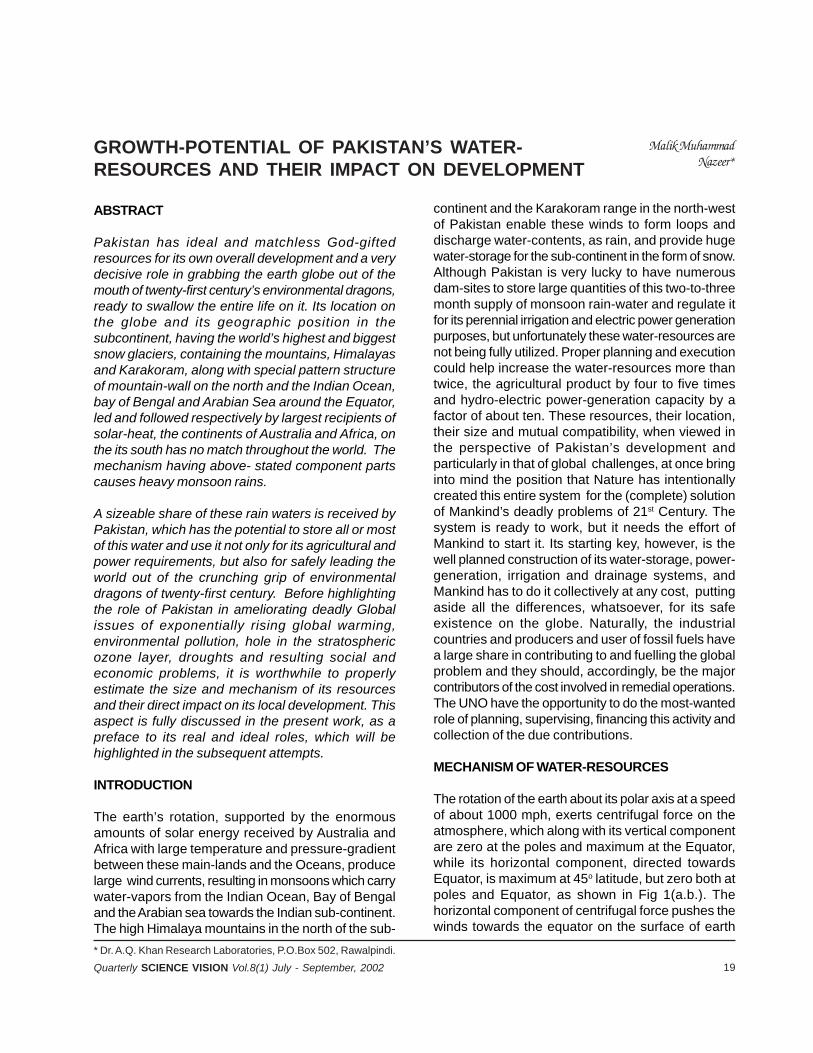
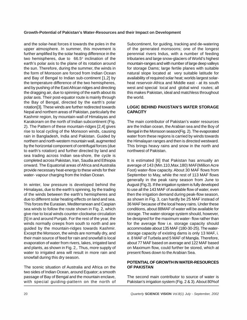
The rotation of the earth about its polar axis at a speedof about 1000 mph, exerts centrifugal force on theatmosphere, which along with its vertical componentare zero at the poles and maximum at the Equator,while its horizontal component, directed towardsEquator, is maximum at 45o latitude, but zero both atpoles and Equator, as shown in Fig 1(a.b.). Thehorizontal component of centrifugal force pushes thewinds towards the equator on the surface of earth
20 Quarterly SCIENCE VISION Vol.8(1) July - September, 2002
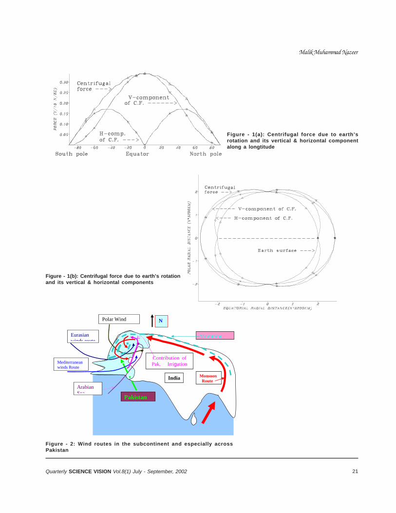
and the solar-heat forces it towards the poles in theupper atmosphere. In summer, this movement isfurther amplified by the solar heating difference in thetwo hemispheres, due to 66.5o inclination of theearth’s polar axis to the plane of its rotation aroundthe sun. Therefore, during the summer, the winds inthe form of Monsoon are forced from Indian Oceanand Bay of Bengal to Indian sub-continent [1,2] bythe temperature difference of the two hemispheres,and by pushing of the East African ridges and directingthe dragging air, due to spinning of the earth about itspolar axis. Their post-equator route is mainly throughthe Bay of Bengal, directed by the earth’s polarrotation[3]. These winds are further redirected towardsNepal and northern areas of Pakistan, particularly theKashmir region, by mountain-wall of Himalayas andKarakoram on the north of Indian subcontinent (Fig.2). The Pattern of these mountain-ridges [2,4] givesrise to local cycling of the Monsoon winds, causingrain in Bangladesh, India and Pakistan. Guided bynorthern and north-western mountain wall, augmentedby the horizontal component of centrifugal forces (dueto earth’s rotation) and further directed by land andsea trading across Indian sea-shore, the cycle iscompleted across Pakistan, Iran, Saudia and Ethiopiaonward. The Equatorial areas of Africa and Australiaprovide necessary heat-energy to these winds for theirwater- vapour charging from the Indian Ocean.
In winter, low pressure is developed behind theHimalayas, due to the earth’s spinning, by the tradingof the winds between the earth’s hemispheres anddue to different solar heating effects on land and sea.This forces the Eurasian, Mediterranean and Caspiansea winds to follow the route shown in Fig. 2, whichgive rise to local winds counter-clockwise circulation[5] in and around Punjab. For the rest of the year, thewinds normally creeps from south to north and areguided by the mountain-ridges towards Kashmir.Except the Monsoon, the winds are normally dry, andtheir main source of feed for rain and snowfall is localevaporation of water from rivers, lakes, irrigated landand plants, as shown in Fig. 2,. Thus, more supply ofwater to irrigated area will result in more rain andsnowfall during this dry season.
The scenic situation of Australia and Africa on thetwo sides of Indian Ocean, around Equator; a smoothpassage of Bay of Bengal and the mountain enclave,with special guiding-pattern on the north of
Subcontinent, for guiding, tracking and de-wateringof the generated monsoons; one of the longestperennial rivers Indus, with a number of feedingtributaries and large snow-glaciers of World’s highestmountain-ranges and with number of large deep valleysfor storage Dams; large fertile planes with suitablenatural slope located at very suitable latitude foravailability of required solar heat; worlds largest solar-heat reservoir-Africa and Middle east - at its southwest and special local and global wind routes; allthis makes Pakistan, ideal and matchless throughoutthe world.
LOGIC BEHIND PAKISTAN’S WATER STORAGECAPACITY
The main contributor of Pakistan’s water resourcesare the Indian ocean, the Arabian sea and the Boy ofBengal in the Monsoon season(Fig. 2). The evaporatedwater from these regions is carried by winds towardsthe Himalayan ranges and then is directed westward.This brings heavy rains and snow in the north andnorthwest of Pakistan.
It is estimated [6] that Pakistan has annually anaverage of 143 (Min.110,Max.180) MAF(Million AcreFoot) water-flow capacity. About 30 MAF flows fromSeptember to May, while the rest of 113 MAF flowsgenerally in the peak rainy season from June toAugust (Fig.3). If the irrigation system is fully developedto use all the 143 MAF of available flow of water, eventhen the irrigation demand during peak-flow season,as shown in Fig. 3, can hardly be 25 MAF instead of36 MAF because of the local heavy rains. Under theseconditions, about 88MAF of water will be available forstorage. The water-storage system should, however,be designed for the maximum water- flow rather thanfor the average flow i.e. storage capacity shouldaccommodate about 135 MAF (180-30-25). The water-storage capacity of existing dams is only 13 MAF, i.e. 8 MAF of Turbela and 5 MAF of Mangla. Therefore,about 77 MAF based on average and 122 MAF basedon Maximum flow, could further be stored, which atpresent flows down to the Arabian Sea.
POTENTIAL OF GROWTH IN WATER-RESOURCESOF PAKISTAN
The second main contributor to source of water isPakistan’s irrigation system (Fig. 2 & 3). About 80%of
Growth-Potential of Pakistan’s Water-Resources and their Impact on Development
21Quarterly SCIENCE VISION Vol.8(1) July - September, 2002
Monsoon Route
MountainsEurasian winds route
Mediterranean winds Route
Polar Wind
India
N
Contribution of Pak. Irrigation
Arabian Sea
Pakistan
Figure - 1(a): Centrifugal force due to earth’srotation and its vertical & horizontal componentalong a longtitude
Figure - 1(b): Centrifugal force due to earth’s rotationand its vertical & horizontal components
Figure - 2: Wind routes in the subcontinent and especially acrossPakistan
Malik Muhammad Nazeer
22 Quarterly SCIENCE VISION Vol.8(1) July - September, 2002
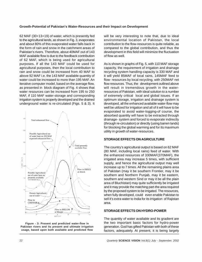
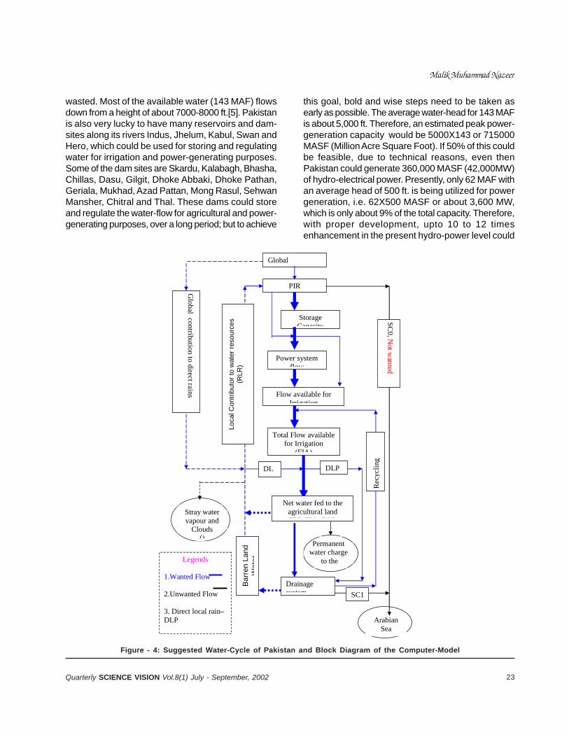
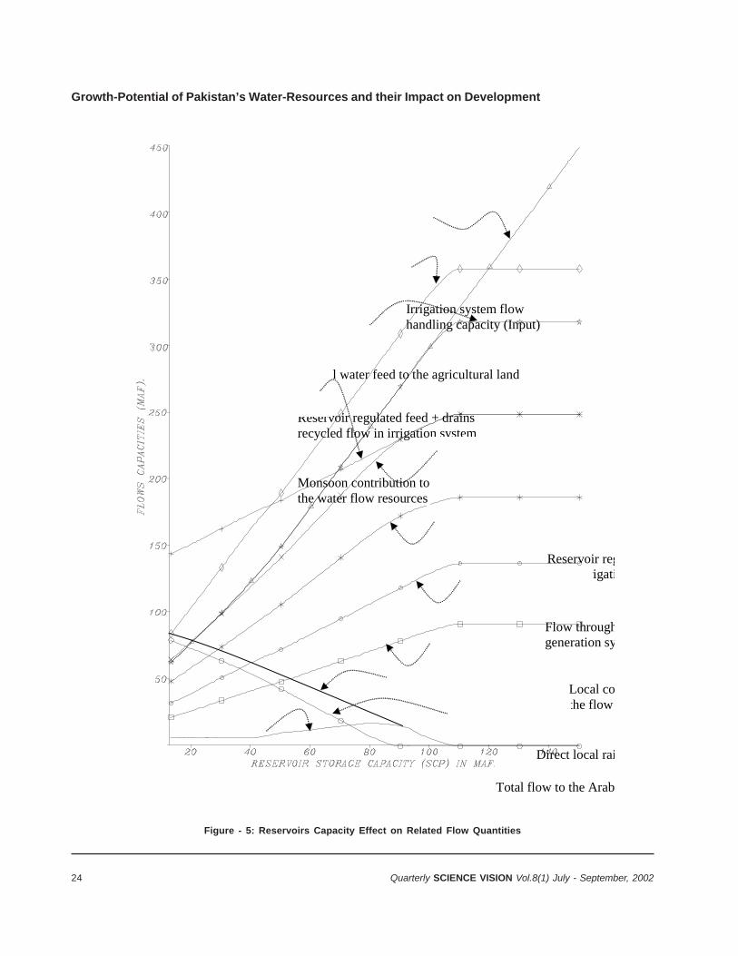
62 MAF (30+13+19) of water, which is presently fedto the agricultural lands, as shown in Fig. 3, evaporatesand about 80% of this evaporated water falls back inthe form of rain and snow in the catchment areas ofPakistan’s rivers. Therefore, about 40MAF out of 143MAF available flow is due to the feedback contributionof 62 MAF, which is being used for agriculturalpurposes. If all the 143 MAF could be used foragricultural purposes, then the local contribution torain and snow could be increased from 40 MAF toabove 92 MAF i.e. the 143 MAF available quantity ofwater could be increased to more than 195 MAF. Aniterative computer model, based on the average flow,as presented in block diagram of Fig. 4 shows thatwater resources can be increased from 195 to 250MAF, if 110 MAF water-storage and correspondingirrigation system is properly developed and the drainedunderground water is re-circulated (Figs. 5 & 3). It
will be very interesting to note that, due to idealenvironmental location of Pakistan, the localcontribution to the flow-resources is quite reliable, ascompared to the global contribution, and thus thedevelopment in this field will minimize the fluctuationof flow as well.
As is shown in graphs of Fig. 5, with 110 MAF storagecapacity, the requirement of irrigation and drainagerecycling system handling-capacity is 330 MAF andit will yield 85MAF of local rains, 145MAF feed toflow- resources by local recycling, with 250MAF netflow resources. Thus, the development outlined abovewill result in tremendous growth in the water-resources of Pakistan, with ideal solution to a numberof extremely critical local and global issues. If anoptimum storage, irrigation and drainage system isdeveloped, all the enhanced available water-flow maywell be utilized for irrigation and all of it will have to beevaporated to avoid water-logging-of course, theabsorbed quantity will have to be extracted throughdrainage- system and forced to evaporate indirectly(through re-circulation) or directly (using barren lands)for blocking the global warming and for its maximumutility in growth of water-resources.
STORAGE EFFECTS ON AGRICULTURE
The country’s agricultural output is based on 62 MAF(80 MAF, including local rains) feed of water. Withthe enhanced resources of 330MAF(370MAF), theirrigated area may increase 5 times, with sufficientsupply, and hence the agricultural output may wellincrease up to 7 times. All the remaining plains areaof Pakistan (may it be southern Frontier, may it besouthern and Northern Punjab, may it be eastern,southern and western Sind or may it be all the plainarea of Bluchistan) may quite sufficiently be irrigatedand it may provide the matching part-the area requiredby the proposed system to be irrigated. The resources,when fully developed, could even enable Pakistan tosell it’s extra water to India for its irrigation of Rajistanarea.
STORAGE EFFECTS ON HYDRO-POWER
The quantity of water available and its gradient arethe two important basic factors for hydro-powergeneration. God has gifted Pakistan with both of thesefactors, adequately. At present, it is being largely
Flow in INDUS at Attock
Flow in CHENAB at
Present Agricultural use of water
Flow in JHELUM at Mangla
Possible Agricultural use of water base on presently available 143 MAF flow
Total presently available flow
Total enhaunced flow
Possible Agricultural use of water base on 250 MAF expected enhaunced flow
Figure - 3: Present and predicted water-flow inPakistan rivers and its present and ultimate irrigationusage, based upon both available and predicted flow
Growth-Potential of Pakistan’s Water-Resources and their Impact on Development
23Quarterly SCIENCE VISION Vol.8(1) July - September, 2002
wasted. Most of the available water (143 MAF) flowsdown from a height of about 7000-8000 ft.[5]. Pakistanis also very lucky to have many reservoirs and dam-sites along its rivers Indus, Jhelum, Kabul, Swan andHero, which could be used for storing and regulatingwater for irrigation and power-generating purposes.Some of the dam sites are Skardu, Kalabagh, Bhasha,Chillas, Dasu, Gilgit, Dhoke Abbaki, Dhoke Pathan,Geriala, Mukhad, Azad Pattan, Mong Rasul, SehwanMansher, Chitral and Thal. These dams could storeand regulate the water-flow for agricultural and power-generating purposes, over a long period; but to achieve
this goal, bold and wise steps need to be taken asearly as possible. The average water-head for 143 MAFis about 5,000 ft. Therefore, an estimated peak power-generation capacity would be 5000X143 or 715000MASF (Million Acre Square Foot). If 50% of this couldbe feasible, due to technical reasons, even thenPakistan could generate 360,000 MASF (42,000MW)of hydro-electrical power. Presently, only 62 MAF withan average head of 500 ft. is being utilized for powergeneration, i.e. 62X500 MASF or about 3,600 MW,which is only about 9% of the total capacity. Therefore,with proper development, upto 10 to 12 timesenhancement in the present hydro-power level could
Global
PIR
Storage Capacity
Power system flow
Flow available for Irrigation
Total Flow available for Irrigation
(FIA)
Net water fed to the agricultural land (FIC FIA+DLP
Arabian Sea
Permanent water charge
to the
Stray water vapour and
Clouds ()
Drainage system
SC
0, Not w
anted t
Rec
ycli
ng
SC1
Bar
ren
Land
W
ater
DL DLP
Loca
l Con
tribu
tor t
o w
ater
reso
urce
s (R
LR)
Global contribution to direct rains
Legends
1.Wanted Flow 2.Unwanted Flow 3. Direct local rain–DLP
Figure - 4: Suggested Water-Cycle of Pakistan and Block Diagram of the Computer-Model
Malik Muhammad Nazeer
24 Quarterly SCIENCE VISION Vol.8(1) July - September, 2002
Direct local rai
Irrigation system flow handling capacity (Input)
Total water feed to the agricultural land
Reservoir regulated feed + drains recycled flow in irrigation system
Monsoon contribution to the water flow resources
Reservoir regto the irrigati
Flow throughgeneration sy
Local cothe flow
Total flow to the Arab
Figure - 5: Reservoirs Capacity Effect on Related Flow Quantities
Growth-Potential of Pakistan’s Water-Resources and their Impact on Development
25Quarterly SCIENCE VISION Vol.8(1) July - September, 2002
well be achieved. It is suggested that, in the first stage,10 to 12 dams with sufficient storage and power-generating capacity should be constructed, to meetthe country’s present power and agricultural demands.
Unlike costly petroleum, oil, gas, and coal sources,water is not consumable and is available free of cost;also running cost of hydro-electric plant is low, ascompared to other sources. This is why the hydro-electricity is much cheaper, as compared to petro-chemical or nuclear power. Moreover, there is no riskof source-exhaustion, atmosphere pollution; and it isfree of any radiation hazards. This will also result inproducing a well regulated supply of all the availablewater to the irrigation system and would be a greathelp for the economic stability of Pakistan, byboosting the agricultural and industrial output andemployment, by creating new opportunities inagriculture, industry, power and irrigation sector.
RECOMMENDATIONS
In order to get full benefit of the water-resources,Pakistan has got to develop its own missing-link inthe water-cycle shown by thick blue lines in Fig. 4,i.e. to develop adequate storage, irrigation, power-generation and water-drainage systems. Even thewastewater should be forced to follow the thick bluedotted route (Fig. 4), using the barren lands at thedownstream side. In order to achieve this goal,sufficient funds, machinery, materials, manpower andexpertise are locally available or can possibly be madeavailable through UNO, by highlighting its impact onthe terrible global issues of earth’s heating, pollution,ozone-layer depletion, petroleum exhaustion andtremendous rise in oceanic levels, etc. Therefore:
Firstly, the overall Planning for surface-storage ofavailable water for power- generation, irrigation, andflood-control, with its time-bound execution, shouldbe started. This planning should be done with mutualcooperation between related departments and shouldbe based upon thorough objective study and analysesof overall aspects, results and consequences.
Secondly, the Execution-Phase should immediatelybe started for the projects already designed andawaiting execution, like the KALABAGH DAM. If thissector is developed with well-organized planning, notonly power and agricultural output of the country, but
also aqua-cultural and industrial output will be boostedmany times.
Thirdly it should be pointed out here that multipurposeLarge dams are vital, very cheap, both inconstruction and in operational cost per unit of theiroutput. It is childish to talk of small dams incomparison with these, just like accepting a numberof very beautiful and cheap small cars against anactual Mercedes car. Also, reclamation ofadditional storage-facility, by raising its hightfurther, in the existing dams is extremelydangerous, and government should refrain from it,until and unless 3-4 non-military organizations, expertin design of dam and allied critical facilities, shouldthoroughly analyze the initial design independentlyand all confirm its feasibility. After all, it is a multi-billion dollar costly dam designed and constructedonly for the present maximum water-level and alsoinvolves question of life of millions of peoples livingdown-steam. The de-silting like that of large harboursmay rather be considered and the collected silt maybe downloaded in the dead volume pockets or in theside-valleys, reclaiming these for agriculture.
KALABAGH Dam Vitality: The multipurposeKALABAGH dam is vital for southern Frontier andBluchistan irrigation and very cheap, very easy inconstruction and has number of merits, as comparedto its sisters other dams, as stated below.
In view of additional 97 MAF storage requirement, allthe possible dams need to be constructed andPakistan should start several of them, in parallel, asmuch as its resources so permit. Thus, within 2-3years, 4-5 dams may be in various phases, oneafter the other, utilizing the same “men and machineryphase-related resources” successively on variousdams. Hence, there is no tie in between any two orthree sites what-so-ever. Kalabagh, a multipurposedam with irrigation and flood-control priorities,has many merits and its priority-construction is vitalunder number of aspects. In this connection, a reviewof following few points is worthwhile.
i) It have gone through a number of initial phasesand is ready for construction right now;
ii) Its storage capacity may be comparable withmany other sister dams, yet in power-generationit has no match at all. All the storage of dams
Malik Muhammad Nazeer
26 Quarterly SCIENCE VISION Vol.8(1) July - September, 2002
upstream will directly add to the flow through itspower-generation turbines, running always atoptimum output and, in this respect, it has nomatch at all. It is not costlier than any competitor,yet, even if it were 4-5 times costly than thecompetitors, it wouldl soon payoff its whole pricewithin a few years.
iii) Tarbala and Warsak Dams, being upstream, Ithas little risk of silting or sedimentation and inthis respect, it does not have any match too.The de-silting option in this dam construction hasno need to be considered. It has additionalstorable flow, due to its location downstream ofrivers Kabul, Swan and Hero.
iv) Adequate supply of Irrigation water to Southernplain area of Frontier province and Bluchistan canbe possible only with its construction. It canprovide most quick and qualitative control onfloods downstream of Kalabagh, due to flood inRivers Indus, Sawan, Hero and Kabul and in thisrespect has no competitor.
v) Being right at the neck of irrigation waterdistribution system, it can relieve Sind andNothern Punjab of Indian-based flood-damage, byproviding most quick, direct and effective controlon water-flow management in the irrigation-system and thus enable Pakistan to takeirrigational benefits in the above stated areas fromthese floods too, in place of their damages.It canboost the agricultural output of District Kohat,Bannu, Mianwali, Chakwal, Attack and Mardan,through favourable change in the climate andfrequent rains, and has no competitor in thisrespect too.
vi) Mobilization of construction materials, Machineryand Manpower may be easiest, cheapest andquickest.
vii) Power produced can most easily, quickly andcheaply be brought to National Power Gridsystems.
viii) It is at a safe distance from the seismic epi centersand has no match in this respect also.
These aspects make Kalabagh a vital constructionand affix it on the top priority. In the real sense,Kalabagh is the lifeline and soul of Pakistan’seconomic existence and its priority construction isvital in any case.
The controversies over its construction are all ofchildish standard and mostly baseless and, generally,not directly on Kalabagh, rather on any storage dam.
CONCLUSIONS
Utilizing maximum water-storage would certainly helpregulate country’s water-needs to increase theagricultural products and make Pakistan self-sufficientin food. This should also increase the Hydro-electricenergy, to meet the much-needed demands ofelectricity which, in turn, helps the industry to grow.It may even turn out that if most of the dam sitesavailable in Pakistan could be constructed to generateHydro-Power, then Pakistan could even sellelectricity. Above all, this will create millions of jobsand could amicably solve Pakistan’s ever-risingunemployment problem. If Pakistan’s presentlyavailable water resources could be fully and properlyutilized, then the following results can be achieved;
• Four to five times increase in the irrigation land.• Six to Seven times increase in the agricultural
output.• Ten to twelve times increase in hydro-electric
power.• Eight to ten times increase in the industrial output.• Millions of job opportunities.
REFERENCES
1. National Geographic, Vol.166, No.6, (December1984), p.712-728
2. National Geographic Atlas of the world, FifthEdition,(1981) Washington D. C. p.18-23.
3. Malik Muhammad Nazeer, Athar Naeem “Role ofEarth Shape and Rotation in Generating andTracking of Cyclones.”, Journal of Natural Scienceand Mathematics, volume 38 No. 1 & 2,pp: 217-227,Lahore, Pakistan, 1998.
4. Phill ips Atlas Of The World, second Edition,(1992)p.58,79-81, 122,109
5. KM Shamshad, The Metrology of Pakistan, RoyalBook Co., Karachi (Pakistan), (1988) p.60-64
6. P. Lieftinck, A. R. Sandove, T.C.Creyke, Water andpower Resources of Pakistan, World Bank Report,John Hopkin Press, 1 (1968) p. 119-123
Growth-Potential of Pakistan’s Water-Resources and their Impact on Development
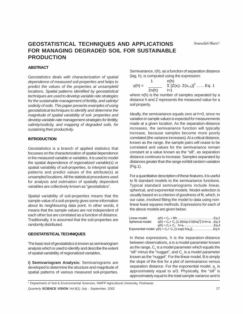
27Quarterly SCIENCE VISION Vol.8(1) July - September, 2002
GEOSTATISTICAL TECHNIQUES AND APPLICATIONSFOR MANAGING DEGRADED SOIL FOR SUSTAINABLEPRODUCTION
Amanullah Bhatti*
ABSTRACT
Geostatistics deals with characterization of spatialdependence of measured soil-properties and helps topredict the values of the properties at unsampleldlocations. Spatial patterns identified by geostatisticaltechniques are used to develop variable rate strategiesfor the sustainable management of fertility, and salinity/sodicity of soils. This paper presents examples of usinggeostatistical techniques to identify and determine themagnitude of spatial variability of soil- properties anddevelop variable-rate management-strategies for fertility,salinity/sodicity, and mapping of degraded soils, forsustaining their productivity.
INTRODUCTION
Geostatistics is a branch of applied statistics thatfocusses on the characterization of spatial dependencein the measured variable or variables. It is used to modelthe spatial dependence of regionalized variable(s) orspatial variability of soil-properties, to interpret spatialpatterns and predict values of the attribute(s) atunsampled locations. All the statistical procedures usedfor analysis and estimation of spatially dependentvariables are collectively known as “geostatistics”.
Spatial variability of soil-properties means that thesample-value of a soil-property gives some informationabout its neighbouring data point. In other words, itmeans that the sample values are not independent ofeach other but are correlated as a function of distance.Traditionally, it is assumed that the soil-properties arerandomly distributed.
GEOSTATISTICAL TECHNIQUES
The basic tool of geostatistics is known as semivariogramanalysis which is used to identify and describe the extentof spatial variability of regionalized variables.
i) Semivariogram Analysis: Semivariograms aredeveloped to determine the structure and magnitude ofspatial patterns of various measured soil-properties.
Semivariance, r(h), as a function of separation distance(lag, h), is computed using the expression:
where n(h) is the number of samples separated by adistance h and Z represents the measured value for asoil property.
Ideally, the semivariance equals zero at h=0, since novariation in sample values is expected for measurementsmade at a given location. As the separation-distanceincreases, the semivariance function will typicallyincrease, because samples become more poorlycorrelated (the variance increases). At a critical distance,known as the range, the sample pairs will cease to becorrelated and values for the semivariance remainconstant at a value known as the “sill”, as separationdistance continues to increase. Samples separated bydistances greater than the range exhibit random variation(Fig.1).
For a quantitative description of these features, it is usefulto fit standard models to the semivariance functions.Typical standard semivariograms include linear,spherical, and exponential models. Model-selection isusually based on a criterion of goodness of fit, which, inour case, involved fitting the model to data using non-linear least-squares methods. Expressions for each ofthe above models are given below:
In these expressions, h is the separation-distancebetween observations, a is a model-parameter knownas the range, C1 is a model parameter which equals the“sill” minus the “nugget”, and Co is a model parameterknown as the “nugget”. For the linear model, B is simplythe slope of the line for a plot of semivariance versusseparation distance. For the exponential model, ao isapproximately equal to a/3. Physically, the “sill” isapproximately equal to the total sample variance and is
* Department of Soil & Environmental Sciences, NWFP Agricultural University, Peshawar.
1 n(h) γ(h) = ______ Σ [Z(xi)- Z(xi+h)]2 ……Eq. 1 2n(h) i=1
Linear model: γ(h) = Co + Bh…………..……….…………Eq.2 Spherical model: γ(h) = Co+ C1 [1.5(h/a)-0.5(h/a)3] 0<h<a…Eq.3 γ(h) = Co+ C1 h>a……….………………..Eq.4 Exponential model: γ(h) = Co+ C1 [1-exp(-h/ao)]..……………….Eq.5

28 Quarterly SCIENCE VISION Vol.8(1) July - September, 2002
the maximum value of variance which the model attainsat large separation distances. Physically, sampleobservations separated by distances smaller than therange are statistically correlated to one another, whilemeasurements separated by distances greater than therange are not correlated (Fig.1). Classical statisticalmethods can be applied to the data only if the rangehas a value which is smaller than the closest samplingdistance.
Ideally, the experimental variance should pass throughthe origin when the distance of sample-separation iszero. However, many soil-properties have non-zerosemivariances as h tends to zero. This non-zero varianceis called the “nugget variance” or “nugget effect”. Itrepresents unexplained or “random variance”, oftencaused by measurement-errors or variability in themeasured property, which was not detected at the scaleof sampling.
ii) Kriging: The parameters of semivariogram are usedfor interpolation of soil-properties at unsampled values.This procedure is called “kriging”. Kriging is a methodfor making optimal, unbiased estimates of regionalizedvariables at unsampled locations, using the structuralproperties of the semivariogram and the initial set ofmeasured data. A useful feature of kriging is that anerror-term, expressing the estimation-variance oruncertainty in estimation, is calculated for eachinterpolated value. Kriging differs greatly from linear-regression methods for estimation at unsampledlocations. Whereas a regression-line never passesthrough all of the measured data-points, kriging alwaysproduces an estimate equal to the measured value if itis interpolating at a location where a measurement wasobtained.
The basic equation for interpolation by kriging at anunsampled location xo is given by:
where n is the number of neighboring samples and aiare weighing factors for each of the Z(Xi). The weightingfactors for neighboring measured points are constrainedto sum to unity, i.e.:
n Zk(XO) = Σ ai Z(Xi)…………………………Eq.6 i=1
n Σ ai=1………………………………Eq.7 i=1
Application of Geostatistics to soil-properties:Geostatistics techniques can be used for the following:
• To determine the nature and extent of spatialvariability of soil-properties and to identify theirspatial patterns;
• Fertility-management of spatially variable soils,based on spatial patterns in soil-fertility and crop-productivity, to avoid over-fertilization and under-fertilization;
• Soil-sampling schemes, based on prior informationof spatial patterns of soil properties;
• Environmental studies;• Mapping of soil-fertility and soil, salinity/sodicity.• Management of salt-affected soils, based on spatial
patterns of salinity/sodicity.• Design of field experiment e.g.
Directional patterns - blocking To determine optimum plot-size;
• Statistical analysis of field experiments, e.g. To identify yield-patterns or trends in field-
experiments and presence of correlated errors.
PAST RESEARCH WORK ON THE USE OFGEOSTATISTICAL TOOLS IN PAKISTAN
Geostatistics is a quite new field to the Pakistani SoilScientists and has been used on a very small scale inPakistan. A course in Applied Geostatistics wasintroduced at M.Sc. Hons level in the Department ofSoil Science, NWFP Agricultural University Peshawar,North West Frontier Province of Pakistan, in early 1990s.Geostatistical techniques were used to study the spatialvariability of soil properties of degraded soils for theirfertility and/or salinity/sodicity management,development of soil-sampling schemes, and mappingof soil-fertility and soil-sodicity. A brief review of theresearch work in this field, especially with regard to themanagement of degraded lands, is presented here.
1. Fertility management of eroded lands
A management-strategy of variable-rate fertilizer-application was developed to match the fertilizer-ratesto the spatial patterns in crop-productivity on an erodedland at Thana, Malakand agency, NWFP, Pakistan.Landscape at the study-site (Fig.2) is characterized bysteep land and its slope faces towards a stream. Relative
Geostatistical Techniques and Applications for Managing Degraded Soil for Sustainable Production
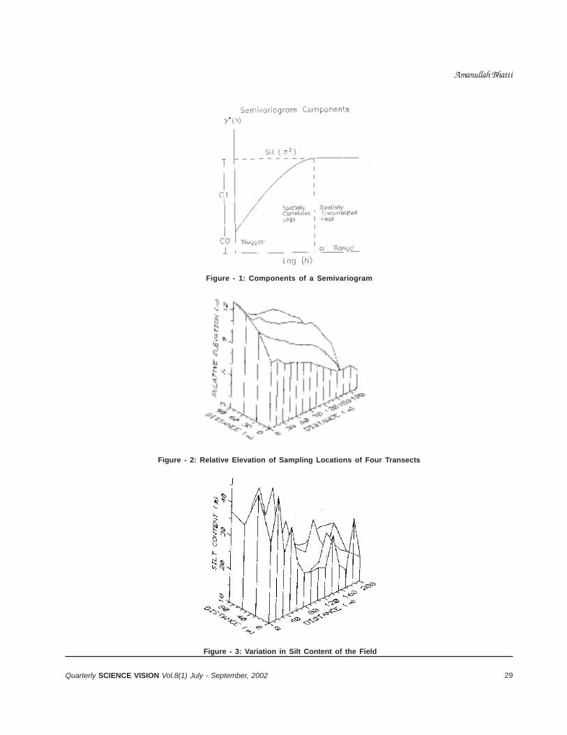
29Quarterly SCIENCE VISION Vol.8(1) July - September, 2002
Figure - 1: Components of a Semivariogram
Figure - 2: Relative Elevation of Sampling Locations of Four Transects
Figure - 3: Variation in Silt Content of the Field
Amanullah Bhatti
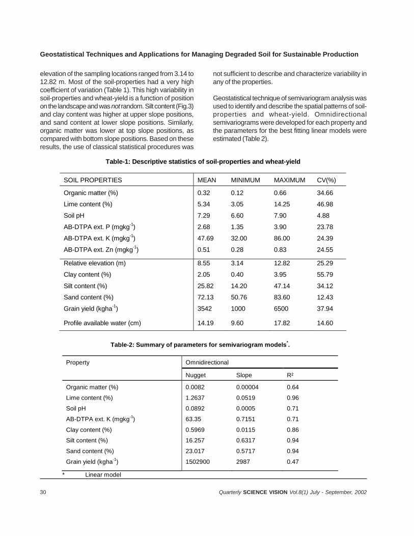
30 Quarterly SCIENCE VISION Vol.8(1) July - September, 2002
elevation of the sampling locations ranged from 3.14 to12.82 m. Most of the soil-properties had a very highcoefficient of variation (Table 1). This high variability insoil-properties and wheat-yield is a function of positionon the landscape and was not random. Silt content (Fig.3)and clay content was higher at upper slope positions,and sand content at lower slope positions. Similarly,organic matter was lower at top slope positions, ascompared with bottom slope positions. Based on theseresults, the use of classical statistical procedures was
not sufficient to describe and characterize variability inany of the properties.
Geostatistical technique of semivariogram analysis wasused to identify and describe the spatial patterns of soil-properties and wheat-yield. Omnidirectionalsemivariograms were developed for each property andthe parameters for the best fitting linear models wereestimated (Table 2).
Table-1: Descriptive statistics of soil-properties and wheat-yield
SOIL PROPERTIES MEAN MINIMUM MAXIMUM CV(%)
Organic matter (%)
Lime content (%)
Soil pH
AB-DTPA ext. P (mgkg-1)
AB-DTPA ext. K (mgkg-1)
AB-DTPA ext. Zn (mgkg-1)
0.32
5.34
7.29
2.68
47.69
0.51
0.12
3.05
6.60
1.35
32.00
0.28
0.66
14.25
7.90
3.90
86.00
0.83
34.66
46.98
4.88
23.78
24.39
24.55
Relative elevation (m)
Clay content (%)
Silt content (%)
Sand content (%)
Grain yield (kgha-1)
Profile available water (cm)
8.55
2.05
25.82
72.13
3542
14.19
3.14
0.40
14.20
50.76
1000
9.60
12.82
3.95
47.14
83.60
6500
17.82
25.29
55.79
34.12
12.43
37.94
14.60
Table-2: Summary of parameters for semivariogram models*.
Property Omnidirectional
Nugget Slope R²
Organic matter (%)
Lime content (%)
Soil pH
AB-DTPA ext. K (mgkg-1)
Clay content (%)
Silt content (%)
Sand content (%)
Grain yield (kgha-1)
0.0082
1.2637
0.0892
63.35
0.5969
16.257
23.017
1502900
0.00004
0.0519
0.0005
0.7151
0.0115
0.6317
0.5717
2987
0.64
0.96
0.71
0.71
0.86
0.94
0.94
0.47
* Linear model
Geostatistical Techniques and Applications for Managing Degraded Soil for Sustainable Production
31Quarterly SCIENCE VISION Vol.8(1) July - September, 2002
Spatial patterns of the potential-yield, calculatedfrom thelime-content, were used to divide the field into zoneswith low (< 3400 kg ha-1), medium (3400-3600 kg ha-1)and high productivity (> 3600 kg ha-1). Potential wheat-yield of each zone was used to determine the N-fertilizerrequirement for that zone, using the following expression:
where a factor of 0.5 is the fertilizer-use efficiency ofwheat.
Using this expression, the following rates of fertilizer Nwere determined, along with proportion of the area forthat particular rate (Table 3). These rates were appliedto wheat in different zones (Fig.4) and compared withthe uniform rate of fertilizer application.
These results (Table 4) showed that the variable rate offertilizer proved more economical, used less fertilizerand also reduces environmental pollution of groundwaterand surfacewater.
2. Reclamation of salt-affected soils (sodic soils),using variable rates of gypsum.
A reclamation strategy for salt-affected soils (sodic soil)was developed, using variable rates of gypsum for different
N fertilizer (kg ha-1) = [(Potential yield x % N in grains) - total mineral soil N (kg ha-1)]/0.5,
Table - 3: Management zones and fertilizer rates
Management Unit Fertilizer rate N (kg ha-1)
Area Proportion
1. 2. 3.
80 110 125
0.18 0.39 0.43
Table-4: Economics of fertilizer application for uniform-rate and variable-rate fertilizer application
Management strategy
Fertilizer N-P2O5-K2O (kg ha-1)
Yield (kg ha-1)
Net return (Rs ha-1)
Cost:Benefit ratio
Variable Uniform
111-90-60 120-90-60
3631 3729
11810 12099
4.35 4.29
management units in a large field. Soil pH of the studysite ranged from 7.4 to 9.0, EC ranged from 0.35 to 4.90with a mean of 1.64 dS m-1 and a coefficient of variationof 49%. The range for GR was wide, from 1.7 to 17.8 tha-1.
Soil pH, EC and GR showed spatial patterns.Omnidirectional semivariogram models were the bestfit. A Spherical model best described EC (Fig.5) asfollows: nugget = 0.17 (dS m-1)2, sill = 0.62 (dS m-1)2,range = 31.27 m, r2=0.94. Similarly GR was describedas: nugget = 1.87 (t ha-1)2, sill=2.73(t ha-1)², range =50.78 m, r2 = 0.80. The soil pH was best described by alinear model as: nugget = 0.05, slope = 0.00015, r2 =0.91. Therefore, one uniform rate of gypsum was not ajudicious application. A new set of criteria was developed,to divide the farm into well defined management-units.
Variable rates of gypsum thus determined werecompared with a single uniform rate for reclamation ofthe salt affected sodic soil. The field was divided intothree management zones (Fig.6), with six transects.One strip in each transect received a uniform rate of4.25 t ha-1 , while the other strip in each zone was treatedwith varying rates of gypsum i.e. low (3.198 t ha-1),medium (6.77 t ha-1) and high (12.802 t ha-1). The farmwas planted with wheat. GR at harvest was significantlylower in the variable-management strategy (1.93 t ha-1)
Amanullah Bhatti
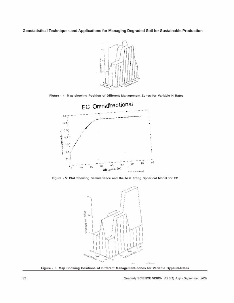
32 Quarterly SCIENCE VISION Vol.8(1) July - September, 2002
Figure - 4: Map showing Position of Different Management Zones for Variable N Rates
Figure - 5: Plot Showing Semivariance and the best fitting Spherical Model for EC
Figure - 6: Map Showing Positions of Different Management-Zones for Variable Gypsum-Rates
Geostatistical Techniques and Applications for Managing Degraded Soil for Sustainable Production
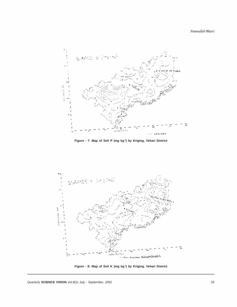
33Quarterly SCIENCE VISION Vol.8(1) July - September, 2002
Figure - 7: Map of Soil P (mg kg-1) by Kriging, Vehari District
Figure - 8: Map of Soil K (mg kg-1) by Kriging, Vehari District
Amanullah Bhatti
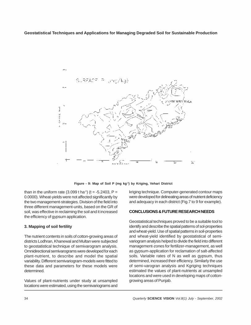
34 Quarterly SCIENCE VISION Vol.8(1) July - September, 2002
Geostatistical Techniques and Applications for Managing Degraded Soil for Sustainable Production
than in the uniform rate (3.099 t ha-1) (t = -5.2403, P =0.0000). Wheat-yields were not affected significantly bythe two management-strategies. Division of the field intothree different management-units, based on the GR ofsoil, was effective in reclaiming the soil and it increasedthe efficiency of gypsum application.
3. Mapping of soil fertility
The nutrient contents in soils of cotton-growing areas ofdistricts Lodhran, Khanewal and Multan were subjectedto geostatistical technique of semivarogram analysis.Omnidirectional semivarograms were developed for eachplant-nutrient, to describe and model the spatialvariability. Different semivariogram-models were fitted tothese data and parameters for these models weredetermined.
Values of plant-nutrients under study at unsampledlocations were estimated, using the semivariograms and
kriging technique. Computer-generated contour mapswere developed for delineating areas of nutrient deficiencyand adequacy in each district (Fig.7 to 9 for example).
CONCLUSIONS & FUTURE RESEARCH NEEDS
Geostatistical techniques proved to be a suitable tool toidentify and describe the spatial patterns of sol-propertiesand wheat-yield. Use of spatial patterns in soil-propertiesand wheat-yield identified by geostatistical of semi-variogram analysis helped to divide the field into differentmanagement-zones for fertilizer-management, as wellas gypsum-application for reclamation of salt-affectedsoils. Variable rates of N as well as gypsum, thusdetermined, increased their efficiency. Similarly the useof semi-varogran analysis and Kgriging techniquesestimated the values of plant-nutrients at unsampledlocations and were used in developing maps of cotton-growing areas of Punjab.
Figure - 9: Map of Soil P (mg kg-1) by Kriging, Vehari District

35Quarterly SCIENCE VISION Vol.8(1) July - September, 2002
Future Research Needs include:
Use in soil-survey operation for structural analysisof soil-variation, to help understanding of soil-genesisand for analysis of reconnaissance-data for definingfuture sampling;
Kriging, to augment general - purpose informationcontained in conventional soil-maps, by interpolationof interpretive data and specific measured soil-properties.
Block kriging, for estimating soil-amendmentrequirements over areas the size of land-management units.
Spatial interpretation of critical levels of soil-constraints to crop-production, by using within-fieldvariation of properties, such as soil-moisture content,for improving the efficiency of irrigation water use,nutrient levels for fertilizer application, or soil-chemicalproperties for amendment needs, such as gypsumrequirement;
Identification of spatially dependent component oferror for reducing the confounding effects of within-plot variability on treatment-effects in agriculturalexperiments;
Use of spatial dependence in determining optimalplot-size and spacing of samples within plots;
Mapping of soil-fertility and salinity/sodicity formanagement of degraded lands.
SOME RESEARCH PRIORITIES
a) Preparation of isarthmic maps of soil-fertility fordelineation of deficient areas in major as well asminor plant-nutrients, at field level and at someadministrative-unit levels, for proper fertilizer-management to increase efficiency of fertilizer-useand reduce environmental pollution of surface andunderground water;
Amanullah Bhatti
b) Preparation of isarithmic maps of soil-salinity/sodicityfor reclamation purposes and to increase theefficiency of amendments;
c) Design of soil-sampling schemes that are less time-consuming and more cost-effective.
d) Design of field experiments, using spatialdependence of soil-properties within plot, todetermine the true treatment-effects and makingsound conclusions and solid recommendationsonfertilizer application.
REFERENCES
1. Bhatti, A.U., F. Hussain, Farmanullah and M.J. Khan.1998. Use of spatial patterns of soil properties andwheat yield in geostatistics for determination of fertilizerrates. Communications in Soil Science and PlantAnalysis 29(5-6):509-522.
2. Bhatti, A.U, A. Bakhsh and A.H. Gurmani. 1998.Comparison of uniform and variable rates of gypsumfor reclamation of salt affected soils. Pak. J. Soil Sci.14(1-2): 14-16.
3. Bhatti, A.U., R. Ali, Farmanullah and M.J.Khan. 1998.Comparison of wheat yield under uniform and variablerates of fertilizer on spatially eroded land.Communications in Soil Science and Plant Analysis.29(19 & 20): 2855-2863. USA.
4. Bhatti, A.U., and A. Bakhsh. 1995. Management strategyof using gypsum for reclamation of slat affected soils.Journal Indian Society of Soil Science. 43(4): 657-659.India.
5. Bhatti, A.U., D.J. Mulla, and B.E. Frazier. 1991.Estimation of soil properties and wheat yields oncomplex eroded hills using geostatistics and thematicmapper images. Remote Sensing of Environment 37:181-191. USA.
6. Rashid, A. and E. Rafique. 1997. Micronutients/NutrientManagement in Cotton in relation to CLCV. AnnualReport. Land Resources Research Institute, NationalAgricultural Research Centre, Islamabad.
36 Quarterly SCIENCE VISION Vol.8(1) July - September, 2002
EFFECT OF BOVINE SOMATOTROPIN ON THELACTATIONAL AND REPRODUCTIVE PERFORMANCE OFLACTATING DAIRY COWS - A REVIEW
Tanveer Ahmad*and M. Sarwar
ABSTRACT
Bovine somatotropin (bST) increases milk productionin dairy animals. The maximum increase in milkproduction has been observed up to 41%.Somatotropin did not change milk compositionsignificantly. During short-term application of bST,cows mobilized their body-reserves to support theincreased milk production. Although DM intake of cowswas increased in the long-term applications, however,gross efficiency of production was improved due tolarger increase in milk production than DM intake.Somatotropin did not adversely affect the health andreproductive performance of the cows. Repartitioningof nutrients in body-tissue was primarily responsiblefor the increase in milk-production but defining theexact mechanism by which bST exerted its effectstill requires additional research.
Key words: Bovine somatotropin, Milk production,Milk composition, DM = Daily Mineral.
INTRODUCTION
The effects of somatotropin on the performance oflactating animals have been the subject of interestfor over 50 years. It was initially demonstrated thatinjections of crude pituitary extracts increased milk-production in dairy cows. However, limited quantitiesof native pituitary somatotropin made field-applications impractical. The advent of recombinantDNA technology allowed the production of relativelylarge quantities of synthetic bST. Since then, a lot ofresearch has been conducted to see the effect ofbovine somatotropin on various production-parametersof dairy cows (Peel et al., 1985; Richard et al., 1985;McGuffey et al., 1990). Milk yield had been increasedupto 41% with daily injections of bST (Bauman et al.,1989). Cows adjust their voluntary feed-intake tosupport increased milk-yield (Eppard et al., 1987).Somatotropin did not affect the cows’ health andreproductive performance (Eppard et al., 1985a).Coordinated changes in many tissues andphysiological processes occurred to support the
* Department of Animal Sciences, University of Arid Agriculture, Murree Road, Rawalpindi.
increases in the synthesis of lactose, fat and proteinin the mammary glands. Changes in the irreversibleloss and oxidation rates of two key metabolites,glucose and free fatty acids, could quantitativelyaccount for increases in lactose and milk-fat duringthe support-term administration of bST (McDowell etal., 1987). Similarly, changes in feed-intake accountedfor increase in milk-production in the longerexperiments (West et al., 1990). The present paperhas the objective to review the effect of bST on differentlactational and health aspects of dairy cows.
MILK PRODUCTION
Daily administration of exogenous bST derived fromthe extracts of pituitary glands, or even the growthhormone release factor from the extracts of thehypothalamus (Enright et al., 1988) of slaughteredcows or recombinantly derived bST, cause a highermilk-yield without altering the gross composition.Almost similar results of increased milk-yield in dairycows by bST administration was reported in manystudies (Asimov and Krouze, 1937; Pocius andHerbein, 1986; Richard et al., 1985; Soderholm etal., 1988; West et al., 1990). In a long-term studywith Holstein cows, bST treatment increased theaverage fat-corrected milk (FCM) yield in a dose-dependent fashion from 23 to 41% over controlproduction (27.9 kg/d) in lactating cows (Bauman etal., 1989). However, increasing increments of bSTshow less increase. In another experiment, 32%increase of milk-yield was reported in cows treatedwith 100 IU/day of bST over control (Eppard et al.,1985a); they also found a pattern of diminishingmarginal response of milk-yield to increasing hormonedose. Similar results have been reported by otherworkers (Eisenbeisz et al., 1990; Elvinge et al., 1988;Soderholm et al., 1988).
Increase in milk production of cows given bST at theirpeak lactation was less than for those treated at midto two third of their lactation (McDowell et al., 1987;Richard et al., 1985). The cows receiving 41.2 mg/dof bST in their early lactation reduced 10% more 3.5%
37Quarterly SCIENCE VISION Vol.8(1) July - September, 2002
FCM than the control group (Schneider et al., 1990).This increase was less than that reported by otherworkers in the cows treated with bST after their peaklactation (Elvinger et al., 1988; West et al., 1990).This indicated that, even though responses: toexogenous bST did occur, the response was muchless than that after peak lactation. One explanationof this was that during early lactation the responsemight be limited by nutrient availability, because cowswere in considerable negative energy balance. Theother possible reason for this reduced response waslimited supply of glucose for lactose rather than bythe ability of cows to mobilize body-reserves in supportof lactation (Richard et al., 1985). Administration ofbST, either by daily injections or in a sustained releasevehicle, had no significant differences in milk or solid-corrected milk of treated cows (McGuffey et al., 1990).In a previous study it was shown that bSTadministered by prolonged release formation waseffective in improving milk-yield and productiveefficiency of cows (Bauman et al., 1989).
MILK COMPOSITION
The complex composition and unique biophysicalproperties of milk can easily be disturbed by slightdeviations in composition. Nevertheless, the cowreceiving bST seems to have the ability to producemore milk with the same mammary gland, whileretaining normal product composition. This hasprobably much to do with the physical limitations forthe composition of milk, as mentioned by Walstraand Jenness (1984). First, milk is iso-osmotic withblood. In milk, lactose, K, Na, and Cl contribute toosmotic pressure. Variations in the lactose contentof milk are small, but if they occur, osmolality ismaintained by changing K+ directly and Na+ and Cl-inversely. Second, the milk is saturated with calciumphosphate and calcium citrate. Additional Ca,phosphate, and citrate are present in the form of acolloidal complex with casein. Third, to be readilydigested, the final melting point of the milk-fat mustnot be higher than body temperature. Crystallizationof fats with higher melting points might also occur incells and alveoli, causing partial coalescence of fatglobules in the udder. Therefore, a certain amount ofshort-chain and unsaturated long-chain fatty acids willbe present in milk fat. However, these physiologicalphenomena do not fully guarantee unchanged milkproperties.
Somatotropin did not influence milk-composition ofdairy cows. No change in percentage of fat, protein ortotal solid milk was reported (Eisenbeisz et al., 1990).Fat, protein, and lactose contents of the milk arenegligibly affected by bST when the cow is in positiveenergy-balance. This state is an importantprerequisite when bST is administered (Vandenberg,1991). Similar results had been found in other studies(Elvinger et al., 1988; Peel et al., 1985; West et al.,1990). They noted no change in percentage of milk-fat, protein and total solids with bST treated milk ofdairy cows. Contrary to this in some studies, theprotein and fat percentage of milk of cows treatedwith bST were influenced (Eppard et al., 1987). Asthe dose of bST increased, fat percentage of milk alsoincreased but protein percentage declined in cowswith negative energy balance. This can be concludedfrom various short and long-term experiments (Mcbrideet al., 1989; Rohr, 1988; Sainoni et al., 1988). Sechenet al. (1989) found an increased secretion of N and Cin milk and decreased urinary loss of N and tissueuse of C from bST administration.
Administration of bST in a sustained-release vehiclebiweekly or once every week is more practical thanmore frequent administration. On the average, the milkhas fat and protein contents rather similar to those ofmilk from untreated cows. However, some cycliceffects in fat and protein contents are found. Bovinesomatotropin may also cause an increase in therelative amount of long-chain fatty acids, and thesomatic cell count was sometimes increased(Vandenberg, 1991).
Experiments show that there was no effect onpercentage lactose of milk from bST treated cows(Bauman et al., 1985; Pocius and Herbein, 1986;Bauman et al., 1989; Phipps, 1988; Rijpkema et al.,1989). Lactose percentage decreased significantly atpeak lactation but no change was noted at midlactation in the milk of bST treated cows (McDowellet al., 1987). Changes in milk composition probablyreflected the nutritional status of the cows at differentmetabolic stages of lactation. Protein concentrationdeclined in cows with negative energy-balance,suggesting that protein synthesis by the mammaryglands could have been limited by the supply of aminoacids.
Tanveer Ahmad and M. Sarwar
38 Quarterly SCIENCE VISION Vol.8(1) July - September, 2002
Effect of Bovine Somatotropin on the Lactational and Reproductive Performance of Lactating DairyCows - A Review
The information on milk-protein composition, in relationto the bST treatment of the cows, is summarized inTable-1. Caseins are present in milk in the form ofmicelles, together with Ca, phosphate, and citrate.The cows treated with bST do not seem to producemilk with a different casein-content (Escher andVandenberg, 1987). The casein:total protein ratio hasnot changed in most cases, except in threeinvestigations, in which a slight decrease occurs(Table-1). No real differences between the propertiesof the caseins i.e., the size of the micelles (Vignonand Ramet, 1988) and the various fractions in whichcalcium is present in milk (Desnouveaux et al., 1988),were observed from the milk of the bST treated anduntreated cows.
An increase in the fat content of milk during bSTadministration is often caused by an extra mobilizationof the fat-reserves of the animal, because of an energyshortage. This is most likely to occur just after thestart of the treatment. This situation leads to anincrease of the longer unsaturated fatty acids in themilk fat and to lower cholesterol and phospholipidcontents (Table-2) in the milk (Bitman et al., 1984).Another study showed a slightly increased cholesterolcontent of the milk fat (Lynch et al., 1989). At veryhigh daily doses of bST and a negative energy-balance,an increase of the proportion of the long-chainunsaturated fatty acids was found by Eppard et al.(1985b). At lower doses and a positive energy balance,the effects on the milk fat were not significant. Ingeneral, the fatty acid composition can be affectedby the energy state of the cow and a negative balancewill more easily occur in high producing cows, inparticular, when bST is administered in higher dosesand in early lactation.
The cation flux from blood plasma into the mammarygland and into the milk is increased with the milkyield, in order to maintain osmotic regulation; theconcentration of the minerals is probably not affected(McBride et al., 1988). This has been confirmed forCa, P, Na, Fe, Cu, and Mn by many workers (Eppardet al., 1985; Desnouveaux et al. 1988; Auberger etal., 1988; Bauman et al. 1989)
Little research has been conducted into the enzymesin milk, in relation to the administration of bST to thedairy cow. The activities of the aminopeptidase,endopeptidase and phosphatase (Desnouveaux et al.,
1988), protease and lipase (Lynch et al., 1988) andlipoprotein lipase (Lough et al., 1989) in milk showedno significant differences between the milk from thetreated and untreated groups.
Vitamin A, thiamine, riboflavin, pyridoxine, vitamin B12,biotin, pantothenic acid, and choline have beeninvestigated by Hartnell (1986) and no differences wereobserved, except for biotin, which was present in aslightly increased concentration in the bST milk.
The pH of the milk was not affected by bST injectionsin differerent studies (Baer et al., 1989; Battistotti andBertoni, 1988; Escher and Vandenberg; 1987;Vandenberg and deJong, 1986; Vignon 1988; Vignonand Ramet, 1988).
Differences in Somatic cell count of milk of bST treatedand untreated cows were found to be non-significantin most of the studies. However, this topic needsfurther investigation under various local conditions,because incidence of mastitis and higher SCCsometimes occur in highly producing cows, thussuggesting that special attention be paid to bST-treated cows.
FEED EFFICIENCY, DRY-MATTER INTAKE ANDBODY WEIGHT
Dry-matter intake, feed efficiency and body weightwere influenced by the bST treatment in dairy cows.The feed intake of cows treated with bST changedafter eight week of treatment, and it had increasedupto 13.4% by week 22 (Peel et al., 1985; Soderhalmet al., 1988). The voluntary intake of cows receivingbST increased gradually and, by 10th week oftreatment, the animals attained positive energy-balance (Bauman et al., 1989). A gradual increase infeed intake of cows treated with bST for a longer periodof time was observed (Eisenbeisz et al., 1990;Elvinger et al., 1988; McDowell et al., 1987; West etal., 1990). Cows receiving bST consumed 4 to 10%more feed, but increase in milk production was largerthan this and, therefore, it showed that bST treatedcows increased the efficiency of production by 11 to17% over control animals (Soderholam et al., 1988).Increase in gross efficiency of production by bSTtreatment had also been reported by many otherworkers (Bauman et al., 1989; Eisenbeisz et al., 1990;Elvinger et al., 1988; West et al., 1990). In all these

39Quarterly SCIENCE VISION Vol.8(1) July - September, 2002
Table – 1: Summary of the effect of bST treatment on content and composition of milk proteins, compared with control Attribute Result References Total protein Similar 1, 2, 3, 4, 5, 6, 7, 8 Decreased 9 Increased 10, 14, 15, 16 Casein content Similar 1, 2, 3, 10, , 11, 13, 17, 18 Decreased 9 Relative casein composition Similar 1, 6, 7, 8 Whey protein content Similar 1, 3, 6, 7, 8 Increased 2, 11 Decreased 9 Relative whey protein composition Similar 6, 7,12, 13 Casein:total protein ratio Similar 1, 3, 7, 8, 9, Decreased 2, 10,11 1Auberger et al.,(1988), 2Baer et al. (1989), 3Desnouveaux et al. (1988), 4Eppard et al. (1988), 5Sechen et al. (1989), 6Vignon (1987), 7Vignon (1988), 8Vignon and Ramet (1988), 9Escher and Vandenberg (1987), 10Barbano et al.(1988), 11Kindstedt et al. (1988), 12Lynch et al. (1988), 13Pabst et al. (1987), 14Bauman et al. (1989) 15Phipps (1988), 16Samuels et al. (1988), 17Escher and Vandenberg (1988a), 18Leonard et al. (1988)
Table – 2: Summary of the effect of bST treatment on content and composition of milk-fat compared with those of control cows
Attribute Result References Total fat Similar 1, 2, 3, 5, 10, 11, 12, 13, 18, 19, 24 Increased 4,6*, 7, 20, 21, 22 Refractive Index Similar 7, 23 Properties of: Short-chain fatty acids Similar 6, 14, 24 Reduced 1,4, 6*, 8 Medium-chain fatty acids Similar 6,14,17, 24 Reduced 1, 4, 6* Long-chain fatty acids Similar 6, 14, 17, 24 Increased 1, 6* Long-chain unsaturated fatty acids Similar 6, 14, 17 Increased 1,4,6*,8 Cholesterol Increased
Reduced 15 4
Phospholipids Reduced 4 *At high bST dose and negative energy balance. 1Baer et al. (1989), 2Barbano et al. (1988), 3Bauman et al. (1989), 4Bitman et al.(1984), 5Eppard et al. (1988), 6Eppard et al. (1985b), 7Escher and Vandenberg (1988), 8Farries and Profittlich (1988), 9Farries (1989), 10Firkins et al. (1989), 11Jenny et al. (1989), 12Lebzien et al. (1989), 13Leonard et al. (1988), 14Lynch et al. (1988), 15Lynch et al. (1989), 16Oldenbroek et al. (1989), 17Pell et al. (1988), 18Rijpkema et al. (1987), 19Rohr (1988), 20Rock et al. (1989), 21Rowe-Bechtel et al. (1988), 22Sainoni et al. (1988), 23Vandenberg and deJong, (1986), 24Vignon, (1987),
Tanveer Ahmad and M. Sarwar
40 Quarterly SCIENCE VISION Vol.8(1) July - September, 2002
Effect of Bovine Somatotropin on the Lactational and Reproductive Performance of Lactating DairyCows - A Review
studies, although DM intake of cows increasedgradually in the long run, but higher increases in milkproduction led to improved efficiency of production.
Dry-matter intake and digestibility by cows was notaffected by bST treatment in short-term studies(Eppard et al., 1985a; Pocius and Herbein, 1986;Schneider et al., 1990). However, these studies alsoindicated increased efficiency of production in bSTtreated cows.
Body weight of cows receiving bST was not affectedsignificantly (Elvinger et al., 1988; McGuffey et al.,1990; Peel et al., 1985; West et al., 1990).
HEALTH AND REPRODUCTION
Somatotropin did not adversely affect the health andreproductive performance of cows (Bauman et al.,1989). It was reported that the health and reproductiveparameters, including clinical observation, physicalexamination, somatic cell count, conception rate,services per conception and gestation-length were ator better than resident-herd average (Bauman et al.,1989). Other workers did not observe any adverseeffects of bST on the reproductive performance of cows(Eisenbeisz et al., 1990; Elvinger et al., 1988). In along-term study, it was demonstrated that bST hadno discernible effects on mammary health, based onsomatic cell count and incidence of clinical mastitis(Eppard et al., 1987). Cows receiving bST showed anaverage of 96% conception rate, 2.0 services perconception and 116 days open, which werecomparable to control-groups. No subclinical orclinical evidence of ketosis or milk fever was observed.Somatropropin treatment had no significant effect ongestation-length or birth weights and growing rate (first28 days) of calves. Milk yield for the first sixty days,post-partum, was compared for the period just priorto start of treatment and the lactation subsequent totreatment: no treatment effects were observed. Cowswere in excellent health during lactation, as was borneout by lactational performance.
MODE OF ACTION
Nutrient Partitioning
Somatotropin increased milk-yield in dairy cowsthrough its coordinated effects on a number of body-
tissues and physiological metabolites. A summary ofthe biological activities of somatotropin has been givenin Table-3.
In a long-term study with dairy cows, a homeorheticcontrol (the coordination of changes in metabolismnecessary to support a given physiological state e.g.,pregnancy, lactation) involved in the orchestration of‘partitioning of nutrients’ to support the requirementsfor milk synthesis was considered (Bauman et al.,1989). The term ‘nutrient partitioning’ is mostcommonly used to describe the manner in whichabsorbed nutrients are directed to various tissues andorgans in support of productive functions. In a moregeneral sense, the definition should also take intoaccount other partitioning, such as between digestedversus undigested nutrients or between productionfunctions versus the overhead costs of maintainingthe animal. Because these may also be affected bybST, they must all be considered as components ofthe nutrient partitioning process.
The results of ‘nutrient partitioning’ in long-term studieswere based on the fact that increased milk yield couldnot persist through the treatment-period unlesscoordinated changes occurred in body-metabolism,so that steady-state conditions were maintained.These changes must have involved the metabolism oflipid, carbohydrates and amino acids, because milk-composition was not altered during the treatments.Other studies using bST demonstrated that milk-composition was unaltered when cows were in positiveenergy balance (Elvinger et al., 1988; Peel et al., 1985;Soderholam et al., 1988).
Diabetogenic and Lipolytic Effects of bST
The diabetogenic and lipolytic effects of bST have beenreviewed by Bauman et al., 1989, and Johnsson andHart, 1986. In some trials bST treatment of animalselevates circulating concentrations of NEFA, insulin,and glucose (Johnsson and Hart, 1986) and, in others,it does not (Bauman and McCutcheon, 1986), exceptwhere treatment drives animals into a negative energybalance, in which case NEFA are chronically elevated.This may relate to the capacity of treated cows formilk production. Treatment of low-yielding beef cowswith bST elevates circulating glucose, but high-yieldingdairy cows did not respond in the same manner (Bineset al., 1980). It was suggested that bST treatment
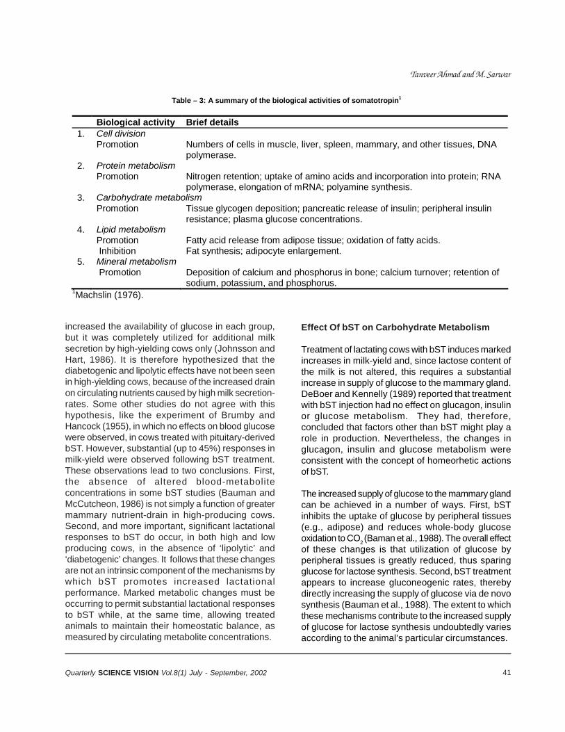
41Quarterly SCIENCE VISION Vol.8(1) July - September, 2002
Table – 3: A summary of the biological activities of somatotropin1 Biological activity Brief details 1. Cell division Promotion Numbers of cells in muscle, liver, spleen, mammary, and other tissues, DNA
polymerase. 2. Protein metabolism Promotion Nitrogen retention; uptake of amino acids and incorporation into protein; RNA
polymerase, elongation of mRNA; polyamine synthesis. 3. Carbohydrate metabolism Promotion Tissue glycogen deposition; pancreatic release of insulin; peripheral insulin
resistance; plasma glucose concentrations. 4. Lipid metabolism Promotion Fatty acid release from adipose tissue; oxidation of fatty acids. Inhibition Fat synthesis; adipocyte enlargement. 5. Mineral metabolism Promotion Deposition of calcium and phosphorus in bone; calcium turnover; retention of
sodium, potassium, and phosphorus. 1Machslin (1976).
increased the availability of glucose in each group,but it was completely utilized for additional milksecretion by high-yielding cows only (Johnsson andHart, 1986). It is therefore hypothesized that thediabetogenic and lipolytic effects have not been seenin high-yielding cows, because of the increased drainon circulating nutrients caused by high milk secretion-rates. Some other studies do not agree with thishypothesis, like the experiment of Brumby andHancock (1955), in which no effects on blood glucosewere observed, in cows treated with pituitary-derivedbST. However, substantial (up to 45%) responses inmilk-yield were observed following bST treatment.These observations lead to two conclusions. First,the absence of altered blood-metaboliteconcentrations in some bST studies (Bauman andMcCutcheon, 1986) is not simply a function of greatermammary nutrient-drain in high-producing cows.Second, and more important, significant lactationalresponses to bST do occur, in both high and lowproducing cows, in the absence of ‘lipolytic’ and‘diabetogenic’ changes. It follows that these changesare not an intrinsic component of the mechanisms bywhich bST promotes increased lactationalperformance. Marked metabolic changes must beoccurring to permit substantial lactational responsesto bST while, at the same time, allowing treatedanimals to maintain their homeostatic balance, asmeasured by circulating metabolite concentrations.
Effect Of bST on Carbohydrate Metabolism
Treatment of lactating cows with bST induces markedincreases in milk-yield and, since lactose content ofthe milk is not altered, this requires a substantialincrease in supply of glucose to the mammary gland.DeBoer and Kennelly (1989) reported that treatmentwith bST injection had no effect on glucagon, insulinor glucose metabolism. They had, therefore,concluded that factors other than bST might play arole in production. Nevertheless, the changes inglucagon, insulin and glucose metabolism wereconsistent with the concept of homeorhetic actionsof bST.
The increased supply of glucose to the mammary glandcan be achieved in a number of ways. First, bSTinhibits the uptake of glucose by peripheral tissues(e.g., adipose) and reduces whole-body glucoseoxidation to CO2 (Baman et al., 1988). The overall effectof these changes is that utilization of glucose byperipheral tissues is greatly reduced, thus sparingglucose for lactose synthesis. Second, bST treatmentappears to increase gluconeogenic rates, therebydirectly increasing the supply of glucose via de novosynthesis (Bauman et al., 1988). The extent to whichthese mechanisms contribute to the increased supplyof glucose for lactose synthesis undoubtedly variesaccording to the animal’s particular circumstances.
Tanveer Ahmad and M. Sarwar
42 Quarterly SCIENCE VISION Vol.8(1) July - September, 2002
Effect of Bovine Somatotropin on the Lactational and Reproductive Performance of Lactating DairyCows - A Review
Effect Of bST on Amino-Acid Metabolism
Oxidation of amino acids decreased with bSTtreatment, as it caused a concomitant increase inoxidation of NEFA in growing heifers. The net effect isan increase in whole body protein-synthesis and adecrease in lipid accretion, consistent with theproduction-effects of exogenous bST in growinganimals (Boyd and Bouman, 1989). Increase in milk-protein secretion by a short-term bST treatmentoccurs due to reduction in oxidation of amino acidsand increased mobilization of labile protein reserves,whereas in long-term studies increase in voluntaryfeed intake also contributes towards more milk-proteinsecretion.
Effect of bST on Lipid Metabolism
The principal effect of bST is to partition nutrients insuch a way that lipid accretion is reduced and fattyacids made available for oxidation. This has the effectof ‘sparing’ nutrients, such as glucose and aminoacids, and is achieved by reciprocal effects onlipo-genesis and lipolysis. The bST treatment causedan increase in plasma free-fatty-acids (FFA)concentrations, without altering blood ketone,suggesting that lipolysis was increased withoutcorresponding increase in fatty acids oxidation by theliver (Pocius and Herbein, 1986). They had opinedthat bST acted by partitioning FFAs towards milkproduction. It was also reported that there was anincrease in plasma FFA in the blood of bST treatedanimals (Lough et al., 1989). However, they did notfind any difference in lipoprotein lipase-activity in milk,mammary tissues and acetate metabolism in cowsinjected with bST. It raised the possibility that higherserum triglyceride concentrations induced by bSTmight have increased the availability of preformedlipids to the mammary glands for increased rate ofmilk-synthesis without an increased mammary lipaseactivity. It was also demonstrated that bST exertedits metabolic effects, resulting in the provision ofsubstrate to the mammary gland for milk biosynthesis(McDowell et al., 1987). They further noticed that bSTexerted different metabolic effects, depending on thephysiological state of the animal. They, thus,concluded that bST exerted a homeorhetic control,resulting in the provision of nutrients to the mammarygland at the expense of the body-tissues for milk
synthesis. Similar hypothesis had been extended byanother worker (Soderholm et al.,1988).
One of the most obvious in-vivo responses to bST isincreased sensitivity to lipolytic stimuli. Thus,circulating NEFA following an acute intravenousepinephrine challenge are elevated in bST-treated dairycows and growing cattle. These changes occur,whether or not the treated animals are in positive ornegative energy balance (i.e., whether or not basalcirculating NEFA are altered). The enhanced lipolyticsensitivity of treated cows was also co-ordinated withtheir increased fat yields (McCutcheon and Bauman,1986). Although bST enhances the antilipolytic effectsof insulin, it appears to antagonize the ability of insulinto stimulate lipogenesis. Treatment with bST appearsto reduce the activity of several key lipogenic enzymesin vitro (Schaffer, 1985; Magri et al., 1987; Vernon etal., 1988) and to inhibit the transport of glucose intoadipocytes. The latter effect was not mimicked byinsulin-like growth factor (IGF)-I or IGF-II treatment,suggesting that it was a direct effect of bST (Schoenleet al., 1985). As a consequence of these reciprocaleffects on lipolysis and lipogenesis, bST partitionsnutrients in such a way that lipid accretion is reducedor lipid reserves mobilized. Thus, in lactating animals,the size of lipid reserves tends to decline (particularlyduring the early phases of treatment) but in growinganimals, rate of lipid deposition is reduced in adiposetissue (Bauman and McCutcheon, 1986; Boyd andBouman, 1989). Moreover, the rates of NEFA oxidationto CO2 are increased (Dunshea et al., 1989; Tyrrell etal., 1988) so that NEFA make a proportionately greatercontribution to the animal’s energy requirements. Thisin turn means that glucose and amino acids, whichmight otherwise be oxidized to provide energy, areavailable for milk lactose and protein-secretion or fortissue protein deposition.
Effect of bST on Voluntary Feed Intake
Bovine somatotropin increased the voluntary intakeof cows after several weeks of treatments (Eisenbeiszet al., 1990; Politis et al., 1990). This observationraised another possibility for mechanism of action forbST in the long-term treatment. This observationsupported the simple contention that an animal ateto maintain energy homeostasis, so that daily energyintake matched daily energy output. In the earlierweeks of treatments, body tissues were mobilized to
43Quarterly SCIENCE VISION Vol.8(1) July - September, 2002
subsidize the increased demands of the mammaryglands and the substantial increase in milk energyoutput. Voluntary feed-intake then increased to meetthe additional demands of the mammary gland andthe rate of live weight-loss was first stabilized andthen reversed.
Effect Of bST on Mammary Gland Tissues
There was no evidence to indicate that bST has adirect effect on mammary gland tissues duringestablished lactation. Direct infusion of bST intomammary artery did not affect rate of milk-synthesis(Peel et al., 1985). It was also demonstrated that bSTdid not bind to the receptors in bovine mammarytissue (Gertler et al., 1984). It was probable that bSTaffected mammary gland mechanism indirectly viastimulation of the synthesis of somatomedins or otherprotein-factors by the liver. These factors might thenact directly on mammary gland. Chronic bSTadministration had been shown to stimulate asignificant elevation of somatomedin concentrationsby 22nd week of treatment (Peel et al., 1985).
The somatotropin treatment increased the blood flowto the mammary glands of the ruminant animals. Therelationship between mammary blood-flow and milk-yield approximates 500:1 under normal conditions(Linzell, 1974). In lactating ewes (McDowell et al.,1988), the ratio was increased from ca. 460:1 beforeto ca. 505:1 during administration of pbST. Studieswith dairy cows indicated an increase in the ratio fromca. 520:1 to ca. 580:1 during administration of pbST(McDowell et al., 1987). Estimates were made 3 to 5days after commencing daily injections of pbST andit was assumed that the mass of mammary tissuewas not affected by the pbST.
The increase in blood flow to the mammary glandappears to be partially attributable to an increase incardiac output (Davis et al., 1988a), as had beensuggested by Mepham et al. (1984). Davis et al.(1988b) expressed the view that it would be unlikelythat the increase in mammary blood-flow occurringduring treatment with bST would be the cause ofincreased milk production. Instead, increased bloodflow would likely be the result of altered metabolicactivity of the mammary glands, as indicated by ameasured rise in oxygen-consumption by the glandsof cows injected with pbST. Another possible cause
of increased blood-flow during administration of bSTmay be IGF-I. Glim et al. (1988), by using theimmunofluorescent techniques, reported that IGF-I waspresent in small blood vessels, including thecapillaries, located within the stroma of the mammarygland, before and after commencement of dailyinjections of bST. They further reported that increasein plasma IGF-I occurred in response to exogenousbST, which could explain the increased blood flow totissues, including the mammary gland. The increasedflow of blood to the mammary glands would result inthe supply of additional nutrients, thereby facilitatingincreased milk synthesis.
Latest model for mechanism of action for bST onmammary gland was reported that in bST injectedcows, milk plasmin was maintained at lowconcentration, and milking performance was enhanced(Politis et al., 1990, Sarwer et al., 1995). Cessationof bST injection at drying-off led to a rapid elevation ofmilk plasmin to control values. They had, therefore,hypothesized that bST suppressed plasminproduction involution and allowing the persistence ofmilk production.
REFERENCES
1. Aguilar, A. A., D.C. Jordan, J. D. Olson, C. Baily, andG. Hammil. 1988. A short-term study evaluating thegalactopoietic effects of the administration of Some-tribove (recombinant methionyl bovine somatotropin)in high producing dairy cows, milked three timesper day. J. Dairy Sci. 71(Suppl. 1):208. (Abstr.)
2. Asimov, g.J., and N.J. Krouze. 1937. The LactogenicPreparation from the Anterior Pituitary and theIncrease of Milk Yield in Cows. J. Dairy. Sci. 2):289.
3. Auberger, B., L Lenoir, and F. Remeuf. 1988.L’incidence da traitement de vaches laitieres par insomatropine bovine sur la composition et lesaptitudes technologiques du lait. Tech. Lait. Mark.1030:14.
4. Baer, R. J., K. M. Tieszen, D. J. Schingoethe, D. P.Caspar, W. A. Eisenbeisz, R. D. Shaver, and R. M.Cleaie. 1989. Composition and flavor of milkproduced by cows injected with recombinant bovinesomatotropin. J. Dairy Sci. 72:1424.
5. Barbano, D. M., J. M. Lynch, D. E. Bauman, and G. F.Hartnell. 1988. Influence of sometribove(recombinant methionyl bovine somatotropin) ongeneral milk composition .J. Dairy Sci. 71(Suppl.1):101. (Abstr.)
Tanveer Ahmad and M. Sarwar
44 Quarterly SCIENCE VISION Vol.8(1) July - September, 2002
Effect of Bovine Somatotropin on the Lactational and Reproductive Performance of Lactating DairyCows - A Review
6. Battistotti, B., and G. Bertoni. 1988. Report on theresults of analyses of milk from cows treated withBST and untreated cows. Catholic Univ. SacredHeart Fac. Agric., Piacenza.
7. Bauman, D. B., D. L. Hard, B. A. Crooker, M. S.Partridge, K. Garrick, L. D. Sandles, H. N. Erb, S. E.Franson, G. F. Hartnell, and R. L. Hartz. 1989. Long-term evaluation of a prolonged-release formulationof N-methionyl bovine somatotropin in lactatingcows. J. Dairy Sci. 72:642.
8. Bauman, D. E., and S. N. McCutcheon. 1986. Theeffects of growth hormone and prolactin onmetabolism. Ch. 23 in Control of digestion andmetabolism in ruminants. L. P. Milligan, W. L.Grovum, and A. Dobson, ed. Prentice Hall,Englewood Cliffs, NJ.
9. Bauman, D. E., F. R. Dunshea, Y. R. Boisclair, M. A.McGuire, D. M. Harris, and K. L. Houseknecht. 1989.Regulation of nutrient partitioning: homeostasis,homeorhesis and exogenous somatotropin. Page306 in Proc. Seventh Int. Conf. Prod. Dis. Farm Anim.,Cornell Univ., Ithaca, NY.
10. Bauman, D.E., D.L. Hart, B.A. Crooker, M.S.Partridge, K. Garrick, L.D. Sanbdles, H.No. Erb. S.E.Franson, g.F. Hartnel l and R.L. Hintz. 1989. LongTerm Evaluation of Prolonged Release Formulationof N methinyle bovine Somatotropin in LactatingDairy Cows. J. Dairy Sci. 72: 642.
11. Bauman, D.E., P.J. Eppard. M. J. DeGeeter and G. M.Lanza. 1985. Responses of high Producing DairyCows to long term with Pituitary Somatorpin andRecombinant Somatotropin. J. Dairy Sci. 68: 1352.
12. Bines, J. A., I. C. Hart and S. V. Morant. 1980.Endocrine control of energy metabolism in thecow:the effect on milk yield and levels of some bloodconstituents of injecting growth hormone and growthhormone fragments. Br. J. Nutr. 43:179.
13. Bitman. D.E., D.L. Wood, H.F.Tyrrell, D.E.Bauman.C.G.Peel, A.C.G.Brown and P.J. Reynolds. 1984.Blood and milk lipid responses induced by growthhormone administration in lactating cows. J. DairySci. 67:2873.
14. Boyd, R D. and D. E. Bauman. 1989. Mechanismsof action for somatotropin in growth. Ch. 12 in Animalgrowth regulation. D. R. Campion, G. J. Haus-man,and R. J. Martin, ed. Plenum Publ. Corp., New York,NY.
15. Brumby, P.J. and J. Hancock. 1955. Thegalac-topoietic role of growth hormone in dairy cattle.NZ. J. Sci. Technol. 36A:417.
16. Davis, S. R., R.J. Collier, J. P. McNamara, H. H. Head,and W. Sussman.1988a. Effects of thyroxine andgrowth hormone treatment of dairy cows on milkyield, cardiac output and mammary blood flow. J.Anim. Sci. 66:70.
17. Davis, S. R., S. C. Hodgkinson, P. D. Gluckman, L.G. Moore, and B. H. Breier. 1988b. The mechanismof action of growth hormone on milk production inruminants. Proc. N. Z. Soc. Anim. Prod. 48:191.
18. De Boer, G. and J.J. Kennelly. 1989. Effect ofSomatotropin Injection and Dietary ProteinConcentration on Milk Yield and Kinetics ofHormones in Dairy Cows. J. Dairy Sci. 72: 419.
19. Desnouveaux, R., H. Montigny, J.-H. LeTreut, L.Schockmel, and B. Biju-Duval. 1988. Verification del’aptitude fromagere du lait de vaches traitees a lasomatotropine bovine methionylee: fabricationex-perimentale de fromages a pates molles de typeCamembert. Tech. Lait. Mark. 1030:17.
20. Dunshea, F. R, D. M. Harris, D. E. Bauman, R. D.Boyd and A. W. Bell. 1989. Effect of porcinesomatotropin (pST) on glucose metabolism andlipid synthesis in the growing pig: an in vivoapproach. J Anim. Sci. 67 (Suppl. 1):216. (Abstr.)
21. Eisenbeisz, W. A., D. P. Casper, D. J. Shingoethe, F.C. Ludens, and R. D. Shaver. 1988. Lactationalevaluation of recombinant bovine somatotropin withcorn and barley diets: response to somatotropin. J.Dairy Sci. 71(Suppl. 1):123. (Abstr.)
22. Eisenbesz, W.A., D.J. Schingoethe, D.P Casper, R.D.Shaver an d R.M. Cleale. 1990. LactationalEvaluation of Recombinant of Bovine somatotropinwith Corn and Barley Diets. J. Dairy Sci. 73: 1269.
23. Elivinger, F., J.H. Head, C.J. Wilcox, R.P. Natzke andR.G. Eggert. 1988. Effect of Administration of BovineSomatotropin on Milk Yield and Composition. J.Dairy Sci. 71: 15:15.
24. Enright, W. I, L. T. Chapin, W. M. Mosely, and H. A.Tucker. 1988. Effects of infusions of various dosesof bovine growth hormone-releasing factor ongrowth hormone and lactation in Holstein cows. J.Dairy Sci.71:99.
25. Enright, W.J., L.T. Chapin, W.M. Mosely and H. A..Tucker. Effects of infusions of various doses ofbovine growth hormone-releasing factor on growthhormone and lactation in Holstein cows. J. DairySci. 71:99.
26. Eppard , P.J., D.E. Bauman and J.Bitman, D.L. Wood,R.M. Akers, and W.A. House. 1985b. Effect of doseof bovine growth hormone on milk composition:a-lacalbumin, fatty acids and mineral elements. J.Dairy Sci. 68:3047.
27. Eppard , P.J., D.E. Bauman and S.N. McCutcheon.1985a. Effect of dose of Bovine Growth Hormoneon Lactation of Dairy Cows. J. Dairy Sci. 68:11 19.
28. Eppard, P.1, D. E. Bauman, I Bitman, D. L. Wood, R.M. Akers, and W. A. House. 1985. Effect of dose ofbovine growth hormone on milk composition: a—lactalbumin, fatty acids and mineral elements. JDairy Sci. 68:3047.
45Quarterly SCIENCE VISION Vol.8(1) July - September, 2002
29. Eppard, P.1, G.M. Lasa, S. Hudson, W. I Cole, IL L.Hartz, T. C. White, W. E. Ribelin, B. G. Hammond,S.C. Bussen, R. K. Leak, and L. E. Metager. 1988.Response of lactating dairy cows to multipleinjections of sometribove, USAN (recombinantmethionyl somatotropin) in a prolonged releasesystem. Part 1. Production response. J. Dairy Sci.71(Suppl. 1):184. (Abstr.)
30. Eppard, P.J., D.E. Bauman, C.R. Curtis, H.N. Erb,g.M. Lanz a and M.J. DeGeeter. 1987. Effect of 188day treatment with Somatotrophic on health andReproductive Performance of Lactating Dairy Cows.J. Dairy Sci. 70: 582.
31. Escher, J.T.M, and G. vandenBerg. 1988a. The effectof somidobove in a sustained release vehicle onsome milk constituents and cheese makingproperties. Rep. NOV-1316, Neth. Inst. Dairy Res.,Ede, Neth.
32. Escher, J.T.M., and G. vandenBerg. 1987.Investiga-tions on the influence of r-DNA bovinesomatotropin on milk properties. Rep. NOV-1245,Neth. Inst. Dairy Res., Ede, Neth.
33. Farries, E. 1989. BST effects on metabolismparameters in dairy cows. Experimental data. Page274 in Use of somatotropin in livestock production.K. Sejrsen, M. Vestergaard, and A. Neimarm-Sorensen, ed. Elsevier Appl. Sci., London, Engl.
34. Firkins, J. L., R.M. Cleale, and J. H. Clark. 1989.Responses of dairy cows to sustained-release formof recombinant bovine somatotropin. J. Dairy Sci.72(Suppl. 1):430. (Abstr.)
35. Gertler, A., A. Ashkenazi and Z. Madar. 1984. Bindingsites o f Human Growth Hormone and Ovine andBovine Proloctins in the Mammary Gkland and inLiver of Lactation Dairy Cows Mol. Cell Endocr.34:51.
36. Glim, D. R., V. E. Baracos, and J. T. Kennelly. 1988.Effect of bovine somatotropin on the distribution ofimmunoreactive insulin-like growth factor-I inlactating bovine mammary tissue. J. Dairy Sci.71:2923.
37. Hard, D. L., W. J. Cole, S. E. Pransen, W. A. Samuels,D. E. Bauman, H. N. Erb, J. T. Huber, and R. C. Lamb.1988. Effect of long term sometribove, USAN(recom-binant methionyl bovine somatotropin),treatment in a prolonged release system on milkyield, animal health and reproductive performance-pooled across four sites. J. Dairy Sci.. 71(Suppl.1):210. (Abstr.)
38. Hartnell, G. P.1986. Evaluation of vitamins in milkproduced from cows treated with placebo andCP115099 in a prolonged release System.Monsanto Tech. Rep. MS-5429, St. Louis, MO.
39. Jenny, B. F., M. Moore, R. B. Tingle, J. E. Ellers, L. W.Grimes, and D. W. Rock. 1989. Effect of sustained
release somatotropin on lactation performance ofdairy cattle. J. Dairy Sci.. 72(Suppl. l):431. (Abstr.)
40. Johnsson, J. D., I. C. Hart. 1986. Manipulation ofmilk yield with growth hormone. Ch. 8 in Recentadvances in animal nutrition. 1986. W. Haresign andD.J.A. Cole, ed. Butterworths, London, Engl.
41. Kindstedt, P.S., J. K. Rippe, A. N. Pell, and G. P.Hartnell. 1988. Effect of long-term administration ofsometribove, USAN (recombinant methionyl bovinesomatotropin) in a prolonged release formulationon protein distribution in Jersey milk. J. Dairy Sci.71(Suppl. l):96. (Abstr.)
42. Lebzien, P., K. Rohr, R. Daenicke, and D. Schlunsen.1989. Recombinant somatotropin-a survey on a 2year experiment with dairy cows. Use ofsomatotropin in livestock production. K. Sejrsen, M.Vestergaard, and A. Neimann-Sorensen, ed.Elsevier Appl. Sci., London, Engl.
43. Leonard, M., J. Turner, and E. Block. 1988. Effects oflong-term somatotropin injection in dairy cows onmilk protein profiles. Res. Rep., Dep. Anim. Sci.,McGill Univ., Ste. Anne de Bellevue, PQ, Can.
44. Linzell, J. L. 1974. Mammary blood flow andmethods of identifying and measuring precursorsof milk. Page 143 in Lactation: a comprehensivetreatise. Vol.1. The mammary gland/developmentand mainte-nance. B. L. Larsen, and V. R. Smith,ed. Academic Press, New York, NY
45. Lough, D. S., L. D. Muller, R S. Kensinger, L. C. GrielJr., and C. D. Azzara. 1989. Effect of exogenousbovine somatotropin on mammary lipid metabolismand milk yield in lactating dairy cows. J. Dairy Sci.72:
46. Lough, D.S., L.D. Muller, R.S. Kensinger, L.C. GrielJr. and C.D. Azzara. 1989. Effect of exogenous BovineSopmtotropin on Mammary Lipid Metabolism andMilk Yield in Lactating Dairy Cows. J. Dairy Sci. 72:1469.
47. Lynch, J. M, D. M. Barbano, D. E. Bauman, and G. F.Hartnell. 1989. Influence of sometribove(recombinant methionyl bovine somatotropin) onthermal properties and cholesterol content of milkfat. J. Dairy Sci. 72(Suppl. 1):153. (Abstr.)
48. Lynch, J. M., D.M. Barbano, D. E. Bauman, and G. F.Hartnell. 1988. Influence of sometribove(recombinant methionyl bovine somatotropin) onthe protein and fatty acid composition of milk. J. DairySci. 71(Suppl 1):l00. (Abstr.)
49. Lynch, J. M., G. F. Senyk, D. M. Barbano, D. E.Bauman, and G. F. Hartnell. 1988. Influence of some-tribove (recombinant methionyl bovine somatotropin)on milk lipase and protease activity. J. Dairy Sci.71(Suppl. 1):100. (Abstr.) enzyme content wala
50. Machlin, L. J. 1976. Role of growth hormone inimproving animal production: Page 43 in Anabolic
Tanveer Ahmad and M. Sarwar
46 Quarterly SCIENCE VISION Vol.8(1) July - September, 2002
Effect of Bovine Somatotropin on the Lactational and Reproductive Performance of Lactating DairyCows - A Review
agents in animal production: F. C. Lu, and R. Rendel,ed. George Thime, Stuttgart, Germany.
51. Magri, K. A., R. Gopinath and T. D. Etherton. 1987.Inhibition of lipogenic enzyme activities by porcinegrowth hormone (pGH). J. Anim. Sci. 65(Suppl.1):258. (Abstr.)
52. McBride, B. W., J. L. Burton, and J. H. Burton. 1988.The influence of bovine growth hormone(somatotropin) on animals and their products. Res.Dev. Agric. 5(1):l.
53. McBride, B. W., J. L. Burton, J. H. Burton, G. K.McLeod, and R. Eggert. 1989. Multilactationaltreat-ment effects of rBST on production responsesin lactat-ing Holstein cows. J Dairy Sci. 72(Suppl.l):430. (Abstr.)
54. McCutcheon, S. N., and D. E. Bauman. 1986. Effectof chronic growth hormone treatment on responsesto epinephrine and thyrotropin-releasing hormonein lactating cows. J. Dairy Sci. 69:44.
55. McDowell, G. H., D. Leenanuruksa, P. Niumsup, J.M. Gooden, J. G. van der Walt, and R. Smithard. 1988.Short term effects of exogenous growth hormone:effects on milk production and utilisation of nutrientsin muscle and mammary tissues of lactating ewes.Aust. J. Biol. Sci. 41:279.
56. McDowell, G. H., J. M. Gooden, D. Leenanuruksa, M.Jois and A. W. English. 1987. Effects of exogenousgrowth hormone on milk production and nutrientuptake by muscle and mammary tissues of dairycows in mid lactation. Aust. J. Biol. Sci. 40:295.
57. McDowell, G.H. I.C. Hart. J.A. Bines, B.B. LIndsayand A.C. Kirby. 1987. Effect of Pi\tuiitary derivedBovine Growth Harmone on Production parametersand biokinetics of key Metabolites in Lactating dairycows in Peak and Mid lactation J. Biol. Sci.40:191.
58. McGuffey, R. K., H. B. Green, and R. P. Basson. 1987.Performance of Holsteins given bovine somatotropinin a sustained delivery vehicle. Effect of dose andfre-quency of administration. J. Dairy Sci. 70(Suppl.1):177. (Abstr.)
59. McGuffey, R.K., H.B. Green, R.P,. Basson and T.H.Ferguson. 1990. lactation response of Dairy CowsReceiving Bovine Somatotropin via Daily injectionsor in a Sustained release vehicle J. Dairy Sci. 73:763.
60. Mepham, T. B., S. E. Lawrence, A. R. Peters, and I C.Hart. 1984. Effects of exogenous growth hormoneon mammary function in lactating goats. Horm.Metab. Res. 16:248.
61. Oldenbroek, J. K., G. J. Garssen, A. B. Forbes, andL. J. Jonker. 1989. The effect of treatment of dairycows of different breeds with recombinantly derivedbovine somatotropin in a sustained-delivery vehicle.Livest. Prod. Sci. 21:13.
62. Pabst, K., N. Roos, and H. Sick. 1987. Influence ofBST-treatment of cows on milk protein pattern. Annu.Rep. 1987, B9, Fed. Dairy Res. Ctr., Kiel, Germany.
63. Peel, C. J., and D. E. Bauman. 1987. Somatotropinand lactation. J. Dairy Sci. 70:474.
64. Peel, C.J., L.D. Sandles, K.J.Queolch and A.C.Herington. 1985. The effect of Long termAdministration of Bovine Growth
65. Phipps, R. K., 1988. The use of prolonged releasebovine somatotropin in milk production. Int. DairyFed. Bull. No.228, Int. Dairy Fed., Brussels, Belgium.
66. Pikus, W., L. Ozimek, F. Wolfe, J. Kennelly, and G.deBoer. 1989. The effect of recombinant bovinesomatotropin on heat stability of milk and partitionof milk salts. J. Dairy Sci. 72(Suppl. 1):154. (Abstr.)
67. Pocius, P.A. and J.H. Herbein. 1986. Effect of in vivoAdministration of growth Hormone of Milk Productionand in Vitro Hepatic Metabolism in Dairy Cattle. J.Dairy Sci. 69: 713.
68. Politis, L., E. Block and J.D. Turner, 1990. Effect ofSomatotropin on the Plasminogen and PlasminSystem in the Mammary Glan: ProposedMechanism of Action for Somatotropin on theMammary gland. J. Daiory Sci. 73: 1494.
69. Richard, A.N.,S.N. McCutcheon and D.E. Bauman.1985. Response of Dairy Cows to ExogenousBovine Growth Hormone Administered During earlyLactation J. Dairy Sci. 68: 2385.
70. Rijpkema, Y. S., L. vanReeuwijk, and D. L.Hard.1989. Responses of dairy cows to treatmentwith some-tribove (rbST) during three consecutiveyears. 40th Annu. Mtg., Eur. Assoc. Ani Prod., Dublin.
71. Rock, D. W., D. L. Patterson, W. V. Chalupa, J.H.Clark, R. M. DeGregorio, and B. F. Jenny. 1989.Lactation performance of dairy cows given asustained release form of recombinant bovinesomatotropin. J. Dairy Sci. 72(Suppl. 1):431. (Abstr.)
72. Rohr, K. 1988. Milchleistung undMilchzusammensetzung. BST-Symposium.Landbauforschung Volken-rode, Sonderheft.88:104.
73. Rowe-Bechtel, C. L., L. D. Muller, D. R. Deaver, andL. C. Griel, Jr. 1988. Administration of recombinantbovine somatotropin (rbS1) to lactating dairy cowsbeginning at 35 and 70 days postpartum. 1.Production response. J. Dairy Sci. 71(Suppl. 1):166.(Abstr.)
74. Sainoni, G., A. vanVuuren and C. vanderKoelen.1988. Administration of somatotropin to dairy cows:effect on milk production and characteristics. AttiSoc. Ital. Sci. Vet. 42:599.
75. Samuels, W. A., D. L. Hard, R. L. Hartz, P. K. Olsson,W. J. Cole, and G. F. Hartnell. 1988. Long termevaluation of sometribove, USAN (recombinantmethionyl bovine somatotropin) treatment in a
47Quarterly SCIENCE VISION Vol.8(1) July - September, 2002
prolonged release system for lactating cows. J. DairySci. 71(Suppl. 1):209. (Abstr.)
76. Schaffer, W. T. 1985. Effects of growth hormone onlipogenic enzyme activities in cultured hepatocytes.Am. J. Physiol. 248:E719.
77. Schneider, P.L., D. Sklan, D.S. Kronfeld and W.Chalupa.1990. Responses of Dairy Cows in DairyCows in early lactation to Bovine somostotropin andRuminally inert Fat. J. Dairy Sci. 73: 1263.
78. Sechen, S. J., D. E. Bauman, H. F. Tyrrell, and P. J.Reynolds. 1989. Effect of somatotropin on kineticsof nonesterified fatty acids and partition of energy,carbon and nitrogen in lactating dairy cows. J. DairySci. 72:59.
79. Soderholm, G.G., D.E. Otterby, J.G. Linn, F.F. Ehle,G.E. Wheaton, W.P. Hansen and J.Annexstad. 1988.Effect or Recombinant Bovine somatotropin on MilkProduction, Body Composition and Physiologicalparameters. J. Dairy Sci. 71 355.
80. Tyrrell, H. F., A.C.G. Brown, P. J. Reynolds, G. L.Haaland, D. E. Bauman, C. J. Peel and W. D.Steinhour. 1988. Effect of bovine somatotropin onmetabolism of lactating dairy cows: energy andnitrogen utilization as determined by respirationcalorime-try. J. Nutr. 118:1024.
81. Vandenberg, G. 1991. A review of quality andprocessing suitability of milk form cows treated withbovine somatotropin. J. Dairy Sci. 74 (Supp.2):2-11
82. VandenBerg, G., and E. deJong. 1986. The influenceof the treatment of lactating cows with methionyl
bovine somatotropin on milk properties. Rep. NOV-1209, Neth. Inst Dairy Res., Ede, Neth.
83. Vernon, R. G., M. Barber, E. Finley, and M. R. Grigor.1988. Endocrine control of lipogenic enzyme activityin adipose tissue from lactating ewes. Proc. Nutr.Soc. 47:100A. (Abstr.)
84. Vignon, C. S. 1987. Injection of somatotropin tograz-ing dairy cows in 1986: effect on thecomposition of fats and nitrogenous substances inmilk. Concluding experimental report, Inst Natl.Polytech., Lorraine, Nancy, Fr.
85. Vignon, C. S. 1988. Effect of the injection ofsomatotropin in dairy cows on the composition andtechnolog-ical value of milk. End of experimentreport, Inst. Natl.. Polytech. Lorraine, Nancy, Fr.
86. Sarwar, M., W. Abbas and S. Mahmood.1995. Effectof bovine somatotropin on the lactational andreproductive performance of lactating dairy cows.Sci. Tech. and Dev. 14:49-52.
87. Vignon, C. S., and J. P. Ramet. 1988. Effect on thetechnological value of milk by injecting dairy cowswith somatotropin. End of experiment report, Inst.Natl. Polytech. Lorraine, Nancy, Fr.
88. Walstra, P. and R. Jenness. 1984. Page 24 in Dairychemistry and physics. Wiley, New York, NY.
89. West, J. W., K. Bondari and J.Jhonson, Jr. 1990.Effect of Bovine somatotropin on Milk Yield andComposition, Body Weight and Condition Score ofHostein and Jersey Cows. J. Dairy Sci. 73: 1062.
Tanveer Ahmad and M. Sarwar

48 Quarterly SCIENCE VISION Vol.8(1) July - September, 2002
PHYSICAL SCIENCES AND TECHNOLOGYLONG-TIME AGING CHARACTERISTICS OF Al-MG-SiCOMMERCAIL ALLOY
S. Khan, M. Farooque,A. Ul Haq and A.Q. Khan*
ABSTRACT
The influence of long-time aging on hardeningprecipitates of Al-Mg-Si commercial alloy has beeninvestigated. Samples were heat treated at differentaging temperatures ranging from 120 to 200C. Incaseof prolonged aging (from 0.5-200 hours) the hardnessvs aging time curve revealed two peaks, a primarypeak and a secondary peak during the agingphenomena. An activation energy of 1.37eV wasmeasured in temperature range of 140-180°C in thepresent study. Transmission electron microscopystudy has identified a low density of fine precipitatesduring the early stage of aging. However, uponprolonged aging, the precipitation hardening processis associated with high density of Mg
2Si precipitates.
INTRODUCTION
Al-Mg-Si alloys are pseudo-binary alloys. These areknown to be age-hardenable and studies have beenundertaken to understand their aging behavior[1-8].The combination of properties, such as tensilestrength, ductility, formability, weld ability, togetherwith a high corrosion resistance, and an attractivesurface appearance render the Al-Mg-Si system veryuseful for extruded product[9]. These alloys can besafely used at relatively low temperature, but theystart loosing their strength when exposed to the hightemperature (above 200C), primarily due to thecoarsening of the hardening precipitates[2]. Theinfluence of heat-treatment on the structure of theMg2Si precipitates was first studied by Thomas[10].He discovered that the precipitates have needle-shaped morphology that continuously changesaccording to the aging conditions. The sequence ofprecipitates formation is as follows:
The formation of GP zone, and precipitates giverise to an appreciable change in the hardness and
other properties of the Al-Mg-Si alloys. It is arguedthat age-hardening in the Al-Mg-Si alloy is controlledby the migration of mobile Mg-Si vacancy cluster, andthe activation energy of the process varies from initialto final stage of aging. The activation energy is affectedby the concentration of quenched-in vacanciescontained in Mg-Si cluster [6-7].
In this paper we report the effect of long-time agingbehavior in Al-Mg-Si alloy as a function of time andtemperature. Its effect on hardness and microstructurehas also been studied.
MATERIALS AND EXPERIMENTAL
The commercial Al-Mg-Si alloy samples 10 x10 x 1mmin size, having 0.54wt%Mg and 0.34wt%Si, wereprepared from a long extruded tube, after sectioning.The samples were homogenized at 420C for 1 hourand were solution-annealed at 547C for 1 hourfollowed by rapid quenching in brine, as it exhibitsbetter cooling rate characteristics[11]. The quenchedsamples were then aged for a pre-determined timeand temperature, in the range from 0.5-200 hours and120-200C, respectively.
Hardnesses of the aged samples were measured onpolished surface, using a Vickerss hardness testerat a load of 5kg. To minimize the factor of error, eachreported hardness-value is the average of five readings.TEM samples were prepared by mechanical grindingof 3mm diameter disc from a thickness of 1 to0.15mm. The samples were then electrolyticallypolished in Fischione twin-jet electro-polisher, usingan electrolyte of 10% percholoric acid in methanol ata temperature of -15C. Thin foils were studied underJEOL-200CX transmission electron microscope (TEM)at an operating voltage of 160 keV.
EXPERIMENTAL RESULTS AND DISCUSSION
Figure 1 shows the isothermal linear-log plot of Vickershardness versus aging-time. Initially, the aging wasplanned at temperatures of 140C, 160C and 180C.
* Metallurgy Division, Dr. A.Q. Khan Research Laboratories, Kahuta, P.O.Box No. 502, Rawalpindi-46000, Pakistan.
Supersaturated Solid solution
Coherent GP zone of needle shape
Semi-coherent rods
Incoherent Mg2Si plates
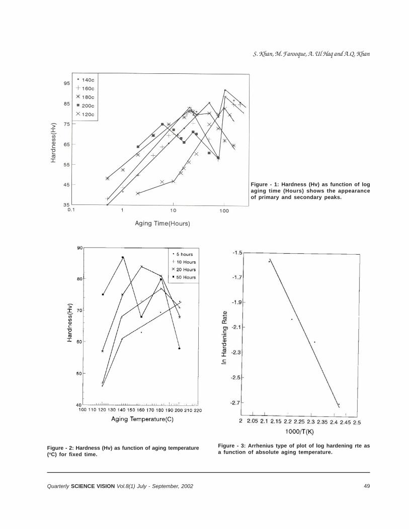
49Quarterly SCIENCE VISION Vol.8(1) July - September, 2002
Figure - 1: Hardness (Hv) as function of logaging time (Hours) shows the appearanceof primary and secondary peaks.
Figure - 2: Hardness (Hv) as function of aging temperature(oC) for fixed time.
Figure - 3: Arrhenius type of plot of log hardening rte asa function of absolute aging temperature.
S. Khan, M. Farooque, A. Ul Haq and A.Q. Khan
50 Quarterly SCIENCE VISION Vol.8(1) July - September, 2002
The plots show that there is a linear increase inhardness during the early stage of the aging process.After this stage, the hardness drops sharply and thenrises again when the alloy is aged further for a longertime. This means, each curve has two hardnesspeaks, a primary and a secondary peak. The agingcurve at 140C shows the formation of the primarypeak around 50 hours, after which the hardness dropsand then rises sharply above 100 hours and thesecondary peak develops. Similarly, the aging curveat 160C shows the primary peak around 20 hours ofaging and the secondary peak above 100 hours, inanalogy to the aging curve at 140C. Although thedifference of time between the two curves to achievethe primary peak is very large, there is only a slightdifference in the hardness values. This indicates thatgrowth-rate of precipitate is slower in case of lowertemperature.
The sample aged at a temperature of 180C showsthe primary peak after 15 hours, the hardness thenslightly decreases and then secondary peak developsabove 50 hours. The drop in hardness after the primarypeak is not very significant at a temperature of 180C;however, it follows a trend similar to that at 140C and160C aging temperatures. At higher agingtemperature, it takes a shorter time to complete thewhole process, as such, primary and secondary peaksfor hardness are not developed properly. Followingthese observations the aging process was repeatedat of 120C and 200C. The aging phenomena at atemperature of 120C occurred with two differentslopes. The rise in hardness in the first 10 hours isvery slow, after which it rises in a normal way as isobserved for 140C, 160C and 180C. This furtherindicates that high activation energy is required forprecipitation at low temperatures. In this case, theprimary peak was observed after 100 hours of aging.The sample was stopped from further aging after theappearance of primary peak at 120C, as it wasexpected to depict a trend similar to that at 140C,160C and 180C aging temperatures. The agingtemperature of 200C did show the primary andsecondary peaks; however, the results at thistemperature are not reproducible. Probably reactionkinetics is so high that it is difficult to follow the agingmechanism. Thus it may be concluded that the higherthe aging temperature, the lower is the time at whichprimary and secondary peaks for hardness appears.
Furthermore, this aging at 200C or above is notrecommended for these alloys.
Figure 2 shows the plot of Vicker’s hardness as afunction of aging temperature for fixed time-intervals.Better hardening tendency is shown in the temperaturerange of 160-180C and in 10-20 hours after that, thehardness decreases continuously as the agingtemperature increases.
The kinetics of age-hardening has been analyzed byemploying Arrhenius type of equation of the form:
where H is the hardening rate, H is the structuralconstant, Q is the activation energy, R is the gasconstant and T is the absolute temperature.
Figure 3 is the Arrhenius plot of log hardening-rate asa function of the reciprocal of the absolute agingtemperature. The slope of the straight line in figure 3gives an activation energy of 1.37eV. The agingphenomenon observed in the initial stage of aging inthe present study is in agreement with the results ofIsmail and Bouchra[7] reported for a similar alloy (Al-Mg-Si). They measured activation energy of 0.95 eVfor their alloy, which appears to have better hardeningtendency and as a result took shorter time to achievethe maximum peak hardness. Moreover, their peakhardness values are relatively high, which is perhapsthe effect of compositional difference of the alloy usedin the two studies (0.98wt%Si, 0.78wt%Mg,0.31wt%Mn and 0.06wt%Fe[7]). However, Ismail andBouchra have proposed that the low activation energyis probably due to the formation of complexes betweenquenched-in vacancies and solute atoms. Yanagwaand co-workers have proposed that activation energyfor the aging process varies from 0.7-1.1eV for theearly stage of aging to 1.3-1.5eV for the later stage.The activation energy is dependent upon theconcentration of alloying elements, such as Si andMg which is a source of precipitates. The value of1.37eV recorded in the present study is consistentwith the result of Ismail and Bouchra and Yanagawaet al. It is to be noted that activation energy of 1.43eVand 1.13 eV has also been reported by Hunsikker[14]for diffusion of Si and Mg in aluminum, respectively.
H = He-Q/RT
Long-Time Aging Characteristics of Al-Mg-Si Commercail Alloy
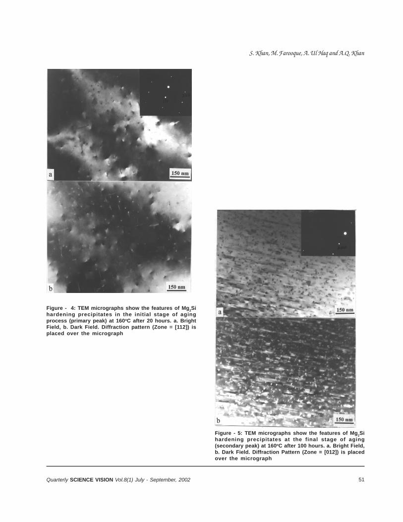
51Quarterly SCIENCE VISION Vol.8(1) July - September, 2002
Figure - 5: TEM micrographs show the features of Mg2Si
hardening precipitates at the final stage of aging(secondary peak) at 160oC after 100 hours. a. Bright Field,b. Dark Field. Diffraction Pattern (Zone = [012]) is placedover the micrograph
Figure - 4: TEM micrographs show the features of Mg2Si
hardening precipitates in the initial stage of agingprocess (primary peak) at 160oC after 20 hours. a. BrightField, b. Dark Field. Diffraction pattern (Zone = [112]) isplaced over the micrograph
S. Khan, M. Farooque, A. Ul Haq and A.Q. Khan
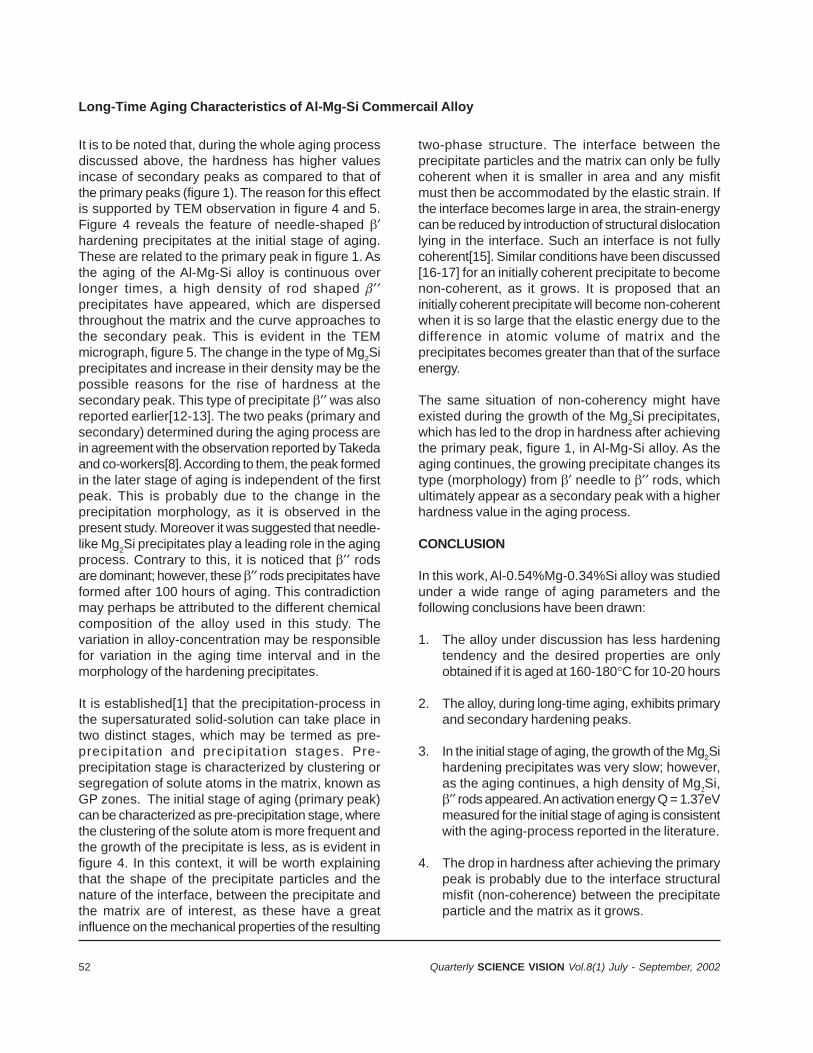
52 Quarterly SCIENCE VISION Vol.8(1) July - September, 2002
It is to be noted that, during the whole aging processdiscussed above, the hardness has higher valuesincase of secondary peaks as compared to that ofthe primary peaks (figure 1). The reason for this effectis supported by TEM observation in figure 4 and 5.Figure 4 reveals the feature of needle-shaped hardening precipitates at the initial stage of aging.These are related to the primary peak in figure 1. Asthe aging of the Al-Mg-Si alloy is continuous overlonger times, a high density of rod shaped precipitates have appeared, which are dispersedthroughout the matrix and the curve approaches tothe secondary peak. This is evident in the TEMmicrograph, figure 5. The change in the type of Mg2Siprecipitates and increase in their density may be thepossible reasons for the rise of hardness at thesecondary peak. This type of precipitate was alsoreported earlier[12-13]. The two peaks (primary andsecondary) determined during the aging process arein agreement with the observation reported by Takedaand co-workers[8]. According to them, the peak formedin the later stage of aging is independent of the firstpeak. This is probably due to the change in theprecipitation morphology, as it is observed in thepresent study. Moreover it was suggested that needle-like Mg2Si precipitates play a leading role in the agingprocess. Contrary to this, it is noticed that rodsare dominant; however, these rods precipitates haveformed after 100 hours of aging. This contradictionmay perhaps be attributed to the different chemicalcomposition of the alloy used in this study. Thevariation in alloy-concentration may be responsiblefor variation in the aging time interval and in themorphology of the hardening precipitates.
It is established[1] that the precipitation-process inthe supersaturated solid-solution can take place intwo distinct stages, which may be termed as pre-precipitation and precipitation stages. Pre-precipitation stage is characterized by clustering orsegregation of solute atoms in the matrix, known asGP zones. The initial stage of aging (primary peak)can be characterized as pre-precipitation stage, wherethe clustering of the solute atom is more frequent andthe growth of the precipitate is less, as is evident infigure 4. In this context, it will be worth explainingthat the shape of the precipitate particles and thenature of the interface, between the precipitate andthe matrix are of interest, as these have a greatinfluence on the mechanical properties of the resulting
two-phase structure. The interface between theprecipitate particles and the matrix can only be fullycoherent when it is smaller in area and any misfitmust then be accommodated by the elastic strain. Ifthe interface becomes large in area, the strain-energycan be reduced by introduction of structural dislocationlying in the interface. Such an interface is not fullycoherent[15]. Similar conditions have been discussed[16-17] for an initially coherent precipitate to becomenon-coherent, as it grows. It is proposed that aninitially coherent precipitate will become non-coherentwhen it is so large that the elastic energy due to thedifference in atomic volume of matrix and theprecipitates becomes greater than that of the surfaceenergy.
The same situation of non-coherency might haveexisted during the growth of the Mg2Si precipitates,which has led to the drop in hardness after achievingthe primary peak, figure 1, in Al-Mg-Si alloy. As theaging continues, the growing precipitate changes itstype (morphology) from needle to rods, whichultimately appear as a secondary peak with a higherhardness value in the aging process.
CONCLUSION
In this work, Al-0.54%Mg-0.34%Si alloy was studiedunder a wide range of aging parameters and thefollowing conclusions have been drawn:
1. The alloy under discussion has less hardeningtendency and the desired properties are onlyobtained if it is aged at 160-180C for 10-20 hours
2. The alloy, during long-time aging, exhibits primaryand secondary hardening peaks.
3. In the initial stage of aging, the growth of the Mg2Sihardening precipitates was very slow; however,as the aging continues, a high density of MgSi, rods appeared. An activation energy Q = 1.37eVmeasured for the initial stage of aging is consistentwith the aging-process reported in the literature.
4. The drop in hardness after achieving the primarypeak is probably due to the interface structuralmisfit (non-coherence) between the precipitateparticle and the matrix as it grows.
Long-Time Aging Characteristics of Al-Mg-Si Commercail Alloy

53Quarterly SCIENCE VISION Vol.8(1) July - September, 2002
Acknowledgment: The authors are thankful to thetechnical staffs of the metallurgy division for theirassistance and help during the course of this work.
REFERENCES
1. A. Lutts: Acta Met., 1961, 9, 577.2. I. J. Polmear: ‘Light Alloys, Metallurgy and Materials
Science’, 1981, U.K, Thomson Litho ltd.3. J. Langerveger: in Conf. Proc., ‘Inst. of Metals’,
London, March 1986, page 49.4. D. W.Pashley, J. W. Rhodes and A. Sendorek: J.Inst.
Metals, 1990, 94, 41.5. H. R. Sherchift and M. F. Ashby: Acta Metall. Mater.,
1990, 38(10), 1789.6. M. Yanagawa, S. Oie and M. Abe: J. Jpn. Inst. light
Met., 1993, 43(3), 146.
S. Khan, M. Farooque, A. Ul Haq and A.Q. Khan
7. Z. H. Ismail and B. Bouchra: Acta Physica Hungaria,1992, 71(1-2), 3.
8. M. Takeda, K. Fukui, F. Ohkubo and T. Shirai: Mat.Sci. Forum, 1996, 222(2), 815.
9. S. J. Anderson: Metall. and Mat. Trans., 1995, 26A,1931.
10. G. Thomas: J. Inst. Metals, 1961-62, 90, 57.11. S. Khan, A. Ali, F. Habiby, A. ul-Haq and A. Q. Khan: in
Conf. Proc., ‘ISAM-95’, Islamabad, Pakistan, Sept.95, page 375.
12. H. J. Rack: Scripta Metallurgica, 1978, 12, 777.13. K. Matsuda, S. Tada and S. Akeno: J. Electron
Microscope, 1993, 42, 1.14. H.Y. Hansikller: Aluminum, ASM, 1967, 1, 187.15. A. Kelly and R.B. Nicholson: Prog. in Material
Science, 1966, 10, 153.16. J. Friedel: ‘Les Dislocation’, 1956, Gauthier Villers.17. H. Brooks: ‘Metal Interfaces’, 20,1952, Amer. Soc.
Metals.
54 Quarterly SCIENCE VISION Vol.8(1) July - September, 2002
A DECENTRALIZED PROCESS-ORIENTEDAPPROACH FOR POWER-SYSTEM OPERATION
M. Farooq Aslam* andTabrez Aslam Shami
* Assistant Professor, Department of Electrical Engieering, University of Engineering & Technology, Lahore - 54890, Pakistan.
ABSTRACT
It has been pointed out that the problem of “EconomicOperation of Electrical Power Systems” is a problemof decision-management. To be able to reach theright decision, the right information is to be madeavailable at the right place, and at the right time. [1JTo that end, it is required that the individual tasksinvolved in electrical power systems, such aseconomic dispatch, unit commitment, hydro-thermalcoordination, etc., be reengineered into decentralizedcoherent processes.
Keywords: Power Systems and New Developments,Power System Planning & Control, Decentralizationof Processes in a Power System
INTRODUCTION
“The operation-scheduling problem is to determinewhich generating units should be committed r. andbe available for generation, the ‘units’ nominalgeneration or dispatch and, in some cases, even thetype of fuel to use. In general utilities may have severalsources of power such as thermal plant (steam andgas), hydro and pumped storage plants, dispersedgeneration (such as wind-power or photo-voltaic),interconnection with other national or internationalgeneration companies. Also many utilities use loadmanagement-control to influence the loading factor,thus affecting the amount of generation required. Theeconomic effect of operations scheduling is veryimportant, when fuel is a major component of the cost.
In the present state of the art, load dispatch isdetermined through control program stored in thememory of the control center computers. The inputsto this program are in the form of proprietary data-files, comprising the fuel-cost characteristics ofthermal units, total system forecast, capability ofgeneration resources, etc. This program computesthe unit commitment order, as well as dispatch forindividual units, and the results derived by the centercomputers are dispatched over the SCADA lines tothe operators who can then accept, modify or ignorethe advice received [5].
It is a centralized decision-management system,which may be simpler to handle if the units to becontrolled are small in number and the distancesinvolved are not very large. It is important to note thatsome components of the system, that are vital forbetter decision management are either not linked atall or are linked through slow paper links.
In order to have an appreciation of the complexityinvolved, consider the unit commitment problem withfollowing assumptions:
• There are M periods per day.• There are N units to commit and dispatch• Anyone of the units, as well as all the units can
supply the whole load.
The number of combinations to be tried each hourwould be
C(N,l) + C(N,2) +.......... C(N,N) = 2N -1
Where C(N;j) is the combination ofN items taken j ata time
which can become a horrid number to think about..Considering M equal to 24 one hour intervals and asystem with N equal to 20 units, this number amountsto 3.12 x 10144. [3] These very large numbers arethe upper bounds for the number of enumerationsrequired. What would happen in systems wherenumber of units is more, than 150?
The present advances in the Information Technologyhave enough potential to provide solutions for optimaloperation of electrical power systems, with thefollowing benefits:
• Information can appear simultaneously in as manyplaces as it is needed.
• Systems can simultaneously reap the benefits ofcentralization and decentralization.
C(N,j) = N! (N – j)!j!

55Quarterly SCIENCE VISION Vol.8(1) July - September, 2002
• Decision-making may become part of everyone’sjob.
• Plans get revised instantaneously.• A generalist can do the work of an expert.
The overhead on the main center computers can bereduced very much, by reengineering the processesin a logical way. As an essential enabler, the moderninformation-technology has an importance to thereengineering process that is difficult to overstate.To reengineer is to take a journey from the familiarinto the unknown. [9]
REENGINEERING:
Reengineering as defined by Hammer and Champy[9], is the fundamental rethinking and radical redesignof processes, to achieve dramatic improvements incritical contemporary measures of performance, suchas cost, quality, service and speed.
“Processes in a company correspond to naturalbusiness activity, but they are often fragmented andobscured by the organizational structures. Processesare invisible and unnamed because people think aboutthe individual departments, not about the processeswith which all of them are involved. Processes alsotend to be unmanaged, because people are put incharge of the departments or work units, but no oneis given the responsibility for getting the whole job —the process —done”. [9]
PROCESSES AND PROCESS-MAPS
Just like organization charts, a process map can beprepared that gives, a picture of how workflows throughthe organization. [9] Some very interestingcharacteristics of a process map may be outlined asfollows:
• Simple: A process-map is much simpler, ascompared to an organization chart of the samecompany. Hardly any company contains morethan ten or so principal processes.
• Process Owners: A process-map includesprocess owners; something that is almost neverdisplayed on a company’s organization chart.
• End Users: A process-map also includes end-users in its view of processes.
• Sub Processes: A process is not seen as amonolith, but in terms of key-concepts to interactwith others. This perspective indicates how asystem appreciates it’s owners work and how itcan contribute to that work
• “Process-maps don’t require months of work toconstruct; several weeks is the norm. But thistask does induce headaches, because it requirespeople to think across organizational grain. It’snot a picture of the organization, which is whatpeople are used to seeing and drawing, but adepiction of the work that is being done. Whenit’s finished, the process map should not surpriseanyone. In fact, people may wonder why drawingit took as long as it did, since the finished mapwill be so easy to understand, even obvious. Ofcourse, people should say, that it is just a modelof what we do around here.” [9]
REDESIGNING PROCESSES
Once a process has been selected and a processowner and user defined, the next step is to understandthe process. The following are the key issues:
• What the process does?• How well (or poorly) it performs?• Critical issues that govern its performance.
Traditional process-analysis takes the process-inputsand outputs as given, and looks purely inside theprocess to measure and examine what goes on. Incontrast to that, part of redesigning a process is, tolook at it from the outside in order to find what theprocess’s customer (the user) does with that output.Therefore, the better place to begin to understand aprocess is on the user-end. The following questionsmust be answered:
• Who is the user of this process?• What are the user’s real requirements?• What do they (users) say they want, and what
do they really need, if the two are different?• What problems they have?• What processes do they perform with the output?
Since the eventual goal of redesigning a process is tocreate one that meets user’s needs better, it is crucial
M. Farooq Aslam and Tabrez Aslam Shami

56 Quarterly SCIENCE VISION Vol.8(1) July - September, 2002
Figure - 1: Control-System Based on Centralized Management for Electrical Power Systems Operations
Figure - 2: A Possible Higher-Level Process-Map of an Electrical Power System
A Decentralized Process-Oriented Approach for Power-System Operation
57Quarterly SCIENCE VISION Vol.8(1) July - September, 2002
that the team truly understands these needs.Understanding means considering the user’sunderlying goals and problems, not just the mechanicsof the process that links the two organizationstogether.
A PROCESS-MAP FOR POWER SYSTEMOPERATION
According to Hammer and Champy [9], one way toidentify processes that make up an organization is togive them names that express their beginning andend states. This implies all the work that gets donebetween their start and finish. Some processesinvolved in operation of electrical power systems, areredesigned in the following, with a view tounderstanding their inputs and outputs.
THERMAL PLANTS STATUS DEVELOPMENTPROCESS
This process would take in the fuel consumption data,scheduled and forced outages, startup and shut-downinformation, and would identify the units available andtheir fuel-cost characteristics, as well as minimumand maximum plant-capability, for next 24 hours. Theprocess-owner is each thermal plant. The customerof this process is the main control center.
ENERGY-INTERCHANGE EVALUATION & PLANT-SCHEDULING PROCESS
This process uses the output of hydel statusdevelopment process and thermal status developmentprocess as its input, along with load-forecast at eachload-center for next 24 hours, tie-line constraints, andidentifies the units to be committed and optimal shareof load for each plant. The process owner is the power-control centre. The customers of this process areeach power-plant. This is a shared process, whichrequires a few hops between plants and main control-centre, for its completion.
PLANT UNITS ECONOMIC LOADING PROCESS:
This process would utilize the output of the aboveprocess and produce optimal share of load for eachof its ONLINE units. The process owner is eachthermal plant. The owner of this process is also thecustomer of the process. This process also requires
a few hops between main control center and plantsfor its completion. Its output would be the operation-schedule for the plant.
Keeping in view these processes, a possible higher-level process-map has been drawn as shown in fig. 2.
CONCLUSION
Older processes of economic dispatch, unitcommitment, load flow analysis, reservoir analysis,are the individual tasks that may become a part ofthe larger objective, but they cannot be consideredas processes. It can be clearly seen now from theProcess Map, of an electrical power system, that thecomponents of system-operation may bedeceptralized. This would help in arriving at betterdecisions in a timely and more efficient manner. Thepresence of high-speed networks has made it possibleto employ knowledge-based access of distributeddatabases.
It is mandatory to Reengineer the Electrical PowerSystem. Only then can one take advantage of artificialintelligent techniques and build a coupled expertsystem [I] for solving the problem of “Optimal Operationof Electrical Power Systems.
FUTURE WORK
Economic operation of electrical power systems isan important issue, on which a research project isgoing on in the University of Engineering andTechnology, Lahore, Pakistan, for developing newmethodologies, utilizing decentralized artificialintelligence techniques. The present research paperis the 4th in the series. After preparation of the“Process Map”, the next task would be thedevelopment of architecture of the databases required,and the communication manners in which they wouldinteract with each other.
REFERENCES
1. Farooq M. Aslam and Tabrez A. Shami, “Decision-Management in Electrical Power Systems, Operationand Control”, COMSATS Quarterly Science VisionVol. 6, no.2 October-December, 2000.
2. Farooq M. Aslam and Tabrez A. Shami, “PowerSystem Operation in Information Technology Era,
M. Farooq Aslam and Tabrez Aslam Shami

58 Quarterly SCIENCE VISION Vol.8(1) July - September, 2002
Proceedings of the 2001 International ElectricalEngineering Congress, Lahore.
3. Allen J. Wood and Bruce F. Wollenberg, PowerGeneration Operation & Control, New York: Wiley,1984. Pp. 5-13, 23-63, 323-353
4. Charles A. Gross, Power System Analysis, NewYork: Wiley, 1986. pp. 305-313
5. J. Arrillaga and C.P. Arnold, Computer Analysis ofPower Systems, Succes: Wiley, 1990
6. William H. Press, Numerical Recipes, New York:Cambridge, 1988. pp. 92-95
7. Lehman R. and J. Mattioni, “Database Methods in
Power System Control Centers”, Electrical Powerand Energy Systems, Vol. 5 No.4 1983, pp. 241-246.
8. E. Lutz and J. Martinaud, “A Modem DatabaseManagement System in Power System Control”,Proceedings of IF AC Symposium on Planning andOperation of Electric Energy Systems, Brazil, 22-25July, 1985.
9. Michael Hammer & James Champy, Reengineeringthe Corporation. A manifesto for BusinessRevolution, New York: HyperCollins, 1993.
10. Yair, Alan, Griver, Visual FoxPro 3 Codebook,California: Sybex, 1995
A Decentralized Process-Oriented Approach for Power-System Operation
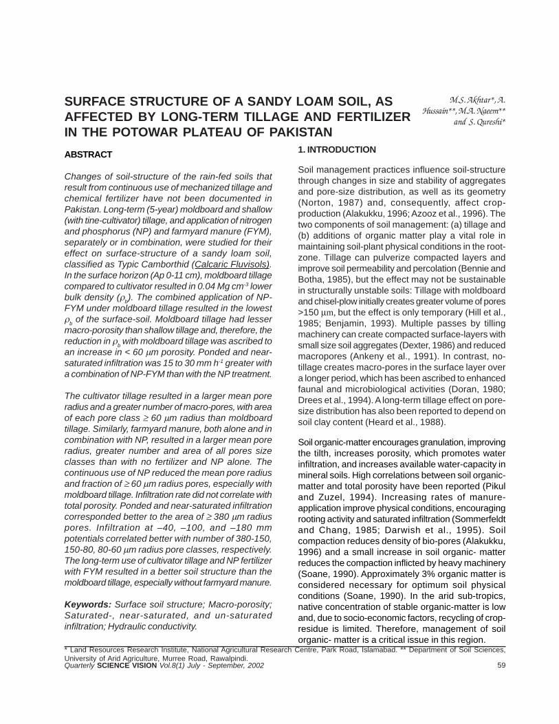
59Quarterly SCIENCE VISION Vol.8(1) July - September, 2002
SURFACE STRUCTURE OF A SANDY LOAM SOIL, ASAFFECTED BY LONG-TERM TILLAGE AND FERTILIZERIN THE POTOWAR PLATEAU OF PAKISTAN
M.S. Akhtar*, A.Hussain**, M.A. Naeem**
and S. Qureshi*
ABSTRACT
Changes of soil-structure of the rain-fed soils thatresult from continuous use of mechanized tillage andchemical fertilizer have not been documented inPakistan. Long-term (5-year) moldboard and shallow(with tine-cultivator) tillage, and application of nitrogenand phosphorus (NP) and farmyard manure (FYM),separately or in combination, were studied for theireffect on surface-structure of a sandy loam soil,classified as Typic Camborthid (Calcaric Fluvisols).In the surface horizon (Ap 0-11 cm), moldboard tillagecompared to cultivator resulted in 0.04 Mg cm-3 lowerbulk density (
b). The combined application of NP-
FYM under moldboard tillage resulted in the lowest
b of the surface-soil. Moldboard tillage had lesser
macro-porosity than shallow tillage and, therefore, thereduction in
b with moldboard tillage was ascribed to
an increase in < 60 m porosity. Ponded and near-saturated infiltration was 15 to 30 mm h-1 greater witha combination of NP-FYM than with the NP treatment.
The cultivator tillage resulted in a larger mean poreradius and a greater number of macro-pores, with areaof each pore class 60 m radius than moldboardtillage. Similarly, farmyard manure, both alone and incombination with NP, resulted in a larger mean poreradius, greater number and area of all pores sizeclasses than with no fertilizer and NP alone. Thecontinuous use of NP reduced the mean pore radiusand fraction of 60 m radius pores, especially withmoldboard tillage. Infiltration rate did not correlate withtotal porosity. Ponded and near-saturated infiltrationcorresponded better to the area of 380 m radiuspores. Infiltration at –40, –100, and –180 mmpotentials correlated better with number of 380-150,150-80, 80-60 m radius pore classes, respectively.The long-term use of cultivator tillage and NP fertilizerwith FYM resulted in a better soil structure than themoldboard tillage, especially without farmyard manure.
Keywords: Surface soil structure; Macro-porosity;Saturated-, near-saturated, and un-saturatedinfiltration; Hydraulic conductivity.
1. INTRODUCTION
Soil management practices influence soil-structurethrough changes in size and stability of aggregatesand pore-size distribution, as well as its geometry(Norton, 1987) and, consequently, affect crop-production (Alakukku, 1996; Azooz et al., 1996). Thetwo components of soil management: (a) tillage and(b) additions of organic matter play a vital role inmaintaining soil-plant physical conditions in the root-zone. Tillage can pulverize compacted layers andimprove soil permeability and percolation (Bennie andBotha, 1985), but the effect may not be sustainablein structurally unstable soils: Tillage with moldboardand chisel-plow initially creates greater volume of pores>150 m, but the effect is only temporary (Hill et al.,1985; Benjamin, 1993). Multiple passes by tillingmachinery can create compacted surface-layers withsmall size soil aggregates (Dexter, 1986) and reducedmacropores (Ankeny et al., 1991). In contrast, no-tillage creates macro-pores in the surface layer overa longer period, which has been ascribed to enhancedfaunal and microbiological activities (Doran, 1980;Drees et al., 1994). A long-term tillage effect on pore-size distribution has also been reported to depend onsoil clay content (Heard et al., 1988).
Soil organic-matter encourages granulation, improvingthe tilth, increases porosity, which promotes waterinfiltration, and increases available water-capacity inmineral soils. High correlations between soil organic-matter and total porosity have been reported (Pikuland Zuzel, 1994). Increasing rates of manure-application improve physical conditions, encouragingrooting activity and saturated infiltration (Sommerfeldtand Chang, 1985; Darwish et al., 1995). Soilcompaction reduces density of bio-pores (Alakukku,1996) and a small increase in soil organic- matterreduces the compaction inflicted by heavy machinery(Soane, 1990). Approximately 3% organic matter isconsidered necessary for optimum soil physicalconditions (Soane, 1990). In the arid sub-tropics,native concentration of stable organic-matter is lowand, due to socio-economic factors, recycling of crop-residue is limited. Therefore, management of soilorganic- matter is a critical issue in this region.
* Land Resources Research Institute, National Agricultural Research Centre, Park Road, Islamabad. ** Department of Soil Sciences,University of Arid Agriculture, Murree Road, Rawalpindi.
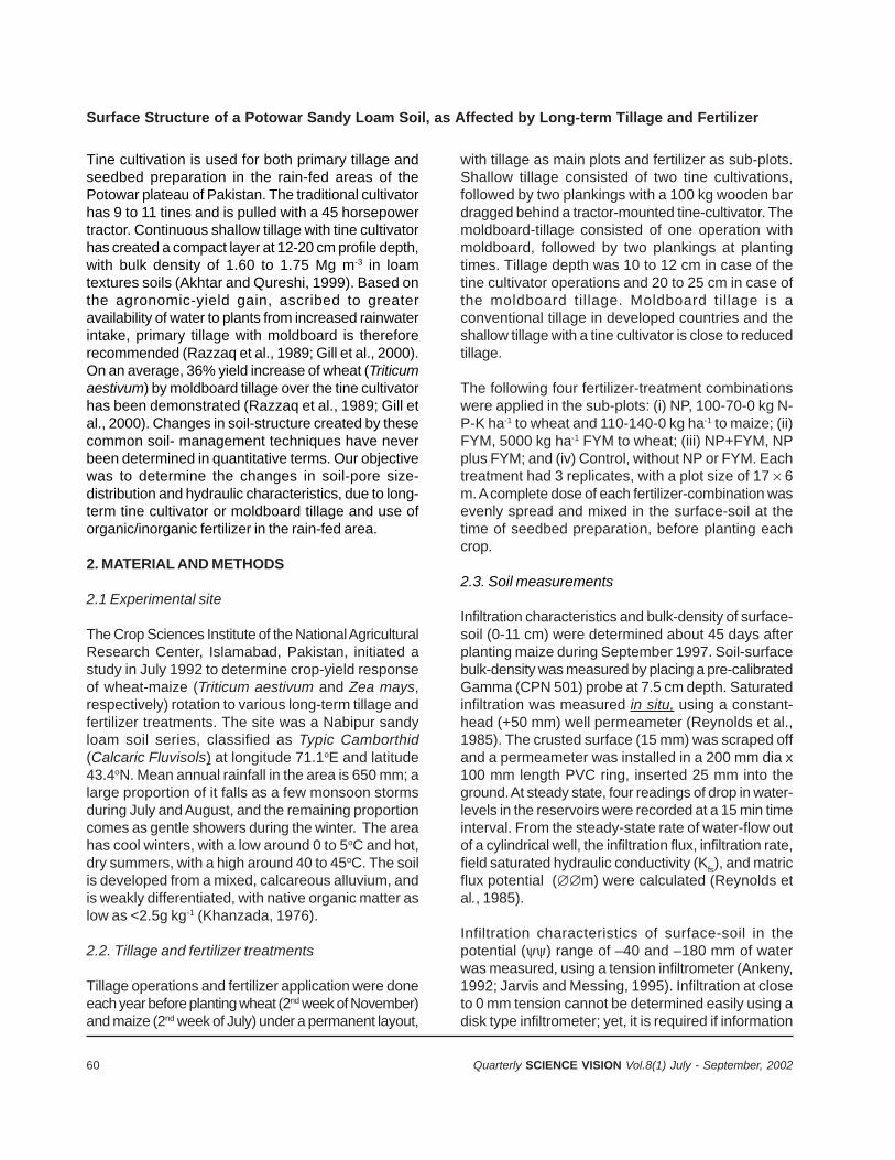
60 Quarterly SCIENCE VISION Vol.8(1) July - September, 2002
Tine cultivation is used for both primary tillage andseedbed preparation in the rain-fed areas of thePotowar plateau of Pakistan. The traditional cultivatorhas 9 to 11 tines and is pulled with a 45 horsepowertractor. Continuous shallow tillage with tine cultivatorhas created a compact layer at 12-20 cm profile depth,with bulk density of 1.60 to 1.75 Mg m-3 in loamtextures soils (Akhtar and Qureshi, 1999). Based onthe agronomic-yield gain, ascribed to greateravailability of water to plants from increased rainwaterintake, primary tillage with moldboard is thereforerecommended (Razzaq et al., 1989; Gill et al., 2000).On an average, 36% yield increase of wheat (Triticumaestivum) by moldboard tillage over the tine cultivatorhas been demonstrated (Razzaq et al., 1989; Gill etal., 2000). Changes in soil-structure created by thesecommon soil- management techniques have neverbeen determined in quantitative terms. Our objectivewas to determine the changes in soil-pore size-distribution and hydraulic characteristics, due to long-term tine cultivator or moldboard tillage and use oforganic/inorganic fertilizer in the rain-fed area.
2. MATERIAL AND METHODS
2.1 Experimental site
The Crop Sciences Institute of the National AgriculturalResearch Center, Islamabad, Pakistan, initiated astudy in July 1992 to determine crop-yield responseof wheat-maize (Triticum aestivum and Zea mays,respectively) rotation to various long-term tillage andfertilizer treatments. The site was a Nabipur sandyloam soil series, classified as Typic Camborthid(Calcaric Fluvisols) at longitude 71.1oE and latitude43.4oN. Mean annual rainfall in the area is 650 mm; alarge proportion of it falls as a few monsoon stormsduring July and August, and the remaining proportioncomes as gentle showers during the winter. The areahas cool winters, with a low around 0 to 5oC and hot,dry summers, with a high around 40 to 45oC. The soilis developed from a mixed, calcareous alluvium, andis weakly differentiated, with native organic matter aslow as <2.5g kg-1 (Khanzada, 1976).
2.2. Tillage and fertilizer treatments
Tillage operations and fertilizer application were doneeach year before planting wheat (2nd week of November)and maize (2nd week of July) under a permanent layout,
with tillage as main plots and fertilizer as sub-plots.Shallow tillage consisted of two tine cultivations,followed by two plankings with a 100 kg wooden bardragged behind a tractor-mounted tine-cultivator. Themoldboard-tillage consisted of one operation withmoldboard, followed by two plankings at plantingtimes. Tillage depth was 10 to 12 cm in case of thetine cultivator operations and 20 to 25 cm in case ofthe moldboard tillage. Moldboard tillage is aconventional tillage in developed countries and theshallow tillage with a tine cultivator is close to reducedtillage.
The following four fertilizer-treatment combinationswere applied in the sub-plots: (i) NP, 100-70-0 kg N-P-K ha-1 to wheat and 110-140-0 kg ha-1 to maize; (ii)FYM, 5000 kg ha-1 FYM to wheat; (iii) NP+FYM, NPplus FYM; and (iv) Control, without NP or FYM. Eachtreatment had 3 replicates, with a plot size of 17 6m. A complete dose of each fertilizer-combination wasevenly spread and mixed in the surface-soil at thetime of seedbed preparation, before planting eachcrop.
2.3. Soil measurements
Infiltration characteristics and bulk-density of surface-soil (0-11 cm) were determined about 45 days afterplanting maize during September 1997. Soil-surfacebulk-density was measured by placing a pre-calibratedGamma (CPN 501) probe at 7.5 cm depth. Saturatedinfiltration was measured in situ, using a constant-head (+50 mm) well permeameter (Reynolds et al.,1985). The crusted surface (15 mm) was scraped offand a permeameter was installed in a 200 mm dia x100 mm length PVC ring, inserted 25 mm into theground. At steady state, four readings of drop in water-levels in the reservoirs were recorded at a 15 min timeinterval. From the steady-state rate of water-flow outof a cylindrical well, the infiltration flux, infiltration rate,field saturated hydraulic conductivity (Kfs), and matricflux potential (m) were calculated (Reynolds etal., 1985).
Infiltration characteristics of surface-soil in thepotential () range of –40 and –180 mm of waterwas measured, using a tension infiltrometer (Ankeny,1992; Jarvis and Messing, 1995). Infiltration at closeto 0 mm tension cannot be determined easily using adisk type infiltrometer; yet, it is required if information
Surface Structure of a Potowar Sandy Loam Soil, as Affected by Long-term Tillage and Fertilizer
61Quarterly SCIENCE VISION Vol.8(1) July - September, 2002
on changes in macropores is needed. Soil strengthat near zero potential may not support the weight ofthe permeameter (White et al., 1992) and collapseunder pressure, yielding negative hydraulicconductivity at zero potential (Ko). Infiltration ratesat 0 and –250 mm of water were predicted byregressing infiltration data from the same surface at+50, –40, –100, and -180 mm water pressure heads.Infiltration rate (infiltration flux per unit surface area, Lh-1), hydraulic conductivity (Ki), and matrix fluxpotential (i) were calculated from the infiltrationflux (Q, L3 T-1) for the potential (i) pairs: (i) 0/–40 (ii)–40/–100, (iii) –100/–180, and (iv) –180/–250 mm ofwater. Three measurements for bulk density andinfiltration were made in each plot.
Calculations for K() and () were done usingthe Poiseuille’s equation, Q = r2 K + 4 r ,(Wooding, 1968), where K is hydraulic conductivity(L T-1) and matric flux potential (L2 T-1) (Ankeny,1992; Akhtar et al., 1999).
As an estimate of soil structure, macroscopiccapillary length, c, was calculated, following Whiteand Sully (1987) and Ankeny (1992). Since c is aK-weighted mean soil-water potential (L), we can relatec by the capillarity theory to obtain a characteristicpore dimension, m, that controls the flow wheninfiltration occurs through the surface: m = /gc,where is the water surface tension (72.75 kg s-2); is the water density (1000 kg m-3); g is theacceleration due to gravity (9.80 m s-2); and c,characteristic capillary length (Bouma, 1991; Ankeny,1992).
Assuming cylindrical pores, an equivalent radius, r,is 2cos/gi (Danielson and Sutherland, 1986)where is the contact angle and i is the water-potential level. Since water from a pore can be removedwhen suction exceeds the force acting to retain it,infiltration at –40, -100, –180, and –250 mm water-potential will exclude pores of equivalent radius, r >380, 150, 80, and 60m, respectively, from the flowprocess. With known r, the number of effective poresper area (m-2) is 8 I / g(r)4, where is the viscosityof water (kg m-1 s-1), I is the infiltration- rate (m s-1) ata given potential, and r is the minimum radius (m) forthe pore class (Watson and Luxmoore, 1986; Wilsonand Luxmoore, 1988). The infiltration rate associatedwith >380, 380–150, 150–80, and 80–60 m pore radii
was calculated as the difference between theinfiltration- rate at –0 and -40; –40 and -100; -
100 and –180; and –180 and -250, respectively. Thetotal effective porosity, m (m = N r2) where N isthe number of pores per m2 and r is the pore radius,is a unitless quantity (Wilson and Luxmoore, 1988;Watson and Luxmoore, 1986).
1.4. Statistical analysis
SAS’s General Linear Model (PROC GLM) was usedfor analysis of variance, to determine whether thesurface-structure parameters varied by tillage andfertilizer treatments, as well as their interaction.Comparison of treatment means was made byDuncan’s Multiple Range test (SAS Institute, 1992).
3. RESULTS
3.1 Soil bulk density (b)
The average b of the soil-profile with shallow tillagewas 1.57 Mg m-3 and was 1.53 Mg m-3 with moldboardtillage. Tillage with moldboard resulted in a reducedbulk-density, specifically of Ap (0-11 cm) (Fig. 1) andBA (11-23 cm) horizons, compared to that of shallowtillage even when no fertilizer was applied (data onBA not presented). Continuous use of chemicalfertilizer (NP) or farmyard manure (FYM) alone reducedb in the case of shallow tillage over the Control, butthere was no further decrease with moldboard tillage.Further, combined application of farmyard manure andNP resulted in a significantly lower average b in themoldboard tillage, but not in the shallow tillage.
3.2. Saturated infiltration and hydraulicconductivity (K
s)
The saturated infiltration for Ap horizon is depicted inFig. 2 at 50 mm potential on x-axis. The infiltration-rate in the shallow-tillage plots (mean of all fertilizertreatments) was greater than that of the moldboardplots. Saturated infiltration increased from 28 to 47mm h-1 with a combined application of NP andfarmyard manure, but moldboard tillage significantly(p < 0.05) modified the fertilizer effect (Fig. 2). TheControl had the same saturated infiltration, both inthe shallow and moldboard tillage, but application ofNP alone, compared to that of Control, resulted ingreater infiltration in shallow tillage and lesser in the
M.S. Akhtar, A. Hussain, M.A. Naeem and S. Qureshi
62 Quarterly SCIENCE VISION Vol.8(1) July - September, 2002
1.25
1.35
1.45
1.55
1.65
1.75
Control NP FYM NP+FYMFertilizer treatment
Bul
k de
nsity
(M
g m
-3) Cultivator
Moldboard
Figure - 1: Bulk density of the surface soil (0-11 cm) as affected by five-year tillage and fertilizer management:Control, no fertilizer; NP, nitrogen and phosphorus fertilizer; FYM, farmyard manure; and NP+FYM, combination of NP
and farmyard manure. Bar equals stnadard deviation divided by the number of samples.
(b ) Moldboard
0
10
20
30
40
50
60
50 0 -40 -100 -180 -250
P o tential (mm, water)
Infi
ltrat
ion
(mm
h-1
)
C ontrolN PFYMN P+FYM
(a) C ultivato r
0
10
20
30
40
50
60
50 0 -40 -100 -180 -250
Infi
ltrat
ion
(mm
h-1
)
Figure - 2: Infiltration determined by Guelphpermeability meter (+50 mm head) (Reynolds etal., 1985) and tension infiltrometer (White et al.,1992). Treatments and the bar, as defined in the
caption of Fig. 1
Surface Structure of a Potowar Sandy Loam Soil, as Affected by Long-term Tillage and Fertilizer
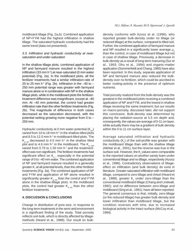
63Quarterly SCIENCE VISION Vol.8(1) July - September, 2002
moldboard tillage (Fig. 2a,b). Combined applicationof NP+FYM had the highest infiltration in shallowtillage. The saturated hydraulic conductivity had thesame trend (data not presented).
3.3. Infiltration and hydraulic conductivity at near-saturation and under-saturation
In the shallow tillage plots, combined application ofNP and farmyard manure resulted in the highestinfiltration (33 mm h-1) at near-saturated (0 mm waterpotential) (Fig. 2a). In the moldboard plots, all thefertilizer treatments had a similar infiltration-rate of20 to 25 mm h-1 (Fig. 2b). Infiltration in the –40 to –250 mm potential range was greater with farmyardmanure alone or in combination with NP in the shallowtillage plots, while in the moldboard plots the fertilizer-treatment difference was insignificant, except at –40mm. At –40 mm potential, the control had greaterinfiltration rate than the other fertilizer treatments (Fig.2b). The magnitude of difference in both casesdecreased as the saturation decreased, with thepotential setting growing more negative from 0 to –250 mm.
Hydraulic conductivity at 0 mm water-potential (K0)varied from 10 to 18 mm h-1 in the shallow-tilled plotsand 8.5 to 12.0 mm h-1 in moldboard tilled plots. TheK–40 decreased to 4.0 mm h-1 in the shallow tilledplot and to 4.6 mm h-1 in the moldboard. The K–180varied from 0.75 to 1.50 mm h-1 and the treatment-effect was non-significant. The fertilizer-treatments hadsignificant effect on K , especially in the potentialrange of 0 to –40 mm water. The combined applicationof NP and farmyard manure resulted in a generallygreater K, at all potential levels, than the other fertilizertreatments (Fig. 3a). The combined application of NPand FYM and application of NP alone resulted insignificantly greater K–40 than the control and FYMalone in the shallow-tillage plots. In the moldboardplots, the control had greater K–40 than the otherfertilizer treatments.
4. DISCUSSION & CONCLUSIONS
Change in distribution of pore-size, in response tothe long-term treatments in the semi-arid environmentis a significant finding of the study. Total porosityreflects soil-bulk, which is directly affected by tillage-methods (Heard et al., 1988). Our result on bulk-
density conforms with Azooz et al. (1996), whoreported greater bulk-density under no tillage (orreduced tillage) at the surface, compared to tilled soil.Further, the combined application of farmyard manureand NP resulted in a significantly lower average bthan the control, in case of moldboard tillage but notin case of shallow tillage. Previously, a decrease inbulk-density as a result of long-term manuring (Sur etal., 1993; Ohu et al., 1994) and organic-matterapplication (Sommerfeldt and Chang, 1985) have alsobeen reported. In this study, separate application ofNP and farmyard manure also reduced the bulk-density over no fertilizer, which could be ascribed tobetter rooting-activity in the presence of optimumnutrients.
Total porosity realized from the bulk-density was thegreatest in the moldboard plots receiving a combinedapplication of NP and FYM, and the lowest in shallowtillage receiving the same treatment; but our resultson macro-porosity, discussed later, did not supportthis conclusion. Bulk-density was determined byplacing the radiation-source at 5.5 cm depth and,consequently, the values are average of 0-11 cm layer,while actually there may be a gradient of bulk-densitywithin the 0 to 11 cm surface layer.
Average saturated infiltration and hydraulicconductivity (Ks) of the soil-profile was greater withthe moldboard tillage than with the shallow tillage(Akhtar et al., 2001), but the reverse was true in thesurface-soil. However, the Ks values were comparableto the reported values on another sandy loam underconventional tillage and no tillage, respectively (Azoozet al., 1996). Contradictory observations of tillage-effect on infiltration (and bulk density) do exist inliterature. Greater saturated infiltration with moldboardtillage, compared to zero tillage and chisel (Heard etal., 1988), greater Ks under zero-tillage than theconventional moldboard tillage (Chang and Lindwall,1992); and no difference between zero-tillage andmoldboard (Sing et al., 1991); have all been reported.The general consensus is that, initially, zero-tillage(or the reduced tillage) has greater bulk-density andlower infiltration than moldboard tillage, but thecondition reverses with time, due to increasedbiological activity in the intact surface (McCoy et al.,1994).
M.S. Akhtar, A. Hussain, M.A. Naeem and S. Qureshi
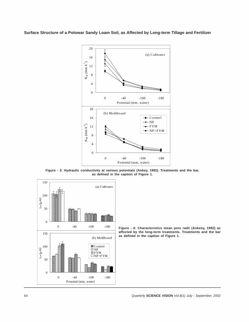
64 Quarterly SCIENCE VISION Vol.8(1) July - September, 2002
(b) Moldboard
0
4
8
12
16
20
0 -40 -100 -180Potential (mm, water)
K (
mm
h-1
)
ConteolNPFYMNP+FYM
(a) Cultivator
0
4
8
12
16
20
0 -40 -100 -180
Potential (mm, water)
K (
mm
h-1
)
Figure - 3: Hydraulic conductivity at various potentials (Ankey, 1992). Treatments and the bar,as defined in the caption of Figure 1.
(a) Cultivator
0
50
100
150
0 -40 -100 -180
m (
m)
(b) Moldboard
0
50
100
150
0 -40 -100 -180Potential (mm, water)
m (
m) Control
NPFYMNP+FYM
Figure - 4: Characteristics mean pore radii (Ankeny, 1992) asaffected by the long-term treatments. Treatments and the baras defined in the caption of Figure 1.
Surface Structure of a Potowar Sandy Loam Soil, as Affected by Long-term Tillage and Fertilizer
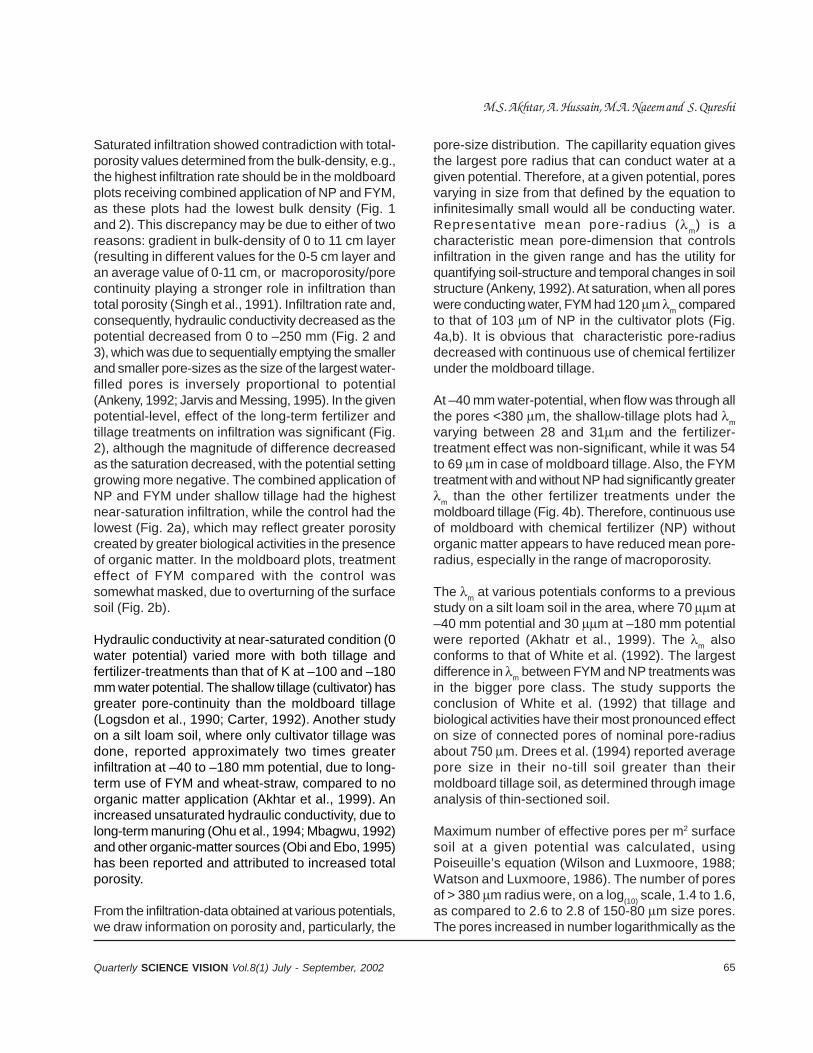
65Quarterly SCIENCE VISION Vol.8(1) July - September, 2002
Saturated infiltration showed contradiction with total-porosity values determined from the bulk-density, e.g.,the highest infiltration rate should be in the moldboardplots receiving combined application of NP and FYM,as these plots had the lowest bulk density (Fig. 1and 2). This discrepancy may be due to either of tworeasons: gradient in bulk-density of 0 to 11 cm layer(resulting in different values for the 0-5 cm layer andan average value of 0-11 cm, or macroporosity/porecontinuity playing a stronger role in infiltration thantotal porosity (Singh et al., 1991). Infiltration rate and,consequently, hydraulic conductivity decreased as thepotential decreased from 0 to –250 mm (Fig. 2 and3), which was due to sequentially emptying the smallerand smaller pore-sizes as the size of the largest water-filled pores is inversely proportional to potential(Ankeny, 1992; Jarvis and Messing, 1995). In the givenpotential-level, effect of the long-term fertilizer andtillage treatments on infiltration was significant (Fig.2), although the magnitude of difference decreasedas the saturation decreased, with the potential settinggrowing more negative. The combined application ofNP and FYM under shallow tillage had the highestnear-saturation infiltration, while the control had thelowest (Fig. 2a), which may reflect greater porositycreated by greater biological activities in the presenceof organic matter. In the moldboard plots, treatmenteffect of FYM compared with the control wassomewhat masked, due to overturning of the surfacesoil (Fig. 2b).
Hydraulic conductivity at near-saturated condition (0water potential) varied more with both tillage andfertilizer-treatments than that of K at –100 and –180mm water potential. The shallow tillage (cultivator) hasgreater pore-continuity than the moldboard tillage(Logsdon et al., 1990; Carter, 1992). Another studyon a silt loam soil, where only cultivator tillage wasdone, reported approximately two times greaterinfiltration at –40 to –180 mm potential, due to long-term use of FYM and wheat-straw, compared to noorganic matter application (Akhtar et al., 1999). Anincreased unsaturated hydraulic conductivity, due tolong-term manuring (Ohu et al., 1994; Mbagwu, 1992)and other organic-matter sources (Obi and Ebo, 1995)has been reported and attributed to increased totalporosity.
From the infiltration-data obtained at various potentials,we draw information on porosity and, particularly, the
pore-size distribution. The capillarity equation givesthe largest pore radius that can conduct water at agiven potential. Therefore, at a given potential, poresvarying in size from that defined by the equation toinfinitesimally small would all be conducting water.Representative mean pore-radius (m) is acharacteristic mean pore-dimension that controlsinfiltration in the given range and has the utility forquantifying soil-structure and temporal changes in soilstructure (Ankeny, 1992). At saturation, when all poreswere conducting water, FYM had 120 m m comparedto that of 103 m of NP in the cultivator plots (Fig.4a,b). It is obvious that characteristic pore-radiusdecreased with continuous use of chemical fertilizerunder the moldboard tillage.
At –40 mm water-potential, when flow was through allthe pores <380 m, the shallow-tillage plots had mvarying between 28 and 31m and the fertilizer-treatment effect was non-significant, while it was 54to 69 m in case of moldboard tillage. Also, the FYMtreatment with and without NP had significantly greaterm than the other fertilizer treatments under themoldboard tillage (Fig. 4b). Therefore, continuous useof moldboard with chemical fertilizer (NP) withoutorganic matter appears to have reduced mean pore-radius, especially in the range of macroporosity.
The m at various potentials conforms to a previousstudy on a silt loam soil in the area, where 70 m at–40 mm potential and 30 m at –180 mm potentialwere reported (Akhatr et al., 1999). The m alsoconforms to that of White et al. (1992). The largestdifference in m between FYM and NP treatments wasin the bigger pore class. The study supports theconclusion of White et al. (1992) that tillage andbiological activities have their most pronounced effecton size of connected pores of nominal pore-radiusabout 750 m. Drees et al. (1994) reported averagepore size in their no-till soil greater than theirmoldboard tillage soil, as determined through imageanalysis of thin-sectioned soil.
Maximum number of effective pores per m2 surfacesoil at a given potential was calculated, usingPoiseuille’s equation (Wilson and Luxmoore, 1988;Watson and Luxmoore, 1986). The number of poresof > 380 m radius were, on a log(10) scale, 1.4 to 1.6,as compared to 2.6 to 2.8 of 150-80 m size pores.The pores increased in number logarithmically as the
M.S. Akhtar, A. Hussain, M.A. Naeem and S. Qureshi
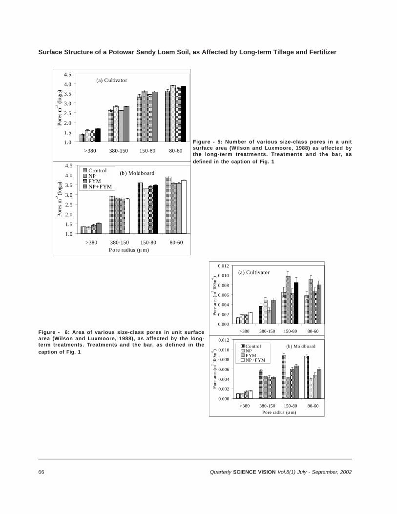
66 Quarterly SCIENCE VISION Vol.8(1) July - September, 2002
(b) Moldboard
1.0
1.5
2.0
2.5
3.0
3.5
4.0
4.5
>380 380-150 150-80 80-60Pore radius (m)
Por
es m
-2 (l
og10
)
ControlNPFYMNP+FYM
(a) Cultivator
1.0
1.5
2.0
2.5
3.0
3.5
4.0
4.5
>380 380-150 150-80 80-60
Por
es m
-2 (
log 1
0)
Figure - 5: Number of various size-class pores in a unitsurface area (Wilson and Luxmoore, 1988) as affected bythe long-term treatments. Treatments and the bar, as
defined in the caption of Fig. 1
(a) Cultivator
0.000
0.002
0.004
0.006
0.008
0.010
0.012
>380 380-150 150-80 80-60
Por
e ar
ea (
m2 1
00m
-2)
(b) Moldboard
0.000
0.002
0.004
0.006
0.008
0.010
0.012
>380 380-150 150-80 80-60
Pore radius (m)
Por
e ar
ea (
m2 1
00m
-2)
ControlNPFYMNP+FYM
Figure - 6: Area of various size-class pores in unit surfacearea (Wilson and Luxmoore, 1988), as affected by the long-term treatments. Treatments and the bar, as defined in thecaption of Fig. 1
Surface Structure of a Potowar Sandy Loam Soil, as Affected by Long-term Tillage and Fertilizer
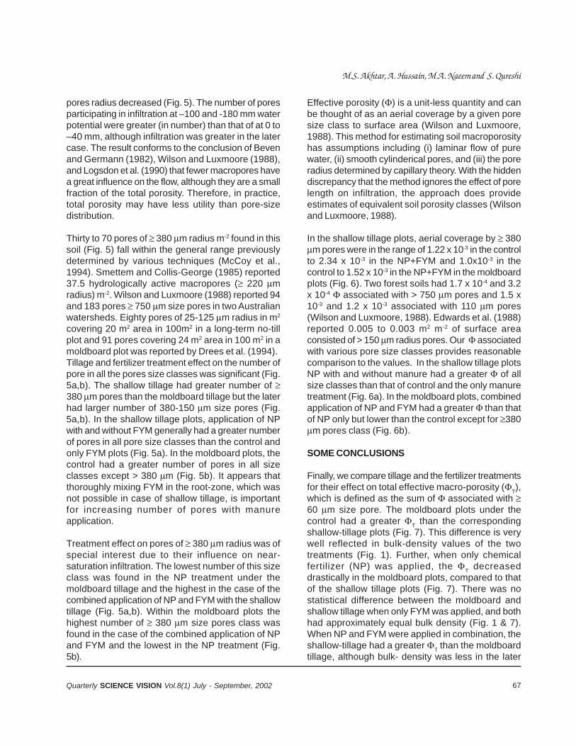
67Quarterly SCIENCE VISION Vol.8(1) July - September, 2002
pores radius decreased (Fig. 5). The number of poresparticipating in infiltration at –100 and -180 mm waterpotential were greater (in number) than that of at 0 to–40 mm, although infiltration was greater in the latercase. The result conforms to the conclusion of Bevenand Germann (1982), Wilson and Luxmoore (1988),and Logsdon et al. (1990) that fewer macropores havea great influence on the flow, although they are a smallfraction of the total porosity. Therefore, in practice,total porosity may have less utility than pore-sizedistribution.
Thirty to 70 pores of 380 m radius m-2 found in thissoil (Fig. 5) fall within the general range previouslydetermined by various techniques (McCoy et al.,1994). Smettem and Collis-George (1985) reported37.5 hydrologically active macropores ( 220 mradius) m-2. Wilson and Luxmoore (1988) reported 94and 183 pores 750 m size pores in two Australianwatersheds. Eighty pores of 25-125 m radius in m2
covering 20 m2 area in 100m2 in a long-term no-tillplot and 91 pores covering 24 m2 area in 100 m2 in amoldboard plot was reported by Drees et al. (1994).Tillage and fertilizer treatment effect on the number ofpore in all the pores size classes was significant (Fig.5a,b). The shallow tillage had greater number of 380 m pores than the moldboard tillage but the laterhad larger number of 380-150 m size pores (Fig.5a,b). In the shallow tillage plots, application of NPwith and without FYM generally had a greater numberof pores in all pore size classes than the control andonly FYM plots (Fig. 5a). In the moldboard plots, thecontrol had a greater number of pores in all sizeclasses except > 380 m (Fig. 5b). It appears thatthoroughly mixing FYM in the root-zone, which wasnot possible in case of shallow tillage, is importantfor increasing number of pores with manureapplication.
Treatment effect on pores of 380 m radius was ofspecial interest due to their influence on near-saturation infiltration. The lowest number of this sizeclass was found in the NP treatment under themoldboard tillage and the highest in the case of thecombined application of NP and FYM with the shallowtillage (Fig. 5a,b). Within the moldboard plots thehighest number of 380 m size pores class wasfound in the case of the combined application of NPand FYM and the lowest in the NP treatment (Fig.5b).
Effective porosity () is a unit-less quantity and canbe thought of as an aerial coverage by a given poresize class to surface area (Wilson and Luxmoore,1988). This method for estimating soil macroporosityhas assumptions including (i) laminar flow of purewater, (ii) smooth cylinderical pores, and (iii) the poreradius determined by capillary theory. With the hiddendiscrepancy that the method ignores the effect of porelength on infiltration, the approach does provideestimates of equivalent soil porosity classes (Wilsonand Luxmoore, 1988).
In the shallow tillage plots, aerial coverage by 380m pores were in the range of 1.22 x 10⁻³ in the controlto 2.34 x 10⁻³ in the NP+FYM and 1.0x10⁻³ in thecontrol to 1.52 x 10⁻³ in the NP+FYM in the moldboardplots (Fig. 6). Two forest soils had 1.7 x 10⁻⁴ and 3.2x 10⁻⁴ associated with > 750 m pores and 1.5 x10⁻³ and 1.2 x 10⁻³ associated with 110 m pores(Wilson and Luxmoore, 1988). Edwards et al. (1988)reported 0.005 to 0.003 m2 m-2 of surface areaconsisted of > 150 m radius pores. Our associatedwith various pore size classes provides reasonablecomparison to the values. In the shallow tillage plotsNP with and without manure had a greater of allsize classes than that of control and the only manuretreatment (Fig. 6a). In the moldboard plots, combinedapplication of NP and FYM had a greater than thatof NP only but lower than the control except for 380m pores class (Fig. 6b).
SOME CONCLUSIONS
Finally, we compare tillage and the fertilizer treatmentsfor their effect on total effective macro-porosity (T),which is defined as the sum of associated with 60 m size pore. The moldboard plots under thecontrol had a greater T than the correspondingshallow-tillage plots (Fig. 7). This difference is verywell reflected in bulk-density values of the twotreatments (Fig. 1). Further, when only chemicalfertilizer (NP) was applied, the T decreaseddrastically in the moldboard plots, compared to thatof the shallow tillage plots (Fig. 7). There was nostatistical difference between the moldboard andshallow tillage when only FYM was applied, and bothhad approximately equal bulk density (Fig. 1 & 7).When NP and FYM were applied in combination, theshallow-tillage had a greater T than the moldboardtillage, although bulk- density was less in the later
M.S. Akhtar, A. Hussain, M.A. Naeem and S. Qureshi
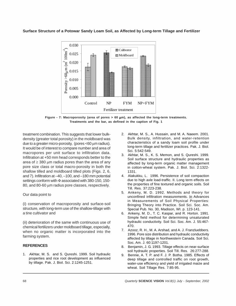
68 Quarterly SCIENCE VISION Vol.8(1) July - September, 2002
0.000
0.005
0.010
0.015
0.020
0.025
0.030
Control NP FYM NP+FYM
Fertilizer treatment
Por
osit
y >
60
m (
m2 1
00m
-2) Cultivator
Moldboard
Figure - 7: Macroporosity (area of pores > 60 m), as affected the long-term treatments.
Treatments and the bar, as defined in the caption of Fig. 1
treatment combination. This suggests that lower bulk-density (greater total porosity) in the moldboard wasdue to a greater micro-porosity, (pores <60 m radius).It would be of interest to compare number and area ofmacropores per unit surface to infiltration data.Infiltration at +50 mm head corresponds better to thearea of 380 m radius pores than the area of anypore size class or total macro-porosity in both theshallow tilled and moldboard tilled plots (Figs. 2, 6,and 7). Infiltration at –40, –100, and –180 mm potentialsettings conform with associated with 380-150, 150-80, and 80-60 m radius pore classes, respectively.
Our data point to
(i) conservation of macroporosity and surface-soilstructure, with long-term use of the shallow-tillage witha tine cultivator and
(ii) deterioration of the same with continuous use ofchemical fertilizers under moldboard tillage, especially,when no organic matter is incorporated into thefarming system.
REFERENCES
1. Akhtar, M. S. and S. Qureshi. 1999. Soil hydraulicproperties and rice root development as influencedby tillage. Pak. J. Biol. Sci. 2:1245-1251.
2. Akhtar, M. S., A. Hussain, and M. A. Naeem. 2001.Bulk density, infi ltration, and water-retentioncharacteristics of a sandy loam soil profile underlong-term tillage and fertilizer practices. Pak. J. Biol.Sci. 5:542-549.
3. Akhtar, M. S., K. S. Memon, and S. Qureshi. 1999.Soil surface structure and hydraulic properties asaffected by long-term organic matter managementin cotton-wheat system. Pak. J. Biol. Sci. 2:1322-1331.
4. Alakukku, L. 1996. Persistence of soil compactiondue to high axle load-traffic. II. Long term effects onthe properties of fine textured and organic soils. SoilTill. Res. 37:223-238.
5. Ankeny, M. D. 1992. Methods and theory forunconfined infiltration measurements. In Advancesin Measurements of Soil Physical Properties:Bringing Theory into Practice. Soil Sci. Soc. Am.Special Pub. No. 30, Madison, WI. p. 123-141.
6. Ankeny, M. D., T. C. Kaspar, and R. Horton. 1991.Simple field method for determining unsaturatedhydraulic conductivity. Soil Sci. Soc. Am. J. 55:467-470.
7. Azooz, R. H., M. A. Arshad, and A. J. Franzluebbers.1996. Pore size distribution and hydraulic conductivityaffected by tillage in Northwestern Canada. Soil Sci.Soc. Am. J. 60:1197-1201.
8. Benjamin, J. G. 1993. Tillage effects on near-surfacesoil hydraulic properties. Soil Till. Res. 26:277-288.
9. Bennie, A. T. P. and F. J. P. Botha. 1985. Effects ofdeep tillage and controlled traffic on root growth,water-use efficiency and yield of irrigated maize andwheat. Soil Tillage Res. 7:85-95.
Surface Structure of a Potowar Sandy Loam Soil, as Affected by Long-term Tillage and Fertilizer

69Quarterly SCIENCE VISION Vol.8(1) July - September, 2002
10. Beven, K. and P. Germann. 1982. Macropores andwater flow in soils. Water Resour. Res. 18:1311-1325.
11. Bouma, J. 1991. Influence of soil macroporosity onenvironmental quality. Adv. Agron. 46:1-39.
12. Carter, M. R. 1992. Characterizing the soil physicalcondition in reduced tillage systems for winter wheaton a fine sandy loam using small cores. Can. J. SoilSci. 72, 395-402.
13. Chang, C. and C. W. Lindwall. 1992. Effects of tillageand crop rotation on physical properties of loam soil.Soil Till. Res. 22:383-389.
14. Danielson, R. E., and P. L. Sutherland. 1986. Porosity.In: A. Klute (Ed.), Methods of Soil Analysis. Part 1.Physical and Mineralogical Methods, 2nd ed.Agronomy 9. American Society of Agronomy, Madison,WI. p. 443-461.
15. Darwish, O. H., N. Persaud, and D. C. Martens. 1995.Effect of long-term application of animal manure onphysical properties of 3 soils. Plant and Soil 176:289-295.
16. Dexter, A. R. 1986. Model experiments on thebehavior of roots at the interface between a tilledseed-bed and a compacted sub-soil. (1) Effects ofseed-bed aggregated size and sub-soil strength onwheat roots. Plant and Soil 95:123-133.
17. Doran, J. W. 1980. Soil microbial and biochemicalchanges associated with reduced tillage. Soil Sci.Soc. Am. J. 44:765-771.
18. Drees, L. R., A. D. Karathanasis, L. P. Wilding, andR. L. Blevins. 1994. Micromorphologicalcharacteristics of long-term no-till and conventionallytilled soils. Soil Sci. Soc. Am. J. 58:508-517.
19. Edwards, W. M., L. D. Norton, and C. E. Redmond.1988. Characterizing macropores that affectinfiltration into non-tilled soil. Soil Sci. Soc. Am. J.52:483-487.
20. Gill, S. M., M. S. Akhtar, and Z. Saeed. 2000. Soilwater use and bulk density as affected by tillage andfertilizer in rain-fed wheat production system. Pak. J.Biol. Sci. 3:1223-1226.
21. Heard, J. R., E. J. Kladivko, and J. V. Mannering.1988. Soil macroporosity, hydraulic conductivity andair permeability of silty soils under long-termconservation tillage in Indiana. Soil Till. Res. 11:1-18.
22. Hill, R. L., R. Horton, and R. M. Curse. 1985. Tillageeffects on soil water retention and pore sizedistribution of two Mollisols. Soil Sci. Soc. Am. J.49:1264-1270.
23. Jarvis, N. J. and I. Messing. 1995. Near-saturatedhydraulic conductivity in soils of contrasting texturemeasured by tension infiltrometer. Soil Sci. Soc. Am.J. 59:28-34.
24. Khanzada, S. K. 1976. Soils and land capability ofPakistan Agricultural Research Center, Islamabad.Soil Survey of Pakistan. Multan Road, Lahore.
25. Logsdon, S. D., R. Allmaras, R. L. Wu, and J. B.Randall. 1990. Macroporosity and its relation tosaturated hydraulic conductivity under different tillagepractices. Soil Sci. Soc. Am. J. 54:1096-1101.
26. Mbagwu, J. S. C. 1992. Improving the productivity ofa degraded Ultisol in Nigeria using organic andinorganic amendments. Part 2: Changes in soilproperties. Bioresource-Technology 42:167-177.
27. McCoy, E. L., C. W. Boast, R. C. Stehouwer, and E. J.Kladivko. 1994. Macropore hydraulics: Taking asledgehammer to classical theory. Adv. Soil Sci.47:303-348.
28. Norton, L. D. 1987. Micromorphological study ofsurface seals developed under simulated rainfallconditions. Geoderma 40:127-140.
29. Obi, M. E. and P. O. Ebo. 1995. The effects of organicand inorganic amendments on soil physicalproperties and maize production in a severelydegraded sandy soil in southern Nigeria. Bio-resource Technology 51:117-123.
30. Ohu, J. O., E. I. Ekwue, and O. A. Folorunso. 1994.The effect of addition of organic matter on thecomposition of a vertisol from northern Nigeria. SoilTechnology 7:155-162.
31. Pikul, J. L. and J. F. Zuzel. 1994. Soil crusting andwater infiltration affected by long-term tillage andresidue management. Soil Sci. Soc. Am. J. 58:1524-1530.
32. Razzaq, A., N. Hashmi, I. B. Khan, B. R. Khan, and P.R. Hobbs. 1989. Wheat in Barani areas of northernPunjab: A synthesis of on-farm research results1982-1988. PARC/CIMMYT Paper 90-2. CoordinatedWheat Program, Pak. Agri. Res. Council, Islamabad.
33. Reynolds, W. D., D. E. Elrick, and B. E. Clotheir. 1985.The constant head permeameter. Effect onunsaturated flow. Soil Sci. 139:172-180.
34. SAS Institute. 1992. SAS User’s guide: Statistics.SAS Institute Cary, NC.
35. Singh, P., R. S. Kanwar, and M. L. Thompson. 1991.Macropore characterization for two tillage systemsusing resin-impregnation technique. Soil Sci. Soc.Am. J. 55:1674-1679.
36. Smettem, K.R.J., and N. Collis-George. 1985.Statistical characterization of soil biopores using asoil peel method. Geoderma 36:27-36.
37. Soane, B. D. 1990. The role of organic matter in soilcompactibilty: A review of some practical aspects.Soil Till. Res. 16:179-201.
38. Sommerfeldt, T. G. and C. Chang. 1985. Changes insoil properties under annual applications of feedlotmanure and different tillage practices. Soil Sci. Soc.Am. J. 49:983-986.
M.S. Akhtar, A. Hussain, M.A. Naeem and S. Qureshi

70 Quarterly SCIENCE VISION Vol.8(1) July - September, 2002
39. Sur, H. S., A. S. Sidhu, R. Singh, G. C. Aggarwal, andK. S. Sandhu. 1993. Long-term effect of greenmanuring on soils physical properties and productionpotential in green manure-maize-wheat sequence.Annals of Agric. Res. 14:125-131.
40. Watson, K. W., and R. L. Luxmoore. 1986. Estimatingmacroporosity in a forest water by use of a tensioninfiltrometer. Soil Sci. Soc. Am. J. 50:578-582.
41. White, I., and M. J. Sully. 1987. Macroscopic andmicroscopic capillary length and time scale from fieldinfiltration. Water Resour. Res. 23:1514-1522.
42. White, I., M. J. Sully, and K. M. Perroux. 1992.Measurement of surface-soil hydraulic properties:
disk permeameters, tension infiltrometers, and othertechniques. In G. C. Topp et al. (Eds.), Advances inMeasurement of Soil Physical Properties: BringingTheory into Practice. Spec. Pub. 30. Soil Sci. Soc.Am. Madison, WI. pp. 69-103.
43. Wilson, G. V., and R. J. Luxmoore. 1988. Infiltrationmacroporosity, and mesoporosity distribution on twowatersheds. Soil Sci. Soc. Am. J. 52:329-335.
44. Wooding, R. A. 1968. Steady infiltration from ashallow circular pond. Water Resour. Res. 4:1259-1273.
Surface Structure of a Potowar Sandy Loam Soil, as Affected by Long-term Tillage and Fertilizer
71Quarterly SCIENCE VISION Vol.8(1) July - September, 2002
THE EFFECT OF SUGAR ON SETTING-TIME OFVARIOUS TYPES OF CEMENTS
Bazid Khan* andBulent Baradan**
ABSTRACT
The objective of this research is to investigate theinfluence of sugar s of different origins (Beet & Cane)on the setting times of cement pastes. Sugar isincorporated with three different types of cementsunder three different curing conditions (Temp. &R.Humidity).
The test results revealed that, under normal curingconditions (Temp.=220C & R.H.60%), the efficiencyof sugar in retarding cement setting becomes higherwith increasing sugar-content upto a certain limit.However, with further increase in sugar content, itsretarding efficiency started to decrease, until at certainhigher content it showed reverse effects (i.e, itaccelerated the cement setting). Furthermore, sugarcauses higher retardation when added a few minutesafter the mixing of water and cement.
INTRODUCTION
When water is added to cement, it sets and hardensgradually under normal climatic conditions. But insome countries, including Pakistan, higher summertemperatures, low relative humidity and hot windblowing cause rapid evaporation of water from the freshconcrete surface. Consequently concrete sets earlierand no proper time is left available for concretingoperations. For example, it has been reported that,when the temperature of cement mortar wit a water/cement (w/c) ratio of 0.6 is increased from 27.80C to45.50C both the initial and final setting times are nearlyhalved1. Further problems also arise such as rapiddecrease of slump2, formation of cold joints and plasticshrinkage cracking3, increased difficulty in airentrainment2, enhanced permeability and reduceddurability4, corrosion of steel5, and reduction in ultimatestrength of concrete6.
Inorder to provide proper time for concreting operation,especially when unavoidable delays between mixingand placing occur, and to save concrete from otherdetrimental effects of adverse climatic conditions,cement set retardation/or use of retarding admixtures
* Assistant Professor B-Tech, Civil, Govt. College of Technology, Peshawar. ** Faculty of Civil Engieering, Dokuz Eulul University, Izmir,Turkey.
is necessary. “ An admixture is a material other thanwater, aggregates, hydraulic cement and fiberreinforcement, used as an ingredient of concrete ormortar and added to a batch before or during mixing.A retarding admixture/retarder is an admixture thatretards the setting of cement concrete, mortar orgrout7”.
A retarding admixture causes cement set retardationby the following mechanisms:
1) Adsorption of the retarding compound on thesurface of cement particles, forming a protectiveskin, which slows down hydrolysis;
2) Adsorption of the retarding compound onto nucleiof calcium hydroxide, poisoning their growth,which is essential for continued hydration ofcement after the end of induction period;
3) Formation of complexes with calcium ions insolution, increasing their solubility anddiscouraging the formation of the nuclei of calciumhydroxide, refereed to in (2);
4) Precipitation around cement particles of insolublederivatives of the retarding compounds formed byreaction with the highly alkaline aqueous solution,forming a protective skin8.
Retarding admixtures are mainly based on materialshaving lignosulfonic acids and their salts, hydroxy-carboxylic acids and their salts, sugar and theirderivatives and inorganic salts, such as borates;phosphates, zinc and lead salts9.
Sugar is a carbohydrate, a substance composed ofonly carbon, oxygen and hydrogen. Sucros, fructose,dextrose, lactose and other ‘Oses’ are members ofthis chemical class. It occurs in sugar cane and sugarbeet. The basic unit of carbohydrate is a linear chainof four to seven carbon atoms with a hydoxyl groupon each one, the terminal carbon being an aldehyde.
Owing to the retardation of ordinary Portland cement,sugar falls into three categories: non-retarding, goodretarders and most effective retarders. The non-reducing sugars, -methyl glucoside and -trehalose, are effectively non-retarding; the reducing
72 Quarterly SCIENCE VISION Vol.8(1) July - September, 2002
sugars, glucose; maltose, lactose and celloboise, aregrouped together as good retarders, while the non-rdeucing sugars (which have a five-member ring)sucrose and raffinose are far the most effectiveretarders. Sugars have been categorized as ‘cementdestroyer’ and when small amounts of sugar (1% byweight of cement) are added to Portland cement pasteat the onset of mixing, hardening may be delayedindefinetly10.
The retarding action of sugar is probably by theprevention of the formation of calcium silicate hydrate(CSH)2.
EXPERIMENTAL PROGRAM
Materials: Two types of sugars of different origins(sugar beet & sugar cane) and three different types ofcements, designated as PKC/A42.5, PKC/B32.5 andPC42.5 (According to Turkish Standard No.20), wereused. Their oxide and compound compositions areshown in Table 1.0.
Table - 1.0: Oxide and Compound composition of cements Name Abbreviation PKC/A 42.5 PKC/B 42.5 PC 42.5 Silica Sio2 23.79 33.06 19.30 Alumina Al2O3 6.33 7.43 5.38 Ferric oxide Fe2O3 3.52 3.33 2.89 Lime CaO 57.20 45.03 62.78 Magnesia MgO 0.69 0.90 1.66 Sodium Na2O - 0.10 0.55 Potassium K2O 1.03 1.46 0.75 Sulfuric Anhydride SO3 2.00 2.07 3.17 Chlorine CL- 0.019 0.0266 0.0089 Loss on ignition L.O.I 2.14 4.21 3.29 Undetermined - 3.28 - - % Free lime % F.CaO 1.37 0.39 0.77 Insoluble residue I.R - 29.06 0.42 Soundness (mm) - 2.00 3 1.00 Specific gravity - 3.03 - 3.08 Weight per liter (g/lt) - 984 910 1050 Fineness-specific surface (cm2/g)
- 3661 4963 3759
Lime saturation factor L.S.F.
- 196.35 99.15
Hydraulic modulus H.M. - 3.05 2.31 Silica modulus S.M. - 0.37 2.29 Alumina modulus A.M. - 2.23 1.86 Tricalcium silicate C3S - - 59.51 Dicalcium silicate C2S - - 10.76 Tricalcium aluminate C3A - - 9.37 Tetracalcium aluminoferrite
C4AF - - 8.79
The Effect of Sugar on Setting-Time of Various Types of Cements

73Quarterly SCIENCE VISION Vol.8(1) July - September, 2002
Procedure
The setting time tests were performed on cement paste of standard consistency. The quantity of cement andwater used per test for each type of cement are:
Type of cement Amount of cement9g) Water (ml) w/c ratio PKC/A42.5 400 130 32.50 PKC/B32.5 385 130 33.75 PC42.5 400 110 27.50
For one type of tests, the sugar was dissolved in themixing water before adding it to cement. Vicatapparatus was used and Turkish Standard(TS) No.19was followed for taking initial and final setting-timesreadings. According to TS-19, initial set is said tohave taken place when the needle(1.13mm dia.) ofVicat apparatus ceases to pass 3-5 mm above thebottom of cement paste taken in a Vicat mould (topinternal dia.= 80mm, bottom int. dia.= 90mm, height= 40mm). Final setting is said to have occurred whenthe needle penetrates the cement paste to a maximumdepth of 1mm. In both the cases, the setting-time isreckoned from the moment when the mixing-water isadded to the cement.
For other type of tests, half of the mixing-watercontaining no sugar was added to the cement and inthe remaining half of the mixing-water, sugar wasdissolved and added, 10 minutes later on, to thecement.
Curing Conditions
Inorder to simulate the approximate outdoors climaticconditions, the following three categories of curingconditions were provided, to the test specimens:
1) Curing condition first (CC-I): Temperature = 220C,Relative Humidity = 55-65%
2) Curing condition second (CC-II): Temperature =350C, Relative Humidity = 35-45%
3) Curing condition third (CC-I): Temperature = 500C,Relative Humidity = 25-35%
Test Data And Presentation Of Results
Setting-time tests with varying sugar-contents(expressed as a percentage by weight of cement) wereperformed, under the specified curing conditions. Theaverage of three test readings was taken as the finalreading. These are shown in the following Tables 1.1to 1.9 and Figures 2.1 to 2.6 together with Tables1.10, 1.11 and Figs. 1.7 and 1.8 for effect of stage ofsugar incorporation and of cane sugar and beet-sugar.
Table - 1.1: Setting time and relative retarding effects of sugar on cement setting under CC-I Sugar (%) 00
0 0.04
0.05 0.06 0.70 0.10 0.20 0.25 0.30 0.4/0.5
Initial setting time(mins)
143
292
325 512 660 840 590 260 42 20
Final setting time(mints)
204
364
402 569 720 960 790 649 72 40
Initial set retardation 1 2.04
2.27 3.58 4.62 5.87 4.13 1.82 0.29 0.14
Final set retardation 1 1.78
1.97 2.79 3.53 4.71 3.87 3.18 0.35 0.20
The results of Table 1.1 are graphically shown in Figures 1.1 and 1.2.
A) RESULTS FOR CEMENT PKC/A42.5
Bazid Khan and Bulent Baradan
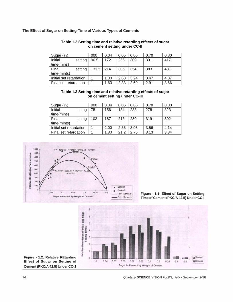
74 Quarterly SCIENCE VISION Vol.8(1) July - September, 2002
Table 1.2 Setting time and relative retarding effects of sugar on cement setting under CC-II
Sugar (%) 000 0.04 0.05 0.06 0.70 0.80 Initial setting time(mins)
96.5 172 256 309 331 417
Final setting time(mints)
131.5 214 306 354 383 481
Initial set retardation 1 1.80 2.68 3.24 3.47 4.37 Final set retardation 1 1.63 2.33 2.69 2.91 3.66
Table 1.3 Setting time and relative retarding effects of sugar on cement setting under CC-III
Sugar (%) 000 0.04 0.05 0.06 0.70 0.80 Initial setting time(mins)
78 156 184 238 278 323
Final setting time(mints)
102 187 216 280 319 392
Initial set retardation 1 2.00 2.36 3.05 3.56 4.14 Final set retardation 1 1.83 21.2 2.75 3.13 3.84
The Effect of Sugar on Setting-Time of Various Types of Cements
Figure - 1.1: Effect of Sugar on SettingTime of Cement (PKC/A 42.5) Under CC-I
Figure - 1.2: Relative REtardingEffect of Sugar on Setting of
Cement (PKC/A 42.5) Under CC-1
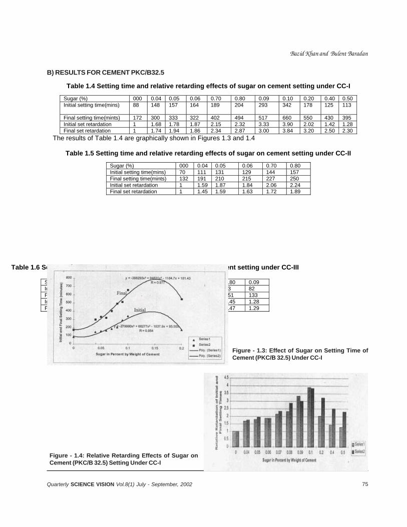
75Quarterly SCIENCE VISION Vol.8(1) July - September, 2002
Table 1.6 Setting time and relative retarding effects of sugar on cement setting under CC-III
Sugar (%) 000 0.04 0.05 0.06 0.70 0.80 0.09 Initial setting time(mins) 64 83 95 94 98 93 82 Final setting time(mints) 103 131 144 146 150 151 133 Initial set retardation 1 1.30 1.48 1.47 1.53 1.45 1.28 Final set retardation 1 1.27 1.40 1.42 1.46 1.47 1.29
Bazid Khan and Bulent Baradan
Table 1.4 Setting time and relative retarding effects of sugar on cement setting under CC-I
Sugar (%) 000 0.04 0.05 0.06 0.70 0.80 0.09 0.10 0.20 0.40 0.50 Initial setting time(mins) 88 148 157 164 189 204 293 342 178 125 113
Final setting time(mints) 172 300 333 322 402 494 517 660 550 430 395 Initial set retardation 1 1.68 1.78 1.87 2.15 2.32 3.33 3.90 2.02 1.42 1.28 Final set retardation 1 1.74 1.94 1.86 2.34 2.87 3.00 3.84 3.20 2.50 2.30
The results of Table 1.4 are graphically shown in Figures 1.3 and 1.4
Table 1.5 Setting time and relative retarding effects of sugar on cement setting under CC-II
Sugar (%) 000 0.04 0.05 0.06 0.70 0.80 Initial setting time(mins) 70 111 131 129 144 157 Final setting time(mints) 132 191 210 215 227 250 Initial set retardation 1 1.59 1.87 1.84 2.06 2.24 Final set retardation 1 1.45 1.59 1.63 1.72 1.89
B) RESULTS FOR CEMENT PKC/B32.5
Figure - 1.3: Effect of Sugar on Setting Time ofCement (PKC/B 32.5) Under CC-I
Figure - 1.4: Relative Retarding Effects of Sugar onCement (PKC/B 32.5) Setting Under CC-I
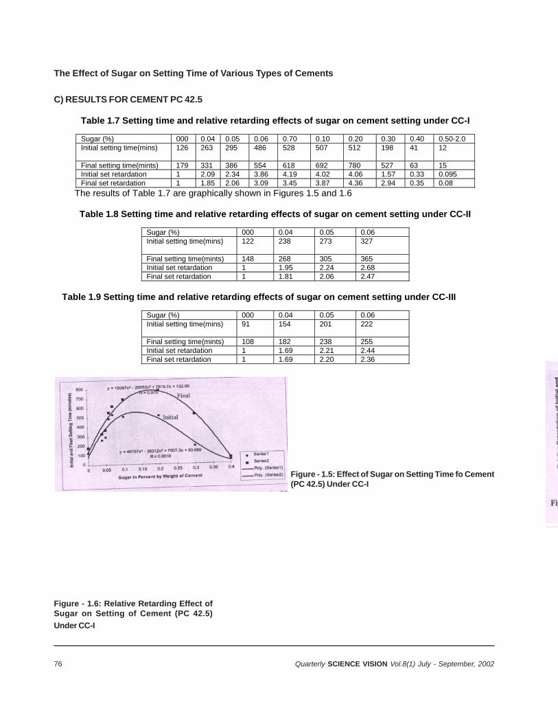
76 Quarterly SCIENCE VISION Vol.8(1) July - September, 2002
The Effect of Sugar on Setting Time of Various Types of Cements
C) RESULTS FOR CEMENT PC 42.5
Table 1.7 Setting time and relative retarding effects of sugar on cement setting under CC-I
Sugar (%) 000 0.04 0.05 0.06 0.70 0.10 0.20 0.30 0.40 0.50-2.0 Initial setting time(mins) 126 263 295 486 528 507 512 198 41 12
Final setting time(mints) 179 331 386 554 618 692 780 527 63 15 Initial set retardation 1 2.09 2.34 3.86 4.19 4.02 4.06 1.57 0.33 0.095 Final set retardation 1 1.85 2.06 3.09 3.45 3.87 4.36 2.94 0.35 0.08
The results of Table 1.7 are graphically shown in Figures 1.5 and 1.6
Table 1.8 Setting time and relative retarding effects of sugar on cement setting under CC-II
Sugar (%) 000 0.04 0.05 0.06 Initial setting time(mins) 122 238 273 327
Final setting time(mints) 148 268 305 365 Initial set retardation 1 1.95 2.24 2.68 Final set retardation 1 1.81 2.06 2.47
Table 1.9 Setting time and relative retarding effects of sugar on cement setting under CC-III
Sugar (%) 000 0.04 0.05 0.06 Initial setting time(mins) 91 154 201 222
Final setting time(mints) 108 182 238 255 Initial set retardation 1 1.69 2.21 2.44 Final set retardation 1 1.69 2.20 2.36
Figure - 1.5: Effect of Sugar on Setting Time fo Cement(PC 42.5) Under CC-I
Figure - 1.6: Relative Retarding Effect ofSugar on Setting of Cement (PC 42.5)
Under CC-I
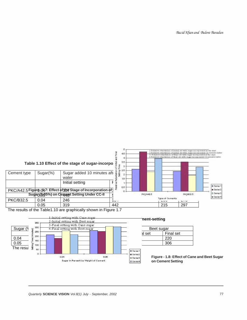
77Quarterly SCIENCE VISION Vol.8(1) July - September, 2002
Bazid Khan and Bulent Baradan
Table 1.10 Effect of the stage of sugar-incorporation in cement on cement setting
Cement type Sugar(%) Sugar added 10 minutes after mixing of cement and
water Sugar added at start
Initial setting Final setting Initial Final
PKC/A42.5 0.04 307 354 173 215 0.05 448 514 255 306 PKC/B32.5 0.04 246 334 200 273 0.05 319 442 215 297 The results of the Table1.10 are graphically shown in Figure 1.7
Table 1.11 Effect of Cane sugar and Beet sugar on cement-setting
Sugar (%) Cane sugar Beet sugar Initial set Final set Initial set Final set 0.04 217 263 176 220 0.05 266 311 256 306
The results of Table 1.11 are graphically shown in Figure 1.8
Figure - 1.7: Effect of the Stage of Incorporation ofSugar (0.05%) on Cement Setting Under CC-II
Figure - 1.8: Effect of Cane and Beet Sugaron Cement Setting

78 Quarterly SCIENCE VISION Vol.8(1) July - September, 2002
CONCLUSIONS & FURTHER RESEARCHSUGGESTIONS
Conclusions:
1) Setting of cement was retarded by incorporationof sugar in cement under all conditions of curing.Consequently, setting-times were extended. Theextension in setting-time was increasing with anincrease in sugar content up to a certain limit(0.15%) and then started to drop with furtherincrease in sugar content. Sugar accelerated thecement-setting when a higher sugarcontent(0.3%) was used
2) Relatively low retarding tendency was shown bysugar under the second and third curingconditions.
3) 0.15% sugar-content acted as an Optimum SugarContent for retarding the setting.
It was further noted that:
a) Practically same retarding tendency wasshown by both Cane sugar and Beet sugar.
b) Increased retardation was caused by sugarwhen it was added to the cement a fewminutes after mixing of cement and water.
c) The effect of sugar on cement setting isdependent upon the chemical composition ofcement.
Following are some suggestions for furtherresearch:
There is need to examine other physical and chemicalproperties of sugar-incorporated cement pastes/mortars, such as strength, shrinkage, permeability,etc.
REFERENCES
1. Fattuhi N.I. (1988). The setting of mortar mixessubjected to different temperatures. An InternationalJournal of Cement and Concrete Research, Vol.15,No.1.
2. Neville A.M.(1995). Properties of concrete(2nd.ED)Longman Group Limited.
3. Portland Cement Association (1968). Design andControl of Concrete Mixes (11th.ED) 5420Old OrchardRoad, Skokie, Illions 60076.
4. Kjellsen K.O., Det Wilter J.R. & Gjrv E.O. (1990).Pore structure of plain cement pastes hydrated atdifferent temperatures. An International Journal ofCement and Concrete Research, Vol.20, No.6.
5. Maslehuddin M., Page C.L. & Rasheeduzzfar (1997).Temperature effects on the pore solution chemistryin contaminated cements. Magazine of ConcreteResearch, Vol.49, No.178.
6. Al-Gahtani H.J.; Abbasi A-G.F. & Al-Moudi O.S.B.(1998). Concrete mixing design for hot weather:Experimental and statistical analysis. Magazine ofConcrete Research, Vol.50, No.2.
7. ASTM Standards for cement and concrete, 19828. Banfil P.F.G. & Saunders D.C. (1986). The
relationship between the sorption of organiccompounds and cement and the retardation ofhydration. An International Journal of Cement andConcrete Research, Vol.6, No.3.
9. Erdogan T.Y. (1997). Admixtures for Concrete, MiddleEast Technical University Ankara-Turkey.
10. Thomas N.L. & Birchall J.D. (1983) The retardingaction of sugars on cement hydration. AnInternational Journal of Cement and ConcreteResearch, Vol.13, No.6.
The Effect of Sugar on Setting-Time of Various Types of Cements
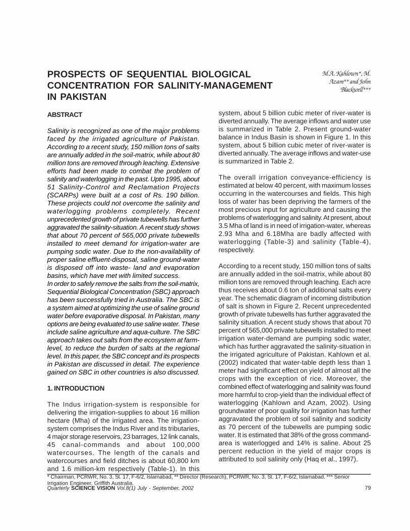
79Quarterly SCIENCE VISION Vol.8(1) July - September, 2002
PROSPECTS OF SEQUENTIAL BIOLOGICALCONCENTRATION FOR SALINITY-MANAGEMENTIN PAKISTAN
M.A. Kahlown*, M.Azam** and John
Blackwell***
ABSTRACT
Salinity is recognized as one of the major problemsfaced by the irrigated agriculture of Pakistan.According to a recent study, 150 million tons of saltsare annually added in the soil-matrix, while about 80million tons are removed through leaching. Extensiveefforts had been made to combat the problem ofsalinity and waterlogging in the past. Upto 1995, about51 Salinity-Control and Reclamation Projects(SCARPs) were built at a cost of Rs. 190 billion.These projects could not overcome the salinity andwaterlogging problems completely. Recentunprecedented growth of private tubewells has furtheraggravated the salinity-situation. A recent study showsthat about 70 percent of 565,000 private tubewellsinstalled to meet demand for irrigation-water arepumping sodic water. Due to the non-availability ofproper saline effluent-disposal, saline ground-wateris disposed off into waste- land and evaporationbasins, which have met with limited success.In order to safely remove the salts from the soil-matrix,Sequential Biological Concentration (SBC) approachhas been successfully tried in Australia. The SBC isa system aimed at optimizing the use of saline groundwater before evaporative disposal. In Pakistan, manyoptions are being evaluated to use saline water. Theseinclude saline agriculture and aqua-culture. The SBCapproach takes out salts from the ecosystem at farm-level, to reduce the burden of salts at the regionallevel. In this paper, the SBC concept and its prospectsin Pakistan are discussed in detail. The experiencegained on SBC in other countries is also discussed.
1. INTRODUCTION
The Indus irrigation-system is responsible fordelivering the irrigation-supplies to about 16 millionhectare (Mha) of the irrigated area. The irrigation-system comprises the Indus River and its tributaries,4 major storage reservoirs, 23 barrages, 12 link canals,45 canal-commands and about 100,000watercourses. The length of the canals andwatercourses and field ditches is about 60,800 kmand 1.6 million-km respectively (Table-1). In this* Chairman, PCRWR, No. 3, St. 17, F-6/2, Islamabad, ** Director (Research), PCRWR, No. 3, St. 17, F-6/2, Islamabad. *** SeniorIrrigation Engineer, Griffith Australia.
system, about 5 billion cubic meter of river-water isdiverted annually. The average inflows and water useis summarized in Table 2. Present ground-waterbalance in Indus Basin is shown in Figure 1. In thissystem, about 5 billion cubic meter of river-water isdiverted annually. The average inflows and water-useis summarized in Table 2.
The overall irrigation conveyance-efficiency isestimated at below 40 percent, with maximum lossesoccurring in the watercourses and fields. This highloss of water has been depriving the farmers of themost precious input for agriculture and causing theproblems of waterlogging and salinity. At present, about3.5 Mha of land is in need of irrigation-water, whereas2.93 Mha and 6.18Mha are badly affected withwaterlogging (Table-3) and salinity (Table-4),respectively.
According to a recent study, 150 million tons of saltsare annually added in the soil-matrix, while about 80million tons are removed through leaching. Each acrethus receives about 0.6 ton of additional salts everyyear. The schematic diagram of incoming distributionof salt is shown in Figure 2. Recent unprecedentedgrowth of private tubewells has further aggravated thesalinity situation. A recent study shows that about 70percent of 565,000 private tubewells installed to meetirrigation water-demand are pumping sodic water,which has further aggravated the salinity-situation inthe irrigated agriculture of Pakistan. Kahlown et al.(2002) indicated that water-table depth less than 1meter had significant effect on yield of almost all thecrops with the exception of rice. Moreover, thecombined effect of waterlogging and salinity was foundmore harmful to crop-yield than the individual effect ofwaterlogging (Kahlown and Azam, 2002). Usinggroundwater of poor quality for irrigation has furtheraggravated the problem of soil salinity and sodicityas 70 percent of the tubewells are pumping sodicwater. It is estimated that 38% of the gross command-area is waterlogged and 14% is saline. About 25percent reduction in the yield of major crops isattributed to soil salinity only (Haq et al., 1997).

80 Quarterly SCIENCE VISION Vol.8(1) July - September, 2002
Table-1: M ain Features of Indus Irrigation System Item Q uantity
Storage reservoirs Live capacity (designed)
4
19.3 Bm 3 Barrages, headworks and s iphons 23 M ain irrigation canals Com m and area Length (including d istribution system )
45 16.67 M ha 60,800 Km
Farm ers W atercourses Length
100,000 1.6 m illion Km
Source: Tarar, 1999
Table-2: Average Inflow s and W ater U se in the Indus Basin W ater Inflow Q uantity (Bm 3) Percent of Total
Inflows in to the system from rivers and tributaries 194 100 D iversions to canals 131 68 O utflow to the sea 48 25 System losses 15 7
Source: Tarrar, 1999
Table-3: Area Affected by W aterlogging in the Indus Plain W atertable (m )
Province Total Com m and Area
(M ha) 0-1.5 1.5-3 Punjab 9.95 0.62 1.89 S indh and Balochistan 6.15 2.28 2.99 NW FP 0.57 0.03 0.15 Total 16.67 2.93 5.03 Source: SM O , W APDA (1999) and M INFAL (2002)
Table-4: Area Affected by Salinity in Pakistan Saline Area (M ha)
Provinces G eographical Area
(M ha) Cultivated Area
(M ha) Cultivated Uncultivated Total Punjab 20.63 12.35 1.51 1.16 2.67 S indh 14.09 5.88 1.15 0.96 2.11 Balochistan 10.17 1.86 0.11 1.24 1.35 NW FP & FATA 34.72 2.07 0.03 0.02 0.05 Total 79.61 22.16 2.80 3.38 6.18 Source: M INFAL (2002)
Table-5: Com pleted Drainage Projects
Province Projects
com pleted Protected
Area (M ha) Salient Features
Cost (Rs. In B illion )
Punjab and Azad Jam m u & Kashm ir
25 3.561 Tubewells Surface drains
15,222 No. 2,346 Km
8.558
Sindh 17 2.220 Tubewells Surface drains T ile Drains
4,788 No. 7,153 Km 13,760 ha
6.866
NW FP 7 0.046 Tubewells Surface Drains Canal Rem odeling T ile drains
491 N o. 901 Km 166 Km 28,906 ha
3.667
Balochistan 2 0.172 Surface Drains 2 Km 0.135 Total 51 5.999 Tubewells
Surface Drains Canal Rem odeling T ile drains
20,501 N o 10,402 Km 166 Km 42,666 ha
19.226
Source: Tarar, 1995
Prospects of Sequential Biological Concentration for Salinity-Management in Pakistan
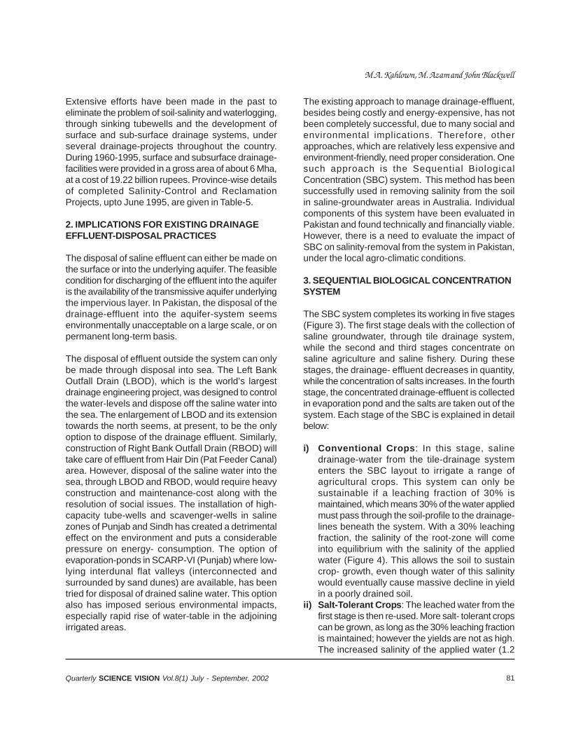
81Quarterly SCIENCE VISION Vol.8(1) July - September, 2002
Extensive efforts have been made in the past toeliminate the problem of soil-salinity and waterlogging,through sinking tubewells and the development ofsurface and sub-surface drainage systems, underseveral drainage-projects throughout the country.During 1960-1995, surface and subsurface drainage-facilities were provided in a gross area of about 6 Mha,at a cost of 19.22 billion rupees. Province-wise detailsof completed Salinity-Control and ReclamationProjects, upto June 1995, are given in Table-5.
2. IMPLICATIONS FOR EXISTING DRAINAGEEFFLUENT-DISPOSAL PRACTICES
The disposal of saline effluent can either be made onthe surface or into the underlying aquifer. The feasiblecondition for discharging of the effluent into the aquiferis the availability of the transmissive aquifer underlyingthe impervious layer. In Pakistan, the disposal of thedrainage-effluent into the aquifer-system seemsenvironmentally unacceptable on a large scale, or onpermanent long-term basis.
The disposal of effluent outside the system can onlybe made through disposal into sea. The Left BankOutfall Drain (LBOD), which is the world’s largestdrainage engineering project, was designed to controlthe water-levels and dispose off the saline water intothe sea. The enlargement of LBOD and its extensiontowards the north seems, at present, to be the onlyoption to dispose of the drainage effluent. Similarly,construction of Right Bank Outfall Drain (RBOD) willtake care of effluent from Hair Din (Pat Feeder Canal)area. However, disposal of the saline water into thesea, through LBOD and RBOD, would require heavyconstruction and maintenance-cost along with theresolution of social issues. The installation of high-capacity tube-wells and scavenger-wells in salinezones of Punjab and Sindh has created a detrimentaleffect on the environment and puts a considerablepressure on energy- consumption. The option ofevaporation-ponds in SCARP-VI (Punjab) where low-lying interdunal flat valleys (interconnected andsurrounded by sand dunes) are available, has beentried for disposal of drained saline water. This optionalso has imposed serious environmental impacts,especially rapid rise of water-table in the adjoiningirrigated areas.
The existing approach to manage drainage-effluent,besides being costly and energy-expensive, has notbeen completely successful, due to many social andenvironmental implications. Therefore, otherapproaches, which are relatively less expensive andenvironment-friendly, need proper consideration. Onesuch approach is the Sequential BiologicalConcentration (SBC) system. This method has beensuccessfully used in removing salinity from the soilin saline-groundwater areas in Australia. Individualcomponents of this system have been evaluated inPakistan and found technically and financially viable.However, there is a need to evaluate the impact ofSBC on salinity-removal from the system in Pakistan,under the local agro-climatic conditions.
3. SEQUENTIAL BIOLOGICAL CONCENTRATIONSYSTEM
The SBC system completes its working in five stages(Figure 3). The first stage deals with the collection ofsaline groundwater, through tile drainage system,while the second and third stages concentrate onsaline agriculture and saline fishery. During thesestages, the drainage- effluent decreases in quantity,while the concentration of salts increases. In the fourthstage, the concentrated drainage-effluent is collectedin evaporation pond and the salts are taken out of thesystem. Each stage of the SBC is explained in detailbelow:
i) Conventional Crops: In this stage, salinedrainage-water from the tile-drainage systementers the SBC layout to irrigate a range ofagricultural crops. This system can only besustainable if a leaching fraction of 30% ismaintained, which means 30% of the water appliedmust pass through the soil-profile to the drainage-lines beneath the system. With a 30% leachingfraction, the salinity of the root-zone will comeinto equilibrium with the salinity of the appliedwater (Figure 4). This allows the soil to sustaincrop- growth, even though water of this salinitywould eventually cause massive decline in yieldin a poorly drained soil.
ii) Salt-Tolerant Crops: The leached water from thefirst stage is then re-used. More salt- tolerant cropscan be grown, as long as the 30% leaching fractionis maintained; however the yields are not as high.The increased salinity of the applied water (1.2
M.A. Kahlown, M. Azam and John Blackwell
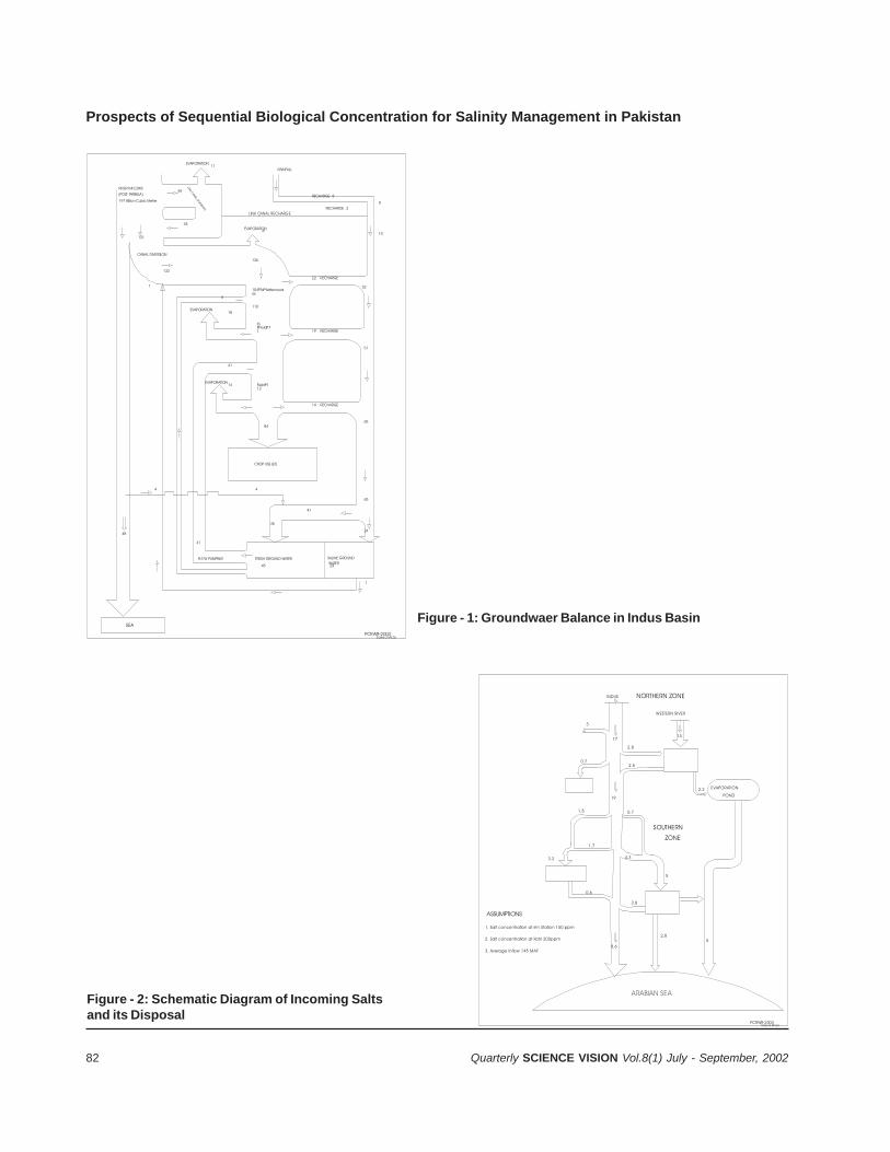
82 Quarterly SCIENCE VISION Vol.8(1) July - September, 2002
ARABIAN SEA
3
INDUS
0.7
2.8
2.5
0.71.5
1.7
3.2
5
4.3
2.2
2.85
8.6
0.6
19
17
NORTHERN ZONE
WESTERN RIVER
EVAPORATION
POND
SOUTHERN
1. Salt concentration at rim Station 150 ppm
2. Salt concentration at Kotri 200ppm
3. Average inflow 145 MAF
ASSUMPTIONS
2.8
ZONE
PCRWR-2003Saee d M ir za
13
Fi 2 S h ti Di f I i S lt d it Di l
RIVER INFLOWS
LINK CANAL RECHARGE
(POST TARBELA)
EVAPORATION
EVAPORATION
EVAPORATION
CROP USE (ET)
FRESH GROUND WATER WATERSALINE GROUND Pr.T/W PUMPING
LINK C
ANAL DIVERSION
SEA
PCRWR-2003Saee d M irza
197 Billion Cubic Meter
131
CANAL DIVERSION
132
126
22 RECHARGE
19 RECHARGE
104PToPWatercourses
110
ToPFieldP71
FieldP112
14
84
14 RECHARGE
32
51
65
65
24
41
45
41
2445
44
41
18
8
10EVAPORATION6
44
59
11RAINFALL
48
RECHARGE 2
RECHARGE 8
1
1
6
Prospects of Sequential Biological Concentration for Salinity Management in Pakistan
Figure - 1: Groundwaer Balance in Indus Basin
Figure - 2: Schematic Diagram of Incoming Saltsand its Disposal
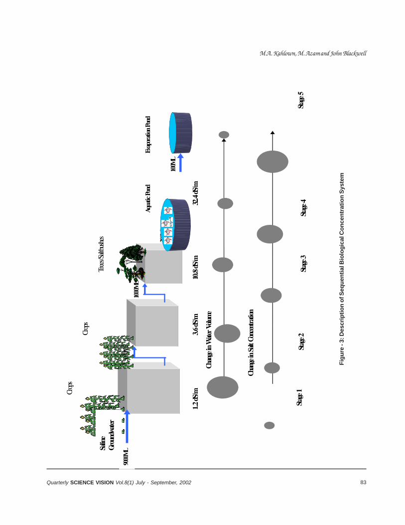
83Quarterly SCIENCE VISION Vol.8(1) July - September, 2002
1.2
dS/
m
3.6
dS/
m
10.8
dS/m
32
.4 dS
/m
100M
L
300M
L
1000
ML
3000
ML
3000
ML
Crop
s
Aqua
tic P
ond
Evap
orati
on P
ond
Salin
e Gr
ound
water
Stag
e 1
Chan
ge in
Wate
r Volu
me
Stag
e 3
Stag
e 4
Chan
ge in
Salt
Con
cent
ratio
n
Stag
e 2
Stag
e 5
9000
ML
Crop
s
Crop
s
Tree
s/Salt
bush
es
Fig
ure
- 3:
Des
crip
tio
n o
f Seq
uen
tial
Bio
log
ical
Co
nce
ntr
atio
n S
yste
m
M.A. Kahlown, M. Azam and John Blackwell

84 Quarterly SCIENCE VISION Vol.8(1) July - September, 2002
dS/m at this second stage) can be expected toreduce yields by 10-20%. Drainage- effluent fromthis second stage can be 3.6 dS/m if the 30%leaching fraction is maintained.
iii) Saltbushes and Trees: At this stage, theremaining water is once again used, with reducedcrop yields (Figure 5) and some of the crops thatcan be produced viably in the first two stagesbecome uneconomical. In this stage, the saltbushand salt-tolerant eucalyptus is grown. Other cropscannot grow with such high-salinity water. Thequantity of water was reduced from 9000 ML to1000 ML with increase in salinity from 1.2 to 10.8dS/m.
iv) Saline Fishery: At this stage, the salinity of wateris increased from 1.2 to 32.4 dS/m, which isalmost similar to sea water. However, water of thissalinity can be used for growing fish. The waterfrom the aquatic pond is discharged into theevaporation ponds.
v) Evaporation Ponds: Water of higher salinity fromfish-ponds is collected in evaporation ponds. Thenumber and size of the ponds would depend onamount of drainage-effluent. The salts from theevaporation ponds are collected and disposed off.
4. APPLICATION OF SBC IN AUSTRALIA
4.1 Saline Agriculture
The SBC method was used in northern Victoria,Australia, to reclaim about 20 ha of badly salt- affectedland, using highly saline groundwater. The tile-drainswere installed across the SBC site at 24m spacing,with a depth-range from 1.5 to 1.8m. The drainageeffluent was used to irrigate the selected salt-toleranttree species and grasses. This project evaluated twosaltbush and 16 tree species for their growth-performance and economic potential. Two salt-tolerantgrasses were also sown between the tree rows. Treesgrown included Eucalyptus cammaldulensis (clonedDouglas Provenance), E. spathulata, E. suggrandis,E. occidentalis, E. trabouti, Melaueca linariifolia, M.alternifolia and M. uncinata and four Poplar species.Trees were monitored for survival, growth rate (Figure6) and oil-yield/composition. These trees wereestablished in the first season with fresh water (1995-96) and have received straight groundwater thereafter.During 1997-98, approximately 16 mega liters were
applied to the 3 ha woodlot. An EC of 10 dS/mconcentration of drainage-effluent was achieved at thelast stage of SBC which amounts to the equivalent ofabout 100 tonnes of salt.
4.2 Saline Aqua-cultureThe second aspect investigated was the saline aqua-culture. The Marine and Freshwater ResourcesResearch Institute had conducted trials over a 3-yearperiod. Marine species investigated included Pacificand Sydney rock oysters, King and Tiger prawns, andthe fish species, Atlantic Salmon, Australian Bass,Black Bream, Greenback Flounder, Sand Whiting,and Snapper. Fresh-water species, Rainbow Trout,Silver Perch and European Carp, were also studied.Initially, all fish were stocked into 1m3 floating cages.Fish showing the best survival and growth-ratesincluded Salmon, Perch, Trout and Bass. The Salmonand Perch were further trailed in larger 20m3 cages.
5. PROSPECTS OF SBC IN PAKISTAN
5.1 Saline Agro-forestry: Large area of agriculturalland has been lost to cultivation, due to the twinmenace of soil-salinization and waterlogging. Despitethe success of previous efforts at higher costs andenergy resources, sustainability of such effort is beingquestioned. Countries like Australia and USA havebenefited from appropriate large-scale tree-plantationson saline and water-logged areas. Bio-drainageevaluation trials on saline sites, around the world, haveshort-listed tree species, which are both useful andsalt-tolerant. Fortunately, the identified species likeEucalyptus, Acacia, etc., are being planted in thecountry. Thus, there are considerable opportunitiesfor the promotion of such species to manage salinity.
5.2 Saline Aqua-culture: In Pakistan, per-capitaconsumption of fish has conventionally remained low,as compared to many other countries, but, still, atthis low consumption-rate the pressure on fish-demandhas consistently been increasing. It is a hard factthat our marine fisheries resources are alreadydwindling, as they are threatened with reachingmaximum sustainable catch-limits. There is a needfor utilization of newly created water-bodies, such aswaterlogged areas. It is estimated that, out of about6 m ha waterlogged and saline area, on about 1 millionha the waterlogged ponds have been created. In someof these waterlogged areas, water is retained
Prospects of Sequential Biological Concentration for Salinity-Management in Pakistan
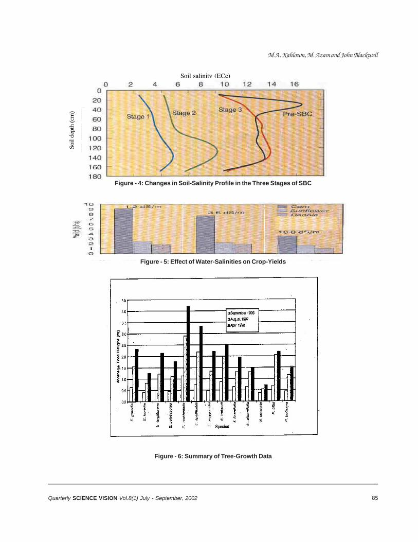
85Quarterly SCIENCE VISION Vol.8(1) July - September, 2002
Soil
dep
th (
cm)
Soil salinity (ECe)
Figure - 4: Changes in Soil-Salinity Profile in the Three Stages of SBC
Figure - 5: Effect of Water-Salinities on Crop-Yields
Figure - 6: Summary of Tree-Growth Data
M.A. Kahlown, M. Azam and John Blackwell

86 Quarterly SCIENCE VISION Vol.8(1) July - September, 2002
throughout the year, while in others, the adjoiningwater level varies and fluctuates with the water-levelof the adjoining water-bodies. To culture trash-fish inthese water bodies is a major possibility for theproduction of fishmeal. There is an immense need forthe development of vast areas under water-logging withsuitable aqua-culture ponds.
The groundwater from various aquifers of irrigatedplains has different levels of salinity and hamperingover total production. Salinity in some waters exceedsthat of seawater. There is need to introduce fish andshell-fish species tolerant to various types of saline-water environments. Several of the species presentlyexistent in Pakistan holds good chances for thesuccessful culture performance in saline water.However, this will largely depend upon the strength ofsalinity and the fluctuation in the salt-levels in thegiven water at the point in time. Tilapia is one option,to harness these resources. Other potent speciesinclude; basses, mullets, snake-heads and othercatfishes, catla & shrimps. Crabs, particularly mudcrab, could be a good choice.
REFERENCES
1. Haq, A, Shakir A.S., and Shahid, B.A. 1997. NationalDrainage Programme: Issue and Options,Proceedings of International Symposium on Waterfor the 21st Century, 17-19 June 1997 CEWRE,University of Engineering and Technology, Lahore,Pakistan. Vol. 2: 521-536.
2. Kahlown, M.A., and Azam, M. 2002. Individual andcombined effect of waterlogging and salinity on cropyields in the Indus basin. Journal of the InternationalCommission on Irrigation and Drainage 51 (4): 329-338.
3. Kahlown, M.A., Iqbal, M., Raoof, A., and Hanif, M. 2002.Impact of waterlogging on major crop yields: A casestudy in southern Punjab. Journal of Drainage andWater Management, 5 (2):1-7.
4. MINFAL. 2002. Agricultural Statistics of Pakistan2000-01, Ministry of Food Agriculture and Livestock(MINFAL), Food Agriculture and Livestock Division,Islamabad.
5. Tarar, N. 1995. National Workshop on DrainageSystem Performance in Indus Plain and FutureStrategies. Drainage Reclamation Institute ofPakistan (DRIP), Tandojam, Sindh.
6. Tarar, R.N. (1999). Surface Water Achievements andIssues in 20th Century, Proceedings of NationalWorkshop on Water Resources Achievements andIssues in 20th Century and Challenges for nextMillennium. pp 32-43.
Prospects of Sequential Biological Concentration for Salinity-Management in Pakistan

87Quarterly SCIENCE VISION Vol.8(1) July - September, 2002
UNDERSTANDING THE PHENOMENA OF INTELLIGENTHEAT-TREATMENT
S. Khan*, R. Qayyumeand A. Tauqir
* Metallurgy Division, Dr. A.Q. Khan Research Laboratories, Kahuta, P.O.Box No. 502, Rawalpindi - 46000, Pakistan.
Heat-treating has been a long history of developmentand is considered to be a mature technology. Fewindustries have equaled the response of the heat-treating industry to rapid changing requirement ofmanufacturing. Often, this response has required thedevelopment of new materials or sensors to implementexisting production and control techniques. At thesame time, new understanding of high-temperaturereactions has been required to keep the cost of heattreatment low in response to energy shortage and“upsets” in manufacturing.
Today, major driving forces for change are the needfor greater flexibility of production and morepredictability of results from the heat treatmentprocess. This has led to greater materialstandardization, tailoring of material composition toachieve predicted properties and application of cellularapproaches to heat treatment system.
Enhanced control of processes and production allowthe heat-treatment industry to contribute greatly tothe modernization of manufacturing. Better sensorspermit a more reliable analysis of the heat-treatingparameters. Improved software enables interactivecontrol of processes with sophisticated mathematicalmodels, and modular hardware and software not onlyallow flexibility, but also provide reliability andcontinued enhancement of control capability as newdevelopments in software became available. Inaddition, interfacing heat-treatment systems withproduction computers permits rapid optimization ofplant productivity. These developments point to a newlife-cycle curve for the heat-treatment industry.
Role of Heat Treatment in Manufacturing
Heat treatment is often considered as an art, not ascience. The heat treatment system can be linkedwith assembly process so that common operationcan be grouped together right in the production lineon the factory floor. The subsequent operation afterheat treatment is dependent upon the performance ofheat treater. Therefore, a relationship exists betweenJust-in-time (JIT) and heat treatment that one can go
from raw material to finish product in one continuousmanufacturing flow.
Most of the time people involved with heat treatmentface manufacturing deadline and production demand.Heat treater has to adopt Just-in-time (JIT) principles,which means “getting the job done right in time everytime”. Just-in-time (JIT) manufacturing is afundamental prerequisite for success in today’smanufacturing environment. It is not a specifictechnique, but rather a manufacturing philosophy andeconomics. The principles that form the foundation ofJust-in-time (JIT) are based on common sense, andits success depends upon its ideas becoming part ofmanufacturing line. To accomplish this goal one mustkeep in mind the key aspects of heat-treating,essential for success of JIT-heat treatment[1]. Thekey aspects are as under:
• To know, metallurgy, what is needed toaccomplish.
• To be able to predict the outcome of a heattreatment operation.
• To have repeatability built into the process.• To use state-of-the art heat-treating equipment
and methods.• To be aware of changes to other manufacturing
operations.• Do not compromise on quality.• Know your costs.• Designing equipment and automation with Just-
in-time (JIT) manufacturing goal in mind.
The eighth factor is important for to day’s heat treaterfor
• Handling the job in time.• On line reporting system.• Relying on statical process control (SPC)
techniques to assure that manufacturing flow istotally reliable.
• SPC and JIT-heat treatment makes the cost andquality of the products competitive.
88 Quarterly SCIENCE VISION Vol.8(1) July - September, 2002
To take full advantages of the process and control theheat treaters need to emphasis on these factors tohave a better quality of the products.
Intelligent Heat Treatment
When it is aimed to produce high quality product itmotivates heat treater to adopt “Total QualityManagement” (TQM) procedures. This comprises ofcomputer-based management, documentation andprocess control system, which provide necessaryinformation needed by the customers.
Properly implemented computerized monitoring andcontrol procedures can help heat treaters:
• To control cost.• Improve scheduling.• Boost productivity.• Optimization of equipment operations.• High quality of the products.
With tighter process control afforded by a computeraided design, rework and rejection rates areminimized. Rework saving could be enhanced uptoto 98%[2-5].
A computer-aided heat-treating system (CAHTS) hassignificant impact on users, as the operators are freeto perform other duties. More time can be spent infixing properly the next load, evaluating report andmaking strategies for heat treatment production, canalert the operator to potential problems before a crisisoccurs.
Implementation of “Total Quality Management” (TQM)requires the collection and analysis of large amountof data which include process variable such as timeand temperature for carburizing and/or process resultssuch as effective case depth. Data can also includein terms of parts within specification limits vs. thoseparts outside specification limits, or the number ofpromise dates set vs. number made.
For an SQC/SPC effort to be successful and long-lived, the data collection of the system must be themainstream information flow. Data collection must berule rather than the exception to ensure that staticalprocess control (SPC) soft ware will be used as a
simple method of obtaining information. In addition, aconvenient method of organizing data for analysismust be built into the system which structuring andformatting the way information is entered into thesystem, should have the flexibility and ease ofretrieval. If set up properly, database will permit a singleentry to be accessed many times in various ways. Toaccomplish this, the data must be stored with all ofthe possible indices and parameters that futureselection of information might be based upon. Thisincludes the shop order number, part type, heat treatprocess type and as-quenched hardness value.
Data collection should be implemented in a typicalorder-path through a heat treatment plant. Technicalinformation on part processing first be entered onprocess master. Then order is generated (order entry),processing begins with system checking andrecording to ensure that planned processing stepshave taken place in correct sequence. In-processinspection to determine information such as if specificas-quenched hardness or case depth is required,which is the part of statical process control (SPC)data in the mainstream line information flow. Finalinspection, key point in the processing route wherefinal hardness and other mechanical properties aremeasured. Certification follows with a general reviewof all processing and the preparation of documents toconfirm that heat treatment meets customer’s criteria.
In general Just-in-time (JIT) heat treatment, tighterprocess control, on line data collection all are thepart of “Total Quality Management” (TQM), and oncethese have been established properly, it means-doingintelligent heat treatment.
Computer Controlled Heat Treating Problems
In the past, the computer control system technologywas not available, the heat treaters were not able tomeasure completely and accurately all of the processvariables that can affect materials during heattreatment. However, recent advancements in control-system designs, sensor technology, digitalcommunications have made it possible to develop acomputer control system that enables heat treater tomeet both process-control and cost reportingrequirements.
Understanding the Phenomena of Intelligent Heat-Treatment
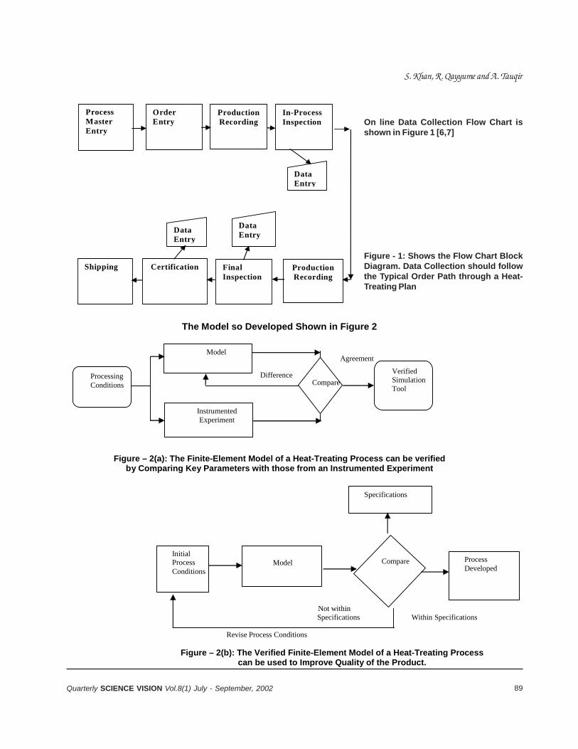
89Quarterly SCIENCE VISION Vol.8(1) July - September, 2002
The Model so Developed Shown in Figure 2
Figure – 2(a): The Finite-Element Model of a Heat-Treating Process can be verified by Comparing Key Parameters with those from an Instrumented Experiment
Processing Conditions
Model
Instrumented Experiment
Compare
Verified Simulation Tool
Difference
Agreement
Not within Specifications Within Specifications
Revise Process Conditions
Figure – 2(b): The Verified Finite-Element Model of a Heat-Treating Process can be used to Improve Quality of the Product.
Initial Process Conditions
Model
Compare Process
Developed
Specifications
Process Master Entry
Order Entry
Production Recording
In-Process Inspection
Shipping Certification Final Inspection
Production Recording
Data Entry
Data Entry
Data Entry
On line Data Collection Flow Chart isshown in Figure 1 [6,7]
Figure - 1: Shows the Flow Chart BlockDiagram. Data Collection should followthe Typical Order Path through a Heat-Treating Plan
S. Khan, R. Qayyume and A. Tauqir
90 Quarterly SCIENCE VISION Vol.8(1) July - September, 2002
The recently developed modeling tool encompassesthe capability to analytically determine the behaviourof steel components during heat treatment. Once theprocess parameters for the type of quenching andthe steels properties have been determine, thisanalysis is used to predict the effect of processchanges, such as part shape, material specification,and quench conditions on final products[6, 8].
was given trial run on computer, rather than costlytrial-and-error experimentation on the shop floor. Theimproved and optimized process can help to:
• Reduce scrap or rework rate.• Reduce or eliminate final grinding of parts to meet
specifications.• Reduce trial and error in developing process
parameters for new parts.• Allow tighter tolerances to be achieved via better
control of heat-treating process.
This technique is used for virtually all of the majorheat-treating and surface-modification process toproduce critical parts. The processes includecarburizing, nitriding, hardening, tempering, annealingand stress reliving. In addition, it is also applied to anextremely broad range of part shapes and materials.To date, most of the efforts have been on parts madeof various low-alloy steels, such as AISI 4140, 4335and 4340 etc. However, this technique can also beapplied to other metals and alloys. Specificapplications are hardening of gun barrels, heattreatment of fasteners and heat-treating of highperformance gears. For each application, heat transferdata, numerical data and process parameters are inputinto a numerical model. The model is then used todetermine distortion or residual stresses.
• Gas Carburizing By Computer
The gas-carburizing process provides the bestillustration of these developments theoriticalexplanations for the gas reaction enable engineers topredict and control the carbon gradient in alloysteels[9-12]. This understanding enables designengineers to produce fatigue-resistance parts at lowermaterial cost.
Precise control of carbon profile on the carburizedparts is now possible with the advent of this controltechnology (numerical model). The key control gases(CO2, CO & other gases) could not be possible tomeasure accurately and reliably in the parts inindustrial heat-treating furnaces. Today, however,infrared analyzers permit continuous analysis of CO2,CO and other gases. In addition, the introduction ofthe solid-electrolyte oxygen sensor, which is basedon the changes in electrical properties of zirconia inthe presence of minute amount of oxygen, permitsrapid determination of sensitive carbon-reactivevariables. These developments led directly to theapplication of mathematical model to the carburizingprocess.
Computerized systems are applied to control the gas-carburizing process, on line monitoring of carbondiffusion into the parts. These systems not onlyregulate the gas carbon profile but also calculatecarbon mass transfer and diffusion. Fig. 3ademonstrates the carbon profile illustrates bycomparing the target specified and actual profile duringthe process, and Fig. 3b produces the carbon profileof steel gears that agree with values predicted by thecomputer simulation. Carburized parts having thisprofile provide high fatigue resistance andreproducibility, especially on surfaces requiringgrinding after treatment.
This technique is reliable in obtaining the surfacecarbon concentration and case depth needed toachieve a given carbon content.
Heat Treatment Industry of The Future
The heat treatment industry is recognized as vital partof the manufacturing operation, and is characterizedby long-term partnerships with customers, supplieruniversities and government. To keep a balancerelationship with these agencies heat treaters willhave to look upon[3]:
• What technological advances will the heat treatersto work with?
• How the technological advances enable heattreaters to meet customers demand while keepingtheir products competitive and profitable?
Understanding the Phenomena of Intelligent Heat-Treatment
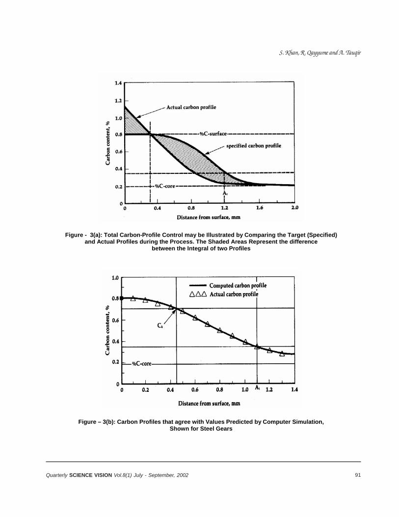
91Quarterly SCIENCE VISION Vol.8(1) July - September, 2002
Figure - 3(a): Total Carbon-Profile Control may be Illustrated by Comparing the Target (Specified) and Actual Profiles during the Process. The Shaded Areas Represent the difference
between the Integral of two Profiles
Figure – 3(b): Carbon Profiles that agree with Values Predicted by Computer Simulation, Shown for Steel Gears
S. Khan, R. Qayyume and A. Tauqir

92 Quarterly SCIENCE VISION Vol.8(1) July - September, 2002
A technological road map, describing the specificstrategies, needed to be developed and implementedfor “A Vision of a Heat Treatment Industry Of TheFuture”.
The heat treaters should have to adopt followingstrategies for application of advanced technologies:
• Global Standards-have to be established formaterials, heat treated parts, safety of the work forceand environmental friendliness. Standards also to beestablished for electronic communications enablingquick and reliable transmission of information betweenthe heat treaters and customers.
• Operations Of Captive Facilities-are value-addedprofit center characterized by advanced technology,well trained workers and low operation cost. Largecaptive facilities have decentralized their heat-treatingoperation and may include a heat-treating systemon each production line. Some of these “in-line”systems are operated by commercial heat treaterson a contract basis. In other capacities, separateheat treating operations are carried out bycommercial heat treaters.
In both captive and commercial facilities, higherproduction reduced energy usage and improvedenvironmental performance has been achieved bymeans of increased throughput and focused energyprocesses.
• Environmental Impact-of heat-treating should bereduced to zero; completely self-contained, closedloop systems are standards. Quenchant are usedshould be non-polluting and nonflammable. Emissionof chemicals, heat and gases should be eliminated.
• Government Relationship-should play their rolein terms of tax incentives, availability of funds forindustrial growth and modernization, encouragementof bank loans for implementation of advancedtechnologies.
• Heat Treating Employees-means giving somebenefits to the heat-treating personnel by providingthem safe, clean and comfortable environment.Organizing short courses and training program incollaboration with universities/other educational
institutions. Heat-treating companies shouldrecognize that progress is readily needed witheducated, confident and flexible people.
• Materials And Process-complete technical know-how should be obtained for the part to be heat-treated.
Industry Challenges
The heat-treating industry faces technological,government, profitability, customers, structural andworkforce challenges to achieve the set goal.
• In The Technology Area-research priorities includedeveloping more efficient furnaces, longer-lastingmaterial for furnace hardware, more precise control ofprocesses, and improved cooling medias.Achievements of these research goals can beaccelerated through co-operative projects with federalagencies. Such program would involve industry,technical societies and universities.
• The Work Force Of The Future-is another majorchallenge. The industry must attract people who havethe potential to learn and train them to become skillfulemployees who will hold good jobs in a clean andsafe environment. Heat treaters should promotefriendly relation with technical societies, tradeassociations, universities and community colleges forthe education of engineers and technicians.
• Government Regulations & Product Liability-must be mitigated if heat-treating is desired to beprospersed. Collaboration replaces confrontation tohelp the industry develop technologies that ensureworkers safety and environmental friendliness.Reforms are required so that new products can bedeveloped without the fear of frivolous low suits. Thisis proper way to reduce the expenses and the industrycan be globally competitive.
• Profitability-must be improved in order to attractthe capital that drives technology advances. This willfollow from aggressive research and developmentprogram funded by the industry in collaboration withuniversities and national laboratories.
• Customer/Industry Relationships-must beestablished right from product design phase. The
Understanding the Phenomena of Intelligent Heat-Treatment

93Quarterly SCIENCE VISION Vol.8(1) July - September, 2002
industry must take active part in programs like; helpingand providing guideline for selection of materials thatlow in cost yet develop advanced properties after heattreatment.
• The Structure Of The Industry-today’smanufacturers is out sourcing parts of themanufacturing process. A possible scenario for heat-treating could be that of specialized segment in theproduction line. Such as “heat-treating module” couldbe the complete responsibility of independent heattreaters.
CONCLUSION
• Design of heat-treating processes can be improvedand made more efficient through numerical simulation.
• Computer-aided control offers heat treaters thecapability to meet the most stringent customer’smaterial-specification requirements.
• Better sensors, improved computer software andadaptive process control permit optimization of heat-treat production.
• With tighter process control, rework and scrap arereduced.
• Computer controls enable workers to work in a clean,comfortable environment. In order to efficiently operateand maintain this advanced equipment, workers willbe among the most technologically capable inmanufacturing.
• The industry faces significant challenges in areasof training and partnerships. Lack of knowledge aboutindustry by young people may result in a diminishingpool of future work.
• The importance of close working relationship withcustomers and suppliers must be recognized if heattreaters are to improve the profitability of all productmanufacturing.
• Effective solution of the challenges requirescollaborative efforts between industry, technicalsocieties, government, and academia.
REFERENCES
1. D.H.Herring, R.Mowry and C.I.Hayes; AdvancedMaterials and Processes Inc., Metal Progress, p.81,vol. 132(3), Sept. 1987.
2. M.B.Bomba and E.D.Jamieson; Conf. Proc., 13th ASMHeat Treatment Conf. & Exposition, 22-24 Oct., Ohio,1991.
3. N.B.La Marca and M.S.Handelsman; Conf. Proc.,13th ASM Heat Treatment Conf. & Exposition, 22-24Oct., Ohio, 1991.
4. T.D.Brown; Conf. Proc., 13th ASM Heat TreatmentConf. & Exposition, 22-24 Oct., Ohio, 1991.
5. T.D.Brown; Advanced Materials & Process, vol. 7,p.14, 1992.
6. L.E.Jones and E.D.Jamieson; Advanced Materials& Processes, vol. 3, p.33, 1990.
7. Lindberg Heat treatment Co. report; AdvancedMaterials & Processes, vol. 7, p.14, 1992.
8. D.Persampieri, A.S.Roman and P.D.Hilton; AdvancedMaterials & Processes, vol. 3, p.19, 1991.
9. J.G.Conybear; Advanced Materials & Processes,vol.10, p.38, 1989.
10. B.Edenhofer and H.Pfau; Heat Treat. Met., vol.16 (1),p.22, 1989.
11. K.H.Edler, A.Knierem and J.Mueller-Zil ler;Metallurgia, vol. 5(2), p.88, 1988.
12. B.Edenhofer an J.Muller-Ziller; Conf. Proc., 11th Heat-treating Conf., ASM 1988.
13. ASM News Report; Advanced Materials andProcesses, vol. 12, p.32P, 1996.
S. Khan, R. Qayyume and A. Tauqir
94 Quarterly SCIENCE VISION Vol.8(1) July - September, 2002
BIO-SCIENCES AND AGRICULTUREGRAZING FOURWING SALTBUSH (ATRIPLEXCANESCENS) UNDER DIFFERENT SUPPLEMENTALFEEDING-REGIMES IN HIGHLAND BALOCHISTAN
Sarwat N. Mirza*,Sarfraz Ahmad, Javed Afzal
and M. Islam
ABSTRACT
A grazing trial on fourwing saltbush pastures wasconducted during summer and early fall of 1993 withthree different grazing treatments (fourwing saltbushgrazing with no supplementation, fourwing saltbushgrazing plus 200 g of wheat-straw/head/day andfourwing saltbush grazing plus 500 g wheat-straw/head/day) to investigate the grazing potential offourwing saltbush pasture and devise management-systems for efficient utilization by sheep. EighteenHarnai yearling rams, weighing 23±0.95 kg were usedin the study in a randomized complete block design,divided into three groups, and the treatments wereallotted to each group randomly. All the animals weregrazed in the allotted plots of saltbush pastures intwo grazing sessions; morning and evening.
The grazing trial lasted for 15 weeks from mid-Juneto the end of September. At the end of the grazingstudy, animals attained varying live weight gains (6.4%,8% and 10%, respectively) in the three grazingtreatments. Animals in the saltbush grazing treatmentwith no supplementation started losing weight after10 weeks of the grazing period, while animals in thegrazing treatments supplemented with 200 g wheat-straw/head/day maintained their body weights at theend of the study. The yearling rams in the grazingtreatment offered 500 g wheat straw/head/day gainedweight till the end of the study-period. Combiningwheat straw with fourwing saltbush diet can thus offera suitable grazing-regime for utilizing saltbushpastures during summer and fall seasons.
Key words: Balochistan, fourwing saltbush, grazing,intake, sheep.
INTRODUCTION
Sheep and goat-rearing is the main use of rangelandsin highland Balochistan, and about 80% of the ruralpopulation live from the sale of small ruminants and
* Arid Zone Research Centre, P.O.Box 63, Brewery Road, Quetta.
their products (FAO, 1983). Out of the total area(34.7m ha) of Balochistan, 21 million ha or 60% isused for grazing (FAO, 1983). According to the latestcensus carried out in 1996, approximately 20.24million sheep and goats have been reported inBalochistan (GOB, 1996). Rangelands are the majorfeed-source for these animals and about 90% of thefeed-requirements are met from rangelands (FAO,1983). However, due to high grazing-pressure andhuman disturbances, these ranges are unable to fulfilthe feed-requirements of small ruminants, particularlyduring fall and winter seasons (Mirza et al., 1995). Asa result of this feed shortage, animal-productivity isseverely affected in the region (Akbar et al., 1990). Toovercome this problem, research conducted at AridZone Research Centre has identified and evaluatedvarious exotic fodder-shrubs, which are adapted underthe prevailing environmental conditions (Mirza, 1995).
Atriplex canescens (Pursh) Nutt., commonly knownas fourwing saltbush, is a perennial halophytic exoticshrub, native to Western United States. It has shownpotential as a promising fodder-shrub in areas having250-300 mm annual rainfall in highland Balochistan(Mirza, 1995). The area has a typical continentalMediterranean climate, with cold winter and drysummer seasons (Kidd et al. 1988). Fourwing saltbushis extremely drought and cold-tolerant and provideshigh-quality browse, especially during summer andautumn months (Mirza, 1995; Thomson et al., 1997).This shrub produces leaves and twigs round the year.Fourwing saltbush can withstand moderate to heavygrazing-pressure (Rumbaugh et al., 1982), but, withoutsuitable grazing-management, sustained productionis not maintained (Jefferies and Pitman, 1986).Utilization of saltbush by animals is generallyrecommended after 18 to 24 months of growth(Ueckert, 1985). The crude-protein content in leavesof fourwing saltbush has been reported from 12 to 15% during mid winter (Thomson et al., 1997).
It has been suggested that one acre of fourwingsaltbush might provide the supplemental protein
95Quarterly SCIENCE VISION Vol.8(1) July - September, 2002
requirements for 0.5 to 1 animal unit during a 90-dayperiod (Ueckert, 1985). Like other halophytes, fourwingsaltbush has low energy-values because of high ash-contents. The energy-values are reported to cover onlymaintenance requirements of sheep, if they consume1.2-1.5 kg DM/d (Le Houerou, 1992). But nutritionally,saltbush species contain high nitrogen-values, whichhave been reported to be as high as 2.5-3.5 % DM ,i.e., 16-20% of crude protein (Le Houerou et al., 1982,1983; Hassan et al., 1979). The digestibility of drymatter and of organic matter has been reported to bearound 60% and 50%, respectively (Le Houerou etal., 1983). The digestibility of nitrogen has beenreported to be around 65%, but the retention ofnitrogen is only 55% (Benjamin et al., 1992). Atriplex,supplemented with grazing of native ranges, resultedin animal weight-gains of around 80 g/h/d (Le Houerouet al., 1983). Atriplex forage consumption, in additionto stubble or wheat-straw consumption, could lead toa well balanced ration and fulfil the nutritionalrequirements of animals in a productive grazingsystem (Le Houerou et al., 1991).
Various pen-feeding studies have already beenconducted on fourwing saltbush, to investigate itspotential as a forage-crop with other supplements(Thomson et al., 1997). However, very little informationis available on grazing-behaviour and grazing-management of this species. Therefore, the presentstudy is conducted to investigate the grazing-potentialof fourwing saltbush pasture and devise management-systems for efficient utilization of these pastures bysheep.
MATERIALS AND METHODS
The grazing trial on fourwing saltbush pastures wasconducted during summer and early fall of 1993.Groups of three yearling rams of Harnai breed,weighing (23 ± 0.95 kg) were used, each in threedifferent grazing-treatments viz; fourwing saltbushgrazing with no supplementation (FWSB alone),fourwing saltbush grazing plus 200 g of wheat-straw/head/day (FWSB+200g WS) and fourwing saltbushgrazing plus 500 g wheat-straw/head/day(FWSB+500g WS). There were two replications foreach treatment. Two adjacent blocks (replicates) ofsizes 35 x 152 m and 42 x 133 m, respectively, plantedwith fourwing saltbush shrubs at 2 x 2 m spacingduring early summer of 1987 at Arid Zone Research
Institute (AZRI), were used. At the start of the study,all leaves and young twigs from seven randomlyselected plants in each plot were removed, weighed,and dried at 70oC for 24 hours, and multiplied by thetotal number of plants in each plot to determine DMforage biomass of fourwing saltbush available at thestart of the study. About 1000, 747 and 687 kg DM/ha of fourwing saltbush was available at the start ofthe study in the plots assigned to the yearling ramsfor the three grazing treatments, respectively. Fiverandomly selected plants in each plot were protectedby 1.5 x 1.5 m cages and the biomass of leaves wasmeasured at the end of the study, in order to measurethe off-take of saltbush leaves per head of sheep. Theamount of saltbush consumed by sheep wasmeasured at the end of the grazing-trial by theestimation of forage on caged (ungrazed) and grazedplants in each plot. The amount of forage contributedby understory (grasses and forbs) in each plot wasalso measured at the start of the trial, by harvestingabove-ground biomass inside the 5, 1m2 quadrats ineach plot.
The two blocks were divided into three equal plots;each plot was grazed by three lambs from June 15 toSeptember 29, 1993. Stocking-rate, calculated on thebasis of saltbush forage biomass, was about 16 rams/ha/15 weeks. The yearling rams were grazed from800-1200 h. and then 1700-1900 h. daily for 15 weeks.Known quantities of wheat-straw were offered to thegroups in the two treatments (grazing plus 200g and500g wheat straw/head/d, respectively) after the firstgrazing session i.e., at noon. The refused wheat-strawwas measured the next morning before removinganimals for grazing, to determine daily wheat-strawintake (g) for each group. Each group was offered aknown amount of water throughout the day and night,and the daily water-intake in litres for each group wasmeasured. Sheep were weighed at the start of thetrial, then once a week in the morning until the trialended. The weekly data on changes in body-weight(kg) and water-consumption (litres) by yearling ramswere analysed, by using analysis of variance in aRandomized Complete Block Design.
RESULTS
Weekly body-weight change (kg) and daily water-intake (litres) of Harani yearling rams in differentgrazing regimes are shown in Fig 1 and Table 1. No
Sarwat N. Mirza, Sarfraz Ahmad, Javed Afzal and M. Islam
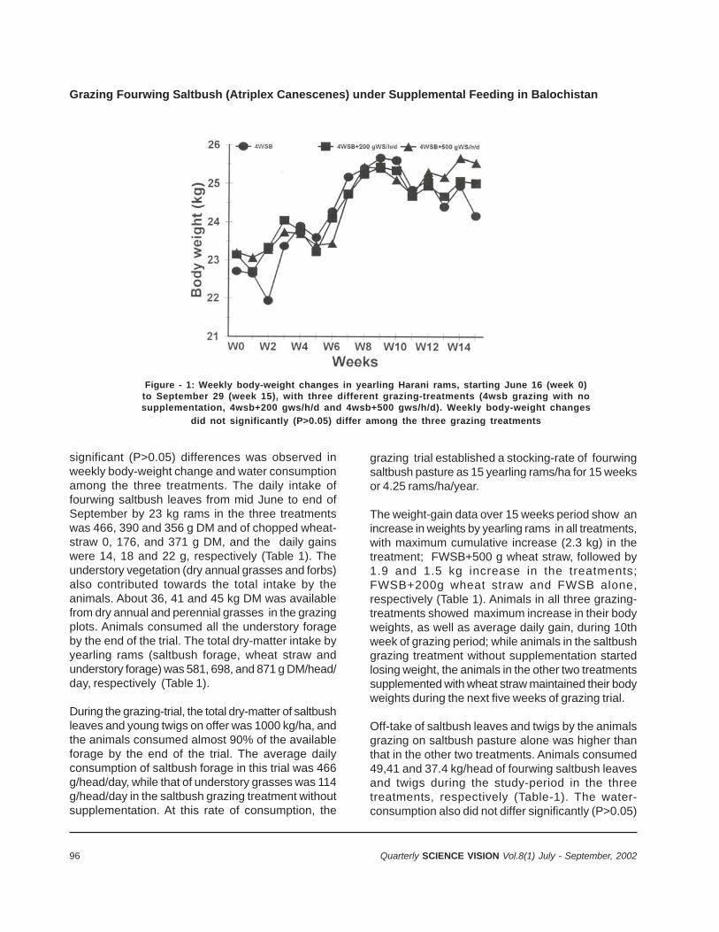
96 Quarterly SCIENCE VISION Vol.8(1) July - September, 2002
Grazing Fourwing Saltbush (Atriplex Canescenes) under Supplemental Feeding in Balochistan
significant (P>0.05) differences was observed inweekly body-weight change and water consumptionamong the three treatments. The daily intake offourwing saltbush leaves from mid June to end ofSeptember by 23 kg rams in the three treatmentswas 466, 390 and 356 g DM and of chopped wheat-straw 0, 176, and 371 g DM, and the daily gainswere 14, 18 and 22 g, respectively (Table 1). Theunderstory vegetation (dry annual grasses and forbs)also contributed towards the total intake by theanimals. About 36, 41 and 45 kg DM was availablefrom dry annual and perennial grasses in the grazingplots. Animals consumed all the understory forageby the end of the trial. The total dry-matter intake byyearling rams (saltbush forage, wheat straw andunderstory forage) was 581, 698, and 871 g DM/head/day, respectively (Table 1).
During the grazing-trial, the total dry-matter of saltbushleaves and young twigs on offer was 1000 kg/ha, andthe animals consumed almost 90% of the availableforage by the end of the trial. The average dailyconsumption of saltbush forage in this trial was 466g/head/day, while that of understory grasses was 114g/head/day in the saltbush grazing treatment withoutsupplementation. At this rate of consumption, the
grazing trial established a stocking-rate of fourwingsaltbush pasture as 15 yearling rams/ha for 15 weeksor 4.25 rams/ha/year.
The weight-gain data over 15 weeks period show anincrease in weights by yearling rams in all treatments,with maximum cumulative increase (2.3 kg) in thetreatment; FWSB+500 g wheat straw, followed by1.9 and 1.5 kg increase in the treatments;FWSB+200g wheat straw and FWSB alone,respectively (Table 1). Animals in all three grazing-treatments showed maximum increase in their bodyweights, as well as average daily gain, during 10thweek of grazing period; while animals in the saltbushgrazing treatment without supplementation startedlosing weight, the animals in the other two treatmentssupplemented with wheat straw maintained their bodyweights during the next five weeks of grazing trial.
Off-take of saltbush leaves and twigs by the animalsgrazing on saltbush pasture alone was higher thanthat in the other two treatments. Animals consumed49,41 and 37.4 kg/head of fourwing saltbush leavesand twigs during the study-period in the threetreatments, respectively (Table-1). The water-consumption also did not differ significantly (P>0.05)
Figure - 1: Weekly body-weight changes in yearling Harani rams, starting June 16 (week 0)to September 29 (week 15), with three different grazing-treatments (4wsb grazing with nosupplementation, 4wsb+200 gws/h/d and 4wsb+500 gws/h/d). Weekly body-weight changes
did not significantly (P>0.05) differ among the three grazing treatments
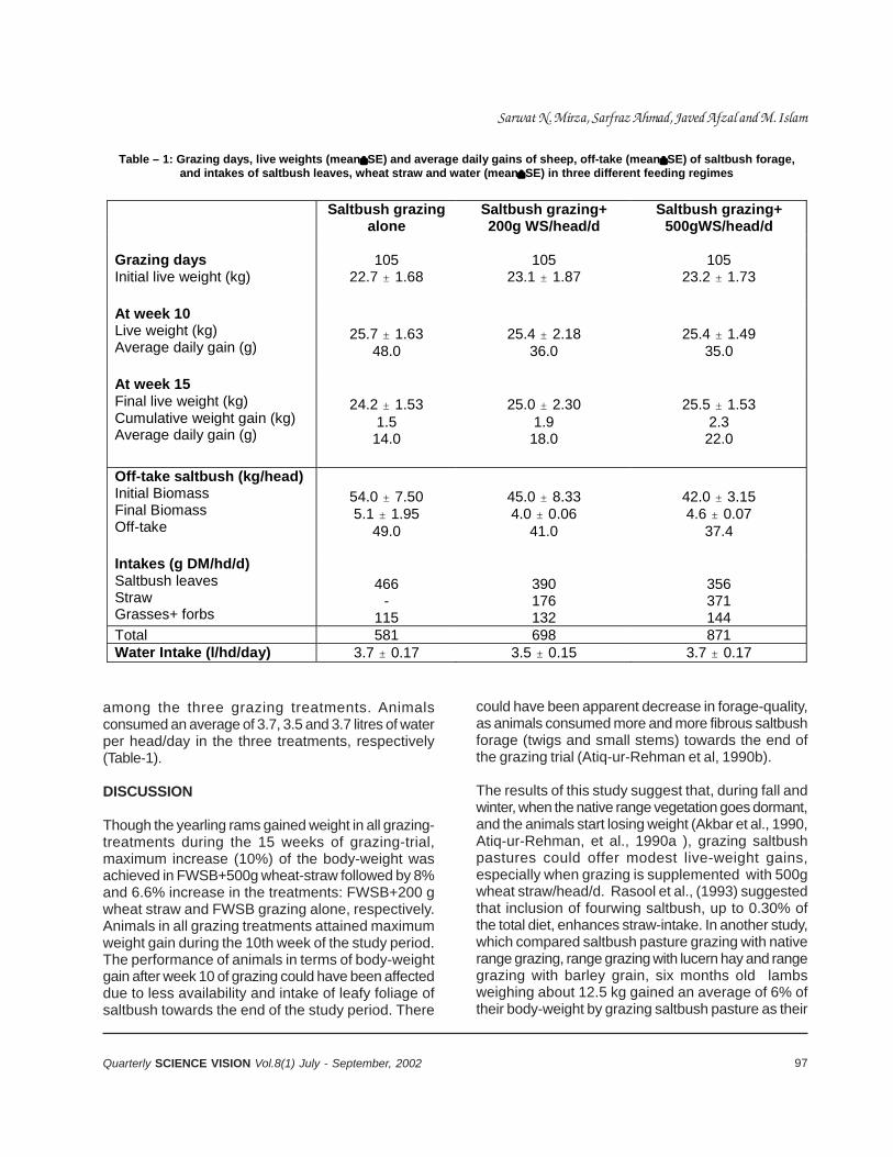
97Quarterly SCIENCE VISION Vol.8(1) July - September, 2002
among the three grazing treatments. Animalsconsumed an average of 3.7, 3.5 and 3.7 litres of waterper head/day in the three treatments, respectively(Table-1).
DISCUSSION
Though the yearling rams gained weight in all grazing-treatments during the 15 weeks of grazing-trial,maximum increase (10%) of the body-weight wasachieved in FWSB+500g wheat-straw followed by 8%and 6.6% increase in the treatments: FWSB+200 gwheat straw and FWSB grazing alone, respectively.Animals in all grazing treatments attained maximumweight gain during the 10th week of the study period.The performance of animals in terms of body-weightgain after week 10 of grazing could have been affecteddue to less availability and intake of leafy foliage ofsaltbush towards the end of the study period. There
could have been apparent decrease in forage-quality,as animals consumed more and more fibrous saltbushforage (twigs and small stems) towards the end ofthe grazing trial (Atiq-ur-Rehman et al, 1990b).
The results of this study suggest that, during fall andwinter, when the native range vegetation goes dormant,and the animals start losing weight (Akbar et al., 1990,Atiq-ur-Rehman, et al., 1990a ), grazing saltbushpastures could offer modest live-weight gains,especially when grazing is supplemented with 500gwheat straw/head/d. Rasool et al., (1993) suggestedthat inclusion of fourwing saltbush, up to 0.30% ofthe total diet, enhances straw-intake. In another study,which compared saltbush pasture grazing with nativerange grazing, range grazing with lucern hay and rangegrazing with barley grain, six months old lambsweighing about 12.5 kg gained an average of 6% oftheir body-weight by grazing saltbush pasture as their
Table – 1: Grazing days, live weights (mean"SE) and average daily gains of sheep, off-take (mean"SE) of saltbush forage, and intakes of saltbush leaves, wheat straw and water (mean"SE) in three different feeding regimes
Saltbush grazing
alone Saltbush grazing+ 200g WS/head/d
Saltbush grazing+ 500gWS/head/d
Grazing days Initial live weight (kg)
105 22.7 " 1.68
105 23.1 " 1.87
105 23.2 " 1.73
At week 10 Live weight (kg) Average daily gain (g)
25.7 " 1.63
48.0
25.4 " 2.18
36.0
25.4 " 1.49
35.0
At week 15 Final live weight (kg) Cumulative weight gain (kg) Average daily gain (g)
24.2 " 1.53
1.5 14.0
25.0 " 2.30
1.9 18.0
25.5 " 1.53
2.3 22.0
Off-take saltbush (kg/head) Initial Biomass Final Biomass Off-take
54.0 " 7.50 5.1 " 1.95
49.0
45.0 " 8.33 4.0 " 0.06
41.0
42.0 " 3.15 4.6 " 0.07
37.4
Intakes (g DM/hd/d) Saltbush leaves Straw Grasses+ forbs
466
- 115
390 176 132
356 371 144
Total 581 698 871 Water Intake (l/hd/day) 3.7 " 0.17 3.5 " 0.15 3.7 " 0.17
Sarwat N. Mirza, Sarfraz Ahmad, Javed Afzal and M. Islam
98 Quarterly SCIENCE VISION Vol.8(1) July - September, 2002
Grazing Fourwing Saltbush (Atriplex Canescenes) under Supplemental Feeding in Balochistan
sole diet over 10 weeks period. The study concludedthat, under fourwing saltbush grazing alone, lambsnot only maintain their body-weight but also gain someweight during early winter (Atiq-ur-Rehman et al.,1990b). Another study concluded that saltbushharvested at the beginning of winter season has afeeding-value below the maintenance requirement ofsheep. This study concluded that sheep browsing onsaltbush pasture, late in the season, would need tobe fed wheat-straw for maintenance (AZRI/ICARDA,1992).
The off-take value of saltbush foliage in the threegrazing-treatments did not differ much. Animals in allgrazing treatments consumed about 90% of thesaltbush foliage on offer by the end of the study. Thisshows that established saltbush stands, in highlandBalochistan of 1000 kg foliage DM/ha, can allow anoff-take up to 750-900 kg DM of saltbush foliage atmedium (75%) to heavy (90%) grazing-pressure duringsummer and fall period. At these off-take rates,saltbush pastures can be grazed at a stocking rate of12-15 yearling rams/ha/15 weeks during summer andfall seasons.
The wheat straw intake by the animals in the twotreatments; grazing saltbush+ 200 and 500 g wheatstraw/head/d was 176 and 372 g/head/d, respectively.This shows that the animals offered 200g wheat straw/head/d consumed 88% of the straw and the refusal inthis case was the hard stem portion of straw rejectedby the animals. In the treatment FWSB+500g wheatstraw/head/d, animals consumed 75% of the wheatstraw, which shows that the animals grazing saltbushforage during summer and fall seasons should besupplemented with at least 400g wheat straw/head/din order to attain modest weight gains.
Ruminants grazing on saltbush diets may increasethe water intake due to ingestion of large quantitiesof sodium and potassium chloride (Le Houerou, 1995).However, in this study the water intake was not muchdifferent in the three grazing treatments during theentire grazing period. Rasool et al., 1995, alsoreported low amounts of water intake by sheep fedfourwing saltbush leaves during December and relatedthis to low salt contents in FWSB leaves. Differentresults have been reported for water intake on fourwingsaltbush grazing alone and in combination with othersupplementals (Thomson et al., 1997). Thesedifferences may be due to body weight, dry matterconsumed, ash content of the diet, and ambient
temperature.
Sheep grazing saltbush range have to avoid grazingduring the period of hot weather to reduce stresses ofa combination of heat and high salt ingestion andreduce water-demands significantly (ACSAD, 1987).The grazing of animals on saltbush pastures in themorning and evening may reduce the heat stressduring summer season and extra water intake helpsto excrete sodium and potassium chloride.
CONCLUSIONS
Browsing shrubs in forage reserves is considered tobe the appropriate way to utilize saltbush pastures,though farmers can also cut and carry these shrubsto use as feed and get some fuelwood. The results ofthis study indicate that the sheep can maintain theirbody-weights if fourwing saltbush pastures are grazedduring summer/early autumn, when growth of theshrubs is maximum and the nutritional quality isadequate. However, the results also indicate thatmodest weight-gains can also be achieved ifsupplements are offered with fourwing saltbush diet.In this case, the addition of wheat-straw to the diet ofsaltbush forage had shown better performance inyearling rams over a period of 15 weeks, as comparedto grazing saltbush pasture alone. Combining wheat-straw with fourwing saltbush diet can offer a suitablegrazing regime for utilizing saltbush pastures duringsummer and fall seasons. This system has anadvantage over grazing saltbush pastures alone, inmeeting both energy and protein requirements ofsheep and allowing more persistency of the shrubs,as these are not subjected to heavy grazing whensupplemented with alternate feed. These results arein agreement with those on penned sheep: thatmodest gains in live-weight can be expected ifsupplements are offered with fourwing saltbush diet(Thomson et al., 1997).
Currently, it is not known how farmers will managetheir saltbush reserves and, therefore, it is importantto expand the area and number of reserves onGovernment and private farms, so that these can begrazed by farmers’ animals. Meanwhile, more detailedgrazing-studies are needed, which will give researchersthe information necessary to advise farmers on grazing-regimes that allow good off-take from saltbushreserves, without jeopardizing the persistency of theplants.
99Quarterly SCIENCE VISION Vol.8(1) July - September, 2002
REFERENCES
1. ACSAD. 1987. Nutritive and Grazing Evaluation ofAtriplex species for Sheep. Part One: nutritiveevaluation. The Arab Centre for the Studies on AridZone and Dry Lands. ACSAD, Damascus, Syria. 242pp.
2. Akbar, G., S. Rafique and B.R. Khan. 1990. Efficacyof water harvesting measures for the developmentof Range-Livestock sector in Balochistan.Proceedings of “National seminar on waterresources development and its management inarid areas” Vol. 2 held at Quetta from October 6-8,273-491pp.
3. Atiq-ur-Rehman., S. Rafique, A. Ali and M. Munir.1990a. Nutritive evaluation of fourwing saltbush ingrowth and digestibility trials with Harnai lambs inupland Balochistan. Asian-Australasian J. AnimalSci., 3: 299-303.
4. Atiq-ur-Rehman , S. Rafique and R. S. Aro. 1990b.Fourwing saltbush as a winter maintenance foragefor sheep in upland Balochistan. AJAS. 3 (2): 85-89.
5. AZRI/ICARDA. 1992. Highland RegionalProgramme: Annual Report 1991 of the MART/AZRProject. ICARDA, Quetta, Pakistan. ICARDA, Aleppo,Syria.
6. Benjamin R.W., E. Oren, E. Katz and K. Becker. 1992.The apparent digestibility of Atriplex barclayana andits effect on nitrogen balance in sheep. Anim.Production 54:259-264.
7. FAO. 1983. Report of the Assistance to Rangelandand Livestock Development Survey in Balochistan.TCP/PAK /0107, FAO Technical CooperationProgram, Food and Agricultural Organization of theUnited Nations, Pakistan.
8. GOB. 1996. Livestock Census Report. Governmentof Balochistan. Quetta.
9. Hassan, N.I., H.M. Abdelaziz and A.E. El Tabbah.1979. Evaluation of some forages introduced tonewly reclaimed areas in Egypt. World Rev. of Anim.Prod. XV 2: 31-35.
10. Jefferies, R.L and M..G. Pitman. 1986. Perspectivesof the biology of halophytes in natural habitats inrelation to forage production. In: Forage and fuelproduction from salt affected wasteland. Editors:Barrett-Lennard, E.G., C.V. Malcolm, W.R. Stern andS.M. Wilkins. Elsevier, Amsterdam. Pages 227-244.
11. Kidd, C.H.R., D.J. Rees, J.D.H. Keatinge, F. Rehman,A. Samiullah and S.H. Raza. 1988. MeteorologicalData Analysis of Balochistan. Research Report No.19. ICARDA, Quetta, Pakistan.
12. Le Houerou H.N., D. Dumancic, M. Eskileh, D.Schweisguth and T. Telahique. 1982. Anatomy andphysiology of a browsing trial: a methodologicalapproach to fodder shrub evaluation. 65.pp. TechPaper N0.28 UNTF Lib. 18, FAO, Agr. Res. Centre,Tripoli, Libya.
13. Le Houerou H.N., G. Gintzburger and N. El Khodja.1983. Chemical composition and nutritive value ofsome range plants and fodder shrubs of Libya. 14pp. 4 tab. Techn. paper No 44. UNTF Lib. 18, FAO,Agr. Res. Centre, Tripoli, Libya.
14. Le Houerou, H.N., E. Correal and S. Lailhacar. 1991.New, man-made agro-sylvo-pastoral systems for theisoclimatic Mediterranean arid zone, 17 pp, IVthInternational Rangeland Congress, Montpellier (inpress).
15. Le Houerou H.N. 1992. The role of saltbushes(Atriplex spp.) in arid land rehabilitation in theMediterranean basin: a review. AgroforestrySystems. 18: 107-148.
16. Le Houerou H.N. 1995.Forage halophytes in theMediterranean basin. Pages 115-136 in Halophytesand Biosaline Agriculture. (R. Choukar-Allah, C.V.Malcolm and A. Hamdy, eds.).Marcel Dekker, Inc.New York, Basel, Hong Kong.
17. Mirza, S.N. 1995. Fourwing saltbush-A multi-purposeshrub for the arid highlands of Balochistan. AridZone Research Institute. Pakistan AgriculturalResearch Council, Quetta. 18pp.
18. Mirza, S.N., G. Akbar and I. Begum. 1995. Landdegradation and its control in highland Balochistan.Progressive Farming. Vol 15(2): 46-51.
19. Rumbaugh, M.D., D.A. Johnson and G.A. Van Epps.1982. Forage yield and quality in a great basin shruband legume experiment. J. Range Manage. 35: 604-609.
20. Rasool, E., S. Rafique and E.F. Thomson. 1993.Nutritive value of fourwing saltbush (Atriplexcanescens) in Balochistan, Pakistan. Pages 70-74.In Annual report 1992. Pasture, Forage andLivestock Programme, ICARDA, Aleppo, Syria.
21. Rasool, E., S.Rafique, I.U. Haq, A.G. Khan and E.F.Thomson. 1995. Impact of fourwing saltbush on feedand water intake and on blood serum profile insheep. Science Technology and Development.Vol.14(No.4):11-14.
22. Thomson, E.F., S.N. Mirza, S. Rafique, J. Afzal, I.Rasool, Atiq-ur-Rehman, M. Ershad, A. Hussain, G.Akbar and A.S. Alvi. 1997. Utilization of Fourwingsaltbush for the Arid Rangelands of HighlandBalochistan, Pakistan. In: N. Haddad, R. Tutwilerand E. Thomson (eds.). Proceedings of RegionalSymposium on Integrated Crop-Livestock Systemsin the Dry Areas of West Asia and North Africa held atAmman, Jordan from 6-10 November, 1995.ICARDA, Aleppo, Syria. 572 p.
23. Ueckert, D.N. 1985. Use of shrubs for RangelandRevegetation. In: Proceedings of the InternationalRanchers Roundup. Laredo, Texas. Editors: L.D.White, D.E. Guyn, and T.R. Troxel. Texas AgriculturalExtension Service. Pages 190-196.
Sarwat N. Mirza, Sarfraz Ahmad, Javed Afzal and M. Islam
100 Quarterly SCIENCE VISION Vol.8(1) July - September, 2002
RESPONSE OF RICE TO ZINC-APPLICATION ANDDIFFERENT N-SOURCES IN CALCAREOUS SOIL
A. Rahman*, M.Yasin**, M. Akram**
and Z.I.Awan**
* Soil Conservation, Government of Punjab, Rawalpindi. ** National Agricultural Research Centre, Islamabad.
ABSTRACT
Widespread Zn deficiency in soil causes serious yield-reduction in rice. Use of zinc (Zn) alongwithnitrogenous fertilizers does improve crop-yield andfertilizer-use efficiency. Therefore, a pot experimentusing four N fertilizers viz., urea, ammonium sulfate,calcium ammonium nitrate (CAN) and ammoniumnitrate (AN) each @ 100 kg/ha, with and without Zn,was conducted. Paddy and straw-yield and paddy-to-straw ratio of rice increased significantly by theapplication of fertilizer N, accompanying zinc in alltreatments. Paddy and straw-yield increased by 25and 14% in ammonium sulfate - Zn , 28 and 13% inurea –Zn, 19 and 9% with CAN –Zn and 12 and 9%with AN - Zn, over control, respectively.
Ammonium sulfate by reducing soil pH enhancedgrowth and paddy yield more than other sources. AllN sources used in the absence of zinc produced lowpaddy and straw yield. A significant increase in paddy-to-straw ratio, tissue nitrogen and zinc concentrationand their uptake in rice were achieved in case ofammonium sulfate and urea. Application of zincalongwith N had synergistic effect on N and Zn uptakein rice.
key words: Oryza sativa, nitrogen, zinc, urea.
INTRODUCTION
Rice Response to Zinc and Nitrogen
Zinc (Zn) deficiency, the most common nutrientdisorder constraining rice-productivity, world wide, iseffectively controlled by field-application of zinc sulfate(ZnSO4) (Rashid, 1996). Due to clayey, alkaline andcalcareous nature of soils in Pakistan (Tahir et. al.,1991), fertilizer Zn is mainly adsorbed by soil and verylittle is available and recovered by plants. Zinc, beingan expensive fertilizer must, therefore, be applied ina way that may enhance its availability as well asefficiency in soils. Nitrogenous fertilizers arecommonly used for crop-production in Pakistan. Useof nitrogen from different sources may influence theefficiency of Zn (Sing et al., 1995; Tahir and Kausar,
1994). Application of acid-forming N-fertilizer, likeammonium sulfate, by reducing soil pH causesenhanced availability of Zn to plants. In contradictionto the positive effect, several workers (Forno et al.,1975, Halder and Mandal, 1979) found depressingeffect of urea on Zn uptake due to interference of HCO3ions in plant. The soils of Pakistan, being situated inarid and semiarid regions, are deficient in Zn (Rashidet. al., 1999). Liberal application of N on these soilsmay further aggravate Zn-deficiency, due to enhancedZn uptake causing substantial yield-losses in the longrun (Rashid, 1996). Therefore, this study was aimedat studying the response of rice to Zn application anddifferent N-sources.
MATERIALS AND METHODS
A pot experiment to study the effect of N-sources,with and without Zn, on rice-growth was conductedon sandy clay loam soil. Bulk soil sample from 0-15cm depth was collected from experimental field-area,with its characteristics (Table 1). After soil preparation,it was filled in glazed pots @ 10 kg per pot. The variousnitrogen sources used were : urea, ammonium sulfate,calcium ammonium nitrate (CAN) and ammoniumnitrate (AN). Nitrogen was applied @ 100 kg/ha intwo splits(half at transplanting and half at bootingstage). Basal dose of P and K was applied each @50 kg/ha as single super-phosphate and potassiumsulfate, before transplanting the nursery plants of ricevariety IR-6. Application of ZnSO4 @ 10 kg/ha wasadded in the following sequence:
T1 100 kg N/ha as urea, with no zinc.T2 100 kg N/ha as urea, with 10 kg ZnSO4/ha.T3 100 kg N/ha as ammonium sulfate, with no
zinc.T4 100 kg N/ha as ammonium sulfate, with 10
kg ZnSO4/ha.T5 100 kg N/ha as calcium ammonium nitrate
(CAN), with no zinc.T6 100 kg N/ha as calcium ammonium nitrate
(CAN), with 10 kg ZnSO4/haT7 100 kg N/ha as ammonium nitrate (AN), with
no zinc.
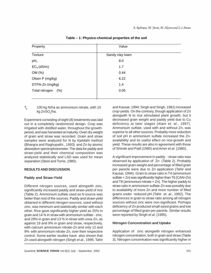
101Quarterly SCIENCE VISION Vol.8(1) July - September, 2002
T8 100 kg N/ha as ammonium nitrate, with 10kg ZnSO4/ha.
Experiment consisting of eight (8) treatments was laidout in a completely randomized design. Crop wasirrigated with distilled water, throughout the growth-period, and was harvested at maturity. Oven dry weightof grain and straw was recorded. Grain and strawsamples were analyzed for N by Kjeldahl method(Bhargra and Raghupathi., 1993) and Zn by atomicabsorption spectrophotometer. The data for paddy andstraw-yield and their chemical composition wasanalyzed statistically and LSD was used for meanseparation (Steel and Torrie, 1980).
RESULTS AND DISCUSSION
Paddy and Straw-Yield
Different nitrogen sources, used alongwith zinc,significantly increased paddy and straw-yield of rice(Table 2). Ammonium sulfate used as N source wasbetter than rest of the sources. Paddy and straw-yieldobtained in different nitrogen-sources, used withoutzinc, was minimum and statistically similar with eachother. Rice gave significantly higher yield as 25% ingrain and 14 % in straw with ammonium sulfate - zinc,and 28% in grain and 13 % in straw with urea-Zn, asagainst 19 and 9% in grain and straw, respectively,with calcium ammonium nitrate-Zn and only 12 and9% with ammonium nitrate-Zn, over their respectivecontrol. Some earlier studies have also shown thatZn used alongwith nitrogen (Singh et al., 1995; Tahir
and Kausar, 1994; Singh and Singh, 1981) increasedcrop-yields. On the contrary, though application of Znalongwith N to rice stimulated plant growth, but itdecreased grain weight and paddy yield due to Cudeficiency at later stages (Alam et. al., 1997).Ammonium sulfate, used with and without Zn, wassuperior to all other sources. Probably more reductionof soil pH in ammonium sulfate increased the Zn-availability and its useful effect on rice-growth andyield. These results are also in agreement with thoseof Shinde and Patil (1980) and Amer et al. (1980).
A significant improvement in paddy : straw ratio wasobserved by application of Zn (Table 2). Probablyincreased grain-weight and percentage of filled grainper panicle were due to Zn application (Tahir andKausar, 1994). Grain to straw ratio in T4 (ammoniumsulfate + Zn) was significantly higher than T6 (CAN+Zn)and T8 (ammonium nitrate + Zn). The higher paddy tostraw ratio in ammonium sulfate-Zn was possibly dueto availability of more Zn and more number of filledgrains under reduced pH (Tahir et. al., 1992). Thedifferences in grain to straw ratio among all nitrogensources without zinc were non-significant. Perhapsdeficiency of Zn produced small-sized grains and lowpercentage of filled grain per panicle. Similar resultswere reported by Singh et al. (1995).
Nitrogen Concentration and Uptake
Application of zinc alongwith nitrogen enhancednitrogen concentration, both in grain and straw (Table3). Nitrogen concentration was significantly higher in
Table – 1: Physico-chemical properties of the soil Property Value Texture Sandy clay loam
pHs 8.0
ECe (dS/m) 1.7
OM (%) 0.44
Olsen P (mg/kg) 6.22
DTPA-Zn (mg/kg) 1.4
Total nitrogen (%) 0.05
A. Rahman, M. Yasin, M. Akram and Z.I.Awan
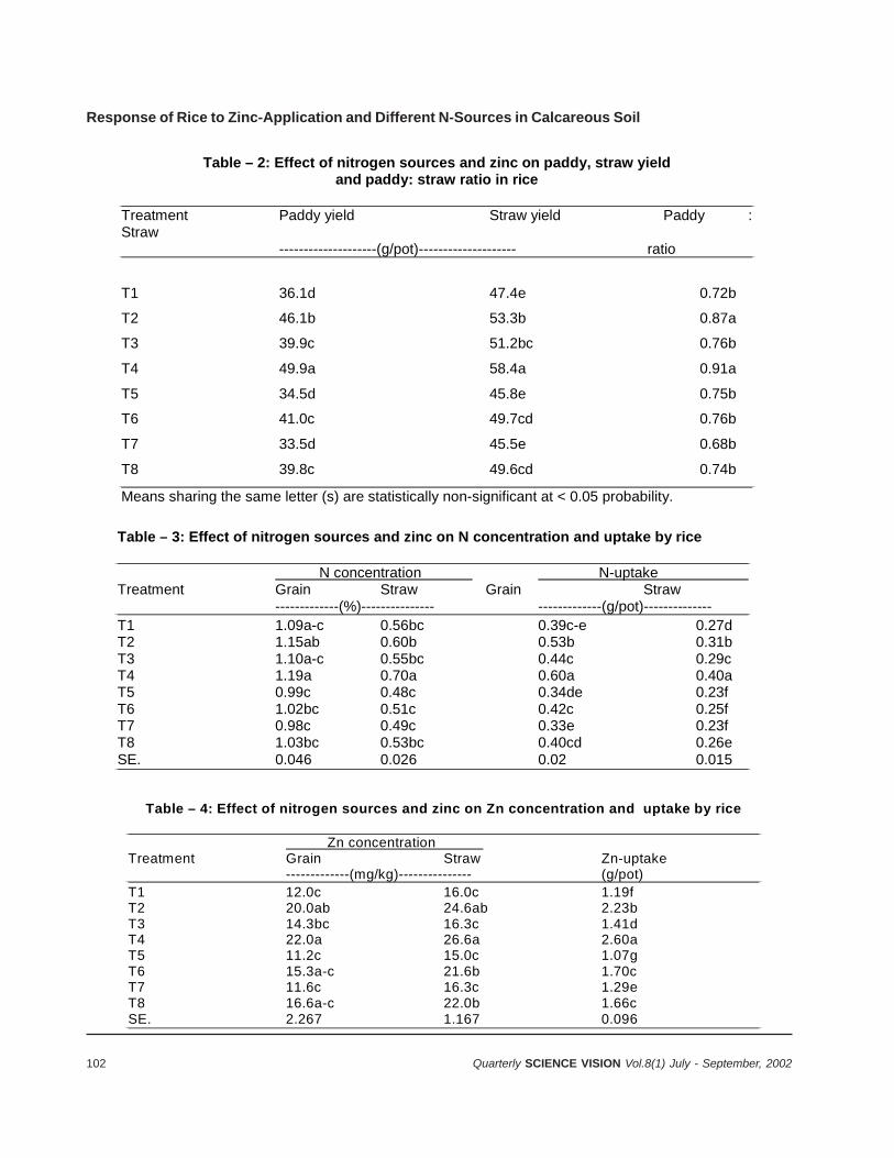
102 Quarterly SCIENCE VISION Vol.8(1) July - September, 2002
Table – 2: Effect of nitrogen sources and zinc on paddy, straw yield and paddy: straw ratio in rice
Treatment Paddy yield Straw yield Paddy : Straw --------------------(g/pot)-------------------- ratio
T1 36.1d 47.4e 0.72b
T2 46.1b 53.3b 0.87a
T3 39.9c 51.2bc 0.76b
T4 49.9a 58.4a 0.91a
T5 34.5d 45.8e 0.75b
T6 41.0c 49.7cd 0.76b
T7 33.5d 45.5e 0.68b
T8 39.8c 49.6cd 0.74b
Means sharing the same letter (s) are statistically non-significant at < 0.05 probability.
Table – 3: Effect of nitrogen sources and zinc on N concentration and uptake by rice
N concentration N-uptake Treatment Grain Straw Grain Straw -------------(%)--------------- -------------(g/pot)-------------- T1 1.09a-c 0.56bc 0.39c-e 0.27d T2 1.15ab 0.60b 0.53b 0.31b T3 1.10a-c 0.55bc 0.44c 0.29c T4 1.19a 0.70a 0.60a 0.40a T5 0.99c 0.48c 0.34de 0.23f T6 1.02bc 0.51c 0.42c 0.25f T7 0.98c 0.49c 0.33e 0.23f T8 1.03bc 0.53bc 0.40cd 0.26e SE. 0.046 0.026 0.02 0.015
Table – 4: Effect of nitrogen sources and zinc on Zn concentration and uptake by rice
Zn concentration Treatment Grain Straw Zn-uptake -------------(mg/kg)--------------- (g/pot) T1 12.0c 16.0c 1.19f T2 20.0ab 24.6ab 2.23b T3 14.3bc 16.3c 1.41d T4 22.0a 26.6a 2.60a T5 11.2c 15.0c 1.07g T6 15.3a-c 21.6b 1.70c T7 11.6c 16.3c 1.29e T8 16.6a-c 22.0b 1.66c SE. 2.267 1.167 0.096
Response of Rice to Zinc-Application and Different N-Sources in Calcareous Soil
103Quarterly SCIENCE VISION Vol.8(1) July - September, 2002
T4 than T6 (CAN + Zn) and T8 (ammonium nitrate +Zn), but values were at par with T2 in grains. In ricestraw, only T4 gave significantly higher Nconcentration. Treatment T2 (urea + Zn), T6 (CAN +Zn ) and T8 (AN + Zn) were statistically non-significantin difference with respect to N values. The treatmentswhere no Zn was applied, nitrogen concentrationdecreased both in grain and straw. The results are inagreement with the observations of Singh et. al.,(1995). Dev and Shukla (1982) stated that ammoniumsulfate is the better source, with respect toimprovement of nitrogen content in rice. Nitrogenuptake, both in paddy and straw, was significantlyaffected by zinc and nitrogen application (Table 3) .Maximum increase in N uptake was found in T4(ammonium sulfate + Zn) followed by T2 (Urea + Zn)which, in turn, was statistically different from T6 ( CAN+ Zn) and T8 (AN + Zn). Fertilization of N and Zntogether had synergistic effect on uptake of each other(Chaudhry et. al., 1977). In the absence of Zn, plantgrowth was stunted and nitrogen uptake was relativelysmaller.
Nitrogen uptake in grain for T3 (ammonium sulfate)was statistically similar to T1 (urea), but wassignificantly higher than T5 (CAN) and T7 (AN).Nitrogen uptake in rice-straw was significantly higherin T3 (ammonium sulfate) than T1 (urea), T5 (CAN)and T7 (AN). With application of Zn, higher N uptakein rice is quite evident from the data. Similarly, nitrogenuptake in rice for ammonium sulfate was better thanother N sources. Singh et al. (1995) and Tahir andKausar (1994) also recorded higher N uptake in ricewhere it was applied with Zn, rather than applyingnitrogen alone. Urea, ammonium nitrate and calciumammonium nitrate used were at par with each other.They did not affect N concentration and uptake in rice-grain significantly.
Zinc Concentration and Uptake
Concentration of Zn, both in grain and straw, as wellas total uptake increased significantly by applicationof Zn alongwith different nitrogen sources (Table 4).Concentration and total uptake of Zn was foundmaximum in T4 (ammonium sulfate + Zn), followedby T2 (Urea + Zn) and T8 (ammonium nitrate +Zn).Having more acidifying effect on soil than other Nsources, ammonium sulfate increased growth andavailability of Zn in rice. Chaudhry et. al. (1977) also
reported similar increase in Zn content of rice plants.In case of urea, uptake and translocation of Zn wasdepressed due to interference by HCO3 ions in plants.In another study, urea applied with Zn to rice hasshown good effect on yield and Zn content in rice(Singh and Singh, 1981). In the treatments where Znwas not applied, Zn concentration and uptake in ricewas low. Stunted rice growth in the absence of Zn,perhaps depressed Zn uptake in plants (Tahir andKausar, 1994). There was non-significant differenceamong N-sources used. The treatment T3 (ammoniumsulfate) was better than T1 (urea) and T7 (ammoniumnitrate). Acidic nature of ammonium sulfate probablyimproved the Zn uptake. The results are in goodagreement with those reported by Singh and Singh(1995).
CONCLUSION
Application of N along with Zn increased paddy yieldand paddy-to-straw ratio significantly. Among thedifferent N sources used, ammonium sulfate enhancedpaddy yield more than other sources. Use of N alonewas not so helpful in improving growth and paddy yield.Application of N along with Zn had synergistic effecton N and Zn uptake in rice.
REFERENCES
1. Alam, S.M., A. Latif and Z. Iqbal, 1997. Response ofrice to nitrogen and zinc fertilization with or withoutcopper. Pak. J. Soil Sci., 13 : 41-45.
2. Amer, F., A. J. Rezk and H. M. Khalid, 1980. Fertilizerzinc efficiency in flooded calcareous soils. Soil Sci.Soc. Amer. J., 44:1025-1030.
3. Bhargra, B.S. and M. B. Raghupathi, 1993. Analysisof plant material for macro and micronutrient, P: 49-82. In Tandon H.L. S. (ed.). Method of analysis ofsoils, plants, waters and fertilizers. Fer. Dev. andConslt. Org. New Delhi.
4. Chaudhry, F.M., M.A. Kausar, A.Rashid andR.Ullah,1977. Mechanism of N effect on the Znnutrition of flooded rice. Plant and Soil, 147: 649-654.
5. Dev, S. and U.C. Shukla, 1982. Nitrogen zinc contentsin rice as affected by their sources. J. Ind. Soc. SoilSci., 28 : 336-341.
6. Forno, D.A., C. J. Asher, and S. Yoshida, 1975. Zincdeficiency in rice. II: Studies of two varieties differingin susceptibility to zinc deficiency. Plant and Soil, 42:351-363.
A. Rahman, M. Yasin, M. Akram and Z.I.Awan

104 Quarterly SCIENCE VISION Vol.8(1) July - September, 2002
7. Halder, M. and L.N. Mandal, 1979. Influence of soilmoisture regimes and organic matter application onextractable Zn and Cu content in rice soils. Plantand soil, 53: 203-213.
8. Rashid, A. 1996. Secondary and micronutrient, pp:341-385. In: A. Rashid and K. S. Memon, (eds). SoilScience. National Book Foundation, Islamabad.
9. Rashid, A., F. Hussain and M.Tahir, 1999. Alleviatingzinc deficiency in transplanted flooded rice grown inalkaline soils of Pakistan, IRRN, 24: 32-33.
10. Shinde, P. B. and N. D. Patil. 1980. Relative efficiencyof nitrogen fertilizer for paddy. J. of Maharashtra Agri.Uni. , 5:135-138.
11. Singh, M. and S.P. Singh. 1981. Effect of nitrogenand zinc on the yield of submerged rice and uptakeof N and Zn on unlimed and limed soils. Plant andSoil, 62:185-192.
12. Singh, A.K., S. Thakar and S.K. Singh, 1995.Response of rice to nitrogen and zinc application ina calcareous situation, IRRN, 20 : 16-17.
13. Steel, R.G.D. and J.D. Torrie. 1980. Principles andProcedures of Statistics. (2nd ed.). McGraw Hill Book.Co. Inc. New York. 754 pp.
14. Tahir, M. and M.A.Kausar,1994. Fertilizer zincefficiency for rice and subsequent wheat as affectedby urea and manure application. Proc. Of 4th NationalCong. Soil Sci.. On Efficient Use of Plant Nutrients.Islamabad, May 24-26, 1992, p: 347-354.
15. Tahir, M., M. A. Kausar, R. Ahmad and S.A. Bhatti.1991.Micronutrient status of Faisalabad and Sheikhupurasoils. Pak. J. Agric. Res., 12: 134-140.
16. Tahir,M., M.A. Kausar and A.S. Bhatti, 1992.Micronutrient status and effectively ameliorating zincdeficiency in rice. Pak. J. Sci. Ind. Res., 35:133-137.
Response of Rice to Zinc-Application and Different N-Sources in Calcareous Soil
105Quarterly SCIENCE VISION Vol.8(1) July - September, 2002
EFFECT OF DICYANDIAMIDE (DCD) AND PYRETHRUMFLOWER-WASTE ON GROWTH AND MENTHOL-CONTENTS OF MENTHA ARVENSIS L.
Muhammad Arshadand Audil Rashid*
ABSTRACT
Pyrethrum (Chrysanthemum cinerariefolium) flowershave been observed to have insecticidal propertiesand could be used as indigenous nitrification inhibitorsfor increasing N-use efficiency and growth. A fieldexperiment was conducted at National AgriculturalResearch Centre, Islamabad, during 1998 and 1999,to evaluate the relative performance of pyrethrumflower-waste and Dicyandiamide (DCD) as nitrificationinhibitors, applied with prilled urea (PU) to Japanesemint (Mentha arvensis L.) The results revealed thatapplication of the nitrification inhibitors with prilledurea significantly increased the growth and mentholcontents of the crop, compared to that of prilled ureaalone. Addition of DCD and pyrethrum flower-wastegave 30% and 23% more herb-yield than prilled ureaalone, the corresponding increase in oil-contents being27% and 22%, respectively. Application of nitrogenat 200 kg ha-1 in dicayndiamide or pyrethrum flowerwaste-treated soil enhanced the growth and mentholcontents of crop significantly more than that for 300kg N ha-1 with prilled urea. Both the materials improvedthe N use-efficiency one and half times, compared tothat with PU at 100 kg N ha-1. The results indicatethat pyrethrum flower-dust can be effectively used asa potential nitrification inhibitor.
INTRODUCTION
Japanese mint is an important essential-oil-bearingcrop, cultivated for menthol, used in cosmetic andpharmaceutical industry. It is generally planted inJanuary-February in the plains of Punjab, Pakistan.Mentha arvensis is a herbaceous plant, usually grownin loamy to clayey loam soil. On the average, itrequires 120 kg ha-1 N for optimum growth. Frequentirrigations are generally given during the entire growth-period of this crop, till the monsoon comes.
A loss of N due to NO3 leaching is a serious problemin the medium-textured soils of Punjab. This loss isconsidered to be greater during the rainy season. Thisresults in a very poor N-use efficiency.
Commercial nitrification-inhibitors are recommendedfor application with ammonium and ammonium-producing fertilizers, to retard the formation of nitrateby nitrifying bacteria and thus reduce the loss byleaching and denitrification. Many plant-products andby-products have also been reported to havenitrification-inhibitory properties and have successfullybeen used to retard nitrification in soil (Sivapalan &Fernando, 1985., Prakasha and Puttana, 1994.,Sharma and Prasad, 1996).
Pyrethrum flowers are grown for their insecticidal andornamental properties. Preliminary investigations haveindicated that pyrethrum also has unique nitrificationinhibitory properties (Ram et al.., 1993). The aim ofthe present work was to evaluate the relativeperformance of pyrethrum flower-waste and DCD asinhibitors for reducing N losses and increasing growthand menthol-contents of mint.
MATERIALS AND METHODS
A field experiment was conducted for two years, during1998 & 1999, at NARC, Islamabad, Pakistan. Thesoil of the experimental plot was loam in texture andhad pH 7.8, EC 0.25dSm-1, available N 0.04%, availableK 0.76 mg kg-1, and P 4.5 mg kg–1.
The treatments consisted of three combinations ofnitrogen and nitrification inhibitors, viz prilled urea +no inhibitor, urea + dicyandiamide (DCD) and urea +pyrethrum flower waste, with three levels of nitrogen(100, 200 and 300 kg ha-1) and one control. Thestatistical design was a randomized block-design withthree replications.
Suckers of Japanese mint were transplanted end-to-end in the last week of January in 5 cm deep furrows,40 cm apart and covered with 5 cm soil. Nitrogen wasapplied in two equal splits i.e., at planting and afterfirst harvest. Dicyandiamide was applied at plantingtime @ 15 ppm on soil-basis, considering the plough-depth having a bulk density of 1.47 g cm-3. This wasthoroughly mixed with the soil. Pyrethrum flower-waste, a by-product of medicinal plant (100 ppm on
106 Quarterly SCIENCE VISION Vol.8(1) July - September, 2002
soil basis) was also applied at planting-time andthoroughly mixed with the soil. The crop, both in thecontrol and N plus inhibitor-treated plots, received auniform application of 60 kg ha-1 each of P and K atthe time of planting, as single super-phosphate andmuriate of potash, respectively. Two harvests of theherb, 15 days after planting (DAP) and 75 days afterfirst harvest, were taken during 1998. However, in1999, only first harvest, 115 days after planting, wastaken because a second harvest from the regeneratedcrop was not possible due to heavy rains.
Soil samples were collected at 0-15 cm and 15-25cm depth, randomly, from five sites in each plot at 30days after planting, 60 days after planting and afterfirst harvest, and analysed for ammoniacal and nitrateform of N, by the procedures described by Jackson(1967) and Black et al. (1965). Mineral N is presentedin kg ha-1, taking bulk density of the soil 1.47 g cm-3
and soil depth 15 cm; 1 hectare soils weighs 2.205 x10⁶ kg. The soil pH, EC, mineral N and soil-texturewas determined by the method described byWinkleman et al. (1990). Values for tissue P and Kwere obtained by atomic absorptionspectrophotometer.
RESULTS AND DISCUSSION
Growth and Menthol Contents
Dicyandiamide (DCD) and pyrethrum flower-wastesignificantly increased the growth and mentholcontents in Japanese mint, over prilled urea (Table1). The increase in growth was in the order of 37 and27 % by DCD and pyrethrum, respectively, over prilledurea (PU) in 1998. The corresponding increase in 1999was 23 and 18 %, respectively. On application of 300kg ha-1 N, the maximum growth observed was 17 tha-1, compared to 4.1 t ha-1 of control (Table 1). Itmight be due to high utilization of N by the crop, as aresult of retardation-loss of fertilizer N by thenitrification inhibitors. The usage of DCD as a potentialinhibitor has been reported by several workers inupland condition. (Sharma and Prasad, 1996; Arshadet al., 1999). Pyrethrum flower-waste applicationsignificantly improved the growth, compared to theprilled urea, although rate of increase was lowcompared to DCD. Pyrethrum flower-waste is thoughtto have some nitrification inhibitory properties (Ramet al., 1993), as in several naturally occuring plant-
materials (Sahrawat, 1982; Sharma and Prasad,1996). The inhibitory properties of pyrethrum flower-waste may be attributed to the residual quantity ofpyrethrin, which is known to be a domestic insecticide.The same insecticidal properties have played a vitalrole in limiting the process of nitrification.
Dicyandiamide and pyrethrum flower-waste increasedthe menthol contents over prilled urea by 23% and20% in 1998 and 31% and 21% in 1999. Both growthand menthol-contents increased with increasing rateof nitrogen application. Substantial increases in herband essential-oil yield of Japanese mint, due to highlevels of N, have been reported by Sharma and Singh(1980) and Ram et al. (1989).
Interaction effects, amongst nitrification-inhibitors andN-rates, showed that growth and menthol-contentswere significantly increased at 200 kg N ha-1 appliedwith DCD or pyrethrum flower-waste, compared to 100kg N ha-1 urea applied alone or with DCD or pyrethrumwaste and 200 and 300 kg N ha-1 applied as PU alone,during both the years (Table1). Obviously, applicationof N at 200 kg ha-1 with DCD or pyrethrum flower-wasteeconomized 100 kg N ha-1. Higher growth and menthol-contents with inhibitor may be due to inhibition ofnitrification-process in soil, resulting in reducednitrogen-losses through different mechanisms.
Mineral nitrogen status of soil
The data on status of NH4–N and NO3–N, estimatedat 30 and 60 days after planting (DAP), and at firstharvest (115 DAP), reveal that NO3–N was the lowestin DCD-treated plot, followed by that in pyrethrum-treated plots (Table 2 and 3). This indicates retardationof nitrate formation by both the nitrification inhibitors.Many studies have shown that nitrification inhibitorscan be used to enhance NH4–N, supply, particularlywhen reduced nitrate-movement to groundwater isincreasing the proportion of N supplied to the crop asNH4–N (Ball-Coelho, 1999). In 1999, however, thenitrate content, which was lower in DCD treated soilthan in the pyrethrum treated soil in the early stages,was found at par during the later stages (60 DAP andfirst harvest). Our results are in agreement with thoseof Puttana et al. (1999), which indicated thatconcentrations of the inhibitors in soil delayed thenitrification up to 60 days. Another reason behind thatis reduced N-leaching, because restricted post-
Effect of Dicyandiamide (DCD) and Pyrethrum Flower-Waste on Growth & Menthol-Contents of Mentha Arvensis L.
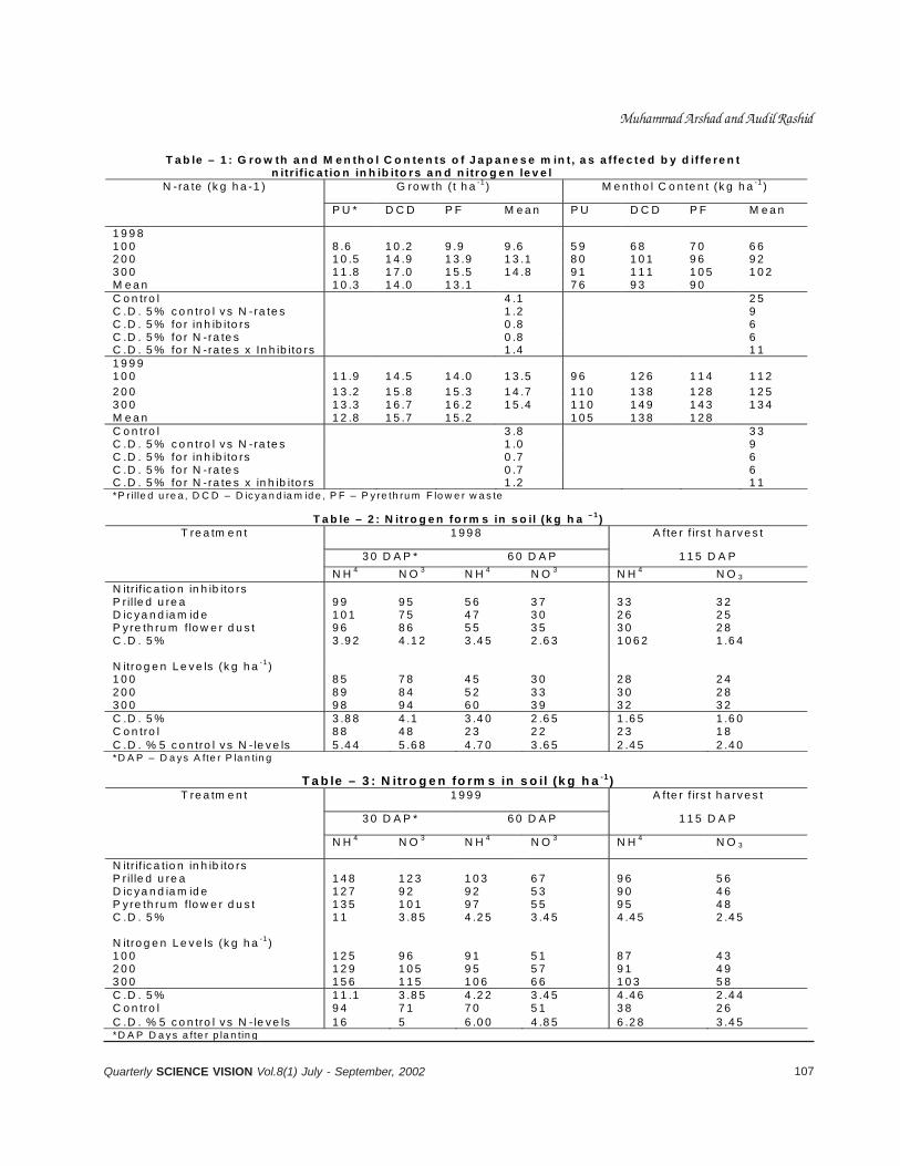
107Quarterly SCIENCE VISION Vol.8(1) July - September, 2002
T a b le – 1 : G ro w th a n d M e n th o l C o n te n ts o f J a p a n e s e m in t , a s a f fe c te d b y d if fe re n t n itr if ic a t io n in h ib ito rs a n d n itro g e n le v e l
G ro w th ( t h a -1 ) M e n th o l C o n te n t (k g h a -1 ) N -ra te (k g h a -1 )
P U * D C D P F M e a n P U D C D P F M e a n
1 9 9 8 1 0 0 8 .6 1 0 .2 9 .9 9 .6 5 9 6 8 7 0 6 6 2 0 0 1 0 .5 1 4 .9 1 3 .9 1 3 .1 8 0 1 0 1 9 6 9 2 3 0 0 1 1 .8 1 7 .0 1 5 .5 1 4 .8 9 1 1 1 1 1 0 5 1 0 2 M e a n 1 0 .3 1 4 .0 1 3 .1 7 6 9 3 9 0 C o n tro l 4 .1 2 5 C .D . 5 % c o n tro l v s N -ra te s 1 .2 9 C .D . 5 % fo r in h ib ito rs 0 .8 6 C .D . 5 % fo r N -ra te s 0 .8 6 C .D . 5 % fo r N -ra te s x In h ib ito rs 1 .4 1 1 1 9 9 9 1 0 0 1 1 .9 1 4 .5 1 4 .0 1 3 .5 9 6 1 2 6 1 1 4 1 1 2 2 0 0 1 3 .2 1 5 .8 1 5 .3 1 4 .7 1 1 0 1 3 8 1 2 8 1 2 5 3 0 0 1 3 .3 1 6 .7 1 6 .2 1 5 .4 1 1 0 1 4 9 1 4 3 1 3 4 M e a n 1 2 .8 1 5 .7 1 5 .2 1 0 5 1 3 8 1 2 8 C o n tro l 3 .8 3 3 C .D . 5 % c o n tro l v s N -ra te s 1 .0 9 C .D . 5 % fo r in h ib ito rs 0 .7 6 C .D . 5 % fo r N -ra te s 0 .7 6 C .D . 5 % fo r N -ra te s x in h ib ito rs 1 .2 1 1 *P r il le d u re a , D C D – D ic y a n d ia m id e , P F – P y re th ru m F lo w e r w a s te
T a b le – 2 : N itro g e n fo rm s in s o il (k g h a – 1 ) 1 9 9 8 A fte r f irs t h a rv e s t
3 0 D A P * 6 0 D A P 1 1 5 D A P
T re a tm e n t
N H 4 N O 3 N H 4 N O 3 N H 4 N O 3 N itr if ic a tio n in h ib ito rs P r il le d u re a 9 9 9 5 5 6 3 7 3 3 3 2 D ic ya n d ia m id e 1 0 1 7 5 4 7 3 0 2 6 2 5 P y re th ru m f lo w e r d u s t 9 6 8 6 5 5 3 5 3 0 2 8 C .D . 5 % 3 .9 2 4 .1 2 3 .4 5 2 .6 3 1 0 6 2 1 .6 4 N itro g e n L e v e ls (k g h a -1 ) 1 0 0 8 5 7 8 4 5 3 0 2 8 2 4 2 0 0 8 9 8 4 5 2 3 3 3 0 2 8 3 0 0 9 8 9 4 6 0 3 9 3 2 3 2 C .D . 5 % 3 .8 8 4 .1 3 .4 0 2 .6 5 1 .6 5 1 .6 0 C o n tro l 8 8 4 8 2 3 2 2 2 3 1 8 C .D . % 5 c o n tro l v s N - le v e ls 5 .4 4 5 .6 8 4 .7 0 3 .6 5 2 .4 5 2 .4 0 *D A P – D a ys A fte r P la n tin g
T a b le – 3 : N itro g e n fo rm s in s o il (k g h a -1) 1 9 9 9 A fte r f irs t h a rv e s t
3 0 D A P * 6 0 D A P 1 1 5 D A P
T re a tm e n t
N H 4 N O 3 N H 4 N O 3 N H 4 N O 3
N itr if ic a tio n in h ib ito rs P r il le d u re a 1 4 8 1 2 3 1 0 3 6 7 9 6 5 6 D ic ya n d ia m id e 1 2 7 9 2 9 2 5 3 9 0 4 6 P y re th ru m f lo w e r d u s t 1 3 5 1 0 1 9 7 5 5 9 5 4 8 C .D . 5 % 1 1 3 .8 5 4 .2 5 3 .4 5 4 .4 5 2 .4 5 N itro g e n L e v e ls (k g h a -1 ) 1 0 0 1 2 5 9 6 9 1 5 1 8 7 4 3 2 0 0 1 2 9 1 0 5 9 5 5 7 9 1 4 9 3 0 0 1 5 6 1 1 5 1 0 6 6 6 1 0 3 5 8 C .D . 5 % 1 1 .1 3 .8 5 4 .2 2 3 .4 5 4 .4 6 2 .4 4 C o n tro l 9 4 7 1 7 0 5 1 3 8 2 6 C .D . % 5 c o n tro l v s N - le v e ls 1 6 5 6 .0 0 4 .8 5 6 .2 8 3 .4 5 *D A P D a y s a fte r p la n tin g
Muhammad Arshad and Audil Rashid
108 Quarterly SCIENCE VISION Vol.8(1) July - September, 2002
harvest leaching of N has been reported when DCDwas applied as nitrification inhibitor (Chen et al., 1998).Not only this, but reduction in N2O emission from soil-plant system is another effect of these inhibitors.(Chen et al., 1998). These inhibitory properties ofpyrethrum flower-waste appear to have started later,compared to DCD. In general, the NH4–N content wasthe lowest in the DCD treated soil, followed by thepyrethrum-treated soil and the highest with prilledurea. Lower NH4 in the soil treated with inhibitors isunusual, but could be due to greater plant-growth andenhanced uptake of NH4–N. The NH4–N inhibition withDCD and pyrethrum seems to be the result of chemicalproperties possessed by the inhibitory compounds ofboth. On the other hand, urea has two amino groupsin its molecular structure that, during NH4–N inhibition,antagonize the chemical-configuration, thus curtailingthe inhibition process.
CONCLUSION
The above results demonstrate an interrelationbetween N-rates and nitrification inhibitors onincreasing N-use efficiency, with respect to yield ofJapanese mint. There was a significant interactionbetween N-rates and inhibitors. Nitrogen applied at200 kg N ha-1, with inhibitors, showed a significantincrease in growth and menthol-contents over the 200and 300 kg N ha-1 applied as prilled urea (no inhibitor).Herb-yield significantly increased with an increase inthe level of N up to 300 kg in DCD-treated plots. Butthe increase was restricted up to 200 kg N ha-1 withPU and pyrethrum. Mean of two years’ data indicatedan increase of 34% and 26% in herb-yield over prilledurea at 300 kg N ha-1 with DCD and pyrethrum,respectively. The corresponding increases in menthol-contents were 29% and 23%, respectively.
Our study shows that the use of nitrification-inhibitorsis favourable for high-N demanding crops, particularlyfor those crops that are grown in N deficient, poorlystructured and leaching-prone soils. The results revealthat pyrethrum flower-waste can be effectively usedas a potential nitrification-inhibitor, although it is notas efficient as DCD.
REFERENCES
1. Arshad, M., M.S. Zia and T. Ahmed. 1999. Effect ofnitrogen sources and dicyandiamide on wheat-yield,
agronomic and physiological efficiency and nitrogenutilization under rainfed ecosystem. Science Vision4 (4) : 54-61.
2. Ball-Coelho, B.R. and R.C. Roy. (1999). Enhancedammonium sources to reduce nitrate leaching. Nutr.Cyc. Agroecosystems. 54(1): 73-80.
3. Black, C.A., D.D., Evans., J.L. Whilte., L.E.,Ensmingar & P.F. Clark. (1965). Methods of SoilAnalysis, Part-II. American Society of Agronomy,Madison, Wisconsin, US.
4. Chen, L., P. Boeckx., L. Zhou., O. Van Cleemput andR. Li. (1998). Effect of hydroquinone, dicyandiamideand encapsulated calcium carbide on urea N uptakeby spring wheat, soil mineral N content and N2Oemission. Soil Use & Management. 14(4): 230-233.
5. Jackson, M.L. (1967). Soil Chemical Analysis.Prentice Hall, Englewood Cliffs, N,. J.
6. Prakasha, E.V.S. and K. Puttana. 1994. Evaluationof dicyandiamide (DCD) treated urea in Javacitronella. J. Ind. Soc. Soil Sci., 42 (1) : 54-59.
7. Puttana, K., N.M.N. Gowda, and E.V.S.P. Rao. (1999).Effect of concentration, temperature, moisture,limiting and organic matter on the efficacy of thenitrification inhibitors benzotriazole, o-nitrophenol,m-nitroaniline and dicyandiamide. Nutr. Cyc.Agrosystems. 54(3): 251-257.
8. Ram, M., D.D. Patra., K. Subrahmanyam & D.V. Singh.(1993). Nitrification inhibitory properties in Menthaspent and Pyrethrum flowers. J. Indian Soc. SoilSci. 4(1): 176-177.
9. Ram, M., R.L. Yadav., B.N. Chatterjee & D.V. Singh.(1989). Relative efficacy of nitrogen –carriers atdifferent rates and times of application on growthand yield of Japanese mint (Mentha arvensis L.)Indian J. Agric. Sci. 59 (4): 236-241.
10. Sahrawat, K.L. (1982). Comparative evaluation ofKaranjin and extract of Karnja (Pongamia glabra)and neem (Azadirachta indica) seeds for retardationof nitrification of urea in soil. J. Indian Soc. Soil Sci.30 (2): 107-115.
11. Sharma, S.N. & A. Singh. (1980). Response ofJapanese mint to nitrogen, phosphorus andpotassium. Indian J., Agron. 25 (3): 428-432.
12. Sharma, S.N. and R. Prasad. 1996. Use ofnitrification inhibitors (Neem & DCD) to increasenitrogen use efficiency in maize-wheat croppingsystem. Fertil. Res., 44 : 169-175.
13. Sivapalan, K., & V. Fernando. (1985). N-minieralisation in polyphenol rich plant-residuesand their effect on nitrification of applied ammoniumsulphate. Soil Biol. Biochem 17(4): 547-551.
14. Wikleman, G.E., R. Amin., W.A. Rice and M.B. Tahir.(1990). Sample processing. In: Methods Manual SoilLaboratory, Barani Agric. Res. Dev. Proj. 27-92.
Effect of Dicyandiamide (DCD) and Pyrethrum Flower-Waste on Growth & Menthol-Contents of Mentha Arvensis L.
109Quarterly SCIENCE VISION Vol.8(1) July - September, 2002
EFFECT OF NITRIFICATION INHIBITORS ON NITROGEN-FIXING BACTERIA
Muhammad Arshad*
ABSTRACT
The nitrification inhibitor dicyandiamide (DCD) did notinhibit the growth and respiration of N-fixing bacteria(Rhizobium leguminosarum Azotobacterchroococcum) in cell-suspensions withconcentrations of 400 m gm-1 DCD. Growth ofRhizobium legumiinosarum was inhibited by 17%with 100 m gm-1 nitrapyrin (N serve), but respirationwas not affected. [Growth of Azotobacterchroococcum was inhibited by 10 m gm-1 (10%) and100 m gm-1 nitrapyrin (50%), in the latter case,respiration was also impaired (36%); thiourea onlycaused a minor growth-inhibition of Azotobacterchroococcum with 100 m gm-1 (8%) and had no effecton Rhizobium leguminosarum.
INTRODUCTION
One of the most important requirements fornitrification-inhibitors is specificity for bacteria of thespecies Nitrosomonas europaea, which perform thefirst step of nitrification. Impact on other soil-bacteriashould be negligible or as low as possible. Symbioticand non-symbiotic N-fixing bacteria of the genusRhizobium and Azotobacter should especially not beimpaired in their activity. The strong inhibiting effectof nitrification-inhibitors on N-fixing bacteria had beenreported by different researchers: Hughes and Welch,1970, Vannelli and Hooper 1993, and Bedard andKnowles 1997.
The objective of this study was to determine the effectof the nitrification-inhibitors, Dicyandiamide (DCD), Nserve (NS) and Thiourea (TU), on growth andrespiration of Rhizobium and Azotobacter.
Materials and Methods
The two strains, Rhizobium leguminosarum andAzotobacter chroococcum, were cultivated in thefollowing nutrient solution:
D (-) Mannite 10.0 gK2HPO4 0.5 g
MgSO4 + 7H2 0.2 gNaCl 0.1 gYeast extract 1.5 g
pH 7.2 (adjusted after autoclaving).
The stock cultures grew on solid nutrient media. Petridishes were prepared from the above nutrient-solution,after addition of 1.5 % agar, and inoculated by meansof a loop.
Both microorganisms were cultivated in the above-mentioned nutrient solution. At first, inoculated mediumwas incubated at 25 0C on a rotary shaker; thispreliminary culture was used as an inocolum afteroptical density was adjusted to 1.2 (578 nm). Fivereplicates of each treatment were started with 10mlnutrient solution plus respective amounts of inhibitorsin flasks. The flasks were inoculated with 0.1 ml ofthe preliminary culture and shaken in the warm water-bath at 25 0C. After 20 h, the turbidity of the nutrientsolution was measured, using a spectrometer(578nm).
Bacteria were pre-cultivated for 20h, then centrifuged(3500 rpm) and washed twice with 0.1 M phosphatebuffer (pH 7.2). From this suspension, 1.5ml werepipetted together with 0.5 ml glucose (1 %) into themain part of warburg flasks. The center-well contained0.2 ml KOH (5%). The nitrification inhibitors werepipetted into the side-arm and added after apreliminary run of 30 minutes. All measurements weredone in 6 replicates at 28 0C.
RESULTS
1. Growth and respiration of Rhizobium
Among the tested inhibitors, only N-serve at thehigher concentration of 100 m gm-1 affected growthof Rhizobium with significant depression of 17%(Figure-1). Respiration was not impaired in anycase. The respiration rates of inhibitor-treatmentsand untreated controls were almost identical(Table-1). The untreated bacteria consumed 215
* University of Arid Agriculture, Murree Road, Rawalpindi, Pakistan.
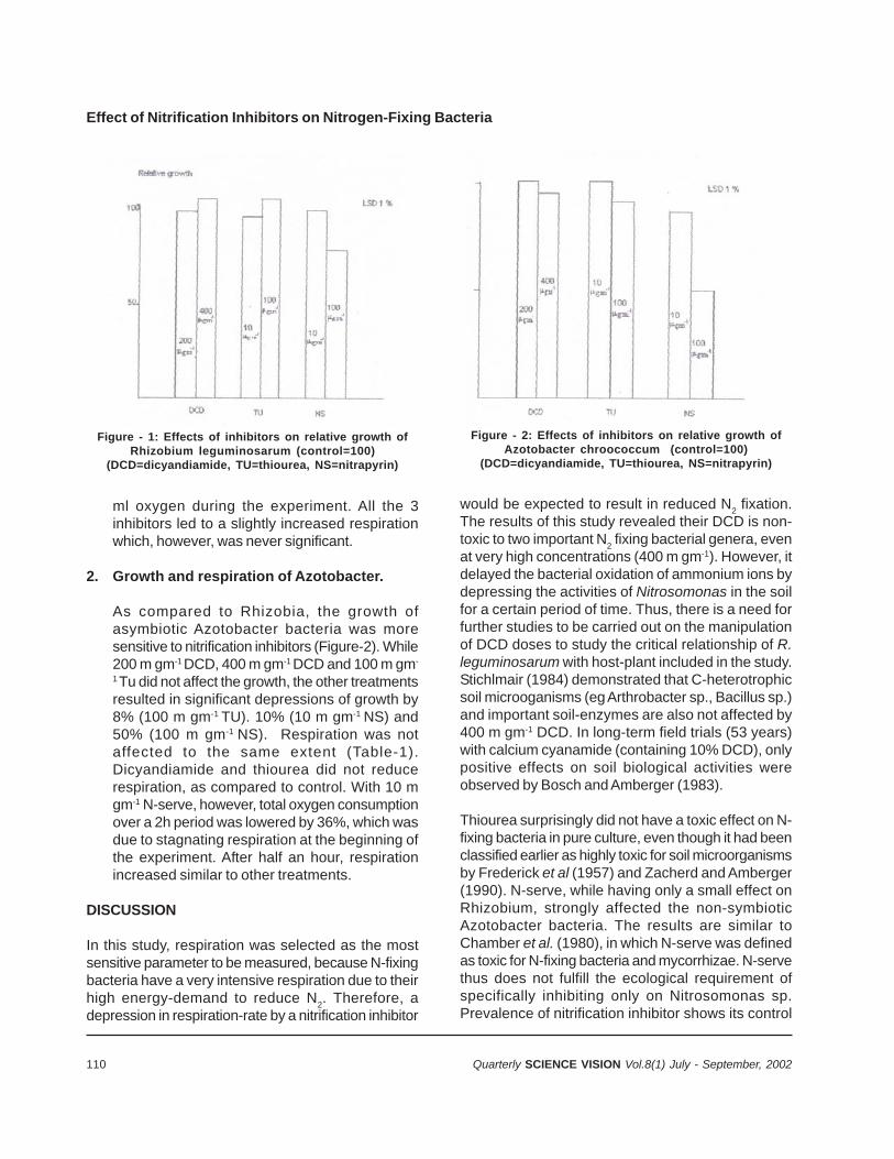
110 Quarterly SCIENCE VISION Vol.8(1) July - September, 2002
ml oxygen during the experiment. All the 3inhibitors led to a slightly increased respirationwhich, however, was never significant.
2. Growth and respiration of Azotobacter.
As compared to Rhizobia, the growth ofasymbiotic Azotobacter bacteria was moresensitive to nitrification inhibitors (Figure-2). While200 m gm-1 DCD, 400 m gm-1 DCD and 100 m gm-
1 Tu did not affect the growth, the other treatmentsresulted in significant depressions of growth by8% (100 m gm-1 TU). 10% (10 m gm-1 NS) and50% (100 m gm-1 NS). Respiration was notaffected to the same extent (Table-1).Dicyandiamide and thiourea did not reducerespiration, as compared to control. With 10 mgm-1 N-serve, however, total oxygen consumptionover a 2h period was lowered by 36%, which wasdue to stagnating respiration at the beginning ofthe experiment. After half an hour, respirationincreased similar to other treatments.
DISCUSSION
In this study, respiration was selected as the mostsensitive parameter to be measured, because N-fixingbacteria have a very intensive respiration due to theirhigh energy-demand to reduce N2. Therefore, adepression in respiration-rate by a nitrification inhibitor
would be expected to result in reduced N2 fixation.The results of this study revealed their DCD is non-toxic to two important N2 fixing bacterial genera, evenat very high concentrations (400 m gm-1). However, itdelayed the bacterial oxidation of ammonium ions bydepressing the activities of Nitrosomonas in the soilfor a certain period of time. Thus, there is a need forfurther studies to be carried out on the manipulationof DCD doses to study the critical relationship of R.leguminosarum with host-plant included in the study.Stichlmair (1984) demonstrated that C-heterotrophicsoil microoganisms (eg Arthrobacter sp., Bacillus sp.)and important soil-enzymes are also not affected by400 m gm-1 DCD. In long-term field trials (53 years)with calcium cyanamide (containing 10% DCD), onlypositive effects on soil biological activities wereobserved by Bosch and Amberger (1983).
Thiourea surprisingly did not have a toxic effect on N-fixing bacteria in pure culture, even though it had beenclassified earlier as highly toxic for soil microorganismsby Frederick et al (1957) and Zacherd and Amberger(1990). N-serve, while having only a small effect onRhizobium, strongly affected the non-symbioticAzotobacter bacteria. The results are similar toChamber et al. (1980), in which N-serve was definedas toxic for N-fixing bacteria and mycorrhizae. N-servethus does not fulfill the ecological requirement ofspecifically inhibiting only on Nitrosomonas sp.Prevalence of nitrification inhibitor shows its control
Effect of Nitrification Inhibitors on Nitrogen-Fixing Bacteria
Figure - 1: Effects of inhibitors on relative growth ofRhizobium leguminosarum (control=100)
(DCD=dicyandiamide, TU=thiourea, NS=nitrapyrin)
Figure - 2: Effects of inhibitors on relative growth ofAzotobacter chroococcum (control=100)
(DCD=dicyandiamide, TU=thiourea, NS=nitrapyrin)
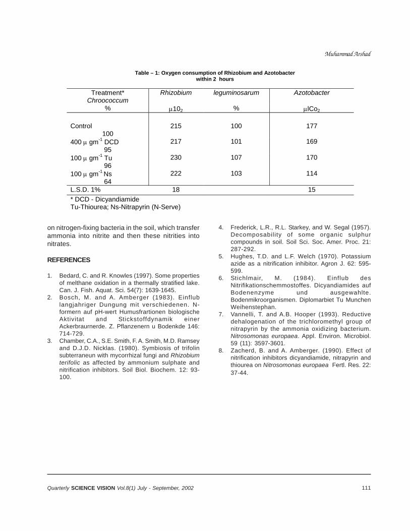
111Quarterly SCIENCE VISION Vol.8(1) July - September, 2002
Muhammad Arshad
on nitrogen-fixing bacteria in the soil, which transferammonia into nitrite and then these nitrities intonitrates.
REFERENCES
1. Bedard, C. and R. Knowles (1997). Some propertiesof melthane oxidation in a thermally stratified lake.Can. J. Fish. Aquat. Sci. 54(7): 1639-1645.
2. Bosch, M. and A. Amberger (1983). Einflublangjahriger Dungung mit verschiedenen. N-formern auf pH-wert Humusfrartionen biologischeAktivitat and Stickstoffdynamik einerAckerbraurnerde. Z. Pflanzenern u Bodenkde 146:714-729.
3. Chamber, C.A., S.E. Smith, F. A. Smith, M.D. Ramseyand D.J.D. Nicklas. (1980). Symbiosis of trifolinsubterraneun with mycorrhizal fungi and Rhizobiumterifolic as affected by ammonium sulphate andnitrification inhibitors. Soil Biol. Biochem. 12: 93-100.
4. Frederick, L.R., R.L. Starkey, and W. Segal (1957).Decomposability of some organic sulphurcompounds in soil. Soil Sci. Soc. Amer. Proc. 21:287-292.
5. Hughes, T.D. and L.F. Welch (1970). Potassiumazide as a nitrification inhibitor. Agron J. 62: 595-599.
6. Stichlmair, M. (1984). Einflub desNitrifikationschemmostoffes. Dicyandiamides aufBodenenzyme und ausgewahlte.Bodenmikroorganismen. Diplomarbiet Tu MunchenWeihenstephan.
7. Vannelli, T. and A.B. Hooper (1993). Reductivedehalogenation of the trichloromethyl group ofnitrapyrin by the ammonia oxidizing bacterium.Nitrosomonas europaea. Appl. Environ. Microbiol.59 (11): 3597-3601.
8. Zacherd, B. and A. Amberger. (1990). Effect ofnitrification inhibitors dicyandiamide, nitrapyrin andthiourea on Nitrosomonas europaea Fertl. Res. 22:37-44.
Table – 1: Oxygen consumption of Rhizobium and Azotobacter within 2 hours
Treatment*
Chroococcum Rhizobium leguminosarum Azotobacter
% 102 % lCo2 Control
100 215 100 177
400 gm-1 DCD 95
217 101 169
100 gm-1 Tu 96
230 107 170
100 gm-1 Ns 64
222 103 114
L.S.D. 1% 18 15 * DCD - Dicyandiamide Tu-Thiourea; Ns-Nitrapyrin (N-Serve)
112 Quarterly SCIENCE VISION Vol.8(1) July - September, 2002
SEED-BORNE PATHOGENS ASSOCIATED WITHCERTIFIED SEED LOTS OF WHEAT IN PAKISTAN
Farrukh Javed* Bhattiand Abdul Rauf Bhutta
ABSTRACT
Ten seed-borne pathogens were detected from 335wheat seed samples that were collected from twelvemajor wheat-growing areas in Pakistan during 1997-98,1998-99 and 1999-2000. Fusarium spp were themajor pathogen, with infection ranging from 0.5 to34.0 per cent. Bipolaris sorokiniana was the secondmajor pathogen, with infection ranging from 0.50 –28.0 per cent. Acremonium spp. was isolated fromPeshawar and D.I.Khan, while Microdochium nivaliswas isolated only from D.I.Khan. Bipolaris tetramera,Curvularia lunata, Phoma spp.. and Stemphylium spp.were detected, with infection less than 2 per cent.
Variation in number of pathogens and their incidencewas found from year to year. High incidence ofpathogens suggests that wheat seed should betested for their health status, regularly and infectedseed-lots should be treated with seed-dressingfungicides before sowing. Alternaria tenuis,Aspergillus spp., Bipolaris hawiiensis, Cladosporiumspp., Epicocum spp., Penicillium spp., and Rhizopusspp. were also identified, but were not counted.
Key words. Seed-borne pathogens , wheat seedlots , Pakistan
INTRODUCTION
The major diseases of wheat in Pakistan are rusts,loose smut, bunts, septoria leaf spot, foot rot, rootrot, black point complex and ear cockle (Kausar,1955). Spot blotch caused by Bipolaris sorokinianais the most severe disease of warmer areas. Yield-loss from 40% to 85% had been reported in Philippinesand Zambia, respectively.( Lapis, 1985 andRaemaekers, 1988) Pink snow mold, caused byMicrodochium nivale, has also caused substantialyield-loss (Mathur & Cunfer, 1993). In Pakistan, lossesdue to different wheat-diseases are also consideredhigh. In view of this scenario, 335 seed samples ofwheat were collected from fields that were inspectedand certified by the Federal Seed Certification andRegistration Department for seed-production and weretested for their health-status using ISTA techniques.
Data about the incidence and association ofpathogens with wheat seed may be very useful tothe breeders and seed technologists, at national andinternational level, for planning better strategies ondisease-management in wheat crop.
MATERIALS & METHODS
A total of 335 wheat-seed samples were collectedfrom different agro-ecological regions, as describedin Agro-ecological regions of Pakistan (Anonymous,1980) according to ISTA rules(1985), during 1997-98,1998-99 and 1999-2000. The seeds were tested bythe standard blotter-paper method (Neergard, 1979).Three blotter papers, well moistened in sterilized water,were placed in each Petri dish .Four hundred seedswere placed in such a manner that each Petri dishmay contain 25 seeds. Seeds were incubated at20°C±2°C for 7 days and on 8th day, seeds in Petridishes were examined under stereo-microscope and,wherever identification was difficult, slides wereprepared and examined under binocular electricmicroscope on the basis of spore shape, size, itsattachment with fruiting body directly from seed.(Chidambaram et al, 1973, Nath et al, 1970, andBarnette, 1960 ). Detail and percentage infection ofthe pathogens is given in Table-1.
RESULTS AND DISCUSSION
Ten important seed-borne pathogens were identifiedfrom the infected seed-samples out of 335 testedduring this study (table-1). The most commonlyoccurring pathogens were Fusarium spp. (Fusariummoniliforme, F.oxysporum, F. semitectum and F.solani ). F. moniliforme, with infection of 34.00 and19.50 per cent, was found in samples collected fromKhanewal and D. I. Khan and, similarly, F. semitectumwas found as 11.00 and 10.50 per-cent in seedsamples from Khanewal and Sakrand, during 1997-98 and 1998-99, respectively. Seeds infected with highpercentage of Fusarium spp. may fail to germinate ormay give rise to blighted seedlings, especially ifinfected seeds are planted in warm dry soil (Mathurand Cunfer 1993).Fusarium spp., primarily soil-bornepathogen to many crops (Trenholm et al, 1981), are
* Seed Certification Officer and Deputy Director, Federal Seed Certification and Registration Department, G-9/4, Islamabad.
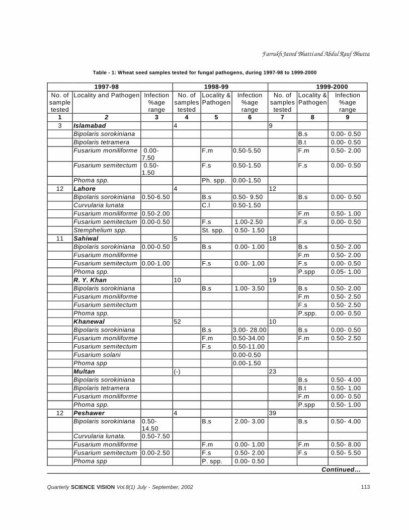
113Quarterly SCIENCE VISION Vol.8(1) July - September, 2002
Farrukh Javed Bhatti and Abdul Rauf Bhutta
Table - 1: Wheat seed samples tested for fungal pathogens, during 1997-98 to 1999-2000
1997-98 1998-99 1999-2000 No. of
sample tested
Locality and Pathogen Infection %age range
No. of samples tested
Locality & Pathogen
Infection %age range
No. of samples tested
Locality & Pathogen
Infection %age range
1 2 3 4 5 6 7 8 9 3 Islamabad 4 9 Bipolaris sorokiniana B.s 0.00- 0.50 Bipolaris tetramera B.t 0.00- 0.50 Fusarium moniliforme 0.00-
7.50 F.m 0.50-5.50 F.m 0.50- 2.00
Fusarium semitectum 0.50- 1.50
F.s 0.50-1.50 F.s 0.00- 0.50
Phoma spp. Ph. spp. 0.00-1.50 12 Lahore 4 12
Bipolaris sorokiniana 0.50-6.50 B.s 0.50- 9.50 B.s 0.00- 0.50 Curvularia lunata C.l 0.50-1.50 Fusarium moniliforme 0.50-2.00 F.m 0.50- 1.00 Fusarium semitectum 0.00-0.50 F.s 1.00-2.50 F.s 0.00- 0.50 Stemphelium spp. St. spp. 0.50- 1.50
11 Sahiwal 5 18 Bipolaris sorokiniana 0.00-0.50 B.s 0.00- 1.00 B.s 0.50- 2.00 Fusarium moniliforme F.m 0.50- 2.00 Fusarium semitectum 0.00-1.00 F.s 0.00- 1.00 F.s 0.00- 0.50 Phoma spp. P.spp 0.05- 1.00 R. Y. Khan 10 19 Bipolaris sorokiniana B.s 1.00- 3.50 B.s 0.50- 2.00 Fusarium moniliforme F.m 0.50- 2.50 Fusarium semitectum F.s 0.50- 2.50 Phoma spp. P.spp. 0.00- 0.50 Khanewal 52 10 Bipolaris sorokiniana B.s 3.00- 28.00 B.s 0.00- 0.50 Fusarium moniliforme F.m 0.50-34.00 F.m 0.50- 2.50 Fusarium semitectum F.s 0.50-11.00 Fusarium solani 0.00-0.50 Phoma spp 0.00-1.50 Multan (-) 23 Bipolaris sorokiniana B.s 0.50- 4.00 Bipolaris tetramera B.t 0.50- 1.00 Fusarium moniliforme F.m 0.00- 0.50 Phoma spp. P.spp 0.50- 1.00
12 Peshawer 4 39 Bipolaris sorokiniana 0.50-
14.50 B.s 2.00- 3.00 B.s 0.50- 4.00
Curvularia lunata. 0.50-7.50 Fusarium moniliforme F.m 0.00- 1.00 F.m 0.50- 8.00 Fusarium semitectum 0.00-2.50 F.s 0.50- 2.00 F.s 0.50- 5.50 Phoma spp P. spp. 0.00- 0.50
Continued…
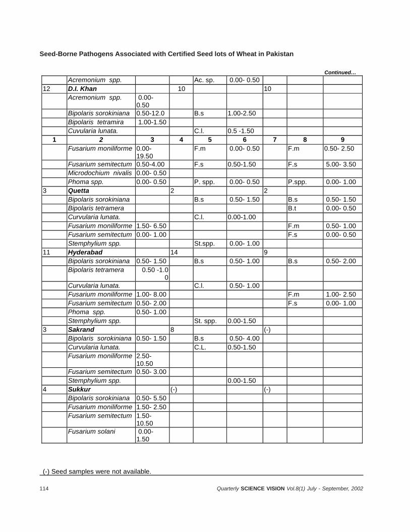
114 Quarterly SCIENCE VISION Vol.8(1) July - September, 2002
Seed-Borne Pathogens Associated with Certified Seed lots of Wheat in Pakistan
Continued… Acremonium spp. Ac. sp. 0.00- 0.50 12 D.I. Khan 10 10 Acremonium spp. 0.00-
0.50
Bipolaris sorokiniana 0.50-12.0 B.s 1.00-2.50 Bipolaris tetramira 1.00-1.50 Cuvularia lunata. C.l. 0.5 -1.50
1 2 3 4 5 6 7 8 9 Fusarium moniliforme 0.00-
19.50 F.m 0.00- 0.50 F.m 0.50- 2.50
Fusarium semitectum 0.50-4.00 F.s 0.50-1.50 F.s 5.00- 3.50 Microdochium nivalis 0.00- 0.50 Phoma spp. 0.00- 0.50 P. spp. 0.00- 0.50 P.spp. 0.00- 1.00 3 Quetta 2 2 Bipolaris sorokiniana B.s 0.50- 1.50 B.s 0.50- 1.50 Bipolaris tetramera B.t 0.00- 0.50 Curvularia lunata. C.l. 0.00-1.00 Fusarium moniliforme 1.50- 6.50 F.m 0.50- 1.00 Fusarium semitectum 0.00- 1.00 F.s 0.00- 0.50 Stemphylium spp. St.spp. 0.00- 1.00 11 Hyderabad 14 9 Bipolaris sorokiniana 0.50- 1.50 B.s 0.50- 1.00 B.s 0.50- 2.00 Bipolaris tetramera 0.50 -1.0
0
Curvularia lunata. C.l. 0.50- 1.00 Fusarium moniliforme 1.00- 8.00 F.m 1.00- 2.50 Fusarium semitectum 0.50- 2.00 F.s 0.00- 1.00 Phoma spp. 0.50- 1.00 Stemphylium spp. St. spp. 0.00-1.50 3 Sakrand 8 (-) Bipolaris sorokiniana 0.50- 1.50 B.s 0.50- 4.00 Curvularia lunata. C.L. 0.50-1.50 Fusarium moniliforme 2.50-
10.50
Fusarium semitectum 0.50- 3.00 Stemphylium spp. 0.00-1.50 4 Sukkur (-) (-) Bipolaris sorokiniana 0.50- 5.50 Fusarium moniliforme 1.50- 2.50 Fusarium semitectum 1.50-
10.50
Fusarium solani 0.00- 1.50
(-) Seed samples were not available.
115Quarterly SCIENCE VISION Vol.8(1) July - September, 2002
known to produce mycotoxin viz. Zeralenone,moniliformine and fusaric acid (Diener et al, 1981).
The second most commonly occurring pathogen wasBipolaris sorokiniana (sacc.) shoem., identified fromall localities except Islamabad, during 1998-99, andfrom D.I.Khan during 1999-2000. Its highest infectionwas found up to 28.00 per cent from Khanewalarea, during 1998-99, but minimum infection level of0.50% was found in seed samples from Sahiwal, during1997-98, and from Islamabad, Khanewal and Lahoreduring 1999-2000. Bhutta and Hussain (1999) havealso reported 0.5 to 11% infection of B. sorokinianain samples collected all over Pakistan .This pathogencan adversely affect germination and sometime killsthe seedlings (Mathur & Cunfer, 1993)Yield lossescaused by this fungus are not known yet in Pakistan.
Acremonium spp. was identified from Peshawar andD.I.Khan seed samples, while Microdocium nivalis (Fr.)Samuels & I.C. Hallet was found only from D.I.Khan.Phoma spp. was identified from samples of centraland southern Punjab, Sindh and southern part ofNWFP provinces. Other pathogens, such as Bipolaristetramera (Mckinney) shoem, Curvularia lunata(wakker) Boedijn and Stemphylium spp. were alsodetected from some localities, with infectionpercentage range from 0.5 to 2.0. In previous studies,it was reported that seed-borne pathogens showeddecreasing trend in southern part of the country ( Khanand Bhutta, 1994), but in this study, increasing trendwas observed. It may be due to the fact thatmovement of untreated seed from one part of thecountry to other part of the country has been veryoften by the private sector.
Keeping in view the distribution and incidence of fungalseed-borne pathogens, wheat seed lots should beregularly monitored for their health-status using seed-health technology and the seed must be treated atpre-basic and basic level for control of plant-diseases,under strict seed health certification and productionprogramme of the country (Bhutta et al, 1992) . Thereis a need to test germ-plasm and other breedingmaterials before their exploitation in wheat breeding
programme of the country. Some seed-borne fungiconsidered to be saprophytes, such as Alternariatenuis., Aspergillus spp., Bipolaris hawaiiensis,Cladosporium spp., Epicocum spp., Penicillium spp.and Rhizopus spp., were also recorded but notcounted.
REFERENCES
1. Barnette, H. L 1960 Illustrated Genera of imperfectfungi (second Edition) Burgess Pub. Co. (Pvt.) Ltd.285 pp.
2. Bhutta. A . R., and Hussain S.A, 1999 Seed-bornepathogens of wheat in Pakistan. RACHIS News-letter 18(2) 66-68.
3. Bhutta., A. R., Bhatti, M. A.R. and Mathur, S. B. 1992Seed health certification programme for productionof quality seed. Science, Technology andDevelopment 11(12): 21-25.
4. Chidambaram.P., Mathur, S. B. and Neergard, P1973 identification of seed-borne Drechsleraspecies.DGISP, Denmark.
5. ISTA, 1985 Proceedings of the International SeedTesting Association, Zurich, Switzerland.
6. Kauser,A.G.1955 Plant diseases in relation toimprovement of wheat in Pakistan. AgriculturePakistan 6(3): 41-46.
7. Khan, M, Q. and Bhutta, A. R. 1994. Seed- bornefungi of wheat cultivars in Pakistan. Pak. J. Sci. &Ind. Res. 37 (9): 397-398.
8. Lapis, D. B 1985 Insect pests and diseases ofwheat in the Philippines P 152-153. In: Wheat formore Tropical Environments, a Proceeding ofInternational Symposium. CIMMYT, Mexico D.F. 354-pp.
9. Mathur.S.B. and Cunfer, B. M. 1993 Seed-bornediseases and seed Health testing of Wheat.DGISP, Denmark. (Pvt.) Ltd.-85-pp
10. Nath, R., Neergard., P and Mathur,S. B. 1970Identification of Fusarium species on seeds as theyoccur in blotter test. DGISP. Denmark.
11. Neergard, P. 1979 Seed Pathology, Macmillan PressLtd., London.
12. Raemaekers, R. H. 1988 Helminthosporiumsativum; disease complex on wheat and sourcesof resistance in Zambia pp 175-186. In: Wheatproduction constraints in Tropical Environment. Klatt.A.R.(ed.). CIMMYT, Mexico, D.F. 410 pp.
Farrukh Javed Bhatti and Abdul Rauf Bhutta
116 Quarterly SCIENCE VISION Vol.8(1) July - September, 2002
FEASIBILITY OF SILVO-PASTORAL MODEL FORSALINE - SODIC SOILS IN ARID CLIMATE
Ghulam Akbar*
* Director, Rangeland Research Institute, National Agricultural Research Centre (PARC), Islamabad.
ABSTRACT
A study was conducted at Arid Zone Research Station(P ARC), Bahawalpur, during 1991-92 on saline-sodicsoils, in order to bring these areas under economicproductivity and to overcome the deticiency of forageand fuelwood. Eighteen strips, each measuring 8mx25m, were planted with Kallar grass (Leptochloafusca). Grass seedlings were planted at 0.5-mspacing. One-year old nursery-raised seedlings of sixspecies of saltbush (Atriplex lentiformis, A. halimus,A. amnicola,. A. nummularia., A. canescens. and A.stocksii) were planted on raised beds (0.5 m high) inrows, along strips containing Kallar grass. Thesaltbush seedlings were planted in linear fashion at aspacing of 2.5 m. There were 10 seedlings of eachsaltbush species in a row, forming a replication. Thestudy was replicated three times. Thus, there were18 strips of Kallar grass having 30 seedlings of eachof the six Artiplex species. Data on green biomass ofKallar Grass, survival percentage, crown diameter andheight of the seedlings of each species of saltbushwere recorded on six-monthly basis.
The results revealed that Atriplex halimus outperfomrdall the six species, in terms of survival, followed by A.conescens, A. amnicola, A. nummularia and A.lentiformis. Atriplex stocksii exhibited the lowest (4%)survival in this study. Maximum crown diameter wasobserved in case of A. canescens, followd by A.amnicola, A. nummularia and A. A. halimus. Theseedlings of A. lentiformis and A. stocksii did ntosurvive in two replications. Kallar grass, on the averageprovided 20-tons/ha fresh matter yield on six-monthlybasis. The study revealed that this type of landuse ishighly suitable for areas infested with salinity/sodicityand where cereal crops cannot be grown. Moreover,this study also exhibited that forage and fueldwooddemand can successfully be met by bringing suchproblem-areas under suitable silvo-pastoral system.
INTRODUCTION
About 20 million hectare (m. ha) of the total area ofPakistan is under cultivation. Almost 16.2 m ha of the
cultivated area is irrigated, of which canals irrigate11.4 m. ha and the rest is irrigated either by tubewellsorother means. Salt-affected area is about 6.3 m. ha,which is mainly confined to the irrigated parts of theIndus plain (Qureshi et at. 1996). These areas haveserious socio- economic implications and mostlyconcerns subsistence farmers. Although occurring inpatches. These soils have combined salinity, sodicityproblems (Aslam et al. 1991; Qureshi and Barrett-Lennard. 1998). Saline sodic soils are generallyregarded as wastelands and such areas play nosignificant role in the national economy. These soilscould be reclaimed,either by use of gypsum or throughraising salt-tolerant plants. Biological approachesimprove soiI-structure by adding organic matter andacidifying the soil that makes soluble calciumavailable. Continuous raising of kallar grass(Leptochloa fusca) on such soils is widely practicedby the farmers (Qureshi and Barrett-Lennard, 1998).
Livestock is an integral part of the agriculture inPakistan and hence fodder-shortage is a commonproblem when we try to raise good-quality animals.Apart from fodder-shortage, household energyrequirements in the rural setup are met mainly fromthe trees grown on agricultural lands. Having thisscenario in mind, a study was underaken to evaluatethe potential of salt-tolerant shrubs and grass speciesunder saline sodic conditions, to meet the forage andfuelwood needs from the areas regarded as waste-lands. The ultimate aim of this study was to explorethe possibilities of bringing saline sodic soils underproductive use.
STUDY SITE
The study was conducted at Arid Zone ResearchStation of Pakistan Agricultural Research .Council atBahawalpur. Bahawalpur lies in the southern part ofPunjab province, at about 29o 24' N latitude andlongitude 710 47' E,at an elevation of about 116 mabove mean sea level (FAO 1993). The soils aregenerally clay loam (clay 43%, silt 36% and sand21%). Irrigation to the study-area was provided throughtubeweII, whose water, like 70% of the tubewells in
117Quarterly SCIENCE VISION Vol.8(1) July - September, 2002
Indus basin (Qureshi and Barret-Lennard 1998), ismarginally fit for cultivation (1300 mmohs) (AZRI 1996).Other chemical characteristics of the study-soilinclude pH 8.9, ECe 10.8 dS/m-l, and SAR 28.
Bahawalpur, being on the immediate verge of Cholistandesert, experiences hot tropical climate (Table 1).Maximum temperature during summer may reach upto 50 °C, while the minimum temperature seldomdrops below zero. Most of the precipitation is receivedduring monsoon period, extending from July throughmid-September (FAO, 1993). Evaporation exceedsprecipitation in each month considerably. Climatedata, based on 30 years average (FAO, 1993), ispresented in Table 1.
MATERIALS AND METHODS
During the month of August, 1991, eighteen strips,each measuring 8m x 25m, were planted with Kallargrass (Leptochloa fusca). Grass seedlings wereplanted at 0.5-m spacing. One-year old nursery-raisedseedlings of six species of saltbushes (Atriplexlentiformis, A. halimus, A. ammnicola, A.mammularia., A. canescens and A. stocksii) wereplanted on raised beds (0.5 m high) in rows, alongstirps containing Kallar grass. The saltbush seedlingswere planted in linear fashion ata spacing of 2.5-m.There were 10 seedlings of each saltubsuh speciesin a row, forming a replication. The study wasreplicated three times. Thus, there were 18 strips ofKallar grass having 30 seedlings of each of the sixAtriplex species. Data on green biomass of Kallargrass. survival percentage, crown diameter and heightof the seedlings of each saltbush species, wererecorded on six-monthly bases. Samples of greenbiomass fo kallar grass were oven-dried for 48 hoursat 60 oC and dry-matter yeild (DMY) was worked out.Irrigation was provided to the study area, except forrainy days, on weekly basis during summer (April -September) and on monthly basis during winter(October - March). The data were analyzed usingRandomized Complete Block Design and means wereseparated using Duncan’s multiple range test (Gomezand Gomez 1984).
RESULTS
Saltbush Species: Final measurements, as inSeptember 1994, regarding growth-rate (height and
crown diameter) and survival of all the saltbush speciesare presented in Table 2 and Figure 1 below.
The results (Table 2) indicate that, in case of plantheight, A. amnicola outperformed numerically all thesaltbush species tested in this study; however, itsheight was significantly (p<0.05) greater than A.canescens and A. stocksii. Both the latter speciesdid not differ significantly (p<0.05) from Atriplexlentiformis, A. nummulari and A. halimus. The crowndiameter among all the species did not differsignificantly (p<0.05). Numerically, Atriplex canescensattained more crown-spread), followed by A. amnicola,A. nummularia, A. halimus, A, lentiformis and finallyA. stocksii. Crown diameters of all the saltbushspecies raised in this study were higher, comparedto their respective vertical growth.
The plants of A, halimus exhibited 100% survival-ratefollowed by A. canescens, A. amnicola, A.mummularia, A. lentiformis and A, stocks ii, Thus,the results revealed that A, stocksii is poor performerin terms of growth-rate as well as plant-survival amongall the six saltbush species planted in this study. Allother species did well in hot climatic and saline sodicconditions of Bahawalpur.
Kallar Grass: Dry matter yield (DMY) of kallar grassincreased progressively with the time from initialestablishment (Fig. 2). The lowest DMY was recordedsix mmonths after the initiation of the study (April1992) that did not differ significantly (p<0.05) from thatone year after planting (September 1992), but it differedsignificantly (p<0.05) as the time increased from oneyear after planting onward. However, the DMY wasnot significantly different (p<0.05) among the last twocuttings (April and September 1994) of the study,showing that the grass had increased potential ofadding biomass with the passage of time, This alsoprovided the evidence that soil-conditions had alsoimproved over time. The earlier reduction in the yieldwas probably the initial growth-development of theplants and their adjustment with the soil conditions.
DISCUSSION
The study-site of Bahawalpur is a representative hotarea of the Indus plain, where salinity-sodicity is awide-spread problem. Accompanied to this, fuel woodand forage are also immediate requirements of the
Ghulam Akbar
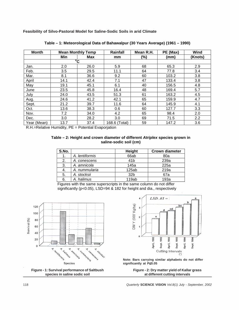
118 Quarterly SCIENCE VISION Vol.8(1) July - September, 2002
Feasibility of Silvo-Pastoral Model for Saline-Sodic Soils in arid Climate
Table – 1: Meteorological Data of Bahawalpur (30 Years Average) (1961 – 1990)
Month Mean Monthly Temp Rainfall Mean R.H. PE (Max) Wind Min Max mm (%) (mm) (Knots) oC
Jan. 2.0 26.0 5.9 68 65.3 2.9 Feb. 3.5 29.5 11.1 64 77.8 3.4 Mar. 8.1 36.6 9.2 60 103.2 3.8 April 14.1 42.4 7.1 47 133.4 3.8 May 19.1 45.1 6.1 40 156.5 4.8 June 23.5 45.8 16.4 48 169.4 5.7 July 24.0 43.5 51.3 61 163.2 4.5 Aug. 24.6 41.2 42.1 65 159.9 4.7 Sept. 21.2 39.7 11.6 64 145.9 4.1 Oct. 13.6 38.3 0.6 60 127.7 3.3 Nov. 7.2 34.0 4.2 65 98.4 2.0 Dec. 3.0 28.2 3.0 69 71.5 2.2 Year (Mean) 13.7 37.4 168.6 (Total) 59 147.2 3.6 R.H.=Relative Humidity, PE = Potential Evaporjation
Table – 2: Height and crown diameter of different Atriplex species grown in saline-sodic soil (cm)
S.No. Height Crown diameter 1. A. lentiformis 66ab 80a 2. A. conescens 41b 239a 3. A. amnicola 145a 225a 4. A. nummularia 125ab 219a 5. A. stocksii 32b 67a 6. A. halimus 119ab 193a
Figures with the same superscripts in the same column do not differ significantly (p<0.05), LSD=94 & 182 for height and dia., respectively
Figure - 1: Survival performance of Saltbushspecies in saline sodic soil
Figure - 2: Dry matter yield of Kallar grassat different cutting intervals
Note: Bars carrying similar alphabets do not differsignificantly at P0.05
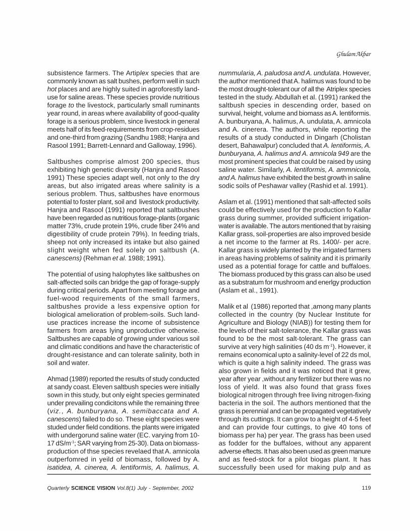
119Quarterly SCIENCE VISION Vol.8(1) July - September, 2002
subsistence farmers. The Artiplex species that arecommonly known as salt bushes, perform well in suchhot places and are highly suited in agroforestly land-use for saline areas. These species provide nutritiousforage to the livestock, particularly small ruminantsyear round, in areas where availability of good-qualityforage is a serious problem, since livestock in generalmeets half of its feed-requirements from crop-residuesand one-third from grazing (Sandhu 1988; Hanjra andRasool 1991; Barrett-Lennard and Galloway, 1996).
Saltbushes comprise almost 200 species, thusexhibiting high genetic diversity (Hanjra and Rasool1991) These species adapt well, not only to the dryareas, but also irrigated areas where salinity is aserious problem. Thus, saltbushes have enormouspotential to foster plant, soil and livestock productivity.Hanjra and Rasool (1991) reported that saltbusheshave been regarded as nutritious forage-plants (organicmatter 73%, crude protein 19%, crude fiber 24% anddigestibility of crude protein 79%). In feeding trials,sheep not only increased its intake but also gainedslight weight when fed solely on saltbush (A.canescens) (Rehman et al. 1988; 1991).
The potential of using halophytes like saltbushes onsalt-affected soils can bridge the gap of forage-supplyduring critical periods. Apart from meeting forage andfuel-wood requirements of the small farmers,saltbushes provide a less expensive option forbiological amelioration of problem-soils. Such land-use practices increase the income of subsistencefarmers from areas lying unproductive otherwise.Saltbushes are capable of growing under various soiland climatic conditions and have the characteristic ofdrought-resistance and can tolerate salinity, both insoil and water.
Ahmad (1989) reported the results of study conductedat sandy coast. Eleven saltbush species were initiallysown in this study, but only eight species germinatedunder prevailing condicitons while the remaining three(viz., A. bunburyana, A. semibaccata and A.canescens) failed to do so. These eight species werestuded under field conditions. the plants were irrigatedwith undergorund saline water (EC. varying from 10-17 dS/m-1; SAR varying from 25-30). Data on biomass-production of thse species revelaed that A. amnicolaoutperfomred in yeild of biomass, followed by A.isatidea, A. cinerea, A. lentiformis, A. halimus, A.
nummularia, A. paludosa and A. undulata. However,the author mentioned that A. halimus was found to bethe most drought-tolerant our of all the Atriplex speciestested in the study. Abdullah et al. (1991) ranked thesaltbush species in descending order, based onsurvival, height, volume and biomass as A. lentiformis.A. bunburyana, A. halimus, A. undulata, A. amnicolaand A. cinerera. The authors, while reporting theresults of a study conducted in Dingarh (Cholistandesert, Bahawalpur) concluded that A. lentiformis, A.bunburyana, A. halimus and A. amnicola 949 are themost prominent species that could be raised by usingsaline water. Similarly, A. lentiformis, A. ammnicola,and A. halimus have exhibited the best growth in salinesodic soils of Peshawar valley (Rashid et al. 1991).
Aslam et al. (1991) mentioned that salt-affected soilscould be effectively used for the production fo Kallargrass during summer, provided sufficient irrigation-water is available. The autors mentioned that by raisingKallar grass, soil-properties are also improved besidea net income to the farmer at Rs. 1400/- per acre.Kallar grass is widely planted by the irrigated farmersin areas having problems of salinity and it is primarilyused as a potential forage for cattle and buffaloes.The biomass produced by this grass can also be usedas a substratum for mushroom and enerlgy production(Aslam et al., 1991).
Malik et al (1986) reported that ,among many plantscollected in the country (by Nuclear Institute forAgriculture and Biology (NIAB)) for testing them forthe levels of their salt-tolerance, the Kallar grass wasfound to be the most salt-tolerant. The grass cansurvive at very high salinities (40 ds m-1). However, itremains economical upto a salinity-level of 22 ds mol,which is quite a high salinity indeed. The grass wasalso grown in fields and it was noticed that it grew,year after year ,without any fertilizer but there was noloss of yield. It was also found that grass fixesbiological nitrogen through free living nitrogen-fixingbacteria in the soil. The authors mentioned that thegrass is perennial and can be propagated vegetativelythrough its cuttings. It can grow to a height of 4-5 feetand can provide four cuttings, to give 40 tons ofbiomass per ha) per year. The grass has been usedas fodder for the buffaloes, without any apparentadverse eftects. It has also been used as green manureand as feed-stock for a pilot biogas plant. It hassuccessfully been used for making pulp and as
Ghulam Akbar
120 Quarterly SCIENCE VISION Vol.8(1) July - September, 2002
Feasibility of Silvo-Pastoral Model for Saline-Sodic Soils in arid Climate
substrata for raising mushrooms and even forsaccharification of celluosic materials and their one-stage conversion into alcohol.
Singh et al. (1988) discussed the forage production,chemical composition and nutrient cycling fo karnalgrass (Leptochloa fusca) planted with mesquite(Prosopis juliflora) in a unified agroforestry system,on an extrely sodic soil lying barren in Karnal districtof India. Karnal grass gave 25.3 t/ha green-forageyield in 8 cuts, in a period of 26 months proving itsgreat potential as a fodder crop. The mean N, P, K,Ca, Mg, S and Na contents in the whole plant was1.36, 0.20,0.65,0.19, 1.54 and 1.52 percent in firstcut, and 0.92,0.18,0.74,0.34,0.68,0.14 and 0.64percent in the last cut, respectively. Increased contentof the Ca and K decreased the Na concentration withsubsequent cuttings and made this grass a valuablefodder under sodic soil conditions. Total nutrientremoved was 567 kg/ha, within a period of little morethan two years. It was interesting to note that thisgrass biologically pumped out 114-kg/ha sodiumthrough the aerial biomass, thus acting as a triggerfor the start of a plant-succession for the reclamationof sodic soils lying unproductive.
CONCLUSION
Silvo-pastoral land-use model discussed above needsto be established in the arid hot climate of the country,where salinity and sodicity are serious problems.However, the present study did not fully determinethe extent of soil-improvement with this model andthe economics of such land-use, if adopted by a smallfarmer. These questions need to be carefully addressedin future in investigations.
REFERENCES
1. Ahmad, R. 1989, Research in forage shrubs inPakistan. paper presetned in Inaugural Meeting ofACIAR Proj est 8619, PARC, Islamabad, February25-26, 1989.
2. Abdullah, M., M. Akram, W. A. Khan and N.}.Davidson. 1991. Selecting halophytic shrubs for theCholistan desert. In: Productive Use of Saline Land.Proceedings of a workshop held at Perth, WesternAustralia, 10-14 May, ‘1991. ACIAR Proceedings No.42.Australian Centre for International AgriculturalResearch, GPO Box 1571, Canberra, ACT 260Ipp:45-48.
3. Aslam. Z., M. Mujab, J. Alshtar, R. Waheed, K. A. Malikand M. Naqvi. 1991. Biological methods foreconomically utilizing salt-affected soils in Pakistan.In: Productive Use of Saline Land. Proceedings of aworkshop held at Perth, Western Australia, 10-14May, 1991. ACIAR Proceedings No. 42.AustralianCentre for International Agricultural Research, GPOBox 1571, Canberra, ACT 2601. pp: 29-31.
4. AZRI 1996. Annual Progress Report (1995-96). AridZone Research Institute. Pakistan AgriculturalResearch Council, Bahawalpur. pp: 66.
5. Barrett-Lennard, E. G. and R. Galloway. 1996Saltbush for water-table reduction and landrehabilitation. In. Productive land use andRehabilitation of saline lands. Conferenceproceeding. 25-30 March, 1996. PromacoConventions Pty Ltd, Canning Bridge, W A 6153. pp.9-15.
6. FAO. 1993. Pakistan, -Cholistan Area DevelopmentProject. Report No. 59/93 ADB-PAK-58 (FinalVersion). Food and Agriculture Organization of TheUnited Nations, Rome.
7. Gomez, K. A. and A. A. Gomez. 1984. Statisticalprocedures for agricultural research. J.ohn Wiley &Sons, New York.
8. Halljra, S H, and S. Rasool. 1991. Potential of Atriplexas a forage for livestock in Pakistan. In: ProductivePerth, Western Austra!ia, 10-14 May, 1991. ACIARProceedings No 42.Australian Centre forInternational Agricultural Research, GPO Box 1571,Canberra, ACT 2601 pp:68-70.
11. Malik, K A., Zahoor, A. and Mujtaba, N., 1986. KallarGrass: A Plant for Saline Land. Nuclear Institute forAgriculture and Biology, Faisalabad.
12. Qureshi, R. Hand E. G. Barrett-Lennard. 1998. SalineAgriculture for Irrigated Land in Pakistan: AHandbook. Australian Centre for InternationalAgricultural Research (ACIAR). Canberra, Australia.
13. Qureshi, R H., S. Nawaz., J. Akhtar, and S. Parveen.1996. Sustainable saline agriculture: Pakistanexperience. In. Productive land use andRehabilitation of saline lands. Conferenceproceeding. 25-30 March, 1996. PromacoConventions Pty Ltd, Canning Bridge, WA 6153.pp.133-117.
15. Rashid, A., J. K. Khattak, M. Z. Khan, M. J. Iqbal, F.Akbar and P. Khan. 1991. Selection of halophyticforage shrubs for the Peshawar valley, Pakistan. In:Productive Use of Saline Land. Proceedings of aworkshop held at Perth, Western Australia, 10-14May, 1991 ! ACIAR Proceedings No. 42.AustralianCentre for International Agricultural Research, . GPOBox 1571, Canberra, ACT 2601. pp: 56-61.
14. Rehman, A., K. N. M. Khan, M. Asghar and M. I.Sultani. 1988. Fourwing saltbush forage compared

121Quarterly SCIENCE VISION Vol.8(1) July - September, 2002
with conventional feeds for yearling sheep. Arid ZoneRes. Institute, Quetta, Pakistan. Report No. 16.
15. Rehman, A., S. Rafique, and B. Khan. Fourwingsaltbush as a inter forage for sheep in uplandBalochistan. In: productive Use of Saline Land.Procee?ings of a workshop held at Perth, WesternAustralIa, 10-14 May, 1991. ACIAR ProceedIngs No.42.Australian Centre for International AgriculturalResearch, GPO Box 1571, Canberra, ACT 2601pp:75-78.
16. Sandhu, G. R. 1988. Prospects saline agriculture inPakistan. Natural Resources Division, PakistanAgricultural Research Council, Islamabad
(unpublished.17. Singh, G, I. P. Abrol and S. S. Cheema,. 1988. Forage
production and nutrient cycling through Kamal grass(Diplachne fi/sca) planted with Mesquite (Pro.~’opi.s’fl/lijlora) in a highly I sodic soil. RangelandsResourc~ and rv1anagement. Range ManagementSociety of India. i Indian Grassland and fodderResearch Institute, Jhansi 284003, India. pp: 322-322.
Ghulam Akbar
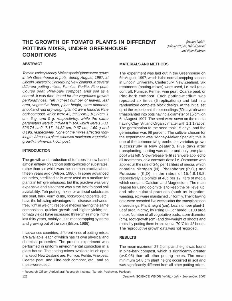
122 Quarterly SCIENCE VISION Vol.8(1) July - September, 2002
THE GROWTH OF TOMATO PLANTS IN DIFFERENTPOTTING MIXES, UNDER GREENHOUSECONDITIONS
Ghulam Nabi*,Jehangir Khan, Abdul Samad
and Noor Rahman
* Research Officer, Agricultural Research Institute, Tarnab, Peshawar, Pakistan.
ABSTRACT
Tomato variety Money Maker special plants were grownin teh Greenhouse in pots, during August, 1997, atLincoln University, Canterbury, New Zealand, in severaldifferent potting mixes; Pumice, Perlite, Fine peat,Course peat, Pine-bark compost, andf soil as acontrol. It was then tested for the vegetative growthperjforamnces. Teh highest number of leaves, leafarea, vegetative buds, plant height, stem diameter,shoot and root dry-weight plant-1 were found in Pinebark compost, which were 43, 1592 cm2, 10,27cm, 1cm, 6 g, and 0 g, respectivley, while the sameparameters were found least in soil, which were 15.00,626.74 cm2, 7.17, 14.82 cm, 0.67 cm, 1.69 g and0.19g, respectivley. None of the mixes affected root-length. Almost all plants showed maximum vegetativegrowth in Pine-bark compost.
INTRODUCTION
The growth and production of tomtoes is now basedalmost entirely on artifical potting-mixes or substrates,rather than soil which was the common practive aboutfifteen years ago (Wilson, 1986). In some advancedcountries, sterilized soils were used as a medium forplants in teh grenehouses, but this practive was veryexpensive and also there was a the lack fo good soilavialability. Teh potting mixes or aritficial substrateslike peat, bark, vermiculite, rockwool and perlite, etc.,have the following advantages i.e., disease and weed-free, light in weight, respeive meixes having the samecomposition, quicker growth and higher yields; so,tomato yields have increased three times more int helast rhity years, mainly due to monocropping systemsand growing out of the soil (Silson, 1986).
In advanced countries, different kinds of potting-mixesare available, each of which has its own physical andchemical properties. The present experiment wasperformed in uniform environmental condiction in aglass house. The potting-mixes available int eh openmarket of New Zealand are; Pumice, Perlite, Fine peat,Coarse peat, and Pine-bark compost, etc., and sothese were used.
MATERIALS AND METHODS
The experiment was laid out in the Greenhouse on6th August, 1997, which is the normal cropping seasonin Lincoln University, Canterbury, New Zealand. Sixtreatments (potting-mixes) were used, i.e. soil (as acontrol), Pumice, Perlite, Fine peat, Coarse peat, orPine-bark compost. Each potting-medium wasrepeated six times (6 replications) and laid in arandomized complete block design. At the initial setup of the experiemnt, three seedlings (50 days ol) weretrnasplanted into pots having a diameter of 15 cm, on6th August 1997. The seed were sown on the mediahaving Clay, Silt and Organic matter with 1:1:1 ratios.The germination fo the seed took 15 days, and thegermination was 98 percent. The cultivar chosen forthe experiment was “Money-Maker Special’; this isone of the commercial greenhouse varieties grownsuccessfully in New Zealand. Five days aftertransplanting, sorting was done and only one plantpot-I was left. Slow-release fertilizers were applied toall treatments, as a constant dose i.e. Osmocote wasapplied at the rate of 24g per 12 liters of media, whichcontains Nitrogen (N), Phosphorus (P2O5) andPotassium (K2O), in the ratios of 15:4.8:18.8,respectively; Dolomite at 48g per 12 liters of mediawhich contains Calcium and Magnesium. The mainreason for using dolomite is to keep the pH level up,and other cultural practices (such as irrigation,weeding, etc) were maintained uniformly. The followingdata were recorded five weeks after the transplantationof seedlings: Plant height (cm), Leaf number plant-1,Leaf area in cm2, by using Li-Cor model 3100 areameter, Number of all vegetative buds, stem diameter(cm), root-growth (cm) and dry-weight of shoots androots; by putting them in an oven at 70°C for 48 hours.The reproductive growth data was not recorded.
RESULTS
The mean maximum 27.2 cm plant height was foundin pine-bark compost, which is significantly greater(p<0.05) than all other potting mixes. The meanminimum 14.8 cm plant height occurred in soil andwas significantly different from all other potting mixes.
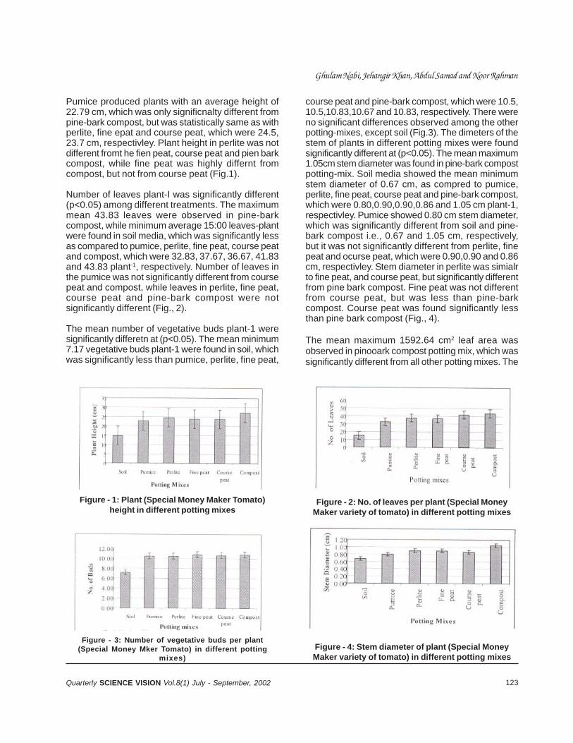
123Quarterly SCIENCE VISION Vol.8(1) July - September, 2002
Pumice produced plants with an average height of22.79 cm, which was only significnalty different frompine-bark compost, but was statistically same as withperlite, fine epat and course peat, which were 24.5,23.7 cm, respectivley. Plant height in perlite was notdifferent fromt he fien peat, course peat and pien barkcompost, while fine peat was highly differnt fromcompost, but not from course peat (Fig.1).
Number of leaves plant-I was significantly different(p<0.05) among different treatments. The maximummean 43.83 leaves were observed in pine-barkcompost, while minimum average 15:00 leaves-plantwere found in soil media, which was significantly lessas compared to pumice, perlite, fine peat, course peatand compost, which were 32.83, 37.67, 36.67, 41.83and 43.83 plant-1, respectively. Number of leaves inthe pumice was not significantly different from coursepeat and compost, while leaves in perlite, fine peat,course peat and pine-bark compost were notsignificantly different (Fig., 2).
The mean number of vegetative buds plant-1 weresignificantly differetn at (p<0.05). The mean minimum7.17 vegetative buds plant-1 were found in soil, whichwas significantly less than pumice, perlite, fine peat,
course peat and pine-bark compost, which were 10.5,10.5,10.83,10.67 and 10.83, respectively. There wereno significant differences observed among the otherpotting-mixes, except soil (Fig.3). The dimeters of thestem of plants in different potting mixes were foundsignificantly different at (p<0.05). The mean maximum1.05cm stem diameter was found in pine-bark compostpotting-mix. Soil media showed the mean minimumstem diameter of 0.67 cm, as compred to pumice,perlite, fine peat, course peat and pine-bark compost,which were 0.80,0.90,0.90,0.86 and 1.05 cm plant-1,respectivley. Pumice showed 0.80 cm stem diameter,which was significantly different from soil and pine-bark compost i.e., 0.67 and 1.05 cm, respectively,but it was not significantly different from perlite, finepeat and ocurse peat, which were 0.90,0.90 and 0.86cm, respectivley. Stem diameter in perlite was simialrto fine peat, and course peat, but significantly differentfrom pine bark compost. Fine peat was not differentfrom course peat, but was less than pine-barkcompost. Course peat was found significantly lessthan pine bark compost (Fig., 4).
The mean maximum 1592.64 cm2 leaf area wasobserved in pinooark compost potting mix, which wassignificantly different from all other potting mixes. The
Figure - 1: Plant (Special Money Maker Tomato)height in different potting mixes
Figure - 2: No. of leaves per plant (Special MoneyMaker variety of tomato) in different potting mixes
Figure - 3: Number of vegetative buds per plant(Special Money Mker Tomato) in different potting
mixes)
Figure - 4: Stem diameter of plant (Special MoneyMaker variety of tomato) in different potting mixes
Ghulam Nabi, Jehangir Khan, Abdul Samad and Noor Rahman
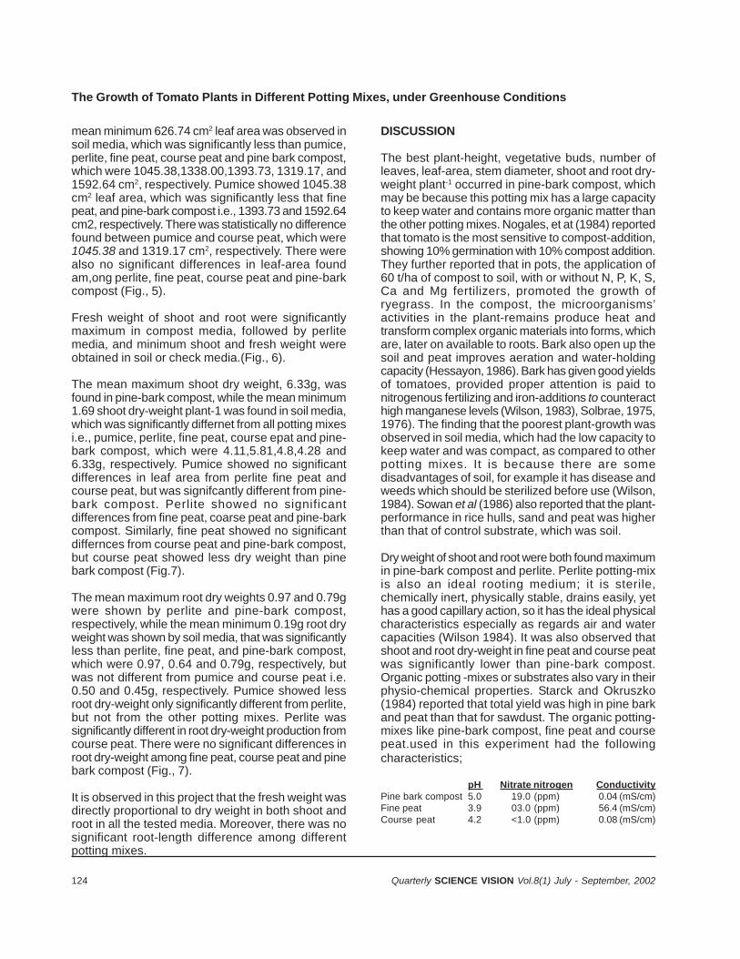
124 Quarterly SCIENCE VISION Vol.8(1) July - September, 2002
The Growth of Tomato Plants in Different Potting Mixes, under Greenhouse Conditions
mean minimum 626.74 cm2 leaf area was observed insoil media, which was significantly less than pumice,perlite, fine peat, course peat and pine bark compost,which were 1045.38,1338.00,1393.73, 1319.17, and1592.64 cm2, respectively. Pumice showed 1045.38cm2 leaf area, which was significantly less that finepeat, and pine-bark compost i.e., 1393.73 and 1592.64cm2, respectively. There was statistically no differencefound between pumice and course peat, which were1045.38 and 1319.17 cm2, respectively. There werealso no significant differences in leaf-area foundam,ong perlite, fine peat, course peat and pine-barkcompost (Fig., 5).
Fresh weight of shoot and root were significantlymaximum in compost media, followed by perlitemedia, and minimum shoot and fresh weight wereobtained in soil or check media.(Fig., 6).
The mean maximum shoot dry weight, 6.33g, wasfound in pine-bark compost, while the mean minimum1.69 shoot dry-weight plant-1 was found in soil media,which was significantly differnet from all potting mixesi.e., pumice, perlite, fine peat, course epat and pine-bark compost, which were 4.11,5.81,4.8,4.28 and6.33g, respectively. Pumice showed no significantdifferences in leaf area from perlite fine peat andcourse peat, but was signifcantly different from pine-bark compost. Perlite showed no significantdifferences from fine peat, coarse peat and pine-barkcompost. Similarly, fine peat showed no significantdiffernces from course peat and pine-bark compost,but course peat showed less dry weight than pinebark compost (Fig.7).
The mean maximum root dry weights 0.97 and 0.79gwere shown by perlite and pine-bark compost,respectively, while the mean minimum 0.19g root dryweight was shown by soil media, that was significantlyless than perlite, fine peat, and pine-bark compost,which were 0.97, 0.64 and 0.79g, respectively, butwas not different from pumice and course peat i.e.0.50 and 0.45g, respectively. Pumice showed lessroot dry-weight only significantly different from perlite,but not from the other potting mixes. Perlite wassignificantly different in root dry-weight production fromcourse peat. There were no significant differences inroot dry-weight among fine peat, course peat and pinebark compost (Fig., 7).
It is observed in this project that the fresh weight wasdirectly proportional to dry weight in both shoot androot in all the tested media. Moreover, there was nosignificant root-length difference among differentpotting mixes.
DISCUSSION
The best plant-height, vegetative buds, number ofleaves, leaf-area, stem diameter, shoot and root dry-weight plant-1 occurred in pine-bark compost, whichmay be because this potting mix has a large capacityto keep water and contains more organic matter thanthe other potting mixes. Nogales, et at (1984) reportedthat tomato is the most sensitive to compost-addition,showing 10% germination with 10% compost addition.They further reported that in pots, the application of60 t/ha of compost to soil, with or without N, P, K, S,Ca and Mg fertilizers, promoted the growth ofryegrass. In the compost, the microorganisms’activities in the plant-remains produce heat andtransform complex organic materials into forms, whichare, later on available to roots. Bark also open up thesoil and peat improves aeration and water-holdingcapacity (Hessayon, 1986). Bark has given good yieldsof tomatoes, provided proper attention is paid tonitrogenous fertilizing and iron-additions to counteracthigh manganese levels (Wilson, 1983), Solbrae, 1975,1976). The finding that the poorest plant-growth wasobserved in soil media, which had the low capacity tokeep water and was compact, as compared to otherpotting mixes. It is because there are somedisadvantages of soil, for example it has disease andweeds which should be sterilized before use (Wilson,1984). Sowan et al (1986) also reported that the plant-performance in rice hulls, sand and peat was higherthan that of control substrate, which was soil.
Dry weight of shoot and root were both found maximumin pine-bark compost and perlite. Perlite potting-mixis also an ideal rooting medium; it is sterile,chemically inert, physically stable, drains easily, yethas a good capillary action, so it has the ideal physicalcharacteristics especially as regards air and watercapacities (Wilson 1984). It was also observed thatshoot and root dry-weight in fine peat and course peatwas significantly lower than pine-bark compost.Organic potting -mixes or substrates also vary in theirphysio-chemical properties. Starck and Okruszko(1984) reported that total yield was high in pine barkand peat than that for sawdust. The organic potting-mixes like pine-bark compost, fine peat and coursepeat.used in this experiment had the followingcharacteristics;
pH Nitrate nitrogen ConductivityPine bark compost 5.0 19.0 (ppm) 0.04 (mS/cm)Fine peat 3.9 03.0 (ppm) 56.4 (mS/cm)Course peat 4.2 <1.0 (ppm) 0.08 (mS/cm)
125Quarterly SCIENCE VISION Vol.8(1) July - September, 2002
(These were the recommended analyses provided bythe manufacturing companies). So, due to thesedifferences among the potting mixes, it may be readilyunderstand that pine-bark compost showed high shootand root dry-weight plant-1. Similar trend was noticedin shoot and root fresh-weight. It is observed in thisproject that the fresh wegith is directly proportional todry weight, in both shoot and root, in all the testedmedia.
All potting mixes other than pine-bark compost alsoshowed some signfiicant differences amongthemselves, but mostly they showed less effect ondifferent vegetative growth parameters.
REFERENCES
1. Hessayon, D. G, Improving your soil by addinghumus. In; The garden expert. pp 22. (1986).
2. Nogales, R., M. A. Zamora, M. Gomez, and L. F.Gallardo, Fertiliser value of a town refuse compost.Effect on seed germination and yields of sequentialharvests. In; Analies de Edafologia y Agrobiologia.
43: 1-2, (1984) 183-194.3. Sawan, O. N., M. S. El-beltagy, A. Muhammedian,
A.S. El-beltagy, and M.A. Maksoud,. A study on theinfluence of some transplant growing media onflowering and yield of some tomato. In; Horticultureabstracts. 55: 6, (1986) 4453.
4. Solbrae, K, Compo sting bark. Proc. of symp. WestGerman working group on standardisation of barkcomposts in Horticulture, Ghert, (1974).
5. Solbrae, K., Composting bark. Parts 1-4. ManusciptsNorsk Int. for Skogforskning. (1976)
6. Stark, J. R. and B. Okruszko,. The effect of nitrogenon yield of green house tomatoes grown in peat,pine bark and sawdust. Acta Horticulturae. 145:(1984) 74-80.
7. Wilson, G. C. S., Tomato production in barksubstrates. Acta Horticulturae. 150: (1983).
8. Wilson, G. C. S., New perlite system for tomatoproduction. Florentica international. No 2: (1984) 23-36,.
9. Wilson, G. C. S., Tomato production in differentgrowing media. Acta Horticulturae. 178: (1986)115-120.
Figure - 5: Leaf Area per plant (Special Money Makervariety of tomato) in different potting mixes)
Figure - 6: Fresh weight of shoot and root of SpecialMoney Maker variety of tomato in different potting
mixes
Figure - 7: Dry weight of shoot and root of Special Money Maker variety of tomato in different potting mixes
Ghulam Nabi, Jehangir Khan, Abdul Samad and Noor Rahman