Embed Size (px)
Citation preview
TECHNICAL REPORTS SERIES IMo. 2 8 3
Radiological Safety Aspects of the Operation
of Proton Accelerators
^ LVJ I NTERNAT IONAL ATOMIC E N E R G Y AGENCY, V IENNA, 1988
The cover picture shows part of the first cyclotron.
By courtesy of Lawrence Berkeley Laboratory, University of California.
RADIOLOGICAL SAFETY ASPECTS OF THE OPERATION
OF PROTON ACCELERATORS
The fol lowing States are Members of the International Atomic Energy Agency:
AFGHANISTAN GUATEMALA PARAGUAY ALBANIA HAITI PERU ALGERIA HOLY SEE PHILIPPINES ARGENTINA HUNGARY POLAND AUSTRALIA ICELAND PORTUGAL AUSTRIA INDIA QATAR BANGLADESH INDONESIA ROMANIA BELGIUM IRAN, ISLAMIC REPUBLIC OF SAUDI ARABIA BOLIVIA IRAQ SENEGAL BRAZIL IRELAND SIERRA LEONE BULGARIA ISRAEL SINGAPORE BURMA ITALY SOUTH AFRICA BYELORUSSIAN SOVIET JAMAICA SPAIN
SOCIALIST REPUBLIC JAPAN SRI LANKA CAMEROON JORDAN SUDAN CANADA KENYA SWEDEN CHILE KOREA, REPUBLIC OF SWITZERLAND CHINA KUWAIT SYRIAN ARAB REPUBLIC COLOMBIA LEBANON THAILAND COSTA RICA LIBERIA TUNISIA COTE D'lVOIRE LIBYAN ARAB JAMAHIRIYA TURKEY CUBA LIECHTENSTEIN UGANDA CYPRUS LUXEMBOURG UKRAINIAN SOVIET SOCIALIST CZECHOSLOVAKIA MADAGASCAR REPUBLIC DEMOCRATIC KAMPUCHEA MALAYSIA UNION OF SOVIET SOCIALIST DEMOCRATIC PEOPLE'S MALI REPUBLICS
REPUBLIC OF KOREA MAURITIUS UNITED ARAB EMIRATES DENMARK MEXICO UNITED KINGDOM OF GREAT DOMINICAN REPUBLIC MONACO BRITAIN AND NORTHERN ECUADOR MONGOLIA IRELAND EGYPT MOROCCO UNITED REPUBLIC OF EL SALVADOR NAMIBIA TANZANIA ETHIOPIA NETHERLANDS UNITED STATES OF AMERICA FINLAND NEW ZEALAND URUGUAY FRANCE NICARAGUA VENEZUELA GABON NIGER VIET NAM GERMAN DEMOCRATIC REPUBLIC NIGERIA YUGOSLAVIA GERMANY, FEDERAL REPUBLIC OF NORWAY ZAIRE GHANA PAKISTAN ZAMBIA GREECE PANAMA ZIMBABWE
T h e Agency ' s Statute was approved on 23 October 1956 by the Conference on the Statute of the I A E A held at United Nations Headquar ters , New York ; it entered into force on 29 July 1957. The Head-quarters of the Agency are situated in Vienna . Its principal objective is " t o accelerate and enlarge the contribution of atomic energy to peace , health and prosperi ty throughout the w o r l d " .
© I A E A , 1988
Permission to reproduce o r t ranslate the informat ion contained in this publication may be obtained by writ ing to the International Atomic Energy Agency , Wagramers t rasse 5, P . O . Box 100, A-1400 Vienna, Austr ia .
Printed by the I A E A in Austria May 1988
TECHNICAL REPORTS SERIES No. 283
RADIOLOGICAL SAFETY ASPECTS OF THE OPERATION
OF PROTON ACCELERATORS
A report written by Ralph H . T H O M A S
Lawrence Berkeley Laboratory
University of California
United States of Amer ica
and
Graham R . S T E V E N S O N
European Centre for Nuclear Research
( C E R N )
INTERNATIONAL ATOMIC ENERGY AGENCY VIENNA, 1988
RADIOLOGICAL SAFETY ASPECTS OF THE OPERATION OF PROTON ACCELERATORS
IAEA, VIENNA, 1988 STI/DOC/10/283
ISBN 92-0-125188-2
FOREWORD Particle accelerators are finding increased application in both the fundamental
and applied sciences and in industry around the world. Recognizing this, the International Atomic Energy Agency began, in 1975, preparing a series of technical reports dealing with the radiological safety of accelerator operation. The first of these, IAEA Safety Series No. 42, entitled Radiological Safety Aspects of the Opera-tion of Neutron Generators and written by R.F. Boggs, was published in 1976. A second book, Radiological Safety Aspects of the Operation of Electron Linear Accelerators (IAEA Technical Reports Series No. 188), written by W.P. Swanson, was issued in 1979. This present report deals with positive ion accelerators.
Since their first operation in the 1930s, positive ion accelerators have been applied to a wide range of investigations in the fundamental sciences, including astronomy, biology, chemistry and physics. Indeed, the birth of the 'radiation sciences' — nuclear physics, fundamental particle physics, radiation biology and radiation chemistry — largely derives from the creation of positive ion accelerators. While the use of these accelerators in the applied sciences and industry has perhaps been slower, and is less extensive, than has been the case for electron accelerators, it is now rapidly increasing. Positive ion accelerators are being applied in a host of fields, including radiation damage studies, induced activation and dating measurements, radiography, radiotherapy and fusion research. Because these devices can be potent sources of neutrons, it is important that information concerning their safe operation be widely available.
This report is conceived as a source book providing authoritative guidance in radiation protection from an important category of radiation sources. It thus supplements other manuals of the IAEA related to the planning and implementation of radiation protection programmes. The authors, Ralph H. Thomas of the University of California and Graham R. Stevenson of the European Organization for Nuclear Research (CERN), were engaged as consultants by the Agency to compile and write the report, and the Agency wishes to express its gratitude to them.
Comments from readers for possible inclusion in a later edition of the manual are welcome and should be addressed to:
The Director, Division of Nuclear Safety, International Atomic Energy Agency, Wagramerstrasse 5, P.O. Box 100, A-1400 Vienna, Austria.

CONTENTS
INTRODUCTION 1 CHAPTER 1. CHARACTERISTICS OF POSITIVE ION
ACCELERATORS 7 1.1. Historical review 7
1.1.1. Phases of accelerator development 8 1.2. Types of positive ion accelerators 14 1.3. Physical and radiological characteristics of positive ion accelerators .. 14
1.3.1. Particle energy 14 1.3.2. Beam intensity 16 1.3.3. Number of accelerators 18
1.4. Fields of application 19 1.5. Typical installations 21
1.5.1. 30 MV electrostatic generator — Daresbury Laboratory 22 1.5.2. 800 MeV linear accelerator — Clinton P. Anderson Meson
Physics Facility 28 1.5.3. 800 MeV proton synchrotron: spallation neutron source —
Rutherford Appleton Laboratory 34 1.5.4. Multi-GeV heavy ion facility: Bevalac —
Lawrence Berkeley Laboratory 38 1.5.5. 12 GeV strong focusing proton synchrotron (KEK) —
National Laboratory for High Energy Physics 41 L5.6. The CERN Super Proton Synchrotron (SPS) 48
References to Chapter 1 55
CHAPTER 2. RADIATION ENVIRONMENT OF POSITIVE ION ACCELERATORS 63
2.1. Introduction 63 2.2. Prompt radiation fields 65
2.2.1. Historical background 65 2.2.2. Operational experience at high energy accelerators 67 2.2.3. Typical neutron spectra at proton accelerators 68
2.2.4. Charged particle environment outside high energy proton accelerator shields 73
2.2.5. Heavy ion accelerators 80 2.2.6. Interpretation of accelerator radiation measurements 82
2.3. Induced radioactivity 90 2.3.1. Introduction: the remanent radiation field 90 2.3.2. Characteristics of the remanent radiation field 91 2.3.3. Magnitude of the problem of induced radioactivity 93 2.3.4. Induced radioactivity 95 2.3.5. Handling and maintenance of radioactive accelerator
components 112 2.3.6. Disposal of radioactive accelerator components 113
References to Chapter 2 124
CHAPTER 3. RADIATION MEASUREMENTS AT ACCELERATORS .. 137 3.1. Dosimetry at particle accelerators 137 3.2. Historical background 140 3.3. Mixed radiation field dosimetry 143
3.3.1. Ionization chambers 143 3.3.2. LET spectrometer instruments 144 3.3.3. Other dose equivalent or radiation quality instruments 145
3.4. Neutron dosimetry at accelerators 146 3.4.1. Classification of radiation detectors 146 3.4.2. Passive detectors 146 3.4.3. Active (prompt) detectors 147 3.4.4. Threshold detectors 147 3.4.5. Activation detectors 148 3.4.6. Moderated thermal neutron detectors 158 3.4.7. Multisphere techniques 161
3.5. Radiation surveys 162 3.5.1. Single detector 163 3.5.2. Two detectors 163 3.5.3. Three or more detectors 164
3.6. Dose equivalent instruments versus physical measurements 168 3.7. Determination of neutron spectra at accelerators 170 3.8. Interpretation of accelerator radiation measurements 173
3.8.1. Fluence to dose equivalent conversion coefficients ; 173 3.8.2. Intercomparison of dose equivalent determinations 178
References to Chapter 3 182
CHAPTER 4. RADIATION SHIELDING 195 4.1. Introduction 195 4.2. Shielding criteria, materials and other considerations 197
4.2.1. Shielding criteria 197 4.2.2. Shielding materials 202 4.2.3. Examples of materials 204
4.3. Shielding at proton energies less than 3 GeV 209 4.3.1. Introduction 209 4.3.2. Particle yields from the proton-nucleus interaction 212
4.4. Shielding of proton accelerators at energies greater than 3 GeV 225 4.4.1. Introduction 225 4.4.2. Design of beam stops (E > 3 GeV) 226
4.5. Tunnels, ducts and labyrinths 262 4.5.1. Introduction 262 4.5.2. Calculation of radiation transmission through ducts and
labyrinths 263 4.5.3. Measurements of the transmission of straight ducts 265 4.5.4. Measurements of transmission in labyrinths 269 4.5.5. Prediction of transmission in ducts and labyrinths 274 4.5.6. Neutron traps 278 4.5.7. Curved tunnels 279
Appendix: Lateral shielding calculations — the Moyer model 280 4A.1. Introduction 280 4A.2. Historical background 281 4A.3. Generalized formulation of the Moyer model 282 4A.4. Variation of the Moyer model parameters with primary
proton energy 287 4A.5. Point source calculations 293 4A.6. Finite uniform line source 299 4A.7. Limitations of the Moyer model 306
References to Chapter 4 307
CHAPTER 5. ACCELERATOR RADIATION SAFETY PROGRAMME 325
5.1. Introduction 325 5.2. Safety organization 326
5.2.1. Line organization 326 5.2.2. Professional occupational health and safety department 327 5.2.3. Health and safety committee 328
5.3. Health and safety programme 329 5.3.1. Health and safety policy 329 5.3.2. Safety at industrial and research installations 330
5.4. Radiation safety programme 335 5.4.1. Radiation safety committee 336 5.4.2. Radiation safety officer 337 5.4.3. Radiation protection group 337 5.4.4. Qualified expert 337 5.4.5. Sample radiation safety programme 338
5.5. Accelerator radiation safety programme 375 5.5.1. Accelerator radiation safety checklist 376
Appendix 5.1: Lawrence Berkeley Laboratory: Employee rights and obligations 381
Appendix 5.2: Lawrence Berkeley Laboratory: Safety Review Committee .. 383 Appendix 5.3: Lawrence Berkeley Laboratory: Health and safety policy .... 388 References to Chapter 5 391
CHAPTER 6. RADIOLOGICAL ENVIRONMENTAL IMPACT OF ACCELERATORS 395
6.1. Radiological impact of accelerators 395 6.2. Skyshine 396
6.2.1. Stray radiation field 396 6.2.2. Population exposure from accelerator prompt radiation 411
6.3. Radioactivity produced in the accelerator structure and its surroundings . 414 6.3.1. Total radioactivity 414 6.3.2. Quantity of radioactivity in earth and groundwater 416 6.3.3. Summary of the production of radioactivity by high energy
accelerators 417 6.4. Radioactivity in earth and water 417
6.4.1. Radioactivity produced in earth 417 6.4.2. Radioactivity produced in cooling water 417 6.4.3. Radioactivity produced in groundwater 421
6.5. Environmental impact of the radioactivity produced in earth and groundwater 421
6.5.1. Radionuclide production in water 422 6.5.2. Radionuclides resulting from dissolved solids in water 423 6.5.3. Radionuclides produced in the earth 423 6.5.4. Migration of radionuclides through the ground 425 6.5.5. Potential contamination of drinking water supplies 427 6.5.6. Population exposure from accelerator produced radionuclides
in groundwater 429 6.6. Radioactivity produced in the atmosphere 430
6.6.1. Radionuclides produced in air by accelerator operation 430 6.6.2. Radionuclides produced in dust 434 6.6.3. Gaseous radionuclides released from water 435 6.6.4. Environmental impact of airborne radionuclides 436 6.6.5. Population exposure from radioactivity in the air 438
Appendix 6.1: Neutron importance functions 441 Appendix 6.2: Photon importance functions 445 References to Chapter 6 446
CHAPTER 7. SOURCES OF INFORMATION AND BIBLIOGRAPHY ON ACCELERATOR RADIATION PROTECTION 453
7.1. Monographs 453 7.2. Proceedings of conferences 454 7.3. Accelerator design studies 455 7.4. Reports of national and international organizations 455 7.5. Review articles 456 General bibliography 457 Conversion table 473

INTRODUCTION During the past 10 to 15 years, a great deal of operating experience has been
gained with several high energy proton accelerators, concurrently with some significant developments relating to accelerator radiation protection. These developments include the following:
(a) Radiation protection practices are being standardized and national and international radiation protection guidelines for medical accelerators have been developed.
(b) Operational flexibility, such as multibeam capability, has placed new demands on personnel protection systems.
(c) The development of sophisticated Monte Carlo techniques has made it possible to undertake otherwise intractable calculational problems. Very useful calculations are now available on hadronic and electromagnetic cascade development, on neutron production and transport and on muon production and transport.
(d) The development of radiation protection practices at a wide variety of particle accelerators has provided a broad base of information. This worldwide experience was shared at conferences in 1965, 1969 and 1971.
(e) The growing sensitivity on the part of the general public to environmental concerns has required a greater degree of attention to radioactive releases. Although such releases have never been a serious problem at particle accelerators, an ability to make definite statements about the amounts produced and their disposal is still desirable.
Concurrently with these developments and with the increase in operating experience, several monographs have appeared that discuss accelerator radiation protection and associated topics in radiation physics. While these monographs have served to delineate accelerator radiation protection as a discipline in its own right, none has been truly comprehensive.
Because of the growing use of positive ion accelerators in teaching institutions, their applications in industry and medicine and the interest in some industrially developing countries in designing and constructing proton accelerators, it was felt worth while to bring together in one place a general discussion of the radiological safety aspects of positive ion accelerator operation. This report is the result and is intended both to summarize the present state of our understanding and to serve as a source book for references to the literature.
1
PURPOSE AND SCOPE OF THE REPORT
This report is intended as a guide for the planning and implementation of radiation protection programmes for all types of positive ion accelerators. It is hoped that it will prove useful to accelerator users, managements of institutional and industrial accelerator installations, accelerator designers and manufacturers, government regulators and, most especially, to radiation safety officers and others responsible for radiation safety at accelerators.
The report is not designed to take into account various local, regional and national regulations for radiation protection that an accelerator installation may have to satisfy. Government authorities and qualified experts should be consulted to ensure that an installation meets all legal requirements.
There is a great diversity in the types of positive ion accelerators in use, but many radiation protection problems are common to each. Although increasing energy results in a greater variety of particles present in the radiation fields close to primary beams, the problems of radiation protection outside shielding are dominated by photons, neutrons and (above about 10 GeV) muons.
The basic types of accelerator are briefly described, followed by a detailed description of several installations covering the energy range from 10 MeV to 500 GeV. Positive ion accelerators are used primarily in fundamental research, so there is little standardization in design (as has developed in recent years, for example, for electron linacs used in radiotherapy);/each facility is unique. Nevertheless, we feel that the discussion of these varied installations will demonstrate the typical radiation protection problems to be investigated for new installations.
Special discussions are devoted to the production of ionizing radiation and its transmission through shielding so that the fundamentals of shielding may be understood. Of particular importance has been the development during the past ten years of computer techniques for shield design. Extensive references to the published literature will facilitate shielding design for particular facilities.
Measurements of radiation fields around accelerator installations may present special problems because of both the pulsed nature of the beam and the varying contribution of low LET and high LET radiations. Considerable discussion, again supported by reference to the literature, is given of radiation measurement and its interpretation.
Public interest in nuclear installations of all types has increased substantially during the past decade, and consequently the radiological impact of accelerators on the environment is discussed in some detail. The subjects of air and water activation are reviewed.
2
Space does not permit a complete treatment of radiation protection for the great variety of positive ion accelerators in operation. Rather, our intention is to present a balanced treatment of the major radiation protection problems and to indicate general methods for their solution. A discussion of the sources of information on accelerator radiation protection together with an extensive bibliography will assist those responsible for accelerator radiation protection. One should have a selection of these references readily available.
The material presented here is derived from the work of many people working at a large number of installations, and no originality is claimed by the authors save in the manner of presentation.
TERMINOLOGY AND UNITS The terminology and concepts used here correspond with the current
recommendations of the International Commission on Radiological Protection and the International Commission on Radiation Units and Measurements (ICRP and ICRU), as expressed in ICRP Report 26 and ICRU Report 33. Wherever possible, the SI system of units is used, but in some cases cgs units are used when quoting from the original documents. In many cases, numerical values are given in SI units with the special unit equivalent in parentheses. Conversion factors may be found in footnotes and more generally in the table at the end of the book.
A C K N O W L E D G E M E N T S
The authors gratefully acknowledge the encouragement and support of the International Atomic Energy Agency, the Lawrence Berkeley Laboratory of the University of California and the European Organization for Nuclear Research (CERN) during the preparation of this report. We particularly wish to thank Dr. Franz N. Flakus of the IAEA, who was responsible for the preparation of the report; Dr. Andrew M. Sessler and Dr. David A. Shirley (Directors, Lawrence Berkeley Laboratory), Mr. Walter D. Hartsough (Associate Director, Facilities Management and Technical Services Division, Lawrence Berkeley Laboratory), Dr. Albert Herz (Head, Health and Safety Division, CERN), Dr. Fritz Ferger (Head, Technical Inspection and Safety Commission, CERN), and Dr. Klaus Goebel (Leader, Radiation Protection Group, CERN), for their forbearance in permitting us time to work on this report, although this diminished the time available for our usual duties.
3
In particular Ralph Thomas wishes to express his thanks to Mr. Clayton Sealy, Dr. H. Henry Stauffer and Mr. Jensen Young of the Occupational Safety Section of the Lawrence Berkeley Laboratory for shouldering extra burdens, making it possible for him to take up an appointment in Oxford. He also is indebted to the Radcliffe Science Library of Oxford University for its hospitality during the academic year 1985-1986 in making its facilities available during the final completion of this handbook during his tenure as a Visiting Scholar. Dr. D. Shaw, Keeper of the Scientific Books, is to be thanked for his generosity in making the invitation and his many kindnesses during the year. The Warden, C.J.E. Ball, and the Governing Body of Keble College, Oxford, graciously made available a Visiting Fellowship during the academic year 1985-1986. He also wishes to thank Pergamon Press (Oxford), especially Mr. R. Miranda of their New York office, and the Central Electricity Generating Board of the United Kingdom, particularly Dr. B.M. Wheatley of the Berkeley Nuclear Laboratories, for financial support at Oxford during this period.
The authors are deeply indebted to Dr. W.P. Swanson of the Lawrence Berkeley Laboratory, University of California, for valuable comments on prelimi-nary drafts and to their colleagues A. Fasso, K. Goebel, M. Hofert and A. Sullivan of CERN, J.B. McCaslin and A.R. Smith of the Lawrence Berkeley Laboratory and H. Wade Patterson (formerly of the Lawrence Berkeley and Lawrence Livermore Laboratories, now retired) for valuable advice and helpful information. Their greatest appreciation is extended to the Technical Information Department of the Lawrence Berkeley Laboratory for their great efforts in typing the early drafts of this report, preparing many of the diagrams and providing editorial assistance.
Many individuals from several other organizations were extremely helpful in supplying data and information. These include:
Altman, M.R. Bureau of Radiological Health, USA Book, H. Nuclear Regulatory Commission, USA Burlin, T.E. The Polytechnic of Central London, UK Chilton, A.B. University of Illinois, Champaign-Urbana, USA Drouet, J. Saclay, France Frey tag, E. DESY, Federal Republic of Germany Fukomoto, S. KEK, Japan Goebel, K. CERN, Switzerland Hyman, J.T. Rutherford Appleton Laboratory, UK Katoh, K. KEK, Japan Miller, A.J. Los Alamos National Laboratory, USA Myers, D. Lawrence Livermore National Laboratory, USA
4
O'Riordan, M. National Radiological Protection Board, UK Pellerin, P. SCPRI, France Pelliccioni, M. Laboratori Nazionali di Frascati, Italy Perry, D.R. Rutherford Appleton Laboratory, UK Putnam, T.M. Los Alamos National Laboratory, USA Ryder, G. Daresbury Laboratory, UK Shaw, K.B. NRPB, UK Stapleton, G.B. Rutherford Appleton Laboratory, UK Tesch, K. DESY, Federal Republic of Germany Voss, R.G.P. Daresbury Laboratory, UK Wagner, S.R. PTB, Federal Republic of Germany
This work was supported in part by the European Centre for Nuclear Research (CERN) and by the US Department of Energy under Contract No. DEAC03-76SF00098 with the University of California and by the Radcliffe Science Library of Oxford University.
5

Chapter 1 CHARACTERISTICS OF POSITIVE ION ACCELERATORS
1.1. HISTORICAL REVIEW The year 1932 was an extremely important one both for nuclear physics and
for particle accelerators. Not only was it the year in which the neutron was discov-ered [Ch 32], but Cockcroft and Walton at Cambridge [Co 32a,b] and Lawrence and Livingston at Berkeley [La 32a,b] independently designed, constructed and operated particle accelerators as research instruments to investigate nuclear structure. Thus was born — in this annus mirabilis — the discipline of nuclear physics as we know it today [Ha 84].
With particle accelerators came the need to study the radiations produced by them and their interaction with biological tissue and so the birth of accelerator health physics took place.
The early accelerators were of such low energy and intensity that their radia-tions were of little biological consequence. However, it was not long before concerns for these unusual radiations were to be expressed. Apocryphal stories abound. One such story was about death of mice exposed to a neutron beam of the Crocker Cyclo-tron at the University of California at first ascribed to radiation but then found to be due to asphyxiation [Va 75].
Despite the low intensity of the early cyclotrons, many were constructed underground in order to avoid anticipated but unquantified radiation problems (see Chapter 6 in Ref. [Pa 73]). Thus the identification and solution of radiation problems during the first 25 years of the history of particle accelerators tend to have been centred at those groups with accelerators constructed above ground — largely because of a real need to go beyond a merely empirical solution of radiation problems [Li 61a, McC 81, Mo 58, Pa 73, Ri 73].
In the early 1950s a sense of urgency was given to accelerator radiation studies by reports in the literature of the observation of cataracts in several French and US cyclotron workers [Ha 53, Up 68].
As more particle accelerators of increased energy and intensity were constructed, and as the variety of accelerator types proliferated, radiation phenomena became an increasingly important aspect of both operation and design. The second 25 years of accelerator history has included detailed investigation of accelerator radiation protection phenomena; and the foundation of these studies was laid in the mid- to late 1950s at Berkeley and Brookhaven [Li 57, Mo 57, Pa 57, So 57]. Any understanding of accelerator radiation protection first requires a knowledge of the types of particle accelerator and their various characteristics, and such a discussion is given in this chapter. The chapter begins with a historical review
7
of accelerator development and a description of the various types of positive ion accelerator and their characteristics and application, and it concludes by describing several typical accelerator installations.
The brief historical review given here cannot attempt to do justice to such an extensive subject and only the highlights can be indicated. Interested readers are referred to some of the standard texts on the subject [Bu 68, Li 61b, Li 62, McM 59, Wi 68a,b] and the bibliography in Chapter 7.
Livingston has compiled 28 of the classic papers of accelerator physics, to which he has added an extremely valuable linking commentary. These papers demonstrate the development of particle accelerators from the early theoretical sug-gestions of the 1920s to the design and construction and operation of the first alter-nating gradient synchrotrons in the late 1950s and early 1960s [Li 66]. In this review the authors have drawn heavily upon the material compiled by Livingston.
A glimpse into the future of high energy research has been given by Panofsky [Pa 80].
Planning or construction is currently under way on several large high energy accelerators. At CERN a large electron-positron storage ring (LEP) is under construction and will begin its experimental programme in 1989 [Fa 84a]. The addition of superconducting RF cavities will make feasible an increase in centre of mass (c.m.) energy to 200 GeV by about 1992. A preliminary design of a large hadron collider facility (LHC) to be constructed in the LEP tunnel has been carried out [Br 84, Fa 84b,c]. With magnetic fields of 10 T, the LHC could reach an energy of 17 TeV (c.m.).
In the Federal Republic of Germany at the DESY laboratory in Hamburg the first electron-proton collider (HERA) is under construction to operate about 1990.
Plans in the Soviet Union envisage a 3 TeV superconducting proton synchro-tron (UNK). UNK will first operate in fixed target mode (80 GeV c.m.) and then in a collider mode against a 400 GeV conventional proton ring (2.2 TeV c.m.).
Finally, in the United States a 20 TeV colliding proton facility is being planned [DOE 84, McC 83]. These vast accelerator complexes will eventually bring with them new and interesting radiological problems. 1.1.1. Phases of accelerator development
Livingston [Li 66] has recognized four distinct phases in the development of particle accelerators:
— direct voltage acceleration — resonance acceleration — synchronous acceleration — alternating gradient focusing
to which should be added a fifth phase: — colliding beam technology
8
Direct voltage acceleration. This is perhaps the most obvious method of charged particle acceleration, and in fact the first accelerator to demonstrate the disintegration of atomic nuclei by artificially accelerated particles was of this type [Co 30, Co 32a,b, Co 34],
The principal difficulty in direct voltage acceleration is to maintain a DC potential that is stable (i.e. free from AC ripple or voltage surges such as occur, for example, from insulator breakdown). Successful solutions to these problems have included the voltage multiplier (as used by Cockcroft and Walton [Co 32a]), its modern successor the Dynamitron [Bu 68, CI 65] and the insulated electrostatic generator.
Versions of accelerators using the voltage multiplication principle are now widely used in industry and research. Low energy accelerators in the voltage range from 100 kV are used as inexpensive neutron generators by accelerating deuterons and taking advantage of the exoenergetic (D,D, 2.3 MeV) and (D,T, 14.7 MeV) reactions. Such accelerators are also used as injectors or pre-injectors to higher energy facilities that consist of an assembly of several accelerators in tandem (see Section 1.5).
The basic principle of the electrostatic generator was discovered in the nineteenth century and applied to machines used to demonstrate electrostatic phenomena in the lecture theatre [Je 08].
The belt charged electrostatic generator derives from the work of Van de Graaff, who in 1931 reported attaining a steady potential of approximately 1.5 MV [Va 31]. By 1936 Van de Graaff and his colleagues at MIT had successfully designed and constructed generators for experimental use that were operated for many years at a terminal potential of 2.75 MV [Va 33, Va 36].
Van de Graaffs work was extended by colleagues at other institutions. Tuve et al. described a high voltage generator that was constructed at the Carnegie Institution. Beam currents of 20 fxA were obtained [Tu 35].
The principal difficulty in the operation of these high voltage generators lay in their unstable terminal voltage due to corona discharges or sparking. This problem was solved by placing the generator in a pressurized housing. The first report in the literature of a pressure insulated generator was made in 1932 by Van Atta and his colleagues [Ba 32]. This development made possible the use of Van de Graaff gener-ators as practical nuclear physics research instruments. One such instrument, operat-ing reliably at 400 kV in the mid-1930s, was described by Herb et al. [He 35],
A useful review of these developments up to 1948 was given by Van de Graaff et al. [Va 48], At this time the terminal voltage was limited for a number of technical reasons to about 10 MV. Developments since the Second World War have now made terminal voltages of 20 MV to 30 MV possible. Section 1.5 describes one such accelerator designed and constructed at the Daresbury Laboratory in the United Kingdom and recently put into operation.
9
Resonance acceleration. Suggestions for particle accelerators based upon a
resonance principle date from the mid-1920s. Wideroe, in 1928 [Wi 28], was the
first to demonstrate RF resonance, but the first application of the principle to a
practical accelerator was at Berkeley, following the invention of the cyclotron by
Lawrence and his colleagues [La 30, Li 31].
The first practical cyclotron used a magnet with a 10 inch1 diameter pole face
with which protons of an energy of 1.2 M e V were obtained [La 32a,b]. Concur-
rently with the application of the 1 MeV cyclotron to nuclear disintegration studies
a larger (27 inch) cyclotron was immediately designed. This accelerator operated in
1934, producing 3 M e V protons and 5 M e V deuterons [La 34].
Lawrence described the early development of the cyclotron in his Nobel
Lecture [La 51]. A progression of cyclotrons followed the 27 inch one at Berkeley.
This latter cyclotron was modified so as to have a magnet pole face diameter of
37 inches and produce 8 M e V deuterons [La 36].
The first applications of the cyclotron to medical problems started, also in
Berkeley, with the operation of the Crocker 60 inch cyclotron [La 39], This was
capable of accelerating deuterons to an energy of 20 M e V and served as a model for
similar cyclotrons at other laboratories [Li 66].
Resonance acceleration is also the basic principle by which proton and heavy
ion linear accelerators operate [Is 24], Sloan and Lawrence operated the first such
accelerator and demonstrated the acceleration of single charge Hg ions to an energy
of 1.26 MeV, at a beam current of 0.1 fxA. Although the authors concluded from
their experiments that the acceleration of ions to energies as high as 10 M e V seemed
possible, their linear accelerator was not practical for nuclear physics experiments
[SI 31],
The development of high power RF supplies during the Second World War
made feasible the construction of proton linear accelerators for use in nuclear
physics. The first such instrument was designed and built by Alvarez and his
colleagues and accelerated protons to 32 M e V [Al 46], This linac has been the basis
for more advanced designs, and proton linear accelerators up to an energy of
200 M e V are often used as injectors to high energy synchrotrons (see Section 1.5).
The highest energy proton linac in operation at the present time is at the Los Alamos
National Laboratory with an energy of 800 M e V (see Section 1.5).
Synchronous acceleration. The energy of particles accelerated by fixed
frequency cyclotrons is limited to about 25 M e V because of the relativistic increase
in mass of the accelerated ions.
In 1945 Veksler and McMil lan independently suggested a method of
synchronous acceleration that permitted acceleration to higher energies [McM 45,
Ve 45]. The first demonstration in the laboratory of such synchronous acceleration
1 1 inch = 2.54 cm.
10
was achieved by Goward and Barnes in 1946, who modified a betatron to operate as a 70 MeV electron synchrotron [Go 46],
The principle of phase stability discovered by McMillan and Veksler was also rapidly applied to the synchronous acceleration of protons. Modulation of the frequency of the accelerating field applied across the cyclotron dees would lead to stable oscillations of the accelerated particles about the equilibrium phase. The principle was first demonstrated on a 37 inch diameter cyclotron magnet [Ri 46], and the theory of the synchrocyclotron, as it became known, was developed by Bohm and Foldy [Bo 47]. With this demonstrated success, plans to construct a 184 inch fixed frequency cyclotron at Berkeley were drastically modified, and the 184-Inch Synchrocyclotron was designed and brought into operation in 1946, producing deute-rons of energy 130 MeV and helium ions of energy 380 MeV [Br 47], Still in opera-tion, this accelerator is now totally dedicated to medical research. After several modifications it now accelerates protons to an energy of 720 MeV and helium ions to an energy of 920 MeV. Throughout its long career the 184-Inch has made an enor-mous contribution to nuclear physics and medical research [Ca 77]. Following the success of the 184-Inch, six other synchrocyclotrons were constructed around the world in the energy range 400-700 MeV.
The principle of phase stability had been anticipated during the Second World War by Oliphant, who, in 1943, proposed construction of a proton accelerator of the type now called a synchrotron [Co 81]. In 1947, after the publication of Veksler's and McMillan's work, Oliphant and his colleagues at Birmingham proposed and designed a 1 GeV proton synchrotron [Go 47, 01 47], For a variety of reasons including inadequate financial resources, the operation of the accelerator was delayed until 1953.
Meanwhile, in the United States, planning for two synchrotrons began, at Brookhaven National Laboratory and the University of California Radiation Laboratory.
At Brookhaven a 3 GeV accelerator — the Cosmotron — first operated in 1952 [Co 53, Li 50]. At Berkeley, after a quarter size scale model had just been built, a 6 GeV proton synchrotron (the Bevatron) was constructed [Br 48, Se 50], It is still operating, although now used to accelerate heavy ions (see Section 1.5).
It is worth noting that much of our present understanding of the radiological phenomena around high energy accelerators is based upon studies made at the 184-Inch Synchrocyclotron, the Cosmotron, and the Bevatron (see for example [So 57]).
Alternating gradient focusing. The technical advance in accelerator design known as alternating gradient focusing or strong focusing was first invented by Christofilos [Ch 56] but independently discovered by Courant et al. and reported by them in 1952 [Co 52].
11
Alternating gradient ( A G ) focusing is not a new principle of particle accelera-
tion but a technical improvement in magnet design applied to synchrotron
accelerators:
"Charged particles traversing a gradient field (one which is strong on one side
and weak on the other) are deviated through different angles, depending on incident
locations and directions. In a positive gradient the particle trajectories will converge,
while in a negative gradient they will diverge (or vice versa, depending on definition
of terms). Also, a gradient which is converging in one transverse plane is diverging
in the perpendicular transverse plane. The alternating gradient principle uses a
sequence of magnet sectors in which the sense of the gradient alternates. Analysis
shows that in such a sequence of alternately focusing and defocusing sectors, the net
effect is focusing in both transverse coordinates. This net focusing about the
equilibrium orbit is much stronger than that obtained in uniform-gradient fields such
as are used in the betatron or the synchrotron. Amplitudes of particle oscillations
about the equilibrium orbit are much smaller, and therefore magnets and vacuum
chambers can be smaller. It becomes economically practical to design circular,
magnetic accelerators of much larger orbit radius and thus for much higher
energies." [Li 66]
The principle of strong focusing was rapidly applied to accelerator design both
in Brookhaven [BI 56] and Geneva [Ad 53, Re 59], The design and construction of
30 G e V proton synchrotrons began in both centres leading to operation by 1960.
Since then strong focusing proton synchrotrons have been brought into
operation at Serpukhov (70 G e V ) in 1967; Batavia (200 GeV) 2 in 1972; and C E R N
(400 GeV ) in 1976. The S P S at C E R N is briefly described in Section 1.5.
Colliding beam technology. In high energy physics experiments the centre of
mass energy (which is available for the production of new particles) is a parameter
of great importance. When an accelerator beam impinges on a stationary target the
centre of mass energy is V 2 M E , where E is the energy of the particles in the
beam and M is the mass of the target particles. However, if beams of energy E are
made to collide head on, the centre of mass energy is 2E.
Colliding beam technology began in 1955 at the Midwest Universities
Research Association ( M U R A ) at Madison, Wisconsin, which was interested in
building a colliding proton beam facility. At that time adequate technology had not
been developed to permit the construction of a proton facility, but several groups
rapidly developed the idea and applied it to electron facilities.
In 1957 a collaboration between Princeton and Stanford Universities led to the
construction of two 500 M e V electron storage rings. This facility was used with
great success to experimentally investigate the predictions of quantum elec-
trodynamics during the early to mid-1960s.
2 At the time of writing (mid-1985) the Fermilab accelerator is operating at 800 GeV.
12
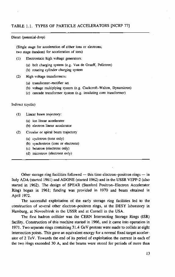
TABLE 1.1. TYPES OF PARTICLE ACCELERATORS [NCRP 77]
Direct (potential-drop)
(Single stage for acceleration of either ions or electrons;
two stage (tandem) for acceleration of ions)
(1) Electrostatic high voltage generators:
(a) belt charging system (e.g. Van de Graaf f , Pelletron)
(b) rotating cylinder charging system
(2) High voltage transformers:
(a) t ransformer-rect i f ier set (b) voltage multiplying system (e.g. Cockcrof t -Wal ton , Dynamitron) (c) cascade t ransformer system (e.g. insulating core transformer)
Indirect (cyclic)
(1) Linear beam trajectory:
(a) ion linear accelerator
(b) electron linear accelerator
(2) Circular or spiral beam trajectory
(a) cyclotron (ions only)
(b) synchrotron (ions or electrons) (c) betatron (electrons only) (d) microtron (electrons only)
Other storage ring facilities followed — this time electron-positron rings — in Italy ADA (started 1961) and ADONE (started 1962) and in the USSR VEPP-2 (also started in 1962). The design of SPEAR (Stanford Positron-Electron Accelerator Ring) began in 1961; funding was provided in 1970 and beam obtained in April 1972.
The successful exploitation of the early storage ring facilities led to the construction of several other electron-positron rings, at the DESY laboratory in Hamburg, at Novosibirsk in the USSR and at Cornell in the USA.
The first hadron collider was the CERN Intersecting Storage Rings (ISR) facility. Construction of this machine started in 1966, and it came into operation in 1971. Two separate rings containing 31.4 GeV protons were made to collide at eight intersection points. This gave an equivalent energy for a normal fixed target acceler-ator of 2 TeV. Towards the end of its period of exploitation the current in each of the two rings exceeded 30 A, and the beams were stored for periods of more than
13
70 hours without any significant degradation in beam quality. This unique facility was dismantled for economic reasons in 1984.
The first proton-antiproton collider was brought into operation at CERN in 1981 (see Section 1.5). Because of the success of this facility, several others are now envisaged. In particular, it is planned that a proton-antiproton colliding beam facility providing centre of mass energies up to 2 TeV will come into operation at Fermilab in 1986.
1.2. TYPES OF POSITIVE ION ACCELERATORS A basic understanding of the principles of accelerator operation is essential for
those concerned with radiation protection at these installations. Space does not permit a discussion here, but several references are given in the bibliography (Chapter 7).
Positive ion accelerators may be classified in a variety of ways, but the parameters of most importance for radiation protection are the particles accelerated, their energy and intensity and the time structure of the accelerated particle beams. These parameters are to a large degree determined by the type of accelerator. Table 1.1 summarizes the various types of accelerator and indicates whether they accelerate electrons or heavy ions.
1.3. PHYSICAL AND RADIOLOGICAL CHARACTERISTICS OF POSITIVE ION ACCELERATORS
1.3.1. Particle energy
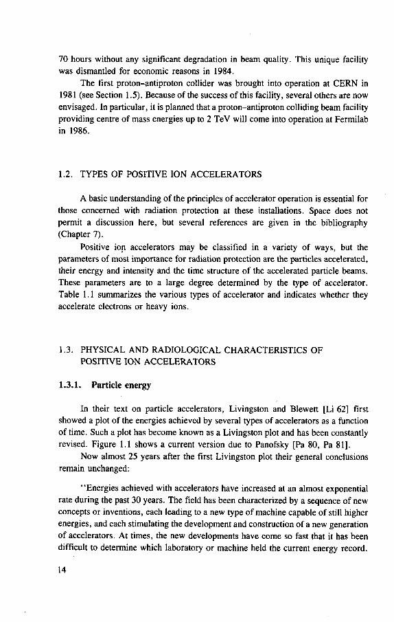
In their text on particle accelerators, Livingston and Blewett [Li 62] first showed a plot of the energies achieved by several types of accelerators as a function of time. Such a plot has become known as a Livingston plot and has been constantly revised. Figure 1.1 shows a current version due to Panofsky [Pa 80, Pa 81].
Now almost 25 years after the first Livingston plot their general conclusions remain unchanged:
"Energies achieved with accelerators have increased at an almost exponential rate during the past 30 years. The field has been characterized by a sequence of new concepts or inventions, each leading to a new type of machine capable of still higher energies, and each stimulating the development and construction of a new generation of accelerators. At times, the new developments have come so fast that it has been difficult to determine which laboratory or machine held the current energy record. 14
YEAR
FIG. 1.1. A 'Livingston plot' showing the increase in particle energy produced by accelerators with time. (After Panofsky [Pa 80, Pa 81])
The record has been held in turn by voltage multipliers, cyclotrons, betatrons, syn-
chrotrons, synchrocyclotrons, proton synchrotrons and alternating-gradient synchro-
trons. In the figure energies achieved with several accelerator types are plotted on
a logarithmic scale against the dates of publication of the results. Separate curves
show the rise in energy with time for the different machines and identify the useful
energy range for each type. A n envelope enclosing all the curves shows a ten-fold
increase in energy every six years." [Li 62]
15
Livingston and Blewett made their analysis when only strong focusing proton accelerators were in operation. Some 20 years later Panofsky was unable to change the conclusions of Livingston and Blewett very much: "The whole progress of this field (high-energy physics) has been nurtured by a succession of new inventions. As any one invention ran out of steam, a new one has followed, and the result of all these inventions has led high energy physics to [a] succession of spectacular discov-eries." [Pa 81] The Livingston plot still indicates a growth in equivalent energy by about a factor of 10 every 6 or 7 years [Ri 84],
In mid-1985 the highest energy accelerator in the world was the CERN proton-antiproton colliding beam facility (see Section 1.5) with a normal centre of mass energy of 540 GeV. Recently in a new mode of pulsed collider operation, maxi-mum centre of mass energies of 900 GeV have been achieved. (Protons and antipro-tons are composite particles made from quarks, and thus the centre of mass energy is considerably higher than the effective centre of mass energy [Qu 85, Ri 85].)
At Fermilab the Tevatron (a superconducting positron synchrotron of 1 TeV) is currently operating in the fixed target mode at about 800 GeV, giving centre of mass energies up to 45 GeV. The SPS operates in fixed target mode at 450 GeV, and the Serpukhov synchrotron operates at 70 GeV.
1.3.2. Beam intensity
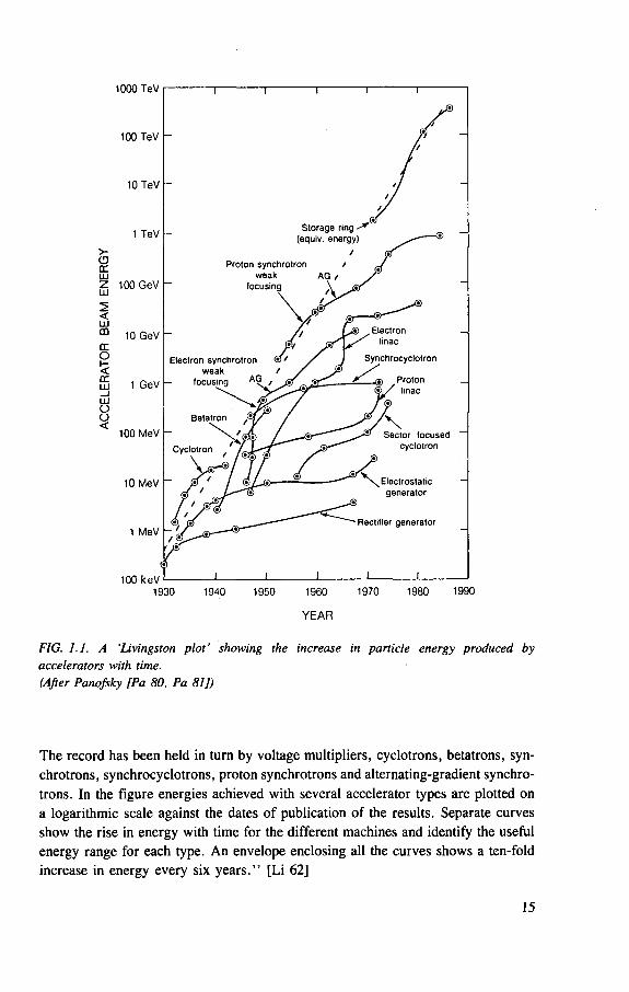
Available beam intensities of the highest energy accelerators tend to be signifi-cantly lower than those from lower energy accelerators, as may be seen by inspecting Fig. 1.2. In this figure, prepared in 1971, the two parameters, maximum beam energy and maximum average current, are plotted for various accelerators. For the highest energy proton accelerators, average currents of a few microamperes were feasible (CERN II, NAL), whereas at the Stanford Linear Accelerator Center (which accelerates electrons) the beam current was an order of magnitude higher.
At these energies the available beam power was almost 1 MW (670 kW at SLAC), and dissipation of the heat generated by the interaction of such beams presents a difficult engineering problem. Experiments at SLAC, with the electron beam focused to a spot of approximately 1 mm in diameter, have demonstrated that 30 cm thick metal beam stops are melted through in times ranging from 1 to 10 s, depending upon the thermal properties of the metal [Bu 69a], The thermal energy density produced in targets, collimators and backstops by such accelerator beams exceeds that in the cores of fast reactors used for generating electricity. At proton accelerators, too, the energy in the beam provides similar engineering problems. 'Lost' beams have easily ruptured vacuum chambers in certain machines. Beam dumps, targets and collimators at the SPS and Fermilab accelerators have to be designed to resist the thermal shock provided by a 20 ixs pulse of several-hundred-GeV protons. 16
10
10'
10'
> o>
> • o ac LjJ Z Ui
s. < LLI m
10
10'
10
I 0.001
J JZGS Za^SS f •CORNELL DESY • o YEREVAN
CAMBRIDGE BEVArRON NINA' •DARESBURY
•CAL-TECH FRASCATia • I.UND KHARKOV+ t-ORSAY
"^""RnrBKr, fy UENINGRA080tRKtLtouSNAS CERN BONN, I p,^
• LIVERPOOLR COLUMBIA
| MARWELLO 0U ROCM HARVAROO UPPSALA o CRSAY
CMC GILL
OAMSTEROAM FORD o OUCLi WINNIPEG
• M E S O N FACTORIES (PHOPOSEO a UNDER CONSTRUCTION)
O CYCLOTRONS 8 SYNCHROCYCLOTRONS • PROTON SYNCHROTRONS • CIRCULAR ELECTRON ACCELERATORS + LINEAR ELECTRON ACCELERATORS
^ P O T E N T I A L DROP ACCELERATORS I B 5 0 ACCELERATORS
+STANFORD
COLUMBIA ft ftftTRlUMF
*LA SL
ALMA ATAO I O „ VHAHWELL | MILAN QNLO OU MlCH + RPl + PHERMCl SACLAY, WASH UO RPHLlPS LAB. U COLO + PHERME* PNlLlPS 0UPMAR
uLivERMORE U,iu?fc-C ma c » ARGON* oM0SC0W
NUFFIELD MARKLE ' U PIT TSgj
CANBERRA COPENHAGEN LASl °UTlNS °KYOTO
OUIND O0AK RlDGE 1 OUMlCH
0.01 0.1 I 10 100 EXTERNAL AVERAGE BEAM CURRENT ( ^ A )
1000
FIG. 1.2. Worldwide inventory of particle accelerators (1971). Each accelerator is plotted on a co-ordinate system of beam energy versus intensity measured in microamperes. (After Rosen [Ro 71])
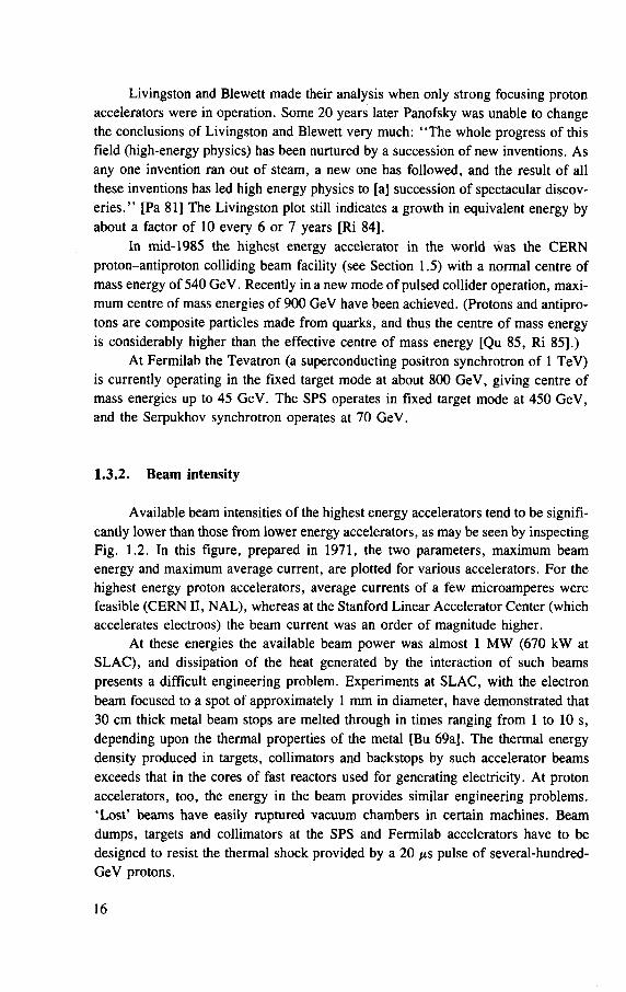
Figure 1.3, prepared in 1982, shows the effective luminosity L versus centre of mass energy for several operating accelerators and for accelerators then planned for construction. The luminosity of an accelerator L is related to intensity by the equation
L - - ^ ( 1 . 1 ) Ana
where f is the collision frequency, N 1 ; N 2 are the numbers of particles per bunch, and a is the beam radius. Figures 1.2 and 1.3 both indjcate the same general princi-ple: the higher the accelerator energy the lower its intensity.
17

1038
1036
1034
1032
1030
1021
1 1 1 I I 1 1 1 1 1 1 1 1 1 1 1 SLAC •
- S L E D Y O 1 II
KEK _AGS — a • PS
SPS BFNAL
I I I I I I I 11 i
• Lepton interaction • Proton interaction P O Under construction
or planned
• Tevatron PRC •
m SPS — • muons
Serpukhov • ISABELLE •
PETRA DESY — • PEP O
SPEAR • • CESR • VEPP-4 •
DORIS • ' S R
LEP O • -
i i i i i ' i 1 i i l l
FNAL pp ~~ • •
CERN pp
i I I 1 i 5 7 10 20 30 50 70 100 200 300 500 1000 2000 CENTRE OF MASS ENERGY (GeV)
FIG. 1.3. Effective luminosity versus centre of mass energy for the largest accelerators now operating or planned. For fixed target accelerators the target is assumed to be liquid hydrogen 1 m thick (except in the case of SPS muons, where a 50 m thick liquid hydrogen target is assumed). (After Panofsky [Pa 81 J)
1.3.3. Number of accelerators
The technological achievements of increasing energy and intensity have made possible the development of a large variety of commercially available particle accelerators that can accelerate a wide range of particles to high energies at high beam intensities. This has made possible the industrial application of accelerators to a host of diverse tasks [Av 73, Bo 71, Ev 73, Fo 61, Ma 79, Pa 79, Ro 71, Se 75, To 71],
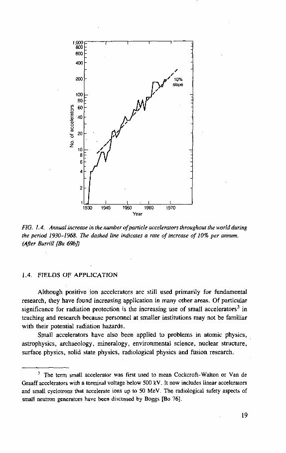
Burrill [Bu 69b] documented the increasing uses of accelerators in industry and medicine during the period ending December 1968 and showed the number of accelerators in use to be increasing at the rate of roughly 10% a year (Fig. 1.4). Morgan [Mo 73] showed that the annual rate of increase during the period 1968-1972 had more than doubled over the estimate of Burrill. 18
Year
FIG. 1.4. Annual increase in the number of particle accelerators throughout the world during the period 1930-1968. The dashed line indicates a rate of increase of 10% per annum. (After Burrill [Bu 69b]}
1.4. FIELDS OF APPLICATION Although positive ion accelerators are still used primarily for fundamental
research, they have found increasing application in many other areas. Of particular significance for radiation protection is the increasing use of small accelerators3 in teaching and research because personnel at smaller institutions may not be familiar with their potential radiation hazards.
Small accelerators have also been applied to problems in atomic physics, astrophysics, archaeology, mineralogy, environmental science, nuclear structure, surface physics, solid state physics, radiological physics and fusion research.
3 The term small accelerator was first used to mean Cockcrof t -Wal ton or Van de Graaff accelerators with a terminal voltage below 500 kV. It now includes linear accelerators and small cyclotrons that accelerate ions up to 50 MeV. The radiological safety aspects of small neutron generators have been discussed by Boggs [Bo 76],
19
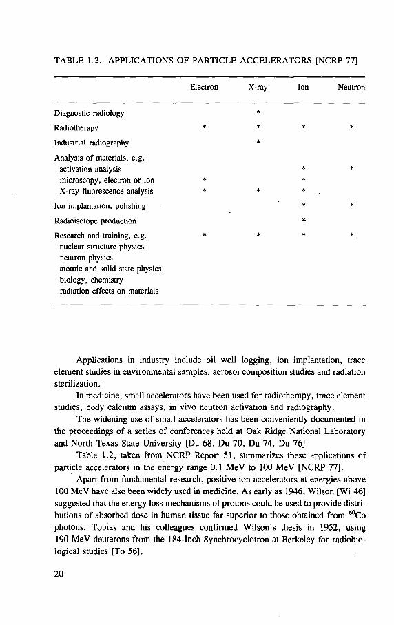
TABLE 1.2. APPLICATIONS OF PARTICLE ACCELERATORS [NCRP 77]
Electron X-ray Ion Neutron
Diagnostic radiology *
Radiotherapy * * *
Industrial radiography *
Analysis of materials, e .g. activation analysis * microscopy, electron or ion * * X-ray fluorescence analysis * * *
Ion implantation, polishing *
Radioisotope production *
Research and training, e .g. * * * nuclear structure physics neutron physics atomic and solid state physics biology, chemistry radiation effects on materials
Applications in industry include oil well logging, ion implantation, trace element studies in environmental samples, aerosol composition studies and radiation sterilization.
In medicine, small accelerators have been used for radiotherapy, trace element studies, body calcium assays, in vivo neutron activation and radiography.
The widening use of small accelerators has been conveniently documented in the proceedings of a series of conferences held at Oak Ridge National Laboratory and North Texas State University [Du 68, Du 70, Du 74, Du 76].
Table 1.2, taken from NCRP Report 51, summarizes these applications of particle accelerators in the energy range 0.1 MeV to 100 MeV [NCRP 77].
Apart from fundamental research, positive ion accelerators at energies above 100 MeV have also been widely used in medicine. As early as 1946, Wilson [Wi 46] suggested that the energy loss mechanisms of protons could be used to provide distri-butions of absorbed dose in human tissue far superior to those obtained from 60Co photons. Tobias and his colleagues confirmed Wilson's thesis in 1952, using 190 MeV deuterons from the 184-Inch Synchrocyclotron at Berkeley for radiobio-logical studies [To 56].
20
Somewhat later, the Berkeley group reported the first therapeutic use of high energy ion beams in attempts to destroy the endocrine function of the pituitary gland in cancer patients [To 52]. Subsequently, protons and other ions have been used for radiotherapy or radiosurgery at many centres around the world, including Uppsala, Harvard, Moscow, Dubna and Leningrad. Larsson has recently reviewed this work [La 80],
A recent review of the use of particle accelerators to generate protons, ion beams, neutrons or pions for use in therapy and diagnosis may be found in the proceedings of the third course of the International School of Radiation Damage and Protection held at the Ettore Majorana Centre for Scientific Culture [Th 80].
1.5. TYPICAL INSTALLATIONS
Examples of actual positive ion accelerators used in research or medicine are presented in this section, together with a number of general points that should be con-sidered in planning new facilities in research settings such as universities and national laboratories. There is usually a small staff knowledgeable in radiation pro-tection. This staff should be consulted as early as possible in the planning stages. In small institutions, where the management and staff may not be familiar with the detailed requirements for radiation safety, expert advice should be obtained at the architectural planning stage to ensure that adequate provision is made for radiation shielding and other features such as radiation and other safety interlocks and require-ments for utilities. Whatever the setting, planning for the radiation safety programme must consider the physical layout (see Chapter 5).
Radiation shielding is generally of large dimensions at accelerators, which are therefore often constructed at or below ground level to avoid the necessity of con-structing massive shield supports. Except where space is at a premium, ordinary con-crete or earth is usually the cheapest means of providing shielding. Steel or heavy aggregate concretes are used to minimize shield thickness, but at some cost premium (see Chapter 4).
The external radiation field of positive ion accelerators is usually dominated by neutrons, with a smaller contribution from photons (see Chapter 2). Shield thick-nesses are therefore often determined by neutron dose equivalent rates. Other impor-tant considerations are adequate roof design to reduce neutron skyshine to acceptable levels (Chapter 6) and the design of labyrinths and other penetrations through the shield to minimize radiation streaming (Chapter 4).
The installations described cover the energy span from 20 MeV to 400 GeV and are generally used for fundamental research. Although the accelerators described are diverse, it will subsequently be shown that they exhibit great similarity in radia-tion protection features.
21
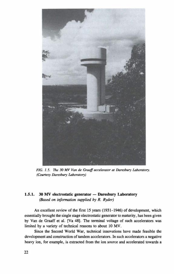
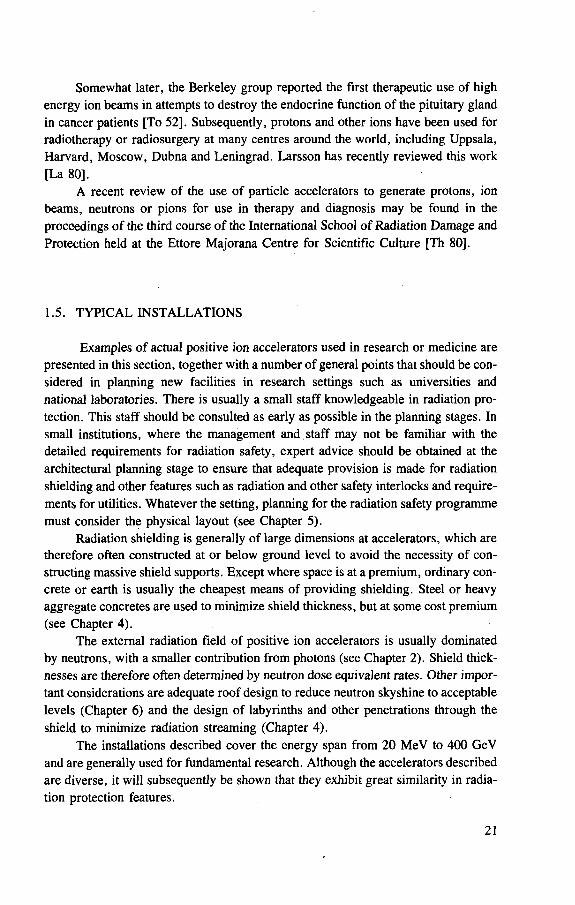
FIG. 1.5. The 30 MV Van de Graaff accelerator at Daresbury Laboratory. (Courtesy Daresbury Laboratory)
1.5.1. 30 MV electrostatic generator — Daresbury Laboratory (Based on information supplied by R. Ryder)
An excellent review of the first 15 years (1931-1946) of development, which essentially brought the single stage electrostatic generator to maturity, has been given by Van de Graaff et al. [Va 48], The terminal voltage of such accelerators was limited by a variety of technical reasons to about 10 MV.
Since the Second World War, technical innovations have made feasible the development and construction of tandem accelerators. In such accelerators a negative heavy ion, for example, is extracted from the ion source and accelerated towards a
INFLECTOR MAGNET
INSULATING LEGS
OUAORUPOLE TRIPLET
a / 6 PRESSURE VESSEL
OUAORUPOLE TRIPLET
OUADRUPOLE TRIPLET
CENTRE TERMINAL CHARGING SYSTEM - LADDERTRON
OUAORUPOLE TRPLET
ANNULAR LFT PLATFORM
STACK SUPPORT 8TRUCTURE
OUAORUPOLE TRIPLET
ANALYSING MAGNET
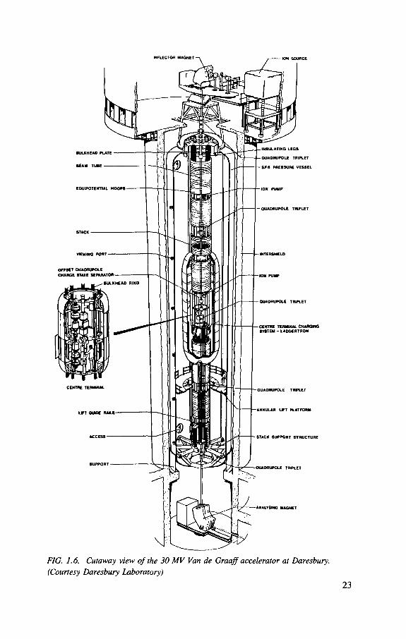
FIG. 1.6. Cutaway view of the 30 MV Van de Graaff accelerator at Daresbury. (Courtesy Daresbury Laboratory)
23
T Y P I C A L S T A C K S E C T I O N I N D I C A T I N G M A I N S T R U C T U R A L & E L E C T R O S T A T I C E L E M E N T S
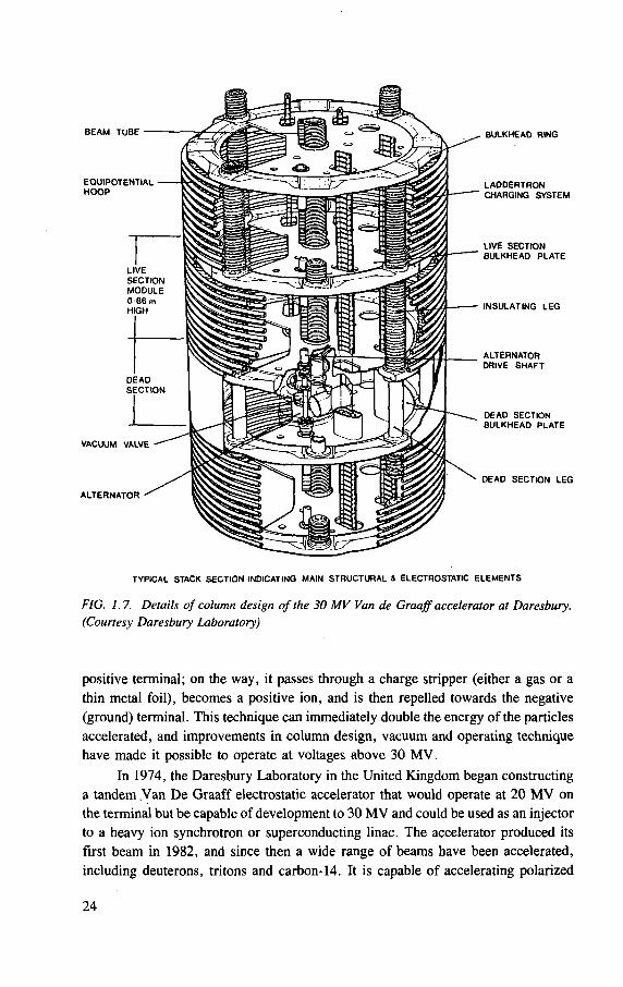
FIG. 1.7. Details of column design of the 30 MV Van de Graaff accelerator at Daresbury. (Courtesy Daresbury Laboratory)
positive terminal; on the way, it passes through a charge stripper (either a gas or a thin metal foil), becomes a positive ion, and is then repelled towards the negative (ground) terminal. This technique can immediately double the energy of the particles accelerated, and improvements in column design, vacuum and operating technique have made it possible to operate at voltages above 30 MV.
In 1974, the Daresbury Laboratory in the United Kingdom began constructing a tandem Van De Graaff electrostatic accelerator that would operate at 20 MV on the terminal but be capable of development to 30 MV and could be used as an injector to a heavy ion synchrotron or superconducting linac. The accelerator produced its first beam in 1982, and since then a wide range of beams have been accelerated, including deuterons, tritons and carbon-14. It is capable of accelerating polarized
24
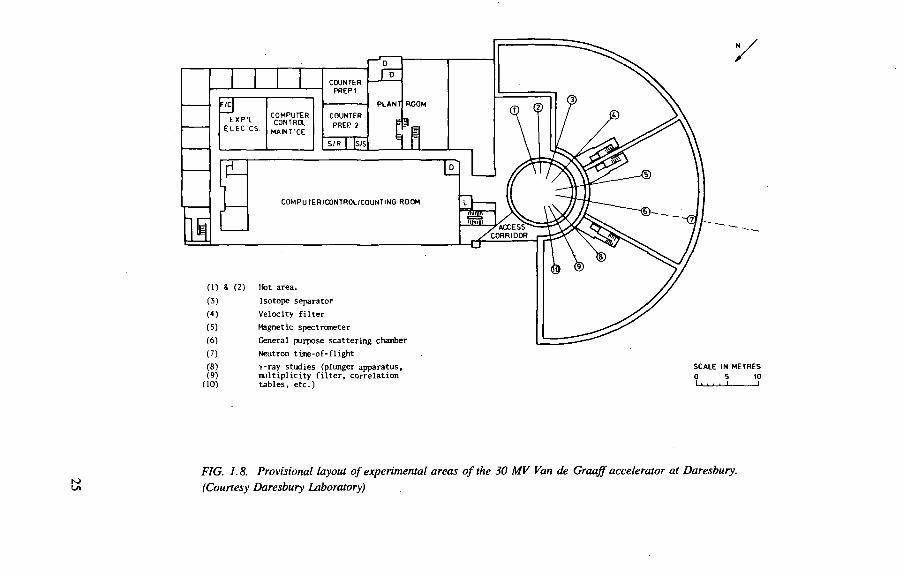
Cl) & (2) Hot area. (3) Isotope separator
(«) Velocity f i l t e r (5) Magnetic spectrometer
(6) General purpose scat ter ing chamber
(7) Neutron t ime-of - f l igh t
(8) y-ray studies (plunger apparatus, (9) mul t ip l i c i ty f i l t e r , cor re la t ion
(10) t ab les , e t c . )
SCALE IN METRES 0 5 10
N) Ul
FIG. 1.8. Provisional layout of experimental areas of the 30 MV Van de Graaff accelerator at Daresbury.
(Courtesy Daresbury Laboratory)
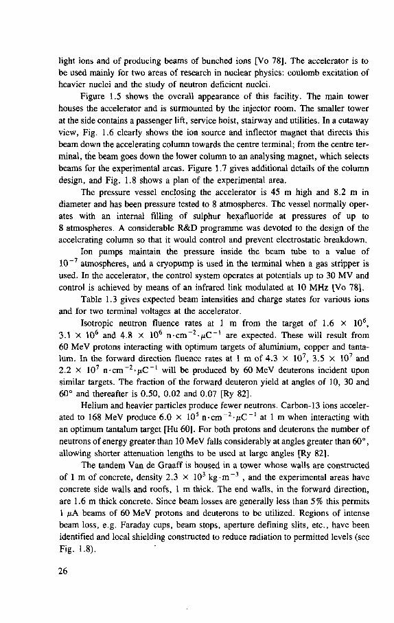
light ions and of producing beams of bunched ions [Vo 78]. The accelerator is to be used mainly for two areas of research in nuclear physics: coulomb excitation of heavier nuclei and the study of neutron deficient nuclei.
Figure 1.5 shows the overall appearance of this facility. The main tower houses the accelerator and is surmounted by the injector room. The smaller tower at the side contains a passenger lift, service hoist, stairway and utilities. In a cutaway view, Fig. 1.6 clearly shows the ion source and inflector magnet that directs this beam down the accelerating column towards the centre terminal; from the centre ter-minal, the beam goes down the lower column to an analysing magnet, which selects beams for the experimental areas. Figure 1.7 gives additional details of the column design, and Fig. 1.8 shows a plan of the experimental area.
The pressure vessel enclosing the accelerator is 45 m high and 8.2 m in diameter and has been pressure tested to 8 atmospheres. The vessel normally oper-ates with an internal filling of sulphur hexafluoride at pressures of up to 8 atmospheres. A considerable R&D programme was devoted to the design of the accelerating column so that it would control and prevent electrostatic breakdown.
Ion pumps maintain the pressure inside the beam tube to a value of 10~7 atmospheres, and a cryopump is used in the terminal when a gas stripper is used. In the accelerator, the control system operates at potentials up to 30 MV and control is achieved by means of an infrared link modulated at 10 MHz [Vo 78].
Table 1.3 gives expected beam intensities and charge states for various ions and for two terminal voltages at the accelerator.
Isotropic neutron fluence rates at 1 m from the target of 1.6 x 10⁶, 3.1 X 10⁶ and 4.8 X 10⁶ n -cm~ 2 - /xC _ l are expected. These will result from 60 MeV protons interacting with optimum targets of aluminium, copper and tanta-lum. In the forward direction fluence rates at 1 m of 4.3 X 10⁷, 3.5 X 10⁷ and 2.2 x 10⁷ n - c m ~ 2 ' f i C _ 1 will be produced by 60 MeV deuterons incident upon similar targets. The fraction of the forward deuteron yield at angles of 10, 30 and 60° and thereafter is 0.50, 0.02 and 0.07 [Ry 82].
Helium and heavier particles produce fewer neutrons. Carbon-13 ions acceler-ated to 168 MeV produce 6.0 X 1 0 5 n - c m ~ 2 - ^ C _ 1 at 1 m when interacting with an optimum tantalum target [Hu 60], For both protons and deuterons the number of neutrons of energy greater than 10 MeV falls considerably at angles greater than 60°, allowing shorter attenuation lengths to be used at large angles [Ry 82].
The tandem Van de Graaff is housed in a tower whose walls are constructed of 1 m of concrete, density 2.3 x 10³ k g - m - 3 , and the experimental areas have concrete side walls and roofs, 1 m thick. The end walls, in the forward direction, are 1.6 m thick concrete. Since beam losses are generally less than 5% this permits 1 fiA beams of 60 MeV protons and deuterons to be utilized. Regions of intense beam loss, e.g. Faraday cups, beam stops, aperture defining slits, etc., have been identified and local shielding constructed to reduce radiation to permitted levels (see Fig. 1.8).
26
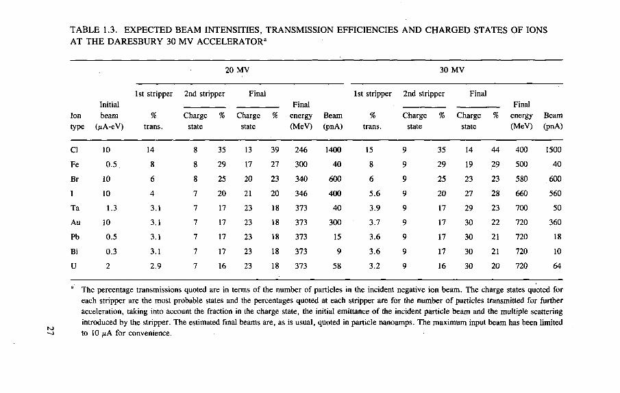
TABLE 1.3. EXPECTED BEAM INTENSITIES, TRANSMISSION EFFICIENCIES AND CHARGED STATES OF IONS AT THE DARESBURY 30 MV ACCELERATORa
20 MV 30 M V
Initial 1st stripper 2nd stripper Final
Final 1st stripper 2nd stripper Final
Final Ion type
beam OiA-eV)
% trans.
Charge state
% Charge state
% energy (MeV)
Beam (pnA)
% trans.
Charge state
% Charge state
% energy (MeV)
Beam (pnA)
CI 10 14 8 35 13 39 246 1400 15 9 35 14 44 400 1500
Fe 0 .5 8 8 29 17 27 300 40 8 9 29 19 29 500 4 0
Br 10 6 8 25 20 23 340 600 6 9 25 23 23 580 600
I 10 4 7 20 21 20 346 400 5 .6 9 20 27 28 660 560
Ta 1.3 3 .1 7 17 23 18 373 4 0 3.9 9 17 29 23 700 50
Au 10 3.1 7 17 23 18 373 300 3.7 9 17 30 22 720 360
Pb 0 .5 3 .1 7 17 23 18 373 15 3 .6 9 17 30 21 720 18
Bi 0 .3 3 .1 7 17 23 18 373 9 3 .6 9 17 30 21 720 10
U 2 2 .9 7 16 23 18 373 58 3.2 9 16 30 20 720 64
a The percentage transmissions quoted are in terms of the number of particles in the incident negative ion beam. The charge states quoted for each stripper are the most probable states and the percentages quoted at each stripper are for the number of particles transmitted for fur ther acceleration, taking into account the fraction in the charge state, the initial emittance of the incident particle beam and the multiple scattering introduced by the stripper. The estimated final beams are, as is usual, quoted in particle nanoamps. The maximum input beam has been limited to 10 fiA for convenience.
During light ion operation, personnel are excluded from the experimental areas. However, access will be allowed to beam lines using heavy ions, subject to radiation survey.
Triton beams are generated from a Middleton sputter ion source, which uses approximately 200 Ci of tritium for 500 hours of beam time at 5 A. Most of the gase-ous tritium released is trapped within the first two turbopumps, and only 300 mCi will be passed by the gas restriction and 30 mCi by the inflector magnet [Ry 80]. The contaminated ion source, turbo pumps, and associated beam line components before the gas restriction are decontaminated in a glove box equipped with facilities for the collection and disposal of cleaning water.
Induced activity at these energies is not a great problem. With short light ion runs (2 to 5 days) followed by long heavy ion beams (5 to 16 days) dose rates at 10 cm from Faraday cups, etc., of 20 to 100 m r e m - h _ 1 are experienced. However, maximum dose rates at 10 cm from tantalum beam stops of 0.47 and 0.76 G y - h _ 1
(47 and 76 r a d - h - 1 ) are expected immediately after running periods of 30 days with 1 nA beams of 60 MeV protons and deuterons. These will decay to 39 and 66 m G y - h _ 1 after 1 day and 12 and 18 m G y - h - 1 after 7 days [Ho 80].
1.5.2. 800 MeV linear accelerator — Clinton P. Anderson Meson Physics Facility
(Based on information supplied by T.M. Putnam and A.J. Miller)
1.5.2.1. Introduction
The Clinton P. Anderson Meson Physics Facility, otherwise known as LAMPF 4 , is operated by the Los Alamos National Laboratory of the University of California for the US Department of Energy. (Figure 1.9 is an overhead view of the facility.) The heart of the installation is a high intensity linear accelerator (linac) producing proton beams of energy 800 MeV at an average current of up to 1 mA, variable energy (300 to 800 MeV) H - beams at up to 10 ixA average current, or variable energy polarized H ~ beams up to 10 nA average current. The accelerator is pulsed at a repetition rate of 120 Hz with a duty factor of from 6% to 9%.
Although primarily a tool for atomic, nuclear and elementary particle physics and nuclear chemistry research, LAMPF is used for extensive research in solid state physics. It also has important applications in medical radioisotope production and materials science.
4 An acronym for Los Alamos Meson Physics Facility.
28
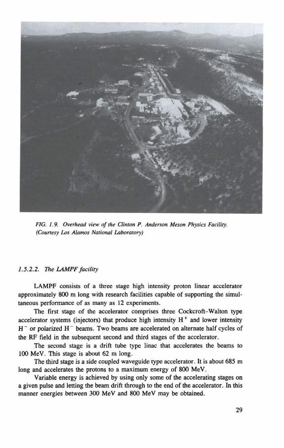
FIG. 1.9. Overhead view of the Clinton P. Anderson Meson Physics Facility. {Courtesy Los Alamos National Laboratory)
1.5.2.2. The LAMPF facility
LAMPF consists of a three stage high intensity proton linear accelerator approximately 800 m long with research facilities capable of supporting the simul-taneous performance of as many as 12 experiments.
The first stage of the accelerator comprises three Cockcroft-Walton type accelerator systems (injectors) that produce high intensity H + and lower intensity H " or polarized H - beams. Two beams are accelerated on alternate half cycles of the RF field in the subsequent second and third stages of the accelerator.
The second stage is a drift tube type linac that accelerates the beams to 100 MeV. This stage is about 62 m long.
The third stage is a side coupled waveguide type accelerator. It is about 685 m long and accelerates the protons to a maximum energy of 800 MeV.
Variable energy is achieved by using only some of the accelerating stages on a given pulse and letting the beam drift through to the end of the accelerator. In this manner energies between 300 MeV and 800 MeV may be obtained.
29
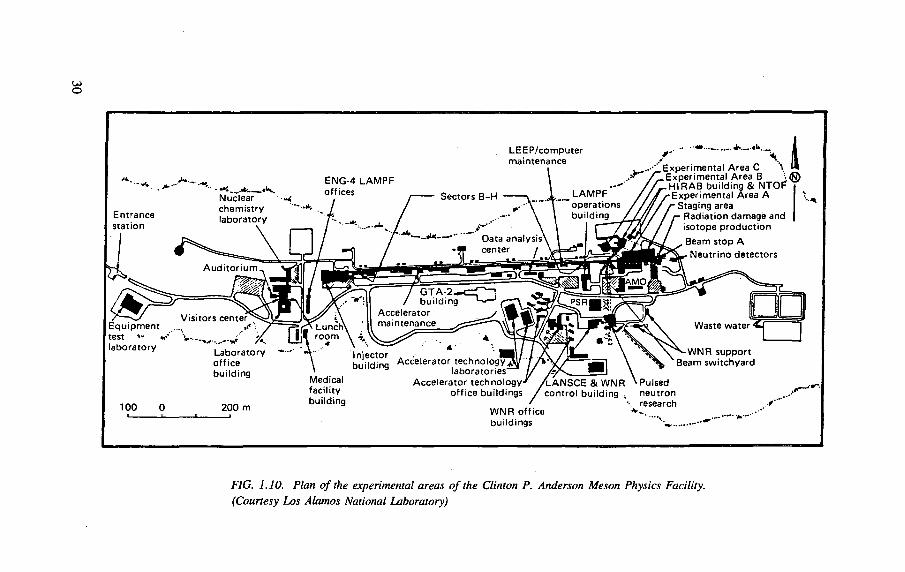
FIG. 1.10. Plan of the experimental areas of the Clinton P. Anderson Meson Physics Facility. (Courtesy Los Alamos National Laboratory)
When the particles leave the accelerator they enter a switchyard, where the two beams are separated and directed by magnets along three beam lines to the various experimental areas shown in Fig. 1.10. The high intensity H + beam passes straight ahead through two production targets in the meson experimental hall, through up to six isotope production targets, and finally to the main beam stop. Beams of H ~ or polarized H~ are directed to the high resolution proton spectrometer and the research areas in the nucleon physics laboratory. Pulses of H~ beam are also directed to the proton storage ring and/or the weapons neutron research facility.
1.5.2.3. General radiological safety
Physical controls. Radiation shielding for the accelerator, beam switchyard, targets, beam stops and experimental caves consists of poured concrete, compacted earth and/or steel and concrete slabs and blocks. The injectors require no shielding, but rope barriers and signs warn personnel of the presence of X-ray fields in front of the H - injector. The drift tube linac channel is shielded by concrete walls and a roof varying in thickness from 0.6 m at the low energy end to 1.5 m at the 100 MeV end. The side coupled waveguide section and the beam switchyard are in a tunnel about 9 m underground. Access to the beam channel is controlled by locked and interlocked doors and gates.
The beam line and target cells in the meson experimental hall are shielded by massive stacks ( — 60 000 tons) of steel slabs and concrete blocks. There are 2.5 m of magnetite and regular concrete beneath the line to limit ground shine. The experimental caves are shielded by 1 m thick concrete blocks 2.5 m high; there is no roof shielding over the experiments. Both the nucleon physics and the high resolu-tion proton spectrometer areas are closed to access when beam is directed to these areas.
Activation of accelerator components from beam spill is controlled by 100 accelerator-protect/beam-spill monitors consisting of small scintillation detectors and fast-shut-down circuitry capable of turning the beam off during a pulse. This system prevents excessive induced activity in accelerator components and minimizes exter-nal radiation fields in occupied areas.
Administrative controls. The control of personnel radiation exposures and the monitoring and control of radioactive materials, including waste disposal and radio-active contamination control, are the two major radiological safety concerns at a high intensity accelerator. A health physics staff provides 24 hour control and surveillance for all activities in radiation areas that involve radioactive materials. They make fre-quent radiation surveys of occupied areas using instruments that allow for the pulsed nature of the proton beam, and provide guidance and assistance in the handling and disposal of radioactive materials (see below).
Everyone working in the accelerator buildings and experimental areas is required to wear a TLD personal dosimetry badge. Personnel entering high radiation areas or working near radioactive components are issued pocket ionization cham-
31
bers. TLD finger rings are worn for close work on radioactive materials. With these efforts personnel exposures are maintained well below the established legal regula-tions for radiation workers.
1.5.2.4. Special radiological problems
The intense proton beams at LAMPF have created numerous special problems and magnified many others.
Induced radioactivity. The intense primary proton beams, secondary pion and neutron beams and scattered particles induce radioactivity in accelerator and target components, shielding and nearby equipment. Surface contamination is not as seri-ous a problem as the induced activity. The major part of the activity is within solid materials, requiring careful surveillance and control during maintenance activities. However, cooling water systems and the air surrounding the targets and beam stops also suffer considerable induced activity. The activity in the cooling water systems is controlled by passing part of the circulating water through deionization columns. This removes most radionuclides except tritium, which can be removed from the system by evaporation techniques. In case of leaks, a drain system has been provided that connects to two 2500 gallon underground storage tanks. The liquid in the tanks is pumped out and disposed of in a manner depending on an analysis of its activity. The activities in the radioactive air consist primarily of "C, 13N, 1 50 and a little 41Ar, all with relatively short half-lives. This activity is exhausted to the atmosphere through a ventilation stack. The gaseous and particulate effluents are continuously monitored.
Control of radioactive materials. The control of radioactive materials involves experiment safety reviews, health physics surveillance and doorway radiation moni-tors. To detect the unauthorized movement of such materials from the LAMPF site, a sensitive gateway monitoring system has been developed. This detection system consists of a 12 cm diameter Nal crystal detector placed beneath the roadway at the exit to the site with sensitive electronics that continuously update the background level. This system provides an alarm if the activity level increases to approximately twice background level. An inductive loop, buried in the road around the detector, provides a coincident signal with the radiation detector, indicating that a vehicle is present when the alarm sounds. The system will alarm if a source of radiation pass-ing through the detector's cone of sensitivity at speeds of up to 25 km-h _ 1
(15 mph) increases the radiation level at the detector to about twice the background, or 400 nGy-h - 1 (0.04 mrad-h_ 1) .
The disposal of massive highly radioactive items, such as a steel shielding block from a target cell or beam stop, has proven to be a difficult problem. Rigging such a block, painting it with fast drying paint to prevent the spread of contamina-tion, loading it into a cask for transportation, and ultimately unloading and depositing it in a hole for burial, all involve special equipment and handling techniques to keep the spread of contamination and exposures to personnel within the allowable range. At LAMPF, remote handling techniques are used as much as possible.
32
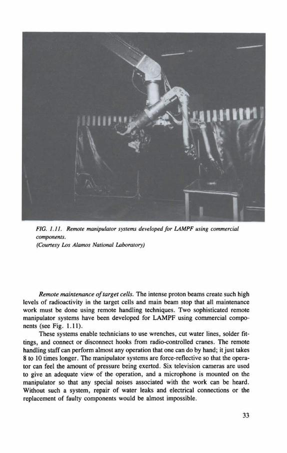
FIG. 1.11. Remote manipulator systems developed for LAMPF using commercial components. (Courtesy Los Alamos National Laboratory)
Remote maintenance of target cells. The intense proton beams create such high levels of radioactivity in the target cells and main beam stop that all maintenance work must be done using remote handling techniques. Two sophisticated remote manipulator systems have been developed for LAMPF using commercial compo-nents (see Fig. 1.11).
These systems enable technicians to use wrenches, cut water lines, solder fit-tings, and connect or disconnect hooks from radio-controlled cranes. The remote handling staff can perform almost any operation that one can do by hand; it just takes 8 to 10 times longer. The manipulator systems are force-reflective so that the opera-tor can feel the amount of pressure being exerted. Six television cameras are used to give an adequate view of the operation, and a microphone is mounted on the manipulator so that any special noises associated with the work can be heard. Without such a system, repair of water leaks and electrical connections or the replacement of faulty components would be almost impossible.
1.5.3. 800 MeV proton synchrotron: spallation neutron source — Rutherford Appleton Laboratory (Based on material supplied by J.T. Hyman and G.B. Stapleton)
Interest in applying pulsed proton accelerators to produce pulsed neutron sources has been growing. Compared with conventional nuclear reactors, such pulsed sources are less expensive and have the technical advantages of a greatly increased effective flux of neutrons within the higher neutron temperature range, with reduced problems of source cooling and radiation damage [Ho 77],
Manning has given a detailed review of the broad scope of scientific research that may be undertaken with such facilities in biology, chemistry, engineering and medical physics [Ma 78]. Manning also discussed the relative merits of various accelerator systems for neutron production.
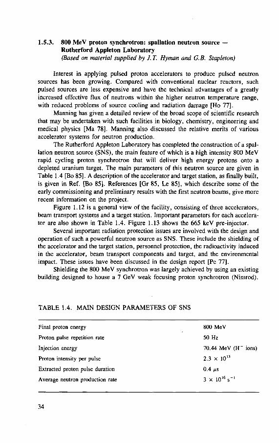
The Rutherford Appleton Laboratory has completed the construction of a spal-lation neutron source (SNS), the main feature of which is a high intensity 800 MeV rapid cycling proton synchrotron that will deliver high energy protons onto a depleted uranium target. The main parameters of this neutron source are given in Table 1.4 [Bo 85]. A description of the accelerator and target station, as finally built, is given in Ref. [Bo 85]. References [Gr 85, Le 85], which describe some of the early commissioning and preliminary results with the first neutron beams, give more recent information on the project.
Figure 1.12 is a general view of the facility, consisting of three accelerators, beam transport systems and a target station. Important parameters for each accelera-tor are also shown in Table 1.4. Figure 1.13 shows the 665 keV pre-injector.
Several important radiation protection issues are involved with the design and operation of such a powerful neutron source as SNS. These include the shielding of the accelerator and the target station, personnel protection, the radioactivity induced in the accelerator, beam transport components and target, and the environmental impact. These issues have been discussed in the design report [Pe 77].
Shielding the 800 MeV synchrotron was largely achieved by using an existing building designed to house a 7 GeV weak focusing proton synchrotron (Nimrod).
TABLE 1.4. MAIN DESIGN PARAMETERS OF SNS
Final proton energy
Proton pulse repetition rate
Injection energy
Proton intensity per pulse
Extracted proton pulse duration
Average neutron production rate
0.4 fis 3 x 10 1 6 s
800 MeV
50 Hz
70.44 MeV ( H " ions)
2.3 x 10
16 - 1
13
34
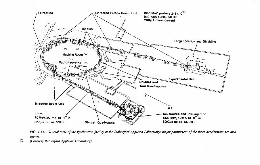
, Extraction Extracted Proton Beam Line.
Dipoles
Injection Beam Line
Linac
70 MeV. 20 mA of H " in
500JJS pulse-50Hz.
800 MeV protons 2-5x10 in0-4jjs pulse. 50 Hz 200>jA mean current
13
Target Station and Shielding
Doublet and Trim Quadrupoles
Singlet Quadrupole
25 m
Ion Source and Pre-injector 665 keV, 40mA of H~ in 500JJS pulse. 5 0 Hz.
FIG. 1.12. General view of the synchrotron facility at the Rutherford Appleton Laboratory; major parameters of the three accelerators are also shown. (Courtesy Rutherford Appleton Laboratory)
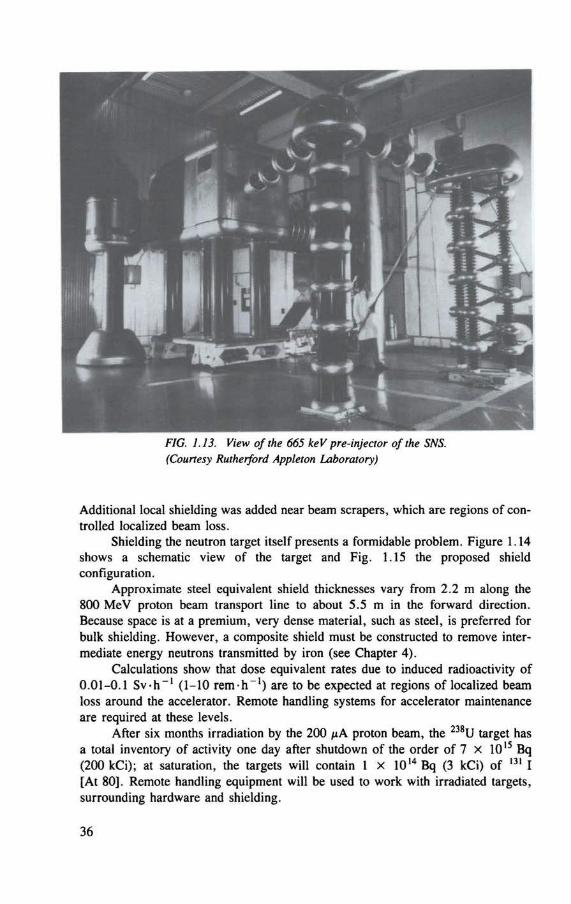
FIG. 1.13. View of the 665 keV pre-injector of the SNS. (Courtesy Rutherford Appleton Laboratory)
Additional local shielding was added near beam scrapers, which are regions of con-trolled localized beam loss.
Shielding the neutron target itself presents a formidable problem. Figure 1.14 shows a schematic view of the target and Fig. 1.15 the proposed shield configuration.
Approximate steel equivalent shield thicknesses vary from 2.2 m along the 800 MeV proton beam transport line to about 5.5 m in the forward direction. Because space is at a premium, very dense material, such as steel, is preferred for bulk shielding. However, a composite shield must be constructed to remove inter-mediate energy neutrons transmitted by iron (see Chapter 4).
Calculations show that dose equivalent rates due to induced radioactivity of 0.01-0.1 Sv-h _ l (1-10 rem-h"1) are to be expected at regions of localized beam loss around the accelerator. Remote handling systems for accelerator maintenance are required at these levels.
After six months irradiation by the 200 /xA proton beam, the 238U target has a total inventory of activity one day after shutdown of the order of 7 x 10¹⁵ Bq (200 kCi); at saturation, the targets will contain 1 X 10¹⁴ Bq (3 kCi) of 131 I [At 80], Remote handling equipment will be used to work with irradiated targets, surrounding hardware and shielding.
36
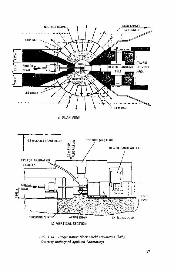
a) PLAN VIEW
b) VERTICAL SECTION
FIG. 1.14. Target station block shield schematics (SNS).
(Courtesy Rutherford Appleton Laboratory)
37
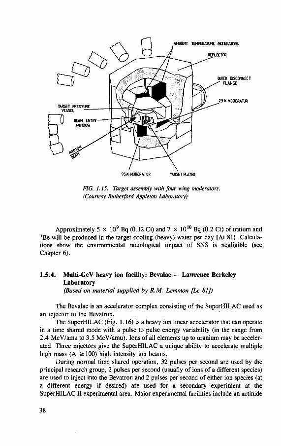
AMBIENT TEMPERATURE MODERATORS
REFLECTOR
QUICK DISCONNECT FLANGE
25 K MODERATOR
95 K MODERATOR TARGET PLATES
FIG. 1.15. Target assembly with four wing moderators. (Courtesy Rutherford Appleton Laboratory)
Approximately 5 x 10⁹ Bq (0.12 Ci) and 7 X 10¹⁰ Bq (0.2 C i ) of tritium and 7Be will be produced in the target cooling (heavy) water per day [At 81]. Calcula-tions show the environmental radiological impact of S N S is negligible (see Chapter 6).
1.5.4. Multi-GeV heavy ion facility: Bevalac — Lawrence Berkeley Laboratory (Based on material supplied by R.M. Lemmon [Le 81])
The Bevalac is an accelerator complex consisting of the S u p e r H I L A C used as an injector to the Bevatron.
The S u p e r H I L A C (Pig. 1.16) is a heavy ion linear accelerator that can operate in a time shared mode with a pulse to pulse energy variability (in the range from 2.4 MeV/amu to 3.5 MeV/amu). Ions of all elements up to uranium may be acceler-ated. Three injectors give the S u p e r H I L A C a unique ability to accelerate multiple high mass (A > 100) high intensity ion beams.
During normal time shared operation, 32 pulses per second are used by the principal research group, 2 pulses per second (usually of ions of a different species) are used to inject into the Bevatron and 2 pulses per second of either ion species (at a different energy if desired) are used for a secondary experiment at the S u p e r H I L A C I I experimental area. Major experimental facilities include an actinide
38
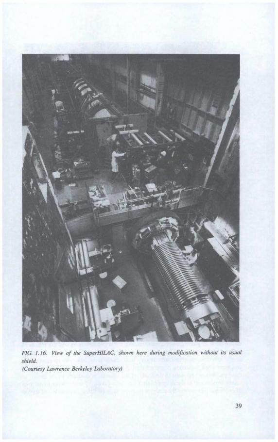
FIG. 1.16. View of the SuperHILAC, shown here during modification without its usual
shield. (Courtesy Lawrence Berkeley Laboratory)
39
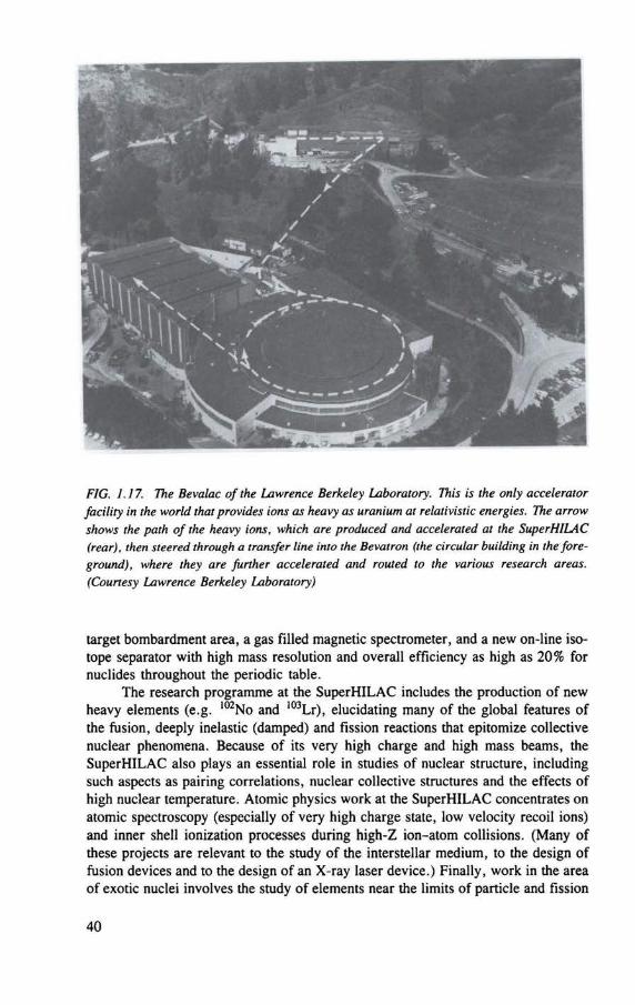
FIG. 1.17. The Bevalac of the Lawrence Berkeley Laboratory. This is the only accelerator facility in the world that provides ions as heavy as uranium at relativistic energies. The arrow shows the path of the heavy ions, which are produced and accelerated at the SuperHlLAC (rear), then steered through a transfer line into the Bevatron (the circular building in the fore-ground), where they are further accelerated and routed to the various research areas. (Courtesy Lawrence Berkeley Laboratory)
target bombardment area, a gas filled magnetic spectrometer, and a new on-line iso-tope separator with high mass resolution and overall efficiency as high as 20% for nuclides throughout the periodic table.
The research programme at the SuperHlLAC includes the production of new heavy elements (e.g. i02No and 103Lr), elucidating many of the global features of the fusion, deeply inelastic (damped) and fission reactions that epitomize collective nuclear phenomena. Because of its very high charge and high mass beams, the SuperHlLAC also plays an essential role in studies of nuclear structure, including such aspects as pairing correlations, nuclear collective structures and the effects of high nuclear temperature. Atomic physics work at the SuperHlLAC concentrates on atomic spectroscopy (especially of very high charge state, low velocity recoil ions) and inner shell ionization processes during high-Z ion-atom collisions. (Many of these projects are relevant to the study of the interstellar medium, to the design of fusion devices and to the design of an X-ray laser device.) Finally, work in the area of exotic nuclei involves the study of elements near the limits of particle and fission
40
stability, the synthesis of new elements and isotopes, the study of reaction mechan-isms for their production and the investigation of their radioactive and chemical properties.
The Bevatron (Fig. 1.17) is a synchrotron that can accelerate heavy ions from either the SuperHILAC (the Bevalac mode) or its local injector to any energy between 50 MeV/amu (where it overlaps with lower energy machines) and 2100 MeV/amu (where it is the only facility in the world with such high energy heavy ions).
Several large detector facilities are used in the research programme at the Bevalac: (1) HISS — a very large volume, heavy ion superconducting spectrometer with
large area detection systems; (2) Plastic Ball and Wall — a multiplicity detector with over 1000 detector
elements, jointly funded by the Federal Republic of Germany and the USA; (3) TASS — a two armed magnetic spectrometer system; (4) TOPAZ TPC — a pion detector system jointly funded by Japan and the USA; (5) LEBL — a low energy beam line designed to host a variety of experiments at
energies from 50 to 250 MeV. The Bevalac has a unique capability to study collisions between nuclei at ener-
gies sufficient to convert nuclear matter into hadronic matter in which neutrons and protons, their excited states such as delta resonances and free pions all coexist. It supports programmes in peripheral fragmentation reactions, pion production with heavy ions, central collisions that create nuclear matter complexes under extreme conditions of compression and stress and reactions in which the nucleonic character of nuclei is isolated from effects of coherent nuclear matter. One third of the Bevalac operating time is used in support of biomedical research, including a trial programme of heavy ion cancer therapy.
The heavy charged particle treatment facility is used to benefit certain cancer patients who have been referred by doctors. The medical staff at LBL reviews each case with the patient's doctors to determine whether or not this type of radiotherapy could be of help to the patient. If the treatment seems to be appropriate, the therapy is planned and carried out by the specialized medical staff. Both the 184-Inch Synchrocyclotron and the Bevalac are used in these treatments.
1.5.5. 12 GeV strong focusing proton synchrotron (KEK) — National Laboratory for High Energy Physics (Based on material supplied by S. Fukomoto and K. Katoh [Ka 85, Ke 84]
The National Laboratory for High Energy Physics (Ko-Enerugi-Ken, or KEK) of Japan is situated at Tsukuba some 90 km north of Tokyo.
The first accelerator constructed at the laboratory was a 12 GeV strong focusing proton synchrotron, which operated in 1976.5 A 2.5 GeV synchrotron
5 A 2 .5 GeV synchrotron radiation facility (photon factory) was completed in 1982.
4 1
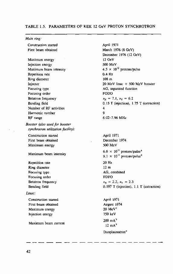
TABLE 1.5. PARAMETERS OF KEK 12 GeV PROTON SYNCHROTRON
Main ring:
Construction started First beam obtained
Maximum energy Injection energy Maximum beam intensity Repetition rate Ring diameter Injector Focusing type Focusing order Betatron frequency Bending field Number of RF activities Harmonic number R F range
Booster (also used for booster synchrotron utilization facility):
Construction started First beam obtained Maximum energy
Maximum beam intensity
Repetition rate Ring diameter Focusing type Focusing OTder Betatron frequency Bending field
Linac:
Construction started First beam obtained Maximum energy Injection energy
Maximum beam current
April 1971 March 1976 (8 GeV) December 1976 (12 GeV) 12 GeV 500 MeV
4.5 x 10¹² protons/pulse 0 .4 Hz 108 m
20 MeV linac + 500 MeV booster AG, separated function F O D O
i»H = 7.1, vv = 6 .2 0 .15 T (injection), 1.75 T (extraction) 4 9 6 .02 -7 .96 M H z
April 1971 December 1974 500 MeV
6 .6 x 1 0 " protons/pulse2
9.1 x 1 0 " protons/pulseb
20 Hz 12 m AG, combined F D F O
= 2.2 , i»v = 2 .3 0 .197 T (injection), l . l T (extraction)
April 1971 August 1974 20 MeV c
750 keV
200 m A b
12 m A b
Duoplasmatron3
42
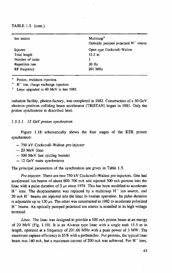
TABLE 1.5. (cont.)
Injector Total length Number of tanks Repetition rate RF frequency
Ion source Multicuspb
Optically pumped polarized H - source
Open type Cockcroft-Walton 15.5 m
20 Hz 201 MHz
a Proton, multiturn injection. b H - ion, charge exchange injection. c Linac upgraded to 40 MeV in late 1985.
radiation facility, photon factory, was completed in 1982. Construction of a 30 GeV electron-positron colliding beam accelerator (TRISTAN) began in 1981. Only the proton synchrotron is described here.
1.5.5.1. 12 GeV proton synchrotron
Figure 1.18 schematically shows the four stages of the KEK proton synchrotron:
— 750 kV Cockcroft-Walton pre-injector — 20 MeV linac — 500 MeV fast cycling booster — 12 GeV main synchrotron
The principal parameters of the synchrotron are given in Table 1.5.
Pre-injector. There are two 750 kV Cockcroft-Walton pre-injectors. One had accelerated ion beams of about 600-700 mA and injected 300 mA protons into the linac with a pulse duration of 5 s since 1974. This has been modified to accelerate H~ ions. The duoplasmatron was replaced by a multicusp H~ ion source, and 20 mA H ~ beams are injected into the linac in routine operation. Its pulse duration is adjustable up to 120 /is. The other was constructed in 1982 to accelerate polarized H~ beams. An optically pumped polarized ion source is installed in its high voltage terminal.
Linac. The linac was designed to provide a 100 mA proton beam at an energy of 20 MeV (Fig. 1.19). It is an Alvarez type linac with a single tank 15.5 m in length, operated at a frequency of 201.06 MHz with a peak power of 3 MW. The maximum capture efficiency is 55% with a prebuncher. For protons, the typical linac beam was 140 mA, but a maximum current of 200 mA was achieved. For H~ ions,
43
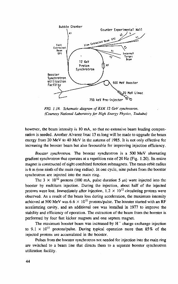
Bubble Chamber
FIG. 1.18. Schematic diagram of KEK 12 GeV synchrotron. (Courtesy National Laboratory for High Energy Physics, Tsukuba)
however, the beam intensity is 10 mA, so that no extensive beam loading compen-sation is needed. Another Alvarez linac 13 m long will be made to upgrade the beam energy from 20 MeV to 40 MeV in the autumn of 1985. It is not only effective for increasing the booster beam but also favourable for improving injection efficiency.
Booster synchrotron. The booster synchrotron is a 500 MeV alternating gradient synchrotron that operates at a repetition rate of 20 Hz (Fig. 1.20). Its entire magnet is constructed of eight combined function submagnets. The mean orbit radius is 6 m (one ninth of the main ring radius). In one cycle, nine pulses from the booster synchrotron are injected into the main ring.
The 3 x 10¹² protons (100 mA, pulse duration 5 /xs) were injected into the booster by multiturn injection. During the injection, about half of the injected protons were lost. Immediately after injection, 1.2 X 10¹² circulating protons were observed. As a result of the beam loss during acceleration, the maximum intensity achieved at 500 MeV was 6.6 x 10¹¹ protons/pulse. The booster started with an RF accelerating cavity, and an additional one was installed in 1977 to improve the stability and efficiency of operation. The extraction of the beam from the booster is performed by four fast kicker magnets and one septum magnet.
The maximum booster beam was increased by H ~ charge exchange injection to 9.1 x 10" protons/pulse. During typical operation more than 85% of the injected protons are accumulated in the booster.
Pulses from the booster synchrotron not needed for injection into the main ring are switched to a beam line that directs them to a separate booster synchrotron utilization facility.
44
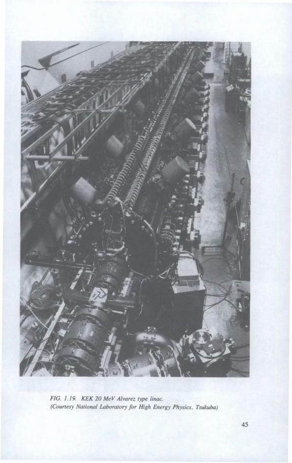
FIG. 1.19. KEK 20 MeV Alvarez type linac. (Courtesy National Laboratory for High Energy Physics, Tsukuba)
45
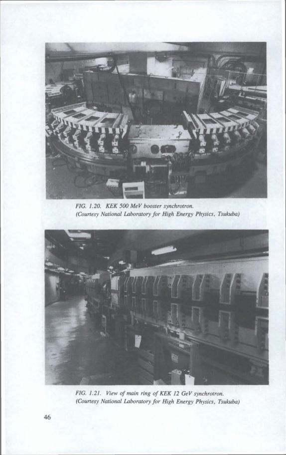
FIG. 1.20. KEK 500 MeV booster synchrotron. (Courtesy National Laboratory for High Energy Physics, Tsukuba)
FIG. 1.21. View of main ring of KEK 12 GeV synchrotron. (Courtesy National Laboratory for High Energy Physics, Tsukuba)
46
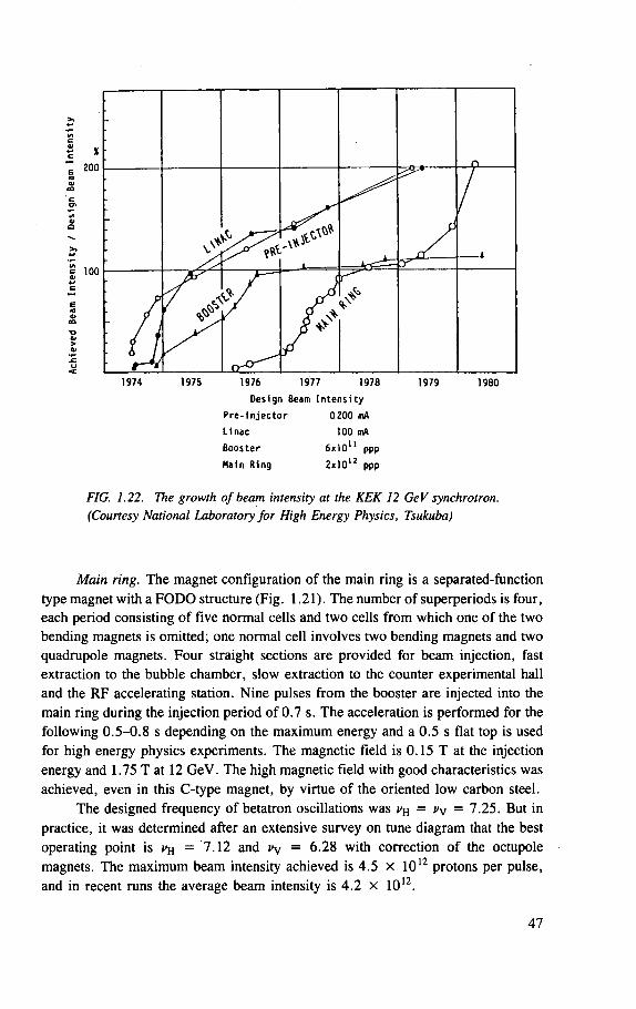
X 200
100
n
/ y
/
i J y 8 ^
N * V
1974 1975 1976 1977 1978
Des ign Beam I n t e n s i t y
P r e - I n j e c t o r 0.200 mA
L inac 100 mA
Booster
Main R ing
1979 1980
nil
2x10 ppp
FIG. 1.22. The growth of beam intensity at the KEK 12 GeV synchrotron. (Courtesy National Laboratory for High Energy Physics, Tsukuba)
Main ring. The magnet configuration of the main ring is a separated-function type magnet with a FODO structure (Fig. 1.21). The number of superperiods is four, each period consisting of five normal cells and two cells from which one of the two bending magnets is omitted; one normal cell involves two bending magnets and two quadrupole magnets. Four straight sections are provided for beam injection, fast extraction to the bubble chamber, slow extraction to the counter experimental hall and the RF accelerating station. Nine pulses from the booster are injected into the main ring during the injection period of 0.7 s. The acceleration is performed for the following 0 .5-0 .8 s depending on the maximum energy and a 0.5 s flat top is used for high energy physics experiments. The magnetic field is 0.15 T at the injection energy and 1.75 T at 12 GeV. The high magnetic field with good characteristics was achieved, even in this C-type magnet, by virtue of the oriented low carbon steel.
The designed frequency of betatron oscillations was vH = vv = 7.25. But in
practice, it was determined after an extensive survey on tune diagram that the best operating point is = 7.12 and c v = 6.28 with correction of the octupole magnets. The maximum beam intensity achieved is 4.5 x 10¹² protons per pulse, and in recent runs the average beam intensity is 4.2 x 10¹².
47
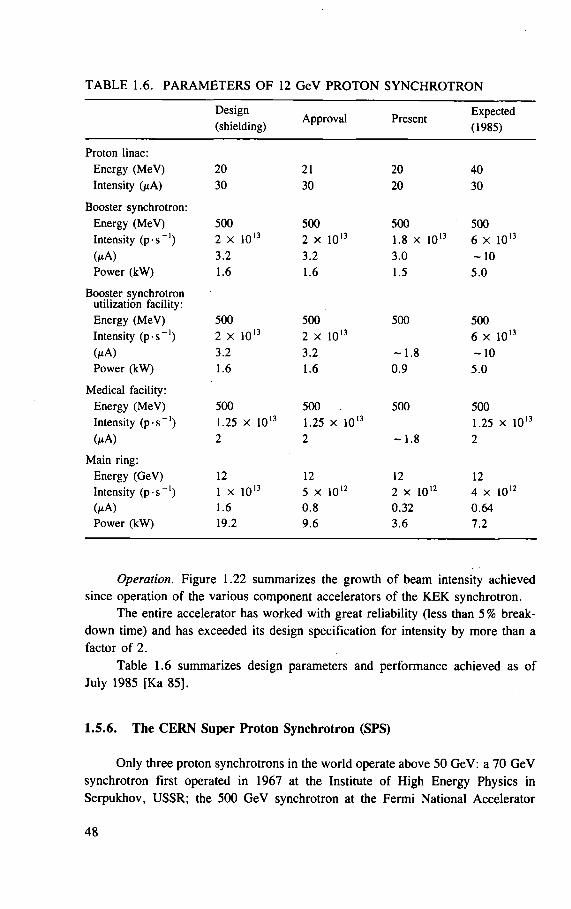
TABLE 1.6. PARAMETERS OF 12 GeV PROTON SYNCHROTRON
Design Expected , , . , . . „ Approval Present (shielding) ™ (1985)
Proton linac: Energy (MeV) 20 21 20 40
Intensity (/tA) 30 30 20 30
Booster synchrotron: Energy (MeV) 500 500 500 500 Intensity ( p - s " 1 ) 2 x 10¹³ 2 x 10¹³ 1.8 x 10¹³ 6 x 10¹³
(/xA) 3.2 3.2 3.0 - 1 0 Power (kW) 1.6 1.6 1.5 5 .0
Booster synchrotron utilization facility: Energy (MeV) 500 500 500 500 Intensity ( p - s " 1 ) 2 x 10¹³ 2 x 10¹³ 6 x 10¹³
0*A) 3.2 3.2 - 1 . 8 - 1 0 Power (kW) 1.6 1.6 0 .9 5 .0
Medical facility: Energy (MeV) 500 500 500 500 Intensity ( p - s " 1 ) 1.25 x 10¹³ 1.25 x 10¹³ 1.25 x 10' 0*A) 2 2 - 1 . 8 2
Main ring: Energy (GeV) 12 12 12 12 Intensity ( p - s " 1 ) 1 x 10¹³ 5 x 10¹² 2 x 10¹² 4 x 10¹²
OiA) 1-6 0 .8 0 .32 0 .64 Power (kW) 19.2 9 .6 3 .6 7.2
Operation. Figure 1.22 summarizes the growth of beam intensity achieved since operation of the various component accelerators of the KEK synchrotron.
The entire accelerator has worked with great reliability (less than 5% break-down time) and has exceeded its design specification for intensity by more than a factor of 2.
Table 1.6 summarizes design parameters and performance achieved as of July 1985 [Ka 85].
1.5.6. The CERN Super Proton Synchrotron (SPS)
Only three proton synchrotrons in the world operate above 50 GeV: a 70 GeV synchrotron first operated in 1967 at the Institute of High Energy Physics in Serpukhov, USSR; the 500 GeV synchrotron at the Fermi National Accelerator
48
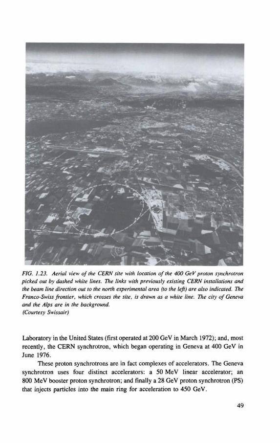
FIG. 1.23. Aerial view of the CERN site with location of the 400 GeV proton synchrotron picked out by dashed white lines. The links with previously existing CERN installations and the beam line direction out to the north experimental area (to the left) are also indicated. The Franco-Swiss frontier, which crosses the site, is drawn as a white line. The city of Geneva and the Alps are in the background. (Courtesy Swissair)
Laboratory in the United States (first operated at 200 GeV in March 1972); and, most recently, the CERN synchrotron, which began operating in Geneva at 400 GeV in June 1976.
These proton synchrotrons are in fact complexes of accelerators. The Geneva synchrotron uses four distinct accelerators: a 50 MeV linear accelerator; an 800 MeV booster proton synchrotron; and finally a 28 GeV proton synchrotron (PS) that injects particles into the main ring for acceleration to 450 GeV.
49
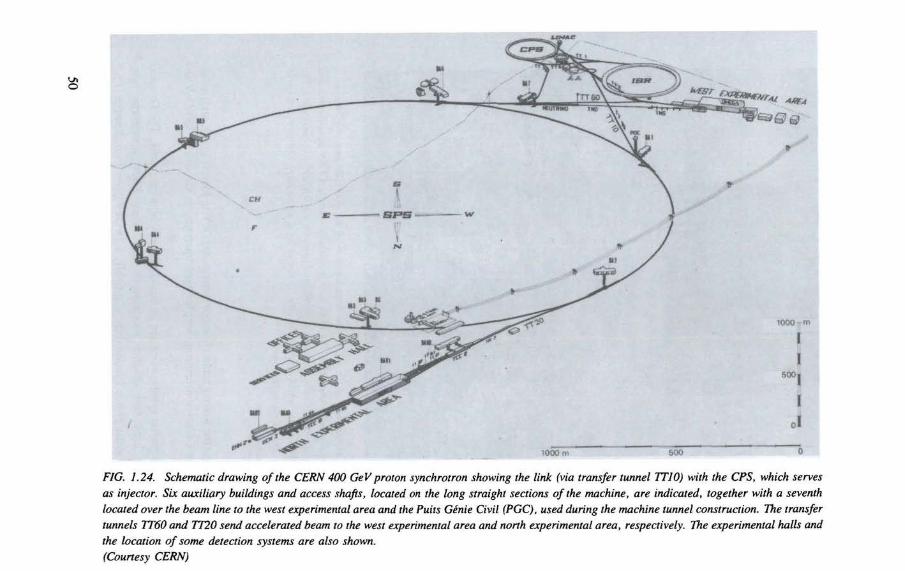
FIG. 1.24. Schematic drawing of the CERN 400 GeV proton synchrotron showing the link (via transfer tunnel TT10) with the CPS, which serves as injector. Six auxiliary buildings and access shafts, located on the long straight sections of the machine, are indicated, together with a seventh located over the beam line to the west experimental area and the Puits Genie Civil (PGC), used during the machine tunnel construction. The transfer tunnels TT60 and TT20 send accelerated beam to the west experimental area and north experimental area, respectively. The experimental halls and the location of some detection systems are also shown. (Courtesy CERN)
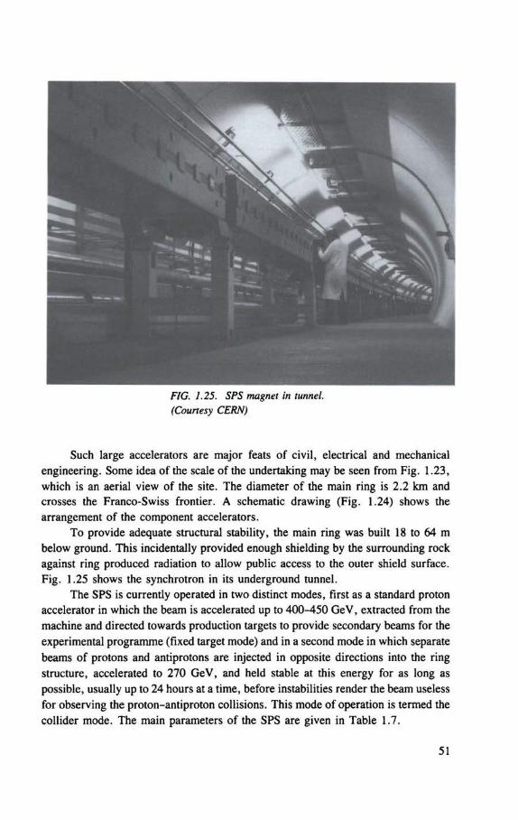
FIG. 1.25. SPS magnet in tunnel. (Courtesy CERN)
Such large accelerators are major feats of civil, electrical and mechanical engineering. Some idea of the scale of the undertaking may be seen from Fig. 1.23, which is an aerial view of the site. The diameter of the main ring is 2.2 km and crosses the Franco-Swiss frontier. A schematic drawing (Fig. 1.24) shows the arrangement of the component accelerators.
To provide adequate structural stability, the main ring was built 18 to 64 m below ground. This incidentally provided enough shielding by the surrounding rock against ring produced radiation to allow public access to the outer shield surface. Fig. 1.25 shows the synchrotron in its underground tunnel.
The SPS is currently operated in two distinct modes, first as a standard proton accelerator in which the beam is accelerated up to 400-450 GeV, extracted from the machine and directed towards production targets to provide secondary beams for the experimental programme (fixed target mode) and in a second mode in which separate beams of protons and antiprotons are injected in opposite directions into the ring structure, accelerated to 270 GeV, and held stable at this energy for as long as possible, usually up to 24 hours at a time, before instabilities render the beam useless for observing the proton-antiproton collisions. This mode of operation is termed the collider mode. The main parameters of the SPS are given in Table 1.7.
51
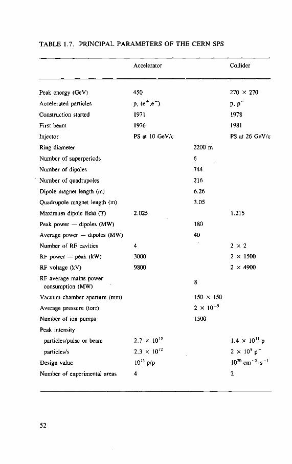
TABLE 1.7. PRINCIPAL PARAMETERS OF THE CERN SPS
Accelerator Collider
Peak energy (GeV) 450 270 x 270
Accelerated particles P, (e + , e~) P. P _
Construction started 1971 1978
First beam 1976 1981
Injector PS at 10 GeV/c PS at 26 GeV/c
Ring diameter 2200 m
Number of superperiods 6
Number of dipoles 744
Number of quadrupoles 216
Dipole magnet length (m) 6.26
Quadrupole magnet length (m) 3.05
Maximum dipole field (T) 2 .025 1.215
Peak power — dipoles (MW) 180
Average power — dipoles (MW) 40
Number of RF cavities 4 2 x 2
R F power — peak (kW) 3000 2 x 1500
RF voltage (kV) 9800 2 x 4900
RF average mains power 8
consumption (MW) 8
Vacuum chamber aperture (mm) 150 x 150
Average pressure (torr) 2 x 1 0 " 9
Number of ion pumps 1500
Peak intensity
particles/pulse or beam 2 .7 x 1 0 " 1.4 x 1 0 " p
particles/s 2 .3 x 1012 2 x l O ' p "
Design value 1013 p /p 103 0 c m ~ 2 - s _ 1
Number of experimental areas 4 2
52
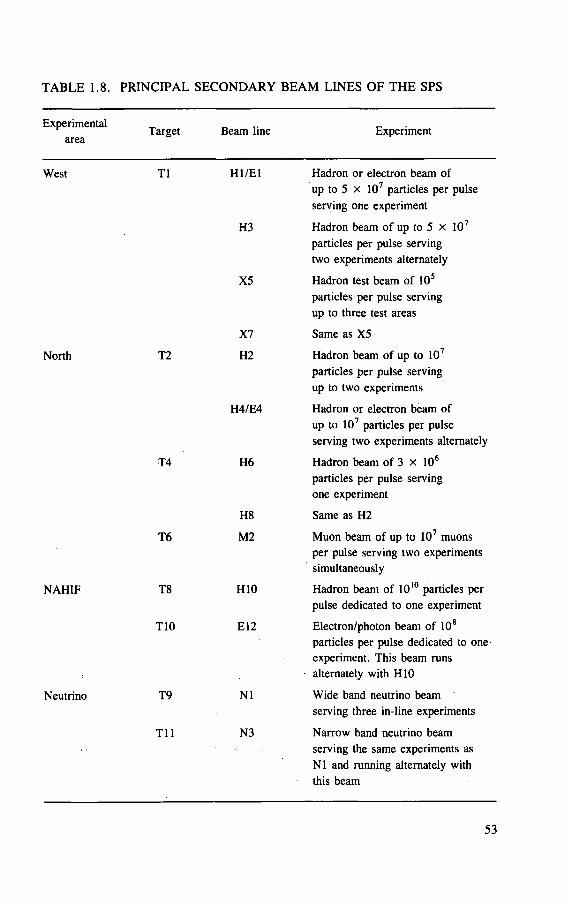
TABLE 1.8. PRINCIPAL SECONDARY BEAM LINES OF THE SPS
Experimental area
Target Beam line Experiment
West T1
North T2
N A H I F
Neutrino
T4
T 6
T8
T10
T9
T i l
H I / E l Hadron or electron beam of up to 5 x 10⁷ particles per pulse serving one experiment
H3 Hadron beam of up to 5 x 10⁷
particles per pulse serving two experiments alternately
X5 Hadron test beam of 105
particles per pulse serving up to three test areas
XI Same as X5
H2 Hadron beam of up to 107
particles per pulse serving up to two experiments
H4/E4 Hadron or electron beam of up to 107 particles per pulse serving two experiments alternately
H6 Hadron beam of 3 x 10⁶
particles per pulse serving one experiment
H8 Same as H2
M2 Muon beam of up to 107 muons per pulse serving two experiments simultaneously
H10 Hadron beam of 1010 particles per pulse dedicated to one experiment
E12 Electron/photon beam of 108
particles per pulse dedicated to one-experiment. This beam runs alternately with H10
N1 Wide band neutrino beam serving three in-line experiments
N3 Narrow band neutrino beam serving the same experiments as N1 and running alternately with this beam
53
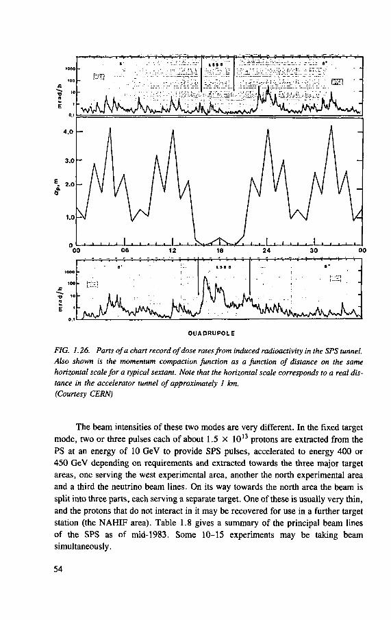
1000
100
E '
• ^ :•• - _ " __ " c u ••
0 U A D R U P 0 L E
FIG. 1.26. Parts of a chart record of dose rates from induced radioactivity in the SPS tunnel. Also shown is the momentum compaction Junction as a function of distance on the same horizontal scale for a typical sextant. Note that the horizontal scale corresponds to a real dis-tance in the accelerator tunnel of approximately 1 km. (Courtesy CERN)
The beam intensities of these two modes are very different. In the fixed target
mode, two or three pulses each of about 1.5 x 10¹³ protons are extracted from the
P S at an energy of 10 G e V to provide S P S pulses, accelerated to energy 400 or
450 G e V depending on requirements and extracted towards the three major target
areas, one serving the west experimental area, another the north experimental area
and a third the neutrino beam lines. On its way towards the north area the beam is
split into three parts, each serving a separate target. One of these is usually very thin,
and the protons that do not interact in it may be recovered for use in a further target
station (the N A H I F area). Table 1.8 gives a summary of the principal beam lines
of the S P S as of mid-1983. Some 10-15 experiments may be taking beam
simultaneously.
54
In the collider mode, the accelerator contains 2 x 10¹¹ protons and the same
number of antiprotons. The only exception to this is during accelerator tests, when
as many as 2 x 10¹² protons per pulse may be accelerated. These particles are
accelerated once per day instead of having a pulse repetition rate of one every 10 s
in the fixed target mode. Thus the radiation protection problems of the SPS are
limited mainly to those from the fixed target mode. Even the shielding between the
collider experimental areas ( E C X ) and their associated assembly areas ( ECA ) is
designed for continuous occupation of the E C A areas during fixed target operation,
rather than for collider considerations. Thus the radiological problems of collider
mode operation are minimal and will not be discussed further except to mention that
periods of collider operation provide a valuable cooling-down time to allow dose
rates in the highly radioactive target stations to decay before maintenance and
replacement operations.
The main problems of radiation protection at the SPS are in fact maintenance
operations in areas where the beam is lost, either intentionally at the internal or exter-
nal dumps and target stations or accidentally during extraction at the electrostatic and
magnetic septa or at regular points around the ring. It is interesting to note the cor-
respondence between the measurements of dose rate from induced activity around
the ring with the variation of the momentum compaction function (see Fig. 1.26).
Wherever this function is large, the protons are preferentially lost. Dose rates from
remanent activity near the extraction systems reach several hundreds of mrem/h and
near the dumps and target stations several rem/h. However there are remarkably few
points other than the dump or extraction regions where the dose rate exceeds
10 mrem/h, and if a person were to travel at a uniform speed around the SPS ring
during a typical shutdown, the average dose rate would only be 1 to 2 mrem/h.
In the occupied experimental areas the dose rates during operation are gener-
ally very low (0.1-1 mrem/h), and a monitor/alarm system allows any beam mis-
steering to be quickly identified and corrected. However, the problem of muons
downstream of the dumps of the secondary beam lines is a particular problem of high
energy accelerators, and special precautions must be taken. This will be discussed
in a later chapter. Problems arising from radioactive air and water are dealt with by
the provision of closed circuits wherever this is necessary, for example in the target
stations.
REFERENCES
[Ad 53] ADAMS, J.B., HINE, M.G.N., LAWSON, J.D., Nature (London) 171 (1953) 926.
[Al 46] ALVAREZ, L.W., The design of a proton linear accelerator, Phys. Rev. 70 (1946) 799.
[At 80] ATCHINSON, F. , Rep. SNS/TCAM/P5/80, Rutherford Appleton Lab., Chil-ton, UK (1980).
[At 81] ATCHINSON, F . , A Theoretical Study of a Target Reflector and Moderator Assembly for SNS, Rep. RL-81-006, Rutherford Appleton Lab., Chilton, UK, (1981).
[Av 73] AVERY, R.T. , KEEFE, D. , Shattering rock with intense bursts of energetic electrons, IEEE Trans. Nucl. Sci. NS-20 3 (1973) 1010.
[Ba 32] BARTON, H.A. , MUELLER, D .W. , VAN ATTA, L .C . , A compact high potential electrostatic generator, Phys. Rev. 42 (1932) 901.
[B1 56] BLEWETT, J .P . , The proton synchrotron, Rep. Prog. Phys. 19 (1956) 37. [Bo 47] BOHM, D. , FOLDY, L . , The theory of the synchro-cyclotron, Phys. Rev. 72
(1947) 649. [Bo 71] BOONE, M.L . , WILEY, A.L. , Fast neutrons and ir~ mesons in cancer
therapy, IEEE Trans. Nucl. Sci. NS-18 3 (1971) 36. [Bo 76] BOGGS, R.F . , Radiological Safety Aspects of the Operation of Neutron Genera-
tors, Safety Series No. 42, IAEA, Vienna (1976). [Bo 85] BOARDMAN, B. (Ed.), Rep. RL-85-006, Rutherford Appleton Lab., Chilton,
UK (1985). [Br 47] BROBECK, W . M . , LAWRENCE, E .O. , MacKENZIE, K.R. ,
McMILLAN, E .M. , SERBER, R. , SEWELL, D .C . , SIMPSON, K.M. , THORNTON, R.L. , Initial performance of the 184-Inch cyclotron of the University of California, Phys. Rev. 71 (1947) 449.
[Br 48] BROBECK, W . M . , Design study for a ten-BeV magnetic accelerator, Rev. Sci. Instrum. 19 (1948) 545.
[Br 84] BRIANTI, G. , HUBNER, K., Large Hadron Collider in the LEP Tunnel - A Feasibility Study of Possible Options, Rep. DIR-TECH/84-01, CERN, Geneva (1984)
[Bu 68] BURRILL, E.A. , " V a n de Graaff accelerators for radiation research and applications", Radiation Sources (CHARLESBY, A. , Ed.), Pergamon Press, Oxford and New York (1968).
[Bu 69a] BUSICK, D. , et al., "Beam safety consideration of the Stanford linear accelera-t o r " , Rep. CONF-691101, USAEC (1969) 782.
[Bu 69b] BURRILL, E .A. , " T h e expanding use of particle accelerators in research, medicine and industry: A statistical rev iew" , Rep. CONF-6911101, USAEC (1969) 9.
[Ca 77] CASTRO, J .R. , QUIVEY, J .M. , LYMAN, J .T . , CHEN, G .T .Y. , TOBIAS, C.A. , KANSTEIN, L.L. , WALTON, R.E. , Heavy-Ion Therapy in Biological and Medical Research with Accelerated Heavy Ions at the Bevalac, Rep. LBL-5610, Lawrence Berkeley Lab., Berkeley, CA (1977).
[Ch 32] CHADWICK, J . , Possible existence of a neutron, Nature (London) 129 (1932) 312; The existence of a neutron, Proc. R. Soc. (London) A 36 (1932) 692.
[Ch 56] CHRISTOFILOS, H. , Focussing System for Ions and Electrons, US Patent 2736799, issued 28 February 1956.
[CI 65] CLELAND, M. , Dynamitrons of the future, IEEE Trans. Nucl. Sci. 12 3 (1965) 227.
56
[Co 30] C O C K C R O F T , J .D . , W A L T O N , E .T .S . , Experiments with high-velocity positive ions, Proc. R. Soc. (London) A 129 (1930) 477.
[Co 32a] C O C K C R O F T , J .D . W A L T O N , E .T .S . , Experiments with high-velocity positive ions. I. Further developments in the method of obtaining high-velocity positive ions, Proc. R. Soc. (London) A 136 (1932) 619.
[Co 32b] C O C K C R O F T , J . D . , W A L T O N , E . T . S . , Experiments with high-velocity positive ions. II. The disintegration of elements by high-velocity protons, Proc. R. Soc. (London) A 137 (1932) 229.
[Co 34] C O C K C R O F T , J . D . , W A L T O N , E . T . S . , Experiments with high-velocity positive ions. III. The disintegration of lithium, boron and carbon by heavy hydrogen ions, Proc. R. Soc. (London) A 144 (1934) 706.
[Co 52] C O U R A N T , E . D . , L IVINGSTON, M . S . , SNYDER H.S . , The strong-focusing synchrotron. A new high energy accelerator, Phys. Rev. 88 (1952) 1190.
[Co 53] C O S M O T R O N STAFF, The Cosmotron, Rev. Sci. Instrum. 24 (1953) 723. [Co 81] C O C K B U R N , S. , E L L Y A R D , D. , Oliphant, Axiom Books, Adelaide (1981). [DOE 84] U N I T E D STATES D E P A R T M E N T O F E N E R G Y , Superconducting Super
Collider: Reference Design Study for the US Dept. of Energy, 8 May 1984, U S D O E , Washington, DC (1984).
[Du 68] D U G G A N , J .L . (Ed). , Rep. CONF-688411 , USAEC (1968). [Du 70] D U G G A N , J .L . (Ed.) . , Rep. CONF-700322, USAEC (1970). [Du 74] D U G G A N , J . L . , M O R G A N , I .L. (Eds), Rep. LU-1970 (2 vols), USERDA
CONF-741040 (1974). [Du 76] D U G G A N , J . L . , M O R G A N , I .L. (Eds), IEEE Publication 76CH 1175-9 NPS
(1976). [Ev 73] EVANS, A .E . , The expanding role of the small Van de Graaff in nuclear non-
destructive analysis, IEEE Trans. Nucl. Sci. NS-20 3 (1973) 989.
[Fa 84a] FASSO, A. , GOEBEL, K , H O F E R T , M . , RAU, G. , S C H O N B A C H E R , H . , S T E V E N S O N , G . R . , SULLIVAN, A . H . , S W A N S O N , W . P . , T U Y N , J . W . N . , Radiation Problems in the Design of the Large Electron-Posi tron Collider (LEP), Rep. 84-02, C E R N , Geneva (1984).
[Fa 84b] FASSO, A. , G O E B E L , K. , H O F E R T , M . , S C H O N B A C H E R , H . , S T E V E N S O N , G . R . , Environmental Considerations for a Large Hadron Collider, Rep. TIS-RP/TM/84-16, C E R N , Geneva (1984).
[Fa 84c] FASSO, A . , GOEBEL, K. , H O F E R T , M . , S C H O N B A C H E R , H . , STEVEN-SON, G . R . , Radiation Protection for a Large Hadron Collider, Rep. TIS-RP/IR/84-20, C E R N , Geneva (1984).
[Fo 61] F O W L E R , P . H . , PERKINS, D . H . , The possibility of therapeutic applications of beams of negative mesons, Nature (London) 189 (1961) 524.
[Go 46] G O W A R D , F . K . , BARNES D . E . , Experimental 8 MeV synchrotron for electron acceleration, Nature (London) 158 (1946) 413.
[Go 47] G O O D E N , J .S . , J E N S E N , H . H . , S Y M O N D S , J .L . , Proc. Phys. Soc. (London) 59 (1947) 677.
[Gr 85] GRAY, D . A . , " T h e spallation neutron source at the Rutherford Appleton Labora to ry" , Neutron Scattering in the 'Nineties (Proc. Conf . Julich, 1985), IAEA, Vienna (1985) 261.
57
[Ha 53] H A M , W . T . , Radiation cataract, Arch. Ophthal. 50 (1953) 618. [Ha 84] H A R T C U P , G . , ALLIBONE, T . E . , Cockcroft and the Atom, Adam Hilger,
Bristol (1984). [He 35] HERB, R .G. , PARKINSON, D . B . , KERST D . W . , A Van de Graaff elec-
trostatic generator operating under high pressure, Rev. Sci. Instrum. 6 (1935) 261.
[Ho 77] HOBBIS, L . C . W . , REES, G . H . , STIRLING, G.C. (Eds), A Pulsed Neutron Facility for Condensed Matter Research, Rep. RL-77-064/C, Rutherford Appleton Lab. , Chilton, UK (1977).
[Ho 80] H O L B O U R N , M . P . , An Assessment of the Induced Activity within the NSF, Rep. H P 80/135, Daresbury Lab. , UK (1980).
[Hu 60] HUBBARD, E . L . , et a l . , Neutron production by heavy ion bombardment , Phys. Rev. 118 (1960) 507.
[Is 24] ISING, G. , Prinzip einer Methode zur Herstellung von Kanalstrahlen hoher Voltzahl, Arkiv. for Matematik, Astronomi och Fysik 18 (1924) 1 (translated by BRASSE, F . W . as: The principle of a method for the production of canal rays of high voltage, in [Li 66], p. 88).
[Je 08] JEANS, J .H . , The Mathematical Theory of Electricity and Magnetism, Cambridge University Press (1908).
[Ka 85] KATOH, K. , Natl Lab. for High Energy Physics, Tsukuba, Japan, private communication, April 1985.
[Ke 84] KO-ENERUGI-KEN (National Laboratory for High Energy Physics), Outline of KEK, Tsukuba, Japan (1984).
[La 30] L A W R E N C E , E .O . , E D L E F S E N , N . E . , On the production of high speed protons, Science 72 (1930) 376.
[La 32a] L A W R E N C E , E .O . , LIVINGSTON, M . S . , The production of high speed light ions without the use of high voltages, Phys. Rev. 40 (1932) 19.
[La 32b] L A W R E N C E , E .O . , LIVINGSTON, M . S . , WHITE, M . G . , Disintegration of lithium by swiftly moving protons, Phys. Rev. 42 (1932) 150.
[La 34] L A W R E N C E , E . O . , LIVINGSTON, M . S . , The multiple acceleration of ions to very high speeds, Phys. Rev. 45 (1934) 608.
[La 36] L A W R E N C E , E . O . , COOKSEY, D . , On the apparatus for the multiple acceler-ation of light ions to high speeds, Phys. Rev. 50 (1936) 1131.
[La 39] L A W R E N C E , E .O . , A L V A R E Z , L . W . , BROBECK, W . M . , COOKSEY, D. , CORSON, D .R . , M c M I L L A N , E . M . , SALISBURY, W . W . , T H O R N T O N , R .L . , Initial performance of the 60-inch cyclotron of the William W . Crocker Radiation Laboratory, University of California, Phys. Rev. 56 (1939) 124.
[La 51] L A W R E N C E , E .O . , Nobel Lecture: The Evolution of the Cyclotron, Les Prix Nobel en 1951, Imprimerie Royale, Norstedt and Soner, Stockholm (1952) 127.
[La 80] LARSSON, B. , "Dos imet ry and radiobiology of protons as applied to cancer therapy and neurosurgery" , Advances in Radiation Protection and Dosimetry in Medicine (THOMAS, R . H . P E R E Z - M E N D E Z , V. , Eds), Plenum Press, New York (1980) 367.
[Le 81] L E M M O N , R . M . (Ed.) , User Facilities at the Lawrence Berkeley Laboratory, Rep. Pub-426, Lawrence Berkeley Lab. , Berkeley, CA (1982).
58
L E A D B E T T E R , A.J . , et al . , First Neutron Results f rom SNS, Rep. RAL-85-030, Rutherford Appleton Lab. , Chilton, UK (1985). L IVINGSTON, M . S . , The Production of High Velocity Hydrogen Ions Without the Use of High Voltages, PhD Thesis, Dept. of Physics, University of California at Berkeley, C A (1931). L IVINGSTON, M . S . , B L E W E T T , J . P . , G R E E N , G . K . , H A W O R T H , L . J . , Design study for a three-Bev proton accelerator, Rev. Sci. Instrum. 21 (1950) 7. L I N D E N B A U M , S.J . , The Brookhaven National Laboratory Proton Synchrotron, in [So 57], p. 28.
L I N D E N B A U M , S.J . , Shielding of high-energy accelerators, Ann. Rev. Nucl. Sci. 11 (1961) 213. L IVINGOOD, J .J . Principles of Cyclic Particle Accelerators, Van Nostrand, Princeton and New York (1961). L IVINGSTON, M . S . , B L E W E T T , J . P . , Particle Accelerators, McGraw Hill, New York (1962). L IVINGSTON, M . S . , The Development of High-Energy Accelerators, Dover Publications, New York (1966). M A N N I N G , G . , Spallation neutron sources for neutron beam research, Contemp. Phys. 19 6 (1978) 505. M A S O N , J . F . , Particle-beam weapons: A controversy, I E E E Spectrum 16 6 (1979) 30. M c C A S L I N , J .B . , T H O M A S , R . H . , "Pract ical neutron dosimetry at high energ ies" (BURGER, G . , EBERT G. , H A R D E R D. , K R A M E R , R . , W A G N E R S. , Eds), Rep. EUR-7101-EN, Harwood Academic Publishers, London (1981) 137. McCASLIN, J .B . , T H O M A S , R . H . , "Genera l shielding for the 20 TeV hadron collider facility: Hadron considerat ions" , Report of the 20 TeV Hadron Collider Technical Workshop, Cornell University, NY (1983).
[McM 45] M c M I L L A N , E . M . , The synchrotron — A proposed high energy particle accelerator, Phys. Rev. 68 (1945) 143.
[McM 59] M c M I L L A N , E . M . , "Par t ic le accelera tors" , Part XH in Experimental Nuclear Physics, Vol. HI (SEGRE, E . , Ed.) , Wiley, New York (1959).
[Mo 57] M O Y E R , B.J . , "Bui ldup fac to r s" , in [So 57], p. 36. [Mo 58] M O Y E R , B.J . , Practical control of radiation hazards in physics research, Ann.
Rev. Nucl. Sci. 8 (1958) 327. [Mo 73] M O R G A N , I .L . , Impact of accelerators on technology, IEEE Trans. Nucl. Sci.
NS-20 (1973) 3. [ N C R P 7 7 ] N A T I O N A L C O U N C I L ON RADIATION P R O T E C T I O N A N D
M E A S U R E M E N T S , Radiation Protection Design Guidelines for 0 .1-100 MeV Particle Accelerator Facilities, Rep. 51, N C R P , Washington, DC (1977).
[Ol 47] O L I P H A N T , M . E . , G O O D E N , J .S . , H Y D E , G .S . , Proc. Phys. Soc. (London) 59 (1947) 666.
[Pa 57] P A T T E R S O N , H . W . , The University of California Synchrocyclotron, in [So 57], p . 99.
[Le 85]
[Li 31]
[Li 50]
[Li 57]
[Li 61a]
[Li 61b]
[Li 62]
[Li 66]
[Ma 78]
[Ma 79]
[McC 81]
[McC 83]
59
[Pa 73] PATTERSON, H . W . , T H O M A S , R . H . , Accelerator Health Physics, Academic Press, New York (1973).
[Pa 79] P A R M E N T O L A , J . , TSIPSIS, K. , Particle-beam weapons. Sci. Am. 240 4 (1979) 54.
[Pa 80] PANOFSKY, W . K . H . , Needs versus means in high-energy physics, Phys. Today 33 6 (1980) 24.
[Pa 81] PANOFSKY, W . K . H . , The State of SLAC. SLAC Beam Line Nos 1, 2 and 3, SLAC, Stanford, C A (1981).
[Pe 77] PERRY, D. , STAPLETON, G. , "Shielding, radioactivity and radiation d a m a g e " , Chapter 3, Appendix II, Project Description: A Pulsed Neutron Facility for Condensed Matter Research, Rep. RL-77-046/C (HOBBS, L . C . W . , REES, G . H . , STIRLING, G . C . , Eds), Rutherford Appleton Lab. , Chilton, UK (1977).
[Qu 85] QUIGG, C . , Elementary particles and forces, Sci. Am. 252 4 (1985) 84. [Re 59] REGENSTREIF , E . , The C E R N Proton Synchrotron, Excerpts f rom the C E R N
Proton Synchrotron Part I, C E R N Internal Report, August 21, 1959; translated by M O L L E T , P . C . P . [from Li 66] (1959).
[Ri 46] RICHARDSON, J .R . , MacKENZIE, K . R . , L O F G R E N , E . J . , W R I G H T , B .T . , Frequency modulated cyclotron, Phys. Rev. 69 (1946) 669.
[Ri 73] RINDI, A. , T H O M A S , R . H . , The radiation environment of high-energy accelerators, Ann. Rev. Nucl. Sci. 23 (1973) 315.
[Ri 84] RICHTER, B. An informal history of SLAC — Part III: Collider beams at Stanford, SLAC Beam Line, Special Issue No. 7, Stanford, C A (1984).
[Ri 85] RICHTER, B. Future Needs of High-Energy Physics. Remarks to Energy Research Advisory Board, US Department of Energy, Washington, DC, February 1985.
[Ro 71] ROSEN, L. , Relevance of particle accelerators to national goals, IEEE Trans . Nucl. Sci. NS-18 3 (1971) 29.
[Ry 80] RYDER, R. , Use of a Tritium Source in the NSF, Daresbury Laboratory, Rep. HP-80/131, Daresbury Lab. , UK (1980).
[Ry 82] RYDER, R. , Neutron Production f rom Protons and Deuterons, Rep. D L / N U C / T M 60A, Daresbury Lab . , UK (1982).
[Se 50] SEWELL, D . C . , BROBECK, W . M . , L A W R E N C E , E . O . , Design of the Bevatron quarter scale operating model, Phys. Rev. 78 (1950) 85.
[Se 75] SERVIAN, J .G . , Production of radionuclides and labelled compounds f rom accelerators, Int. J. Appl. Radiat. Isot. 26 (1975) 763.
[SI 31] SLOAN, D . H . , L A W R E N C E , E .O . , The production of heavy high speed ions without the use of high voltage, Phys. Rev. 38 (1931) 2021.
[So 57] SOLON, L.E. (Ed.) , Rep. TID-7545, USAEC (1957). [Th 80] T H O M A S , R . H . , P E R E Z - M E N D E Z , V. (Eds), "Advances in radiation
protection and dosimetry in medic ine" , Radiation Damage and Protection, (Proc. Int. School, Erice, 1979), Plenum Press, New York (1980).
[To 52] TOBIAS, C .A. , A N G E R , H .O . , L A W R E N C E , J .H . , Radiological use of high energy deuterons and alpha particles, Am. J. Roentgenol. 67 (1952) 1.
60
[To 56] TOBIAS, C . A . , ROBERTS, J .C . , L A W R E N C E , J .H . , L O W - B E E R , B . V . A . , A N G E R , H . O . , B O R N , J .L . , M c C O M B S , R . , HUGGINS, C. "Irradiat ion hypophysectomy and related studies using 340-MeV protons and 190-MeV deu te rons" , Peaceful Uses of Atomic Energy (Proc. Conf . Geneva, 1955), Vol. 10, UN, New York (1956).
[To 71] TOBIAS, C . A . , L Y M A N , J .T . , L A W R E N C E , J .H . , " S o m e considerations of physical and biological factors in radiotherapy with high-LET radiations including heavy particles, pi-mesons and fast neu t rons" , Progress in Atomic Medicine, Vol. 3, Grune and Stratton (1971) 167.
[Tu 35] T U V E , M . A . , H A F S T A D , L .R . , D A H L , O. , High voltage techniques for nuclear physics, Phys. Rev. 48 (1935) 315.
[Up 68] U P T O N , A . C . , Effects of radiation on man, Ann. Rev. Nucl. Sci. 18 (1968) 495.
[Va 31] V A N D E G R A A F F , R.J . , A 1,500,000 volt electrostatic generator, Phys. Rev. 38 (1931) 1919.
[Va 33] V A N D E G R A A F F , R . J . , C O M P T O N , K . T . , V A N A T T A , L . C . , The elec-trostatic production of high voltage for nuclear investigations, Phys. Rev. 43 (1933) 149.
[Va 36] V A N A T T A , L . C . , N O R T H R U P , D .L . , V A N A T T A , C . M . , V A N D E G R A A F F , R . J . , The design operations and performance of the Round Hill electrostatic generator, Phys. Rev. 49 (1936) 761.
[Va 48] V A N DE G R A A F F , R . J . , T R U M P , J .G . , B U E C H N E R , W . W . , Electrostatic generators for the acceleration of charged particles, Rep. Prog. Phys. 11 (1948) 1.
[Va 75] VALE, J . , Lawrence Berkeley Laboratory, private communication, 1975. [Ve 45] VEKSLER, V. , A new method of acceleration of relativistic particles, Sov. J.
Phys. 9 (1945) 153; translated by BELL L. in [Li 66], p. 202.
[Vo 78] VOSS, R . G . P . , The nuclear structure facility at Daresbury Laboratory, ( M U R U M O R I , T . , Ed.) , J. Phys. Soc. Jpn. , Suppl. 44 (1978) 577.
[Wi 28] W I D E R O E , R . , Uber ein neues Prinzip zur Herstellung hoher Spannungen. Archiv fur Elektrotechnik 21 (1928) 387; (translated by F ISCHER, G . E . , BRASSE, F . W . , K U M P F E R T , H . , H A R T M A N N , H . , as: A new principle for the generation of high voltages, in [Li 66], p. 92).
[Wi 46] WILSON, R .R . , Radiological use of fast protons, Radiology 47 (1946) 487. [Wi 68a] W I D E R O E , R. , "Beta t rons and synchro t rons" , Engineering Compendium on
Radiation Shielding, Vol. 1, Springer Verlag, Berlin (West) (1968). [Wi 68b] W I D E R O E , R . , "L inea r electron accelera tors" , Engineering Compendium on
Radiation Shielding, Vol. 1, Springer Verlag, Berlin (West) (1968).
61

Chapter 2
RADIATION ENVIRONMENT OF POSITIVE ION ACCELERATORS
2.1. INTRODUCTION
The prompt radiation of particle accelerators exists only while they are in oper-ation. It results as a natural consequence of the acceleration process and the utiliza-tion of the accelerated beam.
As was shown in Chapter 1, particle acceleration is achieved by the interaction of charged particles (ions) with stable or varying electrical and magnetic fields. Under such conditions there are many potential sources of radiation. The accelera-tion process is not totally efficient: particles are lost before achieving the maximum energy and interact with the accelerator structure. Such losses may occur, for example, close to focusing or bending elements. In many positive ion accelerators it is possible for electrons to back-stream along the potential gradients in a direction opposite to that travelled by the positive ions. The interaction of such accelerated electrons with accelerator components may result in the copious production of X-rays. A beam which is fully accelerated and utilized interacts with target elements, which are then sources of radiation.
In general the higher the energy of the particles accelerated the more complex the character of the prompt radiation field may be. Thus at accelerators such as the 70 GeV synchrotron at Serpukhov or the 800 GeV proton synchrotron at Batavia it is possible to find a wide range of radiation environments, depending upon the thick-ness of the shielding, in which, for example, thermal neutrons dominate, inter-mediate energy neutrons dominate, fast neutrons dominate or muons dominate the radiation field [An 78, McC 77, McC 81].
The most complex radiation environments around particle accelerators will generally arise at locations where the shielding between the radiation source and the point of measurement is 'thin'. Before interacting, the accelerated beam is, of course, essentially monoenergetic, consisting of only one particle type. Passage through the accelerator structure, experimental equipment or thin shielding will lead to the partial development of electromagnetic and hadronic cascades and the produc-tion of many types of particle distributed over a wide range of energies. Accident dosimetry at particle accelerators may be particularly difficult because of this com-plexity of the radiation field in regions of high intensity where the cascades may only be partially developed [Pa 73]. The production of secondary radiations may also be of concern, for example, in the application of charged particles to therapy where the absorbed dose to tissues adjacent to the irradiated tumour must be assessed [McC 84b, Sm 81, Sw 80], Neither of the previous two examples can be considered routine
63
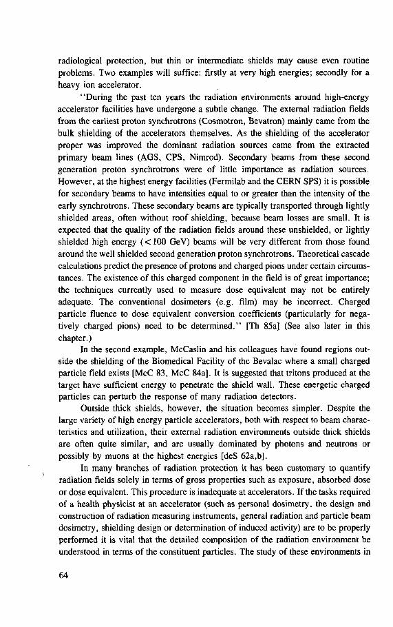
radiological protection, but thin or intermediate shields may cause even routine problems. Two examples will suffice: firstly at very high energies; secondly for a heavy ion accelerator.
"During the past ten years the radiation environments around high-energy accelerator facilities have undergone a subtle change. The external radiation fields from the earliest proton synchrotrons (Cosmotron, Bevatron) mainly came from the bulk shielding of the accelerators themselves. As the shielding of the accelerator proper was improved the dominant radiation sources came from the extracted primary beam lines (AGS, CPS, Nimrod). Secondary beams from these second generation proton synchrotrons were of little importance as radiation sources. However, at the highest energy facilities (Fermilab and the CERN SPS) it is possible for secondary beams to have intensities equal to or greater than the intensity of the early synchrotrons. These secondary beams are typically transported through lightly shielded areas, often without roof shielding, because beam losses are small. It is expected that the quality of the radiation fields around these unshielded, or lightly shielded high energy (<100 GeV) beams will be very different from those found around the well shielded second generation proton synchrotrons. Theoretical cascade calculations predict the presence of protons and charged pions under certain circums-tances. The existence of this charged component in the field is of great importance; the techniques currently used to measure dose equivalent may not be entirely adequate. The conventional dosimeters (e.g. film) may be incorrect. Charged particle fluence to dose equivalent conversion coefficients (particularly for nega-tively charged pions) need to be determined." [Th 85a] (See also later in this chapter.)
In the second example, McCaslin and his colleagues have found regions out-side the shielding of the Biomedical Facility of the Bevalac where a small charged particle field exists [McC 83, McC 84a]. It is suggested that tritons produced at the target have sufficient energy to penetrate the shield wall. These energetic charged particles can perturb the response of many radiation detectors.
Outside thick shields, however, the situation becomes simpler. Despite the large variety of high energy particle accelerators, both with respect to beam charac-teristics and utilization, their external radiation environments outside thick shields are often quite similar, and are usually dominated by photons and neutrons or possibly by muons at the highest energies [deS 62a,b].
In many branches of radiation protection it has been customary to quantify radiation fields solely in terms of gross properties such as exposure, absorbed dose or dose equivalent. This procedure is inadequate at accelerators. If the tasks required of a health physicist at an accelerator (such as personal dosimetry, the design and construction of radiation measuring instruments, general radiation and particle beam dosimetry, shielding design or determination of induced activity) are to be properly performed it is vital that the detailed composition of the radiation environment be understood in terms of the constituent particles. The study of these environments in
64
terms of the energy spectra of their separate components is still being developed, and more extensive measurements are required. The published information only describes neutron spectra and is limited but, when supplemented by information from cosmic ray experiments and neutron transport theory, enables some general conclu-sions to be made concerning radiation fields produced by proton accelerators.
Shielding studies have shown that the radiation field reaches an equilibrium condition within a few mean free paths inside an accelerator shield (see Chapter 4). The shape of the neutron spectrum observed at a shield/air interface is very close to that which exists within the shield, but may be perturbed at the low energy end, owing to the scattering and leakage through holes in the shielding.
2.2. PROMPT RADIATION FIELDS
2.2.1. Historical background
In the early 1950s, following the successful operation of several accelerators in the GeV energy region, interest in accelerator radiation problems had become widespread. A conference held in New York in 1957 indicated the concern of several laboratories in the United States [So 57] and by 1962 an international meeting was organized in Paris [Bo 62].
Experience at the 184-Inch Synchrocyclotron at Berkeley and the early proton synchrotrons — the Cosmotron and Bevatron — rapidly established the qualitative nature of their radiation environments outside thick shielding [Pa 65, Sm 58, Sm 62]. A general rule emerged showing that neutrons between 0.1 and 10 MeV contributed more than 50% to the dose equivalent of the radiation field; gamma rays and low energy neutrons contributed about 10-20%, with the balance made up by neutrons greater than 10 MeV in energy.
In order to quantify the high energy neutron contribution to dose equivalent more precisely, Patterson et al. [Pa 59] suggested that the equilibrium neutron spec-trum low down in the atmosphere produced by the interaction of the primary galactic cosmic radiation (mainly protons) must be very similar to that generated in the shield of a high energy proton accelerator. The cosmic ray neutron spectrum had previously been measured at several altitudes by Hess et al. [He 59] and was shown to reach equilibrium rapidly (at depths greater than 200 g/cm2). Using the Hess spectrum and fluence to dose equivalent conversions given in NBS Handbook No. 63 [NCRP 57], Patterson et al. concluded that "by far the largest contribution to total neutron dose equivalent comes from neutrons in the energy interval from 0.10 to 30 MeV" [Pa 59]. Somewhat later Tardy-Joubert [Ta 65] pointed out that, at energies above 50 MeV, the Hess spectrum was consistent with that deduced from an analysis of the prong number distribution of stars produced in nuclear emulsion exposed at various altitudes above the earth's surface [Ro 54],
65
These similarities to the cosmic ray spectrum also explain the relative unimpor-tance of protons in contributing to the dose equivalent [Pe 66]. At energies greater than a few hundred MeV, protons are present in numbers comparable with neutrons. At lower energies, however, protons are depleted by ionization losses. Puppi and Dallaporta [Pu 65] have suggested that the neutron to proton ratio (N/P) in an equilibrium spectrum is of the form:
N_ _ W2
7 " W2 - (moc2)2 ( 2 > 1 )
where
W is the nucleon total energy, moc2 is the nucleon rest mass.
Given Eq. (2.1), it is trivial to show that protons contribute little to the dose equiva-lent in an equilibrium cascade spectrum.
By early 1965 there was sufficient experience at high energy accelerators at Berkeley [Sm 58, Sm 62, Pa 65], CERN [Ba 65a,b], the Rutherford Laboratory [Pe 65, Pe 66], Saclay [Ta 65] and elsewhere [Ko 70, USAEC 65] to confirm that the cosmic ray and accelerator produced neutron spectra were indeed quite similar. Thus, for example, at the 1966 Vienna meeting Perry [Pe 66] summarized experience at the British 7 GeV proton synchrotron as follows:
".. .the energy spectrum varies from place to place but always falls off rapidly with increasing energy. Most of the neutron flux and dose equivalent is due to neutrons with energies between 0.1 and 10 MeV. The dose contributions from thermal and very high energy neutrons are both very small."
Table 2.1 gives a summary of data given by Perry showing the composition of the radiation field outside the shielding of a 7 GeV proton beam.
This experience with accelerators in the GeV energy region gave increased confidence in the earlier arguments of Patterson et al. [Pa 59] concerning the proba-ble shape of the neutron equilibrium spectrum and led to the use of the Hess spectrum as the design neutron spectrum for the specification of the shields of several high energy accelerators in the early 1960s [CERN 64, Co 65, deS 62a,b, LBL 65, Th 67]. For this assumption to be valid it was necessary that the equilibrium spec-trum be determined by the character of the interaction mechanisms of the nuclear cascade and be essentially independent of the energy of the incident proton. Some theoretical cascade calculations by Riddell [Ri 65] lent support to this assumption but the extrapolation from experience in the GeV energy region to hundreds of GeV could not be made without reservation. Patterson [Pa 65] indicated the need for more
66
TABLE 2.1. RADIATION SPECTRUM ABOVE NIMROD EXTRACTED PROTON BEAM SHIELDING [Pe 66]
Estimated % Estimated % Type of radiation Energy range of neutron of total
flux density dose equivalent
Neutrons < 1 eV < 7 < 1
Neutrons 1 e V - 0 . 7 MeV 70 20
Neutrons 0 . 7 - 3 MeV 15 35
Neutrons 3 - 7 MeV 7 25
Neutrons 7 - 2 0 MeV 1.5 5
Neutrons + protons 2 0 - 1 0 0 MeV 1 5
Neutrons + charged particles > 100 MeV 0 .5 4
Other particles + gammas < 2
detailed information of the neutron spectrum between 1 and 10 MeV where "there may or may not be a flattening due to the production and scattering of evaporation neutrons". Nevertheless by early 1965 there was both a good qualitative and fair quantitative understanding of the radiation environments outside high energy proton accelerator shielding.
2.2.2. Operational experience at high energy accelerators
As we have just seen, in the latter part of the 1950s, experience at the 184-Inch Synchrocyclotron and Bevatron (Lawrence Berkeley Laboratory) and the Cosmotron (Brookhaven) allowed estimation of the qualitative nature of their radiation environ-ments outside thick shielding. Although detailed spectra were not obtained, a general rule emerged for proton accelerators showing that neutrons between 0.1 and 10 MeV contributed more than 50% to the total dose equivalent in the radiation field. This fact was explained by analogy with the cosmic ray produced neutron spectrum. By 1965 there was sufficient experience at many high energy proton accelerators around the world to confirm that the neutron spectra outside accelerator shields and the cosmic ray spectrum were, in general, quite similar.
There were, however, some data that pointed to exceptions to this simple general rule. Table 2.2 [Ba 64, Ba 65a,b, Ca 65] gives a typical example where the relative composition of dose equivalent measured through thick shielding above
67
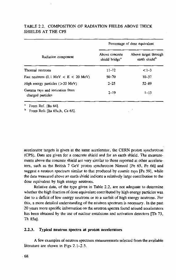
TABLE 2.2. COMPOSITION OF RADIATION FIELDS ABOVE THICK SHIELDS AT THE CPS
Percentage of dose equivalent
„ ,. . Above concrete Above target through Radiation component . . . . . . . » , . , j b
shield bridge earth shield
Thermal neutrons 11-12
Fast neutrons (0.1 MeV < E < 20 MeV) 50 -70
High energy particles ( > 2 0 MeV) 2 - 2 5
Gamma rays and ionization f rom ^
charged particles
a From Ref. [Ba 64], b From Refs [Ba 65a,b, Ca 65],
< 1 - 3
10-37
5 2 - 8 9
1 - 1 3
accelerator targets is given at the same accelerator, the CERN proton synchrotron (CPS). Data are given for a concrete shield and for an earth shield. The measure-ments above the concrete shield are very similar to those reported at other accelera-tors, such as the British 7 GeV proton synchrotron Nimrod [Pe 65, Pe 66] and suggest a neutron spectrum similar to that produced by cosmic rays [Pa 59], while the data measured above an earth shield indicate a relatively large contribution to the dose equivalent by high energy neutrons.
Relative data, of the type given in Table 2.2, are not adequate to determine whether the high fraction of dose equivalent contributed by high energy particles was due to a deficit of low energy neutrons or to a surfeit of high energy neutrons. For this, a more detailed understanding of the neutron spectrum is necessary. In the past 20 years more specific information on the neutron spectra found around accelerators has been obtained by the use of nuclear emulsions and activation detectors [Th 73, Th 85a].
2.2.3. Typical neutron spectra at proton accelerators
A few examples of neutron spectrum measurements selected from the available literature are shown in Figs 2.1-2.5.
68
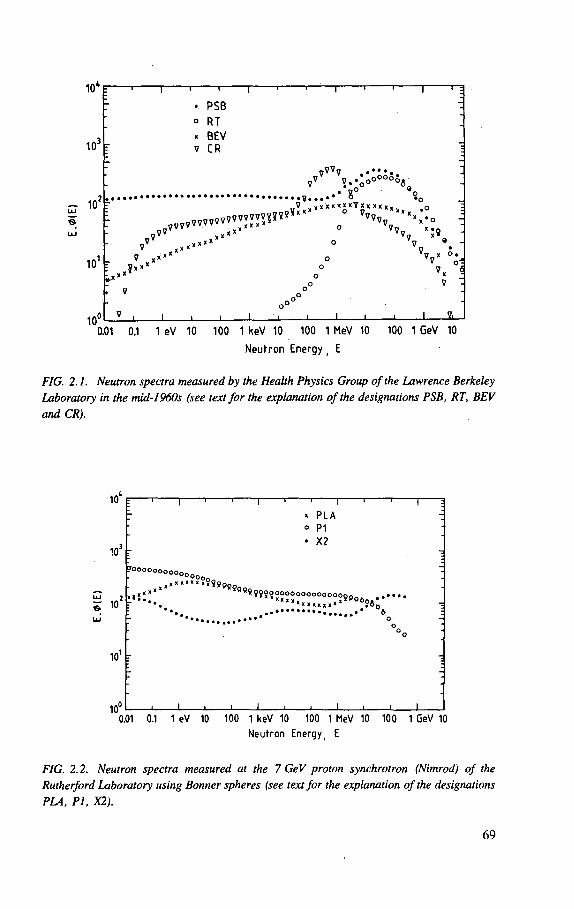
1000
103
LU
10 1
10u
0.01 0.1 1 eV 10 100 1 keV 10 100 1 MeV 10 100 1 GeV 10
Neutron Energy, E
FIG. 2.1. Neutron spectra measured by the Health Physics Group of the Lawrence Berkeley Laboratory in the mid-1960s (see text for the explanation of the designations PSB, RT, BEV and CR).
"i 1 1 r
• P S B o RT x BEV v CR
1° 'o
„' ixxx" O V 9
V v -7 ° V
L x « « ? * X o ° » ; 1 „ o 7 o o
oO°° 7
i i . i i i i i i i i — a _
10'
103
101
10° I I I 1 I I I I I I I
0.01 0.1 1 eV 10 100 1 keV 10 100 1 MeV 10 100 1 GeV 10 Neutron Energy, E
FIG. 2.2. Neutron spectra measured at the 7 GeV proton synchrotron (Nimrod) of the Rutherford Laboratory using Bonner spheres (see text for the explanation of the designations PLA, PI, X2).
I 1
^ x PLA o pi
• X2
(?°°0000000oo
h:::x S9?
ss;?n:ooooooo
;sp°o0,- • — •
••.. \ °
_i i i i i i i i i i
69
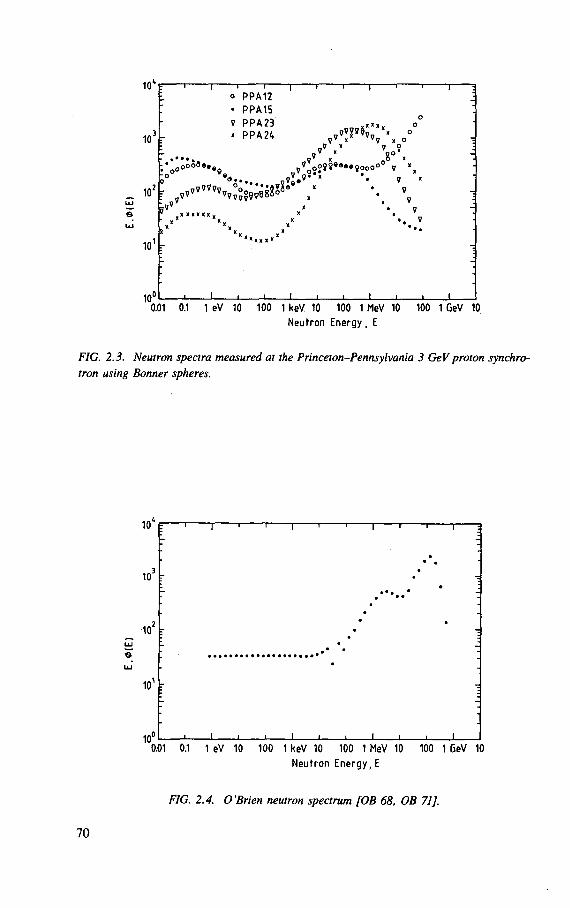
10 e 1 1 1 1 1 1 1 r o PPA12 • PPA15 v PPA23 o , „ , , o « PPA2*. x 0
10>
f^oooa...
„ '"i 10'k ^ " " " ' v f o
V" x" i o V x n O 0 * -. * 7 I® , * n 6 X v 09J»«..90000° v »
9
10 F
XXXK*KK
X
V x V
?
10° -I L 0.01 0.1 1 eV 10 100 1 keV 10 100 1 MeV 10 100 1 GeV 10
Neutron Energy, E
FIG. 2.3. Neutron spectra measured at the Princeton-Pennsylvania 3 GeV proton synchro-tron using Bonner spheres.
0.01 0.1 1 eV 10 100 1 keV 10 100 1 MeV 10 100 1 CeV 10 Neutron Energy,E
FIG. 2.4. O'Brien neutron spectrum [OB 68, OB 71 J.
70
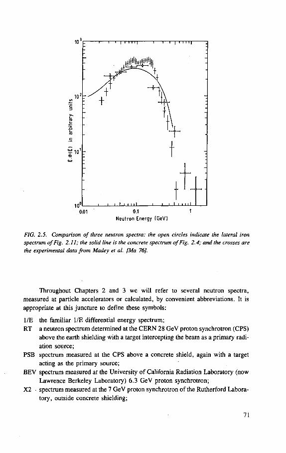
Neutron Energy (CeV)
FIG. 2.5. Comparison of three neutron spectra: the open circles indicate the lateral iron spectrum of Fig. 2.11; the solid line is the concrete spectrum of Fig. 2.4; and the crosses are the experimental data from Madey et al. [Ma 76].
Throughout Chapters 2 and 3 we will refer to several neutron spectra,
measured at particle accelerators or calculated, by convenient abbreviations. It is
appropriate at this juncture to define these symbols:
1/E the familiar 1/E differential energy spectrum;
RT a neutron spectrum determined at the C E R N 28 GeV proton synchrotron (CPS)
above the earth shielding with a target intercepting the beam as a primary radi-
ation source;
PSB spectrum measured at the CPS above a concrete shield, again with a target
acting as the primary source;
B E V spectrum measured at the University of California Radiation Laboratory (now
Lawrence Berkeley Laboratory) 6.3 GeV proton synchrotron;
X2 • spectrum measured at the 7 GeV proton synchrotron of the Rutherford Labora-
tory, outside concrete shielding;
71
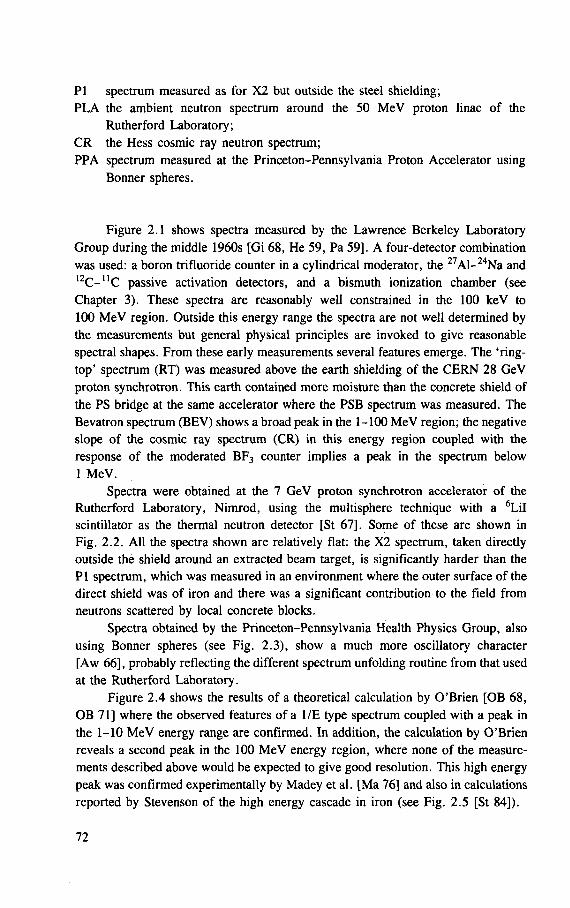
PI spectrum measured as for X2 but outside the steel shielding; PLA the ambient neutron spectrum around the 50 MeV proton linac of the
Rutherford Laboratory; CR the Hess cosmic ray neutron spectrum; PPA spectrum measured at the Princeton-Pennsylvania Proton Accelerator using
Bonner spheres.
Figure 2.1 shows spectra measured by the Lawrence Berkeley Laboratory Group during the middle 1960s [Gi 68, He 59, Pa 59]. A four-detector combination was used: a boron trifluoride counter in a cylindrical moderator, the 27Al-24Na and 1 2 C- U C passive activation detectors, and a bismuth ionization chamber (see Chapter 3). These spectra are reasonably well constrained in the 100 keV to 100 MeV region. Outside this energy range the spectra are not well determined by the measurements but general physical principles are invoked to give reasonable spectral shapes. From these early measurements several features emerge. The 'ring-top' spectrum (RT) was measured above the earth shielding of the CERN 28 GeV proton synchrotron. This earth contained more moisture than the concrete shield of the PS bridge at the same accelerator where the PSB spectrum was measured. The Bevatron spectrum (BEV) shows a broad peak in the 1-100 MeV region; the negative slope of the cosmic ray spectrum (CR) in this energy region coupled with the response of the moderated BF3 counter implies a peak in the spectrum below 1 MeV.
Spectra were obtained at the 7 GeV proton synchrotron accelerator of the Rutherford Laboratory, Nimrod, using the multisphere technique with a 6LiI scintillator as the thermal neutron detector [St 67], Some of these are shown in Fig. 2.2. All the spectra shown are relatively flat: the X2 spectrum, taken directly outside the shield around an extracted beam target, is significantly harder than the PI spectrum, which was measured in an environment where the outer surface of the direct shield was of iron and there was a significant contribution to the field from neutrons scattered by local concrete blocks.
Spectra obtained by the Princeton-Pennsylvania Health Physics Group, also using Bonner spheres (see Fig. 2.3), show a much more oscillatory character [Aw 66], probably reflecting the different spectrum unfolding routine from that used at the Rutherford Laboratory.
Figure 2.4 shows the results of a theoretical calculation by O'Brien [OB 68, OB 71] where the observed features of a 1/E type spectrum coupled with a peak in the 1-10 MeV energy range are confirmed. In addition, the calculation by O'Brien reveals a second peak in the 100 MeV energy region, where none of the measure-ments described above would be expected to give good resolution. This high energy peak was confirmed experimentally by Madey et al. [Ma 76] and also in calculations reported by Stevenson of the high energy cascade in iron (see Fig. 2.5 [St 84]).
72
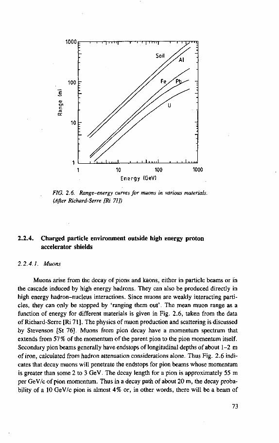
E n e r g y (GeV)
FIG. 2.6. Range-energy curves for muons in various materials. (After Richard-Serre [Ri 71])
2.2.4. Charged particle environment outside high energy proton accelerator shields
2.2.4.1. Muons
Muons arise from the decay of pions and kaons, either in particle beams or in
the cascade induced by high energy hadrons. They can also be produced directly in
high energy hadron-nucleus interactions. Since muons are weakly interacting parti-
cles, they can only be stopped by 'ranging them out'. The mean muon range as a
function of energy for different materials is given in Fig. 2.6, taken from the data
of Richard-Serre [Ri 71]. The physics of muon production and scattering is discussed
by Stevenson [St 76]. Muons from pion decay have a momentum spectrum that
extends from 57% of the momentum of the parent pion to the pion momentum itself.
Secondary pion beams generally have endstops of longitudinal depths of about 1-2 m
of iron, calculated from hadron attenuation considerations alone. Thus Fig. 2.6 indi-
cates that decay muons will penetrate the endstops for pion beams whose momentum
is greater than some 2 to 3 GeV. The decay length for a pion is approximately 55 m
per GeV/c of pion momentum. Thus in a decay path of about 20 m, the decay proba-
bility of a 10 GeV/c pion is almost 4 % or, in other words, there will be a beam of
73
muons whose intensity is some 4% of the incident pion beam which penetrates an endstop designed purely for hadron attenuation. Special care must be taken to avoid radiological hazards of this nature by making sure that sufficient shielding is provided to range out the muons or that diffusion by multiple scattering reduces the flux density to sufficiently low levels.
Hadron endstops for proton beams are typically 4 to 5 m in depth [Fr 71]. Because the spectrum of muons resulting from meson decay in the hadron cascade is rather soft, the depth required to reduce muon flux densities to acceptable levels corresponds to the range of a muon having a momentum of about 75 % of that of the incident proton [Ke 64, Ke 68], Thus muons can be expected to dominate longi-tudinal shielding considerations for proton beam dumps at proton energies of above 20 GeV. Cowan [Co 62] reported that substantial muon intensities were observed downstream from targets when the BNL 33 GeV AGS first came into operation. Muons have been observed behind low energy pion beams at the Nimrod accelerator. They are a regular feature of the radiation field at all the multi-GeV CERN accelera-tors [Be 71, Ni 74] and at Fermilab [Co 83, Ka 72, Th 71]. Cones of muon beams are relatively easy to find by measurement, but an exact diagnosis of the origin of the muons is often difficult (see for example the work of Moore and Velen [Mo 74]).
Except for their higher mass, muons are similar in every respect to electrons. In principle the dose from muons can be measured by normal ionization chamber techniques, but Hofert [Ho 84] has noted discrepancies of up to 30% between the readings of different detector types in pure muon fields. The problem of muon dosimetry in general and of fluence to dose equivalent conversion in particular is discussed by Stevenson [St 83],
Cossairt has described muon measurements made at the Fermi National Accelerator Laboratory using a portable muon telescope [Co 83],
2.2.4.2. Protons
We have already seen that early investigations suggested that the presence of protons in the equilibrium radiation field outside the shielding of the high energy accelerators would not significantly contribute to the dose equivalent that was largely due to neutrons. We have also mentioned the reservations to this generally correct observation for accelerators in the 100 GeV energy region [Th 85a].
It may indeed be quite convenient to investigate radiation fields outside acceler-ator shielding by studying the protons in equilibrium with the neutrons. Unfortunately very few laboratories have used this technique for the purposes of radiation protection. Penfold and Stevenson [Pe 68] have reported the use of a proton telescope to detect intense sources of radiation inside thick shields along an external proton beam. The most important work has been done at Dubna where Aleinikov et al. have reported proton spectrum measurements using counter tele-scope techniques [ Al 75]. Using a proton telescope and a (dE/dx) spectrometer these
74
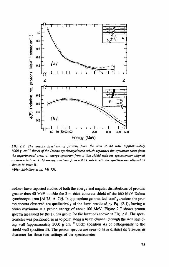
FIG. 2.7. The energy spectrum of protons from the iron shield wall (approximately 3000 g-cm~2 thick) of the Dubna synchrocyclotron which separates the cyclotron room from the experimental area: a) energy spectrum from a thin shield with the spectrometer aligned as shown in inset A; b) energy spectrum from a thick shield with the spectrometer aligned as shown in inset B. (After Aleinikov et al. [Al 75])
authors have reported studies of both the energy and angular distributions of protons
greater than 40 M e V outside the 2 m thick concrete shield of the 660 M e V Dubna
synchrocyclotron [Al 75, A l 79]. In appropriate geometrical configurations the pro-
ton spectra observed are qualitatively of the form predicted by Eq. (2.1), having a
broad maximum at a proton energy of about 100 M e V . Figure 2.7 shows proton
spectra measured by the Dubna group for the locations shown in Fig. 2.8. The spec-
trometer was positioned so as to point along a beam channel through the iron shield-
ing wall (approximately 3000 g - c m ~ 2 thick) (position A ) or orthogonally to the
shield wall (position B). The proton spectra are seen to have distinct differences in
character for these two settings of the spectrometer.
75
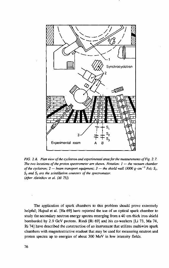
FIG. 2.8. Plan view of the cyclotron and experimental area for the measurements of Fig. 2.7. The two locations of the proton spectrometer are shown. Notation: 1 — the vacuum chamber of the cyclotron; 2 — beam transport equipment; 3 — the shield wall (3000 g-cm~2 Fe); Sh
S2 and S3 are the scintillation counters of the spectrometer. (After Aleinikov et al. [Al 75])
The application of spark chambers to this problem should prove extremely
helpful; Hajnal et al. [Ha 69] have reported the use of an optical spark chamber to
study the secondary neutron energy spectra emerging from a 40 cm thick iron shield
bombarded by 2.9 GeV protons. Rindi [Ri 69] and his co-workers [Li 73, M a 74,
Ri 74] have described the construction of an instrument that utilizes multiwire spark
chambers with magnetostrictive readout that may be used for measuring neutron and
proton spectra up to energies of about 300 M e V in low intensity fields.
76
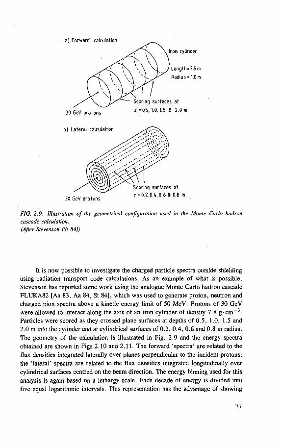
FIG. 2.9. Illustration of the geometrical configuration used in the Monte Carlo hadron cascade calculation. (After Stevenson [St 84])
It is now possible to investigate the charged particle spectra outside shielding using radiation transport code calculations. As an example of what is possible, Stevenson has reported some work using the analogue Monte Carlo hadron cascade FLUKA82 [Aa 83, Aa 84, St 84], which was used to generate proton, neutron and charged pion spectra above a kinetic energy limit of 50 MeV. Protons of 30 GeV were allowed to interact along the axis of an iron cylinder of density 7.8 g-cm~3 . Particles were scored as they crossed plane surfaces at depths of 0.5, 1.0, 1.5 and 2.0 m into the cylinder and at cylindrical surfaces of 0.2, 0.4, 0.6 and 0.8 m radius. The geometry of the calculation is illustrated in Fig. 2.9 and the energy spectra obtained are shown in Figs 2.10 and 2.11. The forward 'spectra' are related to the flux densities integrated laterally over planes perpendicular to the incident protons; the 'lateral' spectra are related to the flux densities integrated longitudinally over cylindrical surfaces centred on the beam direction. The energy binning used for this analysis is again based on a lethargy scale. Each decade of energy is divided into five equal logarithmic intervals. This representation has the advantage of showing
77
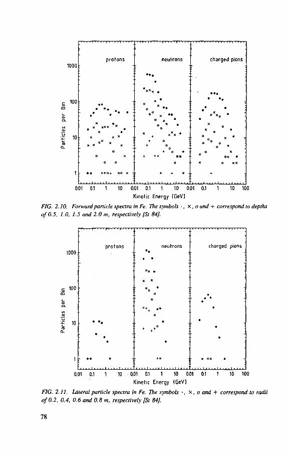
1000
100
tSi Q>
I 10 I— n a.
1
protons neutrons charged pions
1 ; • • • •
:
• • x • X
O ••
• •• • ••
• « • . • • : x •
x X * X * • * o
X •
X X *
o ° * x o x
° ° X • • O X *
o X • o
° + • + o
+ o
x X x • : •
X X
X • 0
x X • ° o
o o o *
o O X
+ o • + + + a n
O X o
o o •
o o o - X o X X
• • + + 0 + o o x -
I . I . I . '
+ + X .
1 1 1 1 1 1 1 1 1 1 1 1 1 1 1 1 1 1 1
+
0.01 0.1 1 10 0.01 0.1 1 10 0.01 0.1 1 10 100
Kinetic Energy (GeV)
FIG. 2.10. Forward particle spectra in Fe. The symbols •, X, o and + correspond to depths of 0.5, 1.0, 1.5 and 2.0 m, respectively [St 84],
1000
100
10
T r r r r ' • « > r f ' • '
protons
i i i i T i i l i j i i i i | i i « i
neutrons • •
- r r T-r-1 t t t - t | i i i i | i r i - r -
charged pions
• • •
*x •
X X
•
o X
o
• • • •
• o
• 0 • •
•
• •
• • •
•
• • * + x :
i i i i i , . i i I i . i i i i i t i
X X X •
0.01 0.1 1 10 0.01 0.1 1 10 0.01 0.1 1 10 100
Kinetic Energy (GeV)
FIG. 2.11. Lateral particle spectra in Fe. The symbols •, X, o and + correspond to radii of 0.2, 0.4, 0.6 and 0.8 m, respectively [St 84],
78
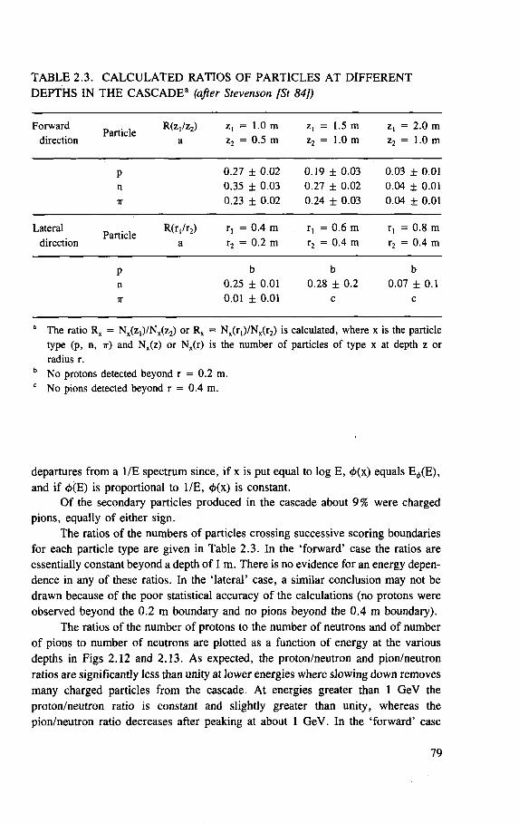
TABLE 2.3. CALCULATED RATIOS OF PARTICLES AT DIFFERENT DEPTHS IN THE CASCADE3 (after Stevenson [St 84])
Forward direction
Particle R(z,/z2)
a z, - 1.0 m z2 = 0 .5 m
z, = 1.5 m z2 = 1.0 m
z, = 2 .0 m z2 = 1.0 m
P n ir
0 .27 ± 0 .02 0 .35 ± 0 .03 0 .23 ± 0 .02
0 .19 ± 0 .03 0 .27 ± 0 .02 0 .24 ± 0 .03
0 .03 ± 0.01 0 .04 ± 0.01 0 .04 ± 0 .01
Lateral direction
Particle R(r, /r2)
a
r, = 0 .4 m r2 = 0 .2 m
r, = 0 .6 m r2 = 0 .4 m
r, = 0 .8 m r2 = 0 .4 m
P n 7T
b 0.25 ± 0 .01 0 .01 ± 0 .01
b 0.28 ± 0 .2
c
b 0.07 ± 0 .1
c
a The ratio Rx = Nx(z,) /Nx(z2) or Rx = Nx(r[)/Nx(r2) is calculated, where x is the particle type (p, n, ir) and Nx(z) or Nx(r) is the number of particles of type x at depth z or radius r.
b No protons detected beyond r = 0 .2 m. c N o pions detected beyond r = 0 .4 m.
departures from a 1/E spectrum since, if x is put equal to log E, <t>(\) equals E^(E), and if </>(E) is proportional to 1/E, 4>(\) is constant.
Of the secondary particles produced in the cascade about 9% were charged pions, equally of either sign.
The ratios of the numbers of particles crossing successive scoring boundaries for each particle type are given in Table 2.3. In the 'forward' case the ratios are essentially constant beyond a depth of 1 m. There is no evidence for an energy depen-dence in any of these ratios. In the 'lateral' case, a similar conclusion may not be drawn because of the poor statistical accuracy of the calculations (no protons were observed beyond the 0.2 m boundary and no pions beyond the 0.4 m boundary).
The ratios of the number of protons to the number of neutrons and of number of pions to number of neutrons are plotted as a function of energy at the various depths in Figs 2.12 and 2.13. As expected, the proton/neutron and pion/neutron ratios are significantly less than unity at lower energies where slowing down removes many charged particles from the cascade. At energies greater than 1 GeV the proton/neutron ratio is constant and slightly greater than unity, whereas the pion/neutron ratio decreases after peaking at about 1 GeV. In the 'forward' case
79
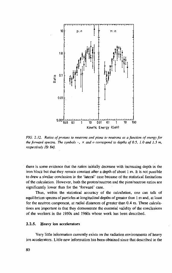
I I I I I I [ I I I I I I I I I I I I
10
1.0 r
o 0.1 :
0.01 :
p : n
.it
il ,
i • • i • • • 11 * • • • i •' • •
n: n
A AA4l f f i i I i I I i I 1 I I i I t > I 1 I i t I 1 1 M I I I I I I I I 1 I. 1 I 0.01 0.1 1 10 0.01 0.1 1 10 100
Kinetic Energy (GeV)
FIG. 2.12. Ratios of protons to neutrons and pions to neutrons as a function of energy for the forward spectra. The symbols •, X and o correspond to depths of 0.5, 1.0 and 1.5 m, respectively [St 84],
there is some evidence that the ratios initially decrease with increasing depth in the iron block but that they remain constant after a depth of about 1 m. It is not possible to draw a similar conclusion in the 'lateral' case because of the statistical limitations of the calculation. However, both the proton/neutron and the pion/neutron ratios are significantly lower than for the 'forward' case.
Thus, within the statistical accuracy of the calculation, one can talk of equilibrium spectra of particles at longitudinal depths of greater than 1 m and, at least for the neutron component, at radial distances of greater than 0.4 m. These calcula-tions are important in that they demonstrate the essential validity of the conclusions of the workers in the 1950s and 1960s whose work has been described.
2.2.5. Heavy ion accelerators
Very little information currently exists on the radiation environments of heavy ion accelerators. Little new information has been obtained since that described in the
80
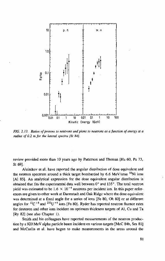
11111 1 1 1 1 1 1 1 1 I 1 1 1 1 1
r p: n TT: fl
f t
: 4 :
i :
: 1
i • I
: t.
• • . i l '
1 ;
1 1 1 1 1 1 1 1 1 I 1 1_1. 1 1 .l_l_L 1 .
: t.
• • . i l ' . . . 1 . . . .
1 ;
1 1 1 1 1 1 1 1 1 I 1 1_1. 1 1 .l_l_L 1 . I • • l l l l l I I I I I I • • • I • • • I I I I I I I I I I I t I I I • I I I I I
0.01 0.1 1 10 0.01 0.1 1 10 100 Kinetic Energy (GeVI
FIG. 2.13. Ratios of protons to neutrons and pions to neutrons as a Junction of energy at a radius of 0.2 m for the lateral spectra [St 84],
review provided more than 10 years ago by Patterson and Thomas [Hu 60, Pa 73, St 69].
Aleinikov et al. have reported the angular distribution of dose equivalent and the neutron spectrum around a thick target bombarded by 6.6 MeV/amu 58Ni ions [Al 85]. An analytical expression for the dose equivalent angular distribution is obtained that fits the experimental data well between 0° and 135°. The total neutron yield was estimated to be 1.6 x 10 ~4 neutrons per incident ion. In this paper refer-ences are given to other work at Darmstadt and Oak Ridge where the dose equivalent was determined at a fixed angle for a series of ions [Fe 80, Oh 80] or at different angles for 12C + 6 and 232U + 4 ions [Fe 80]. Ryder has reported neutron fluence rates for deuteron and other ions incident on optimum thickness targets of Al, Cu and Ta [Ry 82] (see also Chapter 1).
Smith and his colleagues have reported measurements of the neutron produc-tion by a 920 MeV alpha particle beam incident on various targets [McC 84b, Sm 81] and McCaslin et al. have begun to make measurements in the areas around the
81
Bevalac (see Section 1.5 and Refs [McC 83, McC 84a,b, McC 85]). Many of these measurements are preliminary, but the radiation environment outside their shielding may indicate some interesting departures from the usual radiation fields found at proton accelerators. Detailed investigation of these fields as a function of ion energy, ion species and target as well as attenuation measurements in shielding are needed [McC 85].
2.2.6. Interpretation of accelerator radiation measurements (See also Section 3.8)
Perhaps the most difficult aspect of radiation protection dosimetry at particle accelerators is the interpretation of measurements in terms of the particular dose equivalent quantities required by regulation and statute.
The quantity 'dose equivalent' was first formally defined as recently as 1968 [ICRU 68], although its origins go back a further twenty years to the application of RBE dose to radiological protection [Pa 48]. Thomas has reviewed the long standing discussion concerning the definition of both the quantity and its units [Th 85b]. For sources of radiation exposure external to the body, the dose equivalent H is defined by the equation:
where L ^ is the the linear collision stopping power in water, dD(L00)/dL00 is the absorbed dose in the stopping power increment from L ^ to L ^ + d L ^ , Q(L<») is the quality factor as a function of stopping power as defined by ICRU and ICRP [ICRP 73, ICRU 68], and the integral of Eq. (2.2) is evaluated over the entire L K
spectrum. In the determination of the dose equivalent in the radiation fields of particle
accelerators Eq. (2.2) is not normally used directly, for example by the determina-tion of the absorbed dose distribution as a function of L^ . Alternative means are usually taken. Since in most cases we are concerned'with measurements of neutrons, the interpretation of neutron measurements in terms of dose equivalent will be dis-cussed in more detail.
2.2.6.1. Evaluation of dose equivalent produced by neutrons
The evaluation of dose equivalent from neutrons, particularly at high energies, poses severe technical difficulties which are compounded by 'inadequate or incom-plete definition of the quantity to be measured' [Wa 84, Wa 85], McCaslin and Thomas have reviewed neutron dosimetry intercomparisons made by several high
(2.2)
82
energy laboratories and while they found reasonable agreement in the determination of the physical parameters of the radiation field, the conversion of these data to dose equivalent produced disagreement by almost as much as a factor of two [McC 81]. They concluded that these discrepancies were often due to the use of different dose equivalent quantities.
2.2.6.2. Operational dose equivalent quantities for neutrons
The primary limits for radiation exposure recommended by ICRP are expressed in terms of the dose equivalent to various tissues HT, the whole body dose equivalent Hwb, and the effective dose equivalent HE. For external radiation exposure, secondary limits are expressed in terms of the shallow and deep dose equivalent indexes HI s and HI d [ICRP 77]. Since, in general, neither the primary nor the secondary limits may be measured directly, operational quantities must be developed [Ha 81, ICRP 82, ICRU 85, Wa 85],
The most widely used operational dose equivalent quantity for neutrons is the dose equivalent Hc, determined from a measured neutron fluence <f>m , and a fluence-to-dose-equivalent conversion coefficient h or g,6 according to the equations:7
Hc = H m
Hc = <t>Jg
(2.3a)
(2.3b)
Equations (2.3a) and (2.3b) assume monoenergetic neutrons but, of course, both 0 and h are functions of neutron energy. Thus, more exactly:
HC(E) = h(E) 4>m(E) (2.4a)
HC(E) = (2.4b) g(E)
6 Two conversion coefficients have been in common use. The first, h(E), is expressed in units of dose equivalent per unit fluence (e.g. rem-cm2, or Sv-cm2), while the second, g(E) (now obsolete), was expressed in units of fluence rate required to produce a dose equiva-lent rate of 2.5 mrem/h or 1 mrem/h.
7 Throughout this text the subscripts m, p and s indicate parameters, e.g. dose equivalent H or conversion coefficients g(E), corresponding to dose equivalents determined at the maximum m or surface s in the human body or according to the method of Shaw et al. [Sh 69],
83
Tabulations of the conversion coefficients h(E) or g(E) for various neutron energies have been given for example in NCRP Report 38 [NCRP 71] or ICRP Publi-cation 21 [ICRP 70, ICRP 73]. (For a discussion of the derivation of these conver-sion coefficients, see the references given in the review article by Thomas [Th 85b].) The ICRP has recently revised the conversion coefficients published in 1973 and these should now be used [ICRP 86],
The conversion coefficients of NCRP Report 38 and ICRP Publication 21 were determined for an incident broad parallel beam of incident neutrons on a tissue equivalent phantom (e.g. 30 cm thick tissue equivalent slab, 30 cm diameter by 60 cm high tissue equivalent cylinder) [Al 70, Ar 73, Au 68, Ir 67, Ne 66, Sn 50, Sn 57, Sn 71, Wr 69, Ze 65] or the ICRU sphere [Ch 78, Ch 79, Ch 81a,b, Sh 83],
The conversion coefficients determined in this way define a set of conversion coefficients hm(E) for monoenergetic neutrons as a function of energy E. These conversion coefficients may be used to determine a quantity originally called the maximum dose equivalent (MADE) Hm [ICRU 71] defined by the equation
where <t>(E) dE is the differential energy neutron spectrum. This procedure is not entirely logically consistent since the argument of the
integral contains two elements — the first a hypothetical neutron fluence, which would exist if the phantom or body were not present and the second a fluence to dose equivalent conversion coefficient for a particular neutron energy. These conversion coefficients are, however, determined by locating the maximum dose equivalent that occurs in the phantom. The location of this maximum varies with neutron energy. The procedure of integration (summation) of maximum dose equivalents that occur at different positions in the phantom will thus overestimate the actual dose equivalent in typical accelerator spectra. However, this procedure was used at several British and US high energy accelerators in the 1960s and was endorsed in the recommenda-tions of ICRP Publication 21. This concept was further formalized by Harvey to define the dose equivalent ceiling [Ha 75], It has now been realized that ceiling quan-tities are a special subgroup of the so-called 'aligned quantities' [ICRU 85, Wa 85].
In order to avoid the overestimation resulting from the use of ceiling quantities, a somewhat different method of determining dose equivalent in practical situations at accelerators was adopted at CERN [St 73a,b]. Here it was argued that in many cases the radiation penetrating a thick concrete shield essentially had achieved an equilibrium particle spectrum that would not be significantly altered by the presence of the human body. In such circumstances the human body merely acts as additional attenuating material, and the maximum of the depth-dose equivalent distribution will lie close to the body surface. Furthermore, it is a feature of the radiation survey
(2.5)
84
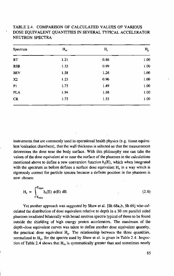
TABLE 2.4. COMPARISON OF CALCULATED VALUES OF VARIOUS DOSE EQUIVALENT QUANTITIES IN SEVERAL TYPICAL ACCELERATOR NEUTRON SPECTRA
Spectrum Hm Hs Hp
RT 1.21 0.86 1.00
RSB 1.33 0.99 1.00
BEV 1.58 1.26 1.00
X2 1.23 0.96 1.00
PI 1.73 1.49 1.00
PLA 1.94 1.68 1.00
CR 1.73 1.53 1.00
instruments that are commonly used in operational health physics (e.g. tissue equiva-lent ionization chambers), that the wall thickness is selected so that the measurement determines the dose near the body surface. With this philosophy one can take the values of the dose equivalent at or near the surface of the phantom in the calculations mentioned above to define a new conversion function hs(E), which when integrated with the spectrum as before defines a surface dose equivalent Hs in a way which is rigorously correct for particle spectra because a definite position in the phantom is now chosen:
J^max hs(E) 0(E) dE (2.6) E m i n
Yet another approach was suggested by Shaw et al. [Sh 68a,b, Sh 69] who cal-culated the distribution of dose equivalent relative to depth in a 30 cm parallel sided phantom irradiated bilaterally with broad neutron spectra typical of those to be found outside the shielding of high energy proton accelerators. The maximum of the depth-dose equivalent curves was taken to define another dose equivalent quantity, the practical dose equivalent Hp. The relationship between the three quantities, normalized to Hp, for the spectra used by Shaw et al. is given in Table 2.4. Inspec-tion of Table 2.4 shows that Hm is systematically greater than and sometimes nearly
85
twice as large as Hp , whereas for these spectra H s never underestimates H p by more than 15%, but may overestimate it by as much as 70%.
In the past decade, the ICRU and ICRP have introduced concepts with the intention of clarifying the quantities to be determined for radiation protection purposes.
In 1973 the ICRU first introduced the concept of the dose equivalent index [ICRU 73] and three years later extended the concept to include shallow and deep indices [ICRU 76]. There is, however, no practical means of locating the maximum dose equivalent in a 30 cm tissue equivalent sphere, and there are many undesirable properties of the index quantities including non-additivity (spatial and secular) and non-point-specificity. At high energies there is very little difference to be expected between fluence to dose equivalent conversion coefficients derived either from a 30 cm diameter sphere or a 30 cm thick parallel sided slab. These considerations led Stevenson et al. [St 73a,b] to suggest that the concept of dose equivalent index was in fact redundant for dosimetry at accelerator laboratories and that H s , determined for the appropriate condition of unilateral or bilateral irradiation, was an adequate quantity to 'attempt to relate the absorbed dose to the risk of the resulting biological effects ' [ICRP 66].
2.2.6.3. Recent developments
During the past decade there have been significant developments that will have a considerable influence in the future on the matter of the interpretation of radiation field quantities in terms of biological risk.
Interestingly enough there have been two different, and perhaps ultimately conflicting, approaches. The first approach has been to improve the basic definition of the quantity dose equivalent and to derive operational dose equivalent quantities that are suitable for measurement. The second approach has been to suggest changes that require either a partial or a total change in the dose equivalent system.
In 1977, the ICRP introduced the effective dose equivalent as the primary quantity to be evaluated in radiation protection [ICRP 77]. This publication went on to suggest that for "external exposures to ionizing radiation, on those occasions when information is lacking concerning the actual distribution of dose equivalents in the bodies, it is possible to assess the maximum value of dose equivalent that would occur in a 30 cm sphere (the deep dose equivalent H] d ) " . Almost immedi-ately following the publication of ICRP 26 there were debates published in the litera-ture suggesting that the dose equivalent indexes might not necessarily provide precise estimates of the effective dose equivalent [Kr 79, Kr 80, OB 78, OB 80],
It has been necessary to assemble a considerable quantity of data, showing the relationship of many dosimetric quantities to the geometry of the irradiation and physical parameters of the radiation field, in order to be able to determine the
86
accuracy with which the index quantities approximate the effective dose equivalent. Over the past nine years these data have been accumulated for photons of energy up to 10 MeV and neutrons of energy up to 14 MeV [Bu 78, Bu 83, Ch 79, Ch 81a,b, Di 79, Dr 78, Kr 82, Sh 83], Committees of both international commissions have been reviewing these data — the ICRP with a view to revising fluence to dose equiva-lent conversion coefficients and the ICRU with a view to improving the definitions of operational dose equivalent quantities [So 83, Wy 83].
Dose equivalent quantities have one important property for radiation protection — they provide a system that is unified for all radiation. (At the present time different operational quantities are used for photons (exposure), for beta particles and elec-trons (absorbed dose in air or tissue), and for neutrons (fluence, dose equivalent ceil-ing).) There is then some argument for retaining the use of some form of dose equivalent quantity(ies) in the future. The dose equivalent indexes have, however, not been widely used in radiation monitoring because of both practical and theoreti-cal difficulties in their application. In searching for improved quantities it is possible to list the desirable properties of dose equivalent operational quantities used in monitoring. They should be:
— measurable under operating conditions — compatible with existing instruments — physically realizable in standards laboratories — calculable — related to primary limits — durable — additive, single valued, point specific — relatable to a specific phantom.
The choice of a specific phantom is not easy. The ICRU sphere has the advan-tage of being uncomplicated and accepted by international authorities; the specifica-tion of its composition (tissue) is unlikely to be changed; it has an isotropic response to radiation. Furthermore, it is a reasonable phantom for calibration purposes (e.g. for personal dosimeters worn on the human abdomen). Such properties make it suita-ble as the basis of a calibration standard to be set up in a national standards laboratory.
The ICRU sphere, however, can clearly never be used to determine organ dose equivalents or the effective dose equivalent. For this purpose an anthropoid phantom is needed. Several simple alternatives to the sphere have been used for calculation (the 30 cm thick tissue slab, cylinder, etc.) but all have the principal defect of the sphere. Several complex anthropoid phantoms have been constructed to facilitate organ dose measurements (e.g. Alderson Rando phantom, Plastinaut, Mr. Adam). Extensive calculations of effective dose equivalent have been made in the modified MIRD-5 phantoms ADAM and EVA. Such phantoms are most important for accurate calculation but doubtless will be subject to continuing improvement.
87
Furthermore, individual anatomical variation in monitored individuals is quite significant, and the accurate determination of organ dose and effective dose equiva-lent must always demand individual attention. Such arguments tend to suggest that measurements based upon calibrations with the ICRU sphere may be linked, with sufficient accuracy for routine monitoring, both to radiation field quantities and to calculations of dose equivalent in anthropoid phantoms.
The development of suitable operational dose equivalent quantities requires one further set of simplifications. It is only practicable, for routine monitoring, to specify maximal conditions. (Consideration of the host of alternative radiation condi-tions is just too complicated.) Such conditions are, in general, obtained when the human body is irradiated by a broad unidirectional parallel beam of radiation incident on the anterior face of the body and leaving from the posterior face.
In discussing radiation fields it is then convenient to define two concepts: expansion and alignment of a radiation field as was done in ICRU Report 39 [ICRU 85a]. An expanded radiation field is a hypothetical field that everywhere in space has the same particle flux density, energy and angular distribution as the unper-turbed field at the point of reference. An aligned and expanded radiation field is a hypothetical field that everywhere in space has the same particle fluence density and energy distribution as the unperturbed actual field at the point of reference but with all radiation incident in one direction. With these radiation field conditions specified we can define quantities which include them — making it possible to calibrate physi-cally small instruments, which have an isotropic response, in terms of these quanti-ties, which are then referred to as 'aligned dose equivalent quantities'.
As we have seen, as early as 1973 workers at high energy accelerator labora-tories have found it helpful to define what is, in effect, the aligned dose equivalent at a depth of 10 mm in a tissue equivalent phantom [St 73 a,b]. Other depths at which these aligned dose equivalents might be specified are 0.07 mm and 3 mm, because of the specification of the thickness of the skin and the depth of the lens by the ICRP [ICRP 77],
Another concept that is of great value in clarifying dose equivalent quantities is that of 'energy summation'. Here the separate maximum dose equivalents from each energy increment of the incident aligned and expanded radiation field, irrespec-tive of where these maximum dose equivalents occur, are summed. The value of the 'energy summed' quantity is equal to this sum. Aligned and energy summed quantities were first identified as ceiling quantities by Harvey in 1975 [Ha 75] and are of great practical importance because the so-called neutron 'rem-meters' are designed to measure this quantity.
In 1985 the ICRU published Report 39 entitled 'Determination of Dose Equivalents Resulting from External Radiation Sources' in which the conclusions of considerations similar to those given above are summarized. The Commission has selected four operational quantities for the determination of dose equivalents resulting from external ionizing radiation sources. These are:
88
Symbol
Ambient dose equivalent Directional dose equivalent Individual dose equivalent, penetrating Individual dose equivalent, superficial
H*(d) H'(d) Hp(d) Hs(d)
These quantities provide a sound metrological basis for the implementation of the current recommendations of the ICRP, are within the SI system of units and achieve a uniform basis for the dosimetry of all types of ionizing radiation. In addi-tion, the quantities are compatible with current practice in radiation monitoring and will not require replacement of existing instruments [ICRU 85a].
The ICRU is preparing a second report giving the supporting data and reasons for its recommendations contained in Report 39 [ICRU 85b]. A third report is planned to discuss the design and construction of instruments to measure the new operational quantities [Wy 83].
The.ICRP is currently revising and extending data on fluence to dose equiva-lent conversion coefficients contained in Publication 21 [ICRP 73], The new data will include conversion coefficients to the maximum dose equivalence (MADE), the index quantities and the ambient dose equivalent quantities [So 83, ICRP 86]. Some of the conversion coefficients are discussed in Chapter 3.
These improvements in the definitions of the dose equivalent quantities and the improved precision of the conversion coefficients will lead to better agreement between measurements.
Non-specific comparisons of 'dose equivalent' derived from fluence measure-ments may be expected to show large differences. Proper comparisons will only follow when the dose equivalent quantities to be examined are rigorously specified. Many of the apparent discrepancies reported in the literature arise from ambiguity in the definition of the dose equivalent actually determined.
Concurrently with these improvements in clarity of the definitions of dose equivalent quantities, there have been some developments that suggest fundamental or partial changes in the present dose equivalent based system.
The principal suggestions for piecemeal changes lie in the modification of the quality factor for neutrons. This has most recently been expressed by the ICRP in the recent statement [ICRP 85a]:
"The information now available on the relative biological effec-tiveness (RBE) of neutrons for a variety of cellular effects in vitro, and for life shortening in the mouse, is being reviewed by the Commission. The implications of this information will be considered as part of a larger review of recommendations to be undertaken by the Commission over the next four years or so. Meanwhile, in the case of neutrons the Commission
89
recommends an increase in Q by a factor of 2. The permitted approxima-tion for Q for fast neutrons thus changes from 10 to 20. These changes relate only to neutrons, and no other changes in Q are recommended at this t ime."
Such a view has previously been expressed by the NCRP and by Rossi and his colleagues [NCRP 80, Ro 77, Ro 78], It is not universally supported, however, and is even contested (see for example [St 85a]).
Even more fundamental challenges to the present dose equivalent system have been suggested on a radiobiological basis by Mole [Mo 79] and on a physical basis by Rossi [Ro 77] (see Section 3.6). Another challenge is mounted on the grounds that a risk based system of radiation protection is to be preferred [NCRP 82],
Casarett has succinctly evaluated the disadvantages of our present dose equiva-lent based system of radiation [Ca 82]:
" I t is proper to distinguish the dose equivalent from biological risk. The utilization of rem for dose is inappropriate in the context of risk because the rem is frozen within the LET-dependent quality factor system. Because of the rigidity of this interlocking physically defined system, a change in MPD for one radiation, e.g. on the basis of a new risk estimate, requires, for consistency, changes in the MPDs for the other radiations. If an exception were made and, in effect, the Q for that one radiation were changed instead, that would be tantamount to injecting a bit of the risk system into the current system. For consistency, either the other Q values would need to be changed according to the LET-dependence in the current system or changed on the basis of risk. With the current system, Q is an especially knotty problem in regard to the internal emitter f ield."
It is difficult to predict the detailed changes that will occur in our dosimetry systems over the next 10 years. It is perhaps time for a cautious review that can incorporate our present understanding without producing a major disruption in oper-ational radiological protection.
2.3. INDUCED RADIOACTIVITY
2.3.1. Introduction: the remanent radiation field
In addition to the prompt radiation field just described there may exist a radia-tion field that, by contrast, remains or lingers on after shutdown. This remanent radi-ation field results from the decay of radioactivity induced in the accelerator structure and its ancillary components by the interaction of the constituent particles of the prompt radiation field: its precise characteristics will depend upon many factors such as the type and energy of the particles accelerated, the beam intensity and materials irradiated by the primary beam and secondary radiations.
90
The specification of the properties of this remanent radiation field merits some effort because it may have consequences for:
(1) The exposure of personnel working in accelerator environments when the accelerator is not operating;
(2) The maintenance of accelerator components — in particular the control of the spread of contamination during operations such as the turning, drilling or milling of radioactive components;
(3) The administrative control of movement of items from accelerator areas that might be radioactive;
(4) The environment of particle accelerators into which radioactive contaminants — particularly in gaseous or liquid form — may be generated;
(5) The disposal of unwanted accelerator components.
This chapter discusses the general characteristics of the remanent radiation field and its consequences for accelerator operation. Chapter 5 discusses the adminis-trative controls necessary and suitable at a particle accelerator laboratory while Chapter 6 discusses the magnitude and consequences of induced radioactivity in the environment.
2.3.2. Characteristics of the remanent radiation field
2.3.2.1. Particle energy
All particle accelerators whose energy exceeds 10 MeV will produce some induced radioactivity. This radioactivity results from the interaction of the particles (including photons) of the prompt radiation field with the accelerator and its surroundings. The precise energy at which radioactivity is produced depends upon the particles accelerated and the target being irradiated: certain nuclear reactions with light target nuclei (such as Be or Li) will produce neutrons, and hence radio-activity, at energies well below 10 MeV. Neutron generators always have a potential for the induction of radioactivity. National Bureau of Standards Handbook 107 gives rules of thumb for determining whether particle accelerators whose energy is below 10 MeV may present a problem with induced radioactivity [ANSI 70]. Only a small fraction of accelerators give cause for concern in this respect. Thus Opelka et al. found that less than 5% of some 1200 accelerators in the USA might have significant induced activity problems [Op 82],
2.3.2.2. Radionuclides produced
Barbier has given an excellent summary of the mechanisms for the production of radioactivity by particle accelerators [Ba 69]. In the interaction of a hadron of sufficient energy with a nucleus an intranuclear cascade is generated. The emission
91
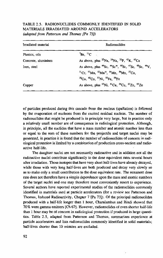
TABLE 2.5. RADIONUCLIDES COMMONLY IDENTIFIED IN SOLID MATERIALS IRRADIATED AROUND ACCELERATORS (adapted from Patterson and Thomas [Pa 73])
Irradiated material Radionuclides
Plastics, oils 7Be, UC
Concrete, aluminium As above, plus 22Na, 24Na, 32P, 42K, 45Ca
Iron, steel As above, plus "Sc, "Sc"1, 46Sc, 47Sc, 48Sc, 48V, 51Cr, 52Mn, 52Mnm, MMn, 56Mn, 57Co, 58Co, ^Co, 57Ni, 55Fe, ' 'Fe
Copper As above, plus 65Ni, 61Cu, "Cu, 63Zn, 65Zn
of particles produced during this cascade from the nucleus (spallation) is followed by the evaporation of nucleons from the excited residual nucleus. The number of radionuclides that might be produced is in principle very large, but in practice only a relatively small number are of consequence in radiological protection. Although, in principle, all the nuclides that have a mass number and atomic number less than or equal to the sum of these numbers for the projectile and target nuclei may be generated, in practice it is found that the number of radionuclides of concern in radi-ological protection is limited by a combination of production cross-section and radio-active half-life.
The daughter nuclei are not necessarily radioactive and in addition not all the radioactive nuclei contribute significantly to the dose equivalent rates several hours after irradiation. Those isotopes that have very short half-lives have already decayed, while those with very long half-lives are both produced and decay very slowly so as to make only a small contribution to the dose equivalent rate. The remanent dose rate does not therefore have a simple dependence upon the mass and atomic numbers of the target nuclei and one may therefore most conveniently resort to experience. Several authors have reported experimental studies of the radionuclides commonly identified in materials used at particle accelerators (for a review see Patterson and Thomas, Induced Radioactivity, Chapter 7 [Pa 73]). Of the principal radionuclides produced with a half-life longer than 1 hour, Charalambus and Rindi showed that 70% were gamma emitters [Ch 67], However, radionuclides of even shorter half-life than 1 hour may be of concern in radiological protection if produced in large quanti-ties. Table 2.5, adapted from Patterson and Thomas, summarizes experience at particle accelerators and lists radionuclides commonly identified in solid materials; half-lives shorter than 10 minutes are excluded.
92
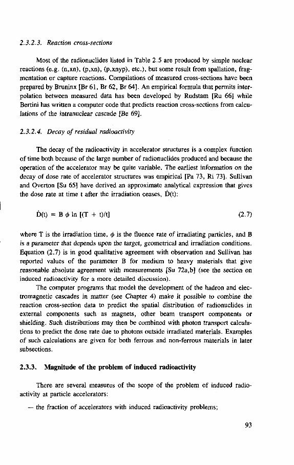
2.3.2.3. Reaction cross-sections
Most of the radionuclides listed in Table 2.5 are produced by simple nuclear reactions (e.g. (n,xn), (p,xn), (p,xnyp), etc.), but some result f rom spallation, frag-mentation or capture reactions. Compilations of measured cross-sections have been prepared by Bruninx [Br 61, Br 62, Br 64]. An empirical formula that permits inter-polation between measured data has been developed by Rudstam [Ru 66] while Bertini has written a computer code that predicts reaction cross-sections from calcu-lations of the intranuclear cascade [Be 69],
2.3.2.4. Decay of residual radioactivity
The decay of the radioactivity in accelerator structures is a complex function of time both because of the large number of radionuclides produced and because the operation of the accelerator may be quite variable. The earliest information on the decay of dose rate of accelerator structures was empirical [Pa 73, Ri 73]. Sullivan and Overton [Su 65] have derived an approximate analytical expression that gives the dose rate at time t after the irradiation ceases, D(t):
D(t) = B In [(T + t)/t] (2.7)
where T is the irradiation time, <f> is the fluence rate of irradiating particles, and B is a parameter that depends upon the target, geometrical and irradiation conditions. Equation (2.7) is in good qualitative agreement with observation and Sullivan has reported values of the parameter B for medium to heavy materials that give reasonable absolute agreement with measurements [Su 72a,b] (see the section on induced radioactivity for a more detailed discussion).
The computer programs that model the development of the hadron and elec-tromagnetic cascades in matter (see Chapter 4) make it possible to combine the reaction cross-section data to predict the spatial distribution of radionuclides in external components such as magnets, other beam transport components or shielding. Such distributions may then be combined with photon transport calcula-tions to predict the dose rate due to photons outside irradiated materials. Examples of such calculations are given for both ferrous and non-ferrous materials in later subsections.
2.3.3. Magnitude of the problem of induced radioactivity
There are several measures of the scope of the problem of induced radio-activity at particle accelerators:
— the fraction of accelerators with induced radioactivity problems;
93
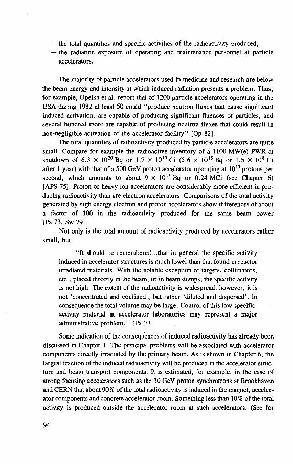
— the total quantities and specific activities of the radioactivity produced; — the radiation exposure of operating and maintenance personnel at particle
accelerators.
The majority of particle accelerators used in medicine and research are below the beam energy and intensity at which induced radiation presents a problem. Thus, for example, Opelka et al. report that of 1200 particle accelerators operating in the USA during 1982 at least 50 could "produce neutron fluxes that cause significant induced activation, are capable of producing significant fluences of particles, and several hundred more are capable of producing neutron fluxes that could result in non-negligible activation of the accelerator facility" [Op 82].
The total quantities of radioactivity produced by particle accelerators are quite small. Compare for example the radioactive inventory of a 1100 MW(e) PWR at shutdown of 6.3 x 10²⁰ Bq or 1.7 x 10¹⁰ Ci (5.6 x 10¹⁸ Bq or 1.5 x 10⁸ Ci after 1 year) with that of a 500 GeV proton accelerator operating at 1013 protons per second, which amounts to about 9 x 10¹⁵ Bq or 0.24 MCi (see Chapter 6) [APS 75]. Proton or heavy ion accelerators are considerably more efficient in pro-ducing radioactivity than are electron accelerators. Comparisons of the total activity generated by high energy electron and proton accelerators show differences of about a factor of 100 in the radioactivity produced for the same beam power [Pa 73, Sw 79].
Not only is the total amount of radioactivity produced by accelerators rather small, but
"I t should be remembered...that in general the specific activity induced in accelerator structures is much lower than that found in reactor irradiated materials. With the notable exception of targets, collimators, etc., placed directly in the beam, or in beam dumps, the specific activity is not high. The extent of the radioactivity is widespread, however, it is not 'concentrated and confined', but rather 'diluted and dispersed'. In consequence the total volume may be large. Control of this low-specific-activity material at accelerator laboratories may represent a major administrative problem." [Pa 73]
Some indication of the consequences of induced radioactivity has already been discussed in Chapter 1. The principal problems will be associated with accelerator components directly irradiated by the primary beam. As is shown in Chapter 6, the largest fraction of the induced radioactivity will be produced in the accelerator struc-ture and beam transport components. It is estimated, for example, in the case of strong focusing accelerators such as the 30 GeV proton synchrotrons at Brookhaven and CERN that about 90% of the total radioactivity is induced in the magnet, acceler-ator components and concrete accelerator room. Something less than 10% of the total activity is produced outside the accelerator room at such accelerators. (See for
94
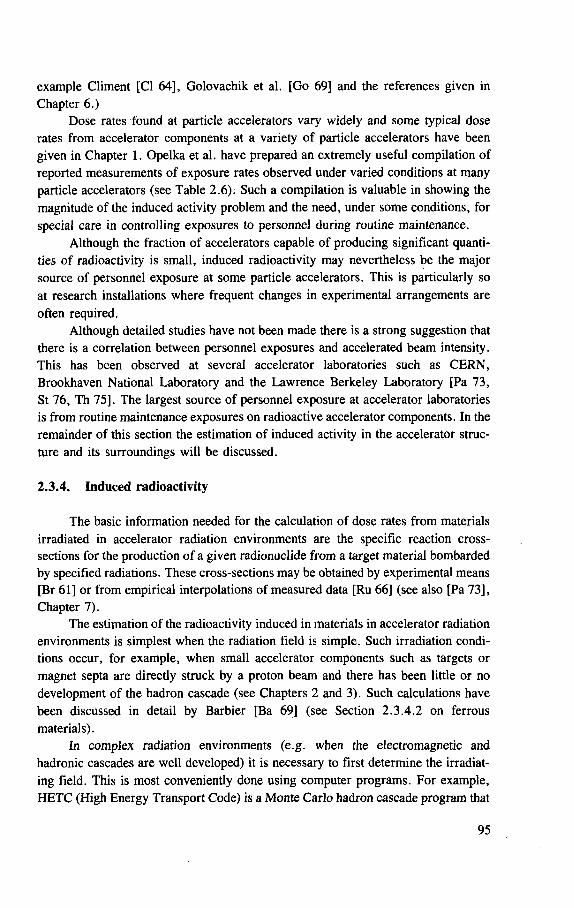
example Climent [CI 64], Golovachik et al. [Go 69] and the references given in Chapter 6.)
Dose rates found at particle accelerators vary widely and some typical dose rates from accelerator components at a variety of particle accelerators have been given in Chapter 1. Opelka et al. have prepared an extremely useful compilation of reported measurements of exposure rates observed under varied conditions at many particle accelerators (see Table 2.6). Such a compilation is valuable in showing the magnitude of the induced activity problem and the need, under some conditions, for special care in controlling exposures to personnel during routine maintenance.
Although the fraction of accelerators capable of producing significant quanti-ties of radioactivity is small, induced radioactivity may nevertheless be the major source of personnel exposure at some particle accelerators. This is particularly so at research installations where frequent changes in experimental arrangements are often required.
Although detailed studies have not been made there is a strong suggestion that there is a correlation between personnel exposures and accelerated beam intensity. This has been observed at several accelerator laboratories such as CERN, Brookhaven National Laboratory and the Lawrence Berkeley Laboratory [Pa 73, St 76, Th 75]. The largest source of personnel exposure at accelerator laboratories is from routine maintenance exposures on radioactive accelerator components. In the remainder of this section the estimation of induced activity in the accelerator struc-ture and its surroundings will be discussed.
2.3.4. Induced radioactivity
The basic information needed for the calculation of dose rates from materials irradiated in accelerator radiation environments are the specific reaction cross-sections for the production of a given radionuclide from a target material bombarded by specified radiations. These cross-sections may be obtained by experimental means [Br 61] or from empirical interpolations of measured data [Ru 66] (see also [Pa 73], Chapter 7).
The estimation of the radioactivity induced in materials in accelerator radiation environments is simplest when the radiation field is simple. Such irradiation condi-tions occur, for example, when small accelerator components such as targets or magnet septa are directly struck by a proton beam and there has been little or no development of the hadron cascade (see Chapters 2 and 3). Such calculations have been discussed in detail by Barbier [Ba 69] (see Section 2.3.4.2 on ferrous materials).
In complex radiation environments (e.g. when the electromagnetic and hadronic cascades are well developed) it is necessary to first determine the irradiat-ing field. This is most conveniently done using computer programs. For example, HETC (High Energy Transport Code) is a Monte Carlo hadron cascade program that
95
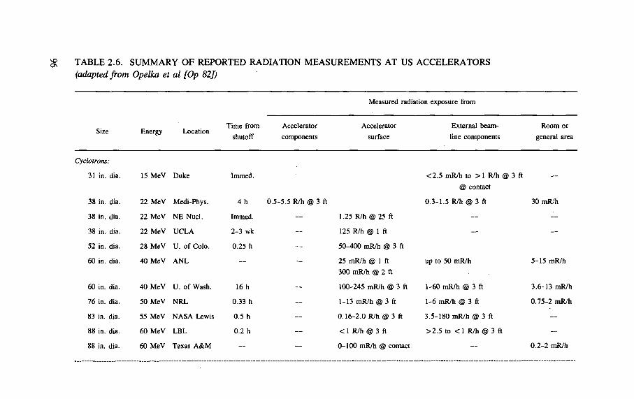
% TABLE 2.6. SUMMARY O F REPORTED RADIATION MEASUREMENTS AT US ACCELERATORS (adapted from Opelka et al [Op 82])
Measured radiation exposure from
Size Energy Location Time from
shutoff
Accelerator
components
Accelerator
surface
External beam-
line components
Room or
general area
Cyclotrons:
31 in. dia. 15 MeV Duke Immed. <2.5 mR/h to > 1 R/h <§
@ contact
? 3 ft
38 in. dia. 22 MeV Medi-Phys. 4 h 0.5-5.5 R/h @ 3 ft 0.3-1.5 R/h @ 3 ft 30 mR/h
38 in. dia. 22 MeV NE Nucl. Immed. 1.25 R/h @ 25 ft — —
38 in. dia. 22 MeV UCLA 2-3 wk 125 R/h @ 1 ft — —
52 in. dia. 28 MeV U. of Colo. 0.25 h 50-400 mR/h @ 3 ft
60 in. dia. 40 MeV ANL — 25 mR/h @ 1 ft
300 mR/h @ 2 ft
up to 50 mR/h 5-15 mR/h
60 in. dia. 40 MeV U. of Wash. 16 h 100-245 mR/h © 3 ft 1-60 mR/h @ 3 ft 3.6-13 mR/h
76 in. dia. 50 MeV NRL 0.33 h 1-13 mR/h @ 3 ft 1-6 mR/h @ 3 ft 0.75-2 mR/h
83 in. dia. 55 MeV NASA Lewis 0.5 h 0.16-2.0 R/h @ 3 ft 3.5-180 mR/h @ 3 ft —
88 in. dia. 60 MeV LBL 0.2 h < 1 R/h @ 3 ft >2.5 to <1 R/h @ 3 ft —
88 in. dia. 60 MeV Texas A&M 0-100 mR/h @ contact 0.2-2 mR/h
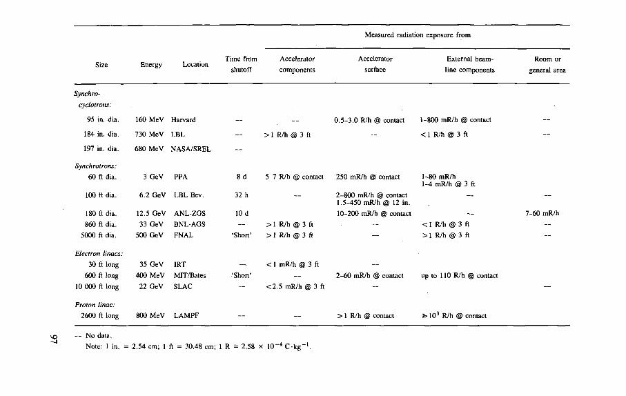
Measured radiation exposure from
Size Energy Location Time from
shutoff
Accelerator
components
Accelerator
surface
External beam-
line components
Room or
general area
Synchro-cyclotrons:
95 in. dia.
184 in. dia.
197 in. dia.
Synchrotrons: 60 ft dia.
100 ft dia.
180 ft dia.
860 ft dia.
5000 ft dia.
Electron linacs: 30 ft long
600 ft long
10 000 ft long
Proton linac: 2600 ft long
160 MeV Harvard
730 MeV LBL
680 MeV NASA/SREL
3 GeV PPA
6.2 GeV LBL Bev.
12.5 GeV ANL-ZGS
33 GeV BNL-AGS
500 GeV FNAL
35 GeV IRT
400 MeV MIT/Bates
22 GeV SLAC
800 MeV LAMPF
8 d
32 h
10 d
'Short1
'Shon'
> 1 R/h @ 3 ft
0.5-3.0 R/h @ contact 1-800 mR/h @ contact
< 1 R/h @ 3 ft
5-7 R/h @ contact 250 mR/h @ contact
2-800 mR/h @ contact 1.5-450 mR/h @ 12 in.
10-200 mR/h @ contact
>1 R/h
> 1 R/h
3 ft
3 ft
1-80 mR/h 1-4 mR/h @ 3 ft
< 1 R/h @ 3 ft
> 1 R/h @ 3 ft
< 1 mR/h @ 3 ft
<2.5 mR/h @ 3 ft
2-60 mR/h @ contact up to 110 R/h @ contact
>1 R/h @ contact i> 103 R/h @ contact
7-60 mR/h
— No data.
Note: 1 in. = 2.54 cm; 1 ft = 30.48 cm; 1 R = 2.58 x 10⁻⁴ C-kg-1.
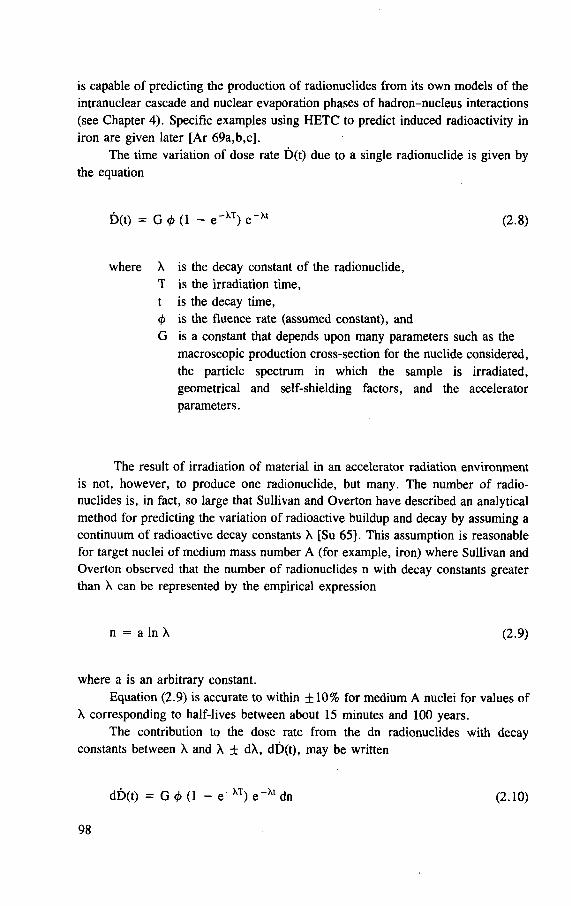
is capable of predicting the production of radionuclides from its own models of the intranuclear cascade and nuclear evaporation phases of hadron-nucleus interactions (see Chapter 4). Specific examples using HETC to predict induced radioactivity in iron are given later [Ar 69a,b,c].
The time variation of dose rate D(t) due to a single radionuclide is given by the equation
D(t) = G <t> (1 - e ' X T ) e - X t (2.8)
where X is the decay constant of the radionuclide, T is the irradiation time, t is the decay time, <A is the fluence rate (assumed constant), and G is a constant that depends upon many parameters such as the
macroscopic production cross-section for the nuclide considered, the particle spectrum in which the sample is irradiated, geometrical and self-shielding factors, and the accelerator parameters.
The result of irradiation of material in an accelerator radiation environment is not, however, to produce one radionuclide, but many. The number of radio-nuclides is, in fact, so large that Sullivan and Overton have described an analytical method for predicting the variation of radioactive buildup and decay by assuming a continuum of radioactive decay constants X [Su 65]. This assumption is reasonable for target nuclei of medium mass number A (for example, iron) where Sullivan and Overton observed that the number of radionuclides n with decay constants greater than X can be represented by the empirical expression
n = a In X (2.9)
where a is an arbitrary constant. Equation (2.9) is accurate to within ± 10% for medium A nuclei for values of
X corresponding to half-lives between about 15 minutes and 100 years. The contribution to the dose rate from the dn radionuclides with decay
constants between X and X ± dX, dD(t), may be written
dD(t) = G <£ (1 - e - X T ) e~At dn - t o . (2.10)
98
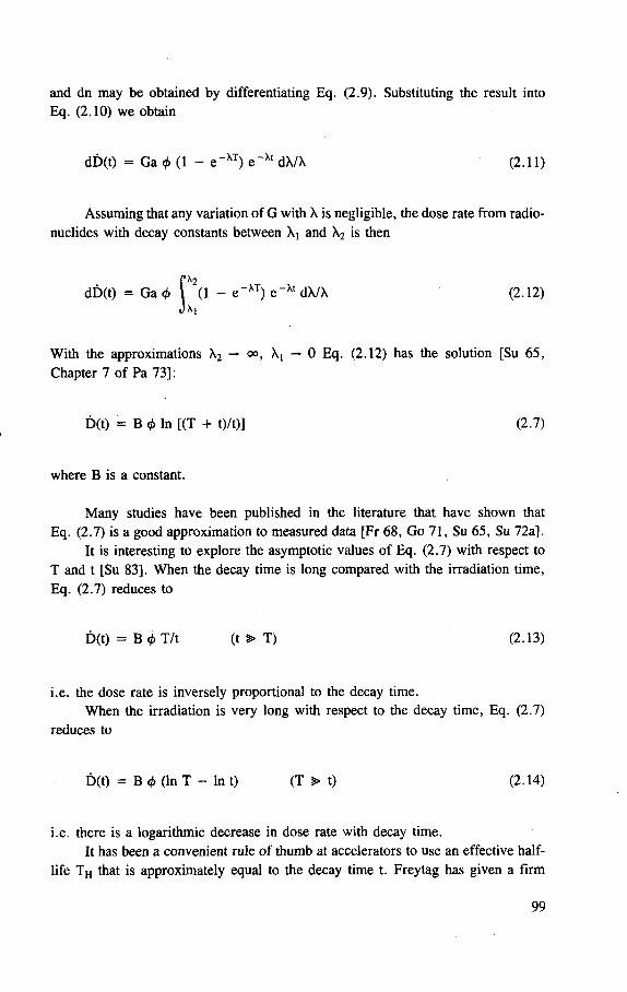
and dn may be obtained by differentiating Eq. (2.9). Substituting the result into Eq. (2.10) we obtain
dD(t) = Ga <f> (1 - e_ X T) e _ X t dX/X (2.11)
Assuming that any variation of G with X is negligible, the dose rate from radio-nuclides with decay constants between X! and X2 is then
Jx2
(1 - e~XT) e _ X t dX/X (2.12) M
With the approximations X2 — <», X! — 0 Eq. (2.12) has the solution [Su 65, Chapter 7 of Pa 73]:
D(t) = B <t> In [(T + t)/t)] (2.7)
where B is a constant.
Many studies have been published in the literature that have shown that Eq. (2.7) is a good approximation to measured data [Fr 68, Go 71, Su 65, Su 72a].
It is interesting to explore the asymptotic values of Eq. (2.7) with respect to T and t [Su 83]. When the decay time is long compared with the irradiation time, Eq. (2.7) reduces to
D(t) = B </> T/t (t ^ T) (2.13)
i.e. the dose rate is inversely proportional to the decay time. When the irradiation is very long with respect to the decay time, Eq. (2.7)
reduces to
D(t) = B <t> (In T - In t) (T > t) (2.14)
i.e. there is a logarithmic decrease in dose rate with decay time. It has been a convenient rule of thumb at accelerators to use an effective half-
life T h that is approximately equal to the decay time t. Freytag has given a firm
99
basis for this rule of thumb [Fr 68]. By differentiating Eq. (2.7) with respect to decay time t we obtain
d[D(t)] x
t2 (1 + T/t) T D(t)
(2.15) dt In (1 + T/t)
Equation (2.15) may be written in terms of an effective half-life TH:
TH = — (1 + T/t) In (1 + T/t) In 2 (2.16)
and by substituting x = T/t
T h = [((1 + x)/x] In (1 + x)] In 2 (2.17)
For values of x — 0, 1 and 10, the corresponding values of effective half-life T h , obtained from Eq. (2.17) are 0.69 t, 1.0 t, and 1.7 t respectively. This result shows the rule of thumb obtained empirically to be quite accurate and can be under-stood on fundamental principles.
2.3.4.1. Dose rate from electrons and positrons
It is most important to determine the dose rate produced by electrons in addi-tion to those produced by photons. This is particularly true when close contact with irradiated materials cannot be avoided, as, for example, during accelerator compo-nent maintenance, or the machining of irradiated materials. There is one important difference between proton accelerator irradiated and reactor irradiated materials in that in the former case positron emitters are much more likely to be produced than in the latter. Doses produced by both positive and negative electrons should therefore be considered.
Sullivan has given a simple discussion to show the magnitude of the dose rate due to electrons [Su 83]. Consider a thin foil irradiated by protons. The dose rate in contact with the foil due to 13 ~ particles D^ is given by
D3 = 1.6 x 10" l° N0 (dE/dx)g Sv-s"1 10 (2.18)
where N^ is the number of 0 ~ particles per square centimetre per second,
(dE/dx)^ is the average stopping power in MeV-g_ 1-cm2 .
100
The corresponding photon dose rate Dy is
D7 = 1.6 x 10~,u/x N t E. 10, Sv's- 1
(2.19)
where N7 is the number of photons emitted per square centimetre per second.
Ey is the average photon energy,
li is the mass energy attenuation coefficient in c m 2 - g - 1 .
The ratio of the dose rates in then given by
For the case NP/NT = 1; (dE/dx)fl = 2 MeV-g~ ' -cm 2 ; Ey = 1 MeV and /x = 0.3 cm 2 -g _ 1 , Eq. (2.20) gives
£ y b 7 « 70
In practice the electron dose rate is not as high as this treatment suggests for several reasons. The self-absorption of even very thin foils considerably reduces the dose due to electrons below that estimated by this simple method. The electron dose is even further reduced in those radionuclides where electron capture is a competing mode of decay. When the electrons emitted have a positive charge, the positrons stopping in the foil emit two annihilation photons of 0.511 MeV.
Sullivan has measured the ratios of doses due to electrons and photons at the surface of metallic foils 0.1 mm thick and reported values for of 12, 7 and 9 for aluminium, steel and copper respectively [Su 82], considerably lower than the value of ~ 7 0 predicted by simple analysis. The actual value of Dg/D7 will be a function of thickness of the irradiated foil. Beyond 0.1 mm it might be expected that the electron dose will increase only slowly with foil thickness but that the photon dose rate will increase almost linearly with thickness. Sullivan predicts that for cop-per or steel foils the electron and photon surface dose rates will be equal at a foil thickness of about 1 mm [Su 83].
The ratio t>0/t)y also clearly depends upon the radionuclide produced in the foils and thus on the irradiation time T and the decay time t. As an example, for aluminium foils the positron emitter 18F (TH = 110 m) is the major contributor to surface dose rates for decay times of less than a few hours. As another example, organic materials (e.g. mylar) when irradiated may produce only positron emitters
(2.20)
101
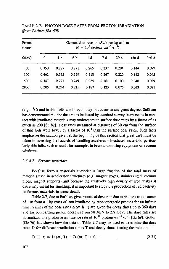
TABLE 2.7. PHOTON DOSE RATES FROM PROTON IRRADIATION (from Barbier [Ba 69])
Proton Gamma dose rates in jiSv/h per kg at 1 m energy (4> = 102 protons-cm~2-s_l)
(MeV) 0 1 h 6 h 1 d 7 d 30 d 180 d 360 d
50 0.350 0.287 0.271 0.265 0.237 0.204 0.144 0.097
100 0.462 0.352 0.329 0.318 0.267 0.220 0.142 0.045
600 0.347 0.271 0.249 0.225 0.161 0.100 0.048 0.029
2900 0.305 0.244 0.215 0.187 0.123 0.075 0.033 0.021
(e.g. UC) and in thin foils annihilation may not occur to any great degree. Sullivan has demonstrated that the dose rates indicated by standard survey instruments in con-tact with irradiated materials may underestimate surface dose rates by a factor of as much as 200 [Su 82]. Dose rates measured at distances of 30 cm from the surface of thin foils were lower by a factor of 104 than the surface dose rates. Such facts emphasize the caution given at the beginning of this section that great care must be taken in assessing the hazards of handling accelerator irradiated materials, particu-larly thin foils, such as used, for example, in beam monitoring equipment or vacuum windows.
2.3.4.2. Ferrous materials
Because ferrous materials comprise a large fraction of the total mass of materials used in accelerator structures (e.g. magnet yokes, stainless steel vacuum pipes, magnet supports) and because the relatively high density of iron makes it extremely useful for shielding, it is important to study the production of radioactivity in ferrous materials in some detail.
Table 2.7, due to Barbier, gives values of dose rate due to photons at a distance of 1 m from a 1 kg mass of iron irradiated by monoenergetic protons for an infinite time. Values of the dose rate (in S v - h - 1 ) are given for decay times up to 360 days and for bombarding proton energies from 50 MeV to 2.9 GeV. The dose rates are normalized to a proton beam fluence rate of 1012 protons-m~2-s~' [Ba 69]. Gollon [Go 76] has shown how the data of Table 2.7 may be used to determine the dose rates D for different irradiation times T and decay times t using the relation
D (T, t) = D (oo, T) - D (oo, T + t) (2.21)
102
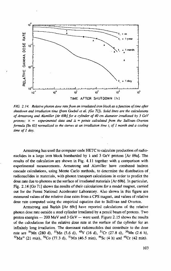
UJ tr
10 10 10
TIME AFTER SHUTDOWN (h)
FIG. 2.14. Relative photon dose rate from an irradiated iron block as a function of time after shutdown and irradiation time (from Goebel et al. [Go 71]). Solid lines are the calculations of Armstrong and Alsmiller [Ar 69b] for a cylinder of 40 cm diameter irradiated by 3 GeV protons; x = experimental data and A = points calculated from the Sullivan-Overton formula [Su 65] normalized to the curves at an irradiation time r, of 1 month and a cooling time of I day.
Armstrong has used the computer code HETC to calculate production of radio-nuclides in a large iron block bombarded by 1 and 3 GeV protons [Ar 69a]. The results of the calculation are shown in Fig. 4.11 together with a comparison with experimental measurements. Armstrong and Alsmiller have combined hadron cascade calculations, using Monte Carlo methods, to determine the distribution of radionuclides in materials, with photon transport calculations in order to predict the dose rate due to photons at the surface of irradiated materials [Ar 69b]. In particular, Fig. 2.14 [Go 71] shows the results of their calculations for a model magnet, carried out for the Fermi National Accelerator Laboratory. Also shown in this figure are measured values of the relative dose rates from a CPS magnet, and values of relative dose rate computed using the empirical equation due to Sullivan and Overton.
Armstrong and Barish [Ar 69c] have reported calculations of the relative photon dose rate outside a steel cylinder irradiated by a pencil beam of protons. Two proton energies — 200 MeV and 3 GeV — were used. Figure 2.15 shows the results of the calculations for the relative dose rate at the surface of the cylinder for an infinitely long irradiation. The dominant radionuclides that contribute to the dose rate are 54Mn (280 d), 52Mn (5.6 d), 48V (16 d), 5ICr (27.8 d), 56Mn (2.6 h), 52Mnm (21 min), 56Co (77.3 d), 51Mn (46.5 min), "Sc (4 h) and 49Cr (42 min).
103
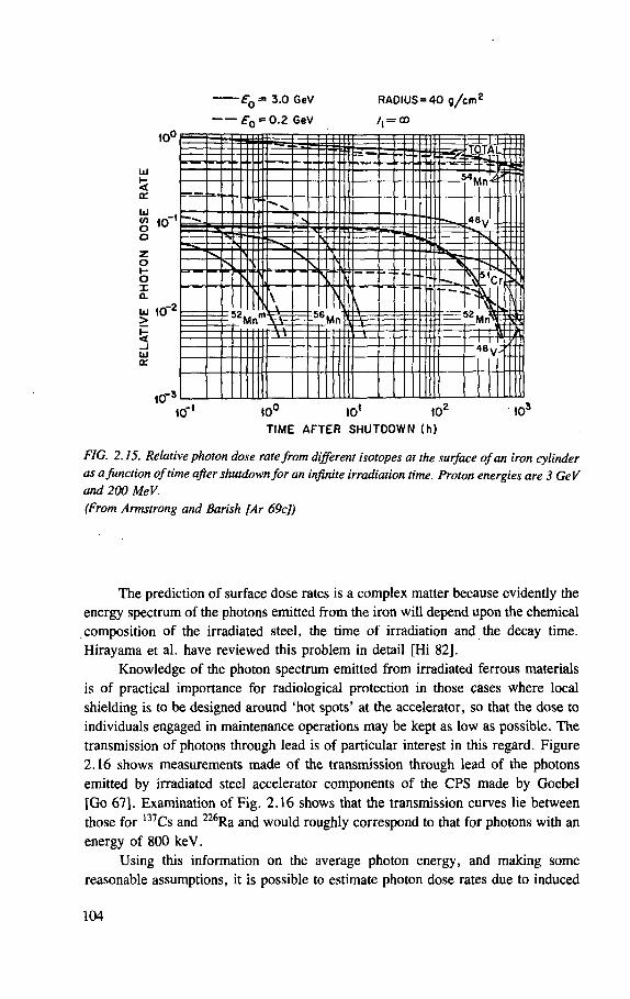
£"0 = 3.0 GeV RADIUS = 40 g/cm2
£ 0 = 0.2 GeV /, = eo
10°
UJ !5 a.
o z o I-o X a. UJ 10"
2
UJ CE
1 0 - "
10"' 10° 10* 102
103
TIME AFTER SHUTDOWN (h)
FIG. 2.15. Relative photon dose rate from different isotopes at the surface of an iron cylinder as a function of time after shutdown for an infinite irradiation time. Proton energies are 3 GeV and 200 MeV. (From Armstrong and Barish [Ar 69c])
The prediction of surface dose rates is a complex matter because evidently the energy spectrum of the photons emitted from the iron will depend upon the chemical composition of the irradiated steel, the time of irradiation and the decay time. Hirayama et al. have reviewed this problem in detail [Hi 82].
Knowledge of the photon spectrum emitted from irradiated ferrous materials is of practical importance for radiological protection in those cases where local shielding is to be designed around 'hot spots' at the accelerator, so that the dose to individuals engaged in maintenance operations may be kept as low as possible. The transmission of photons through lead is of particular interest in this regard. Figure 2.16 shows measurements made of the transmission through lead of the photons emitted by irradiated steel accelerator components of the CPS made by Goebel [Go 67]. Examination of Fig. 2.16 shows that the transmission curves lie between those for 137Cs and 226Ra and would roughly correspond to that for photons with an energy of 800 keV.
Using this information on the average photon energy, and making some reasonable assumptions, it is possible to estimate photon dose rates due to induced
104
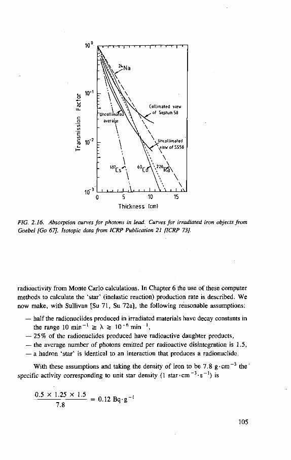
10' 0 5 10 15
Thickness (cm)
FIG. 2.16. Absorption curves for photons in lead. Curves for irradiated iron objects from Goebel [Go 67]. Isotopic data from ICRP Publication 21 [ICRP 73].
radioactivity from Monte Carlo calculations. In Chapter 6 the use of these computer methods to calculate the 'star ' (inelastic reaction) production rate is described. We now make, with Sullivan [Su 71, Su 72a], the following reasonable assumptions:
— half the radionuclides produced in irradiated materials have decay constants in the range 10 m i n - 1 > X > 10~6 m i n - 1 ,
— 25% of the radionuclides produced have radioactive daughter products, — the average number of photons emitted per radioactive disintegration is 1.5, — a hadron 'star ' is identical to an interaction that produces a radionuclide.
With these assumptions and taking the density of iron to be 7.8 g - c m ~ 3 the ' specific activity corresponding to unit star density (1 star• c m - 3 - s " 1 ) is
0 .5 x 1.25 X 1.5
7.8 = 0.12 Bq-g -i
105
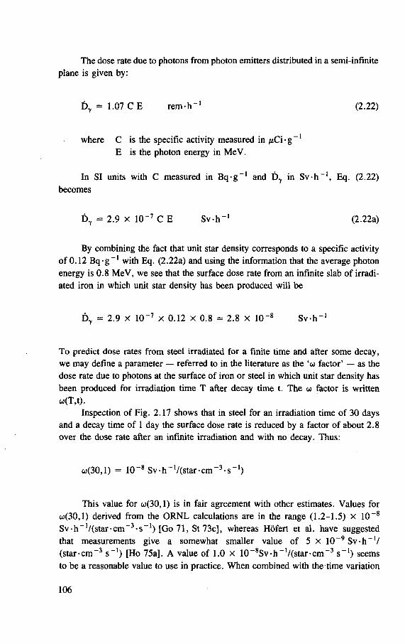
The dose rate due to photons from photon emitters distributed in a semi-infinite plane is given by:
D 7 = 1.07 C E rem-h-1 (2.22)
where C is the specific activity measured in /iCi • g 1
E is the photon energy in MeV.
In SI units with C measured in Bq• g " 1 and D7 in Sv•h ~1, Eq. (2.22) becomes
By combining the fact that unit star density corresponds to a specific activity of 0.12 Bq-g - 1 with Eq. (2.22a) and using the information that the average photon energy is 0.8 MeV, we see that the surface dose rate from an infinite slab of irradi-ated iron in which unit star density has been produced will be
D 7 = 2.9 x 10-7 x 0.12 x 0.8 = 2.8 x 10 -8 Sv-h - 1
To predict dose rates from steel irradiated for a finite time and after some decay, we may define a parameter — referred to in the literature as the factor* — as the dose rate due to photons at the surface of iron or steel in which unit star density has been produced for irradiation time T after decay time t. The co factor is written
Inspection of Fig. 2.17 shows that in steel for an irradiation time of 30 days and a decay time of 1 day the surface dose rate is reduced by a factor of about 2.8 over the dose rate after an infinite irradiation and with no decay. Thus:
w(30,l) = 10 -8 Sv-h_1/(star-cm -3-s -1)
This value for o>(30,l) is in fair agreement with other estimates. Values for w(30,l) derived from the ORNL calculations are in the range (1.2-1.5) x 10 -8
Sv h -1/(star-cm_3-s -1) [Go 71, St 73c], whereas Hofert et al. have suggested that measurements give a somewhat smaller value of 5 x 10~9 Sv-h -1/ (star-cm-3 s - 1 ) [Ho 75a]. A value of 1.0 X 10⁻⁸Sv-h-1/(star-cm-3 s - 1 ) seems to be a reasonable value to use in practice. When combined with the time variation
D7 = 2.9 X 10⁻⁷ C E Sv-h - 1 (2.22a)
co(T.t).
106
1.0 E p = 2.9 GeV
< 2
t t t t t t t Al Ca FeCu Sn W Pb
0.01 0 10 20 30 iO 50 60 70 60 90
ATOMIC NUMBER
FIG. 2.17. Variation of remanent gamma dose rate with atomic number of the irradiated element, from Goebel et al. [Go 71] based on data from Barbier [Ba 69].
formula of Sullivan and Overton, reasonably accurate predictions of photon dose
rates due to remanent radioactivity in steel are possible.
2.3.4.3. Non-ferrous materials
Barbier has comprehensively discussed the induction of radioactivity in non-
ferrous materials [Ba 69]. Figure 2.17 gives examples of the remanent dose rate due
to photons from irradiated elements as a function of atomic number of the element.
The specific example given is for an irradiation by 2.9 GeV protons lasting
5000 days; two decay times are given [Go 71]. Inspection of Fig. 2.17 shows that
the pattern is not widely different for the two decay times shown and that the specific
dose rate (dose rate per unit mass of material) varies in a somewhat irregular way
with atomic number. For elements with atomic number in the range from about 22
to 42 (titanium to molybdenum) there is a tendency for the dose rate per unit mass
of material to increase with atomic number. Thereafter there is a slow but generally
steady decline with increasing number, but Barbier has mentioned that the Rudstam
equation used in his calculations is of limited validity in the high-Z region [Ba 69,
Ru 66]. Of particular note is a region of low specific dose rate for the elements with
107
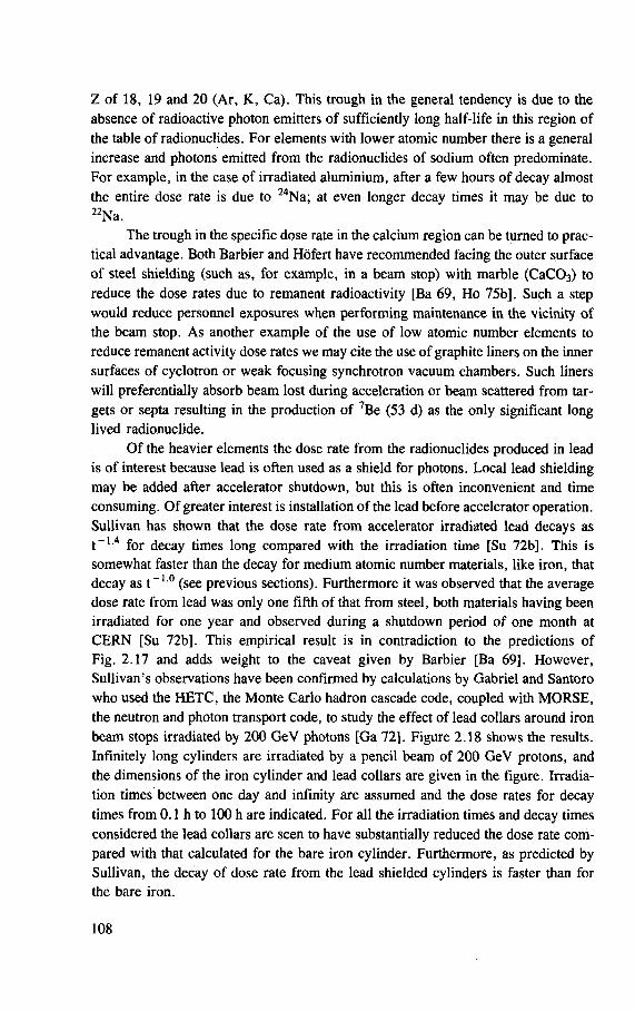
Z of 18, 19 and 20 (Ar, K, Ca). This trough in the general tendency is due to the absence of radioactive photon emitters of sufficiently long half-life in this region of the table of radionuclides. For elements with lower atomic number there is a general increase and photons emitted from the radionuclides of sodium often predominate. For example, in the case of irradiated aluminium, after a few hours of decay almost the entire dose rate is due to 24Na; at even longer decay times it may be due to 22Na.
The trough in the specific dose rate in the calcium region can be turned to prac-tical advantage. Both Barbier and Hofert have recommended facing the outer surface of steel shielding (such as, for example, in a beam stop) with marble (CaC03) to reduce the dose rates due to remanent radioactivity [Ba 69, Ho 75b], Such a step would reduce personnel exposures when performing maintenance in the vicinity of the beam stop. As another example of the use of low atomic number elements to reduce remanent activity dose rates we may cite the use of graphite liners on the inner surfaces of cyclotron or weak focusing synchrotron vacuum chambers. Such liners will preferentially absorb beam lost during acceleration or beam scattered from tar-gets or septa resulting in the production of 7Be (53 d) as the only significant long lived radionuclide.
Of the heavier elements the dose rate from the radionuclides produced in lead is of interest because lead is often used as a shield for photons. Local lead shielding may be added after accelerator shutdown, but this is often inconvenient and time consuming. Of greater interest is installation of the lead before accelerator operation. Sullivan has shown that the dose rate from accelerator irradiated lead decays as t _ L 4 for decay times long compared with the irradiation time [Su 72b]. This is somewhat faster than the decay for medium atomic number materials, like iron, that decay as t - 1 0 (see previous sections). Furthermore it was observed that the average dose rate from lead was only one fifth of that from steel, both materials having been irradiated for one year and observed during a shutdown period of one month at CERN [Su 72b]. This empirical result is in contradiction to the predictions of Fig. 2.17 and adds weight to the caveat given by Barbier [Ba 69]. However, Sullivan's observations have been confirmed by calculations by Gabriel and Santoro who used the HETC, the Monte Carlo hadron cascade code, coupled with MORSE, the neutron and photon transport code, to study the effect of lead collars around iron beam stops irradiated by 200 GeV photons [Ga 72]. Figure 2.18 shows the results. Infinitely long cylinders are irradiated by a pencil beam of 200 GeV protons, and the dimensions of the iron cylinder and lead collars are given in the figure. Irradia-tion times between one day and infinity are assumed and the dose rates for decay times from 0.1 h to 100 h are indicated. For all the irradiation times and decay times considered the lead collars are seen to have substantially reduced the dose rate com-pared with that calculated for the bare iron cylinder. Furthermore, as predicted by Sullivan, the decay of dose rate from the lead shielded cylinders is faster than for the bare iron.
108
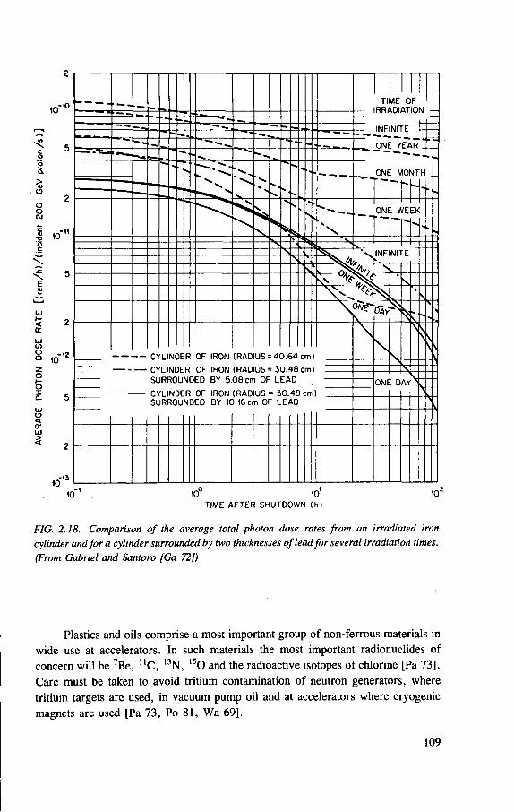
FIG. 2.18. Comparison of the average total photon dose rates from an irradiated iron cylinder and for a cylinder surrounded by two thicknesses of lead for several irradiation times. (From Gabriel and Santoro [Ga 72])
Plastics and oils comprise a most important group of non-ferrous materials in wide use at accelerators. In such materials the most important radionuclides of concern will be 7Be, " C , 13N, 1 5 0 and the radioactive isotopes of chlorine [Pa 73]. Care must be taken to avoid tritium contamination of neutron generators, where tritium targets are used, in vacuum pump oil and at accelerators where cryogenic magnets are used [Pa 73, Po 81, Wa 69].
109
In addition to the radioactivity induced in solid materials, care must be taken to avoid contamination from radioactive dust, chips and filings. In general the radio-logical hazard in accelerator areas from these sources is negligible when compared with that from the external radiological hazard from close-by radioactive accelerator components. Patterson and Thomas have summarized experience with dust activa-tion (Chapter 7 of Ref. [Pa 73]). Baarli et al. indicate that, as expected, the radio-activity in dust closely correlates with the dose rates from the remanent activity in near by accelerator components [Ba 66]. The radionuclides most commonly found are 7Be, 48V, 51Cr, 56Mn and 59Fe, with 54Mn alone accounting for more than 40% of the total activity [Ba 66, Ch 67]. When heavy element targets or shields are used, heavier radionuclides are also observed. Thus, for example, Patterson et al. have reported finding 181W and 237Np in accelerator areas [Pa 69] and Kitao and Ohata have measured 138Re, 184Re, 1850s and 182Ta in dust in cyclotron areas [Ki 71],
2.3.4.4. Concrete
Most if not all accelerators are housed in concrete rooms or are surrounded by concrete shielding blocks. Constituent particles of the electromagnetic and hadronic cascades generated in the accelerator structure may cross the air gap and enter the concrete, inducing radioactivity in the shielding. The fraction of water (a few per cent) present in all concrete provides sufficient hydrogen to slow down evaporation neutrons to thermal energies. These thermal neutrons may leak back into the accelerator room, resulting in significant thermal neutron fluence rates. Experience shows that in the accelerator vault the thermal neutron fluence rates are comparable to the fluence rates of neutrons of about 1 MeV in energy [Pa 58, Pa 73]. Radioactivity may be induced in the concrete walls by both the thermal and fast neu-trons, but as we shall show, the thermal neutron capture usually dominates the production of radionuclides that are important in the short term.
Unlike many of the materials used in the accelerator structure such as aluminium, copper and iron, concrete is a heterogeneous substance whose chemical composition may vary widely (see, for example, Ref. [IAEA 75]). Nevertheless many experimental studies show that one radionuclide, 24Na, usually dominates the radiation field at the surface of concrete irradiated in accelerator environments [deS 62b, Gi 64a,b,c, Gi 65, Mi 65, Na 66]. These empirical conclusions have been con-firmed by calculation [Ar 69d, Ar 70]. For example, Armstrong and Barish [Ar 70] show that 10 minutes after accelerator shutdown the dose rate due to 24Na is about 20 times that from all other radionuclides (7Be, UC, l3N, 22Na, 34C1 and 38K). One hour from shutdown this ratio has increased to about 100. Calculations by Armstrong and Barish suggest that at about 100 hours after accelerator shutdown the dose rates produced by induced radioactivity are almost entirely due to the radionuclides induced in the accelerator structure.
110
The 2 4Na in concrete is principally formed by thermal neutron capture in the
elemental sodium present in the cement and aggregate. Although 2 4Na may also be
formed in spallation reactions in constituents of the concrete, experience shows that
the (n, 7 ) reaction is the most important contributor. Thus for an aggregate contain-
ing 1 % sodium by weight Armstrong and Barish calculate that 25 times as much 24Na activity is produced by thermal neutron capture in 23Na as from all spallation
reactions [Ar 70], Gilbert et al. estimated that from 50% to 90% of the 2 4Na was
produced by the (n, 7 ) reaction in several aggregates studied [Gi 69].
It is important to have some understanding of the magnitude of the dose rates
produced by the decay of induced radioactivity in accelerator rooms. It may be read-
ily shown that the dose rate due to remanent radioactivity inside a cylindrical void
whose walls have been uniformly irradiated will be independent of position within
the void and equal to the dose rate at the inner wall of the shield. Superimposed on
the uniform field will be the radiation level produced by the decay of radioactivity
induced in the accelerator structure [Ar 70, Pa 73]. Gilbert and Thomas have
reported measurements made in the accelerator tunnel of the Brookhaven National
Laboratory A G S and determined that some 6 hours after accelerator shutdown the
uniform dose rate inside the tunnel due to concrete was about 10 / t Sv -h - 1
(1 mrem-h - 1 ) [Gi 65]. Armstrong and Barish made calculations for a simulated
3 GeV proton accelerator magnet situated in a concrete walled tunnel of 2 m radius.
The accelerator magnet was represented by a solid iron cylinder of about 20 cm
radius (160-g cm - 2 ) . The dose equivalent rate due to induced activation from a uni-
form beam in the concrete some 6 minutes after shutoff was 1.5 x 10~13 S v - h - 1
per primary proton interaction per metre per second. This value may be scaled
linearly with primary proton energy and the dose rate will decay with the 15 hour
half-life of 24Na. Thus for a 30 GeV proton synchrotron of radius 100 m operating
at 1013 protons per second in which 1% of the beam is distributed uniformly the
radiation level due to 2 4Na induced in the concrete would be
,, 30 10 - 2 x 10¹³ , . 1.5 x 10 - 1 3 x — x = 2.5 x 10 - 4 Sv -h
3 2ir x 100
The dominance of 2 4Na in contributing to the short term radiation levels from
concrete and the mechanisms by which it is produced offer some possibility for
amelioration. It will not, in general, be cost effective to take steps to reduce the 24Na levels if entry into the accelerator room will take place some considerable time
after shutdown. Thus, as we have seen, after 100 hours, the residual radiation levels
will be dominated by the accelerator structure and even after 24 hours the dose rate
from the concrete activity will equal or be smaller than the dose rate from the magnet
iron [Ar 70, St 76], The problems posed by induced activity in the concrete for long
term access to accelerators are therefore usually trivial.
I l l
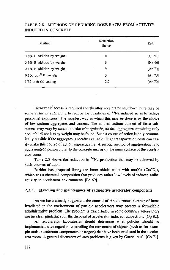
TABLE 2.8. METHODS OF REDUCING DOSE RATES FROM ACTIVITY INDUCED IN CONCRETE
Method Reduction Ref. Method factor Ref.
0.8% B addition by weight 10 [Gi 69]
0.3% B addition by weight 3 [Na 66]
0.1 % B addition by weight 9 [Ar 70]
0.166 g/m2 B coating 3 [Ar 70]
1/32 inch Cd coating 2.7 [Ar 70]
However if access is required shortly after accelerator shutdown there may be some virtue in attempting to reduce the quantities of 24Na induced so as to reduce personnel exposures. The simplest way in which this may be done is by the choice of low sodium aggregates and cement. The natural sodium content of these sub-stances may vary by about an order of magnitude, so that aggregates containing only about 0.1% sodium by weight may be found. Such a course of action is only econom-ically feasible if the aggregate is locally available. High transportation costs can eas-ily make this course of action impracticable. A second method of amelioration is to add a neutron poison either to the concrete mix or on the inner surface of the acceler-ator room.
Table 2.8 shows the reduction in 24Na production that may be achieved by such courses of action.
Barbier has proposed lining the inner shield walls with marble (CaC03), which has a chemical composition that produces rather low levels of induced radio-activity in accelerator environments [Ba 69].
2.3.5. Handling and maintenance of radioactive accelerator components
As we have already suggested, the control of the enormous number of items irradiated in the environment of particle accelerators may present a formidable administrative problem. The problem is exacerbated in some countries where there are no clear guidelines for the disposal of accelerator induced radioactivity [Op 82].
All accelerator laboratories should determine what policies should be implemented with regard to controlling the movement of objects (such as for exam-ple tools, accelerator components or targets) that have been irradiated in the acceler-ator room. A general discussion of such problems is given by Goebel et al. [Go 71].
112
Details of the practical control of radioactive materials during the decommissioning of a facility at a large high energy research laboratory are given by Schonbacher and Tavlet [Sc 85] while Chapter 5 of this report describes an administrative control programme suitable for a large multidisciplinary research laboratory using particle accelerators. Stewart discusses the general aspects of controlling contamination from the use of radioactive materials in national laboratories [St 81].
A convenient rule of thumb for assessing the dose rate to be expected from gamma emitting irradiated materials is to remember that the dose rate D in a cavity surrounded by a uniform distribution of radioactivity is given by
D = 2.14 C E rad-h"1 (2.23)
where C is the specific activity measured in ^Ci-g~' and E is the gamma ray energy in MeV. Thus for photon energies of a little less than 1 MeV the dose rate in contact with a large slab of material (half that given by Eq. (2.23)) will be about C rad-h_ 1 . Caution must be exercised in the use of this simple rule of thumb for two reasons: firstly, it is often necessary to handle small radioactive objects when surface dose rates may be more than a factor of 10 higher than that from a large object of the same specific activity and, secondly, the presence of soft X-rays or beta particles may increase the radiation field intensity by sometimes as much as a factor of 100 [Sc 70].
It is not uncommon for the surface dose rate of objects placed in or near high intensity accelerator beams to exceed tens or even hundreds of rads per hour. It is advisable to minimize the need for maintenance in such regions by adequate design and to provide adequate means of remote handling to perform any necessary main-tenance. Early studies at the Argonne and Brookhaven national laboratories [F1 65, Go 65] have led to sophisticated equipment at high intensity, high energy laboratories such as CERN and LAMPF [Bu 77, El 71, Ho 75c,d, Ho 78]. Ellefsplass, Home and Madsen have given an excellent summary of the use of remote handling equip-ment in accelerators, to which the reader is referred for further information [El 71],
2.3.6. Disposal of radioactive accelerator components
Perhaps the most extensive study of the scope of the problems involved in the disposal of unwanted particle accelerators has been made at the Argonne National Laboratory by Opelka and his colleagues [Op 82], This study was occasioned by the closing of the Zero Gradient Synchrotron (ZGS) but its scope was expanded to include an assessment of the problem of accelerator disposal within the United States. Although the report deals with the particular problems of one country much of its discussion is of general relevance.
113
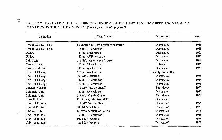
TABLE 2.9. PARTICLE ACCELERATORS WITH ENERGY ABOVE 1 MeV THAT HAD BEEN TAKEN OUT OF OPERATION IN THE USA BY MID-1978 (from Opelka et al. [Op 82])
Institution Identification Disposition Year
Brookhaven Natl Lab. Cosmotron (3 GeV proton synchrotron) Dismantled 1966
Brookhaven Natl Lab. 18 in. FF cyclotron Dismantled 1963
UCLA 41 in. synchrotron Dismanded 1961
UCLA 50 in. AVF cyclotron Dismantled 1973 Cal. Tech. 1.1 GeV electron synchrotron Dismantled 1968
Carnegie Inst. 60 in. FF cyclotron Stored 1955
Carnegie Mellon 141 in. synchrotron Dismantled 1973 Univ. of Chicago 170 in. synchrotron Partially dismantled Univ. of Chicago 100 MeV betatron Dismantled 1955 Univ. of Chicago 32 in. FF cyclotron Dismantled 1944
Univ. of Chicago 170 in. FF cyclotron Dismantled 1971
Chicago Nuclear 3 MV Van de Graaff Shut down 1972
Columbia Univ. 37 in. FF cyclotron Dismantled 1965 Columbia Univ. 5.5 MV Van de Graaff Shut down 1970
Cornell Univ. Electron synchrotron (CES) Dismantled Univ. of Florida 1 MV Van de Graaff Dismantled 1965
General Electric 100 MeV betatron Dismantled 1973
Harvard Univ. Electron accelerator (CEA) Dismantled 1973 Univ. of Illinois 50 in. FF cyclotron Dismantled 1968 Univ. of Illinois 300 MeV betatron Dismantled 1968 Univ. of Illinois 25 MeV betatron Dismantled 1972
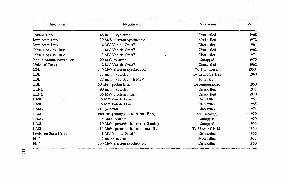
Institution Identification Disposition Year
Indiana Univ. 45 in. FF cyclotron Dismantled 1968 Iowa State Univ. 70 MeV electron synchrotron Mothballed 1972
Iowa State Univ. 4 MV Van de Graaff Dismantled 1964
Johns Hopkins Univ. 1 MV Van de Graaff Dismantled 1962
Johns Hopkins Univ. 3 MV Van de Graaff Dismantled 1974
Knolls Atomic Power Lab. 100 MeV betatron Scrapped 1970
Univ. of Texas 2 MV Van de Graaff Dismantled 1962
LBL 340 MeV electron synchrotron To Smithsonian 1960
LBL 32 in. FF cyclotron To Lawrence Hall 1940
LBL 27 in. FF cyclotron, 6 MeV To museum LBL 30 MeV proton linac Decommissioned 1960
LLNL 90 in. FF cyclotron Dismantled 1971 LLNL 35 MeV electron linac Dismantled 1970 LASL 2.5 MV Van de Graaff Dismantled 1963 LASL 2.5 MV Van de Graaff Dismantled 1965 LASL FF cyclotron Dismantled 1974
LASL Electron prototype accelerator (EPA) Shut down(?) - 1 9 7 0
LASL 15 MeV betatron Scrapped - 1 9 7 0
LASL 10 MeV 'portable' betatron (10 units) Scrapped 1955
LASL 10 MeV 'portable' betatron, modified To Univ. of N . M . 1960
Louisiana State Univ. 1 MV Van de Graaff Dismantled 1966
MIT 42 in. FF cyclotron Mothballed , 1973 MIT 300 MeV electron synchrotron Dismantled 1960
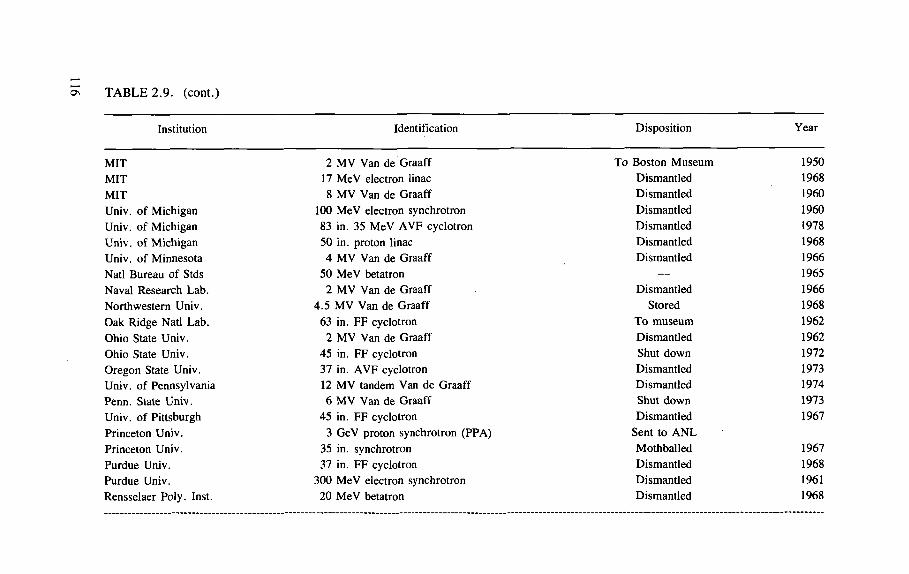
TABLE 2.9. (cont.)
Institution Identification Disposition Year
MIT 2 MV Van de Graaff To Boston Museum 1950
MIT 17 MeV electron linac Dismantled 1968
MIT 8 MV Van de Graaff Dismantled 1960
Univ. of Michigan 100 MeV electron synchrotron Dismantled 1960
Univ. of Michigan 83 in. 35 MeV AVF cyclotron Dismantled 1978
Univ. of Michigan 50 in. proton linac Dismantled 1968 Univ. of Minnesota 4 MV Van de Graaff Dismantled 1966
Natl Bureau of Stds 50 MeV betatron — 1965
Naval Research Lab. 2 MV Van de Graaff Dismantled 1966
Northwestern Univ. 4 .5 MV Van de Graaff Stored 1968
Oak Ridge Natl Lab. 63 in. FF cyclotron To museum 1962
Ohio State Univ. 2 MV Van de Graaff Dismantled 1962
Ohio State Univ. 45 in. FF cyclotron Shut down 1972
Oregon State Univ. 37 in. AVF cyclotron Dismantled 1973
Univ. of Pennsylvania 12 MV tandem Van de Graaff Dismantled 1974
Penn. State Univ. 6 MV Van de Graaff Shut down 1973
Univ. of Pittsburgh 45 in. FF cyclotron Dismantled 1967
Princeton Univ. 3 GeV proton synchrotron (PPA) Sent to A N L Princeton Univ. 35 in. synchrotron Mothballed 1967
Purdue Univ. 37 in. FF cyclotron Dismantled 1968
Purdue Univ. 300 MeV electron synchrotron Dismantled 1961
Rensselaer Poly. Inst. 20 MeV betatron Dismantled 1968
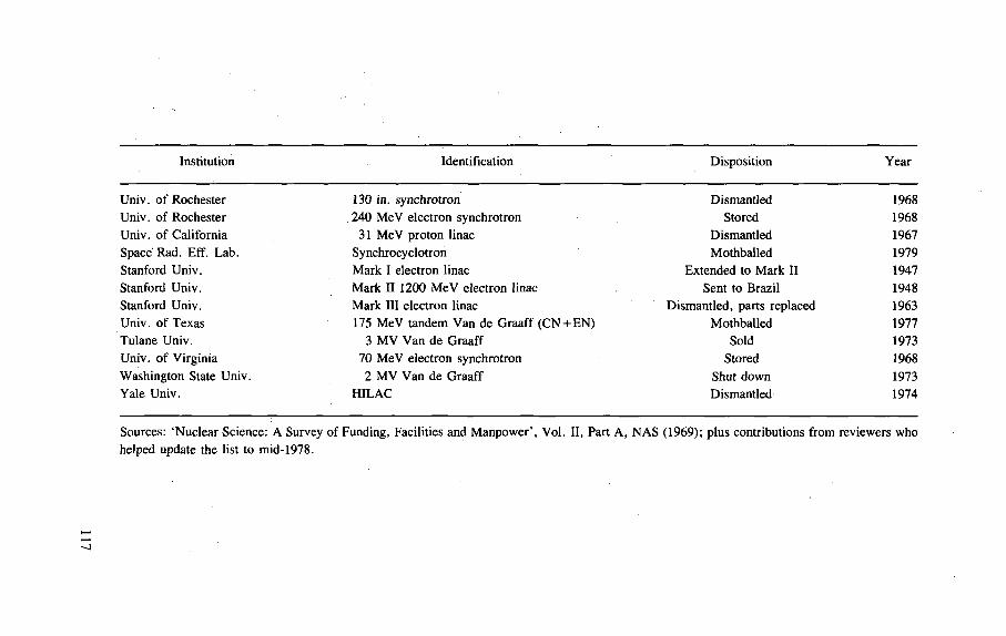
Institution Identification Disposition Year
Univ. of Rochester 130 in. synchrotron Dismantled 1968 Univ. of Rochester . 240 MeV electron synchrotron Stored 1968 Univ. of California 31 MeV proton linac Dismantled 1967 Space Rad. Eff. Lab. Synchrocyclotron Mothballed 1979 Stanford Univ. Mark I electron linac Extended to Mark II 1947 Stanford Univ. Mark II 1200 MeV electron linac Sent to Brazil 1948 Stanford Univ. Mark III electron linac Dismantled, parts replaced 1963 Univ. of Texas 175 MeV tandem Van de Graaff ( C N + E N ) Mothballed 1977 Tulane Univ. 3 MV Van de Graaff Sold 1973 Univ. of Virginia 70 MeV electron synchrotron Stored 1968 Washington State Univ. 2 MV Van de Graaff Shut down 1973 Yale Univ. HILAC Dismantled 1974
Sources: 'Nuclear Science: A Survey of Funding, Facilities and Manpower', Vol. II, Part A, N A S (1969); plus contributions from reviewers who helped update the list to mid-1978.
The Argonne study begins with a brief review of accelerator technology simi-lar in scope to that given in Chapter 1 of this report. This is followed by a history of particle accelerator decommissioning in the USA, a discussion of the appropriate US regulations and details of how to plan for and estimate the cost of particle acceler-ator decommissioning. Nine appendices include a census of US particle accelerators and details of various aspects of decommissioning.
The report classifies accelerator components into three categories based on expected levels of induced activity:
(1) "Those components or materials that were either directly struck by the accelerated-particle beam or in proximity to those points of beam interaction will contain the highest levels of induced activity. Examples of these types of components are targets, target holders and positioning mechanisms, beam stops, collimators and beam-defining slits, extraction magnets and channels, beam pipes or inner chambers, and local shields around targets and slits.
(2) Components that are part of the accelerator itself, and nearby auxiliary items that are subjected to irradiation by the scattered beam or secondary particles (neutrons, protons, etc.), will in general have lower concentrations of induced activity but may be suspected of having radiation levels similar to those of materials in the proximity category. Examples of these items are electrostatic shields, cyclotron vacuum chambers, magnet pole tips (cyclotrons), magnet windings, bending and focussing magnets, synchrotron magnets and coils, and linac drift tubes.
(3) A third general category includes materials used in the building structure housing the accelerator facility and any other similar materials having been subjected to low level neutron irradiation. The residual induced activity in these types of materials would generally be of extremely low concentration, if any exists at all. Examples of these types of material are floors and walls of accelerator vaults (concrete), support structures (steel, concrete), cyclotron magnet yokes (steel), shielding blocks (iron, concrete, lead), earth surrounding underground vaults, and any materials or components located within the vault." [Op 82]
This classification enables decisions to be made as to the deployment of appropriate levels of health physics surveillance in the absence of precise knowledge of either the specific activity or surface dose rate for the materials to be handled. Detailed information from radiation surveys on operating accelerators, such as that given in Table 2.6, is extremely useful in this regard, as is experience obtained from past decommissionings.
Opelka et al. have reported that 81 particle accelerators of energy above 1 MV had been taken out of operation in the USA by mid-1978 and these are listed in Table 2.9.
118
Of these accelerators, Opelka et al. selected five decommissionings for detailed study: the two synchrocyclotrons of the Carnegie Mellon University and the University of Rochester, the HILAC of Yale University and the 5 GeV Cambridge Electron Accelerator. Details are given in Ref. [Op 82] but features common to all decommissionings were apparent: useful equipment and components, even if some radioactivity was exhibited, were salvaged and put to other use.
Opelka et al. suggest four alternatives for accelerator decommissioning:
— mothballing — entombment — dismantling with storage of components — dismantling with disposal of components.
"Mothballing would involve a general cleanup around the accelerator, with loose contamination packaged for disposal. Following cleanup, access to the acceler-ator would be prohibited by blocking all entrances. Entombment would be similar to mothballing with the additional step of sealing all accesses to the accelerator with concrete. Because there is a relatively small amount of induced activity with short half-lives, a marked difference between decommissioning of an accelerator and that of other radioactive facilities (such as nuclear reactors) is the potential recycle of the accelerator-component materials. This reuse potential is directly addressed in the option of dismantling the accelerator and placing components in retrievable storage for a period of time to allow for radioactive decay. On dismantlement, the only components that would require storage are the potentially valuable ones not immedi-ately claimed by other accelerator facilities for reuse. The option of dismantlement with disposal of all radioactive material, as addressed in this report, assumes no recy-cle of accelerator components and, therefore, gives an upper bound on the magnitude of the problem both in terms of cost and quantities of radioactive waste.
In most cases, the induced radioactivity is confined to relatively few parts of the machine, and disposition of these parts (assuming no recycle potential) is through normal radioactive-waste channels without complication. The radioactivity is gener-ally low level (less than 100 R/h at the surface) and has a short half-life (5.26 years for mCo). The waste-disposal problem is complicated because most research accelerators leave a legacy of low level induced radioactivity in massive components (10 to 1000 Mg). Examples of such items are large magnets, shield blocks, beam stops of concrete, earth, or iron, and even the walls and floors of the building itself. These massive components need to be dealt with in a manner so as to pose no poten-tial health hazards to persons in the vicinity or the public at large." [Op 82]
Typical quantities of radioactive waste that would have to be disposed of from some 30 particle accelerators are summarized in Table 2.10.
Given such information it is possible to prepare cost estimates for the various options for decommissioning, and this Opelka et al. have done for four accelerators at the Argonne National Laboratory. Their results for the case where it is assumed
119
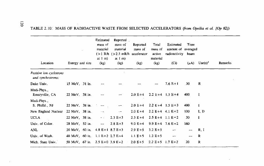
T A B L E 2 . 1 0 . M A S S O F R A D I O A C T I V E W A S T E F R O M S E L E C T E D A C C E L E R A T O R S (from Opelka et al. [Op 82])
Estimated Reported . mass of mass of Reported material material mass of ( > 1 R/h ( > 2 . 5 mR/h accelerator at 1 m) at 1 m)
Location Energy and size (kg) (kg) (kg)
Total Estimated Time mass of amount of averaged active radioactivity beam
material (kg) (Ci) (/t A) Use(s)a Remarks
Positive ion cyclotrons and synchrotrons:
Duke Univ. 15 MeV, 31 in.
Medi-Phys., Emeryville, CA 22 MeV, 38 in.
Medi-Phys., S. Plnfld., NJ 22 MeV, 38 in.
New England Nuclear 22 MeV, 38 in.
UCLA 22 MeV, 38 in.
Univ. of Color. 28 M e V , 52 in.
A N L 20 MeV, 60 in.
Univ. of Wash. 40 MeV, 60 in.
Mich. State Univ. 50 MeV, 67 in.
2 .0 E + 4
— — 2.0 E + 4
— — 2.0 E + 4
— 2.3 E + 3 2.3 E + 4
— 2.8 E + 3 9 .0 E + 4
4 .8 E + l 8.7 E + 3 2.9 E + 5
1.1 E + 2 2.7 E + 4 1.1 E + 5
2.5 E + 0 3.9 E + 2 2 .0 E + 5
— 7 .6 E + l 30 R
2 .2 E + 4 1.5 E + 4 400 I
2 .2 E + 4 1.5 E + 3 400 I
2 .2 E + 4 4.1 E + 2 100 I, D
2.5 E + 4 1.1 E + 2 30 I
9 .9 E + 4 7 . 6 E + 2 160
3.2 E + 5 — — R, I
1.2 E + 5 — — R
2.2 E + 5 1.7 E + 2 20 R
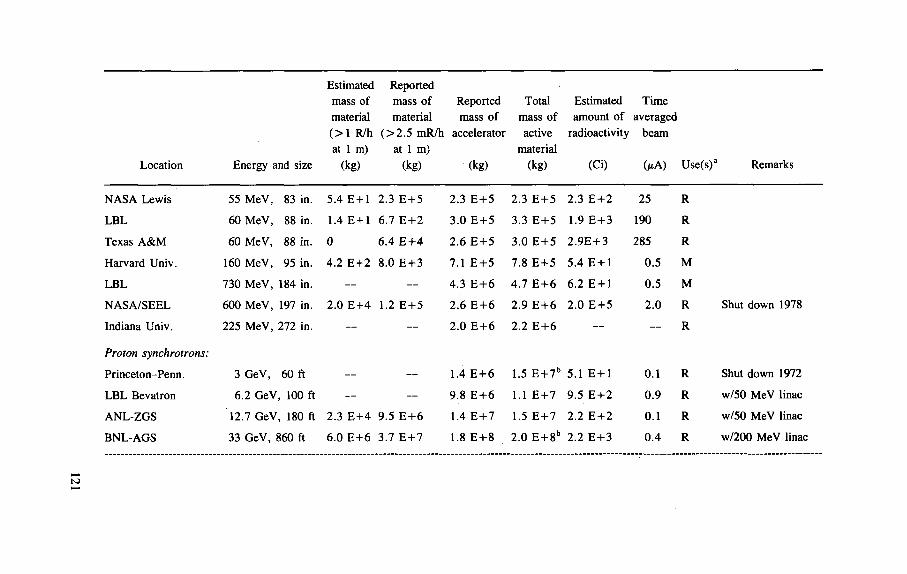
Estimated Reported mass of mass of Reported Total Estimated Time material material mass of mass of amount of averaged ( > 1 R/h ( > 2 . 5 mR/h accelerator active radioactivity beam at 1 m) at 1 m) material
Location Energy and size (kg) (kg) (kg) (kg) (Ci) ( M ) Use(s)a 1 Remarks
NASA Lewis 55 MeV, 83 in. 5 .4 E + l 2 .3 E + 5 2 .3 E + 5 2 .3 E + 5 2 .3 E + 2 25 R
LBL 60 MeV, 88 in. 1.4 E + l 6 .7 E + 2 3 .0 E + 5 3 .3 E + 5 1.9 E + 3 190 R
Texas A&M 60 MeV, 88 in. 0 6 .4 E + 4 2 . 6 E + 5 3 .0 E + 5 2 .9E + 3 285 R
Harvard Univ. 160 MeV, 95 in. 4 .2 E + 2 8 .0 E + 3 7.1 E + 5 7 .8 E + 5 5 .4 E + l 0 .5 M
LBL 730 MeV, 184 in. — — 4 .3 E + 6 4 .7 E + 6 6 .2 E + l 0 .5 M
NASA/SEEL 600 MeV, 197 in. 2 .0 E + 4 1.2 E + 5 2 .6 E + 6 2 .9 E + 6 2 .0 E + 5 2 .0 R Shut down 1978
Indiana Univ. 225 MeV, 272 in. — — 2.0 E + 6 2 .2 E + 6 — — R
Proton synchrotrons:
Princeton-Penn. 3 GeV, 60 ft — — 1.4 E + 6 1.5 E + 7 b 5.1 E + l 0.1 R Shut down 1972
LBL Bevatron 6.2 GeV, 100 ft — — 9.8 E + 6 1.1 E + 7 9 .5 E + 2 0 . 9 R w/50 MeV linac
ANL-ZGS 12.7 GeV, 180 ft 2 .3 E + 4 9 .5 E + 6 1.4 E + 7 1.5 E + 7 2 .2 E + 2 0.1 R w/50 MeV linac
BNL-AGS 33 GeV, 860 ft 6 .0 E + 6 3.7 E + 7 1.8 E + 8 2 .0 E + 8b 2.2 E + 3 0 . 4 R w/200 MeV linac
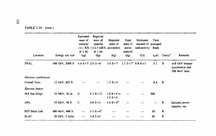
TABLE 2.10. (cont.)
Estimated Reported mass of mass of Reported Total Estimated Time material material mass of mass of amount of averaged ( > 1 R/h ( > 2 . 5 mR/h accelerator active radioactivity beam at 1 m) at 1 m) material
Location Energy and size (kg) (kg) (kg) (kg) (Ci) (MA) Use(s)a 1 Remarks
FNAL 400 GeV, 5000 ft 4 . 6 E + 5 2 .0 E + 6 1.0 E + 7 1.1 E + 7 C 6 .8 E + 3 0.1 R w/8 GeV booster synchrotron and 200 MeV linac
Electron synchrotron:
Cornell Univ. 12 GeV, 820 ft — — 1.3 E + 5 — — 0 .8 R
Electron linacs:
IRT San Diego 35 MeV, 30 in. 0 4 .3 E + 1 2 1.0 E + 4 to — — 500 1.0 E + 5
A N L 35 MeV, 30 ft 0 4 .0 E + l 4 .0 E + 4 d — — — R Includes power
supplies, etc.
MIT Bates Lab. 400 MeV, 600 ft — 5.5 E + 4 d — — — 30 R
SLAC 20 GeV, 2 miles — 3.4 E + 5 — — — 30 R
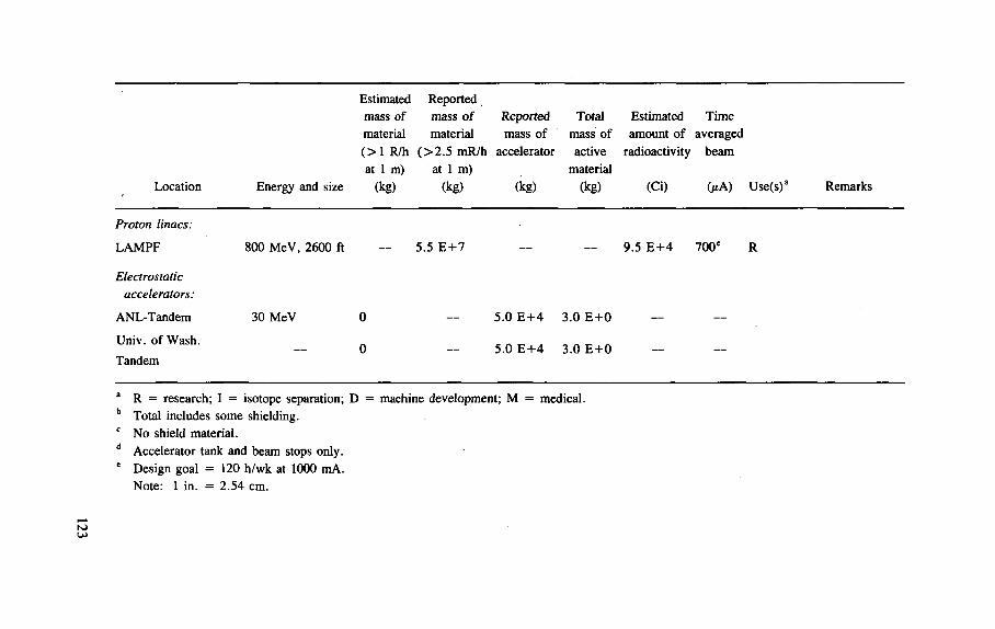
Estimated Reported mass of mass of Reported Total Estimated Time material material mass of mass of amount of averaged ( > 1 R/h ( > 2 . 5 mR/h accelerator active radioactivity beam at 1 m) at 1 m) material
Location Energy and size (kg) (kg) (kg) (kg) (Ci) G*A) Use(s)a Remarks
Proton linacs:
LAMPF 800 MeV, 2600 ft — 5.5 E + 7 — — 9.5 E + 4 700 e R
Electrostatic accelerators:
ANL-Tandem 30 MeV 0 — 5 .0 E + 4 3 .0 E + 0 — —
Univ. of Wash.
Tandem — 0 — 5 .0 E + 4 3 .0 E + 0 — —
a R = research; I = isotope separation; D = machine development; M = medical. b Total includes some shielding. c N o shield material. d Accelerator tank and beam stops only. e Design goal = 120 h/wk at 1000 mA.
Note: 1 in. = 2 .54 cm.
TABLE 2.11. ESTIMATED COSTS OF DISMANTLEMENT AND IMMEDIATE DISPOSAL OF FOUR PROTOTYPIC ACCELERATORS (1978 thousands US $) (from Opelka et al. [Op 82])
Facility Dismantling Packaging Transportation Disposal Total3
ZGS 3700 410 1000 290 6300 60 in. cyclotron 800 40 200 600 1300 22 MeV electron linac 60 0.5 2 0.7 80 Tandem Van de Graaff 100 0.5 2 0.7 140 a Sum of dismantling, packaging, transportation, disposal and a 25% contingency factor for
all activities.
that the accelerator will be dismantled and all components immediately disposed of are shown in Table 2.11.
Of the remaining three options for accelerator decommissioning proposed by Opelka et al., entombment does not appear warranted from the quantities of radio-activity generated and the maximum surface dose rates encountered. The other three options have been utilized both in the United States and elsewhere [St 85b],
Opelka et al. recommend the development of national guidelines for the recy-cling of valuable materials such as those used in accelerator components containing induced radioactivity. To date this has not been done.
R E F E R E N C E S
AARNIO, P. A., RANFT, J., STEVENSON, G.R., A Long Write-up of the FLUKA82 Program, Rep. TIS-RP/106, CERN, Geneva (1983). AARNIO, P.A., RANFT J., STEVENSON, G.R., First Up-date of FLUKA82 Including Particle Production with a Multi-Chain Fragmentation Model (EVENTQ), Rep. TIS-RP/129, CERN, Geneva (1984). ALSMILLER, R.G., Jr., ARMSTRONG, T.W., COLEMAN, W.A., The absorbed dose and dose equivalent from neutrons in the energy range 60 to 3,000 MeV and protons in the energy range 400 to 3,000 MeV, Nucl. Sci. Eng. 42 (1970) 367. ALEINIKOV, V.E., GERDT, V.P., TIMOSHENKO, G.N., Measurement of Spectra of High-Energy Protons Generated in the Shielding of a 680 MeV Synchrocyclotron, Rep. JINR-P16-9400, Joint Institute of Nuclear Research, Dubna (1975).
124
[Aa 83] [Aa 84]
[Al 70]
[Al 75]
[Al 79] ALEINIKOV, V.E. , KOMOCHKOV, M . M . , KRILOV, A.R. , TIMOSHENKO, G.N. , HAHN, G., The Energy Angle Distributions of the Proton Component of the Radiation Field Behind the 660-MeV Synchro-cyclotron Shielding, Preprint 16-12732, Joint Institute for Nuclear Research, Dubna (1979).
[Al 85] ALEINIKOV, V.E. , CHEREVATENKO, A.P. , CLAPIER, F.B. , TSOFBUN, V.I. , Neutron radiation field due to 6 .6 MeV/amu 58Ni beams bombarding a thick Cu target, Radiat. Prot. Dosim. 11 (1985) 245.
[An 78] ANTIPOV, V .A . , BAJSHEV, I.S. , GOLOVACHIK, V.T. , KRUPNYJ, G.I., KUSTAREV, V .M. , LEBEDEV, V .N . , HOEFERT, M. , Comparison of Dose Equivalent Measurements behind the IHEP Accelerator Shielding Using Different Methods, Rep. IFVEORI 78-15, Institute of High Energy Physics, Serpukhov (1978) (in Russian) (Available in English translation by HODGE, B.C. , as CERN Rep. TRANS 78-01).
[ANSI 70] AMERICAN NATIONAL STANDARDS INSTITUTE, Radiological Safety in the Design and Operation of Particle Accelerators, NBS Handbook 107, Washington, DC (1970).
[APS 75] AMERICAN PHYSICAL SOCIETY, Report of the Study Group on Light Water Reactor Safety, Rev. Mod. Phys. 47 (1975) Suppl. 1.
[Ar 69a] ARMSTRONG, T .W. , Monte Carlo calculations of residual nuclei production in thick iron targets bombarded by 1 and 3 GeV protons and comparison with experiment, J. Geophys. Res. 74 (1969) 1361.
[Ar 69b] ARMSTRONG, T .W. , ALSMILLER, R.G., Calculation of the residual photon dose rate around high-energy proton accelerators, Nucl. Sci. Eng. 38 (1969) 53.
[Ar 69c] ARMSTRONG, T.W. , BARISH, J., Calculation of the residual photon dose rate induced in iron by 200 MeV protons, Nucl. Sci. Eng. 38 (1969) 271.
[Ar 69d] ARMSTRONG, T.W. , BARISH, J., Calculation of the residual photon dose rate due to the activation of concrete by neutrons from a 3-GeV proton beam in iron, Nucl. Sci. Eng. 38 (1969) 265.
[Ar 70] ARMSTRONG, T.W. , BARISH, J., Reduction of the residual photon dose rate around high-energy proton accelerators, Nucl. Sci. Eng. 40 (1970) 128.
[Ar 73] ARMSTRONG, T.W. , CHANDLER, K.C. , Calculation of the absorbed dose and dose equivalent from neutrons and protons in the energy range from 3.5 GeV to 1.0 TeV, Health Phys. 24 (1973) 227.
[Au 68] AUXIER, J.A. , SNYDER, W.S . , JONES, T .D . , "Neutron interactions and penetration in tissue", Radiation Dosimetry (ATTIX, F.H. , ROESCH, W . D . , Eds), 2nd edn, Vol. 1, Academic Press, New York (1968) 275.
[Aw 66] AWSCHALOM, M. , The Use of Multisphere Neutron Detector for Dosimetry of Mixed Radiation Fields, Rep. PPAD-596E, Princeton-Pennsylvania Accelerator Lab., Princeton, NJ (1966).
[Ba 64] BAARLI, J., private communication to Middlekoop, W.C. , reported in CERN Internal Rep. AR/INT/SG 64-6, 1964.
[Ba 65a] BAARLI, J., SULLIVAN, A.H. , Radiation dosimetry for protection purposes near high-energy particle accelerators, Health Phys. 11 (1965) 353.
125
[Ba 65b] BAARLI, J., SULLIVAN, A.H., "Health physics survey methods around the CERN high-energy accelerators", Rep. CONF-651109, USAEC (1965) 103.
[Ba 66] BAARLI, J., CHARALAMBUS, S., DUTRANNOIS, J., GOEBEL, K., HUBELL, H.H., OVERTON, T.R., RINDI, A., SULLIVAN, A.H., Hazards from Induced Radioactivity Near High-Energy Accelerators, Rep. DI/HP/84, CERN, Geneva (1966).
[Ba 69] BARBIER, M., Induced Radioactivity, North-Holland, Amsterdam (1969). [Be 69] BERTINI, H.W., Intranuclear cascade calculation of the secondary nuclear
spectra from nucleon-nucleus interactions in the energy range from 340 to 2900 GeV, and comparison with experiment, Phys. Rev. 188 (1969) 1711.
[Be 71] BERTEL, E., FREYTAG, E., DE SEREVILLE, B., WACHSMUTH, E., "Shielding against muons", Radiation Problems Encountered in the Design of Multi-GeV Facilities (GOEBEL, K., Ed.), Rep. 71-21, CERN, Geneva (1971) 79.
[Bo 62] BONET-MAURY, P., DUHAMEL, M., PERRIN, F., La protection auprfcs des grands acc616rateurs (Comptes rendus Coll. Paris, 1961), Presses Universitaires de France, Paris (1962).
[Br 61] BRUNINX, E., High-Energy Nuclear Reaction Cross Sections, Vol. 1, Rep. 61-1, CERN, Geneva (1961).
[Br 62] BRUNINX, E., High-Energy Nuclear Reaction Cross Sections, Vol. 2, Rep. 62-9, CERN, Geneva (1962).
[Br 64] BRUNINX, E., High-Energy Nuclear Reaction Cross Sections, Vol. 3, Rep. 64-17, CERN, Geneva (1964).
[Bu 77] BURGERJON, J.J., et al., A solution for remote handling in accelerator installations, IEEE Trans. Nucl. Sci. NS-24 (1977) 1580.
[Bu 78] BURGER, G., MORHART, A., SCHRAUBE, H., "Recent results in neutron depth dose calculations", Neutron Dosimetry in Biology and Medi-cine, Rep. EUR-5848, CEC, Brussels (1978) 125.
[Bu 83] BURGER, G., WILLIAMS, G., "Organ doses and risks from neutron exposure", paper presented at Sem. on Neutron Cancer Risk, Delft, 1983.
[Ca 65] CAPONE, T., et al., A Radiation Survey Inside and Outside the CPS Tunnel, Rep. DI/HP/71, CERN, Geneva (1965).
[Ca 82] CASARETT, G.W., Scientific Committee on Basic Radiation Protection Criteria, Reports on Selected Activities in Critical Issues in Setting Radiation Dose Limits (Proc. 7th Annual Meeting, 1981), National Council on Radiation Protection and Measurements, Washington, DC (1982) 272.
[CERN 64] CERN, Report on the Design Study of a 300 GeV Proton Synchrotron by the CERN Study Group on New Accelerators (2 vols), Rep. 563, CERN, Geneva (1964).
[Ch 67] CHARALAMBUS, S., RINDI, A., Aerosol and dust radioactivity in the halls of high-energy accelerators, Nucl. Instrum. Methods 56 (1967) 125.
[Ch 78] CHEN, S.Y., Calculation of Neutron-Fluence-to-Dose-Index Conversion Factors for the Standard ICRU Tissue Phantom by the Monte Carlo Method, PhD Thesis, Nuclear Engineering Dept. Univ. of Illinois at Urbana-Champaign, IL (1978).
126
[Ch 79] CHEN, S.Y., CHILTON, A.B., Calculation of fast neutron depth-dose in the ICRU standard-tissue phantom and the derivation of neutron fluence-to-dose index conversion factors, Radiat. Res. 78 (1979) 335.
[Ch 81a] CHILTON, A.B., SHIUE, Y.L., "Progress report on studies concerning doses in the ICRU sphere resulting from neutron beams", Rep. EUR-7448-EN (BURGER, G., EBERT, H.G., Eds), Vol. 1. CEC, Luxembourg (1981) 63.
[Ch 81b] CHILTON, A.B., "Calculated index quantities for neutrons", EUR-7101-EN, Harwood Academic Publishers, Chur, Switzerland (1981) 89.
[CI 64] CLIMENT, V.H., Analysis of the residual radioactivity of a large accelerator, Radiat. Res. 22 (1964) 32.
[Co 62] COWAN, F.P., "A preliminary report on health physics problems at the Brookhaven alternating gradient synchrotron", in [Bo 62], p. 143.
[Co 65] COCHRAN, D.R.F., ISRAEL, H.I., "The radiation and shielding design factors for the Los Alamos Meson Physics Facility", Rep. CONF-651109, USAEC (1965) 459.
[Co 83] COSSAIRT, J.D., Recent muon fluence measurements at Fermilab, Health Phys. 45 (1983) 651.
[deS 62a] de STAEBLER, H., Transverse Shielding for the Stanford Two-Mile Accelerator, Rep. SLAC-9, Stanford Linear Accelerator Center, CA (1962). See also: "Similarity of shielding problems at electron and proton accelerators", Rep. CONF-651109, USAEC (1965) 429.
[deS 62b] de STAEBLER, H., Average Radiation Levels Inside the Accelerator Housing When the Machine is Off, Rep. SLAC-TN-6270, Stanford Linear Accelerator Center, CA (1962).
[Di 79] DIMBYLOW, P.J., FRANCIS, T.M., A Calculation of the Photon Depth-Dose Distributions in the ICRU Sphere for a Broad Parallel Beam, a Point Source, and an Isotropic Field, Rep. NRPB-R92, National Radiological Protection Board, Harwell, UK (1979).
[Dr 78] DREXLER, G., KRAMER, R., Die Grosse Aquivalentdosindex (ADI) und ihre praktische Bedeutung im Strahlenschutz, 12th Jahrestagung, Norderney, 2-6 October 1978 (Fachverband fur Strahlenschutz ev) (1978).
[El 71] ELLEFSPLASS, M., HORNE, R.A., MADSEN, J.B., "Remote handling equipment and its use in accelerators", Radiation Problems Encountered in the Design of Multi-GeV Research Facilities (GOEBEL, K., Ed.), Rep. 71-21, CERN, Geneva (1971), Chap. X.
[Fe 80] FESTAG, J.C., "Dose rates during experiments with heavy ions", Proc. Vth Congress Int. Radiation Protection Association, Jerusalem (1980) 743.
[F1 65] FLATEAU, C.R., Proposed remote handling method for a modified AGS, IEEE Trans. Nucl. Sci. NS-12 (1965) 656.
[Fr 68] FREYTAG, E., Halbwertzeiten der Aktivierung bei Beschleunigern, Health Phys. 14 (1968) 267.
[Fr 71] FREYTAG, E., RANFT, J., "Hadronic and electromagnetic cascades", Radiation Problems Encountered in the Design of Multi-GeV Research Facilities (GOEBEL, K., Ed.), Rep. 71-21, CERN, Geneva (1971) Chap. III.
127
[Ga 72] GABRIEL, T .A. , SANTORO, R.J., Photon Dose Rates from the Interactions of 200 GeV Protons in Iron and Iron-Lead Beam Stops, Rep. ORNL-TM-3945, Oak Ridge Natl Lab., Oak Ridge, TN (1972).
[Gi 64a] GILBERT, W.S . , Induced Activity and Radiation Damage, Rep. UCID-10014, Lawrence Berkeley Lab., Berkeley, CA (1964).
[Gi 64b] GILBERT, W.S . , Self-Shielding of y's from Induced Activity in Accelerator Tunnel Walls, Rep. UCID-10013, Lawrence Berkeley Lab., Berkeley, CA (1964).
[Gi 64c] GILBERT, W.S . , Decay of Shut-Down Field in BNL AGS Tunnel, Rep. UC1D-10119, Lawrence Berkeley Lab., Berkeley, CA (1964).
[Gi 65] GILBERT, W.S . , THOMAS, R.H. , Problems of induced activity around the 200-BeV alternating gradient synchrotron, Trans. Nucl. Sci. 12 (1965) 665.
[Gi 68] GILBERT, W.S. , et al., 1966 CERN-LBL-RHEL Shielding Experiment at the CERN Proton Synchrotron, Rep. UCRL-17941, Lawrence Berkeley Lab., Berkeley, CA (1968).
[Gi 69] GILBERT, W.S . , GOEBEL, K., PATTERSON, H.W. , SMITH, A.R. , Concrete Activation Experiment at the Bevatron, Rep. UCRL-19368, Lawrence Berkeley Lab., Berkeley, CA (1969).
[Go 65] GORKA, A.J., Induced radioactivity and remote handling methods for accelerators, IEEE Trans. Nucl. Sci. NS-12 (1965) 656.
[Go 67] GOEBEL, K., Personnel Exposure from f3-y Radiation of Induced Activity at High Intensity Exploitation of the Proton Synchrotron, Rep. HP-47-1967, CERN, Geneva (1967).
[Go 69] GOLOVACHIK, V.T. , BRITVICH, G.I., LEBEDEV, V .N . , Induced Radioactivity at the IHEP Proton Synchrotron, Rep. IHEP 69-76, Institute of High-Energy Physics, Serpukhov (1969) (in Russian). (English translation available as Rep. Trans 72-11, CERN, Geneva (1972).)
[Go 71] GOEBEL, K., RANFT, J., STEVENSON, G.R., "Remanent radioactivity in the accelerator structure", Radiation Problems Encountered in the Design of Multi-GeV Research Facilities (GOEBEL, K., Ed.), Rep. 71-21, CERN, Geneva (1971), Chap. VIIIA.
[Go 76] GOLLON, P., Production of radioactivity in particle accelerators, IEEE Trans. Nucl. Sci. NS-23 (1976) 1395.
[Ha 69] HAJNAL, F. , et al., A study of the neutron cascade in iron, Nucl. Instrum. Methods 69 (1969) 245.
[Ha 75] HARVEY, J.R., An approach to the surveying of radiation environments for radiation protection purposes, Phys. Med. Biol. 20 (1975) 1003.
[Ha 81] HARDER, D. , "Recently proposed concepts and quantities in radiation protection", in Rep. EUR-7101-EN, Harwood Academic Publishers, Chur, Switzerland (1981) 15.
[He 59] HESS, W.N. , PATTERSON, H.W., WALLACE, R.W., CHUPP, E.L. , Cosmic ray neutron energy spectrum, Phys. Rev. 116 (1959) 445.
[Hi 82] HIRAYAMA, H., MIURA, S. , HOZUMI, K., BAN, S., Measurements of radionuclides induced in the accelerator structure of KEK, Health Phys. 43 (1982) 481.
128
[Ho 75a] HOFERT, M. et al., The Prediction of Radiation Levels from Induced Radio-activity; Discussion of an Internal Dump Target Facility in the PS, Rep. DI/HP/185, CERN, Geneva (1975).
[Ho 75b] HOFERT, M., BONIFAS, A., Measurement of Radiation Parameters for the Prediction of Dose Rates from Induced Radioactivity, Rep. HP-75-148, CERN, Geneva (1975).
[Ho 75c] HORNE, R.A., ELLEFSPLASS, M., Long range, high-speed remote handling at the CERN 26 GeV proton synchrotron, Conf. Remote Syst. Technol. 23 (1975) 247.
[Ho 75d] HORNE, R.A., EKBERG, E.L., Monitor — A versatile remote handling system, Conf. Remote Syst. Technol. 23 (1975) 242.
[Ho 78] HORNE, R.A., Mantis — A compact mobile remote-handling system for accelerator halls and tunnels, Conf. Remote Syst. Technol. 26 (1978) 55.
[Ho 84] HOFERT, M., Muons and Exposure Dose, Rep. TIS-RP/IR/84-23, CERN, Geneva (1984).
[Hu 60] HUBBARD, E.L., MAIN, R.M., PYLE, R.V., Neutron production by heavy-ion bombardments, Phys. Rev. 118 (1960) 507.
[IAEA 75] INTERNATIONAL ATOMIC ENERGY AGENCY, Engineering Compendium on Radiation Shielding (JAEGER, R.G., BLIZARD, E.P., CHILTON, A.B., GROTENHUIS, M., HONIG, A., JAEGER, T.A., EISENLOHR, M.H., Eds), Vol. II, Springer Verlag, Berlin (West) (1975).
[ICRP 66] INTERNATIONAL COMMISSION ON RADIOLOGICAL PROTECTION, Recommendations of the International Commission on Radiological Protection, ICRP Publication 9, Pergamon Press, Oxford and New York (1966) para. 13.
[ICRP 70] INTERNATIONAL COMMISSION ON RADIOLOGICAL PROTECTION, Protection Against Ionizing Radiation from External Sources, ICRP Publication 15, Pergamon Press, Oxford and New York (1970).
[ICRP 73] INTERNATIONAL COMMISSION ON RADIOLOGICAL PROTECTION, Data for Protection Against Ionizing Radiation from External Sources: Supplement to ICRP Publication 15, ICRP Publication 21, Pergamon Press, Oxford and New York (1973).
[ICRP 77] INTERNATIONAL COMMISSION ON RADIOLOGICAL PROTECTION, Recommendations of the ICRP, ICRP Publication 26, Pergamon Press, Oxford and New York (1977).
[ICRP 82] INTERNATIONAL COMMISSION ON RADIOLOGICAL PROTECTION, Genera] Principles of Monitoring for Radiation Protection of Workers, ICRP Publication 35, Pergamon Press, Oxford and New York (1982) para. 5.
[ICRP 85] INTERNATIONAL COMMISSION ON RADIOLOGICAL PROTECTION, The Value of the Quality Factor in the Case of Neutrons, Statement from the 1985 Paris Meeting of the ICRP, ICRP/85/G-03 (1985).
[ICRP 86] INTERNATIONAL COMMISSION ON RADIOLOGICAL PROTECTION, Data for Use in Protection against External Radiation, ICRP Publication 44, Pergamon Press, Oxford and New York (1986).
129
[ICRU 68] INTERNATIONAL COMMISSION ON RADIATION UNITS AND MEASUREMENTS, Radiation Quantities and Units, ICRU Rep. 11, Washington, DC (1968).
[ICRU 71] INTERNATIONAL COMMISSION ON RADIOLOGICAL UNITS AND MEASUREMENTS, Radiation Protection and Instrumentation and its Application, ICRU Report 20, Washington, DC (1971).
[ICRU 73] INTERNATIONAL COMMISSION ON RADIATION UNITS AND MEASUREMENTS, Dose Equivalent — Supplement to ICRU Report 19, ICRU Report 19S, Washington, DC (1973). See also: Radiation Quantities and Units, ICRU Report 19 (1971) (replaced by ICRU Report 33 (1980)).
[ICRU 76] INTERNATIONAL COMMISSION ON RADIATION UNITS AND MEASUREMENTS, Conceptual Basis for the Determination of Dose Equivalent, ICRU Report 25, Washington, DC (1976).
[ICRU 85a] INTERNATIONAL COMMISSION ON RADIATION UNITS AND MEASUREMENTS, Determination of Dose Equivalents Resulting from External Radiation Sources, ICRU Report 39, Washington, DC (1985).
[ICRU 85b] INTERNATIONAL COMMISSION ON RADIATION UNITS AND MEASUREMENTS, Report in preparation, Washington, DC (1985).
[Ir 67] IRVING, D.C., ALSMILLER, R.G., Jr., MORAN, H.S., Tissue Current-to-Dose Conversion Factors for Neutrons with Energies from 0.5 to 60 MeV, Rep. ORNL-4032, Oak Ridge Natl Lab., Oak Ridge, TN (1967).
[Ka 72] KANG, Y., et al., Design of a magnetized iron muon shield for a high energy neutrino laboratory, Part. Accel. 4 (1972) 31.
[Ke 64] KEEFE, D., Mu-Meson Shielding Problems at 200 GeV: Approximate Calculations, Rep. UCID-10018, Lawrence Berkeley Lab., Berkeley, CA (1964).
[Ke 68] KEEFE, D., NOBLE, C.M., Radiation shielding for high energy muons: The case of a cylindrically symmetrical shield and no magnetic fields, Nucl. Instrum. Methods 64 (1968) 173.
[Ki 71] KIT AO, K., OHATA, T., Gamma-ray analysis on radioactive aerosols and dust in the machine hall of a cyclotron, Health Phys. 21 (1971) 475.
[Ko 70] KOMOCHKOV, M.M., "The Dubna synchrophasotron", Engineering Compendium on Radiation Shielding, Vol. 3 (JAEGER, R.G., Ed.), Springer-Verlag, Berlin (West) (1970) 171.
[Kr 79] KRAMER, R., DREXLER, G., "Practical implications of the concept of dose equivalent index", Application of the Dose Limitation System for Radiation Protection (Proc. Sem. Vienna, 1979), IAEA, Vienna (1979) 451.
[Kr 80] KRAMER, R., DREXLER, G., The Dose equivalent index (DEI) as a func-tion of angular distribution of photons (Letter), Health Phys. 38 (1980) 426.
[Kr 82] KRAMER, R., DREXLER, G., On the calculation of the effective dose equivalent, Radiat. Prot. Dosim. 3 1/2 (1982) 13.
[LBL 65] LAWRENCE RADIATION LABORATORY, 200 BeV-Design Study (2 Vols), Rep. UCRL-16000, Lawrence Radiation Lab., California Univ., CA (1965).
130
[Li 73] LIM, C.B., The Development of a Neutron Spectrometer Using Multi-Wire Spark Chambers, Rep. LBL-1719, PhD Thesis, Univ. of California, CA (1973).
[Ma 74] MAMONT-CIESLA, K., RINDI, A., Spark Chamber Neutron and Proton Spectrometer: First Report on Performance, Rep. LBL-3343, Lawrence Berkeley Lab., Berkeley, CA (1974).
[Ma 76] MADEY, R., BALDWIN, A.R., WATERMAN, F.M., Neutron spectrum from 20 to about 600 MeV above the Brookhaven National Laboratory AGS shielding, Trans. Am. Nucl. Soc. 23 (1976) 612.
[McC 77] McCASLIN, J.B., SMITH, A.R., STEPHENS, L.D., THOMAS, R.H., JENKINS, T.M., WARREN, G.J., BAUM, J.W., An intercomparison of dosimetry methods in radiation fields at two high-energy accelerators, Health Phys. 33 (1977) 611.
[McC 81] McCASLIN, J.B., THOMAS, R.H., "Practical neutron dosimetry at high energies", Rep. EUR-7101-EN, Harwood Academic Publishers, Chur, Switzerland (1981) 137.
[McC 83] McCASLIN, J.B., LA PLANT, P.R., SMITH, A.R., THOMAS, R.H., Bevalac Biomed Radiation Measurements Note HI, Lawrence Berkeley Lab., Berkeley, CA (September 1983).
[McC 84a] McCASLIN, J.B., LA PLANT, P.R., SMITH, A.R., THOMAS, R.H., Bevalac Biomed Radiation Measurements Note H2, Lawrence Berkeley Lab., Berkeley, CA (1984).
[McC 84b] McCASLIN, J.B., SMITH, A.R., CHEN, G.T., ZINK, S., Absorbed Dose Estimates of Neutrons from the Primary Beam Particle Interactions in a Water Phantom at the 184-Inch Synchrocyclotron Medical Facility, Rep. HPN-142, Lawrence Berkeley Lab., Berkeley, CA (1984).
[McC 85] McCASLIN, J.B., LA PLANT, P., SMITH, A.R., SWANSON W.P., THOMAS, R.H., Neutron production by Ne and Si ions on a thick Cu target at 670 MeV-A with application to radiation protection, IEEE Trans Nucl. Sci. NS-32 (1985) 3104.
[Mi 65] MIDDLEKOOP, W.C., DE RAAD, B., Induced 24Na in the Concrete of the CPS Tunnel, Rep. AR/Int. SG/65-13, CERN, Geneva (1965).
[Mo 74] MOORE, C., VELEN, S., Muon Beam Halo Studies, Rep. TM-497, Fermilab, Batavia, IL (1974).
[Mo 79] MOLE, R.H., RBE for carcinogenesis by fission neutrons, Health Phys. 36 (1979) 463.
[Na 66] NACHTIGALL, D., CHARALAMBUS, S., Induced 24Na Activity in the Concrete Shielding of High-Energy Accelerators, Rep. 66-28, 'CERN, Geneva (1966).
[NCRP 57] NATIONAL COUNCIL ON RADIATION PROTECTION AND MEASUREMENTS, Protection Against Neutron Radiation Up to 30 MeV, National Bureau of Standards (NBS Handbook No. 63), Washington, DC (1957).
[NCRP 71] NATIONAL COUNCIL ON RADIATION PROTECTION AND MEASUREMENTS, Protection against Neutron Radiation, NCRP Report 38, Washington, DC (1971).
131
[NCRP 80] NATIONAL COUNCIL ON RADIATION PROTECTION AND MEASUREMENTS, Statement on the Dose Limit for Neutrons, Washington, DC (1980).
[NCRP 82] NATIONAL COUNCIL ON RADIATION PROTECTION AND MEASUREMENTS, Proceedings of the Seventh Annual Meeting, April 1981, Washington, DC (1982).
[Ne 66] NEUFELD, J., SNYDER, W.S., TURNER, J.E., WRIGHT, H.A., Calculation of radiation dose from protons and neutrons, Health Phys. 12 (1966) 227.
[Ni 74] NIELSEN, B., Muon Measurements for Radiation Protection, Rep. HP-74-135, CERN, Geneva (1974).
[OB 68] O'BRIEN, K., McLAUGHLIN, J.E., The propagation of the neutron component of the nucleonic cascade at energies less than 500 MeV: theory and a solution to the accelerator transverse shielding problem, Nucl. Instrum. Methods 60 (1968) 129.
[OB 71] O'BRIEN, K., Neutron Spectra in the Side-Shielding of a Large Particle Accelerator, Rep. HASL-240, USAEC Health and Safety Lab., Oak Ridge, TN (1971).
[OB 78] O'BRIEN, K., The application of the dose-equivalent index to the natural radiation background, Health Phys. 35 (1978) 506.
[OB 80] O'BRIEN, K., Reply to "The Dose-Equivalent Index (DEI) as a Function of Angular Distribution of Photons "(Letter), Health Phys. 38 (1980) 428.
[Oh 80] OHNESORGE, W.F., et al., Heavy ion target area fast neutron dose equivalent rates, Health Phys. 39 (1980) 633.
[Op 82] OPELKA, J.H., MUNDIS, R.L., MARMER, G.J., PETERSON, J.M. SISKIND, B., KIKTA, M.J., Particle Accelerator Decommissioning, Rep. ANL/ES-82 , Argonne Natl Lab., Argonne, IL (1982).
[Pa 48] PARKER, H.M., Health physics, instrumentation, and radiation protection, Adv. Biol. Med. Phys. 1 (1948) 223.
[Pa 58] PATTERSON, H.W., WALLACE, R., A Method of Calibrating Slow Neutron Detectors, Rep. UCRL-8359, Lawrence Berkeley Lab., Berkeley, CA (1958).
[Pa 59] PATTERSON, H.W., HESS, W.N., MOYER, B.J., WALLACE, R.W., The flux and spectrum of cosmic rays produced neutrons as a function of altitude, Health Phys. 2 (1959) 69.
[Pa 65] PATTERSON, H.W., "Accelerator radiation monitoring and shielding at the Lawrence Radiation Laboratory, Berkeley", Rep. CONF-651109, USAEC (1965) 3.
[Pa 69] PATTERSON, H.W., LOW-BEER, A.G., SARGENT, T.N., Whole-body counting and bioassay determination of accelerator workers, Health Phys. 17 (1969) 621.
[Pa 73] PATTERSON, H.W., THOMAS, R.H., Accelerator Health Physics, Academic Press, New York (1973).
[Pe 65] PERRY, D.R., SHAW, K.B., "Radiation levels in and around Nimrod", Rep. CONF-651109, USAEC (1965) 20.
132
[Pe 66] PERRY, D.R., "Neutron dosimetry methods and experience on the 7-GeV proton synchrotron, Nimrod", Neutron Monitoring (Proc. Symp. Vienna, 1966), IAEA, Vienna (1967) 355.
[Pe 68] PENFOLD, J., STEVENSON, G.R., Preliminary Measurements of the Angular Distribution of the Stray Radiation Field, Rep. RP/PN/29, Rutherford Lab., Chilton, UK (1968).
[Po 81] POLLOCK, R.W., Tritium contamination in accelerator cryogenic facilities, Health Phys. 40 (1981) 565.
[Pu 65] PUPPI, G., DALLAPORTA, N., "The equilibrium of the cosmic ray beam in the atmosphere", Progress in Cosmic Ray Physics (WILSON, J.G., Ed.), Vol 1 (1965) 317.
[Ri 65] RIDDELL, R.J., High Energy Nuclear Cascades in Matter, Rep. UCRL-11989, Lawrence Berkeley Lab., Berkeley, CA (1965).
[Ri 69] RINDI, A., "Present and projected uses of multiwire spark chambers in health physics", Rep. CONF-691101, USAEC (1969) 660.
[Ri 71] RICHARD-SERRE, C., Evaluation de la perte d'energie unitaire et du parcours pour des muons de 2 a 600 GeV dans un absorbant quelconque, Rep. 71-18, CERN, Geneva (1971).
[Ri 73] RINDI, A., THOMAS, R.H., The radiation environment of high-energy accelerators, Ann. Rev. Nucl. Sci. 23 (1973) 315.
[Ri 74] RINDI, A., A spectrometer for measuring charged particles and neutrons, Nucl. Instrum. Methods 116 (1974) 471.
[Ro 54] ROSSI, B., High-Energy Particles, Prentice-Hall, New York (1954) 488. [Ro 77] ROSSI, H.H., A proposal for the revision of quality factors, J. Environ.
Biophys. 14 (1977) 275. [Ro 78] ROSSI, H.H., MAYS, C.W., Leukemia risk from neutrons, Health Phys. 34
(1978) 353. [Ru 66] RUDSTAM, G., Systematics of spallation yields, Z. Naturforsch. 21a (1966)
1027. [Ry 82] RYDER, R., Neutron Production from Protons and Deuterons,
Rep. DL/NUC/TM60A, Daresbury Lab., Daresbury, UK (1982). [Sc 70] SCHONBACHER, H., SULLIVAN, A.H., BAARLI, A.H., The Surface
Dose Hazard from Radioactivity Induced in High-Energy Particle Accelerators, Rep. DI/HP/126, CERN, Geneva (1970).
[Sc 85] SCHONBACHER, H., TAVLET, M., Demontage des ISR. Activites du Service Radioprotection, Rep. TIS-RP/IR/85-03, CERN, Geneva (1985).
[Sh 68a] SHAW, K.B., STEVENSON, G.R., THOMAS, R.H., Evaluation of Dose Equivalent from Neutron Energy Spectra, Rep. RPP/R5, Rutherford Lab., Chilton, UK (1968).
[Sh 68b] SHAW, K.B., STEVENSON, G.R., THOMAS, R.H., Depth Dose and Dose Equivalent Data as Functions of Neutron Energy, Rep. RHEL/M149, Rutherford Lab., Chilton, UK (1968).
[Sh 69] SHAW, K.B., STEVENSON, G.R., THOMAS, R.H., Evaluation of dose equivalent from neutron energy spectra, Health Phys. 17 (1969) 459.
[Sh 83] SH1UE, Y.L., CHILTON, A.B., Calculation of low-energy dose indices and depth doses in the ICRU sphere, Radiat. Res. 93 (1983) 421.
133
[Sm 58] SMITH, A.R., The Stray Radiation Field of the Bevatron, Rep. UCRL-8377, Lawrence Berkeley Lab., Berkeley, CA (1958).
[Sm 62] SMITH, A.R., Measurements of radiation field around high energy accelerators, see [Bo 62], p. 137.
[Sm 81] SMITH, A.R., SCHIMMERLING, W., KANSTEIN, L.L., McCASLIN, J.B., THOMAS, R.H., Neutron flux density and secondary-particle energy spectra at the 184-Inch Synchrocyclotron Medical Facility, Med. Phys. 8 5 (1981) 668.
[Sn 50] SNYDER, W.S., Calculations for maximum permissible exposure to thermal neutrons, Nucleonics 6 2 (1950) 46.
[Sn 57] SNYDER, W.S., "Depth dose, in protection against neutron radiation up to 30 million electron volts", see [NCRP 57], p. 39.
[Sn 71] SNYDER, W.S., "Dose distribution in a cylindrical phantom for neutron energies up to 14 MeV", see [NCRP 71], p. 46.
[So 57] SOLON, L.E. (Ed.), Rep. TID-7545, USAEC (1957). [So 83] SOWBY, F.D., International Commission on Radiological Protection,
private communication, 1983. [St 67] STEVENSON, G.R., Neutron Spectrometry from 0.025 eV to 25 GeV, Rep.
RHEL/R 154, Rutherford Lab., Chilton, UK (1967). [St 69] STEPHENS, L.D., MILLER, A.J., "Radiation studies at a medium energy
accelerator", Rep. CONF-691101, USAEC (1969) 459. [St 73a] STEVENSON, G.R., HOFERT, M., NEUFELD, J., RINDI, A., ROUTTI,
J.T., PRETRE, S., "Standardizing the fluence-to-dose equivalent conversion factors for whole-body neutron exposures", Neutron Monitoring for Radia-tion Protection Purposes (Proc. Symp. Vienna, 1972), Vol. 1, IAEA, Vienna, (1973) 177.
[St 73b] STEVENSON, G.R., et al., Discussion in Ref. [St 73a], p. 185. [St 73c] STEVENSON, G.R., The Determination of Remanent Dose Rates from
Hadron-Cascade Star Densities — A Reappraisal of the Oak Ridge Comparisons, Rep. LABH-RA/Note/73-17, CERN, Geneva (1973).
[St 76] STEVENSON, G.R., The Radiation Environment of Proton Accelerators and Storage Rings, Rep. 76-04, CERN, Geneva (1976).
[St 81] STEWART, D.C., Handling of Radioactivity, Wiley, New York (1981). [St 83] STEVENSON, G.R., Dose and Dose Equivalent from Muons,
Rep. TIS-RP/099, CERN, Geneva (1983). [St 84] STEVENSON, G.R., The estimation of dose equivalent from the activation
of plastic scintillators, Health Phys. 47 (1984) 837. [St 85a] STRAUME, T., A radiobiological basis for the establishment of exposure
limits to neutrons, Health Phys. 49 (1985) 883. [St 85b] STAPLETON, G.B., Rutherford Appleton Lab., private communication,
1985. [Su 65] SULLIVAN, A.H., OVERTON, T.R., Time variation of the dose rate from
radioactivity induced in high-energy particle accelerators, Health Phys. 11 (1965) 1101.
134
SULLIVAN, A.M., An Approximate Relation for the Estimation of the Dose Rate from Radioactivity Induced in High Energy Particle Accelerators, Rep. MP-71-196, CERN, Geneva (1971). SULLIVAN, A.H., An approximate relation for the prediction of the dose rate from radioactivity induced in high-energy particle accelerators, Health Phys. 23 (1972) 253. SULLIVAN, A.H., Induced Radioactivity Dose Rates from Steel and Lead, Rep. HP-72-106, CERN, Geneva (1972). SULLIVAN, A.H., Dose Rates from Radioactivity Induced in Thin Foils, Rep. HS-RP/IR/82-46, CERN, Geneva (1982). SULLIVAN, A.H., Some Ideas on Radioactivity Induced in High-Energy Particle Accelerators, Rep. TIS-RP/TM/83-27, CERN, Geneva (1983). SWANSON, W.P., Radiological Safety Aspects of the Operation of Electron Linear Accelerators, Technical Reports Series No. 188, IAEA, Vienna (1979). SW ANSON, W.P., Estimate of the risk in radiation therapy due to unwanted neutrons, Med. Phys. 7 2 (1980) 141. TARDY-JOUBERT, P., "Methods and experience acquired in dosimetry at the synchrotron Saturne", Rep. CONF-651109, USAEC (1965) 117. THOMAS, R.H., "Radiation field observed around high energy accelerators", Progress in Radiology, Vol. 2, Excerpta Medica Foundation, Amsterdam (1967) 1829. THERIOT, D., AWSCHALOM, M., LEE, K., "Muon shielding calculations: Heterogeneous passive and active shields, applications to experimental beams and areas", Rep. 71-16, CERN, Geneva (1971) 641. THOMAS, R.H., "Neutron dosimetry at high-energy particle accelerators", Neutron Monitoring for Radiation Protection Purposes (Proc. Symp. Vienna, 1972), Vol. 1, IAEA, Vienna (1973) 327. THOMAS, R.H., Implementing the Requirements to Reduce Radiation Exposure to as Low as Practicable at the Lawrence Berkeley Laboratory, Rep. LBL-3640, Lawrence Berkeley Lab., Berkeley, CA (1975).
[Th 85a] THOMAS, R.H., STEVENSON, G.R., Radiation protection around high-energy accelerators, Radiat. Prot. Dosim. 10 1-4 (1985) 283.
[Th 85b] THOMAS, R.H., "Dosimetric aspects", Some Important Issues in Developing Radiation Protection Issues (Proc. 1984 Annual Mtg Natl Council on Radiation Protection and Measurements, Washington, DC) NCRP, Washington, DC (1985) 182.
[USAEC 65] Proceedings First Symp. on Accelerator Radiation Dosimetry and Experience, Brookhaven Natl Lab., November 3-5, 1965, Rep. CONF-651109, USAEC (1965).
[Wa 69] WATSON, E.E., CLOUTIER, R.J., BERGER, J.D., Tritium concentrations in neutron generator pump oil, Health Phys. 17 (1969) 739.
[Wa 84] WAGNER, S.R., Definition and realization of the operational quantities used or proposed for radiation protection measurements, Radiat. Prot. Dosim. 9 (1984) 153.
[Su 71]
[Su 72a]
[Su 72b]
[Su 82]
[Su 83]
[Sw 79]
[Sw 80]
[Ta 65]
[Th 67]
[Th 71]
[Th 73]
[Th 75]
135
[Wa 85] WAGNER, S.R., Quantities and units for neutron dosimetry in radiation protection, Radiat. Prot. Dosim. 10 1-4 (1985) 23.
[Wr 69] WRIGHT, H.A., ANDERSON, V.E., TURNER, J.E., NEUFELD, J., SNYDER, W.S., Calculation of radiation dose due to protons and neutrons with energies from 0.4 to 2.4 GeV, Health Phys. 16 (1969) 13.
[Wy 83] WYCKOFF, H., International Commission on Radiation Units and Measurements, private communication, 1983.
[Ze 65] ZERBY, C.D., KINNEY, W.E., Calculated tissue current-to-dose conversion factors for nucleons below 400 MeV, Nucl. Instrum. Methods 36 (1965) 125.
136
Chapter 3
RADIATION MEASUREMENTS AT ACCELERATORS
3.1. DOSIMETRY AT PARTICLE ACCELERATORS
Radiation dosimetry is, for our purposes here, taken to be the entire process of the acquisition of physical parameters of the radiation field and the interpretation of these measurements in terms of quantities needed for the purposes of radiological protection.
McCaslin and Thomas [McC 81] have defined six reasons for which radiation measurements are needed at particle accelerators:
— Routine radiation surveys for radiation protection purposes, at dose equivalent rates in the range 1-10 nSv-s - 1 (0.4-4 mrem-h"1);
— Interpretation of the readings of personal dosimeters; — Environmental monitoring; — Accident dosimetry; — Beam intensity measurements; — Radiation measurements in regions of high radiation intensity, to permit an
understanding of the radiation environment so that reductions in intensity may be made (e.g. by the addition of shielding or changes in operating conditions).
These various reasons for which dosimetric information is needed sug-gest three basic conditions under which measurements will be made:
(1) Beam dosimetry — measurement in essentially pure, often monoenergetic and non-divergent, particle beams. Such measurements may be made with great accuracy. Typical examples would be: nuclear physics experiments (e.g. the absolute determination of reaction cross-sections [Sm 76, Sm 83, St 71a]; and beam dose rate determinations for radiotherapy [Ne 76, Th 80a]).
(2) Out of beam dosimetry — measurements close to beams, targets, magnets, etc., to determine the parameters of the scattered radiation. Such measurements are very difficult to interpret. Typical examples would be: radiation damage studies to accelerator components [Be 82, Iz 80, Sc 79a,b]; determination of absorbed dose to healthy tissues surrounding irradiated tumours [Sm 81] and accident dosimetry [HP 77, Mi 72],
(3) Radiological protection — measurements usually at low average dose rates, although at instantaneous dose rates which may be high.
This chapter principally deals with the latter of these three conditions: dosi-metry for the purposes of radiological protection. The first two conditions are largely beyond the scope of this chapter. Interested readers are referred to the literature for further information [La 69, Ra 69, Th 80a],
137
As was pointed out in Chapter 2, the radiation fields around particle accelera-tors are often complex. In general the higher the particle energy the greater the com-plexity, and the health physicist should be prepared to make sophisticated measurements to define the prompt radiation field, even for the purposes of radiation protection for which dosimetry is often thought to be relatively crude [ICRU 68].
Because the relative terms 'high energy' and 'low energy' will be frequently used throughout this chapter it is convenient to define what they mean. 'High energy' is a term which has taken on different meanings as the particle energies commonly available in the laboratory have changed. In the early 1950s high energy was often taken to be greater than 3 MeV (by virtue of the definition of the roentgen [ICRP 64]). In ICRU Report 28 high energy was defined as greater than 100 MeV [ICRU 78], and this definition will often be used here. However, as we shall see later, it is often convenient for dosimetry purposes to make a break-point at 20 MeV as the position between low energy and high energy particles in accelerator radiation fields [McC 81, Th 85a],
High energy particles interact with matter to produce copious numbers of lower energy particles in cascade processes. In radiological protection dosimetry it is the electromagnetic and hadronic cascades that are of greatest practical impor-tance, and these have been extensively discussed in the literature (see, for example, Refs [ICRU 78, Pa 73]). In most cases the health physicist will be required to make measurements in situations where these cascades are well developed and uncharged particles (photons, neutrons) usually dominate the radiation field: practical high energy dosimetry often then resolves itself into the measurement of these two compo-nents. Particle energies may extend up to the primary particle energy and down to thermal energies but, typically, a large fraction of the absorbed dose is deposited by low energy particles and there are thus important similarities between 'high' and 'low' energy dosimetry [Pa 73]. The low energy particles that are observed are, however, produced quite locally by the interactions of high energy particles and therefore appear to have the transport characteristics of their high energy parents. As a consequence the dose equivalent/depth distribution characteristics of high energy radiation fields are different from the more familiar low energy situations [Sh 69].
Because of the importance of the low energy particles in the deposition of absorbed dose it is often convenient and appropriate to use low energy measurement techniques in radiation fields generated by high energy particles. A word of caution is necessary here — the presence of high energy particles may, in some instances, perturb the readings of low energy detectors.8 Furthermore, many of the current
8 A specific example would be where elastic scattering of neutrons above 1.02 MeV confuses the signals produced by the inelastic (n + 3He) — (p + T + 0.764 MeV) reaction in a 3He spectrometer system.
138
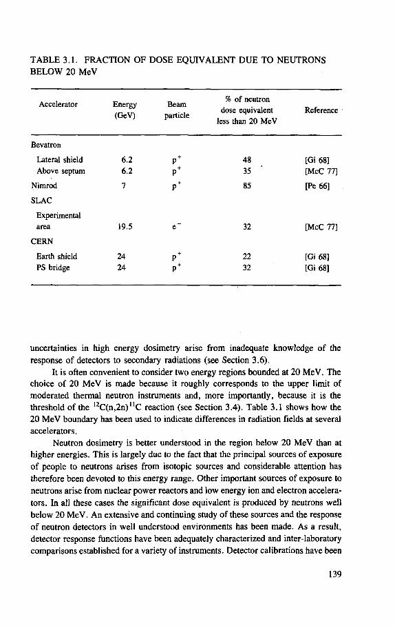
TABLE 3.1. FRACTION OF DOSE EQUIVALENT DUE TO NEUTRONS BELOW 20 MeV
Accelerator Energy (GeV)
Beam particle
% of neutron dose equivalent
less than 20 MeV Reference
Bevatron
Lateral shield 6.2 P + 48 [Gi 68] Above septum 6.2 P + 35 [McC 77]
Nimrod 7 P + 85 [Pe 66]
SLAC
Experimental area 19.5 e - 32 [McC 77]
CERN
Earth shield 24 P + 22 [Gi 68] PS bridge 24 P + 32 [Gi 68]
uncertainties in high energy dosimetry arise from inadequate knowledge of the response of detectors to secondary radiations (see Section 3.6).
It is often convenient to consider two energy regions bounded at 20 MeV. The choice of 20 MeV is made because it roughly corresponds to the upper limit of moderated thermal neutron instruments and, more importantly, because it is the threshold of the 1 2C(n,2n)uC reaction (see Section 3.4). Table 3.1 shows how the 20 MeV boundary has been used to indicate differences in radiation fields at several accelerators.
Neutron dosimetry is better understood in the region below 20 MeV than at higher energies. This is largely due to the fact that the principal sources of exposure of people to neutrons arises from isotopic sources and considerable attention has therefore been devoted to this energy range. Other important sources of exposure to neutrons arise from nuclear power reactors and low energy ion and electron accelera-tors. In all these cases the significant dose equivalent is produced by neutrons well below 20 MeV. An extensive and continuing study of these sources and the response of neutron detectors in well understood environments has been made. As a result, detector response functions have been adequately characterized and inter-laboratory comparisons established for a variety of instruments. Detector calibrations have been
139
performed with monoenergetic neutrons from continuous and pulsed sources; (a, n) and spontaneous fission sources have also been extensively used in calibrations [Pa 73] and information on the neutron spectra emitted by such sources continues to be refined [He 59a, In 81]. At energies above 20 MeV the calibration and test facilities available are much less reliable [Al 79a]. Spatial and temporal variations of radiation intensity may impose severe limitations. In addition, the qualitative fea-tures of the radiation field — for example particle energy spectra — may not be well defined (see Section 3.8).
Radiation dosimetry at particle accelerator laboratories has tended to develop almost independently of work in the mainstream of radiological protection. There are many reasons for this separate development, but it is principally due to the fact that health physicists at accelerator laboratories often have backgrounds in nuclear or particle physics and are thus familiar with techniques used to quantify the physical parameters of radiation fields, in addition to the standard techniques of dosimetry used in radiological protection.
One clear advantage of measurements that define the physical properties of the radiation field is that the parameters so determined are immutable. Quantities which are administratively defined, such as dose equivalent, are transient and may vary as changes in their definitions are brought about. While it is always possible to derive dose equivalent quantities from appropriate field quantities, the converse is not true (see Sections 3.5 and 3.8).
3.2. HISTORICAL BACKGROUND
The first serious high energy radiation studies around particle accelerators began to be reported in the literature in the middle and late 1950s. Naturally enough they originated in those laboratories with significant radiation problems. The labora-tories that built their early synchrocyclotrons underground were not particularly active in these studies because they had few problems.
Many of the early qualitative and quantitative data originate from the early proton synchrotrons operated at Brookhaven National Laboratory (the Cosmotron) and the Radiation Laboratory9 of the University of California (the Bevatron).
Experience at the 184-Inch Synchrocyclotron at Berkeley and the early proton synchrotrons — the Cosmotron and Bevatron — rapidly established the qualitative nature of their radiation environments outside thick shielding [Pa 65, Sm 58, Sm 62]. A general rule emerged, showing that neutrons between 0.1 and 10 MeV contributed more than 50% to the dose equivalent of the radiation field; gamma rays and low energy neutrons contributed about 10-20%, and the balance was made up by
9 Now the Lawrence Berkeley Laboratory.
140
neutrons greater than 10 MeV in energy. These early studies have been reported by Lindenbaum [Li 57], Moyer [Mo 57] and Patterson [Pa 57], and summarized by Patterson and Thomas [Pa 73].
In order to understand the dosimetric problem in a qualitative manner, Moyer and his colleagues leaned heavily on analogy to cosmic radiation. They argued that the radiation environment outside high energy accelerator shields must in many respects be similar to that which exists at the base of the earth's atmosphere produced by the interaction of the galactic cosmic radiation with the earth's atmosphere. In particular, the neutron spectrum was of great interest [He 59b]. Patterson et al. used the analogy to suggest that neutrons between 0.1 and 20 MeV would dominate the contribution to the dose equivalent [Pa 59]. This suggestion led to the strategy, subsequendy found to be largely sound, of concentrating on neutron measurements in that energy range.
As early as 1954 Moyer, among others, identified the experimental techniques that would be of value in high energy dosimetry at accelerators:
(1) " fo r the determination of the flux density and spectrum of unidirectional fast neutrons: proportional counters, scintillation counters, photographic emulsions;
(2) for the determination of thermal neutron flux densities, regardless of direction: counting techniques based on neutron capture in boron, activation foils;
(3) for the approximately absolute determination of energy flux density delivered by fast neutrons, independent of energy spectrum or angular direction: polyethylene-lined proportional counters;
(4) for the contribution to energy absorption in tissue due to neutrons, where the effects due to 7-rays are known and may be corrected for: cavity chambers or tissue equivalent chambers." [Mo 54]
"Such a list, if written today, would look much the same. Sullivan [Su 69], in reviewing dosimetric techniques used at particle accelerators up to 1969, showed that, although there has been a steady improvement over the past 18 years in the tech-niques listed by Moyer, few basically new ideas have arisen. Perhaps the two most important new techniques absent from Moyer's list and mentioned by Sullivan were the use of ionization chambers to estimate the quality factors for mixed radiation fields and the development of activation detectors capable of yielding neutron spectra adequate for health physics purposes." [Th 73]
By 1972 the course for the future development for techniques of high energy dosimetry seemed clear. Speaking of the period 1965-1971, it was possible to say:
" . . . the last six years have resulted in solid, if not spectacular, achievement in neutron dosimetry with threshold detectors at accelerators. Given this depth of understanding of radiation environments, the response of any detector(s) used to monitor accelerator radiation may be correctly interpreted. Several authors have
141
examined the errors involved in using a routine monitoring system based on a small number of activation detectors [Gi 68, Ri 68, Sh 69],
For example, a moderated BF3 counter, suitably calibrated, will almost always estimate dose equivalent to about a factor of 2, in a wide range of accelerator spectra. If an additional measurement using the 12C(n, 2n) n C reaction is made, the accuracy can be improved to much better than 50% (usually 20% or better). Furthermore, since the measurements and their evaluation take quite a short time (typically one hour or less), threshold detectors may be used as the basis of a very practical routine monitoring system." [Th 73]
Since that time work has proceeded in the following areas:
— Classification of the definition of the concept of dose equivalent [Bu 81a, Pa 71, Ri 71, Ri 72, St 73a];
— Development of new activation detector techniques [Ch 66, Gi 68, Ro 69]; — Incorporation of Bonner spheres and activation detectors
[Al 76, Aw 66, Aw 85, St 67]; — Improvement of neutron spectrum unfolding routines [Ro 80, Ro 85, St 67]; — Improvement in the interpretation of neutron spectra in terms of dose equiva-
lent [ICRP 70, ICRP 73, NCRP 71, Sh 68, Sh 69].
During the thirteen years from 1966 to 1979 several comparisons of dosimetric methods and results were made by various groups at the CERN 28 GeV proton synchrotron [Ho 75a,b], the Stanford 20 GeV electron linac [McC 77], and the 70 GeV proton synchrotron of the Institute of High Energy Physics at Serpukhov [An 78]. These intercomparisons have been summarized by McCaslin and Thomas [McC 81] who pointed out some important discrepancies. Intercomparisons are continuing at Serpukhov and will hopefully lead to important improvements in dosimetric techniques in the future [An 78, Ho 83].
As we have seen, the basic key to our understanding of particle accelerator radiation environments was the realization that in some respects they would be similar to that produced by the interaction of the galactic cosmic radiation with the earth's atmosphere. This was of particular value in the case of neutrons [He 59a] and led Patterson et al. [Pa 59] to conclude that neutrons between 0.1 MeV and 20 MeV would produce the largest component of dose equivalent around high energy acceler-ators. This prediction was borne out by observations around particle accelerators at Berkeley [Pa 65, Sm 58, Sm 62] and elsewhere [Bo 62, CERN 71, Pe 66, USAEC 57, USAEC 65, USAEC 67, USAEC 69] and is still valid.
As early as 1965, however, it became clear that, under certain conditions, as much as 90% of the dose equivalent could be contributed by high energy particles, i.e. those above 20 MeV in energy [Ba 64, Ba 65, Ca 65]. Such conditions are increasingly important at very high energy facilities (in the 100 GeV energy range) and it is thus important to improve techniques for the measurement of particles of energy above 20 MeV present in accelerator radiation environments [St 84, Th 85a].
142
3.3. MIXED RADIATION FIELD DOSIMETRY
In genera] the radiation fields around accelerators are complex, often consis-ting of many different ionizing radiations extending over a broad range of energies [Ba 69b].
Zielczynski has discussed the uncertainties in mixed radiation field dosimetry [Zi 70] and cites two major difficulties:
— determination of response functions of radiation detectors — interpretation of measurements and determination of accuracy.
More specifically at particle accelerators, dosimetric techniques that span the wide energy range of accelerator radiation environments suffer from all or some of the following drawbacks:
— interference from radiations other than those to be measured — response rate dependence in intense radiation fields — complexity — incomplete instrument response function data — uncertainties in instrument response interpretation.
Dosimetrists continue their quest for techniques by which a single dosimeter would permit direct accurate measurement to be made of the entire radiation field. We have the LET spectrometer of Rossi [Ro 55], the modified LET spectrometer of Kuehner et al. [Ba 69a, Ku 72, Ku 73a, b], the differential recombination cham-bers of Zielczynski [Zi 62, Zi 64] and Sullivan [Su 63] and the scintillation method of Pszona [Ps 71].
3.3.1. Ionization chambers
Perhaps the simplest experimental approach to the determination of dose equivalent H in accelerator radiation fields is to make a determination of absorbed dose D with a suitable ionization chamber and multiply the result by an appropriate quality factor Q according to the relationship:
H = QD (3.1)
Many different means of determining absorbed dose by ionization chambers have been developed, including paired ion chambers, high pressure argon filled chambers and cavity chambers [Bu 68, Go 68, Pa 73].
At accelerators the absorbed dose is usually determined by a tissue equivalent chamber, following the original work of Rossi and Failla [Fa 50, Ro 56],
143
Tissue equivalent chambers have found wide application at the PPA, the Argonrie ZGS, and at CERN, where they are in routine use and have even been used for beam dosimetry [Ba 65, Ba 69b, USAEC 65],
The conceptual difficulty with this technique lies in the fact that it provides no method for the determination of Q in Eq. (3.1) and provides only a measurement of D. A conservative approach is to assume a quality factor of about 10, but this is often unreasonably restrictive (experience shows typical values for Q of about 5 in accelerator radiation fields [Pa 73]). Either some detailed knowledge of the radiation environment is required to estimate Q or resort may be made to an empirical determi-nation of Q using recombination chambers. Both methods require further measurements.
Practical problems that arise with use of ionization chambers in accelerator fields include:
(1) Radiofrequency interference — ion chambers are low signal high gain detec-tors that are sensitive to electromagnetic interference such as is caused by the stray fields from the tuned radiofrequency cavities used in particle accelerators.
(2) Pulsed radiation fields — the field strength may be insufficient to ensure com-plete charge collection in pulsed radiation fields of low duty cycle. Even though the average absorbed dose rates may be low, the rates during pulses may be extremely high. Fine structure (e.g. RF structure) in the beam spill may exacerbate this problem.
3.3.2. LET spectrometer instruments
Nguyen et al. [Ng 85] have recently reviewed LET and event size (Y) spectrometry in detail and the interested reader is referred to their article. Baum and others of Brookhaven National Laboratory have developed a more robust and improved ion chamber that also reduces the need for frequent gas filling [Ba 69a, Ku 72, Ku 73a,b]. Two signals are extracted: one is proportional to the dose rate, independent of LET; the other is processed by non-linear amplifiers to produce an amplitude dependence that varies with LET in the same manner as does quality factor.
LET spectrometer instruments are of limited value for dosimetry for radio-logical protection purposes in typical particle accelerator environments because of their low sensitivity. Such instruments are not therefore found in routine use [Fr 70],
3.3.2.1. Ionization recombination instruments
These instruments depend upon the fact that ions produced in the gas will recombine to some degree when the electrical gradient across an ionization chamber
144
is not adequate to achieve saturation. This recombination, which occurs along primary and secondary charged particle tracks, will depend upon the local density of ionization in the tracks and thus has some relation to the linear energy transfer L c used to define the quality factor Q in radiological protection [Su 84].
This has led to attempts to produce an instrument that measures the dose equivalent due to any ionizing radiation field, independently of L^ or, alternatively, to determine the Q of any field. Such instruments would be extremely useful for the complicated mixtures of radiations that comprise the radiation field outside the shielding of particle accelerators.
Several techniques for measuring quality factor have been suggested. For example, the characteristics of columnar recombination in ionization chambers are dependent on the LET of the charged particles causing the ionization. One approach, due to Zielczynski, is to use a double ionization chamber in which one part is operated at saturation voltage and another at a lower voltage in which a certain amount of columnar recombination can occur [Zi 62], It was sho\vn to be possible to adjust the lower voltage so that the ratio of the currents from the two parts of the chamber is a linear function of quality factor, which means that the difference in ionization current from the two parts of the chamber will be directly proportional to the dose equivalent.
Another method based on columnar recombination relies on the observation that over a large voltage range the current is empirically related to the polarizing voltage by a relation of the form:
i = kVn (3.2)
The index n is approximately proportional to Q and so a determination of n in a neutron field can give an estimate of the average quality factor to be applied to a measurement of absorbed dose [Di 65, Su 63, Su 64].
3.3.3. Other dose equivalent or radiation quality instruments
Another effect that can be used to obtain an estimate of radiation quality is the light output from a plastic scintillator. The method devised by Pszona [Ps 69, Ps 71, Ps 77] relies on the simultaneous measurement of currents from an ionization chamber and a photomultiplier tube attached to a plastic scintillator. The ratio of the currents is a complex function of LET, but it can be used to give a measure of the average Q in an unknown field.
Yet another technique, described by Tesch [Te 70], is to use pulse shape discrimination on the pulses coming from an organic scintillator to discriminate against photons and to choose a suitable discriminator threshold so that the pulse rate is proportional to dose equivalent.
145
All these techniques have given satisfactory estimates of quality factor and dose equivalent in near laboratory conditions of exposure. However, as yet, there is no universal dose equivalent meter which is both sufficiently sensitive and robust enough to withstand the rigours of measurement in the field and give reliable results at occupational radiation levels. This is to be contrasted with the multiple detector systems described later in this section, which have been shown to be reliably consis-tent for more than 20 years.
3.4. NEUTRON DOSIMETRY AT ACCELERATORS
Special discussion of the measurement of neutrons is given here because it is neutrons that lead to the most important dosimetric problems outside the shielding at many, or most, proton accelerators (see Chapter 2).
Neutrons must be measured over a wide range of energies, often in pulsed fields and usually as one component of a mixed radiation field. Such conditions impose a stern test on the dosimetrists who must resort to all the dosimetric techniques normally available in radiological protection.
3.4.1. Classification of radiation detectors
There are many types of radiation detectors, which may be classified in almost any number of ways. To assist the reader in understanding the published literature a brief summary is given here. In the literature on accelerator neutron dosimetry one will find several ways of classifying radiation detectors:
— passive detectors — active (prompt) detectors — threshold detectors — activation detectors — moderator devices.
3.4.2. Passive detectors
Passive detectors yield their information after their irradiation has ended and often only after some technical processing of the detector itself or interpretation of data from it [Th 80b]. Holt has given an alternative definition as "detectors which do not require any electronics equipment to be connected during the irradiation; the irradiation induces some change in the detector material as a function of the fluence, and the change is measured after the end of the irradiation" [Ho 85],
146
Examples of passive detectors are:
— activation detectors — fission track detectors — nuclear emulsions — radioluminescent glasses — silicon diodes — thermoluminescent dosimeters.
Detectors that are often thought of as prompt may be converted to the passive mode. For example a passive thermal neutron detector may be used in conjunction with a set of Bonner moderators [Br 60],
Passive detectors are best used to determine the intensity of radiation fields that are essentially invariant over the time of measurement.
3.4.3. Active (prompt) detectors
Active (prompt) detectors give immediate information in real time about radia-tion intensity and may be used to make measurements in radiation fields that fluctuate with time [Pe 80], Examples are:
— Geiger counters — proportional counters — fission counters — scintillation counters — solid state detectors.
3.4.4. Threshold detectors
Threshold detectors are those that require a finite, fixed radiation energy to initiate any response to ionizing radiation. Below the threshold they give no response; above it they have a response proportional to the excitation functions (response function) of the detector. Examples of threshold detectors used in accelerator radiation field dosimetry are: the thorium fission chamber, which utilizes the (n, fission) reaction in thorium and has a threshold of 1.6 MeV; the production of " C , a positron emitter with a half-life of 20.3 min, by the 1 2C(n,2n)nC reaction, which has a threshold of about 20 MeV (see Fig. 3.1). Threshold detectors may be either of the active type [Pe 80] (e.g. bismuth fission chambers [He 57, Ke 48, McC 68]) or the passive type [Ho 85, Sm 65, Th 80b] (e.g. the production of n C from 12C in a plastic scintillator [Ba 57, McC 60, Sh 51, Sh 62, St 84]). Suitable nuclear reactions, their thresholds and sample materials are indicated in Table 3.2. Care must be taken in the particular reactions selected because in the high energy environments of accelerators multiple reactions may be possible with the
147
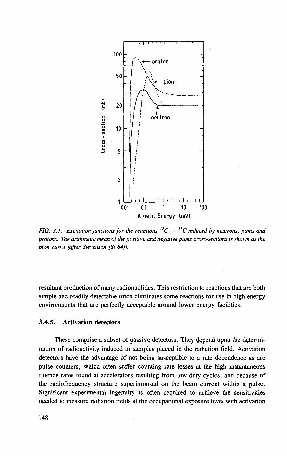
I T I J | I I I I | I I I V | I I I
100 -
50
I \ « — proton
I \ I A \
— p i o n
E 20 - I t neutron
2 •
1 I i i i i I i • i i I i i i i I i i i i
0.01 0.1 1 10 100 Kinetic Energy IGeV)
FIG. 3.1. Excitation functions for the reactions nC — "C induced by neutrons, pions and protons. The arithmetic mean of the positive and negative pions cross-sections is shown as the pion curve (after Stevenson [St 84]).
resultant production of many radionuclides. This restriction to reactions that are both simple and readily detectable often eliminates some reactions for use in high energy environments that are perfecdy acceptable around lower energy facilities.
3.4.5. Activation detectors
These comprise a subset of passive detectors. They depend upon the determi-nation of radioactivity induced in samples placed in the radiation field. Activation detectors have the advantage of not being susceptible to a rate dependence as are pulse counters, which often suffer counting rate losses at the high instantaneous fluence rates found at accelerators resulting from low duty cycles, and because of the radiofrequency structure superimposed on the beam current within a pulse. Significant experimental ingenuity is often required to achieve the sensitivities needed to measure radiation fields at the occupational exposure level with activation
148
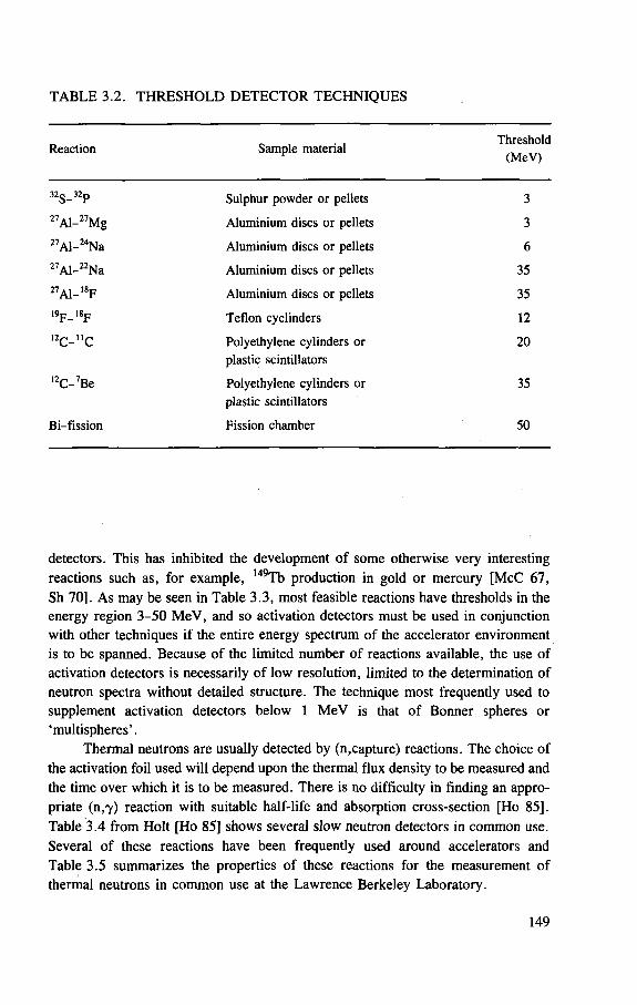
TABLE 3.2. THRESHOLD DETECTOR TECHNIQUES
Reaction Sample material Threshold
(MeV)
32s_32p Sulphur powder or pellets 3
2 7 Al- 2 7 Mg Aluminium discs or pellets 3
2 7 Al- 2 4 Na Aluminium discs or pellets 6
2 7 Al- 2 2 Na Aluminium discs or pellets 35
2 7A1-1 8F Aluminium discs or pellets 35 19p_18p Teflon cyclinders 12
1 2 C - " C Polyethylene cylinders or plastic scintillators
20
1 2 C- 7 Be Polyethylene cylinders or plastic scintillators
35
Bi-f ission Fission chamber 50
detectors. This has inhibited the development of some otherwise very interesting reactions such as, for example, 149Tb production in gold or mercury [McC 67, Sh 70], As may be seen in Table 3.3, most feasible reactions have thresholds in the energy region 3-50 MeV, and so activation detectors must be used in conjunction with other techniques if the entire energy spectrum of the accelerator environment is to be spanned. Because of the limited number of reactions available, the use of activation detectors is necessarily of low resolution, limited to the determination of neutron spectra without detailed structure. The technique most frequently used to supplement activation detectors below 1 MeV is that of Bonner spheres or 'multispheres'.
Thermal neutrons are usually detected by (n,capture) reactions. The choice of the activation foil used will depend upon the thermal flux density to be measured and the time over which it is to be measured. There is no difficulty in finding an appro-priate (n,7) reaction with suitable half-life and absorption cross-section [Ho 85], Table 3.4 from Holt [Ho 85] shows several slow neutron detectors in common use. Several of these reactions have been frequently used around accelerators and Table 3.5 summarizes the properties of these reactions for the measurement of thermal neutrons in common use at the Lawrence Berkeley Laboratory.
149
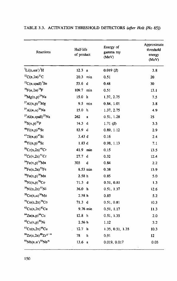
TABLE 3.3. ACTIVATION THRESHOLD DETECTORS (after Holt [Ho 85])
Reactions Half-l ife of product
Energy of gamma ray (MeV)
Approximate threshold
energy (MeV)
7 L i ( n , a n ' ) 3 H 12.3 a 0 .019 (|8) 3 .8 1 2 C(n ,2n ) "C 20 .3 min 0 .51 20 12C(n,spall) 7Be 53 .6 d 0 .48 30 1 9F(n,2n) 1 8F 109.7 min 0 .51 13.1 2 4Mg(n,p) 2 4Na 15.0 h 1.37, 2 .75 7 .5 2 7Al(n,p) 2 7Mg 9.5 min 0 .84 , 1.01 3 .8 2 7 Al(n ,a ) 2 4 Na 15.0 h 1.37, 2 .75 4 .9 27 Al(n,spall) 2 2Na 262 a 0 .51 , 1.28 25 3 2S(n,p) 3 2P 14.3 d 1.71 ((3) 3 .3 4 6Ti(n,p)4 6Sc 83.9 d 0 .89 , 1.12 2 .9 4 7Ti(n,p)4 7Sc 3.43 d 0 .16 2 .4 4 8Ti(n,p)4 8Sc 1.83 d 0 .98 , 1.13 7.1 5 0 Cr(n,2n) 4 9 Cr 41 .9 min 0 .15 13.5 5 2 Cr(n,2n) 5 1 Cr 27 .7 d 0 .32 12.4
^ F e f a . p ^ M n 303 d 0 .84 2 .2 5 4 Fe(n,2n) 5 3 Fe 8.53 min 0 . 3 8 13.9 5 6Fe(n,p) 5 6Mn 2 .58 h 0 .85 5 .0 5 8 Ni(n,p) 5 8 Co 71 .3 d 0 .51 , 0.81 1.3 5 8Ni(n,2n)5 7Ni 36.0 h 0 .51, 1.37 12.6 5 9 Co(n ,a ) 5 6 Mn 2.58 h 0 .85 5.2 5 9Co(n,2n) 5 8Co 71.3 d 0 .51, 0.81 10.3 6 3Cu(n,2n) 6 2Cu 9 .76 min 0 .51 , 1.17 11.3
" Z n O i . p ^ C u 12.8 h 0 .51 , 1.35 2 .0 6 5Cu(n,p) 6 5Ni 2 .56 h 1.12 3.2
" C u f r ^ n ^ C u 12.7 h 1.35, 0 .51, 1.35 10.3 90Zr(n,2n)S9Zri+m 78 h 0 .91 12 9 3 Nb(n ,n ' ) 9 3 Nb m 13.6 a 0 .019, 0 .017 0 .03
150
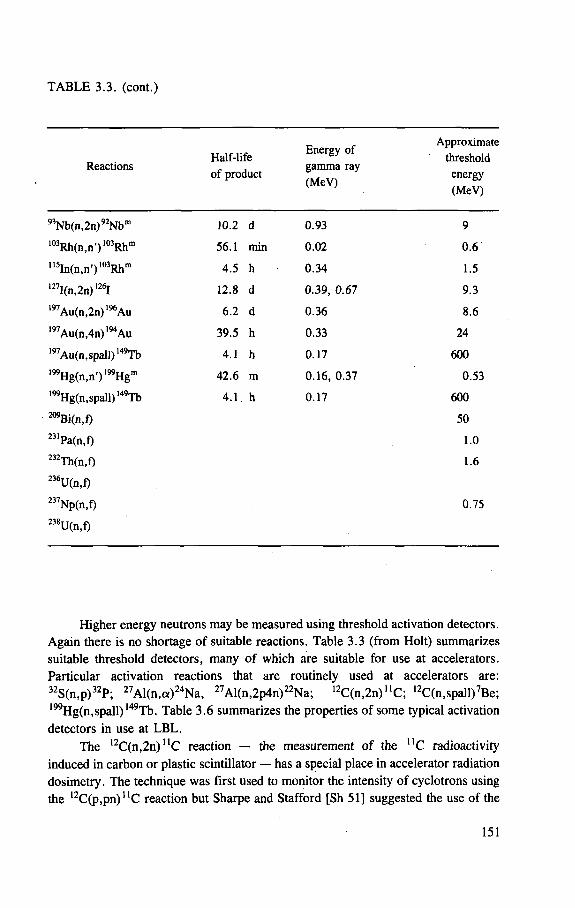
T A B L E 3.10. (cont . )
Reactions Half-life of product
Energy of gamma ray (MeV)
Approximate threshold
energy (MeV)
93Nb(n,2n)92Nbm 10.2 d 0.93 9
103Rh(n,n')103Rhm 56.1 min 0.02 0.6 , 15In(n )n')103Rhm 4.5 h 0.34 1.5 127I(n,2n) 126I 12.8 d 0.39, 0.67 9.3 197Au(n,2n)196Au 6.2 d 0.36 8.6 197Au(n,4n)194 Au 39.5 h 0.33 24 197Au(n,spall) 149Tb 4.1 h 0.17 600 199Hg(n,n')199Hgm 42.6 m 0.16, 0.37 0.53 l99Hg(n,spall) 149Tb 4.1 h 0.17 600 209Bi(n,f) 50 231Pa(n,f) 1.0 232Th(n,f) 1.6 236U(n,f) 237Np(n,f) 0.75 238U(n,f)
Higher energy neutrons may be measured using threshold activation detectors.
Again there is no shortage of suitable reactions. Table 3.3 (from Holt) summarizes
suitable threshold detectors, many of which are suitable for use at accelerators.
Particular activation reactions that are routinely used at accelerators are: 32S(n,p)32P; 27Al(n,a)24Na, 27Al(n,2p4n)22Na; 1 2C(n,2n)uC; 12C(n,spall)7Be; 199Hg(n,spall) 149Tb. Table 3.6 summarizes the properties of some typical activation
detectors in use at L B L .
The 1 2C(n,2n) nC reaction — the measurement of the n C radioactivity
induced in carbon or plastic scintillator — has a special place in accelerator radiation
dosimetry. The technique was first used to monitor the intensity of cyclotrons using
the 1 2C(p,pn)uC reaction but Sharpe and Stafford [Sh 51] suggested the use of the
151
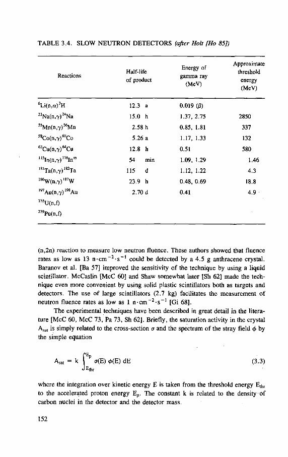
TABLE 3.4. SLOW NEUTRON DETECTORS (after Holt [Ho 85])
Reactions Half- l i fe
Energy of Approximate
threshold Reactions
of product gamma ray
(MeV) energy
(MeV)
6 L i ( n , a ) 3 H 12.3 a 0 .019 (/3)
2 3 N a ( n , 7 ) 2 4 N a 15.0 h 1.37, 2 .75 2850
5 5 M n ( n , 7 ) 5 6 M n 2 .58 h 0 .85 , 1.81 337
5 9 C o ( n , 7 ) 6 0 C o 5 .26 a 1.17, 1.33 132
" C u f t i ^ C u 12.8 h 0 . 5 1 580
" 5 I n ( n , 7 ) l l 6 I n m 54 min 1.09, 1.29 1.46
l 8 l T a ( n , 7 ) 1 8 2 T a 115 d 1.12, 1.22 4 . 3
1 8 6 W(n,7) 1 8 7 W 2 3 . 9 h 0 .48 , 0 .69 18.8
1 9 7 Au(n,7) 1 9 8 Au 2 .70 d 0 .41 4 . 9
2 3 5 U(n, f )
2 3 9 Pu(n, f )
(n,2n) reaction to measure low neutron fluence. These authors showed that fluence rates as low as 13 n - c m _ 2 - s _ 1 could be detected by a 4.5 g anthracene crystal. Baranov et al. [Ba 57] improved the sensitivity of the technique by using a liquid scintillator. McCaslin [McC 60] and Shaw somewhat later [Sh 62] made the tech-nique even more convenient by using solid plastic scintillators both as targets and detectors. The use of large scintillators (2.7 kg) facilitates the measurement of neutron fluence rates as low as 1 n - c m ~ 2 - s _ l [Gi 68],
The experimental techniques have been described in great detail in the litera-ture [McC 60, McC 73, Pa 73, Sh 62], Briefly, the saturation activity in the crystal Asat is simply related to the cross-section a and the spectrum of the stray field <t> by the simple equation
Asat = k r (7(E) <£(E) d E ( 3 . 3 ) J E t h r
where the integration over kinetic energy E is taken from the threshold energy E th r
to the accelerated proton energy Ep . The constant k is related to the density of carbon nuclei in the detector and the detector mass.
152
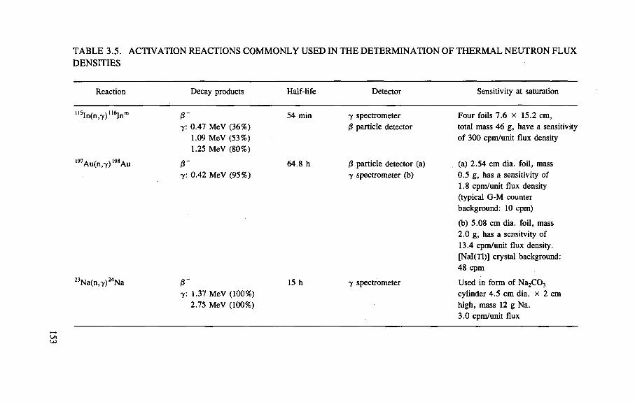
TABLE 3.5. ACT IVAT ION REACTIONS C O M M O N L Y USED IN THE DETERM INAT ION OF T H E R M A L NEUTRON FLUX DENSIT IES
Reaction Decay products Half-life Detector Sensitivity at saturation
115In(n,7)116Inm 0 " 7: 0.47 MeV (36%)
1.09 MeV (53%) 1.25 MeV (80%)
54 min 7 spectrometer /3 particle detector
Four foils 7.6 x 15.2 cm, total mass 46 g, have a sensitivity of 300 cpm/unit flux density
197Au(n,7)198 Au r 7: 0.42 MeV (95%)
64.8 h 0 particle detector (a) 7 spectrometer (b)
(a) 2.54 cm dia. foil, mass 0.5 g, has a sensitivity of 1.8 cpm/unit flux density (typical G-M counter background: 10 cpm)
(b) 5.08 cm dia. foil, mass 2.0 g, has a sensitvity of 13.4 cpm/unit flux density. [Nal(Tl)] crystal background: 48 cpm
23Na(n,7)24Na r 7: 1.37 MeV (100%)
2.75 MeV (100%)
15 h 7 spectrometer Used in form of Na2C03
cylinder 4.5 cm dia. x 2 cm high, mass 12 g Na. 3.0 cpm/unit flux
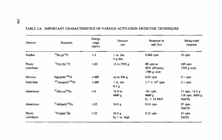
T A B L E 3.6. I M P O R T A N T C H A R A C T E R I S T I C S O F V A R I O U S A C T I V A T I O N D E T E C T O R T E C H N I Q U E S
Detector Reactions Energy range
(MeV)
Detector Response to unit flux
Background response
Sulphur
Plastic scintillator
Mercury
Gold foils
Aluminium
Aluminium
Plastic scintillator
32S(n,p)32P
l2C(n,2n)"C
Hg(spall) 149Tb 197 Au(spall) ,49Tb
27Al(n,a)24Na
27Al(spall)22Na
12C(spall)7Be
> 3
>20
>600
>600
> 6
>25
>25
1 in. dia. 4 g disc
13 to 2700 g
up to 500 g
1 in. dia. 0.5 g
16.9 to 6600 g
16.9 g
16.9 g by 1 in. high
0.049 cpm
88 cpm at 85% efficiency 1700 g scint
0.03 cpm
2.7 x 10⁶ cpm
101 cpm 6600 g
E„ = 14 MeV
0.21 cpm
0.21 cpm
10 cpm
165 cpm 1700 g scint
0.1 cpm
0.1 cpm
11 cpm, 16.9 g 118 cpm, 6600 g Nal(Tl)
67 cpm Nal(Tl)
67 cpm Na(Tl)
In using the activation technique it has been customary to make the assumption that the greatest part of the activity is induced by neutrons, and that the contribution due to photons and charged particles is either negligible or adequately accounted for by the procedures adopted. A nominal fluence </>nom is calculated from the saturated U C activity, using an effective cross-section aeff.
As a t = k ffeff 4>nom (3-4)
Early interpretations of the measurement of the cross-section <j(E) suggested a step-like excitation function with the threshold at 20 MeV, rapidly rising to a constant value of 22 mb (see Figs 3.2 and 3.3) [Gi 68]. With such a simple excitation function a value for <jeff could readily be identified and it became the universal practice at accelerator laboratories to use a value of 22 mb for the effective cross-section [St 84].
These conventions resulted in excellent agreement in the determination of effective neutron fluence (E > 20 MeV) at accelerator laboratories [Gi 68, St 84]. There were, however, significant differences in the interpretation of these fluence measurements, leading to differences in the equivalent estimates of more than a factor of two [Ba 65, Gi 68, Go 67, Sh 68] (see also Section 3.7).
Since the work of the 1960s and early 1970s several important improvements in our understanding have occurred:
— new cross-section data are available — radiation transport calculations have made possible the study of the charged
component of accelerator radiation fields — dose equivalent concepts have been clarified.
Figure 3.1 shows a summary of I2C — n C cross-section data for neutrons, pions and protons. Charalumbus et al. have reviewed these cross-sections [Ch 66] and their data have been augmented in Fig. 3.1 by the work of Garber and Kinsey [Ga 76] for neutrons, Tobailem for protons [To 71], and Butler et al. for pions [Bu 82], The arithmetic mean of the charged pion cross-sections is shown. It is clear that the original assumption of a step-like excitation function for the (n,2n) reaction was incorrect and the usual 'resonance' type excitation function is observed, with a peak in the cross-section at about 100 MeV.
Radiation transport calculations now make it possible to study both the charged and uncharged hadron components of accelerator radiation fields (see Chapter 4). Stevenson has reported calculations of the neutron, pion and proton components out-side the shielding of a 30 GeV proton beamline [St 84] (see Chapter 2). He shows that for transverse shields the assumption that neutrons dominate the production of n C is adequate. Furthermore, the estimation of neutron fluence using the assump-tion of a step-like excitation is in error by less that 15%. However, in the forward
155
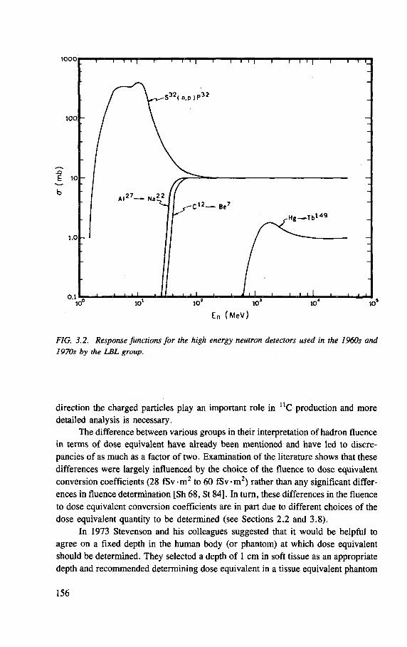
FIG. 3.2. Response functions for the high energy neutron detectors used in the 1960s and 1970s by the LBL group.
direction the charged particles play an important role in U C production and more detailed analysis is necessary.
The difference between various groups in their interpretation of hadron fluence in terms of dose equivalent have already been mentioned and have led to discre-pancies of as much as a factor of two. Examination of the literature shows that these differences were largely influenced by the choice of the fluence to dose equivalent conversion coefficients (28 fSv-m2 to 60 fSv-m2) rather than any significant differ-ences in fluence determination [Sh 68, St 84], In turn, these differences in the fluence to dose equivalent conversion coefficients are in part due to different choices of the dose equivalent quantity to be determined (see Sections 2.2 and 3.8).
In 1973 Stevenson and his colleagues suggested that it would be helpful to agree on a fixed depth in the human body (or phantom) at which dose equivalent should be determined. They selected a depth of 1 cm in soft tissue as an appropriate depth and recommended determining dose equivalent in a tissue equivalent phantom
156
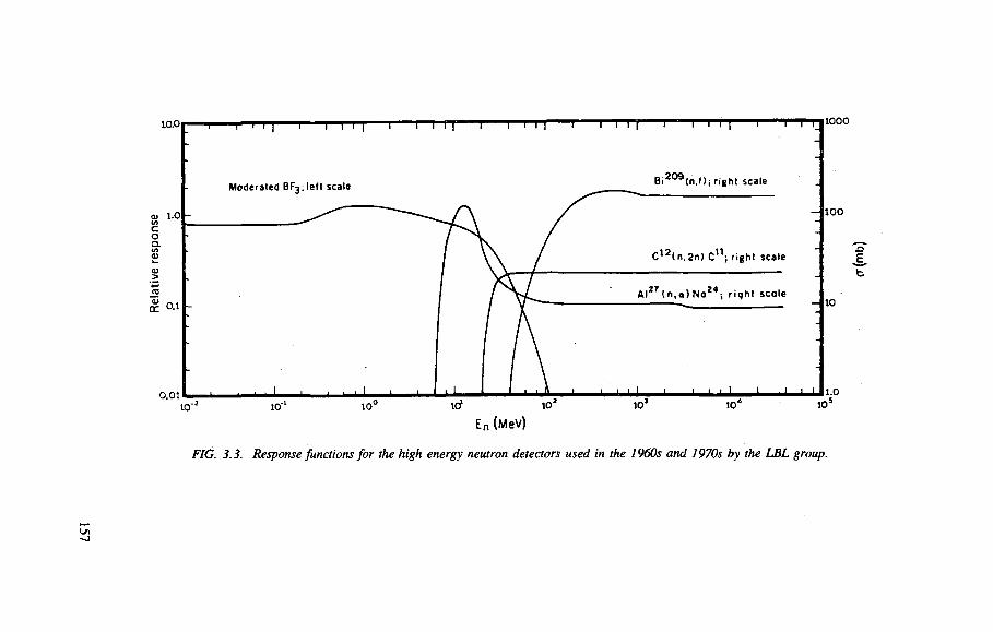
FIG. 3.3. Response Junctions for the high energy neutron detectors used in the 1960s and 1970s by the LBL group.
-J
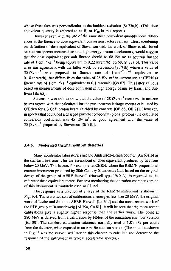
whose front face was perpendicular to the incident radiation [St 73a,b]. (This dose equivalent quantity is referred to as Hs or H 1 0 in this report.)
However even with the use of the same dose equivalent quantity some differ-ences in the fluence to dose equivalent conversion factors remain. Thus, combining the definition of dose equivalent of Stevenson with the work of Shaw et al., based on neutron spectra measured around high energy proton accelerators, would suggest that the dose equivalent per unit fluence should be 60 fSv-m 2 (a neutron fluence rate of 1 c m _ 2 - s - 1 being equivalent to 0.22 mrem/h) [Sh 68, St 73a,b]. This value is in fair agreement with the latter work of Stevenson [St 71b] where a value of 50 fSv-m 2 was proposed (a fluence rate of 1 c m ~ 2 - s _ 1 equivalent to 0.18 mrem/h), but differs from the value of 28 fSv-m 2 in current use at CERN (a fluence rate of 1 c m " 2 - s _ l equivalent to 0.1 mrem/h) [Go 67], This latter value is based on measurements of dose equivalent in high energy beams by Baarli and Sul-livan [Ba 65],
Stevenson was able to show that the value of 28 fSv -m 2 measured in neutron beams agreed with that calculated for the pure neutron leakage spectra calculated by O'Brien for a 3 GeV proton beam shielded by concrete [OB 68, OB 71]. However, in spectra that contained a charged particle component (pions, protons) the calculated conversion coefficient was 45 fSv-m 2, in good agreement with the value of 50 fSv-m 2 proposed by Stevenson [St 71b],
3.4.6. Moderated thermal neutron detectors
Many accelerator laboratories use the Andersson-Braun counter [An 63a,b] as the standard instrument for the assessment of dose equivalent produced by neutrons below 20 MeV. This is true, for example, at CERN, where the REM/N proportional counter instrument produced by 20th Century Electronics Ltd, based on the original design of the group of AERE Harwell (Harwell type 1940 A), is regarded as the reference dose equivalent meter. For area monitoring the ionization chamber version of this instrument is routinely used at CERN.
The response as a function of energy of the REM/N instrument is shown in Fig. 3.4. There are two sets of calibrations at energies less than 20 MeV, the original work of Leake and Smith at AERE Harwell [Le 64a] and the more recent work of the PTB group at Braunschweig [Al 79a, Co 81]. It will be seen that the more recent calibrations give a slightly higher response than the earlier work. The point at 280 MeV is derived from a calibration by Hofert of the ionization chamber version [Ho 80]. The standard calibration reference normally used is 1.01 nSv per count from the detector, when exposed to an Am-Be neutron source. (The solid line shown in Fig. 3.4 is the curve used later in this chapter to calculate and determine the response of the instrument in typical accelerator spectra.) 158

Neutron Energy
FIG. 3.4. Response of the REM/N neutron dose equivalent meter as a function of neutron energy measured by groups at AERE (o), PTB (x), and CERN CD) (see text for details).
Another commonly used detector of this type is an indium foil or other thermal
neutron activation detector placed in a spherical (or cylindrical) hydrogenous neutron
moderator first described by Stephens et al. [St 58]. Many variations on the original
design have been reported in the literature [Ba 67, Ca 70, Si 64, Sm 61, Sm 66,
St 58], The specific detector chosen as an example for discussion here is the 7 in.
diameter paraffin wax moderator in a cadmium can used at the Rutherford
Laboratory. The indium foil placed at the centre of the sphere is beta assayed by a
thin end-window Geiger counter. This device was calibrated by Simpson [Si 64] and
these calibrations can be related to the response of a 7 in. diameter polyethylene
sphere with a 6 Li I crystal as detector (derived from the calculations of McGuire
[McG 66] to give the response of the wax sphere over the whole energy range
(Fig. 3.5). The detector is calibrated in terms of the apparent flux density of 2 M e V
neutrons, but a dose equivalent per unit fluence of 15 fSv -m2 was found to be most
appropriate for the determination of dose equivalent in typical accelerator spectra
[St 71b],
159
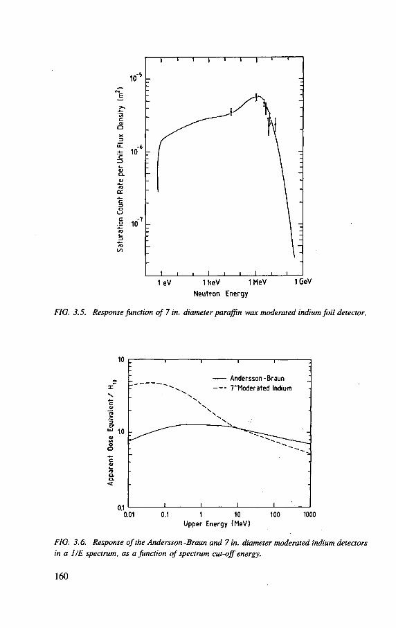
.t 10 -
10 -
1 eV 1 keV 1 MeV
Neutron Energy
1 QeV
FIG. 3.5. Response function of 7 in. diameter paraffin wax moderated indium foil detector.
10
0.1 0.01
Andersson-Braun
7"Moderated Indium
0.1 1 10 Upper Energy (MeV)
100 1000
FIG. 3.6. Response of the Andersson-Braun and 7 in. diameter moderated indium detectors in a HE spectrum, as a function of spectrum cut-off energy.
160
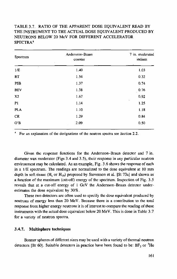
TABLE 3.7. RATIO OF THE APPARENT DOSE EQUIVALENT READ BY THE INSTRUMENT TO THE ACTUAL DOSE EQUIVALENT PRODUCED BY NEUTRONS BELOW 20 MeV FOR DIFFERENT ACCELERATOR SPECTRA®
Spectrum Andersson-Braun
counter 7 in. moderated
indium
1/E 1.40 1.03
RT 1.54 0 .32
PSB 1.37 0 .74
BEV 1.38 0 .76
X2 1.67 0 .92
P I 1.14 1.25
PLA 1.10 1.18
CR 1.29 0 .84
O ' B 2 .09 0 .50
a For an explanation of the designations of the neutron spectra see Section 2 .2 .
Given the response functions for the Andersson-Braun detector and 7 in. diameter wax moderator (Figs 3.4 and 3.5), their response in any particular neutron environment may be calculated. As an example, Fig. 3.6 shows the response of each in a 1/E spectrum. The readings are normalized to the dose equivalent at 10 mm depth in soft tissue (Hs or H10) proposed by Stevenson et al. [St 73a] and shown as a function of the maximum (cut-off) energy of the spectrum. Inspection of Fig. 3.5 reveals that at a cut-off energy of 1 GeV the Andersson-Braun detector under-estimates the dose equivalent by 30%.
These two detectors are often used to specify the dose equivalent produced by neutrons of energy less than 20 MeV. Because there is a contribution to the total response from higher energy neutrons it is of interest to compare the reading of these instruments with the actual dose equivalent below 20 MeV. This is done in Table 3.7 for a variety of neutron spectra.
3.4.7. Multisphere techniques
Bonner spheres of different sizes may be used with a variety of thermal neutron detectors [Br 60]. Suitable detectors in practice have been found to be: BF3 or 3He
161
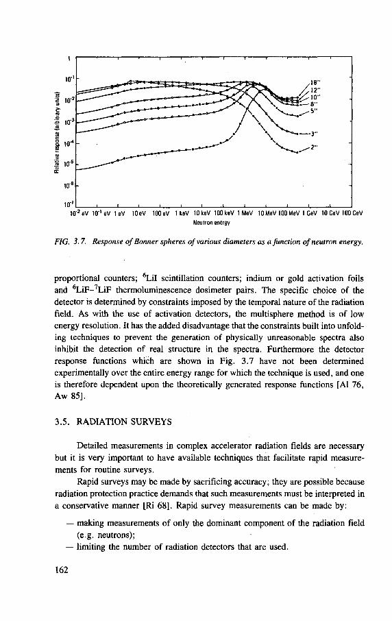
Neutron energy
FIG. 3.7. Response of Bonner spheres of various diameters as a Junction of neutron energy.
proportional counters; 6 Li I scintillation counters; indium or gold activation foils and 6 L iF - 7 L iF thermoluminescence dosimeter pairs. The specific choice of the detector is determined by constraints imposed by the temporal nature of the radiation field. As with the use of activation detectors, the multisphere method is of low energy resolution. It has the added disadvantage that the constraints built into unfold-ing techniques to prevent the generation of physically unreasonable spectra also inhibit the detection of real structure in the spectra. Furthermore the detector response functions which are shown in Fig. 3.7 have not been determined experimentally over the entire energy range for which the technique is used, and one is therefore dependent upon the theoretically generated response functions [Al 76, Aw 85].
3.5. R A D I A T I O N S U R V E Y S
Detailed measurements in complex accelerator radiation fields are necessary
but it is very important to have available techniques that facilitate rapid measure-
ments for routine surveys.
Rapid surveys may be made by sacrificing accuracy; they are possible because
radiation protection practice demands that such measurements must be interpreted in
a conservative manner [Ri 68], Rapid survey measurements can be made by:
— making measurements of only the dominant component of the radiation field
(e.g. neutrons);
— limiting the number of radiation detectors that are used.
162
Because neutrons usually dominate the radiation field outside the shield of heavy ion accelerators, neutron survey techniques will be discussed in some detail.
There are significant differences in the neutron spectra outside accelerator shielding and no single detector can be expected to give a response that is propor-tional to dose equivalent under all circumstances.
However, in general we may approximate the actual dose equivalent quantity required by
n
H = 2 a ' R i ( 3 - 5 )
i=l
where the ai's are suitably chosen dose equivalent conversion coefficients and the Rj's are the detector responses. The precise values of the a^s will depend upon many parameters. The greater the number of detectors (n) the better the actual dose equivalent will be approximated and the errors in its determination appreciated.
3.5.1. Single detector
The simplest (and usually least accurate) method of determining neutron dose equivalent in surveys is to use a moderated thermal neutron detector that has an approximate dose equivalent response in the energy range from thermal to about 15 MeV. To compensate for neutrons above 15 MeV the measured response may be multiplied by a factor of 2 to 3. Moderated thermal neutron detector instruments designed by Leake [Le 67, Le 68] or by Andersson and Braun [An 63a,b] are in common use for this purpose.
An alternative survey method that has been used is to determine the observed dose using a tissue equivalent ionization chamber and to assume a conservative value of quality factor. This has been taken to be between 5 and 10 in accelerator radiation fields [Co 53],
Other survey techniques using single instruments include the use of recombina-tion chamber instruments of the type described by Zielczynski and the scintillator instruments of Tesch described previously [Te 70, Zi 64],
3.5.2. Two detectors
Techniques using two detectors already described are the combined use of a tissue equivalent ionization chamber with a recombination chamber to estimate Q [Di 65, Su 63, Su 64, Su 69] and the combined ionization chamber/scintillator instrument of Pszona [Ps 69, Ps 71, Ps 77],
At the Lawrence Berkeley Laboratory the average energy of the neutron spectrum has been determined using a polyethylene lined proportional counter.
163
This knowledge combined with a determination of neutron fluence with an instrument of the long counter type facilitates the determination of dose equivalent due to neutrons. The Moyer polyethylene lined argon-C02 gas proportional counter has a response that is proportional to energy fluence so that the ratio of the energy fluence (given by the polyethylene lined chamber) to the fluence (given by the saturated BF3 counter) gives the average neutron energy E„. The fluence to dose equivalent conversion coefficient corresponding to En can then be applied to the flux density measurement to estimate the dose equivalent [Mo 52, St 73c]. How well this technique approximates the true dose equivalent will depend on the spectral distribution of neutrons. For example the data of Ing et al. [In 81] give the average neutron energy En for a 238Pu-Li source as 0.5 MeV with a corresponding fluence to dose equivalent conversion coefficient of 18.2 fSv-m2
(1.82 x 10 ~8 rem-cm2). The survey technique using a moderated counter and a polyethylene lined counter would overestimate the dose equivalent by a factor of 1.4 by declaring the average dose equivalent (corresponding to E = 0.5 MeV) to be 25.7 fSv-m2 (2.57 X10 - 8 rem-cm2).
Care must always be exercised when using the PE counter, especially at elec-tron accelerators, to ensure that photon pile-up is not interfering with the measurement.
3.5.3. Three or more detectors
Experience shows that three detectors are the minimum that may be used to determine dose equivalent in the environment of particle accelerators with sufficient accuracy for radiation protection purposes (in terms of Eq. (3.5) n > 3).
Typically the three detectors used are:
(1) An air ionization chamber to determine the dose equivalent contribution from charged particles and photons;
(2) A 'low energy' (E < 20 MeV) neutron detector — usually one of the many types of moderated thermal neutron detectors [An 63a,b, Aw 66, Ha 47, Ha 62, Le 67, Le 68, Na 72, Si 64, St 58];
(3) A 'high energy' (E > 20 MeV) neutron detector — most frequently based on the 12C(n,2n)nC reaction [Ba 57, McC 60, Sh 51, Sh 62],
Such a scheme has been the basis for measurements at Berkeley (LBL), CERN and the Rutherford Appleton Laboratory for many years.
At CERN the total dosimetry system consists of four instruments — the three specified above plus a tissue equivalent ionization chamber to determine absorbed dose and give an indication of the average quality factor of the radiation field [Ho 72]. This dosimetry system has somewhat whimsically been named Cerberus after the many-headed monster of Greek mythology.
164
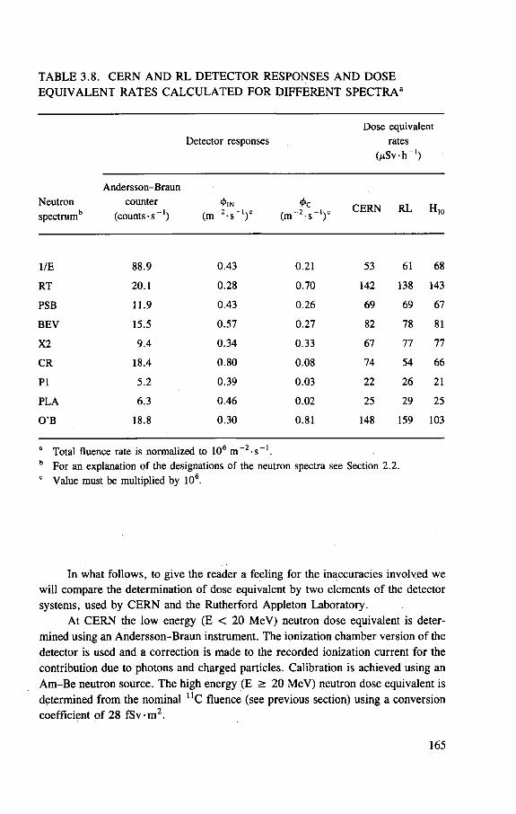
T A B L E 3.8. C E R N A N D R L D E T E C T O R R E S P O N S E S A N D D O S E
E Q U I V A L E N T R A T E S C A L C U L A T E D F O R D I F F E R E N T S P E C T R A 3
Detector responses Dose equivalent
rates ( f iSv-h _ 1 )
Andersson-Braun Neutron counter <j>m
spectrumb ( coun t s - s - 1 ) ( m ~ 2 - s " ')c
<t> c ( m ~ 2 - s _ 1 ) c CERN RL H„
1/E 88.9 0 .43 0.21 53 61 68
RT 20.1 0.28 0.70 142 138 143
PSB 11.9 0.43 0.26 69 69 67
BEV 15.5 0.57 0.27 82 78 81
X2 9 .4 0 .34 0.33 67 77 77
CR 18.4 0 .80 0.08 74 54 66
PI 5.2 0.39 0.03 22 26 21
PLA 6.3 0 .46 0.02 25 29 25
O 'B 18.8 0 .30 0.81 148 159 103
a Total fluence rate is normalized to 106 m ~ 2 - s ~ ' . b For an explanation of the designations of the neutron spectra see Section 2.2. c Value must be multiplied by 106.
In what follows, to give the reader a feeling for the inaccuracies involved we
will compare the determination of dose equivalent by two elements of the detector
systems, used by C E R N and the Rutherford Appleton Laboratory.
At C E R N the low energy (E < 20 M e V ) neutron dose equivalent is deter-
mined using an Andersson-Braun instrument. The ionization chamber version of the
detector is used and a correction is made to the recorded ionization current for the
contribution due to photons and charged particles. Calibration is achieved using an
A m - B e neutron source. The high energy ( E > 20 M e V ) neutron dose equivalent is
determined from the nominal U C fluence (see previous section) using a conversion
coefficient of 28 fSv -m 2 .
165
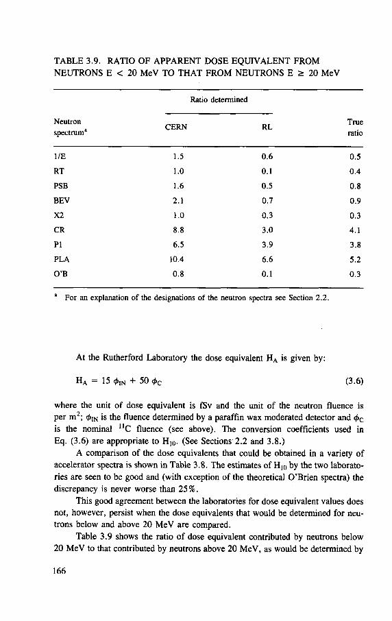
TABLE 3.9. RATIO OF APPARENT DOSE EQUIVALENT FROM NEUTRONS E < 20 MeV TO THAT FROM NEUTRONS E > 20 MeV
Ratio determined
Neutron spectrum2 C E R N RL
True ratio
1/E 1.5 0 .6 0 .5
R T 1.0 0 .1 0 .4
PSB 1.6 0 .5 0 .8
BEV 2 .1 0 .7 0 .9
X2 1.0 0 .3 0 .3
CR 8.8 3 .0 4 .1
P I 6 .5 3 .9 3 .8
PLA 10.4 6 .6 5.2
O ' B 0 .8 0 .1 0 .3
a For an explanation of the designations of the neutron spectra see Section 2 .2 .
At the Rutherford Laboratory the dose equivalent HA is given by:
H a = 15 fa + 50 <t>c (3.6)
where the unit of dose equivalent is fSv and the unit of the neutron fluence is per m2; 0 IN is the fluence determined by a paraffin wax moderated detector and <t>c
is the nominal n C fluence (see above). The conversion coefficients used in Eq. (3.6) are appropriate to H10. (See Sections 2.2 and 3.8.)
A comparison of the dose equivalents that could be obtained in a variety of accelerator spectra is shown in Table 3.8. The estimates of H10 by the two laborato-ries are seen to be good and (with exception of the theoretical O'Brien spectra) the discrepancy is never worse than 25%.
This good agreement between the laboratories for dose equivalent values does not, however, persist when the dose equivalents that would be determined for neu-trons below and above 20 MeV are compared.
Table 3.9 shows the ratio of dose equivalent contributed by neutrons below 20 MeV to that contributed by neutrons above 20 MeV, as would be determined by
166
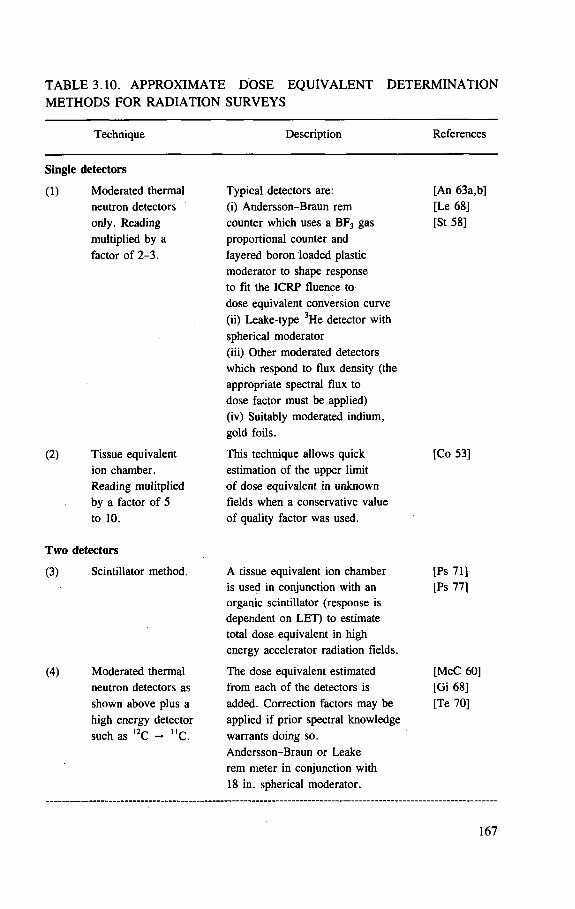
T A B L E 3.10. A P P R O X I M A T E D O S E E Q U I V A L E N T D E T E R M I N A T I O N
M E T H O D S F O R R A D I A T I O N S U R V E Y S
Technique Description References
Single detectors
(1)
(2)
Moderated thermal neutron detectors only. Reading multiplied by a factor of 2 -3 .
Tissue equivalent ion chamber. Reading mulitplied by a factor of 5 to 10.
Typical detectors are: [An 63a,b] (i) Andersson-Braun rem [Le 68] counter which uses a BF3 gas [St 58] proportional counter and
layered boron loaded plastic moderator to shape response to fit the ICRP fluence to dose equivalent conversion curve (ii) Leake-type 3He detector with spherical moderator (iii) Other moderated detectors which respond to flux density (the appropriate spectral flux to dose factor must be applied) (iv) Suitably moderated indium, gold foils.
This technique allows quick [Co 53] estimation of the upper limit of dose equivalent in unknown fields when a conservative value of quality factor was used.
Two detectors
(3) Scintillator method.
(4) Moderated thermal neutron detectors as shown above plus a high energy detector such as 12C - U C .
A tissue equivalent ion chamber [Ps 71] is used in conjunction with an [Ps 77] organic scintillator (response is dependent on LET) to estimate total dose equivalent in high energy accelerator radiation fields.
The dose equivalent estimated [McC 60] from each of the detectors is [Gi 68] added. Correction factors may be [Te 70] applied if prior spectral knowledge warrants doing so. Andersson-Braun or Leake rem meter in conjunction with 18 in. spherical moderator.
167
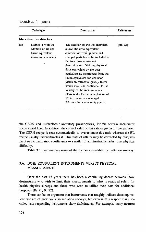
TABLE 3.10. (cont.)
Technique Description References
More than two detectors
(5) Method 4 with the addition of air and tissue equivalent ionization chambers
The addition of the ion chambers allows the dose equivalent contribution f rom gamma and charged particles to be included in the total dose equivalent determination. Dividing the total dose equivalent by the dose equivalent as determined f rom the tissue equivalent ion chamber yields an 'effective quality factor ' which may lend confidence to the validity of the measurements. (This is the Cerberus technique of Hofert , when a moderated BF 3 rem ion chamber is used.)
[Ho 72]
the CERN and Rutherford Laboratory prescriptions, for the several accelerator spectra used here. In addition, the correct value of this ratio is given for comparison. The CERN recipe is seen systematically to overestimate this ratio whereas the RL recipe usually underestimates it. This state of affairs may be corrected by readjust-ment of the calibration coefficients — a matter of administrative rather than physical difficulty.
Table 3.10 summarizes some of the methods available for radiation surveys.
3.6. DOSE EQUIVALENT INSTRUMENTS VERSUS PHYSICAL MEASUREMENTS
Over the past 15 years there has been a continuing debate between those dosimetrists who wish to limit their measurements to what is required solely for health physics surveys and those who wish to utilize their data for additional purposes [Ri 71, Ri 72],
There can be no argument that instruments that roughly indicate dose equiva-lent rate are of great value in radiation surveys, but even in this respect many so-called rem responding instruments show deficiencies. For example, many neutron
168
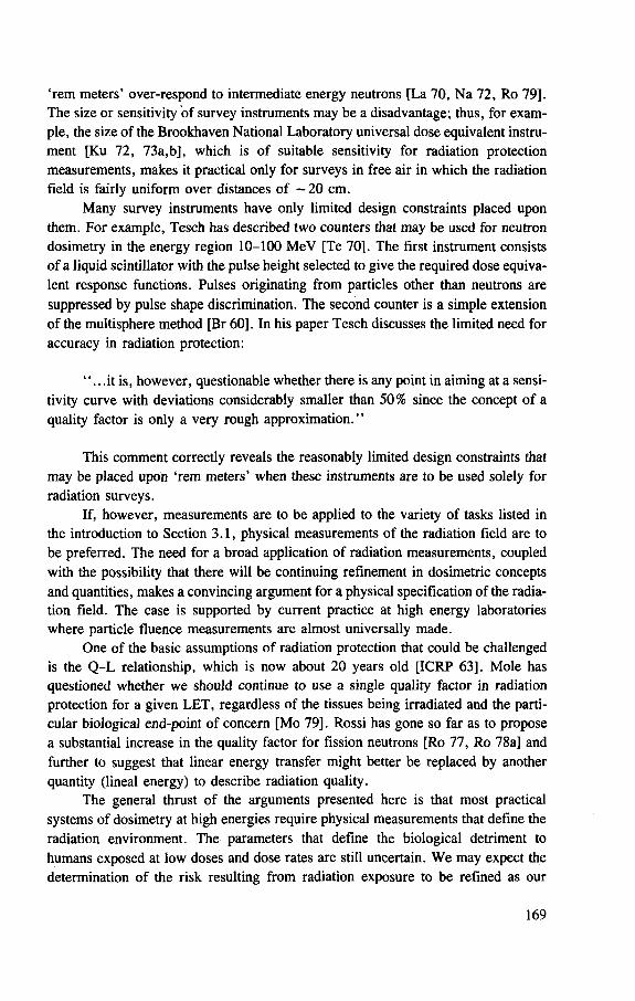
'rem meters' over-respond to intermediate energy neutrons [La 70, Na 72, Ro 79]. The size or sensitivity of survey instruments may be a disadvantage; thus, for exam-ple, the size of the Brookhaven National Laboratory universal dose equivalent instru-ment [Ku 72, 73a,b], which is of suitable sensitivity for radiation protection measurements, makes it practical only for surveys in free air in which the radiation field is fairly uniform over distances of —20 cm.
Many survey instruments have only limited design constraints placed upon them. For example, Tesch has described two counters that may be used for neutron dosimetry in the energy region 10-100 MeV [Te 70]. The first instrument consists of a liquid scintillator with the pulse height selected to give the required dose equiva-lent response functions. Pulses originating from particles other than neutrons are suppressed by pulse shape discrimination. The second counter is a simple extension of the multisphere method [Br 60], In his paper Tesch discusses the limited need for accuracy in radiation protection:
". . . i t is, however, questionable whether there is any point in aiming at a sensi-tivity curve with deviations considerably smaller than 50% since the concept of a quality factor is only a very rough approximation."
This comment correctly reveals the reasonably limited design constraints that may be placed upon 'rem meters' when these instruments are to be used solely for radiation surveys.
If, however, measurements are to be applied to the variety of tasks listed in the introduction to Section 3.1, physical measurements of the radiation field are to be preferred. The need for a broad application of radiation measurements, coupled with the possibility that there will be continuing refinement in dosimetric concepts and quantities, makes a convincing argument for a physical specification of the radia-tion field. The case is supported by current practice at high energy laboratories where particle fluence measurements are almost universally made.
One of the basic assumptions of radiation protection that could be challenged is the Q-L relationship, which is now about 20 years old [ICRP 63], Mole has questioned whether we should continue to use a single quality factor in radiation protection for a given LET, regardless of the tissues being irradiated and the parti-cular biological end-point of concern [Mo 79]. Rossi has gone so far as to propose a substantial increase in the quality factor for fission neutrons [Ro 77, Ro 78a] and further to suggest that linear energy transfer might better be replaced by another quantity (lineal energy) to describe radiation quality.
The general thrust of the arguments presented here is that most practical systems of dosimetry at high energies require physical measurements that define the radiation environment. The parameters that define the biological detriment to humans exposed at low doses and dose rates are still uncertain. We may expect the determination of the risk resulting from radiation exposure to be refined as our
169
knowledge increases. Precise determination of the physical parameters of the radia-tion field, however, provides an immutable basis for the derivation of any physical quantities subsequently required for a risk determination. The converse is not so. Measurements specified in terms of dose equivalent quantities may be invalidated if fundamental changes are made in our dosimetric systems for radiological protection [Ca 82, NCRP 82].
3.7. DETERMINATION OF NEUTRON SPECTRA AT ACCELERATORS
While radiation surveys in the field provide useful after-the-fact data, the goals of radiation protection may only be met when the origin, attenuation through shielding, and transport through the air of accelerator produced radiation are fully understood. As we have seen in previous sections, the dominant radiation protection problem around high energy accelerators is expected to be due to neutrons. Thus knowledge of the neutron spectra found around particle accelerators provides an essential starting point for an understanding of accelerator radiation protection.
Neutron spectra are also a fundamental starting point in the measurement of the dose equivalent, since they permit an optimum choice of radiation detector combinations; they enable LET distributions to be calculated in phantoms and, finally, they facilitate the calculation of dose equivalent quantities from appropriate fluence to dose equivalent conversion coefficients. The techniques available for the determination of neutron spectra around accelerators will be discussed in this section.
Accelerator neutron spectra have been measured at only a few laboratories. This is no doubt partly because the techniques are protracted and long periods of stable operation are required (not a usual feature of particle accelerators used in research), partly because spectrum unfolding requires some mathematical ability or familiarity with some of the many computer programs (and, as a corollary, access to a computer facility), but principally because sufficient resources have not been made available at any national laboratory or university for a systematic study of accelerator radiation environments.
The techniques used for spectrum measurement at particle accelerators are well established and have been extensively described in the literature [Pa 73, In 85]. The basic techniques used or attempted at high energy accelerators are summarized in Table 3.11.
Threshold detectors, activation detectors and Bonner spheres have already been described, so we will discuss only nuclear emulsion and other techniques for proton recoil spectrum measurements in what follows.
Proton recoil spectrum measurements. Nuclear emulsions can be used to record recoil proton spectra, but their evaluation is tedious and time consuming [Ak 63, Le 64b], They also require techniques and equipment that are no longer in
170
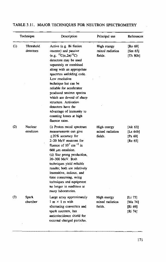
T A B L E 3.11. M A J O R T E C H N I Q U E S F O R N E U T R O N S P E C T R O M E T R Y
Technique Description Principal use References
(1) Threshold Active (e.g. Bi fission High energy [Ro 69] detectors counter) and passive mixed radiation [Sm 65]
(e.g. 1 2 C(n,2n)"C) fields. [Th 80b] detectors may be used separately or combined along with an appropriate spectrum unfolding code. Low resolution technique but can be reliable for accelerator produced neutron spectra which are devoid of sharp structure. Activation detectors have the advantage of immunity to counting losses at high fluence rates.
(2) Nuclear (i) Proton recoil spectrum High energy [Ak 63] emulsion measurements can give mixed radiation [Le 64b]
± 2 0 % accuracy for fields. [Pa 69] 2 - 2 0 MeV neutrons for [Re 65] fluence of 107 c m - 2 in 600 /im emulsion. (ii) Star prong production, 20-300 MeV. Both techniques yield reliable results; both are relatively insensitive, tedious, and time consuming, using techniques and equipment no longer in readiness at many laboratories.
(3) Spark Large array approximately High energy [Li 73] chamber 1 m x 1 m with mixed radiation [Ma 74]
alternating converters and fields. [Ri 69] spark counters, has [Ri 74] anticoincidence shield for external charged particles.
171
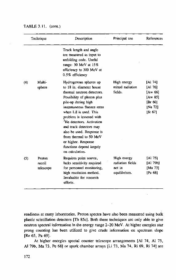
TABLE 3.10. (cont.)
Technique Description Principal use References
Track length and angle are measured as input to unfolding code. Useful range: 30 MeV at 15% efficiency to 300 MeV at 0 .5% efficiency
(4) Multi- Hydrogenous spheres up sphere to 18 in. diameter house
thermal neutron detectors. Possibility of photon plus pile-up during high instantaneous fluence rates when Lil is used. This problem is lessened with 3He detectors. Activation and track detectors may also be used. Response is f rom thermal to 50 MeV or higher. Response functions depend largely on calculation.
(5) Proton Requires point source, recoil lacks sensitivity required telescope for personnel monitoring,
high resolution method. Invaluable for research efforts.
High energy mixed radiation fields.
High energy radiation fields not in equilibrium.
[Al 74] [Al 76] [Aw 66] [Aw 85] [Br 60] [Na 72] [St 67]
[Al 75] [Al 79b] [Ma 73] [Pe 68]
readiness at many laboratories. Proton spectra have also been measured using bulk
plastic scintillation detectors [Th 85c]. Both these techniques are only able to give
neutron spectral information in the energy range 2 -20 M e V . At higher energies star
prong counting has been utilized to give crude information on spectrum slope
[Re 65, Pa 69].
A t higher energies special counter telescope arrangements [Al 74, A l 75,
A l 79b, M a 73, Pe 68] or spark chamber arrays [Li 73, M a 74, R i 69, R i 74] are
172
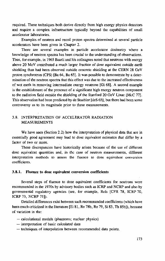
required. These techniques both derive directly from high energy physics detectors and require a complex infrastructure typically beyond the capabilities of small accelerator laboratories.
Examples of neutron and recoil proton spectra determined at several particle accelerators have been given in Chapter 2.
There are several examples in particle accelerator dosimetiy where a knowledge of neutron spectra has been crucial to the understanding of observations. Thus, for example, in 1965 Baarli and his colleagues noted that neutrons with energy above 20 MeV contributed a much larger fraction of dose equivalent outside earth shielding than had been observed outside concrete shielding at the CERN 28 GeV proton synchrotron (CPS) [Ba 64, Ba 65], It was possible to demonstrate by a deter-mination of the neutron spectra that this effect was due to the increased effectiveness of wet earth in removing intermediate energy neutrons [Gi 68]. A second example is the establishment of the presence of a significant high energy neutron component to the radiation field outside the shielding of the Stanford 20 GeV Linac [McC 77]. This observation had been predicted by de Staebler [deS 65], but there had been some controversy as to its magnitude prior to these measurements.
3.8. INTERPRETATION OF ACCELERATOR RADIATION MEASUREMENTS
We have seen (Section 2.2) how the interpretation of physical data that are in essentially good agreement may lead to dose equivalent estimates that differ by a factor of two or more.
These discrepancies have historically arisen because of the use of different dose equivalent quantities and, in the case of neutron measurements, different interpretation methods to assess the fluence to dose equivalent conversion coefficients.
3.8.1. Fluence to dose equivalent conversion coefficients
Several steps of fluence to dose equivalent coefficients for neutrons were recommended in the 1970s by advisory bodies such as ICRP and NCRP and also by governmental regulatory agencies (see, for example, Refs [CFR 78, ICRP 70, ICRP 73, NCRP 71]).
Detailed differences exist between such recommended coefficients (which have been much criticized in the literature [Ei 81, Ro 78b, Ro 79, Si 83, Th 85b]), because of variation in the:
— calculational models (phantoms; nuclear physics) — interpretation of basic calculated data — techniques of interpolation between recommended data points.
173
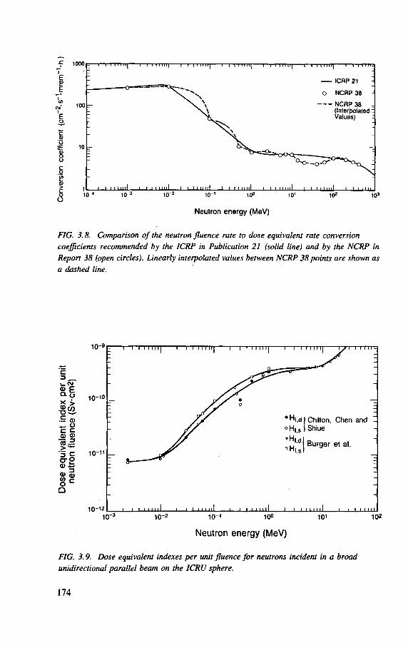
FIG. 3.8. Comparison of the neutron fluence rate to dose equivalent rate conversion coefficients recommended by the ICRP in Publication 21 (solid line) and by the NCRP in Report 38 (open circles). Linearly interpolated values between NCRP 38 points are shown as a dashed line.
Q
10~,Z
"•! i i i 111 iii i I ' i i 1111 il i i i 11111 10"
3
10~2
10"1
100 10
1 102
Neutron energy (MeV)
FIG. 3.9. Dose equivalent indexes per unit fluence for neutrons incident in a broad unidirectional parallel beam on the ICRU sphere.
174
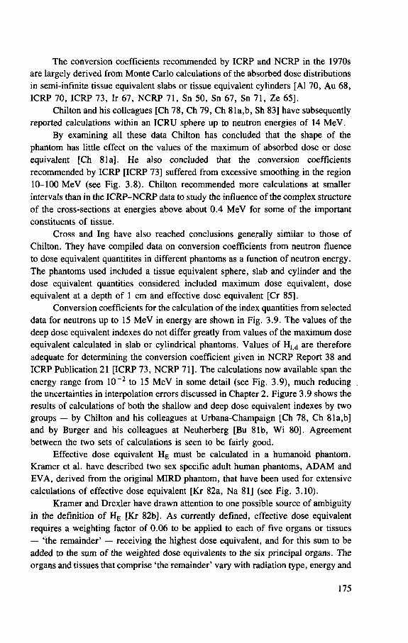
The conversion coefficients recommended by ICRP and NCRP in the 1970s are largely derived from Monte Carlo calculations of the absorbed dose distributions in semi-infinite tissue equivalent slabs or tissue equivalent cylinders [Al 70, Au 68, ICRP 70, ICRP 73, Ir 67, NCRP 71, Sn 50, Sn 67, Sn 71, Ze 65].
Chilton and his colleagues [Ch 78, Ch 79, Ch 81a,b, Sh 83] have subsequently reported calculations within an ICRU sphere up to neutron energies of 14 MeV.
By examining all these data Chilton has concluded that the shape of the phantom has little effect on the values of the maximum of absorbed dose or dose equivalent [Ch 81a]. He also concluded that the conversion coefficients recommended by ICRP [ICRP 73] suffered from excessive smoothing in the region 10-100 MeV (see Fig. 3.8). Chilton recommended more calculations at smaller intervals than in the ICRP-NCRP data to study the influence of the complex structure of the cross-sections at energies above about 0.4 MeV for some of the important constituents of tissue.
Cross and Ing have also reached conclusions generally similar to those of Chilton. They have compiled data on conversion coefficients from neutron fluence to dose equivalent quantitites in different phantoms as a function of neutron energy. The phantoms used included a tissue equivalent sphere, slab and cylinder and the dose equivalent quantities considered included maximum dose equivalent, dose equivalent at a depth of 1 cm and effective dose equivalent [Cr 85].
Conversion coefficients for the calculation of the index quantities from selected data for neutrons up to 15 MeV in energy are shown in Fig. 3.9. The values of the deep dose equivalent indexes do not differ gready from values of the maximum dose equivalent calculated in slab or cylindrical phantoms. Values of HI |d are therefore adequate for determining the conversion coefficient given in NCRP Report 38 and ICRP Publication 21 [ICRP 73, NCRP 71]. The calculations now available span the energy range from 10~2 to 15 MeV in some detail (see Fig. 3.9), much reducing the uncertainties in interpolation errors discussed in Chapter 2. Figure 3.9 shows the results of calculations of both the shallow and deep dose equivalent indexes by two groups — by Chilton and his colleagues at Urbana-Champaign [Ch 78, Ch 81a,b] and by Burger and his colleagues at Neuherberg [Bu 81b, Wi 80]. Agreement between the two sets of calculations is seen to be fairly good.
Effective dose equivalent HE must be calculated in a humanoid phantom. Kramer et al. have described two sex specific adult human phantoms, ADAM and EVA, derived from the original MIRD phantom, that have been used for extensive calculations of effective dose equivalent [Kr 82a, Na 81] (see Fig. 3.10).
Kramer and Drexler have drawn attention to one possible source of ambiguity in the definition of HE [Kr 82b]. As currently defined, effective dose equivalent requires a weighting factor of 0.06 to be applied to each of five organs or tissues — 'the remainder' — receiving the highest dose equivalent, and for this sum to be added to the sum of the weighted dose equivalents to the six principal organs. The organs and tissues that comprise 'the remainder' vary with radiation type, energy and
175
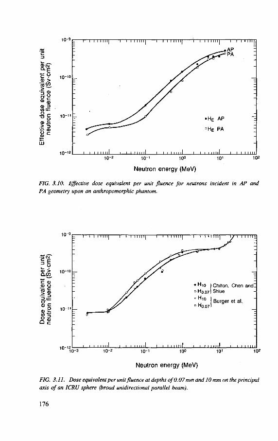
10-12 10-2
I l I l I l l 1 0 " ' 100
Mil 10'
I I I I I It I 102
Neutron energy (MeV)
FIG. 3.10. Effective dose equivalent per unit fluence for neutrons incident in AP and PA geometry upon an anthropomorphic phantom.
10-9
1 0 - 1 0
1 0 - ' i
1 0 - 1 2 I 1 i i i i in 1 0 - 3
Neutron energy (MeV)
FIG. 3.11. Dose equivalent per unit fluence at depths of 0.07 mm and 10 mm on the principal axis of an ICRU sphere (broad unidirectional parallel beam).
176
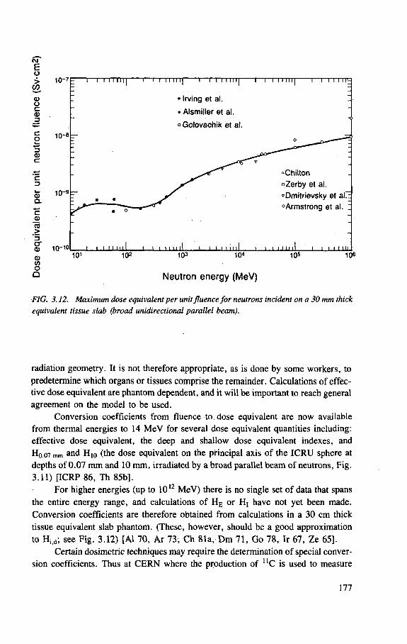
CM E o > 1 0 -
U)
1 0 -
10-9
10-10
= 1 1 i 11 11 [ | i l 1 1 1 11 1] 1 I I 1 1 111| 1 1 i 111111 i i i i i i i ' -
: • Irving et al. • Alsmiller et al.
mij
oGolovachik et al.
O
-
"Chilton oZerby et al.
• • "Dmitrievsky et alTE
• * ®Armstrong et al. :
i i n u l l i i i 1111 il i i i 11111I i i -i i m i l I i i i mm
d> OT o a
1 0 1 1 0 2 1 0 3 1 0 *
Neutron energy (MeV)
105 106
FIG. 3.12. Maximum dose equivalent per unit fluence for neutrons incident on a 30 mm thick equivalent tissue slab (broad unidirectional parallel beam).
radiation geometry. It is not therefore appropriate, as is done by some workers, to predetermine which organs or tissues comprise the remainder. Calculations of effec-tive dose equivalent are phantom dependent, and it will be important to reach general agreement on the model to be used.
Conversion coefficients from fluence to dose equivalent are now available from thermal energies to 14 MeV for several dose equivalent quantities including: effective dose equivalent, the deep and shallow dose equivalent indexes, and Hq q7 mm and H10 (the dose equivalent on the principal axis of the ICRU sphere at depths of 0.07 mm and 10 mm, irradiated by a broad parallel beam of neutrons, Fig. 3.11) [ICRP 86, Th 85b],
For higher energies (up to 1012 MeV) there is no single set of data that spans the entire energy range, and calculations of HE or H( have not yet been made. Conversion coefficients are therefore obtained from calculations in a 30 cm thick tissue equivalent slab phantom. (These, however, should be a good approximation to Hi d; see Fig. 3.12) [Al 70, Ar 73, Ch 81a, Dm 71, Go 78, Ir 67, Ze 65].
Certain dosimetric techniques may require the determination of special conver-sion coefficients. Thus at CERN where the production of U C is used to measure
177
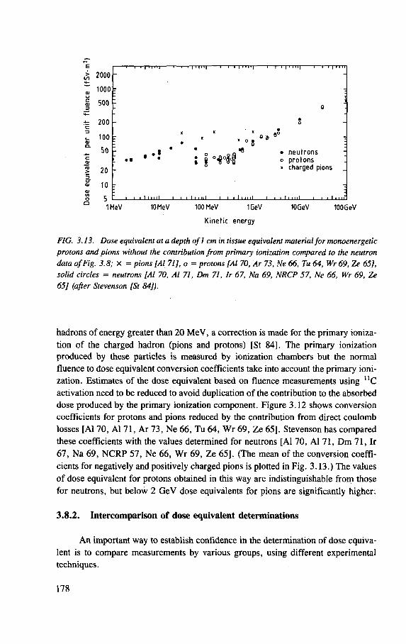
2000 1000
500
200
100
50
20 10
1 I I I Mil) 1 1 1 1 1 1 MI r i,-i | ii rrj- i t i | »i '»| • r i |'T i it
T 1 0 "
_ • o
X * z x •
I * • « • • o . . . . . g O,,
' y •
j o " ® • neutrons -o protons ' « charged pions
1 1 1 1 1 1 111 1 1 1 1 M III i i 111111 i i t 111111 i > i i • 11 r 1MeV 10 MeV 100 MeV 1GeV
Kinetic energy
10GeV 100GeV
FIG. 3.13. Dose equivalent at a depth of 1 cm in tissue equivalent material for monoenergetic protons and pions without the contribution from primary ionization compared to the neutron data of Fig. 3.8; X = pions [Al 71], o = protons [Al 70, Ar 73, Ne 66, Tu 64, Wr 69, Ze 65], solid circles = neutrons [Al 70, Al 71, Dm 71, Ir 67, Na 69, NRCP 57, Ne 66, Wr 69, Ze 65] (after Stevenson [St 84]).
hadrons of energy greater than 20 MeV, a correction is made for the primary ioniza-tion of the charged hadron (pions and protons) [St 84], The primary ionization produced by these particles is measured by ionization chambers but the normal fluence to dose equivalent conversion coefficients take into account the primary ioni-zation. Estimates of the dose equivalent based on fluence measurements using 11C activation need to be reduced to avoid duplication of the contribution to the absorbed dose produced by the primary ionization component. Figure 3.12 shows conversion coefficients for protons and pions reduced by the contribution from direct coulomb losses [Al 70, Al 71, Ar 73, Ne 66, Tu 64, Wr 69, Ze 65], Stevenson has compared these coefficients with the values determined for neutrons [Al 70, Al 71, Dm 71, Ir 67, Na 69, NCRP 57, Ne 66, Wr 69, Ze 65], (The mean of the conversion coeffi-cients for negatively and positively charged pions is plotted in Fig. 3.13.) The values of dose equivalent for protons obtained in this way are indistinguishable from those for neutrons, but below 2 GeV dose equivalents for pions are significantly higher.
3.8.2. Intercomparison of dose equivalent determinations
An important way to establish confidence in the determination of dose equiva-lent is to compare measurements by various groups, using different experimental techniques.
178
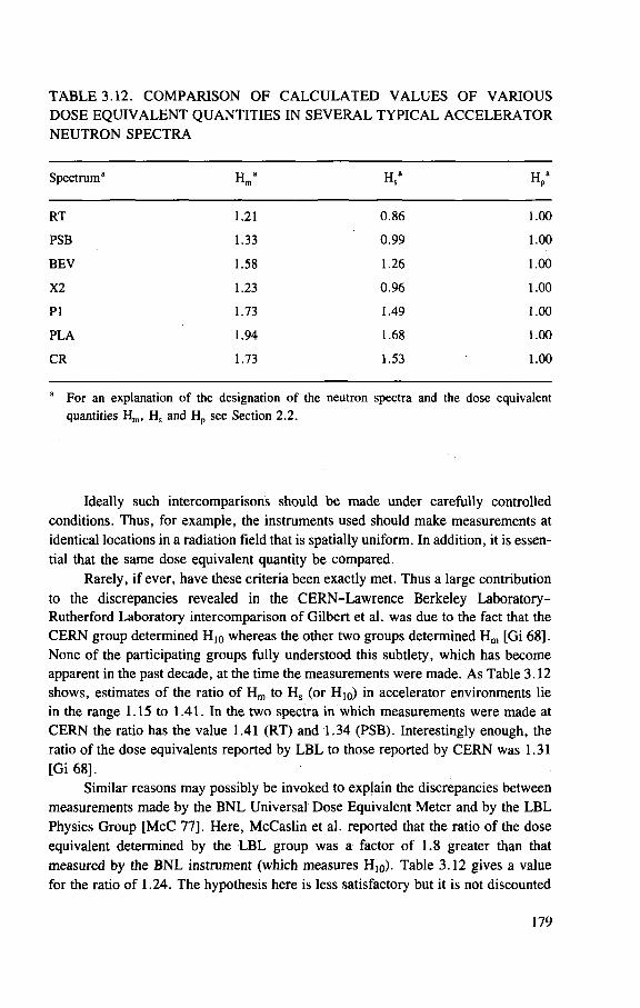
TABLE 3.12. COMPARISON OF CALCULATED VALUES OF VARIOUS DOSE EQUIVALENT QUANTITIES IN SEVERAL TYPICAL ACCELERATOR NEUTRON SPECTRA
Spectrum 3 H ma H s
a H pa
RT 1.21 0 .86 1.00
PSB 1.33 0 .99 1.00
BEV 1.58 1.26 1.00
X2 1.23 0 .96 1.00
P I 1.73 1.49 1.00
PLA 1.94 1.68 1.00
CR 1.73 1.53 1.00
For an explanation of the designation of the neutron spectra and the dose equivalent quantities H m , H s and H p see Section 2 .2 .
Ideally such intercomparisons should be made under carefully controlled conditions. Thus, for example, the instruments used should make measurements at identical locations in a radiation field that is spatially uniform. In addition, it is essen-tial that the same dose equivalent quantity be compared.
Rarely, if ever, have these criteria been exactly met. Thus a large contribution to the discrepancies revealed in the CERN-Lawrence Berkeley Laboratory-Rutherford Laboratory intercomparison of Gilbert et al. was due to the fact that the CERN group determined H10 whereas the other two groups determined Hm [Gi 68]. None of the participating groups fully understood this subtlety, which has become apparent in the past decade, at the time the measurements were made. As Table 3.12 shows, estimates of the ratio of Hm to Hs (or Hi0) in accelerator environments lie in the range 1.15 to 1.41. In the two spectra in which measurements were made at CERN the ratio has the value 1.41 (RT) and 1.34 (PSB). Interestingly enough, the ratio of the dose equivalents reported by LBL to those reported by CERN was 1.31 [Gi 68].
Similar reasons may possibly be invoked to explain the discrepancies between measurements made by the BNL Universal Dose Equivalent Meter and by the LBL Physics Group [McC 77], Here, McCaslin et al. reported that the ratio of the dose equivalent determined by the LBL group was a factor of 1.8 greater than that measured by the BNL instrument (which measures Hi0). Table 3.12 gives a value for the ratio of 1.24. The hypothesis here is less satisfactory but it is not discounted
179
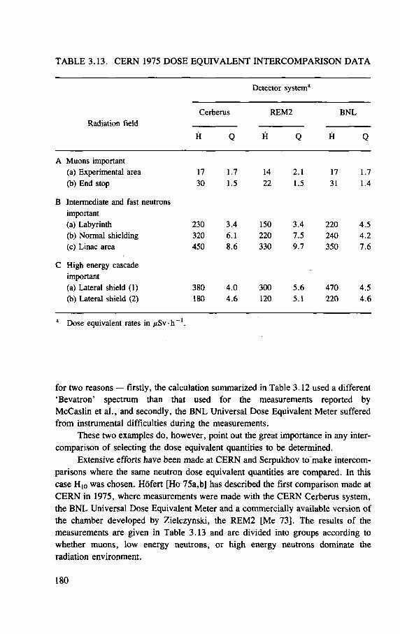
TABLE 3.13. CERN 1975 DOSE EQUIVALENT INTERCOMPARISON DATA
Detector system3
Radiation field Cerberus REM2 B N L
Radiation field
H Q H Q H Q
A Muons important (a) Experimental area 17 1.7 14 2.1 17 1.7 (b) End stop 30 1.5 22 1.5 31 1.4
B Intermediate and fast neutrons important (a) Labyrinth 230 3 .4 150 3.4 220 4 .5 (b) Normal shielding 320 6 .1 220 7 .5 240 4 .2 (c) Linac area 450 8.6 330 9 .7 350 7 .6
C High energy cascade important
(a) Lateral shield (1) 380 4 .0 300 5 .6 470 4 .5 (b) Lateral shield (2) 180 4 . 6 120 5.1 220 4 . 6
a Dose equivalent rates in /xSv • h 1.
for two reasons — firstly, the calculation summarized in Table 3.12 used a different 'Bevatron' spectrum than that used for the measurements reported by McCaslin et al., and secondly, the BNL Universal Dose Equivalent Meter suffered from instrumental difficulties during the measurements.
These two examples do, however, point out the great importance in any inter-comparison of selecting the dose equivalent quantities to be determined.
Extensive efforts have been made at CERN and Serpukhov to make intercom-parisons where the same neutron dose equivalent quantities are compared. In this case H10 was chosen. Hofert [Ho 75a,b] has described the first comparison made at CERN in 1975, where measurements were made with the CERN Cerberus system, the BNL Universal Dose Equivalent Meter and a commercially available version of the chamber developed by Zielczynski, the REM2 [Me 73], The results of the measurements are given in Table 3.13 and are divided into groups according to whether muons, low energy neutrons, or high energy neutrons dominate the radiation environment.
180
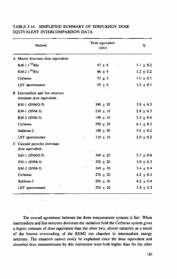
T A B L E 3.14. S I M P L I F I E D S U M M A R Y O F S E R P U K H O V D O S E
E Q U I V A L E N T I N T E R C O M P A R I S O N D A T A
Method Dose equivalent
(nSv)
A Muons dominate dose equivalent:
KM-1 (103Rh) 67 ± 6 1.1 ± 0 . 2
KM-2 ( l 0 3Rh) 66 ± 9 1.2 ± 0.2
Cerberus 53 ± 3 1.0 ± 0.1
LET spectrometer 65 ± 6 1.2 ± 0.1
B Intermediate and fast neutrons dominate dose equivalent:
KM-1 (SNMO-5) 390 ± 30 3.9 ± 0.3
KM-1 (SNM-3) 210 ± 10 2.8 ± 0 .3
KM-2 (SNM-3) 190 ± 10 3.5 ± 0.4
Cerberus 290 ± 20 6.1 ± 0 .5
Sukhona-2 180 ± 30 3.6 ± 0.2
LET spectrometer 110 ± 10 2.0 ± 0.2
C Cascade particles dominate dose equivalent:
KM-1 (SNMO-5) 340 ± 20 3.2 ± 0 .6
KM-1 (SNM-3) 300 ± 20 3.0 ± 0 .3
KM-2 (SNM-3) 240 ± 20 3.4 ± 0.4
Cerberus 270 ± 20 4.2 ± 0 .3
Sukhona-2 290 ± 30 4.2 ± 0 .4
LET spectrometer 200 ± 20 2.8 ± 0.3
The overall agreement between the three measurement systems is fair. When
intermediate arid fast neutrons dominate the radiation field the Cerberus system gives
a higher estimate of dose equivalent than the other two, almost certainly as a result
of the known overreading of the R E M 2 ion chamber to intermediate energy
neutrons. The situation cannot easily be explained since the dose equivalent and
absorbed dose measurements by this instrument were both higher than for the other
181
two systems. A s would be expected, the agreement is much better in those situations
where the dose equivalent is dominated by radiation of low L E T .
Antipov et al. have reported on measurements made in three locations around
the 70 G e V proton synchrotron at Serpukhov [An 78]. The detectors used included
an L E T spectrometer, a recombination chamber device (Sukhona-2) and various
thermal neutron detectors in moderating spheres (called S N M O - 5 , S N M O - 3 , S N M - 3
and l 03Rh) that are used in conjunction with n C measurements and measurements
with an aluminium walled air ionization chamber. Different matrices were used to
correct the response of one detector due to components of the radiation field other
than the one expected to be measured ( K M - 1 and KM-2 ) . A simplified summary of
the results of the measurements is given in Table 3.14. The two matrix methods used
to derive the Serpukhov Group values will provide estimates of the M A D E and can
thus be expected to be higher than the H 1 0 estimate of the Cerberus system. Again,
if intermediate and fast neutrons dominate then the Cerberus system gives a high
result.
REFERENCES
[Ak 63] AKAGI, H. , LEHMAN, R. , Neutron dosimetry in and around human phantoms by the use of nuclear track emulsion, Health Phys. 9 (1963) 207.
[Al 70] ALSMILLER, R.G. , J r . , ARMSTRONG, T .W. , COLEMAN, W . A . , The absorbed dose and dose equivalent f rom neutrons in the energy range 60 to 3,000 MeV and protons in the energy range 400 to 3,000 MeV, Nucl. Sci. Eng. 42 (1970) 367.
[Al 71] ALSMILLER, R .G. , Jr . , ARMSTRONG, T .W. , BISHOP, B.L. The absorbed dose and dose equivalent f rom negatively and positively charged pions in the energy range 10 to 2000 MeV, Nucl. Sci. Eng. 43 (1971) 257.
[Al 74] ALEINIKOV, V .E . , GERDT, V.P . , KOMOCHKOV, M . M . , Neutron Spectra Outside the Shielding of High-Energy Proton Accelerators, Preprint JINR P16-8176, Joint Institute of Nuclear Research, Dubna (1974).
[Al 75] ALEINIKOV, V.E. , GERDT, V.P . , TIMOSHENKO, G.N. , Measurement of the Spectra of High-Energy Protons from the Shielding of the 680-MeV Synchrocyclotron, Preprint JINR P16-9400, Joint Institute of Nuclear Research, Dubna (1975).
[Al 76] ALEINIKOV, V .E . , GERDT, V .P . , KOMOCHKOV, M . M . , Some Regularities of the Formation of Neutron Spectra Outside the Shielding of Proton Accelerators, Rep. JINR P16-9870, Joint Institute of Nuclear Research, Dubna (1976).
[Al 79a] ALBERTS, W.G. , COSACK, M. , KLUGE, H . , LESIECKI, H. , WAGNER, S., ZILL, H . W . , European Workshop on Neutron Dosimetry for Radiation Protection, Rep. PTB-ND-17, Physikalisch-Technische Bundesanstalt, Braunschweig (1979).
182
[Al 79b] ALEINIKOV, V . E . , K O M O C H K O V , M . M . , KRILOV, A . R . , T I M O S H E N K O , G . H . , H A H N , G . , The Energy-Angle Distributions of the Proton Component of the Radiation Field Behind the 660 MeV Synchro-cyclotron Shielding, Preprint 16-12732, Joint Institute for Nuclear Research, Dubna (1979).
[An 63a] A N D E R S S O N , I .O . , B R A U N , J . , A neutron rem counter, Nucleonik 6 (1963) 237.
[An 63b] A N D E R S S O N , I .O . , B R A U N , J . , " A neutron rem counter with uniform sensitivity f rom 0 .025 MeV to 10 M e V " , Neutron Dosimetry (Proc. Symp. Harwell , 1962), Vol. 2, IAEA, Vienna (1963) 87.
[An 78] ANTIPOV, A . V . , BAJSHEV, I .S . , G O L O V A C H I K , V . T . , KRUPNYJ , G . I . , K U S T A R E V , V . N . , L E B E D E V , V . N . , H O F E R T , M . , Comparison of Dose Equivalent Measurements behind the I H E P Accelerator Shielding Using Different Methods, Rep. IFVEORI 78-15, Institute of High-Energy Physics, Serpukhov (1978) (in Russian) (Available in English translation in Rep. C E R N Trans. 78-01).
[Ar 73] A R M S T R O N G , T . W . , C H A N D L E R , K . C . , Calculation of the absorbed dose and dose equivalent f rom neutrons and protons in the energy range f rom 3.5 GeV to 1.0 TeV, Health Phys. 24 (1973) 277.
[Au 68] AUXIER, J .A . , S N Y D E R , W.S . , JONES, T . D . , "Neu t ron interactions and penetration in t i s sue , " Radiation Dosimetry (ATTIX, F . H . , ROESCH, W . C . , Eds), 2nd edn, Vol. 1, Academic Press, New York (1968) 275.
[Aw 66] A W S C H A L O M , M . , The Use of the Multisphere Neutron Detector for Dosimetry of Mixed Radiation Fields, Rep. PPAD-596E Princeton-Pennsylvania Accelerator, Princeton, NJ (1966).
[Aw 85] A W S C H A L O M , M . , S A N N A , R.S . , Applications of Bonner sphere detectors in neutron field dosimetry, Radiat. Prot. Dosim. 10 1 - 4 (1985) 89.
[Ba 57] B A R A N O V , P .S . , GOLDANSKII , V . I . , R O G A N O V , V .S . , Dosimeter for high-energy neutrons, Rev. Sci. Instrum. 28 (1957) 1029.
[Ba 64] BAARLI , J . , private communication to W . Middelkoop, Rep. AR/INT/SG64-6 , C E R N , Geneva (1964).
[Ba 65] BAARLI , J . , SULLIVAN, A . H . , "Heal th physics survey methods around the C E R N high-energy accelera tors" , Rep. CONF-651109, USAEC (1965) 103.
[Ba 67] B A T H O W , G . , F R E Y T A G , E . , T E S C H , K. , Measurements on 6.3-GeV electromagnetic cascades and cascade produced neutrons, Nucl. Phys. , B 2 (1967) 669.
[Ba 69a] B A U M , J . W . , W O O D C O C K , R . C . , K U E H N E R , A . V . , "Fac to r s affecting pulse size in sealed tissue equivalent coun te r s " , Rep. CONF-691101 (1969) 648.
[Ba 69b] BAARLI , J . , "Dos imet ry of very high energy rad ia t ion" , Health Physics ( D U H A M E L , A . , Ed.) , Pergamon Press, Oxford and New York (1969) 297.
[Be 82] B E Y N E L , P . , MAIER, P . , S C H O N B A C H E R , H . , Compilation of Radiation Damage Test Data, Part HI: Materials Used Around High-Energy Accelera-tors, Rep. 82-10, C E R N , Geneva (1982).
183
[Bo 62] B O N E T - M A U R Y , P . , D U H A M E L , M . , PERRIN, F . , in Premier colloque international sur la protection aupr&s des grands acc616rateurs, Presses Universitaires de France, Paris (1962).
[Br 60] B R A M B L E T T , R . L . , E W I N G , R . I . , B O N N E R , T . W . , A new type of neutron spectrometer, Nucl. Instrum. Methods 9 (1960) 1.
[Bu 68] BURLIN, T . E . , "Cavi ty chamber t heo ry" , Radiation Dosimetry, Vol. 1 (ATTIX, F . H . , , ROESCH, W . C . , Eds), Academic Press, New York (1968) 332.
[Bu 81a] BURGER, G . , EBERT, H . G . , H A R D E R , D . , K R A M E R , R. , W A G N E R , S.R. (Eds), Radiation Protection Quantities for External Exposures (Proc. Sem. Braunschweig, 1980), Rep. EUR-7101-EN, Harwood Academic Pub-lishers, Chur , Switzerland (1981).
[Bu 81b] BURGER, G . , M O R H A R T , A . , N A G A R A J A N , P .S . , W I T T M A N N , A. , "Convers ion functions for primary and operational quantities in neutron radiation pro tec t ion" , Rep. EUR-7101-EN, Commission of the European Communities, Luxembourg (1981) 33.
[Bu 82] BUTLER, G . W . , DROPESKY, B . J . , O R T H , C . J . , G R E E N , R . E . L . , KORTELING, R . G . , L A M , G . K . Y . , Cross Sections for the , 2 C ( i r V N ) " C Reactions f rom 20 to 100 MeV, Rep. LA-UR-82-1323, Los Alamos Natl Lab. , Los Alamos, N M (1982).
[Ca 65] C A P O N E , T . , et a l . , A Radiation Survey Inside and Outside the CPS Tunnel to Estimate the Effectiveness of the Roof Shielding, Rep. DI /HP/71 , C E R N , Geneva (1965).
[Ca 70] CARTER, T . G . , C H A K A L I A N , V . M . , T H O M A S , R . H . , Stanford Mark I Moderator Calibration Using Tantalum, Rep. RHT/TN/70-2 , Stanford University, C A (1970).
[Ca 82] CASARETT, G . W . , Scientific Commit tee on Basic Radiation Protection Criteria, Reports on Selected N C R P Activities, in Ref. [NCRP 82], p. 272.
[CERN 71] C E R N , Proceedings of the International Congress on Protection Against Accelerator and Space Radiation, Geneva, April 1971, Rep. 71-16, C E R N , Geneva (1971).
[CFR 78] Code of Federal Regulations Title 10, Energy: Part 20, Standards for Protection Against Radiation, US Govt Printing Off ice , Washington, DC (1978).
[Ch 66] C H A R A L A M B U S , St . , D U T R A N N O I S , J . , GOEBEL, K. , Particle Flux Measurements with Activation Detectors, Rep. DI /HP/90 , C E R N , Geneva (1966).
[Ch 78] C H E N , S .Y. , Calculation of Neutron Fluence-to-Dose-Index Conversion Factors for the Standard ICRU Tissue Phantom by the Monte Carlo Method, PhD Thesis, Nuclear Engineering Dept . , Univ. of Illinois at Urbana-Champaign, IL (1978).
[Ch 79] C H E N , S .Y. , C H I L T O N , A.B. , Calculations of fast neutron depth-dose in the ICRU standard tissue phantom and the derivation of neutron fluence-to-dose-index conversion factors, Radiat. Res. 78 (1979) 335.
184
[Ch 81a] C H I L T O N , A .B . , "Calculated index quantities for neu t rons" , Rep. EUR-7101-EN, Harwood Academic Publishers, Chur , Switzerland (1981) 89.
[Ch 81b] C H I L T O N , A.B. , SHIUE, Y . L . , "Progress report on studies concerning doses in the ICRU sphere resulting f rom neutron b e a m s " , Rep. EUR-7448-EN, Commission of the European Communit ies, Luxembourg (1981) 63.
[Co 53] C O W A N , F . P . , H A N D L O S E R , J .S . , Health Physics Program for the Brookhaven Cosmotron, Rep. BNL-264 (T-43), Brookhaven Natl Lab. , Upton, NY (1953).
[Co 81] COSACK, M . , LESIECKI, H . , "Dependence of the response of eight neutron dose equivalent survey meters with regard to energy and direction of incident neu t rons" , Rep. EUR-7448-EN, Commission of the European Com-munities, Luxembourg (1981) 407.
[Cr 85] CROSS, W . G . , ING, H . , Conversion and quality factors relating neutron
fluence and dosimetric quantities, Radiat. Prot . Dosim. 10 1 - 4 (1985) 29. [deS 65] de STAEBLER, H . , ' 'Similarity of shielding problems at electron and proton
accelera tors" , Rep. CONF-651109, USAEC (1965) 429. [Di 65] D I S T E N F E L D , C . H . , M A R K O E , A . M . , "Determinat ion of quality factor
through the utilization of a balanced tissue-equivalent ionization c h a m b e r " , Rep. CONF-651109, USAEC (1965) 181.
[Dm 71] DMITRIEVSKY, I . M . , KABAKOV, J . I . , POTJOMKIN, E . L . , F R O L O V , V . V . , " H i g h energy nucleon tissue d o s e s " , Rep. 71-16, C E R N , Geneva (1971) 328.
[Ei 81] E I S E N H A U E R , C . , S C H W A R T Z , R. Difficulties in calculating spectrum-averaged values of neutron dose equivalent, Health Phys. 41 (1981) 774.
[Fa 50] FAILLA, G . , ROSSI, H . H . , Tissue equivalent ionization chambers , Am. J. Roentgenol. Radium Ther . Nucl. Med. 64 (1950) 485.
[Fr 70] F R E Y T A G , E . , N A C H T I G A L L , D . , A Comparison of Health Physics Measuring Procedures at Accelerators, Rep. DESY/70/27 , Deutsches Electronen Synchrotron, Hamburg (1970).
[Ga 76] GARBER, D. I . , KINSEY, R .R . , Neutron Cross Sections, 3rd edn, Vol.2, National Neutron Cross Section Center, Brookhaven Natl Lab. , Upton, NY (1976).
[Gi 68] GILBERT, W . S . , et al . , 1966 C E R N - L B L - R H E L Shielding Experiment at the C E R N Proton Synchrotron, Rep. UCRL-17941, Lawrence Berkeley Lab . , Berkeley, CA (1968).
[Go 67] G O E B E L , K. , RINDI , A . , SULLIVAN, A . H . , BAARLI , J . , " T h e purpose, interpretation and utilization of area monitoring measurements near the C E R N accelera tors" , Rep. CONF-670621 (1967) 435.
[Go 68] G O O D M A N , L . J . , ROSSI, H . H . , The measurement of dose equivalent using paired ionization chambers, Health Phys. 14 (1968) 168.
[Go 78] G O L O V A C H I K , V . T . , P O T E M K I N , E . L . , L E B E D E V , V .N . F R O L O V , V . V . , " D o s e s f rom high-energy particles in a tissue-equivalent p h a n t o m " , cited in Atlas of Dose Characteristics of External Radiations (BIKROV, A. I . ,
185
DUDKIN, V .E . , K O V A L E V , E . E . , et al . , Eds), Atomizdat, Moscow (1978).
[Ha 47] H A N S O N , A . O . , McKIBBEN, J . L . , A neutron detector having uniform sensitivity f rom 10 keV to 3 MeV, Phys. Rev. 72 (1947) 673.
[Ha 62] HANKINS, D . E . , A Neutron Monitoring Instrument Having a Response Approximately Proportional to the Dose Rate f rom Thermal to 7 MeV, Rep. LA-2717, Los Alamos Scientific Lab. , NM (1962).
[He 57] HESS, W . N . , P A T T E R S O N , H . W . , W A L L A C E , R . W . , Delay-line chamber has large area, low capacitance, Nucleonics 15 3 (1957) 74.
[He 59a] HESS, W . N . , Neutrons from (a , n) sources, Ann. Phys. (N.Y.) 6 (1959) 115.
[He 59b] HESS, W . N . , PATTERSON, H . W . , W A L L A C E , R . W . , C H U P P , E . L . , Cosmic ray neutron energy spectrum, Phys. Rev. 116 (1959) 445.
[Ho 72] HOFERT, M . , " D o s e equivalent and quality factor of radiation f rom high-energy accelera tors" , Rep. EUR-4896d-f-e , Commission of the European Communities, Luxembourg (1972) 873.
[Ho 75a] H O F E R T , M . , A Comparison of Dose Equivalent Measurements Around a GeV Proton Accelerator, Rep. DI /HP/187, C E R N , Geneva (1975).
[Ho 75b] H O F E R T , M . , BAARLI , I . , " D o s e estimation of very high neutron radiation for protection pu rposes" , Proceedings of the IVth Ail-Union Congress on Charged Particle Accelerators, Vol. 2 , Nauka, Moscow (1975) 207.
[Ho 80] H O F E R T , M . , R A F F N S O E , Ch . , Measurements of absolute absorbed dose and dose-equivalent response for instruments used around high-energy proton accelerators, Nucl. Instrum. Methods 176 (1980) 443.
[Ho 83] H O F E R T , M . , On the Problem of Neutron Dosimetry Around High-energy Accelerators and Pragmatic Solutions, Rep. HS-RP/IR/83-22, C E R N , Geneva (1983).
[Ho 85] HOLT, P . D . , Passive detectors for neutron fluence measurement, Radiat. Prot. Dosim. 10 1 - 4 (1985) 251.
[HP 77] H E A L T H PHYSICS G R O U P , L A W R E N C E BERKELEY L A B O R A T O R Y , Accidental Accelerator Beam Exposure Dosimetry Procedure, Rep. UCID-3905, Lawrence Berkeley Lab. , Berkeley, CA (1977).
[ ICRP 63] RBE C O M M I T T E E , Report of the RBE Committee to the International Commissions on Radiological Protection and on Radiological Units and Measurements, Health Phys. 9 (1968) 357.
[ICRP 64] I N T E R N A T I O N A L COMMISSION ON RADIOLOGICAL P R O T E C T I O N , Protection Against Electromagnetic Radiation above 3 MeV and Electrons, Neutrons and Protons, ICRP Publication 4 , Pergamon Press, Oxford and New York (1964).
[ ICRP 70] I N T E R N A T I O N A L COMMISSION O N RADIOLOGICAL P R O T E C T I O N , Protection against Ionizing Radiation f rom External Sources, I C R P Publication 15, Pergamon Press, Oxford and New York (1970).
[ ICRP 73] I N T E R N A T I O N A L COMMISSION O N RADIOLOGICAL P R O T E C T I O N , Data for Protection Against Ionizing Radiation f rom External Sources: Supplement to ICRP Publication 15, I C R P Publication 21, Pergamon Press, Oxford and New York (1973).
186
[ ICRP 86] I N T E R N A T I O N A L COMMISSION O N RADIOLOGICAL P R O T E C T I O N , Data for Use in Protection against External Radiation, I C R P Publication 44 , Pergamon Press, Oxford and New York (1986).
[ICRU 68] I N T E R N A T I O N A L COMMISSION O N RADIATION UNITS A N D M E A S U R E M E N T S , Radiation Quantities and Units, ICRU Report 11, Washington, DC (1968).
[ ICRU 78] I N T E R N A T I O N A L COMMISSION O N RADIATION UNITS A N D M E A S U R E M E N T S , Basic Aspects of High Energy Particle Interactions and Radiation Dosimetry, ICRU Report 28, Washington, DC (1978).
[In 81] ING, H. , CROSS, W . G . , T Y M O N S , B.J . , The spectrum of neutrons f rom
a 238Pu-Li source, Health Phys. 40 (1981) 345. [In 85] ING, H . , P IESCH, E. (Eds), Neutron dosimetry in radiation protection,
Radiat. Prot. Dosim. 10 1 - 4 (1985). [Ir 67] IRVING, D . C . , ALSMILLER, R . G . , J r . , M O R A N , H .S . , Tissue Current-
to-Dose Conversion Factors for Neutrons with Energies f rom 0 .5 to 60 MeV, Rep. ORNL-4032, Oak Ridge Natl Lab . , TN (1967).
[Iz 80] I Z Y C K A , A. , S C H O N B A C H E R , H . , "High-level dosimetry for radiation damage studies at high-energy accelera tors" , Rep. EUR-6813, Euratom Ispra (1980).
[Ke 48] KELLY, E . , W E I G A N D , C . , Fission of elements f rom Pt to Bi by high-energy neutrons, Phys. Rev. 73 (1948) 1135.
[Kr 82a] K R A M E R , R. , Z A N K E , M . , WILLIAMS, G. , D R E X L E R , G . , The Calculation of Dose f rom External Photon Exposures Using Reference Human Phantoms and Monte Carlo Methods. Part 1. The Male (ADAM) and Female (EVA) Adult Mathematical Phantoms, GSF Rep. S-885, Gesellschaft fur Strahlen und Umweltforschung mbH, Munich (1982).
[Kr 82b] K R A M E R , R . , D R E X L E R , G . , On the calculation of the effective dose equivalent, Radiat. Prot. Dosim. 3 1/2 (1982) 13.
[Ku 72] K U E H N E R , A . V . , C H E S T E R , J .D . , BAUM, J . W . , Portable Mixed Radiation Dose Equivalent Meter , Rep. BNL-17298, Brookhaven Natl Lab . , Upton, NY (1972).
[Ku 73a] K U E H N E R , A . V . , CHESTER, J . D . , BAUM, J . W . , "Por tab le mixed radiation dose-equivalent meter for protection moni to r ing" , Neutron Monitoring for Protection Purposes (Proc. Symp. Vienna, 1972), IAEA, Vienna (1973) 233.
[Ku 73b] K U E H N E R , A . V . , C H E S T E R , J . D . , Dose Equivalent Meter Operating Instructions, BNL, Health and Safety Division, Informal Report , Brookhaven Natl Lab . , Upton, N Y (1973).
[La 69] L A U G H L I N , J .S . , "Elec t ron b e a m s " , Radiation Dosimetry, Vol. Ill (ATTIX, F . H . , T O C H I L I N , E . , Eds), Academic Press, New York (1969) 92.
[La 70] LARSON, H . V . , " A n intercomparison of the characteristics of beta/gamma
and neutron survey ins t ruments" , Advances in Physical and Biological Radiation Detectors (Proc. Symp. Vienna, 1970), IAEA, Vienna (1971) 533.
187
[Le 64a] LEAKE, J . W . , SMITH, J . W . , Calibration of a Neutron Rem Counter, Rep. AERE-R 4524, Atomic Energy Research Establishment, Harwell , UK (1964).
[Le 64b] L E H M A N , R. , F E K U L A , O . M . , Energy spectrum of stray neutrons f rom the bevatron, Nucleonics 22 11 (1964) 35.
[Le 67] LEAKE, J .W. , "Por tab le instruments for the measurement of dose-equivalent rate in steady state and pulsed neutron f i e lds" , Neutron Monitoring (Proc. Symp. Vienna, 1966), IAEA, Vienna (1967) 313.
[Le 68] LEAKE, J . W . , An improved spherical dose equivalent neutron detector, Nucl. Instrum. Methods 63 (1968) 329.
[Li 57] L I N D E N B A U M , S . J . , " T h e Brookhaven National Laboratory Proton Synchrot ron" , Rep. TID-7545, USAEC (1957) 28.
[Li 73] LIM, C .B . , The Development of a Neutron Spectrometer using Mult i-Wire Spark Chambers , PhD Thesis, Rep. LBL-1719, Nuclear Engineering Department, University of California at Berkeley, Berkeley, C A (1973).
[Ma 73] M A D E Y , R . , W A T E R M A N , F . M . , "Neu t ron spectroscopy f rom 1 MeV to 1 G e V " , Neutron Monitoring for Radiation Protection Purposes (Proc. Symp. Vienna, 1972), Vol. 1, IAEA, Vienna (1973) 113.
[Ma 74] M A M O N T - C I E S L A , K. , RINDI, A. , Spark Chamber Neutron and Proton Spectrometer — First Report on Performance, Rep. LBL-3343, University of California, Lawrence Berkeley Lab . , Berkeley, CA (1974).
[McC 60] McCASLIN, J .B . , A high energy neutron flux detector, Health Phys. 2 (1960) 399.
[McC 67] McCASLIN, J .B . , STEPHENS, L . D . , High-Sensitivity Neutron and Proton Flux Detector with a Practical Threshold Near 600 MeV Using Hg(spallation) 149Tb, Rep. UCRL-17505, Lawrence Berkeley Lab. , Berkeley, CA (1967).
[McC 68] McCASLIN, J .B . , PATTERSON, H . W . , SMITH, A . R . , S T E P H E N S , L .D . , " S o m e recent developments in techniques for monitoring high-energy accelerator rad ia t ion" , Proceedings of the First International Symposium of the International Radiation Protection Association, Pergamon Press, Oxford and New York (1968) 113.
[McC 73] McCASLIN, J .B. , "Detect ion of neutrons greater than 20 MeV from the production of " C " , Accelerator Health Physics (PATTERSON, H . W . , T H O M A S , R . H . , Eds), Academic Press, New York (1973) 621.
[McC 77] McCASLIN, J .B. , SMITH, A .R . , STEPHENS, L . D . , T H O M A S , R . H . , JENKINS, T . M . , W A R R E N , G. J . , B A U M , J .W. , An intercomparison of dosimetry techniques in radiation fields at two high-energy accelerators, Health Phys. 33 (1977) 611.
[McC 81] McCASLIN, J .B . , T H O M A S , R . H . , "Pract ical neutron dosimetry at high energ ies" , Radiation Protection Quantities for External Exposure (BURGER, G . , HARDER, D . , K R A M E R , R . , W A G N E R , S. , Eds), Rep. EUR-7101-EN, Harwood Academic Publishers, Chur , Switzerland (1981) 137.
[McG 66] McGUIRE, S. A . , A Dose-Monitoring Instrument for Neutrons f rom Thermal to 100 MeV, Rep. LA-3435, Los Alamos Lab. , CA (1966).
188
[Me 73] M E T R O N E X C O M P A N Y , Recombination Chamber Type REM-2 , Technical Manual , Warsaw (1973).
[Mi 72] M I L L E R , A . J . , P A T T E R S O N , H . W . , Measurement of induced activity to estimate personal radiation exposures received f rom accelerator beams, Health Phys. 23 (1972) 671.
[Mo 52] M O Y E R , B. , Survey methods for fast and high-energy neutrons, Nucleonics 10 5 (1952) 14.
[Mo 54] M O Y E R , B.J . , Neutron physics of concern to the biologist, Radiat. Res. 1 (1954) 10.
[Mo 57] M O Y E R , B.J . , "Bui ldup fac to r s" , Rep. TID-7545, U S A E C (1957) 96. [Mo 79] M O L E , R . H . , Role for carcinogenesis by fission neutrons, Health Phys. 36
(1979) 463. [Na 69] N A G A R A J A N , P .S . , "Neu t ron dose distributions in an infinite slab of
standard-man compos i t ion" , Radiation Protection Monitoring (Proc. Sem. Bombay, 1968), IAEA, Vienna (1969) 61.
[Na 72] N A C H T I G A L L , D . , BURGER, G . , " D o s e equivalent determinations in neutron fields by means of moderator techniques" , Topics in Radiation Dosimetry, Supplement 1 (ATTIX, F . H . , Ed.) , Academic Press, New York (1972) 385.
[Na 81] N A G A R A J A N , P .S . , W I T T M A N N , A . , BURGER, G . , " F a s t neutron organ dose calculations using a MIRD p h a n t o m " , Rep. EUR-7448-EN, Vol. 1, Commission of the European Community , Luxembourg (1981) 49.
[NCRP 57] N A T I O N A L C O U N C I L O N RADIATION PROTECTION A N D M E A S U R E M E N T S , Protection against Neutron Radiation up 30 Million Electron Volts, National Bureau of Standards Handbook 63, US Dept. of Commerce , Washington, DC (1957).
[NCRP 71] N A T I O N A L C O U N C I L ON RADIATION P R O T E C T I O N A N D M E A S U R E M E N T S , Protection Against Neutron Radiation, Rep. 38, Washington, DC (1971).
[NCRP 82] N A T I O N A L C O U N C I L O N RADIATION P R O T E C T I O N A N D M E A S U R E M E N T S , Critical Issues in Setting Radiation Dose Limits, Proc. 7th Annual Mtg NRCP, April 1981, N C R P , Washington, D C (1982).
[Ne 66] N E U F E L D , J . , S N Y D E R , W . S . , T U R N E R , J .E . , W R I G H T , H . , Calcula-tion of radiation dose f rom protons and neutrons to 400 MeV, Health Phys. 12 (1966) 227.
[Ne 76] N E L S O N , W . R . , Accelerator beam dosimetry, IEEE Trans. Nucl. Sci. NS-23 4 (1976) 1376.
[Ng 85] N G U Y E N , V . D . , L U C C I O N I , C . , P A R M E N T I E R , N . , Average quality factor and dose equivalent meter based on microdosimetry technique, Radiat. Prot. Dosim. 10 1 - 4 (1985) 277.
[OB 68] O ' B R I E N , K. , M c L A U G H L I N , J .E . , The propagation of the neutron component of the nucleonic cascade at energies less than 500 MeV: theory and a solution to the accelerator transverse shielding problems, Nucl. Instrum. Methods 60 (1968) 129.
189
[OB 71] O 'BRIEN, K. , Neutron Spectra in the Sideshielding of a Large Particle Accelerator, Rep. HASL-240, Health and Safety Lab. USNRC, Washington, DC (1971).
[Pa 57] PATTERSON, H . W . , " T h e University of California Radiation Laboratory synchrocyclot ron" , Rep. TID-7545, USAEC (1957) 3.
[Pa 59] PATTERSON, H . W . , HESS, W . N . , M O Y E R , B.J . , W A L L A C E , R . W . , The flux and spectrum of cosmic-ray produced neutrons as a function of altitude, Health Phys. 2 (1959) 69.
[Pa 65] PATTERSON, H . W . , "Accelerator radiation monitoring and shielding at the Lawrence Radiation Laboratory, Berke ley" , Rep. CONF-651109, USAEC (1965) 3.
[Pa 69] PATTERSON, H . W . , H E C K M A N , H . , ROUTTI , J .T . , " N e w measurement of star production in nuclear emulsions and applications to high-energy neutron spec t roscopy" , Rep. CONF-691101, USAEC (1969) 750.
[Pa 71] P A T T E R S O N , H . W . , ROUTTI , J .T . , T H O M A S , R . H . , What quality factor?, Health Phys. 20 (1971) 517.
[Pa 73] PATTERSON, H . W . , T H O M A S , R . H . , Accelerator Health Physics, Academic Press, New York (1973).
[Pe 66] PERRY, D . R . , "Neu t ron dosimetry methods and experience on the 7 GeV proton synchrotron N i m r o d " , Neutron Monitoring (Proc. Symp. Vienna, 1967), IAEA, Vienna (1967) 355.
[Pe 68] P E N F O L D , J . , STEVENSON, G . R . , Preliminary Measurements of the Angular Distribution of the Stray Radiation Field, Rep. RP /PN/29 , Rutherford Lab. , Chilton, UK (1968).
[Pe 80] P E R E Z - M E N D E Z , V . , "Detectors for radiation dos imet ry" , Advances in Radiation Protection and Dosimetry in Medicine ( T H O M A S , R . H . , P E R E Z - M E N D E Z , V. , Eds), Plenum Press, New York and London (1980) 143.
[Ps 69] PSZONA, S. , A new approach for determining quality factor and dose equivalent in mixed radiation fields, Health Phys. 16 (1969) 9.
[Ps 71] PSZONA, S. , " T h e N E 102A organic scintillation detector as an acceptable L E T dependent detector for quality factor and dose equivalent determination in mixed radiation f i e lds" , Rep. 71-16, Vol. 1, C E R N , Geneva (1971) 388.
[Ps 77] PSZONA, S. , H O F E R T , M. , A rapid method for the determination of dose equivalent in mixed radiation fields, Nucl. Instrum. Methods 146 (1977) 509-512.
[Ra 69] RAJU, M . R . , L Y M A N , J .T . , BRUSTAD, T . , TOBIAS, C . A . , " H e a v y charged-particle b e a m s " , Radiation Dosimetry, Vol. 3 (ATTIX, F . H . , TOCHILIN, E. , Eds), Academic Press, New York (1969) 151.
[Re 65] R E M Y , R. , Neutron Spectroscopy by the Use of Nuclear Stars f rom 20-300 MeV, MSc Thesis, Rep. UCRL-16325, Lawrence Berkeley Lab . , Berkeley,' CA (1965).
[Ri 68] RINDI, A. , Evaluation of Fluxes and Dose Equivalent Rates in Neutron Fields Around High-Energy Accelerators, Rep. UCRL-18424, Lawrence Berkeley Lab. , Berkeley, CA (1968).
190
[Ri 69] RINDI, A. , "Presen t and projected uses of multiwire spark chambers in health phys ics" , Rep. CONF-691101, USAEC (1969) 660.
[Ri 71] RINDI, A . , T H O M A S , R . H . , ' 'Absorbed dose — An unfortunate red herring in radiation pro tec t ion" , Proc. 6th Annual Health Physics Society Mid-Year Topical Symposium, Richland, Washington, Nov. 1971, Columbia Chapter , Health Physics Society, Richland, W A (1971).
[Ri 72] RINDI, A . , T H O M A S , R . H . , Povera e Nuda Vai, Dosimetria, Health Phys. 23 (1972) 715.
[Ri 74] RINDI A . , A spectrometer for measuring charged particles and neutrons, Nucl. Instrum. Methods 116 (1974) 471.
[Ro 55] ROSSI, H . H . , R O S E N Z W E I G , W . , A device for the measurement of dose as a function of specific ionization, Radiology 64 (1955) 404.
[Ro 56] ROSSI, H . H . , FAILLA, G . , Tissue equivalent ionization chambers, Nucleonics 14 2 (1956) 32.
[Ro 69] ROUTTI , J .T . , "Mathematical considerations of determining neutron spectra f rom activation measurements" , Rep. CONF-691101, USAEC (1969) 494.
[Ro 77] ROSSI, H . H . , A proposal for the revision of quality factor, J. Environ. Biophys. 14 (1977) 275.
[Ro 78a] ROSSI, H . H . , MAYS, C . W . , Leukemia risk from neutrons, Health Phys. 34 (1978) 353.
[Ro 78b] ROGERS, D . W . O . , Conversion of neutron/cm2 to rem, Health Phys. 34 (1978) 395.
[Ro 79] ROGERS, D . W . O . , Why not to trust a neutron remmeter , Health Phys. 37 (1979) 735.
[Ro 80] ROUTTI , J .T . , SANDBERG, J .V . , "Unfo ld ing techniques in activation detector ana lys is" , Computer Techniques in Radiation Transport and Dosimetry (NELSON, W . R . , JENKINS, T . M . , Eds), Plenum Press, New York and London (1980).
[Ro 85] ROUTTI , J .T . , SANDBERG, J .V . , Unfolding activation and multisphere detector data, Radiat. Prot. Dosim. 10 1 - 4 (1985) 103.
[Sc 79a] S C H O N B A C H E R , H . , STOLARZ- IZYCKA, A. , Compilation of Radiation Damage Test Data, Part I: Cable Insulating Materials, Rep. 79-04, C E R N , Geneva (1979).
[Sc 79b] S C H O N B A C H E R , H . , STOLARZ- IZYCKA, A. , Compilation of Radiation Damage Test Data, Part II: Thermosetting and Thermoplastic Resins, Rep. 79-08, C E R N , Geneva (1979).
[Sh 51] SHARPE, J . , S T A F F O R D , G . H . , The 1 2 C ( n , 2 n ) n C reaction in an anthracene crystal, Proc. Phys. Soc (London) A64 (1951) 211.
[Sh 62] S H A W , K.B. , High-Energy Flux Measurements Using Plastic Scintillators, Rep. DI /HP/6 , C E R N , Geneva (1962).
[Sh 68] S H A W , K.B. , STEVENSON, G . R . , T H O M A S , R . H . , Evaluation of Dose Equivalent f rom Neutron Energy Spectra, Rep. RPP/R5, Rutherford Lab. , Chilton, UK (1968).
[Sh 69] S H A W , K.B. , S T E V E N S O N , G . R . , T H O M A S , R . H . , Evaluation of dose equivalent f rom neutron energy spectra, Health Phys. 17 (1969) 459.
191
SHAVE, A.J . , The Extraction of Terbium from Mercury by a Chemical Method, Rep. RP/PN/43 , Rutherford Lab. , Chilton, UK (1970) SHIUE, Y . -L . , CHILTON, A.B. , Calculation of low-energy neutron dose indices and depth doses in the ICRU tissue sphere, Radiat. Res. 93 (1983) 421.
SIMPSON, P . W . , The Measurement of Accelerator-Produced Neutron Flux by Activation of Indium, Gold and Cobalt , Rep. NIRL/M/70 , Rutherford Lab. , Chilton, UK (1964).
SIMS, C:S . , KILLOUGH, G . C . , Neutron fluence to dose-equivalent conversion factors: A comparison of data sets and interpolation methods, Radiat. Prot. Dos. 5 1 (1983) 45.
SMITH, A . R . , The Stray Radiation Field of the Bevatron, Rep. UCRL-8377, Lawrence Berkeley Lab. , Berkeley, C A (1958). SMITH, A . R . , A cobalt neutron flux integrator, Health Phys. 7 (1961) 40. SMITH, A.R. , " T h e measurement of the radiation-field around high-energy accelera tors" , Shielding Around High-Energy Accelerators (Proc. Conf . Paris, 1962), Presses Universitaires de France, Paris (1962) 137. SMITH, A .R . , "Threshold detector applications to neutron spectroscopy at the Berkeley accelerators" , Rep. CONF-651109, USAEC (1965) 224. SMITH, A . R . , A Tantalum Fast Neutron Integrator, Rep. UCRL-17051, Lawrence Berkeley Lab. , Berkeley, CA (1966).
SMITH, A . R . , T H O M A S , R . H . , The production of " C by the interaction of 376-MeV/amu N e 1 0 + ions with carbon, Nucl. Instrum. Methods 137 (1976) 459. SMITH, A . R . , S C H I M M E R L I N G , W . , KANSTEIN, L .L . , McCASLIN, J .B. , T H O M A S , R . H . , Neutron flux density and secondary particle spectra at the 184-Inch Synchrocyclotron Medical Facility, Med. Phys. 8 (1981) 668. SMITH, A .R . , McCASLIN, J .B . , G E A G A , J .V . , HILL, J .C . , VARY, J . P . , Cross sections for the production of 11C in C targets by 12C at relativistic energies, Phys. Rev. 28 (1983) 1641. SNYDER, W . S . , Calculations for maximum permissible exposure to thermal neutrons, Nucleonics 6 2 (1950) 46. SNYDER, W.S . , Depth Dose, in Protection Against Neutron Radiation up to 30 Million Electron Volts, N C R P Report 20, National Council on Radiation Protection and Measurements , Washington, D C (1957) 39. (Reprinted with corrections, April 1967).
SNYDER, W.S . , " D o s e distribution in a cylindrical phantom for neutron energies up to 14 M e V " , in [NCRP 71], p. 46. STEPHENS, L . D . , SMITH, A . R . , Fast Neutron Surveys Using Indium Foil Activation, Rep. UCRL-8418, Lawrence Berkeley Lab . , Berkeley, CA (1958).
STEVENSON, G . R . , Neutron Spectrometry from 0 .025 eV to 25 GeV, Rep. RHEL/R 154, Rutherford Lab. , Chilton, UK (1967). STAPLETON, G.B. , T H O M A S , R . H . , The production of 7Be by 7-GeV proton interactions with oxygen, Nucl. Phys. , A 125 (1971) 124.
[St 71b] S T E V E N S O N , G . R . , Evaluation of Neutron Dose Equivalent Around Nimrod, Rep. RP/PN/56 , Rutherford Lab. , Chilton, UK (1971).
[St 73a] S T E V E N S O N , G . R . , H O F E R T , M. , N E U F E L D , J . , RINDI, A. , ROUTTI , J .T . , P R E T R E , S. , "Standardizing the fluence-to-dose-equivalent conversion factors for whole-body neutron exposures" Neutron Monitoring for Radia-tion Protection Purposes (Proc. Symp. Vienna, 1972), Vol. 1, IAEA, Vienna (1973) 177.
[St 73b] STEVENSON, G . R . , discussion in [St 73a] (1973) 185. [St 73c] STEPHENS, L . D . , " T h e polyethylene-lined proportional coun te r " ,
Laboratory Manual , Accelerator Health Physics (PATTERSON, H . W . , T H O M A S , R . H . , Eds.) , Academic Press, New York (1973) 601.
[St 84] S T E V E N S O N , G . R . , The estimation of dose equivalent f rom the activation of plastic scintillators, Health Phys. 47 (1984) 837.
[Su 63] SULLIVAN, A . H . , BAARLI , J . , An Ionization Chamber for the Estimation of the Biological Effectiveness of Radiation, Rep. 63-17, CERN, Geneva (1963).
[Su 64] SULLIVAN, A . H . , An Approach to a Rem Dosimeter Using Ionization Chambers , Rep. DI /HP/29 , C E R N , Geneva (1964).
[Su 69] SULLIVAN, A . H . , " T h e present status of instrumentation for accelerator health phys i c s " , USAEC Rep. CONF-691101, USAEC (1969) 625.
[Su 84] SULLIVAN, A . H . , The use of detectors based on ionisation recombination in radiation protection, Radiat. Prot. Dosim. 9 (1984) 123.
[Te 70] T E S C H , K. , Neutron dosimetry in the energy range between 10 and 100 MeV, Nucl. Instrum. Methods 8 3 (1970) 295.
[Th 73] T H O M A S , R. H . , " Neutron dosimetry at high-energy particle accelerators ' ' , Neutron Monitoring for Radiation Protection Purposes (Proc. Symp. Vienna, 1972), IAEA, Vienna (1973) 327.
[Th 80a] T H O M A S , R . H . , P E R E Z - M E N D E Z , V. (Eds), "Advances in radiation pro-tection and dosimetry in medic ine" , Proceedings of the Third Course of the International School of Radiation Damage and Protection, Erice, September
1979, Plenum Press, New York and London (1980). [Th 80b] T H O M A S , R . H . , "Pass ive de tec tors" , Advances in Radiation Protection and
Dosimetry in Medicine (THOMAS, R . H . , P E R E Z - M E N D E Z V. , Eds) Plenum Press, New York and London (1980) 181.
[Th 85a] T H O M A S , R . H . , STEVENSON, G . R . , Radiation protection around high-energy accelerators, Radiat. Prot. Dosim. 10 1 - 4 (1985) 283.
[Th 85b] T H O M A S , R. , "Dosimetr ic aspec t s" , Some Important Issues in Developing Radiation Protection Issues, N C R P , Washington, DC (1985) 182.
[Th 85c] T H O R N G A T E , J . H . , GRIFFITH, R .V. , Neutron spectrometers for radiation monitoring at Lawrence Livermore National Laboratory, Radiat. Prot. Dosim. 10 1 - 4 (1985) 125.
[To 71] T O B A I L E M , J . , Cross Sections for the Nuclear Reactions Induced by Protons, Deuterons, and Alpha Particles. I. Monitor Reactions, Rep. CEA-N-1466( l ) , Centre dEtudes nucldaires de Saclay (1971) (in French).
193
[Tu 64]
[USAEC 57]
[USAEC 65]
[USAEC 67]
[USAEC 69]
[Wi 80]
[Wr 69]
[Ze 65]
[Zi 62]
[Zi 64]
[Zi 70]
T U R N E R , J .E . , ZERBY, C . D . , W O O D Y A R D , R .L . , WRIGHT, H . A . , KINNEY, W . E . , SNYDER, W . S . , N E U F E L D , J . , Calculation of radiation dose f rom protons to 400 MeV, Health Phys. 10 (1964) 783. UNITED STATES A T O M I C E N E R G Y COMMISSION, Rep. TID-7545, U S A E C (1957).
E N E R G Y COMMISSION,
E N E R G Y COMMISSION,
E N E R G Y COMMISSION,
Rep.
Rep.
Rep.
UNITED STATES A T O M I C CONF-651109, U S A E C (1965). U N I T E D STATES A T O M I C CONF-670305, U S A E C (1967). UNITED STATES ATOMIC CONF-691101, U S A E C (1969).
W I T T M A N N , A. , BURGER, G . , Organ Doses and Effective Dose Equivalent for External Neutron Beams derived by the Chord Method, Rep. GSF-Bericht 708, Gesellschaft fu r Strahlen und Umweltforschung mbH, Munich (1980).
WRIGHT, H . A . , A N D E R S O N , V . E . , T U R N E R , J . E . , N E U F E L D , J . , SNYDER, W . S . , Calculation of radiation dose due to protons and neutrons with energies f rom 0 .4 to 2 .4 GeV, Health Phys. 16 (1969) 13. ZERBY, C . D . , KINNEY, W . L . Calculated tissue current-to-dose conversion factors for nucleons below 400 MeV, Nucl. Instrum. Methods 36 (1965) 125. Z IELCZYNSKI , M . , Use of columnar recombination for determination of relative biological efficiency of radiation, Nukleonika 7 (1962) 175. Z IELCZYNSKI , M . , Instrument for determination of recommended relative biological effectiveness of radiation, Instrum. Exp. Tech. (Engl. Transl .) 6 (1964) 1217.
ZIELCZYNSKI , M . , "Comment s in radiation dos imet ry" , Proceedings of the International Summer School on Radiation Protection, Cavtat, Sep. 1970, Vol. 2, Boris Kidric Institute, Belgrade (1970) 34.
194
Chapter 4
RADIATION SHIELDING
4.1. INTRODUCTION
This chapter briefly discusses shielding criteria, the materials available for shielding and the factors determining the optimum choice. In addition the vast litera-ture on the shielding of proton accelerators is reviewed. Because the number of papers is so large, those discussed in detail here either deal with general techniques or contain data that may be incorporated as parameters in a generalized description used to specify shielding in simple geometries. The treatment of shielding in complex geometries or with several materials is not given here but reference is made to the literature in which techniques are given that are able to solve these problems.
In what follows it is important that the reader has an understanding of the basic physical processes involved in the interaction of ionizing radiations and particles with matter. These are concisely reviewed in Chapters 3 and 6 of Ref. [Pa 73]. These chapters also review the history of shielding studies at particle accelerators. For broader and more general discussions on radiation shielding the reader is referred to standard texts such as those by Price, Horton and Spinney [Pr 57], Chilton, Shultis and Faw [Ch 84], or the IAEA Engineering Compendium on Radiation Shielding [IAEA 68, 70, 75]. (See also the bibliography in Chapter 7.) Most of these texts primarily deal with radiation energies below about 20 MeV — much lower than the highest energies met with at particle accelerators. Nevertheless, they are relevant because, as we have seen in Chapters 2 and 3, much of the absorbed dose (and dose equivalent) from exposure to accelerator radiation environments is due to relatively low energy radiations. The only text devoted entirely to particle accelerator shielding is by Zaitsev, Komochkov and Sychev [Za 71].
For convenience, the treatment of shielding of proton accelerators is divided into two energy regions somewhat arbitrarily bounded at 3 GeV. The selection of this energy boundary may be justified by noting that below an energy of about 3 GeV the development of the hadronic cascade is relatively unimportant in determining the shield thickness.
A detailed discussion of the shielding of proton accelerators in a third energy region, below about 50 MeV, is not given here. The energy range below 100 MeV has been discussed in Report 51 of the National Council on Radiation Protection and Measurements [NCRP 77], This report gives equilibrium dose equivalent index tenth-value layers in concrete for neutrons of energy between 10 ~6 and 102 MeV. NCRP Report 38 gives attenuation data for absorbed dose in a variety of materials (water, concrete, earth and polythene), for neutrons of energy 0.5, 1, 2, 3 and
195
5 MeV. Broad geometry is considered, but with angles of incidence to the shield varying between 0° to 70° [Al 63, NRCP 71]. These data may be used in other geometries by the application of appropriate form-factors [Pa 73, Pr 57, Ro 56]. For neutrons between 0.5 and 15 MeV the use of removal cross-sections — an empirical approach to shielding developed for nuclear reactors — is applicable [CI 71]. For a discussion of the use of removal cross-sections and details of measured values for fission neutrons see Chilton et al. [Ch 84]. From an analysis of early shielding measurements made at accelerators Thomas has extended the concept of removal cross-sections to 150 MeV [Mo 57, Pa 57, Pa 62a, Th 61].
For clarity it is important to define two terms that will frequently be used in connection with shielding in the discussions that follow. These are the 'longitudinal (or forward) direction' and the 'transverse (or lateral) direction'. The longitudinal direction is the direction along that of the incident proton beam, and the transverse direction is the direction orthogonal to the proton beam direction. Alternative terms sometimes used for the transverse direction will be the 'overhead' or 'sideways' directions.
The estimation of shielding for targets, both in the forward and lateral direc-tions, and the design of beam stops in which the entire accelerator beam may be dumped are first described for proton energies between 50 MeV and 3 GeV. Simple empirical equations are developed for the calculation of shielding, with a discussion of the value of the parameters required and their variation with primary proton energy.
The subsequent section on shielding at proton energies greater than 3 GeV con-tains descriptions of the theoretical treatments that have been developed to describe the development of the extra-nuclear hadron cascade. Comparisons of these theoretical descriptions with experiment is made and guidance provided on the specification of shielding for extended and thin targets.
A limited discussion is given of muon shielding, which becomes important at proton energies greater than 10 GeV and completely dominates the forward shielding requirements at very high energies.
Finally, the specific problems in the design of penetrations through a shield for access of personnel and the provision of services such as electrical power, air for ventilation and cooling water are briefly discussed.
An historical review of the development of an empirical approach to deter-mining the lateral shielding required around targets bombarded by protons of energy greater than 3 GeV is given as an appendix to this chapter. Again the value and variation with primary proton energy of the parameters empirically derived are discussed. Comparison is made with values of these parameters derived from computer calculation of the hadron cascade.
196
4.2. SHIELDING CRITERIA, MATERIALS AND OTHER CONSIDERATIONS
4.2.1. Shielding criteria
The goal of all efficient accelerator shielding designs is to attenuate the high radiation intensities produced by the accelerator and its associated equipment to levels that are acceptable outside the shielding, at minimum cost and without compromising the utility of the particle accelerator for its designed purposes. This is achieved in three stages:
(1) Determination of the source term. (2) Specification of the required dose equivalent levels outside the shielding (dose
equivalent limitations). (3) Design of the shield with adequate attenuation to achieve the required dose
equivalent limits, with sufficient flexibility to permit efficient accelerator operation, with readily available shielding materials and at optimum cost.
4.2.1.1. Determination of source term
The proton intensity to be utilized must be specified before any shield design is attempted. In many cases this will be trivial — such as, for example, where a single proton beam utilizes only one beam stop. (Although even here it may be necessary to anticipate improved accelerator technology and an increasing beam intensity with time.) When multiple beam operation is planned, either by developing several independent particle beams or by diverting a single beam to several experimental areas, the specification of source terms is more difficult. In the latter case it is prudent to assume that each target station must be built to receive the full proton intensity of the accelerator unless special beam intensity interlocks can be provided as part of the safety system.
If it is assumed in the shield design that proton losses of less than full proton intensities can occur on beam splitters, extraction septa or at other loss points, then special interlocked monitors inside the shield or area radiation monitors outside the shield should be provided to maintain radiation intensities below the permitted maximum. Operational considerations may impose an upper limit to the source strength as, for example, when accelerator elements are destroyed or damaged when protons are incident at too high an intensity. In some cases such damage could be described as 'catastrophic' as, for example, in the case of an accelerator using a superconducting magnet that is quenched as a result of excessive power input during the beam loss, or in the case of the physical destruction of a target, or the piercing of the vacuum chamber where the time averaging of proton intensities could take account of the time needed to repair the device. There are also 'chronic' losses that will cause the degradation of magnet insulation by radiation damage and that will also cause down time of the accelerator for necessary repairs.
197
It is worth while reiterating that proton intensities and losses on which a shield
design is based should be agreed upon by the laboratory management and any
national or regional radiation control authority before shield specifications begin.
4.2.1.2. Dose equivalent limitation
The International Commission on Radiological Protection ( ICRP) has recom-
mended a system of dose limitation that has three interrelated components
[ ICRP 77]:
(1) No practice shall be adopted unless its introduction produces a net benefit
(2) All exposures shall be kept as low as reasonably achievable, economic and
social factors being taken into account
(3) The dose equivalent to individuals shall not exceed the limits recommended for
the appropriate circumstances by the Commission.
These three components are often abbreviated by the terms:
(1) Justification
(2) Optimization of radiation protection
(3) Individual dose equivalent limitation.
Justification
The research worker may find the concept of justifying 'the practice' (i.e. his
own research programme) to be obscure. It is often taken to be a self-evident truth
that scientific research will be of clear benefit to humanity. Nevertheless, when that
research involves some possible detriment to health (as does work utilizing ionizing
radiations) and in an atmosphere of increasing public concern about nuclear installa-
tions, it may be necessary to present a reasonable argument justifying the construc-
tion and operation of particle accelerators to the surrounding community. In doing
this the health physicist will often be assisted by the fact that research proposals of
this magnitude are usually scrutinized by committees of the funding agency whether
they be institutional or national in character. Nowadays expensive research, or even
applied science, is rarely undertaken without a general consensus in the scientific
community that beneficial results will follow.
The health physicist may find that while members of the community in which
a particle accelerator is to be situated do not question the value of the research
programme to be implemented, they do have concerns for the radiation exposures
that may result. It is most important, therefore, that careful attention be given to clear
explanation of the steps taken to optimize radiation protection.
198
Optimization of radiation protection
The optimization of radiation protection follows quite naturally from the Commission's recommendation that 'all radiation exposure shall be kept as low as readily achievable, economic and social factors being taken into account'. The significance of this recommendation is discussed in ICRP Publications 22 and 37 [ICRP 73a, 83], Publication 37, which discusses the use of cost-benefit analysis in radiation protection, will be particularly helpful. Because accelerator shielding is also massive (and therefore costly), optimization of shielding has long been practised at accelerator laboratories, as it has, for example, for nuclear reactors [Bu 70, Me 65, Th 76].
"A wide range of techniques is available to optimize radiation protection. Some of these techniques are drawn from operational research, some from engineer-ing. The techniques available include, but are not confined to, procedures based on cost-benefit analysis, although it is these procedures that have been discussed in detail in the ICRP report on optimization of protection [ICRP 83]. It is important to recognize that other techniques, some quantitative, some more qualitative, may also be used in the optimization of radiation protection.'' [ICRP 84a]
Individual dose equivalent limits
In the design of accelerator shielding we are usually concerned with limiting whole body exposure to external ionizing radiations, but four different sets of dose limits must be used in minimizing exposure to:
— radiation workers — employees of the institution who are not radiation workers — m e m b e r s o f t he g e n e r a l p u b l i c
— scientific equipment and apparatus.
The ICRP has made recommendations of dose equivalent limits for both radia-tion workers and members of the general public. These are discussed in ICRP Publication 26 [ICRP 77] and in subsequent statements by the Commision [ICRP 80, 84b,c, 85]. Because the detailed implementation of these recommendations and the philosophy behind them are rather sophisticated the reader is encouraged to study these ICRP reports carefully.
Radiation workers and non-radiation workers. In the final analysis it is national or local regulations that prevail. An example of the detailed regulations and dose limits that apply at the Lawrence Berkeley Laboratory, which is regulated by the Department of Energy in the USA, is given in Chapter 5. Other examples will be found in the radiation safety manuals listed in the General Bibliography (Chapter 7). Because dose equivalent limits are frequently changed it is most important to review current regulations when accelerator installations are being planned.
199
The philosophy of the ICRP is that the primary dose equivalent limits appli-cable to radiation workers represent a ceiling that is rarely exceeded by individuals. Experience has shown that the implementation of programmes to maintain radiation levels as low as readily achievable produces in the irradiated population dose equiva-lents that are log-normally distributed. The average dose is almost an order of magni-tude lower than the dose equivalent limit. It is not the intention of the ICRP that radiation workers should regularly be exposed to radiation levels at the limits. The simplest requirement of the ICRP for radiation workers is to maintain whole body exposures below 50 mSv (5 rem) per year, but this would not be regarded as good practice: average exposures below 10 mSv (1 rem) should be aimed for, and in most cases can be achieved. This philosophy conforms with the design requirements of the American National Standards Institute (ANSI) that new accelerator installations should be designed with shielding sufficient to limit dose equivalent to one fifth of the applicable dose equivalent limits [ANSI 70]. It will usually be too costly to design shielding that reduces the annual dose equivalent to less than 10 mSv (1 rem) at all locations: recourse is then usually made to administrative and physical controls. It is convenient to limit exposures by limiting the hourly or weekly dose equivalent rates in occupied areas, but because accelerator operation can be quite variable, an average weekly dose equivalent limit will give greater flexibility. The policies of accelerator laboratories vary somewhat in this regard; what follows is an example of the practices to minimize radiation exposure adopted at CERN. Practices at other institutions, while similar in principle, may differ in detail.
It is usual practice to consider the occupants of laboratories and offices not directly concerned with operation and utilization of the accelerator as non-radiation workers. The annual dose equivalent limit for these personnel would then be the same as that for members of the general public (see next section). This is taken to be less than 5 mSv/a (500 mrem/a). This annual dose equivalent rate can be taken to be the boundary that requires the establishment of a controlled radiation area, although in practice it is more convenient to use authorized limits of 100 /xSv (10 mrem) in any one week but to permit dose equivalent rates to rise as high as 10 /xSv in any one hour (see previous paragraph).
If areas outside the accelerator shield are classified as controlled radiation areas, higher levels are permissible because individual doses will be monitored and exposures limited by personal and area dosimeters, administrative controls and physical barriers. The greater the degree of the administrative and physical controls the higher the dose equivalent rate that may be tolerated (within limits). Thus, for example, in laboratories or workshops, excursions as high as 50 /zSv/h are permis-sible provided the integrated dose limit is maintained. In areas of very low occupa-tion dose equivalent rates as high as 200 pSv/h might be permitted. If special measures are taken to control and restrict access (simple barriers), levels of up to 1 mSv/h are tolerable while in locked or interlocked areas up to 100 mSv/h may be permitted. However, the regions where these high dose equivalent rates are allowed
200
must be strictly limited in number and extent because they contribute to the global source of sky shine neutrons and will increase site boundary levels (see Chapter 6).
Members of the general public (environmental levels). No consistent scheme of radiation limits for the public has yet been developed. In general the limits for members of the general population are taken to be an order of magnitude lower than those for radiation workers, i.e. 5 mSv per annum. This value had been adopted at many institutions where adequate radiation monitoring programmes at the site boundary are in place. If perimeter monitoring is not carried out it is usual to introduce a safety factor of three and use 0.17 mSv per annum as the limit for an average member of the population. Variations of exposure conditions within the population as a whole should then ensure that the dose equivalent of any individual does not exceed 0.5 mSv per annum.
The ICRP has recently recommended that the principal limit on effective dose equivalent to members of the general public is 1 mSv (100 mrem) in a year [ICRP 85]. It is permissible to use a subsidiary dose equivalent limit of 5 mSv in a year for some years, provided that the average annual effective dose equivalent over a lifetime does not exceed the principal limit of 1 mSv per year. Because the dose equivalents to the skin and the lens of the eye are not included in the computa-tion of effective dose equivalent for the individual [ICRP 84b], separate organ limits are needed — the recommended dose equivalent limit for both the skin and lens is 50 mSv in a year for members of the public. This new interpretation is consistent with that for radiation workers and means that for planning purposes site boundary dose equivalents for individual members of the general population should be limited to 1 mSv per annum.
The prime regulations that apply to the radiological protection of the general public are for determination by local or national authorities. It should not therefore be expected that there will be any consistency in authorized limits at various acceler-ator laboratories around the world. Thus, examples of site boundary dose equivalent limits currently in operation are:
50 n S \ per annum (5 mrem per annum) at Fermilab, 1.5 mSv per annum (150 mrem per annum) at CERN, and 5 mSv per annum (1 mSv per annum lifetime average) at the
Lawrence Berkeley Laboratory.
Most regulations are expressed in terms of annual dose equivalent rates, i.e. upper limits to the dose equivalent to individuals. However, in some cases exposures from any particular radiation source may be limited by placing an additional limit on the contribution to population exposure from that source. For example, the Environmental Protection Agency of the USA, in addition to specifying exposure levels of less than 250 fiS\ per annum, imposes a limit to collective dose equivalent of 1 man-Sv per annum. For control purposes, these limits are often translated into
201
hourly dose equivalent rates at the site boundary, taking account of accelerator oper-ating schedules. Thus in the case of CERN, one talks of normally limiting boundary dose rates to 150 nSv/h with occasional allowed excursions up to 500 nSv/h.
In considering site boundary levels one must take into account the possible legal interpretations of the term 'site boundary'. The boundary of a laboratory is not a simple line drawn on the surface of the earth. Depending on national legislation in fields other than radiological protection, the boundary could in principle be taken as extending deep underground or outwards to some unspecified but high altitude. However, in relation to dose rate limits at site boundaries where the underlying philosophy is the exposure of persons, the site could be reasonably deemed to extend as deep as the deepest local cellar or subway (10-20 m) and as high as local apart-ment blocks (30-100 m). This viewpoint must be agreed beforehand with local authorities before discussing, for example, the implications of a neutron beam coming from a diagonal hole in the roof shield of an accelerator. Evidently due account must be taken of the diffusion (skyshine) of such beams into the occupiable height zone beyond the site boundary.
Scientific equipment and apparatus. In general scientific equipment is not particularly sensitive to ionizing radiation. Magnet insulation may fail at absorbed doses of the order of 107 Gy, semiconductor devices may deteriorate at doses three orders of magnitude less [Be 82, Li 85, Sc 79a,b, Va 72a], Such problems are usually solved by the location of the equipment away from any high intensity source in the accelerator room or along beam lines. Patterson and Thomas have pointed out, however, that "many radiation detectors are so sensitive that they operate in radia-tion levels one or two orders of magnitude below those allowed for personnel safety" [Pa 73],
4.2.2. Shielding materials
Because in the case of most particle accelerators the source intensity is large it is almost always necessary to interpose shielding material between the accelerator and working areas. Consequently the determination of shield transmission factors for different materials as a function of shield thickness is the most important task in accelerator design.
The detailed computation of shield transmission factors is a complex process requiring, for the radiation of interest, a detailed knowledge of the atomic and nuclear interactions and their transport through the shield. Although, as was shown in Chapter 3, the radiation environments outside accelerator shields are usually dominated by those radiations that have no electrical charge or interact weakly with nuclear matter — photons, muons and neutrons — it is often necessary to consider the production and transport of many other radiations such as, for example, kaons, pions and protons because they also will contribute to the photon, muon and neutron intensity outside the shield. (See, for example [Pa 73], Chapter 6.)
202
The number of radiations of interest increases with the energy of the acceler-ated particles. Below about 500 MeV it is sufficient to determine the production of neutrons and photons by the first interaction of the charged particle and to determine the transmission of both components through the shield. The combined influences of relative yield, absorption in the target and the greater attenuation result in a radia-tion field outside the shield in which photons are usually only a minor component (Chapter 3).
As we shall see in later sections, at energies above 500 MeV the development of the hadronic cascade becomes increasingly complex and the production of pions (and even kaons) must be taken in account. At energies above 10 GeV muons become of increasing concern until at energies in the 100 GeV region they can dominate some radiation environments.
The increasing complexity of the hadronic cascade with energy makes it neces-sary that sophisticated computational methods be used to study the shield transmission.
4.2.2.1. Sources of data in shield transmission
There are two principal sources of information on shield transmission:
— experiment and theory — transport calculations.
Experiment and theory. The most direct approach to accelerator shield design is by the measurement of the transmission of the radiations of interest through shielding materials. In the subsequent section references to many such measurements are given. Although measurement has the appeal of apparent simplicity it is, by itself, of limited utility. The design of an accelerator shield is determined by many variables: type and energy of the incident radiation, target materials, shield composition and so on. It is extremely difficult to make a sufficient number of measurements of all the important variables to interpolate reliably to all situations of interest. Extrapolation of experimental data to new energy regions is even less reliable. It it therefore essential that interpretation of the experimental data be under-pinned by our theoretical understanding of particle and nuclear interactions and the subsequent generation of electromagnetic and hadronic cascades in matter. Our current theoretical understanding of these phenomena is such that it is now possible to calculate the transport of radiation through shielding. A very important role of measurement is therefore to confirm the results of these calculations by comparing experimental and calculated data determined under identical shielding conditions.
Transport calculations. The two principal methods used to determine the transport of radiations through matter are:
— analytical and numerical solutions of the Boltzmann transport equation — Monte Carlo simulation of particle interactions.
203
The standard methods for analytical and numerical methods of solving the Boltzmann transport equation are described in the standard texts (see, for example, Refs [Ch 84, Da 57, IAEA 68]). For example, below 400 MeV the transport of neutrons through material can be treated by the methods of spherical harmonics and discrete ordinates. O'Brien [OB 70] and Alsmiller [Al 69a] have shown that these two methods give essentially indentical results that are in agreement with those obtained by Monte Carlo methods.
The difficulty in obtaining numerical solutions to the Boltzmann equation in complex geometries has led to the widespread use of Monte Carlo methods. At energies above 3 GeV this need to use Monte Carlo methods is enhanced because the application of analytical and numerical methods requires several approximations that severely limit the utility of the solutions obtained.
In the Monte Carlo approach the solution of the radiation transport equation is formulated as a succession of physical processes and the cascade is simulated by making a mathematical experiment.
4.2.2.2. Empirical models
Whatever the source of the radiation transmission data there is usually great practical convenience in summarizing the data in the form of simplified empirical equations. Such equations provide a convenient means of interpolating between data and facilitate rapid and inexpensive shield estimates. In many cases, despite the approximations made by these empirical equations, the results are of sufficient accuracy to proceed with shield construction. If not, the more sophisticated methods described later in this chapter may be employed to refine the estimates. These empirical equations have the general form, for point sources, of combining the inverse square law, an exponential transmission factor and a virtual source term. They are used widely in shielding calculations [Th 60]. It is important to add a note of caution: because the exponential transmission factor is an approximation, empirical models should be used only within the range for which they are known to give results of acceptable accuracy. Considerable error may result from extra-polation beyond this range.
4.2.3. Examples of materials
Of the many possible materials available for the construction of accelerator shielding, experience has shown that, principally for economic reasons, only three — concrete, earth and steel — are widely used. To a limited extent other materials such as polythene, lead, uranium, water and wood have also been used in special circumstances. In addition, special techniques have been used to reduce the levels of induced activity in concrete either by the inclusion of low sodium aggregates or by the addition of boron components (see Chapter 2).
204
An excellent source of information on the properties of shielding materials is to be found in Volume 2 of the Engineering Compendium of Radiation Shielding sponsored by the IAEA [IAEA 75]. Entitled 'Shielding Materials', this volume dis-cusses materials to shield against both gamma rays and neutrons. Although primarily directed toward the design of reactor shields, the volume is also of great value to accelerator shielding. In the remainder of this section we shall restrict our remarks to the latter concern.
4.2.3.1. Earth
Many of the early cyclotrons were constructed underground, usually in a concrete vault covered with earth [Li 52]. Earth, in fact, has many admirable proper-ties for the construction of accelerator shielding. The principal constituent of dry earth is S i0 2 so that it is an effective shielding material for both photons and neutrons. The neutron attenuating powers of earth are enhanced by its water content. The maximum water content of loosely packed water saturated soil is about 40% by weight [Sp 75]; Gilbert et al. reported finding 20% water by weight in the earth shield of the CPS [Gi 68], The water content is extremely effective in reducing the dose equivalent contributed by intermediate and slow neutrons (see Chapter 2). Earth varies in density, depending upon the degree of compaction, from about 1.7 g - c m - 3 to as high as 2.2 g - c m ~ 3 ; this can be compared with the density of 'light' concrete, which is 2.35 g - c m ~ 3 [Ca 67, Gi 68].
In circumstances where it is decided to place the accelerator underground, and space constraints are not severe, earth can thus be an extremely useful shield material. It is, however, — to make a bad pun — not 'dirt cheap'. During the con-struction of a large accelerator to be sited underground, earth will be readily avail-able and costs can be minimized by placing the accelerator room at an optimum depth such that the volume of earth excavated equals that required for overhead shielding. Transportation of earth away from and to the accelerator site will significantly increase costs and is to be avoided wherever possible.
4.2.3.2. Concrete
"Ordinary concrete is an inexpensive, easily handled material whose nuclear properties are good enough, taken in conjunction with its excellent structural properties, to make it desirable as a shielding material ." [Hu 75] Concrete may be used either in the form of modular blocks or as reinforced concrete to be poured in place to create an immobile and essentially inflexible structure. In the latter method, concrete is used to build accelerator rooms and tunnels. In many cases the accelerator room is designed to be sufficiently strong to support an overburden of earth shielding (see Chapter 1). The use of concrete blocks to construct shield walls and roofs adds an essential degree of flexibility at accelerators, such as those engaged in research,
205
where frequent changes in shield design and configuration are necessary. When mobile shielding blocks are used, they should be constructed to have agreed modular dimensions. At CERN, for example, the modular dimensions found to be convenient are 0.2 m, 0.4 m, 0.8 m, 1.6 m and 2.4 m. Block dimensions must coincide with one of these module sizes (see also the section on steel).
Portland concrete is a relatively standard material whose density is nearly always in the range 2 .3-2 .4 g - c m - 3 , but obviously the composition of the aggregate used will influence this. Special aggregates such as barytes (barite) or iron ore are used to produce concretes of higher density (exceeding 4.5 g -cm~ 3 ) for special purposes, but at great increase in cost. Where space constraints are severe, rather than pay the extra cost for special concretes, it is usually more economical to specify a composite shield consisting of steel and ordinary concrete (see the section on steel).
It is worth while to carefully select the aggregate and cement used in accelera-tor installations. Special low sodium aggregates may be used to reduce thermal neutron induced radioactivation of concrete and consequently residual radiation levels after the accelerator is turned off. The same result may be achieved by the addition of boron compounds such as boron frits or colemanite. The reader should consult the IAEA Engineering Compendium on Shielding for further details [IAEA 75].
The efficiency of both earth and concrete shields somewhat depends upon their water content, which may vary with time. O'Brien has calculated the magnitude of these effects for accelerator produced neutron spectra [OB 68a,b,c],
4.2.3.3. Steel
The use of steel is particularly advantageous when space considerations require compact shielding. Its relatively high density, which is roughly three times that of ordinary concrete, facilitates great savings in space, which lead to greater flexibility and efficiency of the accelerator. As with the other two primary shielding materials the density can vary significantly. The density of low grade cast iron barely attains a value of 7 .0 g - c m - 3 , while steel is generally taken to have a density of 7.8 g - c m ~ 3 . The density of 7.9 g - c m - 3 of elemental iron quoted in tables of physical constants such as, for example, Kaye and Laby [Ka 71] is only rarely attained.
Steel or iron for shielding is generally available in the form of blocks. Occasionally, scrap steel becomes available from decommissioned warships or large accelerators. Such a source of steel is usually economically attractive, but there may be hidden costs, such as cutting the steel into blocks of suitable size, rough machining and transportation from source, that should be included in the cost analysis.
206
In any form iron poses significant handling difficulties because of its high density. The size of blocks will be limited by the weight capabilities of cranes and other handling facilities. The consequent limitation in volume may then result in a large number of lifting operations in the construction or modification of shield walls.
Steel has one important deficiency for shielding neutrons: it contains no hydrogen and its lowest inelastic energy level is 600 keV. In consequence there is a buildup of neutrons below this energy. This fact explains the observation in the 1950s of a very 'soft ' neutron radiation field around the Bevatron when it operated without overhead shielding. Intermediate energy neutrons streaming from the magnet yoke were thus an important component of the radiation field [Th 73]. Somewhat later Perry and Shaw observed an increase in dose equivalent rate at Nimrod when steel was used to replace concrete [Pe 65, Pe 66]. At the same acceler-ator Shaw et al. showed that the neutron operation spectrum outside shielding was richer in neutrons of energy less than 1 keV than the equivalent neutron spectra outside concrete or earth shielding [Sh 69a].
It is usual, then, to construct composite shields with the steel toward the source side, the intermediate energy neutrons being removed by a hydrogenous shield (normally concrete) on the outside. Whereas for reactor shields extensive optimi-zation studies have been made for multimedia shields, such is not the case for particle accelerators. A useful rule of thumb is to ensure that at least one high energy inelastic interaction mean free path thickness of hydrogenous shielding lies on the outside. In practical terms this translates to about 60 cm of concrete.
Because both steel and concrete blocks will normally be used in modular shielding, it is a matter of common sense and convenience that the same basic modular dimensions for blocks of all materials be used.
4.2.3.4. Other shielding materials
Any departure from the three basic shielding materials, earth, ordinary concrete or steel, should only be undertaken after careful study. It will usually be expensive to use other materials. Nevertheless, special circumstances may demand special solutions. Examples of other materials used for accelerator shielding include lead, polyethylene, water, wood and depleted uranium.
Polyethylene
Polyethylene, (CH2)n , has often been used to shield neutrons produced by D - D and D - T generators. It is convenient for such a purpose because of its consider-able hydrogen content ( ~ 5 % by weight) and its density (0.92 g - c m ~ 3 ) . Neutron attenuation data for neutrons up to 5 MeV may be found in NCRP Report 38 [Al 63, NCRP 71]. The addition of boron carbide ( ~ 8 % B4C) is of value in reducing the buildup of 2.2 MeV gamma rays produced by thermal neutron capture in hydrogen.
207
The principal disadvantages of polyethylene lie in the fact that it is a fire hazard and relatively expensive. Its use is therefore limited to those situations where the volume of shielding required is small or cost is of minor concern.
Water
At first sight water appears to be an attractive material for neutron shielding. Like polyethylene it is rich in hydrogen but, in addition, it is plentiful and cheap. Many of the early neutron generators and cyclotrons were shielded with walls constructed of water filled cans. More ambitious schemes have used water that could be pumped into or out of space sealed off by watertight doors. Experience has shown, however, that water is not as convenient a shielding material for accelerators as might be thought. The integrity of 'water can' walls was breached by the rusting of cans and the development of leaks. Maintenance of even such simple shields became inconvenient and expensive. Like polyethylene, water can act as a source of 2.2 MeV photons [Ma 70] but boration is more difficult than for polyethylene because boron salts are rather insoluble in water. It is often therefore necessary to design a composite shield, with a high-Z shield material (such as steel or lead) outside the water shield. As a consequence of this experience, water is no longer widely used as a shielding material at particle accelerators.
Wood
During the early years of operation of the Bevatron, wood was found to be as effective on a linear basis as concrete for neutron shielding — despite the difference in density of a factor of about 2.5 [Pa 57]. This high efficiency of wood was due to the depletion of the intermediate energy region of the neutron leakage spectrum from the magnet steel (see the section on steel). Since wood is often considerably cheaper than concrete it may thus serve as an economical shielding material. However, its use at the Bevatron was effective only under the special conditions that obtained in the 1950s. Knowledge of the neutron spectrum to be attenuated is essential before deciding whether wood may effectively replace concrete. One major disadvantage of wood is that it represents a major fire hazard.
Uranium
The use of uranium as a shield material is discussed by Hamer and McArthur [Ha 75]. Its principal advantage lies in its very high density (19 g - c m - 3 ) . Depleted uranium (2 3 8U) is available in many countries, thus reducing the production of fission products in the irradiated material. Uranium has been used in accelerator shields where space problems are severe (for example above the straight sections of the Bevatron [Ev 70]). Special precautions must be taken with uranium to prevent
208
the spread of low level contamination by the abrasion of the surface oxide layer. Many practical solutions are available: painting, lacquering or electroplating the sur-face, or containment in metal boxes [Ha 75].
Other heavy materials — lead, tungsten
Heavy materials will have uses where space problems are severe or where photons are to be attenuated. Lead shielding in the form of thin sheets is widely used to attenuate the X-rays produced, for example, by the injectors at large accelerator complexes. Lead has poor physical properties for the construction of massive shield-ing and when so used has been contained in steel boxes. Tungsten is of value in the construction of beam dumps when large quantities of heat must be dissipated. Thus tungsten is usually placed in front of a depleted uranium backstop to absorb the peak of the energy dissipation curve and so avoid disruption of the uranium containment.
4.3. SHIELDING AT PROTON ENERGIES LESS THAN 3 GeV
4.3.1. Introduction
The principal concern in shielding proton accelerators of less than about 3 GeV in energy is to attenuate to an acceptable level the neutrons produced by the inter-action of the high energy protons with experimental targets, beam transport compo-nents, the accelerator structure and the shield itself. Most of the relevant published experimental and theoretical data in this energy range are for neutrons of energy less than 400 MeV. Consequently, principal consideration will be given in this section to proton accelerator shielding below that energy.
The energy region between 400 MeV and 3 GeV is difficult to treat theoreti-cally because hadron cascade processes have not stabilized. Experimental data are meagre. It is convenient to resort to interpolation between 400 MeV and the 'high energy limit' that is achieved at proton energies of several GeV [Pa 73].
The estimation of shielding for proton accelerators requires a detailed under-standing of the production of particles by the interaction of the primary protons, their transport through the shield and the determination of the energy spectrum of the radiations that penetrate the shield.
At proton energies above 3 GeV the lateral shielding (at 90° to the proton beam), and to some extent the longitudinal shielding (i.e. in the direction of the proton beam), may be determined by means of simple models. (See for example the discussion of the Moyer model in the appendix to this chapter.) At these higher ener-gies (above 3 GeV) simplifications are possible because the attenuation length of high energy neutrons is independent of neutron energy above about 100 MeV and the yield of high energy neutrons is roughly proportional to the primary proton energy
209
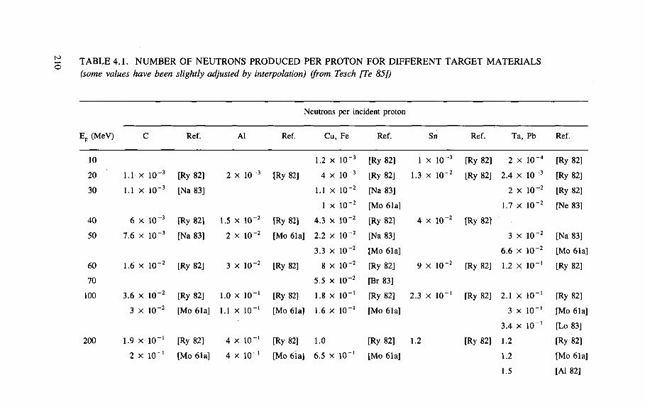
TABLE 4.1. NUMBER OF NEUTRONS PRODUCED PER PROTON FOR DIFFERENT TARGET MATERIALS (some values have been slightly adjusted by interpolation) (from Tesch [Te 85])
Neutrons per incident proton
Ep (MeV) C Ref. Al Ref. Cu, Fe Ref. Sn Ref. Ta, Pb Ref.
10 1.2 X 1 0 " 3 [Ry 82] 1 x 10 " 3 [Ry 82] 2 X 10 " 4 [Ry 82]
20 1.1 X 10 - 3 [Ry 82] 2 x 1 0 - 3 [Ry 82] 4 X 10" 3 [Ry 82] 1.3 x 1 0 ' 2 [Ry 82] 2 .4 X i o - 3 [Ry 82] 30 1.1 X 10 - 3 [Na 83] 1.1 X 10 " 2 [Na 83] 2 X 10 " 2 [Ry 82]
1 X i o - 2 [Mo 61a] 1.7 X 10 " 2 [Ne 83]
4 0 6 x 10 -3 [Ry 82] 1.5 x 1 0 " 2 [Ry 82] 4 .3 X 10 " 2 [Ry 82] 4 x 1 0 - 2 [Ry 82]
50 7 .6 x 10 -3 [Na 83] 2 x 1 0 - 2 [Mo 61a] 2.2 X 1 0 - 2 [Na 83] 3 X 10 " 2 [Na 83]
3 .3 X 10 " 2 [Mo 61a] 6 .6 X 10 " 2 [Mo 61a]
60 1.6 x 10 -2 [Ry 82] 3 x 1 0 " 2 [Ry 82] 8 X 10 " 2 [Ry 82] 9 x 10 " 2 [Ry 82] 1.2 X i o - ' [Ry 82]
70 5.5 X 1 0 - 2 [Br 83]
100 3 .6 x 10 -2 [Ry 82] 1.0 x 1 0 " ' [Ry 82] 1.8 X I O - 1 [Ry 82] 2 .3 x 1 0 " ' [Ry 82] 2.1 X I O - 1 [Ry 82] 3 x 10 -2 [Mo 61a] 1.1 x 1 0 - 1 [Mo 61a] 1.6 X 1 0 " ' [Mo 61a] 3 X lO" 1 [Mo 61a]
3 .4 X 1 0 " ' [Lo 83]
200 1.9 x 10" - 1 [Ry 82] 4 x 10" 1 [Ry 82] 1.0 [Ry 82] 1.2 [Ry 82] 1.2 [Ry 82]
2 x 10" - 1 [Mo 61a] 4 x 1 0 " ' [Mo 61a] 6 .5 X 10" 1 [Mo 61a] 1.2 [Mo 61a]
1.5 [Al 82]
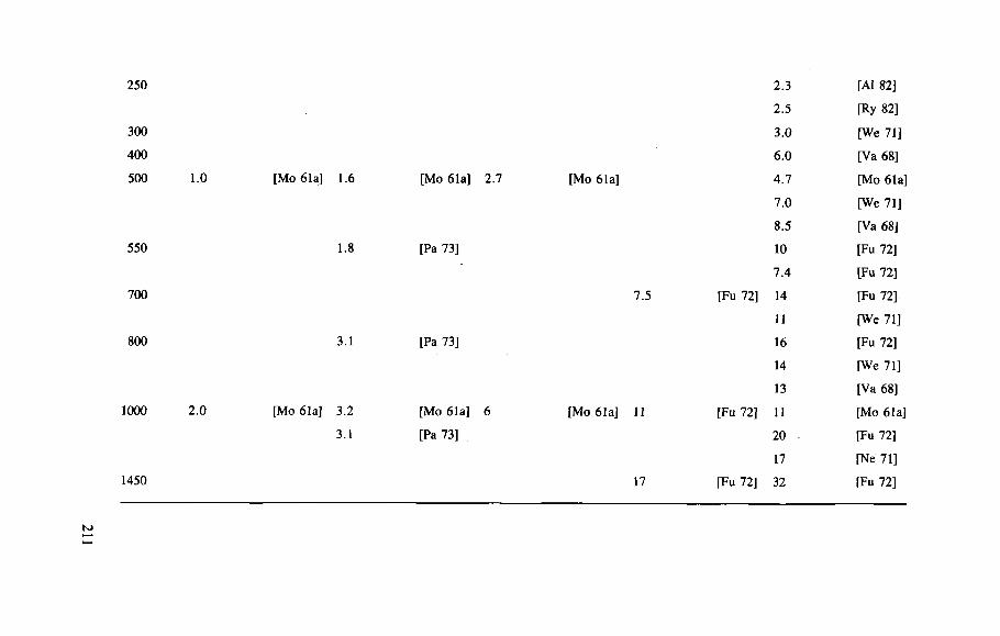
250
300
400
500 1.0 [Mo 61a] 1.6 [Mo 61a] 2 .7
550 1.8 [Pa 73]
700
800 3.1 [Pa 73]
1000 2.0 [Mo 61a] 3.2
3.1
[Mo 61a] 6
[Pa 73]
1450
2 .3 [Al 82]
2 .5 [Ry 82]
3 .0 [We 71]
6 .0 [Va 68]
[Mo 61a] 4 .7 [Mo 61a]
7 .0 [We 71]
8 .5 [Va 68]
10 [Fu 72]
7 .4 [Fu 72]
7 .5 [Fu 72] 14 [Fu 72]
11 [We 71]
16 [Fu 72]
14 [We 71]
13 [Va 68]
[Mo 61a] 11 [Fu 72] 11 [Mo 61a]
20 [Fu 72]
17 [Ne 71]
17 [Fu 72] 32 [Fu 72]
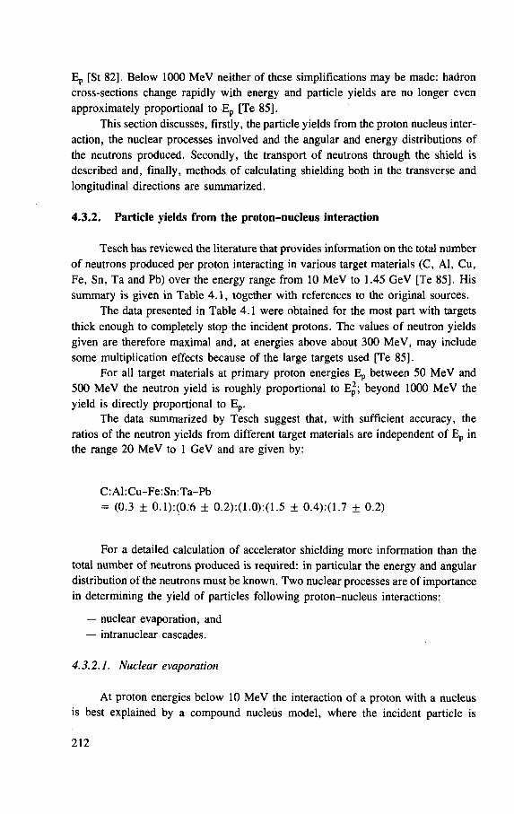
Ep [St 82], Below 1000 MeV neither of these simplifications may be made: hadron cross-sections change rapidly with energy and particle yields are no longer even approximately proportional to Ep [Te 85].
This section discusses, firstly, the particle yields from the proton nucleus inter-action, the nuclear processes involved and the angular and energy distributions of the neutrons produced. Secondly, the transport of neutrons through the shield is described and, finally, methods of calculating shielding both in the transverse and longitudinal directions are summarized.
4.3.2. Particle yields from the proton-nucleus interaction
Tesch has reviewed the literature that provides information on the total number of neutrons produced per proton interacting in various target materials (C, Al, Cu, Fe, Sn, Ta and Pb) over the energy range from 10 MeV to 1.45 GeV [Te 85]. His summary is given in Table 4.1, together with references to the original sources.
The data presented in Table 4.1 were obtained for the most part with targets thick enough to completely stop the incident protons. The values of neutron yields given are therefore maximal and, at energies above about 300 MeV, may include some multiplication effects because of the large targets used [Te 85].
For all target materials at primary proton energies Ep between 50 MeV and 500 MeV the neutron yield is roughly proportional to E p ; beyond 1000 MeV the yield is directly proportional to Ep .
The data summarized by Tesch suggest that, with sufficient accuracy, the ratios of the neutron yields from different target materials are independent of Ep in the range 20 MeV to 1 GeV and are given by:
C: Al: Cu-Fe: Sn: Ta-Pb = (0.3 ± 0.1):(0.6 + 0.2):(1.0):(1.5 ± 0.4):(1.7 + 0.2)
For a detailed calculation of accelerator shielding more information than the total number of neutrons produced is required: in particular the energy and angular distribution of the neutrons must be known. Two nuclear processes are of importance in determining the yield of particles following proton-nucleus interactions:
— nuclear evaporation, and — intranuclear cascades.
4.3.2.1. Nuclear evaporation
At proton energies below 10 MeV the interaction of a proton with a nucleus is best explained by a compound nucleus model, where the incident particle is
212
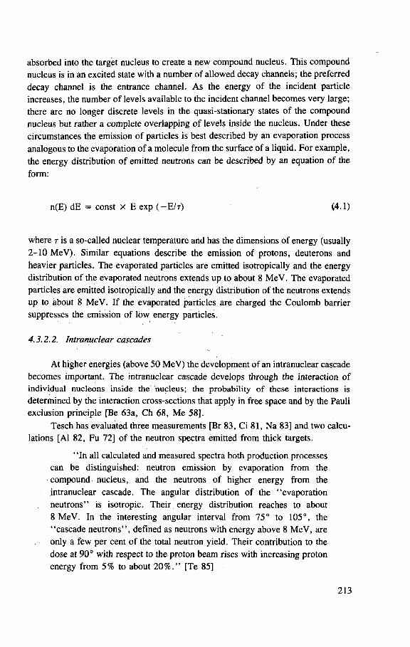
absorbed into the target nucleus to create a new compound nucleus. This compound nucleus is in an excited state with a number of allowed decay channels; the preferred decay channel is the entrance channel. As the energy of the incident particle increases, the number of levels available to the incident channel becomes very large; there are no longer discrete levels in the quasi-stationary states of the compound nucleus but rather a complete overlapping of levels inside the nucleus. Under these circumstances the emission of particles is best described by an evaporation process analogous to the evaporation of a molecule from the surface of a liquid. For example, the energy distribution of emitted neutrons can be described by an equation of the form:
n(E) dE = const X E exp ( - E I T ) (4.1)
where T is a so-called nuclear temperature and has the dimensions of energy (usually 2 -10 MeV). Similar equations describe the emission of protons, deuterons and heavier particles. The evaporated particles are emitted isotropically and the energy distribution of the evaporated neutrons extends up to about 8 MeV. The evaporated particles are emitted isotropically and the energy distribution of the neutrons extends up to about 8 MeV. If the evaporated particles are charged the Coulomb barrier suppresses the emission of low energy particles.
4.3.2.2. Intranuclear cascades
At higher energies (above 50 MeV) the development of an intranuclear cascade becomes important. The intranuclear cascade develops through the interaction of i nd iv idua l n u c l e o n s i n s ide t he n u c l e u s ; t h e p r o b a b i l i t y o f t h e s e i n t e r ac t i ons is
determined by the interaction cross-sections that apply in free space and by the Pauli exclusion principle [Be 63a, Ch 68, Me 58].
Tesch has evaluated three measurements [Br 83, Ci 81, Na 83] and two calcu-lations [Al 82, Fu 72] of the neutron spectra emitted from thick targets.
" In all calculated and measured spectra both production processes can be distinguished: neutron emission by evaporation from the compound nucleus, and the neutrons of higher energy from the intranuclear cascade. The angular distribution of the "evaporation neutrons" is isotropic. Their energy distribution reaches to about 8 MeV. In the interesting angular interval from 75° to 105°, the "cascade neutrons", defined as neutrons with energy above 8 MeV, are only a few per cent of the total neutron yield. Their contribution to the dose at 90° with respect to the proton beam rises with increasing proton energy from 5% to about 2 0 % . " [Te 85]
213
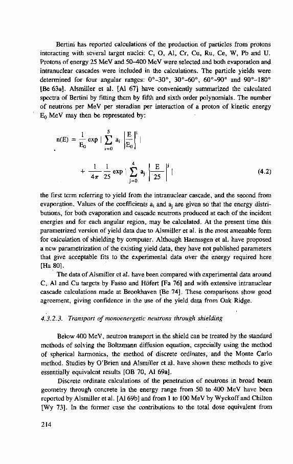
Bertini has reported calculations of the production of particles from protons interacting with several target nuclei: C, O, Al, Cr, Cu, Ru, Ce, W, Pb and U. Protons of energy 25 MeV and 50-400 MeV were selected and both evaporation and intranuclear cascades were included in the calculations. The particle yields were determined for four angular ranges: 0 ° - 3 0 ° , 30°-60° , 60° -90° and 90°-180° [Be 63a]. Alsmiller et al. [Al 67] have conveniently summarized the calculated spectra of Bertini by fitting them by fifth and sixth order polynomials. The number of neutrons per MeV per steradian per interaction of a proton of kinetic energy Eq MeV may then be represented by.
5
n(E) = -j- exp | V aj E
0
w
i = 0
+ 1 1
4tt 25 ^ e x p | D a i i =o
25 (4.2)
the first term referring to yield from the intranuclear cascade, and the second from evaporation. Values of the coefficients a, and aj are given so that the energy distri-butions, for both evaporation and cascade neutrons produced at each of the incident energies and for each angular region, may be calculated. At the present time this parametrized version of yield data due to Alsmiller et al. is the most amenable form for calculation of shielding by computer. Although Haenssgen et al. have proposed a new parametrization of the existing yield data, they have not published parameters that give acceptable fits to the experimental data over the energy required here [Ha 80].
The data of Alsmiller et al. have been compared with experimental data around C, Al and Cu targets by Fasso and Hofert [Fa 76] and with extensive intranuclear cascade calculations made at Brookhaven [Be 74], These comparisons show good agreement, giving confidence in the use of the yield data from Oak Ridge.
4.3.2.3. Transport of monoenergetic neutrons through shielding
Below 400 MeV, neutron transport in the shield can be treated by the standard methods of solving the Boltzmann diffusion equation, especially using the method of spherical harmonics, the method of discrete ordinates, and the Monte Carlo method. Studies by O'Brien and Alsmiller et al. have shown these methods to give essentially equivalent results [OB 70, Al 69a].
Discrete ordinate calculations of the penetration of neutrons in broad beam geometry through concrete in the energy range from 50 to 400 MeV have been reported by Alsmiller et al. [Al 69b] and from 1 to 100 MeV by Wyckoff and Chilton [Wy 73]. In the former case the contributions to the total dose equivalent from
214
Neutron energy (MeV)
FIG. 4.1. The variation of the attenuation length \for monoenergetic neutrons in concrete as a function of neutron energy. Full circles indicate the data ofAlsmiller et al. [Al 69b], open circles those of Wyckoff and Chilton [Wy 73]. The solid line shows recommended values of X and the dashed line shows the high energy limiting value of 1170 kg-m~2.
neutrons and photons are given separately, whereas the Wyckoff and Chilton calcu-lations give only the total dose equivalent. (This is of little practical significance because photons contribute less than a few per cent of the total dose equivalent.) The latter calculations are used as a basis for the NCRP recommendations for shielding low energy accelerators [NCRP 77]. Comparison of these two sets of calculations shows essential agreement in their common energy regions and both sets agree with calculations of O'Brien using spherical harmonics [OB 70].
These three sets of calculations may be conveniently parametrized using an exponential function of the form:
H(z) = ko exp( -x /X) (4.3)
where H(z) is the dose equivalent at depth z in the shield, X is the attenuation length, and ko is the extrapolated dose equivalent at zero depth.
215
1—I—I I I 1 11 T 1 1 I I I I | 1—I I II £ a Q) T> O /
/ /
/ /
Q) O) O a i i i i 11
10 i i i i i i 111
100 Neutron energy (MeV)
^ i I i i i i 1000
FIG. 4.2. The variaton of the parameter k0 as a function of monoenergetic neutron energy; k0 is the value of the dose equivalent per unit neutron fluence extrapolated from deep in the shield back to zero depth. Full circles indicate values calculated by Alsmiller et al. [Al 69b], open circles indicate values calculated by Wyckoff and Chilton [Wy 73]. The solid line indicates recommended values of kg.
Figures 4.1 and 4.2 show the variation of the parameters X and ko with neutron energy. The values of X and ko shown have been selected to give a satis-factory representation of the Alsmiller data and the Wyckoff and Chilton data at depths greater than 1 m in concrete. The values of these parameters used for sub-sequent analysis in this section are indicated by the solid line in Figs 4.1 and 4.2 and are compared with the calculated values. For convenience, some values are listed in Table 4.2. The value of X at energies above 200 MeV has been chosen so as to agree with the limiting value of 1170 kg -m~ 2 found at high energies (see Ref. [Pa 73] and also the appendix to this chapter, which describes the Moyer model).
4.3.2.4. Shielding calculations
Over a fairly wide range of shield thicknesses it has been found sufficiently accurate to estimate shielding with simple equations of the form:
H(d,0) = r " 2 Hfl exp(-d(0)/X e f f) (4.4)
216
This equation applies to a point source with the symbols having the following meanings (see Figs A4.1 and A4.3):
H(d,0) is the dose equivalent at depth d, angle 0 in the shield; He is a constant that may be described as the dose equivalent extrapo-
lated to zero depth in the shield, and corresponding to angle 0, and at unit distance from the point source;
r is the distance from the source to the shield surface (or other point of interest outside the shield);
Xgff is the effective attenuation length for dose equivalent through the shield.
Experience has shown that, over a limited range of shield thicknesses, the approximation of the radiation transmission by an exponential function works well: it fails for shield thicknesses less than about 100 g - c m - 2 and the value of \ e f f
changes with increasing depth in the shield. Nevertheless, in the range of practical interest, 200-1200 g e m - 2 , a single value of X ^ will suffice.
In principle, values of H as a function of both angle and depth are needed for shield design. However it is often only necessary in practice to design shielding in the longitudinal (0 = 0) and transverse (0 = ir/2) directions. Table 4.3 summarizes values of the corresponding values H0 and H t / 2 for proton energies in the range 20-1000 MeV. These values were obtained as described in the following section.
Tesch has described an empirical approach for the determination of the parameters H t / 2 and Xeff [Te 85], By reviewing published data he was able to generate graphs showing the variation of both parameters up to a photon energy of 1000 MeV. Comparison between calculations using Tesch's empirical approach and those by Braid et al. [Br 71] and Alsmiller et al. [Al 75] shows agreement to within a factor of better than three.
A somewhat different approach has been adopted here, following the earlier work of Braid et al. [Br 71] and Stevenson [St 80]. The entire spectrum of neutrons emitted from the target is transported through the accelerator shield: both the particle production and transport were calculated by the methods described earlier in this section. The resultant emerging neutron spectrum is then converted to dose equiva-lent using the fluence to dose equivalent conversion coefficients [ICRP 73b, NCRP 71]-
One particular advantage of the method described in this section is that any arbitrariness in the interpolations for X f is avoided — the value to be used is derived naturally from the calculation.
217
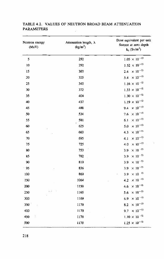
TABLE 4.2. VALUES OF NEUTRON BROAD BEAM ATTENUATION PARAMETERS
Neut ron energy
(MeV)
Attenuat ion length , X
(kg /m 2 )
Dose equivalent per uni
fluence at ze ro depth
ko (Sv /m 2 )
5 292 1.05 X 1 0 " 1 3
10 292 1.52 X 1 0 - 1 3
15 303 2 . 4 X 1 0 - , 3
2 0 325 5 . 4 X 1 0 - 1 3
25 345 1.16 X k t 1 2
30 372 1.33 X 1 0 " 1 2
35 404 1.30 X 1 0 " 1 2
4 0 437 1.19 X 1 0 " 1 2
45 488 9 . 4 X 1 0 " ' 3
50 534 7 . 6 X i o - ' 3
55 581 6 .1 X 1 0 " 1 3
6 0 625 5 . 0 X 1 0 - "
65 663 4 . 3 X 1 0 - ' 3
70 695 4 .1 X 1 0 " 1 3
75 725 4 . 0 X 1 0 " 1 3
80 753 3 .9 X 1 ( T 1 3
85 782 3 . 9 X 1 0 " 1 3
90 810 3 .9 X 1 0 " 1 3
95 836 3 .9 X 1 0 - 1 3
100 860 3 . 9 X 1 0 " 1 3
150 1064 4 . 2 X K T 1 3
2 0 0 1150 4 . 6 X i o - 1 3
250 1165 5 . 6 X 1 0 " 1 3
300 1169 6 .9 X i < r 1 J
350 1170 8 .2 X i o - ' 3
4 0 0 1170 9 .7 X 1 0 " 1 3
4 5 0 1170 1 .10 X i o - 1 2
500 1170 1.25 X 10 " , 2
218
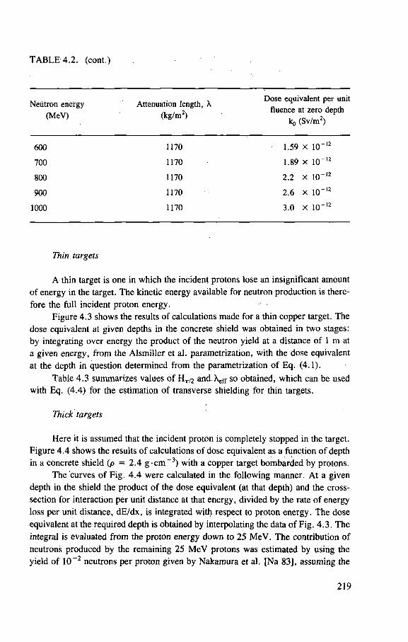
TABLE 4.2. (cont.)
„ , , . Dose equivalent per unit Neutron energy Attenuation length, A „ , ,
. . . . . . n , fluence at zero depth ( M C V ) . ( k g / m ) ko (Sv/m2)
600 1170 1.59 X 10" -12
700 1170 1.89 X 10" -12
800 1170 2.2 X 10" -12
900 1170 2.6 X 10" -12
1000 1170 3.0 X 10" -12
Thin targets
A thin target is one in which the incident protons lose an insignificant amount of energy in the target. The kinetic energy available for neutron production is there-fore the full incident proton energy.
Figure 4.3 shows the results of calculations made for a thin copper target. The dose equivalent at given depths in the concrete shield was obtained in two stages: by integrating over energy the product of the neutron yield at a distance of 1 m at a given energy, from the Alsmiller et al. parametrization, with the dose equivalent at the depth in question determined from the parametrization of Eq. (4.1).
Table 4.3 summarizes values of H t / 2 and. \ e f f so obtained, which can be used with Eq. (4.4) for the estimation of transverse shielding for thin targets.
Thick targets
Here it is assumed that the incident proton is completely stopped in the target. Figure 4.4 shows the results of calculations of dose equivalent as a function of depth in a concrete shield (p = 2.4 g - c m - 3 ) with a copper target bombarded by protons.
The curves of Fig. 4 .4 were calculated in the following manner. At a given depth in the shield the product of the dose equivalent (at that depth) and the cross-section for interaction per unit distance at that energy, divided by the rate of energy loss per unit distance, dE/dx, is integrated with respect to proton energy. The dose equivalent at the required depth is obtained by interpolating the data of Fig. 4.3. The integral is evaluated from the proton energy down to 25 MeV. The contribution of neutrons produced by the remaining 25 MeV protons was estimated by using the yield of 1 0 - 2 neutrons per proton given by Nakamura et al. [Na 83], assuming the
219
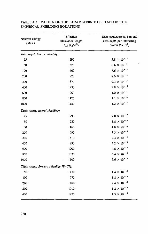
TABLE 4.3. VALUES OF THE PARAMETERS TO BE USED IN THE EMPIRICAL SHIELDING EQUATIONS
Effective Dose equivalent at 1 m and Neutron energy , , a t t e n u a t l o n ' e n S t " z e r o depth per interacting
( } \e f f(kg/m2) proton (Svm 2 )
Thin target, lateral shielding:
25 290 5.8 X 10"
50 320 6.6 X 10"
100 460 7.6 X 10"
200 720 8.6 X 10"
300 870 9.3 X 10"
400 950 9.8 X 10"
600 1060 1.0 X 10"
800 1120 1.1 X 10"
1000 1150 1.2 X 10"
Thick target, lateral shielding:
25 290 7.0 X 10"
50 230 1.8 X 10"
100 460 4.8 X 10"
200 690 1.3 X 10"
300 810 2.3 X 10"
400 890 3.2 X 10"
600 1000 4.8 X 10"
800 1070 6.4 X 10"
1000 1100 7.6 X 10"
Thick target, forward shielding [Br 71]:
50 470 1.4 X 10"
100 770 1.8 X 10"
200 880 7.4 X 10"
300 1010 1.2 X 10"
400 1270 1.3 X 10"
220
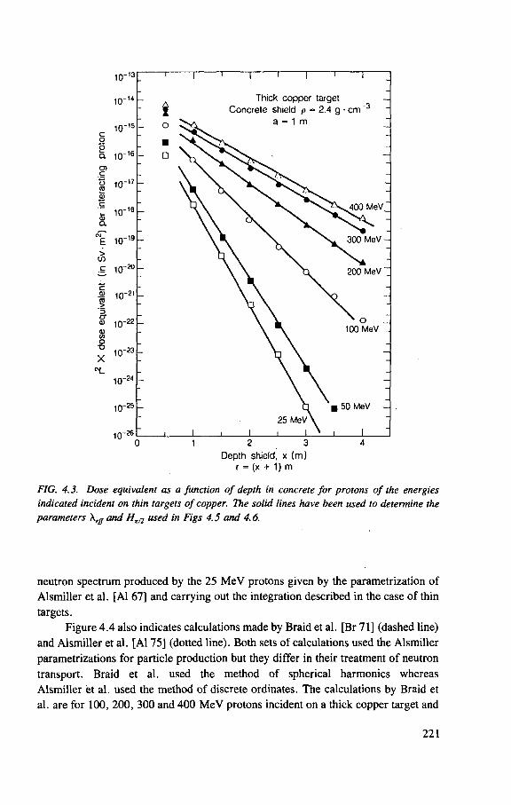
Depth shield, x (m) r = (x + 1) m
FIG. 4.3. Dose equivalent as a function of depth in concrete for protons of the energies indicated incident on thin targets of copper. The solid lines have been used to determine the parameters \effand Ht/2 used in Figs 4.5 and 4.6.
neutron spectrum produced by the 25 MeV protons given by the parametrization of Alsmiller et al. [Al 67] and carrying out the integration described in the case of thin targets.
Figure 4 .4 also indicates calculations made by Braid et al. [Br 71] (dashed line) and Alsmiller et al. [Al 75] (dotted line). Both sets of calculations used the Alsmiller parametrizations for particle production but they differ in their treatment of neutron transport. Braid et al. used the method of spherical harmonics whereas Alsmiller et al. used the method of discrete ordinates. The calculations by Braid et al. are for 100, 200, 300 and 400 MeV protons incident on a thick copper target and
221
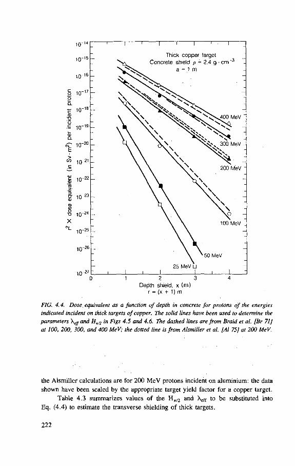
Depth shield, x (m) r = (x + 1) m
FIG. 4.4. Dose. equivalent as a function of depth in concrete for protons of the energies indicated incident on thick targets of copper. The solid lines have been used to determine the parameters and Ht/2 in Figs 4.5 and 4.6. The dashed lines are from Braid et al. [Br 71] at 100, 200, 300, and 400 MeV; the dotted line is from Alsmiller et al. [Al 75] at 200 MeV.
the Alsmiller calculations are for 200 MeV protons incident on aluminium: the data shown have been scaled by the appropriate target yield factor for a copper target.
Table 4.3 summarizes values of the H t / 2 and Xeff to be substituted into Eq. (4.4) to estimate the transverse shielding of thick targets.
222
Forward shielding
There are suprisingly few published data on the attenuation of neutrons in the forward direction (i.e. along the direction of the proton beam) at energies below 1 GeV.
Some early shielding studies for 90 MeV neutrons have been described by Patterson [Pa 57]. These suggested that the attenuation length X was approximately given by the well known relation [Pa 73]:
X = — - — (4.5) Na inel
where <xinei is the inelastic cross-section of the shield material.
Theoretical considerations suggested that, at least for high energies, the effec-tive attenuation length Xeff would in fact be somewhat greater than that predicted by Eq. (4.5) [Fi 63]. Experience of Sychev et al. [Sy 66a,b] at Dubna suggested that in the case of broad beam geometry in the energy range between 350 MeV and 660 MeV the attenuation length was given by:
Xan = (1.3 ± 0.1) X; inel (4.6)
Ban et al. were able to confirm this suggestion at higher energies by making measurements of transverse attenuation in various materials of neutrons produced by 12 GeV protons incident upon a steel target [Ba 80].
The most convenient data available are those of Braid et al. [Br 71] which are based on the same data as the transverse shield calculations but use as a source term the 0° -30° yield data from Alsmiller et al. [Al 67], The authors of that work expressed their results using an equation similar to that proposed here for the lateral shielding case, and from which the parameters H0 and X for use in the present equation can be derived. These parameters are given in Table 4.3. Braid et al. warn that these parameters should not be used for thin shields ( < 1000 kg/m2) nor for shield thicknesses of greater than about 7 m.
Parameters for simple shielding equations
The result of the thin and thick copper target calculations for a concrete {p = 2 .4 -g -cm~ 3 ) shield are summarized in Figs 4 .5 and 4.6.
Figure 4.5 shows Xeff as a function of proton energy: the values of Xeff for the neutrons from a thick target are somewhat smaller than those for the thin target. This is to be expected because of the slightly softer neutron spectrum emitted from thick
223
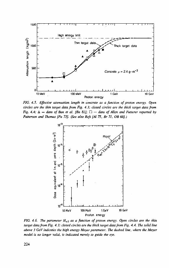
FIG. 4.5. Effective attenuation length in concrete as a Junction of proton energy. Open circles are the thin target data from Fig. 4.3; closed circles are the thick target data from Fig. 4.4; A — data of Ban et al. [Ba 81]; • — data of Allen and Futterer reported by Patterson and Thomas [Pa 73], (See also Refs [Al 75, Br 71, OB 68].)
10
10 r
10_n -
. 10"'° r
"I
Moyer
A X,'
A •x 1
I
10 10 GeV 10 MeV 100 MeV 1 GeV
Proton energy
FIG. 4.6. The parameter as a function of proton energy. Open circles are the thin target data from Fig. 4.3; closed circles are the thick target data from Fig. 4.4. The solid line above 3 GeV indicates the high energy Moyer parameter. The dashed line, where the Moyer model is no longer valid, is indicated merely to guide the eye.
224
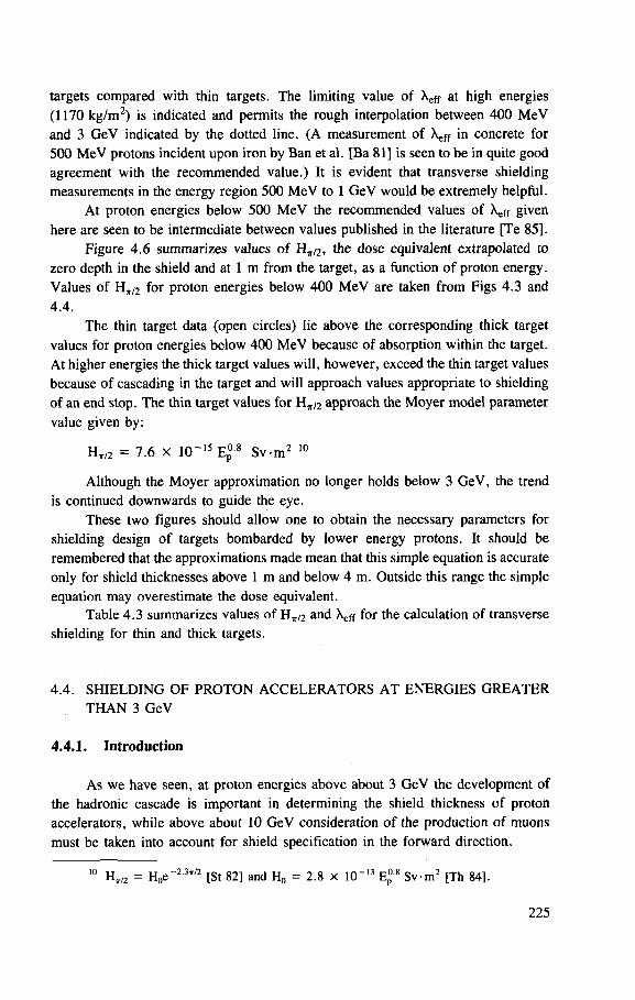
targets compared with thin targets. The limiting value of Xeff at high energies (1170 kg/m2) is indicated and permits the rough interpolation between 400 MeV and 3 GeV indicated by the dotted line. (A measurement of Xeff in concrete for 500 MeV protons incident upon iron by Ban et al. [Ba 81] is seen to be in quite good agreement with the recommended value.) It is evident that transverse shielding measurements in the energy region 500 MeV to 1 GeV would be extremely helpful.
At proton energies below 500 MeV the recommended values of Xeff given here are seen to be intermediate between values published in the literature [Te 85].
Figure 4 .6 summarizes values of H t /2> the dose equivalent extrapolated to zero depth in the shield and at 1 m from the target, as a function of proton energy. Values of H t / 2 for proton energies below 400 MeV are taken from Figs 4.3 and 4.4.
The thin target data (open circles) lie above the corresponding thick target values for proton energies below 400 MeV because of absorption within the target. At higher energies the thick target values will, however, exceed the thin target values because of cascading in the target and will approach values appropriate to shielding of an end stop. The thin target values for H t / 2 approach the Moyer model parameter value given by:
H t / 2 = 7.6 x 10~15 Ep°-8 Sv -m 2 10
Although the Moyer approximation no longer holds below 3 GeV, the trend is continued downwards to guide the eye.
These two figures should allow one to obtain the necessary parameters for shielding design of targets bombarded by lower energy protons. It should be remembered that the approximations made mean that this simple equation is accurate only for shield thicknesses above 1 m and below 4 m. Outside this range the simple equation may overestimate the dose equivalent.
Table 4 . 3 summarizes values of H t / 2 and XEFF for the calculation of transverse shielding for thin and thick targets.
4.4. SHIELDING OF PROTON ACCELERATORS AT ENERGIES GREATER THAN 3 GeV
4.4.1. Introduction
As we have seen, at proton energies above about 3 GeV the development of the hadronic cascade is important in determining the shield thickness of proton accelerators, while above about 10 GeV consideration of the production of muons must be taken into account for shield specification in the forward direction.
10 H t / 2 = H 0 e [ S t 82] and H 0 = 2 .8 x 10" 1 3 Ep08 S v - m 2 [Th 84].
225
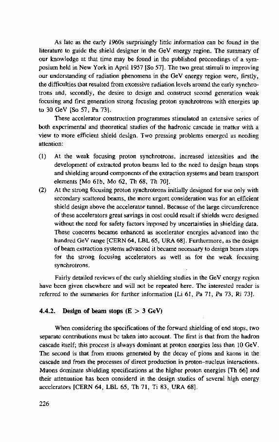
As late as the early 1960s surprisingly little information can be found in the literature to guide the shield designer in the GeV energy region. The summary of our knowledge at that time may be found in the published proceedings of a sym-posium held in New York in April 1957 [So 57], The two great stimuli to improving our understanding of radiation phenomena in the GeV energy region were, firstly, the difficulties that resulted from excessive radiation levels around the early synchro-trons and, secondly, the desire to design and construct second generation weak focusing and first generation strong focusing proton synchrotrons with energies up to 30 GeV [So 57, Pa 73].
These accelerator construction programmes stimulated an extensive series of both experimental and theoretical studies of the hadronic cascade in matter with a view to more efficient shield design. Two pressing problems emerged as needing attention:
(1) At the weak focusing proton synchrotrons, increased intensities and the development of extracted proton beams led to the need to design beam stops and shielding around components of the extraction systems and beam transport elements [Mo 61b, Mo 62, Th 68, Th 70],
(2) At the strong focusing proton synchrotrons initially designed for use only with secondary scattered beams, the more urgent consideration was for an efficient shield design above the accelerator tunnel. Because of the large circumference of these accelerators great savings in cost could result if shields were designed without the need for safety factors imposed by uncertainties in shielding data. These concerns became enhanced as accelerator energies advanced into the hundred GeV range [CERN 64, LBL 65, URA 68]. Furthermore, as the design of beam extraction systems advanced it became necessary to design beam stops for the strong focusing accelerators as well as for the weak focusing synchrotrons.
Fairly detailed reviews of the early shielding studies in the GeV energy region have been given elsewhere and will not be repeated here. The interested reader is referred to the summaries for further information [Li 61, Pa 71, Pa 73, Ri 73].
4.4.2. Design of beam stops (E > 3 GeV)
When considering the specifications of the forward shielding of end stops, two separate contributions must be taken into account. The first is that from the hadron cascade itself; this process is always dominant at proton energies less than 10 GeV. The second is that from muons generated by the decay of pions and kaons in the cascade and from the processes of direct production in proton-nucleus interactions. Muons dominate shielding specifications at the higher proton energies [Th 66] and their attenuation has been considerd in the design studies of several high energy accelerators [CERN 64, LBL 65, Th 71, Ti 83, URA 68],
226
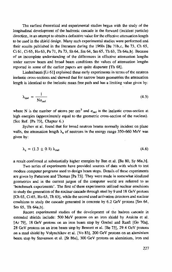
The earliest theoretical and experimental studies began with the study of the longitudinal development of the hadronic cascade in the forward (incident particle) direction, in an attempt to obtain a definitive value for the effective attenuation length to be used in the shield design. Many such experimental studies were performed and their results published in the literature during the 1960s [Be 71b,c, Be 73, Ch 65, Ci 61, Ci 65, Ho 63, Pa 71, Pa 73, Sh 64, Sm 64, Sm 65, Th 63, Th 64a,b]. Because of an incomplete understanding of the differences in effective attenuation lengths under narrow beam and broad beam conditions the values of attenuation lengths reported in some of the earlier papers are quite disparate [Th 68].
Lindenbauni [Li 61] explained these early experiments in terms of the neutron inelastic cross-sections and showed that for narrow beam geometries the attenuation length is identical to the inelastic mean free path and has a limiting value given by:
Xi„e. = ~TT~ (4-5) Nff ine l
where N is the number of atoms per cm3 and <rinei is the inelastic cross-section at high energies (approximately equal to the geometric cross-section of the nucleus). (See Ref. [Pa 73], Chapter 6.)
Sychev et al. found that for broad neutron beams normally incident on plane walls, the attenuation length Xa of neutrons in the energy range 350-660 MeV was given by:
\ a = (1.3 ± 0 . 1 ) \ i n e l (4.6)
a result confirmed at substantially higher energies by Ban et al. [Ba 80, Sy 66a,b]. Two series of experiments have provided sources of data with which to test
modern computer programs used to design beam stops. Details of these experiments are given by Patterson and Thomas [Pa 73]. They were made in somewhat idealized geometries and in the current jargon of the computer world are referred to as 'benchmark experiments'. The first of these experiments utilized nuclear emulsions to study the generation of the nuclear cascade through steel by 9 and 18 GeV protons [Ch 65, Ci 65, Ho 63, Th 63], while the second used activation detectors and nuclear emulsions to study the cascade generated in concrete by 6.2 GeV protons [Sm 64, Sm 65, Th 64a,b].
Recent experimental studies of the development of the hadron cascade in extended shields include: 500 MeV protons on an iron shield by Arakita et al. [Ar 79], 18 GeV protons on an iron beam stop by Goebel and Ranft [Go 70a], 28 GeV protons on an iron beam stop by Bennett et al. [Be 73], 29.4 GeV protons on a steel shield by Volynchikov et al. [Vo 83], 200 GeV protons on an aluminium beam stop by Stevenson et al. [St 86a], 300 GeV protons on aluminium, iron and
227
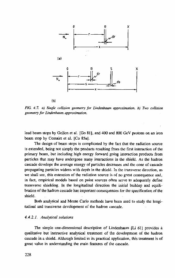
0 R
r dr
(a)
dr
ds
(b)
FIG. 4.7. a) Single collision geometry for Lindenbaum approximation, b) Two collision geometry for Lindenbaum approximation.
lead beam stops by Gollon et al. [Go 81], and 400 and 800 GeV protons on an iron beam stop by Cossairt et al. [Co 85a].
The design of beam stops is complicated by the fact that the radiation source is extended, being not simply the products resulting from the first interaction of the primary beam, but including high energy forward going interaction products from particles that may have undergone many interactions in the shield. As the hadron cascade develops the average energy of particles decreases and the cone of cascade propagating particles widens with depth in the shield. In the transverse direction, as we shall see, this extension of the radiation source is of no great consequence and, in fact, empirical models based on point sources often serve to adequately define transverse shielding. In the longitudinal direction the initial buildup and equili-bration of the hadron cascade has important consequences for the specification of the shield.
Both analytical and Monte Carlo methods have been used to study the longi-tudinal and transverse development of the hadron cascade.
4.4.2.1. Analytical solutions
The simple one-dimensional description of Lindenbaum [Li 61] provides a qualitative but instructive analytical treatment of the development of the hadron cascade in a shield. Although limited in its practical application, this treatment is of great value in understanding the main features of the cascade.
228
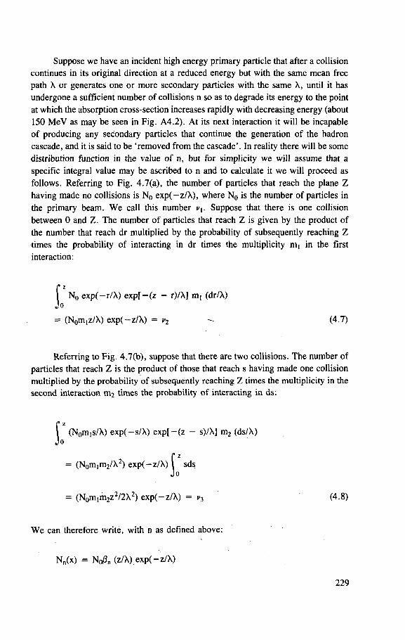
Suppose we have an incident high energy primary particle that after a collision continues in its original direction at a reduced energy but with the same mean free path X or generates one or more secondary particles with the same X, until it has undergone a sufficient number of collisions n so as to degrade its energy to the point at which the absorption cross-section increases rapidly with decreasing energy (about 150 MeV as may be seen in Fig. A4.2). At its next interaction it will be incapable of producing any secondary particles that continue the generation of the hadron cascade, and it is said to be 'removed from the cascade'. In reality there will be some distribution function in the value of n, but for simplicity we will assume that a specific integral value may be ascribed to n and to calculate it we will proceed as follows. Referring to Fig. 4.7(a), the number of particles that reach the plane Z having made no collisions is N0 exp(-z/X), where N0 is the number of particles in the primary beam. We call this number v\. Suppose that there is one collision between 0 and Z. The number of particles that reach Z is given by the product of the number that reach dr multiplied by the probability of subsequently reaching Z times the probability of interacting in dr times the multiplicity n^ in the first interaction:
Referring to Fig. 4.7(b), suppose that there are two collisions. The number of particles that reach Z is the product of those that reach s having made one collision multiplied by the probability of subsequently reaching Z times the multiplicity in the second interaction m2 times the probability of interacting in ds:
z N0 exp(—r/X) exp[-(z - r)/X] m, (dr/X)
o
= (Non^z/X) exp(-z/X) = c2 (4.7)
z (Nom,s/X) exp(-s/X) exp[-(z - s)/A] m2 (ds/X)
o
= (N0m!m2/X2) exp(-z/X) sds
= (N0mim2z2/2X2) exp(-z/X) = v3 (4.8)
We can therefore write, with n as defined above:
Nn(x) = N0/3„ (z/X) exp( -z/X)
229
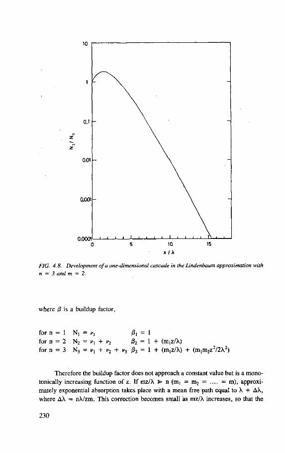
x / A
FIG. 4.8. Development of a one-dimensional cascade in the Lindenbaum approximation with n = 3 and m = 2.
where /3 is a buildup factor,
for n = 1 N, = JSJ = 1 for n = 2 N2 = + v2 J32 = 1 + (miz/A) for n = 3 N3 = + v2 + v3 fc = 1 + (m,z/X) + (m1m2z2/2X2)
Therefore the buildup factor does not approach a constant value but is a mono-tonically increasing function of z. If mz/X > n (m, = m2 = .... = m), approxi-mately exponential absorption takes place with a mean free path equal to X + AX, where AX = nX/zm. This correction becomes small as mz/X increases, so that the
230
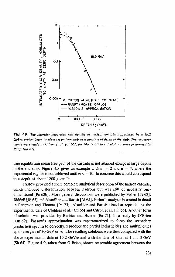
SI
10
<
I f S f c _o
>: o t a. in UJ 2 N l±J O I-a
cot
Q => UJ
t ° < h-0C o
0.1
0.01
0.001
0 1000 2000
D E P T H ( g / c m 2 )
FIG. 4.9. The laterally integrated star density in nuclear emulsions produced by a 19.2 GeV/c proton beam incident on an iron slab as a function of depth in the slab. The measure-ments were made by Citron et al. [Ci 65], the Monte Carlo calculations were performed by Ranft [Ra 67],
true equilibrium mean free path of the cascade is not attained except at large depths in the end stop. Figure 4.8 gives an example with m = 2 and n = 3, where the exponential region is not achieved until z/X = 10. In concrete this would correspond to a depth of about 1200 g - c m - 2 .
Passow provided a more complete analytical description of the hadron cascade, which included differentiation between hadrons but was still of necessity one-dimensional [Pa 62b]. More general discussions were published by Fisher [Fi 63], Riddell [Ri 65] and Alsmiller and Barish [Al 65]. Fisher 's analysis is treated in detail in Patterson and Thomas [Pa 73]. Alsmiller and Barish aimed at reproducing the experimental data of Childers et al. [Ch 65] and Citron et al. [Ci 65]. Another form of solution was provided by Barbier and Hunter [Ba 71]. In a study by O'Brien [OB 69], Passow's approximation was reparametrized to force the secondary production spectra to correctly reproduce the partial inelasticities and multiplicities up to energies of 30 GeV or so. The resulting solutions were then compared with the above experimental data at 19.2 GeV/c and with the data of Shen at 1 and 3 GeV [Sh 64]. Figure 4.9, taken from O'Brien, shows reasonable agreement between the
231
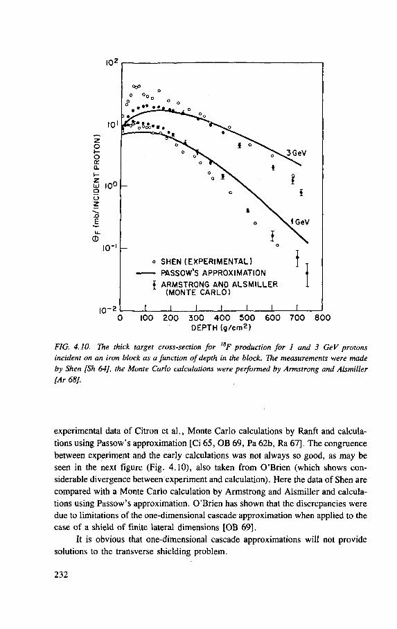
DEPTH (g/cm2)
FIG. 4.10. The thick target cross-section for ISF production for 1 and 3 GeV protons incident on an iron block as a Junction of depth in the block. The measurements were made by Shen [Sh 64], the Monte Carlo calculations were performed by Armstrong and Alsmiller [Ar 68].
experimental data of Citron et al., Monte Carlo calculations by Ranft and calcula-tions using Passow's approximation [Ci 65, OB 69, Pa 62b, Ra 67], The congruence between experiment and the early calculations was not always so good, as may be seen in the next figure (Fig. 4.10), also taken from O'Brien (which shows con-siderable divergence between experiment and calculation). Here the data of Shen are compared with a Monte Carlo calculation by Armstrong and Alsmiller and calcula-tions using Passow's approximation. O'Brien has shown that the discrepancies were due to limitations of the one-dimensional cascade approximation when applied to the case of a shield of finite lateral dimensions [OB 69],
It is obvious that one-dimensional cascade approximations will not provide solutions to the transverse shielding problem.
232
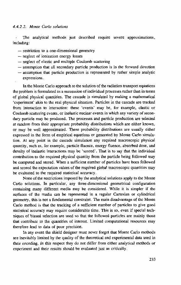
4.4.2.2. Monte Carlo solutions
The analytical methods just described require severe approximations, including:
— restriction to a one-dimensional geometry — neglect of ionization energy losses — neglect of elastic and multiple Coulomb scattering — assumption that all secondary particle production is in the forward direction — assumption that particle production is represented by rather simple analytic
expressions.
In the Monte Carlo approach to the solution of the radiation transport equations the problem is formulated as a succession of individual processes rather than in terms of global physical quantities. The cascade is simulated by making a mathematical 'experiment' akin to the real physical situation. Particles in the cascade are tracked from interaction to interaction: these 'events' may be, for example, elastic or Coulomb scattering events, or inelastic nuclear events in which any variety of secon-dary particle may be produced. The processes and particle production are selected at random from their appropriate probability distributions which are either known, or may be well approximated. These probability distributions are usually either expressed in the form of empirical equations or generated by Monte Carlo simula-tion. At any point in the cascade simulation any required macroscopic physical quantity, such as, for example, particle fluence, energy fluence, absorbed dose, and density of inelastic interactions may be 'scored' . That is to say that the individual contribution to the required physical quantity from the particle being followed may be computed and stored. When a sufficient number of particles have been followed and scored the expectation values of the required global macroscopic quantities may be evaluated to the required statistical accuracy.
None of the restrictions imposed by the analytical solutions apply to the Monte Carlo solutions. In particular, any three-dimensional geometrical configuration containing many different media may be considered. While it is simpler if the surfaces of the media can be represented in a regular Cartesian or cylindrical geometry, this is not a fundamental constraint. The main disadvantage of the Monte Carlo method is that the tracking of a sufficient number of particles to give good statistical accuracy may require considerable time. This is so, even if special tech-niques of biased selection are used so that the followed particles are mainly those that contribute to the quantities of interest. Limited computational resources may therefore lead to data of poor precision.
In any event the shield designer must never forget that Monte Carlo methods are inevitably limited by the quality of the theoretical and experimental data used in their encoding. In this respect they do not differ from either analytical methods or experiment and their results should be evaluated just as critically.
233
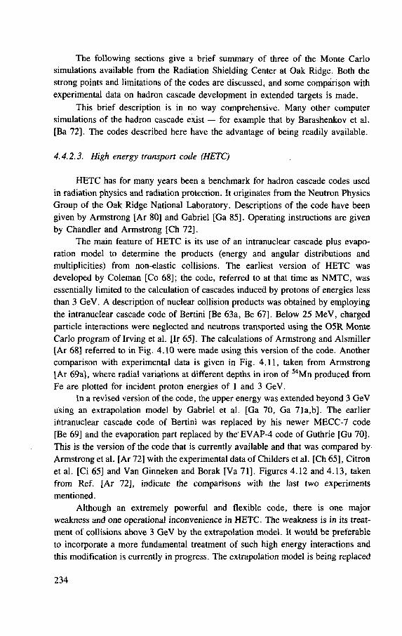
The following sections give a brief summary of three of the Monte Carlo simulations available from the Radiation Shielding Center at Oak Ridge. Both the strong points and limitations of the codes are discussed, and some comparison with experimental data on hadron cascade development in extended targets is made.
This brief description is in no way comprehensive. Many other computer simulations of the hadron cascade exist — for example that by Barashenkov et al. [Ba 72]. The codes described here have the advantage of being readily available.
4.4.2.3. High energy transport code (HETC)
HETC has for many years been a benchmark for hadron cascade codes used in radiation physics and radiation protection. It originates from the Neutron Physics Group of the Oak Ridge National Laboratory. Descriptions of the code have been given by Armstrong [Ar 80] and Gabriel [Ga 85]. Operating instructions are given by Chandler and Armstrong [Ch 72].
The main feature of HETC is its use of an intranuclear cascade plus evapo-ration model to determine the products (energy and angular distributions and multiplicities) from non-elastic collisions. The earliest version of HETC was developed by Coleman [Co 68]; the code, referred to at that time as NMTC, was essentially limited to the calculation of cascades induced by protons of energies less than 3 GeV. A description of nuclear collision products was obtained by employing the intranuclear cascade code of Bertini [Be 63a, Be 67], Below 25 MeV, charged particle interactions were neglected and neutrons transported using the 0 5 R Monte Carlo program of Irving et al. [Ir 65]. The calculations of Armstrong and Alsmiller [Ar 68] referred to in Fig. 4.10 were made using this version of the code. Another comparison with experimental data is given in Fig. 4.11, taken from Armstrong [Ar 69a], where radial variations at different depths in iron of 5 4Mn produced from Fe are plotted for incident proton energies of 1 and 3 GeV.
In a revised version of the code, the upper energy was extended beyond 3 GeV using an extrapolation model by Gabriel et al. [Ga 70, Ga 71a,b]. The earlier intranuclear cascade code of Bertini was replaced by his newer MECC-7 code [Be 69] and the evaporation part replaced by the'EVAP-4 code of Guthrie [Gu 70]. This is the version of the code that is currently available and that was compared by Armstrong et al. [Ar 72] with the experimental data of Childers et al. [Ch 65], Citron et al. [Ci 65] and Van Ginneken and Borak [Va 71]. Figures 4.12 and 4.13, taken from Ref. [Ar 72], indicate the comparisons with the last two experiments mentioned.
Although an extremely powerful and flexible code, there is one major weakness and one operational inconvenience in HETC. The weakness is in its treat-ment of collisions above 3 GeV by the extrapolation model. It would be preferable to incorporate a more fundamental treatment of such high energy interactions and this modification is currently in progress. The extrapolation model is being replaced
234
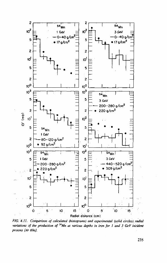
5 4
= I O2
^ -
- 5 —
- 2
10'
5
- 2
10
(0
•O
J to' ©
10
I02
5
2
10'
5
5 4
Mn
I GeV
~ — 8 0 - 1 2 0 g/cn
• 92 g/cm2
i
10
E 5 4
M n 1 1=
- 1 GeV —
jt- 200-280 g/cm2
_
_ • 220 g/cm2
_ f •
—1—i
• —
'1 ! 1
Mn
Si 3 GeV
0 - 4 0
• 17g/cmz
—
- 0 - 4 0 g/crr^
L - r n
to3
= 5 4 ,
5 — Mn
3 GeV
— 2 0 0 - 2 8 0 g/cm2
• 220 g/cm2
10 =
2 —
to' I0
2
5 —
2
10'
5
2 |—
10°
5 4 . Mn 1
3 GeV
— 4 4 0 - 5 2 0 g/cm^
• 509 g/cm2
to 10 15 15 0 5
Radiol distance (cm)
FIG. 4.11. Comparison of calculated (histograms) and experimental (solid circles) radial variations of the production of 54Mn at various depths in iron for 1 and 3 GeV incident protons [Ar 69a].
235
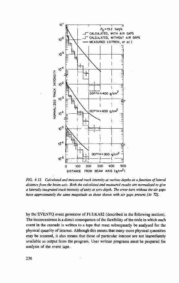
DISTANCE FROM BEAM AX IS (g/cm2)
FIG. 4.12. Calculated and measured track intensity at various depths as a Junction of lateral distance from the beam axis. Both the calculated and measured results are normalized to give a laterally integrated track intensity of unity at zero depth. The error bars without the air gaps have approximately the same magnitude as those shown with air gaps present [Ar 72].
by the EVENTQ event generator of FLUKA82 (described in the following section). The inconvenience is a direct consequence of the flexibility of the code in which each event in the cascade is written to a tape that must subsequently be analysed for the physical quantity of interest. Although this means that many more physical quantities may be scanned, it also means that those of particular interest are not immediately available as output from the program. User written programs must be prepared for analysis of the event tape.
236
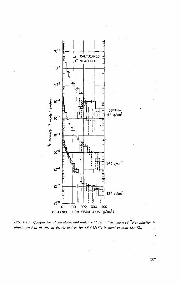
D I S T A N C E FROM BEAM A X I S ( g / c m 2 )
FIG. 4.13. Comparison of calculated and measured lateral distribution of ,SF production in aluminium foils at various depths in iron for 19.4 GeV/c incident protons [Ar 72].
237
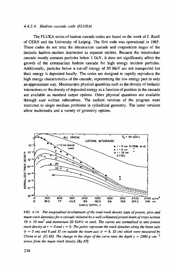
4.4.2.4. Hadron cascade code (FLUKA)
The FLUKA series of hadron cascade codes are based on the work of J. Ranfit of CERN and the University of Leipzig. The first code was operational in 1965. These codes do not treat the intranuclear cascade and evaporation stages of the inelastic hadron-nucleus interaction as separate entities. Because the intranuclear cascade mostly contains particles below 1 GeV, it does not significantly affect the growth of the extranuclear hadron cascade for high energy incident particles. Additionally, particles below a cut-off energy of 50 MeV are not transported but their energy is deposited locally. The codes are designed to rapidly reproduce the high energy characteristics of the cascade, representing the low energy part in only an approximate way. Macroscopic physical quantities such as the density of inelastic interactions or the density of deposited energy as a function of position in the cascade are available as standard output options. Other physical quantities are available through user written subroutines. The earliest versions of the program were restricted to single medium problems in cylindrical geometry. The latest versions allow multimedia and a variety of geometry options.
IO-'
10-2
UJ 1 0 " 1
o
S , 0 " s
| 10"s
<c § 10- *
10"
1
- ^ A L L TRACKS "I 1 1 1 1 — — |
P 0 = 2 0 GeV/c
L A T E R A L INTEGRATED • n . r = r \
0 cm (beam oxis)
• r = 0 cm C ITRON et al. -o r - Q cm " o r = 32 cm
S T E E L / o — j o
— "^V
• r = 0 cm C ITRON et al. -o r - Q cm " o r = 32 cm
S T E E L
/ o 2 0
^ 3 0 D ' ^ ^ ^
4 0 —
i I
c
v ^ / X X ^ O v o
• i I I i' r —
3 0 0 38 .5
600 7 7
9 0 0 115.5
1200 1500
154 192.5
SH IELO DEPTH, z
1800 231
2100 2 6 9
2 4 0 0 307.5
2 7 0 0 g / c m a
3 4 6 cm
FIG. 4.14. The longitudinal development of the total track density (sum of proton, pion and muon track densities) for a cascade initiated by a well collimated proton beam of cross-section 10 x 10 mm2 and momentum 20 GeV/c in steel. The curves are normalized to unit proton track density at r = 0 and z = 0. The points represent the track densities along the beam axis (r = 0 cm) and 8 and 32 cm outside the beam axis (r — 8, 32 cm) which were measured by Citron et al. [Ci 65]. The change in the slope of the curve near the depth z = 2000 g-cm~2
arises from the muon track density [Ra 67],
238
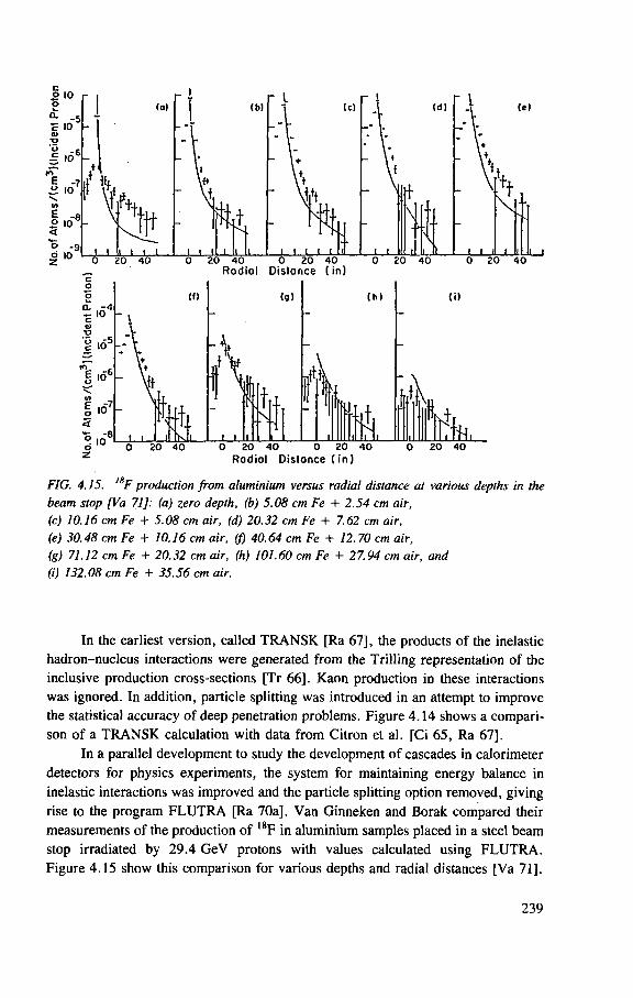
FIG. 4.15. 1SF production from aluminium versus radial distance at various depths in the beam stop [Va 71]: (a) zero depth, (b) 5.08 cm Fe + 2.54 cm air, (c) 10.16 cm Fe + 5.08 cm air, (d) 20.32 cm Fe + 7.62 cm air, (e) 30.48 cm Fe + 10.16 cm air, ( f ) 40.64 cm Fe + 12.70 cm air, (g) 71.12 cm Fe + 20.32 cm air, (h) 101.60 cm Fe + 27.94 cm air, and (i) 132.08 cm Fe + 35.56 cm air.
In the earliest version, called TRANSK [Ra 67], the products of the inelastic hadron-nucleus interactions were generated from the Trilling representation of the inclusive production cross-sections [Tr 66], Kaon production in these interactions was ignored. In addition, particle splitting was introduced in an attempt to improve the statistical accuracy of deep penetration problems. Figure 4.14 shows a compari-son of a TRANSK calculation with data from Citron et a). [Ci 65, Ra 67],
In a parallel development to study the development of cascades in calorimeter detectors for physics experiments, the system for maintaining energy balance in inelastic interactions was improved and the particle splitting option removed, giving rise to the program FLUTRA [Ra 70a], Van Ginneken and Borak compared their measurements of the production of 18F in aluminium samples placed in a steel beam stop irradiated by 29.4 GeV protons with values calculated using FLUTRA. Figure 4.15 show this comparison for various depths and radial distances [Va 71],
239
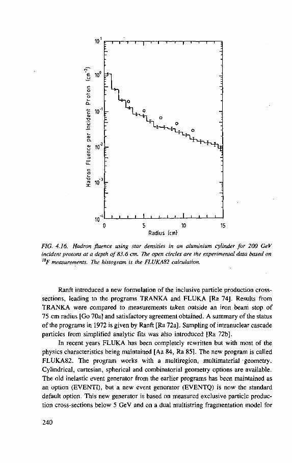
FIG. 4.16. Hadron fluence using star densities in an aluminium cylinder for 200 GeV incident protons at a depth of 83.6 cm. The open circles are the experimental data based on l8F measurements. The histogram is the FLUKA82 calculation.
Ranft introduced a new formulation of the inclusive particle production cross-sections, leading to the programs TRANKA and FLUKA [Ra 74]. Results from TRANKA were compared to measurements taken outside an iron beam stop of 75 cm radius [Go 70a] and satisfactory agreement obtained. A summary of the status of the programs in 1972 is given by Ranft [Ra 72a]. Sampling of intranuclear cascade particles from simplified analytic fits was also introduced [Ra 72b].
In recent years FLUKA has been completely rewritten but with most of the physics characteristics being maintained [Aa 84, Ra 85], The new program is called FLUKA82. The program works with a multiregion, multimaterial geometry. Cylindrical, cartesian, spherical and combinatorial geometry options are available. The old inelastic event generator from the earlier programs has been maintained as an option (EVENTI), but a new event generator (EVENTQ) is now the standard default option. This new generator is based on measured exclusive particle produc-tion cross-sections below 5 GeV and on a dual multistring fragmentation model for
240
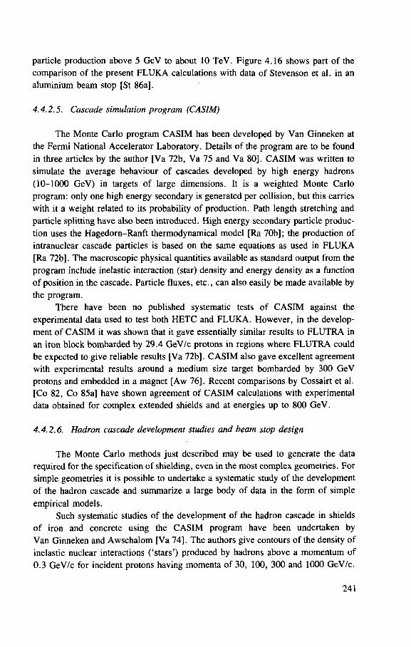
particle production above 5 GeV to about 10 TeV. Figure 4.16 shows part of the comparison of the present FLUKA calculations with data of Stevenson et al. in an aluminium beam stop [St 86a].
4.4.2.5. Cascade simulation program (CASIM)
The Monte Carlo program CASIM has been developed by Van Ginneken at the Fermi National Accelerator Laboratory. Details of the program are to be found in three articles by the author [Va 72b, Va 75 and Va 80]. CASIM was written to simulate the average behaviour of cascades developed by high energy hadrons (10-1000 GeV) in targets of large dimensions. It is a weighted Monte Carlo program: only one high energy secondary is generated per collision, but this carries with it a weight related to its probability of production. Path length stretching and particle splitting have also been introduced. High energy secondary particle produc-tion uses the Hagedorn-Ranft thermodynamical model [Ra 70b]; the production of intranuclear cascade particles is based on the same equations as used in FLUKA [Ra 72b]. The macroscopic physical quantities available as standard output from the program include inelastic interaction (star) density and energy density as a function of position in the cascade. Particle fluxes, etc., can also easily be made available by the program.
There have been no published systematic tests of CASIM against the experimental data used to test both HETC and FLUKA. However, in the develop-ment of CASIM it was shown that it gave essentially similar results to FLUTRA in an iron block bombarded by 29.4 GeV/c protons in regions where FLUTRA could be expected to give reliable results [Va 72b]. CASIM also gave excellent agreement with experimental results around a medium size target bombarded by 300 GeV protons and embedded in a magnet [Aw 76], Recent comparisons by Cossairt et al. [Co 82, Co 85a] have shown agreement of CASIM calculations with experimental data obtained for complex extended shields and at energies up to 800 GeV.
4.4.2.6. Hadron cascade development studies and beam stop design
The Monte Carlo methods just described may be used to generate the data required for the specification of shielding, even in the most complex geometries. For simple geometries it is possible to undertake a systematic study of the development of the hadron cascade and summarize a large body of data in the form of simple empirical models.
Such systematic studies of the development of the hadron cascade in shields of iron and concrete using the CASIM program have been undertaken by Van Ginneken and Awschalom [Va 74]. The authors give contours of the density of inelastic nuclear interactions ( 'stars') produced by hadrons above a momentum of 0.3 GeV/c for incident protons having momenta of 30, 100, 300 and 1000 GeV/c.
241
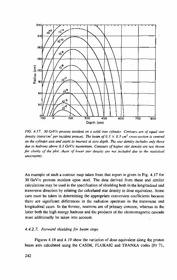
FIG. 4.17. 30 GeV/c protons incident on a solid iron cylinder. Contours are of equal star density (stars/cm3 per incident proton). The beam of 0.3 X 0.3 cm2 cross-section is centred on the cylinder axis and starts to interact at zero depth. The star density includes only those due to hadrons above 0.3 GeV/c momentum. Contours of higher star density are not shown for clarity of the plot, those of lower star density are not included due to the statistical uncertainty.
An example of such a contour map taken from that report is given in Fig. 4.17 for 30 GeV/c protons incident upon steel. The data derived from these and similar calculations may be used in the specification of shielding both in the longitudinal and transverse direction by relating the calculated star density to dose equivalent. Some care must be taken in determining the appropriate conversion coefficients because there are significant differences in the radiation spectrum in the transverse and longitudinal cases. In the former, neutrons are of primary concern, whereas in the latter both the high energy hadrons and the products of the electromagnetic cascade must additionally be taken into account.
4.4.2.7. Forward shielding for beam stops
Figures 4.18 and 4.19 show the variation of dose equivalent along the proton beam axis calculated using the CASIM, FLUKA82 and TRANKA codes [Fr 71,
242
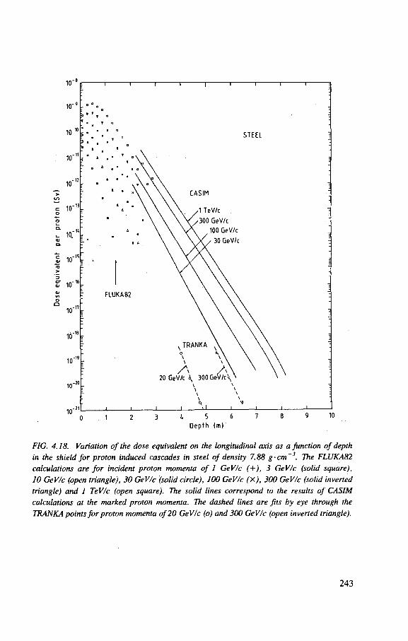
10"
10'
10"
10"
10"
i n " " a; 10
10"
10"
1 0 " '
10"
- i 1 1 1 1 r
STEEL
CASIM
A TeV/c
/300 GeV/c
100 GeV/c
• 30 GeV/c
FLUKA82
s T R A N K A N ,
^ A , 20 GeV/c \ 300 GeV/c \
3 4 5 6 7
Dep th (m)
FIG. 4.18. Variation of the dose equivalent on the longitudinal axis as a Junction of depth in the shield for proton induced cascades in steel of density 7.88 g-cm~3. The FLUKA82 calculations are for incident proton momenta of 1 GeV/c (+), 3 GeV/c (solid square), 10 GeV/c (open triangle), 30 GeV/c (solid circle), 100 GeV/c (X), 300 GeV/c (solid inverted triangle) and 1 TeV/c (open square). The solid lines correspond to the results of CASIM calculations at the marked proton momenta. The dashed lines are fits by eye through the TRANKA points for proton momenta of 20 GeV/c (o) and 300 GeV/c (open inverted triangle).
243
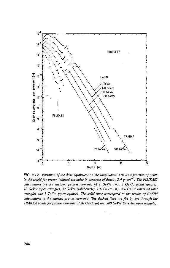
FIG. 4.19. Variation of the dose equivalent on the longitudinal axis as a function of depth in the shield for proton induced cascades in concrete of density 2.4 g-cm~3. The FLUKA82 calculations are for incident proton momenta of 1 GeV/c (+), 3 GeV/c (solid square), 10 GeV/c (open triangle), 30 GeV/c (solid circle), 100 GeV/c (X), 300 GeV/c (inverted solid triangle) and I TeV/c (open square). The solid lines correspond to the results of CASIM calculations at the marked proton momenta. The dashed lines are fits by eye through the TRANKA points for proton momenta of 20 GeV/c (o) and 300 GeV/c (inverted open triangle).
244
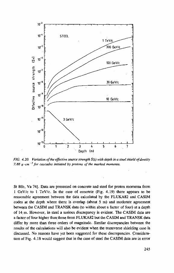
FIG. 4.20. Variation of the effective source strength S(z) with depth in a steel shield of density 7.88 g- cm 3 for cascades initiated by protons of the marked momenta.
St 86b, Va 74]. Data are presented on concrete and steel for proton momenta from 1 GeV/c to 1 TeV/c. In the case of concrete (Fig. 4.19) there appears to be reasonable agreement between the data calculated by the FLUKA82 and CASIM codes at the depth where there is overlap (about 5 m) and moderate agreement between the CASIM and TRANSK data (to within about a factor of four) at a depth of 14 m. However, in steel a serious discrepancy is evident. The CASIM data are a factor of four higher than those from FLUKA82 but the CASIM and TRANSK data differ by more than three orders of magnitude. Similar discrepancies between the results of the calculations will also be evident when the transverse shielding case is discussed. No reasons have yet been suggested for these discrepancies. Considera-tion of Fig. 4.18 would suggest that in the case of steel the CASIM data are in error
245
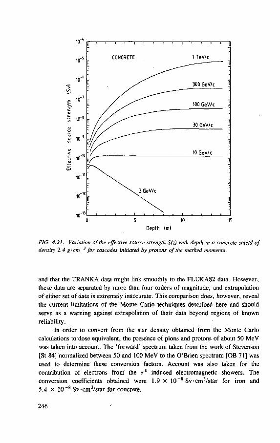
FIG. 4.21. Variation of the effective source strength S(z) with depth in a concrete shield of density 2.4 g-cm~3 for cascades initiated by protons of the marked momenta.
and that the TRANKA data might link smoothly to the FLUKA82 data. However, these data are separated by more than four orders of magnitude, and extrapolation of either set of data is extremely inaccurate. This comparison does, however, reveal the current limitations of the Morite Carlo techniques described here and should serve as a warning against extrapolation of their data beyond regions of known reliability.
In order to convert from the star density obtained from the Monte Carlo calculations to dose equivalent, the presence of pions and protons of about 50 MeV was taken into account. The 'forward' spectrum taken from the work of Stevenson [St 84] normalized between 50 and 100 MeV to the O'Brien spectrum [OB 71] was used to determine these conversion factors. Account was also taken for the contribution of electrons from the ir° induced electromagnetic showers. The conversion coefficients obtained were 1.9 x 10"8 Sv •cm /star for iron and 5.4 X 1 0 - 8 Sv-cm3/star for concrete.
246
Because of the complex longitudinal development of the cascade it is not possible, as is the case for transverse shielding, to specify a virtual source strength that is independent of the thickness of the shield. It is possible, however, to use an empirical formulation:
H(z) = S(z) exp ( - z / X ) (4.9)
for the dose equivalent at depth z in the shield. Figures 4.20 and 4.21 show the value of S(z) as a function of depth in steel
and concrete respectively over the energy range from 2 GeV to 1 TeV. The values of attenuation length X are the same as those determined for the lateral shield case described in the following section (viz. 1700 k g - m ~ 2 for iron and 1170 k g - m ~ 2
for concrete). With the approximation of the complex transmission curve by the simple exponential form of Eq. (4.9) the required value of the virtual source strength S(z) approaches plateau values at large depths for the highest proton momenta, is nearly constant at momenta around 10 to 30 GeV/c and decreases with depth at the lowest proton momentum illustrated, perhaps because an equilibrium spectrum is never achieved at these low energies.
4.4.2.8. Transverse shielding for beam stops and targets
In many respects the problem of calculating transverse (overhead and lateral) shielding for targets operating in accelerator tunnels is similar to that of determining the lateral dimension of beam stops. The calculations of the longitudinal development of the hadronic cascade described in the previous section and illustrated in Figs 4.18 and 4.19 show that in concrete, even in the highest energies, the length of the radiation source along the incident proton direction is comparable to or less than the lateral dimensions of the shielding. Under such conditions the radiation source may often be regarded as point-like (see appendix to this chapter).
In operating accelerators the longitudinal dimensions of the radiation source may also be comparable with the lateral shield dimensions. Thus, for example, Gilbert et al. found that with a thin target operating in the 28 GeV CERN proton synchrotron the apparent radiation source had a relaxation length of about 6 m [Gi 68]. Interactions in the accelerator magnets of secondary particles emitted in the forward direction from the target resulted in the development of a hadron cascade similar to that generated in a beam stop. Such conditions are often typical of those at operating accelerators, and represent those for which many transverse shielding measurements have been made.
Several experiments to study transverse shielding have been reported in the literature. One of the earliest studies was reported by Hoffmann and Sullivan, who measured the attenuation through steel of particles produced by the interaction of
247
20 GeV protons with a thin beryllium target [Ho 65]. A series of measurements through the steel shield of the Brookhaven AGS [Ca 67, Di 65] was followed by an extensive series of measurements at the CPS [Gi 68, Gi 69]. Bennett et al. have reported attenuation studies in a steel side shield above a thin tungsten target bombarded by 28 GeV protons [Be 71a]. Other measurements are mentioned in the appendix to this chapter.
The transverse shielding problem for a target may be quite well treated by semi-empirical methods. The appendix to this chapter gives a detailed discussion of the Moyer model, which expresses the dose equivalent H(0) above a target as:
H ( ( ? ) = N *(EP) exp(-fffl) e x p ( - l cosec 6) ( 4 ] Q )
R2 cosec2 0
where N is the number of protons interacting in the target and the other symbols are explained in the appendix. Appropriate values for the parameters 0o(Ep), the source strength in the forward direction, and /3, the angular relaxation parameter, are:
iAo(Ep) = 2.8 x 10~13 E£ 8 Sv-m2 (Ep in GeV)
0 = 2.3 radians - 1
The approximate value of the source strength parameter orthogonal to the beam direction, 4/T/2(Ep), is related to the value in the forward direction, ^o(Ep), by the equation:
*»/2(Ep) = ^o(Ep) exp(-07r/2) (4.11)
with /3 = 2.3 radians then:
^ / 2 ( E p ) = 2.70 x 1 0 - 2 ^o(Ep) = 7.6 X 10 - 1 5 Ep0'8 Sv-m 2 (4.12)
The computer codes described in the previous section may also be used to determine transverse shielding. They have the advantage of being able to make com-putations for complex geometries inaccessible to the Moyer model. It is nevertheless interesting to compare the results of the computer calculations with those of the Moyer model for several reasons, not the least of which is because the Moyer model is based on measured data.
248
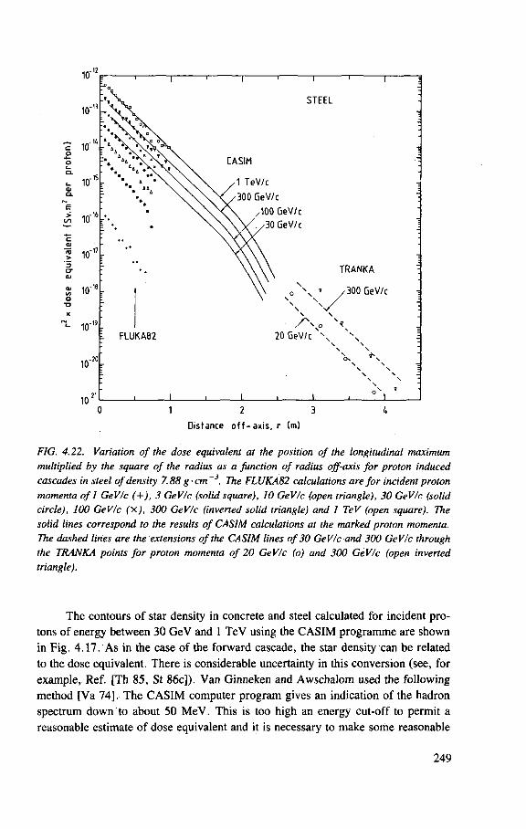
Distance o f f - ax i s , r (m)
FIG. 4.22. Variation of the dose equivalent at the position of the longitudinal maximum multiplied by the square of the radius as a function of radius off-axis for proton induced cascades in steel of density 7.88 g- cm ~3. The FLUKA82 calculations are for incident proton momenta of 1 GeV/c (+), 3 GeV/c (solid square), 10 GeV/c (open triangle), 30 GeV/c (solid circle), 100 GeV/c fx), 300 GeV/c (inverted solid triangle) and 1 TeV (open square). The solid lines correspond to the results of CASIM calculations at the marked proton momenta. The dashed lines are the extensions of the CASIM lines of 30 GeV/c and 300 GeV/c through the TRANKA points for proton momenta of 20 GeV/c (o) and 300 GeV/c (open inverted triangle).
The contours of star density in concrete and steel calculated for incident pro-tons of energy between 30 GeV and 1 TeV using the CASIM programme are shown in Fig. 4.17. As in the case of the forward cascade, the star density can be related to the dose equivalent. There is considerable uncertainty in this conversion (see, for example, Ref. [Th 85, St 86c]). Van Ginneken and Awschalom used the following method [Va 74]. The CASIM computer program gives an indication of the hadron spectrum down to about 50 MeV. This is too high an energy cut-off to permit a reasonable estimate of dose equivalent and it is necessary to make some reasonable
249
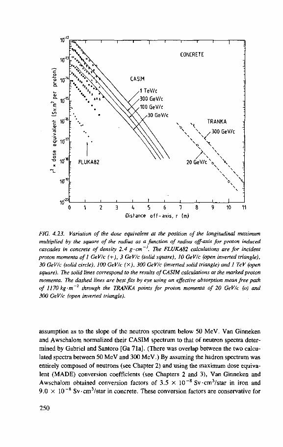
FIG. 4.23. Variation of the dose equivalent at the position of the longitudinal maximum multiplied by the square of the radius as a function of radius off-axis for proton induced cascades in concrete of density 2.4 g-cm~3. The FLUKA82 calculations are for incident proton momenta of 1 GeV/c (+), 3 GeV/c (solid square), 10 GeV/c (open inverted triangle), 30 GeV/c (solid circle), 100 GeV/c (X), 300 GeV/c (inverted solid triangle) and 1 TeV (open square). The solid lines correspond to the results of CASIM calculations at the marked proton momenta. The dashed lines are best fits by eye using an effective absorption mean free path of 1170 kg-m~2 through the TRANKA points for proton momenta of 20 GeV/c (o) and 300 GeV/c (open inverted triangle).
assumption as to the slope of the neutron spectrum below 50 MeV. Van Ginneken and Awschalom normalized their CASIM spectrum to that of neutron spectra deter-mined by Gabriel and Santoro [Ga 71a]. (There was overlap between the two calcu-lated spectra between 50 MeV and 300 MeV.) By assuming the hadron spectrum was entirely composed of neutrons (see Chapter 2) and using the maximum dose equiva-lent (MADE) conversion coefficients (see Chapters 2 and 3), Van Ginneken and Awschalom obtained conversion factors of 3.5 x 10 _ 8 Sv-cm3 /star in iron and 9.0 x 10 _ 8 Sv-cm3 /star in concrete. These conversion factors are conservative for
250
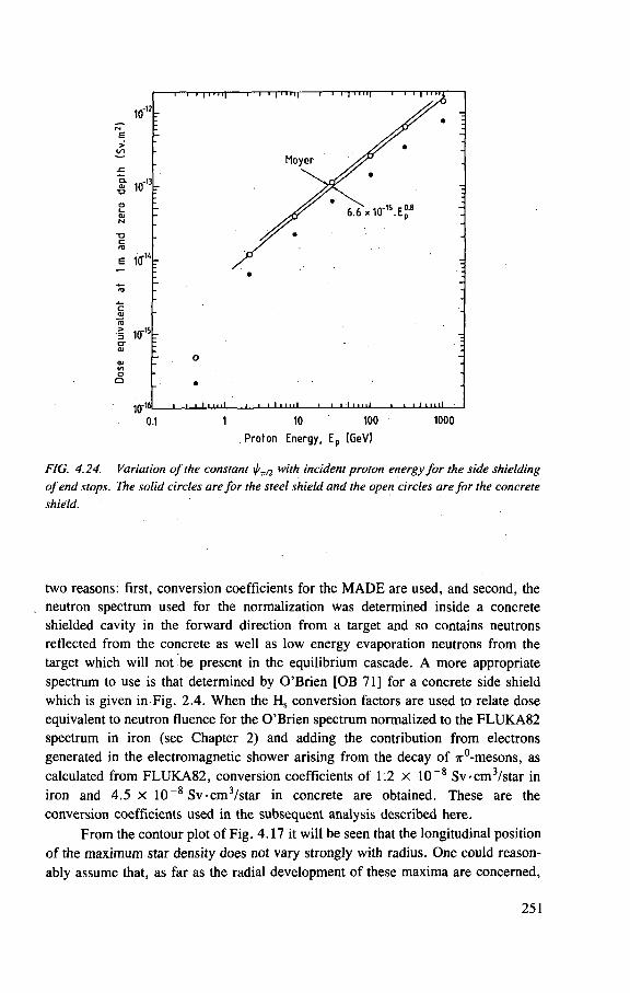
1/1 o o
i I i I i 11 ii i i I I I n 11 i i i I I • i il t . i I i 1111
0.1 1 10 100 1000
Proton Energy. E p (GeV)
FIG. 4.24. Variation of the constant t/v/2 w'th incident proton energy for the side shielding of end stops. The solid circles are for the steel shield and the open circles are for the concrete shield.
two reasons: first, conversion coefficients for the MADE are used, and second, the neutron spectrum used for the normalization was determined inside a concrete shielded cavity in the forward direction from a target and so contains neutrons reflected from the concrete as well as low energy evaporation neutrons from the target which will not be present in the equilibrium cascade. A more appropriate spectrum to use is that determined by O'Brien [OB 71] for a concrete side shield which is given in Fig. 2.4. When the Hs conversion factors are used to relate dose equivalent to neutron fluence for the O'Brien spectrum normalized to the FLUKA82 spectrum in iron (see Chapter 2) and adding the contribution from electrons generated in the electromagnetic shower arising from the decay of 7r°-mesons, as calculated from FLUKA82, conversion coefficients of 1.2 x 10 ~8 Sv-cm3 /star in iron and 4.5 X 10~8 Sv •cm /star in concrete are obtained. These are the conversion coefficients used in the subsequent analysis described here.
From the contour plot of Fig. 4.17 it will be seen that the longitudinal position of the maximum star density does not vary strongly with radius. One could reason-ably assume that, as far as the radial development of these maxima are concerned,
251
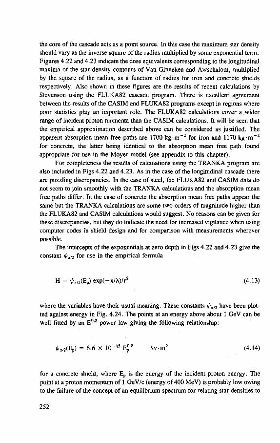
the core of the cascade acts as a point source. In this case the maximum star density should vary as the inverse square of the radius multiplied by some exponential term. Figures 4.22 and 4.23 indicate the dose equivalents corresponding to the longitudinal maxima of the star density contours of Van Ginneken and Awschalom, multiplied by the square of the radius, as a function of radius for iron and concrete shields respectively. Also shown in these figures are the results of recent calculations by Stevenson using the FLUKA82 cascade program. There is excellent agreement between the results of the CASIM and FLUKA82 programs except in regions where poor statistics play an important role. The FLUKA82 calculations cover a wider range of incident proton momenta than the CASIM calculations. It will be seen that the empirical approximation described above can be considered as justified. The apparent absorption mean free paths are 1700 k g - m ~ 2 for iron and 1170 kg -m~ 2
for concrete, the latter being identical to the absorption mean free path found appropriate for use in the Moyer model (see appendix to this chapter).
For completeness the results of calculations using the TRANKA program are also included in Figs 4.22 and 4.23. As in the case of the longitudinal cascade there are puzzling discrepancies. In the case of steel, the FLUKA82 and CASIM data do not seem to join smoothly with the TRANKA calculations and the absorption mean free paths differ. In the case of concrete the absorption mean free paths appear the same but the TRANKA calculations are some two orders of magnitude higher than the FLUKA82 and CASIM calculations would suggest. No reasons can be given for these discrepancies, but they do indicate the need for increased vigilance when using computer codes in shield design and for comparison with measurements wherever possible.
The intercepts of the exponentials at zero depth in Figs 4.22 and 4.23 give the constant \j/Tn for use in the empirical formula
H = ^ / 2 ( E p ) exp(-x /X) / r 2 (4.13)
where the variables have their usual meaning. These constants \f/v/2 have been plot-ted against energy in Fig. 4.24. The points at an energy above about 1 GeV can be well fitted by an E 0 8 power law giving the following relationship:
^ / 2 ( E p ) = 6.6 X U P 1 5 Ep0-8 Sv -m 2 (4.14)
for a concrete shield, where E p is the energy of the incident proton energy. The point at a proton momentum of 1 GeV/c (energy of 400 MeV) is probably low owing to the failure of the concept of an equilibrium spectrum for relating star densities to
252
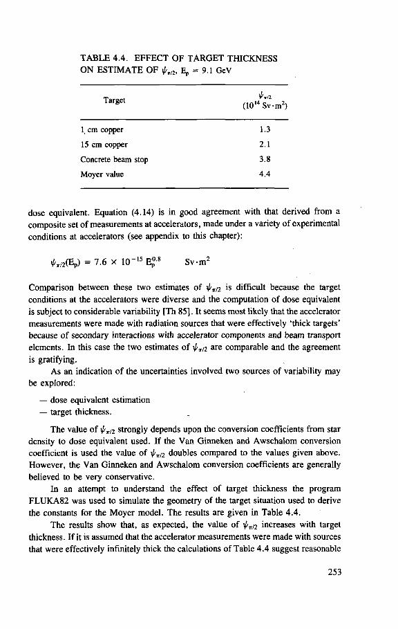
TABLE 4.4. EFFECT OF TARGET THICKNESS ON ESTIMATE OF Ep = 9.1 GeV
T a r g C t (101 4^Sv-m2)
1 cm copper 1.3
15 cm copper 2.1
Concrete beam stop 3.8
Moyer value 4 .4
dose equivalent. Equation (4.14) is in good agreement with that derived from a composite set of measurements at accelerators, made under a variety of experimental conditions at accelerators (see appendix to this chapter):
^ / 2 ( E p ) = 7.6 x 10" 1 5 Ep0-8 S v m 2
Comparison between these two estimates of 2 is difficult because the target conditions at the accelerators were diverse and the computation of dose equivalent is subject to considerable variability [Th 85], It seems most likely that the accelerator measurements were made with radiation sources that were effectively 'thick targets' because of secondary interactions with accelerator components and beam transport elements. In this case the two estimates of 0 t / 2 are comparable and the agreement is gratifying.
As an indication of the uncertainties involved two sources of variability may be explored:
— dose equivalent estimation — target thickness.
The value of i /v2 strongly depends upon the conversion coefficients from star density to dose equivalent used. If the Van Ginneken and Awschalom conversion coefficient is used the value of doubles compared to the values given above. However, the Van Ginneken and Awschalom conversion coefficients are generally believed to be very conservative.
In an attempt to understand the effect of target thickness the program FLUKA82 was used to simulate the geometry of the target situation used to derive the constants for the Moyer model. The results are given in Table 4.4.
The results show that, as expected, the value of increases with target thickness. If it is assumed that the accelerator measurements were made with sources that were effectively infinitely thick the calculations of Table 4.4 suggest reasonable
253
agreement with the empirical data. It would be interesting to establish a series of measurements under well controlled target situations in simple geometries to compare calculations and measurements [Th 78]. Whatever these studies reveal, it is clear that the present agreement in estimates of i/ ' t / 2 is perhaps better than could be expected considering the uncertainties in dose equivalent estimation.
4.4.2.9. Muon shielding
It is usually only at proton accelerators with energies above 10 GeV that the specification of shielding against muons is needed. For completeness, a brief discussion is given here with references to the scientific literature that enable the interested reader to find further details. (See also the relevant section in Chapter 2.)
Muons were first identified as a significant problem during the initial operation of the 30 GeV AGS of the Brookhaven National Laboratory [Co 62] and are commonly observed at the very high energy accelerators at CERN, Fermilab and Serpukhov [Be 71b, Co 83, Ka 72, Ni 74, Th 71]. Examples where muons have dominated the radiation environments around such accelerators have been given in Chapter 3.
At high energy physics laboratories sophisticated radiation transport programs are usually available and are routinely used to specify shielding against muons. In many (or most) practical situations, the physical configuration of the accelerator components, beam transport systems and shielding together with the presence of magnetic fields make the calculation of muon transport extremely complicated. Resort to transport codes based on Monte Carlo techniques, such as those available at high energy physics laboratories, is usually necessary. In consequence, muon shielding is routinely specified using such methods and particular shielding problems have been solved as needed. There has been little attempt (save in the work of Keefe and his colleagues [Ke 64, LBL 65, Th 64c]) to develop simple empirical equations containing a few derived parameters for the specification of muon shielding in simple geometries as there has been, for example, in the case of neutron shielding. Analytical techniques are severely limited because of the complexities we have just described. Nevertheless, an attempt is made here to summarize the muon shielding problem in analytic terms, so that the reader may understand the essential points.
In what follows, the development of muon source terms, the radial diffusion of muons as they pass through the shield, the experimental verification of Fermi-Eyges theory and practical shield design will be described.
4.4.2.10. Source terms
As we have suggested, the diffusion of muons through shielding materials can be treated by analytical or Monte Carlo techniques; both methods have their advan-tages and limitations. In either case the first step required is to describe the source
254
term. Analytical representation of the source term is possible when, for example, the muons are produced by the decay of kaons or pions collimated in a beam [Ke 64]. However, when the muons are created more diffusely, for example, by the decay of pions resulting from proton interactions in a thick shield, an analytical represen-tation requires a very simplified empirical description of the pion production which may result in errors. Alternatively, more complex particle production models may be used requiring Monte Carlo techniques. When the muons produced have to be transported through regions of a shield that contain magnetic fields the use of Monte Carlo techniques becomes essential.
4.4.2.11. Muon distribution function
The spatial and angular distributions of a beam of particles that on passing through a layer of matter undergoes multiple scattering are described in a theory developed by Rossi and Greisen [Ro 41, Ro 52] following the treatment of Fermi [Fe 40], and extended by Eyges [Ey 48] to include the slowing down of particles while passing through the layer. From the results of Eyges, it can be shown that the radial distribution of particle fluence at a given depth in the scattering material, independent of angle to the beam axis, is given by:
where r is the radial distance off-axis, N0 is the number of particles incident in the pencil beam and A2 an area given by the following integral:
where z is the depth of the plane of interest in the shielding or scattering material and x 2 is one-quarter of the mean square scattering angle per unit distance. The dependence of x 2 on the position in the shield t is given through the momentum of the particle at that position. In the Fermi-Eyges theory, all range straggling is ignored and the range-momentum relationship is considered to be monotonic. All scattering is considered to be the sum of many individual small angle scattering processes. It was shown by Alsmiller et al. [Al 71] that the integration in Eq. (4.16) rigorously holds true for shielding consisting of slabs of different materials, even vacuum.
0(r) = N0 exp[-r2 /(4A2)]/(47rA2) (4.15)
(4.16)
255
4.4.2.12. Scattering and energy loss
An essential part in the use of the Fermi-Eyges distribution function is the determination of the mean square angle of scattering per unit distance. There are four principal scattering processes for high energy muons:
(i) Coulomb scattering from the nuclei of the medium, and to a lesser extent from the orbital electrons,
(ii) bremsstrahlung from muon-nucleus collisions, (iii) pair production from muon-nucleus collisions, and (iv) muon-nucleus non-elastic collisions.
An approximate expression for Coulomb scattering is [Ro 52]:
xl = 7r(me/p/3)
2
/(aX0) (4.17)
where a is the fine structure constant, me is the mass of the electron, p is the muon momentum in units corresponding to m,,, (3 is the relativistic velocity of the muon and X0 is the radiation length of the material. Alsmiller et al. [Al 71] used the formulation of Hofstadter [Ho 56] to obtain values for the Coulomb differential scattering cross-section and showed that the values of Xc s 0 obtained did not signifi-cantly differ from those given by Eq. (4.16) for use in muon transport calculations.
The remaining three scattering processes differ from multiple Coulomb scattering in that, although of low probability, they have the potential for large angle scattering, coupled with significant energy loss of the muon. The cross-sections for these processes only become important at muon energies above about 200 GeV, and they are discussed in detail by Alsmiller et al. [Al 71], to which the interested reader is referred. Monte Carlo programs that divide the track of a muon into many small segments and calculate the scattering in each segment can treat these phenomena adequately. Analytical calculations treat these single-event processes in the same approximate manner as is used to treat Coulomb scattering, calculating mean square angles of scattering for each process and then summing the different processes in a Gaussian manner [Al 71],
The energy loss of muons from the ionization and excitation of atomic electrons is well established and may be computed from the Bethe-Bloch equation [Be 63b] with the density effect correction given by Sternheimer [St 71a]. Muons also lose energy by bremsstrahlung production, direct pair production and inelastic nuclear collisions [Ko 67, Th 64c]. The continuous slowing down approximation is used in most muon transport calculations, i.e. straggling is ignored, single large energy loss processes are averaged and a single value of the range is assumed for any momentum value.
256
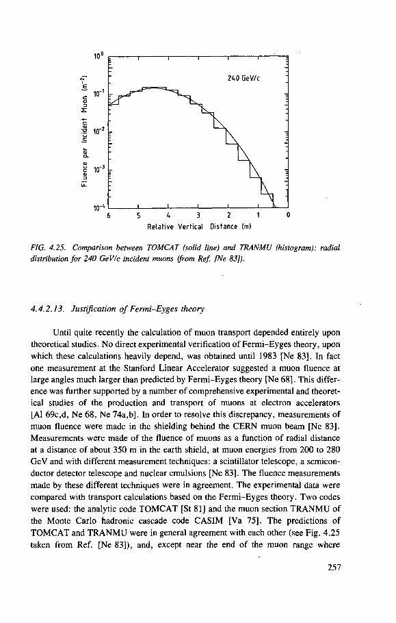
240 GeV/c
K N
10"' 6 S 4 3 2
Relative Vertical Distance (m)
0
FIG. 4.25. Comparison between TOMCAT (solid line) and TRANMU (histogram): radial distribution for 240 GeV/c incident muons (from Ref. [Ne 83]).
4.4.2.13. Justification of Fermi-Eyges theory
Until quite recently the calculation of muon transport depended entirely upon theoretical studies. No direct experimental verification of Fermi-Eyges theory, upon which these calculations heavily depend, was obtained until 1983 [Ne 83], In fact one measurement at the Stanford Linear Accelerator suggested a muon fluence at large angles much larger than predicted by Fermi-Eyges theory [Ne 68]. This differ-ence was further supported by a number of comprehensive experimental and theoret-ical studies of the production and transport of muons at electron accelerators [Al 69c,d, Ne 68, Ne 74a,b]. In order to resolve this discrepancy, measurements of muon fluence were made in the shielding behind the CERN muon beam [Ne 83]. Measurements were made of the fluence of muons as a function of radial distance at a distance of about 350 m in the earth shield, at muon energies from 200 to 280 GeV and with different measurement techniques: a scintillator telescope, a semicon-ductor detector telescope and nuclear emulsions [Ne 83]. The fluence measurements made by these different techniques were in agreement. The experimental data were compared with transport calculations based on the Fermi-Eyges theory. Two codes were used: the analytic code TOMCAT [St 81] and the muon section TRANMU of the Monte Carlo hadronic cascade code CASIM [Va 75]. The predictions of TOMCAT and TRANMU were in general agreement with each other (see Fig. 4.25 taken from Ref. [Ne 83]), and, except near the end of the muon range where
257
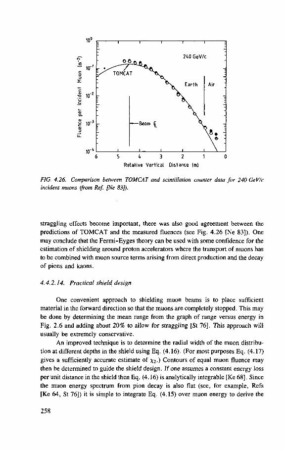
FIG. 4.26. Comparison between TOMCAT and scintillation counter data for 240 GeV/c incident muons (from Ref. [Ne 83]).
straggling effects become important, there was also good agreement between the predictions of TOMCAT and the measured fluences (see Fig. 4.26 [Ne 83]). One may conclude that the Fermi-Eyges theory can be used with some confidence for the estimation of shielding around proton accelerators where the transport of muons has to be combined with muon source terms arising from direct production and the decay of pions and kaons.
4.4.2.14. Practical shield design
One convenient approach to shielding muon beams is to place sufficient material in the forward direction so that the muons are completely stopped. This may be done by determining the mean range from the graph of range versus energy in Fig. 2.6 and adding about 20% to allow for straggling [St 76]. This approach will usually be extremely conservative.
An improved technique is to determine the radial width of the muon distribu-tion at different depths in the shield using Eq. (4.16). (For most purposes Eq. (4.17) gives a sufficiently accurate estimate of Contours of equal muon fluence may then be determined to guide the shield design. If one assumes a constant energy loss per unit distance in the shield then Eq. (4.16) is analytically integrable [Ke 68], Since the muon energy spectrum from pion decay is also flat (see, for example, Refs [Ke 64, St 76]) it is simple to integrate Eq. (4.15) over muon energy to derive the
258
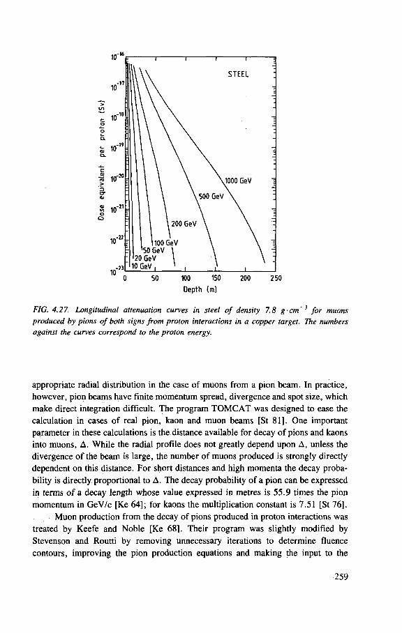
FIG. 4.27. Longitudinal attenuation curves in steel of density 7.8 g-cm~3 for muons produced by pions of both signs from proton interactions in a copper target. The numbers against the curves correspond to the proton energy.
appropriate radial distribution in the case of muons from a pion beam. In practice, however, pion beams have finite momentum spread, divergence and spot size, which make direct integration difficult. The program TOMCAT was designed to ease the calculation in cases of real pion, kaon and muon beams [St 81]. One important parameter in these calculations is the distance available for decay of pions and kaons into muons, A. While the radial profile does not greatly depend upon A, unless the divergence of the beam is large, the number of muons produced is strongly directly dependent on this distance. For short distances and high momenta the decay proba-bility is directly proportional to A. The decay probability of a pion can be expressed in terms of a decay length whose value expressed in metres is 55.9 times the pion momentum in GeV/c [Ke 64]; for kaons the multiplication constant is 7.51 [St 76].
Muon production from the decay of pions produced in proton interactions was treated by Keefe and Noble [Ke 68], Their program was slightly modified by Stevenson and Routti by removing unnecessary iterations to determine fluence contours, improving the pion production equations and making the input to the
259
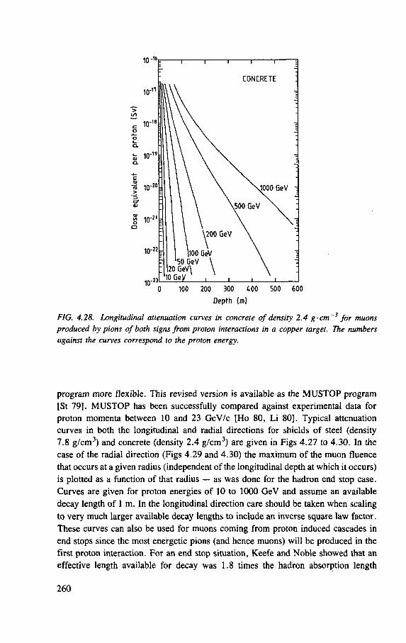
« 10
200 300 400 500 600
Depth <m)
FIG. 4.28. Longitudinal attenuation curves in concrete of density 2.4 g-cm~3 for muons produced by pions of both signs from proton interactions in a copper target. The numbers against the curves correspond to the proton energy.
program more flexible. This revised version is available as the MUSTOP program [St 79]. MUSTOP has been successfully compared against experimental data for proton momenta between 10 and 23 GeV/c [Ho 80, Li 80], Typical attenuation curves in both the longitudinal and radial directions for shields of steel (density 7.8 g/cm3) and concrete (density 2.4 g/cm3) are given in Figs 4.27 to 4.30. In the case of the radial direction (Figs 4.29 and 4.30) the maximum of the muon fluence that occurs at a given radius (independent of the longitudinal depth at which it occurs) is plotted as a function of that radius — as was done for the hadron end stop case. Curves are given for proton energies of 10 to 1000 GeV and assume an available decay length of 1 m. In the longitudinal direction care should be taken when scaling to very much larger available decay lengths to include an inverse square law factor. These curves can also be used for muons coming from proton induced cascades in end stops since the most energetic pions (and hence muons) will be produced in the first proton interaction. For an end stop situation, Keefe and Noble showed that an effective length available for decay was 1.8 times the hadron absorption length
260
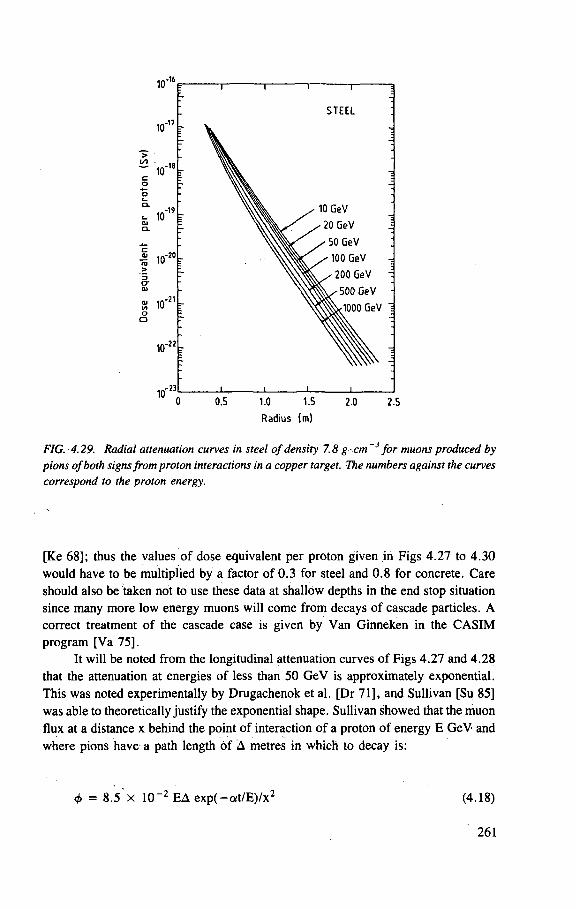
Radius (m)
FIG. 4.29. Radial attenuation curves in steel of density 7.8 g- cm'3 for muons produced by pions of both signs from proton interactions in a copper target. The numbers against the curves correspond to the proton energy.
[Ke 68]; thus the values of dose equivalent per proton given in Figs 4.27 to 4.30 would have to be multiplied by a factor of 0 .3 for steel and 0.8 for concrete. Care should also be taken not to use these data at shallow depths in the end stop situation since many more low energy muons will come from decays of cascade particles. A correct treatment of the cascade case is given by Van Ginneken in the CASIM program [Va 75].
It will be noted from the longitudinal attenuation curves of Figs 4.27 and 4.28 that the attenuation at energies of less than 50 GeV is approximately exponential. This was noted experimentally by Drugachenok et al. [Dr 71], and Sullivan [Su 85] was able to theoretically justify the exponential shape. Sullivan showed that the muon flux at a distance x behind the point of interaction of a proton of energy E GeV and where pions have a path length of A metres in which to decay is:
<j> = 8.5 x 10 ~2 EA exp(-o; t /E) /x 2 (4.18)
261
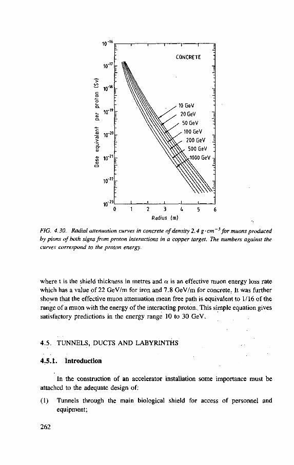
1 0 - "
CONCRETE
I 1 1 I 1 0 1 2 3 4 5 6
Radius (m)
FIG. 4.30. Radial attenuation curves in concrete of density 2.4 g-cm ~3 for muons produced by pions of both signs from proton interactions in a copper target. The numbers against the curves correspond to the proton energy.
where t is the shield thickness in metres and a is an effective muon energy loss rate which has a value of 22 GeV/m for iron and 7.8 GeV/m for concrete. It was further shown that the effective muon attenuation mean free path is equivalent to 1/16 of the range of a muon with the energy of the interacting proton.. This simple equation gives satisfactory predictions in the energy range 10 to 30 GeV.
4.5. TUNNELS, DUCTS AND LABYRINTHS
4.5.1. Introduction
In the construction of an accelerator installation some importance must be attached to the adequate design of:
(1) Tunnels through the main biological shield for access of personnel and equipment;
262
(2) Ducts to allow the connection of essential services such as water, air, radio-frequency power and cryogenic cooling lines for the accelerator.
These ducts and tunnels act as leakage paths for radiation, especially low energy neutrons. They also remove absorber from the shield, reducing the effective-ness of the shield, particularly in the region of the penetrations. Thus they must be carefully designed such that their presence does not impair the efficiency of the main shield.
The streaming of neutrons along ducts is an important aspect of shield design for fission reactors [IAEA 68], and because of recent interest in fusion reactors, there have been several experimental and theoretical studies of the attenuation of 14 MeV neutrons in ducts (see, for example, Refs [Ha 83, Sa 82, Sa 83]). However, in reactors the ducts are generally only for utilities and are rather small (of the order of 0.5 m x 0.5 m). At accelerator installations, in addition to such service ducts, much larger passages are required both for the entry of personnel and for the movement of equipment. The width of personnel entries may be quite large (1.2 m or more), particularly if emergency fire and medical services are to be permitted efficient access and egress. Equipment access may require even larger ducts. For example, at the CERN SPS equipment access ducts with diameters up to 9 m are provided. In ducts of such large cross-section the scattering of neutrons around corners by collisions in the air as well as by collisions at the duct wall may become important. At the largest accelerators where tunnels and ducts may be as long as tens, or even hundreds of metres, the scattering and attenuation in the air may become a significant factor.
The major theoretical and experimental studies of the transmission of radiation by tunnels have concentrated on neutrons produced by reactors. An excellent summary of the state of knowledge up to the mid-1950s is given by Price, Horton and Spinney [Pr 57]. Early work is also reviewed in Chapter 8 of the Engineering Compendium on Radiation Shielding (Vol. 1) [IAEA 68]. The more recent book by Chilton et al. [Ch 84] also contains a summary of ideas useful in calculating the transmission of neutrons and photons in ducts. Soviet experience is summarized in a book by Zolotukhin et al. [Zo 68] (see also Ref. [Bo 71]).
4.5.2. Calculation of radiation transmission through ducts and labyrinths
There are several types of Monte Carlo techniques that are applied to duct and labyrinth transmission problems. One of these is the strictly analogue Monte Carlo calculation that simulates the most important interactions occurring as the neutrons traverse the duct system. The calculations are based on interactions at the nuclear level. Particle tracks are sampled from probability distributions corresponding to microscopic elemental cross-sections. One such analogue Monte Carlo programme that has been applied to labyrinth calculations at accelerators is SAM-CE [Co 72,
263
Co 73]. This program was used by Vogt in its analogue mode to study access ways at the CERN SPS [Vo 75],
Because of the enormous computer time required in the execution of purely analogue programs that track particles in regions of space that may be of little interest to the problem in hand, weighted Monte Carlo codes such as MORSE [Em 75] can be much more efficient for duct attenuation calculations. Although differential cross-sections at the nuclear level are again used, various techniques of variance reduction can be employed to 'point' particle tracks to low probability regions of interest, e.g. down the tunnel and around the bends, rather than tracking particles for long times in the tunnel walls. An example of the use of the MORSE code in the tunnel attenu-ation problem around accelerators is given by Ye [Ye 82].
One way of making duct calculations even more efficient is to use the albedo concept in which the reflecting properties of the tunnel walls are parametrized in great detail. The total effect of an interaction with a duct wall is assumed to be either absorption in the wall or a reflection back into the duct at the point of incidence, with a probability equal to the total albedo. The direction and energies of the reflected neutrons are determined from probabilities derived from the double differential albedos, which are functions of the angle of incidence and the initial energy of the neutron, as well as of the reflected polar and azimuthal angles, and the energy of the reflected neutron. The albedo concept is based on the assumption that when a neutron enters the wall of a tunnel, the area from which the neutron may re-emerge around the entry point is small compared with the cross-sectional area of the duct. It was shown by Maerker and Muckenthaler [Ma 67a] that this concept was valid in multilegged ducts provided that the lateral dimensions of the duct exceeded 0.3 m. The multigroup transport code AMC [Ma 67b] is based on this albedo technique, and was used by Alsmiller and Solomito [Al 69e] in a duct study at the Princeton PPA and by Routti and van der Voorde [Ro 72a] to study tunnels in the shielding of the CERN ISR.
It is also possible to run the MORSE program in the albedo mode, the limitation being the availability of albedo data. In the middle 1970s double differen-tial albedos with respect to angle of incidence and neutron energy had been measured and calculated only for concrete [Co 67, Ma 65, Ma 66], At the present time, calcu-lated albedo data are available for four materials (water, ordinary concrete, carbon steel, and steel-over-concrete) and can be prepared for use in the MORSE program [Ca 79, Em 78]; to date no comparisons of experimental data with predictions using this option of MORSE have been made for tunnels leading to accelerator enclosures.
A simplification of the multigroup albedo concept can be made by assuming that attenuation of absorbed dose, or dose equivalent, along a multilegged duct can be described by the albedo properties of a single energy group of neutrons. The ZEUS code of Gervaise and d'Hombres [Ge 68] makes use of this assumption. d'Hombres et al. found that the energy group between 3 and 4 MeV most closely approximated dose in its transmission properties along tunnels of the CERN PS
264
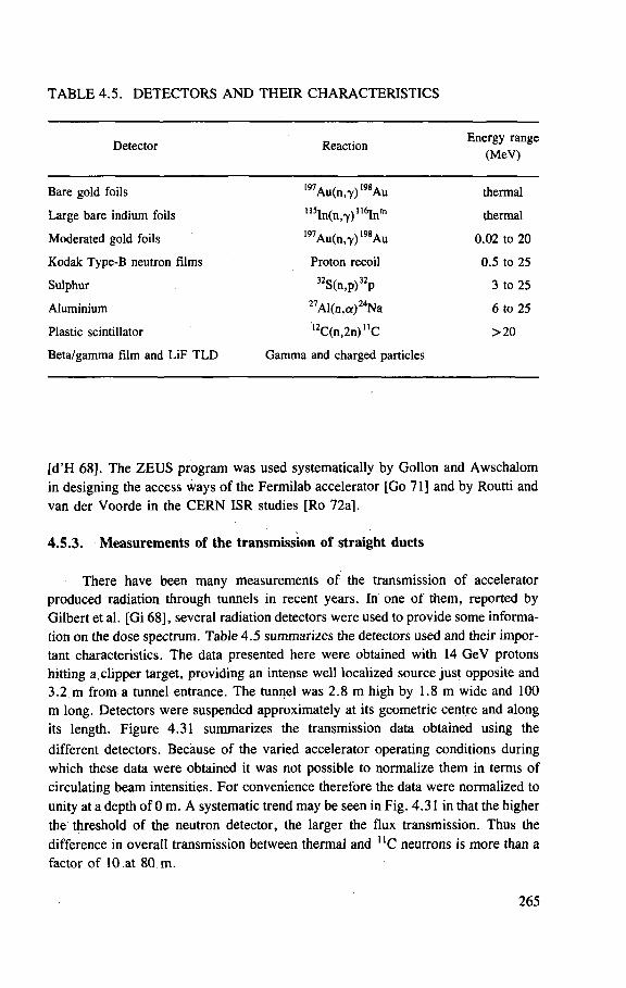
TABLE 4.5. DETECTORS AND THEIR CHARACTERISTICS
Detector Reaction Energy range
(MeV)
Bare gold foils
Large bare indium foils
Moderated gold foils
Kodak Type-B neutron films
Sulphur
Aluminium
Plastic scintillator
Beta/gamma film and LiF T L D
197Au(n,Y)198 Au 115 I n ( n , 7 ) u V r
1 9 7Au(n, 7 ) 1 9 8Au
Proton recoil
3 2 c f \ 3 2 _
S(n,p) p
2 7 Al(n ,a ) 2 4 Na 1 2 C ( n , 2 n ) n C
Gamma and charged particles
thermal
thermal
0 .02 to 20
0 .5 to 25
3 to 25
6 to 25
>20
[d'H 68]. The ZEUS program was used systematically by Gollon and Awschalom in designing the access ways of the Fermilab accelerator [Go 71] and by Routti and van der Voorde in the CERN ISR studies [Ro 72a],
4.5.3. Measurements of the transmission of straight ducts
There have been many measurements of the transmission of accelerator produced radiation through tunnels in recent years. In one of them, reported by Gilbert et al. [Gi 68], several radiation detectors were used to provide some informa-tion on the dose spectrum. Table 4.5 summarizes the detectors used and their impor-tant characteristics. The data presented here were obtained with 14 GeV protons hitting a. clipper target, providing an intense well localized source just opposite and 3.2 m from a tunnel entrance. The tunnel was 2.8 m high by 1.8 m wide and 100 m long. Detectors were suspended approximately at its geometric centre and along its length. Figure 4.31 summarizes the transmission data obtained using the different detectors. Because of the varied accelerator operating conditions during which these data were obtained it was not possible to normalize them in terms of circulating beam intensities. For convenience therefore the data were normalized to unity at a depth of 0 m. A systematic trend may be seen in Fig. 4.31 in that the higher the threshold of the neutron detector, the larger the flux transmission. Thus the difference in overall transmission between thermal and n C neutrons is more than a factor of 10 at 80 m.
265
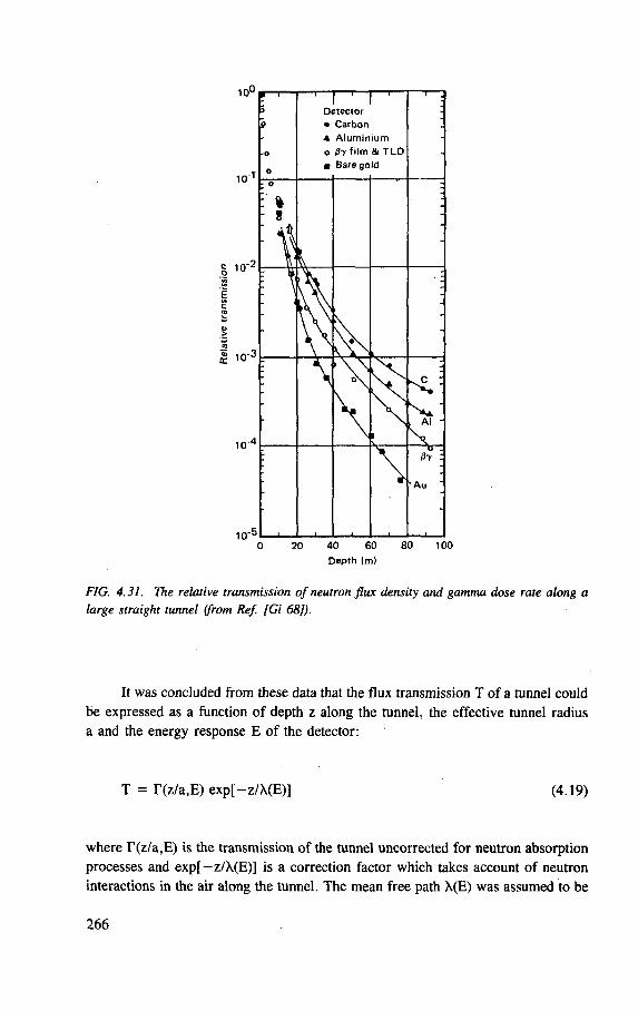
D e p t h IFTI)
FIG. 4.31. The relative transmission of neutron flux density and gamma dose rate along a large straight tunnel (from Ref. [Gi 68]).
It was concluded from these data that the flux transmission T of a tunnel could be expressed as a function of depth z along the tunnel, the effective tunnel radius a and the energy response E of the detector:
T = r (z /a ,E) exp[-z/X(E)] (4.19)
where T(z/a,E) is the transmission of the tunnel uncorrected for neutron absorption processes and exp[-z/X(E)] is a correction factor which takes account of neutron interactions in the air along the tunnel. The mean free path X(E) was assumed to be
266
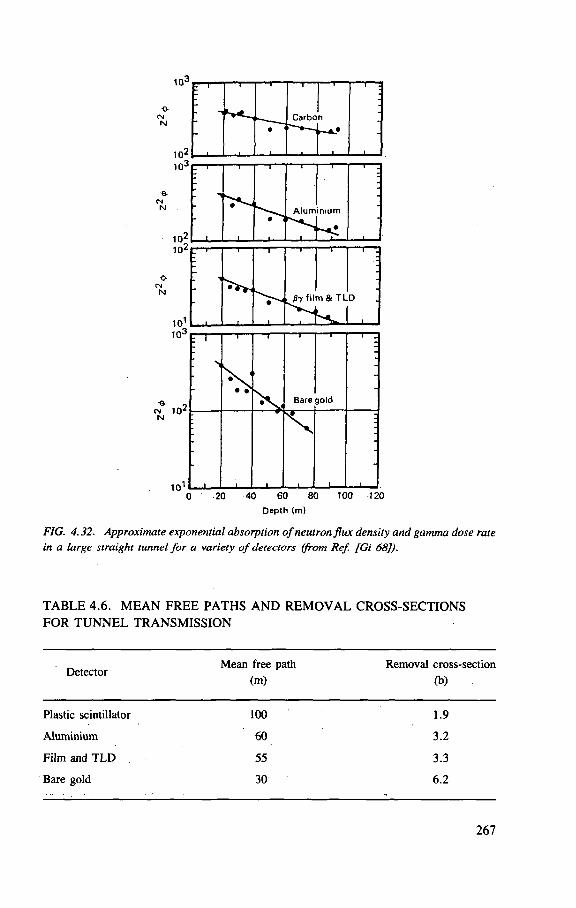
"1—
1
— i —
• i
•
i
Alum
1
nium
i
i .
1 i
i
t
i
07 fil m & T L
H . D
T~T~ i
•
- i — I —
Bare
— f —
gold
— i — ;
i 1 1
s *
i — > 0 20 40 60 80 100 T20
Depth (m)
FIG. 4.32. Approximate exponential absorption of neutron flux density and gamma dose rate in a large straight tunnel for a variety of detectors (from Ref. [Gi 68]).
TABLE 4.6. MEAN FREE PATHS AND REMOVAL CROSS-SECTIONS FOR TUNNEL TRANSMISSION
Detector Mean free path Removal cross-section
(m) (b)
Plastic scintillator 100 1.9
Aluminium 60 3.2
Film and T L D . 55 3 .3
Bare gold 30 6 .2
267
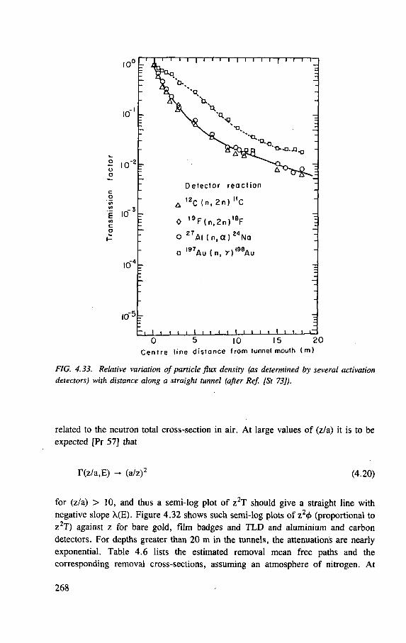
, - 3 E 10 r-
10V
IO" 5 -
D e t e c t o r r e a c t i o n
A IZC (n, 2 n ) "C
0 , 9 F ( n , 2 n ) ' 8 F
o 2 7AI ( n , a ) 2 4 N a
a i 9 7 A U ( n, r ) , 9 8 A u
- • I i i i i I i i i i I i i i • I • t t 0 5 10 15 2 0
C e n t r e l ine d i s t a n c e f rom tunnel mouth ( m )
FIG. 4.33. Relative variation of particle flux density (as determined by several activation detectors) with distance along a straight tunnel (after Ref. [St 73]).
related to the neutron total cross-section in air. At large values of (z/a) it is to be expected [Pr 57] that
r(z/a,E) - (a/z)2 (4.20)
for (z/a) > 10, and thus a semi-log plot of z2T should give a straight line with
negative slope \(E). Figure 4.32 shows such semi-log plots of z24> (proportional to
Z2T) against z for bare gold, film badges and TLD and aluminium and carbon
detectors. For depths greater than 20 m in the tunnels, the attenuations are nearly
exponential. Table 4.6 lists the estimated removal mean free paths and the
corresponding removal cross-sections, assuming an atmosphere of nitrogen. At
268
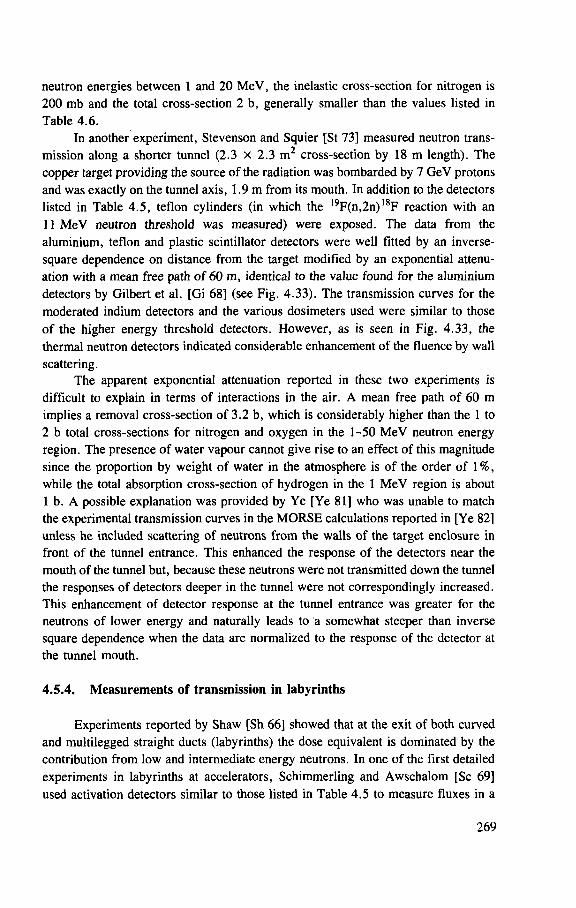
neutron energies between 1 and 20 M e V , the inelastic cross-section for nitrogen is
200 mb and the total cross-section 2 b, generally smaller than the values listed in
Table 4.6.
In another experiment, Stevenson and Squier [St 73] measured neutron trans-
mission along a shorter tunnel (2.3 x 2.3 m 2 cross-section by 18 m length). The
copper target providing the source of the radiation was bombarded by 7 GeV protons
and was exactly on the tunnel axis, 1.9 m from its mouth. In addition to the detectors
listed in Table 4.5, teflon cylinders (in which the l9F(n,2n)18F reaction with an
11 M e V neutron threshold was measured) were exposed. The data from the
aluminium, teflon and plastic scintillator detectors were well fitted by an inverse-
square dependence on distance from the target modified by an exponential attenu-
ation with a mean free path of 60 m, identical to the value found for the aluminium
detectors by Gilbert et al. [Gi 68] (see Fig. 4.33). The transmission curves for the
moderated indium detectors and the various dosimeters used were similar to those
of the higher energy threshold detectors. However, as is seen in Fig. 4.33, the
thermal neutron detectors indicated considerable enhancement of the fluence by wall
scattering.
The apparent exponential attenuation reported in these two experiments is
difficult to explain in terms of interactions in the air. A mean free path of 60 m
implies a removal cross-section of 3.2 b, which is considerably higher than the 1 to
2 b total cross-sections for nitrogen and oxygen in the 1-50 M e V neutron energy
region. The presence of water vapour cannot give rise to an effect of this magnitude
since the proportion by weight of water in the atmosphere is of the order of 1 % ,
while the total absorption cross-section of hydrogen in the 1 M e V region is about
1 b. A possible explanation was provided by Ye [Ye 81] who was unable to match
the experimental transmission curves in the M O R S E calculations reported in [Ye 82]
unless he included scattering of neutrons from the walls of the target enclosure in
front of the tunnel entrance. This enhanced the response of the detectors near the
mouth of the tunnel but, because these neutrons were not transmitted down the tunnel
the responses of detectors deeper in the tunnel were not correspondingly increased.
This enhancement of detector response at the tunnel entrance was greater for the
neutrons of lower energy and naturally leads to a somewhat steeper than inverse
square dependence when the data are normalized to the response of the detector at
the tunnel mouth.
4.5.4. Measurements of transmission in labyrinths
Experiments reported by Shaw [Sh 66] showed that at the exit of both curved
and multilegged straight ducts (labyrinths) the dose equivalent is dominated by the
contribution from low and intermediate energy neutrons. In one of the first detailed
experiments in labyrinths at accelerators, Schimmerling and Awschalom [Sc 69]
used activation detectors similar to those listed in Table 4.5 to measure fluxes in a
269
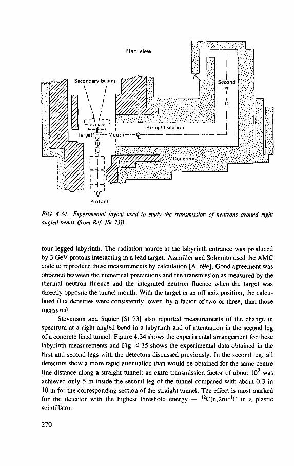
P l a n v i e w
Secondary beams
\
l Straight section Target ^ — Mouth (£-
Protons
FIG. 4.34. Experimental layout used to study the transmission of neutrons around right angled bends (from Ref. [St 73]).
four-legged labyrinth. The radiation source at the labyrinth entrance was produced by 3 GeV protons interacting in a lead target. Alsmiller and Solomito used the A M C code to reproduce these measurements by calculation [Al 69e]. Good agreement was obtained between the numerical predictions and the transmission as measured by the thermal neutron fluence and the integrated neutron fluence when the target was directly opposite the tunnel mouth. With the target in an off-axis position, the calcu-lated flux densities were consistently lower, by a factor of two or three, than those measured.
Stevenson and Squier [St 73] also reported measurements of the change in spectrum at a right angled bend in a labyrinth and of attenuation in the second leg of a concrete lined tunnel. Figure 4.34 shows the experimental arrangement for these labyrinth measurements and Fig. 4.35 shows the experimental data obtained in the first and second legs with the detectors discussed previously. In the second leg, all detectors show a more rapid attenuation than would be obtained for the same centre line distance along a straight tunnel: an extra transmission factor of about 102 was achieved only 5 m inside the second leg of the tunnel compared with about 0.3 in 10 m for the corresponding section of the straight tunnel. The effect is most marked for the detector with the highest threshold energy — 1 2C(n,2n)uC in a plastic scintillator.
270
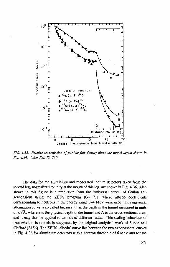
FIG. 4.35. Relative transmission of particle flux density along the tunnel layout shown in Fig. 4.34. (after Ref. [St 73]).
The data for the aluminium and moderated indium detectors taken from the
second leg, normalized to unity at the mouth of this leg, are shown in Fig. 4.36. Also
shown in this figure is a prediction from the 'universal curve' of Gollon and
Awschalom using the Z E U S program [Go 71], where albedo coefficients
corresponding to neutrons in the energy range 3-4 M e V were used. This universal
attenuation curve is so called because it has the depth in the tunnel measured in units
of z/VA, where z is the physical depth in the tunnel and A is the cross-sectional area,
and it may thus be applied to tunnels of different radius. This scaling behaviour of
transmission in tunnels is suggested by the original analytical work of Simon and
Clifford [Si 56]. The Z E U S 'albedo' curve lies between the two experimental curves
in Fig. 4.36 for aluminium detectors with a neutron threshold of 6 M e V and for the
271
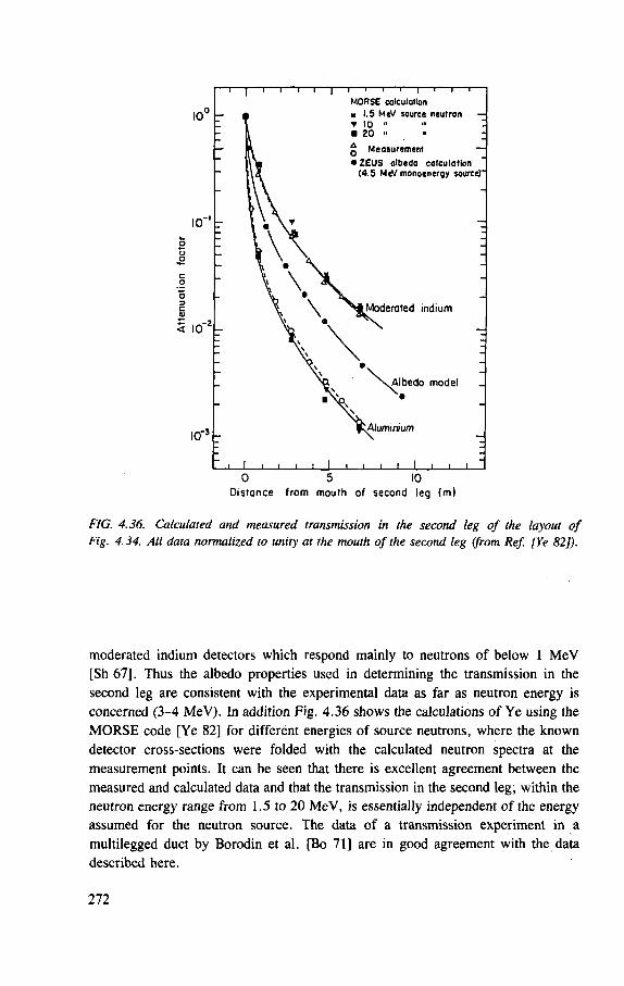
Distance from mouth of second leg (m)
FIG. 4.36. Calculated and measured transmission in the second leg of the layout of Fig. 4.34. All data normalized to unity at the mouth of the second leg (from Ref. [Ye 82]).
moderated indium detectors which respond mainly to neutrons of below 1 M e V
[Sh 67], Thus the albedo properties used in determining the transmission in the
second leg are consistent with the experimental data as far as neutron energy is
concerned (3-4 MeV). In addition Fig. 4.36 shows the calculations of Ye using the
M O R S E code [Ye 82] for different energies of source neutrons, where the known
detector cross-sections were folded with the calculated neutron spectra at the
measurement points. It can be seen that there is excellent agreement between the
measured and calculated data and that the transmission in the second leg, within the
neutron energy range from 1.5 to 20 MeV, is essentially independent of the energy
assumed for the neutron source. The data of a transmission experiment in a
multilegged duct by Borodin et al. [Bo 71] are in good agreement with the data
described here.
272
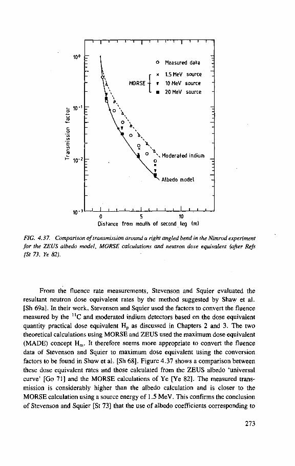
10°
10"
10 - 2
10 - 3
- i—|—i—i—i—i—|—i—I—I—I—|—I—i—r
o Measured data
r * 1.5 MeV source
MORSE- i t 10 MeV source
• 20 MeV source
0 \ Moderated indium o
Albedo model
i I i ' i i L JL 0 5 10
Distance from mouth of second leg (m)
FIG. 4.37. Comparison of transmission around a right angled bend in the Nimrod experiment for the ZEUS albedo model, MORSE calculations and neutron dose equivalent (after Refs [St 73, Ye 82).
From the fluence rate measurements, Stevenson and Squier evaluated the
resultant neutron dose equivalent rates by the method suggested by Shaw et al.
[Sh 69a]. In their work, Stevenson and Squier used the factors to convert the fluence
measured by the n C and moderated indium detectors based on the dose equivalent
quantity practical dose equivalent H p as discussed in Chapters 2 and 3. The two
theoretical calculations using M O R S E and Z E U S used the maximum dose equivalent
( M A D E ) concept H m . It therefore seems more appropriate to convert the fluence
data of Stevenson and Squier to maximum dose equivalent using the conversion
factors to be found in Shaw et al. [Sh 68]. Figure 4.37 shows a comparison between
these dose equivalent rates and those calculated from the Z E U S albedo 'universal
curve' [Go 71] and the M O R S E calculations of Ye [Ye 82]. The measured trans-
mission is considerably higher than the albedo calculation and is closer to the
M O R S E calculation using a source energy of 1.5 MeV. This confirms the conclusion
of Stevenson and Squier [St 73] that the use of albedo coefficients corresponding to
273
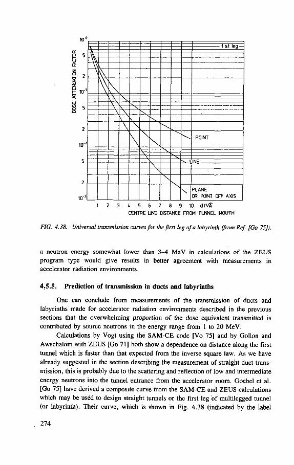
10
3
5
10"
10"
v -1 st leg —
"W"
V V \ \\ \ A r V \ V N \ Y
X.
\ \ \ \ \ POINT
M \
— ^ N 1 INF
V s \
s , \ \ PLANE
OR POINT OFF AXIS
1 2 3 4 5 6 7 8 9 10 d/vfr
CENTRE LINE DISTANCE FROM TUNNEL MOUTH
FIG. 4.38. Universal transmission curves for the first leg of a labyrinth (from Ref. [Go 75]).
a neutron energy somewhat lower than 3-4 M e V in calculations of the Z E U S program type would give results in better agreement with measurements in accelerator radiation environments.
4.5.5. Prediction of transmission in ducts and labyrinths
One can conclude from measurements of the transmission of ducts and
labyrinths made for accelerator radiation environments described in the previous
sections that the overwhelming proportion of the dose equivalent transmitted is
contributed by source neutrons in the energy range from 1 to 20 MeV.
Calculations by Vogt using the S A M - C E code [Vo 75] and by Gollon and
Awschalom with Z E U S [Go 71] both show a dependence on distance along the first
tunnel which is faster than that expected from the inverse square law. As we have
already suggested in the section describing the measurement of straight duct trans-
mission, this is probably due to the scattering and reflection of low and intermediate
energy neutrons into the tunnel entrance from the accelerator room. Goebel et al.
[Go 75] have derived a composite curve from the S A M - C E and Z E U S calculations
which may be used to design straight tunnels or the first leg of multilegged tunnel
(or labyrinth). Their curve, which is shown in Fig. 4.38 (indicated by the label
274
'point'), may be used when the dose equivalent produced by neutrons between 1 and
20 M e V at the entrance to the tunnel is known.
I f the tunnel is to be designed from known or expected beam losses, instead
of a defined dose equivalent rate at the tunnel entrance, the neutron yield in the
1-20 M e V range from the effective source must be determined. This may then be
converted to dose equivalent using a conversion coefficient. When the point source
is in full view of the back end of the duct, a simple inverse square law can be used
to determine the neutron fluence at the end of the duct. It is suggested that an
appropriate coefficient to convert the apparent neutron fluence to dose equivalent is
20 fSv-m 2 (1 neutron/(cm2• s) is equivalent to 0.07 mrem/h). Both thin and thick
target neutron yield data are available. The experiments of Stevenson and Squier
[St 73] allow one to obtain a source term for those neutrons detected by a moderated
thermal neutron detector which are produced in a copper target, giving a figure of
one neutron produced per 1.6 GeV of proton energy lost from the beam at 7 GeV
(at 90° to the incident proton beam). The yield experiments of Stevenson et al. at
proton energies from 7 to 400 GeV [St 71b, St 83] suggest that since the neutron
multiplicity scales as E° 25, the energy required to produce a neutron scales as E° 75
above an energy of 7 GeV. Below this energy the thin target curve of Fig. 4.6 may
be used to scale the neutron yield. For a thicker target there is evidently an optimum
size of block in which the cascade develops to produce the maximum number of
neutrons. It was suggested by Routti [Ro 72a], based on the H E T C calculations of
Armstrong and Alsmiller [Ar 69b] and Armstrong and Barish [Ar 69c], that one
neutron would be produced per 0.25 GeV of energy from a proton beam at 25 GeV.
This thick target yield is expected to scale as E ° 8 (see the section on high energy
shielding) leading to a scaling law of E° 2 for the energy required to produce a
neutron. This scaling law is expected to be valid above a proton energy of 3 GeV.
Below this energy, scaling according to the 'thick target' curve of Fig. 4.6 should
be used.
Figure 4.38 also summarizes the first leg transmission for source conditions
other than the point source on the tunnel axis. These curves are again composites
from S A M - C E , Z E U S and A M C calculations. The values of the dose equivalent at
the tunnel mouth should either be known from measurements or estimated using the
inverse square law approximation and the source strengths discussed in the previous
paragraphs.
We have already suggested that the transmission of tunnels of different size
might be compared by using a 'universal curve' in which length along the tunnel is
measured in units of z/VA. The studies of Vogt [Vo 75] show that there strictly could
be no such 'universal curve' describing transmission in the second leg of a tunnel
if the height:width ratio were allowed to vary outside the range 0.5-2.0. Neverthe-
less, Goebel et al. [Go 75], by summarizing S A M - C E , A M C and Z E U S calcula-
tions, and taking into account the available experimental data, suggested that in most
cases the transmission would lie close to the solid line in Fig. 4.39. Generalized
275
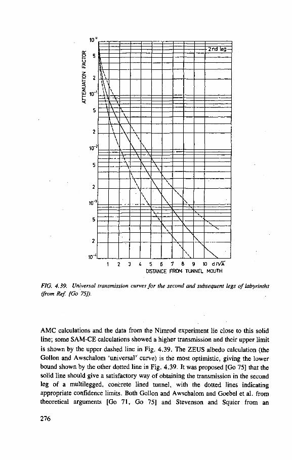
10u
a
3 z
10"
10 "
10 '
[— -2nd leg — 1 I % \\\
A \ \ \ \ - V -
— r \ \ \ \ \ \ \ \ \ \ \ \ V
2
\ \ \
\ \ \
V \ — 1.
\ V \ V \
\ V \ \ \ \ \ \ V \ \
\
\ N \ \
— V - V \
\ \ s \ s \ \
\ \ N \
\ s \ \ \
1 2 3 4 5 6 7 8 9 10 d/vS" DISTANCE FROM TUNNEL MOUTH
FIG. 4.39. Universal transmission curves for the second and subsequent legs of labyrinths (from Ref. [Go 75]).
A M C calculations and the data from the Nimrod experiment lie close to this solid
line; some S A M - C E calculations showed a higher transmission and their upper limit
is shown by the upper dashed line in Fig. 4.39. The Z E U S albedo calculation (the
Gollon and Awschalom 'universal' curve) is the most optimistic, giving the lower
bound shown by the other dotted line in Fig. 4.39. It was proposed [Go 75] that the
solid line should give a satisfactory way of obtaining the transmission in the second
leg of a multilegged, concrete lined tunnel, with the dotted lines indicating
appropriate confidence limits. Both Gollon and Awschalom and Goebel et al. from
theoretical arguments [Go 71, Go 75] and Stevenson and Squier from an
276
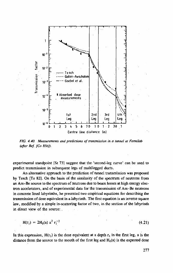
Centre line d i s tance (m)
FIG. 4.40. Measurements and predictions of transmission in a tunnel at Fermilab (after Ref. [Co 85b]).
experimental standpoint [St 73] suggest that the 'second-leg curve' can be used to predict transmission in subsequent legs of multilegged ducts.
An alternative approach to the prediction of tunnel transmission was proposed by Tesch [Te 82]. On the basis of the similarity of the spectrum of neutrons from an Am-Be source to the spectrum of neutrons due to beam losses at high energy elec-tron accelerators, and of experimental data for the transmission of Am-Be neutrons in concrete lined labyrinths, he presented two empirical equations for describing the transmission of dose equivalent in a labyrinth. The first equation is an inverse square law, modified by a simple in-scattering factor of two, in the section of the labyrinth in direct view of the source:
H(r,) = 2H0(a) a2 r f 2 (4.21)
In this expression, H(ri) is the dose equivalent at a depth r, in the first leg, a is the
distance from the source to the mouth of the first leg and H0(a) is the expected dose
277
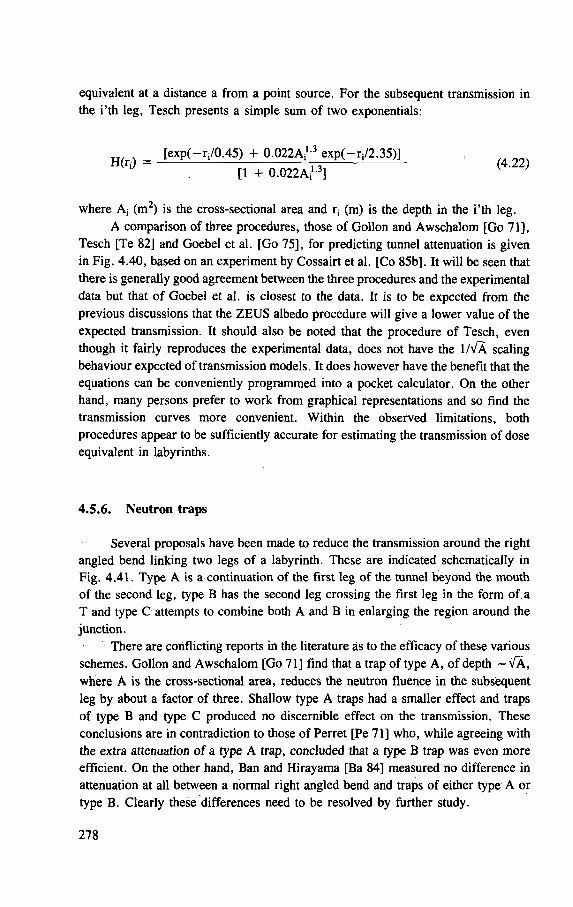
equivalent at a distance a from a point source. For the subsequent transmission in
the i'th leg, Tesch presents a simple sum of two exponentials:
= [exp(-rj/0.45) + 0.022A i '-3 exp(- r i/2.35)]
[1 + 0 . 0 2 2 A i1 3 ]
where A, (m2) is the cross-sectional area and r, (m) is the depth in the i'th leg.
A comparison of three procedures, those of Gollon and Awschalom [Go 71],
Tesch [Te 82] and Goebel et al. [Go 75], for predicting tunnel attenuation is given
in Fig. 4.40, based on an experiment by Cossairt et al. [Co 85b], It will be seen that
there is generally good agreement between the three procedures and the experimental
data but that of Goebel et al. is closest to the data. It is to be expected from the
previous discussions that the Z E U S albedo procedure will give a lower value of the
expected transmission. It should also be noted that the procedure of Tesch, even
though it fairly reproduces the experimental data, does not have the 1/VA scaling
behaviour expected of transmission models. It does however have the benefit that the
equations can be conveniently programmed into a pocket calculator. On the other
hand, many persons prefer to work from graphical representations and so find the
transmission curves more convenient. Within the observed limitations, both
procedures appear to be sufficiently accurate for estimating the transmission of dose
equivalent in labyrinths.
4.5.6. Neutron traps
Several proposals have been made to reduce the transmission around the right
angled bend linking two legs of a labyrinth. These are indicated schematically in
Fig. 4.41. Type A is a continuation of the first leg of the tunnel beyond the mouth
of the second leg, type B has the second leg crossing the first leg in the form of a
T and type C attempts to combine both A and B in enlarging the region around the
junction.
There are conflicting reports in the literature as to the efficacy of these various
schemes. Gollon and Awschalom [Go 71] find that a trap of type A , of depth ~ V A ,
where A is the cross-sectional area, reduces the neutron fluence in the subsequent
leg by about a factor of three. Shallow type A traps had a smaller effect and traps
of type B and type C produced no discernible effect on the transmission. These
conclusions are in contradiction to those of Perret [Pe 71] who, while agreeing with
the extra attenuation of a type A trap, concluded that a type B trap was even more
efficient. On the other hand, Ban and Hirayama [Ba 84] measured no difference in
attenuation at all between a normal right angled bend and traps of either type A or
type B. Clearly these differences need to be resolved by further study.
278
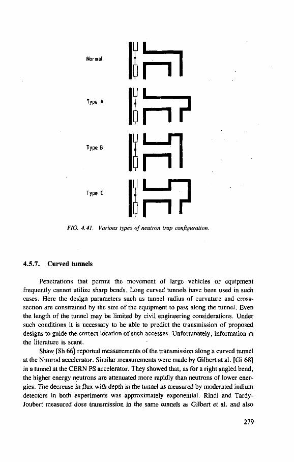
Normal
Type A
Type B
Type C
FIG. 4.41. Various types of neutron trap configuration.
4.5.7. Curved tunnels
Penetrations that permit the movement of large vehicles or equipment frequently cannot utilize sharp bends. Long curved tunnels have been used in such cases. Here the design parameters such as tunnel radius of curvature and cross-section are constrained by the size of the equipment to pass along the tunnel. Even the length of the tunnel may be limited by civil engineering considerations. Under such conditions it is necessary to be able to predict the transmission of proposed designs to guide the correct location of such accesses. Unfortunately, information in
the literature is scant. / Shaw [Sh 66] reported measurements of the transmission along a curved tunnel
at the Nimrod accelerator. Similar measurements were made by Gilbert at al. [Gi 68]
in a tunnel at the C E R N PS accelerator. They showed that, as for a right angled bend,
the higher energy neutrons are attenuated more rapidly than neutrons of lower ener-
gies. The decrease in flux with depth in the tunnel as measured by moderated indium
detectors in both experiments was approximately exponential. Rindi and Tardy-
Joubert measured dose transmission in the same tunnels as Gilbert et al. and also
279
obtained an exponential attenuation (Ri 67], These measurements by Rindi and
Tardy-Joubert facilitated the development of the Z E U S program discussed
previously.
Patterson and Thomas [Pa 73], on the basis of Z E U S calculations reported by
Gollon and Corrigan [Go 70b], suggested that the effective attenuation length X is
a function only of the radius of curvature of the tunnel R given by
X = 0.7 VR (4.23)
where R is measured in metres and lies in the range 4-40 m. Gollon and Awschalom
[Go 71], on the basis of more systematic Z E U S studies, proposed that X was more
closely linearly dependent on R, with the constant of proportionality lying between
0.13 and 0.16. Both equations predict the correct X for the C E R N and Nimrod
experiments. They both also give satisfactory agreement with the limited data of Ban
and Hirayama [Ba 84], There is an evident need here for more experimental and
theoretical studies.
Appendix
LATERAL SHIELDING CALCULATIONS - THE MOYER MODEL
4A.1. I N T R O D U C T I O N
It was seen in Chapter 4 that the increasing intensities of weak focusing
synchrotrons in the late 1950s generated a need for efficient shield design, particu-
larly in the transverse direction. This is a problem particularly amenable to solution
by the use of empirical methods and one of the best known of these was developed
for the design of the shielding of proton synchrotrons in the 10 GeV energy region.
It has become know as the 'Moyer model' and despite its limitations is still in use
today. Its development is described here in some detail because it gives good physical
insight into shielding phenomena.
In 1961 Moyer described a semi-empirical method for determining the
shielding required for the Bevatron, the 6 GeV proton synchrotron of the (then)
University of California Radiation Laboratory [Mo 61b, M o 62], whose intensity
was to be substantially increased [We 63], This model "provides a formalism to
evaluate the high energy neutron fluxes and associated biological dose rates outside
the main shield of the accelerator, in places where the nucleon-meson cascade is well
developed and essentially in equilibrium" [Ro 72b].
280
The design and construction of the first proton accelerators in the GeV energy
region during the 1950s and early 1960s demanded an increased understanding of
high energy particle accelerator radiation environments [Pa 73], Control of the
intensity of the radiation field around these accelerators — to permit safe and
efficient operations — by the design of radiation shielding became an urgent task
following experience obtained with the early operation of the Cosmotron and
Bevatron [So 57],
At that time there was no firm theoretical basis for designing accelerator
shielding and, in consequence, semi-empirical methods were developed of which, as
we have suggested, the most useful and widely known is the Moyer model [Mo 61b,
M o 62],
Moyer's procedure was to "f ind the best available data on total neutron
production, angular distribution and spectrum of the neutrons created by the
Bevatron [and to] consider a target in different positions characteristic of Bevatron
operation and evaluate the necessary shielding to accommodate the situation within
the bounds of the radiation guide rules" [Mo 61b]. Because "the most severe
requirements on local shielding will occur when a target of considerable thickness
effects a concentrated creation of neutrons and secondary particles in its immediate
vicinity" Moyer calculated shielding for a target whose dimension in the beam direc-
tion was about 100 g -cm~ 2 . Shielding thick enough for this condition would "be
easily capable of accommodating the distributed production of neutrons and
secondary particles from the machine in general".
The numerical values of the parameters used by Moyer may be found in his
original papers and review articles [Mo 61b, M o 62, Th 70], He made calculations
for four situations, representative, for the most part, of familiar operating conditions
at the Bevatron.
This appendix discusses the historical background; the generalized formulation
of the Moyer model; the derivation of numerical values for the parameters of the
model and the variation of these values with proton energy; and, finally, the
application of the model to point source and extended source calculations.
4A.2. H I S T O R I C A L B A C K G R O U N D
Moyer designed a shield for the 6 GeV proton synchrotron of the Lawrence
Radiation Laboratory (the Bevatron) to reduce dose equivalent rates by a factor of
100. Measurements showed that in practice the overall effect on the recommended
shield was to reduce neutron flux densities (proportional to dose equivalent) by a
factor between 90 and 100 [Sm 65, Th 70].
This success naturally stimulated an interest in generalizing Moyer's method
so that it could be applied to shield design over a wide range of energies, in particular
to the 100 GeV region.
281
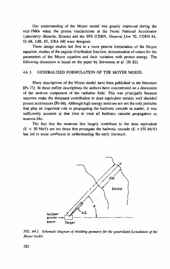
Our understanding of the Moyer model was greatly improved during the
mid-1960s when the proton synchrotrons at the Fermi National Accelerator
Laboratory (Batavia, Illinois) and the SPS (CERN, Geneva) [Aw 70, C E R N 64,
Gi 68, L B L 65, U R A 68] were designed.
These design studies led first to a more precise formulation of the Moyer
equation, studies of the angular distribution function, determination of values for the
parameters of the Moyer equation and their variation with proton energy. The
following discussion is based on the paper by Stevenson et al. [St 82].
4A.3. G E N E R A L I Z E D F O R M U L A T I O N O F T H E M O Y E R M O D E L
Many descriptions of the Moyer model have been published in the literature
[Pa 73]. In these earlier descriptions the authors have concentrated on a discussion
of the neutron component of the radiation field. This was principally because
neutrons make the dominant contribution to dose equivalent outside well shielded
proton accelerators [Pe 66]. Although high energy neutrons are not the only particles
that play an important role in propagating the hadronic cascade in matter, it was
sufficiently accurate at that time to treat all hadronic cascade propagators as
neutron-like.
The fact that the neutrons that largely contribute to the dose equivalent
(E < 50 MeV) are not those that propagate the hadronic cascade (E >150 MeV)
has led to some confusion in understanding the early literature.
FIG. A4.1. Schematic diagram of shielding geometry for the generalized formulation of the Moyer model.
Incident proton —
b e a m Torget
282
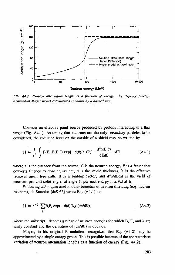
1000
160
£ 120
80
40
1 1 1
-1 /
/ Neutron attenuation length — / 1 (after Patterson)
1 Moyer model approximation
1 I I 1 10 100 1000 10 000
Neutron energy (MeV)
FIG. A4.2. Neutron attenuation length as a function of energy. The step-like function assumed in Moyer model calculations is shown by a dashed line.
Consider an effective point source produced by protons interacting in a thin
target (Fig. A4.1). Assuming that neutrons are the only secondary particles to be
considered, the radiation level on the outside of a shield may be written by
H = \ f F(E) B(E,0) exp[-d(0)/X (E)] dE (A4.1) r J dEdO
where r is the distance from the source, E is the neutron energy, F is a factor that converts fluence to dose equivalent, d is the shield thickness, X is the effective removal mean free path, B is a buildup factor, and d2n/dEdfi is the yield of neutrons per unit solid angle, at angle 6, per unit energy interval at E.
Following techniques used in other branches of neutron shielding (e.g. nuclear
reactors), de Staebler [deS 62] wrote Eq. (A4.1) as:
H = r " 2 £ B i F j exp(-d(0)/Xi) (dn/dQ); (A4.2)
i
where the subscript i denotes a range of neutron energies for which B, F, and X are
fairly constant and the definition of (dn/dfi) is obvious.
Moyer, in his original formulation, recognized that Eq. (A4.2) may be
approximated by a single energy group. This is possible because of the characteristic
variation of neutron attenuation lengths as a function of energy (Fig. A4.2).
283
Neutron attenuation lengths above 150 M e V are roughly independent of
energy, but diminish rapidly with energy below about 100 M e V . Consequently the
greater yields of low energy, as compared to high energy, neutrons at the primary
interaction will be more than compensated for by the greater attenuating action of
the shield for these neutrons. The actual variation of attenuation length with energy
may be approximated by a step function (see Fig. A4.2) where:
X (E > 150 MeV ) = X (A4.3)
X (E < 150 M e V ) = 0
Consideration of only the high energy (E > 150 MeV ) group of neutrons is not
strictly accurate because the lower energy particles do have a small but finite
attenuation length. Some allowance therefore has to be made for these lower energy
particles.
Moyer recognized that the nature of the radiation field outside the shield of a
high energy proton accelerator will be determined by neutrons with energy greater
than about 150 MeV . In fact, because high energy pions and protons in the hadronic
cascade have very similar cross-sections to neutrons, we may talk of 'cascade
propagators' rather than just 'high energy' neutrons. Deep in the shield these high
energy (E < 150 M e V ) hadrons regenerate the cascade but are present in relatively
small numbers. At a shield interface the radiation field observed consists of these
'propagators', born close to the primary radiation source, accompanied by many
particles of much lower energy, mainly neutrons, born near the interface.
The total neutron flux density (and consequently the dose equivalent rate) will
be proportional to the high energy hadron flux density. Because the low energy
components are produced by interaction of the high energy propagators, their
intensity decreases through the shield in an exponential manner with effectively the
same attenuation length for all directions through the shield.
The essence of the Moyer model, therefore, is that the dose equivalent at any
point outside the accelerator shield is largely governed by the simple line-of-sight
propagation of the cascade generating particles produced at the first interaction
(target) and a multiplication factor may be used to account for particle buildup. The
cascade generating particles have an attenuation length that is independent of energy.
Several experimental verifications of Moyer 's basic assumptions have been
reported in the literature. In a series of measurements in concrete irradiated by
protons with energy between 2.2 and 6.2 GeV, Smith et al. demonstrated the
essential independence of radiation attenuation length with angle to the incident
proton beam direction, and with a threshold of the neutron detector used [Sm 64].
284
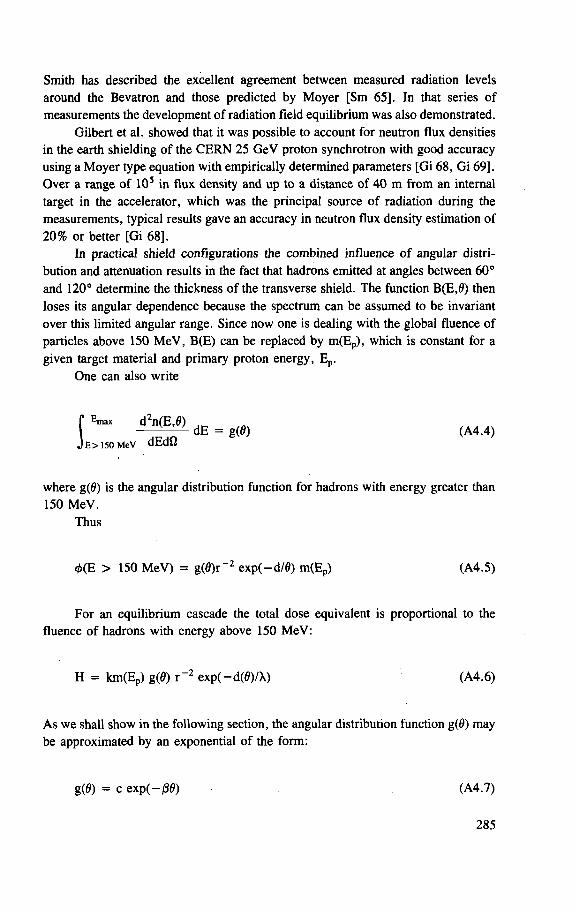
Smith has described the excellent agreement between measured radiation levels
around the Bevatron and those predicted by Moyer [Sm 65]. In that series of
measurements the development of radiation field equilibrium was also demonstrated.
Gilbert et al. showed that it was possible to account for neutron flux densities
in the earth shielding of the C E R N 25 GeV proton synchrotron with good accuracy
using a Moyer type equation with empirically determined parameters [Gi 68, G i 69].
Over a range of 10s in flux density and up to a distance of 40 m from an internal
target in the accelerator, which was the principal source of radiation during the
measurements, typical results gave an accuracy in neutron flux density estimation of
20% or better [Gi 68],
In practical shield configurations the combined influence of angular distri-
bution and attenuation results in the fact that hadrons emitted at angles between 60°
and 120° determine the thickness of the transverse shield. The function B(E,0) then
loses its angular dependence because the spectrum can be assumed to be invariant
over this limited angular range. Since now one is dealing with the global fluence of
particles above 150 M e V , B(E) can be replaced by m(Ep), which is constant for a
given target material and primary proton energy, Ep.
One can also write
f E m a x d2n(E,0) dE = g(0) (A4.4)
J E > 150 M e V a t a "
where g ( f f ) is the angular distribution function for hadrons with energy greater than
150 MeV .
Thus
4>(E > 150 M e V ) = g(0)r~2 exp(-d/0) m(Ep) (A4.5)
For an equilibrium cascade the total dose equivalent is proportional to the
fluence of hadrons with energy above 150 M e V :
H = km(Ep) g(0) r " 2 exp(-d(0)/X) (A4.6)
A s we shall show in the following section, the angular distribution function g(0) may
be approximated by an exponential of the form:
g(0) = c exp(-|80) (A4.7)
285
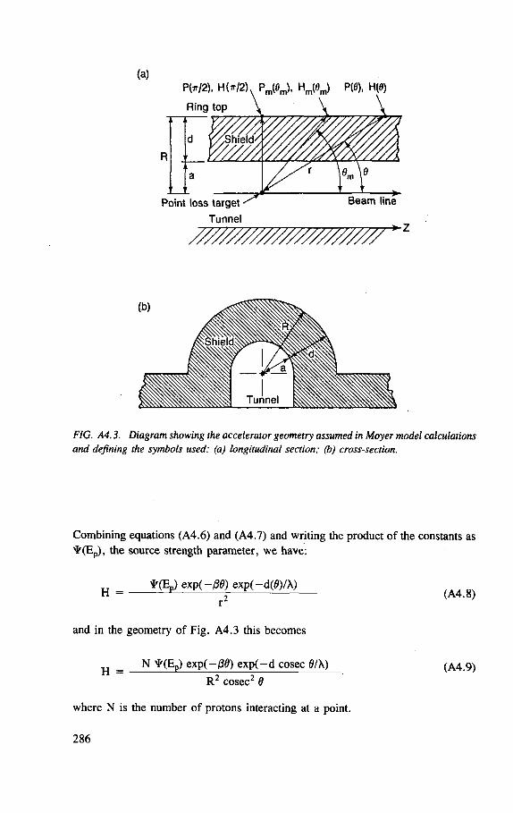
(a) P(W2). H(W2) Pm(0m), Hm(0m) P(0), H(0)
Ring top \ \
Point loss target Tunnel
Beam line
- • Z
FIG. A4.3. Diagram showing the accelerator geometry assumed in Moyer model calculations and defining the symbols used: (a) longitudinal section; (b) cross-section.
Combining equations (A4.6) and (A4.7) and writing the product of the constants as ^(Ep), the source strength parameter, we have:
* (E„) exp(-ffi>) exp(-d(fl)A) H = t r (A4.8)
r"
and in the geometry of Fig. A4.3 this becomes
_ N ¥(E p ) exp(-flfl) exp( -d cosec 0/X) (A4.9)
R 2 cosec2 6
where N is the number of protons interacting at a point.
286

4A.4. V A R I A T I O N OF T H E M O Y E R M O D E L P A R A M E T E R S W I T H
P R I M A R Y P R O T O N E N E R G Y
Source strength parameter, ^(Ep)
During the period in which the Moyer model was formulated there was
considerable discussion in the literature about the variation of ¥ with primary proton
energy (Ep). Lindenbaum suggested that if the variation be written in the form
¥(E p ) = H 0 E pm (A4.10)
the value of m was bounded between the values 0.25 < m < 1.0 [Li 61]. The basis
for this argument was that the production of shower particles varied as Ep'25, while
T A B L E A4.1. S U M M A R Y OF E X P E R I M E N T A L L Y D E T E R M I N E D V A L U E S
OF S O U R C E S T R E N G T H O F M O Y E R M O D E L P A R A M E T E R * ( E p ) A S A
F U N C T I O N O F P R O T O N E N E R G Y Ep [Th 84]
Primary proton energy, Ep
(GeV) Moyer parameter, ¥(Ep)
(Sv-m2) . Source
7.4 1.4 [Sh 69b, St 69] 7.4 2.1 [Sh 69b, St 69]
10.0 0.96 [Ho 66] 13.7 7.2 [Gi 68] 13.7 3.1 [Gi 68] 21.0 1.6 [Ho 79] 23.0 3.5 [Ma 79] 25.5 3.3 [Gi 68] 25.5 5.0 [Gi 68] 25.5 6.6 [Ro 69, St 82] 30.0 3.4 [Aw 70]
350 21.2 [Co 82] 350 44.6 [Co 82]
287
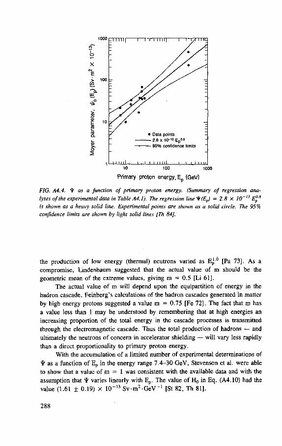
1000
95% confidence limits
i i i i i i n 1000
Primary proton energy, Ep (GeV)
FIG. A4.4. ¥ as a Junction of primary proton energy. (Summary of regression ana-t~13 rO.H lyses of the experimental data in Table A4.1). The regression line ^f(Ep) = 2.8 X 10~
is shown as a heavy solid line. Experimental points are shown as a solid circle. The 95% confidence limits are shown by light solid lines [Th 84].
the production of low energy (thermal) neutrons varied as Ep 0 [Pa 73]. A s a
compromise, Lindenbaum suggested that the actual value of m should be the
geometric mean of the extreme values, giving m = 0.5 [Li 61].
The actual value of m will depend upon the equipartition of energy in the
hadron cascade. Feinberg's calculations of the hadron cascades generated in matter
by high energy protons suggested a value m = 0.75 [Fe 72]. The fact that m has
a value less than 1 may be understood by remembering that at high energies an
increasing proportion of the total energy in the cascade processes is transmitted
through the electromagnetic cascade. Thus the total production of hadrons — and
ultimately the neutrons of concern in accelerator shielding — will vary less rapidly
than a direct proportionality to primary proton energy.
With the accumulation of a limited number of experimental determinations of
^ as a function of Ep in the energy range 7.4-30 GeV, Stevenson et al. were able
to show that a value of m = 1 was consistent with the available data and with the
assumption that ^ varies linearly with Ep. The value of H 0 in Eq. (A4.10) had the
value (1.61 ± 0.19) x 10~13 S v m 2 - G e V _ 1 [St 82, Th 81].
288
More recent statistical analyses of a somewhat larger database [Li 84, Th 84]
(Table A4.1) with values of ^ determined up to energies of 350 GeV have shown
that when E p is in GeV, the best values of the parameters of Eq. (A4.10) are
H 0 = (2.84 ± 0.14) x 10 - 1 3
m = 0.80 ± 0.10
A Student's t-test applied to the data rejects the hypotheses m = 0.5 (p = 1%, two
tail test) and m = 1.0 (p = 3%, one tail test). Figure A4.4 shows the results of
regression analysis of the data together with the 95 % confidence limits to the regres-
sion line.
Cossairt et al. [Co 85a] and Stevenson [St 86b] have extended the energy
region over which the parameter proposed by Thomas and Thomas applies [Th 84].
Cossairt et al. made a detailed comparison of measured values of absorbed
dose with values calculated using the Monte Carlo simulation code C A S I M in both
steel and composite (steel, concrete, earth) absorbers. Incident proton energies of
200, 400, 600 and 800 GeV were assumed. Agreement of the measurements (of
absorbed dose) with the calculations was quite good (within 20%) at small distances
from the beam axis (d < 0.5 cm) in steel, while for even a thick earth shield
(d ~ 5 m) the agreement was acceptable for radiation protection purposes (within
a factor of 2). For the two cases studied the energy exponents for the absorbed dose
(which may be assumed to be proportional to dose equivalent) were 0.84 ± 0.02 and
0.61 ± 0.08 respectively. Cossairt et al. conclude that the energy scaling
determined in their study is consistent with that suggested earlier [Li 84, Th 84].
Stevenson has derived values of Hr/211 from cascade calculations in concrete
for protons of energy from 400 M e V to 1 TeV [St 86b], His data confirm an energy
variation as Ep'8:
Hw/2 = 6.6 x 10 - 1 5 E°'8 Sv -m 2
The value of the constant 6.6 x 10"1 5 Sv -m 2 is in agreement within 20% of
the value derived by Thomas and Thomas for thick targets [Th 84]. For a complete
discussion see Section 4.3.
11 Hx/2 is related to H0 by the equation HI/2 = HO exp(-07r/2). With /3 = 2.3 radians HT/2 = 2.70 x 10~2 Ho.
289
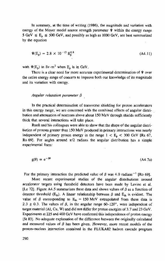
In summary, at the time of writing (1986), the magnitude and variation with
energy of the Moyer model source strength parameter • within the energy range
5 GeV < E p < 500 GeV, and possibly as high as 1000 GeV, are best summarized
by the equation
with * ( E p ) in Sv-m 2 when E p is in GeV.
There is a clear need for more accurate experimental determination of • over
the entire energy range of concern to improve both our knowledge of its magnitude
and its variation with energy.
Angular relaxation parameter /3
In the practical determination of transverse shielding for proton accelerators in this energy range, we are concerned with the combined effects of angular distri-bution and attenuation of neutrons above about 150 M e V through shields sufficiently thick that several interactions will take place.
Ranfit and his colleagues were able to show that the shape of the angular distri-bution of protons greater than 150 M e V produced in primary interactions was nearly independent of primary proton energy in the range 1 < E p < 300 GeV [Ra 67, Ro 69]. For angles around ir/2 radians the angular distribution has a simple experimental form:
For the primary interaction the predicted value of 0 was 4.0 radians -1 [Ro 69],
More recent experimental studies of the angular distributions around
accelerator targets using threshold detectors have been made by Levine et al.
[Le 72]. Figure A4.5 summarizes these data and shows values of /3 as a function of
detector threshold (Eth). A linear relationship between (3 and E A is evident. The
value of 0 corresponding to E^ = 150 M e V extrapolated from these data is
2.3 ± 0.3. The values of 0, in the angular range 60-120°, were independent of
target material (Al, Cu, W) and did not differ for proton energies of 3.7 and 23 GeV.
Experiments at 225 and 400 GeV have confirmed this independence of proton energy
[St 83]. No adequate explanation of the difference between the originally calculated
and measured values of 0 has been given. However, more recent models of the
proton-nucleus interaction contained in the F L U K A 8 2 hadron cascade program
• ( E p ) = 2 .8 X 10~ 1 3 Ep'8 (A4. l l )
g ( f f ) a e-*36 (A4.7a)
290
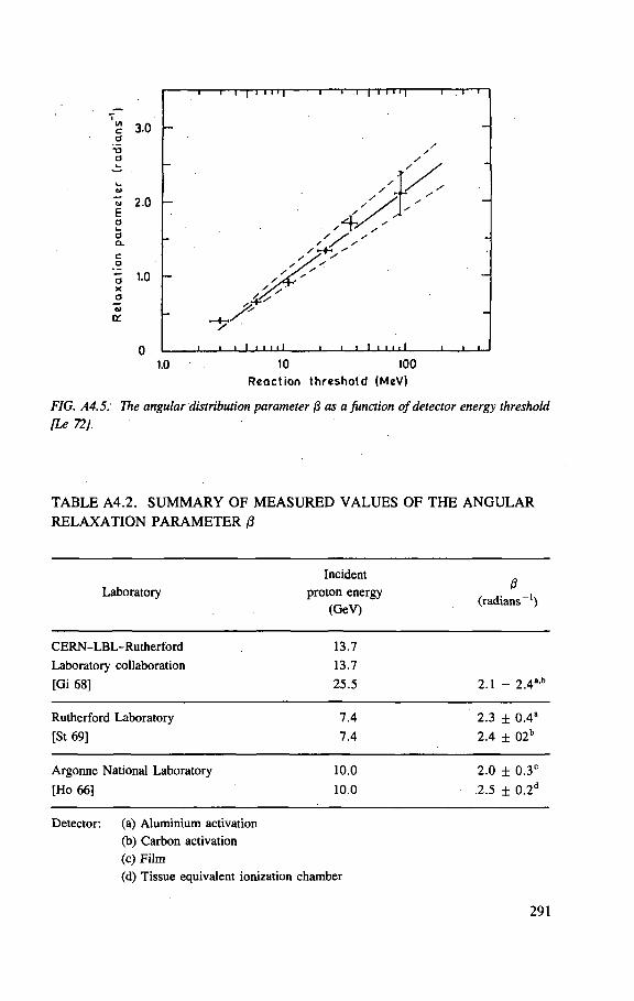
1.0 10 100
Reaction threshold (MeV)
FIG. A4.5: The angular distribution parameter 0 as a Junction of detector energy threshold [Le 72].
T A B L E A 4 . 2 . S U M M A R Y O F M E A S U R E D V A L U E S O F T H E A N G U L A R
R E L A X A T I O N P A R A M E T E R 0
Laboratory Incident
proton energy (GeV)
0 (radians - 1 )
CERN-LBL-Rutherford
Laboratory collaboration
[Gi 68]
13.7
13.7
25 .5 2 .1 - 2.4a 'b
Rutherford Laboratory
[St 69]
7 .4
7 . 4
2 .3 ± 0 . 4 a
2 .4 ± 0 2 b
Argonne National Laboratory
[Ho 66]
10.0
10.0
2 . 0 ± 0.3C
.2.5 ± 0 .2 d
Detector: (a) Aluminium activation (b) Carbon activation (c) Film
(d) Tissue equivalent ionization chamber
2 9 1
[Aa 84] are able to reproduce the experimental data of Levine et al. [Le 72] and
Stevenson et al. [St 83] (see Stevenson et al. [St 86a]). It is therefore probable that
the earlier calculations [Ro 69] were based on an inadequate model of the proton-
nucleus interaction.
In the practical determination of transverse shielding for proton accelerators
in the 1-100 GeV range we are concerned with the combined effects of the angular
distribution and attenuation through shields in which several interactions have
occurred. We are thus interested more in the apparent angular distribution of the
'virtual source' of neutrons which control the transverse shielding than in the angular
distribution close to accelerator targets.
Stevenson et al. [St 82] have summarized determinations of /? derived from
several target and shielding measurements. These values are summarized in
Table A4.2. There is no indication of any large variation of (3 with primary proton
energy and assuming invariance the mean of these values of (3 is
2.3 ± 0.1 radians -1 — in good agreement with the value extrapolated from the
data of Levine et al. [Le 72].
Measurements of angular distributions of high energy neutrons around targets
bombarded with heavy ions of about 500 MeV/amu have also confirmed values of
/3 close to 2.3 radians -1 [McC 84].
It may be concluded that the best value of /3 that may be determined from exist-
ing data is 2.3 ± 0 . 1 radians -1 and that 0 is either independent of, or only weakly
dependent upon, incident proton energy.
Attenuation parameter X
The attenuation length (parameter) X appropriate for use in the Moyer model is determined by the neutron inelastic cross-section of the constituents of the shield. At high energies the attenuation XA for material of mass number A is given by:
\ a = ~ A % . (A4.12)
where XA is in units of mass per unit area, p is the density of the shield material
(mass per unit volume) and k is a constant. Theoretical considerations suggest that
k has a value of 380 k g - m - 2 [Pa 73],
Perhaps the best empirical determination of attenuation length was made in
earth by Gilbert et al. [Gi 68]. A value of:
XE = 1170 ± 20 k g - m - 2
292
was obtained. Assuming that the earth in which this measurement was made consists
of 95% S i 0 2 (by weight) and 5 % H 2 0 (by weight) the effective mass number for
earth A E is 20.4 [ M c C 85].
Substituting into Eq. (A4.12), we obtain:
= = _ 1 1 7 0 ^ 4 2 G _ 2
AG ( 2 0 . 4 )
a result in reasonable agreement with that predicted on theoretical grounds.
Use of the empirically determined value k will lead to somewhat thicker shields
than by using the theoretical value of 380 k g - m - 2 and is thus, perhaps,
conservative.
In summary, for the Moyer model a value of
pXA = 4 2 8 A % k g - m ~ 2 (A4.13)
independent of energy is recommended.
4A.5. P O I N T S O U R C E C A L C U L A T I O N S
Although beam losses at high energy particle accelerators are usually of an
extended nature it is often the case that the region of high beam loss occurs over
lengths small or comparable with the thickness of the accelerator shields and tunnel
radius (the distance R in Fig. A4.3). Under such conditions the assumption of point
loss may be used to determine the dose equivalent at the shield surface.
Substitution into Eq. (A4.9) enables the dose equivalent at the shield surface
H 9 to be calculated as a function of 0 (Fig. A4.3).
Figure A4.6 summarizes the calculation of H e , normalized to the value at
0 - ir/2, as a function of 0 for values of shield thickness I between 1 and 20
[ M c C 85]. The figure shows values of the function F(0) defined by the equation:
u/m H W exp(-fffl) exp[(l - cosec 9)] F(0) = = (A4.14)
H(ir/2) exp(-j3ir/2) cosec2 0
Substituting the value 0 = 2.3 radians we obtain:
F(0) = 37.1 sin2 0 exp(-2.3O0) exp[£ (1 - cosec 0)] (A4.14a)
293
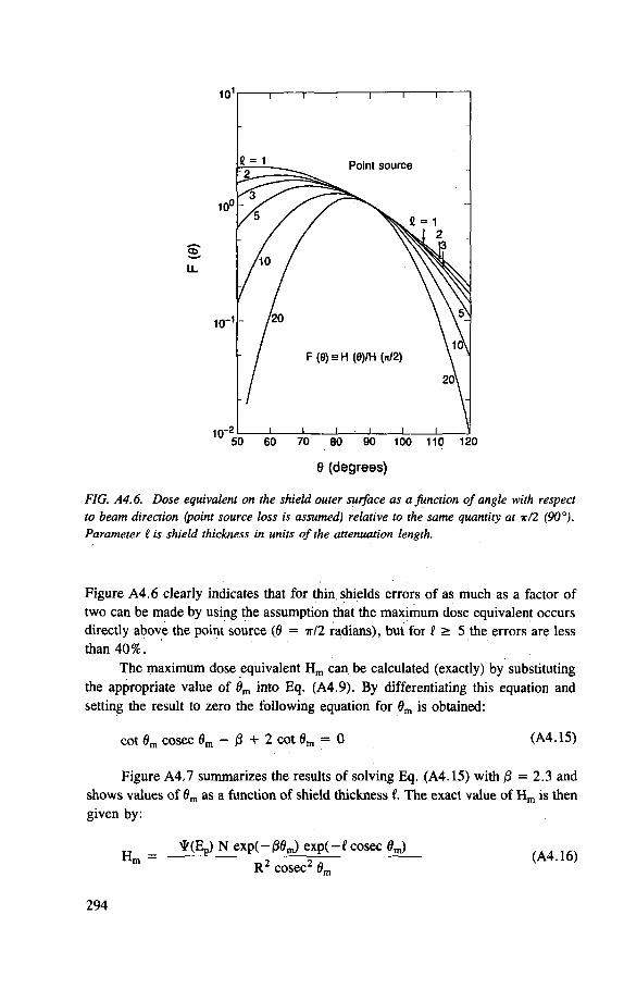
100 110 120
8 (degrees)
FIG. A4.6. Dose equivalent on the shield outer surface as a function of angle with respect to beam direction (point source loss is assumed) relative to the same quantity at -jr/2 (90°). Parameter ? is shield thickness in units of the attenuation length.
Figure A4.6 clearly indicates that for thin, shields errors of as much as a factor of
two can be made by using the assumption that the maximum dose equivalent occurs
directly above the point source (0 = it 12 radians), but for t > 5 the errors are less
than 40%.
The maximum dose equivalent H m can be calculated (exactly) by substituting
the appropriate value of 0m into Eq. (A4.9). By differentiating this equation and
setting the result to zero the following equation for 0m is obtained:
cot 0m cosec 6m - 0 + 2 cot 0m = 0 (A4.15)
Figure A4.7 summarizes the results of solving Eq. (A4.15) with /3 = 2.3 and
shows values of 0m as a function of shield thickness I. The exact value of H m is then
given by:
H = *(Ep) N exp(-/30m) exp( - f cosec flm)
R 2 cosec2 0m
(A4.16)
294
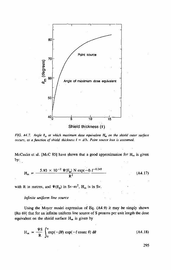
Angle of maximum dose equivalent
5 10 15 Shield thickness (e)
FIG. A4.7. Angle 9m at which maximum dose equivalent Hm on the shield outer surface occurs, as a function of shield thickness I = dfX. Point source loss is asssumed.
McCaslin et al. [McC 85] have shown that a good approximation for H m is given
by:
H m — 5.93 x 10~2 * ( E P ) N exp(-Q r 0 245
R 2 (A4.17)
with R in metres, and ^(E p ) in Sv -m , H m is in Sv.
Infinite uniform line source
Using the Moyer model expression of Eq. (A4.9) it may be simply shown
[Ro 69] that for an infinite uniform line source of S protons per unit length the dose
equivalent on the shield surface H e is given by
H Q O R
| exp( -136) exp( - f cosec 6) dd (A4.18)
295
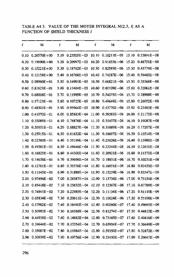
T A B L E A4.3. V A L U E O F T H E M O Y E R I N T E G R A L M(2.3, Q A S A
F U N C T I O N O F S H I E L D T H I C K N E S S i
M i M I M M 0.10
0.20
0.30 0.40 0.50 0.60 0.70 0.80
0.90 1.00
1.10 1.20
1.30 1.40 1.50 1.60
1.70 1.80
1.90 2.00.
2.10
2.20
2.30 2.40 2.50 2.60
2.70 2.80
2.90
0.26570E+00 0.19690E+00 0.15221E+00 0.12158E+00 0.98960E-01 0.81623E-01 0.68008E—01 0.57123E-01 0.48301E-01 0.41070E-01 0.35089E—01 0.30101E-01 0.25915E-01 0.22380E—01 0.19381E—01 0.16825E-01 0.14638E—01 0.12761E—01 0.11145E—01 0.97496E-02 0.85418E—02 0.74841E—02 0.65834E-02 0.57902E—02 0.50982E-02 0.44936E-02 0.39644E—02 0.35007E-02 0.30939E—02
5.10 5.20 5.30 5.40 5.50 5.60 5.70 5.80 5.90 6.00 6.10
6.20
6.30 6.40 6.50 6.60
6.70 6.80 6.90 7.00 7.10 7.20 7.30 7.40 7.50 7.60 7.70 7.80 7.90
0.23505E-0.20997E-0.18762E-0.16768E-0.14991E-0.13404E-0.11989E-0.10725E-0.95964E-0.85883E-0.76876E-0.68827E-0.61632E-0.55199E-0.49446E-0.44300E-0.39696E-0.35576E-0.31888E-0.28587E-0.25632E-0.22985E-0.20611E-0.18490E-0.16588E-0.14882E-0.13354E-0.11984E-0.10756E-
03 10.10 •03 10.20 03 10.30 03 10.40 •03 10.50 03 10.60 03 10.70 03 10.80 03 10.90 04 11.00 •04 11.10 •04 11.20 04 11.30 -04 11.40 04 11.50 •04 11.60 -04 11.70 •04 11.80 -04 11.90 -04 12.00 -04 12.10 -04 12.20 -04 12.30 -04 12.40 -04 12.50 -04 12.60 -04 12.70 -04 12.80 -04 12.90
0.10211E-05 0.91833E—06 0.82593E—06 0.74287E—06 0.66821E—06 0.60109E-06 0.54075E—06 0.49649E—06 0.43770E-06 0.39383E-06 0.35437E—06 0.31889E—06 0.18697E—06 0.25826E—06 0.23244E—06 0.20921E-06 0.18831E-06 0.16951E-06 0.15259E—06 0.13736E-06 0.12367E-06 0.11134E—06 0.10024E-06 0.90260E—07 0.81274E-07 0.73185E—07 0.65904E—07 0.59350E-07 0.53450E-07
15.10 15.20 15.30 15.40 15.50 15.60 15.70 15.80 15.90 16.00
16.10
16.20
16.30 16.40 16.50 16.60
16.70 16.80
16.90 17.00 17.10 17.20 17.30 17.40 17.50 17.60 17.70 17.80 17.90
0.53891E-08 0.48751E—08 0.43779E—08 0.39460E-08 0.35568E—08 0.32061E—08 0.28900E-08 0.26052E-08 0.23485E-08 0.21172E—08 0.19087E-08 0.17207E-08 0.15514E-08 0.13986E—08 0.12610E—08 0.11370E-08 0.10251E—08 0.92435E—09 0.83347E—09 0.75154E—09 0.67769E-09 0.61110E—09 0.55108E—09 0.49695E—09 0.44815E-09 0.40416E—09 0.36449E-09 0.32872E-09 0.29647E—09
296
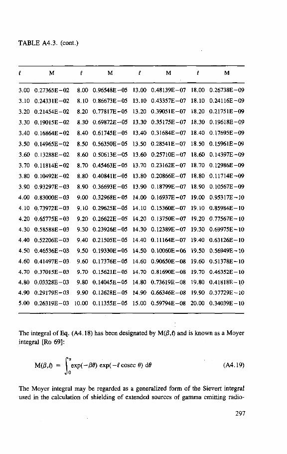
TABLE A4.3. (cont.)
e M I M I M t M
3.00 0 .27365E - 0 2 8 .00 0 .96548E - 0 5 13.00 0 .48139E - 0 7 18.00 0 .26738E - 0 9
3 .10 0 .24331E - 0 2 8 .10 0 .86673E - 0 5 13.10 0 .43357E - 0 7 18.10 0 .24116E - 0 9
3 .20 0 .21454E - 0 2 8 .20 0 .77817E - 0 5 13.20 0 .39051E - 0 7 18.20 0 .21751E - 0 9
3 .30 0 .19015E - 0 2 8 .30 0 .69872E - 0 5 13.30 0 .35175E - 0 7 18.30 0 .19618E - 0 9
3 .40 0 .16864E - 0 2 8 .40 0 .61745E - 0 5 13.40 0 .31684E - 0 7 18.40 0 .17695E - 0 9
3 .50 0 .14965E - 0 2 8 .50 0 .56350E - 0 5 13.50 0 .28541E - 0 7 18.50 0 .15961E - 0 9
3 .60 0 .13288E - 0 2 8 .60 0 .50613E - 0 5 13.60 0 .25710E - 0 7 18.60 0 .14397E - 0 9
3 .70 0 .11814E - 0 2 8 .70 0 .45463E - 0 5 13.70 0 .23162E - 0 7 18.70 0 .12986E - 0 9
3 .80 0 .10492E - 0 2 8 .80 0 .40841E - 0 5 13.80 0 .20866E - 0 7 18.80 0 .11714E - 0 9
3 .90 0 .93297E - 0 3 8 .90 0 .36693E - 0 5 13.90 0 .18799E - 0 7 18.90 0 .10567E - 0 9
4 . 0 0 0 .83000E - 0 3 9 .00 0 .32968E - 0 5 14.00 0 .16937E - 0 7 19.00 0 .95317E - 1 0
4 .10 0 .73972E - 0 3 9 .10 0 .29625E - 0 5 14.10 0 .15360E - 0 7 19.10 0 .85984E - 1 0
4 .20 0 .65775E - 0 3 9 .20 0 .26622E - 0 5 14.20 0 .13750E - 0 7 19.20 0 .77567E - 1 0
4 .30 0 .58588E - 0 3 9 .30 0 .23926E - 0 5 14.30 0 .12389E - 0 7 19.30 0 .69975E - 1 0
4 .40 0 .52206E - 0 3 9 .40 0 .21505E - 0 5 14.40 0 .11164E - 0 7 19.40 0 .63126E - 1 0
4 .50 0 .46536E - 0 3 9 .50 0 .19330E - 0 5 14.50 0 .10060E - 0 6 19.50 0 .56949E - 1 0
4 .60 0 .41497E - 0 3 9 .60 0 .17376E - 0 5 14.60 0 .90650E - 0 8 19.60 0 .51378E - 1 0
4 . 7 0 0 .37015E - 0 3 9 .70 0 .15621E - 0 5 14.70 0 .81690E - 0 8 19.70 0 .46352E - 1 0
4 . 8 0 0 .03328E - 0 3 9 .80 0 .14045E - 0 5 14.80 0 .73619E - 0 8 19.80 0 .41818E - 1 0
4 . 9 0 0 .29179E - 0 3 9 . 9 0 0 .12628E - 0 5 14.90 0 .66346E - 0 8 19.90 0 .37729E - 1 0
5 .00 0 .26319E - 0 3 10.00 0 .11355E - 0 5 15.00 0 .59794E - 0 8 20 .00 0 .34039E - 1 0
The integral of Eq. (A4.18) has been designated by M(|8,Q and is known as a M o y e r
integral [Ro 69]:
M(P,t) = | exp(-j30) e x p ( - £ cosec 0) d0 (A4.19)
The M o y e r integral may be regarded as a generalized form o f the Sievert integral
used in the calculation of shielding of extended sources of gamma emitting radio-
297
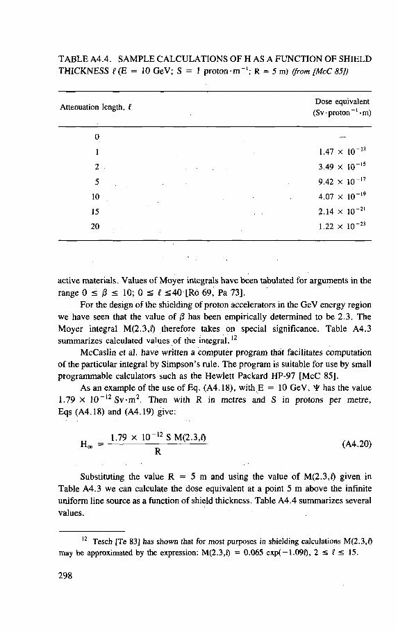
T A B L E A4.4. S A M P L E C A L C U L A T I O N S O F H A S A F U N C T I O N OF S H I E L D
T H I C K N E S S e(E = 10 GeV; S = 1 proton -m"1; R = 5 m) (from [McC 85])
, „ Dose equivalent Attenuation length, t _.
(Sv-proton -m)
0 -
1 1.47 x 1CT13
2 3.49 x 10"15
5 9.42 x 10 - 1 7
10 4.07 x 10 - 1 9
15 2.14 x 10"21
20 1.22 x 10"23
active materials. Values of Moyer integrals have been tabulated for arguments in the range 0 < 0 < 10; 0 < t < 4 0 [Ro 69, Pa 73],
For the design of the shielding of proton accelerators in the GeV energy region we have seen that the value of (3 has been empirically determined to be 2.3. The Moyer integral M(2.3,Q therefore takes on special significance. Table A4.3 summarizes calculated values of the integral.12
McCaslin et al. have written a computer program that facilitates computation of the particular integral by Simpson's rule. The program is suitable for use by small programmable calculators such as the Hewlett Packard HP-97 [McC 85],
As an example of the use of Eq. (A4.18), with E = 1 0 GeV, ^ has the value 1.79 x 10 _ 1 2 Sv -m 2 . Then with R in metres and S in protons per metre, Eqs (A4.18) and (A4.19) give:
_ 1 . 7 9 * 1 0 - " S M ( 2 . 3 . 0
R
Substituting the value R = 5 m and using the value of M(2.3,f) given in
Table A4.3 we can calculate the dose equivalent at a point 5 m above the infinite
uniform line source as a function of shield thickness. Table A4.4 summarizes several
values.
12 Tesch [Te 83] has shown that for most purposes in shielding calculations M(2.3,Q may be approximated by the expression: M(2.3,Q = 0.065 exp( -1 .090 , 2 < f < 15.
298
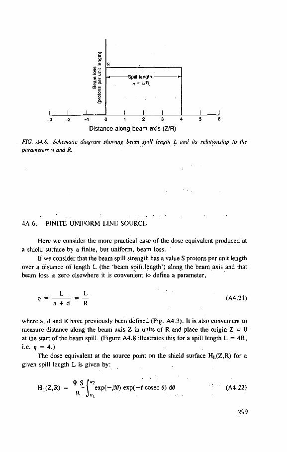
- 3 - 2 - 1 0 1 2 3 4
Distance along beam axis (Z/R)
FIG. A4.8. Schematic diagram showing beam spill length L and its relationship to the parameters ri and R.
4A.6. F I N I T E U N I F O R M L I N E S O U R C E
Here we consider the more practical case of the dose equivalent produced at
a shield surface by a finite, but uniform, beam loss.
If we consider that the beam spill strength has a value S protons per unit length
over a distance of length L (the 'beam spill.length') along the beam axis and that
beam loss is zero elsewhere it is convenient to define a parameter,
L L (A4.21)
a + d R
where a, d and R have previously been defined-(Fig. A4.3). It is also convenient to
measure distance along the beam axis Z in units of R and place the origin Z = 0
at the start of the beam spill. (Figure A4.8 illustrates this for a spill length L = 4R,
i.e. rj = 4.)
The dose equivalent at the source point on the shield surface H L (Z ,R ) for a
given spill length L is given by:
* S P°
w = - r .
. „ ra2 HL(Z,R) = - ^ - \ exp(-j30) exp(-£cosec 0) d0 (A4.22)
299
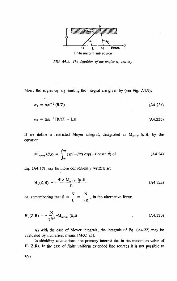
FIG. A4.9. The definition of the angles a, and a2.
where the angles c^, a 2 limiting the integral are given by (see Fig. A4.9):
a , = t an - 1 (R/Z) (A4.23a)
a 2 = t a n - 1 [R/(Z - L)] (A4.23b)
I f we define a restricted Moyer integral, designated as M a i > 0 I J by the
equation:
H,,,<« 0 3 , 0 = I exp(-/30) exp( -£cosec 6) dd (A4.24) P a2
W = I J<*1
Eq. (A4.18) may be more conveniently written as:
H L ( Z , R ) = * S (ftQ (A4.22a) R
N N or, remembering that S = — = , in the alternative form:
L TJR
H L ( Z , R ) = — ^ - M A I > A 2 (|8,D (A4.22b) T;R
A s with the case of Moyer integrals, the integrals of Eq. (A4.22) may be
evaluated by numerical means [ M c C 85].
In shielding calculations, the primary interest lies in the maximum value of
H L (Z ,R ) . In the case of finite uniform extended line sources it is not possible to
300
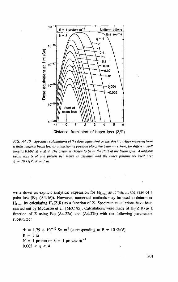
Distance from start of beam loss (Z/R)
FIG. A4.10. Specimen calculations of the dose equivalent on the shield surface resulting from a finite uniform beam loss as a junction of position along the beam direction, for different spill lengths 0.002 < JJ < 4. The origin is chosen to be at the start of the beam spill. A uniform beam loss S of one proton per metre is assumed and the other parameters used are: E = 10 GeV, R = lm.
write down an explicit analytical expression for H L m a x as it was in the case of a
point loss (Eq. (A4.16)). However, numerical methods may be used to determine
H L m a x by calculating H L (Z ,R ) as a function of Z. Specimen calculations have been
carried out by McCaslin et al. [McC 85], Calculations were made of H L (Z ,R ) as a
function of Z using Eqs (A4.22a) and (A4.22b) with the following parameters
substituted:
* = 1.79 x 10"12 Sv -m 2 (corresponding to E = 10 GeV)
R = 1 m
N = 1 proton or S = 1 proton-m - 1
0.002 < i? < 4.
301
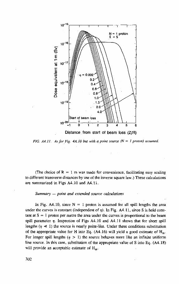
Distance from start of beam loss (Z/R)
FIG. A4.ll. As for Fig. 4A.10 but with a point source (N = 1 proton) assumed.
(The choice of R = 1 m was made for convenience, facilitating easy scaling to different transverse distances by use of the inverse square law.) These calculations are summarized in Figs A4.10 and A4 . l l .
Summary — point and extended source calculations
In Fig. A4:10, since N = 1 proton is assumed for all spill lengths the area
under the curves is constant (independent of 17). In Fig. A4.11, since S is held cons-
tant at S = 1 proton per metre the area under the curves is proportional to the beam
spill parameter 77. Inspection of Figs A4.10 and A4 . l l shows that for short spill
lengths (77 < 1) the source is nearly point-like. Under these conditions substitution
of the appropriate value for H into Eq. (A4.16) will yield a good estimate of Hm .
For longer spill lengths (77 > 1) the source behaves more like an infinite uniform
line source. In this case, substitution of the appropriate value of S into Eq. (A4.18)
will provide an acceptable estimate of Hm.
302
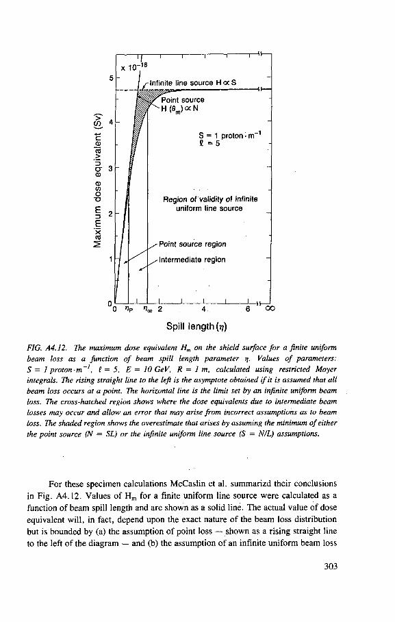
x 10"
> w
c 0) co
cr 0) a> o •o E 3 E x al
Infinite line source H oc S
Point source H(flm)ocN
S = 1 proton • m - 1
£ = 5
Region of validity of infinite uniform line source
- Point source region
- Intermediate region
0 1p loo 2 OO
Spil l l e n g t h (??)
FIG. A4.12. The maximum dose equivalent Hm on the shield surface for a finite uniform beam loss as a function of beam spill length parameter rValues of parameters: S = 1 proton• m~1, £ = 5, E = 10 GeV, R = 1 m, calculated using restricted Moyer integrals. The rising straight line to the left is the asymptote obtained if it is assumed that all beam loss occurs at a point. The horizontal line is the limit set by an infinite uniform beam loss. The cross-hatched region shows where the dose equivalents due to intermediate beam losses may occur and allow an error that may arise from incorrect assumptions as to beam loss. The shaded region shows the overestimate that arises by assuming the minimum of either the point source (N = SL) or the infinite uniform line source (S = N/L) assumptions.
For these specimen calculations McCaslin et al. summarizd their conclusions
in Fig. A4.12. Values of H m for a finite uniform line source were calculated as a
function of beam spill length and are shown as a solid line. The actual value of dose
equivalent will, in fact, depend upon the exact nature of the beam loss distribution
but is bounded by (a) the assumption of point loss — shown as a rising straight line
to the left of the diagram — and (b) the assumption of an infinite uniform beam loss
303
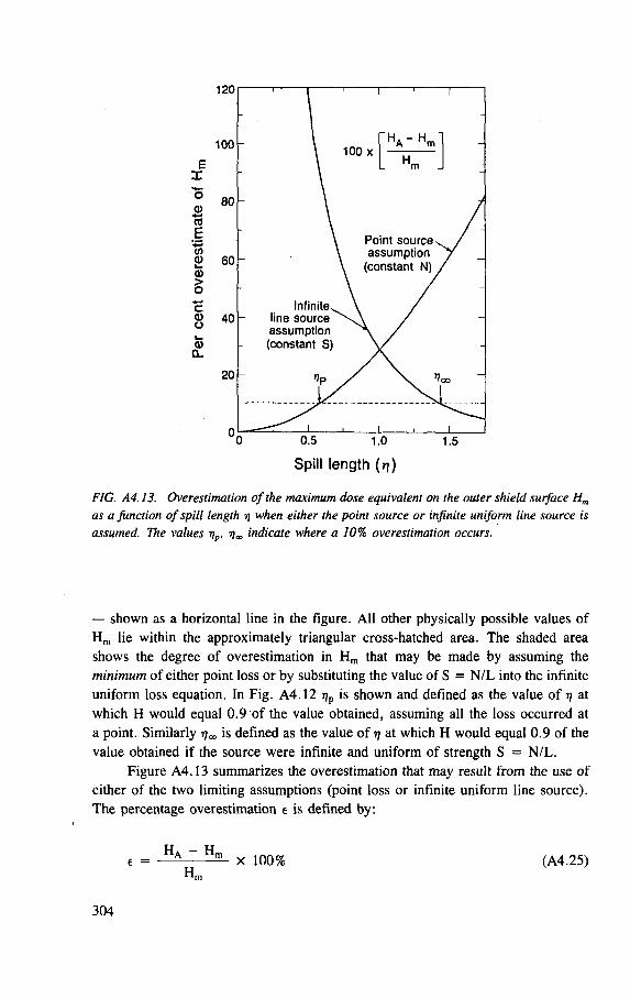
Spill length (rj)
FIG. A4.13. Overestimation of the maximum dose equivalent on the outer shield surface Hm
as a function of spill length rj when either the point source or infinite uniform line source is assumed. The values rjp, r\„ indicate where a 10% overestimation occurs.
— shown as a horizontal line in the figure. All other physically possible values of
H m lie within the approximately triangular cross-hatched area. The shaded area
shows the degree of overestimation in H m that may be made by assuming the
minimum of either point loss or by substituting the value of S = N /L into the infinite
uniform loss equation. In Fig. A4.12 r)p is shown and defined as the value of 17 at
which H would equal 0.9 of the value obtained, assuming all the loss occurred at
a point. Similarly is defined as the value of rj at which H would equal 0.9 of the
value obtained if the source were infinite and uniform of strength S = N/L.
Figure A4.13 summarizes the overestimation that may result from the use of
either of the two limiting assumptions (point loss or infinite uniform line source).
The percentage overestimation e is defined by.
e = Ha ~ H m X 100% (A4.25) H m
304
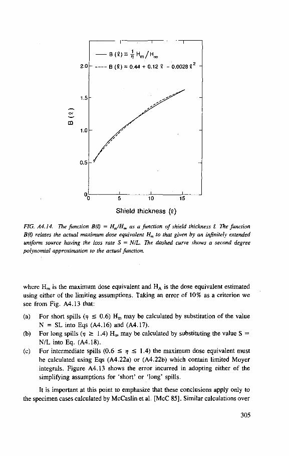
I
B(S) =
I I
Ti H m / H o o
2.0 - B (C) = 0.44 + 0.12 B - 0.0028 C2 -
1.5 - —
/ / A'
1.0 y / — A / / / / / / / / / / / / //
-
0.5 tf -
n I I l
Shield thickness (e)
FIG. A4.14. The function B(() = Hm/Ha as a function of shield thickness I The function B(() relates the actual maximum dose equivalent Hm to that given by an infinitely extended uniform source having the loss rate S = N/L. The dashed curve shows a second degree polynomial approximation to the actual function.
where H m is the maximum dose equivalent and H A is the dose equivalent estimated using either of the limiting assumptions. Taking an error of 10% as a criterion we see from Fig. A4.13 that:
(a) For short spills (rj < 0.6) H m may be calculated by substitution of the value
N = S L into Eqs (A4.16) and (A4.17).
(b) For long spills (TJ > 1.4) H ^ may be calculated by substituting the value S =
N /L into Eq. (A4.18).
(c) For intermediate spills (0.6 < r) < 1.4) the maximum dose equivalent must
be calculated using Eqs (A4.22a) or (A4.22b) which contain limited Moyer
integrals. Figure A4.13 shows the error incurred in adopting either of the
simplifying assumptions for 'short' or 'long' spills.
It is important at this point to emphasize that these conclusions apply only to
the specimen cases calculated by McCaslin et al. [McC 85]. Similar calculations over
305
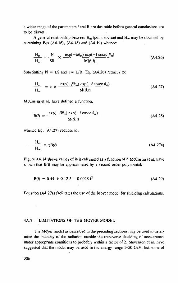
a wider range of the parameters I and R are desirable before general conclusions are
to be drawn.
A general relationship between H m (point source) and H a may be obtained by
combining Eqs (A4.16), (A4.18) and (A4.19) whence:
H m N e x p ( - < 3 0 J e x p ( - l co sec 0 J = X (A4.26)
HCO S R MG3.D
Substituting N = L S and t)= L /R , Eq. (A4.26) reduces to:
H m exp ( - /30J e x p ( - l cosec flm) = n X (A4.27)
H a M(/3,Q
McCas l in et al. have defined a function,
= exp(-ffl?m) e x p ( - f cosec 0m)
M 0 3 . 0
whence Eq. (A4.27) reduces to:
H„
H Q
= T?B(Q (A4.27a)
Figure A4.14 shows values of B(f) calculated as a function of I McCas l in et al. have
shown that B(Q may be approximated by a second order polynomial:
B(Q = 0.44 + 0.12 i - 0.0028 f (A4.29)
Equation (A4.27a) facilitates the use of the Moyer model for shielding calculations.
4A.7. L I M I T A T I O N S O F T H E M O Y E R M O D E L
The Moyer model as described in the preceding sections may be used to deter-
mine the intensity of the radiation outside the transverse shielding of accelerators
under appropriate conditions to probably within a factor of 2. Stevenson et al. have
suggested that the model may be used in the energy range 1-50 GeV , but some of
306
the more recent developments have suggested it might be used under limited circum-
stances up to as high as 1 TeV [Co 84, St 82, Th 83], However, it is important to
understand the limitations of the model.
Stevenson et al. [St 82] have given two examples where significant errors
might result from use of the value of H 0 given in the earlier sections. The recom-
mended value of H 0 (2.8 x 10~13 Sv •m ) was determined with small target to
shield distances (a < R) and normal to thick targets (0 = 90°). Any large departure
from these conditions (0 = 0° or a R) may result in error (see Ref. [St 82]).
4 A . 8. C O N C L U S I O N S
The Moyer model for high energy neutron shielding has proved itself a very
durable instrument since it was first developed in the early 1960s and has been
utilized in the design of several important high energy accelerator facilities. It has
recently been used to estimate shielding for a 50 G e V proton synchrotron and for
the transverse shielding of a 20 T e V collider facility [Ch 80, C o 84, Th 83], Its
advantage over sophisticated methods lies in its simplicity; the algorithm contains
only three parameters whose values are now well established. The figures presented
and the sample codes for use with desk-top or hand-held computers demonstrate the
ease with which the Moyer model can be applied to many shielding problems. The
procedure, which requires very modest computational power, is useful in its own
right besides serving as a check on more elaborate, but less transparent, methods of
shielding calculation.
REFERENCES
[Aa 84] AARNIO, P.A., RANFT, J., STEVENSON, G.R., A Long Write-up of the FLUKA82 Program, Rep. TIS-RP/106-Rev, CERN, Geneva (1984).
[Al 63] ALLEN, F. J., FUTTERER, A.T. , Neutron transmission data, Nucleonics 21 8 (1963) 120.
[Al 65] ALSMILLER, R.G., Jr., BARISH, J., Calculation of the nuclear cascade in steel initiated by 10 and 19.2 GeV/c protons and comparison with experiments, Nucl. Instrum. Methods 36 (1965) 309.
[Al 67] ALSMILLER, R.G., Jr., LEIMDORFER, M., BARISH, J., Analytic Representation of Non-Elastic Cross-Sections and Particle Emission Spectra from Nucleon-Nucleus Collisions in the Energy Range 25-400 MeV, Rep. ORNL-4046, Oak Ridge Natl Lab., Oak Ridge, TN (1967).
[Al 69a] ALSMILLER, Jr., MYNATT, R.G., BARISH, J., ENGLE, W.W., Jr., High energy ( < 4 0 0 MeV) neutron transport using the method of discrete ordinates, Nucl. Sci. Eng. 36 (1969) 251.
307
[Al 69b] ALSMILLER, R.G. , Jr., MYNATT, F.R. , BARISH, J., ENGLE, W.W. , Jr., Shielding against neutrons in the energy range 50 to 400 MeV, Nucl. Instrum. Methods 72 (1969) 213.
[Al 69c] ALSMILLER, R.G. , Jr., BARISH, J., High-energy ( < 1 8 GeV) muon transport calculations and comparison with experiment, Nucl. Instrum. Methods 71 (1969) 121.
[Al 69d] ALSMILLER, R.G. , Jr., BARISH, J., High-energy ( < 1 8 GeV) muon transport calculations and comparison with experiment, II., Nucl. Instrum. Methods 75 (1969) 344 .
[Al 69e] ALSMILLER, R.G., Jr., SOLOMITO, E., The transport of neutrons produced by 3 GeV proton-lead collisions through a labyrinth and compari-son with experiment, Nucl. Instrum. Methods 73 (1969) 280.
[Al 71] ALSMILLER, R.G. , Jr., ALSMILLER, F.S. , BARISH, J., SHIMA, Y. , "Muon transport and the shielding of high-energy ( < 5 0 0 Gev) proton accelerators", Rep. 71-16, Vol. 2, CERN, Geneva (1971) 601.
[Al 75] ALSMILLER, R.G. , Jr., SANTORO, R.T., BARISH, J., Shielding calculations for a 200 MeV proton accelerator and comparisons with experimental data, Part. Accel. 7 (1975) 1.
[Al 82] ALSMILLER, R.G. , BARISH, J., BARNES, J.M., SANTORO, R.T. , Calculated neutron production by 190 to 268 MeV protons in a water cooled tantalum target, Nucl. Sci. Eng. 80 (1982) 452.
[ANSI 70] AMERICAN NATIONAL STANDARDS INSTITUTE, Radiological Safety in the Design and Operation of Particle Accelerators, NBS Handbook 107, Washington, DC (1970) 101.
[Ar 68] ARMSTRONG, T .W. , ALSMILLER, R.G. , Jr., Monte-Carlo calculations of the nucleon-meson cascade in iron initiated by 1 and 3 GeV protons and comparison with experiment, Nucl. Sci. Eng. 33 (1968) 291.
[Ar 69a] ARMSTRONG, T.W. , Monte-Carlo calculations of residual nuclei production in thick iron targets bombarded by 1 and 3 GeV protons and comparison with experiment, J. Geophys. Res. 74 (1969) 1361.
[Ar 69b] ARMSTRONG, T .W. , ALSMILLER, R.G. , Jr., Calculation of the residual photon dose rate around high-energy proton accelerators, Nucl. Sci. Eng. 38 (1969) 53.
[Ar 69c] ARMSTRONG, T.W. , BARISH, J., Calculation of the residual photon dose rate due to activation of concrete by neutrons from a 3 GeV proton beam on iron, Nucl. Sci. Eng. 38 (1969) 265.
[Ar 72] ARMSTRONG, T.W. , ALSMILLER, R.G., Jr., CHANDLER, K.C. , BISHOP, B.L. , Monte Carlo calculations of high energy nucleon-meson cascades and comparison with experiment, Nucl. Sci. Eng. 49 (1972) 82.
[Ar 79] ARAKITA, Y. , HIRAYAMA, H., INAGAKI, T., MIYAJIMA, M. , Study of an iron beam stop for 500 MeV protons, Nucl. Instrum. Methods 164 (1979) 255.
[Ar 80] ARMSTRONG, T.W. , "The HETC hadronic cascade code", Computer Techniques in Radiation Transport and Dosimetry (NELSON, W.R. , JENKINS, T .M. , Eds), Plenum Press, New York and London (1980) 373.
308

AWSCHALOM, M. , Lateral Shielding for the 8 GeV and 200 GeV Synchrotrons, Rep. FNAL TM-241, Fermi Natl Accelerator Lab., Batavia, IL (1970). AWSCHALOM, M., BAKER, S. , MOORE, C., VAN GINNEKEN, A. , GOEBEL, K., RANFT, J., Measurements and calculations of cascades produced by 300 GeV protons incident on a target inside a magnet, Nucl. Instrum. Methods 138 (1976) 521. BARBIER, M. , HUNTER, R., Systematics of Extra-Nuclear Hadron Cascades in Shields, Rep. 71-13, CERN, Geneva (1971). BARASHENKOV, V.S. , SOBOLEVSKII, N .M. , TONEEV, V.D. , The penetration of beams of high-energy particles through thick layers of material, At. Ehnerg. 32 (1972) 2170.
BAN, S. , HIRAYAMA, H., KONDO, K., MIURA, S. , HOZUMI, K., TAINO, M. , YAMAMOTO, A. , HIRABAYASHI, H., KATOH, K. Measurement of transverse attenuation lengths for paraffin, heavy concrete and iron around an external target for 12 GeV protons, Nucl. Instrum. Methods 174 (1980) 271.
BAN, S. , HIRAYAMA, H. , KATOH, K., Measurement of secondary neutron fluxes around a beam stop for 500 MeV protons, Nucl. Instrum. Methods 184 (1981) 409. BAN, S. , HIRAYAMA, H., "The attenuation of neutrons in a labyrinth at an accelerator", Proc. 5th Symp. Accelerator Science and Technology, Sep. 1984, KEK, Tsukuba, Japan (1984) 378. BERTINI, H.W. , Low energy intranuclear cascade calculation, Phys. Rev. 131 (1963) 1801. BETHE, H.A. , ASHKIN, J., "Passage of radiations through matter", Experimental Nuclear Physics, Vol. 1 (SEGRE, E., Ed.), Wiley, New York (1963) 166. BERTINI, H.W. , Preliminary Data from Intranuclear Cascade Calculations of 0 .75 , 1 and 2 GeV Protons on Oxygen, Aluminium and Lead, and 1 GeV Neutrons on the Same Elements, Rep. ORNL-TM-1996, Oak Ridge Natl Lab., Oak Ridge, TN (1967). BERTINI, H.W. , Intranuclear cascade calculation of the secondary nucleon spectra from nucleon-nucleus interactions in the energy range 340 to 2900 MeV and comparison with experiment, Phys. Rev. 188 (1969) 1711.
[Be 71a] BENNETT, G.W., FOELSCHE, H., LAZARUS, D. , LEVINE, G., MOORE, W. , TOOHIG, T. , Flux attenuation in a steel side shield at the AGS, IEEE Trans. Nucl. Sci. NS-18 3 (1971) 778.
[Be 71b] BERTEL, E., de SEREVILLE, B. , FREYTAG, E., WACHSMUTH, H., "Shielding against muons", Radiation Problems Encountered in the Design of Multi-GeV Facilities (GOEBEL, K., Ed.), Rep. 71-12, CERN, Geneva (1971) Chapter VI.
[Be 71c] BENNETT, G.W., FOELSCHE, H., LAZARUS, D. , LEVINE, G., MOORE, W. , TOOHIG, T., THOMAS, R.H. , KOUSTOULAS, J., Study of a uniform steel beam stop at 28 GeV, IEEE Trans. Nucl. Sci. NS-18 2 (1971) 776.
[Aw 70]
[Aw 76]
[Ba 71]
[Ba 72]
[Ba 80]
[Ba 81]
[Ba 84]
[Be 63a]
[Be 63b]
[Be 67]
309
[Be 73] BENNETT, G.W., et al., Particle distribution in a steel beam stop for 28 GeV protons, Part. Accel. 4 (1973) 229.
[Be 74] BERTINI, H.W. , HARP, G . D . , BERTRAND, F.E. , Comparisons of predictions from two intranuclear cascade models with measured secondary proton spectra at several angles from 62 and 39 MeV protons on various elements, Phys. Rev., C 10 6 (1974) 2472.
[Be 82] BEYNEL, P., MAIER, P., SCHONBACHER, H., Compilation of Radiation Damage Test Data: Part III, Materials Used Around High-Energy Accelera-tors, Rep. 82-10, CERN, Geneva (1982).
[Bo 71] BORODIN, V.E. , OBRYASHIKOVA, L.P. , CHIMANKOV, M.N. , On Radiation Passing through the Labyrinth of the IHEP 70 GeV Synchrotron, Rep. IHEP 71-84, Serpukhov (1971).
[Br 71] BRAID, T.H. , RAPIDS, R.F. , SIEMSSEN, R.H. , TIPPIE, J.W., O'BRIEN, K., Calculations of shielding for large cyclotrons, IEEE Trans. Nucl. Sci. NS-18 (1971) 821.
[Br 83] BROOME, T .A. , PERRY, D.R. , STAPLETON, G.B. , DUC, D. , Particle distribution around a copper beam stop for 72 MeV protons, Health Phys. 44 (1983) 487.
[Bu 70] BUENEMANN, D. , ENGINOL, T.B. , "Shield optimization", Shielding of Ship Propulsion Reactors, in [IAEA-70], p. 425.
[Ca 67] CASEY, W.R. , DISTENFELD, C.H. , LEVINE, G.S. , MOORE, W . H . , SMITH, L.W., Sand as a side shield for 30 GeV proton stopping in the Brookhaven AGS, Nucl. Instrum. Methods 55 (1967) 253.
[Ca 79] CAIN, V.R. , EMMETT, M.B. , BREESE-II: Auxiliary Routines for Implementing the Albedo Option in the MORSE Monte-Carlo Code, Rep. ORNL-TM-6807, Oak Ridge Natl Lab., Oak Ridge, TN (1979).
[CERN 64] CERN STUDY GROUP ON NEW ACCELERATORS, Report on the Design Study of a 300 GeV Proton Synchrotron (2 Vols), Rep. 563, CERN, Geneva (1964).
[Ch 65] CH1LDERS, R.L. , ZERBY, C.D. , FISHER, C.M. , THOMAS, R.H. , Measurement of the nuclear cascade at 10 GeV/c with emulsions, Nucl. Instrum. Methods 32 (1965) 53.
[Ch 68] CHEN, K., FRAENKEL, Z. , FRIEDLANDER, G. , GROYER, J.R., MILLER, J.M., SHIMAMOTO, Y. , VEGAS: A Monte Carlo simulation of intranuclear cascades, Phys. Rev. 166 (1968) 949.
[Ch 72] CHANDLER, K.C. , ARMSTRONG, T.W. , Operating Instructions for the High-Energy Nucleon-Meson Transport Code HETC, Rep. ORNL-4744, Oak Ridge Natl Lab., Oak Ridge, TN (1972).
[Ch 80] CHU YU-CHENG, The Estimation of Transverse Shielding Thickness for the BPS, Rep. HS-RP/TM/80-14, CERN, Geneva (1980).
[Ch 84] CHILTON, A.B. , SHULTIS, J.K., FAW, R.E., Principles of Radiation Shielding, Prentice Hall, Englewood Cliffs, NJ (1984).
[Ci 61] CITRON, A. , HOFFMANN, L. , PASSOW C. , Investigation of the nuclear cascade in shielding materials, Nucl. Instrum. Methods 14 (1961) 97.
310
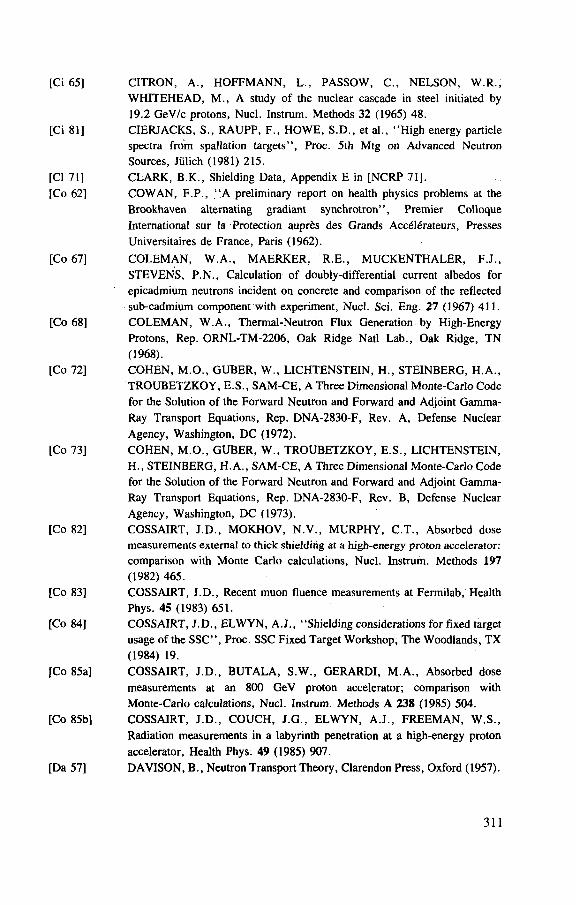
[Ci 65] CITRON, A. , HOFFMANN, L., PASSOW, C., NELSON, W.R. , WHITEHEAD, M. , A study of the nuclear cascade in steel initiated by 19.2 GeV/c protons, Nucl. Instrum. Methods 32 (1965) 48.
[Ci 81] CIERJACKS, S. , RAUPP, F., HOWE, S .D. , et al., "High energy particle spectra from spallation targets", Proc. 5th Mtg on Advanced Neutron Sources, Jiilich (1981) 215.
[CI 71] CLARK, B.K. , Shielding Data, Appendix E in [NCRP 71]. [Co 62] COWAN, F.P. , "A preliminary report on health physics problems at the
Brookhaven alternating gradiant synchrotron", Premier Colloque International sur la Protection aupr&s des Grands Accdl£rateurs, Presses Universitaires de France, Paris (1962).
[Co 67] COLEMAN, W.A. , MAERKER, R.E. , MUCKENTHALER, F.J., STEVENS, P .N. , Calculation of doubly-differential current albedos for epicadmium neutrons incident on concrete and comparison of the reflected sub-cadmium component with experiment, Nucl. Sci. Eng. 27 (1967) 411.
[Co 68] COLEMAN, W . A . , Thermal-Neutron Flux Generation by High-Energy Protons, Rep. ORNL-TM-2206, Oak Ridge Natl Lab., Oak Ridge, TN (1968).
[Co 72] COHEN, M.O. , GUBER, W. , LICHTENSTEIN, H. , STEINBERG, H.A. , TROUBETZKOY, E.S. , SAM-CE, A Three Dimensional Monte-Carlo Code for the Solution of the Forward Neutron and Forward and Adjoint Gamma-Ray Transport Equations, Rep. DNA-2830-F, Rev. A, Defense Nuclear Agency, Washington, DC (1972).
[Co 73] COHEN, M.O. , GUBER, W. , TROUBETZKOY, E.S. , LICHTENSTEIN, H., STEINBERG, H.A. , SAM-CE, A Three Dimensional Monte-Carlo Code for the Solution of the Forward Neutron and Forward and Adjoint Gamma-Ray Transport Equations, Rep. DNA-2830-F, Rev. B, Defense Nuclear Agency, Washington, DC (1973).
[Co 82] COSSAIRT, J .D. , MOKHOV, N . V . , MURPHY, C.T. , Absorbed dose measurements external to thick shielding at a high-energy proton accelerator: comparison with Monte Carlo calculations, Nucl. Instrum. Methods 197 (1982) 465.
[Co 83] COSSAIRT, J.D. , Recent muon fluence measurements at Fermilab, Health Phys. 45 (1983) 651.
[Co 84] COSSAIRT, J.D. , ELWYN, A.J. , "Shielding considerations for fixed target usage of the SSC", Proc. SSC Fixed Target Workshop, The Woodlands, TX (1984) 19.
[Co 85a] COSSAIRT, J .D. , BUTALA, S .W. , GERARDI, M.A . , Absorbed dose measurements at an 800 GeV proton accelerator; comparison with Monte-Carlo calculations, Nucl. Instrum. Methods A 238 (1985) 504.
[Co 85b] COSSAIRT, J.D. , COUCH, J.G., ELWYN, A.J. , FREEMAN, W.S . , Radiation measurements in a labyrinth penetration at a high-energy proton accelerator, Health Phys. 49 (1985) 907.
[Da 57] DAVISON, B. , Neutron Transport Theory, Clarendon Press, Oxford (1957).
311
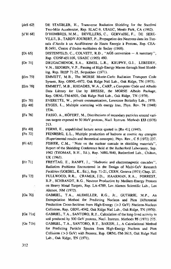
[deS 62] D E STAEBLER, H. , Transverse Radiation Shielding for the Stanford Two-Mile Accelerator, Rep. SLAC-9, USAEC, Menlo Park, CA (1962).
[d'H 68] D'HOMBRES, M . M . , DEVILLERS, C., GERVAISE, F., DE SERE-VILLE, B., TARDY-JOUBERT, P., Propagation des Neutrons dans les Tun-nels d'Acces a un Accdlerateur de Haute Energie & Protons, Rep. CEA-R-3491, Centre d'etudes nucleaires de Saclay (1968).
[Di 65] DISTENFELD, C. , COLVETT, R .D . , "AGS conversion — A summary", Rep. CONF-651109, USAEC (1965) 490.
[Dr 71] DRUGACHENOK, S .A. , KIMEL, L.R., KRUPNY, G.I., LEBEDEV, V . N . , SIDORIN, V.P . , Passing of High-Energy Muons through Steel Shield-ing, Rep. IHEP 71-25, Serpukhov (1971).
[Em 75] EMMETT, M.B. , The MORSE Monte-Carlo Radiation Transport Code System, Rep. ORNL-4972, Oak Ridge Natl Lab., Oak Ridge, TN (1975).
[Em 78] EMMETT, M.B. , RHOADES, W.A. , CARP, a Computer Code and Albedo Data Library for Use by BREESE, the MORSE Albedo Package, Rep. ORNL-TM-6503, Oak Ridge Natl Lab., Oak Ridge, TN (1978).
[Ev 70] EVERETTE, W. , private communication, Lawrence Berkeley Lab., 1970. [Ey 48] EYGES, L., Multiple scattering with energy loss, Phys. Rev. 74 (1948)
1534.
[Fa 76] FASSO, A. , HOFERT, M., Distributions of secondary particles around vari-ous targets exposed to 50 MeV protons, Nucl. Instrum. Methods 133 (1976) 213.
[Fe 40] FERMI, E., unpublished lecture notes quoted in [Ro 41] (1940). [Fe 72] FEINBERG, E.L., Multiple production of hadrons at cosmic ray energies
(Experimental results and theoretical concepts), Phys. Rev., C 5 (1972) 237. [Fi 63] FISHER, C.M. , "Note on the nuclear cascade in shielding materials",
Report of the Shielding Conference held at the Rutherford Laboratory, Sep. 1962 (THOMAS, R.H. , Ed.), Rep. NIRL/R40, Rutherford Lab., Chilton, UK (1963).
[Fr 71] FREYTAG, E., RANFT, J., "Hadronic and electromagnetic cascades", Radiation Problems Encountered in the Design of Multi-GeV Research Facilities (GOEBEL, K., Ed.), Rep. 71-21, CERN, Geneva (1971) Chap. III.
[Fu 72] FULL WOOD, R.R. , CRAMER, J .D. , HAARMAN, R.A. , FORREST, R.P. , SCHRANDT, R.G., Neutron Production by Medium-Energy Protons on Heavy Metal Targets, Rep. LA-4789, Los Alamos Scientific Lab., Los Alamos, NM (1972).
[Ga 70] GABRIEL, T .A. , ALSMILLER, R.G. , Jr., GUTHRIE, M.P. , An Extrapolation Method for Predicting Nucleon and Pion Differential Production Cross-Sections from High-Energy ( > 3 GeV) Nucleon-Nucleus Collisions, Rep. ORNL-4542, Oak Ridge Natl Lab., Oak Ridge, TN (1970).
[Ga 71a] GABRIEL, T.A. , SANTORO, R.T. , Calculation of the long-lived activity in soil produced by 500 GeV protons, Nucl. Instrum. Methods 95 (1971) 275.
[Ga 71b] GABRIEL, T .A . , SANTORO, R.T. , BARISH, J., A Calculational Method for Predicting Particle Spectra from High-Energy Nucleon and Pion Collisions ( > 3 GeV) with Protons, Rep. ORNL-TM-3615, Oak Ridge Natl Lab., Oak Ridge, TN (1971).
312
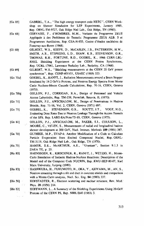
[Ga 85] GABRIEL, T.A. , "The high energy transport code HETC", CERN Work-shop on Shower Simulation for LEP Experiments, January 1985, Rep. ORNL-TM-9727, Oak Ridge Natl Lab., Oak Ridge, TN (1985).
[Ge 68] GERVAISE, F . , d'HOMBRES, M . M . , Variante du Programme ZEUS Appliquee a des Problfemes de Tunnels: Programme ZEUS ALB. 5 et Programmes Auxiliaires, Rep. CEA-N-933, Centre d'etudes nucl6aires de Fontenay-aux-Roses (1968).
[Gi 68] GILBERT, W.S . , KEEFE, D. , McCASLIN, J.B., PATTERSON, H.W., SMITH, A.R. , STEPHENS, L .D. , SHAW, K.B., STEVENSON, G.R., THOMAS, R.H., FORTUNE, R.D. , GOEBEL, K., 1966 CERN-LBL-RHEL Shielding Experiment at the CERN Proton Synchrotron, Rep. UCRL-17941, Lawrence Berkeley Lab., Berkeley, CA (1968).
[Gi 69] GILBERT, W.S . , "Shielding measurements at the CERN 25 GeV proton synchrotron", Rep. CONF-601101, USAEC (1969) 323.
[Go 70a] GOEBEL, K., RANFT, J., Radiation Measurements around a Beam Stopper Irradiated by 19.2 GeV/c Protons, and Neutron Energy Spectra from Monte Carlo Nucleon-Meson Cascade Calculations, Rep. 70-16, CERN, Geneva (1970).
[Go 70b] GOLLON, P.J., CORRIGAN, R.A. , Design of Personnel and Vehicle Access Labyrinths, Rep. TM-239, Fermilab, Batavia, IL (1970).
[Go 71] GOLLON, P.J., AWSCHALOM, M., Design of Penetrations in Hadron Shields, Rep. 71-16, Vol. 2, CERN, Geneva (1971) 697.
[Go 75] GOEBEL, K., STEVENSON, G.R. , ROUTTI, J.T., VOGT, H.G., Evaluating Dose Rates Due to Neutron Leakage Through the Access Tunnels of the SPS, Rep. LABII-RA/Note/75-10, CERN, Geneva (1975).
[Go 81] GOLLON, P.J., AWSCHALOM, M., BAKER, S.I., COULSON, L., MOORE, C. , VELEN, S., Measurements of radial and longitudinal hadron shower development at 300 GeV, Nucl. Instrum. Methods 189 (1981) 387.
[Gu 70] GUTHRIE, M.P. , EVAP-4: Another Modification of a Code to Calculate Particle Evaporation from Excited Compound Nuclei, Rep. ORNL-TM-3119, Oak Ridge Natl Lab., Oak Ridge, TN (1970).
[Ha 75] HAMER, E.E. , McARTHUR, A.E. , "Uranium", Section 9 .1 .3 in [IAEA 75], p. 20.
[Ha 80] HAENSSGEN, K., KIRSCHNER, R., RANFT, J., WETZIG, H., Monte-Carlo Simulation of Inelastic Hadron-Nucleus Reactions: Description of the Model and of the Computer Code NUCRIN, Rep. KMU-HEP-80-07, Karl Marx University, Leipzig (1980).
[Ha 83] HASHIKURA, H., FUKUMOTO, H., OKA, Y. , AKIYAMA, M., AN, S. , Neutron streaming through a slit and duct in concrete shields and comparison with a Monte-Carlo analysis, Nucl. Sci. Eng. 84 (1983) 337.
[Ho 56] HOFSTADTER, R., Electron scattering and nuclear structure, Rev. Mod. Phys. 28 (1956) 214.
[Ho 63] HOFFMANN, L., A Summary of the Shielding Experiments Using 20-GeV Protons of the CERN PS, Rep. NIRL/R40 (1963) 3.
313
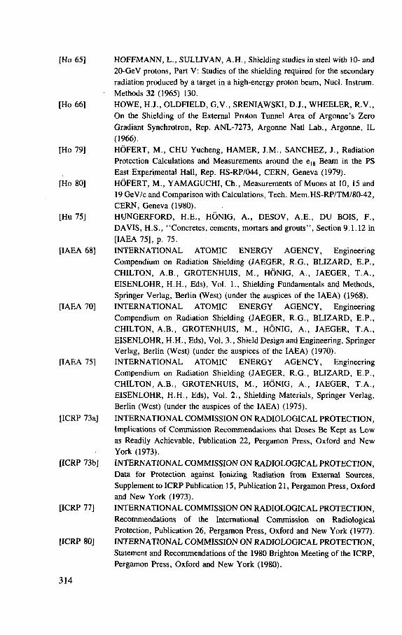
[Ho 65] HOFFMANN, L., SULLIVAN, A.H. , Shielding studies in steel with 10- and 20-GeV protons, Part V: Studies of the shielding required for the secondary radiation produced by a target in a high-energy proton beam, Nucl. Instrum. Methods 32 (1965) 130.
[Ho 66] HOWE, H.J., OLDFIELD, G.V. , SRENIAWSKI, D.J. , WHEELER, R.V. , On the Shielding of the External Proton Tunnel Area of Argonne's Zero Gradiant Synchrotron, Rep. ANL-7273, Argonne Natl Lab., Argonne, IL (1966).
[Ho 79] HOFERT, M. , CHU Yucheng, HAMER, J.M., SANCHEZ, J., Radiation Protection Calculations and Measurements around the e1 8 Beam in the PS East Experimental Hall, Rep. HS-RP/044, CERN, Geneva (1979).
[Ho 80] HOFERT, M., YAMAGUCHI, Ch., Measurements of Muons at 10, 15 and 19 GeV/c and Comparison with Calculations, Tech. Mem.HS-RP/TM/80-42, CERN, Geneva (1980).
[Hu 75] HUNGERFORD, H.E. , HONIG, A. , DESOV, A.E. , DU BOIS, F. , DAVIS, H.S. , "Concretes, cements, mortars and grouts", Section 9 .1 .12 in [IAEA 75], p. 75.
[IAEA 68] INTERNATIONAL ATOMIC ENERGY AGENCY, Engineering Compendium on Radiation Shielding (JAEGER, R.G. , BLIZARD, E.P. , CHILTON, A.B. , GROTENHU1S, M. , HONIG, A. , JAEGER, T .A. , EISENLOHR, H.H. , Eds), Vol. 1., Shielding Fundamentals and Methods, Springer Verlag, Berlin (West) (under the auspices of the IAEA) (1968).
[IAEA 70] INTERNATIONAL ATOMIC ENERGY AGENCY, Engineering Compendium on Radiation Shielding (JAEGER, R.G., BLIZARD, E.P. , CHILTON, A.B. , GROTENHUIS, M. , HONIG, A. , JAEGER, T .A. , EISENLOHR, H.H. , Eds), Vol. 3. , Shield Design and Engineering, Springer Verlag, Berlin (West) (under the auspices of the IAEA) (1970).
[IAEA 75] INTERNATIONAL ATOMIC ENERGY AGENCY, Engineering Compendium on Radiation Shielding (JAEGER, R.G., BLIZARD, E.P. , CHILTON, A.B. , GROTENHUIS, M. , HONIG, A. , JAEGER, T .A . , EISENLOHR, H.H. , Eds), Vol. 2 . , Shielding Materials, Springer Verlag, Berlin (West) (under the auspices of the IAEA) (1975).
[ICRP 73a] INTERNATIONAL COMMISSION ON RADIOLOGICAL PROTECTION, Implications of Commission Recommendations that Doses Be Kept as Low as Readily Achievable, Publication 22, Pergamon Press, Oxford and New York (1973).
[ICRP 73b] INTERNATIONAL COMMISSION O N RADIOLOGICAL PROTECTION, Data for Protection against Ionizing Radiation from External Sources, Supplement to ICRP Publication 15, Publication 21, Pergamon Press, Oxford and New York (1973).
[ICRP 77] INTERNATIONAL COMMISSION ON RADIOLOGICAL PROTECTION, Recommendations of the International Commission on Radiological Protection, Publication 26, Pergamon Press, Oxford and New York (1977).
[ICRP 80] INTERNATIONAL COMMISSION ON RADIOLOGICAL PROTECTION, Statement and Recommendations of the 1980 Brighton Meeting of the ICRP, Pergamon Press, Oxford and New York (1980).
314
[ICRP 83] INTERNATIONAL COMMISSION ON RADIOLOGICAL PROTECTION, Cost Benefit Analysis in the Optimization of Radiological Protection, Publication 37, Pergamon Press, Oxford and New York (1983).
[ICRP 84a] INTERNATIONAL COMMISSION ON RADIOLOGICAL PROTECTION, A Compilation of the Major Concepts and Quantities in Use by the ICRP, Publication 42, Pergamon Press, Oxford and New York (1984) 10.
[ICRP 84b] INTERNATIONAL COMMISSION ON RADIOLOGICAL PROTECTION, Statement from the 1983 Washington Meeting, Pergamon Press, Oxford and New York (1984).
[ICRP 84c] INTERNATIONAL COMMISSION ON RADIOLOGICAL PROTECTION, Statement from the 1984 Stockholm Meeting of the Commission, Pergamon Press, Oxford and New York (1984).
[ICRP 85] INTERNATIONAL COMMISSION ON RADIOLOGICAL PROTECTION, Statement from the 1983 Paris Meeting, Radiat. Prot. Dosim. 11 2 (1985) 134.
[Ir 65] IRVING, D.C. , FREESTONE, R.M. , Jr., KAM, F.B.K. , 05R, A General Purpose Monte Carlo Neutron Transport Code, Rep. ORNL-3622, Oak Ridge Natl Lab., Oak Ridge, TN (1965).
[Ka 71] KAYE, G.W.C. , LABY, T.H. , Tables of Physical and Chemical Constants, Longman, London (1971).
[Ka 72] KANG, Y. , et al., Design of a magnetized iron muon shield for a high energy neutrino laboratory, Part. Accel. 4 (1972) 31.
[Ke 64] KEEFE, D. Mu-Meson Shielding Problems at 200 GeV: Approximate Calculations, Rep. UCID-10018, Lawrence Berkeley Lab., Berkeley, CA (1964). .
[Ke 68] KEEFE, D. , NOBLE, C .M. , Radiation shielding for high-energy muons: The case of a cylindrically symmetrical shield and no magnetic fields, Nucl. Instrum. Methods 64 (1968) 173.
[Ko 67] KOBAYAKAWA, K., Fluctuations and nuclear interactions in the energy loss of cosmic-ray muons, Nuovo Cim. 47B (1967) 156.
[LBL 65] LAWRENCE BERKELEY LABORATORY, 200 BeV Design Study, Rep. UCRL-1600, 2 Vols, Lawrence Berkeley Lab., Berkeley, CA (1965).
[Le 72] LEVINE, G.S. , SQUIER, D .M. , STAPLETON, G.B. , STEVENSON, G.R. , GOEBEL, K., RANFT, J., The angular dependence of dose and hadron yield from targets in 8 GeV/c and 24 GeV/c extracted proton beams, Part. Accel. 3 (1972) 91.
[Li 52] LIVINGSTON, M.S . , High-energy accelerators — standard cyclotron, Ann. Rev. Nucl. Sci. 1 (1952) 157; High-energy accelerators — synchrocyclotron, Ann. Rev. Nucl. Sci. 1 (1952) 163; High-energy accelerators — proton synchrotron, Ann. Rev. Nucl. Sci. 2 (1952) 169.
[Li 61] LINDENBAUM, S.J., The shielding of high-energy accelerators, Ann. Rev. Nucl. Sci. 11 (1961) 213.
[Li 80] LIU, Kueilin, Calculation of Muon-Shielding Using the MUSTOP Program and Comparison with Experimental Data, Rep. HS-RP/IR/80-19, CERN, Geneva (1980).
315
[Li 84] LIU, Kueilin, STEVENSON, G.R. , THOMAS, R.H. , THOMAS, S .V. , Variance and regression analyses of Moyer model parameter data and their variation with primary proton energy, Health Phys. 46 (1984) 674.
[Li 85] LIPTAK, G., SCHULER, R., MAIER, P. SCHONBACHER, H., HABERTHUER, B. , MULLER, H., ZEIER, W. , Radiation Tests on Selected Electrical Insulating Materials for High-Power and High-Voltage Application, Rep. 85-02, CERN, Geneva (1985).
[Lo 83] LONE, M.A. , JONES, R., OZAKI, A. , et al., Total neutron yields from 100 MeV protons on Pb and Li targets, Nucl. Instrum. Methods 214 (1983) 333.
[Ma 65] MAERKER, R.E. , MUCKENTHALER, F.J., Calculation and measurement of the fast neutron differential dose albedo for concrete, Nucl. Sci. Eng. 22 (1965) 455.
[Ma 66] MAERKER, R.E. MUCKENTHALER, F.J., Measurements and single-velocity calculations of differential angular thermal neutron albedos for concrete, Nucl. Sci. Eng. 26 (1966) 339.
[Ma 67a] MAERKER, R.E. , MUCKENTHALER, F.J., Monte-Carlo calculations, using the albedo concept, of the fast-neutron dose rates along the center lines of one- and two-legged square concrete open ducts and comparison with experiment, Nucl. Sci. Eng. 27 (1967) 423.
[Ma 67b] MAERKER, R.E. , CAIN, V.R. , AMC, a Monte-Carlo Code Utilizing the Albedo Approach for Calculating Neutron and Capture Gamma-Ray Distributions in Rectangular Concrete Ducts, Rep. ORNL-3964, Oak Ridge Natl Lab., Oak Ridge, TN (1967).
[Ma 70] MARSHALL, T.O. , The attenuation of 14-MeV neutrons in water, Health Phys. 19 (1970) 571.
[Ma 79] MARCHAL, H., private communication, CERN, Geneva, 1979. [McC 85] McCASLIN, J.B., LA PLANT, P.R., SMITH, A.R. , SWANSON, W.P. ,
THOMAS, R.H. , Neutron production by Ne and Si ions on a thick Cu target at 670 M e V - A with application to radiation protection, IEEE Trans. Nucl Sci. NS-32 5 (1985) 3104.
[McC 85] McCASLIN, J.B. , SWANSON, W.P. , THOMAS, R.H., Moyer Model Approximations for Point and Extended Beam Losses, Rep. LBL-14699, Lawrence Berkeley Lab., Berkeley, CA (1985).
[Me 58] METROPOLIS, N . , BIVINS, R., STORM, M., TURKEVITCH, A. , MILLER, J.M., FRIEDLANDER, G., Monte Carlo calculations on intranuclear cascades, Phys. Rev. 110 (1958) 185.
[Me 65] MEUSER, R.B. , "Shielding: beam transport sections", Advanced Accelerator-Experimental Area Project, Lawrence Berkeley Lab. Mechanical Engineering Dept. Note AS/Experimental/01 M3563, 17 May 1965.
[Mo 57] MOYER, B.J., "Buildup factors", Rep. TID-7545, USAEC (1957) 96. [Mo 61a] MOYER, B.J., Lawrence Berkeley Laboratory, private communication,
quoted in [Pa 73], 128. [Mo 61b] MOYER, B.J., Evaluation of Shielding Required for the Improved Bevatron,
Rep. UCRL-9769, Lawrence Berkeley Lab., Berkeley, CA (1961).
316
[Mo 62] MOYER, B.J., "Method of calculation of the shielding enclosure for the Berkeley Bevatron", Premier Colloque International sur la Protection auprfes des Grands Accelerateurs, Presses Universitaires de France, Paris (1962) 65.
[Na 83] NAKAMURA, T., FUJII, M., SHIN, K., Neutron production from thick targets of carbon, iron, copper and lead by 30 and 52 MeV protons, Nucl. Sci. Eng. 83 (1983) 444.
[NCRP 71] NATIONAL COUNCIL ON RADIATION PROTECTION A N D MEASUREMENTS, Protection Against Neutron Radiation, Rep. 38, Washington, DC (1971).
[NCRP 77] NATIONAL COUNCIL ON RADIATION PROTECTION A N D MEASUREMENTS, Recommendations of the National Council on Radiation Protection and Measurements, Radiation Protection Design Guidelines for 0 .1-100 MeV Particle Accelerator Facilities, Report 51, Washington, DC (1977).
[Ne 68] NELSON, W.R. , The shielding of muons around high-energy electron accelerators: theory and measurement, Nucl. Instrum. Methods 66 (1968) 293.
[Ne 74a] NELSON, W.R. , KASE, K.R., Muon shielding around high-energy accelerators. Part I. Theory, Nucl. Instrum. Methods 120 (1974) 401.
[Ne 74b] NELSON, W.R. , KASE, K.R., SVENSSON, G.K., Muon shielding around high-energy accelerators. Part II. Experimental investigation, Nucl. Instrum. Methods 120 (1974) 413.
[Ne 83] NELSON, W.R. , JENKINS, T .M. , STEVENSON, G.R. , NIELSEN, M. , HEUNE, E .H.M. , JARRON, P., LORD, J., ANDERSON, S., Transport of high-energy muons in a soil shield, Nucl. Instrum. Methods 215 (1983) 385.
[Ni 74] NIELSEN, B. , Muon Measurements for Radiation Protection, Rep. HP-74-135, CERN, Geneva (1974).
[OB 67] O'BRIEN, K., The Neutron Shielding of the Los Alamos Meson Physics Facility, Rep. HASL-188, USAEC Health and Safety Lab. (1967).
[OB 68a] O'BRIEN, K., McLAUGHLIN, J. The propagation of the neutron component of the nucleonic cascade at energies less than 500 MeV: theory and a solution to the accelerator transverse shielding problem, Nucl. Instrum. Methods 60 (1968) 129.
[OB 68b] O'BRIEN, K. Transverse Shielding Calculations for Components of a 1/2-TeV Proton Synchrotron, Rep. HASL-199, USAEC Health and Safety Lab. (1968).
[OB 68c] O'BRIEN, K., Tables for the Determination of the Lateral Shielding Requirements of High-Energy Accelerators, Rep. HASL-203, USAEC Health and Safety Lab. (1968).
[OB 69] O'BRIEN, K., Extra-nuclear hadron cascade calculations using Passow's approximation, Nucl. Instrum. Methods 72 (1969) 93.
[OB 70] O'BRIEN, K , Shielding Calculations for Broad Neutron Beams Normally Incident on Slabs of Concrete, Rep. HASL-221, USAEC Health and Safety Lab. (1970).
317
[OB 71] O'BRIEN, K., Neutron Spectra in the Side Shielding of a Large Particle Accelerator, Rep. HASL-240, USAEC Health and Safety Lab. (1971).
[Pa 57] PATTERSON, H.W. , "The University of California Synchro-Cyclotron", in [So 57], p. 3.
[Pa 62a] PATTERSON, H.W., "The effect of shielding on radiation produced by the 730 MeV synchrocyclotron and the 6 .3 GeV proton synchrotron at the Lawrence Radiation Laboratory", Premier Colloque International sur la Protection aupres des Grands Acc616rateurs, Presses Universitaires de France, Paris (1962).
[Pa 62b] PASSOW, C. , Phanomenologische Theorie zur Berechnung einer Kaskade aus schweren Teilchen (Nukleonenkaskade) in der Materie, Rep. DESY-Notiz A 2.85, Deutsches Elektronen-Synchrotron, Hamburg (1962).
[Pa 71] PATTERSON, H.W. , THOMAS, R.H. , Experimental shielding studies — A review, Part. Accel. 2 (1971) 77.
[Pa 73] PATTERSON, H.W. , THOMAS, R.H. , Accelerator Health Physics, Academic Press, New York (1973) (with special reference to pp. 386-400).
[Pe 65] PERRY, D.R. , SHAW, K.B., Radiation Levels in and around Nimrod, Rep. CONF-651109, USAEC (1965) 20.
[Pe 66] PERRY, D.R. , "Neutron dosimetry methods and experience on the 7 GeV proton synchrotron, Nimrod", Neutron Monitoring (Proc. Symp. Vienna, 1966), IAEA, Vienna (1967) 355.
[Pe 71] PERRET, C.S. , "Dosisverteilung schneller Neutronen in Betonlabyrinthe in Abhangigkeit der Neutronenenergie und der Geometrie", Rep. 71-16, Vol. 2 , CERN, Geneva (1971) 714.
[Pr 57] PRICE, B.T. , HORTON, C.C. , SPINNEY, K.T., Radiation Shielding, Pergamon Press, Oxford and New York (1957).
[Ra 67] RANFT, J., Improved Monte Carlo calculation of the nucleon-meson cascade in shielding material, I and II, Nucl. Instrum. Methods 48 (1967) 133 and 261.
[Ra 70a] RANFT, J., Monte Carlo calculation of energy deposition by the nucleon-meson cascade and total absorption nuclear cascade (TANC) counters, Nucl. Instrum. Methods 81 (1970) 29.
[Ra 70b] RANFT, J., Secondary Particle Spectra According to the Thermodynamical Model. A Fit to Data Measured in p-Nucleus Collisions, Rep. TUL-36, Karl Marx University, Leipzig (1970).
[Ra 72a] RANFT, J., Estimation of radiation problems around high-energy accelerators using calculations of the hadronic cascade in matter, Part. Accel. 3 (1972) 129.
[Ra 72b] RANFT, J., ROUTTI, J.T., Hadronic cascade calculations of angular distributions of integrated secondary particle fluxes from external targets and new empirical formulae describing particle production in proton-nucleus collisions, Part. Accel. 4 (1972) 101.
[Ra 74] RANFT, J., ROUTTI, J.T., Monte Carlo programs for calculating three-dimensional high-energy (50 M e V - 5 0 0 GeV) hadron cascades in matter, Comput. Phys. Commun. 7 (1974) 327.
318
[Ra 85] RANFT, J., AARNIO, P.A. , STEVENSON, G.R., FLUKA82, CERN Divisional Report TIS-RP/156/CF, paper presented at the CERN Workshop on Shower Simulation for LEP Experiments, 19-31 January 1985.
[Ri 65] RIDDELL, R.J., Jr., High-Energy Nuclear Cascades in Matter, Rep. UCRL-11989, Lawrence Radiation Lab., Berkeley, CA (1965).
[Ri 67] RINDI, A. , TARDY-JOUBERT, P., Contribution to the experimental study of the transmission of radiation through service tunnels in the shielding of high-energy accelerators, Industries Atomiques 3 /4 (1967) 53 (in French) (English translation available at Lawrence Berkeley Lab. UCRL Transl. 350).
[Ri 73] RINDI, A. , THOMAS, R.H. , The radiation environment of high-energy accelerators, Ann. Rev. Nucl. Sci. 23 (1973) 315.
[Ro 41] ROSSI, B. , GREISEN, K., Cosmic ray theory, Rev. Mod. Phys. 13 (1941) 240.
[Ro 52] ROSSI, B. , High Energy Particles, Prentice Hall, Englewood Cliffs, NJ (1952).
[Ro 56] ROCKWELL, T., Reactor Shielding Design Manual, Office of Technical Services, US Department of Commerce, Washington, DC (1956).
[Ro 69] ROUTTI, J.T., THOMAS R.H. , Moyer integrals for estimating shielding of high-energy accelerators, Nucl. Instrum. Methods 76 (1969) 157.
[Ro 72a] ROUTTI, J.T., VAN DE VOORDE, M. , Monokinetic and Multi-Group Monte-Carlo Albedo Estimates of Neutron Leakage Through Penetrations of the ISR Shielding, Rep. ISR-MA/72-27, CERN, Geneva (1972).
[Ro 72b] ROUTTI, J.T., VAN DE VOORDE, M.H. , Dose estimates outside the shielding of the CERN intersecting storage rings by the Moyer method, Nucl. Eng. Des. 21 (1972) 421.
[Ry 82] RYDER, R., Neutron Production from Protons and Deuterons, Rep. DL/NUC/TM60A, Daresbury Lab., UK (1982).
[Ry 83] RYABOV, Y . V . , MATUSHKO, G.K., SLASTNIKOV, V .M. , Measure-ment of the average neutron yield from 250 MeV protons absorbed in a lead target, Z. Phys., A 311 (1983) 363.
[Sa 82] SANTORO, R.T. , ALSMILLER, R.G. , Jr., BARNES, J.M., CHAPMAN, G.T. , TANG, J.S., Comparison of measured and calculated neutron and gamma-ray energy spectra behind an in-line shielded duct, J. Fusion Energy 2 (1982) 403.
[Sa 83] SANTORO, R.T. , BARNES, J.M., ALSMILLER, R.G. , Jr., SORAN, P .D . , Streaming of 14 MeV neutrons through an iron duct — Comparison of measured neutron and gamma-ray energy spectra with results calculated using the Monte-Carlo MNCP Code, Nucl. Sci. Eng. 84 (1983) 260.
[Sc 69] SCHIMMERLING, W. , AWSCHALOM, M., 3 GeV protons on Pb neutrons streaming through a labyrinth, IEEE Trans. Nucl. Sci. NS-16 (1969) 604.
[Sc 79a] SCHONBACHER, H., STOLARZ-IZYCKA, A. , Compilation of Radiation Damage Test Data: Part I. Cable Insulating Materials, Rep. 79-04, CERN, Geneva (1979).
319
[Sc 79b] SCHONBACHER, H., STOLARZ-IZYCKA, A. , Compilation of Radiation Damage Test Data: Part II. Thermosetting and Thermoplastic Resins. Rep. 79-08, CERN, Geneva (1979).
[Sh 64] SHEN, S.P., Passage of High-Energy Particles in Matter: Nuclear Cascades Induced in Dense Media by 1 and 3 GeV Protons. Rep. BNL-8721, Brookhaven Nad Lab., Upton, N Y (1964).
[Sh 66] SHAW, K.B. , "Neutron studies in shields and tunnels with the 7 GeV proton synchrotron NIMROD", Proc. Conf. Rad. Meas. in Nucl. Power, Berkeley, UK, Inst. Phys. and Phys. Soc., London (1966).
[Sh 67] SHAW, K.B. , STEVENSON, G.R. , Interpretation of Results from the Activation in Indium, Gold and Cobalt Disks in Wax Moderators, Rep. RP/A/1, Rutherford Lab., Chilton, UK (1967).
[Sh 68] SHAW, K.B. , STEVENSON, G.R. , THOMAS, R.H. , Evaluation of Dose Equivalent from Neutron Energy Spectra, Rep. RPP/R5, Rutherford Lab., Chilton, UK (1968).
[Sh 69a] SHAW, K.B., STEVENSON, G.R., THOMAS, R.H. , Evaluation of dose equivalent from neutron energy spectra, Health Phys. 17 (1969) 459.
[Sh 69b] SHAW, K.B. , STEVENSON, G.R. , Radiation studies around extracted beams at Nimrod, IEEE Trans. Nucl. Sci. NS-16 3 Part 1 (1969) 57.
[Si 56] SIMON, A. , CLIFFORD, C.E. , The attenuation of neutrons by air-ducts in shields, Nucl. Sci. Eng. 1 (1956) 156.
[Sm 64] SMITH, A.R. , McCASLIN, J.B., PICK, M.A. , Radiation Field inside a Thick Concrete Shield for 6 .2 BeV Incident Protons, Rep. UCRL-11331, Lawrence Radiation Lab., Berkeley, CA (1964).
[Sm 65] SMITH, A.R. , "Some experimental shielding studies at the 6.2 BeV Berkeley Bevatron", Rep. CONF-651109, USAEC (1965) 365.
[So 57] SOLON, L.R. (Ed.), Conference on Shielding High-Energy Accelerators, New York, 11-13 April 1957, Rep. TID-7545, USAEC (1957).
[Sp 75] SPIELBERG, D. , 'Soil', Section 9 .1 .8 in [IAEA 75], p. 31. [St 69] STEVENSON, G.R. , SHAW, K.B. , HARGREAVES, D .M. , LISTER,
L.P. , MOTH, D . A . , Measurements of the Radiation Field Around the X2 Extracted Proton Beam, Rep. RHEL/M 148, Rutherford Lab., Chilton, UK (1969).
[St 71a] STERNHEIMER, R.M. , PEIERLS, R.F. , General expression for the density effect for the ionization loss of charged particles, Phys. Rev. B3 (1971) 3681.
[St 71b] STEVENSON, G.R. , SQUIER, D .M. , LEVINE, G.S. , Measurements of the Angular Dependence of Dose and Hadron Yield from Targets in 8 GeV/c and 24 GeV/c Extracted Proton Beams, Rep. RHEL/MR, Rutherford Lab., Chilton, UK (1971).
[St 73] STEVENSON, G.R. , SQUIER, D .M. , An experimental study of the attenua-tion of radiation in tunnels penetrating the shield of an extracted beam of the 7 GeV proton synchrotron NIMROD, Health Phys. 24 (1973) 87.
[St 76] STEVENSON, G.R. , The Radiation Environment of Proton Accelerators and Storage Rings, Rep. 76-04, CERN, Geneva (1976).
320
[St 79] STEVENSON, G.R. , A User Guide to the MUSTOP Program, Tech. Mem. HS-RP/TM/79-37, CERN, Geneva (1979).
[St 80] STEVENSON, G.R., Shielding of Low Energy Accelerators ( < 100 MeV): Part I, Rep. HS-RP/IR/80-51, CERN, Geneva (1980).
[St 81] STEVENSON, G.R., A Description of the TOMCAT Muon Transport Program, Rep. HS-RP/IR/81-28, CERN, Geneva (1981).
[St 82] STEVENSON, G.R. , LIU, Kuei-Lin, THOMAS, R.H. , Determination of transverse shielding for proton accelerators using the Moyer model, Health Phys. 43 (1982) 13.
[St 83] STEVENSON, G.R. , FASSO, A. , SANDBERG, J., REGELBRUGGE, A. , BONIFAS, A. , MULLER, A. , NIELSEN, M., Measurements of the Dose and Hadron Yield from Copper Targets in 200 GeV/c and 400 GeV/c Extracted Proton Beams. An Atlas of the Results Obtained, Rep. TIS-RP/112, CERN, Geneva (1983).
[St 84] STEVENSON, G.R. , The estimation of dose equivalent from the activation of plastic scintillators, Health Phys. 47 (1984) 837.
[St 86a] STEVENSON, G.R. , AARNIO, P.A. , FASSO, A. , RANFT, J., SANDBERG, J.V. , SIEVERS, P., Comparison of measurements of angular hadron energy spectra, induced activity and dose with FLUKA82 calculations, Nucl. Instrum. Methods A24S (1986) 323.
[St 86b] STEVENSON, G.R. , Shielding of Extended Targets at Proton Energies of Greater than 3 GeV, Rep. TIS/IR/86-04, CERN, Geneva (1986).
[St 86c] STEVENSON, G.R. , Dose Equivalent per Star in Hadron Cascade Calculations, Rep. TIS-RP/173, CERN, Geneva (1986).
[Su 85] SULLIVAN, A .H. , A method for estimating muon production and penetration through a shield, Nucl. Instrum. Methods A239 (1985) 197.
[Sy 66a] SYCHEV, B.S. , MAL'KOV, V .V . , KOMOCKHOV, M . M . , ZAITSEV, L .N. , At. Ehnerg. 20 (1966) 23.
[Sy 66b] SYCHEV, B.S. , MAL'KOV, V .V . , KOMOCKHOV, M . M . , ZAITSEV, L .N . , At. Ehnerg. 2 0 (1966) 355.
[Te 82] TESCH, K., The attenuation of the neutron dose equivalent in a labyrinth through an accelerator shield, Part. Accel. 12 (1982) 169.
[Te 83] TESCH, K., Comments on the transverse shielding of proton accelerators, Health Phys. 44 (1983) 79.
[Te 85] TESCH, A. , A simple estimation of the lateral shielding for proton accelerators in the energy range 50 to 1000 MeV, Radiat. Prot. Dosim. 11 3 (1985) 165.
[Th 60] THOMAS, R.H. , Rough estimates of shielding requirements in the Nimrod experimental area, Rep. NIRL/M/10, Rutherford Lab., Chilton, UK (1960).
[Th 61] THOMAS, R.H. , Neutron Shielding Properties of Various Materials in the Energy Region 1-100 MeV, Rep. NIRL/M/13, Rutherford Lab., Chilton, UK (1961).
[Th 63] THOMAS, R.H. (Ed.), Report of the Shielding Conference Held at the Rutherford Laboratory 26-27 September 1962, Rep. NIRL/R/40, Rutherford Lab., Chilton, UK (1963).
321
[Th 64a] THOMAS, R.H. , Shielding Experiment at 6 GeV I, Rep. UCID-10023, Lawrence Berkeley Lab., Berkeley, CA (1964).
[Th 64b] THOMAS, R.H. , Shielding Experiment at 6 GeV II, Rep. UCID-10021, Lawrence Berkeley Lab., Berkeley, CA (1964).
[Th 64c] THOMAS, R.H. , Energy Loss of High Energy Muons, Rep. UCID-10010, Lawrence Berkeley Lab., Berkeley, CA (1964).
[Th 66] THOMAS, R.H. , Radiation hazards of the new generation of accelerators, Nucleonics 24 4 (1966) 64.
[Th 68] THOMAS, R.H. , "Proton synchrotron accelerators", in [IAEA 68], p. 56. [Th 70] THOMAS, R.H. , "The Bevatron", in Section 10.7.3, Proton Synchrotrons:
Shield Designs, in [IAEA 70], p. 165. [Th 71] THERIOT, D. , AWSCHALOM, M., LEE, K., "Muon shielding
calculations: heterogeneous passive and active shields, applications to experimental beams and areas", Rep. 71-16, Vol. 2, CERN, Geneva (1971) 641.
[Th 73] THOMAS, R.H. , "Neutron dosimetry at high-energy particle accelerators", Neutron Monitoring for Radiation Protection Purposes (Proc. Symp. Vienna, 1972), Vol. 1, IAEA, Vienna (1973) 327.
[Th 76] THOMAS, R.H. , Implementing the requirement to reduce radiation exposure to " . . . as low as practicable" at the Lawrence Berkeley Laboratory, Health Phys. 30 (1976) 271.
[Th 78] THOMAS, R.H. , "High energy accelerator shielding — The present situation and future needs", Rep. KEK-77-31, Natl Lab. for High Energy Physics, Tsukuba, Japan (1978).
[Th 81] THOMAS, R.H. , The Variation of the Moyer Model Parameter, H0 , with Primary Proton Energy, Health Physics Note HPN-115, Lawrence Berkeley Lab., Berkeley, CA (1981).
[Th 83] THOMAS, R.H. , McCASLIN, J.B., "General shielding for the 20 TeV hadron collider facility: hadron considerations", Report of the 20-TeV Hadron Collider Technical Workshop, Cornell University, NY (1983).
[Th 84] THOMAS, R.H. , THOMAS, S .V . , Variance and regression analyses of Moyer model parameter data — a sequel, Health Phys. 46 (1984) 954.
[Th 85] THOMAS, R.H. , "Some important issues in developing radiation protection recommendations: dosimetric aspects", National Council on Radiation Protection and Measurements Proceedings No. 7, Washington, DC (1985).
[Ti 83] TIGNER, M. (Ed.), Report of the 20-TeV Hadron Collider Technical Workshop, Cornell University, N Y (1983).
[Tr 66] TRILLING, G.H. , Pion and Proton Fluxes from High Energy Proton Collisions, Rep. UCRL-16830, Lawrence Berkeley Lab., Berkeley, CA (1966).
[URA 68] UNIVERSITIES RESEARCH ASSOCIATION, National Accelerator Laboratory Design Report, Batavia, IL (July 1968).
[Va 68] VASIL'KOV, R.G, . , GOL'DANSKI, V.I. , GRISHKEVICH, T.V. , et al., Neutron yields in a lead-water system by high energy protons, At. Ehnerg. 25 (1968) 1307.
322
[Va 71] V A N GINNEKEN, A. , BORAK, T. , Beamstop experiment at 29.4 GeV, IEEE Trans. Nucl. Sci. NS-18 3 (1971) 746.
[Va 72a] V A N DE VOORDE, M.H. , RESTAT, C., Selection Guide to Organic Materials for Nuclear Engineering, Rep. 72-7, CERN, Geneva (1972).
[Va 72b] V A N GINNEKEN, A. , Weighted Monte Carlo Calculations of Hadronic Cascades in Thick Targets, Rep. FN-250, Fermilab, Batavia, IL (1972).
[Va 74] V A N GINNEKEN, A. , AWSCHALOM, M., High-Energy Particle Interactions in Large Targets: Vol. I. Hadronic Cascades, Shielding, Energy Distribution, Fermilab report (unnumbered), Batavia, IL (1974).
[Va 75] V A N GINNEKEN, A. , CASIM, Program to Simulate Hadronic Cascades in Bulk Matter, Rep. FN-272, Fermilab, Batavia, IL (1975).
[Va 80] V A N GINNEKEN, A. , "Calculation of the average properties of hadronic cascades at high energies (CASIM)", Computer Techniques in Radiation Transport and Dosimetry (NELSON, W.R. , JENKINS, T.M. , Eds), Plenum Press, New York and London (1980) 323.
[Vo 75] VOGT, H.G. , Monte-Carlo Calculations of the Neutron Transmission Through the Access Ways of the CERN Super Proton Synchrotron, Rep. 75-14, CERN, Geneva (1975).
[Vo 83] VOLYNCH1KOV, A.I . , GETMANOV, V.B. , KUZNETSOV, A .A . , KRUPNYI, G.I., LUKANIN, V.S . , RASTSVETALOV, Ya.N. , TATARENKO, V.H. , Secondary Radiation Field Measurements in a Steel Block Absorbing 69 GeV/c Proton Beams, Rep. IFVE 83-86, Serpukhov Inst, for High Energy Physics (in Russian) (translated by SCHULZ-DAHLEN, I., Rep. DESY L-Trans-284 (1983)).
[We 63] WENZEL, W . A . , "Bevatron external proton beams", Proc. Int. Conf. on High-Energy Accelerators, Dubna, 21-27 August 1963, Atomizdat, Moscow (1964) 698.
[We 71] WEST, D. , WOOD, E., Neutron yield from protons and deuterons of momenta between 0.85 and 1.7 GeV/c totally absorbed in lead, Can. J. Phys. 49 (1971) 2061.
[Wy 73] WYCKOFF, J.M., CHILTON. A.G. , "Dose due to practical neutron energy distributions incident on concrete shielding walls", Proc. 3rd Int. Cong. IRPA (SNYDER, W.S . , Ed.), Rep. CONF-730907-P1 (1973) 694.
[Ye 81] YE Sizong, private communication to G.R. Stevenson, 1981. [Ye 82] YE Sizong, The calculation of the neutron transmission through the access
way of a high-energy accelerator installation (using the MORSE code), Part. Accel. 12 (1982) 65.
[Za 71] ZAITSEV, L .N. , KOMOCHKOV, M . M . , S Y C H E V , B . S . , Fundamentals of Shielding for Accelerators, Atomizdat, Moscow (1971) (in Russian).
[Zo 68] ZOLOTUKHIN, V.G. , KLIMANOV, V.A. , LEIPUNSKII, O.I. , MASHKOVICH, V.P. , SAKHAROV, V.K. , SINITSYN, B.I. , TSYPIN, S.G. , Radiation Transmission Through Inhomogeneities in Shields, Atomiz-dat, Moscow (1968) (in Russian). (English translation published by Israel Program for Scientific Publications (Jerusalem) (1971)).
323

Chapter 5
ACCELERATOR RADIATION SAFETY PROGRAMME
5.1. I N T R O D U C T I O N
As we have seen from the examples of typical accelerator facilities given in
Chapter 1 there is a great diversity among accelerator institutions and each radiation
safety programme must be designed to facilitate the safe and effective operation of
accelerators according to the needs of the operating institution. Although there is no
standard organization suitable for all institutions, experience suggests some general
principles that should be considered in establishing an accelerator radiation safety
programme. These general principles will be discussed in this chapter.
There have been profound changes over the past twenty-five years in general
attitudes to health and safety in the work place. It is increasingly recognized that we
all have a right to a safe and healthy working environment. This realization has led
in many countries to the enactment of legislation that specifies both the rights and
obligations of individual workers.
For example in the United States of America the passage of the Williams and
Steiger Occupational Safety and Health Act in 1970 requires that employees be
informed of their rights under this legislation. Appendix 5.1 shows how this require-
ment is implemented at the Lawrence Berkeley Laboratory of the University of
California, which is regulated by the Department of Energy, a Department of the
Government of the United States of America.
It is most important to recognize that an accelerator radiation safety
programme should not be developed in isolation from the institution's health physics
programme or indeed from its own overall health and safety programme. On the
contrary, a good accelerator radiation safety programme is integrated with all the
disciplines involved in a comprehensive safety programme.
This integration of safety disciplines into a comprehensive programme is
especially necessary at accelerator laboratories because some desirable aspects of the
radiological safety programme may conflict with other safety needs. Seldom, if ever,
are safety requirements absolute. The success of an occupational safety and health
programme will depend upon the successes of the compromises it can make between
conflicting requirements and the balance it makes among them, keeping in mind that
the overall goals are the protection of human life, prevention of injuries and the
minimization of property damage.
Three typical examples of such conflicts in safety requirements at accelerator
laboratories are given below:
(1) At physics research laboratories explosive gas mixtures are used in some thin
walled particle detectors. The room in which such detectors are used may
325
require special ventilation, but it may not be possible to release the air from
this room during accelerator operation because of its radioactivity.
(2) Escape routes from an accelerator vault should ideally be sufficiently wide and
straight to permit the removal of injured persons without undue difficulty: this
is in direct conflict with good maze design for minimum photon and neutron
leakage.
(3) Good access control to a radioactive accelerator vault requires only one entry,
while emergency escape from the vault requires many exits.
A comprehensive occupational health and safety programme must ensure that no
unsafe compromises are made.
This chapter will briefly discuss the occupational safety and health
organization; the safety programme and its relation to the radiation safety
programme; and, finally, give a specific example of an occupational health
programme suitable for a large multidisciplinary research institution (national
laboratory) utilizing ionizing radiations, including those produced by several types
of particle accelerators.
5.2. S A F E T Y O R G A N I Z A T I O N
The responsibility for the safe operation of accelerator facilities, for the
protection of personnel, the public and the environment rests with management.
Experience shows that an efficient safety organization has three branches (see
Fig. 5.1):
(i) The normal line organization
(ii) A professional occupational health and safety department
(iii) A health and safety committee.
5.2.1. Line organization
The normal line organization is responsible, by delegation from the
director13, for the detailed implementation of safety policy and procedure. To every
level of management is delegated authority commensurate with the responsibilities
for safety assigned to them. In this respect, safety is treated no differently from other
functions of the organization. Every member of management is responsible for
ensuring that employees under his or her supervision are provided a safe and healthy
working environment, free from undue hazards. Supervisors at all levels should
13 In what follows the word 'director' is used to describe the head of the organization operating particle accelerators. Readers will be able to substitute the appropriate description in their own particular case.
326
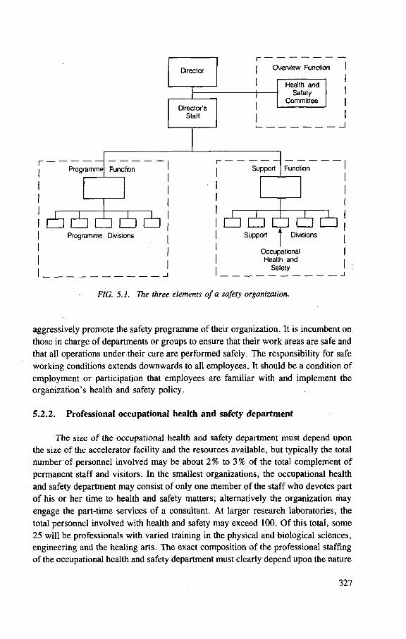
FIG. 5.1. The three elements of a safety organization.
aggressively promote the safety programme of their organization. It is incumbent on
those in charge of departments or groups to ensure that their work areas are safe and
that all operations under their care are performed safely. The responsibility for safe
working conditions extends downwards to all employees. It should be a condition of
employment or participation that employees are familiar with and implement the
organization's health and safety policy.
5.2.2. Professional occupational health and safety department
The size of the occupational health and safety department must depend upon
the size of the accelerator facility and the resources available, but typically the total
number of personnel involved may be about 2% to 3% of the total complement of
permanent staff and visitors. In the smallest organizations, the occupational health
and safety department may consist of only one member of the staff who devotes part
of his or her time to health and safety matters; alternatively the organization may
engage the part-time services of a consultant. At larger research laboratories, the
total personnel involved with health and safety may exceed 100. O f this total, some
25 will be professionals with varied training in the physical and biological sciences,
engineering and the healing arts. The exact composition of the professional staffing
of the occupational health and safety department must clearly depend upon the nature
327
of work performed. Advice may be obtained from standard texts on safety [Ch 81,
N S C 78, Pe 75, Pe 78, St 76] (see also the bibliography in Chapter 7). At a
minimum, all organizations that operate particle accelerators should obtain the
services of what the American National Standards Institute describes as a 'qualified
expert' during the early planning stage or installation phase of any new particle
accelerator [ A N S I 70].
5.2.3. Health and safety committee
A health and safety committee should be appointed by the director (or
equivalent) to advise top management on all aspects of health and safety practice and
policy. Its terms of reference should be clearly specified and include monitoring the
safety performance of the line organization and of the professional safety group. A s
an example of the scope of such a committee, Appendix 5.2 gives the charter for
the Safety Review Committee of the Lawrence Berkeley Laboratory [ LBL 80a]. The
policy statement of other research institutions will, of course, reflect their own
functions and needs.
Membership of the safety committee should be determined on the basis of
scientific activity, balance of technical knowledge and expertise in safety matters.
Membership may be made up of two types of persons — first, professional health
and safety experts (e.g. health physicist, industrial hygienist, fire protection officer,
physician, safety engineer, etc.) and second, responsible members of the line
organization. Particularly in research laboratories, participation by active
experimental scientists is most important because, in some cases, no applicable
safety codes may exist for research operations or equipment. Without such a diverse
composition of the health and safety committee, it would be extremely difficult to
operate an efficient health and safety programme at a research institution.
Appendix 5.2 gives an example of the function and organization of the safety
committee of a large national laboratory. Several important points should be made
about this committee. It is:
— appointed by top management
— advisory
— balanced in membership (scientists, safety experts, administrators).
Such a system of peer review has been found to work well at the Lawrence
Berkeley Laboratory of the University of California, a multidisciplinary national
laboratory.
At large institutions, the review of safety policies and practice can be an
extremely large task. There may be important economic, political, or institutional
issues related to health and safety matters, so that it may be necessary to separate
the review of day to day safety practice from the fundamental consideration of safety
328
policy, forming two distinct but evidently linked committees. On the other hand,
smaller institutions may require a single small committee consisting of the director,
the accelerator operator and the qualified expert. However, whatever the different
needs and preferences, the same general principles outiined in this section apply.
5.3. H E A L T H A N D S A F E T Y P R O G R A M M E
Analysis of health and safety programmes in a wide variety of facilities shows
that seven basic elements are necessary for satisfactory safety performance:
(1) Management leadership
(2) Assignment of responsibilities
(3) Maintenance of safe working conditions
(4) Safety training
(5) Accident recording and investigation system
(6) Professional health and safety staff
(7) Acceptance of personal responsibility.
5.3.1. Health and safety policy
The responsibility for the specification, provision and enforcement of a safe
working environment rests with management. Management in turn may delegate
authority and assign responsibility for the implementation of the safety policies and
programme but retains accountability for oversights and errors that lead to injury,
illness or damage to property.
Management leadership begins with a clear statement of policy. Such a
statement should be issued by top management and contain the following elements:
(a) Concise statement of health and safety policy.
(b) Acceptance of primary responsibility by top management and a statement on
the source of their authority.
(c) Delegation of health and safety responsibilities to middle management, the
health and safety staff, and all employees.
(d) Statement of health and safety performance required of all employees.
(e) Description of the safety resources and organization.
Appendix 5.3 gives as an example the health and safety policy statement of the
Lawrence Berkeley Laboratory, which includes all the elements listed above
[ L B L 82] . The policy statement of other research institutions will, of course, reflect
their own function and needs.
329
5.3.2. Safety at industrial and research installations
Details of the requirements of health and safety programmes may be found in the copious literature available. Only a few references can be given here (see also the bibliography in Chapter 7).
In the United States, general safety standards have been codified under the Occupational Safety and Health Act (OSHA) of 1970 [OSHA 83], Similar regula-tions exist for other countries.
Occupational medicine is addressed in standard texts [Hu 80, La 80, La 81, Sc 82, Ze 75, Ze 80], Electrical safety is discussed in the US National Safety Council Accident Prevention Manual [NSC 78] and the Handbook of Laboratory Safety [St 76]. Industrial hygiene is dealt with in the standard texts by Patty [Pa 81, 81a,b, Pa 82, Pa 85] and those issued by the National Institute of Occupational Safety and Health and the National Safety Council [NIOSH 78, NSC 79] and in the bibliography of Chapter 7. Toxicology and the dangers of hazardous materials are discussed in Casarett and Doull [Do 80], Sax [Sa 75], the Handbook of Laboratory Safety [St 76], monographs published by the US National Academy of Sciences [NAS 81, NAS 83] and other standard texts [An 81, Pr 78]. In the United States, fire protection is dealt with in publications of the National Fire Protection Association [NFPA nd]; it is also discussed in the Accident Prevention Manual of the National Safety Council [NSC 78]. For the special problems in fire fighting at installations where radioactive materials are used the monograph by Purington and Patterson [Pu 77] should be consulted.
The safety programme should be developed in accordance with local and national regulations, but the advice of national advisory bodies (such as the National Council on Radiation Protection and Measurements in the USA) and international organizations such as the ICRP, ICRU and IAEA should also be carefully consi-dered. (See Chapter 7, General Bibliography.)
As a general example the Occupational Health Programme of the Lawrence Berkeley Laboratory will be briefly described. This programme is specified in a health and safety manual [LBL 80b], the table of contents of which is given opposite so that the reader can visualize how the components of the safety programme fit together. Other institutions will make variations appropriate to their own functions.
In IAEA Technical Reports Series No. 188, Radiological Safety Aspects of the Operation of Electron Linear Accelerators, Swanson has given a good brief summary of safety problems at industrial and research installations; this discussion is reproduced below, for the convenience of the reader [IAEA 79],
Safety at industrial and research installation. The following safety areas are particularly relevant to industrial and research facilities. The suggestions given may be developed to meet the particular needs of the installation.
330
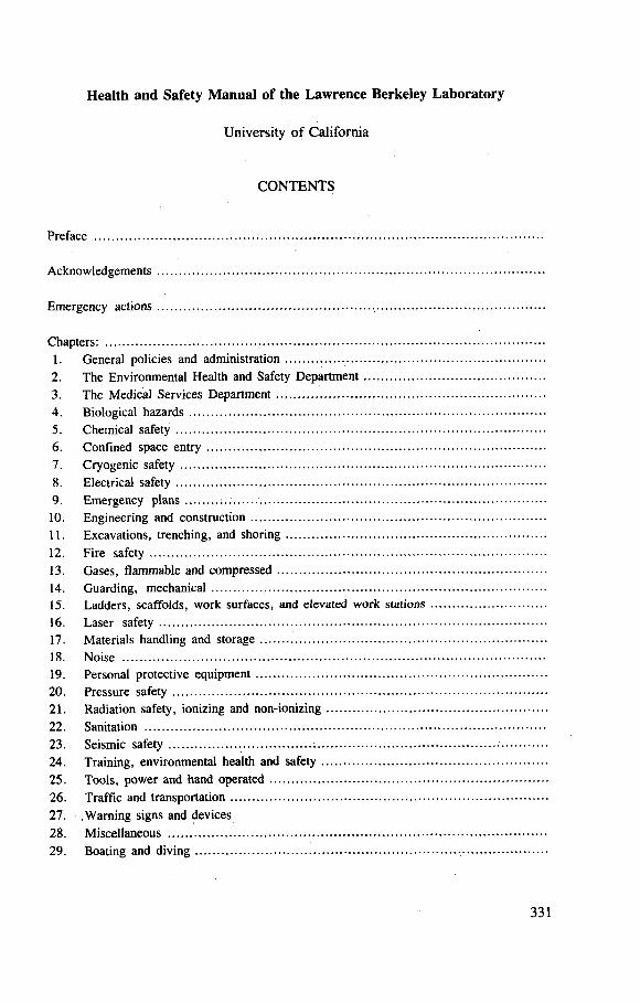
Health and Safety Manual of the Lawrence Berkeley Laboratory
University of California
CONTENTS
Preface
Acknowledgements
Emergency actions
Chapters:
1. General policies and administration 2. The Environmental Health and Safety Department 3. The Medical Services Department 4. Biological hazards 5. Chemical safety 6. Confined space entry 7. Cryogenic safety 8. Electrical safety 9. Emergency plans : . .
10. Engineering and construction 11. Excavations, trenching, and shoring 12. Fire safety 13. Gases, flammable and compressed 14. Guarding, mechanical 15. Ladders, scaffolds, work surfaces, and elevated work stations 16. Laser safety 17. Materials handling and storage 18. Noise 19. Personal protective equipment 20. Pressure safety 21. Radiation safety, ionizing and non-ionizing 22. Sanitation 23. Seismic safety 24. Training, environmental health and safety 25. Tools, power and hand operated 26. Traff ic and transportation 27. Warning signs and devices
28. Miscellaneous 29. Boating and diving
331
Emergencies. Notices of emergency procedures should be conspicuously posted. Emergency telephone numbers should be posted at every telephone (fire, emergency paramedical services, ambulance). Periodic instruction should be given in emergency procedures, including resuscitation techniques.
Electrical safety. Because of the variety of unusual circuitry found at research facilities, electrical safety should be given very careful attention. A fundamental aspect of electrical safety is the thorough training of personnel in the operation and safety provisions of the equipment used. All pertinent electrical codes should be well understood by responsible personnel and every attempt made to ensure compliance with them. The physical planning should allow convenient access to electrical equipment and this is to be installed in dry, well lighted locations. The provisions for enclosure, interlocking and grounding of circuits should be adequate. A grounding hook or preferably an automatic mechanical discharging device should be provided for high voltage power supplies and particularly for capacitor banks. Only connectors approved by the safety organization should be installed, and they should be maintained in good repair at all times. Metal ladders should not be used for electrical work. The equipment should be turned off in an obvious and positive manner before working on it. (This is best accomplished by means of multiple padlocks, one for each person who wishes to lock out the circuit.) Work on energized high voltage circuits should be undertaken only as a last resort and then only by persons having complete understanding of the equipment, and with cognizance of the responsible authorities. In such cases a stand-by person is essential.
Fire and explosion. Fire protection should be planned in terms of preven-tion, provision for prompt detection and containment. Unnecessary sources of ignition should be eliminated and unnecessary combustible loading should be removed. Flammable substances such as solvents, oils, acetylene, propane and hydrogen should be carefully stored, handled and properly disposed of. Cabling is susceptible to fire and is particularly capable of propagating an existing fire. A smoke detector and automatic sprinkler system is advisable for most areas. Adequate fire extinguishers should be maintained and conveniently available. Adequate means of egress should be provided, particularly for the accelerator and target room(s).
Hydrogen. Liquid hydrogen is frequently used in experiments in nuclear and elementary particle physics. The precautions should include a committee review of each new experiment using hydrogen, ventilation to prevent dangerous accumulations, grounding to prevent electrostatic buildup, sealed wiring and switches, enclosure of necessary nearby electrical equipment in
332
inert atmosphere at positive pressure, elimination of other sources of ignition, mechanical protection of thin target windows, and access control. Although emphasis must be.placed on prevention, consideration must also be given to provisions for damage limiting, such as walls or partitions that are swung open by excess pressure. Electrical equipment used in the area should be of a type approved by national or regional authorities for the particular class of hazard.
Gas cylinders should be properly labelled, carefully handled, stored upright and secured to prevent overturning. Proper regulators and other fixtures should be used.
Hazardous materials. A variety of unusual materials may be used at large research institutions. They should be properly labelled, using words such as CAUTION, WARNING, DANGER, POISON, together with a brief expla-nation of the hazard (such as 'do not machine', etc.), as appropriate. An inventory should be kept of dangerous materials and they should be locked up until released to responsible persons for use. Among the materials sometimes found in laboratories are mercury, beryllium metal, lithium hydride, asbestos, polychlorinated biphenyls (PCBs), epoxy resins, acids, caustic fluids, ether and solvents. Where volatile materials are used, adequate ventilation should be available. Where acids, caustics or strong chemicals are used, emergency eye wash facilities and showers are advisable.
Solvents. Protection against harmful solvents should include breathing protection (ventilation, complete enclosure or respirators) and skin protection (avoidance, gloves or creams), in addition to precautions against fire. Extremely toxic solvents (e.g. carbon tetrachloride arid carbon disulphide) should not be used.
Microwaves. Where microwave components, including klystrons, magnetrons, RF separators, RF cavities and connecting waveguides, are operating in accessible areas, there is a possibility of exposure to unsafe micro-wave intensities from openings in the system. Operating systems should remain entirely shielded and flanges and joints examined for integrity. An instrument, preferably one that does not distort the field appreciably, should be available to ensure that microwave intensities at frequencies between 10 MHz and 100 GHz do not exceed lO m W - c m - 2 when averaged over any possible 0.1-hour period (there may be other limitations imposed by government authorities).
Rigging and handling of heavy objects. The handling of shielding blocks, large objects to be radiographed, and accelerator and beam-transport equipment gives rise to chance of accidents. Crane and forklift operators should be properly trained and provided with adequate equipment.
333
Magnetic fields. Magnets should bear a warning sign and, when energized, be marked by a flashing light. There should be positive means of ensuring that they are off for personnel working nearby. There is a risk that tools and other ferrous objects may be pulled into magnetic fields, causing injury or damage. Personnel should not be permitted to enter areas where their bodies are immersed in high magnetic fields, such as between the pole faces or in fringing fields of large magnets.
Noxious gases. Ozone and oxides of nitrogen formed in the air by radiation should be assessed. If necessary, steps should be taken to mitigate this health hazard.
Noise. In rooms containing large motor generators, compressors or boilers the limits of noise levels allowed by local standards may be exceeded. When engineering or administrative controls cannot bring the exposure of personnel down to the levels allowed, hearing protectors should be worn.
Vacuum safety. A special hazard is presented by large vacuum systems with thin windows such as, for example, the long, large diameter pipes used in neutron time-of-flight facilities. The rupture of a window can result in a serious, even fatal, accident to a nearby person. There is danger of objects or persons being drawn into a system through a large window, and some possi-bility of ear damage, even with a small window, if the vacuum system is large enough. When the system is not in use, thin windows to large vacuum systems should be protected by temporary covers capable of withstanding atmospheric pressure. Alternatively, a gate valve near each end of a large vacuum pipe should be provided which can be closed to isolate the largest volume. Warning signs at the window should be used to alert personnel to this peculiar hazard and remind them to implement these protective measures. Unessential occupancy of the vicinity should be discouraged.
Radiation doors. The heavy, motor operated doors that are used at many research facilities should be designed to permit safe operation. The operating switch should be designed such that continual manual activation is required for motion of the door to continue. A warning bell should sound while the door is in motion. Limit switches should prevent motion beyond the proper range, and the closing edge should be equipped with a pressure sensitive safety plate which will disconnect power if a person or object is caught. Each door should also be capable of manual operation in case of power failure.
General provisions for safety should also include the provision and maintenance of emergency lighting and power, ventilation systems, respira-tors, emergency showers and eye wash facilities, self-contained breathing
334
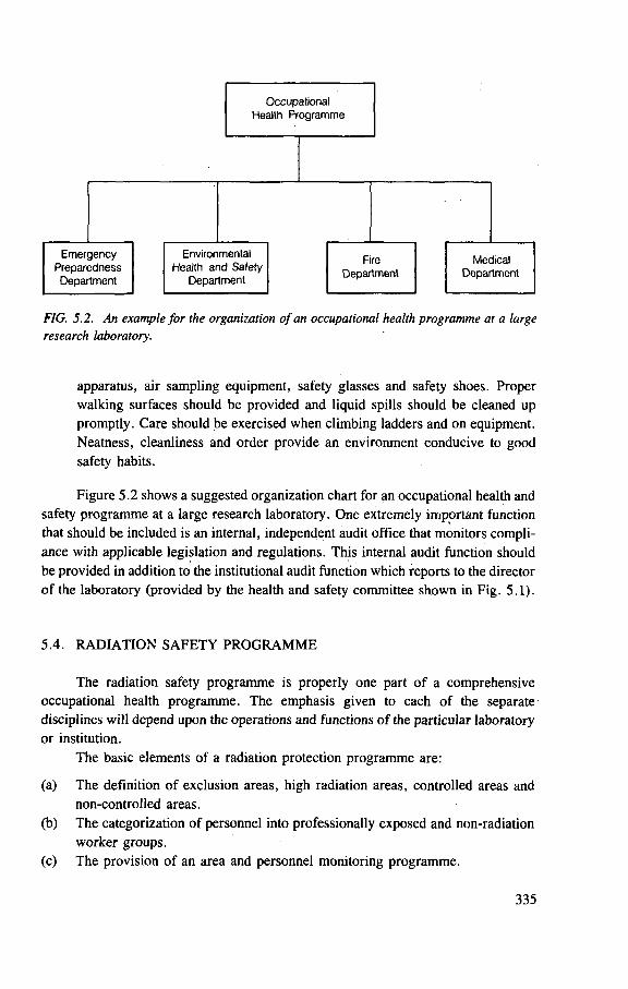
FIG. 5.2. An example for the organization of an occupational health programme at a large research laboratory.
apparatus, air sampling equipment, safety glasses and safety shoes. Proper walking surfaces should be provided and liquid spills should be cleaned up promptly. Care should be exercised when climbing ladders and on equipment. Neatness, cleanliness and order provide an environment conducive to good safety habits.
Figure 5.2 shows a suggested organization chart for an occupational health and safety programme at a large research laboratory. One extremely important function that should be included is an internal, independent audit office that monitors compli-ance with applicable legislation and regulations. This internal audit function should be provided in addition to the institutional audit function which reports to the director of the laboratory (provided by the health and safety committee shown in Fig. 5.1).
5.4. RADIATION SAFETY PROGRAMME
The radiation safety programme is properly one part of a comprehensive occupational health programme. The emphasis given to each of the separate disciplines will depend upon the operations and functions of the particular laboratory or institution.
The basic elements of a radiation protection programme are:
(a) The definition of exclusion areas, high radiation areas, controlled areas and non-controlled areas.
(b) The categorization of personnel into professionally exposed and non-radiation worker groups.
(c) The provision of an area and personnel monitoring programme.
335

Element (a) defines the requirements for shielding and other barriers designed to prevent access to areas where sometimes lethal doses could be received in a matter of minutes. It also defines the need for locked and/or interlocked doors to control access to these areas. This is particularly important at accelerator laboratories where in order to allow the accelerator to be switched on there must be mechanisms to ensure that all doors are closed, all movable shielding and barriers are in place and that no person is present inside the exclusion area. Administrative procedures play an important role in this process. The machine elements that must be 'made safe' in order that access to the exclusion area is possible must also be determined and signals from these linked correctly into the access authorization procedure.
The requirements of element (b) are administrative in character and require compliance with national and local regulations.
Element (c) takes on particular importance at accelerator laboratories where it depends on the shielding philosophy adopted in the design of the accelerator. The requirements for monitoring could be minimal if the accelerator is so heavily shielded and the configuration so stable that any dose rates in accessible areas are insignificant. On the other hand, radiation monitors could be part of an interlock chain to prevent the escape of beams into occupied areas, and personal monitors could be necessary to prove that small excursions in dose rate due to unwanted operation have not given rise to unacceptable exposures. More usually the monitoring programme is an economic and operational balance between these two extremes.
In organizing the radiological safety programme NCRP Report 59 will be found to be extremely helpful [NCRP 78].
A n y o r g a n i z a t i o n u s i n g ion iz ing r a d i a t i o n s s h o u l d f o r m a r ad i a t ion sa fe ty
c o m m i t t e e a n d a p p o i n t a r a d i a t i o n sa fe ty o f f i c e r . T h e a d v i c e of q u a l i f i e d e x p e r t s
s h o u l d b e o b t a i n e d as n e e d e d .
5.4.1. Radiation safety committee
All organizations that use ionizing radiations should form a committee dealing with radiation safety. If the institution is large enough, the committee may be devoted solely to matters concerning radiation safety; alternatively, radiation safety may be one of the concerns of a general safety committee (see Section 5.2). The functions of the radiation safety committee should include:
— advising management on radiation safety policy and procedures — monitoring radiation safety performance — reviewing unusual procedures or operations and requests for variances from
established policies.
It is imperative that members of the radiation safety committee keep, themselves informed of the recommendations of advisory organizations and.of the appropriate legal requirements for radiation safety.
336
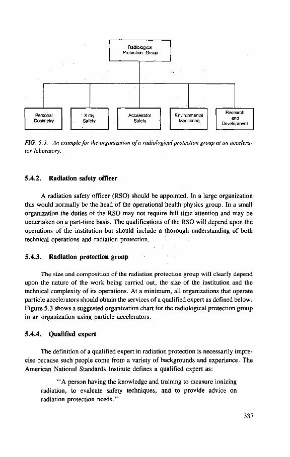
FIG. 5.3. An example for the organization of a radiological protection group at an accelera-tor laboratory.
5.4.2. Radiation safety officer
A radiation safety officer (RSO) should be appointed. In a large organization this would normally be the head of the operational health physics group. In a small organization the duties of the RSO may not require full time attention and may be undertaken on a part-time basis. The qualifications of the RSO will depend upon the operations of the institution but should include a thorough understanding of both technical operations and radiation protection.
5.4.3. Radiation protection group
The size and composition of the radiation protection group will clearly depend upon the nature of the work being carried out, the size of the institution and the technical complexity of its operations. At a minimum, all organizations that operate particle accelerators should obtain the services of a qualified expert as defined below. Figure 5.3 shows a suggested organization chart for the radiological protection group in an organization using particle accelerators.
5.4.4. Qualified expert
The definition of a qualified expert in radiation protection is necessarily impre-cise because such people come from a variety of backgrounds and experience. The American National Standards Institute defines a qualified expert as:
" A person having the knowledge and training to measure ionizing radiation, to evaluate safety techniques, and to provide advice on radiation protection needs ."
337
Such persons generally will have studied the physical or biological sciences at the baccalaureate level and often will have some postgraduate experience in nuclear physics, radiobiology or perhaps occupational health or industrial hygiene. In addition to the experience required for a health physicist, it is essential that a qualified expert in accelerator health physics have several years' experience in the design and operation of particle accelerators.
Several countries have systems for the registration of those personnel that have relevant qualifications and experience in the radiological sciences. In the United States, there are three national boards that register professionals in the radiological sciences — the American Board of Health Physics, the American Board of Industrial Hygiene and the American Board of Radiology [ABHP 80]. In addition many states, for example California, also register engineers qualified in safety disciplines, includ-ing health physics. The detailed requirements for such registration are continually changing and the interested reader should make direct contact with the organization of interest for current information.
5.4.5. Sample radiation safety programme
As a sample radiation safety programme, we here reproduce the Ionizing and Non-Ionizing Radiation Safety chapter of the Lawrence Berkeley Laboratory Health and Safety Manual [LBL 80b]. A few modifications have been made to clarify its meaning and usefulness for the reader who will be using it only as an example.
There is, of course, no unique way of organizing a radiation safety programme and the interested reader should study several typical accelerator radiation safety programmes. (See the section on Accelerator Radiation Safety Manuals in the General Bibliography — Chapter 7.)
The Radiation Safety Programme of the Lawrence Berkeley Laboratory is, as we have already seen, one component of a complete Occupational Health Programme described in its Health and Safety Manual [LBL 80b], Chapter 21 of this manual sets forth the Ionizing and Non-ionizing Radiation Safety Programme and is given below as an example for the reader.
338
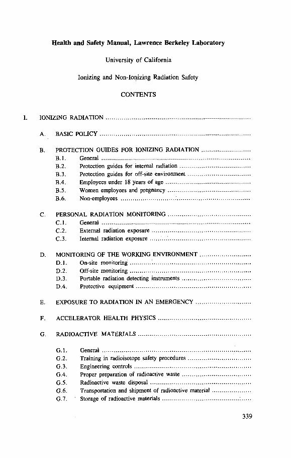
Health and Safety Manual, Lawrence Berkeley Laboratory
University of California
Ionizing and Non-Ionizing Radiation Safety
CONTENTS
IONIZING RADIATION
A. BASIC POLICY
B. P R O T E C T I O N GUIDES FOR IONIZING RADIATION
B . l . General B.2. Protection guides for internal radiation B.3 . Protection guides for off-site environment B.4. Employees under 18 years of age B.5. Women employees and pregnancy B. 6. Non-employees
C . PERSONAL RADIATION M O N I T O R I N G C . l . General C .2 . External radiation exposure C .3 . Internal radiation exposure
D. M O N I T O R I N G O F T H E W O R K I N G E N V I R O N M E N T D . l . On-site monitoring D.2 . Off-si te monitoring D.3 . Portable radiation detecting instruments D.4 . Protective equipment
E. E X P O S U R E T O RADIATION IN AN E M E R G E N C Y
F. A C C E L E R A T O R H E A L T H PHYSICS
G. R A D I O A C T I V E MATERIALS
G . l . General G.2 . Training in radioisotope safety procedures G.3 . Engineering controls G .4 . Proper preparation of radioactive waste G.5 . Radioactive waste disposal G .6 . Transportation and shipment of radioactive material G.l. Storage of radioactive materials
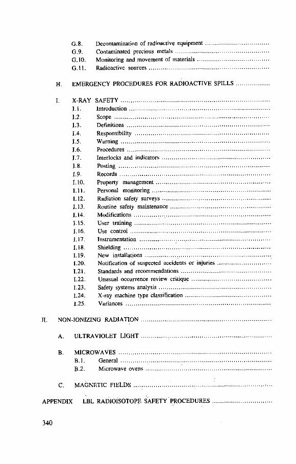
G.8 . Decontamination of radioactive equipment G.9 . Contaminated precious metals G.10. Monitoring and movement of materials G . l l . Radioactive sources
H. E M E R G E N C Y P R O C E D U R E S FOR RADIOACTIVE SPILLS
I. X-RAY SAFETY 1.1. Introduction 1.2. Scope 1.3. Definitions 1.4. Responsibility
1.5. Warning 1.6. Procedures 1.7. Interlocks and indicators 1.8. Posting
1.9. Records 1.10. Property management 1.11. Personal monitoring 1.12. Radiation safety surveys 1.13. Routine safety maintenance 1.14. Modifications 1.15. User training 1.16. Use control 1.17. Instrumentation ,
1.18. Shielding 1.19. New installations 1.20. Notification of suspected accidents or injuries 1.21. Standards and recommendations 1.22. Unusual occurrence review critique 1.23. Safety systems analysis 1.24. X-ray machine type classification 1.25. Variances
II. NON-IONIZING RADIATION
A. ULTRAVIOLET LIGHT
B. M I C R O W A V E S B . l . General
B.2. Microwave ovens
C. M A G N E T I C FIELDS
APPENDIX LBL RADIOISOTOPE SAFETY P R O C E D U R E S
340
I. IONIZING RADIATION
A. Basic policy
All Laboratory operations must be planned to prevent exposure of personnel to ionizing radiation in excess of the limits stated in the following Standards for Radiation Protection: Department of Energy Order DOE 5480.1 Ch. XI [DOE nd] and Occupational Safety and Health Standards 29 CFR 1910.96 [OSHA 83], These documents give radiation dose equivalent limits for both radiation workers and non-radiation workers.
In addition to these basic regulations, it is also Laboratory policy that exposure to ionizing radiation associated with Laboratory operations be as low as is reasonably achievable. This policy means that, subject to programmatic requirements and economic limitations, radiation dose equivalents to employees and radiation levels at the perimeter fence should be the minimum attainable. Implementation of this policy requires that each operation involving the use of radioactive material or the production of radiation be evaluated individually to ensure that the associated personnel exposures are as low as is reasonably achievable.
For external radiation, protection is provided by time and distance restrictions, source intensity (beam current limitations for accelerators) and adequate shielding. For internal radiation, protection is normally provided by preventing the escape of radioactive material into the working environment. Work with radionuclides must be restricted to certain locations that are designed specifically for such work. Further-more, persons under 18 years of age are restricted from working in certain areas. (See section entitled 'Employees under 18 years of age')
B. Protection guides for ionizing radiation
B.J. General
The protection guides for the control of external and internal dose equivalents are based on the standards listed in the DOE 5480.1 Ch. XI and are shown in Table 5 .1 . 1 4 Supervisors are primarily responsible for assuring that employee's exposures to ionizing radiation are kept as low as is reasonably achievable and within the standards shown in Table 5.1. Assistance in that regard is available from the Environmental Health and Safety Department.
It is recommended that whole body dose equivalent increments in excess of 150 mrem over a short period of time be avoided. Consult with the EH&S Department personnel when it appears likely that certain procedures can lead to a dose equivalent accumulation in excess of 150 mrem in a single exposure or in a series of exposures encompassing only a few days.
14 At the time of writing the US Department of Energy had not fully adopted the International System of Units or the recommendations of ICRP Publication 26 [ICRP 77], Discussions were under way to prepare for their adoption in the future.
341
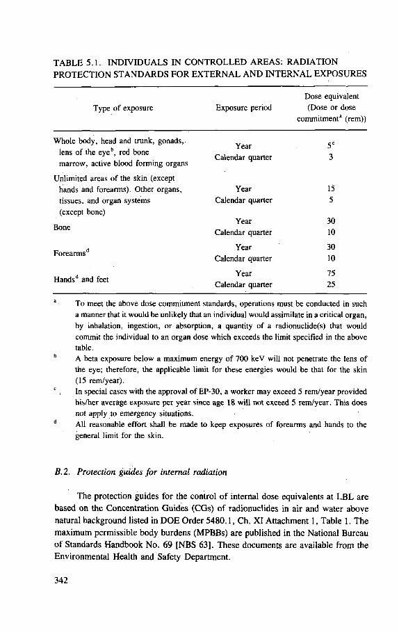
TABLE 5.1. INDIVIDUALS IN CONTROLLED AREAS: RADIATION PROTECTION STANDARDS FOR EXTERNAL AND INTERNAL EXPOSURES
Type of exposure
Dose equivalent Exposure period (Dose or dose
commitment 2 (rem))
Whole body, head and trunk, gonads, lens of the eye b , red bone marrow, active blood forming organs
Unlimited areas of the skin (except hands and forearms). Other organs, tissues, and organ systems (except bone)
Bone
Year Calendar quarter
Calendar quarter
Year Calendar quarter
Year Calendar quarter
Year Calendar quarter
Year 30 10
5C
3
15 5
Forearms' .d 30 10
Hands d and feet 75 25
To meet the above dose commitment standards, operations must be conducted in such a manner that it would be unlikely that an individual would assimilate in a critical organ, by inhalation, ingestion, or absorption, a quantity of a radionuclide(s) that would commit the individual to an organ dose which exceeds the limit specified in the above table.
A beta exposure below a maximum energy of 700 keV will not penetrate the lens of the eye; therefore, the applicable limit for these energies would be that for the skin (15 rem/year). In special cases with the approval of EP-30, a worker may exceed 5 rem/year provided his/her average exposure per year since age 18 will not exceed 5 rem/year . This does not apply to emergency situations. All reasonable effort shall be made to keep exposures of forearms and hands to the general limit for the skin.
B.2. Protection guides for internal radiation
The protection guides for the control of internal dose equivalents at LBL are based on the Concentration Guides (CGs) of radionuclides in air and water above natural background listed in DOE Order 5480.1, Ch. XI Attachment 1, Table 1. The maximum permissible body burdens (MPBBs) are published in the National Bureau of Standards Handbook No. 69 [NBS 63]. These documents are available from the Environmental Health and Safety Department.
342
The concentration guides were established at levels that present knowledge indicates will not result in significant injury after continual exposure at that level for many years. Nevertheless, personnel must not be exposed for extended periods at the limit values while reasonable avenues exist for avoiding such exposure.
When the concentration guide value (which is based on continuous exposure at 40 hours per week) is exceeded, the exposure time must be limited so that the total intake during a calendar quarter does not exceed the intake permitted. If external radiation is present, the permissible internal concentration values must be reduced to bring the whole body or a particular organ to the total dose within the basic dose limits.
The control of airborne radioactivity below CGs often involves sophisticated enclosure systems and careful experimental planning. Failure of a control system for an experiment involving a large amount of radioactivity could result in exceeding the CGs both on and off the site. Therefore, it is mandatory that operations involving large quantities of unencapsulated radioactive material be planned with EH&S Department assistance.
B. 3. Protection guides for off-site environment
The off-site protection guide for external and internal radiation as established by DOE Order 5480.1 Ch. XI is that no person outside the fence receives a whole body dose equivalent exceeding 0.5 rem in a year.
The specific protection guide values to be used at the Lawrence Berkeley Laboratory for concentrations of radionuclides in air and water are to be those stated in DOE Order 5480.1, Ch. XI, Attachment 1, Table II (with the exception of discharge to the sanitary sewer). In the case of releases to sanitary sewers, the concentration values are to be those stated in DOE Order 5480.1, Ch. XI, Attachment 1, Table I.
The Laboratory policy regarding off-site radiation and radioactivity is that the levels be reduced to the lowest reasonably achievable amounts within the DOE guidelines consistent with economic and programmatic considerations.
B.4. Employees under 18 years of age
Employees under 18 years old must be limited to a total body dose equivalent of 0.5 rem in any calendar year and a dose equivalent no greater than 0.3 rem in any calendar quarter.
The following guidelines are to be followed for all employees and participating guests under age 18 who work in radiation areas:
— Each case is to be handled individually. — The programme for each person is to be outlined in writing with a listing of
the proposed work areas and time schedule.
343
— A supervisor for each person is to be designated. — Access to the proposed work area must be evaluated by the EH&S Department
personnel for possible radiation hazards or exposures above background. In general, persons under 18 years of age are restricted from working in certain buildings and areas, such as accelerators, areas adjacent to accelerators, parts of buildings that contain large quantities of radioisotopes, and machines producing ionizing radiation. At the present time the following buildings are in this category:
[HERE FOLLOWS A LIST OF BUILDINGS AND AREAS IN WHICH PERSONS UNDER THE AGE OF 18 MAY NOT WORK]
NOTE: this list is correct as of the date of publication of this page; it is updated whenever conditions change. Consult the EH&S Department for current status.
— All new employees or participating guests must attend the safety orientation sessions presented by the EH&S Department.
B.5. Women employees and pregnancy
The National Council on Radiation Protection and Measurements in Report No. 53 [NCRP 77a, see also NCRP 77b] has recommended that during the entire gestation period, the maximum permissible dose equivalent to the embryo-fetus from occupational exposure of the expectant mother should be 0.5 rem. It is Labora-tory policy that fertile women who work in radiation areas, as well as their supervi-sors, should be aware of this recommendation and the reasons for it. As in all cases, occupational radiation exposure of fertile or pregnant women should be kept as low as is readily achievable. It is DOE policy, however, that no woman be denied a job or work assignment solely because of this recommendation.
As soon as an employee learns that she is pregnant, she is required to inform Medical Services of the expected date of childbirth (see RPM, Sec. 2.09, D, 3 [LBL nd]). A physician will discuss her work environment with her and will deter-mine whether or not any changes in the environment should be made to ensure her good health and that of her baby. All new employees are given a copy of the booklet, 'Pregnancy and Radiation' [LBL 78].
B. 6. Non-employees
The radiation protection rules and guides for non-LBL personnel are the same as for employees. Non-LBL personnel include visitors and contractor workers.
Contractor personnel are the responsibility of their employer who is obligated by contract to comply with all pertinent DOE and LBL safety and health regulations and requirements. (See section on Contractor Safety in Chapter 10 of Ref. [LBL 80a].)
Non-LBL personnel under 18 years of age must be limited to the dose equi-valents specified for employees under the age of 18.
344
C. Personal radiation monitoring
C.l. General
Certain employees and participating guests who work at the Laboratory are defined to be radiation workers. A radiation worker is an individual whose regular job duties involve, or potentially involve, exposure to ionizing radiation. Such work is subject to appropriate radiological protection controls and is usually performed in controlled areas.
All radiation workers at LBL are required to participate in the Laboratory's bioassay programme, its personal dosimetry programme, or both.
Most radiation workers who are exposed to external ionizing radiation will be issued a personal dosimeter (usually film badge/badges) to record their exposure to radiation. Radiation workers exposed to internal emitters will be required to parti-cipate in the bioassay programme. The US Department of Energy requires monitoring of individuals who have the potential to receive a dose equivalent in any calendar quarter which is 10% of the applicable radiation protection standard. (For whole body external exposure this guideline translates to a potential exposure of 300 mrem per quarter.)
C.2. External radiation exposure
Personal dosimetry programme. Dosimeters which are issued to employees who work with ionizing radiation are the primary personal detectors used to monitor the amount of radiation dose equivalent to employees from Laboratory and non-Laboratory exposure.
The plastic dosimeter holder contains a large pocket to hold the Laboratory identification card and two smaller pockets to hold the monitoring films. One of these smaller pockets has two circular metal filters and holds the beta-gamma film used for all radiation workers. The other holds a neutron film for those employees who may be exposed to significant neutron radiation, e.g. persons working in accelerator areas.
Radiation workers are issued two holders. One has a blue identification tag, the other, a yellow tag. The tags contain the employee's name and dosimeter number. Holders are alternated monthly by the wearer at exchange points located throughout the Laboratory. New employees must check with their supervisors for their exchange location.
Film packets must be carried at all times in areas where a radiation exposure might be received. Employees working in induced radioactivity areas, in radio-isotope areas, or with machines must clip the dosimeter to the front of their chest. Clips are available at the Personal Dosimetry Office on request. Dosimeters must be stored in natural background areas when not worn by radiation workers.
345
The dosimeter is relied on to provide accurate information about the wearer 's exposure to radiation, so it must not be misused. Each individual's record of exposure to Laboratory produced ionizing and particulate radiation is carefully maintained at the Personal Dosimetry Office. It is important that non-Laboratory exposures, such as those that might be received through medical or dental proce-dures, be reported to the Personal Dosimetry Office. Employees may request extra film to monitor non-Laboratory exposures and in that way make the task of record keeping easier.
Criteria for issuance of personal dosimeters:
— Gamma film dosimeters will be issued monthly to employees who work directly with the following radiation producing items:
(a) particle accelerators, 10 hours or more per month (b) X-ray generators (c) irradiators (d) radioisotopes, except exclusive users of the radionuclides l 4C
and/or 3H (e) anyone having the potential for significant exposure (such as
experimenters, radiation therapy personnel, etc.) — Firemen, certain Protective Services personnel, and other selected individuals
will also be issued personal gamma dosimeters. — Neutron dosimeters will be issued monthly to a limited number of personnel
who work at accelerator sites; these fall in the following categories: (a) operations and maintenance personnel who work 35 hours or more
p e r m o n t h a t a n y o f the a c c e l e r a t o r s
(b) users (experimenters, radiation therapy personnel) (c) special cases as determined by the EH&S Department on an
individual basis. Employees whose work only occasionally falls in one of the above categories will be issued dosimeters to cover those time intervals.
Questions concerning the need for neutron film packets may be directed to the Personal Dosimetry Office, Ext. xxx.
Finger dosimeters are worn on the finger by experimenters whenever they handle concentrated amounts of radioisotopes. They are used only for short intervals and then sent to the EH&S Department for evaluation and record keeping. Finger dosimeters are normally issued and collected by the EH&S Department monitors.
Pocket dosimeters are a self-reading beta-gamma indicating type and are worn in areas where the radiation levels are high or unpredictable. Usually these are areas of induced activity within the accelerator shielding. The purpose of the dosimeter is to provide the wearer with a means of keeping a running check on the approximate radiation dose equivalent received while working in a high radiation field. When the wearer has finished using the pocket dosimeter, he must record the amount of radia-
346
tion he received in the logbook that is kept with the dosimeters. The pocket dosimeter is not a substitute for the film badge, which must be worn concurrently.
Thermoluminescent dosimeters (TLDs) . are a supplementary means of measuring the dose received on the extremities such as the hands and forearms. The TLDs may be obtained from the EH&S monitors.
Wearing of personal dosimeters. It is mandatory that radiation workers wear their personal dosimeters in posted areas. It is recommended that radiation workers wear their personal dosimeters at all times when at the Laboratory.
When a single dosimeter is used, the preferred location for wearing it is the upper torso, where it will give the best measure for estimating the whole body dose equivalent. When wearing the dosimeter on the upper torso is impracticable and the whole body radiation exposure is from omnidirectional, penetrating radiation (as for example, when working around operating particle accelerators) it is sufficient that the dosimeter be carried on the person. In certain work areas it is mandatory that the dosimeter be worn on the upper torso — these areas are so posted.
During off-hours, the dosimeter may be taken home or stored in the Laboratory in areas having relatively low background radiation intensities. Most office areas at the laboratory meet this requirement. The Environmental Health and Safety Coordinator in your area can advise you as to appropriate dosimeter storage locations. The dosimeter must not be worn during medical or dental X-rays, nuclear medical procedures, or radiation therapy. It is important that you notify the Personal Dosimetry Office should such exposures to your dosimeter occur.
Monitoring responsibility
Each radiation worker is responsible to wear an issued dosimeter in accordance with this policy.
Line management is responsible to:
— determine which employees should be designated as radiation workers — ensure compliance with the DOE radiation monitoring order — ensure that dosimeters are properly worn in posted areas, substantiated by peri-
odic audits of record — ensure compliance with bioassay monitoring programme requirements.
Penalty for non-return of dosimeter
Each month anyone who does not return his/her dosimeter during the prescribed month will receive a reminder indicating this fact; the person's supervisor will also receive this notice. It is the individual's responsibility to follow laboratory procedure and return the dosimeter at the prescribed time. The supervisor's responsi-bility is to enforce this procedure.
347
If the dosimeter is not returned after two months, the person's Division Head will be notified of this fact. After three months delinquency, the individual will be subject to removal from any radiation work.
C.3. Internal radiation exposure
The programme to monitor internal radiation dose equivalent to LBL employees is administered by the Medical Services Department, with the advice of the EH&S Department. The EH&S Department provides the Medical Services Department with a list of LBL personnel working with radioactive material (exclusive of some encapsulated material, such as sealed sources; see Radioactive Sources, Section G.10). This bioassay list is reviewed every six months by the EH&S Department Area Co-ordinators. Everyone on the list is required by the Medical Services Department to provide appropriate bioassay samples.
The bioassay programme consists of in vivo counting at the Donner Laboratory whole body counter and radiochemical analysis of urine samples. Employees submit urine samples and have whole body counts once a year, or more frequently as appropriate. Persons working only with low energy beta emitters (e.g. 3H, 14C) are not included in the whole body counter programme. Results of all bioassay tests are kept in the employee's medical file and by the Medical and EH&S Departments.
In all cases of known exposure to internal radiation by ingestion, inhalation, or puncture wound, the absorbed dose equivalent must be estimated by the most appropriate methods available. Elimination rates must be followed as long as they are relevant to the exposure.
Those employees who have worked in areas where internal deposition of radio-nuclides is possible must have a bioassay examination included in their terminal physical examination.
D. Monitoring of the working environment
The EH&S Department maintains a working environment monitoring programme to assure that dose equivalent rates and the concentration of radioactivity in areas inhabited by people do not exceed the radiation protection guide values.
D.l. On-site monitoring
Where radiation producing machines are operated, external radiation intensity must be measured at least every 6 months and whenever a significant change is made in equipment or mode of operation, or on the schedule stated in the operating procedure.
348
In areas containing radioactive material:
— External radiation intensity must be measured at least every 3 months, and whenever a significant change is made in equipment, quantity of material, or mode of operation, or on the schedule stated in the operating procedure.
— At the onset, during and upon completion of an operation, surveys must be made. Area contamination surveys must be made at least monthly when work is in progress, once every three months when an experiment is inactive, and whenever there is reason to believe that radioactive material may have escaped from its enclosure.
— Air sampling must be performed on a continuous basis in the areas of actual operations with radioactive material that can potentially release airborne contamination and in exhaust systems serving the radioactive material handling areas.
— Certain areas at the Laboratory are designated Restricted Areas due to the presence of radiation or radioactive materials in amounts above the levels set by DOE regulations. These areas are identified by signs bearing the universal radiation symbol and the words 'Caution Radiation Area' (Fig. 5.4), 'Caution High Radiation Area' (Fig. 5.5) or 'Caution Radioactive Materials' (Fig. 5.6).
'Radiation Area' means any area, accessible to personnel, in which a major portion of the body could receive in any 1 hour a dose equivalent in excess of 5 mrem, or in any 5 consecutive days a dose equivalent in excess of 100 mrem.
'High Radiation Area' means any area, accessible to personnel, in which a major portion of the body could receive in any 1 hour a dose equivalent in excess of 100 mrem.
The 'Caution Radioactive Materials' warning sign is to be used in areas and rooms where radioactive material is present and on containers in which radioactive material is being transported, stored, or otherwise used.
To enter these areas, persons must find out from the local area supervisors or EH&S Department representative where and what the radiation hazards are and proceed as appropriate.
The radiation warning signs are posted at the advice of the EH&S Department. Radiation of a level high enough to cause possible injury exists in certain areas
of the Laboratory, for example the large gamma irradiators, many vaults and experimental caves associated with particle accelerators. These areas are identified by warning signs and, when in operation, by flashing magenta or red lights. All of these areas are equipped with various types of entry interlocks and run-safe switches. Never attempt to enter one of these areas unless you have permission and unless you are fully familiar with the operational safety rules of that particular facility. These rules are printed in the facility's Operational Safety Procedures, which can be obtained from the facility's Building Manager. For further information, call the EH&S Department.
349
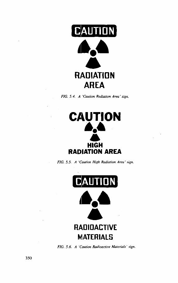
M RADIATION
AREA FIG. 5.4. A 'Caution Radiation Area' sign.
CAUTION M HIGH
RADIATION AREA FIG. 5.5. A 'Caution High Radiation Area' sign.
M
RADIOACTIVE MATERIALS
FIG. 5.6. A 'Caution Radioactive Materials' sign.
D.2. Off-site monitoring
A programme of sampling air, water, and sewage as well as ionizing radiation is maintained by the EH&S Department to evaluate:
— the effect of the Laboratory's operations on the environment — the effectiveness of on-site control measures in meeting the radiation protection
guide restrictions on concentrations of radioactivity that may be released to the area around the site.
External radiation is monitored at the boundary fence to establish the Laboratory's control of the external radiation reaching the off-site environment. This monitoring programme is described in 'The Environmental Surveillance Program of the Lawrence Berkeley Laboratory' [LBL 76]. The EH&S Department prepares an annual summary of off-site surveillance which is contained in 'The Annual Environmental Monitoring Report of the Lawrence Berkeley Laboratory' .
D.3. Portable radiation detecting instruments
The Laboratory provides and maintains radiation detection and measuring instruments. Instruments are issued to employees or groups when their use is clearly of value in monitoring and controlling exposure of personnel. The EH&S Department selects, obtains, and distributes the portable instruments. The Instrument Techniques Support group provides maintenance. These instruments are delicate and expensive, and the employees who use them must be trained to operate and interpret them and be familiar with their limitations.
D.4. Protective equipment
The primary control of unencapsulated radioactive material is through confine-ment in a suitable enclosure provided with appropriate ventilation. The enclosure is designed to provide control of airborne radioactivity commensurate with the hazard.
E. Exposure to radiation in an emergency
Specific dose criteria and judgment factors are set forth for the three categories of risk-benefit considerations, i.e. actions involving the saving of human life, the recovery of deceased victims, and the protection of health and property. Details are found in DOE Order 5480.1, Ch. XI.
351
F. Accelerator health physics
The accelerator health physics safety programme of the EH&S Department consists of the following functions:
— Consultation with operations personnel, experimenters and monitoring personnel
— Training for operations and monitoring personnel — Radiation monitoring — Shielding evaluation and design and other safety systems, such as interlocks,
area monitors, etc. — Personal radiation monitoring.
It is recommended that experimenters, operations and monitoring personnel consult with an accelerator health physicist for help in planning new or unusual beams, beam lines, targets, unusual requirements for rapid access to a target or target area, or for special shielding.
Prior to the use of a new or unusual operation at any of the LBL accelerators or ion sources, monitoring must be requested from the EH&S Department.
Each of the accelerators must have a current Operational Safety Procedure (OSP) manual prior to operations. These manuals detail accelerator health physics and safety programmes. Help in reviewing the OSP is available from the EH&S Department. Operations as detailed in the OSP must be followed.
Interlocks and warning device operation must be checked and serviced for proper functioning at intervals not to exceed a months; review of the system require-ments must be made on a regular basis.
Requirements for personal radiation monitoring must be met by all employees and participating guests. Contact the EH&S Department Personal Dosimetry Office, Ext. xxx, for the necessary dosimeters.
G. Radioactive materials
G. 1. General
Operations during regular hours
The handling of, or working with any radioisotope (except sealed sources) is prohibited unless an EH&S monitor is present, or the person is trained in a specific procedure which has been approved by the EH&S Department. Radiological assistance normally is available during the following hours: Monday through Friday, 8:00 a.m. to midnight.
352
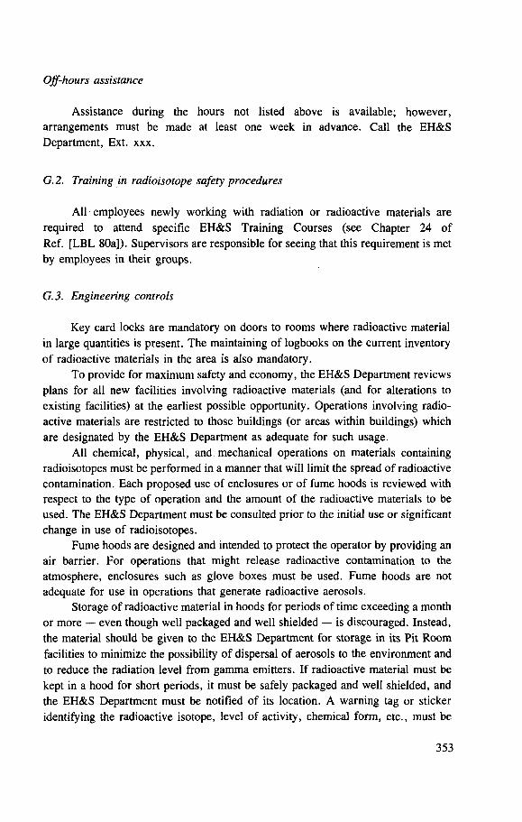
Off-hours assistance
Assistance during the hours not listed above is available; however, arrangements must be made at least one week in advance. Call the EH&S Department, Ext. xxx.
G.2. Training in radioisotope safety procedures
All employees newly working with radiation or radioactive materials are required to attend specific EH&S Training Courses (see Chapter 24 of Ref. [LBL 80a]). Supervisors are responsible for seeing that this requirement is met by employees in their groups.
G.3. Engineering controls
Key card locks are mandatory on doors to rooms where radioactive material in large quantities is present. The maintaining of logbooks on the current inventory of radioactive materials in the area is also mandatory.
To provide for maximum safety and economy, the EH&S Department reviews plans for all new facilities involving radioactive materials (and for alterations to existing facilities) at the earliest possible opportunity. Operations involving radio-active materials are restricted to those buildings (or areas within buildings) which are designated by the EH&S Department as adequate for such usage.
All chemical, physical, and. mechanical operations on materials containing radioisotopes must be performed in a manner that will limit the spread of radioactive contamination. Each proposed use of enclosures or of fume hoods is reviewed with respect to the type of operation and the amount of the radioactive materials to be used. The EH&S Department must be consulted prior to the initial use or significant change in use of radioisotopes.
Fume hoods are designed and intended to protect the operator by providing an air barrier. For operations that might release radioactive contamination to the atmosphere, enclosures such as glove boxes must be used. Fume hoods are not adequate for use in operations that generate radioactive aerosols.
Storage of radioactive material in hoods for periods of time exceeding a month or more — even though well packaged and well shielded — is discouraged. Instead, the material should be given to the EH&S Department for storage in its Pit Room facilities to minimize the possibility of dispersal of aerosols to the environment and to reduce the radiation level from gamma emitters. If radioactive material must be kept in a hood for short periods, it must be safely packaged and well shielded, and the EH&S Department must be notified of its location. A warning tag or sticker identifying the radioactive isotope, level of activity, chemical form, etc., must be
353
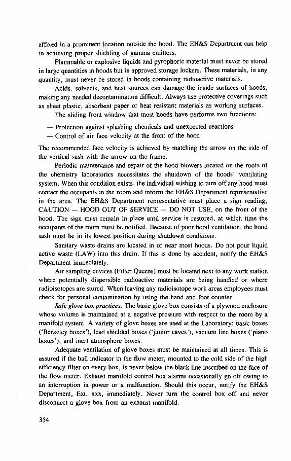
affixed in a prominent location outside the hood. The EH&S Department can help in achieving proper shielding of gamma emitters.
Flammable or explosive liquids and pyrophoric material must never be stored in large quantities in hoods but in approved storage lockers. These materials, in any quantity, must never be stored in hoods containing radioactive materials.
Acids, solvents, and heat sources can damage the inside surfaces of hoods, making any needed decontamination difficult. Always use protective coverings such as sheet plastic, absorbent paper or heat resistant materials as working surfaces.
The sliding front window that most hoods have performs two functions:
— Protection against splashing chemicals and unexpected reactions — Control of air face velocity at the front of the hood.
The recommended face velocity is achieved by matching the arrow on the side of the vertical sash with the arrow on the frame.
Periodic maintenance and repair of the hood blowers located on the roofs of the chemistry laboratories necessitates the shutdown of the hoods' ventilating system. When this condition exists, the individual wishing to turn off any hood must contact the occupants in the room and inform the EH&S Department representative in the area. The EH&S Department representative must place a sign reading, CAUTION - HOOD OUT OF SERVICE - DO NOT USE, on the front of the hood. The sign must remain in place until service is restored, at which time the occupants of the room must be notified. Because of poor hood ventilation, the hood sash must be in its lowest position during shutdown conditions.
Sanitary waste drains are located in or near most hoods. Do not pour liquid active waste (LAW) into this drain. If this is done by accident, notify the EH&S Department immediately.
Air sampling devices (Filter Queens) must be located next to any work station where potentially dispersible radioactive materials are being handled or where radioisotopes are stored. When leaving any radioisotope work areas employees must check for personal contamination by using the hand and foot counter.
Safe glove box practices. The basic glove box consists of a plywood enclosure whose volume is maintained at a negative pressure with respect to the room by a manifold system. A variety of glove boxes are used at the Laboratory: basic boxes ('Berkeley boxes'), lead shielded boxes ('junior caves'), vacuum line boxes ('piano boxes'), and inert atmosphere boxes.
Adequate ventilation of glove boxes must be maintained at all times. This is assured if the ball indicator in the flow meter, mounted to the cold side of the high efficiency filter on every box, is never below the black line inscribed on the face of the flow meter. Exhaust manifold control box alarms occasionally go off owing to an interruption in power or a malfunction. Should this occur, notify the EH&S Department, Ext. xxx, immediately. Never turn the control box off and never disconnect a glove box from an exhaust manifold.
354
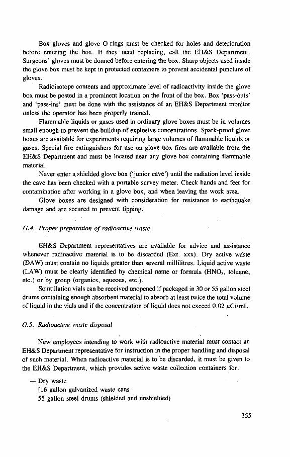
Box gloves and glove O-rings must be checked for holes and deterioration before entering the box. If they need replacing, call the EH&S Department. Surgeons' gloves must be donned before entering the box. Sharp objects used inside the glove box must be kept in protected containers to prevent accidental puncture of gloves.
Radioisotope contents and approximate level of radioactivity inside the glove box must be posted in a prominent location on the front of the box. Box 'pass-outs' and 'pass-ins' must be done with the assistance of an EH&S Department monitor unless the operator has been properly trained.
Flammable liquids or gases used in ordinary glove boxes must be in volumes small enough to prevent the buildup of explosive concentrations. Spark-proof glove boxes are available for experiments requiring large volumes of flammable liquids or gases. Special fire extinguishers for use on glove box fires are available from the EH&S Department and must be located near any glove box containing flammable material.
Never enter a shielded glove box ('junior cave') until the radiation level inside the cave has been checked with a portable survey meter. Check hands and feet for contamination after working in a glove box, and when leaving the work area.
Glove boxes are designed with consideration for resistance to earthquake damage and are secured to prevent tipping.
G.4. Proper preparation of radioactive waste
EH&S Department representatives are available for advice and assistance whenever radioactive material is to be discarded (Ext. xxx). Dry active waste (DAW) must contain no liquids greater than several millilitres. Liquid active waste (LAW) must be clearly identified by chemical name or formula (HN0 3 , toluene, etc.) or by group (organics, aqueous, etc.).
Scintillation vials can be received unopened if packaged in 30 or 55 gallon steel drums containing enough absorbent material to absorb at least twice the total volume of liquid in the vials and if the concentration of liquid does not exceed 0.02 /xCi/mL.
G.5. Radioactive waste disposal
New employees intending to work with radioactive material must contact an EH&S Department representative for instruction in the proper handling and disposal of such material. When radioactive material is to be discarded, it must be given to the EH&S Department, which provides active waste collection containers for:
— Dry waste [16 gallon galvanized waste cans 55 gallon steel drums (shielded and unshielded)
355
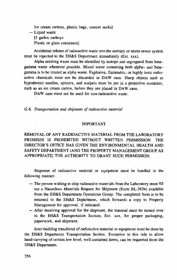
Ice cream cartons, plastic bags, cement sacks] — Liquid waste
[5 gallon carboys Plastic or glass containers]
Accidental release of radioactive waste into the sanitary or storm sewer system must be reported to the EH&S Department immediately (Ext. xxx).
Alpha emitting waste must be identified by isotope and segregated from beta-gamma waste whenever possible. Mixed waste containing both alpha- and beta-gamma is to be treated as alpha waste. Explosive, flammable, or highly toxic radio-active chemicals must not be discarded in DAW cans. Sharp objects such as hypodermic needles, spitzers, and scalpels must be put in a protective container, such as an ice cream carton, before they are placed in DAW cans.
DAW cans must not be used for non-radioactive waste.
G.6. Transportation and shipment of radioactive material
IMPORTANT
REMOVAL OF ANY RADIOACTIVE MATERIAL FROM THE LABORATORY PREMISES IS PROHIBITED WITHOUT WRITTEN PERMISSION. THE DIRECTOR'S OFFICE HAS GIVEN THE ENVIRONMENTAL HEALTH AND SAFETY DEPARTMENT (AND THE PROPERTY MANAGEMENT GROUP AS APPROPRIATE) THE AUTHORITY TO GRANT SUCH PERMISSION.
Shipment of radioactive material or equipment must be handled in the following manner:
— The person wishing to ship radioactive materials from the Laboratory must fill out a Hazardous Materials Request for Shipment (Form RL-3634) available from the EH&S Department Operations Group. The completed form is to be returned to the EH&S Department, which forwards a copy to Property Management for approval, if indicated.
— After receiving approval for the shipment, the material must be turned over to the EH&S Transportation Section, Ext. xxx, for proper packaging, paperwork, and shipment.
Inter-building transferral of radioactive material or equipment must be done by the EH&S Department Transportation Section. Exception to this rule to allow hand-carrying of certain low level, well contained items, can be requested from the EH&S Department.
356
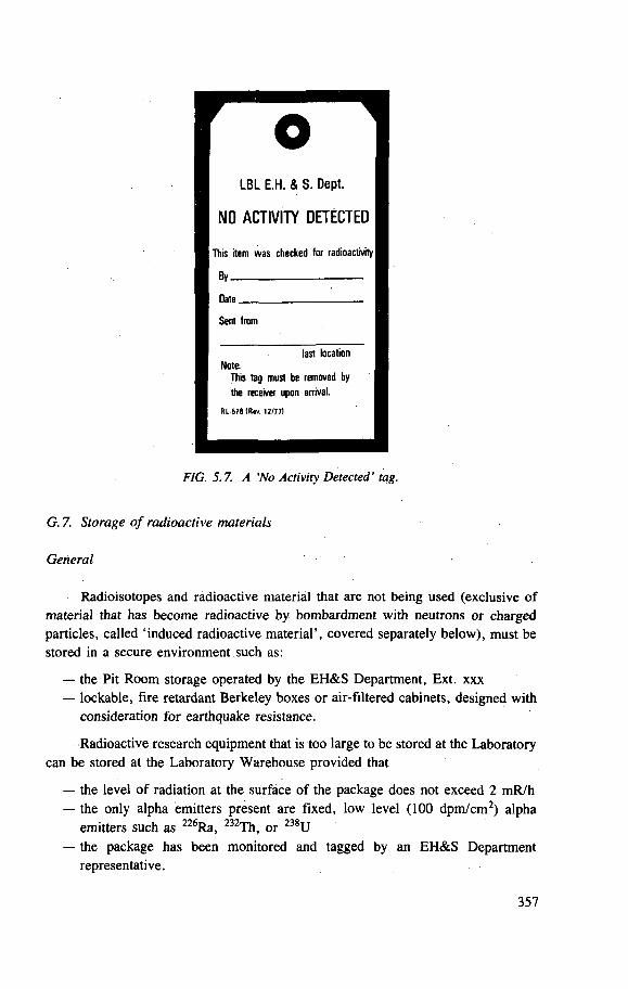
FIG. 5.7. A 'No Activity Detected' tag.
G. 7. Storage of radioactive materials
General
Radioisotopes and radioactive material that are not being used (exclusive of material that has become radioactive by bombardment with neutrons or charged particles, called 'induced radioactive material', covered separately below), must be stored in a secure environment such as:
— the Pit Room storage operated by the EH&S Department, Ext. xxx — lockable, fire retardant Berkeley boxes or air-filtered cabinets, designed with
consideration for earthquake resistance.
Radioactive research equipment that is too large to be stored at the Laboratory can be stored at the Laboratory Warehouse provided that
— the level of radiation at the surface of the package does not exceed 2 mR/h — the only alpha emitters present are fixed, low level (100 dpm/cm2) alpha
emitters such as 226Ra, 232Th, or 238U — the package has been monitored and tagged by an EH&S Department
representative.
357
Unsafe storage areas include: bench tops, desk drawers, fume hoods, and wooden cabinets or lockers.
Storage of induced radioactive materials
'Induced radioactive material' is the term used to describe material that has been made radioactive by bombardment with neutrons or charged particles produced by accelerators.
Any item is called 'induced radioactive material' if, when monitored with a portable thin window Geiger-Muller count-rate survey instrument in a low back-ground area (0.05 to 0.1 mR/h), a definite reading above background is indicated.
Guidelines regarding induced radioactive material:
(a) The proper disposal of induced radioactive material is encouraged. (b) All equipment, furniture, and material that is to be moved from the accelerator
buildings and accelerator areas must be monitored, and, if found free of activity, tagged with a NO ACTIVITY DETECTED tag (Fig. 5.7).
(c) With the exception of material within the accelerator operational area,1 5
induced radioactive material falls into two general categories — portable items that are easily hand-carried, and heavy and/or bulky items. The storage of these items is to be as follows: Portable items: store in locked areas identified by radiation warning signs. (See Figs 5.4, 5.5, and 5.6.) Heavy items: store in areas clearly identified by radiation warning signs; those reading greater than 100 mR/h must be inventoried.
(d) If items in either category are not stored as described above (and are not within the accelerator operational area), they must be tagged with radiation warning signs; those reading over 100 mR/h at the surface with a portable ion chamber survey meter or that can cause radioactive contamination are to be inventoried.
(e) Inventory number, description, location, Area Co-ordinator, and owner of the material are assigned and records maintained by the EH&S Department, which must make an annual inventory.
G.8. Decontamination of radioactive equipment
Articles that are of sufficient value to make recycling economical are to be given to the EH&S Department for decontamination. Proper packaging and identifi-cation of these items must be done by an EH&S Department representative. Glove boxes, hoods, and other enclosed work areas can be cleaned in place by EH&S Department personnel. Contaminated clothing and other personal items must be
15 Accelerator operational area: area inside the shielding, beam line, etc.
358
decontaminated by the EH&S Department before they can be removed from the Laboratory premises. Contaminated lab coats must be given to an EH&S Department representative.
Decontaminated equipment will be released to the owner when any radioactive residue cannot escape into the air or be transferred by contact, or when there is no hazard from external radiation levels.
G. 9. Contaminated precious metals
Radioactively contaminated precious metals must be kept separate from non-contaminated precious metals. The EH&S Department is responsible for the monitoring of all radioactive precious metals to be returned to stock, for providing proper disposition of contaminated metals, and for the maintenance of a secured repository for radioactive precious metals.
Return of contaminated precious metal to the Property Accounting Office is done in the following manner:
(1) The user, with the assistance of an EH&S Department representative and in the presence of a Property Accounting representative, Ext. xxx, must load a tared weight ice cream carton with the contaminated metal. The carton is given to the EH&S Department.
(2) The ice cream carton is then sealed, surveyed for radioactivity, and reweighed for the true weight of the metal.
(3) The identification of the metal, its weight, contaminating isotope, survey meter readings in mR/h or dpm, and its ownership is put on the carton.
(4) The material is sent to the Lawrence Livermore National Laboratory, for decontamination and the proper account is credited.
G. 10. Monitoring and movement of materials
All equipment and furniture that is not radioactive must be tagged with a NO ACTIVITY DETECTED tag (Fig. 5.7) before being removed from the following buildings:
[HERE FOLLOWS A LIST OF BUILDINGS IN WHICH CONTAMINATED EQUIPMENT OR FURNITURE MIGHT POSSIBLY BE LOCATED]
Material that is to be scrapped, regardless of its point of origin must be monitored and then tagged with a NO ACTIVITY DETECTED tag (Fig. 5.7) before it is sent to the Salvage Department for reclamation.
Gas cylinders do not require a tag if they are located in the designated cylinder collection areas for each building.
359
Waste collected from certain buildings [here specified] must be certified free of radioactivity before it is released to waste collectors. Waste from all other buildings needs no special delineation.
G.ll. Radioactive sources
WILFUL VIOLATIONS OF THE FOLLOWING REGULATIONS OR NEGLIGENCE IN HANDLING AND STORAGE OF RADIOACTIVE SOURCES ARE GROUNDS FOR DISCIPLINARY ACTION (REGULATIONS AND PROCEDURES MANUAL (RPM), PUB-201, PARAGRAPH 2.05B) AND MAY ALSO RESULT IN THE CANCELLATION OF FURTHER PRIVILEGES TO DRAW OR USE SUCH MATERIALS AND/OR IMMEDIATE RECALL OF SUCH MATERIALS [LBL nd].
A radioactive source is defined as a radioisotope of a known amount of activity that has been encapsulated in such a manner that the radioisotope will not be released under conditions likely to be encountered by the source. Serial numbers must be assigned, by the EH&S Department, to all radioactive sources whether they are purchased from an outside vendor or fabricated at LBL.
Procurement of radioactive sources is handled through EH&S, which also maintains a supply of used sources of various types. Arrangements can be made to purchase new sources from commercial vendors.
Responsibility for the location and condition of the source belongs to the person in whose name the source is assigned. This rule remains in effect even if the source is loaned by the assignee to another person. Sources not in use must be stored in a locked storage area, room, or container bearing the sign: CAUTION — RADIOACTIVE MATERIAL (Fig. 5.6). Sources left unattended in an unsecured or unauthorized area will be confiscated by the EH&S Department. A confiscated source will not be released to its former assignee without authorization from the Director's Office.
Periodic inventory and inspection of all serially numbered sources is conducted by the EH&S Department. The user of a serially numbered source must produce the source for inspection when requested by EH&S. The inventory schedule is as follows:
WARNING:
Three classifications of inventory
Class A — Up to 10 body burdens Class B — 11 body burdens or over
Inventoried annually Inventoried semiannually Inventoried semiannually with special instructions given to assignee
Class C — High hazards sources that require special care and handling
360
Missing sources must be reported to the EH&S Department immediately. If, after a thorough search, the source is not found, a memo stating when and where the source was last seen must be sent to EH&S. Destruction of, or tampering with, a serially numbered source without the approval of the EH&S Department is prohibited. Removal of any radioactive source from the Laboratory premises without written authorization is prohibited; see Sections G . l to G.6 for instructions.
Sources no longer needed or sources that may not be used for long periods of time are to be given to the EH&S Department for safe keeping. Employees terminating from the Laboratory must turn in all radioactive sources assigned to them. Termination processing will not be complete until all sources have been accounted for.
Violations of any of the preceding rules and regulations will be reported by the EH&S Department to the Director's Office.
H. Emergency procedures for radioactive spills
The following procedures must be followed whenever a spill has occurred or is suspected to have occurred:
(1) Immediately notify the EH&S Department representative, Ext. xxx or Emergency Ext. xxx, and evacuate all personnel from the immediate area.
(2) Retain personnel in a safe area until the EH&S Department can monitor them for contamination.
(3) Quarantine the spill area to prevent further personnel contamination. (4) Give as many details of the incident as possible to the EH&S Department
person in charge of the clean-up operation. This information will be used for reports and accident analysis.
(5) Never attempt to clean up a spill without the assistance of an EH&S Department representative.
I. X-ray safety
1.1. Introduction
The bulk of this section determines general requirements for all X-ray equipment at LBL. Specific requirements are given for X-ray machines that are classified into analytical (open and enclosed beam), portable, therapy, diagnostic and photoemission types. Safety requirements for these X-ray machines are based on ANSI Standards and the appropriate sections of NGRP Reports 33 and 49 [ANSI 78, NCRP 68, NCRP 76].
This section determines responsibilities, specific authorization of users, and requirements for X-ray machine operation and maintenance. Logbooks are to be used
361
to keep records of operation and maintenance. Double interlocks are required for all X-ray machines. An Operational Safety Procedure is to be included in all operating instructions for X-ray machines.
Exceptions to the general safety standards for specific operational cases are to be handled on a variance basis. This will require the operator to evaluate and explain his need for a variance. The X-Ray Safety Officer, an appointee of the Director's Office, is to review the standards at least annually and revise as necessary and to continually review the quality of the X-ray safety programme.
1.2. Scope
This section establishes requirements and recommendations pursuant to radiation safety aspects of the design and operation of electronic equipment designed to produce X-rays and to be used under the administrative control of the Lawrence Berkeley Laboratory.
1.3. Definitions
bistable indicator: an indicator which is either on or off and has no normal metastable state.
controlled items: the Laboratory's Property Management designation of items which must be kept under inventory control regardless of value.
dead-man switch: a switch so constructed that a circuit closing contact can be maintained only by continuous pressure on the switch.
fail safe design: one in which all failures of indicators or safety components that can reasonably be anticipated cause the equipment to fail in such a manner as to maintain personnel safe from exposure to radiation. For example: (a) if a light indicating "X-RAY O N " fails, the production of X-rays must be prevented, and (b) if a shutter status indicator fails, the shutter shall close.
must: see " sha l l " . shall: where " sha l l " and " m u s t " are used for a provision specified herein,
that provision is intended to be a requirement. techniques: instrument use parameters employed during an X-ray exposure,
i.e. kV, mA, mA-s , s, filter, distance, field size, etc. (all parameters are, of course, not applicable to all types of X-ray machines).
X-ray accessory apparatus: any portion of an X-ray installation which is external to the radiation source housing and into which an X-ray beam is directed for making X-ray measurements or for other uses.
X-ray generator: that portion of an X-ray system which provides the accelerating voltage and current for the X-ray tube.
362
NOTE: the following terms are equivalent to an X-ray system: X-ray equipment, X-ray generating equipment, X-ray generating unit, X-ray machine, X-ray unit.
X-ray system supervisor: a person having administrative control over an X-ray machine and so designated in the Operational Safety Procedure for that machine.
1.4. Responsibility
The X-ray system supervisor is charged with the prime responsibility of ensuring that all requirements are completely and continuously applied. The responsibilities of the individual worker are detailed in Section 7.1 of the American National Standards Institute (Report N43.2) as follows:
"7 .1 .2 Each worker shall, upon the instruction of a qualified expert or responsible supervisor, follow the recommendations and instructions which have been drawn up in the interest of radiation protection. 7.1.3 Each worker shall use the protective devices provided. 7.1.4 Each worker shall bring to the attention of those in charge any defect or deficiency in radiation protection devices and procedures."
1.5. Warning
WILFUL VIOLATIONS OF THE FOLLOWING REGULATIONS OR NEGLIGENCE IN THE USE AND SECURING OF X-RAY SYSTEMS ARE GROUNDS FOR DISCIPLINARY ACTION (RPM, PAGE 2-10, PARAGRAPH 2.03) AND MAY ALSO RESULT IN THE CANCELLATION OF FURTHER PRIVILEGES TO USE SUCH EQUIPMENT AND/OR IMMEDIATE REMOVAL FROM SERVICE OF THE X-RAY SYSTEMS INVOLVED.
1.6. Procedures
Each X-ray generating unit must have Operational Safety Procedures (OSP) located near the unit. It must contain at least:
(1) Diagram of facility. (2) Name of person responsible for the unit (system supervisor). (3) List of authorized users. (4) List of authorized instructors. (5) Emergency or problem call list. (6) Description of safety features (prepared by the X-Ray Safety Officer). (7) Specific operating procedures (submitted by the systems supervisor for
approval by the X-Ray Safety Officer).
363
(8) Specific alignment procedures as applicable (submitted and approved as 7 above).
(9) Emergency instructions. (10) Copies of appropriate standards and policies.
These Operational Safety Procedures are to be prepared from the latest OSP preparation guide filled out initially by the X-Ray Safety Officer and the X-ray system supervisor, and sent at least annually to the X-ray system supervisor for review and, if necessary, revision.
/. 7. Interlocks and indicators
All X-ray generating equipment is to have interlocks and indicators as specified in applicable standards [NCRP 68, ANSI 77] and by the X-Ray Safety Officer.
In addition, all X-ray generating equipment is to have the following, with the exception that medical diagnostic type equipment is exempt from items 1 and 2.
(1) Redundant interlock chains or mechanical shutters, either of which may prohibit the emission of X-rays from the X-ray tube. It is recommended that a signal from a fail safe area radiation monitor be part of one of these interlock chains.
(2) A bistable indicator which gives a positive indication that high voltage is applied to the X-ray tube. It is required that either this indication be incorporated into an interlock chain in a fail safe manner or that a bistable indicator be used which gives a positive indication that high voltage is not applied to the X-ray tube.
(3) A key-controlled switch which controls the main power to the entire X-ray unit. Furthermore, actuation of this switch must not in and of itself cause high voltage to be applied to the X-ray tube. Also, it must not be possible to remove the key while the switch is in the ON position. Access to this key must be controlled. It is recommended that there should be as few copies of this key as possible and those copies must be serialized and assigned. When not in use, this key must be secured. This requirement may be exempted where access to the room in which the X-ray generating unit is located is both limited and controlled at all times.
In addition, it is recommended that each X-ray generating unit have an audible, attention catching, reliable or fail-safe indication when high voltage is applied to the X-ray tube and one or the other interlock chain has not been satisfied.
I. 8. Posting
Posting must be in accordance with the standards listed in the standards section of this document (Section 1.21), and according to the recommendations of the X-Ray Safety Officer. 364
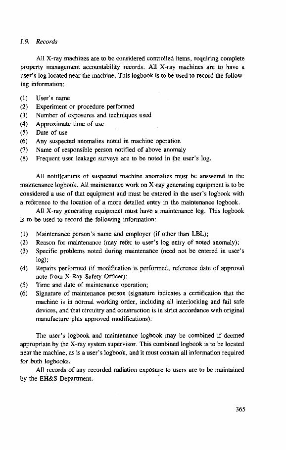
1.9. Records
All X-ray machines are to be considered controlled items, requiring complete property management accountability records. All X-ray machines are to have a user 's log located near the machine. This logbook is to be used to record the follow-ing information:
(1) User 's name (2) Experiment or procedure performed (3) Number of exposures and techniques used (4) Approximate time of use (5) Date of use (6) Any suspected anomalies noted in machine operation (7) Name of responsible person notified of above anomaly (8) Frequent user leakage surveys are to be noted in the user 's log.
All notifications of suspected machine anomalies must be answered in the maintenance logbook. All maintenance work on X-ray generating equipment is to be considered a use of that equipment and must be entered in the user 's logbook with a reference to the location of a more detailed entry in the maintenance logbook.
All X-ray generating equipment must have a maintenance log. This logbook is to be used to record the following information:
(1) Maintenance person's name and employer (if other than LBL); (2) Reason for maintenance (may refer to user 's log entry of noted anomaly);
(3) Specific problems noted during maintenance (need not be entered in user 's log);
(4) Repairs performed (if modification is performed, reference date of approval note from X-Ray Safety Officer);
(5) Time and date of maintenance operation; (6) Signature of maintenance person (signature indicates a certification that the
machine is in normal working order, including all interlocking and fail safe devices, and that circuitry and construction is in strict accordance with original manufacture plus approved modifications).
The user 's logbook and maintenance logbook may be combined if deemed appropriate by the X-ray system supervisor. This combined logbook is to be located near the machine, as is a user 's logbook, and it must contain all information required for both logbooks.
All records of any recorded radiation exposure to users are to be maintained by the EH&S Department.
365
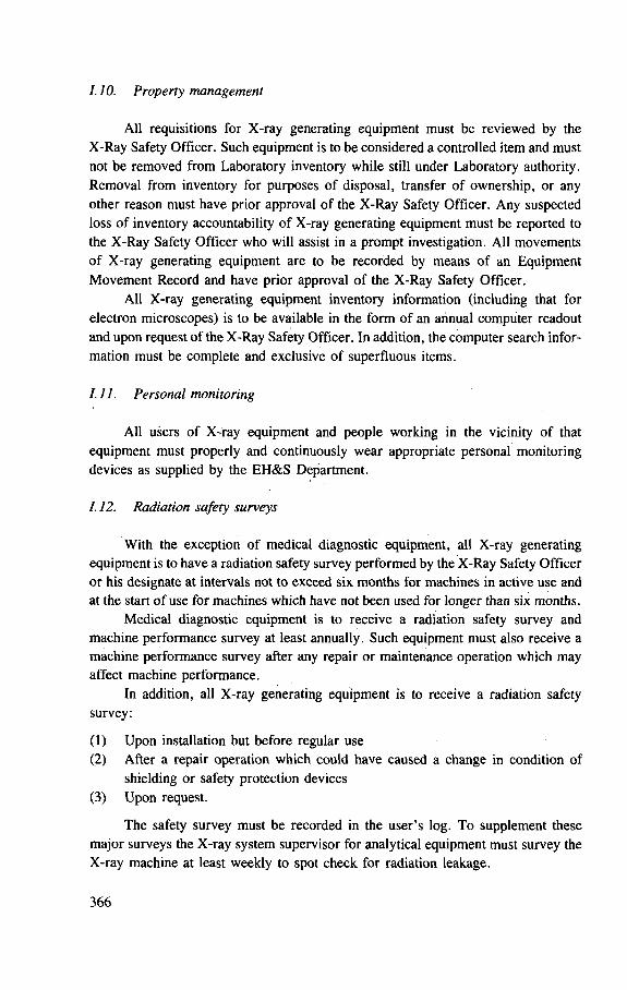
1.10. Property management
All requisitions for X-ray generating equipment must be reviewed by the X-Ray Safety Officer. Such equipment is to be considered a controlled item and must not be removed from Laboratory inventory while still under Laboratory authority. Removal from inventory for purposes of disposal, transfer of ownership, or any other reason must have prior approval of the X-Ray Safety Officer. Any suspected loss of inventory accountability of X-ray generating equipment must be reported to the X-Ray Safety Officer who will assist in a prompt investigation. All movements of X-ray generating equipment are to be recorded by means of an Equipment Movement Record and have prior approval of the X-Ray Safety Officer.
All X-ray generating equipment inventory information (including that for electron microscopes) is to be available in the form of an annual computer readout and upon request of the X-Ray Safety Officer. In addition, the computer search infor-mation must be complete and exclusive of superfluous items.
1.11. Personal monitoring
All users of X-ray equipment and people working in the vicinity of that equipment must properly and continuously wear appropriate personal monitoring devices as supplied by the EH&S Department.
/. 12. Radiation safety surveys
With the exception of medical diagnostic equipment, all X-ray generating equipment is to have a radiation safety survey performed by the X-Ray Safety Officer or his designate at intervals not to exceed six months for machines in active use and at the start of use for machines which have not been used for longer than six months.
Medical diagnostic equipment is to receive a radiation safety survey and machine performance survey at least annually. Such equipment must also receive a machine performance survey after any repair or maintenance operation which may affect machine performance.
In addition, all X-ray generating equipment is to receive a radiation safety survey:
(1) Upon installation but before regular use (2) After a repair operation which could have caused a change in condition of
shielding or safety protection devices (3) Upon request.
The safety survey must be recorded in the user 's log. To supplement these major surveys the X-ray system supervisor for analytical equipment must survey the X-ray machine at least weekly to spot check for radiation leakage.
366
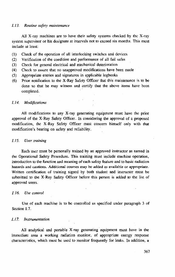
1.13. Routine safety maintenance
All X-ray machines are to have their safety systems checked by the X-ray system supervisor or his designate at intervals not to exceed six months. This must include at least:
(1) Check of the operation of all interlocking switches and devices (2) Verification of the condition and performance of all fail safes (3) Check for general electrical and mechanical deterioration (4) Check to assure that no unapproved modifications have been made (5) Appropriate entries and signatures in applicable logbooks (6) Prior notification to the X-Ray Safety Officer that this maintenance is to be
done so that he may witness and certify that the above items have been completed.
1.14. Modifications
All modifications to any X-ray generating equipment must have the prior approval of the X-Ray Safety Officer. In considering the approval of a proposed modification, the X-Ray Safety Officer must concern himself only with that modification's bearing on safety and reliability.
/. 15. User training
Each user must be personally trained by an approved instructor as named in the Operational Safety Procedure. This training must include machine operation, introduction to the function and meaning of each safety feature and to basic radiation hazards and cautions. Additional courses may be added as available or appropriate. Written certification of training signed by both student and instructor must be submitted to the X-Ray Safety Officer before this person is added to the list of approved users.
1.16. Use control
Use of each machine is to be controlled as specified under paragraph 3 of Section 1.7.
1.17. Instrumentation
All analytical and portable X-ray generating equipment must have in the immediate area a working radiation monitor, of appropriate energy response characteristics, which must be used to monitor frequently for leaks. In addition, a
367
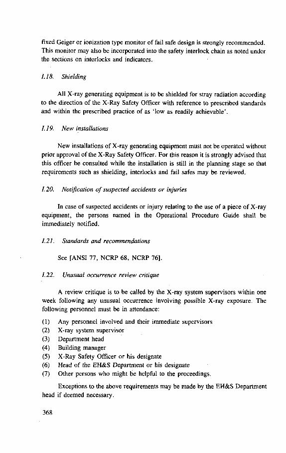
fixed Geiger or ionization type monitor of fail safe design is strongly recommended. This monitor may also be incorporated into the safety interlock chain as noted under the sections on interlocks and indicators.
1.18. Shielding
All X-ray generating equipment is to be shielded for stray radiation according to the direction of the X-Ray Safety Officer with reference to prescribed standards and within the prescribed practice of as 'low as readily achievable'.
1.19. New installations
New installations of X-ray generating equipment must not be operated without prior approval of the X-Ray Safety Officer. For this reason it is strongly advised that this officer be consulted while the installation is still in the planning stage so that requirements such as shielding, interlocks and fail safes may be reviewed.
1.20. Notification of suspected accidents or injuries
In case of suspected accidents or injury relating to the use of a piece of X-ray equipment, the persons named in the Operational Procedure Guide shall be immediately notified.
1.21. Standards and recommendations
See [ANSI 77, NCRP 68, NCRP 76],
1.22. Unusual occurrence review critique
A review critique is to be called by the X-ray system supervisors within one week following any unusual occurrence involving possible X-ray exposure. The following personnel must be in attendance:
(1) Any personnel involved and their immediate supervisors (2) X-ray system supervisor (3) Department head (4) Building manager (5) X-Ray Safety Officer or his designate (6) Head of the EH&S Department or his designate (7) Other persons who might be helpful to the proceedings.
Exceptions to the above requirements may be made by the EH&S Department head if deemed necessary.
368
The critique shall cover: the incident, causal factors, responsibilities, dosimetry, and corrective action.
A summary of this critique must be sent to the LBL Safety Review Committee. An additional copy is to be sent to the Department of Energy, San Francisco Operations Office (DOE SAN) as a follow-up to the initial report made to DOE SAN at the time of the occurrence as required by the terms of the contract between DOE and the Laboratory.
1.23. Safety systems analysis
Safety systems analysis for X-ray machines is provided for in Laboratory procedures. These procedures are covered in Pub. 3001, Rules and Procedures for the Design and Operation of Hazardous Research Equipment.
1.24. X-ray machine type classification
Analytical X-ray equipment. Analytical X-ray machines are classified into two types: open beam X-ray systems and enclosed beam X-ray systems.
The definitions of these terms are contained in ANSI N43.2, paragraphs 5.2.1.1, 5.2.1.2 and Section 5.2.2.3.
Contained in the classification of enclosed beam X-ray systems are X-ray diffraction and X-ray fluorescence equipment which meet the specifications in ANSI N43.2. In addition, all cabinet X-ray units are considered as an enclosed beam X-ray system.
Contained in the classification of open beam X-ray systems are all X-ray diffraction and X-ray fluorescence equipment not meeting the requirements for an enclosed beam X-ray system.
In all cases first consideration and effort must be given to making a system meet the requirements of an enclosed system. Approval to use an open beam X-ray system is to be handled as a variance.
An operable portable survey meter must be used with this equipment to check for stray radiation periodically and whenever any changes are made to the experimental set-up which could compromise shielding effectiveness.
Portable X-ray equipment. Portable X-ray equipment presents particular hazards due to its flexibility of use and must be used more carefully. The output of such units is, with a few exceptions, generally low and will usually overload before a serious X-ray exposure can occur.
The following requirements are to be applied specifically to portable generators:
(1) Fail safe visual indication that X-rays are being generated. This is to be located in a prominent place and its meaning obvious.
(2) Reliable audio indication that X-rays are being generated.
369
(3) Circuitry must be such that exposure can be ultimately controlled by a dead-man type switch.
(4) Extra caution and awareness must be given to beam orientation and the location of other persons in the vicinity of the X-ray machine.
(5) Interlocks are recommended to be used if possible; however, the nature and use of these machines often precludes such considerations.
(6) An operable portable survey meter must be used with this equipment to check for stray radiation periodically and whenever any changes are made to the experimental set-up which could compromise shielding effectiveness.
(7) A key switch must be on each unit.
All NCRP standards applicable to portable X-ray machines are required. Therapy type X-ray equipment. Medical therapy X-ray equipment safety is
detailed in the appropriate sections of NCRP Nos 33 and 49. Because of the moderate to high output of these machines and their ability to maintain a continuous exposure, the shielding of their location is a prime concern.
The Operational Safety Procedure for this equipment will state whether or not the X-ray machine is known to meet State and Federal regulations for use on human subjects. Any X-ray machine to be used on human subjects must be found by the X-Ray Safety Officer to be in compliance with these regulations before such use commences, unless specifically exempted on the responsibility of the Human Use Committee.
Diagnostic type X-ray equipment. Medical diagnostic equipment safety is detailed in NCRP Nos 33 and 49. Since long exposures at high outputs are generally impossible with such units, interlocking is deemed inappropriate. All such equipment is to have a reliable audible indicator which signals the production of X-rays.
The Operational Safety Procedure for this equipment is to state whether or not the X-ray machine is known to meet State and Federal regulations for use on human subjects. Any X-ray machine to be used on human subjects must be found by the X-Ray Safety Officer to be in compliance with these regulations before such use commences, unless specifically exempted on the responsibility of the Human Use Committee.
All these installations are to have a light outside the room that must indicate when the X-ray control unit is energized and when X-rays are being produced (a " r o t o r " on indication will suffice for the "X-ray o n " indication). These lights are to be fail safe or redundant in nature. Furthermore, they are to be positioned and labelled so that their meaning and presence is obvious.
Photoemission X-ray spectrometers. These X-ray systems do not, by design, emit X-rays beyond the contiguous internal vacuum. They are therefore not within the scope of these regulations and must be considered exempt from them. The X-Ray Safety Officer must, however, survey them for X-ray leakage on a perennial basis and maintain records of their location and existence.
370
1.25. Variances
When the X-ray system supervisor feels that it is impossible or highly impracti-cal to adhere to this standard, he may request, in writing, a variance. This request is to be directed to the LBL Safety Review Committee for approval.
All requests for variances are to be evaluated on an individual basis and for approval must demonstrate:
— definite need for variance — alternate safety devices and/or procedures which ensure an equivalent degree
of safety.
All requests for variances from DOE prescribed regulations must, in addition, require specific DOE approval.
II. NON-IONIZING RADIATION
A. Ultraviolet light
The effects of exposure to ultraviolet radiation are similar to sunburn. Since there is a measurable period of time between exposure and development of injury, deep burns may be caused without immediate discomfort. The severity of the burn depends upon the spectral distribution of energy in the ultraviolet region, the intensity, and the time of exposure.
Considerable discomfort can be produced in the eye by exposure to radiation below about 3100 A. The absorption of this radiation by the outer layers of the eye (cornea and conjunctiva) produces conjunctivitis, which occurs 4 to 8 hours after exposure and may last several days.
Most lamps used for general lighting purposes emit little or no ultraviolet radiation so that in typical lighting installations there are no harmful effects. On the other hand, there are certain special purpose lamps that are designed to emit shorter wave radiation. Some industrial processes, such as welding, also produce considerable amounts of such radiation. In these cases it is necessary to take certain precautions.
It is recommended that protective glasses be worn by all personnel when they may be exposed to ultraviolet radiation. Furthermore, opaque shielding is recommended to be used around welding areas to protect other persons. Measurement of ultraviolet radiation can be obtained from Industrial Hygiene, Ext. xxx.
371
B. Microwaves
B. 1. General
Microwaves are electromagnetic radiations which occur in the electromagnetic spectrum between radiowaves and infrared radiation. They cover a frequency range of approximately 30 MHz to 300 000 MHz with the corresponding wavelengths of 10 m to 1 mm.
Typical sources of microwave radiation are klystrons, magnetrons, backward wave oscillators, and semiconductor transit time devices. Some of these sources, when operated at high voltages, also generate X-rays.
At LBL the most common application of microwave energy is in cooking with microwave ovens. Additional information on microwave ovens is given below. Microwaves may also be associated with diathermy equipment, induction and dielectric heaters, and accelerators.
The primary effect of exposure to microwave energy is thermal. The depth of heating is frequency dependent. Above 3000 MHz, heating occurs primarily within the skin. Frequencies below 3000 MHz can penetrate the skin and heat the underlying tissues. Serious damage may occur in these tissues without warning because this area of the body has fewer nerve endings to sense overheating. In general, the higher the frequency the lower the potential health hazard.
The exact biological effects of microwave radiation at low power levels has not been established. However, at high power levels there is substantial evidence linking microwave exposures to eye cataracts and gonadal damage. In addition to biological effects, flammable gases and vapours, confined inside metallic objects, may ignite when exposed to microwave radiation.
Based on thermal damage to tissue, the maximum permissible exposure limit for all microwave frequencies has been established at 10 mW/cm 2 as averaged over any 0.1 hour (six minute) period. A safety factor of 10 has been applied to this limit. For more information see the American National Standard C95.1, Safety Levels with Respect to Human Exposure to Radiofrequency Electromagnetic fields, 30 kHz to 100 GHz [ANSI 82], available in building B75B.
The use of engineering controls is the preferred method for limiting exposures to microwave radiation. Typical engineering measures involve either completely enclosing the source or shielding the source from personnel.
B.2. Microwave ovens
The microwave oven is a convenient tool which cooks food on the inside and outside simultaneously by means of microwave radiation. Most general use ovens operate at a frequency of 2450 MHz.
372
The hazards involved are commonly due to leakage of microwave energy by warped or misaligned doors, through defective seals around the door or viewing window, or failure of door interlocks to shut off the oven when the door is opened. While present-day ovens are built so well that leakage at a density of radiation high enough to cause injury is unlikely, faulty interlocks could expose personnel in the vicinity of the oven to densities of a hundredfold above safe levels.
The following precautions must be taken to reduce the possibility of injury from microwave radiation:
— Do not operate the oven when empty. — Do not use metallic containers. — Do not leave food residue in oven. — Never tamper with oven. — Keep door gaskets clean.
The Industrial Hygiene Group of the EH&S Department is responsible for evaluating each oven once a year, as well as any new ovens when initially placed in service.
C. Magnetic fields
Very little information is available on the biological effects of magnetic fields, both varying and steady state. The meagre literature indicates that while actual survival is not threatened by exposure to high magnetic fields, these fields can influence humans to a degree sufficient to cause a number of disturbances (e.g. headache, fatigue, low blood pressure, decreased red blood cell count, etc.). For this reason, appropriate control measures must be taken by those working in magnetic fields greater than background. Precautions applicable to both varying and steady state magnetic fields are as follows:
— Employees and visitors with pacemakers must be excluded from all areas where they could be exposed to magnetic fields.
— Personnel must not linger unnecessarily in magnetic fields greater than background.
Appendix LBL RADIOISOTOPE SAFETY PROCEDURES
EMERGENCIES
(1) In case of suspected area or personnel contamination or abnormal exposure to penetrating radiation, evacuate all personnel and quarantine the area; avoid
373
tracking contamination; retain all personnel in a safe area; do not attempt decontamination; and immediately notify the Environmental Health and Safety Department (EH&S Department Ext. xxx).
(2) DOE requires notification of accidents for the purpose of investigating and identifying causes and corrective action. Immediate notification and preserva-tion of the scene are necessary in the case of a serious accident. If you are in doubt about severity, preserve the scene.
PROCUREMENT AND TRANSPORTATION
(1) Employees intending to work or make significant changes in experiments with radioisotopes must review their operations with the area EH&S Department representative before procurement and/or possession of radioactive materials. Holders of radioactive materials must maintain a logbook and a current inventory.
(2) Purchase must be through the EH&S Department representative and/or the local business office, by requisition form sent to the Purchasing Department.
(3) All incoming and outgoing radioisotope shipments and inter-building trans-ferral of radioisotopes must be done by the EH&S Department Transportation Section.
(4) Removal of any radioisotopes from Laboratory premises is prohibited without permission. Fill out a Hazardous Materials Request for Shipment (form RL-3634) available from the EH&S Department.
LABORATORY USE
(1) Employees presently working with radioisotopes must be encouraged to take the EH&S Department Radiation Orientation courses, and all new employees who will work with radioisotopes must attend.
(2) Radioisotope operations (except sealed, low level sources) must not be performed without an EH&S Department radiation representative being present on the Laboratory site. Normal assistance is during the hours between 8:00 a.m. to midnight, Monday through Friday. Arrangements for off-hour assistance must be made with the EH&S Department at least one week in advance.
(3) Ventilated glove boxes must be used for all radioactive operations that can generate aerosols, or the possible spread of contamination; fume hoods are not adequate for use in operations that generate radioactive aerosols.
(4) Glove box pass-outs and pass-ins must be done with the assistance of an EH&S Department monitor.
374
(5) Lab coat and disposable gloves must be worn at all times when working in a glove box, or where chance of contamination exists. All working surfaces must be covered with absorbent paper.
(6) Radiation detection equipment is available from the EH&S Department. (7) Storage areas, glove boxes, and contaminated or radioactive items must be
labelled with a "CAUTION RADIOACTIVE MATERIAL" sticker. (8) Mouth pipetting, eating, drinking, and smoking when working with radio-
isotopes are prohibited. (9) All radioactive sources (encapsulated radioisotopes) must be assigned a serial
number for inventory by the EH&S Department. Responsibility for the loca-tion and condition of the source belongs to the person assigned the source.
(10) All equipment and furniture from areas containing radioisotopes, and all items going to reclamation must be tagged by the EH&S Department with a " N O ACTIVITY DETECTED" tag before removal.
(11) All employees working with those radioisotopes which emit penetrating radiation must wear film packets and be on the Medical Bioassay Programme.
DISPOSAL AND DECONTAMINATION
(1) Contact an EH&S Department representative for all radioactive materials requiring decontamination or discard.
(2) Accidental release of radioactive waste into the sanitary or storm sewer system must be reported to the EH&S Department.
(3) Dry active waste (DAW) must contain no liquids, and liquid active waste (LAW) shall be identified by chemical name.
(4) Liquid scintillation vials can be submitted unopened, either in 16 gallon drums, or in delivery carton.
(5) Animals and tissue must be kept frozen until an EH&S Department pick-up for waste disposal.
LBL Environmental Health & Safety Department Building B75B — Ext. xxx
Off-hours - Ext. xxx April 1980
5.5. ACCELERATOR RADIATION SAFETY PROGRAMME
Any organization that has an effective occupational health programme with appropriate emphasis on radiological safety will have no difficulty in coping with the special problems presented by the operation of particle accelerators. In fact with few
375
exceptions accelerators present radiological protection problems that are qualita-tively similar to those found in many institutions using ionizing radiations. The principal differences that do exist lie in the energy and variety of the radiations and in their production in pulsed modes that may demand special techniques for measurement.
There is a large diversity among accelerators and the hazards they present. It is not necessary, or even desirable, for all accelerators to have identical physical and administrative safety controls. The controls recommended here represent the mini-mum necessary for accelerator operation.
In large multipurpose laboratories the accelerator radiation safety programme will administratively be a part of a larger radiological protection group (as, for example, obtains at the Lawrence Berkeley Laboratory). In single purpose laboratories solely dedicated to particle accelerator research (such as CERN) all necessary aspects of radiological protection will be contained within the accelerator health physics group.
Whatever the precise administrative arrangement might be, the necessary tasks remain the same.
The basic elements of an accelerator radiation protection programme are:
— administrative procedures — shielding and physical barriers — interlocked access — area monitoring — personnel monitoring — e n v i r o n m e n t a l m o n i t o r i n g .
The specific requirements of the LBL Accelerator Health Physics Programme are given in Part I, Subsection F of the Ionizing and Non-Ionizing Radiation Safety chapter of the LBL Health and Safety Manual.
5.5.1. Accelerator radiation safety checklist
The Lawrence Berkeley Laboratory has used the following checklist as an aid in assessing accelerator radiation safety programmes [Pa 73]; it is reproduced here in slightly modified form for the convenience of the reader.
Accelerator radiation safety checklist
Following is a checklist of a number of areas found to be important in many accelerator radiation safety programmes. The list, though not applicable to all accelerators, should prove useful in many circumstances. The reader may wish to add items or put greater emphasis on some, but probably nothing should be omitted.
376
I. Shielding
(1) Design and calculations. Are the calculations available on which shielding design is based? What is the source of the input data for the calculations?
(2) Measurements. Have measurements been made to check the accuracy of the calculations and the efficacy of the shield?
II. Radiation damage estimates for sensitive components
Are sensitive components of the radiation monitoring system or the interlock system so located that their function cannot be impaired by exposure to very high radiation doses?
III. Accelerator controls
Is access to the accelerator controls restricted to those persons who are autho-rized to operate the accelerator or can the accelerator controls be locked to prevent unauthorized use?
IV. Interlocks
(a) Manual reset. Can tripped interlocks be reset only manually at the location of the interlock, rather than remotely from the control console?
(b) Run-safe switches. Are there switches in the radiation and high radiation areas that make it impossible for the accelerator to operate or beam to be admitted to the area when the switch is in the 'safe ' position or is each person entering the zone forced to take a key or other token with him that cuts accelerator operation until all keys (tokens) are returned to their distribution point?
(c) Regular tests. Is the function of the entire interlock system tested at regular intervals and are the results recorded?
(d) Up-to-date circuit diagrams. Are up-to-date circuit diagrams maintained?
V. Exclusion areas and high radiation areas
(a) Have all areas that must be cleared of personnel before the accelerator can be allowed to operate been properly marked and interlocked? Have the responsibilities of the persons who will effect the search and secure procedure been set down in writing? Has special attention been paid to the possibilities of holes in the enclosures of exclusion areas?
(b) Can all areas where high radiation levels could occur be locked, or has a visible and audible alarm system been provided to warn of the presence of radiation? Have staff working in such areas been instructed concerning the correct course of action should alarms occur?
377
(c) Is an audible warning or other suitable indication given to alert personnel that the accelerator is about to be turned on, or that beam is about to be admitted to a specific area?
(d) Are suitable radiation monitors available to indicate the presence of radiation in areas where personnel may have access?
(1) Are these monitors calibrated at regular intervals? (2) Is the functioning of the monitors and any associated alarms checked
regularly? (3) Is the readout from these monitors and alarms conveniendy available to the
operators? (4) Are suitable records maintained concerning calibration, testing and radia-
tion levels? (5) Is there a need to carry a portable instrument to monitor for unsuspected
radiation upon entry to a shutdown accelerator (induced radioactivity or X-rays from high voltage equipment) or into a shutdown beam area (beam in an adjacent area)?
VI. Procedures
(a) Widespread understanding. Are procedures posted, read, and familiar to operators and support personnel and to visitors?
(b) Validity. Are procedures reviewed and updated at suitable intervals? (c) I n c l u s i v e n e s s . D o p r o c e d u r e s i n c l u d e
(1) A clear statement of responsibilities of management, accelerator operators, and radiation safety officers?
(2) Standard operating procedures and procedures for emergency situations? (3) Access rules and regulations and search procedures to be used before
turning on the accelerator? (4) Instructions for the proper handling of radioactivity and disposal of radio-
active waste? (5) Descriptions of the facility and the accelerator giving enough information
so that people unfamiliar with it can make some estimate of the relative hazard that prevails? Are any special problems described?
VII. Personnel monitoring
(a) Requirement. Is suitable personnel monitoring required? (b) Calibration. Is the calibration correct for the circumstances under which the
monitors are used?
378
(c) Interpretation. Is there adequate justification for the interpretation of results and assumptions made in deriving dose equivalent?
(d) Records. Are adequate monitoring records maintained and are they available to the supervisor and employees?
VIII. Area monitoring and surveys
(a) Instruments
(1) Calibration. Is their calibration correct for the circumstances under which monitoring or survey instruments are used?
(2) Interpretation. Is there adequate justification for the interpretation of results and assumptions made in deriving dose equivalent?
(b) Repetition. Are area radiation surveys performed at regular intervals? (c) Records. Do the records of radiation surveys include
(1) Date and time and person doing? (2) Particle, energy, and current? (3) Target? (4) Collimator and magnets? (5) Purpose and detector used? (6) Location? (7) Results and recommendations?
(d) Induced activity
(1) Accelerator. Have suitable measurements been made of the radioactivity induced in the accelerator itself, in targets, and in shielding? Are suitable methods used to reduce personnel exposures from this source?
(2) Atmosphere. Have suitable measurements or estimates been made of radioactivity induced in air? If this is a problem, is ventilation adequate, and where does the exhausted air go?
(3) Water. Have measurements been taken to ensure pipes carrying radio-active water do not pass through occupied areas, or are adequately shielded? Have suitable measures been taken for the storage and regenera-tion or disposal of deionizing resins? Is a programme for monitoring the release of radioactivity in water necessary?
(4) Workers. Are bioassay and whole body counting procedures used occasionally to check for ingested or inhaled radioactivity?
IX. Education and training of operators, support personnel, and others
Is there a regular programme of education training available? Does it include at least the following topics?
379
(a) Radiation safety
(1) Interaction of radiation with matter (2) Units of dose and radioactivity (3) Biological hazards (4) Methods of control of exposure (5) Procedures.
(b) Radiation detection
(1) Use of instruments and personnel monitors
(2) Survey and measurement techniques.
(c) Equipment
(1) Accelerator (2) Remote handling devices (3) Interlocks.
X. Relations between health physics, accelerator operators, and experiments
Are the technical and personal relations between health physics, accelerator operators, experiments, and management good? Are there frequent interchanges of views and positions? Is there a radiation safety committee? If not, what takes its place?
380
Appendix 5.1
LAWRENCE BERKELEY LABORATORY: EMPLOYEE RIGHTS AND OBLIGATIONS
Attached to this memorandum is a copy of the DOE poster on occupational safety and health protection, which is widely displayed around the Laboratory.
Please read this notice carefully since it summarizes both your rights and obligations under DOE Order 5483. Copies of this Order are available in Building B75B (Environmental Health and Safety Department).
This memo is being sent to all employees and guests as our annual reminder of your rights and obligations relating to health and safety.
Laboratory management is committed to providing safe and healthful working
conditions. Please do your part toward achieving this goal.
April 22, 1985 Volume XI, No. 21
EMPLOYEE RIGHTS AND OBLIGATIONS (Update of Vol. X - No. 16)
Director
DAS:RHT:es 0878C
Attachment: 1
381
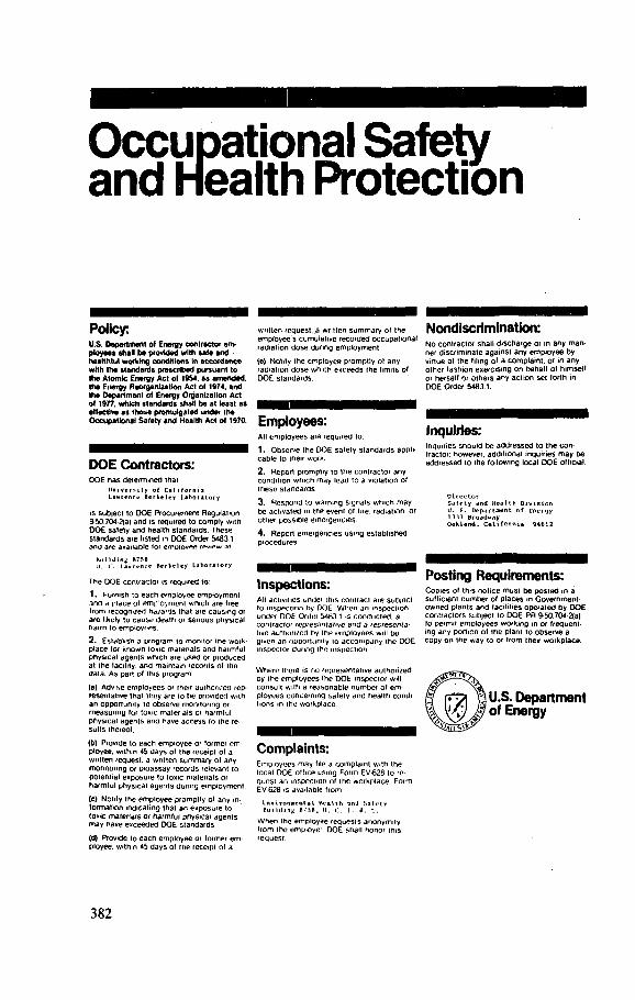
Occupational Safety and Health Protection
Policy: U.S. Department of E n e r g y contractor em-ployees shall be provided with sale and healthful wording conditions In accordance with the standards prescribed pursuant to the Atomic Energy Act ol 19S4, as amended, the Energy Reorganization Act ol t974, and the Department of Energy Organization Act ol 19/7, which standards shall be at least as effective as those promulgated under the Occupational Salety and Health Act of 1970.
DOE Contractors: D O E h a s d e t e r m i n e d t h a i
l . aarcncc o f C a l i f o r n i a r k e l e y L a b o r a t o r y
is subject to D O E P r o c u r e m e n t R e g u l a t i o n 9 5 0 704 2(a) a n d is requi red to c o m p l y w i t h D O E safety a n d h e a l t h s tandards . T h e s e s t a n d a r d s a r e l isted m D O E Order 5 4 8 3 . 1
and are available lor e m o l o v m rpvipw at
building R7SB l l . c . l a * r i m e H e r K e l e y L a b o r a t o r y
T h e D O E cont rac tor is requ i red to
1 . Furn ish to e a c h e m p l o y e e e m p l o y m e n t a n d A p l a c e o l o m p ' o y m e n t w h i c h a re tree I r o m recogn ized h d / a r J s that a re c a u s i n g or a re likely to c a u s e d e a t h or ser ious phys ica l h a r m to empioyr-os.
2. E s t a b l i s h 3 p r o g r a m to moni tor m e work-p l a c e lor k n o w n tox ic m a t e r i a l s a n d h a i r n l u l phys ica l a g e n t s w h i c h a re u s e d or p r o d u c e d at i h e faci l i ty. a n d m a i n t a i n records o l the d a t a . As par i o l th is p rogram:
(a) Advise e m p l o y e e s or their au thor i zed rep-r e s e n t a t i v e that thoy a re t o h e prov ided w i t h a n oppor tun i ty to observe mon i to r ing or m e a s u r i n g lor t o n e m a t e r i a l s or h a r m f u l phys ica l a g e n t s a n d h a v e a c c e s s to the re-sul ts thereof .
(b) Provide to e a c h e m p l o y e e or former em-ployee, w i t h i n 4b d a y s ot the rcceipt o l a wr i t t en request , a wr i t ten s u m m a r y o l any m o n i t o r i n g or D ioassay records relevant to p o t e n t i a l e x p o s u r e to toxic m a t e r i a l s or h a r m l u l phys ica l a g e n t s dur ing e m p l o y m e n t .
(e) N o t i l y the e m p l o y e e p rompt ly o l any in-f o r m a t i o n ind ica t ing that a n e x p o s u r e to toxic m a t e r i a l s or h a r m f u l phys ica l a g e n t s m a y h a v e e x c e e d e d O O E s t a n d a r d s
(d) Provide to e a c h e m p l o y e e or former e m -ployee. w i th in 45 d a y s of the receipt of a
w r i t t e n request , a wr i t t en s u m m a r y of the e m p l o y e e s c u m u l a t i v e r e c o r d e d o c c u p a t i o n a l r a d i a t i o n d o s e dur ing e m p l o y m e n t .
(e) N o t i l y the e m p l o y e e p r o m p t l y ot a n y rad ia t ion d o s e w h i c h e x c e e d s the l imi ts of D O E s t a n d a r d s .
Employees: All e m p l o y e e s a re requ i red to.
1 . O b s e r v e the D O E safety s t a n d a r d s appli-c a b l e to Iheir work.
2. Repor t p r o m p t l y to t h e cont rac tor any c o n d i t i o n w h i c h m a y l ead to a v io la t ion of t h e s e s t a n d a r d s
3. R e s p o n d to w a r n i n g s igna ls w h i c h m a y b e a c t i v a t e d in the event ot fire, rad ia t ion , or other poss ib le e m e r g e n c i e s .
4. Repor t e m e r g e n c i e s u s i n g e s t a b l i s h e d p rocedures .
Inspections: All act iv i t ies under this con t rac t a re sub jec t to i n s p e c t i o n by D O E W h e n an i n s p e c t i o n u n d e r D O E Order 5483.1 is c o n d u c t e d , a conuaciot r e p r e s e n t a t i v e a n d a representa -tive a u t h o r i z e d by the e m p l o y e e s wil l b e g iven a n oppor tun i ty lo a c c o m p a n y the D O E inspector dur ing Ihe i n s p e c t i o n
W h e r e there is no r e p r e s e n t a t i v e a u t h o r i z e d by t h e e m p l o y e e s the D O E inspector wi l l consu l t w i t h a r e a s o n a b l e n u m b e r of e m -p l o y e e s c o n c e r n i n g sa fe ty a n d h e a l t h condi-t ions m the workp lace .
Complaints: E m p l o y e e s m a y M e a c o m p l a i n t w i t h t h e local D O E o f f i c e us ing F o r m EV-628 lo re quest a n inspect ion o l I h e w o r k p l a c e . F o r m EV-628 is ava i lab le f r o m
l.nvironwvnial Wraith an J Safriv Hui IdifiK I.. H. t..
W h e n the e m p l o y e e r e q u e s t s a n o n y m i t y I r o m the e m p l o y e ' . D O E shal l honor this r e q u e s t .
Nondiscrimination: N o c o n t r a c t o r sha l l d i s c h a r g e or in any m a n -ner d i s c r i m i n a t e a g a i n s t a n y e m p l o y e e b y vir tue ot the f i l ing of a c o m p l a i n t , or in a n y o ther f a s h i o n e x e r c i s i n g o n beha l f of h imse l f or hersel f or o t h e r s a n y a c t i o n set for th in D O E Order 5 4 8 3 1.
Inquiries: Inqu i r ies s h o u l d b e a d d r e s s e d to t h e con-t ractor : h o w e v e r , a d d i t i o n a l inqui r ies m a y b e a d d r e s s e d to the fo l lowing local D O E off ic ia l .
0 ircctor Safety and HoJ 1th Division U. S. Department of Energy 1 111 Broadway Oakland, California - M M 2
Posting Requirements: C o p i e s of th is n o l i c e m u s t b e p o s t e d in a suf f ic ient n u m b e r o ' p l a c e s in G o v e r n m e n t -o w n e d p l a n t s a n d fac i l i t ies o p e r a t e d b y D O E c o n t r a c t o r s sub jec t to D O E P R 9 -50 .704 2(a) lo permi t e m p l o y e e s w o r k i n g in or f requent -ing a n y por t ion of the p lant to o b s e r v e a c o p y o n the w a y to or f r o m their w o r k p l a c e .
U.S. Department of Energy
382
Appendix 5.1
LAWRENCE BERKELEY LABORATORY: SAFETY REVIEW COMMITTEE
April 4, 1983 V o l I X - No. 9
S A F E T Y REVIEW COMMITTEE
For many y e a r s the Laboratory has had a S a f e t y R e v i e w C o m m i t t e e which
reports to the D i r e c t o r , independent ly of the A s s o c i a t e D i r e c t o r s who h a v e the l ine
respons ib i l i ty f or the i m p l e m e n t a t i o n of the Laboratory H e a l t h and S a f e t y P o l i c i e s .
The S a f e t y R e v i e w C o m m i t t e e , wi th i t s s e v e n S u b c o m m i t t e e s - E l e c t r i c a l S a f e t y ,
E m e r g e n c y Preparedness , Mechan ica l S a f e t y , Rad ia t ion S a f e t y , S e i s m i c S a f e t y ,
Tox ic S u b s t a n c e s , T r a f f i c S a f e t y - draws wide ly for m e m b e r s h i p f r o m e x p e r t i s e
ava i lable throughout the Laboratory . The C o m m i t t e e p e r f o r m s a va luable
overs ight f u n c t i o n for the D i r e c t o r .
The c h a r t e r , r ev i s ed f rom that prepared in D e c e m b e r 1980, is a t t a c h e d . I
should like to thank Dr. Rolf Muller, Cha irman of the S a f e t y R e v i e w C o m m i t t e e ,
for preparing this rev is ion .
DAS:mc
Distribution: LEVEL I
383
FUNCTION AND ORGANIZATION OF THE SAFETY REVIEW COMMITTEE
Introduction
The Safety Review C o m m i t t e e advises the Director on all a spect s of health and sa fe ty policy. Its members are appointed by, are responsible to and serve at the pleasure of the Director of the Laboratory.
Functions and Responsibi l i t ies
The functions and responsibil it ies of the Sa fe ty Review C o m m i t t e e are:
(I) To advise the Director on any policy matters that a f f e c t the health and sa fe ty of all employees , part ic ipating guests and visitors of the laboratory, or which may adversely a f f e c t the general public or the environment.
(II) To make recommendat ions to the Director as to the need for new policies , or modif icat ions to exist ing pol ic ies , on health and s a f e t y .
(III) To appoint subcommit tees to address s p e c i f i c health and sa fe ty matters .
(IV) To oversee the implementat ion of sa f e ty policy throughout the Lab-oratory and spec i f ica l ly to assess the sa fe ty programs of the Laboratory Divisions.
(V) To review hazardous operations and designs for equipment for which no applicable standard exists .
(VI) To appraise the performance of the Health and Sa fe ty Sect ion and Emergency Preparedness Organization.
(VII) To review requests for variances from Laboratory s a f e t y guidel ines and procedures.
(VIII) To submit an annual report to the Director , describing the ac t iv i t i e s of the C o m m i t t e e .
Membership
The Safe ty Review C o m m i t t e e is made up of a chairperson, deputy chair-person, secretary , divisional representat ives , chairperson of s u b c o m m i t t e e s and ex o f f i c i o members.
Members are se l ec ted on the basis of their sc ient i f i c ac t iv i ty , balance of technical knowledge and sa fe ty expert i se . Participation by ac t ive experimental sc ient i s ts is important to the functioning of the Safe ty Review C o m m i t t e e .
Members are appointed by the Director for an indef ini te term.
The secretary of the Safe ty Review C o m m i t t e e is responsible for maintaining records of ac t iv i t i e s of the c o m m i t t e e .
384
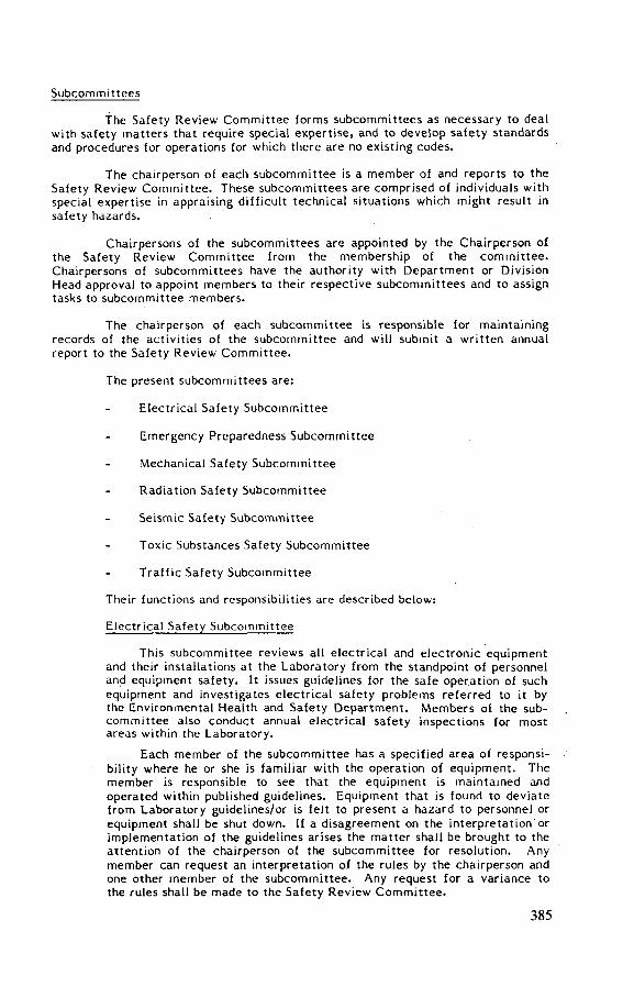
Subcommit tees
The Sa fe ty Rev iew C o m m i t t e e forms s u b c o m m i t t e e s as necessary to deal with sa fe ty mat ters that require special exper t i s e , and to deve lop s a f e t y standards and procedures for operat ions for which there are no exis t ing codes .
The chairperson of each s u b c o m m i t t e e is a member of and reports to the Safe ty Review C o m m i t t e e . These s u b c o m m i t t e e s are comprised of individuals with special expert i se in appraising d i f f i cu l t technical s i tuations which might result in sa fe ty hazards.
Chairpersons of the s u b c o m m i t t e e s are appointed by the Chairperson of the Sa fe ty Review C o m m i t t e e from the membership of the c o m m i t t e e . Chairpersons of s u b c o m m i t t e e s have the authority with Department or Division Head approval to appoint members to their respec t ive s u b c o m m i t t e e s and to assign tasks to subcommit tee members .
The chairperson of each subcommit tee is responsible for maintaining records of the ac t iv i t i e s of the s u b c o m m i t t e e and will submit a wri t ten annual report to the Sa fe ty Rev iew C o m m i t t e e .
The present s u b c o m m i t t e e s are:
Electr ical Sa fe ty Subcommit tee
Emergency Preparedness S u b c o m m i t t e e
Mechanical Safe ty Subcommit t ee
Radiation Safe ty Subcommit t ee
Se i smic Safe ty Subcommit tee
Toxic Substances Safe ty Subcommit t ee
T r a f f i c Sa fe ty Subcommit tee
Their funct ions and responsibil it ies are described below:
Electrical Sa fe ty Subcommit tee
This subcommit tee rev iews all e l ec tr ica l and e l ec t ron ic equipment and their instal lat ions at the Laboratory from the standpoint of personnel and equipment s a f e t y . It issues guidel ines for the s a f e operat ion of such equipment and inves t igates e l ec tr ica l sa f e ty problems referred to it by the Environmental Health and Sa fe ty Department . Members of the sub-c o m m i t t e e also conduct annual e l ec tr ica l s a f e t y inspect ions for most areas within the Laboratory.
Each member of the subcommit tee has a spec i f i ed area of responsi-bility where he or she is familiar with the operation of equipment . The member is responsible to see that the equipment is maintained and operated within published guidel ines. Equipment that is found to dev ia te from Laboratory guidel ines/or is fe l t to present a hazard to personnel or equipment shall be shut down. If a d i sagreement on the interpretat ion or implementat ion of the guidel ines arises the matter shall be brought to the at tent ion of the chairperson of the s u b c o m m i t t e e for resolution. Any member can request an interpretat ion of the rules by the chairperson and one other member of the s u b c o m m i t t e e . Any request for a variance to the rules shall be made to the Sa fe ty Rev iew C o m m i t t e e .
385
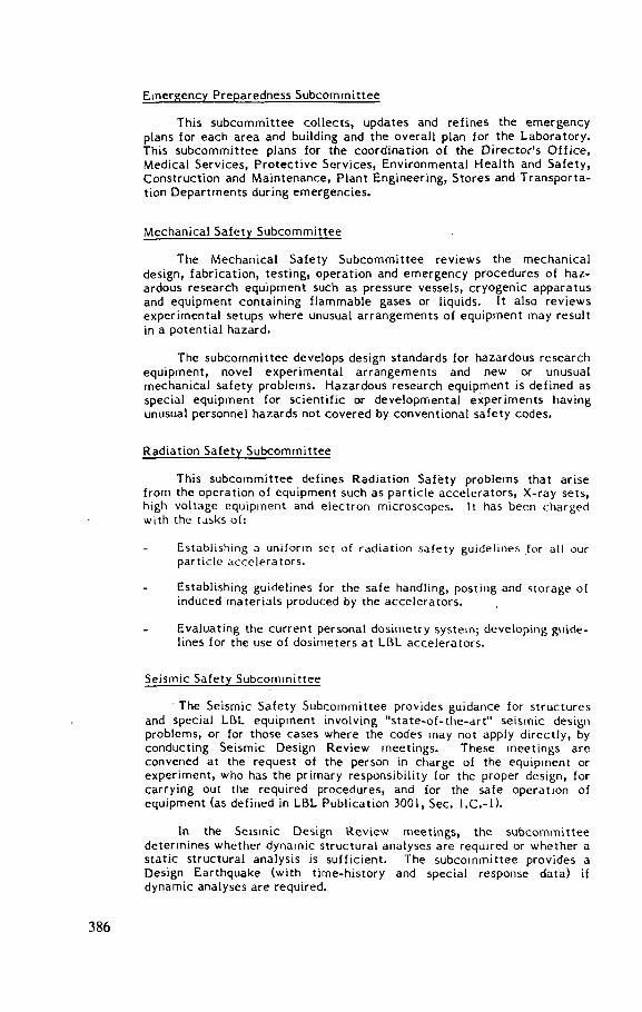
E m e r g e n c y Preparednes s S u b c o m m i t t e e
This s u b c o m m i t t e e c o l l e c t s , update s and r e f i n e s the e m e r g e n c y plans for e a c h area and building and the overa l l plan for t h e Laboratory . This s u b c o m m i t t e e plans for the coord inat ion of the D irec tor ' s O f f i c e , Medical S e r v i c e s , P r o t e c t i v e S e r v i c e s , Env ironmenta l H e a l t h and S a f e t y , Cons truc t ion and M a i n t e n a n c e , P lant Eng ineer ing , S t o r e s and Transpor ta -t ion D e p a r t m e n t s during e m e r g e n c i e s .
Mechanica l S a f e t y S u b c o m m i t t e e
The Mechanica l S a f e t y S u b c o m m i t t e e r e v i e w s the m e c h a n i c a l des ign , fabr ica t ion , t e s t i n g , operat ion and e m e r g e n c y procedures of haz -ardous research equ ipment such as pressure v e s s e l s , c r y o g e n i c apparatus and equipment c o n t a i n i n g f l a m m a b l e g a s e s or liquids. It a l so r e v i e w s e x p e r i m e n t a l s e tups where unusual a r r a n g e m e n t s of e q u i p m e n t may resul t in a potent ia l hazard.
The s u b c o m m i t t e e d e v e l o p s des ign s tandards for hazardous r e s e a r c h equ ipment , novel e x p e r i m e n t a l a r r a n g e m e n t s and new or unusual m e c h a n i c a l s a f e t y problems . Hazardous re search e q u i p m e n t is d e f i n e d as spec ia l equ ipment for s c i e n t i f i c or d e v e l o p m e n t a l e x p e r i m e n t s having unusual personnel hazards not c o v e r e d by c o n v e n t i o n a l s a f e t y c o d e s .
Radia t ion S a f e t y S u b c o m m i t t e e
This s u b c o m m i t t e e d e f i n e s Radia t ion S a f e t y prob lems that ar i se from the operat ion of equ ipment such as par t i c l e a c c e l e r a t o r s , X-ray s e t s , high v o l t a g e equ ipment and e l e c t r o n m i c r o s c o p e s . It has been charged with the tasks of:
E s t a b l i s h i n g a u n i f o r m se t of r a d i a t i o n s a f e t y g u i d e l i n e s for all our p a r t i c l e a c c e l e r a t o r s .
Establ ishing gu ide l ines for the s a f e handling, pos t ing and s t o r a g e of induced m a t e r i a l s produced by the a c c e l e r a t o r s .
Eva luat ing the current personal d o s i m e t r y s y s t e m ; d e v e l o p i n g guide-l ines for the use of d o s i m e t e r s at LBL a c c e l e r a t o r s .
S e i s m i c S a f e t y S u b c o m m i t t e e
The S e i s m i c S a f e t y S u b c o m m i t t e e provides gu idance for s t r u c t u r e s and spec ia l LBL equ ipment involv ing " s t a t e - o f - t h e - a r t " s e i s m i c des ign problems, or for those c a s e s where the c o d e s may not apply d i r e c t l y , by conduct ing S e i s m i c Des ign R e v i e w m e e t i n g s . T h e s e m e e t i n g s are convened at the request of the person in charge of the equ ipment or e x p e r i m e n t , who has the primary responsibi l i ty for the proper des ign , for carrying out the required procedures , and for the s a f e operat ion of equ ipment (as d e f i n e d in LBL Publ i ca t ion 3001, S e c . l . C . - l ) .
In the S e i s m i c Des ign R e v i e w m e e t i n g s , the s u b c o m m i t t e e d e t e r m i n e s whether dynamic s tructural ana lyses are required or w h e t h e r a s t a t i c s tructural analys i s is s u f f i c i e n t . The s u b c o m m i t t e e provides a Des ign Earthquake (with t irne-history and spec ia l response data) if dynamic ana lyses are required.
386

The subcommit tee is responsible for being aware of s t a t e - o f - t h e - a r t deve lopments in the se i smic response of structures and for uti l iz ing this knowledge in the performance of its functions. The s e i s m i c - s a f e t y codes have been in a s ta te of rapid evolutionary change in recent years. Therefore , it is important to recognize this rapid evolut ion and its impact on the funct ions of subcommit tee and on the LBL se ismic sa f e ty pol icy.
The statutory se i smic codes are changed as se i smic knowledge is developed and codi f i ed . However , current codes necessari ly lag the s t a t e -o f -ar t deve lopments and are considered a minimum LBL standard. Accordingly, all s tructures and equipment at LBL, as a minimum requirement, shall be designed and constructed to be in accordance with: (1) The latest edit ion of the "Uniform Building Code" and all other applicable se i smic sa fe ty codes; and (2) LBL Publication 3001, "Rules and Procedures for the Design and Operation of Hazardous Research Equipment".
Toxic Substances Sa fe ty Subcommit tee
The Toxic Substances Sa fe ty Subcommit tee is charged with reviewing exist ing pol ic ies and procedures for the use, accountabi l i ty and control of carcinogens, radioact ive materials , sources and toxic chemicals ; it also prepares and recommends new pol ic ies and procedures as required.
Tra f f i c Sa fe ty Subcommit t ee
The T r a f f i c Sa fe ty Subcommit t ee rev iews moving t r a f f i c violations, vehic le acc idents and their re lated causes such as road layouts and condi-tions, and makes recommendat ions for the correct ion of t r a f f i c sa f e ty hazards. It rev iews all acc idents involving laboratory-furnished veh ic l e s whether on s i te or off s i te .
The c o m m i t t e e serves as the hearing board for drivers who are involved in vehic le acc idents or who rece ive moving t r a f f i c violation warnings or c i ta t ions . Such drivers may be requested to appear before the board to review such incidents .
Procedure to Obtain a Variance from Laboratory Sa fe ty Guidel ines
A variance from Laboratory sa fe ty guidelines may be requested from the Sa fe ty Rev iew C o m m i t t e e . The Chairperson of the Sa fe ty Rev iew C o m m i t t e e may ask that the request for a variance be first studied by the appropriate subcommit tee . Approval or denial for a variance may be given a f t e r the writ ten request with documentat ion has been discussed by the S a f e t y R e v i e w C o m m i t t e e . Denial of a variance may be appealed to the Laboratory Director .
387
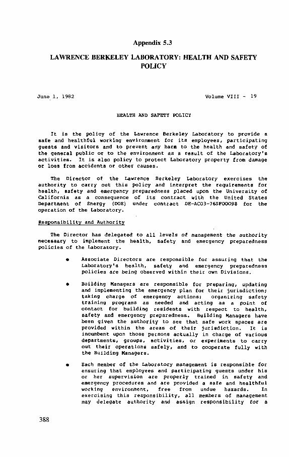
Appendix 5.1
LAWRENCE BERKELEY LABORATORY: HEALTH AND SAFETY POLICY
June 1, 1982 Volume VIII - 19
HEALTH AND SAFETY POLICY
It is the policy of the Lawrence Berkeley Laboratory to provide a safe and healthful working environment for its employees, participating guests and visitors and to prevent any harm to the health and safety of the general public or to the environment as a result of the Laboratory's activities. It is also policy to protect Laboratory property from damage or loss from accidents or other causes.
The Director of the Lawrence Berkeley Laboratory exercises the authority to carry out this policy and interpret the requirements for health, safety and emergency preparedness placed upon the University of California as a consequence of its contract with the United States Department of Energy (DOE) under contract DE-AC03-76SF00098 for the operation of the Laboratory.
Responsibility and Authority
The Director has delegated to all levels of management the authority necessary to implement the health, safety and emergency preparedness policies of the Laboratory.
• Associate Directors are responsible for assuring that the Laboratory's health, safety and emergency preparedness policies are being observed within their own Divisions.
• Building Managers are responsible for preparing, updating and implementing the emergency plan for their jurisdiction; taking charge of emergency actions; organizing safety training programs as needed and acting as a point of contact for building residents with respect to health, safety and emergency preparedness. Building Managers have been given the authority to see that safe work spaces are provided within the areas of their jurisdiction. It is incumbent upon those persons actually in charge of various departments, groups, activities, or experiments to carry out their operations safely, and to cooperate fully with the Building Managers.
• Each member of the Laboratory management is responsible for ensuring that employees and participating guests under his or her supervision are properly trained in safety and emergency procedures and are provided a safe and healthful working environment, free from undue hazards. In exercising this responsibility, all members of management may delegate authority and assign responsibility for a
388
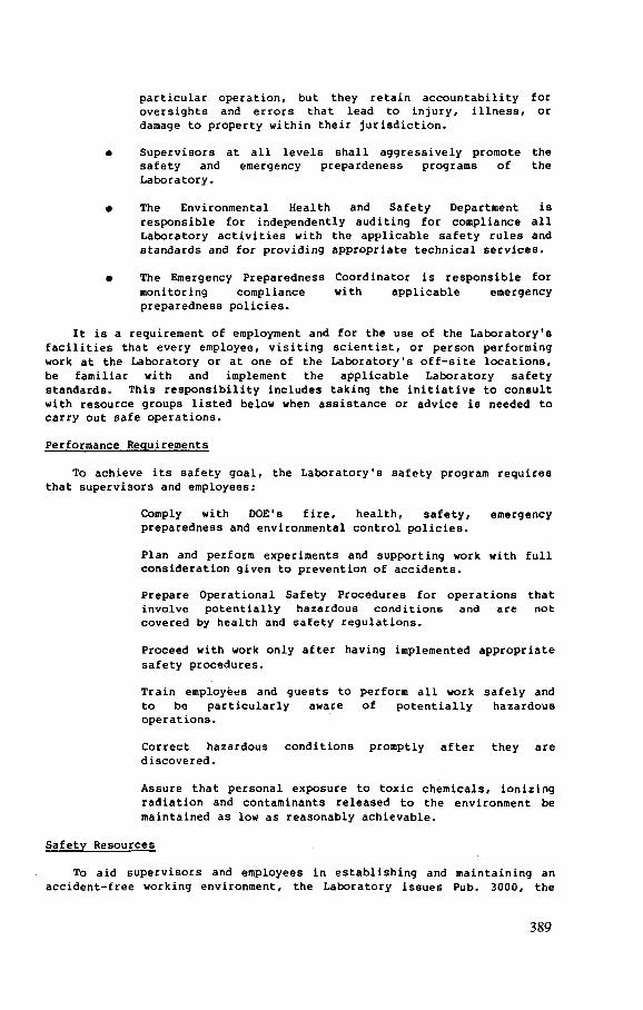
particular operation, but they retain accountability for oversights and errors that lead to injury, illness, or damage to property within their jurisdiction.
• Supervisors at all levels shall aggressively promote the safety and emergency prepardeness programs of the Laboratory.
• The Environmental Health and Safety Department is responsible for independently auditing for compliance all Laboratory activities with the applicable safety rules and standards and for providing appropriate technical services.
• The Emergency Preparedness Coordinator is responsible for monitoring compliance with applicable emergency preparedness policies.
It is a requirement of employment and for the use of the Laboratory's facilities that every employee, visiting scientist, or person performing work at the Laboratory or at one of the Laboratory's off-site locations, be familiar with and implement the applicable Laboratory safety standards. This responsibility includes taking the initiative to consult with resource groups listed below when assistance or advice is needed to carry out safe operations.
Performance Requirements
To achieve its safety goal, the Laboratory's safety program requires that supervisors and employees:
Comply with DOE's fire, health, safety, emergency preparedness and environmental control policies.
Plan and perform experiments and supporting work with full consideration given to prevention of accidents.
Prepare Operational Safety Procedures for operations that involve potentially hazardous conditions and are not covered by health and safety regulations.
Proceed with work only after having implemented appropriate safety procedures.
Train employees and guests to perform all work safely and to be particularly aware of potentially hazardous operations.
Correct hazardous conditions promptly after they are discovered.
Assure that personal exposure to toxic chemicals, ionizing radiation and contaminants released to the environment be maintained as low as reasonably achievable.
Safety Resources
To aid supervisors and employees in establishing and maintaining an accident-free working environment, the Laboratory issues Pub. 3000, the
389
Health and Safety Manual, for general guidance. The safe design and operation of hazardous experimental equipment is discussed in Pub. 3001, Rules and Procedures for the Design and Operation of Hazardous Research Equipment. Applicable rules and procedures extend to all Laboratory operations. These publications are available from the Environmental Health and Safety Department, which also issues manuals and reports discussing safety in specialized areas. It is the responsibility of every employee to be familiar with these publications, and to apply the rules and regulations that are applicable in planning and carrying out their work. In addition, the Laboratory makes available the services of the Environmental Health and Safety Department and Medical Services Department. These departments can provide specialized support skills and resources. The personnel of these groups evaluate operations for hazardous conditions, recommend methods of safe operations, and monitor the work environment for all groups at the Laboratory.
Safety Review Committee
Work at the Laboratory is often experimental in nature and involves several different areas of science and technology for which there are no published safety guidelines or applicable codes or regulations. Therefore the Safety Review Committee has been established and its members, who represent a broad range of scientific and safety experience, are appointed by the Director. The functions and responsibilities of this committee are described in its Charter.
The Safety Review Committee has formed several subcommittees to deal with specialized safety problems.
These subcommittees are: Mechanical Safety Subcommittee
Electrical Safety Subcommittee
Emergency Preparedness Advisory Subcommittee
Seismic Safety Subcommittee
Toxic Substances Safety Subcommittee
Traffic Safety Subcommittee
Radiation Safety Subcommittee The Chairman of each Subcommittee is a member of and reports to the
Safety Review Committee. The Subcommittees comprise individuals with a wide variety of experience in appraising difficult technical situations which might result in safety hazards. They are a valuable Laboratory resource available to all who use the Laboratory's facilities.
David A. Shirley ^ Director Lawrence Berkeley Laboratory
DAS:mc
390
REFERENCES
[ABHP 80] A M E R I C A N B O A R D O F H E A L T H PHYSICS, General Requirements of Certification, Bethesda, M D (1980).
[An 81] A N D E R S O N , K. , SCOTT, K. , Fundamentals of Industrial Toxicology, Ann Arbor Science Publishers, Ann Arbor , MI (1981).
[ANSI 70] A M E R I C A N N A T I O N A L S T A N D A R D S INSTITUTE, Radiological Safety in the Design and Operation of Particle Accelerators, NBS Handbook 107, Washington, DC (1970).
[ANSI 77] A M E R I C A N N A T I O N A L S T A N D A R D S INSTITUTE, Standard 43 .2 , Radiation Safety for X-Ray and Fluorescence Analysis Equipment, New York (1977).
[ANSI 78] A M E R I C A N N A T I O N A L S T A N D A R D S INSTITUTE, Standard N43.2 , Radiation Safety for X-Ray Diffract ion and Fluorescence Analysis Equip-ment, New York (1978).
[ANSI 82] A M E R I C A N N A T I O N A L S T A N D A R D S INSTITUTE, Standard C95-1, Safety Levels with Respect to Human Exposure to Radiofrequency Electromagnetic Fields, 30 kHz to 100 GHz, New York (1982).
[CERN 75] E U R O P E A N O R G A N I Z A T I O N F O R N U C L E A R R E S E A R C H , Radiation Safety Manual, C E R N , Geneva (1975).
[Ch 81] CHISSICK, S.S. , DERRICOT, R. (Eds), Occupational Health and Safety Management , Wiley, Chichester (1981).
[DEHW 68] U N I T E D STATES D E P A R T M E N T O F H E A L T H , E D U C A T I O N A N D W E L F A R E , Public Health Service, Particle Accelerator Safety Manual, Rep. M O R P 68-12, Rockville, M D (1968).
[Do 80] D O U L L , I . , KLAASSEN, C . D . , A M D U R , M . O . , Casarett and Doul l ' s Toxicology, Macmillan, London and New York (1980).
[DOE nd] U N I T E D STATES D E P A R T M E N T O F E N E R G Y , D O E Order 5480.1, Chapter XI, Requirements for Radiation Protection, U S D O E , Oak Ridge, TN (revised frequently).
[Hu 80] H U N T E R , D . , The Diseases of Occupations, Hodder and Stoughton, London (1980).
[IAEA 79] S W A N S O N , W . P . , Radiological Safety Aspects of the Operation of Electron Linear Accelerators, Technical Reports Series No. 188, IAEA, Vienna (1979).
[ ICRP 77] I N T E R N A T I O N A L COMMISSION ON RADIOLOGICAL P R O T E C T I O N , Recommendations of the ICRP, Publication 26, Pergamon Press, Oxford and New York (1977).
[La 80] LAST, J . M . (Ed.) , Maxey-Rosenau Public Health and Preventive Medicine, Appleton-Century-Crofts , New York (1980).
[La 81] LaDOU, J . , Occupational Health Law — A Guide for Industry, Marcell Dekker , New York (1981).
[LBL 76] T H O M A S , R .H . (Ed.) , The Environmental Surveillance Program of the Lawrence Berkeley Laboratory, Rep. LBL-4678, Lawrence Berkeley Lab. , Berkeley, CA (1976).
391
[LBL 78] L A W R E N C E BERKELEY L A B O R A T O R Y , Pregnancy and Radiation, Publication 105, Lawrence Berkeley Lab . , Berkeley, C A (1978).
[LBL 80a] L A W R E N C E BERKELEY L A B O R A T O R Y , Charter for the Safety Review Committee, Lawrence Berkeley Lab. , University of California, Berkeley, C A (1980).
[LBL 80b] L A W R E N C E BERKELEY L A B O R A T O R Y , Health and Safety Manual , Publication 3000, Lawrence Berkeley Lab. , Berkeley, CA (1980 and subsequent revisions).
[LBL 82] L A W R E N C E BERKELEY LABORATORY, Health and Safety Policy, Lawrence Berkeley Lab. , Berkeley, C A (1982).
[LBL nd] L A W R E N C E BERKELEY L A B O R A T O R Y , Regulations and Procedures Manual, Publication 201, Lawrence Berkeley Laboratory, Berkeley, C A (revised frequently).
[Ma 72] MARTIN, T . C . (Ed.) , Accelerator Radiation Protection, Rep. TR-73-7, US Army Natick Laboratories, Natick, M A (1972).
[NAS 81] N A T I O N A L A C A D E M Y O F SCIENCES, Prudent Practice for Handling Hazardous Chemicals in Laboratories, National Academy Press, Washington, DC (1981).
[NAS 83] N A T I O N A L A C A D E M Y OF SCIENCES, Prudent Practice for the Disposal of Chemicals f rom Laboratories, National Academy Press, Washington, DC (1983).
[NBS 63] N A T I O N A L B U R E A U O F S T A N D A R D S , Maximum Permissible Body Burdens and Maximum Permissible Concentrations of Radionuclides in Air and in Water for Occupational Exposure, Handbook No. 69, US Dept. of Commerce, Washington, DC (1963).
[NCRP 68] N A T I O N A L C O U N C I L ON RADIATION PROTECTION A N D M E A S U R E M E N T S , Medical X-Ray and Gamma-Ray Protection for Energies up to 10 MeV — Equipment Design and Use, Rep. 33, Washington, D C (1968).
[NCRP 76] N A T I O N A L C O U N C I L ON RADIATION PROTECTION A N D M E A S U R E M E N T S , Structural Shielding Design and Evaluation for Medical and Allied Health Personnel, Rep. 49, Washington, DC (1976).
[NCRP 77a] N A T I O N A L C O U N C I L O N RADIATION PROTECTION A N D M E A S U R E M E N T S , Review of N C R P Radiation Dose Limit for Embryo and Fetus in Occupationally Exposed Women , Rep. 53, Washington, DC (1977).
[NCRP 77b] N A T I O N A L C O U N C I L ON RADIATION PROTECTION A N D MEAS-U R E M E N T S , Medical Radiation Exposure of Pregnant and Potentially Preg-nant Woman, Rep. 56, Washington, DC (1977).
[NCRP 78] N A T I O N A L C O U N C I L ON RADIATION PROTECTION A N D M E A S U R E M E N T S , Operational Radiation Safety Program, Rep. 59, Washington, DC (1978).
[NFPA nd] N A T I O N A L FIRE PROTECTION ASSOCIATION, National Fire Codes, Boston, M A (published periodically).
392
[NIOSH 78] N A T I O N A L INSTITUTE O F O C C U P A T I O N A L SAFETY A N D H E A L T H , The Industrial Environment — Its Evaluation and Control , US Department of Health Education and Welfare , US Government Printing Off ice , Washington, DC (1978).
[NSC 78] N A T I O N A L SAFETY C O U N C I L , Accident Prevention Manual for Indus-trial Operations, 7th edn, NSC, Chicago, IL (1978).
[NSC 79] N A T I O N A L SAFETY C O U N C I L , Fundamentals of Industrial Hygiene, 2nd edn, NSC, Chicago, IL (1979).
[OSHA 83] O C C U P A T I O N A L SAFETY A N D H E A L T H A D M I N I S T R A T I O N , US D E P A R T M E N T O F LABOR, OSHA Safety and Health Standards (29 CFR 1910), General Industry, Occupational Safety and Health Administration OSHA-2206 (Rev. March 11, 1983).
[Pa 73] P A T T E R S O N , H . W . , T H O M A S , R . H . , Accelerator Health Physics, Aca-demic Press, New York (1973).
[Pa 81] C L A Y T O N , G . D . , C L A Y T O N , F . E . (Eds), Pat ty 's Industrial Hygiene and Toxicology, 3rd edn, Vol. I, General Principles, Wiley, New York (1978).
[Pa 81a] C L A Y T O N , G . D . , C L A Y T O N , F .E . (Eds), Patty 's Industrial Hygiene and Toxicology, 3rd edn, Vol. Ha, Toxicology, Wiley, New York (1981).
[Pa 81b] C L A Y T O N , G . D . , C L A Y T O N , F .E . (Eds), Patty 's Industrial Hygiene and Toxicology, 3rd edn, Vol. l ib , Toxicology, Wiley, New York (1981).
[Pa 82] C L A Y T O N , G . D . , C L A Y T O N , F .E . (Eds), Patty 's Industrial Hygiene and Toxicology, 3rd edn, Vol. l ie , Toxicology, Wiley, New York (1982).
[Pa 85] C R A L L E Y , L . J . , C R A L L E Y , L .V . (Eds), Pat ty 's Industrial Hygiene and Toxicology, 3rd edn, Vol. I l lb , Theory and Rationale of Industrial Hygiene Practice, Wiley, New York (1985).
[Pe 75] P E T E R S E N , D . , Safety Management , Aloray, Fairview, NJ (1975). [Pe 78] P E T E R S E N , D . , Techniques of Safety Management , McGraw Hill,
New York (1978). [PI 76] P L U N K E T T , E .R . , Handbook of Industrial Toxicology, Chemical
Publishing Co . , New York (1976). [Pr 78] P R O C T O R , N . H . , H U G H E S , J .P . , Chemical Hazards in the Work Place,
J .P . Lippincott, Philadelphia (1978). [Pu 77] P U R I N G T O N , R . G . , P A T T E R S O N , H . W . , Handling Radiation Emergen-
cies, National Fire Protection Association, Boston, M A (1977). [Sa 75] SAX, N. I . , Dangerous Properties of Industrial Materials, Van Nostrand,
Princeton and New York (1975). [Sc 82] SCHILLING, R.S .F . (Ed.) , Occupational Health Practice, Butterworths,
London (1982). [St 76] STEETE, N .V . (Ed.) , Handbook of Laboratory Safety, Chemical Rubber
Company, Cleveland, OH (1976). [Ze 75] Z E N Z , C. (Ed.) , Occupational Medicine, Year Book Medical Publishers,
Chicago, IL (1975). [Ze 80] Z E N Z , C . (Ed.) , Developments in Occupational Medicine, Year Book
Medical Publishers, Chicago, IL (1980).
393

Chapter 6
RADIOLOGICAL ENVIRONMENTAL IMPACT OF ACCELERATORS
6.1. RADIOLOGICAL IMPACT OF ACCELERATORS
In assessing the radiological impact of an accelerator installation, attention must be given to the following exposure pathways:
(1) Prompt radiation fields during accelerator operation; (2) Radionuclides and noxious chemicals (such as ozone and nitric oxide) in the
air of the accelerator vault and their subsequent release; (3) Radionuclides in the soil and groundwater near the accelerator and possible
subsequent migration from the accelerator site into wells or other sources of potable water;
(4) Radionuclides in the cooling water of the installation that may mix with, or be accidentally released into, the normal effluent;
(5) Long lived radionuclides in accelerator components that may subsequently be recycled, with consequent transmission of the radionuclides into the general environment; this would be particularly true for valuable metals such as copper, brass, iron or aluminium.
For prompt stray radiation, it is necessary to assess only external exposure; for radioactivity in air and water, both external and internal exposure pathways must be considered.
This chapter will not discuss the radiological impact of accelerators whose primary purpose is to produce radioisotopes. The impact of such accelerators depends mainly on the radiotoxicity and quantities of radioisotopes produced and on the separation procedures used [Bi 80, Ci 79]. These problems must be treated individually with a full knowledge of each possible exposure pathway. Another problem that requires individual attention and will not be treated here is the intro-duction of radioisotopes into the accelerator as a target material; tritium gas, for example, could be released by a rupture or by absorption in vacuum pump oil, or could be accelerated. These problems depend more on the quantity of the radio-isotope introduced into the accelerator rather than on the operation of the accelerator itself.
The problems that will be treated in this chapter are:
(a) The spectrum of particles leaving the accelerator enclosure and the scattering and transport of these particles in the air/ground/building complex to the point where they can irradiate persons outside the accelerator laboratory;
395
(b) The radionuclides of importance created in the air of the accelerator enclosure and the release of this air into the environment;
(c) The radionuclides of importance created in cooling water and in groundwater around the accelerator, together with their subsequent migration (with consideration, as well, of radioisotopes in surrounding soil that may be leached by rain or groundwater movement).
6.2. SKYSHINE
6.2.1. Stray radiation field
As it appears in the literature, the word skyshine refers to all the radiation reaching a point in the vicinity of an accelerator, whether unscattered (direct) or scattered by ground, air, or neighbouring buildings (indirect). In this section, we will assume that the environmental point of interest is at least 50-100 m from the accelerator enclosure and that it is shielded from a direct view of the outer surface of the enclosure, so that the radiation environment is dominated by particles that have undergone elastic and inelastic scattering in the air and, perhaps, in the ground before reaching the point of interest.
A summary of the skyshine phenomenon around accelerators was given by Rindi and Thomas, where experience up to 1975 was reviewed [Ri 75]. Experience has shown that neutrons will be the dominant skyshine component, and Fig. 6.1 shows measurements of neutron flux density versus distance at several accelerators. It can be concluded from the data that the empirical relation
Q exp(—r/X) <t> (r) = —5 (6.1)
is a simple but adequate expression for the skyshine intensity around most accelerators, where r is the distance from the accelerator enclosure, Q is an effective source strength of neutrons emitted from the shield surface, and X is an effective absorption length.
The use of Eq. (6.1) requires knowledge of the two parameters X and Q. The values of X observed in practice vary between 267 m and 990 m [Ri 75]. The lower value generally pertains to those conditions when low energy neutrons dominate the shield leakage spectra, and the higher value is more appropriate where the high energy cascade in the shield may be considered as continuing in the air, giving rise to a diffuse source of evaporation neutrons, which then is subsequently scattered before arriving at the point of interest. In this latter case, X should approximately
396
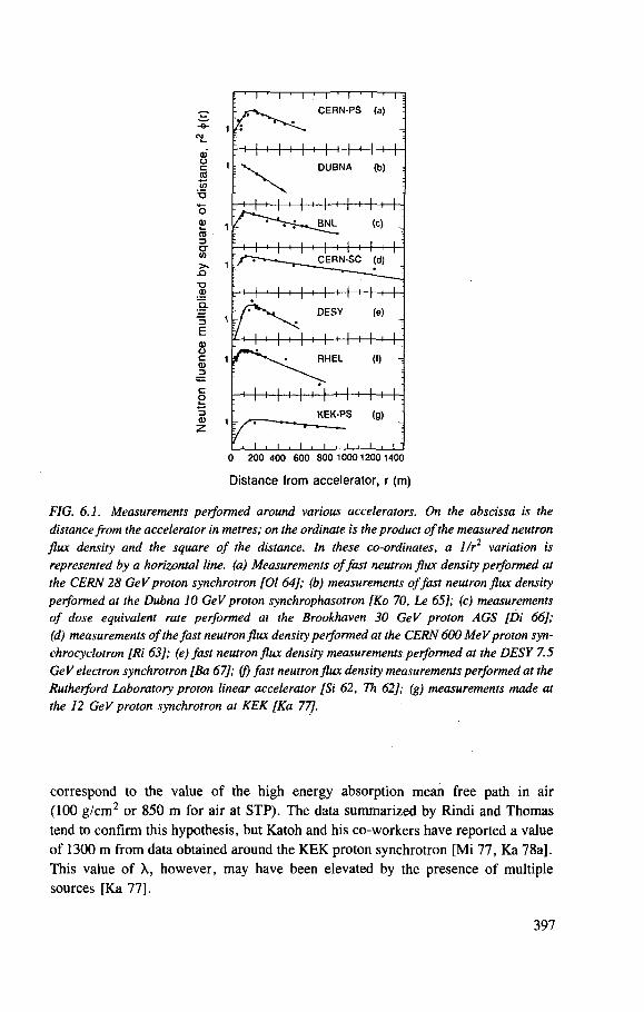
0 200 400 600 800 100012001400
Distance from accelerator, r (m)
FIG. 6.1. Measurements performed around various accelerators. On the abscissa is the distance from the accelerator in metres; on the ordinate is the product of the measured neutron flux density and the square of the distance. In these co-ordinates, a I/r2 variation is represented by a horizontal line, (a) Measurements of fast neutron flux density performed at the CERN 28 GeV proton synchrotron [01 64]; (b) measurements offast neutron flux density performed at the Dubna 10 GeV proton synchrophasotron [Ko 70, Le 65]; (c) measurements of dose equivalent rate performed at the Brookhaven 30 GeV proton AGS [Di 66]; (d) measurements of the fast neutron flux density performed at the CERN 600 MeV proton syn-chrocyclotron [Ri 63]; (e) fast neutron flux density measurements performed at the DESY 7.5 GeV electron synchrotron [Ba 67]; ( f ) fast neutron flux density measurements performed at the Rutherford Laboratory proton linear accelerator [Si 62, Th 62]; (g) measurements made at the 12 GeV proton synchrotron at KEK [Ka 77].
correspond to the value of the high energy absorption mean free path in air (100 g/cm 2 or 850 m for air at STP). The data summarized by Rindi and Thomas tend to confirm this hypothesis, but Katoh and his co-workers have reported a value of 1300 m from data obtained around the KEK proton synchrotron [Mi 77, Ka 78a], This value of X, however, may have been elevated by the presence of multiple sources [Ka 77],
397
The practical use of Eq. (6.1) is also limited by the choice of the value of the effective source strength, which depends on the energy spectrum and angular distribution of particles leaving the enclosure surface. Effective neutron source strengths have appeared to be unique to each accelerator, because their value depended strongly on the amount of local shielding and, to some extent, on the technique used to measure the leakage neutrons.
Any complete theoretical treatment of skyshine from accelerators must treat the transport through the air of neutrons with energies of up to hundreds of MeV. Much of the published work, however, is limited to neutrons of energy up to a few MeV.
In 1957, in one of the first theoretical studies of the subject, Lindenbaum [Li 57, Mo 57] formulated an expression to describe the propagation of low energy neutrons (a few MeV) through the atmosphere. This work, which incidentally introduced the term skyshine for these phenomena at high energy proton accelerators, was based on experience at the Brookhaven National Laboratory Cosmotron.
In essence, Lindenbaum used the expression for the neutron flux produced by a point source in an infinite isotropic scattering medium. This expression was derived by Case et al. [Ca 53] using diffusion theory. Lindenbaum wrote the scalar neutron flux density 4>(r) in the form:
Qe _ E , r N Qk(c) e_ k° r
*(r) = y e(c,r) + (6.2) 47rr 47rDr
where
Q is the neutron source strength (neutrons-s - 1) , E, is the macroscopic total cross-section, D is the diffusion coefficient, 1/ko is the diffusion length, c is Es/E t, the ratio of the scattering cross-section to the total
cross-section, and e(c,r) and k(c) are functions of c.
The assumptions made in the Case formulation are:
(i) One velocity group neutron diffusion, i.e. the source emits monoenergetic neutrons and neutrons arriving at points distant from the source have the same energy as those emitted at the source (they do not lose any kinetic energy in elastic collisions);
(ii) The source is an isotropic point source; (iii) Neutrons diffuse in an infinite uniform absorbing medium (taken to be air by
Lindenbaum); (iv) Scattering is isotropic in the centre of mass system.
398

Given these assumptions, the general solution to the steady state problem (i.e. a source intensity constant with time) has for the flux density the familiar form of Eq. (6.2) given by Lindenbaum.
For neutrons of a few MeV transported in air, substitution of the appropriate numerical value for the parameters in Eq. (6.2) yields:
r 7 9 v 1 0- 2
0(r) = Q — - 2 exp( - r / (1 .4 X 104))
i 4 x 1 0- 5
") + — exp(r/(2.5 x 104)) (6.3)
where
0 is in neutrons • cm ~2 • s ~1, r is in cm, Q is in neutrons • s ~1.
The presence of the ground requires some modification of Eq. (6.2). Lindenbaum suggested this could be adequately achieved by changing only the value of c. Such a change limits the use of the equation to the transport of neutrons of a few MeV. Lindenbaum pointed out that if higher energy neutrons were to be considered, changes in both mean free path and c would be necessary.
The first term of Eq. (6.2) is almost identical with the equation describing propagation of radiation from a point source with absorption but without scattering. With the values of the parameters proposed by Lindenbaum, the first term of Eq. (6.3) becomes negligible in comparison with the second for distances larger than about 3 mean free paths in air (some 300 m). The second term of Eq. (6.3) represents the component of the radiation field scattered to the point of measurement from all directions. In practice, the component of the radiation field at a point arriving from the ground is much smaller than that arriving from the air.
Lindenbaum's equation was intended to describe those situations where the neutron leakage spectrum into the air was composed of, or at least strongly dominated by, neutrons in a narrow band of energy in the MeV region. When neutrons in the MeV region are dominant — as for example when there is either no roof shielding or the shield is constructed of materials containing little or no hydrogen (e.g. steel or lead), Lindenbaum's equation can predict neutron flux densities to within a factor of three at distances out to ~ 2 0 0 m. In particular, reasonable agreement (within a factor of 2) was found between measurements within a range of 30 and 150 m at the Cosmotron and theoretical estimates using Eq. (6.3) [Li 61]. Other workers have developed treatments of skyshine similar to those of Lindenbaum [Pa 57, Wi 57], For those cases where the accelerator is well shielded
399
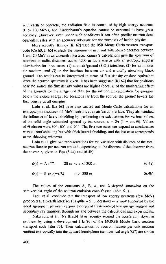
with earth or concrete, the radiation field is controlled by high energy neutrons (E > 100 MeV), and Lindenbaum's equation cannot be expected to have great accuracy. However, even under such conditions it can often predict neutron dose equivalent rates with an accuracy adequate for the purposes of health physics.
More recently, Kinney [Ki 62] used the 05R Monte Carlo neutron transport code [Co 60, Ir 65] to study the transport of neutrons with source energies between 1 and 20 MeV at an air/earth interface. Kinney's calculations give the spectrum of neutrons at radial distances out to 4000 m for a source with an isotropic angular distribution for three cases: (1) at an air/ground (Si02) interface, (2) for an infinite air medium, and (3) on the interface between air and a totally absorbing black ground. The results can be interpreted in terms of flux density or dose equivalent since the neutron spectrum is given. It has been suggested [Ki 62] that for positions near the source the flux density values are higher (because of the moderating effect of the ground) for the air/ground than for the infinite air calculation for energies below the source energy; for locations far from the source, the ground lowers the flux density at all energies.
Ladu et al. [La 68] have also carried out Monte Carlo calculations for an isotropic point source of 5 MeV neutrons at an air/earth interface. They also studied the influence of lateral shielding by performing the calculations for various values of the solid angle subtended upward by the source, co = 2ir (1 — cos 9) . Values of 9 chosen were 30°, 60° and 90°. The first two cases correspond to accelerators without roof shielding but with thick lateral shielding, and the last case corresponds to no shielding whatever.
Ladu et al. give two representations for the variation with distance of the total neutron fluence per neutron emitted, depending on the distance of the observer from the source r, given in Eqs (6.4a) and (6.4b)
0(r) = A r " ° 20 m < r < 300 m (6.4a)
4>(r) = B exp(—r/X) r > 300 m (6.4b)
The values of the constants A, B, a , and X depend somewhat on the semivertical angle of the neutron emission cone 9 (see Table 6.1).
Ladu et al. conclude that the transport of low energy neutrons (few MeV) produced at air/earth interfaces is quite well understood — a view supported by the good agreement between various theoretical treatments-of low energy neutron and secondary ray transport through air and between the calculations and experiments.
Nakamura et al. [Na 81a,b] have recently studied the accelerator skyshine problem by using a development [Ha 76] of the MORSE Monte Carlo neutron transport code [Em 75], Their calculations of neutron fluence per unit neutron emitted isotropically into the upward hemisphere (semivertical angle 85°) are shown
400
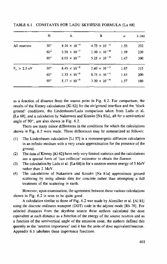
TABLE 6.1. CONSTANTS FOR LADU SKYSHINE FORMULA [La 68]
e A B a M m )
All neutrons 30° 8.24 x 1 0 " 8 4.75 x 10" II 1.53 232
60° 3.56 x i o - 7 1.50 x 10" 10 1.59 220
90° 6 .03 x H T 7 5.25 x 10" 10 1.47 200
En > 2.5 eV 30° 8.45 x 1 0 " 8 2.40 x 10" II 1.67 215
60° 2 .33 x 1 0 " 8 8.75 x 10" ii 1.63 200
90° 5.17 x 1 0 " 8 3.30 x IO- 10 1.57 180
as a function of distance from the source point in Fig. 6.2. For comparison, the results of the Kinney calculations [Ki 62] for the air/ground interface and the 'black ground' conditions, the Lindenbaum/Ladu comparison taken from Ladu et al. [La 68], and a calculation by Nakamura and Kosako [Na 81a], all for a semivertical angle of 90°, are also shown in Fig. 6.2.
There are many minor differences in the conditions for which the calculations shown in Fig. 6.2 were made. These differences may be summarized as follows:
(1) The Lindenbaum calculation [Li 57] is a monoenergetic diffusion calculation in an infinite medium with a very crude approximation for the presence of the ground.
(2) The data of Kinney [Ki 62] have only very limited statistics and the calculations use a special form of 'last collision' estimator to obtain the fluence.
(3) The calculation by Ladu et al. [La 68] is for a neutron source energy of 5 MeV rather than 2 MeV.
(4) The calculations of Nakamura and Kosako [Na 81a] approximate ground scattering by using albedo data for concrete rather than attempting a full treatment of the scattering in earth.
However, upon examination, the agreement between these various calculations shown in Fig. 6.2 is seen to be quite good.
A calculation similar to those of Fig. 6.2 was made by Alsmiller et al. [Al 81] using the discrete ordinates transport (DOT) code in the adjoint mode [Rh 78]. For selected distances from the skyshine source these authors calculated the dose equivalent at each distance as a function of the energy of the source neutron and as a function of the semivertical angle of the emission cone; the authors defined this quantity as the 'neutron importance' and it has the units of dose equivalent/neutron. Appendix 6.1 tabulates these importance functions.
401
200 400 600 800 1000 1200 1400 1600
Distance (m)
FIG. 6.2. Absolute neutron fluence as a function of distance from the source for an opening angle of 90° (after Ref. [La 68]). The dotted line gives the Lindenbaum curve, the solid line and histogram represent the [La 68] empirical relation and Monte Carlo calculation, respectively. The crosses and open diamonds represent the [Ki 62] calculations for the air/ground interface and the black ground, respectively. The open circles give the results from the [Na 81a] calculations.
A comparison of the Nakamura and Alsmiller calculations for neutrons emitted into a cone with a small vertex angle is given in Fig. 6.3. Comparison is complicated by minor differences in the intrinsic assumptions of these two calculations. The Alsmiller calculations are for a semivertical angle of 37°, whereas the Nakamura data for 0° have been used in Fig. 6.3 (the latter calculations, however, showed very little dependence of dose equivalent on semivertical angle in this range; this difference in semivertical angle should not therefore result in serious differences). Another difference is that the Alsmiller dose equivalent includes a photon contribution generated by the neutron interactions. Although Fig. 6.3 shows that the Nakamura calculations give somewhat lower values of dose equivalent per neutron emitted than those obtained by Alsmiller et al., as would be expected from the differ-ence in dose equivalents calculated, this difference is also in the direction to be expected from any comparison between weighted Monte Carlo and discrete ordinates methods in a low probability region.
The use of the importance functions calculated by Alsmiller et al. [Al 81] for the conditions of the Brookhaven Alternating Gradient Synchrotron (AGS) experiment [Di 66] of Fig. 6.1 was shown to give good agreement with the form of the experimental data (see Fig. 6.4), but the prediction differs from the experiment on an absolute basis by a factor of 2.5. The same importance functions were used
402
FIG. 6.3. Neutron skyshine importance junctions for small semivertical angles. The histogram gives the results of the calculations of Alsmiller et al. [Al 81]. The crosses, open circles, and closed circles are from Nakamura et al. [Na 81a] for distances of 100 m, 500 m and 1000 m, respectively.
by Stevenson and Thomas [St 84a] under the conditions of the experiments reported by Nakamura et al. [Na 81a,b]. The comparison by Nakamura et al. between their calculations and measurements is shown in Figs 6.5 and 6.6. Also shown in these latter two figures are our own calculations of neutron dose equivalent as a function of distance using the spectra and neutron emission of Nakamura but folding these spectra with the importance functions of Alsmiller et al. [St 84a], It will be seen that the points calculated in this manner are in as good agreement with experiment as those of Nakamura et al. for the YAYOI reactor spectrum and are in better agreement with the experimental data for the accelerator spectrum. It would thus appear that the importance functions calculated by Alsmiller et al. form a reasonable basis for the estimation of dose equivalent from skyshine neutrons. However, in their present form they are too cumbersome and ill adapted for similar desk-top calculations. The authors have therefore studied the way in which parameters for
403
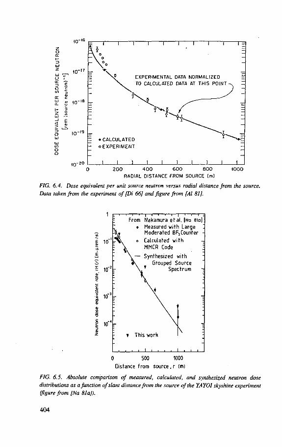
z o o: h-3 UJ z Ul a (E D 0 </l <r UJ CL H Z UJ _) 1 D O UJ UJ (A O Q
I0"16
•=•
10"" -
«; I0",s
br
10
"i 1 r n i r
s? EXPERIMENTAL DATA NORMALIZED TO CALCULATED DATA AT THIS POINT-
10"'9
k = •CALCULATED - OEXPERIMENT
•20 _L 200 1 0 0 600 800
RADIAL DISTANCE FROM SOURCE (m) 1000
FIG. 6.4. Dose equivalent per unit source neutron versus radial distance from the source. Data taken from the experiment of [Di 66] and figure from [Al 81].
E 10
i 10"
I 10" t
8 TJ
10
:—i 1 1 r-: From
| I 1 I 1 | I t 1 :
Nakamura et al. [Na 8ia): Measured with Large -
" j J Moderated BF3Counter -
Calculated with -! ^ MMCR Code
" Synthesized with
Grouped Source
; i T Spectrum -
r
\+ -
1 f This work
i i > i i i i i i
\ 1
, , , 0 500 1000
Distance from source, r (m)
FIG. 6.5. Absolute comparison of measured, calculated, and synthesized neutron dose distributions as a function of slant distance from the source of the YAYOl skyshine experiment (figure from [Na 81aJ).
404
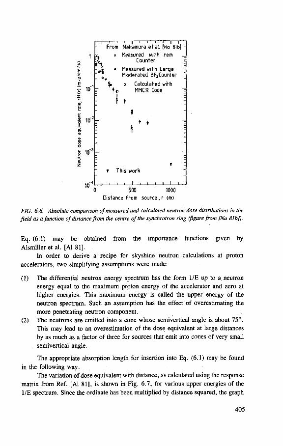
E
5. E
*S
u'S - o.
— i — i — i — i — i — i — i — i — i — r ~ From Nakamura ef al. [Na Bib]
o Measured with rem Counter
Measured with Large Moderated BF3Counter
c 10 r
B 10-V
Calculated with MMCR Code
t •
t This work
10 0 500 1000
Distance from source, r (m)
FIG. 6.6. Absolute comparison of measured and calculated neutron dose distributions in the field as a Junction of distance from the centre of the synchrotron ring (figure from [Na 8IbJ).
Eq. (6.1) may be obtained from the importance functions given by Alsmiller et al. [Al 81].
In order to derive a recipe for skyshine neutron calculations at proton accelerators, two simplifying assumptions were made:
(1) The differential neutron energy spectrum has the form 1/E up to a neutron energy equal to the maximum proton energy of the accelerator and zero at higher energies. This maximum energy is called the upper energy of the neutron spectrum. Such an assumption has the effect of overestimating the more penetrating neutron component.
(2) The neutrons are emitted into a cone whose semivertical angle is about 75°. This may lead to an overestimation of the dose equivalent at large distances by as much as a factor of three for sources that emit into cones of very small semivertical angle.
The appropriate absorption length for insertion into Eq. (6.1) may be found in the following way.
The variation of dose equivalent with distance, as calculated using the response matrix from Ref. [Al 81], is shown in Fig. 6.7, for various upper energies of the 1/E spectrum. Since the ordinate has been multiplied by distance squared, the graph
405
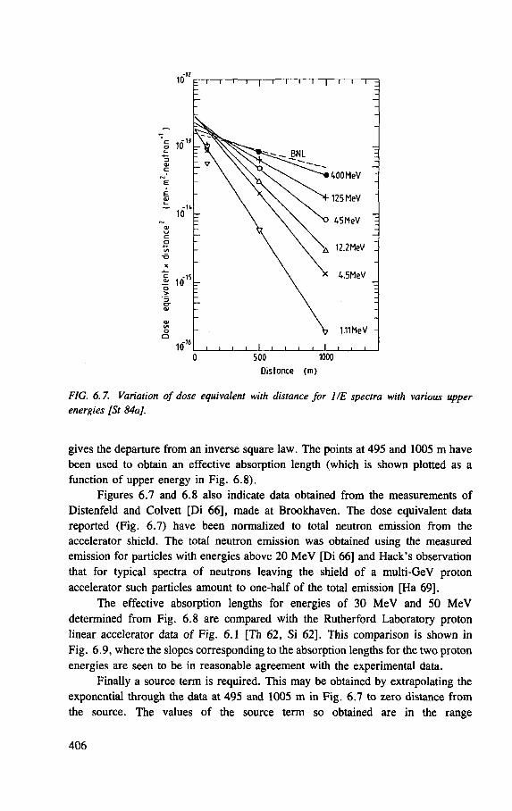
U J
400MeV
125 MeV
45MeV
12.2MeV
4.5MeV
1.11 MeV
10" j i u_i I i I I 1 0 500 1000
Distance (m)
FIG. 6.7. Variation of dose equivalent with distance for 1/E spectra with various upper energies [St 84a],
gives the departure from an inverse square law. The points at 495 and 1005 m have been used to obtain an effective absorption length (which is shown plotted as a function of upper energy in Fig. 6.8).
Figures 6.7 and 6.8 also indicate data obtained from the measurements of Distenfeld and Colvett [Di 66], made at Brookhaven. The dose equivalent data reported (Fig. 6.7) have been normalized to total neutron emission from the accelerator shield. The total neutron emission was obtained using the measured emission for particles with energies above 20 MeV [Di 66] and Hack's observation that for typical spectra of neutrons leaving the shield of a multi-GeV proton accelerator such particles amount to one-half of the total emission [Ha 69].
The effective absorption lengths for energies of 30 MeV and 50 MeV determined from Fig. 6.8 are compared with the Rutherford Laboratory proton linear accelerator data of Fig. 6.1 [Th 62, Si 62], This comparison is shown in Fig. 6.9, where the slopes corresponding to the absorption lengths for the two proton energies are seen to be in reasonable agreement with the experimental data.
Finally a source term is required. This may be obtained by extrapolating the exponential through the data at 495 and 1005 m in Fig. 6.7 to zero distance from the source. The values of the source term so obtained are in the range
406
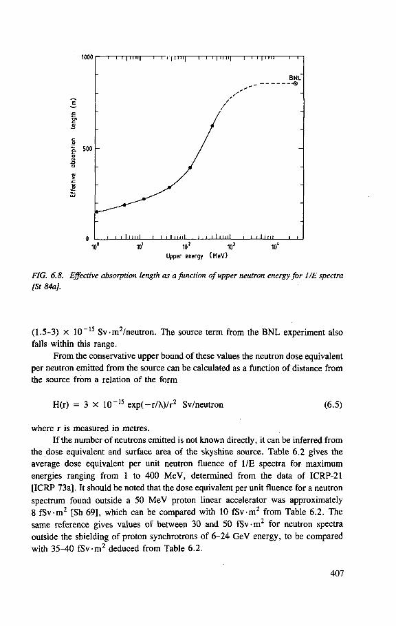
Upper energy (MeV)
FIG. 6.8. Effective absorption length as a junction of upper neutron energy for 1/E spectra [St 84a].
(1.5-3) X 10" 1 5 Sv •m /neutron. The source term from the BNL experiment also falls within this range.
From the conservative upper bound of these values the neutron dose equivalent per neutron emitted from the source can be calculated as a function of distance from the source from a relation of the form
H(r) = 3 X 10~1 5 exp( —r/X)/r2 Sv/neutron (6.5)
where r is measured in metres. If the number of neutrons emitted is not known direcdy, it can be inferred from
the dose equivalent and surface area of the skyshine source. Table 6.2 gives the average dose equivalent per unit neutron fluence of 1/E spectra for maximum energies ranging from 1 to 400 MeV, determined from the data of ICRP-21 [ICRP 73a]. It should be noted that the dose equivalent per unit fluence for a neutron spectrum found outside a 50 MeV proton linear accelerator was approximately 8 fSv-m 2 [Sh 69], which can be compared with 10 fSv-m 2 from Table 6.2. The same reference gives values of between 30 and 50 fSv-m 2 for neutron spectra outside the shielding of proton synchrotrons of 6 -24 GeV energy, to be compared with 35-40 fSv-m 2 deduced from Table 6.2.
407
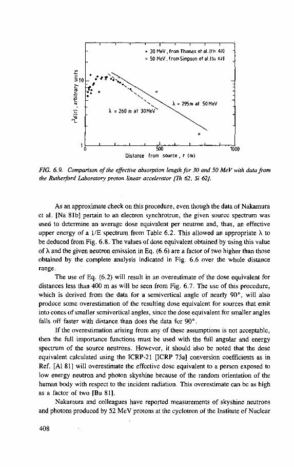
FIG. 6.9. Comparison of the effective absorption length for 30 and 50 MeV with data from the Rutherford Laboratory proton linear accelerator [Th 62, Si 62].
As an approximate check on this procedure, even though the data of Nakamura et al. [Na 81b] pertain to an electron synchrotron, the given source spectrum was used to determine an average dose equivalent per neutron and, thus, an effective upper energy of a 1/E spectrum from Table 6.2. This allowed an appropriate X to be deduced from Fig. 6.8. The values of dose equivalent obtained by using this value of X and the given neutron emission in Eq. (6.6) are a factor of two higher than those obtained by the complete analysis indicated in Fig. 6.6 over the whole distance range.
The use of Eq. (6.2) will result in an overestimate of the dose equivalent for distances less than 400 m as will be seen from Fig. 6.7. The use of this procedure, which is derived from the data for a semivertical angle of nearly 90°, will also produce some overestimation of the resulting dose equivalent for sources that emit into cones of smaller semivertical angles, since the dose equivalent for smaller angles falls off faster with distance than does the data for 90°.
If the overestimation arising from any of these assumptions is not acceptable, then the full importance functions must be used with the full angular and energy spectrum of the source neutrons. However, it should also be noted that the dose equivalent calculated using the ICRP-21 [ICRP 73a] conversion coefficients as in Ref. [Al 81] will overestimate the effective dose equivalent to a person exposed to low energy neutron and photon skyshine because of the random orientation of the human body with respect to the incident radiation. This overestimate can be as high as a factor of two [Bu 81].
Nakamura and colleagues have reported measurements of skyshine neutrons and photons produced by 52 MeV protons at the cyclotron of the Institute of Nuclear
408
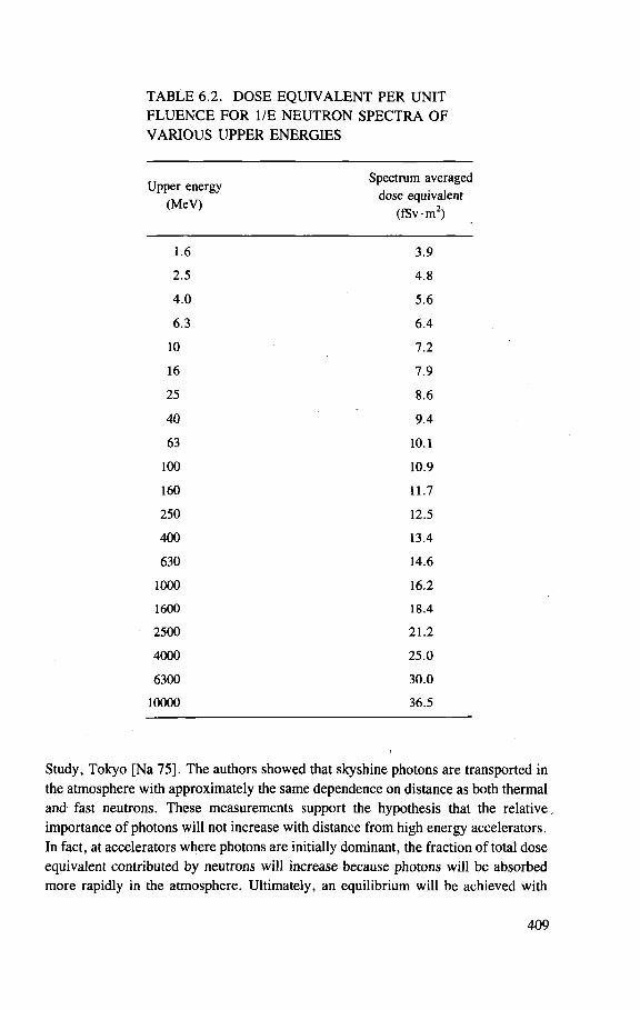
TABLE 6.2. DOSE EQUIVALENT PER UNIT FLUENCE FOR 1/E NEUTRON SPECTRA OF VARIOUS UPPER ENERGIES
Upper energy (MeV)
Spectrum averaged dose equivalent
( fSv-m 2 )
1.6 3 .9
2 .5 4 .8
4 .0 5 .6
6 .3 6 .4
10 7 .2
16 7 .9
25 8.6
40 9 .4
63 10.1
100 10.9
160 11.7
250 12.5
400 13.4
630 14.6
1000 16.2
1600 18.4
2500 21 .2
4000 25.0
6300 30.0
10000 36.5
Study, Tokyo [Na 75]. The authors showed that skyshine photons are transported in the atmosphere with approximately the same dependence on distance as both thermal and fast neutrons. These measurements support the hypothesis that the relative, importance of photons will not increase with distance from high energy accelerators. In fact, at accelerators where photons are initially dominant, the fraction of total dose equivalent contributed by neutrons will increase because photons will be absorbed more rapidly in the atmosphere. Ultimately, an equilibrium will be achieved with
409
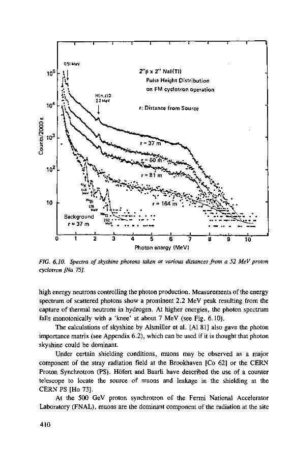
FIG. 6.10. Spectra of skyshine photons taken at various distances from a 52 MeV proton cyclotron [Na 75],
high energy neutrons controlling the photon production. Measurements of the energy spectrum of scattered photons show a prominent 2.2 MeV peak resulting from the capture of thermal neutrons in hydrogen. At higher energies, the photon spectrum falls monotonically with a 'knee' at about 7 MeV (see Fig. 6.10).
The calculations of skyshine by Alsmiller et al. [Al 81] also gave the photon importance matrix (see Appendix 6.2), which can be used if it is thought that photon skyshine could be dominant.
Under certain shielding conditions, muons may be observed as a major component of the stray radiation field at the Brookhaven [Co 62] or the CERN Proton Synchrotron (PS). Hofert and Baarli have described the use of a counter telescope to locate the source of muons and leakage in the shielding at the CERN PS [Ho 73].
At the 500 GeV proton synchrotron of the Fermi National Accelerator Laboratory (FNAL), muons are the dominant component of the radiation at the site
410
boundary [Ba 76]. This is in part due to the large distances from the accelerator to the site boundary. Neutrons produced at the accelerator are greatly reduced in intensity at the laboratory perimeter by inverse square law and air attenuation. Muons, on the other hand, as a consequence of experimental use of the accelerator, are produced in a highly collimated beam directed towards the site boundary. Because of their weak interaction with matter, they survive thick shielding and emerge into the air still well collimated. At the site boundary, a well defined 'beam' 50 m wide can be identified. The maximum dose equivalent at the site boundary was 2 mrem during 1974. At FNAL, as at CERN, a muon telescope is used to locate the origin of the more energetic muons.
6.2.2. Population exposure from accelerator prompt radiation
Because the prompt radiation field dominates the radiation environment of high energy accelerators (as we shall show in later sections) it is the dominant source of population exposure resulting from accelerator operations.
There is no generally accepted method of calculating the population exposure resulting from accelerator operation [Je 74, Ri 75]. In the following discussion, a model suggested by Stephens et al. [St 75, St 76] is described.
The population dose equivalent M resulting from operation of a nuclear facility is defined by the equation [ICRP 73b]:
where N(H)dH is the number of people receiving a dose equivalent H, and the subscripts refer to the minimum and maximum dose equivalent.
For accelerator laboratories, where M is averaged over an extended period such as a year, it has been suggested [St 75] that Eq. (6.6) be replaced by the equation:
where H(r) is the annual dose equivalent at a distance r from the accelerator, and R m a x and R m i n are the furthest and closest possible distance within which members of the public approach the accelerator.
It has been shown [St 76] that Eq. (6.7) may be numerically evaluated using the approximation:
(6.6)
H(r) N(r)dr (6.7)
2 ^ 1 Hp er
°/x
N;
S,S2 fa r t f - r U )
r„/X i = n
r dr (6.8)
411
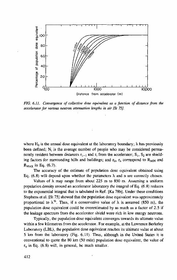
"I—i—I—I r c Q> O i 100
S 80 o
60 CL O * 40 o 01 CJ> £ 2 0 -a> o
1000 Distance from accelerator (m)
i i ' ' ' ' 10,000
FIG. 6.11. Convergence of collective dose equivalent as a function of distance from the accelerator for various neutron attenuation lengths in air [St 75].
where Ho is the annual dose equivalent at the laboratory boundary ; X has previously been defined; Nj is the average number of people who may be considered perma-nently resident between distances r ^ and rs f rom the accelerator; S,, S2 are shield-ing factors for surrounding hills and buildings; and r0, rn correspond to RMIN and R m a x in Eq. (6.7).
The accuracy of the estimate of population dose equivalent obtained using Eq. (6.8) will depend upon whether the parameters X and n are correctly chosen.
Values of X may range from about 225 m to 850 m. Assuming a uniform population density around an accelerator laboratory the integral of Eq. (6.8) reduces to the exponential integral that is tabulated in Ref. [Ka 78b]. Under these conditions Stephens et al. [St 75] showed that the population dose equivalent was approximately proportional to X%. Thus, if a conservative value of X is assumed (850 m), the population dose equivalent could be overestimated by as much as a factor of 2.5 if the leakage spectrum from the accelerator shield were rich in low energy neutrons.
Typically, the population dose equivalent converges towards its ultimate value within a few kilometres from the accelerator. For example, at the Lawrence Berkeley Laboratory (LBL), the population dose equivalent reaches its ultimate value at about 5 km from the laboratory (Fig. 6.11). Thus, although in the United States it is conventional to quote the 80 km (50 mile) population dose equivalent, the value of rn in Eq. (6.8) will, in general, be much smaller.
412
The extent of the radiological impact on the environment resulting from penetrating radiation produced by high energy accelerators may be measured by the parameter M/H0 (population dose equivalent per unit fence-post dose equivalent).
At LBL, numerical integration gave M/H0 = 1023 [St 75]. This value probably represents an upper limit to the value of M/H0 likely to be found at accelerator laboratories, since LBL is situated adjacent to fairly densely populated areas of the San Francisco Bay Region [Th 76a], About 170 000 people live within 5 km of the laboratory, at an average population density ranging from 2000 to 3000 persons per square kilometre.
In calculating the population dose equivalent resulting from operations at the Stanford Linear Accelerator Center, the variation of dose equivalent with distance is assumed to be of the form [Je 74]:
e - r / X
H(r) oc (6.9) r
where X = 140 m, and a value of M/H0 = 460 man-rem per fence-post rem was obtained [Bu 76a,b]. This value is lower than that at LBL for two reasons. First, the population density around the Stanford accelerator is somewhat lower than that at Berkeley, and second, the evaluation of dose equivalent was only carried out to a distance of 1 mile (1.6 km) from the accelerator. Nevertheless, the values of the population dose equivalent produced by these two centres with similar locations adjacent to a university campus and a large urban population are seen to be comparable.
At CERN, where the average population density around the laboratory is considerably lower than at Berkeley (Table 6.3), M/H0 has the value 160.
At laboratories such as Brookhaven National Laboratory (BNL), where the site boundaries are at considerable distances from the accelerator produced radiation sources, the parameter M/H0 has a low value. At BNL, the value of M/H0
estimated from data contained in its environmental report for 1975 is 54 [Hu 76]. At the Fermi National Accelerator Laboratory (FNAL), the population dose
equivalent was largely due to penetrating muons directed towards the northeast boundary of the laboratory. Baker [Ba 76] has estimated a population dose equivalent of 10 mSv resulting from a total equivalent of 10 fiSv during 1975 over a region about 50 m wide at the FNAL site boundary.
When the fence-post dose equivalent resulting from accelerators is only a few tens of microsieverts per year, spatial and temporal variations in natural background and detector sensitivity place a limit on the accuracy to which the fence-post dose equivalent resulting from photons may be determined. These problems have been discussed in detail elsewhere [deP 74a,b].
413
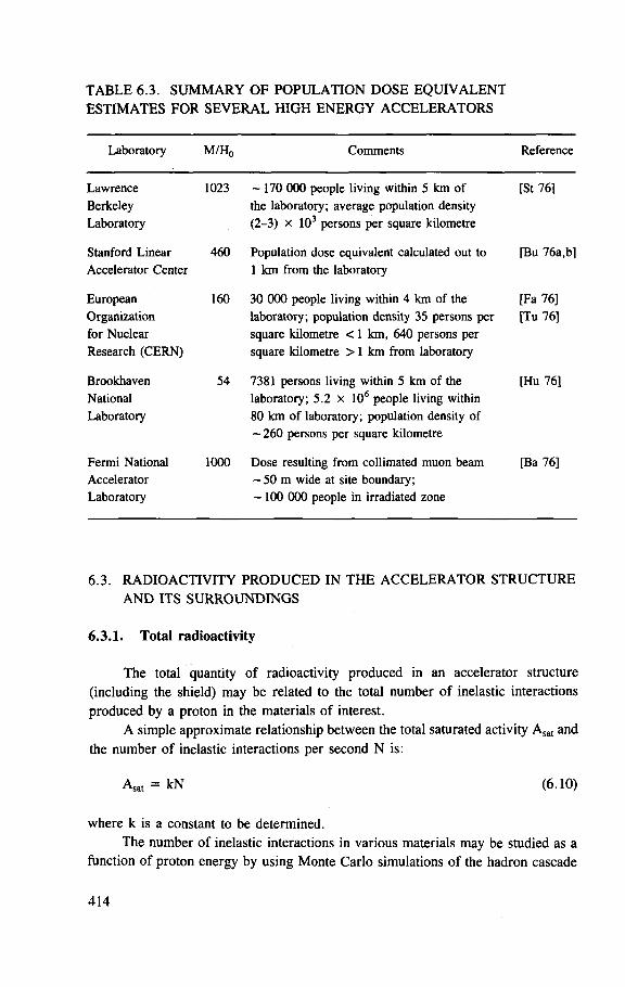
TABLE 6.3. SUMMARY OF POPULATION DOSE EQUIVALENT ESTIMATES FOR SEVERAL HIGH ENERGY ACCELERATORS
Laboratory M/Ho Comments Reference
Lawrence Berkeley Laboratory
1023 ~ 170 000 people living within 5 km of the laboratory; average population density (2-3) x 103 persons per square kilometre
[St 76]
Stanford Linear Accelerator Center
460 Population dose equivalent calculated out to 1 km f rom the laboratory
[Bu 76a,b]
European Organization for Nuclear Research (CERN)
160 30 000 people living within 4 km of the laboratory; population density 35 persons per square kilometre < 1 km, 640 persons per square kilometre > 1 km f rom laboratory
[Fa 76] [Tu 76]
Brookhaven National Laboratory
54 7381 persons living within 5 km of the laboratory; 5 .2 x 106 people living within 80 km of laboratory; population density of — 260 persons per square kilometre
[Hu 76]
Fermi National Accelerator Laboratory
1000 Dose resulting f rom collimated muon beam - 5 0 m wide at site boundary; - 1 0 0 000 people in irradiated zone
[Ba 76]
6.3. RADIOACTIVITY PRODUCED IN THE ACCELERATOR STRUCTURE AND ITS SURROUNDINGS
6.3.1. Total radioactivity
The total quantity of radioactivity produced in an accelerator structure (including the shield) may be related to the total number of inelastic interactions produced by a proton in the materials of interest.
A simple approximate relationship between the total saturated activity Asat and the number of inelastic interactions per second N is:
Asat = kN (6.10)
where k is a constant to be determined. The number of inelastic interactions in various materials may be studied as a
function of proton energy by using Monte Carlo simulations of the hadron cascade
414
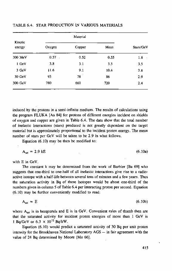
TABLE 6.4. STAR PRODUCTION IN VARIOUS MATERIALS
Material
Kinetic energy Oxygen Copper Mean Stars/GeV
300 MeV 0 .57 0 .52 0 .55 1.8
1 GeV 3.8 3 .1 3.5 3.5
3 GeV 11.6 9 .1 10.4 3 .8
30 GeV 93 78 86 2 .9
300 GeV 780 660 720 2.4
induced by the protons in a semi-infinite medium. The results of calculations using the program FLUKA [Aa 84] for protons of different energies incident on shields of oxygen and copper are given in Table 6.4. The data show that the total number of inelastic interactions (stars) produced is not greatly dependent on the target material but is approximately proportional to the incident proton energy. The mean number of stars per GeV will be taken to be 2.9 in what follows.
Equation (6.10) may be then be modified to:
Asat = 2.9 kE (6.10a)
with E in GeV.
The constant k may be determined from the work of Barbier [Ba 69] who suggests that one-third to one-half of all inelastic interactions give rise to a radio-active isotope with a half-life between several tens of minutes and a few years. Thus the saturation activity in Bq of these isotopes would be about one-third of the numbers given in column 5 of Table 6.4 per interacting proton per second. Equation (6.10) may be further conveniently modified to read:
Asat » E (6.10b)
where Asat is in becquerels and E is in GeV. Convenient rules of thumb then are that the saturated activity for incident proton energies of more than 1 GeV is 1 Bq/GeV or 6.3 X 10¹² Bq/kW.
Equation (6.10) would predict a saturated activity of 30 Bq per unit proton intensity for the Brookhaven National Laboratory AGS — in fair agreement with the value of 24 Bq determined by Moore [Mo 66],
415
The total saturated activity produced by a 30 GeV proton accelerator operating at a proton intensity of 5 X 10¹² s
_ 1
would be 150 TBq (4000 Ci). Most of the induced radioactivity will be produced in the accelerator structure and shield and is therefore tightly bound in the constituent materials; it is thus not likely to migrate into the environment. It is, however, important to understand the quantities of radioactivity produced outside the accelerator shield, directly in the environment, which might be potential sources of radioactive contamination.
6.3.2. Quantity of radioactivity in earth and groundwater
Stapleton and Thomas [St 72] have estimated the total quantity of radionuclides produced in the earth Q E and groundwater Q w of an accelerator buried underground. If Q w is known, the total activity in the earth shield QE may be estimated from the equation
Qe
Qw
Pe QE Mw
P w ^ w M E
(6.11)
where
f is the fraction of water by weight in the earth shield, p is density, a is the inelastic reaction cross-section, M is the molecular weight,
and the subscripts E and W represent earth and water respectively.
The value of Q w was estimated using experimental data [Gi 68] to give:
Qw = 2.2 x 1 0 - 6 Bq • mb ~1 • GeV~ 1 • s~ 1 (6.12)
Using a value of 290 mb for the total inelastic cross-section of oxygen, we may estimate the total activity produced in groundwater to be about 6.3 X 10~3 B q - G e V - ' - s - 1 (1.7 x 1 0 - 1 3 C i - G e V " 1 - s - 1 ) which is less than 1% of the total activity produced (1 B q - G e V - 1 ) .
Once Q w is known, QE may be calculated using Eq. (6.11). In the case of an accelerator buried in chalk considered by Stapleton and Thomas [St 72], we can assume that the earth contains 20% water by weight and so the values to be substituted into Eq. (6.11) are:
416
f = 0.2
= 2.0 Pw
Mw =
1
M e 5.5
orw
whence
Qw
Conditions will vary somewhat for other accelerators, but we see that typically the total radioactivity in the earth will be 5-10 times higher than the radioactivity in the water.
6.3.3. Summary of the production of radioactivity by high energy accelerators
Table 6.5 summarizes the distribution of radioactivity produced by strong focusing accelerators such as the Brookhaven National Laboratory AGS or the CPS, operating at an energy of 30 GeV and a proton intensity of 5 x 10 1 2 - s _ 1 .
6.4. RADIOACTIVITY IN EARTH AND WATER
6.4.1. Radioactivity produced in earth
The radioactivity produced in earth is discussed in Section 6.5.
6.4.2. Radioactivity produced in cooling water
One source of contamination of the environment arises from the possibility of accidental releases from the water circuit used to cool such machine elements as magnets, extraction septa, etc. The circuits are normally closed, but accidental rupture, possibly caused by the proton beam itself, could lead to an eventual release of radioactive water to the environment through the drainage system of the accelerator. Another problem that must be considered is the external dose rate from
417
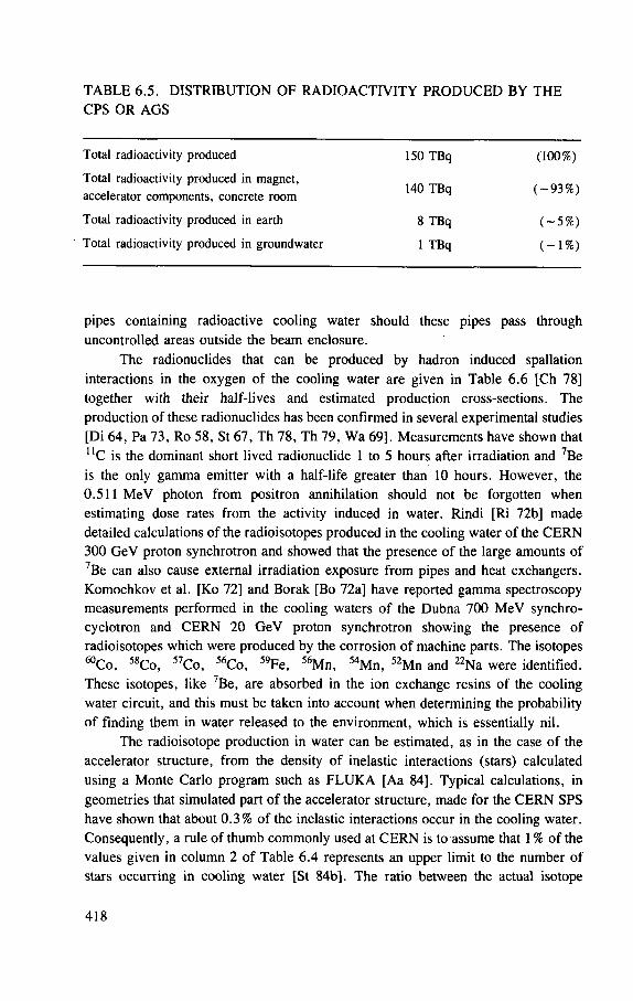
TABLE 6.5. DISTRIBUTION OF RADIOACTIVITY PRODUCED BY THE CPS OR AGS
Total radioactivity produced
Total radioactivity produced in magnet, accelerator components, concrete room
Total radioactivity produced in earth
Total radioactivity produced in groundwater
150 TBq
140 TBq
8 TBq
1 TBq
( - 9 3 % )
(100%)
( - 5 % )
(~1%)
pipes containing radioactive cooling water should these pipes pass through uncontrolled areas outside the beam enclosure.
The radionuclides that can be produced by hadron induced spallation interactions in the oxygen of the cooling water are given in Table 6.6 [Ch 78] together with their half-lives and estimated production cross-sections. The production of these radionuclides has been confirmed in several experimental studies [Di 64, Pa 73, Ro 58, St 67, Th 78, Th 79, Wa 69], Measurements have shown that " C is the dominant short lived radionuclide 1 to 5 hours after irradiation and 7Be is the only gamma emitter with a half-life greater than 10 hours. However, the 0.511 MeV photon from positron annihilation should not be forgotten when estimating dose rates from the activity induced in water. Rindi [Ri 72b] made detailed calculations of the radioisotopes produced in the cooling water of the CERN 300 GeV proton synchrotron and showed that the presence of the large amounts of 7Be can also cause external irradiation exposure from pipes and heat exchangers. Komochkov et al. [Ko 72] and Borak [Bo 72a] have reported gamma spectroscopy measurements performed in the cooling waters of the Dubna 700 MeV synchro-cyclotron and CERN 20 GeV proton synchrotron showing the presence of radioisotopes which were produced by the corrosion of machine parts. The isotopes ^ C o , 58Co, 5 7Co, 56Co, 59Fe, 56Mn, 5 4Mn, 52Mn and 22Na were identified. These isotopes, like 7Be, are absorbed in the ion exchange resins of the cooling water circuit, and this must be taken into account when determining the probability of finding them in water released to the environment, which is essentially nil.
The radioisotope production in water can be estimated, as in the case of the accelerator structure, from the density of inelastic interactions (stars) calculated using a Monte Carlo program such as FLUKA [Aa 84]. Typical calculations, in geometries that simulated part of the accelerator structure, made for the CERN SPS have shown that about 0.3% of the inelastic interactions occur in the cooling water. Consequently, a rule of thumb commonly used at CERN is to assume that 1 % of the values given in column 2 of Table 6.4 represents an upper limit to the number of stars occurring in cooling water [St 84b]. The ratio between the actual isotope
418
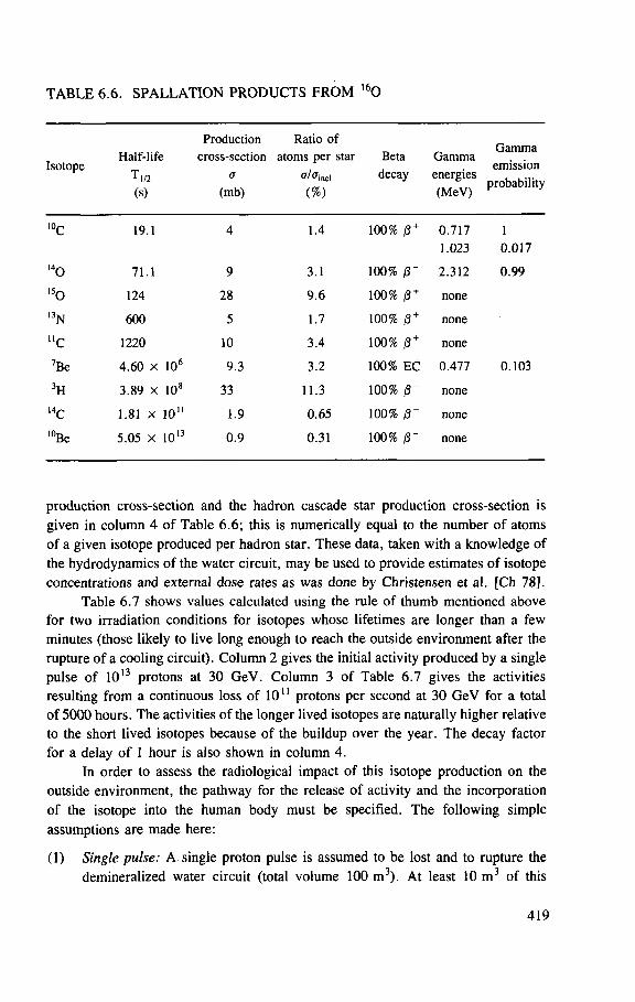
TABLE 6.6. SPALLATION PRODUCTS FROM 1 6 0
Production Ratio of Gamma
emission probability
Isotope Half-life
T„2 (S)
cross-section a
(mb)
atoms per star
inel (%)
Beta decay
Gamma energies (MeV)
Gamma emission
probability
10c 19.1 4 1.4 100% (3 + 0.717 1.023
1 0.017
l4o 71.1 9 3.1 100% |3 + 2.312 0 .99 l5o 124 28 9 . 6 100% 0 + none
l 3N 600 5 1.7 100% 0 + none
"c 1220 10 3 .4 100% /3 + none
7Be 4 .60 x 106 9.3 3.2 100% EC 0.477 0 .103
3H 3.89 x 10⁸ 33 11.3 100% 0 " none
l 4C 1.81 x 1 0 " 1.9 0 .65 100% none
l 0Be 5.05 x 10¹³ 0.9 0 .31 100% none
production cross-section and the hadron cascade star production cross-section is given in column 4 of Table 6.6; this is numerically equal to the number of atoms of a given isotope produced per hadron star. These data, taken with a knowledge of the hydrodynamics of the water circuit, may be used to provide estimates of isotope concentrations and external dose rates as was done by Christensen et al. [Ch 78].
Table 6.7 shows values calculated using the rule of thumb mentioned above for two irradiation conditions for isotopes whose lifetimes are longer than a few minutes (those likely to live long enough to reach the outside environment after the rupture of a cooling circuit). Column 2 gives the initial activity produced by a single pulse of 1013 protons at 30 GeV. Column 3 of Table 6.7 gives the activities resulting from a continuous loss of 1011 protons per second at 30 GeV for a total of 5000 hours. The activities of the longer lived isotopes are naturally higher relative to the short lived isotopes because of the buildup over the year. The decay factor for a delay of 1 hour is also shown in column 4.
In order to assess the radiological impact of this isotope production on the outside environment, the pathway for the release of activity and the incorporation of the isotope into the human body must be specified. The following simple assumptions are made here:
(1) Single pulse: A single proton pulse is assumed to be lost and to rupture the demineralized water circuit (total volume 100 m3) . At least 10 m 3 of this
419
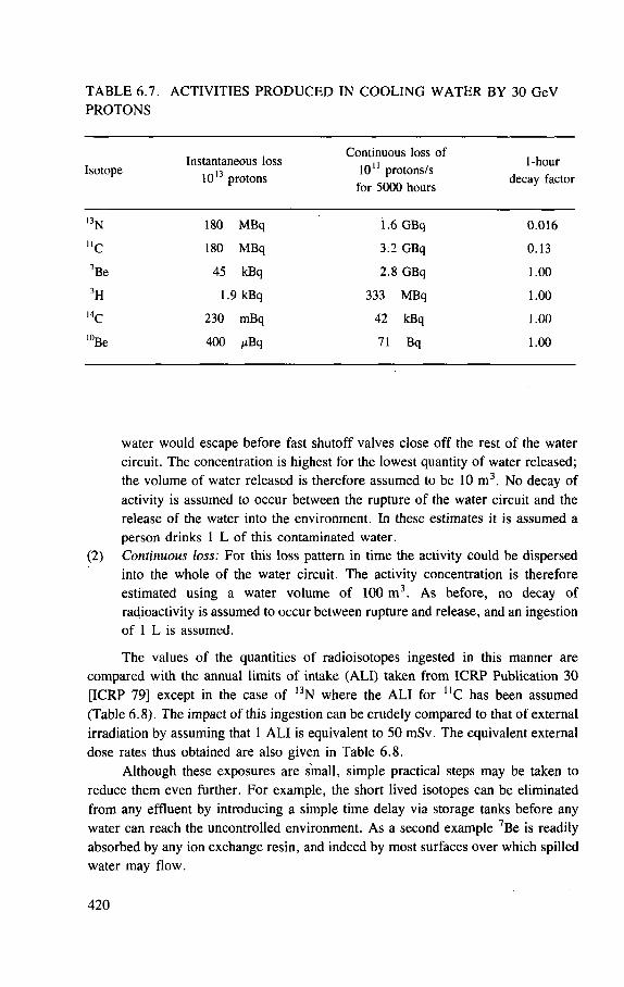
TABLE 6.7. ACTIVITIES PRODUCED IN COOLING WATER BY 30 GeV PROTONS
Isotope Instantaneous loss
1013 protons
Continuous loss of 10 " protons/s
for 5000 hours
1-hour decay factor
l 3N 180 MBq 1.6 GBq 0 .016
"c 180 MBq 3:2 GBq 0.13
7Be 45 kBq 2.8 GBq 1.00
3H 1.9 kBq 333 MBq 1.00
, 4 C 230 mBq 42 kBq 1.00
10Be 400 fiBq 71 Bq 1.00
water would escape before fast shutoff valves close off the rest of the water circuit. The concentration is highest for the lowest quantity of water released; the volume of water released is therefore assumed to be 10 m 3 . No decay of activity is assumed to occur between the rupture of the water circuit and the release of the water into the environment. In these estimates it is assumed a person drinks 1 L of this contaminated water.
(2) Continuous loss: For this loss pattern in time the activity could be dispersed into the whole of the water circuit. The activity concentration is therefore estimated using a water volume of 100 m 3 . As before, no decay of radioactivity is assumed to occur between rupture and release, and an ingestion of 1 L is assumed.
The values of the quantities of radioisotopes ingested in this manner are compared with the annual limits of intake (ALI) taken from ICRP Publication 30 [ICRP 79] except in the case of 13N where the ALI for U C has been assumed (Table 6.8). The impact of this ingestion can be crudely compared to that of external irradiation by assuming that 1 ALI is equivalent to 50 mSv. The equivalent external dose rates thus obtained are also given in Table 6.8.
Although these exposures are small, simple practical steps may be taken to reduce them even further. For example, the short lived isotopes can be eliminated from any effluent by introducing a simple time delay via storage tanks before any water can reach the uncontrolled environment. As a second example 7Be is readily absorbed by any ion exchange resin, and indeed by most surfaces over which spilled water may flow.
420
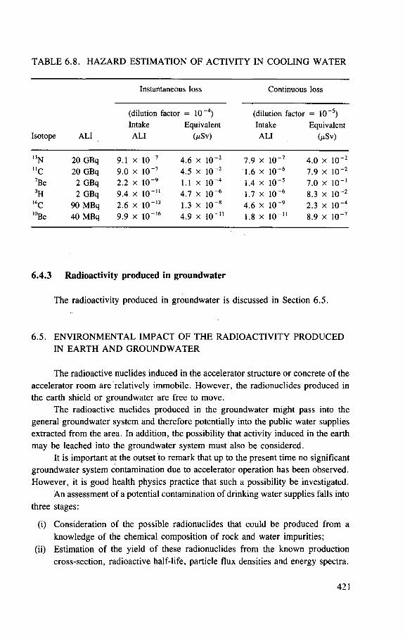
TABLE 6.8. HAZARD ESTIMATION OF ACTIVITY IN COOLING WATER
Instantaneous loss Continuous loss
(dilution factor = 10" 4 ) (dilution factor = 10" 5 ) Intake Equivalent Intake Equivalent
Isotope ALI ALI (jtSv) ALI (/xSv)
13N 20 GBq 9.1 x 10 - 7 4.6 x 10 - 2 7.9 x 10 - 7 4.0 x 10 - 2
"c 20 GBq 9 .0 x 10 - 7 4 .5 x 10 - 2 1.6 x 10 - 6 7.9 x 10 - 2
7Be 2 GBq 2 .2 x 10 - 9 1.1 X 10 - 4 1.4 x 10 - 5 7.0 x 10 - 1
3H 2 GBq 9 .4 x 10 - 1 1 4.7 x 10 - 6 1.7 x 10 - 6 8.3 x 10 - 2
L4C 90 MBq 2 .6 x 10 - 1 3 1.3 x 10 - 8 4.6 x 10 - 9 2.3 x 10 - 4
10Be 40 MBq 9 .9 x 10 - 1 6 4 .9 x 10 -11 1.8 x 10 -11 8.9 x 10 - 7
6.4.3 Radioactivity produced in groundwater
The radioactivity produced in groundwater is discussed in Section 6.5.
6.5. ENVIRONMENTAL IMPACT OF THE RADIOACTIVITY PRODUCED IN EARTH AND GROUNDWATER
The radioactive nuclides induced in the accelerator structure or concrete of the accelerator room are relatively immobile. However, the radionuclides produced in the earth shield or groundwater are free to move.
The radioactive nuclides produced in the groundwater might pass into the general groundwater system and therefore potentially into the public water supplies extracted from the area. In addition, the possibility that activity induced in the earth may be leached into the groundwater system must also be considered.
It is important at the outset to remark that up to the present time no significant groundwater system contamination due to accelerator operation has been observed. However, it is good health physics practice that such a possibility be investigated.
An assessment of a potential contamination of drinking water supplies falls into three stages:
(i) Consideration of the possible radionuclides that could be produced from a knowledge of the chemical composition of rock and water impurities;
(ii) Estimation of the yield of these radionuclides from the known production cross-section, radioactive half-life, particle flux densities and energy spectra.
421
Should the yield of radionuclides estimated at stage (ii) be sufficiently high, then a third stage follows:
(iii) Estimation of the final specific concentration of radionuclides in local water supplies taking into account site hydrology, dilution, radioactive decay and chemical sorption.
Several authors have reported the observation of radionuclide production in earth and water, either in laboratory simulations or directly in the accelerator shield. None of them is complete, but together they give a fairly comprehensive picture of the most important radionuclides of concern.
6.5.1. Radionuclide production in water
The most obvious potential source of radioactive contamination of ground-water systems arises from the production of radionuclides directly in the water. Thermal neutron capture in hydrogen and spallation reactions in oxygen and dissolved substances in water may result in a large number of radionuclides. Because these radionuclides are produced directly in water which is mobile, there might be a possibility of their transfer from the site of activation (around the accelerator) and entry into local groundwater systems.
A review of studies prior to 1972 of the production of radionuclides in water around accelerators has been published by Stapleton and Thomas [St 72, Th 70] and more recent work has been discussed by Patterson, Rindi and Thomas [Pa 73, Th 79].
Table 6.6 lists the possible spallation products from 1 6 0 with half-lives longer than 10 s that will be produced directly in water (listed in order of increasing half-life). Nelson [Ne 65] reported the first studies of possible groundwater contamination due to a high energy accelerator, in estimating radionuclide production near beam dumps of the SLAC 20 GeV electron linac. Middlekoop [Mi 66], in a design study for a 300 GeV proton synchrotron, showed that spallation reactions in water could produce concentrations of 3H and 7Be many times greater than the maximum permissible concentrations recommended by the ICRP.
Measurements of the production of radionuclides in water irradiated in accelerator environments have identified U C as the dominant short lived radionuclide 1 to 5 hours after irradiation. The only gamma emitter with half-life greater than 10 hours that was produced in measurable quantities was 7Be and this had a cross-section of about 10 mb in a variety of experimental conditions. The production of tritium under these conditions was consistent with a production cross-section of 30-35 mb [St 67, St 71, St 72]. From this information and the data of Gilbert et al. [Gi 68], Stapleton and Thomas estimated that at saturation there are about 220 GBq (6 Ci) of 7Be and 670 GBq (18 Ci) of tritium in the groundwater of
422
the earth shield around a 300 GeV proton accelerator operating at an intensity of 3 x 10¹³ protons • s ~1 [St 72],
6.5.2. Radionuclides resulting from dissolved solids in water
Middlekoop [Mi 66] was the first to estimate the specific activity due to irradiation of the impurities dissolved in groundwater. His investigation was limited to those radionuclides produced by thermal neutron capture and to only a single example, the groundwater of a chalk region in the United Kingdom.
Middlekoop showed that no nuclides are produced in concentrations at saturation comparable to the maximum permissible concentration (MPC), with the exception of 36C1. This radionuclide will be of no consequence, however, because its half-life of 3 x 10⁵ years will result in an extremely low production rate.
In the experiments of Stapleton and Thomas, [St 67, St 71, St 72] the presence of 32P in the dissolved solids of irradiated groundwater taken from the chalk site was detected. However, 32P is fixed in chalk in the form of calcium phosphate and would not be expected to be mobile in groundwater in chalk soil [B1 nd].
The special problems of corrosion products in cooling water have been discussed in Section 6.4.
6.5.3. Radionuclides produced in the earth
As in the case of groundwater, several studies of the production of radionuclides in earth have been made and the results are summarized in Table 6.9. From the chemical composition of the soil at the CERN site and measurements of particle flux densities in the CPS earth shield, Hoyer [Ho 68] calculated the specific activity of radionuclides to be expected in the soil. He concluded that only four radionuclides were produced in measurable quantities. To check his calculations, Hoyer compared his estimates with measured values of the specific activity of 45Ca and 22Na found in earth taken from several locations in the earth shield. Measured activities were, in general, lower by a factor of 3 than those calculated, which Hoyer attributed to leaching of these nuclides from the site by rain water. Hoyer took the rough agreement between his measured and calculated values to confirm his suggestion that only four radionuclides will be of significance. The production of tritium was not considered in this study.
In studying the radiological impact of the 500 GeV proton synchrotron of the Fermi National Accelerator Laboratory, Borak et al. [Bo 72b] irradiated glacial till and various clay soils in typical high energy accelerator radiation fields. Table 6.9 summarizes the radionuclides identified in these soils.
Since operation of the Fermilab 500 GeV accelerator, an extensive programme monitoring the radioactivity in earth and groundwaters at critical areas on the accelerator site has been developed [Ba 75a,b]. Water samples are collected from
423
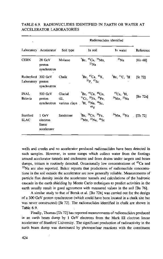
TABLE 6.9. RADIONUCLIDES IDENTIFIED IN EARTH OR WATER AT ACCELERATOR LABORATORIES
Radionuclides identified
Laboratory Accelerator Soil type In soil In water Reference
C E R N 28 GeV
proton synchrotron
Molasse 7Be, 4 5Ca, 5 4Mn, 2 2Na
2 2Na [Ho 68]
Rutherford Laboratory
300 GeV proton synchrotron
Chalk 7Be, 4 7Ca, « K , 3 2P, 4 7Sc
7Be, " C , 3 H [St 72]
I N A L Batavia
500 GeV proton synchrotron
Glacial till, various clays
7Be, 4 5Ca, ^ C o , 5 1Cr, 5 5Fe, 5 9Fe, 3 H, 2 2Na, 4 6Sc,
4 8 y
4 5Ca, 3 H, 5 4Mn, 2 2Na
[Bo 72a]
Stanford SLAC
1 GeV electron linear accelerator
Sandstone 7Be, 5 8Co, 5 9Fe, 5 4Mn, 2 2Na, 4 6Sc
5 4Mn, 2 2Na [Th 72]
wells and creeks and no accelerator produced radionuclides have been detected in such samples. However, in some sumps which collect water from the footings around accelerator tunnels and enclosures and from drains under targets and beam dumps, tritium is routinely detected. Occasionally low concentrations of 45Ca and 22Na are also reported. Baker reports that predictions of radionuclide concentra-tions in the soil outside the accelerator are now generally reliable. Measurements of particle flux density inside the accelerator tunnels and calculations of the hadronic cascade in the earth shielding by Monte Carlo techniques to predict activities in the earth usually result in good agreement with measured values in the soil [Ba 76].
A similar study to that of Borak et al. [Bo 72b] was carried out for the design of a 300 GeV proton synchrotron (which could have been located in a chalk site but was never constructed) [St 72]. The radionuclides identified in chalk are shown in Table 6.9.
Finally, Thomas [Th 72] has reported measurements of radionuclides produced in an earth beam dump by 1 GeV electrons from the Mark III electron linear accelerator of Stanford University. The significant production of radioactivity in the earth beam dump was dominated by photonuclear reactions with the constituent
424
elements of the soil. The data obtained in this series of measurements were in good agreement with electromagnetic cascade theory.
6.5.4. Migration of radionuclides through the ground
A large number of radionuclides may be produced in the earth and ground-water by high energy accelerator production. However, the ultimate concentration of radionuclides in the groundwater will then be controlled by the half-life of the radioactive species, solubility of the radionuclide, its possible dilution and the site hydrology. Radionuclides with too short a half-life will decay so rapidly as to be of no potential hazard when they reach a public water supply. Conversely, if the half-life is too long saturation activities will not be approached.
Knowledge of the hydrology of the accelerator site being studied will indicate the range of radioactive half-lives that are of interest. It is reasonable to study radio-nuclides with half-lives TH in the range:
10 h < TH < 100 a
It should be noted that this general consideration limits the number of radionuclides that can appear in maximal quantities in groundwater systems. In practice, therefore, only a small number of radionuclides usually need to be studied in detail. Detailed investigation of site conditions will identify the appropriate range to be investigated. In particular, the production of 3H, 7Be, 22Na, 54Mn, and 45Ca merits detailed study.
Not all the radioactivity produced will be in soluble chemical form. Thus, for example, less than 0.7% of the gamma activity (principally 54Mn and 22Na) produced in the earth dump of the Mark III electron linac was soluble [Th 72]. Borak et al. [Bo 72b] have made detailed studies of the solubility of the radionuclides produced in glacial till (Table 6.9). Of these radionuclides only 45Ca, 54Mn, 22Na and 3H were observed in leach waters. Of 45Ca and 54Mn, only a fraction of the activity (5% and 2% respectively) was readily soluble.
However, even the production of radionuclides in soluble form in the earth shield and the appearance of radioactive species in the groundwater are not necessarily indicative of environmental harm — the radionuclides may be immobile. In a review of the movement of radioactive wastes buried in the ground, Mawson reports that "with few exceptions, absorption and exchange processes occur between the radionuclides and constituents of the soil. If the site is selected with care any radionuclides that enter the soil will progress quite slowly down the water table. Once in the groundwater they will move faster, but still at a rate one to several orders of magnitude less than the rate of movement of the groundwater. These statements apply to most cations — many anions move at about the same speed as the ground-water" [Ma 69].
425
The greater part of radioactivity induced in the soil is confined to regions of high radiation intensity and is typically confined to a few locations close to the accelerator. Stapleton and Thomas [St 72] estimate that 95 % of the activity induced in earth is produced within 2 m from the outer wall of the accelerator tunnel of a proton synchrotron. In the absence of migration of any radionuclides from the activation zone, the radioactivity would increase to a final saturation determined by the accelerator intensity, the nuclear cascade process in the shield and the macroscopic cross-sections for radionuclide production in rock and groundwater.
Migration of the radionuclides will be determined by the distribution coefficient K, which is a measure of the relative affinity of the radionuclide for earth compared with water. It is defined as the ratio of the concentration of ions absorbed by the soil to those remaining in solution at equilibrium. A large value of K indicates that ions preferentially adhere to soil and their migration is retarded.
The average velocity of ions through the earth vs is related to the velocity of the water vw by the equation:
VI 1 — = (6.13)
vw 1 + K O/P)
where
K is the distribution coefficient, p is the bulk density of the rock, and P is the porosity of the rock (fraction of total volume of soil occupied by
voids).
For large distribution coefficients Eq. (6.13) reduces to:
Table 6.10 summarizes measurements of the distribution coefficient K for some radionuclides in various soils.
If the distribution coefficient is high, the potential for contamination of public water supplies is much reduced. Thus Stapleton and Thomas point out that for 7Be in chalk the beryllium ions move more slowly than the groundwater by a factor of about 15 000. Under these conditions migration rates would be so slow that radio-active decay will reduce the original activity to negligible levels [St 73]. In the case of 22Na there seems to be a significant difference between the observations of Hoyer, who determined a distribution coefficient of 100 at CERN, and those of Borak et al. at FNAL. The latter workers found that in the case of 22Na, 10-20%
426
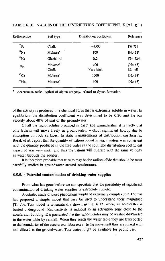
TABLE 6.10. VALUES OF THE DISTRIBUTION COEFFICIENT, K (mL • g " ' )
Radionuclide Soil type Distribution coefficient Reference
7Be Chalk - 4 5 0 0 [St 73]
2 2Na Molasse" 100 [Ho 68]
2 2Na Glacial till 0 .2 [Bo 72b]
3 2 p Molasse3 100 [Ho 68]
Chalk Very high [B1 nd]
4 5Ca Molasse3 1000 [Ho 68]
5 4Mn Molasse3 100 [Ho 68]
3 Arenaceous rocks, typical of alpine orogeny, related to flysch formation.
of the activity is produced in a chemical form that is extremely soluble in water. In equilibrium the distribution coefficient was determined to be 0.20 and the ion velocity about 40% of that of the groundwater.
Of all the radionuclides produced in earth and groundwater, it is likely that only tritium will move freely in groundwater, without significant holdup due to absorption on rock surfaces. In static measurements of distribution coefficients, Borak et al. report that the quantity of tritium found in leach waters was consistent with the quantity produced in the free water in the soil. The distribution coefficient measured was very small and thus the tritium will migrate with the same velocity as water through the aquifer.
It is therefore probable that tritium may be the radionuclide that should be most carefully studied in groundwater around accelerators.
6.5.5. • Potential contamination of drinking water supplies
From what has gone before we can speculate that the possibility of significant contamination of drinking water supplies is extremely remote.
A detailed study of these phenomena would be extremely complex, but Thomas has proposed a simple model that may be used to understand their magnitude [Th 70], This model is schematically shown in Fig. 6.12, where an accelerator is buried underground. Radioactivity is induced in an activation zone close to the accelerator building. It is postulated that the radionuclides may be washed downward to the water table by rainfall. When they reach the water table they are transported to the boundaries of the accelerator laboratory. In the movement they are mixed with and diluted in the groundwater. This water might be available for public use.
427
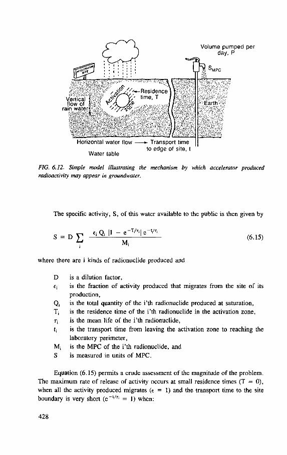
Vertical (low of >
rain water
Q Volume pumped per day, P
L n K
/ ^ Residence time. T ;
Horizontal water flow — T r a n s p o r t t ime to edge of site, t
MPC
Earth.
Water table
FIG. 6.12. Simple model illustrating the mechanism by which accelerator produced radioactivity may appear in groundwater.
The specific activity, S, of this water available to the public is then given by
f. n II — e
-T
i/T
i| e-t
'/T
i S
= D
E ' ° (6-15) Mj
i
where there are i kinds of radionuclide produced and
D is a dilution factor, €i is the fraction of activity produced that migrates from the site of its
production, Qi is the total quantity of the i'th radionuclide produced at saturation, T| is the residence time of the i'th radionuclide in the activation zone, 7; is the mean life of the i'th radionuclide, tj is the transport time from leaving the activation zone to reaching the
laboratory perimeter, M; is the MPC of the i'th radionuclide, and S is measured in units of MPC.
Equation (6.15) permits a crude assessment of the magnitude of the problem. The maximum rate of release of activity occurs at small residence times (T = 0), when all the activity produced migrates (e = 1) and the transport time to the site boundary is very short (e_t i /Ti = 1) when:
428
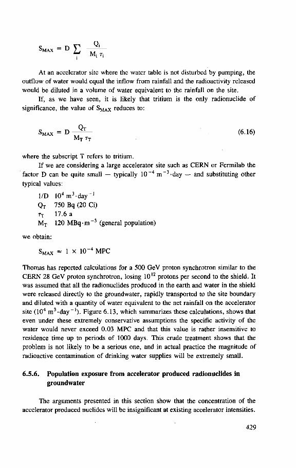
S M A X - D £ MQ ' T j
At an accelerator site where the water table is not disturbed by pumping, the outflow of water would equal the inflow from rainfall and the radioactivity released would be diluted in a volume of water equivalent to the rainfall on the site.
If, as we have seen, it is likely that tritium is the only radionuclide of significance, the value of S M A X reduces to:
Smax =
D ~ ~ ~ (6.16) M
t Tj
where the subscript T refers to tritium. If we are considering a large accelerator site such as CERN or Fermilab the
factor D can be quite small — typically 10 ~4 m~ 3 -day — and substituting other typical values:
1/D 1 0 4 m 3 - d a y _ 1
Q t 750 Bq (20 Ci) 7T 17.6 a M t 120 MBQ-m~3 (general population)
we obtain:
'MAX = 1 x 10~4 MPC
Thomas has reported calculations for a 500 GeV proton synchrotron similar to the CERN 28 GeV proton synchrotron, losing 1012 protons per second to the shield. It was assumed that all the radionuclides produced in the earth and water in the shield were released directly to the groundwater, rapidly transported to the site boundary and diluted with a quantity of water equivalent to the net rainfall on the accelerator site (104 m 3 - d a y - 1 ) . Figure 6.13, which summarizes these calculations, shows that even under these extremely conservative assumptions the specific activity of the water would never exceed 0.03 MPC and that this value is rather insensitive to residence time up to periods of 1000 days. This crude treatment shows that the problem is not likely to be a serious one, and in actual practice the magnitude of radioactive contamination of drinking water supplies will be extremely small.
6.5.6. Population exposure from accelerator produced radionuclides in groundwater
The arguments presented in this section show that the concentration of the accelerator produced nuclides will be insignificant at existing accelerator intensities.
429
FIG. 6.13. Specific activity of accelerator produced radionuclides in groundwater at a hypothetical 500 GeV accelerator site, as a junction of water time T in the activation zone.
The radioactivity from natural sources will in fact be higher by orders of magnitude than that from accelerator produced nuclides.
There have been no reported observations of accelerator produced radio-nuclides in public water supplies and experience shows the consequent population dose equivalent to therefore be effectively zero.
6.6. RADIOACTIVITY PRODUCED IN THE ATMOSPHERE
The second most important source of exposure resulting from accelerators is from radioactivity produced in the air. Typically, the magnitude of this exposure is many times smaller than that from prompt radiation.
6.6.1. Radionuclides produced in air by accelerator operation
The principal source of radioactivity in air is the interaction of primary and secondary particles directly with constituent target nuclei of the air. A secondary source of airborne radioactivity is dust, formed by natural erosion and wear or by
430
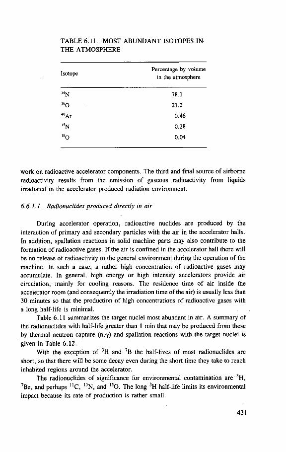
TABLE 6.11. MOST ABUNDANT ISOTOPES IN THE ATMOSPHERE
Isotope Percentage by volume
in the atmosphere
l 4N 78.1
l 6 0 21.2
^ A r 0 .46
i 5N 0.28
1 8 0 0 .04
work on radioactive accelerator components. The third and final source of airborne radioactivity results from the emission of gaseous radioactivity from liquids irradiated in the accelerator produced radiation environment.
6.6.1.1. Radionuclides produced directly in air
During accelerator operation, radioactive nuclides are produced by the interaction of primary and secondary particles with the air in the accelerator halls. In addition, spallation reactions in solid machine parts may also contribute to the formation of radioactive gases. If the air is confined in the accelerator hall there will be no release of radioactivity to the general environment during the operation of the machine. In such a case, a rather high concentration of radioactive gases may accumulate. In general, high energy or high intensity accelerators provide air circulation, mainly for cooling reasons. The residence time of air inside the accelerator room (and consequently the irradiation time of the air) is usually less than 30 minutes so that the production of high concentrations of radioactive gases with a long half-life is minimal.
Table 6.11 summarizes the target nuclei most abundant in air. A summary of the radionuclides with half-life greater than 1 min that may be produced from these by thermal neutron capture (n,Y) and spallation reactions with the target nuclei is given in Table 6.12.
With the exception of 3H and 7B the half-lives of most radionuclides are short, so that there will be some decay even during the short time they take to reach inhabited regions around the accelerator.
The radionuclides of significance for environmental contamination are 3H, 7Be, and perhaps U C , 13N, and 1 5 0. The long 3H half-life limits its environmental impact because its rate of production is rather small.
431
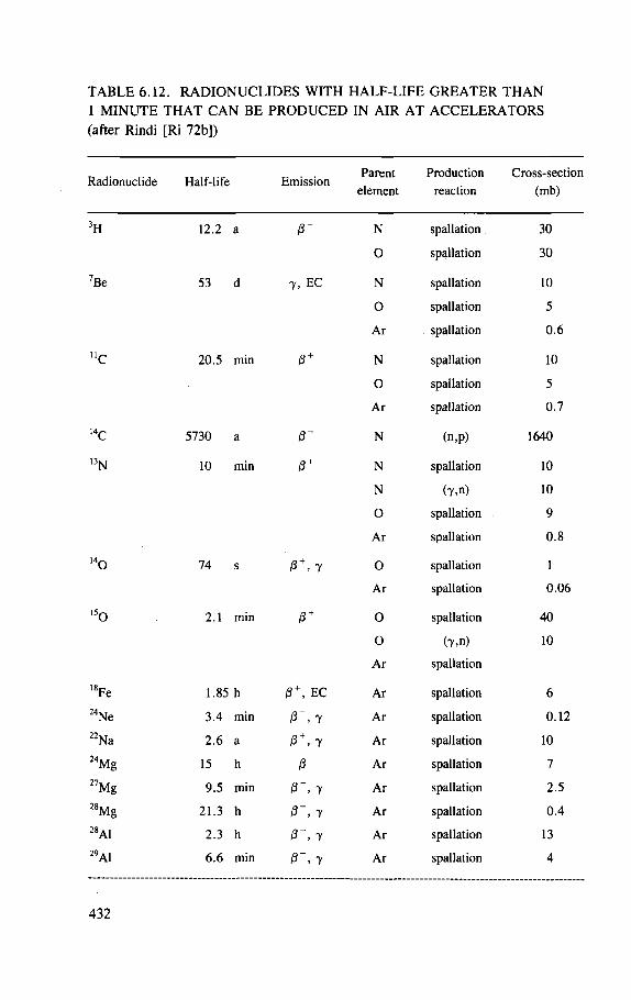
TABLE 6.12. RADIONUCLIDES WITH HALF-LIFE GREATER THAN 1 MINUTE THAT CAN BE PRODUCED IN AIR AT ACCELERATORS (after Rindi [Ri 72b])
Radionuclide Half-life Emission Parent
element Production
reaction Cross-section
(mb)
3H 12.2 a 0 " N spallation 30
O spallation 30
7Be 53 d 7 , EC N spallation 10
0 spallation 5
Ar spallation 0.6
" C 20.5 min R N spallation 10
0 spallation 5
Ar spallation 0.7
14c 5730 a N (n,p) 1640
, 3N 10 min N spallation 10
N (Y.n) 10
O spallation 9
Ar spallation 0 .8
l 4 0 74 s P + , 7 O spallation 1
Ar spallation 0 .06
15o 2.1 min /3 + 0 spallation 40
O (7.n) 10
Ar spallation
l 8Fe 1.85 h EC Ar spallation 6
2 4Ne 3.4 min 7 Ar spallation 0.12
22Na 2.6 a 0 + , 7 Ar spallation 10 24Mg 15 h R Ar spallation 7
" M g 9.5 min 0 ~ , y Ar spallation 2.5
28Mg 21.3 h y Ar spallation 0 .4 28A1 2.3 h y Ar spallation 13 29AI 6.6 min , y Ar spallation 4
432
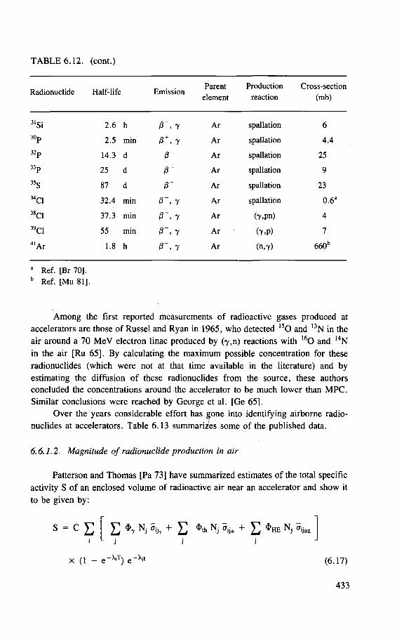
TABLE 6.12. (cont.)
„ . . Parent Production Cross-section Radionuclide Half-life Emission , , , „
element reaction (mb)
31Si 2.6 h 0 ~ , . 7 Ar spallation 6 30p 2.5 min @ + •. . 7 Ar spallation 4.4 32p 14.3 d 0 ' Ar spallation 25 33p 25 d 0 ' Ar spallation 9 35s 87 d 0 ' Ar spallation 23 34C1 32.4 min 0 ~ , 7 Ar spallation 0.6:
38C1 37.3 min 0 ~ , - 7 Ar (y.pn) 4 39C1 55 min 0 ~ , 7 Ar (7.P) 7 4 1Ar 1.8 h 0 ~ , • 7 Ar (n,7) 660b
Ref. [Br 70], Ref. [Mu 81].
Among the first reported measurements of radioactive gases produced at accelerators are those of Russel and Ryan in 1965, who detected l s O and 13N in the air around a 70 MeV electron linac produced by (Y,n) reactions with 1 6 0 and 14N in the air [Ru 65]. By calculating the maximum possible concentration for these radionuclides (which were not at that time available in the literature) and by estimating the diffusion of these radionuclides from the source, these authors concluded the concentrations around the accelerator to be much lower than MPC. Similar conclusions were reached by George et al. [Ge 65],
Over the years considerable effort has gone into identifying airborne radio-nuclides at accelerators. Table 6.13 summarizes some of the published data.
6.6.1.2. Magnitude of radionuclide production in air
Patterson and Thomas [Pa 73] have summarized estimates of the total specific activity S of an enclosed volume of radioactive air near an accelerator and show it to be given by:
s = c E E * y n j + E * * n j + E * h e n J ffy™
x (1 - e ' ) e (6.17)
433
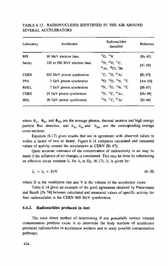
TABLE 6.13. RADIONUCLIDES IDENTIFIED IN THE AIR AROUND SEVERAL ACCELERATORS
Laboratory Accelerator Radionuclides
identified Reference
RPI 50 MeV electron linac 15o, 13N [Ru 65]
Saclay 330 to 560 MeV electron linac 13N, 4 1Ar,
,50, "c, 38C1, 7Be
[Vi 69]
C E R N 600 MeV proton synchrotron "c, 13N, 41 Ar [Ri 67]
PPA 3 GeV proton synchrotron 140, 150, 13N, "c [Aw 65]
R H E L 7 GeV proton synchrotron 16N, 150, I 3N, " C [Sh 67]
C E R N 25 GeV proton synchrotron 13N, " C , 4 1Ar, [Ho 69]
B N L 30 GeV proton synchrotron 13N, llc, 4 l A r [Di 64]
where <J>7, 4>th, and $ H E are the average photon, thermal neutron and high energy particle flux densities, and a i h , and ajjHE are the corresponding average cross-sections.
Equation (6.17) gives results that are in agreement with observed values to within a factor of two or better. Figure 6.14 compares calculated and measured values of activity around the accelerators at CERN [Ri 67].
Quite accurate estimates of the concentration of radioactivity in air may be made if the influence of air changes is considered. This may be done by substituting an effective decay constant X- for X; in Eq. (6.17); X- is given by:
X:' = Xi + D/V (6.18)
where D is the ventilation rate and V is the volume of the accelerator room. Table 6.14 gives an example of the good agreement obtained by Peetermans
and Baarli [Pe 74] between calculated and measured values of specific activity for four radionuclides at the CERN 600 MeV synchrotron.
6.6.2. Radionuclides produced in dust
The most direct method of determining if any potentially serious internal contamination problem exists is to determine the body burdens of accelerator produced radionuclides in accelerator workers and to study possible contamination pathways.
434
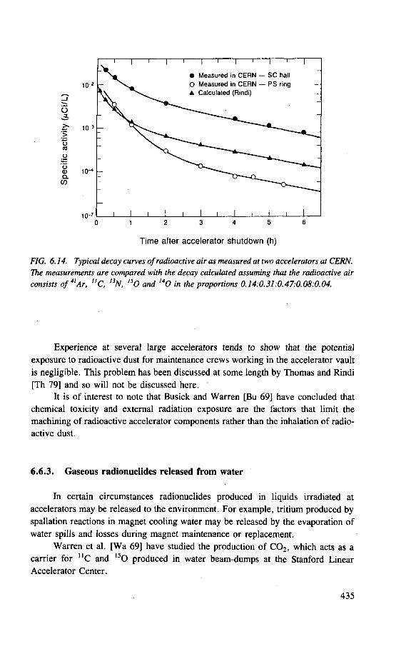
10-
10"'
1 0 " '
1 0 "
T T T ~r T i
• Measured in CERN — SC hall O Measured in CERN — PS ring • Calculated (Rindi)
Time after accelerator shutdown (h)
FIG. 6.14. Typical decay curves of radioactive air as measured at two accelerators at CERN. The measurements are compared with the decay calculated assuming that the radioactive air consists of 41 Ar, "C, 13N, 15O and I40 in the proportions 0.14:0.31:0.47:0.08:0.04.
Experience at several large accelerators tends to show that the potential exposure to radioactive dust for maintenance crews working in the accelerator vault is negligible. This problem has been discussed at some length by Thomas and Rindi [Th 79] and so will not be discussed here.
It is of interest to note that Busick and Warren [Bu 69] have concluded that chemical toxicity and external radiation exposure are the factors that limit the machining of radioactive accelerator components rather than the inhalation of radio-active dust.
6.6.3. Gaseous radionuclides released from water
In certain circumstances radionuclides produced in liquids irradiated at accelerators may be released to the environment. For example, tritium produced by spallation reactions in magnet cooling water may be released by the evaporation of water spills and losses during magnet maintenance or replacement.
Warren et al. [Wa 69] have studied the production of C 0 2 , which acts as a carrier for U C and 1 5 0 produced in water beam-dumps at the Stanford Linear Accelerator Center.
435
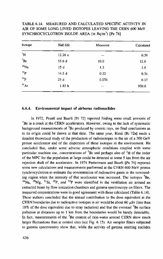
TABLE 6.14. MEASURED AND CALCULATED SPECIFIC ACTIVITY IN AIR OF SOME LONG LIVED ISOTOPES LEAVING THE CERN 600 MeV SYNCHROCYCLOTRON ISOLDE AREA (in Bq/m3) [Pe 74]
Isotope Half-life Measured Calculated
3H 12.26 a 0 .59 7Be 53.6 d ]().() 12.0 2 4Na 15 d 1.3 1.8 32p 14.5 d 0 .22 0.31 33p 25 d 0 .074 0 .17 4 l A r 1.83 h — 930.0
6.6.4. Environmental impact of airborne radionuclides
In 1972, Prantl and Baarli [Pr 72] reported finding some small amounts of 7Be in a creek at the CERN accelerators. However, owing to the lack of systematic background measurements of 7Be produced by cosmic rays, no final conclusions as to its origin could be drawn at that time. The same year, Rindi [Ri 72a] made a detailed theoretical study of the production of radioisotopes in the air of a 300 GeV proton accelerator and of the dispersion of these isotopes in the environment. He concluded that, under some adverse atmospheric conditions coupled with some particular machine use, concentrations of 7Be and perhaps also of 3H of the order of the MPC for the population at large could be detected at some 5 km from the air rejection shaft of the accelerator. In 1974 Peetermans and Baarli [Pe 74] reported some new calculations and measurements performed at the CERN 600 MeV proton synchrocyclotron to estimate the concentration of radioactive gases in the surround-ing region when the intensity of that accelerator was increased. The isotopes 7Be, 24Na, 28Mg, 3 'Si, 32P, and 33P were identified in the ventilation air around an extracted beam by flow ionization chambers and gamma spectroscopy on filters. The measured concentrations were in good agreement with those calculated (Table 6.14). These authors concluded that the annual contribution to the dose equivalent at the CERN boundaries due to radioactive isotopes in air would be about 60 ^Sv (less than 10% of the dose equivalent due to stray radiation) and that the eventual 7Be surface pollution at distances up to 1 km from the boundaries would be barely detectable. In fact, measurements of the 7Be content of rain-water around CERN show much larger fluctuations than at control sites (see Fig. 6.15). Air sampler filters subjected to gamma spectrometry show that, while the activity of gamma emitting nuclides
436
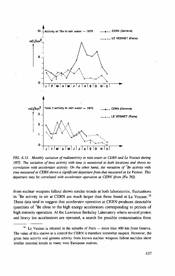
10 _
m C i / k m 2
5 _
Activity of 7Be in rain water — 1975 — « — C E R N (Geneva)
* LE V E S I N E T (Paris)
\
j I F I M I A I M I J I J I A I s I O I N I D
FIG. 6.15. Monthly variation of radioactivity in rain-water at CERN and Le Vesinet during 1975. The variation of beta activity with time is monitored at both locations and shows no correlation with accelerator activity. On the other hand, the variation of 7Be activity with time measured at CERN shows a significant departure from that measured at Le Vesinet. This departure may be correlated with accelerator operation at CERN (from [Fa 76]).
from nuclear weapons fallout shows similar trends at both laboratories, fluctuations in 7Be activity in air at CERN are much larger than those found at Le Vesinet.16
These data tend to suggest that accelerator operation at CERN produces detectable quantities of ?Be close to the high energy accelerators corresponding to periods of high intensity operation. At the Lawrence Berkeley Laboratory where several proton and heavy ion accelerators are operated, a search for possible contamination from
16 Le Vesinet is situated in the suburbs of Paris — more than 400 km f rom Geneva. The value of this station as a control for C E R N is therefore somewhat suspect. However , the gross beta activity and gamma activity f rom known nuclear weapons fallout nuclides show similar seasonal trends at many west European stations.
437
7Be was made by measuring the radioactivity of bracken ferns collected around the centre and at different locations several miles away. These studies show that the ?Be contamination in air due to the presence of the accelerators at the Berkeley laboratory, if any, is within the variation of the background produced by cosmic rays [Sm 77],
The measurement of the concentration of 7Be in air or in dust around accelerators may prove to be a valuable indicator of radioactive contamination. Further studies are needed, including measurements of the natural background fluc-tuation of 7Be in rain-water.
6.6.5. Population exposure from radioactivity in the air
Four short lived radionuclides — 10C, n C , 12N and l 5 0 — typically account for the major portion of the total activity released. Of the longer lived radionuclides only 41Ar, 7Be and 3H are released in significant quantities.
The calculation of population exposure resulting from the release of these gaseous radionuclides is normally performed according to the following steps:
(1) Measurement or calculation of the concentration of the different radioisotopes released at the ventilation stacks of the accelerators.
(2) Calculation of the transport of the gases outside the boundaries of the laboratory. This is generally done by applying the Sutton equation for some average meteorological conditions.
(3) Conversion of the concentrations of radioactive gases to dose equivalent to an exposed individual by using the MPC values.
(4) Summation of the total number of exposed individuals and their dose equivalent to give the total population dose.
Steps 2, 3 and 4 can be summarized in a general equation. Thomas [Th 76a] has described the use of the following expression to calculate the population dose equivalent resulting from the release of a given radionuclide that applies for the Lawrence Berkeley Laboratory, but which can be easily generalized
where
n
fi
£ 1 \ 2 t J \ 2 t ) U J r o raz(r) J
is the number of sectors into which the region surrounding the source is divided (this division is decided by the wind direction frequencies); is the fraction of time in which the wind blows towards a given sector;
438
Q is the total quantity of radionuclide released (in Bq); R is the dose equivalent conversion factor for the given radionuclide
(Sv-m3 per Bq-s); u is the average wind velocity (in m-s~ ' ) ; r is the distance from the rejection point; Nj(r) dr is the total number of people in the i'th sector in the region between
r and r + dr; r0 is the distance of closest approach to the laboratory; and az(r) is the vertical dispersion coefficient (in m).
The integral can be simplified into a summation by subdividing each sector into m regions in which the population density may be assumed to be constant.
The number of residents at a distance r from the rejection point in the j ' th region of the i'th sector is then given by
jNj(r) = — ay dr (6.20) n
where ay is the population density. The expression between square brackets in Eq. (6.19) can be expressed by
^ f, QRffij p
S Jrj-jMi = (2/t)* \' (6.21)
1
and the population dose equivalent is then expressed by
M = D D Jm i
(6
'2 2 )
i=i J=I
From the meteorological statistics for the region under study, az(r) can be given an analytical expression as a function of r such that the integral in Eq. (6.21) can be evaluated.
It is customary at accelerator centres to report yearly on environmental monitoring results. Several centres perform continuous measurements of gaseous radioactivity in air, in addition to radioactivity deposited on filters, and also periodi-cally investigate the radioactivity on ground, water and plants around the boundaries of the centre.
439
At the Fermi Laboratory in Batavia, where a 300 GeV proton synchrotron is located, the annual off-site exposure from airborne release was estimated to be about 91 mSv, one-tenth of the exposure from external radiation during 1975 [Ba 76].
At the Lawrence Berkeley Laboratory, where several proton and heavy ion accelerators are located, the air monitoring systems detect releases of radioactive gas only from chemistry laboratories and not from accelerator operation [Th 76b],
440
Appendix 6.1
NEUTRON IMPORTANCE FUNCTIONS
441
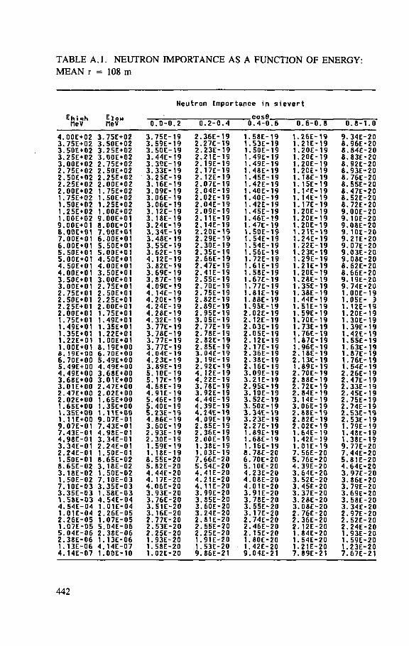
TABLE A . l . NEUTRON IMPORTANCE AS A FUNCTION OF ENERGY: MEAN r = 108 m
Neutron Importance in sievert
E h i i h MeV
E low MeV
COS0 1.4-0
E h i i h MeV
E low MeV 0 .0-0 .2 (1 1.2-0 .4 0
COS0 1.4-0 .6 0 1.6-0 .8 0.8-1 .0
4 . 0 0 E + 0 2 3. 75E+02 3. 75E- 19 2 . 36E- 19 1. 58E- 19 1. 26E- 19 9. 34E- 20 3. 7 5 E + 0 2 3. 50E+02 3. 59E- 19 2 . 27E- 19 1. 53E- 19 1. 21E- 19 8 . 96E- 20 3 . 5 0 E + 0 2 3 . 25E+02 3 . 50E- 19 2 . 23E- 19 1. 50E- 19 1. 20E- 19 8. 84E- 20 3. 2 5 E + 0 2 3. 0 0 E + 0 2 3. 44E- 19 2 . 21E- 19 1. 49E- 19 1. 20E- 19 8 . 83E- 20 3 . 0 0 E + 0 2 2 . 75E+02 3 . 39E- 19 2 . 19E- 19 1. 49E- 19 1. 20E- 19 8 . 92E- 20 2 . 75E+02 2 . 50E+02 3 . 33E- 19 2 . 17E- 19 1. 48E- 19 1. 2CE- 19 8 . 93E- 20 2 . 5 0 E + 0 2 2 . 25E+02 3. 25E- 19 2 . 12E- 19 1. 45E- 19 1. 18E- 19 8. 76E- 20 2 . 2 5 E + 0 2 2 . 00E+02 3. 16E- 19 2 . 07E- 19 1. 42E- 19 1. 15E- 19 8 . 55E- 20 2 . 0 0 E + 0 2 1. 75E+02 3. 09E- 19 2 . 04E- 19 1. 40E- 19 1. 1'E- 19 8 . 47E- 20 1. 75E+02 1. 50E+02 3. 06E- 19 2 . 02E- 19 1. 40E- 19 1. 14E- 19 8 . 52E- 20 1. 5 0 E + 0 2 1. 25E+02 3. 06E- 19 2 . 04E- 19 1. 42E- 19 1. 17E- 19 8. 72E- 20 1. 2 5 E + 0 2 1. 00E+02 3. 12E- 19 2 . 09E- 19 1. 45E- 19 1. 20E- 19 9. OOE- 20 1. 00E+02 9. OOE+OI 3. 18E- 19 2 . 11E- 19 1. 46E- 19 1. 20E- 19 9. 10E- 20 9 . 00E+01 8 . OOE+OI 3 . 24E- 19 2 . 14E- 19 1. 47E- 19 1. 20E- 19 9 . 08E- 20 8 . OOE+OI 7 . OOE+OI 3. 34E- 19 2 . 20E- 19 1. 50E- 19 1. 21E- 19 9 . 10E- 20 7. OOE+OI 6. OOE+OI 3. 48E- 19 2 . 29E- 19 1. 54E- 19 1. 24E- 19 9. 21E- 20 6 . OOE+OI 5. 50E+01 3. 55E- 19 2 . 30E- 19 1. 54E- 19 1. 22E- 19 9 . 07E- 20 5. 50E+01 5. OOE+OI 3. 62E- 19 2 . 35E- 19 1. 56E- 19 1. 23E- 19 9 . 03E- 20 5 . OOE+OI 4. 50E+01 4 . 12E- 19 2 . 66E- 19 1. 72E- 19 1. 29E- 19 9. 08E- 20 4 . 50E+01 4 . OOE+OI 3. 82E- 19 2 . 47E- 19 1. 61E- 19 1. 21E- 19 8 . 62E- 20 4 . OOE+OI 3. 50E + 01 3. 69E- 19 2 . 41E- 19 1. 58E- 19 1. 20E- 19 8 . 66E- 20 3 . 50E + 01 3 . OOE+OI 3. 87E- 19 2 . 55E- 19 1. 67E- 19 1. 28E- 19 9 . 19E- 20 3. 00E+01 2 . 75E+01 4 . 09E- 19 2 . 70E- 19 1. 77E- 19 1. 35E- 19 9. 74E- 20 2 . 75E+01 2 . 50E+01 4. 14E- 19 2 . 75E- 19 1. 81E- 19 1. 38E- 19 1. 00E- 19 2 . 50E+01 2. 25E+01 4 . 20E- 19 2 . 82E- 19 1. 88E- 19 1. 44E- 19 1. 05E- 9 2. 25E+0I 2 . OOE+OI 4. 24E- 19 2 . 89E- 19 1. 95E- 19 1. 51E- 19 1. 12E- 19 2. 00E+01 1. 75E+01 4. 28E- 19 2. 95E- 19 2 . 02E- 19 1. 59E- 19 1. 20E- 19 1. 75E+01 1. 49E+01 4 . 32E- 19 3. 05E- 19 2 . 12E- 19 1. 70E- 19 1. 30E- 19 1. 49E+01 1. 35E+01 3 . 77E- 19 2 . 77E- 19 2 . 03E- 19 1. 73E- 19 1. 39E- 19 1. 35E+01 1. 22E+01 3. 78E- 19 2 . 78E- 19 2 . 05E- 19 1. 76E- 19 1. 42E- 19 1. 22E+01 1. OOE+OI 3. 77E- 19 2. 82E- 19 2 . 12E- 19 1. 87E- 19 1. 55E- 19 1. OOE+OI 8. 19E+00 3. 77E- 19 2 . 85E- 19 2 . 17E- 19 1. 96E- 19 1. 63E- 19 8 . 19E+00 6. 70E+00 4 . 04E- 19 3. 04E- 19 2 . 36E- 19 2 . 18E- 19 1. 87E- 19 6 . 70E+00 5. 49E+00 4. 23E- 19 3. 19E- 19 2 . 38E- 19 2 . 13E- 19 1. 76E- 19 5. 49E+00 4. 49E+00 3. 89E- 19 2. 92E- 19 2 . 16E- 19 1. 89E- 19 1. 54E- 19 4 . 49E+00 3. 68E+00 5. 10E- 19 4 . I2E- 19 3 . 09E- 19 2 . 70E- 19 2 . 26E- 19 3. 6 8 E + 0 0 3. 01E+00 5. 17E- 19 4. 22E- 19 3. 21E- 19 2 . 88E- 19 2 . 47E- 19 3. 01E+00 2 . 47E+00 4. 68E- 19 3. 78E- 19 2 . 95E- 19 2 . 72E- 19 2 . 33E- 19 2. 47E+00 2 . 02E+00 4. 91E- 19 3. 92E- 19 3 . 10E- 19 2 . 84E- 19 2 . 45E- 19 2 . 02E+00 1. 65E+00 5. 46E- 19 4 . 44E- 19 3. 52E- 19 3. 14E- 19 2 . 75E- 19 1. 65E+00 1. 35E+00 5. 40E- 19 4 . 39E- 19 3. 50E- 19 3. 06E- 19 2 . 74E- 19 1. 35E+00 1. 11E+00 5 . 23E- 19 4 . 24E- 19 3 . 34E- 19 2 . 88E- 19 2 . 53E- 19 1. 11E+00 9 . 07E-01 4. 86E- 19 4 . 09E- 19 3. 23E- 19 2 . 82E- 19 2 . 53E- 19 9. 07E-01 7 . 43E-01 3. 60E- 19 2 . S5E- 19 2 . 27E- 19 2 . 02E- 19 1. 79E- 19 7. 43E-01 4 . 98E-01 2. 93E- 19 2 . 36E- 19 1. 89E- 19 1. 64E- 19 1. 48E- 19 4 . 98E-01 3 . 34E-01 2 . 30E- 19 2 . 00E- 19 1. 68E- 19 1. 42E- 19 1. 38E- 19 3 . 34E-01 2 . 24E-01 1. 59E- 19 1. 38E- 19 1. 16E- 19 1. 01E- 19 9 . 77E- 20 2. 24E-01 1. 50E-01 1. 18E- 19 1. 03E- 19 8 . 78E- 20 7. 56E- 20 7. 44E- 20 1. 50E-01 8. 6 5 E - 0 2 8.55E- 20 7 . 66E- 20 6 . 70E- 20 5. 76E- 20 5. 81E- 20 8 . 65E-02 3. 18E-02 5. 82E- 20 5. 54E- 20 5. 10E- 20 4. 39E- 20 4 . 64E- 20 3. 18E-02 1. 50E-02 4 . 44E- 20 4. 41E- 20 4. 23E- 20 3. 64E- 20 3. 97E- 20 1. 50E-02 7. 10E-03 4. 17E- 20 4 . 21E- 20 4 . 08E- 20 3. 52E- 20 3. 86E- 20 7 . 10E-03 3. 3 5 E - 0 3 4. 06E- 20 4 . 11E- 20 4. 01E- 20 3. 45E- 20 3. 79E- 20 3 . 3 5 E - 0 3 1. 5 8 E - 0 3 3 . 93E- 20 3. 99E- 20 3. 91E- 20 3. 37E- 20 3 . 69E- 20 1. 5 8 E - 0 3 4. 54E-04 3 . 76E- 20 3. 85E- 20 3 . 78E- 20 3. 28E- 20 3. 58E- 20 4 . 54E-04 1. 01E-04 3. 51E- 20 3. 60E- 20 3 . 55E- 20 3 . 08E- 20 3. 34E- 20 1. 01E-04 2. 2 6 E - 0 5 3 . 16E- 20 3. 24E- 20 3. 17E- 20 2 . 76E- 20 2 . 97E- 20 2 . 2 6 E - 0 5 1. 0 7 E - 0 5 2. 77E- 20 2 . 81E- 20 2 . 74E- 20 2 . 36E- 20 2 . 52E- 20 1. 0 7 E - 0 5 5. 0 4 E - 0 6 2 . 53E- 20 2 . 55E- 20 2. 46E- 20 2. 12E- 20 2 . 24E- 20 5. 0 4 E - 0 6 2 . 38E-06 2 . 25E- 20 2 . 25E- 20 2 . 15E- 20 1. 84E- 20 1. 93E- 20 2 . 38E-06 1. 13E-06 1. 93E- 20 1. 91E- 20 1. 80E- 20 1. 54E- 20 1. 59E- 20 1. 13E-06 4 . 14E-07 1. 58E- 20 1. 53E- 20 1. 42E- 20 1. 21E- 20 1. 23E- 20 4 . 14E-07 1. 00E-10 1. 02E- 20 9 . 86E- 21 9 . 04E- 21 7 . 89E- 21 7. 67E- 21
442
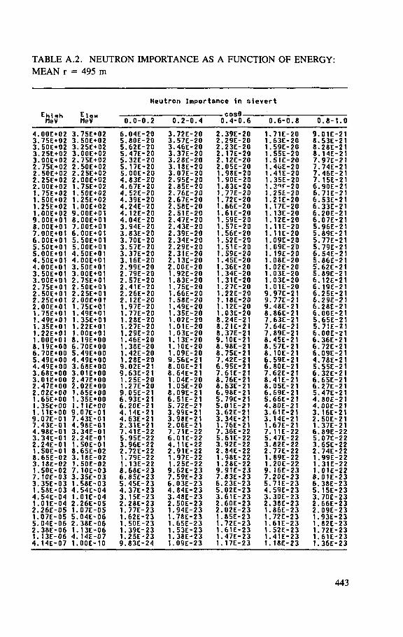
TABLE A.2. NEUTRON IMPORTANCE AS A FUNCTION OF ENERGY: MEAN r = 495 m
Neutron Importance in sievert
E h i i h fleV
E low MeV t 1.0-0.2 0.2-C 1.4 t
cosfl 1.4-0
i 1.6 0.6-0 1.8 0 1.8-1 .0
4. 0 0 E + 0 2 3. 7 5 E + 0 2 6. 04E- 20 3. 72E- 20 2. 39E- 20 1. 71E- 20 9 . 01E- 21 3 . 7 5 E + 0 2 3. 50E+02 5. 80E- 20 3. 57E- 20 2. 29E- 20 1. 63E- 20 8 . 53E- 21 3. 50E+02 3. 2 5 E + 0 2 5. 62E- 20 3. 46E- 20 2. 23E- 20 1. 59E- 20 8 . 28E- 21 3. 2 5 E + 0 2 3. 00E+02 5. , 47E-20 3. 37E- 20 2. , 17E-20 1. 55E- 20 8 . 14E- 21 3. 0 0 E + 0 2 2 . 75E+02 5. 32E- 20 3. 28E- 20 2. J2E- 20 1. 51E- 20 7. 97E- 21 2. 7 5 E + 0 2 2. 50E+02 5. , 17E-20 3. 18E- 20 2. . 05E-20 1. 4(iE- 20 7 . 74E- 21 2. 50E+02 2. 2 5 E + 0 2 5. , 00E-20 3. 07E- 20 1. . 98E-20 1. 41E- 20 7 . 46E- 21 2. 25E+02 2 . 0 0 E + 0 2 A. 83E- 20 2 . 95E- 20 1. , 90E-20 1. , 35E-20 7 . 15E- 21 2. 00E+02 1. 75E+02 A. , 67E-20 2. 85E- 20 1. , 83E-20 1. 39F- 20 6 . 90E- 21 1. 75E+02 J. 50E+02 A. 52E-•20 2 . 76E- 20 1. 77E- 20 1. 25E- 20 6. 71E- 21 1. 50E+02 1. 2 5 E + 0 2 A. 39E- 20 2 . 67E- 20 1. 72E- 20 1. 21E- 20 6 . 53E- 21 1. 2 5 E + 0 2 1. 0 0 E + 0 2 A. 24E- 20 2 . 58E- 20 1. 66E- 20 1. 17E- 20 6 . 33E- 21 1. 0 0 E + 0 2 9 . OOE+O1 A. 12E- 20 2 . 51E- 20 1. , 61E-20 1. 13E- 20 6 . 20E- 21 9. OOE+O1 8. OOE+O1 A. , 04E-20 2 . 47E- 20 1. . 59E-20 1. 12E- 20 6 . 07E- 21 8 . 0 0 E + 0 1 7. OOE+O1 3. , 94E-20 2. 43E- 20 1. , 57E-20 1. 11E- 20 5. 96E- 21 7. OOE+O1 6 . OOE+O1 3. 83E- 20 2 . 39E- 20 1. 56E- 20 1. 11E- 20 5. 89E- 21 6. OOE+O1 5. 50E+01 3. , 70E-20 2 . 34E- 20 1. 52E- 20 1. 09E- 20 5. 77E- 21 5. 50E+01 5. OOE+O1 3. 57E- 20 2 . 29E- 20 1. . 51E -20 1. 09E- 20 5 . 79E- 21 5. 00E+01 4 . 50E+01 3. 37E- 20 2 . 31E- 20 1. 59E- 20 1. 19E- 20 6 . S4E- 21 4. 50E+01 4 . OOE+01 3. 16E- 20 2 . 13E- 20 1. , 45E-20 1. 08E- 20 5. 86E- 21 A. 00E+01 3. 50E+01 2. 99E- 20 2 . 00E- 20 1. 36E- 20 1. 02E- 20 5. 62E- 21 3. 50E+01 3. OOE+O1 2. 79E- 20 1. 92E- 20 1. 34E- 20 1. 03E- 20 5 . 89E- 21 3. 00E+01 2 . 75E+01 2. . 57E-20 1. 83E- 20 1. . 31E-20 1. 03E- 20 6 . 12E- 21 2. 75E+01 2 . 50E+01 2. 41E- 20 1. 75E- 20 1. 27E- 20 1. 01E- 20 6 . 19E- 21 2. 50E+01 2. 25E+01 2. , 26E-20 1. 66E- 20 1. , 22E-20 9 . 97E- 21 6 . 25E- 21 2 . 25E+01 2 . OOE+O 1 2. 12E- 20 1. 58E- 20 1. 18E- 20 9. 77E- 21 6 . 29E- 21 2. OOE+O1 1. 75E+01 1. 97E- 20 1. 49E- 20 1. 12E- 20 9 . 48E- 21 6 . 28E- 21 1. 75E+01 1. 49E+01 1. 77E- 20 1. 35E- 20 1. 03E- 20 8 . 86E- 21 6 . 00E- 21 I. 49E+01 1. 35E+01 1. 28E- 20 1. 02E- 20 8. i 24E-21 7. 63E- 21 5. 65E- 21 1. 35E+01 1. 22E+01 1. 27E- 20 1. 01E- 20 8. 21E- 21 7. 64E- 21 5. 71E- 21 1. 22E+01 1. OOE+01 1. 29E- 20 1. 03E- 20 8. 37E- 21 7 . 89E- 21 6 . 00E- 21 1. OOE+O 1 8 . 19E+00 1. 46E- 20 1. 13E- 20 9 . 10E- 21 8 . 4SE- 21 6 . 36E- 21 8 . 19E+00 6 . 70E+00 1. 38E- 20 1. 10E- 20 8. 98E- 21 8 . 57E- 21 6 . 72E- 21 6 . 70E+00 5. 49E+00 1. 42E- 20 1. 09E- 20 8. 75E- 21 8 . 10E- 21 6 . 09E- 21 5. 49E+00 4 . 49E+00 1. 28E- 20 9 . 56E- 21 7. 42E- 21 6 . 59E- 21 4 . 78E- 21 A. 49E+00 3 . 68E+00 9. 02E- 21 8 . 00E- 21 6. 95E- 21 6 . 80E- 21 5. 55E- 21 3. 68E+00 3. 01E+00 9 . 63E- 21 8. 64E- 21 7 . 61E- 21 7. 62E- 21 6 . 32E- 21 3. 01E+00 2 . 47E+00 1. 25E- 20 1. 04E- 20 8. 76E- 21 8 . 41E- 21 6 . 65E- 21 2 . 47E+00 2 . 02E+00 1. 27E- 20 1. 05E- 20 8. 63E- 21 8 . 05E- 21 6 . 27E- 21 2 . 0 2 E + 0 0 1. 65E+00 9 . 05E- 21 8 . 09E- 21 6. 98E- 21 6 . 69E- 21 5. 47E- 21 1. 65E+00 1. 35E+00 6 . 93E- 21 6. 51E- 21 5. 79E- 21 5. 66E- 21 4 . 80E- 21 I. 35E+00 1. 11E+00 6 . 20E- 21 5. 72E- 21 S. 01E- 21 4 . 80E- 21 4. 00E- 21 1. 11E+00 9 . 07E-01 4 . 14E- 21 3. 99E- 21 3. 62E- 21 3. 61E- 21 3. 16E- 21 9 . 07E-01 7. 43E-01 4. 63E-; 21 3. 98E- 21 3 . 34E- 21 3. 14E- 21 2 . 50E- 21 7 . 43E-01 4 . 98E-01 2 . 31E- 21 2 . 06E- 21 1. 76E- 21 1. 67E- 21 1. 37E- 21 4 . 98E-01 3 . 34E-01 7 . 41E- 22 7 . 71E- 22 7 . 36E- 22 7 . 11E- 22 6 . 89E- 22 3. 34E-01 2 . 24E-01 5. 95E- 22 6 . 01E- 22 5. 61E- 22 5. 47E- 22 5. 07E- 22 2 . 24E-01 1. 50E-01 3. 96E- 22 4 . 11E- 22 3. 92E- 22 3. 82E- 22 3. 6SE- 22 1. 50E-01 8 . 6 5 E - 0 2 2 . 72E- 22 2 . 91E- 22 2 . 84E- 22 2 . 77E- 22 2 . 74E- 22 8 . 65E-02 3. 18E-02 1. 79E- 22 1. 97E- 22 1. 98E- 22 1. 89E- 22 1. 99E- 22 3. 18E-02 1. 50E-02 1. 13E- 22 1. 25E- 22 1. 28E- 22 1. 20E- 22 1. 31E- 22 1. 50E-02 7. 10E-03 8 . 68E- 23 9 . 62E- 23 9 . 91E- 23 9 . 16E- 23 1.01E- 22 7. 10E-03 3 . 3 5 E - 0 3 6 . 85E- 23 7. 59E- 23 7. 83E- 23 7. 20E- 2 3 8 . 01E- 2 3 3. 3 5 E - 0 3 1. 5 8 E - 0 3 5. 45E- 23 6 . 03E- 23 6 . 23E- 23 5. 71E- 23 6 . 38E- 2 3 1. 5 8 E - 0 3 4 . 54E-04 4 . 37E- 23 4 . 84E- 23 5. 02E- 23 4 . 59E- 2 3 5. 15E- 23 4 . 54E-04 1. 0 1 E - 0 4 3. 15E- 23 3 . 48E- 23 3. 61E- 23 3. 30E- 23 3. 70E- 23 1. 01E-04 2 . 2 6 E - 0 5 2 . 28E- 23 2. 50E- 23 2 . 60E- 23 2 . 38E- 2 3 2 . 66E- 2 3 2 . 2 6 E - 0 5 1. 0 7 E - 0 5 1. 77E- 2 3 1. 94E- 2 3 2 . 02E- 23 1. 86E- 23 2 . 09E- 23 1. 0 7 E - 0 5 5. 0 4 E - 0 6 1. 62E- 23 1. 78E- 23 1. 85E- 23 1. 72E- 23 1. 93E- 23 5. 0 4 E - 0 6 2. 38E-06 1. 50E- 23 1. 65E- 23 1. 72E- 23 1. 61E- 23 1. 82E- 23 2 . 38E-06 1. 13E-06 1. 39E- 23 1. 53E- 23 1. 61E- 23 1. 52E- 23 1. 72E- 2 3 J. 13E-06 4 . 14E-07 1. 25E- 2 3 1. 38E- 23 1. 47E- 23 1. 41E- 23 1. 61E- 23 4 . 14E-07 1. 00E-10 9 . 83E- 24 1. 09E- 23 1. 17E- 23 1. I8E- 23 1. 36E- 23
443
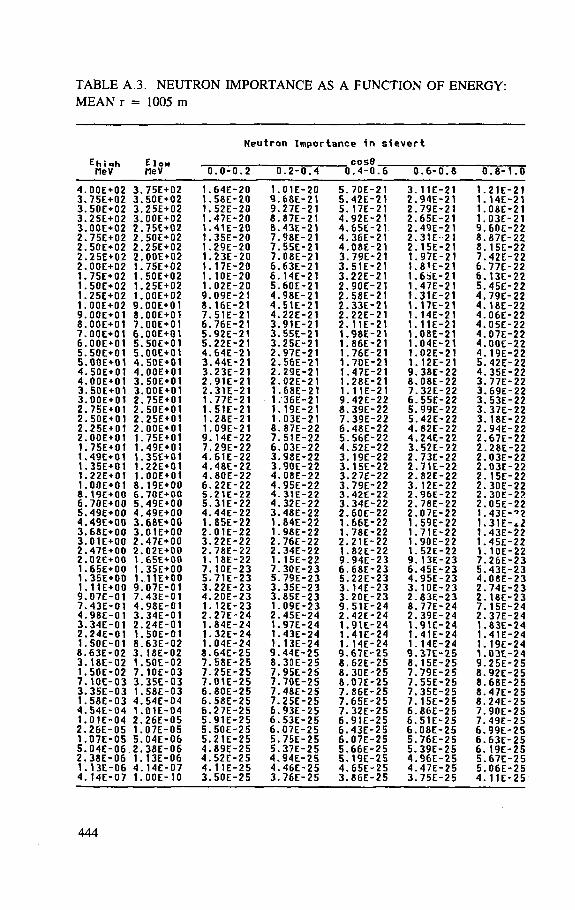
TABLE A.3. NEUTRON IMPORTANCE AS A FUNCTION OF ENERGY: MEAN r = 1005 m
Neutron Importance in sievert
Ehi flh MeV
E low COS0 Ehi flh MeV MeV 0 1.0-0 .2 0 1.2-0 .4 0 1.4-0 1 . 6 0 1.6-0 1 . 8 C 1.8-1 . 0
4. 0OE+O2 3 . 75E+02 1. 64E- 20 1. 01E- 20 5 . 70E- 21 3 . 11E- 21 1. 21E- 21 3 . 75E+02 3 . 50E+02 1. 58E- 20 9. 68E- 21 5 . 42E- 21 2 . 94E- 21 1. 14E- 21 3 . 50E+02 3 . 25E+02 1. 52E- 20 9. 27E- 21 5 . 17E- 21 2. 79E- 21 1. 08E- 21 3. 25E+02 3 . O0E+02 1. 47E- 20 8. 87E- 21 4. 92E- 21 2. 65E- 21 1. 03E- 21 3. 00E+02 2. 75E+02 1. 41E- 20 8. 43E- 21 4. 65E- 21 2. 49E- 21 9. 60E- 22 2. 75E+02 2. 50E+02 1. 35E- 20 7. 98E- 21 4. 36E- 21 2. 31E- 21 8 . 87E- 22 2. 50E+02 2. 25E+02 1. 29E- 20 7 . 55E- 21 4. 08E- 21 2. 15E- 21 8 . 15E- 22 2. 25E+02 2. 00E+02 1. 23E- 20 7 . 08E- 21 3 . 79E- 21 1. 97E- 21 7. 42E- 22 2. OOE+ O 2 1. 75E+02 1. 17E- 20 6 . 63E- 21 3 . 51E- 21 1. 81E- 21 6 . 77E- 22 1. 75E+02 1. 50E+02 1. 10E- 20 6 . 14E- 21 3 . 22E- 21 1. 6bE- 21 6 . 13E- 22 1. 50E+02 1. 25E+02 1. 02E- 20 5 . 60E- 21 2. 90E- 21 1. 47E- 21 5 . 45E- 22 1. 25E+02 1. 00E+02 9. 09E- 21 4. 98E- 21 2. 58E- 21 1. 31E- 21 4. 79E- 22 1. 00E+02 9. OOE+01 8 . 16E- 21 4 . 51E- 21 2 . 33E- 21 1. 17E- 21 4. 18E- 22 9. 00E+01 8 . OOE + 01 7. 51E- 21 4. 22E- 21 2. 22E- 21 1. 14E- 21 4. 06E- 22 8 . 00E+01 7. OOE+O1 6 . 76E- 21 3 . 91E- 21 2. 11E- 21 1. 11E- 21 4. 05E- 22 7. OOE+OI 6 . OOE+OI 5. 92E- 21 3 . 55E- 21 1. 98E- 21 1. 08E- 21 4. 07E- 22 6. OOE+OI 5 . 50E+01 5. 22E- 21 3. 25E- 21 1. 86E- 21 1. 04E- 21 4. 00E- 22 5 . 50E+01 5. OOE+OI 4. 64E- 21 2 . 97E- 21 1. 76E- 21 1. 02E- 21 4. 19E- 22 5 . 00E+01 4. 50E+01 3 . 44E- 21 2. 56E- 21 1. 70E- 21 1. 12E- 21 5. 42E- 22 4. 50E+01 4. OOE+OI 3. 23E- 21 2. 29E- 21 1. 47E- 21 9. 38E- 22 4. 35E- 22 4. 00E+01 3. 50E+01 2. 91E- 21 2. 02E- 21 1. 28E- 21 8 . 08E- 22 3. 77E- 22 3 . 50E+01 3 . OOE+OI 2. 31E- 21 1. 68E- 21 1. 11E- 21 7. 32E- 22 3. 69E- 22 3. OOE+O1 2. 75E+01 1. 77E- 21 1. 36E- 21 9. 42E- 22 6 . 55E- 22 3 . 53E- 22 2 . 75E+01 2 . 50E+01 1. 51E- 21 1. 19E- 21 8 . 39E- 22 5 . 99E- 22 3. 37E- 22 2. 50E+01 2. 25E+01 1. 28E- 21 1. 03E- 21 7. 39E- 22 5. 42E- 22 3. 18E- 22 2 . 25E+01 2. OOE+OI 1. 09E- 21 8 . 87E- 22 6. 48E- 22 4. 82E- 22 2. 94E- 22 2 . OOE+O1 1. 75E+01 9. 14E- 22 7. 51E- 22 5. 56E- 22 4. 24E- 22 2. 67E- 22 1. 75E+01 t. 49E+01 7. 29E- 22 6. 03E- 22 4. 52E- 22 3 . 52E- 22 2. 28E- 22 1 . 49E+01 1 . 35E+01 4. 61E- 22 3 . 98E- 22 3. 19E- 22 2. 73E- 22 2 . 03E- 22 1 . 35E+01 1 . 22E+01 4. 48E- 22 3 . 90E- 22 3. 15E- 22 2 . 71E- 22 2. 03E- 22 1 . 22E+01 1 . OOE+OI 4. 80E- 22 4. 08E- 22 3. 27E- 22 2 . 82E- 22 2 . 15E- 22 1 . OOE+O1 8 . 19E+00 6. 22E- 22 4. 95E- 22 3. 79E- 22 3. 12E- 22 2. 30E- 22 8 . 19E+00 6. 70E+00 5. 21E- 22 4. 31E- 22 3. 42E- 22 2. 96E- 22 2 . 30E- 22 6. 70E+00 5. 49E+00 5. 31E- 22 4. 32E- 22 3 . 34E- 22 2 . 78E- 22 2. 05E- 22 5. 49E+00 4. 49E+00 4. 44E- 22 3 . 48E- 22 2 . 60E- 22 2 . 07E- 22 1 . 43E-4 . 49E+00 3 . 68E+00 1 . 85E- 22 1 . 84E- 22 1 . 66E- 22 1 . 59E- 22 1 . 31E- cl 3 . 68E+00 3 . 01E+00 2 . 01E- 22 1 . 98E- 22 1 . 78E- 22 1 . 71E- 22 1 . 43E- 22 3 . 01E+00 2 . 47E+00 3. 22E- 22 2 . 76E- 22 2. 21E- 22 1 . 90E- 22 1 . 45E- 22 2 . 47E+00 2 . 02E+00 2 . 78E- 22 2. 34E- 22 1 . 82E- 22 1 . 52E- 22 1 . 10E- 22 2. 02E+00 1 . 65E+00 1. 18E- 22 1 . 15E- 22 9. 94E- 23 9. 13E- 23 7. 26E- 23 1 . 65E+00 1 . 35E+00 7. 10E- 23 7. 30E- 23 6. 68E- 23 6. 45E- 23 5. 43E- 23 1 . 35E+00 1. 11E+00 5 . 71E- 23 5 . 79E- 23 5. 22E- 23 4. 95E- 23 4. 08E- 23 1 . 11E+00 9. 07E-01 3 . 22E- 23 3. 35E- 23 3. 14E" 23 3 . 10E- 23 2 . 74E- 23 9. 07E-01 7. 43E-01 4. 20E- 23 3. 85E- 23 3. 20E- 23 2 . 83E- 23 2 . 18E- 23 7. 43E-01 4. 98E-01 1 . 12E- 23 1 . 09E- 23 9. 51E- 24 8 . 77E- 24 7. 15E- 24 4. 98E-01 3. 34E-0I 2. 27E- 24 2. 45E- 24 2. 42E- 24 2 . 39E- 24 2. 37E- 24 3 . 34E-01 2. 24E-01 1 . 84E- 24 1 . 97E- 24 1 . 91E" 24 1 . 91E- 24 1 . 83E- 24 2 . 24E-01 1 . 50E-0t 1 . 32E- 24 1 . 43E- 24 1 . 41E- 24 1 . 41E- 24 1 . 41E- 24 1. 50E-01 8 . 63E-02 1 . 04E- 24 1 . 13E- 24 1 . 14E- 24 1 . 14E- 24 1 . 19E- 24 8 . 63E-02 3. 18E-02 8 . 64E- 25 9. 44E- 25 9 . 67E- 25 9 . 37E- 2 5 1 . 03E- 24 3 . 18E-02 1 . 50E-02 7 . 58E- 25 8 . 30E- 25 8 . 62E- 25 8 . 15E- 25 9. 25E- 25 1 . 50E-02 7. 10E-03 7. 25E- 25 7. 95E- 25 8 . 30E- 25 7. 79E- 25 8 . 92E- 25 7. 10E-03 3 . 35E-03 7. 01E- 25 7. 70E- 25 8 . 07E- 25 7 . 55E- 25 8 . 68E- 25 3 . 3 5 E - 0 3 1 . 58E-03 6 . 80E- 25 7. 48E- 25 7. 86E- 25 7. 35E- 25 8 . 47E- 25 1 . 58E-03 4. 54E-04 6 . 58E- 25 7. 25E- 25 7. 65E- 25 7. 15E- 25 8 . 24E- 25 4. 54E-04 1 . 01E-04 6 . 27E- 25 6. 93E- 25 7. 32E- 25 6 . 86E- 25 7. 90E- 25 1 . 01E-04 2 . 26E-05 5. 91E- 25 6 . 53E- 25 6 . 91E- 25 6 . 51E- 25 7. 49E- 25 2 . 26E-05 1 . 07E-05 5. 50E- 25 6. 07E- 25 6. 43E- 25 6. 08E- 25 6 . 99E- 25 1 . 0 7 E - 0 5 5. 04E-06 5. 21E- 25 5. 75E- 25 6. 07E- 25 5. 76E- 25 6. 63E- 25 5. 04E-06, 2 . 38E-06 4. 89E- 25 5. 37E- 25 5. 66E- 25 5. 39E- 25 6. 19E- 25 2 . 38E-06 1 . 13E-06 4. 52E- 25 4 . 94E- 25 5. 19E- 25 4 . 96E- 25 5. 67E- 25 1 . 13E-06 4. 14E-07 4. 11E — 25 4. 46E- 25 4. 65E- 25 4. 47E- 25 5. 06E- 25 4. 14E-07 1 . OOE-IO 3 . 50E- 25 3 . 76E- 25 3. 86E- 25 3. 75E- 25 4. 11E- 25
444
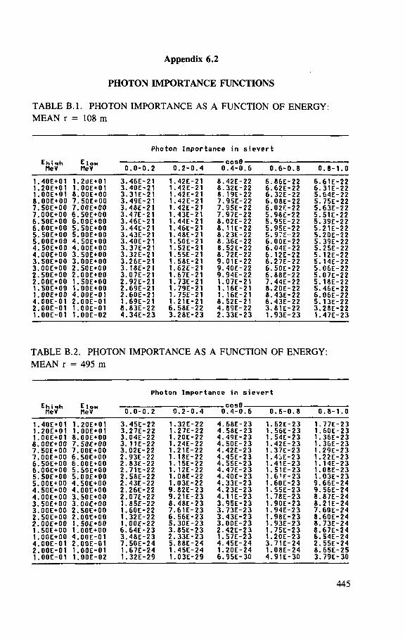
Appendix 6.2
PHOTON IMPORTANCE FUNCTIONS
TABLE B. l . PHOTON IMPORTANCE AS A FUNCTION OF ENERGY: MEAN r = 108 m
Photon Importance i n sievert
Ehi ih MeV
EIOH MeV 0 l.O-O 1.2 0.2-0 1.4
cosfl 0.4-0 .6 0 1.6-0 i.8 0 I.8-1 .0
1. 40E+01 1. .2UE+01 3. 46E- 21 1.42E- 21 8. 42E- 22 6. 86E- 22 6. 61E- 22 1. 20E+01 1. , OOE+01 3. 40E- 21 1.42E- 21 8. 32E- 22 6. 62E- 22 6. 31E- 22 1. 00E+01 8. .OOE+OO 3. 31E- 21 1.42E- 21 8. 19E- 22 6. 32E- 22 5. 64E- 22 8. OOE+OO 7. , 50E+00 3. 49E- 21 1.42E- 21 7. 95E- 22 6. 08E- 22 5. 75E- 22 7. 50E+00 7. 00E+00 3. 48E- 21 1.42E- 21 7. 95E- 22 6. 02E- 22 5. 63E- 22 7. OOE+OO 6. 50E+00 3. 47E- 21 1.43E- 21 7. 97E- 22 5. 98t- 22 5. 51E- 22 6. 50E+00 6. 00E+00 3. 46E- 21 1.44E- 21 8. 02E- 22 5. 95E- 22 5. 39E- 22 6. 00E+00 5. , 50E + 00 3. 44E- 21 1.46E- 21 8. 11E- 22 5. 95E- 22 5. 21E - 22 5. 50E+00 5. 00E+00 3. 43E- 21 1.48E- 21 8. 23E- 22 5. 9?E" 22 5. 20E- 22 5. 00E+00 4. ,50E+00 3. 40E- 21 1.50E- 21 8. 36E- 22 6. 00E- 22 5. 39E- 22 4. 50E+00 4. .OOE+OO 3. 37E- 21 1.52E- 21 8. S2E- 22 6. 04E- 22 5. 25E- 22 4. 00E+00 3. . 50E + 00 3. 32E- 21 1.55E- 21 8. 72E- 22 6. 12E- 22 5. 12E- 22 3. 50E+00 3. 00E+00 3. 26E- 21 1.58E- 21 9. 01E- 22 6. 27E- 22 5. 14E- 22 3. 00E+00 2. 50E+00 3. 18E- 21 1.62E- 21 9. 40E- 22 6. 50E- 22 5. 06E- 22 2. 50E+00 2. OOE+OO 3. 07E- 21 1.67E- 21 9. 94E- 22 6. 88E- 22 5. 07E- 22 2. 00E+00 1. S0E+00 2. 92E- 21 1.73E- 21 1. 07E- 21 7. 44E- 22 5. 18E- 22 1. 50E+00 1. OOE+OO 2. 69E- 21 1.79E- 21 1. 16E- 21 8. 20E- 22 5. 46E- 22 1. 00E+00 4. 00E-01 2. 60E- 21 1.75E- 21 1. 16E- 21 8. 43E- 22 6. 06E- 22 4. OOE-OI 2. 00E-01 1. 69E- 21 1.21E- 21 8. 52E- 21 6. 43E- 22 5. 13E- 22 2. 00E-01 1. , OOE-01 8.83E- 22 6.58E- 22 4. 89E- 22 3. 81E- 22 3. 28E- 22 1. 00E-01 1. , 00E-02 4. 34E- 23 3.28E- 23 2. 33E- 23 1. 93E- 23 1. 47E- 23
TABLE B.2. PHOTON IMPORTANCE AS A FUNCTION OF ENERGY: MEAN r = 495 m
Photon Importance in sievert
Ehixh MeV
E I O N MeV 0 l.O-O 1.2 ( J.2-0 1.4
C O S B 0.4-0
i 1.6 L 0.6-0 l. 8 ( 1.8-1 .0
1. 40E+01 1. 20E+01 3. 45E- 22 1. . 32E-22 4. 68E- 23 1 . 62E-23 1. , 77E-23 1. 20E+01 1. OOE+O1 3. 27E- 22 1. 27E- 22 4. 58E- 23 1 . 56E-23 1. , 60E-23 1. OOE+O1 8. OOE+OO 3. 04E- 22 1. , 20E-22 4. 49E- 23 1 . 54E-23 1. 36E- 23 8. 00E+00 7. 50E+00 3. 11E- 22 1. 24E- 22 4. S0E- 23 1 . 42E-23 1. 36E- 23 7. 50E+00 7. 00E+00 3. 02E- 22 1. 21E- 22 4. 42E- 23 1 . 37E-23 1. 29E- 23 7. 00E+00 6. 50E+00 2. 93E- 22 1. , 18E-22 4. 45E- 23 1 . 4iE-23 1. 22E- 23 6. 50E+00 6. 00E+00 2. 83E- 22 1. , 15E-22 4. 55E- 23 1 . 41E-23 1. 14E- 23 6. OOE+OO 5. 50E+00 2. 71E- 22 1. . 12E-22 4. 47E- 23 1 . 51E- 23 1. , 08E-23 5. 50E+00 5. 00E+00 2. 58E- 22 1. , 08E-22 4. 40E- 23 i • 6'F-23 1. ,03E- 23 5. OOE+OO 4. 50E+00 2. 43E- 22 1. 03E- 22 4. 33E- 23 1 . 60E-23 9. 66E- 24 4. 50E+00 4. 00E+00 2. 26E- 22 9. , 82E-23 4. 23E- 23 1 . 55E-23 9. 56E- 24 4. 00E+00 3. 50E+00 2. 07E- 22 9. , 21E-23 4. 11E- 23 1 . 78E-23 8. 87E- 24 3. 50E+00 3. 00E+00 1. 85E- 22 8. . 48E-23 3. 95E- 23 1 . 90E-23 8. 21E- 24 3. 00E+00 2. 50E+00 1. 60E- 22 7. 61E- 23 3. 73E- 23 1 • 94E-23 7. 60E- 24 2. 50E+00 2. 00E+00 1. 32E- 22 6. , 56E-23 3. 43E- 23 1 . 98E-23 8. 60E- 24 2. 00E+00 1. 50E+00 1. 00E- 22 5. 30E- 23 3. 00E- 23 1 . 93E-23 8. 73E- 24 1. 50E+00 1. 00E+00 6. 64E- 23 3. 85E- 23 2. 42E- 23 1 . 75E-23 8. 67E- 24 1. 00E+00 4. OOE-01 3. 48E- 23 2. , 33E-23 1. 57E- 23 1 . 20E-23 6. , 54E-24 4. 00E-01 2. 00E-01 7. 50E- 24 5. , 88E-24 4. 45E- 24 3 . 71E-24 2. , 55E-24 2. OOE-O1 1. OOE-01 1. 67E- 24 1. . 45E-24 1. 20E- 24 1 . 08E-24 8. , 65E-25 1. 00E-01 1. 00E-02 1. 32E- 29 1. . 03E-29 6. 95E- 30 4 . 91E-30 3. . 79E-30
445
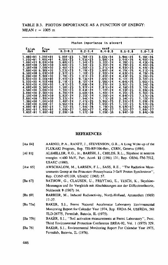
TABLE B.3. PHOTON IMPORTANCE AS A FUNCTION OF ENERGY: MEAN r = 1005 m
Photon Importance in sievert
Ehiah E Ioh cos8 Ehiah E Ioh cos8 MeV MeV 0 .0-0 .2 0 .2-0 .4 0 .4-0 .6 0 .6-0 .8 0 .8-1 .0
1. 40E+01 1.20E+01 5. OOE- 23 1. 70E- 23 3. 62E- 24 3. 90E- 25 5. 10E- 26 1. 20E+01 1.00E+01 4. 50E- 23 1. S3E- 23 3. 58E- 24 3. 94E- 25 4. 90E- 26 1. 00E+01 8.OOE+OO 3. 88E- 23 1. 34E- 23 3. 32E- 24 4. 70E- 25 4. 43E- 26 8. 00E+00 7.50E+00 3. 68E- 23 1. 34E- 23 3. 35E- 24 4. 79E- 25 4. 40E- 26 7. 50E+00 7.OOE+OO 3. 46E- 23 1. 26E- 23 3. 21E- 24 4. 93E- 25 4. 44E- 26 7. OOE+OO 6.50E+00 3. 23E- 23 1. 19E- 23 3. 09E- 24 4. 79E- 25 4. 21E- 26 6. 50E+00 6.OOE+OO 2. 97E- 23 1. 10E- 23 2. 92E- 24 4. 63E- 25 4. 15E- 26 6. 00E+00 5.50E+00 2. 70E- 23 1. 01E- 23 2. 89E- 24 4. 43E- 25 3. 78E- 26 5. 50E+00 5.OOE+OO 2. 41E- 23 9. 13E- 24 2. 69E- 24 4. ieE- 25 3. 72E- 26 5. OOE+OO 4.50E+00 2. 11E- 23 8. 12E- 24 2. 50E- 24 4. 04E- 25 3. 66E- 26 4. 50E+00 4.OOE+OO I. 81E- 23 7. 08E- 24 2. 29E- 24 3. 92E- 25 3. 34E- 26 4. OOE+OO 3.50E+00 1. 50E- 23 5. 97E- 24 2. 01E- 24 4. 18E- 25 3. 10E- 26 3. 50E+00 3.OOE+OO 1. 18E- 23 4. 83E- 24 1. 72E- 24 4. 33E- 25 4. 28E- 26 3. OOE+OO 2.50E+00 8. 70E- 24 3. 68E- 24 t. 40E- 24 4. 35E- 25 5. 40E- 26 2. 50E+00 2.OOE+OO 5. 82E- 24 2. 55E- 24 1. 06E- 24 4. 04E- 25 7. 67E- 26 2. OOE+OO 1.50E+00 3. 33E- 24 1. 54E- 24 7. 11E- 25 3. 34E- 25 1. 12E- 25 1. 50E+00 1.00E+00 1. 48E- 24 7. 41E- 25 3. 96E- 25 2. 31E- 25 1. 09E- 25 1. OOE+OO 4.00E-01 3. 56E- 25 2. 51E- 25 1. 65E- 25 1. 12E- 25 5. 97E- 26 4. 00E-01 2.00E-01 1. 76E- 26 1. 54E- 26 1. 19E- 26 9. 54E- 27 6. 48E- 27 2. 00E-01 1.00E-01 1. 68E- 27 1. 66E- 27 1. 45E- 27 1. 32E- 27 1. 08E- 27 1. OOE-OI 1.00E-02 2. 28E- 38 1. 57E- 38 1. 05E- 38 6. 94E- 39 5. 84E- 39
REFERENCES
[Aa 84] AARNIO, P .A. , R A N F T , J . , S T E V E N S O N , G .R . , A Long Write-up of the FLUKA82 Program, Rep. TIS-RP/106-Rev, C E R N , Geneva (1984).
[Al 81] ALSMILLER, R . G . , J r . , BARISH, J . , CHILDS, R .L . , Skyshine at neutron energies < 4 0 0 MeV, Part. Accel. 11 (1981) 131; Rep. ORNL-TM-7512 , USAEC (1980).
[Aw 65] A W S C H A L O M , M . , LARSEN, F . L . , SASS, R .E . , " T h e Radiation Meas-urements Group at the Princeton-Pennsylvania 3 GeV Proton Synchro t ron" , Rep. CONF-651109, USAEC (1965) 57.
[Ba 67] B A T H O W , G . , C L A U S E N , U . , FREYTA.G, E . , T E S C H , K . , Skyshine-Messungen und ihr Vergleich mit Abschatzungen aus der Diffusionstheorie, Nukleonik 9 (1967) 14.
[Ba 69] BARBIER, M . , Induced Radioactivity, North-Holland, Amsterdam (1969) 17-27.
[Ba 75a] BAKER, S.I . , Fermi National Accelerator Laboratory Environmental Monitoring Report for Calendar Year 1974, Rep. ERDA-54, USERDA, 561 TLD-26775, Fermilab, Batavia, IL (1975).
[Ba 75b] BAKER, S.I . , "Soi l activation measurements at Fermi Labora to ry" , Proc. Third Environmental Protection Conference ERDA-92, Vol. 1 (1975) 329.
[Ba 76] BAKER, S.I . , Environmental Monitoring Report For Calendar Year 1975, Fermilab, Batavia, IL (1976).
446
[Bi 80] BIRATARRI , C . , "Radioisotope production by accelera tors" , Advances in Radiation Protection and Dosimetry in Medicine ( T H O M A S , R . H . , P E R E Z - . M E N D E Z , V. , Eds), Plenum Press, New York and London (1980).
[Bl nd] B L Y T H E , H. J . , Some Field Trials on Ground Disposal by the Industrial Chemical Group, Rep. AERE, G D F / P 2 , Harwell , UK, undated.
[Bo 72a] BORAK, T .B . , Measurement of Induced Radioactivity in Cooling Waters for the C E R N PS and External Beam Magnets, Rep. HP-72-112, C E R N , Geneva (1972).
[Bo 72b] BORAK, T .B . , A W S C H A L O M , M . , F A I R M A N , W . , IWAMI , F . , S E D L E T , J . , The underground migration of radionuclides produced in soil near high-energy proton accelerators, Health Phys. 23 (1972) 679.
[Br 70] BRODZINSKI , R .L . , W O G M A N , N . A . , High-energy proton spallation of argon, Phys. Rev. , C 1 (1970) 1955.
[Bu 69] BUSICK, D . , W A R R E N , G.J . , Operational Health Physics Associated with Induced Radioactivity at the Stanford Linear Accelerator Center , Rep. CONF-691101, USAEC (1969) 139.
[Bu 76a] BUSICK, D . , Environmental Monitoring Report, 1975, Stanford Linear Accelerator Center , Menlo Park, C A (1976) 194.
[Bu 76b] BUSICK, D . , Stanford Linear Accelerator Center, private communication, 1976.
[Bu 81] BURGER, G. , M O R H A R T , A. , N A G A R A J A N , P .S . , W I T T M A N , A . , "Ef fec t ive dose equivalent and its relationship to operational quantities for neu t rons" , Rep. EUR-7101-EN, Harwood Academic Publishers, Chur , Switzerland (1981) 117.
[Ca 53] CASE, K . M . , de H O F F M A N N , F . , PLACZEK, G . , Introduction to the Theory of Neutron Diffusion, Vol. 1, Los Alamos Scientific Lab. , CA (1953).
[Ch 78] C H R I S T E N S E N , G . C . , FASSO, A . , STEVENSON, G . R . , Radioactivity in the Cooling Water f rom the N A H I F Installation, Rep. HS-RP/IR/78-46, C E R N , Geneva (1978).
[Ci 79] C I M E T I E R E , C . , LEGER, J . , M U X A R T , R. , VERNOIS , J . , "Util isation de cyclotrons pour la preparation de r ad ionuc l ides & usage med ica l " , SFRP SSminaire sur les Accelerateurs de Particles, Utilisation et Radioprotection, Saclay (1979).
[Co 60] C O V E Y O U , R .R . , SULLIVAN, J .G . , O R N L Neutron Physics Division Annual Progress Report , Rep. ORNL-3016, Oak Ridge, TN (1960) 193.
[Co 62] C O W A N , P .F . , A Preliminary Report on Health Physics Problems at the Brookhaven Alternating Gradient Synchrotron, in Premier Colloque International sur la Protection Auprfcs des Grands Accelerateurs, Presses Universitaires de France, Paris (1962) 143.
[deP 74a] de P L A N Q U E BURKE, G. , Variations in Natural Environmental Gamma Radiation and its Effect on the Interpretability of T L D Measurements Made near Nuclear Facilities, Rep. HASL-287, Health and Safety Lab. , New York (1974).
447
[deP 74b] de P L A N Q U E B U R K E , G. , " A model for estimating variations in terrestrial radiation exposures based on soil-water ba lance" , Second Workshop on the Natural Radiation Environment (LOWDER, W . M . , Ed.) , Health and Safety Laboratory, New York (1974).
[Di 64] D I S T E N F E L D , C . , in A Proposal for Increasing the Intensity of the AGS at the Brookhaven National Laboratory, Rep. BNL-7956, Upton, NY (1964).
[Di 66] D I S T E N F E L D , C . H . , C O L V E T T , R . D . , Skyshine considerations for accelerator shielding design, Nucl. Sci. Eng. 26 (1966) 117.
[Em 75] E M M E T T , M . B . , The MORSE Monte Carlo Radiation Transport System,
Rep. ORNL-4972, Oak Ridge Natl Lab. , Oak Ridge, TN (1975). [Fa 76] FALK, R . , GROBON, G. , R E N A U D , C . , R O U B A U D , G . ,
T U Y N , J . W . N . , Environmental Radiation on the C E R N Site During 1975, Rep. HP-76-151, C E R N , Geneva (1976).
[Ge 65] GEORGE, A . C . , BRESLIN, A . J . , HASKINS, J . W . , J r . , RYAN, R .R . , "Evaluat ion of the hazard f rom radioactive gas and ozone at linear electron accelerators" , Rep. CONF-651109, USAEC (1965) 513.
[Gi 68] GILBERT, W . S . , et al . , 1966 C E R N - L B L - R H E L Shielding Experiment at the C E R N Proton Synchrotron, Rep. UCRL-17941, Lawrence Berkeley Lab . , Berkeley, C A (1968).
[Ha 69] HACK, R .C . , Radiation Protection Group (Operations) Progress Report for 1968, Rep. R H E L / M 171, Rutherford Lab. , Chilton, UK (1969).
[Ha 76] HAYASHIDA, Y. , Study on the Production and Transport of Neutron-Induced Secondary Gamma Rays in Matter , Master ' s Thesis, Department of Nuclear Engineering, Kyoto University (1976) (in Japanese).
[Ho 68] H O Y E R , F . E . , Induced Radioactivity in the Earth Shielding on Top of High-Energy Particle Accelerators, Rep. 68-42, C E R N , Geneva (1968).
[Ho 69] H O F E R T , M . , "Radia t ion hazard of induced radioactivity in air as produced by high-energy accelera tors" , Rep. CONF-691101, USAEC (1969) 111.
[Ho 73] H O F E R T , M . , BAARLI , J . , " S o m e preliminary investigations on the contributions of muons to the stray radiation level around the C E R N 28 GeV proton synchro t ron" , Rep. CONF-730907 , USAEC (1973) 841.
[Hu 76] HULL, A . P . , ASH, J .A. , 1975 Environmental Monitoring Report , Rep. BNL-21320, Brookhaven Natl Lab . , Upton, NY (1976).
[ ICRP 73a] I N T E R N A T I O N A L COMMISSION O N RADIOLOGICAL PROTECTION, Data for Protection against Ionizing Radiation f rom External Sources; Supplement to I C R P Publication 15, I C R P Publication 21, Pergamon Press, Oxford and New York (1973).
[ICRP 73b] I N T E R N A T I O N A L COMMISSION ON RADIOLOGICAL PROTECTION, Implications of Commission Recommendations that Doses Be Kept as Low as Readily Achievable, ICRP Publication 22, Pergamon Press, Oxford and New York (1973).
[ ICRP 79] I N T E R N A T I O N A L COMMISSION O N RADIOLOGICAL PROTECTION, Limits for Intake of Radionuclides by Workers , ICRP Publication 30, Part 1 (1979), Part 2 (1980), Part 3, including addendum to Parts 1 and 2 (1981), Supplement A to Part 3, Supplement B to Part 3 (1982), Pergamon Press, Oxford and New York.
448
[Ir 65] IRVING, D . C . , F R E E S T O N E , R . M . , J r . , K A M , R .B .K. , 0 5 R , A General Purpose Monte Carlo Neutron Transport Code, Rep. ORNL-3622 , Oak Ridge Natl Lab. , Oak Ridge, TN (1965).
[Je 74] JENKINS, T . M . , Accelerator boundary doses and skyshine, Health Phys. 27 (1974) 251.
[Ka 77] K A T O H , K. , Natl Lab. for High Energy Physics, Tsukuba, private communication, 1977.
[Ka 78a] K A T O H K. , "Radia t ion and Safety Control Div is ion" , KEK Annual Report 1978, Natl Lab. for High Energy Physics, Tsukuba (1978).
[Ka 78b] K A T O H , K. , T H O M A S , R . H . , Population Dose Equivalent Due to Accelerator Operations at KEK, Natl Lab. for High Energy Physics, Tsukuba (1978).
[Ki 62] KINNEY, W . E . , A Monte Carlo Calculation of Scattered Neutron Fluxes at an Air-Ground Interface due to Point Isotropic Sources on the Interface, Rep. ORNL-3287 , Oak Ridge Natl Lab. , Oak Ridge, TN (1962).
[Ko 70] K O M O C H K O V , M . M . , " T h e Dubna synchrophasotron" , Engineering Compendium on Radiation Shielding, Vol. 3 ( JAEGER, R . G . , et al. , Eds), Springer-Verlag, Berlin (West) (1970) 171.
[Ko 72] K O M O C H K O V , M . M . , T E T E R E V , Y . G . , Activation of Water Cooling the Synchrocyclotron Units, Rep. JINR-P16-6314, Joint Institute for Nuclear Research, Dubna (1972).
[La 68] L A D U , M . , PELLICCIONI , M . , P ICCHI , P. , VERRI , G . , A contribution to the skyshine study, Nucl. Instrum. Methods 62 (1968) 51.
[Le 65] L E B E D E V , V . N . , ZOLIN, L .S . , SALATSKAYA, M. I . , Distribution of the Penetrating Radiation Field over the Protective Zone of the 10 GeV Synchrophasotron, Rep. JINR-P-2177, Joint Institute for Nuclear Research, Dubna (1965).
[Li 57] L I N D E N B A U M , S.J . , "Brookhaven National Laboratory Proton Synchro-t r o n " , Rep. TID-7545, USAEC (1957) 28.
[Li 61] L I N D E N B A U M , S.J . , Shielding of high energy accelerators, Ann. Rev. Nucl. Sci. 11 (1961) 213.
[Ma 69] M A W S O N , C . A . , "Consequences of radioactive disposal into the g r o u n d " , Health Physics, Vol. 2, Part I ( D U H A M E L , A . M . F . , Ed. ) , Pergamon Press, Oxford and New York (1969).
[Mi 66] M I D D L E K O O P , W . C . , Remarks about Groundwater Activation by a 300 GeV Proton Synchrotron, Rep. ISR/INT BT/66-3, C E R N , Geneva (1966).
[Mi 77] MIYAJIMA, M . , H I R A M A Y A , H . , H O Z U M I , K . , M I U R A , S. , K A T O H , K. , Measurement of Stray Neutron Doses around KEK PS-Facility (1), Rep. KEK-77-17, Natl Lab. for High Energy Physics, Tsukuba (1977).
[Mo 57] M O Y E R , B.J . , "Univers i ty of California Radiation Laboratory Proton Synchro t ron" , Rep. TID-7545, U S A E C (1957) 38.
[Mo 66] M O O R E , W . H . , Source of High-Energy Particles f rom Internal Target in the AGS, Rep. AGSCD-62 , Brookhaven Lab. , Upton, NY (1966).
449
[Mu 81] M U G H A B G H A B , S .F . , D I V A D E E N A M , M. , H O L D E N , N .E . , Neutron
Cross Sections: Neutron Resonance Parameters and Thermal Cross Sections, Vol. 1, Part A, Academic Press, New York (1981).
[Na 75] N A K A M U R A , T . , KAWABATA, H . , HAYASHI , K. , SHIN, K. , SUGAI, I . , H A S E G A W A , T . , ISHIZAKI, Y. , Skyshine of Neutrons and Photons from the INS FM-Cyclotron, Rep. 43, Institute of Nuclear Study, Tokyo (1975).
[Na 81a] N A K A M U R A , T . , KOSAKO, T . , A systematic study on the neutron skyshine f rom nuclear facilities, Part I: Monte Carlo analysis of neutron propagation in air-over-ground environment f rom a monoenergetic source, Nucl. Sci. Eng. 77 (1981) 168.
[Na 81b] N A K A M U R A , T . , KOSAKO, T . , HAYASHI , K. , BAN, S. , KATOH, K. , A systematic study on the neutron skyshine from nuclear facilities, Part II: Experimental approach to the behaviour of environmental neutrons around an electron synchrotron, Nucl. Sci. Eng. 77 (1981) 182.
[Ne 65] NELSON, W . R . , Radioactive Groundwater Produced in the Vicinity of Beam
Dumps, Rep. SLAC-TN-65-16, Stanford Linear Accelerator Center, Menlo Park, CA (1965).
[Ol 64] O L L E N D O R F , W . , A Study of Radiation Levels at the CERN Site, Rep. DI /HP/66, C E R N , Geneva (1964).
[Pa 57] PANOFSKY, W . K . H . , "Shielding work at Stanford Univers i ty" , Rep.
TID-7545, U S A E C (1957) 199. [Pa 73] PATTERSON, H . W . , T H O M A S , R . H . , " Induced radioactivi ty",
Accelerator Health Physics, Academic Press, New York (1973) Chap. 7. [Pe 74] P E E T E R M A N S , A. , BAARLI, J . , "Radioact ive gas and aerosol production
by the C E R N high-energy accelerators and evaluation of their influences on environmental p rob lems" , Environmental Surveillance around Nuclear Installations (Proc. Symp. Warsaw, 1973), IAEA, Vienna (1974) 433.
[Pr 72] PRANTL, F .A . , BAARLI, J . , Control of Radioactive Pollution in the Environment of the C E R N Accelerators, Rep. 72-15, C E R N , Geneva (1972).
[Rh 78] RHOADES, W . A . , SIMPSON, D .B . , CHILDS, R .L . , ENGLE, W . W . , The DOT-IV Two-Dimensional Discrete Ordinates Transport Code with Space-Dependent Mesh and Quadrature, Rep. ORNL-TM-6529 , Oak Ridge Natl Lab. , Oak Ridge, T N (1978).
[Ri 63] RINDI, A. , BAARLI , J . , Scattered Radiation at Large Distance f rom the C E R N 600 MeV Synchrocyclotron, Rep. DI /HP/19, C E R N , Geneva (1963).
[Ri 67] RINDI, A. , C H A R A L A M B U S , S. , Airborne radioactivity produced at high-energy accelerators, Nucl. Instrum. Methods 47 (1967) 227.
[Ri 72a] RINDI, A. , La Radioactivite Induite dans 1'Air de l 'Accdlerateur de Protons de 300 GeV du C E R N , Rep. LABII-RA/72-5, C E R N , Geneva (1972).
[Ri 72b] RINDI, A. , Induced Radioactivity in the Cooling Waters of the 300 GeV SPS, Rep. LABII-RA/NOTE/72-13, C E R N , Geneva (1972).
[Ri 75] RINDI, A. , T H O M A S , R .H. , Skyshine — A paper tiger?, Part. Accel. 7 (1975) 23.
450
[Ro 58] ROSE, B. , G O D D A R D , B.A. , LOVERIDGE, B . A . , S A L M O N , L . , T H O M A S , A . M . , Radioactivity of Synchrocyclotron Cooling Water , Rep. AERE NP/R 2768, AERE, Harwell (1958).
[Ru 65] RUSSEL, J .E . , RYAN, R . M . , Radioactive gas production f rom the R.P. I . electron linear accelerator, IEEE Trans. Nucl. Sci. NS-12 3 (1965) 678.
[Sh 67] S H A W , K.B. , T H O M A S , R . H . , Radiation problems associated with a high-energy extracted proton beam, Health Phys. 13 (1967) 1127.
[Sh 69] S H A W , K.B. , STEVENSON, G . R . , T H O M A S , R . H . , Evaluation of dose equivalent f rom neutron energy spectra, Health Phys. 17 (1969) 459.
[Si 62] S IMPSON, P . W . , LAWS, D . , Addendum to [Th 62], Rutherford Lab. , Chilton, UK (1962).
[Sm 77] SMITH, A . R . , Lawrence Berkeley Laboratory, private communication, 1977.
[St 67] S T A P L E T O N , G .B . , T H O M A S , R .H. , Radioassay for 7Be and 3H of Nimrod Cooling Water , Rep. RP/PN/45 , Rutherford Lab. , Chilton, UK (1967).
[St 71] STAPLETON, G .B . , T H O M A S , R . H . , The production of 7Be by 7 GeV proton interactions with oxygen, Nucl. Phys. A175 (1971) 124.
[St 72] S T A P L E T O N , G .B . , T H O M A S , R . H . , Estimation of the induced radioactivity of the groundwater system in the neighborhood of a proposed 300-GeV high-energy accelerator situated on a chalk site, Health Phys. 23 (1972) 689.
[St 73] S T A P L E T O N , G.B. , T H O M A S , R . H . , The effect of sorption on the migration of 7Be f rom a high-energy accelerator constructed on a chalk site, Water Res. 7 (1973) 1259.
[St 75] S T E P H E N S , L . D . , T H O M A S , R . H . , T H O M A S , S.B. , Population exposure f rom high energy accelerators, Health Phys. 29 (1975) 853.
[St 76] STEPHENS, L .D . , T H O M A S , R . H . , T H O M A S , S .B. , A model for estimating population exposures due to the operation of high energy accelerators at the Lawrence Berkeley Laboratory, Health Phys. 30 (1976) 404.
[St 84a] S T E V E N S O N , G . R . , T H O M A S , R . H . , A simple procedure for the estimation of neutron skyshine from proton accelerators, Health Phys. 46 (1984) 115.
[St 84b] S T E V E N S O N , G . R . , Estimation of Star Densities in the Cooling Water of Certain SPS Machine Components, Rep. TIS-RP/IR/84-12, C E R N , Geneva (1984).
[Th 62] T H O M A S , R . H . , S H A W , K.B. , S IMPSON, P . W . , M A C E W A N , J .E . , Neutron Surveys around the Rutherford Laboratory 50 MeV Proton Linear Accelerator, Rep. NIRL/M/30 , Rutherford Lab. , Chilton, UK (1962).
[Th 70] T H O M A S , R . H . , "Poss ib le contamination of groundwater system by high-energy accelera tors" , Rep. UCRL-20131, University of California, CA (1970).
[Th 72] T H O M A S , R . H . , Radioactivity in earth induced by high-energy electrons, Nucl. Instrum. Methods 102 (1972) 149.
451
[Th 76a] T H O M A S , R . H . , (Ed.) , The Environmental Surveillance Program of the Lawrence Berkeley Laboratory, Rep. LBL-4678, Lawrence Berkeley Lab. , Berkeley, CA (1976).
[Th 76b] T H O M A S , R . H . , (Ed.) , Annual Environmental Monitoring Report of the Lawrence Berkeley Laboratory-1975, Rep. LBL-4827, Lawrence Berkeley Lab. , Berkeley, CA (1976).
[Th 78] T H O M A S , R . H . , The Radiological Impact of High-Energy Accelerators on the Environment, Rep. LBL-8101, Lawrence Berkeley Lab. , Berkeley, C A (1978).
[Th 79] T H O M A S , R . H . , RINDI, A. , Radiological environmental impact of high-
energy accelerators, CRC Crit. Rev. Environ. Control 9 1 (1979) 51. [Tu 76] T U Y N , J . W . N . , C E R N Health Physics Group, private communication,
1976. [Vi 69] VIALETTES, H . , " G a s and dust activation in the target room of the Saclay
electron linac: identification of the produced radioactive nuclei and determi-nation of the rejected activi t ies", Rep. CONF-691101, USAEC (1969) 121.
[Wa 69] W A R R E N , G.J . , BUSICK, D . D . , M c C A L L , R .C . , "Radioactivity produced and released f rom water at high ene rg ies" , Rep. CONF-691101, USAEC (1969) 99.
[Wi 57] WILLIMAS, R . W . , "At t enua t ion" , Rep. TID-7545, USAEC (1957) 92.
452
Chapter 7
SOURCES OF INFORMATION AND BIBLIOGRAPHY ON ACCELERATOR RADIATION PROTECTION
It is not possible in this report to discuss adequately the many complex topics that comprise accelerator radiation protection. It is possible only to indicate the high-lights of the subject and to provide guidance to other sources of information.
In general, most information on accelerator radiation phenomena has been obtained at the larger national laboratories engaging in accelerator design and construction for nuclear and high energy physics research. These institutions can provide resources commensurate with the magnitude of the problems to be solved and have a continuing interest in their study. By contrast, small university departments, radiotherapy departments in medical centres and industrial facilities must often depend on the advice of extramural consultants and usually are not able to conduct research in accelerator health physics. Furthermore, much of the information that has been collected is unpublished and not widely available.
The principal sources of information on accelerator radiation phenomena are:
(1) Monographs (2) Proceedings of symposia and conferences (3) Accelerator design studies (4) Reports of national and international organizations (5) Review articles.
These most important sources are described, followed by listings in the General Bibliography.
7.1. MONOGRAPHS
The past decade has seen the appearance of a handful of monographs discussing accelerator health physics and associated topics in high energy radiation phenomena. These monographs have served to delineate accelerator health physics as an independent discipline in its own right.
In the summer of 1970, Kase and Nelson gave a series of seminars at the Stanford Medical Center on radiation dosimetry. These seminars attempted to clarify the basic concepts of radiation dosimetry and to incorporate experience with high energy electrons, obtained at the Stanford Linear Accelerator Center and elsewhere during the preceding five years. Although publication was delayed until 1978, the lecture notes were available as an internal report and provide a good starting point for the study of electron and photon dosimetry.
453
Freytag (1972) published the first systematic treatment of radiation phenomena at high energy electron accelerators. The original edition was published in German, but a translation into English has now been made available by the US National Aeronautics and Space Administration. A year later, Patterson and Thomas published a more comprehensive monograph discussing electron, proton and heavy ion accelerators, with a substantial emphasis on the higher energy accelerators. More recently, Pellicioni and Rindi have published a somewhat shorter treatment (in Italian, no English translation available).
Several monographs exist on particular aspects of accelerator health physics: for example, induced radioactivity has been discussed by Barbier; accelerator shielding by Zaitsev, Komochkov and Sychev.
In addition to these monographs, several books are also of great value in dealing with accelerator radiation problems, although their scope is more general. Radiation shielding is discussed in three volumes published under the auspices of the International Atomic Energy Agency and in this compendium the specific problems of particle accelerator shielding are discussed.
7.2. PROCEEDINGS OF CONFERENCES
Perhaps the single, most useful source of information on particle accelerator radiation matters is contained in the proceedings of international conferences devoted to the topic. The first of these was held in Paris in 1962 and broadly discussed the shielding of high energy accelerators. It had been preceded in 1957 by a meeting held in New York which discussed the radiation problems associated with the new weak focusing synchrotrons at Berkeley and Brookhaven and how this experience could be applied to the second generation of synchrotrons then being designed. With the operation of these second generation accelerators there was a flurry of activity and interest and the Atomic Energy Commission of the United States organized three symposia whose proceedings are extremely useful. These symposia were organized in the period 1965-1969. Two years later an international symposium was held in CERN. In 1975 a course on high energy radiation protection and dosimetry was held at the Ettore Majorana Centre for Scientific Culture in Erice under the auspices of the School of Radiation Damage and Protection. The proceedings of this course, 'High Energy Radiation Protection and Dosimetry', were published by the IEEE. The School, under the direction of A. Rindi, has since held several additional courses. The most recent, of interest to accelerator users, were those on 'The Appli-cation of Computers to Health Physics' and 'Advances in Radiation Protection and Dosimetry in Medicine', the proceedings of which are published.
The proceedings of some national conferences also provide a useful source of information on accelerator radiation problems and their solution. Since 1965, the IEEE has sponsored a series of biennial national particle accelerator conferences in
454
the United States. The first was held in Washington, DC, in 1965, followed by others in 1967 and 1969. The fourth conference was held in Chicago in 1971, and since that time the location of the meetings has rotated between Washington, DC, Chicago and San Francisco. Proceedings of the conferences are published by the IEEE in special volumes of the Transactions in Nuclear Science. They are a valuable source of information on particle accelerator design, as well as containing a few papers discussing radiation problems.
In the United Kingdom, a conference, 'Radiation Protection in Accelerator Radiation Environments', was held at the Rutherford Laboratory in 1969, the proceedings being published as an internal report. In 1977, the National Laboratory for High Energy Physics (KEK) at Tsukuba, Japan, held a conference to discuss radiation shielding which largely addressed particle accelerators. The proceedings are available, although mostly in Japanese.
7.3. ACCELERATOR DESIGN STUDIES
During the design phase of large particle accelerators, a considerable effort is devoted to the study of their radiation problems and to their resolution. These design studies often lead to significant advances in our understanding of accelerator radiation phenomena; design study reports of large accelerators are often, therefore, a rich source of information.
Examples are the design reports for the Stanford 20 GeV linear accelerator, the Los Alamos 800 MeV proton linear accelerator, the Fermilab 500 GeV proton synchrotron, the CERN 300 GeV proton synchrotron, the electron storage ring, PEP, at Stanford, and the proton storage ring, ISABELLE, at Brookhaven.
7.4. REPORTS OF NATIONAL AND INTERNATIONAL ORGANIZATIONS
The International Commission on Radiological Protection (ICRP) has published two reports of particular interest to accelerator health physicists: Reports 15 and 21, which provide data of value in assessing dose equivalent resulting from external exposure to ionizing radiation.
The International Commission of Radiation Units and Measurements (ICRU) has issued several reports discussing the dosimetry of radiation fields typical of particle accelerators. Because such radiation fields are complex, it is important to have a firm grasp of the basic concepts of radiation dosimetry. Radiation quantities and units are discussed in ICRU Report 33, and ICRU Report 25 discusses the conceptual basis for the determination of dose equivalent. Basic aspects of high energy particle interactions and radiation dosimetry for energies greater than 100 MeV are discussed in ICRU Report 28. Other reports of interest are those on
455
Neutron Fluence, Neutron Spectra and Kerma (Report 13), Linear Energy Transfer and Radiation Protection Instrumentation and its Applications (Report 20).
The International Atomic Energy Agency (IAEA) has issued an extremely useful volume entitled 'Radiological Safety Aspects of the Operation of Electron Linear Accelerators'. (The present volume covers the same ground for high energy positive ion accelerators.)
7.5. REVIEW ARTICLES
In addition to the sources mentioned, several review articles on various aspects of accelerator radiation problems are of both historical and current interest. They are listed in the General Bibliography.
456
GENERAL BIBLIOGRAPHY
BASIC TEXTS ON O C C U P A T I O N A L H E A L T H A N D SAFETY
General safety
CALABRESE, E . J . , Methodological Approach to Deriving Environmental and Occupational Health Standards, Wiley, New York (1978).
CHISSICK, S.S. , D E R R I C O T T , R. (Eds), Occupational Health and Safety Management , Wiley, Chichester (1981).
C O O P E R , M . G . (Ed.) , Risk of Man-Made Hazards to Man, Clarendon Press, Oxford (1985).
C R A N D A L L , R . W . , LAVE, L.B. (Eds), The Scientific Basis of Health and Safety Regulation, Brookings Institution, Washington, DC (1981).
De R E A M E R , R. , Modern Safety and Health Technology, Wiley, New York (1981).
GRIFFITH, R .F . (Ed.) , Dealing with Risk, Wiley, New York (1981).
LAVE, L.B. (Ed.) , Quantitative Risk Assessment in Regulation, Brookings Institution, Washington, DC (1983).
L A W R E N C E , W . W . , Off Acceptable Risk, William Kauffmann, Los Altos, CA (1976).
N A T I O N A L C O U N C I L ON RADIATION PROTECTION A N D M E A S U R E M E N T S , Perceptions of Risk, Proceedings of the Fifteenth Annual Meeting of the N C R P , March 14-15, 1979, Washington, DC (1980).
N A T I O N A L C O U N C I L O N RADIATION PROTECTION A N D M E A S U R E M E N T S , Qualitative Risk in Standards Setting, Proceedings of the Sixteenth Annual Meeting of the N C R P , April 2 - 3 , 1980, Washington, DC (1981)
N A T I O N A L SAFETY C O U N C I L , Accident Prevention Manual for Industrial Operations, 7th Edition, Chicago, IL (1978).
P E T E R S E N , D . , Safety Management , Aloray, Fairview, NJ (1975).
P E T E R S E N , D . , Techniques of Safety Management, McGraw Hill, New York (1978).
STEERE, N .V . (Ed.) , Handbook of Laboratory Safety, CRC Press, Cleveland, OH (1976).
Occupational medicine
B A R T H , P .S . , A L L A N - H U N T , H . , Workers ' Compensation and Work-Related Illnesses and Diseases, MIT Press, Cambridge, M A (1980).
D A G E T T N O R W O O D , W . , Health Protection of Radiation Workers , Charles C. Thomas,
Springfield, IL (1975).
ESSEX-CATER, A. J . , A Manual of Public Health and Community Medicine, John Wright
and Sons, Bristol (1979).
457
HOBSON, W . (Ed.) , Theory and Practice of Public Health, Oxford University Press, Oxford
(1979).
H O L L A N D , W . W . , DETELS, R. , K N O X , G. (Eds), Oxford Text Book of Public Health, Oxford University Press, Oxford:
Vol. 1, History, Determinants, Scope and Strategies (1984); Vol. 2, Processes for Public Health Protection (1985); Vol. 3, Investigative Methods in Public Health (1985); Vol. 4 , Specific Applications (1985).
H U N T E R , D . , The Diseases of Occupations, Hodder and Stoughton, London (1980).
LaDOU, J . , Occupational Health Law — A Guide for Industry, Marcel Dekker , New York (1981).
LAST, J . M . (Ed.) , Maxey-Rosenau Public Health and Preventive Medicine, Appleton-Century-Crofts , New York (1980).
M E C H A N I C , D. (Ed.), Handbook of Health, Health Care, and the Health Professions, The Free Press, New York (1983).
P R E G E R , L. (Ed.) , Induced Disease — Drug, Irradiation, Occupation, Grune and Stratton, New York (1980).
SCHILLING, R .S .F . (Ed.), Occupational Health Practice, Butterworths, London (1982).
S INGLETON, W . T . , D E B N E Y , L . M . , Occupational Disability, M T P Press, Lancaster (1982).
Z E N Z , C. (Ed.) , Developments in Occupational Medicine, Year Book Medical Publishers, Chicago, IL (1980).
Z E N Z , C. (Ed.) , Occupational Medicine, Year Book Medical Publishers, Chicago, IL (1975).
Industrial (or occupational) hygiene
B A L L A N T Y N E , B. , SCHWABE, P . H . , Respiratory Protection, Chapman Hall, London (1981).
Clay ' s Handbook of Environmental Health (Revised by BASSETT, W . H . , DAVIES, F .G . ) , H .K . Lewis, London (1981).
C L A Y T O N , G . D . , C L A Y T O N , F . E . (Eds), Pat ty 's Industrial Hygiene and Toxicology, 3rd edn, Vol. I, General Principles, Wiley, New York (1978).
C L A Y T O N , G . D . , C L A Y T O N , F . E . (Eds), Pat ty 's Industrial Hygiene and Toxicology, 3rd edn, Vol. Ha, Toxicology, Wiley, New York (1981).
C L A Y T O N , G . D . , C L A Y T O N , F .E . (Eds), Pat ty 's Industrial Hygiene and Toxicology, 3rd edn, Vol. l ib , Toxicology, Wiley, New York (1981).
458
C L A Y T O N , G . D . , C L A Y T O N , F , E . (Eds), Pat ty 's Industrial Hygiene and Toxicology, 3rd edn, Vol. He, Toxicology, Wiley, New York (1982).
C R A L L E Y , L . J . , C R A L L E Y , L . V . , (Eds), Pat ty 's Industrial Hygiene and Toxicology, 3rd edn, Vol. n i b , Theory and Rationale of Industrial Hygiene Practice, Wiley, New York (1985).
N A T I O N A L INSTITUTE FOR O C C U P A T I O N A L SAFETY A N D H E A L T H , The Industrial Environment — Its Evaluation and Control, US Department of Health Education and Welfare , National Institute for Occupational Safety and Health, US Government Printing Off ice , Washington, D C (1973).
N A T I O N A L SAFETY C O U N C I L , Fundamentals of Industrial Hygiene, NSC, Chicago, IL
(1979).
O C C U P A T I O N A L S A F E T Y A N D H E A L T H ADMINISTRATION, US Department of Labor, OSHA Safety and Health Standards (29 C F R 1910) — General Industry, OSHA 2201 (1983).
O C C U P A T I O N A L SAFETY A N D H E A L T H ADMINISTRATION, Employment Safety and Health Guide No. 680, OSHA Industrial Hygiene Technical Manual , Commerce Clearing House, Chicago, IL (1984).
PETERSON, J .E . , Industrial Health, Prentice Hall, Englewood Cliffs , NJ (1977).
W A L D R O N , H . A . , H A R R I N G T O N , J . M . , Occupational Hygiene, Blackwell, Oxford
(1980).
Toxicology
A N D E R S O N , K . , SCOTT, K . , Fundamentals of Industrial Toxicology, Ann Arbor Science Publishers, Ann Arbor , MI (1981).
D O U L L , J . , KLAASSEN, C . D . , A M D U R , M . O . , Casarett and Doull 's Toxicology, Macmillan, London and New York (1980).
L E T A V E T , A. A . , K U R Y L A N D S K A Y A , E .B . , The Toxicology of Radioactive Substances, Pergamon Press, Oxford and New York:
Vol. 1, Strontium, Caesium, Ruthenium, Radon (translated by L L O Y D , E. ) (1962); Vol. 2 , Radioactive Cobalt , Sodium, Phosphorus and Gold (translated by T R A V E R S , R .E . , translation edited by L L O Y D , E.) (1963); Vol. 3, Iron-59 (translated by TRAVERS, R.E. ) (1967);
Vol. 4 , Thorium-232 and Uranium-238 (translated by C R O Z Y , A . , translation edited by D O L P H I N , G .W. ) (1970).
M O U T S C H E N , J . , Introduction to Genetic Toxicology, Wiley, Chichester (1985).
N A T I O N A L A C A D E M Y O F SCIENCES, Prudent Practices for Disposal of Chemicals f rom Laboratories, National Academy Press, Washington, DC (1981).
459
N A T I O N A L A C A D E M Y O F SCIENCES, Prudent Practices for Handling Hazardous Chemicals in Laboratories, National Academy Press, Washington, D C (1981).
N E N O T , J .C . , STATHER, J . W . , The Toxicity of Plutonium, Americium, and Curium, published for the Commission of the European Communit ies by Pergamon Press, Oxford and New York (1979).
P L U N K E T T , E .R . , Handbook of Industrial Toxicology, Chemical Publishing Co . , New York (1976).
P R O C T O R , N . H . , H U G H E S , J . P . , Chemical Hazards in the Workplace, J .P . Lippincott, Philadelphia (1978).
SAX, N. I . , Dangerous Properties of Industrial Materials, Van Nostrand, Princeton and New York (1975).
R E F E R E N C E S ON N U C L E A R A N D PARTICLE PHYSICS
EVANS, R . D . , The Atomic Nucleus, McGraw Hill, New York (1955).
H A L L I D A Y , D. , Introductory Nuclear Physics, 2nd edn, Wiley, New York (1955).
HEITLER, W . , The Quantum Theory of Radiation, Oxford University Press, Oxford (1954).
ROSSI, B, , High-Energy Particles, Prentice Hall, Englewood Cliffs, NJ (1956).
SEGRE, E . , Nuclei and Particles, W . A . Benjamin, New York (1965).
BASIC TEXTS ON RADIOBIOLOGY AND RADIATION E F F E C T S
BACQ, Z . M . , A L E X A N D E R , P . , Fundamentals of Radiobiology, 2nd edn, Pergamon Press, Oxford and New York (1961).
BOICE, J .D . , F R A U M E N I , J .F . , Radiation Carcinogenesis Epidemiology and Biological Significance, Raven Press, New York (1984).
FABRIKANT, J . I . , Radiobiology, Medical Publishers, Chicago, IL (1972).
F U L L E R T O N , G . D . , KEEP, D . T . , W A G G E N E R , R . G . , WEBSTER, W . (Eds), Biological Risks of Medical Irradiations, Medical Monographs No. 5, American Association of Physicists in Medicine, American Institute of Physics, New York (1980).
GROSCH, D.S . , H O P W O O D , L .E . , Biological Effects of Radiations, Academic Press, New York (1979).
L E A , D . E . , Actions of Radiations on Living Cells, Cambridge University Press, Cambridge (1962).
N A T I O N A L A C A D E M Y O F SCIENCES, The Effects on Populations of Exposure to Low Levels of Ionizing Radiation: 1980, National Academy Press, Washington, DC (1980).
P I Z Z A R E L L O , D.J . , WITCOFSKI , R .L . , Basic Radiation Biology, Lea and Febiger, Philadelphia, PA (1975).
460
U N I T E D NATIONS, Ionizing Radiation: Sources and Biological Effects (Report to the General Assembly), Scientific Committee on the Effects of Atomic Radiation (UNSCEAR) , New York (1982).
BASIC TEXTS O N R A D I O L O G I C A L PROTECTION
C E M B E R , H . , Introduction to Health Physics, 2nd edn, Pergamon Press, Oxford and New York (1983).
H U G H E S , D . , Notes on Ionizing Radiation: Quantities Units, Biological Units and Permissible Doses, Occupational Monograph No. 5, Science Reviews, Leeds (1982).
LAPP, R .E . , A N D R E W S , H . P . , Nuclear Radiation Physics, 4th edn, Prentice Hall,
Englewood Cliffs , NJ (1972).
M O R G A N , K .Z . , T U R N E R , J .E . (Eds), Principles of Radiation Protection, Wiley, New
York (1967).
OLIVER, R. , Radiation Physics in Radiology, Blackwell, Oxford (1966).
REES, D . J . , Health Physics, MIT Press, Cambridge, M A (1967).
SHAPIRO, J . , Radiation Protection — A Guide for Scientists and Physicians, Harvard University Press, Cambridge, M A (1972).
S T E W A R T , D . C . , Handling Radioactivity, Wiley, New York (1981).
C O N C E P T S A N D S T A N D A R D S IN R A D I O L O G I C A L PROTECTION
C O U N C I L O F T H E E U R O P E A N C O M M U N I T Y , Council Directive Laying Down the Revised Basic Safety Standards for the Health Protection of the General Public and Workers Against the Dangers of Ionizing Radiation, Official Journal of the European Communit ies, Vol. 19, No. L187, Luxembourg (1976).
I N T E R N A T I O N A L A T O M I C E N E R G Y A G E N C Y , Basic Safety Standards for Radiation Protection, Safety Series No. 9, 1967 edn, IAEA, Vienna (1967).
I N T E R N A T I O N A L COMMISSION ON RADIATION UNITS A N D M E A S U R E M E N T S , Conceptual Basis for the Determination of Dose Equivalent, Report No. 25, Washington, DC (1976).
I N T E R N A T I O N A L COMMISSION ON RADIATION UNITS A N D M E A S U R E M E N T S , Radiation Quantities and Units, Report No. 33, Washington, D C (1985).
I N T E R N A T I O N A L COMMISSION O N RADIATION UNITS A N D M E A S U R E M E N T S , Determination of Dose Equivalents Resulting f rom External Radiations, Report No. 39, Washington, D C (1985).
I N T E R N A T I O N A L COMMISSION ON R A D I O L O G I C A L P R O T E C T I O N , Recommenda-tions of the International Commission on Radiological Protection, Publication 26, Pergamon Press, Oxford and New York (1977).
461
I N T E R N A T I O N A L COMMISSION ON R A D I O L O G I C A L PROTECTION, Problems Involved in Developing an Index of Harm, Publication 27, Pergamon Press, Oxford and New York (1977).
I N T E R N A T I O N A L COMMISSION O N RADIOLOGICAL PROTECTION, Statement f rom the 1978 Stockholm Meeting of the ICRP, Pergamon Press, Oxford and New York (1978).
I N T E R N A T I O N A L COMMISSION ON RADIOLOGICAL P R O T E C T I O N , Statement and Recommendations of the 1980 Brighton Meeting of the ICRP, Pergamon Press, Oxford and New York (1980).
I N T E R N A T I O N A L COMMISSION O N R A D I O L O G I C A L PROTECTION, Limits of the Intakes of Radionuclides by Workers , ICRP Publication 30: Part 1 and Suppl. (1979), Part 2 (1980), Suppl. to Part 2 (1981), Part 3 (1981), Suppls A and B to Part 3 (1982), Index (1982), Pergamon Press, Oxford and New York.
I N T E R N A T I O N A L COMMISSION O N R A D I O L O G I C A L PROTECTION, Cost Benefit Analysis in the Optimization of Radiation Protection, Publication 37, Pergamon Press, Oxford and New York (1983).
I N T E R N A T I O N A L COMMISSION ON RADIOLOGICAL PROTECTION, Nonstochastic Effects of Ionizing Radiation, Publication 41, Pergamon Press, Oxford and New York (1984).
I N T E R N A T I O N A L COMMISSION O N RADIOLOGICAL PROTECTION, A Compilation of the Major Concepts and Quantities in Use by the ICRP, Publication 42, Pergamon Press, Oxford and New York (1984).
N A T I O N A L C O U N C I L ON RADIATION PROTECTION A N D M E A S U R E M E N T S , Basic Radiation Protection Criteria, Report No. 39, Washington, DC (1971).
N A T I O N A L C O U N C I L ON RADIATION P R O T E C T I O N A N D M E A S U R E M E N T S , Review of the Current Status of Radiation Protection Philosophy, Report No. 43, Washington, DC (1975).
N A T I O N A L C O U N C I L ON RADIATION PROTECTION A N D M E A S U R E M E N T S , Critical Issues in Setting Radiation Dose Limits, Proc. Seventeenth Annual Meeting of the N C R P , April 8 - 9 , 1981, Washington, DC (1982).
N A T I O N A L C O U N C I L O N RADIATION P R O T E C T I O N A N D M E A S U R E M E N T S , Some Issues Important in Developing Basic Radiation Protection Recommendations, Proc. Twentieth Annual Meeting of the N C R P , April 4 - 5 , 1984, Washington, DC (1984).
T A Y L O R , L .S . , Organization for Radiation Protection, Rep. DOE/TIC-10124, US Dept. of Energy (1979).
BASIC R E F E R E N C E S ON DOSIMETRY A N D I N S T R U M E N T A T I O N
ATTIX, F .H. (Ed.) , Topics in Radiation Dosimetry, Radiation Dosimetry, Supplement 1, Academic Press, New York (1972).
462
ATTIX, F . H . , R O E S C H , W . C . , TOCHILIN, E. , (Eds), Radiation Dosimetry, 2nd edn (in three volumes: Vol. I: Fundamentals; Vol. II: Instrumentation; Vol. I l l : Sources, Fields, Measurements and Applications), Academic Press, New York (1968, 1966, 1969).
B E C K E R , K . , Solid State Dosimetry, CRC Press, Cleveland, OH (1973).
B O O Z , J . , DIETZE, G . , Radiation Protection Quantities for External Exposure, Radiat. Prot. Dosim. 12 2 (1985).
G R E E N I N G , J .R . , Fundamentals of Radiation Dosimetry, Adam Hilger, Bristol (1981).
H A N D L O S E R , J .S . , Health Physics Instrumentation, Pergamon Press, Oxford and New York (1959).
HINE, G.J . , B R O W N E L L , G .L . (Eds), Radiation Dosimetry, Academic Press, New York
(1956).
H O L M , N . W . , BERRY, R . J . , Manual on Radiation Dosimetry, Marcel Dekker , New York (1970).
I N T E R N A T I O N A L COMMISSION ON RADIATION UNITS A N D M E A S U R E M E N T S , Radiation Protection Instrumentation and its Application, Report 20, ICRU, Washington, DC (1971).
KASE, K . R . , N E L S O N , W . R . , Concepts of Radiation Dosimetry, Pergamon Press, Oxford
and New York (1978).
KIEFER, H . , M A U S H A R T , R. (translated by FRIESE R.) , Radiation Protection Measurement , Pergamon Press, Oxford and New York (1972).
L A W R E N C E BERKELEY L A B O R A T O R Y , Instrumentation for Environmental Monitoring (BUDNITZ, R.J . , N E R O , A . V . , M U R P H Y , D. J . , G R A V E N , R. , Eds), Environmental Instrumentation Survey, Vol. 1, Radiation, Wiley, New York (1983).
M A N N , W . B . , AYRES, R . L . , G A R F I N K E L , S.B. , Radioactivity and its Measurement , 2nd edn, Pergamon Press, Oxford and New York (1980).
McKINLEY, A . F . , Thermoluminescence Dosimetry, Adam Hilger, Bristol (1981).
N A T I O N A L C O U N C I L ON RADIATION PROTECTION A N D M E A S U R E M E N T S , Instrumentation and Monitoring Methods for Radiation Protection, Report No. 57, Washington, DC (1978).
N A T I O N A L C O U N C I L ON RADIATION PROTECTION A N D M E A S U R E M E N T S , A Handbook of Radioactivity Measurement Procedures, Report No. 58, Washington, DC (1978).
PRICE, W.J . , Nuclear Radiation Detection, McGraw Hill, New York (1958).
ROSSI, B.B. , STAUB, H . H . , Ionization Chambers and Counters: Experimental Techniques,
McGraw Hill, New York (1949).
463
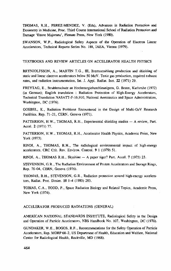
T H O M A S , R . H . , P E R E Z - M E N D E Z , V. (Eds), Advances in Radiation Protection and Dosimetry in Medicine, Proc. Third Course International School of Radiation Protection and Damage 'Ettore Majorana ' , Plenum Press, New York (1980).
S W A N S O N , W . P . , Radiological Safety Aspects of the Operation of Electron Linear Accelerators, Technical Reports Series No. 188, IAEA, Vienna (1979).
TEXTBOOKS A N D REVIEW ARTICLES ON A C C E L E R A T O R H E A L T H PHYSICS
BRYNJOLFSSON, A. , MARTIN T . G . , III, Bremsstrahlung production and shielding of static and linear electron accelerators below 50 MeV. Toxic gas production, required exhaust rates, and radiation instrumentation, Int. J. Appl. Radiat. Isot. 22 (1971) 29.
F R E Y T A G , E . , Strahlenschutz an Hochenergiebeschleunigern, G. Braun, Karlsruhe (1972) (in German); English translation : Radiation Protection of High-Energy Accelerators, Technical Translation NASATT-F-16 ,910 , National Aeronautics and Space Administration, Washington, DC (1976).
GOEBEL, K. , Radiation Problems Encountered in the Design of Multi-GeV Research
Facilities, Rep. 71-21 , C E R N , Geneva (1971).
PATTERSON, H . W . , T H O M A S , R . H . , Experimental shielding studies — A review, Part. Accel. 2 (1971) 77.
P A T T E R S O N , H . W . , T H O M A S , R . H . , Accelerator Health Physics, Academic Press, New York (1973).
RINDI , A. , T H O M A S , R . H . , The radiological environmental impact of high-energy accelerators, CRC Crit. Rev. Environ. Control. 9 1 (1979) 51.
RINDI, A. , T H O M A S R . H . , Skyshine — A paper tiger? Part. Accel. 7 (1975) 23.
STEVENSON, G . R . , The Radiation Environment of Proton Accelerators and Storage Rings, Rep. 76-04 , C E R N , Geneva (1976).
T H O M A S , R . H . , STEVENSON, G . R . , Radiation protection around high-energy accelera-tors, Radiat. Prot. Dosim. 10 1 - 4 (1985) 283.
TOBIAS, C . A . , T O D D , P. , Space Radiation Biology and Related Topics, Academic Press, New York (1974).
A C C E L E R A T O R P R O D U C E D RADIATIONS (GENERAL)
A M E R I C A N N A T I O N A L S T A N D A R D S INSTITUTE, Radiological Safety in the Design and Operation of Particle Accelerators, NBS Handbook No. 107, Washington, DC (1970).
G U N D A K E R , W . E . , BOGGS, R . F . , Recommendations for the Safety Operation of Particle Accelerators, Rep. M O R P 68 -2 , US Department of Health, Education and Welfare, National Center for Radiological Health, Rockville, M D (1968).
464
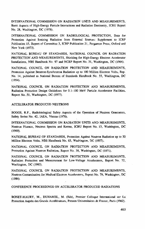
I N T E R N A T I O N A L COMMISSION O N RADIATION UNITS A N D M E A S U R E M E N T S , Basic Aspects of High-Energy Particle Interactions and Radiation Dosimetry, ICRU Report No. 28, Washington, DC (1978).
I N T E R N A T I O N A L COMMISSION O N R A D I O L O G I C A L P R O T E C T I O N , Data for Protection Against Ionizing Radiation f rom External Sources: Supplement to I C R P Publication 15, Report of Committee 3, ICRP Publication 21, Pergamon Press, Oxford and New York (1973).
N A T I O N A L B U R E A U O F S T A N D A R D S , N A T I O N A L C O U N C I L O N RADIATION P R O T E C T I O N A N D M E A S U R E M E N T S , Shielding for High-Energy Electron Accelerator Installations, NBS Handbook No. 97 and N C R P Report No. 31, Washington, DC (1964).
N A T I O N A L C O U N C I L O N RADIATION P R O T E C T I O N A N D M E A S U R E M E N T S , Protection Against Betatron-Synchrotron Radiation up to 100 Million Electron Volts, Rep. No. 14, published as National Bureau of Standards Handbook No. 55, Washington, DC (1954).
N A T I O N A L C O U N C I L O N RADIATION P R O T E C T I O N A N D M E A S U R E M E N T S , Radiation Protection Design Guidelines for 0 . 1 - 1 0 0 M e V Particle Accelerator Facilities, Report No. 51, Washington, D C (1977).
A C C E L E R A T O R P R O D U C E D N E U T R O N S
BOGGS, R . F . , Radiobiological Safety Aspects of the Operation of Neutron Generators, Safety Series No. 42 , IAEA, Vienna (1976).
I N T E R N A T I O N A L COMMISSION O N RADIATION UNITS A N D M E A S U R E M E N T S , Neutron Fluence, Neutron Spectra and Kerma, I C R U Report No. 13, Washington, D C (1969).
N A T I O N A L B U R E A U O F S T A N D A R D S , Protection Against Neutron Radiation up to 30 Million Electron Volts, NBS Handbook No. 63, Washington, DC (1957).
N A T I O N A L C O U N C I L O N RADIATION P R O T E C T I O N A N D M E A S U R E M E N T S , Protection Against Neutron Radiation, Report No. 38, Washington, DC (1971).
N A T I O N A L C O U N C I L O N RADIATION PROTECTION A N D M E A S U R E M E N T S , Radiation Protection and Measurement for Low-Voltage Accelerators, Report No. 72, Washington, DC (1983).
N A T I O N A L C O U N C I L O N RADIATION P R O T E C T I O N A N D M E A S U R E M E N T S , Neutron Contamination for Medical Electron Accelerators, Report No. 79, Washington, D C (1984).
C O N F E R E N C E P R O C E E D I N G S O N A C C E L E R A T O R P R O D U C E D RADIATIONS
B O N E T - M A U R Y , M . , D U H A M E L , M. (Eds), Premier Colloque International sur La Protection Auprfes des Grands Acc616rateurs, Presses Universitaires de France, Paris (1962).
465
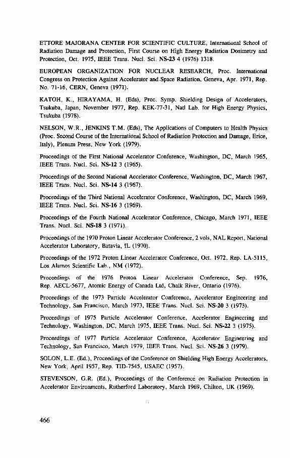
E T T O R E M A J O R A N A C E N T E R FOR SCIENTIFIC C U L T U R E , International School of Radiation Damage and Protection, First Course on High Energy Radiation Dosimetry and Protection, Oct. 1975, IEEE Trans. Nucl. Sci. NS-23 4 (1976) 1318.
E U R O P E A N O R G A N I Z A T I O N F O R N U C L E A R R E S E A R C H , Proc. International Congress on Protection Against Accelerator and Space Radiation, Geneva, Apr. 1971, Rep. No. 71-16, C E R N , Geneva (1971).
K A T O H , K. , H I R A Y A M A , H. (Eds), Proc. Symp. Shielding Design of Accelerators, Tsukuba, Japan, November 1977, Rep. KEK-77-31, Natl Lab. for High Energy Physics, Tsukuba (1978).
N E L S O N , W . R . , JENKINS T . M . (Eds), The Applications of Computers to Health Physics (Proc. Second Course of the International School of Radiation Protection and Damage, Erice, Italy), Plenum Press, New York (1979).
Proceedings of the First National Accelerator Conference, Washington, DC, March 1965, IEEE Trans. Nucl. Sci. NS-12 3 (1965).
Proceedings of the Second National Accelerator Conference, Washington, DC, March 1967, IEEE Trans. Nucl. Sci. NS -14 3 (1967).
Proceedings of the Third National Accelerator Conference, Washington, DC, March 1969, IEEE Trans. Nucl. Sci. NS -16 3 (1969).
Proceedings of the Fourth National Accelerator Conference, Chicago, March 1971, IEEE Trans. Nucl. Sci. NS-18 3 (1971).
Proceedings of the 1970 Proton Linear Accelerator Conference, 2 vols, N A L Report, National Accelerator Laboratory, Batavia, IL (1970).
Proceedings of the 1972 Proton Linear Accelerator Conference, Oct. 1972, Rep. LA-5115, Los Alamos Scientific Lab. , N M (1972).
Proceedings of the 1976 Proton Linear Accelerator Conference, Sep. 1976, Rep. AECL-5677, Atomic Energy of Canada Ltd, Chalk River, Ontario (1976).
Proceedings of the 1973 Particle Accelerator Conference, Accelerator Engineering and Technology, San Francisco, March 1973, IEEE Trans. Nucl. Sci. NS-20 3 (1973).
Proceedings of 1975 Particle Accelerator Conference, Accelerator Engineering and Technology, Washington, DC, March 1975, IEEE Trans. Nucl. Sci. NS-22 3 (1975).
Proceedings of 1977 Particle Accelerator Conference, Accelerator Engineering and Technology, San Francisco, March 1979, IEEE Trans. Nucl. Sci. .NS-26 3 (1979).
SOLON, L .E . (Ed.) , Proceedings of the Conference on Shielding High Energy Accelerators, New York, April 1957, Rep. TID-7545, USAEC (1957).
STEVENSON, G.R. (Ed.) , Proceedings of the Conference on Radiation Protection in
Accelerator Environments, Rutherford Laboratory, March 1969, Chilton, UK (1969).
466
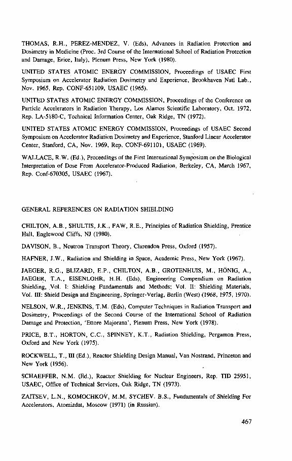
T H O M A S , R . H . , P E R E Z - M E N D E Z , V. (Eds), Advances in Radiation Protection and Dosimetry in Medicine (Proc. 3rd Course of the International School of Radiation Protection and Damage, Erice, Italy), Plenum Press, New York (1980).
U N I T E D STATES A T O M I C E N E R G Y COMMISSION, Proceedings of U S A E C First Symposium on Accelerator Radiation Dosimetry and Experience, Brookhaven Natl Lab . , Nov. 1965, Rep. CONF-651109, USAEC (1965).
U N I T E D STATES A T O M I C E N E R G Y COMMISSION, Proceedings of the Conference on Particle Accelerators in Radiation Therapy, Los Alamos Scientific Laboratory, Oct. 1972, Rep. LA-5180-C, Technical Information Center, Oak Ridge, T N (1972).
U N I T E D STATES A T O M I C E N E R G Y C O M M I S S I O N , Proceedings of USAEC Second Symposium on Accelerator Radiation Dosimetry and Experience, Stanford Linear Accelerator Center , Stanford, CA, Nov. 1969, Rep. CONF-691101 , USAEC (1969).
W A L L A C E , R .W. (Ed.) , Proceedings of the First International Symposium on the Biological Interpretation of Dose From Accelerator-Produced Radiation, Berkeley, CA, March 1967, Rep. Conf-670305, USAEC (1967).
G E N E R A L R E F E R E N C E S ON RADIATION SHIELDING
C H I L T O N , A.B. , SHULTIS, J .K . , F A W , R .E . , Principles of Radiation Shielding, Prentice Hall, Englewood Cliffs , NJ (1980).
DAVISON, B. , Neutron Transport Theory, Clarendon Press, Oxford (1957).
H A F N E R , J . W . , Radiation and Shielding in Space, Academic Press, New York (1967).
J A E G E R , R . G . , B L I Z A R D , E . P . , C H I L T O N , A .B . , G R O T E N H U I S , M . , HONIG, A . , J A E G E R , T . A . , E ISENLOHR, H .H . (Eds), Engineering Compendium on Radiation Shielding, Vol. I: Shielding Fundamentals and Methods; Vol. II: Shielding Materials, Vol. Ill: Shield Design and Engineering, Springer-Verlag, Berlin (West) (1968, 1975, 1970).
N E L S O N , W . R . , JENKINS, T . M . (Eds), Computer Techniques in Radiation Transport and Dosimetry, Proceedings of the Second Course of the International School of Radiation Damage and Protection, 'Et tore Majorana ' , Plenum Press, New York (1978).
PRICE, B .T . , H O R T O N , C . C . , SPINNEY, K .T . , Radiation Shielding, Pergamon Press,
Oxford and New York (1975).
R O C K W E L L , T . , Ill (Ed.) , Reactor Shielding Design Manual , Van Nostrand, Princeton and
New York (1956).
S C H A E F F E R , N . M . (Ed.) , Reactor Shielding for Nuclear Engineers, Rep. TID 25951, USAEC, Off ice of Technical Services, Oak Ridge, TN (1973).
ZAITSEV, L . N . , K O M O C H K O V , M . M , SYCHEV. B.S . , Fundamentals of Shielding For Accelerators, Atomizdat, Moscow (1971) (in Russian).
467
ADVISORY M A T E R I A L O N RADIOLOGICAL PROTECTION, U S E F U L AT A C C E L E R A T O R INSTALLATIONS, B U T B R O A D E R IN SCOPE
I N T E R N A T I O N A L A T O M I C E N E R G Y A G E N C Y , The Provision of Radiological Protection Services, Safety Series No. 13, IAEA, Vienna (1965).
I N T E R N A T I O N A L A T O M I C E N E R G Y A G E N C Y , Radiation Protection Procedures, Safety Series No. 38, IAEA, Vienna (1973).
N A T I O N A L B U R E A U O F S T A N D A R D S , A Manual of Radioactivity Procedures, NBS Handbook No . 80 and N C R P Report No. 28, Washington, DC (1961).
N A T I O N A L B U R E A U O F S T A N D A R D S , Physical Aspects of Irradiation, NBS Handbook No. 85 and ICRU Report No. 10b, Washington, DC (1964).
N A T I O N A L C O U N C I L O N RADIATION PROTECTION A N D M E A S U R E M E N T S , Safe Handling of Radioactive Materials, Report No. 29 (NBS Handbook No. 92), Washington, DC (1964).
N A T I O N A L C O U N C I L O N RADIATION PROTECTION A N D M E A S U R E M E N T S , Medical Exposure of Pregnant and Potentially Pregnant Women, Report No. 54, Washington, DC (1979).
N A T I O N A L C O U N C I L O N RADIATION PROTECTION A N D M E A S U R E M E N T S , Operational Safety Program, Report No. 59, Washington, DC (1978).
N A T I O N A L C O U N C I L ON RADIATION P R O T E C T I O N A N D M E A S U R E M E N T S , Management of Persons Accidentally Contaminated with Radionuclides, Report No. 65, Washington, DC (1980).
N A T I O N A L C O U N C I L O N RADIATION PROTECTION A N D M E A S U R E M E N T S , Radio-Frequency Electromagnetic Fields, Report No. 67, Washington, DC (1981).
ADVISORY M A T E R I A L R E L A T E D T O RADIATION M O N I T O R I N G
I N T E R N A T I O N A L ATOMIC E N E R G Y A G E N C Y , The Use of Film Badges for Personnel Monitoring, Safety Series No. 8, IAEA, Vienna (1962).
I N T E R N A T I O N A L A T O M I C E N E R G Y A G E N C Y , The Basic Requirements for Personnel Monitoring, Safety Series No. 14, IAEA, Vienna (1965).
I N T E R N A T I O N A L A T O M I C E N E R G Y A G E N C Y , Personnel Dosimetry Systems for External Radiation Exposures, Technical Reports Series No. 109, IAEA, Vienna (1970).
I N T E R N A T I O N A L ATOMIC E N E R G Y A G E N C Y , Handbook on Calibration of Radiation Protection Monitoring Instruments, Technical Reports Series No. 133, IAEA, Vienna (1971).
I N T E R N A T I O N A L COMMISSION ON RADIATION UNITS A N D M E A S U R E M E N T S , Radiation Protection Instrumentation and its Applications, Report No. 20, Washington, DC (1971).
468
I N T E R N A T I O N A L COMMISSION ON RADIOLOGICAL P R O T E C T I O N , General Principles of Monitoring for Radiation Protection of Workers , Publication 35, Pergamon Press, Oxford and New York (1969).
I N T E R N A T I O N A L COMMISSION ON RADIATION UNITS A N D M E A S U R E M E N T S , Radiological Monitoring Methods and Instruments, Report No. 10 and NBS Handbook No. 51, Washington, DC (1952).
I N T E R N A T I O N A L COMMISSION ON RADIATION UNITS A N D M E A S U R E M E N T S , Instrumentation and Monitoring Methods for Radiation Protection, Report No. 57, Washing-ton, D C (1978).
I N T E R N A T I O N A L COMMISSION ON RADIOLOGICAL PROTECTION, Principles of Monitoring for the Radiation Protection of the Population, Publication 43, Pergamon Press, Oxford and New York (1985).
H A N D B O O K A N D D A T A TABULATIONS
BERGER, M.J . , SELTZER, S . M . , Tables of Energy Losses and Ranges of Electrons and Positrons, Rep. NASA-SP-3012, National Aeronautics and Space Administration, Washington, DC (1974); Additional Stopping Power and Range Tables for Protons, Mesons, and Electrons, Rep. NASA-SP-3036, National Aeronautics and Space Administration, Washington, DC (1966). (These reports are available at the Off ice of Technical Services, Washington, DC 20230).
B U R E A U O F R A D I O L O G I C A L H E A L T H , Radiological Health Handbook, Public Health Service, US Department of Health, Education and Welfare , Rockville, M D (1970).
G O L D M A N , D . T . , ROESSER, J .R . , Chart of the Nuclides, 9th edn, Knolls Atomic Power Laboratory, General Electric Co . , Schenectady, NY (1966).
HUBBELL, J .H . , Photon Cross Sections, Attenuation Coefficients, and Energy Absorption Coefficients f rom 10 keV to 100 GeV, National Bureau of Standards, Publication No. NSRDS-NBS 29, Washington, DC (1969).
L E D E R E R , C . M . , H O L L A N D E R , J . M . , P E R L M A N , I . , Table of Isotopes, 7th edn, Wiley, New York (1978).
N A C H T I G A L L , D . , Table of Specific Gamma Ray Constants, Karl Thiemig, Munich (1969).
PAGES, L. , BERTEL, E . , JOFFRE, H . , SKLAVENITIS, L . , Energy loss, range, and bremsstrahlung yield for 10-keV to 100-MeV electrons in various elements and chemical compounds, At. Data Nucl. Data Tables 4 1 (1972) 1.
P A R T I C L E DATA G R O U P , Review of Particle Properties, Lawrence Berkeley Laboratory Rep. LBL-100, revised, Phys. Lett . , B 111 (1982) 1.
P L E C H A T Y , E . F . , C U L L E N , D . E . , H O W E R T O N , R.J . , Tables and Graphs of Photon Interaction Cross Sections f rom 1.0 keV to 100 MeV Derived f rom the LLL Evaluated Nuclear Data Library, Rep. UCRL-50400, Lawrence Livermore Lab. , Vol. 26, Rev. 1 (1975).
469
S E E L M A N N - E G G E B E R T , W . , P F E N N I N G G. , M U N Z E L , H . , 'Nukl idkar te ' , 3rd edn, Institut fur Radiochemie, Kernforschungszentrum Karlsruhe, Bundesminister fur Wissenschaftliche Forschung, Bonn (1968).
STORM, E . , ISRAEL, H. I . , Photon cross sections f rom 0.001 to 100 MeV for elements 1 through 100, Rep. LA-3753, Los Alamos Scientific Lab. , N M (1967); Photon cross sections f rom 1 keV to 100 MeV for elements Z = 1 to Z = 100, Nucl. Data Tables A7 (1970) 565.
VEIGELE, W.J . , Photon cross sections from 0.1 keV to 1 MeV for elements Z = 1 to Z = 94, At. Data Tables 5 1 (1973) 51.
W A N G , Y. (Ed.) , Handbook of Radioactive Nuclides, Chemical Rubber Co . , Cleveland, OH (1969).
E N V I R O N M E N T A L RADIATION
EISENBUD, M. , Environmental Radioactivity, Academic Press, New York (1973).
GOEBEL, K. , Radio-Ecological Considerations for Operating Particle Accelerators, Rep. 79-09, C E R N , Geneva (1979).
G O E B E L , K. (Ed.)', The Radiological Impact of the L E P Project on the Environment, Rep. 81-08, C E R N , Geneva (1981).
N A T I O N A L C O U N C I L ON RADIATION PROTECTION A N D M E A S U R E M E N T S , Environmental Radiation Measurements , Rep. 50, Washington, DC (1977).
N A T I O N A L C O U N C I L ON RADIATION PROTECTION A N D M E A S U R E M E N T S , Natural Background Radiation in the United States, Rep. 45, Washington, D C (1975).
RINDI, A. , T H O M A S , R . H . , Radiological environmental impact of high-energy accelerators, CRC Crit. Rev. Environ. Control 9 (1979) 51.
SLADE, D .H . (Ed.), Methodology and Atomic Energy 1968, Rep. No.TID-24190, USAEC, Washington, DC (1968).
T H O M A S , R . H . , The Radiological Impact of High-Energy Accelerators on the Environment, Rep. KEK-78-20, Natl Lab. for High Energy Physics, Tsukuba, Japan (1978).
A C C E L E R A T O R DESIGN STUDIES
E U R O P E A N ORGANIZATION F O R N U C L E A R RESEARCH, The 300 GeV Program, Rep. CERN/1050 , C E R N , Geneva (1972).
FERMI N A T I O N A L A C C E L E R A T O R LABORATORY, A Report on the Design of the Fermi National Accelerator Laboratory Superconducting Accelerator, Batavia, IL (1979).
HOBBIS, L . C . W . , REES. , G . H . , STIRLING, G . C . , A Pulsed Neutron Facility for Condensed Matter Research, Rep. RL-77-064-C, Rutherford Lab. , Chilton, UK (June 1977).
L A W R E N C E BERKELEY LABORATORY, The 200-BeV Accelerator Design Study, 2 vols, Rep. UCRL-16000, Berkeley, CA (1965).
470
L A W R E N C E B E R K E L E Y L A B O R A T O R Y , High Intensity Uranium Beams f rom the SuperHILAC and the Bevalac, Proposal 32, Berkeley, C A (1975).
L A W R E N C E BERKELEY L A B O R A T O R Y , The Heavy Ion Medical Accelerator, Rep. Pub-5122, Berkeley, C A (1984).
National Accelerator Laboratory — Design Report , Universities Research Association Internal Rep. (1968).
N E A L E , R .D . (Ed.) , The Stanford Two-Mile Accelerator, Benjamin, New York (1968).
PEP Conceptual Design Report , Rep. LBL-4288/SLAC-185, Lawrence Berkeley Lab. , Berkeley, CA (1976).
S A N F O R D , J .R . (Ed.) , Isabelle — A Proton-Proton Colliding Beam Facility, Rep. BNL-5078, Brookhaven Natl Lab. , Upton, NY (1978).
UNITED STATES D E P A R T M E N T O F E N E R G Y , Superconducting Super Collider Reference Design Study, Reference Designs Study Group, Lawrence Berkeley Lab. , Berkeley, CA (1984).
PROBLEMS O F I N D U C E D RADIOACTIVITY
BARBIER, M . , Induced Radioactivity, North-Holland, Amsterdam (1969).
BLASEWITZ, A . G . , DAVIS, J . M . , SMITH, M . R . , The Treatment and Handling of Radioactive Waste, Battelle Press, Columbus, O H (1983).
O P E L K A , J .H . , M U N D I S , R .L . , M A R M E R , G.J . , PETERSON, J . M . , SISKIND, B. , KITKA, M.J . , Particle-Accelerator Decommissioning, Rep. ANL/ES-82 , Argonne Natl Lab. , IL (1979).
S T E W A R T , D . C . , Handling Radioactivity, Wiley, New York (1981).
A C C E L E R A T O R RADIATION SAFETY M A N U A L S
E U R O P E A N O R G A N I Z A T I O N FOR N U C L E A R R E S E A R C H , Radiation Safety Manual , Geneva (1975).
L A W R E N C E B E R K E L E Y L A B O R A T O R Y , Health and Safety Manual , Rep. Pub-3000 (1980 and subsequent revisions).
M A R T I N , T . G . (Ed.) , Accelerator Radiation Protection, Rep. TR-73-7, US Army Natick Labs, . Natick, M A (1972).
Particle Accelerator Manual (Prepared by W . M . Brobeck and Associates), Rep. MORP-68-12, US Department of Health, Education and Welfare , National Center for Radiological Health, Rockville, M D (1968).
471

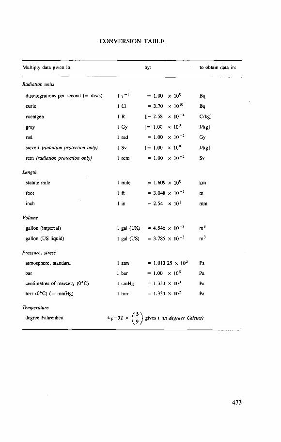
CONVERSION TABLE
Multiply data given in: by: to obtain data in:
Radiation units
disintegrations per second (= dis/s) 1 s"1 = 1.00 X 10° Bq
curie 1 Ci = 3.70 X 10¹⁰ Bq
roentgen 1 R [ = 2.58 X 10"4 C/kg]
gray 1 Gy 1.00 X 10° J/kg]
rad 1 rad = 1.00 X io-2 Gy
sievert (radiation protection only) 1 Sv [ = 1.00 X 10° J/kg]
rem (radiation protection only) 1 rem = 1.00 X io-2 Sv
Length
statute mile 1 mile = 1.609 X 10° km
foot 1 ft = 3.048 X 10'1 m
inch 1 in = 2.54 X 101 mm
Volume
gallon (imperial) 1 gal (UK) = 4.546 X 10⁻³ m3
gallon (US liquid) 1 gal (US) = 3.785 X 10"3 m3
Pressure, stress
atmosphere, standard 1 atm = 1.013 25 x 105 Pa
bar 1 bar = 1.00 X 10⁵ Pa
centimetres of mercury (0°C) 1 cmHg = 1.333 X 10³ Pa
torr (0°C) (= mmHg) 1 torr = 1.333 X 10² Pa
Temperature
degree Fahrenheit t=F—32 x ) gives t (in degrees Celsius)
473
HOW TO ORDER IAEA PUBLICATIONS An exclusive sales agent for IAEA publications, to whom all orders
and inquiries should be addressed, has been appointed in the following country:
U N I T E D S T A T E S O F A M E R I C A U N I P U B . 4611-F A s s e m b l y Dr i ve , L a n h a m , M D 2 0 7 0 6 - 4 3 9 1
In the following countries IAEA publications may be purchased from the sales agents or booksellers listed or through major local booksellers. Payment can be made in local currency or with UNESCO coupons.
A R G E N T I N A
A U S T R A L I A B E L G I U M
C H I L E
C H I N A
C Z E C H O S L O V A K I A
F R A N C E
H U N G A R Y
I N D I A
I S R A E L
I T A L Y
J A P A N P A K I S T A N
P O L A N D
R O M A N I A S O U T H A F R I C A
S P A I N
S W E D E N
U N I T E D K I N G D O M
USSR Y U G O S L A V I A
C o m i s i o n Nac iona l de Energfa A t o m i c a , A v e n i d a del L i b e r t a d o r 8 2 5 0 , R A - 1 4 2 9 Buenos A i res H u n t e r P u b l i c a t i o n s , 5 8 A G ipps S t ree t , C o l l i n g w o o d , V i c t o r i a 3 0 6 6 Serv ice C o u r r i e r U N E S C O , 2 0 2 , A v e n u e d u R o i , B - 1 0 6 0 Brussels C o m i s i 6 n Ch i l ena de Energt'a Nuc lea r , V e n t a de Pub l i cac iones , A m u n a t e g u i 9 5 , Casi l la 188-D, San t iago I A E A P u b l i c a t i o n s in Ch inese: Ch ina Nuc lear Energy I n d u s t r y C o r p o r a t i o n , T r a n s l a t i o n S e c t i o n , P . O . B o x 2103 , Be i j i ng I A E A P u b l i c a t i o n s o t h e r t h a n in Ch inese: Ch ina N a t i o n a l P u b l i c a t i o n s I m p o r t & E x p o r t C o r p o r a t i o n , Deu t sche A b t e i l u n g , P.O. B o x 8 8 , Be i j i ng S .N .T .L . , M i k u l a n d s k a 4 , CS-11686 Prague 1 A l f a , Pub l ishers , H u r b a n o v o namest ie 3 .CS-815 8 9 Bra t i s lava O f f i c e I n t e r n a t i o n a l de D o c u m e n t a t i o n et L i b r a i r i e , 4 8 , rue Gay-Lussac , F - 7 5 2 4 0 Paris Cedex 0 5 K u l t u r a , H u n g a r i a n Fore ign T rad ing C o m p a n y , P.O. B o x 149. H - 1 3 8 9 Budapes t 6 2 O x f o r d B o o k a n d S t a t i o n e r y Co. , 17, Park S t ree t , C a l c u t t a - 7 0 0 016 O x f o r d B o o k a n d S t a t i o n e r y Co. , Sc ind ia House , N e w D e l h i - 1 1 0 0 0 1 He i l iger & Co. L t d . 23 K e r e n Hayesod S t ree t , Je rusa lem 94188 L i b r e r i a S c i e n t i f i c a , D o t t . L u c i o de Bias io " a e i o u " , V i a Merav ig l i 16, 1-20123 M i l a n M a r u z e n C o m p a n y , L t d , P.O. B o x 5 0 5 0 , 1 0 0 - 3 1 T o k y o I n t e r n a t i o n a l M i r z a B o o k A g e n c y , 6 5 , Shah rah Q u a i d - e - A z a m , P.O. B o x 7 2 9 , L a h o r e 3 A r s P o l o n a - R u c h , Cen t ra l a H a n d l u Z a g r a n i c z n e g o , K r a k o w s k i e P rzedmiesc ie 7, P L - 0 0 - 0 6 8 Warsaw l l e x i m , P O . B o x 136-137, Buchares t V a n Scha i k B o o k s t o r e ( P t y ) L t d , P.O. B o x 724 , P re to r i a 0 0 0 1 D iaz de San tos , Lagasca 9 5 , E - 2 8 0 0 6 M a d r i d D iaz de San tos , Ba lmes 417, E - 0 8 0 2 2 Ba rce lona A B Fr i t zes K u n g l . H o v b o k h a n d e l , F redsgatan 2 , P.O. B o x 1 6 3 5 6 , S-103 27 S t o c k h o l m Her Ma jes ty ' s S t a t i o n e r y O f f i c e , P u b l i c a t i o n s C e n t r e , A g e n c y S e c t i o n , 51 N i n e E lms Lane , L o n d o n SW8 5 D R M e z h d u n a r o d n a y a K n i g a . S m o l e n s k a y a - S e n n a y a 3 2 - 3 4 , M o s c o w G - 2 0 0 Jugos lovenska K n j i g a , Teraz i je 27 ,P .O . B o x 3 6 , YU-11001 Be lgrade
Orders from countries where sales agents have not yet been appointed and requests for information should be addressed directly to:
^ Division of Publications ' J International Atomic Energy Agency
Wagramerstrasse 5, P.O. Box 100, A-1400 Vienna, Austria

in I D CO o CO 00
INTERNATIONAL SUBJECT GROUP: II ATOMIC ENERGY AGENCY Nuclear Safety and Environmental Protection/Radiological Safety VIENNA, 1988


