Embed Size (px)
Citation preview

G
C
Cs
SSa
b
a
ARRAA
KMHESS
1
figcroct
fTrpctdcfluip
0h
ARTICLE IN PRESS Model
EP-6317; No. of Pages 7
Chemical Engineering and Processing xxx (2013) xxx– xxx
Contents lists available at ScienceDirect
Chemical Engineering and Processing:Process Intensification
jo ur nal homepage: www.elsev ier .com/ locate /cep
FD simulation of acetone separation from an aqueous solution usingupercritical fluid in a hollow-fiber membrane contactor
eyed Abolfazl Miraminia, S.M.R. Razavia, Mehdi Ghadirib,∗, S.Z. Mahdavia,adegh Moradia
Department of Chemical Engineering, Faculty of Engineering, Arak University, Arak 38156-8-8349, IranDepartment of Chemical Engineering, Iran University of Science and Technology, Tehran, Iran
r t i c l e i n f o
rticle history:eceived 29 December 2012eceived in revised form 15 July 2013ccepted 17 July 2013vailable online xxx
a b s t r a c t
In the present study, separation and mass transfer of acetone using a polymeric hollow fiber membraneby a supercritical fluid as a dense solvent was simulated. The propane is used as supercritical fluid forextraction of acetone. The simulated hollow-fiber membrane contactor has three compartments: tube,porous membrane and shell. The aqueous solution and solvent pass in the lumen and shell sides, respec-tively. The model equations have been solved by CFD technique using a finite element as numerical
eywords:ass transferollow-fiber membranextraction
method. The simulation results were compared with experimental data obtained from literature andshowed great agreement with the measured values. The simulation results of acetone extraction alsoshowed that reducing the feed rate and increasing the solvent velocity will enhance the separation ofacetone.
imulationeparation
. Introduction
A number of separation processes are carried out using hollow-ber membrane contactors or conventional equipment such asas adsorption and solvent extraction. In hollow-fiber membraneontactors (HFMCs), the membrane mainly acts as a physical bar-ier between the two fluids. In this case, unlike most membraneperations, the membrane will not have any effect on partitionoefficients. This kind of contactors provides considerable extrac-ion [1–3].
In hollow-fiber membrane contactors (HFMCs), the mass trans-er of species between two sides of membrane is very landmark.he hydrophilic or hydrophobic nature of the porous membraneepresents a relationship between the aqueous phase and organichase. One of the main advantages of hollow-fiber membraneontactors is that the membrane will develop scattering and dis-ribution without any contact, so that the emulsion is not formeduring the separation. Moreover, the rate of both phases can behosen independently. As a result, problems such as undevelopedow and foaming will not occur in these contactors. The ability of
Please cite this article in press as: S.A. Miramini, et al., CFD simulation of ain a hollow-fiber membrane contactor, Chem. Eng. Process. (2013), http://d
sing a supercritical fluid as the separating agent of the system hasncreased the use of hollow-fiber membranes. This process is calledorocritical process [4,5].
Abbreviations: CFD, computational fluid dynamics.∗ Corresponding author. Tel.: +98 21 77240496; fax: +98 21 77240495.
E-mail address: m [email protected] (M. Ghadiri).
255-2701/$ – see front matter © 2013 Elsevier B.V. All rights reserved.ttp://dx.doi.org/10.1016/j.cep.2013.07.005
© 2013 Elsevier B.V. All rights reserved.
In this process, a porous membrane provides contact betweenthe feed and solvent phases. On one side of the membrane, thefeed or aqueous solution of the acetone flows, on the other side, anear-critical or supercritical fluid flows as the solvent. It is note-worthy that to develop a relationship between the solvent andfeed, the aqueous solution is compressed to a pressure close tothat of the compressed solvent. As the membrane materials arehydrophobic, and the aqueous solution is not able to diffuse intothe membrane pores, the solvent will fill all membrane pores. Inthis case, it can be noted that the driving force for this process isthe solute concentration gradient between feed and dense solvent.The porocritical process consists of 4 different stages for transfer-ring solutes throughout the membrane. The porocritical processcould be clarified by following the direction of mass transfer of ace-tone from the aqueous feed solution flowing inside the hollow fiberto the supercritical fluid solvent flowing outside the hollow fiberbetween membrane and shell in an annular gap. The first stage istransfer of acetone through the feed boundary layer; second stageis dissolution into the solvent at the liquid-membrane interfaceinside the hollow fiber, third stage is diffusion through the porousmembrane fiber and finally the fourth stage the transfer of acetonethrough the solvent boundary layer into the bulk solvent flowingbetween membrane and shell. Fig. 1a shows a view of the generalprinciples of this process [2].
cetone separation from an aqueous solution using supercritical fluidx.doi.org/10.1016/j.cep.2013.07.005
The modeling of mass transfer in hollow fiber membrane con-tactor has been investigated by many researchers. Two ways havebeen developed for the simulation and modeling of transportphenomena in separation by means membrane contactors. The

ARTICLE IN PRESSG Model
CEP-6317; No. of Pages 7
2 S.A. Miramini et al. / Chemical Engineering and Processing xxx (2013) xxx– xxx
extra
fit(tbtbbcsmnerTd
moeim
2
phicbe
2
wa
Fig. 1. (a) Mass transfer in a counter-current porocritical
rst one is based on resistance-in-series model, through whichhe solute can be explained by taking four actions into account:i) transport species flow through the feed boundary layer; (ii) andhen crossing of the aqueous-solvent interface within the mem-rane; (iii) transport species diffusion into the pores filled withhe solvent phase; (iv) transport species pass through the solventoundary layer. The mass transfer resistances in the feed phaseoundary layer, the porous membrane, and the solvent phases areonsidered in series [6]. The second method is based on solving con-ervation equations for the transport species in all domains. In thisethod, conservation equations including momentum and conti-
uity equations are derived and solved at the same time using finitelement method. This method was used to simulate the gas sepa-ation and solvent extraction carried out in membrane contactors.heir results reveal excellent agreement among the experimentalata and modeling and simulation results [7–13].
The main objective of the present study is to develop and solve aathematical mass transfer model for overall prediction of the por-
critical process. The model is then tested in simulation of acetonextraction. The comprehensive developed model is able to exam-ne the axial and radial distribution of variables inside the tube,
embrane and shell sides of hollow fiber membrane contactor.
. The model development
A comprehensive 2D mathematical model is proposed for trans-ort of acetone through hollow-fiber membrane contactor. Theollow-fiber membrane is located in stainless steel tube hous-
ng. The aqueous solution and solvent (supercritical propane) flowounter-currently inside and outside the fiber, respectively. It cane said that the simulation was done in the same conditions asxperimental works.
.1. Mass transfer equations
Please cite this article in press as: S.A. Miramini, et al., CFD simulation of ain a hollow-fiber membrane contactor, Chem. Eng. Process. (2013), http://d
As shown in Fig. 1a, the feed solution enters the tube at Z = 0ith laminar and fully developed flow. Solvent will enter the shell
t Z = L in the opposite direction of the feed flow. Triangular mesh
ction. (b) Triangular mesh elements and model domains.
elements and model domain are shown in Fig. 1b. Size of meshelements near the membrane surface is smaller than in other zonesof contactor. This is because the concentration gradient is higher inthis zone of membrane contactor. The following assumptions havebeen considered for model simulation:
(1) Steady-state and isothermal conditions.(2) Fully developed velocity profiles for the fluid within hollow
fibers.(3) The solution and dense solvent are immiscible inside the shell.
The conservation equations for each section can be written asfollows [14]:
∂(��)∂t
+ div(�→ u� − �, grad�) = S, (1)
where � is the mixture density; � is the dependent variable and �uis the velocity vector. The variable of � � is the convenient coeffi-cient for � which is calculated as � � = �D, where D is the diffusioncoefficient and S� is the source term of each sink unit volume for�. Steady-state continuity equation for aqueous solution of acetonein three sections of the hollow fiber membrane is as follows, whichincludes Fick’s diffusion law for estimation of diffusion flux:
−Di∇ · (∇Ci) + ∇ · (CiV) = 0 (2)
It is assumed that no chemical reactions will occur during theprocess in the model. However, in the shell side and for a laminarflow, Navier–Stokes equations can be applied:
�∂Vz
∂t− ∇ · �(∇Vz + (∂Vz)T ) + �(Vz · ∇)Vz + ∇p = f
∇ · Vz = 0(3)
The boundary conditions in the shell side are applied as follows:
cetone separation from an aqueous solution using supercritical fluidx.doi.org/10.1016/j.cep.2013.07.005
@z = L, → Ci-shell = 0, Vz = V0 (4)
@r = r3, → ∂Ci-shell
∂r= 0 (insulation) (5)

ARTICLE IN PRESSG Model
CEP-6317; No. of Pages 7
S.A. Miramini et al. / Chemical Engineering and Processing xxx (2013) xxx– xxx 3
he me
@
f
@
@
@
Fig. 2. The radial concentration profile of acetone in t
r = r2, → Ci-shell = Ci-membrane (6)
The boundary conditions in the membrane side are applied asollows:
r = r2, → Ci-membrane = Ci-shell (7)
Please cite this article in press as: S.A. Miramini, et al., CFD simulation of ain a hollow-fiber membrane contactor, Chem. Eng. Process. (2013), http://d
r = r1, → Ci-membrane = Ci-tube × m (8)
z = 0, → ∂Ci-membrane
∂r= 0 (insulation) (9)
Fig. 3. The radial concentration profile of acetone in the
mbrane side. Inlet concentration of acetone = 10 wt%.
@z = L, → ∂Ci-membrane
∂r= 0 (insulation) (10)
where m is the physical solubility of liquid feed in the dense gas. Theboundary conditions in the tube side of contactors are as follows:
cetone separation from an aqueous solution using supercritical fluidx.doi.org/10.1016/j.cep.2013.07.005
@z = 0, → Ci-tube = Ci-inlet (11)
@r = r1, → Ci-tube = Ci-membrane/m (12)
tube side. Inlet concentration of acetone = 10 wt%.
ARTICLE IN PRESSG Model
CEP-6317; No. of Pages 7
4 S.A. Miramini et al. / Chemical Engineering and Processing xxx (2013) xxx– xxx
Table 1The parameters of membrane used in the simulation [5].
Parameter Unit Symbol Value
Porosity (%) – ε 0.75Fiber length cm L 106.7The average size of membrane pore �m d 0.4The number of fibers – n 1Internal radius of fiber mm r1 0.3External radius of fiber mm r2 0.51Internal radius of shell mm r3 0.76Diffusivity of acetone in the propane m2/s D3 1.1e−8Diffusivity of acetone in the feed m2/s D1 1.14e−9Partition coefficient – m 1.63Kinematic viscosity of dense fluid cm2/s � 2.2e−3
Table 2Represents the results of comparisons, from a 10 wt% aqueous solution using a fiberby supercritical propane at T = 298 ◦C and P = 35.5 bar [5].
Aqueous phaseflow rate [ml/min]
S/F Experimental results(extraction %)
Simulation results(extraction %)
0.15 3 64.6 68.70.25 3 63.9 66.5
@
l2
V
dmu
D
sdam
2
ppUtdtf
3
3
turi
0.50 3 33.5 37.11.00 3 23.9 26.2
r = 0, → ∂Ci-tube
∂r= 0 (symmetry) (13)
Velocity distribution in the tube side is assumed as a Newtonianaminar flow in which the calculated Reynolds number is equal to100 [14]. u is the average velocity inside the tube:
z-tube = 2u
[1 −
(r
r1
)2]
(14)
The effective diffusion coefficient of the porous membrane isetermined through the tortuosity and porosity of the porousembrane (Eq. (15)), which are provided by the membrane man-
facturer [12].
membrane = Dsolvent phase
(ε
)(15)
Table 1 shows the parameters of membrane used in the presenttudy [5]. The partition coefficient and diffusion coefficient areetermined using thermodynamic property. Therefore, the inter-ction of supercritical solvent with acetone is considered in theathematical modeling and simulation [15].
.2. Numerical solution and equations
Numerical calculations were performed using COMSOL Multi-hysics based on finite element method. The FEM analysis waserformed along with error control and mesh adaption using solverMFPACK. The grid was composed of 50411 meshes. A scaling fac-
or of 150 has been employed in the z-direction because of largeifference between r and z. The software automatically scales backhe geometry after meshing. The physical parameters and constantsor numerical solution were obtained from the literature [16–22].
. Results and discussion
.1. Model validation
To ensure optimal extraction of acetone calculated by the mass
Please cite this article in press as: S.A. Miramini, et al., CFD simulation of ain a hollow-fiber membrane contactor, Chem. Eng. Process. (2013), http://d
ransfer model, the calculated percentage of extracted acetonesing mathematical model was compared with the experimentalesults of Bothum et al. [5]. Table 2 represents the results of compar-sons, from a 10 wt% aqueous solution using a fiber by supercritical
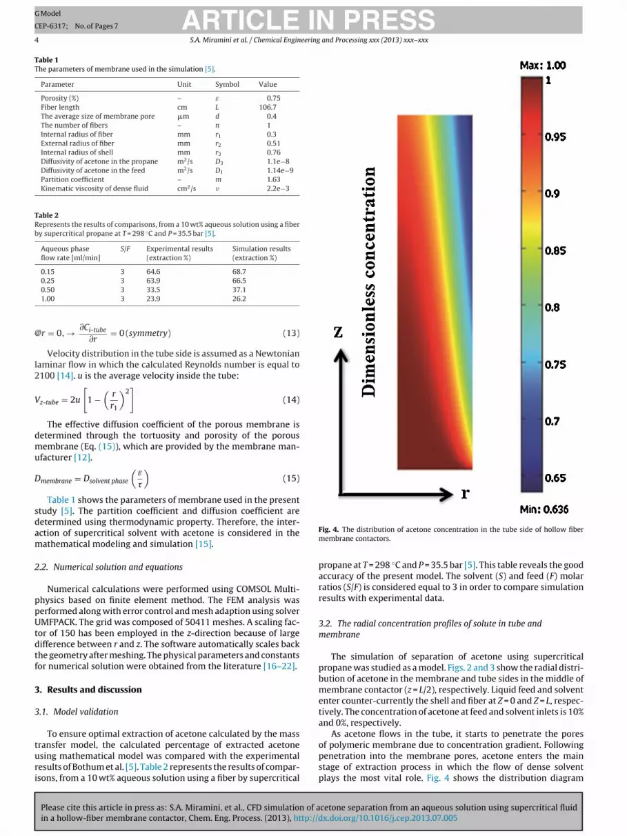
Fig. 4. The distribution of acetone concentration in the tube side of hollow fibermembrane contactors.
propane at T = 298 ◦C and P = 35.5 bar [5]. This table reveals the goodaccuracy of the present model. The solvent (S) and feed (F) molarratios (S/F) is considered equal to 3 in order to compare simulationresults with experimental data.
3.2. The radial concentration profiles of solute in tube andmembrane
The simulation of separation of acetone using supercriticalpropane was studied as a model. Figs. 2 and 3 show the radial distri-bution of acetone in the membrane and tube sides in the middle ofmembrane contactor (z = L/2), respectively. Liquid feed and solvententer counter-currently the shell and fiber at Z = 0 and Z = L, respec-tively. The concentration of acetone at feed and solvent inlets is 10%and 0%, respectively.
As acetone flows in the tube, it starts to penetrate the pores
cetone separation from an aqueous solution using supercritical fluidx.doi.org/10.1016/j.cep.2013.07.005
of polymeric membrane due to concentration gradient. Followingpenetration into the membrane pores, acetone enters the mainstage of extraction process in which the flow of dense solventplays the most vital role. Fig. 4 shows the distribution diagram

IN PRESSG Model
C
eering and Processing xxx (2013) xxx– xxx 5
omoobcpmBas
fitpstsidodmh
3d
sflrFtts
ARTICLEEP-6317; No. of Pages 7
S.A. Miramini et al. / Chemical Engin
f acetone concentration in the tube side. As can be seen, theembrane-tube interface has the highest concentration gradient
f acetone. The concentration gradient increases by enhancementf partition coefficient and diffusion coefficient of porous mem-rane. The diffusion coefficient of feed phase has adverse effect ononcentration gradient at interface of membrane-tube. Followingassing a 10 wt% acetone solution through the polymeric adsorbentembrane, significant changes will occur in acetone adsorption.
y moving radially from the center of tube to the surface of thedsorbent membrane, the concentration of acetone in the aqueousolution will significantly decrease.
Fig. 5 shows the velocity profile in the shell side of hollowber membrane which represents the maximum fluid velocity athe center of shell. In this figure, the dense solvent (supercriticalropane) is flowing and it is worth noting that the velocity of thehell side is determined by solving the Navier–Stokes equations byhe shell. As can be seen in Fig. 6, the radial velocity profile in thehell side is approximately parabolic in which the average velocityncreases with increasing the membrane length due to continuousiffusion of liquid. Fig. 6 also shows that the velocity is not devel-ped in inlet region of solvent in the shell side, but after a shortistance, the velocity profile is fully grown and developed. In thisodel, the hydrodynamic effects of fluid flow inlet on the shell side
ave been considered.
.3. The effect of solvent flow rate on solutes concentrationistribution
Fig. 7 reveals the axial profile of acetone concentration in thehell side of membrane contactor in which the supercritical solventows. The solvent flow along the shell dissolves the acetone, for thiseason, the concentration of acetone in the shell side increases.
Please cite this article in press as: S.A. Miramini, et al., CFD simulation of acetone separation from an aqueous solution using supercritical fluidin a hollow-fiber membrane contactor, Chem. Eng. Process. (2013), http://dx.doi.org/10.1016/j.cep.2013.07.005
ig. 7 also illustrates that increasing the solvent flow rate leadso increasing the acetone mass transfer flux. This may be due tohis fact that increasing the solvent flow rate will decrease theolute concentration in the shell [3]. It should be mentioned that by
Fig. 5. The velocity field in shell side of hollow fiber membrane contactor.
Fig. 6. The radial velocity profile in the shell side of hollow fiber membrane contactor.

ARTICLE ING Model
CEP-6317; No. of Pages 7
6 S.A. Miramini et al. / Chemical Engineering
Fc
ii
4
dwfldavdottwc
A
AVCCCCCCDDDDf
[
[
[
[
[
[
ig. 7. The axial profile of acetone concentration in the shell side of membraneontactor.
ncreasing the solvent flow rate, the residence time of the solventn the hollow fiber membrane contactor is reduced.
. Conclusions
The present study was conducted using computational fluidynamic technique where a supercritical or near-critical solventith acetone aqueous solution was used. As the aqueous phaseows through the fibers, acetone moves toward the membrane wallue to the concentration gradient, the driving force of the processnd makes the concentration of acetone decrease. Increase in sol-ent flow rate will enhance the acetone mass transfer flux due toecreasing solute concentrations in the shell side. Also, increasef aqueous solution flow rate reduces the residence time; therebyhe acetone mass transfer reduces in hollow fiber membrane con-actor. The results of conducted simulation are in good agreementith previous experimental results which demonstrates the high
apability of presented model.
ppendix A. Nomenclature
cross section of tube (m2)z-tube z-velocity in the tube (m/s)
concentration (mol/m3)outlet outlet concentration of solute in the tube side (mol/m3)intlet inlet concentration of solute in the tube side (mol/m3)i-tube concentration of solute in the tube side (mol/m3)i-shell concentration of solute in the shell side (mol/m3)i-membrane concentration of solute in the membrane (mol/m3)
diffusion coefficient (m2/s)
Please cite this article in press as: S.A. Miramini, et al., CFD simulation of ain a hollow-fiber membrane contactor, Chem. Eng. Process. (2013), http://d
i-shell diffusion coefficient of solute in the shell (m2/s)i-tube diffusion coefficient of solute in the tube (m2/s)i-membrane diffusion coefficient of solute in the membrane (m2/s)
body force (N)
[
[
PRESS and Processing xxx (2013) xxx– xxx
Ji diffusive flux of species i (mol/m2 s)L length of the fiber (m)m partition coefficient (dimensionless)n number of fibers (dimensionless)p pressure (Pa)Q volumetric flow rate (m3/s)r radial coordinate (m)r1 inner tube radius (m)r2 outer tube radius (m)r3 inner shell radius (m)T temperature (K)u average velocity (m/s)V velocity in the module (m/s)Vz-shell z-velocity in the shell (m/s)Z axial coordinate (m)
Greek symbolsε membrane porosity tortuosity factor� mixture density� dependent variable
References
[1] G. Afrane, E.H. Chimowitz, Experimental investigation of a new supercriticalfluid-inorganic membrane separation process, Journal of Membrane Science116 (1996) 293–299.
[2] H. Estay, S. Bocquet, J. Romero, J. Sanchez, G.M. Rios, F. Valenzuela, Mod-eling and simulation of mass transfer in near-critical extraction using ahollow fiber membrane contactor, Chemical Engineering Science 62 (2007)5794–5808.
[3] S. Sarrade, C. Guizard, G.M. Rios, Membrane technology and supercriticalfluids: chemical engineering for coupled processes, Desalination 144 (2002)137–142.
[4] S. Sarrade, G.M. Rios, M. Carlés, Nano filtration membrane behavior in a super-critical medium, Journal of Membrane Science 114 (1996) 81–91.
[5] G.D. Bothun, B.L. Knutson, H.J. Strobel, S.E. Nokes, E.A. Brignole, S. Díaz,Compressed solvents for the extraction of fermentation products within ahollow fiber membrane contactor, Journal of Supercritical Fluids 25 (2003)119–134.
[6] S. Bocquet, A. Torres, J. Sanchez, G.M. Rios, Modeling the mass transferin solvent-extraction processes with hollow-fiber membranes 51 (2005)1067–1079.
[7] M. Ghadiri, S. Shirazian, Computational simulation of mass transfer in extrac-tion of alkali metals by means of nanoporous membrane extractors, ChemicalEngineering and Processing: Process Intensification 69 (2013) 57–62.
[8] M. Ghadiri, A. Marjani, S. Shirazian, Mathematical modeling and simulationof CO2 stripping from monoethanolamine solution using nano porous mem-brane contactors, International Journal of Greenhouse Gas Control 13 (2013)1–8.
[9] M. Ghadiri, S. Fakhri, S. Shirazian, Modeling and CFD simulation of water desali-nation using nanoporous membrane contactors, Industrial Engineering andChemistry Research 52 (2013) 3490–3498.
10] M. Ghadiri, S. Fakhri, S. Shirazian, Modeling of water transport throughnanopores of membranes in direct-contact membrane distillation process,Polymer Engineering Science, doi:10.1002/pen.23601.
11] M. Ghadiri, M. Ghasemi Darehnaei, S. Sabbaghian, S. Shirazian, Compu-tational simulation for transport of priority organic pollutants throughnanoporous membranes, Chemical Engineering and Technology 36 (2013)507–512.
12] M. Ghadiri, S. Shirazian, S.N. Ashrafizadeh, Mass transfer simulation of goldextraction in membrane extractors, Chemical Engineering and Technology 35(2012) 2177–2182.
13] M. Ranjbar, S. Shirazian, S. Ghafarnejad Parto, M. Ahmadi, Computational fluiddynamics simulation of mass transfer in the separation of fermentation prod-ucts using nanoporous membranes, Chemical Engineering and Technology 36(2013) 728–732.
14] R.B. Bird, W.E. Stewart, E.N. Lightfoot, Transport Phenomena, 2nd ed., JohnWiley & Sons, New York, 2002.
15] S. Shirazian, S.N. Ashrafizadeh, Near-critical extraction of the fermentationproducts by membrane contactors: a mass transfer simulation, Industrial Engi-neering and Chemistry Research 50 (2011) 2245–2253.
cetone separation from an aqueous solution using supercritical fluidx.doi.org/10.1016/j.cep.2013.07.005
16] S. Shirazian, A. Moghadassi, S. Moradi, Numerical simulation of mass transferin gas–liquid hollow fiber membrane contactors for laminar flow conditions,Simulation Modeling Practice and Theory 17 (2009) 708–718.
17] R. Reid, J. Prausnitz, T. Sherwood, The Properties of Gases and Liquids, 3rd ed.,McGraw-Hill Inc., New York, 1977.

ING Model
C
eering
[
[
[
[
influence of operating parameters, Journal of Supercritical Fluids 41 (2007)
ARTICLEEP-6317; No. of Pages 7
S.A. Miramini et al. / Chemical Engin
18] O.J. Catchpole, M.B. King, Measurement and correlation of binary diffu-sion coefficients in near critical fluids, Industrial and Engineering ChemistryResearch 33 (1994) 1828–1837.
Please cite this article in press as: S.A. Miramini, et al., CFD simulation of ain a hollow-fiber membrane contactor, Chem. Eng. Process. (2013), http://d
19] T. Funazukuri, Y. Ishiwata, N. Wakao, Predictive correlation for binary diffusioncoefficients in dense carbon dioxide, AIChE Journal 38 (1992) 1761–1768.
20] S. Hirohama, T. Takatsuka, S. Miyamoto, T. Muto, Measurement and correlationof phase equilibria for the carbon dioxide–ethanol–water system, Journal ofChemical Engineering of Japan 26 (1993) 408–415.
[
PRESS and Processing xxx (2013) xxx– xxx 7
21] S. Bocquet, J. Romero, J. Sanchez, G.M. Rios, Membrane contactors for the extrac-tion process with subcritical carbon dioxide or propane: simulation of the
cetone separation from an aqueous solution using supercritical fluidx.doi.org/10.1016/j.cep.2013.07.005
246–256.22] S. Shirazian, A. Marjani, F. Fadaei, Supercritical extraction of organic solution
from aqueous solutions by means of membrane contactor: CFD simulation,Desalination 277 (2011) 135–140.