Embed Size (px)
Citation preview
1 INTRODUCTION
Due to various factors, the global disaster events occur inevitably every year. Terrorism, natural disasters or destructive earthquakes tend to cause a large number of people buried in the ruins of buildings. Using scien-tific methods and advanced technical equipment to rescue the buried people and make the loss to a mini-mum becomes a hot topic of current research on search and rescue equipment [1,2]. There are already many research findings about gap search and rescue occurred at home and abroad. Snake-like robot and handheld life detector are both representatives. ACM-R3 invented by Japanese professor Hirose is one of the typical snake-like robots, which is driven by a series of modular joints in a flexible way [3]. H S1-S5 is currently the world’s leading snake-like robot, and the RoboSnake designed by National University of Defense Technology is the earliest reported snake-like robot at home. Handheld life detector, rep-resented by American “Snake Eyes” RTK616 and ZISTOS “Hawkeye”, has a small size and is conven-ient to carry [4]. Handheld life detector can intuitively find the trapped person by using the optical probe and cables into the ruins. The CCD sensors in handheld life detector would send the video messages to the display terminal. The snake-like robot is too compli-cated and it is hard to get into the gaps and narrow spaces. Handheld life detectors, such as “Snake Eyes”, still on the stage of manual sending which makes the operating personnel in a risk during the process of search and rescue.
This paper provides an automatic insertion way based on endoscopic gap search and rescue robot. The method uses the segmented gradual pulling-pushing method to send the endoscope. This paper analyzes the automatic insertion mechanism of endoscope at first. Based on the flexible structure characteristic, the pa-
per analyzed the mechanics characteristics of the flexible endoscope. Insertion failure may happen due to the mechanical properties of flexible endoscope in the process of sending. For this kind of situation, this paper also analyzes some kinds of failure situations, and summarized the mechanical properties of insertion process, proposed segmented gradual pulling-pushing method. All of these give a theoretical basis for the insertion mechanism of endoscope.
2 ANALYSIS OF AUTOMATIC GRADUAL PULLING-PUSHING INSERTION MECHA-NISM
2.1 Structure characteristics of endoscope
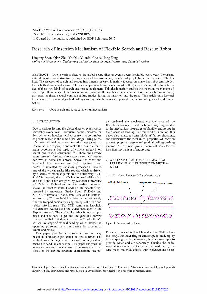
Figure 1. Structure of endoscope
Robot is consisted of flexible endoscope. With a flex-ible body, the outer ring of endoscope is made up by helical spring. In the endoscope, there are two pipes to provide water and air separately. Outside the endo-scope it is an outer protective sleeve made up by the wire mesh material, coated with polyurethane to re-
Research of Insertion Mechanism of Flexible Search and Rescue Robot
Linyong Shen, Qian Zhu, Ya Qiu, Yuanfei Cao & Hang Ding College of Mechatronic Engineering and Automation, Shanghai University, Shanghai, China
ABSTRACT: Due to various factors, the global scope disaster events occur inevitably every year. Terrorism,natural disasters or destructive earthquakes tend to cause a large number of people buried in the ruins of build-ings. The research of search and rescue instruments research is mainly focused on snake-like robot and life de-tector both at home and abroad. The endoscopic search and rescue robot in this paper combines the characteris-tics of these two kinds of search and rescue equipment. This thesis mainly studies the insertion mechanism ofendoscopic flexible search and rescue robot. Based on the mechanics characteristics of the flexible robot body,this paper analyzes several common failure modes during the insertion into the ruins. This article puts forwardthe scheme of segmented gradual pulling-pushing, which plays an important role in promoting search and rescuework.
Keywords: robot; search and rescue; insertion mechanism
DOI: 10.1051/C© Owned by the authors, published by EDP Sciences, 2015
/
0 0 ( 2015)201conf
Web of Conferences ,5
MATEC 22220 0atecm
22
This is an Open Access article distributed under the terms of the Creative Commons Attribution License 4.0, which permits unrestricted use, distribution, and reproduction in any medium, provided the original work is properly cited.
33
00
Article available at http://www.matec-conferences.org or http://dx.doi.org/10.1051/matecconf/20152203020
duce the friction. Structure of endoscope is shown in Figure 1. The coil spring structure makes the body have a good softness in the axial direction, with large stiffness in the radial direction. This structure features make it possible to send the endoscope by pull-ing-pushing method.
2.2 Compressive mechanical properties
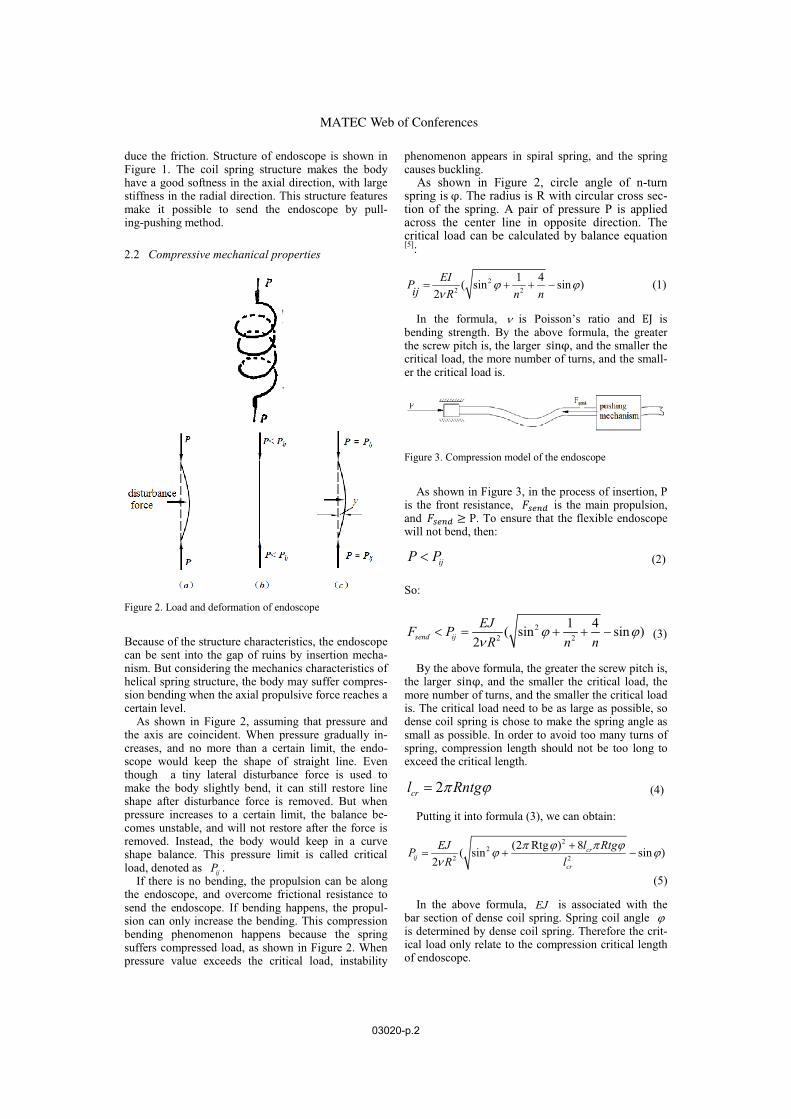
Figure 2. Load and deformation of endoscope
Because of the structure characteristics, the endoscopecan be sent into the gap of ruins by insertion mecha-nism. But considering the mechanics characteristics of helical spring structure, the body may suffer compres-sion bending when the axial propulsive force reaches a certain level.
As shown in Figure 2, assuming that pressure and the axis are coincident. When pressure gradually in-creases, and no more than a certain limit, the endo-scope would keep the shape of straight line. Eventhough a tiny lateral disturbance force is used to make the body slightly bend, it can still restore line shape after disturbance force is removed. But when pressure increases to a certain limit, the balance be-comes unstable, and will not restore after the force is removed. Instead, the body would keep in a curve shape balance. This pressure limit is called critical load, denoted as
ijP .
If there is no bending, the propulsion can be along the endoscope, and overcome frictional resistance to send the endoscope. If bending happens, the propul-sion can only increase the bending. This compression bending phenomenon happens because the spring suffers compressed load, as shown in Figure 2. When pressure value exceeds the critical load, instability
phenomenon appears in spiral spring, and the spring causes buckling.
As shown in Figure 2, circle angle of n-turn spring is �. The radius is R with circular cross sec-tion of the spring. A pair of pressure P is applied across the center line in opposite direction. The critical load can be calculated by balance equation[5]:
22 2
1 4( sin sin )2
EIPij R n n
� ��
� � � � (1)
In the formula, � is Poisson’s ratio and EJ is bending strength. By the above formula, the greater the screw pitch is, the larger sin�, and the smaller the critical load, the more number of turns, and the small-er the critical load is.
Figure 3. Compression model of the endoscope
As shown in Figure 3, in the process of insertion, Pis the front resistance, ����� is the main propulsion,and ����� � P. To ensure that the flexible endoscope will not bend, then:
ijP P� (2)
So:
22 2
1 4( sin sin )2send ij
EJF P
R n n
� ��
� � � � � (3)
By the above formula, the greater the screw pitch is,the larger sin�, and the smaller the critical load, the more number of turns, and the smaller the critical load is. The critical load need to be as large as possible, so dense coil spring is chose to make the spring angle as small as possible. In order to avoid too many turns of spring, compression length should not be too long to exceed the critical length.
2cr
l Rntg� �� (4)
Putting it into formula (3), we can obtain:
22
2 2
(2 Rtg ) 8( sin sin )2
cr
ij
cr
EJ l RtgP
R l
� � � �� ��
�� � �
(5)
In the above formula, EJ is associated with the bar section of dense coil spring. Spring coil angle �is determined by dense coil spring. Therefore the crit-ical load only relate to the compression critical length of endoscope.
Web of ConferencesMATEC
03020-p.2
In actual situation, the radius of spring tube is 5.5 mm. The screw pitch is 4h mm� . Spring coil angle�is calculated in the trigonometric function: sin 0.0578� � , 0.058tg� � ,
0.004 0.11582 2 3.14 0.0055
htg
R
��
� � �
(6)
sin 0.1152 2(2 )
h
R h
��
� ��
(7)
Relationship between number of turns of dense coil spring and the endoscope compression critical lengthis shown as follows:
32 2 10cr cr cr
l l ln
Rtg h� � �� � �
(8) Putting Formula (8) into formula (3), we can obtain :
6 32
2
4 10 8 10( sin sin )2 2ij
cr cr
EJP
R l l
� ��
� � � � � � (9)
Poisson’s ratio of spring steel 0.26 0.32� � �(0.30). Tensile modulus of elasticity of spring steel
200900 203950E � � MPa(202000MPa). Spring section is 2 mm diameter circle. Moment of inertia of spring is as follows:
4 43.14 0.002 -13 47.85 1064 64d
J m�
� � � (10)
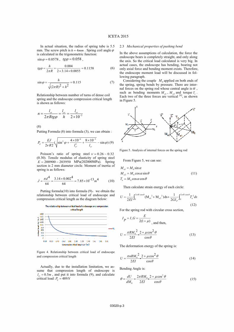
Putting formula(10) into formula (9) we obtain the relationship between critical load of endoscope and compression critical length as the diagram below:
Figure 4. Relationship between critical load of endoscope and compression critical length
Actually, due to the installation limitation, we as-sume that compression length of endoscope is
0.5cr
l m� , and put it into formula (9), and calculate critical load: 489
ijP N�
2.3 Mechanical properties of pushing bend
In the above assumptions of calculation, the force the endoscope bears is completely straight, and only along the axis. So the critical load calculated is very big. In actual cases, the endoscope has bending, bearing not only axial force and bending moment exists. Therefore, the endoscope moment load will be discussed in fol-lowing paragraph.
Considering the couple 0M applied on both ends of the spring, spring bends by pressure. There are inter-nal forces on the spring rod whose central angle is ,such as bending moments 1a
M , 2aM and torque
aT .
Each two of the three forces are vertical [6], as shown in Figure 5.
Figure 5. Analysis of internal forces on the spring rod
From Figure 5, we can see:
1 0
2 0
0
sincos sin
cos cos
a
a
a
M M
M M
T M
�
�
��
�
(11)
Then calculate strain energy of each circle:
2 /cos 2 /cos2 2 21 20 0
1 1(M M )ds2 2
R R
a a a
P
U T ds
EI GI
� � � �� � �� �
(12) For the spring rod with circular cross section,
,2(1 )
EI I GP � �
� , and then,
02 22 cos
2 cosRM
U
EI
� ��
�� � (13)
The deformation energy of the spring is:
02 22 cos
2 cosnRM
U
EI
� ��
�� � (14)
Bending Angle is:
20
0
2 2 cos2 cos
dU RM
dM EI
� ���
�� � � (15)
ICETA 2015
03020-p.3
According to the calculation of bending beam,(EI)
eqis used here as a bending rigidity [7].
0 1 , 2(EI)
Ml Rntgcr
eq
�� � ��
� � � (16)
So:
00
0
2 2 sin(EI) 2 22 cos 2 coscos
eq
L M Rntg EIM
nRM
EI
� � �� � � �
�
� � �� ��
(17)
A bending rigidity only has relationship to spring itself, so: (EI) 0.0318
eq� .
So it can be calculated according to Euler’s formu-la:
2(EI)20.5
eq
lr
P
l
�� (18)
The relationship between bending critical load and compression critical length is shown below:
Figure 6. Relationship between bending critical load and compression critical length
From the figure above, the bending critical load is much smaller than the number only bearing the axial force. It is closer to actual number. Assuming that the compression length of the endoscope 0.5
crl m� , the
critical load 5ij
P N� .
3 FAILURE ANALYSIS OF SEGMENTED GRADUAL PULLING-PUSHING METHOD
As the mechanical properties mentioned in previous section, there exist the following two kinds of failure modes if we merely push or pull the endoscope of the search and rescue robot into the narrow gap.
3.1 Pushing failure
If merely push the endoscope, due to the Euler critical load mentioned in the previous section (as shown in Figure 7), when the compression length of the flexible endoscope is more than the compression critical length, or the propulsive force applied at the back-end of the
endoscope is greater than the critical force, the bend-ing instability will occur and the propulsion will fail partly or even all.
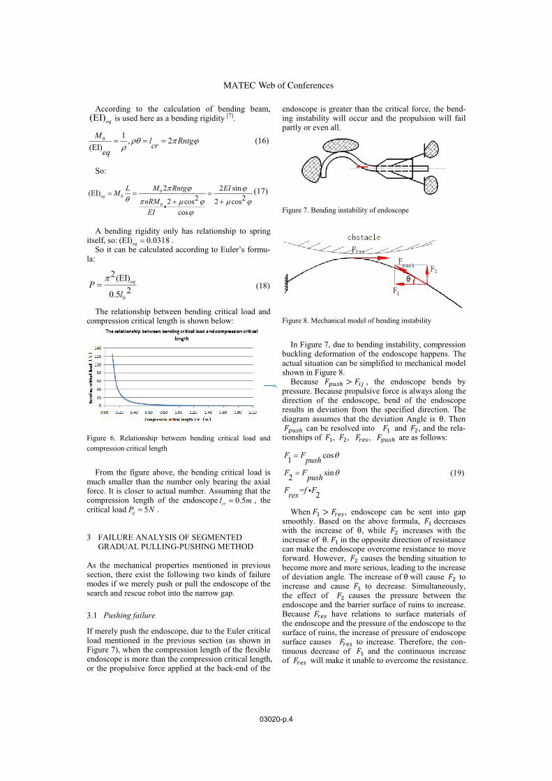
Figure 7. Bending instability of endoscope
Figure 8. Mechanical model of bending instability
In Figure 7, due to bending instability, compressionbuckling deformation of the endoscope happens. The actual situation can be simplified to mechanical model shown in Figure 8.
Because ��� > �� , the endoscope bends by pressure. Because propulsive force is always along the direction of the endoscope, bend of the endoscoperesults in deviation from the specified direction. The diagram assumes that the deviation Angle is �. Then ��� can be resolved into �� and ��, and the rela-tionships of ��, ��, ����, ��� are as follows:
cos1sin2
= 2
F Fpush
F Fpush
F f Fres
�
�
�
�
�
(19)
When �� > ����, endoscope can be sent into gap smoothly. Based on the above formula, �� decreaseswith the increase of �, while �� increases with the increase of �. �� in the opposite direction of resistance can make the endoscope overcome resistance to move forward. However, �� causes the bending situation tobecome more and more serious, leading to the increaseof deviation angle. The increase of � will cause �� to increase and cause �� to decrease. Simultaneously,the effect of �� causes the pressure between the endoscope and the barrier surface of ruins to increase. Because ���� have relations to surface materials of the endoscope and the pressure of the endoscope to the surface of ruins, the increase of pressure of endoscope surface causes ���� to increase. Therefore, the con-tinuous decrease of �� and the continuous increase of ���� will make it unable to overcome the resistance.
Web of ConferencesMATEC
03020-p.4
3.2 Pulling failure
If merely pull the endoscope at the front-end, the fric-tion will increase with the increase of pulling lengthand the obstacles of ruins make the endoscope to bend. As shown in figure 9, due to the pulling distance is too long, the back of the endoscope bend. Pulling force will be difficult to overcome the friction. At this time the pulling force will fail, as mechanical model shown in Figure 10.
Figure 9. Pulling failure of endoscope
Figure 10. Mechanical model of pulling failure
Due to the increase of pulling distance, the endo-scope bends in the gap of ruins. The pulling force of the front-end pulling mechanism cannot be fully used to overcome the frictional resistance. The diagram assumes that the deviation Angle is �. Then ��� can be resolved into �� and ��, and the relationships of ��, ��, ���� , ��� are as follows:
1
2
cos
sin
= 2
F Fpull
F Fpull
F f Fres
�
�
�
�
�
(20)
When �� > ����, endoscope can be sent into gap smoothly. Based on the above formula, �� decreaseswith the increase of �, while �� increases with the increase of �. �� in the opposite direction of re-sistance can make the endoscope to overcome re-sistance to move forward. However, �� causes the pressure of the endoscope to the surface to become bigger. Because ���� have relations to surface mate-rials of the endoscope and the pressure the endoscopeto the surface of ruins, the increase of pressure of en-doscope surface cause ���� to increase. Therefore, when the bending angle � is big enough, �� will not be able to overcome ���� , the endoscope will not be able to be sent into gap.
Due to the motor torque limitation, we assume that
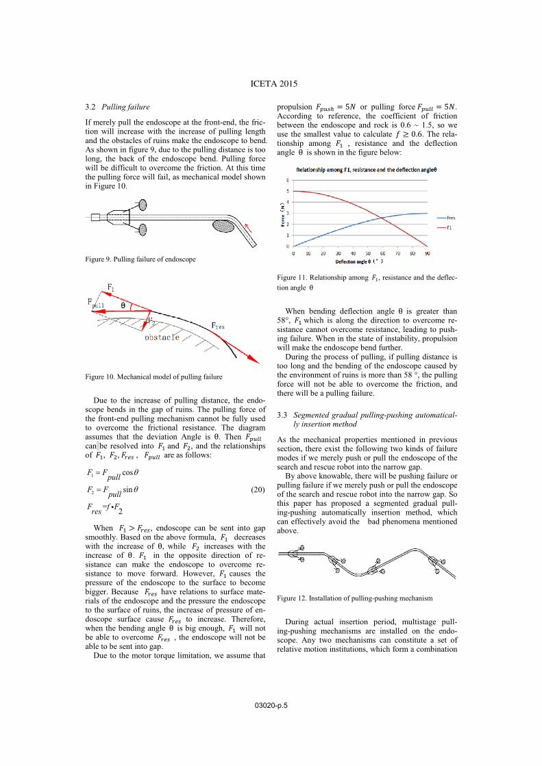
propulsion ��� = 5� or pulling force ��� = 5�. According to reference, the coefficient of friction between the endoscope and rock is 0.6 ~ 1.5, so we use the smallest value to calculate � � 0.6. The rela-tionship among �� , resistance and the deflection angle � is shown in the figure below:
Figure 11. Relationship among ��, resistance and the deflec-tion angle �
When bending deflection angle � is greater than 58°, �� which is along the direction to overcome re-sistance cannot overcome resistance, leading to push-ing failure. When in the state of instability, propulsion will make the endoscope bend further.
During the process of pulling, if pulling distance is too long and the bending of the endoscope caused by the environment of ruins is more than 58 °, the pulling force will not be able to overcome the friction, and there will be a pulling failure.
3.3 Segmented gradual pulling-pushing automatical-
ly insertion method
As the mechanical properties mentioned in previoussection, there exist the following two kinds of failure modes if we merely push or pull the endoscope of the search and rescue robot into the narrow gap.
By above knowable, there will be pushing failure or pulling failure if we merely push or pull the endoscope of the search and rescue robot into the narrow gap. So this paper has proposed a segmented gradual pull-ing-pushing automatically insertion method, which can effectively avoid the bad phenomena mentionedabove.
Figure 12. Installation of pulling-pushing mechanism
During actual insertion period, multistage pull-ing-pushing mechanisms are installed on the endo-scope. Any two mechanisms can constitute a set of relative motion institutions, which form a combination
ICETA 2015
03020-p.5
of pushing and pulling, known as “pulling-pushingmechanism”. Therefore endoscope can be gradually sent into narrow gap, as shown in Figure 12.
Two arbitrary adjacent pulling-pushing mechanisms’installation distance should not be greater than the compression critical length of the endoscope, so that the pushing failure will not happen. Simultaneously,the combination of multistage relative motion mecha-nism and pulling-pushing also can effectively avoid too long pulling distance and pulling failure.
4 DESIGN OF EXPERIMENTAL PLATFORMAND EXPERIMENTAL VERIFICATION
4.1 Automatically insertion mechanism structure and
design of experimental environment
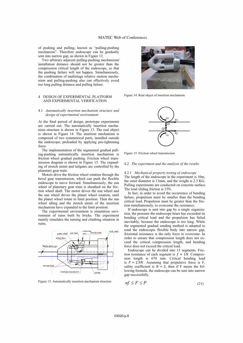
At the final period of design, prototype experimentsare carried out. The automatically insertion mecha-nism structure is shown in Figure 13. The real objectis shown in Figure 14. The insertion mechanism iscomposed of two symmetrical parts, installed outside the endoscope, preloaded by applying pre-tightening force.
The implementation of the segmented gradual pull-ing-pushing automatically insertion mechanism is friction wheel gradual pushing. Friction wheel trans-mission diagram is shown in Figure 15. The expand-ing of stretch stents and tailgates are controlled by the planetary gear train.
Motors drive the friction wheel rotation through the bevel gear transmission, which can push the flexibleendoscope to move forward. Simultaneously, the sun wheel of planetary gear train is sheathed on the fric-tion wheel shaft. The motor drives the sun wheel and the sun wheel drives the planet wheel rotation, until the planet wheel rotate to limit position. Then the sun wheel idling and the stretch stents of the insertion mechanism have expanded to the limit position.
The experimental environment is simulation envi-ronment of ruins built by bricks. The experimentmainly simulates the turning and climbing situation in ruins.
Figure 13. Automatically insertion mechanism structure
Figure 14. Real object of insertion mechanism
Figure 15. Friction wheel transmission
4.2 The experiment and the analysis of the results
4.2.1 Mechanical property testing of endoscope
The length of the endoscope in the experiment is 10m, the outer diameter is 13mm, and the weight is 2.3 KG. Pulling experiments are conducted on concrete surface. The total sliding friction is 15N.
In fact, in order to avoid the occurrence of bending failure, propulsion must be smaller than the bending critical load. Propulsion must be greater than the fric-tion simultaneously, to overcome the resistance.
If endoscope is sent into gap by a single organiza-tion, the pressure the endoscope bears has exceeded its bending critical load and the propulsion has failed inevitably, because the endoscope is too long. While the segmented gradual sending method is adopted to send the endoscopic flexible body into narrow gap, frictional resistance is the only force to overcome. In order to ensure that compression length does not ex-ceed the critical compression length, and bending force does not exceed the critical load.
Endoscope can be divided into 15 segments. Fric-tion resistance of each segment is � = 1�. Compres-sion length is 670 mm. Critical bending load is � = 2.9�. Assuming that propulsive force is F, safety coefficient is � = 2, then if F meets the fol-lowing formula, the endoscope can be sent into narrow gap successfully.
nf F P� � (21)
Web of ConferencesMATEC
03020-p.6
4.2.2 Mechanical property testing of pulling-pushing
method
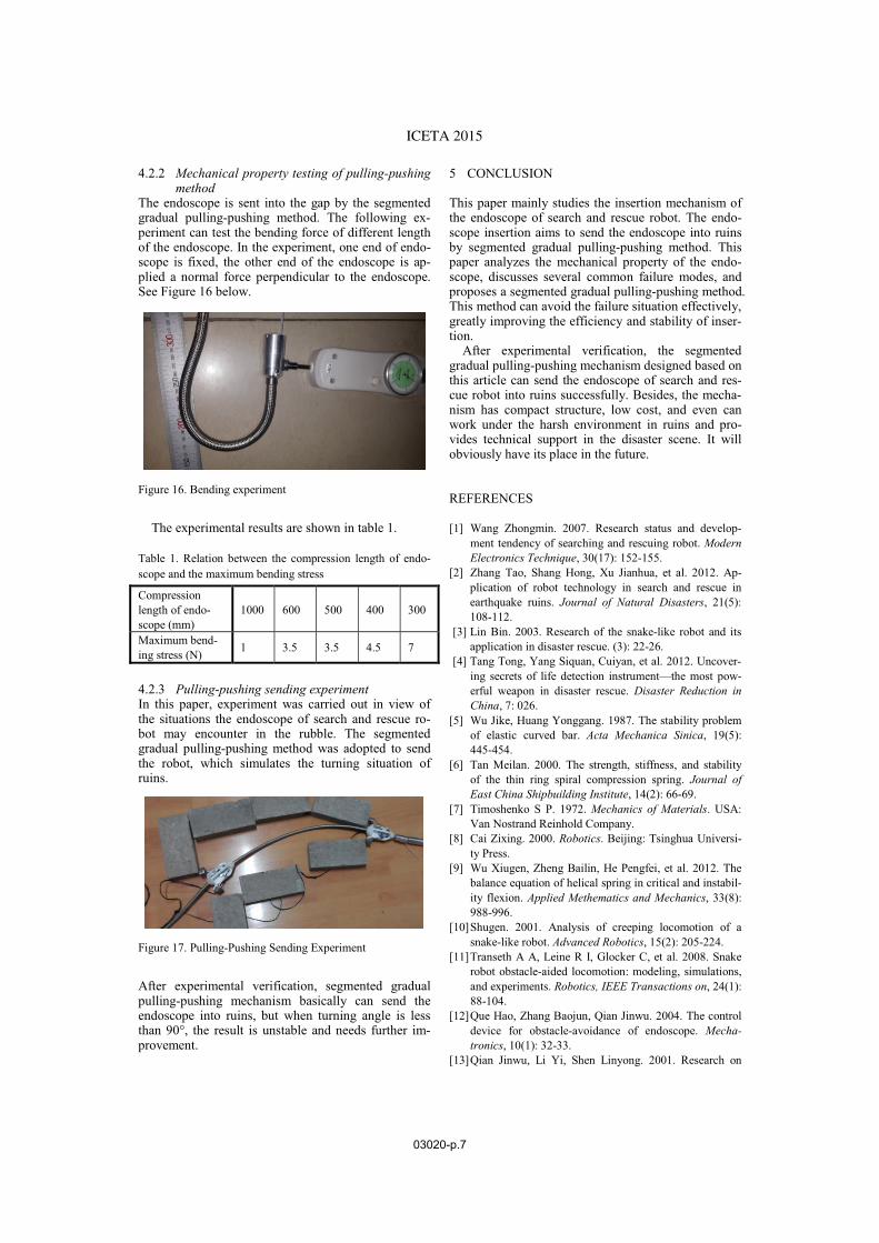
The endoscope is sent into the gap by the segmented gradual pulling-pushing method. The following ex-periment can test the bending force of different length of the endoscope. In the experiment, one end of endo-scope is fixed, the other end of the endoscope is ap-plied a normal force perpendicular to the endoscope. See Figure 16 below.
Figure 16. Bending experiment
The experimental results are shown in table 1.
Table 1. Relation between the compression length of endo-scope and the maximum bending stress
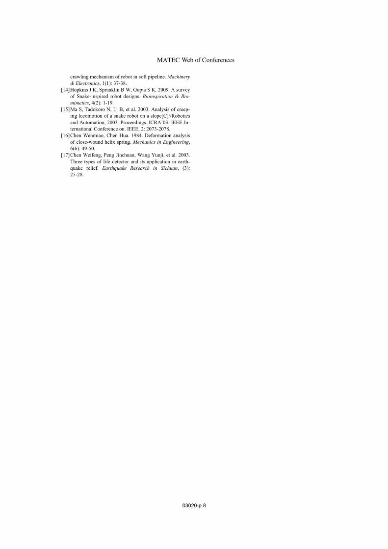
4.2.3 Pulling-pushing sending experiment
In this paper, experiment was carried out in view of the situations the endoscope of search and rescue ro-bot may encounter in the rubble. The segmented gradual pulling-pushing method was adopted to send the robot, which simulates the turning situation of ruins.
Figure 17. Pulling-Pushing Sending Experiment
After experimental verification, segmented gradualpulling-pushing mechanism basically can send the endoscope into ruins, but when turning angle is less than 90°, the result is unstable and needs further im-provement.
5 CONCLUSION
This paper mainly studies the insertion mechanism ofthe endoscope of search and rescue robot. The endo-scope insertion aims to send the endoscope into ruins by segmented gradual pulling-pushing method. This paper analyzes the mechanical property of the endo-scope, discusses several common failure modes, andproposes a segmented gradual pulling-pushing method.This method can avoid the failure situation effectively, greatly improving the efficiency and stability of inser-tion.
After experimental verification, the segmented gradual pulling-pushing mechanism designed based on this article can send the endoscope of search and res-cue robot into ruins successfully. Besides, the mecha-nism has compact structure, low cost, and even can work under the harsh environment in ruins and pro-vides technical support in the disaster scene. It will obviously have its place in the future.
REFERENCES
[1] Wang Zhongmin. 2007. Research status and develop-ment tendency of searching and rescuing robot. Modern
Electronics Technique, 30(17): 152-155.[2] Zhang Tao, Shang Hong, Xu Jianhua, et al. 2012. Ap-
plication of robot technology in search and rescue in earthquake ruins. Journal of Natural Disasters, 21(5):108-112.
[3] Lin Bin. 2003. Research of the snake-like robot and its application in disaster rescue. (3): 22-26.
[4] Tang Tong, Yang Siquan, Cuiyan, et al. 2012. Uncover-ing secrets of life detection instrument—the most pow-erful weapon in disaster rescue. Disaster Reduction in
China, 7: 026.[5] Wu Jike, Huang Yonggang. 1987. The stability problem
of elastic curved bar. Acta Mechanica Sinica, 19(5):445-454.
[6] Tan Meilan. 2000. The strength, stiffness, and stability of the thin ring spiral compression spring. Journal of
East China Shipbuilding Institute, 14(2): 66-69.[7] Timoshenko S P. 1972. Mechanics of Materials. USA:
Van Nostrand Reinhold Company. [8] Cai Zixing. 2000. Robotics. Beijing: Tsinghua Universi-
ty Press. [9] Wu Xiugen, Zheng Bailin, He Pengfei, et al. 2012. The
balance equation of helical spring in critical and instabil-ity flexion. Applied Methematics and Mechanics, 33(8):988-996.
[10]Shugen. 2001. Analysis of creeping locomotion of a snake-like robot. Advanced Robotics, 15(2): 205-224.
[11]Transeth A A, Leine R I, Glocker C, et al. 2008. Snake robot obstacle-aided locomotion: modeling, simulations, and experiments. Robotics, IEEE Transactions on, 24(1): 88-104.
[12]Que Hao, Zhang Baojun, Qian Jinwu. 2004. The control device for obstacle-avoidance of endoscope. Mecha-
tronics, 10(1): 32-33.[13]Qian Jinwu, Li Yi, Shen Linyong. 2001. Research on
Compression length of endo-scope (mm)
1000 600 500 400 300
Maximum bend-ing stress (N) 1 3.5 3.5 4.5 7
ICETA 2015
03020-p.7
crawling mechanism of robot in soft pipeline. Machinery
& Electronics, 1(1): 37-38.[14]Hopkins J K, Spranklin B W, Gupta S K. 2009. A survey
of Snake-inspired robot designs. Bioinspiration & Bio-
mimetics, 4(2): 1-19.[15]Ma S, Tadokoro N, Li B, et al. 2003. Analysis of creep-
ing locomotion of a snake robot on a slope[C]//Robotics and Automation, 2003. Proceedings. ICRA’03. IEEE In-ternational Conference on. IEEE, 2: 2073-2078.
[16]Chen Wenmiao, Chen Hua. 1984. Deformation analysisof close-wound helix spring. Mechanics in Engineering,6(6): 49-50.
[17]Chen Weifeng, Peng Jinchuan, Wang Yunji, et al. 2003.Three types of life detector and its application in earth-quake relief. Earthquake Research in Sichuan, (3):25-28.
Web of ConferencesMATEC
03020-p.8


