Embed Size (px)
Citation preview
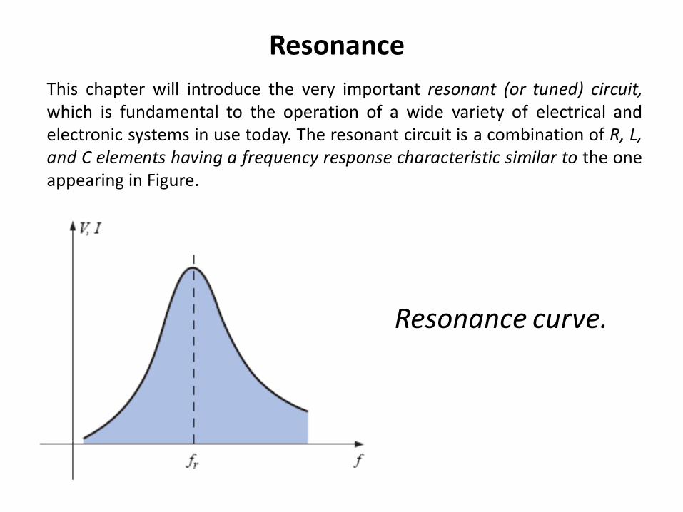
Resonance
This chapter will introduce the very important resonant (or tuned) circuit, which is fundamental to the operation of a wide variety of electrical and electronic systems in use today. The resonant circuit is a combination of R, L, and C elements having a frequency response characteristic similar to the one appearing in Figure.
Resonance curve.
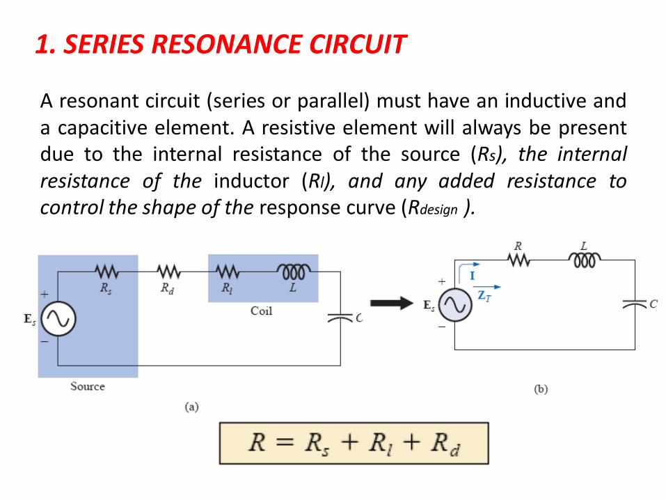
1. SERIES RESONANCE CIRCUIT
A resonant circuit (series or parallel) must have an inductive and a capacitive element. A resistive element will always be present due to the internal resistance of the source (Rs), the internal resistance of the inductor (Rl), and any added resistance to control the shape of the response curve (Rdesign ).
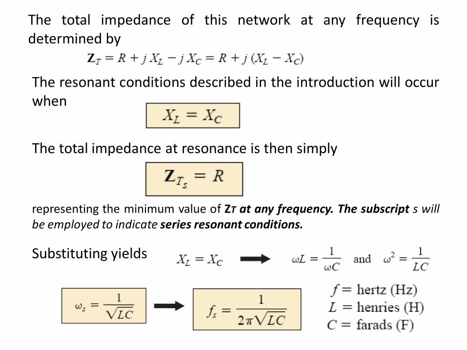
The total impedance of this network at any frequency is determined by
The resonant conditions described in the introduction will occur when
The total impedance at resonance is then simply
representing the minimum value of ZT at any frequency. The subscript s will be employed to indicate series resonant conditions.
Substituting yields
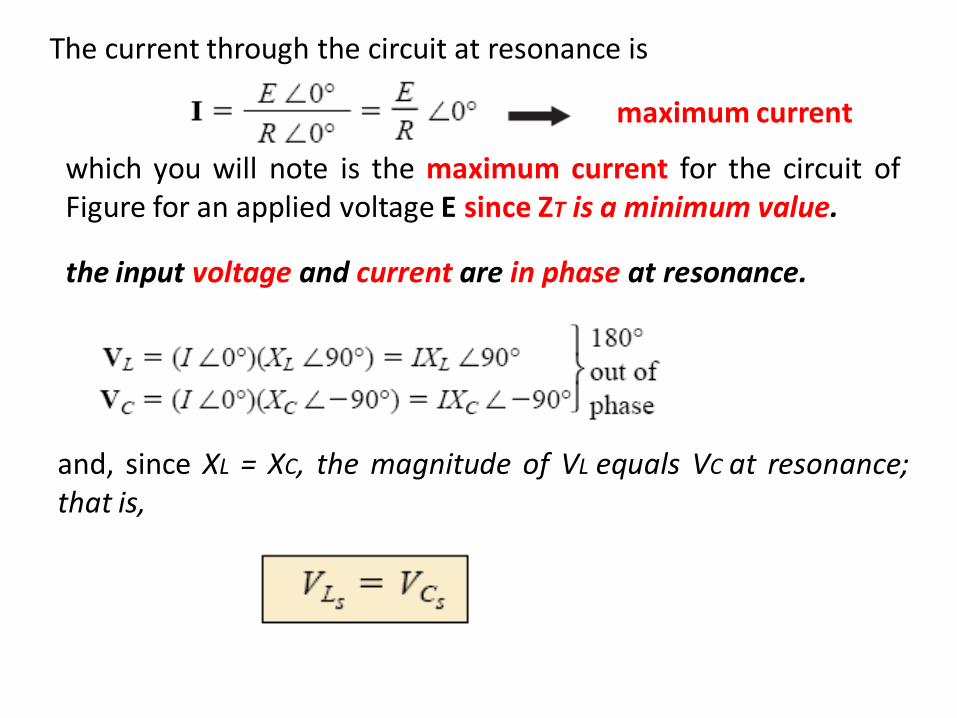
The current through the circuit at resonance is
which you will note is the maximum current for the circuit of Figure for an applied voltage E since ZT is a minimum value.
the input voltage and current are in phase at resonance.
maximum current
and, since XL = XC, the magnitude of VL equals VC at resonance; that is,
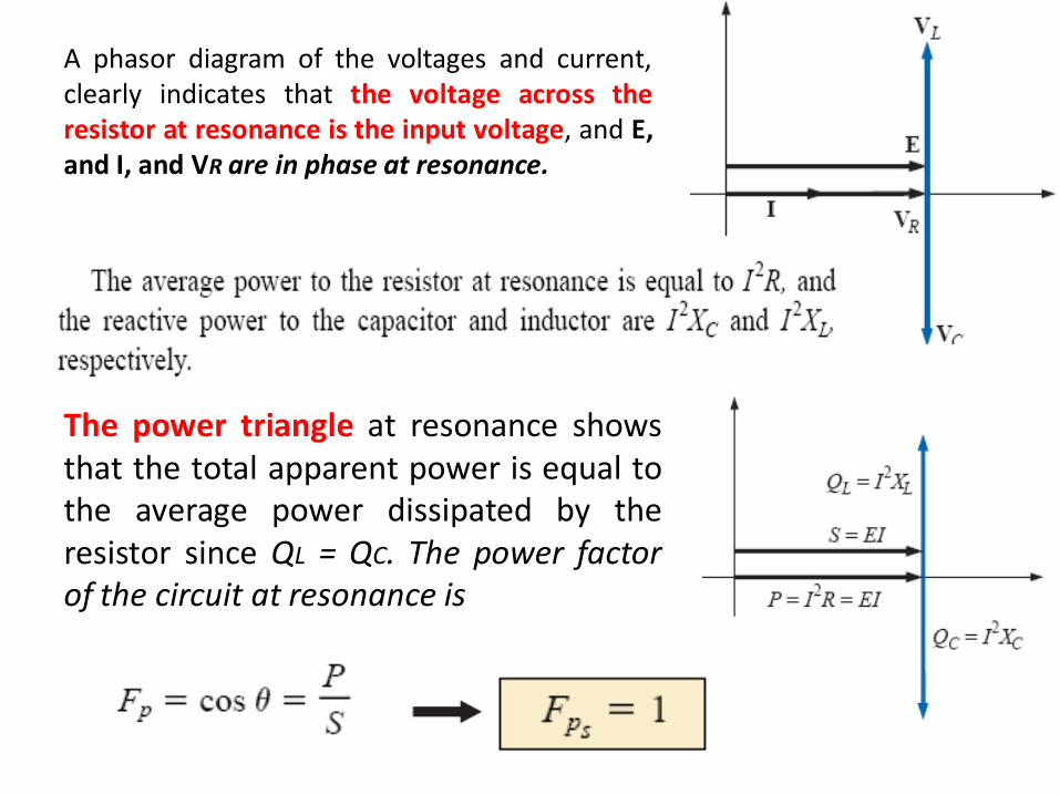
A phasor diagram of the voltages and current, clearly indicates that the voltage across the resistor at resonance is the input voltage, and E, and I, and VR are in phase at resonance.
The power triangle at resonance shows that the total apparent power is equal to the average power dissipated by the resistor since QL = QC. The power factor of the circuit at resonance is

THE QUALITY FACTOR (Q )
The quality factor Q of a series resonant circuit is defined as the ratio of the reactive power of either the inductor or the capacitor to the average power of the resistor at resonance; that is,
The quality factor is also an indication of how much energy is placed in storage (continual transfer from one reactive element to the other) compared to that dissipated.
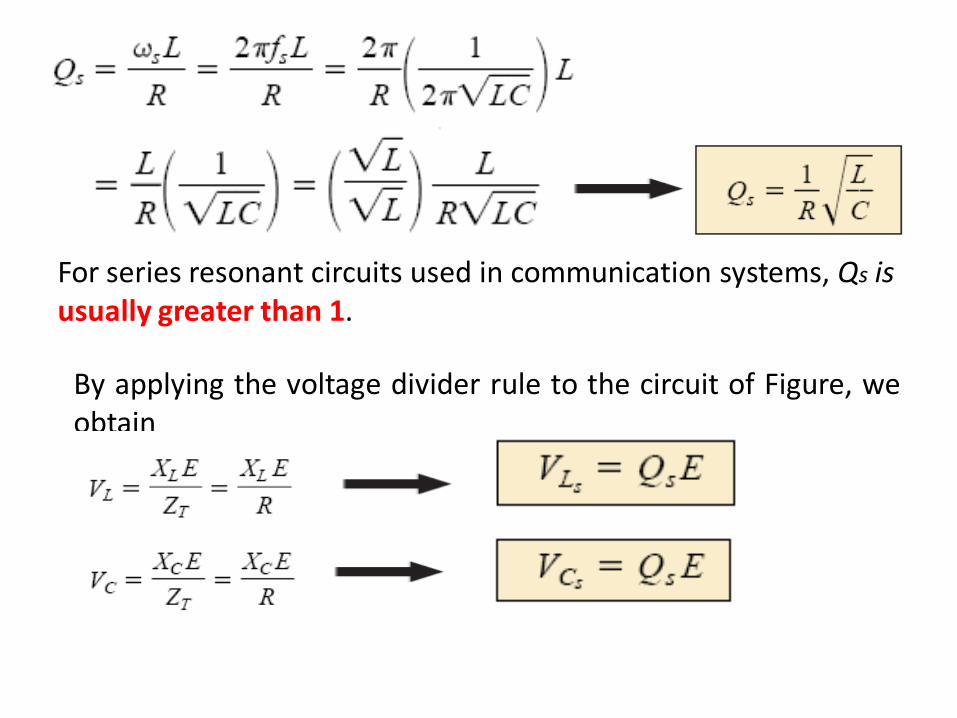
For series resonant circuits used in communication systems, Qs is usually greater than 1.
By applying the voltage divider rule to the circuit of Figure, we obtain
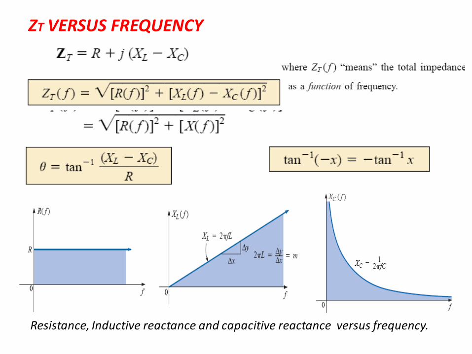
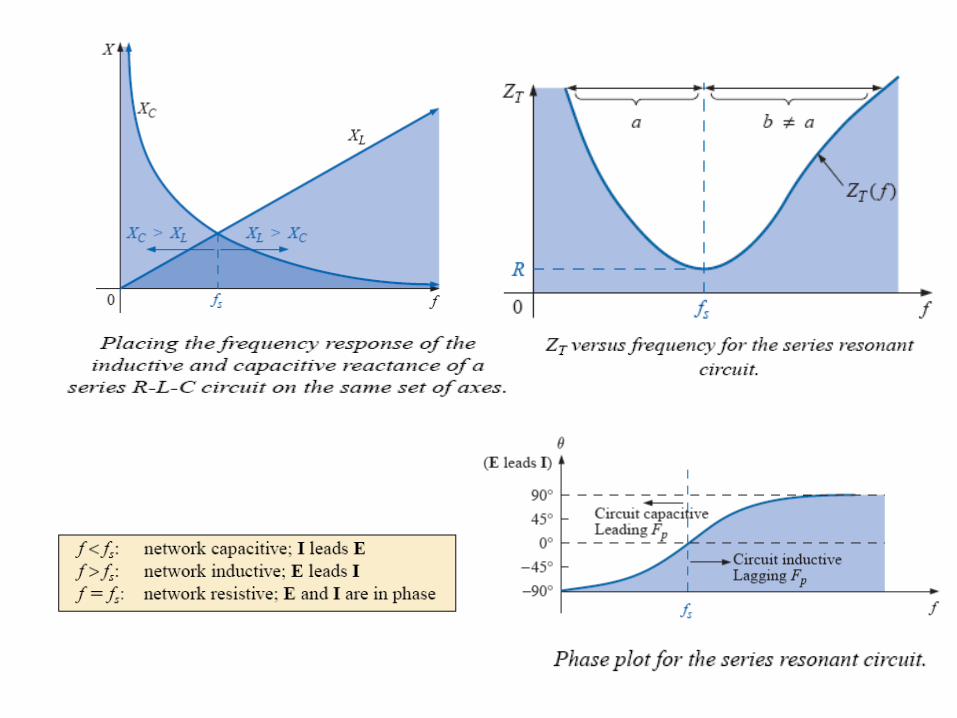
ZT VERSUS FREQUENCY
Resistance, Inductive reactance and capacitive reactance versus frequency.
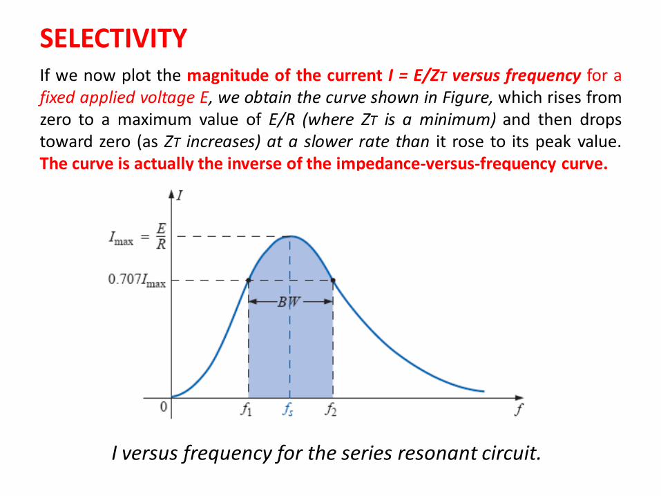
SELECTIVITY If we now plot the magnitude of the current I = E/ZT versus frequency for a fixed applied voltage E, we obtain the curve shown in Figure, which rises from zero to a maximum value of E/R (where ZT is a minimum) and then drops toward zero (as ZT increases) at a slower rate than it rose to its peak value. The curve is actually the inverse of the impedance-versus-frequency curve.
I versus frequency for the series resonant circuit.
Those frequencies corresponding to 0.707 of the maximum current are called the band frequencies, cutoff frequencies, or half-power frequencies. They are indicated by f1 and f2
The range of frequencies between the two is referred to as the bandwidth (BW) of the resonant circuit.
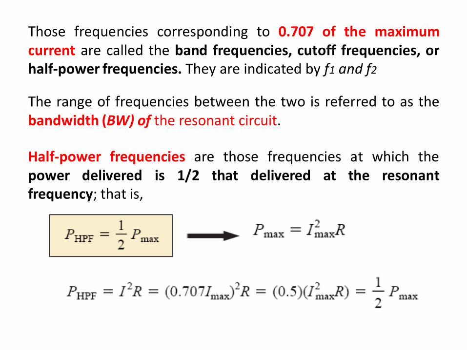
Half-power frequencies are those frequencies at which the power delivered is 1/2 that delivered at the resonant frequency; that is,
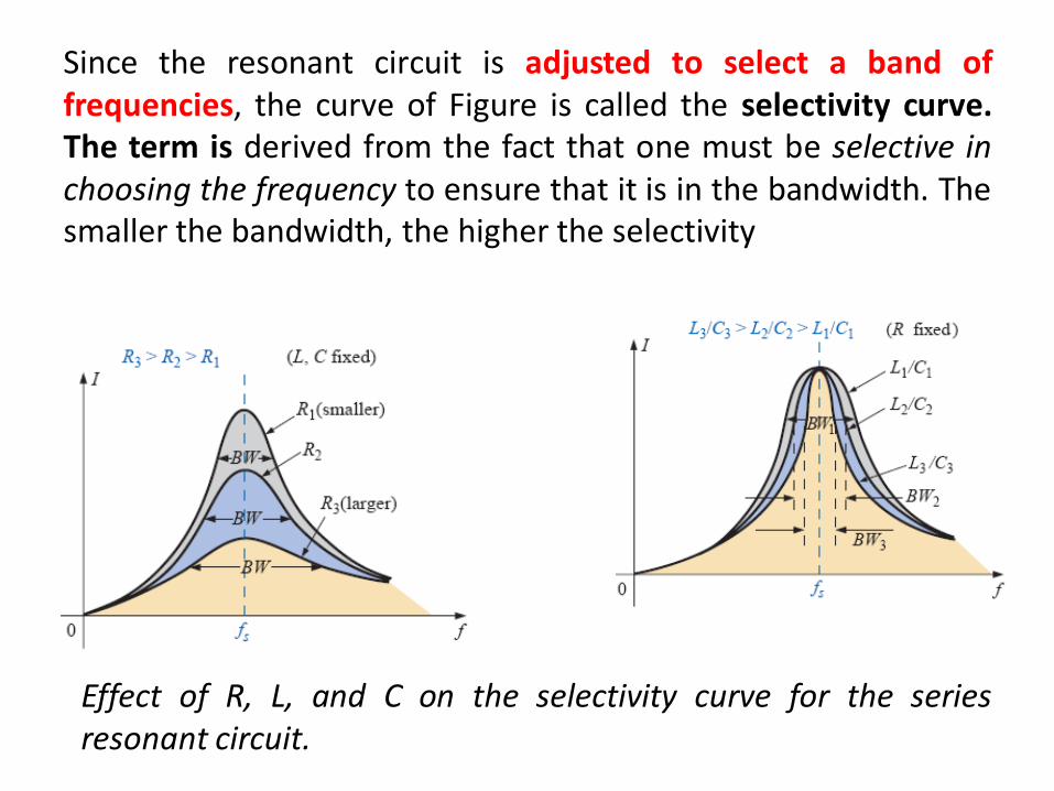
Since the resonant circuit is adjusted to select a band of frequencies, the curve of Figure is called the selectivity curve. The term is derived from the fact that one must be selective in choosing the frequency to ensure that it is in the bandwidth. The smaller the bandwidth, the higher the selectivity
Effect of R, L, and C on the selectivity curve for the series resonant circuit.
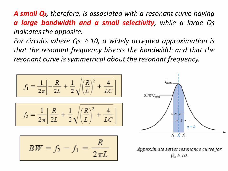
A small Qs, therefore, is associated with a resonant curve having a large bandwidth and a small selectivity, while a large Qs indicates the opposite. For circuits where Qs 10, a widely accepted approximation is that the resonant frequency bisects the bandwidth and that the resonant curve is symmetrical about the resonant frequency.
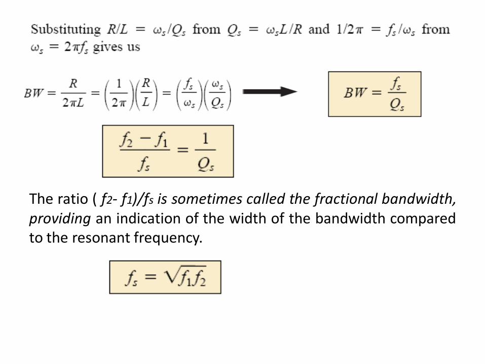
The ratio ( f2- f1)/fs is sometimes called the fractional bandwidth, providing an indication of the width of the bandwidth compared to the resonant frequency.
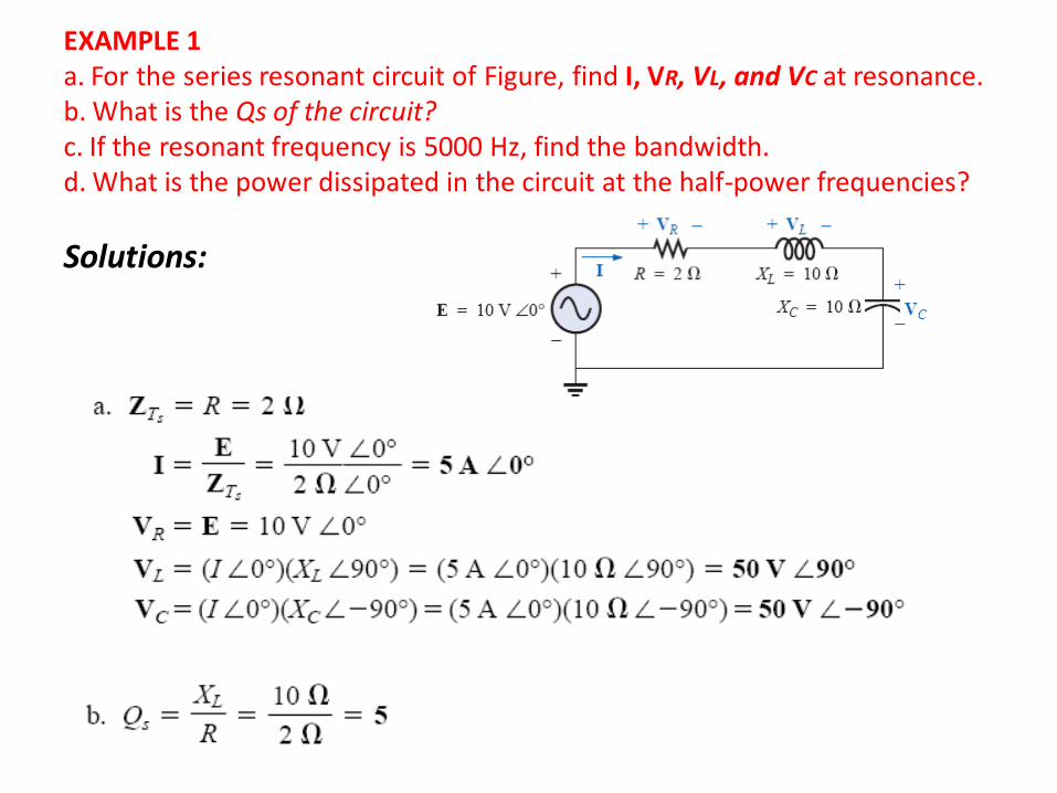
EXAMPLE 1 a. For the series resonant circuit of Figure, find I, VR, VL, and VC at resonance. b. What is the Qs of the circuit? c. If the resonant frequency is 5000 Hz, find the bandwidth. d. What is the power dissipated in the circuit at the half-power frequencies?
Solutions:
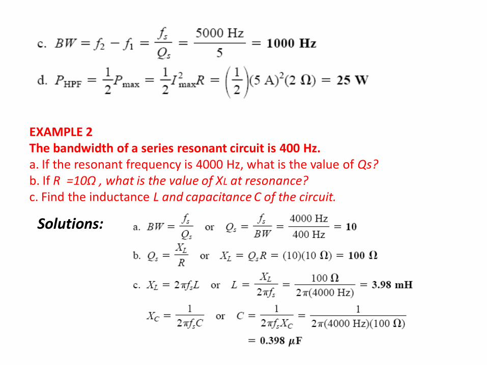
EXAMPLE 2 The bandwidth of a series resonant circuit is 400 Hz. a. If the resonant frequency is 4000 Hz, what is the value of Qs? b. If R =10Ω , what is the value of XL at resonance? c. Find the inductance L and capacitance C of the circuit.
Solutions:
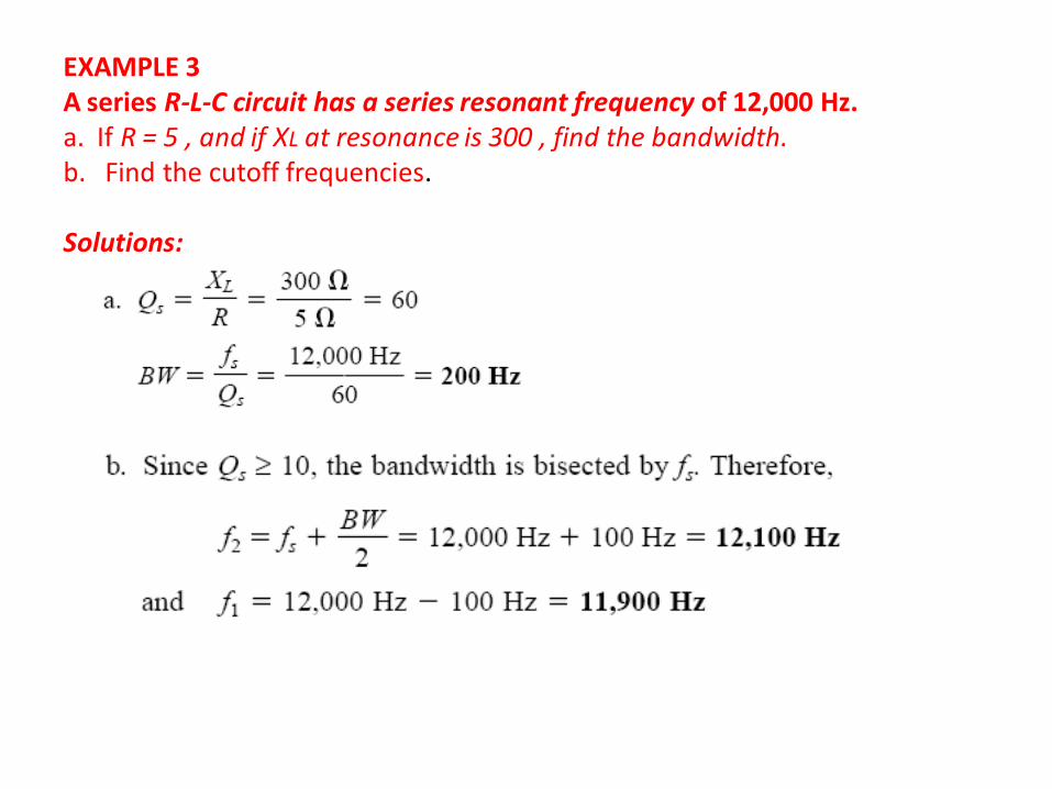
EXAMPLE 3 A series R-L-C circuit has a series resonant frequency of 12,000 Hz. a. If R = 5 , and if XL at resonance is 300 , find the bandwidth. b. Find the cutoff frequencies. Solutions:
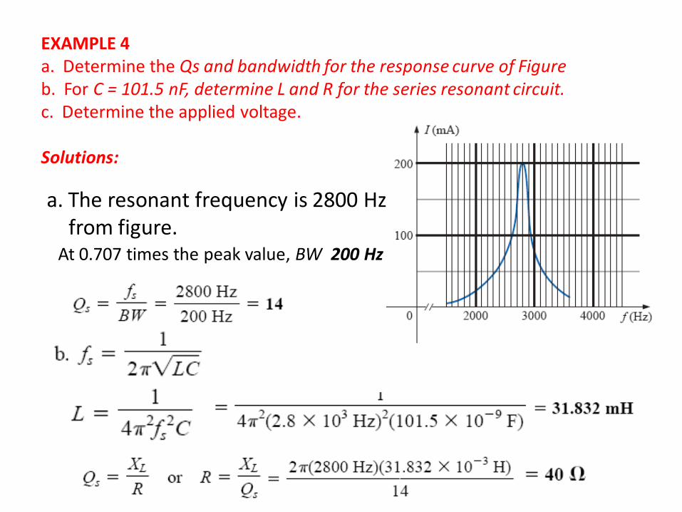
EXAMPLE 4 a. Determine the Qs and bandwidth for the response curve of Figure b. For C = 101.5 nF, determine L and R for the series resonant circuit. c. Determine the applied voltage. Solutions:
a. The resonant frequency is 2800 Hz from figure.
At 0.707 times the peak value, BW 200 Hz
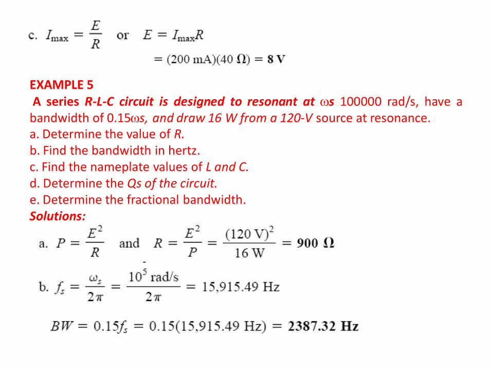
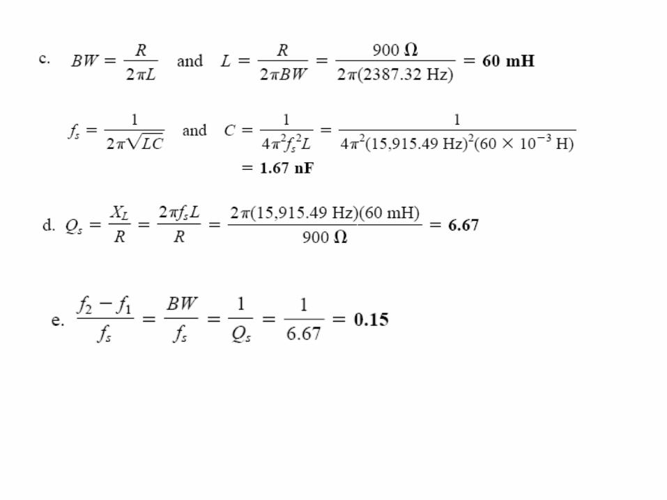
EXAMPLE 5 A series R-L-C circuit is designed to resonant at s 100000 rad/s, have a bandwidth of 0.15s, and draw 16 W from a 120-V source at resonance. a. Determine the value of R. b. Find the bandwidth in hertz. c. Find the nameplate values of L and C. d. Determine the Qs of the circuit. e. Determine the fractional bandwidth. Solutions:
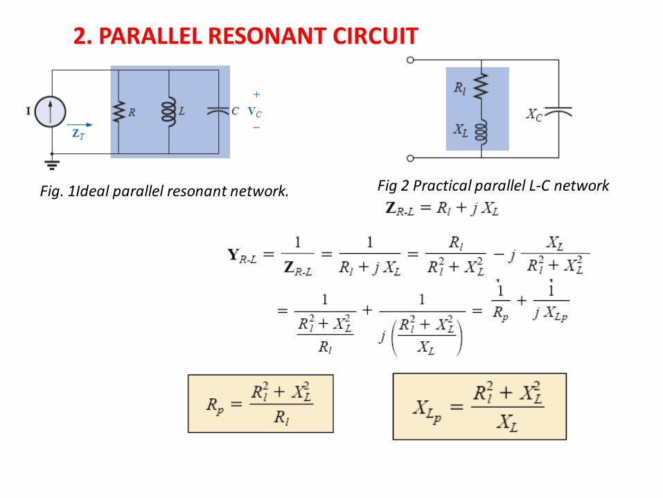
2. PARALLEL RESONANT CIRCUIT
Fig. 1Ideal parallel resonant network. Fig 2 Practical parallel L-C network
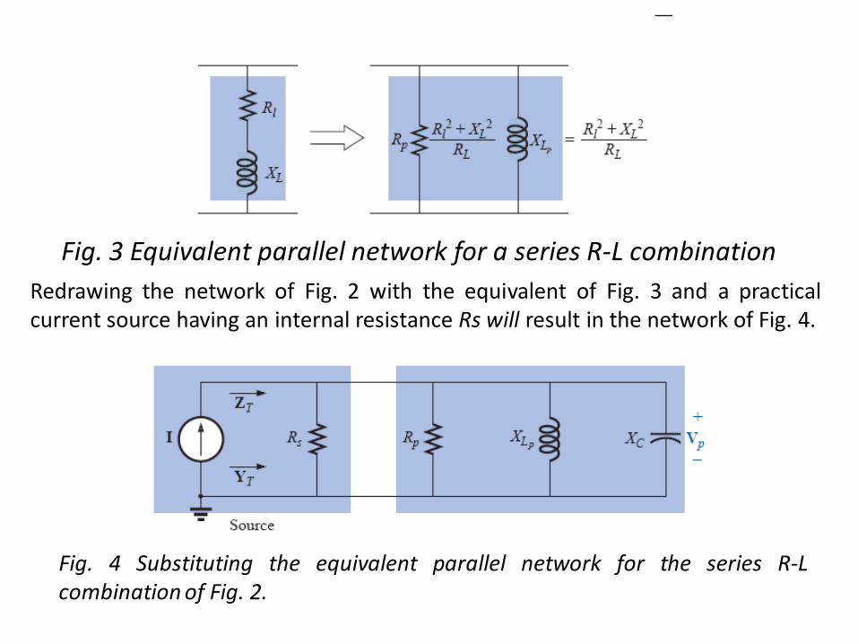
Fig. 3 Equivalent parallel network for a series R-L combination
Redrawing the network of Fig. 2 with the equivalent of Fig. 3 and a practical current source having an internal resistance Rs will result in the network of Fig. 4.
Fig. 4 Substituting the equivalent parallel network for the series R-L combination of Fig. 2.
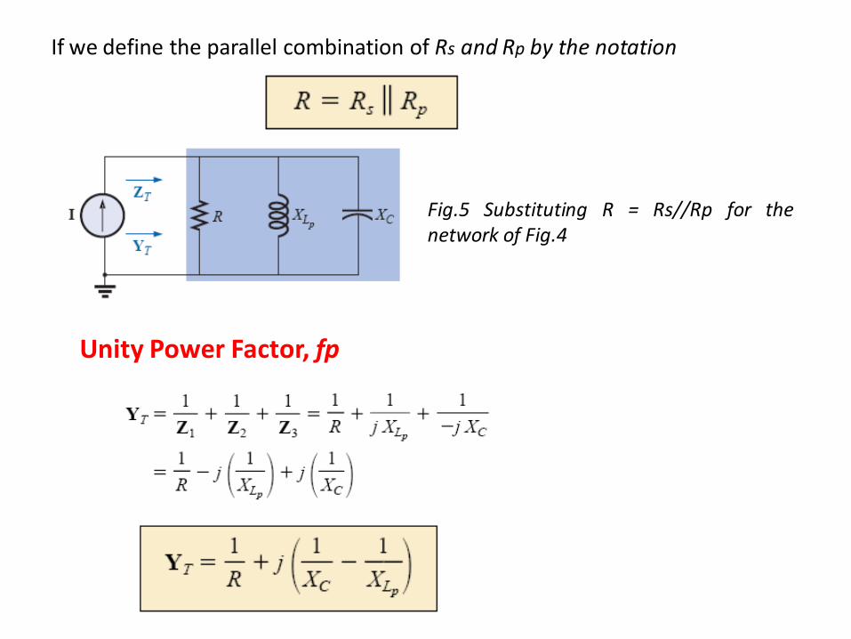
If we define the parallel combination of Rs and Rp by the notation
Fig.5 Substituting R = Rs//Rp for the network of Fig.4
Unity Power Factor, fp
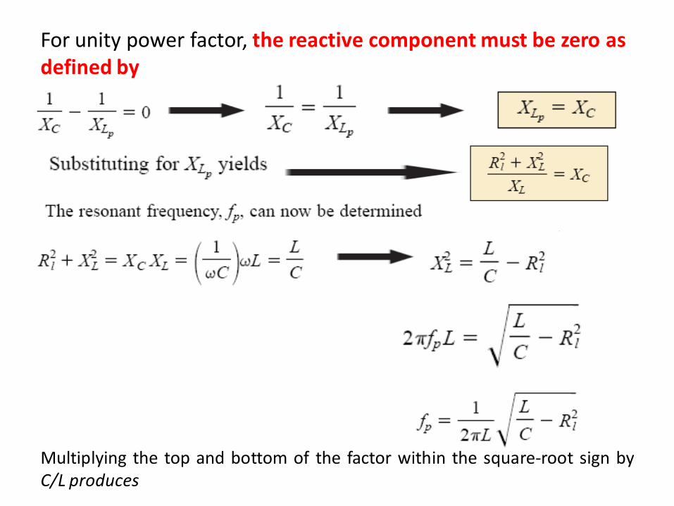
For unity power factor, the reactive component must be zero as defined by
Multiplying the top and bottom of the factor within the square-root sign by C/L produces
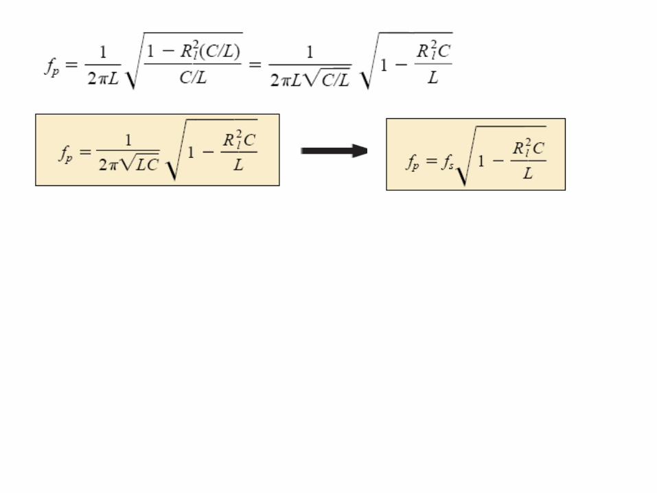
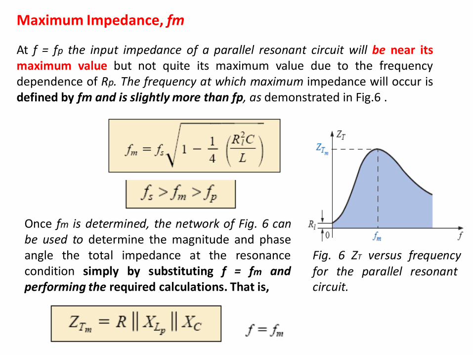
Fig. 6 ZT versus frequency for the parallel resonant circuit.
Once fm is determined, the network of Fig. 6 can be used to determine the magnitude and phase angle the total impedance at the resonance condition simply by substituting f = fm and performing the required calculations. That is,
Maximum Impedance, fm
At f = fp the input impedance of a parallel resonant circuit will be near its maximum value but not quite its maximum value due to the frequency dependence of Rp. The frequency at which maximum impedance will occur is defined by fm and is slightly more than fp, as demonstrated in Fig.6 .
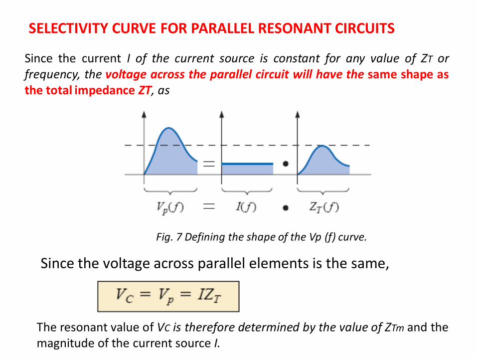
SELECTIVITY CURVE FOR PARALLEL RESONANT CIRCUITS
Since the current I of the current source is constant for any value of ZT or frequency, the voltage across the parallel circuit will have the same shape as the total impedance ZT, as
Fig. 7 Defining the shape of the Vp (f) curve.
Since the voltage across parallel elements is the same,
The resonant value of VC is therefore determined by the value of ZTm and the magnitude of the current source I.
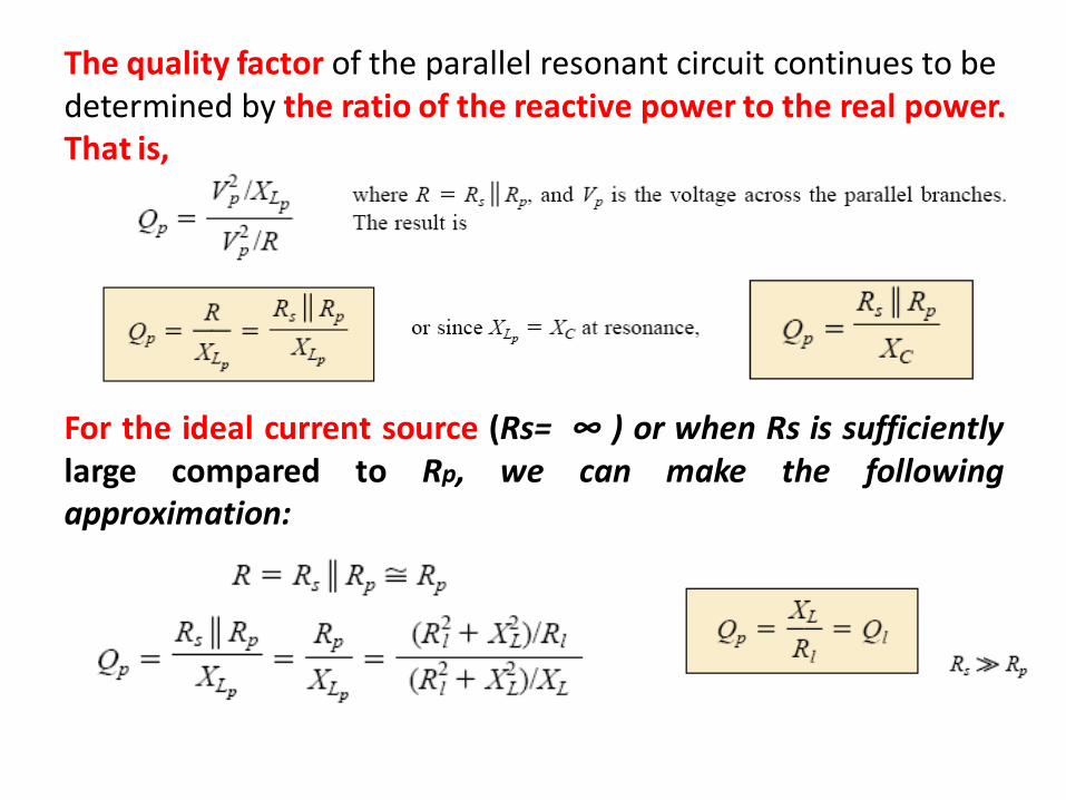
The quality factor of the parallel resonant circuit continues to be determined by the ratio of the reactive power to the real power. That is,
For the ideal current source (Rs= ∞ ) or when Rs is sufficiently large compared to Rp, we can make the following approximation:
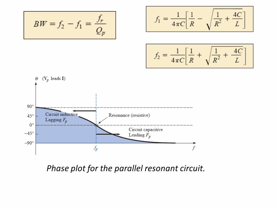
Phase plot for the parallel resonant circuit.
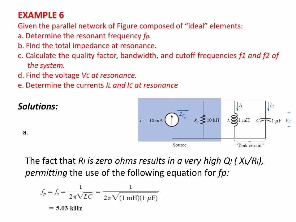
EXAMPLE 6 Given the parallel network of Figure composed of “ideal” elements: a. Determine the resonant frequency fp. b. Find the total impedance at resonance. c. Calculate the quality factor, bandwidth, and cutoff frequencies f1 and f2 of
the system. d. Find the voltage VC at resonance. e. Determine the currents IL and IC at resonance
Solutions:
The fact that Rl is zero ohms results in a very high Ql ( XL/Rl), permitting the use of the following equation for fp:
a.
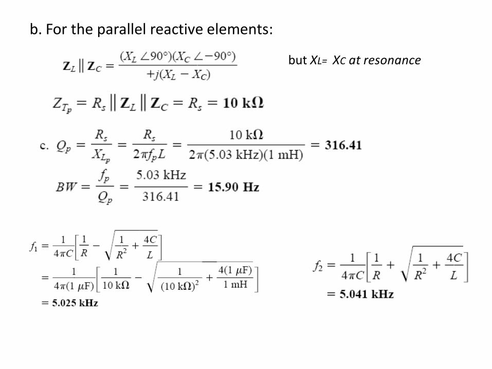
b. For the parallel reactive elements:
but XL= XC at resonance
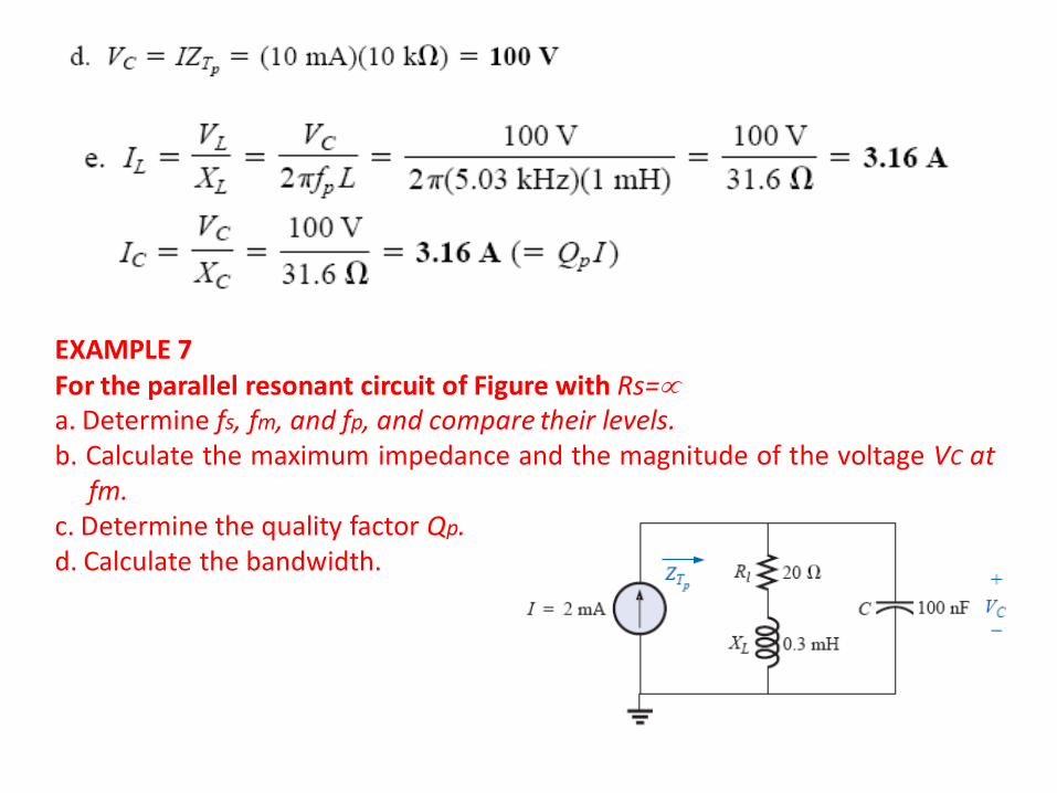
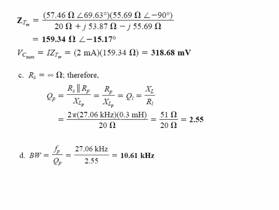
EXAMPLE 7 For the parallel resonant circuit of Figure with Rs= a. Determine fs, fm, and fp, and compare their levels. b. Calculate the maximum impedance and the magnitude of the voltage VC at
fm. c. Determine the quality factor Qp. d. Calculate the bandwidth.
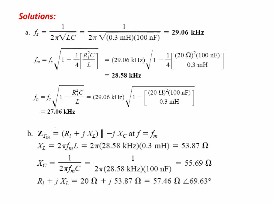
Solutions: