Embed Size (px)
Citation preview
Reynolds’sReinforcedConcreteDesigner’sHandbook
Reynolds’s Reinforced Concrete Designer’s Handbook has beencompletely rewritten and updated for this new edition to takeaccount of the numerous developments in design and practiceover the last 20 years. These include significant revisions toBritish Standards and Codes of Practice, and the introduction ofthe new Eurocodes. The principal feature of the Handbook is thecollection of over 200 full-page tables and charts, covering allaspects of structural analysis and reinforced concrete design.These, together with extensive numerical examples, will enableengineers to produce rapid and efficient designs for a large rangeof concrete structures conforming to the requirements of BS 5400,BS 8007, BS 8110 and Eurocode 2.
Design criteria, safety factors, loads and material propertiesare explained in the first part of the book. Details are then givenof the analysis of structures ranging from single-span beamsand cantilevers to complex multi-bay frames, shear walls,
arches and containment structures. Miscellaneous structuressuch as helical stairs, shell roofs and bow girders are alsocovered.
A large section of the Handbook presents detailed informationconcerning the design of various types of reinforced concreteelements according to current design methods, and their use insuch structures as buildings, bridges, cylindrical and rectangulartanks, silos, foundations, retaining walls, culverts and subways.All of the design tables and charts in this section of the Handbookare completely new.
This highly regarded work provides in one publication awealth of information presented in a practical and user-friendlyform. It is a unique reference source for structural engineersspecialising in reinforced concrete design, and will also be ofconsiderable interest to lecturers and students of structuralengineering.

Also available from Taylor & Francis
Concrete Pavement Design GuidanceG. Griffiths et al. Hb: ISBN 0–415–25451–5
Reinforced Concrete 3rd edP. Bhatt et al. Hb: ISBN 0–415–30795–3
Pb: ISBN 0–415–30796–1
Concrete BridgesP. Mondorf Hb: ISBN 0–415–39362–0
Reinforced & Prestressed Concrete 4th edS. Teng et al. Hb: ISBN 0–415–31627–8
Pb: ISBN 0–415–31626–X
Concrete Mix Design, Quality Control and Specification 3rd edK. Day Hb: ISBN 0–415–39313–2
Examples in Structural AnalysisW. McKenzie Hb: ISBN 0–415–37053–1
Pb: ISBN 0–415–37054–X
Wind Loading of Structures 2nd edJ. Holmes Hb: ISBN 0–415–40946–2
Information and ordering details
For price availability and ordering visit our website www.tandf.co.uk/builtenvironment
Alternatively our books are available from all good bookshops.
Reynolds’sReinforcedConcreteDesigner’sHandbookELEVENTH EDITION
Charles E. ReynoldsBSc (Eng), CEng, FICE
James C. SteedmanBA, CEng, MICE, MIStructE
and
Anthony J. ThrelfallBEng, DIC
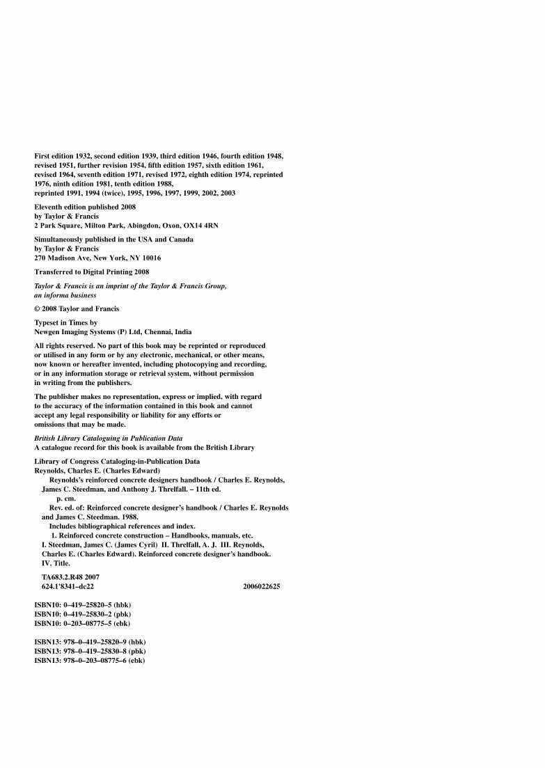
First edition 1932, second edition 1939, third edition 1946, fourth edition 1948,revised 1951, further revision 1954, fifth edition 1957, sixth edition 1961,revised 1964, seventh edition 1971, revised 1972, eighth edition 1974, reprinted1976, ninth edition 1981, tenth edition 1988,reprinted 1991, 1994 (twice), 1995, 1996, 1997, 1999, 2002, 2003
Eleventh edition published 2008by Taylor & Francis2 Park Square, Milton Park, Abingdon, Oxon, OX14 4RN
Simultaneously published in the USA and Canadaby Taylor & Francis270 Madison Ave, New York, NY 10016
Taylor & Francis is an imprint of the Taylor & Francis Group,an informa business
© 2008 Taylor and Francis
Typeset in Times byNewgen Imaging Systems (P) Ltd, Chennai, India
All rights reserved. No part of this book may be reprinted or reproduced or utilised in any form or by any electronic, mechanical, or other means,now known or hereafter invented, including photocopying and recording,or in any information storage or retrieval system, without permission in writing from the publishers.
The publisher makes no representation, express or implied, with regard to the accuracy of the information contained in this book and cannot accept any legal responsibility or liability for any efforts or omissions that may be made.
British Library Cataloguing in Publication DataA catalogue record for this book is available from the British Library
Library of Congress Cataloging-in-Publication DataReynolds, Charles E. (Charles Edward)
Reynolds’s reinforced concrete designers handbook / Charles E. Reynolds,James C. Steedman, and Anthony J. Threlfall. – 11th ed.
p. cm.Rev. ed. of: Reinforced concrete designer’s handbook / Charles E. Reynolds
and James C. Steedman. 1988.Includes bibliographical references and index.1. Reinforced concrete construction – Handbooks, manuals, etc.
I. Steedman, James C. (James Cyril) II. Threlfall, A. J. III. Reynolds,Charles E. (Charles Edward). Reinforced concrete designer’s handbook.IV. Title.
TA683.2.R48 2007624.1'8341–dc22 2006022625
ISBN10: 0–419–25820–5 (hbk)ISBN10: 0–419–25830–2 (pbk)ISBN10: 0–203–08775–5 (ebk)
ISBN13: 978–0–419–25820–9 (hbk)ISBN13: 978–0–419–25830–8 (pbk)ISBN13: 978–0–203–08775–6 (ebk)
Transferred to Digital Printing 2008
List of tables viPreface to the eleventh edition ixThe authors xAcknowledgements xiSymbols and abbreviations xii
Part 1 – General information 11 Introduction 32 Design criteria, safety factors and loads 53 Material properties 144 Structural analysis 285 Design of structural members 446 Buildings, bridges and containment structures 547 Foundations, ground slabs, retaining walls,
culverts and subways 63
Part 2 – Loads, materials and structures 738 Loads 759 Pressures due to retained materials 86
10 Concrete and reinforcement 9511 Cantilevers and single-span beams 10512 Continuous beams 11113 Slabs 12814 Framed structures 15415 Shear wall structures 16916 Arches 17517 Containment structures 18318 Foundations and retaining walls 195
19 Miscellaneous structures and details 20620 Elastic analysis of concrete sections 226
Part 3 – Design to British Codes 23721 Design requirements and safety factors 23922 Properties of materials 24523 Durability and fire-resistance 24924 Bending and axial force 25625 Shear and torsion 28326 Deflection and cracking 29527 Considerations affecting design details 31228 Miscellaneous members and details 322
Part 4 – Design to European Codes 33329 Design requirements and safety factors 33530 Properties of materials 33831 Durability and fire-resistance 34232 Bending and axial force 34533 Shear and torsion 36234 Deflection and cracking 37135 Considerations affecting design details 38136 Foundations and earth-retaining walls 390
Appendix: Mathematical formulae and data 395
References and further reading 397
Index 399
Contents
2.1 Weights of construction materials and concretefloor slabs
2.2 Weights of roofs and walls2.3 Imposed loads on floors of buildings2.4 Imposed loads on roofs of buildings2.5 Imposed loads on bridges – 12.6 Imposed loads on bridges – 22.7 Wind speeds (standard method of design)2.8 Wind pressures and forces (standard method
of design)2.9 Pressure coefficients and size effect factors
for rectangular buildings2.10 Properties of soils2.11 Earth pressure distributions on rigid walls2.12 Active earth pressure coefficients2.13 Passive earth pressure coefficients – 12.14 Passive earth pressure coefficients – 22.15 Silos – 12.16 Silos – 22.17 Concrete: cements and aggregate grading2.18 Concrete: early-age temperatures2.19 Reinforcement: general properties2.20 Reinforcement: cross-sectional areas of bars
and fabric2.21 Reinforcement: standard bar shapes and method of
measurement – 12.22 Reinforcement: standard bar shapes and method of
measurement – 22.23 Reinforcement: typical bar schedule2.24 Moments, shears, deflections: general case for beams2.25 Moments, shears, deflections: special cases for beams2.26 Moments, shears, deflections: general cases for
cantilevers2.27 Moments, shears, deflections: special cases for
cantilevers2.28 Fixed-end moment coefficients: general data2.29 Continuous beams: general data2.30 Continuous beams: moments from equal loads on
equal spans – 12.31 Continuous beams: moments from equal loads on
equal spans – 22.32 Continuous beams: shears from equal loads on
equal spans2.33 Continuous beams: moment redistribution2.34 Continuous beams: bending moment diagrams – 1
2.35 Continuous beams: bending moment diagrams – 22.36 Continuous beams: moment distribution methods2.37 Continuous beams: unequal prismatic spans and loads2.38 Continuous beams: influence lines for two spans2.39 Continuous beams: influence lines for three spans2.40 Continuous beams: influence lines for four spans2.41 Continuous beams: influence lines for five or
more spans2.42 Slabs: general data2.43 Two-way slabs: uniformly loaded rectangular panels
(BS 8110 method)2.44 Two-way slabs: uniformly loaded rectangular panels
(elastic analysis)2.45 One-way slabs: concentrated loads2.46 Two-way slabs: rectangular panel with concentric
concentrated load – 12.47 Two-way slabs: rectangular panel with concentric
concentrated load – 22.48 Two-way slabs: non-rectangular panels (elastic
analysis)2.49 Two-way slabs: yield-line theory: general information2.50 Two-way slabs: yield-line theory: corner levers2.51 Two-way slabs: Hillerborg’s simple strip theory2.52 Two-way slabs: rectangular panels: loads on beams
(common values)2.53 Two-way slabs: triangularly distributed load (elastic
analysis)2.54 Two-way slabs: triangularly distributed load (collapse
method)2.55 Flat slabs: BS 8110 simplified method – 12.56 Flat slabs: BS 8110 simplified method – 22.57 Frame analysis: general data2.58 Frame analysis: moment-distribution method:
no sway2.59 Frame analysis: moment-distribution method:
with sway2.60 Frame analysis: slope-deflection data2.61 Frame analysis: simplified sub-frames2.62 Frame analysis: effects of lateral loads2.63 Rectangular frames: general cases2.64 Gable frames: general cases2.65 Rectangular frames: special cases2.66 Gable frames: special cases2.67 Three-hinged portal frames2.68 Structural forms for multi-storey buildings
List of tables
List of tables vii
2.69 Shear wall layout and lateral load allocation2.70 Analysis of pierced shear walls2.71 Arches: three-hinged and two-hinged arches2.72 Arches: fixed-ended arches2.73 Arches: computation chart for symmetrical
fixed-ended arch2.74 Arches: fixed-ended parabolic arches2.75 Cylindrical tanks: elastic analysis – 12.76 Cylindrical tanks: elastic analysis – 22.77 Cylindrical tanks: elastic analysis – 32.78 Rectangular tanks: triangularly distributed load
(elastic analysis) – 12.79 Rectangular tanks: triangularly distributed load
(elastic analysis) – 22.80 Rectangular containers spanning horizontally:
moments in walls2.81 Bottoms of elevated tanks and silos2.82 Foundations: presumed allowable bearing values
and separate bases2.83 Foundations: other bases and footings2.84 Foundations: inter-connected bases and rafts2.85 Foundations: loads on open-piled structures2.86 Retaining walls2.87 Rectangular culverts2.88 Stairs: general information2.89 Stairs: sawtooth and helical stairs2.90 Design coefficients for helical stairs – 12.91 Design coefficients for helical stairs – 22.92 Non-planar roofs: general data2.93 Shell roofs: empirical design method – 12.94 Shell roofs: empirical design method – 22.95 Bow girders: concentrated loads2.96 Bow girders: uniform loads – 12.97 Bow girders: uniform loads – 22.98 Bridges2.99 Hinges and bearings2.100 Movement joints2.101 Geometric properties of uniform sections2.102 Properties of reinforced concrete sections – 12.103 Properties of reinforced concrete sections – 22.104 Uniaxial bending and compression (modular ratio)2.105 Symmetrically reinforced rectangular columns
(modular ratio) – 12.106 Symmetrically reinforced rectangular columns
(modular ratio) – 22.107 Uniformly reinforced cylindrical columns
(modular ratio)2.108 Uniaxial bending and tension (modular ratio)2.109 Biaxial bending and compression (modular ratio)3.1 Design requirements and partial safety factors
(BS 8110)3.2 Design requirements and partial safety factors
(BS 5400) – 13.3 Design requirements and partial safety factors
(BS 5400) – 23.4 Design requirements and partial safety factors
(BS 8007)3.5 Concrete (BS 8110): strength and deformation
characteristics3.6 Stress-strain curves (BS 8110 and BS 5400): concrete
and reinforcement
3.7 Exposure classification (BS 8500)3.8 Concrete quality and cover requirements for durability
(BS 8500)3.9 Exposure conditions, concrete and cover requirements
(prior to BS 8500)3.10 Fire resistance requirements (BS 8110) – 13.11 Fire resistance requirements (BS 8110) – 23.12 Building regulations: minimum fire periods3.13 BS 8110 Design chart for singly reinforced
rectangular beams3.14 BS 8110 Design table for singly reinforced
rectangular beams3.15 BS 8110 Design chart for doubly reinforced
rectangular beams – 13.16 BS 8110 Design chart for doubly reinforced
rectangular beams – 23.17 BS 8110 Design chart for rectangular columns – 13.18 BS 8110 Design chart for rectangular columns – 23.19 BS 8110 Design chart for circular columns – 13.20 BS 8110 Design chart for circular columns – 23.21 BS 8110 Design procedure for columns – 13.22 BS 8110 Design procedure for columns – 23.23 BS 5400 Design chart for singly reinforced
rectangular beams3.24 BS 5400 Design table for singly reinforced
rectangular beams3.25 BS 5400 Design chart for doubly reinforced
rectangular beams – 13.26 BS 5400 Design chart for doubly reinforced
rectangular beams – 23.27 BS 5400 Design chart for rectangular columns – 13.28 BS 5400 Design chart for rectangular columns – 23.29 BS 5400 Design chart for circular columns – 13.30 BS 5400 Design chart for circular columns – 23.31 BS 5400 Design procedure for columns – 13.32 BS 5400 Design procedure for columns – 23.33 BS 8110 Shear resistance3.34 BS 8110 Shear under concentrated loads3.35 BS 8110 Design for torsion3.36 BS 5400 Shear resistance3.37 BS 5400 Shear under concentrated loads – 13.38 BS 5400 Shear under concentrated loads – 23.39 BS 5400 Design for torsion3.40 BS 8110 Deflection – 13.41 BS 8110 Deflection – 23.42 BS 8110 Deflection – 33.43 BS 8110 (and BS 5400) Cracking3.44 BS 8007 Cracking3.45 BS 8007 Design options and restraint factors3.46 BS 8007 Design table for cracking due to temperature
effects3.47 BS 8007 Elastic properties of cracked rectangular
sections in flexure3.48 BS 8007 Design table for cracking due to flexure
in slabs – 13.49 BS 8007 Design table for cracking due to flexure
in slabs – 23.50 BS 8007 Design table for cracking due to flexure
in slabs – 33.51 BS 8007 Design table for cracking due to direct
tension in walls – 1
List of tablesviii
4.9 EC 2 Design chart for doubly reinforcedrectangular beams – 1
4.10 EC 2 Design chart for doubly reinforcedrectangular beams – 2
4.11 EC 2 Design chart for rectangular columns – 14.12 EC 2 Design chart for rectangular columns – 24.13 EC 2 Design chart for circular columns – 14.14 EC 2 Design chart for circular columns – 24.15 EC 2 Design procedure for columns – 14.16 EC 2 Design procedure for columns – 24.17 EC 2 Shear resistance – 14.18 EC 2 Shear resistance – 24.19 EC 2 Shear under concentrated loads4.20 EC 2 Design for torsion4.21 EC 2 Deflection – 14.22 EC 2 Deflection – 24.23 EC 2 Cracking – 14.24 EC 2 Cracking – 24.25 EC 2 Cracking – 34.26 EC 2 Early thermal cracking in end restrained panels4.27 EC 2 Early thermal cracking in edge
restrained panels4.28 EC 2 Reinforcement limits4.29 EC 2 Provision of ties4.30 EC 2 Anchorage requirements4.31 EC 2 Laps and bends in bars4.32 EC 2 Rules for curtailment, large diameter bars
and bundles
3.52 BS 8007 Design table for cracking due to directtension in walls – 2
3.53 BS 8110 Reinforcement limits3.54 BS 8110 Provision of ties3.55 BS 8110 Anchorage requirements3.56 BS 8110 Curtailment requirements3.57 BS 8110 Simplified curtailment rules for beams3.58 BS 8110 Simplified curtailment rules for slabs3.59 BS 5400 Considerations affecting design details3.60 BS 8110 Load-bearing walls3.61 BS 8110 Pile-caps3.62 Recommended details: nibs, corbels and halving joints3.63 Recommended details: intersections of members4.1 Design requirements and partial safety factors
(EC 2: Part 1)4.2 Concrete (EC 2): strength and deformation
characteristics – 14.3 Concrete (EC 2): strength and deformation
characteristics – 24.4 Stress–strain curves (EC 2): concrete and
reinforcement4.5 Exposure classification (BS 8500)4.6 Concrete quality and cover requirements for durability
(BS 8500)4.7 EC 2 Design chart for singly reinforced
rectangular beams4.8 EC 2 Design table for singly reinforced
rectangular beams
Since the last edition of Reynolds’s Handbook, considerabledevelopments in design and practice have occurred. These includesignificant revisions to British standard specifications and codesof practice, and the introduction of the Eurocodes. Although cur-rent British codes are due to be withdrawn from 2008 onwards,their use is likely to continue beyond that date at least in someEnglish-speaking countries outside the United Kingdom.
One of the most significant changes has been in the systemfor classifying exposure conditions, and selecting concretestrength and cover requirements for durability. This is now dealtwith exclusively in BS 8500, which takes into account theparticular cement/combination type. The notation used todefine concrete strength gives the cylinder strength as well asthe cube strength. For structural design, cube strength is usedin the British codes and cylinder strength in the Eurocodes.
The characteristic yield strength of reinforcement has beenincreased to 500 N/mm2 (MPa). As a result, new design aidshave become necessary, and the Handbook includes tables andcharts for beams and columns (rectangular and circular)designed to both British and European codes. Throughout theHandbook, stress units are given as N/mm2 for British codesand MPa for European codes. The decimal point is shown by afull stop (rather than a comma) in both cases.
The basic layout of the Handbook is similar to the previousedition, but the contents have been arranged in four separateparts for the convenience of the reader. Also, the opportunityhas been taken to omit a large amount of material that was nolonger relevant, and to revise the entire text to reflect moderndesign and construction practice. Part 1 is descriptive in formand covers design requirements, loads, materials, structuralanalysis, member design and forms of construction. Frequentreference is made in Part 1 to the tables that are found in therest of the Handbook. Although specific notes are attached tothese tables in Parts 2, 3 and 4, much of the relevant text isembodied in Part 1, and the first part of the Handbook shouldalways be consulted.
Part 2 has more detailed information on loads, materialproperties and analysis in the form of tabulated data and chartsfor a large range of structural forms. This material is largelyindependent of any specific code of practice. Parts 3 and 4 cover
the design of members according to the requirements ofthe British and European codes respectively. For each code, thesame topics are covered in the same sequence so that the readercan move easily from one code to the other. Each topic isillustrated by extensive numerical examples.
In the Eurocodes, some parameters are given recommendedvalues with the option of a national choice. Choices also existwith regard to certain classes, methods and procedures. Thedecisions made by each country are given in a national annex.Part 4 of the Handbook already incorporates the values given inthe UK national annex. Further information concerning the useof Eurocode 2 is given in PD 6687: Background paper to theUK National Annex to BS EN 1992–1–1.
The Handbook has been an invaluable source of reference forreinforced concrete engineers for over 70 years. I madeextensive use of the sixth edition at the start of my professionalcareer 50 years ago. This edition contains old and new infor-mation, derived by many people, and obtained from manysources past and present. Although the selection inevitablyreflects the personal experience of the authors, the informationhas been well tried and tested. I owe a considerable debt ofgratitude to colleagues and mentors from whom I have learntmuch over the years, and to the following organisations forpermission to include data for which they hold the copyright:
British Cement AssociationBritish Standards InstitutionCabinet Office of Public Sector InformationConstruction Industry Research and Information AssociationPortland Cement AssociationThe Concrete Bridge Development GroupThe Concrete Society
Finally, my sincere thanks go to Katy Low and all the staff atTaylor & Francis Group, and especially to my dear wife Joanwithout whose unstinting support this edition would never havebeen completed.
Tony ThrelfallMarlow, October 2006
Preface to theeleventh edition

Charles Edward Reynolds was born in 1900 and received hiseducation at Tiffin Boys School, Kingston-on-Thames, andBattersea Polytechnic. After some years with Sir WilliamArroll, BRC and Simon Carves, he joined Leslie Turner andPartners, and later C W Glover and Partners. He was for someyears Technical Editor of Concrete Publications Ltd and thenbecame its Managing Editor, combining this post with privatepractice. In addition to the Reinforced Concrete Designer’sHandbook, of which almost 200,000 copies have been soldsince it first appeared in 1932, Charles Reynolds was the authorof numerous other books, papers and articles concerningconcrete and allied subjects. Among his various professionalappointments, he served on the council of the Junior Institutionof Engineers, and was the Honorary Editor of its journal at hisdeath on Christmas Day 1971.
James Cyril Steedman was educated at Varndean GrammarSchool and first was employed by British Rail, whom he joinedin 1950 at the age of 16. In 1956 he began working for GKNReinforcements Ltd and later moved to Malcolm Glover andPartners. His association with Charles Reynolds began when,after the publication of numerous articles in the magazine
Concrete and Constructional Engineering, he accepted anappointment as Technical Editor of Concrete Publications, apost he held for seven years. He then continued in privatepractice, combining work for the Publications Division of theCement and Concrete Association with his own writing andother activities. In 1981 he set up Jacys Computing Services,subsequently devoting much of his time to the development ofmicro-computer software for reinforced concrete design. He isthe joint author, with Charles Reynolds, of Examples of theDesign of Reinforced Concrete Buildings to BS 8110.
Anthony John Threlfall was educated at Liverpool Institute forBoys, after which he studied civil engineering at LiverpoolUniversity. After eight years working for BRC, Pierhead Ltdand IDC Ltd, he took a diploma course in concrete structuresand technology at Imperial College. For the next four years heworked for CEGB and Camus Ltd, and then joined the Cementand Concrete Association in 1970, where he was engagedprimarily in education and training activities until 1993. Afterleaving the C&CA, he has continued in private practice toprovide training in reinforced and prestressed concrete designand detailing.
The authors
The publishers would like to thank the following organisationsfor their kind permission to reproduce the following material:
Permission to reproduce extracts from British Standards isgranted by BSI. This applies to information in Tables 2.1, 2.3,2.4, 2.7–2.10, 2.15, 2.16, 2.19–2.23, 2.42, 2.43, 2.45, 2.55,2.56, 2.100, 3.1–3.11, 3.21, 3.22, 3.31–3.45, 3.53–3.61, 4.1–4.6,4.15–4.25, and 4.28–4.32. British Standards can be obtainedfrom BSI Customer Services, 389 Chiswick High Street,London W4 4AL. Tel: �44 (0)20 8996 9001. email:[email protected]
Information in section 3.1, and Tables 2.17–2.18, is reproducedwith permission from the British Cement Association, andtaken from the publication Concrete Practice (ref. 10).
Information in section 6.2 is reproduced with permissionfrom the Concrete Bridge Development Group, and taken
from the publication An introduction to concrete bridges(ref. 52).
Information in section 7.2 is reproduced with permissionfrom The Concrete Society, and taken from TechnicalReport 34: Concrete industrial ground floors – A guide todesign and construction (ref. 61). Technical Report 34 isavailable to purchase from The Concrete Bookshop www.concretebookshop.com Tel: 0700 460 7777.
Information in Chapter 15, and Table 2.70, is reproduced withpermission from CIRIA, and taken from CIRIA Report 102:Design of shear wall buildings, London, 1984 (ref. 38).
Information in Tables 2.53 and 2.75–2.79 is reproduced withpermission from the Portland Cement Association (refs 32and 55).
Information in Tables 2.5, 2.6 and 3.12 is reproduced withpermission from HMSO.
Acknowledgements
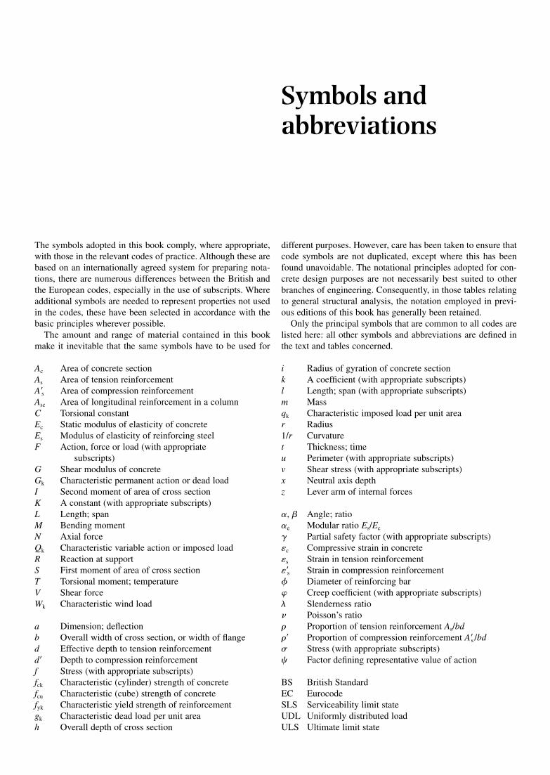
The symbols adopted in this book comply, where appropriate,with those in the relevant codes of practice. Although these arebased on an internationally agreed system for preparing nota-tions, there are numerous differences between the British andthe European codes, especially in the use of subscripts. Whereadditional symbols are needed to represent properties not usedin the codes, these have been selected in accordance with thebasic principles wherever possible.
The amount and range of material contained in this bookmake it inevitable that the same symbols have to be used for
different purposes. However, care has been taken to ensure thatcode symbols are not duplicated, except where this has beenfound unavoidable. The notational principles adopted for con-crete design purposes are not necessarily best suited to otherbranches of engineering. Consequently, in those tables relatingto general structural analysis, the notation employed in previ-ous editions of this book has generally been retained.
Only the principal symbols that are common to all codes arelisted here: all other symbols and abbreviations are defined inthe text and tables concerned.
Symbols andabbreviations
Ac Area of concrete sectionAs Area of tension reinforcementA�s Area of compression reinforcementAsc Area of longitudinal reinforcement in a columnC Torsional constantEc Static modulus of elasticity of concreteEs Modulus of elasticity of reinforcing steelF Action, force or load (with appropriate
subscripts)G Shear modulus of concreteGk Characteristic permanent action or dead loadI Second moment of area of cross sectionK A constant (with appropriate subscripts)L Length; spanM Bending momentN Axial forceQk Characteristic variable action or imposed loadR Reaction at supportS First moment of area of cross sectionT Torsional moment; temperatureV Shear forceWk Characteristic wind load
a Dimension; deflectionb Overall width of cross section, or width of flanged Effective depth to tension reinforcementd� Depth to compression reinforcementf Stress (with appropriate subscripts)fck Characteristic (cylinder) strength of concretefcu Characteristic (cube) strength of concretefyk Characteristic yield strength of reinforcementgk Characteristic dead load per unit areah Overall depth of cross section
i Radius of gyration of concrete sectionk A coefficient (with appropriate subscripts)l Length; span (with appropriate subscripts)m Massqk Characteristic imposed load per unit arear Radius1/r Curvaturet Thickness; timeu Perimeter (with appropriate subscripts)v Shear stress (with appropriate subscripts)x Neutral axis depthz Lever arm of internal forces
�, � Angle; ratio�e Modular ratio Es/Ec
� Partial safety factor (with appropriate subscripts)�c Compressive strain in concrete�s Strain in tension reinforcement��s Strain in compression reinforcement� Diameter of reinforcing bar� Creep coefficient (with appropriate subscripts)� Slenderness ratio� Poisson’s ratio Proportion of tension reinforcement As/bd� Proportion of compression reinforcement A�s /bd Stress (with appropriate subscripts)� Factor defining representative value of action
BS British StandardEC EurocodeSLS Serviceability limit stateUDL Uniformly distributed loadULS Ultimate limit state

Part 1
General information
A structure is an assembly of members each of which, under theaction of imposed loads and deformations, is subjected tobending or direct force (either tensile or compressive), or to acombination of bending and direct force. These effects may beaccompanied by shearing forces and sometimes by torsion.Imposed deformations occur as a result of concrete shrinkageand creep, changes in temperature and differential settlement.Behaviour of the structure in the event of fire or accidentaldamage, resulting from impact or explosion, may need to beexamined. The conditions of exposure to environmental andchemical attack also need to be considered.
Design includes selecting a suitable form of construction,determining the effects of imposed loads and deformations,and providing members of adequate stiffness and resistance.The members should be arranged so as to combine efficientload transmission with ease of construction, consistent withthe intended use of the structure and the nature of the site.Experience and sound judgement are often more important thanprecise calculations in achieving safe and economical structures.Complex mathematics should not be allowed to confuse a senseof good engineering. The level of accuracy employed in thecalculations should be consistent throughout the designprocess, wherever possible.
Structural design is largely controlled by regulations or codesbut, even within such bounds, the designer needs to exercisejudgement in interpreting the requirements rather than designingto the minimum allowed by the letter of a clause. In the UnitedKingdom for many years, the design of reinforced concretestructures has been based on the recommendations of BritishStandards. For buildings, these include ‘Structural use ofconcrete’ (BS 8110: Parts 1, 2 and 3) and ‘Loading on build-ings’ (BS 6399: Parts 1, 2 and 3). For other types of structures,‘Design of concrete bridges’ (BS 5400: Part 4) and ‘Design ofconcrete structures for retaining aqueous liquids’ (BS 8007)have been used. Compliance with the particular requirements ofthe Building Regulations and the Highways Agency Standardsis also necessary in many cases.
Since the last edition of this Handbook, a comprehensiveset of harmonised Eurocodes (ECs) for the structural andgeotechnical design of buildings and civil engineering workshas been developed. The Eurocodes were first introduced asEuronorme Voluntaire (ENV) standards, intended for use inconjunction with a national application document (NAD), asan alternative to national codes for a limited number of years.
These have now been largely replaced by Euronorme (EN)versions, with each member state adding a National Annex(NA) containing nationally determined parameters in order toimplement the Eurocode as a national standard. The relevantdocuments for concrete structures are EC 0: Basis of structuraldesign, EC 1: Actions on structures, and EC 2: Design of con-crete structures. The last document is in four parts, namely –Part 1.1: General rules and rules for buildings, Part 1.2:Structural fire design, Part 2: Reinforced and prestressed con-crete bridges, and Part 3: Liquid-retaining and containingstructures.
The tables to be found in Parts 2, 3 and 4 of this Handbookenable the designer to reduce the amount of arithmetical workinvolved in the analysis and design of members to the relevantstandards. The use of such tables not only increases speed butalso eliminates inaccuracies provided the tables are thoroughlyunderstood, and their applications and limitations are realised.In the appropriate chapters of Part 1 and in the supplementaryinformation given on the pages preceding the tables, the basisof the tabulated material is described. Some general informa-tion is also provided. The Appendix contains trigonometricaland other mathematical formulae and data.
1.1 ECONOMICAL STRUCTURES
The cost of construction of a reinforced concrete structure isobviously affected by the prices of concrete, reinforcement,formwork and labour. The most economical proportions ofmaterials and labour will depend on the current relationshipbetween the unit prices. Economy in the use of formwork isgenerally achieved by uniformity of member size and the avoid-ance of complex shapes and intersections. In particular cases,the use of available formwork of standard sizes may determinethe structural arrangement. In the United Kingdom, speed ofconstruction generally has a major impact on the overall cost.Fast-track construction requires the repetitive use of a rapidformwork system and careful attention to both reinforcementdetails and concreting methods.
There are also wider aspects of economy, such as whetherthe anticipated life and use of a proposed structure warrant theuse of higher or lower factors of safety than usual, or whetherthe use of a more expensive form of construction is warrantedby improvements in the integrity and appearance of the structure.The application of whole-life costing focuses attention on
Chapter 1
Introduction
Introduction4
whether the initial cost of a construction of high quality,with little or no subsequent maintenance, is likely to be moreeconomical than a cheaper construction, combined with theexpense of maintenance.
The experience and method of working of the contractor, theposition of the site and the nature of the available materials, andeven the method of measuring the quantities, together withnumerous other points, all have their effect, consciously or not,on the designer’s attitude towards a contract. So many andvaried are the factors involved that only experience and acontinuing study of design trends can give reliable guidance.Attempts to determine the most economical proportions for aparticular member based only on inclusive prices of concrete,reinforcement and formwork are likely to be misleading. It isnevertheless possible to lay down certain principles.
In broad terms, the price of concrete increases with thecement content as does the durability and strength. Concretegrades are often determined by durability requirements withdifferent grades used for foundations and superstructures.Strength is an important factor in the design of columns andbeams but rarely so in the case of slabs. Nevertheless, the samegrade is generally used for all parts of a superstructure, exceptthat higher strength concrete may sometimes be used to reducethe size of heavily loaded columns.
In the United Kingdom, mild steel and high yield reinforce-ments have been used over the years, but grade 500 is nowproduced as standard, available in three ductility classes A, B andC. It is always uneconomical in material terms to use compressionreinforcement in beams and columns, but the advantages gainedby being able to reduce member sizes and maintain the samecolumn size over several storeys generally offset the additionalmaterial costs. For equal weights of reinforcement, the combinedmaterial and fixing costs of small diameter bars are greater thanthose of large diameter bars. It is generally sensible to use thelargest diameter bars consistent with the requirements for crackcontrol. Fabric (welded mesh) is more expensive than barreinforcement in material terms, but the saving in fixing time willoften result in an overall economy, particularly in slabs and walls.
Formwork is obviously cheaper if surfaces are plane and atright angles to each other and if there is repetition of use. Thesimplest form of floor construction is a solid slab of constantthickness. Beam and slab construction is more efficient struc-turally but less economical in formwork costs. Two-way beamsystems complicate both formwork and reinforcement detailswith consequent delay in the construction programme.Increased slab efficiency and economy over longer spans maybe obtained by using a ribbed form of construction. Standardtypes of trough and waffle moulds are available in a range ofdepths. Precasting usually reduces considerably the amountof formwork, labour and erection time. Individual mouldsare more expensive but can be used many more timesthan site formwork. Structural connections are normally moreexpensive than with monolithic construction. The economicaladvantage of precasting and the structural advantage of in situcasting may be combined in composite forms of construction.
In many cases, the most economical solution can only bedetermined by comparing the approximate costs of differentdesigns. This may be necessary to decide, say, when a simplecantilever retaining wall ceases to be more economical thanone with counterforts or when a beam and slab bridge is moreeconomical than a voided slab. The handbook Economic
Concrete Frame Elements published by the British CementAssociation on behalf of the Reinforced Concrete Councilenables designers to rapidly identify least-cost options for thesuperstructure of multi-storey buildings.
1.2 DRAWINGS
In most drawing offices a practice has been developed to suitthe particular type of work done. Computer aided drafting andreinforcement detailing is widely used. The following observa-tions should be taken as general principles that accord with therecommendations in the manual Standard method of detailingstructural concrete published by the Institution of StructuralEngineers (ref. 1).
It is important to ensure that on all drawings for a particularcontract, the same conventions are adopted and uniformity ofsize and appearance are achieved. In the preliminary stagesgeneral arrangement drawings of the whole structure are usuallyprepared to show the layout and sizes of beams, columns, slabs,walls, foundations and other members. A scale of 1:100 isrecommended, although a larger scale may be necessary forcomplex structures. Later, these or similar drawings, are devel-oped into working drawings and should show precisely suchparticulars as the setting-out of the structure in relation to anyadjacent buildings or other permanent works, and the level of,say the ground floor in relation to a fixed datum. All principaldimensions such as distances between columns and walls, andthe overall and intermediate heights should be shown. Plansshould generally incorporate a gridline system, with columnspositioned at the intersections. Gridlines should be numbered 1,2, 3 and so on in one direction and lettered A, B, C and soon in the other direction, with the sequences starting at thelower left corner of the grid system. The references canbe used to identify individual beams, columns and othermembers on the reinforcement drawings.
Outline drawings of the members are prepared to suitablescales, such as 1:20 for beams and columns and 1:50 for slabsand walls, with larger scales being used for cross sections.Reinforcement is shown and described in a standard way. Theonly dimensions normally shown are those needed to positionthe bars. It is generally preferable for the outline of the concreteto be indicated by a thin line, and to show the reinforcement bybold lines. The lines representing the bars should be shown inthe correct positions, with due allowance for covers and thearrangement at intersections and laps, so that the details onthe drawing represent as nearly as possible the appearanceof the reinforcement as fixed on site. It is important to ensurethat the reinforcement does not interfere with the formation ofany holes or embedment of any other items in the concrete.
A set of identical bars in a slab, shown on plan, might bedescribed as 20H16-03-150B1. This represents 20 numbergrade 500 bars of 16 mm nominal size, bar mark 03, spaced at150 mm centres in the bottom outer layer. The bar mark is anumber that uniquely identifies the bar on the drawing and thebar bending schedule. Each different bar on a drawing is givena different bar mark. Each set of bars is described only once onthe drawing. The same bars on a cross section would be denotedsimply by the bar mark. Bar bending schedules are prepared foreach drawing on separate forms according to recommendationsin BS 8666 Specification for scheduling, dimensioning, bendingand cutting of steel reinforcement for concrete.
References Institution of Structural Engineers/Concrete Society . Standard method of detailing structural concrete: a manual for best practice. London, TheInstitution of Structural Engineers, 2006, p. 188. CP2: Civil Engineering Code of Practice No.2 . Earth retaining structures. London, The Institution of Structural Engineers, 1951, p. 224 The Highways Agency . BD 37/01: Loads for highway bridges, Design manual for roads and bridges. London, HMSO, 2001, p. 118. The Highways Agency . BD 64/94: The design of highway bridges for vehicle collision loads, Design manual for roads and bridges. London, HMSO,1994, p. 13. The Highways Agency . BD 21/01: The assessment of highway bridges and structures, Design manual for roads and bridges. London, HMSO,2001, p. 84. The Highways Agency . BD 52/93: The design of highway bridge parapets, Design manual for roads and bridges. London, HMSO, 1993, p. 44. Department of Transport . BD 30/87: Backfilled retaining walls and bridge abutments. London, Department of Transport, 1987, p. 12. Caquot A. and Kerisel J. Tables for calculation of passive pressure, active pressure and bearing capacity of foundations (translated from French byM. A. Bec , London). Paris, Gauthier-Villars, 1948, p. 121 The Highways Agency . BA 42/96: The design of integral bridges, Design manual for roads and bridges. London: HMSO, 1996, p. 10. Blackledge, G. F. , and Binns R. A. . Concrete practice. Crowthorne, British Cement Association, Publication 48.037, 2002, p. 71. CIRIA Report 91 . Early-age thermal crack control in concrete. London, CIRIA, 1981, p. 160 BRE Digest 357 . Shrinkage of natural aggregates in concrete. Watford, BRE, 1991, p. 4 BRE Special Digest 1 . Concrete in aggressive ground. Six parts, Watford, BRE, 2005 Concrete Society Technical Report No. 51 . Guidance on the use of stainless steel reinforcement. Slough, The Concrete Society, 1998, p. 55 Coates, R. C. , Coutie M. G. , and Kong F. K. Structural analysis. Sunbury-on-Thames, Nelson, 1972, p. 496. Rygol, J. Structural analysis by direct moment distribution. London, Crosby Lockwood, 1968, p. 407. Westergaard, H. M. Computation of stresses in bridge slabs due to wheel loads. Public Roads, Vol. 2 No. 1, March 1930, pp. 1–23. Pucher, A. Influence surfaces for elastic plates. Wien and New York, Springer Verlag, 1964. Bares, R. Tables for the analysis of plates and beams based on elastic theory. Berlin, Bauverlag, 1969. Timoshenko, S. P. and Woinowsky-Krieger S. Theory of plates and shells (second edition). New York, McGraw-Hill, 1959, p. 580. Sarkar, R. K. Slab design - elastic method (plates). Munich, Verlag UNI-Druck, 1975, p. 191. Wang, P. C. Numerical and matrix methods in structural mechanics. New York, Wiley, 1966, p. 426. Jones, L. L. , and Wood R. H. . Yield-line analysis of slabs. London, Thames and Hudson, 1967, p. 405.This book, written by leading UK experts, isthe best English language text dealing with yield-line theory (essential for designers using the method frequently and for more than ‘standard’solutions) Johansen, K. W. Yield-line theory. London, Cement and Concrete Association, 1962, p. 181.This is an English translation of the original 1943 texton which yield-line theory is founded Johansen, K. W. Yield-line formulae for slabs. London, Cement and Concrete Association, 1972, p. 106.Gives design formulae for virtually every‘standard’ slab shape and loading (essential for practical design purposes) Wood, R. H. Plastic and elastic design of slabs and plates. London, Thames and Hudson, 1961, p. 344.Relates collapse and elastic methods ofslab analysis, but mainly from the viewpoint of research rather than practical design Jones, L. L. Ultimate load analysis of reinforced and prestressed concrete structures. London, Chatto and Windus, 1962, p. 248.About half of thiseasily readable book deals with the yield-line method, describing in detail the analysis of several ‘standard’ slabs Pannell, F. N. Yield-line analysis, Concrete and Constructional Engineering. June-Nov. 1996Basic application of virtual-work methods in slabdesign, June, 1966, pp. 209-216Economical distribution of reinforcement in rectangular slabs, July, 1966, pp. 229-233Edge conditions in flat plates,Aug. 1966, pp. 290-294General principle of superposition in the design of rigid-plastic plates, Sept. 1966, pp. 323-326Design of rectangular plateswith banded orthotropic reinforcement, Oct. 1966, pp. 371-376Non-rectangular slabs with orthotropic reinforcement, Nov. 1966, pp. 383-390 Hillerborg, A. Strip method of design. London, Viewpoint, 1975, p. 225This book is the English translation of the basic text on the strip method (bothsimple and advanced) by its originator. It deals with theory and gives appropriate design formulae for many problems Fernando J. S. and Kemp K. O. A generalised strip deflexion method of reinforced concrete slab design. Proceedings of the Institution of CivilEngineers: Part 2: Research and Theory, March 1978, pp. 163–174 Taylor, R. , Hayes B. and Mohamedbhai G. T. G. Coefficients for the design of slabs by the yield-line theory. Concrete 3 (5), 1969, pp. 171–172. Munshi, J. A. Rectangular concrete tanks (revised fifth edition). Skokie, Illinois, Portland Cement Association, 1998, p. 188This is the most detailedbook on the subject with complete tables giving moments, shears and deflections for plates and tanks, with useful worked examples CIRIA Report 110 . Design of reinforced concrete flat slabs to BS8110. London, CIRIA, 1985, p. 48 Beeby, A. W. The analysis of beams in plane frames according to CP110. London, Cement and Concrete Association, Publication 44.001, 1978, p.34. Rygol, J. Structural analysis by direct moment distribution. London, Crosby Lockwood, 1968, p. 407. Naylor, N. Side-sway in symmetrical building frames. The Structural Engineer 28 (4), 1950, pp. 99–102. Orton A. The way we build now: form, scale and technique. London, E & FN Spon, 1988, p. 530 CIRIA Report 102 . Design of shear wall buildings. London, CIRIA, 1984, p. 80 Eurocode 8: Design of structures for earthquake resistance. Brussels, European Committee for Standardization, 2004 Penelis G. G. and Kappos A. J. Earthquake-resistant concrete structures. London, E & FN Spon, 1997, p. 572 Kruger, H. G. Crack width calculation to BS 8007 for combined flexure and direct tension. The Structural Engineer, 80 (18), 2002, pp. 18–22. Kong F. K. , Robins P. J. and Sharp G. R. The design of reinforced concrete deep beams in current practice. The Structural Engineer 53(4), 1975,pp. 73–80 Ove Arup and Partners . The design of deep beams in reinforced concrete. CIRIA Guide No. 2, p. 131. Concrete Society Technical Report No. 42 . Trough and waffle floors. Slough, The Concrete Society, 1992, p. 34 Gibson J. E. The design of shell roofs (Third edition). London, E & FN Spon, 1968, p. 300 Chronowicz, A. The design of shells. London, Crosby Lockwood, 1959, p. 202. Tottenham, H. A. A simplified method of design for cylindrical shell roofs. The Structural Engineer 32 (6), 1954, pp. 161–180. Bennett J. D. Empirical design of symmetrical cylindrical shells. Proceedings of the colloquium on simplified calculation methods, Brussels, 1961.Amsterdam, North-Holland, 1962, pp. 314-332 Salvadori and Levy . Structural design in architecture. Englewood Cliffs: Prentice-Hall, 1967, p. 457. Schulz, M. , and Chedraui M. . Tables for circularly curved horizontal beams with symmetrical uniform loads. Journal of the American ConcreteInstitute 28 (11), 1957, pp. 1033–1040. Spyropoulos, P. J. Circularly curved beams transversely loaded. Journal of the American Concrete Institute 60 (10), 1963, pp. 1457–1469. Concrete Society/CBDG . An introduction to concrete bridges. Camberley, The Concrete Society, 2006, p. 32 Leonhardt Fritz . Bridges. Stuttgart, Deutsche Verlags-Anstalt, 1982, p. 308.

Hambly E. C. Bridge deck behaviour (Second edition). London, E & FN Spon, 1991, p. 313 PCA . Circular concrete tanks without prestressing. Skokie, Illinois, Portland Cement Association, p. 54 Ghali A. Circular storage tanks and silos. London, E & FN Spon, 1979, p. 210 CIRIA Reports 139 and 140 (Summary Report) . Water-resisting basement construction. London, CIRIA, 1995, p. 192; p. 64 Irish, K. and Walker W. P. Foundations for reciprocating machines. London, Cement and Concrete Association, 1969, p. 103. Barkan, D. D. Dynamics of bases and foundations. New York, McGraw Hill, 1962, p. 434. Tomlinson, M. J. Pile design and construction practice. London, Cement and Concrete Association, 1977, p. 413. Concrete Society Technical Report No. 34 . Concrete industrial ground floors (Third edition). Crowthorne, The Concrete Society, 2003, p. 146 CIRIA Report 104 . Design of retaining walls embedded in stiff clay. London, CIRIA, 1984, p. 146 Hairsine, R. C. A design chart for determining the optimum base proportions of free standing retaining walls. Proceedings of the Institution of CivilEngineers 51 (February), 1972, pp. 295–318. Cusens A. R. and Kuang Jing-Gwo . A simplified method of analysing free-standing stairs. Concrete and Constructional Engineering 60(5), 1965,pp. 167–172 and 194 Cusens, A. R. Analysis of slabless stairs. Concrete and Constructional Engineering 61 (10), 1966, pp. 359–364. Santathadaporn Sakda and Cusens . A. R. Charts for the design of helical stairs. Concrete and Constructional Engineering 61 (2), 1966, pp. 46–54. Terrington, J. S. , and Turner L. . Design of non-planar roofs. London: Concrete Publications, 1964, p. 108. Krishna J. and Jain O. P. The beam strength of reinforced concrete cylindrical shells. Civil Engineering and Public Works Review, 49(578), 1954,pp. 838–840 and 49(579), 1954, pp. 953-956 Faber, C. Candela: the shell builder. London: The Architectural Press, 1963, 240. Bennett, J. D. Structural possibilities of hyperbolic paraboloids. London, Reinforced Concrete Association, February 1961, p. 25. Lee D. J. Bridge bearings and expansion joints (Second edition). London, E & FN Spon, 1994, p. 212