Embed Size (px)
Citation preview

Seismic Design of Reinforced Concrete Buildings
00_Moehle_FM.indd 1 8/30/14 12:55 PM
About the AuthorJack Moehle is the T.Y. and Margaret Lin Professor of Engineering in the Department of Civil and Environmental Engineering at the University of California, Berkeley. He received his Ph.D. from the University of Illinois and joined the U.C. Berkeley faculty in 1980. His research and teaching activities are mainly in structural engineering, with emphasis on reinforced concrete and earthquake engineering. He was founding direc-tor of the Pacific Earthquake Engineering Research Center, a multi- campus research center that advanced the concepts and practice of performance-based earthquake engineering. As a licensed Civil Engineer in the State of California, Dr. Moehle works regularly as a consulting engi-neer, offering advice and expert peer review on highway and mass transit systems, water distribution systems, existing construction, and high-rise buildings. He has played a leading role in developing professional guid-ance and design standards, including Improved Seismic Design Guidelines for California Highway Bridges (ATC 32); Guidelines for Evaluation and Repair of Masonry and Concrete Walls (FEMA 306); Guidelines for Seismic Rehabilitation of Buildings (FEMA 273 and ASCE 356); Development of Next-Generation Performance-Based Seismic Design Procedures for New and Existing Buildings (FEMA P-58); and Guidelines for Performance-Based Seismic Design of Tall Buildings (Tall Buildings Initiative, PEER). He has served on the Boards of Directors of the Structural Engineers Association of Northern California, the Earthquake Engineering Research Institute, and the American Concrete Institute. His awards include the Lindau Award, the Siess Award, and the Boase Award from the American Concrete Institute; the Huber Research Prize from the American Society of Civil Engineers; the Annual Distinguished Lecturer and Outstanding Paper Award from the Earthquake Engineering Research Institute; and Honorary Member and College of Fellows of the Structural Engineers Association of California. He is an elected member of the U.S. National Academy of Engineering. He has been a member of the ACI 318 Building Code Committee since 1989, chair of ACI 318H (Seismic Provisions) from 1995 to 2014, and is chair of the ACI 318 Building Code Committee for the 2014–2019 code cycle.
Cover image courtesy of Magnusson Klemencic Associates
00_Moehle_FM.indd 2 9/11/14 6:25 PM
Seismic Design of Reinforced Concrete
BuildingsJack Moehle
New York Chicago San Francisco Athens London Madrid
Mexico City Milan New Delhi Singapore Sydney Toronto
00_Moehle_FM.indd 3 8/30/14 12:55 PM

Copyright © 2015 by McGraw-Hill Education. All rights reserved. Except as permitted under the United States Copyright Act of 1976, no part of this publication may be reproduced or distributed in any form or by any means, or stored in a database or retrieval system, without the prior written permission of the publisher.
ISBN: 978-0-07-183945-7
MHID: 0-07-183945-3
The material in this eBook also appears in the print version of this title: ISBN: 978-0-07-183944-0,MHID: 0-07-183944-5.
eBook conversion by codeMantraVersion 1.0
All trademarks are trademarks of their respective owners. Rather than put a trademark symbol after every occurrence of a trademarked name, we use names in an editorial fashion only, and to the benefit of the trademark owner, with no intention of infringement of the trademark. Where such designations appear in this book, they have been printed with initial caps.
McGraw-Hill Education eBooks are available at special quantity discounts to use as premiums and sales promotions or for use in corporate training programs. To contact a representative, please visit the Contact Us page at www.mhprofessional.com.
Information contained in this work has been obtained by McGraw-Hill Education from sources believed to be reliable. However, neither McGraw-Hill Education nor its authors guarantee the accuracy or completeness of any information published herein, and neither McGraw-Hill Education nor its authors shall be responsible for any errors, omissions, or damages arising out of use of this information. This work is published with the understanding that McGraw-Hill Education and its authors are supplying information but are not attempting to render engineering or other professional services. If such services are required, the assistance of an appropriate professional should be sought.
TERMS OF USE
This is a copyrighted work and McGraw-Hill Education and its licensors reserve all rights in and to the work. Use of this work is subject to these terms. Except as permitted under the Copyright Act of 1976 and the right to store and retrieve one copy of the work, you may not decompile, disassemble, reverse engineer, reproduce, modify, create derivative works based upon, transmit, distribute, disseminate, sell, publish or sublicense the work or any part of it without McGraw-Hill Education’s prior consent. You may use the work for your own noncommercial and personal use; any other use of the work is strictly prohibited. Your right to use the work may be terminated if you fail to comply with these terms.
THE WORK IS PROVIDED “AS IS.” McGRAW-HILL EDUCATION AND ITS LICENSORS MAKE NO GUARANTEES OR WARRANTIES AS TO THE ACCURACY, ADEQUACY OR COMPLETENESS OF OR RESULTS TO BE OBTAINED FROM USING THE WORK, INCLUDING ANY INFORMATION THAT CAN BE ACCESSED THROUGH THE WORK VIA HYPERLINK OR OTHERWISE, AND EXPRESSLY DISCLAIM ANY WARRANTY, EXPRESS OR IMPLIED, INCLUDING BUT NOT LIMITED TO IMPLIED WARRANTIES OF MERCHANTABILITY OR FITNESS FOR A PARTICULAR PURPOSE. McGraw-Hill Education and its licensors do not warrant or guarantee that the functions contained in the work will meet your requirements or that its operation will be uninterrupted or error free. Neither McGraw-Hill Education nor its licensors shall be liable to you or anyone else for any inaccuracy, error or omission, regardless of cause, in the work or for any damages resulting therefrom. McGraw-Hill Education has no responsibility for the content of any information accessed through the work. Under no circumstances shall McGraw-Hill Education and/or its licensors be liable for any indirect, incidental, special, punitive, consequential or similar damages that result from the use of or inability to use the work, even if any of them has been advised of the possibility of such damages. This limitation of liability shall apply to any claim or cause whatsoever whether such claim or cause arises in contract, tort or otherwise.

To Melissa, For time, encouragement, diversions.
00_Moehle_FM.indd 5 9/11/14 6:25 PM

This page intentionally left blank
ContentsPreface . . . . . . . . . . . . . . . . . . . . . . . . . . . . . . . . . . . . . . . . . . . . . . . . . . . . . xixAcknowledgments . . . . . . . . . . . . . . . . . . . . . . . . . . . . . . . . . . . . . . . . . . . xxi
1 Seismic Design and Performance Verification . . . . . . . . . . . . . . . . 11.1 Earthquake Resistance in Concrete Buildings . . . . . . . . . . . . . . . 11.2 Early Developments . . . . . . . . . . . . . . . . . . . . . . . . . . . . . . . . . . . . . 21.3 Current Practices . . . . . . . . . . . . . . . . . . . . . . . . . . . . . . . . . . . . . . . 3
1.3.1 Building Codes . . . . . . . . . . . . . . . . . . . . . . . . . . . . . . . . . . . 51.3.2 Conceptual Design . . . . . . . . . . . . . . . . . . . . . . . . . . . . . . . . 61.3.3 Prescriptive Design Approach . . . . . . . . . . . . . . . . . . . . . . 81.3.4 Performance-Based Design Approach . . . . . . . . . . . . . . . 101.3.5 Construction Inspection . . . . . . . . . . . . . . . . . . . . . . . . . . . 12
1.4 Building Performance . . . . . . . . . . . . . . . . . . . . . . . . . . . . . . . . . . . 121.4.1 Anticipated Response of Buildings to Earthquake
Ground Shaking . . . . . . . . . . . . . . . . . . . . . . . . . . . . . . . . . . 121.4.2 Performance Concepts . . . . . . . . . . . . . . . . . . . . . . . . . . . . . 131.4.3 Use, Occupancy, and Risk Classifications . . . . . . . . . . . . . 151.4.4 Building Performance Expectations . . . . . . . . . . . . . . . . . 15
1.5 Performance Verification . . . . . . . . . . . . . . . . . . . . . . . . . . . . . . . . . 171.5.1 Limit State Design . . . . . . . . . . . . . . . . . . . . . . . . . . . . . . . . 171.5.2 Serviceability Limit State . . . . . . . . . . . . . . . . . . . . . . . . . . . 171.5.3 Ultimate Limit State
(Load and Resistance Factor Design) . . . . . . . . . . . . . . . . 181.5.4 Capacity Design . . . . . . . . . . . . . . . . . . . . . . . . . . . . . . . . . . 261.5.5 Displacement-Based Design . . . . . . . . . . . . . . . . . . . . . . . . 291.5.6 Performance Evaluation under
Earthquake Ground Shaking . . . . . . . . . . . . . . . . . . . . . . . 301.6 The Purpose and Organization of This Book . . . . . . . . . . . . . . . . 31References . . . . . . . . . . . . . . . . . . . . . . . . . . . . . . . . . . . . . . . . . . . . . . . . . . 32
2 Steel Reinforcement . . . . . . . . . . . . . . . . . . . . . . . . . . . . . . . . . . . . . . . 352.1 Preview . . . . . . . . . . . . . . . . . . . . . . . . . . . . . . . . . . . . . . . . . . . . . . . . 352.2 Steel Reinforcement Used in Buildings . . . . . . . . . . . . . . . . . . . . . 35
2.2.1 Standard Steel Reinforcement . . . . . . . . . . . . . . . . . . . . . . . 352.2.2 Reinforcement Grades and Availability . . . . . . . . . . . . . . . 392.2.3 Permitted Reinforcement . . . . . . . . . . . . . . . . . . . . . . . . . . 41
vii
00_Moehle_FM.indd 7 8/30/14 12:55 PM
C o n t e n t s ix viii C o n t e n t s
2.3 Steel Reinforcement under Monotonic Loading . . . . . . . . . . . . . 432.3.1 General Characteristics of the Stress–Strain
Relation . . . . . . . . . . . . . . . . . . . . . . . . . . . . . . . . . . . . . . . . . 432.3.2 Tensile Properties of Steel Reinforcement . . . . . . . . . . . . 442.3.3 Compressive Properties of Steel Reinforcing Bars . . . . . . 462.3.4 Strain Rate Effect . . . . . . . . . . . . . . . . . . . . . . . . . . . . . . . . . 47
2.4 Reinforcing Bars under Cyclic Loading . . . . . . . . . . . . . . . . . . . . . 492.4.1 Stress–Strain Response . . . . . . . . . . . . . . . . . . . . . . . . . . . . 492.4.2 Low-Cycle Fatigue . . . . . . . . . . . . . . . . . . . . . . . . . . . . . . . . 51
References . . . . . . . . . . . . . . . . . . . . . . . . . . . . . . . . . . . . . . . . . . . . . . . . . . 57
3 Concrete . . . . . . . . . . . . . . . . . . . . . . . . . . . . . . . . . . . . . . . . . . . . . . . . . . 593.1 Preview . . . . . . . . . . . . . . . . . . . . . . . . . . . . . . . . . . . . . . . . . . . . . . . . 593.2 Composition and Structure of Concrete . . . . . . . . . . . . . . . . . . . . 593.3 Concrete Strength . . . . . . . . . . . . . . . . . . . . . . . . . . . . . . . . . . . . . . . 61
3.3.1 Materials Characteristics and Proportions . . . . . . . . . . . . 613.3.2 Curing Time and Conditions . . . . . . . . . . . . . . . . . . . . . . . 633.3.3 In-Place Concrete . . . . . . . . . . . . . . . . . . . . . . . . . . . . . . . . . 643.3.4 Test Specimen Parameters . . . . . . . . . . . . . . . . . . . . . . . . . . 663.3.5 Expected Strength in Structures . . . . . . . . . . . . . . . . . . . . . 67
3.4 Behavior in Uniaxial Monotonic Loading . . . . . . . . . . . . . . . . . . . 693.4.1 Compressive Stress–Strain Response . . . . . . . . . . . . . . . . . 693.4.2 Tensile Strength . . . . . . . . . . . . . . . . . . . . . . . . . . . . . . . . . . 713.4.3 Strain Rate Effects . . . . . . . . . . . . . . . . . . . . . . . . . . . . . . . . . 72
3.5 Behavior in Uniaxial Cyclic Loading . . . . . . . . . . . . . . . . . . . . . . . 733.6 Behavior in Multi-axial Stress States . . . . . . . . . . . . . . . . . . . . . . . 74
3.6.1 Plain Concrete in Biaxial Stress State . . . . . . . . . . . . . . . . . 743.6.2 Reinforced Concrete in Biaxial Loading . . . . . . . . . . . . . . 763.6.3 Plain Concrete in Triaxial Stress State . . . . . . . . . . . . . . . . 77
3.7 Fiber-Reinforced Concrete . . . . . . . . . . . . . . . . . . . . . . . . . . . . . . . 793.8 Chapter Review . . . . . . . . . . . . . . . . . . . . . . . . . . . . . . . . . . . . . . . . . 80References . . . . . . . . . . . . . . . . . . . . . . . . . . . . . . . . . . . . . . . . . . . . . . . . . . 81
4 Confined Concrete . . . . . . . . . . . . . . . . . . . . . . . . . . . . . . . . . . . . . . . . . 834.1 Preview . . . . . . . . . . . . . . . . . . . . . . . . . . . . . . . . . . . . . . . . . . . . . . . . 834.2 Behavior of Confined Concrete Sections . . . . . . . . . . . . . . . . . . . 834.3 Mechanism of Concrete Confinement . . . . . . . . . . . . . . . . . . . . . . 84
4.3.1 Passive Confinement of Concrete . . . . . . . . . . . . . . . . . . . 854.3.2 Columns with Spiral and Circular
Hoop Reinforcement . . . . . . . . . . . . . . . . . . . . . . . . . . . . . . 864.3.3 Columns with Rectilinear Hoop Reinforcement . . . . . . . 914.3.4 Loading Rate Effect . . . . . . . . . . . . . . . . . . . . . . . . . . . . . . . 974.3.5 Aggregate Density Effect . . . . . . . . . . . . . . . . . . . . . . . . . . . 984.3.6 Compressive Strength Effect . . . . . . . . . . . . . . . . . . . . . . . . 99
00_Moehle_FM.indd 8 8/30/14 12:55 PM
C o n t e n t s ix viii C o n t e n t s
4.3.7 Cyclic Loading Effect . . . . . . . . . . . . . . . . . . . . . . . . . . . . . . 1004.3.8 Reinforcement Details . . . . . . . . . . . . . . . . . . . . . . . . . . . . . 100
4.4 Analytical Modeling of Confined Concrete . . . . . . . . . . . . . . . . . 1024.4.1 Strain at Peak Stress . . . . . . . . . . . . . . . . . . . . . . . . . . . . . . . 1024.4.2 Maximum Strain Capacity for Confined Concrete . . . . . 1034.4.3 Stress−Strain Relation . . . . . . . . . . . . . . . . . . . . . . . . . . . . . 104
References . . . . . . . . . . . . . . . . . . . . . . . . . . . . . . . . . . . . . . . . . . . . . . . . . . 106
5 Axially Loaded Members . . . . . . . . . . . . . . . . . . . . . . . . . . . . . . . . . . . 1095.1 Preview . . . . . . . . . . . . . . . . . . . . . . . . . . . . . . . . . . . . . . . . . . . . . . . . 1095.2 Some Observations on the Behavior
of Compression Members . . . . . . . . . . . . . . . . . . . . . . . . . . . . . . . . 1095.3 Analysis Assumptions for Compression Members . . . . . . . . . . . 1115.4 Service Load Behavior of Compression Members . . . . . . . . . . . . 112
5.4.1 Linear Elastic Response . . . . . . . . . . . . . . . . . . . . . . . . . . . . 1125.4.2 Effects of Drying Shrinkage and Creep . . . . . . . . . . . . . . . 113
5.5 Inelastic Behavior of Compression Members . . . . . . . . . . . . . . . . 1155.5.1 Cover and Core Concrete . . . . . . . . . . . . . . . . . . . . . . . . . . 1155.5.2 Longitudinal Reinforcement . . . . . . . . . . . . . . . . . . . . . . . . 1165.5.3 Load–Displacement Response . . . . . . . . . . . . . . . . . . . . . . 1225.5.4 Transverse Reinforcement Required for Ductility . . . . . . 124
5.6 Tension Members . . . . . . . . . . . . . . . . . . . . . . . . . . . . . . . . . . . . . . . 1285.7 Reversed Cyclic Loading . . . . . . . . . . . . . . . . . . . . . . . . . . . . . . . . . 133
5.7.1 Stability of Longitudinal Reinforcement . . . . . . . . . . . . . . 1335.7.2 Stability of Axially Loaded Members . . . . . . . . . . . . . . . . . 134
5.8 Chapter Review . . . . . . . . . . . . . . . . . . . . . . . . . . . . . . . . . . . . . . . . . 138References . . . . . . . . . . . . . . . . . . . . . . . . . . . . . . . . . . . . . . . . . . . . . . . . . . 138
6 Moment and Axial Force . . . . . . . . . . . . . . . . . . . . . . . . . . . . . . . . . . . 1416.1 Preview . . . . . . . . . . . . . . . . . . . . . . . . . . . . . . . . . . . . . . . . . . . . . . . . 1416.2 Some Observations about Flexural Behavior . . . . . . . . . . . . . . . . 1416.3 Internal and External Force Equilibrium . . . . . . . . . . . . . . . . . . . 1436.4 Flexural Deformations . . . . . . . . . . . . . . . . . . . . . . . . . . . . . . . . . . . 1446.5 Flexural Behavior of Sections . . . . . . . . . . . . . . . . . . . . . . . . . . . . . 146
6.5.1 General Observations . . . . . . . . . . . . . . . . . . . . . . . . . . . . . 1466.5.2 Spalling Strain . . . . . . . . . . . . . . . . . . . . . . . . . . . . . . . . . . . . 147
6.6 Moment–Curvature Analysis . . . . . . . . . . . . . . . . . . . . . . . . . . . . . 1486.6.1 Analysis Assumptions and General Procedure . . . . . . . . 1486.6.2 Linear-Elastic Response of Uncracked Sections . . . . . . . 1496.6.3 Linear-Elastic Response of Cracked Sections . . . . . . . . . . 1506.6.4 Flexural Stiffness at Service Loads . . . . . . . . . . . . . . . . . . . 1536.6.5 Response at Ultimate Limit States . . . . . . . . . . . . . . . . . . . 1546.6.6 Compression Stress Block Parameters . . . . . . . . . . . . . . . . 1556.6.7 Automation of Moment–Curvature Calculations . . . . . . 164
00_Moehle_FM.indd 9 8/30/14 12:55 PM
C o n t e n t s xi x C o n t e n t s
6.7 Beams . . . . . . . . . . . . . . . . . . . . . . . . . . . . . . . . . . . . . . . . . . . . . . . . 165 6.7.1 Moment–Curvature Response . . . . . . . . . . . . . . . . . . . . . 166 6.7.2 Nominal, Probable, and Design Moment Strengths . . . 169 6.7.3 Reinforcement Limits . . . . . . . . . . . . . . . . . . . . . . . . . . . . 174
6.8 Columns . . . . . . . . . . . . . . . . . . . . . . . . . . . . . . . . . . . . . . . . . . . . . . 176 6.8.1 General Observations about Axial Force, Moment, and
Curvature . . . . . . . . . . . . . . . . . . . . . . . . . . . . . . . . . . . . . . 176 6.8.2 Construction of P -M-f Relations
by Hand Calculations . . . . . . . . . . . . . . . . . . . . . . . . . . . . 177 6.8.3 Axial Force, Moment, and Curvature Response . . . . . . 178 6.8.4 Nominal, Probable, and Design Strengths . . . . . . . . . . . 180 6.8.5 Reinforcement Limits . . . . . . . . . . . . . . . . . . . . . . . . . . . . 181
6.9 Walls . . . . . . . . . . . . . . . . . . . . . . . . . . . . . . . . . . . . . . . . . . . . . . . . . 181 6.9.1 Geometry and Reinforcement . . . . . . . . . . . . . . . . . . . . . 181 6.9.2 Axial Force, Moment, and Curvature Response . . . . . . 182 6.9.3 Nominal, Probable, and Design Strengths . . . . . . . . . . . 186 6.9.4 Reinforcement Limits . . . . . . . . . . . . . . . . . . . . . . . . . . . . 186
6.10 Flanged Sections . . . . . . . . . . . . . . . . . . . . . . . . . . . . . . . . . . . . . . . 1866.10.1 Beams . . . . . . . . . . . . . . . . . . . . . . . . . . . . . . . . . . . . . . . . . . 1866.10.2 Walls . . . . . . . . . . . . . . . . . . . . . . . . . . . . . . . . . . . . . . . . . . . 193
6.11 Load-Deflection Calculations . . . . . . . . . . . . . . . . . . . . . . . . . . . . 1966.11.1 Linear Response . . . . . . . . . . . . . . . . . . . . . . . . . . . . . . . . . 1966.11.2 Nonlinear Inelastic Range . . . . . . . . . . . . . . . . . . . . . . . . . 201
6.12 Reversed Cyclic Loading . . . . . . . . . . . . . . . . . . . . . . . . . . . . . . . . 2106.12.1 General Aspects of Response
to Reversed Cyclic Loading . . . . . . . . . . . . . . . . . . . . . . . 2106.12.2 Laboratory Tests . . . . . . . . . . . . . . . . . . . . . . . . . . . . . . . . . 211
References . . . . . . . . . . . . . . . . . . . . . . . . . . . . . . . . . . . . . . . . . . . . . . . . . . 216
7 Shear in Beams, Columns, and Walls . . . . . . . . . . . . . . . . . . . . . . . . . 219 7.1 Preview . . . . . . . . . . . . . . . . . . . . . . . . . . . . . . . . . . . . . . . . . . . . . . . 219 7.2 Some Observations about Shear in Flexural Members . . . . . . . 219 7.3 Relations among Moment, Shear, and Bond . . . . . . . . . . . . . . . . 222 7.4 Beam Action and Arch Action . . . . . . . . . . . . . . . . . . . . . . . . . . . 225 7.5 Internal Forces in Members with Transverse Reinforcement . . . 227 7.6 Strut-and-Tie Models . . . . . . . . . . . . . . . . . . . . . . . . . . . . . . . . . . . 228
7.6.1 Plastic Truss Analysis for Beams . . . . . . . . . . . . . . . . . . . 229 7.6.2 Example Strut-and-Tie Models . . . . . . . . . . . . . . . . . . . . 233
7.7 Proportioning of Strut-and-Tie Models . . . . . . . . . . . . . . . . . . . 235 7.7.1 Overall Geometry . . . . . . . . . . . . . . . . . . . . . . . . . . . . . . . . 235 7.7.2 Design Strength . . . . . . . . . . . . . . . . . . . . . . . . . . . . . . . . . 236 7.7.3 Struts . . . . . . . . . . . . . . . . . . . . . . . . . . . . . . . . . . . . . . . . . . 237 7.7.4 Ties . . . . . . . . . . . . . . . . . . . . . . . . . . . . . . . . . . . . . . . . . . . . 241 7.7.5 Nodal Zones . . . . . . . . . . . . . . . . . . . . . . . . . . . . . . . . . . . . 242
00_Moehle_FM.indd 10 8/30/14 12:55 PM
C o n t e n t s xi x C o n t e n t s
7.8 Transverse Reinforcement Detailing . . . . . . . . . . . . . . . . . . . . . . 244 7.9 Empirical Approach for Shear Strength
of Beams and Columns . . . . . . . . . . . . . . . . . . . . . . . . . . . . . . . . . 245 7.9.1 Strength of Members without
Transverse Reinforcement . . . . . . . . . . . . . . . . . . . . . . . . 245 7.9.2 Members with Transverse Reinforcement . . . . . . . . . . . 249 7.9.3 ACI 318 Design Equations and Requirements
for Beams and Columns . . . . . . . . . . . . . . . . . . . . . . . . . . 250 7.9.4 Comparison of ACI 318 and Truss Models . . . . . . . . . . 252
7.10 Effects of Inelastic Cyclic Loading . . . . . . . . . . . . . . . . . . . . . . . . 2537.11 Diagonally Reinforced Beams . . . . . . . . . . . . . . . . . . . . . . . . . . . . 2577.12 Shear in Structural Walls . . . . . . . . . . . . . . . . . . . . . . . . . . . . . . . . 263
7.12.1 Wall Classification Based on Slenderness . . . . . . . . . . . . 2637.12.2 Slender Structural Walls . . . . . . . . . . . . . . . . . . . . . . . . . . 2647.12.3 Squat Structural Walls . . . . . . . . . . . . . . . . . . . . . . . . . . . . 2697.12.4 Shear in Panel Zones . . . . . . . . . . . . . . . . . . . . . . . . . . . . . 273
7.13 Interface Shear Transfer . . . . . . . . . . . . . . . . . . . . . . . . . . . . . . . . . 2767.14 Shear Stiffness . . . . . . . . . . . . . . . . . . . . . . . . . . . . . . . . . . . . . . . . . 282
7.14.1 General Aspects . . . . . . . . . . . . . . . . . . . . . . . . . . . . . . . . . 2827.14.2 Coupling Beams . . . . . . . . . . . . . . . . . . . . . . . . . . . . . . . . . 2847.14.3 Slender Walls . . . . . . . . . . . . . . . . . . . . . . . . . . . . . . . . . . . . 2867.14.4 Squat Walls . . . . . . . . . . . . . . . . . . . . . . . . . . . . . . . . . . . . . 287
References . . . . . . . . . . . . . . . . . . . . . . . . . . . . . . . . . . . . . . . . . . . . . . . . . . 288
8 Development and Anchorage . . . . . . . . . . . . . . . . . . . . . . . . . . . . . . . 293 8.1 Preview . . . . . . . . . . . . . . . . . . . . . . . . . . . . . . . . . . . . . . . . . . . . . . . 293 8.2 Some Observations about Bond and Anchorage . . . . . . . . . . . . 293 8.3 Relations among Bond Stress and External Forces . . . . . . . . . . 295 8.4 Bond Mechanics . . . . . . . . . . . . . . . . . . . . . . . . . . . . . . . . . . . . . . . 296 8.5 Bond Strength of Deformed Reinforcement . . . . . . . . . . . . . . . . 299
8.5.1 Empirical Relations . . . . . . . . . . . . . . . . . . . . . . . . . . . . . . 299 8.5.2 ACI 318 Provisions for Development of Deformed Bars
and Deformed Wires in Tension . . . . . . . . . . . . . . . . . . . 302 8.5.3 ACI 318 Provisions for Development of Deformed Bars
and Deformed Wire in Compression . . . . . . . . . . . . . . . 303 8.6 Lap Splices . . . . . . . . . . . . . . . . . . . . . . . . . . . . . . . . . . . . . . . . . . . . 305
8.6.1 Tension Lap Splices . . . . . . . . . . . . . . . . . . . . . . . . . . . . . . 305 8.6.2 Compression Lap Splices . . . . . . . . . . . . . . . . . . . . . . . . . . 307
8.7 Mechanical Splices . . . . . . . . . . . . . . . . . . . . . . . . . . . . . . . . . . . . . 308 8.8 Welded Splices . . . . . . . . . . . . . . . . . . . . . . . . . . . . . . . . . . . . . . . . 310 8.9 Hooked Anchorages . . . . . . . . . . . . . . . . . . . . . . . . . . . . . . . . . . . . 310
8.9.1 Standard Hooks . . . . . . . . . . . . . . . . . . . . . . . . . . . . . . . . . 310 8.9.2 Force Transfer Mechanism . . . . . . . . . . . . . . . . . . . . . . . . 311 8.9.3 ACI 318 Provisions . . . . . . . . . . . . . . . . . . . . . . . . . . . . . . 313
00_Moehle_FM.indd 11 8/30/14 12:55 PM
C o n t e n t s xiii xii C o n t e n t s
8.10 Headed Reinforcement . . . . . . . . . . . . . . . . . . . . . . . . . . . . . . . . . 3158.10.1 Force Transfer Mechanism . . . . . . . . . . . . . . . . . . . . . . . . 3158.10.2 ACI 318 Provisions . . . . . . . . . . . . . . . . . . . . . . . . . . . . . . . 316
8.11 Effects of Inelastic Cyclic Loading . . . . . . . . . . . . . . . . . . . . . . . . 3188.11.1 Straight Bar Anchorages . . . . . . . . . . . . . . . . . . . . . . . . . . 3188.11.2 Lap Splices . . . . . . . . . . . . . . . . . . . . . . . . . . . . . . . . . . . . . . 3198.11.3 Hooked Bars . . . . . . . . . . . . . . . . . . . . . . . . . . . . . . . . . . . . 3258.11.4 Headed Reinforcement . . . . . . . . . . . . . . . . . . . . . . . . . . . 326
References . . . . . . . . . . . . . . . . . . . . . . . . . . . . . . . . . . . . . . . . . . . . . . . . . . 326
9 Beam-Column Connections . . . . . . . . . . . . . . . . . . . . . . . . . . . . . . . . . 329 9.1 Preview . . . . . . . . . . . . . . . . . . . . . . . . . . . . . . . . . . . . . . . . . . . . . . . 329 9.2 Forces in Beam-Column Connections . . . . . . . . . . . . . . . . . . . . 329
9.2.1 Connection Forces from Gravity and Lateral Loading . . . . . . . . . . . . . . . . . . . . . . . . . . . . . . 329
9.2.2 Calculation of Joint Shear . . . . . . . . . . . . . . . . . . . . . . . . . 331 9.3 Joint Classifications . . . . . . . . . . . . . . . . . . . . . . . . . . . . . . . . . . . . 335
9.3.1 Connection Geometry . . . . . . . . . . . . . . . . . . . . . . . . . . . . 336 9.3.2 Loading Type . . . . . . . . . . . . . . . . . . . . . . . . . . . . . . . . . . . 336 9.3.3 Joint Reinforcement . . . . . . . . . . . . . . . . . . . . . . . . . . . . . . 336
9.4 Beam-Column Joints without Transverse Reinforcement . . . . 336 9.4.1 Interior Connections . . . . . . . . . . . . . . . . . . . . . . . . . . . . . 337 9.4.2 Exterior Connections . . . . . . . . . . . . . . . . . . . . . . . . . . . . . 340 9.4.3 Tee Connections . . . . . . . . . . . . . . . . . . . . . . . . . . . . . . . . . 341 9.4.4 Corner Connections . . . . . . . . . . . . . . . . . . . . . . . . . . . . . 342 9.4.5 ASCE 41 Joint Strength . . . . . . . . . . . . . . . . . . . . . . . . . . . 344
9.5 Beam-Column Joints with Transverse Reinforcement . . . . . . . 345 9.5.1 Interior Connections . . . . . . . . . . . . . . . . . . . . . . . . . . . . . 345 9.5.2 Exterior Connections . . . . . . . . . . . . . . . . . . . . . . . . . . . . . 354 9.5.3 Tee (Roof) Connections . . . . . . . . . . . . . . . . . . . . . . . . . . 357 9.5.4 Corner Connections . . . . . . . . . . . . . . . . . . . . . . . . . . . . . 357 9.5.5 Predictive Models for Joint Shear Strength . . . . . . . . . . . 358
9.6 Recommended Design Procedure for Beam-Column Joints . . 360 9.6.1 Classify Joints According to Loading
Conditions and Geometry . . . . . . . . . . . . . . . . . . . . . . . . 361 9.6.2 Determine Joint Shear Demands . . . . . . . . . . . . . . . . . . . 362 9.6.3 Size the Connection for Joint Shear Demands . . . . . . . . 364 9.6.4 Develop Beam and Column
Longitudinal Reinforcement . . . . . . . . . . . . . . . . . . . . . . 366 9.6.5 Provide Joint Confinement . . . . . . . . . . . . . . . . . . . . . . . . 369 9.6.6 Provide Adequate Strength and
Detailing in Columns . . . . . . . . . . . . . . . . . . . . . . . . . . . . 371 9.7 Beam-Column Joint Deformations . . . . . . . . . . . . . . . . . . . . . . . 371References . . . . . . . . . . . . . . . . . . . . . . . . . . . . . . . . . . . . . . . . . . . . . . . . . . 375
00_Moehle_FM.indd 12 8/30/14 12:55 PM
C o n t e n t s xiii xii C o n t e n t s
10 Slab-Column and Slab-Wall Connections . . . . . . . . . . . . . . . . . . . . 379 10.1 Preview . . . . . . . . . . . . . . . . . . . . . . . . . . . . . . . . . . . . . . . . . . . . . 379 10.2 Some Observations on Seismic Behavior
of Slab-Column Connections . . . . . . . . . . . . . . . . . . . . . . . . . . . 379 10.3 Slab-Column Systems . . . . . . . . . . . . . . . . . . . . . . . . . . . . . . . . . 381 10.4 Moments, Shears, and Deformations
in Slab-Column Framing . . . . . . . . . . . . . . . . . . . . . . . . . . . . . . 382 10.5 Flexural Reinforcement in Slab-Column Frames . . . . . . . . . . 384 10.6 Lateral Stiffness . . . . . . . . . . . . . . . . . . . . . . . . . . . . . . . . . . . . . . . 386 10.7 Shear and Moment Transfer Strength
at Slab-Column Connections . . . . . . . . . . . . . . . . . . . . . . . . . . . 387 10.7.1 Connections Transferring Shear without Moment . . . 387 10.7.2 Connections Transferring Shear and Moment . . . . . . 396
10.8 Drift Capacity under Deformation Reversals . . . . . . . . . . . . . . 400 10.8.1 Slabs without Shear Reinforcement . . . . . . . . . . . . . . . . 401 10.8.2 Slabs with Shear Reinforcement . . . . . . . . . . . . . . . . . . . 403
10.9 Post-Punching Behavior and Structural Integrity Reinforcement . . . . . . . . . . . . . . . . . . . . . . . . . . . . . . . 403
10.10 Slab-Wall Connections . . . . . . . . . . . . . . . . . . . . . . . . . . . . . . . . 40610.10.1 One-Way Slab-Wall Connections . . . . . . . . . . . . . . . . . 40610.10.2 Slab-Wall Coupling . . . . . . . . . . . . . . . . . . . . . . . . . . . . . 407
References . . . . . . . . . . . . . . . . . . . . . . . . . . . . . . . . . . . . . . . . . . . . . . . . . . 409
11 Seismic Design Overview . . . . . . . . . . . . . . . . . . . . . . . . . . . . . . . . . . . 411 11.1 Preview . . . . . . . . . . . . . . . . . . . . . . . . . . . . . . . . . . . . . . . . . . . . . . 411 11.2 Earthquakes and Engineering Representation
of Seismic Hazard . . . . . . . . . . . . . . . . . . . . . . . . . . . . . . . . . . . . . 411 11.2.1 Earthquakes and Earthquake Hazards . . . . . . . . . . . . . 411 11.2.2 Engineering Characterization of Ground Motion . . . . 415 11.2.3 Site-Specific Seismic Hazard Evaluation . . . . . . . . . . . . 417 11.2.4 Design Response Spectra in U.S.
Building Codes . . . . . . . . . . . . . . . . . . . . . . . . . . . . . . . . . 420 11.3 Earthquake Demands on Building Structures . . . . . . . . . . . . . 423
11.3.1 Linear-Elastic Response . . . . . . . . . . . . . . . . . . . . . . . . . 423 11.3.2 Nonlinear Inelastic Response . . . . . . . . . . . . . . . . . . . . . 424 11.3.3 Drift and Ductility Demands . . . . . . . . . . . . . . . . . . . . . 427
11.4 Earthquake-Resisting Buildings . . . . . . . . . . . . . . . . . . . . . . . . . 433 11.5 Design Approach . . . . . . . . . . . . . . . . . . . . . . . . . . . . . . . . . . . . . 439
11.5.1 Strength-Based Design in Accordance with ASCE 7 . . . . . . . . . . . . . . . . . . . . . . . . . . . . . . . . . . . 439
11.5.2 Displacement-Based Design . . . . . . . . . . . . . . . . . . . . . . 445 11.5.3 Performance-Based Design . . . . . . . . . . . . . . . . . . . . . . 448
11.6 Chapter Review . . . . . . . . . . . . . . . . . . . . . . . . . . . . . . . . . . . . . . . 450References . . . . . . . . . . . . . . . . . . . . . . . . . . . . . . . . . . . . . . . . . . . . . . . . . . 450
00_Moehle_FM.indd 13 8/30/14 12:55 PM
C o n t e n t s xv xiv C o n t e n t s
12 Special Moment Frames . . . . . . . . . . . . . . . . . . . . . . . . . . . . . . . . . . . . 45312.1 Preview . . . . . . . . . . . . . . . . . . . . . . . . . . . . . . . . . . . . . . . . . . . . . . . 45312.2 The Use of Special Moment Frames . . . . . . . . . . . . . . . . . . . . . . . 454
12.2.1 Historic Development . . . . . . . . . . . . . . . . . . . . . . . . . . . . 45412.2.2 When to Use Special Moment Frames . . . . . . . . . . . . . . 45512.2.3 Frame Layout and Proportioning . . . . . . . . . . . . . . . . . . 455
12.3 Principles for Design of Special Moment Frames . . . . . . . . . . . 45712.3.1 Design a Strong-Column/Weak-Beam System . . . . . . . 45712.3.2 Detail Beams and Columns for Ductile
Flexural Response . . . . . . . . . . . . . . . . . . . . . . . . . . . . . . . 45812.3.3 Avoid Nonductile Failure Modes . . . . . . . . . . . . . . . . . . . 45912.3.4 Avoid Interaction with Nonstructural Components . . . 462
12.4 Seismic Response of Special Moment Frames . . . . . . . . . . . . . . 46312.4.1 Observations on Dynamic Response . . . . . . . . . . . . . . . . 46312.4.2 Frame Yielding Mechanisms . . . . . . . . . . . . . . . . . . . . . . . 46712.4.3 Member Forces . . . . . . . . . . . . . . . . . . . . . . . . . . . . . . . . . . 47412.4.4 Member Deformation Demands and Capacities . . . . . . 483
12.5 Modeling and Analysis . . . . . . . . . . . . . . . . . . . . . . . . . . . . . . . . . 48812.5.1 Analysis Procedure . . . . . . . . . . . . . . . . . . . . . . . . . . . . . . . 48812.5.2 Stiffness Recommendations . . . . . . . . . . . . . . . . . . . . . . . 48812.5.3 Foundation Modeling . . . . . . . . . . . . . . . . . . . . . . . . . . . . 489
12.6 Proportioning and Detailing Guidance . . . . . . . . . . . . . . . . . . . . 49012.6.1 Beam Flexure and Longitudinal Reinforcement . . . . . . 49012.6.2 Joint Shear and Anchorage . . . . . . . . . . . . . . . . . . . . . . . . 49212.6.3 Beam Shear and Transverse Reinforcement . . . . . . . . . . 49512.6.4 Column Design and Reinforcement . . . . . . . . . . . . . . . . 498
12.7 Additional Requirements . . . . . . . . . . . . . . . . . . . . . . . . . . . . . . . 50312.7.1 Special Inspection . . . . . . . . . . . . . . . . . . . . . . . . . . . . . . . . 50312.7.2 Material Properties . . . . . . . . . . . . . . . . . . . . . . . . . . . . . . . 50412.7.3 Additional System Design Requirements . . . . . . . . . . . . 506
12.8 Detailing and Constructability Issues . . . . . . . . . . . . . . . . . . . . . 50612.8.1 Longitudinal Bar Compatibility . . . . . . . . . . . . . . . . . . . . 50612.8.2 Beam and Column Confinement . . . . . . . . . . . . . . . . . . . 50812.8.3 Bar Splices . . . . . . . . . . . . . . . . . . . . . . . . . . . . . . . . . . . . . . 51112.8.4 Concrete Placement . . . . . . . . . . . . . . . . . . . . . . . . . . . . . . 512
References . . . . . . . . . . . . . . . . . . . . . . . . . . . . . . . . . . . . . . . . . . . . . . . . . . 512
13 Special Structural Walls . . . . . . . . . . . . . . . . . . . . . . . . . . . . . . . . . . . . 51513.1 Preview . . . . . . . . . . . . . . . . . . . . . . . . . . . . . . . . . . . . . . . . . . . . . . . 51513.2 The Use of Special Structural Walls . . . . . . . . . . . . . . . . . . . . . . . 515
13.2.1 Structural Walls in Buildings . . . . . . . . . . . . . . . . . . . . . . 51513.2.2 When to Use Structural Walls . . . . . . . . . . . . . . . . . . . . . 51613.2.3 Wall Layout . . . . . . . . . . . . . . . . . . . . . . . . . . . . . . . . . . . . . 517
00_Moehle_FM.indd 14 8/30/14 12:55 PM
C o n t e n t s xv xiv C o n t e n t s
13.2.4 Wall Foundations . . . . . . . . . . . . . . . . . . . . . . . . . . . . . . . . 52013.2.5 Wall Configurations . . . . . . . . . . . . . . . . . . . . . . . . . . . . . . 52113.2.6 Wall Reinforcement . . . . . . . . . . . . . . . . . . . . . . . . . . . . . . 52413.2.7 Wall Proportioning . . . . . . . . . . . . . . . . . . . . . . . . . . . . . . 525
13.3 Principles for Design of Special Structural Walls . . . . . . . . . . . . 52613.3.1 Slender Walls . . . . . . . . . . . . . . . . . . . . . . . . . . . . . . . . . . . . 52713.3.2 Squat Walls . . . . . . . . . . . . . . . . . . . . . . . . . . . . . . . . . . . . . 53113.3.3 Diaphragms and Foundations . . . . . . . . . . . . . . . . . . . . . 531
13.4 Observations on the Behavior of Special Structural Walls . . . . 53113.4.1 Slender versus Squat Walls . . . . . . . . . . . . . . . . . . . . . . . . 53113.4.2 Flexural Response of Walls . . . . . . . . . . . . . . . . . . . . . . . . 53213.4.3 Stability of Flexural Compression Zone . . . . . . . . . . . . . 53513.4.4 Dynamic Response . . . . . . . . . . . . . . . . . . . . . . . . . . . . . . . 53813.4.5 Backstay Effects . . . . . . . . . . . . . . . . . . . . . . . . . . . . . . . . . 54613.4.6 Walls with Cap Beams and Outriggers . . . . . . . . . . . . . . 54813.4.7 Frame–Wall Interaction . . . . . . . . . . . . . . . . . . . . . . . . . . 549
13.5 Analysis Guidance . . . . . . . . . . . . . . . . . . . . . . . . . . . . . . . . . . . . . 55013.5.1 Analysis Procedures . . . . . . . . . . . . . . . . . . . . . . . . . . . . . . 55013.5.2 Stiffness Recommendations . . . . . . . . . . . . . . . . . . . . . . . 55113.5.3 Effective Flange Width . . . . . . . . . . . . . . . . . . . . . . . . . . . . 55213.5.4 Foundation Modeling . . . . . . . . . . . . . . . . . . . . . . . . . . . . 55213.5.5 Limit Analysis and Redistribution
of Coupled Walls . . . . . . . . . . . . . . . . . . . . . . . . . . . . . . . . 55213.6 Load and Resistance Factors for Wall Design . . . . . . . . . . . . . . . 55513.7 Preliminary Proportioning . . . . . . . . . . . . . . . . . . . . . . . . . . . . . . 556
13.7.1 Proportioning for Base Shear . . . . . . . . . . . . . . . . . . . . . . 55613.7.2 Proportioning for Drift . . . . . . . . . . . . . . . . . . . . . . . . . . . 557
13.8 Design of Slender Walls with Single Critical Section . . . . . . . . 55713.8.1 Moment and Axial Force Design
of Intended Plastic Hinge . . . . . . . . . . . . . . . . . . . . . . . . . 55713.8.2 Shear Design of the Intended Plastic Hinge . . . . . . . . . . 56613.8.3 Shear-Friction Design of the Intended
Plastic Hinge . . . . . . . . . . . . . . . . . . . . . . . . . . . . . . . . . . . . 56813.8.4 Requirements above the Intended Plastic Hinge . . . . . . 569
13.9 Design of Walls without an Identified Critical Section . . . . . . . 57213.10 Squat Walls . . . . . . . . . . . . . . . . . . . . . . . . . . . . . . . . . . . . . . . . . . . . 573
13.10.1 Conventionally Reinforced Squat Walls . . . . . . . . . . . . . 57313.10.2 Diagonally Reinforced Squat Walls . . . . . . . . . . . . . . . . . 574
13.11 Wall Piers . . . . . . . . . . . . . . . . . . . . . . . . . . . . . . . . . . . . . . . . . . . . . 57513.12 Coupled Wall Systems . . . . . . . . . . . . . . . . . . . . . . . . . . . . . . . . . . 576
13.12.1 Coupling Beams . . . . . . . . . . . . . . . . . . . . . . . . . . . . . . . . . 57713.12.2 Coupled Walls . . . . . . . . . . . . . . . . . . . . . . . . . . . . . . . . . . . 582
13.13 Wall Panel Zones . . . . . . . . . . . . . . . . . . . . . . . . . . . . . . . . . . . . . . . 584
00_Moehle_FM.indd 15 8/30/14 12:55 PM
C o n t e n t s xvii xvi C o n t e n t s
13.14 Wall Transfer at Podium and Subterranean Levels . . . . . . . . . 58513.15 Outriggers . . . . . . . . . . . . . . . . . . . . . . . . . . . . . . . . . . . . . . . . . . . 58613.16 Geometric Discontinuities . . . . . . . . . . . . . . . . . . . . . . . . . . . . . 588
13.16.1 Walls with Openings . . . . . . . . . . . . . . . . . . . . . . . . . . . . 58813.16.2 Columns Supporting Discontinuous Walls . . . . . . . . . 59613.16.3 Thickness Transitions . . . . . . . . . . . . . . . . . . . . . . . . . . . 59613.16.4 Foundation Steps . . . . . . . . . . . . . . . . . . . . . . . . . . . . . . . 597
13.17 Additional Requirements . . . . . . . . . . . . . . . . . . . . . . . . . . . . . . 59813.17.1 Special Inspection . . . . . . . . . . . . . . . . . . . . . . . . . . . . . . 59813.17.2 Material Properties . . . . . . . . . . . . . . . . . . . . . . . . . . . . . . 59813.17.3 Additional System Design Requirements . . . . . . . . . . . 599
13.18 Detailing and Constructability Issues . . . . . . . . . . . . . . . . . . . . 59913.18.1 Reinforcement Cage Fabrication . . . . . . . . . . . . . . . . . . 59913.18.2 Boundary Element Confinement . . . . . . . . . . . . . . . . . . 60013.18.3 Bar Compatibility . . . . . . . . . . . . . . . . . . . . . . . . . . . . . . . 60213.18.4 Bar Splices . . . . . . . . . . . . . . . . . . . . . . . . . . . . . . . . . . . . . 60413.18.5 Miscellaneous Detailing Issues . . . . . . . . . . . . . . . . . . . . 60413.18.6 Concrete Placement . . . . . . . . . . . . . . . . . . . . . . . . . . . . . 605
References . . . . . . . . . . . . . . . . . . . . . . . . . . . . . . . . . . . . . . . . . . . . . . . . . . 606
14 Gravity Framing . . . . . . . . . . . . . . . . . . . . . . . . . . . . . . . . . . . . . . . . . . . 609 14.1 Preview . . . . . . . . . . . . . . . . . . . . . . . . . . . . . . . . . . . . . . . . . . . . . . 609 14.2 The Use of Gravity Framing . . . . . . . . . . . . . . . . . . . . . . . . . . . . 609
14.2.1 Historic Development . . . . . . . . . . . . . . . . . . . . . . . . . . . 609 14.2.2 Example Applications . . . . . . . . . . . . . . . . . . . . . . . . . . . 610 14.2.3 Performance of Gravity Framing
in Past Earthquakes . . . . . . . . . . . . . . . . . . . . . . . . . . . . . 612 14.3 Principles for Design of Gravity Framing . . . . . . . . . . . . . . . . . 614
14.3.1 Control Deformation Demands . . . . . . . . . . . . . . . . . . . 615 14.3.2 Confine Column Sections Where
Yielding Is Expected . . . . . . . . . . . . . . . . . . . . . . . . . . . . 615 14.3.3 Avoid Shear and Axial Failures . . . . . . . . . . . . . . . . . . . 615
14.4 Analysis Guidance . . . . . . . . . . . . . . . . . . . . . . . . . . . . . . . . . . . . 615 14.4.1 Analysis Procedure . . . . . . . . . . . . . . . . . . . . . . . . . . . . . 615 14.4.2 Stiffness Recommendations . . . . . . . . . . . . . . . . . . . . . . 617
14.5 Design Guidance . . . . . . . . . . . . . . . . . . . . . . . . . . . . . . . . . . . . . 617 14.5.1 Design Actions . . . . . . . . . . . . . . . . . . . . . . . . . . . . . . . . . 617 14.5.2 Columns . . . . . . . . . . . . . . . . . . . . . . . . . . . . . . . . . . . . . . 618 14.5.3 Beams . . . . . . . . . . . . . . . . . . . . . . . . . . . . . . . . . . . . . . . . . 620 14.5.4 Beam-Column Joints . . . . . . . . . . . . . . . . . . . . . . . . . . . . 621 14.5.5 Slab-Column Framing . . . . . . . . . . . . . . . . . . . . . . . . . . . 623 14.5.6 Slab-Wall Framing . . . . . . . . . . . . . . . . . . . . . . . . . . . . . . 627 14.5.7 Wall Piers . . . . . . . . . . . . . . . . . . . . . . . . . . . . . . . . . . . . . . 628
00_Moehle_FM.indd 16 8/30/14 12:55 PM
C o n t e n t s xvii xvi C o n t e n t s
14.6 Additional Requirements . . . . . . . . . . . . . . . . . . . . . . . . . . . . . . . 62914.6.1 Special Inspection . . . . . . . . . . . . . . . . . . . . . . . . . . . . . . . . 62914.6.2 Material Properties . . . . . . . . . . . . . . . . . . . . . . . . . . . . . . . 629
14.7 Detailing and Constructability Issues . . . . . . . . . . . . . . . . . . . . . 629References . . . . . . . . . . . . . . . . . . . . . . . . . . . . . . . . . . . . . . . . . . . . . . . . . . 632
15 Diaphragms and Collectors . . . . . . . . . . . . . . . . . . . . . . . . . . . . . . . . . 63515.1 Preview . . . . . . . . . . . . . . . . . . . . . . . . . . . . . . . . . . . . . . . . . . . . . . . 63515.2 The Roles of Diaphragms . . . . . . . . . . . . . . . . . . . . . . . . . . . . . . . . 63615.3 Diaphragm Components . . . . . . . . . . . . . . . . . . . . . . . . . . . . . . . . 63815.4 Diaphragm Behavior and Design Principles . . . . . . . . . . . . . . . 640
15.4.1 Dynamic Response of Buildings and Diaphragms . . . . 64015.4.2 Intended and Observed Behavior . . . . . . . . . . . . . . . . . . 643
15.5 Analysis Guidance . . . . . . . . . . . . . . . . . . . . . . . . . . . . . . . . . . . . . 64415.5.1 Design Lateral Forces . . . . . . . . . . . . . . . . . . . . . . . . . . . . . 64415.5.2 Diaphragm Modeling and Analysis Approaches . . . . . . 64615.5.3 Idealized Load Paths within the Diaphragm . . . . . . . . . 65015.5.4 Displacement Compatibility
for Flexible Diaphragms . . . . . . . . . . . . . . . . . . . . . . . . . . 65515.5.5 Ramps . . . . . . . . . . . . . . . . . . . . . . . . . . . . . . . . . . . . . . . . . 65515.5.6 Diaphragm Slabs-on-Ground . . . . . . . . . . . . . . . . . . . . . . 656
15.6 Design Guidance . . . . . . . . . . . . . . . . . . . . . . . . . . . . . . . . . . . . . . . 65615.6.1 Load and Resistance Factors . . . . . . . . . . . . . . . . . . . . . . . 65615.6.2 Chord Longitudinal and
Confinement Reinforcement . . . . . . . . . . . . . . . . . . . . . . 65715.6.3 Diaphragm Shear Strength . . . . . . . . . . . . . . . . . . . . . . . . 65915.6.4 Force Transfer (Including Collector Forces) to Vertical
Elements . . . . . . . . . . . . . . . . . . . . . . . . . . . . . . . . . . . . . . . 66015.6.5 Reinforcement Development . . . . . . . . . . . . . . . . . . . . . . 66215.6.6 Special Cases . . . . . . . . . . . . . . . . . . . . . . . . . . . . . . . . . . . . 662
15.7 Additional Requirements . . . . . . . . . . . . . . . . . . . . . . . . . . . . . . . 66615.7.1 Material Properties . . . . . . . . . . . . . . . . . . . . . . . . . . . . . . . 66615.7.2 Inspection Requirements . . . . . . . . . . . . . . . . . . . . . . . . . 66715.7.3 Bracing Columns to Diaphragms . . . . . . . . . . . . . . . . . . . 66815.7.4 Interaction of Diaphragm Reinforcement
with Vertical Elements . . . . . . . . . . . . . . . . . . . . . . . . . . . 66815.8 Detailing and Constructability Issues . . . . . . . . . . . . . . . . . . . . . 669
15.8.1 Diaphragm Reinforcement . . . . . . . . . . . . . . . . . . . . . . . . 66915.8.2 Collector and Chord Detailing . . . . . . . . . . . . . . . . . . . . . 67015.8.3 Confinement . . . . . . . . . . . . . . . . . . . . . . . . . . . . . . . . . . . . 67115.8.4 Shear Transfer . . . . . . . . . . . . . . . . . . . . . . . . . . . . . . . . . . . 67215.8.5 Mechanical Splices . . . . . . . . . . . . . . . . . . . . . . . . . . . . . . . 672
00_Moehle_FM.indd 17 8/30/14 12:55 PM
xviii C o n t e n t s
15.8.6 Conduits and Embedded Services . . . . . . . . . . . . . . . . . 672 15.8.7 Location of Construction Joints . . . . . . . . . . . . . . . . . . . 673
References . . . . . . . . . . . . . . . . . . . . . . . . . . . . . . . . . . . . . . . . . . . . . . . . . . 674
16 Foundations . . . . . . . . . . . . . . . . . . . . . . . . . . . . . . . . . . . . . . . . . . . . . . . 675 16.1 Preview . . . . . . . . . . . . . . . . . . . . . . . . . . . . . . . . . . . . . . . . . . . . . . 675 16.2 Foundation Elements in Earthquake-Resisting Buildings . . . 676
16.2.1 Shallow Foundations . . . . . . . . . . . . . . . . . . . . . . . . . . . . 676 16.2.2 Deep Foundations . . . . . . . . . . . . . . . . . . . . . . . . . . . . . . 678 16.2.3 Grade Beams and Structural Slabs-on-Ground . . . . . . 680
16.3 Soil–Structure Interaction . . . . . . . . . . . . . . . . . . . . . . . . . . . . . . 680 16.4 Geotechnical Investigation Report . . . . . . . . . . . . . . . . . . . . . . . 682 16.5 Foundation Performance Objectives and Design Values . . . . 684 16.6 Spread Footings . . . . . . . . . . . . . . . . . . . . . . . . . . . . . . . . . . . . . . 687
16.6.1 Behavior and Analysis Considerations . . . . . . . . . . . . . 687 16.6.2 Geotechnical Considerations . . . . . . . . . . . . . . . . . . . . . 688 16.6.3 Footing Design and Reinforcement Details . . . . . . . . . 691 16.6.4 Combined Footings . . . . . . . . . . . . . . . . . . . . . . . . . . . . . 694 16.6.5 Foundation Ties . . . . . . . . . . . . . . . . . . . . . . . . . . . . . . . . 695
16.7 Mat Foundations . . . . . . . . . . . . . . . . . . . . . . . . . . . . . . . . . . . . . . 697 16.7.1 Behavior and Analysis Considerations . . . . . . . . . . . . . 697 16.7.2 Geotechnical Considerations . . . . . . . . . . . . . . . . . . . . . 699 16.7.3 Mat Foundation Design and
Reinforcement Details . . . . . . . . . . . . . . . . . . . . . . . . . . 699 16.8 Deep Foundations . . . . . . . . . . . . . . . . . . . . . . . . . . . . . . . . . . . . 702
16.8.1 Behavior and Analysis Considerations . . . . . . . . . . . . . 702 16.8.2 Geotechnical Considerations . . . . . . . . . . . . . . . . . . . . . 704 16.8.3 Pile Design and Reinforcement Details . . . . . . . . . . . . 706 16.8.4 Pile Cap Design and Reinforcement Details . . . . . . . . 709 16.8.5 Foundation Ties . . . . . . . . . . . . . . . . . . . . . . . . . . . . . . . . 711
16.9 Combined Footings and Outriggers to Increase Overturning Resistance . . . . . . . . . . . . . . . . . . . . . . . . . . . . . . . . 711
16.10 Buildings with Subterranean Levels . . . . . . . . . . . . . . . . . . . . . . 71316.11 Basement Walls . . . . . . . . . . . . . . . . . . . . . . . . . . . . . . . . . . . . . . . 717
16.11.1 Behavior and Design . . . . . . . . . . . . . . . . . . . . . . . . . . . . 71716.11.2 Reinforcement Detailing . . . . . . . . . . . . . . . . . . . . . . . . . 718
References . . . . . . . . . . . . . . . . . . . . . . . . . . . . . . . . . . . . . . . . . . . . . . . . . . 719
Notation . . . . . . . . . . . . . . . . . . . . . . . . . . . . . . . . . . . . . . . . . . . . . . . . . . 721
Index . . . . . . . . . . . . . . . . . . . . . . . . . . . . . . . . . . . . . . . . . . . . . . . . . . . . . 745
xix
00_Moehle_FM.indd 18 8/30/14 12:55 PM
xviii C o n t e n t s
Preface
This book emphasizes the behavior and design requirements for earthquake-resistant reinforced concrete buildings. Design of a building for earthquake effects requires a different perspective than is required for other load
effects. Earthquake loads are mainly absent during the life of a building, but suddenly may be applied with an intensity that drives the structure beyond the linear range of response in multiple loading cycles. Earthquake response of a structure is dynamic, with distributed inertial forces that act in all directions simultaneously. To meet established performance objectives under earthquake loading, a building requires a structural system that is appropriately configured, proportioned, and detailed. These complicated design conditions are beyond the scope of traditional reinforced concrete or earthquake engineering textbooks. This book aims to provide the focused and in-depth treatment necessary to fully understand the design requirements for earthquake-resistant concrete buildings.
The content emphasizes the mechanics of reinforced concrete behavior and the design requirements applicable to buildings located in “highly seismic” regions. The content will also be of value to engineers interested in the seismic evaluation of existing structures, design in regions of lower seismicity, and the general design of concrete structures for routine and extreme loading conditions.
Although the mechanics of reinforced concrete is universal, the performance expectations and associated design requirements may vary by region. This book mainly follows the requirements of the 2014 edition of the American Concrete Institute’s Building Code Requirements for Structural Concrete (ACI 318-14) and Commentary. Those requirements are augmented by additional recommendations derived from other codes, guidelines, and the general literature, as deemed appropriate by the author. Dual units [U.S. customary units and International System of Units (SI)] are used throughout.
The target audience is twofold: (1) graduate students with structural engineering emphasis and (2) practicing structural engineers. For graduate students, this book provides a logical progression of content that builds knowledge of reinforced concrete construction, including design methods, behavior of structural materials and members, and the assembly of structural members into complete buildings capable of resisting strong earthquake shaking. This content
xix
00_Moehle_FM.indd 19 8/30/14 12:55 PM
xx P r e f a c e
has been developed and honed through years of graduate student instruction. For the practitioner, this book can build knowledge and serve as a reference resource to help solve challenging design problems. The book draws extensively from research literature and the experience of the author working with practicing structural engineers. The presentation emphasizes practical aspects, with numerous illustrations of concepts and requirements.
Topics are organized in four main parts. The first part (Chapter 1) reviews design methods applicable to the earthquake-resistant design of reinforced concrete buildings. The second part (Chapters 2 to 4) discusses material properties of steel, concrete, and confined concrete that are important for seismic performance and design. The third part (Chapters 5 to 10) covers the behavior of structural concrete components, including tension and compression members, beams, columns, walls, beam-column connections, and slab-column and slab-wall framing subjected to axial force, moment, shear, and imposed inelastic deformations. The last part of the book (Chapters 11 to 16) addresses seismic design of moment-resisting frames, structural walls, gravity frames, diaphragms, and foundations. Taken together, these four parts provide comprehensive coverage of the mechanics and design of earthquake-resistant concrete buildings.
The book is suitable for advanced undergraduate or graduate courses in structural engineering. At the University of California, Berkeley, it serves as a resource for a first-semester graduate course on seismic design of reinforced concrete buildings, touching on selected subjects in most of the chapters, but leaving the remaining chapter content for individual study. The book could also be used in a two-semester sequence, the first semester covering design methods, materials, and structural components (Chapters 1 to 10) and the second semester covering the design of earthquake-resistant structural systems (Chapters 11 to 16).
Numerous graduate students have read early drafts of this book in graduate classes, and individual experts have reviewed individual chapters. Readers are encouraged to send further suggestions for improvements, clarifications, and corrections to my attention at [email protected].
Jack MoehleAugust 2014
xxi
00_Moehle_FM.indd 20 9/12/14 9:57 AM
Acknowledgments
An early text on seismic design of concrete buildings1 begins with the line: “Considerable knowledge has been gained in the last three decades about the phenomena of ground motion, the characteristics of structures, and
their behavior in earthquakes.” In the intervening five decades, knowledge and methods for earthquake-resistant concrete buildings have grown at an increasing rate. The key contributions to this book are acknowledged in an extensive list of references at the end of each chapter.
I am grateful for the contributions of several individuals and organizations as noted below.
Instructors at the University of Illinois at Urbana–Champaign introduced me to reinforced concrete and inspired a lifelong study of the subject. Especially, Professors William Gamble and Mete Sozen emphasized the mechanics of reinforced concrete and instilled an appreciation of the role and the limits of mechanics in engineering practice and the building code. Professor Sozen has continued as a lifelong mentor.
The University of California, Berkeley, has extended to me the privilege of teaching courses and conducting research on the subject of this book over three decades. An extraordinary group of faculty members and graduate students provided me with challenges, ideas, solutions, and a testing ground for much of the content of this book.
Many structural and geotechnical engineers have collaborated with me on research, code and guideline development efforts, and structural/earthquake engineering design and assessment projects. These interactions have revealed engineering problems and solutions that served as the basis for many practical recommendations presented in the book.
Several individuals contributed directly to this book. Nicholas Moehle processed the data in support of the confined concrete models of Chapter 4. Santiago Pujol of Purdue University, while on leave at UC Berkeley in 2014, led developments on panel zone shear that are presented in Chapters 7 and 13.
1Blume, J.A., N.M. Newmark, and L.H. Corning (1961). Design of Multistory Reinforced Concrete Buildings for Earthquake Motions, Portland Cement Association, Evanston, IL, 318 pp.
xx P r e f a c e
xxi
00_Moehle_FM.indd 21 8/30/14 12:55 PM

xxii A c k n o w l e d g m e n t s
Ian McFarlane, Michael Valley, and John Hooper of Magnusson Klemencic Associates; Jay Love and Wayne Low of Degenkolb Engineers; and Dom Campi of Rutherford & Chekene discussed and provided examples of foundation design. Steve Kramer of the University of Washington provided extensive references on geotechnical earthquake engineering and foundation design, and Marshall Lew of AMEC, Los Angeles, provided references on retaining wall design.
The National Institute of Standards and Technology, under the auspices of the U.S. National Earthquake Hazard Reduction Program and the leadership of John (Jack) Hayes, supported the development of three technical briefs that were the starting point of Chapters 12, 13, and 15. Co-authors of these technical briefs were John Hooper, Dave Fields, and Chris Lubke of Magnusson Klemencic Associates; Dominic Kelly of Simpson Gumpertz & Heger; and Tony Ghodsi and Rajnikanth Gedhada of Englekirk Structural Engineers.
Many individuals and organizations permitted the use of copyrighted images and tables that added considerably to the presentation. The American Concrete Institute was especially generous in facilitating the use of numerous images and other content.
Several individuals reviewed various chapters and example problems, including Ron Hamburger of Simpson Gumpertz & Heger; David Gustafson of the Concrete Reinforcing Steel Institute; Julio Ramirez and Santiago Pujol of Purdue University; Gustavo Parra of the University of Wisconsin, Madison; Ian McFarlane and Michael Valley of Magnusson Klemencic Associates; Dom Campi of Rutherford & Chekene; and Professors Paulo Monteiro and Yousef Bozorgnia, and Graduate Student Researchers Carlos Arteta, John N. Hardisty, and Ahmet Tanyeri of the University of California, Berkeley.
This book would not have been possible without the support of my wife, Melissa, who gave ideas on content and organization, proofread the chapters, and provided continual encouragement through many lost evenings and weekends.
00_Moehle_FM.indd 22 9/11/14 12:16 PM
7 3/8 x 9 1/4 Technical / Radar Signal Processing / Richards / 474-2 / Chapter 1
Chapter 1Seismic Design
and performance Verification
1.1 earthquake resistance in Concrete BuildingsCast-in-place reinforced concrete construction is naturally well suited to earthquake resistance. As a monolithic construction form, it can readily provide a continuous load path to resist forces and maintain structural integrity during earthquake shaking. Concrete structures can also have high rigidity to protect nonstructural elements and contents from the deformations that are caused by earthquake shaking. To be earthquake-resistant, however, a reinforced concrete building should have an appropriate and clearly defined lateral-force-resisting system that is proportioned and detailed to resist the expected earthquake demands. Without these features, reinforced concrete buildings can be susceptible to localized and relatively brittle failures. The aim of modern design procedures is to produce a structural system having the stiffness, strength, and deformation capacity necessary to resist earthquake shaking with acceptable performance. The aim of this book is to describe the requirements of earthquake-resistant concrete buildings, starting from a fundamental materials level and ending with conceptual considerations and the detailed requirements for design and construction of complete structural systems.
This book is organized into a series of chapters that sequentially build the knowledge required for seismic design of concrete buildings. Chapter 1 introduces basic concepts of building performance and the methods commonly used to verify performance. Chapters 2 to 4 present common structural materials used in reinforced concrete buildings. Chapters 5 to 10 present elements and connections of reinforced concrete construction, including methods for modeling, design, and verification. Finally, Chapters 11 to 16 present requirements for seismic design and construction of complete structural systems. Together, these chapters provide a strong foundation for conceiving, designing, and verifying reinforced concrete buildings for seismic resistance.
1
01_Moehle_Ch01.indd 1 9/4/14 5:17 PM
7 3/8 x 9 1/4 Technical / Radar Signal Processing / Richards / 474-2 / Chapter 1
S e i s m i c D e s i g n a n d p e r f o r m a n c e V e r i f i c a t i o n 3 2 C h a p t e r O n e
This book emphasizes conventionally reinforced, cast-in-place construction. Structural systems that use precast or prestressed concrete, or that use specialized “self-centering” systems, are not emphasized. However, a thorough understanding of the subjects covered in this book will serve as an effective basis for the design of such systems.
1.2 early DevelopmentsReinforced concrete was introduced around the middle of the 19th century. The earliest forms of reinforced concrete construction included many patented systems that are unfamiliar today. By the beginning of the 20th century, publication of papers, books, and codes introduced the mechanics and construction requirements of reinforced concrete to an increasing number of engineers, leading to acceleration in the use of reinforced concrete. Many engineers of this period understood the importance of detailing for reinforcement continuity, but general requirements for earthquake resistance were little understood, and construction in seismically active regions did not differ significantly from construction in apparently non-seismic regions.
Concepts of seismic design for concrete buildings, including proportioning and detailing for ductile response, were introduced by Blume et al. (1961). Borrowing from technologies developed for blast resistance and with a nascent understanding of earthquake design requirements, that book introduced flexural ductility concepts, capacity design for shear, requirements for rein-forcement continuity, and the use of transverse reinforcement to confine heavily strained sections. Concurrent activities by the Structural Engineers Association of California (SEAOC, 1963 and later editions) further contributed to knowledge about seismic design requirements for buildings in California. By the mid-1960s, a wide audience of practicing structural engineers was learning about the requirements for earthquake-resistant concrete buildings (Figure 1.1). Salient requirements for such buildings included use of transverse reinforcement to make the strength in shear greater than the shear occurring at flexural strength; hoops with 135° and 180° hooks to keep hoops closed after spalling of cover concrete, and with tight spacing to confine concrete in potential yielding regions; and effectively continuous longitudinal reinforcement developed within the beam-column joints, with splices located away from yielding regions.
The recommendations of Blume et al. (1961) and the Structural Engineers Association of California (SEAOC, 1963 and later) were not immediately adopted as requirements by U.S. building codes. It took the 1971 San Fernando earthquake (NOAA, 1973), and its demonstration of the vulnerabilities of some concrete buildings, to instigate code changes. By 1976, the Uniform Building Code (UBC, 1976) introduced many of the recommendations of Blume et al. and SEAOC as building code requirements. Early developments in other countries have been reported by Park (1986), Otani (1995), and Fardis (2013).
01_Moehle_Ch01.indd 2 8/30/14 2:27 PM
7 3/8 x 9 1/4 Technical / Radar Signal Processing / Richards / 474-2 / Chapter 1
S e i s m i c D e s i g n a n d p e r f o r m a n c e V e r i f i c a t i o n 3 2 C h a p t e r O n e
1.3 Current practicesExperience, research, computational capabilities, and developments in conceptual thinking have led to important advances in the practice of earthquake engineering since the 1970s. Today, an engineer has available a wide variety of procedures that can be used for seismic assessment and design of buildings. These are contained in building codes, standards, guidelines, and the general literature on structural and earthquake engineering.
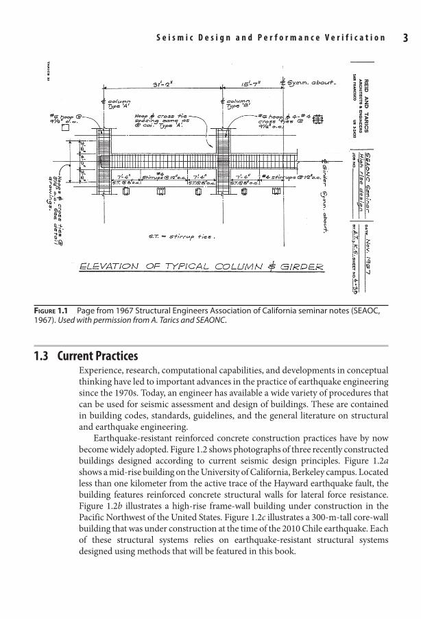
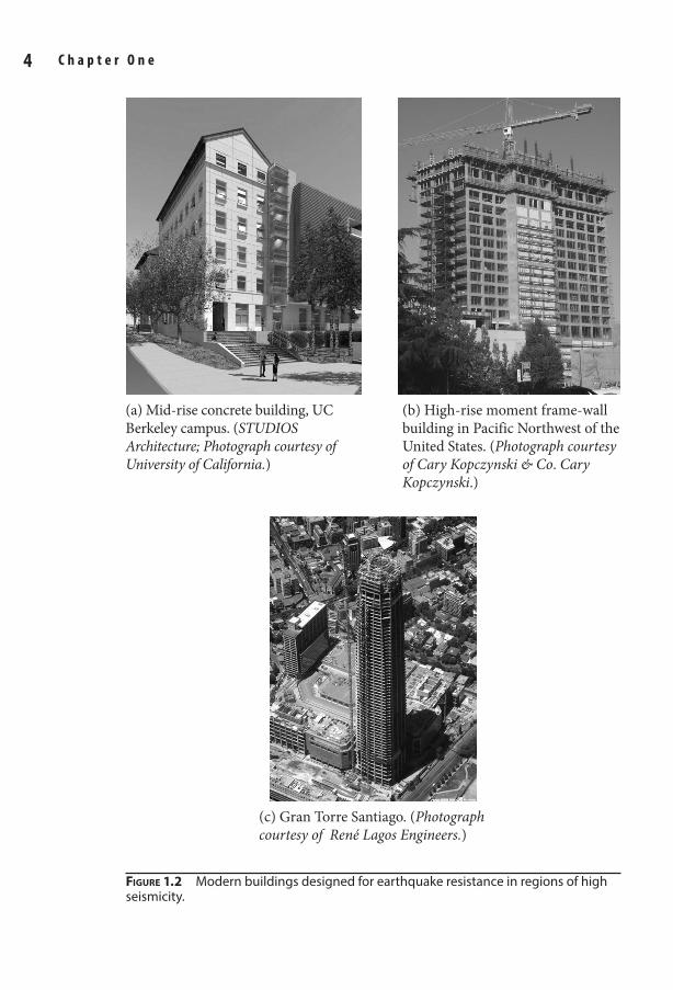
Earthquake-resistant reinforced concrete construction practices have by now become widely adopted. Figure 1.2 shows photographs of three recently constructed buildings designed according to current seismic design principles. Figure 1.2a shows a mid-rise building on the University of California, Berkeley campus. Located less than one kilometer from the active trace of the Hayward earthquake fault, the building features reinforced concrete structural walls for lateral force resistance. Figure 1.2b illustrates a high-rise frame-wall building under construction in the Pacific Northwest of the United States. Figure 1.2c illustrates a 300-m-tall core-wall building that was under construction at the time of the 2010 Chile earthquake. Each of these structural systems relies on earthquake-resistant structural systems designed using methods that will be featured in this book.
Figure 1.1 Page from 1967 Structural Engineers Association of California seminar notes (SEAOC, 1967). Used with permission from A. Tarics and SEAONC.
01_Moehle_Ch01.indd 3 8/30/14 2:27 PM
7 3/8 x 9 1/4 Technical / Radar Signal Processing / Richards / 474-2 / Chapter 1
S e i s m i c D e s i g n a n d p e r f o r m a n c e V e r i f i c a t i o n 5 4 C h a p t e r O n e
Figure 1.2 Modern buildings designed for earthquake resistance in regions of high seismicity.
(a) Mid-rise concrete building, UC Berkeley campus. (STUDIOS Architecture; Photograph courtesy of University of California.)
(b) High-rise moment frame-wall building in Pacific Northwest of the United States. (Photograph courtesy of Cary Kopczynski & Co. Cary Kopczynski.)
(c) Gran Torre Santiago. (Photograph courtesy of René Lagos Engineers.)
01_Moehle_Ch01.indd 4 8/30/14 2:27 PM
7 3/8 x 9 1/4 Technical / Radar Signal Processing / Richards / 474-2 / Chapter 1
S e i s m i c D e s i g n a n d p e r f o r m a n c e V e r i f i c a t i o n 5 4 C h a p t e r O n e
Design of any building begins with a conceptual design, in which the structural systems and materials are identified and configured. Once the structural system has been identified and approximately proportioned, structural analysis and design are used to confirm that the building design is capable of meeting intended performance objectives. Generally this is done following the requirements of the building code, using either prescriptive or performance-related provisions. In a prescriptive design, the structural analysis and design are implemented in strict accordance with the prescriptive requirements of the building code, with the implicit assumption that a code-conforming building will automatically meet the performance objectives. In contrast, a performance-based design can deviate from the prescriptive provisions and use structural analysis and design to demonstrate that the building nonetheless meets or exceeds the performance objectives of the building code.
Regardless of the design approach, competent construction inspection is required to ensure that the project is constructed in accordance with the design intent. The following subsections discuss aspects of building codes, conceptual design, prescriptive design, performance-based design, and construction inspection. Performance objectives are discussed in Section 1.4.
1.3.1 Building CodesA building code is a set of minimum regulations intended to safeguard public health, safety, and general welfare of the occupants. The development, adoption, and enforcement of building codes vary widely from one country to another. In some countries, building codes are developed by governmental agencies and are enforced nationwide. In other countries, including the United States, the authority to regulate building construction is delegated to local jurisdictions. Ideally, the local jurisdictions in such countries adopt model building codes by reference, making these model codes part of the law governing construction in that jurisdiction.
In the United States, most jurisdictions adopt and use the International Building Code (IBC, 2012), which establishes minimum regulations for building systems using prescriptive and performance-related provisions. The IBC, in turn, adopts by reference the standard Minimum Design Loads for Buildings and Other Structures (ASCE 7-10, 2010), which establishes minimum requirements for design loads including those associated with earthquakes. The IBC also adopts by reference the standard Building Code Requirements for Structural Concrete (ACI 318-11) and Commentary (ACI 318-11, 2011),1 which establishes minimum requirements for structural concrete design.
It should be emphasized that the purpose of a building code is to establish the minimum requirements to safeguard the public health, safety, and general welfare. These are generally established through strength, serviceability, durability, and
1Building codes are in a continual state of development, such that several different editions of each code or standard may be available. A jurisdiction generally adopts a specific edition of the code. In the United States, most jurisdictions adopt the IBC, but not necessarily the latest edition. At the time of this writing, the latest edition was IBC (2012), which incorporates by reference ASCE 7-10 (2010) and ACI 318-11 (2011). This book, however, references ACI 318-14 (2014).
01_Moehle_Ch01.indd 5 8/30/14 2:27 PM
7 3/8 x 9 1/4 Technical / Radar Signal Processing / Richards / 474-2 / Chapter 1
S e i s m i c D e s i g n a n d p e r f o r m a n c e V e r i f i c a t i o n 7 6 C h a p t e r O n e
other requirements of the building code. It is also permitted to design a building to exceed the minimum requirements of the code, including design for enhanced performance or sustainability. Various design guidelines and standards have been developed by professional organizations to present recommended practices that may exceed minimum building code requirements. Performance-based design can also be used to target performance exceeding the building code performance intent.
1.3.2 Conceptual DesignConceptual design refers to the early design phase in which the structural systems are selected, configured, and approximately proportioned. The structural system must fit within the space and function of the building, while at the same time providing a suitable load path for anticipated loads, including gravity, wind, and earthquake loads. Selection of the structural concept is a key responsibility of the structural engineer. By selecting a good structural concept, the structural engineer usually can simplify the structural analysis, design, and review process, while providing a high degree of confidence that the performance objectives will be achieved.
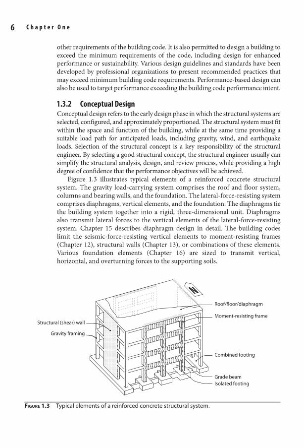
Figure 1.3 illustrates typical elements of a reinforced concrete structural system. The gravity load-carrying system comprises the roof and floor system, columns and bearing walls, and the foundation. The lateral-force-resisting system comprises diaphragms, vertical elements, and the foundation. The diaphragms tie the building system together into a rigid, three-dimensional unit. Diaphragms also transmit lateral forces to the vertical elements of the lateral-force-resisting system. Chapter 15 describes diaphragm design in detail. The building codes limit the seismic-force-resisting vertical elements to moment-resisting frames (Chapter 12), structural walls (Chapter 13), or combinations of these elements. Various foundation elements (Chapter 16) are sized to transmit vertical, horizontal, and overturning forces to the supporting soils.
Figure 1.3 Typical elements of a reinforced concrete structural system.
Moment-resisting frame
Roof/floor/diaphragm
Structural (shear) wall
Gravity framing
Combined footing
Grade beamIsolated footing
01_Moehle_Ch01.indd 6 8/30/14 2:27 PM
7 3/8 x 9 1/4 Technical / Radar Signal Processing / Richards / 474-2 / Chapter 1
S e i s m i c D e s i g n a n d p e r f o r m a n c e V e r i f i c a t i o n 7 6 C h a p t e r O n e
The ideal structural system for an earthquake-resistant building is compact and symmetric, with stiffness and strength that are uniformly distributed over the height and across the plan, and without irregularities caused by discontinuous or offset structural elements. The structural system illustrated in Figure 1.3 has the desired attributes. Figure 1.4 illustrates a range of building configurations, some of which create design challenges that are better avoided through good conceptual design.
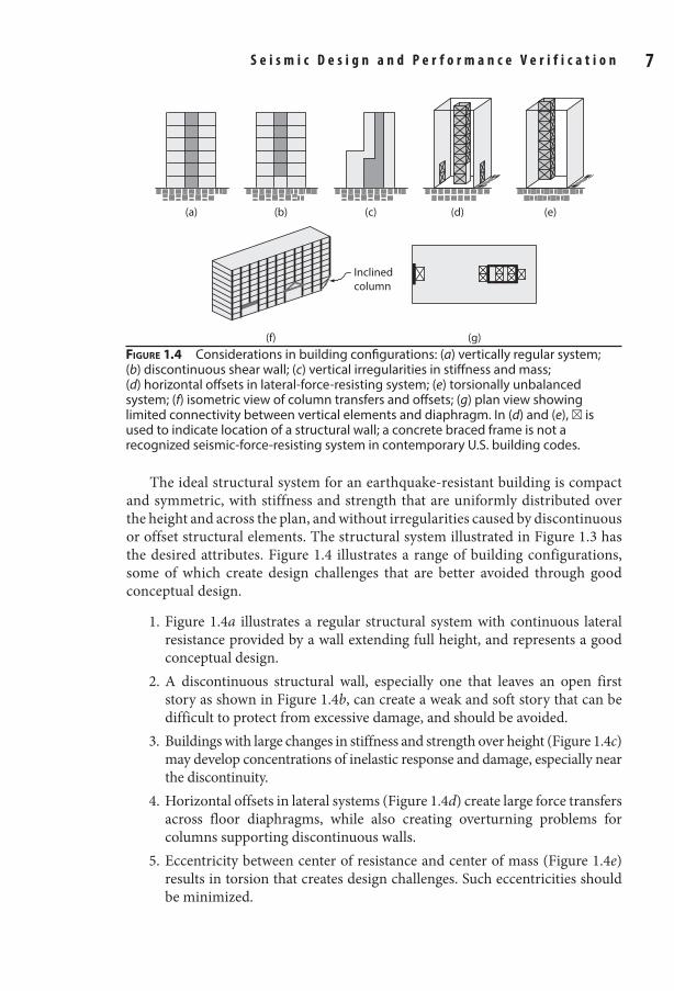
1. Figure 1.4a illustrates a regular structural system with continuous lateral resistance provided by a wall extending full height, and represents a good conceptual design.
2. A discontinuous structural wall, especially one that leaves an open first story as shown in Figure 1.4b, can create a weak and soft story that can be difficult to protect from excessive damage, and should be avoided.
3. Buildings with large changes in stiffness and strength over height (Figure 1.4c) may develop concentrations of inelastic response and damage, especially near the discontinuity.
4. Horizontal offsets in lateral systems (Figure 1.4d) create large force transfers across floor diaphragms, while also creating overturning problems for columns supporting discontinuous walls.
5. Eccentricity between center of resistance and center of mass (Figure 1.4e) results in torsion that creates design challenges. Such eccentricities should be minimized.
Figure 1.4 Considerations in building configurations: (a) vertically regular system; (b) discontinuous shear wall; (c) vertical irregularities in stiffness and mass; (d) horizontal offsets in lateral-force-resisting system; (e) torsionally unbalanced system; (f) isometric view of column transfers and offsets; (g) plan view showing limited connectivity between vertical elements and diaphragm. In (d) and (e), ⊠ is used to indicate location of a structural wall; a concrete braced frame is not a recognized seismic-force-resisting system in contemporary U.S. building codes.
(f) (g)
(d)(a) (b) (c) (e)
Inclinedcolumn
01_Moehle_Ch01.indd 7 8/30/14 2:27 PM
7 3/8 x 9 1/4 Technical / Radar Signal Processing / Richards / 474-2 / Chapter 1
S e i s m i c D e s i g n a n d p e r f o r m a n c e V e r i f i c a t i o n 9 8 C h a p t e r O n e
6. Column transfers and offsets (including inclined columns) (Figure 1.4f ) disturb the load path and create large forces in transfer elements and diaphragms.
7. Diaphragm openings adjacent to structural walls (Figure 1.4g) limit the ability to transfer forces between the two elements, and are especially problematic near the base of a building where forces commonly must be transferred out of the structural walls.
Each of these conceptual design problems will be addressed in greater detail at appropriate locations throughout this book.
As will be discussed subsequently, most buildings are designed such that some inelastic response is anticipated during a design-basis earthquake. Hence, conceptual design also involves selection of a target yielding mechanism. For the structural system depicted in Figure 1.3, the intended mechanism might include flexural yielding of the walls for north-south loading and flexural yielding of the beams over the height and the columns at the base of the frames for east-west loading. The capacity design method is commonly used to proportion the structure for the intended mechanism (Section 1.5.4).
Once the structural system has been configured and approximately propor-tioned, preferably using a regular and symmetric layout, it can be analyzed and designed using either the prescriptive or the performance-based design approach.
1.3.3 prescriptive Design approachA prescriptive design is one that adheres strictly to the prescriptive provisions of the building code, such as those contained in the IBC. Most building designs follow this approach. The provisions are prescriptive in the sense that they prescribe required analysis procedures, strengths, stiffnesses, and component and system details, with little leeway for deviating from the prescription. A typical prescriptive design includes the following steps:
• The building code specifies the intensity of the design loads for dead, live, wind, earthquake, and other effects, and spells out how the loads are to be combined for determining worst effects. In reference to Figure 1.5, dead load (D) is calculated from the weight of the building components and live load (L) is prescribed based on the building occupancy2. Earthquake load (E) is determined through a set of prescribed calculations set forth in the building code. Unlike other loads, E as specified in the codes is not intended to be a realistic estimation of actual earthquake loads, but instead is used to set a minimum strength, such that excessive ductility is not required under anticipated ground shaking. The code also prescribes several different load combinations, that is, ways in which to apply the specified loads, only one of which is shown in the figure. See Section 1.5.3 for load combinations.
2See the Notation section for definitions of all notation.
01_Moehle_Ch01.indd 8 8/30/14 2:27 PM
7 3/8 x 9 1/4 Technical / Radar Signal Processing / Richards / 474-2 / Chapter 1
S e i s m i c D e s i g n a n d p e r f o r m a n c e V e r i f i c a t i o n 9 8 C h a p t e r O n e
• The building code specifies how structural analysis is to be done, including the required stiffness and strength models. In most cases, the structural analysis is strictly linear, although stiffness may be reduced to approximately account for nonlinear effects, and some allowance for redistribution of internal actions may be permitted. In Figure 1.5, member stiffnesses are modified to approximate the effects of cracking and axial force, and then linear analysis is conducted to obtain the required strengths in shear (Vu), moment (Mu), and axial force (Pu).
• The building code specifies how to calculate member design strengths, and requires that these be at least equal to required strengths as determined from the structural analysis. See Section 1.5.3.
• The code also specifies requirements for member dimensions and reinforcement detailing. Figure 1.6 illustrates the types of details that will be prescribed, including requirements for continuity of reinforcement, locations and types of splices, and spacing and configuration of transverse reinforcement. Some of the reinforcement quantities and details will be dictated by calculated member actions, and others will be specified as requirements that are independent of the magnitude of the calculated member actions.
• The building code specifies displacement limits for members and for the building as a whole.
The prescriptive approach has the advantage that it uses well-established and familiar analysis and design techniques, with all of the requirements spelled out in the building code in such a way that an engineer can reliably implement them and
Pcolumn
1.2D + 0.5L
E
Vbeam
Mbeam
Vcolumn Mcolumn
0.35EcIg
0.7EcIg
Design values Vu, Mu,and Pu at face of beam
Design values Vu and Mu at face of beam
Figure 1.5 Determination of design shears, moments, and axial forces in a prescriptive design.
01_Moehle_Ch01.indd 9 8/30/14 2:27 PM
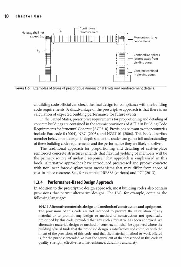
7 3/8 x 9 1/4 Technical / Radar Signal Processing / Richards / 474-2 / Chapter 1
S e i s m i c D e s i g n a n d p e r f o r m a n c e V e r i f i c a t i o n 11 10 C h a p t e r O n e
a building code official can check the final design for compliance with the building code requirements. A disadvantage of the prescriptive approach is that there is no calculation of expected building performance for future events.
In the United States, prescriptive requirements for proportioning and detailing of concrete buildings are contained in the seismic provisions of ACI 318 Building Code Requirements for Structural Concrete (ACI 318). Provisions relevant to other countries include Eurocode 8 (2004), NBC (2005), and NZS3101 (2006). This book describes member behavior and design in depth so that the reader can gain a full understanding of these building code requirements and the performance they are likely to deliver.
The traditional approach for proportioning and detailing of cast-in-place reinforced concrete structures intends that flexural yielding of members will be the primary source of inelastic response. That approach is emphasized in this book. Alternative approaches have introduced prestressed and precast concrete with nonlinear force-displacement mechanisms that may differ from those of cast-in-place concrete. See, for example, PRESSS (various) and PCI (2013).
1.3.4 performance-Based Design approachIn addition to the prescriptive design approach, most building codes also contain provisions that permit alternative designs. The IBC, for example, contains the following language:
104.11 Alternative materials, design and methods of construction and equipment. The provisions of this code are not intended to prevent the installation of any material or to prohibit any design or method of construction not specifically prescribed by this code, provided that any such alternative has been approved. An alternative material, design or method of construction shall be approved where the building official finds that the proposed design is satisfactory and complies with the intent of the provisions of this code, and that the material, method or work offered is, for the purpose intended, at least the equivalent of that prescribed in this code in quality, strength, effectiveness, fire resistance, durability and safety.
Figure 1.6 Examples of types of prescriptive dimensional limits and reinforcement details.
Moment-resistingconnections
Confined lap spliceslocated away fromyielding zones
Concrete confinedin yielding zones
Continuousreinforcement
hb
hc
Note: hb shall notexceed 2hc
01_Moehle_Ch01.indd 10 8/30/14 2:27 PM
7 3/8 x 9 1/4 Technical / Radar Signal Processing / Richards / 474-2 / Chapter 1
S e i s m i c D e s i g n a n d p e r f o r m a n c e V e r i f i c a t i o n 11 10 C h a p t e r O n e
Such alternative design approaches are often referred to as performance-based approaches, because the main basis for accepting the alternative method is a demonstration (through testing, analysis, or both) that the resulting building meets or exceeds the performance intent of the building code. Several conditions can trigger the use of performance-based design, including:
• A proposed building uses structural materials, elements, or systems that are not covered by the prescriptive building code provisions. The performance-based design may require physical tests to verify equivalent performance of the new materials. Structural analysis may also be required to demonstrate that a building using the new material will have equivalent performance.
• A proposed building height exceeds the prescriptive limits of the building code. In this case, structural analysis is used to demonstrate that the taller building can be safe and serviceable even though it exceeds the prescribed height limit.
• An owner or other responsible entity desires building performance that exceeds the minimum performance objectives of the building code. As a first step in this process, the structural engineer works with the owner or responsible entity to define the enhanced performance objective. Innovative structural materials may be introduced, or structural analysis may be used to demonstrate enhanced performance, or both.
Most performance-based designs rely on the prescriptive building code provisions, with specific exceptions to those provisions that emphasize the unique aspects of the proposed design. The performance evaluation can then focus mainly on those aspects of the design that are exceptions, greatly simplifying the process.
For buildings located in seismically active regions, performance-based seismic design generally involves a seismic hazard analysis to determine site-specific shaking levels, and usually includes the selection of representative earthquake ground motions by which to “test” the structure. A nonlinear computer model of the building structure is then subjected to these ground motions to determine the building response. Key response quantities are analyzed to establish whether the design meets the performance criteria that have been adopted for the building. TBI (2010) and LATBSDC (2011) contain detailed guidelines for performance-based seismic design of tall buildings. These same guidelines can also serve as a basis for performance-based design of other building types.
Performance-based design gives the engineer much greater flexibility in the choice of the structural system and its design method. Such designs, however, typically require additional design effort and time, advanced engineering capabilities, and a building official who is willing to accept designs not conforming strictly to the prescriptive provisions of the building code. Most building officials will not have the expertise necessary to judge the adequacy of a design falling under the alternative methods clause of the building code. Therefore, independent peer review is usually required to advise the building official as to whether a design is satisfactory.
01_Moehle_Ch01.indd 11 8/30/14 2:27 PM
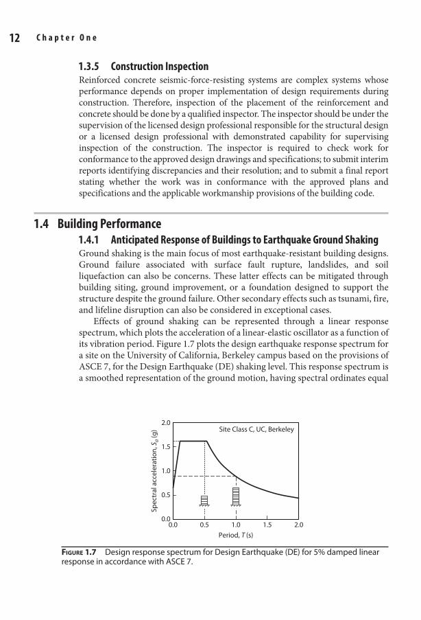
7 3/8 x 9 1/4 Technical / Radar Signal Processing / Richards / 474-2 / Chapter 1
S e i s m i c D e s i g n a n d p e r f o r m a n c e V e r i f i c a t i o n 13 12 C h a p t e r O n e
1.3.5 Construction InspectionReinforced concrete seismic-force-resisting systems are complex systems whose performance depends on proper implementation of design requirements during construction. Therefore, inspection of the placement of the reinforcement and concrete should be done by a qualified inspector. The inspector should be under the supervision of the licensed design professional responsible for the structural design or a licensed design professional with demonstrated capability for supervising inspection of the construction. The inspector is required to check work for conformance to the approved design drawings and specifications; to submit interim reports identifying discrepancies and their resolution; and to submit a final report stating whether the work was in conformance with the approved plans and specifications and the applicable workmanship provisions of the building code.
1.4 Building performance1.4.1 anticipated response of Buildings to earthquake Ground ShakingGround shaking is the main focus of most earthquake-resistant building designs. Ground failure associated with surface fault rupture, landslides, and soil liquefaction can also be concerns. These latter effects can be mitigated through building siting, ground improvement, or a foundation designed to support the structure despite the ground failure. Other secondary effects such as tsunami, fire, and lifeline disruption can also be considered in exceptional cases.
Effects of ground shaking can be represented through a linear response spectrum, which plots the acceleration of a linear-elastic oscillator as a function of its vibration period. Figure 1.7 plots the design earthquake response spectrum for a site on the University of California, Berkeley campus based on the provisions of ASCE 7, for the Design Earthquake (DE) shaking level. This response spectrum is a smoothed representation of the ground motion, having spectral ordinates equal
0.0 0.5 1.0 1.5 2.00.0
0.5
1.5
1.0
2.0
Period, T (s)
Spec
tral
acc
eler
atio
n, S
a (g
) Site Class C, UC, Berkeley
Figure 1.7 Design response spectrum for Design Earthquake (DE) for 5% damped linear response in accordance with ASCE 7.
01_Moehle_Ch01.indd 12 8/30/14 2:27 PM
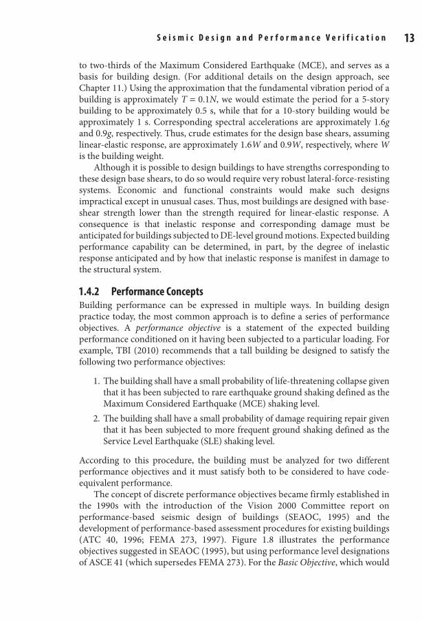
7 3/8 x 9 1/4 Technical / Radar Signal Processing / Richards / 474-2 / Chapter 1
S e i s m i c D e s i g n a n d p e r f o r m a n c e V e r i f i c a t i o n 13 12 C h a p t e r O n e
to two-thirds of the Maximum Considered Earthquake (MCE), and serves as a basis for building design. (For additional details on the design approach, see Chapter 11.) Using the approximation that the fundamental vibration period of a building is approximately T = 0.1N, we would estimate the period for a 5-story building to be approximately 0.5 s, while that for a 10-story building would be approximately 1 s. Corresponding spectral accelerations are approximately 1.6g and 0.9g, respectively. Thus, crude estimates for the design base shears, assuming linear-elastic response, are approximately 1.6W and 0.9W, respectively, where W is the building weight.
Although it is possible to design buildings to have strengths corresponding to these design base shears, to do so would require very robust lateral-force-resisting systems. Economic and functional constraints would make such designs impractical except in unusual cases. Thus, most buildings are designed with base-shear strength lower than the strength required for linear-elastic response. A consequence is that inelastic response and corresponding damage must be anticipated for buildings subjected to DE-level ground motions. Expected building performance capability can be determined, in part, by the degree of inelastic response anticipated and by how that inelastic response is manifest in damage to the structural system.
1.4.2 performance ConceptsBuilding performance can be expressed in multiple ways. In building design practice today, the most common approach is to define a series of performance objectives. A performance objective is a statement of the expected building performance conditioned on it having been subjected to a particular loading. For example, TBI (2010) recommends that a tall building be designed to satisfy the following two performance objectives:
1. The building shall have a small probability of life-threatening collapse given that it has been subjected to rare earthquake ground shaking defined as the Maximum Considered Earthquake (MCE) shaking level.
2. The building shall have a small probability of damage requiring repair given that it has been subjected to more frequent ground shaking defined as the Service Level Earthquake (SLE) shaking level.
According to this procedure, the building must be analyzed for two different performance objectives and it must satisfy both to be considered to have code-equivalent performance.
The concept of discrete performance objectives became firmly established in the 1990s with the introduction of the Vision 2000 Committee report on performance-based seismic design of buildings (SEAOC, 1995) and the development of performance-based assessment procedures for existing buildings (ATC 40, 1996; FEMA 273, 1997). Figure 1.8 illustrates the performance objectives suggested in SEAOC (1995), but using performance level designations of ASCE 41 (which supersedes FEMA 273). For the Basic Objective, which would
01_Moehle_Ch01.indd 13 8/30/14 2:27 PM
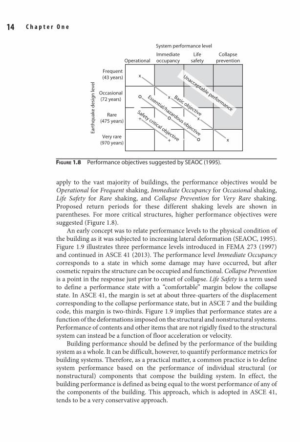
7 3/8 x 9 1/4 Technical / Radar Signal Processing / Richards / 474-2 / Chapter 1
S e i s m i c D e s i g n a n d p e r f o r m a n c e V e r i f i c a t i o n 15 14 C h a p t e r O n e
apply to the vast majority of buildings, the performance objectives would be Operational for Frequent shaking, Immediate Occupancy for Occasional shaking, Life Safety for Rare shaking, and Collapse Prevention for Very Rare shaking. Proposed return periods for these different shaking levels are shown in parentheses. For more critical structures, higher performance objectives were suggested (Figure 1.8).
An early concept was to relate performance levels to the physical condition of the building as it was subjected to increasing lateral deformation (SEAOC, 1995). Figure 1.9 illustrates three performance levels introduced in FEMA 273 (1997) and continued in ASCE 41 (2013). The performance level Immediate Occupancy corresponds to a state in which some damage may have occurred, but after cosmetic repairs the structure can be occupied and functional. Collapse Prevention is a point in the response just prior to onset of collapse. Life Safety is a term used to define a performance state with a “comfortable” margin below the collapse state. In ASCE 41, the margin is set at about three-quarters of the displacement corresponding to the collapse performance state, but in ASCE 7 and the building code, this margin is two-thirds. Figure 1.9 implies that performance states are a function of the deformations imposed on the structural and nonstructural systems. Performance of contents and other items that are not rigidly fixed to the structural system can instead be a function of floor acceleration or velocity.
Building performance should be defined by the performance of the building system as a whole. It can be difficult, however, to quantify performance metrics for building systems. Therefore, as a practical matter, a common practice is to define system performance based on the performance of individual structural (or nonstructural) components that compose the building system. In effect, the building performance is defined as being equal to the worst performance of any of the components of the building. This approach, which is adopted in ASCE 41, tends to be a very conservative approach.
Figure 1.8 Performance objectives suggested by SEAOC (1995).
OperationalImmediateoccupancy
Lifesafety
Collapseprevention
Frequent(43 years)
Occasional(72 years)
Rare(475 years)
Very rare(970 years)
Basic objective
Eart
hqua
ke d
esig
n le
vel
System performance level
x
x
x
x+
+
Unacceptable performanceSafety critical objective
Essential/hazardous objective
01_Moehle_Ch01.indd 14 8/30/14 2:27 PM
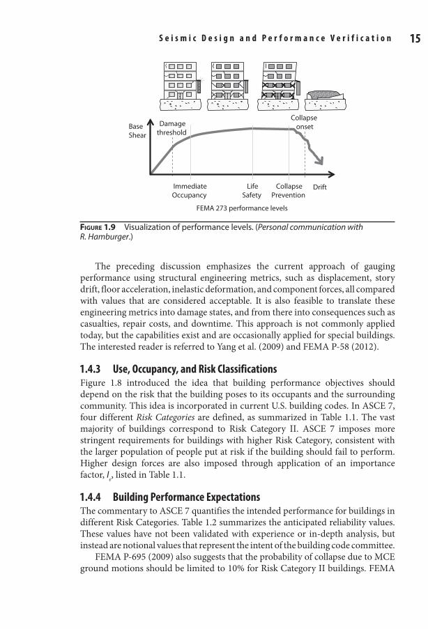
7 3/8 x 9 1/4 Technical / Radar Signal Processing / Richards / 474-2 / Chapter 1
S e i s m i c D e s i g n a n d p e r f o r m a n c e V e r i f i c a t i o n 15 14 C h a p t e r O n e
The preceding discussion emphasizes the current approach of gauging performance using structural engineering metrics, such as displacement, story drift, floor acceleration, inelastic deformation, and component forces, all compared with values that are considered acceptable. It is also feasible to translate these engineering metrics into damage states, and from there into consequences such as casualties, repair costs, and downtime. This approach is not commonly applied today, but the capabilities exist and are occasionally applied for special buildings. The interested reader is referred to Yang et al. (2009) and FEMA P-58 (2012).
1.4.3 Use, Occupancy, and risk ClassificationsFigure 1.8 introduced the idea that building performance objectives should depend on the risk that the building poses to its occupants and the surrounding community. This idea is incorporated in current U.S. building codes. In ASCE 7, four different Risk Categories are defined, as summarized in Table 1.1. The vast majority of buildings correspond to Risk Category II. ASCE 7 imposes more stringent requirements for buildings with higher Risk Category, consistent with the larger population of people put at risk if the building should fail to perform. Higher design forces are also imposed through application of an importance factor, Ie, listed in Table 1.1.
1.4.4 Building performance expectationsThe commentary to ASCE 7 quantifies the intended performance for buildings in different Risk Categories. Table 1.2 summarizes the anticipated reliability values. These values have not been validated with experience or in-depth analysis, but instead are notional values that represent the intent of the building code committee.
FEMA P-695 (2009) also suggests that the probability of collapse due to MCE ground motions should be limited to 10% for Risk Category II buildings. FEMA
Figure 1.9 Visualization of performance levels. (Personal communication with R. Hamburger.)
FEMA 273 performance levels
BaseShear
Drift
Damagethreshold
Collapse onset
ImmediateOccupancy
LifeSafety
CollapsePrevention
01_Moehle_Ch01.indd 15 8/30/14 2:27 PM
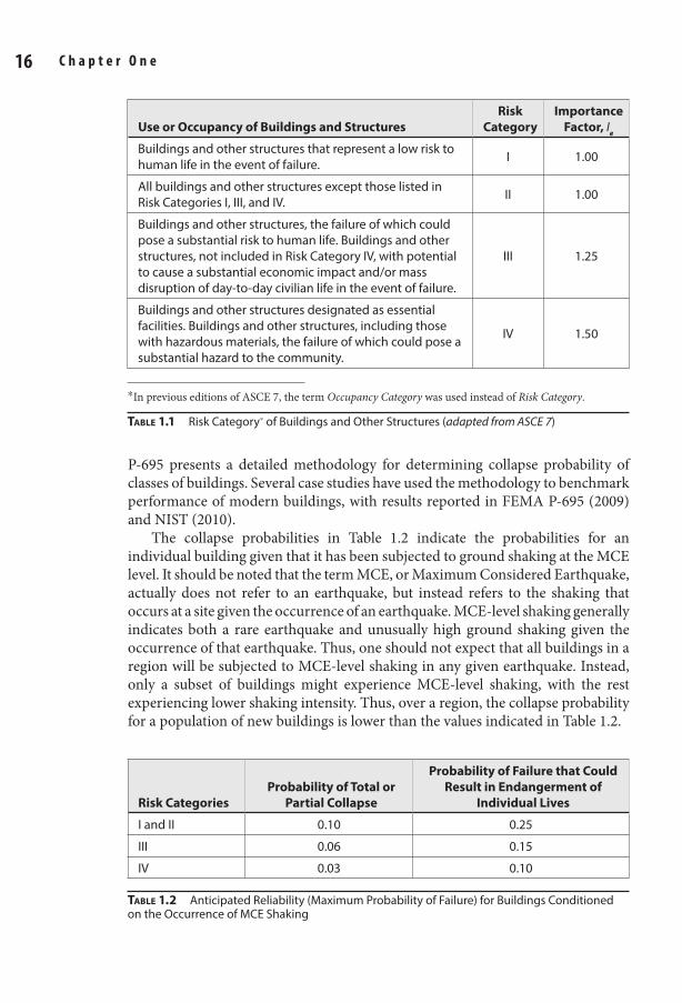
7 3/8 x 9 1/4 Technical / Radar Signal Processing / Richards / 474-2 / Chapter 1
S e i s m i c D e s i g n a n d p e r f o r m a n c e V e r i f i c a t i o n 17 16 C h a p t e r O n e
Table 1.1 Risk Category* of Buildings and Other Structures (adapted from ASCE 7)
Use or Occupancy of Buildings and StructuresRisk
CategoryImportance
Factor, Ie
Buildings and other structures that represent a low risk to human life in the event of failure. I 1.00
All buildings and other structures except those listed in Risk Categories I, III, and IV. II 1.00
Buildings and other structures, the failure of which could pose a substantial risk to human life. Buildings and other structures, not included in Risk Category IV, with potential to cause a substantial economic impact and/or mass disruption of day-to-day civilian life in the event of failure.
III 1.25
Buildings and other structures designated as essential facilities. Buildings and other structures, including those with hazardous materials, the failure of which could pose a substantial hazard to the community.
IV 1.50
*In previous editions of ASCE 7, the term Occupancy Category was used instead of Risk Category.
Table 1.2 Anticipated Reliability (Maximum Probability of Failure) for Buildings Conditioned on the Occurrence of MCE Shaking
Risk CategoriesProbability of Total or
Partial Collapse
Probability of Failure that Could Result in Endangerment of
Individual Lives
I and II 0.10 0.25
III 0.06 0.15
IV 0.03 0.10
P-695 presents a detailed methodology for determining collapse probability of classes of buildings. Several case studies have used the methodology to benchmark performance of modern buildings, with results reported in FEMA P-695 (2009) and NIST (2010).
The collapse probabilities in Table 1.2 indicate the probabilities for an individual building given that it has been subjected to ground shaking at the MCE level. It should be noted that the term MCE, or Maximum Considered Earthquake, actually does not refer to an earthquake, but instead refers to the shaking that occurs at a site given the occurrence of an earthquake. MCE-level shaking generally indicates both a rare earthquake and unusually high ground shaking given the occurrence of that earthquake. Thus, one should not expect that all buildings in a region will be subjected to MCE-level shaking in any given earthquake. Instead, only a subset of buildings might experience MCE-level shaking, with the rest experiencing lower shaking intensity. Thus, over a region, the collapse probability for a population of new buildings is lower than the values indicated in Table 1.2.
01_Moehle_Ch01.indd 16 8/30/14 2:27 PM
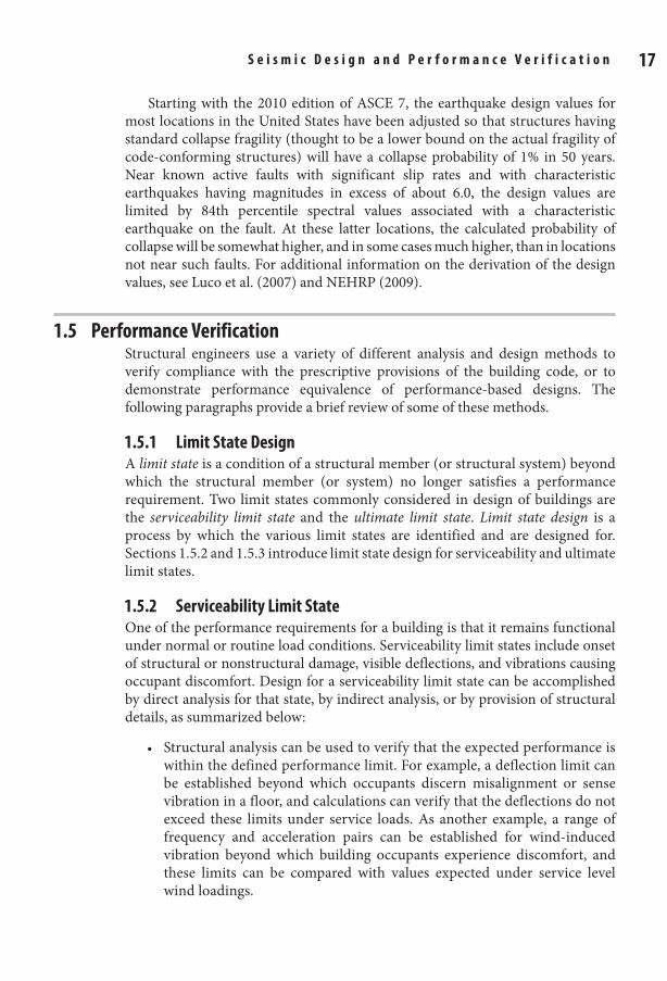
7 3/8 x 9 1/4 Technical / Radar Signal Processing / Richards / 474-2 / Chapter 1
S e i s m i c D e s i g n a n d p e r f o r m a n c e V e r i f i c a t i o n 17 16 C h a p t e r O n e
Starting with the 2010 edition of ASCE 7, the earthquake design values for most locations in the United States have been adjusted so that structures having standard collapse fragility (thought to be a lower bound on the actual fragility of code-conforming structures) will have a collapse probability of 1% in 50 years. Near known active faults with significant slip rates and with characteristic earthquakes having magnitudes in excess of about 6.0, the design values are limited by 84th percentile spectral values associated with a characteristic earthquake on the fault. At these latter locations, the calculated probability of collapse will be somewhat higher, and in some cases much higher, than in locations not near such faults. For additional information on the derivation of the design values, see Luco et al. (2007) and NEHRP (2009).
1.5 performance VerificationStructural engineers use a variety of different analysis and design methods to verify compliance with the prescriptive provisions of the building code, or to demonstrate performance equivalence of performance-based designs. The following paragraphs provide a brief review of some of these methods.
1.5.1 Limit State DesignA limit state is a condition of a structural member (or structural system) beyond which the structural member (or system) no longer satisfies a performance requirement. Two limit states commonly considered in design of buildings are the serviceability limit state and the ultimate limit state. Limit state design is a process by which the various limit states are identified and are designed for. Sections 1.5.2 and 1.5.3 introduce limit state design for serviceability and ultimate limit states.
1.5.2 Serviceability Limit StateOne of the performance requirements for a building is that it remains functional under normal or routine load conditions. Serviceability limit states include onset of structural or nonstructural damage, visible deflections, and vibrations causing occupant discomfort. Design for a serviceability limit state can be accomplished by direct analysis for that state, by indirect analysis, or by provision of structural details, as summarized below:
• Structural analysis can be used to verify that the expected performance is within the defined performance limit. For example, a deflection limit can be established beyond which occupants discern misalignment or sense vibration in a floor, and calculations can verify that the deflections do not exceed these limits under service loads. As another example, a range of frequency and acceleration pairs can be established for wind-induced vibration beyond which building occupants experience discomfort, and these limits can be compared with values expected under service level wind loadings.
01_Moehle_Ch01.indd 17 8/30/14 2:27 PM
7 3/8 x 9 1/4 Technical / Radar Signal Processing / Richards / 474-2 / Chapter 1
S e i s m i c D e s i g n a n d p e r f o r m a n c e V e r i f i c a t i o n 19 18 C h a p t e r O n e
• Onset of damage to nonstructural elements can be related indirectly to the vertical or lateral distortions of a building. For example, if damageable nonstructural components are attached to a floor member, ACI 318 limits the vertical deflections after attachment of the nonstructural component to /480l . Similarly, common practice is to limit story drifts to /400hi and total
roof drift to /500hn under service level wind loading. • Crack width can be controlled through calculation and control of crack
width indices, such as the index provided by Gergely and Lutz (1968). Alternatively, crack width can be controlled by provision of well-distributed flexural tension reinforcement, as is done in ACI 318, without direct calculation of the crack width.
For gravity loads, normal or routine loads are considered for serviceability checks. Dead load is the expected dead load without load factors. Live load is the maximum value expected over some defined period, usually 50 years, as tabulated in codes such as ASCE 7, without load factors. Procedures for establishing wind or seismic loads vary depending on the governing code. Because the consequences of exceeding wind drift or acceleration levels are not severe, it is more common to use service level wind speeds on the order of 10 or 20 years.
The serviceability limit states are generally well below the inelastic range of response, such that linear analysis is appropriate. Because even moderate-intensity earthquakes are relatively rare events, moderate excursions into the inelastic range of response may be acceptable for service-level earthquakes.
1.5.3 Ultimate Limit State (Load and resistance Factor Design)3
A building should be stable under abnormal load conditions that reasonably may occur during the service life. A structure can become unstable if its materials rupture, its members buckle, or if the structural system forms a mechanism that leads to overall instability of the building frame. Such failures can lead to local collapse or overall structural collapse, both of which pose substantial risk to life safety. Such failures should have a small probability of occurring during the service life of the building. A load and resistance factor design (LRFD) method is commonly adopted to provide a structure with adequate strength so that the probability of failure is reduced to an acceptable level. MacGregor (1983) describes development of the LRFD factors and associated safety levels for reinforced concrete design.
General approachThe LRFD method can be expressed generically through Eq. (1.1):
φ ≥S Un (1.1)
3The LRFD factors and load combinations in this chapter are in accordance with the requirements of ASCE 7-10 (2010). Different factors or approaches may apply where other codes are adopted.
01_Moehle_Ch01.indd 18 8/30/14 2:27 PM
7 3/8 x 9 1/4 Technical / Radar Signal Processing / Richards / 474-2 / Chapter 1
S e i s m i c D e s i g n a n d p e r f o r m a n c e V e r i f i c a t i o n 19 18 C h a p t e r O n e
in which fSn = design strength, f = strength reduction factor, Sn = nominal strength, and U = factored load effect. In practice, Eq. (1.1) is applied more specifically to internal member forces such as shear and moment, as in
φ ≥V Vn u (1.2)
φ ≥M Mn u (1.3)
where Vn = nominal shear strength, Mn = nominal moment strength, Vu = shear due to factored loads, and Mu = moment due to factored loads.
Although the LRFD method refers to an ultimate limit state approaching the failure or collapse state, structural analysis for the limit state is often done using assumptions of linear-elastic behavior. The ultimate limit state for the structural system as a whole is presumed to be reached for the loading that first causes a member cross section to reach the design strength fSn. Inelastic analysis would consider redistribution of internal actions, thereby permitting factored loads equal to or exceeding the factored load limit determined by linear-elastic analysis. Thus, linear-elastic analysis provides a conservative measure of the ultimate limit state performance.
Load and resistance factors for the LRFD method are established considering variability and uncertainty in different load effects and material properties, the accuracy and variability of nominal strengths, the brittleness of different failure modes, and the consequences of failure. For buildings assigned to Risk Category II of ASCE 7, the intended annual probabilities of failure for load conditions that do not include earthquake are 3 × 10⁻⁵ per year for failure that is not sudden and does not lead to widespread progression of damage, 3 × 10⁻⁶ per year for failure that is either sudden or leads to widespread progression of damage, and 7 × 10⁻⁷ per year for failure that is sudden and results in widespread progression of damage (ASCE 7).
aSCe 7 Factored Load CombinationsThe factored load effect is represented by U in Eq. (1.1). In practice, the quantity U is the maximum (or minimum) load effect determined through a series of load combinations. Each load combination considers one or more load cases, with load factors adjusted to achieve approximately uniform reliability.
The main load cases are listed below, and refer to the load itself or to its effect on internal moments and forces:
D = dead loadE = earthquake loadF = load due to fluids with well-defined pressures and maximum heightsH = load due to lateral earth pressure, ground water pressure, or pressure of
bulk materialsL = live loadLr = roof live load
01_Moehle_Ch01.indd 19 8/30/14 2:27 PM
7 3/8 x 9 1/4 Technical / Radar Signal Processing / Richards / 474-2 / Chapter 1
S e i s m i c D e s i g n a n d p e r f o r m a n c e V e r i f i c a t i o n 21 20 C h a p t e r O n e
S = snow loadW = wind load
The basic load combinations consider different combinations of the load cases as follows:
1. 1.4D2. 1.2 1.6 0.5( or or )+ +D L L S Rr
3. 1.2 1.6 or or ( or 0.5 )( )+ + αD L S R L Wr L
4. 1.2 1.0 0.5( or or )+ + α +D W L L S RL r
5. 1.2 1.0 0.2+ + α +D E L SL
6. 0.9 1.0+D W7. 0.9 1.0+D E
In combinations 3, 4, and 5, the factor αL applied to L is equal to 1.0 for garages, for areas occupied as places of public assembly, and for any occupancies in which L > 100 psf (4.8 kPa). Otherwise, αL = 0.5.
Where fluid loads F are present, they are to be included with the same load factor as dead load D in combinations 1 through 5 and 7.
Where loads H are present, they are to be included as follows:
1. Where the effect of H adds to the primary variable load effect, include H with a load factor of 1.6.
2. Where the effect of H resists the primary variable load effect, include H with a load factor of 0.9 where the load is permanent or a load factor of 0.0 for all other conditions.
In any of the load combinations, effects of one or more loads not acting or effects of loads acting in the opposite direction (where possible) are to be investigated. The most unfavorable effects from both wind and earthquake loads are to be investigated, where appropriate, but they need not be considered to act simultaneously. Additional effects of flood, atmospheric ice loads, and self-restraining loads are not covered in this book. See ASCE 7 for additional details.
For earthquake-resistant design, the engineer must consider the effects of earthquake directionality. In general, this includes effects of earthquake loads in two principal horizontal directions plus vertical earthquake shaking effects. Effects of overstrength on design loads must also be considered in some special cases. See Chapter 11 of this book for these additional details.
Figure 1.10 illustrates the application of the load combinations for a planar system considering the load cases D, L, and E. Basic load combinations 1 and 2 consider only D and combined D and L. In this illustration, both D and L are taken at their full intensities. To obtain the worst shear at beam midspan, however, L should be placed on only half of the beam span. The building code requires that this latter loading case also be considered.
01_Moehle_Ch01.indd 20 8/30/14 2:27 PM
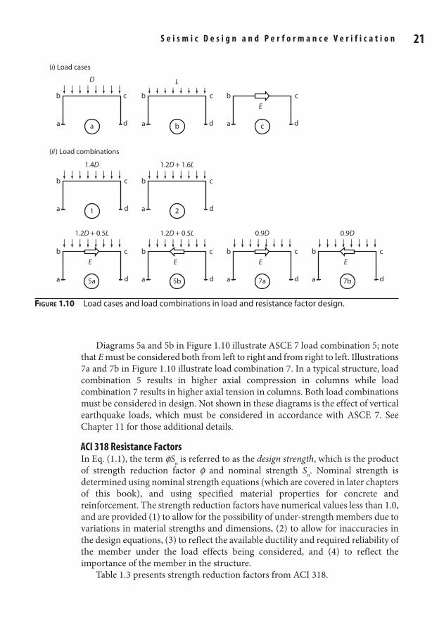
7 3/8 x 9 1/4 Technical / Radar Signal Processing / Richards / 474-2 / Chapter 1
S e i s m i c D e s i g n a n d p e r f o r m a n c e V e r i f i c a t i o n 21 20 C h a p t e r O n e
Diagrams 5a and 5b in Figure 1.10 illustrate ASCE 7 load combination 5; note that E must be considered both from left to right and from right to left. Illustrations 7a and 7b in Figure 1.10 illustrate load combination 7. In a typical structure, load combination 5 results in higher axial compression in columns while load combination 7 results in higher axial tension in columns. Both load combinations must be considered in design. Not shown in these diagrams is the effect of vertical earthquake loads, which must be considered in accordance with ASCE 7. See Chapter 11 for those additional details.
aCI 318 resistance FactorsIn Eq. (1.1), the term fSn is referred to as the design strength, which is the product of strength reduction factor f and nominal strength Sn. Nominal strength is determined using nominal strength equations (which are covered in later chapters of this book), and using specified material properties for concrete and reinforcement. The strength reduction factors have numerical values less than 1.0, and are provided (1) to allow for the possibility of under-strength members due to variations in material strengths and dimensions, (2) to allow for inaccuracies in the design equations, (3) to reflect the available ductility and required reliability of the member under the load effects being considered, and (4) to reflect the importance of the member in the structure.
Table 1.3 presents strength reduction factors from ACI 318.
D L
E
a
b c
d a
b c
d a
b c
d
1.4D 1.2D + 1.6L
a
b c
d a
b c
d
(i) Load cases
(ii) Load combinations
1 2
1.2D + 0.5L
E
1.2D + 0.5L
E
0.9D
E
0.9D
E
a
b c
d a
b c
d a
b c
d a
b c
d5a 5b 7a 7b
a b c
Figure 1.10 Load cases and load combinations in load and resistance factor design.
01_Moehle_Ch01.indd 21 8/30/14 2:27 PM
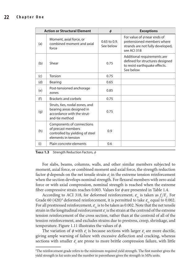
7 3/8 x 9 1/4 Technical / Radar Signal Processing / Richards / 474-2 / Chapter 1
S e i s m i c D e s i g n a n d p e r f o r m a n c e V e r i f i c a t i o n 23 22 C h a p t e r O n e
Action or Structural Element φ Exceptions
(a)Moment, axial force, or combined moment and axial force
0.65 to 0.9. See below
For value of f near ends of pretensioned members where strands are not fully developed, see ACI 318
(b) Shear 0.75
Additional requirements are defined for structures designed to resist earthquake effects. See below
(c) Torsion 0.75
(d) Bearing 0.65
(e) Post-tensioned anchorage zones 0.85
(f ) Brackets and corbels 0.75
(g)
Struts, ties, nodal zones, and bearing areas designed in accordance with the strut-and-tie method
0.75
(h)
Components of connections of precast members controlled by yielding of steel elements in tension
0.9
(i) Plain concrete elements 0.6
Table 1.3 Strength Reduction Factors, f
For slabs, beams, columns, walls, and other similar members subjected to moment, axial force, or combined moment and axial force, the strength reduction factor f depends on the net tensile strain et in the extreme tension reinforcement when the section develops nominal strength. For flexural members with zero axial force or with axial compression, nominal strength is reached when the extreme fiber compressive strain reaches 0.003. Values for f are presented in Table 1.4.
According to ACI 318, for deformed reinforcement, ety is taken as fy/Es. For Grade 60 (420)4 deformed reinforcement, it is permitted to take ety equal to 0.002. For all prestressed reinforcement, ety is to be taken as 0.002. Note that the net tensile strain in the longitudinal reinforcement et is the strain at the centroid of the extreme tension reinforcement of the cross section, rather than at the centroid of all of the tension reinforcement, and excludes strains due to prestress, creep, shrinkage, and temperature. Figure 1.11 illustrates the values of f.
The variation of f with et is because sections with larger et are more ductile, giving ample warning of failure with excessive deflection and cracking, whereas sections with smaller et are prone to more brittle compression failure, with little
4The reinforcement grade refers to the minimum required yield strength. The first number gives the yield strength in ksi units and the number in parentheses gives the strength in MPa units.
01_Moehle_Ch01.indd 22 8/30/14 2:27 PM
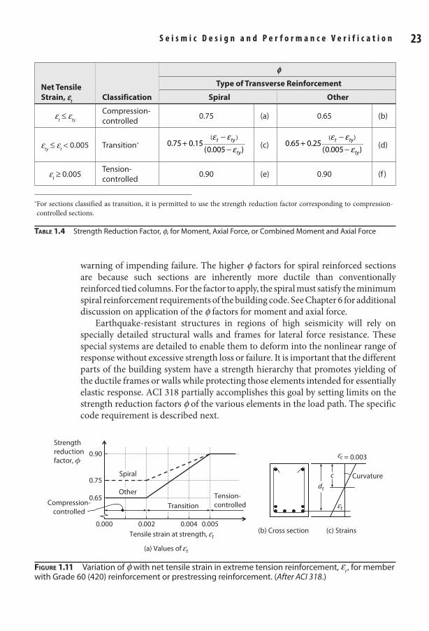
7 3/8 x 9 1/4 Technical / Radar Signal Processing / Richards / 474-2 / Chapter 1
S e i s m i c D e s i g n a n d p e r f o r m a n c e V e r i f i c a t i o n 23 22 C h a p t e r O n e
warning of impending failure. The higher f factors for spiral reinforced sections are because such sections are inherently more ductile than conventionally reinforced tied columns. For the factor to apply, the spiral must satisfy the minimum spiral reinforcement requirements of the building code. See Chapter 6 for additional discussion on application of the f factors for moment and axial force.
Earthquake-resistant structures in regions of high seismicity will rely on specially detailed structural walls and frames for lateral force resistance. These special systems are detailed to enable them to deform into the nonlinear range of response without excessive strength loss or failure. It is important that the different parts of the building system have a strength hierarchy that promotes yielding of the ductile frames or walls while protecting those elements intended for essentially elastic response. ACI 318 partially accomplishes this goal by setting limits on the strength reduction factors f of the various elements in the load path. The specific code requirement is described next.
Net Tensile Strain, e
tClassification
φType of Transverse Reinforcement
Spiral Other
et ≤ ety
Compression-controlled 0.75 (a) 0.65 (b)
ety ≤ et < 0.005 Transition*ε ε
ε+
−−
0.75 0.15(0.005 )
( )t ty
ty(c)
ε εε
+−
−0.65 0.25
(0.005 )
( )t ty
ty(d)
et ≥ 0.005Tension-controlled 0.90 (e) 0.90 (f )
*�For sections classified as transition, it is permitted to use the strength reduction factor corresponding to compression-controlled sections.
Table 1.4 Strength Reduction Factor, f, for Moment, Axial Force, or Combined Moment and Axial Force
(b) Cross section (c) Strains
Curvature
t
= 0.003c
c
dt
Strengthreductionfactor, ϕ
Tensile strain at strength, t
0.000 0.0050.0040.002
0.90
0.65
0.75
TransitionTension-controlledCompression-
controlled
Spiral
Other
(a) Values of t
Figure 1.11 Variation of f with net tensile strain in extreme tension reinforcement, et , for member with Grade 60 (420) reinforcement or prestressing reinforcement. (After ACI 318.)
01_Moehle_Ch01.indd 23 8/30/14 2:27 PM
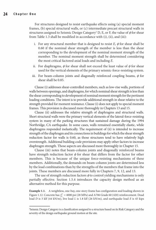
7 3/8 x 9 1/4 Technical / Radar Signal Processing / Richards / 474-2 / Chapter 1
S e i s m i c D e s i g n a n d p e r f o r m a n c e V e r i f i c a t i o n 25 24 C h a p t e r O n e
For structures designed to resist earthquake effects using (a) special moment frames, (b) special structural walls, or (c) intermediate precast structural walls in structures assigned to Seismic Design Category5 D, E, or F, the value of f for shear from Table 1.3 shall be modified in accordance with (i), (ii), and (iii):
i. For any structural member that is designed to resist E, f for shear shall be 0.60 if the nominal shear strength of the member is less than the shear corresponding to the development of the nominal moment strength of the member. The nominal moment strength shall be determined considering the most critical factored axial loads and including E.
ii. For diaphragms, f for shear shall not exceed the least value of f for shear used for the vertical elements of the primary seismic-force-resisting system.
iii. For beam-column joints and diagonally reinforced coupling beams, f for shear shall be 0.85.
Clause (i) addresses shear-controlled members, such as low-rise walls, portions of walls between openings, and diaphragms, for which nominal shear strength is less than the shear corresponding to development of nominal moment strength for the pertinent loading conditions. The intent is to provide additional strength in shear relative to the strength provided for moment resistance. Clause (i) does not apply to special moment frames. This provision is discussed more thoroughly in Chapters 13 and 15.
Clause (ii) addresses the relative strength of diaphragms and structural walls. Short structural walls were the primary vertical elements of the lateral-force-resisting system in many of the parking structures that sustained damage during the 1994 Northridge, CA earthquake. In some cases, walls remained essentially elastic, while diaphragms responded inelastically. The requirement of (ii) is intended to increase strength of the diaphragm and its connections in buildings for which the shear strength reduction factor for walls is 0.60, as those structures tend to have relatively high overstrength. Additional building code provisions may apply other factors to increase diaphragm strength. Those aspects are discussed more thoroughly in Chapter 15.
Clause (iii) notes that beam-column joints and diagonally reinforced beams have strength reduction factor f for shear that differs from the factor for other members. This is because of the unique force-resisting mechanisms of these members. Additionally, the demands on beam-column joints are determined less by the load combinations than by the strengths of the members that frame into the joints. These members are discussed more fully in Chapters 7, 9, 12, and 13.
The use of strength reduction factors f to control yielding mechanisms is only partially effective. Section 1.5.4 introduces the capacity design method as an alternative method for this purpose.
Example 1.1. A weightless, one-bay, one-story frame has configuration and loading shown in Figure 1.12. Concrete has c′f = 4000 psi (28 MPa) and A706 Grade 60 (420) reinforcement. Dead load D is 3 klf (44 kN/m), live load L is 1.8 klf (26 kN/m), and earthquake load E is 45 kips
5Seismic Design Category is a classification assigned to a structure based on its Risk Category and the severity of the design earthquake ground motion at the site.
01_Moehle_Ch01.indd 24 8/30/14 2:27 PM
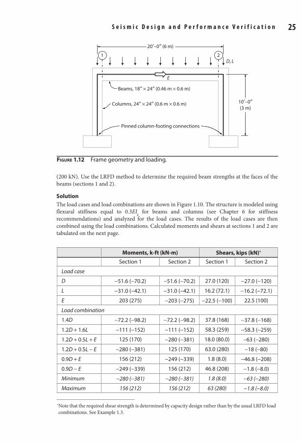
7 3/8 x 9 1/4 Technical / Radar Signal Processing / Richards / 474-2 / Chapter 1
S e i s m i c D e s i g n a n d p e r f o r m a n c e V e r i f i c a t i o n 25 24 C h a p t e r O n e
(200 kN). Use the LRFD method to determine the required beam strengths at the faces of the beams (sections 1 and 2).
SolutionThe load cases and load combinations are shown in Figure 1.10. The structure is modeled using flexural stiffness equal to 0.3EIg for beams and columns (see Chapter 6 for stiffness recommendations) and analyzed for the load cases. The results of the load cases are then combined using the load combinations. Calculated moments and shears at sections 1 and 2 are tabulated on the next page.
D, L
E
Pinned column-footing connections
Columns, 24″ × 24″ (0.6 m × 0.6 m)
Beams, 18″ × 24″ (0.46 m × 0.6 m)
1 2
10′–0″(3 m)
20′–0″ (6 m)
Figure 1.12 Frame geometry and loading.
Moments, k-ft (kN-m) Shears, kips (kN)*
Section 1 Section 2 Section 1 Section 2
Load case
D −51.6 (−70.2) −51.6 (−70.2) 27.0 (120) −27.0 (−120)
L −31.0 (−42.1) −31.0 (−42.1) 16.2 (72.1) −16.2 (−72.1)
E 203 (275) −203 (−275) −22.5 (−100) 22.5 (100)
Load combination
1.4D −72.2 (−98.2) −72.2 (−98.2) 37.8 (168) −37.8 (−168)
1.2D + 1.6L −111 (−152) −111 (−152) 58.3 (259) −58.3 (−259)
1.2D + 0.5L + E 125 (170) −280 (−381) 18.0 (80.0) −63 (−280)
1.2D + 0.5L − E −280 (−381) 125 (170) 63.0 (280) −18 (−80)
0.9D + E 156 (212) −249 (−339) 1.8 (8.0) −46.8 (−208)
0.9D − E −249 (−339) 156 (212) 46.8 (208) −1.8 (−8.0)
Minimum −280 (−381) −280 (−381) 1.8 (8.0) −63 (−280)
Maximum 156 (212) 156 (212) 63 (280) −1.8 (−8.0)
* Note that the required shear strength is determined by capacity design rather than by the usual LRFD load combinations. See Example 1.3.
01_Moehle_Ch01.indd 25 8/30/14 2:27 PM
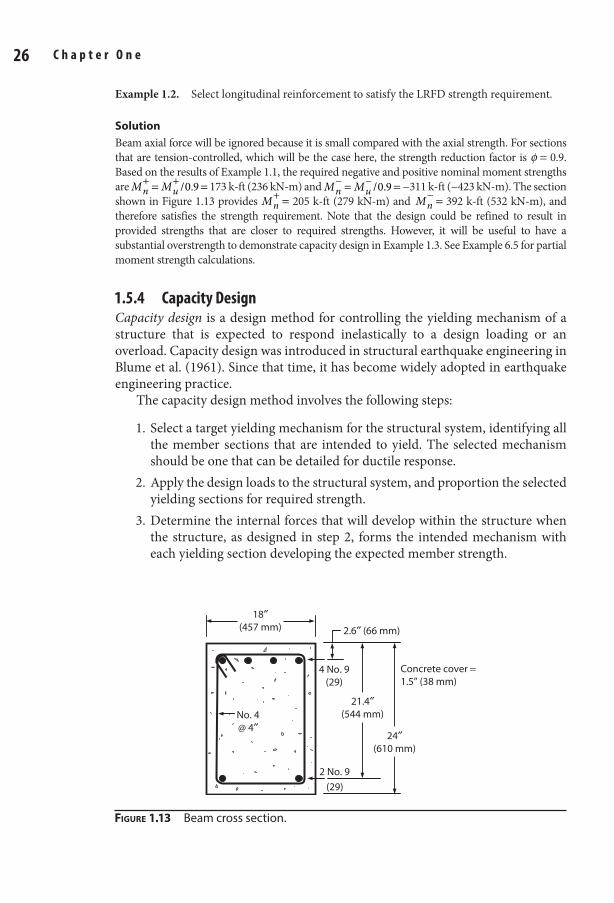
7 3/8 x 9 1/4 Technical / Radar Signal Processing / Richards / 474-2 / Chapter 1
S e i s m i c D e s i g n a n d p e r f o r m a n c e V e r i f i c a t i o n 27 26 C h a p t e r O n e
Example 1.2. Select longitudinal reinforcement to satisfy the LRFD strength requirement.
SolutionBeam axial force will be ignored because it is small compared with the axial strength. For sections that are tension-controlled, which will be the case here, the strength reduction factor is f = 0.9. Based on the results of Example 1.1, the required negative and positive nominal moment strengths are M M /0.9= =+ +
n u 173 k-ft (236 kN-m) and M M /0.9= =− −n u −311 k-ft (−423 kN-m). The section
shown in Figure 1.13 provides M =+n 205 k-ft (279 kN-m) and M =−
n 392 k-ft (532 kN-m), and therefore satisfies the strength requirement. Note that the design could be refined to result in provided strengths that are closer to required strengths. However, it will be useful to have a substantial overstrength to demonstrate capacity design in Example 1.3. See Example 6.5 for partial moment strength calculations.
1.5.4 Capacity DesignCapacity design is a design method for controlling the yielding mechanism of a structure that is expected to respond inelastically to a design loading or an overload. Capacity design was introduced in structural earthquake engineering in Blume et al. (1961). Since that time, it has become widely adopted in earthquake engineering practice.
The capacity design method involves the following steps:
1. Select a target yielding mechanism for the structural system, identifying all the member sections that are intended to yield. The selected mechanism should be one that can be detailed for ductile response.
2. Apply the design loads to the structural system, and proportion the selected yielding sections for required strength.
3. Determine the internal forces that will develop within the structure when the structure, as designed in step 2, forms the intended mechanism with each yielding section developing the expected member strength.
2 No. 9
(29)
18″(457 mm)
4 No. 9(29)
2.6″ (66 mm)
21.4″(544 mm)No. 4
@ 4″
Concrete cover =1.5” (38 mm)
24″(610 mm)
Figure 1.13 Beam cross section.
01_Moehle_Ch01.indd 26 8/30/14 2:27 PM
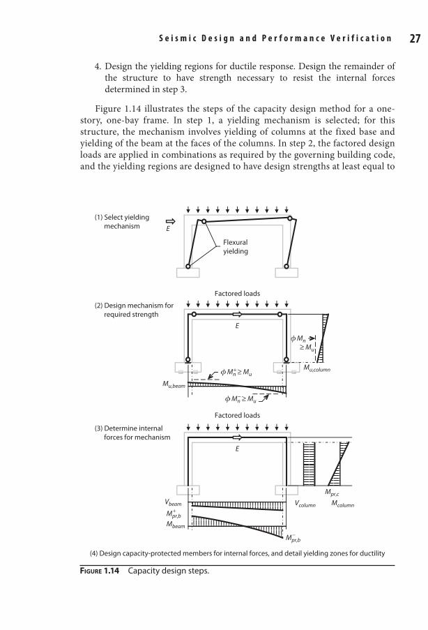
7 3/8 x 9 1/4 Technical / Radar Signal Processing / Richards / 474-2 / Chapter 1
S e i s m i c D e s i g n a n d p e r f o r m a n c e V e r i f i c a t i o n 27 26 C h a p t e r O n e
4. Design the yielding regions for ductile response. Design the remainder of the structure to have strength necessary to resist the internal forces determined in step 3.
Figure 1.14 illustrates the steps of the capacity design method for a one-story, one-bay frame. In step 1, a yielding mechanism is selected; for this structure, the mechanism involves yielding of columns at the fixed base and yielding of the beam at the faces of the columns. In step 2, the factored design loads are applied in combinations as required by the governing building code, and the yielding regions are designed to have design strengths at least equal to
(1) Select yielding mechanism E
Flexuralyielding
E
Mu,beam
Mu,column
Factored loads
(2) Design mechanism for required strength
Vcolumn Mcolumn
Mpr,c
E
Factored loads
(3) Determine internal forces for mechanism
(4) Design capacity-protected members for internal forces, and detail yielding zones for ductility
Vbeam
Mbeam
Mpr,b+
Mpr,b−
ϕ Mn ≥ Mu
ϕ Mn ≥ Mu
−
ϕ Mn ≥ Mu+
Figure 1.14 Capacity design steps.
01_Moehle_Ch01.indd 27 8/30/14 2:27 PM
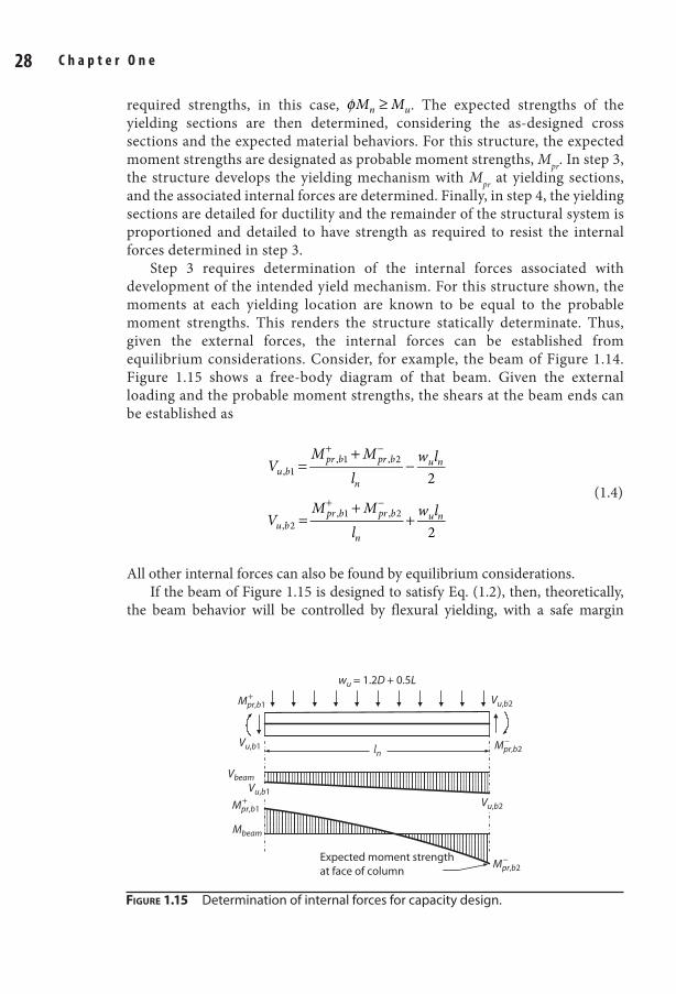
7 3/8 x 9 1/4 Technical / Radar Signal Processing / Richards / 474-2 / Chapter 1
S e i s m i c D e s i g n a n d p e r f o r m a n c e V e r i f i c a t i o n 29 28 C h a p t e r O n e
required strengths, in this case, φ ≥M Mn u. The expected strengths of the yielding sections are then determined, considering the as-designed cross sections and the expected material behaviors. For this structure, the expected moment strengths are designated as probable moment strengths, Mpr. In step 3, the structure develops the yielding mechanism with Mpr at yielding sections, and the associated internal forces are determined. Finally, in step 4, the yielding sections are detailed for ductility and the remainder of the structural system is proportioned and detailed to have strength as required to resist the internal forces determined in step 3.
Step 3 requires determination of the internal forces associated with development of the intended yield mechanism. For this structure shown, the moments at each yielding location are known to be equal to the probable moment strengths. This renders the structure statically determinate. Thus, given the external forces, the internal forces can be established from equilibrium considerations. Consider, for example, the beam of Figure 1.14. Figure 1.15 shows a free-body diagram of that beam. Given the external loading and the probable moment strengths, the shears at the beam ends can be established as
=+
−+ −
2, 1, 1 , 2V
M Ml
w lu b
pr b pr b
n
u n
(1.4)
=+
++ −
2, 2, 1 , 2V
M Ml
w lu b
pr b pr b
n
u n
All other internal forces can also be found by equilibrium considerations.If the beam of Figure 1.15 is designed to satisfy Eq. (1.2), then, theoretically,
the beam behavior will be controlled by flexural yielding, with a safe margin
Figure 1.15 Determination of internal forces for capacity design.
wu = 1.2D + 0.5L
Expected moment strengthat face of column
lnVu,b1
Vbeam
Vu,b2
Mpr,b2−
Mpr,b2−
Mbeam
Mpr,b1+
Mpr,b1+
Vu,b2
Vu,b1
01_Moehle_Ch01.indd 28 8/30/14 2:27 PM
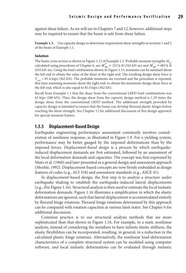
7 3/8 x 9 1/4 Technical / Radar Signal Processing / Richards / 474-2 / Chapter 1
S e i s m i c D e s i g n a n d p e r f o r m a n c e V e r i f i c a t i o n 29 28 C h a p t e r O n e
against shear failure. As we will see in Chapters 7 and 12, however, additional steps may be required to ensure that the beam is safe from shear failure.
Example 1.3. Use capacity design to determine requirement shear strengths at sections 1 and 2 of the beam of Example 1.1.
SolutionThe beam cross section is shown in Figure 1.13 of Example 1.2. Probable moment strengths Mpr, calculated using procedures of Chapter 6, are M =+
pr 252 k-ft (342 kN-m) and M =−pr 483 k-ft
(655 kN-m). Using the load combination shown in Figure 1.15, moments can be summed about the left end to obtain the value of the shear at the right end. The resulting design shear force is Vu,b2 = 81.4 kips (362 kN). The probable moments are reversed and the procedure is repeated, this time summing moments about the right end, to obtain the maximum design shear force at the left end, which is also equal to 81.4 kips (362 kN).Recall from Example 1.1 that the shear from the conventional LRFD load combinations was 63 kips (280 kN). Thus, the design shear from the capacity design method is 1.29 times the design shear from the conventional LRFD method. The additional strength provided by capacity design is intended to ensure that the beam can develop flexural plastic hinges before reaching the shear strength. See Chapter 12 for additional discussion of this design approach for special moment frames.
1.5.5 Displacement-Based DesignEarthquake engineering performance assessment commonly involves consid–eration of nonlinear response, as illustrated in Figure 1.9. For a yielding system, performance may be better gauged by the imposed deformations than by the imposed forces. Displacement-based design is a process by which earthquake-induced displacement demands are first estimated, followed by an assessment of the local deformation demands and capacities. The concept was first expressed by Muto et al. (1960) and later presented as a general design and assessment approach (Moehle, 1992). Displacement-based concepts are now firmly embedded as design features of codes (e.g., ACI 318) and assessment standards (e.g., ASCE 41).
In displacement-based design, the first step is to analyze a structure under earthquake shaking to establish the earthquake-induced lateral displacements (e.g., d in Figure 1.16). Structural analysis is then used to estimate the local inelastic deformation demands. Figure 1.16 illustrates a simplification in which the elastic deformations are ignored, such that lateral displacement is accommodated entirely by flexural hinge rotations. Flexural hinge rotations determined by this approach can be compared with rotation capacities at various limit states. See Chapter 6 for additional discussion.
Common practice is to use structural analysis methods that are more sophisticated than that shown in Figure 1.16. For example, in a static nonlinear analysis, instead of considering the members to have infinite elastic stiffness, the elastic flexibilities can be incorporated, resulting, in general, in a reduction in the calculated plastic hinge rotations. Alternatively, the nonlinear load-deformation characteristics of a complete structural system can be modeled using computer software, and local inelastic deformations can be evaluated through inelastic
01_Moehle_Ch01.indd 29 8/30/14 2:27 PM
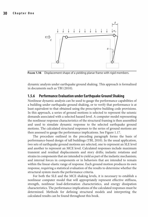
7 3/8 x 9 1/4 Technical / Radar Signal Processing / Richards / 474-2 / Chapter 1
S e i s m i c D e s i g n a n d p e r f o r m a n c e V e r i f i c a t i o n 31 30 C h a p t e r O n e
dynamic analysis under earthquake ground shaking. This approach is formalized in documents such as TBI (2010).
1.5.6 performance evaluation under earthquake Ground ShakingNonlinear dynamic analysis can be used to gauge the performance capabilities of a building under earthquake ground shaking, or to verify that performance is at least equivalent to that obtained using the prescriptive building code provisions. In this approach, a series of ground motions is selected to represent the seismic demands associated with a selected hazard level. A computer model representing the nonlinear response characteristics of the structural framing is then assembled and used to simulate dynamic response to the selected earthquake ground motions. The calculated structural responses to the series of ground motions are then assessed to gauge the performance implications. See Figure 1.17.
The procedure outlined in the preceding paragraph forms the basis of performance-based design of tall buildings (TBI, 2010). In the usual application, two sets of earthquake ground motions are selected, one to represent an SLE level and another to represent an MCE level. Calculated responses include maximum transient and residual displacements and story drifts; inelastic rotations and strains in components that are intended to yield as part of the inelastic mechanism; and internal forces in components or in behaviors that are intended to remain within the linear-elastic range of response. Each ground motion produces its own response, requiring a statistical evaluation of the results to determine whether the structural system meets the performance criteria.
For both the SLE and the MCE shaking levels, it is necessary to establish a nonlinear computer model that will appropriately represent effective stiffness, strength, nonlinear load-deformation characteristics, and energy dissipation characteristics. The performance implications of the calculated responses must be determined. Methods for defining structural models and interpreting the calculated results can be found throughout this book.
wu
E
θ
δ
Figure 1.16 Displacement shape of a yielding planar frame with rigid members.
01_Moehle_Ch01.indd 30 8/30/14 2:27 PM
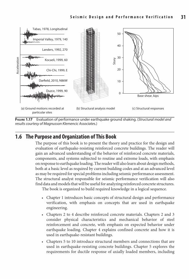
7 3/8 x 9 1/4 Technical / Radar Signal Processing / Richards / 474-2 / Chapter 1
S e i s m i c D e s i g n a n d p e r f o r m a n c e V e r i f i c a t i o n 31 30 C h a p t e r O n e
1.6 the purpose and Organization of this BookThe purpose of this book is to present the theory and practice for the design and evaluation of earthquake-resisting reinforced concrete buildings. The reader will gain an advanced understanding of the behavior of reinforced concrete materials, components, and systems subjected to routine and extreme loads, with emphasis on response to earthquake loading. The reader will also learn about design methods, both at a basic level as required by current building codes and at an advanced level as may be required for special problems including seismic performance assessment. The structural analyst responsible for seismic performance verification will also find data and models that will be useful for analyzing reinforced concrete structures.
The book is organized to build required knowledge in a logical sequence.
• Chapter 1 introduces basic concepts of structural design and performance verification, with emphasis on concepts that are used in earthquake engineering.
• Chapters 2 to 4 describe reinforced concrete materials. Chapters 2 and 3 consider physical characteristics and mechanical behavior of steel reinforcement and concrete, with emphasis on expected behavior under earthquake loading. Chapter 4 explains confined concrete and how it is used in earthquake-resistant buildings.
• Chapters 5 to 10 introduce structural members and connections that are used in earthquake-resisting concrete buildings. Chapter 5 explores the requirements for ductile response of axially loaded members, including
Figure 1.17 Evaluation of performance under earthquake ground shaking. (Structural model and results courtesy of Magnusson Klemencic Associates.)
(a) Ground motions recorded atparticular sites
Acc
eler
atio
n
Chi-Chi, 1999, E
Darfield, 2010, N86W
Duzce, 1999, 90
Kocaeli, 1999, 60
Imperial Valley, 1979, 140
Landers, 1992, 270
Tabas, 1978, Longitudinal
(b) Structural analysis model (c) Structural responses
Stor
y
Base shear, kips
50
40
30
20
10
0
01_Moehle_Ch01.indd 31 8/30/14 2:27 PM
7 3/8 x 9 1/4 Technical / Radar Signal Processing / Richards / 474-2 / Chapter 1
S e i s m i c D e s i g n a n d p e r f o r m a n c e V e r i f i c a t i o n 33 32 C h a p t e r O n e
the use of transverse reinforcement to confine core concrete and restrain longitudinal reinforcement buckling. Chapter 6 describes behavior of beams, columns, and structural walls under moment or combined moment and axial force, and introduces procedures for calculating the nonlinear load-deformation response of flexural members. Chapter 7 describes the shear behavior of beams, columns, walls, and coupling beams. Chapter 8 covers requirements for development and splicing of reinforcement, including straight development lengths, lap splices and mechanical splices, and hooked and headed bar anchorages. Chapters 9 and 10 describe the behavior of beam-column, slab-column, and slab-wall connections.
• The remaining chapters (11 to 16) bring together the knowledge gained from previous chapters to describe the design and behavior of complete structural systems. Chapter 11 presents an overview of seismic design principles, including a review of earthquake shaking effects and how these are incorporated in building design. Chapters 12 to 14 cover the main vertical elements of buildings, including special moment frames, special structural walls, and gravity framing systems. Chapter 15 covers structural diaphragms and their role in completing a three-dimensional framing system capable of resisting gravity and lateral loads. Chapter 16 completes the book with a review of common foundation elements and their design for seismic resistance.
ReferencesACI 318-14 (2014). Building Code Requirements for Structural Concrete (ACI 318-14) and
Commentary, American Concrete Institute, Farmington Hills, MI.ASCE 7-10 (2010). Minimum Design Loads for Buildings and Other Structures, American Society
of Civil Engineers, Reston, VA, 608 pp.ASCE 41 (2013). Seismic Evaluation and Retrofit of Existing Buildings, American Society of Civil
Engineers, Reston, VA.ATC 40 (1996). Seismic Evaluation and Retrofit of Buildings, Report No. ATC-40, Applied
Technology Council, Redwood City, CA.Blume, J.A., N.M. Newmark, and L.H. Corning (1961). Design of Multistory Reinforced Concrete
Buildings for Earthquake Motions, Portland Cement Association, Chicago, IL, 318 pp.Eurocode 8 (2004). Eurocode 8: Design of Structures for Earthquake Resistance, Part 1: General
Rules, Seismic Actions and Rules for Buildings, ComitéEuropéen de Normalisation, European Standard EN 1998-1:2004, Brussels, Belgium.
Fardis, M. (2013). “The European Approach to Seismic Engineering and Codification for Concrete Structures,” Closing Plenary, fib Symposium, Tel Aviv.
FEMA 273 (1997). NEHRP Guidelines for the Seismic Rehabilitation of Buildings, FEMA-273, Federal Emergency Management Agency, Washington, DC.
FEMA P-58 (2012). Seismic Performance Assessment of Buildings, Methodology and Implementation, Vols. 1, 2, and 3, Federal Emergency Management Agency, Washington, DC.
FEMA P-695 (2009). Quantification of Building Seismic Performance Factors, Federal Emergency Management Agency, Washington, DC, 421 pp.
Gergely, P., and L.A. Lutz (1968). “Maximum Crack Width in Reinforced Flexural Members,” Causes, Mechanism, and Control of Cracking in Concrete, SP-20, American Concrete Institute, pp. 87–117.
01_Moehle_Ch01.indd 32 8/30/14 2:27 PM
7 3/8 x 9 1/4 Technical / Radar Signal Processing / Richards / 474-2 / Chapter 1
S e i s m i c D e s i g n a n d p e r f o r m a n c e V e r i f i c a t i o n 33 32 C h a p t e r O n e
IBC (2012). International Building Code, International Code Council, Country Club Hills, IL. LATBSDC (2011). An Alternative Procedure for Seismic Analysis and Design of Tall Buildings
Located in the Los Angeles Region, Los Angeles Tall Building Structural Design Council, Los Angeles, CA.
Luco, N., B.R. Ellingwood, R.O. Hamburger, J.D. Hooper, J.K. Kimball, and C.A. Kircher (2007). “Risk-Targeted versus Current Seismic Design Maps for the Conterminous United States,” Proceedings, SEAOC 2007 Convention, Structural Engineers Association of California, Sacramento, CA, 13 pp.
MacGregor, J.G. (1983). “Load and Resistance Factors for Concrete Design,” ACI Structural Journal, Vol. 80, No. 4, pp. 279–287.
Moehle, J.P. (1992). “Displacement-based Design of RC Structures Subjected to Earthquakes,” Earthquake Spectra, Vol. 8, No. 3, pp. 403–428.
Muto, K., et al. (1960). “Non-linear Response Analyzers and Application to Earthquake Resistant Design,” Proceedings, 2nd World Conference on Earthquake Engineering, Japan, Vol. 2, pp. 649–668.
NBC (2005). The National Building Code of Canada, Canadian Commission on Building and Fire Codes, National Research Council, Ottawa.
NEHRP (2009). NEHRP Recommended Provisions (and Commentary), National Earthquake Hazard Reduction Program.
NIST (2010). “Evaluation of the FEMA P-695 Methodology for Quantification of Building Seismic Performance Factors,” NIST GCR 10-917-8, National Institute of Standards and Technology, Gaithersburg, MD, 268 pp.
NOAA (1973). San Fernando, California, Earthquake of February 9, 1971, U.S. Dept. of Commerce, National Oceanic and Atmospheric Administration, Washington, DC, 3 volumes.
NZS3101 (2006). Concrete Design Standard, NZS3101:2006, Part 1 and Commentary on the Concrete Design Standard, NZS 3101:2006, Part 2, Standards Association of New Zealand, 2006, Wellington, New Zealand.
Otani, S. (1995). “A Brief History of Japanese Seismic Design Requirements,” Concrete International, Vol. 17, No. 12, pp. 46–53.
Park, R. (1986). “Ductile Design Approach for Reinforced Concrete Frames,” Earthquake Spectra, Vol. 2, No. 3, pp. 565–619.
PCI (2013). PCI Journal, Summer issue.PRESSS (various). Precast Seismic Structural Systems (PRESSS), http://pci.org/cms/index.cfm/
PRESSSresources.SEAOC (1963). Recommended Lateral Force Requirements (commonly referred to as the “Blue Book”),
Seismology Committee, Structural Engineers Association of California, Sacramento, CA.SEAOC (1967). “Design of Earthquake Resistant High-Rise Buildings,” Lecture notes from
SEAOC seminar, October–December 1967, figure by A. Tarics, Reid & Tarics, Structural Engineers Association of Northern California Sacramento, CA.
SEAOC (1995). Performance-Based Seismic Engineering of Buildings (also known as the Vision 2000 Report), Structural Engineers Association of California, Sacramento, CA, 538 pp.
TBI (2010). Guidelines for Performance-Based Seismic Design of Tall Buildings, Report No. 2010/05, Pacific Earthquake Engineering Research Center, University of California, Berkeley, CA, 84 pp.
UBC (1976). Uniform Building Code, International Conference of Building Officials, Whittier, CA.Yang, T.Y., J.P. Moehle, B. Stojadinovic, and A. Der Kiureghian (2009). “Seismic Performance
Evaluation of Facilities: Methodology and Implementation,” Journal of Structural Engineering, Vol. 135, No. 10, pp. 1146–1154.
01_Moehle_Ch01.indd 33 8/30/14 2:27 PM