Embed Size (px)
Citation preview

IEEE TRANSACTIONS ON PATTERN ANALYSIS AND MACHINE INTELLIGENCE , VOL. X, NO. X, YY 2006 1
Robust and Accurate Visual Echo Cancelation
in a Full-duplex Projector-camera SystemMiao Liao∗, Ruigang Yang∗, Zhengyou Zhang+
Abstract
In this paper we study the problem of “visual echo” in a full-duplex projector-camera system for tele-collaboration
applications.Visual echois defined as the appearance of projected contents observed by the camera. It can potentially
saturate the projected contents, similar to audio echo in telephone conversation.
Our approach to visual echo cancelation includes an off-line calibration procedure that records the geometric and
photometric transfer between the projector and the camera in a look-up table. During run-time, projected contents in the
captured video are identified using the calibration information and suppressed, therefore achieving the goal of canceling
visual echo. Our approach can accurately handle full color images under arbitrary reflectance of display surfaces and
photometric response of the projector or camera. It is robust to geometric registration errors and quantization effect,
therefore particularly effective for high-frequency contents such as texts and hand drawings. We demonstrate the
effectiveness of our approach with a variety of real images in a full-duplex projector-camera system.
Index Terms
visual echo cancelation, projector-camera system, geometric calibration, photometric calibration, whiteboard-
camera system, teleconferencing, collaboration.
I. I NTRODUCTION
During the last few years, driven by the diminishing costandsize of digital light projectors and cameras, we have
seen a proliferation of research projects in using them for a variety of applications. The combination of projectors
and cameras in a common space provides both the input and the output capabilities that enable a new paradigm for
human-computer interactions, from motion tracking (e.g. [17], [12]), immersive self-calibrating displays (e.g., [16],
[13], [23], [3], [14], [7]), to remote collaboration tools that bring geographically distributed participants to share
virtually the same physical space(e.g. [15], [6], [19]).
In a typical remote collaboration setup, two or more projector-camera pairs are “cross-wired”, as shown in
Figure 1, to form a full-duplex system for two-way communication. A whiteboard can be used as the projector
screen, and in that case, the whiteboard serves as an output device as well as an input device. Users can write on
the whiteboard to comment on what is projected or to add new thoughts in the discussion. That is, images from the
∗M. Liao and R. Yang are with the Department of Computer Science, University of Kentucky, Lexington, KY, USA.+Z. Zhang is with Microsoft Research, Redmond, WA, USA.
September 9, 2006 DRAFT

IEEE TRANSACTIONS ON PATTERN ANALYSIS AND MACHINE INTELLIGENCE , VOL. X, NO. X, YY 2006 2
projector are mixed with real objects (such as papers, writings, and hands) to create a shared space. Such a setup
offers several immediate advantages:
1) seamless integration: computer presentations (such as PowerPoint) and whiteboard discussions are combined
into one session. Participants will not be distracted by switching from the computer screen to the whiteboard,
or vice versa.
2) shared workspace: both local and remote participants can collaborate on a shared workspace similar to face-
to-face discussions.
3) ease of deployment: It can be easily installed in existing meeting environments. It is therefore much more
economical than most remote collaboration systems that require special equipment.
Fig. 1. A typical setup for remote collaboration using projector-camera pairs. The projection screen is used as both an output area for display
and an input area captured by the camera. Camera images from the remote site are mixed with computer contents, typically shared, and projected
locally.
In such a setup (shown in Figure 1), the captured video contains writings or user gesture (foreground) along with
projected contents. If we simply send the image for display on the other end, there could be a feedback loop that
will distort the projected image. As shown in Figure 2 (top), the captured image is directly projected back. After
a few frames, some part of the image becomes saturated and some part of the real writing has ghosting effect.
Analogous to auido echo in telephone communication, we call this effectvisual echo, i.e., the appearance of the
projected contents viewed by the camera. ThereforeVisual Echo Cancellationis defined as extracting the physical
foreground from the video containing both the foreground and the projected contents. Such a separation will not
only improve the participants’ experience in tele-collabrations, but also brings other advantages:
1) It dramatically reduces the bandwidth requirement for teleconferencing, because both extracted foreground
and the computer-projected contents can be transmitted with very low bandwidth, comparing with the original
mixed video, since the video is affected by shadow and lighting variation.
2) By feeding the results to an OCR (Optical Character Recognition) system, the meeting archive can be more
easily accessed or transferred into other forms.
September 9, 2006 DRAFT

IEEE TRANSACTIONS ON PATTERN ANALYSIS AND MACHINE INTELLIGENCE , VOL. X, NO. X, YY 2006 3
Fig. 2. The problem of visual echo in a full duplex projector-camera system. (Top row) In the leftmost photo, a user is annotating a presentation
slide. A camera is capturing his annotations as well as the projected slide. The image is displayed directly, causing a visual echo. The right two
images show the effect after four and seven frames, respectively. As expected, the visual echo becomes worse as time goes by. (Bottom row)
To suppress visual echo, we present techniques to segment the captured image (left) into projected contents and foreground. The right image
shows the foreground (i.e., the user’s writing and gesture). The light-colored checkerboard is used to illustrate the transparent background.
To suppress visual echo boils down to a classification problem. That is, one needs to distinguish whether or
not a pixel in the camera image only contains projected pixels reflected off the screen, i.e., an “echo”. If so, the
echo content should be removed. Given an image to be projected (i.e., the framebuffer content), one needs to first
predict accurately its appearance in the camera’s view and then compare it with the actual camera image to make
the identification on a pixel-by-pixel basis.
We here present a comprehensive set of techniques to address the visual echo cancelation problem in general.
Drawn upon the extensive research on projector calibration, we developed a simple and accurate procedure to find
a complete photometric and geometric mapping between projector and camera pixels. It is a per-pixel mapping
that allows arbitrary color transfer between the projector and the camera. From the mapping, we designed a robust
classification scheme to find out echo pixels in the presence of quantization errors that are unavoidable when warping
images from projector to camera. Figure 2 (bottom) shows the camera image before and after classification.
II. RELATED WORK
The use of projectors and cameras for augmented reality applications has long been proposed [22], [15], [6], [11].
But it was until recently that the problem of “visual echoing” received attention. In the Telegraffiti system [19], a
user’s sketch is captured by a camera and projected on a piece of paper in a remote site. To avoid visual echoing in
two-way communication, they increase the ambient lighting so that the real sketch (in black) is significantly darker
than the projected sketch [21]. But the amount of lighting necessary is tricky to adjust. In their technical report [20],
September 9, 2006 DRAFT

IEEE TRANSACTIONS ON PATTERN ANALYSIS AND MACHINE INTELLIGENCE , VOL. X, NO. X, YY 2006 4
the visual echo problem is formally studied. The proposed solution is to adjust gain properly. It is demonstrated
that it works quite well for extracting sketches from a clean background, but has difficulties with color or complex
patterns.
Geometric calibration of projectors and cameras has been very well studied [16], [13], [3], [14]) under the context
of constructing tiled projection-based display that areseamless. Many of these techniques are able to register images
with sub-pixel accuracy. Interested readers are referred to a recent survey of camera-based calibration techniques [1].
On the other hand, photometric calibration has received much less attention. Most projector-based displays simply
blend linearly the pixels in the overlap regions. Previous methods mainly attack the intensity or color variations
within or between projectors [18], [10], [9]. To deal with visual echo, we need more accurate chromatic estimation
between the projector color space and the camera color space.
The issue of predicting a projected image from the camera’s perspective has been studied under the context
of shadow removal [2], [8] and adaptive projection on colored-surfaces [5]. In [2], the projected images are pre-
captured by the cameras in the absence of any other object. In other words, the predicted images are captured
directly. Therefore this method cannot deal with dynamic images not known a priori. The approach in [8] is a step
forward: it estimates the photometric transfer function so it can process dynamic contents. They assume that the
three color-channels in the projector can be mapped to the corresponding channels in the camera via independent
intensity transfer functions. This assumption is valid for projectors and cameras that are color balanced and have
narrow-band spectral responses. However, the typical spectral responses of cameras and projectors are wideband
and have large overlaps [5]. The photometric model in [5] is probably the most general one to measure the color
transfer between a projector and a camera. They have achieved some of the most accurate predictions, but they
require the projector and camera to be co-axial to avoid the geometric alignment issue. This requirement does not
scale to a multi-projector setup. Our photometric model is similar to that in [5], but instead of trying to solve the
color transfer matrix numerically, we use a look-up-table based approach to deal with projectors with non-linear
responses.
Finally it should be noted that it is possible to avoid the visual echo problem in design. In [15], the cameras
and projectors are synchronized, so the camera takes an image only when the projector is off or showing a specific
pattern. This effectively interleaves the operation of the projector and camera in a time-sequential manner. To avoid
visual flicking, DLP projectors have to be used to provide a fast enough switching rate (> 1000Hz). This approach
is probably the most robust way to avoid visual echoes. But it requires modifications in hardware and it is usually
difficult to synchronize a large network of projectors and camera in practice.
The termvisual echo cancelationwas introduced in our earlier work [26], in which the basic steps to address
such a problem were also articulated. To find the color transfer, they proposed the use of a large 5D look-up-table,
i.e., for each pixel(x, y) in the project, iterate through its full range(r, g, b) and record the observed color in the
camera. This requires a prohibitively large table (e.g.,2563×1024×768). We show in this paper that by linearizing
the camera’s spectral response, the 5D look-up table can be factorized into several independent tables that are orders
smaller.
September 9, 2006 DRAFT

IEEE TRANSACTIONS ON PATTERN ANALYSIS AND MACHINE INTELLIGENCE , VOL. X, NO. X, YY 2006 5
One motivation to this work is our desire of developing tools to facilitate tele-collaboration on physical white-
boards by using a camera and a microphone [25]. A physical whiteboard is an economical but great collaboration
tool. However, the contents on the board is hard to archive or share with others who are not present in the session.
Our tools allow a user to take digitally enhanced notes, to transmit the whiteboard contents to remote participants
in real time and in an efficient way, and to archive the whole whiteboard session for efficient post-viewing. The
work described in this paper goes one step further, allowing a user to use a whiteboard as the projecting surface
(output) as well as the writing surface (input).
III. O UR METHODS
Our processing pipeline for visual echo cancelation starts with a calibration procedure to find out the geometric
and photometric mapping between projector and camera pixels. For the scope of our paper, we assume that the
projector, the camera, and the display surface are fixed. Therefore the calibration only needs to be done once per
setup. At run-time, a classification procedure determines for each pixel in the camera image if it is a visual echo
or from a real object, given the corresponding projector image. In the next few sections, we present in details how
we perform these tasks.
A. Geometric Calibration
For visual echo cancellation, we need to know the relationship between the pixels in the camera view and the
pixels in the projector screen. This is the task of geometric calibration. We present two methods. The first method
assumes a linear model, i.e., both camera and projector are linear projective with no lens distortions and the display
surface is flat. The second method is non-linear and does not make any of these assumptions and therefore it can
be used for any display setup. Both methods are easy to implement by leveraging the fact that the projector can
actively project the patterns we want.
a) Linear Method:Under the linear assumption, it can be easily shown that the mapping between a point in
the camera view and a point in the projector screen is a homography, and can be described by a3 × 3 matrix H
defined up to a scale factor.
Camera captureCamera capture Corner detectionCorner detection
Homographyestimation
Homographyestimation
Screen
Project rectangular patterns
Project rectangular patterns
Fig. 3. A flow chart for linear geometric calibration
Figure 3 shows the flowchart for linear geometric calibration. The main steps are:
September 9, 2006 DRAFT
IEEE TRANSACTIONS ON PATTERN ANALYSIS AND MACHINE INTELLIGENCE , VOL. X, NO. X, YY 2006 6
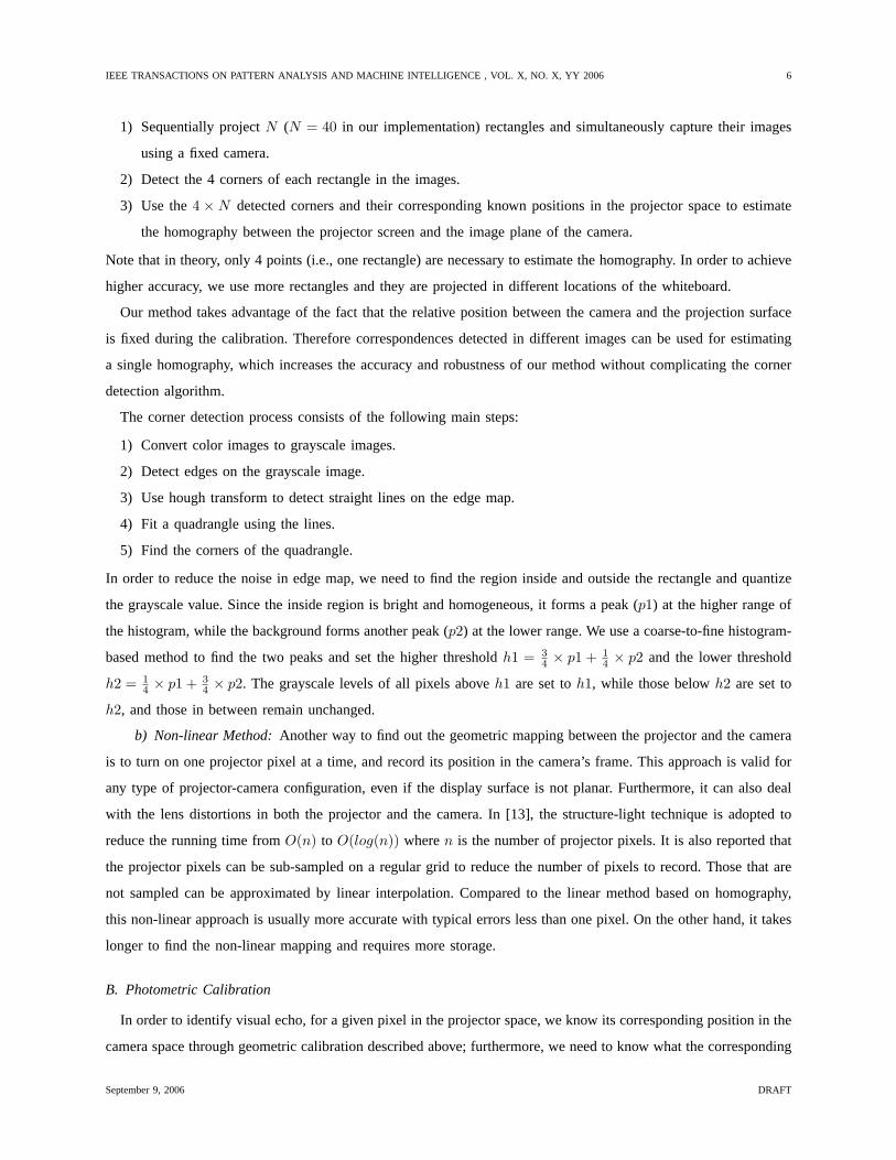
1) Sequentially projectN (N = 40 in our implementation) rectangles and simultaneously capture their images
using a fixed camera.
2) Detect the 4 corners of each rectangle in the images.
3) Use the4 ×N detected corners and their corresponding known positions in the projector space to estimate
the homography between the projector screen and the image plane of the camera.
Note that in theory, only 4 points (i.e., one rectangle) are necessary to estimate the homography. In order to achieve
higher accuracy, we use more rectangles and they are projected in different locations of the whiteboard.
Our method takes advantage of the fact that the relative position between the camera and the projection surface
is fixed during the calibration. Therefore correspondences detected in different images can be used for estimating
a single homography, which increases the accuracy and robustness of our method without complicating the corner
detection algorithm.
The corner detection process consists of the following main steps:
1) Convert color images to grayscale images.
2) Detect edges on the grayscale image.
3) Use hough transform to detect straight lines on the edge map.
4) Fit a quadrangle using the lines.
5) Find the corners of the quadrangle.
In order to reduce the noise in edge map, we need to find the region inside and outside the rectangle and quantize
the grayscale value. Since the inside region is bright and homogeneous, it forms a peak (p1) at the higher range of
the histogram, while the background forms another peak (p2) at the lower range. We use a coarse-to-fine histogram-
based method to find the two peaks and set the higher thresholdh1 = 34 × p1 + 1
4 × p2 and the lower threshold
h2 = 14 × p1 + 3
4 × p2. The grayscale levels of all pixels aboveh1 are set toh1, while those belowh2 are set to
h2, and those in between remain unchanged.
b) Non-linear Method:Another way to find out the geometric mapping between the projector and the camera
is to turn on one projector pixel at a time, and record its position in the camera’s frame. This approach is valid for
any type of projector-camera configuration, even if the display surface is not planar. Furthermore, it can also deal
with the lens distortions in both the projector and the camera. In [13], the structure-light technique is adopted to
reduce the running time fromO(n) to O(log(n)) wheren is the number of projector pixels. It is also reported that
the projector pixels can be sub-sampled on a regular grid to reduce the number of pixels to record. Those that are
not sampled can be approximated by linear interpolation. Compared to the linear method based on homography,
this non-linear approach is usually more accurate with typical errors less than one pixel. On the other hand, it takes
longer to find the non-linear mapping and requires more storage.
B. Photometric Calibration
In order to identify visual echo, for a given pixel in the projector space, we know its corresponding position in the
camera space through geometric calibration described above; furthermore, we need to know what the corresponding
September 9, 2006 DRAFT

IEEE TRANSACTIONS ON PATTERN ANALYSIS AND MACHINE INTELLIGENCE , VOL. X, NO. X, YY 2006 7
color should look like in the captured video, and this is the task of photometric calibration. Due to the different
color spectra responses the two devices have, the same color in the project space appears very different in the
camera space. The issue of color non-uniformity in the projected image further complicated this matter. The same
input color, when displayed in the projector’s corner, is different from that in the projector’s center. This is due to
many factors, including intensity variation in the projector lamp, ambient light, and non-uniformity on the display
surface. Therefore, photometric calibration should be both color- and position-dependent.
We now describe the photometric model we use. For a single pointM on the display surface, it is illuminated
by a point light source—a projector pixel. For the sake of discussion, let us for now assume that the projector and
the camera have just one channel each. LetI be the pixel value to be projected andP be the projector brightness,
then we have
P = h(I), (1)
whereh is the non-linear response function of the projector. Typically, the response curve is “gamma” like.
The projector brightness is then modulated by the spectral responses(λ) of the projector whereλ is the
wavelength. Considering the effect of ambient illumination, the irradiance atM is written as
D(λ) = f(λ) + P · s(λ), (2)
where f(λ) is the ambient light. We found that the inclusion of the ambient light term is important since most
commodity projectors leak a substantial amount of light even when a blank image is projected.
Let r(λ) be the spectral reflectance ofM in the viewing direction of the camera.M ’s radiance in this direction
is therefore:
L = (f(λ) + P · s(λ))r(λ). (3)
If t(λ)is the spectral response for the camera, then the irradiance detected by the camera sensor is:
Q =∫
L · t(λ)dλ
=∫
f(λ)r(λ)t(λ)dλ + P∫
s(λ)r(λ)t(λ)dλ(4)
For a fixed setup, the integrations remain constant, therefore equation 4 can be simply written as
Q = A + P · v, (5)
where:
v =∫
s(λ)r(λ)t(λ)dλ, andA =∫
f(λ)r(λ)t(λ)dλ (6)
Finally the measured irradianceQ is converted to a pixel valueC via a camera response functiong() that is typically
non-linear too. So the entire transform from a projector pixel valueI to a camera pixel valueC is
C = g(Q) = g(A + h(I) · v). (7)
September 9, 2006 DRAFT

IEEE TRANSACTIONS ON PATTERN ANALYSIS AND MACHINE INTELLIGENCE , VOL. X, NO. X, YY 2006 8
Now let us consider the case that the projector and the camera have three color channels (R, G, B). Following
the similar analysis outline above, we can expand and rewrite equation (7) to:
Q =
g−1
R (CR)
g−1G (CG)
g−1B (CB)
= A + VP, (8)
where :
A =
AR
AG
AB
,V =
vR
R vRG vR
B
vGR vG
G vGB
vBR vB
G vBB
,P =
h(IR)
h(IG)
h(IB)
.
The vectorA is the contribution due to the environmental light, including the black level of the projector. The
matrixV, typically referred to as thecolor mixing matrix, is the interaction of the spectral responses of the projector
and camera. The superscript and subscript ofv indicate the response from the corresponding projector and camera
color channel, respectively.
Note that because of the non-linear transforms (h(), g()), the color transfer from the projector to the camera
is not linear, directly recording the transfer function will result in a prohibitively large table—224 color images.
However, if we find out the camera response curveg(), we can recover the irradiance value from a pixel value.
Then we can decompose equation (8) as:
Q = (A + VP1) + (A + VP2) + (A + VP3)− 2A, (9)
where:
P1 =
h(IR)
0
0
,P2 =
0
h(IG)
0
,P3 =
0
0
h(IB)
.
The camera’s response curve and its inverse can be estimated as in [4].
Now we can use four separate look-up tables, three for RGB and one for ambient, to record the color transfer
function because the resulting irradiance values are linear and additive. For a projector pixel valueI(r, g, b), its
predicted color could be obtained by subtracting the ambient contribution twice from the sum of the responses of
all three channels.
Our photometric model is similar to that in [5], but we did not solve the color transfer matrixV numerically.
Instead we use a look-up-table based approach to avoid the step for projector calibration (i.e., finding out the
function h()). It is also worth mentioning that some previous approaches [21], [8] to predict camera images treat
the three RGB channels independently, i.e, red maps only to red, green maps only to green, and blue maps only to
blue. This is equivalent to assuming the color mixing matrixV is diagonal.
Our photometric calibration procedure is summarized in Algorithm 1.
After calibration, for each pixel(x, y) in the camera, there is a256 × 3 look-up table, each table cell, indexed
by a color channel and an intensity value, holds alinearizedRGB tuple. In addition, there is a table to record the
September 9, 2006 DRAFT

IEEE TRANSACTIONS ON PATTERN ANALYSIS AND MACHINE INTELLIGENCE , VOL. X, NO. X, YY 2006 9
Algorithm 1 Photometric Calibration1: Estimate the camera response curves (gR(), gG(), gB()) and their inverse as in [4];
2: Project the scene with a blank image (i.e., color value← [0 0 0])
3: Capture the projected imageA0 = [R0, G0, B0]
4: Initialize the ambient look-up tableA such that
A[x, y] = linearize(A0[x, y])
5: for all color channeli ∈ {R,G,B} do
6: for all intensity valuej ∈ [0 · · · 255] do
7: Project the pure-color image forj in i and capture the camera viewC = [R,G,B]
8: Initialize the color look-up tableLUT such that
LUT[x, y][i][j]=linearize(C[x, y])
9: end for
10: end for
11: function linearize([R,G,B])
12: return [g−1R (R), g−1
G (G), g−1B (B)]
ambient lighting term. Thus, if a projector pixel with colorI(r, g, b) is warped to a pixel location(x, y) in the
camera’s view, its predicted color could be obtained by:
Q(r, g, b) = LUT[x, y][R][r] + LUT[x, y][G][g]+
LUT[x, y][B][b]− 2A[x, y](10)
Note that each LUT contains ambient light; that is why we need to subtract the ambient look-up table in the above
equation.
We assume the irradianceC detected by camera is linear in output intensity. This may not be true for most
consumer cameras. In these cases, the camera response curve can be easily calibrated and linearized as introduced
in [4].
C. Online Visual Echo Removal
After the calibration, we are ready to segment camera images to remove visual echo. Given a projector image
and its corresponding camera image, the following three steps are applied:
1) Geometric warp.The projector image is warped into the camera’s reference frame, either through a direct
mapping or a homography;
2) Color Transfer.For every pixel in the warped projector imageIp, its appearance in the camera is predicted
by equation (10). The captured camera image is also transferred by the recovered camera response curveg()
to obtain an “irradiance” imageIc.
September 9, 2006 DRAFT

IEEE TRANSACTIONS ON PATTERN ANALYSIS AND MACHINE INTELLIGENCE , VOL. X, NO. X, YY 2006 10
3) Image Classification.The color difference is computed betweenIp andIc, i.e.,
e = ‖Ip(x, y)− Ic(x, y)‖. (11)
If e is smaller than a threshold, then it is a visual echo.
The output from the above procedure is a segmented image in which all the “echo” pixels have been removed.
That image can be sent for display on the remote site without causing any visual echo. Note that in this on-line
process we make a simplification of sending the remaining “non-echo” pixels directly. These pixels can in fact
include projected contents as well, i.e., some pixels could be a mix of the projected pixels and foreground. If
the foreground is on the projection screen, such as marker writings, we can remove the contribution of projected
contents and recover the foreground-only color (as we will discuss in section III-C.3). If the foreground is in front
of the screen, such as user gesture, removing the remaining projection contents requires 3D reconstruction of the
foreground. Nevertheless, simply making a binary decision regarding echo or non-echo is sufficient to remove the
ghosting and saturation effect due to visual echo since the foreground pixels will never be transmitted back.
1) Feature-based Post-processing:In practice we found that there are quite some false negatives in the identified
echo pixels. This is primarily due to the error in the geometric calibration and color quantization. Here we introduce
a novel procedure to increase the classification robustness.
For a pixelIc(x, y) in the camera image, if it is an echo, it should appear somewhere nearIp(x, y) if not exactly
at Ip(x, y). So we could search aroundIp(x, y) in a small neighborhood, typically less than3× 3, to find if there
is a corresponding matching pixel. To increase the robustness in differentiate the echo pixels from non-echo ones,
we match over a small window area. Instead of using a square window that poses difficulty on mixed regions that
contain both echo and non-echo pixels, we adopted the adaptive weight approach from [24]. The basic idea is to
compute the similarity score based on both color and geometric proximity. Given a pixelp, and a pixell in its
support window, the matching cost froml is weighted by the color difference (∆cpl) betweenp and l, and the
Euclidian distance (∆gpl) betweenp and l on the image plane. The formulation for the weightw(p, l) is:
w(p, l) = exp(−(
∆cpl
γc+
∆gpl
γg))
, (12)
whereγc andγg are weighting constants determined empirically. The aggregated cost is computed as aweighted
sum of the per-pixel cost. We compute the costs of all neighboring pixels ofIp(x, y). If one of them is less than a
certain threshold, we classifyIc(x, y) as an echo. We have found that this methoddramatically reduces the false
negative rate for echo pixels. Figure 4 shows the effectiveness of our approach with one example.
This feature-base search is the most time-consuming part in the whole procedure, so we implemented it on
the graphics processing unit (GPU), which enables our system to run at real-time. To further suppress noise,
we also apply a3 × 3 median filter to the non-echo (foreground) images, which is also implemented on the
GPU. Our implementation uses the programmable pixel shader to manipulate each pixel in an image. Readers
interested in this type of image processing on GPU are referred to the general purpose computing on GPU web
site: http://www.gpgpu.org .
September 9, 2006 DRAFT

IEEE TRANSACTIONS ON PATTERN ANALYSIS AND MACHINE INTELLIGENCE , VOL. X, NO. X, YY 2006 11
Fig. 4. The effectiveness of post-processing. From left to right, captured image, predicted images, non-echo (foreground) pixels using intensity
thresholding as in equation 11, and non-echo pixels after post-processing using template matching.
2) Projector-Camera Image Synchronization:Another practical issue we discovered in building our projector-
camera pairs is image synchronization. The display and the capture routine are in two different threads. Both the
projector and camera have certain delays in processing the imagery, and these delays vary due to many factors.
Therefore, for dynamic contents, we need to have a means to establish frame correspondences between projector
images and camera images. To address this, every time we project an image, we draw a four-digit bar code in a
small corner of the image and store this image with its ID in a circular buffer. When the camera captures an image,
we first decode the bar code on the image, and then based on the ID, retrieve the corresponding projector image
in the buffer. Note that since we know the projector-camera mapping from calibration, there is no need to search
for the bar code in the camera image, yielding a very efficient algorithm. Furthermore the bar code can be made
very small to avoid causing distractions.
3) Marker Color Classification and Recovery :The segmented foreground image typically includes user annota-
tions written by color markers. These writings appears to be quite dark due to the limited dynamic range of camera
images—it is very difficult to clearly capture the writing while keeping the projected contents not saturated. In
order to better recover the color, we compute the albedo change by estimating thealbedo ratioa of the pixel [x, y]
in color channelc ∈ {R,G,B}, which is given by
ac(x, y) =Icp(x, y)
Ice(x, y)
(13)
Note that writings on the screen absorb light, soIcp(x, y) ≤ Ic
e(x, y), and consequentlyac(x, y) ≤ 1. For each pixel
[x, y] classified as foreground (non-echo), we can recover its colors as
W c(x, y) = ac(x, y)× 255 (14)
assuming the color intensity ranges from 0 to 255.
In practice, the above procedure can sometime generate noisy color output in dark regions in which the albedo
ratio is biased by the sensor noise or camera demosaicing. We further developed techniques to recover, or more
precisely, recognize annotation colors. The basic idea is that most foreground are annotations written with color
markers and these markers have a very limited number in color. Therefore we can use a classification method to
September 9, 2006 DRAFT
IEEE TRANSACTIONS ON PATTERN ANALYSIS AND MACHINE INTELLIGENCE , VOL. X, NO. X, YY 2006 12
recover the colors of user annotations. We choose the four most commonly used markers (red, black, blue and
green) as classesM0 ∼M3. For supervised training, we use Equations (13) and (14) to recover a set of annotations
W , and then convert it from RGB color space to HSI (hue, saturation and intensity) color space, and denoting the
new image asW ′. We label the training data for classMk by manually selecting the region of written by Marker
k, and collect its histogramnk(h, s, i).
To classify a pixelW (x, y) obtained from Equation (14), we convert its RGB value toW ′(x, y) in HSI space
and evaluate the likelihood that it belongs to Clusterk (k = 0, . . . , 3) as
p((x, y)|Mk) =nk(W ′(x, y)h,W ′(x, y)s,W
′(x, y)i)Ni
, (15)
whereNi is the total number of data points in Histogramk.
Due to noise in camera sensor, a MAP decision rule may not give spatially consistent results, so we use a61×61
window to collect votes from all the pixels in the neighborhood and classify the center pixel based on the maximum
votes.
While the above scheme may produce incorrect colors for foreground other than marker writings, we point out
that it is the annotation’s color that is important for collaborations, and color bias in transient effects such as gestures
is more acceptable.
IV. EXPERIMENTAL RESULTS
camera A
projector A projector B
Site A Site B
camera B
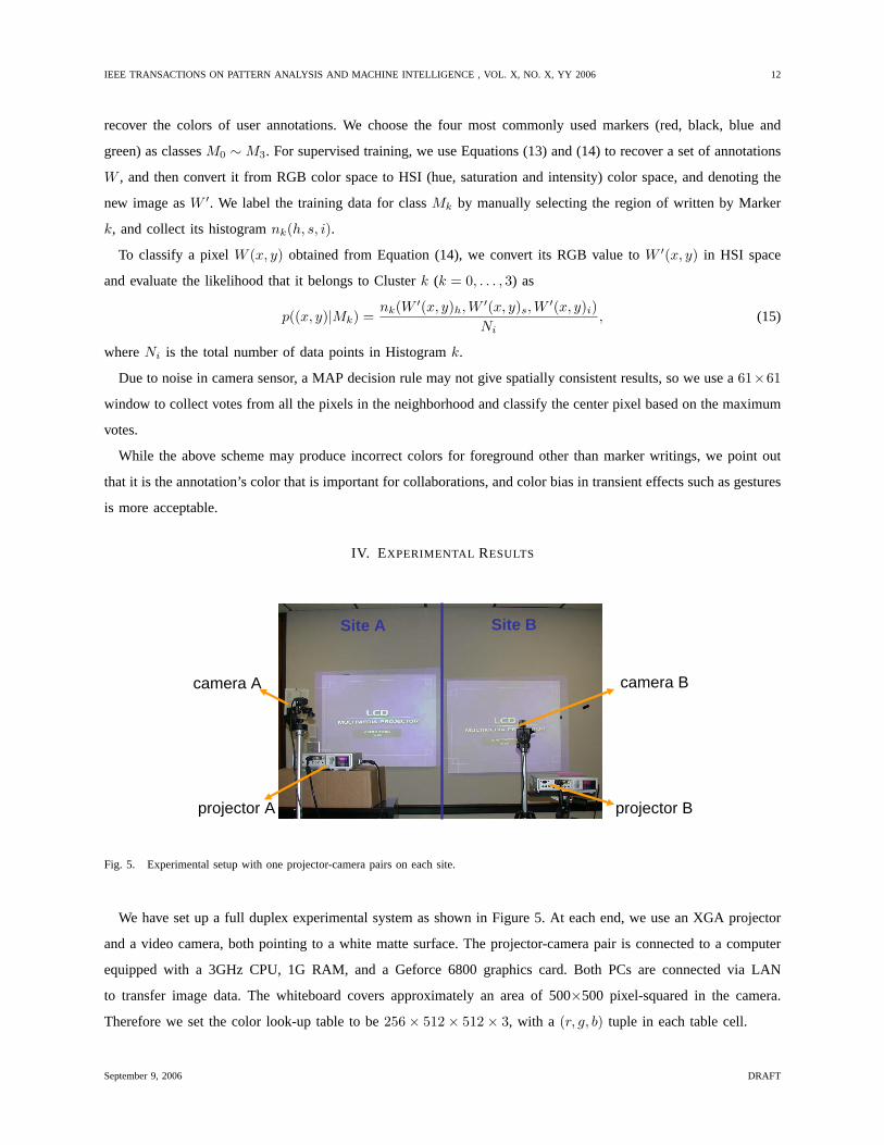
Fig. 5. Experimental setup with one projector-camera pairs on each site.
We have set up a full duplex experimental system as shown in Figure 5. At each end, we use an XGA projector
and a video camera, both pointing to a white matte surface. The projector-camera pair is connected to a computer
equipped with a 3GHz CPU, 1G RAM, and a Geforce 6800 graphics card. Both PCs are connected via LAN
to transfer image data. The whiteboard covers approximately an area of 500×500 pixel-squared in the camera.
Therefore we set the color look-up table to be256× 512× 512× 3, with a (r, g, b) tuple in each table cell.
September 9, 2006 DRAFT

IEEE TRANSACTIONS ON PATTERN ANALYSIS AND MACHINE INTELLIGENCE , VOL. X, NO. X, YY 2006 13
Since our display surface is flat, we estimated the homography between the projector and the camera. During
our experiments we found that the surface is not very rigid and the projector image is not stable (each projector is
connected to a PC via a 30-foot long VGA cable). All these resulted in the inaccuracy in our geometric calibration.
Nevertheless, our feature-based post-processing successfully overcame this limitation.
Figure 6 shows our visual echo cancelation results on various projected background. Notice the busy background
both in color and contents. Figure 7 shows the differences between the camera images and images predicted by
different photometric calibration methods. We can see that our method achieved more accurate prediction with the
least pixel error. Figure 7 also highlights the problem of misalignment due to quantization and non-rigid setup. This
is addressed by the post-processing step.
Fig. 6. Visual echo cancelation results produced by our method. From left to right, (1st column) original projector images; (2nd column)
predicted images by our photometric calibration method; (3rd column) images captured by the camera; (4th column) images after visual echo
cancelation; only non-echo foreground pixels are shown.
In Figure 8 we show some annotations with recovered color. The recovered writing is much more vivid than that
from the camera image.
Our accelerated implementation using the GPU allows the full system to run at a speed of about 8 fps on a
NVIDIA GeForce 6800 card. This speed is fast enough to enable two users to collaborate. The effects ofwithout
visual echo cancellation are demonstrated in Figure 9. We show the images from both sites to better illustrate the
problem. Figure 10 shows the full duplex operations in which two people from different sites collaborate in the
shared space with projected contents.More results can be found in the companion video.
September 9, 2006 DRAFT

IEEE TRANSACTIONS ON PATTERN ANALYSIS AND MACHINE INTELLIGENCE , VOL. X, NO. X, YY 2006 14
Pixel error: <10 10~25 25~65 >65
Fig. 7. The pixel color error (measured by absolute difference) between the captured images and predicted images by other photometric
calibration method. From left to right, (1st column) images captured by the camera. (2nd column) color error from images predicted by three
(RGB) independent intensity transfer functions—an assumption made in [21], [8]. (3rd column) color error from our predicted images.
Fig. 8. Marker Color Recovery. The first one is the projected content, the second is the camera image, and the last is the foreground image
with recovered color.
V. CONCLUSION
We have demonstrated a comprehensive pipeline for visual echo cancelation in a full-duplex projector camera
system. Both ends conduct a geometric and photometric calibration off-line. With the recorded calibration informa-
tion at each end, the camera-view image predicted from the projector image is compared against the real captured
image to remove visual echo at run-time. Only non-echo foreground pixels are transferred in network and used for
display, therefore achieving the goal of suppressing visual echo.
Compared to some previous methods, our color look-up-table model obtained in the photometric calibration
shows a significant advantage in initial echo-pixel classification. The following feature-based post-processing method
further reduces the false negative rate for classifying each pixel, which leads to dramatically improved segmentation
September 9, 2006 DRAFT

IEEE TRANSACTIONS ON PATTERN ANALYSIS AND MACHINE INTELLIGENCE , VOL. X, NO. X, YY 2006 15
Fig. 9. Images from the live system with visual echo cancallationdisabled. The two rows show images from two different sites. There is only
one participant in one site (top image row).
result.
Looking into the future there are some places for improvement. Our system currently can only work at night or
under weak constant environment light, it cannot deal with sun light, because it is too strong and it changes all the
time at daytime. We would like to address this problem to make our system more robust. We also want to make
the off-line geometric and photometric calibration on-line in order to reduce the overhead of these manual work.
AcknowledgementWe would like to thank Mingxuan Sun and Hanning Zhou for working on an early prototype of
the visual echo cancelation system. This work is supported in part by University of Kentucky Research Foundation
and US National Science Foundation award IIS-0448185.
REFERENCES
[1] M. Brown, A. Majumder, and R. Yang. Camera-Based Calibration Techniques for Seamless Multiprojector Displays.IEEE Transactions
on Visualization and Computer Graphics, 11(2):193–206, 2005.
[2] T.J. Cham, J. Rehg, R. Sukthankar, and G. Sukthankar. Shadow elimination and occluder light suppression for multi-projector displays.
Proceedings of Computer Vision and Pattern Recognition, 2003.
[3] H. Chen, R. Sukthankar, and G. Wallace. Scalable Alignment of Large-Format Multi-Projector Displays Using Camera Homography Trees.
In Proceeding of IEEE Visualization 2002, pages 339–346, 2002.
[4] P. E. Debevec and J. Malik. Recovering High Dynamic Range Radiance Maps from Photographs.Proceedings of ACM Siggraph, pages
369–378, 1997.
[5] K. Fujii, M.D. Grossberg, and S.K. Nayar. A Projector-Camera System with Real-Time Photometric Adaptation for Dynamic Environments.
In IEEE Conference on Computer Vision and Pattern Recognition (CVPR), volume 1, pages 814–821, 2005.
[6] D. Hall, C. Le Gal, J. Martin, O. Chomat, T. Kapuscinski, and J. Crowley. Magicboard: A contribution to an intelligent office environment.
In Proc. of the International Symposium on Intelligent Robotic Systems, 1999.
September 9, 2006 DRAFT

IEEE TRANSACTIONS ON PATTERN ANALYSIS AND MACHINE INTELLIGENCE , VOL. X, NO. X, YY 2006 16
Fig. 10. Full duplex operation of the live system, allowing natural interactions in the virtually shared space. Each row shows images from one
site.
[7] C. Jaynes, B. Seales, K. Calvert, Z. Fei, and J. Griffioen. The Metaverse - A Collection of inexpensive, self-configuring,immersive
environments. InProceeding of 7th International Workshop on Immersive Projection Technology/Eurographics Workshop on virtual
Environments, 2003.
[8] C. Jaynes, S. Webb, and R. Steele. Camera-based detection and removal of shadows from interactive multiprojector displays.IEEE
Transactions on Visualization and Computer Graphics, 10(3):290–301, 2004.
[9] A. Majumder, D. Jones, M. McCrory, M. E. Papka, and R. Stevens. Using a Camera to Capture and Correct Spatial Photometric Variation
in Multi-Projector Displays. InProceeding of IEEE International Workshop on Projector-Camera Systems, 2003.
[10] A. Majumder and R. Stevens. Color Nonuniformity in Projection-Based Displays: Analysis and Solutions.IEEE Transactions on
Visualization and Computer Graphics, 10(2), 2003.
[11] E. Mynatt, T. Igarashi, W. Edwards, and A. LaMarca. Flatland: New Dimensions in the Whiteboard. InProceedings of Computer-Human
Interaction (CHI), pages 346–353, 1999.
[12] C.S. Pinhanez. ”the everywhere displays projector: a device to create ubiquitous graphical interfaces. InUbicomp01, Proceedings of an
International Conference on Ubiquitous Computing, 2001.
[13] R. Raskar, M. Brown, R. Yang, W. Chen, G. Welch, H. Towles, B. Seales, and H. Fuchs. Multi-projector displays using camera-based
registration. InProceeding of IEEE Visualization 1999, pages 161–168, 1999.
[14] R. Raskar, J. van Baar, P. Beardsley, T. Willwacher, S. Rao, and C. Forlines. ilamps: Geometrically aware and self-configuring projectors.
ACM Transactions on Graphics (SIGGRAPH 2003), 22(3):809–818, 2003.
[15] R. Raskar, G. Welch, M. Cutts, A. Lake, L. Stesin, and H. Fuchs. The Office of the Future: A Unified Approach to Image-Based Modeling
and Spatially Immersive Displays.Computer Graphics, 32(Annual Conference Series):179–188, 1998.
[16] R.Surati.Scalable Self-Calibrating Display Technology for Seamless Large-Scale Displays. PhD thesis, Department of Computer Science,
Massachusetts Institute of Technology, 1998.
[17] Y. Sato, Y. Kobayashi, and H. Koike. Fast tracking of hands and fingertips in infrared images for augmented desk interface. InProc. of
the 4th Intl. Conf. on Automatic Face and Gesture Recognition, 2000.
[18] Maureen C. Stone. Color and brightness appearance issues in tiled displays.IEEE Comput. Graph. Appl., 21(5):58–66, 2001.
[19] N. Takao, J. Shi, and S. Baker. Telegraffiti: A camera-projector based remote sketching system with hand-based user interface and automatic
session summarization.International Journal of Computer Vision (IJCV),, 53(2):115–133, 2003.
September 9, 2006 DRAFT

IEEE TRANSACTIONS ON PATTERN ANALYSIS AND MACHINE INTELLIGENCE , VOL. X, NO. X, YY 2006 17
[20] N. Takao, J. Shi, and S.Baker. Tele-grafitti. TechnicalReport CMU-RI-TR-02-10, Robotics Institute,Carnegie Mellon University, 2002.
[21] Naoya Takao, Simon Baker, and Jianbo Shi. Steady-state feedback analysis of tele-graffiti. InProceedings of the IEEE International
Workshop on Projector-Camera Systems, October 2003.
[22] Pierre Wellner. Interactivng with paper on the DigitialDesk.Communications of the ACM, 36(7):86–97, 1993.
[23] R. Yang, D. Gotz, J. Hensley, H. Towles, and M. Brown. PixelFlex: A Reconfigurable Multi-Projector Display System. InProceeding of
IEEE Visualization 2001, pages 167–174, San Diego, CA, 2001.
[24] K.-J. Yoon and I.-S. Kweon. Locally adaptive support-weight approach for visual correspondence search. InProceedings of Conference
on Computer Vision and Pattern Recognition (CVPR), pages 924–931, 2005.
[25] Z. Zhang. Computer vision techniques for remote collaboration using physical whiteboards, projectors and cameras. In C. Jaynes and
R. Collins, editors,Computer Vision for Interactive and Intelligent Environments, pages 109–122. IEEE Computer Society, 2006.
[26] H. Zhou, Z. Zhang, and T. Huang. Visual Echo Cancellation in a Projector-Camera-Whiteboard System. InProceedings of International
Conference on Image Processing (ICIP), pages 2885–2888, 2004.
September 9, 2006 DRAFT