Embed Size (px)
Citation preview
31C14SW2010 2.22989 ANGLESEA 010
Report On
Airborne Geophysical Survey
Tudor Township, Ontario
By
Fugro Airborne Surveys
For
Lydia Diamond Exploration of Canada Ltd.
J i/'[fi OFF
Index
Page
Introduction l
Property l
Location and Access 2
General Geology 2
Geophysical Survey 3
Appendix I
Report by Emily Farquhar
Fugro Airborne Survey Corp.
Mississauga, Ont. November 2000
Introduction
A close spaced (25 m) helicopter airborne geophysical survey was carried out
during September - October 2000 in the south-east part of Tudor Township and a second
area in the north-central part of Grimsthorpe Township. A total of 1,797.8 line kilmetres
were flown, of which 1,615 line kilometers are claimed in this report.
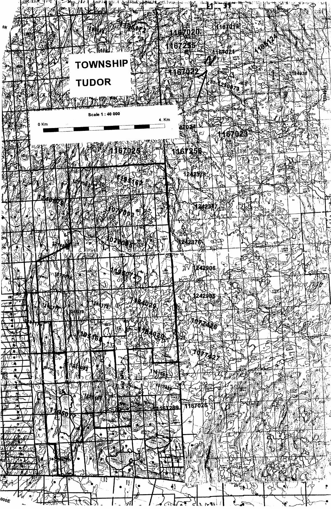
Property
The property in Tudor Township consisted of 21 claims containing 138 claim
units at the time of the airborne survey. The claims are numbered SO 1077074 to
1077075, SO 1077091 to 1077095 inclusive, SO 1184209 to 1184030, SO 1195071 to
1195072, SO 1195077, SO 1195165, SO 1195167, SO 1195169, SO 1195177 to
1195181 inclusive and SO 1195183 in the south east part of Tudor Township, Southern
Ontario Mining Division. They are held in the name of Lydia Diamond Exploration of
Canada Ltd.
The property in Grimsthorpe Township consisted of 9 claims containing 134
claim units at the time of the airborne survey. The claims are number SO 1235047 to
1235052 inclusive and SO 1235054 to 1235056 inclusive in the north central part of
Grimsthorpe Township, Southern Ontario Mining Division. They are held 50^o in the
name of Emilia, Princess von Anhalt and 50*^o in the name of Jurgen Freidman Prinz von
Anhalt.
Location and Access
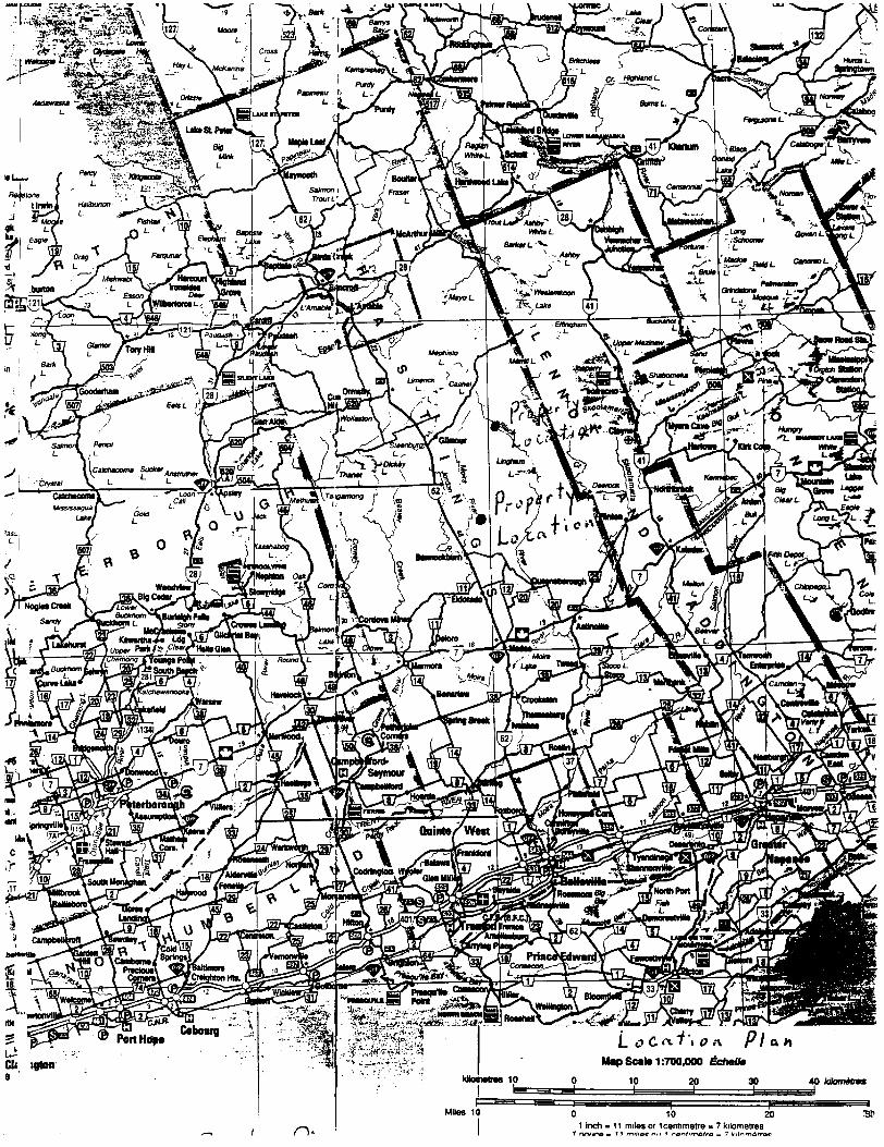
The Tudor property is located about 20 km north of Madoc, Ontario. Madoc lies
at the junction of Highways 7 and 62. Highway 7 runs east from Toronto through
Peterborough to Ottawa; Highway 62 runs north from Belleville to Bancroft. Madoc is
about 41 km north of Belleville. Access to the property is by secondary township roads
which run east from Highway 62.
The Grimsthorpe Township property is located about 10 km east of Gilmour,
Ontario. Gilmour lies east on Highway 62 on the Weslemkoon Lake road about halfway
between Madoc and Bancroft. Access to the property is by a forest access road which
runs from the Weslemkoon Lake Road through the center of the property.
Property locations are shown on the enclosed map.
General Geology
The property is underlain by a volcanic to sedimentary sequence intruded by
mafic to granitic rocks. Metamorphic grade is generally high. The area is part of the
Proterozoic Grenville province of the Precambrian shield. In general the east part of the
property is underlain by mafic intrusive rocks of the Lingham Lake complex with mafic
volcanics, to the west and south, with a narrow band of felsic volcanics followed by
carbonate metasediments further west.
There has been previous exploration in the area for gold and lead-zinc.
:^bS*Fitk
5uiUt igton
h*A /7/a*
Map Scale 1:700,000
10 10 20 30
10
i D*O 10 20
11nch - 11 miles or 1 centimetre - 7 kilometres
40 kllcmMnf
3T
TOWNSHIP
TUDOR
ra* x^-^vi i. ;fi; : u^jv/ay v r^it'*** ^ ^*l w ^ v Mf -li
Geophysical Survey
The airborne survey was carried out by Fugro Airborne Survey Corp. of
Mississauga, Ontario. Details of the survey are given in a report by Emily Farquhar in
Appendix I. A total of 1,797.8 line kilometers were flown at a cost of 555,453.14 . This
was reduced to 1,615 line kilometers with a cost of 549,814.68. The reduction is for a
small amount of the airborne survey previously reported on the property of Saxongate
Ltd., and for areas overflown , but not owned which have been removed from the survey
plans.
Appendix I
Report by Emily FarquharFugro Airborne Survey Corp.
Mississauga, Ont., November 2000
Contract # 2034
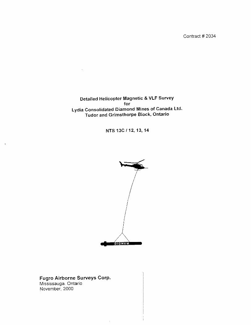
Detailed Helicopter Magnetic 4 VLF Surveyfor
Lydia Consolidated Diamond Mines of Canada Ltd.
Tudor and Grimsthorpe Block, Ontario
NTS 13C/12, 13, 14
Fugro Airborne Surveys Corp.Mississauga, Ontario November, 2000
SUMMARY
This report describes the logistics and results of a helicopter-borne magnetic/VLF geophysical survey carried out for Lydia Consolidated Diamond Mines of Canada, over a property located near Madoc, Ontario. Total coverage of the survey blocks amounted to 1,797.8 km. The survey was flown from September 24th to October 1st, 2000.
The purpose of the survey was to detect zones of conductive mineralization and to provide information that could be used to map the geology and structure of the survey area. This was accomplished by using a High-Sense MiniMag system with a GFCS II flight control system, supplemented by a high sensitivity cesium magnetometer and a four-channel VLF receiver. The information from these sensors was processed to produce maps that display the magnetic and conductive properties of the survey area. A GPS electronic navigation system, utilizing a satellite link, ensured accurate positioning of the geophysical data with respect to the base maps. Visual flight path recovery techniques were used to confirm the location of the helicopter where visible topographic features could be identified on the ground.
TABLE OF CONTENTS
1. INTRODUCTION..........................................................................................................1.1
2. SURVEY EQUIPMENT................................................................................................2.1Geophysical Flight Control System...............................................................................2.1Magnetometer.............................................................................................................. 2.1Magnetic Base Station..................................................................................................2.1VLFSystem..................................................................................................................2.2Radar Altimeter ............................................................................................................2.2Barometric Pressure and Temperature Sensors ..........................................................2.2Digital Data Acquisition System....................................................................................2.2Video Flight Path Recording System ............................................................................2.2Navigation (Global Positioning System)........................................................................2.3Field Workstation .........................................................................................................2.3
3. PRODUCTS AND PROCESSING TECHNIQUES........................................................3.1Base Maps ...................................................................................................................3.1Total Magnetic Field .....................................................................................................3.2Magnetic Derivatives (optional) ....................................................................................3.3VLF..............................................................................................................................3.4Contour and Colour Map Displays................................................................................3.4Digital Terrain...............................................................................................................3.4
4. SURVEY RESULTS.....................................................................................................4.1General Discussion ......................................................................................................4.1Magnetics.....................................................................................................................4.1VLF..............................................................................................................................4.1
5. CONCLUSIONS AND RECOMMENDATIONS .............................................................5.1
APPENDICES
A. List of PersonnelB. Statement of CostC. Background InformationD. Archive Description
-1.1 -
1. INTRODUCTION
A MiniMag magnetic/VLF survey was flown for Lydia Consolidated Diamond Mines of
Canada, from September 24th to October 1st, 2000, over two survey blocks located
near Madoc, Ontario. The survey areas can be located on NTS map sheets 13C/12, 13,
14.
Survey coverage consisted of approximately 1,797.8 line-km, including tie lines. Flight
lines were flown in an azimuthal direction of N450E for the Tudor Block and N200W for the
Grimsthorpe Block with a line separation of 25 metres.
The survey employed the MiniMag system. Ancillary equipment consisted of radar and
barometric altimeters, video camera, a VLF receiver, and an electronic navigation system.
The instrumentation was installed in an AS350B3 helicopter C-GECL which was provided
by Questral Helicopters. The helicopter flew at an average airspeed of 100 km/h with a
magnetometer sensor height of approximately 25 m.
Section 2 provides details on the survey equipment, the data channels, their respective
sensitivities, and the navigation/flight path recovery procedure.
In some portions of the survey area, strong winds permitted excessive bird swinging. This
problem gave rise to aerodynamic noise levels that are slightly higher than normal on
some lines. Where warranted, refiights were carried out to minimize these adverse
effects.
-2.1 -
2. SURVEY EQUIPMENT
This section provides a brief description of the geophysical instruments used to acquire
the survey data and the calibration procedures employed.
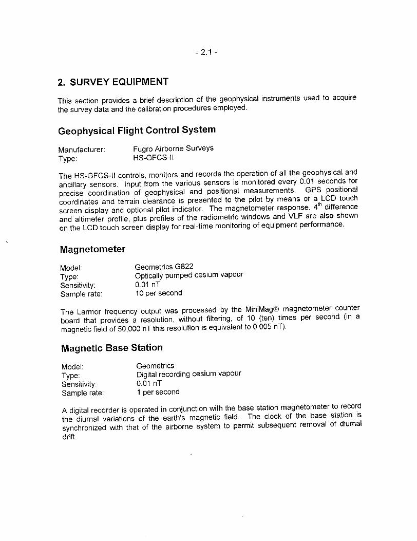
Geophysical Flight Control System
Manufacturer: Fugro Airborne Surveys Type: HS-GFCS-II
The HS-GFCS-II controls, monitors and records the operation of all the geophysical and
ancillary sensors. Input from the various sensors is monitored every 0.01 seconds for
precise coordination of geophysical and positional measurements. GPS positional
coordinates and terrain clearance is presented to the pilot by means of a LCD touch
screen display and optional pilot indicator. The magnetometer response, 4th difference
and altimeter profile, plus profiles of the radiometric windows and VLF are also shown
on the LCD touch screen display for real-time monitoring of equipment performance.
Magnetometer
Model: Geometrics G822Type: Optically pumped cesium vapourSensitivity: 0.01 nTSample rate: 10 per second
The Larmor frequency output was processed by the MiniMag magnetometer counter
board that provides a resolution, without filtering, of 10 (ten) times per second (in a
magnetic field of 50,000 nT this resolution is equivalent to 0.005 nT).
Magnetic Base Station
Model: GeometricsType: Digital recording cesium vapourSensitivity: 0.01 nTSample rate: 1 per second
A digital recorder is operated in conjunction with the base station magnetometer to record
the diurnal variations of the earth's magnetic field. The clock of the base station is
synchronized with that of the airborne system to permit subsequent removal of diurnal
drift.
-2.2-
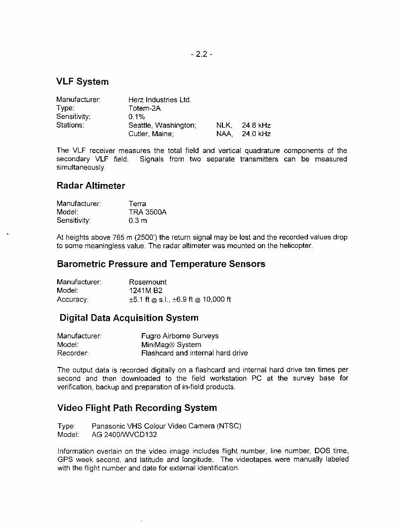
VLF System
Manufacturer: Herz Industries Ltd. Type: Totem-2A Sensitivity: 0.1 "/oStations: Seattle, Washington; NLK, 24.8 kHz
Cutler, Maine; NAA, 24.0 kHz
The VLF receiver measures the total field and vertical quadrature components of the secondary VLF field. Signals from two separate transmitters can be measured simultaneously.
Radar Altimeter
Manufacturer: TerraModel: TRA 3500ASensitivity: 0.3 m
At heights above 765 m (2500') the return signal may be lost and the recorded values drop to some meaningless value. The radar altimeter was mounted on the helicopter.
Barometric Pressure and Temperature Sensors
Manufacturer: RosemountModel: 1241M B2Accuracy: 5.1 ft @ s.l., 6.9 ft @ 10,000 ft
Digital Data Acquisition System
Manufacturer: Fugro Airborne SurveysModel: MiniMag SystemRecorder: Flashcard and internal hard drive
The output data is recorded digitally on a flashcard and internal hard drive ten times per second and then downloaded to the field workstation PC at the survey base for verification, backup and preparation of in-field products.
Video Flight Path Recording System
Type: Panasonic VHS Colour Video Camera (NTSC) Model: AG 2400/WVCD132
Information overlain on the video image includes flight number, line number, DOS time, OPS week second, and latitude and longitude. The videotapes were manually labeled with the flight number and date for external identification.
-2.3-
Navigation (Global Positioning System)
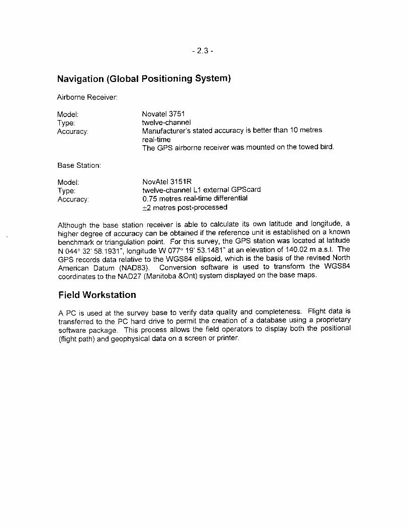
Airborne Receiver:
Model: Novatel 3751Type: twelve-channelAccuracy: Manufacturer's stated accuracy is better than 10 metres
real-timeThe GPS airborne receiver was mounted on the towed bird.
Base Station:
Model: NovAtel3151R Type: twelve-channel L1 external GPScard Accuracy: 0.75 metres real-time differential
2 metres post-processed
Although the base station receiver is able to calculate its own latitude and longitude, a higher degree of accuracy can be obtained if the reference unit is established on a known benchmark or triangulation point. For this survey, the GPS station was located at latitude
N 0440 32' 58.1931", longitude W 0770 19' 53.1481" at an elevation of 140.02 m a.s.l. The GPS records data relative to the WGS84 ellipsoid, which is the basis of the revised North American Datum (NAD83). Conversion software is used to transform the WGS84 coordinates to the NAD27 (Manitoba SOnt) system displayed on the base maps.
Field Workstation
A PC is used at the survey base to verify data quality and completeness. Flight data is transferred to the PC hard drive to permit the creation of a database using a proprietary
software package. This process allows the field operators to display both the positional
(flight path) and geophysical data on a screen or printer.
-3.1 -
3. PRODUCTS AND PROCESSING TECHNIQUES
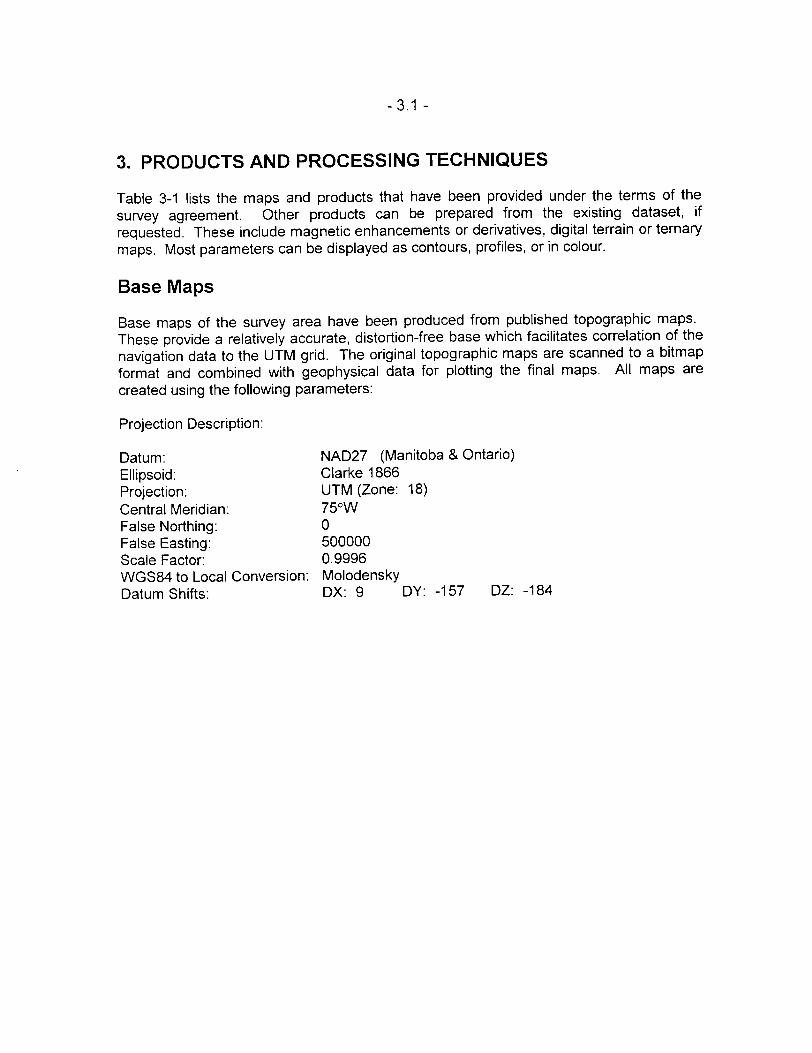
Table 3-1 lists the maps and products that have been provided under the terms of the survey agreement. Other products can be prepared from the existing dataset, if requested. These include magnetic enhancements or derivatives, digital terrain or ternary maps. Most parameters can be displayed as contours, profiles, or in colour.
Base Maps
Base maps of the survey area have been produced from published topographic maps. These provide a relatively accurate, distortion-free base which facilitates correlation of the navigation data to the UTM grid. The original topographic maps are scanned to a bitmap format and combined with geophysical data for plotting the final maps. All maps are created using the following parameters:
Projection Description:
Datum: NAD27 (Manitoba b Ontario)Ellipsoid: Clarke 1866Projection: UTM (Zone: 18)Central Meridian: 750WFalse Northing: OFalse Easting: 500000Scale Factor: 0.9996WGS84 to Local Conversion: MolodenskyDatum Shifts: DX: 9 DY: -157 DZ: -184
-3.2-
Table 3-1 Survey Products
1. Final Transparent Maps (+S prints) @ 1:5,000
Total magnetic field Filtered total field VLF
2. Final Transparent Maps (+S prints) @ 1:10,000
Total magnetic field Filtered total field VLF
3. Colour Maps (2 sets) @ 1:5,000
Total magnetic field Filtered total field VLF
4. Colour Maps (2 sets) @ 1:10,000
Total magnetic field
5. Additional Products
Digital XYZ archive in Geosoft format (CD-ROM)
Digital grid archives in Geosoft format (CD-ROM)
Survey report (3 copies) Flight path videocassettes
Note: Other products can be produced from existing survey data, if requested.
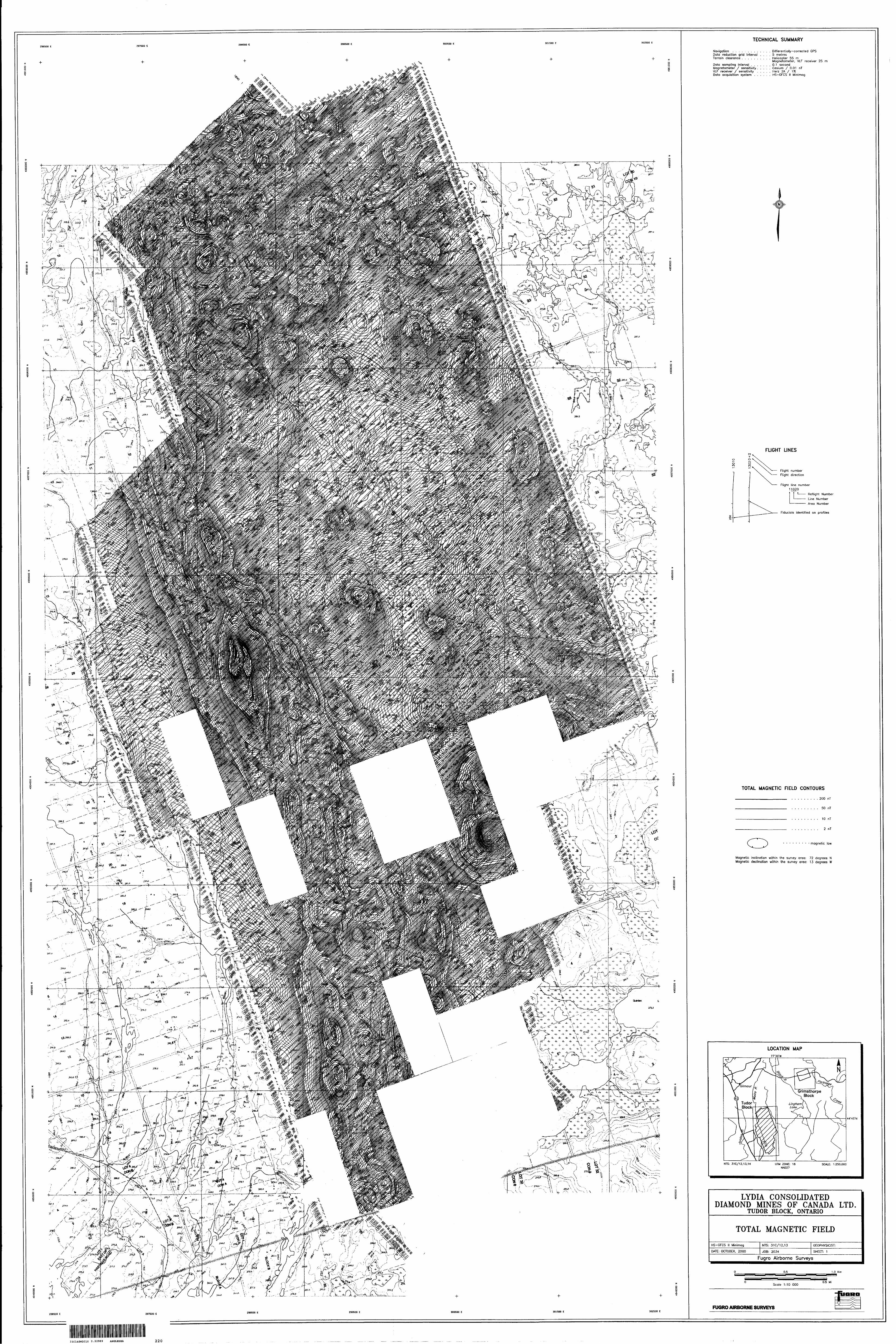
Total Magnetic Field
Diurnal activity recorded at the base station was time-stamped with the GPS week
seconds. Spikes are removed and interpolated to 0.1 seconds before being merged with
the airborne data. The diurnal is subtracted from the raw total field magnetics.
Errors in time caused by a data transfer delay in the acquisition system is commonly called
the lag. The difference in time between prominent peaks flown in opposite directions is
twice the lag, and the lag correction is therefore one half of this time difference.
Total field magnetic data varies from line to line due to several factors, such as diurnal
activity, lag and difference in terrain clearance. Even after diurnal and lag corrections,
data will still have some residual errors left in it. Those residuals combined with level
errors caused by survey altitude differences between lines will make the magnetic data still
unsuitable for final presentation. To correct the problem, control lines, perpendicular to
-3.3-
traverse lines, are always flown during a survey, and are to be used to minimize line to line
level noise.
The effective wavelength of control line correction is twice the control line spacing,
because the corrections for points in between are linearly interpolated from the corrections
calculated at the two intersections. Any higher order corrections of wavelength less than
the control line spacing is not possible with the control line leveling technique.
Microleveling is an enhancement leveling technique mostly suited in corrections with
wavelength less than control line spacing where normal control line leveling is no longer
effective. It is essentially a 'decorrugation' filtering process, which seeks to remove level
noise. A decorrugation filter as applied to grids is usually elliptically shaped, and
orientated with major axis along the traverse line direction. The length of its major axis is
in the order of control line spacing, whilst the length of its minor axis is in the order of twice
traverse line spacing. Any small features, hopefully mostly noise, which can be enclosed
by the decorrugation filter, will be removed. The microleveling corrections calculated from
the grids were 'threaded' into a database channel, low-pass filtered, and applied to profile
data.
Since microleveling does not have the ability to distinguish valid magnetic anomalies from
noise features of similar wavelength, it should be used with extreme caution. Microleveling
can remove noise as well as valid signal. To prevent unwarranted data distortion,
microleveling corrections are kept to a bare minimum. However, without microleveling, low
level noise features are still quite evident in shaded relief image of the total field
magnetics, or the calculated second vertical derivative. Therefore, the tradeoff between
data quality and very minor reduction in signal is necessary through microleveling, which
has become a commonly used standard processing procedure in geophysical exploration
industry.
Magnetic Derivatives (optional)
The total magnetic field data can be subjected to a variety of filtering techniques to yield
maps of the following:
enhanced magneticshorizontal derivativesvertical derivativesreduction to the pole/equatormagnetic susceptibility with reduction to the pole
upward/downward continuations
analytic signal
All of these filtering techniques improve the recognition of near-surface magnetic bodies,
with the exception of upward continuation. Any of these parameters can be produced on
request. Fugro's proprietary enhanced magnetic technique is designed to provide a
general "all-purpose" map, combining the more useful features of the above parameters.
-3.4-
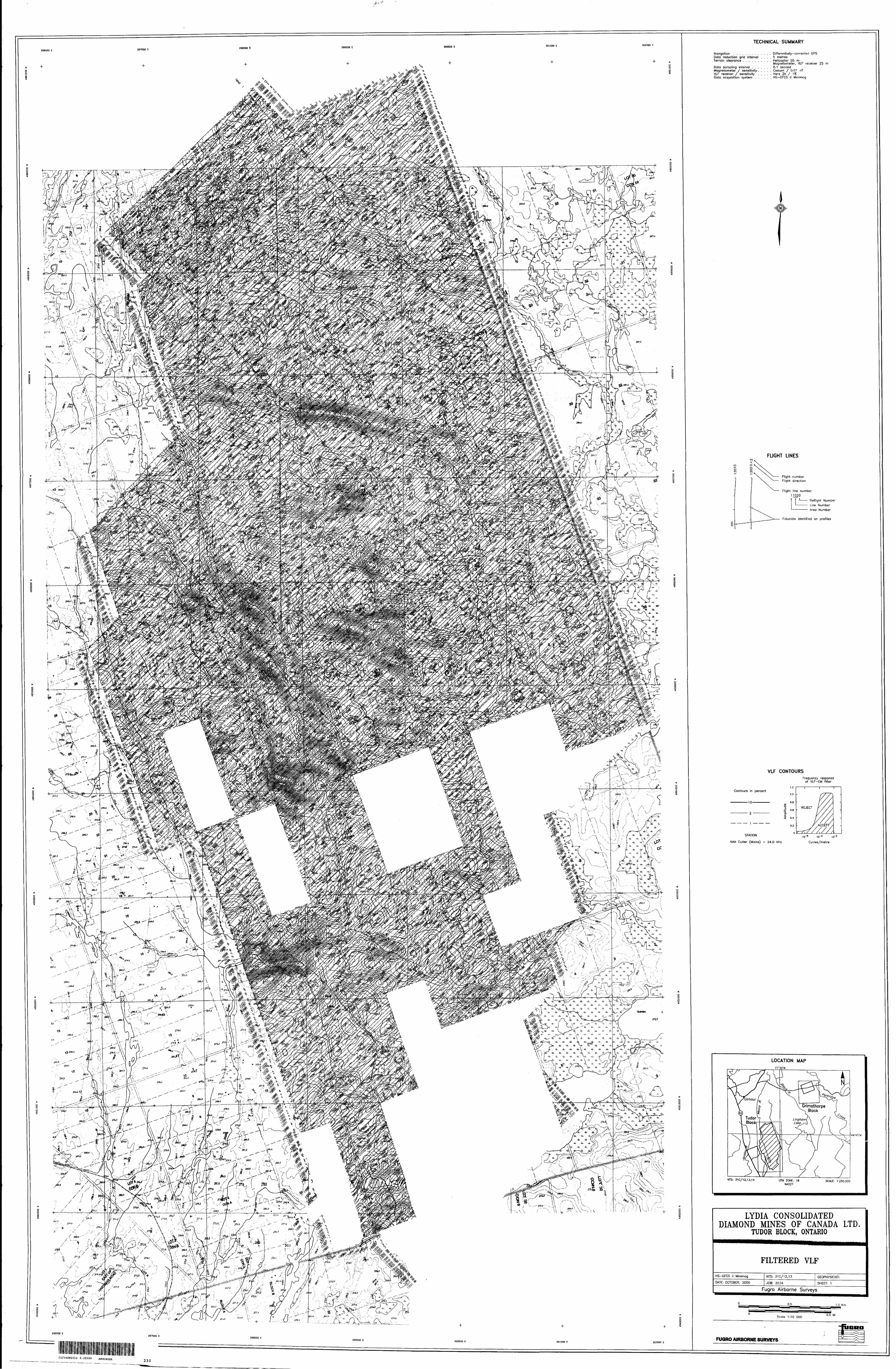
VLF
The VLF total field data is digitally filtered to autonormalize the response and to remove long wavelengths such as those caused by variations in the transmitted field strength. Further high frequency suppression results in an effective band pass filter for the final display of the total field VLF. The total field response from the Line (NAA) channel of the VLF have been filtered in this way.
Contour and Colour Map Displays
The geophysical data is interpolated onto a regular grid using a modified Akima spline technique. The resulting grid is suitable for generating contour maps of excellent quality. The grid cell size is usually 25 07o of the line interval.
Colour maps are produced by interpolating the grid down to the pixel size. The parameter is then incremented with respect to specific amplitude ranges to provide colour "contour" maps. Colour maps of the total magnetic field are particularly useful in defining the lithology of the survey area.
Digital Terrain
The radar altimeter values were subtracted from the differentially corrected GPS-Z values, which were transformed to the local datum, to produce profiles of the height above mean sea level along the survey lines. These values were gridded to produce contour maps showing approximate elevations within the survey blocks. The resulting digital terrain contours were compared against published topographic maps. The data was manually adjusted to remove differences between the two. The data was then subjected to a microleveling algorithm to remove any remaining small line-to-line discrepancies.
The accuracy of the elevation calculation is directly dependent on the accuracy of the two input parameters. The altimeter value may be erroneous in areas of heavy tree cover, where the device reflects the distance to the tree canopy rather than the ground. The GPS-Z value is primarily dependent on the number of available satellites. Although post processing of GPS data will yield X and Y accuracy's in the order of 5 metres, the accuracy of the Z value is usually much less, sometimes in the 20 metre range. Further inaccuracies may be introduced during the interpolation and gridding process.
Because of the inherent inaccuracies of this method, no guarantee is made or implied that the information displayed is a true representation of the height above sea level. Although this product may be of some use as a general reference, THIS PRODUCT MUST NOT BE USED FOR NAVIGATION PURPOSES.
-4.1 -
4. SURVEY RESULTS
General Discussion
The survey results are presented on 5 separate map sheets for each parameter at a scale of 1:5,000.
Magnetics
A Geometrics cesium vapour magnetometer was operated at the survey base to record diurnal variations of the earth's magnetic field. The clock of the base station was synchronized with that of the airborne system to permit subsequent removal of diurnal drift
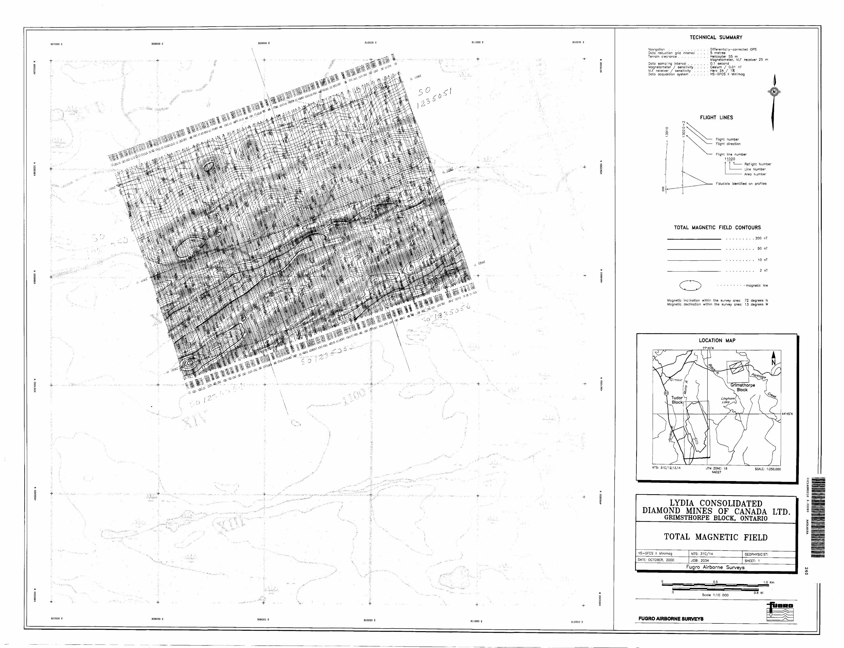
The total magnetic field data have been presented as contours on the base maps using a contour interval of 2 nT where gradients permit. The maps shows the magnetic properties of the rock units underlying the survey area.
If a specific magnetic intensity can be assigned to the rock type which is believed to host the target mineralization, it may be possible to select areas of higher priority on the basis of the total field magnetic data. This is based on the assumption that the magnetite content of the host rocks will give rise to a limited range of contour values that will permit differentiation of various lithological units.
The magnetic results, in conjunction with the other geophysical parameters, have provided valuable information that can be used to effectively map the geology and structure in the survey areas.
VLF
VLF results were obtained from the transmitting stations at Cutler, Maine (NAA -24.0 kHz) and Seattle, Washington (NLK - 24.8 kHz). The VLF parameter does not normally provide the same degree of resolution available from helicopter frequency domain EM data. Closely spaced conductors, conductors of short strike length or conductors that are poorly coupled to the VLF field, may escape detection with the VLF method. Erratic signals from the VLF transmitters can also give rise to strong, isolated anomalies which should be viewed with caution. Regardless of these limitations, however, the VLF results can provide valuable additional information, particularly within the more resistive portions of the survey area. The VLF method could probably be used as a follow-up tool in most areas, although its effectiveness will be somewhat limited in areas of moderate to high conductivity. The filtered total field VLF contours from Cutler, Maine (NAA 24.0 kHz), the Line VLF channel are presented on the base map(s) with a contour interval of one percent.
-5.1 -
5. CONCLUSIONS AND RECOMMENDATIONS
This report describes the equipment, procedures and logistics of the survey.
It is recommended that image processing of existing geophysical data be considered, in
order to extract the maximum amount of information from the survey results. Current
software and imaging techniques often provide valuable information on structure and
lithology, which may not be clearly evident on the contour and colour maps. These
techniques can yield images which define subtle, but significant, structural details.
Respectfully submitted,
FUGRO AIRBORNE SURVEYS CORP.
Emily FarquharManager, Data Processing and Interpretation
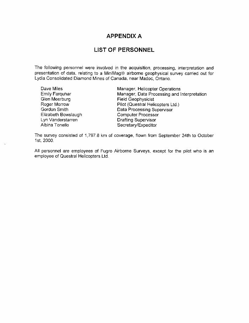
APPENDIX A
LIST OF PERSONNEL
The following personnel were involved in the acquisition, processing, interpretation and presentation of data, relating to a MiniMag airborne geophysical survey carried out for Lydia Consolidated Diamond Mines of Canada, near Madoc, Ontario.
Dave Miles Manager, Helicopter OperationsEmily Farquhar Manager, Data Processing and InterpretationGlen Meerburg Field GeophysicistRoger Morrow Pilot (Questral Helicopters Ltd.)Gordon Smith Data Processing SupervisorElizabeth Bowslaugh Computer ProcessorLyn Vanderstarren Drafting SupervisorAlbina Tonello Secretary/Expediter
The survey consisted of 1,797.8 km of coverage, flown from September 24th to October 1st, 2000.
All personnel are employees of Fugro Airborne Surveys, except for the pilot who is an employee of Questral Helicopters Ltd.
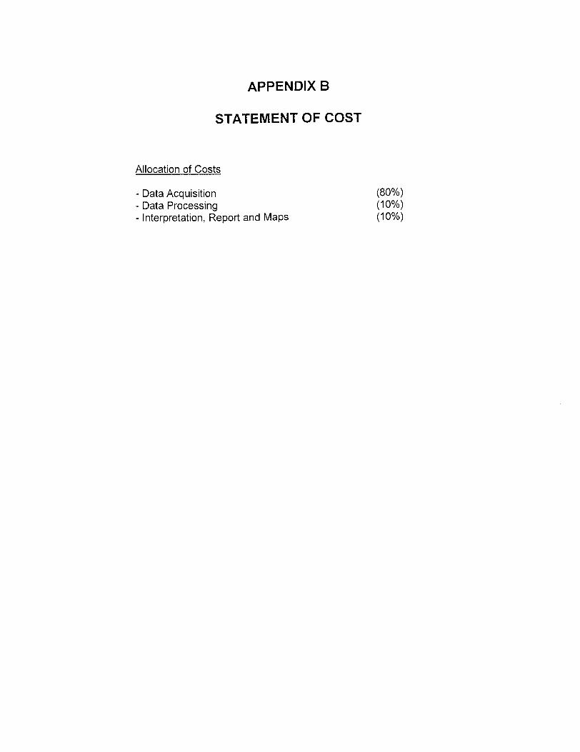
APPENDIX B
STATEMENT OF COST
Allocation of Costs
- Data Acquisition (8007o)- Data Processing (1007o)- Interpretation, Report and Maps (1007o)
-Appendix C.1 -
APPENDIX C
Magnetics
Total field magnetics provides information on the magnetic properties of the earth materials in the survey area. The information can be used to locate magnetic bodies of direct interest for exploration, and for structural and lithological mapping.
The total field magnetic response reflects the abundance of magnetic material, in the source. Magnetite is the most common magnetic mineral. Other minerals such as ilmenite, pyrrhotite, franklinite, chromite, hematite, arsenopyrite, limonite and pyrite are also magnetic, but to a lesser extent than magnetite on average.
In some geological environments, an EM anomaly with magnetic correlation has a greater likelihood of being produced by sulphides than one that is non-magnetic. However, sulphide ore bodies may be non-magnetic (e.g., the Kidd Creek deposit near Timmins, Canada) as well as magnetic (e.g., the Mattabi deposit near Sturgeon Lake, Canada).
Iron ore deposits will be anomalously magnetic in comparison to surrounding rock due to the concentration of iron minerals such as magnetite, ilmenite and hematite.
Changes in magnetic susceptibility often allow rock units to be differentiated based on the total field magnetic response. Geophysical classifications may differ from geological classifications if various magnetite levels exist within one general geological classification. Geometric considerations of the source such as shape, dip and depth, inclination of the earth's field and remanent magnetization will complicate such an analysis.
In general, mafic lithologies contain more magnetite and are therefore more magnetic than many sediments which tend to be weakly magnetic. Metamorphism and alteration can also increase or decrease the magnetization of a rock unit.
Textural differences on a total field magnetic contour, colour or shadow map due to the frequency of activity of the magnetic parameter resulting from inhomogeneities in the distribution of magnetite within the rock, may define certain lithologies. For example, near surface volcanics may display highly complex contour patterns with little line-to-line correlation.
Rock units may be differentiated based on the plan shapes of their total field magnetic responses. Mafic intrusive plugs can appear as isolated "bulls-eye" anomalies. Granitic intrusives appear as sub-circular zones, and may have contrasting rings due to contact metamorphism. Generally, granitic terrain will lack a pronounced strike direction, although granite gneiss may display strike.
Linear north-south units are theoretically not well-defined on total field magnetic maps in equatorial regions due to the low inclination of the earth's magnetic field. However, most
-Appendix C.2 -
stratigraphic units will have variations in composition along strike that will cause the units to appear as a series of alternating magnetic highs and lows.
Faults and shear zones may be characterized by alteration that causes destruction of magnetite (e.g., weathering) which produces a contrast with surrounding rock. Structural breaks may be filled by magnetite-rich, fracture filling material as is the case with diabase dikes, or by non-magnetic felsic material.
Faulting can also be identified by patterns in the magnetic total field contours or colours. Faults and dikes tend to appear as lineaments and often have strike lengths of several kilometres. Offsets in narrow, magnetic, stratigraphic trends also delineate structure. Sharp contrasts in magnetic lithologies may arise due to large displacements along strike- slip or dip-slip faults.
VLF
VLF transmitters produce high frequency uniform electromagnetic fields. However, VLF anomalies are not EM anomalies in the conventional sense. EM anomalies primarily reflect eddy currents flowing in conductors that have been energized inductively by the primary field. In contrast, VLF anomalies primarily reflect current gathering, which is a non-inductive phenomenon. The primary field sets up currents which flow weakly in rock and overburden, and these tend to collect in low resistivity zones. Such zones may be due to massive sulphides, shears, river valleys and even unconformities.
The VLF field is horizontal. Because of this, the method is quite sensitive to the angle of coupling between the conductor and the transmitted VLF field. Conductors which strike towards the VLF station will usually yield a stronger response than conductors which are nearly orthogonal to it.
The Herz Industries Ltd. Totem VLF-electromagnetometer measures the total field and vertical quadrature components. The total field yields peaks over VLF current concentrations whereas the quadrature component tends to yield crossovers. Both appear as traces on the analog profile records.
APPENDIX D
ARCHIVE DESCRIPTION
This CD-ROM contains final data archives of an airborne survey conducted Fugro Airborne Surveys on behalf of Lydia Conslidated Diamond Mines of Canada in Madoc, Ontario during September to October, 2000.
Fuqro Job # 2034.
For each survey block, Tudor and Grimsthorpe, the archives contain 3 directories.
1. Profile data in Geosoft ASCII XYZ format, along with channel header description in the file.
Area.xyz
Profile data in Geosoft GOB format.
Area.gdb
2. Grids: Grids in Geosoft format for the following parameters:
Magnetic Total FieldVLF Total Field for Cutler, Maine transmitter
3. Vectors: Vector files in DXF format of:
Flight Path Contours
Report in Microsoft Word 97: This logisitics report is found in the main directory \2034
Projection Description:Datum: NAD27 (Manitoba 8^ Ontario)Ellipsoid: Clark 1866Projection: UTM (Zone: 18)Central Meridian: 750WFalse Northing: OFalse Easting: 500000Scale Factor: 0.9996WGS84-Local Conversion :MolodenskyDatum Shifts: DX: 9 DY: -157 DZ: -184
ONTARIO MINISTRY OF NORTHERN DEVELOPMENT AND MINES
Work Report Summarv
Transaction No: W0290 00284 Status:
Recording Date: 2002-FEB-14 Work Done from:
Approval Date: 2002-MAY-15 to:
Client(s):
300883 PRINZ, VON ANHALT
300933 PRINCESS, VON ANHALT
392675 LYDIA DIAMOND EXPLORATION OF CANADA
Survey Type(s):
AMAG AVLF
APPROVED (D)
2000-SEP-24
2002-FEB-11
LTD.
Work Report Details:
Claim*
SO
SO
sososososososososososososo so so sososo sososo so so
1077074
1077091
1077092
1077093
1077094
1077095
1184029
1184030
1195071
1195072
1195077
1195165
1195167
1195169
1195177
1195178
1195179
1195180
1195181
1195183
1235050
1235051
1235054
1235055
1235056
Perform
5325
S650
51,300
55,200
S325
55,200
53,250
52,600
3650
55,200
53,900
53,900
53,900
5650
31,300
31,300
31,300
S650
51,300
5650
52,608
51,955
51,304
51,955
31,304
552,676
External Credits:
Perform Approve
5325
3650
51,300
55,200
5325
55,200
53,250
52,600
5650
55,200
53,900
53,900
33,900
S650
51,300
51,300
31,300
S650
31,300
5650
52,608
51,955
51,304
31,955
31,304
352,676
SO
Applied
5325
5650
51,300
55,200
5325
55,200
53,250
32,600
S650
55,200
SO
53,900
53,900
5650
51,300
51,300
51,300
5650
31,300
5650
52,608
31,955
31,304
51,955
51,304
348,776
Applied Assign Approve Assign Approve
S325
5650
51,300
55,200
S325
55,200
53,250
32,600
5650
55,200
SO
33,900
S3, 900
S650
51,300
31,300
31,300
S650
51,300
3650
52,608
51,955
51,304
31,955
51,304
548,776
SO
SO
sososososo50
soSO
50
50
50
SO
SO
SO
SO
SO
soso50
50
50
SO
SO
SO
0
0
0
0
0
0
0
0
0
0
0
0
0
0
0
0
0
0
0
0
0
0
0
0
0
so
Reserve
sososoSO
so30
soSO
50
SO
53,900
soSO
sososo so so50
50
SO
50
50
SO
so
53,900
Reserve Approve
SO
soSO
SO
so50
so50
50
SO
53,900
sosososo so so so50
50
soSO
50
50
SO
53,900
Due Date
2003-NOV-16
2003-MAR-27
2003-MAR-27
2003-MAR-27
2003-MAR-27
2003-MAR-27
2003-JUL-17
2003-JUL-17
2003-MAR-27
2003-MAR-27
2007-DEC-29
2003-MAR-27
2003-MAR-27
2003-MAR-27
2003-MAR-27
2003-MAR-27
2003-MAR-27
2003-MAR-07
2004-MAR-07
2003-AUG-12
2003-AUG-28
2003-AUG-28
2003-AUG-28
2003-AUG-28
2003-AUG-28
31C14SW2010
to
22989
ANGLESEA
Reserve:
53,900 Reserve of Work
53,900 Total
Status
Remaining
nf rlaim is h
Report*: W0290. 00284
aspd on information r.urrpntlv on rer.nrrl
VD O O
2002-May-24 16:11 Armstrong-d Page 1 of 1
Ministers du Developpement du Nord et des Mines
Ministry ofNorthern Developmentand Mines
Date:2002-MAY-15
LYDIA DIAMOND EXPLORATION OF CANADALTD.8 KING STREET EAST, SUITE 1704TORONTO, ONTARIOM5C1B5 CANADA
OntarioGEOSCIENCE ASSESSMENT OFFICE 933 RAMSEY LAKE ROAD, 6th FLOOR SUDBURY, ONTARIO P3E6B5
Tel: (888)415-9845 Fax:(877)670-1555
Dear Sir or Madam
Submission Number: 2.22989 Transaction Number(s): W0290.00284
Subject: Deemed Approval of Assessment Work
We have approved your Assessment Work Submission with the above noted Transaction Number(s) as per6(7) of the Assessment Work Regulation. Only eligible assessment work is deemed approved for assessment workcredit. The attached Work Report Summary indicates the results of the approval.
NOTE: The report has not been reviewed for technical deficiencies and reported expenses were not evaluated based on the Industry Standard.
At the discretion of the Ministry, the assessment work performed on the mining lands noted in this work report may be subject to inspection and/or investigation at any time.
If you have any question regarding this correspondence, please contact LUCILLE JEROME by email at [email protected] or by phone at (705) 670-5858.
Yours Sincerely,
Ron Gashinski
Senior Manager, Mining Lands Section
Gc: Resident Geologist
Robert Allan Macgregor (Agent)
Assessment File Library
Von Anhalt Prinz (Claim Holder)
Von Anhalt Princess (Claim Holder)
Lydia Diamond Exploration Of Canada Ltd. (Claim Holder)
Lydia Diamond Exploration Of Canada Ltd. (Assessment Office)
Visit our website at http://www.gov.on.ca/MNDM/LANDS/mlsmnpge.htm Page: 1 Correspondence 10:17055
Hn
n
[On
10 O O
PFUlVIMClAl HMIHA
MINING LAND TENURE
MAP
toot m ataf At D 3 BOP* 97 D B MCI aeoLot avaont nit HDMDE JfrlOOE IMOGtt 3MWHE W [ HOE ?Wi4GE 3OJ UB TOflOM M3MB WOCBE Us UKm SBalat
Dale l Time of Issue Sep 28 2001
TOWNSHIP/AREA
TUDOR
10:03h Eastern
PLAN
M-0156
ADMINISTRATIVE DISTRICTS /DIVISIONSMining Division Southern Ontario
Land Titles'Reglstry Division HASTINGS
Ministry of Natural Resources District BANCROFT
TOPOGRAPHIC
lg riV,"
j Q c,..,,,.
LAND TENURE
f***old HKsrt
G
Nol-jnrP'jis - c'.+t?
[ozi^pMPltlM
1=1 *,,fcp,.-^.,,
m .,,,,,.,,4c icij iri Occiipotiiin
Q ,,,,,™^w Q ,.^.,.,.-, ! .Q i™"."
S ^,,, t ,.n0
(jlj rtstp fq-S-UMJUS'J"!!'
LAND TENURE WITHDRAWALS
IMPORTANT NOTICES
LAND TENURE WITHDRAWAL DESCRIPTIONS
Uaatlrlir T.j. t______K*e. Jg^^tam -mM^.^^^
s?m nwn
^nlZODt
jftniani jiiiinmi Jamsci
fLOofEPHBDi
HF3 MM.H FLf: IM*d
REI H.M.R F LE: H3M
HDFT SURFACE RtHft HtSERVUriQfl ALONG
THE SIIORtlOf flLL LAHtS l RWtHS
bitt,-iS WU.CT1W flHI Mfly 17** HAS
Vi WPtH h OH SlAKMk' O
*T3.ay
W^flfl
VD), MHIHG *
jiits IMG seiMewii'W*m Jut M itoe
V14** Mn Jttn ZG 1HD ^EC.aaW15,'fli"os"; MJW, 4H.b
n**OK?9MRC 1KBJ1
iWOiMwno imti
RIdrniiv!SMFtOlU611
Jhl ID t?* u.c.KvrwMi
FM H HOE SEC.jami-fjfl'
DV. i7iw; ste win rana
j IMPORTANT NOTICESl ap*flp i*d*( ut** ipcclri rBfliMtMii. tkiqlBjara or nMnni^wmm^nKrnann^i Dromcflno.
" V
? -,
M ^ v
f r *JliDhniW JUG b* CKfltrlM frrmirtlth* kK M L"ul* TH*'
Dwrhmintnt jnriHBn **b Ha
R*Ulttry Oflfttft, *r ths HHiBiry rH*ur*l R
General Ir.fotmatlon and Llni Katlans
Prmkiii*! Whine Reorder*1 WTK* Tfll f f* Mn Drtin. PtM) H Proimttoii: J rirt.^i.rt*raij Fvpogivptii: Dda SMIIC*: La *Fi 5 i ve T en UT e- Samcr crown
jHHut, MkitniMi*.rigH of wfeyi.nb^iuig .VM4.|inPHi.i)i.uiMr r, r mn ritfcniplilghli M' Inmilftaifi *r Cram USD [w-ilta tamftwyra nod ^ )h^ resold iF vrol*Mt fi BF Enuy w stake mlrilna tl*fli mv not h* l b Ir
en
IDCO
ra eng
toh-1
O
MINING LAND TENURE
MAP
Date ; Time of Issue May 14 2002
TOWNSHIP/AREA
GRIMSTHORPE
10:31h Eastern
PLAN
M-0097
ADMINISTRATIVE DISTRICTS ; DIVISIONSMining Division! Southern Ontario
Land Titles/Reg
Ministry oINaiu
TOPOGRAPHIC
try Division
l Resources District
HASTINGS
BANCROFT
LAND TENURE
G Q
e sr i; MM? '^ ̂ -..--, ...it
LAND TENURE WITHDRAWALS
i . ffif ,i l A'MlT
IMPORTANT NOTICES
LAND TENURE WITHDRAWAL DESCRIPTIONS
61K M
H&URVE FUR HIFORIS1 *TWN 4mOU.K.*. HcsrftvE .miMJt w*', HI*S IWtO 6ft 5UHtAtER*iHlSHESEFlWJk1*m JUC
IMF S HORE l C l" (,LLLM(FS*RrVr-TS
FLQODWa TO C ON T OUR. E LE WU T ion USD F T
(lEl MN.fl FIF: U5HO
Ht*. MN.fl FIF.;913H
HlElng H ri tenKW^gnte ithdtvwp iKtlDIV H Xlh
TMT i* hMn? pi apani
Mlnlnt Md Surf KA n
CI R SO ISHCrdV
HUH Aid tn^ bu Hib^ctra IUrth*( ukunifi
MM SKflon K at Mi* Nml* Id FI SO BM Old*
ttiMr* rt ri fcrfMHitiH HWiHriHu InjlfcHi Zntthi llliilnjJIclRIO ntDQidfl
f fHL 2H111 rjHT, HW. fl.^HI H9UI.mil MIHHMV Cttllh f*'IH*l OW VH
iiiMM Bimg pr^piHinrimuatimi ana m* ut wblHI tfrniHrlf^auiia.
thdiilgng knRntd ftr ii^lalui *rU mv h* Mtbtatlta FurtWi eh)* ph
to W4.L-ZKI141 Dttl.HM.
Thai* hM*i pi xpntnil Ml" legutllKM jnfl rti^ N* MJhlfltt to ni
Bm ?1 20Q-1 Hliiitt M4 SjiTjtB riihUHtidrawi S BC tan 3S ptifiQ Hintnfl
CWLL JflOlOI QhT.PWW 21, 2flfltNoti:thte DM*i syc.Bit^ .f ̂ i*oW*W
tbdta b*nflprtifid!Wrf*rr***W trd mf In wblatt tn furrhfi lion**,
IteU: tan bviwrtvy th.eJy rwrw*** DM HH
M jnfl rti^ N* MJhlfltt to nidhf I CMNDlk
tain Oiitq
\ WU-CH Wani*LL J go-Id OH T. hw. 11,301 Hati:irrtc MHM*n'c*iHp.r*ianM
ali*b*iiigpiwaMri1*riravMnii4ndmvbBHtijecKDrwntMiclM
iiiii ̂ 4 brf4C4 ri^u udidraiM EBCWM Hvtth* HMniJlFlRSCi n
*M-?BH vi OflT I fW.?t2MI MoK.mii Mwrin etai* rflpi*i**
M BiMg piapkHi Mr i^nbttod and mw w HD|HI latrnirtt.atmu
W4.L C11 HUH Now J-
General Information and Limitations
HAV Ofltum. flW U
.^dinniv IIIBU*. 9*1*114*11, iiqM DI i^n rfawHMR Hgirti, tfcap* ,ui ui K1 dtauflUBctnf itqNH vd IntavK fiDm tivCtanv Has c*ndn bind i bod iiflwrhal re^rta H prnhibkfrK nrny lo ridte inunifq cUfrniiniy
f YitL JIBldi OK1. Ho*, n 2H1 Now Thla bkund sry tbietf rtPFA
R ind mxy H HbhKt to runwr c
J *LL 2KHV1 owl. Mw, ZL2DU1 No tt m* bvvMwy cutely rniHBKi Die vn
ihdif titina FI i up ww d t*i ^nfVor ind mw hi tuhittttu fur it* F rtmaa.
296SOO E
4-
291500 E
4-
29BSOO E 299500 E 300500 E 301500 E 302500 E
4-
x*?^ \ [\ -. N..* A
) t 'i *- '
f' **. f s* ^** ^ . r!fc -f •S,- * *- < ^| -JC'
^\-'-"-^;H ,-
^,^^ ^f i'1 •,.^s
r i ' ~". v *
iAO /v-T -? '-
\,-^ ̂ ?
1 ^-^ * 'i i i - \ '^^.*! H f \\', " ; S *! - * i
l J^. .ilv, Hi - .-i., J
: *pL \.ctj .i. .A^V^.^
' .-*ftrf? ^^r^sf--., .-r i. vi^i
*w if i '/f"C- m ''c"? '^•Wr'&i i v^-'' isib . - -^ 1". -- A^' -, \ ! .^'^fi V
-^^^..^.-.--v ^
-' r~'^A
^' n--.-'" - /H *.;-.-'c-r-**. \i' ;"'|; v -----. , - \ i.tss^aff** ~^, -*: v-^-- ^ v.,..--.-~. J s./ ^-r ,-^.--——--j "-^ .
.i Vv Pftot ,,-- ,- l -^ ~^/ J f'c-^&^r rvr-,?-- ,^i
296500 E 297500 E Z98SOO E 293500 E
4-
300500 E
4-
301500 E
4
302500 E
TECHNICAL SUMMARY
Novigotion , . . . . , . . . . . . . Differentially-corrected GPSData reduction grid interval . . . . 5 metresTerrain clearance . , , , , , . . . . Helicopter 55 m
Magnetometer, VLF receiver 25 m Data sampling interval , . , . . . . 0.1 secondMagnetometer / sensitivity . . . . . Cesium / 0.01 nTVLF receiver / sensitivity . . . . . Herz 2A X 1SSData acquisition system . . . . . . HS—GFCS II Minimag
FLIGHT LINES
Flight number Flight direction
Flight line number 11020
'—— Reflight Number——— Line Number——— Area Number
Fiducials identified on profiles
TOTAL MAGNETIC FIELD CONTOURS
200 nT
50 nT
. . . . . . . . . 10 nT
. . . . . . . . . 2 nT
- - - - - * magnetic low
Magnetic inclination within the survey area: 72 degrees N Magnetic declination within the survey area: 13 degrees W
LOCATION MAP7T30'W
44"45'N
NTS: 31C/12.13.14 UTM ZONE: 18 NAD27
SCALE: 1:250.000
LYDIA CONSOUDATED DIAMOND MINES OF CANADA LTD
TUDOR BLOCK, ONTARIO
TOTAL MAGNETIC FIELD
HS-GFCS II Minimog
DATE: OCTOBER. 2000
NTS: 31C/12.13
JOB: 2034
GEOPHYSICIST:
SHEET: 1
Fugro Airborne Surveys
0.5 1.0 Km
Scale 1:10 0000.5 Mi
FUGRO AIRBORNE SURVEYS
31C14SW2010 2.22989 ANGLESEA 220
z
g
296500 E
4-
291SOO E 298500 E 299500 E 300500 E 301500 E
+
302500 E
SK i* ^ ,k^as-^i w ,!Y^\
\ ~ /\^Y?.i.,' y* ^ 'i '
r*'*'~ / i --' i ;' JMJ) . i j ' , . , .f J
1-14 /? wwft'jjji ri- k y /.s a*} .-) MF '.v ,', --^. cS-\ X -' .
"••-3*1.* ' ••-..- If--... 'i '-V.a* .-"-! 'i ' * \.-'
jf ,l.. kr *- i i\ t
S "•y-*-'**./ ~ "— *~l \\Oi .* * *. -i- ju ' \ v-K I , , '- \ v
JOtt* \ \ -•'- ' ' .-r'V
; /i* ^
r .. ' -- v - - -1 \ \
.^, -j v,v^ - T V'* ^^ A ' lT -J -\
--' \V * ^*
,- .- ,' i -at- ^ \ *, ' ," ^!
\ x ---
^ 'jfcVV. l- H ,' l X *s*\i,^., V
,--1 \t~jt
- -i, i 't *"i V ''^-- VNi.l-C." S V V J^
-. -,. - vX \ \ l ' \ \ \ J-"' '' '
\ -;):
X f f
JC? i ; : "^" ' J V' jli t ' i
.- -' '.'. -:" .--S. : ..-A S~*\.
,:0^*'' *.r "**/
296500 EZ97SOO E
296500 EZ99SOO E
+
300500 E 301500 E 302500 E
o o o
TECHNICAL SUMMARY
Navigation . . . . . . . . . . . . . Differentially-corrected GPSData reduction grid interval . , . . 5 metresTerrain clearance . . . . . . . . . . Helicopter 55 m
Magnetometer, VLF receiver 25 m Data sampling interval . . . . . . . 0.1 secondMagnetometer f sensitivity . . . . , Cesium / 0.01 nTVLF receiver f sensitivity . . . . . Herz 2A X 15!Data acquisition system . . . . . . HS-GFCS li Minimag
FLIGHT LINES
Flight number Flight direction
Flight line number 11020
'——— Reflight Number——— Line Number——— Area Number
Fiducials identified on profiles
VLF CONTOURSFrequency response
of VLF-EM filter
Contours in percent
—————10—————
————— 2 —————
STATION
NAA Cutler (Maine) - 24.0 kHz Cycles/metre
LOCATION MAP77-30'W
44'45'N
NTS: 31C/12.1J.U UTM ZONE: 18 NA027
SCALE: 1:250.000
LYDIA CONSOLIDATED DIAMOND MINES OF CANADA LTD.
TUDOR BLOCK, ONTARIO
FILTERED VLFHS-GFCS II Minimag
DATE: OCTOBER, 2000
NTS: 31C/12.13
JOB: 2034
GEOPHYSICIST:
SHEET: 1
Fugro Airborne Surveys
Scale 1:10 000 0.5 Mi
FUGRO AIRBORNE SURVEYS
31C14SW2010 2.22989 ANGLESEA230
3D7DQD E aoflooo E 309000 E 310000 E 311000 E
r-t-
4.,.,
3070DO E
4-
•H-
+
303000 E 309QOQ E 31DDOO E 311DDD E 31200D E
TECHNICAL SUMMARY
Navigation . . . . . . . . . . . . . Differentially-corrected GPSData reduction grid interval . . . , 5 metresTerrain clearance . . . . . . . . . . Helicopter 55 m
Magnetometer, VLF receiver 25 mData sampling interval . . . . . . . 0.1 secondMagnetometer / sensitivity . . . . . Cesium / 0.01 nTVLF receiver / sensitivity . . . . . Herz 2A / ^%Data acquisition system . . . . . . HS-GFCS II Minlmag
FLIGHT LINES
Flight number Flight direction
Flight line number 11020
'——— Reflight Number——— Line Number——— Area Number
Fiducials identified on profiles
TOTAL MAGNETIC FIELD CONTOURS
200 nT
50 nT
10 nT
2 nT
magnetic low
Magnetic inclination within the survey area: 72 degrees N Magnetic declination within the survey area: 13 degrees W
LOCATION MAP
44'45'N
NTS: 310/12,13,14. UTM ZONE: 18 NAD27
SCALE: 1:250,000
DI
SO
LYDIA CONSOLIDATED DIAMOND MINES OF CANADA LTD.
GRIMSTHORPE BLOCK, ONTARIO
TOTAL MAGNETIC FIELDHS-GFCS II Minimag
DATE: OCTOBER, 2000
NTS: 31C/U
JOB: 2034
GEOPHYSICIST:
^HEET: 1
Fugro Airborne Surveys
lB [n
Kl rf* O
0.5 1.0 Km
Scale 1:10 0000.5 Mi
FUGRO AIRBORNE SURVEYS
toUlo
307000 E 308000 E 309000 E 310000 E 311000 E 312000 E
d^li@* eO\ ?* ^'^^T
j.'"•M* •fft*r*ijfiat'ttf M ~- M(|p*m(*iiqMM*i- -
LM^lr
307000 E 306000 E 309000 E 310000 E 311000 E 312000 E
TECHNICAL SUMMARY
Navigation . . . . . . . . . . . . . Differentially-corrected GPSData reduction grid interval . . . . 5 metresTerrain clearance . . . . . . . . . . Helicopter 55 m
Magnetometer, VLF receiver 25 m Data sampling interval . . . . . . . 0.1 secondMagnetometer f sensitivity. . . . . Cesium f 0.01 nTVLF receiver f sensitivity . . . . . Herz 2A f 1 /5Data acquisition system . . . . . . HS-GFCS II Minimag
FLIGHT LINES
Flight number Flight direction
Flight line number 11020
'——— Reflight Number——— Line Number
——— Area Number
Fiducials identified on profiles
VLF CONTOURSFrequency response
of VLF-EM filter
Contours in percent
•10-
STATION
NAA Cutler (Maine) - 24.0 kHz Cycles/metre
LOCATION MAP77'30'W
44'45'N
NTS: 31C/12,13,14 UTM ZONE: 18 NAD 2 7
SCALE: 1:250,000
LYDIA CONSOLIDATED DIAMOND MINES OF CANADA LTD
GRIMSTHORPE BLOCK, ONTARIO
FILTERED VLF
HS-GFCS II Minimag
DATE: OCTOBER, 2000
NTS; 31 C/14
JOB: 2034
GEOPHYSICIST:
SHEET: 1
Fugro Airborne Surveys
0.5 1.0 Km
Scale 1:10 0000.5 Mi
FUGRO AIRBORNE SURVEYS


![[www fisierulmeu ro] 33078008-Tudor-Sbenghe-Kinetologie-Profilactica-Terapeutica-Si-de-re](https://img.pdfslide.net/doc/110x75/631f04b7097e038f7c0945dc/www-fisierulmeu-ro-33078008-tudor-sbenghe-kinetologie-profilactica-terapeutica-si-de-re.jpg)


