Embed Size (px)
Citation preview

Flare Flange
Dimensions
Flare Flange
Clearance Holes
NPS
FFC64
Flare Flange
Clearance Holes
Metric
FFCM64
Flare Flange
Threaded Holes
NPS
FFT64
Flare Flange
Threaded Holes
Metric
FFTM64
Flare Flange
Reducing
Clearance Holes NPSFFCR64
Flare Flange Set
O-Ring Face Cone
Clearance Holes NPSFFC64-CO
Flare Flange
Cone Inserts
NPS
CO, CF, CD
Retain Ring Flange
Dimensions
Retain Ring Style
Butt Weld Adapter
Assembly, Metric
A/BWAR
Flare Flange Set
O-Ring Face Cone
Clearance Holes MetricFFCM64-CO
Flare Flange
Cone Inserts
with Pilot Port NPSCOP, CFP
Retain Ring Flange
Clearance Holes
NPS, Metric
RFAC64, RFC64
BSPP Female
Thread Adapter
Assembly
A/FBTA
Flare Flange Set
Flat Face Cone
Clearance Holes NPSFFC64-CF
Flare Flange
Cone Inserts
Metric
CO, CF, CD
Retain Ring Flange
Threaded Holes
NPS, Metric
RFAT64, RFT64, RFTM64
SAE Male
Thread Adapter
Assembly
A/STA
Flare Flange Set
Flat Face Cone
Clearance Holes MetricFFCM64-CF
Flare Flange
Cone Inserts
with Pilot Port MetricCOP, CFP
Bump Style Butt
Weld Adapter
Assembly, NPS
A/BWA
NPT Male
Thread Adapter
Assembly
A/NTA
Flare Flange Set
Double Cone
Clearance Holes NPSFFC64-CD
Flare Flange
O-Ring Face Cone
Reducer
COR
Bump Style Butt
Weld Adapter
Assembly, Metric
A/BWA
BSPP Male
Thread Adapter
Assembly
A/BTA
Flare Flange
Reducing
Threaded Holes NPSFFTR64
Flare Flange
Flat Face Cone
Reducer
CFR
Retain Ring Style
Butt Weld Adapter
Assembly, NPS
A/BWAR
Flare Flange Set
Double Cone
Clearance Holes MetricFFCM64-CD
PIP
ES
&
TU
BE
SC
LAM
PS
VA
LVE
SH
P H
OS
ES
BIT
E T
YP
EF
ITT
ING
SQ
UIC
K
CO
UP
L.T
ES
T
PO
INT
SA
DA
PT
OR
SM
AC
HIN
ES
OT
HE
R
PR
OD
UC
TS
PY
PLO
K

Retain Ring Flange
Bend Elbow
Assembly
A/RFE
Reducing Branch
Block Tee
NPS, Metric
BTR64, BTRM64
Transition Plate
Reducer
NPS, Metric
TPR6-34, TPRM6-34
Adapter Plate
NPS, Metric
AP64, APM64
Retain Ring
Flange Elbow
Assembly
A/RRFE
Reducing Branch
Block Tee
NPS, Metric
BTR7-64, BTRM7-64
Transition Plate
ISO Reducer
NPS, Metric
TPR7-64, TPRM7-64
O-Ring Connector
Plate
OCP
Block Elbow
NPS, Metric
BE64, BEM64
Transition Plate
Reducer
NPS, Metric
TPR64, TPRM64
Connector Plate
CP
Transition Plate
Reducer Manifold
Mount NPS, Metric
TPRO6-34, TPROM6-34
Retain Ring
R, RA
Flange Tee
Assembly
NPS, Metric
A/RRFT
ISO Transition Plate
Reducer Manifold
Mount NPS, Metric
TPRO7-64, TPROM7-64
O-Ring Spacer
RR Pipe Flange
Connection
OS
Flare Flange Bend
Elbow Assembly
NPS, Metric
A/FFE
Transition Plate
Manifold Mount
NPS, Metric
TPO6-34, TPOM6-34
Transition Plate
Reducer Manifold
Mount NPS, Metric
TPRO64, TPROM64
Block Tee
NPS, Metric
BT64, BTM64
Flare Flange
Pipe Assembly
NPS, Metric
PAF
Flare Flange
Bent Pipe Assembly
NPS, Metric
BPAF
O-Ring Spacer
RR Pipe
to Hose End
OSH
O-Ring Spacer
With Pilot Port
NPS, Metric
OSP, OSPM
Retain Ring
Flange Bulkhead
Assembly
A/RFBH
Retain Ring Flange
Concentric Reducer
Assembly
A/CR

Blanking Flange
O-Ring Face with
Clearance Holes
BFO64, BFOM64
Blanking Flange
Flat Face with
Threaded Holes
BFF64, BFFM64
Non-Conductive
Connector Plate
NPS, Metric
NCCP64 PIP
ES
&
TU
BE
SC
LAM
PS
VA
LVE
SH
P H
OS
ES
BIT
E T
YP
EF
ITT
ING
SQ
UIC
K
CO
UP
L.T
ES
T
PO
INT
SA
DA
PT
OR
SM
AC
HIN
ES
OT
HE
R
PR
OD
UC
TS
PY
PLO
K

3D step models available upon request
SAE 6000 PSI Flare Flange Dimensions
SAE J518 Code 62 (ISO 6162-2)
FFCM34 Metric Flare Flange, Clearance
* SHCS Bolt Specification
Carbon Steel: ASTM A574316 Stainless Steel: ASTM A193 B8M Class 2
SizeDimensions (in) SHCS Bolt (in)*
L (L)
Working
Pressure
PSI (Bar)A B G H M N P E
1/2" 0.72 1.59 1.88 2.22 2.20 2.09 2.32 0.81 5/16"-18 UNC x 2.25 (1.50) 6000 (420)
3/4" 0.94 2.00 2.38 2.81 2.76 2.68 2.95 1.02 3/8"-16 UNC x 2.75 (1.75) 6000 (420)
1" 1.09 2.25 2.75 3.19 3.19 2.99 3.35 1.03 7/16"-14 UNC x 2.75 (1.75) 6000 (420)
1-1/4" 1.25 2.63 3.06 3.75 3.58 3.27 3.90 1.25 1/2"-13 UNC x 3.25 (2.00) 6000 (420)
1-1/2" 1.44 3.13 3.75 4.44 4.25 3.98 4.57 1.38 5/8"-11 UNC x 4.00 (2.50) 6000 (420)
2" 1.75 3.81 4.50 5.25 5.04 4.72 5.39 1.68 3/4"-10 UNC x 4.50 (2.75) 6000 (420)
Flare Flange Dimensions (Inches)
Flare Flange Dimensions (Millimeters)
SizeDimensions (mm) SHCS Bolt*
L (L)
Working
Pressure
PSI (Bar)A B G H M N P E
1/2" 18.3 40.4 47.8 56.4 55.9 53.1 58.9 20.6 M8 x 60 (40) 6000 (420)
3/4" 23.9 50.8 60.5 71.4 70.1 68.1 74.9 25.9 M10 x 70 (45) 6000 (420)
1" 27.7 57.2 69.9 81.0 81.0 75.9 85.1 26.2 M12 x 70 (45) 6000 (420)
1-1/4" 31.8 66.8 77.7 95.3 90.9 83.1 99.1 31.8 M12 x 80 (50) 6000 (420)
1-1/4" (2) 31.8 66.8 77.7 95.3 90.9 83.1 99.1 31.8 M14 x 80 (50) 6000 (420)
1-1/2" 36.6 79.5 95.3 112.8 108.0 101.1 116.1 35.1 M16 x 100 (65) 6000 (420)
2" 44.5 96.8 114.3 133.4 128.0 119.9 136.9 42.7 M20 x 120 (70) 6000 (420)
* SHCS Bolt Specification
Carbon Steel: DIN912 / ISO4762 Grade 8.8316 Stainless Steel: DIN912 / ISO4762 A480(2) Designates M14 Bolt – Special Order

3D step models available upon request
SAE 6000 PSI Flare Flange with Clearance Holes, NPS
SAE J518 Code 62 (ISO 6162-2)
Size Pipe O.D. (in)Standard
Part Number
Working
Pressure
PSI (Bar)
Weight
lbs (kg)
1/2" 0.840 FFC64-050-* 6000 (420) 0.56 (0.25)
3/4" 1.050 FFC64-075-* 6000 (420) 0.97 (0.44)
1" 1.315 FFC64-100-* 6000 (420) 1.27 (0.58)
1-1/4" 1.660 FFC64-125-* 6000 (420) 1.89 (0.86)
1-1/2" 1.900 FFC64-150-* 6000 (420) 3.32 (1.51)
2" 2.375 FFC64-200-* 6000 (420) 5.00 (2.27)
FFC64 - Flare Flange with Clearance Holes, NPS
* Materials:
Standard, No Designation = Carbon Steel, Clear Zinc Plated (Cr6 Free).HDG = Carbon Steel, Hot Dip Galvanized.SS = Stainless Steel, Type 316.
Ordering Example: FFC64-200-SS
* Insert Material
PIP
ES
&
TU
BE
SC
LAM
PS
VA
LVE
SH
P H
OS
ES
BIT
E T
YP
EF
ITT
ING
SQ
UIC
K
CO
UP
L.T
ES
T
PO
INT
SA
DA
PT
OR
SM
AC
HIN
ES
OT
HE
R
PR
OD
UC
TS
PY
PLO
K

3D step models available upon request
SizePipe O.D.
(mm)Standard Part Number
Working Pressure
PSI (Bar)
Weight
lbs (kg)
1/2" 16 FFCM64-050-16MM-* 6000 (420) 0.56 (0.25)
1/2" 18 FFCM64-050-18MM-* 6000 (420) 0.56 (0.25)
1/2" 20 FFCM64-050-20MM-* 6000 (420) 0.56 (0.25)
1/2" 25 FFCM64-050-25MM-* 6000 (420) 0.56 (0.25)
3/4" 20 FFCM64-075-20MM-* 6000 (420) 0.97 (0.44)
3/4" 25 FFCM64-075-25MM-* 6000 (420) 0.97 (0.44)
3/4" 30 FFCM64-075-30MM-* 6000 (420) 0.97 (0.44)
1" 25 FFCM64-100-25MM-* 6000 (420) 1.27 (0.58)
1" 30 FFCM64-100-30MM-* 6000 (420) 1.27 (0.58)
1" 38 FFCM64-100-38MM-* 6000 (420) 1.27 (0.58)
1-1/4" 30 FFCM64-125-30MM-* 6000 (420) 1.89 (0.86)
1-1/4" 38 FFCM64-125-38MM-* 6000 (420) 1.89 (0.86)
1-1/4" 42 FFC64-125-* 6000 (420) 1.89 (0.86)
1-1/4" (2) 30 FFCM64-125-M14-30MM-* 6000 (420) 1.89 (0.86)
1-1/4" (2) 38 FFCM64-125-M14-38MM-* 6000 (420) 1.89 (0.86)
1-1/4" (2) 42 FFCM64-125-M14-42MM-* 6000 (420) 1.89 (0.86)
1-1/2" 30 FFCM64-150-30MM-* 6000 (420) 3.32 (1.51)
1-1/2" 38 FFCM64-150-38MM-* 6000 (420) 3.32 (1.51)
1-1/2" 42 FFCM64-150-42MM-* 6000 (420) 3.32 (1.51)
1-1/2" 50 FFCM64-150-50MM-* 6000 (420) 3.32 (1.51)
2" 50 FFCM64-200-50MM-* 6000 (420) 5.00 (2.27)
2" 60 FFC64-200-* 6000 (420) 5.00 (2.27)
FFCM64 - Flare Flange with Clearance Holes, Metric
SAE 6000 PSI Flare Flange with Clearance Holes, Metric
SAE J518 Code 62 (ISO 6162-2)
* Materials:
Standard, No Designation = Carbon Steel, Clear Zinc Plated (Cr6 Free).HDG = Carbon Steel, Hot Dip Galvanized.SS = Stainless Steel, Type 316.(2) Designates M14 Bolt – Special Order
Ordering Example: FFCM64-200-50MM-SS
* Insert Material

3D step models available upon request
Size
(flange x pipe)Standard Part Number
Working Pressure PSI
(Bar)
Weight
lbs (kg)
3/4" x 1/2" FFCR64-075 x 050 6000 (420) 0.56 (0.25)
1” x 3/4" FFCR64-100 x 075 6000 (420) 0.97 (0.44)
1-1/4” x 1” FFCR64-125 x 100 6000 (420) 1.27 (0.58)
1-1/2” x 1-1/4” FFCR64-150 x 125 6000 (420) 1.89 (0.86)
2” x 1-1/2” FFCR64-200 x 150 6000 (420) 3.32 (1.51)
2-1/2” x 2” FFCR64-250 x 200 6000 (420) 5.00 (2.27)
FFCR64 - Flare Flange - Reducing with Clearance Holes, NPS
* Materials:
Standard, No Designation = Carbon Steel, Clear Zinc Plated (Cr6 Free).HDG = Carbon Steel, Hot Dip Galvanized.SS = Stainless Steel, Type 316.
Ordering Example: FFCR64-075 x 050-SS
* Insert Material
SAE 6000 PSI Flare Flange - Reducing
with Clearance Holes, NPS
SAE J518 Code 62 (ISO 6162-2)
Note:
Reducing Flanges for NPS Pipe Only
PIP
ES
&
TU
BE
SC
LAM
PS
VA
LVE
SH
P H
OS
ES
BIT
E T
YP
EF
ITT
ING
SQ
UIC
K
CO
UP
L.T
ES
T
PO
INT
SA
DA
PT
OR
SM
AC
HIN
ES
OT
HE
R
PR
OD
UC
TS
PY
PLO
K

3D step models available upon request
Size
(flange x pipe)Standard Part Number
Working Pressure PSI
(Bar)
Weight
lbs (kg)
3/4" x 1/2" FFTR64-075 x 050 6000 (420) 0.56 (0.25)
1” x 3/4" FFTR64-100 x 075 6000 (420) 1.03 (0.47)
1-1/4” x 1” FFTR64-125 x 100 6000 (420) 1.39 (0.63)
1-1/2” x 1-1/4” FFTR64-150 x 125 6000 (420) 2.09 (0.95)
2” x 1-1/2” FFTR64-200 x 150 6000 (420) 3.85 (1.75)
2-1/2” x 2” FFTR64-250 x 200 6000 (420) 6.04(2.75)
FFTR64 - Flare Flange - Reducing with Threaded Holes, NPS
* Materials:
Standard, No Designation = Carbon Steel, Clear Zinc Plated (Cr6 Free).HDG = Carbon Steel, Hot Dip Galvanized.SS = Stainless Steel, Type 316.
Ordering Example: FFTR64-075 x 050-SS
* Insert Material
Note:
Reducing Flanges for NPS Pipe Only
SAE 6000 PSI Flare Flange - Reducing
with Threaded Holes, NPS
SAE J518 Code 62 (ISO 6162-2)
3D step models available upon request
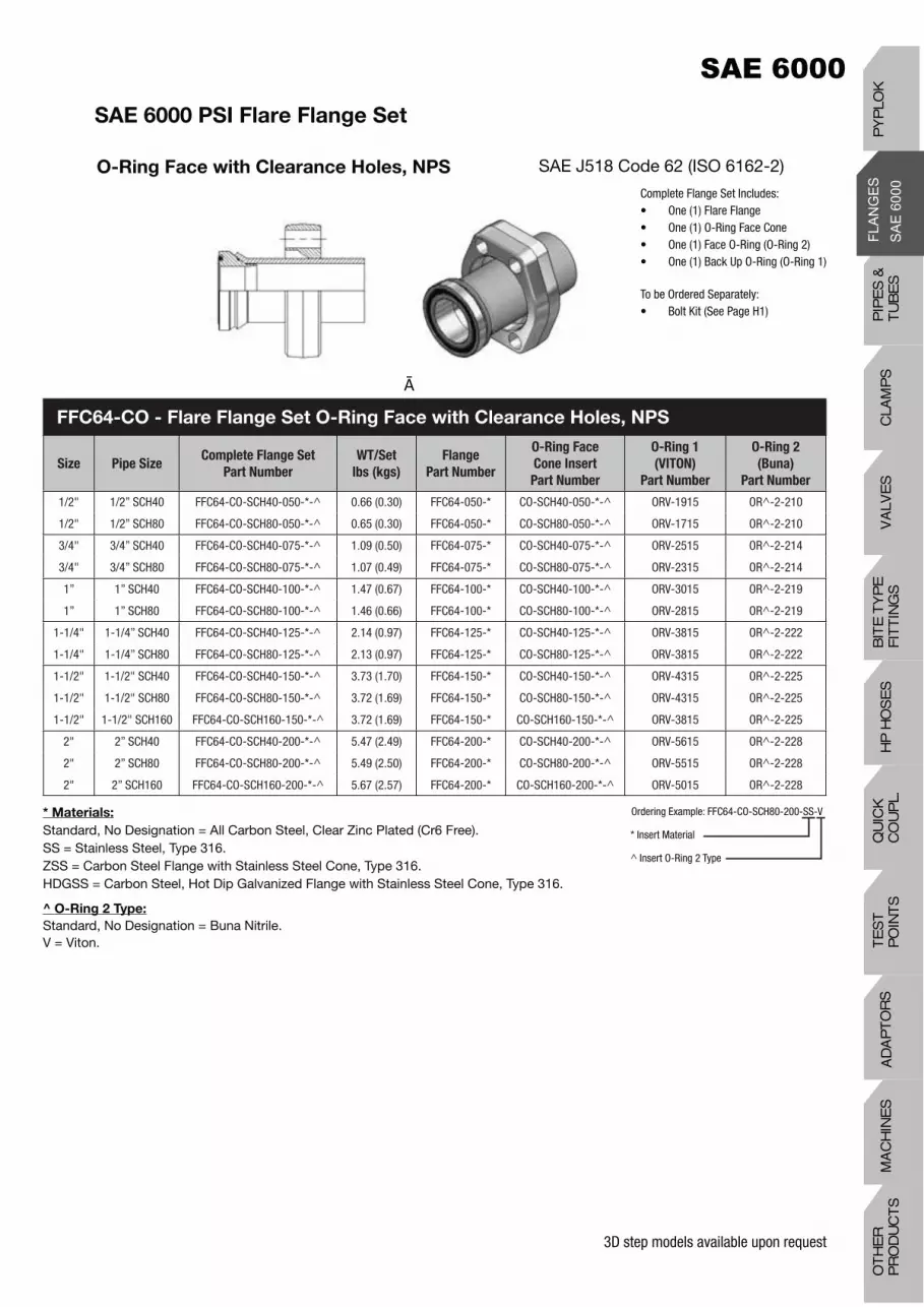
SAE 6000 PSI Flare Flange Set
O-Ring Face with Clearance Holes, NPS SAE J518 Code 62 (ISO 6162-2)
Complete Flange Set Includes:• One (1) Flare Flange• One (1) O-Ring Face Cone• One (1) Face O-Ring (O-Ring 2)• One (1) Back Up O-Ring (O-Ring 1)
To be Ordered Separately:• Bolt Kit (See Page H1)
* Materials:
Standard, No Designation = All Carbon Steel, Clear Zinc Plated (Cr6 Free).SS = Stainless Steel, Type 316.ZSS = Carbon Steel Flange with Stainless Steel Cone, Type 316.HDGSS = Carbon Steel, Hot Dip Galvanized Flange with Stainless Steel Cone, Type 316.
^ O-Ring 2 Type:
Standard, No Designation = Buna Nitrile.V = Viton.
Ordering Example: FFC64-CO-SCH80-200-SS-V
* Insert Material
^ Insert O-Ring 2 Type
FFC64-CO - Flare Flange Set O-Ring Face with Clearance Holes, NPS
Size Pipe SizeComplete Flange Set
Part Number
WT/Set
lbs (kgs)
Flange
Part Number
O-Ring Face
Cone Insert
Part Number
O-Ring 1
(VITON)
Part Number
O-Ring 2
(Buna)
Part Number
1/2" 1/2” SCH40 FFC64-CO-SCH40-050-*-^ 0.66 (0.30) FFC64-050-* CO-SCH40-050-*-^ ORV-1915 OR^-2-210
1/2" 1/2” SCH80 FFC64-CO-SCH80-050-*-^ 0.65 (0.30) FFC64-050-* CO-SCH80-050-*-^ ORV-1715 OR^-2-210
3/4" 3/4” SCH40 FFC64-CO-SCH40-075-*-^ 1.09 (0.50) FFC64-075-* CO-SCH40-075-*-^ ORV-2515 OR^-2-214
3/4" 3/4” SCH80 FFC64-CO-SCH80-075-*-^ 1.07 (0.49) FFC64-075-* CO-SCH80-075-*-^ ORV-2315 OR^-2-214
1” 1” SCH40 FFC64-CO-SCH40-100-*-^ 1.47 (0.67) FFC64-100-* CO-SCH40-100-*-^ ORV-3015 OR^-2-219
1” 1” SCH80 FFC64-CO-SCH80-100-*-^ 1.46 (0.66) FFC64-100-* CO-SCH80-100-*-^ ORV-2815 OR^-2-219
1-1/4" 1-1/4” SCH40 FFC64-CO-SCH40-125-*-^ 2.14 (0.97) FFC64-125-* CO-SCH40-125-*-^ ORV-3815 OR^-2-222
1-1/4" 1-1/4” SCH80 FFC64-CO-SCH80-125-*-^ 2.13 (0.97) FFC64-125-* CO-SCH80-125-*-^ ORV-3815 OR^-2-222
1-1/2" 1-1/2" SCH40 FFC64-CO-SCH40-150-*-^ 3.73 (1.70) FFC64-150-* CO-SCH40-150-*-^ ORV-4315 OR^-2-225
1-1/2" 1-1/2" SCH80 FFC64-CO-SCH80-150-*-^ 3.72 (1.69) FFC64-150-* CO-SCH80-150-*-^ ORV-4315 OR^-2-225
1-1/2" 1-1/2" SCH160 FFC64-CO-SCH160-150-*-^ 3.72 (1.69) FFC64-150-* CO-SCH160-150-*-^ ORV-3815 OR^-2-225
2" 2” SCH40 FFC64-CO-SCH40-200-*-^ 5.47 (2.49) FFC64-200-* CO-SCH40-200-*-^ ORV-5615 OR^-2-228
2" 2” SCH80 FFC64-CO-SCH80-200-*-^ 5.49 (2.50) FFC64-200-* CO-SCH80-200-*-^ ORV-5515 OR^-2-228
2" 2” SCH160 FFC64-CO-SCH160-200-*-^ 5.67 (2.57) FFC64-200-* CO-SCH160-200-*-^ ORV-5015 OR^-2-228
PIP
ES
&
TU
BE
SC
LAM
PS
VA
LVE
SH
P H
OS
ES
BIT
E T
YP
EF
ITT
ING
SQ
UIC
K
CO
UP
L.T
ES
T
PO
INT
SA
DA
PT
OR
SM
AC
HIN
ES
OT
HE
R
PR
OD
UC
TS
PY
PLO
K

3D step models available upon request
SAE 6000 PSI Flare Flange Set
O-Ring Face with Clearance Holes, Metric
SAE J518 Code 62 (ISO 6162-2)
Complete Flange Set Includes:• One (1) Flare Flange• One (1) O-Ring Face Cone• One (1) Face O-Ring (O-Ring 2)• One (1) Back Up O-Ring (O-Ring 1)
To be Ordered Separately:• Bolt Kit (See Page H1)
* Materials:
Standard, No Designation = All Carbon Steel, Clear Zinc Plated (Cr6 Free).SS = Stainless Steel, Type 316.ZSS = Carbon Steel Flange with Stainless Steel Cone, Type 316.HDGSS = Carbon Steel, Hot Dip Galvanized Flange with Stainless Steel Cone, Type 316.
^ O-Ring 2 Type:
Standard, No Designation = Buna Nitrile.V = Viton.
Ordering Example: FFCM64-CO-50x3.0-200-SS-V
* Insert Material
^ Insert O-Ring 2 Type
FFCM64-CO - Flare Flange Set O-Ring Face with Clearance Holes, Metric
Size Pipe SizeComplete Flange Set
Part Number
WT/Set
lbs (kgs)
Flange
Part Number
O-Ring Face
Cone Insert
Part Number
O-Ring 1
(VITON)
Part Number
O-Ring 2
(Buna)
Part Number
1/2" 20x2.0 FFCM64-CO-20x2.0-050-*-^ 0.67 (0.31) FFCM64-050-20MM-* CO-20x2.0-050-*-^ ORV-1715 OR^-2-210
1/2" 20x3.0 FFCM64-CO-20x3.0-050-*-^ 0.67 (0.31) FFCM64-050-20MM-* CO-20x3.0-050-*-^ ORV-1715 OR^-2-210
1/2" 25x2.5 FFCM64-CO-25x2.5-050-*-^ 0.67 (0.31) FFCM64-050-25MM-* CO-25x2.5-050-*-^ ORV-2315 OR^-2-210
1/2" 25x3.0 FFCM64-CO-25x3.0-050-*-^ 0.67 (0.31) FFCM64-050-25MM-* CO-25x3.0-050-*-^ ORV-2315 OR^-2-210
3/4” 20x2.0 FFCM64-CO-20x2.0-075-*-^ 1.08 (0.49) FFCM64-075-20MM-* CO-20x2.0-075-*-^ ORV-1715 OR^-2-214
3/4” 20x2.5 FFCM64-CO-20x2.5-075-*-^ 1.08 (0.49) FFCM64-075-20MM-* CO-20x2.5-075-*-^ ORV-1715 OR^-2-214
3/4" 20x3.0 FFCM64-CO-20x3.0-075-*-^ 1.08 (0.49) FFCM64-075-20MM-* CO-20x3.0-075-*-^ ORV-1715 OR^-2-214
3/4” 25x2.5 FFCM64-CO-25x2.5-075-*-^ 1.08 (0.49) FFCM64-075-25MM-* CO-25x2.5-075-*-^ ORV-2315 OR^-2-214
3/4” 25x3.0 FFCM64-CO-25x3.0-075-*-^ 1.08 (0.49) FFCM64-075-25MM-* CO-25x3.0-075-*-^ ORV-2315 OR^-2-214
3/4” 25x4.0 FFCM64-CO-25x4.0-075-*-^ 1.08 (0.49) FFCM64-075-25MM-* CO-25x4.0-075-*-^ ORV-2315 OR^-2-214
3/4” 30x3.0 FFCM64-CO-30x3.0-075-*-^ 1.10 (0.50) FFCM64-075-30MM-* CO-30x3.0-075-*-^ ORV-2515 OR^-2-214
1” 25x2.5 FFCM64-CO-25x2.5-100-*-^ 1.45 (0.66) FFCM64-100-25MM-* CO-25x2.5-100-*-^ ORV-2315 OR^-2-219
1” 25x3.0 FFCM64-CO-25x3.0-100-*-^ 1.45 (0.66) FFCM64-100-25MM-* CO-25x3.0-100-*-^ ORV-2315 OR^-2-219
1” 25x4.0 FFCM64-CO-25x4.0-100-*-^ 1.45 (0.66) FFCM64-100-25MM-* CO-25x4.0-100-*-^ ORV-2315 OR^-2-219
1” 30x3.0 FFCM64-CO-30x3.0-100-*-^ 1.47 (0.67) FFCM64-100-30MM-* CO-30x3.0-100-*-^ ORV-2815 OR^-2-219
1” 30x4.0 FFCM64-CO-30x4.0-100-*-^ 1.47 (0.67) FFCM64-100-30MM-* CO-30x4.0-100-*-^ ORV-2815 OR^-2-219
1” 30x5.0 FFCM64-CO-30x5.0-100-*-^ 1.47 (0.67) FFCM64-100-30MM-* CO-30x5.0-100-*-^ ORV-2815 OR^-2-219
1” 38x4.0 FFCM64-CO-38x4.0-100-*-^ 1.49 (0.68) FFCM64-100-38MM-* CO-38x4.0-100-*-^ ORV-3515 OR^-2-219
1” 38x5.0 FFCM64-CO-38x5.0-100-*-^ 1.49 (0.68) FFCM64-100-38MM-* CO-38x5.0-100-*-^ ORV-3215 OR^-2-219
1-1/4" 30x3.0 FFCM64-CO-30x3.0-125-*-^ 2.11 (0.96) FFCM64-125-30MM-* CO-30x3.0-125-*-^ ORV-2815 OR^-2-222
1-1/4" 30x4.0 FFCM64-CO-30x4.0-125-*-^ 2.11 (0.96) FFCM64-125-30MM-* CO-30x4.0-125-*-^ ORV-2815 OR^-2-222
1-1/4" 30x5.0 FFCM64-CO-30x5.0-125-*-^ 2.11 (0.96) FFCM64-125-30MM-* CO-30x5.0-125-*-^ ORV-2815 OR^-2-222
1-1/4" 38x4.0 FFCM64-CO-38x4.0-125-*-^ 2.13 (0.97) FFCM64-125-38MM-* CO-38x4.0-125-*-^ ORV-3515 OR^-2-222
1-1/4" 38x5.0 FFCM64-CO-38x5.0-125-*-^ 2.13 (0.97) FFCM64-125-38MM-* CO-38x5.0-125-*-^ ORV-3215 OR^-2-222
1-1/4" 42x3.0 FFCM64-CO-42x3.0-125-*-^ 2.18 (0.99) FFC64-125-* CO-42x3.0-125-*-^ ORV-3815 OR^-2-222
1-1/4" 42x4.0 FFCM64-CO-42x4.0-125-*-^ 2.18 (0.99) FFC64-125-* CO-42x4.0-125-*-^ ORV-3815 OR^-2-222

3D step models available upon request
SAE 6000 PSI Flare Flange Set
O-Ring Face with Clearance Holes, Metric SAE J518 Code 62 (ISO 6162-2)
Complete Flange Set Includes:• One (1) Flare Flange• One (1) O-Ring Face Cone• One (1) Face O-Ring (O-Ring 2)• One (1) Back Up O-Ring (O-Ring 1)
To be Ordered Separately:• Bolt Kit (See Page H1)
* Materials:
Standard, No Designation = All Carbon Steel, Clear Zinc Plated (Cr6 Free).SS = Stainless Steel, Type 316.ZSS = Carbon Steel Flange with Stainless Steel Cone, Type 316.HDGSS = Carbon Steel, Hot Dip Galvanized Flange with Stainless Steel Cone, Type 316.
^ O-Ring 2 Type:
Standard, No Designation = Buna Nitrile.V = Viton.
(2) Designates M14 Bolt - Special Order
Ordering Example: FFCM64-CO-50x3.0-200-SS-V
* Insert Material
^ Insert O-Ring 2 Type
FFCM64-CO - Flare Flange Set O-Ring Face with Clearance Holes, Metric
Size Pipe SizeComplete Flange Set
Part Number
WT/Set
lbs (kgs)
Flange
Part Number
O-Ring Face
Cone Insert
Part Number
O-Ring 1
(VITON)
Part
Number
O-Ring 2
(Buna)
Part
Number
1-1/4" (2) 30x3.0 FFCM64-CO-30x3.0-125-M14-*-^ 2.11 (0.96) FFCM64-125-M14-30MM-* CO-30x3.0-125-*-^ ORV-2815 OR^-2-222
1-1/4" (2) 30x4.0 FFCM64-CO-30x4.0-125-M14-*-^ 2.11 (0.96) FFCM64-125-M14-30MM-* CO-30x4.0-125-*-^ ORV-2815 OR^-2-222
1-1/4” (2) 30x5.0 FFCM64-CO-30x5.0-125-M14-*-^ 2.11 (0.96) FFCM64-125-M14-30MM-* CO-30x5.0-125-*-^ ORV-2815 OR^-2-222
1-1/4" (2) 38x4.0 FFCM64-CO-38x4.0-125-M14-*-^ 2.13 (0.97) FFCM64-125-M14-38MM-* CO-38x4.0-125-*-^ ORV-3515 OR^-2-222
1-1/4" (2) 38x5.0 FFCM64-CO-38x5.0-125-M14-*-^ 2.13 (0.97) FFCM64-125-M14-38MM-* CO-38x5.0-125-*-^ ORV-3215 OR^-2-222
1-1/4" (2) 42x3.0 FFCM64-CO-42x3.0-125-M14-*-^ 2.18 (0.99) FFCM64-125-M14-42MM-* CO-42x3.0-125-*-^ ORV-3815 OR^-2-222
1-1/4" (2) 42x4.0 FFCM64-CO-42x4.0-125-M14-*-^ 2.18 (0.99) FFCM64-125-M14-42MM-* CO-42x4.0-125-*-^ ORV-3815 OR^-2-222
1-1/2" 30x3.0 FFCM64-CO-30x3.0-150-*-^ 3.69 (1.68) FFCM64-150-30MM-* CO-30x3.0-150-*-^ ORV-2815 OR^-2-225
1-1/2" 38x4.0 FFCM64-CO-38x4.0-150-*-^ 3.72 (1.69) FFCM64-150-38MM-* CO-38x4.0-150-*-^ ORV-3215 OR^-2-225
1-1/2" 42x3.0 FFCM64-CO-42x3.0-150-*-^ 3.72 (1.69) FFCM64-150-42MM-* CO-42x3.0-150-*-^ ORV-3815 OR^-2-225
1-1/2" 42x4.0 FFCM64-CO-42x4.0-150-*-^ 3.72 (1.69) FFCM64-150-42MM-* CO-42x4.0-150-*-^ ORV-3815 OR^-2-225
1-1/2" 50x3.0 FFCM64-CO-50x3.0-150-*-^ 3.74 (1.70) FFCM64-150-50MM-* CO-50x3.0-150-*-^ ORV-4715 OR^-2-225
1-1/2" 50x5.0 FFCM64-CO-50x5.0-150-*-^ 3.74 (1.70) FFCM64-150-50MM-* CO-50x5.0-150-*-^ ORV-4515 OR^-2-225
1-1/2” 50X6.0 FFCM64-CO-50X6.0-150-*-^ 3.74 (1.70) FFCM64-150-50MM-* CO-50X6.0-150-*-^ ORV-4515 OR^-2-225
1-1/2” 56X8.5 FFCM64-CO-56X8.5-150-*-^ 3.75 (1.70) FFCM64-150-56MM-* CO-56X8.5-150-*-^ ORV-4315 OR^-2-225
2” 50x3.0 FFCM64-CO-50x3.0-200-*-^ 5.44 (2.47) FFCM64-200-50MM-* CO-50x3.0-200-*-^ ORV-4515 OR^-2-228
2” 50x5.0 FFCM64-CO-50x5.0-200-*-^ 5.44 (2.47) FFCM64-200-50MM-* CO-50x5.0-200-*-^ ORV-4515 OR^-2-228
2” 50x6.0 FFCM64-CO-50x6.0-200-*-^ 5.44 (2.47) FFCM64-200-50MM-* CO-50x6.0-200-*-^ ORV-4515 OR^-2-228
2” 60x3.0 FFCM64-CO-60x3.0-200-*-^ 5.46 (2.48) FFC64-200-* CO-60x3.0-200-*-^ ORV-5715 OR^-2-228
2” 60x5.0 FFCM64-CO-60x5.0-200-*-^ 5.46 (2.48) FFC64-200-* CO-60x5.0-200-*-^ ORV-5615 OR^-2-228
2” 60x6.0 FFCM64-CO-60x6.0-200-*-^ 5.46 (2.48) FFC64-200-* CO-60x6.0-200-*-^ ORV-5615 OR^-2-228
2” 60X8.0 FFCM64-CO-60X8.0-200-*-^ 5.46 (2.48) FFC64-200-* CO-60X8.0-200-*-^ ORV-5015 OR^-2-228
2” 66X8.5 FFCM64-CO-66X8.5-200-*-^ 5.46 (2.48) FFCM64-200-66MM-* CO-66X8.5-200-*-^ ORV-5615 OR^-2-228
PIP
ES
&
TU
BE
SC
LAM
PS
VA
LVE
SH
P H
OS
ES
BIT
E T
YP
EF
ITT
ING
SQ
UIC
K
CO
UP
L.T
ES
T
PO
INT
SA
DA
PT
OR
SM
AC
HIN
ES
OT
HE
R
PR
OD
UC
TS
PY
PLO
K

3D step models available upon request
SAE 6000 PSI Flare Flange Set
Flat Face with Clearance Holes, NPS SAE J518 Code 62 (ISO 6162-2)
Complete Flange Set Includes:• One (1) Flare Flange• One (1) Flat Face Cone• One (1) Back Up O-Ring (O-Ring 1)
To be Ordered Separately:• Bolt Kit (See Page H1)
* Materials:
Standard, No Designation = All Carbon Steel, Clear Zinc Plated (Cr6 Free).SS = Stainless Steel, Type 316.ZSS = Carbon Steel Flange with Stainless Steel Cone, Type 316.HDGSS = Carbon Steel, Hot Dip Galvanized Flange with Stainless Steel Cone, Type 316.
FFC64-CF - Flare Flange Set Flat Face with Clearance Holes, NPS
Size Pipe SizeComplete Flange Set
Part Number
WT/Set
lbs (kgs)
Flange
Part Number
Flat Face
Cone Insert
Part Number
O-Ring 1
(VITON)
Part Number
1/2" 1/2” SCH40 FFC64-CF-SCH40-050-* 0.67 (0.30) FFC64-050-* CF-SCH40-050-* ORV-1915
1/2" 1/2” SCH80 FFC64-CF-SCH80-050-* 0.66 (0.30) FFC64-050-* CF-SCH80-050-* ORV-1715
3/4" 3/4” SCH40 FFC64-CF-SCH40-075-* 1.10 (0.50) FFC64-075-* CF-SCH40-075-* ORV-2515
3/4" 3/4” SCH80 FFC64-CF-SCH80-075-* 1.08 (0.49) FFC64-075-* CF-SCH80-075-* ORV-2315
1” 1” SCH40 FFC64-CF-SCH40-100-* 1.48 (0.67) FFC64-100-* CF-SCH40-100-* ORV-3015
1” 1” SCH80 FFC64-CF-SCH80-100-* 1.47 (0.66) FFC64-100-* CF-SCH80-100-* ORV-2815
1-1/4" 1-1/4” SCH40 FFC64-CF-SCH40-125-* 2.16 (0.98) FFC64-125-* CF-SCH40-125-* ORV-3815
1-1/4" 1-1/4” SCH80 FFC64-CF-SCH80-125-* 2.14 (0.97) FFC64-125-* CF-SCH80-125-* ORV-3815
1-1/2" 1-1/2" SCH40 FFC64-CF-SCH40-150-* 3.75 (1.71) FFC64-150-* CF-SCH40-150-* ORV-4315
1-1/2" 1-1/2" SCH80 FFC64-CF-SCH80-150-* 3.73 (1.70) FFC64-150-* CF-SCH80-150-* ORV-4315
1-1/2" 1-1/2" SCH160 FFC64-CF-SCH160-150-* 3.73 (1.70) FFC64-150-* CF-SCH160-150-* ORV-3815
2" 2” SCH40 FFC64-CF-SCH40-200-* 5.49 (2.50) FFC64-200-* CF-SCH40-200-* ORV-5615
2" 2” SCH80 FFC64-CF-SCH80-200-* 5.48 (2.49) FFC64-200-* CF-SCH80-200-* ORV-5515
2" 2” SCH160 FFC64-CF-SCH160-200-* 5.45 (2.48) FFC64-200-* CF-SCH160-200-* ORV-5015
Ordering Example: FFC64-CF-SCH80-200-SS
* Insert Material

3D step models available upon request
SAE 6000 PSI Flare Flange Set
Flat Face with Clearance Holes, Metric SAE J518 Code 62 (ISO 6162-2)
Complete Flange Set Includes:• One (1) Flare Flange• One (1) Flat Face Cone• One (1) Back Up O-Ring (O-Ring 1)
To be Ordered Separately:• Bolt Kit (See Page H1)
* Materials:
Standard, No Designation = All Carbon Steel, Clear Zinc Plated (Cr6 Free).SS = Stainless Steel, Type 316.ZSS = Carbon Steel Flange with Stainless Steel Cone, Type 316.HDGSS = Carbon Steel, Hot Dip Galvanized Flange with Stainless Steel Cone, Type 316.
FFCM64-CF - Flare Flange Set Flat Face with Clearance Holes, Metric
Size Pipe SizeComplete Flange Set
Part Number
WT/Set
lbs (kgs)
Flange
Part Number
Flat Face
Cone Insert
Part Number
O-Ring 1
(VITON)
Part Number
1/2" 20x2.0 FFCM64-CF-20x2.0-050-* 0.67 (0.30) FFCM64-050-20MM-* CF-20x2.0-050-* ORV-1715
1/2" 20x3.0 FFCM64-CF-20x3.0-050-* 0.67 (0.30) FFCM64-050-20MM-* CF-20x3.0-050-* ORV-1715
1/2" 25x2.5 FFCM64-CF-25x2.5-050-* 0.67 (0.30) FFCM64-050-25MM-* CF-25x2.5-050-* ORV-2315
1/2" 25x3.0 FFCM64-CF-25x3.0-050-* 0.67 (0.30) FFCM64-050-25MM-* CF-25x3.0-050-* ORV-2315
3/4” 20x2.0 FFCM64-CF-20x2.0-075-* 1.08 (0.49) FFCM64-075-20MM-* CF-20x2.0-075-* ORV-1715
3/4” 20x2.5 FFCM64-CF-20x2.5-075-* 1.08 (0.49) FFCM64-075-20MM-* CF-20x2.5-075-* ORV-1715
3/4" 20x3.0 FFCM64-CF-20x3.0-075-* 1.08 (0.49) FFCM64-075-20MM-* CF-20x3.0-075-* ORV-1715
3/4” 25x2.5 FFCM64-CF-25x2.5-075-* 1.08 (0.49) FFCM64-075-25MM-* CF-25x2.5-075-* ORV-2315
3/4” 25x3.0 FFCM64-CF-25x3.0-075-* 1.08 (0.49) FFCM64-075-25MM-* CF-25x3.0-075-* ORV-2315
3/4” 25x4.0 FFCM64-CF-25x4.0-075-* 1.08 (0.49) FFCM64-075-25MM-* CF-25x4.0-075-* ORV-2315
3/4” 30x3.0 FFCM64-CF-30x3.0-075-* 1.11 (0.50) FFCM64-075-30MM-* CF-30x3.0-075-* ORV-2515
1” 25x2.5 FFCM64-CF-25x2.5-100-* 1.46 (0.66) FFCM64-100-25MM-* CF-25x2.5-100-* ORV-2315
1” 25x3.0 FFCM64-CF-25x3.0-100-* 1.46 (0.66) FFCM64-100-25MM-* CF-25x3.0-100-* ORV-2315
1” 25x4.0 FFCM64-CF-25x4.0-100-* 1.46 (0.66) FFCM64-100-25MM-* CF-25x4.0-100-* ORV-2315
1” 30x3.0 FFCM64-CF-30x3.0-100-* 1.48 (0.67) FFCM64-100-30MM-* CF-30x3.0-100-* ORV-2815
1” 30x4.0 FFCM64-CF-30x4.0-100-* 1.48 (0.67) FFCM64-100-30MM-* CF-30x4.0-100-* ORV-2815
1” 30x5.0 FFCM64-CF-30x5.0-100-* 1.48 (0.67) FFCM64-100-30MM-* CF-30x5.0-100-* ORV-2815
1” 38x4.0 FFCM64-CF-38x4.0-100-* 1.50 (0.68) FFCM64-100-38MM-* CF-38x4.0-100-* ORV-3515
1” 38x5.0 FFCM64-CF-38x5.0-100-* 1.50 (0.68) FFCM64-100-38MM-* CF-38x5.0-100-* ORV-3215
1-1/4" 30x3.0 FFCM64-CF-30x3.0-125-* 2.12 (0.96) FFCM64-125-30MM-* CF-30x3.0-125-* ORV-2815
1-1/4" 30x4.0 FFCM64-CF-30x4.0-125-* 2.12 (0.96) FFCM64-125-30MM-* CF-30x4.0-125-* ORV-2815
1-1/4" 30x5.0 FFCM64-CF-30x5.0-125-* 2.12 (0.96) FFCM64-125-30MM-* CF-30x5.0-125-* ORV-2815
1-1/4" 38x4.0 FFCM64-CF-38x4.0-125-* 2.14 (0.97) FFCM64-125-38MM-* CF-38x4.0-125-* ORV-3515
1-1/4" 38x5.0 FFCM64-CF-38x5.0-125-* 2.14 (0.97) FFCM64-125-38MM-* CF-38x5.0-125-* ORV-3215
1-1/4" 42x3.0 FFCM64-CF-42x3.0-125-* 2.19 (1.00) FFC64-125-* CF-42x3.0-125-* ORV-3815
1-1/4" 42x4.0 FFCM64-CF-42x4.0-125-* 2.19 (1.00) FFC64-125-* CF-42x4.0-125-* ORV-3815
Ordering Example: FFCM64-CF-50x3.0-200-SS
* Insert Material
PIP
ES
&
TU
BE
SC
LAM
PS
VA
LVE
SH
P H
OS
ES
BIT
E T
YP
EF
ITT
ING
SQ
UIC
K
CO
UP
L.T
ES
T
PO
INT
SA
DA
PT
OR
SM
AC
HIN
ES
OT
HE
R
PR
OD
UC
TS
PY
PLO
K

3D step models available upon request
SAE 6000 PSI Flare Flange Set
Flat Face with Clearance Holes, Metric SAE J518 Code 62 (ISO 6162-2)
Complete Flange Set Includes:• One (1) Flare Flange• One (1) Flat Face Cone• One (1) Back Up O-Ring (O-Ring 1)
To be Ordered Separately:• Bolt Kit (See Page H1)
* Materials:
Standard, No Designation = All Carbon Steel, Clear Zinc Plated (Cr6 Free).SS = Stainless Steel, Type 316.ZSS = Carbon Steel Flange with Stainless Steel Cone, Type 316.HDGSS = Carbon Steel, Hot Dip Galvanized Flange with Stainless Steel Cone, Type 316.
(2) Designates M14 Bolt - Special Order
FFCM64-CF - Flare Flange Set with Clearance Holes, Metric
Size Pipe SizeComplete Flange Set
Part Number
WT/Set
lbs (kgs)
Flange
Part Number
Flat Face
Cone Insert
Part Number
O-Ring 1
(VITON)
Part
Number
1-1/4" (2) 30x3.0 FFCM64-CF-30x3.0-125-M14-* 2.12 (0.96) FFCM64-125-M14-30MM-* CF-30x3.0-125-* ORV-2815
1-1/4" (2) 30x4.0 FFCM64-CF-30x4.0-125-M14-* 2.12 (0.96) FFCM64-125-M14-30MM-* CF-30x4.0-125-* ORV-2815
1-1/4" (2) 30x5.0 FFCM64-CF-30x5.0-125-M14-* 2.12 (0.96) FFCM64-125-M14-30MM-* CF-30x5.0-125-* ORV-2815
1-1/4" (2) 38x4.0 FFCM64-CF-38x4.0-125-M14-* 2.14 (0.97) FFCM64-125-M14-38MM-* CF-38x4.0-125-* ORV-3515
1-1/4" (2) 38x5.0 FFCM64-CF-38x5.0-125-M14-* 2.14 (0.97) FFCM64-125-M14-38MM-* CF-38x5.0-125-* ORV-3215
1-1/4” (2) 42x3.0 FFCM64-CF-42x3.0-125-M-14-* 2.19 (1.00) FFCM64-125-M14-42MM-* CF-42x3.0-125-* ORV-3815
1-1/4” (2) 42x4.0 FFCM64-CF-42x4.0-125-M14-* 2.19 (1.00) FFCM64-125-M14-42MM-* CF-42x4.0-125-* ORV-3815
1-1/2" 30x3.0 FFCM64-CF-30x3.0-150-* 3.70 (1.68) FFCM64-150-30MM-* CF-30x3.0-150-* ORV-2815
1-1/2" 38x4.0 FFCM64-CF-38x4.0-150-* 3.74 (1.70) FFCM64-150-38MM-* CF-38x4.0-150-* ORV-3215
1-1/2" 42x3.0 FFCM64-CF-42x3.0-150-* 3.74 (1.70) FFCM64-150-42MM-* CF-42x3.0-150-* ORV-3215
1-1/2" 42x4.0 FFCM64-CF-42x4.0-150-* 3.74 (1.70) FFCM64-150-42MM-* CF-42x4.0-150-* ORV-3815
1-1/2" 50x3.0 FFCM64-CF-50x3.0-150-* 3.76 (1.71) FFCM64-150-50MM-* CF-50x3.0-150-* ORV-3815
1-1/2" 50x5.0 FFCM64-CF-50x5.0-150-* 3.76 (1.71) FFCM64-150-50MM-* CF-50x5.0-150-* ORV-4515
1-1/2” 50X6.0 FFCM64-CF-50X6.0-150-* 3.76 (1.71) FFCM64-150-50MM-* CF-50X6.0-150-* ORV-4515
1-1/2” 56X8.5 FFCM64-CF-56X8.5-150-* 3.76 (1.71) FFCM64-150-56MM-* CF-56X8.5-150-* ORV-4315
2” 50x3.0 FFCM64-CF-50x3.0-200-* 5.46 (2.48) FFCM64-200-50MM-* CF-50x3.0-200-* ORV-4515
2” 50x5.0 FFCM64-CF-50x5.0-200-* 5.46 (2.48) FFCM64-200-50MM-* CF-50x5.0-200-* ORV-4515
2” 50x6.0 FFCM64-CF-50x6.0-200-* 5.46 (2.48) FFCM64-200-50MM-* CF-50x6.0-200-* ORV-4515
2” 60x3.0 FFCM64-CF-60x3.0-200-* 5.48 (2.49) FFC64-200-* CF-60x3.0-200-* ORV-5715
2” 60x5.0 FFCM64-CF-60x5.0-200-* 5.48 (2.49) FFC64-200-* CF-60x5.0-200-* ORV-5615
2” 60x6.0 FFCM64-CF-60x6.0-200-* 5.48 (2.49) FFC64-200-* CF-60x6.0-200-* ORV-5615
2” 60X8.0 FFCM64-CF-60X8.0-200-* 5.48 (2.49) FFC64-200-* CF-60X8.0-200-* ORV-5015
2” 66X8.5 FFCM64-CF-66X8.5-200-* 5.48 (2.49) FFCM64-200-66MM-* CF-66X8.5-200-* ORV-5615
Ordering Example: FFCM64-CF-50x3.0-200-SS
* Insert Material

3D step models available upon request
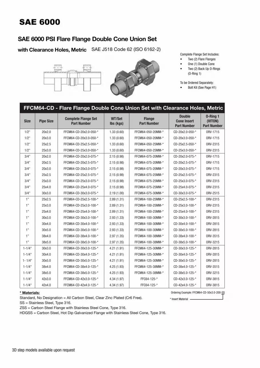
SAE 6000 PSI Flare Flange Double Cone Union Set
with Clearance Holes, NPS SAE J518 Code 62 (ISO 6162-2)Complete Flange Set Includes:• Two (2) Flare Flanges• One (1) Double Cone• Two (2) Back Up O-Rings
(O-Ring 1)
To be Ordered Separately:• Bolt Kit (See Page H1)
* Materials:
Standard, No Designation = All Carbon Steel, Clear Zinc Plated (Cr6 Free).SS = Stainless Steel, Type 316.ZSS = Carbon Steel Flange with Stainless Steel Cone, Type 316.HDGSS = Carbon Steel, Hot Dip Galvanized Flange with Stainless Steel Cone, Type 316.
FFC64-CD - Flare Flange Double Cone Union Set with Clearance Holes, NPS
Size Pipe SizeComplete Flange Set
Part Number
WT/Set
lbs (kgs)
Flange
Part Number
Double
Cone Insert
Part Number
O-Ring 1
(VITON)
Part
Number
1/2" 1/2” SCH40 FFC64-CD-SCH40-050-* 1.32 (0.60) FFC64-050-* CD-SCH40-050-* ORV-1915
1/2" 1/2” SCH80 FFC64-CD-SCH80-050-* 1.30 (0.59) FFC64-050-* CD-SCH80-050-* ORV-1715
3/4" 3/4” SCH40 FFC64-CD-SCH40-075-* 2.19 (1.00) FFC64-075-* CD-SCH40-075-* ORV-2515
3/4" 3/4” SCH80 FFC64-CD-SCH80-075-* 2.19 (1.00) FFC64-075-* CD-SCH80-075-* ORV-2315
1” 1” SCH40 FFC64-CD-SCH40-100-* 2.95 (1.34) FFC64-100-* CD-SCH40-100-* ORV-3015
1” 1” SCH80 FFC64-CD-SCH80-100-* 2.96 (1.35) FFC64-100-* CD-SCH80-100-* ORV-2815
1-1/4" 1-1/4” SCH40 FFC64-CD-SCH40-125-* 4.27 (1.94) FFC64-125-* CD-SCH40-125-* ORV-3815
1-1/4" 1-1/4” SCH80 FFC64-CD-SCH80-125-* 4.26 (1.94) FFC64-125-* CD-SCH80-125-* ORV-3815
1-1/2" 1-1/2" SCH40 FFC64-CD-SCH40-150-* 7.46 (3.39) FFC64-150-* CD-SCH40-150-* ORV-4315
1-1/2" 1-1/2" SCH80 FFC64-CD-SCH80-150-* 7.48 (3.40) FFC64-150-* CD-SCH80-150-* ORV-4315
1-1/2" 1-1/2" SCH160 FFC64-CD-SCH160-150-* 7.47 (3.40) FFC64-150-* CD-SCH160-150-* ORV-3815
2" 2” SCH40 FFC64-CD-SCH40-200-* 10.94 (4.97) FFC64-200-* CD-SCH40-200-* ORV-5615
2" 2” SCH80 FFC64-CD-SCH80-200-* 10.94 (4.97) FFC64-200-* CD-SCH80-200-* ORV-5515
2" 2” SCH160 FFC64-CD-SCH160-200-* 11.31 (5.14) FFC64-200-* CD-SCH160-200-* ORV-5015
Ordering Example: FFC64-CD-SCH80-200-SS
* Insert Material
PIP
ES
&
TU
BE
SC
LAM
PS
VA
LVE
SH
P H
OS
ES
BIT
E T
YP
EF
ITT
ING
SQ
UIC
K
CO
UP
L.T
ES
T
PO
INT
SA
DA
PT
OR
SM
AC
HIN
ES
OT
HE
R
PR
OD
UC
TS
PY
PLO
K
3D step models available upon request
SAE 6000 PSI Flare Flange Double Cone Union Set
with Clearance Holes, Metric SAE J518 Code 62 (ISO 6162-2)Complete Flange Set Includes:• Two (2) Flare Flanges• One (1) Double Cone• Two (2) Back Up O-Rings
(O-Ring 1)
To be Ordered Separately:• Bolt Kit (See Page H1)
* Materials:
Standard, No Designation = All Carbon Steel, Clear Zinc Plated (Cr6 Free).SS = Stainless Steel, Type 316.ZSS = Carbon Steel Flange with Stainless Steel Cone, Type 316.HDGSS = Carbon Steel, Hot Dip Galvanized Flange with Stainless Steel Cone, Type 316.
FFCM64-CD - Flare Flange Double Cone Union Set with Clearance Holes, Metric
Size Pipe SizeComplete Flange Set
Part Number
WT/Set
lbs (kgs)
Flange
Part Number
Double
Cone Insert
Part Number
O-Ring 1
(VITON)
Part Number
1/2" 20x2.0 FFCM64-CD-20x2.0-050-* 1.33 (0.60) FFCM64-050-20MM-* CD-20x2.0-050-* ORV-1715
1/2" 20x3.0 FFCM64-CD-20x3.0-050-* 1.33 (0.60) FFCM64-050-20MM-* CD-20x3.0-050-* ORV-1715
1/2" 25x2.5 FFCM64-CD-25x2.5-050-* 1.33 (0.60) FFCM64-050-25MM-* CD-25x2.5-050-* ORV-2315
1/2" 25x3.0 FFCM64-CD-25x3.0-050-* 1.33 (0.60) FFCM64-050-25MM-* CD-25x3.0-050-* ORV-2315
3/4” 20x2.0 FFCM64-CD-20x2.0-075-* 2.15 (0.98) FFCM64-075-20MM-* CD-20x2.0-075-* ORV-1715
3/4” 20x2.5 FFCM64-CD-20x2.5-075-* 2.15 (0.98) FFCM64-075-20MM-* CD-20x2.5-075-* ORV-1715
3/4" 20x3.0 FFCM64-CD-20x3.0-075-* 2.15 (0.98) FFCM64-075-20MM-* CD-20x3.0-075-* ORV-1715
3/4” 25x2.5 FFCM64-CD-25x2.5-075-* 2.15 (0.98) FFCM64-075-25MM-* CD-25x2.5-075-* ORV-2315
3/4” 25x3.0 FFCM64-CD-25x3.0-075-* 2.15 (0.98) FFCM64-075-25MM-* CD-25x3.0-075-* ORV-2315
3/4” 25x4.0 FFCM64-CD-25x4.0-075-* 2.15 (0.98) FFCM64-075-25MM-* CD-25x4.0-075-* ORV-2315
3/4” 30x3.0 FFCM64-CD-30x3.0-075-* 2.19 (1.00) FFCM64-075-30MM-* CD-30x3.0-075-* ORV-2515
1” 25x2.5 FFCM64-CD-25x2.5-100-* 2.89 (1.31) FFCM64-100-25MM-* CD-25x2.5-100-* ORV-2315
1” 25x3.0 FFCM64-CD-25x3.0-100-* 2.89 (1.31) FFCM64-100-25MM-* CD-25x3.0-100-* ORV-2315
1” 25x4.0 FFCM64-CD-25x4.0-100-* 2.89 (1.31) FFCM64-100-25MM-* CD-25x4.0-100-* ORV-2315
1” 30x3.0 FFCM64-CD-30x3.0-100-* 2.93 (1.33) FFCM64-100-30MM-* CD-30x3.0-100-* ORV-2815
1” 30x4.0 FFCM64-CD-30x4.0-100-* 2.93 (1.33) FFCM64-100-30MM-* CD-30x4.0-100-* ORV-2815
1” 30x5.0 FFCM64-CD-30x5.0-100-* 2.93 (1.33) FFCM64-100-30MM-* CD-30x5.0-100-* ORV-2815
1” 38x4.0 FFCM64-CD-38x4.0-100-* 2.97 (1.35) FFCM64-100-38MM-* CD-38x4.0-100-* ORV-3515
1” 38x5.0 FFCM64-CD-38x5.0-100-* 2.97 (1.35) FFCM64-100-38MM-* CD-38x5.0-100-* ORV-3215
1-1/4" 30x3.0 FFCM64-CD-30x3.0-125-* 4.21 (1.91) FFCM64-125-30MM-* CD-30x3.0-125-* ORV-2815
1-1/4" 30x4.0 FFCM64-CD-30x4.0-125-* 4.21 (1.91) FFCM64-125-30MM-* CD-30x4.0-125-* ORV-2815
1- 1/4" 30x5.0 FFCM64-CD-30x5.0-125-* 4.21 (1.91) FFCM64-125-30MM-* CD-30x5.0-125-* ORV-2815
1-1/4" 38x4.0 FFCM64-CD-38x4.0-125-* 4.25 (1.93) FFCM64-125-38MM-* CD-38x4.0-125-* ORV-3515
1-1/4" 38x5.0 FFCM64-CD-38x5.0-125-* 4.25 (1.93) FFCM64-125-38MM-* CD-38x5.0-125-* ORV-3215
1-1/4" 42x3.0 FFCM64-CD-42x3.0-125-* 4.34 (1.97) FFC64-125-* CD-42x3.0-125-* ORV-3815
1-1/4" 42x4.0 FFCM64-CD-42x4.0-125-* 4.34 (1.97) FFC64-125-* CD-42x4.0-125-* ORV-3815
Ordering Example: FFCM64-CD-50x3.0-200-SS
* Insert Material

3D step models available upon request
SAE 6000 PSI Flare Flange Double Cone Union Set
with Clearance Holes, Metric SAE J518 Code 62 (ISO 6162-2) Complete Flange Set Includes:• Two (2) Flare Flanges• One (1) Double Cone• Two (2) Back Up O-Rings
(O-Ring 1)
To be Ordered Separately:• Bolt Kit (See Page H1)
* Materials:
Standard, No Designation = All Carbon Steel, Clear Zinc Plated (Cr6 Free).SS = Stainless Steel, Type 316.ZSS = Carbon Steel Flange with Stainless Steel Cone, Type 316.HDGSS = Carbon Steel, Hot Dip Galvanized Flange with Stainless Steel Cone, Type 316.
(2) Designates M14 Bolt - Special Order
Ordering Example: FFCM64-CD-50x3.0-200-SS
* Insert Material
FFCM64-CD - Flare Flange Double Cone Union Set with Clearance Holes, Metric
Size Pipe SizeComplete Flange Set
Part Number
WT/Set
lbs (kgs)
Flange
Part Number
Double
Cone Insert
Part Number
O-Ring 1
(VITON)
Part Number
1-1/4" (2) 30x3.0 FFCM64-CD-30x3.0-125-M14-* 4.21 (1.91) FFCM64-125-M14-30MM-* CD-30x3.0-125-* ORV-2815
1-1/4” (2) 30x4.0 FFCM64-CD-30x4.0-125-M14-* 4.21 (1.91) FFCM64-125-M14-30MM-* CD-30x4.0-125-* ORV-2815
1-1/4” (2) 30x5.0 FFCM64-CD-30x5.0-125-M14-* 4.21 (1.91) FFCM64-125-M14-30MM-* CD-30x5.0-125-* ORV-2815
1-1/4” (2) 38x4.0 FFCM64-CD-38x4.0-125-M14-* 4.25 (1.93) FFCM64-125-M14-38MM-* CD-38x4.0-125-* ORV-3515
1-1/4” (2) 38x5.0 FFCM64-CD-38x5.0-125-M14-* 4.25 (1.93) FFCM64-125-M14-38MM-* CD-38x5.0-125-* ORV-3215
1-1/4” (2) 42x3.0 FFCM64-CD-42x3.0-125-M14-* 4.34 (1.97) FFCM64-125-M14-42MM-* CD-42x3.0-125-* ORV-3815
1-1/4” (2) 42x4.0 FFCM64-CD-42x4.0-125-M14-* 4.34 (1.97) FFCM64-125-M14-42MM-* CD-42x4.0-125-* ORV-3815
1-1/2" 30x3.0 FFCM64-CD-30x3.0-150-* 7.36 (3.35) FFCM64-150-30MM-* CD-30x3.0-150-* ORV-2815
1-1/2" 38x4.0 FFCM64-CD-38x4.0-150-* 7.42 (3.37) FFCM64-150-38MM-* CD-38x4.0-150-* ORV-3215
1-1/2" 42x3.0 FFCM64-CD-42x3.0-150-* 7.42 (3.37) FFCM64-150-42MM-* CD-42x3.0-150-* ORV-3815
1-1/2" 42x4.0 FFCM64-CD-42x4.0-150-* 7.42 (3.37) FFCM64-150-42MM-* CD-42x4.0-150-* ORV-3815
1-1/2" 50x3.0 FFCM64-CD-50x3.0-150-* 7.45 (3.39) FFCM64-150-50MM-* CD-50x3.0-150-* ORV-4715
1-1/2" 50x5.0 FFCM64-CD-50x5.0-150-* 7.45 (3.39) FFCM64-150-50MM-* CD-50x5.0-150-* ORV-4515
1-1/2” 50X6.0 FFCM64-CD-50X6.0-150-* 7.45 (3.39) FFCM64-150-50MM-* CD-50X6.0-150-* ORV-4515
1-1/2” 56X8.5 FFCM64-CD-56X8.5-150-* 7.45 (3.39) FFCM64-150-56MM-* CD-56X8.5-150-* ORV-4315
2” 50x3.0 FFCM64-CD-50x3.0-200-* 10.85 (4.93) FFCM64-200-50MM-* CD-50x3.0-200-* ORV-4515
2” 50x5.0 FFCM64-CD-50x5.0-200-* 10.85 (4.93) FFCM64-200-50MM-* CD-50x5.0-200-* ORV-4515
2” 50x6.0 FFCM64-CD-50x6.0-200-* 10.85 (4.93) FFCM64-200-50MM-* CD-50x6.0-200-* ORV-4515
2” 60x3.0 FFCM64-CD-60x3.0-200-* 10.89 (4.95) FFC64-200-* CD-60x3.0-200-* ORV-5715
2” 60x5.0 FFCM64-CD-60x5.0-200-* 10.89 (4.95) FFC64-200-* CD-60x5.0-200-* ORV-5615
2” 60x6.0 FFCM64-CD-60x6.0-200-* 10.89 (4.95) FFC64-200-* CD-60x6.0-200-* ORV-5615
2” 60X8.0 FFCM64-CD-60X6.0-200-* 10.89 (4.95) FFC64-200-* CD-60X8.0-200-* ORV-5015
2” 66X8.5 FFCM64-CD-66X8.5-200-* 1089 (4.95) FFCM64-200-66MM-* CD-66X8.5-200-* ORV-5615
PIP
ES
&
TU
BE
SC
LAM
PS
VA
LVE
SH
P H
OS
ES
BIT
E T
YP
EF
ITT
ING
SQ
UIC
K
CO
UP
L.T
ES
T
PO
INT
SA
DA
PT
OR
SM
AC
HIN
ES
OT
HE
R
PR
OD
UC
TS
PY
PLO
K

3D step models available upon request
SAE 6000 PSI Cone Inserts
for Flare Flange Connections, NPS SAE J518 Code 62 (ISO 6162-2)
* Materials:
Standard, No Designation = All Carbon Steel, Clear Zinc Plated (Cr6 Free).SS = Stainless Steel, Type 316.
^ O-Ring 2 Type:
Standard, No Designation = Buna Nitrile.V = Viton.
Ordering Example: CO-SCH80-200-SS-V
* Insert Material
^ Insert O-Ring 2 Type
CO, CF and CD - Cone Inserts for Flare Flange Connections, NPS
Size Pipe Size
O-Ring Face
Cone Insert
Part Number
(Type CO)
WT
lbs (kgs)
Flat Face
Cone Insert
Part Number
(Type CF)
WT
lbs (kgs)
Double
Cone Insert
Part Number
(Type CD)
WT
lbs (kgs)
O-Ring 1
(VITON)
Part
Number
O-Ring 2
(Buna)
Part
Number
1/2" 1/2” SCH40 CO-SCH40-050-*-^ 0.10 (0.50) CF-SCH40-050-* 0.11 (0.05) CD-SCH40-050-* 0.20 (0.09) ORV-1915 OR^-2-210
1/2" 1/2” SCH80 CO-SCH80-050-*-^ 0.09 (0.04) CF-SCH80-050-* 0.10 (0.05) CD-SCH80-050-* 0.18 (0.08) ORV-1715 OR^-2-210
3/4" 3/4” SCH40 CO-SCH40-075-*-^ 0.12 (0.05) CF-SCH40-075-* 0.14 (0.06) CD-SCH40-075-* 0.25 (0.11) ORV-2515 OR^-2-214
3/4" 3/4” SCH80 CO-SCH80-075-*-^ 0.12 (0.05) CF-SCH80-075-* 0.14 (0.06) CD-SCH80-075-* 0.25 (0.11) ORV-2315 OR^-2-214
1” 1” SCH40 CO-SCH40-100-*-^ 0.20 (0.09) CF-SCH40-100-* 0.23 (0.10) CD-SCH40-100-* 0.41 (0.19) ORV-3015 OR^-2-219
1” 1” SCH80 CO-SCH80-100-*-^ 0.21 (0.10) CF-SCH80-100-* 0.23 (0.10) CD-SCH80-100-* 0.42 (0.19) ORV-2815 OR^-2-219
1-1/4" 1-1/4” SCH40 CO-SCH40-125-*-^ 0.25 (0.11) CF-SCH40-125-* 0.27 (0.12) CD-SCH40-125-* 0.49 (0.22) ORV-3815 OR^-2-222
1-1/4" 1-1/4” SCH80 CO-SCH80-125-*-^ 0.24 (0.11) CF-SCH80-125-* 0.27 (0.12) CD-SCH80-125-* 0.48 (0.22) ORV-3815 OR^-2-222
1-1/2" 1-1/2" SCH40 CO-SCH40-150-*-^ 0.41 (0.19) CF-SCH40-150-* 0.45 (0.20) CD-SCH40-150-* 0.82 (0.37) ORV-4315 OR^-2-225
1-1/2" 1-1/2" SCH80 CO-SCH80-150-*-^ 0.42 (0.19) CF-SCH80-150-* 0.46 (0.21) CD-SCH80-150-* 0.84 (0.38) ORV-4315 OR^-2-225
1-1/2" 1-1/2" SCH160 CO-SCH160-150-*-^ 0.42 (0.19) CF-SCH160-150-* 0.45 (0.20) CD-SCH160-150-* 0.83 (0.37) ORV-3815 OR^-2-225
2" 2” SCH40 CO-SCH40-200-*-^ 0.47 (0.21) CF-SCH40-200-* 0.52 (0.24) CD-SCH40-200-* 0.94 (0.43) ORV-5615 OR^-2-228
2" 2” SCH80 CO-SCH80-200-*-^ 0.49 (0.22) CF-SCH80-200-* 0.53 (0.24) CD-SCH80-200-* 0.97 (0.44) ORV-5515 OR^-2-228
2" 2” SCH160 CO-SCH160-200-*-^ 0.67 (0.30) CF-SCH160-200-* 0.71 (0.32) CD-SCH160-200-* 1.31 (0.59) ORV-5015 OR^-2-228

3D step models available upon request
SAE 6000 PSI Cone Inserts with Pilot Port
for Flare Flange Connections, NPS SAE J518 Code 61 (ISO 6162-2)
* Materials:
Standard, No Designation = All Carbon Steel, Clear Zinc Plated (Cr6 Free).SS = Stainless Steel, Type 316.
^ O-Ring 2 Type:
Standard, No Designation = Buna Nitrile.V = Viton.
Ordering Example: COP-SCH80-200-SS-V
* Insert Material
^ Insert O-Ring 2 Type
COP and CFP - Cone Inserts with Pilot Port for Flare Flange Connections, NPS
Size Pipe Size
O-Ring Face
Cone Insert
Part Number
(Type COP)
WT
lbs (kgs)
Flat Face
Cone Insert
Part Number
(Type CFP)
WT
lbs (kgs)
O-Ring 1
(VITON)
Part Number
O-Ring 2
(Buna)
Part Number
1/2" 1/2” SCH40 COP-SCH40-050-*-^ 0.40 (0.18) CFP-SCH40-050-* 0.40 (0.18) ORV-1915 OR^-2-210
1/2" 1/2” SCH80 COP-SCH80-050-*-^ 0.40 (0.18) CFP-SCH80-050-* 0.40 (0.18) ORV-1715 OR^-2-210
3/4" 3/4” SCH40 COP-SCH40-075-*-^ 0.62(0.28) CFP-SCH40-075-* 0.62(0.28) ORV-2515 OR^-2-214
3/4" 3/4” SCH80 COP-SCH80-075-*-^ 0.62 (0.28) CFP-SCH80-075-* 0.62 (0.28) ORV-2315 OR^-2-214
1” 1” SCH40 COP-SCH40-100-*-^ 0.77 (0.35) CFP-SCH40-100-* 0.77 (0.35) ORV-3015 OR^-2-219
1” 1” SCH80 COP-SCH80-100-*-^ 0.77 (0.35) CFP-SCH80-100-* 0.77 (0.35) ORV-2815 OR^-2-219
1-1/4" 1-1/4” SCH40 COP-SCH40-125-*-^ 0.93 (0.42) CFP-SCH40-125-* 0.93 (0.42) ORV-3815 OR^-2-222
1-1/4" 1-1/4” SCH80 COP-SCH80-125-*-^ 0.93 (0.42) CFP-SCH80-125-* 0.93 (0.42) ORV-3815 OR^-2-222
1-1/2" 1-1/2" SCH40 COP-SCH40-150-*-^ 1.31 (0.59) CFP-SCH40-150-* 1.31 (0.59) ORV-4315 OR^-2-225
1-1/2" 1-1/2" SCH80 COP-SCH80-150-*-^ 1.31 (0.59) CFP-SCH80-150-* 1.31 (0.59) ORV-4315 OR^-2-225
1-1/2" 1-1/2" SCH160 COP-SCH160-150-*-^ 1.20 (0.54) CFP-SCH160-150-* 1.20 (0.54) ORV-3815 OR^-2-225
2" 2” SCH40 COP-SCH40-200-*-^ 1.70 (0.77) CFP-SCH40-200-* 1.70 (0.77) ORV-5615 OR^-2-228
2" 2” SCH80 COP-SCH80-200-*-^ 1.70 (0.77) CFP-SCH80-200-* 1.70 (0.77) ORV-5515 OR^-2-228
2" 2” SCH160 COP-SCH160-200-*-^ 1.64 (0.74) CFP-SCH160-200-* 1.64 (0.74) ORV-5015 OR^-2-228
PIP
ES
&
TU
BE
SC
LAM
PS
VA
LVE
SH
P H
OS
ES
BIT
E T
YP
EF
ITT
ING
SQ
UIC
K
CO
UP
L.T
ES
T
PO
INT
SA
DA
PT
OR
SM
AC
HIN
ES
OT
HE
R
PR
OD
UC
TS
PY
PLO
K

3D step models available upon request
SAE 6000 PSI Cone Inserts
for Flare Flange Connections, Metric SAE J518 Code 62 (ISO 6162-2)
* Materials:
Standard, No Designation = All Carbon Steel, Clear Zinc Plated (Cr6 Free).SS = Stainless Steel, Type 316.
^ O-Ring 2 Type:
Standard, No Designation = Buna Nitrile.V = Viton.
Ordering Example: CO-50x3.0-200-SS-V
* Insert Material
^ Insert O-Ring 2 Type
CO, CF and CD - Cone Inserts for Flare Flange Connections, Metric
SizePipe
Size
O-Ring Face
Cone Insert
Part Number
(Type CO)
WT
lbs (kgs)
Flat Face
Cone Insert
Part Number
(Type CF)
WT
lbs (kgs)
Double
Cone Insert
Part Number
(Type CD)
WT
lbs (kg)
O-Ring 1
(VITON)
Part
Number
O-Ring 2
(Buna)
Part
Number
1/2" 20x2.0 CO-20x2.0-050-*-^ 0.11 (0.05) CF-20x2.0-050-* 0.11 (0.05) CD-20x2.0-050-* 0.21 (0.10) ORV-1715 OR^-2-210
1/2" 20x3.0 CO-20x3.0-050-*-^ 0.11 (0.05) CF-20x3.0-050-* 0.11 (0.05) CD-20x3.0-050-* 0.21 (0.10) ORV-1715 OR^-2-210
1/2" 25x2.5 CO-25x2.5-050-*-^ 0.11 (0.05) CF-25x2.5-050-* 0.11 (0.05) CD-25x2.5-050-* 0.21 (0.10) ORV-2315 OR^-2-210
1/2" 25x3.0 CO-25x3.0-050-*-^ 0.11 (0.05) CF-25x3.0-050-* 0.11 (0.05) CD-25x3.0-050-* 0.21 (0.10) ORV-2315 OR^-2-210
3/4” 20x2.0 CO-20x2.0-075-*-^ 0.11 (0.05) CF-20x2.0-075-* 0.11 (0.05) CD-20x2.0-075-* 0.21 (0.10) ORV-1715 OR^-2-214
3/4” 20x2.5 CO-20x2.5-075-*-^ 0.11 (0.05) CF-20x2.5-075-* 0.11 (0.05) CD-20x2.5-075-* 0.21 (0.10) ORV-1715 OR^-2-214
3/4" 20x3.0 CO-20x3.0-075-*-^ 0.11 (0.05) CF-20x3.0-075-* 0.11 (0.05) CD-20x3.0-075-* 0.21 (0.10) ORV-1715 OR^-2-214
3/4” 25x2.5 CO-25x2.5-075-*-^ 0.11 (0.05) CF-25x2.5-075-* 0.11 (0.05) CD-25x2.5-075-* 0.21 (0.10) ORV-2315 OR^-2-214
3/4” 25x3.0 CO-25x3.0-075-*-^ 0.11 (0.05) CF-25x3.0-075-* 0.11 (0.05) CD-25x3.0-075-* 0.21 (0.10) ORV-2315 OR^-2-214
3/4” 25x4.0 CO-25x4.0-075-*-^ 0.11 (0.05) CF-25x4.0-075-* 0.11 (0.05) CD-25x4.0-075-* 0.21 (0.10) ORV-2315 OR^-2-214
3/4” 30x3.0 CO-30x3.0-075-*-^ 0.13 (0.06) CF-30x3.0-075-* 0.14 (0.06) CD-30x3.0-075-* 0.25 (0.11) ORV-2315 OR^-2-214
1” 25x2.5 CO-25x2.5-100-*-^ 0.18 (0.08) CF-25x2.5-100-* 0.19 (0.08) CD-25x2.5-100-* 0.35 (0.16) ORV-2315 OR^-2-219
1” 25x3.0 CO-25x3.0-100-*-^ 0.18 (0.08) CF-25x3.0-100-* 0.19 (0.08) CD-25x3.0-100-* 0.35 (0.16) ORV-2315 OR^-2-219
1” 25x4.0 CO-25x4.0-100-*-^ 0.18 (0.08) CF-25x4.0-100-* 0.19 (0.08) CD-25x4.0-100-* 0.35 (0.16) ORV-2315 OR^-2-219
1” 30x3.0 CO-30x3.0-100-*-^ 0.20 (0.09) CF-30x3.0-100-* 0.21 (0.09) CD-30x3.0-100-* 0.39 (0.18) ORV-2815 OR^-2-219
1” 30x4.0 CO-30x4.0-100-*-^ 0.20 (0.09) CF-30x4.0-100-* 0.21 (0.09) CD-30x4.0-100-* 0.39 (0.18) ORV-2815 OR^-2-219
1” 30x5.0 CO-30x5.0-100-*-^ 0.20 (0.09) CF-30x5.0-100-* 0.21 (0.09) CD-30x5.0-100-* 0.39 (0.18) ORV-2815 OR^-2-219
1” 38x4.0 CO-38x4.0-100-*-^ 0.22 (0.10) CF-38x4.0-100-* 0.23 (0.10) CD-38x4.0-100-* 0.43 (0.19) ORV-3015 OR^-2-219
1” 38x5.0 CO-38x5.0-100-*-^ 0.22 (0.10) CF-38x5.0-100-* 0.23 (0.10) CD-38x5.0-100-* 0.43 (0.19) ORV-3215 OR^-2-219

3D step models available upon request
SAE 6000 PSI Cone Inserts
for Flare Flange Connections, Metric SAE J518 Code 62 (ISO 6162-2)
* Materials:
Standard, No Designation = All Carbon Steel, Clear Zinc Plated (Cr6 Free).SS = Stainless Steel, Type 316.
^ O-Ring 2 Type:
Standard, No Designation = Buna Nitrile.V = Viton.
Ordering Example: CO-50x3.0-200-SS-V
* Insert Material
^ Insert O-Ring 2 Type
CO, CF and CD - Cone Inserts for Flare Flange Connections, Metric
SizePipe
Size
O-Ring Face
Cone Insert
Part Number
(Type CO)
WT
lbs (kgs)
Flat Face
Cone Insert
Part Number
(Type CF)
WT
lbs (kgs)
Double
Cone Insert
Part Number
(Type CD)
WT
lbs (kg)
O-Ring 1
(VITON)
Part
Number
O-Ring 2
(Buna)
Part
Number
1-1/4" 30x3.0 CO-30x3.0-125-*-^ 0.22 (0.10) CF-30x3.0-125-* 0.23 (0.10) CD-30x3.0-125-* 0.43 (0.19) ORV-2815 OR^-2-222
1-1/4" 30x4.0 CO-30x4.0-125-*-^ 0.22 (0.10) CF-30x4.0-125-* 0.23 (0.10) CD-30x4.0-125-* 0.43 (0.19) ORV-2815 OR^-2-222
1-1/4" 30x5.0 CO-30x5.0-125-*-^ 0.22 (0.10) CF-30x5.0-125-* 0.23 (0.10) CD-30x5.0-125-* 0.43 (0.19) ORV-2815 OR^-2-222
1-1/4" 38x4.0 CO-38x4.0-125-*-^ 0.24 (0.11) CF-38x4.0-125-* 0.25 (0.11) CD-38x4.0-125-* 0.47 (0.21) ORV-3515 OR^-2-222
1-1/4" 38x5.0 CO-38x5.0-125-*-^ 0.24 (0.11) CF-38x5.0-125-* 0.25 (0.11) CD-38x5.0-125-* 0.47 (0.21) ORV-3215 OR^-2-222
1-1/4" 42x3.0 CO-42x3.0-125-*-^ 0.29 (0.13) CF-42x3.0-125-* 0.30 (0.14) CD-42x3.0-125-* 0.56 (0.25) ORV-3815 OR^-2-222
1-1/4" 42x4.0 CO-42x4.0-125-*-^ 0.29 (0.13) CF-42x4.0-125-* 0.30 (0.14) CD-42x4.0-125-* 0.56 (0.25) ORV-3815 OR^-2-222
1-1/2" 30x3.0 CO-30x3.0-150-*-^ 0.37 (0.17) CF-30x3.0-150-* 0.38 (0.17) CD-30x3.0-150-* 0.72 (0.33) ORV-2815 OR^-2-225
1-1/2" 38x4.0 CO-38x4.0-150-*-^ 0.40 (0.18) CF-38x4.0-150-* 0.42 (0.19) CD-38x4.0-150-* 0.78 (0.35) ORV-3215 OR^-2-225
1-1/2" 38x5.0 CO-38x5.0-150-*-^ 0.40 (0.18) CF-38x5.0-150-* 0.42 (0.19) CD-38x5.0-150-* 0.78 (0.35) ORV-3215 OR^-2-225
1-1/2" 42x3.0 CO-42x3.0-150-*-^ 0.40 (0.18) CF-42x3.0-150-* 0.42 (0.19) CD-42x3.0-150-* 0.78 (0.35) ORV-3815 OR^-2-225
1-1/2" 42x4.0 CO-42x4.0-150-*-^ 0.40 (0.18) CF-42x4.0-150-* 0.42 (0.19) CD-42x4.0-150-* 0.78 (0.35) ORV-3815 OR^-2-225
1-1/2" 50x3.0 CO-50x3.0-150-*-^ 0.42 (0.19) CF-50x3.0-150-* 0.44 (0.20) CD-50x3.0-150-* 0.81 (0.37) ORV-4715 OR^-2-225
1-1/2" 50x5.0 CO-50x5.0-150-*-^ 0.42 (0.19) CF-50x5.0-150-* 0.44 (0.20) CD-50x5.0-150-* 0.81 (0.37) ORV-4515 OR^-2-225
1-1/2” 50X6.0 CO-50X6.0-150-*-^ 0.42 (0.19) CF-50X6.0-150-* 0.44 (0.20) CD-50X6.0-150-* 0.81 (0.37) ORV-4515 OR^-2-225
1-1/2” 56X8.5 CO-56X8.5-150-*-^ 0.42 (0.19) CF-56X8.5-150-* 0.44 (0.20) CD-56X8.5-150-* 0.81 (0.37) ORV-4315 OR^-2-225
2” 50x3.0 CO-50x3.0-200-*-^ 0.44 (0.20) CF-50x3.0-200-* 0.46 (0.21) CD-50x3.0-200-* 0.85 (0.39) ORV-4515 OR^-2-228
2” 50x5.0 CO-50x5.0-200-*-^ 0.44 (0.20) CF-50x5.0-200-* 0.46 (0.21) CD-50x5.0-200-* 0.85 (0.39) ORV-4515 OR^-2-228
2” 50x6.0 CO-50x6.0-200-*-^ 0.44 (0.20) CF-50x6.0-200-* 0.46 (0.21) CD-50x6.0-200-* 0.85 (0.39) ORV-4515 OR^-2-228
2” 60x3.0 CO-60x3.0-200-*-^ 0.46 (0.21) CF-60x3.0-200-* 0.48 (0.22) CD-60x3.0-200-* 0.89 (0.40) ORV-5715 OR^-2-228
2” 60x5.0 CO-60x5.0-200-*-^ 0.46 (0.21) CF-60x5.0-200-* 0.48 (0.22) CD-60x5.0-200-* 0.89 (0.40) ORV-5615 OR^-2-228
2” 60x6.0 CO-60x6.0-200-*-^ 0.46 (0.21) CF-60x6.0-200-* 0.48 (0.22) CD-60x6.0-200-* 0.89 (0.40) ORV-5615 OR^-2-228
2” 60X8.0 CO-60X8.0-200-*-^ 0.46 (0.21) CF-60X8.0-200-* 0.48 (0.22) CD-60X8.0-200-* 0.89 (0.40) ORV-5015 OR^-2-228
2” 66X8.5 CO-66X8.5-200-*-^ 0.46 (0.21) CF-66X8.5-200-* 0.48 (0.22) CD-66X8.5-200-* 0.89 (0.40) ORV-5615 OR^-2-228
PIP
ES
&
TU
BE
SC
LAM
PS
VA
LVE
SH
P H
OS
ES
BIT
E T
YP
EF
ITT
ING
SQ
UIC
K
CO
UP
L.T
ES
T
PO
INT
SA
DA
PT
OR
SM
AC
HIN
ES
OT
HE
R
PR
OD
UC
TS
PY
PLO
K

3D step models available upon request
SAE 6000 PSI Cone Inserts with Pilot Port
for Flare Flange Connections, Metric SAE J518 Code 62 (ISO 6162-2)
* Materials:
Standard, No Designation = All Carbon Steel, Clear Zinc Plated (Cr6 Free).SS = Stainless Steel, Type 316.
^ O-Ring 2 Type:
Standard, No Designation = Buna Nitrile.V = Viton.
Ordering Example: COP-50x3.0-200-SS-V
* Insert Material
^ Insert O-Ring 2 Type
COP and CFP - Cone Inserts with Pilot Port for Flare Flange Connections, Metric
Size Pipe Size
O-Ring Face
Cone Insert
Part Number
(Type COP)
WT
lbs (kgs)
Flat Face
Cone Insert
Part Number
(Type CFP)
WT
lbs (kgs)
O-Ring 1
(VITON)
Part Number
O-Ring 2
(Buna)
Part Number
1/2" 20x2.0 COP-20x2.0-050-*-^ 0.40 (0.18) CFP-20x2.0-050-* 0.40 (0.18) ORV-1715 OR^-2-210
1/2" 20x3.0 COP-20x3.0-050-*-^ 0.40 (0.18) CFP-20x3.0-050-* 0.40 (0.18) ORV-1715 OR^-2-210
1/2" 25x2.5 COP-25x2.5-050-*-^ 0.51 (0.23) CFP-25x2.5-050-* 0.51 (0.23) ORV-2315 OR^-2-210
1/2" 25x3.0 COP-25x3.0-050-*-^ 0.51 (0.23) CFP-25x3.0-050-* 0.51 (0.23) ORV-2315 OR^-2-210
3/4” 20x2.0 COP-20x2.0-075-*-^ 0.55 (0.25) CFP-20x2.0-075-* 0.55 (0.25) ORV-1715 OR^-2-214
3/4” 20x2.5 COP-20x2.5-075-*-^ 0.55 (0.25) CFP-20x2.5-075-* 0.55 (0.25) ORV-1715 OR^-2-214
3/4" 20x3.0 COP-20x3.0-075-*-^ 0.55 (0.25) CFP-20x3.0-075-* 0.55 (0.25) ORV-1715 OR^-2-214
3/4” 25x2.5 COP-25x2.5-075-*-^ 0.62 (0.28) CFP-25x2.5-075-* 0.62 (0.28) ORV-2315 OR^-2-214
3/4” 25x3.0 COP-25x3.0-075-*-^ 0.62 (0.28) CFP-25x3.0-075-* 0.62 (0.28) ORV-2315 OR^-2-214
3/4” 25x4.0 COP-25x4.0-075-*-^ 0.62 (0.28) CFP-25x4.0-075-* 0.62 (0.28) ORV-2315 OR^-2-214
3/4” 30x3.0 COP-30x3.0-075-*-^ 0.68 (0.31) CFP-30x3.0-075-* 0.68 (0.31) ORV-2515 OR^-2-214
1” 25x2.5 COP-25x2.5-100-*-^ 0.70 (0.32) CFP-25x2.5-100-* 0.70 (0.32) ORV-2315 OR^-2-219
1” 25x3.0 COP-25x3.0-100-*-^ 0.70 (0.32) CFP-25x3.0-100-* 0.70 (0.32) ORV-2815 OR^-2-219
1” 25x4.0 COP-25x4.0-100-*-^ 0.70 (0.32) CFP-25x4.0-100-* 0.70 (0.32) ORV-2315 OR^-2-219
1” 30x3.0 COP-30x3.0-100-*-^ 0.77 (0.35) CFP-30x3.0-100-* 0.77 (0.35) ORV-2815 OR^-2-219
1” 30x4.0 COP-30x4.0-100-*-^ 0.77 (0.35) CFP-30x4.0-100-* 0.77 (0.35) ORV-2815 OR^-2-219
1” 30x5.0 COP-30x5.0-100-*-^ 0.77 (0.35) CFP-30x5.0-100-* 0.77 (0.35) ORV-2815 OR^-2-219
1” 38x4.0 COP-38x4.0-100-*-^ 0.81 (0.37) CFP-38x4.0-100-* 0.81 (0.37) ORV-3515 OR^-2-219
1” 38x5.0 COP-38x5.0-100-*-^ 0.79 (0.36) CFP-38x5.0-100-* 0.79 (0.36) ORV-3215 OR^-2-219
1-1/4" 30x3.0 COP-30x3.0-125-*-^ 0.82 (0.37) CFP-30x3.0-125-* 0.82 (0.37) ORV-2815 OR^-2-222
1-1/4" 30x4.0 COP-30x4.0-125-*-^ 0.82 (0.37) CFP-30x4.0-125-* 0.82 (0.37) ORV-2815 OR^-2-222
1-1/4" 30x5.0 COP-30x5.0-125-*-^ 0.82 (0.37) CFP-30x5.0-125-* 0.82 (0.37) ORV-2815 OR^-2-222
1-1/4" 38x4.0 COP-38x4.0-125-*-^ 0.86 (0.39) CFP-38x4.0-125-* 0.86 (0.39) ORV-3515 OR^-2-222
1-1/4" 38x5.0 COP-38x5.0-125-*-^ 0.86 (0.39) CFP-38x5.0-125-* 0.86 (0.39) ORV-3215 OR^-2-222
1-1/4" 42x3.0 COP-42x3.0-125-*-^ 0.93 (0.42) CFP-42x3.0-125-* 0.93 (0.42) ORV-3815 OR^-2-222
-1/4" 42x4.0 COP-42x4.0-125-*-^ 0.93 (0.42) CFP-42x4.0-125-* 0.93 (0.42) ORV-3815 OR^-2-222

3D step models available upon request
SAE 6000 PSI Cone Inserts with Pilot Port
for Flare Flange Connections, Metric SAE J518 Code 62 (ISO 6162-2)
* Materials:
Standard, No Designation = All Carbon Steel, Clear Zinc Plated (Cr6 Free).SS = Stainless Steel, Type 316.
^ O-Ring 2 Type:
Standard, No Designation = Buna Nitrile.V = Viton.
Ordering Example: COP-50x3.0-200-SS-V
* Insert Material
^ Insert O-Ring 2 Type
COP and CFP - Cone Inserts with Pilot Port for Flare Flange Connections, Metric
Size Pipe Size
O-Ring Face
Cone Insert
Part Number
(Type COP)
WT
lbs (kgs)
Flat Face
Cone Insert
Part Number
(Type CFP)
WT
lbs (kgs)
O-Ring 1
(VITON)
Part Number
O-Ring 2
(Buna)
Part Number
1-1/2" 30x3.0 COP-30x3.0-150-*-^ 1.02 (0.46) CFP-30x3.0-150-* 1.02 (0.46) ORV-2815 OR^-2-225
1-1/2" 38x4.0 COP-38x4.0-150-*-^ 1.02 (0.46) CFP-38x4.0-150-* 1.02 (0.46) ORV-3215 OR^-2-225
1-1/2" 42x3.0 COP-42x3.0-150-*-^ 1.21 (0.55) CFP-42x3.0-150-* 1.21 (0.55) ORV-3815 OR^-2-225
1-1/2" 42x4.0 COP-42x4.0-150-*-^ 1.21 (0.55) CFP-42x4.0-150-* 1.21 (0.55) ORV-3815 OR^-2-225
1-1/2" 50x3.0 COP-50x3.0-150-*-^ 1.31 (0.59) CFP-50x3.0-150-* 1.31 (0.59) ORV-4715 OR^-2-225
1-1/2" 50x5.0 COP-50x5.0-150-*-^ 1.31 (0.59) CFP-50x5.0-150-* 1.31 (0.59) ORV-4515 OR^-2-225
1-1/2" 50x6.0 COP-50x6.0-150-*-^ 1.28 (0.58) CFP-50x6.0-150-* 1.28 (0.58) ORV-4515 OR^-2-225
1-1/2” 56X8.5 COP-56X8.5-150-*-^ 1.28 (0.58) CFP-56X8.5-150-* 1.28 (0.58) ORV-4315 OR^-2-225
2” 50x3.0 COP-50x3.0-200-*-^ 1.58 (0.72) CFP-50x3.0-200-* 1.58 (0.72) ORV-4515 OR^-2-228
2” 50x5.0 COP-50x5.0-200-*-^ 1.58 (0.72) CFP-50x5.0-200-* 1.58 (0.72) ORV-4515 OR^-2-228
2” 50x6.0 COP-50x6.0-200-*-^ 1.55 (0.70) CFP-50x6.0-200-* 1.55 (0.70) ORV-4515 OR^-2-228
2” 60x3.0 COP-60x3.0-200-*-^ 1.70 (0.77) CFP-60x3.0-200-* 1.70 (0.77) ORV-5715 OR^-2-228
2” 60x5.0 COP-60x5.0-200-*-^ 1.70 (0.77) CFP-60x5.0-200-* 1.70 (0.77) ORV-5615 OR^-2-228
2” 60x6.0 COP-60x6.0-200-*-^ 1.62 (0.73) CFP-60x6.0-200-* 1.62 (0.73) ORV-5615 OR^-2-228
2” 60X8.0 COP-60X8.0-200-*-^ 1.62 (0.73) CFP-60X8.0-200-* 1.62 (0.73) ORV-5015 OR^-2-228
2” 66X8.5 COP-66X8.5-200-*-^ 1.62 (0.73) CFP-66X8.5-200-* 1.62 (0.73) ORV-5615 OR^-2-228P
IPE
S &
T
UB
ES
CLA
MP
SV
ALV
ES
HP
HO
SE
SB
ITE
TY
PE
FIT
TIN
GS
QU
ICK
C
OU
PL.
TE
ST
P
OIN
TS
AD
AP
TO
RS
MA
CH
INE
SO
TH
ER
P
RO
DU
CT
SP
YP
LOK

3D step models available upon request
Flange
SizePipe Size
O-Ring Face Cone Insert
Part Number
(Type COR)
WT
lbs (kg)
O-Ring 1
(VITON)
Part Number
O-Ring 2
(Buna)
Part Number
3/4" 1/2" SCH40 COR-SCH40-075x050-*-^ 0.15 (0.07) ORV-1715 OR^-2-214
3/4" 1/2" SCH80 COR-SCH80-075x050-*-^ 0.16 (0.07) ORV-1715 OR^-2-214
1” 3/4" SCH40 COR-SCH40-100x075-*-^ 0.25 (0.11) ORV-2315 OR^-2-219
1” 3/4" SCH80 COR-SCH80-100x075-*-^ 0.27 (0.12) ORV-2315 OR^-2-219
1-1/4” 1” SCH40 COR-SCH40-125x100-*-^ 0.34 (0.15) ORV-2815 OR^-2-222
1-1/4" 1” SCH80 COR-SCH80-125x100-*-^ 0.37 (0.17) ORV-2815 OR^-2-222
1-1/2" 1 1/4” SCH40 COR-SCH40-150x125-*-^ 0.51 (0.23) ORV-3815 OR^-2-225
1-1/2" 1 1/4” SCH80 COR-SCH80-150x125-*-^ 0.56 (0.25) ORV-3815 OR^-2-225
2” 1 1/2" SCH40 COR-SCH40-200x150-*-^ 0.59 (0.27) ORV-4515 OR^-2-228
2” 1 1/2" SCH80 COR-SCH80-200x150-*-^ 0.66 (0.30) ORV-4515 OR^-2-228
COR - Cone Inserts Reducer for Flare Flange Connections with O Ring Face, NPS
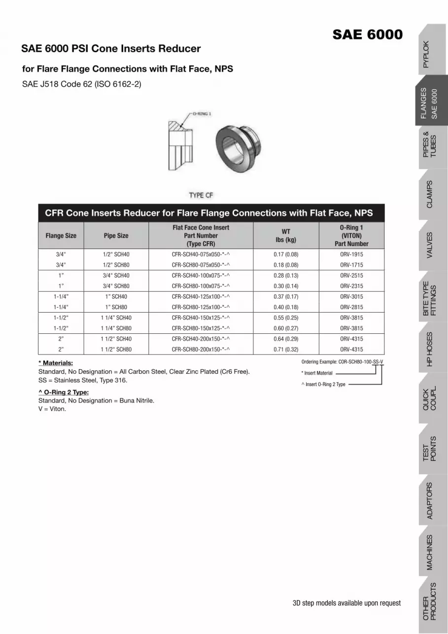
SAE 6000 PSI Cone Inserts Reducer
for Flare Flange Connections with O-Ring Face, NPS SAE J518 Code 62 (ISO 6162-2)
* Materials:
Standard, No Designation = All Carbon Steel, Clear Zinc Plated (Cr6 Free).SS = Stainless Steel, Type 316.
^ O-Ring 2 Type:
Standard, No Designation = Buna Nitrile.V = Viton.
Ordering Example: COR-SCH80-100x075-SS-V
* Insert Material
^ Insert O-Ring 2 Type
3D step models available upon request
Flange Size Pipe Size
Flat Face Cone Insert
Part Number
(Type CFR)
WT
lbs (kg)
O-Ring 1
(VITON)
Part Number
3/4" 1/2" SCH40 CFR-SCH40-075x050-*-^ 0.17 (0.08) ORV-1915
3/4" 1/2" SCH80 CFR-SCH80-075x050-*-^ 0.18 (0.08) ORV-1715
1” 3/4" SCH40 CFR-SCH40-100x075-*-^ 0.28 (0.13) ORV-2515
1” 3/4" SCH80 CFR-SCH80-100x075-*-^ 0.30 (0.14) ORV-2315
1-1/4” 1” SCH40 CFR-SCH40-125x100-*-^ 0.37 (0.17) ORV-3015
1-1/4" 1” SCH80 CFR-SCH80-125x100-*-^ 0.40 (0.18) ORV-2815
1-1/2" 1 1/4” SCH40 CFR-SCH40-150x125-*-^ 0.55 (0.25) ORV-3815
1-1/2" 1 1/4” SCH80 CFR-SCH80-150x125-*-^ 0.60 (0.27) ORV-3815
2” 1 1/2" SCH40 CFR-SCH40-200x150-*-^ 0.64 (0.29) ORV-4315
2” 1 1/2" SCH80 CFR-SCH80-200x150-*-^ 0.71 (0.32) ORV-4315
CFR Cone Inserts Reducer for Flare Flange Connections with Flat Face, NPS
SAE 6000 PSI Cone Inserts Reducer
for Flare Flange Connections with Flat Face, NPS
SAE J518 Code 62 (ISO 6162-2)
* Materials:
Standard, No Designation = All Carbon Steel, Clear Zinc Plated (Cr6 Free).SS = Stainless Steel, Type 316.
^ O-Ring 2 Type:
Standard, No Designation = Buna Nitrile.V = Viton.
Ordering Example: COR-SCH80-100-SS-V
* Insert Material
^ Insert O-Ring 2 Type
PIP
ES
&
TU
BE
SC
LAM
PS
VA
LVE
SH
P H
OS
ES
BIT
E T
YP
EF
ITT
ING
SQ
UIC
K
CO
UP
L.T
ES
T
PO
INT
SA
DA
PT
OR
SM
AC
HIN
ES
OT
HE
R
PR
OD
UC
TS
PY
PLO
K

3D step models available upon request
SAE 6000 PSI Retain Ring Flange Dimensions
SAE J518 Code 62 (ISO 6162-2)
FFCM34 Metric Flare Flange, Clearance
* SHCS Bolt Specification
Carbon Steel: ASTM A574316 Stainless Steel: ASTM A193 B8M Class 2
SizeDimensions (in) SHCS Bolt*
L (L)
Working
Pressure
PSI (Bar)A B G H M N P E
1/2" 0.72 1.59 1.88 2.22 2.20 2.09 2.32 0.81 5/16"-18 UNC x 2.25 (1.50) 6000 (420)
3/4" 0.94 2.00 2.38 2.81 2.76 2.68 2.95 1.02 3/8"-16 UNC x 2.75 (1.75) 6000 (420)
1" 1.09 2.25 2.75 3.19 3.19 2.99 3.35 1.03 7/16"-14 UNC x 2.75 (1.75) 6000 (420)
1-1/4" 1.25 2.63 3.06 3.75 3.58 3.27 3.90 1.25 1/2"-13 UNC x 3.25 (2.00) 6000 (420)
1-1/2" 1.44 3.13 3.75 4.44 4.25 3.98 4.57 1.38 5/8"-11 UNC x 4.00 (2.50) 6000 (420)
2" 1.75 3.81 4.50 5.25 5.04 4.72 5.39 1.68 3/4"-10 UNC x 4.50 (2.75) 6000 (420)
Retain Ring Flange Dimensions (Inches)
Retain Ring Flange Dimensions (Millimeters)
SizeDimensions (mm) SHCS Bolt*
L (L)
Working
Pressure
PSI (Bar)A B G H M N P E
1/2" 18.3 40.4 47.8 56.4 55.9 53.1 58.9 20.6 M8 x 60 (40) 6000 (420)
3/4" 23.9 50.8 60.5 71.4 70.1 68.1 74.9 25.9 M10 x 70 (45) 6000 (420)
1" 27.7 57.2 69.9 81.0 81.0 75.9 85.1 26.2 M12 x 70 (45) 6000 (420)
1-1/4" 31.8 66.8 77.7 95.3 90.9 83.1 99.1 31.8 M12 x 80 (50) 6000 (420)
1-1/4" (2) 31.8 66.8 77.7 95.3 90.9 83.1 99.1 31.8 M14 x 80 (50) 6000 (420)
1-1/2" 36.6 79.5 95.3 112.8 108.0 101.1 116.1 35.1 M16 x 100 (65) 6000 (420)
2" 44.5 96.8 114.3 133.4 128.0 119.9 136.9 42.7 M20 x 120 (70) 6000 (420)
* SHCS Bolt Specification
Carbon Steel: DIN912 / ISO4762 Grade 8.8316 Stainless Steel: DIN912 / ISO4762 A480
(2) Designates M14 Bolt – Special Order

3D step models available upon request
SAE 6000 PSI Retain Ring Flange with Clearance Holes
SAE J518 Code 62 (ISO 6162-2)
Size Pipe SizeStandard
Part Number
Working Pressure
PSI (Bar)
Weight
lbs (kg)
1-1/2” 1 1/2” SCHXXS RFAC64-150-* 6000 (420) 3.14 (1.43)
2” 2” SCH160/XXS RFAC64-200-* 6000 (420) 4.82 (2.19)
SizePipe Size
OD x Wall
Standard
Part Number
Working Pressure
PSI (Bar)
Weight
lbs (kg)
1/2” 26X6.0 RFC64-050-* 6000 (420) 0.43 (0.20)
3/4” 36X8.0 RFC64-075-* 6000 (420) 0.83 (0.38)
1” 39X7.5 RFC64-100-* 6000 (420) 1.16 (0.51)
1-1/4” 46X8.0 RFC64-125-* 6000 (420) 1.86 (0.85)
1-1/4" (2) 46X8.0 RFC64-125-M14-* 6000 (420) 1.86 (0.85)
1-1/2” 56X8.5 RFC64-150-* 6000 (420) 3.14 (1.43)
2” 66X8.5 RFC64-200-* 6000 (420) 4.82 (2.19)
RFC64 - Retain Ring Flange with Clearance Holes, Metric
* Materials:
Standard, No Designation = Carbon Steel, Clear Zinc Plated (Cr6 Free).HDG = Carbon Steel, Hot Dip Galvanized.SS = Stainless Steel, Type 316.(2) Designates M14 Bolt – Special Order
Ordering Example: RFAC64-200-SS
* Insert Material
RFAC64 – Retain Ring Flange with Clearance Holes, for
Grooved NPS Pipe Only
PIP
ES
&
TU
BE
SC
LAM
PS
VA
LVE
SH
P H
OS
ES
BIT
E T
YP
EF
ITT
ING
SQ
UIC
K
CO
UP
L.T
ES
T
PO
INT
SA
DA
PT
OR
SM
AC
HIN
ES
OT
HE
R
PR
OD
UC
TS
PY
PLO
K

3D step models available upon request
* Materials:
Standard, No Designation = All Carbon Steel, Clear Zinc Plated (Cr6 Free).SS = Stainless Steel, Type 316.ZSS = Carbon Steel Flange with Stainless Steel Adapter Body, Type 316.HDGSS = Carbon Steel, Hot Dip Galvanized Flange with Stainless Steel Adapter Body, Type 316.
Note: To Order A Retain Ring Flange with Threaded Holes, Replace FC with FT in the Part Number.
Ordering Example: A/BWAR-SCH80-200-FC64-SS
* Insert Material
Assembly Retain Ring Style with Clearance Holes, NPS
SAE J518 Code 62 (ISO 6162-2)
Size Pipe SizeComplete Flange Set
Part Number
WT/Set
lbs (kg)
Dimension
(in)
L
Weld Adapter
Body
Part Number
Flange
Part Number
Retain Ring
(Stainless
Steel)
Part Number
1/2" 1/2” SCH80 A/BWAR-SCH80-050-FC64-* 0.67 (0.30) 1.25 BWAR-SCH80-050-* RFC64-050-* R-050
1/2" 1/2” SCH160 A/BWAR-SCH160-050-FC64-* 0.68 (0.31) 1.25 BWAR-SCH160-050-* RFC64-050-* R-050
1/2” 1/2” SCHXXS A/BWAR-SCHXXS-050-FC64-* 0.69 (0.31) 1.25 BWAR-SCHXXS-050-* RFC64-050-* R-050
3/4” 3/4” SCH80 A/BWAR-SCH80-075-FC64-* 1.29 (0.59) 1.75 BWAR-SCH80-075-* RFC64-075-* R-075
3/4" 3/4” SCH160 A/BWAR-SCH160-075-FC64-* 1.37 (0.62) 1.75 BWAR-SCH160-075-* RFC64-075-* R-075
3/4” 3/4” SCHXXS A/BWAR-SCHXXS-075-FC64-* 1.40 (0.64) 1.75 BWAR-SCHXXS-075-* RFC64-075-* R-075
1” 1” SCH80 A/BWAR-SCH80-100-FC64-* 1.66 (0.75) 1.75 BWAR-SCH80-100-* RFC64-100-* R-100
1” 1” SCH160 A/BWAR-SCH160-100-FC64-* 1.77 (0.80) 1.75 BWAR-SCH160-100-* RFC64-100-* R-100
1” 1” SCHXXS A/BWAR-SCHXXS-100-FC64-* 1.81 (0.82) 1.75 BWAR-SCHXXS-100-* RFC64-100-* R-100
1-1/4” 1-1/4” SCH80 A/BWAR-SCH80-125-FC64-* 2.69 (1.22) 2.00 BWAR-SCH80-125-* RFC64-125-* R-125
1-1/4” 1-1/4” SCH160 A/BWAR-SCH160-125-FC64-* 2.72 (1.24) 2.00 BWAR-SCH160-125-* RFC64-125-* R-125
1-1/4” 1-1/4” SCHXXS A/BWAR-SCHXXS-125-FC64-* 2.83 (1.29) 2.00 BWAR-SCHXXS-125-* RFC64-125-* R-125
1-1/2” 1-1/2” SCH80 A/BWAR-SCH80-150-FC64-* 3.79 (1.72) 2.25 BWAR-SCH80-150-* RFC64-150-* R-150
1-1/2” 1-1/2” SCH160 A/BWAR-SCH160-150-FC64-* 4.43 (2.01) 2.25 BWAR-SCH160-150-* RFC64-150-* R-150
1-1/2” 1-1/2” SCHXXS A/BWAR-SCHXXS-150-FC64-* 4.45 (2.02) 2.25 BWAR-SCHXXS-150-* RFC64-150-* R-150
2” 2” SCH80 A/BWAR-SCH80-200-FC64-* 6.50 (2.95) 2.50 BWAR-SCH80-200-* RFC64-200-* R-200
2” 2” SCH160 A/BWAR-SCH160-200-FC64-* 6.67 (3.03) 2.50 BWAR-SCH160-200-* RFC64-200-* R-200
2” 2” SCHXXS A/BWAR-SCHXXS-200-FC64-* 6.71 (3.05) 2.50 BWAR-SCHXXS-200-* RFC64-200-* R-200
A/BWAR - Butt Weld Adapter Assembly Retain Ring Style with Clearance Holes, NPS
Complete Flange Set Includes:• One (1) Retain Ring Flange• One (1) Weld Adapter Body• One (1) Retain Ring
To be Ordered Separately:• Bolt Kit (See Page H25)• O-Ring Spacer (See Page H75)

3D step models available upon request
* Materials:
Standard, No Designation = All Carbon Steel, Clear Zinc Plated (Cr6 Free).SS = Stainless Steel, Type 316.ZSS = Carbon Steel Flange with Stainless Steel Adapter Body, Type 316.HDGSS = Carbon Steel, Hot Dip Galvanized Flange with Stainless Steel Adapter Body, Type 316.
Note: To Order A Retain Ring Flange with Threaded Holes, Replace FC with FT in the Part Number.
Ordering Example: A/BWAR-50.0X3.0-200-FC64-SS
* Insert Material
Assembly Retain Ring Style with Clearance Holes, Metric
SAE J518 Code 62 (ISO 6162-2)
SizePipe Size
OD x Wall
Complete Flange Set
Part Number
WT/Set
lbs (kg)
Dimension
(mm)
L
Weld Adapter Body
Part Number
Flange
Part Number
Retain Ring
(Stainless
Steel)
Part Number
1/2” 16.0x2.0 A/BWAR-16.0X2.0-050-FC64-* 0.68 (0.31) 38.1 BWAR-16.0X2.0-050-* RFC64-050-* R-050
1/2” 18.0x2.0 A/BWAR-18.0X2.0-050-FC64-* 0.68 (0.31) 38.1 BWAR-18.0X2.0-050-* RFC64-050-* R-050
1/2” 20.0x2.0 A/BWAR-20.0X2.0-050-FC64-* 0.70 (0.35) 38.1 BWAR-20.0X2.0-050-* RFC64-050-* R-050
1/2” 20.0x2.5 A/BWAR-20.0X2.5-050-FC64-* 0.70 (0.35) 38.1 BWAR-20.0X2.5-050-* RFC64-050-* R-050
1/2” 20.0x3.0 A/BWAR-20.0X3.0-050-FC64-* 0.70 (0.35) 38.1 BWAR-20.0X3.0-050-* RFC64-050-* R-050
1/2” 21.3x2.8 A/BWAR-SCH40-050-FC64-* 0.66 (0.30) 31.8 BWAR-SCH40-050-* RFC64-050-* R-050
1/2” 21.3X3.7 A/BWAR-SCH80-050-FC64-* 0.67 (0.30) 31.8 BWAR-SCH80-050-* RFC64-050-* R-050
1/2” 21.3x4.8 A/BWAR-SCH160-050-FC64-* 0.68 (0.31) 31.8 BWAR-SCH160-050-* RFC64-050-* R-050
1/2” 21.3X7.5 A/BWAR-SCHXXS-050-FC64-* 0.69 (0.31) 31.8 BWAR-SCHXXS-050-* RFC64-050-* R-050
1/2” 25.0X2.5 A/BWAR-25.0X2.5-050-FC64-* 0.69 (0.31) 38.1 BWAR-25.0X2.5-050-* RFC64-050-* R-050
1/2” 25.0X3.0 A/BWAR-25.0X3.0-050-FC64-* 0.69 (0.31) 38.1 BWAR-25.0X3.0-050-* RFC64-050-* R-050
1/2” 26.0X6.0 A/BWAR-26.0X6.0-050-FC64-* 0.74 (0.34) 38.1 BWAR-26.0X6.0-050-* RFC64-050-* R-050
3/4" 20.0X2.0 A/BWAR-20.0X2.0-075-FC64-* 1.32 (0.60) 44.5 BWAR-20.0X2.0-075-* RFC64-075-* R-075
3/4" 20.0X2.5 A/BWAR-20.0X2.5-075-FC64-* 1.34 (0.61) 44.5 BWAR-20.0X2.5-075-* RFC64-075-* R-075
3/4” 20.0X3.0 A/BWAR-20.0X3.0-075-FC64-* 1.34 (0.61) 44.5 BWAR-20.0X3.0-075-* RFC64-075-* R-075
3/4" 25.0X2.5 A/BWAR-25.0X2.5-075-FC64-* 1.31 (0.60) 44.5 BWAR-25.0X2.5-075-* RFC64-075-* R-075
3/4" 25.0X3.0 A/BWAR-25.0X3.0-075-FC64-* 1.32 (0.60) 44.5 BWAR-25.0X3.0-075-* RFC64-075-* R-075
3/4" 25.0X4.0 A/BWAR-25.0X4.0-075-FC64-* 1.34 (0.61) 44.5 BWAR-25.0X4.0-075-* RFC64-075-* R-075
3/4" 26.7X2.9 A/BWAR-SCH40-075-FC64-* 1.27 (0.58) 44.5 BWAR-SCH40-075-* RFC64-075-* R-075
3/4" 26.7X3.9 A/BWAR-SCH80-075-FC64-* 1.29 (0.59) 44.5 BWAR-SCH80-075-* RFC64-075-* R-075
3/4" 26.7X5.5 A/BWAR-SCH160-075-FC64-* 1.37 (0.62) 44.5 BWAR-SCH160-075-* RFC64-075-* R-075
3/4" 26.7X7.8 A/BWAR-SCHXXS-075-FC64-* 2.02 (0.92) 44.5 BWAR-SCHXXS-075-* RFC64-075-* R-075
3/4" 30.0X3.0 A/BWAR-30.0X3.0-075-FC64-* 1.22 (0.55) 44.5 BWAR-30.0X3.0-075-* RFC64-075-* R-075
3/4" 30.0X4.0 A/BWAR-30.0X4.0-075-FC64-* 1.25 (0.57) 44.5 BWAR-30.0X4.0-075-* RFC64-075-* R-075
3/4" 36.0X8.0 A/BWAR-36.0X8.0-075-FC64-* 1.40 (0.64) 44.5 BWAR-36.0X8.0-075-* RFC64-075-* R-075
A/BWAR - Butt Weld Adapter Assembly Retain Ring Style with Clearance Holes, Metric
Complete Flange Set Includes:• One (1) Retain Ring Flange• One (1) Weld Adapter Body• One (1) Retain Ring
To be Ordered Separately:• Bolt Kit (See Page H25)• O-Ring Spacer (See Page H75)
PIP
ES
&
TU
BE
SC
LAM
PS
VA
LVE
SH
P H
OS
ES
BIT
E T
YP
EF
ITT
ING
SQ
UIC
K
CO
UP
L.T
ES
T
PO
INT
SA
DA
PT
OR
SM
AC
HIN
ES
OT
HE
R
PR
OD
UC
TS
PY
PLO
K

3D step models available upon request
* Materials:
Standard, No Designation = All Carbon Steel, Clear Zinc Plated (Cr6 Free).SS = Stainless Steel, Type 316.ZSS = Carbon Steel Flange with Stainless Steel Adapter Body, Type 316.HDGSS = Carbon Steel, Hot Dip Galvanized Flange with Stainless Steel Adapter Body, Type 316.
Note: To Order A Retain Ring Flange with Threaded Holes, Replace FC with FT in the Part Number.
Ordering Example: A/BWAR-50.0X3.0-200-FC64-SS
* Insert Material
Assembly Retain Ring Style with Clearance Holes, Metric
SAE J518 Code 62 (ISO 6162-2)
SizePipe Size
OD x Wall
Complete Flange Set
Part Number
WT/Set
lbs (kg)
Dimension
(mm)
L
Weld Adapter Body
Part Number
Flange
Part Number
Retain Ring
(Stainless
Steel)
Part Number
1" 25.0X2.5 A/BWAR-25.0X2.5-100-FC64-* 1.64 (0.75) 44.5 BWAR-25.0X2.5-100-* RFC64-100-* R-100
1” 25.0x3.0 A/BWAR-25.0X3.0-100-FC64-* 1.64 (0.75) 44.5 BWAR-25.0X3.0-100-* RFC64-100-* R-100
1” 25.0X4.0 A/BWAR-25.0X4.0-100-FC64-* 1.67 (0.76) 44.5 BWAR-25.0X4.0-100-* RFC64-100-* R-100
1” 30.0X3.0 A/BWAR-30.0X3.0-100-FC64-* 1.68 (0.76) 44.5 BWAR-30.0X3.0-100-* RFC64-100-* R-100
1” 30.0X4.0 A/BWAR-30.0X4.0-100-FC64-* 1.66 (0.75) 44.5 BWAR-30.0X4.0-100-* RFC64-100-* R-100
1” 30.0X5.0 A/BWAR-30.0X5.0-100-FC64-* 1.73 (0.79) 44.5 BWAR-30.0X5.0-100-* RFC64-100-* R-100
1” 33.4X3.4 A/BWAR-SCH40-100-FC64-* 1.66 (0.75) 44.5 BWAR-SCH40-100-* RFC64-100-* R-100
1” 33.4X4.6 A/BWAR-SCH80-100-FC64-* 1.66 (0.75) 44.5 BWAR-SCH80-100-* RFC64-100-* R-100
1” 33.4X6.4 A/BWAR-SCH160-100-FC64-* 1.77 (0.80) 44.5 BWAR-SCH160-100-* RFC64-100-* R-100
1” 33.4X9.1 A/BWAR-SCHXXS-100-FC64-* 1.81 (0.82) 44.5 BWAR-SCHXXS-100-* RFC64-100-* R-100
1” 38.0X4.0 A/BWAR-38.0X4.0-100-FC64-* 1.66 (0.75) 44.5 BWAR-38.0X4.0-100-* RFC64-100-* R-100
1” 38.0X5.0 A/BWAR-38.0X5.0-100-FC64-* 1.66 (0.75) 44.5 BWAR-38.0X5.0-100-* RFC64-100-* R-100
1” 38.0X6.0 A/BWAR-38.0X6.0-100-FC64-* 1.75 (0.80) 44.5 BWAR-38.0X6.0-100-* RFC64-100-* R-100
1” 39.0X7.5 A/BWAR-39.0X7.5-100-FC64-* 1.78 (0.81) 44.5 BWAR-39.0X7.5-100-* RFC64-100-* R-100
1-1/4" 30.0X3.0 A/BWAR-30.0X3.0-125-FC64-* 2.67 (1.21) 50.8 BWAR-30.0X3.0-125-* RFC64-125-* R-125
1-1/4" 30.0X4.0 A/BWAR-30.0X4.0-125-FC64-* 2.70 (1.23) 50.8 BWAR-30.0X4.0-125-* RFC64-125-* R-125
1-1/4" 30.0X5.0 A/BWAR-30.0X5.0-125-FC64-* 2.72 (1.24) 50.8 BWAR-30.0X5.0-125-* RFC64-125-* R-125
1-1/4" 38.0X4.0 A/BWAR-38.0X4.0-125-FC64-* 2.66 (1.21) 50.8 BWAR-38.0X4.0-125-* RFC64-125-* R-125
1-1/4" 38.0X5.0 A/BWAR-38.0X5.0-125-FC64-* 2.69 (1.22) 50.8 BWAR-38.0X5.0-125-* RFC64-125-* R-125
1-1/4" 38.0X6.0 A/BWAR-38.0X6.0-125-FC64-* 2.72 (1.24) 50.8 BWAR-38.0X6.0-125-* RFC64-125-* R-125
1-1/4" 42.0X3.0 A/BWAR-42.0X3.0-125-FC64-* 2.67 (1.21) 50.8 BWAR-42.0X3.0-125-* RFC64-125-* R-125
1-1/4" 42.0X4.0 A/BWAR-42.0X4.0-125-FC64-* 2.68 (1.22) 50.8 BWAR-42.0X4.0-125-* RFC64-125-* R-125
1-1/4" 42.2X3.6 A/BWAR-SCH40-125-FC64-* 2.68 (1.22) 50.8 BWAR-SCH40-125-* RFC64-125-* R-125
1-1/4" 42.2X4.9 A/BWAR-SCH80-125-FC64-* 2.68 (1.22) 50.8 BWAR-SCH80-125-* RFC64-125-* R-125
1-1/4" 42.2X6.4 A/BWAR-SCH160-125-FC64-* 2.68 (1.22) 50.8 BWAR-SCH160-125-* RFC64-125-* R-125
1-1/4" 42.2X9.7 A/BWAR-SCHXXS-125-FC64-* 2.83 (1.29) 50.8 BWAR-SCHXXS-125-* RFC64-125-* R-125
1-1/4" 46.0X8.5 A/BWAR-46.0X8.5-125-FC64-* 2.83 (1.29) 50.8 BWAR-46.0X8.5-125-* RFC64-125-* R-125
IMPORTANT NOTE: For 1-1/4" SAE 6000 PSI (ISO 6162-2) Flanges with M14 bolt requirements please add -M14 to the end of the part numbers above
A/BWAR - Butt Weld Adapter Assembly Retain Ring Style with Clearance Holes, Metric
Complete Flange Set Includes:• One (1) Retain Ring Flange• One (1) Weld Adapter Body• One (1) Retain Ring
To be Ordered Separately:• Bolt Kit (See Page H25)• O-Ring Spacer (See Page H75)
213

3D step models available upon request
* Materials:
Standard, No Designation = All Carbon Steel, Clear Zinc Plated (Cr6 Free).SS = Stainless Steel, Type 316.ZSS = Carbon Steel Flange with Stainless Steel Adapter Body, Type 316.HDGSS = Carbon Steel, Hot Dip Galvanized Flange with Stainless Steel Adapter Body, Type 316.
Note: To Order A Retain Ring Flange with Threaded Holes, Replace FC with FT in the Part Number.
Ordering Example: A/BWAR-50.0X3.0-200-FC64-SS
* Insert Material
Assembly Retain Ring Style with Clearance Holes, Metric
SAE J518 Code 62 (ISO 6162-2)
SizePipe Size
OD x Wall
Complete Flange Set
Part Number
WT/Set
lbs (kg)
Dimension
(mm)
L
Weld Adapter Body
Part Number
Flange
Part Number
Retain Ring
(Stainless
Steel)
Part Number
1-1/2" 38.0X4.0 A/BWAR-38.0X4.0-150-FC64-* 4.13 (1.88) 57.2 BWAR-38.0X4.0-150-* RFC64-150-* R-150
1-1/2" 38.0X5.0 A/BWAR-38.0X5.0-150-FC64-* 4.08 (1.85) 57.2 BWAR-38.0X5.0-150-* RFC64-150-* R-150
1-1/2" 38.0X6.0 A/BWAR-38.0X6.0-150-FC64-* 4.21 (1.91) 57.2 BWAR-38.0X6.0-150-* RFC64-150-* R-150
1-1/2" 42.0X3.0 A/BWAR-42.0X3.0-150-FC64-* 4.03 (1.83) 57.2 BWAR-42.0X3.0-150-* RFC64-150-* R-150
1-1/2" 42.0X4.0 A/BWAR-42.0X4.0-150-FC64-* 4.08 (1.85) 57.2 BWAR-42.0X4.0-150-* RFC64-150-* R-150
1-1/2" 48.3X3.7 A/BWAR-SCH40-150-FC64-* 4.18 (1.90) 57.2 BWAR-SCH40-150-* RFC64-150-* R-150
1-1/2" 48.3X5.1 A/BWAR-SCH80-150-FC64-* 4.11 (1.87) 57.2 BWAR-SCH80-150-* RFC64-150-* R-150
1-1/2" 48.3X7.1 A/BWAR-SCH160-150-FC64-* 4.43 (2.01) 57.2 BWAR-SCH160-150-* RFC64-150-* R-150
1-1/2" 48.3X10.2 A/BWAR-SCHXXS-150-FC64-* 4.37 (1.99) 57.2 BWAR-SCHXXS-150-* RFC64-150-* R-150
1-1/2" 50.0X3.0 A/BWAR-50.0X3.0-150-FC64-* 4.05 (1.84) 57.2 BWAR-50.0X3.0-150-* RFC64-150-* R-150
1-1/2" 50.0X5.0 A/BWAR-50.0X5.0-150-FC64-* 3.98 (1.81) 57.2 BWAR-50.0X5.0-150-* RFC64-150-* R-150
1-1/2" 56.0X8.5 A/BWAR-56.0X8.5-150-FC64-* 4.41 (2.00) 57.2 BWAR-56.0X8.5-150-* RFC64-150-* R-150
2” 50.0X3.0 A/BWAR-50.0X3.0-200-FC64-* 6.35 (2.89) 63.5 BWAR-50.0X3.0-200-* RFC64-200-* R-200
2” 50.0X5.0 A/BWAR-50.0X5.0-200-FC64-* 6.48 (2.95) 63.5 BWAR-50.0X5.0-200-* RFC64-200-* R-200
2” 50.0X6.0 A/BWAR-50.0X6.0-200-FC64-* 6.55 (2.98) 63.5 BWAR-50.0X6.0-200-* RFC64-200-* R-200
2” 60.0X3.0 A/BWAR-60.0X3.0-200-FC64-* 6.24 (2.84) 63.5 BWAR-60.0X3.0-200-* RFC64-200-* R-200
2” 60.0X5.0 A/BWAR-60.0X5.0-200-FC64-* 5.97 (2.71) 63.5 BWAR-60.0X5.0-200-* RFC64-200-* R-200
2” 60.0X6.0 A/BWAR-60.0X6.0-200-FC64-* 6.44 (2.92) 63.5 BWAR-60.0X6.0-200-* RFC64-200-* R-200
2” 60.0X8.0 A/BWAR-60.0X8.0-200-FC64-* 6.61 (3.00) 63.5 BWAR-60.0X8.0-200-* RFC64-200-* R-200
2” 60.3X3.9 A/BWAR-SCH40-200-FC64-* 6.40 (2.91) 63.5 BWAR-SCH40-200-* RFC64-200-* R-200
2” 60.3X5.5 A/BWAR-SCH80-200-FC64-* 6.50 (2.95) 63.5 BWAR-SCH80-200-* RFC64-200-* R-200
2” 60.3X8.7 A/BWAR-SCH160-200-FC64-* 6.67 (3.03) 63.5 BWAR-SCH160-200-* RFC64-200-* R-200
2” 60.3X11.1 A/BWAR-SCHXXS-200-FC64-* 6.71 (3.05) 63.5 BWAR-SCHXXS-200-* RFC64-200-* R-200
2” 66.0X8.5 A/BWAR-66.0X8.5-200-FC64-* 6.56 (2.98) 63.5 BWAR-66.0X8.5-200-* RFC64-200-* R-200
A/BWAR - Butt Weld Adapter Assembly Retain Ring Style with Clearance Holes, Metric
Complete Flange Set Includes:• One (1) Retain Ring Flange• One (1) Weld Adapter Body• One (1) Retain Ring
To be Ordered Separately:• Bolt Kit (See Page H25)• O-Ring Spacer (See Page H75)
214
PIP
ES
&
TU
BE
SC
LAM
PS
VA
LVE
SH
P H
OS
ES
BIT
E T
YP
EF
ITT
ING
SQ
UIC
K
CO
UP
L.T
ES
T
PO
INT
SA
DA
PT
OR
SM
AC
HIN
ES
OT
HE
R
PR
OD
UC
TS
PY
PLO
K

3D step models available upon request
SAE 6000 PSI BSPP Female Thread Adapter
Complete Assembly SAE J518 Code 62 (ISO 6162-2)
Size
(flange x
thread)
Complete Assembly
Part Number
Dimensions
in (mm)
Thread
Size O-Ring (Buna)
Part Number
Assembly
WT
lbs (kg)
Body Only
Part Number
Body Only
WT
lbs (kg)L R
1/2”x 1/4” A/FBTA-050x025-FC64-*-^ 2.50 (63.5) 1/4" OR^-3-909 0.95 (0.43) FBTA-050x025-*-^ 0.52 (0.24)
3/4”x 1/2" A/FBTA-075x050-FC64-*-^ 2.88 (73.0) 1/2" OR^-3-913 1.79 (0.81) FBTA-075x050*-^ 0.97 (0.44)
1”x 3/4" A/FBTA-100x075-FC64-*-^ 3.75 (95.3) 3/4" OR^-3-916 3.14 (1.41) FBTA-100x075-*-^ 1.98 (0.90)
1-1/4”x 1” A/FBTA-125x100-FC64-*-^ 3.88 (98.6) 1” OR^-3-918 4.14 (1.88) FBTA-125x100-*-^ 2.28 (1.04)
1-1/2”x 1-1/4" A/FBTA-150x125-FC64-*-^ 4.00 (101.6) 1-1/4” OR^-3-924 5.97 (2.71) FBTA-150x125-*-^ 2.83 (1.28)
2”x 1-1/2" A/FBTA-200x150-FC64-*-^ 4.25 (108.0) 1-1/2” OR^-3-928 8.49 (3.86) FBTA-200x150-*-^ 3.67 (1.66)
Complete Flange Set Includes:• One (1) Female Thread Adapter• One (1) Retain Ring Flange• One (1) Retain Ring• One (1) Face O-Ring (O-Ring 1)
To be Ordered Separately:• Bolt Kit (See Page H25)
Flange Option:
Standard, FC64 = SAE 6000 PSI Code 62 (ISO 6162-2) Clearance Flange.FT64 = SAE 6000 PSI Code 62 (ISO 6162-2) UNC Threaded Flange.FTM64 = SAE 6000 PSI Code 62 (ISO 6162-2) Metric Threaded Flange.
* Materials:
Standard, No Designation = All Carbon Steel, Clear Zinc Plated (Cr6 Free).SS = Stainless Steel, Type 316.
^ O-Ring Type:
Standard, No Designation = Buna Nitrile.V = Viton.
Ordering Example: A/FBTA-200x200-FC64-SS-V
Flange Option
* Insert Material
^ Insert O-Ring Type
A/FBTA - BSPP Female Thread Adapter Complete Assembly with Buna O-Ring

3D step models available upon request
SAE 6000 PSI SAE Male Thread Adapter
Complete AssemblySAE J518 Code 62 (ISO 6162-2)
Size
(flange x
thread)
Complete Assembly
Part Number
Dimensions
in (mm) Thread Size
UNF/UN-2A
O-Ring 1
(Buna)
Part No.
O-Ring 2
(Buna)
Part No.
Assembly
WT
lbs (kg)
Body Only
Part Number
Body Only
WT
lbs (kg)L
1/2”x 3/8” A/STA-050x038-FC64-*-^ 2.63 (66.80) 9/16”-18 OR^-3-909 OR^-3-906 0.96 (0.44) STA-050x038-* 0.50 (0.23)
1/2”x 1/2” A/STA-050x050-FC64-*-^ 2.63 (66.80) 3/4”-16 OR^-3-909 OR^-3-908 0.94 (0.43) STA-050x050-* 0.52 (0.24)
1/2”x 5/8” A/STA-050x063-FC64-*-^ 2.63 (66.80) 7/8”-14 OR^-3-909 OR^-3-910 1.00 (0.45) STA-050x063-* 0.57 (0.26)
1/2”x 3/4” A/STA-050x075-FC64-*-^ 2.63 (66.80) 1 1/16”-12 OR^-3-909 OR^-3-912 1.12 (0.50) STA-050x075-* 0.66 (0.30)
3/4”x 1/2” A/STA-075x050-FC64-*-^ 2.75 (69.85) 3/4”-16 OR^-3-913 OR^-3-908 1.50 (0.68) STA-075x050-* 1.00 (0.45)
3/4”x 3/4” A/STA-075x075-FC64-*-^ 2.75 (69.85) 1 1/16”-12 OR^-3-913 OR^-3-912 1.57 (0.71) STA-075x075-* 1.07 (0.49)
3/4”x 1” A/STA-075x100-FC64-*-^ 2.75 (69.85) 1 5/16”-12 OR^-3-913 OR^-3-916 1.78 (0.81) STA-075x100-* 1.15 (0.52)
1”x 3/4” A/STA-100x075-FC64-*-^ 3.00 (76.20) 1 1/16”-12 OR^-3-916 OR^-3-912 1.88 (0.85) STA-100x075-* 1.25 (0.57)
1”x 1” A/STA-100x100-FC64-*-^ 3.00 (76.20) 1 5/16”-12 OR^-3-916 OR^-3-916 1.93 (0.88) STA-100x100-* 1.30 (0.59)
1”x 1-1/4” A/STA-100x125-FC64-*-^ 3.00 (76.20) 1 5/8”-12 OR^-3-916 OR^-3-920 2.12 (0.96) STA-100x125-* 1.49 (0.68)
1-1/4”x 1” A/STA-125x100-FC64-*-^ 3.25 (82.55) 1 5/16”-12 OR^-3-918 OR^-3-916 2.65 (1.20) STA-125x100-* 1.75 (0.79)
1-1/4”x 1-1/4” A/STA-125x125-FC64-*-^ 3.25 (82.55) 1 5/8”-12 OR^-3-918 OR^-3-920 2.72 (1.23) STA-125x125-* 1.82 (0.83)
1-1/4”x 1-1/2” A/STA-125x150-FC64-*-^ 3.25 (82.55) 1 7/8”-12 OR^-3-918 OR^-3-924 2.93 (1.33) STA-125x150-* 2.03 (0.92)
1-1/2”x 1-1/4” A/STA-150x125-FC64-*-^ 4.25 (107.95) 1 5/8”-12 OR^-3-924 OR^-3-920 3.84 (1.74) STA-150x125-* 2.94 (1.33)
1-1/2”x 1-1/2” A/STA-150x150-FC64-*-^ 4.25 (107.95) 1 7/8”-12 OR^-3-924 OR^-3-924 4.32 (1.96) STA-150x150-* 2.97 (1.35)
1-1/2” x 2” A/STA-150x200-FC64-*-^ 4.25 (107.95) 2 1/2”-12 OR^-3-924 OR^-3-932 4.89 (2.22) STA-150x200-* 3.54 (1.61)
2”x 1-1/2” A/STA-200x150-FC64-*-^ 4.38 (111.25) 1 7/8”-12 OR^-3-928 OR^-3-924 5.78 (2.62) STA-200x150-* 3.76 (1.71)
2”x 2” A/STA-200x200-FC64-*-^ 4.38 (111.25) 2 1/2”-12 OR^-3-928 OR^-3-932 5.98 (2.71) STA-200x200-* 3.96 (1.80)
Complete Flange Set Includes:• One (1) Male Thread Adapter• One (1) Retain Ring Flange• One (1) Retain Ring• One (1) Face O-Ring (O-Ring 1)• One (1) Thread O-Ring (O-Ring 2)
To be Ordered Separately:• Bolt Kit (See Page H25)
Flange Option:
Standard, FC64 = SAE 6000 PSI Code 62 (ISO 6162-2) Clearance Flange.FT64 = SAE 6000 PSI Code 62 (ISO 6162-2) UNC Threaded Flange.FTM64 = SAE 6000 PSI Code 62 (ISO 6162-2) Metric Threaded Flange.
* Materials:
Standard, No Designation = All Carbon Steel, Clear Zinc Plated (Cr6 Free).SS = Stainless Steel, Type 316. Body OnlySSA = Stainless Steel, Type 316. All SS including flange
^ O-Ring Type:
Standard, No Designation = Buna Nitrile.V = Viton.
Ordering Example: A/STA-200x150-FC64-SS-V
Flange Option
* Insert Material
^ Insert O-Ring Type
A/STA - SAE Male Thread Adapter Complete Assembly
PIP
ES
&
TU
BE
SC
LAM
PS
VA
LVE
SH
P H
OS
ES
BIT
E T
YP
EF
ITT
ING
SQ
UIC
K
CO
UP
L.T
ES
T
PO
INT
SA
DA
PT
OR
SM
AC
HIN
ES
OT
HE
R
PR
OD
UC
TS
PY
PLO
K

3D step models available upon request
Complete Flange Set Includes:• One (1) Male Thread Adapter• One (1) Retain Ring Flange• One (1) Retain Ring• One (1) Face O-Ring (O-Ring 1)
To be Ordered Separately:• Bolt Kit (See Page H25)
The seal for the 2” BSPP thread consists of a self-centering bonded seal.
Flange Option:
Standard, FC64 = SAE 6000 PSI Code 62 (ISO 6162-2) Clearance Flange.FT64 = SAE 6000 PSI Code 62 (ISO 6162-2) UNC Threaded Flange.FTM64 = SAE 6000 PSI Code 62 (ISO 6162-2) Metric Threaded Flange.
* Materials:
Standard, No Designation = All Carbon Steel, Clear Zinc Plated (Cr6 Free).SS = Stainless Steel, Type 316. Body OnlySSA = Stainless Steel, Type 316. All Including Flange
^ O-Ring Type:
Standard, No Designation = Buna Nitrile.V = Viton.
Ordering Example: A/NTA-200x150-FC64-SS-V
Flange Option
* Insert Material
^ Insert O-Ring Type
SAE 6000 PSI NPT Male Thread Adapter
Complete Assembly SAE J518 Code 62 (ISO 6162-2)
A/NTA - NPT Male Thread Adapter – Complete Assembly with Buna O-Ring
Size
(flange x
thread)
Complete Assembly
Part Number
Dimension
in (mm)
L
NPTF
Thread
(Dryseal)
O-Ring
(Buna)
Part
Number
Assembly
WT
lbs (kg)
Body Only
Part Number
Body Only
WT
lbs (kg)
1/2”x 1/2” A/NTA-050x050-FC64-*-^ 2.88 (73.15) 1/2"-14 OR*-3-909 1.1 (.50) NTA-050x050-*-^ .54 (.25)
1/2”x 3/4” A/NTA-050x075-FC64-*-^ 2.86 (72.64) 3/4"-14 OR*-3-909 1.25 (.56) NTA-050x075-*-^ .69 (.31)
3/4”x 1/2” A/NTA-075x050-FC64-*-^ 3.00 (76.2) 1/2"-14 OR*-3-913 2.03 (.93) NTA-075x050-*-^ 1.06 (.48)
3/4”x 3/4” A/NTA-075x075-FC64-*-^ 2.98 (75.69) 3/4"-14 OR*-3-913 2.04 (.93) NTA-075x075-*-^ 1.07 (.49)
3/4”x 1” A/NTA-075x100-FC64-*-^ 3.07 (77.98) 1”-11-1/2 OR*-3-913 2.07 (.94) NTA-075x100-*-^ 1.10 (.50)
1”x 3/4” A/NTA-100x075-FC64-*-^ 3.23 (82.04) 3/4"-14 OR*-3-916 2.37 (1.08) NTA-100x075-*-^ 1.10 (.50)
1”x 1” A/NTA-100x100-FC64-*-^ 3.32 (84.33) 1”-11-1/2 OR*-3-916 2.52 (1.15) NTA-100x100-*-^ 1.25 (.57)
1”x 1-1/4” A/NTA-100x125-FC64-*-^ 3.33 (84.58) 1-1/4"-11-1/2 OR*-3-916 2.72 (1.24) NTA-100x125-*-^ 1.45 (.66)
1-1/4”x 1” A/NTA-125x100-FC64-*-^ 3.57 (90.68) 1”-11-1/2 OR*-3-918 3.33 (1.51) NTA-125x100-*-^ 1.44 (.66)
1-1/4”x 1-1/4” A/NTA-125x125-FC64-*-^ 3.58 (90.93) 1-1/4"-11-1/2 OR*-3-918 3.7 (1.68) NTA-125x125-*-^ 1.81 (.82)
1-1/4”x 1-1/2” A/NTA-125x150-FC64-*-^ 3.61 (91.69) 1-1/2"-11-1/2 OR*-3-918 3.92 (1.78) NTA-125x150-*-^ 2.03 (.92)
1-1/2”x 1-1/4” A/NTA-150x125-FC64-*-^ 4.58 (116.33) 1-1/4"-11-1/2 OR*-3-924 5.49 (2.49) NTA-150x125-*-^ 2.17 (.98)
1-1/2”x 1-1/2” A/NTA-150x150-FC64-*-^ 4.61 (117.09) 1-1/2"-11-1/2 OR*-3-924 6.27 (2.84) NTA-150x150-*-^ 2.95 (1.33)
1-1/2” x 2” A/NTA-150x200-FC64-*-^ 4.63 (117.60) 2”-11-1/2 OR*-3-924 6.85 (3.11) NTA-150x200-*-^ 3.53 (1.60)
2”x 1-1/2” A/NTA-200x150-FC64-*-^ 4.61 (117.09) 1-1/2"-11-1/2 OR*-3-928 8.02 (3.64) NTA-200x150-*-^ 3.02 (1.37)
2”x 2” A/NTA-200x200-FC64-*-^ 4.63 (117.60) 2”-11-1/2 OR*-3-928 8.95 (4.06 NTA-200x200-*-^ 3.95 (1.79)
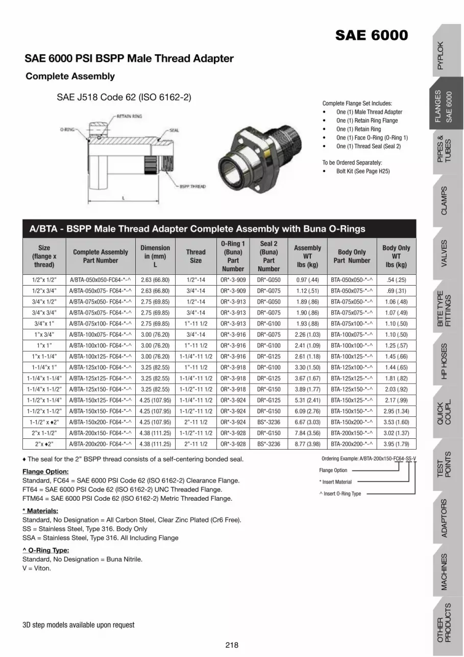
3D step models available upon request
Complete Flange Set Includes:• One (1) Male Thread Adapter• One (1) Retain Ring Flange• One (1) Retain Ring• One (1) Face O-Ring (O-Ring 1)• One (1) Thread Seal (Seal 2)
To be Ordered Separately:• Bolt Kit (See Page H25)
The seal for the 2” BSPP thread consists of a self-centering bonded seal.
Flange Option:
Standard, FC64 = SAE 6000 PSI Code 62 (ISO 6162-2) Clearance Flange.FT64 = SAE 6000 PSI Code 62 (ISO 6162-2) UNC Threaded Flange.FTM64 = SAE 6000 PSI Code 62 (ISO 6162-2) Metric Threaded Flange.
* Materials:
Standard, No Designation = All Carbon Steel, Clear Zinc Plated (Cr6 Free).SS = Stainless Steel, Type 316. Body OnlySSA = Stainless Steel, Type 316. All Including Flange
^ O-Ring Type:
Standard, No Designation = Buna Nitrile.V = Viton.
Ordering Example: A/BTA-200x150-FC64-SS-V
Flange Option
* Insert Material
^ Insert O-Ring Type
SAE 6000 PSI BSPP Male Thread Adapter
Complete Assembly
SAE J518 Code 62 (ISO 6162-2)
A/BTA - BSPP Male Thread Adapter Complete Assembly with Buna O-Rings
Size
(flange x
thread)
Complete Assembly
Part Number
Dimension
in (mm)
L
Thread
Size
O-Ring 1
(Buna)
Part
Number
Seal 2
(Buna)
Part
Number
Assembly
WT
lbs (kg)
Body Only
Part Number
Body Only
WT
lbs (kg)
1/2”x 1/2” A/BTA-050x050-FC64-*-^ 2.63 (66.80) 1/2"-14 OR*-3-909 DR*-G050 0.97 (.44) BTA-050x050-*-^ .54 (.25)
1/2”x 3/4” A/BTA-050x075- FC64-*-^ 2.63 (66.80) 3/4"-14 OR*-3-909 DR*-G075 1.12 (.51) BTA-050x075-*-^ .69 (.31)
3/4”x 1/2” A/BTA-075x050- FC64-*-^ 2.75 (69.85) 1/2"-14 OR*-3-913 DR*-G050 1.89 (.86) BTA-075x050-*-^ 1.06 (.48)
3/4”x 3/4” A/BTA-075x075- FC64-*-^ 2.75 (69.85) 3/4"-14 OR*-3-913 DR*-G075 1.90 (.86) BTA-075x075-*-^ 1.07 (.49)
3/4”x 1” A/BTA-075x100- FC64-*-^ 2.75 (69.85) 1”-11 1/2 OR*-3-913 DR*-G100 1.93 (.88) BTA-075x100-*-^ 1.10 (.50)
1”x 3/4” A/BTA-100x075- FC64-*-^ 3.00 (76.20) 3/4"-14 OR*-3-916 DR*-G075 2.26 (1.03) BTA-100x075-*-^ 1.10 (.50)
1”x 1” A/BTA-100x100- FC64-*-^ 3.00 (76.20) 1”-11 1/2 OR*-3-916 DR*-G100 2.41 (1.09) BTA-100x100-*-^ 1.25 (.57)
1”x 1-1/4” A/BTA-100x125- FC64-*-^ 3.00 (76.20) 1-1/4”-11 1/2 OR*-3-916 DR*-G125 2.61 (1.18) BTA-100x125-*-^ 1.45 (.66)
1-1/4”x 1” A/BTA-125x100- FC64-*-^ 3.25 (82.55) 1”-11 1/2 OR*-3-918 DR*-G100 3.30 (1.50) BTA-125x100-*-^ 1.44 (.65)
1-1/4”x 1-1/4” A/BTA-125x125- FC64-*-^ 3.25 (82.55) 1-1/4”-11 1/2 OR*-3-918 DR*-G125 3.67 (1.67) BTA-125x125-*-^ 1.81 (.82)
1-1/4”x 1-1/2” A/BTA-125x150- FC64-*-^ 3.25 (82.55) 1-1/2”-11 1/2 OR*-3-918 DR*-G150 3.89 (1.77) BTA-125x150-*-^ 2.03 (.92)
1-1/2”x 1-1/4” A/BTA-150x125- FC64-*-^ 4.25 (107.95) 1-1/4”-11 1/2 OR*-3-924 DR*-G125 5.31 (2.41) BTA-150x125-*-^ 2.17 (.99)
1-1/2”x 1-1/2” A/BTA-150x150- FC64-*-^ 4.25 (107.95) 1-1/2”-11 1/2 OR*-3-924 DR*-G150 6.09 (2.76) BTA-150x150-*-^ 2.95 (1.34)
1-1/2” x 2” A/BTA-150x200- FC64-*-^ 4.25 (107.95) 2”-11 1/2 OR*-3-924 BS*-3236 6.67 (3.03) BTA-150x200-*-^ 3.53 (1.60)
2”x 1-1/2” A/BTA-200x150- FC64-*-^ 4.38 (111.25) 1-1/2”-11 1/2 OR*-3-928 DR*-G150 7.84 (3.56) BTA-200x150-*-^ 3.02 (1.37)
2”x 2” A/BTA-200x200- FC64-*-^ 4.38 (111.25) 2”-11 1/2 OR*-3-928 BS*-3236 8.77 (3.98) BTA-200x200-*-^ 3.95 (1.79)
218
PIP
ES
&
TU
BE
SC
LAM
PS
VA
LVE
SH
P H
OS
ES
BIT
E T
YP
EF
ITT
ING
SQ
UIC
K
CO
UP
L.T
ES
T
PO
INT
SA
DA
PT
OR
SM
AC
HIN
ES
OT
HE
R
PR
OD
UC
TS
PY
PLO
K

3D step models available upon request
Complete Flange Set Includes:• One (1) length of clean pipe• Two (2) flare flanges • Two (2) cones
TMP2205SS PIPE IS ONLY AVAILABLE UPON REQUEST
PART Number (EXAMPLE): PAF/52 - SCH80-100 - FC64 - FC64 - CO - CF - 240
ASSEMBLY WORKING PRESSURE RATINGS ARE SUBJECT TO THE LESSER OF THE FLANGE OR PIPE RATINGS
PAFPipe & Cone
Material
Pipe Size &
Schedule
Flange
1
Cone
1
Cone
2Options/ - - - - - - -
Bent Pipe Assembly - Flared PAF
Pipe & Cone
Material
Carbon Steel TMP52CD 52
Pipe & Cone
Material
Stainless Steel
TMP304SS 304
TMP316SS 316
TMP2205SS 2205
Pipe Size
1/2”SCH40-050SCH80-050
3/4”SCH40-075SCH80-075
1”SCH40-100SCH80-100
1-1/4”SCH40-125SCH80-125
1-1/2”
SCH40-150SCH80-150
SCH160-150
2”
SCH40-200SCH80-200
SCH160-200
Flange Type
Carbon Steel
FFC64
SAE Code 62 W/Clearance Holes
FC64
FFTM64
SAE Code 62 W/TClearance Holes
FT64
Cone Type
Cone - Flat Face CF
Cone - ‘O’ Ring Face CO
Length L2 Specify (in.)
Options
Viton V
Painted (Specify) P
Complete Stainless Steel Assembly:
(including flanges)SS
Code LengthFlange
2
SAE 6000 PSI Flare Flange Pipe Assembly, NPS
SAE J518 Code 62 (ISO 6162-2) Typical PAF Assembly
219

3D step models available upon request
Complete Flange Set Includes:• One (1) length of clean pipe• Two (2) flare flanges • Two (2) cones
TMP2205SS PIPE IS ONLY AVAILABLE UPON REQUEST
PART Number (EXAMPLE): PAF/52 - 38x4.0 - 100 - FCM64 - FCM64 - CO - CF - 6000
ASSEMBLY WORKING PRESSURE RATINGS ARE SUBJECT TO THE LESSER OF THE FLANGE OR PIPE RATINGS
PAFPipe & Cone
Material
Pipe Size &
Schedule
Flange
1
Cone
1
Cone
2Options/ - - - - - - -
Bent Pipe Assembly - Flared PAF
Pipe & Cone
Material
Carbon Steel
TMP52CD 52
TMP37CD 37
Pipe & Cone
Material
Stainless Steel
TMP304SS 304
TMP316SS 316
TMP2205SS 2205
Pipe Size
1/2”20x3.0-05025x3.0-050
3/4”30x3.0-07530x4.0-075
1”38x4.0-10038x5.0-100
1-1/4”42x4.0-125 42x5.0-125
1-1/2”50x3.0-15050x5.0-150
2”60x5.0-20060x6.0-200
Flange Type
Carbon Steel
FFCM34
SAE Code 62 W/Clearance Holes
FCM64
FFTM64
SAE Code 62 W/Threaded Holes
FTM64
Cone Type
Cone - Flat Face CF
Cone - ‘O’ Ring Face CO
Length L2 Specify (mm)
Options
Viton V
Painted (Specify) P
Complete Stainless Steel Assembly:
(including flanges)SS
Code LengthFlange
2
SAE 6000 PSI Flare Flange Pipe Assembly, Metric
SAE J518 Code 62 (ISO 6162-2) Typical PAF Assembly
PIP
ES
&
TU
BE
SC
LAM
PS
VA
LVE
SH
P H
OS
ES
BIT
E T
YP
EF
ITT
ING
SQ
UIC
K
CO
UP
L.T
ES
T
PO
INT
SA
DA
PT
OR
SM
AC
HIN
ES
OT
HE
R
PR
OD
UC
TS
PY
PLO
K

3D step models available upon request
SAE 6000 PSI Flare Flange Bent Pipe Assembly, NPS
Typical BPAF AssemblyComplete assembly consists of:• One (1) length of bent clean pipe• Two (2) flare flanges • Two (2) cones
Size
R1 R2 R3
Dimensions (in) Dimensions (in) Dimensions (in)
L(min.) R L(min.) R L(min.) R
1/2” 4.50 1.68 5.50 2.52 6.75 3.88
3/4” 5.00 2.10 6.00 3.15 7.00 4.25
1” 5.50 2.63 7.00 3.95 7.75 4.88
1-1/4” 6.38 3.32 8.00 4.98 8.63 5.63
1-1/2” 7.50 3.80 9.25 5.70 11.75 8.19
2” 8.50 4.75 10.75 7.13 13.00 9.44
Note: OTHER RADII AVAILABLE (CONSULT FACTORY)

3D step models available upon request
SAE 6000 PSI Flare Flange Bent Pipe Assembly, Metric
Typical BPAF Assembly
Complete assembly consists of:• One (1) length of bent clean pipe• Two (2) flare flanges • Two (2) cones
Size
R1 R2 R3
Dimensions (mm) Dimensions (mm) Dimensions (mm)
L(min.) R L(min.) R L(min.) R
1/2” 126 50 151 75 176 100
3/4” 134 60 164 90 194 120
1” 153 76 191 114 229 152
1-1/4” 162 84 204 126 246 168
1-1/2” 194 100 244 150 294 200
2” 215 120 275 180 335 240
Note: OTHER RADII AVAILABLE (CONSULT FACTORY)
PIP
ES
&
TU
BE
SC
LAM
PS
VA
LVE
SH
P H
OS
ES
BIT
E T
YP
EF
ITT
ING
SQ
UIC
K
CO
UP
L.T
ES
T
PO
INT
SA
DA
PT
OR
SM
AC
HIN
ES
OT
HE
R
PR
OD
UC
TS
PY
PLO
K

3D step models available upon request
Flange Options:
Standard, FC34 = SAE 3000 PSI Code 61 (ISO 6162-1) Clearance Flange.FT34 = SAE 3000 PSI Code 61 (ISO 6162-1) UNC Threaded Flange.FTM34 = SAE 3000 PSI Code 61 (ISO 6162-1) Metric Threaded Flange.
Cone Options:
Standard, CO = O-Ring Faced Cone.CF = Flat Faced Cone.
•Bend Radius Options (Other radii available, consult factory):
R1R2R3
* Materials:
Standard, No Designation = All Carbon Steel, Clear Zinc Plated (Cr6 Free).SS = Stainless Steel, Type 316.
^ O-Ring Type:
Standard, No Designation = Buna Nitrile.V = Viton.
SizeComplete Assembly
Part Number
R1 Bend Radius
(in)
R2 Bend Radius
(in)
R3 Bend Radius
(in)
R L1 R L1 R L1
1/2” A/FFE-SCH40-050-FC64-FC64-CO-CO-•-*-^ 1.68 4.5 2.52 5.5 3.875 6.75
1/2” A/FFE-SCH80-050-FC64-FC64-CO-CO-•-*-^ 1.68 4.5 2.52 5.5 3.875 6.75
3/4” A/FFE-SCH40-075-FC64-FC64-CO-CO-•-*-^ 2.1 5.0 3.15 6.0 4.25 7.0
3/4” A/FFE-SCH80-075-FC64-FC64-CO-CO-•-*-^ 2.1 5.0 3.15 6.0 4.25 7.0
1” A/FFE-SCH40-100-FC64-FC64-CO-CO-•-*-^ 2.63 5.5 3.95 7.0 4.875 7.75
1” A/FFE-SCH80-100-FC64-FC64-CO-CO-•-*-^ 2.63 5.5 3.95 7.0 4.875 7.75
1-1/4” A/FFE-SCH40-125-FC64-FC64-CO-CO-•-*-^ 3.32 6.375 4.98 8.0 5.625 8.625
1-1/4” A/FFE-SCH80-125-FC64-FC64-CO-CO-•-*-^ 3.32 6.375 4.98 8.0 5.625 8.625
1-1/2” A/FFE-SCH40-150-FC64-FC64-CO-CO-•-*-^ 3.8 7.5 5.7 9.25 8.1875 11.75
1-1/2” A/FFE-SCH80-150-FC64-FC64-CO-CO-•-*-^ 3.8 7.5 5.7 9.25 8.1875 11.75
1-1/2” A/FFE-SCH160-150-FC64-F634-CO-CO-•-*-^ 3.8 7.5 5.7 9.25 8.1875 11.75
2” A/FFE-SCH40-200-FC64-FC64-CO-CO-•-*-^ 4.75 8.5 7.125 10.75 9 7/16 13
2” A/FFE-SCH80-200-FC64-FC64-CO-CO-•-*-^ 4.75 8.5 7.125 10.75 9 7/16 13
2” A/FFE-SCH160-200-FC64-FC64-CO-CO-•-*-^ 4.75 8.5 7.125 10.75 9 7/16 13
SAE 6000 PSI Flare Flange Bend Elbow
Complete Assembly, NPS
SAE J518 Code 62 (ISO 6162-2)
A/FFE - Flare Flange Bend Elbow – Complete Assembly, NPS
Ordering Example: A/FFE-SCH40-200-FC64-FC64-CO-CO-R1-SS-V
Flange 1 Option
Flange 2 Option
Cone 1 Option
Cone 2 Option
• Insert Bend Radius
* Insert Material
^ Insert O-Ring Type

3D step models available upon request
Flange Options:
Standard, FCM64 = SAE 6000 PSI Code 62 (ISO 6162-2) Clearance Flange. FT64 = SAE 6000 PSI Code 62 (ISO 6162-2) UNC Threaded Flange. FTM64 = SAE 6000 PSI Code 62 (ISO 6162-2) Metric Threaded Flange.
Cone Options:
Standard, CO = O-Ring Faced Cone.CF = Flat Faced Cone.
•Bend Radius Options (Other radii available, consult factory):
R1R2R3
* Materials:
Standard, No Designation = All Carbon Steel, Clear Zinc Plated (Cr6 Free).SS = Stainless Steel, Type 316.
^ O-Ring Type:
Standard, No Designation = Buna Nitrile.V = Viton.
Ordering Example: A/FFEM-60x5.0-200-FCM64-FCM64-CO-CO-R1-SS-V
Flange 1 Option
Flange 2 Option
Cone 1 Option
Cone 2 Option
• Insert Bend Radius
* Insert Material
^ Insert O-Ring Type
SAE 6000 PSI Flare Flange Bend Elbow
Complete Assembly, Metric
SAE J518 Code 62 (ISO 6162-2)
A/FFEM - Flare Flange Bend Elbow Complete Assembly, Metric
SizeComplete Assembly
Part Number
R1 Bend Radius
(mm)
R2 Bend Radius
(mm)
R3 Bend Radius
(mm)
R L1 R L1 R L1
1/2” A/FFEM-20x3.0-050- FCM64-FCM64-CO-CO-•-*-^ 40 116 60 136 80 156
1/2” A/FFEM-25x3.0-050- FCM64-FCM64-CO-CO-•-*-^ 50 126 75 151 100 176
3/4” A/FFEM-30x3.0-075- FCM64-FCM64-CO-CO-•-*-^ 50 134 90 149 120 194
3/4” A/FFEM-30x4.0-075- FCM64-FCM64-CO-CO-•-*-^ 60 134 90 164 120 194
1” A/FFEM-38x4.0-100- FCM64-FCM64-CO-CO-•-*-^ 76 153 114 167 152 229
1” A/FFEM-38x5.0-100- FCM64-FCM64-CO-CO-•-*-^ 76 153 114 191 152 229
1-1/4” A/FFEM-42x4.0-125- FCM64-FCM64-CO-CO-•-*-^ 84 162 126 192 168 246
1-1/4” A/FFEM-42x5.0-125- FCM64-FCM64-CO-CO-•-*-^ 84 162 126 204 168 246
1-1/2” A/FFEM-50x5.0-150- FCM64-FCM64-CO-CO-•-*-^ 100 194 150 220 200 294
1-1/2” A/FFEM-50x6.0-150- FCM64-FCM64-CO-CO-•-*-^ 100 194 150 244 200 294
1-1/2” A/FFEM-56x8.5-150- FCM64-FCM64-CO-CO-•-*-^ 100 194 150 244 200 294
2” A/FFEM-60x5.0-200- FCM64-FCM64-CO-CO-•-*-^ 120 215 180 245 240 335
2” A/FFEM-60x6.0-200- FCM64-FCM64-CO-CO-•-*-^ 120 215 180 275 240 335
2” A/FFEM-66x8.5-200- FCM64-FCM64-CO-CO-•-*-^ 120 215 180 275 240 335
COMPLETE ASSEMBLY CONSISTS OF:• FLARE FLANGE 90° ELBOW BODY• TWO (2) FLARE FLANGES • TWO (2) CONES
PIP
ES
&
TU
BE
SC
LAM
PS
VA
LVE
SH
P H
OS
ES
BIT
E T
YP
EF
ITT
ING
SQ
UIC
K
CO
UP
L.T
ES
T
PO
INT
SA
DA
PT
OR
SM
AC
HIN
ES
OT
HE
R
PR
OD
UC
TS
PY
PLO
K

3D step models available upon request
SizeComplete Assembly
Part Number
Dimensions
in (mm)Assembly
WT
lbs (kg)
Body Only
Part Number
Body Only
WT
lbs (kg)
Working
Pressure
PSI (bar)L
1-1/2" A/RFE-150-FC64-*-^ 13.00 (330.20) 14.98 (6.80) RFE-150-*-^ 11.50 (5.22) 6000 (420)
2” A/RFE-200-FC64-*-^ 14.50 (368.30) 20.47 (9.30) RFE-200-*-^ 15.59 (7.07) 6000 (420)
A/RFE - Retain Ring Flange Bend Elbow – Complete Assembly
Complete Flange Set Includes:• One (1) Retain Ring Flange Bend
Elbow Body
• Two (2) Retain Ring Flanges• Two (2) Retain Rings• Two (2) O-Ring Spacers
Flange Option:
Standard, FC64 = SAE 6000 PSI Code 61 (ISO 6162-2) Clearance Flange. FT64 = SAE 6000 PSI Code 62 (ISO 6162-2) UNC Threaded Flange. FTM64 = SAE 6000 PSI Code 62 (ISO 6162-2) Metric Threaded Flange.
* Materials:
Standard, No Designation = All Carbon Steel, Clear Zinc Plated (Cr6 Free).SS = Stainless Steel, Type 316.
^ O-Ring Type:
Standard, No Designation = Buna Nitrile.V = Viton.
Ordering Example: A/RFE-200-FC64-SS-V
Flange Option
* Insert Material
^ Insert O-Ring Type
SAE 6000 PSI Retain Ring Flange Bend Elbow
SAE J518 Code 62 (ISO 6162-2)

3D step models available upon request
SAE J518 Code 62 (ISO 6162-2)
SizeComplete Assembly
Part Number
Dimensions
in (mm)O-Ring
(Buna)
Part Number
Assembly
WT
lbs (kg)
Body Only
Part Number
Body Only
WT
lbs (kg)
Working
Pressure
PSI (bar)L
1/2" A/RRFE-050-FC64-*-^ 2.40 (61.0) OR^-3-909 2.02 (0.92) RRFE-050-*-^ 1.10 (0.50) 6000 (420)
3/4" A/RRFE-075-FC64-*-^ 2.61 (66.2) OR^-3-913 3.68 (1.67) RRFE-075-*-^ 1.94 (0.88) 6000 (420)
1” A/RRFE-100-FC64-*-^ 2.81 (71.4) OR^-3-916 4.73 (2.15) RRFE-100-*-^ 2.26 (1.03) 6000 (420)
1-1/4" A/RRFE-125-FC64-*-^ 3.22 (81.8) OR^-3-918 7.26 (3.29) RRFE-125-*-^ 3.29 (1.49) 6000 (420)
1-1/2" A/RRFE-150-FC64-*-^ 4.01 (101.9) OR^-3-924 12.18 (5.52) RRFE-150-*-^ 6.08 (2.76) 6000 (420)
2” A/RRFE-200-FC64-*-^ 4.40 (111.8) OR^-3-928 18.74 (8.5) RRFE-200-*-^ 7.62 (3.46) 6000 (420)
A/RRFE - Retain Ring Flange Elbow – Complete Assembly with Buna O-Ring
Complete Flange Set Includes:• One (1) Flange Elbow• Two (2) Retain Ring Flanges• Two (2) Retain Rings• Two (2) Face O-Rings
To be Ordered Separately:• Bolt KitSee page H25
Flange Option:
Standard, FC64 = SAE 6000 PSI Code 62 (ISO 6162-2) Clearance Flange.FT64 = SAE 6000 PSI Code 62 (ISO 6162-2) UNC Threaded Flange.FTM64 = SAE 6000 PSI Code 62 (ISO 6162-2) Metric Threaded Flange.
* Materials:
Standard, No Designation = All Carbon Steel, Clear Zinc Plated (Cr6 Free).SS = Stainless Steel, Type 316.
^ O-Ring Type:
Standard, No Designation = Buna Nitrile.V = Viton.
Ordering Example: A/RRFE-200-FC64-SS-V
Flange Option
* Insert Material
^ Insert O-Ring Type
PIP
ES
&
TU
BE
SC
LAM
PS
VA
LVE
SH
P H
OS
ES
BIT
E T
YP
EF
ITT
ING
SQ
UIC
K
CO
UP
L.T
ES
T
PO
INT
SA
DA
PT
OR
SM
AC
HIN
ES
OT
HE
R
PR
OD
UC
TS
PY
PLO
K

3D step models available upon request
SAE 6000 PSI Block Elbow
SAE J518 Code 62 (ISO 6162-2) Flange Style
Materials:
Standard, No Designation = All Carbon Steel, Clear Zinc Plated (Cr6 Free).SS = Stainless Steel, Type 316.
SizeBlock Elbow
Part Number
Dimensions (in) Thread
UNC-2B
WT
lbs (kg)
Working
Pressure
PSI (bar)A B C D E F G H K
1/2” BE64-050-* 0.72 1.59 1.88 0.50 2.00 1.00 2.50 2.50 1.25 5/16”-18 3.10 6000 (420)
3/4” BE64-075-* 0.94 2.00 2.25 0.75 2.00 1.00 3.00 3.25 1.50 3/8”-16 4.74 6000 (420)
1” BE64-100-* 1.09 2.25 2.50 0.94 2.25 1.13 3.00 4.00 1.50 7/16”-14 6.42 6000 (420)
1-1/4” BE64-125-* 1.25 2.63 2.75 1.25 2.50 1.25 4.00 4.00 2.00 1/2"-13 9.18 6000 (420)
1-1/2” BE64-150-* 1.44 3.13 3.00 1.50 3.00 1.50 4.00 4.50 2.00 5/8”-11 11.66 6000 (420)
2” BE64-200-* 1.75 3.81 3.38 1.94 3.00 1.50 5.00 5.00 2.50 3/4"-10 14.97 6000 (420)
BE64 - Block Elbow Flat Face with Threaded Holes Complete with #4 SAE
Port (Plugged), NPS
SizeBlock Elbow
Part Number
Dimensions (mm)Thread
WT
lbs (kg)
Working
Pressure
PSI (bar)A B C D E F G H K
1/2” BEM64-050-* 18.3 40.4 47.8 12.7 50.8 25.4 63.5 63.5 31.8 M8 x 1.25 1.41 6000 (420)
3/4” BEM64-075-* 23.9 50.8 57.2 19.1 50.8 25.4 76.2 82.6 38.1 M10 x 1.50 2.15 6000 (420)
1” BEM64-100-* 27.7 57.2 63.5 23.9 57.2 28.7 76.2 101.6 38.1 M12 x 1.75 2.92 6000 (420)
1-1/4” BEM64-125-* 31.8 66.8 69.9 31.8 63.5 31.8 101.6 101.6 50.8 M12 x 1.75 4.17 6000 (420)
1-1/4”(2) BEM64-125-M14-* 31.8 66.8 69.9 31.8 63.5 31.8 101.6 101.6 50.8 M14 x 2.00 4.17 6000 (420)
1-1/2” BEM64-150-* 36.6 79.5 76.2 38.1 76.2 38.1 101.6 114.3 50.8 M16 x 2.00 5.30 6000 (420)
2” BEM64-200-* 44.5 96.8 85.9 49.3 76.2 38.1 127.0 127.0 63.5 M20 x 2.50 6.80 6000 (420)
BEM64 - Block Elbow Flat Face with Threaded Holes Complete with G1/8
Port (Plugged), Metric
Ordering Example: BE64-200-SS
* Insert Material
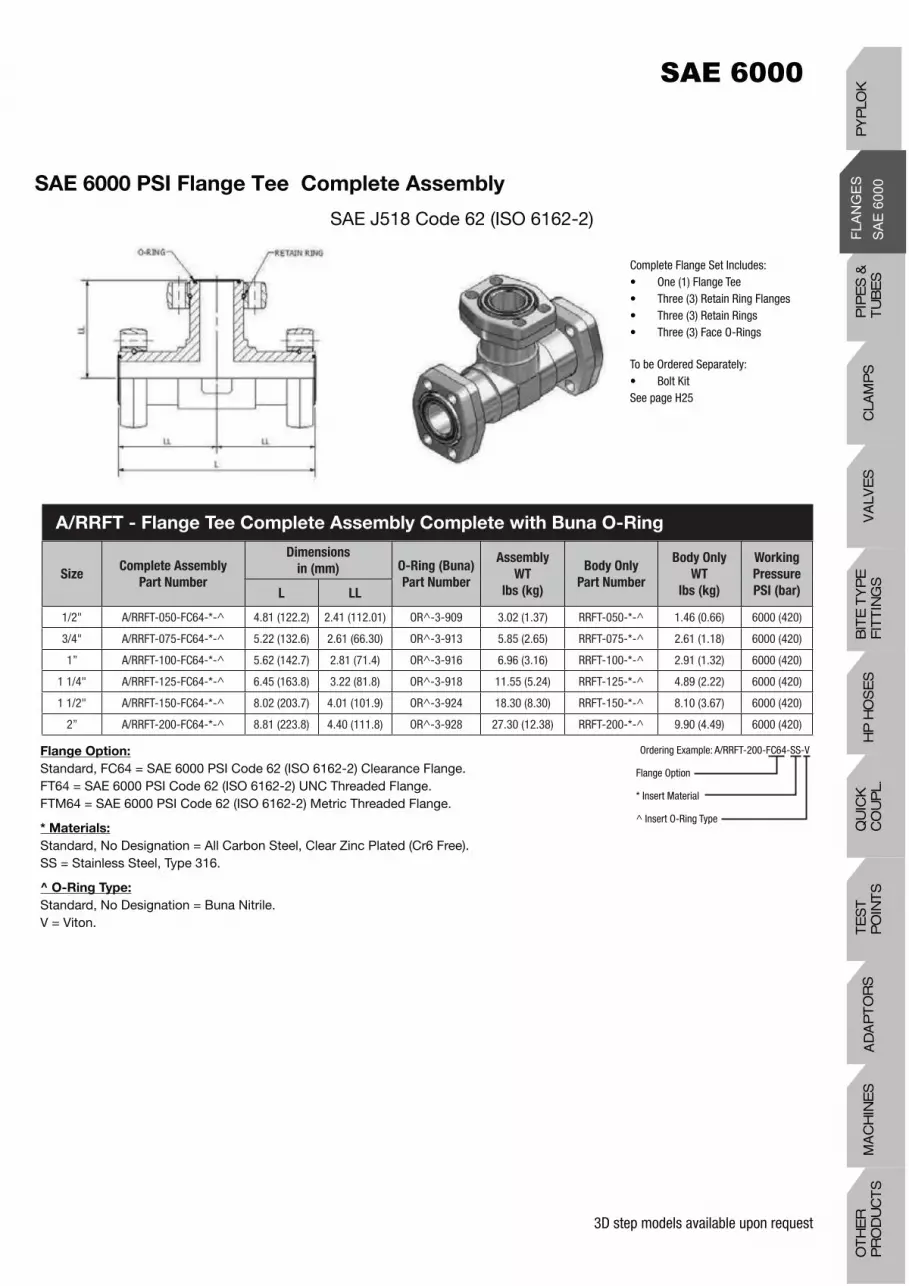
3D step models available upon request
SAE 6000 PSI Flange Tee Complete Assembly
SAE J518 Code 62 (ISO 6162-2)
SizeComplete Assembly
Part Number
Dimensions
in (mm) O-Ring (Buna)
Part Number
Assembly
WT
lbs (kg)
Body Only
Part Number
Body Only
WT
lbs (kg)
Working
Pressure
PSI (bar)L LL
1/2" A/RRFT-050-FC64-*-^ 4.81 (122.2) 2.41 (112.01) OR^-3-909 3.02 (1.37) RRFT-050-*-^ 1.46 (0.66) 6000 (420)
3/4" A/RRFT-075-FC64-*-^ 5.22 (132.6) 2.61 (66.30) OR^-3-913 5.85 (2.65) RRFT-075-*-^ 2.61 (1.18) 6000 (420)
1” A/RRFT-100-FC64-*-^ 5.62 (142.7) 2.81 (71.4) OR^-3-916 6.96 (3.16) RRFT-100-*-^ 2.91 (1.32) 6000 (420)
1 1/4" A/RRFT-125-FC64-*-^ 6.45 (163.8) 3.22 (81.8) OR^-3-918 11.55 (5.24) RRFT-125-*-^ 4.89 (2.22) 6000 (420)
1 1/2" A/RRFT-150-FC64-*-^ 8.02 (203.7) 4.01 (101.9) OR^-3-924 18.30 (8.30) RRFT-150-*-^ 8.10 (3.67) 6000 (420)
2” A/RRFT-200-FC64-*-^ 8.81 (223.8) 4.40 (111.8) OR^-3-928 27.30 (12.38) RRFT-200-*-^ 9.90 (4.49) 6000 (420)
Complete Flange Set Includes:• One (1) Flange Tee• Three (3) Retain Ring Flanges• Three (3) Retain Rings• Three (3) Face O-Rings
To be Ordered Separately:• Bolt KitSee page H25
Flange Option:
Standard, FC64 = SAE 6000 PSI Code 62 (ISO 6162-2) Clearance Flange.FT64 = SAE 6000 PSI Code 62 (ISO 6162-2) UNC Threaded Flange.FTM64 = SAE 6000 PSI Code 62 (ISO 6162-2) Metric Threaded Flange.
* Materials:
Standard, No Designation = All Carbon Steel, Clear Zinc Plated (Cr6 Free).SS = Stainless Steel, Type 316.
^ O-Ring Type:
Standard, No Designation = Buna Nitrile.V = Viton.
Ordering Example: A/RRFT-200-FC64-SS-V
Flange Option
* Insert Material
^ Insert O-Ring Type
A/RRFT - Flange Tee Complete Assembly Complete with Buna O-Ring
PIP
ES
&
TU
BE
SC
LAM
PS
VA
LVE
SH
P H
OS
ES
BIT
E T
YP
EF
ITT
ING
SQ
UIC
K
CO
UP
L.T
ES
T
PO
INT
SA
DA
PT
OR
SM
AC
HIN
ES
OT
HE
R
PR
OD
UC
TS
PY
PLO
K

3D step models available upon request
SAE 6000 PSI Block Tee
SAE J518 Code 62 (ISO 6162-2) Flange Style
* Materials:
Standard, No Designation = All Carbon Steel, Clear Zinc Plated (Cr6 Free).SS = Stainless Steel, Type 316.
SizeBlock Tee
Part No
Dimensions (in) Thread
UNC-2B
WT
lbs (kg)
Working
Pressure
PSI (bar)A B C D E F G H K
1/2” BT64-050-* 0.72 1.59 1.88 0.50 2.00 1.00 2.50 2.50 1.25 5/16”-18 3.05 (1.38) 6000 (420)
3/4” BT64-075-* 0.94 2.00 2.25 0.75 2.00 1.00 3.00 3.25 1.50 3/8”-16 4.66 (2.11) 6000 (420)
1” BT64-100-* 1.09 2.25 2.50 0.94 2.25 1.13 3.00 4.00 1.50 7/16”-14 6.20 (2.81) 6000 (420)
1-1/4” BT64-125-* 1.25 2.63 2.75 1.25 2.50 1.25 4.00 4.00 2.00 1/2"-13 8.86 (4.02) 6000 (420)
1-1/2” BT64-150-* 1.44 3.13 3.00 1.50 3.00 1.50 4.00 4.50 2.00 5/8”-11 11.04 (5.01) 6000 (420)
2” BT64-200-* 1.75 3.81 3.38 1.94 3.00 1.50 5.00 5.00 2.50 3/4"-10 14.41 (6.54) 6000 (420)
BT64 - Block Tee Flat Face with Threaded Holes Complete with #4 SAE Port (Plugged),
NPS
Size
(inch)
Block Tee
Part No
Dimensions (mm)Thread
WT
lbs (kg)
Working
Pressure
PSI (bar)A B C D E F G H K
1/2” BTM64-050-* 18.3 40.4 47.8 12.7 50.8 25.4 63.5 63.5 31.8 M8 X 1.25 3.07 (1.39) 6000 (420)
3/4” BTM64-075-* 23.9 50.8 57.2 19.1 50.8 25.4 76.2 82.6 38.1 M10 X 1.50 4.67 (2.12) 6000 (420)
1” BTM64-100-* 27.7 57.2 63.5 23.9 57.2 28.7 76.2 101.6 38.1 M12 X 1.75 6.22 (2.82) 6000 (420)
1-1/4” BTM64-125-* 31.8 66.8 69.9 31.8 63.5 31.8 101.6 101.6 50.8 M12 X 1.75 8.88 (4.03) 6000 (420)
1-1/4”(2) BTM64-125-M14-* 31.8 66.8 69.9 31.8 63.5 31.8 101.6 101.6 50.8 M14 x 2.00 8.88 (4.03) 6000 (420)
1-1/2” BTM64-150-* 36.6 79.5 76.2 38.1 76.2 38.1 101.6 114.3 50.8 M16 X 2.00 11.07 (5.02) 6000 (420)
2” BTM64-200-* 44.5 96.8 85.9 49.3 76.2 38.1 127.0 127.0 63.5 M20 X 2.50 14.44(6.55) 6000 (420)
Ordering Example: BT64-200-SS
* Insert Material
BTM64 - Block Tee Flat Face with Threaded Holes Complete with G1/8 Port (Plugged),
Metric

3D step models available upon request
SAE 6000 PSI Reducing Branch Block Tee - NPS
1
(ISO 6162-2) Flange Style
Size
(run x
branch)
Tee
Part Number
Dimensions (in) Thread 1
UNC-2B
Thread 2
UNC-2B
WT
lbs (kg)
Working
Pressure
PSI (bar)A B C D D1 E F G H K M N
3/4”x1/2” BTR64-075x050-* 0.94 2.00 2.25 0.75 0.50 2.00 1.00 3.00 3.25 1.50 0.72 1.59 3/8”-16 5/16”-18 5.20 (2.36) 6000 (420)
1”x1/2” BTR64-100x050-* 1.09 2.25 2.50 0.94 0.50 2.25 1.13 3.00 4.00 1.50 0.72 1.59 7/16”-14 5/16”-18 5.20 (2.36) 6000 (420)
1”x3/4” BTR64-100x075-* 1.09 2.25 2.50 0.94 0.75 2.25 1.13 3.00 4.00 1.50 0.94 2.00 7/16”-14 3/8”-16 5.20 (2.36) 6000 (420)
1-1/4”x1/2” BTR64-125x050-* 1.25 2.63 2.75 1.25 0.50 2.50 1.25 4.00 4.00 2.00 0.72 1.59 1/2"-13 5/16”-18 10.00 (4.54) 6000 (420)
1-1/4”x3/4” BTR64-125x075-* 1.25 2.63 2.75 1.25 0.75 2.50 1.25 4.00 4.00 2.00 0.94 2.00 1/2"-13 3/8”-16 10.00 (4.54) 6000 (420)
1-1/4”x1” BTR64-125x100-* 1.25 2.63 2.75 1.25 0.94 2.50 1.25 4.00 4.00 2.00 1.09 2.25 1/2"-13 7/16”-14 10.00 (4.54) 6000 (420)
1-1/2”x1/2” BTR64-150x050-* 1.44 3.13 3.00 1.50 0.50 3.00 1.50 4.00 4.50 2.00 0.72 1.59 5/8”-11 5/16”-18 11.30 (5.13) 6000 (420)
1-1/2”x3/4” BTR64-150x075-* 1.44 3.13 3.00 1.50 0.75 3.00 1.50 4.00 4.50 2.00 0.94 2.00 5/8”-11 3/8”-16 11.30 (5.13) 6000 (420)
1-1/2”x1” BTR64-150x100-* 1.44 3.13 3.00 1.50 0.94 3.00 1.50 4.00 4.50 2.00 1.09 2.25 5/8”-11 7/16”-14 11.30 (5.13) 6000 (420)
1-1/2”x1-1/4” BTR64-150x125-* 1.44 3.13 3.00 1.50 1.25 3.00 1.50 4.00 4.50 2.00 1.25 2.63 5/8”-11 1/2"-13 11.30 (5.13) 6000 (420)
2”x1/2” BTR64-200x050-* 1.75 3.81 3.38 1.94 0.50 3.00 1.50 5.00 5.00 2.50 0.72 1.59 3/4"-10 5/16”-18 14.80 (6.71) 6000 (420)
2”x3/4” BTR64-200x075-* 1.75 3.81 3.38 1.94 0.75 3.00 1.50 5.00 5.00 2.50 0.94 2.00 3/4”-10 3/8”-16 14.80 (6.71) 6000 (420)
2”x1” BTR64-200x100-* 1.75 3.81 3.38 1.94 0.94 3.00 1.50 5.00 5.00 2.50 1.09 2.25 3/4"-10 7/16”-14 14.80 (6.71) 6000 (420)
2”x1-1/4” BTR64-200x125-* 1.75 3.81 3.38 1.94 1.25 3.00 1.50 5.00 5.00 2.50 1.25 2.63 3/4"-10 1/2"-13 14.80 (6.71) 6000 (420)
2”x1-1/2” BTR64-200x150-* 1.75 3.81 3.38 1.94 1.50 3.00 1.50 5.00 5.00 2.50 1.44 3.13 3/4"-10 5/8”-11 14.80 (6.71) 6000 (420)
BTR64 - Reducing Branch Block Tee Flat Face with Threaded Holes Complete with #4
SAE Port (Plugged), NPS
* Materials:
Standard, No Designation = All Carbon Steel, Clear Zinc Plated (Cr6 Free).SS = Stainless Steel, Type 316.
Ordering Example: BTR64-200x050-SS
* Insert Material
PIP
ES
&
TU
BE
SC
LAM
PS
VA
LVE
SH
P H
OS
ES
BIT
E T
YP
EF
ITT
ING
SQ
UIC
K
CO
UP
L.T
ES
T
PO
INT
SA
DA
PT
OR
SM
AC
HIN
ES
OT
HE
R
PR
OD
UC
TS
PY
PLO
K

3D step models available upon request
SAE 6000 PSI Reducing Branch Block Tee - Metric
SAE J518 Code 62 (ISO 6162-2) Flange Style
Size
(run x
branch)
Block Tee
Part Number
Dimensions (mm)Thread 1 Thread 2
WT
lbs (kg)
Working
Pressure
PSI (bar)A B C D D1 E F G H K M N
3/4”x1/2” BTRM64-075x050-* 23.9 50.8 57.2 19.1 12.7 50.8 25.4 76.2 82.6 38.1 18.3 40.4 M10 x 1.50 M8 x 1.25 5.20 (2.36) 6000 (420)
1”x1/2” BTRM64-100x050-* 27.7 57.2 63.5 23.9 12.7 57.2 28.7 76.2 101.6 38.1 18.3 40.4 M12 x 1.75 M8 x 1.25 5.20 (2.36) 6000 (420)
1”x3/4” BTRM64-100x075-* 27.7 57.2 63.5 23.9 19.1 57.2 28.7 76.2 101.6 38.1 23.9 50.8 M12 x 1.75 M10 x 1.50 5.20 (2.36) 6000 (420)
1-1/4”x1/2” BTRM64-125x050-* 31.8 66.8 69.9 31.8 12.7 63.5 31.8 101.6 101.6 50.8 18.3 40.4 M12 x 1.75 M8 x 1.25 10.00 (4.54) 6000 (420)
1-1/4”(2)x1/2” BTRM64-125-M14x050* 31.8 66.8 69.9 31.8 12.7 63.5 31.8 101.6 101.6 50.8 18.3 40.4 M14 x 2.00 M8 x 1.25 10.00 (4.54) 6000 (420)
1-1/4”x3/4” BTRM64-125x075-* 31.8 66.8 69.9 31.8 19.1 63.5 31.8 101.6 101.6 50.8 23.9 50.8 M12 x 1.75 M10 x 1.50 10.00 (4.54) 6000 (420)
1-1/4” (2) x3/4” BTRM64-125-M14x075* 31.8 66.8 69.9 31.8 19.1 63.5 31.8 101.6 101.6 50.8 23.9 50.8 M14 x 2.00 M10 x 1.50 10.00 (4.54) 6000 (420)
1-1/4”x1” BTRM64-125x100-* 31.8 66.8 69.9 31.8 23.9 63.5 31.8 101.6 101.6 50.8 27.7 57.2 M12 x 1.75 M12 x 1.75 10.00 (4.54) 6000 (420)
1-1/4”(2)x1” BTRM64-125-M14x100* 31.8 66.8 69.9 31.8 23.9 63.5 31.8 101.6 101.6 50.8 27.7 57.2 M14 x 2.00 M12 x 1.75 10.00 (4.54) 6000 (420)
1-1/2”x1/2” BTRM64-150x050-* 36.6 79.5 76.2 38.1 12.7 76.2 38.1 101.6 114.3 50.8 18.3 40.4 M16 x 2.00 M8 x 1.25 11.30 (5.13) 6000 (420)
1-1/2”x3/4” BTRM64-150x075-* 36.6 79.5 76.2 38.1 19.1 76.2 38.1 101.6 114.3 50.8 23.9 50.8 M16 x 2.00 M10 x 1.50 11.30 (5.13) 6000 (420)
1-1/2”x1” BTRM64-150x100-* 36.6 79.5 76.2 38.1 23.9 76.2 38.1 101.6 114.3 50.8 27.7 57.2 M16 x 2.00 M12 x 1.75 11.30 (5.13) 6000 (420)
1-1/2”x1-1/4” BTRM64-150x125-* 36.6 79.5 76.2 38.1 31.8 76.2 38.1 101.6 114.3 50.8 31.8 66.8 M16 x 2.00 M12 x 1.75 11.30 (5.13) 6000 (420)
1-1/2”x1-1/4”(2) BTRM64-150x125-M14-* 36.6 79.5 76.2 38.1 31.8 76.2 38.1 101.6 114.3 50.8 31.8 66.8 M16 x 2.00 M14 x 2.00 11.30 (5.13) 6000 (420)
2”x1/2” BTRM64-200x050-* 44.5 96.8 85.9 49.3 12.7 76.2 38.1 127.0 127.0 63.5 18.3 40.4 M20 x 2.50 M8 x 1.25 14.80 (6.71) 6000 (420)
2”x3/4” BTRM64-200x075-* 44.5 96.8 85.9 49.3 19.1 76.2 38.1 127.0 127.0 63.5 23.9 50.8 M20 x 2.50 M10 x 1.50 14.80 (6.71) 6000 (420)
2”x1” BTRM64-200x100-* 44.5 96.8 85.9 49.3 23.9 76.2 38.1 127.0 127.0 63.5 27.7 57.2 M20 x 2.50 M12 x 1.75 14.80 (6.71) 6000 (420)
2”x1-1/4” BTRM64-200x125-* 44.5 96.8 85.9 49.3 31.8 76.2 38.1 127.0 127.0 63.5 31.8 66.8 M20 x 2.50 M12 x 1.75 14.80 (6.71) 6000 (420)
2”x1-1/4”(2) BTRM64-200x125-M14-* 44.5 96.8 85.9 49.3 31.8 76.2 38.1 127.0 127.0 63.5 31.8 66.8 M20 x 2.50 M14 x 2.00 14.80 (6.71) 6000 (420)
2”x1-1/2” BTRM64-200x150-* 44.5 96.8 85.9 49.3 38.1 76.2 38.1 127.0 127.0 63.5 36.6 79.5 M20 x 2.50 M16 x 2.00 14.80 (6.71) 6000 (420)
* Materials:
Standard, No Designation = All Carbon Steel, Clear Zinc Plated (Cr6 Free).SS = Stainless Steel, Type 316.
Ordering Example: BTRM64-200x050-SS
* Insert Material
BTRM64 - Reducing Branch Block Tee Flat Face with Threaded Holes Complete with
G1/8 Port (Plugged), Metric
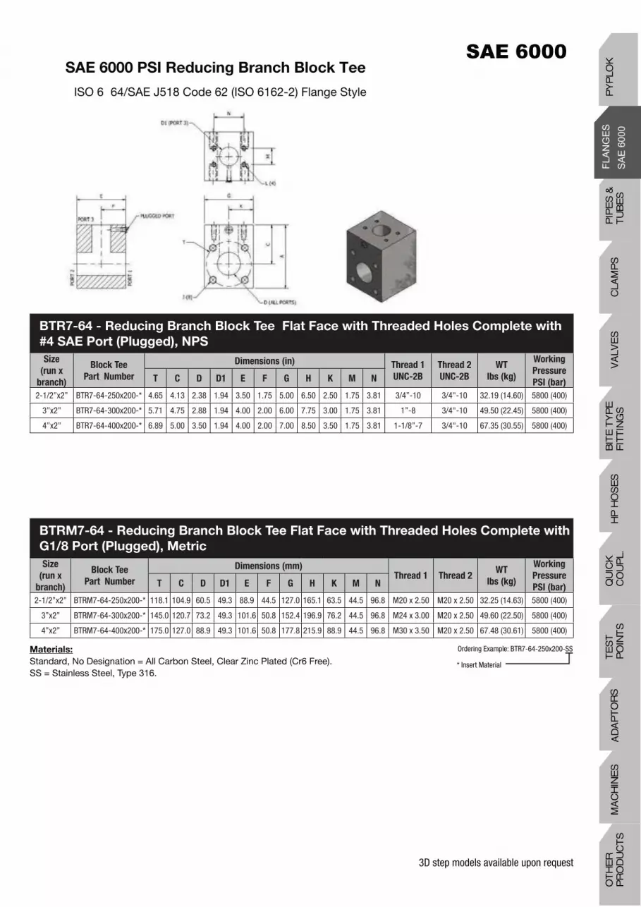
3D step models available upon request
SAE 6000 PSI Reducing Branch Block Tee
ISO 6 64/SAE J518 Code 62 (ISO 6162-2) Flange Style
Materials:
Standard, No Designation = All Carbon Steel, Clear Zinc Plated (Cr6 Free).SS = Stainless Steel, Type 316.
Size
(run x
branch)
Block Tee
Part Number
Dimensions (in) Thread 1
UNC-2B
Thread 2
UNC-2B
WT
lbs (kg)
Working
Pressure
PSI (bar)T C D D1 E F G H K M N
2-1/2”x2” BTR7-64-250x200-* 4.65 4.13 2.38 1.94 3.50 1.75 5.00 6.50 2.50 1.75 3.81 3/4”-10 3/4"-10 32.19 (14.60) 5800 (400)
3”x2” BTR7-64-300x200-* 5.71 4.75 2.88 1.94 4.00 2.00 6.00 7.75 3.00 1.75 3.81 1”-8 3/4"-10 49.50 (22.45) 5800 (400)
4”x2” BTR7-64-400x200-* 6.89 5.00 3.50 1.94 4.00 2.00 7.00 8.50 3.50 1.75 3.81 1-1/8”-7 3/4"-10 67.35 (30.55) 5800 (400)
Ordering Example: BTR7-64-250x200-SS
* Insert Material
Size
(run x
branch)
Block Tee
Part Number
Dimensions (mm)Thread 1 Thread 2
WT
lbs (kg)
Working
Pressure
PSI (bar)T C D D1 E F G H K M N
2-1/2”x2” BTRM7-64-250x200-* 118.1 104.9 60.5 49.3 88.9 44.5 127.0 165.1 63.5 44.5 96.8 M20 x 2.50 M20 x 2.50 32.25 (14.63) 5800 (400)
3”x2” BTRM7-64-300x200-* 145.0 120.7 73.2 49.3 101.6 50.8 152.4 196.9 76.2 44.5 96.8 M24 x 3.00 M20 x 2.50 49.60 (22.50) 5800 (400)
4”x2” BTRM7-64-400x200-* 175.0 127.0 88.9 49.3 101.6 50.8 177.8 215.9 88.9 44.5 96.8 M30 x 3.50 M20 x 2.50 67.48 (30.61) 5800 (400)
BTR7-64 - Reducing Branch Block Tee Flat Face with Threaded Holes Complete with
#4 SAE Port (Plugged), NPS
BTRM7-64 - Reducing Branch Block Tee Flat Face with Threaded Holes Complete with
G1/8 Port (Plugged), Metric
PIP
ES
&
TU
BE
SC
LAM
PS
VA
LVE
SH
P H
OS
ES
BIT
E T
YP
EF
ITT
ING
SQ
UIC
K
CO
UP
L.T
ES
T
PO
INT
SA
DA
PT
OR
SM
AC
HIN
ES
OT
HE
R
PR
OD
UC
TS
PY
PLO
K

3D step models available upon request
SAE 6000 PSI Transition Plate
SAE J518 Code 62/Code 61 (ISO 6162-2/6162-1) Flange Manifold Mount Style
SizeTransition Plate
Part Number
Dimensions (in) C’T Bore
Bolt
Thread 1
UNC-2B
O-Ring
(Buna)
Part No.
WT
lbs (kg)
Working
Pressure
PSI (bar)A B C D E G H K M N
1/2” TPO6-34-050-*-^ 0.69 1.50 1.25 0.50 1.00 2.50 2.50 1.50 0.72 1.60 5/16” 5/16”-18 OR^-2-210 1.40 (0.64) 5000 (350)
3/4” TPO6-34-075-*-^ 0.88 1.88 1.50 0.75 1.00 3.00 3.00 1.75 0.94 2.00 3/8” 3/8”-16 OR^-2-214 2.00 (0.91) 5000 (350)
1” TPO6-34-100-*-^ 1.03 2.06 1.50 0.94 1.00 3.00 3.00 1.50 1.10 2.24 7/16” 3/8”-16 OR^-2-219 1.90 (0.86) 5000 (350)
1-1/4” TPO6-34-125-*-^ 1.19 2.31 2.00 1.25 1.25 3.00 4.00 1.50 1.24 2.62 1/2” 7/16”-14 OR^-2-222 3.59 (1.63) 4000 (275)
1-1/2” TPO6-34-150-*-^ 1.41 2.75 2.25 1.50 1.25 4.00 4.50 2.00 1.44 3.13 31/32” 1/2”-13 OR^-2-225 4.56 (2.07) 3000 (210)
2” TPO6-34-200-*-^ 1.69 3.06 2.75 1.94 1.75 4.00 5.50 2.00 1.75 3.81 3/4” 1/2”-13 OR^-2-228 7.40 (3.36) 3000 (210)
TPO6- 34 - Transition Plate O-Ring Face with Counterbored Holes Complete with Buna
O-Ring and #4 SAE Port (Plugged), NPS
TPOM6- 34 - Transition Plate O-Ring Face with Counterbored Holes Complete with
Buna O-Ring and G 1/8 Port (Plugged), Metric
SizeTransition Plate
Part Number
Dimensions (mm) C’T
BoreThread
O-Ring
(Buna)
Part No.
WT
lbs (kg)
Working
Pressure
PSI (bar)A B C D E G H K M N
1/2” TPOM6-34-050-*-^ 17.5 38.10 31.8 12.7 25.4 63.5 63.5 38.1 18.3 40.6 M8 M8x1.25 OR^-2-210 1.40 (0.64) 5000 (350)
3/4” TPOM6-34-075-*-^ 22.4 47.8 38.1 19.1 25.4 76.2 76.2 44.5 23.9 50.8 M10 M10x1.50 OR^-2-214 2.00 (0.91) 5000 (350)
1” TPOM6-34-100-*-^ 26.2 52.3 38.1 23.9 25.4 76.2 76.2 38.1 27.9 56.9 M12 M12x1.50 OR^-2-219 1.90 (0.86) 5000 (350)
1-1/4” TPOM6-34-125-*-^ 30.2 58.7 50.8 31.8 31.8 76.2 101.6 38.1 31.5 66.5 M12 M12x1.50 OR^-2-222 3.59 (1.63) 4000 (275)
1-1/4”(2) TPOM6-34-125-M14-*-^ 30.2 58.7 50.8 31.8 31.8 76.2 101.6 38.1 31.5 66.5 M14 M12x1.50 OR^-2-222 3.59 (1.63) 4000 (275)
1-1/2” TPOM6-34-150-*-^ 35.8 69.9 57.2 38.1 31.8 101.6 114.3 50.8 36.6 79.5 M16 M16x1.75 OR^-2-225 4.56 (2.07) 3000 (210)
2” TPOM6-34-200-*-^ 42.9 77.7 69.9 49.3 44.5 101.6 139.7 50.8 44.5 96.8 M20 M20x1.75 OR^-2-228 7.40 (3.36) 3000 (210)
* Materials:
Standard, No Designation = All Carbon Steel, Clear Zinc Plated (Cr6 Free).SS = Stainless Steel, Type 316.
^ O-Ring Type:
Standard, No Designation = Buna Nitrile.V = Viton.
Ordering Example: TPO6- 34- 200-SS-V
* Insert Material
^ Insert O-Ring Type

3D step models available upon request
SAE 6000 PSI Transition Plate Reducer
SAE J518 Code 62/Code 61 (ISO 6162- 2/6162- 1) Flange Union Style
Size
(SAE Code 62
x Code 61)
Reducer
Part Number
Dimensions (in) Thread 1
UNC-2B
Thread 2
UNC-2B
WT
lbs (kg)
Working
Pressure
PSI (bar)A B C D D1 E G H K M N
3/4” x 1/2” TPR6-34-075x050- 0.69 1.50 1.25 0.75 0.50 1.00 2.50 3.00 1.25 0.94 2.00 3/8”-16 5/16”-18 1.87 (0.85)) 5000 (350)
1” x 1/2” TPR6-34-100x050- 0.69 1.50 1.25 0.94 0.50 1.50 3.00 3.00 1.50 1.09 2.25 7/16”-14 5/16”-18 3.42 (1.55) 5000 (350)
1” x 3/4” TPR6-34-100x075- 0.88 1.88 1.50 0.94 0.75 1.25 3.00 3.00 1.50 1.09 2.25 7/16”-14 3/8”-16 2.70 (1.22) 5000 (350)
1-1/4” x 3/4” TPR6-34-125x075- 0.88 1.88 1.50 1.25 0.75 1.50 3.00 3.50 1.50 1.25 2.62 1/2"-13 3/8”-16 3.80 (1.72) 5000 (350)
1-1/4” x 1” TPR6-34-125x100- 1.03 2.06 1.50 1.25 0.94 1.25 3.00 3.50 1.50 1.25 2.62 1/2"-13 3/8”-16 3.00 (1.36) 5000 (350)
1-1/2” x 1” TPR6-34-150x100- 1.03 2.06 1.50 1.50 0.94 1.50 3.00 4.00 1.50 1.44 3.13 5/8”-11 3/8”-16 4.10 (1.86) 5000 (350)
1-1/2” x 1-1/4” TPR6-34-150x125- 1.19 2.31 2.00 1.50 1.25 1.50 4.00 4.00 2.00 1.44 3.13 5/8”-11 7/16"-14 55.50 (2.49) 4000 (280)
2” x 1-1/4” TPR6-34-200x125- 1.19 2.31 2.00 1.94 1.25 1.75 4.00 5.00 2.00 1.75 3.82 3/4"-10 7/16”-14 8.27 (3.75) 4000 (280)
2” x 1-1/2” TPR6-34-200x150- 1.41 2.75 2.50 1.94 1.50 1.50 5.00 5.00 2.50 1.75 3.81 3/4”-10 1/2”-13 8.93 (4.05) 4000 (280)
TPR6- 34 - Transition Plate Reducer Flat Face with Threaded Holes Complete with #4
SAE Port (Plugged), NPS
Size
(SAE Code 62
x Code 61)
Reducer
Part Number
Dimensions (mm)Thread 1 Thread 2
WT
lbs (kg)
Working
Pressure
PSI (bar)A B C D D1 E G H K M N
3/4” x 1/2” TPRM6- 34- 075x050- * 17.5 38.1 31.8 19.1 12.7 25.4 63.5 76.2 31.8 23.9 50.8 M10 x 1.50 M8 x 1.25 1.87 (0.85) 5000 (350)
1” x 1/2” TPRM6- 34-100x050- * 17.5 38.1 38.1 23.9 12.7 38.1 76.2 76.2 38.1 27.7 57.2 M12 x 1.75 M8 x 1.25 3.42 (1.55) 5000 (350)
1” x 3/4” TPRM6- 34- 100x075- * 22.4 47.8 38.1 23.9 19.1 31.8 76.2 76.2 38.1 27.7 57.2 M12 x 1.75 M10 x 1.50 2.70 (1.22) 5000 (350)
1-1/4” x 3/4” TPRM6- 34- 125x075- * 22.4 47.8 38.1 31.8 19.1 38.1 76.2 88.9 38.1 31.8 66.5 M12 x 1.75 M10 x 1.50 3.80 (1.72) 5000 (350)
1-1/4”(2) x 3/4” TPRM6-34-125-M14x075-* 22.4 47.8 38.1 31.8 19.1 38.1 76.2 88.9 38.1 31.8 66.5 M14 x 2.00 M10 x 1.50 3.80 (1.72) 5000 (350)
1-1/4” x 1” TPRM6- 34- 125x100- * 26.2 52.3 38.1 31.8 23.9 31.8 76.2 88.9 38.1 31.8 66.5 M12 x 1.75 M10 x 1.50 3.00 (1.36) 5000 (350)
1-1/4”(2) x 1” TPRM6-34-125-M14x100- 26.2 52.3 38.1 31.8 23.9 31.8 76.2 88.9 38.1 31.8 66.5 M14 x 2.00 M10 x 1.50 3.00 (1.36) 5000 (350)
1-1/2” x 1” TPRM6- 34-150x100- * 26.2 52.3 38.1 38.1 23.9 38.1 76.2 101.6 38.1 36.6 79.5 M16 x 2.00 M10 x 1.50 4.10 (1.86) 5000 (350)
1-1/2” x 1-1/4” TPRM6- 34- 150x125- * 30.2 58.7 50.8 38.1 31.8 38.1 101.6 101.6 50.8 36.6 79.5 M16 x 2.00 M10 x 1.50 55.50 (2.49) 4000 (280)
2” x 1-1/4” TPRM6- 34- 200x125- * 30.2 58.7 50.8 49.3 31.8 44.5 101.6 127.0 50.8 44.7 97.0 M20x2.50 M10 x 1.50 8.27 (3.75) 4000 (280)
2” x 1-1/2” TPRM6- 34- 200x150- * 35.8 69.9 63.5 49.3 38.1 38.1 127.0 127.0 63.5 44.5 96.8 M20x2.50 M12 x 1.75 8.93 (4.05) 4000 (280)
TPRM6- 34 - Transition Plate Reducer Flat Face with Threaded Holes Complete with
G1/8 Port (Plugged), Metric
* Materials:
Standard, No Designation = All Carbon Steel, Clear Zinc Plated (Cr6 Free).SS = All Stainless Steel, Type 316.
Ordering Example: TPR6- 34- 200x125-SS
* Insert Material
PIP
ES
&
TU
BE
SC
LAM
PS
VA
LVE
SH
P H
OS
ES
BIT
E T
YP
EF
ITT
ING
SQ
UIC
K
CO
UP
L.T
ES
T
PO
INT
SA
DA
PT
OR
SM
AC
HIN
ES
OT
HE
R
PR
OD
UC
TS
PY
PLO
K

3D step models available upon request
SAE 6000 PSI Transition Plate Reducer
SAE J518 Code 62/Code 61 (ISO 6162- 2/6162- 1) Flange Union Style
Size
(ISO 6164 x
SAE Code 62)
Reducer
Part Number
Dimensions (in) Thread 1
UNC-2B
Thread 2
UNC-2B
WT
lbs (kg)
Working
Pressure
PSI (bar)T A B C D D1 E H
2-1/2” x 1-1/2” TPR7-64-250x150-* 4.65 1.44 3.13 2.50 2.38 1.50 2.00 5.00 3/4”-10 5/8”-11 11.46 (5.20) 5800 (400)
2-1/2” x 2” TPR7-64-250x200-* 4.65 1.75 3.81 3.00 2.38 1.94 1.50 6.00 3/4”-10 3/4"-10 8.65 (3.92) 5800 (400)
3” x 2” TPR7-64-300x200-* 5.71 1.75 3.81 3.00 2.88 1.94 2.25 6.00 1”-8 3/4"-10 17.80 (8.07) 5800 (400)
4” x 2” TPR7-64-400x200-* 6.89 1.75 3.81 3.50 3.50 1.94 2.25 7.00 1 1/8”-7 3/4"-10 25.54 (11.58) 5800 (400)
TPR7-64 - Transition Plate Reducer Flat Face with Threaded Holes Complete
With #4 SAE Port (Plugged), NPS
* Materials:
Standard, No Designation = All Carbon Steel, Clear Zinc Plated (Cr6 Free).SS = All Stainless Steel, Type 316.
Ordering Example: TPR7-64-250x150-SS
* Insert Material
Size
(ISO 6164 x
SAE Code 62)
Reducer
Part Number
Dimensions (mm)Thread 1 Thread 2
WT
lbs (kg)
Working
Pressure
PSI (bar)T A B C D D1 E H
2-1/2” x 1-1/2” TPRM7-64-250x150-* 118.1 36.6 79.5 63.5 60.5 38.1 50.8 127.0 M20 x 2.50 M16 x 2.00 11.49 (5.21) 5800 (400)
2-1/2” x 2” TPRM7-64-250x200-* 118.1 44.5 96.8 76.2 60.5 49.3 38.1 152.4 M20 x 2.50 M20 x 2.50 8.66 (3.93) 5800 (400)
3” x 2” TPRM7-64-300x200-* 145.0 44.5 96.8 76.2 73.2 49.3 57.2 152.4 M24 x 3.00 M20 x 2.50 17.84 (8.09) 5800 (400)
4” x 2” TPRM7-64-400x200-* 175.0 44.5 96.8 88.9 88.9 49.3 57.2 177.8 M30 x 3.50 M20 x 2.50 25.60 (11.61) 5800 (420)
TPRM7-64 - Transition Plate Reducer Flat Face with Threaded Holes Complete
with G1/8 Port (Plugged), Metric

3D step models available upon request
Size Part NumberDimensions (in) Thread 1
UNC-2B
Thread 2
UNC-2B
WT
lbs (kg)
Working
Pressure
PSI (bar)A B C D D1 E G H K M N
3/4” x 1/2” TPR64-075x050-* 0.72 1.59 1.88 0.75 0.50 1.38 3.00 3.25 1.50 0.94 2.00 3/8”-16 5/16”-18 3.43 (1.56) 6000 (420)
1” x 1/2” TPR64-100x050-* 0.72 1.59 1.50 0.94 0.50 1.38 3.00 3.00 1.50 1.09 2.25 7/16”-14 5/16”-18 3.09 (1.40) 6000 (420)
1” x 3/4” TPR64-100x075-* 0.94 2.00 1.50 0.94 0.75 1.25 3.00 3.00 1.50 1.09 2.25 7/16”-14 3/8”-16 2.66 (1.21) 6000 (420)
1-1/4” x 3/4” TPR64-125x075-* 0.94 2.00 2.00 1.25 0.75 1.50 3.00 4.00 1.50 1.25 2.63 1/2"-13 3/8”-16 3.11 (1.41) 6000 (420)
1-1/4” x 1” TPR64-125x100-* 1.09 2.25 2.00 1.25 0.94 1.25 3.00 4.00 1.50 1.25 2.63 1/2"-13 7/16”-14 3.37 (1.53) 6000 (420)
1-1/2” x 1” TPR64-150x100-* 1.09 2.25 2.25 1.50 0.94 1.50 3.00 4.50 1.50 1.44 3.13 5/8”-11 7/16”-14 4.62 (2.10) 6000 (420)
1-1/2” x 1-1/4” TPR64-150x125-* 1.25 2.63 2.25 1.50 1.25 1.50 4.00 4.50 2.00 1.44 3.13 5/8”-11 1/2"-13 6.27 (2.84) 6000 (420)
2” x 1-1/4” TPR64-200x125-* 1.25 2.63 2.50 1.94 1.25 1.75 4.00 5.00 2.00 1.75 3.81 3/4"-10 1/2"-13 8.03 (3.64) 6000 (420)
2” x 1-1/2” TPR64-200x150-* 1.44 3.13 2.50 1.94 1.50 1.75 4.00 5.00 2.00 1.75 3.81 3/4”-10 5/8”-11 7.55 (3.42) 6000 (420)
TPR64 Transition Plate Reducer Flat Face with UNC Threaded Holes,Complete with #4
SAE Port (Plugged), NPS
SAE 6000 PSI Transition Plate Reducer
SAE J518 Code 62 (ISO 6162-2) Flange Style
Size Part NumberDimensions (mm)
Thread 1 Thread 2WT
lbs (kg)
Working
Pressure
PSI (bar)A B C D D1 E G H K M N
3/4” x 1/2” TPRM64-075x050-* 18.3 40.4 47.8 19.1 12.7 38.1 76.2 82.6 38.1 23.9 50.8 M10 x 1.50 M8 x1.25 3.44 (1.56) 6000 (420)
1” x 1/2” TPRM64-100x050-* 18.3 40.4 38.1 23.9 12.7 38.1 76.2 76.2 38.1 27.7 57.2 M12 x 1.75 M8 x 1.25 3.09 (1.40) 6000 (420)
1” x 3/4” TPRM64-100x075-* 23.9 50.8 38.1 23.9 19.1 38.1 76.2 76.2 38.1 27.7 57.2 M12 x 1.75 M10 x 1.50 2.67 (1.21) 6000 (420)
1-1/4” x 3/4” TPRM64-125x075-* 23.9 50.8 50.8 31.8 19.1 38.1 76.2 101.6 38.1 31.8 66.8 M12 x 1.75 M10 x 1.50 3.11 (1.41) 6000 (420)
1-1/4”(2) x 3/4” TPRM64-125-M14x075-* 23.9 50.8 50.8 31.8 19.1 38.1 76.2 101.6 38.1 31.8 66.8 M14 x 2.00 M10 x 1.50 3.11 (1.41) 6000 (420)
1-1/4” x 1” TPRM64-125x100-* 27.7 57.2 50.8 31.8 23.9 31.8 76.2 101.6 38.1 31.8 66.8 M12 x 1.75 M12 x 1.75 3.37 (1.53) 6000 (420)
1-1/4”(2) x 1” TPRM64-125-M14x100-* 27.7 57.2 50.8 31.8 23.9 31.8 76.2 101.6 38.1 31.8 66.8 M14 x 2.00 M12 x 1.75 3.37 (1.53) 6000 (420)
1-1/2” x 1” TPRM64-150x100-* 27.7 57.2 57.2 38.1 23.9 38.1 76.2 114.3 38.1 36.6 79.5 M16 x 2.00 M12 x 1.75 4.63 (2.10) 6000 (420)
1-1/2” x 1-1/4” TPRM64-150x125-* 31.8 66.8 57.2 38.1 31.8 38.1 101.6 114.3 50.8 36.6 79.5 M16 x 2.00 M12 x 1.75 6.28 (2.85) 6000 (420)
1-1/2” x 1-1/4” (2) TPRM64-150x125-M14-* 31.8 66.8 57.2 38.1 31.8 38.1 101.6 114.3 50.8 36.6 79.5 M16 x 2.00 M14 x 2.00 6.28 (2.85) 6000 (420)
2” x 1-1/4” TPRM64-200x125-* 31.8 66.8 63.5 49.3 31.8 44.5 101.6 127.0 50.8 44.5 96.8 M20 x 2.50 M12 x 1.75 8.05 (3.65) 6000 (420)
2” x 1-1/4” (2) TPRM64-200x125-M14-* 31.8 66.8 63.5 49.3 31.8 44.5 101.6 127.0 50.8 44.5 96.8 M20 x 2.50 M14 x 2.00 8.05 (3.65) 6000 (420)
2” x 1-1/2” TPRM64-200x150-* 36.6 79.5 63.5 49.3 38.1 44.5 101.6 127.0 50.8 44.5 96.8 M20 x 2.50 M16 x 2.00 7.56 (3.43) 6000 (420)
TPRM64 - Transition Plate Reducer Flat Face with Metric Threaded Holes Complete
with G1/8 Port (Plugged), Metric
* Materials:
Standard, No Designation = All Carbon Steel, Clear Zinc Plated (Cr6 Free).SS = All Stainless Steel, Type 316.
Ordering Example: TPRM64-200x125-SS
* Insert Material
PIP
ES
&
TU
BE
SC
LAM
PS
VA
LVE
SH
P H
OS
ES
BIT
E T
YP
EF
ITT
ING
SQ
UIC
K
CO
UP
L.T
ES
T
PO
INT
SA
DA
PT
OR
SM
AC
HIN
ES
OT
HE
R
PR
OD
UC
TS
PY
PLO
K

3D step models available upon request
SAE 6000 PSI Transition Plate Reducer
SAE J518 Code 62/Code 61 (ISO 6162- 2/6162- 1) Flange Manifold Mount Style
Size
(SAE Code 62
x Code 61)
Reducer
Part Number
Dimensions (in)C’T Bore
Bolt
Thread
UNC-2B
O-Ring (Buna)
Part Number
WT
lbs (kg)
Working
Pressure
PSI (bar)A B C D D1 E G H K M N
3/4” x 1/2” TPRO6-34-075x050*-^ 0.69 1.50 1.38 0.75 0.50 1.00 3.00 2.75 1.25 0.94 2.00 3/8”-16 5/16”-18 OR^-2-214 2.99 (1.36) 5000 (350)
1” x 1/2” TPRO6-34-100x050*-^ 0.69 1.50 1.50 0.94 0.50 1.50 3.00 3.00 1.75 1.09 2.25 7/16”-14 5/16”-18 OR^-2-219 3.16 (1.43) 5000 (350)
1” x 3/4” TPRO6-34-100x0750*-^ 0.88 1.88 1.50 0.94 0.75 1.25 3.00 3.00 1.75 1.09 2.25 7/16”-14 3/8”-16 OR^-2-219 3.04 (1.38) 5000 (350)
1-1/4” x 3/4” TPRO6-34-125x075*-^ 0.88 1.88 1.75 1.25 0.75 1.50 3.00 3.50 1.75 1.25 2.62 1/2"-13 3/8”-16 OR^-2-222 3.40 (1.54) 5000 (350)
1-1/4” x 1” TPRO6-34-125x100*-^ 1.03 2.06 1.75 1.25 0.94 1.25 3.00 3.50 1.75 1.25 2.62 1/2"-13 3/8”-16 OR^-2-222 4.03 (1.83) 5000 (350)
1-1/2” x 1” TPRO6-34-150x100*-^ 1.03 2.06 2.25 1.50 0.94 1.75 3.50 4.50 2.00 1.44 3.13 5/8”-11 3/8”-16 OR^-2-225 6.10 (2.77) 5000 (350)
1-1/2” x 1-1/4” TPRO6-34-150x125*-^ 1.19 2.31 2.25 1.50 1.25 1.75 3.00 4.50 1.50 1.44 3.13 5/8”-11 7/16"-14 OR^-2-225 4.70 (2.13) 4000 (280)
2” x 1-1/4” TPRO6-34-200x125*-^ 1.19 2.31 2.63 1.94 1.25 1.75 4.00 5.25 2.00 1.75 3.82 3/4"-10 7/16”-14 OR^-2-228 7.60 (3.45) 4000 (280)
2” x 1-1/2” TPRO6-34-200x150*-^ 1.41 2.75 2.63 1.94 1.50 1.75 4.00 5.25 2.00 1.75 3.81 3/4”-10 1/2”-13 OR^-2-228 7.30 (3.31) 4000 (280)
TPRO6- 34 - Transition Plate Reducer O-Ring Face with Counterbored Holes Complete
with Buna O-Ring and #4 SAE Port (Plugged), NPS
Size
(SAE Code 62
x Code 61)
Reducer
Part Number
Dimensions (mm) C’T
Bore
Bolt
Thread
O-Ring (Buna)
Part Number
WT
lbs (kg)
Working
Pressure
PSI (bar)A B C D D1 E G H K M N
3/4” x 1/2” TPROM6-34-075x050*-^ 17.5 38.1 35.1 19.1 12.7 38.1 76.2 69.9 44.5 23.9 50.8 M10 M8 x 1.25 OR^-2-214 2.99 (1.36) 5000 (350)
1” x 1/2” TPROM6-34-100x050*-^ 17.5 38.1 38.1 23.9 12.7 38.1 76.2 76.2 44.5 27.7 57.2 M12 M8 x 1.25 OR^-2-219 3.16 (1.43) 5000 (350)
1” x 3/4” TPROM6-34-100x0750*-^ 22.4 47.8 38.1 23.9 19.1 38.1 76.2 76.2 44.5 27.7 57.2 M12 M10 x 1.50 OR^-2-219 3.04 (1.38) 5000 (350)
1-1/4” x 3/4” TPROM6-34-125x075*-^ 22.4 47.8 44.5 31.8 19.1 38.1 76.2 88.9 44.5 31.8 66.8 M12 M10 x 1.50 OR^-2-222 3.40 (1.54) 5000 (350)
1-1/4” (2) x 3/4”TPROM6-34-125-M14x075-* 22.4 47.8 44.5 31.8 19.1 38.1 76.2 88.9 44.5 31.8 66.8 M14 M10 x 1.50 OR^-2-222 3.40 (1.54) 5000 (350)
1-1/4” x 1” TPROM6-34-125x100*-^ 26.2 52.3 44.5 31.8 23.9 25.4 76.2 88.9 38.1 31.8 66.8 M12 M10 x 1.50 OR^-2-222 4.03 (1.83) 5000 (350)
1-1/4” (2) x 1” TPROM6-34-125-M14x100-* 26.2 52.3 44.5 31.8 23.9 25.4 76.2 88.9 38.1 31.8 66.8 M14 M10 x 1.50 OR^-2-222 4.03 (1.83) 5000 (350)
1-1/2” x 1” TPROM6-34-150x100*-^ 26.2 52.3 57.2 38.1 23.9 44.5 88.9 114.3 50.8 36.6 79.5 M16 M10 x 1.50 OR^-2-225 6.10 (2.77) 5000 (350)
1-1/2” x 1-1/4” TPROM6-34-150x125*-^ 30.2 58.7 57.2 38.1 31.8 44.5 76.2 114.3 38.1 36.6 79.5 M16 M10 x 1.50 OR^-2-225 4.70 (2.13) 4000 (280)
2” x 1-1/4” TPROM6-34-200x125*-^ 30.2 58.7 66.8 49.3 31.8 44.5 101.6 133.4 50.8 44.5 96.8 M20 M10 x 1.50 OR^-2-228 7.60 (3.45) 4000 (280)
2” x 1-1/2” TPROM6-34-200x150*-^ 35.8 69.9 66.8 49.3 38.1 44.5 101.6 133.4 50.8 44.5 96.8 M20 M12 x 1.75 OR^-2-228 7.30 (3.31) 4000 (280)
TPROM6-34 – Transition Plate Reducer O-Ring Face with Counterbored Holes
Complete with G1/8 Port (Plugged) – Metric
* Materials:
Standard, No Designation = All Carbon Steel, Clear Zinc Plated (Cr6 Free).SS = All Stainless Steel, Type 316.
Ordering Example: TPRO6- 34- 200x125-SS
* Insert Material

3D step models available upon request
SAE 6000 PSI Transition Plate Reducer
SAE J518 Code 62/Code 61 (ISO 6162- 2/6162- 1) Flange Manifold Mount Style
Size
(ISO 6164 x
SAE Code 62)
Reducer
Part Number
Dimensions (in)C’T Bore
Bolt
Thread C’T
Bore Bolt
UNC-2B
O-Ring (Buna)
Part Number
WT
lbs (kg)
Working
Pressure
PSI (bar)T A B C D D1 E H
2-1/2” x 1-1/2” TPRO7-64-250x150-* 4.65 1.44 3.13 2.50 2.38 1.50 2.00 5.00 3/4”-10 5/8”-11 OR^-2-232 10.61 (4.82) 5800 (400)
3” x 2” TPRO7-64-300x200-* 5.71 1.75 3.81 3.00 2.88 1.94 2.25 6.00 1”-8 3/4"-10 OR^-2-237 16.05 (7.30) 5800 (400)
4” x 2” TPRO7-64-400x200-* 6.89 1.75 3.81 3.50 3.50 1.94 2.25 7.00 11-1/8”-7 3/4"-10 OR^-2-241 23.09 (10.50) 5800 (400)
TPRO7-64 - Transition Plate Reducer O-Ring Face with Counterbored Holes Complete
with Buna O-Ring and #4 SAE Port (Plugged), NPS
Size
(ISO 6164 x
SAE Code 62)
Reducer
Part Number
Dimensions (mm)C’T Bore
BoltThread
O-Ring (Buna)
Part Number
WT
lbs (kg)
Working
Pressure
PSI (bar)T A B C D D1 E H
2-1/2” x 1-1/2”TPROM7-64-250x150-* 118.1 36.6 79.5 63.5 60.5 38.1 50.8 127.0 M20 x 2.50 M16 x 2.00 OR^-2-232 10.61 (4.82) 5800 (400)
3” x 2” TPROM7-64-300x200-* 145.0 44.5 96.8 76.2 73.2 49.3 57.2 152.4 M24 x 3.00 M20 x 2.50 OR^-2-237 16.05 (7.30) 5800 (400)
4” x 2” TPRM7-64-400x200-* 175.0 44.5 96.8 88.9 88.9 49.3 57.2 177.8 M30 x 3.50 M20 x 2.50 OR^-2-241 23.09 (10.50) 5800 (420)
TPRMO7-64 - Transition Plate Reducer O-Ring Face with Counterbored Holes
Complete with Buna O-Ring and G1/8 Port (Plugged), Metric
* Materials:
Standard, No Designation = All Carbon Steel, Clear Zinc Plated (Cr6 Free).SS = Stainless Steel, Type 316.
^ O-Ring Type:
Standard, No Designation = Buna Nitrile.V = Viton.
Ordering Example: TPRO7-64-250x150-SS-V
* Insert Material
^ Insert O-Ring Type
PIP
ES
&
TU
BE
SC
LAM
PS
VA
LVE
SH
P H
OS
ES
BIT
E T
YP
EF
ITT
ING
SQ
UIC
K
CO
UP
L.T
ES
T
PO
INT
SA
DA
PT
OR
SM
AC
HIN
ES
OT
HE
R
PR
OD
UC
TS
PY
PLO
K

3D step models available upon request
SAE 6000 PSI Transition Plate Reducer
SAE J518 Code 62/Code 61 (ISO 6162- 2/6162- 1) Flange Manifold Mount Style
SizeReducer
Part Number
Dimensions (in)C’T Bore
Bolt
Thread
UNC-2B
O-Ring (Buna)
Part Number
WT
lbs (kg)
Working
Pressure
PSI (bar)A B C D D1 E G H K M N
3/4” x 1/2” TPRO64-075x050-*-^ 0.72 1.59 1.50 0.75 0.50 1.00 2.50 3.00 1.25 0.94 2.00 3/8”-16 5/16”-18 OR*-2-214 1.75 (0.79) 6000 (420)
1” x 1/2” TPRO64-100x050-*-^ 0.72 1.59 1.50 0.94 0.50 1.50 2.50 3.00 1.25 1.09 2.25 7/16”-14 5/16”-18 OR*-2-219 2.34 (1.06) 6000 (420)
1” x 3/4” TPRO64-100x075-*-^ 0.94 2.00 1.50 0.94 0.75 1.25 3.00 3.00 1.50 1.09 2.25 7/16”-14 3/8”-16 OR*-2-219 2.49 (1.13) 6000 (420)
1-1/4” x 3/4” TPRO64-125x075-*-^ 0.94 2.00 2.00 1.25 0.75 1.50 3.00 4.00 150 1.25 2.63 1/2"-13 3/8”-16 OR*-2-222 4.14 (1.88) 6000 (420)
1-1/4” x 1” TPRO64-125x100-*-^ 1.09 2.25 2.00 1.25 0.94 1.25 3.00 4.00 1.50 1.25 2.63 1/2"-13 7/16”-14 OR*-2-222 3.24 (1.47) 6000 (420)
1-1/2” x 1” TPRO64-150x100-*-^ 1.09 2.25 2.25 1.50 0.94 1.50 3.00 4.50 1.50 1.44 3.13 5/8”-11 7/16”-14 OR*-2-225 4.18 (1.90) 6000 (420)
1-1/2” x 1-1/4” TPRO64-150x125-*-^ 1.25 2.63 2.25 1.50 1.25 1.50 4.00 4.50 2.00 1.44 3.13 5/8”-11 1/2"-13 OR*-2-225 5.12 (2.32) 6000 (420)
2” x 1-1/4” TPRO64-200x125-*-^ 1.25 2.63 2.50 1.94 1.25 1.75 4.00 5.50 2.00 1.75 3.81 3/4"-10 1/2”-13 OR*-2-228 7.21 (3.27) 6000 (420)
2” x 1-1/2” TPRO64-200x150-*-^ 1.44 3.13 2.50 1.94 1.50 1.75 5.00 5.50 2.00 1.75 3.81 3/4"-10 5/8”-11 OR*-2-228 7.28 (3.30) 6000 (420)
TPRO64 - Transition Plate Reducer O-Ring Face with Counterbored Holes Complete
with Buna O-Ring and #4 SAE Port (Plugged), NPS
TPROM64 - Transition Plate Reducer O-Ring Face with Counterbored Holes
Complete with Buna O-Ring and G1/8 (Plugged), Metric
SizeReducer
Part Number
Dimensions (mm) C’T
Bore
Bolt
Thread
O-Ring (Buna)
Part Number
WT
lbs (kg)
Working
Pressure
PSI (bar)A B C D D1 E G H K M N
3/4” x 1/2” TPROM64-075x050-*-^ 18.3 40.4 38.1 19.1 12.7 24.5 63.5 76.2 31.8 23.9 50.8 M10 M8 x 1.25 OR*-2-214 1.75 (0.79) 6000 (420)
1” x 1/2” TPROM64-100x050-*-^ 18.3 40.4 38.1 23.9 12.7 38.1 63.5 76.2 31.8 27.7 57.2 M12 M8 x 1.25 OR*-2-219 2.34 (1.06) 6000 (420)
1” x 3/4” TPROM64-100x075-*-^ 23.9 50.8 38.1 23.9 19.1 31.8 76.2 76.2 38.1 27.7 57.2 M12 M10 x 1.50 OR*-2-219 2.49 (1.13) 6000 (420)
1-1/4” x 3/4” TPROM64-125x075-*-^ 23.9 50.8 50.8 31.8 19.1 38.1 76.2 101.6 38.1 31.8 66.8 M12 M10 x 1.50 OR*-2-222 4.14 (1.88) 6000 (420)
1-1/4”(2) x 3/4” TPROM64-125-M14x075-* 23.9 50.8 50.8 31.8 19.1 38.1 76.2 101.6 38.1 31.8 66.8 M14 M10 x 1.50 OR*-2-222 4.14 (1.88) 6000 (420)
1-1/4” x 1” TPROM64-125x100-*-^ 27.7 57.2 50.8 31.8 23.9 31.8 76.2 101.6 38.1 31.8 66.8 M12 M12 x 1.75 OR*-2-222 3.24 (1.47) 6000 (420)
1-1/4”(2) x 1” TPROM64-125-M14x100-* 27.7 57.2 50.8 31.8 23.9 31.8 76.2 101.6 38.1 31.8 66.8 M14 M12 x 1.75 OR*-2-222 3.24 (1.47) 6000 (420)
1-1/2” x 1” TPROM64-150x100-*-^ 27.7 57.2 57.2 38.1 23.9 38.1 76.2 114.3 38.1 36.6 79.5 M16 M12 x 1.75 OR*-2-225 4.18 (1.90) 6000 (420)
1-1/2” x 1-1/4” TPROM64-150x125-*-^ 31.8 66.8 57.2 38.1 31.8 38.1 101.6 114.3 50.8 36.6 79.5 M16 M12 x 1.75 OR*-2-225 5.12 (2.32) 6000 (420)
1-1/2” x 1-1/4”(2) TPROM64-150x125-M14-* 31.8 66.8 57.2 38.1 31.8 38.1 101.6 114.3 50.8 36.6 79.5 M16 M14 x 2.00 OR*-2-225 5.12 (2.32) 6000 (420)
2” x 1-1/4” TPROM64-200x125-*-^ 31.8 66.8 63.5 49.3 31.8 44.5 101.6 139.7 50.8 44.5 96.8 M20 M12 x 1.75 OR*-2-228 7.21 (3.27) 6000 (420)
2” x 1-1/4”(2) TPROM64-200x125-M14-* 31.8 66.8 63.5 49.3 31.8 44.5 101.6 139.7 50.8 44.5 96.8 M20 M14 x 2.00 OR*-2-228 7.21 (3.27) 6000 (420)
2” x 1-1/2” TPROM64-200x150-*-^ 36.6 79.5 63.5 49.3 38.1 44.5 127.0 139.7 63.5 44.5 96.8 M20 M16 x 2.00 OR*-2-228 7.28 (3.30) 6000 (420)
* Materials:
Standard, No Designation = All Carbon Steel, Clear Zinc Plated (Cr6 Free).SS = Stainless Steel, Type 316.
^ O-Ring Type:
Standard, No Designation = Buna Nitrile.V = Viton.
Ordering Example: TPROM64-200x150-SS-V
* Insert Material
^ Insert O-Ring Type

3D step models available upon request
SAE 6000 PSI Adapter Plate
SAE J518 Code 62 (ISO 6162-2)
* Materials:
Standard, No Designation = All Carbon Steel, Clear Zinc Plated (Cr6 Free).SS = Stainless Steel, Type 316.
SizeAdapter Plate
Part No
Dimensions (in) Thread
UNC-2B
WT
lbs (kg)
Working
Pressure
PSI (bar)A B C D E G H K
1/2” AP64-050-* 0.72 1.59 1.25 0.50 1.00 2.75 2.50 1.38 5/16”-18 1.66 (0.75) 6000 (420)
3/4” AP64-075-* 0.94 2.00 1.50 0.75 1.00 3.00 3.00 1.50 3/8”-16 2.19 (1.00) 6000 (420)
1” AP64-100-* 1.098 2.25 1.50 0.94 1.25 3.00 3.00 1.50 7/16”-14 2.10 (0.95) 6000 (420)
1-1/4” AP64-125-* 1.25 2.63 2.00 1.25 1.25 4.00 4.00 2.00 1/2"-13 5.40 (2.45) 6000 (420)
1-1/2” AP64-150-* 1.44 3.13 2.00 1.50 1.50 4.00 4.00 2.00 5/8”-1 5.08 (2.31) 6000 (420)
2” AP64-200-* 1.75 3.81 2.50 1.94 1.50 5.00 5.00 2.50 3/4"-10 8.10 (3.68) 6000 (420)
AP64 - Adapter Plate Flat Face with Threaded Holes Complete with #4 SAE Port
(Plugged), NPS
Size
(inch)
Adapter Plate
Part No
Dimensions (mm)Thread
WT
lbs (kg)
Working
Pressure
PSI (bar)A B C D E G H K
1/2” APM64-050-* 18.3 40.4 31.8 12.7 25.4 69.9 63.5 35.1 M8 x 1.25 1.66 (0.75) 6000 (420)
3/4” APM64-075-* 23.9 50.8 38.1 19.1 25.4 76.2 76.2 38.1 M10 x 1.50 2.19 (1.00) 6000 (420)
1” APM64-100-* 27.7 57.2 38.1 23.9 31.8 76.2 76.2 38.1 M12 x 1.75 2.10 (0.95) 6000 (420)
1-1/4” APM64-125-* 31.8 66.8 50.8 31.8 31.8 101.6 101.6 50.8 M12 x 1.75 5.40 (2.45) 6000 (420)
1-1/4”(2) APM64-125-M14-* 31.8 66.8 50.8 31.8 31.8 101.6 101.6 50.8 M14 x 2.00” 5.40 (2.45) 6000 (420)
1-1/2” APM64-150-* 36.6 79.5 50.8 38.1 38.1 101.6 101.6 50.8 M16 x 2.00 5.08 (2.31) 6000 (420)
2” APM64-200-* 44.5 96.8 63.5 49.3 38.1 127.0 127.0 63.5 M20 x 2.50 8.10 (3.68) 6000 (420)
Ordering Example: AP64-200-SS
* Insert Material
APM64 - Adapter Plate Flat Face with Threaded Holes Complete with G 1/8 Port
(Plugged), Metric
PIP
ES
&
TU
BE
SC
LAM
PS
VA
LVE
SH
P H
OS
ES
BIT
E T
YP
EF
ITT
ING
SQ
UIC
K
CO
UP
L.T
ES
T
PO
INT
SA
DA
PT
OR
SM
AC
HIN
ES
OT
HE
R
PR
OD
UC
TS
PY
PLO
K

3D step models available upon request
SAE 6000 PSI O-Ring Connector PlateSAE J518 Code 62 (ISO 6162-2)
* Materials:
Standard, No Designation = Carbon Steel, Clear Zinc Plated (Cr6 Free).SS = Stainless Steel, Type 316.
Ordering Example: OCP-200-SS
* Insert Material
Size
Connector
Plate
Part Number
Dimensions
in (mm) WT
lbs (kg)D L
1/2" OCP-050-* 0.50 (12.7) 0.13 (3.3) 0.04 (0.02)
3/4" OCP-075-* 0.75 (19.1) 0.13 (3.3) 0.06 (0.03)
1” OCP-100-* 0.94 (23.9) 0.13 (3.3) 0.07 (0.03)
1-1/4" OCP-125-* 1.20 (30.5) 0.13 (3.3) 0.08 (0.04)
1-1/2" OCP-150-* 1.50 (38.1) 0.13 (3.3) 0.11 (0.05)
2” OCP-200-* 1.94 (49.3) 0.13 (3.3) 0.13 (0.06)
OCP - O-Ring Connector Plate

3D step models available upon request
SAE 6000 PSI Connector Plate
SAE J518 Code 62 (ISO 6162-2)
Size Part Number
Dimensions
in (mm) WT
lbs (kg)A B D E
1/2" CP64-050 0.72 (18.28) 1.59 (40.39) 0.50 (12.70) 0.12 (3.05) 0.09 (0.04)
3/4" CP64-075 0.94 (23.88) 2.00 (50.80) 0.75 (19.05) 0.12 (3.05) 0.15 (0.07)
1" CP64-100 1.09 (27.69) 2.25 (57.15) 1.00 (25.40) 0.12 (3.05) 0.20 (0.09)
1-1/4" CP64-125 1.25 (31.75) 2.63 (66.80) 1.25 (31.75) 0.12 (3.05) 0.25 (0.11)
1-1/4"(1) CP64-125-M14 1.25 (31.75) 2.63 (66.80) 1.25 (31.75) 0.12 (3.05) 0.25 (0.11)
1-1/2" CP64-150 1.44 (36.58) 3.13 (79.50) 1.50 (38.10) 0.12 (3.05) 0.36 (0.16)
2" CP64-200 1.75 (44.45) 3.81 (96.77) 2.00 (50.80) 0.12 (3.05) 0.49 (0.22)
CP - Connector Plate
Note: (1) Designates M14 Bolt – Special Order
PIP
ES
&
TU
BE
SC
LAM
PS
VA
LVE
SH
P H
OS
ES
BIT
E T
YP
EF
ITT
ING
SQ
UIC
K
CO
UP
L.T
ES
T
PO
INT
SA
DA
PT
OR
SM
AC
HIN
ES
OT
HE
R
PR
OD
UC
TS
PY
PLO
K

3D step models available upon request
Retain Ring SAE J518 Code 62 (ISO 6162-2)
SizeRetain Ring
Part Number
Dimensions
in (mm) WT
lbs (kg)D t
1/2" R-050 0.85 (21.6) 0.16 (4.1) 0.01 (0.005)
3/4" R-075 1.24 (31.5) 0.16 (4.1) 0.02 (0.009)
1” R-100 1.32 (33.5) 0.20 (5.1) 0.03 (0.014)
1-1/4" R-125 1.59 (40.4) 0.20 (5.1) 0.04 (0.018)
1-1/2” R-150 1.99 (50.5) 0.20 (5.1) 0.05 (0.023)
2” R-200 2.38 (60.5) 0.20 (5.1) 0.06 (0.027)
R - Retain Ring
* Materials:
Stainless Steel – AISI 302/304 Spring Temper
SizeRetain Ring
Part Number
Dimensions
in (mm) WT
lbs (kg)D t
1-1/2” RA-150 1.69 (42.93) 0.20 (5.0) 0.04 (0.018)
2” RA-200 2.16 (54.86) 0.20 (5.0) 0.05 (0.023)
2-1/2” RA-250 2.66 (67.50) 0.20 (5.0) 0.07 (0.032)
3” RA-300 3.24 (82.4) 0.24 (6.0) 0.11 (0.050)
RA - Retain Ring for Grooved NPS Pipe

3D step models available upon request
Size Part Number
Dimensions
in (mm)
O-Rings
1&2
(Buna)
Part Number
WT
lbs (kg)D L
1/2" OS-050-*-^ 0.55 (14.0) 0.50 (12.7) OR^-3-909 0.11 (0.05)
3/4" OS-075-*-^ 0.79 (20.1) 0.50 (12.7) OR^-3-913 0.18 (0.08)
1” OS-100-*-^ 0.91 (23.1) 0.50 (12.7) OR^-3-916 0.21 (0.10)
1-1/4" OS-125-*-^ 1.18 (30.0) 0.50 (12.7) OR^-3-918 0.26 (0.12)
1-1/2” OS-150-*-^ 1.54 (39.1) 0.50 (12.7) OR^-3-924 0.33 (0.15)
2” OS-200-*-^ 1.93 (49.0) 0.50 (12.7) OR^-3-928 0.43 (0.20)
Ordering Example: OS-200-SS-V
* Insert Material
^ Insert O-Ring Type
* Materials:
Standard, No Designation = All Carbon Steel, Clear Zinc Plated (Cr6 Free).SS = Stainless Steel, Type 316.
^ O-Ring Type:
Standard, No Designation = Buna Nitrile.V = Viton.
SAE 6000 PSI O-Ring Spacer
SAE J518 Code 62 (ISO 6162-2)
OS - O-Ring Spacer for Retain Ring Pipe – 1/2”- 2”
Complete with Buna O-Rings
PIP
ES
&
TU
BE
SC
LAM
PS
VA
LVE
SH
P H
OS
ES
BIT
E T
YP
EF
ITT
ING
SQ
UIC
K
CO
UP
L.T
ES
T
PO
INT
SA
DA
PT
OR
SM
AC
HIN
ES
OT
HE
R
PR
OD
UC
TS
PY
PLO
K

3D step models available upon request
Size Part Number
Dimensions
in (mm) O-Ring (Buna)
Part Number
WT
lbs (kg)D L
1/2" OSH-050-*-^ 0.55 (14.0) 0.25 (6.4) OR^-3-909 0.04 (0.02)
3/4" OSH-075-*-^ 0.79 (20.1) 0.25 (6.4) OR^-3-913 0.07 (0.03)
1” OSH-100-*-^ 0.91 (23.1) 0.25 (6.4) OR^-3-916 0.08 (0.04)
1-1/4" OSH-125-*-^ 1.18 (30.0) 0.25 (6.4) OR^-3-918 0.09 (0.04)
1-1/2” OSH-150-*-^ 1.54 (39.1) 0.25 (6.4) OR^-3-924 0.12 (0.05)
2” OSH-200-*-^ 1.91 (48.5) 0.25 (6.4) OR^-3-928 0.20 (0.09)
Ordering Example: OSH-200-SS-V
* Insert Material
^ Insert O-Ring Type
* Materials:
Standard, No Designation = All Carbon Steel, Clear Zinc Plated (Cr6 Free).SS = Stainless Steel, Type 316.
^ O-Ring Type:
Standard, No Designation = Buna Nitrile.V = Viton.
SAE 6000 PSI O-Ring Spacer
for Retain Ring Pipe to Hose End SAE J518
Code 62 (ISO 6162-2)
OSH – O-Ring Spacer for Retain Ring Pipe to Hose End

3D step models available upon request
SAE 6000 PSI O-Ring Spacer with Pilot Port
SAE J518 Code 62 (ISO 6162-2)
Size Part Number
Dimensions
in (mm)O-Rings
1&2
(Buna)
Part Number
WT
lbs (kg)D L
1/2" OSP-050-*-^ 0.55 (14.0) 1.50 (38.1) OR^-3-909 0.37 (0.17)
3/4" OSP-075-*-^ 0.79 (20.1) 1.50 (38.1) OR^-3-913 0.64 (0.29)
1” OSP-100-*-^ 0.91 (23.1) 1.50 (38.1) OR^-3-916 0.78 (0.35)
1-1/4" OSP-125-*-^ 1.18 (30.0) 1.50 (38.1) OR^-3-918 0.86 (0.39)
1-1/2” OSP-150-*-^ 1.54 (39.1) 1.50 (38.1) OR^-3-924 1.40 (0.64)
2” OSP-200-*-^ 1.91 (48.5) 1.50 (38.1) OR^-3-928 1.49 (0.68)
OSP - O-Ring Spacer with Pilot Port for Retain Ring Pipe - 1/2”- 3”
Complete with Buna O-Rings (Standard) and #4 SAE Port (Plugged)
Ordering Example: OSP-200-SS-V
* Insert Material
^ Insert O-Ring Type
* Materials:
Standard, No Designation = All Carbon Steel, Clear Zinc Plated (Cr6 Free).SS = Stainless Steel, Type 316.
^ O-Ring Type:
Standard, No Designation = Buna Nitrile.V = Viton.
Size Part Number
Dimensions
in (mm)
O-Rings 1&2
(Buna)
Part Number
WT
lbs (kg)D L
1/2" OSPM-050-*-^ 0.55 (14.0) 1.50 (38.1) OR^-3-909 0.37 (0.17)
3/4" OSPM-075-*-^ 0.79 (20.1) 1.50 (38.1) OR^-3-913 0.64 (0.29)
1” OSPM-100-*-^ 0.91 (23.1) 1.50 (38.1) OR^-3-916 0.78 (0.35)
1-1/4" OSPM-125-*-^ 1.18 (30.0) 1.50 (38.1) OR^-3-918 0.86 (0.39)
1-1/2” OSPM-150-*-^ 1.54 (39.1) 1.50 (38.1) OR^-3-924 1.40 (0.64)
2” OSPM-200-*-^ 1.91 (48.5) 1.50 (38.1) OR^-3-928 1.49 (0.68)
OSPM - O-Ring Spacer with Metric Pilot Port for Retain Ring Pipe -
1/2”- 3” Complete with Buna O-Rings (Standard) and G1/8 Port (Plugged)
Ordering Example: OSPM-200-SS-V
* Insert Material
^ Insert O-Ring Type
* Materials:
Standard, No Designation = All Carbon Steel, Clear Zinc Plated (Cr6 Free).SS = Stainless Steel, Type 316.
^ O-Ring Type:
Standard, No Designation = Buna Nitrile.V = Viton.
PIP
ES
&
TU
BE
SC
LAM
PS
VA
LVE
SH
P H
OS
ES
BIT
E T
YP
EF
ITT
ING
SQ
UIC
K
CO
UP
L.T
ES
T
PO
INT
SA
DA
PT
OR
SM
AC
HIN
ES
OT
HE
R
PR
OD
UC
TS
PY
PLO
K
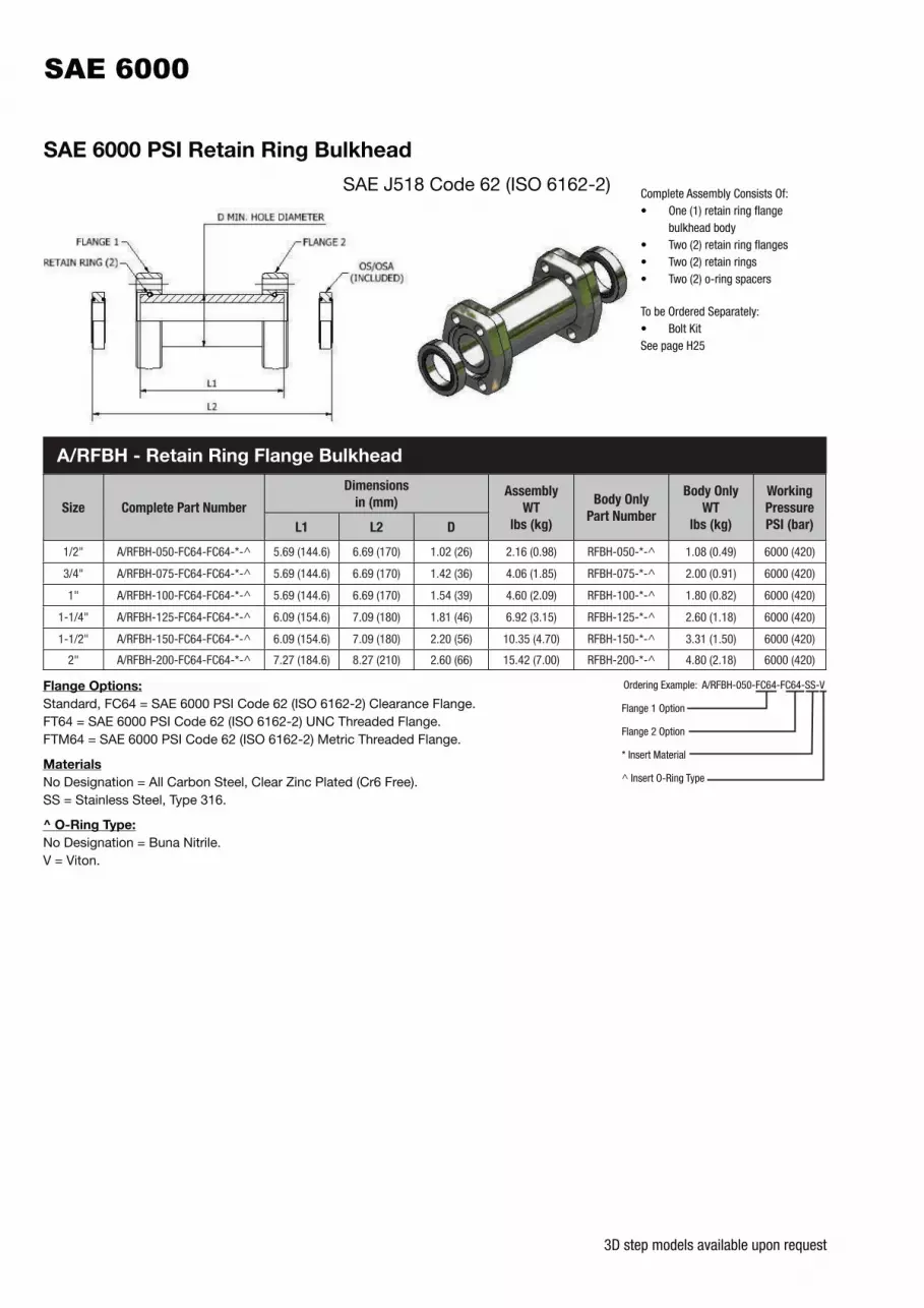
3D step models available upon request
SAE 6000 PSI Retain Ring Bulkhead
SAE J518 Code 62 (ISO 6162-2)
Size Complete Part Number
Dimensions
in (mm)Assembly
WT
lbs (kg)
Body Only
Part Number
Body Only
WT
lbs (kg)
Working
Pressure
PSI (bar)L1 L2 D
1/2" A/RFBH-050-FC64-FC64-*-^ 5.69 (144.6) 6.69 (170) 1.02 (26) 2.16 (0.98) RFBH-050-*-^ 1.08 (0.49) 6000 (420)
3/4" A/RFBH-075-FC64-FC64-*-^ 5.69 (144.6) 6.69 (170) 1.42 (36) 4.06 (1.85) RFBH-075-*-^ 2.00 (0.91) 6000 (420)
1" A/RFBH-100-FC64-FC64-*-^ 5.69 (144.6) 6.69 (170) 1.54 (39) 4.60 (2.09) RFBH-100-*-^ 1.80 (0.82) 6000 (420)
1-1/4" A/RFBH-125-FC64-FC64-*-^ 6.09 (154.6) 7.09 (180) 1.81 (46) 6.92 (3.15) RFBH-125-*-^ 2.60 (1.18) 6000 (420)
1-1/2" A/RFBH-150-FC64-FC64-*-^ 6.09 (154.6) 7.09 (180) 2.20 (56) 10.35 (4.70) RFBH-150-*-^ 3.31 (1.50) 6000 (420)
2" A/RFBH-200-FC64-FC64-*-^ 7.27 (184.6) 8.27 (210) 2.60 (66) 15.42 (7.00) RFBH-200-*-^ 4.80 (2.18) 6000 (420)
Complete Assembly Consists Of:• One (1) retain ring flange
bulkhead body• Two (2) retain ring flanges• Two (2) retain rings• Two (2) o-ring spacers
To be Ordered Separately:• Bolt KitSee page H25
Flange Options:
Standard, FC64 = SAE 6000 PSI Code 62 (ISO 6162-2) Clearance Flange.FT64 = SAE 6000 PSI Code 62 (ISO 6162-2) UNC Threaded Flange.FTM64 = SAE 6000 PSI Code 62 (ISO 6162-2) Metric Threaded Flange.
Materials
No Designation = All Carbon Steel, Clear Zinc Plated (Cr6 Free).SS = Stainless Steel, Type 316.
^ O-Ring Type:
No Designation = Buna Nitrile.V = Viton.
Ordering Example: A/RFBH-050-FC64-FC64-SS-V
Flange 1 Option
Flange 2 Option
* Insert Material
^ Insert O-Ring Type
A/RFBH - Retain Ring Flange Bulkhead
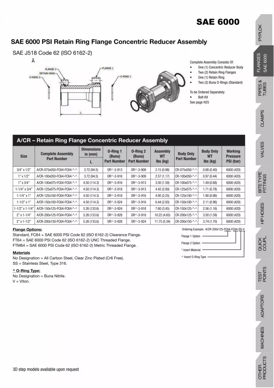
3D step models available upon request
SAE 6000 PSI Retain Ring Flange Concentric Reducer Assembly
SAE J518 Code 62 (ISO 6162-2)
SizeComplete Assembly
Part Number
Dimensions
in (mm)O-Ring 1
(Buna)
Part Number
O-Ring 2
(Buna)
Part Number
Assembly
WT
lbs (kg)
Body Only
Part Number
Body Only
WT
lbs (kg)
Working
Pressure
PSI (bar)L
3/4” x 1/2” A/CR-075x050-FC64-FC64-*-^ 3.72 (94.5) OR^-3-913 OR^-3-909 2.15 (0.98) CR-075x050-*-^ 0.88 (0.40) 6000 (420)
1” x 1/2” A/CR-100x050-FC64-FC64-*-^ 3.72 (94.5) OR^-3-916 OR^-3-909 2.57 (1.17) CR-100x050-*-^ 0.97 (0.44) 6000 (420)
1” x 3/4” A/CR-100x075-FC64-FC64-*-^ 4.50 (114.3) OR^-3-916 OR^-3-913 3.50 (1.59) CR-100x075-*-^ 1.49 (0.68) 6000 (420)
1-1/4” x 3/4” A/CR-125x075-FC64-FC64-*-^ 4.50 (114.3) OR^-3-918 OR^-3-913 4.42 (2.00) CR-125x075-*-^ 1.71 (0.78) 6000 (420)
1-1/4” x 1” A/CR-125x100-FC64-FC64-*-^ 4.50 (114.3) OR^-3-918 OR^-3-916 4.95 (2.25) CR-125x100-*-^ 1.90 (0.86) 6000 (420)
1-1/2” x 1” A/CR-150x100-FC64-FC64-*-^ 4.50 (114.3) OR^-3-924 OR^-3-916 6.44 (2.93) CR-150x100-*-^ 2.11 (0.96) 6000 (420)
1-1/2” x 1-1/4” A/CR-150x125-FC64-FC64-*-^ 5.26 (133.6) OR^-3-924 OR^-3-918 7.60 (3.45) CR-150x125-*-^ 2.56 (1.16) 6000 (420)
2” x 1-1/4” A/CR-200x125-FC64-FC64-*-^ 5.26 (133.6) OR^-3-928 OR^-3-918 10.22 (4.65) CR-200x125-*-^ 3.50 (1.59) 6000 (420)
2” x 1-1/2” A/CR-200x150-FC64-FC64-*-^ 5.26 (133.6) OR^-3-928 OR^-3-924 11.75 (5.34) CR-200x150-*-^ 3.74 (1.70) 6000 (420)
Flange Options:
Standard, FC64 = SAE 6000 PSI Code 62 (ISO 6162-2) Clearance Flange.FT64 = SAE 6000 PSI Code 62 (ISO 6162-2) UNC Threaded Flange.FTM64 = SAE 6000 PSI Code 62 (ISO 6162-2) Metric Threaded Flange.
Materials
No Designation = All Carbon Steel, Clear Zinc Plated (Cr6 Free).SS = Stainless Steel, Type 316.
^ O-Ring Type:
No Designation = Buna Nitrile.V = Viton.
Ordering Example: A/CR-200x125-FC64-FC64-SS-V
Flange 1 Option
Flange 2 Option
* Insert Material
^ Insert O-Ring Type
Complete Assembly Consists Of:• One (1) Concentric Reducer Body• Two (2) Retain Ring Flanges• One (1) Retain Ring• Two (2) Buna O-Rings (Standard)
To be Ordered Separately:• Bolt KitSee page H25
A/CR – Retain Ring Flange Concentric Reducer Assembly
PIP
ES
&
TU
BE
SC
LAM
PS
VA
LVE
SH
P H
OS
ES
BIT
E T
YP
EF
ITT
ING
SQ
UIC
K
CO
UP
L.T
ES
T
PO
INT
SA
DA
PT
OR
SM
AC
HIN
ES
OT
HE
R
PR
OD
UC
TS
PY
PLO
K

3D step models available upon request
* Materials:
Standard, No Designation = Carbon Steel, Clear Zinc Plated (Cr6 Free).HDG = Carbon Steel, Hot Dip Galvanized.SS = Stainless Steel, Type 316.
^ O-Ring Type:
Standard, No Designation = Buna Nitrile.V = Viton.
Ordering Example: BFO64-200-SS-V
* Insert Material
^ Insert O-Ring 2 Type
SizeBlanking Flange
Part Number
Dimensions (in) Bolt Size
J
O-Ring
(Buna)
Part Number
Working
Pressure
PSI (bar)
WT
lbs (kg)A B G H E
1/2" BFO64-050-*-^ 0.72 1.59 1.88 2.22 0.81 5/16” OR*-2-210 6000 (420) 0.53 (0.24)
3/4" BFO64-075-*-^ 0.94 2.00 2.38 2.81 1.02 3/8” OR*-2-214 6000 (420) 1.08 (0.49)
1" BFO64-100-*-^ 1.09 2.25 2.75 3.19 1.03 7/16” OR*-2-219 6000 (420) 1.70 (0.77)
1-1/4" BFO64-125-*-^ 1.25 2.63 3.06 3.75 1.25 1/2" OR*-2-222 6000 (420) 2.63 (1.20)
1-1/2" BFO64-150-*-^ 1.44 3.13 3.75 4.44 1.38 5/8” OR*-2-225 6000 (420) 3.90 (1.77)
2" BFO64-200-*-^ 1.75 3.81 4.50 5.25 1.68 3/4" OR*-2-228 6000 (420) 5.66 (2.57)
BFO64 – Blanking Flange Complete with Buna O-Ring (Standard) and #4 SAE Port
(Plugged), NPS
SAE J518 Code 62 (ISO 6162-2)
SizeBlanking Flange
Part Number
Dimensions (mm) Bolt Size
J
O-Ring
(Buna)
Part Number
Working
Pressure
PSI (bar)
WT
lbs (kg)A B G H E
1/2" BFOM64-050-*-^ 18.3 40.4 47.8 56.4 20.6 M8 OR*-2-210 6000 (420) 0.53 (0.24)
3/4" BFOM64-075-*-^ 23.9 50.8 60.5 71.4 25.9 M10 OR*-2-214 6000 (420) 1.08 (0.49)
1" BFOM64-100-*-^ 27.7 57.2 69.9 81.0 26.2 M12 OR*-2-219 6000 (420) 1.70 (0.77)
1-1/4" BFOM64-125-*-^ 31.8 66.8 77.7 95.3 31.8 M12 OR*-2-222 6000 (420) 2.63 (1.20)
1-1/2" BFOM64-150-*-^ 36.6 79.5 95.3 112.8 35.1 M16 OR*-2-225 6000 (420) 3.90 (1.77)
2" BFOM64-200-*-^ 44.5 96.8 114.3 133.4 42.7 M20 OR^-2-228 6000 (420) 5.66 (2.57)
BFOM64 – Blanking Flange Complete with Nitrile O-Ring (Standard) and G1/4 BSPP
Port (Plugged,) Metric

3D step models available upon request
* Materials:
Standard, No Designation = Carbon Steel, Clear Zinc Plated (Cr6 Free).HDG = Carbon Steel, Hot Dip Galvanized.SS = Stainless Steel, Type 316.
SizeBlanking Flange
Part Number
Dimensions (in) Thread
UNC-2B
J
Working
Pressure
PSI (bar)
WT
lbs (kg)A B G H E
1/2" BFF64-050-* .72 1.59 1.88 2.22 0.81 5/16”-18 6000 (420) 0.56 (0.25)
3/4" BFF64-075-* .94 2.00 2.38 2.81 1.02 3/8”-16 6000 (420) 1.08 (0.49)
1" BFF64-100-* 1.09 2.25 2.75 3.19 1.03 7/16”-14 6000 (420) 1.79 (0.81)
1-1/4" BFF64-125-* 1.25 2.63 3.06 3.75 1.25 1/2"-13 6000 (420) 2.74 (1.25)
1-1/2" BFF64-150-* 1.44 3.13 3.75 4.44 1.38 5/8”-11 6000 (420) 4.01 (1.82)
2" BFF64-200-* 1.75 3.81 4.50 5.25 1.68 3/4"-10 6000 (420) 5.82 (2.65)
BFF64 – Blanking Flange Flat Face with #4 SAE Port (Plugged) and UNC
Threaded Holes, NPS
Flat Face with Threaded Holes SAE J518 Code 62 (ISO 6162-2)
SizeBlanking Flange
Part Number
Dimensions (mm) Thread
J
Working
Pressure
PSI (bar)
WT
lbs (kg)A B G H E
1/2" BFFM64-050-* 18.3 40.4 47.8 56.4 20.6 M8 x 1.25 6000 (420) 0.56 (0.25)
3/4" BFFM64-075-* 23.9 50.8 60.5 71.4 25.9 M10 x 1.50 6000 (420) 1.08 (0.49)
1" BFFM64-100-* 27.7 57.2 69.9 81.0 26.2 M12 x 1.75 6000 (420) 1.79 (0.81)
1-1/4" BFFM64-125-* 31.8 66.8 77.7 95.3 31.8 M12 x 1.75 6000 (420) 2.74 (1.25)
1-1/2" BFFM64-150-* 36.6 79.5 95.3 112.8 35.1 M16 x 2.00 6000 (420) 4.01 (1.82)
2" BFFM64-200-* 44.5 96.8 114.3 133.4 42.7 M20 x 2.50 6000 (420) 5.82 (2.65)
BFFM64 – Blanking Flange Flat Face with G1/4 BSPP Port (Plugged) and
Threaded Holes, Metric
Ordering Example: BFF64-200-SS
* Insert Material
PIP
ES
&
TU
BE
SC
LAM
PS
VA
LVE
SH
P H
OS
ES
BIT
E T
YP
EF
ITT
ING
SQ
UIC
K
CO
UP
L.T
ES
T
PO
INT
SA
DA
PT
OR
SM
AC
HIN
ES
OT
HE
R
PR
OD
UC
TS
PY
PLO
K
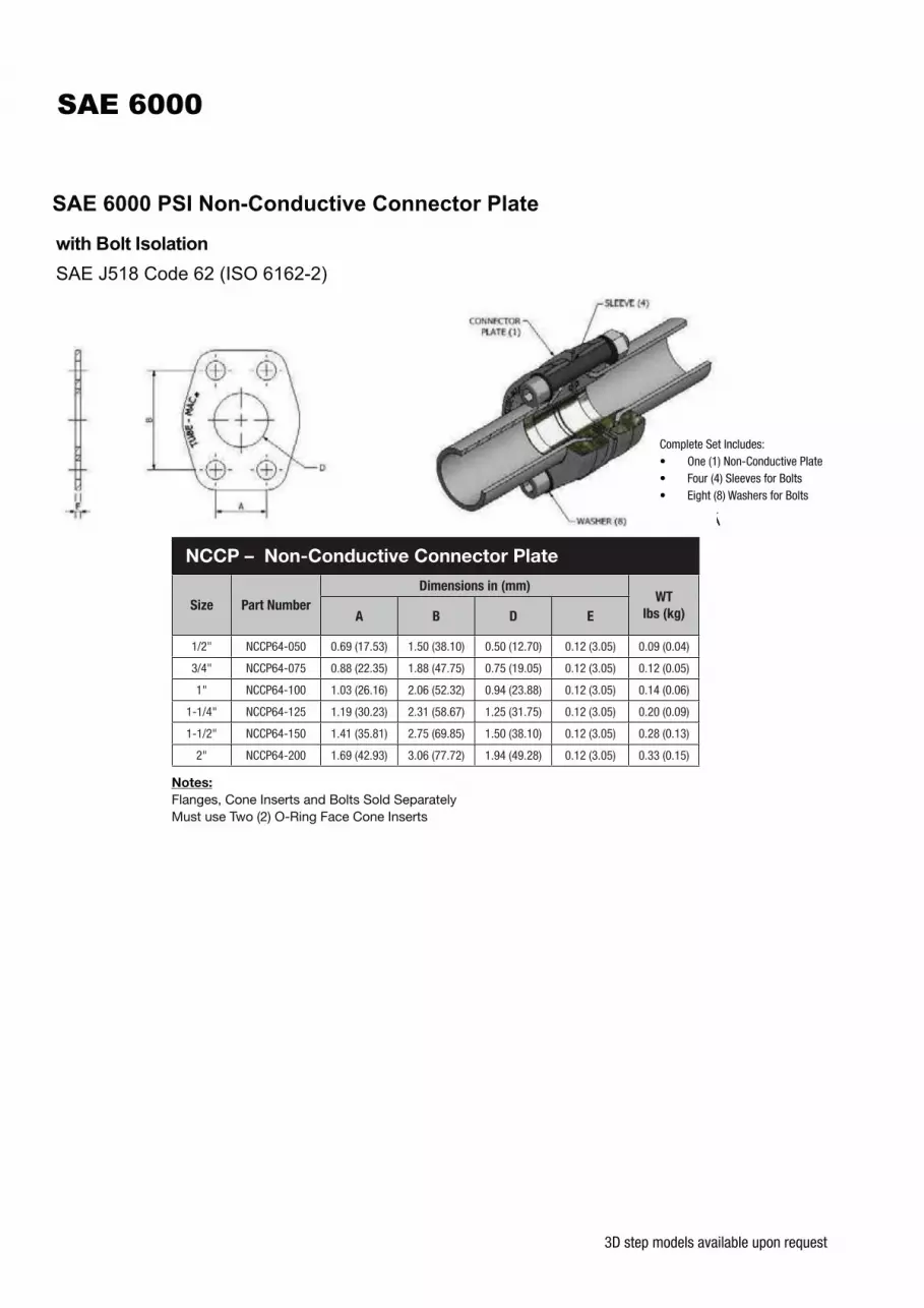
3D step models available upon request
Notes:
Flanges, Cone Inserts and Bolts Sold SeparatelyMust use Two (2) O-Ring Face Cone Inserts
Size Part Number
Dimensions in (mm)WT
lbs (kg)A B D E
1/2" NCCP64-050 0.69 (17.53) 1.50 (38.10) 0.50 (12.70) 0.12 (3.05) 0.09 (0.04)
3/4" NCCP64-075 0.88 (22.35) 1.88 (47.75) 0.75 (19.05) 0.12 (3.05) 0.12 (0.05)
1" NCCP64-100 1.03 (26.16) 2.06 (52.32) 0.94 (23.88) 0.12 (3.05) 0.14 (0.06)
1-1/4" NCCP64-125 1.19 (30.23) 2.31 (58.67) 1.25 (31.75) 0.12 (3.05) 0.20 (0.09)
1-1/2" NCCP64-150 1.41 (35.81) 2.75 (69.85) 1.50 (38.10) 0.12 (3.05) 0.28 (0.13)
2" NCCP64-200 1.69 (42.93) 3.06 (77.72) 1.94 (49.28) 0.12 (3.05) 0.33 (0.15)
NCCP – Non-Conductive Connector Plate
Complete Set Includes:• One (1) Non-Conductive Plate• Four (4) Sleeves for Bolts• Eight (8) Washers for Bolts


