Embed Size (px)
Citation preview
SAFE EARTHING SYSTEM FOR THE DISTRIBUTION SECTOR
Jaymin Patel, Pushkar Bhokri, Vithal Kamat
Synopsis
Earthing system is installed as an integral part of an electric distribution system which has SAFETY
as a primary goal. This paper reveals why the prevailing earthing system in the Indian distribution
sector is defective. A large number of precious lives could be saved in India if we adopt an earthing
system that is testable, observable and controllable. In this paper, we have proposed an earth
network that is amenable to easy testing with a clamp-on earth tester and best suited for the
overhead distribution system prevailing in India.
1 Introduction
Over the years, humans have made some truly remarkable discoveries, one of which has been the
importance of grounding electrical systems. Electricity has provided countless benefits to people,
but its network still remains one of the most deadly elements in human society, and unless there is
an appropriate grounding provided to the electrical systems, there is a rather large risk to human
lives. But unfortunately, in today’s times, good earthing practice has been put to disuse!!
Earthing simply means connecting a part of an electrical appliance to the earth or soil. Good
earthing practice is an important requirement for sound electrical system protection, and though
every electrical engineer would claim to know it well, it is a topic that is less understood and often
taken for granted. Without a good earthing practice, even the best of protection gadgets may fail to
operate, putting at risk the lives of human beings and animals.
2 Earthing Basics
A century back, when electricity was first generated and engineers wanted to have a common
reference for their supply, the earth’s conductive surface was the only convenient one available.
One of the supply conductors would be connected to earth or ground, later to be considered as a
reference – a practice called system earthing.
When a fault within an electrical device connects a live wire to an exposed conductive surface, then,
anyone coming in direct contact with it while standing on earth would complete a circuit back to the
earthed supply conductor and receive an electric shock. However, if this exposed conductive
surface would have been connected to earth, a practice called equipment earthing, then it would
offer a low resistance parallel path to not only prevent such a shock but also to offer a return path
for the fault currents which would now be high enough to operate a protective mechanism that
would clear / isolate the faulty circuit.
2.1 Types of Earthing
Depending on its usage and purpose, earth can be categorized into two basic types
2.1.1 Protective Earth and Equipment Earthing
A protective earth (PE) is a conductor that grounds an equipment, and is used to prevent accidental
electric shock. Such an earth keeps the exposed conductive surfaces of the equipment at earth
potential and under normal conditions do not carry current. However, on a low impedance line to
2
ground fault, heavy currents would flow causing a fuse to blow or a circuit breaker to trip, thereby
protecting the circuit. Even if we have a high impedance line-to-ground fault, the small levels of
fault currents through earth is still sufficient to trip a residual current circuit breaker (RCCB) and
help protect lives [1]. PE is also called an ‘equipment grounding conductor’.
The process of connecting a PE to the non-current–carrying metal parts (e.g. metallic enclosure) of
the electrical equipment is called equipment earthing.
2.1.2 Functional Earth and System Earthing
A functional earth connection serves a purpose other than shock protection, and may carry current
under normal conditions. It is typically used for measurements in measuring instruments or for
noise filtering in EMI filters or quenching surges in surge suppressors. Probably the most widely
used example of functional earth is the Neutral in an electrical supply system which is a current
carrying conductor. The neutral conductor is connected to earth often at only one point to avoid
earth currents [1]. For this reason, a neutral is also called a grounded supply conductor.
The process of connecting a neutral conductor to earth is called system earthing
2.2 Earthing Arrangements
For describing earthing arrangements, the following notations are used [1]:
T : Direct connection of a point with earth (terra)
I : Isolated, or no point is connected with earth
N : Direct connection to Neutral
The IEC60364 distinguishes 3 families of earthing arrangements that are in place around the globe
using the two letter codes - TN, TT and IT. While the first letter indicates the connection between
earth and the power supply equipment (generator or transformer), the second letter indicates the
connection between earth and the electrical device being supplied (on the consumer side)[2].
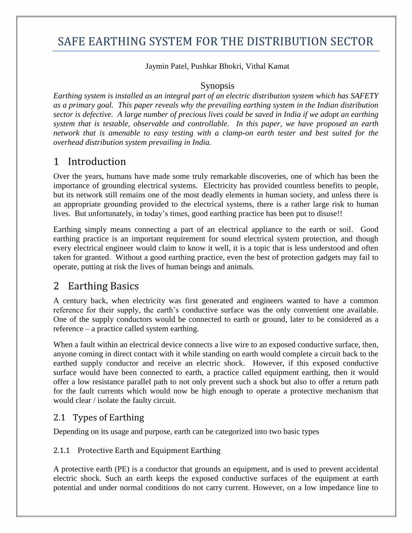
2.2.1 TN networks
The TN networks are of 3 types- TN-S, TN-C, TN-CS. Figure 1 describes the nature and
functioning of these networks (for more details see [1], [3]).
TN-S TN-C TN-C-S.
Figure 1. Variants of the TN earth arrangement
R Y B N E R Y B N E R Y B N E
PE
PEN
PE
N N
3
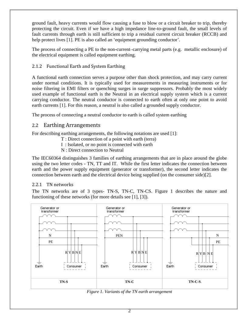
2.2.2 Networks with Consumer Earth
Under the above notation system, if the second character is a ‘T’, then it refers to a local earth
connection of the consumer at his/her premises that is independent of the earth connection at the
generator (see Figure 2). Such networks can be further classified into TT and IT networks.
Figure 2. Systems with Earth on the consumer side
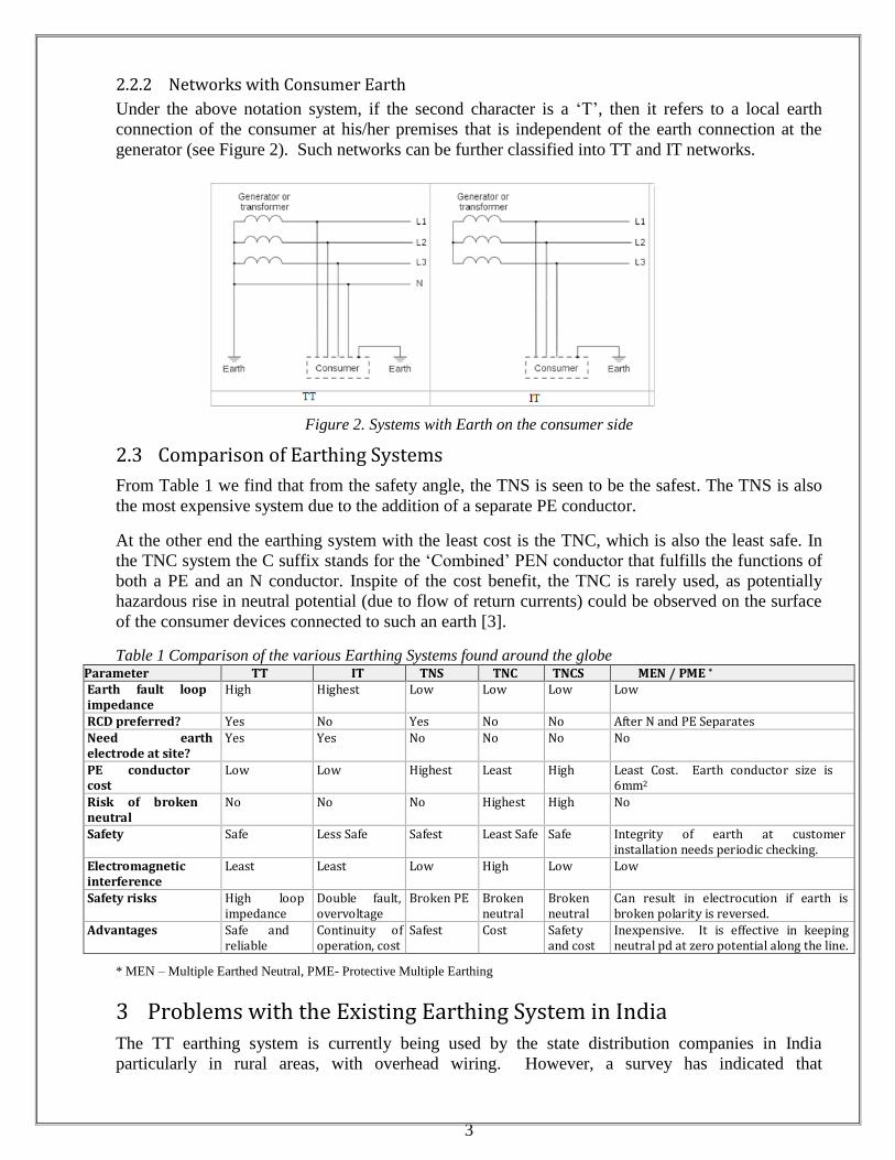
2.3 Comparison of Earthing Systems
From Table 1 we find that from the safety angle, the TNS is seen to be the safest. The TNS is also
the most expensive system due to the addition of a separate PE conductor.
At the other end the earthing system with the least cost is the TNC, which is also the least safe. In
the TNC system the C suffix stands for the ‘Combined’ PEN conductor that fulfills the functions of
both a PE and an N conductor. Inspite of the cost benefit, the TNC is rarely used, as potentially
hazardous rise in neutral potential (due to flow of return currents) could be observed on the surface
of the consumer devices connected to such an earth [3].
Table 1 Comparison of the various Earthing Systems found around the globe Parameter TT IT TNS TNC TNCS MEN / PME * Earth fault loop impedance
High Highest Low Low Low Low
RCD preferred? Yes No Yes No No After N and PE Separates
Need earth electrode at site?
Yes Yes No No No No
PE conductor cost
Low Low Highest Least High Least Cost. Earth conductor size is 6mm2
Risk of broken neutral
No No No Highest High No
Safety Safe Less Safe Safest Least Safe Safe Integrity of earth at customer installation needs periodic checking.
Electromagnetic interference
Least Least Low High Low Low
Safety risks High loop impedance
Double fault, overvoltage
Broken PE Broken neutral
Broken neutral
Can result in electrocution if earth is broken polarity is reversed.
Advantages Safe and reliable
Continuity of operation, cost
Safest Cost Safety and cost
Inexpensive. It is effective in keeping neutral pd at zero potential along the line.
* MEN – Multiple Earthed Neutral, PME- Protective Multiple Earthing
3 Problems with the Existing Earthing System in India
The TT earthing system is currently being used by the state distribution companies in India
particularly in rural areas, with overhead wiring. However, a survey has indicated that
4
approximately 60 percent of the consumers do not have an earth provision at their premises. And
amongst those who do, the earthing system is ill maintained. This means that the earth network
reduces to a TN-C. Ironically, the TN-C is the very network that is rarely used in other countries.
All the disadvantages of this potentially dangerous system are frequently observed in India.
Some of the utilities that were established during the British era, like the Torrent Power in
Ahmedabad have underground cables with the TN-S. Due to weathering, the sheaths of these
underground cables have corroded and, therefore, have stopped providing good earth connections.
Thus the installations where ‘bad earths’ are found have got converted to TN-C-S.
In this section, we shall see how an inappropriate choice for an earthing system coupled with a total
disregard for Indian Electricity Rules can prove to be a recipe for disaster.
3.1 Safety Issues with TN-C system
In a TN-C system, the RCD devices are quite vulnerable to unwanted triggering from contact
between earth conductors of circuits on different RCDs or with real ground. If the threshold
settings of the RCDs are increased, then they are far less likely to detect an insulation fault. It is
also unsafe to isolate the neutral core in a TN-C system, and hence the RCDs should be wired to
interrupt only the live conductor and not the neutral, a convention that is not followed.
On an event of a neutral break, in a single phase system, all parts of the earthing system beyond the
neutral break would rise to the potential of the L conductor. In case of an unbalanced three phase
system, the potential of the earthing system would move towards the most loaded live conductor. In
the Indian consumer premises, we frequently observe the use of plug/socket connections and
flexible cables where there is a high probability of contact problems. Instead of a 3 pin plug/socket,
consumers are found to frequently use a 2 pin plug/socket where live (L) and neutral (N) could get
interchanged. The use of TN-C or TN-C-S system should be banned in such premises. For
instance, in the UK, the use of TN-C-S is banned while TT system is recommended for outdoor
wiring.
3.2 Disregard for the Electricity Rules
Rule 29 of the Indian Electricity Rules, 1956, mandates that the electric supply lines and apparatus
should be of sufficient rating for fault currents, and that the same shall be constructed, installed,
protected, worked and maintained to ensure safety of human beings, animals and property. Why
then do we commonly hear of fatal accidents and damage to property. We still carry in our mind
the vivid picture of an engineering student from our institute at Vallabh Vidyanagar who got
electrocuted due to earth fault when his bicycle got too close to a guy wire (used to keep an electric
pole upright). We dedicate this paper to this innocent young student.
How often do we see a danger notice with skull and bones? Rule 35 of the IE Rules mandates that
such notice be affixed in conspicuous locations of medium or high voltage installations. Similarly,
Rule 31 requires that the electric utility provide a cut out on every service line in the network and at
the customer premises, just as Rule 33 requires that the utility provides and maintains an earth
terminal for the consumer’s use at an accessible position in his/her premises. Earlier, the utilities
would make lame excuses such as, ‘cut-outs are convenient points for energy pilferage’; or else they
would take recourse to admitting that their utility is sick. However, of late, after the setting up of
the electric regulatory commissions, the health of the utilities has seen a dramatic improvement.
Isn’t it time that the authorities connected with electricity start giving human lives and their
property the due importance?
5
3.3 Which Earthing System to Choose?
In the United States and Canada, the TN-C-S system is used. In Argentina, Australia (MEN) and
France (TT), the customers must provide their own ground connections. Japan uses TT earthing in
most installations. UK has shifted from the TN-S to the PME. Modern homes in Europe have a
TN-C-S earthing system. Norway is shifting from an IT to a TN-C-S system. TT networks are
commonly used when the cost of an additional PE conductor outweighs the cost of a local earth
connection, typically in older properties or in rural areas.
Even in the developed countries, until the mid 1990s, power outlets generally lacked protective
earth terminals. Therefore, devices needing an earth connection used the supply neutral. Some
used dedicated ground rods. Many appliances had polarized plugs to maintain a distinction between
live and neutral, but using the supply neutral for equipment earthing was highly problematical. Live
and neutral might be accidentally reversed in the outlet or plug, or the neutral-to-earth connection
might fail or be improperly installed. Even normal load currents in the neutral might generate
hazardous voltage drops. For these reasons, most countries mandated dedicated protective earth
connections that are now almost universal.
4 Adopting the Correct Earth Measurement Tool for India
To simplify our decision making process and choose the right earthing system for India, we first
shift to a more basic question. Which would the right earth measurement tool for India?
4.1 Observability, Testability, and Controllability (OTC) Issue
In a tropical country like India, where humidity is high, the electrical systems corrode and need
frequent maintenance. How do we know that the earthing system is functional? Does the system
facilitate easy testing? These questions would get answered if we address the issues of
Observability, Testability and Controllability (OTC). A laborious test procedure that involves
disconnection of the earthing system for it to be tested or which requires additional earth spikes to
be driven into the soil before taking the earth measurement is a deterrent to its usage. This is one of
the main reasons why earthing systems, in developing countries, are hardly ever tested. The
measurement of earth has dropped to such pathetic levels, that today, it is even difficult to find a
working earth measuring instrument with the local utilities.
A faulty insulator on an unearthed pole could prove to be hazardous to lives. If the pole is earthed,
then the potential would drop to near zero, however, leakage currents would now flow through the
earth. It is necessary to check for such leakage currents and to identify and correct the faulty
insulator. If this is not done, then the continued flow of leakage currents would cause the earthing
to deteriorate. Also the utility would lose precious energy through this fault.
In the following section we will describe an elegant, simple to use clamp-on earth tester which has
the ability to measure the earth resistance or the earth (leakage) currents without disconnecting the
earth wire.
4.2 Clamp-on Earth Tester to overcome the OTC Issue
A clamp-on earth tester offers the ability to measure the resistance without disconnecting the
ground wire, and without the need for auxiliary earth spikes (which were part of the traditional earth
testers). A clamp on tester, typically, has the ability to measure the earth resistance from 0.05 to
1200Ω. It can also measure accurate true RMS readings of AC current including distorted
waveform, typically, from 1mA to 30.0A. This comes in handy for the measurement of leakage
6
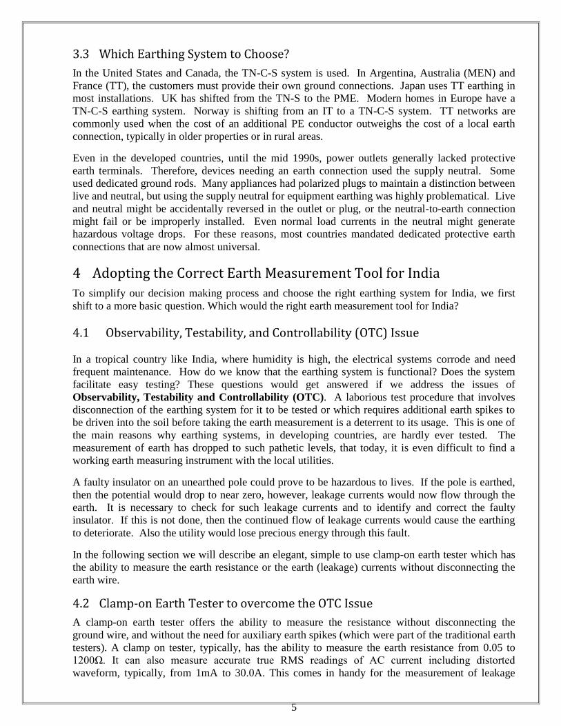
currents through the earth wire as we shall see later. Figure 3 shows such a tester [4][5]. Since the
ground wire is not disconnected, this measurement procedure also offers the advantage of
preserving the bonding to earth and thereby the earth connection resistance values.
View of an Earth Clamp Tester [4] Calibration of the Earth Tester [4] Using the Earth Tester in Field [5]
Figure 3. Earth Clamp Tester and its usage
4.3 Principle of Operation of a Earth Clamp tester
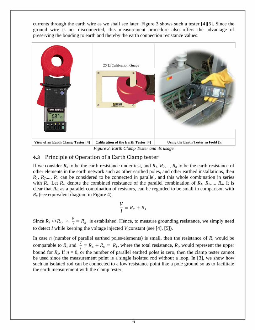
If we consider Rx to be the earth resistance under test, and R1, R2,..., Rn to be the earth resistance of
other elements in the earth network such as other earthed poles, and other earthed installations, then
R1, R2,..., Rn can be considered to be connected in parallel, and this whole combination in series
with Rx. Let Rs, denote the combined resistance of the parallel combination of R1, R2,..., Rn. It is
clear that Rs, as a parallel combination of resistors, can be regarded to be small in comparison with
Rx (see equivalent diagram in Figure 4).
Since Rs <<Rx,
is established. Hence, to measure grounding resistance, we simply need
to detect I while keeping the voltage injected V constant (see [4], [5]).
In case n (number of parallel earthed poles/elements) is small, then the resistance of Rs would be
comparable to Rx and
, where the total resistance, Rt, would represent the upper
bound for Rx. If n = 0, or the number of parallel earthed poles is zero, then the clamp tester cannot
be used since the measurement point is a single isolated rod without a loop. In [3], we show how
such an isolated rod can be connected to a low resistance point like a pole ground so as to facilitate
the earth measurement with the clamp tester.
25 Ω Calibration Guage
7
Figure 4. Equivalent Circuit for Earth Measurement [4, 5]
While the principle of operation has been the reason for the main advantage of the Clamp-on tester,
namely, its ability to take earth measurements without disconnection, it is also the reason for two
main disadvantages:
1. A singular earth cannot be measured. The clamp on tester operates only when we have an
earth loop, i.e. . Moreover, it is useful only when we have Multiple Earth systems
i.e. .
2. The earth clamp tester can only measure the earth loop resistance , and
cannot bifurcate the resistance of the earthing conductor under test, Rx, from the rest of the
loop resistance Rs.
However, both the disadvantages pose no deterrent to us since our proposed earthing arrangement
overcomes and nullifies them. Before describing our proposed system, we analyze the major flaws
in the existing one.
5 Analyzing the Prevalent Earthing System
At present, Madhya Gujarat Vij Company Limited (MGVCL) and other distribution utilities are
adopting the 5 wire system in their distribution system, namely, the three (R, Y, B) Phases,
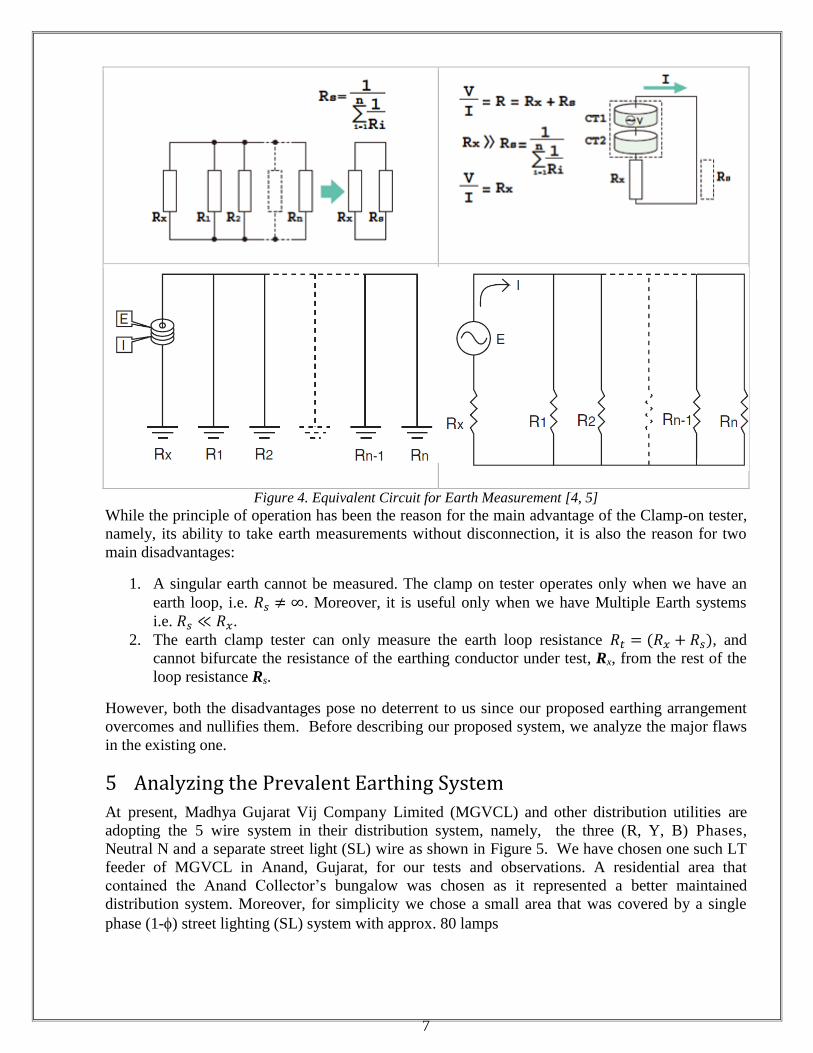
Neutral N and a separate street light (SL) wire as shown in Figure 5. We have chosen one such LT
feeder of MGVCL in Anand, Gujarat, for our tests and observations. A residential area that
contained the Anand Collector’s bungalow was chosen as it represented a better maintained
distribution system. Moreover, for simplicity we chose a small area that was covered by a single
phase (1-) street lighting (SL) system with approx. 80 lamps
8
Figure 5. Present 5- wire system adopted by the Electric Utilities
For further understanding, refer to the single line diagram of the distribution system shown in
Figure 6. Here, X1 represents the distribution transformer that, in addition to feeding its Local Loads
(LL) – domestic or commercial, also feeds 80 numbers of street lights (SL). Most of the lamps
(approx. 50 Nos.), from this set of 80 lamps, light up the areas that are having their local
distribution transformers, X2, . . . , Xn, different from X1. By local distribution transformers we
mean those transformers that are feeding their respective Local Loads (LL) - domestic, commercial,
or load categories other than SL, in its area/ vicinity. In other words, only 30 Nos. of lamps light up
the area whose local loads (domestic, commercial, etc.) are also fed by the same transformer X1.
Henceforth, for simplicity we will consider the area covered by Xn to be synonymous with Xn.
Moreover, though the transformers used in the field are 3 phase, in the diagram we have restricted
our line diagrams, without loss of generality, to represent only a single phase, namely R phase (see
Figure 6).
One may note, from Figure 6, that in the areas X2, . . . , Xn, the Local Loads (LL-Rn phase) are
having feeds that are different from the SL feed, and hence are separate. However, in these same
areas (X2, . . . , Xn) to economize on conductors, the ground path is used to provide a current return
and complete the circuit back to X1 neutral. Such a malpractice causes large currents to flow
through the ground wire and earth which deteriorates the quality of the earth pit, a detailed
explanation for which is given in the next section. These return currents have been indicated in
Figure 6 as IE2E1, …, IEnE1. Figure 6 thus shows a defective distribution system with Protective Earth
(PE) abused by injecting currents.
Many a times, it is observed that the consumers connect the neutral wire in their premises to their
local earth. Probably, this may be to protect their own loads from damage due to over-voltages on
an occasion when the incoming neutral breaks. However, this practice compounds the problem
since the street light currents also choose to return through these consumer earth pits damaging
them, too, in the process. These return currents have been indicated in Figure 6 for zone X1 as
IX1C1, …, IX1Cn., for zone X2 as IX2C1, …, IX2Cn, and so on.
Though the above observations are factual and supported by basic electrical laws (such as
Kirchoff’s laws), they are additionally strengthened here with consistent readings which are
analyzed in the following section.
9
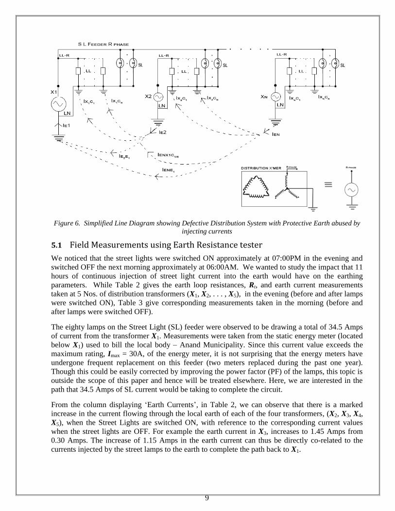
Figure 6. Simplified Line Diagram showing Defective Distribution System with Protective Earth abused by
injecting currents
5.1 Field Measurements using Earth Resistance tester
We noticed that the street lights were switched ON approximately at 07:00PM in the evening and
switched OFF the next morning approximately at 06:00AM. We wanted to study the impact that 11
hours of continuous injection of street light current into the earth would have on the earthing
parameters. While Table 2 gives the earth loop resistances, Rt, and earth current measurements
taken at 5 Nos. of distribution transformers (X1, X2, . . . , X5), in the evening (before and after lamps
were switched ON), Table 3 give corresponding measurements taken in the morning (before and
after lamps were switched OFF).
The eighty lamps on the Street Light (SL) feeder were observed to be drawing a total of 34.5 Amps
of current from the transformer X1. Measurements were taken from the static energy meter (located
below X1) used to bill the local body – Anand Municipality. Since this current value exceeds the
maximum rating, Imax = 30A, of the energy meter, it is not surprising that the energy meters have
undergone frequent replacement on this feeder (two meters replaced during the past one year).
Though this could be easily corrected by improving the power factor (PF) of the lamps, this topic is
outside the scope of this paper and hence will be treated elsewhere. Here, we are interested in the
path that 34.5 Amps of SL current would be taking to complete the circuit.
From the column displaying ‘Earth Currents’, in Table 2, we can observe that there is a marked
increase in the current flowing through the local earth of each of the four transformers, (X2, X3, X4,
X5), when the Street Lights are switched ON, with reference to the corresponding current values
when the street lights are OFF. For example the earth current in X3, increases to 1.45 Amps from
0.30 Amps. The increase of 1.15 Amps in the earth current can thus be directly co-related to the
currents injected by the street lamps to the earth to complete the path back to X1.
10
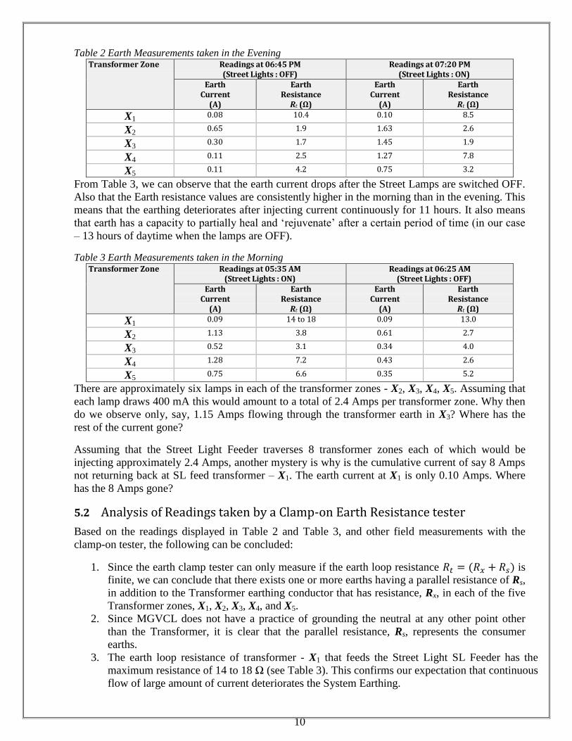
Table 2 Earth Measurements taken in the Evening Transformer Zone Readings at 06:45 PM
(Street Lights : OFF) Readings at 07:20 PM
(Street Lights : ON) Earth
Current (A)
Earth Resistance Rt (Ω)
Earth Current
(A)
Earth Resistance Rt (Ω)
X1 0.08 10.4 0.10 8.5
X2 0.65 1.9 1.63 2.6
X3 0.30 1.7 1.45 1.9
X4 0.11 2.5 1.27 7.8
X5 0.11 4.2 0.75 3.2
From Table 3, we can observe that the earth current drops after the Street Lamps are switched OFF.
Also that the Earth resistance values are consistently higher in the morning than in the evening. This
means that the earthing deteriorates after injecting current continuously for 11 hours. It also means
that earth has a capacity to partially heal and ‘rejuvenate’ after a certain period of time (in our case
– 13 hours of daytime when the lamps are OFF).
Table 3 Earth Measurements taken in the Morning Transformer Zone Readings at 05:35 AM
(Street Lights : ON) Readings at 06:25 AM
(Street Lights : OFF) Earth
Current (A)
Earth Resistance Rt (Ω)
Earth Current
(A)
Earth Resistance Rt (Ω)
X1 0.09 14 to 18 0.09 13.0
X2 1.13 3.8 0.61 2.7
X3 0.52 3.1 0.34 4.0
X4 1.28 7.2 0.43 2.6
X5 0.75 6.6 0.35 5.2
There are approximately six lamps in each of the transformer zones - X2, X3, X4, X5. Assuming that
each lamp draws 400 mA this would amount to a total of 2.4 Amps per transformer zone. Why then
do we observe only, say, 1.15 Amps flowing through the transformer earth in X3? Where has the
rest of the current gone?
Assuming that the Street Light Feeder traverses 8 transformer zones each of which would be
injecting approximately 2.4 Amps, another mystery is why is the cumulative current of say 8 Amps
not returning back at SL feed transformer – X1. The earth current at X1 is only 0.10 Amps. Where
has the 8 Amps gone?
5.2 Analysis of Readings taken by a Clamp-on Earth Resistance tester
Based on the readings displayed in Table 2 and Table 3, and other field measurements with the
clamp-on tester, the following can be concluded:
1. Since the earth clamp tester can only measure if the earth loop resistance is
finite, we can conclude that there exists one or more earths having a parallel resistance of Rs,
in addition to the Transformer earthing conductor that has resistance, Rx, in each of the five
Transformer zones, X1, X2, X3, X4, and X5.
2. Since MGVCL does not have a practice of grounding the neutral at any other point other
than the Transformer, it is clear that the parallel resistance, Rs, represents the consumer
earths.
3. The earth loop resistance of transformer - X1 that feeds the Street Light SL Feeder has the
maximum resistance of 14 to 18 Ω (see Table 3). This confirms our expectation that continuous
flow of large amount of current deteriorates the System Earthing.
11
4. In the Transformer - X1 zone, i.e. the resistance, Rx, of the earthing conductor under test located
below X1, is quite large in comparison to the rest of the loop resistance Rs , i.e. . This
can be concluded since majority of the street light current (8 Amps) chooses to flow through Rs
while only a small portion (0.10 Amps) flows through Rx. Transformer X1 earth has been
heavily damaged with resistance varying between 14 and 18 Ω.
5. In the other transformer zones, namely, X2, X3, X4, X5, the resistance of the earthing
conductor under test below the corresponding transformer, Rx, is almost equal to the rest of
the loop resistance Rs , i.e. . This is because, as we studied in the case of X3, only
half the street light current, 1.15 Amps, from the total of 2.4 Amps, flows through Rx. The
rest of 2.4 Amps (i.e. 1.25 Amps ) flows through Rs.
6. After damage at 5:35 AM, the earth loop resistances, Rt, vary between 3.1 and 18 Ω. If we
consider a typical value of Rt, to be 6 Ω, and assume , then Rx and Rs, each, would
be 3 Ω and their parallel combination would be 1.5 Ω. The fault currents
would be severely limited by Rp, and would fail to trip the protection mechanisms (circuit
breakers, etc.).
7. The protection levels are lower (Rp is higher) at night than in the day. Less safety at night is
dangerous since at night time there is less activity and hence an accident may go un-noticed
posing grave threat to life and property.
8. The measurements were taken in the monsoon season when the soil is wet and conditions
favourable. We anticipate that Rp would be even higher at other times during the year,
particularly in the summer.
9. With the clamp-on tester, we could not measure the resistance of the guy wires, the
transformer body earth, pole earth (if any), and a few consumer earths, due to non
completion of the earth loop. The safety of the corresponding equipments could not be
ascertained. Jugalkumar died due to a guy wire/ pole that became live.
10. Many poles carry not only the LT distribution wires, but also the HT (11 kV feeders) on top
of the pole. Inability to test the poles, guy wires, or transformer body makes the system even
more dangerous. Fatal accidents are not uncommon as a consequence.
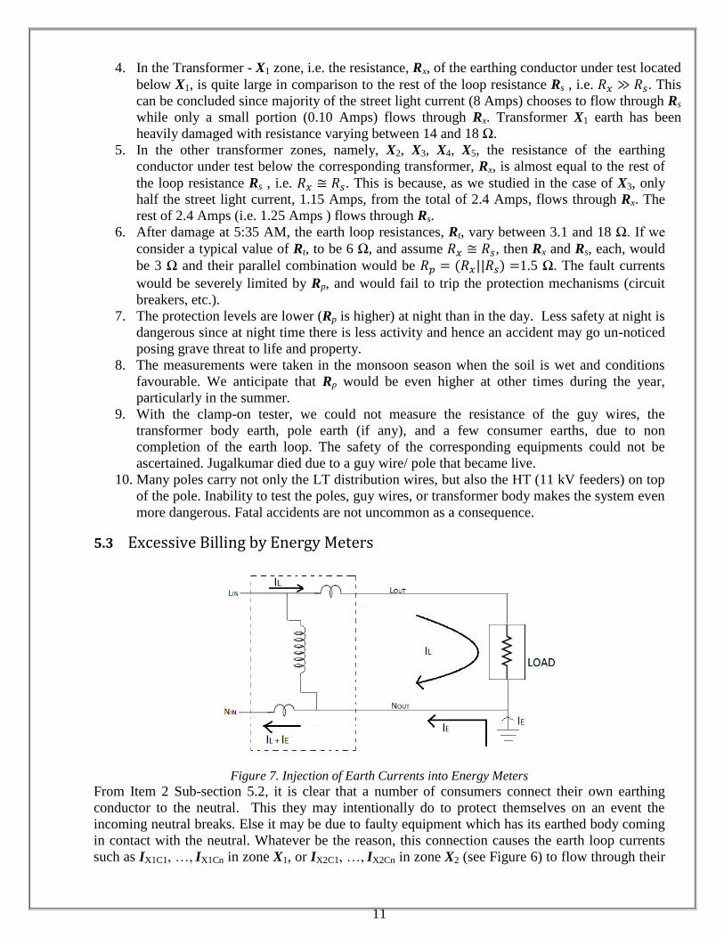
5.3 Excessive Billing by Energy Meters
Figure 7. Injection of Earth Currents into Energy Meters
From Item 2 Sub-section 5.2, it is clear that a number of consumers connect their own earthing
conductor to the neutral. This they may intentionally do to protect themselves on an event the
incoming neutral breaks. Else it may be due to faulty equipment which has its earthed body coming
in contact with the neutral. Whatever be the reason, this connection causes the earth loop currents
such as IX1C1, …, IX1Cn in zone X1, or IX2C1, …, IX2Cn in zone X2 (see Figure 6) to flow through their
12
own neutral. This current, represented as IE in Figure 7, adds to the consumer load current, IL ,
(assuming that both belong to the same phase) and returns back through the energy meter.
Since the static energy meters are configured, on the pretext of tamper protection, to bill the
consumers on the basis of higher of the two currents, namely phase and neutral currents, it follows
that the consumer will be excessively billed due to the higher neutral current (IE + IL). See Figure 7
for the equivalent circuit of a static energy meter.
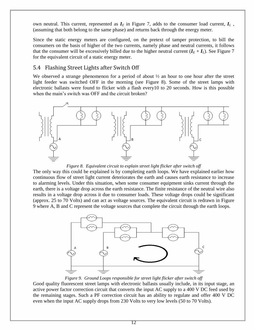
5.4 Flashing Street Lights after Switch Off
We observed a strange phenomenon for a period of about ½ an hour to one hour after the street
light feeder was switched OFF in the morning (see Figure 8). Some of the street lamps with
electronic ballasts were found to flicker with a flash every10 to 20 seconds. How is this possible
when the main’s switch was OFF and the circuit broken?
Figure 8. Equivalent circuit to explain street light flicker after switch off
The only way this could be explained is by completing earth loops. We have explained earlier how
continuous flow of street light current deteriorates the earth and causes earth resistance to increase
to alarming levels. Under this situation, when some consumer equipment sinks current through the
earth, there is a voltage drop across the earth resistance. The finite resistance of the neutral wire also
results in a voltage drop across it due to consumer loads. These voltage drops could be significant
(approx. 25 to 70 Volts) and can act as voltage sources. The equivalent circuit is redrawn in Figure
9 where A, B and C represent the voltage sources that complete the circuit through the earth loops.
Figure 9. Ground Loops responsible for street light flicker after switch off
Good quality fluorescent street lamps with electronic ballasts usually include, in its input stage, an
active power factor correction circuit that converts the input AC supply to a 400 V DC feed used by
the remaining stages. Such a PF correction circuit has an ability to regulate and offer 400 V DC
even when the input AC supply drops from 230 Volts to very low levels (50 to 70 Volts).
13
As the voltage builds up across the earth resistances (see voltage sources A, B and C in Figure 9) ,
the PF circuit too ramps up its output DC voltage to 400 V DC. The electronic ballast becomes
active at some point and ignites the lamp resulting in a flash. However, due to the high source
(earth) impedance, it is unable to sustain the power feed, and the voltage drop across the earth
resistance collapses and the lamps goes off. The cycle repeats when the voltage across the earth
resistance builds up steadily once again. This phenomenon lasts only for about ½ an hour to one
hour since, thereafter, the damaged earth starts healing itself and the earth resistance reduces.
6 The Proposed Earthing System for India
It is important that the earthing system not only protects the consumer premises but also all the
electrical devices in its own distribution system including the electrical poles used to carry the
overhead lines. How do we ensure that each pole is protected with adequately low earth resistance
that is safe for human beings or animals who may accidently come in contact with it? Such an
assurance can be given only when the earthing at each pole is testable. Below we reason out the
design of a safe earthing system originally proposed in [3].
6.1 The 1st requirement - Multiple Earth
A clamp on earth tester (described earlier in Section 4.2) is an elegant tool, but it cannot measure a
singular earth such as an individual pole earthing (Section 4.3). This tool is only useful when we
have an earth loop, i.e. , and when we have a multiple earthing system, i.e. .
For the earth resistance to be measureable, it is therefore necessary to link up the earth of each of
the poles together [7]. This can be done by earthing the Neutral wire at each pole in which case the
system would become PME/ MEN just like the networks in the UK or Australia. Though this is a
modification of the TN-CS system, this has one major drawback. The neutral currents would also
find a parallel path through the earth at each pole. This constant flow of the return load currents
through the earth wire would cause the earthing system to deteriorate. Unless the earthing network
is frequently checked, it would be difficult to trace the sections where the earth resistance has
increased. The maintenance of earth resistance to low values is the biggest challenge of a TN-CS
with PME/MEN network. Moreover, the leakage faults are no longer observable. If we consider a
case of faulty pole insulator, the resulting leakage current would mix with the neutral current,
thereby making it impossible to trace and eliminate such a fault.
6.2 The 2nd Requirement - Separate PE Wire
An earth network that overcomes the maintenance problem of PME/ MEN described in the earlier
section is the TN-S network. Each of the poles can now be connected to the separate protective
earth PE wire which, under normal circumstances, does not carry any current (as per the definition
of a PE). The system therefore requires very little maintenance. Both the earth resistance as well as
the leakage currents can be measured with equal ease. The TN-S system is also amenable to easy
test procedure without disconnection of the earth wire, using the clamp-on tester.
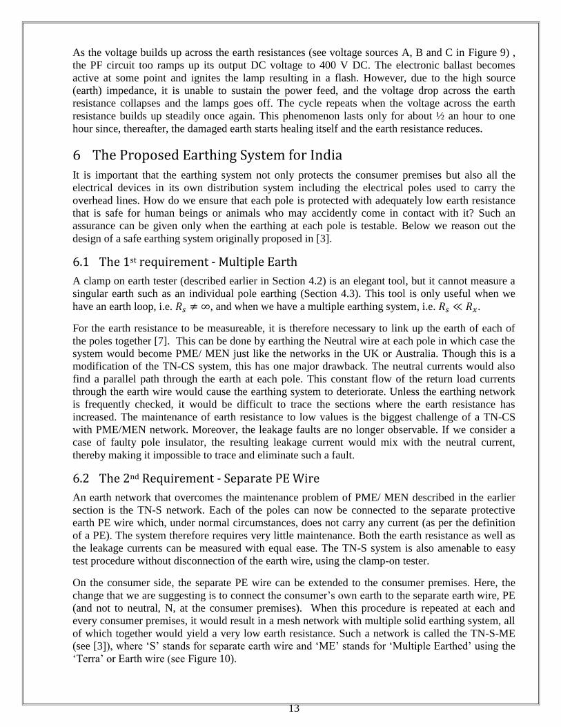
On the consumer side, the separate PE wire can be extended to the consumer premises. Here, the
change that we are suggesting is to connect the consumer’s own earth to the separate earth wire, PE
(and not to neutral, N, at the consumer premises). When this procedure is repeated at each and
every consumer premises, it would result in a mesh network with multiple solid earthing system, all
of which together would yield a very low earth resistance. Such a network is called the TN-S-ME
(see [3]), where ‘S’ stands for separate earth wire and ‘ME’ stands for ‘Multiple Earthed’ using the
‘Terra’ or Earth wire (see Figure 10).
14
Figure 10. TN-S-ME network showing ‘Separate Multiple Earthed’ wire
The TN-S-ME network, originally proposed in [3], has picked up all the advantages of each of the
networks described earlier in Sections 2.2 and 2.3, while dropping off the disadvantages of each of
them. Probably the only disadvantage of the TN-S-ME is the higher cost due to the separate fifth
earth wire. But if this would result in a safe network and save lives, the incremental cost should not
be a deterrent. The TN-S-ME system is best suited for the dangerous overhead distribution systems
that also carry the HT (11 kV) feeders. Even with the extra cost of the PE wire, it would still be
cheaper and less complicated than making a shift to underground cables (which have other earthing
related challenges).
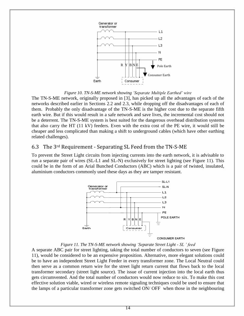
6.3 The 3rd Requirement - Separating SL Feed from the TN-S-ME
To prevent the Street Light circuits from injecting currents into the earth network, it is advisable to
run a separate pair of wires (SL-L1 and SL-N) exclusively for street lighting (see Figure 11). This
could be in the form of an Arial Bunched Conductors (ABC) which is a pair of twisted, insulated,
aluminium conductors commonly used these days as they are tamper resistant.
Figure 11. The TN-S-ME network showing ‘Separate Street Light - SL ’ feed
A separate ABC pair for street lighting, taking the total number of conductors to seven (see Figure
11), would be considered to be an expensive proposition. Alternative, more elegant solutions could
be to have an independent Street Light Feeder in every transformer zone. The Local Neutral could
then serve as a common return wire for the street light return current that flows back to the local
transformer secondary (street light source). The issue of current injection into the local earth thus
gets circumvented. And the total number of conductors would now reduce to six. To make this cost
effective solution viable, wired or wireless remote signaling techniques could be used to ensure that
the lamps of a particular transformer zone gets switched ON/ OFF when those in the neighbouring
R Y B N E
Consumer Earth
Pole Earth
15
zone are switched ON/ OFF respectively. A detailed description of this novel concept will be
described in the following paper.
7. Conclusions
Survey shows that 60% of consumer premises are not earthed, while the balance 40% which have a
local consumer earth are never tested once installed. So also the earthing of the street lamp poles
and distribution transformers were never tested. It is justified, therefore, if we consider the existing
earthing system to be unsafe, as it is not testable, observable and controllable.
We have analyzed some of the major disadvantages of the existing earth network configurations
that make them unsuitable for the Indian overhead distribution system. A large number of precious
lives could be saved if we adopt an earthing system that has low earth resistances and that can be
easily tested. The TN-S-ME earth network coupled with the separation of the street lamp feeder that
we have proposed here overcomes these disadvantages and is amenable to easy testing with a
clamp-on earth tester.
Acknowledgements: We acknowledge the work done by Mr. Anand Kanjaria, Sumit Nakum, Rajesh Ravalia, Malde
Solanki, Semel Tank and Kalpesh Nakum, students who graduated in 2012 from BVM Engineering College, Vallabh
Vidyanagar, who under guidance of the 3rd
author, discovered major problems in the prevailing earthing system.
Dedication: We dedicate this work to Late Shri. Jugalkumar Bhupendrakumar Shah, resident of
Bayad, Sabarkantha, Gujarat, India. He was a student of G.H. Patel College of Engineering, Bakrol,
Vallabh Vidyanagar, District Anand, and completed his 3rd
year engineering degree course in
Electronics and Communication. On June 28, 2006, he got electrocuted when he approached a ‘live’
guy wire near University Circle, Vallabh Vidyanagar. He was aspiring to specialize in Speech
processing.
References:
1. Wikipedia – the free encyclopedia on the internet, Earthing Systems http://en.wikipedia.org/wiki/Earthing_system.
2. IEC 60364-1: Electrical installations of buildings — Part 1: Fundamental principles, assessment of general
characteristics, definitions. International Electrotechnical Commission, Geneva.
3. Kamat V. N. On the Need for Earth Measurement and Testing, Electrical India, published by Chary Publications,
311, Raikar Chambers, Govandi (E), Mumbai, 400 088, Vol. 52, No. 3, March 2012, pp. 38-52.
4. AEMC instruments, Application note on Clamp-On Ground Resistance Tester Models 3711 and 3731,
www.aemc.com.
5. Kyoritsu Earth Clamp Tester Model 4200 Specifications, Kyoritsu Electrical Instrument Works Ltd. www.kew-
ltd.co.jp
6. Nakum Kalpesh et al, Evaluation of different Earthing Systems BE(Electrical) Project Report, 2012, BVM
Engineering College, Vallabh Vidyanagar, Gujarat 388120.
7. Vachharajani V. J. Proposal for TNCS+CNT (Continuous Neutral Technique) System to reduce number of
earthings required per network to achieve the Maximum Permissible Earth Resistance Norm (MPERN) , GERC
order dated 20.04.2009 in Petition No. 909/2007.
16
Biographies:
Jaymin Patel is a final year undergraduate student of BE (Electrical) at G. H. Patel College of Engineering and Technology and
an active member of IEEE.. He has been a part of various Non-Profit Organizations with a keen interest inpolitics, national
affairs, economics and public administration, public speaking and event management. Enjoys exploring and travelling, reading and blogging. His area of interest is Power System
Pushkar Bhokri is a final year undergraduate student of BE (Electrical) at G. H. Patel College of Engineering and Technology
He is involved in a lot of extra-curricular activities in as well as out of campus. He is an active volunteer in IEEE. Key strengths
are quick Learner, Enthusiastic, Optimistic, Adaptable and Team player. His area of interest includes Power system and analysis, Machines and Switchgear.
Vithal Narasinha Kamat (M’1986) was born in Mumbai, on October 22, 1963. He graduated from Birla Vishwakarma
Mahavidyalaya, Anand, Gujarat,and completed post-graduation in Control and Instrumentation from the Indian Institute of
Technology, Mumbai. He completed his Doctoral studies in Artificial Intelligence from the University of New Brunswick,
Canada. His employment experience includes the Centre for Development of Telematics (CDOT), Centre for Apparent Energy
Research, Centre for Embedded Software Engineering Solutions, and as a technical consultant to NXP Semiconductors. His
field of interest includes high voltage protection, learning machines, apparent energy tariffs, demand side management, and embedded software. Currently, he is serving as an advisor to a Women’s Engg. college – MBICT