Embed Size (px)
Citation preview

Sanitary distributionsystems


900EMPLOYEES
COMPANY ESTABLISHMENT
A TURNOVER CLOSE TO
130,000 m2 PRODUCTION PLANTS
TONS OF BRASS DAILY
EXPORT
190
1951
70
80 %
More than
millions
Our passion never stops growing. Just like our Group.

ITALY
FRANCE
SPAIN
PORTUGAL
1
2
3
4
ENGLAND
BELGIUM
SWITZERLAND
GERMANY
7
8
5
6
POLAND
CHINA
BRAZIL
ARGENTINA
9
10
11
12
CANADA
CZECH REPUBLIC
SLOVAKIA
TURKEY
13
14
15
16
17
18
19
20
JORDANIA
INDIA
RUSSIA
UAE
BRANCHES, REPRESENTATIVE OFFICES AND EXCLUSIVE PARTNERS
To be the best you need the right numbers. Such numbers make our group one of today’s world leaders in the production of heating, conditioning and sanitary water distribution components and systems for the residential, industrial and commercial sectors. A reality constantly expanding, just like our goals.
1
14
16
15
17
18
2
34
11
12
135
7
9
10
8
196
20

Water Management.Innovative systems for Sanitary Distribution ofDrinking Water.
Radiant floor and wall conditioning, false ceilings for residential and commercial use, thermoregulation and air treatment.
Components for optimization of energy consumptions and metering, distribution of hot and cold fluids.
Components for drinking water distribution networks, water-sanitary system devices.
Distribution products and systems for safe and performing gas transfers.
Components for energy production systems from renewable sources.
Specialized performing components for the professional fire-prevention sector.

1 · The evolution of sanitary water distribution: health and energy efficiency
TABLE OF CONTENTS
page 8
page 36
page 44
2 · Main distribution types
3 · Plastic pipes

4 · Giacomini systems page 54
page 98
page 127
5 · In-depth analysis of technical-regulatory aspects
Product codes

The highest quality, safety and health standards for sanitary water distribution using innovative materials and systems.
Chapter 1
The evolution of sanitary water distribution: health and energy efficiency
Chapter 110 - 11
Drinking water represents one of the most valuable resources for human life. The ancient Romans used to say Salus per aquam, health through water. Water for human consumption, in the past as today, contains essential health and nutritional benefits.
Even if 70.9 % of the Earth’s surface is made up of water, only 0.03 % is accessible and unpolluted enough for human consumption.
Protection of such a precious element (already referred to as blue gold) requires a collective action by public administrations, technical operators of the sector (distribution organizations, planners, installers) and final users. This would include:
quality control of the springs and public networks; govern-ments, according to WHO (World Health Organization) provisions, set the guidelines (EU directives, laws and standards) for water parameters that must be periodically monitored and tested by the distributors. The latter would be responsible for the public network, up to building inlets of private buildings (metering unit)
planning and sizing of the domestic system1; the planner conceives and sizes the sanitary system inside the building based on the customer’s requirements, the technical standards and existing guidelines
state-of-the art assembly and commissioning; the installer uses suitable systems and products that do not alter water quality, from the building inlet up to each delivery point
mindful use; the final user, after using the system, performs peri-odical maintenance
In addition to sanitary safety, energy saving for hot water production and distribution is becoming more and more important, considering the general willingness to conciliate low consumptions with reasonably low investments or in any case abatable by exploiting regulations and eco-bonuses.
With its drinking water products and systems, Giacomini can offer professional operators cutting-edge technologies for an efficient realization of cold water (SCW) and hot water (DHW) systems in the most varied residential solutions.
THE HIGHEST QUALITY AND SAFETY
Drinking water as one of the Millennium development goals
The United Nations Millennium Declaration, signed in September 2000 by all UN Member States, defined eight fundamental development goals, among which eradication of extreme poverty and hunger in the world, universal primary education, reduction of child and mother mortality, the fight against HIV/AIDS, malaria and other diseases. The seventh of these “Millennium Goals” (Millennium Development Goals or MDG), i.e. guarantee environmental sustainability, provided a target by which the global community would cut by half the number of people without sustainable access to a safe drinking water source2 within 2015.
INTRODUCTION
NOTES1 The term “domestic distribution system” refers to pipes, fittings and
devices installed between faucets normally used for dispensing drinking water and the external distribution network. The limit be-tween the domestic distribution system and the external distribution network, also known as delivery point, includes the metering unit, except when differently specified by the supply contract.
The evolution of sanitary water distribution: health and energy efficiency
The World Health Organization (WHO) and UNICEF have started assessing the drinking water issue in 1990, thus providing regular estimates of the MDG progresses through the Joint Monitoring Program for Water Supply and Sanitation (JMP). As in 1990 the global coverage for use of improved drinking water sources reached 76 %, the MDG target cutting by half the population without such opportunities was increased to 88 % within 2015. This was a great challenge as the global figures concealed large coverage differences between the various countries, many of which were fighting poverty, political instability and fast population growth.
The 88 % MDG global goal for drinking water had already been achieved in 2010 and 2015 witnessed 91 % of the global population enjoying an improved drinking water source3.
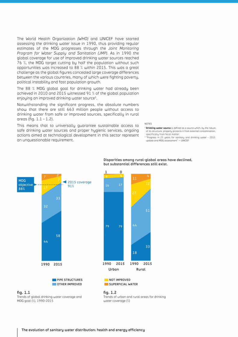
Notwithstanding the significant progress, the absolute numbers show that there are still 663 million people without access to drinking water from safe or improved sources, specifically in rural areas (fig. 1.1 - 1.2).
This means that to universally guarantee sustainable access to safe drinking water sources and proper hygienic services, ongoing actions aimed at technological development in this sector represent an unquestionable requirement.
fig. 1.1 Trends of global drinking water coverage and MDG goal (%), 1990-2015
fig. 1.2 Trends of urban and rural areas for drinking water coverage (%)
NOTES2 Drinking water source is defined as a source which, by the nature
of its structure, properly protects it from external contamination, specifically from fecal matter.
3 “Progress in 25 years for sanitary and drinking water - 2015 update and MDG assessment” – UNICEF
32
58
44
33
77
17
2
ACQUA SUPERFICIALE NON MIGLIORATA
ALTRA MIGLIORATASTRUTTURE CON TUBAZIONI
2015 coverage91%
41
411
12
27
51
44
18
33
04
1716
79 79
1990 2015 1990 2015
Urban
PIPE STRUCTURESOTHER IMPROVED
NOT IMPROVEDSUPERFICIAL WATER
Rural
Disparities among rural-global areas have declined, but substantial differences still exist.
1990 2015
MDG objective 88%
Chapter 112 - 13
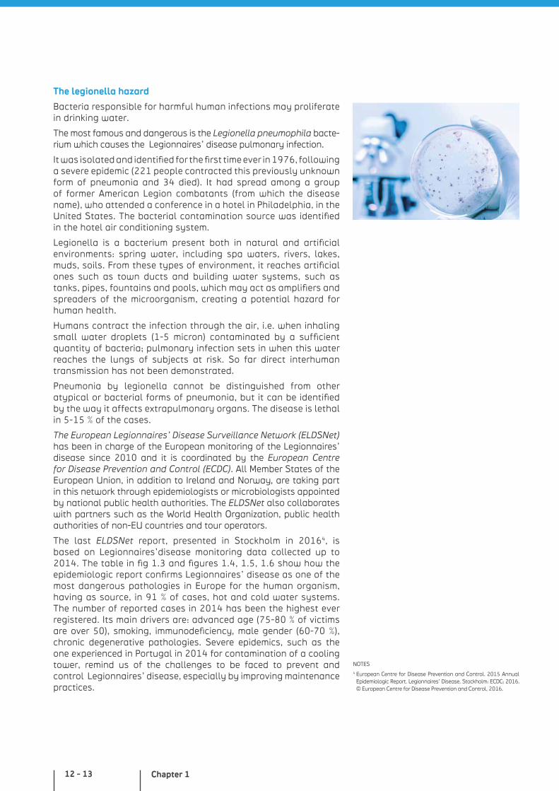
The legionella hazard
Bacteria responsible for harmful human infections may proliferate in drinking water.
The most famous and dangerous is the Legionella pneumophila bacte-rium which causes the Legionnaires’ disease pulmonary infection.
It was isolated and identified for the first time ever in 1976, following a severe epidemic (221 people contracted this previously unknown form of pneumonia and 34 died). It had spread among a group of former American Legion combatants (from which the disease name), who attended a conference in a hotel in Philadelphia, in the United States. The bacterial contamination source was identified in the hotel air conditioning system.
Legionella is a bacterium present both in natural and artificial environments: spring water, including spa waters, rivers, lakes, muds, soils. From these types of environment, it reaches artificial ones such as town ducts and building water systems, such as tanks, pipes, fountains and pools, which may act as amplifiers and spreaders of the microorganism, creating a potential hazard for human health.
Humans contract the infection through the air, i.e. when inhaling small water droplets (1-5 micron) contaminated by a sufficient quantity of bacteria; pulmonary infection sets in when this water reaches the lungs of subjects at risk. So far direct interhuman transmission has not been demonstrated.
Pneumonia by legionella cannot be distinguished from other atypical or bacterial forms of pneumonia, but it can be identified by the way it affects extrapulmonary organs. The disease is lethal in 5-15 % of the cases.
The European Legionnaires’ Disease Surveillance Network (ELDSNet) has been in charge of the European monitoring of the Legionnaires’ disease since 2010 and it is coordinated by the European Centre for Disease Prevention and Control (ECDC). All Member States of the European Union, in addition to Ireland and Norway, are taking part in this network through epidemiologists or microbiologists appointed by national public health authorities. The ELDSNet also collaborates with partners such as the World Health Organization, public health authorities of non-EU countries and tour operators.
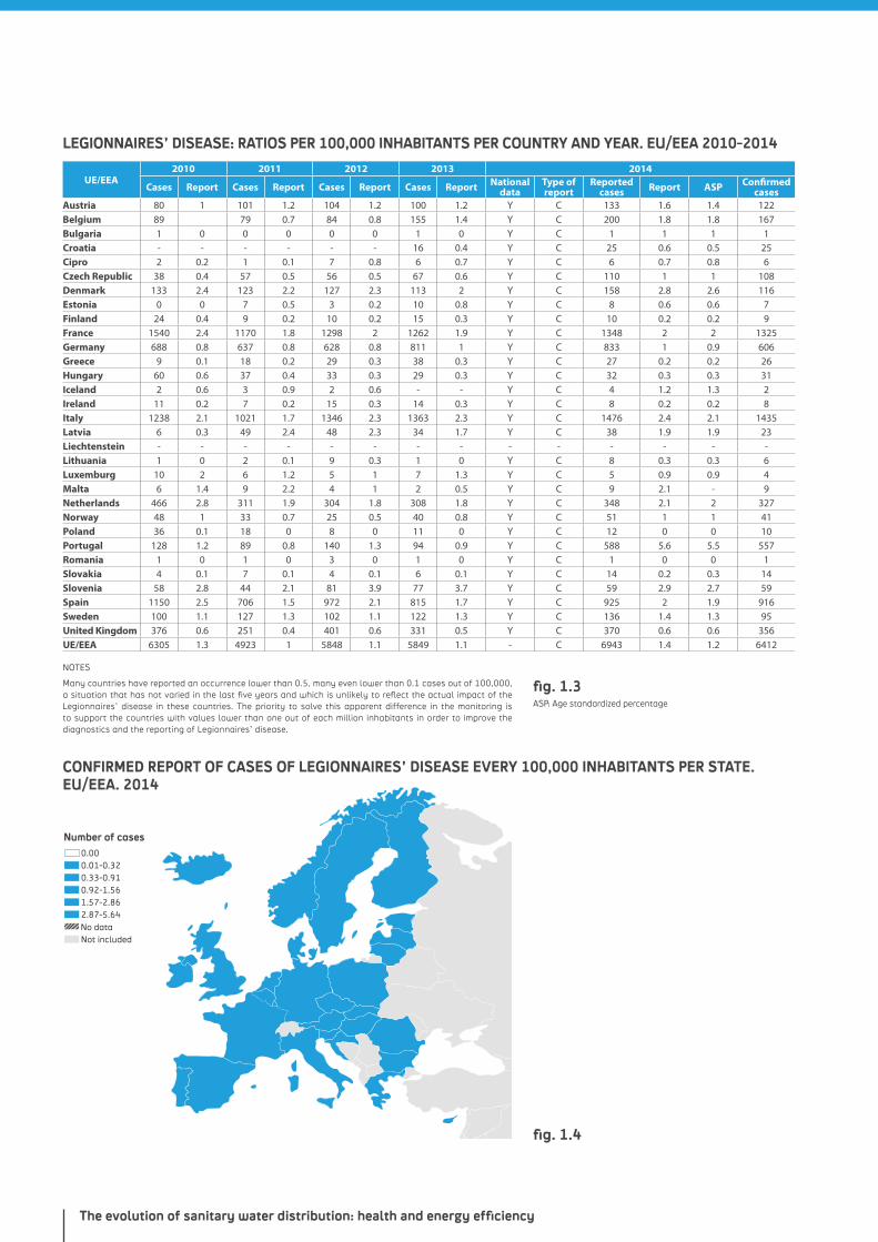
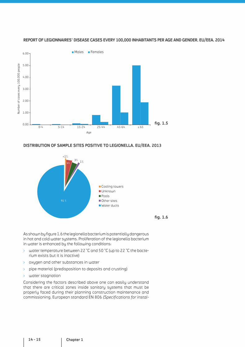
The last ELDSNet report, presented in Stockholm in 20164, is based on Legionnaires’disease monitoring data collected up to 2014. The table in fig 1.3 and figures 1.4, 1.5, 1.6 show how the epidemiologic report confirms Legionnaires’ disease as one of the most dangerous pathologies in Europe for the human organism, having as source, in 91 % of cases, hot and cold water systems. The number of reported cases in 2014 has been the highest ever registered. Its main drivers are: advanced age (75-80 % of victims are over 50), smoking, immunodeficiency, male gender (60-70 %), chronic degenerative pathologies. Severe epidemics, such as the one experienced in Portugal in 2014 for contamination of a cooling tower, remind us of the challenges to be faced to prevent and control Legionnaires’ disease, especially by improving maintenance practices.
NOTES4 European Centre for Disease Prevention and Control. 2015 Annual
Epidemiologic Report. Legionnaires’ Disease. Stockholm: ECDC; 2016. © European Centre for Disease Prevention and Control, 2016.
The evolution of sanitary water distribution: health and energy efficiency
NOTES
Many countries have reported an occurrence lower than 0.5, many even lower than 0.1 cases out of 100,000, a situation that has not varied in the last five years and which is unlikely to reflect the actual impact of the Legionnaires’ disease in these countries. The priority to solve this apparent difference in the monitoring is to support the countries with values lower than one out of each million inhabitants in order to improve the diagnostics and the reporting of Legionnaires’ disease.
0.00
Number of cases
0.01-0.320.33-0.910.92-1.561.57-2.862.87-5.64
Not includedNo data
ASP: Age standardized percentage
LEGIONNAIRES’ DISEASE: RATIOS PER 100,000 INHABITANTS PER COUNTRY AND YEAR. EU/EEA 2010-2014
CONFIRMED REPORT OF CASES OF LEGIONNAIRES’ DISEASE EVERY 100,000 INHABITANTS PER STATE. EU/EEA. 2014
fig. 1.4
fig. 1.3
UE/EEA2010 2011 2012 2013 2014
Cases Report Cases Report Cases Report Cases Report National data
Type of report
Reported cases Report ASP Confirmed
casesAustria 80 1 101 1.2 104 1.2 100 1.2 Y C 133 1.6 1.4 122Belgium 89 79 0.7 84 0.8 155 1.4 Y C 200 1.8 1.8 167Bulgaria 1 0 0 0 0 0 1 0 Y C 1 1 1 1Croatia - - - - - - 16 0.4 Y C 25 0.6 0.5 25Cipro 2 0.2 1 0.1 7 0.8 6 0.7 Y C 6 0.7 0.8 6Czech Republic 38 0.4 57 0.5 56 0.5 67 0.6 Y C 110 1 1 108Denmark 133 2.4 123 2.2 127 2.3 113 2 Y C 158 2.8 2.6 116Estonia 0 0 7 0.5 3 0.2 10 0.8 Y C 8 0.6 0.6 7Finland 24 0.4 9 0.2 10 0.2 15 0.3 Y C 10 0.2 0.2 9France 1540 2.4 1170 1.8 1298 2 1262 1.9 Y C 1348 2 2 1325Germany 688 0.8 637 0.8 628 0.8 811 1 Y C 833 1 0.9 606Greece 9 0.1 18 0.2 29 0.3 38 0.3 Y C 27 0.2 0.2 26Hungary 60 0.6 37 0.4 33 0.3 29 0.3 Y C 32 0.3 0.3 31Iceland 2 0.6 3 0.9 2 0.6 - - Y C 4 1.2 1.3 2Ireland 11 0.2 7 0.2 15 0.3 14 0.3 Y C 8 0.2 0.2 8Italy 1238 2.1 1021 1.7 1346 2.3 1363 2.3 Y C 1476 2.4 2.1 1435Latvia 6 0.3 49 2.4 48 2.3 34 1.7 Y C 38 1.9 1.9 23Liechtenstein - - - - - - - - - - - - - -Lithuania 1 0 2 0.1 9 0.3 1 0 Y C 8 0.3 0.3 6Luxemburg 10 2 6 1.2 5 1 7 1.3 Y C 5 0.9 0.9 4Malta 6 1.4 9 2.2 4 1 2 0.5 Y C 9 2.1 - 9Netherlands 466 2.8 311 1.9 304 1.8 308 1.8 Y C 348 2.1 2 327Norway 48 1 33 0.7 25 0.5 40 0.8 Y C 51 1 1 41Poland 36 0.1 18 0 8 0 11 0 Y C 12 0 0 10Portugal 128 1.2 89 0.8 140 1.3 94 0.9 Y C 588 5.6 5.5 557Romania 1 0 1 0 3 0 1 0 Y C 1 0 0 1Slovakia 4 0.1 7 0.1 4 0.1 6 0.1 Y C 14 0.2 0.3 14Slovenia 58 2.8 44 2.1 81 3.9 77 3.7 Y C 59 2.9 2.7 59Spain 1150 2.5 706 1.5 972 2.1 815 1.7 Y C 925 2 1.9 916Sweden 100 1.1 127 1.3 102 1.1 122 1.3 Y C 136 1.4 1.3 95United Kingdom 376 0.6 251 0.4 401 0.6 331 0.5 Y C 370 0.6 0.6 356UE/EEA 6305 1.3 4923 1 5848 1.1 5849 1.1 - C 6943 1.4 1.2 6412
Chapter 114 - 15
0.00
1.00
2.00
3.00
4.00
5.00
6.00
0-4 5-14 15-24 25-44 45-64 ≥ 65
Age
Num
ber
of c
ases
eve
ry 1
00
,00
0 p
eopl
e
Males Females
REPORT OF LEGIONNAIRES’ DISEASE CASES EVERY 100,000 INHABITANTS PER AGE AND GENDER. EU/EEA. 2014
DISTRIBUTION OF SAMPLE SITES POSITIVE TO LEGIONELLA. EU/EEA. 2013
As shown by figure 1.6 the legionella bacterium is potentially dangerous in hot and cold water systems. Proliferation of the legionella bacterium in water is enhanced by the following conditions:
water temperature between 22 °C and 50 °C (up to 22 °C the bacte-rium exists but it is inactive)
oxygen and other substances in water
pipe material (predisposition to deposits and crusting)
water stagnation
Considering the factors described above one can easily understand that there are critical zones inside sanitary systems that must be properly faced during their planning construction maintenance and commissioning. European standard EN 806 (Specifications for instal-
fig. 1.5
91 %
3% 1%4%
<1%
Cooling towersUnknown
PoolsOther sitesWater ducts
91 %
3% 1%4%
<1%
Cooling towersUnknown
PoolsOther sitesWater ducts
fig. 1.6
The evolution of sanitary water distribution: health and energy efficiency
NOTES5 For the simplified pipe sizing method, refer to the EN 806 European
standard (Specifications for installations inside buildings convey-ing water for human consumption), part 3 (Pipe sizing – Simplified method).
lations inside buildings conveying water for human consumption) 2 (Planning) and 5 (Operation and Maintenance) with regards to the legionella bacterium provides that every Member State must indicate the measures to be adopted to prevent proliferation of the bacte-rium. Basically specific actions are required to face the risk of Legionnaires’ disease mainly by:
carefully selecting the materials used to realize the installation and prevent the formation of biofilms and crusting
periodically heating water at a temperature higher than that of the bacteria proliferation value for boilers and pipes at risk (heating methods and temperatures must comply with the provisions of national law)
properly insulating hot and cold water pipes: max. cold water temperature 22 °C and min. hot water temperature 55 °C
preventing contact between water and air or accumulation in unsealed tanks
avoiding use of pipes with blind ends or without circulation
preventing stagnation by calculating the possible minimum dimensions of the pipes based on the required flow rates and the user’s habits. Planning with adequate diameters and avoiding excessive pipe lengths enables a reduction in water contents and in turn stagnation times, to enhance the user’s comfort while optimizing installation costs5
applying hot water recirculation
controlling the system at regular intervals to check its safety and performance
There are three disinfection procedures that can be adopted, for example in Germany, for the recovery of contaminated water systems:
thermal disinfection (at every delivery point for at least 3 minutes at a minimum of 70 °C)
chemical disinfection (for example by adding a sodium hypochlorite solution or other suitable chemical products)
UV irradiation (after cleaning and flushing the system)
PEX-b pipes: high resistance to chlorine
The use of chlorine-based disinfectants, increasingly popular as anti-bacterial actions, has corrosive effects on distribution systems.
PEX-b, a polymer used by Giacomini to manufacture water supply pipes, is highly recommended to face the increase of chlorine in drinking water and is therefore the best choice for sanitary installations.
Chapter 116 - 17
Lead, public enemy
The presence of lead in drinking water may affect consumers’ health. In fact, the scientific community agrees on a possible correlation between lead exposure and pathologic effects such as neurologic and behavioral disturbances, cardiovascular diseases, renal insufficiency, hypertension, reduced fertility and aborts, delayed sexual maturation and altered dental development. Fetuses, newborns and children up to 6 represent sensible subgroups. In the adult population, instead, individuals with kidney disorders and high blood pressure are more at risk.
Based on the toxicological risk evaluations given above, the WHO (World Health Organization) recommends as a collective health prevention action the implementation of measures aiming at reducing the total exposition to lead, especially for population sensitive groups6.
In rare cases, possible lead contamination of drinking water may be traced back to presence of the mineral in rocks and sediments in contact with the aquifer of origin. More generally, contamination is caused by transfer phenomena of the element from the materials of pipes, faucets and/or by release from welding, fittings or other materials that release lead in distribution systems. Transfer phenomena are generally driven by extended permanence of water inside the distribution network (stagnation) and by specific chemical-physical conditions of water which tend to favor dissolution of the element from the material to the watery means. More specifically, larger quantities of lead are released within the water system in piped water with poor acid contents characterized by a high presence of dissolved chloride and oxygen, high temperatures, low tenors of water hardness (softened water). There are proofs also indicating that the tendency to release lead in water by a contact material, with the other conditions unvaried, reduces with the material ageing.
The use of lead in pipes and other components of water networks, both of aqueducts and domestic distribution systems, was quite popular in many European countries in the past, and it drastically decreased starting from the Sixties. Currently, the use of lead in materials in contact with drinking water is strictly regulated from a normative stand point, to limit the risk of water contamination. As the provision of the Drinking Water Directive 98/83/CE and related enforcing decrees of the Member States, the lead limit parameter for faucet water is currently equal to 10 µg/liter.
Removal of lead in contact with drinking water represents the only viable and effective solution to eliminate the risk. Considering that, as already discussed above, the main cause of contamination is connected to transfer of the element from the network materials – especially those inside buildings – removal or mitigation of the risks on a long term provides for replacement of the entire or part of the water distribution system, a measure requiring heavy resources in terms of money and time. However, in case of construction renovation, it is strongly recommended to realize new sanitary installations with materials complying with the rules in force.
Once the system has been realized in compliance with law, its devices must be regularly cleaned as they may experience lead-content material deposits (for example, diffuser meshes or possible filters installed on the faucets).
NOTE6 Since 1970, in Europe various standards have been adopted to
remove lead from varnish, gasoline and materials in contact with food and water, thus achieving satisfying results in reducing exposition. It is however essential to contribute in the reduction of lead within the food chain, including drinking water.
IT’S A LEAD PIPE IF …
It produces a dull sound if beaten with a metal object
The bare pipe features an even grey color
Magnets do not stick to the pipe
The evolution of sanitary water distribution: health and energy efficiency
ENERGY-SAVING DHW PRODUCTION AND DISTRIBUTION
DHW production
Sanitary hot water production devices may be broken down into various categories, based on different criteria:
ISTANTANEOUS PRODUCTION / ACCUMULATION PRODUCTION
DHWInstantaneous DHW production systems produce hot water upon actual consumption, with a flow rate varying based on the installed power and temperature differential between hot and cold water.
DHW production systems with accumulation tanks instead produce and maintain a hot water reserve for differed use. Consequently, the hot water temperature can be considered constant, but the quantity of water that may be used at a specific time is limited by the tank content, the storing temperature and the re-provisioning method.
Examples: Gas-fired tankless water heatersGas-fired accumulation tanks
DIRECT HEATING / INDIRECT HEATING
In DHW production systems with direct heating, sanitary water and heat source are put into direct contact through the heat exchanger wall.
In DHW production systems with indirect heating, instead, sanitary water and heating source are separated by an intermediate means acting as exchanging heat transfer agent.
Examples:Gas boiler with Instantaneous DHW production Puffer with heat exchanger
DEDICATED DHW PRODUCTION / DHW AND HEATING PRODUCTION COMBINED
In dedicated DHW production systems, the heat generator is dedicated only to DHW.
In combined production systems, the generator task is to both feed the heating circuit and produce DHW, giving priority to the latter (to limit the energy factor of the device).
Examples:Instantaneous electric water heater Wall-mounted water heater with heat exchanger
Chapter 118 - 19
This type of schematization is purely theoretical, as there is an actual tendency to combine the different categories. The choice of a type of generator and its sizing depend on the actual usage needs and various conditions:
number of users and simultaneity factor
frequency of DHW use
type of dwelling (single-family house, multifamily house)
energy efficiency class of the building (for example, a passive house requires almost exclusively production of DHW)
availability of renewable energy sources
The planning choice, also in case of hot water systems, must always be oriented at enhancing comfort and energy efficiency.
DHW distribution
DHW distribution systems are broken down based on the type of dwelling unit installation:
individual or single-user systems. DHW production and distri-bution occur locally inside the single dwelling unit
collective or multiuser systems. DHW production occurs inside the boiler room and then distributed to the individual users through specific inlet points to the dwelling unit (modules)
combined collective or multiuser systems. The heating water production (primary circuit) is centralized, while DHW production occurs locally at the individual dwelling unit through proper heat exchangers inside specific inlet points to the dwelling unit (satellites)
Single-family residential units are obviously provided with individual production/distribution systems, while multifamily units (condominiums) may have both individual and collective systems.
To enjoy a greater efficiency of the building-installation and curb emissions, central heating is being used again in new multi-family constructions. Modules and satellites contain fuel consumption meters and volumetric meters to directly measure the consumptions of each dwelling unit.
In the multi-family installation field of application, the legislative orientation towards multiuser centralized systems is justified by overcoming the drawbacks typical of individual production:
higher costs for individual systems (multiple fuel and fume extraction devices)
individual generator sizing according to peak load, i.e. the DHW production power
intervention proliferation for periodical service and repairs
possible remote-heating connection failure
difficulties in opting for alternative energy sources (biomass, geothermal energy, thermal solar energy)
The evolution of sanitary water distribution: health and energy efficiency
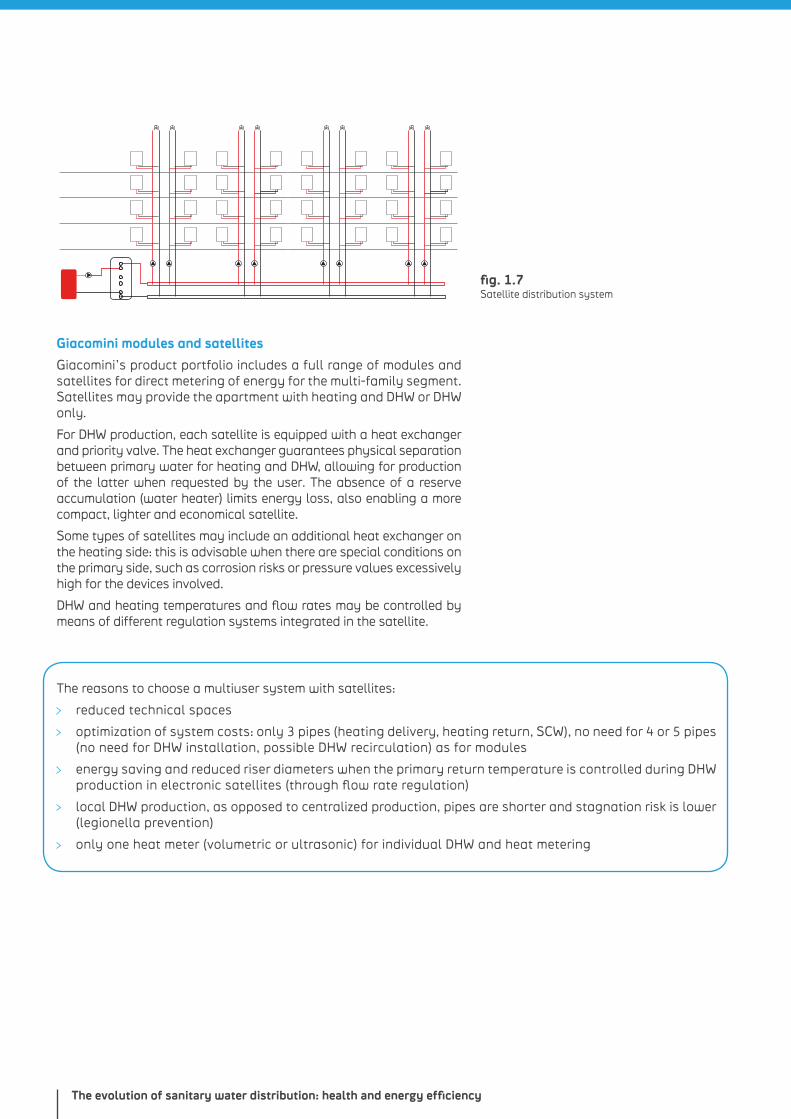
fig. 1.7 Satellite distribution system
Giacomini modules and satellites
Giacomini’s product portfolio includes a full range of modules and satellites for direct metering of energy for the multi-family segment. Satellites may provide the apartment with heating and DHW or DHW only.
For DHW production, each satellite is equipped with a heat exchanger and priority valve. The heat exchanger guarantees physical separation between primary water for heating and DHW, allowing for production of the latter when requested by the user. The absence of a reserve accumulation (water heater) limits energy loss, also enabling a more compact, lighter and economical satellite.
Some types of satellites may include an additional heat exchanger on the heating side: this is advisable when there are special conditions on the primary side, such as corrosion risks or pressure values excessively high for the devices involved.
DHW and heating temperatures and flow rates may be controlled by means of different regulation systems integrated in the satellite.
The reasons to choose a multiuser system with satellites:
reduced technical spaces
optimization of system costs: only 3 pipes (heating delivery, heating return, SCW), no need for 4 or 5 pipes (no need for DHW installation, possible DHW recirculation) as for modules
energy saving and reduced riser diameters when the primary return temperature is controlled during DHW production in electronic satellites (through flow rate regulation)
local DHW production, as opposed to centralized production, pipes are shorter and stagnation risk is lower (legionella prevention)
only one heat meter (volumetric or ultrasonic) for individual DHW and heat metering
Chapter 120 - 21
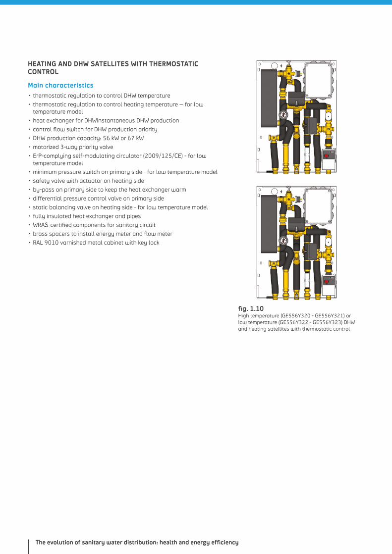
fig. 1.9 Heating and DHW satellites with electronic regulation (GE556Y401 and GE556Y402)
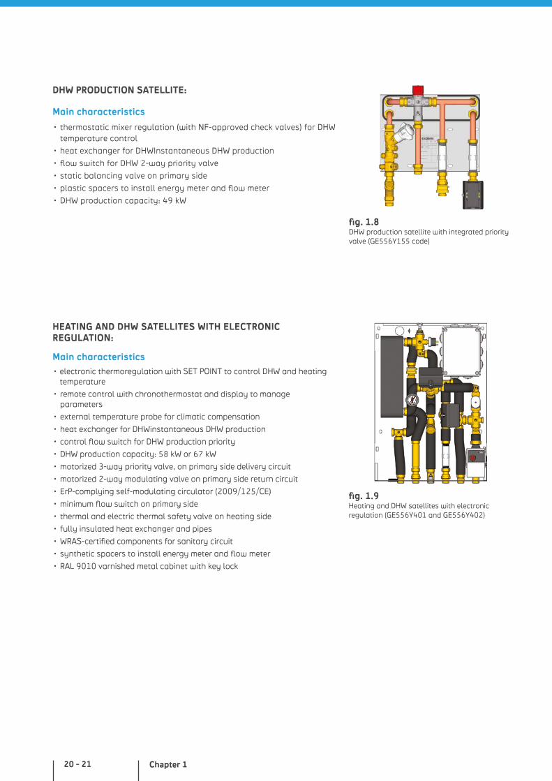
DHW PRODUCTION SATELLITE:
Main characteristics
• thermostatic mixer regulation (with NF-approved check valves) for DHW temperature control
• heat exchanger for DHWInstantaneous DHW production
• flow switch for DHW 2-way priority valve
• static balancing valve on primary side
• plastic spacers to install energy meter and flow meter
• DHW production capacity: 49 kW
HEATING AND DHW SATELLITES WITH ELECTRONIC REGULATION:
Main characteristics• electronic thermoregulation with SET POINT to control DHW and heating
temperature
• remote control with chronothermostat and display to manage parameters
• external temperature probe for climatic compensation
• heat exchanger for DHWinstantaneous DHW production
• control flow switch for DHW production priority
• DHW production capacity: 58 kW or 67 kW
• motorized 3-way priority valve, on primary side delivery circuit
• motorized 2-way modulating valve on primary side return circuit
• ErP-complying self-modulating circulator (2009/125/CE)
• minimum flow switch on primary side
• thermal and electric thermal safety valve on heating side
• fully insulated heat exchanger and pipes
• WRAS-certified components for sanitary circuit
• synthetic spacers to install energy meter and flow meter
• RAL 9010 varnished metal cabinet with key lock
fig. 1.8 DHW production satellite with integrated priority valve (GE556Y155 code)
The evolution of sanitary water distribution: health and energy efficiency
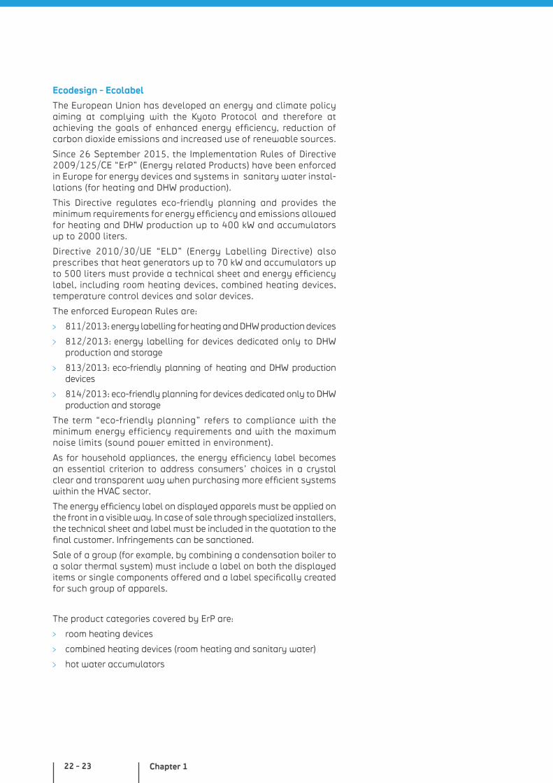
fig. 1.10 High temperature (GE556Y320 - GE556Y321) or low temperature (GE556Y322 - GE556Y323) DHW and heating satellites with thermostatic control
HEATING AND DHW SATELLITES WITH THERMOSTATIC CONTROL
Main characteristics• thermostatic regulation to control DHW temperature
• thermostatic regulation to control heating temperature – for low temperature model
• heat exchanger for DHWInstantaneous DHW production
• control flow switch for DHW production priority
• DHW production capacity: 56 kW or 67 kW
• motorized 3-way priority valve
• ErP-complying self-modulating circulator (2009/125/CE) - for low temperature model
• minimum pressure switch on primary side - for low temperature model
• safety valve with actuator on heating side
• by-pass on primary side to keep the heat exchanger warm
• differential pressure control valve on primary side
• static balancing valve on heating side - for low temperature model
• fully insulated heat exchanger and pipes
• WRAS-certified components for sanitary circuit
• brass spacers to install energy meter and flow meter
• RAL 9010 varnished metal cabinet with key lock
Chapter 122 - 23
Ecodesign - Ecolabel
The European Union has developed an energy and climate policy aiming at complying with the Kyoto Protocol and therefore at achieving the goals of enhanced energy efficiency, reduction of carbon dioxide emissions and increased use of renewable sources.
Since 26 September 2015, the Implementation Rules of Directive 2009/125/CE “ErP” (Energy related Products) have been enforced in Europe for energy devices and systems in sanitary water instal-lations (for heating and DHW production).
This Directive regulates eco-friendly planning and provides the minimum requirements for energy efficiency and emissions allowed for heating and DHW production up to 400 kW and accumulators up to 2000 liters.
Directive 2010/30/UE “ELD” (Energy Labelling Directive) also prescribes that heat generators up to 70 kW and accumulators up to 500 liters must provide a technical sheet and energy efficiency label, including room heating devices, combined heating devices, temperature control devices and solar devices.
The enforced European Rules are:
811/2013: energy labelling for heating and DHW production devices
812/2013: energy labelling for devices dedicated only to DHW production and storage
813/2013: eco-friendly planning of heating and DHW production devices
814/2013: eco-friendly planning for devices dedicated only to DHW production and storage
The term “eco-friendly planning” refers to compliance with the minimum energy efficiency requirements and with the maximum noise limits (sound power emitted in environment).
As for household appliances, the energy efficiency label becomes an essential criterion to address consumers’ choices in a crystal clear and transparent way when purchasing more efficient systems within the HVAC sector.
The energy efficiency label on displayed apparels must be applied on the front in a visible way. In case of sale through specialized installers, the technical sheet and label must be included in the quotation to the final customer. Infringements can be sanctioned.
Sale of a group (for example, by combining a condensation boiler to a solar thermal system) must include a label on both the displayed items or single components offered and a label specifically created for such group of apparels.
The product categories covered by ErP are:
room heating devices
combined heating devices (room heating and sanitary water)
hot water accumulators
The evolution of sanitary water distribution: health and energy efficiency
groups including room heating devices, combined heating devices, temperature control devices and solar devices
combined heating devices such as B1<30 kW as replacements in multi-family buildings
Not interested by the rule are:
biomass heating devices
gas, steam or air-powered heating systems
cogeneration devices starting from a 50 kW minimum electric power
room heating systems starting from 400 kW, hot water accumula-tors starting from 2000 liters
The energy efficiency label is applied on the product and on multiple product bundles.
For individual products, the current ErP label for room heating devices shows the energy efficiency class on a scale from A++ to G (for heat pumps up to D, while for accumulators from A to G). Starting from 2019 an additional limit will apply, from A+++ to G, for accumulators from A+ to G, while for low-temperature heat pumps the label will have to include information on the climate zone. Other values will also be included, such as sound performance and heating power.
Combined devices for room heating and sanitary water heating must include efficiency classes for both functions. This label is provided together with the technical documentation enclosed to the product. The distributor/concessionaire/retailer must apply the label on the displayed product.
Every quotation for product bundles must indicate the energy efficiency class. For such purpose, the label and technical sheet provided by the system promoter must be clearly visible. As opposed to product labels, system labels are not filled in by manufacturers of single products (system elements), but by the person defining the group of products that will be later installed. This may be, for example, the manufacturer himself who is offering the system, the retailer or the installer.
Supporting tools are available for those who need to create system labels, helping them to create and fill them in (ErP software available on the market).
Chapter 124 - 25
ENERGY LABELLING: OBLIGATIONS BY THE PARTIES INVOLVED
The Manufacturer:
• provides products complying to all requirements• provides product energy efficiency labels and technical sheets• provides energy efficiency labels of the system possibly promoted• provides support tools (documentation and information) to clients
The Retailer, Wholesaler or Installer:
• must display and offer to the clients products bearing energy efficiency labels• must generate and apply the system energy efficiency label
In this volume, considering its purposes, some information will be given as example for devices dedicated to sani-tary hot water production only and their storage tanks.
Apparels dedicated to sanitary hot water production only
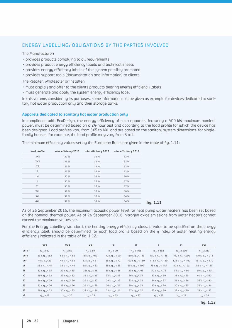
In compliance with EcoDesign, the energy efficiency of such apparels, featuring a 400 kW maximum nominal power, must be determined based on a 24-hour test and according to the load profile for which the device has been designed. Load profiles vary from 3XS to 4XL and are based on the sanitary system dimensions: for single-family houses, for example, the load profile may vary from S to L.
The minimum efficiency values set by the European Rules are given in the table of fig. 1.11:
load profile min. efficiency 2015 min. efficiency 2017 min. efficiency 2018
3XS 22 % 32 % 32 %
XXS 23 % 32 % 32 %
XS 26 % 32 % 32 %
S 26 % 32 % 32 %
M 30 % 36 % 36 %
L 30 % 37 % 37 %
XL 30 % 37 % 37 %
XXL 32 % 37 % 60 %
3XL 32 % 37 % 64 %
4XL 32 % 38 % 64 %
As of 26 September 2015, the maximum acoustic power level for heat pump water heaters has been set based on the nominal thermal power. As of 26 September 2018, nitrogen oxide emissions from water heaters cannot exceed the maximum values set.
For the Energy Labelling standard, the heating energy efficiency class, a value to be specified on the energy efficiency label, should be determined for each load profile based on the η index of water heating energy efficiency indicated in the table of fig. 1.12:
3XS XXS XS S M L XL XXL
A+++ ηwh
≥ 62 ηwh
≥ 62 ηwh
≥ 69 ηwh
≥ 90 ηwh
≥ 163 ηwh
≥ 188 ηwh
≥ 200 ηwh
≥ 213
A++ 53 ≤ ηwh
<62 53 ≤ ηwh
< 62 61≤ ηwh
<69 72 ≤ ηwh
< 90 130 ≤ ηwh
< 163 150 ≤ ηwh
< 188 160 ≤ ηwh
<200 170 ≤ ηwh
< 213
A+ 44 ≤ ηwh
<53 44 ≤ ηwh
< 53 53 ≤ ηwh
< 61 55 ≤ ηwh
< 72 100 ≤ ηwh
< 130 115 ≤ ηwh
< 150 123 ≤ ηwh
< 160 131 ≤ ηwh
< 170
A 35 ≤ ηwh
< 44 35 ≤ ηwh
< 44 38 ≤ ηwh
< 53 38 ≤ ηwh
< 55 65 ≤ ηwh
< 100 75 ≤ ηwh
< 115 80 ≤ ηwh
< 123 85 ≤ ηwh
< 131
B 32 ≤ ηwh
< 35 32 ≤ ηwh
< 35 35≤ ηwh
< 38 35 ≤ ηwh
< 38 39 ≤ ηwh
< 65 50 ≤ ηwh
< 75 55 ≤ ηwh
< 80 60 ≤ ηwh
< 85
C 29 ≤ ηwh
< 32 29 ≤ ηwh
< 32 32 ≤ ηwh
< 35 32 ≤ ηwh
< 35 36 ≤ ηwh
< 39 37 ≤ ηwh
< 50 38 ≤ ηwh
< 55 40 ≤ ηwh
< 60
D 26 ≤ ηwh
< 29 26 ≤ ηwh
< 29 29 ≤ ηwh
< 32 29 ≤ ηwh
< 32 33 ≤ ηwh
< 36 34 ≤ ηwh
< 37 35 ≤ ηwh
< 38 36 ≤ ηwh
< 40
E 22 ≤ ηwh
< 26 23 ≤ ηwh
< 26 26 ≤ ηwh
< 29 26 ≤ ηwh
< 29 30 ≤ ηwh
< 33 30 ≤ ηwh
< 34 30 ≤ ηwh
< 35 32 ≤ ηwh
< 36
F 19 ≤ ηwh
< 22 20 ≤ ηwh
< 23 23 ≤ ηwh
< 26 23 ≤ ηwh
< 26 27 ≤ ηwh
< 30 27 ≤ ηwh
< 30 27 ≤ ηwh
< 30 28 ≤ ηwh
< 32
G ηwh
≥ 19 ηwh
≥ 20 ηwh
≥ 23 ηwh
≥ 23 ηwh
≥ 27 ηwh
≥ 27 ηwh
≥ 27 ηwh
≥ 28
fig. 1.11
fig. 1.12
The evolution of sanitary water distribution: health and energy efficiency
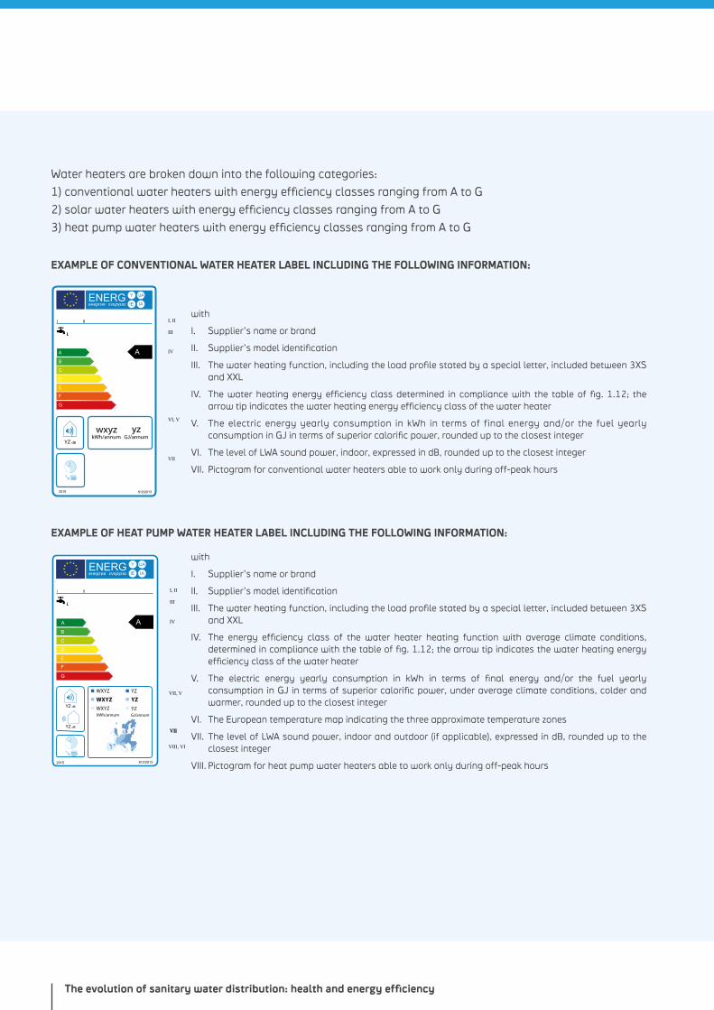
Water heaters are broken down into the following categories:
1) conventional water heaters with energy efficiency classes ranging from A to G
2) solar water heaters with energy efficiency classes ranging from A to G
3) heat pump water heaters with energy efficiency classes ranging from A to G
EXAMPLE OF CONVENTIONAL WATER HEATER LABEL INCLUDING THE FOLLOWING INFORMATION:
ENERG Y IJA
IAIEенергия ενεργεια
G
F
E
D
C
B
A A
YZ
wxyzkWh/annum GJ/annum
yzdB
2015 812/2013
IV
VI, V
VII
III
I, IIwith
I. Supplier’s name or brand
II. Supplier’s model identification
III. The water heating function, including the load profile stated by a special letter, included between 3XS and XXL
IV. The water heating energy efficiency class determined in compliance with the table of fig. 1.12; the arrow tip indicates the water heating energy efficiency class of the water heater
V. The electric energy yearly consumption in kWh in terms of final energy and/or the fuel yearly consumption in GJ in terms of superior calorific power, rounded up to the closest integer
VI. The level of LWA sound power, indoor, expressed in dB, rounded up to the closest integer
VII. Pictogram for conventional water heaters able to work only during off-peak hours
EXAMPLE OF HEAT PUMP WATER HEATER LABEL INCLUDING THE FOLLOWING INFORMATION:
YZ dB
YZ dB
ENERG Y IJA
IAIEенергия ενεργεια
G
F
E
D
C
B
A A IV
VII, V
VIIVII
VIII, VI
III
I, II
WXYZ
WXYZ YZ
YZ
WXYZ YZ
kWh/annum GJ/annum
2015 812/2013
with
I. Supplier’s name or brand
II. Supplier’s model identification
III. The water heating function, including the load profile stated by a special letter, included between 3XS and XXL
IV. The energy efficiency class of the water heater heating function with average climate conditions, determined in compliance with the table of fig. 1.12; the arrow tip indicates the water heating energy efficiency class of the water heater
V. The electric energy yearly consumption in kWh in terms of final energy and/or the fuel yearly consumption in GJ in terms of superior calorific power, under average climate conditions, colder and warmer, rounded up to the closest integer
VI. The European temperature map indicating the three approximate temperature zones
VII. The level of LWA sound power, indoor and outdoor (if applicable), expressed in dB, rounded up to the closest integer
VIII. Pictogram for heat pump water heaters able to work only during off-peak hours
Chapter 126 - 27
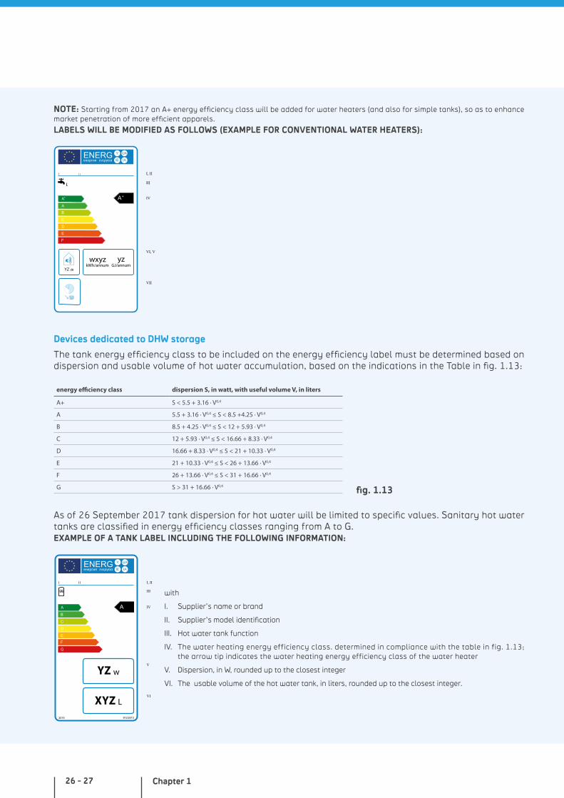
NOTE: Starting from 2017 an A+ energy efficiency class will be added for water heaters (and also for simple tanks), so as to enhance market penetration of more efficient apparels.
LABELS WILL BE MODIFIED AS FOLLOWS (EXAMPLE FOR CONVENTIONAL WATER HEATERS):
ENERG Y IJA
IAIEенергия ενεργεια
F
E
D
C
B
A
A++ A
YZ
wxyzkWh/annum GJ/annum
yzdB
IV
VI, V
VII
III
I, II
Devices dedicated to DHW storage
The tank energy efficiency class to be included on the energy efficiency label must be determined based on dispersion and usable volume of hot water accumulation, based on the indications in the Table in fig. 1.13:
energy efficiency class dispersion S, in watt, with useful volume V, in liters
A+ S < 5.5 + 3.16 ∙ V0,4
A 5.5 + 3.16 ∙ V0,4 ≤ S < 8.5 +4.25 ∙ V0,4
B 8.5 + 4.25 ∙ V0,4 ≤ S < 12 + 5.93 ∙ V0,4
C 12 + 5.93 ∙ V0,4 ≤ S < 16.66 + 8.33 ∙ V0,4
D 16.66 + 8.33 ∙ V0,4 ≤ S < 21 + 10.33 ∙ V0,4
E 21 + 10.33 ∙ V0,4 ≤ S < 26 + 13.66 ∙ V0,4
F 26 + 13.66 ∙ V0,4 ≤ S < 31 + 16.66 ∙ V0,4
G S > 31 + 16.66 ∙ V0,4
As of 26 September 2017 tank dispersion for hot water will be limited to specific values. Sanitary hot water tanks are classified in energy efficiency classes ranging from A to G. EXAMPLE OF A TANK LABEL INCLUDING THE FOLLOWING INFORMATION:
ENERG Y IJA
IAIEенергия ενεργεια
IV
V
VI
III
I, II
G
F
E
D
C
B
A A
XYZ
YZ
L
w
2015 812/2013
with
I. Supplier’s name or brand
II. Supplier’s model identification
III. Hot water tank function
IV. The water heating energy efficiency class. determined in compliance with the table in fig. 1.13; the arrow tip indicates the water heating energy efficiency class of the water heater
V. Dispersion, in W, rounded up to the closest integer
VI. The usable volume of the hot water tank, in liters, rounded up to the closest integer.
fig. 1.13
The evolution of sanitary water distribution: health and energy efficiency
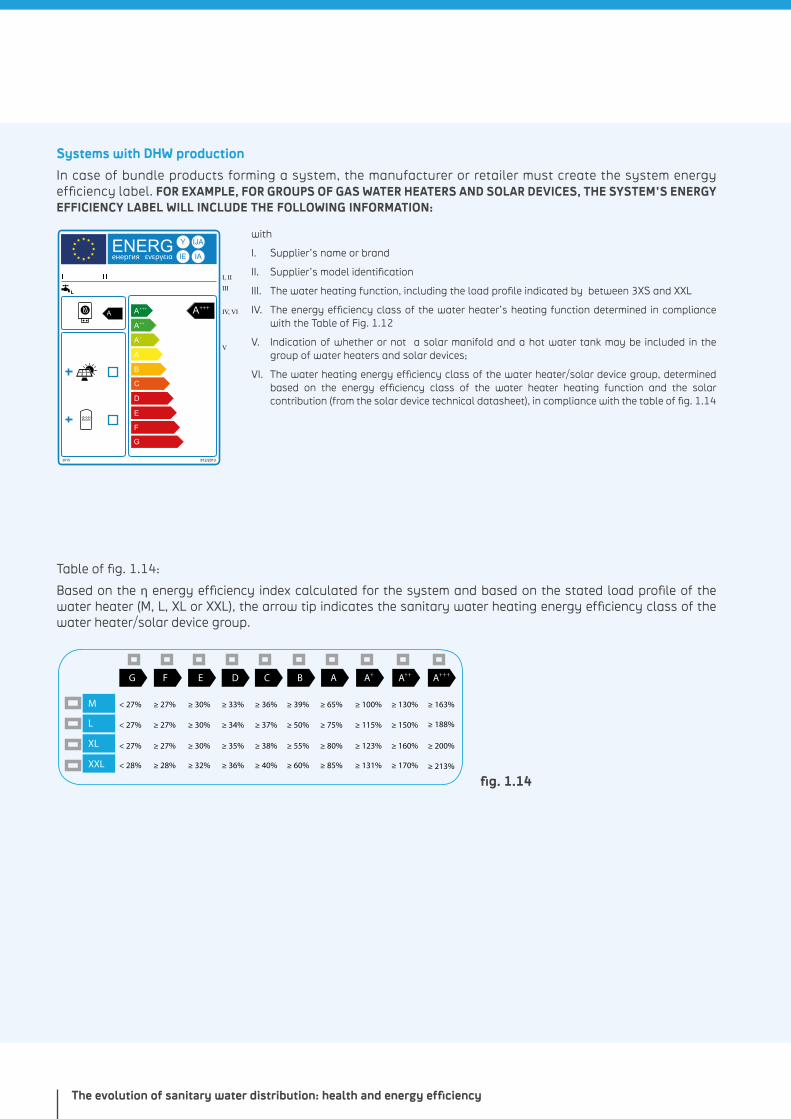
Systems with DHW production
In case of bundle products forming a system, the manufacturer or retailer must create the system energy efficiency label. FOR EXAMPLE, FOR GROUPS OF GAS WATER HEATERS AND SOLAR DEVICES, THE SYSTEM’S ENERGY EFFICIENCY LABEL WILL INCLUDE THE FOLLOWING INFORMATION:
Y IJA
IAIE
G
F
E
D
C
B
A
A
A
AA A
+
++
+++ +++
V
IV, VI
III
I, II
2015 812/2013
ENERGенергия ενεργεια
with
I. Supplier’s name or brand
II. Supplier’s model identification
III. The water heating function, including the load profile indicated by between 3XS and XXL
IV. The energy efficiency class of the water heater’s heating function determined in compliance with the Table of Fig. 1.12
V. Indication of whether or not a solar manifold and a hot water tank may be included in the group of water heaters and solar devices;
VI. The water heating energy efficiency class of the water heater/solar device group, determined based on the energy efficiency class of the water heater heating function and the solar contribution (from the solar device technical datasheet), in compliance with the table of fig. 1.14
Table of fig. 1.14:
Based on the η energy efficiency index calculated for the system and based on the stated load profile of the water heater (M, L, XL or XXL), the arrow tip indicates the sanitary water heating energy efficiency class of the water heater/solar device group.
++
< 27% ≥ 27% ≥ 30%
< 27% ≥ 27% ≥ 30%
< 27%
< 28%
≥ 27%
≥ 28%
≥ 30%
≥ 32%
≥ 33%
≥ 34%
≥ 35%
≥ 36%
≥ 36%
≥ 37%
≥ 38%
≥ 40%
≥ 39%
≥ 50%
≥ 55%
≥ 60%
≥ 65%
≥ 75%
≥ 80%
≥ 85%
≥ 100%
≥ 115%
≥ 123%
≥ 131%
≥ 130%
≥ 150%
≥ 160%
≥ 170%
≥ 163%
≥ 188%
≥ 200%
≥ 213%
M
L
XL
XXL
G F E D C B A A+ A ++ A+
fig. 1.14
Chapter 128 - 29
HEALTH PROTECTION STANDARDS
Drinking water directive - 98/83/EC (*)
On 3 November 1998 the European Council voted Council Directive 98/83/EC, better known as “Drinking Water Directive”, with the goal of protecting European citizens’ health from the harmful effects caused by water contamination.
The Directive text, with the latest amendments including Commission Directive (EU) 2015/1787 of 6 October 2015, is by now part of the European Union consolidated legislation.
The Drinking Water Directive is applied to:
all distribution systems serving more than 50 individuals or supplying more than 10 cubic meters per day, but also to distribution systems serving and supplying lower quantities if the provided water is part of a business activity
drinking water from tank trucks
drinking water in containers or bottled
water used in the food industry, except when competent national authorities are positive that water quality will not affect finished product integrity
The Directive sets the essential quality standards at EU level: a total of 48 microbiologic, chemical and indication parameters must be periodically monitored and tested. In general, the standards have been sketched starting from WHO drinking water guidelines and the Commission Scientific Advisory Committee.
Each member state may include additional requirements, such has more restrictive standards or rules regarding specific substances relevant in a given territory. However, member states may not set less restrictive standards, as the health protection level must be the same for the entire European Union.
At the time of this catalogue, the characteristics of drinking water are defined by the current legislation through Law Decrees No. 31 of 2 February 2001 and No. 27 of 2 February 2002, as defined by the Italian standard UNI 9182: 2014 “Hot and cold water supply and distribution installations – Design, installation and testing”.
The Directive includes various parts: planning, rules (Member States and Commission’s obligations), monitoring and information for the consumers.
Planning
Member States must define the water supply zones and suitable monitoring programs in compliance with the minimum requites set by the Directive.
NOTES(*) http://ec.europa.eu/environment/water/water-drink/legislation_
en.html
The evolution of sanitary water distribution: health and energy efficiency
Rules
Each EU Member State is required to acknowledge the Drinking Water Directive in its own legislation.
In short, each State must:
undertake every required action to guarantee that water is healthy and clean and that underno circumstance will the deterioration of water quality will be tolerate
guarantee that any non-compliance with the parameters will be investigated and corrected through specific measures in the shortest time possible
forbid/limit the use of said water supply, (should health protection reasons require it) and promptly inform consumers and offer advice
undertake all the required actions to guarantee, in case of specific materials in new installations, that no impurity associated to such materials remains in the drinking water
Monitoring
Member States must guarantee periodical quality monitoring to verify compliance with Drinking Water Directive requirements.
To comply with these requirements, the competent authorities will have to define specific monitoring programs. The Directive defines minimum requirements for these programs. Every three years, each Member State must publish a water quality report. The European Commission evaluates the results according to the standards and draws up a synthesis report to summarize drinking water quality and its improvements at a European level.
Information
The Directive provides for guaranteeing updated and adequate infor-mation on water quality. More specifically:
possible exemptions from application of the Directive
compliance with quality standards and monitoring requirements
corrective actions and usage restrictions in case of non-compli-ance with the defined parameters
Chapter 130 - 31
Practical implications for professional operators
European Directive 98/83/EC article covering materials and items possibly used in sanitary systems for drinking water concerns designers and installers directly.
Article 10 – Treatment, equipment and material quality warranty
Member States shall take all measures necessary to ensure that no substances or materials for new installations used in the prepara-tion or distribution of water intended for human consumption or impurities associated with such substances or materials for new installations remain in water intended for human consumption in concentrations higher than is necessary for the purpose of their use and do not, either directly or indirectly, reduce the protection of human health provided for in this Directive; the interpretative document and technical specifications pursuant to Article 3 and Article 4 (1) of Council Directive 89/106/EEC of 21 December 1988 on the approximation of laws, regulations and administrative provisions of the Member States relating to construction products (10) shall respect the requirements of this Directive.
In Italy, for example, article 10 has been implemented by Decree No. 174 of 6 April 2004 – Ministry of Health - “Regulation concerning materials and items that may be used in fixed plants for catchment, treatment, feeding and distribution for drinking water”, published in the Official Gazette no. 166 dated 17 July 2004 and enforced on 17 July 2007.
The collateral effect of having such European regulations normed by the single Member States is a lack of uniformity across European countries: this makes a transparent application of such articles quite complicated.
Some Member States have decided to collaborate to solve this issue by creating shared standards to accept materials and testing practices.
Observation:
The European Commission has appointed a consortium for this task. Its goal is to assess the possible revision, with special attention to the article appointing single states with the autonomous legislation on materials in contact with drinking water.
NOTES7 GU L 40 dell’11.2.1989, page 12. Directive amended from latest
version of Directive 93/68/CEE (GU L 220 del 30.8.1993, page 1).
The evolution of sanitary water distribution: health and energy efficiency
The 4MS initiative and the UBA list
1998 witnessed, together with the Drinking Water Directive, the definition of the European Acceptance Scheme (EAS), a framework for hygienic evaluation of products in contact with drinking water.
Its goal was to create a universal approval scheme for materials used for drinking water distribution, thus satisfying the growing awareness for protection of drinking water quality, from source to faucet. These works, originally carried out under the patronage of the European Commission, gradually lost their political power to the point of becoming a more generic and limited “harmonization” project of the Construction Product Directive, satisfying only in part the ambitious goals of the EAS.
In 2007 France, Germany, the Netherlands and UK, great supporters of the EAS ideas since its origin, decided autonomously to follow a common approach for product evaluation, with the firm intention to achieve the EAS hygiene safety goals within their borders. After many years of informal work, the four Member States (later referred to as the “4MS” group) made their cooperation official through a statement of purpose in January 2011 with the formalization of the agreements for the harmonization of the hygiene sustainability tests of products in contact with drinking water. The 4MS’ primary goal of guaranteeing the hygiene and safety of water in sanitation plants focused on the continuity of their efforts to actively achieve a European agreement.
Bases of the Common Approach
The 4MS intend to adopt common, or directly comparable, practices for:
acceptance of the components used for materials in contact with drinking water
material testing
adoption of common testing methods and acceptance levels
specification of product tests to apply
revision of factory quality assurance and laying down test requirements
assessment of certification capacity and testing organizations
The common approach goal is not to introduce a single assessment system working in the same identical way for every country: it rather defines a set of policies and practices that may be adopted within the national legal and institutional structures. The ultimate purpose is therefore to guarantee that the products are evaluated in a consistent way and with the same results, regardless of where the work is carried out.
Chapter 132 - 33
Component acceptance
Approval of the substances and materials used for products in contact with drinking water is obviously essential for the common approach.
The nature of the requirements will change based on the materials to be broken down into:
organic materials
metallic materials
cementitious materials
other materials
The approved materials will become part of a Positive List, which thus include substances admitted for products in contact with drinking water.
This catalogue will only discuss organic and metallic materials, i.e. the materials used by Giacomini to manufacture drinking water system components.
Organic materials
This category includes: monomers, other basic substances, additives, polymer production aids (PPA) and polymerization aids (PA). These are used to produce the organic material to (partially) manufacture a product which enters into contact with drinking water (for example, sealing components or gaskets, floats, diffuser heads, etc.).
The 4MS have compared their individual practices for substance assessment and their positive lists, also identifying the shared basic principles for their common approach. As it would have been impos-sible to entirely evaluate all substances on the various national lists, they decided to start with a Combined List (that is a consolidated list of all products included in the various national positive lists) which, following product assessment based on agreed approval criteria, will then become a Core List. This means that substances assessed in whole or substances which do not require further assessment will be included in the 4MS Core List. The Core List will become the future Positive List, it will be periodically updated and it will have to be inte-grated into the standards or guidelines of each Member State.
The Core List is not available yet. Its (re)evaluation is expected to take place between 2017 and 2022, with a transition period which will enable manufacturers to submit an application to include a substance in the Core List. The 4MS are also working on common testing requirements for organic materials.
In the meantime, for this category, Giacomini is exclusively using products complying with national laws of the countries where such products are sold.
Metallic materials
Pending a European acceptance scheme, the 4MS have collaborated in converging their national frameworks, defining the testing procedures and approving the metallic material composition.
The evolution of sanitary water distribution: health and energy efficiency
The document “Acceptance of Metallic Materials used for Products in Contact with Drinking Water” ratifies the provisions established by the 4MS.
In part A of the document (“Procedure for the acceptance”, 2nd revi-sion 03/07/2016), the 4MS have defined the acceptance concept for metallic materials for their national standards. The document is subject to revisions agreed by the 4MS.
Part B of the document (“4MS Common Composition List”, 6th Revision 05/27/2016) includes a Positive List of metallic materials accepted by all the 4MS, based on the procedure described in part A. This Positive List is often referred to as the UBA-list, from the name of the German organization Umwelt Bundesamt which represents Germany for the 4MS initiative. The list is now ready for implemen-tation on a national level in the 4MS. For certification or approval of products in contact with drinking water in the 4MS countries, the only requirement is guaranteeing the use of the metallic materials that are on the UBA-list.
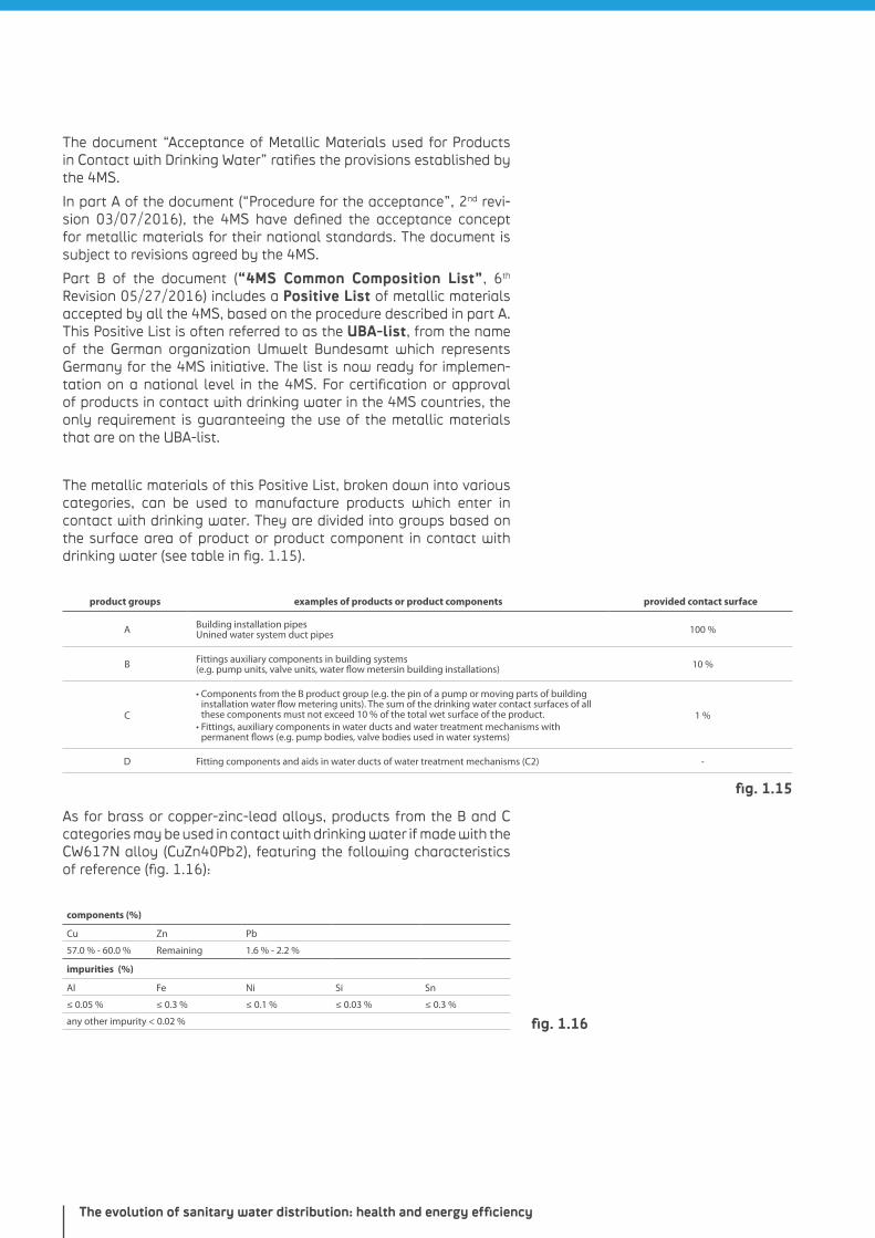
The metallic materials of this Positive List, broken down into various categories, can be used to manufacture products which enter in contact with drinking water. They are divided into groups based on the surface area of product or product component in contact with drinking water (see table in fig. 1.15).
product groups examples of products or product components provided contact surface
A Building installation pipesUnined water system duct pipes 100 %
B Fittings auxiliary components in building systems(e.g. pump units, valve units, water flow metersin building installations) 10 %
C
• Components from the B product group (e.g. the pin of a pump or moving parts of building installation water flow metering units). The sum of the drinking water contact surfaces of all these components must not exceed 10 % of the total wet surface of the product.
• Fittings, auxiliary components in water ducts and water treatment mechanisms with permanent flows (e.g. pump bodies, valve bodies used in water systems)
1 %
D Fitting components and aids in water ducts of water treatment mechanisms (C2) -
As for brass or copper-zinc-lead alloys, products from the B and C categories may be used in contact with drinking water if made with the CW617N alloy (CuZn40Pb2), featuring the following characteristics of reference (fig. 1.16):
components (%)
Cu Zn Pb
57.0 % - 60.0 % Remaining 1.6 % - 2.2 %
impurities (%)
Al Fe Ni Si Sn
≤ 0.05 % ≤ 0.3 % ≤ 0.1 % ≤ 0.03 % ≤ 0.3 %
any other impurity < 0.02 %
fig. 1.15
fig. 1.16
Chapter 134 - 35
The migration elements in drinking water to be monitored are Cu. Ni. Pb and Zn with special attention to Pb (between 1.6 % and 2.2 %) and Ni (≤0.1 %).
All Giacomini products intended for drinking water are part of the B and C groups and are manufactured with the CW617N alloy (CuZn40Pb2), which means that they can be used in sanitary systems in contact with drinking water.
Diffusion of the Common Approach
The 4MS are confident that their work will lead to a more widespread adoption of the Common Approach in Europe. This would offer tangible benefits in terms of the achievement of high-level standards for consumer protection with fewer tests required.
The other EU Member States can collaborate for this project in the following ways:
with “Full Group Membership” for Member States committing to adopt the Common Approach for their product assessment activities
as “Registered User” for the Member States which intend to adopt some or all of the Common Practices but do not wish to have full membership or do not have the requirements to obtain it
Harmonization within the EC
Development of the 4MS Common Approach is carried out in parallel with the revision of the practices throughout Europe to achieve “harmonization” in compliance with the “Construction Product Directive” and “Construction Product Standards” required to obtain the EC marking. The 4MS representatives are actively involved in the harmonization project, so much so that the 4MS Common Approach can be partially integrated in the harmonized practices.
Access to information
The 4MS are committed to the transparency of information related to the Common Approach implementation. Reports and documents on the progress of the 4MS initiative are posted on the website http://www.umweltbundesamt.de/en/node/13888.

The evolution of sanitary water distribution: health and energy efficiency
NOTES

Comfort, hygiene, practicality. Three fundamental criteria to choose the ideal system for your needs.
Chapter 2
Main types of distribution systems
Chapter 238 - 39
The type of cold and hot water system may vary based on the building where it is installed and the type of application. For a single-family house, “individual” distribution systems are the most popular, where DHW production and distribution are carried out inside the dwelling unit. As for multi-family dwellings, office buildings, sport centers, etc., “collective” distribution systems are generally used with centralized DHW production. It is not uncommon to combine both types.
This chapter will present an in-depth analyis of a few installation types that can be outlined as follows:
INDIVIDUAL SYSTEMS
Manifold installations
• connection to single inlet units • connection to single + double inlet units • closed-loop connection
Manifold-free installations
• derivation distribution (T-shaped outputs) • distribution in series • loop distribution
Individual installations with hot water recirculation risers
COLLECTIVE SYSTEMS
Collective systems with hot water recirculation risers
As described in Chapter 1, DHW production in collective systems may be realized centrally (module distribution) or locally (satellite distribution). The single-user systems will then feature an individual system layout.
Regardless of the selected distribution system, sanitary installa-tions should be realized based on economy and hygiene reasons so that:
• draw-off points used rarely are not integrated in a closed loop
• the main extraction point or flushing system is at the end of the section
• a hot water recirculation system is provided (and is practically mandatory for collective systems with centralized installation)
INTRODUCTION
Main types of distribution systems
MANIFOLD DISTRIBUTION SYSTEMS
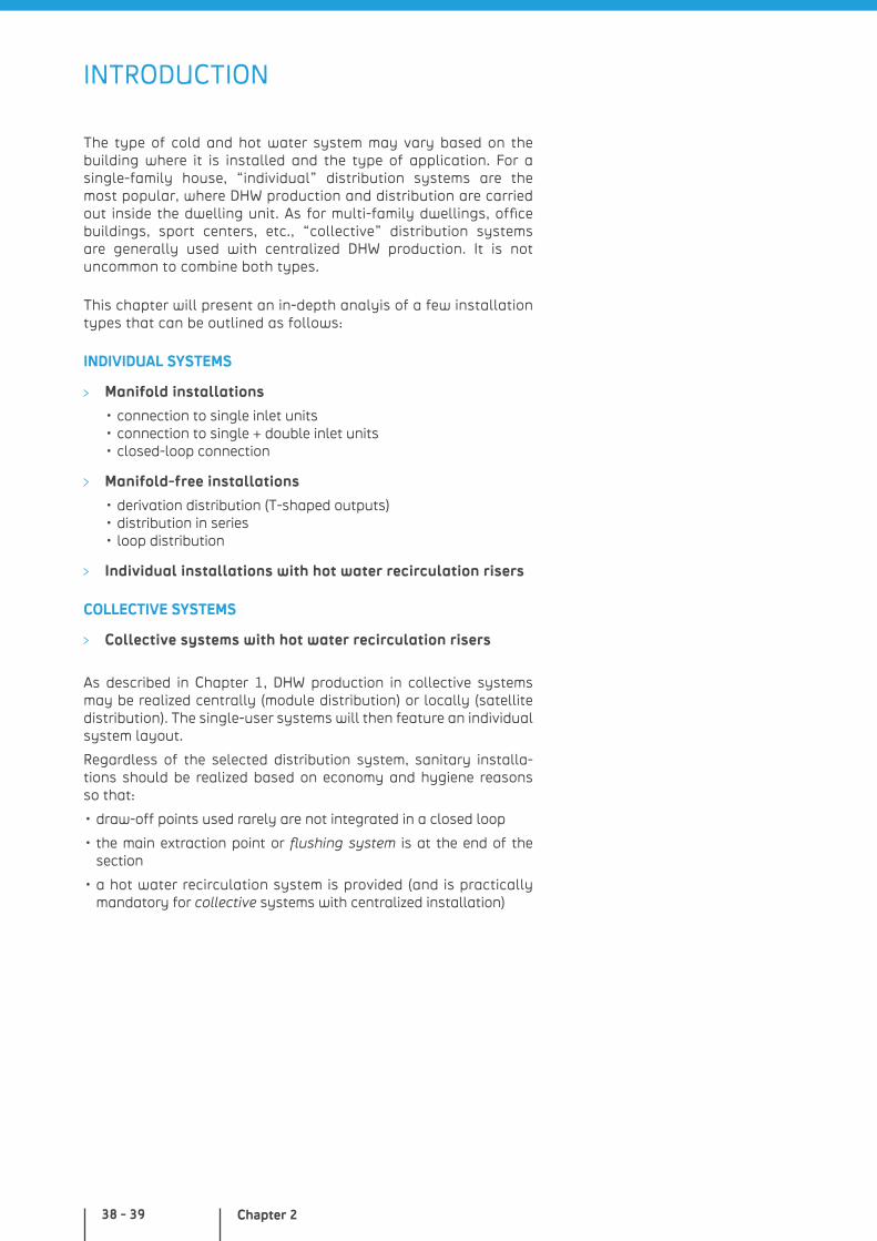
Single-unit connection
The manifold hydraulic system provides for installation of a distri-bution element (hydraulic manifold) in a special wall-mount cabinet which supplies all draw-off points of the hydraulic system. All draw-off points, both for hot and cold water, are connected indi-vidually to the manifold which is equipped with an interception valve for every single outlet. In this specific case, connection to the sanitary elements is obtained by using terminals (elbows with wall-mount bracket) with a single inlet. Water flows through the single pipe only when the draw-off point collects it.
The major benefit of this type of hydraulic system is the installation of whole pipes, i.e. in-wall connection-free pipes. In fact, the only featured connections are inside the cabinet where the manifold is installed and at the terminal.
Single + double terminal connection
This specific type of manifold system also requires using double inlet terminals (elbows with wall-mount bracket) for connection to hot-water elements: in case of draw-off points with high water flow rates (e.g. Jacuzzi tubs, large shower heads, etc.), the manifold and draw-off point are connected through two pipes.
All usage points, both for hot and cold water, are connected to the manifold separately. The water required by a draw-off point with high flow rates runs through both connection pipes and, in any case, only upon collection from the draw-off point.
WHY CHOOSE IT?
• reduced length of distribution circuits
• high comfort with reduced hot water availability times
• possibility to easily intercept draw-off points on the manifold
• suitable for removable systems with PEX-b pipes
WHY CHOOSE IT?
• suitable for draw-off points with high water flow rates
• reduced circuit length
• high comfort with reduced hot water availability times
• possibility to easily intercept draw-off points on the manifold
• suitable for removable systems with PEX-b pipes
Chapter 240 - 41
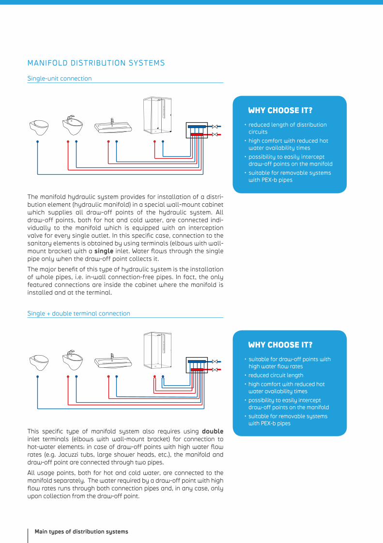
WHY CHOOSE IT?
• hygienically ideal because free of “dead” sections
• reduced risk of bacterial proliferation
• manifold with a reduced number of outputs
• suitable for removable systems with PEX-b pipes
WHY CHOOSE IT?
• ideal hygienic standards in case of frequent use
• easy to install
• less pipes with larger diameters and limited “off-cuts”
Closed-loop connection
The manifold hydraulic system with closed-loop connection provides for connection of all draw-off points through double inlet terminals (elbow fittings with wall-mount bracket).
This guarantees, for all connected draw-off points, high flow rates. In addition, it drastically limits the risk of bacterial proliferation as water flows through all feed pipes, even for unused draw-off points.
MANIFOLD-FREE DISTRIBUTION SYSTEMS
Derivation distribution (T-shaped outputs)
Hydraulic derivation systems provide for installation of a main pipe diverted at every draw-off point.
Derivations are obtained by means of T-shaped fittings. That is why they generally feature in-wall connections, which however, as opposed to manifold systems, cannot be accessed easily in case of maintenance of single draw-off points.
Terminals are of a single type (elbow fittings with wall-mount bracket).
Main types of distribution systems
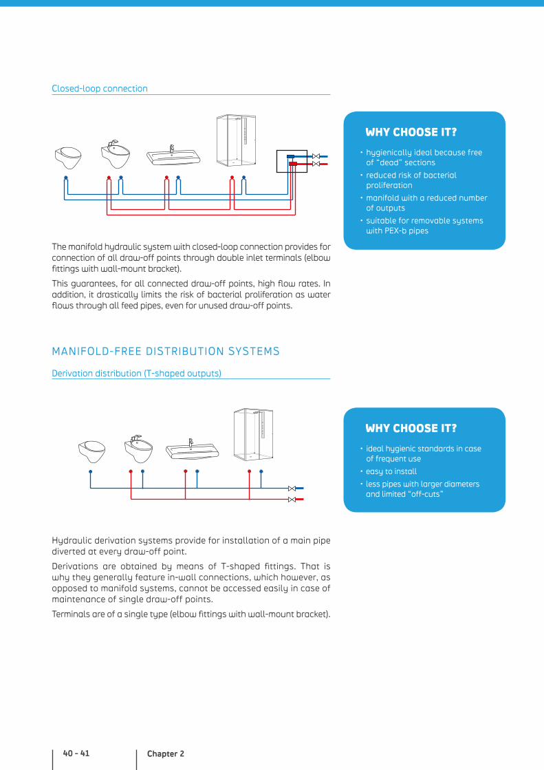
WHY CHOOSE IT?
• very reduced risk of bacterial proliferation
• regular water exchange
• fewer pipes
• rapid installation
• suitable for removable systems with PEX-b pipes
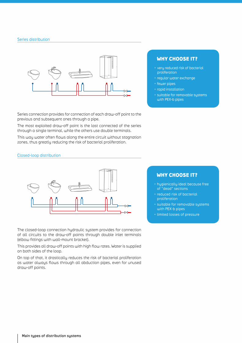
WHY CHOOSE IT?
• hygienically ideal because free of “dead” sections
• reduced risk of bacterial proliferation
• suitable for removable systems with PEX-b pipes
• limited losses of pressure
Series distribution
Series connection provides for connection of each draw-off point to the previous and subsequent ones through a pipe.
The most exploited draw-off point is the last connected of the series through a single terminal, while the others use double terminals.
This way water often flows along the entire circuit without stagnation zones, thus greatly reducing the risk of bacterial proliferation.
Closed-loop distribution
The closed-loop connection hydraulic system provides for connection of all circuits to the draw-off points through double inlet terminals (elbow fittings with wall-mount bracket).
This provides all draw-off points with high flow rates. Water is supplied on both sides of the loop.
On top of that, it drastically reduces the risk of bacterial proliferation as water always flows through all abduction pipes, even for unused draw-off points.
Chapter 242 - 43
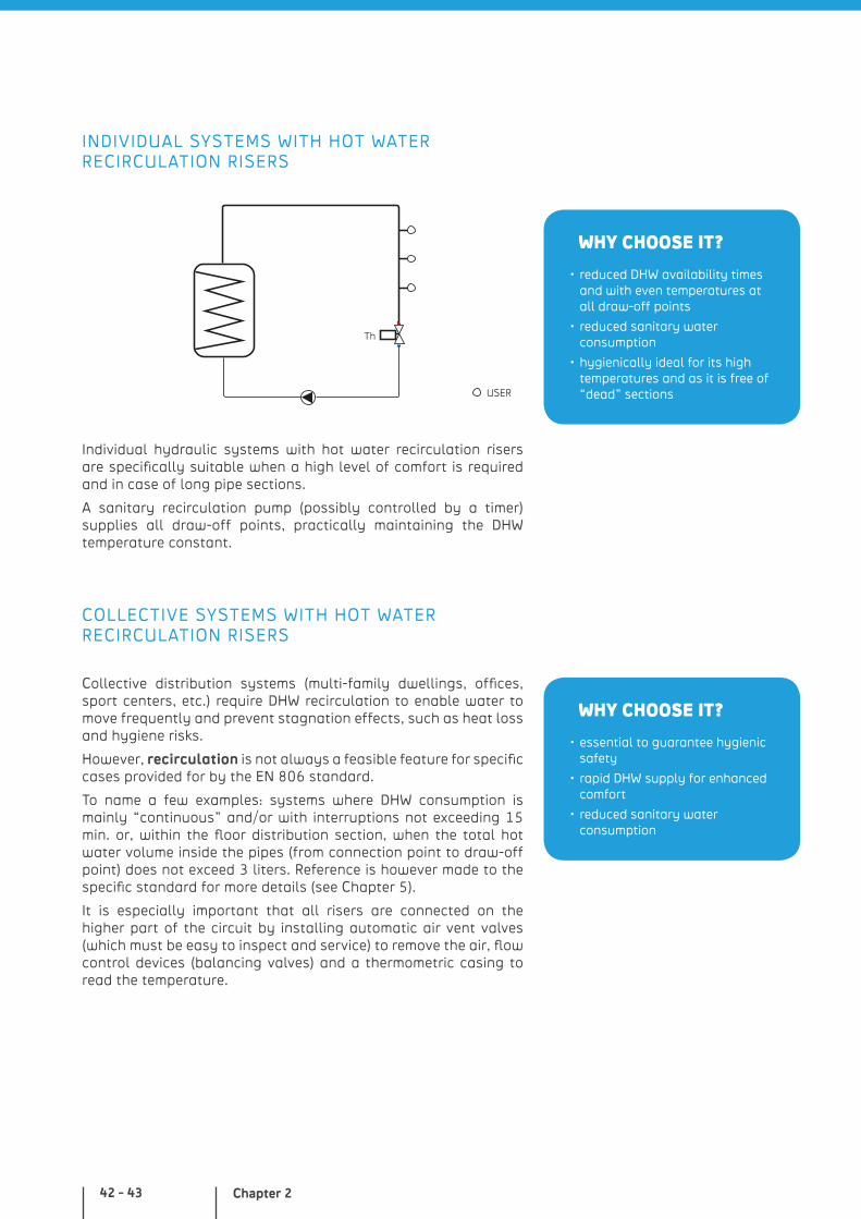
WHY CHOOSE IT?
• reduced DHW availability times and with even temperatures at all draw-off points
• reduced sanitary water consumption
• hygienically ideal for its high temperatures and as it is free of “dead” sections
WHY CHOOSE IT?
• essential to guarantee hygienic safety
• rapid DHW supply for enhanced comfort
• reduced sanitary water consumption
INDIVIDUAL SYSTEMS WITH HOT WATER RECIRCULATION RISERS
Th
Individual hydraulic systems with hot water recirculation risers are specifically suitable when a high level of comfort is required and in case of long pipe sections.
A sanitary recirculation pump (possibly controlled by a timer) supplies all draw-off points, practically maintaining the DHW temperature constant.
COLLECTIVE SYSTEMS WITH HOT WATER RECIRCULATION RISERS
Collective distribution systems (multi-family dwellings, offices, sport centers, etc.) require DHW recirculation to enable water to move frequently and prevent stagnation effects, such as heat loss and hygiene risks.
However, recirculation is not always a feasible feature for specific cases provided for by the EN 806 standard.
To name a few examples: systems where DHW consumption is mainly “continuous” and/or with interruptions not exceeding 15 min. or, within the floor distribution section, when the total hot water volume inside the pipes (from connection point to draw-off point) does not exceed 3 liters. Reference is however made to the specific standard for more details (see Chapter 5).
It is especially important that all risers are connected on the higher part of the circuit by installing automatic air vent valves (which must be easy to inspect and service) to remove the air, flow control devices (balancing valves) and a thermometric casing to read the temperature.
USER
Main types of distribution systems
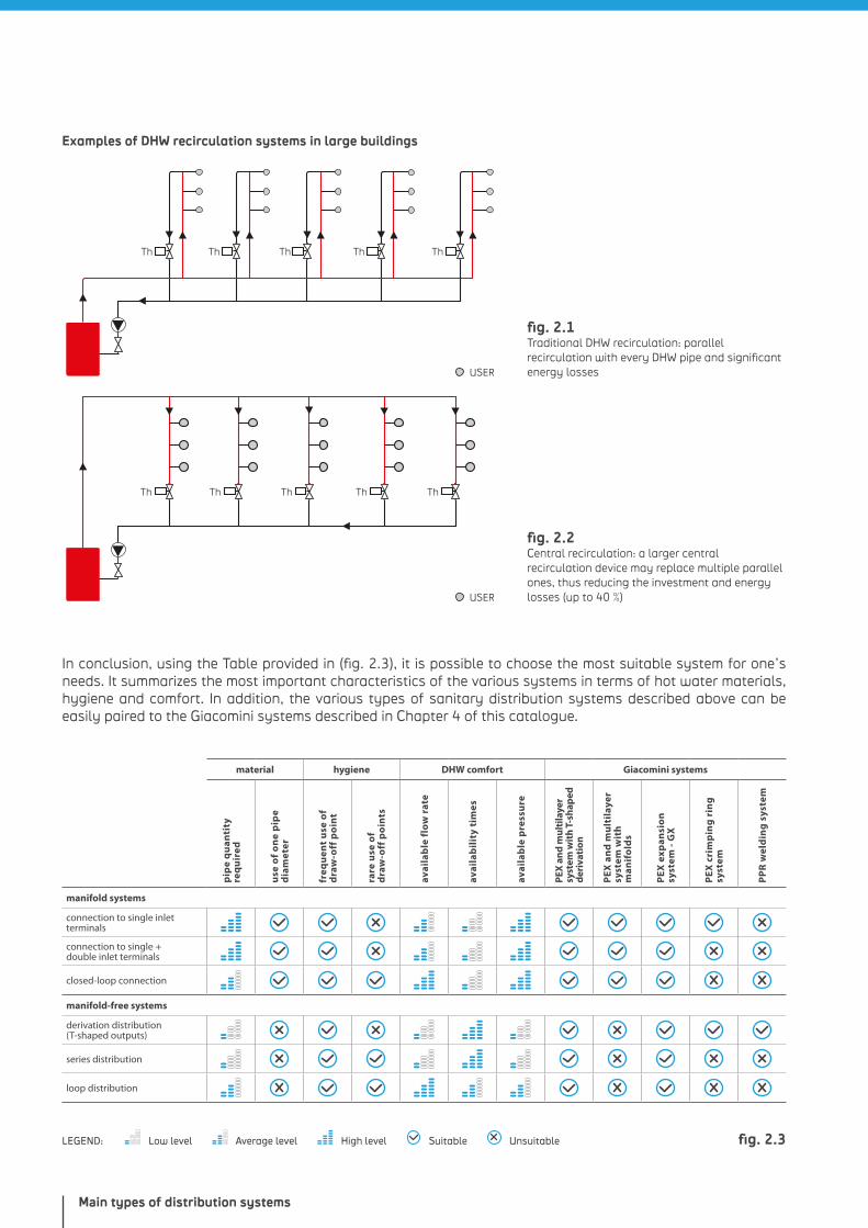
fig. 2.1 Traditional DHW recirculation: parallel recirculation with every DHW pipe and significant energy losses
fig. 2.2 Central recirculation: a larger central recirculation device may replace multiple parallel ones, thus reducing the investment and energy losses (up to 40 %)
Low level Average level High levelLEGEND: Suitable Unsuitable fig. 2.3
In conclusion, using the Table provided in (fig. 2.3), it is possible to choose the most suitable system for one’s needs. It summarizes the most important characteristics of the various systems in terms of hot water materials, hygiene and comfort. In addition, the various types of sanitary distribution systems described above can be easily paired to the Giacomini systems described in Chapter 4 of this catalogue.
Examples of DHW recirculation systems in large buildings
Th Th Th Th Th
Th Th Th ThTh
material hygiene DHW comfort Giacomini systems
pip
e q
uan
tity
re
qu
ired
use
of
on
e p
ipe
dia
met
er
freq
uen
t u
se o
f
dra
w-o
ff p
oin
t
rare
use
of
d
raw
-off
po
ints
avai
lab
le f
low
rat
e
avai
lab
ilit
y ti
mes
avai
lab
le p
ress
ure
PEX
an
d m
ulti
laye
r sy
stem
wit
h T
-sh
aped
d
eriv
atio
n
PEX
an
d m
ult
ilay
er
syst
em w
ith
m
anif
old
s
PEX
exp
ansi
on
sy
stem
- G
X
PEX
cri
mp
ing
rin
g
syst
em
PP
R w
eld
ing
sys
tem
manifold systems
connection to single inlet terminals
connection to single + double inlet terminals
closed-loop connection
manifold-free systems
derivation distribution (T-shaped outputs)
series distribution
loop distribution
USER
USER

The benefits of plastic: a material guaranteeing long-term resistance and installation versatility at reduced costs.
Chapter 3
Plastic pipes
Chapter 346 - 47
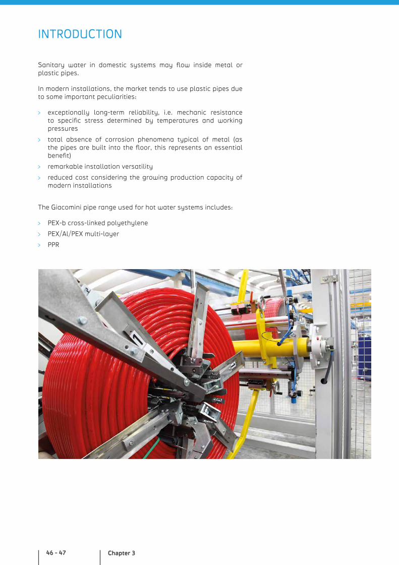
Sanitary water in domestic systems may flow inside metal or plastic pipes.
In modern installations, the market tends to use plastic pipes due to some important peculiarities:
exceptionally long-term reliability, i.e. mechanic resistance to specific stress determined by temperatures and working pressures
total absence of corrosion phenomena typical of metal (as the pipes are built into the floor, this represents an essential benefit)
remarkable installation versatility
reduced cost considering the growing production capacity of modern installations
The Giacomini pipe range used for hot water systems includes:
PEX-b cross-linked polyethylene
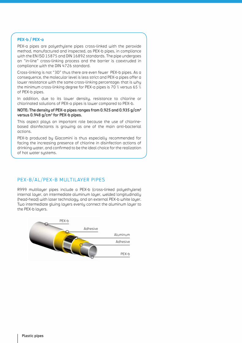
PEX/Al/PEX multi-layer
PPR
INTRODUCTION
Plastic pipes
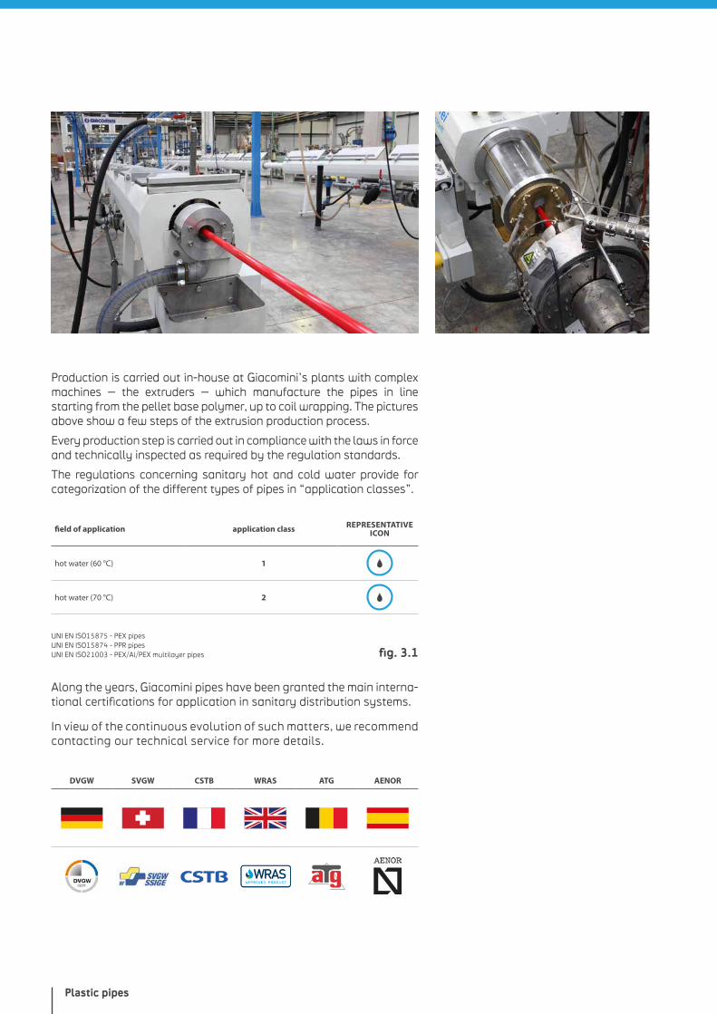
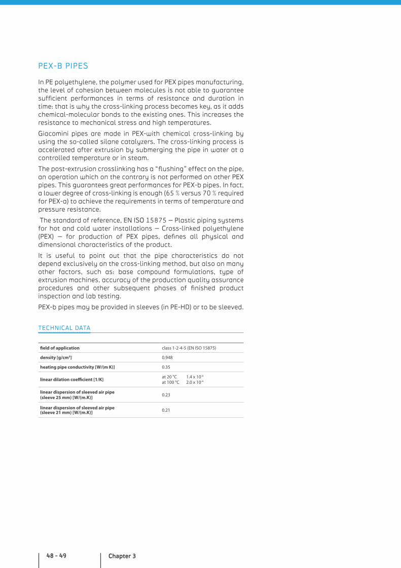
Production is carried out in-house at Giacomini’s plants with complex machines – the extruders – which manufacture the pipes in line starting from the pellet base polymer, up to coil wrapping. The pictures above show a few steps of the extrusion production process.
Every production step is carried out in compliance with the laws in force and technically inspected as required by the regulation standards.
The regulations concerning sanitary hot and cold water provide for categorization of the different types of pipes in “application classes”.
field of application application class REPRESENTATIVE ICON
hot water (60 °C) 1
hot water (70 °C) 2
UNI EN ISO15875 - PEX pipesUNI EN ISO15874 - PPR pipesUNI EN ISO21003 - PEX/Al/PEX multilayer pipes
Along the years, Giacomini pipes have been granted the main interna-tional certifications for application in sanitary distribution systems.
In view of the continuous evolution of such matters, we recommend contacting our technical service for more details.
DVGW SVGW CSTB WRAS ATG AENOR
fig. 3.1
Chapter 348 - 49
PEX-B PIPES
In PE polyethylene, the polymer used for PEX pipes manufacturing, the level of cohesion between molecules is not able to guarantee sufficient performances in terms of resistance and duration in time: that is why the cross-linking process becomes key, as it adds chemical-molecular bonds to the existing ones. This increases the resistance to mechanical stress and high temperatures.
Giacomini pipes are made in PEX-with chemical cross-linking by using the so-called silane catalyzers. The cross-linking process is accelerated after extrusion by submerging the pipe in water at a controlled temperature or in steam.
The post-extrusion crosslinking has a “flushing” effect on the pipe, an operation which on the contrary is not performed on other PEX pipes. This guarantees great performances for PEX-b pipes. In fact, a lower degree of cross-linking is enough (65 % versus 70 % required for PEX-a) to achieve the requirements in terms of temperature and pressure resistance.
The standard of reference, EN ISO 15875 – Plastic piping systems for hot and cold water installations – Cross-linked polyethylene (PEX) – for production of PEX pipes, defines all physical and dimensional characteristics of the product.
It is useful to point out that the pipe characteristics do not depend exclusively on the cross-linking method, but also on many other factors, such as: base compound formulations, type of extrusion machines, accuracy of the production quality assurance procedures and other subsequent phases of finished product inspection and lab testing.
PEX-b pipes may be provided in sleeves (in PE-HD) or to be sleeved.
TECHNICAL DATA
field of application class 1-2-4-5 (EN ISO 15875)
density [g/cm3] 0.948
heating pipe conductivity [W/(m K)] 0.35
linear dilation coefficient [1/K] at 20 °C 1.4 x 10⁻⁴
at 100 °C 2.0 x 10⁻⁴
linear dispersion of sleeved air pipe(sleeve 25 mm) [W/(m.K)] 0.23
linear dispersion of sleeved air pipe(sleeve 21 mm) [W/(m.K)] 0.21
Plastic pipes
PEX-b / PEX-a
PEX-a pipes are polyethylene pipes cross-linked with the peroxide method, manufactured and inspected, as PEX-b pipes, in compliance with the EN ISO 15875 and DIN 16892 standards. The pipe undergoes an “in-line” cross-linking process and the barrier is coextruded in compliance with the DIN 4726 standard.
Cross-linking is not “3D” thus there are even fewer PEX-b pipes. As a consequence, the molecular level is less strict and PEX-a pipes offer a lower resistance with the same cross-linking percentage: that is why the minimum cross-linking degree for PEX-a pipes is 70 % versus 65 % of PEX-b pipes.
In addition, due to its lower density, resistance to chlorine or chlorinated solutions of PEX-a pipes is lower compared to PEX-b.
NOTE: The density of PEX-a pipes ranges from 0.925 and 0.935 g/cm3 versus 0.948 g/cm3 for PEX-b pipes.
This aspect plays an important role because the use of chlorine-based disinfectants is growing as one of the main anti-bacterial actions.
PEX-b produced by Giacomini is thus especially recommended for facing the increasing presence of chlorine in disinfection actions of drinking water, and confirmed to be the ideal choice for the realization of hot water systems.
PEX-B/AL/PEX-B MULTILAYER PIPES
R999 multilayer pipes include a PEX-b (cross-linked polyethylene) internal layer, an intermediate aluminum layer, welded longitudinally (head-head) with laser technology, and an external PEX-b white layer. Two intermediate gluing layers evenly connect the aluminum layer to the PEX-b layers.
PEX-b
Adhesive
Aluminum
Adhesive
PEX-b
Chapter 350 - 51
The aluminum layer limits linear dilation of the pipe and guaran-tees a safe barrier against oxygen and other gases in addition to conferring exceptional product resistance to crushing. PEX-b/Al/PEX-b multilayer pipes are suitable for (hot and cold) drinking water conveying in compliance with the laws in force and for application in heating and cooling systems.
Multilayer pipes are also available as insulated pipes or may be provided sleeved (in PE-HD).
NOTE: Installations with PEX-b/Al/PEX-b pipes are not removable.
range of use class 1-2-4-5 (UNI EN ISO 21003)
linear dilation coefficient [1/K] at 20 °C 2.4x10⁻⁵
pipe thermal conductivity [W/(m K)] 0.40
insulation thermal conductivity [W/(m K)] 0.040
insulation fire reaction Class 1, in compliance with Ministerial Decree. 26/06/84
insulation fire reaction Euroclass E, in compliance with EN 1350-1
TECHNICAL DATA
PPR PIPES
The raw material used is polypropylene (PP), is obtained through random polymerization and is also known as PPR.
The technical characteristics of the material make it ideal for the realization of systems conveying drinking water, even when very calcareous.
Among the main benefits that PPR shares with other plastic pipes are: extended duration, thanks to its superior resistance to aggres-sive agents, no perforations caused by stray currents which the material does not transmit as it is a bad electric conductor, reduced pressure drops and much less surface roughness.
The PPR used by Giacomini for its system, already known by the conventional name Giacogreen, is PPR TYPE3 100 which, compared to the previous version 80, guarantees – with the same thickness values – better performances, especially in terms of long-term mechanical resistance.
field of application class 1-2-4-5 (EN ISO 15874)
density [g/cm3] 0.905
pipe thermal conductivity [W/(m K)] 0.24
linear dilation coefficient [1/K] at 20 °C 1.5x10⁻⁴
TECHNICAL DATA
Plastic pipes
GIACOMINI PIPE STORAGE PRECAUTIONS
To guarantee use of the pipes in compliance with the best quality standards, a few simple but essential precautions are required when storing them in the various warehouses of the distribution chain:
store the pipe in roofed and dry areas to prevent humidity from damaging the package
pipe piles should not exceed 1 m of height and this must be kept into consideration also during transportation (PPR only)
keep the pipe packed to preventexposure to direct sunlight
take special care during transportation and installation
prevent contact of the pipe with sharp objects that may scratch and perforate it
prevent formation of ice as dilations due to a change of status may damage the pipe
prevent contact of the pipe with open flames
prevent contact of the pipe with chemical solvents or paints
STANDARDS OF REFERENCE
The main standards of reference for the distribution systems discussed in the next chapter are summarized below:
Systems with T-shaped fittings and manifold systems:
EN ISO 15875 – Plastic pipe systems for hot and cold water installations – Cross-linked polyethylene (PEX)
DIN 16892 – Cross-linked high density polyethylene (PEX) pipe systems – General quality and testing requirements
UNI EN ISO 21003 – Multilayer pipe systems for hot and cold water installations inside buildings
EN 1254-3 – Copper and copper alloys – Hydraulic fittings – Fittings for plastic pipes with compression terminal
EN 1254-4 – Copper and copper alloys – Hydraulic fittings – Fittings combining other connection terminals with capillary or compression terminals
EN 12165 and DIN 50930-6 – Classification standards applied to brass (CW617N)
PEX expansion system - GX:
EN ISO 15875 Plastic pipe systems for hot and cold water installations – Cross-linked polyethylene (PEX)
DIN 16892 Plastic pipe systems – Technical requirements
DIN 4726 Plastic pipe systems - Technical requirements
EN 12165 and DIN 50930-6 - Classification standards applied to brass (CW617N)
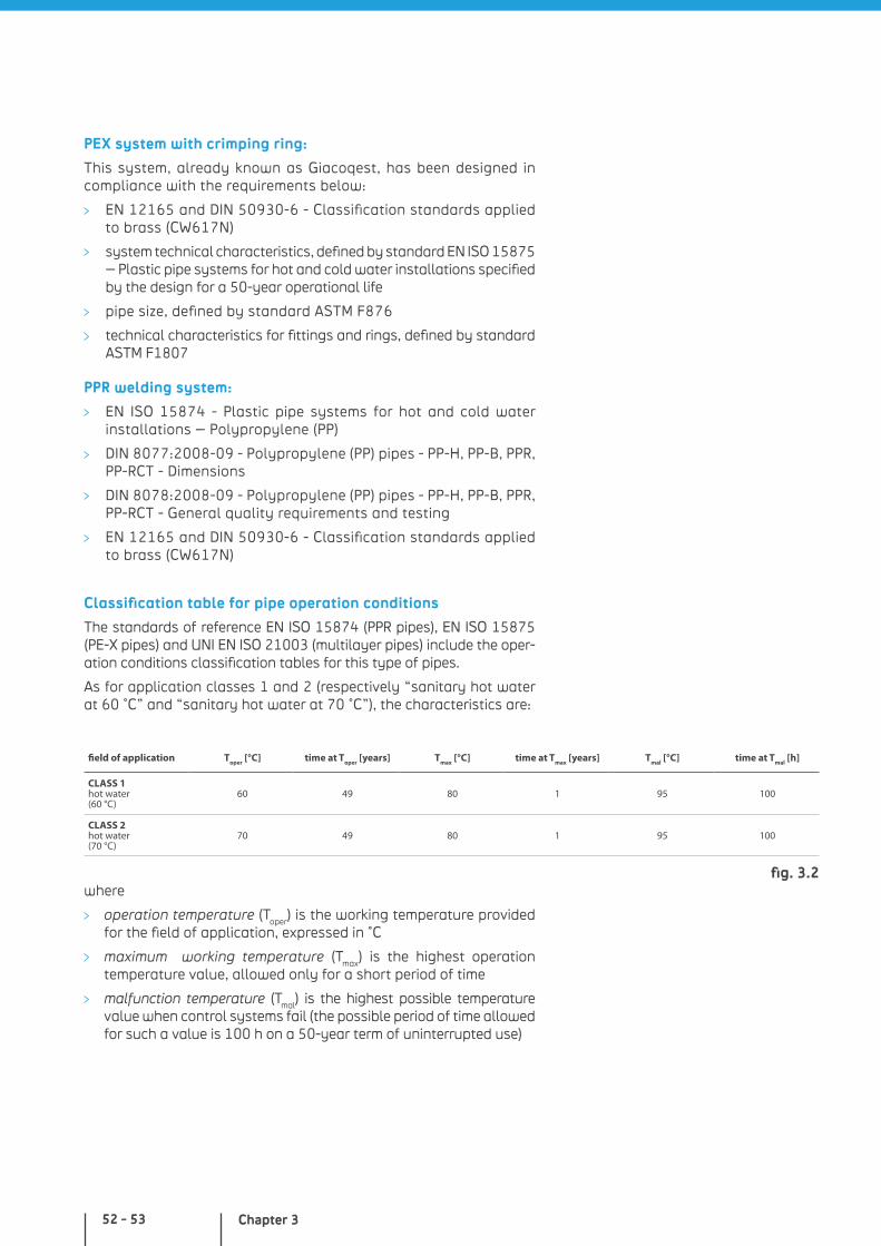
Chapter 352 - 53
PEX system with crimping ring:
This system, already known as Giacoqest, has been designed in compliance with the requirements below:
EN 12165 and DIN 50930-6 - Classification standards applied to brass (CW617N)
system technical characteristics, defined by standard EN ISO 15875 – Plastic pipe systems for hot and cold water installations specified by the design for a 50-year operational life
pipe size, defined by standard ASTM F876
technical characteristics for fittings and rings, defined by standard ASTM F1807
PPR welding system:
EN ISO 15874 - Plastic pipe systems for hot and cold water installations – Polypropylene (PP)
DIN 8077:2008-09 - Polypropylene (PP) pipes - PP-H, PP-B, PPR, PP-RCT - Dimensions
DIN 8078:2008-09 - Polypropylene (PP) pipes - PP-H, PP-B, PPR, PP-RCT - General quality requirements and testing
EN 12165 and DIN 50930-6 - Classification standards applied to brass (CW617N)
Classification table for pipe operation conditions
The standards of reference EN ISO 15874 (PPR pipes), EN ISO 15875 (PE-X pipes) and UNI EN ISO 21003 (multilayer pipes) include the oper-ation conditions classification tables for this type of pipes.
As for application classes 1 and 2 (respectively “sanitary hot water at 60 °C” and “sanitary hot water at 70 °C”), the characteristics are:
field of application Toper [°C] time at Toper [years] Tmax [°C] time at Tmax [years] Tmal [°C] time at Tmal [h]
CLASS 1hot water(60 °C)
60 49 80 1 95 100
CLASS 2hot water(70 °C)
70 49 80 1 95 100
fig. 3.2where
operation temperature (Toper) is the working temperature provided for the field of application, expressed in °C
maximum working temperature (Tmax) is the highest operation temperature value, allowed only for a short period of time
malfunction temperature (Tmal) is the highest possible temperature value when control systems fail (the possible period of time allowed for such a value is 100 h on a 50-year term of uninterrupted use)

Plastic pipes
All pipes are suitable for water conveying for a period of 50 years at working temperature corresponding to the range of use and an operation pressure of 10 bar. An exception is made for PPR for which, with reference to category 2, the operation pressure is 8 bar.
In addition, all pipes are suitable for water conveying for a period of 50 years at a temperature of 20 °C and a working pressure of 10 bar.
NOTES

Competence, reliability, cutting-edge materials for state-of-the art water distribution in new constructions and building renovations.

Chapter 4
Giacomini Systems

PEX AND MULTILAYER SYSTEM, WITH T-SHAPED DERIVATIONS
WHY CHOOSE IT?
• multilayer and/or PEX-b pipes
• press and compression fittings
• press fitting multitongs
• components complying with major standards of reference
• PEX-b pipes with reduced roughness and chlorine-resistance
more details at giacomini.com

INTRODUCTION
Giacomini press and compression fittings with adapter are designed for use with hot and cold water distribution for sanitary and heating systems.
They feature a dual-pipe and fitting system: the first includes multilayer pipes and press or compression fittings with adapter.
The second includes PEX-b pipes and compression fittings with adapter.
The fitting range width allows to solve any on-site problem caused by space limits, technical or economic preferences by using PEX-b or multilayer pipes.
The production of every system component guarantees a totally non-toxic product, suitable for hot water distribution, as required by the European Directive 98/83/CE for drinking water quality.
MULTILAYER PIPE
RM PRESS FITTINGS
COMPRESSION FITTINGS
SYSTEM COMPONENTS
PEX-b PIPE WITH SLEEVE
PRESS FITTING PRESS MACHINE AND TONGS
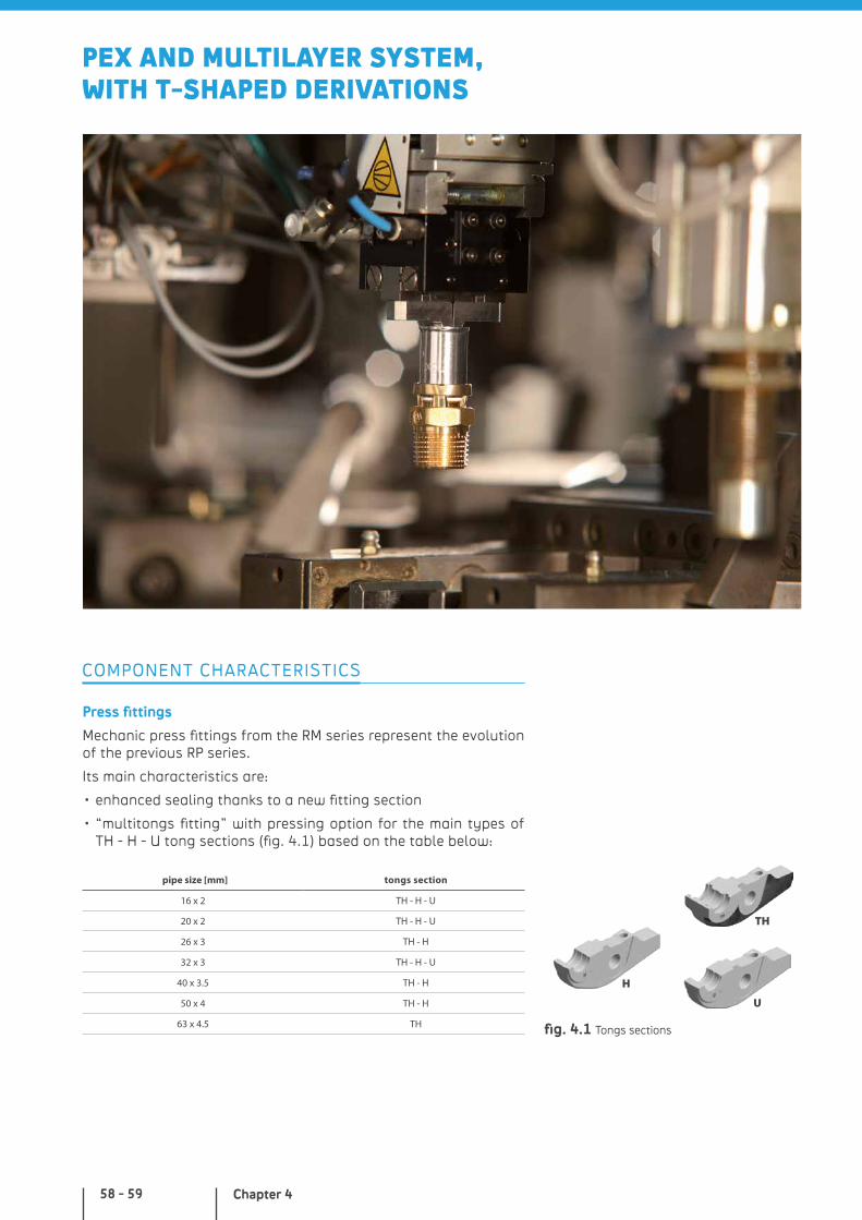
Chapter 458 - 59
Press fittings
Mechanic press fittings from the RM series represent the evolution of the previous RP series.
Its main characteristics are:
• enhanced sealing thanks to a new fitting section
• “multitongs fitting” with pressing option for the main types of TH - H - U tong sections (fig. 4.1) based on the table below:
pipe size [mm] tongs section
16 x 2 TH - H - U
20 x 2 TH - H - U
26 x 3 TH - H
32 x 3 TH - H - U
40 x 3.5 TH - H
50 x 4 TH - H
63 x 4.5 TH
COMPONENT CHARACTERISTICS
fig. 4.1 Tongs sections
H
U
TH
PEX AND MULTILAYER SYSTEM, WITH T-SHAPED DERIVATIONS
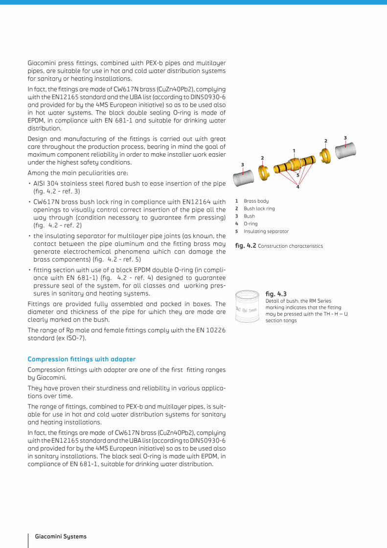
Giacomini Systems
Giacomini press fittings, combined with PEX-b pipes and multilayer pipes, are suitable for use in hot and cold water distribution systems for sanitary or heating installations.
In fact, the fittings are made of CW617N brass (CuZn40Pb2), complying with the EN12165 standard and the UBA list (according to DIN50930-6 and provided for by the 4MS European initiative) so as to be used also in hot water systems. The black double sealing O-ring is made of EPDM, in compliance with EN 681-1 and suitable for drinking water distribution.
Design and manufacturing of the fittings is carried out with great care throughout the production process, bearing in mind the goal of maximum component reliability in order to make installer work easier under the highest safety conditions.
Among the main peculiarities are:
• AISI 304 stainless steel flared bush to ease insertion of the pipe (fig. 4.2 - ref. 3)
• CW617N brass bush lock ring in compliance with EN12164 with openings to visually control correct insertion of the pipe all the way through (condition necessary to guarantee firm pressing) (fig. 4.2 - ref. 2)
• the insulating separator for multilayer pipe joints (as known, the contact between the pipe aluminum and the fitting brass may generate electrochemical phenomena which can damage the brass components) (fig. 4.2 - ref. 5)
• fitting section with use of a black EPDM double O-ring (in compli-ance with EN 681-1) (fig. 4.2 - ref. 4) designed to guarantee pressure seal of the system, for all classes and working pres-sures in sanitary and heating systems.
Fittings are provided fully assembled and packed in boxes. The diameter and thickness of the pipe for which they are made are clearly marked on the bush.
The range of Rp male and female fittings comply with the EN 10226 standard (ex ISO-7).
Compression fittings with adapter
Compression fittings with adapter are one of the first fitting ranges by Giacomini.
They have proven their sturdiness and reliability in various applica-tions over time.
The range of fittings, combined to PEX-b and multilayer pipes, is suit-able for use in hot and cold water distribution systems for sanitary and heating installations.
In fact, the fittings are made of CW617N brass (CuZn40Pb2), complying with the EN12165 standard and the UBA list (according to DIN50930-6 and provided for by the 4MS European initiative) so as to be used also in sanitary installations. The black seal O-ring is made with EPDM, in compliance of EN 681-1, suitable for drinking water distribution.
fig. 4.2 Construction characteristics
32
1
5
4
2 3
1 Brass body
2 Bush lock ring
3 Bush
4 O-ring
5 Insulating separator
fig. 4.3 Detail of bush: the RM Series marking indicates that the fitting may be pressed with the TH - H – U section tongs
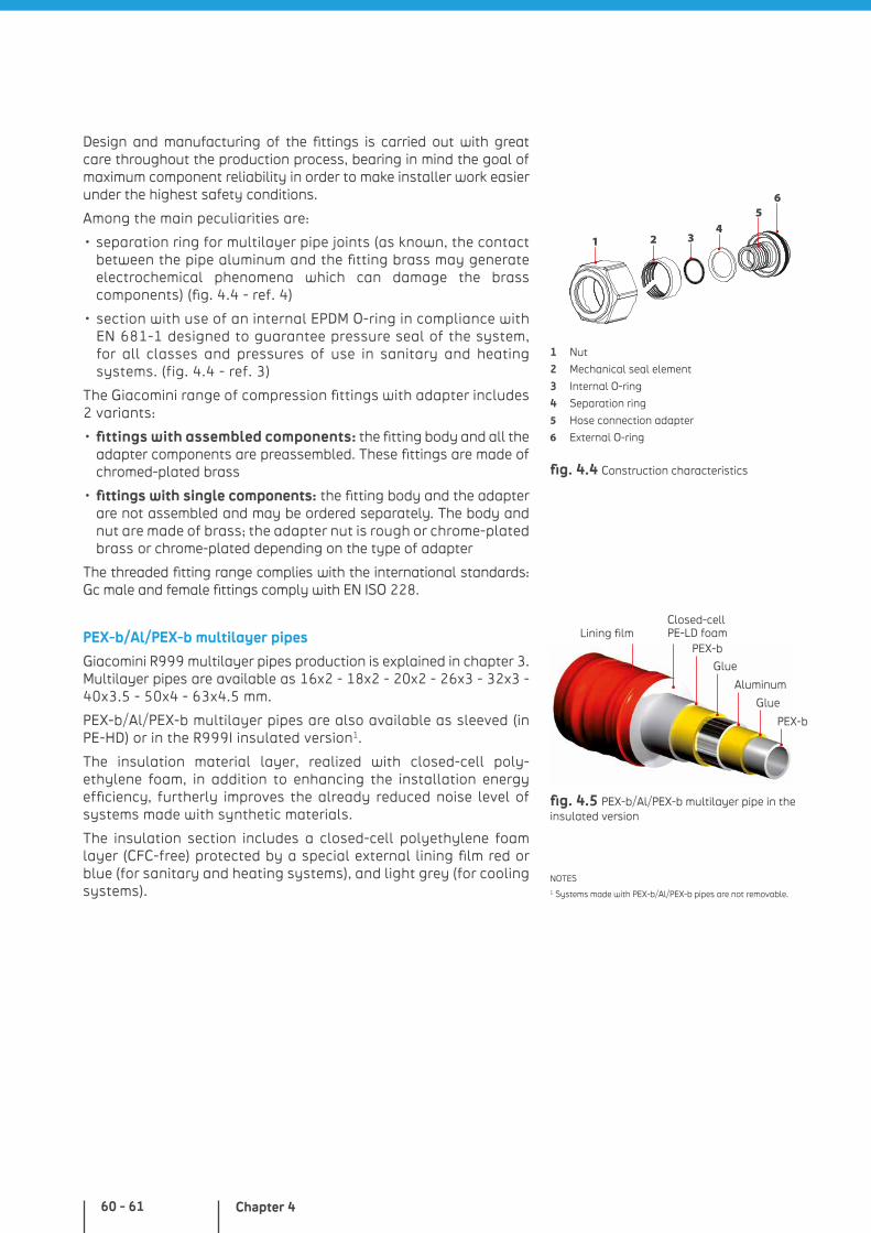
Chapter 460 - 61
fig. 4.4 Construction characteristics
1 Nut
2 Mechanical seal element
3 Internal O-ring
4 Separation ring
5 Hose connection adapter
6 External O-ring
NOTES1 Systems made with PEX-b/Al/PEX-b pipes are not removable.
PEX-b
Glue
Aluminum
Glue
PEX-b
Closed-cell PE-LD foamLining film
fig. 4.5 PEX-b/Al/PEX-b multilayer pipe in the insulated version
21
56
34
Design and manufacturing of the fittings is carried out with great care throughout the production process, bearing in mind the goal of maximum component reliability in order to make installer work easier under the highest safety conditions.
Among the main peculiarities are:
• separation ring for multilayer pipe joints (as known, the contact between the pipe aluminum and the fitting brass may generate electrochemical phenomena which can damage the brass components) (fig. 4.4 - ref. 4)
• section with use of an internal EPDM O-ring in compliance with EN 681-1 designed to guarantee pressure seal of the system, for all classes and pressures of use in sanitary and heating systems. (fig. 4.4 - ref. 3)
The Giacomini range of compression fittings with adapter includes 2 variants:
• fittings with assembled components: the fitting body and all the adapter components are preassembled. These fittings are made of chromed-plated brass
• fittings with single components: the fitting body and the adapter are not assembled and may be ordered separately. The body and nut are made of brass; the adapter nut is rough or chrome-plated brass or chrome-plated depending on the type of adapter
The threaded fitting range complies with the international standards: Gc male and female fittings comply with EN ISO 228.
PEX-b/Al/PEX-b multilayer pipes
Giacomini R999 multilayer pipes production is explained in chapter 3. Multilayer pipes are available as 16x2 - 18x2 - 20x2 - 26x3 - 32x3 - 40x3.5 - 50x4 - 63x4.5 mm.
PEX-b/Al/PEX-b multilayer pipes are also available as sleeved (in PE-HD) or in the R999I insulated version1.
The insulation material layer, realized with closed-cell poly-ethylene foam, in addition to enhancing the installation energy efficiency, furtherly improves the already reduced noise level of systems made with synthetic materials.
The insulation section includes a closed-cell polyethylene foam layer (CFC-free) protected by a special external lining film red or blue (for sanitary and heating systems), and light grey (for cooling systems).
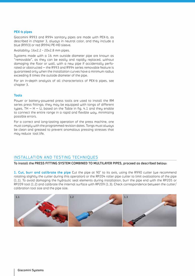
Giacomini Systems
PEX-b pipes
Giacomini R993 and R994 sanitary pipes are made with PEX-b, as described in chapter 3, always in neutral color, and they include a blue (R993) or red (R994) PE-HD sleeve.
Availabilty: 16x2.2 - 20x2.8 mm pipes.
Systems made with a 16 mm outside diameter pipe are known as “removable”, as they can be easily and rapidly replaced, without damaging the floor or wall, with a new pipe if accidentally perfo-rated or obstructed – the R993 and R994 series removable feature is guaranteed only when the installation curves have a minimum radius exceeding 8 times the outside diameter of the pipe.
For an in-depth analysis of all characteristics of PEX-b pipes, see chapter 3.
Tools
Power or battery-powered press tools are used to install the RM series press fittings; they may be equipped with tongs of different types, TH – H – U, based on the Table in fig. 4.1 and they enable to connect the entire range in a rapid and flexible way, minimizing possible errors.
For a correct and long-lasting operation of the press machine, one must comply with the programmed revision dates. Tongs must always be clean and greased to prevent anomalous pressing stresses that may reduce tool life.
INSTALLATION AND TESTING TECHNIQUES
To install the PRESS FITTING SYSTEM COMBINED TO MULTILAYER PIPES, proceed as described below:
1. Cut, burr and calibrate the pipe Cut the pipe at 90° to its axis, using the R990 cutter (we recommend rotating slightly the cutter during this operation) or the RP204 roller pipe cutter to limit ovalizations of the pipe (1.1). To avoid damaging the hydraulic seal elements during installation, burr the pipe end with the RP205 or RP209 tool (1.2) and calibrate the internal surface with RP209 (1.3). Check correspondence between the cutter/calibration tool size and the pipe size.
1.1 1.2 1.3
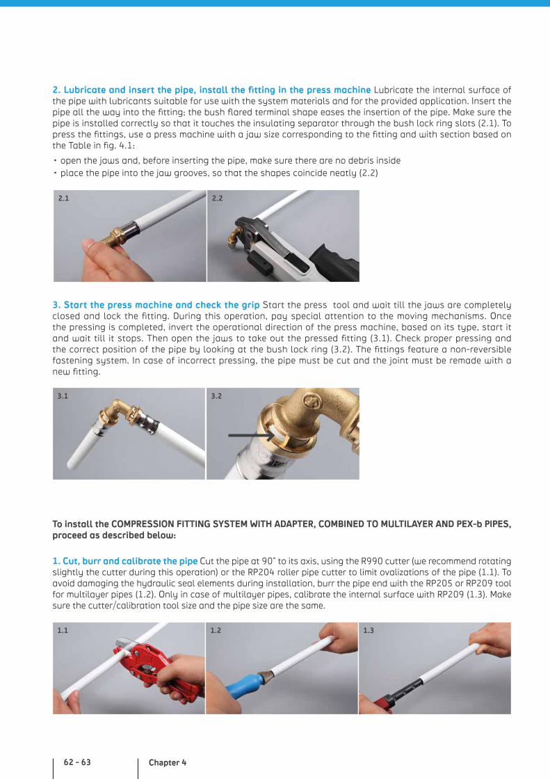
Chapter 462 - 63
2. Lubricate and insert the pipe, install the fitting in the press machine Lubricate the internal surface of the pipe with lubricants suitable for use with the system materials and for the provided application. Insert the pipe all the way into the fitting; the bush flared terminal shape eases the insertion of the pipe. Make sure the pipe is installed correctly so that it touches the insulating separator through the bush lock ring slots (2.1). To press the fittings, use a press machine with a jaw size corresponding to the fitting and with section based on the Table in fig. 4.1:
• open the jaws and, before inserting the pipe, make sure there are no debris inside • place the pipe into the jaw grooves, so that the shapes coincide neatly (2.2)
3. Start the press machine and check the grip Start the press tool and wait till the jaws are completely closed and lock the fitting. During this operation, pay special attention to the moving mechanisms. Once the pressing is completed, invert the operational direction of the press machine, based on its type, start it and wait till it stops. Then open the jaws to take out the pressed fitting (3.1). Check proper pressing and the correct position of the pipe by looking at the bush lock ring (3.2). The fittings feature a non-reversible fastening system. In case of incorrect pressing, the pipe must be cut and the joint must be remade with a new fitting.
2.1
3.1 3.2
2.2
To install the COMPRESSION FITTING SYSTEM WITH ADAPTER, COMBINED TO MULTILAYER AND PEX-b PIPES, proceed as described below:
1. Cut, burr and calibrate the pipe Cut the pipe at 90° to its axis, using the R990 cutter (we recommend rotating slightly the cutter during this operation) or the RP204 roller pipe cutter to limit ovalizations of the pipe (1.1). To avoid damaging the hydraulic seal elements during installation, burr the pipe end with the RP205 or RP209 tool for multilayer pipes (1.2). Only in case of multilayer pipes, calibrate the internal surface with RP209 (1.3). Make sure the cutter/calibration tool size and the pipe size are the same.
1.1 1.2 1.3
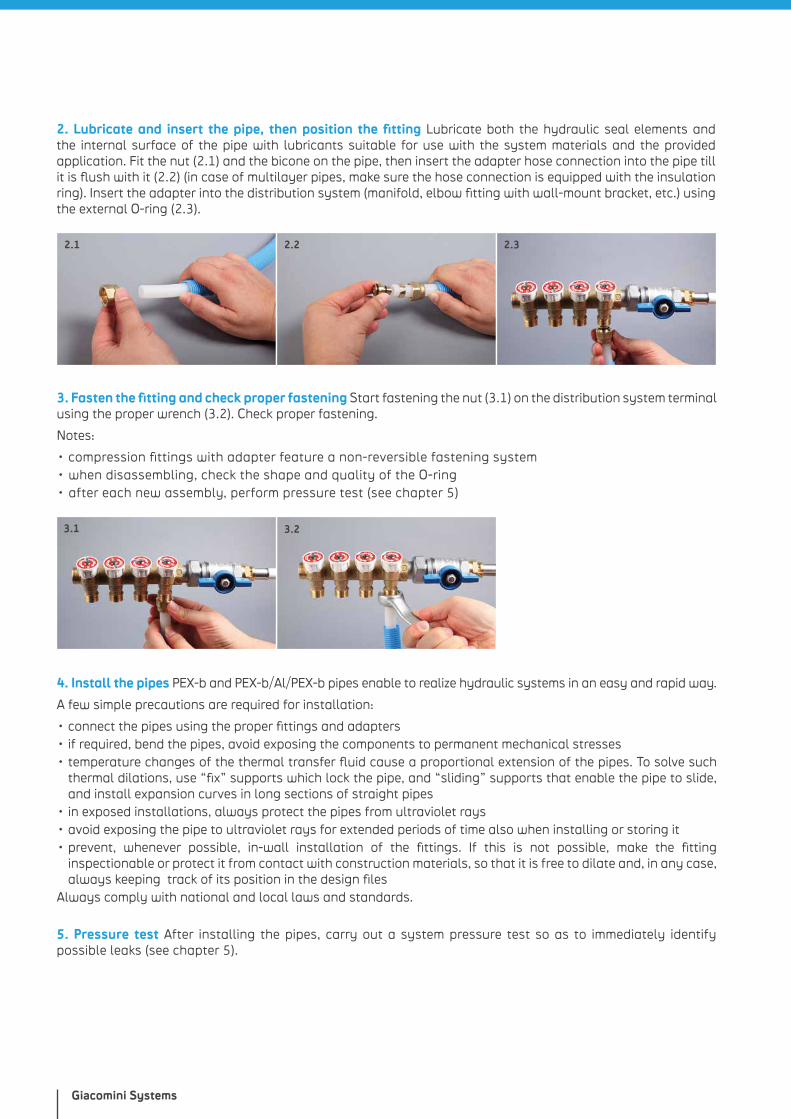
Giacomini Systems
2. Lubricate and insert the pipe, then position the fitting Lubricate both the hydraulic seal elements and the internal surface of the pipe with lubricants suitable for use with the system materials and the provided application. Fit the nut (2.1) and the bicone on the pipe, then insert the adapter hose connection into the pipe till it is flush with it (2.2) (in case of multilayer pipes, make sure the hose connection is equipped with the insulation ring). Insert the adapter into the distribution system (manifold, elbow fitting with wall-mount bracket, etc.) using the external O-ring (2.3).
2.1 2.2
3. Fasten the fitting and check proper fastening Start fastening the nut (3.1) on the distribution system terminal using the proper wrench (3.2). Check proper fastening.
Notes:
• compression fittings with adapter feature a non-reversible fastening system• when disassembling, check the shape and quality of the O-ring• after each new assembly, perform pressure test (see chapter 5)
4. Install the pipes PEX-b and PEX-b/Al/PEX-b pipes enable to realize hydraulic systems in an easy and rapid way.
A few simple precautions are required for installation:
• connect the pipes using the proper fittings and adapters• if required, bend the pipes, avoid exposing the components to permanent mechanical stresses• temperature changes of the thermal transfer fluid cause a proportional extension of the pipes. To solve such
thermal dilations, use “fix” supports which lock the pipe, and “sliding” supports that enable the pipe to slide, and install expansion curves in long sections of straight pipes
• in exposed installations, always protect the pipes from ultraviolet rays • avoid exposing the pipe to ultraviolet rays for extended periods of time also when installing or storing it • prevent, whenever possible, in-wall installation of the fittings. If this is not possible, make the fitting
inspectionable or protect it from contact with construction materials, so that it is free to dilate and, in any case, always keeping track of its position in the design files
Always comply with national and local laws and standards.
3.2
2.3
3.1
5. Pressure test After installing the pipes, carry out a system pressure test so as to immediately identify possible leaks (see chapter 5).
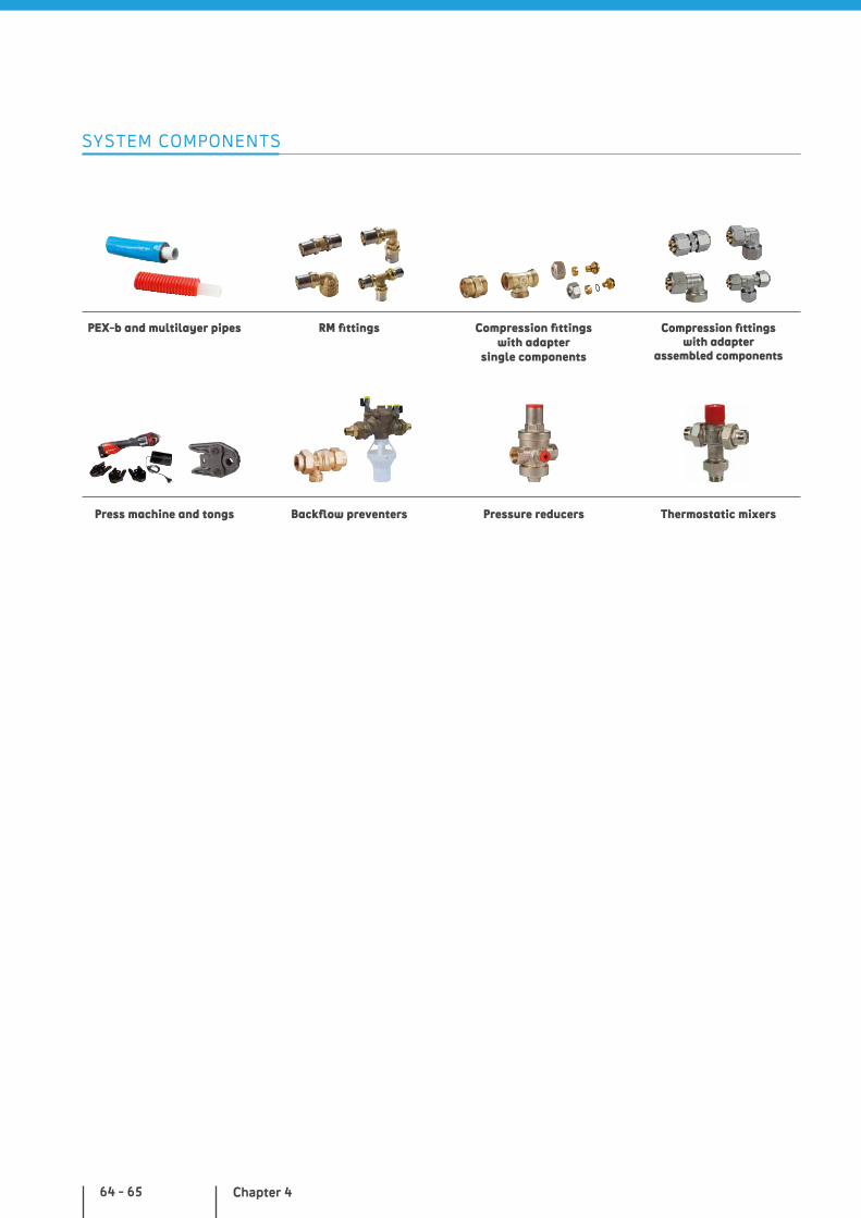
Chapter 464 - 65
SYSTEM COMPONENTS
PEX-b and multilayer pipes
Press machine and tongs
RM fittings Compression fittings with adapter
single components
Compression fittingswith adapter
assembled components
Backflow preventers Thermostatic mixersPressure reducers

Giacomini Systems
NOTES

PEX AND MULTILAYER SYSTEM WITH MANIFOLDS
WHY CHOOSE IT?
• possibility to intercept single draw-off points of the system through the manifold
• suitable for the PEX-b pipe removable system
• multitongs press fittings
• components complying with the main standards of reference
• PEX-b pipes with reduced roughness, chlorine-resistant
more details at giacomini.com
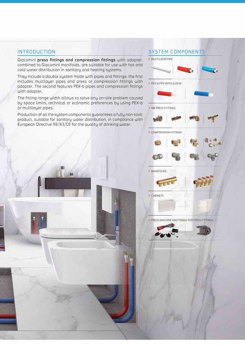
INTRODUCTION
Giacomini press fittings and compression fittings with adapter, combined to Giacomini manifolds, are suitable for use with hot and cold water distribution in sanitary and heating systems.
They include a double system made with pipes and fittings: the first includes multilayer pipes and press or compression fittings with adapter. The second features PEX-b pipes and compression fittings with adapter.
The fitting range width allows to solve any on-site problem caused by space limits, technical or economic preferences by using PEX-b or multilayer pipes.
Production of all the system components guarantees a fully non-toxic product, suitable for sanitary water distribution, in compliance with European Directive 98/83/CE for the quality of drinking water.
SYSTEM COMPONENTS MULTILAYER PIPE
PEX-b PIPE WITH SLEEVE
RM PRESS FITTINGS
COMPRESSION FITTINGS
MANIFOLDS
CABINETS
PRESS MACHINE AND TONGS FOR PRESS FITTINGS
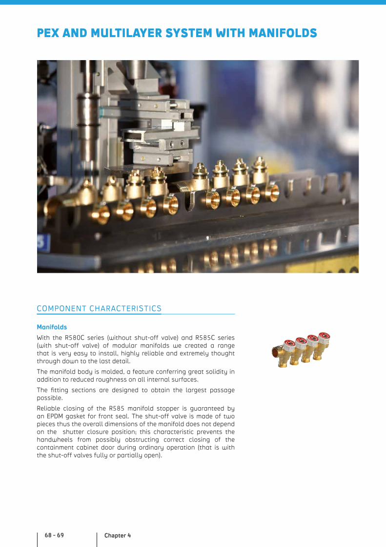
Chapter 468 - 69
Manifolds
With the R580C series (without shut-off valve) and R585C series (with shut-off valve) of modular manifolds we created a range that is very easy to install, highly reliable and extremely thought through down to the last detail.
The manifold body is molded, a feature conferring great solidity in addition to reduced roughness on all internal surfaces.
The fitting sections are designed to obtain the largest passage possible.
Reliable closing of the R585 manifold stopper is guaranteed by an EPDM gasket for front seal. The shut-off valve is made of two pieces thus the overall dimensions of the manifold does not depend on the shutter closure position; this characteristic prevents the handwheels from possibly obstructing correct closing of the containment cabinet door during ordinary operation (that is with the shut-off valves fully or partially open).
COMPONENT CHARACTERISTICS
PEX AND MULTILAYER SYSTEM WITH MANIFOLDS
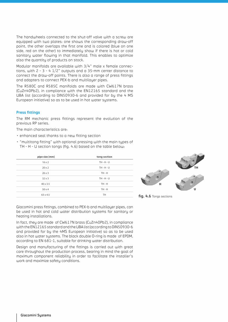
Giacomini Systems
The handwheels connected to the shut-off valve with a screw are equipped with two plates: one shows the corresponding draw-off point, the other overlaps the first one and is colored (blue on one side, red on the other) to immediately show if there is hot or cold sanitary water flowing in that manifold. This enables to optimize also the quantity of products on stock.
Modular manifolds are available with 3/4” male x female connec-tions, with 2 - 3 - 4 1/2” outputs and a 35-mm center distance to connect the draw-off points. There is also a range of press fittings and adapters to connect PEX-b and multilayer pipes.
The R580C and R585C manifolds are made with CW617N brass (CuZn40Pb2), in compliance with the EN12165 standard and the UBA list (according to DIN50930-6 and provided for by the 4 MS European initiative) so as to be used in hot water systems.
Press fittings
The RM mechanic press fittings represent the evolution of the previous RP series.
The main characteristics are:
• enhanced seal thanks to a new fitting section
• “multitong fitting” with optional pressing with the main types of TH - H - U section tongs (fig. 4.6) based on the table below:
pipe size [mm] tong section
16 x 2 TH - H - U
20 x 2 TH - H - U
26 x 3 TH - H
32 x 3 TH - H - U
40 x 3.5 TH - H
50 x 4 TH - H
63 x 4.5 TH
Giacomini press fittings, combined to PEX-b and multilayer pipes, can be used in hot and cold water distribution systems for sanitary or heating installations.
In fact, they are made of CW617N brass (CuZn40Pb2), in compliance with the EN12165 standard and the UBA list (according to DIN50930-6 and provided for by the 4MS European initiative) so as to be used also in hot water systems. The black double O-ring is made of EPDM, according to EN 681-1, suitable for drinking water distribution.
Design and manufacturing of the fittings is carried out with great care throughout the production process, bearing in mind the goal of maximum component reliability in order to facilitate the installer’s work and maximize safety conditions.
fig. 4.6 Tongs sections
H
U
TH
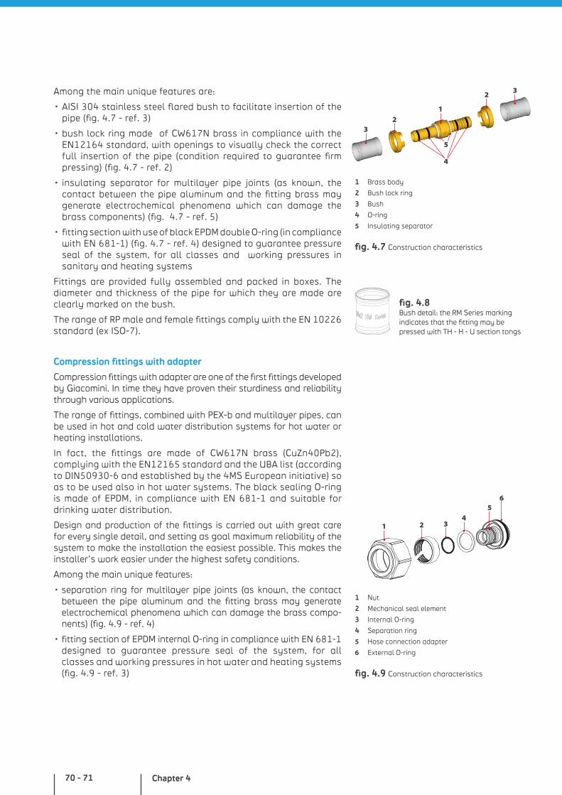
Chapter 470 - 71
Among the main unique features are:
• AISI 304 stainless steel flared bush to facilitate insertion of the pipe (fig. 4.7 - ref. 3)
• bush lock ring made of CW617N brass in compliance with the EN12164 standard, with openings to visually check the correct full insertion of the pipe (condition required to guarantee firm pressing) (fig. 4.7 - ref. 2)
• insulating separator for multilayer pipe joints (as known, the contact between the pipe aluminum and the fitting brass may generate electrochemical phenomena which can damage the brass components) (fig. 4.7 - ref. 5)
• fitting section with use of black EPDM double O-ring (in compliance with EN 681-1) (fig. 4.7 - ref. 4) designed to guarantee pressure seal of the system, for all classes and working pressures in sanitary and heating systems
Fittings are provided fully assembled and packed in boxes. The diameter and thickness of the pipe for which they are made are clearly marked on the bush.
The range of RP male and female fittings comply with the EN 10226 standard (ex ISO-7).
Compression fittings with adapter
Compression fittings with adapter are one of the first fittings developed by Giacomini. In time they have proven their sturdiness and reliability through various applications.
The range of fittings, combined with PEX-b and multilayer pipes, can be used in hot and cold water distribution systems for hot water or heating installations.
In fact, the fittings are made of CW617N brass (CuZn40Pb2), complying with the EN12165 standard and the UBA list (according to DIN50930-6 and established by the 4MS European initiative) so as to be used also in hot water systems. The black sealing O-ring is made of EPDM, in compliance with EN 681-1 and suitable for drinking water distribution.
Design and production of the fittings is carried out with great care for every single detail, and setting as goal maximum reliability of the system to make the installation the easiest possible. This makes the installer’s work easier under the highest safety conditions.
Among the main unique features:
• separation ring for multilayer pipe joints (as known, the contact between the pipe aluminum and the fitting brass may generate electrochemical phenomena which can damage the brass compo-nents) (fig. 4.9 - ref. 4)
• fitting section of EPDM internal O-ring in compliance with EN 681-1 designed to guarantee pressure seal of the system, for all classes and working pressures in hot water and heating systems (fig. 4.9 - ref. 3) fig. 4.9 Construction characteristics
1 Nut
2 Mechanical seal element
3 Internal O-ring
4 Separation ring
5 Hose connection adapter
6 External O-ring
21
56
34
fig. 4.7 Construction characteristics
32
1
5
4
2 3
1 Brass body
2 Bush lock ring
3 Bush
4 O-ring
5 Insulating separator
fig. 4.8 Bush detail: the RM Series marking indicates that the fitting may be pressed with TH - H - U section tongs
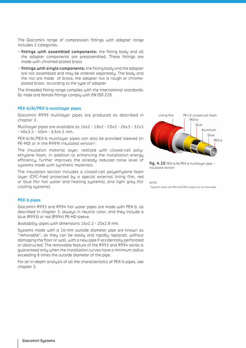
Giacomini Systems
The Giacomini range of compression fittings with adapter range includes 2 categories:
• fittings with assembled components: the fitting body and all the adapter components are preassembled. These fittings are made with chromed-plated brass
• fittings with single components: the fitting body and the adapter are not assembled and may be ordered separately. The body and the nut are made of brass; the adapter nut is rough or chrome-plated brass according to the type of adapter
The threaded fitting range complies with the international standards: Gc male and female fittings comply with EN ISO 228.
PEX-b/Al/PEX-b multilayer pipes
Giacomini R999 multilayer pipes are produced as described in chapter 3.
Multilayer pipes are available as 16x2 - 18x2 - 20x2 - 26x3 - 32x3 - 40x3.5 - 50x4 - 63x4.5 mm.
PEX-b/Al/PEX-b multilayer pipes can also be provided sleeved (in PE-HD) or in the R999I insulated version1.
The insulation material layer, realized with closed-cell poly-ethylene foam, in addition to enhancing the installation energy efficiency, further improves the already reduced noise level of systems made with synthetic materials.
The insulation section includes a closed-cell polyethylene foam layer (CFC-free) protected by a special external lining film, red or blue (for hot water and heating systems), and light grey (for cooling systems).
PEX-b pipes
Giacomini R993 and R994 hot water pipes are made with PEX-b, as described in chapter 3, always in neutral color, and they include a blue (R993) or red (R994) PE-HD sleeve.
Availabilty: pipes with dimensions 16x2.2 - 20x2.8 mm.
Systems made with a 16-mm outside diameter pipe are known as “removable”, as they can be easily and rapidly replaced, without damaging the floor or wall, with a new pipe if accidentally perforated or obstructed. The removable feature of the R993 and R994 series is guaranteed only when the installation curves have a minimum radius exceeding 8 times the outside diameter of the pipe.
For an in-depth analysis of all the characteristics of PEX-b pipes, see chapter 3.
NOTES1 Systems made with PEX-b/Al/PEX-b pipes are not removable
PEX-b
Glue
Aluminum
Glue
PEX-bPE-LE closed-cell foamLining film
fig. 4.10 PEX-b/Al/PEX-b multilayer pipe – insulated version
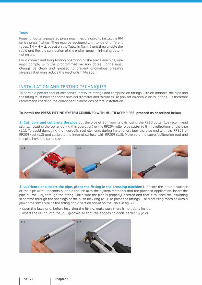
Chapter 472 - 73
INSTALLATION AND TESTING TECHNIQUES
To obtain a perfect seal of mechanical pressure fittings and compression fittings with an adapter, the pipe and the fitting must have the same nominal diameter and thickness. To prevent erroneous installations, we therefore recommend checking the component dimensions before installation.
1. Cut, burr and calibrate the pipe Cut the pipe at 90° from its axis, using the R990 cutter (we recommend slightly rotating the cutter during this operation) or the RP204 roller pipe cutter to limit ovalizations of the pipe (1.1). To avoid damaging the hydraulic seal elements during installation, burr the pipe end with the RP205 or RP209 tool (1.2) and calibrate the internal surface with RP209 (1.3). Make sure the cutter/calibration tool and the pipe have the same size.
2. Lubricate and insert the pipe, place the fitting in the pressing machine Lubricate the internal surface of the pipe with lubricants suitable for use with the system materials and the provided application. Insert the pipe all the way through the fitting. Make sure the pipe is properly inserted and that it touches the insulating separator through the openings of the bush lock ring (2.1). To press the fittings, use a pressing machine with a jaw of the same size as the fitting and a section based on the Table in fig. 4.6:
• open the jaws and, before inserting the fitting, make sure there is no debris inside • insert the fitting into the jaw grooves so that the shapes coincide perfectly (2.2)
1.1 1.2 1.3
2.1 2.2
To install the PRESS FITTING SYSTEM COMBINED WITH MULTILAYER PIPES, proceed as described below:
Tools
Power or battery-powered press machines are used to install the RM series press fittings. They may be equipped with tongs of different types, TH – H – U, based on the Table in fig. 4.6 and they enable the rapid and flexible connection of the entire range, minimizing poten-tial errors.
For a correct and long-lasting operation of the press machine, one must comply with the programmed revision dates. Tongs must always be clean and greased to prevent anomalous pressing stresses that may reduce the mechanism life span.

Giacomini Systems
3. Start the press machine and check the grip Start the press machine and wait till the jaws are completely closed and lock the fitting. During this operation, pay special attention to the moving mechanisms. Once the clamping is completed, invert the operational direction of the press machine based on its type, start it and wait till it stops. Then open the jaws to take out the pressed fitting (3.1). Check proper clamping and correct positioning of the pipe by looking at the bush lock ring (3.2). The fittings feature a non-reversible fastening system. In case of incorrect pressing, the pipe must be cut and the joint must be remade with a new fitting.
3.1
To install the SYSTEM HAVING COMPRESSION FITTING WITH ADAPTER, COMBINED TO MULTILAYER AND PEX-b PIPES proceed as described below:
2. Lubricate and insert the pipe, introduce the fitting into the press Lubricate both the hydraulic seal elements and the internal surface of the pipe with lubricants suitable for use with the system materials and the provided application. Fit the nut (2.1) and the bicone on the pipe, then insert the adapter hose connection into the pipe till it is flush with it (2.2) (in case of multilayer pipes, make sure the hose connection is equipped with the insulation ring). Insert the adapter into the distribution system (manifold, elbow fitting with wall-mount bracket, etc.) using the external O-ring (2.3).
2.1 2.2
1. Cut, burr and calibrate the pipe Cut the pipe at 90° from its axis, using the R990 cutter (we recommend slightly rotating the cutter during this operation) or the RP204 roller pipe cutter to limit ovalizations of the pipe (1.1). To avoid damaging the hydraulic seal elements during installation, burr the pipe end with the RP205 or RP209 tool (1.2) for multilayer pipes. Only with multilayer pipes, calibrate the internal surface with RP209 (1.3). Make sure the cutter/calibration tool and the pipe have the same size.
1.1 1.2 1.3
2.3
3.2
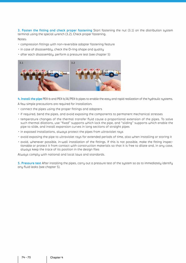
Chapter 474 - 75
3. Fasten the fitting and check proper fastening Start fastening the nut (3.1) on the distribution system terminal using the special wrench (3.2). Check proper fastening.
Notes:
• compression fittings with non-reversible adapter fastening feature
• in case of disassembly, check the O-ring shape and quality
• after each disassembly, perform a pressure test (see chapter 5)
4. Install the pipe PEX-b and PEX-b/Al/PEX-b pipes to enable the easy and rapid realization of the hydraulic systems.
A few simple precautions are required for installation:
• connect the pipes using the proper fittings and adapters
• if required, bend the pipes, and avoid exposing the components to permanent mechanical stresses
• temperature changes of the thermal transfer fluid cause a proportional extension of the pipes. To solve such thermal dilations, use “fixed” supports which lock the pipe, and “sliding” supports which enable the pipe to slide, and install expansion curves in long sections of straight pipes
• in exposed installations, always protect the pipes from ultraviolet rays
• avoid exposing the pipe to ultraviolet rays for extended periods of time, also when installing or storing it
• avoid, whenever possible, in-wall installation of the fittings. If this is not possible, make the fitting inspec-tionable or protect it from contact with construction materials so that it is free to dilate and, in any case, always keep the trace of its position in the design files
Always comply with national and local laws and standards.
3.23.1
5. Pressure test After installing the pipes, carry out a pressure test of the system so as to immediately identify any fluid leaks (see chapter 5).
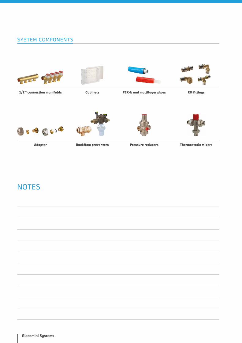
Giacomini Systems
SYSTEM COMPONENTS
1/2” connection manifolds
Adapter
Cabinets PEX-b and multilayer pipes RM fittings
Backflow preventers Thermostatic mixersPressure reducers
NOTES

PEX EXPANSION SYSTEMS - GX
WHY CHOOSE IT?
• wide range of O-Ring-free fittings
• long-lasting polymeric ring
• rapid installation and reduced number of components
• components complying with the main standards of reference
• PEX-b pipes with reduced roughness, chlorine-resistant
more details at giacomini.com

INTRODUCTION
The PEX expansion system – GX – Giacomini eXpansion System – is a distribution system for sanitary installations (also suitable for traditional or radiant heating and cooling systems) made with PEX-b pipes and brass fittings with a special seal section guaranteed by a polymeric ring.
A gradual expansion of the pipes combined to the ring allows instal-lation of the fitting which, in a very short time, will be locked by the force generated by the elastic return of the polymeric elements.
Once the process is completed, the joint features improved mechanical characteristics compared to the single pipe and offers great reliability for the entire life cycle of the system.
Production of all the GX system components guarantees a fully non-toxic product, suitable for sanitary water distribution, in compli-ance with European Directive 98/83/CE for the quality of drinking water.
SYSTEM COMPONENTS PEX-b PIPES
GX EXPANSION FITTINGS
RINGS
TOOLS
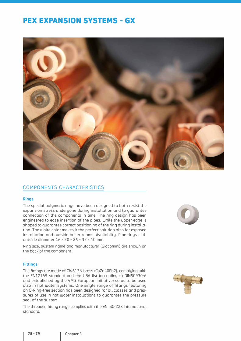
Chapter 478 - 79
PEX EXPANSION SYSTEMS - GX
Rings
The special polymeric rings have been designed to both resist the expansion stress undergone during installation and to guarantee connection of the components in time. The ring design has been engineered to ease insertion of the pipes, while the upper edge is shaped to guarantee correct positioning of the ring during installa-tion. The white color makes it the perfect solution also for exposed installation and outside boiler rooms. Availabilty: Pipe rings with outside diameter 16 - 20 - 25 - 32 - 40 mm.
Ring size, system name and manufacturer (Giacomini) are shown on the back of the component.
Fittings
The fittings are made of CW617N brass (CuZn40Pb2), complying with the EN12165 standard and the UBA list (according to DIN50930-6 and established by the 4MS European initiative) so as to be used also in hot water systems. One single range of fittings featuring an O-Ring-free section has been designed for all classes and pres-sures of use in hot water installations to guarantee the pressure seal of the system.
The threaded fitting range complies with the EN ISO 228 international standard.
COMPONENTS CHARACTERISTICS
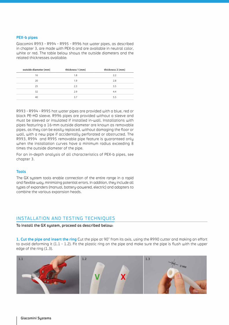
Giacomini Systems
PEX-b pipes
Giacomini R993 - R994 - R995 - R996 hot water pipes, as described in chapter 3, are made with PEX-b and are available in neutral color, white or red. The table below shows the outside diameters and the related thicknesses available:
outside diameter [mm] thickness 1 [mm] thickness 2 [mm]
16 1.8 2.2
20 1.9 2.8
25 2.3 3.5
32 2.9 4.4
40 3.7 5.5
R993 - R994 - R995 hot water pipes are provided with a blue, red or black PE-HD sleeve. R996 pipes are provided without a sleeve and must be sleeved or insulated if installed in-wall. Installations with pipes featuring a 16-mm outside diameter are known as removable pipes, as they can be easily replaced, without damaging the floor or wall, with a new pipe if accidentally perforated or obstructed. The R993, R994 and R995 removable pipe feature is guaranteed only when the installation curves have a minimum radius exceeding 8 times the outside diameter of the pipe.
For an in-depth analysis of all characteristics of PEX-b pipes, see chapter 3.
Tools
The GX system tools enable connection of the entire range in a rapid and flexible way, minimizing potential errors. In addition, they include all types of expanders (manual, battery-powered, electric) and adapters to combine the various expansion heads.
INSTALLATION AND TESTING TECHNIQUES
To install the GX system, proceed as described below:
1. Cut the pipe and insert the ring Cut the pipe at 90° from its axis, using the R990 cutter and making an effort to avoid deforming it (1.1 - 1.2). Fit the plastic ring on the pipe and make sure the pipe is flush with the upper edge of the ring (1.3).
1.1
XV
1.2 1.3
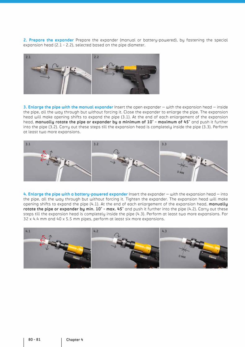
Chapter 480 - 81
4. Enlarge the pipe with a battery-powered expander Insert the expander – with the expansion head – into the pipe, all the way through but without forcing it. Tighten the expander. The expansion head will make opening shifts to expand the pipe (4.1). At the end of each enlargement of the expansion head, manually rotate the pipe or expander by min. 10° - max. 45° and push it further into the pipe (4.2). Carry out these steps till the expansion head is completely inside the pipe (4.3). Perform at least two more expansions. For 32 x 4.4 mm and 40 x 5.5 mm pipes, perform at least six more expansions.
3. Enlarge the pipe with the manual expander Insert the open expander – with the expansion head – inside the pipe, all the way through but without forcing it. Close the expander to enlarge the pipe. The expansion head will make opening shifts to expand the pipe (3.1). At the end of each enlargement of the expansion head, manually rotate the pipe or expander by a minimum of 10° - maximum of 45° and push it further into the pipe (3.2). Carry out these steps till the expansion head is completely inside the pipe (3.3). Perform at least two more expansions.
2. Prepare the expander Prepare the expander (manual or battery-powered), by fastening the special expansion head (2.1 - 2.2), selected based on the pipe diameter.
2.1 2.2
3.1 3.33.2
4.2 4.34.1
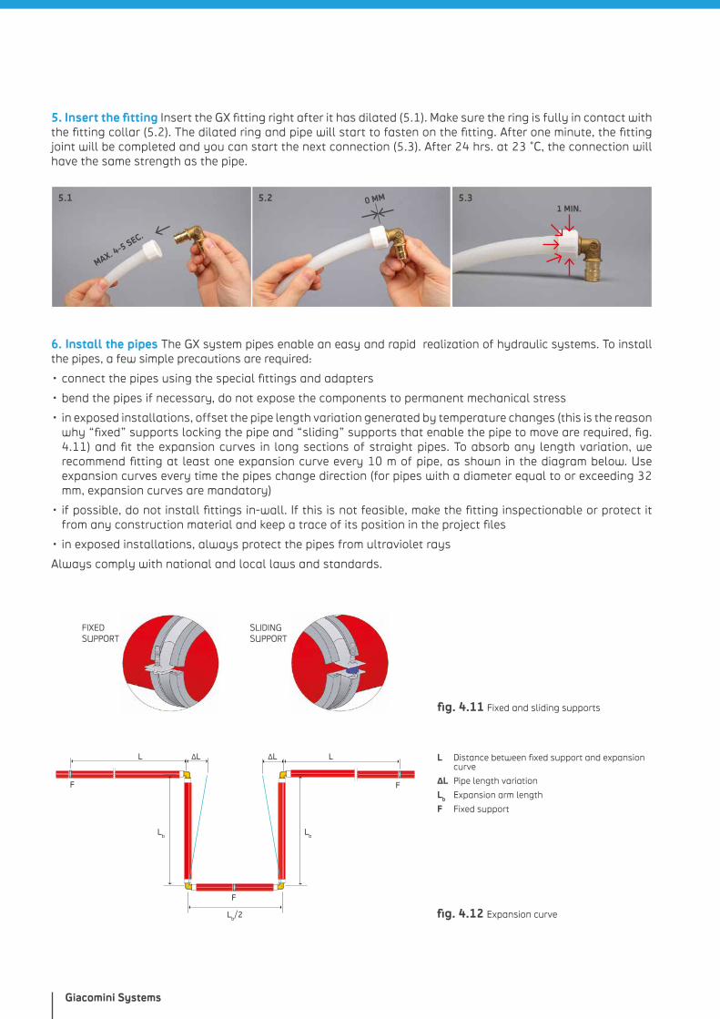
Giacomini Systems
6. Install the pipes The GX system pipes enable an easy and rapid realization of hydraulic systems. To install the pipes, a few simple precautions are required:
• connect the pipes using the special fittings and adapters
• bend the pipes if necessary, do not expose the components to permanent mechanical stress
• in exposed installations, offset the pipe length variation generated by temperature changes (this is the reason why “fixed” supports locking the pipe and “sliding” supports that enable the pipe to move are required, fig. 4.11) and fit the expansion curves in long sections of straight pipes. To absorb any length variation, we recommend fitting at least one expansion curve every 10 m of pipe, as shown in the diagram below. Use expansion curves every time the pipes change direction (for pipes with a diameter equal to or exceeding 32 mm, expansion curves are mandatory)
• if possible, do not install fittings in-wall. If this is not feasible, make the fitting inspectionable or protect it from any construction material and keep a trace of its position in the project files
• in exposed installations, always protect the pipes from ultraviolet rays
Always comply with national and local laws and standards.
5. Insert the fitting Insert the GX fitting right after it has dilated (5.1). Make sure the ring is fully in contact with the fitting collar (5.2). The dilated ring and pipe will start to fasten on the fitting. After one minute, the fitting joint will be completed and you can start the next connection (5.3). After 24 hrs. at 23 °C, the connection will have the same strength as the pipe.
5.2
SLIDING SUPPORT
FIXED SUPPORT
F
L ∆L L∆L
F F
LbLb
Lb/2 fig. 4.12 Expansion curve
5.1
MAX. 4-5 SEC.
5.31 MIN.
fig. 4.11 Fixed and sliding supports
L Distance between fixed support and expansion curve
ΔL Pipe length variation
Lb Expansion arm length
F Fixed support
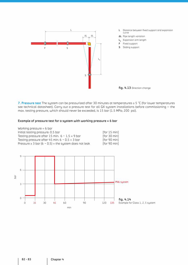
Chapter 482 - 83
7. Pressure test The system can be pressurized after 30 minutes at temperatures ≥ 5 °C (for lower temperatures see technical datasheet). Carry out a pressure test for all GX system installations before commissioning – the max. testing pressure, which should never be exceeded, is 15 bar (1.5 MPa; 200 psi).
Example of pressure test for a system with working pressure = 6 bar
Working pressure = 6 barInitial testing pressure: 0.5 bar [for 15 min]Testing pressure after 15 min: 6 • 1.5 = 9 bar [for 30 min]Testing pressure after 45 min: 6 • 0.5 = 3 bar [for 90 min]Pressure ≥ 3 bar (6 • 0.5) = the system does not leak [for 90 min]
9
6
3
0
0 30 60 90 12015 45 135
PN6 system
fig. 4.14 Example for Class 1, 2, 5 system
L
∆L∆L
F S
S
Lb
fig. 4.13 Direction change
L Distance between fixed support and expansion curve
ΔL Pipe length variation
Lb Expansion arm length
F Fixed support
S Sliding support
bar
min
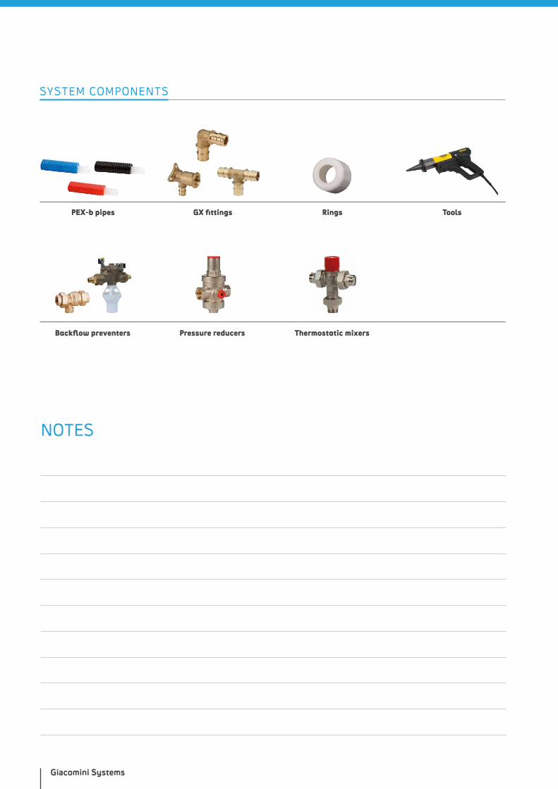
Giacomini Systems
SYSTEM COMPONENTS
PEX-b pipes
Backflow preventers
GX fittings
Pressure reducers
Rings Tools
Thermostatic mixers
NOTES

PEX SYSTEM WITH CRIMPING RING
WHY CHOOSE IT?
• easy and rapid installations
• O-ring-free fittings
• light for convenient use
• pipes produced in the most popular sizes (1/2” - 3/4” - 1”)
• components complying with the main standards of reference
• PEX-b pipes with reduced roughness, chlorine-resistant
more details at giacomini.com

INTRODUCTION
The PEX system with crimping ring is a distribution system for hot water installations, also used for traditional or radiant heating and cooling systems. It is made with PEX-b pipes with 1/2” - 3/4” - 1” imperial dimensions and brass fittings with a special section providing a seal through a black heat-treated ductile copper ring.
After pressing it into the correct position, the ring fastens the pipe and the fitting in a permanent and reliable way for the entire life cycle of the system.
Production of all PEX system components with fastening ring guar-antees a fully non-toxic product, suitable for hot water distribution, as established by European Directive 98/83/CE for the quality of drinking water.
SYSTEM COMPONENTS PEX-b PIPES
GZ FITTINGS
RINGS
TOOLS
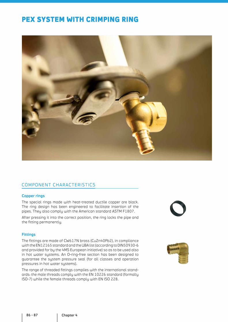
Chapter 486 - 87
PEX SYSTEM WITH CRIMPING RING
Copper rings
The special rings made with heat-treated ductile copper are black. The ring design has been engineered to facilitate insertion of the pipes. They also comply with the American standard ASTM F1807.
After pressing it into the correct position, the ring locks the pipe and the fitting permanently.
Fittings
The fittings are made of CW617N brass (CuZn40Pb2), in compliance with the EN12165 standard and the UBA list (according to DIN50930-6 and provided for by the 4MS European initiative) so as to be used also in hot water systems. An O-ring-free section has been designed to guarantee the system pressure seal (for all classes and operation pressures in hot water systems).
The range of threaded fittings complies with the international stand-ards: the male threads comply with the EN 10226 standard (formally ISO-7) while the female threads comply with EN ISO 228.
COMPONENT CHARACTERISTICS
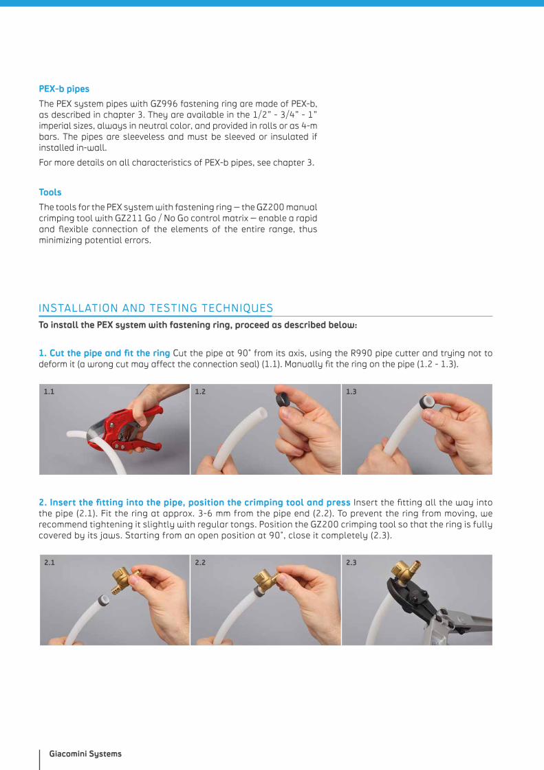
Giacomini Systems
1.2 1.3
INSTALLATION AND TESTING TECHNIQUES
To install the PEX system with fastening ring, proceed as described below:
1. Cut the pipe and fit the ring Cut the pipe at 90° from its axis, using the R990 pipe cutter and trying not to deform it (a wrong cut may affect the connection seal) (1.1). Manually fit the ring on the pipe (1.2 - 1.3).
1.1
PEX-b pipes
The PEX system pipes with GZ996 fastening ring are made of PEX-b, as described in chapter 3. They are available in the 1/2” - 3/4” - 1” imperial sizes, always in neutral color, and provided in rolls or as 4-m bars. The pipes are sleeveless and must be sleeved or insulated if installed in-wall.
For more details on all characteristics of PEX-b pipes, see chapter 3.
Tools
The tools for the PEX system with fastening ring – the GZ200 manual crimping tool with GZ211 Go / No Go control matrix – enable a rapid and flexible connection of the elements of the entire range, thus minimizing potential errors.
2.1 2.2 2.3
2. Insert the fitting into the pipe, position the crimping tool and press Insert the fitting all the way into the pipe (2.1). Fit the ring at approx. 3-6 mm from the pipe end (2.2). To prevent the ring from moving, we recommend tightening it slightly with regular tongs. Position the GZ200 crimping tool so that the ring is fully covered by its jaws. Starting from an open position at 90°, close it completely (2.3).
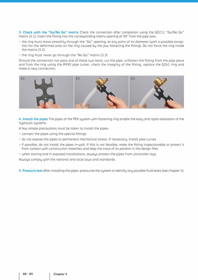
Chapter 488 - 89
4. Install the pipes The pipes of the PEX system with fastening ring enable the easy and rapid realization of the hydraulic systems.
A few simple precautions must be taken to install the pipes:
• connect the pipes using the special fittings
• do not expose the pipes to permanent mechanical stress. If necessary, install pipe curves
• if possible, do not install the pipes in-wall. If this is not feasible, make the fitting inspectionable or protect it from contact with construction materials and keep the trace of its position in the design files
• when storing and in exposed installations, always protect the pipes from ultraviolet rays
Always comply with the national and local laws and standards.
5. Pressure test After installing the pipes, pressurize the system to identify any possible fluid leaks (see chapter 5).
3.1 3.2 3.3
3. Check with the “Go/No Go” matrix Check the connection after completion using the GZ211 “Go/No Go” matrix (3.1). Insert the fitting into the corresponding matrix opening at 90° from the pipe axis:
• the ring must move smoothly through the “Go” opening, at any point of its diameter (with a possible excep-tion for the deformed area on the ring caused by the jaw fastening the fitting). Do not force the ring inside the matrix (3.2)
• the ring must never go through the “No Go” matrix (3.3)
Should the connection not pass one of these two tests, cut the pipe, unfasten the fitting from the pipe piece and from the ring using the R990 pipe cutter, check the integrity of the fitting, replace the GZ61 ring and make a new connection.
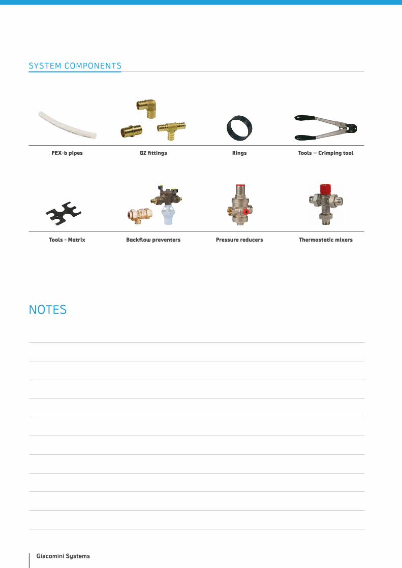
Giacomini Systems
SYSTEM COMPONENTS
PEX-b pipes
Backflow preventers
GZ fittings
Pressure reducers
Rings Tools – Crimping tool
Tools - Matrix Thermostatic mixers
NOTES

PPR WELDING SYSTEM
WHY CHOOSE IT?
• very light components
• sound-absorbing and thermally insulated
• pipes and fittings with minimized surface roughness
• simple and rapid installation
• components complying with the main standards of reference
more details at giacomini.com
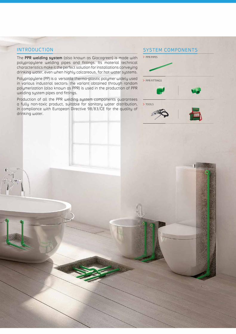
INTRODUCTION
The PPR welding system (also known as Giacogreen) is made with polypropylene welding pipes and fittings. Its material technical characteristics make it the perfect solution for installations conveying drinking water, even when highly calcareous, for hot water systems.
Polypropylene (PP) is a versatile thermo-plastic polymer widely used in various industrial sectors: the variant obtained through random polymerization (also known as PPR) is used in the production of PPR welding system pipes and fittings.
Production of all the PPR welding system components guarantees a fully non-toxic product, suitable for sanitary water distribution, in compliance with European Directive 98/83/CE for the quality of drinking water.
SYSTEM COMPONENTS PPR PIPES
PPR FITTINGS
TOOLS
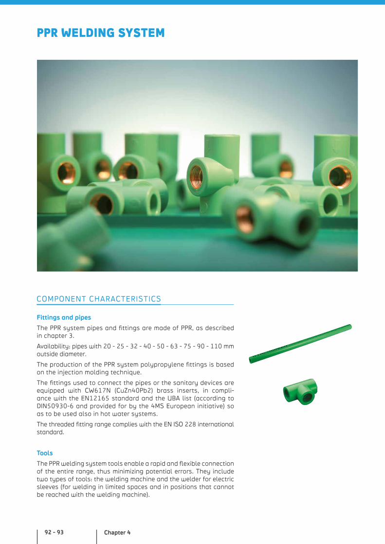
Chapter 492 - 93
PPR WELDING SYSTEM
Fittings and pipes
The PPR system pipes and fittings are made of PPR, as described in chapter 3.
Availability: pipes with 20 - 25 - 32 - 40 - 50 - 63 - 75 - 90 - 110 mm outside diameter.
The production of the PPR system polypropylene fittings is based on the injection molding technique.
The fittings used to connect the pipes or the sanitary devices are equipped with CW617N (CuZn40Pb2) brass inserts, in compli-ance with the EN12165 standard and the UBA list (according to DIN50930-6 and provided for by the 4MS European initiative) so as to be used also in hot water systems.
The threaded fitting range complies with the EN ISO 228 international standard.
Tools
The PPR welding system tools enable a rapid and flexible connection of the entire range, thus minimizing potential errors. They include two types of tools: the welding machine and the welder for electric sleeves (for welding in limited spaces and in positions that cannot be reached with the welding machine).
COMPONENT CHARACTERISTICS
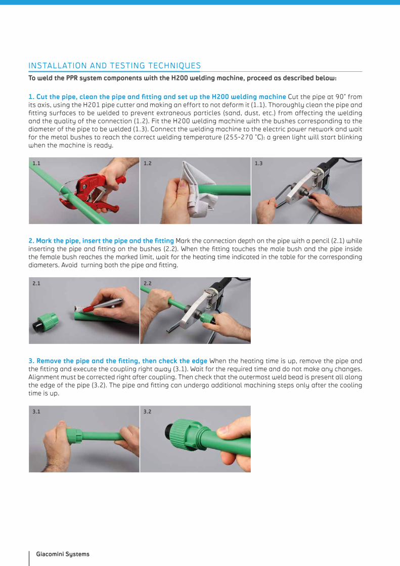
Giacomini Systems
INSTALLATION AND TESTING TECHNIQUES
To weld the PPR system components with the H200 welding machine, proceed as described below:
1. Cut the pipe, clean the pipe and fitting and set up the H200 welding machine Cut the pipe at 90° from its axis, using the H201 pipe cutter and making an effort to not deform it (1.1). Thoroughly clean the pipe and fitting surfaces to be welded to prevent extraneous particles (sand, dust, etc.) from affecting the welding and the quality of the connection (1.2). Fit the H200 welding machine with the bushes corresponding to the diameter of the pipe to be welded (1.3). Connect the welding machine to the electric power network and wait for the metal bushes to reach the correct welding temperature (255-270 °C): a green light will start blinking when the machine is ready.
2. Mark the pipe, insert the pipe and the fitting Mark the connection depth on the pipe with a pencil (2.1) while inserting the pipe and fitting on the bushes (2.2). When the fitting touches the male bush and the pipe inside the female bush reaches the marked limit, wait for the heating time indicated in the table for the corresponding diameters. Avoid turning both the pipe and fitting.
3. Remove the pipe and the fitting, then check the edge When the heating time is up, remove the pipe and the fitting and execute the coupling right away (3.1). Wait for the required time and do not make any changes. Alignment must be corrected right after coupling. Then check that the outermost weld bead is present all along the edge of the pipe (3.2). The pipe and fitting can undergo additional machining steps only after the cooling time is up.
1.1 1.2 1.3
2.1 2.2
3.1 3.2
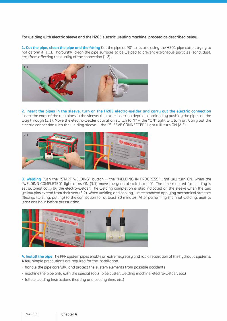
Chapter 494 - 95
For welding with electric sleeve and the H205 electric welding machine, proceed as described below:
1. Cut the pipe, clean the pipe and the fitting Cut the pipe at 90° to its axis using the H201 pipe cutter, trying to not deform it (1.1). Thoroughly clean the pipe surfaces to be welded to prevent extraneous particles (sand, dust, etc.) from affecting the quality of the connection (1.2).
2. Insert the pipes in the sleeve, turn on the H205 electro-welder and carry out the electric connection Insert the ends of the two pipes in the sleeve: the exact insertion depth is obtained by pushing the pipes all the way through (2.1). Move the electro-welder activation switch to “I” – the “ON” light will turn on. Carry out the electric connection with the welding sleeve – the “SLEEVE CONNECTED” light will turn ON (2.2).
3. Welding Push the “START WELDING” button – the “WELDING IN PROGRESS” light will turn ON. When the “WELDING COMPLETED” light turns ON (3.1) move the general switch to “0”. The time required for welding is set automatically by the electro-welder. The welding completion is also indicated on the sleeve when the two yellow pins extend from their seat (3.2). When welding and cooling, we recommend applying mechanical stresses (flexing, twisting, pulling) to the connection for at least 20 minutes. After performing the final welding, wait at least one hour before pressurizing.
4. Install the pipe The PPR system pipes enable an extremely easy and rapid realization of the hydraulic systems. A few simple precautions are required for the installation:
• handle the pipe carefully and protect the system elements from possible accidents
• machine the pipe only with the special tools (pipe cutter, welding machine, electro-welder, etc.)
• follow welding instructions (heating and cooling time, etc.)
1.1 1.2
2.1 2.2
3.1 3.2
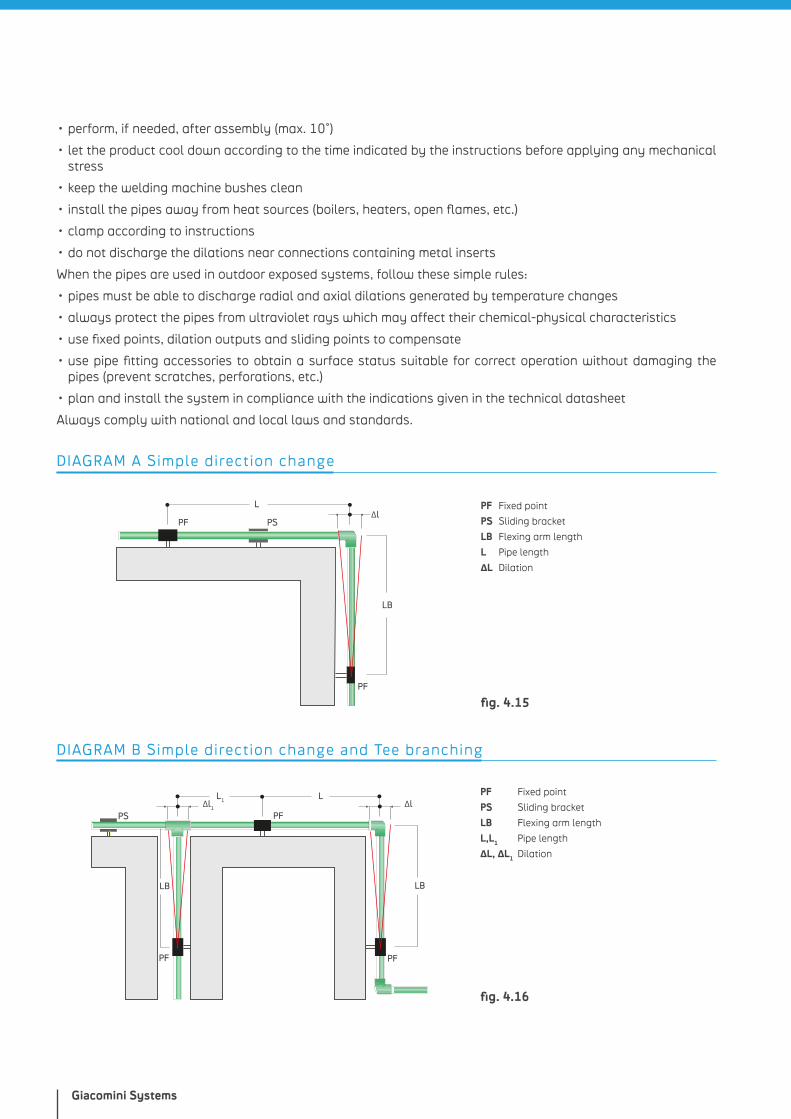
Giacomini Systems
• perform, if needed, after assembly (max. 10°)
• let the product cool down according to the time indicated by the instructions before applying any mechanical stress
• keep the welding machine bushes clean
• install the pipes away from heat sources (boilers, heaters, open flames, etc.)
• clamp according to instructions
• do not discharge the dilations near connections containing metal inserts
When the pipes are used in outdoor exposed systems, follow these simple rules:
• pipes must be able to discharge radial and axial dilations generated by temperature changes
• always protect the pipes from ultraviolet rays which may affect their chemical-physical characteristics
• use fixed points, dilation outputs and sliding points to compensate
• use pipe fitting accessories to obtain a surface status suitable for correct operation without damaging the pipes (prevent scratches, perforations, etc.)
• plan and install the system in compliance with the indications given in the technical datasheet
Always comply with national and local laws and standards.
PF Fixed point
PS Sliding bracket
LB Flexing arm length
L Pipe length
ΔL Dilation
L
PF
PF
∆lPS
LB
DIAGRAM A Simple direction change
fig. 4.15
L1 L
PF
PFPS
LB
PF
LB
∆l∆l1
DIAGRAM B Simple direction change and Tee branching
fig. 4.16
PF Fixed point
PS Sliding bracket
LB Flexing arm length
L,L1 Pipe length
ΔL, ΔL1 Dilation
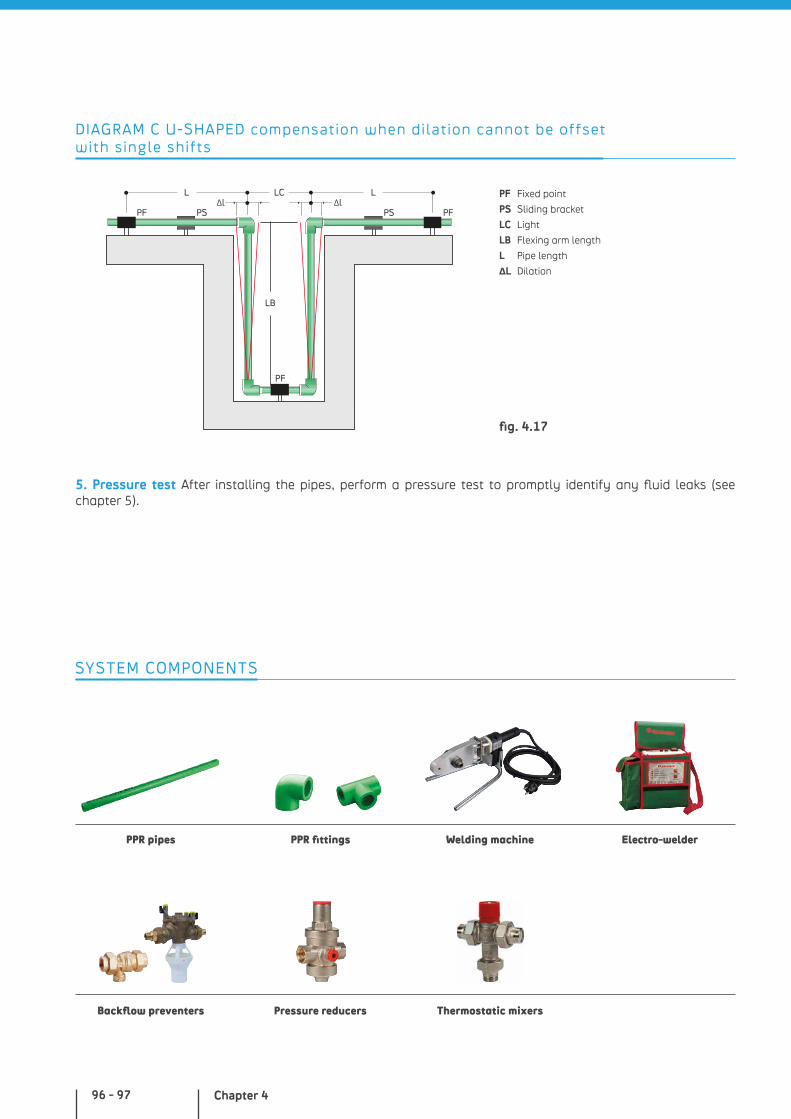
Chapter 496 - 97
L LC
LB
PF
PF PFPS PS
L∆l ∆l
DIAGRAM C U-SHAPED compensation when dilation cannot be offset with single shifts
fig. 4.17
PF Fixed point
PS Sliding bracket
LC Light
LB Flexing arm length
L Pipe length
ΔL Dilation
5. Pressure test After installing the pipes, perform a pressure test to promptly identify any fluid leaks (see chapter 5).
SYSTEM COMPONENTS
PPR pipes
Backflow preventers
PPR fittings
Pressure reducers
Welding machine Electro-welder
Thermostatic mixers

Giacomini Systems
NOTES
European requirements and recommendations for system planning, installation, modification and maintenance.
Chapter 5
In-depth analysis of technical aspects and standards
Chapter 5100 - 101
IN-DEPTH ANALYSIS OF TECHNICAL ASPECTS AND STANDARDS
EN 806 EUROPEAN DIRECTIVE SPECIFICATIONS FOR DRINKING WATER CONVEYING INDOOR SYSTEMS
The European standard EN 806 includes the requirements and recommendations for design, installation, modification, testing, maintenance and operation of new and existing systems for the distribution of drinking water inside buildings.
Drinking water must be fit for drinking and comply with relevant regu-lations based on the European Union Directives. Water may also be used to wash, cook and for hygiene purposes (up to 95 °C tempera-tures to take into account possible malfunctions).
Key points from European Regulation for pipes, accessories and equipment for the supply of drinking water can be split into 5 main chapters:
Part 1: General Information
Part 2: Design
Part 3: Pipe sizing – Simplified method
Part 4: Installation
Part 5: Operation and maintenance
The various parts of EN 806 are dedicated to engineers, architects, supervisors, contractors, installers, water distributors, consumers: they are also used to perform regulatory inspections on the systems.
The national standardization organizations of EU countries must acknowledge the EN 806 European Standard and confer it the status of national standard, either by publishing an identical text or by announcing its adoption. Any preexisting national standard in contrast with the European standard must be withdrawn.
Planning of drinking water systems must therefore comply with the EN 806-2 European standard along with any more stringent national completion standard; among these are, e.g.:
• Italy, UNI 9182: 2014 – Hot and cold water supply and distribu-tion systems - Planning, installation and testing
• Germany, DIN 1988-300: 2012-05 Technische Regeln für Trinkwasser-Installationen - Teil 300: Ermittlung der Rohrdurchmesser; Technische Regel des DVGW
• France, NF DTU 60.11 P1-1: 2013
NOTE: products for use in water conveying systems must comply with regulations and provisions, if any, for the national tests ensuring suitability of contact with drinking water.
The competent government representatives of the Member States and European Commission agreed upon the principle of a shared European Acceptance Scheme (EAS), providing tests and approval
In-depth analysis of technical aspects and standards
systems which will be the same on a European level. If and when the EAS is adopted, the product European Regulations will be amended by adding a Z/EAS appendix within the M136 directive which will include formal references to tests and product certification/marking requirements of EAS products. The current national regulations will continue to apply until the EAS becomes effective.
EN 806 - Part 1: General Information
With the EN 806 standard, the legislative body defines the main goals for realization of the systems, such as: prevent deterioration of water quality in the system; comply with the physical, chemical and microbiological quality standards at draw-off points; achieve the required water flow and pressure of devices, if any, at draw-off points and connection points; prevent damage to goods, including all components for the entire usable life expected and health hazards; minimize noise emissions level; prevent contamination of public water supply, excessive consumption, loss and misuse; functional maintenance.
In addition, the EN806 standard specifies and defines the compe-tences of professional operators involved in drinking water distribution.
Design: the project must be planned by competent professionals of proven experience, qualification, who know the rules and safety requirements.
Installer: the construction, modification and maintenance works must be carried out by competent installers with the qualifications required by national or local regulations.
Water distributor: this entity must provide the data required for the system design and construction, such as supply pressure, flows and analyses of the water quality at the draw-off point.
User: the building owner/tenant is responsible for safe operation and maintenance of the drinking water system.
EN 806 - Part 2: Design
This part of the standard provides the main indications for engineering the drinking water system in terms of technical performance: prevent excessive speed, low flow rates and stagnation areas; prevent air trapping during supply and the formation of air bubbles during operation; minimize or eliminate environmental impact (prevent water waste, excessive consumption, misuse and contamination; do not cause health hazards nor disturbances to people and pets, nor damage buildings or the goods contained therein; minimumize noise generation; prevent crusting, corrosion and deterioration; ensure usability and maintenance, i.e. prevent the local environment from affecting water quality; prevent cross-connections; facilitate access to the devices and the maintenance interventions therein).
Chapter 5102 - 103
It is essential for the planner to design the system in a way that minimizes water consumption and energy demands.
All materials, components and devices used to build drinking water systems must comply with the appropriate CEN product standards or with the European Technical Approval (ETA) guidelines whenever applicable. When existing, national rules and local regulations must be complied with.
Pressure and temperature
All system components must resist the test pressure established by national and local laws and regulations, equal to at least 1.5 times the maximum allowed working pressure. The system pressure must not exceed the working pressure of the components.
When required, supply pressure must be adjusted using pressure reducing valves.
Chapter 3 describes service conditions for plastic pipe systems (application class 1 for supply of hot water at 60 °C, application class 2 for supply of hot water at 70 °C – see Table in fig. 3.2). These systems must also be able to distribute cold water for 50 years, at 20 °C and at a Design Pressure of 10 bar.
The system operation temperature (read 30 s after opening a draw-off point) should not exceed 25 °C for cold water and should not be lower than 60 °C for hot centralized water systems.
The hot water system temperature, up to the system terminal points, should be able to be increased up to 70 °C for disinfection purposes; in case of failure, the system components and connected devices should be able to resist up to 95 °C.
Choosing the materials
The materials used for hot and cold drinking water systems should be selected based on different factors, such as: resistance to internal and external corrosion; compatibility between the various materials and their effect on water quality; internal water pressure; internal and external temperature; permeation; vibration, stress, settling phenomena; mechanical factors such as aging, fatigue, durability, etc.
Lead pipes and fittings should not be used because they are health hazards.
All connections used for drinking water must comply with the standards of reference. All connection methods must comply with the manufacturer’s instructions or local regulations.
Pipe connections must feature permanent watertightness when exposed to alternate stresses during operation.
All connection methods are acceptable for copper and copper alloy pipes and fittings, i.e.: threaded joints, compression fittings, press fittings, quick-lock fittings, flanges and disassemblable tail pieces; threaded joints must have threads complying with EN 10226-1 and national standards and regulations.
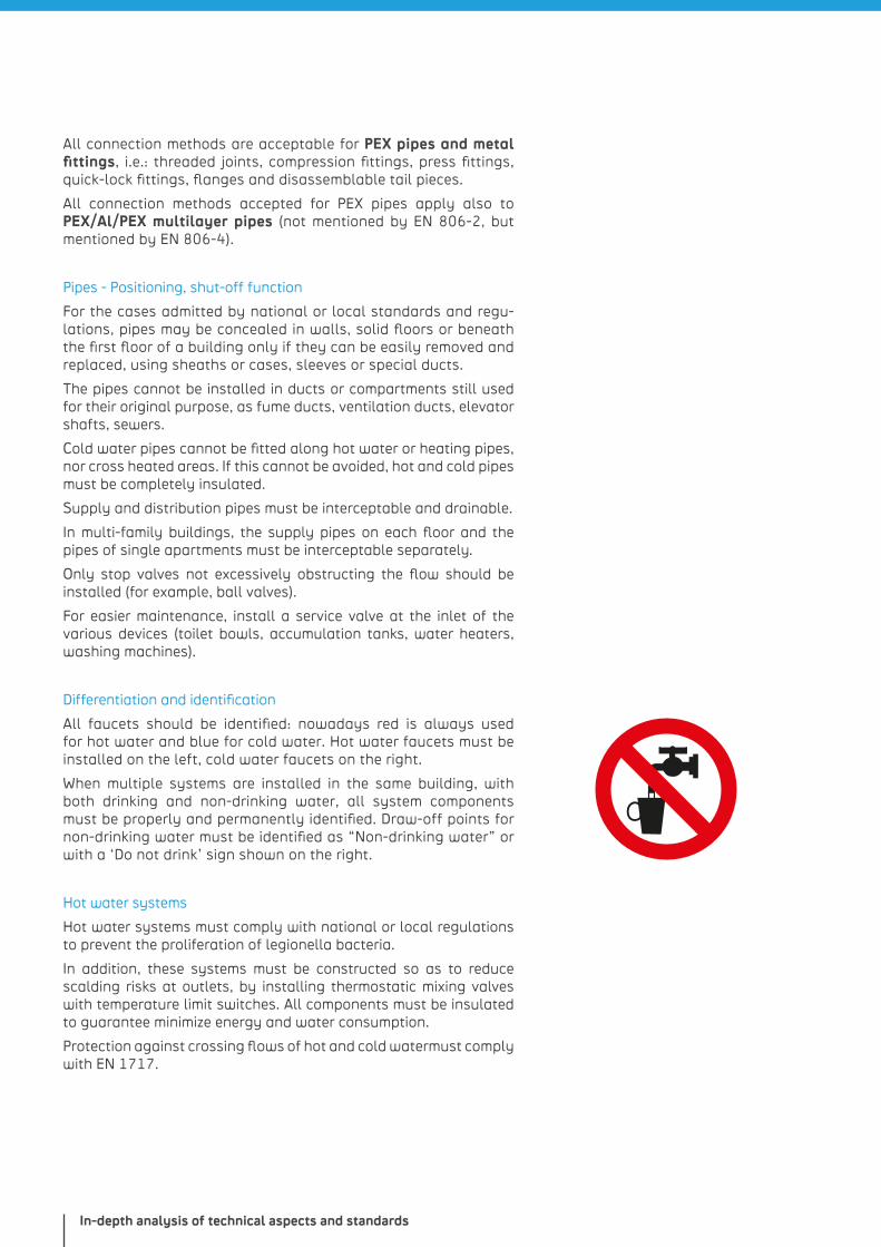
In-depth analysis of technical aspects and standards
All connection methods are acceptable for PEX pipes and metal fittings, i.e.: threaded joints, compression fittings, press fittings, quick-lock fittings, flanges and disassemblable tail pieces.
All connection methods accepted for PEX pipes apply also to PEX/Al/PEX multilayer pipes (not mentioned by EN 806-2, but mentioned by EN 806-4).
Pipes - Positioning, shut-off function
For the cases admitted by national or local standards and regu-lations, pipes may be concealed in walls, solid floors or beneath the first floor of a building only if they can be easily removed and replaced, using sheaths or cases, sleeves or special ducts.
The pipes cannot be installed in ducts or compartments still used for their original purpose, as fume ducts, ventilation ducts, elevator shafts, sewers.
Cold water pipes cannot be fitted along hot water or heating pipes, nor cross heated areas. If this cannot be avoided, hot and cold pipes must be completely insulated.
Supply and distribution pipes must be interceptable and drainable.
In multi-family buildings, the supply pipes on each floor and the pipes of single apartments must be interceptable separately.
Only stop valves not excessively obstructing the flow should be installed (for example, ball valves).
For easier maintenance, install a service valve at the inlet of the various devices (toilet bowls, accumulation tanks, water heaters, washing machines).
Differentiation and identification
All faucets should be identified: nowadays red is always used for hot water and blue for cold water. Hot water faucets must be installed on the left, cold water faucets on the right.
When multiple systems are installed in the same building, with both drinking and non-drinking water, all system components must be properly and permanently identified. Draw-off points for non-drinking water must be identified as “Non-drinking water” or with a ‘Do not drink’ sign shown on the right.
Hot water systems
Hot water systems must comply with national or local regulations to prevent the proliferation of legionella bacteria.
In addition, these systems must be constructed so as to reduce scalding risks at outlets, by installing thermostatic mixing valves with temperature limit switches. All components must be insulated to guarantee minimize energy and water consumption.
Protection against crossing flows of hot and cold watermust comply with EN 1717.
Chapter 5104 - 105
Water meters
Installation of water meters inside and outside buildings must comply with EN 805 water service distributor guidelines.
Water meters must comply with Directive 75/33/CEE (b) for cold water and with Directive 79/830/CEE for hot water.
These devices must be installed horizontally or vertically in a way that facilitates access and maintenance.
Noise
In compliance with national or local regulations, hot water systems must be designed so as to generate the minimum noise possible. To install pipes, use fasteners or brackets that prevent direct contact with the structure and absorb vibrations.
Use expansion loops or suitable alternatives for long straight pipe sections to ease pipe movement.
Protecting the system from external temperatures for pipes, fittings and devices
All components of the drinking water distribution system must be protected from freezing and the influence of weather conditions by draining, insulating with linings resistant to atmospheric agents or through a local heating system combined with an anti-freeze thermo-stat. National or local provisions indicate minimum thickness of the thermal insulation materials to be used.
Cold water pipes must be properly protected from heat gain and condensation: the insulation requirements are the same as those applied to thermal dispersion.
Pressurization and pressure reducing valves
Pressurization systems can be installed in cases where the pressure required at all draw-off points cannot be provided under normal operation conditions (e.g., auxiliary pressurization pumps).
To curb energy consumption, use of such systems must be reduced to an absolute minimum, and the need must be demonstrated through a differentiated calculation.
Pressure reducers can be required to create systems with multiple pressure zones or when the static pressure at draw-off points exceeds 500 kPa or 5 bar. Pressure reducing valves should not be sized based on nominal pipe dimensions, but on the required flow rate.
In-depth analysis of technical aspects and standards
They are generally installed inside the cold water pipe downstream of the water meter unit; for regulation and maintenance purposes, they must include a pressure plug and shut-off valves. To prevent backflow phenomena, a pipe section 5 times as long as the inside diameter must be installed as an outflow section on the valve’s delivery side.
All regulation devices must protect the hot and cold water systems from bursting. In addition, they must be easy to access and properly identified to prevent erroneous regulations and improper replace-ments. Maintenance requirements must be clearly shown for the operator.
EN 806 - Part 3: Pipe sizing - Simplified method
Part 3 of standard EN 806 describes a calculation method for pipe sizing in drinking water systems, used both for hot and cold water.
This method, known as “simplified”, complies with the European minimum standard and it is characterized by a series of limitations:
it applies only to “normalized” systems, that is systems with devices whose single-unit flow rates do not exceed those shown in Table 5.1, not destined for uninterrupted use of water (more than 15 minutes), with traditional simultaneous use, that is when the typical demand does not exceed the one shown by the simultaneity curve (see fig. 5.2)
it does not apply to buildings with dimensions much greater than average buildings
it does not take into consideration how pressure is distributed within the installation, the geodetic height, the device’s losses of pressure, the minimum flow of each draw-off point
it determines the pipe diameters from the Tables based on the number of draw-off points and hot water devices connected
it does not size the hot water recirculations
it does not include pipe sizing for fire prevention systems
In brief, the simplified method can be applied to most residential buildings. The designer may however adopt a calculation method that is approved on a national level.
The simplified method does not apply to non-standardized systems (the so-called “special” systems) and to systems destined to buildings with dimensions much greater than the average: in such cases, sizing must be carried out by calculation methods specified and approved on a national level.
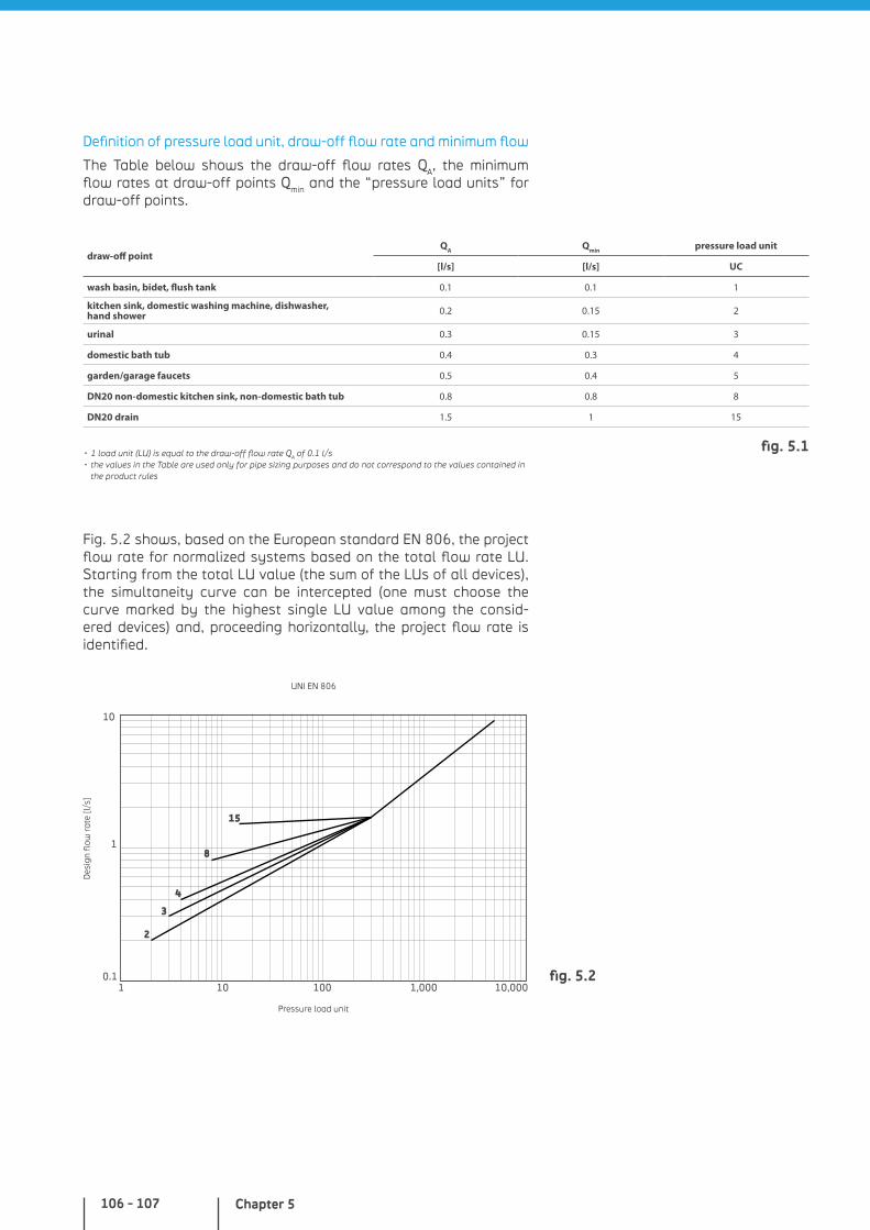
Chapter 5106 - 107
Definition of pressure load unit, draw-off flow rate and minimum flow
The Table below shows the draw-off flow rates QA, the minimum flow rates at draw-off points Qmin and the “pressure load units” for draw-off points.
draw-off pointQA Qmin pressure load unit
[l/s] [l/s] UC
wash basin, bidet, flush tank 0.1 0.1 1
kitchen sink, domestic washing machine, dishwasher, hand shower 0.2 0.15 2
urinal 0.3 0.15 3
domestic bath tub 0.4 0.3 4
garden/garage faucets 0.5 0.4 5
DN20 non-domestic kitchen sink, non-domestic bath tub 0.8 0.8 8
DN20 drain 1.5 1 15
• 1 load unit (LU) is equal to the draw-off flow rate QA of 0.1 l/s• the values in the Table are used only for pipe sizing purposes and do not correspond to the values contained in
the product rules
Fig. 5.2 shows, based on the European standard EN 806, the project flow rate for normalized systems based on the total flow rate LU. Starting from the total LU value (the sum of the LUs of all devices), the simultaneity curve can be intercepted (one must choose the curve marked by the highest single LU value among the consid-ered devices) and, proceeding horizontally, the project flow rate is identified.
0.1
1
2
3
4
8
15
10
1 10 100 1,000 10,000fig. 5.2
Des
ign
flow
rat
e [l
/s]
Pressure load unit
UNI EN 806
fig. 5.1
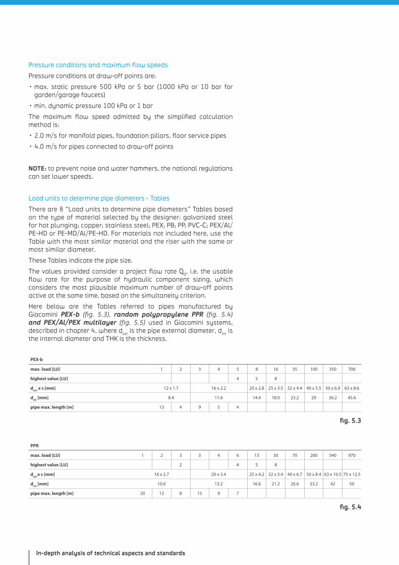
In-depth analysis of technical aspects and standards
Pressure conditions and maximum flow speeds
Pressure conditions at draw-off points are:
• max. static pressure 500 kPa or 5 bar (1000 kPa or 10 bar for garden/garage faucets)
• min. dynamic pressure 100 kPa or 1 bar
The maximum flow speed admitted by the simplified calculation method is:
• 2.0 m/s for manifold pipes, foundation pillars, floor service pipes
• 4.0 m/s for pipes connected to draw-off points
NOTE: to prevent noise and water hammers, the national regulations can set lower speeds.
Load units to determine pipe diameters - Tables
There are 8 “Load units to determine pipe diameters” Tables based on the type of material selected by the designer: galvanized steel for hot plunging; copper; stainless steel; PEX; PB; PP; PVC-C; PEX/Al/PE-HD or PE-MD/Al/PE-HD. For materials not included here, use the Table with the most similar material and the riser with the same or most similar diameter.
These Tables indicate the pipe size.
The values provided consider a project flow rate QD, i.e. the usable flow rate for the purpose of hydraulic component sizing, which considers the most plausible maximum number of draw-off points active at the same time, based on the simultaneity criterion.
Here below are the Tables referred to pipes manufactured by Giacomini PEX-b (fig. 5.3), random polypropylene PPR (fig. 5.4) and PEX/Al/PEX multilayer (fig. 5.5) used in Giacomini systems, described in chapter 4, where dext is the pipe external diameter, dint is the internal diameter and THK is the thickness.
PEX-b
max. load [LU] 1 2 3 4 5 8 16 35 100 350 700
highest value [LU] 4 5 8
dext x s [mm] 12 x 1.7 16 x 2.2 20 x 2.8 25 x 3.5 32 x 4.4 40 x 5.5 50 x 6.9 63 x 8.6
dint [mm] 8.4 11.6 14.4 18.0 23.2 29 36.2 45.6
pipe max. length [m] 13 4 9 5 4
PPR
max. load [LU] 1 2 3 3 4 6 13 30 70 200 540 970
highest value [LU] 2 4 5 8
dest x s [mm] 16 x 2.7 20 x 3.4 25 x 4.2 32 x 5.4 40 x 6.7 50 x 8.4 63 x 10.5 75 x 12.5
dint [mm] 10.6 13.2 16.6 21.2 26.6 33.2 42 50
pipe max. length [m] 20 12 8 15 9 7
fig. 5.3
fig. 5.4
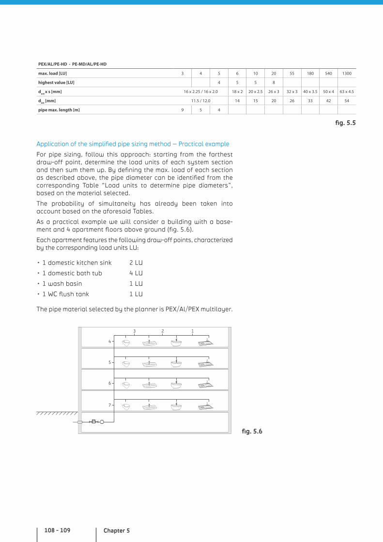
Chapter 5108 - 109
PEX/AL/PE-HD - PE-MD/AL/PE-HD
max. load [LU] 3 4 5 6 10 20 55 180 540 1300
highest value [LU] 4 5 5 8
dest x s [mm] 16 x 2.25 / 16 x 2.0 18 x 2 20 x 2.5 26 x 3 32 x 3 40 x 3.5 50 x 4 63 x 4.5
dint [mm] 11.5 / 12.0 14 15 20 26 33 42 54
pipe max. length [m] 9 5 4
Application of the simplified pipe sizing method – Practical example
For pipe sizing, follow this approach: starting from the farthest draw-off point, determine the load units of each system section and then sum them up. By defining the max. load of each section as described above, the pipe diameter can be identified from the corresponding Table “Load units to determine pipe diameters”, based on the material selected.
The probability of simultaneity has already been taken into account based on the aforesaid Tables.
As a practical example we will consider a building with a base-ment and 4 apartment floors above ground (fig. 5.6).
Each apartment features the following draw-off points, characterized by the corresponding load units LU:
• 1 domestic kitchen sink 2 LU
• 1 domestic bath tub 4 LU
• 1 wash basin 1 LU
• 1 WC flush tank 1 LU
The pipe material selected by the planner is PEX/Al/PEX multilayer.
m3
3
4
5
6
7
2 1
fig. 5.5
fig. 5.6
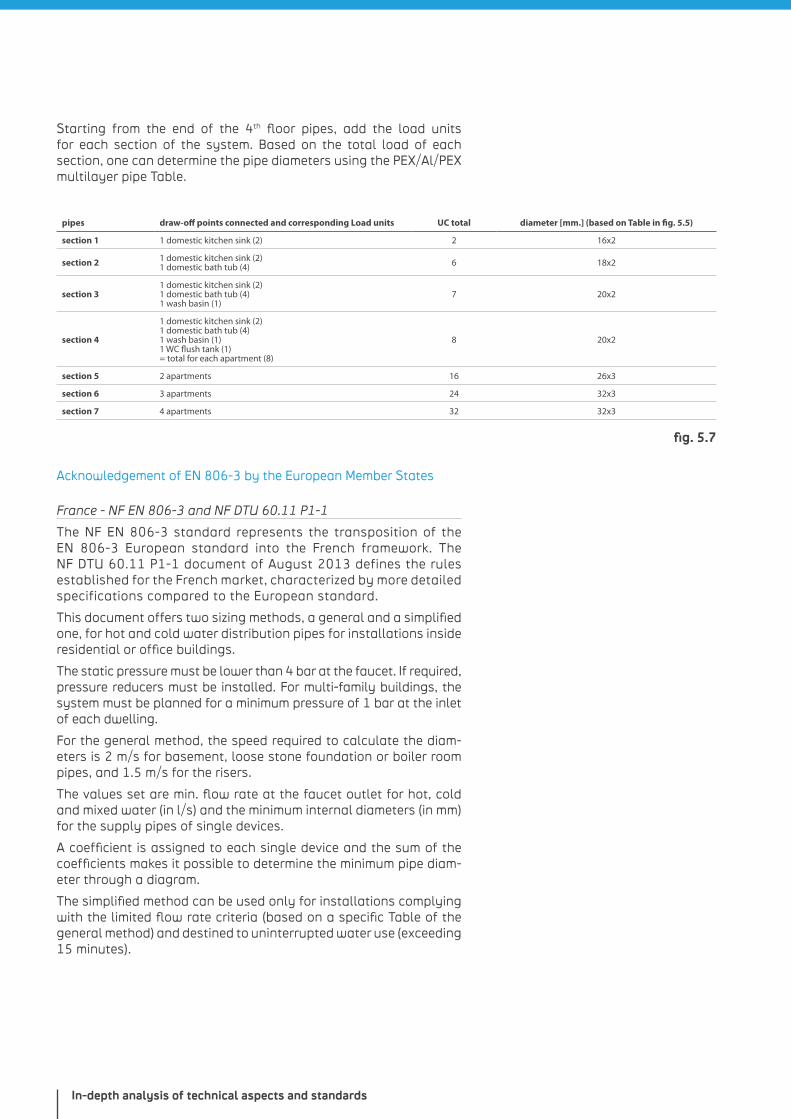
In-depth analysis of technical aspects and standards
Starting from the end of the 4th floor pipes, add the load units for each section of the system. Based on the total load of each section, one can determine the pipe diameters using the PEX/Al/PEX multilayer pipe Table.
pipes draw-off points connected and corresponding Load units UC total diameter [mm.] (based on Table in fig. 5.5)
section 1 1 domestic kitchen sink (2) 2 16x2
section 2 1 domestic kitchen sink (2)1 domestic bath tub (4) 6 18x2
section 31 domestic kitchen sink (2)1 domestic bath tub (4)1 wash basin (1)
7 20x2
section 4
1 domestic kitchen sink (2)1 domestic bath tub (4)1 wash basin (1)1 WC flush tank (1)= total for each apartment (8)
8 20x2
section 5 2 apartments 16 26x3
section 6 3 apartments 24 32x3
section 7 4 apartments 32 32x3
Acknowledgement of EN 806-3 by the European Member States
France - NF EN 806-3 and NF DTU 60.11 P1-1
The NF EN 806-3 standard represents the transposition of the EN 806-3 European standard into the French framework. The NF DTU 60.11 P1-1 document of August 2013 defines the rules established for the French market, characterized by more detailed specifications compared to the European standard.
This document offers two sizing methods, a general and a simplified one, for hot and cold water distribution pipes for installations inside residential or office buildings.
The static pressure must be lower than 4 bar at the faucet. If required, pressure reducers must be installed. For multi-family buildings, the system must be planned for a minimum pressure of 1 bar at the inlet of each dwelling.
For the general method, the speed required to calculate the diam-eters is 2 m/s for basement, loose stone foundation or boiler room pipes, and 1.5 m/s for the risers.
The values set are min. flow rate at the faucet outlet for hot, cold and mixed water (in l/s) and the minimum internal diameters (in mm) for the supply pipes of single devices.
A coefficient is assigned to each single device and the sum of the coefficients makes it possible to determine the minimum pipe diam-eter through a diagram.
The simplified method can be used only for installations complying with the limited flow rate criteria (based on a specific Table of the general method) and destined to uninterrupted water use (exceeding 15 minutes).
fig. 5.7
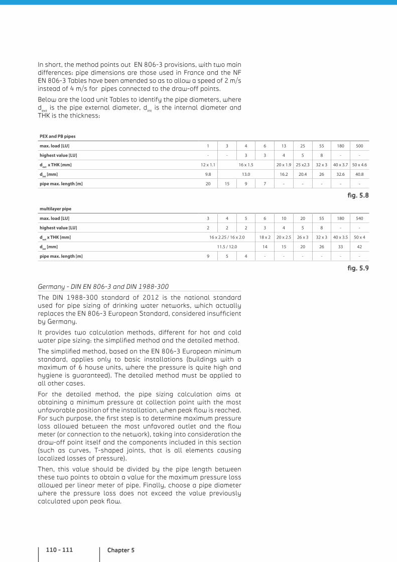
Chapter 5110 - 111
In short, the method points out EN 806-3 provisions, with two main differences: pipe dimensions are those used in France and the NF EN 806-3 Tables have been amended so as to allow a speed of 2 m/s instead of 4 m/s for pipes connected to the draw-off points.
Below are the load unit Tables to identify the pipe diameters, where dext is the pipe external diameter, dint is the internal diameter and THK is the thickness:
PEX and PB pipes
max. load [LU] 1 3 4 6 13 25 55 180 500
highest value [LU] - - 3 3 4 5 8 - -
dext x THK [mm] 12 x 1.1 16 x 1.5 20 x 1.9 25 x2.3 32 x 3 40 x 3.7 50 x 4.6
dint [mm] 9.8 13.0 16.2 20.4 26 32.6 40.8
pipe max. length [m] 20 15 9 7 - - - - -
multilayer pipe
max. load [LU] 3 4 5 6 10 20 55 180 540
highest value [LU] 2 2 2 3 4 5 8 - -
dest x THK [mm] 16 x 2.25 / 16 x 2.0 18 x 2 20 x 2.5 26 x 3 32 x 3 40 x 3.5 50 x 4
dint [mm] 11.5 / 12.0 14 15 20 26 33 42
pipe max. length [m] 9 5 4 - - - - - -
Germany - DIN EN 806-3 and DIN 1988-300
The DIN 1988-300 standard of 2012 is the national standard used for pipe sizing of drinking water networks, which actually replaces the EN 806-3 European Standard, considered insufficient by Germany.
It provides two calculation methods, different for hot and cold water pipe sizing: the simplified method and the detailed method.
The simplified method, based on the EN 806-3 European minimum standard, applies only to basic installations (buildings with a maximum of 6 house units, where the pressure is quite high and hygiene is guaranteed). The detailed method must be applied to all other cases.
For the detailed method, the pipe sizing calculation aims at obtaining a minimum pressure at collection point with the most unfavorable position of the installation, when peak flow is reached. For such purpose, the first step is to determine maximum pressure loss allowed between the most unfavored outlet and the flow meter (or connection to the network), taking into consideration the draw-off point itself and the components included in this section (such as curves, T-shaped joints, that is all elements causing localized losses of pressure).
Then, this value should be divided by the pipe length between these two points to obtain a value for the maximum pressure loss allowed per linear meter of pipe. Finally, choose a pipe diameter where the pressure loss does not exceed the value previously calculated upon peak flow.
fig. 5.8
fig. 5.9
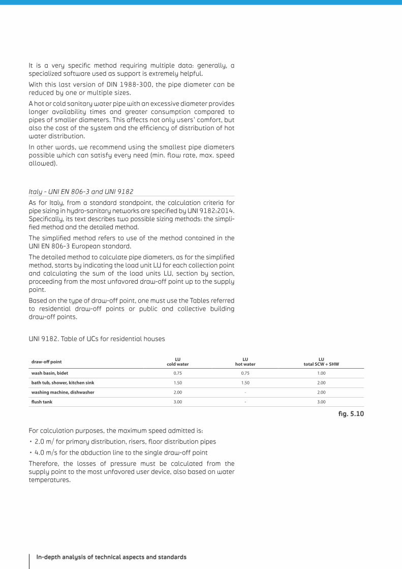
In-depth analysis of technical aspects and standards
It is a very specific method requiring multiple data: generally, a specialized software used as support is extremely helpful.
With this last version of DIN 1988-300, the pipe diameter can be reduced by one or multiple sizes.
A hot or cold sanitary water pipe with an excessive diameter provides longer availability times and greater consumption compared to pipes of smaller diameters. This affects not only users’ comfort, but also the cost of the system and the efficiency of distribution of hot water distribution.
In other words, we recommend using the smallest pipe diameters possible which can satisfy every need (min. flow rate, max. speed allowed).
Italy - UNI EN 806-3 and UNI 9182
As for Italy, from a standard standpoint, the calculation criteria for pipe sizing in hydro-sanitary networks are specified by UNI 9182:2014. Specifically, its text describes two possible sizing methods: the simpli-fied method and the detailed method.
The simplified method refers to use of the method contained in the UNI EN 806-3 European standard.
The detailed method to calculate pipe diameters, as for the simplified method, starts by indicating the load unit LU for each collection point and calculating the sum of the load units LU, section by section, proceeding from the most unfavored draw-off point up to the supply point.
Based on the type of draw-off point, one must use the Tables referred to residential draw-off points or public and collective building draw-off points.
UNI 9182. Table of UCs for residential houses
draw-off point LU cold water
LUhot water
LUtotal SCW + SHW
wash basin, bidet 0.75 0.75 1.00
bath tub, shower, kitchen sink 1.50 1.50 2.00
washing machine, dishwasher 2.00 - 2.00
flush tank 3.00 - 3.00
For calculation purposes, the maximum speed admitted is:
• 2.0 m/ for primary distribution, risers, floor distribution pipes
• 4.0 m/s for the abduction line to the single draw-off point
Therefore, the losses of pressure must be calculated from the supply point to the most unfavored user device, also based on water temperatures.
fig. 5.10
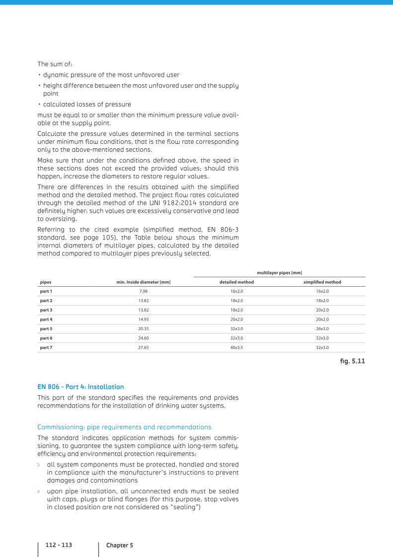
Chapter 5112 - 113
The sum of:
• dynamic pressure of the most unfavored user
• height difference between the most unfavored user and the supply point
• calculated losses of pressure
must be equal to or smaller than the minimum pressure value avail-able at the supply point.
Calculate the pressure values determined in the terminal sections under minimum flow conditions, that is the flow rate corresponding only to the above-mentioned sections.
Make sure that under the conditions defined above, the speed in these sections does not exceed the provided values; should this happen, increase the diameters to restore regular values.
There are differences in the results obtained with the simplified method and the detailed method. The project flow rates calculated through the detailed method of the UNI 9182:2014 standard are definitely higher: such values are excessively conservative and lead to oversizing.
Referring to the cited example (simplified method, EN 806-3 standard, see page 105), the Table below shows the minimum internal diameters of multilayer pipes, calculated by the detailed method compared to multilayer pipes previously selected.
multilayer pipes [mm]
pipes min. Inside diameter [mm] detailed method simplified method
part 1 7.98 16x2.0 16x2.0
part 2 13.82 18x2.0 18x2.0
part 3 13.82 18x2.0 20x2.0
part 4 14.93 20x2.0 20x2.0
part 5 20.35 32x3.0 26x3.0
part 6 24.60 32x3.0 32x3.0
part 7 27.65 40x3.5 32x3.0
EN 806 - Part 4: Installation
This part of the standard specifies the requirements and provides recommendations for the installation of drinking water systems.
Commissioning: pipe requirements and recommendations
The standard indicates application methods for system commis-sioning, to guarantee the system compliance with long-term safety, efficiency and environmental protection requirements:
all system components must be protected, handled and stored in compliance with the manufacturer’s instructions to prevent damages and contaminations
upon pipe installation, all unconnected ends must be sealed with caps, plugs or blind flanges (for this purpose, stop valves in closed position are not considered as “sealing”)
fig. 5.11
In-depth analysis of technical aspects and standards
pipes must be bent with special tools, making an effort to prevent wrinkling, corrugations or narrowing
in case of long straight sections, the pipes must be free to expand and contract through dilation compensators, expan-sion joints or changes of direction
pipes must be installed so as to prevent the formation of air bubbles. Draining points must be provided in the lowest points of the system. To prevent freezing damages, pipes must be drained, insulated or heated locally
in case of overlapping installation of hot and cold water pipes, the hot water pipe must be placed on top of the other
in-wall pipes must be properly sleeved and/or insulated. In compliance with the national regulations, access to specific connections must be guaranteed for maintenance and inspection
plastic pipes inside sleeves must be installed with a bending radius of at least 8 times the external pipe diameter; we recom-mend fitting a sleeve at the floor or wall outlet
pipes crossing walls or floors must be sleeved, without affecting the integrity of the structural elements and fire prevention barriers
in general, systems must minimize noise levels. For such purpose, pipes must be installed away from joints, beams, floor planks and other pipes: if this is unfeasible, insulation panels must be installed between the pipe and the structure
pipe supports or brackets must guarantee permanent fitting to the structure and should not be installed to fit other compo-nents. For plastic pipes, special plastic or metal collars are required, leaving some space for axial movement within the clips which are not anchoring points. The distance between supports must comply with manufacturer’s instructions or with national regulations or, if these fail, with appendix B and C of the standard
pipes unions must be made according to manufacturer’s instruc-tions and related standards, and preventive internal cleaning must be carried out on pipes and fittings. All connections must be permanently sealed and covered with insulation only after the pressure test is done (except when access is required by national regulations). The standard also refers to tables with connection methods to be used based on the types of materials for pipes and joints, as already specified by part 2, and the table for multilayer pipes (identical to the PEX pipes Table) is added
plastic pipes must not be connected directly to boilers and instantaneous water heaters as their safety devices allow for overtemperatures higher than 95 °C (< 10 s) and overpressures higher than the max. design pressure (MDP) (< 10 %)
valves and faucets must be installed in compliance with EN 806-2 - Planning, in compliance with EN 1717 and national regulations, so as to prevent water stagnation and with access guaranteed for maintenance and service interventions
Chapter 5114 - 115
pipes and delivery valves must show the performed service, with exceptions made for single-family houses
the use of different metals in drinking water systems must comply with the provisions of the relevant standards. Differ-ences of electrochemical potential may generate galvanic corrosion under specific circumstances. For example, copper, as a noble metal, may corrode galvanized steel: in this case, galva-nized steel products (hot-dip galvanizing) must be installed upstream of copper elements, in other words water must flow from the galvanized steel towards copper and direct contact between the galvanized steel and copper components must be avoided, e.g. by placing brass or bronze fittings in between. Copper, copper alloys and stainless steel can be used together without significant galvanic corrosions as their electrochemical potential differs only for a minimum part. In such case, use of copper alloy valves in water distribution systems is not consid-ered critical, as they feature a relatively limited surface
when installing water distribution systems, one must trace a map of the pipe layouts and the position of the various compo-nents. Upon completion, this report will represent a long-lasting document of the system “as is on site” and must be delivered to the building owner
Commissioning
Filling and hydraulic test
Drinking water systems must be filled only with drinking water free of particles larger than 150 µm: to guarantee the above requirement, mechanic filters complying with EN 13443-1 must be included.
For hydraulic testing, all parameters must be recorded and saved, including the complete procedure diagram. The gauges and recording device must be installed in the lowest point of the system, they must have a size interval between 0 and 1.6 MPa and accuracy up to 0.02 MPa bar.
The test pressure is equal to the MDP increased by 10 % (TP = 1.1 x MDP), while maximum pressure climbing speed is calculated based on the nominal pressure.
NOTE FOR PLASTIC PIPES:
• the specific properties of the plastic material make large pressurized plastic pipes expand for a limited time: this may affect the hydraulic test. For such reason, the hydraulic test of large plastic pipes differs from that of metal pipes
• based on the same specific properties of the material, temperature variations in the system may cause pressure variations for elastic (multilayer, PVC, etc.) and viscoelastic (PEX, PP, etc.) pipes. Thus, for balancing temperatures exceeding 25 °C, the test pressure must be calculated by applying a reduction factor fT based on the material used, provided by the system manufacturer (TP = 1.1 x fT x MDP). For the entire test duration, water must be maintained at a constant temperature for as long as possible
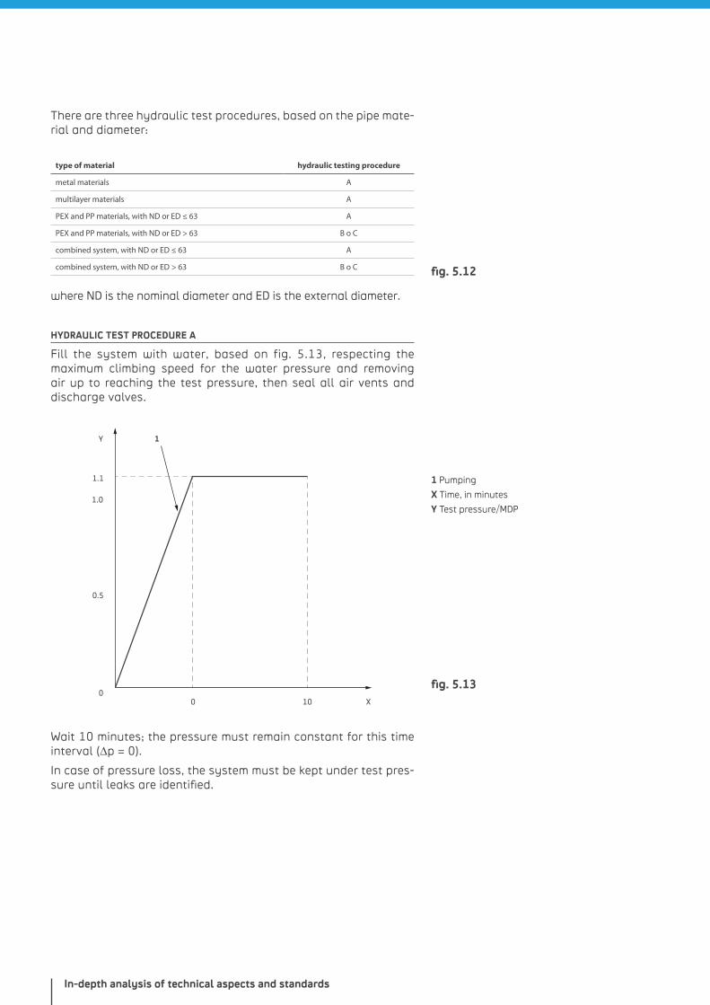
In-depth analysis of technical aspects and standards
There are three hydraulic test procedures, based on the pipe mate-rial and diameter:
type of material hydraulic testing procedure
metal materials A
multilayer materials A
PEX and PP materials, with ND or ED ≤ 63 A
PEX and PP materials, with ND or ED > 63 B o C
combined system, with ND or ED ≤ 63 A
combined system, with ND or ED > 63 B o C
where ND is the nominal diameter and ED is the external diameter.
HYDRAULIC TEST PROCEDURE A
Fill the system with water, based on fig. 5.13, respecting the maximum climbing speed for the water pressure and removing air up to reaching the test pressure, then seal all air vents and discharge valves.
1
1.0
1.1
0.5
00 10
Y
X
Wait 10 minutes; the pressure must remain constant for this time interval (∆p = 0).
In case of pressure loss, the system must be kept under test pres-sure until leaks are identified.
1 Pumping
X Time, in minutes
Y Test pressure/MDP
fig. 5.12
fig. 5.13
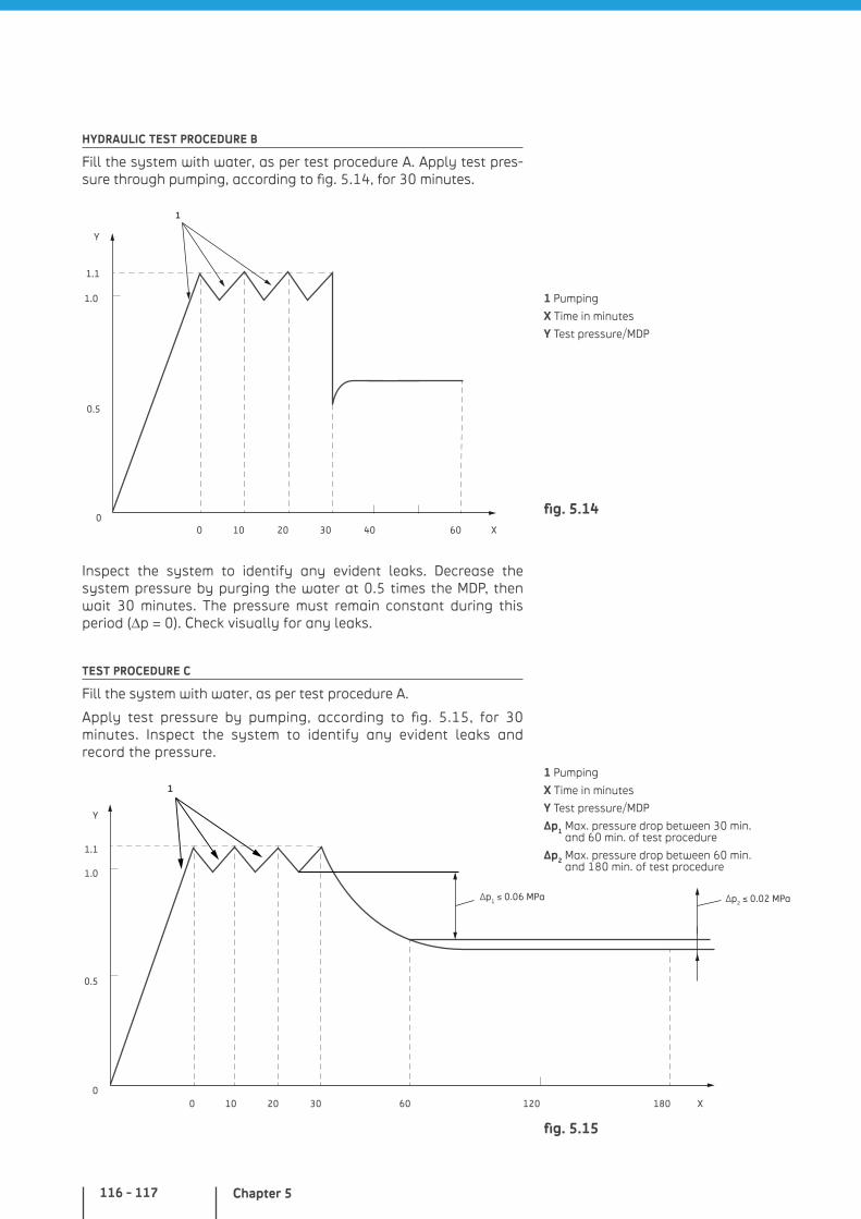
Chapter 5116 - 117
HYDRAULIC TEST PROCEDURE B
Fill the system with water, as per test procedure A. Apply test pres-sure through pumping, according to fig. 5.14, for 30 minutes.
1
1.0
1.1
0.5
00 10 20 30 40 60
Y
X
Inspect the system to identify any evident leaks. Decrease the system pressure by purging the water at 0.5 times the MDP, then wait 30 minutes. The pressure must remain constant during this period (∆p = 0). Check visually for any leaks.
TEST PROCEDURE C
Fill the system with water, as per test procedure A.
Apply test pressure by pumping, according to fig. 5.15, for 30 minutes. Inspect the system to identify any evident leaks and record the pressure.
Y
X
∆p1 ≤ 0.06 MPa
1
1.0
1.1
0.5
00 10 20 30 60 120 180
∆p2 ≤ 0.02 MPa
1 Pumping
X Time in minutes
Y Test pressure/MDP
1 Pumping
X Time in minutes
Y Test pressure/MDP
Δp1 Max. pressure drop between 30 min. and 60 min. of test procedure
Δp2 Max. pressure drop between 60 min. and 180 min. of test procedure
fig. 5.14
fig. 5.15
In-depth analysis of technical aspects and standards
Wait for another 30 minutes and record the pressure. If the pressure loss is lower than 0.06 MPa, the system can be considered free of evident leaks.
Proceed with the test without pumping and wait for other 120 minutes.
If the pressure drops by more than 0.02 MPa or 0.2 bar, there is a leak inside the system. Maintain pressure and identify the leak.
Fluxing
The drinking water system must be fluxed right after pressure testing and right before commissioning. If the system is not used right after commissioning, it must be fluxed at regular intervals (up to every 7 days).
This requires drinking water free of particles larger than 150 µm (by using mechanical filters in compliance with EN 13443-1 to protect sensitive components and devices) or a water-air mixture.
The entire procedure must be reported completely (with hot and cold water pipes fluxed separately) and delivered to the building owner.
The system must be fluxed by section, based on its dimensions and layout, starting from the lowest floor and proceeding grad-ually up. All service valves installed in the section to be fluxed must be completely open. Aerators, flow filters, flow controllers, shower nozzles installed with pre-set valves must be removed to increase the flow.
On each floor, starting from the farthest point from the riser, open the draw-off points completely and perform water exchange for at least 20 times, with a minimum speed of 2 m/s.
The filters installed upstream of the valves or system, that cannot be replaced after fluxing, must be counter-flushed or renewed.
For single-family houses, small extensions or modifications on any property, the fluxing procedure is enough to use the drinking water system. If required by the competent authorities, the system must also be disinfected.
Disinfection
Disinfection of drinking water systems required by competent authorities must be performed by specialized personnel with proper qualifications and in compliance with national or local regulations.
Make sure no water is collected during the entire procedure. The system must be broken down into sections based on its dimensions.
After disinfection, the system must be promptly drained and thoroughly fluxed with drinking water, in compliance with the disinfectant manufacturer’s instructions/recommendations (the external chemical agent must be absent or below the level estab-lished by national laws).
Chapter 5118 - 119
Then, samples must be collected for the bacteriological analyses.
The type of disinfectants to be used depends on multiple factors. All chemical substances used for disinfection of drinking water systems must comply with the related requirements, as estab-lished by the European and national standards. The disinfectant application and use must be carried out in compliance with the pertinent EU Directives and all local or national laws.
If the water used for disinfection must be drained in a drainage or sewerage system, the competent organization must be noti-fied and its approval given before proceeding with the drainage. Neutralizing agents are available on request.
The entire procedure and the test results must be reported in detail and delivered to the building owner.
EN 806 - Part 5: Operation and maintenance
The systems must be operated and undergo maintenance to prevent any negative influence on the quality of the drinking water, its distribution to the users and the equipment of water distributors.
For proper operation and maintenance, information related to the system (product technical information and manufacturer’s instruc-tions, commissioning report, and periodical maintenance records) must be promptly available.
Responsibility for system operation, inspection and maintenance is subject to local and national requirements.
Operation
The system must be operated according to the conditions of the original project.
The systems and devices must be tested so as to ensure their oper-ation reliability.
If not specified otherwise by the related operational instructions, comply with the general conditions below:
stop valves and service valves must be always fully opened or closed and activated on a regular basis to ensure their operation
all spare parts, preferably from the original manufacturer, must be promptly available and suitable for the purpose
connection of the devices may affect the quality of water and must be carried out by qualified personnel
connection of devices (e.g. washing machine and dishwasher) must be properly protected against reflux in compliance with EN 1717
flexible pipes (such as gardening hoses) must be connected only to dedicated draw-off points, specifically designed for such purpose and provided with anti-reflux protection
In-depth analysis of technical aspects and standards
system parts used more rarely and containing water (e.g. pipes connected to guest rooms, garages or basement connections) must be fluxed on a regular basis
check water temperature inside pipes, cold water tanks, hot water accumulation tanks and faucet discharge to ensure it complies with the limits of part 2 of the standard
by applying the local and national regulations, pay special attention to operation and maintenance of safety and protec-tion devices in addition to the position of the stop valves
Operation interruptions and supply resumption
Systems not activated within 7 days after completion, or left out of service for more than 7 days, must be disconnected at the supply stop valve and drained; as an alternative, flux the water on a regular basis.
Connection pipes not commissioned right after completion, or which must be temporarily disconnected or not used for a year, must be disconnected from the water supply network.
Systems that have been temporarily disconnected and drained must be thoroughly fluxed based on a special procedure before restoring operation.
In case of extended absence, to prevent potential damages caused by water and water leaks, the standard requires insulating the system at the supply stop valve in residential units or on the inlet pipe of the apartment.
In general, following an operation interruption, the stagnating water flows out by simply opening completely the single draw-off point fittings for a short time (approx. 5 minutes).
Damages and failures
Damages and failures of the system may pollute the water or affect its qualities (smell, taste, color): the system must be connected at the service stop valve and the water distribution company should be promptly notified.
In case of stagnation, with non-complying water temperatures, there is a higher risk of bacterial proliferation bacteria (Legionella). Corrective measures must be taken.
Maintenance
Systems must be inspected on a regular basis to check safety and performance. Adequate procedures must be adopted to maintain system performance on the level specified by EN 806-2, EN 1717 and by the single product standards.
Procedures and frequency of ordinary maintenance must comply with the manufacturer’s instructions. If applicable, national require-ments must also be complied with.
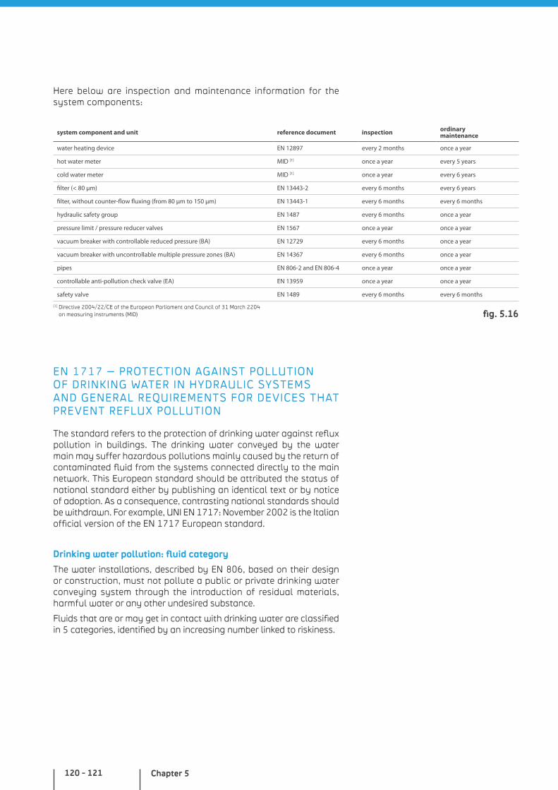
Chapter 5120 - 121
Here below are inspection and maintenance information for the system components:
system component and unit reference document inspection ordinary maintenance
water heating device EN 12897 every 2 months once a year
hot water meter MID [1] once a year every 5 years
cold water meter MID [1] once a year every 6 years
filter (< 80 μm) EN 13443-2 every 6 months every 6 years
filter, without counter-flow fluxing (from 80 μm to 150 μm) EN 13443-1 every 6 months every 6 months
hydraulic safety group EN 1487 every 6 months once a year
pressure limit / pressure reducer valves EN 1567 once a year once a year
vacuum breaker with controllable reduced pressure (BA) EN 12729 every 6 months once a year
vacuum breaker with uncontrollable multiple pressure zones (BA) EN 14367 every 6 months once a year
pipes EN 806-2 and EN 806-4 once a year once a year
controllable anti-pollution check valve (EA) EN 13959 once a year once a year
safety valve EN 1489 every 6 months every 6 months
[1] Directive 2004/22/CE of the European Parliament and Council of 31 March 2204 on measuring instruments (MID)
EN 1717 – PROTECTION AGAINST POLLUTION OF DRINKING WATER IN HYDRAULIC SYSTEMS AND GENERAL REQUIREMENTS FOR DEVICES THAT PREVENT REFLUX POLLUTION
The standard refers to the protection of drinking water against reflux pollution in buildings. The drinking water conveyed by the water main may suffer hazardous pollutions mainly caused by the return of contaminated fluid from the systems connected directly to the main network. This European standard should be attributed the status of national standard either by publishing an identical text or by notice of adoption. As a consequence, contrasting national standards should be withdrawn. For example, UNI EN 1717: November 2002 is the Italian official version of the EN 1717 European standard.
Drinking water pollution: fluid category
The water installations, described by EN 806, based on their design or construction, must not pollute a public or private drinking water conveying system through the introduction of residual materials, harmful water or any other undesired substance.
Fluids that are or may get in contact with drinking water are classified in 5 categories, identified by an increasing number linked to riskiness.
fig. 5.16
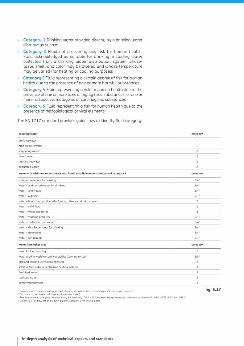
In-depth analysis of technical aspects and standards
Category 1 Drinking water provided directly by a drinking water distribution system
Category 2 Fluid not presenting any risk for human health. Fluid acknowledged as suitable for drinking, including water collected from a drinking water distribution system whose-taste, smell and color may be altered and whose temperature may be varied (for heating or cooling purposes)
Category 3 Fluid representing a certain degree of risk for human health due to the presence of one or more harmful substances
Category 4 Fluid representing a risk for human health due to the presence of one or more toxic or highly toxic substances, or one or more radioactive, mutagenic or carcinogenic substances
Category 5 Fluid representing a risk for human health due to the presence of microbiological or viral elements
The EN 1717 standard provides guidelines to identify fluid category:
drinking water category
drinking water 1
high pressure water 1
stagnating water1 2
frozen water 2
sanitary hot water 2
depurated water2 2
water with additives or in contact with liquid or solid elements not part of category 1 category
softened water not for drinking 3/43
water + anti-corrosives not for drinking 3/43
water + anti-freeze 3/43
water + algicide 3/43
water + liquid food products (fruit juice, coffee, soft drinks, soups) 2
water + solid food 2
water + wines and spirits 2
water + washing products 3/43
water + surface-active products 3/43
water + disinfectants not for drinking 3/43
water + detergents 3/43
water + refrigerants 3/43
water from other uses category
water for food cooking 2
water used to wash fruit and vegetables (catering system) 3/54
dish and cooking utensil rinsing water 3
additive-free water of centralized heating systems 3
flush tank water 3
sterilized water 2
demineralized water 2
[1] Some elements may have a higher level of bacterial proliferation risk (see legionella bacteria chapter 1)[2] Depurated water inside buildings (equipment excluded)[3] The limit between category 2 and category 3 is basically LD 50 = 200 mg/kg of body weight with reference to Directive EU 93/21/CEE of 27 April 1993[4] Category 4 for draw-off and washing water. Category 3 for rinsing water.
fig. 5.17
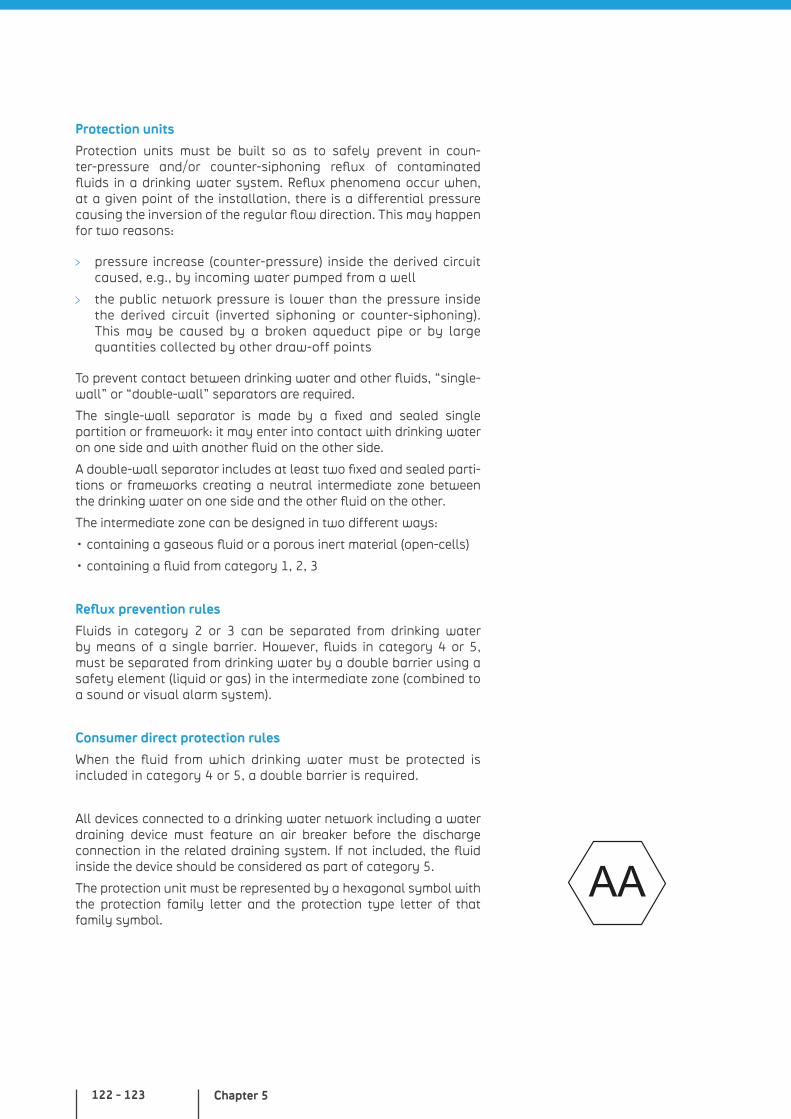
Chapter 5122 - 123
Protection units
Protection units must be built so as to safely prevent in coun-ter-pressure and/or counter-siphoning reflux of contaminated fluids in a drinking water system. Reflux phenomena occur when, at a given point of the installation, there is a differential pressure causing the inversion of the regular flow direction. This may happen for two reasons:
pressure increase (counter-pressure) inside the derived circuit caused, e.g., by incoming water pumped from a well
the public network pressure is lower than the pressure inside the derived circuit (inverted siphoning or counter-siphoning). This may be caused by a broken aqueduct pipe or by large quantities collected by other draw-off points
To prevent contact between drinking water and other fluids, “single-wall” or “double-wall” separators are required.
The single-wall separator is made by a fixed and sealed single partition or framework: it may enter into contact with drinking water on one side and with another fluid on the other side.
A double-wall separator includes at least two fixed and sealed parti-tions or frameworks creating a neutral intermediate zone between the drinking water on one side and the other fluid on the other.
The intermediate zone can be designed in two different ways:
• containing a gaseous fluid or a porous inert material (open-cells)
• containing a fluid from category 1, 2, 3
Reflux prevention rules
Fluids in category 2 or 3 can be separated from drinking water by means of a single barrier. However, fluids in category 4 or 5, must be separated from drinking water by a double barrier using a safety element (liquid or gas) in the intermediate zone (combined to a sound or visual alarm system).
Consumer direct protection rules
When the fluid from which drinking water must be protected is included in category 4 or 5, a double barrier is required.
All devices connected to a drinking water network including a water draining device must feature an air breaker before the discharge connection in the related draining system. If not included, the fluid inside the device should be considered as part of category 5.
The protection unit must be represented by a hexagonal symbol with the protection family letter and the protection type letter of that family symbol.
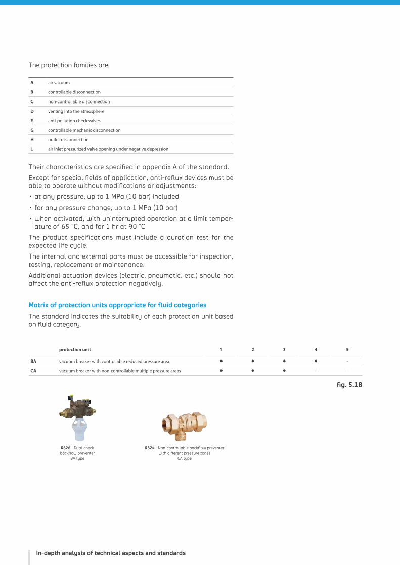
In-depth analysis of technical aspects and standards
The protection families are:
A air vacuum
B controllable disconnection
C non-controllable disconnection
D venting Into the atmosphere
E anti-pollution check valves
G controllable mechanic disconnection
H outlet disconnection
L air inlet pressurized valve opening under negative depression
Their characteristics are specified in appendix A of the standard.
Except for special fields of application, anti-reflux devices must be able to operate without modifications or adjustments:
• at any pressure, up to 1 MPa (10 bar) included
• for any pressure change, up to 1 MPa (10 bar)
• when activated, with uninterrupted operation at a limit temper-ature of 65 °C, and for 1 hr at 90 °C
The product specifications must include a duration test for the expected life cycle.
The internal and external parts must be accessible for inspection, testing, replacement or maintenance.
Additional actuation devices (electric, pneumatic, etc.) should not affect the anti-reflux protection negatively.
Matrix of protection units appropriate for fluid categories
The standard indicates the suitability of each protection unit based on fluid category.
protection unit 1 2 3 4 5
BA vacuum breaker with controllable reduced pressure area • • • • -
CA vacuum breaker with non-controllable multiple pressure areas • • • - -
R626 - Dual-check backflow preventer
BA type
R624 - Non-controllable backflow preventer with different pressure zones
CA type
fig. 5.18

GIACOMINI HOT WATER DISTRIBUTION SYSTEMS IN YOUR HOUSE
PEX AND MULTILAYER SYSTEMS WITH T-SHAPED DERIVATIONS
PEX EXPANSION SYSTEM - GX

GIACOMINI HOT WATER DISTRIBUTION SYSTEMS IN YOUR HOUSE
PPR WELDING SYSTEM
PEX AND MULTILAYER SYSTEM WITH MANIFOLDS
PEX SYSTEM WITH CRIMPING RINGS

NOTES
Giacomini sanitary distribution systems
Product codes
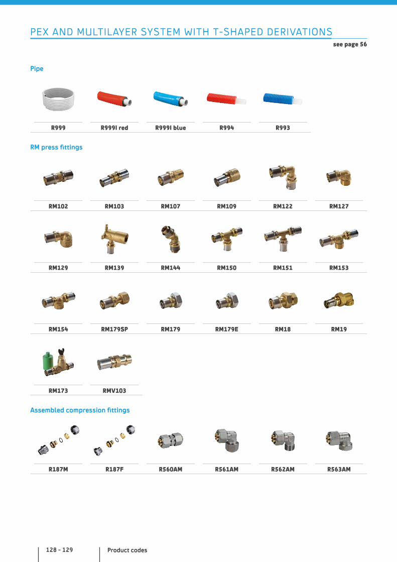
Product codes128 - 129
PEX AND MULTILAYER SYSTEM WITH T-SHAPED DERIVATIONSsee page 56
Pipe
R999 R999I red R999I blue R994 R993
RM press fittings
RM102 RM103 RM107 RM109 RM122 RM127
RM129 RM139 RM144 RM150 RM151 RM153
RM154 RM179SP RM179 RM179E RM18 RM19
RM173 RMV103
Assembled compression fittings
R187M R187F R560AM R561AM R562AM R563AM
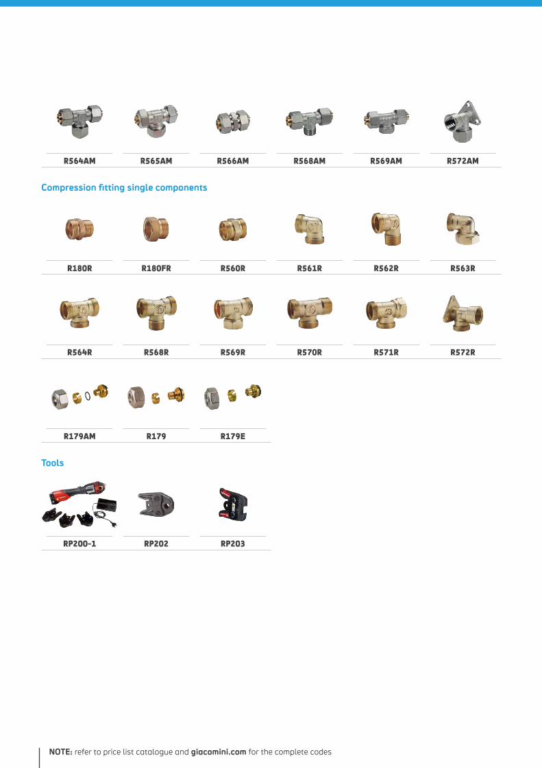
NOTE: refer to price list catalogue and giacomini.com for the complete codes
R564AM R565AM R566AM R568AM R569AM R572AM
Compression fitting single components
R180R R180FR R560R R561R R562R R563R
R564R R568R R569R R570R R571R R572R
R179AM R179 R179E
Tools
RP200-1 RP202 RP203
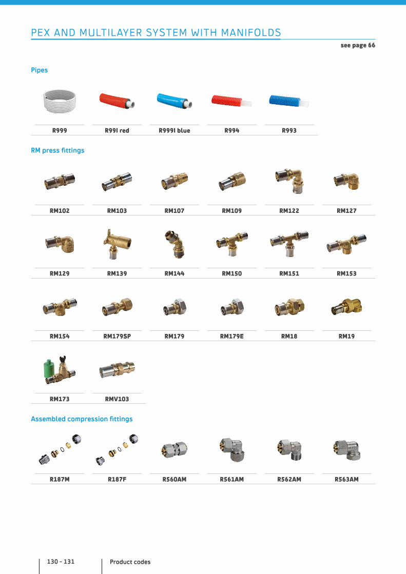
Product codes130 - 131
PEX AND MULTILAYER SYSTEM WITH MANIFOLDS see page 66
Pipes
R999 R99I red R999I blue R994 R993
RM press fittings
RM102 RM103 RM107 RM109 RM122 RM127
RM129 RM139 RM144 RM150 RM151 RM153
RM154 RM179SP RM179 RM179E RM18 RM19
RM173 RMV103
Assembled compression fittings
R187M R187F R560AM R561AM R562AM R563AM
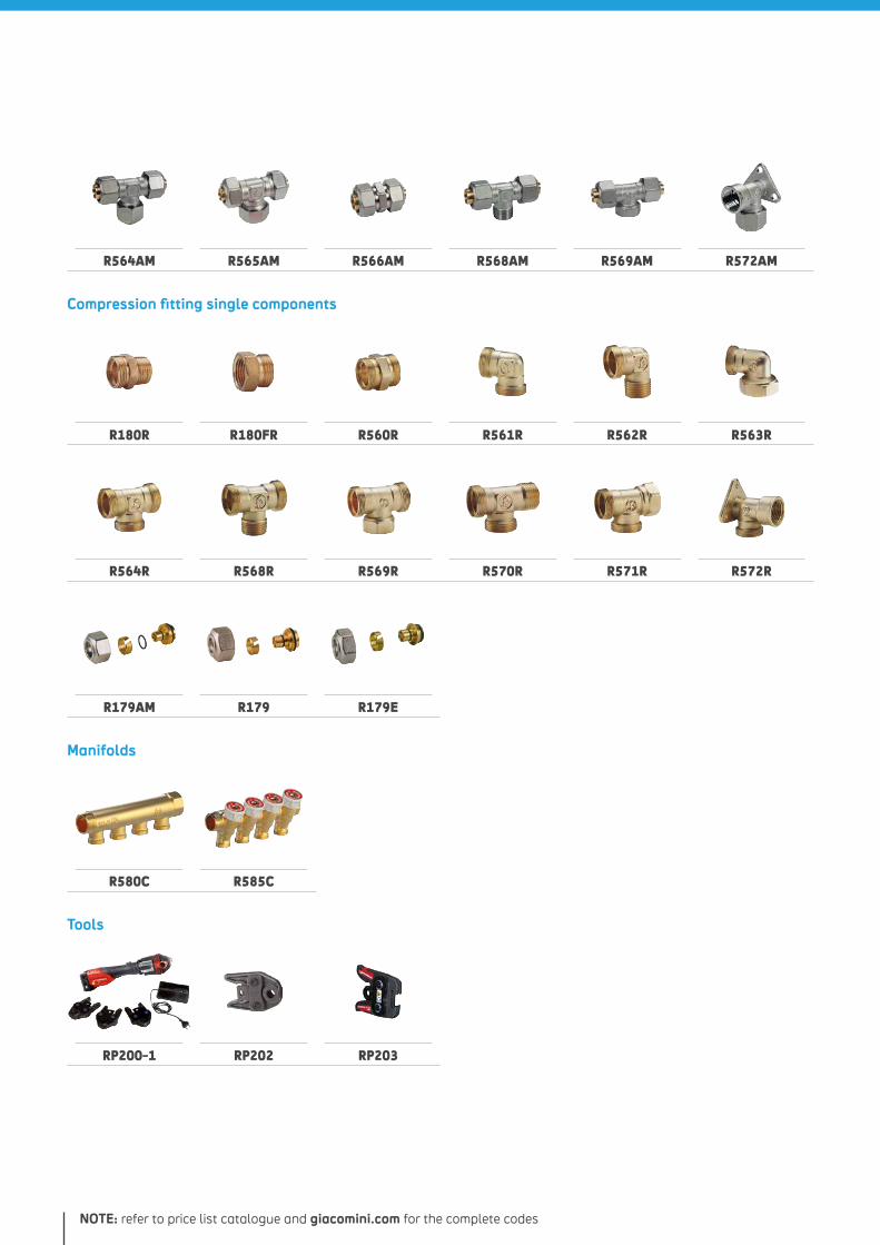
NOTE: refer to price list catalogue and giacomini.com for the complete codes
R564AM R565AM R566AM R568AM R569AM R572AM
Compression fitting single components
R180R R180FR R560R R561R R562R R563R
R564R R568R R569R R570R R571R R572R
R179AM R179 R179E
Manifolds
R580C R585C
Tools
RP200-1 RP202 RP203
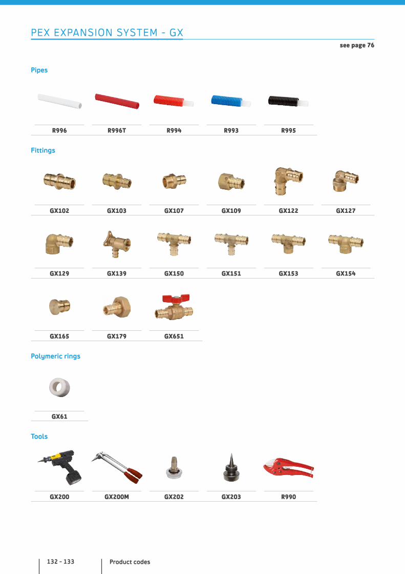
Product codes132 - 133
PEX EXPANSION SYSTEM - GXsee page 76
Pipes
R996 R996T R994 R993 R995
Fittings
GX102 GX103 GX107 GX109 GX122 GX127
GX129 GX139 GX150 GX151 GX153 GX154
GX165 GX179 GX651
Polymeric rings
GX61
Tools
GX200 GX200M GX202 GX203 R990
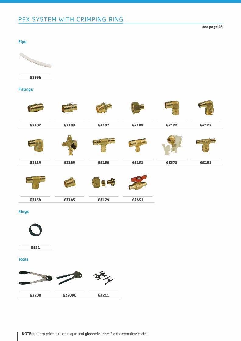
NOTE: refer to price list catalogue and giacomini.com for the complete codes
PEX SYSTEM WITH CRIMPING RING see page 84
Pipe
GZ996
Fittings
GZ102 GZ103 GZ107 GZ109 GZ122 GZ127
GZ129 GZ139 GZ150 GZ151 GZ573 GZ153
GZ154 GZ165 GZ179 GZ651
Rings
GZ61
Tools
GZ200 GZ200C GZ211
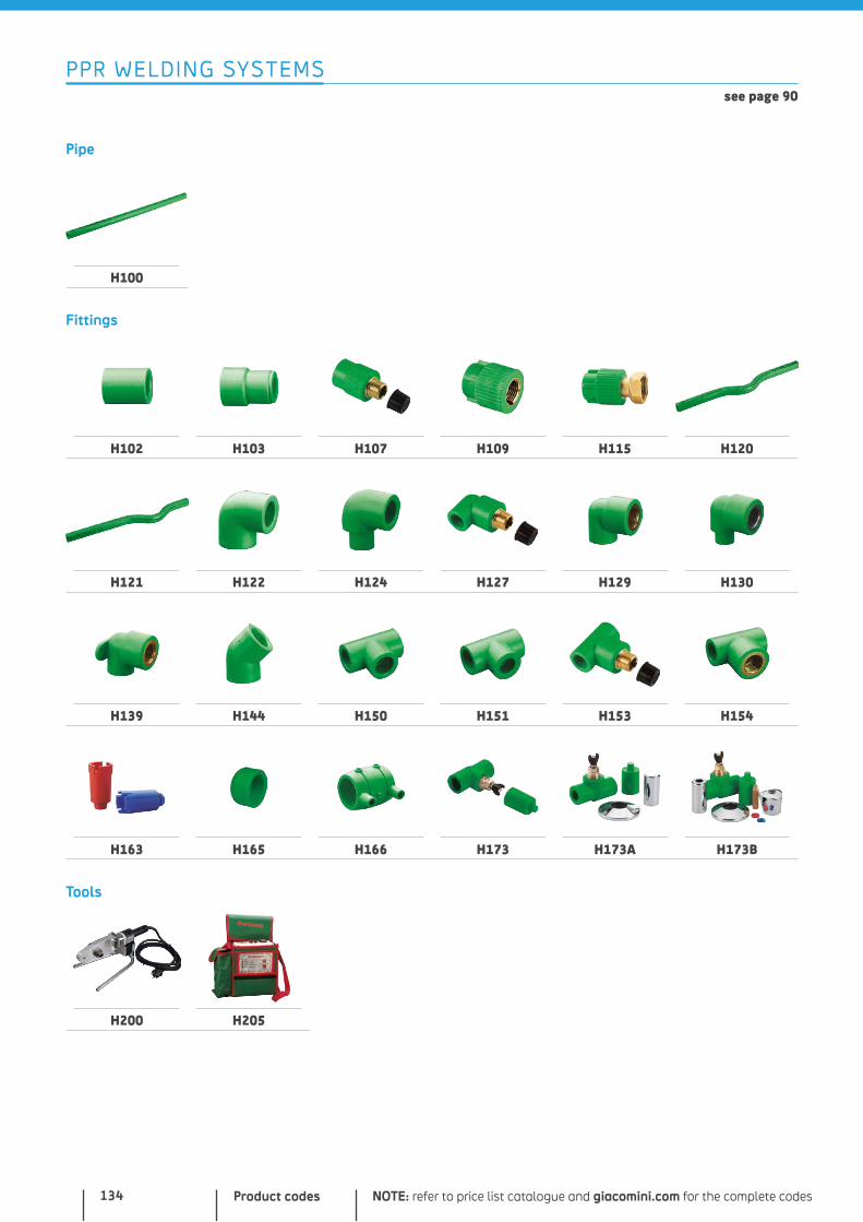
Product codes134
PPR WELDING SYSTEMS see page 90
Pipe
H100
Fittings
H102 H103 H107 H109 H115 H120
H121 H122 H124 H127 H129 H130
H139 H144 H150 H151 H153 H154
H163 H165 H166 H173 H173A H173B
Tools
H200 H205
NOTE: refer to price list catalogue and giacomini.com for the complete codes

NOTES
NOTE: refer to price list catalogue and giacomini.com for the complete codes

NOTES

Giacomini S.p.A. waives any responsibility for any technical and commercial modifications and printing errors connected to the data and characteristics of the products shown in this catalogue. Reproductions are forbidden unless expressly approved by the Management in writing.
Giacomini S.p.A. is a company with an ICIM certified Integrated Quality Management System for Environment, Health & Safety
UNI EN ISO 14001: 2004Environmental Management Systems
UNI EN ISO 9001: 2008Quality Management Systems
OHSAS 18001: 2007Occupational Health & Safety
Mangement Systems

EW
0013
- M
ay 2
01
7 Via per Alzo, 39
28017 San Maurizio d’Opaglio (NO) ITALY
Phone +39 0322 923111
giacomini.com


