Embed Size (px)
Citation preview
Transaction number: 81225247
Project processing number: 16.2208.3-001
November 2019
SCADA Report
Institutional and Organisational Strengthening of
WASCO Saint Lucia and Regional Water Utilities
Saint Lucia
SCADA Report Institutional and Organisational Strengthening of WASCO - SAINT LUCIA
ii
Title SCADA Report
Institutional and Organisational Strengthening of WASCO Saint Lucia and
Regional Water Utilities
Saint Lucia
Date
November 2019
Consultant JOINT VENTURE
CONSULAQUA Hamburg Beratungs-GmbH - Como Consult GmbH
CONSULAQUA Beratungsgesellschaft mbH Hamburg
Ausschläger Elbdeich 2, D-20539 Hamburg, Germany
Como Consult GmbH,
Winterstraße 4-8. D-22765 Hamburg
Contacts
for this
report
Marc Luedtke
Kees de Jong
SCADA Report Institutional and Organisational Strengthening of WASCO - SAINT LUCIA
iii
CONTENT
List of Abbreviations ________________________________________________________ iv
1 Introduction and Objective ________________________________________________ 1
2 Current Status of SCADA at WASCO _________________________________________ 2
2.1 SCADA at Theobald WTP ____________________________________________________ 2
2.2 SCADA at Central Control Room (Headquarter) __________________________________ 4
2.3 General Recommendations __________________________________________________ 4
3 Overview: Northern Supply System __________________________________________ 6
4 Recommendations for SCADA System ________________________________________ 7
4.1 General SCADA system design ________________________________________________ 7
4.2 SCADA Control System ______________________________________________________ 7
4.3 Hardware / Software requirements ___________________________________________ 8
4.4 Instruments required _______________________________________________________ 9
5 Requirements for different system components ______________________________ 10
5.1 Pumping Stations _________________________________________________________ 10
5.2 Water Tank with Gravity Outflow ____________________________________________ 10
5.3 Water Tank with pumped outflow ___________________________________________ 11
5.4 Pressure reducing valves ___________________________________________________ 12
5.5 Distribution Zone / DMA ___________________________________________________ 12
5.6 Safety measures __________________________________________________________ 13
6 Conclusions and Recommendations ________________________________________ 15
Attachment ________________________________________________________________ 1
SCADA Report Institutional and Organisational Strengthening of WASCO - SAINT LUCIA
iv
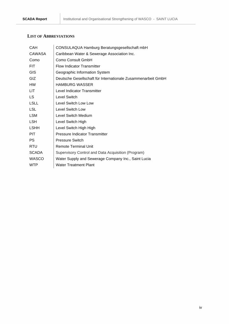
LIST OF ABBREVIATIONS
CAH CONSULAQUA Hamburg Beratungsgesellschaft mbH
CAWASA Caribbean Water & Sewerage Association Inc.
Como Como Consult GmbH
FIT Flow Indicator Transmitter
GIS Geographic Information System
GIZ Deutsche Gesellschaft für Internationale Zusammenarbeit GmbH
HW HAMBURG WASSER
LIT Level Indicator Transmitter
LS Level Switch
LSLL Level Switch Low Low
LSL Level Switch Low
LSM Level Switch Medium
LSH Level Switch High
LSHH Level Switch High High
PIT Pressure Indicator Transmitter
PS Pressure Switch
RTU Remote Terminal Unit
SCADA Supervisory Control and Data Acquisition (Program)
WASCO Water Supply and Sewerage Company Inc., Saint Lucia
WTP Water Treatment Plant
SCADA Report Institutional and Organisational Strengthening of WASCO - SAINT LUCIA
Page 1 of 15
1 INTRODUCTION AND OBJECTIVE
This Report is one of the outcomes of the project “Institutional and Organizational Strengthening of
WASCO Saint Lucia and Regional Water Utilities”. The project started on 1st of November 2018, it
has a duration of 13 months and is carried out by a joint venture between CONSULAQUA Hamburg,
which is a 100% subsidiary of HAMBURG WASSER, public Water Utility of Hamburg, and COMO
Consult, both from Germany.
According to the project’s ToR, the deliverable B.2.2 is the “analysis and assessment of the existing
SCADA system used for monitoring of the existing network (software and hardware) and
recommendation of necessary updates and upgrades […]”.
During various missions, the consultant has obtained impressions of the status of SCADA at
WASCO. It was observed, that the SCADA system is not, or only partly in operation and a holistic
review is required. Furthermore, as part of Vieux Fort Water Supply Redevelopment Project in the
southern part of the island, a completely new SCADA system will be installed for the Vieux Fort water
supply system.
In consultation with WASCO, the ToR was therefore altered, and the consultant asked to provide a
general assessment and draft work plan for a central SCADA system for the northern supply zone.
The proposed SCADA system should be as similar as possible to the SCADA system in the south,
which will be installed soon, to provide uniformity within the whole supply system.
SCADA Report Institutional and Organisational Strengthening of WASCO - SAINT LUCIA
Page 2 of 15
2 CURRENT STATUS OF SCADA AT WASCO
Two SCADA systems are in place at two locations namely the Theobalds WTP and at the head office
in Castries.
Additionally, a "third" SCADA system will be installed soon in the south of St. Lucia as part of a Vieux
Fort Water Supply Redevelopment Project.
2.1 SCADA AT THEOBALD WTP
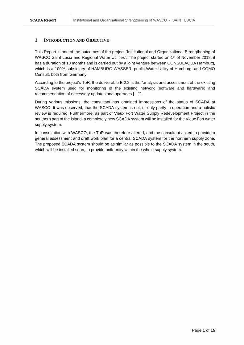
The Theobalds WTP has the more comprehensive and functional SCADA in comparison to the
SCADA at the head office in Castries. The SCADA system itself, called ‘Rockwell’, is working and
devices are connected by cable and radio. However, many devices cannot be connected or
integrated. E.g., the meters at the treatment plant are read manually every hour.
Currently all actuators need to be exchanged (step by step) and then integrated into the system.
Reportedly a programmer from AUMA is expected to visit St. Lucia and perform the initial
programming.
Figure 1: Meter at Theobald
SCADA Report Institutional and Organisational Strengthening of WASCO - SAINT LUCIA
Page 3 of 15
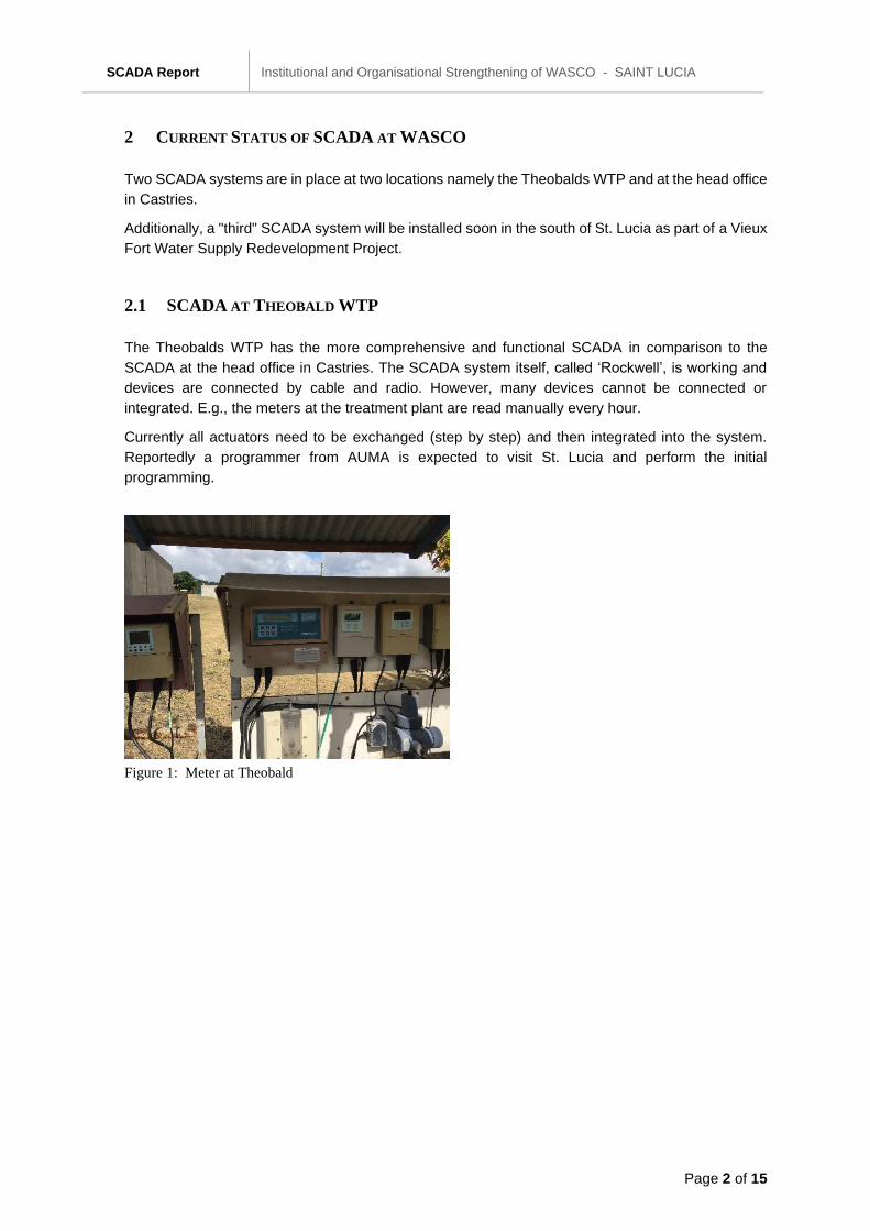
Figure 2: Screens of the SCADA System at Theobald
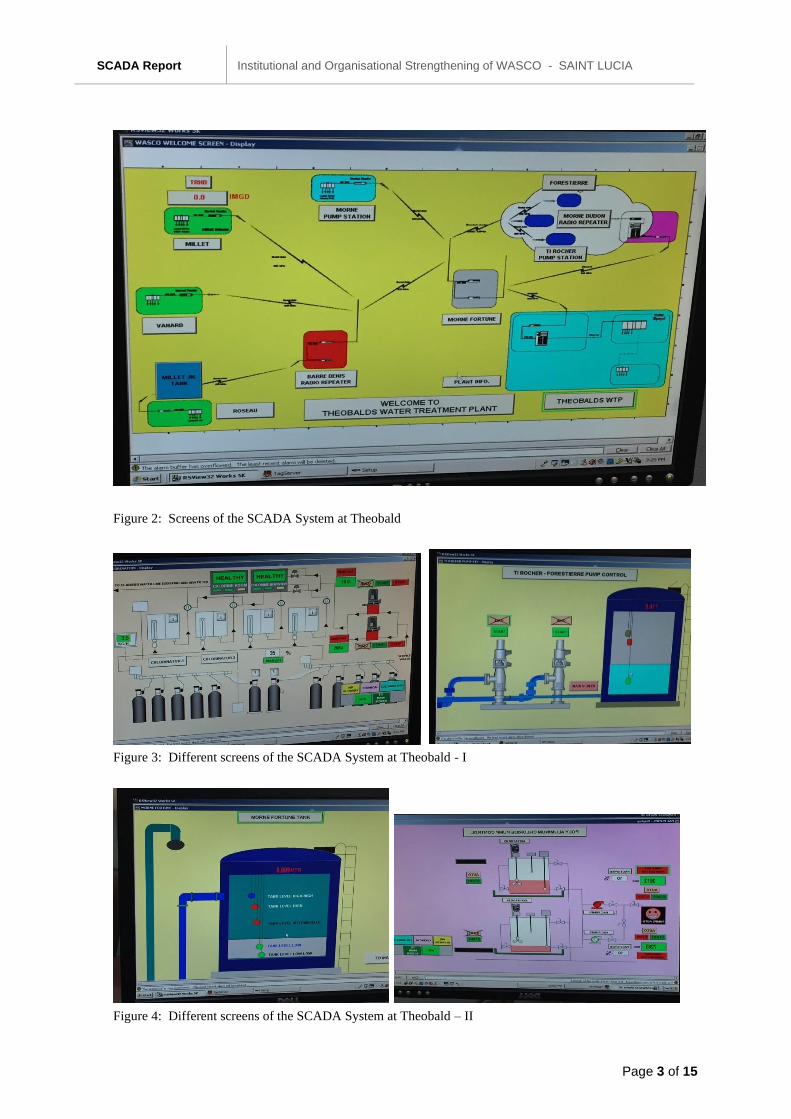
Figure 3: Different screens of the SCADA System at Theobald - I
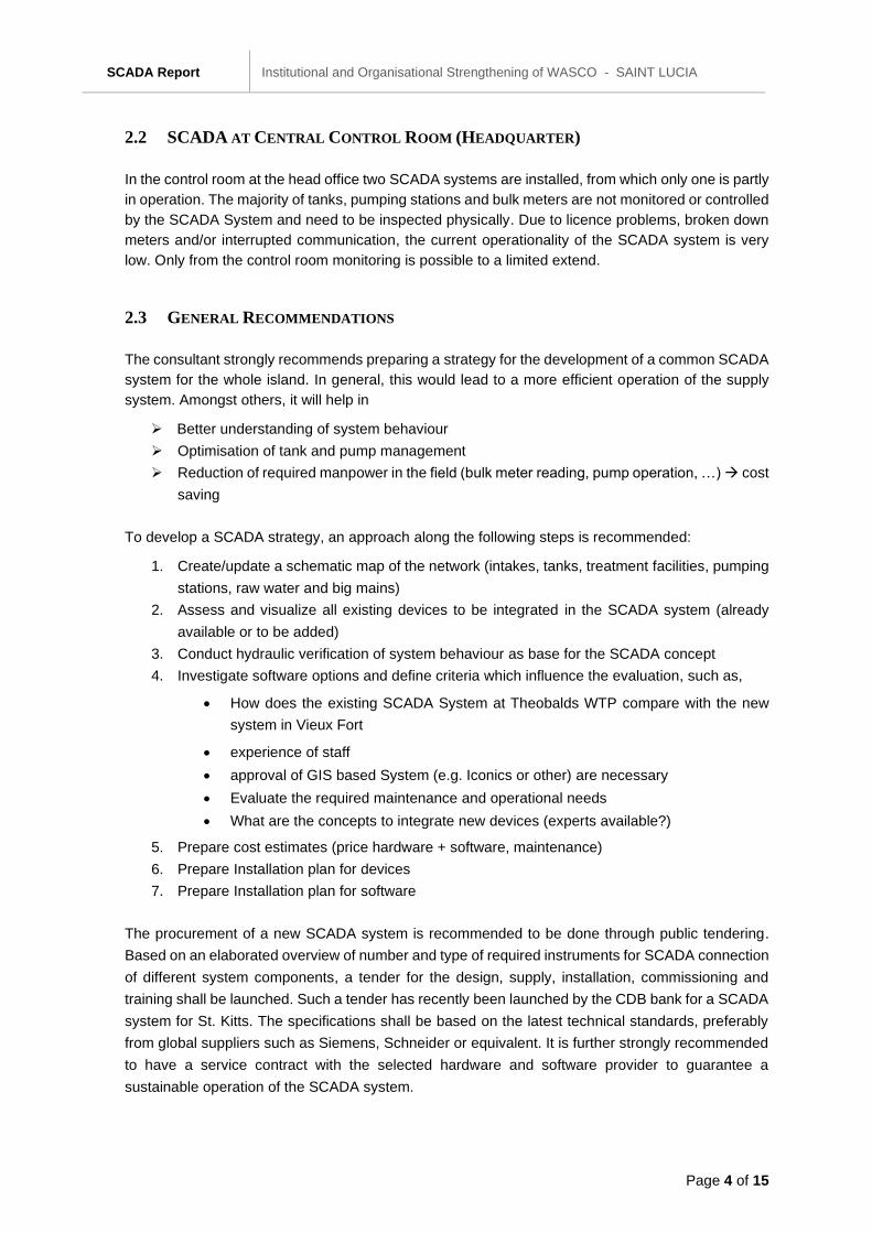
Figure 4: Different screens of the SCADA System at Theobald – II
SCADA Report Institutional and Organisational Strengthening of WASCO - SAINT LUCIA
Page 4 of 15
2.2 SCADA AT CENTRAL CONTROL ROOM (HEADQUARTER)
In the control room at the head office two SCADA systems are installed, from which only one is partly
in operation. The majority of tanks, pumping stations and bulk meters are not monitored or controlled
by the SCADA System and need to be inspected physically. Due to licence problems, broken down
meters and/or interrupted communication, the current operationality of the SCADA system is very
low. Only from the control room monitoring is possible to a limited extend.
2.3 GENERAL RECOMMENDATIONS
The consultant strongly recommends preparing a strategy for the development of a common SCADA
system for the whole island. In general, this would lead to a more efficient operation of the supply
system. Amongst others, it will help in
➢ Better understanding of system behaviour
➢ Optimisation of tank and pump management
➢ Reduction of required manpower in the field (bulk meter reading, pump operation, …) → cost
saving
To develop a SCADA strategy, an approach along the following steps is recommended:
1. Create/update a schematic map of the network (intakes, tanks, treatment facilities, pumping
stations, raw water and big mains)
2. Assess and visualize all existing devices to be integrated in the SCADA system (already
available or to be added)
3. Conduct hydraulic verification of system behaviour as base for the SCADA concept
4. Investigate software options and define criteria which influence the evaluation, such as,
• How does the existing SCADA System at Theobalds WTP compare with the new
system in Vieux Fort
• experience of staff
• approval of GIS based System (e.g. Iconics or other) are necessary
• Evaluate the required maintenance and operational needs
• What are the concepts to integrate new devices (experts available?)
5. Prepare cost estimates (price hardware + software, maintenance)
6. Prepare Installation plan for devices
7. Prepare Installation plan for software
The procurement of a new SCADA system is recommended to be done through public tendering.
Based on an elaborated overview of number and type of required instruments for SCADA connection
of different system components, a tender for the design, supply, installation, commissioning and
training shall be launched. Such a tender has recently been launched by the CDB bank for a SCADA
system for St. Kitts. The specifications shall be based on the latest technical standards, preferably
from global suppliers such as Siemens, Schneider or equivalent. It is further strongly recommended
to have a service contract with the selected hardware and software provider to guarantee a
sustainable operation of the SCADA system.
SCADA Report Institutional and Organisational Strengthening of WASCO - SAINT LUCIA
Page 5 of 15
In the next paragraphs, a general layout is provided as a proposal for a new SCADA system for
WASCO. In order to provide conformity of the system, the general layout is based on the planned
SCADA system which will soon be implemented in Vieux Fort.
It recommends installing SCADA first in the northern supply area (separate from the ongoing
measures in Vieux Fort) and then expand it to other parts of the island.
SCADA Report Institutional and Organisational Strengthening of WASCO - SAINT LUCIA
Page 6 of 15
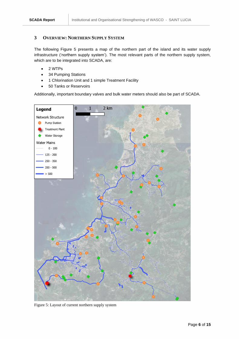
3 OVERVIEW: NORTHERN SUPPLY SYSTEM
The following Figure 5 presents a map of the northern part of the island and its water supply
infrastructure (‘northern supply system’). The most relevant parts of the northern supply system,
which are to be integrated into SCADA, are:
• 2 WTPs
• 34 Pumping Stations
• 1 Chlorination Unit and 1 simple Treatment Facility
• 50 Tanks or Reservoirs
Additionally, important boundary valves and bulk water meters should also be part of SCADA.
Figure 5: Layout of current northern supply system
SCADA Report Institutional and Organisational Strengthening of WASCO - SAINT LUCIA
Page 7 of 15
4 RECOMMENDATIONS FOR SCADA SYSTEM
4.1 GENERAL SCADA SYSTEM DESIGN
As part of the “Vieux Fort Water Supply Redevelopment Project”, a complete SCADA system will be
implemented in Vieux Fort for WASCO. The system includes the two water treatment plants
Beausejour and Grace including their pumping stations, and the reservoirs Augier, Laborie, La
Tourney and Beanfield.
The consultant recommends using a similar system for the northern supply zone of St. Lucia. This
allows for an exchange of knowledge and experiences between the responsible persons within
WASCO. As the SCADA system in Vieux Fort is likely established ahead of the SCADA system in
the northern supply area, first experiences in Vieux Fort can be helpful for the implementation in
Castries.
Further, a modular design is recommended. The system should be implemented gradually (step-by-
step), starting with the core distribution network (Water Treatment Plants, Pumping Stations, Water
Tanks) and eventually the Northern Line. In the subsequent steps, further sections of the water
supply system and installations regulating the network can be added incrementally to the SCADA
system. This ensures a functioning SCADA system from the start.
4.2 SCADA CONTROL SYSTEM
The SCADA system should consist of the following sub-systems:
• A human–machine interface (HMI) presenting process data to the operator to monitor and
control the process.
• A supervisory computerized system, gathering (acquiring) data on the process and sending
commands (controlling) to the process.
• Programmable logic controllers (PLCs).
• Various process and analytical instruments with remote terminal units (RTUs) connected to
sensors in the supply process, converting sensor signals to digital data and sending digital
data to the supervisory system.
The data transfer between RTUs, PLCs and the SCADA Control Center is preferably carried out
through fiber optic cables with GSM mobile provider as backup.
The control system hierarchy can be viewed as a pyramid structure with three layers:
• First Layer: Field Instruments (flow meters, pressure meters, level meters, kWh-meters) and
Field Control Devices (valve actuators, motor starters, main power switches)
• Second Layer: Local RTU and PLC Panels for control/monitoring
• Third Layer: SCADA Control Centres for monitoring/controlling
All controlling actions are performed automatically by the PLCs. The host control functions are
restricted to basic overriding or supervisory level intervention. The PLCs are capable of
autonomously executing simple logic processes without involving the master computer.
SCADA Report Institutional and Organisational Strengthening of WASCO - SAINT LUCIA
Page 8 of 15
The SCADA system allows operators to change the PLC settings and enable alarm conditions to
be displayed and recorded. The feedback control loop passes through the PLCs, while the SCADA
system will monitor the overall performance of the loop.
Data acquisition is provided at SCADA System level and the data is collected from the RTU or PLC
levels. It includes meter readings and equipment status reports that are communicated to the
SCADA. Data is then compiled and formatted in such a way that a control room operator using the
HMI can make supervisory decisions to adjust or override normal RTU / PLC controls.
The RTUs should be located at remote sites, e.g. storage reservoirs, which shall be on a distance
longer than 1 km from the water feeding pump station. An RTU shall collect signals from reservoir
water level sensors and flow meters on the outlets of the storage reservoirs. The RTU units shall
consist of small compact PLC unit, fibre optic communication port and GSM communication module
as back up. The RTU units shall be equipped with communication modules to transfer the process
data to PLC Panels in the pumping station, which is pumping the water to the remote reservoirs, for
remote monitoring, controlling and data acquisition.
The RTUs for controlling and monitoring communicate through fibre optic cables (or GSM mobile
provider as backup) with the local PLC and at the same time communicate with the SCADA Centre
for data transfer, recording and reporting. For ensuring a better maintenance and better repairability,
using standard cables instead of fibre optic cables can be taken into consideration.
The HMI system presents the information to the operating personnel in the form of a mimic
diagram. Mimic diagrams consist of digital “photographs” of the process equipment overlain with
animated symbols.
Data is fed to a Database Management System, to allow trending and other analytical auditing -
reporting.
Alarms are displayed on the HMI and stored in the database.
The SCADA system includes a master station in the operator room. A back-up PC is provided, e.g.
at the director’s office location.
4.3 HARDWARE / SOFTWARE REQUIREMENTS
The control system should be a modern system with a clear and easy to use interface and open to
the office and process work. It is important that its functions are sophisticated and reliable, efficient
to configure and scalable for simple and complex tasks. A worldwide usability and support is also
essential.
Commercially available workstations (a powerful personal computer) should be used for all working
stations. Rack mounted professional server stations should be used as master station of the
SCADA system. The SCADA control systems software should be consisting of one complete
package. It should be possible to establish the coupling to other devices and applications from
various manufacturers via the standardized software interface OPC (‘open platform
communications’).
The system should be upgradable to implement or add further components and procedures at any
time. When expanding the system, it should be possible to integrate the expansions into the user
interface. It is strongly recommended that a switchover between various applications using standard
controls such as Alt-Tab or Ctrl-Esc is not allowed for safety reasons. The hardware and software
SCADA Report Institutional and Organisational Strengthening of WASCO - SAINT LUCIA
Page 9 of 15
installed should be state of the art with latest versions of processors and software to guarantee
compatibility in the future.
Process control systems must be organized in a logical control hierarchy in order to provide a
standard format for 24 hours monitoring/control of the overall facilities. This shall provide operators
and maintenance staff a uniform interface, which improves monitoring/controlling the equipment, the
control modes the equipment can attain, and how to override the controls when necessary due to
failures or when required for routine maintenance.
4.4 INSTRUMENTS REQUIRED
For the operation of the facilities with the SCADA system, field instruments need to be installed in
order to control the field control devices. Among these instruments are level indicator transmitters
(LIT), flow indicator transmitters (FIT), pressure indicator transmitters (PIT) level switches (LS), and
pressure switches (PS). The type of instruments with analogue outputs are
• Electromagnetic flow meters
• Ultrasonic Water Level Meters
• Hydrostatic Level Meters
• Pressure sensors with transmitters
The type of instruments with digital outputs are
• Flow switches
• Level switches
• Pressure switches
• Limit switches
SCADA Report Institutional and Organisational Strengthening of WASCO - SAINT LUCIA
Page 10 of 15
5 REQUIREMENTS FOR DIFFERENT SYSTEM COMPONENTS
Table 1 and the following sections give an overview, of the type of instruments that are needed for
controlling and monitoring pumping stations, water tanks, pressure reducing valves and DMAs.
Further equipment for operation (e.g. shut-off valves) need to be considered as well, but are not
discussed with this document.
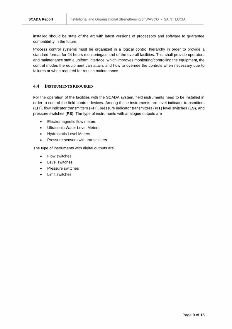
Table 1: Overview of number and type of required instruments for SCADA connection for different system components
Installation LIT LS Backup float valve
FIT PIT PS Inlet valve
Outlet valve
Pumping Station 1 2 2
Water Tank Gravity Outflow
1 5 1 2 1 1
Water Tank Pump Outflow
1 5 1 2 2 2 (1)
Pressure Reducing Valve
1 2
Boundary Valve 1
5.1 PUMPING STATIONS
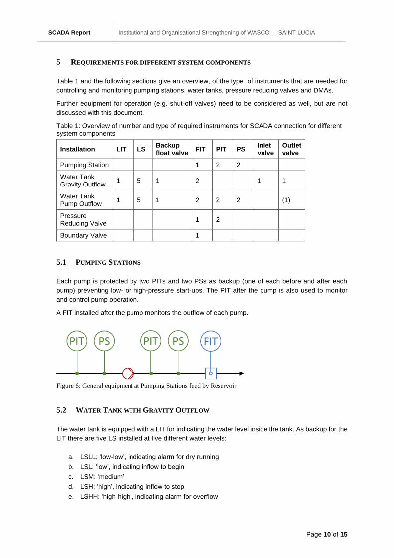
Each pump is protected by two PITs and two PSs as backup (one of each before and after each
pump) preventing low- or high-pressure start-ups. The PIT after the pump is also used to monitor
and control pump operation.
A FIT installed after the pump monitors the outflow of each pump.
Figure 6: General equipment at Pumping Stations feed by Reservoir
5.2 WATER TANK WITH GRAVITY OUTFLOW
The water tank is equipped with a LIT for indicating the water level inside the tank. As backup for the
LIT there are five LS installed at five different water levels:
a. LSLL: ‘low-low’, indicating alarm for dry running
b. LSL: ‘low’, indicating inflow to begin
c. LSM: ‘medium’
d. LSH: ‘high’, indicating inflow to stop
e. LSHH: ‘high-high’, indicating alarm for overflow
SCADA Report Institutional and Organisational Strengthening of WASCO - SAINT LUCIA
Page 11 of 15
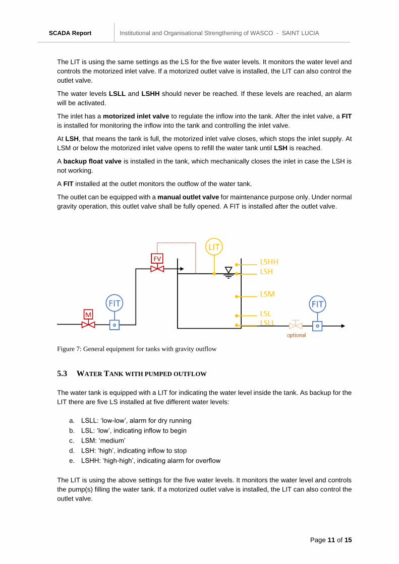
The LIT is using the same settings as the LS for the five water levels. It monitors the water level and
controls the motorized inlet valve. If a motorized outlet valve is installed, the LIT can also control the
outlet valve.
The water levels LSLL and LSHH should never be reached. If these levels are reached, an alarm
will be activated.
The inlet has a motorized inlet valve to regulate the inflow into the tank. After the inlet valve, a FIT
is installed for monitoring the inflow into the tank and controlling the inlet valve.
At LSH, that means the tank is full, the motorized inlet valve closes, which stops the inlet supply. At
LSM or below the motorized inlet valve opens to refill the water tank until LSH is reached.
A backup float valve is installed in the tank, which mechanically closes the inlet in case the LSH is
not working.
A FIT installed at the outlet monitors the outflow of the water tank.
The outlet can be equipped with a manual outlet valve for maintenance purpose only. Under normal
gravity operation, this outlet valve shall be fully opened. A FIT is installed after the outlet valve.
Figure 7: General equipment for tanks with gravity outflow
5.3 WATER TANK WITH PUMPED OUTFLOW
The water tank is equipped with a LIT for indicating the water level inside the tank. As backup for the
LIT there are five LS installed at five different water levels:
a. LSLL: ‘low-low’, alarm for dry running
b. LSL: ‘low’, indicating inflow to begin
c. LSM: ‘medium’
d. LSH: ‘high’, indicating inflow to stop
e. LSHH: ‘high-high’, indicating alarm for overflow
The LIT is using the above settings for the five water levels. It monitors the water level and controls
the pump(s) filling the water tank. If a motorized outlet valve is installed, the LIT can also control the
outlet valve.
SCADA Report Institutional and Organisational Strengthening of WASCO - SAINT LUCIA
Page 12 of 15
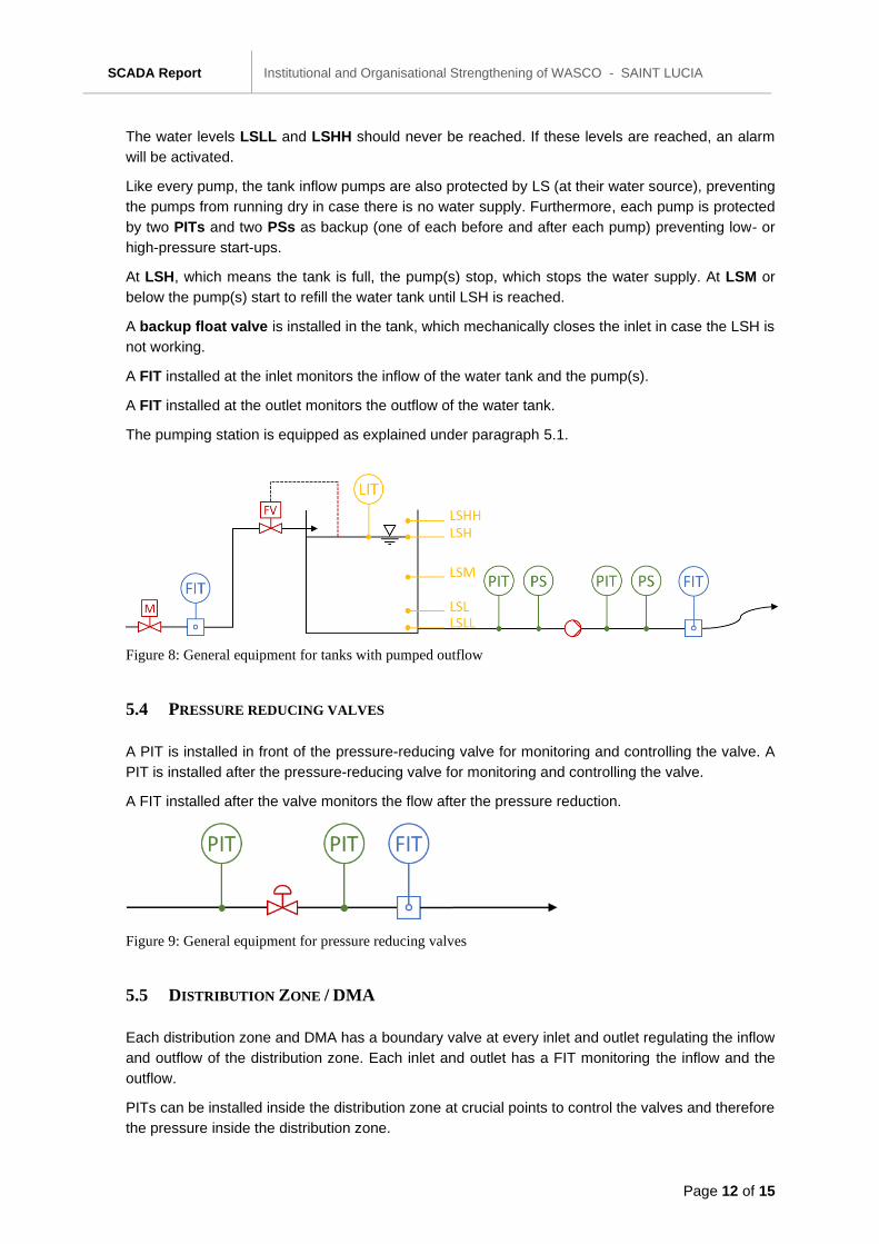
The water levels LSLL and LSHH should never be reached. If these levels are reached, an alarm
will be activated.
Like every pump, the tank inflow pumps are also protected by LS (at their water source), preventing
the pumps from running dry in case there is no water supply. Furthermore, each pump is protected
by two PITs and two PSs as backup (one of each before and after each pump) preventing low- or
high-pressure start-ups.
At LSH, which means the tank is full, the pump(s) stop, which stops the water supply. At LSM or
below the pump(s) start to refill the water tank until LSH is reached.
A backup float valve is installed in the tank, which mechanically closes the inlet in case the LSH is
not working.
A FIT installed at the inlet monitors the inflow of the water tank and the pump(s).
A FIT installed at the outlet monitors the outflow of the water tank.
The pumping station is equipped as explained under paragraph 5.1.
Figure 8: General equipment for tanks with pumped outflow
5.4 PRESSURE REDUCING VALVES
A PIT is installed in front of the pressure-reducing valve for monitoring and controlling the valve. A
PIT is installed after the pressure-reducing valve for monitoring and controlling the valve.
A FIT installed after the valve monitors the flow after the pressure reduction.
Figure 9: General equipment for pressure reducing valves
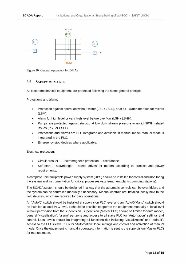
5.5 DISTRIBUTION ZONE / DMA
Each distribution zone and DMA has a boundary valve at every inlet and outlet regulating the inflow
and outflow of the distribution zone. Each inlet and outlet has a FIT monitoring the inflow and the
outflow.
PITs can be installed inside the distribution zone at crucial points to control the valves and therefore
the pressure inside the distribution zone.
SCADA Report Institutional and Organisational Strengthening of WASCO - SAINT LUCIA
Page 13 of 15
Figure 10: General equipment for DMAs
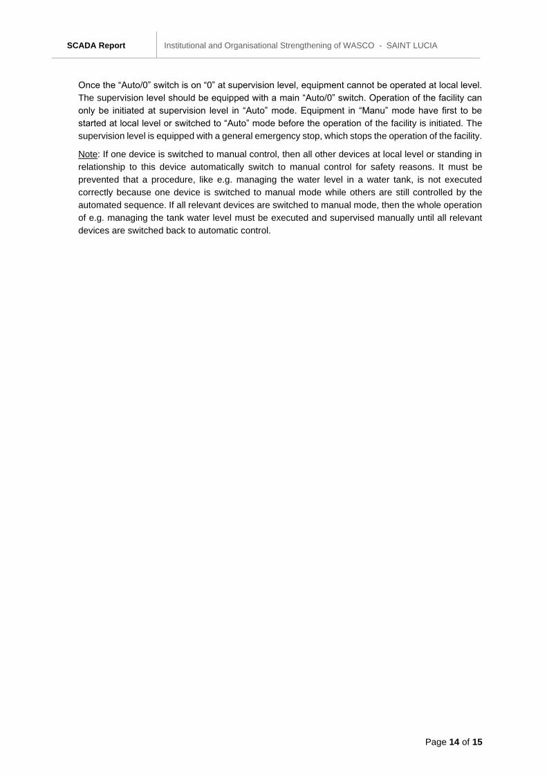
5.6 SAFETY MEASURES
All electromechanical equipment are protected following the same general principle.
Protections and alarm:
• Protection against operation without water (LSL / LSLL), or at air - water interface for mixers
(LSM).
• Alarm for high level or very high level before overflow (LSH / LSHH).
• Pumps are protected against start-up at low downstream pressure to avoid NPSH related
issues (PSL or PSLL).
• Protections and alarms are PLC integrated and available in manual mode. Manual mode is
integrated in the PLC.
• Emergency stop devices where applicable.
Electrical protection:
• Circuit breaker – Electromagnetic protection - Discordance.
• Soft-start – star/triangle – speed drives for motors according to process and power
requirements.
A complete uninterruptable power supply system (UPS) should be installed for control and monitoring
the system and instrumentation for critical processes (e.g. treatment plants, pumping stations).
The SCADA system should be designed in a way that the automatic controls can be overridden, and
the system can be controlled manually if necessary. Manual controls are installed locally next to the
field devices, which are required for daily operations.
An “Auto/0” switch should be installed at supervision PLC level and an “Auto/0/Manu” switch should
be installed at local PLC level. It should be possible to operate the equipment manually at local level
without permission from the supervision. Supervision (Master PLC) should be limited to “auto mode”,
general “visualization”, “alarm” per zone and access to all slave PLC for “Automation” settings and
control. Local levels should be integrating all functionalities including “visualization” and “default”,
access to the PLC (slave PLC) for “Automation” local settings and control and activation of manual
mode. Once the equipment is manually operated, information is sent to the supervision (Master PLC)
for manual mode.
SCADA Report Institutional and Organisational Strengthening of WASCO - SAINT LUCIA
Page 14 of 15
Once the “Auto/0” switch is on “0” at supervision level, equipment cannot be operated at local level.
The supervision level should be equipped with a main “Auto/0” switch. Operation of the facility can
only be initiated at supervision level in “Auto” mode. Equipment in “Manu” mode have first to be
started at local level or switched to “Auto” mode before the operation of the facility is initiated. The
supervision level is equipped with a general emergency stop, which stops the operation of the facility.
Note: If one device is switched to manual control, then all other devices at local level or standing in
relationship to this device automatically switch to manual control for safety reasons. It must be
prevented that a procedure, like e.g. managing the water level in a water tank, is not executed
correctly because one device is switched to manual mode while others are still controlled by the
automated sequence. If all relevant devices are switched to manual mode, then the whole operation
of e.g. managing the tank water level must be executed and supervised manually until all relevant
devices are switched back to automatic control.
SCADA Report Institutional and Organisational Strengthening of WASCO - SAINT LUCIA
Page 15 of 15
6 CONCLUSIONS AND RECOMMENDATIONS
The SCADA System for the northern supply zone currently consists of two partly functional separate
systems. They are located at the Theobalds WTP and at WASCO’s head office in Castries. The
SCADA Systems at both locations do not include all relevant instruments installed at the locations,
as many devices cannot be connected or integrated. Therefore, these instruments must be inspected
and read manually. The SCADA System at Theobalds WTP is more comprehensive and functional
than the SCADA System at the Head Office.
As the SCADA System for the northern supply zone is only partly functional and only for two
locations, the consultant recommends introducing a new SCADA System for the northern supply
zone. This SCADA System should be of modular design and should be implemented step-by-step.
The implementation should start at the most important infrastructure. This guarantees a working
system for the most important infrastructure from the start. To guarantee a long working SCADA, the
system should consist of new hardware operating with the latest operating systems and software.
The system should also be upgradable to implement further components and procedures at any time.
Implementing a SCADA System similar to the SCADA System in Vieux Fort would allow for an
exchange of knowledge and experiences between the responsible persons at Castries and at Vieux
Fort.
For the sustainable development and operation of the future SCADA system it is recommended for
WASCO to train its staff and to enter into a water operating partnership (WOP) through e.g.
GWOPA (Global Water Operating Partnership) to allow for peer to peer support.
A SCADA system and SCADA operation can be compared with a piano (SCADA System) and a
piano player (SCADA Operator). The experienced piano player develops the music score, likewise
only with professional support by experienced water operators the operation of the water supply
system can be better understood and gradually improved. This activity should not be outsourced to
external private companies as this directly affects WASCO’s core business.
SCADA Report Institutional and Organisational Strengthening of WASCO - SAINT LUCIA
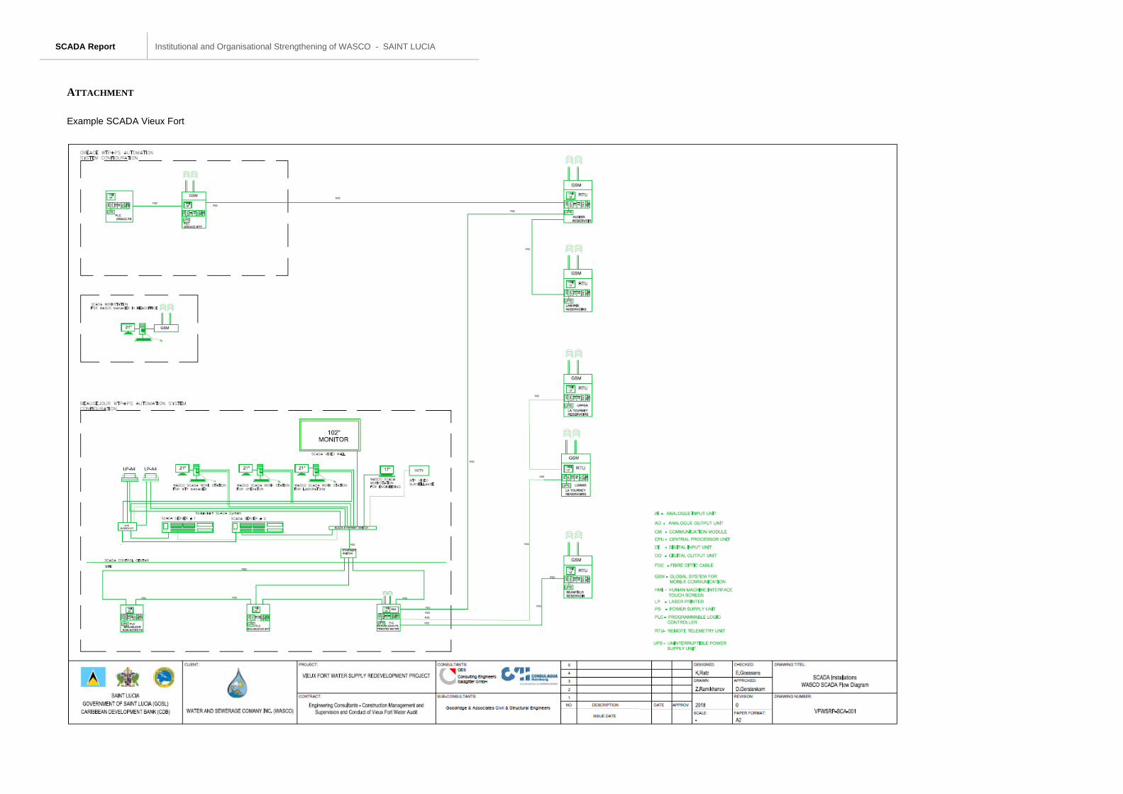
ATTACHMENT
Example SCADA Vieux Fort


