Embed Size (px)
Citation preview

Journal of Quantitative Spectroscopy &Radiative Transfer 70 (2001) 675–695
www.elsevier.com/locate/jqsrt
Scattering properties of rutile pigments located eccentricallywithin microvoids
Jean-Claude Augera, Brian Stoutb, Rub/en G. Barrerac; ∗; 1, Fernando Curiela
aCentro de Investigaci�on en Pol��meros, COMEX, Marcos Achar Lobat�on 2, 55885 Tepexpan,Estado de Mexico, Mexico
bL.O.E. UPRESA 6079, Facult�e des Sciences et Techniques, Centre de Saint Jer�ome,13397 Marseilles Cedex 20, France
cInstituto de F��sica, UNAM, Apartado Postal 20-364, 01000 Mexico D.F., Mexico
Abstract
We study the optical properties of opaque polymer pigmented coatings. The system consists of spher-ical rutile particles encapsulated in spherical microvoids embedded in a transparent polymer resin. Thesingle-scattering properties of this system have been analyzed already, in case the rutile particle is locatedat the center of the microvoid . Here, we use a T-matrix approach to generalize and extend this analysisto the more realistic case when the rutile particles is located o6-center within the microvoid. We alsoconsider the multiple-scattering e6ects of a cluster composed by a collection of air bubbles with o6-centerrutile inclusions. Our calculations take into account the multiple scattering and the dependent-scatteringprocesses of each pigment particle of the aggregate, using a new recursive T-matrix algorithm. ? 2001Elsevier Science Ltd. All rights reserved.
Keywords: Multiple-scattering; O6-center inclusions; T-matrix
1. Introduction
Since the last decade and due to the everyday larger availability and development of supercomputers, the =eld of scattering processes of electromagnetic waves in inhomogeneous me-dia is in constant expansion. It is well known that the solution of Maxwell’s equations forthe scattered =eld from non-spherical objects or from even simple inhomogeneous systems, re-quires the implementation of elaborated numerical codes. Therefore, although the foundationsof multiple scattering theory were set before the 1970s [1–3], its direct application has been
∗ Corresponding author. Tel.: +52-5622-5093; fax: +52-5616-1535.E-mail address: [email protected]=sicacu.unam.mx (R.G. Barrera).1 Consultant at Centro de Investigaci/on en Pol/Gmeros, COMEX.
0022-4073/01/$ - see front matter ? 2001 Elsevier Science Ltd. All rights reserved.PII: S 0022-4073(01)00037-1

676 J.-C. Auger et al. / Journal of Quantitative Spectroscopy & Radiative Transfer 70 (2001) 675–695
limited, to a great extent, by the capacity of computers for handling the existing numerical pro-cedures. Nowadays, applications of the scattering theories of electromagnetic radiation, cover awide range of interests, both in basic and in industrial research, in areas such as: astrophysics,atmospheric and material science, medical imagery analysis, and radar and I-R furtivity.
The work we present here is included in a research project for the coating industry, on whitepaints. A paint =lm can be described as an inhomogeneous medium composed of pigmentparticles embedded in a transparent polymer resin. Opacity (also called hiding power) is theproperty of the system to cover a substrate, to the human eye, when illuminated by light. Ina white paint, opacity is the result of the multiple scattering of light by transparent pigmentparticles which enhances the reLectance of the otherwise transparent resin, yielding a di6useangular distribution of the reLected light. At a local scale, a large opacity is related to astrong scattering eMciency of the pigment. This scattering eMciency is related to some intrinsicproperties of the pigment particles, such as their shape and size, but also to system properties,like the relative index of refraction between the pigment and the surrounding resin. Due to itshigh refractive index (∼ 2:8) and transparency in the visible range, rutile TiO2 with an optimumsize around 0:23 �m, has become the most eMcient pigment in white paint formulation. At aglobal scale, opacity is proportional to the pigment volume concentration (PVC), since anincrease in the PVC increases the amount of scattering centers and, consequently, the hidingpower. However, at high PVC the reLectance of the =lm is no longer proportional to the PVC,showing a decrease in the scattering eMciency per particle. This e6ect is known as dependentscattering, and it also appears in the scattering from clusters. Since in a cluster the scatteringeMciency per particle is reduced, in the production of white paints a special attention is givento processes or pigment surface treatments which help to minimize clustering.
However, a large part of the cost in the production of a white paint comes directly fromthe cost of TiO2. As a consequence, there have been many e6orts for trying to substituterutile by a less expensive pigment, and air has been, since long, a good candidate. Microvoidsencapsulated in a strong polyester resin, known commercially as Rhopaque, are already in themarket. Although rutile is a more eMcient light scatterer than air, one is not looking for thewhole substitution of TiO2 by microvoids, but rather for a partial substitution which couldyield reasonable savings. There are also projects to manufacture vesiculated particles. Theseare transparent polymer micrometer particles =lled with microvoids. In all these e6orts, thereis still the open question about the possibilities of improving the scattering eMciency of themicrovoids. It has been argued [4], that the scattering eMciency of rutile could be improvedby introducing the rutile particles inside the microvoids, because the contrast in the index ofrefraction between rutile and air is larger than the one between rutile and the resin. Thereis a very complete study [5] of the scattering properties of pigmented microvoid coatings, inwhich the TiO2 spherical particles are located at the center of spherical microvoids, and theexact results for the scattering cross section of coated spheres [6] are used. It was found, thatfor pigments within microvoids whose size is much smaller than the wavelength of light, thescattering cross section per unit volume of the microvoid-pigment entity is, in general, muchsmaller than the corresponding one for the pigment and air bubble embedded separately in theresin. Nevertheless, the attention of this study was focused more on larger particles, where forspeci=c combinations of geometrical and optical parameters of the pigment and the microvoid,an increase in the corresponding volumetric scattering eMciency of the microvoid-pigment entity

J.-C. Auger et al. / Journal of Quantitative Spectroscopy & Radiative Transfer 70 (2001) 675–695 677
was found. This was called a synergetic e6ect. However, this e6ect occurred for sizes muchlarger than the optimum size of the TiO2 particles to be useful in the coating industry, besidesthe unrealistic assumption of having the pigment right at the center of the microvoid.
The aim of this work is to present a study on the scattering properties of the TiO2=microvoidsystem for a more general and realistic case, where the TiO2 spherical inclusions are assumedto stick to the internal surface of the air bubble (o6 center of the sphere). Also, in order to takeinto account the dependent-scattering e6ects which occur in real paints, we present the studyof the scattering properties of a cluster composed of a collection of air bubbles with o6-centerinclusions. The paper is organized as follows: Section 2 gives a short review of previous work,in Section 3, we present the T-matrix formalism which we develop to calculate the scattered =eldand the scattering cross section of an isolated sphere containing a spherical eccentric inclusion.Then, we extend these results by considering the scattering from an aggregate composed byseveral of these eccentric systems taking into account dependent-scattering e6ects. In Section 4,we present and discuss the results of our calculations, and =nally Section 5 is devoted to ourconclusion.
2. Previous work
The analytical derivations presented here are based on the T-matrix formalism originally de-veloped by Waterman [7]. Its aim is the evaluation of the scattered =eld by an arbitrary-shapedparticle by expressing the electric and magnetic =elds in terms of the general solutions of thevector Helmholtz equation expanded in a spherical basis. Using the Extended Boundary Condi-tion (EBC) also called the Null Field Approach one obtains a relation between the expansioncoeMcients of the scattered =elds and those of the incident wave, through an in=nite-dimensionalmatrix. This matrix is known as the T-matrix and can be calculated in terms of surface integralsof the =elds at the scatterer boundary. In the case of a spherical geometry, these integrals aregreatly simpli=ed and the T-matrix approach becomes equivalent to Mie theory [8]. Numericalevaluations of the =elds, using this formalism, have been possible because there is a naturalcut-o6 for the in=nite multipolar expansion of the =elds. This cut-o6 depends on the size pa-rameters of the system, that is, the modulus of the incident wave vector times the radius of thescatterer, and it is commonly admitted to be given by the Wiscombe criterium [9]. An addi-tional advantage of the T-matrix formalism is that it can be systematically extended to solvethe scattering problem from a collection of spherical particles located at arbitrary positions.The formalism for solving the electromagnetic scattering problem by a host sphere, containinga spherical eccentric inclusion, was =rst introduced by Fikioris [10], in the late 1970s. Thisapproach was limited to the case in which the contrast between the refractive index of theinclusion and the host is suMciently small. At the beginning of the last decade, Borghese [11]developed a more complete theory based on the single T-matrix approach. This formalism wasapplied to the evaluation of the di6erential scattering cross section of a metallic inclusion andan empty cavity within a host dielectric. Later on, Videen [12] developed an iterative procedureto solve the light scattering problem from a sphere with an inclusion of irregular shape. Anapplication of this procedure to the case of a spherical inclusion was made by Ngo et al. [13].Both of these approaches lifted the original restriction of suMciently small contrast between the

678 J.-C. Auger et al. / Journal of Quantitative Spectroscopy & Radiative Transfer 70 (2001) 675–695
refractive index of the host sphere and the inclusions. Furthermore, one of them allowed thesolution of the more general problem in which the inclusion is located at a =xed distance fromthe origin, but it is randomly oriented. This requires an averaging procedure over all possibleorientations of the inclusion, yielding average scattering parameters, where average means anorientational average. Now, the averaging over the orientations of the inclusion is equivalentto an average over all possible directions of the incident wave-vector, keeping the location ofthe inclusion =xed. This latter procedure turns out to be simpler and faster. However, the iter-ative procedure derived by Videen et al. [12] does not allow the analytical calculation of theaverage scattering parameters, which can be evaluated through a T-matrix formalism, and thatare needed for a full characterization of the system. On the other hand, the T-matrix formalismprovides us with the tools to solve not only the averaging problem of a single inclusion, butalso to extend the formalism in order to obtain the solution of the multiple-scattering problemof a collection of host spheres with randomly oriented inclusions. But for this latter problem,the formulation of Borghese et al. [11] for an isolated eccentric system, does not consider allthe possible localizations of the inclusion needed for the evaluation of the multiple-dependentscattering e6ect of several entities. Therefore, our purpose here is to derive a full T-matrixformulation for the eccentric system, in order to use it as an input in the multiple-scatteringcalculations for a cluster or a collection of host spheres with randomly oriented inclusions. Wewill do this, by taking as a guideline the formalism developed in the work of Ngo et al. [13],and then apply it to the above-mentioned case of rutile inclusions within air bubbles in resin.
3. Formalism
Let us consider an incident electric =eld of magnitude E0 traveling as linearly polarized planewave oscillating at frequency !. The plane wave travels in a non-absorbing medium of refractiveindex N0, and impinges on a system composed by a sphere centered at O2, with radius a2, andindex of refraction N2, which is located within a host sphere centered at O1, with radius a1and refractive index N1. The inclusion is located at a position denoted by (r0; 0; �0) in thespherical coordinate system of the host, and the wavelength of light in media 0, 1, and 2 will bedenoted by �0; �1 and �2, respectively. Due to the spherical geometry of the two componentsof the system, it is found convenient to express the electric and magnetic =elds in the di6erentregions of space, in terms of the general solutions of the vector Helmholtz’ equation expandedin a spherical-wave basis. Taking, =rst, the origin of the coordinate system at O1, we write theelectric =eld E as,
Einc;1 = E0
2∑ =1
∞∑n=1
n∑m=−n
a nm�(1) nm;1(k0r); (1)
Esca;1 = E0
2∑ =1
∞∑n=1
n∑m=−n
f nm�(3) nm;1(k0r); (2)
Eint;1 = E0
2∑ =1
∞∑n=1
n∑m=−n
[e nm�(3) nm;1(k1r) + g nm�(4)
nm;1(k1r)]; (3)
J.-C. Auger et al. / Journal of Quantitative Spectroscopy & Radiative Transfer 70 (2001) 675–695 679
where r denotes the position vector, Einc;1 is the incident plane wave of amplitude E0; Esca;1,and Eint;1 are the scattered and internal =eld, the subscript 1 denotes that the basis frame is R1with origin at O1. By internal, we mean the region of space inside sphere 1 and outside sphere 2,and k0 = (2�N0=�0) and k1 = (2�N1=�1) are the magnitudes of the wave-vector in the matrixand in sphere 1, respectively. Here a nm; f nm; e nm, and g nm are the expansion coeMcients,and the spherical-wave basis is given by [14],
�(i)1nm(kr; ; �) =
√�nm
0
imsin
z(i)n (kr)Pmn (cos )e
im�
−z(i)n (kr)@@
[Pmn (cos )]e
im�
er
ee�
(4)
and
�(i)2nm(kr; ; �) =
√�nm
n(n+ 1)kr
z(i)n (kr)Pmn (cos )e
im�
1kr
@@r
[r z(i)n (kr)]@@
[Pmn (cos )]e
im�
imkrsin
@@r
[r z(i)n (kr)]Pmn (cos )e
im�
er
ee�
; (5)
where �nm=(2n+1)(n−m)!=[4�n(n+1)(n−+m)!] is a normalization constant, Pmn denotes the
Legendre polynomials of second kind of order (n;m), and we follow the usual convention bytaking z(1)n (kr) ≡ jn(kr); z(3)n (kr) ≡ h(1)n (kr) and z(4)n (kr) ≡ h(2)n (kr). Here jn(kr) is the sphericalBessel function, while h(1)n (kr) and h(2)n (kr) are the spherical Hankel functions of =rst and secondkind, respectively, and we will be using SI units. Let us recall that jn(kr) are =nite (regular) atthe origin, while the waves with h(1)n (kr) and h(2)n (kr) describe outgoing and incoming sphericalwaves, respectively. Taking the origin of the coordinate system at O2, the electric =eld in theregion internal and external to sphere 2, can be written as,
Eint;2 =2∑
=1
∞∑n=1
n∑m=−n
p nm�(1) nm;2(k2r); (6)
Eext;2 =2∑
=1
∞∑n=1
n∑m=−n
[r nm�(3) nm;2(k1r) + t nm�(4)
nm;2(k1r)]; (7)
where the subscript 2 denotes that the basis frame is R2 (which has its axes, respectively,parallel to those of R1), with origin at O2; k2 = (2�=�2)N2 is the magnitude of the wave-vectorin sphere 2, and p nm; r nm, and t nm are the expansion coeMcients.One now applies boundary conditions at the interface of spheres 1 and 2, by demanding the
continuity of tangential components of the electric and magnetic =eld. Since the electric andmagnetic =elds are related through Maxwell’s equations, the corresponding expansions for the

680 J.-C. Auger et al. / Journal of Quantitative Spectroscopy & Radiative Transfer 70 (2001) 675–695
magnetic =eld in the di6erent regions of space do not actually add new expansion coeMcients.Therefore, the boundary conditions at the interface of sphere 1 yield a set of four relationsamong the coeMcients a nm; f nm; e nm, and g nm, and the boundary conditions at the interfaceof sphere 2 yield another set of four relations among the coeMcients p nm; r nm, and t nm. First,from this last relations one can eliminate the coeMcients of the internal =eld of the inclusion(p nm) getting a relation between the coeMcients of the outgoing (r nm) and the incoming waves(t nm), which can be written as, r nm =Q
n t mn, where Q n are given in Appendix A. Obviously,
the internal =eld of the host, Eint;1, and the external =eld of the inclusion, Eext;2, are the samebut expressed in two di6erent coordinate systems. It is then necessary to use the translationaddition theorem for a spherical basis in order to express the coeMcients of the internal =eld ofthe host (e nm; g nm) in terms of the coeMcients of the external =eld of the inclusion (r nm; t nm).In this case, the general form of the addition theorem for r¿r0 is given by relation (B.1), seealso [15]:
�(q)1nm;2 =
∞∑"=1
"∑#=−"
[RgA"#(q)nm �(q)
1"#;1 + RgB"#(q)nm �(q)
2"#;1] q= 3; 4; (8)
�(q)2nm;2 =
∞∑"=1
"∑#=−"
[RgB"#(q)nm �(q)
1"#;1 + RgA"#(q)nm �(q)
2"#;1] q= 3; 4; (9)
where Rg denotes regular part, and the explicit expressions for the coeMcients A"#(q)nm and B"#(q)
nm
are given in Appendix A, where one can see that A"#(q)nm and B"#(q)
nm contain the spherical functionz(q)n (kr), which is chosen with the same convention as above. Here, it is assumed that the seriesexpansions of the translation addition theorem are uniformly convergent. Therefore, one cantruncate the series at " = "MAX assuming that the resulting error is small enough if "MAX issuMciently large. Since the coeMcients A"#(3)
nm ; B"#(3)nm and A"#(4)
nm ; B"#(4)nm contain the spherical
Hankel functions h(1)n (kr) and h(2)n (kr), and their regular part is jn(kr), we have RgA"#(4)nm =
RgA"#(3)nm = A"#(1)
nm and RgB"#(4)nm =RgB"#(3)
nm = B"#(1)nm .
One now substitutes Eqs. (8) and (9) into Eq. (7) for the external =eld of the inclusion Eext;2and identi=es the resulting expansion with the one for internal =eld of the host sphere Eint;1,getting a relation between the coeMcients (r nm; t nm) and (e nm; g nm). If one goes back to thefour equations obtained from the boundary conditions at the interface of sphere 1, and uses therelations between (r nm; t nm) and (e nm; g nm) and r nm = Q
n t mn, one obtains four equationswhich relate the coeMcients a nm of the incident =eld, the coeMcients f mn of the scattered=eld and the coeMcients t "# of the internal =eld. This can be =nally written as,
a2nm n(k0a1) + f2nm'(1)n (k0a1)
=∑"
∑#
[t1"#Bnm(1)"# Z (a)
"n + t2"#Anm(1)"# Z (b)
"n ]; (10)
a2nm ′n(k0a1) + f2nm'′(1)n (k0a1)
=k0k1
∑"
∑#
[t1"#Bnm(1)"# Z (c)
"n + t2"#Anm(1)"# Z (d)
"n ]; (11)

J.-C. Auger et al. / Journal of Quantitative Spectroscopy & Radiative Transfer 70 (2001) 675–695 681
a1nm ′n(k0a1) + f1nm'′(1)n (k0a1)
=∑"
∑#
[t1"#Anm(1)"# Z (c)
"n + t2"#Bnm(1)"# Z (d)
"n ]; (12)
a1nm n(k0a1) + f1nm'(1)n (k0a1)
=k0k1
∑"
∑#
[t1"#Anm(1)"# Z (a)
"n + t2"#Bnm(1)"# Z (b)
"n ]; (13)
where n(x)=xjn(x); '(1)n =xh(1)n (x), the prime denotes a derivative with respect to the argumentand Z (a)
"n ; Z (b)"n ; Z (c)
"n , and UZ(d)"n are given in Appendix A.
From these relations one can obtain the T-matrix coeMcients of the total system (host plusinclusion sphere). One =rst eliminates the expansion coeMcients (f1nm; f2nm) of the scattered=eld in order to express the expansion coeMcients (a1nm; a2nm) of the incident =eld in termsof the expansion coeMcients (t1"#; t2"#) of the internal =eld. This is expressed in terms of amatrix relation which is then inverted to get a relationship between the coeMcients (t1"#; t2"#) ofthe internal =eld and those of the incident =eld. This relationship can be written succinctly as,t = UM
−1 · a, where t and a (in bold) denote column vector. Now, from these same relations(Eqs. (10)–(13)), one eliminates the coeMcients (a1nm; a2nm) in order to obtain a matrix rela-tion between the expansion coeMcients of the scattering =eld (f1nm; f2nm) and the expansioncoeMcients of the internal =eld (t1"#; t2"#), that is, f = UD · t. Finally, by combining the UM
−1
and UD matrices, one can express directly the coeMcients of the scattered =eld f in terms of thecoeMcients of the incident =eld a, through a T-matrix relation,
f = UD · UM−1· a ≡ UT · a; (14)
where UT is the T-matrix of the eccentric–sphere system. The explicit expressions for the com-ponents of the matrices UM and UD are given in Appendix A.
3.1. Multiple-scattering equations
Let us consider a collection of N randomly located spheres with radius ai and complexrefractive indexes ni
s (i=1; N ). The center of each sphere Oi is de=ned in a principal coordinatesystem O by a position vector ri and the relative position vector between two arbitrary spheresi and j is denoted by rij. Due to the superposition principle, the total electric =eld ET
sca scatteredby the cluster, is equal to the sum of the =elds scattered by each of the individual sphere, thatis, ET
sca =∑
i Ei(N )sca . First we de=ne the local =eld Ei(N )
loc at the ith sphere as the sum, at ith,of applied incident =eld Ei
inc plus the =elds Ej(N )sca scattered by all the other spheres. The =elds
are now expanded in a spherical vector wave functions. However, while the incident =eld isnaturally expanded in the principal coordinate system O, the =elds scattered from each of thejth spheres are expanded in the coordinate system Oj. Therefore, in order to express both termsin the coordinate system of the ith sphere, one should use the translational addition theorem

682 J.-C. Auger et al. / Journal of Quantitative Spectroscopy & Radiative Transfer 70 (2001) 675–695
(relations (B.2) and (B.3)), and write,
Ei(N )loc =Rg�(3)t(k0|r− ri|) · UJ(i;0) · a
+N∑
j=1j �=i
Rg�(3)t(k0|r− ri|) · UH(i; j) · f j(N ); (15)
where the superscript t means transpose (row vector), UJ(i;0)
and UH(i; j)
are the translation matricesfor the incident and the scattered =elds, respectively, and they are given in Appendix B. Heref j(N ) is the column vector whose components are the expansion coeMcients of the electric =eldscattered by the jth sphere in the cluster. Using the de=nition of the single T-matrix UT
i(1)
of the ith sphere, and the de=nition of the local =eld (Eq. (15)), one can write a set of Ncoupled-linear equations for the scattering coeMcients (i = 1; : : : ; N ),
f i(N ) = UTi(1)
UJ
(i;0)· a+N∑
j=1j �=i
UH(i; j) · f j(N )
= UT
i(N )· UJ(i;0)· a; (16)
where UTi(N )
is the ith N-scatterer T-matrix, which includes all the information about themultiple-scattering e6ects due to the presence of the N − 1 other scatterers. Using Eq. (16),one gets a set of N coupled-linear equations whose unknowns are the N-scattered T-matrixcoeMcients of each individual sphere, that is,
UTi(N )
= UTi(1)
UI+
N∑j=1j �=i
UH(i; j) · UTj(N ) · UJ( j; i)
: (17)
This system can be solved using di6erent kinds of procedures, such as, the direct matrix inver-sion , the order of scattering method, or iterative and recursive algorithms. A detailed descriptionof these methods are available in the current literature, see for example [16–19]. One of themain advantages of this formalism is that each scatterer is characterized through its singleT-matrix UT
i(1), with the only restriction of having an external spherical geometry. Thus, they
can be either metallic, dielectric, coated, multi-layered, or even spherical particles containingone or more spherical inclusions.
3.2. Extension of the recursive T-matrix algorithm
Here we =rst review brieLy the Recursive T-matrix Algorithm (RTMA) introduced by Chew[20] for scalar waves and extended to the electromagnetic case by Tzeng and Fung [21], and thenextend the concept of N-centered T-matrix developed by Mackowski [18] to the calculation ofthe scattering properties of a collection of spheres with randomly oriented eccentric inclusions.

J.-C. Auger et al. / Journal of Quantitative Spectroscopy & Radiative Transfer 70 (2001) 675–695 683
In the RTMA procedure, the presence of the N th sphere in the cluster acts as a perturbationon the N − 1 previous scatterers, modifying their scattering properties. It can be shown that therecurrence relations of this algorithm are given by,
UTN (N ) · UJ(N;0)
=
[UI − UT
N (1)N−1∑i=1
· UH(N; i) · UTi(N−1) · UJ(i;0) UH(0;N )
]−1
× UTN (1)
[UJ(N;0)
+N−1∑i=1
· UH(N; i) · UT
i(N−1) · UJ(i;0)]; (18)
UTi(N ) · UJ(i;0) = UT
i(N−1) UJ(i;0)
[UI+ UH(0;N ) · UTN (N ) · UJ(N;0)
] i �= N: (19)
The algorithm has two steps: =rst, one needs to evaluate the multiple T-matrix UTN (N )
of theN th scatterer as a function of the UT
i(N−1)matrices of each constituent of the (N − 1) cluster
Eq. (18). Then, the individual multiple-scattering T-matrices UTi(N )
for a cluster with N scatterersare evaluated from the previous individual multiple-scattering T-matrices UT
i(N−1)and the UT
N (N )
matrix Eq. (19). Nevertheless, the numerical implementation of this algorithm encounters con-vergence problems due to the necessary cut-o6 of the UJ
(i;0)and UJ
(N;0)matrices associated with
the translation of the incident plane wave which has non-negligible components up to in=niteorder. To overcome this truncation problem, some modi=cations to the RTMA procedure, basedon the phase-shift formalism, have been proposed [22]. Unfortunately these modi=cations havenot proven to be successful in all types of clusters . Furthermore, convergence problems mightalso arise whenever the perturbation . UT
i(N ) ≡ UTi(N ) − UT
i(N−1), due to the presence of the N th
sphere, is not small. Therefore, in order to cope with some of these problems, we extend herethe RTMA algorithm, using the N-centered T-matrix concept U�(i; j)N introduced by Mackowski[18] who pointed out that a formal matrix inversion of the scattering Eq. (16) could be writtenas:
f1(N )
f2(N )
...
fN (N )
=
U�(1;1)N U�(1;2)N · · · U�(1;N )N
U�(2;1)N U�(2;2)N · · · U�(2;N )N
......
. . ....
U�(N;1)N U�(N;2)
N · · · U�(N;N )N
UJ(1;0) · aUJ(2;0) · a...
UJ(N;0) · a
: (20)
Using relation (16) in Eq. (20) one expresses the N-scattered T-matrix UTi(N )
of the ith sphere interms of the N-centered T-matrix U�(i; j)N . These latter matrices are de=ned through the relation:
UTi(N )
=N∑
j=1
U�(i; j)N · UJ( j; i); i = 1; : : : ; N: (21)

684 J.-C. Auger et al. / Journal of Quantitative Spectroscopy & Radiative Transfer 70 (2001) 675–695
Since the scattering properties of the cluster are given by UTi(N )
, these properties will then befully speci=ed once all the N-centered T-matrix U�(i; j)N are determined. Below we propose ananalytical procedure towards this aim.
One starts by substituting the corresponding expression for UTi(N−1)
, given by Eq. (21), intoEq. (18), and then using the relations UJ
(i;N )= UJ
(i; j) · UJ( j;N )and UH
(i;N )= UJ
(i; j) · UH( j;N )
to write,
UTN (N )
=
UI − UT
N (1) ·N−1∑i=1
UH(N; i) ·
N−1∑j=1
U�(i; j)N−1 · UH( j;N )
−1
UTN (1)
× UI+ N−1∑
i=1
UH(N; i) ·
N−1∑j=1
U�(i; j)N−1 · UJ( j;N )
: (22)
A comparison of this expression with the corresponding one given by Eq. (21), in terms of thematrices U�(N; i)
N , leads to the identi=cation of two recursive relations for the centered T-matricesU�(N;N )N and U�(N;j)
N , given by
U�(N;N )N =
UI − UT
N (1)N−1∑i=1
UH(N; i) ·
N−1∑j=1
U�(i; j)N−1 · UH( j;N )
−1
· UTN (1); (23)
U�(N;j)N = U�(N;N )
N ·[UI +
N−1∑i=1
UH(N; i) · U�(i; j)N−1
]; j �= N: (24)
To obtain analogous recursive relations for the matrices U�(i; j)N and U�( j;N )N , one substitutes the
corresponding expressions for UTi(N−1)
and UTN (N )
in terms of U�(i; j)N−1 and U�(N;j)N , as given by
Eq. (21), into Eq. (19). After some rearrangement of terms one gets,
UTi(N )
=N−1∑j=1
U�(i; j)N−1 · UJ( j; i) · UH
(i;N ) ·(
N−1∑k=1
U�(N;k)N · UJ(k; i) + U�(N;N )
N · UJ(N; i)
)
+N−1∑j=1
U�(i; j)N−1 · UJ( j; i)
; (25)
which after some algebra, yields
UTi(N )
=N−1∑j=1
[U�(i; j)N−1 +
N−1∑k=1
U�(i; k)N−1 · UH(k;N ) · U�(N;j)
N
]· UJ(i; k)
+N−1∑j=1
U�(i; j)N−1 · UH( j;N ) · U�(N;N )
N · UJ(N; i): (26)

J.-C. Auger et al. / Journal of Quantitative Spectroscopy & Radiative Transfer 70 (2001) 675–695 685
Finally, using in the above equation the expression for UTi(N )
in terms of U�(i; j)N , one can identifythe two last recursive relations for the N-centered T-matrices U�(i; j)N and U�(i;N )
N , which can bewritten as
U�(i; j)N = U�(i; j)N−1 +N−1∑k=1
U�(i; k)N−1 · UH(k;N ) · U�(N;j)
N j �= N; (27)
U�(i;N )N =
N−1∑j=1
U�(i; j)N−1 · UH( j;N ) · U�(N;N )
N ; i �= N: (28)
In conclusion, the recursive relations (23), (24), (27) and (28) provide the evaluation of allthe N-centered T-matrices U�(i; j)N of an ensemble of particles with symmetrical geometry. Onceall the U�(i; j)N matrices are determined, the scattered =elds f i(N ) can be calculated from Eqs.(21) and (16), and the problem is solved. The initial values in the recursive algorithm canbe obtained, solving system (17) for two spheres problem, in which the N-centered T-matricesU�(1;1)N ; U�(1;2)N ; U�(2;1)N and U�(2;2)N can be easily identi=ed from the expressions for UT
1(2)and UT
2(2).
U�(1;1)N = [UI − UT1(1) · UH
(1;2) · UT2(1) · UH(2;1)
]−1 · UT1(1); (29)
U�(1;2)N = U�(1;1)N · UH(1;2) · UT2(1)
; (30)
U�(2;2)N = [UI − UT2(1) · UH
(2;1) · UT1(1) · UH(1;2)
]−1 · UT2(1); (31)
U�(2;1)N = U�(2;2)N · UH(2;1) · UT1(1)
: (32)
The main advantage of this approach is that the recursion relations do not involve UJ(i;0)
matrices and as a consequence they are free from their truncation problem evoked in the previousparagraph. Also each U�(i; j)N matrices start with an ordinary one-particle transfer matrix of typeUTi(1)
and end with a transfer matrix of type UTj(1)
. As these transfer matrices have a naturaltruncation arising from their physical size parameter, the U�(i; j)N will always have their dimensionlimited to the same multipolarity.
3.3. Optical properties
The study of the optical properties of a system made of spherical scatterers with an eccentricinclusion, embedded in an otherwise homogeneous medium, requires an adequate treatment ofthe multiple scattering phenomenon. These spherical scatterers can be either isolated or in clus-ters, and are dispersed in the matrix with di6erent =lling fractions and with di6erent statisticalcorrelations. One of the main ingredients in almost any approach to the multiple scattering prob-lem are the scattering properties of the isolated scatterers. These scattering properties are givenby quantities like the di6erential scattering cross section and the total extinction and scatteringcross sections. In case of a system with anisotropic spherical scatterers with random orienta-tions, one would require the orientational averages of both the extinction and scattering cross
686 J.-C. Auger et al. / Journal of Quantitative Spectroscopy & Radiative Transfer 70 (2001) 675–695
sections. The connection between these concepts and the T-matrix is that there is a well-de=nedrelationship between all these cross sections and the elements of the T-matrix. For example,the relation between the extinction cross section of an isolated scatterer and the elements of itsT-matrix is,
Cext =− 1k2
Re[at( UTa)∗]; (33)
while the orientational average of the extinction cross section 〈Cext〉 for anisotropic scattererscan be calculated as [23],
〈Cext〉=−2�k2
Tr[ UT]; (34)
Here, k is the amplitude of the incident wave vector, ∗ is complex conjugate, 〈: : :〉 denotes theorientational average over all incident angles and polarization states, and Tr denotes trace. Onthe other hand, the average extinction cross section for a cluster of N spheres can be expressedin terms of the T-matrix UT
i(N )of each of its components. For example, Mackowski [24] and
Fuller [25] have shown that the total average extinction cross section 〈CText〉 of the cluster is
simply given by,
〈CText〉=
N∑i=1
〈Ci(N )ext 〉=−2�
k2
N∑i=1
Tr[ UTi(N )
]; (35)
while the di6erential scattering cross section for one isolated scatterer can be written as [26],dCsca
d0=
1k20
[|F|2 + |F�|2] (36)
with
F ≡∞∑n=1
(−i)nn∑
m=−n
√�nm(f1nm�m
n (cos ) + f2nm2mn (cos ))eim�;
F� ≡∞∑n=1
− (−i)n+1n∑
m=−n
√�nm(f2nm�m
n (cos ) + f1nm2mn (cos ))eim�;
where �mn (cos ) =
msinP
mn (cos ) and 2mn (cos ) =
@@P
mn (cos ) are the angular functions.
4. Results and discussion
The code implemented and used for this study has been rigorously checked and tested. Thecalculations were performed on an Alpha processor and numerical results, on various clustersof di6erent sizes and geometries, were compared and found in good agreement with the onesavailable in the literature. We present here only the most relevant results taken from a morecomplete analysis of the system. Since we are interested on the optical properties of paint =lmsas seen by the human eye, we have used in all our calculations a wavelength of 0:56 �m, whichis the wavelength at which the spectral sensitivity of a standard observer attains its maximum.
J.-C. Auger et al. / Journal of Quantitative Spectroscopy & Radiative Transfer 70 (2001) 675–695 687
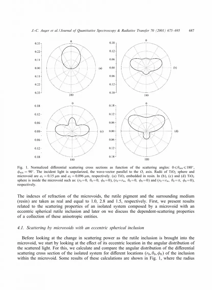
Fig. 1. Normalized di6erential scattering cross sections as function of the scattering angles: 06sca6180◦;�sca = 90◦. The incident light is unpolarized, the wave-vector parallel to the Oz axis. Radii of TiO2 sphere andmicrovoid are a1 = 0:15 �m and a2 = 0:096 �m, respectively. (a) TiO2 embedded in resin. In (b), (c) and (d) TiO2
sphere is inside the microvoid such as: (r0=0; 0=0; �0=0), (r0=rm; 0=0; �0=0) and (r0=rm; 0=�; �0=0),respectively.
The indexes of refraction of the microvoids, the rutile pigment and the surrounding medium(resin) are taken as real and equal to 1:0, 2.8 and 1.5, respectively. First, we present resultsrelated to the scattering properties of an isolated system composed by a microvoid with aneccentric spherical rutile inclusion and later on we discuss the dependent-scattering propertiesof a collection of these anisotropic entities.
4.1. Scattering by microvoids with an eccentric spherical inclusion
Before looking at the change in scattering power as the rutile inclusion is brought into themicrovoid, we start by looking at the e6ect of its eccentric location in the angular distribution ofthe scattered light. For this, we calculate and compare the angular distribution of the di6erentialscattering cross section of the isolated system for di6erent locations (r0; 0; �0) of the inclusionwithin the microvoid. Some results of these calculations are shown in Fig. 1, where the radius

688 J.-C. Auger et al. / Journal of Quantitative Spectroscopy & Radiative Transfer 70 (2001) 675–695
Fig. 2. Same as Fig. 1 with the scattering angles:06sca6180◦; �sca = 90◦ and 180≤sca60◦; �sca= 270◦. The position of the TiO2 sphere is(r0 = rm; 0 = �=2; �0 = �=2).
Fig. 3. Volumetric average extinction cross sections, in�m−1, as functions of the distance of the pigment fromthe center of the host sphere to its maximum value rm.(a) a1 = 0:15 �m; a2 = 0:096 �m, and rm = 0:054 �m.(b) a1 = 0:51 �m; a2 = 0:43 �m, and rm = 0:07 �m.
of the air bubble and the rutile pigment are kept constant and equal to a1 = 0:15 �m anda2 = 0:096 �m, respectively. Light is taken unpolarized, the azimuthal angle of scattering is=xed at �sca = 90◦, and the wave-vector of the incident =eld is taken parallel to the Oz axisof the host sphere. As a consequence, an azimuthal symmetry is kept as long as the inclusionstays on this axis. Also, the integral of the di6erential cross section over all solid angles isnormalized to 1. In Fig. 1 we show the angular distribution of the di6erential cross sectionwhen the pigment (a) is embedded in resin, when (b) is located at the center of the microvoid,and when located at (c) (r0 = rm; 0 = 0; �0 = 0), and (d) (r0 = rm; 0 = �; �0 = 0), whererm = 0:054 �m is the maximum radial position of the inclusion. In the two last locations theinclusion is stuck to the upper (c) and bottom (d) sides of the internal interface of the hostsphere. In curve (a) one sees the typical strong scattering in forward direction predicted bythe Mie theory. When the pigment is located at the center of the microvoid (b) the angulardistribution broadens. Now, when one compares curves (c) and (d) with (b), one observesan enhancement in the intensity of the scattered light in the same direction as the o6-centerlocation of the inclusion. It seems like the o6-center direction of the inclusion is indicating thedirection in which the intensity of the scattered light is enhanced. To test the generality of thisassessment, in Fig. 2 we show the angular distribution of the scattered light when the inclusionis located o6 the Oz axis, at (r0=rm; 0=�=2; �0=�=2). In this case, the azimuthal symmetry ofthe angular distribution is broken but one still sees that the intensity of scattered light is greatlyenhanced on the side of the microvoid where the inclusion is located. Then, one concludes thatthe angular distribution of the scattering =eld is strongly linked to the location of the pigmentwithin the microvoid, being enhanced along the o6-center direction of the inclusion.
The displacement of the inclusion within the microvoid also has an inLuence on the scatteringproperties of the isolated system. In Fig. 3, we show the normalized average of the extinction

J.-C. Auger et al. / Journal of Quantitative Spectroscopy & Radiative Transfer 70 (2001) 675–695 689
Fig. 4. Volumetric average extinction cross sections, in�m−1, as functions of a2=a1 with a1 = 0:15 �m. (a) airmicrovoid alone. (b) TiO2 and microvoid separated inthe resin. (c) TiO2 at the center of the microvoid. (d)TiO2 stuck to the microvoid internal surface (r0 = rm).
Fig. 5. Volumetric average extinction cross sections,in �m−1, as functions of a1 and a2=a1, for TiO2 andmicrovoid as separated entities in resin.
cross section, over all incident angles and polarization states (orientational average), as a func-tion of the distance of the pigment from the center of the host sphere to its maximum value rm.Curve (a) corresponds to a system where a1=0:15 �m; a2=0:096 �m, and rm=0:054 �m, whilein curve (b) a1 = 0:51 �m; a2 = 0:43 �m, and rm =0:07 � m. One can see that the displacementof the pigment from the center to the edge of the host sphere can lead to either an increase ora decrease in the magnitude of average extinction cross section. For the system in panel (a),the average extinction cross section increases by a factor 1.56 between its minimum at r0 = 0and its maximum at r0 = rm. On the other hand, for the system in curve (b) the magnitude ofthe average extinction cross section decreases by a factor 0.15 for the same translation from thecenter to the edge. In this latter case, the maximum occurs at an intermediate distance betweenthe center and the edge while the minimum is at rm. Therefore, one concludes that the behaviorof the average extinction cross section of the isolated system, as a function of the size parameterand the location of the inclusion, is non-monotonic.
After this succinct analysis of the e6ect of the pigment location on the scattering propertiesof the isolated system, we now look at the changes on the average extinction cross sectionwhen the pigment is brought into the microvoids. We recall that one of our objectives is totest if there is an improvement in the scattering properties of rutile inclusions when the contrastin the index of refraction is increased by bringing them inside air bubbles. To look at thiswe calculate the extinction cross section per unit volume (volumetric cross section) for threedi6erent systems: In system 1 we consider that both, the rutile spheres and the microvoids areembedded in resin and they behave as independent scatterers. In system 2 the rutile spheres arelocated at the center of the microvoids while in system 3 the rutile spheres are stuck to theinternal face of the microvoids with random orientations. This latter system is supposed to givea more realistic description of an actual system. In Fig. 4 we show, the average volumetric
690 J.-C. Auger et al. / Journal of Quantitative Spectroscopy & Radiative Transfer 70 (2001) 675–695
extinction cross sections for systems 1, 2 and 3, respectively. These cross sections are plottedas functions of a2=a1 for a1 = 0:15 �m. The values a2=a1 = 0 and 1 correspond, respectively, toa microvoid without pigment and a pigment in resin with the same size of the air bubble. For abetter understanding of the =gure we have added curve (a), which is the volumetric extinctioncross section of the air microvoid alone. The major observation of this calculation is that in thechosen range of size parameters, the volumetric extinction cross section of system 1 (curve(b))is always larger than in systems 2 and 3 (curves (c) and (d), respectively). This simply meansthat rutile is a less eMcient scatterer when it is located inside the air bubbles than when itis outside. One can also see that for small values of a2=a1, the presence of the pigment doesnot perturb the scattering properties of the microvoid. On the other hand, when a2=a1 is closeto 1, the extinction of the system is dominated by the extinction of rutile. There are a coupleof things we should point out about this =gure. The =rst one is the strong decrease in theextinction cross sections in curves (c) and (d) at (a2=a1 =0:58), although the decrease in (d) isnot as pronounced. With such a low value of the extinction cross section, one might say thatthe system behaves as “invisible” to the incident wave, where by this we mean the remanentof a phenomenon found out by Kerker [28], for the case of coated spheres and in the limit ofsmall size parameters (Rayleigh scattering). Under this condition and for speci=c combinationsof values of the relative refractive indexes and radii, it can be shown that the induced dipolein the host sphere has the same amplitude but opposite direction as the one induced dipolein the inclusion. Thus, the total dipole moment is null and there is simply no scattering. Thesecond observation is that at a2=a1 = 0:64, the microvoid alone scatters more than the systemwith the pigment located at the center but less than when it is located at its maximum positionrm. Based on this observation we evaluated the average extinction cross section as a function ofr0. It was found that for r0 = 0:04 �m, the extinction of the eccentric system was equal to thatof the microvoid alone, leading to the conclusion that at this location, the rutile pigment (witha =lling fraction of 0.26) is “invisible” to the incident wave. Therefore, in the same way as thecentered inclusion can lead to an “invisible” system for certain combinations of size parameters,here we show that an eccentric location of the inclusion can lead to interference e6ects suchthat the inclusions might become “invisible” inside the microvoid.
To check if the main conclusion of the previous calculations continues to hold for a di6erentchoice of size parameters, we have evaluated the extinction cross section for the three systemsmentioned above, for values of a1 and a2 in the range 0:15¡a1 ¡ 0:65 �m and 06 a2 6 a1.It was found that the values of the volumetric extinction cross section of the centered andeccentric systems was quite similar, but always smaller than when the TiO2 pigment is outsidethe microvoid. In Figs. 5 and 6 we show, in a 3D plot, the results for the volumetric extinctioncross section as a function of a1 and a1=a2 for systems 1 and 3. One can see that the conclusionsreached above about the loss of scattering power of the rutile inclusions inside an air bubblealso hold for this extended choice of parameters. Also, the highest value of the volumetricextinction cross section is always attained at the optimum size of the rutile sphere in resin.
4.2. Dependent scattering by microvoids containing an eccentric TiO2 spherical inclusion
Since dependent scattering processes are also important in a paint =lm, the recursive procedureintroduced in the previous section was used to evaluate its e6ects on clusters composed by a

J.-C. Auger et al. / Journal of Quantitative Spectroscopy & Radiative Transfer 70 (2001) 675–695 691
Fig. 6. Same as Fig. 5 for TiO2 stuck to the microvoidinternal surface (r0 = rm).
Fig. 7. Volumetric average extinction cross sections, in�m−1, of clusters with seven scattering spheres as func-tions of the distance d between each spheres and theorigin. The radii of the TiO2 spheres and microvoidsare a2 = 0:96 �m and a1 = 0:15 �m, respectively. (a)and (b): independent-scattering calculations for eccen-tric and centered pigments. (c), (d) and (e): depen-dent-scattering calculations with the inclusions at thecenter of the microvoid, closest and the farthest fromthe origin of the aggregate, respectively.
microvoid system containing randomly oriented eccentric inclusion of rutile. In Fig. 7, weshow the average volumetric extinction cross sections of three di6erent aggregates of sevenspheres as a function of the radial distance d between the central sphere and each of itssix other constituents. Each aggregate is built up of seven scatters, one at the origin and theothers located at positions (0; 0; d); (0; 0;−d); (d; 0; 0); (−d; 0; 0); (0; d; 0) and (0;−d; 0). Eachscatterer is made of rutile pigment with radius a2 = 0:96 �m, and located in a microvoid ofradius a1 = 0:15 �m. The results for the di6erent relative locations of the pigment inside eachmicrovoid are labeled with di6erent letters. In plot (c), the inclusion is at the center, whilein plots (d) and (e) the inclusion is located at the closest and the farthest positions from thecentral sphere in the aggregate. For a better understanding of the results, the total volumetricextinction cross sections of a system composed of independent scattering spheres for eccentricand centered pigments were added in plots (a) and (b), respectively. The parameters were chosenso that an isolated system with a centered pigment scatters less than the one with an eccentricposition. One can see that as it is expected, at long distances between the constituents of asame cluster the dependent and independent cross sections are identical. When these distancesdecrease, dependent scattering becomes predominant leading to a decrease of the total extinctioncross section. Appearance of oscillations should come from interferences and resonant modesdue to the symmetrical geometry chosen for the clusters. When all scatterers are in contact(case of a compact cluster), curve (d) undergoes a higher decrease than curve (e) because itcorresponds to the case where the TiO2 pigments inside the microvoid are closer, leading to astronger e6ect of dependent scattering.

692 J.-C. Auger et al. / Journal of Quantitative Spectroscopy & Radiative Transfer 70 (2001) 675–695
5. Conclusion
In this paper, we have derived the general T-matrix formulations for an isolated system com-posed of a dielectric sphere containing an eccentric dielectric spherical inclusion. We also havepresented a new recursive procedure to solve the coupled linear equations for multiple scatter-ing problem. We applied these formalisms to the study of the optical properties of microvoidscontaining eccentric TiO2 pigments. It is shown that the scattering eMciency of TiO2 pigmentis not improved when it is introduced into a microvoid.
Acknowledgements
The authors acknowledge Eduardo Nahmad for the support given to this work.
Appendix A. Expressions of the )M and )D matrices
In this appendix we write, as a reference, the explicit form of several expressions used inthe text.
Q1n =
[k1'
′(2)n (k1r2) n(k2r2)− k2'
(2)n (k1r2) ′
n(k2r2)
k2'(1)n (k1r2) ′
n(k2r2)− k1'′(1)n (k1r2) n(k2r2)
];
Q2n =
[k1'
(2)n (k1r2) ′
n(k2r2)− k2'′n(2)(k1r2) n(k2r2)
k2'′(1)n (k1r2) n(k2r2)− k1'
(1)n (k1r2) ′
n(k2r2)
]; (A.1)
and
Z (a)"n = [Q1
"'(1)n (k1a1) + '(2)n (k1a1)];
Z (b)"n = [Q2
"'(1)n (k1a1) + '(2)n (k1a1)];
Z (c)"n = [Q1
"'′(1)n (k1a1) + '
′(2)n (k1a1)];
Z (d)"n = [Q2
"'′(1)n (k1a1) + '
′(2)n (k1a1)]: (A.2)
The general expressions for the UM and UD matrices are given by the following relations:
UM=
UM
nm(1;1)"#
UMnm(1;2)"#
UMnm(2;1)"#
UMnm(2;2)"#
and UD=
UD
nm(1;1)"#
UDnm(1;2)"#
UDnm(2;1)"#
UDnm(2;2)"#
: (A.3)
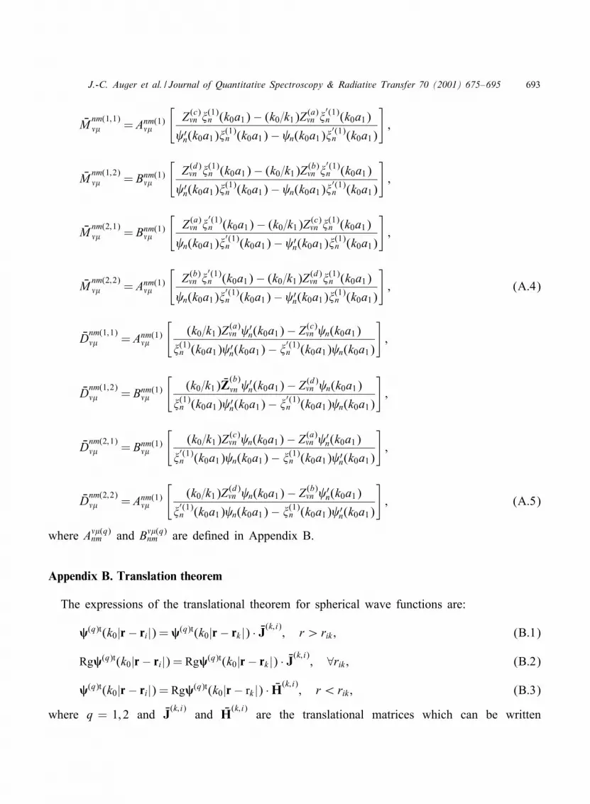
J.-C. Auger et al. / Journal of Quantitative Spectroscopy & Radiative Transfer 70 (2001) 675–695 693
UMnm(1;1)"# = Anm(1)
"#
[Z (c)"n '(1)n (k0a1)− (k0=k1)Z
(a)"n '
′(1)n (k0a1)
′n(k0a1)'
(1)n (k0a1)− n(k0a1)'
′(1)n (k0a1)
];
UMnm(1;2)"# = Bnm(1)
"#
[Z (d)"n '(1)n (k0a1)− (k0=k1)Z
(b)"n '
′(1)n (k0a1)
′n(k0a1)'
(1)n (k0a1)− n(k0a1)'
′(1)n (k0a1)
];
UMnm(2;1)"# = Bnm(1)
"#
[Z (a)"n '
′(1)n (k0a1)− (k0=k1)Z
(c)"n '(1)n (k0a1)
n(k0a1)'′(1)n (k0a1)− ′
n(k0a1)'(1)n (k0a1)
];
UMnm(2;2)"# = Anm(1)
"#
[Z (b)"n '
′(1)n (k0a1)− (k0=k1)Z
(d)"n '(1)n (k0a1)
n(k0a1)'′(1)n (k0a1)− ′
n(k0a1)'(1)n (k0a1)
]; (A.4)
UDnm(1;1)"# = Anm(1)
"#
[(k0=k1)Z
(a)"n ′
n(k0a1)− Z (c)"n n(k0a1)
'(1)n (k0a1) ′n(k0a1)− '
′(1)n (k0a1) n(k0a1)
];
UDnm(1;2)"# = Bnm(1)
"#
[(k0=k1) UZ
(b)"n ′
n(k0a1)− Z (d)"n n(k0a1)
'(1)n (k0a1) ′n(k0a1)− '
′(1)n (k0a1) n(k0a1)
];
UDnm(2;1)"# = Bnm(1)
"#
[(k0=k1)Z
(c)"n n(k0a1)− Z (a)
"n ′n(k0a1)
'′(1)n (k0a1) n(k0a1)− '(1)n (k0a1) ′
n(k0a1)
];
UDnm(2;2)"# = Anm(1)
"#
[(k0=k1)Z
(d)"n n(k0a1)− Z (b)
"n ′n(k0a1)
'′(1)n (k0a1) n(k0a1)− '(1)n (k0a1) ′
n(k0a1)
]; (A.5)
where A"#(q)nm and B"#(q)
nm are de=ned in Appendix B.
Appendix B. Translation theorem
The expressions of the translational theorem for spherical wave functions are:
�(q)t(k0|r− ri|) = �(q)t(k0|r− rk |) · UJ(k; i); r ¿ rik ; (B.1)
Rg�(q)t(k0|r− ri|) = Rg�(q)t(k0|r− rk |) · UJ(k; i); ∀rik ; (B.2)
�(q)t(k0|r− ri|) = Rg�(q)t(k0|r− rk |) · UH(k; i)
; r ¡ rik ; (B.3)
where q = 1; 2 and UJ(k; i)
and UH(k; i)
are the translational matrices which can be written

694 J.-C. Auger et al. / Journal of Quantitative Spectroscopy & Radiative Transfer 70 (2001) 675–695
as:
UJ(k; i)
=
RgA"#(q)
nm RgB"#(q)nm
RgB"#(q)nm RgA"#(q)
nm
and UH
(k; i)=
A"#(q)
nm B"#(q)nm
B"#(q)nm A"#(q)
nm
(B.4)
The A"#(q)nm and B"#(q)
nm are the translation coeMcients needed for the transformation from the ithto the kth coordinate system. They depend on the position vector rki between the two spheresand the amplitude of the wave-vector of the medium in which they are. They can be derivedfrom scalar translational matrices coeMcients [27], 7";#
n;m and 8";#n;m expended in terms of the jn(kr)
and h(1)n (kr), respectively. Then one can use the relations between vector and scalar coeMcientsderived by Mackowski. In terms of our chosen normalization for the spherical-wave basis,Eq. (4) and Eq. (25) have the following expressions:
RgA"#(1)nm =
12
√1
"("+ 1)n(n+ 1)[2 �m7";#
n;m
+√(n−m)(n+m+ 1)("− #)("+ #+ 1)7";#+1
n;m+1
+√(n+m)(n−m+ 1)("+ #)("− #+ 1)7";#−1
n;m−1] (B.5)
RgB"#(1)nm =−i
12
√2"+ 12"− 1
1"("+ 1)n(n+ 1)
[2m√("− #)("+ #)7"−1;#
n;m
+√(n+m)(n+m+ 1)("− #)("− # − 1)7"−1;#+1
n;m+1
−√(n+m)(n−m+ 1)("+ #)("+ # − 1)7"−1;#−1
n;m−1 ] (B.6)
The A"#(3)nm and B"#(3)
nm coeMcients are found from relations (B.5) and (B.6) replacing the 7";#n;m
scalar matrix coeMcients by the 8";#n;m.
References
[1] Chandrasekhar S. Radiative transfer. New York: Dover, 1960.[2] Frisch U. Propagation des ondes en milieu al/eatoire et les /equations stochastisques. Annales d’Astrophysique
1966;29:645–82.[3] Frisch U. Annales d’Astrophysique 1966;30:565–601.[4] Wick ZW, Jones FN, Pappas PS. Organic coatings: science and technology. Vol. 1. New York: Wiley; 1992.[5] Ross W. Theoretical computation of light scattering power: comparison between TiO2 and air bubbles.
J Paint Technol 1971;43(563):50–65.[6] Kerker M, Cooke D, Ross W. Pigmented microvoid coatings: theoretical study of three models. Paint Res Inst
1975;47(603):33–41.[7] Waterman P. Symmetry unitary and geometry in electromagnetic scattering. Phys Rev D 1971;3(4):825–39.

J.-C. Auger et al. / Journal of Quantitative Spectroscopy & Radiative Transfer 70 (2001) 675–695 695
[8] Bohren CF, Hu6man DR. Absorption and scattering of light by small particles. New York: Wiley-Interscience;1983.
[9] Wiscombe W. Improve Mie scattering algorithms. Appl Opt 1980;19(9):1505–9.[10] Fikioris U. J Opt Soc Am 1979;69:1359.[11] Borghese F, Denti P, Saija R. Optical properties of spheres containing a spherical eccentric inclusion. J Opt
Soc Am A 1992;9(8):1327–35.[12] Videen G, Ngo D, Chylek P, Pinnick R. Light scattering from a sphere with an irregular inclusion. J Opt Soc
Am A 1995;12(5):922–8.[13] Ngo D, Videen G, Chylek P. A FORTRAN code for the scattering of EM waves by a sphere with a
nonconcentric spherical inclusion. Comput Phys Commun 1996;1077:94–112.[14] Tsang L, Kong J, Shin R. Theory of microwave remote sensing. New York: Wiley; 1985.[15] Stein S. Addition theorems for spherical wave functions. Quart Appl Math 1961;19(1):15–24.[16] Borghese F, Denti P, Saija R, Toscano G. Multiple electromagnetic scattering from a cluster of sphere I theory.
Aerosol Sci Technol 1984;4:227–35.[17] Hamid A. Electromagnetic scattering by an arbitrary con=guration of dielectric spheres. Can J Phys
1990;68:1419–28.[18] Mackowski D, Mishchenko M. Calculation of the T-matrix and the scattering matrix for ensembles of spheres.
J Opt Soc Am A 1996;13(11):2266–78.[19] Xu Y. Electromagnetic scattering by an aggregate of sphere. Appl Opt 1995;34(21):4573–88.[20] Chew W. Waves and Fields in Inhomogeneous Media, Series on Electromagnetic Waves. New York: IEEE
Press; 1990.[21] Tzeng Y, Fung A. T-matrix approach to multiple scattering of EM waves from N-spheres. J Electromagn
Waves Appl 1994;8(1):61–84.[22] Holler S, Auger JC, Stout B, Pan Y, Bottiger J, Chang RK, Videen G. Observations and calculations of light
scattering from clusers of spheres. Appl Opt 2000;39(36):6873–87.[23] Mishchenko M, Travis L, Mackowski D. T-matrix computations of light scattering by nonspherical particles:
a review. JQSRT 1996;55(5):535–75.[24] Mackowski D. Calculation of total cross sections of multiple-sphere clusters. J Opt Soc Am A
1994;11(11):2851–61.[25] Fuller K. Scattering and absorption cross sections of compounded spheres: I theory for external aggregation.
J Opt Soc Am A 1994;11(12):3251–60.[26] Van de Hulst HC. Light scattering by small particles. New York: Dover; 1957.[27] Chew W. Recurrence relations for three-dimensional scalar addition theorem. J Electromagn Waves Appl
1992;6(2):133–42.[28] Kerker M. Invisible bodies. J Opt Soc Am A 1975;65(4):376–9.


](https://img.pdfslide.net/doc/110x75/6336ac0eb5f91cb18a0beec4/adsorption-of-bi-isonicotinic-acid-on-rutile-tiosub-2110.jpg)


