Embed Size (px)
Citation preview


Sewers- Rehabilitation and New Construction
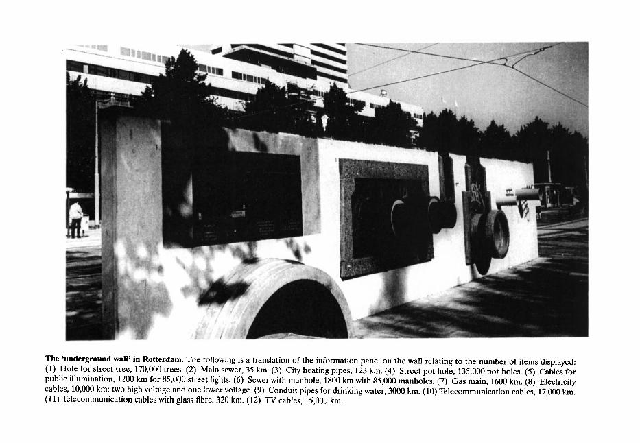
The 'underground wail' in Rotterdam. The following is a translation of the information panel on the wall relating to the number of items displayed: (1) Hole for street tree, 170,000 trees. (2) Main sewer, 35 km. (3) City heating pipes, 123 km. (4) Street pot hole, 135,000 pot-holes. (5) Cables for public illumination, 1200 km for 85,000 street lights. (6) Sewer with manhole, 1800 km with 85,000 manholes. (7) Gas main, 1600 km. (8) Electricity cables, 10,000 km" two high voltage and one lower voltage. (9) Conduit pipes for drinking water, 3000 km. (10) Telecommunication cables, 17,000 km. (11) Telecommunication cables with glass fibre, 320 km. (12) TV cables, 15,000 km.

Sewers -Rehabilitation and New Construction Repa~'r and Renovation
edited by
Geoffrey F. Read Consulting Civil and Structural Engineer and Visiting Lecturer, Department of Civil and Structural Engineering, UMIST, UK
with lan G. Vickridge Senior Lecturer, Department of Civil and Structural Engineering, UMIST, UK
ELSEVIER B U T T E R W O R T H
H E I N E M A N N
A M S T E R D A M �9 B O S T O N ~ HEIDELBERG ~ LONDON ~ NEW YORK �9 O X F O R D PARIS ~ SAN D IEGO - SAN F R A N C I S C O ~ S INGAPORE ~ SYDNEY �9 T O K Y O

Elsevier Butterworth-Heinemann Linacre House, Jordan Hill, Oxford OX2 8DP 30 Corporate Drive, Burlington, MA 01803
First published 1997 Transferred to Digital Printing 2005
Copyright �9 1997, Elsevier Ltd. All rights reserved
No part of this publication may be reproduced in any material form (including photocopying or storing in any medium by electronic means and whether or not transiently or incidentally to some other use of this publication) without the written permission of the copyright holder except in accordance with the provisions of the Copyright, Designs and Patents Act 1988 or under the. terms of a licence issued by the Copyright Licensing Agency Ltd, 90 Tottenham Court Road, London, England W 1T 4LP. Applications for the copyright holder's written permission to reproduce any part of this publication should be addressed to the publisher
Permissions may be sought directly from Elsevier's Science & Technology Rights Department in Oxford, UK: phone: (+44) 1865 843830, fax: (+44) 1865 853333, e-mail: [email protected]. You may also complete your request on-line via the Elsevier homepage (http://www.elsevier.com), by selecting 'Customer Support' and then 'Obtaining Permissions'
British Library Cataloguing in Publication Data A catalogue record for this book is available from the British Library
Library of Congress Cataloguing in Publication Data A catalogue record for this book is available from the Library of Congress
ISBN 0 340 54472 4
For information on all Elsevier Butterworth-Heinemann publications visit our website at www.bh.com
Working together to grow libraries in developing countries
www.elsevier.com I www.bookaid.org I www.sabre.org
Printed and bound in Great Britain

Contents
About the Editor
About the Assistant Editor
Foreword Professor Peter Thompson
Preface
The Development of Public Health Engineering Geoffrey F. Read 1.1 1.2 1.3 1.4 1.5 1.6
Introduction Ancient hygiene The Middle Ages and the early modem period Water - the foundation of life - waste water Population and urbanisation Life in the Victorian period Bibliography
2 The Development of the National Sewerage Network Geoffrey F. Read 2.1 2.2 2.3 2.4 2.5 2.6 2.7
Early sewers, pre-1830 Second generation sewers, 1828-90 Characteristics of first and second generation sewers in Manchester The interceptor sewers - lettered sewers Extended main drainage scheme - numbered sewers The present-day situation Construction materials
3 The Problems of Sewerage Dereliction Geoffrey F. Read 3.1 3.2 3.3 3.4
Background Infiltration/exfiltration The environmental impact of sewer collapse Sewer collapses- effect on overall economy
xi
xiii
XV
XVI I
1 4 6 8
13 18 21
22
23 24 30 33 37 39 40
41
41 46 47 54

vi Contents
3.5 3.6 3.7 3.8 3.9 3.10 3.11
The problem The brick sewers of Manchester Generally Present-day impact of original construction methods Structural considerations Assessing structural condition Summary
Planning Sewerage Rehabilitation and Maintenance Geoffrey F. Read and/an G. Vickridge
4.1 Introduction 4.2 Maintenance strategies 4.3 Rehabilitation strategies 4.4 Computerised maintenance management systems 4.5 The future
References
57 58 62 63 64 64 68
69
69 71 74 80 81 82
Sewer Surveys lan G. Vickridge and Dimitri Leontidis
5.1 5.2 5.3 5.4 5.5
Introduction Location of underground assets Inspection of underground assets Computer and software support for surveying The future References
84
84 85 92 98
100 101
6 Traffic Management and Public Relations C. Barber 6.1 6.2 6.3 6.4 6.5 6.6
Introduction Traffic problems following sewer collapse Traffic management - planned sewer repairs and renovation works The wider view Public relations The future Bibliography
Access D. 114. Fa rra r
7.1 7.2 7.3 7.4 7.5 7.6 7.7 7.8
Present-day requirements Access in early sewers Types of manholes Shaft construction Internal layouts of manholes Shaft construction programmes Access and public utilities City centre problems and solutions References
103
103 103 110 117 120 123 124
125
125 126 129 133 138 141 143 146 148

Contents vii
Hydraulic Assessment A. J. Saul 8.1 8.2 8.3 8.4 8.5 8.6 8.7
Rainfall runoff and overland flow processes Rainfall Rainfall losses Rainfall runoff Mathematical modelling Building and verifying the mathematical simulation model Catchment and sewer system data References
149
149 150 161 166 173 175 180 192
Ancillary Works - Cleaning and Overpumping Paul Nedwe// and /an G. Vickridge 9.1 Introduction 9.2 Overpumping 9.3 Sewer cleaning
Bibliography
193
193 193 199 203
10 Repair and Renovation Geoffrey F. Read and Paul Nedwe// 10.1 10.2 10.3 10.4 10.5 10.6 10.7 10.8 10.9
Introduction Repair or stabilisation techniques- man-entry sewers Renovation- man-entry sewers Renovation- non-man-entry sewers Hard linings Soft linings Spray linings Problems associated with lining systems Stabilisation
10.10 Renovation- long-term
204
204 206 208 217 218 224 228 229 229 232
11 Localised Repair Techniques for Non-man-entry Sewers /Veil Bunting 11.1 Background 11.2 Design criteria 11.3 Types of system 11.4 Summary 11.5 Directory
233
233 234 237 252 253
12 Structural Aspects of Sewer Rehabilitation /an G. V/ckridge 12.1 Introduction 12.2 Structural defects and their causes 12.3 Sewer deterioration 12.4 Structural assessment 12.5 Structural design 12.6 Future research and development needs
References
254
254 254 256 259 263 270 271

viii Contents
13 Assessment of Renovation Techniques and Costs Geoffrey F. Read 13.1 Introduction 13.2 The options 13.3 Safety and welfare 13.4 Sewer rehabilitation- the Manchester experience 13.5 The future 13.6 Manual guidance renovation 13.7 Hydraulic aspects 13.8 Cost estimates 13.9 Economic appraisal
14 Combined Sewer Overflows A. J. Saul
14.1 Introduction 14.2 Definitions of CSO performance 14.3 Detailed design of CSO chambers 14.4 Hydraulic performance of CSO structures 14.5 Continuation flow 14.6 Flow over end weirs 14.7 Analysis of flow over side weirs 14.8 Screens at CSO chambers 14.9 Storage tanks 14.10 Hydraulic performance in tanks 14.11 Sediments in tanks and their implications on design
References
272
272 273 274 275 277 277 277 279 281
283
283 295 297 303 305 307 307 311 312 313 314 316
15 Contract Strategy N. ,I. Smith
15.1 Introduction 15.2 Project characteristics 15.3 Organisational structure 15.4 The engineer 15.5 Type of contract 15.6 Tendering procedure 15.7 Risk in contract strategy 15.8 Choice of contract strategy 15.9 Developments affecting contractual procedures
Contract documents Bibliography
16 Construction Management N. J. Smith
16.1 Introduction 16.2 Contractual procurement 16.3 Contract documents 16.4 Quality management 16.5 Site management 16.6 Special types of construction
318
318 319 319 321 322 327 329 330 331 332 333
334
334 334 337 340 341 348
16.7 Construction management of sewer renovation and repair Acknowledgements Bibliography
17 Site Supervision R. D. Tins/ey 17.1 Introduction 17.2 Form of agreement 17.3 Supervision - currency of contract 17.4 Setting out 17.5 Early stage checks 17.6 Safety 17.7 Permit to work 17.8 Precontract and progress meetings 17.9 Site reports 17.10 Valuations 17.11 Measured items 17.12 Dayworks 17.13 Variation orders 17.14 Contractual claims 17.15 The final account 17.16 Inspection of the works
Bibliography
18 Sewer Repair and Renovation in Japan Satoru Tohyama 18.1 18.2 18.3 18.4 18.5 18.6 18.7 18.8
Introduction The general situation of sewerage systems in Japan The water sealing method Resin lining process The inversion lining method The pipe-in-pipe method Pipe jacking method Conclusion
19 Development and Research Geoffrey F. Read and/an G. Wckridge 19.1 19.2
Introduction The future - the need for research and development Bibliography
Contents ix
349 350 350
351
351 351 351 354 354 356 357 359 359 361 362 362 367 367 370 371 374
375
375 375 378 381 383 384 385 390
391
391 395 402
Index 403

This Page Intentionally Left Blank

About the Editor
GEOFFREY E READ, MSc, CEng, FICE, FIStructE, FCIWEM, FIHT, MILE, FIMgt, MAE, MUKSTT Geoffrey Read is a Consulting Civil and Structural Engineer, a Member of the Academy of Experts, and a Director of Consulting Engineers, John Walton Associates. As well as running his own practice he is a Research Fellow and Visiting Lecturer at the Department of Civil and Structural Engineering, University of Manchester Institute of Science and Technology. He has many years construction industry experience including 12 years as City Engineer and Surveyor, Manchester - during the period when the city-centre suffered a considerable number of sewer collapses- and Engineer to Manchester Airport. As such, Geoffrey became known world-wide as one of the leading campaigners for the rehabilita- tion of sewerage infrastructure. He has written a variety of technical papers on the subject as well as directing, among other things, a large programme of rehabilitation of

xii About the Editor
Manchester's Victorian brick and pipe sewers, involving renovation and on- and off-line replacement. He has previously held appointments with six other local authorities and was Advisor on Highways and Sewerage to the Association of Metropolitan Authorities; past Chairman of the City Engineers Group and Founder President of the Association of Metropolitan District Engineers. He is the author of several research papers on social costs of utility works as well as numerous other technical papers and has contributed to the Sewer and Culvert section of The Maintenance of Brick and Stone Masonry Structures for E. & E N. Spon.
Geoffrey Read's experience covers a broad spectrum of civil and structural engineering but latterly has tended to be concentrated on sewerage particularly Trenchless Technology and Environmental Management. He was for eight years the Engineer to the former Bolton and District Joint Sewerage Board (an area of 25.70 hectares), as well as a recognised authority on sewerage rehabilitation and on the social and indirect costs of public utility works in highways. Lately he directed a socio-economic cost benefit study for a major flood alleviation and sewerage improvement scheme (s in a large industrial city as well as developing and implementing a strategy for rehabilitation of the effluent drainage system in a major industrial complex. Geoffrey also provides an expert witness service for Solicitors and Insurers over a full range of professional services.

About the Assistant Editor
Ian Vickridge BSc, MSc, CEng, MICE, MCIWEM, MUKSTT is a Senior Lecturer in the Department of Civil and Structural Engineering at UMIST, where he is the Director of the MSc course in the Management and Implementation of Development Projects. In the past he has worked with consultants and contractors, as well as other academic institutions, both in the UK and various locations overseas including Canada, Saudi Arabia, Hong Kong, and Singapore. He has been involved in research and training in sewer rehabilitation for many years and instigated short courses in sewer rehabilitation for practising engineers at UMIST in 1986. He has made contributions to several books and has written over 40 technical papers for journals and conferences. He has also undertaken a number of consultancy assignments relating to sewer rehabilitation and trenchless technology, and is currently the Executive Secretary for the UK Society for Trenchless Technology.

This Page Intentionally Left Blank

Foreword
The essential infrastructure of a developed country is usually taken for granted by the public until they are personally affected by rare malfunctioning, failure or rehabilitation of the facility. Although sensing the necessity for keeping the infrastructure functioning, the public are not altogether enamoured about the impact which remedial work causes to their accus- tomed pattern of life, albeit for a relatively short period.
Sewers in particular, are hidden from the public view and consequently there has been a tendency to neglect their maintenance - in fact some of them have never been repaired since construction!
Regardless of the type of controlling authority, funding has generally in the past been inadequate. In a paper on 'The development, renovation and reconstruction of Manchester's sewerage system' to the Manchester Literary and Philosophical Society in 1982 the then City Engineer Geoffrey E Read warned: 'that a losing battle is being fought and dereliction is taking place much more rapidly than renewal, strengthening or maintenance can be carried out.'
Subsequent events have only served to confirm the wisdom of these observations. Many of the sewers in the centres of our industrial cities were constructed in the early days of the last century and have performed remarkably well despite this neglect, many remaining fully operational to day. No engineering structure however well constructed will last forever.
Manchester possesses the oldest extensive sewer network in the UK and consequently during his time as City Engineer, Geoffrey E Read was amongst the first to encounter and respond to the problem of wide-scale sewer collapses in the city-centre. Each collapse necessitating some form of road closure or restriction with resultant traffic disruptions and immediate risk to public health notwithstanding the always present potential risk to life and limb presented by such emergencies. As a result Mr Read became known world-wide as one of the leading campaigners for the urgent renewal of sewerage infrastructure and has written many technical papers on the subject as well as directing a large programme of sewerage rehabilitation in Manchester.
Sewers generally run along the centre line of busy streets, access is difficult and refurbishment impacts on the lives of the community, as well as on the commercial well- being of the area. There were particular problems with brick sewers constructed with lime mortar and natural stone inverts and soffits prior to 1870 and with the vast number of such conduits being too small for man-entry. The bricks themselves being of poor quality and

xvi Foreword
irregular shape. Nevertheless, it is clear that the brick-built sewers and culverts represent a remarkable monument to the skills, knowledge and qualities of workmanship of the nineteenth-century civil engineers and contractors.
It became clear to Mr Read in the early stages of the dramatic sewer collapse era in central Manchester during the late 1970s and early 1980s that some form of internal lining or permanent framework was required to quickly stabilise the old brick structures before collapse took place. Urgent development of such techniques being essential in an endeavour to retain parts of the network which had not deteriorated too far and so ensure that the very limited funds then available were spread as widely as possible. Much research and development rapidly followed in the City Engineer's Department utilising new materials then becoming available - this laboratory and site trial work forming much of the early foundations of the current renovation practice.
Inspection, renovation and refurbishment generally demanded innovation and ingenuity and much of the early work in this field was carried out in Manchester by the Editor and the majority of contributors to this book who have jointly compiled a reservoir of knowledge in relation to techniques, procedure and materials. They investigated collapse mechanisms, researched the social impact of sewer rehabilitation and developed new techniques for stabilising, renovating, relining and in some instances replacing parts of the network with the minimum of local disturbance to the community.
It was a successful collaborative effort driven by Mr Read and his department and involving local universities, consultants and contractors. I am delighted that colleagues in the Department of Civil Engineering at UMIST made a significant contribution to this work.
It is primarily a book for the technical practitioner but is relevant to all those with political or commercial responsibility for the functioning of urban sewerage systems. As every defective sewer will require an individual response this practical collection of knowledge will doubtless prove invaluable for the planning of maintenance and selection of the appropriate method for inspection, repair and renovation with minimum environmental impact.
Peter Thompson AMEC Professor of Engineering Project Management
Department of Civil and Structural Engineering University of Manchester Institute of Science and Technology

Preface
The public health is the foundation on which reposes the happiness of the people and the power of a country.
Disraeli
As one of the generation of Chartered Civil Engineers, whose early training in sewerage utilised the textbooks Sewers by Bevan and Rees and Sewerage Design and Specification by Escritt, I was eventually persuaded that there was an overdue need for a sewerage book or books relating to the more recent developments in this specialised field of public health engineering.
It seemed when planning the two books in this series and endeavouring to formulate each of the chapter contents so as to provide a logical pattern without significant overlap that assistance was desirable from colleagues in the local authority, consultancy, contractual and academic fields in order to provide the reader with a wide base of technical expertise and opinion. This approach has had the disbenefit of a long gestation period but hopefully the finished composite content will have brought appropriate overall benefit.
It was intended that the two books would be for the benefit of middle-level technical staff employed in water companies, consultants and local authority offices as well as for university students to assist them in bridging the gulf between theory and practice.
Volume I concentrates on repair and renovation and particularly in connection with the latter relates closely to Water Research Council's (WRc) Sewerage Rehabilitation Manual (SRM) and the wealth of information it contains.
Renovation is not a panacea - merely an important option worthy of consideration at the outset - in fact when the SRM was first launched, the message coming across from WRc was not renovation or renewal but rather 'has renovation been considered an option?'.
The SRM has provided a great deal of detail for the design of renovation schemes and is an excellent commonsense treatise on the subject addressed, although it does not offer any fundamental dramatic new concepts. It was intended to provide a framework for decision making which is consistent and technically justifiable while still allowing the necessary flexibility for drainage engineers to apply their personal judgement and skill to particular situations.
One had hoped that consideration would perhaps have been given to the possibility of extending the strategy proposed to one of 'fully preventative or planned maintenance' so

xviii Preface
that cost-effective solutions could be adopted earlier rather than later in the life of the structure. Perhaps, in addition, Volume IV of the SRM might follow in due course so as to include coverage of conventional and new methods of reconstruction and new construction which may well materialise during the next few years.
Age is not the only significant feature in classifying sewerage dereliction but construction before the middle of the nineteenth century will nevertheless indicate a very serious risk of dereliction, in fact much higher than after this time. If one examines in detail the location of the 5000 collapses a year, it can be confirmed that age has a major influence on the frequency of failure and therefore on degree of deterioration.
As described later, our sewerage infrastructure was initially developed in the late eighteenth and early nineteenth century, but in general the population has shown little interest in it until such time as it fails and interferes with their normal lifestyle. The same can be said for the other public utilities. A few years ago I visited Rotterdam with my colleague at UMIST, Ian Vickridge, to present a paper entitled 'The Environmental Impact of Sewerage Replacement and Renovation' to the No-Dig '90 Conference of the Inter- national Society for Trenchless Technology.
A permanent reminder of the event, which attracted some 650 participants was provided by an instructive 'pipe wall' which had been built in the square outside the De Doelen Conference Centre. The wall (illustrated at the front of the book) illustrates the often forgotten utility mains which are located under the highways of the city, showing them true to size and relative location. This unquestionably reminds Rotterdamers and visitors what in fact lies beneath the surface they traverse and seems to be an excellent way to highlight the infrastructure in relation to problems and extension of the system as a result of development. Perhaps this is a feature which some of our larger cities might, with advantage, copy?
Various techniques are described in the books. These are not exhaustive but represent perhaps the most popular solutions although others continue to develop and the experienced engineer will be able to select with confidence the most suitable for a particular problem. There is not a standard solution applicable to all problems. It i s - as I have expressed frequently- still very much a question of 'horses for courses'.
Finally I would like to take this opportunity of recording my appreciation to all the friends and colleagues who have given such valuable assistance in the production of this first volume.
Geoffrey E Read
The Public
1 Development of Health Engineering
Geoffrey E Read MSc, CEng, FICE, FlStructE, FCIWEM, FIHT, MILE, FIMgt, MAE, MUKSTT
1.1 Introduction
The following definitions have been assumed, notwithstanding the fact that both types of underground structure present similar problems so far as rehabilitation is concerned. Reference in the text below to sewers therefore includes culverts:
�9 S e w e r - an underground conduit or duct formed of pipes or other construction used for the conveyance of surface, sub-soil or waste water.
�9 C u l v e r t - a large pipe or enclosed channel used for conveying a water course or stream below formation level.
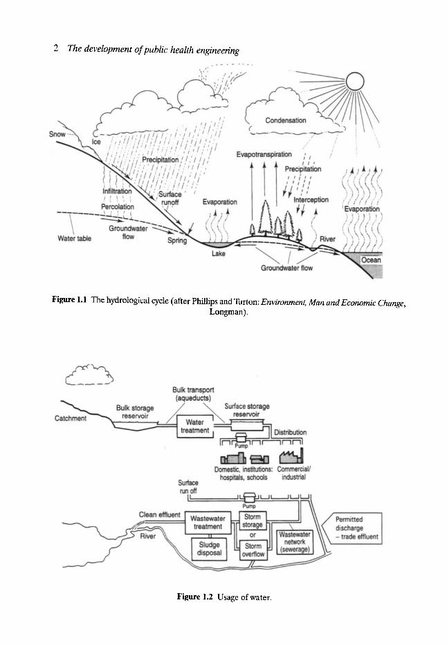
Sewerage systems are sewer networks for the collection of waste water, conveying it via pipes, conduits and ancillary works from its point of origin to treatment works prior to discharge back into the environment. Domestic waste water includes the used water of business, industrial plants and office buildings as well as dwellings. In addition to waste water, sewerage systems also handle the flow of storm water from roofs and paved surfaces (Figs 1.1 and 1.2).
From the point of view of the health and general well-being of the community, the satisfactory disposal of refuse in all forms is clearly of paramount importance. It would therefore seem desirable to briefly describe the earlier forms of sewage disposal, practised in the UK, which are referred to later in more detail.
It will soon be appreciated that public health in Britain did not automatically improve with the passage of time. In the Roman period, for instance, going to the toilet was usually a clean, comfortable and relaxing experience. Hundreds of years later, in the Middle Ages toilets were often quite dangerous and disgusting places to enter (Fig. 1.3).
Prior to the industrial revolution when Britain was primarily agricultural in character, the disposal of human excreta was by privies (where people went on their own) or pail closets. In a privy the excreta being collected in a fixed receptacle which was provided with a door at the back or side, through which it was periodically emptied, generally at night; dry earth or ashes being mixed with the deposit and applied both before and after use. A pail closet is one in which a bucket or pail is used to collect the human wastes which are generally covered with earth, etc., the pail - in an ideal situation being emptied at least once per day. The final disposal of the refuse from privies or pail closets was on to the land at the bottom of shallow trenches subsequently covered over.
2 The development ofpublic health engineering
Figure 1.1 The hydrological cycle (after Phillips and Turton: Environment, Man and Economic Change, Longman).
Figure 1.2 Usage of water.

Introduction 3
i III mira, ~ ~.soo ,~t..mat III Borons a~es ha~a ~ 111 toner lint more ~ there was a III commmua one. eeoCe ohm m
�9 ., . III ~er,,~~as~roou ~:::111 w ~ ~ u a ~ , ~ ~ ~ a n d ~;~:111 m..eomme. 'mn.e m. ,e .a t+ ~ l l l around the side and nmning water I l l , Ill w rake the wine a n y . ~ t an
~][1 whets were ads comfottuble, in i~ ~11 anuy camps u~ some p n or the
~;: ~." ::? :~: ~i-. *. +.=~i" ~:~ :~ ~:+,i,i.
i~ "2.
I-The water and sewage system of a tathedral in the middle ages. It was often freezing cold but at least it was reasonably dean and effiaent. The monks understood the Importance of using water to flush " away the waste. They used the iwater which had been esed In the kitchens or the brewery w slop out the-dirt- Some hl~rla~ think that this might be why monasteries tended to escape the worst effects of the Black Death which killed about 8OO,OOO people in Btltain in the 14th century.
, |,
~ A typical WHet in a medieval castle, about 135o. It was semetlms called a garderobe and was simply a seat placed over a short funnel which carried away the waste through a hole in the castle wall, which then plopped into the moat or piled up into a large dung heap against the castle wall. There is no record of toilet paper having been used at this stage in history.
rmtt~ ~ AN ELIZABETHAN TOILET. (ROUND AeOUT 16oo) In one of the "Blackadder" programmes, there is a joke about people lust going to the toilet out of the window and "doing it" onto the streets below. This did somet~nes happen (although not everyone did this). Human filth might fall onto innocent passers by. The only public WHets in London, on London Bridge drained straight into the River Thames.
I ~ ~ chamber pot and the 1060 a.d. dinner parties Jt .was
bshionable to keep _dhnmhl~ ~ t i t tbe dining room so that guem could relieve thmnselves without lntmupaug the flow of convenmtlon. Some people used the fireplace, (the servants cleaned it up later).
m i r a " ~ From " ~ enqu~ into the state of the town of Leeds, 1S42." "b~nbers of streets have been made without pavements or sewers. Privies w laden with ashes and excrement as to be unusable, in one cul de sac there are :34 houses from which 75 cartloads of manure have been removed which had been untouched for years." At least people went on their own, hence the name "pdvles" for toilets. After 18r5 public health acts made town councils provide clean wnter, drainage and sewerage.
J,',i ,t,"~,'l'l,I ~emmnent alSdtish 'i~iilli,~t: t,'l lromJrr by i .I : } J } i , q l i l l [ 11 wilet hiswrlan: ~it i I i -By the 1980% toilets hadbecome !~I~il~[U il'!j'~l clean and com_foCtable~sKuated in
i I i l ~ f ~ i a i.i.I l?':1 .~l,l,!#O; I centrally heated rooms, with emcient ~4r ' ' m-~,, z,:~ +~'"~l:;i i i - i ~ ~ flushing and draining mechanisms,
soft toilet paper, washbasins and air [~//,,l:+/i_%,:! fresheners. Some people took their ------"' ':~6',:1.'.::!~'.i I time on the WHet, and took
/~?i:~i.~,'/.;)~ newspapers or crosswords to browse through. It had become a relaxing
f 1 ~ ~ . . . ~ and stress free experience; forsome people it might well be one of the highlights of the day."
Figure 1.3 Toilets through the ages. Reproduced with permission.
A cesspool- a Renaissance development- is a watertight tank and nothing else, into which the refuse from water closets and sinks is discharged, the stored contents- in theory- being cleaned out at frequent intervals to prevent overflowing; bad smells and odours being very much a part of urban life at that time. A septic tank is an extension of this system where the refuse is allowed to remain at the bottom of the tank long enough for exhaustion of the oxygen to take place so that it becomes stale or septic, the overlying water draining away to the nearest water course. It was first believed that all the organic solids could be liquefied or gasified in a system of this type, but in practice this does not happen completely, although as a result of anaerobic bacteria they do give a reduction in organic content.
4 The development of public health engineering
1.2 Ancient hygiene Civilisation has been described as the art of living in towns. Some people, even as long as 5000 years ago, were skilled in that a r t - others as recently as 500 years ago neglected it and suffered the consequences.
The first civilisations grew in Egypt, Crete, Iraq, northern India and China and they all learned at some stage to provide good water supplies and some sort of drainage system. The need to have convenient access to water has always been one of the most powerful influences on human life and settlement patterns. Everyone needs water for personal health and hygiene - indeed for life itself. As water circulates in the hydrological cycle with its own momentum, everyone has, in principle, the same equitable right to share in its plenty and its scarcity. The development of the ability to carry water enabled early people to extend their hunting range and gave them the possibility of greater mobility generally, but for permanent settlement and the cultivation of crops, etc., ready access to water or a frequent and reliable rainfall is essential.
Sewers were commonplace in the Indus valley (now western Pakistan) in the years around 2500BC. In Mohenjo-Daro, one of the largest towns of that early civilisation, every house had a latrine, many had bathrooms and there was a large public bath.
The location of settlements was usually conditioned by the availability of a water supply. However, as a community grew it would need to supplement its water supply and, for public health to organise the safe and efficient disposal of its waste products - especially if occurring in congested or confined conditions. The Greeks instinctively equated hygiene with health and, like some other ancient civilisations, had very clear ideas on how to achieve it. On the island of Crete for instance, people knew how to build drainage systems long before the time we think of as 'ancient Greece' and the Minoan palace of Knossos even had clay drainage pipes taking away human waste which were apparently tapered to increase the velocity and provide a self-cleansing flow - all some 3600 years ago.
Years later, water supplies and sewers were common at the time of the Roman civilisation - the famous sewer of ancient Rome, the Cloaca Maxima ('Cloacina' was the goddess of sewers), was built about 588BC to drain the valleys between the Esquiline, the Viminal and the Quirinal to prevent disease and to carry away the surplus water to the River Tiber. It was originally a natural water course but had to be artificially diverted where building made this necessary and in the sixth century BC the Romans also arched it o v e r - not dissimilar in treatment to that given to the water courses in the centres of industrial towns during the early nineteenth century. The Roman's fondness for baths and fountains is well known and they certainly appreciated the importance of a proper sewerage system, epitomised by the shrine to Venus Cloacina, although the River Tiber was ill-treated - nearly all the city's waste water and sewage were allowed to flow into it including the flow from the Cloaca Maxima.
Rome had a great consumer economy and its largest consumption was of water. Initially it was dependent on water drawn from the River Tiber and private wells within the city. Population growth and the increasing sophistication of the Roman lifestyle with its require- ments for public fountains and baths, meant that it became necessary for the Romans to supplement these supplies. Baths, thermae and grottoes as well as household needs resulted in a demand of over a billion litres daily in 97AD. To supply this demand five aqueducts some 400 km in total length were buil t- the fifth, 80 km long, being on stone a rches- followed in due course by eight more. These aqueducts transporting water from the surrounding hills were subsequently copied in the Roman provinces. Details of these aqueducts are given in An Illustrated History of Civil Engineering by Parnell and can be summarised as follows:
Ancient hygiene 5
1. In 313BC the Censor brought water from a spring 11-13 km from Rome. The channel was 17 km long of which all but 90 m was underground, the remainder being on a masonry arched structure above ground. It was 1.5 rn high by 750 mm wide.
2. Followed in 273BC by the Old Anio - 65 km long. 3. In 145BC the Marcian aqueduct was constructed. It was 95 km long, of which 82 km were
underground, 3 km was in a masonry channel above ground and 10 km on arches, the section was 1.7 m high by 1 m wide.
4. The Tepula was the fourth aqueduct, built almost entirely of concrete in 127BC. 5. In 33BC Julia the fifth aqueduct was built. 6. The Virgo aqueduct followed in 20BC. 7. The Alsetine aqueduct followed. 8. The Claudia and Anio Novus aqueducts followed in 50AD; in due course followed by
four other aqueducts- a total of 13 in all.
The Romans were at their most ingenious when building aqueducts. The 160-km aqueduct carrying water from Jebel to Leptis Magna in Libya also transported olive oil. The oil was simply poured into the water in the aqueduct at one end and was skimmed off and put into containers for export at the other end.
Unfortunately we are unable to relate the amount of water on a per-person basis for comparison with present-day provision because the population of Rome is not precisely known. The most generally accepted figure is around one million which would suggest that each Roman had two or three times as much water at his or her disposal as the inhabitants of most modern cities today. However, in practice, the maximum delivery of the aqueducts was much reduced as a result of repairs, theft and leakage so that the actual flow may have sometimes been no more than half the theoretical capacity of the aqueducts. Much of the water was consumed in fountains, bath houses, etc., and it was consumed on a constant flow basis not on a demand system like the modern private house with its valves, taps, etc. Therefore, much of the water was wasted. It would seem, however, that the average Roman's water supply was comparable with ours today.
Just as the Romans built aqueducts to bring water to their cities they also built drains and sewers to take away the waste water. Although amongst ancient cities, Rome was pre- eminent for its sewerage systems, it was not, as indicated previously, the first to have one. Nevertheless it had a number of large public latrines connected to the sewerage system. People often sat together and chatted, as the building would be quite warm and comfortable - the idea of having separate cubicles being relatively modern. There were seats around the side and running water to take the waste away. Used water from baths and industrial establishments often being channelled to flush these appliances. Most buildings had their own latrines on the ground floor often connected to the sewer but vast numbers of Romans lived either at an awkward distance from the latrines or on the upper floors of buildings. These either carried their sewage to cesspools, or notwithstanding, laws to the contrary, threw it out of the window.
In 1842 a British Royal Commission was appointed to consider ways of improving the health of the people of London and included in its report a description of the sanitary arrangements of the Colosseum and of the Roman amphitheatre at Verona. They were, notwithstanding their age better than anything Britain could boast at the time.
Unfortunately the Romans in Britain did not pass on their philosophy of hygiene or their techniques of water supply or sanitation to their British subjects. Britain therefore has none of the great aqueducts which carried water overland to Roman towns, although underground
6 The development of public health engineering
timber water pipes bound in iron have been found at St Albans, Cirencester and other Romano-British towns. At Housesteads, on Hadrian's Wall, there is a public latrine and cistern to flush away waste. After the Roman armies left Britain early in the fifth century, the country apparently continued with its rather unsavoury habits for many centuries. Even in their own country the Romans, having developed the infrastructure, failed to give it adequate maintenance a t tent ion- a situation perhaps not dissimilar to that in the UK during the last hundred years! History records that about 2000 years ago, economic inflation in the city of Rome reached 13% (which is not very high when judged by modern-day standards, but it lasted for 100 years). During that time the price of corn rose 300,000 times. It became impossible to levy taxes and public works, particularly the maintenance of the sewers, were neglected. The main outfall of the great sewer was blocked, the Forum was flooded, more seriously the Pontine Marshes were flooded, mosquitoes bred throughout the city and there was an outbreak of malaria which left the population of Rome decimated. The barbarians came in and the dark ages supervened. In due course, the Roman civilisation perished, and for hundreds of years the basic principles of town sanitation were largely ignored internationally. Although some primitive hygiene was still being observed in the ancient towns of India and China, in general, the world seemed to have forgotten the early lessons.
1.3 The Middle Ages and the early modern period The early Middle Ages witnessed few developments in the field of drainage, in the rude garrison towns and frontier outposts of north-west Europe the disposal of human waste was largely in keeping with the instruction contained in the twenty-third chapter of Deuteronomy that prescribed withdrawal outside the camp.
During this period it was the monasteries that were really responsible for most of the more ambitious enterprises of water engineering and sanitation. The monks understood the importance of using water to flush away the waste and may be this is perhaps why monas- teries tended to escape the worst effects of the black death which killed about 800,000 people in Britain in the fourteenth century. We read, for instance, that the Benedictines at Canter- bury in 1160 produced a scheme to supplement the existing water supplies from wells within the infirmary by bringing in water from fresh springs a kilometre outside the city. The water from the springs was channelled to a conduit house and then passed through a perforated plate to remove any larger impurities; from here it was carried by pipes to a series of settling tanks and then into the city, across the moat and into the monastery. Underground pipes then delivered the water to the infirmary kitchen, the various washrooms, etc. In a large, confined community it was also essential to have well-ordered sanitary arrangements and the monastery at Canterbury was also able to boast a reredorter (lavatory) with seats for 55 monks.
Water supply and sanitation arrangements for the rest of the population were, however, a much more haphazard affair. From about the twelfth century onwards, there was a revival of town life, mainly due to the increase of trade and the development of communications. At that time generally the liquid wastes of European towns drained into ditches and moats. Nevertheless, some attempts were made to set up an organised system of waste disposal although in practice it was far from satisfactory. Family privies or shared communal lava- tories were supposed to be cleaned out at regular intervals, but generally were not attended to. If you were fairly well-off, the most popular solution was to site your house or castle near or over a stream - or surround it with a moat - and build you privy or 'garderobe' jutting
The Middle Ages and the early modem period 7
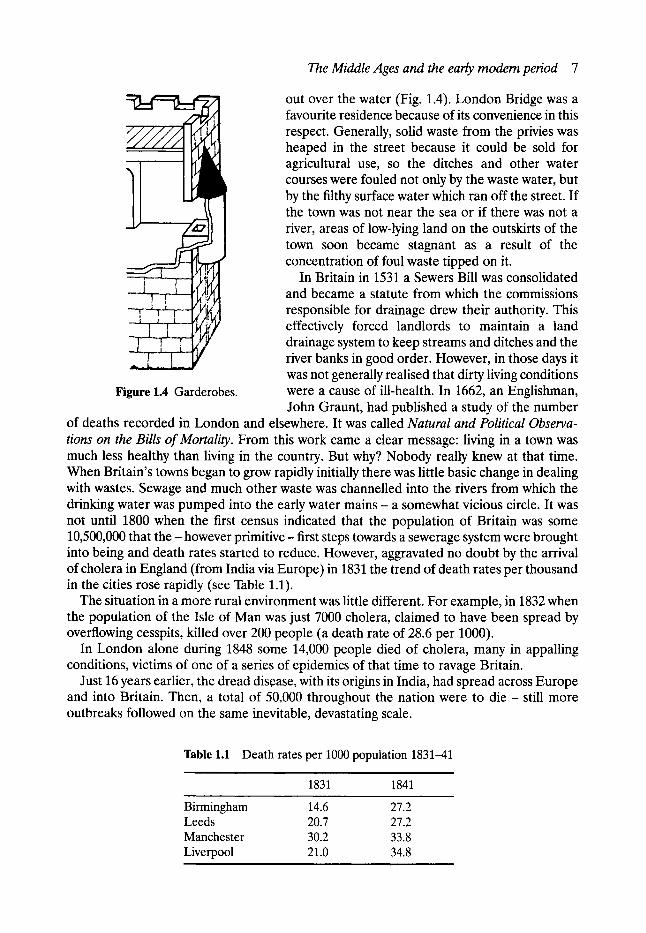
Figure 1.4 Garderobes.
out over the water (Fig. 1.4). London Bridge was a favourite residence because of its convenience in this respect. Generally, solid waste from the privies was heaped in the street because it could be sold for agricultural use, so the ditches and other water courses were fouled not only by the waste water, but by the filthy surface water which ran off the street. If the town was not near the sea or if there was not a river, areas of low-lying land on the outskirts of the town soon became stagnant as a result of the concentration of foul waste tipped on it.
In Britain in 1531 a Sewers Bill was consolidated and became a statute from which the commissions responsible for drainage drew their authority. This effectively forced landlords to maintain a land drainage system to keep streams and ditches and the river banks in good order. However, in those days it was not generally realised that dirty living conditions were a cause of ill-health. In 1662, an Englishman, John Graunt, had published a study of the number
of deaths recorded in London and elsewhere. It was called Natural and Political Observa- tions on the Bills of Mortality. From this work came a clear message: living in a town was much less healthy than living in the country. But why? Nobody really knew at that time. When Britain's towns began to grow rapidly initially there was little basic change in dealing with wastes. Sewage and much other waste was channelled into the rivers from which the drinking water was pumped into the early water mains - a somewhat vicious circle. It was not until 1800 when the first census indicated that the population of Britain was some 10,500,000 that t h e - however primitive- first steps towards a sewerage system were brought into being and death rates started to reduce. However, aggravated no doubt by the arrival of cholera in England (from India via Europe) in 1831 the trend of death rates per thousand in the cities rose rapidly (see Table 1.1).
The situation in a more rural environment was little different. For example, in 1832 when the population of the Isle of Man was just 7000 cholera, claimed to have been spread by overflowing cesspits, killed over 200 people (a death rate of 28.6 per 1000).
In London alone during 1848 some 14,000 people died of cholera, many in appalling conditions, victims of one of a series of epidemics of that time to ravage Britain.
Just 16 years earlier, the dread disease, with its origins in India, had spread across Europe and into Britain. Then, a total of 50,000 throughout the nation were to die - still more outbreaks followed on the same inevitable, devastating scale.
Table 1.1 Death rates per 1000 population 1831-41 . . . . . . . i
1831 1841
Birmingham 14.6 27.2 Leeds 20.7 27.2 Manchester 30.2 33.8 Liverpool 21.0 34.8
8 The development ofpublic health engineering
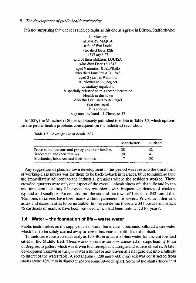
It is not surprising that one sees such epitaphs as this one at a grave in Bilston, Staffordshire:
In Memory of MARY MARIA wife of Wm.Dodd
who died Decr.12th 1847 aged 27
and of their children, LOUISA who died Decr.12, 1847
aged 9 months, & ALFRED who died Jany.3rd A.D. 1848
aged 2 years & 9 months All victims to the neglect
of sanitary regulation & specially referred to in a recent lecture on
Health in this town And the Lord said to the angel
that destroyed It is enough
stay now thy hand - 1 Chron. xx 17
In 1837, the Manchester Statistical Society published the data in Table 1.2, which epitom- ise the public health problems consequent on the industrial revolution.
Table 1.2 Average age of death 1837
Manchester Rutland
Professional persons and gentry and their families 38 Tradesmen and their families 20 Mechanics, labourers and their families 17
. ,
52 41 38
Any suggestion of planned town development in this period was rare and the usual form of working-class houses was for them to be back-to-back in terraces, built to minimise land use immediately adjacent to the industrial premises where the residents worked. These crowded quarters were only one aspect of the overall unhealthiness of urban life and by the mid-nineteenth century life expectancy was short, with frequent epidemics of cholera, typhoid and smallpox. An enquiry into the state of the town of Leeds in 1842 found that 'Numbers of streets have been made without pavements or sewers. Privies so laden with ashes and excrement as to be unusable. In one cul-de-sac there are 34 houses from which 75 cartloads of manure have been removed which had been untouched for years'.
1.4 W a t e r - t h e f o u n d a t i o n of life - w a s t e w a t e r
Public health relies on the supply of clean water but in turn it becomes polluted waste water which has to be safely carried away or else it becomes a health hazard in itself.
Tunnels were constructed as early as 1200BC in order to obtain water for ancient fortified cities in the Middle East. These works known as sin-nors consisted of steps leading to an underground gallery which was driven to intercept an underground source of water. A later development, known as the qanat was a tunnel or adit driven at a fiat gradient into a hillside to intercept the water table. A rectangular (1200 mm • 600 mm) adit was constructed from shafts about 1050 mm in diameter spaced some 30--46 m apart. Some of the shafts discovered

Water- the foundation of l i fe- waste water 9
being over 91 m deep. Evidence exists that qanats were utilised widely throughout the near and Middle East as far back as 700BC and the technique is still utilised today in some remote areas of Iran.
As indicated earlier, the Roman invasion of Britain brought with it various achievements in the field of water engineering - superior to what came before or for almost 1500 years afterwards. They were nevertheless not as spectacular as elsewhere in the Roman empire, perhaps related to the comparative smallness of the Romano-British towns in comparison with say, Rome, which had at that time a population of about a million. During the four centuries of Roman rule in Britain people came from many parts of the Roman world to serve as officials in the administration bringing with them advanced skills and new culture. Estimates suggest that the population of Roman Britain around 200AD was between four and six million. Three cities were founded specifically to provide for army encampments: Colchester, Lincoln and Gloucester but in addition:
�9 Lincoln, built by Roman contractors was provided with a system of main and tributary sewers which was very rare in Romano-British towns, the water supply being brought in from springs outside the town by means of earthenware pipes coated in concrete.
�9 Silchester, Cirencester, Caerwent and other forts which had their water supply delivered in timber pipes joined by iron collars.
�9 Dorchester and Wroxeter, where the water supply was provided by an open leat (a channel or ditch) and at the latter there was a fairly extensive distribution system with supplies for flushing private latrines.
Local wells were often sufficient to provide an adequate water supply and remains of wells have been found on several Roman sites, the sides of the well often being lined with wood, stone or brick. The Romans also invented the force pump to assist in the raising of water. In Manchester during the sixteenth century a public conduit was built to bring water via wooden pipes from the River Irwell to the market place - the supply only being turned on at certain times of the day. The pipes were formed from tree trunks, the hole being bored out with a tool worked by a bow and the pipes and joint were sealed with clay or pitch.
In general, until the middle of the nineteenth century most British towns obtained their water from nearby wells, springs and rivers, which rapidly became polluted from the overloaded piecemeal drainage systems which in the main only collected filthy water from the rapidly developing areas to discharge it into the nearest water course where it again became drinking water. At that time the link between polluted water and disease did not appear to have been taken seriously. It was not until 1852 that the compulsory filtration of all river water used for domestic purposes was secured.
Water pipes in medieval times were often made of lead but such mains were unreliable and wooden pipes came to be preferred. They were usually about 150 mm in diameter, they had socket and spigot joints, often with iron bands and could withstand a pressure of about 3.6 kN/m 2. The timber was usually elm and they usually only lasted about 14 years.
The early mains did not supply water constantly. If one were wealthy enough you kept a cistern in your cellar and the water trickled into it several times a week. The poor had to get water when they could at a public standpipe (Fig. 1.5) although it should be appreciated that the lower orders of society in most cases never washed at all and consequently they needed very little in the way of water supply! They would store it in old kettles and buckets in their overcrowded dwellings. As the factories grew there was an ever-increasing demand for water power via the installation of water wheels and the damming of water courses to provide the necessary operating head for machinery, in addition to the needs for processing

10 The development of public health engineering
Figure 1.5 Queuing at the public conduit.
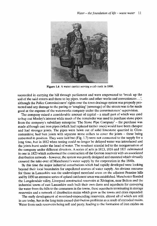
water. This retention of flow and the pollution resulting from the many industrial processes reduced the supply for domestic purposes. In many towns the water consumption of the population outstripped the supply capacity so that in the first part of the nineteenth century the water shortage became severe (Fig. 1.6).
In 60 years from 1801, the British population not only grew from 10 to 30 million but also changed its urban/rural pattern from a ratio of 30:70 to 55:45. An official report of 1845 found only six out of 51 towns had a good water supply, even among manufacturing centres and major ports. Of the rest 13 were classified as indifferent and 32 as very bad indeed.
In Manchester in 1800 the lord of the manor, Sir Oswald Mosley, built a pumping station at Holt Town to raise water from the River Medlock and deliver it to several storage ponds in elevated parts of the city. It proved grossly inadequate and in 1808 a committee of local residents attempted to gain control of it. The scheme had reached the parliamentary stage before the Police Commissioners realised that the town's water supply was in danger of being controlled by 'persons whose sole object will be the promotion of their own private interest and who are induced to the undertaking from no other motive'.
Following the principle of municipal enterprise implicit in other local reforms proposed in 1808 the Police Commissioners gave their support to a plan whereby the town's water supply was to be organised as a public service under the joint management of the church- wardens and overseers, the Police Commissioners and the surveyors of highways. The plan, however, proved impractical and the commissioners had to content themselves with opposi- tion to the 'private' scheme. The Commissioner's main opposition to the waterworks com- pany was that their operations would injure the sewers and drains! The company however
Water- the foundation of life- waste water 11
Figure 1.6 A water carrier serving a cab rank in 1808.
succeeded in carrying the bill through parliament and were empowered to 'break up the soil of the said streets and there to lay pipes, trunks and other works and conveniences ...', although the Police Commissioners' rights over the town drainage system was properly pro- tected and any damage to the paving or 'soughing' (sewerage) of the streets was to be made good at the expense of the waterworks company under the commissioners' supervision.
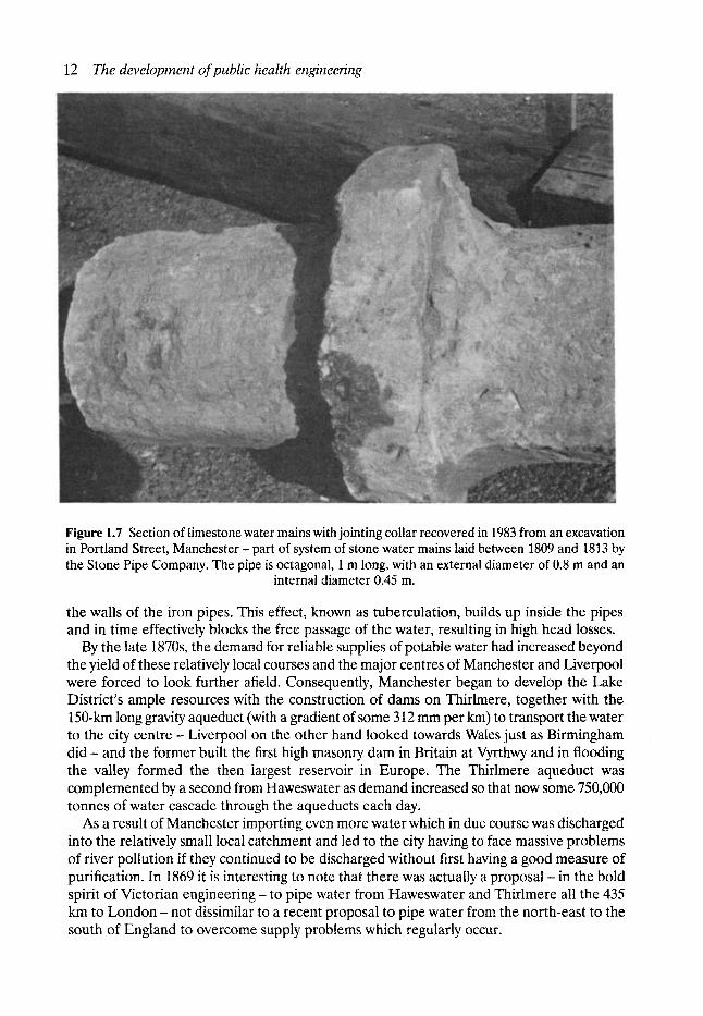
The company raised a considerable amount of capital - a small part of which was used to buy out Mosley's interest while much of the remainder was used to purchase stone pipes from the company's subsidiary enterprise 'The Stone Pipe Company ' - the purchase was made although cast iron pipes (which had replaced timber ones) would have been cheaper and had stronger joints. The pipes were hewn out of solid limestone quarried in Glou- cestershire; had butt joints with separate stone collars to cover the jo in t s - these being cemented in position. They were laid but (Fig. 1.7) were not connected to the supply for a long time, but in 1812 when testing could no longer be delayed water was introduced and the joints burst under the head of water. The resultant scandal led to the reorganisation of the company under different directors. A series of acts in 1813, 1816 and 1821 culminated in one in 1823 which authorised the construction of the Gorton reservoir with an associated distribution network- however, the system was poorly designed and executed which virtually ensured the take-over of Manchester's water supply by the corporation in the 1840s.
By this time the major industrial conurbations which had rapidly developed were looking beyond their local boundaries for unpolluted sources of water supply. An obvious resource for those in Lancashire was the undeveloped moorland areas on the adjacent Pennine hills and by 1850 an extensive series of upland catchment areas was established. Manchester flooded the Longdendale valley, Liverpool constructed reservoirs at Rivington, near Bolton and the industrial towns of east Lancashire each built their own dams and aqueducts for conveying the water from the hills to the consumers in the towns, these aqueducts terminating in storage reservoirs and a network of distribution mains which grew as the towns and cities expanded.
The early development of moorland-impounding reservoirs, almost all of which are still in use today, has in the long term caused distribution problems as a result of corroded mains. Water from such reservoirs being soft and peaty, leading to the formation of iron oxides on
12 The development of public health engineering
Figure 1.7 Section of limestone water mains with jointing collar recovered in 1983 from an excavation in Portland Street, Manchester- part of system of stone water mains laid between 1809 and 1813 by the Stone Pipe Company. The pipe is octagonal, 1 m long, with an external diameter of 0.8 m and an
internal diameter 0.45 m.
the walls of the iron pipes. This effect, known as tuberculation, builds up inside the pipes and in time effectively blocks the free passage of the water, resulting in high head losses.
By the late 1870s, the demand for reliable supplies of potable water had increased beyond the yield of these relatively local courses and the major centres of Manchester and Liverpool were forced to look further afield. Consequently, Manchester began to develop the Lake District's ample resources with the construction of dams on Thirlmere, together with the 150-km long gravity aqueduct (with a gradient of some 312 mm per kin) to transport the water to the city cen t re - Liverpool on the other hand looked towards Wales just as Birmingham d i d - and the former built the first high mason13, dam in Britain at Vyrthwy and in flooding the valley formed the then largest reservoir in Europe. The Thirlmere aqueduct was complemented by a second from Haweswater as demand increased so that now some 750,000 tonnes of water cascade through the aqueducts each day.
As a result of Manchester importing even more water which in due course was discharged into the relatively small local catchment and led to the city having to face massive problems of river pollution if they continued to be discharged without first having a good measure of purification. In 1869 it is interesting to note that there was actually a proposal - in the bold spirit of Victorian engineering- to pipe water from Haweswater and Thirlmere all the 435 km to L o n d o n - not dissimilar to a recent proposal to pipe water from the north-east to the south of England to overcome supply problems which regularly occur.

Population and urbanisation 13
1.5 Population and urbanisation The eighteenth century was a period when a number of developments took place which had a significant effect on the industrialisation of Britain. In i711 an ironmaster at Coalbrook- dale, Shropshire began to use coke to smelt iron and in 1712 an ironmonger in Dartmouth, Thomas Newcomen, used a steam engine to pump water from a coal mine. In 1759 a mill- wright, James Brindley, built a successful canal to transport coal between Worsley and Man- chester and in 1781, a Scottish engineer, James Watt improved the steam engine to produce rotational power and could therefore drive machinery. These four developments duly led to cheaper iron, more coal, better transport and greater utilisation of steam power. New factories followed even in the smaller towns which grew rapidly from about 1780. Prior to then, most people worked on the land. Nevertheless there was some industry in the first half of the eighteenth century. Factories, such as they were, employed few people because their size was limited by the water power available. Goods being transported by pack-horse.
In the nineteenth century the effects of the industrial revolution in Britain started to have a significant impact on population growth (from about 10 million in 1800 to 19 million in 1837) (Fig. 1.8). It was accompanied by a massive movement of the population from scatter- ed rural living to concentrated urban living, where they were able to obtain higher wages. Britain soon became an industrial power house recognised throughout the world but at a terrible cost for many. There came the concentrations of manufacturing industry into large dependent units and also the growth of new industrial towns. Significant overcrowding was commonplace and although the priority was the provision of new housing, the related infra- structure such as roads, water supply and sewerage were neglected. By the mid-nineteenth century many industrial towns had been formed from the old market towns and the popu- lation had increased dramatically, these changes being particularly noticeable in areas such as the valleys east and west of the Pennines where plentiful supplies of water provided power for mills and enabled canals - then the most advanced forms of transport to be constructed. This dramatic period in history was epitomised by unprecedented social, intellectual and technological change. The population movement from agricultural to industry; the development from water power to steam and the mechanisation of labour, all combined and led to the creation of significant wealth and power alongside indescribable poverty and squalid conditions which can only be described as foul and fatal.
Cholera killed many thousands of people in the first epidemic of 1831-2. Thousands died every year from other bacterial diseases. It was mostly in the towns that people of all ages, including many children, were falling ill in great numbers. It was unquestionable that civilisa- tion was entering a new age but where as today only some ten people out of every 1000 die prematurely in Britain each year, in 1831 the rate was over 20 per 1000 and in some towns it was as high as 30 or 40 per 1000.
The rivers and streams in this period were virtually open sewers. When the organic matter, in sewage concentrations of this type, decomposes it absorbs oxygen and releases offensive gasses; fish and other river life are destroyed if, as the general situation was in these early industrial towns, there is insufficient dilution. Birmingham, Sheffield, Leeds and Manchester all came within this category. Historians have endeavoured to describe the deplorable conditions in which the workers in an industrial town had to face when living side by side with their employment. One writer looking at Manchester in 1844 wrote:
further up there are dye works, bone mills and gas works. All the filth, both liquid and solid, dis- charged by these works finds its way into the River Irk which also receives the contents of the adja- cent sewers and privies. The nature of the filth deposited by this river alone may well be imagined.
14 The development of public health engineering
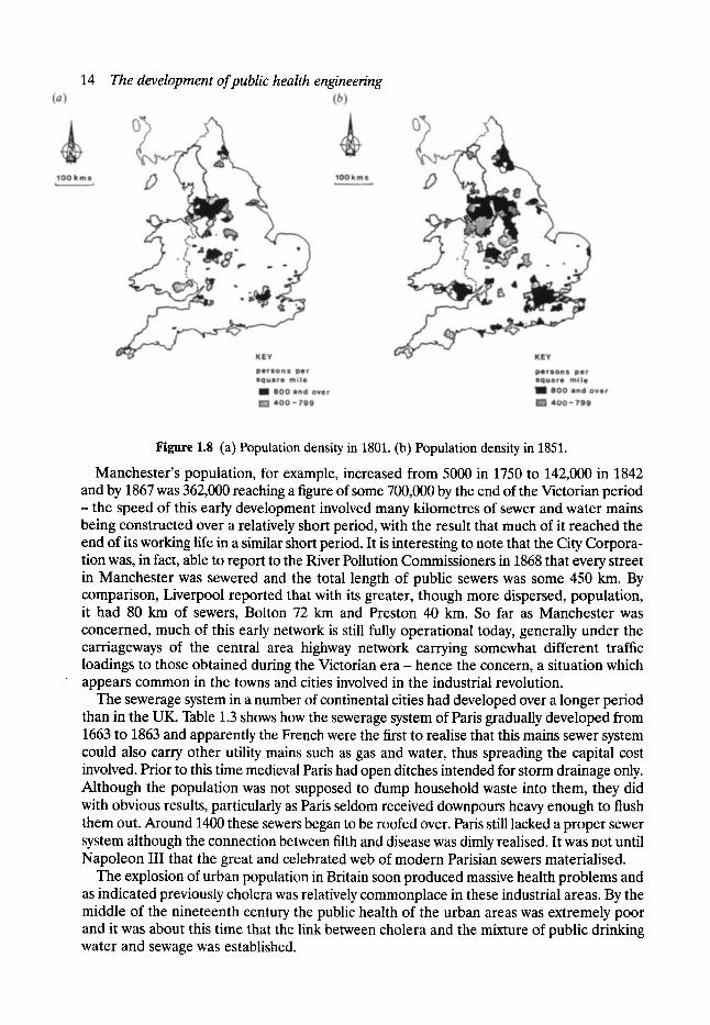
Figure 1.8 (a) Population density in 1801. (b) Population density in 1851.
Manchester's population, for example, increased from 5000 in 1750 to 142,000 in 1842 and by 1867 was 362,000 reaching a figure of some 700,000 by the end of the Victorian period
- the speed of this early development involved many kilometres of sewer and water mains being constructed over a relatively short period, with the result that much of it reached the end of its working life in a similar short period. It is interesting to note that the City Corpora- tion was, in fact, able to report to the River Pollution Commissioners in 1868 that every street in Manchester was sewered and the total length of public sewers was some 450 km. By comparison, Liverpool reported that with its greater, though more dispersed, population, it had 80 km of sewers, Bolton 72 km and Preston 40 km. So far as Manchester was concerned, much of this early network is still fully operational today, generally under the carriageways of the central area highway network carrying somewhat different traffic loadings to those obtained during the Victorian e r a - hence the concern, a situation which appears common in the towns and cities involved in the industrial revolution.
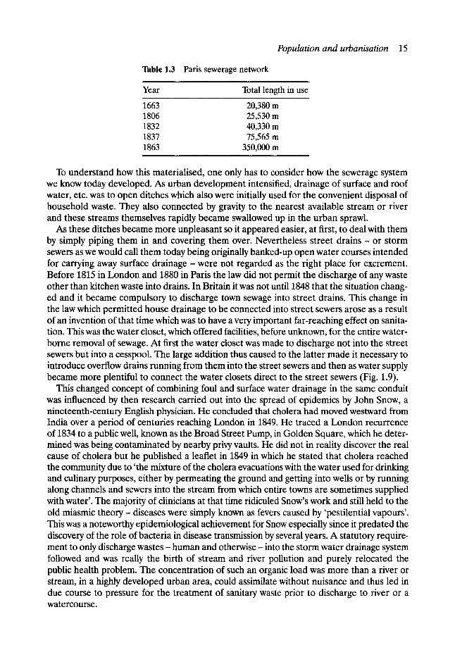
The sewerage system in a number of continental cities had developed over a longer period than in the UK. Table 1.3 shows how the sewerage system of Paris gradually developed from 1663 to 1863 and apparently the French were the first to realise that this mains sewer system could also carry other utility mains such as gas and water, thus spreading the capital cost involved. Prior to this time medieval Paris had open ditches intended for storm drainage only. Although the population was not supposed to dump household waste into them, they did with obvious results, particularly as Paris seldom received downpours heavy enough to flush them out. Around 1400 these sewers began to be roofed over. Paris still lacked a proper sewer system although the connection between filth and disease was dimly realised. It was not until Napoleon III that the great and celebrated web of modem Parisian sewers materialised.
The explosion of urban population in Britain soon produced massive health problems and as indicated previously cholera was relatively commonplace in these industrial areas. By the middle of the nineteenth century the public health of the urban areas was extremely poor and it was about this time that the link between cholera and the mixture of public drinking water and sewage was established.
Population and urbanisation 15
Table 1.3 Paris sewerage network
Year Total length in use
1663 20,380 rn 1806 25,530 m 1832 40,330 rn 1837 75,565 m 1863 350,000 rn
To understand how this materialised, one only has to consider how the sewerage system we know today developed. As urban development intensified, drainage of surface and roof water, etc. was to open ditches which also were initially used for the convenient disposal of household waste. They also connected by gravity to the nearest available stream or river and these streams themselves rapidly became swallowed up in the urban sprawl.
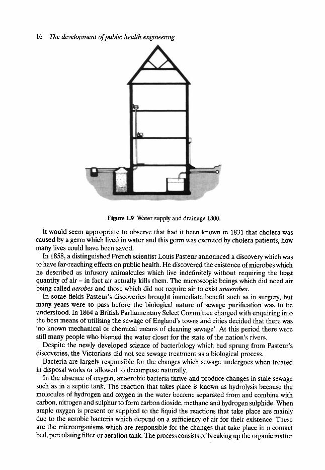
As these ditches became more unpleasant so it appeared easier, at first, to deal with them by simply piping them in and covering them over. Nevertheless street drains - or storm sewers as we would call them today being originally banked-up open water courses intended for carrying away surface drainage - were not regarded as the right place for excrement. Before 1815 in London and 1880 in Paris the law did not permit the discharge of any waste other than kitchen waste into drains. In Britain it was not until 1848 that the situation chang- ed and it became compulsory to discharge town sewage into street drains. This change in the law which permitted house drainage to be connected into street sewers arose as a result of an invention of that time which was to have a very important far-reaching effect on sanita- tion. This was the water closet, which offered facilities, before unknown, for the entire water- borne removal of sewage. At first the water closet was made to discharge not into the street sewers but into a cesspool. The large addition thus caused to the latter made it necessary to introduce overflow drains running from them into the street sewers and then as water supply became more plentiful to connect the water closets direct to the street sewers (Fig. 1.9).
This changed concept of combining foul and surface water drainage in the same conduit was influenced by then research carried out into the spread of epidemics by John Snow, a nineteenth-century English physician. He concluded that cholera had moved westward from India over a period of centuries reaching London in 1849. He traced a London recurrence of 1834 to a public well, known as the Broad Street Pump, in Golden Square, which he deter- mined was being contaminated by nearby privy vaults. He did not in reality discover the real cause of cholera but he published a leaflet in 1849 in which he stated that cholera reached the community due to 'the mixture of the cholera evacuations with the water used for drinking and culinary purposes, either by permeating the ground and getting into wells or by running along channels and sewers into the stream from which entire towns are sometimes supplied with water'. The majority of clinicians at that time ridiculed Snow's work and still held to the old miasmic theory - diseases were simply known as fevers caused by 'pestilential vapours'. This was a noteworthy epidemiological achievement for Snow especially since it predated the discovery of the role of bacteria in disease transmission by several years. A statutory require- ment to only discharge wastes - human and otherwise - into the storm water drainage system followed and was really the birth of stream and river pollution and purely relocated the public health problem. The concentration of such an organic load was more than a river or stream, in a highly developed urban area, could assimilate without nuisance and thus led in due course to pressure for the treatment of sanitary waste prior to discharge to river or a watercourse.
16 The development of public health engineering
Figure 1.9 Water supply and drainage 1800.
It would seem appropriate to observe that had it been known in 1831 that cholera was caused by a germ which lived in water and this germ was excreted by cholera patients, how many lives could have been saved.
In 1858, a distinguished French scientist Louis Pasteur announced a discovery which was to have far-reaching effects on public health. He discovered the existence of microbes which he described as infusory animalcules which live indefinitely without requiring the least quantity of a i r - in fact air actually kills them. The microscopic beings which did need air being called aerobes and those which did not require air to exist anaerobes.
In some fields Pasteur's discoveries brought immediate benefit such as in surgery, but many years were to pass before the biological nature of sewage purification was to be understood. In 1864 a British Parliamentary Select Committee charged with enquiring into the best means of utilising the sewage of England's towns and cities decided that there was 'no known mechanical or chemical means of cleaning sewage'. At this period there were still many people who blamed the water closet for the state of the nation's rivers.
Despite the newly developed science of bacteriology which had sprung from Pasteur's discoveries, the Victorians did not see sewage treatment as a biological process.
Bacteria are largely responsible for the changes which sewage undergoes when treated in disposal works or allowed to decompose naturally.
In the absence of oxygen, anaerobic bacteria thrive and produce changes in stale sewage such as in a septic tank. The reaction that takes place is known as hydrolysis because the molecules of hydrogen and oxygen in the water become separated from and combine with carbon, nitrogen and sulphur to form carbon dioxide, methane and hydrogen sulphide. When ample oxygen is present or supplied to the liquid the reactions that take place are mainly due to the aerobic bacteria which depend on a sufficiency of air for their existence. These are the microorganisms which are responsible for the changes that take place in a contact bed, percolating filter or aeration tank. The process consists of breaking up the organic matter

Population and urbanisation 17
and the liberation of carbon which combines with oxygen to form carbon dioxide, followed by the oxidation of the nitrogenous material with the formulation of nitrites and nitrates.
It is interesting to note that in ,the early introduction of water closets some strange res- ponses came from the responsible authorities and an example is recorded in Manchester, where the installation of water closets was actually opposed initially because of the effects that they were allegedly having on public health.
Towns are sewered according to three systems:
1. The combined system in which foul and surface water sewage are discharged into one system of sewers which lead to the sewage treatment works - this being the format existing in the older towns and cities.
2. The separate system in which the soil sewage is carried by an individual system of sewers to the sewage treatment works while surface water is carried away by a number of local systems discharging at various points into natural watercourses - this system generally being found in the newer towns and cities.
3. The partially separate system in which the greater part of the surface water is dealt with by the surface water sewers while the surface water from the backyards and roofs is passed to sewers draining away the foul sewage.
By the mid-nineteenth century the link between the contamination of drinking water by sewage and water-borne diseases was clearly established and from then on saw the building of many intercepting (combined) sewerage systems, many of which exist, fully operational, to this day. Broadly speaking, the general pattern was that the intercepting sewers were built along the river valleys intercepting the connections of the smaller systems and conduits before they discharged into the main river systems. Thus the sewage could be collected and taken away from the rivers and only discharged ultimately to the rivers after treatment, and then downstream of any fresh water intakes. The waste water treatment at that time gener- ally consisting of chemical precipitation in continuous flow sedimentation tanks followed by downward filtration on large areas of suitable under-drained land.
The following extract from a paper entitled 'The main features of the Manchester mains drainage' by J. Alison, City Surveyor, Manchester which was presented to a district meeting of the Institution of Civil Engineers held in Manchester on 6 May 1893 serves as a useful illustrative backcloth to the public health situation in the birthplace of the industrial revolution during the nineteenth century:
Previous to 1885 the boundaries of the City of Manchester were exceedingly limited, having only a area of 4294 acres and a population of 341,414, and allowing about 300 acres unbuilt upon on the northerly side of the city, and about 300 acres for shop and warehouse property in an near the centre of the city, where there is no resident population, the residential area would be reduced to about 3694 acres, which averages 92 person per acre.
In 1885 two local board districts and one rural sanitary authority were added, increasing the area to 5927 acres and again in 1890, by provisional order, other six townships were added, comprising an area of 6361 acres, so that to-day the total area of the city is 12,788 acres and the population about 515,600.
Manchester has for a very long time been credited with a high death-rate, and after allowing for the area covered by streets and passages, this number of persons per acre could not be con- sidered a satisfactory condition of affairs.
During the past four years the sanitary committee have had under consideration the over- crowded condition of the old city, which is mainly due to narrow streets in the working-class district, such streets ranging from four to eight yards in width, the back passages having an average width of from three feet to three feet six inches, very few indeed measuring four feet wide.
18 The development of public health engineering
In this crowded area also there were about 9240 back-to-back houses abutting upon these narrow streets, and so impressed were the sanitary committee with the evils arising from this class of property that they resolved, some three years ago, that something must be done to give freer ventilation and improved sanitary accommodation, and they have accordingly within that period dealt with about 1100 of these dwellings, 340 of which have been entirely demolished, and the remainder altered to suit the committee's requirements or closed as dwellings. There still remain about 8000 to be dealt with.
Originally Manchester might be considered a privy and midden town, but in 1871 the health committee adopted the pail-closet system, which no doubt was a great improvement upon the old midden town; but even with this system, there are many objectionable features, as the pails can only be emptied on an average of say, twice a week, and as the contents are stored up in these small yards and narrow passages it cannot be considered healthy for the people who live constantly amidst such surroundings.
In view of all this the Corporation have determined to convert Manchester into a water-closet town, and the present drainage scheme has been sanctioned and the greater part of it already carried out. At present the whole of our domestic sewage, with the exception of that removed by the pail-closet system, finds it way by the street sewers into the various rivers and streams which flow through the city, and the scheme now being proceeded with is an intercepting scheme whereby the new main sewers are as far as practicable, carried along the valleys at such depths as to intercept the existing sewers, and convey all the sewage into one main outfall and forward to the sewage works now being constructed on the westerly side of and about five miles distant from the city
The final stage of sewerage development in most large industrial towns came when urban development increased to the point that the original interceptor sewers became inadequate and further intercepting relief sewers were built, many of these not being completed until relatively recent times.
1.6 Life in the Victorian period The great difference between the Victorians and their predecessors was that they started to see the connection between dirt and disease much more clearly (Fig. 1.10). The poor were considered a health nuisance because they were dirty, so both they and their immediate environment had to be cleansed. During the seventeenth and eighteenth centuries the upper and middle classes of society apparently washed face and hands as well as their feet fairly regularly, the rest of their bodies very infrequently, if ever. The lower orders of society in most cases never washed at all and consequently they required little in the way of water supply and drainage. One eighteenth-century peer of the realm is on record as saying that heavy sweat is as good as a bath and once that had been accomplished all that was necessary was to have one's dirt-laden clothes washed from time to time and then start all over again.
It is almost certainly fair to say that from the point of view of personal cleanliness the social classes were in England a good deal further apart in 1850 than they had been in 1750. The working classes being increasingly forced into filth and degradation, the upper classes getting steadily cleaner. The extent to which you were clean and the extent to which you smelt became a very powerful reinforcing element in the English class system.
Certainly by the 1830s any gentleman's country house could in theory have running water on all floors, could have as many baths or water closets as either the owner wanted or could afford. But in practice it turned out that very little use was made of the technical posibilities partly because personal cleanliness had such a low priority and partly because it was so easy to have servants, cheap servants bringing jugs of water from the kitchen to a moveable bath.

Life in the Victorian period 19
Figure 1.10 A court for King Cholera.
Further down the social scale, among the lower middle and upper artisan classes, the weekly bath gradually established itself as a family ritual.
The hand basin, the water jug and the soap dish were by the 1860s part of the bedroom equipment in every household with any sort of claim to respectability. And yet even in the 1860s there must have been some within the middle levels of English society who found this bathing business rather puzzling and needed a little guidance as to how to go about it. The first issue of that very sedate, very practical publication, The Lady, gave in 1865 precise instructions as to how to take a bath. The article is illustrated with helpful sketches and these naturally showed men, not women in the act of cleansing themselves, even though The Lady was hardly a man's paper, but anyway it was 1865 and at this date women didn't yet have bodies, so to make it realistic, read 'she' for 'he' throughout this article:
The bather should provide himself with a deep and large empty bath, having a raised grating or pierced metal false floor in which he may either sit or stand and through which the foul water may run, and with either taps or jugful or canful of warm water. In addition to this he should have a basin in which he may make a lather soap. He should begin by pouring the running water over his hands or his soaping pad in order that the instruments of abolution may first be cleansed. This done he should use his hands to soap himself with the lather already made in the separate basin and having done this sufficiently he should finally wash off the lather again by turning on the tap or pouring over himself jugfuls or canfulls of water. He is then clean and entirely clean, for the last thing that has touched him is the clean running water which has run away and left no trace of pollution upon him. In no other way can he be cleansed.
George Orwell, educated at Eton, was born in the first decade of this century and there is a famous passage about this subject in his book the The Road to Wigan Pier: 'Very early in life you acquired the idea that there was something subtly repulsive about a working class body; you would not get nearer to it than you could help. You watched a great sweaty navvy walking down the road with his pick over his shoulder, you looked at his discoloured
20 The development of public health engineering
shirt and his corduroy trousers stiff with the dirt of a decade, you thought of those nests and layers of greasy rags below and under all, the unwashed body, brown all over (that was how I used to imagine it) with its strong bacon-like reek.'
Ingle, in his famous description of the Lancashire industrial area in the 1840s said:
The most horrible spot lies on the Manchester side, immediately south west of Oxford Road. It is a rather deep hole in the curve of the Medlock and surrounded on all four sides by tall factories and high embankments covered with buildings, stand groups of about 200 cottages, built chiefly back-to-back, in which live about 4000 human beings. The cottages are old and of the smallest sort. The streets uneven, fallen into ruts and in part without drains or pavements, masses of refuse, offal and sickening filth lie among standing pools in all directions. The atmosphere is poisoned by the effluvia from these and darkened by the smoke of a dozen tall factory chimneys. A hoard of ragged women and children swarm about here as filthy as the swine that feed on the garbage heaps and in the puddles.
It is not surprising with this sort of background in his home town, that in 1832, a keen young lawyer from Longsight in Manchester, Edwin Chadwick, was appointed an Assistant Poor Law Commiss ioner - soon afterwards to become secretary to the commission. Although he had become a barrister at 30 he was much more interested in working for the public good rather than a career in law. In 1842 he published his general report on 'The sanitary conditions of the labouring population of Great Bri ta in ' - it became, in fact, the Stationery Office's most successful publication to date. While working on his report, he took evidence from a variety of people including 'a contractor for cleansing', John Darke, who he questioned carefully about the value of night-soil. He replied 'some night-soil has been dried, packed-up in the returned sugar hogsheads and sent to the West Indies for use as manure.' The early Victorians being very fond of the idea that sewage was a potential form of wealth. His interest in the health of the people was inspired not so much by com- passion or sympathy as by a dislike of waste and inefficiency. People who were sick did not work and were therefore a wasted asset. They were ill as a result of the atmosphere caused by the filth in which they live - the filth itself was in fact waste which could be put to use.
Chadwick was the instigator of the municipal engineering concept - he had little time for doctors. He was not a man to pull punches and his report was outspoken, passionate and thorough as well as being full of indignation and anger. He described vividly the foul conditions in which many towns people lived conditions which the early Victorians had so far ignored. His report included the following:
The Greatest preventatives are drainage, street and house cleansing by means of supplies of water and uniformed sewerage and especially the introduction of cheaper and more efficient modes of removing all noxious refuse from the towns, are operations for which aid must be sought from the Science of the Civil Engineer, not from the Physician.
Civil engineering in those days was a fairly new profession. In 1818 a group of young engi- neers formed the Institution of Civil Engineers, and this can be said to mark the establishment of a profession which was to contribute more to urban public health than any other has done.
Chadwick's 1842 report influenced the design of sewers and the provision of water supplies and had the engineers of that period had been allowed to put as much energy and skill as they were then putting into railway construction, much illness and disease could have been prevented. Progress was slow because of political opposition.
In the 1830s Chadwick appreciated the importance of cheap self-cleansing water-borne sewerage systems with constant water supplies, but his theories were strongly opposed by many engineers. He even read Liebig's Chemistry of the Soil to make his point that the
Bibliography 21
Figure 1.11 A sewer in 1830.
excrement of one man yielded 7.44 kg of nitrogen per year. Waste material in sewage might prove valuable and present-day utilisation of methane gas at modern treatment works perhaps shows how effectively he made his point. In 1838, when he was secretary to the Poor Law Board, there was a serious outbreak of typhus and Chadwick persuaded the board to initiate an inquiry. The subsequent report confirmed the relationship between the environment and health. This, in turn, led to the government setting up a Health of Towns Commission to which Chadwick acted as secretary, the first report being published in 1844. One witness who gave evidence was Richard Nelsey, surveyor to the city commission. He had a map of the sewers in his district, but no-one except himself could tell which way the sewage flowed. He declared 'that the maxim of the City Commissioners is never to make any sewer so small as that a man cannot get in it easily' so that even in courts and alleys a sewer 900 mm • 600 mm with brickwork 360 mm thick was used. He admitted sewers of this size proposed accumulations (Fig. 1.11). These brick caverns were rarely inspected or cleaned out and were sometimes put to strange uses - the beadle of one parish having been buried in a sewer! It was against this background of credulous ignorance and outdated tradition that Chadwick brought forward his own witnesses, one of who said:
The curved invert at the bottom of main sewers is indispensable to their perfect action and I admire most those which have the segments of a similar circle at the bottom, that such an arrangement gives full action to the water at the time when it is most needed, viz. when the quantity is smallest.
Chadwick died on 5 July 1890 and he certainly left his mark on public health engineering as we know it today. In one of the obituary notices in a sanitary journal of 1890 he was said to have been 'a great believer in daily head to foot washing.. , and no doubt he helped greatly to bring about the habit of tubbing which is now infinitely more popular in England than it was even 25 years ago'.
Bibliography 1. Read, Brian. Healthy Cities- A Study of Urban Hygiene. Blackie, 1970. 2. Spragne de Camp, L.Ancient Engineers. Tandem Publishing, 1963. 3. Armytage W. H. G.A Social History of Engineering. Faber, 1961. 4. The Federation of Civil Engineering Contractors. Public Health and the Engineers. 5. Kinnersley, David. Troubled Water. 6. Parnell. An Illustrated History of Civil Engineering.
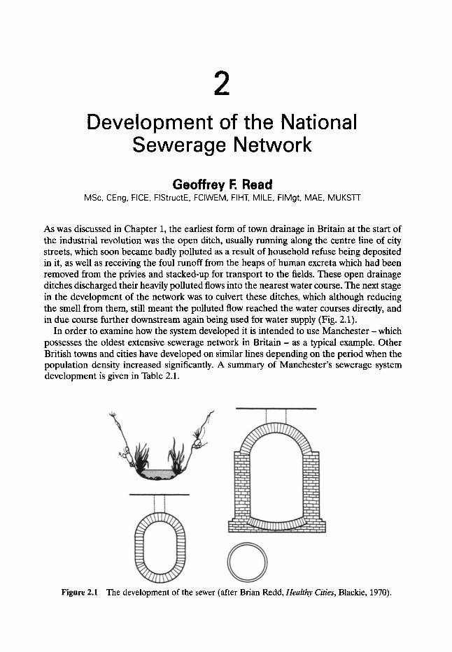
2 Development of the National
Sewerage Network
Geoffrey F. Read MSc, CEng, FICE, FIStructE, FCIWEM, FIHT, MILE, FIMgt, MAE, MUKSTT
As was discussed in Chapter 1, the earliest form of town drainage in Britain at the start of the industrial revolution was the open ditch, usually running along the centre line of city streets, which soon became badly polluted as a result of household refuse being deposited in it, as well as receiving the foul runoff from the heaps of human excreta which had been removed from the privies and stacked-up for transport to the fields. These open drainage ditches discharged their heavily polluted flows into the nearest water course. The next stage in the development of the network was to culvert these ditches, which although reducing the smell from them, still meant the polluted flow reached the water courses directly, and in due course further downstream again being used for water supply (Fig. 2.1).
In order to examine how the system developed it is intended to use Manchester - which possesses the oldest extensive sewerage network in Bri tain- as a typical example. Other British towns and cities have developed on similar lines depending on the period when the population density increased significantly. A summary of Manchester's sewerage system development is given in Table 2.1.
Figure 2.1 The development of the sewer (after Brian Redd, Healthy Cities, Blackie, 1970).
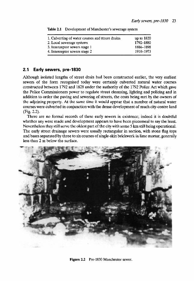
Early sewers, pre-1830 23
Table 2.1 Development of Manchester's sewerage system
1. Culverting of water courses and street drains 2. Local sewerage systems 3. Interceptor sewers stage 1 4. Interceptor sewers stage 2
up to 1820 1792-1880 1886-1898 1910-1973
2.1 Early sewers, pre-1830 Although isolated lengths of street drain had been constructed earlier, the very earliest sewers of the form recognised today were certainly culverted natural water courses constructed between 1792 and 1828 under the authority of the 1792 Police Act which gave the Police Commissioners power to regulate street cleansing, lighting and policing and in addition to order the paving and sewering of streets, the costs being met by the owners of the adjoining property. At the same time it would appear that a number of natural water courses were culverted in conjunction with the dense development of much city-centre land (Fig. 2.2).
There are no formal records of these early sewers in existence; indeed it is doubtful whether any were made and development appears to have been piecemeal to say the least. Nevertheless they still serve the oldest part of the city with some 5 km still being operational. The early street drainage sewers were usually rectangular in section, with stone flag tops and bases separated by three to six courses of single-skin brickwork in lime mortar, generally less than 2 m below the surface.
Figure 2.2 Pre-1830 Manchester sewer.
24 Development of the national sewerage network
These sewers were little more than sub-surface drains serving isolated streets and did not in themselves constitute a sewerage system. In many respects, they have subsequently proved extremely troublesome. There are no formal records of the location of these sewers and their presence only becomes apparent when they are encountered during excavation necessitated by other works. When opened up they are often found to be carrying small scale but still appreciable flows. Access is virtually non-existent and the origin of the flows is rarely known nor can it easily be traced.
At the same time, a deeper system had been constructed within the underlying sandstone rock in the older parts of the Manchester, but still in the same basic constructional format. The pace of development in this period generally was such that many of the earlier sewers were soon rendered obsolete. The new buildings being constructed were much more substantial reflecting the increased prosperity. Larger and deeper sewers then becoming necessary in order to drain premises with basements and so on.
2.2 Second generation sewers 1828-90 A new Police Act in 1828 gave additional and strengthened powers to the Police Commis- sioners who could order frontages to pave streets and construct sewers or, if difficult, to undertake the work themselves and recover a proportion of the costs from the frontages in Manchester. The responsibility for carrying out this work was assigned to the 'Lamp, Scavenging, Fire Engine and Main Sewer Committee'. In 1829 the Committee reported that the main sewers in the city were in a very poor condition, they being found not only to be imperfect in construction but inadequate in size to carry the 'great accumulation of water which through the increased size of the Town has to flow through them'.
In 1828 expenditure by the Committee on sewering was a little over s Two years later this amount had increased to s and the committee then reported: 'a very considerable expense in this Department will probably have to be incurred for many years to come'.
A separate committee, the Paving and Soughing Committee was then formed ('soughing' being derived from 'sough' meaning an underground channel or sewer) and presided over the most rapid growth of the City's sewerage system from 1830 to 1860. The work involved the systematic sewering of Manchester and commenced with the primary sewers which discharged directly into the principal rivers via the Irwell, Irk and Medlock traversing the city centre. These sewers were originally intended for the conveyance of surface water but as described earlier by 1860 they had in fact become combined sewers receiving effluent discharges. The sewers tended to be laid under the streets and in general followed the line of natural drainage.
Figure 2.4 shows an indication of the rate of expansion of the sewerage system during this particular period. The data represented relate to a roughly triangular area of approxi- mately 2 km 2 centred on the tower hall and shows throughout this second generation of sewer construction, that two main forms were used, namely the U-shaped brick sewer and the egg-shaped butt-jointed clayware pipes - both of which will be described in detail later (Fig. 2.3). At the peak of the construction programme in the 1840s up to 2 km per year was completed- an impressive achievement by any standard. The maximum dimension rarely exceeded 910 mm and was generally 750 mm or less so they can really be described in accordance with present-day standards as non-man access. Their small size together with the fact that few permanent manholes were provided effectively meant that proper inspection was virtually impossible until the recent advent of closed-circuit television (CCTV).
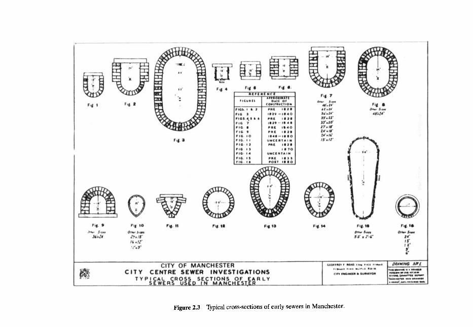
Figure 2.3 Typical cross-sections of early sewers in Manchester.
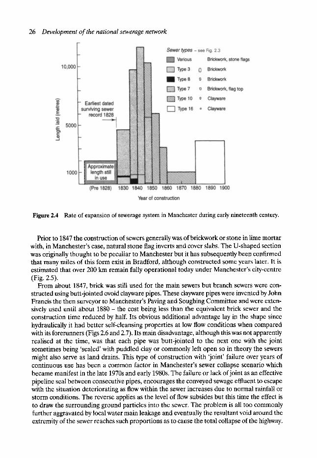
26 Development of the national sewerage network
Figure 2.4 Rate of expansion of sewerage system in Manchester during early nineteenth century.
Prior to 1847 the construction of sewers generally was of brickwork or stone in lime mortar with, in Manchester's case, natural stone flag inverts and cover slabs. The U-shaped section was originally thought to be peculiar to Manchester but it has subsequently been confirmed that many miles of this form exist in Bradford, although constructed some years later. It is estimated that over 200 km remain fully operational today under Manchester's city-centre (Fig. 2.5).
From about 1847, brick was still used for the main sewers but branch sewers were con- structed using butt-jointed ovoid clayware pipes. These clayware pipes were invented by John Francis the then surveyor to Manchester's Paving and Soughing Committee and were exten- sively used until about 1880 - the cost being less than the equivalent brick sewer and the construction time reduced by half. Its obvious additional advantage lay in the shape since hydraulically it had better self-cleansing properties at low flow conditions when compared with its forerunners (Figs 2.6 and 2.7). Its main disadvantage, although this was not apparently realised at the time, was that each pipe was butt-jointed to the next one with the joint sometimes being 'sealed' with puddled clay or commonly left open so in theory the sewers might also serve as land drains. This type of construction with 'joint' failure over years of continuous use has been a common factor in Manchester's sewer collapse scenario which became manifest in the late 1970s and early 1980s. The failure or lack ofjoint as an effective pipeline seal between consecutive pipes, encourages the conveyed sewage effluent to escape with the situation deteriorating as flow within the sewer increases due to normal rainfall or storm conditions. The reverse applies as the level of flow subsides but this time the effect is to draw the surrounding ground particles into the sewer. The problem is all too commonly further aggravated by local water main leakage and eventually the resultant void around the extremity of the sewer reaches such proportions as to cause the total collapse of the highway.
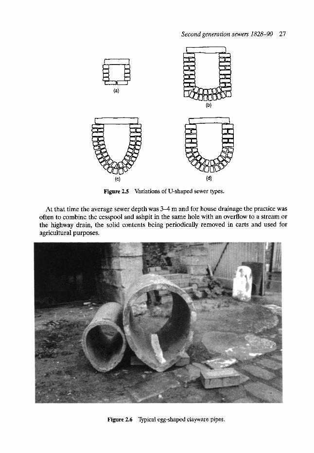
Second generation sewers 1828-90 27
( /_ -~
(a)
I - ~_J
(b)
(c) (d)
Figure 2.5 Variations of U-shaped sewer types.
At that time the average sewer depth was 3-4 m and for house drainage the practice was often to combine the cesspool and ashpit in the same hole with an overflow to a stream or the highway drain, the solid contents being periodically removed in carts and used for agricultural purposes.
Figure 2.6 Typical egg-shaped clayware pipes.
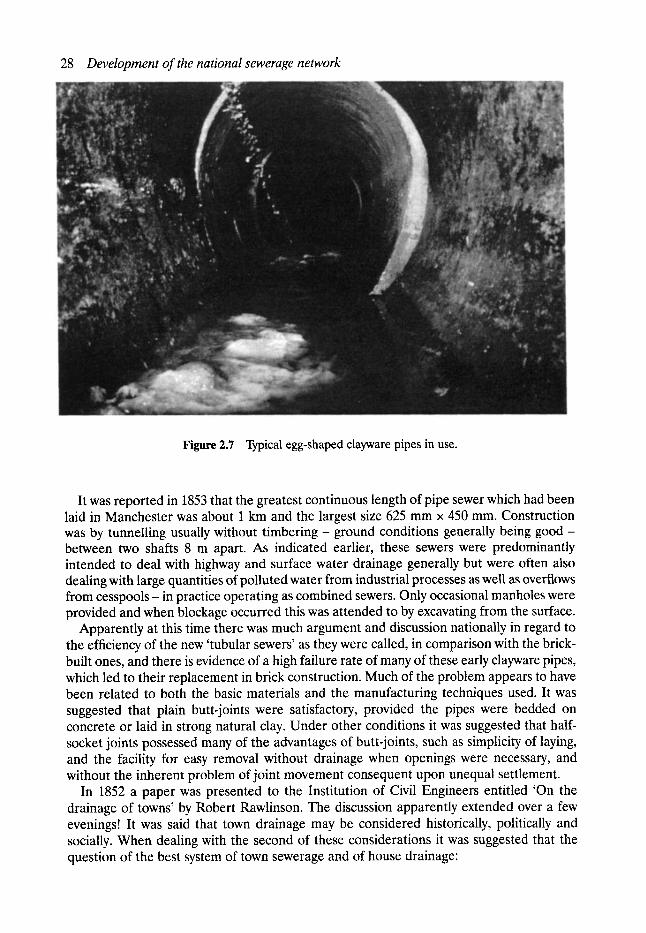
28 Development of the national sewerage network
Figure 2.7 Typical egg-shaped clayware pipes in use.
It was reported in 1853 that the greatest continuous length of pipe sewer which had been laid in Manchester was about 1 km and the largest size 625 mm x 450 mm. Construction was by tunnelling usually without timbering - ground conditions generally being good - between two shafts 8 m apart. As indicated earlier, these sewers were predominantly intended to deal with highway and surface water drainage generally but were often also dealing with large quantities of polluted water from industrial processes as well as overflows from cesspools- in practice operating as combined sewers. Only occasional manholes were provided and when blockage occurred this was attended to by excavating from the surface.
Apparently at this time there was much argument and discussion nationally in regard to the efficiency of the new 'tubular sewers' as they were called, in comparison with the brick- built ones, and there is evidence of a high failure rate of many of these early clayware pipes, which led to their replacement in brick construction. Much of the problem appears to have been related to both the basic materials and the manufacturing techniques used. It was suggested that plain butt-joints were satisfactory, provided the pipes were bedded on concrete or laid in strong natural clay. Under other conditions it was suggested that half- socket joints possessed many of the advantages of butt-joints, such as simplicity of laying, and the facility for easy removal without drainage when openings were necessary, and without the inherent problem of joint movement consequent upon unequal settlement.
In 1852 a paper was presented to the Institution of Civil Engineers entitled 'On the drainage of towns' by Robert Rawlinson. The discussion apparently extended over a few evenings! It was said that town drainage may be considered historically, politically and socially. When dealing with the second of these considerations it was suggested that the question of the best system of town sewerage and of house drainage:

Second generation sewers 1828-90 29
is very urgent and at no period has it ever been of greater importance... It may be clearly shown, that the progress, if not the permanence of civilisation is dependent on a correct appreciation of its merits; as the healthy existence of town populations must ever be influenced by their sanitary condition. Misery, pauperism, vice and crime find a forcing bed in the unsewered parts of towns and amongst the foul air of undrained houses.
In this paper the following reply from Mr John Francis, the surveyor of the Paving and Sewering Depar tment of Manchester, to questions raised with him in relation 'to the state of the pipe drains in Manchester ' is given:
The main, or street drains, are laid at various depths, from 9 feet to 30 feet the passage and branch drains at all depths from 2 feet to 10 feet.
The ordinary inclination, for main drains, is half an inch per yard, but few are laid at a quarter of an inch per yard. I do not remember any with less than that inclination. Branch, or house drains, have an inclination of 1 inch per yard and more, according to circumstances.
The largest size we have used is 25 inches by 18 inches, and the maximum size, at which tubes are likely to be preferable to brickwork is, I think, 3 feet by 2 feet.
The largest area drained into a tubular sewer, is about 50 acres; - but the whole area is not yet drained, and the tube, at its outlet, has never been half full. With respect to areas of drainage, my experience is in accordance with the recent 'Minutes of Information of the General Board of Health' as to the sizes of sewers required. But in practice I have adhered to sizes in excess of any formula. I think this should be done for the smaller areas, and greater exactness be observed, as you approach the larger areas.
I am now constructing an oval sewer 64 inches by 46 inches for a brook, having a drainage area of 550 acres, with an inclination of 1 in 300; (commenced before I saw Mr. Roe's table and agreeing very closely with it).
The smallest tube I have used, for main drains, in small streets and passages, is 12 inches by 9 inches, and the smallest branch drain, for foul water, is 6 inches by 4 inches. There is a principle which appears to me inimical to the use of very small tubes for foul water, or water loaded with the solid matter; viz. the ratio of the periphery to the transverse areas, increases inversely to the size; therefore also the friction and liability to stoppage; other circumstances being similar.
Our drains and sewers are intended to take off storm waters, and no case has come within my knowledge, where our tubes have appeared to be incapable of this duty.
We have not had one case of breakage from pressure, where the tubes were laid 2 feet, or more, below the surface. The laying and packing well with earth is the main point. All decay in sewers arises (within my experience) more from the stream within, than from the pressure outside. Our soil here, both clay and gravel, is tunnelled for sewers, ordinarily, without timber, therefore, when the soil is laid compactly about the tube, the pressure upon it is next to nothing. We use no sockets to our oval tubes, for the drains, but have them to the round pipes, which form the vertical shafts, connecting the surface with the main drains. I am more satisfied, every day, with our rejection of the socket joint. I am not aware of any disadvantage from its absence, and I partly attribute, to that cause, our immunity from breakage. It is easy to see, that in pipes having sockets, carelessly laid, the said sockets become so many points of unequal pressure. We have had many cases of stoppage, at the upper extremities of our drains, which soon caused me to adopt universally a syphon trap to every grating; but upon the whole, and taking into consideration, that we were left to acquire our experience unaided,- I think our success, in the use of tubes, has been most signal,- and for minor sewers and drains, glazed fire-clay tubes are preferable to anything else.
The first generation of sewer construction was characterised by the variety of sewer types, their crude construction and an apparent overall lack of planning. In comparison the second generat ion shows markedly improved features.
The standardised sewer sections being introduced and the construction techniques, although still primitive by the standards adopted later in the century, were a significant
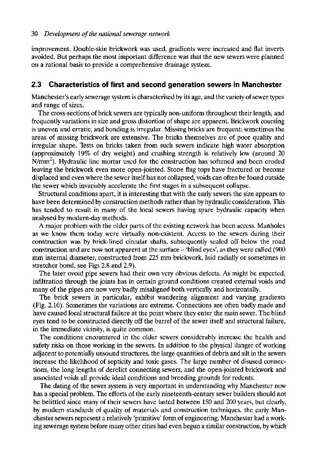
30 Development of the national sewerage network
improvement. Double-skin brickwork was used, gradients were increased and flat inverts avoided. But perhaps the most important difference was that the new sewers were planned on a rational basis to provide a comprehensive drainage system.
2.3 Characteristics of first and second generation sewers in Manchester Manchester's early sewerage system is characterised by its age, and the variety of sewer types and range of sizes.
The cross-sections of brick sewers are typically non-uniform throughout their length, and frequently variations in size and gross distortion of shape are apparent. Brickwork coursing is uneven and erratic, and bonding is irregular. Missing bricks are frequent; sometimes the areas of missing brickwork are extensive. The bricks themselves are of poor quality and irregular shape. Tests on bricks taken from such sewers indicate high water absorption (approximately 19% of dry weight) and crushing strength is relatively low (around 20 N/mm2). Hydraulic line mortar used for the construction has softened and been eroded leaving the brickwork even more open-jointed. Stone flag tops have fractured or become displaced and even where the sewer itself has not collapsed, voids can often be found outside the sewer which invariably accelerate the first stages in a subsequent collapse.
Structural conditions apart, it is interesting that with the early sewers the size appears to have been determined by construction methods rather than by hydraulic consideration. This has tended to result in many of the local sewers having spare hydraulic capacity when analysed by modern-day methods.
A major problem with the older parts of the existing network has been access. Manholes as we know them today were virtually non-existent. Access to the sewers during their construction was by brick-lined circular shafts, subsequently sealed off below the road construction and are now not apparent at the surface- 'blind eyes', as they were called (900 mm internal diameter, constructed from 225 mm brickwork, laid radially or sometimes in stretcher bond, see Figs 2.8 and 2.9).
The later ovoid pipe sewers had their own very obvious defects. As might be expected, infiltration through the joints has in certain ground conditions created external voids and many of the pipes are now very badly misaligned both vertically and horizontally.
The brick sewers in particular, exhibit wandering alignment and varying gradients (Fig. 2.10). Sometimes the variations are extreme. Connections are often badly made and have caused local structural failure at the point where they enter the main sewer. The blind eyes tend to be constructed directly off the barrel of the sewer itself and structural failure, in the immediate vicinity, is quite common.
The conditions encountered in the older sewers considerably increase the health and safety risks on those working in the sewers. In addition to the physical danger of working adjacent to potentially unsound structures, the large quantities of debris and silt in the sewers increase the likelihood of septicity and toxic gases. The large number of disused connec- tions, the long lengths of derelict connecting sewers, and the open-jointed brickwork and associated voids all provide ideal conditions and breeding grounds for rodents.
The dating of the sewer system is very important in understanding why Manchester now has a special problem. The efforts of the early nineteenth-century sewer builders should not be belittled since many of their sewers have lasted between 150 and 200 years, but clearly, by modern standards of quality of materials and construction techniques, the early Man- chester sewers represent a relatively 'primitive' form of engineering. Manchester had a work- ing sewerage system before many other cities had even begun a similar construction, by which
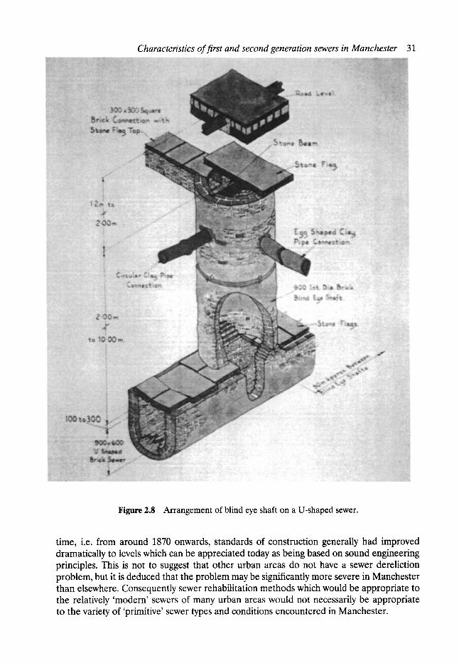
Characteristics of first and second generation sewers in Manchester 31
Figure 2.8 Arrangement of blind eye shaft on a U-shaped sewer.
time, i.e. from around 1870 onwards, standards of construction generally had improved dramatically to levels which can be appreciated today as being based on sound engineering principles. This is not to suggest that other urban areas do not have a sewer dereliction problem, but it is deduced that the problem may be significantly more severe in Manchester than elsewhere. Consequently sewer rehabilitation methods which would be appropriate to the relatively 'modern' sewers of many urban areas would not necessarily be appropriate to the variety of 'primitive' sewer types and conditions encountered in Manchester.
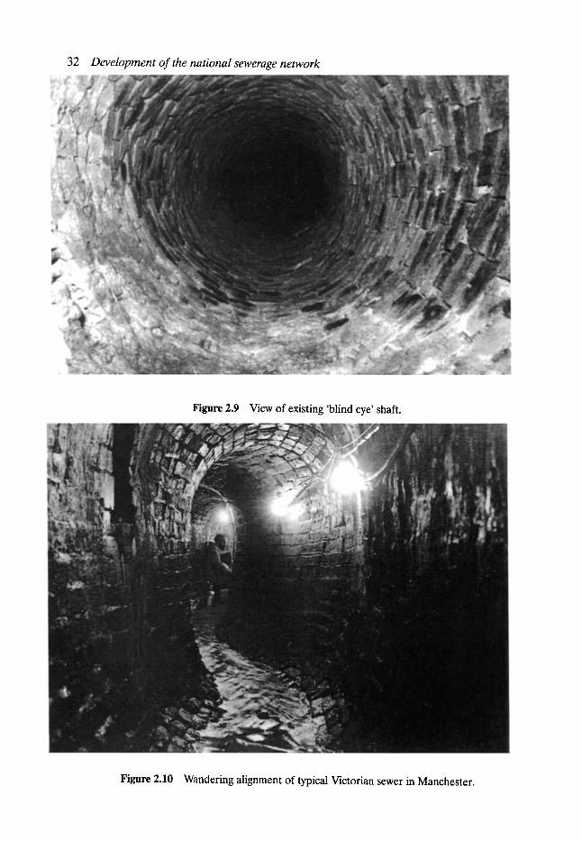
32 Development of the national sewerage network
Figure 2.9 View of existing 'blind eye' shaft.
Figure 2.10 Wandering alignment of typical Victorian sewer in Manchester.
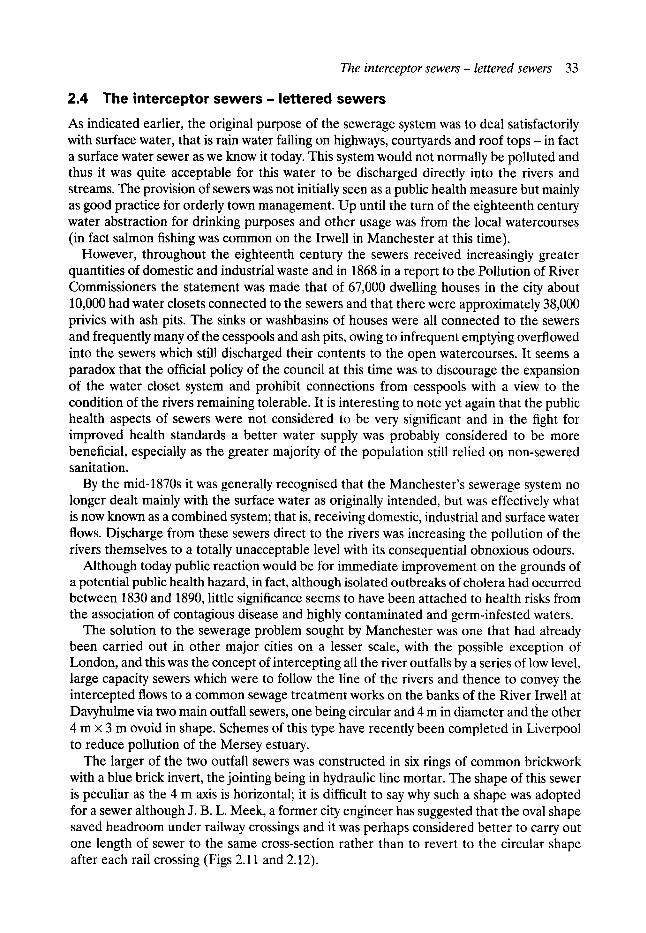
T h e in t e rcep tor sewers - l e t tered sewers 33
2.4 The interceptor s e w e r s - lettered sewers
As indicated earlier, the original purpose of the sewerage system was to deal satisfactorily with surface water, that is rain water falling on highways, courtyards and roof tops - in fact a surface water sewer as we know it today. This system would not normally be polluted and thus it was quite acceptable for this water to be discharged directly into the rivers and streams. The provision of sewers was not initially seen as a public health measure but mainly as good practice for orderly town management. Up until the turn of the eighteenth century water abstraction for drinking purposes and other usage was from the local watercourses (in fact salmon fishing was common on the Irwell in Manchester at this time).
However, throughout the eighteenth century the sewers received increasingly greater quantities of domestic and industrial waste and in 1868 in a report to the Pollution of River Commissioners the statement was made that of 67,000 dwelling houses in the city about 10,000 had water closets connected to the sewers and that there were approximately 38,000 privies with ash pits. The sinks or washbasins of houses were all connected to the sewers and frequently many of the cesspools and ash pits, owing to infrequent emptying overflowed into the sewers which still discharged their contents to the open watercourses. It seems a paradox that the official policy of the council at this time was to discourage the expansion of the water closet system and prohibit connections from cesspools with a view to the condition of the rivers remaining tolerable. It is interesting to note yet again that the public health aspects of sewers were not considered to be very significant and in the fight for improved health standards a better water supply was probably considered to be more beneficial, especially as the greater majority of the population still relied on non-sewered sanitation.
By the mid-1870s it was generally recognised that the Manchester's sewerage system no longer dealt mainly with the surface water as originally intended, but was effectively what is now known as a combined system; that is, receiving domestic, industrial and surface water flows. Discharge from these sewers direct to the rivers was increasing the pollution of the rivers themselves to a totally unacceptable level with its consequential obnoxious odours.
Although today public reaction would be for immediate improvement on the grounds of a potential public health hazard, in fact, although isolated outbreaks of cholera had occurred between 1830 and 1890, little significance seems to have been attached to health risks from the association of contagious disease and highly contaminated and germ-infested waters.
The solution to the sewerage problem sought by Manchester was one that had already been carried out in other major cities on a lesser scale, with the possible exception of London, and this was the concept of intercepting all the river outfalls by a series of low level, large capacity sewers which were to follow the line of the rivers and thence to convey the intercepted flows to a common sewage treatment works on the banks of the River Irwell at Davyhulme via two main outfall sewers, one being circular and 4 rn in diameter and the other 4 rn x 3 rn ovoid in shape. Schemes of this type have recently been completed in Liverpool to reduce pollution of the Mersey estuary.
The larger of the two outfall sewers was constructed in six rings of common brickwork with a blue brick invert, the jointing being in hydraulic line mortar. The shape of this sewer is peculiar as the 4 m axis is horizontal; it is difficult to say why such a shape was adopted for a sewer although J. B. L. Meek, a former city engineer has suggested that the oval shape saved headroom under railway crossings and it was perhaps considered better to carry out one length of sewer to the same cross-section rather than to revert to the circular shape after each rail crossing (Figs 2.11 and 2.12).
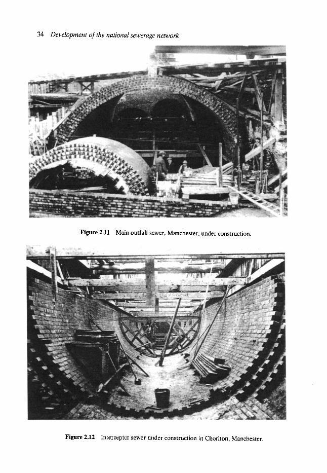
34 Development of the national sewerage network
Figure 2.11 Main outfall sewer, Manchester, under construction.
Figure 2.12 Intercepter sewer under construction in Chorlton, Manchester.
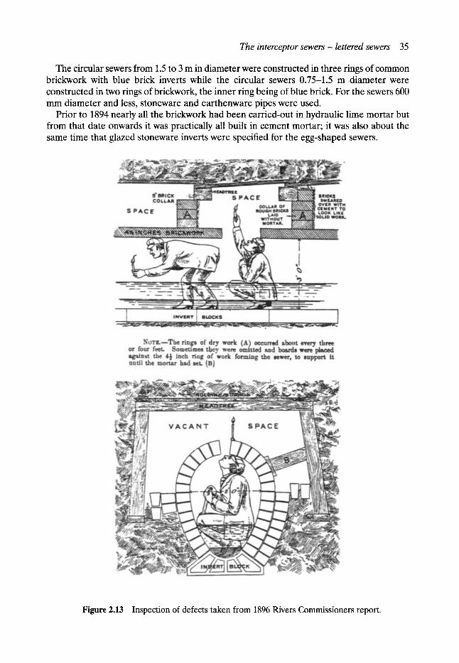
T h e in t e rcep tor sewers - l e t t ered sewers 35
The circular sewers from 1.5 to 3 m in diameter were constructed in three rings of common brickwork with blue brick inverts while the circular sewers 0.75-1.5 m diameter were constructed in two rings of b r i c ~ o r k , the inner ringbeing of blue brick. For the sewers 600 mm diameter and less, stoneware and earthenware pipes were used.
Prior to 1894 nearly all the brickwork had been carried-out in hydraulic lime mortar but from that date onwards it was practically all built in cement mortar; it was also about the same time that glazed stoneware inverts were specified for the egg-shaped sewers.
Figure 2.13 Inspection of defects taken from 1896 Rivers Commissioners report.
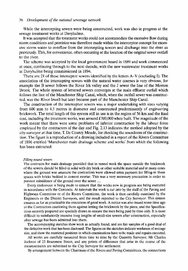
36 Development of the national sewerage network
While the intercepting sewers were being constructed, work was also in progress at the sewage treatment works at Davyhulme.
It was accepted that the treatment works could not accommodate the excessive flow during storm conditions and provision was therefore made within the interceptor concept for exces- sive storm water to overflow from the intercepting sewers and discharge into the river as previously. This, for convenience, often occurring at the location of the original sewer ouffall to the river.
The scheme was accepted by the local government board in 1889 and work commenced at once, continuing through to the next decade, with the new wastewater treatment works at Davyhulme being commissioned in 1894.
There are 21 of these interceptor sewers identified by the letters A-V (excluding I). The association of the intercepting sewers with the natural water courses is very obvious, for example the B sewer follows the River Irk valley and the J sewer the line of the Moston Brook. The whole system of lettered sewers converges at the main effluent outfall which follows the line of the Manchester Ship Canal, which, when the outfall sewer was construc- ted, was the River Irwell but later became part of the Manchester Ship Canal.
The construction of the interceptor sewers was a major undertaking with sizes varying from 600 mm to 4.5 metres in diameter and constructed predominantly of engineering brickwork. The total length of this system still in use is in the region of 56 km and the final cost, including the treatment works, was around s when built. The magnitude of the work meant that there were some problems of inferior construction by the labour force employed by the contractors of the day and Fig. 2.13 indicates the method adopted by the city surveyor at that time, T. De Courcy Meade, for checking the soundness of the construc- tion. The figure is a reproduction of a drawing included in a report of the Rivers Committee of 1896 entitled 'Manchester main drainage scheme and works' from which the following has been extracted:
Filling round sewers The contracts for main drainage provided that in tunnel work the space outside the brickwork of the sewers should be filled-in solid with dry brick or other suitable material and in many cases where the ground was unsecure the contractors were allowed extra payment for filling-in these spaces with bricks bedded in cement mortar. This was a very necessary precaution in order to prevent subsidence of the ground over the sewer ...
Every endeavour is being made to ensure that the works now in progress are being executed in accordance with the Contracts. At intervals the work is cut into by the staff of the Paving and Highways Committee or of the Rivers Committee, the work is then carefully examined by the Engineers or the District Surveyors, and the result reported to the City Surveyor. This system ensures as far as practicable the execution of good work. A notice was also issued some time ago to the Contractors cautioning them against letting the brickwork by the piece, and the Specifica- tions recently prepared are specially drawn to ensure the men being paid by time only. It is most difficult to satisfactorily examine long lengths of small-size sewers after construction, especially after sewage has been admitted into them.
The accompanying sketches show work as actually found, and are fair samples of a good deal of the defective work that has been disclosed. The figures on the sketches indicate workmen of average size, and show the restricted positions in which examinations have to be made and repairs executed.
All works are carefully measured from time to time by the Quantity Surveyor, Mr Charles Jackson of 23 Brazonese Street, and any points of difference that arise in the course of the measurements are submitted to the City Surveyor for settlement.
By arrangement between the Chairman of the Rivers and Paving Committees, the connections
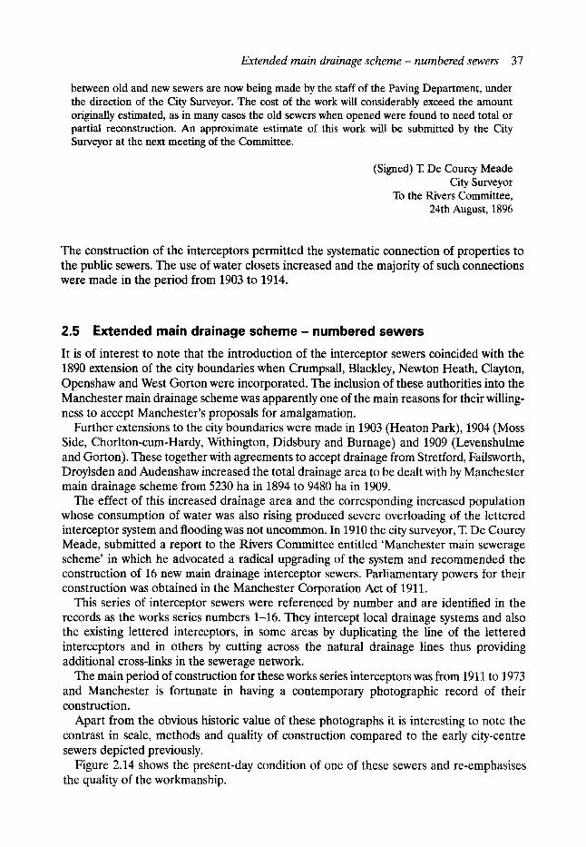
Extended main drainage scheme- numbered sewers 37
between old and new sewers are now being made by the staff of the Paving Department, under the direction of the City Surveyor. The cost of the work will considerably exceed the amount originally estimated, as in many cases the old sewers when opened were found to need total or partial reconstruction. An approximate estimate of this work will be submitted by the City Surveyor at the next meeting of the Committee.
(Signed) T. De Courcy Meade City Surveyor
To the Rivers Committee, 24th August, 1896
The construction of the interceptors permitted the systematic connection of properties to the public sewers. The use of water closets increased and the majority of such connections were made in the period from 1903 to 1914.
2.5 Extended main drainage scheme - numbered sewers
It is of interest to note that the introduction of the interceptor sewers coincided with the 1890 extension of the city boundaries when Crumpsall, Blackley, Newton Heath, Clayton, Openshaw and West Gorton were incorporated. The inclusion of these authorities into the Manchester main drainage scheme was apparently one of the main reasons for their willing- ness to accept Manchester's proposals for amalgamation.
Further extensions to the city boundaries were made in 1903 (Heaton Park), 1904 (Moss Side, Chorlton-cum-Hardy, Withington, Didsbury and Burnage) and 1909 (Levenshulme and Gorton). These together with agreements to accept drainage from Stretford, Failsworth, Droylsden and Audenshaw increased the total drainage area to be dealt with by Manchester main drainage scheme from 5230 ha in 1894 to 9480 ha in 1909.
The effect of this increased drainage area and the corresponding increased population whose consumption of water was also rising produced severe overloading of the lettered interceptor system and flooding was not uncommon. In 1910 the city surveyor, T. De Courcy Meade, submitted a report to the Rivers Committee entitled 'Manchester main sewerage scheme' in which he advocated a radical upgrading of the system and recommended the construction of 16 new main drainage interceptor sewers. Parliamentary powers for their construction was obtained in the Manchester Corporation Act of 1911.
This series of interceptor sewers were referenced by number and are identified in the records as the works series numbers 1-16. They intercept local drainage systems and also the existing lettered interceptors, in some areas by duplicating the line of the lettered interceptors and in others by cutting across the natural drainage lines thus providing additional cross-links in the sewerage network.
The main period of construction for these works series interceptors was from 1911 to 1973 and Manchester is fortunate in having a contemporary photographic record of their construction.
Apart from the obvious historic value of these photographs it is interesting to note the contrast in scale, methods and quality of construction compared to the early city-centre sewers depicted previously.
Figure 2.14 shows the present-day condition of one of these sewers and re-emphasises the quality of the workmanship.
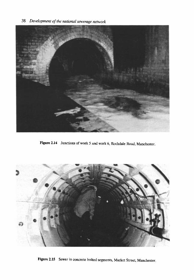
38 Development of the national sewerage network
Figure 2.14 Junctions of work 5 and work 6, Rochdale Road, Manchester.
Figure 2.15 Sewer in concrete bolted segments, Market Street, Manchester.
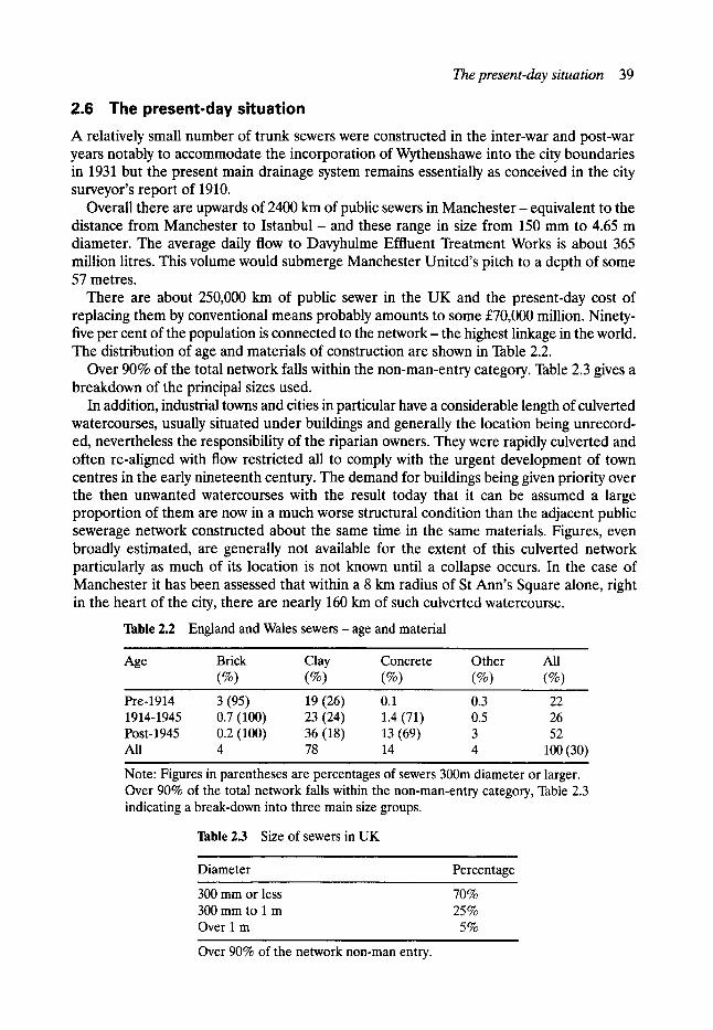
The present-day situation 39
2.6 The present-day situation A relatively small number of trunk sewers were constructed in the inter-war and post-war years notably to accommodate the incorporation of Wythenshawe into the city boundaries in 1931 but the present main drainage system remains essentially as conceived in the city surveyor's report of 1910.
Overall there are upwards of 2400 km of public sewers in Manchester - equivalent to the distance from Manchester to Istanbul - and these range in size from 150 mm to 4.65 m diameter. The average daily flow to Davyhulme Effluent Treatment Works is about 365 million litres. This volume would submerge Manchester United's pitch to a depth of some 57 metres.
There are about 250,000 km of public sewer in the UK and the present-day cost of replacing them by conventional means probably amounts to some s million. Ninety- five per cent of the population is connected to the network- the highest linkage in the world. The distribution of age and materials of construction are shown in Table 2.2.
Over 90% of the total network falls within the non-man-entry category. Table 2.3 gives a breakdown of the principal sizes used.
In addition, industrial towns and cities in particular have a considerable length of culverted watercourses, usually situated under buildings and generally the location being unrecord- ed, nevertheless the responsibility of the riparian owners. They were rapidly culverted and often re-aligned with flow restricted all to comply with the urgent development of town centres in the early nineteenth century. The demand for buildings being given priority over the then unwanted watercourses with the result today that it can be assumed a large proportion of them are now in a much worse structural condition than the adjacent public sewerage network constructed about the same time in the same materials. Figures, even broadly estimated, are generally not available for the extent of this culverted network particularly as much of its location is not known until a collapse occurs. In the case of Manchester it has been assessed that within a 8 km radius of St Ann's Square alone, right in the heart of the city, there are nearly 160 km of such culverted watercourse.
Table 2.2 England and Wales sewers- age and material
Age Brick Clay Concrete (%) (%) (%)
Other All (%) (%)
Pre-1914 3 (95) 19 (26) 0.1 0.3 22 1914-1945 0.7 (100) 23 (24) 1.4 (71) 0.5 26 Post-1945 0.2 (100) 36 (18) 13 (69) 3 52 All 4 78 14 4 100 (30)
Note: Figures in parentheses are percentages of sewers 300m diameter or larger. Over 90% of the total network falls within the non-man-entry category, Table 2.3 indicating a break-down into three main size groups.
Table 2.3 Size of sewers in UK
Diameter Percentage
300 mm or less 70% 300 mm to 1 m 25% Over i m 5%
Over 90% of the network non-man entry.
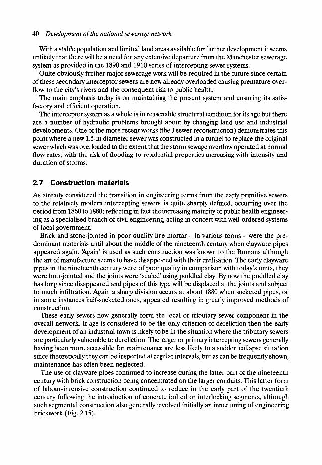
40 Development of the national sewerage network
With a stable population and limited land areas available for further development it seems unlikely that there will be a need for any extensive departure from the Manchester sewerage system as provided in the 1890 and 1910 series of intercepting sewer systems.
Quite obviously further major sewerage work will be required in the future since certain of these secondary interceptor sewers are now already overloaded causing premature over- flow to the city's rivers and the consequent risk to public health.
The main emphasis today is on maintaining the present system and ensuring its satis- factory and efficient operation.
The interceptor system as a whole is in reasonable structural condition for its age but there are a number of hydraulic problems brought about by changing land use and industrial developments. One of the more recent works (the J sewer reconstruction) demonstrates this point where a new 1.5-m diameter sewer was constructed in a tunnel to replace the original sewer which was overloaded to the extent that the storm sewage overflow operated at normal flow rates, with the risk of flooding to residential properties increasing with intensity and duration of storms.
2.7 Construction materials As already considered the transition in engineering terms from the early primitive sewers to the relatively modern intercepting sewers, is quite sharply defined, occurring over the period from 1860 to 1880; reflecting in fact the increasing maturity of public health engineer- ing as a specialised branch of civil engineering, acting in concert with well-ordered systems of local government.
Brick and stone-jointed in poor-quality line mor t a r - in various forms- were the pre- dominant materials until about the middle of the nineteenth century when clayware pipes appeared again. ~gain' is used as such construction was known to the Romans although the art of manufacture seems to have disappeared with their civilisation. The early clayware pipes in the nineteenth century were of poor quality in comparison with today's units, they were butt-jointed and the joints were 'sealed' using puddled clay. By now the puddled clay has long since disappeared and pipes of this type will be displaced at the joints and subject to much infiltration. Again a sharp division occurs at about 1880 when socketed pipes, or in some instances half-socketed ones, appeared resulting in greatly improved methods of construction.
These early sewers now generally form the local or tributary sewer component in the overall network. If age is considered to be the only criterion of dereliction then the early development of an industrial town is likely to be in the situation where the tributary sewers are particularly vulnerable to dereliction. The larger or primary intercepting sewers generally having been more accessible for maintenance are less likely to a sudden collapse situation since theoretically they can be inspected at regular intervals, but as can be frequently shown, maintenance has often been neglected.
The use of clayware pipes continued to increase during the latter part of the nineteenth century with brick construction being concentrated on the larger conduits. This latter form of labour-intensive construction continued to reduce in the early part of the twentieth century following the introduction of concrete bolted or interlocking segments, although such segmental construction also generally involved initially an inner lining of engineering brickwork (Fig. 2.15).
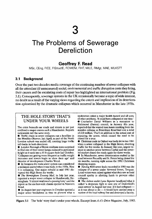
3 The Problems of Sewerage
Dereliction
Geoffrey i-, Read MSc, CEng, FICE, FlStructE, FCIWEM, FIHT, MILE, FIMgt, MAE, MUKSTT
3.1 Background Over the past two decades media coverage of the continuing number of sewer collapses with all the attendant (if unmeasured) social, environmental and traffic disruption costs they bring, their causes and the escalating costs of repair has highlighted an international problem (Fig. 3.1). Consequently, sewerage systems in the UK occasionally become a topic of wide interest, no doubt as a result of the varying views regarding the extent and implication of its deteriora- tion epitomised by the dramatic collapses which occurred in Manchester in the late 1970s.
T H E H O L E S T O R Y T H A T ' S U N D E R Y O U R W H E E L S
The crisis beneath our roads and streets is not just confined to major centres such a Manchester. Reports nationwide tell the same story. �9 Traffic chaos as sewer collapses ran a headline in the Wembley Observer, last April, as part of the North London suburb was sealed off, creating huge traffic tail-backs in both directions. �9 London Borough of Brent residents were surprised to find one of their street lamps reduced to pavement height as it sank into a 15 ft square hole last October. 'Collapses are getting more frequent as traffic weight increases and sewers begin to show their age' said director of development Charles Wood. �9 In Swansea the main sewer system was considered a technical marvel when it was built, in the 1930s. Now it is collapsing. One major rebuild in mid 1981 dis- rupted the High Street for weeks. �9 The Birmingham Evening Mail, in July last year, reported a major sewer collapse in Handsworth, Bir- mingham. 'It almost swallowed a passing lorry' said the report as the six-foot-wide chasm opened in Ninevers Road. �9 In August last year engineers in Croydon spotted a major sewer breakdown in time to prevent what a
spokesman called a major health hazard and all sorts of other problems. 'It could have collapsed at any time.' �9 Counsellor David Williams in a statement to Richmond (Surrey) council, in January tlais year, reported that the wasted man hours resulting from the massive collapse in Petersham Road had cost a total of s million. That's in addition to the actual cost of repairing the sewer, which caused the road to be closed for a year. �9 Christmas trade in Oxford was badly hit in late 1981 when a sewer collapsed in the High Street, diverting traffic for five weeks. In January this year, urgent re- pairs to another sewer between Carfax and the cover- ed market dosed the roads again for three weeks. �9 In Manchester, sewer deterioration reulted in the road between Piccadily and St. Peters being closed for six months, running right across the 1982 Christmas shopping season. �9 Among 4030 sewer leaks recorded in 1981 was the collapse of a sewer under Torwood Street, Torquay. Local voices were raised against what they saw as local council apathy in allotting funds to prevent other collapses. �9 The Ashton under Lyme Reporter headlined what it called 'a desperate fight to save one of Dukinfield's main sewers' in August last year. If it had collapsed m as it was about to do m it would have carried away a section of the local railway line and destroyed a factory.
Figure 3.1 The 'hole ' story that ' s under your wheels. Excerpt f r o m A - A ' s Drive Magazine, July, 1983.

42 The problems of sewerage dereliction
Press comments have varied from ~kll the nation's sewers were built in the last century and are now in a terrible state' through to the other extreme 'Our infrastructure is perfectly adequate and in any case spending money on it is not cost-effective'. Although the UK was the first country to install large-scale sewerage systems, it would seem, as suggested previ- ously that the Victorian civil engineers were not backward in exporting their expertise and consequently the current problems of sewer dereliction are not just confined to Britain. Sewers are part of a country's national industrial heritage and the rehabilitation of many of them is long overdue (Fig. 3.2). There are about 250,000 km of public sewer in the UK and the present-day cost of replacing the network by conventional means amounts to probably s billion. The repair and planned maintenance of an asset of this magnitude should accordingly be of paramount importance, particularly when it is remembered that 95% of the population are connected to the network.
Investment in the water industry has steadily declined, in real terms, from a peak in the early 1970s until the past few years when there has been a modest increase. Some 70% of water company assets are buried underground which makes it difficult to estimate the investment needs with any precision. A major problem in assessing the condition of sewers is the lack of detailed knowledge so far as location and condition is concerned. It has been estimated that only 30-40% of local authorities have reasonably satisfactory records and that 15-30% of all public sewers are not recorded at all. Many of the assets are old, some dating back into the last century but need for investment is unquestionable in view of the continuing number of collapses.
Figure 3.2(a) Figure 3.2(b )
Figure 3.2 Sewer collapses (a) Shudehill, Manchester, 1979. A 900 mm x 600 mm U-shaped sewer with natural stone top constructed in 1841. One stone slab has collapsed and debris has accumulated. A second stone slab has failed and is near collapse. (b) Sewer collapse in Harris Street, Wemeth, Oldham. (c) Sackville Street, Manchester. (d) Albert Square, Manchester 1986. (e) Oldham, 1995. (f) Oxford Street,Manchester. General site view. (g) Market Street, Manchester- start of collapse mechanism, 1981.
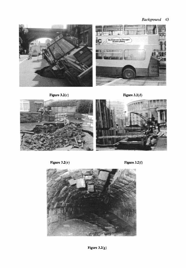
Background 43
Figure 3.2(c) Figure 3.2(d)
Figure 3.2(e) Figure 3.2(f)
Figure 3.2(g)
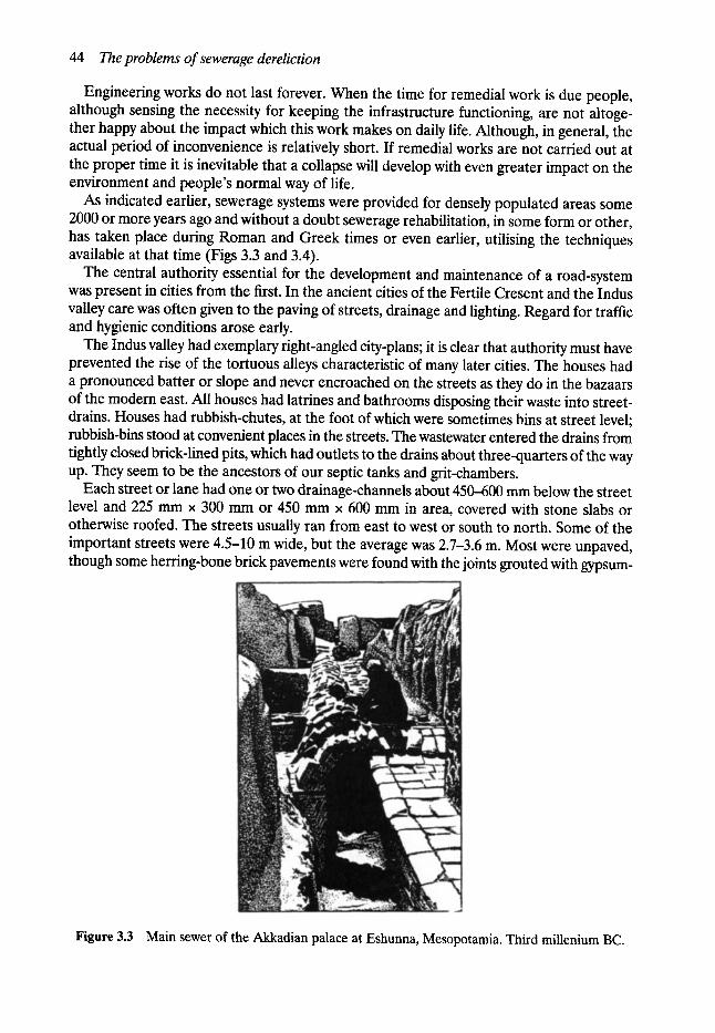
44 The problems of sewerage dereliction
Engineering works do not last forever. When the time for remedial work is due people, although sensing the necessity for keeping the infrastructure functioning, are not altoge- ther happy about the impact which this work makes on daily life. Although, in general, the actual period of inconvenience is relatively short. If remedial works are not carried out at the proper time it is inevitable that a collapse will develop with even greater impact on the environment and people's normal way of life.
As indicated earlier, sewerage systems were provided for densely populated areas some 2000 or more years ago and without a doubt sewerage rehabilitation, in some form or other, has taken place during Roman and Greek times or even earlier, utilising the techniques available at that time (Figs 3.3 and 3.4).
The central authority essential for the development and maintenance of a road-system was present in cities from the first. In the ancient cities of the Fertile Cresent and the Indus valley care was often given to the paving of streets, drainage and lighting. Regard for traffic and hygienic conditions arose early.
The Indus valley had exemplary right-angled city-plans; it is clear that authority must have prevented the rise of the tortuous alleys characteristic of many later cities. The houses had a pronounced batter or slope and never encroached on the streets as they do in the bazaars of the modem east. All houses had latrines and bathrooms disposing their waste into street- drains. Houses had rubbish-chutes, at the foot of which were sometimes bins at street level; rubbish-bins stood at convenient places in the streets. The wastewater entered the drains from tightly closed brick-lined pits, which had outlets to the drains about three-quarters of the way up. They seem to be the ancestors of our septic tanks and grit-chambers.
Each street or lane had one or two drainage-channels about 450--600 mm below the street level and 225 mm x 300 mm or 450 mm x 600 mm in area, covered with stone slabs or otherwise roofed. The streets usually ran from east to west or south to north. Some of the important streets were 4.5-10 m wide, but the average was 2.7-3.6 m. Most were unpaved, though some herring-bone brick pavements were found with the joints grouted with gypsum-
Figure 3.3 Main sewer of the Akkadian palace at Eshunna, Mesopotamia. Third millenium BC.
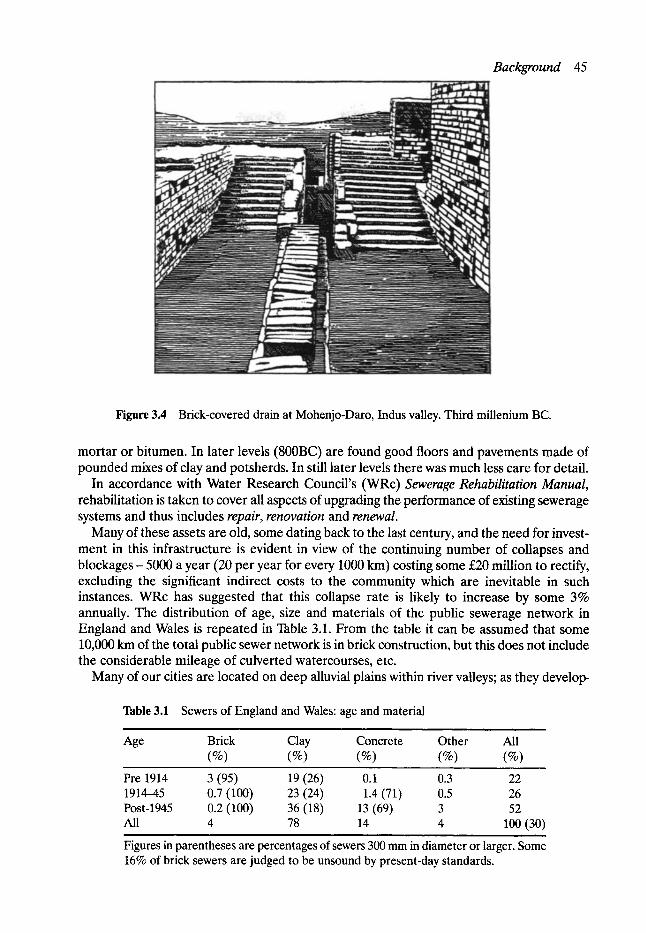
Background 45
Figure 3.4 Brick-covered drain at Mohenjo-Daro, Indus valley. Third millenium BC.
mortar or bitumen. In later levels (800BC) are found good floors and pavements made of pounded mixes of clay and potsherds. In still later levels there was much less care for detail.
In accordance with Water Research Council's (WRc) Sewerage Rehabilitation Manual, rehabilitation is taken to cover all aspects of upgrading the performance of existing sewerage systems and thus includes repair, renovation and renewal.
Many of these assets are old, some dating back to the last century, and the need for invest- ment in this infrastructure is evident in view of the continuing number of collapses and blockages - 5000 a year (20 per year for every 1000 km) costing some s million to rectify, excluding the significant indirect costs to the community which are inevitable in such instances. WRc has suggested that this collapse rate is likely to increase by some 3% annually. The distribution of age, size and materials of the public sewerage network in England and Wales is repeated in Table 3.1. From the table it can be assumed that some 10,000 km of the total public sewer network is in brick construction, but this does not include the considerable mileage of culverted watercourses, etc.
Many of our cities are located on deep alluvial plains within river valleys; as they develop-
Table 3.1 Sewers of England and Wales: age and material
Age Brick Clay Concrete Other All (%) (%) (%) (%) (%)
Pre 1914 3 (95) 19 (26) 0.1 0.3 22 1914-45 0.7 (100) 23 (24) 1.4 (71) 0.5 26 Post-1945 0.2 (100) 36 (18) 13 (69) 3 52 All 4 78 14 4 100 (30)
, ,
Figures in parentheses are percentages of sewers 300 mm in diameter or larger. Some 16% of brick sewers are judged to be unsound by present-day standards.
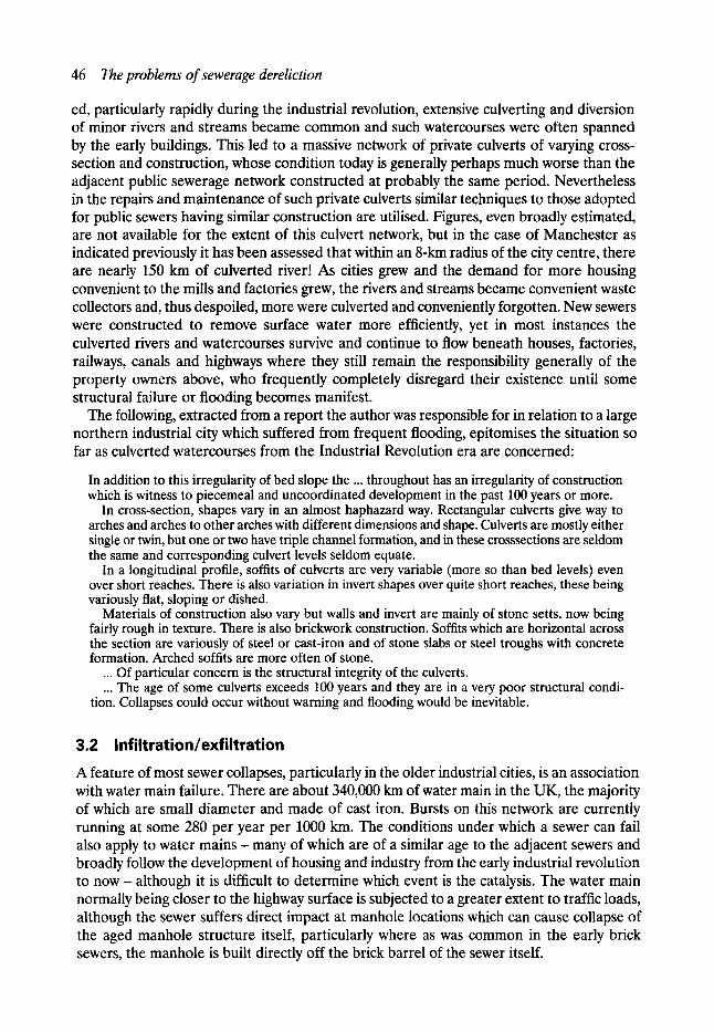
46 The problems of sewerage dereliction
ed, particularly rapidly during the industrial revolution, extensive culverting and diversion of minor rivers and streams became common and such watercourses were often spanned by the early buildings. This led to a massive network of private culverts of varying cross- section and construction, whose condition today is generally perhaps much worse than the adjacent public sewerage network constructed at probably the same period. Nevertheless in the repairs and maintenance of such private culverts similar techniques to those adopted for public sewers having similar construction are utilised. Figures, even broadly estimated, are not available for the extent of this culvert network, but in the case of Manchester as indicated previously it has been assessed that within an 8-km radius of the city centre, there are nearly 150 km of culverted river! As cities grew and the demand for more housing convenient to the mills and factories grew, the rivers and streams became convenient waste collectors and, thus despoiled, more were culverted and conveniently forgotten. New sewers were constructed to remove surface water more efficiently, yet in most instances the culverted rivers and watercourses survive and continue to flow beneath houses, factories, railways, canals and highways where they still remain the responsibility generally of the property owners above, who frequently completely disregard their existence until some structural failure or flooding becomes manifest.
The following, extracted from a report the author was responsible for in relation to a large northern industrial city which suffered from frequent flooding, epitomises the situation so far as culverted watercourses from the Industrial Revolution era are concerned:
In addition to this irregularity of bed slope the ... throughout has an irregularity of construction which is witness to piecemeal and uncoordinated development in the past 100 years or more.
In cross-section, shapes vary in an almost haphazard way. Rectangular culverts give way to arches and arches to other arches with different dimensions and shape. Culverts are mostly either single or twin, but one or two have triple channel formation, and in these crosssections are seldom the same and corresponding culvert levels seldom equate.
In a longitudinal profile, soffits of culverts are very variable (more so than bed levels) even over short reaches. There is also variation in invert shapes over quite short reaches, these being variously flat, sloping or dished.
Materials of construction also vary but walls and invert are mainly of stone setts, now being fairly rough in texture. There is also brickwork construction. Soffits which are horizontal across the section are variously of steel or cast-iron and of stone slabs or steel troughs with concrete formation. Arched soffits are more often of stone.
... Of particular concern is the structural integrity of the culverts.
... The age of some culverts exceeds 100 years and they are in a very poor structural condi- tion. Collapses could occur without warning and flooding would be inevitable.
3.2 Infiltration/exfiltration A feature of most sewer collapses, particularly in the older industrial cities, is an association with water main failure. There are about 340,000 km of water main in the UK, the majority of which are small diameter and made of cast iron. Bursts on this network are currently running at some 280 per year per 1000 km. The conditions under which a sewer can fail also apply to water m a i n s - many of which are of a similar age to the adjacent sewers and broadly follow the development of housing and industry from the early industrial revolution to n o w - although it is difficult to determine which event is the catalysis. The water main normally being closer to the highway surface is subjected to a greater extent to traffic loads, although the sewer suffers direct impact at manhole locations which can cause collapse of the aged manhole structure itself, particularly where as was common in the early brick sewers, the manhole is built directly off the brick barrel of the sewer itself.

The environmental impact of sewer collapse 47
If the water main precipitates the fracture/failure of the sewer, then the escaping water (under pressure) will seek the path of least resistance generally to the defective sewer below. In this context one must appreciate:
1. some 30-35% of all treated water currently leaks out of the mains between the reservoir and the user, although there is a fair amount of guesswork involved in determining the figure precisely; and
2. as indicated earlier, it was common practice to endeavour to use the early sewers for the dual purpose of removing wastewater and acting as land drainage, in the case of brick sewers, leaving a number of brick courses with dry joints or in the early clayware pipes to either butt joint them or only have a socket in the bottom half of the pipe. Hence water leaking from the mains often has a convenient point of discharge into the defective sewer below.
Whilst ground conditions will have a bearing on the issue it is suggested that irrespective of soil conditions in which the main sewer may have been constructed, the numerous sewer connections which in part at least will have been trench excavated, will, without exception, either directly or indirectly provide a route for clean water to reach the sewer.
If infiltration can take place then the converse can also occur. When a sewer is defective and hydraulically overloaded, internal water pressure forces sewerage out into the surround- ing ground; when the pressure falls the sewerage re-enters the sewer bringing silt with it, thus tending to clog the pipe but more importantly, weakening the external support, thus accelerating failure.
As the external void situation develops, often over quite a considerable period of years, it progressively extends to the highway surface usually before the real extent of the failure has been detected. The cavity from a damaged 250 mm sewer can be big enough to contain a double-decker bus.
3.3 The environmental impact of sewer collapse Within the European Union, the environment ranks as second only to unemployment as the most important political problem perceived by the electorate.
The environment is something which affects people's lives - sewerage is obviously a factor affecting people's lives and hence also the environment.
The obvious immediate consequences of a sewer collapse may include the contamination of drinking water supply, flooding of habitable properties with crude sewage, or other equally obnoxious and unacceptable conditions affecting the environment. The result of such prob- lems is often the disruption of the normal business and commercial life of a city frequently leading to a loss of confidence in its future well-being, serious transport delays, as well as the other indirect costs including the environmental factors which inevitably arise.
When a sewer collapse occurs or sewerage rehabilitation takes place traffic disruption arises. After a few days the immediate impact becomes less as motorists learn to avoid the individual site and often the prescribed diversions. Nevertheless the effects of a number of collapses and sewerage works in the central area of a city is cumulative with the official and unofficial diversion routes often overlapping. It is not unusual for these diversionary routes to involve traffic using areas where the size and volume is completely out of keeping with the layout and the environment. Frequently these routes suffer resultant damage to surface, foundations and the statutory undertakers plant beneath. In addition the area involved may include housing development where immediate road safety publicity must be provided in
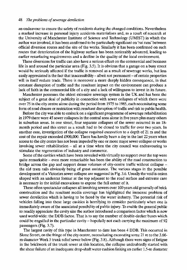
48 The problems of sewerage dereliction
an endeavour to ensure the safety of residents during the changed conditions. Nevertheless a marked increase in personal injury accidents materialises and, as a result of research at the University of Manchester Institute of Science and Technology (UMIST) in which the author was involved, it has been confirmed to be particularly significant on 'rat runs' between official diversion routes and the site of the works. Similarly it has been confirmed on such routes that deterioration of the highway surface has been noticeably advanced, leading to earlier resuffacing requirements and a decline in the quality of the local environment.
These diversions for traffic can also have a serious effect on the commercial and business life in and around the particular area (Fig. 3.5). It is obvious that a garage on a busy street would be seriously affected if the traffic is removed as a result of sewerage works, but less easily appreciated is the fact that inaccessibility- albeit not permanent - of certain properties will in itself reduce trade. There is moreover a more deeply hidden consequence, in that constant disruption of traffic and the resultant impact on the environment can produce a lack of faith in the commercial life of a city and a lack of willingness to invest in its future.
Manchester possesses the oldest extensive sewerage system in the UK and has been the subject of a great deal of publicity in connection with sewer collapses of which there were over 75 in the city centre alone during the period from 1975 to 1985, each necessitating some form of road closure or restriction with resultant disruption of traffic and risk to public health.
Before the city was able to embark on a significant programme of sewerage rehabilitation in 1979 there were 45 sewer collapses in the central area alone in five years plus many others in suburban areas. In one street, four separate collapses of the sewer occurred in an 18- month period and this street as a result had to be closed to traffic for over two years. In another case, investigation of the collapse required excavation to a depth of 21 m and the cost of the repair exceeded s There has hardly been a day in the last 22 years when access to the city centre has not been impeded by one or more major sewer collapse or works involving sewer rehabilitation- all at a time when the city council was endeavouring to stimulate the regeneration of industry and commerce.
Some of the cavities which have been revealed with virtually no support over the top were quite remarkable - even more remarkable has been the ability of the road construction to bridge across the gap and support dense volumes of city-centre traffic without collapse - the old tram rails obviously being of great assistance. The various stages in the possible development of a Victorian sewer collapse are suggested in Fig. 3.6. Usually the void is onion shaped with an undercut format at the top adjacent to the road surface and extreme care is necessary in the initial excavations to expose the full extent of it.
These often spectacular collapses all involving sewers over 100 years old generally of brick construction and the resultant media coverage has highlighted the immense problem of sewer dereliction which is having to be faced by the water industry. The potential risk of vehicles falling into these large cavities is horrifying to consider particularly when one is immediately aware of the associated possibility of public injury. To enable the general public to readily appreciate the cavity size the author introduced a comparison factor which is now used world-wide: the DDB factor. That is to say the number of double-decker buses which could be engulfed in the particular cavity- hopefully not each carrying the maximum of 92 passengers (Fig. 3.7).
The largest cavity of this type in Manchester to date has been 4 DDB. This occurred in Slone Street, on the fringe of the city centre, necessitating excavating some 21 m to the 3.66- m diameter Work 5 trunk relief sewer below (Fig. 3.8). Although there were signs of fatigue in the brickwork of the trunk sewer at this location, the collapse undoubtedly started with the shear failure of an inadequate drop-shaft water cushion linking an earlier 1.5-m diameter
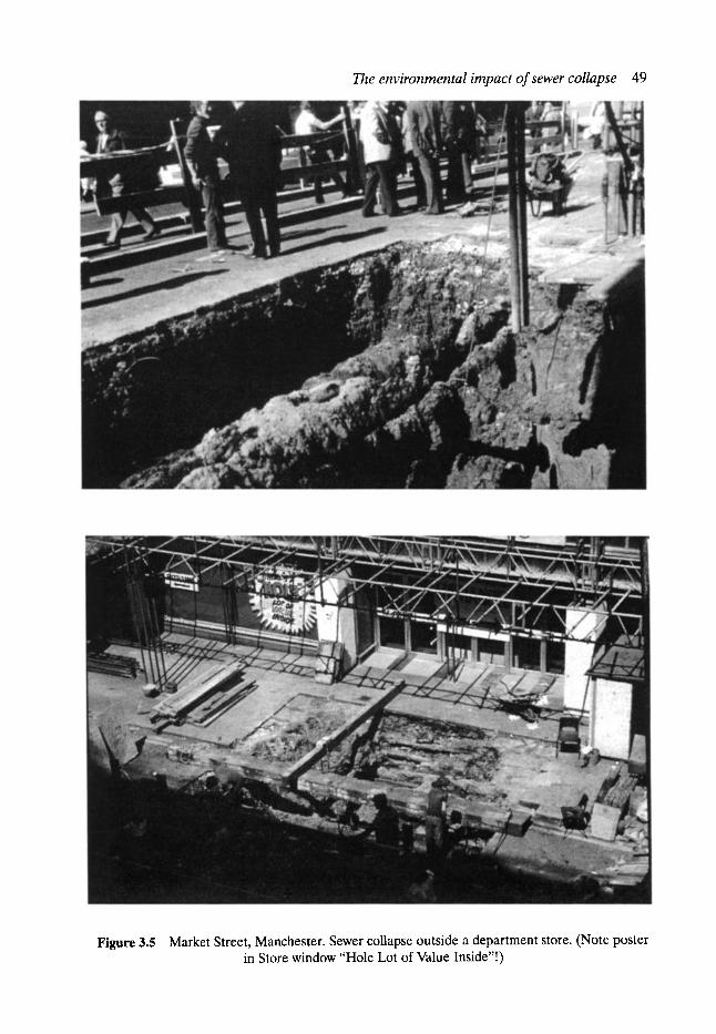
The environmental impact of sewer collapse 49
Figure 3.5 Market Street, Manchester. Sewer collapse outside a department store. (Note poster in Store window "Hole Lot of Value Inside"!)
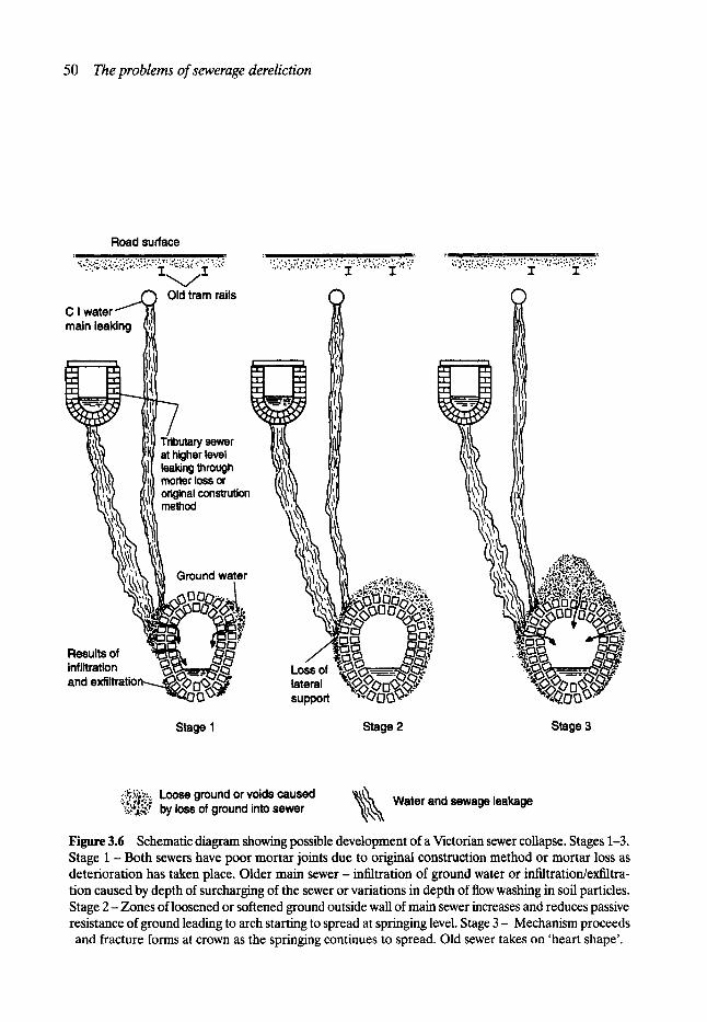
50 T h e p r o b l e m s o f s ewerage dere l i c t i on
Road surface i i ,r , ' , . ~ . ' , - ' . . ' . " ; ' . ' . ' . " - " , : ' : . ' r ; ' , ~ . . : - ; : ' . * . . ' . , ' " ! ":
.:.:1:;.~,.;:.~.....-.:.,:-. -i,~,...~:,~ji E-:.:
Old tram rails C I water main leaking ~ ! I !
i - - ' ,
"~':':'"":: := .... ""'" i" .... ":""" i ::'"
. . �9 , , . . . . . . . - ,. ~...:.:~..!.,!:..~.:.,,~-~-:,..,: :~ ~...:,,..:~ !...-~; .-::.,- J. d.
Tributary sewer at higher level leaking through morter loss or original constrution method
Results of
and
Ground water
Loss of lateral support
iD
Stage I Stage 2 Stage 3
~;~'-,~ Loose ground or voids caused ~;~"..q by loss of ground into sewer " ~ ~ Water and sewage leakage
Figure 3.6 Schematic diagram showing possible development of a Victorian sewer collapse. Stages 1-3. Stage 1 - Both sewers have poor mortar joints due to original construction method or mortar loss as deterioration has taken place. Older main sewer- infiltration of ground water or infiltration/exfiltra- tion caused by depth of surcharging of the sewer or variations in depth of flow washing in soil particles. Stage 2 - Zones of loosened or softened ground outside wall of main sewer increases and reduces passive resistance of ground leading to arch starting to spread at springing level. Stage 3 - Mechanism proceeds and fracture forms at crown as the springing continues to spread. Old sewer takes on 'heart shape'.
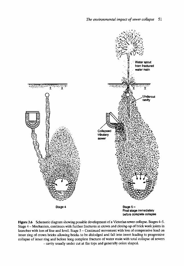
The env i ronmen ta l impac t o f sewer collapse 51
a i i :
"" ' ' " ' .... I . . . . 7" '
?" :i '....-. '.. '.~" '.2--;'-'. .~. :,. �9 " . . ; . ,... ,.. ,.;.:.,_'(.. ~.' ~. i?~,"r.
i;. �9 ..t0 =. a; ?,, ...~ . . . . ~ :.t..
g-" "U z -..~..s
. , ~: ;:...~,:.~.7,~.,,., �9 "~ ',~ .~.....ir ~:; i"." : . , , . , . . . ~ : , : ..'. :. "~; !i~ '. '."~'";~;':" ~":: ,r,: :'~ :~.".~ ' - : ' . . '~":
".~.:'..:~.
% i
~ % , ' ~ ' ~ \ , , ~ , " , . - ,\.,x, ~ .,,,.,, �9 ,~'~ " . . I~'" a ~ "
. ' - - , ~:~ , %
" l j . x ,.,, �9
�9 ~
�9 ~ " Water spout �9 :~'~ . from fractured
�9 ~.',~- water main iI"
cavity
Collapsed tributary sewer
:2.=.
';-b~ ,=.;o
: :d. ' " ' ~ l P : .~ . . . ?
;" ; , . , �9 .~ .e- . ' ~ . ~ . ~ '
i:..'..-.C ~.~.',, ?.....~,
Stage 4 Stage 5 - Final stage immediately before complete collapse
Figure 3.6 Schematic diagram showing possible development of a Victorian sewer collapse. Stages 4-5. Stage 4 - Mechanism, continues with further fractures at crown and closing-up of brick work joints in launches with loss of line and level. Stage 5 - Cont inued movement with loss of compressive load on inner ring of crown bricks allowing bricks to be dislodged and fall into invert leading to progressive collapse of inner ring and before long complete fracture of water main with total collapse of sewers
- cavity usually under cut at the tops and generally onion shaped.
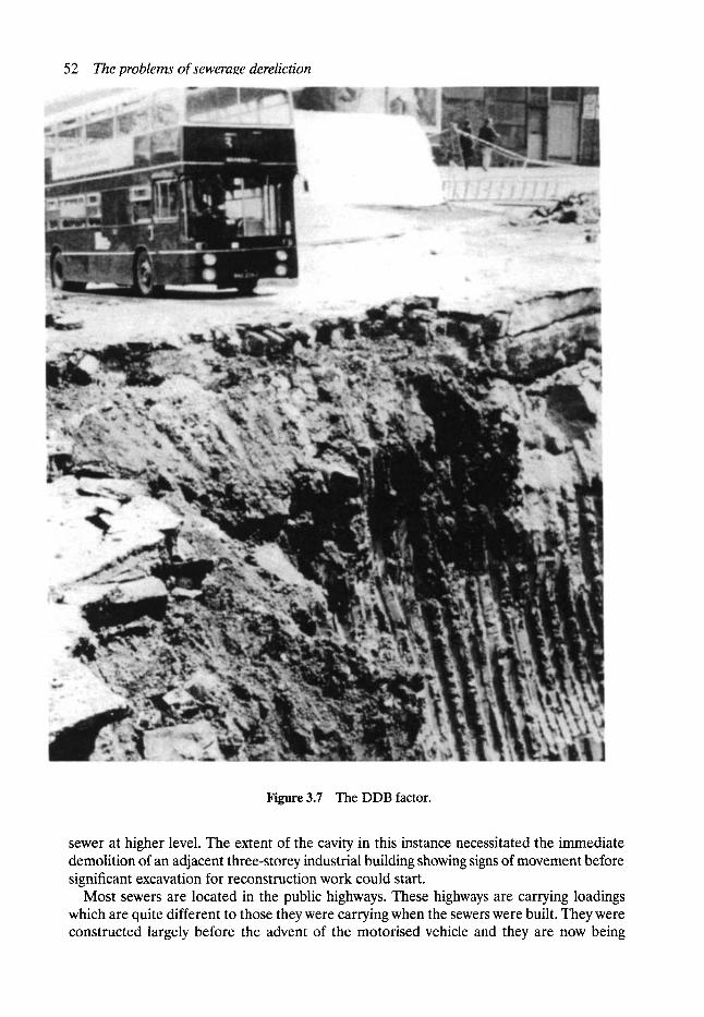
52 The problems of seweraee dereliction
Figure 3.7 The DDB factor.
sewer at higher level. The extent of the cavity in this instance necessitated the immediate demolition of an adjacent three-storey industrial building showing signs of movement before significant excavation for reconstruction work could start.
Most sewers are located in the public highways. These highways are carrying loadings which are quite different to those they were carrying when the sewers were built. They were constructed largely before the advent of the motorised vehicle and they are now being
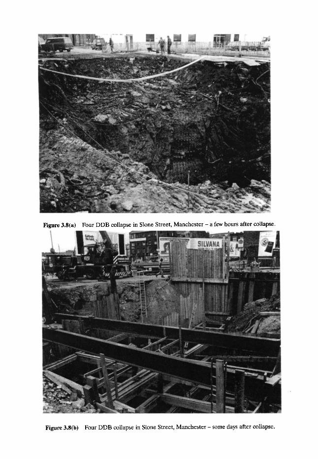
Figure 3.8(a) Four DDB collapse in Slone Street, Manchester- a few hours after collapse.
Figure 3.8(b) Four DDB collapse in Slone Street, Manchester- some days after collapse.

54 The problems of sewerage dereliction
pounded by loads of 38 tonnes or more on a sub-structure that is often unable to take the strain. An assessment of whether this increased loading has any effect on the sewers at the depth generally found is unfortunately subjective. Suffice to say that not enough is known as to the relationship between heavy vehicles and drainage to underground mains, etc. This is a serious omission in our knowledge, but there can be little doubt that heavy lorries do have some effect on underground equipment, since, if heavy traffic is diverted to a relatively minor route, it is common for a failure of underground plant to follow. Such failures usually including sewer collapses.
At the time when the worst collapses were occurring in Manchester, when there were only limited resources available, a strategy was developed which attempted to tackle the potential crisis situation, and two basic objectives were defined as follows:
�9 Objective 1. To reduce the risk of a catastrophe (a catastrophe being an event in which loss of life or injury of persons result, major damage to property or major disruption to the commercial well-being of the city occur).
�9 Objective 2. To maintain the principal element of the existing sewerage system.
Other towns and cities developed more slowly with the sewerage infrastructure being provided over a longer period; hence they have not been faced with the situation of many kilometres of dereliction reaching a crisis situation over a relatively short timescale. Never- theless, as indicated previously, there are about 5000 collapses a year throughout Britain, or on average about 20 collapses a year for every 1000 km of sewer, so that dereliction is quite widespread.
Every sewer collapse brings with it a number of effects: immediate, consequential and resulting. These are summarised in Tables 3.2-3.6.
3 4 Sewer collapses- effect on overall economy It is extremely difficult to suggest a typical cost of a sewer collapse even related to a particular sewer size at a specific d e p t h - they obviously all vary considerably depending on a variety of factors. Manchester has recently averaged six collapses per year in the central area.
For every collapse, additional to the direct repair cost, there are social or indirect costs to be considered. These are not borne by the water company but fall directly on the public.
Table 3.2 Sewer collapses - environmental aspects
Immediate effects could include:
1. Contamination of drinking water supply
2. Flooding of habitable properties with crude sewage
3. Danger to the public
4. Smell nuisance
5. Property damage
6. Damage to other utilities equipment , , , ,

Sewer collapse - effect on overall economy 55
Table 3.3 Sewer collapses - environmental aspects
Consequential emergency action could involve:
1. Isolation of collapsed area of highway from vehicle and pedestrian use
2. Provision of temporary support to damaged property
3. Provision and signing of diversion routes for vehicles and pedestrians
4. Dealing with flooding and restoring flow in sewer by overpumping, etc.
5. Reinstatement of damaged utility equipment
6. Exposing damaged sewer and repairing , , ,
Table 3.4 Sewer collapses - environmental aspects
Results of collapse:
1. Disruption of normal business and commercial life often leading to loss of confidence in its economic well being if the frequency increases
2. Delays to transport--diversions, shuttle working, etc.
3. Increased road traffic accidents and additional highway maintenance
4. Flood damage to stock and fittings
5. Public transport losses
6. Loss of amenity as a result of noise, dirt and smell
Note: Similar effects arise as a result of sewerage rehabilitation but can be minimised by the design giving adequate consideration to all environmental impacts as well as the civil engineering content.
Table 3.5 Highway damage from diverting traffic on unofficial diversion routes (June 1987 to August 1988)
, , , , ,, , i ,
Damage identified by march survey Diversion routes (unofficial) Control sites
Major deterioration 1063 sq m (+ 19.7%) 1200 sq m (9.2%) Minor deterioration 4655 sq m (+35%) 163 sq m (16.4%)
.'. Diverted traffic associated with an additional 10.5% increase in major deterioration and 18.5 % increase in minor deterioration.
Estimated additional maintenance costs: Major deterioration Minor deterioration
565 sq m patching @ s m 2185 sq m s/dressing @ s m .'. Total extra maintenance cost = (1988 prices)
s
7294 1966 9260
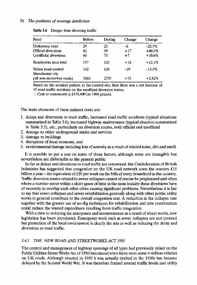
56 The problems of sewerage dereliction
Table 3.6 Danger from diverting traffic
Road Before During Change Change
Dickenson road 29 23 -6 -20.7% Official diversions 42 59 + 17 +40.5% Unofficial diversions 66 73 + 7 + 10.6%
Roadworks area total 137 155 + 18 + 13.1%
Minor road control 142 124 -19 -13.3% Manchester city (all non-motorway roads) 2660 2735 + 75 + 2.82%
Based on the accident pattern at the control site, then there was a net increase of 15 road traffic accidents on the unofficial diversion routes. .'. Cost to community is s (at 1988 prices).
The main elements of these indirect costs are:
1. delays and diversions to road traffic, increased road traffic accidents (typical situations summarised in Table 3.6), increased highway maintenance (typical situation summarised in Table 3.5), etc., particularly on diversion routes, both official and unofficial
2. damage to other underground mains and services 3. damage to buildings 4. disruption of local economy, and 5. environmental damage including loss of amenity as a result of related noise, dirt and smell.
It is possible to put a cost on some of these factors, although some are intangible but nevertheless are disbenefits to the general public.
So far as delays and diversions to road traffic are concerned, the Confederation of British Industries has suggested that congestion on the UK road network costs the country s billion a yea r - the equivalent of s per week on the bills of every household in the country. Traffic diversion routes related to sewer collapses cannot of course be preplanned and often where a number occur within a short space of time in the same locality these diversions have of necessity to overlap each other often causing significant problems. Nevertheless it is fair to say that sewer collapses and sewer rehabilitation generally along with other public utility works in general contribute to the overall congestion cost. A reduction in the collapse rate together with the greater use of no-dig techniques for rehabilitation and new construction could reduce the wasted expenditure resulting from traffic congestion.
With a view to reducing the annoyance and inconvenience as a result of street works, new legislation has been introduced. Emergency work such as sewer collapses are not covered but protection of the local environment is clearly the aim as well as reducing the delay and diversions to road traffic.
3. 4.1 THE NEW ROAD AND STREETWORKS A CT 1991
The control and management of highway openings of all types had previously relied on the Public Utilities Street Works Act of 1950 introduced when there were some 4 million vehicles on UK roads. Although enacted in 1950 it was actually drafted in the 1930s but became delayed by the Second World War. It was therefore framed around traffic levels and utility

The problem 57
usage levels which were different from those in 1950 and vastly different from those of today. These 'controls' had become increasingly inadequate to deal with the dramatic use in the levels of both traffic and works on a highway network which had only increased by some 20% since 1950 yet was having to carry some 24 million vehicles (an increase of 500%). The resultant chaos and interference with traffic flow caused by highway openings of all types- including sewerage works- could no longer be accepted.
The new legislation is intended to improve coordination between utilities and others opening the highway with the aim of reducing the consequent traffic disruption. The Act includes a number of major changes designed to minimise the impact of public utility works with particular benefit to the overloaded highway network.
It is clear that greater emphasis is being given to social and environmental considerations.
3.4.2 SEWER COLLAPSE COSTS
A typical sewer collapse account for a city-centre location might be made up as follows:
Direct costs to water company
1. Repair and reinstatement of damaged sewer and connections 2. Business loss claims under Public Health Act legislation
Indirect costs to general public, etc.
1. Losses to bus operator 2. Traffic disruption 3. Damage to other utilities plant 4. Emergency services 5. Flooding
s
45,000 177,000
, ,
222,000
10,500 82,815 90,000
2,000 70,000
255,315
Therefore, the possible cost to the water company and the public of a major sewer collapse is s
Based on the recent Manchester situation of six major collapses per year in the central area the overall costs (direct and indirect) for localised repairs are as follows:
s • 6 = s
Of course this scenario ignores the potential ever-present injury risk in such a situation. These figures are based on estimates produced for a recent socioeconomic cost-benefit analysis for a large industrial city in the north of England - not Manchester - for which the author was responsible.
3.5 The problem Engineering works do not last forever and regular maintenance works are of paramount importance if collapses, with the resultant risk of injury, are to be avoided. Unfortunately in the past sewers and culverts have not always attracted the necessary maintenance funding. Currently they are competing with other environmental matters covered by European legislation such as river and coastal pollution.
58 The problems of sewerage dereliction
It is generally accepted that the older parts of the British sewerage network are in poor structural condition, their hydraulic performance is often inadequate and they are having to carry much greater live loads than those for which they were designed. Consequently, substantial civil engineering works are undertaken each year to deal with sewers which have serious structural defects or where lack of capacity is causing river or stream pollution or flooding - often with associated public health risks. The immediate cost of these works is high, currently around s million per year, but in addition there are indirect or 'social costs' arising out of the consequential impact on the community- perhaps varying between three and even ten times, in the most critical places, the civil engineering costs. There are now indications that central government will expect the industry to move towards a cost- benefit approach and this will mean the inclusion of such social costs along with benefits.
The author has been involved in a research programme in the Department of Civil and Structural Engineering at UMIST which was aimed at developing easy-to-use models for the prediction of such indirect costs associated with different sewage rehabilitation techniques.
Age is not the only feature in classifying sewerage dereliction. Nevertheless, construction before the middle of the nineteenth century will generally indicate a very serious risk of dere- liction; much higher than for the younger parts of the network. Other significant factors include the type of road in which the sewer or culvert is situated, sub-soil conditions and the care taken in the original bedding and backfilling. There is no substitute for a proper engi- neering survey leading to a clearly identified need. On average over 15% of the British sewer- age network is over 100 years old but when the situation in the older industrial cities such as Manchester is considered, where the comparable figure is 38% (900 km), the potentially ever- present serious situation which generally exists under the older parts of such towns and cities is appreciated. Manchester, in fact, possesses the oldest extensive sewerage system in Eng- land; early forms of construction are illustrated in Fig. 2.3 in Chapter 2. Recent investigations suggest that some of the construction dates shown require amendment, usually to earlier dates. It seems that many of these early forms of sewer construction are similar to the format used under other towns and cities as they subsequently developed in the nineteenth century, so it is intended to examine the sewer developments in Manchester in some detail.
3.6 The brick sewers of Manchester
As mentioned in Chapter 2, U-shaped brick sewers appear to have been first constructed in Manchester at around 1828 and remained the most general form of sewer construction in the former Manchester township of the city (roughly the present city-centre area, together with Ancoats) until 1848. After this date, butt-jointed, egg-shaped clayware pipes became the 'standard' method of sewer construction, although it is recorded that U-shaped brick sewers continued to be constructed in the outer Manchester townships of Hulme, Chorlton- on-Medlock, Ardwick and Cheetham until about 1860. U-shaped sewers may also have been built in areas outlying the city, such as Rusholme, until well into the 1860s. Apparently, the brick U-shaped sewer type was still favoured when sewers of larger capacity were required, than could be achieved with clayware pipes.
3. 6.1 EXTENT OF THE SYSTEM
The estimate for the extent of the U-shaped sewer network in Manchester as a whole is 250 km long, which represents approximately 10% of the total sewerage system of the city. It should be noted that this figure takes account only of recorded public sewers. There are
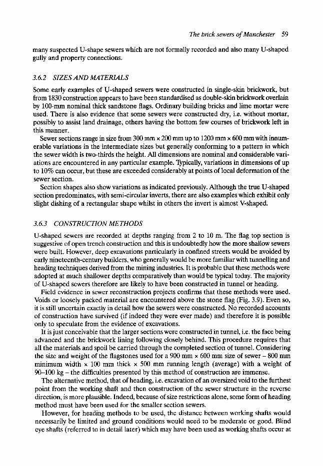
The brick sewers of Manchester 59
many suspected U-shape sewers which are not formally recorded and also many U-shaped gully and property connections.
3.6.2 SIZES AND MATERIALS
Some early examples of U-shaped sewers were constructed in single-skin brickwork, but from 1830 construction appears to have been standardised as double-skin brickwork overlain by 100-ram nominal thick sandstone flags. Ordinary building bricks and lime mortar were used. There is also evidence that some sewers were constructed dry, i.e. without mortar, possibly to assist land drainage, others having the bottom few courses of brickwork left in this manner.
Sewer sections range in size from 300 mm x 200 mm up to 1200 mm x 600 mm with innum- erable variations in the intermediate sizes but generally conforming to a pattern in which the sewer width is two-thirds the height. All dimensions are nominal and considerable vari- ations are encountered in any particular example. Typically, variations in dimensions of up to 10% can occur, but these are exceeded considerably at points of local deformation of the sewer section.
Section shapes also show variations as indicated previously. Although the true U-shaped section predominates, with semi-circular inverts, there are also examples which exhibit only slight dishing of a rectangular shape whilst in others the invert is almost V-shaped.
3. 6.3 CONSTRUCTION METHODS
U-shaped sewers are recorded at depths ranging from 2 to 10 m. The flag top section is suggestive of open trench construction and this is undoubtedly how the more shallow sewers were built. However, deep excavations particularly in confined streets would be avoided by early nineteenth-century builders, who generally would be more familiar with tunnelling and heading techniques derived from the mining industries. It is probable that these methods were adopted at much shallower depths comparatively than would be typical today. The majority of U-shaped sewers therefore are likely to have been constructed in tunnel or heading.
Field evidence in sewer reconstruction projects confirms that these methods were used. Voids or loosely packed material are encountered above the stone flag (Fig. 3.9). Even so, it is still uncertain exactly in detail how the sewers were constructed. No recorded accounts of construction have survived (if indeed they were ever made) and therefore it is possible only to speculate from the evidence of excavations.
It is just conceivable that the larger sections were constructed in tunnel, i.e. the face being advanced and the brickwork lining following closely behind. This procedure requires that all the materials and spoil be carried through the completed section of tunnel. Considering the size and weight of the flagstones used for a 900 mm x 600 mm size of sewer - 800 mm minimum width x 100 mm thick x 500 mm running length (average) with a weight of 90-100 k g - the difficulties presented by this method of construction are immense.
The alternative method, that of heading, i.e. excavation of an oversized void to the furthest point from the working shaft and then construction of the sewer structure in the reverse direction, is more plausible. Indeed, because of size restrictions alone, some form of heading method must have been used for the smaller section sewers.
However, for heading methods to be used, the distance between working shafts would necessarily be limited and ground conditions would need to be moderate or good. Blind eye shafts (referred to in detail later) which may have been used as working shafts occur at
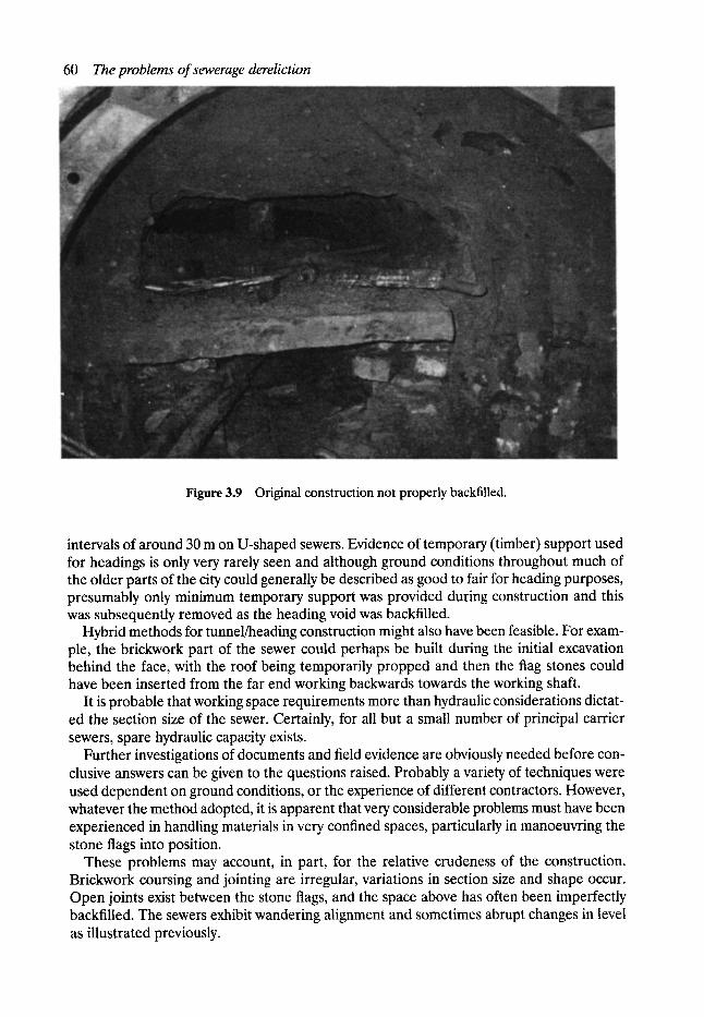
60 The problems of sewerage dereliction
Figure 3.9 Original construction not properly backffiled.
intervals of around 30 m on U-shaped sewers. Evidence of temporary (timber) support used for headings is only very rarely seen and although ground conditions throughout much of the older parts of the city could generally be described as good to fair for heading purposes, presumably only minimum temporary support was provided during construction and this was subsequently removed as the heading void was backfilled.
Hybrid methods for tunnel/heading construction might also have been feasible. For exam- ple, the brickwork part of the sewer could perhaps be built during the initial excavation behind the face, with the roof being temporarily propped and then the flag stones could have been inserted from the far end working backwards towards the working shaft.
It is probable that working space requirements more than hydraulic considerations dictat- ed the section size of the sewer. Certainly, for all but a small number of principal carrier sewers, spare hydraulic capacity exists.
Further investigations of documents and field evidence are obviously needed before con- clusive answers can be given to the questions raised. Probably a variety of techniques were used dependent on ground conditions, or the experience of different contractors. However, whatever the method adopted, it is apparent that very considerable problems must have been experienced in handling materials in very confined spaces, particularly in manoeuvring the stone flags into position.
These problems may account, in part, for the relative crudeness of the construction. Brickwork coursing and jointing are irregular, variations in section size and shape occur. Open joints exist between the stone flags, and the space above has often been imperfectly backfilled. The sewers exhibit wandering alignment and sometimes abrupt changes in level as illustrated previously.
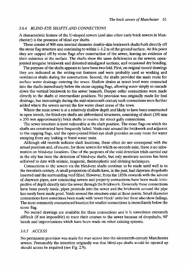
The brick sewers of Manchester 61
3.6.4 BLIND-EYE SHAFTS AND CONNECTIONS
A characteristic feature of the U-shaped sewers (and also other early brick sewers in Man- chester) is the presence of blind-eye shafts.
These consist of 900-mm internal diameter double-skin brickwork shafts built directly off the stone flag structure and continuing to within 1-1.2 m of the ground surface. At this point they are capped off by stone flags after construction of the sewer, leaving no evidence of their existence at the surface. The shafts show the same deficiencies as the sewers; open- jointed irregular brickwork and distorted misaligned sections, and occasional dry bonding.
The purpose of the shafts appears to have been two-fold. First, on original record drawings they are indicated as the setting-out features and were probably used as working and ventilation shafts during the construction. Second, the shafts provided the main route for surface water drainage entering the sewer. Shallow drains at street level were connected into the shafts immediately below the stone capping flags, allowing water simply to cascade down the vertical brickwork to the sewer beneath. Deeper cellar connections were made directly to the shafts at intermediate positions. No provision was originally made for foul drainage, but increasingly during the mid-nineteenth century such connections were further added where the sewers served the few water closet areas of the town.
Where the main sewer is at a relatively shallow depth and likely to have been constructed in open trench, the blind-eye shafts are abbreviated structures, consisting of short (350 mm x 350 mm approximately) brick shafts to receive the street gully connections.
The sewer structure is most vulnerable at the shaft position. The stone flags on which the shafts are constructed have frequently failed. Voids exist around the brickwork and adjacent to the capping flags, and the open-jointed blind-eye shaft provides an easy route for water escaping from any leaking or burst water main.
Although old records indicate shaft locations, these often do not correspond with the actual positions and, of course, for those sewers for which no records exist, there is no infor- mation on blind-eye locations. One of the purposes of the void detection trials carried out in the city has been the detection of blind-eye shafts, but only moderate success has been achieved to date with seismic, magnetic, thermoplastic and divining techniques.
Connections to the sewers via the blind-eye shafts continue to be made until well in to the twentieth century. A small proportion of shafts have, in the past, had clayware dropshafts inserted and the surrounding void filled. However, from the 1850s onwards with the advent of clayware pipes, new connecting sewers and property connections have been made irres- pective of depth directly into the sewer through the brickwork. Generally these connections have been poorly made, pipes protrude into the sewer and the brickwork around the pipe has rarely been made good. Voids around the structure exist at these points. Small diameter connections have sometimes been made with 'sewer block' units but these also show failings. The most commonly encountered location for smaller connections is immediately below the stone flag.
No record drawings are available for these connections and it is sometimes extremely difficult (if not impossible) to trace their courses to the sewer because of dropshafts, 90 ~ bends and improvisations which have been made on other existing systems.
3.6.5 ACCESS
No permanent provision was made for man access into the nineteenth-century Manchester sewers. Presumably the intention originally was that blind-eye shafts would be opened up should access be required (see Fig. 2.9).
62 The problems of sewerage dereliction
Figure 3.10 Construction of typical investigating shaft in city centre.
Since 1900, a limited number of manholes have been provided, generally these have not been located at the key junctions, but more often on the branch sewer in the side street. Some blind-eye shafts have also been converted to provide restricted access.
A programme of investigatory shaft construction was initiated in 1982 to provide access points at key junctions on the older sewers (Fig. 3.10).
Access is further impeded by the general condition of the sewers. Only a small proportion are free of silt and debris, and are free-flowing. Typically bricks, rubble and other debris lie in the invert, particularly at the base of the blind-eye shafts. The flow is disrupted so that solids are deposited. Removal of this debris is extremely difficult.
3.7 Generally The efforts of the nineteenth-century brick sewer builders should never be belittled since many of their sewers have lasted between 150 and 200 years and are still in full operational u s e .
The brick-built sewers and culverts in the UK represent a remarkable tribute to the skills, knowledge and qualities of workmanship of the nineteenth-century civil engineers and contractors. These structures have withstood the effects of time extremely well, and their present, often dilapidated condition, is due primarily to the unavoidable decay of the original lime mortar, significant changes in superimposed loading conditions, and a lack of planned or even minimal maintenance, as a result of the limited funds allocated when competing with other more socially oriented demands at budget time. The Victorians certainly built to last, but not forever!
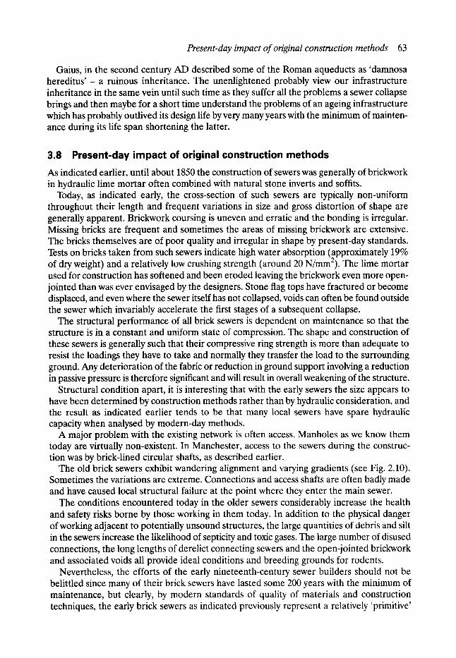
Present-day impact of original construction methods 63
Gaius, in the second century AD described some of the Roman aqueducts as 'damnosa hereditus' - a ruinous inheritance. The unenlightened probably view our infrastructure inheritance in the same vein until such time as they suffer all the problems a sewer collapse brings and then maybe for a short time understand the problems of an ageing infrastructure which has probably outlived its design life by very many years with the minimum of mainten- ance during its life span shortening the latter.
3.8 Present-day impact of original construction methods As indicated earlier, until about 1850 the construction of sewers was generally of brickwork in hydraulic lime mortar often combined with natural stone inverts and soffits.
Today, as indicated early, the cross-section of such sewers are typically non-uniform throughout their length and frequent variations in size and gross distortion of shape are generally apparent. Brickwork coursing is uneven and erratic and the bonding is irregular. Missing bricks are frequent and sometimes the areas of missing brickwork are extensive. The bricks themselves are of poor quality and irregular in shape by present-day standards. Tests on bricks taken from such sewers indicate high water absorption (approximately 19% of dry weight) and a relatively low crushing strength (around 20 N/mm2). The lime mortar used for construction has softened and been eroded leaving the brickwork even more open- jointed than was ever envisaged by the designers. Stone flag tops have fractured or become displaced, and even where the sewer itself has not collapsed, voids can often be found outside the sewer which invariably accelerate the first stages of a subsequent collapse.
The structural performance of all brick sewers is dependent on maintenance so that the structure is in a constant and uniform state of compression. The shape and construction of these sewers is generally such that their compressive ring strength is more than adequate to resist the loadings they have to take and normally they transfer the load to the surrounding ground. Any deterioration of the fabric or reduction in ground support involving a reduction in passive pressure is therefore significant and will result in overall weakening of the structure.
Structural condition apart, it is interesting that with the early sewers the size appears to have been determined by construction methods rather than by hydraulic consideration, and the result as indicated earlier tends to be that many local sewers have spare hydraulic capacity when analysed by modern-day methods.
A major problem with the existing network is often access. Manholes as we know them today are virtually non-existent. In Manchester, access to the sewers during the construc- tion was by brick-lined circular shafts, as described earlier.
The old brick sewers exhibit wandering alignment and varying gradients (see Fig. 2.10). Sometimes the variations are extreme. Connections and access shafts are often badly made and have caused local structural failure at the point where they enter the main sewer.
The conditions encountered today in the older sewers considerably increase the health and safety risks borne by those working in them today. In addition to the physical danger of working adjacent to potentially unsound structures, the large quantities of debris and silt in the sewers increase the likelihood of septicity and toxic gases. The large number of disused connections, the long lengths of derelict connecting sewers and the open-jointed brickwork and associated voids all provide ideal conditions and breeding grounds for rodents.
Nevertheless, the efforts of the early nineteenth-century sewer builders should not be belittled since many of their brick sewers have lasted some 200 years with the minimum of maintenance, but clearly, by modern standards of quality of materials and construction techniques, the early brick sewers as indicated previously represent a relatively 'primitive'
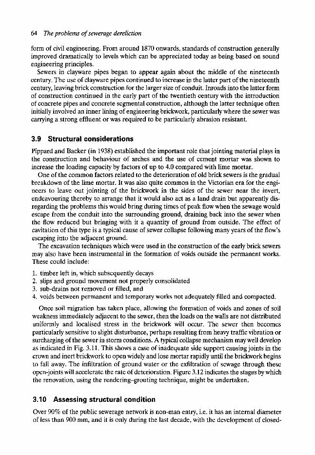
64 The problems of sewerage dereliction
form of civil engineering. From around 1870 onwards, standards of construction generally improved dramatically to levels which can be appreciated today as being based on sound engineering principles.
Sewers in clayware pipes began to appear again about the middle of the nineteenth century. The use of clayware pipes continued to increase in the latter part of the nineteenth century, leaving brick construction for the larger size of conduit. Inroads into the latter form of construction continued in the early part of the twentieth century with the introduction of concrete pipes and concrete segmental construction, although the latter technique often initially involved an inner lining of engineering brickwork, particularly where the sewer was carrying a strong effluent or was required to be particularly abrasion resistant.
3.9 Structural considerations Pippard and Backer (in 1938) established the important role that jointing material plays in the construction and behaviour of arches and the use of cement mortar was shown to increase the loading capacity by factors of up to 4.0 compared with lime mortar.
One of the common factors related to the deterioration of old brick sewers is the gradual breakdown of the lime mortar. It was also quite common in the Victorian era for the engi- neers to leave out jointing of the brickwork in the sides of the sewer near the invert, endeavouring thereby to arrange that it would also act as a land drain but apparently dis- regarding the problems this would bring during times of peak flow when the sewage would escape from the conduit into the surrounding ground, draining back into the sewer when the flow reduced but bringing with it a quantity of ground from outside. The effect of cavitation of this type is a typical cause of sewer collapse following many years of the flow's escaping into the adjacent ground.
The excavation techniques which were used in the construction of the early brick sewers may also have been instrumental in the formation of voids outside the permanent works. These could include:
1. timber left in, which subsequently decays 2. slips and ground movement not properly consolidated 3. sub-drains not removed or filled, and 4. voids between permanent and temporary works not adequately filled and compacted.
Once soil migration has taken place, allowing the formation of voids and zones of soil weakness immediately adjacent to the sewer, then the loads on the walls are not distributed uniformly and localised stress in the brickwork will occur. The sewer then becomes particularly sensitive to slight disturbance, perhaps resulting from heavy traffic vibration or surcharging of the sewer in storm conditions. A typical collapse mechanism may well develop as indicated in Fig. 3.11. This shows a case of inadequate side support causing joints in the crown and inert brickwork to open widely and lose mortar rapidly until the brickwork begins to fall away. The infiltration of ground water or the exfiltration of sewage through these open-joints will accelerate the rate of deterioration. Figure 3.12 indicates the stages by which the renovation, using the rendering-grouting technique, might be undertaken.
3.10 Assessing structural condition Over 90% of the public sewerage network is non-man entry, i.e. it has an internal diameter of less than 900 mm, and it is only during the last decade, with the development of closed-
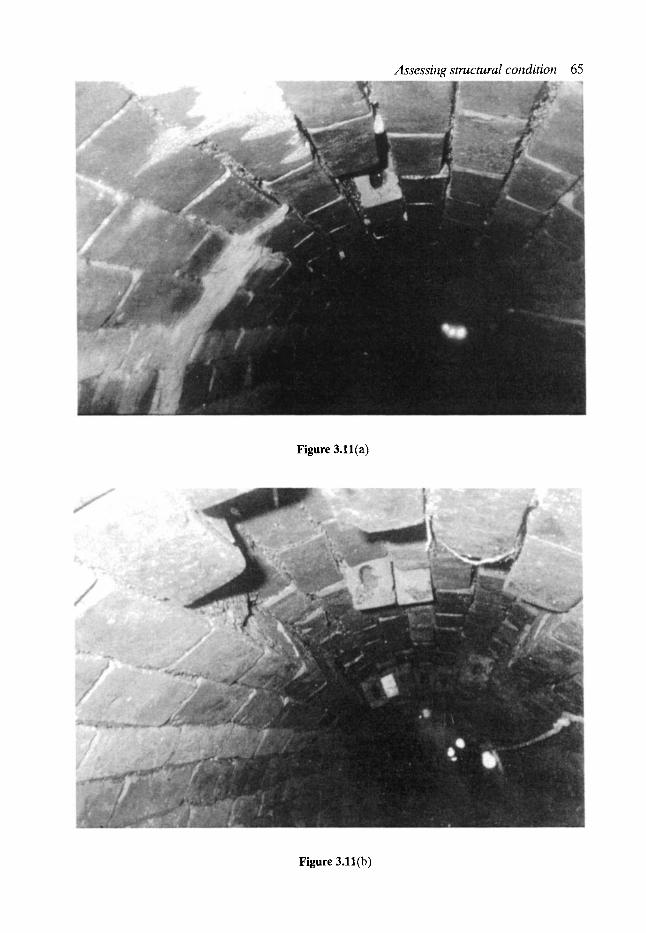
Assessing structural condition 65
Figure 3.11 (a)
Figure 3.11(b)
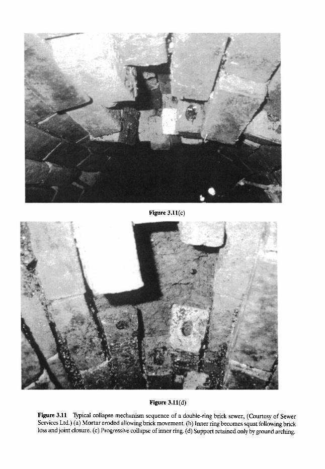
Figure 3.11(c)
Figure 3.11(d)
Figure 3.11 Typical collapse mechanism sequence of a double-ring brick sewer, (Courtesy of Sewer Services Ltd.) (a) Mortar eroded allowing brick movement. (b) Inner ring becomes squat following brick loss and joint closure. (c) Progressive collapse of inner ring. (d) Support retained only by ground arching.
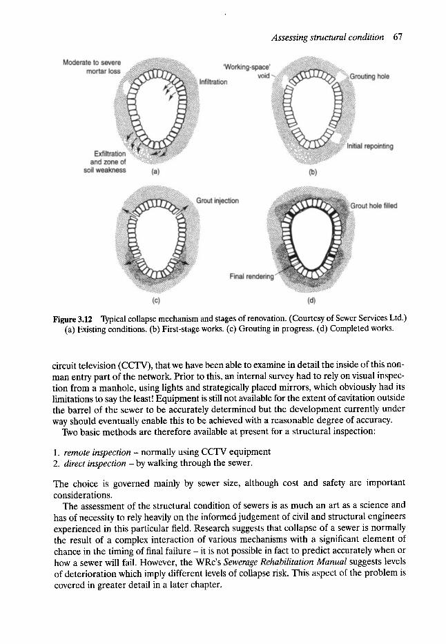
Assessing structural condition 67
Figure 3.12 Typical collapse mechanism and stages of renovation. (Courtesy of Sewer Services Ltd.) (a) Existing conditions. (b) First-stage works. (c) Grouting in progress. (d) Completed works.
circuit television (CCTV), that we have been able to examine in detail the inside of this non- man entry part of the network. Prior to this, an internal survey had to rely on visual inspec- tion from a manhole, using lights and strategically placed mirrors, which obviously had its limitations to say the least! Equipment is still not available for the extent of cavitation outside the barrel of the sewer to be accurately determined but the development currently under way should eventually enable this to be achieved with a reasonable degree of accuracy.
Two basic methods are therefore available at present for a structural inspection:
1. remote inspection - normally using CCTV equipment 2. direct inspection - by walking through the sewer.
The choice is governed mainly by sewer size, although cost and safety are important considerations.
The assessment of the structural condition of sewers is as much an art as a science and has of necessity to rely heavily on the informed judgement of civil and structural engineers experienced in this particular field. Research suggests that collapse of a sewer is normally the result of a complex interaction of various mechanisms with a significant element of chance in the timing of final failure - it is not possible in fact to predict accurately when or how a sewer will fail. However, the WRc's Sewerage Rehabilitation Manual suggests levels of deterioration which imply different levels of collapse risk. This aspect of the problem is covered in greater detail in a later chapter.

68 The problems of sewerage dereliction
3.11 Summary Much of Britain's present infrastructure- and only one element is being discussed h e r e - is part of national industrial heritage and rehabilitation of parts of it is long overdue.
It should always be remembered that it has, in practice, been an important factor in ensuring the health and prosperity of the public for a considerable period, although some of it has now become a liability which would obviously attract move positive and financial support if it were above rather than below the ground.
However, had the 'structures' been above the ground the planners may well have insured that many of them were 'listed'. In such an event Victorian and preservation societies would have been mobilised if appropriate maintenance had not been carried out and preservation societies would have pressed for funds to cover such restoration. On the other hand where replacement was necessary this would no doubt have been opposed, so perhaps things are better the way they are?

4 Planning Sewerage Rehabilitation
and Maintenance Geoffrey E Read
MSc, CEng, FICE, FlStructE, FCIWEM, FIHT, MILE, FIMgt, MAE, MUKSTT
lan G. Vickridge BSc(Eng), MSc, MICE, MCIWEM, MUKSTT
4.1 Introduction
In Chapter 3 the problems of sewer dereliction, and how they came about in the UK, have been discussed. In order to rectify these problems, the present sewerage system must be rehabilitated and brought up to acceptable standards and, in order to ensure that these problems do not recur in the future, appropriate preventative maintenance programmes must be put into operation. Both rehabilitation and maintenance must be done in the most cost-effective manner within current budgetary constraints. This requires effective strategic planning and management of both the rehabilitation and the maintenance effort.
In this chapter the general principles of both rehabilitation and maintenance management are discussed, and the rehabilitation strategy adopted in the UK is explained in detail.
4.1.1 HISTORICAL BACKGROUND TO MAINTENANCE AND REHABILITATION PLANNING
Any physical structure or artefact will have a limited life expectancy which depends on the soundness of its original construction or manufacture, the amount of use made of it, the nature of the environment in which it must work, and the amount of maintenance. Roads must be repaired and resurfaced, steel structures must be painted, bridges require strengthening if greater loads are to be sustained- and sewers must be inspected, cleaned and repaired as required if they are to perform to their full capacity. Unfortunately, many of the sewers constructed by our forefathers have not received the maintenance they deserved and, at the same time, they have had to cope with greater structural and hydraulic loads than were originally envisaged at the time of their construction.
Sewers were well out of sight and, as long as they continued to function reasonably well, they were also out of m i n d - that is, until problems, such as those described in Chapter 3, started to arise. Even then the need for effective maintenance management was not at first fully recognised. Sewer collapses, such as the spectacular one in 1957 in Fylde Street, Farnworth, Lancashire, should have provided a dramatic warning to all concerned.
Yet, when the UK water industry was reorganised in 1973, the government's background paper was preoccupied with the then-fashionable question of growing demand for water and sewerage and the problem of river pollution control - it did not mention the condition of water mains and sewers. As late as 1974, the Department of the Environment Working Party
70 Planning sewerage rehabilitation and maintenance
on Sewers and Water Mains reported only on the design of the new systems and neglected the possibility of rehabilitating existing systems.
In the late 1970s the central area of Manchester suffered a continuing series of dramatic sewer collapses and, against this potentially lethal backcloth, the E d i t o r - known inter- nationally at that time as 'the man from the holey ci ty ' -warned during television interviews, and in the press generally, that sewer deterioration was a major problem which would have to be faced by the water industry as a matter of urgency. The following is an extract from a paper (Read, 1981) presented at that time:
Without wishing to be unduly pessimistic it would seem at the present level of expenditure a losing battle is being fought and dereliction is taking place more rapidly than renewal, strengthening or maintenance can be carried out. This problem will not disappear or be solved quickly. Sanita- tion was among many of the amenities neglected in the Middle Ages and one can only hope that we are not entering an era which, due to lack of adequate finance, results in history repeating itself!
This situation was nationally recognised in 1977, when the Standing Committee for Sewers and Water Mains published a national assessment (NWC/DoE, 1977) which suggested that the nation might have serious problems of sewer dereliction. This report pointed out that there was a grave lack of information about the extent and condition of the systems, and gave alarmingly high estimates for the cost of renewal.
The national assessment prompted many branches of the industry to endeavour to quantify the scale of the sewerage problems and to develop ways of significantly extending the operational life of the existing system. The immediate reaction to the report was to initiate research aimed at producing a national strategy to ensure that the money available for the preservation of Britain's sewers would be spent as effectively as possible. To this end a research programme was undertaken by engineers at the Water Research Centre (WRc), the aim being to investigate the properties of available renovation techniques, help develop new ideas, and advise on the advantages of actively participating in the strategy.
It was at about this time that severe structural problems began to be even more apparent. In the north-west of England, for example, coincidentally following one of the worst droughts of the century in 1976, widespread reports of blockages and collapses began to occur. By 1978, after a particularly major collapse, the then city engineer of Manchester, Geoffrey Read, coined the now well-known unit of measurement the DDB (double-decker bus) - to indicate the volume of a cavity or crater resulting from a collapse, as mentioned earlier. It was intended to be a graphic and easily understood description of the size of the hole.
Clearly, structural problems were building u p - see Anderson and Cullen's (1982) report on the collapses and blockages study that WRc commenced in 1978. A systematic approach to the problem had begun to evolve in Manchester at that time, as reported by Read (1981). This approach was in fact not dissimilar to the strategy subsequently recommended by the WRc in the Sewerage Rehabilitation Manual (SRM).
In the past, policy, dictated by the availability of finance, had allowed events to determine the priorities for action. In other words, only nominal resources were allocated for investi- gation and maintenance, and major incidents such as collapses were dealt with as they happened. Such crisis-oriented works were essentially of an emergency nature, in which costs and resources were not predicted or effectively managed, thus giving overall poor value for money. The results of such an approach were that the extent of the particular problem was never fully recognised. For the civil engineer, the basic objection to this thinking was that it completely contravened the principle of planned and efficient use of resources. It was clear in the light of the collapse situation then developing, that the 'crisis' approach to the problem
Maintenance strategies 71
must give way to a pre-emptive approach. Furthermore, it also became apparent that reconstruction must give way to repair, renovation, and in certain circumstances renewal.
The WRc's initial research culminated in 1984, when the first edition of the SRM (WRc, 1984) was published. This signalled the beginning of strategic rehabilitation planning in the UK.
Roughly at about this time, similar problems were noted in sewerage systems in many other parts of the world. In some cases the concerns were slightly different to those expressed in the UK. In North America and Australia, for example, the main consideration was that of controlling infiltration into sewers, whilst in the Middle East major problems associated with corrosion of sewers had been noted. This world-wide concern has lead to a much greater awareness of the need for effective monitoring and management of sewer systems and hence to the development of maintenance and rehabilitation management systems and strategies appropriate to specific locations.
4.2 Maintenance strategies Failure of a sewerage system may result in flooding of properties and streets, unnecessarily high flow rates in the sewer as a consequence of infiltration, pollution of watercourses or groundwater, or widespread disruption resulting from collapse of a sewer. The cause of failure might include obstructions, blockages, leaks, infiltration, cracks, abrasion, corrosion, fractures and collapses. In order to minimise these problems, and the inherent cost of rectifying them, it is essential that a rational sewerage maintenance strategy is developed. In order to use limited resources to their greatest effect, such a strategy needs to clearly define methods for the prioritisation of both fault identification procedures and maintenance operations.
However, before this can be done, a complete, accurate, and up-to-date set of drawings and records of the system is required. In many cases this information is incomplete or inaccurate, and therefore the first step in formulating a maintenance strategy may be to check the completeness and accuracy of existing records and, if necessary, carry out a survey of those parts of the system where records are suspect. Details of sewer surveys are given in Chapter 5.
4.2.1 FAULT IDENTIFICATION PROCEDURES
Once reliable records have been established, routine inspection of all components of a sewerage system should be carried out on a regular basis, and a systematic method of report- ing and recording such inspections should be developed. In designing a system for recording inspections, a serious attempt should be made to quantify the condition of all components. In the case of electromechanical equipment, this could entail measuring parameters such as pressure. For static structures, such as wet wells, manholes and pipes, a procedure for coding faults and defects might well be adopted.
For example, sewer faults and defects which can be identified through closed-circuit television (CCTV) inspections might include:
�9 cracks- longitudinal and circumferential �9 collapses �9 displaced bricks �9 broken pipes
72 Planning sewerage rehabilitation and maintenance
�9 defective and displaced joints �9 evidence of abrasion or corrosion �9 siltation �9 encrustation �9 root penetration �9 loss of mortar �9 deformations �9 infiltration �9 all lateral connections and their degree of penetration.
Flow surveys and computer simulation of the hydraulics of a sewerage system may also help to identify leaks and points of infiltration, thus giving an indication of the existence of cracks, bad joints, and collapses in the pipe network.
From an analysis of the survey reports 'scores' can be allocated to each type of defect, and then aggregated in order to assign condition grades to each length of sewer. This quantitative record of the condition of each part of the system can subsequently be used to compare the condition with that assessed in future surveys. Hence rates of deterioration can be monitored and this information can be used to determine maintenance priorities.
It is now generally more convenient to store the data from inspection reports in a computerised database, which can then form an integral part of an overall maintenance management system. Further details of maintenance management systems are given in the appropriate section later in this chapter.
4.2.2 PLANNING SEWER INSPECTION PROGRAMMES
Sewer surveys are not cheap, and it is therefore neither possible nor cost-effective to carry them out too frequently. Some sections may need more frequent monitoring than others and therefore, as with maintenance itself, it is often necessary to set priorities for inspection. Methods for the identification of those elements of the sewer network which need inspecting most, and for determining the frequency of inspection, are thus required.
There are two major questions which need to be asked when planning a sewer inspection programme:
�9 What is the risk or likelihood of a particular section of the network failing? �9 What would be the effects or consequences of such a failure?
The risk of failure will depend on certain key characteristics of the section of the network being assessed, including the pipe material, the location within the network, the age of the pipe, the type of bedding and support, characteristics of the surrounding soil and water table, the imposed loads, the present and anticipated flow rates, the diameter and thickness of the pipe, and any history of failures in the vicinity or in other similar section of pipe within the network.
The consequences of failure will include the degree and extent of flooding likely to occur, possible pollution of watercourses and groundwater, interference with other sections of the sewerage network and sewage treatment facilities downstream, and, in the case of sewer collapses, disruption to traffic, commerce, other utilities and any further activity in the area of the collapse.
Both the risk and the consequences of failure need to be considered when setting priorities for sewer inspection. In order to do this in a logical and rational manner, a system of

Maintenance strategies 73
allocating points to every length of pipe within the network can be adopted. A range of points can be assigned to each factor affecting both the risk and the consequences of failure, and then a total score can be calculated for each pipe length within the network. For example, sewers under main roads or in busy shopping areas would warrant a higher score than those under minor roads, and asbestos cement, large diameter, trunk sewers would attract a higher score than small diameter PVC pipes serving only a few properties. A knowledge of the age, size and pipe materials is required to do this. This process, as outlined in the WRc's Sewer Rehabilitation Manual and described in more detail later in this chapter, is referred to as the identification of the 'critical' sewers.
A programme of inspection can then be drawn up on the basis of the scores and the inspection resources and budget available.
4.2.3 P L A N N I N G S E W E R M A I N T E N A N C E P R O G R A M M E S
The purpose of a strategic maintenance plan or programme is to ensure continuous and effective operation of the entire sewerage system at the lowest cost commensurate with these objectives. Reactive, or crisis, maintenance - that is dealing with faults and breakdowns only - is rarely cost-effective in the long-term.
A complete and accurate set of detailed records (preferably stored in a computer database) of the system is required before attempting to develop a strategic maintenance programme. These records should be as comprehensive as possible and should contain at least the following information relating to each component in the system:
�9 name and unique identification mark �9 accurate geographic information including exact location on plan and elevation, relevant
information on each component of the system. For pipelines this should include the diameter, thickness, material, jointing method, type of bedding and support, and details of any coating, lining or other corrosion protection provided. Records for mechanical/ electrical equipment and plant might include details normally supplied by the manufac- turer, such as power rating, voltage, operating pressures and temperatures, type of lubri- cants required, etc.
�9 historical informat ion- this should include any previous failures, faults or problems, results of surveys and inspections, and details of any previous maintenance work carried o u t
�9 other information on soil conditions, water table, traffic flow, strategic importance of roads, etc.
The structure of the database should allow for easy updating of the records in order that future faults, maintenance and changes to the system can be included as and when they occur. The purpose of the database is to assist in identifying potential problems and prioritis- ing maintenance activities.
A hierarchy of maintenance operations can be identified such that failure to carry out work at one level will often lead to the need to carry out work at a higher and more expensive level at a later date.
A simple hierarchy for sewer maintenance might be defined as follows:
�9 Level 1 - routine and periodic cleaning (pre-emptive). If this is not carried out it may lead to level 2 maintenance requirements.
�9 Level 2 - unblocking pipes (reactive).
74 Planning sewerage rehabilitation and maintenance
�9 Level 3 - Local repair and root control (pre-emptive with the need being identified through sewer inspections). If this is not done it may lead to level 4 maintenance.
�9 Level 4 - relining. Failure to reline when required could lead to collapse and the need to completely replace the pipe (level 5).
�9 Level 5 - replacement.
A strategic maintenance programme should seek to identify the required frequency of each level of maintenance to minimise overall costs. This will be highly dependent on local conditions, and knowledge must be built up over time, amending the strategy as conditions dictate. For example, if more material is removed from a given sewer-cleaning operation than from the previous one on the same length of pipe, the period between cleanings should be shortened. This emphasises the need to keep accurate records of all maintenance activities in order that this type of informed decision can be made.
In addition to a database of accurate records of the system, a set of criteria, against which various maintenance options may be assessed is required. These criteria might include goals and objectives together with details of the effectiveness of different maintenance operations. Such a database can be linked to decision criteria in a fully computerised maintenance management system.
4.3 Rehabilitation strategies A maintenance management strategy or programme is required to ensure that a sewerage system continues to effectively perform its intended function. However, the problem facing many drainage engineers throughout the world is not so much that of ensuring that the system continues to perform effectively, but that of upgrading or rehabilitating a system which has become sub-standard as a result of many years of neglect. To do this an efficient and realistic rehabilitation strategy needs to be developed.
As mentioned previously, 1984 saw the publication in the UK of the WRc's SRM which set out a clear and logical approach to the planning of rehabilitation programmes. The recommended strategy was based on concentrating rehabilitation efforts on those sewers where collapse repairs would be very expensive or disruptive to the community at large - the critical sewers. Pre-emptive maintenance on these sewers would greatly reduce the risk of such failures recurring and could be shown to be cost-effective. It was accepted that failures would nevertheless recur in the non-critical sewers, but it was claimed that the cost of rehabilitation following failure would be relatively cheap and non-disruptive, and therefore surveys and pre-emptive action would not be justified. For the non-critical sewers the view was taken that the response to failure or crisis maintenance was the most cost- effective s t ra tegy- a view perhaps not shared by the people affected.
The identification of these critical sewers in this strategy is based mainly on an assessment of the consequences of a collapse and not merely on the risk of such an event. The criticality of any sewer is therefore, in practical terms, a combination of the risk of failure and the consequences of it.
The relative size of the critical and non-critical elements of the network varies from town to town, but generally, in the UK, they are of the order of 25% and 75% of the total network respectively, although in larger cities such as Manchester, the proportion is more likely to be of the order of 40% and 60%.
The aim of the SRM sewerage rehabilitation strategy is therefore to maintain the critical sewers in a failure-free condition, whilst leaving the non-critical ones to be dealt with as
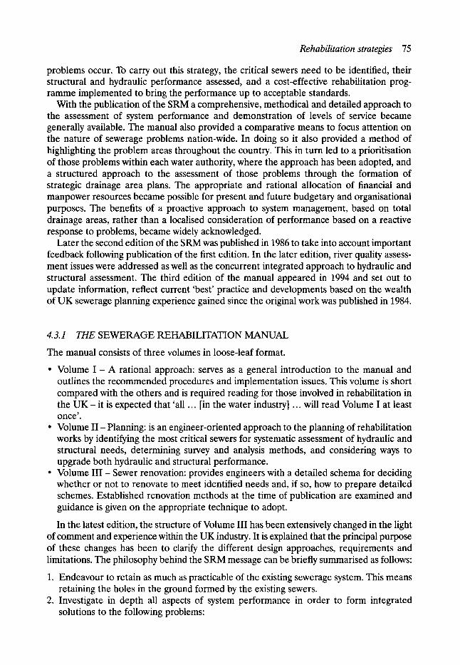
Rehabilitation strategies 75
problems occur. To carry out this strategy, the critical sewers need to be identified, their structural and hydraulic performance assessed, and a cost-effective rehabilitation prog- ramme implemented to bring the performance up to acceptable standards.
With the publication of the SRM a comprehensive, methodical and detailed approach to the assessment of system performance and demonstration of levels of service became generally available. The manual also provided a comparative means to focus attention on the nature of sewerage problems nation-wide. In doing so it also provided a method of highlighting the problem areas throughout the country. This in turn led to a prioritisation of those problems within each water authority, where the approach has been adopted, and a structured approach to the assessment of those problems through the formation of strategic drainage area plans. The appropriate and rational allocation of financial and manpower resources became possible for present and future budgetary and organisational purposes. The benefits of a proactive approach to system management, based on total drainage areas, rather than a localised consideration of performance based on a reactive response to problems, became widely acknowledged.
Later the second edition of the SRM was published in 1986 to take into account important feedback following publication of the first edition. In the later edition, river quality assess- ment issues were addressed as well as the concurrent integrated approach to hydraulic and structural assessment. The third edition of the manual appeared in 1994 and set out to update information, reflect current 'best' practice and developments based on the wealth of UK sewerage planning experience gained since the original work was published in 1984.
4.3.1 THE SEWERAGE REHABILITATION MANUAL
The manual consists of three volumes in loose-leaf format.
�9 Volume I - A rational approach: serves as a general introduction to the manual and outlines the recommended procedures and implementation issues. This volume is short compared with the others and is required reading for those involved in rehabilitation in the U K - it is expected that 'all ... [in the water industry] ... will read Volume I at least once'.
�9 Volume II - Planning: is an engineer-oriented approach to the planning of rehabilitation works by identifying the most critical sewers for systematic assessment of hydraulic and structural needs, determining survey and analysis methods, and considering ways to upgrade both hydraulic and structural performance.
�9 Volume III - Sewer renovation: provides engineers with a detailed schema for deciding whether or not to renovate to meet identified needs and, if so, how to prepare detailed schemes. Established renovation methods at the time of publication are examined and guidance is given on the appropriate technique to adopt.
In the latest edition, the structure of Volume III has been extensively changed in the light of comment and experience within the UK industry. It is explained that the principal purpose of these changes has been to clarify the different design approaches, requirements and limitations. The philosophy behind the SRM message can be briefly summarised as follows:
1. Endeavour to retain as much as practicable of the existing sewerage system. This means retaining the holes in the ground formed by the existing sewers.
2. Investigate in depth all aspects of system performance in order to form integrated solutions to the following problems"
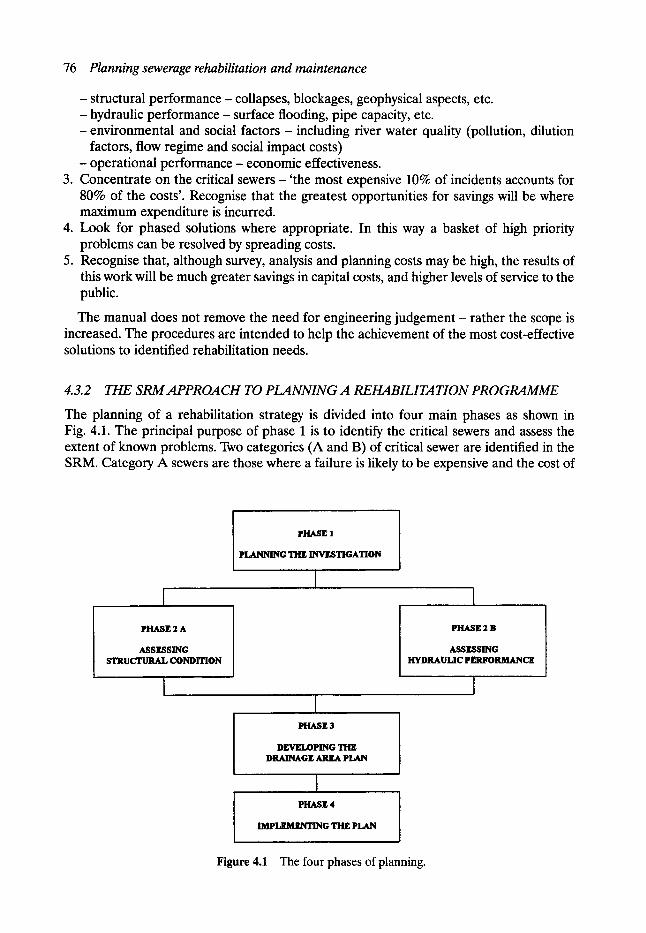
76 Planning sewerage rehabilitation and maintenance
-structural performance- collapses, blockages, geophysical aspects, etc. - hydraulic performance- surface flooding, pipe capacity, etc. -environmental and social factors - including river water quality (pollution, dilution
factors, flow regime and social impact costs) - operational performance - economic effectiveness.
3. Concentrate on the critical sewers- 'the most expensive 10% of incidents accounts for 80% of the costs'. Recognise that the greatest opportunities for savings will be where maximum expenditure is incurred.
4. Look for phased solutions where appropriate. In this way a basket of high priority problems can be resolved by spreading costs.
5. Recognise that, although survey, analysis and planning costs may be high, the results of this work will be much greater savings in capital costs, and higher levels of service to the public.
The manual does not remove the need for engineering judgement - rather the scope is increased. The procedures are intended to help the achievement of the most cost-effective solutions to identified rehabilitation needs.
4.3.2 THE SRMAPPROACH TO PLANNING A REHABILITATION PROGRAMME
The planning of a rehabilitation strategy is divided into four main phases as shown in Fig. 4.1. The principal purpose of phase 1 is to identify the critical sewers and assess the extent of known problems. Two categories (A and B) of critical sewer are identified in the SRM. Category A sewers are those where a failure is likely to be expensive and the cost of
PHASE 2 A
ASSESSING STRUCTURAL CONDITION
PHASE 1
PLANNING THE INVESTIGATION
I
| PHASE 3
DEVELOPING THE DRAINAGE AREA PLAN
I PHASE 4
IMPLEMENTING THE PLAN
PHASE 2 B
ASSESSING HYDRAULIC PERF'ORMANCE
Figure 4.1 The four phases of planning.
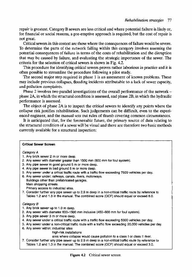
Rehabilitation strategies 77
repair is greatest. Category B sewers are less critical and where potential failure is likely or, for financial or social reasons, a pre-emptive approach is required, but the cost of repair is not great.
Critical sewers in this context are those where the consequences of failure would be severe. To determine the parts of the network falling within this category involves assessing the potential consequences of failure in terms of the costs of rehabilitation and the disruption that may be caused by failure, and evaluating the strategic importance of the sewer. The criteria for the selection of critical sewers is shown in Fig. 4.2.
This procedure for identifying critical sewers proves rather laborious in practice and it is often possible to streamline the procedure following a pilot study.
The second major step required in phase 1 is an assessment of known problems. These may include previous collapses, flooding incidents attributable to a lack of sewer capacity, and pollution complaints.
Phase 2 involves two parallel investigations of the overall performance of the network- phase 2A, in which the structural condition is assessed, and phase 2B, in which the hydraulic performance is assessed.
The object of phase 2A is to inspect the critical sewers to identify any points where the collapse risk justifies rehabilitation. Such judgements can be difficult, even to the experi- enced engineer, and the manual sets out rules of thumb covering common circumstances.
It is anticipated that, for the foreseeable future, the primary source of data relating to the structural condition of a sewer will be visual and there are therefore two basic methods currently available for a structural inspection:
Critical Sewer Screen
Category A I. Any brick sewer 2 m or more deep. 2. Any sewer with diameter greater than 1500 mm (600 mm for foul system). 3. Any pipe sewer in good ground 6 m or more deep. 4. Any pipe sewer in bad ground 5 m or more deep. 5. Any sewer under a critical traffic route with a traffic flow exceeding 7500 vehicles per day. 6. Any sewer under: railways, canals, rivers, motorways.
Buildings other than prefabricated garages. Main shopping streets. Primary access to industrial sites.
7. Consider further any pipe sewer up to 2.9 m deep in a non-critical traffic route by reference to Tables 1.2 and 1.3 in the manual. The combined score (OCF) should equal or exceed 6.0.
Category B 1. Any brick sewer up to 1.0 m deep. 2. Any sewer with diameter 600-1500 mm inclusive (450-600 mm for foul system). 3. Any pipe sewer 3 m or more deep. 4. Any sewer under a critical traffic route with a traffic flow exceeding 5000 vehicles per day. 5. Any sewer under a non-critical traffic route with a traffic flow exceeding 20,000 vehicles per day. 6. Any sewer within: industrial sites
high-risk installations area where collapse would cause pollution to a class I or class II river.
7. Consider further any pipe sewer up to 2.9 m deep in a non-critical traffic route by reference to Tables 1.2 and 1.3 in the manual. The combined score (OCF) should equal or exceed 3.0.
Figure 4.2 Critical sewer screen.
78 Planning sewerage rehabilitation and maintenance
�9 remote inspection- normally using CCTV equipment �9 direct inspection - by walking through the sewer.
The choice is governed mainly by sewer size, cost and safety considerations- further information is given in Chapter 5.
Although structural assessment of the condition of sewers is often seen as much of an art as a science, the photographic chart and guidance notes provided in the manual, make it a relatively straightforward procedure for the experienced drainage engineer. The subject of structural assessment is addressed in greater detail in Chapter 12.
The object of phase 2B is to assess the hydraulic performance of the critical sewers in their current form and to identify the causes of substandard performance. It should be noted that the rationalisation of storm overflows, to alleviate pollution of the receiving watercourse, can significantly change loads on to the sewer network and it is essential that the perfor- mance of the whole network is fully understood. Large-scale future developments which would drain to the existing system should also be considered.
Hydraulic assessment, in the context of sewerage rehabilitation, normally now involves the use of a mathematical model to assess the current hydraulic performance of the system, to examine the effects of the proposed structural upgrading measures, and to identify the overall characteristics of the system needed to attain specified performance criteria. A number of such models are now available and, among the most commonly used in the UK, are the WALLRUS model, developed by Hydraulic Research of Wallingford, and the MicroDrainage program, which are dealt with in Chapter 8.
To ensure the theoretical modelling technique is truly realistic it must be verified in relation to the actual flow characteristics by comparing the model's predictions with the actual measured response of the system to observed rainfall events. This calls for both flow and rainfall surveys. If a significant mismatch occurs, the cause may not always be obvious, but the extent of the area causing the problem, and hence requiring further investigation, can be identified. A most important part of the verification process comprises a comparison of predicted sewer surcharge and flooding with historical records. If the model predicts flooding which has not been previously recorded, then extensive field checks should be made by questioning residents. Once a model has been verified by actual flow and rainfall measurements it can be used to assess the performance of each critical sewer and to identify the direct cause of any performance problems.
The reader is referred to Chapter 8 for further details of hydraulic assessment. With the completion of phase 2B, the investigation will have yielded a list of identified
structural and hydraulic problems and clues as to their likely solution. The object of phase 3 is to develop an outline set of rehabilitation proposals which deal
with all identified problems and also give economy in construction and ease division of the work into stages. Because each rehabilitation technique can be expected to have a different life expectancy, some consideration must be given to the anticipated life of the renovated sewer and an estimate of the whole life costs must be made. The manual provides only elementary guidance on this, in the form of tables and graphs.
At the end of phase 3 there will exist an outline plan - the drainage area plan - covering all the works needed to improve the condition and performance of the critical sewers in the network.
The purpose of phase 4 is to put the plan into effect. This involves two parallel lines of acti- vity- the detailed design and construction of rehabilitation works, and the monitoring of the hydraulic performance - the object here being to ensure that the plan remains appropriate.

Rehabilitation strategies 79
4.3.3 COSTS AND BENEFITS OF USING THE SRMAPPROACH
The basic philosophy of the SRM strategy is to provide an acceptable service at least cost by using resources as efficiently as possibly. It is claimed that cost savings will result from the simultaneous upgrading of the three aspects of performance - structural, hydraulic and operational - and the optimal use of recently developed technology.
Application of the procedures set out in the manual should result in a reduction in the costs of the following works:
�9 collapse repairs (including associated compensation and social costs) �9 flood alleviation works; and �9 work required to achieve water quality objectives.
It has been suggested that detailed studies and the development of drainage areas plans as advocated in the SRM can result in rehabilitation solutions which are 20-30% cheaper than those produced by more conventional or 'traditional' planning methods, which were essentially reactive in nature and based on repairing the most structurally defective sewers as and when required rather than considering the 'critical' sewers first. Based on the report by Bamwell and Fiddes (1987) the mean capital cost of normal rehabilitation works for drainage areas serving populations of about 100,000 would lie in the range of s million to s million.
From these figures it would appear that the savings which would ensue from using drainage area studies of the type covered in the manual would be in the range of s million to s million.
Table 4.1 shows some savings from Barnwell and Fiddes' (1987) report. These reported cost savings need, of course, to be set against the actual cost of carrying
out the drainage areas study in the first place. The cost of these studies will depend on a number of factors, the main ones being as follows:
�9 the size of the catchment �9 the amount of work involved in checking and upgrading the sewer records �9 the lengths of critical sewers to be surveyed �9 the performance of the sewerage system (frequency and amount of surcharge) �9 complexity of the system.
It has been estimated by Perfect and Aikman (1991) that the overall cost of preparing a drainage area plan for a drainage area of around 1500 ha with a population of about 100,000 is likely to be of the order of s to s depending for example on the completeness of the sewerage record plans. A comparison of these costs with the estimated savings outlined above indicate that the costs of drainage area studies can therefore easily be justified.
Table 4.1 Savings in SRM case studies
Case study 'Traditional' solution i
'SRM' solution
York s m s m Torquay s m s m Crawley s k s k

80 Planning sewerage rehabilitation and maintenance
4.3. 4 APPLICATION AND LIMITATION OF THE SRM APPROA CH
The SRM, and its suggested strategy, was written for the UK where it has found wide application for both old and new sewerage systems and for a wide variety of different-sized towns and cities. The assembly of rehabilitation knowledge presented in the manual provides ample means by which drainage engineers can methodically approach the problems of sewer system management through the integrated assessment of hydraulic, structural and operational performance. Although the SRM presents a strategy for rehabilitation in the UK, its principles and philosophies could be used as a starting point for the overall management of sewerage systems in other parts of the world, and be applicable at any stage in their development.
However, even though the general methodological approach may be seen as widely applic- able, it is important to recognise that it should be local in its implementation. For example, in some cases, such as Manchester, the accent in the implementation of the strategy has been on the avoidance of major collapses of sewers, whereas in other situations the major consider- ation may be the avoidance of infiltration or the reduction of pollution of local watercourses.
It is also important to recognise that the strategy is based on the concept of critical and non-critical sewers and that the strategy for non-critical sewers is to rely on crisis main- tenance which may not be a6ceptable in some environments. The SRM approach is thus essentially one of rehabilitation management rather than a fully comprehensive preventa- tive maintenance management strategy. It is hoped that as the UK water industry comes to terms with the problem of renovating the existing sewerage network, nationally accepted strategies for cost-effective solutions can be adopted earlier, rather then later, in the life of the structures and systems.
4.4 Computerised maintenance management systems The key to effective management of maintenance is access to comprehensive and relevant data without which it is practically impossible to determine the most cost-effective mainten- ance operations and when to carry them out. Effective use can now be made of computerised databases to store and, perhaps more importantly, retrieve all the data necessary to make informed decisions on maintenance interventions. A number of software packages are now available which have been specifically designed for the storage of data relating to sewerage networks, and these are explained in greater detail in Chapter 5.
However, data alone do not make a management strategy- they can merely be used in helping to make decisions within current budgetary policy or legal constraints. Only some of the maintenance needs can be addressed at any one time and therefore these needs must be ranked in order of priority. An accepted set of criteria against which each requirement can be assessed is thus required. These 'decision criteria' may be ones developed intuitively by experienced engineering managers or they can be more formalised within a maintenance management system, which may or may not be computerised.
The SRM critical sewer screen, outlined earlier in this chapter, is in effect a set of decision criteria designed to select those sewers most warranting further attention. Although this screening can be done manually, the process can be quicker and more accurate if done by a computer, as long as all the necessary data are available and can be assessed.
In order to develop a maintenance plan it is not only necessary to identify which parts of the system are most critical or most in need of attention, but also to determine the most technically appropriate and cost-effective method of resolving the problem. This too requires
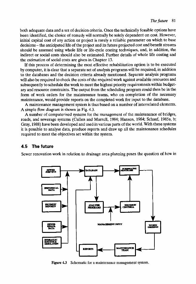
Thefuture 81
both adequate data and a set of decision criteria. Once the technically feasible options have been identified, the choice of remedy will normally be solely dependent on cost. However, initial capital cost of any action or project is rarely a reliable parameter on which to base decisions- the anticipated life of the project and its future projected cost and benefit streams should be assessed using whole life or life-cycle costing techniques, and, in addition, the indirect or social costs should also be estimated. Further details of whole life costing and the estimation of social costs are given in Chapter 13.
If this process of determining the most effective rehabilitation option is to be executed by computer, it is clear that a separate set of analysis programs will be required, in addition to the databases and the decision criteria already mentioned. Separate analysis programs will also be required to check the costs of the required work against available resources and subsequently to schedule the work to meet the highest priority requirements within budget- ary and resource constraints. The output from the scheduling program could then be in the form of work orders for the maintenance teams, who on completion of the necessary maintenance, would provide reports on the completed work for input to the database.
A maintenance management system is thus based on a number of interrelated elements. A simple flow diagram is shown in Fig. 4.3.
A number of computerised systems for the management of the maintenance of bridges, roads, and sewerage systems (Cullen and Murrell, 1984; Hansen, 1984; Schaaf, 1985a, b; Gray, 1988) have been developed and used in various parts of the world. With these systems it is possible to analyse data, produce reports and draw up all the maintenance schedules required to meet the objectives set within the system.
4.5 The future Sewer renovation work in relation to drainage area planning poses the question of how in
i i i
8URVgY8
I lllS'IOll/CAL DATA - ~ D
DATA
f----I Dir, CIQON
ii
~v
iiii
!-" ! l~kltgrl~l/g~z I _..~, ....
Figure 4.3 Schematic for a maintenance management system.

82 Planning sewerage rehabilitation and maintenance
the following century the system can be further renovated economically. It is likely that for economic reasons some form of renovation treatment will continue in order to retain the valuable 'hole in the ground' concept and avoid costly reconstruction. However, further reduction in the size of the sewer will probably recur in the process, and the question of how many times a sewer can be renovated must be addressed. A key aspect in this respect will be greater use of either on-line or off-line storage in order to improve hydraulic performance. Flow attenuation by provision of storage might be further improved by real- time operation of such storage, using computer-controlled penstocks in association with flow forecasts from telemetry rain gauges or weather radar.
It is inevitable that new, stronger and more durable materials and methods will be developed which will have an impact on the planning of rehabilitation and maintenance - not least in terms of the changes in material life expectancy and the consequent effect on life-cycle costs.
Perhaps the greatest impact, certainly in the short-term, will be developments in information technology. New methods for gathering information, such as ground-probing radar and infrared thermography, could lead to the ability to produce a three-dimensional map of the underground space beneath a street in the time it takes to drive a survey vehicle along the road. Developments in digital mapping and geographic information systems will mean much more accurate and accessible records of our underground utilities and the surrounding soil structure.
Flow characteristics of sewerage systems and watercourses may be continuously moni- tored and fed directly into databases, flow-simulation programs, management maintenance systems or other appropriate software, making real time management of sewer networks a genuine possibility.
It is likely that water quality simulation models will be used to a greater extent in order to fully examine the interrelationship between the river system and the sewerage system thereby minimising the potential impact of pollution. Continuous water quality monitoring is also a possibility, further enhancing the power of real-time operation of sewer systems.
The growth of urban traffic and the general public's growing awareness of environmental issues will probably lead to a much greater concern over the disruption caused by sewerage maintenance work. This will lead to social costs rather than direct costs becoming the dominant criteria for selecting renovation techniques and will thus have an impact on the management of sewerage systems. This may in turn steer new agencies and other authorities responsible for the installation and operation of underground utilities. The future may be in the overall management of all underground utilities rather than in the management of sewerage systems alone which will produce new and greater challenges for the manager of rehabilitation and maintenance operations.
References Anderson, D. and Cullen, N. Sewer failures 1981 - the full year. WRc Extemal Report No. 73E, WRc
Engineering, August, 1982. BamweU, E and Fiddes, D. The north west sewerage rehabilitation review. Institution of Water and
Environmental Management Conference, 1987. Cullen, N. and Murrell, M. Knowledge is power - developments in sewer management information
systems. International Conference on the Planning, Construction, Maintenance, and Operation of Sewerage Systems. BHRA, The Fluid Engineering Centre, 1984.

References 83
Gray, Jonathon P. Computer package helps city manage sewer system. Public Works, October, 1988. Hansen, Robert J. Wastewater collection maintenance management system. International Conference
on the Planning, Construction, Maintenance, and Operation of Sewerage Systems. BHRA, The Fluid Engineering Centre, 1984.
NWC/DoE. Sewers and water mains - a national assessment. NWC/DoE Standing Technical Commit- tee Report No. 4, NWC, June, 1977.
Perfect, H. G. and Aikrnan, D. I. Drainage area planning: from the Pennines to the sea. Municipal Engineer, Institution of Civil Engineers, April, 1991.
Read, Geoffrey E Sewer dereliction and renovation - an industrial city's view. Repair of Sewerage Systems Conference, Institution of Civil Engineers, London, 1981.
Schaaf, J. R. Computerization of sewer maintenance scheduling Part 2 - preliminary results. Public Works, Vol. 116, part 10, October, 1985b.
Schaaf, J. R. Computerization of sewer maintenance scheduling. Part 1 - principles of operation. Public Works, Vol. 116, part 9, September, 1985a.
Water Research Centre/Water Authorities Association. Sewerage Rehabilitation Manual. WRc/WAA, 1984.
5 Sewer Surveys
lan G. Vickridge BSc, MSc, MICE, MCIWEM, MUKSTT
Dimitri Leont id is* BEng, MSc
5.1 Introduction The development of underground water, gas, electricity, telecommunications and sewerage networks, over many years has resulted in underground congestion, especially beneath urban streets, at depths of between 1 and 4 m. Information on the condition of sewers is often not available and, in many cases, even the location of sewers and other public utility equipment is not known.
It is clearly very important to have up-to-date information on the condition of sewers in order to develop a cost-effective maintenance and rehabilitation strategy. The internal condition of the larger pipes can be assessed by man-entry inspection techniques and, until the 1960s this was the only method available. However now, as a result of the evolution of closed-circuit television (CCTV) technology, inspection of even the smallest pipes is possible. Moreover this kind of inspection is safer, more accurate and cheaper than man-entry surveys. Any assessment of the external condition of the sewer and the surrounding ground is more difficult, although techniques such as infrared thermography may have potential applica- tion to this problem.
It is equally important to know the location of all underground public utility equipment for planning, designing and implementing any rehabilitation or new construction works. Most utility companies possess plans containing basic information on their respective networks, but they are not always sufficiently accurate to ensure that damage will not be done during the course of rehabilitation of other nearby mains. Further, the information often only locates the services in two dimensions in the form of a line on a plan or map. The third dimension- depth - is critically important when attempting to use most of the trenchless rehabilitation techniques.
Various techniques have recently been developed for the location of underground assets. Some, such as resistivity methods, acoustic, and falling deflectometer techniques, are fairly simple but suffer from certain deficiencies. Others, including ground probing radar, electromagnetic induction systems and infrared thermographic scanning, show potential for providing very good results but are still being developed.
The interpretation, storage and processing of the data collected from both location and inspection surveys is perhaps as important as the collection itself. Accurate interpretation of
*Project engineer.
Location of underground assets 85
the data is required for the precise and effective planning of new works or any remedial action. Moreover, the output must be easily accessible and readable, and the engineer must have a high level of confidence in the quality of the results. There are a number of software packages available for this task, and there are constant new developments and improvements.
The existing provisions of legislation on record-keeping relate to specific utilities and services date back to the mid-1800s! The most recent updating is in the Electricity Supply Regulations 1988, but even this is ambiguous and does not specify levels of detail or accuracy but, for the first time provided for electricity records to be held electronically.
It is not therefore unexpected that the regulations made under the New Roads and Street Works Act 1991 are intended to put record-keeping on a common basis with consistent and improved standards. There is clearly a need for accurate records of all equipment under the highway to be readily available to all public utilities and street authorities although it is accepted that it will take many years to accomplish properly.
5.2 Location of underground assets In the past, the location of underground assets has been based on often inaccurate records, supplemented by on-site trial hole investigations. However, several non-destructive detec- tion techniques are now available and, as further developments take place, confidence in their use is increasing. The detection and precise location of underground assets is an essen- tial requirement for the successful use of any trenchless method. This is necessary firstly in order to construct a three-dimensional picture of all buried plant- an essential requirement when planning underground works of any type. Secondly, during the implementation of underground works, detection devices can be used for tracking and monitoring equipment used for the rehabilitation itself. In this way damage to other buried assets can be avoided, and any deviations from the designed route can be identified early and the appropriate corrective action taken.
Some of the non-destructive detection techniques can also identify the position of the water table, any changes in geological strata, pipe leaks and voids in the soil surrounding pipes. They therefore have a further use in the early identification of potential problems and can provide valuable information for the strategic planning of maintenance and rehabili- tation programmes.
No single non-destructive technique is suitable for all situations- all currently available methods have their own limitations, but rapid developments are underway. However, ground probing radar, electromagnetic methods and thermal imagery are all available and have been used with varying degrees of success.
5.2.1 MANHOLE LOCATION SURVEYS
The most common method of locating and mapping sewer networks is through the use of simple manhole surveys. The position and level of each manhole in the network is deter- mined using standard land surveying techniques. The manhole cover is then lifted and the vertical distance from the cover to the inverts of all the pipes coming into and going out of the manhole is measured. The diameter of each pipe is also noted, as is the plan position and angle at which it connects to the manhole. The positions of each manhole can then be plotted on a map of the area and straight lines drawn between the manholes to represent the sewers. As the invert levels and diameters are also recorded, longitudinal sections of each sewer length can also be drawn.
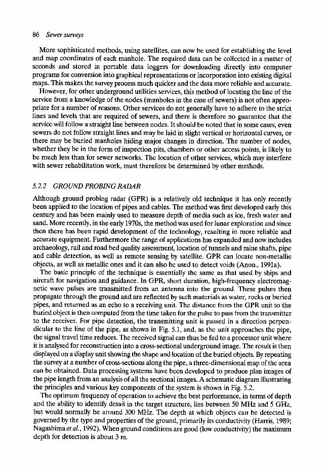
86 Sewer surveys
More sophisticated methods, using satellites, can now be used for establishing the level and map coordinates of each manhole. The required data can be collected in a matter of seconds and stored in portable data loggers for downloading directly into computer programs for conversion into graphical representations or incorporation into existing digital maps. This makes the survey process much quicker and the data more reliable and accurate.
However, for other underground utilities services, this method of locating the line of the service from a knowledge of the nodes (manholes in the case of sewers) is not often appro- priate for a number of reasons. Other services do not generally have to adhere to the strict lines and levels that are required of sewers, and there is therefore no guarantee that the service will follow a straight line between nodes. It should be noted that in some cases, even sewers do not follow straight lines and may be laid in slight vertical or horizontal curves, or there may be buried manholes hiding major changes in direction. The number of nodes, whether they be in the form of inspection pits, chambers or other access points, is likely to be much less than for sewer networks. The location of other services, which may interfere with sewer rehabilitation work, must therefore be determined by other methods.
5. 2. 2 GROUND PROBING RADAR
Although ground probing radar (GPR) is a relatively old technique it has only recently been applied to the location of pipes and cables. The method was first developed early this century and has been mainly used to measure depth of media such as ice, fresh water and sand. More recently, in the early 1970s, the method was used for lunar exploration and since then there has been rapid development of the technology, resulting in more reliable and accurate equipment. Furthermore the range of applications has expanded and now includes archaeology, rail and road bed quality assessment, location of tunnels and mine shafts, pipe and cable detection, as well as remote sensing by satellite. GPR can locate non-metallic objects, as well as metallic ones and it can also be used to detect voids (Anon., 1991a).
The basic principle of the technique is essentially the same as that used by ships and aircraft for navigation and guidance. In GPR, short duration, high-frequency electromag- netic wave pulses are transmitted from an antenna into the ground. These pulses then propagate through the ground and are reflected by such materials as water, rocks or buried pipes, and retumed as an echo to a receiving unit. The distance from the GPR unit to the buried object is then computed from the time taken for the pulse to pass from the transmitter to the receiver. For pipe detection, the transmitting unit is passed in a direction perpen- dicular to the line of the pipe, as shown in Fig. 5.1, and, as the unit approaches the pipe, the signal travel time reduces. The received signal can thus be fed to a processor unit where it is analysed for reconstruction into a cross-sectional underground image. The result is then displayed on a display unit showing the shape and location of the buried objects. By repeating the survey at a number of cross-sections along the pipe, a three-dimensional map of the area can be obtained. Data processing systems have been developed to produce plan images of the pipe length from an analysis of all the sectional images. A schematic diagram illustrating the principles and various key components of the system is shown in Fig. 5.2.
The optimum frequency of operation to achieve the best performance, in terms of depth and the ability to identify detail in the target structure, lies between 50 MHz and 5 GHz, but would normally be around 300 MHz. The depth at which objects can be detected is governed by the type and properties of the ground, primarily its conductivity (Harris, 1989; Nagashima et al., 1992). When ground conditions are good (low conductivity) the maximum depth for detection is about 3 m.
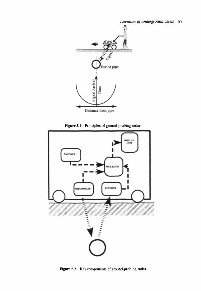
Location of underground assets 87
Figure 5.1 Principles of ground-probing radar.
Figure 5.2 Key components of ground-probing radar.

88 Sewer surveys
The processing and interpretation of the signals is very important, as the received wave signals are complex. In situations where many objects are buried, there will be numerous echoes and it may therefore be difficult to differentiate between the various buried utilities, and other underground discontinuities such as boulders and voids. The interpretation of GPR data thus requires skill and experience and, although it has given good results in certain situations, it does have limitations and further development is still required.
One of the major issues is signal attenuation. The high-frequency wave signals lose strength very quickly in conductive media such as clay and saturated soils, thus affecting depth penetration. Although in certain cases this can be used to advantage by comparing returned signal strengths across a site, the soil parameters, especially the soil conductivity, do affect the accuracy of the results
Research has shown that a major difficulty in clearly detecting underground targets occurs at those sites where there has already been extensive excavation. The difficulty arises because soil moisture is higher at the base of recently excavated and backfilled trenches and shafts, and this affects ground conductivity and hence attenuation of the GPR signal. It has also been found that the target is generally difficult to detect where there are many utilities in the ground (Kikuta and Tanaka, 1990). It would therefore appear that, at the present time, the method is least successful in those locations where it would be of greatest benefit. However, some users of the system still claim that, with careful interpretation of data by experienced operators, detection success rates of up to 80% can be achieved even in urban areas (Nagashima et al., 1992). New developments in, for example, pattern recognition (Akutu et al., 1990), sensitivity timing control (Kikuta and Tanaka, 1990), antenna design (Scott, 1989) and the use of expert systems for data interpretation should ensure the wider use and greater success of GPR in the future.
5.2.3 ELECTROMAGNETIC L O C A T I O N METHODS
Electromagnetic methods have been used for the location of underground metallic pipes since the start of this century, and they are now the most widely used methods for the detection of buried pipes and cables. The principle of the method is shown in Figure 5.3. An alternating current (AC) is applied to a metallic pipe, thus inducing a magnetic field
Figure 5.3 Direct transission electromagnetic induction system for pipe detection.
Location of underground assets 89
which can then be detected by magnetic sensors positioned on the ground surface. From the analysis of the received signal the location and the depth of the target is estimated.
The current can be applied directly to the pipe by connecting to an exposed portion, as shown in Fig. 5.3, or the current can be induced by generation and transmission of a magnetic field above ground. Although only metallic pipes can be located in this way, the method can be used for plastic, and other non-metallic pipes, providing there is access for a small radio transmitting sonde to be inserted and propelled along the pipe. In this case the sensor picks up the signal generated directly by the sonde. Sonde elements can be built into no-dig tools to monitor and control their progress from the surface.
In addition to the above mentioned 'active' process, it is also possible to use electro- magnetic methods in 'passive' mode, where the location relies on receiving natural signals transmitted from the underground assets themselves. These signals arise from stray currents, mainly from the buried power network, finding a path through metallic conduits. Passive location has the advantage of simplicity although the results are not of high quality. By incorporating both active and passive modes in one piece of equipment, the detection and location of underground assets can be both quick and reliable.
The equipment itself is inexpensive, portable and relatively easy to use. The method can provide accurate information and the results are unaffected by soil conditions or the position of the water table. It has been reported that, apart from locating pipework, it can also be used to locate water leaks, monitor current loss on a coated pipeline (Frost, 1988; Sato, 1990), pinpoint joints in iron gas pipes, find lost valve boxes and vault covers and to locate submerged cables and sewer blockages or collapses.
In addition to these applications, the method can monitor the movement of no-dig equipment, such as microtunnelling machines and pipe bursters. This facilitates greater drive lengths, because deviations can be detected and any necessary corrective action can be taken. The system can also be used in combination with a CCTV camera to relate the image to the exact position on the ground. Some CCTV equipment manufacturers now provide a sonde transmitter and a receiver with their cameras.
The main weakness of the method is its inability to trace non-metallic objects. However, this could be at least partially overcome if all new non-metallic pipes incorporated tracer wires securely bonded to them and protected from future damage. As previously mentioned, it is possible to trace non-metallic pipes if there is a suitable access point for inserting a sonde. Sondes are small, self-contained radio transmitters, which create an electromagnetic field of their own. They can be as small as 12 mm in diameter and are able to transmit a signal as far as 15 m. Once inserted into the pipe network, the sonde's movement can be monitored and, in this way, complete networks can be traced and blockages or collapses located.
Another weakness, that may cause some errors in measurements, is the fact that this system locates a magnetic field radiated by the buried network and not the buried network itself. Because the locator's calculations assume a circular magnetic field around the pipe, any detectable distortion of that field will generate inaccurate depth readings. The magnetic field is distorted when there is interference, congestion or when a bend or a T-junction occurs. Furthermore, if a pipe, situated near the target pipe, possesses a strong magnetic field, it will cause extraneous currents to be induced thus leading to misinterpretation (Fedde and Patterson, 1988). The user of a locator may not therefore be able to accurately locate targets in a very complex or congested situation.
Recent developments of the equipment include reliability indicators to indicate to the user when readings may not be accurate or the equipment is malfunctioning. This micro-

90 Sewer surveys
processor-controlled facility automatically confirms whether the unit is functioning correc- tly and is calibrated accurately. In addition, new high-power transmitters have been launched to deal with congested areas.
There is a wide range of electromagnetic locators available in the market, from simple tools for avoiding buried cables to sophisticated locating systems for resolving complex trac- ing and identification problems. With the more sophisticated equipment the user can choose the operating parameters, such as the optimum frequency, impedance match, sensitivity, power and aerial configuration. Obviously a specialist is required to exploit this potential, which the simple equipment lacks, as every parameter is preset for the specific purpose of that instrument.
Significant advances are being made in the mapping of buried networks using electro- magnetic locators. The objective is that locators, mounted on computer-controlled trucks, will rapidly collect data over large areas, and on board computers will automatically analyse the images received. In this way, it is hoped that the underground space beneath our cities will eventually be accurately and comprehensively mapped.
5. 2. 4 MAGNETOMETERS
This method takes advantage of the variations in the earth's magnetic field that can be caused by certain underground features such as metallic pipes, large voids and ore bodies. This can be measured by using two coils to evaluate the difference in intensity and/or direction of the vertical component of magnetic flux which may be caused by a ferromagnetic object. Under favourable conditions these features can be quickly located with a good degree of accuracy although results can be seriously affected by buildings, cables, fences and other objects. Interpretation of results can be facilitated by specially developed software (Anon., 1986) which can analyse the data and provide a graphical output showing the depth and nature of the buried object.
Another type of magnetic detection uses permanent magnets buried with the service networks (Minarovic and Cosman, 1988). Since these objects have a definite north or south pole, they can be clearly detected, although magnetic materials, that form part of the buried network or backfill debris, can often mask the magnetic field. So, although the method is relatively cheap, it is not used extensively because the results are not sufficiently reliable.
5.2.5 R E S I S T M T Y M E T H O D S
Four electrode probes are placed in a line in the ground and a current is passed through the outer pair. The inner pair measure the potential drop between them, thus giving an estimate of the ground resistivity. The distance between the various electrodes is the main factor affecting the depth of measurement. Several measurements, using different positions and electrode spacings, are required to ascertain the longitudinal and depth-resistivity profiles, the correct interpretation of which can give an estimation of the position of buried services.
The method has been used for many years and, with accumulated experience and good knowledge of the system, useful results can be achieved. However surveying by this method is quite slow, and electrodes need to be very well coupled with the ground. Moreover, as the small stakes normally used for the electrodes are difficult to drive into hard surfaces, surveying for assets buried beneath roads is often difficult.
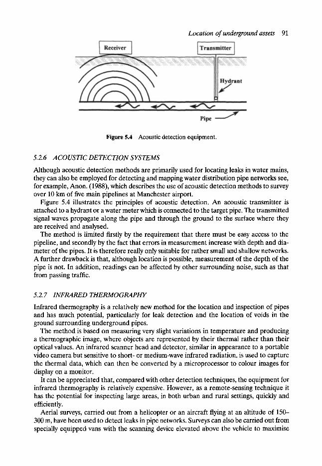
Location of underground assets 91
Figure 5.4 Acoustic detection equipment.
5.2.6 ACOUSTIC DETECTION SYSTEMS
Although acoustic detection methods are primarily used for locating leaks in water mains, they can also be employed for detecting and mapping water distribution pipe networks see, for example, Anon. (1988), which describes the use of acoustic detection methods to survey over 10 km of five main pipelines at Manchester airport.
Figure 5.4 illustrates the principles of acoustic detection. An acoustic transmitter is attached to a hydrant or a water meter which is connected to the target pipe. The transmitted signal waves propagate along the pipe and through the ground to the surface where they are received and analysed.
The method is limited firstly by the requirement that there must be easy access to the pipeline, and secondly by the fact that errors in measurement increase with depth and dia- meter of the pipes. It is therefore really only suitable for rather small and shallow networks. A further drawback is that, although location is possible, measurement of the depth of the pipe is not. In addition, readings can be affected by other surrounding noise, such as that from passing traffic.
5.2.7 INFRARED THERMOGRAPHY
Infrared thermography is a relatively new method for the location and inspection of pipes and has much potential, particularly for leak detection and the location of voids in the ground surrounding underground pipes.
The method is based on measuring very slight variations in temperature and producing a thermographic image, where objects are represented by their thermal rather than their optical values. An infrared scanner head and detector, similar in appearance to a portable video camera but sensitive to short- or medium-wave infrared radiation, is used to capture the thermal data, which can then be converted by a microprocessor to colour images for display on a monitor.
It can be appreciated that, compared with other detection techniques, the equipment for infrared thermography is relatively expensive. However, as a remote-sensing technique it has the potential for inspecting large areas, in both urban and rural settings, quickly and efficiently.
Aerial surveys, carried out from a helicopter or an aircraft flying at an altitude of 150- 300 m, have been used to detect leaks in pipe networks. Surveys can also be carried out from specially equipped vans with the scanning device elevated above the vehicle to maximise
92 Sewer surveys
the scanning area. Infrared thermography has been shown to be an extremely accurate and useful method of finding sewer, water and gas pipeline problems before they can cause expensive and dangerous failures (Weil, 1988, 1990).
However, there are still a few limitations to this technique, the main one being that en- vironmental factors such as solar radiation, cloud cover, wind speed and ground moisture can influence the results. The most important of these is moisture on the ground, which tends to disperse the surface heat and mask the temperature differences. For this reason tests are usually run only when the ground surface has been dry for at least 48 h.
A further disadvantage of this method is that, at this stage of development, the depth or thickness of a void cannot be measured. It could however be used in combination with other detection methods such as ground probing radar, infrared thermography being used to survey large areas in order to locate anomalies, and GPR then employed to assess its depth and thickness.
5.2.8 COMPARISON OF LOCATING METHODS
Non-destructive methods of locating underground assets can provide great benefits to those planning sewer rehabilitation works. Compared with the alternative of digging trial holes, the methods described above are usually quicker, cheaper, less disruptive and often provide more comprehensive information.
Electromagnetic methods are low-cost, simple and quick but cannot locate non-metallic objects, although this can be partially overcome when tracing wires are buried with the pipe or if sondes can be used. Although GPR has a wide range of uses, difficulties are encoun- tered when used in conductive media, such as clay and saturated soils, and in congested areas. Infrared thermography can survey large areas quickly, but the equipment is sophi- sticated, expensive, and sensitive to environmental conditions. Furthermore it cannot give an indication of depth. Magnetometers, resistivity methods, and acoustic detection all have their own merits and deficiencies which have been outlined above.
At the present time no one detection method can be recommended for all situations. However, a combination of different techniques can give excellent and comprehensive infor- mation on the size and position of underground assets.
5.3 Inspection of underground assets Two basic methods are currently available for the internal inspection of sewers: remote inspection (normally using CCq'V or sonar equipment) and direct inspection (by walking through the sewer). The choice is governed by sewer size, cost and safety considerations.
5.3.1 DIRECT INSPECTION SURVEYS
Surveys of this kind are only possible in large man-entry sewers. They require a team of at least six people, mainly for safety reasons. The survey is carried out by walking or crawling through the sewer and noting all defects and their location. The cost of man-entry surveys is much higher than remote surveys using CCTV cameras.
5.3.2 MANHOLE CONDITION SURVEYS
The location of sewers is usually determined by carrying out a survey of the nodes or manholes in the network as described in a previous section of this chapter. At the same time
Inspection of underground assets 93
as carrying out the manhole location survey, it is normal practice to also carry out a manhole condition survey. The procedure for manhole surveys was standardised in the UK when the National Water Council published Standing Technical Committee Report No. 25 (STC25) in 1980.
The data to be collected for each manhole in such a survey would include the following:
�9 manhole reference number �9 map reference �9 description of location �9 level above datum of manhole cover �9 shape, size, and condition of manhole cover �9 description of manhole shaft - size, depth, condition, access, bench in, etc. �9 depth of flow �9 depth of silt �9 presence of vermin, toxic gases, etc. �9 details of incoming and outgoing p i p e s - position, depth to invert, shape, size, pipe
material, etc.
This information is normally collected by specialist contractors and recorded on specially prepared manhole record cards for subsequent use in preparing plans and long sections of the sewer network. The information can also be used for maintenance purposes and for preparing the input data required to build hydraulic models of the network. However, although the data can be recorded and stored in this way, it is time consuming to retrieve relevant information from hundreds or perhaps thousands of record cards stored in filing cabinets. The use of computer database systems greatly facilitates the retrieval of data as discussed in Section 5.4.
5.3.3 CLOSED-CIRCUIT TELEVISION (CCTV)
Some 95% of the public sewerage network in the UK is non-man en t ry - that is having an internal diameter of less than 900 mm. Prior to the introduction of CCTV inspection meth- ods in the 1960s, internal surveys could only be carried out by visual inspection from a manhole using strategically placed torches and mirrors. However, these practices have since been replaced by CCTV, which is now the most commonly used technique for inspecting sewers.
The basic principle of CCTV inspection is that a television camera, together with a light source, is mounted on a tractor or skid which is pulled or propelled through the sewer from one manhole to the next. The camera transmits pictures by cable to a monitor, normally housed in a specially equipped vehicle parked close to one of the access manholes. Modem cameras can be remotely controlled from within the vehicle and the entire survey can be recorded on videotape.
Although in the early days of CCTV inspection black and white cameras were used exclusively, these have now almost universally been replaced by colour CCTV equipment, which gives excellent results and most sewer defects can be readily identified by those practised in the art.
Cameras, which are housed in strong waterproof stainless-steel cases, are now normally of the charge coupling device (CCD) solid-state type, which have superseded the older vidicon tube cameras. These old tube cameras were fragile but could provide high-resolution images with low power consumption. However, recent developments in the newer CCD
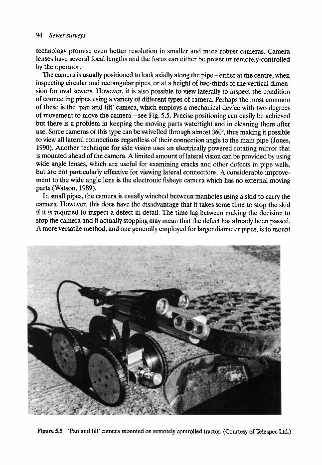
94 Sewer surveys
technology promise even better resolution in smaller and more robust cameras. Camera lenses have several focal lengths and the focus can either be preset or remotely-controlled by the operator.
The camera is usually positioned to look axially along the pipe - either at the centre, when inspecting circular and rectangular pipes, or at a height of two-thirds of the vertical dimen- sion for oval sewers. However, it is also possible to view laterally to inspect the condition of connecting pipes using a variety of different types of camera. Perhaps the most common of these is the 'pan and tilt' camera, which employs a mechanical device with two degrees of movement to move the camera - see Fig. 5.5. Precise positioning can easily be achieved but there is a problem in keeping the moving parts watertight and in cleaning them after use. Some cameras of this type can be swivelled through almost 360 ~ thus making it possible to view all lateral connections regardless of their connection angle to the main pipe (Jones, 1990). Another technique for side vision uses an electrically powered rotating mirror that is mounted ahead of the camera. A limited amount of lateral vision can be provided by using wide angle lenses, which are useful for examining cracks and other defects in pipe walls, but are not particularly effective for viewing lateral connections. A considerable improve- ment to the wide angle lens is the electronic fisheye camera which has no external moving parts (Watson, 1989).
In small pipes, the camera is usually winched between manholes using a skid to carry the camera. However, this does have the disadvantage that it takes some time to stop the skid if it is required to inspect a defect in detail. The time lag between making the decision to stop the camera and it actually stopping may mean that the defect has already been passed. A more versatile method, and one generally employed for larger diameter pipes, is to mount
Figure 5.5 'Pan and tilt' camera mounted on remotely controlled tractor. (Courtesy of Telespec Ltd.)
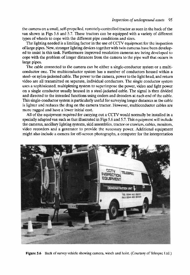
Inspection of underground assets 95
the camera on a small, self-propelled, remotely-controlled tractor as seen in the back of the van shown in Figs 5.6 and 5.7. These tractors can be equipped with a variety of different types of wheels to cope with the different pipe conditions and sizes.
The lighting needed is a limiting factor in the use of CC-q~ equipment for the inspection of large pipes. New, stronger lighting devices together with twin cameras have been develop- ed to assist in this task. Furthermore improved resolution cameras are being developed to cope with the problem of longer distances from the camera to the pipe wall that occurs in large pipes.
The cable connected to the camera can be either a single-conductor system or a multi- conductor one. The multiconductor system has a number of conductors housed within a steel- or nylon-jacketed cable. The power to the camera, power to the light head, and return video are all transmitted on separate, individual conductors. The single conductor system uses a sophisticated, multiplexing system to superimpose the power, video and light power on a single conductor usually housed in a steel-jacketed cable. The signal is then divided and directed to the intended functions using coders and decoders at each end of the cable. This single-conductor system is particularly useful for surveying longer distances as the cable is lighter and reduces the drag on the camera tractor. However, multiconductor cables are more rugged and have a lower initial cost.
All of the equipment required for carrying out a CCTV would normally be installed in a specially adapted van such as that illustrated in Figs 5.6 and 5.7. This equipment will include the cameras, ancillary lighting systems, skid assemblies, tractor or crawlers, cables, monitors, video recorders and a generator to provide the necessary power. Additional equipment might also include a camera for off-screen photographs, a computer for the interpretation
Figure 5.6 Back of survey vehicle showing camera, winch and hoist. (Courtesy of Telespec Ltd.)
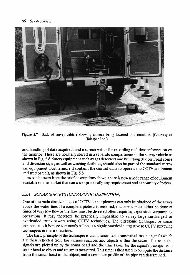
96 Sewer surveys
Figure 5.7 Back of survey vehicle showing camera being lowered into manhole. (Courtesy of Telespec Ltd.)
and handling of data acquired, and a screen writer for recording real-time information on the monitor. These are normally stored in a separate compartment of the survey vehicle as shown in Fig. 5.8. Safety equipment such as gas detectors and breathing devices, road cones and diversion signs, as well as washing facilities, should also be part of the standard survey van equipment. Furthermore it contains the control units to operate the CCTV equipment and tractor unit, as shown in Fig. 5.8.
As can be seen from the brief descriptions above, there is now a wide range of equipment available on the market that can cover practically any requirement and at a variety of prices.
5. 3. 4 SONAR S UR VEYS (ULTRA SONIC INSPECTION)
One of the main disadvantages of CCTV is that pictures can only be obtained of the sewer above the water line. If a complete picture is required, the survey must either be done at times of very low flow or the flow must be diverted often requiring expensive overpumping operations. It may therefore be practically impossible to survey large surcharged or overloaded trunk sewers using CCTV techniques. The ultrasonic technique, or sonar inspection as it is more commonly called, is a highly practical alternative to CCTV surveying techniques in these situations.
The basic principle of the technique is that a sonar head transmits ultrasonic signals which are then reflected from the various surfaces and objects within the sewer. The reflected signals are picked up by the sonar head and the time taken for the signal's passage from sonar head to object and return is measured. This time is then used to compute the distance from the sonar head to the object, and a complete profile of the pipe can determined.
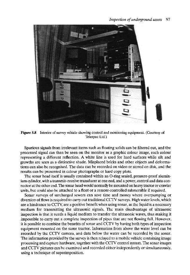
Inspection of underground assets 97
Figure 5.8 Interior of survey vehicle showing control and monitoring equipment. (Courtesy of Telespec Ltd.)
Spurious signals from irrelevant items such as floating solids can be filtered out, and the processed signal can then be seen on the monitor as a graphic colour image, each colour representing a different reflection. A white line is used for hard surfaces while silt and growths are seen as a distinctive shade. Misplaced bricks and other objects and deforma- tions can also be recognised. The data can be recorded on video or stored on disk, and the results can be presented in colour photographs or hard copy plots.
The sonar head itself is usually contained within an O-ring sealed, pressure-proof alumin- ium cylinder, with a transmit-receive transducer at one end, and a power, control and data con- nector at the other end. The sonar head would normally be mounted on heavy tractor or crawler units, but could also be attached to a float or a remote-controlled submersible if required.
Sonar surveys of surcharged sewers can save time and money where overpumping or diversion of flows is required to carry out traditional CCTV surveys. High water levels, which are a hindrance to CCTV, are a positive benefit when using sonar, as the liquid is a necessary medium for transmitting the ultrasonic signals. The main disadvantage of ultrasonic inspection is that it needs a liquid medium to transfer the ultrasonic waves, thus making it impossible to carry out a complete inspection of pipes that are not flowing full. However, it is possible to combine the benefits of sonar and CCTV by having both types of inspection equipment mounted on the same tractor. Information from above the water level can be recorded by the CCTV camera, and data below the water can be recorded by the sonar. The information provided by the survey is then relayed to a mobile vehicle containing image processing and capture hardware, together with the CCTV control system. The sonar images and CCTV pictures can be examined and recorded either independently or simultaneously, using a technique of superimposition.
98 Sewer surveys
During the past few years a number of sewers have been successfully inspected in UK using the sonar method (Winney, 1989) and it has also found application elsewhere including developing countries (Anon., 1991b).
5.3.5 LIGHTLINE METHOD
The detection and measurement of changes in the shape of sewers, caused by deformation, siltation or corrosion, is difficult when using conventional CCTV equipment. This is because there is no calibration or reference point to use for such measurements. However, it is often very important to quantify the deformation of a sewer, as this may be required for monitor- ing sewer deterioration, determining what rehabilitation action to take, and for designing the required lining.
The lightline method can be used, in conjunction with a CCTV survey, to assess the shape and measure the internal dimensions of a sewer. This is done by continuously generating a line of light around the sewer circumference, thus highlighting and profiling the sewer shape at any point along the length being surveyed. Subtle changes in shape can easily be detected and, with the use of appropriate computer software, distances between any two points on the lightline can be accurately measured. A circle can also be generated on the screen to compare with the actual shape of the sewer and thus calculate the severity of the deforma- tion. This is particularly useful for surveying and monitoring brick sewers, and accurately assessing the shape of the more flexible types of pipework.
5.3.6 COMPARISON OF INSPECTION METHODS
Direct inspection of man-entry sewers can provide the most comprehensive information for large sewers. Photographs and video pictures can be taken, internal dimensions can be directly measured, samples of pipe or jointing material can be taken for further testing and even some in situ testing might be carried out. However, only man-entry size sewers can be surveyed in this way; surveys are costly due to high labour resource requirements, and safety is a major issue. Non-man-entry sewers can only be surveyed by remote methods.
CCTV is now the most widely used method for inspecting sewers in the developed world. It is well proven, gives very good images of the inspected network and is relatively cheap. The lightline technique can be used in conjunction with CCTV to obtain dimensional data of the conduit if required. However, lighting in general may pose a problem for very large sewers, and CCTV cannot be used effectively under water. In contrast, sonar survey methods require a liquid medium to transmit the sound waves to the pipe wall and therefore only operate below the water surface. In most cases, CCTV surveys can be carried out when flow depth is low and a reasonably comprehensive assessment of the condition of a sewer can then be obtained. However, when the sewer is always flowing relatively full, and if a complete picture of the conduit is required, CCTV should be used in conjunction with sonar.
5.4 Computer and software support for surveying The function of a sewer survey is to gather information, which may relate to a general description, the structural or hydraulic condition, or the geographic location of the sewer or its immediate surroundings. The survey of a single manhole can generate up to 100 or more separate items of data, whilst the survey along a length of sewer by infrared
Computer and software support for surveying 99
thermography or ultrasonics may entail the collection and storage of many thousands of data items for processing into visual images. The processing, storage and retrieval of such large quantities of data would be practically impossible without the use of computers, which have now become an essential tool for anyone involved in collecting or analysing sewer survey data.
The three main applications of computers to sewer surveying are database systems, graphical representation of sewer networks and associated maps, and data collection and processing.
5. 4.1 DA TA BA S E S
One of the main applications of database systems is to the storage and retrieval of data obtained from manhole surveys. As mentioned previously, it is a troublesome and lengthy business to obtain specific information from a large number of manhole record cards. Imagine, for example, that all the cards were filed according to the district or street in which the manholes were located, and that an engineer wished to know the location of all those manholes where the access ladders were reported to be in need of attention. This would require detailed inspection of all the cards, and the engineer would have to note or abstract those cards which reported defective access ladders - a task that may take several hours. If, on the other hand, all the information is stored in a computerised database, the required details can be located in a matter of seconds.
This was one of the problems faced by those agencies charged with the responsibility of sewerage networks in the UK after the implementation of the standardised sewer records system. A further problem relates to the quality of the survey data, which were often found to be incomplete or inconsistent. It was not uncommon, for example, to find record cards indicating that the invert level of the outgoing sewer was higher than the incoming sewer, or that the sewer outgoing from one manhole was of a larger diameter, or different material or shape, than the one reported to be entering the next. This inconsistency of data between record cards was clearly very undesirable.
By the late 1980s some software companies had started to develop database software systems specifically designed for sewer records, and which could help overcome the two problems outlined above. The fact that databases can be searched or interrogated for matching parameters in any chosen field of data entry made retrieval of information quick and easy. But perhaps more importantly, the new systems made it possible to check all the data for consistency thus highlighting particular areas which needed resurveying.
In addition to the data normally collected during manhole surveys, it is possible to include in the database further information needed for the planning and management of sewer maintenance and rehabilitation. For example, details of the traffic flow in the street above the sewer may be used in identifying critical sewers in the network, as outlined in Chapter 4. As long as the relevant data are input to the database, programs of this type can search the database to identify and list critical sewers according to whatever parameters are chosen for the criticality.
Information on pipe size, gradient and length, which can all be obtained from the manhole records, is required in a specified computer file format for computer simulation models of sewer networks, such as those described in Chapter 8. Several of the sewer records computer programs now have the facility for producing these compatible data files for direct input to specified hydraulic simulation models, thus saving a great deal of time and eliminating errors which may otherwise occur when inputting data manually.

100 Sewersurveys
5.4.2 MAPPING
Until recently, geographic information of the utility networks was recorded on paper or plastic film, and, in the UK, this has been based on Ordnance Survey maps on which the network was drawn. Such records are vulnerable to wear and tear and a lot of drawing time is consumed in updating them from time to time. Digital mapping and computer-generated graphics are now replacing this method of keeping and updating geographic information. Information that was previously stored in filing cabinets, drawers, and vaults can now be stored on computer disks from where it can be accessed and updated much more readily.
The manhole records mentioned previously contain all the information required to locate the sewer in three dimensions- the map coordinates and the invert level at both ends of each sewer length. Thus, the next logical software development was to link sewer records databases to graphics or computer-aided design (CAD) software in order to produce graphi- cal representations of sewer networks, which could be overlaid on digital maps of the area, or on plans of other service networks (gas, water, etc.).
The software that is currently available allows the user to input data in the form of manhole records and produce sewer network plans on the screen. Sewer networks can be viewed in isolation or overlaid on maps or other networks, and there is the facility to zoom in (or 'mooz' out) on selected areas for more detailed scrutiny. A mouse can be used to point at a manhole or sewer length and all the stored information relevant to that partibular component of the network can be instantly retrieved. Branches of the network can be defined on the screen so that information relevant only to that particular area can be retrieved from the database. For example, it is possible to use a mouse to draw a boundary around a particular street, and quickly identify all the sewers of less than say 450 mm diameter within the prescribed boundary.
It is also possible, with some programs, to specify portions of the network and produce longitudinal sections for viewing on the screen or preparing a hard copy on a suitable printer or plotter.
5. 4.3 DATA COLLECTION AND PROCESSING
Whenever data are collected and recorded on paper there is the potential for mistakes to be made when those data are later transferred to drawings, record cards or input to compu- ters. It is now possible to directly enter survey data on-site into preprogrammed hand-held data loggers or portable computers. These devices can prompt the surveyor to collect and record all the required information on the data logger, which can then be downloaded directly to the main office system.
Specialised software packages are required for the interpretation and processing of data obtained from certain survey techniques such as sonar, infrared thermography and GPR. These are under continual development to improve the reliability and ease of use of these survey methods - see Hironaka et al. (1987), for example.
Programs are also available which enable more efficient input and on-site validation of CCTV survey data (Anon., 1990). It is claimed that such systems increase productivity through the early identification of mistakes, thus saving the costs of a resurvey.
5.5 The future As with other aspects of sewer maintenance and rehabilitation, the technology related to surveying our underground assets is rapidly changing and, no doubt, many readers will find

References 101
that some of the techniques and methods outlined above have been significantly developed and improved by the time they read this. It is therefore perhaps worthwhile to attempt to make some predictions of how the technology might develop.
In terms of locating and mapping the underground space and services contained there, there seems little doubt that techniques such as GPR, infrared thermography, and ultrasonics will develop to provide accurate and comprehensive survey information. At this point in time, it seems unlikely that any one method will provide all the necessary information, and that future detection vehicles will be equipped with several forms of device. We look forward to the time when a survey vehicle will drive along (or fly over) a city street, gathering underground data and producing three-dimensional information on all the services, voids and soil conditions.
In the nearer future, developments in CCTV equipment promise to extend the range of inspection by using glass-fibre cables. An even more radical alternative, already in the experimental stage, is the transfer of data by radio waves instead of cables, thus dramatically increasing the length of sewer that can be surveyed from one access point. We anticipate the development of even smaller cameras with better resolution, requiring less lighting and power and having the ability to establish a direct link between the position of the camera and a digital map database.
The further development of robots for the internal inspection of underground pipe will greatly enhance the use of CCTV and sonar equipment by extending the working range, eliminating the need for any man-entry inspection, and enabling surveying and other operations, such as cleaning and root removal, to be carried out simultaneously. Inspection robots of the future might be expected to survey complete networks of pipes of various sizes, including side connections and laterals and be able to traverse or remove obstacles. They may be equipped with automatic route navigation devices, advanced sensors for detection of leaks and voids, and fault diagnosis and non-destructive testing equipment,
The improvement in computing power and associated software has been extremely rapid over the past few years and the developments outlined in Section 5.4 have all come about in the last two to five years. Rapid changes are likely to continue in this area with the increased use of expert systems, more sophisticated software for analysing complex sets of data and controlling survey robots, greater use of digital mapping and satellite surveying techniques, and perhaps a host of hitherto unknown applications. Whatever the future holds, one thing is almost certain - we will know much more about our underground space than we do today.
References Akutu, Haruji, Nagashima, Yugi, Masuda, Jun-ichi, Kouno, Sadao and Sudoh, Yosikazu. Develop-
ment of an underground radar system. ISTT, No-Dig 90, Osaka, Japan., paper L-4, October, 1990. Anon. A complete system for pipeline mapping and location". Pipes & Pipelines International, Vol. 33,
No. 5, pp. 24-25, September-October, 1988. Anon. Magnetometer shows new mapping potential. Underground Magazine, p. 6, April, 1986. Anon. CCTV: data while you wait. Underground Magazine, p. 17, June, 1990. Anon. Probing for voids. Underground Magazine, p, 27, June, 1991a. Anon. Delhi sewer sonar survey completed. Underground Magazine, p. 10, March, 1991b. Fedde, P. A. and Patterson, C. Locator continuously records pipeline depth-readings. Oil & Gas
Journal, Vol. 86, No. 35, pp. 39-42, August, 1988. Frost, N. J. Electromagnetic techniques to monitor pipe line coatings. Pipe Line Industry, Vol. 69, No.
3, pp. 33-35, September, 1988.

102 Sewersurveys
Harris, A. Ground probing radar. Foundations and Tunnels, pp. 273-278, 1989. Hironaka, M. C., Liem, R. and Davis, T. J. Image reconstruction with ground penetrating radar data.
ISTT, No-Dig 87, London, paper 1-3, April, 1987. Jones, M. Eyes on the underworld. No-Dig International Magazine, The Mining Magazine, pp. 9-12,
August, 1990. Kikuta, Takashi and Tanaka, Hiroaki. Ground probing radar system. IEEE Aerospace and Electronic
System Magazine, Vol 5, No. 6, pp. 23-26, June, 1990. Minarovic, J. T. and Cosman, A. D. Dig here: relocating buried when you have to dig. ISTT, No-Dig
88, Washington, DC, paper 3-B, October, 1988. Nagashima, S., Suyama, K. and Kobori, T. Techniques for locating underground utilities. Proceedings
of 5th International No-Dig Conference, Washington. International Society of Trenchless Technology, April 1992.
National Water Council. Sewer and Water Main Records, Standard Technical Committee Report Number 25, National Water Council, Department of the Environment, June, 1980.
Sato, Taisaku. Development of a coating defect inspection system for buried steel pipelines. ISTT, No- Dig 90, Osaka, Japan, paper L-2, October, 1990.
Scott, H. E Buried plant mapping by ground probing radar. NJUG, Harrogate, paper 3-1, June, 1989. Watson, R. Futuristic fisheye camera takes Pearpoint forward. Underground Magazine, pp. 14-16,
March, 1989. Weil, G. J. Predictive maintenance using remote infrared thermographic non-destructive sensing of
sewer system problems. ISTT, No-Dig 90, Osaka, Japan, paper B-4, October, 1990. Weil, G. J. Remote infrared thermal sensing of sewer voids-four year update. ISTT, No-Dig 88,
Washington, DC, paper 5-B, October, 1988. Winney, M. New sonar survey cracks flooded pipe problems. Underground Magazine, pp. 17-18, March,
1989.
6 Traffic Management and
Public Relations
C. Barber* BSc, CEng, MICE
6.1 Introduction As sewerage systems have been developed over the last two centuries they have of necessity been constructed in the spaces between the buildings which they serve. The largest and most accessible area has obviously been the highway network which has developed over the same time period as the communities which they service. Consequently, the oldest and often structurally suspect roads tend to have the oldest and most structurally suspect sewers running beneath them. Strategic roads passing directly through a city are also likely to be the most convenient collection point for local sewers and hence often carry main collector or interceptor sewers beneath them. There is therefore a direct comparison between the interruption of the sewer network and the interruption of the highway network following a collapse of a major sewer.
6.2 Traffic problems following sewer collapse Frequent road journeys are an integral part of modern western industrial, commercial and leisure activities. The highway network is not merely a means of travelling from one village, town or city to another. It has an integral part to play in our daily lives. Industry needs roads in order to acquire its raw materials and to deliver goods to its distributors. Rail traffic alone cannot cope with the demand and flexibility required. Retailers need roads to receive their goods and for customers to reach their outlets in large numbers. Tourism and leisure activi- ties require roads to enable visitors to avail themselves of their amenities e n m a s s e . Then there are the commuters who throng our city streets twice a day to travel between office or factory and home. Again rail corridors alone cannot cope with the complicated pattern of origins and destinations demanded by the travelling public. Lastly highways serve the strategic purpose of enabling emergency services to reach all areas of the community quickly.
A disruption to the highway network is therefore a disruption to society in general and in particular to the lives of the users of the particular road which has been temporarily restricted or closed. As can be seen from Fig. 6.1 heavily trafficked streets are not only a recent regular occurrence. Disruption to horsedrawn traffic in Eagle Street, Manchester, would have caused just as much inconvenience in 1917 as it would to motorised traffic in a
*Acting Senior Assistant City Engineer, City Engineers Department, Manchester.
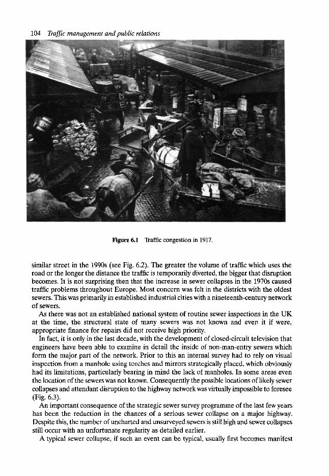
104 Traffic management and public relations
Figure 6.1 Traffic congestion in 1917.
similar street in the 1990s (see Fig. 6.2). The greater the volume of traffic which uses the road or the longer the distance the traffic is temporarily diverted, the bigger that disruption becomes. It is not surprising then that the increase in sewer collapses in the 1970s caused traffic problems throughout Europe. Most concern was felt in the districts with the oldest sewers. This was primarily in established industrial cities with a nineteenth-century network of sewers.
As there was not an established national system of routine sewer inspections in the UK at the time, the structural state of many sewers was not known and even it if were, appropriate finance for repairs did not receive high priority.
In fact, it is only in the last decade, with the development of closed-circuit television that engineers have been able to examine in detail the inside of non-man-entry sewers which form the major part of the network. Prior to this an internal survey had to rely on visual inspection from a manhole using torches and mirrors strategically placed, which obviously had its limitations, particularly bearing in mind the lack of manholes. In some areas even the location of the sewers was not known. Consequently the possible locations of likely sewer collapses and attendant disruption to the highway network was virtually impossible to foresee (Fig. 6.3).
An important consequence of the strategic sewer survey programme of the last few years has been the reduction in the chances of a serious sewer collapse on a major highway. Despite this, the number of uncharted and unsurveyed sewers is still high and sewer collapses still occur with an unfortunate regularity as detailed earlier.
A typical sewer collapse, if such an event can be typical, usually first becomes manifest
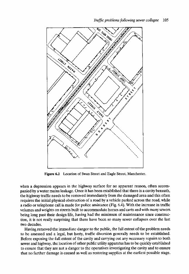
Traffic problems following sewer collapse 105
"\ '" 4
, / , / r
\ \ \ \ ,~\
\ x \ \ \ \ \ N
\ \ N \
\ \ \ \ \ \
\ \ \
\ \
\
Figure 6.2 Location of Swan Street and Eagle Street, Manchester.
when a depression appears in the highway surface for no apparent reason, often accom- panied by a water mains leakage. Once it has been established that there is a cavity beneath, the highway traffic needs to be removed immediately from the damaged area and this often requires the initial physical obstruction of a road by a vehicle parked across the road, while a radio or telephone call is made for police assistance (Fig. 6.4). With the increase in traffic volumes and weights on streets built to accommodate horses and carts and with many sewers being long past their design life, having had the minimum of maintenance since construc- tion, it is not really surprising that there have been so many sewer collapses over the last two decades.
Having removed the immediate danger to the public, the full extent of the problem needs to be assessed and a legal, but hasty, traffic diversion generally needs to be established. Before exposing the full extent of the cavity and carrying out any necessary repairs to both sewer and highway, the location of other public utility apparatus has to be quickly established to ensure that they are not a danger to the operatives investigating the cavity and to ensure that no further damage is caused as well as restoring supplies at the earliest possible stage.
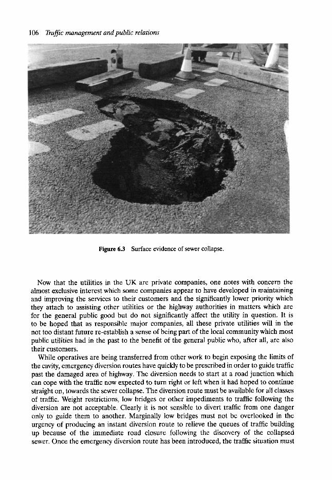
106 Traffic management and public relations
Figure 6.3 Surface evidence of sewer collapse.
Now that the utilities in the UK are private companies, one notes with concern the almost exclusive interest which some companies appear to have developed in maintaining and improving the services to their customers and the significantly lower priority which they attach to assisting other utilities or the highway authorities in matters which are for the general public good but do not significantly affect the utility in question. It is to be hoped that as responsible major companies, all these private utilities will in the not too distant future re-establish a sense of being part of the local community which most public utilities had in the past to the benefit of the general public who, after all, are also their customers.
While operatives are being transferred from other work to begin exposing the limits of the cavity, emergency diversion routes have quickly to be prescribed in order to guide traffic past the damaged area of highway. The diversion needs to start at a road junction which can cope with the traffic now expected to turn right or left when it had hoped to continue straight on, towards the sewer collapse. The diversion route must be available for all classes of traffic. Weight restrictions, low bridges or other impediments to traffic following the diversion are not acceptable. Clearly it is not sensible to divert traffic from one danger only to guide them to another. Marginally low bridges must not be overlooked in the urgency of producing an instant diversion route to relieve the queues of traffic building up because of the immediate road closure following the discovery of the collapsed sewer. Once the emergency diversion route has been introduced, the traffic situation must
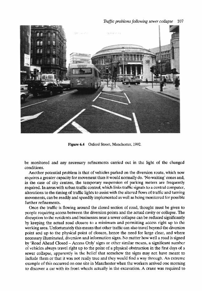
Traf-fic problems following sewer collapse 107
Figure 6.4 Oxford Street, Manchester, 1992.
be monitored and any necessary refinements carried out in the light of the changed conditions.
Another potential problem is that of vehicles parked on the diversion route, which now requires a greater capacity for movement than it would normally do. 'No waiting' cones and, in the case of city centres, the temporary suspension of parking meters are frequently required. In areas with urban traffic control, which links traffic signals to a central computer, alterations to the timing of traffic lights to assist with the altered flows of traffic and turning movements, can be readily and speedily implemented as well as being monitored for possible further refinements.
Once the traffic is flowing around the closed section of road, thought must be given to people requiring access between the diversion points and the actual cavity or collapse. The disruption to the residents and businesses near a sewer collapse can be reduced significantly by keeping the actual road closure to a minimum and permitting access right up to the working area. Unfortunately this means that other traffic can also travel beyond the diversion point and up to the physical point of closure, hence the need for large clear, and where necessary illuminated, diversion and information signs. No matter how well a road is signed by 'Road Ahead Closed - Access Only' signs or other similar means, a significant number of vehicles always travel right up to the point of a physical obstruction in the first days of a sewer collapse, apparently in the belief that somehow the signs may not have meant to include them or that it was not really true and they would find a way through. An extreme example of this occurred on one site in Manchester when the workers arrived one morning to discover a car with its front wheels actually in the excavation. A crane was required to
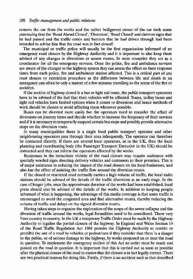
108 Traffic management and public relations
remove the car from the works and the rather belligerent owner of the car took some convincing that the 'Road Ahead Closed', 'Diversion', 'Road Closed' and chevron signs that he had passed and the traffic cones and barriers that he had driven through had been intended to advise him that the road was in fact closed!
The municipal or traffic police will usually be the first organisation informed of an emergency road closure by the Highway Authority and it is important to also keep them advised of any changes in diversions or access routes. In most countries they act as a coordinator for all the emergency services. Once the police, fire and ambulance services are aware of the changes to the highway system they can assess the effect on their response times from each police, fire and ambulance station affected. This is a critical part of any road closure or restriction procedure as the difference between life and death in an emergency can often be only a matter of a few minutes travelling to the scene of the fire or accident.
If the section of highway closed is a bus or light rail route, the public transport operators have to be advised of the fact that their vehicles will be affected. Trams, trolley buses and light rail vehicles have limited options when it comes to diversions and hence methods of work should be chosen to avoid affecting them whenever possible.
Buses can be diverted more easily but the operators need to consider the effect of diversions on journey times and decide whether to increase the frequency of their services and if it is necessary to temporarily suspend certain bus stops and possibly provide alternative stops on the diversion route.
In many municipalities there is a single local public transport operator and other neighbouring operators pass through their area infrequently. The operator can therefore be contacted directly. If there are several local operators, as in the UK, then the local planning and coordinating body (the Passenger Transport Executive in the UK) should be contacted and they can inform the operators affected by the works.
Businesses in the immediate vicinity of the road closure may require assistance with specially worded signs directing delivery vehicles and customers to their premises. This is of major assistance in reducing the impact of the road closure on the local businesses, and also has the effect of assisting the traffic flow around the diversion routes.
If the closed or restricted road normally carries a high volume of traffic, the local radio stations should be advised of the details of the traffic diversions at an early stage. In the case of longer jobs, once the approximate duration of the works had been established, local press should also be advised of the details of the works. In addition to keeping people informed of what is happening, the advantage of this media coverage is that some traffic is encouraged to avoid the congested area and find alternative routes, thereby reducing the volume of traffic and delays on the signed diversion routes.
Having taken steps to organise the exploration of the scope of the sewer collapse and the diversion of traffic around the works, legal formalities need to be considered. These vary from country to country. In the UK a temporary Traffic Order must be made by the Highway Authority to legalise the partial closure of the highway. In England and Wales Section 14 of the Road Traffic Regulation Act 1984 permits the Highway Authority to restrict or prohibit the use of a road by vehicles or pedestrians if they consider that there is a danger to the public, or of serious damage to the highway, by works proposed on or near the road in question. To implement the emergency section of this Act an order must be made and posted on the road in question. It is important that this is carried out as soon as possible after the physical closure of the road to ensure that the closure is in fact legally correct. There are two practical reasons for doing this. Firstly, if there is an accident such as that described
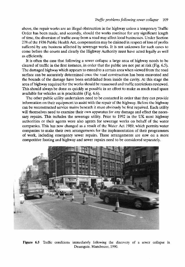
Traffic problems following sewer collapse 109
above, the repair works are an illegal obstruction in the highway unless a temporary Traffic Order has been made, and secondly, should the works continue for any significant length of time, the diversion of traffic away from a road may affect local businesses. Under Section 278 of the 1936 Public Health Act, compensation may be claimed in respect of loss of profits suffered by any business affected by sewerage works. It is not unknown for such cases to come before the courts and clearly the Highway Authority must have acted legally as well as efficiently.
It is often the case that following a sewer collapse a large area of highway needs to be cleared of traffic in the first instance, in order that the public are not put at risk (Fig. 6.5). The damaged highway which appears to extend to a certain area when viewed from the road surface can be accurately determined once the road construction has been excavated and the bounds of the damage have been established from inside the cavity. At this stage the area of highway required for the works should be reassessed and traffic restrictions reviewed. This should always be done as quickly as possible in an effort to make as much road space available for vehicles as is practicable (Fig. 6.6).
The other public utility undertakers need to be contacted in order that they can provide information on their equipment to assist with the repair of the highway. Before the highway can be reconstructed service mains beneath it must obviously be first repaired. Each utility will themselves need to examine their own apparatus for any damage and effect the neces- sary repairs. This includes the sewerage utility. Prior to 1992 in the UK most highway authorities or their agents were also agents for sewerage works on behalf of the water companies. This has now changed as a result of the Water Act 1989, which permits water companies to make their own arrangements for the implementation of their programmes of work, including emergency sewer repairs. These arrangements are now on a more competitive footing and highway and sewer repairs need to be considered separately.
Figure 6.5 Traffic conditions immediately following the discovery of a sewer collapse in Deansgate, Manchester, 1990.
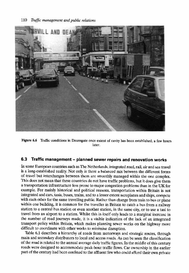
110 Traffic management and public relations
Figure 6.6 Traffic conditions in Deansgate once extent of cavity has been established, a few hours later.
6.3 Traffic management- planned sewer repairs and renovation works In some European countries such as The Netherlands, integrated road, raft, air and sea travel is a long-established reality. Not only is there a balanced mix between the different forms of travel but interchanges between them are smoothly managed within the one complex. This does not mean that these countries do not have traffic problems, but it does give them a transportation infrastructure less prone to major congestion problems than in the UK for example. For mainly historical and political reasons, transportation within Britain is not integrated and cars, taxis, buses, trains, and to a lesser extent aeroplanes and ships, compete with each other for the same travelling public. Rather than change from train to bus or plane within one building, it is common for the traveller in Britain to catch a bus from a railway station to a central bus station or even another station, in the same city, or to use a taxi to travel from an airport to a station. Whilst this in itself only leads to a marginal increase in the number of road journeys made, it is a visible indication of the lack of an integrated transport policy within Britain, which makes planning sewer works on the highway more difficult to coordinate with other works to minimise disruption.
Table 6.1 describes a hierarchy of roads from motorways and strategic routes, through main and secondary distributors to local and access roads. As can be seen the classification of the road is related to the annual average daily traffic figures. In the middle of this century roads were designed to accommodate peak-hour traffic flows. Car ownership in the earlier part of the century had been confined to the affluent few who could afford their own private
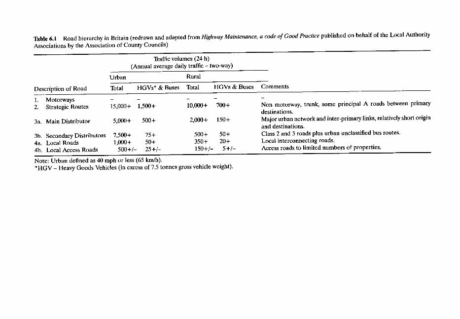
Table 6.1 Road hierarchy in Britain (redrawn and adapted from Highway Maintenance, a code of Good Practice published on behalf of the Local Authority
Associations by the Association of County Councils)
Traffic volumes (24 h) (Annual average daily traffic- two-way)
Urban Rural
Description of Road Total HGVs* & Buses Total
1. Motorways - - - 2. Strategic Routes 15,000+ 1,500+ 10,000+
HGVs & Buses
700+
3a. Main Distributor 5,000+ 500+ 2,000+ 150+
3b. Secondary Distributors 4a. Local Roads 4b. Local Access Roads
7,500+ 75 + 500+ 50+ 1,000+ 50+ 350+ 20+
500+/- 25+/- 150+/- 5+/ -
Note: Urban defined as 40 mph or less (65 km/h). *HGV - Heavy Goods Vehicles (in excess of 7.5 tonnes gross vehicle weight).
Comments
m
Non motorway, trunk, some principal A roads between primary destinations. Major urban network and inter-primary links, relatively short origin and destinations. Class 2 and 3 roads plus urban unclassified bus routes. Local interconnecting roads. Access roads to limited numbers of properties.
112 Traffic management and public relations
personal means of transport and even in the 1950s and 1960s road design could afford to be based on peak-hour capacities without appearing to be excessive. By the 1970s this had changed and so had methods of designing roads.
As we have become more affluent, the two-car family has become more common. The underlying trend of steady growth in both car ownership and numbers of journeys made by road now means that to design roads for peak traffic would require vast areas of our cities to be demolished to make way for wide expanses of carriageways and enormous grade separated junctions. Because of this we have reached the stage in some British cities where it is often argued that building a new road hardly seems worthwhile because it rapidly fills up in peak times with traffic and becomes just another traffic jam. This is, of course, a simplification of our road traffic problems but nevertheless the peak 'hour' saturation of our city roads is a reality which is self-evident to anyone who has to travel during these times. Making the best use of the road space available has therefore become a major aspect of modem traffic engineering. Urban traffic control plays a key role in this by optimising the flow of traffic throughout the entire conurbation which is under its control. In Britain most systems work on a fixed time plan which optimises the traffic flow through each junction, revises this to optimise flows on each route and again to optimise flows throughout the conurbation. The central computer programme utilises data from each traffic signal- controlled junction as well as theoretical calculations on junction and lane capacities.
While adding a new section of road may in certain cases merely move a traffic jam further along, removing a section of a strategic route would have a major impact on the highway network. Even removing a distributor road could have such an impact that its effect would cause traffic congestion on nearby strategic routes even with the use of urban traffic control. Against this background it is not surprising then that repair and renovation works to sewers and other public utilities have to be carefully planned to minimise disruption to traffic flows and the resultant impact on the environment.
Sewerage systems are usually designed to drain by gravity and, by their very nature, are variable in depth and below the level on which nearby buildings are founded. Sewers are generally located under the centre of carriageways, and consequently sewerage repair or renovation works require working areas on the highway, even if access for the repairs can be gained from existing chambers. From a traffic engineer's point of view the best methods of repair are therefore the quickest ones and, as the access point required is often in the centre of the carriageway, those which require the narrowest working widths.
The first information required in order to consider the traffic implications of any planned sewer works are the dimensions of any working areas. If possible two-way traffic should be maintained. The narrowest width for this will depend on the type of traffic using the road. In the UK this is defined in a Code of Practice based on Chapter 8 of the Traffic Signs Manual and made mandatory on sewerage utilities under regulations issued under the New Roads and Street Works Act 1991. The following information is based on the author's UK experience. On a local access road 5 m is adequate for two-way working, but on a distributor road this would not allow heavy goods to pass safely and a minimum of 6 m is required. A higher vehicle speed can be expected on a strategic route and this would also be desirable in order to maintain the capacity of the road. Here 7 m should be the minimum two-way carriageway width. In order to carry out sewer repair or renovation work on a road with four lanes or more, a contraflow system involving vehicles travelling in a protected area on the other side of the road, may be required. An extra 300 mm is required in this case for traffic separation coning. Residual road widths of less than the above would result in the road only being capable of safely accepting one-way traffic. On a very minor road, giving
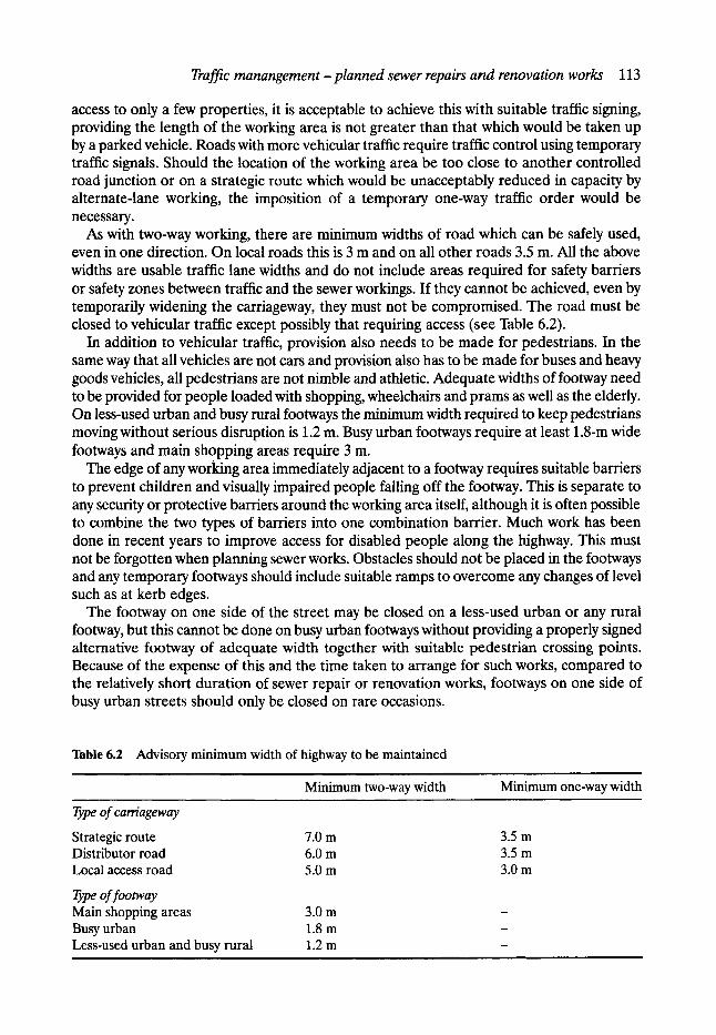
Traffic manangement- planned sewer repairs and renovation works 113
access to only a few properties, it is acceptable to achieve this with suitable traffic signing, providing the length of the working area is not greater than that which would be taken up by a parked vehicle. Roads with more vehicular traffic require traffic control using temporary traffic signals. Should the location of the working area be too close to another controlled road junction or on a strategic route which would be unacceptably reduced in capacity by alternate-lane working, the imposition of a temporary one-way traffic order would be necessary.
As with two-way working, there are minimum widths of road which can be safely used, even in one direction. On local roads this is 3 m and on all other roads 3.5 m. All the above widths are usable traffic lane widths and do not include areas required for safety barriers or safety zones between traffic and the sewer workings. If they cannot be achieved, even by temporarily widening the carriageway, they must not be compromised. The road must be closed to vehicular traffic except possibly that requiring access (see Table 6.2).
In addition to vehicular traffic, provision also needs to be made for pedestrians. In the same way that all vehicles are not cars and provision also has to be made for buses and heavy goods vehicles, all pedestrians are not nimble and athletic. Adequate widths of footway need to be provided for people loaded with shopping, wheelchairs and prams as well as the elderly. On less-used urban and busy rural footways the minimum width required to keep pedestrians moving without serious disruption is 1.2 m. Busy urban footways require at least 1.8-m wide footways and main shopping areas require 3 m.
The edge of any working area immediately adjacent to a footway requires suitable barriers to prevent children and visually impaired people falling off the footway. This is separate to any security or protective barriers around the working area itself, although it is often possible to combine the two types of barriers into one combination barrier. Much work has been done in recent years to improve access for disabled people along the highway. This must not be forgotten when planning sewer works. Obstacles should not be placed in the footways and any temporary footways should include suitable ramps to overcome any changes of level such as at kerb edges.
The footway on one side of the street may be closed on a less-used urban or any rural footway, but this cannot be done on busy urban footways without providing a properly signed alternative footway of adequate width together with suitable pedestrian crossing points. Because of the expense of this and the time taken to arrange for such works, compared to the relatively short duration of sewer repair or renovation works, footways on one side of busy urban streets should only be closed on rare occasions.
Table 6.2 Advisory minimum width of highway to be maintained
Minimum two-way width Minimum one-way width
Type of carriageway
Strategic route 7.0 m Distributor road 6.0 m Local access road 5.0 m
Type of footway Main shopping areas 3.0 m Busy urban 1.8 m Less-used urban and busy rural 1.2 m
3.5 m 3.5 m 3.0m
114 Traffic management and public relations
The disruption caused to traffic by any work on the highway means that repairs which do not require major excavations should only be carried out on busy roads outside peak travelling times. Night-time working, with the excavation covered by steel plates in the day, should also be considered. The possibility of using no-dig techniques should in any case receive careful consideration.
Having reached a tentative decision on the area of highway to be used for the sewer works, the local effect of the loss of this area to the public needs to be considered. The obvious item to check first is the effect on access to property from the area of highway affected. It is essential to provide pedestrian access from the highway to all properties. Direct vehicular access is not essential but the effect of denying access needs to be carefully considered. Having to park a car elsewhere may be a minor inconvenience to some residents (a major inconvenience to the disabled), but to others it may raise the risk of theft or damage to the car to unacceptable levels. Disruption to deliveries for business premises may vary from having to carry light loads a few metres across the highway to having to close down a production line and put the viability of the business at risk. Each sewer job requires individual checks on each affected property along with a properly organised consultation exercise so that the public is made aware of the need for the works and the proposed programme along with any subsequent changes which may become necessary.
As mentioned in the previous section, the local public transport operators should be con- suited on the need for alternative routes and stops for their buses, crossovers to alternative tracks for their trams, and battery-powered short diversions for trolley buses. Separate special traffic arrangements may be necessary for trolley buses and trams.
The temporary loss of certain street furniture such as street seats may only be an inconvenience, but alternative locations for traffic signals, street lights and traffic signs may be necessary in addition to more mundane items such as litter bins.
The implications of a fire in surrounding properties needs to be carefully considered. Fire escapes and hydrants must not be obstructed without the express consent of the chief fire officer, who may not agree without acceptable alternatives being already available or temporarily provided during the sewerage works.
Similarly, access chambers and valves will be needed by the statutory undertakings to inspect, maintain and repair their mains, and their consent is required before obstructing access to their apparatus. Licensed apparatus especially telecommunication links, are becoming more common and the owners of this equipment need to be consulted should it be proposed to restrict access to their apparatus.
Once the area immediately adjacent to the proposed working site has been considered and the limits of the operations finalised, it will be necessary to determine suitable diversion routes to replace any roads closed or made one-way. On strategic routes, which have had their capacity reduced, advisory alternative routes may be signed, even though a diversion is not necessary. Diversion routes must obviously be capable of taking the traffic being diverted along them. In addition to the route being available to all classes of vehicular traffic with no height, weight or width restrictions, the diversion route must also be structurally capable of taking the vehicle loading. A typical urban access road constructed of 50 mm of asphalt on 150 mm of stone setts on 200--300 mm of ash, is not suitable for repetitive loading by heavy goods vehicles and buses diverted from a distributor road, built to a higher specification. In cases where no suitable alternative exists, carriageway strengthening by overlaying the existing road foundation with a more substantial base and wearing course may be a necessary prerequisite to the sewerage works.
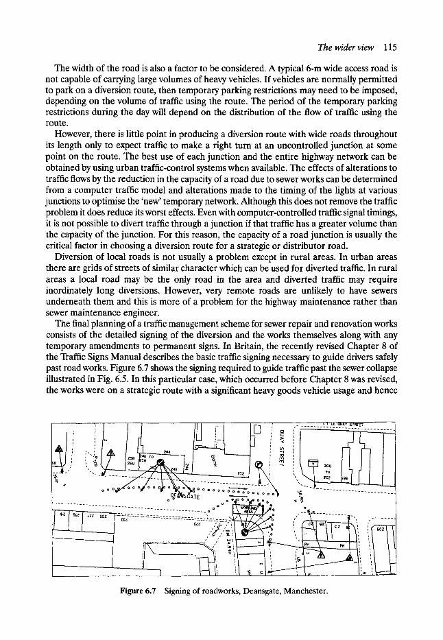
The wider view 115
The width of the road is also a factor to be considered. A typical 6-m wide access road is not capable of carrying large volumes of heavy vehicles. If vehicles are normally permitted to park on a diversion route, then temporary parking restrictions may need to be imposed, depending on the volume of traffic using the route. The period of the temporary parking restrictions during the day will depend on the distribution of the flow of traffic using the route.
However, there is little point in producing a diversion route with wide roads throughout its length only to expect traffic to make a right turn at an uncontrolled junction at some point on the route. The best use of each junction and the entire highway network can be obtained by using urban traffic-control systems when available. The effects of alterations to traffic flows by the reduction in the capacity of a road due to sewer works can be determined from a computer traffic model and alterations made to the timing of the lights at various junctions to optimise the 'new' temporary network. Although this does not remove the traffic problem it does reduce its worst effects. Even with computer-controlled traffic signal timings, it is not possible to divert traffic through a junction if that traffic has a greater volume than the capacity of the junction. For this reason, the capacity of a road junction is usually the critical factor in choosing a diversion route for a strategic or distributor road.
Diversion of local roads is not usually a problem except in rural areas. In urban areas there are grids of streets of similar character which can be used for diverted traffic. In rural areas a local road may be the only road in the area and diverted traffic may require inordinately long diversions. However, very remote roads are unlikely to have sewers underneath them and this is more of a problem for the highway maintenance rather than sewer maintenance engineer.
The final planning of a traffic management scheme for sewer repair and renovation works consists of the detailed signing of the diversion and the works themselves along with any temporary amendments to permanent signs. In Britain, the recently revised Chapter 8 of the Traffic Signs Manual describes the basic traffic signing necessary to guide drivers safely past road works. Figure 6.7 shows the signing required to guide traffic past the sewer collapse illustrated in Fig. 6.5. In this particular case, which occurred before Chapter 8 was revised, the works were on a strategic route with a significant heavy goods vehicle usage and hence
" . . . . . . . . . / - - / - - l - k _ _ "~" [ \ ; ', ~ l ,o, I,,~ I ! I / oo .Z:{o ~ ok A o ~:-~-~- , - . . . . . . . ~ - - - ~ - - ' \ - - - . __
o o ~E . . . . . ~ . . . . . . "~ T . . . . . . . . . . . o o e ao o .o_,,e o �9 o v . '~
. . . . . . . . . . . . . . . . . . o o o
. . . . . . . . . . . . . . . . . . . . o . " i . - . 'O.L _ . . . . . . " ~ t " - - - " - _ - - - - 2 2 - - 2 2 2 ~ 0 r " - -
I I I I czz , ' ;4" ;"~ l I ~ i ~ / - ~ ' . 0 I t "'*, I ~'~I I . . . . . , ' ~ ', I
,,,z,, ', / i 7/ i ' , I '~
! 1 ........................................... Figure 6.7 Signing of roadworks, Deansgate, Manchester.
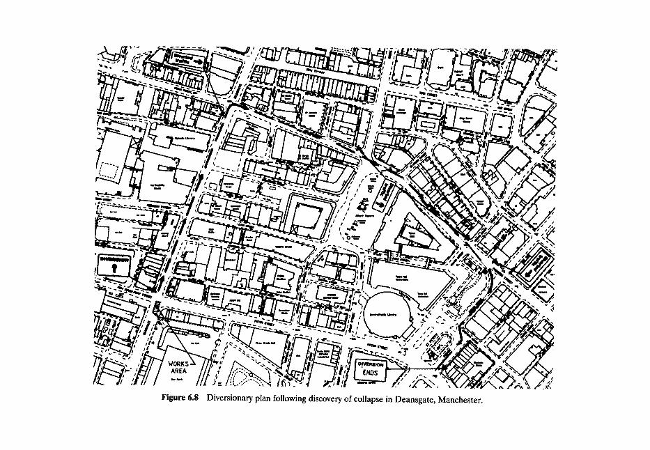
~L o~ iii ~ d
h m
~ ~ lmm N
AREA
Figure 6.8 Diversionary plan following discovery of collapse in Deansgate, Manchester.
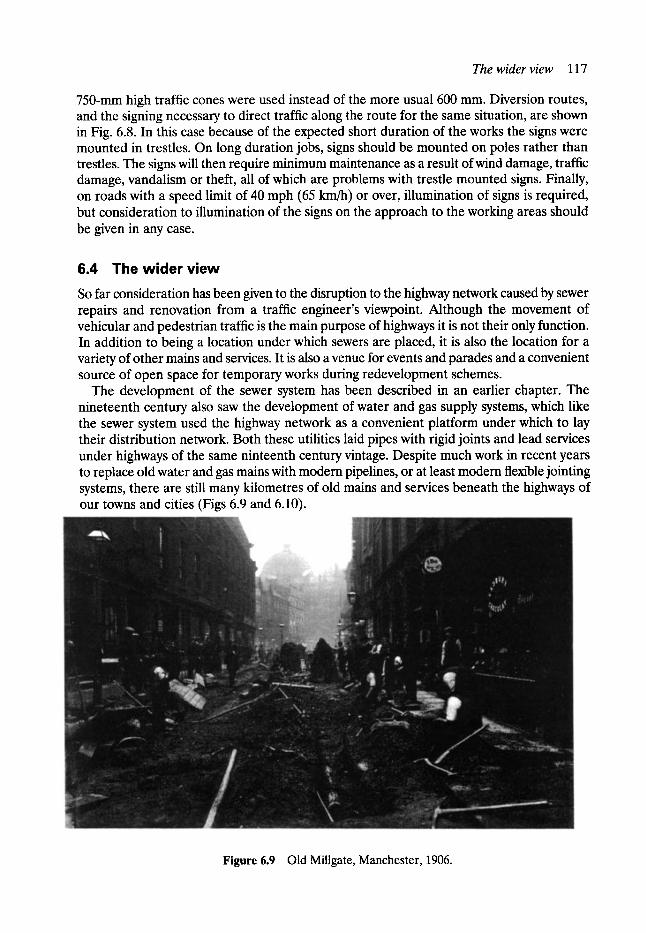
The wider view 117
750-mm high traffic cones were used instead of the more usual 600 mm. Diversion routes, and the signing necessary to direct traffic along the route for the same situation, are shown in Fig. 6.8. In this case because of the expected short duration of the works the signs were mounted in trestles. On long duration jobs, signs should be mounted on poles rather than trestles. The signs will then require minimum maintenance as a result of wind damage, traffic damage, vandalism or theft, all of which are problems with trestle mounted signs. Finally, on roads with a speed limit of 40 mph (65 km/h) or over, illumination of signs is required, but consideration to illumination of the signs on the approach to the working areas should be given in any case.
6.4 The wider view So far consideration has been given to the disruption to the highway network caused by sewer repairs and renovation from a traffic engineer's viewpoint. Although the movement of vehicular and pedestrian traffic is the main purpose of highways it is not their only function. In addition to being a location under which sewers are placed, it is also the location for a variety of other mains and services. It is also a venue for events and parades and a convenient source of open space for temporary works during redevelopment schemes.
The development of the sewer system has been described in an earlier chapter. The nineteenth century also saw the development of water and gas supply systems, which like the sewer system used the highway network as a convenient platform under which to lay their distribution network. Both these utilities laid pipes with rigid joints and lead services under highways of the same ninteenth century vintage. Despite much work in recent years to replace old water and gas mains with modem pipelines, or at least modem flexible jointing systems, there are still many kilometres of old mains and services beneath the highways of our towns and cities (Figs 6.9 and 6.10).
Figure 6.9 Old Millgate, Manchester, 1906.
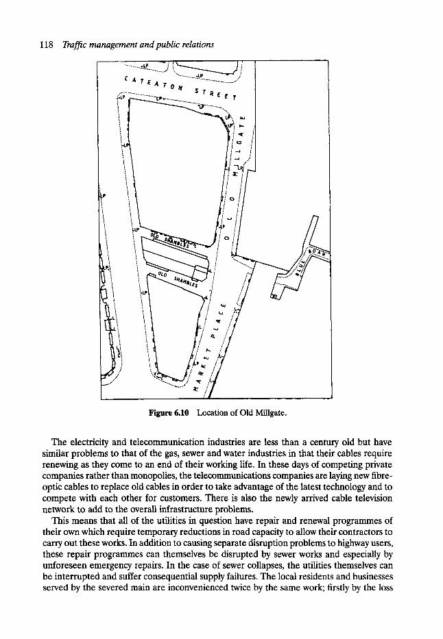
118 Traffic management and public relations
L',
,_...~176
" . . . . . . . . . . . . L P e . . . . . . . . . . . . . .-. . . . . . . . . "
C A T E A T O N $ T Rs E T
i
Figure 6.10 Location of Old Millgate.
The electricity and telecommunication industries are less than a century old but have similar problems to that of the gas, sewer and water industries in that their cables require renewing as they come to an end of their working life. In these days of competing private companies rather than monopolies, the telecommunications companies are laying new fibre- optic cables to replace old cables in order to take advantage of the latest technology and to compete with each other for customers. There is also the newly arrived cable television network to add to the overall infrastructure problems.
This means that all of the utilities in question have repair and renewal programmes of their own which require temporary reductions in road capacity to allow their contractors to carry out these works. In addition to causing separate disruption problems to highway users, these repair programmes can themselves be disrupted by sewer works and especially by unforeseen emergency repairs. In the case of sewer collapses, the utilities themselves can be interrupted and suffer consequential supply failures. The local residents and businesses served by the severed main are inconvenienced twice by the same work; firstly by the loss
The wider view 119
of the utility, and secondly by the traffic congestion caused during the emergency repairs and possibly at a further stage by the execution of more extensive renovation work.
Hardly a week passes in our larger cities without a parade, procession, protest march, celebration or road race by car, cycle or foot taking place on the public highway. These legitimate uses of the highway are usually planned, and the date and route fixed, months in advance. Planned sewer works should therefore be organised in such a manner as not to interfere with the event. Luckily it is rare, but not unheard of, for an event on the highway to coincide with a sewer collapse on the route, but obviously this is a potential hazard.
Redevelopment of existing properties is nowadays commonplace, especially in establish- ed city areas. As the price of land in urban locations is extremely high, the sites are usually redeveloped in such a manner as to completely fill the site with the permanent works. Most city buildings are already constructed in a similar fashion and this puts more pressure on the use of the highway. As well as the disruption caused to highway users by the making of new service connections to the building, further disruption is caused by temporary works. The highway is often the only area adjacent to the works which can be made available for vehicles serving the demolition and reconstruction works and for working areas for the contractor to construct the new facade and often to locate works cabins and offices.
Finally, as mentioned earlier, the Highway Authority also has to carry out its own programme of repair and renovation works to keep the crumbling highway network in an adequate state of repair. To the general public the reason for the roadworks is immaterial. They expect to use the highway to travel along and to receive the various services from the statutory undertaking unhindered. If their journey is disrupted or their gas or water service cut off they will quite understandably want to see a return to normal service as soon as possible and will have little sympathy with the view that it is impossible to achieve both continued service supply and highway availability at the same time.
The maintenance, renewal and new construction regimes of electricity distribution, gas supply, water supply, sewerage, telecommunications, highway and transport authorities and companies all have an effect on the availability of the often overloaded highway for its prime purpose of moving people. In the UK control of the many thousands of road openings in each municipality every year was until recently exercised through the Public Utilities Street Works Act of 1950, which was enacted before the need for so many repairs, replacements, new constructions and new connections was envisaged. It was also introduced before computers were readily available to both record and transmit information from one company or authority to another. It is hoped that one benefit to be derived from the New Roads and Street Works Act 1991 will be a better coordination of all the various utilities' streetworks and a reduction in highway disruption and the consequential social and environmental costs.
At present each company has its own method of inspecting, repairing and renewing its assets. An annual programme of works is prepared by each company but even this is not made available to other utilities until shortly before work commences on site. A three-year rolling programme of planned works notified to each statutory undertaking would go some way towards reducing the number of streets which are excavated and reinstated by first one utility and then another within a matter of months. The frequency of excavations in the highway will eventually only be reduced to a manageable level by the adoption of adequate inspection and maintenance regimes by all utilities and, as mentioned earlier in the chapter, a commitment to the overall public good as well as the greater acceptance of no-dig techniques.
An example of this lack of commitment to the overall public good is the ludicrous, but legal situation, which existed in the UK prior to 1992 in that water companies were not
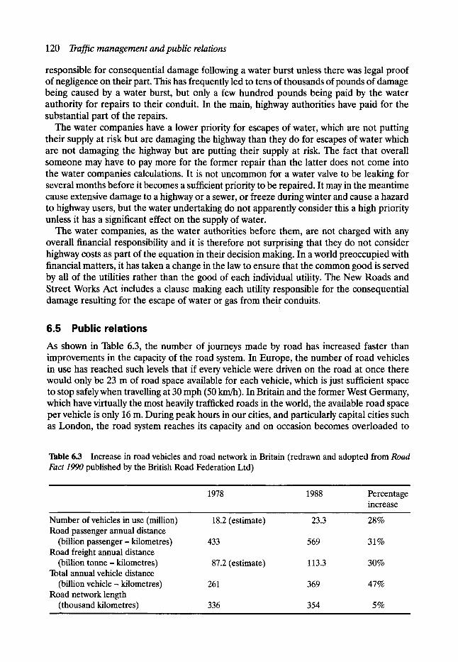
120 Traffic management and public relations
responsible for consequential damage following a water burst unless there was legal proof of negligence on their part. This has frequently led to tens of thousands of pounds of damage being caused by a water burst, but only a few hundred pounds being paid by the water authority for repairs to their conduit. In the main, highway authorities have paid for the substantial part of the repairs.
The water companies have a lower priority for escapes of water, which are not putting their supply at risk but are damaging the highway than they do for escapes of water which are not damaging the highway but are putting their supply at risk. The fact that overall someone may have to pay more for the former repair than the latter does not come into the water companies calculations. It is not uncommon for a water valve to be leaking for several months before it becomes a sufficient priority to be repaired. It may in the meantime cause extensive damage to a highway or a sewer, or freeze during winter and cause a hazard to highway users, but the water undertaking do not apparently consider this a high priority unless it has a significant effect on the supply of water.
The water companies, as the water authorities before them, are not charged with any overall financial responsibility and it is therefore not surprising that they do not consider highway costs as part of the equation in their decision making. In a world preoccupied with financial matters, it has taken a change in the law to ensure that the common good is served by all of the utilities rather than the good of each individual utility. The New Roads and Street Works Act includes a clause making each utility responsible for the consequential damage resulting for the escape of water or gas from their conduits.
6.5 Public relations As shown in Table 6.3, the number of journeys made by road has increased faster than improvements in the capacity of the road system. In Europe, the number of road vehicles in use has reached such levels that if every vehicle were driven on the road at once there would only be 23 m of road space available for each vehicle, which is just sufficient space to stop safely when travelling at 30 mph (50 km/h). In Britain and the former West Germany, which have virtually the most heavily trafficked roads in the world, the available road space per vehicle is only 16 m. During peak hours in our cities, and particularly capital cities such as London, the road system reaches its capacity and on occasion becomes overloaded to
Table 6.3 Increase in road vehicles and road network in Britain (redrawn and adopted from Road Fact 1990 published by the British Road Federation Ltd)
1978 1988 Percentage increase
Number of vehicles in use (million) Road passenger annual distance
(billion passenger - kilometres) 433 Road freight annual distance
(billion tonne- kilometres) Total annual vehicle distance
(billion vehicle - kilometres) 261 Road network length
(thousand kilometres) 336
18.2 (estimate) 23.3 28%
569 31%
87.2 (estimate) 113.3 30%
369 47%
354 5%

Public relations 121
such an extent that traffic comes to a virtual standstill for a considerable length of time each day. This condition is best described by the American term 'gridlock'.
US city streets are normally constructed in a grid pattern. When vehicles attempting to travel along the streets match the capacity of the streets, it only requires one incident such as a vehicle breakdown or accident - or sewer collapse - to block a junction which progres- sively leads to many more junctions becoming blocked so that the whole grid of streets becomes locked with traffic or gridlocked.
Apart from vehicle incapacity, which can usually be swiftly remedied, roadworks are most likely to be the cause of gridlock, especially if they are imposed unexpectedly as in the case of a sewer collapse or collapses. The choice of which area of road is to be restricted is extremely limited following a sewer collapse and the sudden imposition of any significant reduction in capacity of a junction on a strategic city centre route will almost certainly lead to gridlock during peak times.
Having gained the best possible capacity out of the junction by careful selection of working areas, the only other way to improve matters is to reduce the demand for road space and this is where public relations enters the arena. Public relations are much more than rapid com- munication with the travelling public, but this rapid communication has the most dramatic results in the scenario outlined above. Local radio stations are listened to by a significant pro- portion of the commuters who travel by road. An announcement on a local radio station that a certain road is to be avoided because of a sewer collapse does reduce the demand for that road, although this is difficult to measure definitively. If local demand is reduced sufficiently, the immediate highway network may not become overloaded, but the problem may become manifest elsewhere, although dilution may result with little overall inconvenience.
Public relations in connection with sewer works on the highway can be extensive. They cover legal notices, road signs, press advertisements and articles, radio announcements, letters, telephone responses, personnel meetings and the works themselves. This last point should not be overlooked as the public's perception of what is going on is an important aspect of public relations and the travelling public will become even more dissatisfied if they see a section of cordoned-off road causing traffic disruption but no work taking place. It is consequently desirable from a public relations point of view to have operatives actively working on a site not only during the normal working day but also during the peak travelling times.
In the UK legal requirements for non-emergency traffic orders necessary to permit sewer repair or renovation works to take place are that an order be made under Section 14 of the Road Traffic Regulation Act 1984. Legal notices are posted on the highway, usually on street- lighting columns, and placed in local newspapers. Apart from the necessary diversion and roadworks signs themselves, this is all that is legally required prior to the works commencing. However, not all of the people that would be affected by the sewer works will read the legal notices in small print in the inside pages of the local press and even fewer will make a habit of reading street lighting columns! As a means of informing the various interested parties, legal notices are not particularly useful.
Local radio has already been mentioned as a useful means of letting drivers know of emergency works. Similarly, it is also particularly appropriate as means of informing the travelling public of works in progress or about to start. However, car drivers are by no means the only members of the public and there are several groups of people who require informing of sewer repair and renovation works.
Repair works in residential areas can be of very little importance to the vast majority of people but they can be very disruptive to the local residents. The method of working is
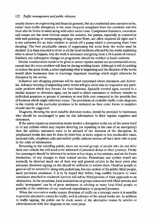
122 Traffic management and public relations
usually chosen on engineering and financial grounds, but in a residential area excessive noise, rather than traffic disruption, is the most frequent complaint from the residents and this must also be borne in mind along with other social costs. Compressor hammers, excavators and cranes are the most obvious causes for concern, but pumps, especially in connection with well pointing or overpumping of large sewer flows, are often required all night and it is not unknown for an irate resident to switch off a pump which is preventing them from sleeping! The best practicable means of suppressing the noise from the works must be decided. It is then essential to write to all the local residents affected by the works explaining what is about to happen, why the work is necessary and giving them a 24-h point of contact. Similarly any subsequent changes in programme should be notified to local residents.
Similar consideration needs to be given to sewer repairs carried out in commercial areas, except that the noise problem will then be during working hours. Although it will do nothing to reduce the noise levels, a letter explaining what is happening and the duration of the works would allow businesses time to rearrange important meetings which might otherwise be disrupted by the works.
Industrial and shopping premises will be most concerned about customers and deliver- ies. Advance warning of impending sewer works will give them time to respond to any parti- cular problem which they foresee for their business. Specially worded signs, erected in a similar manner to diversion signs, can be used to direct customers or delivery vehicles to individual premises or groups of premises at very little cost compared to the possible loss of business which might otherwise ensue. The provisions of available traffic route diagrams in the vicinity of the particular premises to be included on their order forms to suppliers should also be suggested.
Diagrams, showing the most suitable diversion routes, should be provided to businesses who should be encouraged to pass on this information to their regular suppliers and customers.
If the sewer repairs or renovation works involve a disruption to the use of the sewer itself or of any utilities which may require diverting (or repairing in the case of an emergency) then the utilities customers need to be advised of the duration of the disruption. In preplanned works this may be done by letter but, in more urgent or less predictable cases, personal calls, telephone calls and mobile public address systems all have their role to play in the relay of information.
Returning to the travelling public, there are several groups of people who do not drive their own vehicle but still need to be informed of potential delays to their journeys. Firstly bus passengers should be informed by notices at bus stops, at bus stations, and on the buses themselves, of any changes to their normal service. Pedestrians and cyclists would not normally be diverted much out of their way and general articles in the local press plus adequate diversion signing on site should be sufficient to inform them. Disabled people in general will be catered for along with pedestrians, but one section of the public, blind people, need particular assistance. It is to be hoped that before long audible bleepers or voice simulators attached to roadwork barriers will advise blind persons of their approach to an obstruction. In the meantime, local associations or groups connected with blind persons and audio 'newspapers' can be of great assistance in advising as many local blind people as possible of the existence of any roadwork impediments to proposed journeys.
When the renovation works require diversion of traffic on a strategic route it is sensible to provide alternative routes for traffic, well in advance of the actual works site. In addition to traffic signing, the public can be made aware of the alternative routes by articles or advertisements with line diagrams in the local press.
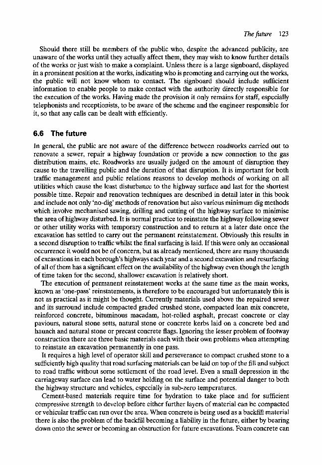
Thefuture 123
Should there still be members of the public who, despite the advanced publicity, are unaware of the works until they actually affect them, they may wish to know further details of the works or just wish to make a complaint. Unless there is a large signboard, displayed in a prominent position at the works, indicating who is promoting and carrying out the works, the public will not know whom to contact. The signboard should include sufficient information to enable people to make contact with the authority directly responsible for the execution of the works. Having made the provision it only remains for staff, especially telephonists and receptionists, to be aware of the scheme and the engineer responsible for it, so that any calls can be dealt with efficiently.
6.6 The future In general, the public are not aware of the difference between roadworks carried out to renovate a sewer, repair a highway foundation or provide a new connection to the gas distribution mains, etc. Roadworks are usually judged on the amount of disruption they cause to the travelling public and the duration of that disruption. It is important for both traffic management and public relations reasons to develop methods of working on all utilities which cause the least disturbance to the highway surface and last for the shortest possible time. Repair and renovation techniques are described in detail later in this book and include not only 'no-dig' methods of renovation but also various minimum dig methods which involve mechanised sawing, drilling and cutting of the highway surface to minimise the area of highway disturbed. It is normal practice to reinstate the highway following sewer or other utility works with temporary construction and to return at a later date once the excavation has settled to carry out the permanent reinstatement. Obviously this results in a second disruption to traffic whilst the final surfacing is laid. If this were only an occasional occurrence it would not be of concern, but as already mentioned, there are many thousands of excavations in each borough's highways each year and a second excavation and resurfacing of all of them has a significant effect on the availability of the highway even though the length of time taken for the second, shallower excavation is relatively short.
The execution of permanent reinstatement works at the same time as the main works, known as 'one-pass' reinstatements, is therefore to be encouraged but unfortunately this is not as practical as it might be thought. Currently materials used above the repaired sewer and its surround include compacted graded crushed stone, compacted lean mix concrete, reinforced concrete, bituminous macadam, hot-rolled asphalt, precast concrete or clay paviours, natural stone setts, natural stone or concrete kerbs laid on a concrete bed and haunch and natural stone or precast concrete flags. Ignoring the lesser problem of footway construction there are three basic materials each with their own problems when attempting to reinstate an excavation permanently in one pass.
It requires a high level of operator skill and perseverance to compact crushed stone to a sufficiently high quality that road surfacing materials can be laid on top of the fill and subject to road traffic without some settlement of the road level. Even a small depression in the carriageway surface can lead to water holding on the surface and potential danger to both the highway structure and vehicles, especially in sub-zero temperatures.
Cement-based materials require time for hydration to take place and for sufficient compressive strength to develop before either further layers of material can be compacted or vehicular traffic can run over the area. When concrete is being used as a backfill material there is also the problem of the backfill becoming a liability in the future, either by bearing down onto the sewer or becoming an obstruction for future excavations. Foam concrete can

124 Traffic management and public relations
overcome both these problems, as it does not develop excessive strength or density but it still requires time to develop its compressive strength.
Asphalt and bituminous materials have the advantage of being able to carry traffic relatively quickly, but there are disadvantages in requiring different materials for roadbase, base course and wearing course, coupled with the problem of securing adequate compac- tion in a trench. It is also unlikely that the sewer operatives who carry out the repair to the sewer will be capable of using these materials correctly. In the case of the other utilities, who tend to have shallower excavations but more of them, the lack of adequate training of the operatives and supervisors, who carry out the backfill compaction and lay the finished surface is a major reason for the inability of service undertakings to carry out 'one-pass' reinstatements. In the future as more services, such as cable television companies, require more ducts in the highway the number of excavations is bound to increase and the need for one-pass reinstatement or at least minimal secondary reinstatement works, will intensify.
The New Road and Street Works Act 1991 enabled central government in the UK to lay down detailed codes of practice for anyone excavating in the highway to comply with notification periods, training requirements, work specification and safety. It is expected that this will encourage better reinstatements and minimise disruption to the road user.
Coordination of works on the highway is now the responsibility of highway authorities who will use information stored in a computerised street works register to assist them. There is a statutory duty on Undertakings and Highway Authorities to register all their street works and by freely exchanging advance information on major work programmes it is expected that an improved programme of street works will lead to less disruption to the public. The Act encourages more detailed consideration of 'traffic sensitive streets' and 'streets with special engineering difficulties' by requiring longer notice periods and more details to be registered for works on these types of streets.
Improved safety standards, by guiding vehicles and pedestrians safely past street works, are now mandatory along the lines of the revised Chapter 8 of the Traffic Signs Manual. Particular emphasis on safety zones and provisions for disabled people are included in these measures.
The standard of work in reinstating the highway is given the highest priority by the new Act. National reinstatement standards are controlled by a mandatory reinstatement speci- fication and training and accreditation schemes for workers, supervisors and managers of reinstatement works. As sewers are laid relatively deeply, they require significant depths of backfill and reinstatement. Sewering work will require improved standards on open-cut schemes to comply with the new Act. This will encourage the use of self-compacting backfill materials and trenchless technology.
Bibliography Code of Practice for the Co-ordination of Streetworks and Works for Road Purposes and Related Matters.
HMSO, 1992. Highway Maintenance- A Code of Good Practice. Local Authority Associations, 1989. Safety at Streetworks and Roadworks. HMSO, 1992. Specification for the Reinstatement of Openings in Highways. HMSO, 1992. Traffic Sign Manual, Chapter 8 (Traffic Safety Measures and Signs for Roadworks and Temporary
Situations). HMSO, 1991.
7 Access
D. M. Farrar* BSc, MSc, PhD, CEng, MICE, MCIWEM
7.1 Present-day requirements Access is provided to sewerage systems for two main reasons:
�9 for maintenance purposes, such as sewer cleansing and carrying out routine repairs and �9 to enable the system to be surveyed, either for operational purposes, e.g. investigation
of poor performance resulting from any excessive sedimentation or tree roots, or for assessing structural condition.
A further important reason for providing access to certain sewers would be to establish a working place from which major repairs or sewer renovation could be undertaken. This requirement applies particularly to sewers which are deep or awkwardly situated and excavation from the surface would be costly, impracticable or disruptive to the community.
An assessment of these factors establishes the spacing of access points on the system and the type of manhole to be provided, in particular its size and facilities.
A distinction is made between man-entry and non-man-entry sewers. The former are generally classified as those greater than 1000 mm in diameter (BS8005, 1987) though this restriction is reduced to 900 mm principal dimension in the recent edition of BS6164 (1990) which is concerned with working environments.
For non-man-entry sewers present-day design practice is for manholes to be located at every change in alignment of the sewer, at changes of gradient, at the extremities of the system, at changes in sewer size, and at every junction of two or more sewers.
Here the implication is that access points for this type of construction could be less frequent because the sewer is likely to be deep and/or be located where surface access is awkward and therefore manhole construction costs could be unacceptably high.
Increasingly, health and safety considerations for working environments are being recognised as the controlling factor for spacing manholes. Sewers are 'confined spaces' under health and safety legislation and, as such, breathing apparatus may be needed for work with- in the sewer, or at the least 'escape' breathing sets may be necessary for work to be carried out with safety. In these circumstances the criterion for manhole spacing would be the distance which could be safely negotiated whilst evacuating the sewer in the time provided by the escape breathing apparatus. This is usually of around 10-min duration.
*Kennedy Construction Ltd.
126 Access
The depth of the sewer below ground will then become a significant factor to be consider- ed, particularly where ladders and rest platforms have to be negotiated on deep manholes. These are the sewers likely to have been constructed in tunnel and therefore there could well be a need for reduced spacing of manholes for these sewers.
Sewers in this category form a small proportion of the sewerage network and it would be appropriate for individual design criteria to be established in each case. These could take into account specific local conditions, such as the likelihood of toxic discharges into the sewer, but as a general rule for present-day practice, spacing of manholes on foul sewers, or those receiving industrial discharges, should not exceed 200 m.
However, a number of factors can be identified which suggest future trends are towards increasing the spacing of manholes.
The first of these is the widespread demand for minimising periods of highway occupancy for construction activities. Most access manholes are located within the carriageway and increased manhole spacing would not only lessen traffic disruption during the construction period, but would also reduce the likelihood of disruption during subsequent inspection and maintenance.
Satisfying demands for free-flowing traffic in the past has compromised the construction and operational requirements of sewerage systems, but new developments in tunnelling technology and in remote inspection and repair methods allow the designer greater freedom in the routing of sewers and particularly in the spacing of manholes.
Modem machine tunnelling and pipejacking methods enable a sewer of several hundred metres in length to be safely undertaken as a single drive from a working shaft. Drive lengths exceeding 200 m undertaken by microtunnelling methods (for sewers of 1000 mm diameter or less) are also feasible and thus limitations of tunnelling technology no longer impose major constraints on manhole spacing in new sewers.
Similarly, remote methods for sewer inspection and maintenance are being used with increasing confidence over longer lengths. Further developments are likely to extend their use to the smaller man entry systems. At the same time improved design and construction standards for sewers will lead to a lesser requirement for routine maintenance, and therefore it can be predicted that the need for persons to enter sewers in the future will be greatly reduced. As a consequence distances between manholes could be increased significantly.
However, there will always be occasions when man-entry inspections or repairs are the only solution to operational problems, but these could be dealt with by treating them as special events with a greater emphasis on the safety implications for confined space working.
7.2 Access in early sewers Manchester, as the first British industrial city, provides the prime example of sewerage systems constructed with the specific purpose of serving the rapid town expansion of the early and mid-nineteenth century. At the peak of sewer construction in the 1840s upwards of 2 km a year were being built within the present-day inner city areas, and by 1869 the city surveyor was able to report that every street within the Manchester township boundary was sewered.
No permanent provision was made for access into these nineteenth-century sewers. The intention appears to have been that should problems arise with a sewer, excavation would be made to open up a 'blind-eye' shaft referred to in an earlier chapter.
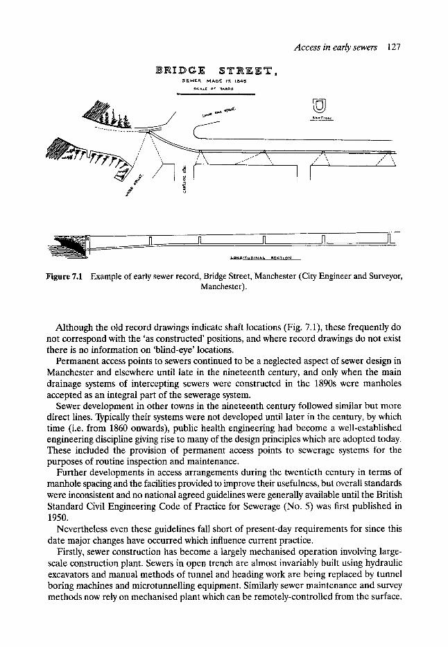
5 F_WER M A D F - I1~1 1 ~ 5
S ~ L E OF YARDS , . . . . . . . . . .
t.o * ~ ~ ~, ' f~"
Access in early sewers 127
�9 i ra Ti o l .4
~- %, p , ..'~ - " i
n , N rl . ,fL
. t .o~G,T~t l~Nk t~ S g c T l o ~ l ,
Figure 7.1 Example of early sewer record, Bridge Street, Manchester (City Engineer and Surveyor, Manchester).
Although the old record drawings indicate shaft locations (Fig. 7.1), these frequently do not correspond with the 'as constructed' positions, and where record drawings do not exist there is no information on 'blind-eye' locations.
Permanent access points to sewers continued to be a neglected aspect of sewer design in Manchester and elsewhere until late in the nineteenth century, and only when the main drainage systems of intercepting sewers were constructed in the 1890s were manholes accepted as an integral part of the sewerage system.
Sewer development in other towns in the nineteenth century followed similar but more direct lines. Typically their systems were not developed until later in the century, by which time (i.e. from 1860 onwards), public health engineering had become a well-established engineering discipline giving rise to many of the design principles which are adopted today. These included the provision of permanent access points to sewerage systems for the purposes of routine inspection and maintenance.
Further developments in access arrangements during the twentieth century in terms of manhole spacing and the facilities provided to improve their usefulness, but overall standards were inconsistent and no national agreed guidelines were generally available until the British Standard Civil Engineering Code of Practice for Sewerage (No. 5) was first published in 1950.
Nevertheless even these guidelines fall short of present-day requirements for since this date major changes have occurred which influence current practice.
Firstly, sewer construction has become a largely mechanised operation involving large- scale construction plant. Sewers in open trench are almost invariably built using hydraulic excavators and manual methods of tunnel and heading work are being replaced by tunnel boring machines and microtunnelling equipment. Similarly sewer maintenance and survey methods now rely on mechanised plant which can be remotely-controlled from the surface.
128 Access
These changes from manual to mechanised methods are reflected in manhole design. Manholes are now constructed on a scale compatible with the plant and component materials available. Hence there is now widespread use of precast concrete components and manholes are sized to suit construction plant and maintenance equipment rather than the less demanding requirements for solely man access and manual labour.
The second major change is the increasing attention which is given to health and safety considerations of personnel who enter sewers. This change, which has occurred alongside the trend of increased mechanisation, is partly the result of demands to reduce operational costs by cutting down on routine maintenance and inspections of sewers by gangs of workers. Traditionally, sewer gangs regularly walked the main sewers and carried out cleansing and minor repairs largely by manual methods. In fact, a certain degree of reliance was placed on these typically long-serving workers being familiar with the sewerage system and being aware of the trouble spots, such as lengths prone to blockages, sewer gas problems or manholes known to be in a dangerous structural condition.
Although the benefits of local knowledge should never be discounted, its seemingly inevitable loss can be counteracted to some degree by removing the known hazards, by standardisation of access arrangements and by the adoption of common safety procedures. These considerations, together with the trend in society as a whole for greater safety awareness, have major implications for manhole design.
A basic premise for considering safety aspects of manhole design is that people required to gain access to sewers will be of a sound state of health (both physically and mentally) and will have been adequately trained for the task.
Suitable training should ensure that persons would be fully aware of the conditions and potential hazards to be encountered, would have knowledge of basic first aid including the use of respiratory equipment and would have experience of equipment for testing and monitoring the atmosphere. Training would also include systems of communication between members of the workforce, and procedures for escape and rescue.
Manhole design contributes to the objective of providing a safe work place. Standard- isation of the features and layouts of manholes not only provides a familiar environment for persons entering a sewer, but also ensures maximum efficiency during emergency procedures.
The main considerations are to provide sufficient space for access and safe working, bearing in mind that members of a sewer gang may be wearing breathing apparatus, and to ensure that the manhole structure itself presents no hazardous projections. Cavities and defects which could be exploited by rodents should be avoided.
Protective handrailing should be fitted to landing platforms and high sewer benchings, and grab handles provided at steps or transitions. The selection of the material for 'metal- work', whether wrought/cast iron, galvanised steel, stainless steel, aluminium or glass- reinforced plastic (GRP), should take into account the durability of the material in the atmospheric and flow conditions to be encountered. Metalwork detailing should preferably be consistent throughout the sewerage system so that, for example, ladder rungs and step irons are always the same uniform spacing. Benching surfaces should be sloping and smooth (but not slippery) so that deposition of sewage solids and debris is prevented.
Finally, design considerations extend beyond the manhole chamber to the point where access is gained. Extension ladders are available which can be pulled up above the manhole cover level to facilitate access, and if possible manhole covers should be located off the carriageway away from road traffic. In extreme cases, it may be desirable to construct man- holes in a safe zone, off line of the sewer, allowing a 'side entry' access to the system.
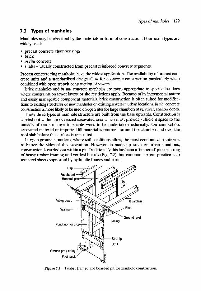
Types o f manholes 129
7.3 Types of m a n h o l e s
Manholes may be classified by the materials or form of construction. Four main types are widely used:
�9 precast concrete chamber rings �9 brick �9 in situ concrete �9 shafts - usually constructed from precast reinforced concrete segments.
Precast concrete ring manholes have the widest application. The availability of precast con- crete units and a standardised design allow for economic construction particularly when combined with open trench construction of sewers.
Brick manholes and in situ concrete manholes are more appropriate to specific locations where constraints on sewer layout or site restrictions apply. Because of its incremental nature and easily manageable component materials, brick construction is often suited for modifica- tions to existing structures or new manholes on existing sewers in urban locations. In situ concrete construction is more likely to be used on open sites for large chambers at relatively shallow depth.
These three types of manhole structure are built from the base upwards. Construction is carried out within an oversized excavated area which must provide sufficient space to the outside of the structure to enable work to be undertaken externally. On completion, excavated material or imported fill material is returned around the chamber and over the roof slab before the surface is reinstated.
In open ground situations, where soil conditions allow, the most economical solution is to batter the sides of the excavation. However, in made up areas or urban situations, construction is carried out within a pit. Traditionally this has been a 'timbered' pit consisting of heavy timber framing and vertical boards (Fig. 7.2), but common current practice is to use steel sheets supported by hydraulic frames and struts.
Cap J
Faceboard Handrail post
Poling board ~ ~ < ~ ~ , ~ ~ ~ , ~ J J J Guard rail
Waling ~ ~ ~ Biat
Puncheon or prop- Lacing
Ground level
Ground prop or leg Foot block
Figure 7.2 Timber framed and boarded pit for manhole construction.
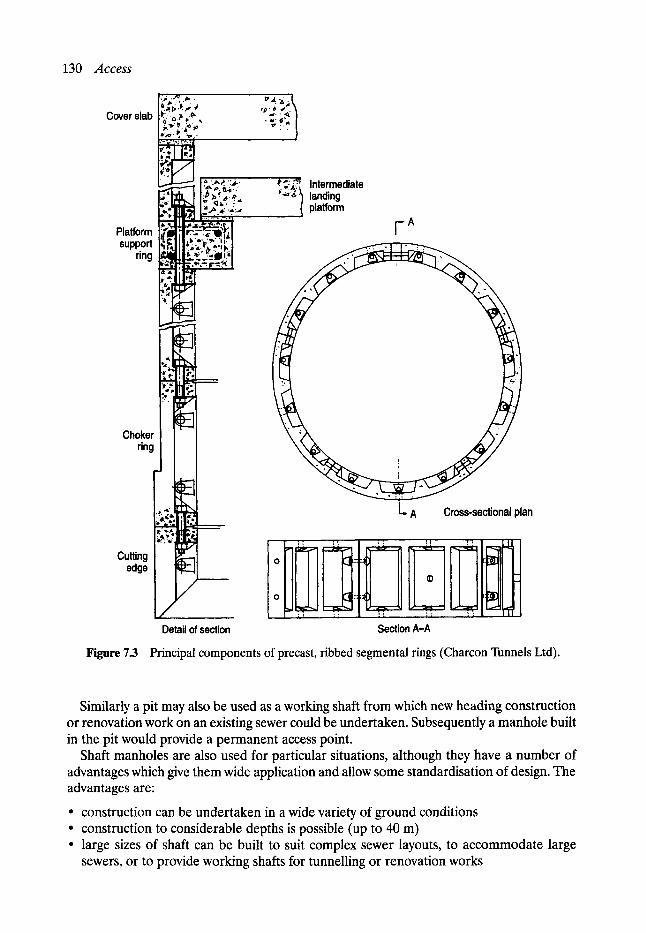
130 Access
Cover slab 1~.~..,.} ;.~., .
1 ,-,*" ~, ~, �9
.' !~.'" ".'.'. .g ~ ~ platform
Platform support
ring
Choker ring
. . . .~ , ~# j.,
Cutting edge
Detail of section
1- A Cross-sectional plan
O
O
Section A-A Figure 7.3 Principal components of precast, ribbed segmental rings (Charcon Tunnels Ltd).
Similarly a pit may also be used as a working shaft from which new heading construction or renovation work on an existing sewer could be undertaken. Subsequently a manhole built in the pit would provide a permanent access point.
Shaft manholes are also used for particular situations, although they have a number of advantages which give them wide application and allow some standardisation of design. The advantages are:
�9 construction can be undertaken in a wide variety of ground conditions �9 construction to considerable depths is possible (up to 40 m) �9 large sizes of shaft can be built to suit complex sewer layouts, to accommodate large
sewers, or to provide working shafts for tunnelling or renovation works
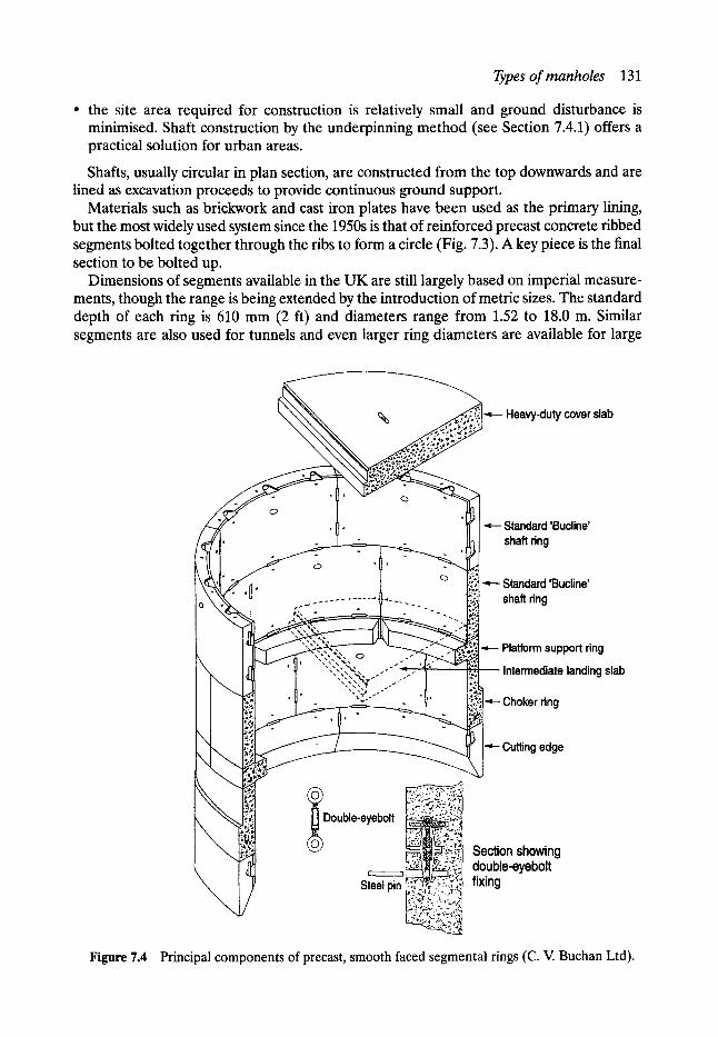
Types of manholes 131 �9 the site area required for construction is relatively small and ground disturbance is
minimised. Shaft construction by the underpinning method (see Section 7.4.1) offers a practical solution for urban areas.
Shafts, usually circular in plan section, are constructed from the top downwards and are lined as excavation proceeds to provide continuous ground support.
Materials such as brickwork and cast iron plates have been used as the primary lining, but the most widely used system since the 1950s is that of reinforced precast concrete ribbed segments bolted together through the ribs to form a circle (Fig. 7.3). A key piece is the final section to be bolted up.
Dimensions of segments available in the UK are still largely based on imperial measure- ments, though the range is being extended by the introduction of metric sizes. The standard depth of each ring is 610 mm (2 ft) and diameters range from 1.52 to 18.0 m. Similar segments are also used for tunnels and even larger ring diameters are available for large
Heavy-duty cover slab
_ . _ . . _ - . ~ _ , ,
, , ~ Standard 'Bucline' . - . shaft ring
-
o , I , .
~ Standard 'Bucline' .- . . . . . . . . . . . . . . . . . . . . . . shaft ring
" ' ~ Platform support ring ' 2 . " , N~ . o .
"-"-'~, -'" ~ Intermediate landing slab
.,..4" ..- i 1 "'=~;'"'" - ' ~ ~ Choker ring ~
l: / f ' ~ ~ ~ ~ Cutting edge
Double-eyebolt , ~ .... ~,.;
Steel pin ~ t ~ , ~ t l : - :~:
Section showing double-eyebolt fixing
Figure 7.4 Principal components of precast, smooth faced segmental rings (C. V. Buchan Ltd).
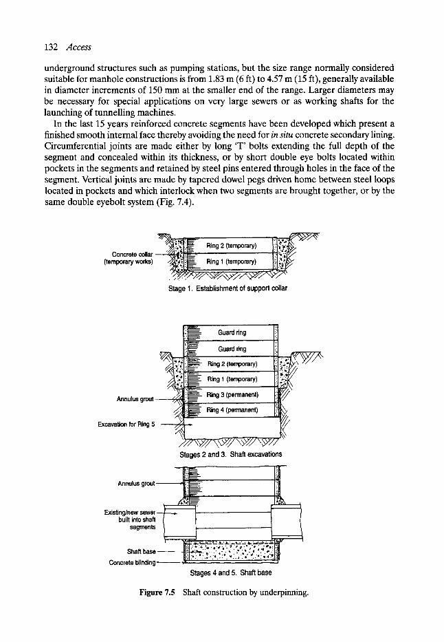
132 Access
underground structures such as pumping stations, but the size range normally considered suitable for manhole constructions is from 1.83 m (6 ft) to 4.57 m (15 ft), generally available in diameter increments of 150 mm at the smaller end of the range. Larger diameters may be necessary for special applications on very large sewers or as working shafts for the launching of tunnelling machines.
In the last 15 years reinforced concrete segments have been developed which present a finished smooth internal face thereby avoiding the need for in situ concrete secondary lining. Circumferential joints are made either by long 'T' bolts extending the full depth of the segment and concealed within its thickness, or by short double eye bolts located within pockets in the segments and retained by steel pins entered through holes in the face of the segment. Vertical joints are made by tapered dowel pegs driven home between steel loops located in pockets and which interlock when two segments are brought together, or by the same double eyebolt system (Fig. 7.4).
;:,=!;~" Ring 2 (temporary) i .. ;,.~ Concrete collar ! ! ~ "~i
(temporary works) Ring 1 (temporary) !" ~'~~
Stage 1. Establishment of support collar
: : i~_ Guard ring i: . .
�9 ..: .__ .j.: i'i ~ Guard ring ::,
,k',;2.,., Ring 2 (temporary) [i! �9 ~. ~ i" ~ ;.
�9 . . o ~ ~ ; i ~ Ring 1 (temporary) iil .. :i ~
Annulus grout !!~------ Ring 3 (permanent) '. " ' ~
Ring 4 (permanent) 1:~i Excavation for Ring 5
Stages 2 and 3. Shaft excavations
Annulus
Existing/new sewer built into shaft
segments
Shaft base Concrete blinding
:'=. :=,. �9 .,t .,'. ~. 7: * ' " " " �9 . ; , '~ . *'. ~:
Stages 4 and 5. Shaft base
Figure 7.5 Shaft construction by underpinning.
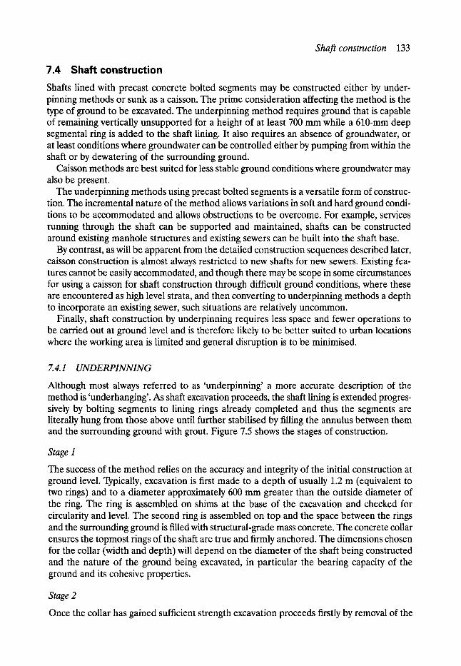
Shaft construction 133
7.4 Shaft construction Shafts lined with precast concrete bolted segments may be constructed either by under- pinning methods or sunk as a caisson. The prime consideration affecting the method is the type of ground to be excavated. The underpinning method requires ground that is capable of remaining vertically unsupported for a height of at least 700 mm while a 610-mm deep segmental ring is added to the shaft lining. It also requires an absence of groundwater, or at least conditions where groundwater can be controlled either by pumping from within the shaft or by dewatering of the surrounding ground.
Caisson methods are best suited for less stable ground conditions where groundwater may also be present.
The underpinning methods using precast bolted segments is a versatile form of construc- tion. The incremental nature of the method allows variations in soft and hard ground condi- tions to be accommodated and allows obstructions to be overcome. For example, services running through the shaft can be supported and maintained, shafts can be constructed around existing manhole structures and existing sewers can be built into the shaft base.
By contrast, as will be apparent from the detailed construction sequences described later, caisson construction is almost always restricted to new shafts for new sewers. Existing fea- tures cannot be easily accommodated, and though there may be scope in some circumstances for using a caisson for shaft construction through difficult ground conditions, where these are encountered as high level strata, and then converting to underpinning methods a depth to incorporate an existing sewer, such situations are relatively uncommon.
Finally, shaft construction by underpinning requires less space and fewer operations to be carried out at ground level and is therefore likely to be better suited to urban locations where the working area is limited and general disruption is to be minimised.
7.4.1 UNDERPINNING
Although most always referred to as 'underpinning' a more accurate description of the method is 'underhanging'. As shaft excavation proceeds, the shaft lining is extended progres- sively by bolting segments to lining rings already completed and thus the segments are literally hung from those above until further stabilised by filling the annulus between them and the surrounding ground with grout. Figure 7.5 shows the stages of construction.
Stage I
The success of the method relies on the accuracy and integrity of the initial construction at ground level. Typically, excavation is first made to a depth of usually 1.2 m (equivalent to two rings) and to a diameter approximately 600 mm greater than the outside diameter of the ring. The ring is assembled on shims at the base of the excavation and checked for circularity and level. The second ring is assembled on top and the space between the rings and the surrounding ground is filled with structural-grade mass concrete. The concrete collar ensures the topmost rings of the shaft are true and firmly anchored. The dimensions chosen for the collar (width and depth) will depend on the diameter of the shaft being constructed and the nature of the ground being excavated, in particular the bearing capacity of the ground and its cohesive properties.
Stage 2
Once the collar has gained sufficient strength excavation proceeds firstly by removal of the
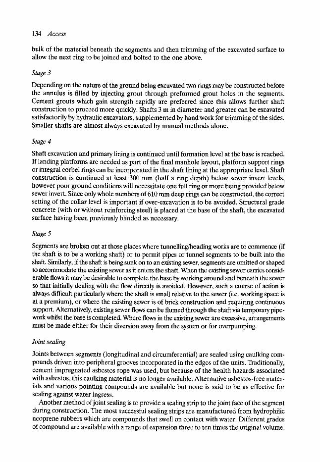
134 Access
bulk of the material beneath the segments and then trimming of the excavated surface to allow the next ring to be joined and bolted to the one above.
Stage 3
Depending on the nature of the ground being excavated two rings may be constructed before the annulus is filled by injecting grout through preformed grout holes in the segments. Cement grouts which gain strength rapidly are preferred since this allows further shaft construction to proceed more quickly. Shafts 3 rn in diameter and greater can be excavated satisfactorily by hydraulic excavators, supplemented by hand work for trimming of the sides. Smaller shafts are almost always excavated by manual methods alone.
Stage 4
Shaft excavation and primary lining is continued until formation level at the base is reached. If landing platforms are needed as part of the final manhole layout, platform support rings or integral corbel rings can be incorporated in the shaft lining at the appropriate level. Shaft construction is continued at least 300 mm (half a ring depth) below sewer invert levels, however poor ground conditions will necessitate one full ring or more being provided below sewer invert. Since only whole numbers of 610 mm deep rings can be constructed, the correct setting of the collar level is important if over-excavation is to be avoided. Structural grade concrete (with or without reinforcing steel) is placed at the base of the shaft, the excavated surface having been previously blinded as necessary.
Stage 5
Segments are broken out at those places where tunnelling/heading works are to commence (if the shaft is to be a working shaft) or to permit pipes or tunnel segments to be built into the shaft. Similarly, if the shaft is being sunk on to an existing sewer, segments are omitted or shaped to accommodate the existing sewer as it enters the shaft. When the existing sewer carries consid- erable flows it may be desirable to complete the base by working around and beneath the sewer so that initially dealing with the flow directly is avoided. However, such a course of action is always difficult particularly where the shaft is small relative to the sewer (i.e. working space is at a premium), or where the existing sewer is of brick construction and requiring continuous support. Alternatively, existing sewer flows can be flumed through the shaft via temporary pipe- work whilst the base is completed. Where flows in the existing sewer are excessive, arrangements must be made either for their diversion away from the system or for overpumping.
Joint sealing
Joints between segments (longitudinal and circumferential) are sealed using caulking com- pounds driven into peripheral grooves incorporated in the edges of the units. Traditionally, cement impregnated asbestos rope was used, but because of the health hazards associated with asbestos, this caulking material is no longer available. Alternative asbestos-free mater- ials and various pointing compounds are available but none is said to be as effective for sealing against water ingress.
Another method of joint sealing is to provide a sealing strip to the joint face of the segment during construction. The most successful sealing strips are manufactured from hydrophilic neoprene rubbers which are compounds that swell on contact with water. Different grades of compound are available with a range of expansion three to ten times the original volume.

Shaft construction 135
The hydrophilic rubber strip is applied to preformed grooves in the joint faces of the seg- ments as a single or double layer before erection of the rings. A surface coating inhibits immediate expansion giving sufficient time to allow construction to proceed normally. Groundwater ingress through the joints causes the strip to expand and effectively seal them by exerting a continuous pressure on the confined surfaces.
More elaborate seals can be provided by moulded preformed compressible ethylene propylene diene monomer (EPDM) gaskets which are fitted around all the joint faces of a segment before erection. This system is effective against high heads of water.
Hydrophilic rubber sealing strips and EPDM gaskets are expensive materials. The latter also have further cost implications to shaft construction since non-standard segments are needed to accommodate the additional compressive forces involved during bolting of the segments. However the additional expense may be justified as a means of achieving water tight shafts which in other circumstances would have been concrete lined.
Shaft conversion
Conversion of the shaft is the last stage of the construction sequence. Shafts may be provided with a secondary concrete lining (generally 100-150 mm thickness) to provide additional strength, or as a safeguard against water ingress, or for protection of the bolted segments when storage or surcharging of sewage flows is anticipated. Alternatively, the segment panel may be fitted with precast concrete 'pellets' to give a smooth finish. Precast concrete landing slabs and roof (reducing) slabs lessen the time of construction compared with in situ concrete slabs. Reinstatement of the ground surface requires removal of the top temporary segmental rings, placing of the reducing slab, construction of the smaller access shaft capped with the manhole cover and frame, and breaking out part if not all the temporary concrete collar.
7. 4.2 CAISSONS
Construction of a caisson shaft is carried out at ground level. Excavation of the shaft core is made, and as spoil is removed the shaft lining sinks under its own weight, or if necessary further weight (kentledge) is added. More segmental units are bolted to the top rings to extend the caisson as the lining continues to sink below ground level.
The lower edge of the first ring is provided with a bevelled sacrificial cutting edge (Fig. 7.6) and arrangements are made for lubricating the outside faces of the rings with bentonite. The sequences of construction are shown (Fig. 7.7).
Stage I
The need for accurate, secure temporary works at ground level is as equally important as for 'underpinning'; caissons allow few opportunities for correction of plumb and circularity once sinking has commenced.
The first operation is construction of the guidance collar for the caisson. Excavation to a depth of approximately 1.2 m is made as for underpinning and two rings are assembled and checked for level and circularity. This temporary construction can then provide a shutter for casting a concrete ring beam at ground level.
A 50--100 mm annulus between the segments and the ring beam is created by use of sacrific- ial void filler (such as polystyrene sheet) during casting of the ring beam. Alternatively, suita- bly oversized segmental rings surrounded in concrete can also be used to construct the ring beam.
During caisson sinking the annular space is filled with bentonite.
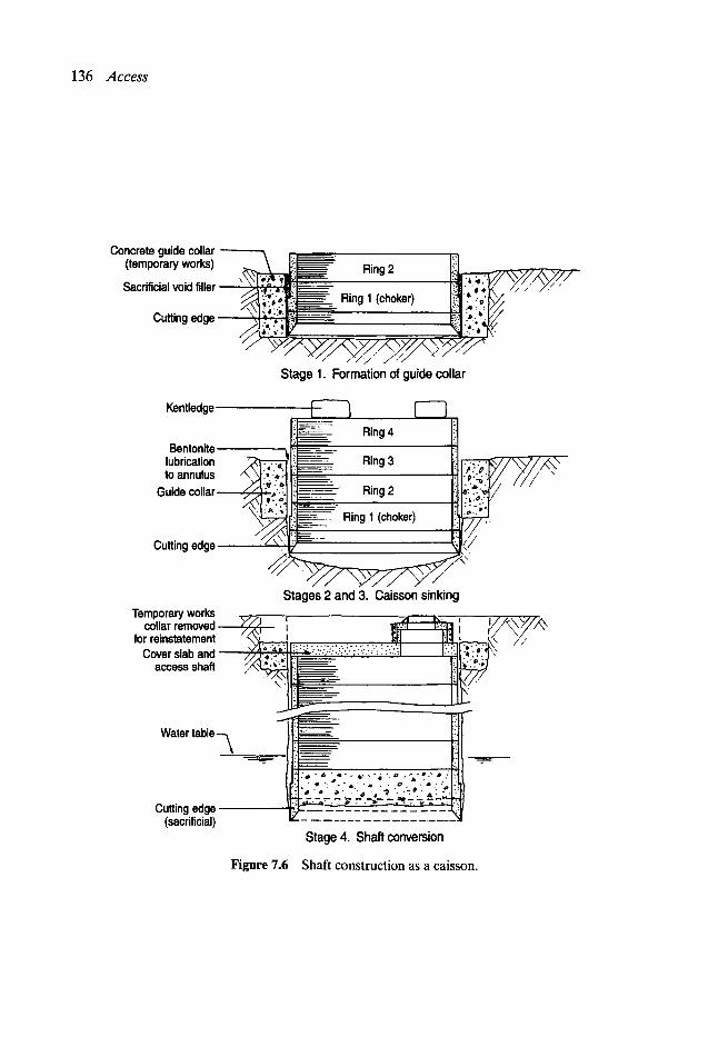
Concrete guide collar (temporary works) Sacrificial void filler \ / /
Cutting edge
136 Access
Stage 1. Formation of guide collar
Kentledge ~ I } ] . ~ Ring4 H
Bentonite ~ .~I!~ ~-- ..... 3 ~ . ~ / / ~ - - lubrication ~'~ ",' r ! Ring liJ l.,;....#.i~ ~,,\
�9 ~: : , , : . . . = . - p . . . .
Guide collar ~ Ring 2 / ~ ' ~ " ~ i ~ - ~ ' - Ring, (choker) I ~ ~
Cutting edge
Stages 2 and 3. Caisson sinking Temporary works
collar removed 7 / ) ' ' ~..~'~' ;i~:.]'l ~ for reinstatement , y / . i!:: ~ :. ;:.:.:-: :-i-i: :':- ; ! ""; "." o Cover slab and ///A:Z: :,~lPi-" " '~ ;" access shaft ; ~ , , , ~ ~ . . . . _ j.~H "~'" "~
:~' ~ - ~ - - - ' ":1
Water table--~ ;1~~-- :::
B
Cutting edge (sacrificial)
Stage 4. Shaft conversion
Figure 7.6 Shaft construction as a caisson.
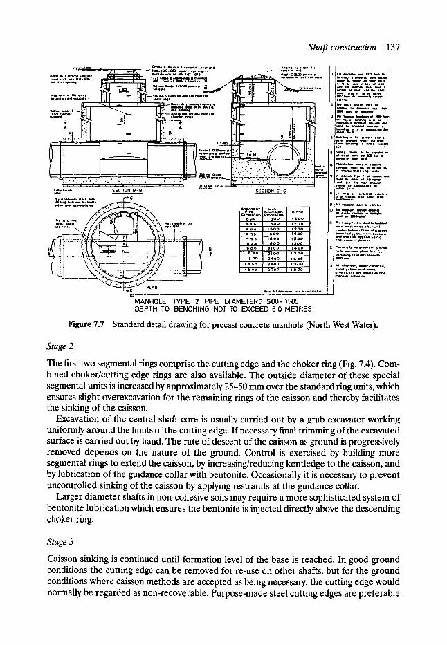
Shaft construction 137
(,,,~,a~l l e , , i % / ~ 'oae A 4 ~ b l e Iraurwjulut ,.over ~ �9 Al l l lnol , , , t de |Q, | , . l | " I" .-~,~m~m.,*lr.',~lr . [ . . , , . t~. : . . . . I r o m e l G U O , ~ s, q l J ~ o i ~ l | ~ ...- -" c ~ . , m t,e. i
- - ~'~,.-w ~ L ~ t _ a U c h l e iron Io 6 S &O7 ' ~ ? G � 9 . . . . . . . . . " . - r C ~ l l t ~ u m t l e t , 7 F r o ~ N ~ ~ to
l ioal l , I ~ in ~ l m I
�9 ~ * ~ I 1411Oil I lu ly IN l r I l i t I lmlll ltt l till I I tRNl i l l I l l s I l l lh
: " ~ t t - - - - " ' ~ ~ . . . . . . . . . . t
' . . . . . . . " . . . .
t ;r[ n l l4 t l l i l~ ld i h o t f f I l o l J t
�9 . . ,- ~ ,m, I~mr I~$1~d I 3O � 9 I Sulll~, r Io k, 1 ~ 1 1 4 in , . . . . . o , , - - a l ~ . . ~ _ - ' ' L J ' : I . . . . . = : ~ o . .
, : . . �9 .,., $ . . . . . . . ",,."~;~ , , o . . . . . . - - ~ )~.~11/11~ Glodt SlldioD OI C l t l lm~ lWl l im I MI lL
]must I~ morn. ut sillmlmlls
~ , . , t . , ~ . S E C T I O N B ' B c ~ c , , t , S E C T I O N C - C J e I t . , ~as 0, , . . ~ c ~ c m . . ~ ,
. . . . . . . . . . / ' . 7 1 / ~ 1 , r ~ I ' ~ \ . ; N t ~ o , ,~,oo I , ~ o o j I / ' ~ ' ' ' * ' ' ' ~ - ' , , , ,~o'* / " 7 / ' X " ~ i : l \ N % ' \ ~ " ~.:~t '~* ' , . ' �9 s ~ a - i s o o I , , 2 o o Jl " / P " " ~ . " '" " ' - " " - ~ * . ' ~
I / I )~ I I r . . - l l l ; l l~ lOl~ i l ~ , . l ~ . l ~ I I / ' ~ ' ~ . I * " ' ~ " ~ " " - ~ *
~ - / ~ ~ - ~ . ~ _ - : J : _ - ' t . 1 ~, , .~no ieoo I 13oo- J: I /e,~i~,..~*~....d,,.;,,.j I~ ~ F ' l l l ~ ~ _ _ ~ L ~ 1 l l l . ' l El / | a=n ~ . o o ! ,~oo~, / / *~ . . . . * ' ; " "
~'~ . . . . ~ ~ , , c , , , , , , o o ~ , o o 1 , - ~ 1 . ..,_,.":"'=~-.". - - I ~ l t A l l dlmensll l~b e l ih , i l l l m e l l l b
" M A N H O L E TYPE 2 PIPE DIAMETERS 5 0 0 - l S 0 0 DEPTH TO BENCHING NO]" TO EXCEED G.0 METRES
Figure 7.7 Standard detail drawing for precast concrete manhole (North West Water).
Stage 2
The first two segmental rings comprise the cutting edge and the choker ring (Fig. 7.4). Com- bined choker/cutting edge rings are also available. The outside diameter of these special segmental units is increased by approximately 25-50 mm over the standard ring units, which ensures slight overexcavation for the remaining rings of the caisson and thereby facilitates the sinking of the caisson.
Excavation of the central shaft core is usually carried out by a grab excavator working uniformly around the limits of the cutting edge. If necessary final trimming of the excavated surface is carried out by hand. The rate of descent of the caisson as ground is progressively removed depends on the nature of the ground. Control is exercised by building more segmental rings to extend the caisson, by increasing/reducing kentledge to the caisson, and by lubrication of the guidance collar with bentonite. Occasionally it is necessary to prevent uncontrolled sinking of the caisson by applying restraints at the guidance collar.
Larger diameter shafts in non-cohesive soils may require a more sophisticated system of bentonite lubrication which ensures the bentonite is injected directly above the descending choker ring.
Stage 3
Caisson sinking is continued until formation level of the base is reached. In good ground conditions the cutting edge can be removed for re-use on other shafts, but for the ground conditions where caisson methods are accepted as being necessary, the cutting edge would normally be regarded as non-recoverable. Purpose-made steel cutting edges are preferable
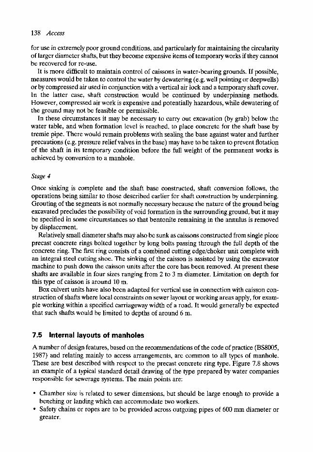
138 Access
for use in extremely poor ground conditions, and particularly for maintaining the circularity of larger diameter shafts, but they become expensive items of temporary works if they cannot be recovered for re-use.
It is more difficult to maintain control of caissons in water-bearing grounds. If possible, measures would be taken to control the water by dewatering (e.g. well pointing or deepwells) or by compressed air used in conjunction with a vertical air lock and a temporary shaft cover. In the latter case, shaft construction would be continued by underpinning methods. However, compressed air work is expensive and potentially hazardous, while dewatering of the ground may not be feasible or permissible.
In these circumstances it may be necessary to carry out excavation (by grab) below the water table, and when formation level is reached, to place concrete for the shaft base by tremie pipe. There would remain problems with sealing the base against water and further precautions (e.g. pressure relief valves in the base) may have to be taken to prevent flotation of the shaft in its temporary condition before the full weight of the permanent works is achieved by conversion to a manhole.
Stage 4
Once sinking is complete and the shaft base constructed, shaft conversion follows, the operations being similar to those described earlier for shaft construction by underpinning. Grouting of the segments is not normally necessary because the nature of the ground being excavated precludes the possibility of void formation in the surrounding ground, but it may be specified in some circumstances so that bentonite remaining in the annulus is removed by displacement.
Relatively small diameter shafts may also be sunk as caissons constructed from single piece precast concrete rings bolted together by long bolts passing through the full depth of the concrete ring. The first ring consists of a combined cutting edge/choker unit complete with an integral steel cutting shoe. The sinking of the caisson is assisted by using the excavator machine to push down the caisson units after the core has been removed. At present these shafts are available in four sizes ranging from 2 to 3 m diameter. Limitation on depth for this type of caisson is around 10 m.
Box culvert units have also been adapted for vertical use in connection with caisson con- struction of shafts where local constraints on sewer layout or working areas apply, for exam- ple working within a specified carriageway width of a road. It would generally be expected that such shafts would be limited to depths of around 6 m.
7.5 Internal layouts of manholes A number of design features, based on the recommendations of the code of practice (BS8005, 1987) and relating mainly to access arrangements, are common to all types of manhole. These are best described with respect to the precast concrete ring type. Figure 7.8 shows an example of a typical standard detail drawing of the type prepared by water companies responsible for sewerage systems. The main points are:
�9 Chamber size is related to sewer dimensions, but should be large enough to provide a benching or landing which can accommodate two workers.
�9 Safety chains or ropes are to be provided across outgoing pipes of 600 mm diameter or greater.
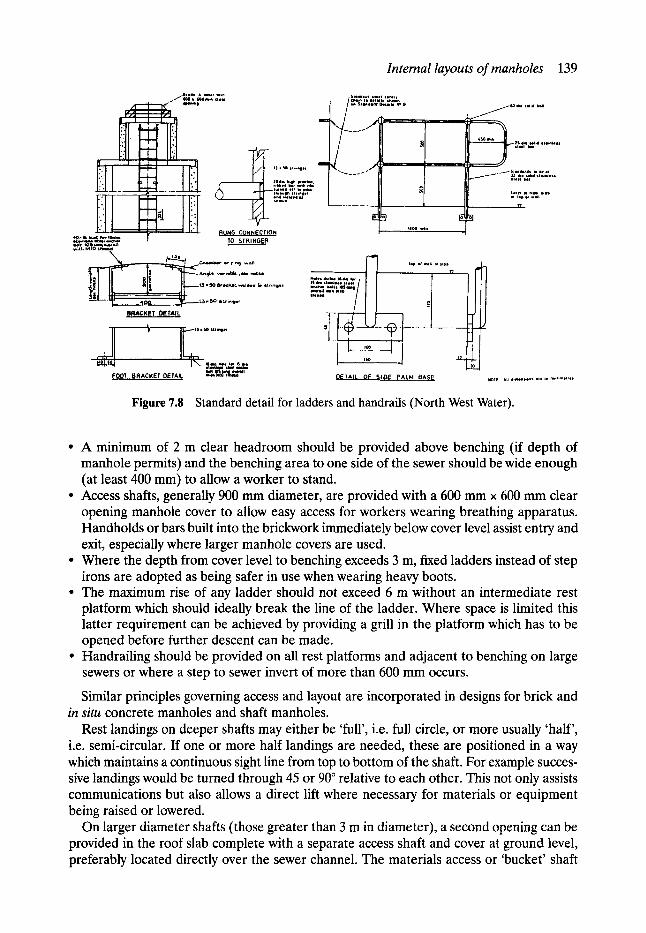
Internal layouts of manholes 139
/ o , ~ . . , r w,,, ~.t~ .. r ~om,n t i n ,
,,1 ~i ~ "
i ' n , I
H 3 I :
4 0 . 1 6 Ql,~t ~w ISdl~m. otA~,lWm i . l t ~
/ . . . . . . . . . . . . . 2,;.
" t l - :'.;".'::::'="
_ ~ L . . . . Eo-! leOO m a ,
RUNG CONNECTION TO STRINGER
~ C h ~ k ~ r ,~" r ; ~ wall
h i II ~N I F ~ " " " . . . . . . " . . . .
BRACKET DETAIL
-L . I ~ - �9 .,,..~. ,- ~ - . item l int FOOT BRACKET DETA,L ~,~ t rm '~"
j l01,a . l , d h a l
g ,..3 ~ o , ~ . - - - - - - - - L ~ ; ; . , I . ~ , ...........
_ . - s,.f:,t l,/. ,.:.,
+ ::ii:.:',o,- / ~ lop ol wo*l o, s|a~
= " .... / ! l f I .- U , 1
.DE I',AI]. OF ~1 (D~ pA.LM BASE
Figure 7.8 Standard detail for ladders and handrails (North West Water).
�9 A minimum of 2 m clear headroom should be provided above benching (if depth of manhole permits) and the benching area to one side of the sewer should be wide enough (at least 400 mm) to allow a worker to stand.
�9 Access shafts, generally 900 mm diameter, are provided with a 600 mm x 600 mm clear opening manhole cover to allow easy access for workers wearing breathing apparatus. Handholds or bars built into the brickwork immediately below cover level assist entry and exit, especially where larger manhole covers are used.
�9 Where the depth from cover level to benching exceeds 3 m, fixed ladders instead of step irons are adopted as being safer in use when wearing heavy boots.
�9 The maximum rise of any ladder should not exceed 6 m without an intermediate rest platform which should ideally break the line of the ladder. Where space is limited this latter requirement can be achieved by providing a grill in the platform which has to be opened before further descent can be made.
�9 Handrailing should be provided on all rest platforms and adjacent to benching on large sewers or where a step to sewer invert of more than 600 mm occurs.
Similar principles governing access and layout are incorporated in designs for brick and in situ concrete manholes and shaft manholes.
Rest landings on deeper shafts may either be 'full', i.e. full circle, or more usually 'half', i.e. semi-circular. If one or more half landings are needed, these are positioned in a way which maintains a continuous sight line from top to bottom of the shaft. For example succes- sive landings would be turned through 45 or 90 ~ relative to each other. This not only assists communications but also allows a direct lift where necessary for materials or equipment being raised or lowered.
On larger diameter shafts (those greater than 3 m in diameter), a second opening can be provided in the roof slab complete with a separate access shaft and cover at ground level, preferably located directly over the sewer channel. The materials access or 'bucket' shaft

140 Access
enables major maintenance and sewer cleansing operations to be undertaken without recourse to excavation to open up the shaft.
Large diameter shafts needed to accommodate hydraulic features of the sewerage system such as major changes in direction, junctions, changes in gradient or level, internal drop pipes from high level sewers or flow control devices (penstocks, weirs, throttle pipes or hydro brakes), may involve complex arrangements of platforms, benchings, steps, mesh flooring, ladders and handrailing to ensure adequate access for maintenance and inspection. It should be noted that the metalwork items, ladders, handrailing etc. are expensive to fabricate and install (especially in stainless steel), and in some cases may amount to 15% of the cost of the shaft. There can therefore be significant benefits in careful planning of shaft layouts and detailing of metalwork to ensure economy of design.
Although small diameter dropshafts (up to 300 mm diameter) can be connected directly to high level sewers at the shaft wall and left with access plates and rodding facilities accessible by ladder from platforms, it is usual to arrange a platform level to coincide with the invert level of larger high level sewers and construct a separate internal flow collection chamber at platform level. Access to the high level chamber would be by step irons or ladders over the chamber walls. Sewage flows are conveyed to the lower level via bellmouth entry dropshaft built into the landing and supported at intervals from the main shaft wall. A grill over the bellmouth entry prevents large pieces of debris blocking the dropshaft and reduces risk to personnel.
For large volume flows from high level sewers, a vortex drop arrangement may be required comprising a vortex chamber at high level and an energy dissipation device such as a water cushion at the lower level (White, 1987). The vortex chamber requires a precise geometrical layout, the dimensions of which depend on the diameter of the incoming sewer, the diameter of the drop pipe and the quantity of flow. The size of the main shaft may be dependent on the physical space requirements of the vortex chamber, though below this platform level it would be feasible to construct the lower shaft containing a drop pipe as a smaller diameter shaft whose size is determined only by the need to accommodate the drop pipe and the benching layout at the base. The lower section of shaft need not necessarily be concentric with the upper section.
Ladder and handrail dimensions and fixing arrangements are usually covered by other standard detail drawings, but these show some variation between the water companies.
The choice of materials for ladders and handrails may depend on the designation of the sewer (foul, combined or surface water), or whether aggressive trade effluents are likely to be carried. Water companies in the UK have already partially adopted a standardised approach. For example, one uses stainless steel throughout the system, whilst others use galvanised steel ladders and handrailing but stainless-steel safety chains with stainless-steel ladders being employed for locations subject to frequent immersion in foul sewage. Elsewhere aluminium ladders and polypropylene safety ropes are specified.
Material specification for 'metalwork' is important where conditions in sewers give rise to septicity. Although septicity problems are more usually associated with sewage in hot climates, the production of the corrosive hydrogen sulphide gas also occurs in temperate climates in situations where anaerobic conditions exist in sewage, such as completely filled rising mains.
Hydrogen sulphide corrodes copper-based alloys and cast iron and some grades of stainless steel are affected. Penstocks and valves (which usually include bronze parts) are vulnerable, as is cast-iron pipework. Handrailing and ladders manufactured from stainless steel and GRP are less vulnerable. The type of stainless steel specified for the water industry is grade 316 (Water Authorities Association, 1985).

Shaft construction programmes 141
However, it is the drastic corrosive effect of hydrogen sulphide on concrete which presents a more difficult world wide problem, particularly in hot climates (Boon, 1992). Although plastic and vitrified clay products can be specified for the sewer pipeline construction, the alternatives to concrete used in manhole construction are less apparent. Concrete mixes containing limestone or dolomite aggregate are more resistant to attack, and concrete surfaces can be treated with epoxy coatings or lined with brickwork jointed with epoxy mor- tar. However, a better long-term solution to the problem of septicity is best achieved by designing sewerage systems to prevent or contain the condition.
7.6 Shaft construction programmes By modern standards access to the majority of existing sewers in the UK is deficient in some respects. Access to the earliest sewers (those constructed before the latter part of the nine- teenth century) is often non-existent, and that to later sewers is frequently irregular and restricted to personnel access only.
In Manchester, limited attempts had been made since 1990 to improve access to the early sewers. Some blind shafts were converted into restricted access points, new manholes were constructed on sewers connecting the early sewers to the new intercepting sewers, and a limited number of other manholes had been built, but often these were on branch sewers rather than at the key junctions of the main sewers. The overall problem remained one in which lack of access inhibited understanding of the early sewerage system and prevented investigations.
Elsewhere in Manchester, and probably in other conurbations, access to the existing sewerage system, although not ideal, generally allows basic investigation of the system to be made, sufficient for drainage catchment analysis to be undertaken.
In these circumstances, apart from a small number of new manholes needed to complete the investigations to support the analysis, improvements in access would normally be incor- porated in the main sewer rehabilitation programme for an area.
But to deal with more basic problems of preliminary investigation of the sewerage system, to establish what it is, and where it is, an advance programme of shaft construction is an essential prerequisite.
In the 1980s after suffering a spate of sewer collapses, the city engineer (Geoffrey E Read) initiated a phased programme of investigatory shaft construction in Manchester to tackle the access problems of the early city centre sewers. The purpose of the programme was two- fold:
�9 to provide basic sewer information on location, depths and sewer construction for those sewers with inadequate records, and
�9 to enable preliminary condition surveys to be undertaken.
The sewers to be investigated in the programme were those which would be defined as 'critical' using the criteria of the Sewer Rehabilitation Manual (Water Research Centre and Water Authorities Association, 1986), i.e. generally brick sewers, where the risks of failure were high and the consequences costly.
Establishing blind-eye positions on early sewers is crucial to siting modern shaft locations, since these are the only positions on the existing sewer which can be fixed with certainty, sewer alignments between blind-eye shafts almost always wander.
Recourse was made to the original sewer drawings (Fig. 7.1) to identify blind-eye loca- tions, and the information shown for the setting out of blind-eye positions was related to present-day features such as building lines of early nineteenth-century buildings which have
142 Access
remained unchanged. Where drawings did not exist, further fragmentary information may be revealed by the original field notebooks of investigations made by the city surveyor's staff in the mid-nineteenth century. Typically these entries record in some detail opening up 'eyes' to give access to 'old' sewers. Taken together these records were used to establish suitable shaft positions. This procedure demonstrates the advantages of studying and maintaining the early records, not only for their intrinsic historical value, but also for their uses in present- day planning (Farrar and John, 1987).
Where possible, shafts were located at key points of the sewerage system, such as junctions, which would give access to more than one sewer. However, known 'blind-eye' positions rarely coincided with these points and in these instances it was necessary to extrapolate the blind-eye data to establish an intersection point of two sewers. This method was further complicated by the nineteenth-century practice of joining branch sewers to main sewers via a long radius bend, presumably for hydraulic reasons. In these situations the decision was usually made to site the shaft at the projected intersection of the two sewer lines rather than at the actual intersection, on the grounds that this would provide more useful long-term access for surveys and possible renovation works. The intention would be that a shaft sunk at a projected intersection should be of sufficient size to incorporate the branch sewer or at least minimise the extent of exploratory excavation work at the base.
The objective of the shaft programme was to maximise the potential for carrying out extensive survey work. The conditions of the existing sewers were such that even where limited manhole access already existed, often little benefit was obtained because of poor structural conditions and rubble and silt in the invert preventing the passage of closed-circuit television (CCFV) cameras. Removal of the debris could prove to be extremely difficult.
The better conditions for survey work were found at the downstream end of the system where flows were greater. Hence higher priority was given to these sewer lengths for pro- vision of access, with subsequent attention being directed towards the upstream lengths for later phases of the programme.
Finally, consideration was always given to ensure that shaft locations and sizes would be suitable as working shafts for future replacement or renovation works.
Altogether around 100 shafts were constructed under the programme which was split into a number of contract phases, each phase comprised construction of approximately twenty shafts over a six-month period.
Investigatory shafts for sewers less than 3.5 m deep consisted of 3-m square sheeted pits in which subsequently a 2400 mm diameter precast concrete manhole was constructed. For deeper sewers the investigatory shaft was a bolted segmental shaft of size 2.44, 3.05 or 3.66 m in diameter, dependent on the size of the sewer and the likelihood of the future use of the shaft being a working shaft for replacement or renovation of the sewer.
It should be noted that the minimum shaft size from which heading works can be comfortably undertaken is 2.44 m, and that 3.05 m diameter shaft is needed for entry or removal of a 1.5-m diameter tunnelling shield. Most renovation methods of course can be accommodated by the smaller shaft sizes.
The selection of shaft size also reflected the degree of certainty which could be ascribed to the setting out information derived as described above. A large size for both sheeted pits and segmental shafts allows a greater 'margin for error' in the incorporation of an 'off-line' sewer at the base, as well as allowing changes to location at surface level to suit other services.
Clearly in busy urban areas there are conflicts of interest. Potential shaft locations, especially those at sewer junctions, frequently coincide with major traffic junctions and plant
Access and public utilities 143
of statutory undertakers, so that compromise solutions ultimately seem inevitable. However, the primary purpose of the programme should not be forgotten, to gain access to the key points of the sewerage system, and unless that can be achieved, the effectiveness of the programme is lost. Success depends on thorough planning and preparation.
7.7 Access and public utilities Sewers were the first public utility service in towns, but already by the mid-nineteenth century gas and water mains were competing for the same limited street space. Later in the nineteenth century and the early twentieth century, first electricity and then telephone cables were adding to the congestion of services. Further underground utilities were also provided in some towns. For example, electric tram systems had their own independent power cables, and in Manchester, as in a number of other cities, an extensive network of high pressure ('hydraulic') water mains in the centre of the city served manufacturers and commercial users who had hydraulic equipment. Street lighting and traffic controls have separate cabling systems, and computer, telecommunications and cable television links have expanded rapidly. Signalling cables are also needed to serve the new rapid transit rail systems now being promoted for city centres.
The majority of service routes are contained within a band extending 1.2 m below street level and, as systems are developed, new routes are threaded around existing systems and other obstructions, occasionally being laid to greater depths at road crossings, when for example telecommunications and electricity cables might be constructed in headings.
Sewerage, however, is typically a physically larger system than other services and being essentially a gravity system is the only service where levels are always critical to operation.
The areas of direct conflict of levels occur principally with shallow drainage systems, and when major electricity, telecommunications or gas services have been constructed at greater depths than usual. But the main consequence of the preponderance of public utility equipment in urban areas is that construction of a new sewer, or making access to an existing sewer, is very frequently impeded by the presence of the other utilities.
Legislation has placed an obligation on the owners of public utilities to provide information on the location of services when notice is given to them of intention to excavate, but the records of the statutory undertakers are often inadequate for the supply of accurate information.
A generalisation may be made that the quality of service records are broadly related to the age of the system to which they refer. Sewer and water mains being the oldest systems suffer most from inadequate records, whilst telecommunications are generally well recorded. Further generalisations may be made regarding likely locations. Most sewers lie within the central region of the carriageway of a road with property and gully connections entering from both sides. Water mains also frequently lie within the carriageway but nearer the channel on one or both sides. Gas mains are also found near the channel, whilst electricity and telecommunication cables are more likely to be found beneath footpaths. In narrow streets the whole width between buildings is likely to be fully occupied. Redevelopments and street widening schemes may of course change the general pattern, perhaps resulting in more services being located within the carriageway at greater depths.
The locations of the primary mains are nearly always known with a high level of confid- ence. These include the interceptor sewers and main carrier sewers, oil-filled high voltage electricity cables, large concentrations of telecommunication cables and fibre-optic cables, high-pressure gas mains and large diameter water mains. However, because of inadequate

144 Access
records there is less certainty about the location of middle-range services which constitute the greater part of the networks.
All the statutory undertakers have made great improvements in recording the locations of their assets, in association with the development of digital mapping systems. However, although such records show items of plant (junction boxes, valve chambers, manholes, etc.) the route of the service line between these fixed points can still be uncertain, and the minor services such as individual property connections are rarely recorded, nor are services which have been abandoned.
The consequences of unplanned encounters with mains and services during excavation can be severe. The primary concern is the risk to human life and property if electricity cables and gas mains are struck. However, although dangerous incidents are rare, damage to services during excavation is very common, and the costs of repairs can also be very high, particularly in relation to fibre-optic cables and oil-filled cables. The consequential costs of disrupting supplies such as electricity and telecommunication links to commerce, and gas and water supplies to industry can be enormous.
It is clearly sensible therefore, even if records are known to be inadequate, that efforts are made to locate equipment accurately before excavation commences. A variety of detec- tion methods has been developed for locating services. These range from the oldest and simplest art of dowsing to metal detection, and more recently to methods based on radio- magnetic field techniques and ground probing radar (GPR). The latter are useful for tracing non-metallic materials such as polyethylene and for plotting anomalies in ground conditions such as voids. Electromagnetic methods may be used for tracing sewers by detecting the progress of signal-emitting probes inserted into the sewer attached to a CCTV camera or winched through on a rope- always assuming that access to the sewer is available nearby.
Detection methods are fully described in another chapter, but it is worth noting here that in urban situations in particular, survey results may be misleading. The density and variety of mains and services induces confusion, and extraneous items such as buried tramlines or abandoned mains and services can induce false readings, so that whilst more information may be obtained about the presence of the equipment, this is still likely to be insufficient to confirm their identity or exact location.
The only certain way this can be achieved is by hand excavation of trial holes, preferably as part of the planning process before the main project is carried out. Trial holes would typically consist of a trench 600 mm wide, up to 1.5 m deep and a length sufficient to span the width of any proposed future excavation. For shafts a cross-shaped trial hole would be appropriate to locate those services which might be running across the mains route. Even so 'diagonally' aligned services might be missed and those left at depths below 1.5 m because of raised road levels after reconstruction would also be missed.
The identification of the majority of the services encountered in trial holes will be a straightforward comparison with the records provided by the statutory undertakers, but sometimes expected mains are missing and others are revealed, the identification of which can be difficult. Occasionally a pipe, typically grey or cast iron, 75-125 mm in diameter, is disowned by all the statutory undertakers, in which case the only way to determine its purpose and discover whether it remains live is to carefully drill and tap the main and accept responsibility for the consequences.
Excavation of trial holes by hand is expensive, and subsequent logging of the holes and identification of the equipment is time consuming, so a complete programme of trial holes in a busy highway is a lengthy process involving careful planning including that for temporary traffic control measures. It may not be possible to avoid significant disruption.
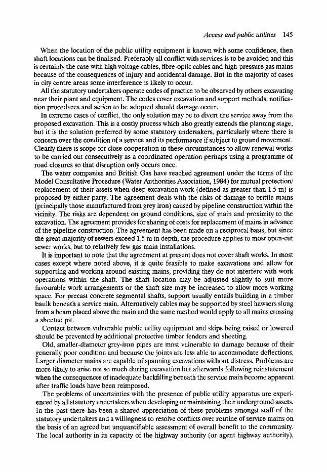
Access and public utilities 145
When the location of the public utility equipment is known with some confidence, then shaft locations can be finalised. Preferably all conflict with services is to be avoided and this is certainly the case with high voltage cables, fibre-optic cables and high-pressure gas mains because of the consequences of injury and accidental damage. But in the majority of cases in city centre areas some interference is likely to occur.
All the statutory undertakers operate codes of practice to be observed by others excavating near their plant and equipment. The codes cover excavation and support methods, notifica- tion procedures and action to be adopted should damage occur.
In extreme cases of conflict, the only solution may be to divert the service away from the proposed excavation. This is a costly process which also greatly extends the planning stage, but it is the solution preferred by some statutory undertakers, particularly where there is concern over the condition of a service and its performance if subject to ground movement. Clearly there is scope for close cooperation in these circumstances to allow renewal works to be carried out consecutively as a coordinated operation perhaps using a programme of road closures so that disruption only occurs once.
The water companies and British Gas have reached agreement under the terms of the Model Consultative Procedure (Water Authorities Association, 1984) for mutual protection/ replacement of their assets when deep excavation work (defined as greater than 1.5 m) is proposed by either party. The agreement deals with the risks of damage to brittle mains (principally those manufactured from grey iron) caused by pipeline construction within the vicinity. The risks are dependent on ground conditions, size of main and proximity to the excavation. The agreement provides for sharing of costs for replacement of mains in advance of the pipeline construction. The agreement has been made on a reciprocal basis, but since the great majority of sewers exceed 1.5 m in depth, the procedure applies to most open-cut sewer works, but to relatively few gas main installations.
It is important to note that the agreement at present does not cover shaft works. In most cases except where noted above, it is quite feasible to make excavations and allow for supporting and working around existing mains, providing they do not interfere with work operations within the shaft. The shaft location may be adjusted slightly to suit more favourable work arrangements or the shaft size may be increased to allow more working space. For precast concrete segmental shafts, support usually entails building in a timber baulk beneath a service main. Alternatively cables may be supported by steel hawsers slung from a beam placed above the main and the same method would apply to all mains crossing a sheeted pit.
Contact between vulnerable public utility equipment and skips being raised or lowered should be prevented by additional protective timber fenders and sheeting.
Old, smaller-diameter grey-iron pipes are most vulnerable to damage because of their generally poor condition and because the joints are less able to accommodate deflections. Larger diameter mains are capable of spanning excavations without distress. Problems are more likely to arise not so much during excavation but afterwards following reinstatement when the consequences of inadequate backfilling beneath the service main become apparent after traffic loads have been reimposed.
The problems of uncertainties with the presence of public utility apparatus are experi- enced by all statutory undertakers when developing or maintaining their underground assets. In the past there has been a shared appreciation of these problems amongst staff of the statutory undertakers and a willingness to resolve conflicts over routine of service mains on the basis of an agreed but unquantifiable assessment of overall benefit to the community. The local authority in its capacity of the highway authority (or agent highway authority),

146 Access
and which may, in the more distant past, have owned the assets directly, often provided a coordinating role in resolving conflicts.
However, significant changes have been made to these working relationships. The utility apparatus is now largely in private ownership, and the statutory undertakers have become commercial organisations. It remains to be seen whether the same degree of mutual cooperation will still continue. Some formal framework for cooperation seems to be essential for work in congested locations and it is suggested that this will again be provided by the local (highway) authority under the terms of the New Roads and Street Works Act 1991.
7.8 City centre problems and solutions The earliest sewers with their limited access are generally concentrated in city centres. It is here where the tight network of streets, the repeated cycles of urban development and changing site uses have led to a large number of sewer junctions and connections, duplication of sewerage systems and abandonment of others. But although the need for good access to city centre sewers is clearly apparent, that which presently exists is frequently inadequate.
Physical constraints in city centres combine to make provision of access difficult. Streets are often narrow, buildings large and foundations and basements encroaching below ground into the width of the street require that sewers are deep, whilst at the same time severely restricting access from the surface.
These constraints of course apply to the other statutory undertakers, but because sewers are generally the deepest and the first laid, access is further constrained by the other services laid across and above.
The final constraint on city centre working is the raison d'etre of the city i tself- people, trade and commerce, manufacturing and service industries, culture, entertainment and shop- ping, traffic and pedestrians- all the constituents of city life.
An important point to be recognised when considering sewer works in the city centre is that costs are unavoidably high. This applies to all forms of construction activity in such loca- tions; costs may be orders of magnitude higher than in rural areas and several times that of suburban areas. Construction work in cities is restricted by proximity of traffic, buildings and the presence of public utility apparatus, all of which could limit the type of construction plant which may be used. Similarly, the frequency of vehicle movements for material deliveries and spoil removal may be restricted, and, finally social and environmental constraints may impose limits on working hours. These factors together contribute to lower productiviiy.
Inevitably compromise has to be sought to satisfy the competing claims of achieving all the objectives of the shaft construction programme in terms of access provisions and longer term uses for the shafts, against the direct costs which have to be met by the owners of the sewers and the disruption (social costs) which has to be borne by people in the city.
A considerable proportion of the efforts made to reduce disruption have very little effect on direct costs, but can have significant effects on the social costs. These would include:
�9 A comprehensive study of relevant records to ensure all information for location of manholes has been assessed.
�9 Careful examination of the records of statutory undertakers to minimise conflict at proposed locations.
�9 Prior consultation with police, highway authorities, emergency services and safety advisers to ensure all preparations and signing for road closures and traffic orders (including parking restrictions, etc.) have been agreed. Bearing in mind the time required for posting
City centre problems and solutions 147
of statutory notices of temporary traffic orders and the consequential delays if the legal requirements are not satisfied exactly, this factor is probably the greatest influence on successful coordination of work in city centres and is dealt with more fully in another chapter.
�9 Detailed programming of works to maximise efficiency and minimise site occupation. The implication here is that time is of the essence, careful planning of the works will
reduce disruption, but this may be considered to be an extension of good site management practice, which is desirable in any situation.
An obvious way to reduce disruption further is to carry out work during those periods when fewer people will be inconvenienced. This may entail restricting working to off- peak traffic hours during the day, say after 9.30 am or before 3.30 pm, or both, and ensuring the site is clear to allow uninterrupted traffic flow at other times. A more extreme solution is to permit night time working only, say, after 7.00 pm, together with Sunday working.
Direct costs for this type of working can increase significantly. Fragmented working days suggested for non-peak-hour working are not favoured by contractors since productivity is inhibited. Night-time working, although traditionally associated with tunnelling work and, to a lesser extent, with shaft sinking, would only achieve daytime productivity rates if continuity of work over periods of whole weeks can be ensured.
However, even night-time working can be disruptive in some city centre locations. Cinemas and theatres are busy until near midnight, restaurants and nightclubs until the early hours. Streets around these places are thronged with people and traffic, and sometimes the cessation of daytime parking restrictions mean that the proposed night-time working areas are even more congested than during the day. Although temporary traffic orders can be introduced to limit night-time parking, ensuring compliance with orders is even more difficult than for the normal daytime regulations.
Noise, one of the main disruptive features of daytime work, can be equally disruptive at night. Restaurants, theatres and cinemas are noise sensitive locations and it should not be forgotten that as well as hotel residents, there are other people, such as residents of flats and permanent residents in city centres. Even some hospitals are situated in city centres.
How should the lesser inconvenience of the many be measured against the greater disruption of the few? Guidelines could not be expected to cover all situations; however, the importance of the planning stage which would include advance observations of night- time conditions, will be apparent.
The choice of working method can also influence the level of disruption. The advantages of concrete segmental shaft construction in confining working areas and reducing plant requirements have already been mentioned. The method also has advantages wherever off- peak or night-time working is specified because shafts can be 'plated' over either by using steel beams and sheet steel road plates (placed in sections), or even by adapting the shaft, heavy duty, precast concrete shaft cover slab of the permanent works as a temporary cover slab. In either event, design checks are needed to ensure that the covers are capable of carrying the appropriate traffic loadings and that seatings do not move under repeated impact of heavy traffic. Attention to the details at the edge of the covers and the matching of road camber are essential for avoiding hazards to cyclists.
The key to the success of using covers is the effectiveness of the initial set up. In the first session the road surface construction has to be broken out and, ideally, the concrete collar and the two top rings built before the plates are seated. This is more than can comfortably
148 Access
be accomplished in a single night-time session working to a tight schedule, and therefore it is preferable for the night-time session to provide more time. Care and attention at this stage of the operation avoids potential problems the following morning. If all is not well when the road is re-opened to traffic, full emergency procedures may be required for a new road closure to apply corrective measures. The consequences for this course of action could be even more disruption than the night-time work was intended to avoid.
A further complication for night-time and Sunday working is obtaining ready-mix concrete supplies for the concrete collar. Other materials can be stockpiled locally during the day and brought to the working area as required. Parking meter bays, temporarily closed off, can provide a suitable day-time storage area for materials and barriers.
Whilst present-day citizens have perhaps come to expect that change and renewal are an integral part of life in a city, there remains an obligation on those responsible for maintaining the working environment to avoid disruption if possible.
What appears to be of most concern to the citizens is the need to reduce the perceived level of disruption in terms of the noise, dust, restrictions on access and visual intrusion. Thus sub-surface solutions to sewer work that can be confined to easily maintainable compound areas negotiable by pedestrians and traffic are more readily assimilated into city life. The initial confusion when work areas are established in the city centre usually lasts only a day or two and by the end of the first week travel patterns have been re-established to accommodate them.
References Boon A. G. Septicity in sewers; causes, consequences and containment. J. Inst. Water and Environ. Mgrnt
Vol. 6, No. 1, pp. 79-90, 1992. BS6164. Code of Practice for Safety in Tunnelling in the Construction Industry. British Standards
Institution, London, 1990. BS8005:Partl:1987. Guide to New Sewerage Construction. British Standards Institution, London, 1987. Farrar, D. M. and John, S. J. Aspects of early 19th century public health engineering in Manchester;
implications for present day sewerage strategy. J. Inst. Public Health Engrs Vol. 14, No. 6, pp. 79-84, 1987.
Water Authorities Association and British Gas Corporation. Model Consultative Procedure for Pipeline Construction involving Deep Excavation, first revision, 1984.
Water Authorities Association. Civil Engineering Specification for the Water Industry, 3rd edn. Water Research Centre, 1989.
Water Authorities Association. Sewer for Adoption- A Design and Construction Guide for Developers, 2nd edn. Water Research Centre, 1985.
Water Research Centre and Water Authorities Association. Sewerage Rehabilitation Manual, 2nd edn. Water Research Centre, 1986.
White, J. B. Wastewater Engineering, 3rd edn. Edward Arnold, London, 1987.
8 Hydraulic Assessment
A. J. Saul* BEng, PhD
8.1 Rainfall-runoff and overland flow processes The rainfall-runoff process is a very complex one and it is required to describe the following processes:
�9 rainfall �9 rainfall loss- absorption and wetting
interception depression storage evapotranspiration infiltration
�9 overland flow.
The rainfall loss is a function of the catchment characteristics - the type and texture (cover) of the surface, the extent to which the surface is impervious, the catchment slope, the initial wetness condition of the catchment and the properties of the rainfall event - intensity, duration and depth. The overland flow process is a function of the catchment roughness and slope and of the individual drainage paths defined by the detailed topography of the catchment surface. The problem is further compounded by differences in the speed of runoff from surfaces, some having fast response, such as steeply sloping roofs while others have a slower response, for example, flat concrete areas, or lawns and gardens. In addition, the runoff from pervious surfaces is very much a function of the soil type and cover and for this type of surface it is usual that the infiltration loss is the dominant process. In some instances however the runoff response time for a pervious surface, e.g. a clay soil may be shorter than that of an impervious surface, for example a concrete surface with large texture voids and depressions. In most of northern Europe, the losses due to the absorption, inter- ception and evaporation are usually small when compared to those of depression storage and infiltration, but, in warmer climates the evaporation loss may need to be taken into account. However, most urban drainage mathematical models include some provision for an initial loss (usually depression storage) and a continuous loss (usually infiltration).
Details of appropriate rainfall inputs are described in Section 8.2 while Section 8.3 is devoted to some of the concepts and processes associated with the loss of rainfall prior to
*Professor, Department of Civil and Structural Engineering, University of Sheffield.
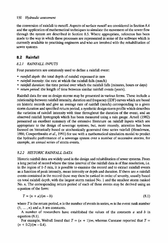
150 Hydraulic assessment
the conversion of rainfall to runoff. Aspects of surface runoff are considered in Section 8.4 and the application of mathematical techniques to simulate the movement of the sewer flow through the system are described in Section 8.5. Where appropriate, reference has been made to the way in which these processes are represented in some of the software which is currently available to practising engineers and who are involved with the rehabilitation of sewer systems.
8.2 Rainfall 8.2.1 RAINFALL INPUTS
Four parameters are commonly used to define a rainfall event:
�9 rainfall depth: the total depth of rainfall expressed in mm �9 rainfall intensity: the rate at which the rainfall falls (mm/h) �9 rainfall duration: the time period over which the rainfall falls (minutes, hours or days) �9 return period: the length of time between similar rainfall events (years).
Rainfall data for use as design storms may be presented in various forms. These include a relationship between rainfall intensity, duration and frequency (IDF) curves which are based on historic records and give an average rate of rainfall ( m n ~ ) corresponding to a given storm duration and specified return period, a synthetic design storm profile which describes the variation of rainfall intensity with time throughout the duration of the event, and an observed rainfall hyetograph which has been measured using a rain gauge. Arnell (1982) presented an excellent summary of the extensive literature on rainfall inputs which are appropriate to the design of sewerage systems, but, more recently, attention has been focused on historically based or stochastically generated time series rainfall (Henderson, 1986; Cowperthwaite et al., 1991) for use with a mathematical simulation model to predict the hydraulic performance of a sewerage system over a number of successive storms, for example, an annual series of storm events.
8.2.2 HISTORIC RAINFALL DATA
Historic rainfall data are widely used in the design and rehabilitation of sewer systems. From a long period of record where the time interval of the rainfall data is of fine resolution, i.e. in the region of 1-5 min, it is possible to examine the record and to extract rainfall events as a function of peak intensity, mean intensity or depth and duration. If there are n rainfall events contained in the record these may then be ranked in order of severity, usually based on total rainfall depth, with the largest storm ranked No. 1 and the smallest storm ranked No. n. The corresponding return period of each of these events may be derived using an equation of the form:
T = (n + a ) / ( m - b) (8.1)
where T is the return period, n is the number of events in series, m is the event rank number (1, . . . , n) and a, b are constants.
A number of researchers have established the values of the constants a and b in equation (8.1).
For example, Weibull found that T = (n + 1)/m, whereas Cunnane reported that T = (n + 0.2)/(m - 0.4).

Rainfall 151
8.2.3 IDF CURVES AND DESIGN STORM RAINFALL
To establish the relationship between rainfall depth, duration and return frequency in the UK, the Natural Environment Research Council carried out a statistical analysis on the daily total of rainfall recorded at 600 stations with 60 years of record and 6000 stations with 10 years of record together with continuous rainfall records from some 200 autographic rain- gauge stations. To describe the rainfall corresponding to a particular return period and duration, the notation M T - D was adopted, where T is the return period and D is the rainfall duration. In the basic statistical analysis rainfall durations of 60 min, two days and 25 days and a return period of five years were used, i.e. M5-60 min, M5-2 day and M5-25 day and the results of the study were presented within the Flood Studies Report (NERC, 1975). This defined a methodology to establish, from these basic data values, the rainfall depth corresponding to any other duration and return period. For example, the 2M-20 min rainfall describes an event of return period twice in one year with a duration of 20 min whereas the M10-12 h rainfall corresponds to an event of 10-year return period of 12-h duration.
If a long period of record is available at a particular site, say 60 years, it is possible to use an elementary statistical analysis to establish a reasonably accurate value of M5-2 day rainfall. However, for the rarer event, say M50-2 day rainfall, the sample is unlikely to be representative due to the random nature of the extreme rainfall, i.e. there may be none, one or even more M50-2 day events in the 60 years of record. It is necessary therefore to use statistical theory of extremes to extrapolate to the rare event. To relate the individual elements of data within each record of rainfall to a particular return period, the methodology adopted in the Flood Studies Report was to assemble the data into an ordered set, starting with the smallest value through to the largest and to split the set into four quartiles (quarters). Using extreme value theory with annual maxima series for return periods greater than five years and a partial duration series for return periods less than five years, good agreement was observed between the mean value of each quartile and the following return periods:
�9 First quartile mean 2M �9 Mean of middle two quartiles M2 �9 Mean of upper two quartiles M5 �9 Mean of fourth quartile M10
Using this information it was possible to establish the relationship between the rainfall (cor- responding to each of the quartile means) and the return period at the particular location where an individual rainfall record was monitored. Hence, by considering the two-day rainfall at stations with an M5 within a certain range, say 50-60 mm, it was possible, using a logarithmic plot of the return period against the rainfall amount, to establish a smooth growth curve of two-day rainfall for five-year return period rainfall of depth within the range of 50--60 mm. Similar curves were drawn for M5 rainfall of other durations and depth to produce a family of curves with each of the curves having the same shape. Hence, for a given M5 value these curves may be used to predict the value of MT, where the return period T may have any value. The ratio of MT/M5 was termed the growth factor and in the Flood Studies Report (1975) two generalised growth factors were presented, one for England and Wales and the other for Scotland and Ireland. The growth factors for England and Wales are shown in Table 8.1.
To establish the rainfall depth corresponding to other storm durations, use is made of two basic rainfall data values. These are the rainfall depth corresponding to the five-year return

Table 8.1 Growth factors MT/M5 for England and Wales ,,
M5 (mm) 2M 1M M2 MIO M20 M50 MIO0 M1000 M10000
0.5 0.52 0.67 0.76 1.14 1.30 1.51 1.70 2.52 2 0.49 0.65 0.74 1.16 1.32 1.53 1.74 2.60 5 0.45 0.62 0.72 1.18 1.35 1.56 1.79 2.75
10 0.43 0.61 0.70 1.21 1.41 1.65 1.91 3.09 15 0.46 0.62 0.70 1.23 1.44 1.70 1.99 3.32 20 0.50 0.64 0.72 1.23 1.45 1.73 2.03 3.43 25 0.52 0.66 0.73 1.22 1.43 1.72 2.01 3.37 30 0.54 0.68 0.75 1.21 1.41 1.70 1.97 3.27 40 0.56 0.70 0.77 1.18 1.37 1.64 1.89 3.03 50 0.58 0.72 0.79 1.16 1.33 1.58 1.81 2.81 75 0.63 0.76 0.81 1.13 1.27 1.47 1.64 2.37
100 0.64 0.78 0.83 1.12 1.24 1.40 1.54 2.12 150 0.64 0.78 0.84 1.11 1.21 1.33 1.45 1.90 200 0.64 0.78 0.84 1.10 1.30 1.30 1.40 1.79 500 0.65 0.79 0.85 1.09 1.15 1.20 1.27 1.52
1000 0.66 0.80 0.86 1.07 1.12 1.18 1.23 1.42
i 2
3.76 3.94 4.28 5.01 5.54 5.80 5.67 5.41 4.86 4.36 3.43 2.92 2.50 2.30
The values on the contours are in mm of rainfall
0 100
o 6o I I
D
QO
~d~
GRID 1
Figure 8.1(a)

Rainfall 153
period event of 60 min duration (M5-60 min) and the ratio r of the five-year 60-min rainfall depth and the five-year two-day rainfall depth (M5-2 day), i.e.
r = M5-60 min/M5-2 day
Values of M5-60 min and r for each location in the UK were outlined on maps in the Flood Studies Report and these are illustrated in Fig. 8.1. The relationship between r, M5-2 day and duration D is shown in Table 8.2.
As an example, use the data outlined in Fig. 8.1 and Tables 8.1 and 8.2 to establish the M10--12 h rainfall for Sheffield. 1. Read off values of M5-60 min and r from Fig. 8.1
M5-60 min = 19 mm (to nearest mm)
r = 0.35 (to within _ 0.01)
Hence M5-2 day = 19/0.35 = 54 mm.
Figure 8.1
Figure 8.1(b)
(a) and (b) Maps of M5-60 minute rainfall and r.
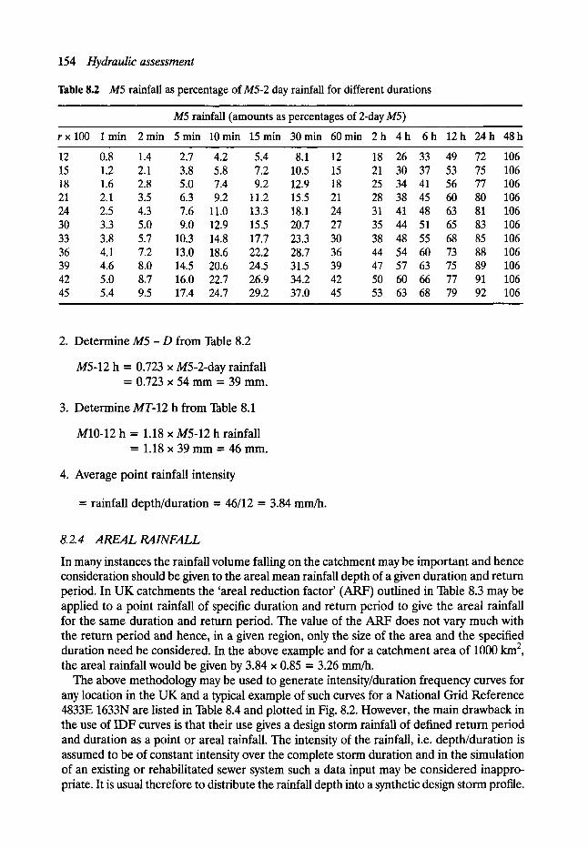
154 Hydraulic assessment
Table 8.2 M5 rainfall as percentage of M5-2 day rainfall for different durations
M5 rainfall (amounts as percentages of 2-day M5)
r x l 0 0 lmin 2min 5min 10min 15min 30min 60min 2h 4h 6h 12h 24h 48h
12 0.8 1.4 2.7 4.2 5.4 8.1 12 18 26 33 15 1.2 2.1 3.8 5.8 7.2 10.5 15 21 30 37 18 1.6 2.8 5.0 7.4 9.2 12.9 18 25 34 41 21 2.1 3.5 6.3 9.2 11.2 15.5 21 28 38 45 24 2.5 4.3 7.6 11.0 13.3 18.1 24 31 41 48 30 3.3 5.0 9.0 12.9 15.5 20.7 27 35 44 51 33 3.8 5.7 10.3 14.8 17.7 23.3 30 38 48 55 36 4.1 7.2 13.0 18.6 22.2 28.7 36 44 54 60 39 4.6 8.0 14.5 20.6 24.5 31.5 39 47 57 63 42 5.0 8.7 16.0 22.7 26.9 34.2 42 50 60 66 45 5.4 9.5 17.4 24.7 29.2 37.0 45 53 63 68
, , , , , i
49 72 106 53 75 106 56 77 106 60 80 106 63 81 106 65 83 106 68 85 106 73 88 106 75 89 106 77 91 106 79 92 106
2. Determine M5 - D from Table 8.2
M5-12 h = 0.723 x M5-2-day rainfall = 0.723 • 54 mm = 39 mm.
3. Determine MT-12 h from Table 8.1
M10-12 h = 1.18 x M5-12 h rainfall = 1 . 1 8 • 39 mm = 46 mm.
4. Average point rainfall intensity
= rainfall depth/duration = 46/12 = 3.84 mm~.
8.2.4 AREALRAINFALL
In many instances the rainfall volume falling on the catchment may be important and hence consideration should be given to the areal mean rainfall depth of a given duration and return period. In UK catchments the 'areal reduction factor' (ARF) outlined in Table 8.3 may be applied to a point rainfall of specific duration and return period to give the areal rainfall for the same duration and return period. The value of the ARF does not vary much with the return period and hence, in a given region, only the size of the area and the specified duration need be considered. In the above example and for a catchment area of 1000 km 2, the areal rainfall would be given by 3.84 x 0.85 = 3.26 mm/h.
The above methodology may be used to generate intensity/duration frequency curves for any location in the UK and a typical example of such curves for a National Grid Reference 4833E 1633N are listed in Table 8.4 and plotted in Fig. 8.2. However, the main drawback in the use of IDF curves is that their use gives a design storm rainfall of defined return period and duration as a point or areal rainfall. The intensity of the rainfall, i.e. depth/duration is assumed to be of constant intensity over the complete storm duration and in the simulation of an existing or rehabilitated sewer system such a data input may be considered inappro- priate. It is usual therefore to distribute the rainfall depth into a synthetic design storm profile.
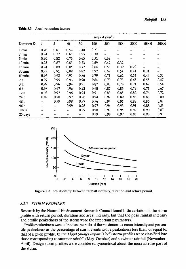
Table 8.3 Areal reduction factors
AreaA (kin 2)
Rainfall 155
Duration D 1 5 10 30 100 300 1000 3000 10000 30000
I rnin 0.76 0.61 0.52 0.40 0.27 . . . . . 2 min 0.84 0.72 0.65 0.53 0.39 . . . . . 5 min 0.90 0.82 0.76 0.65 0.51 0.38 . . . . 10 min 0.93 0.87 0.83 0.73 0.59 0.47 0.32 - - - 15 min 0.94 0.89 0.85 0.77 0.64 0.53 0.39 0.29 - - 30 min 0.95 0.91 0.89 0.82 0.72 0.62 0.51 0.41 0.31 - 60 min 0.96 0.93 0.91 0.86 0.79 0.71 0.62 0.53 0.44 0.35 2 h 0.97 0.95 0.93 0.90 0.84 0.79 0.73 0.65 0.55 0.47 3 h 0.97 0.96 0.94 0.91 0.87 0.83 0.78 0.71 0.62 0.54 6 h 0.98 0.97 0.96 0.93 0.90 0.87 0.83 0.79 0.73 0.67 12 h 0.98 0.97 0.96 0.94 0.91 0.89 0.85 0.82 0.76 0.72 24 h 0.99 0.98 0.97 0.96 0.94 0.92 0.89 0.86 0.83 0.80 48 h - 0.99 0.98 0.97 0.96 0.94 0.91 0.88 0.86 0.82 96 h - - 0.99 0.98 0.97 0.96 0.93 0.91 0.88 0.85 192 h - - - 0.99 0.98 0.97 0.95 0.92 0.90 0.87 25 days . . . . 0.99 0.98 0.97 0.95 0.93 0.91
250 -
~ ' 2 0 0
E ._.g, 150 US t ' -
C - - 100 . r
n- 50
- lO0-year return period
_ Y " . . Z
I I I I I ! I I I I 2 4 6 8 10 12 14 16 18 20
Duration (min)
Figure 8.2 Relationship between rainfall intensity, duration and return period.
8.2.5 STORM PROFILES
Research by the Natural Envi ronment Research Council found little variat ion in the storm profile with return period, durat ion and areal intensity, but that the peak rainfall intensity and profile peakedness of the s torm were the important parameters .
Profile peakedness was defined as the ratio of the maximum-to-mean intensity and percen- tile peakedness as the percentage of storm events with a peakedness less than, or equal to, that of a given profile. In the Flood Studies Report (1975) storm profiles were classified into those corresponding to summer rainfall (May-October) and to winter rainfall (November - April). Design storm profiles were considered symmetrical about the most intense part of
the storm.

156 Hydraulic assessment
Table 8.4 Rates of rainfall as a function of duration and return period for a specified location in the United Kingdom, National Grid Reference 4833E 1633N
Return period (years)
Duration 1 2 5 10 20 50 100
2.0 min 75.6 93.4 120.5 138.3 158 187 213 2.5 min 70.5 87.5 113.4 130.4 149 177 202 3.0 min 66.3 82.3 107.2 123.4 141 168 192 3.5 min 62.8 77.8 101.7 117.3 135 161 184 4.0 min 59.6 73.8 96.8 111.8 128 154 176 4.1 min 59.1 73.1 95.9 110.8 127 152 174 4.2 min 58.5 72.3 95.0 109.8 126 151 173 4.3 min 57.9 71.6 94.1 108.8 125 150 172 4.4 min 57.4 71.0 93.2 107.9 124 149 170 4.5 min 56.9 70.3 92.4 106.9 123 148 169 4.6 min 56.3 69.6 91.6 106.0 122 146 168 4.7 min 55.8 69.0 90.8 105.1 121 145 166 4.8 min 55.3 68.3 90.0 104.2 120 144 165 4.9 min 54.8 67.7 89.2 103.4 119 143 164 5.0 min 54.3 67.1 88.5 102.5 118 142 163 5.1 min 53.9 66.5 87.7 101.7 117 141 162 5.2 min 53.4 65.9 87.0 100.9 116 149 160 5.3 min 53.0 65.4 86.3 100.1 115 139 159 5.4 min 52.5 64.8 85.6 99.3 115 138 158 5.5 min 52.1 63.4 84.9 98.5 114 137 157 5.6 min 51.7 63.7 84.2 97.8 113 136 156 5.7 min 51.2 63.2 83.5 97.0 112 135 155 5.8 min 50.8 62.7 82.9 96.3 111 134 154 5.9 min 50.4 62.2 82.3 95.6 110 133 153 6.0 min 50.0 61.7 81.6 94.9 110 132 152 6.2 min 49.3 60.7 80.4 93.5 108 130 150 6.4 min 48.5 59.8 79.2 92.2 107 129 148 6.6 min 47.8 58.9 78.1 90.9 105 127 146 6.8 min 47.1 58.0 77.0 89.6 104 125 144 7.0 min 46.4 57.2 75.9 88.4 102 124 143 7.2 min 45.8 56.4 74.9 87.3 101 122 141 7.4 min 45.2 55.6 73.9 86.1 100 121 139 7.6 min 44.5 54.8 72.9 85.0 99 119 138 7.8 min 44.0 54.1 71.9 84.0 97 118 136 8.0 min 43.4 53.4 71.0 82.9 96 117 135 8.2 min 42.8 52.7 70.1 81.9 95 115 133 8.4 min 42.3 52.0 69.3 81.0 94 114 132 8.6 min 41.8 51.4 68.4 80.0 93 113 131 8.8 min 41.2 50.7 67.6 79.1 92 112 129 9.0 min 40.8 50.1 66.8 78.2 91 110 128 9.2 min 40.3 49.5 66.0 77.3 90 109 127 9.4 min 39.9 49.0 65.3 76.4 89 108 125 9.6 min 39.4 48.4 64.6 75.6 88 107 124 9.8 min 39.0 47.9 63.8 74.8 87 106 123
10.0 min 38.6 47.4 63.1 74.0 86 105 121 10.5 min 37.6 46.1 61.5 72.1 84 102 118
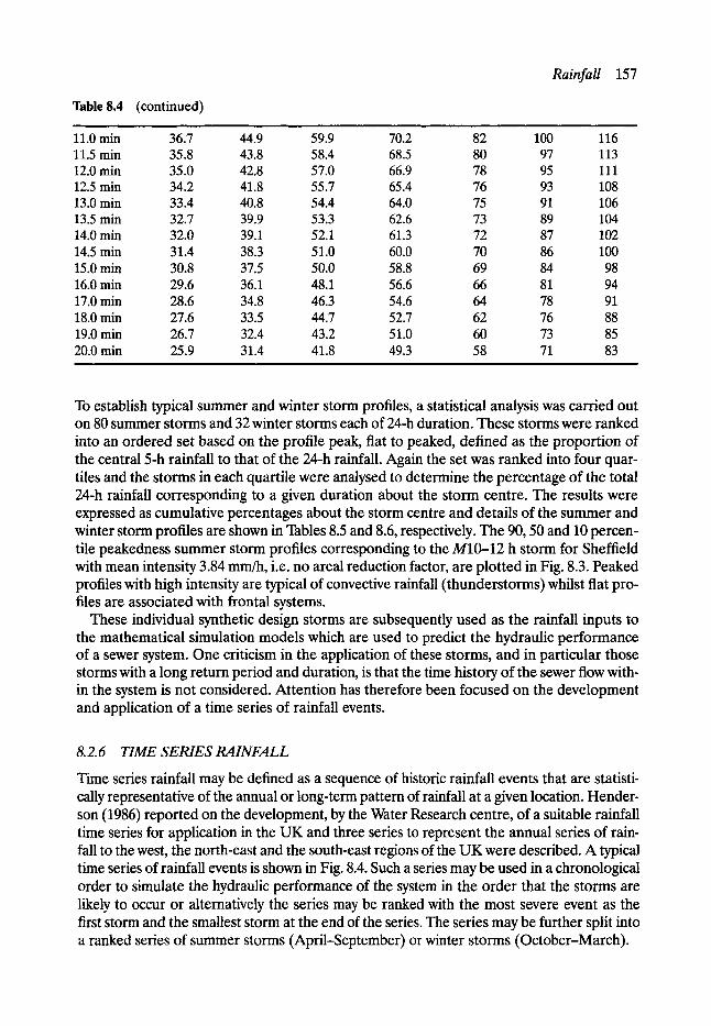
Rainfall 157
Table 8.4 (continued)
11.0 rain 36.7 44.9 59.9 70.2 82 100 116 11.5 min 35.8 43.8 58.4 68.5 80 97 113 12.0 min 35.0 42.8 57.0 66.9 78 95 111 12.5 min 34.2 41.8 55.7 65.4 76 93 108 13.0 min 33.4 40.8 54.4 64.0 75 91 106 13.5 min 32.7 39.9 53.3 62.6 73 89 104 14.0 min 32.0 39.1 52.1 61.3 72 87 102 14.5 min 31.4 38.3 51.0 60.0 70 86 100 15.0 min 30.8 37.5 50.0 58.8 69 84 98 16.0 min 29.6 36.1 48.1 56.6 66 81 94 17.0 min 28.6 34.8 46.3 54.6 64 78 91 18.0 min 27.6 33.5 44.7 52.7 62 76 88 19.0 min 26.7 32.4 43.2 51.0 60 73 85 20.0 min 25.9 31.4 41.8 49.3 58 71 83
, ,
To establish typical summer and winter storm profiles, a statistical analysis was carried out on 80 summer storms and 32 winter storms each of 24-h duration. These storms were ranked into an ordered set based on the profile peak, fiat to peaked, defined as the proportion of the central 5-h rainfall to that of the 24-h rainfall. Again the set was ranked into four quar- tiles and the storms in each quartile were analysed to determine the percentage of the total 24-h rainfall corresponding to a given duration about the storm centre. The results were expressed as cumulative percentages about the storm centre and details of the summer and winter storm profiles are shown in Tables 8.5 and 8.6, respectively. The 90, 50 and 10 percen- tile peakedness summer storm profiles corresponding to the M10-12 h storm for Sheffield with mean intensity 3.84 mm/h, i.e. no areal reduction factor, are plotted in Fig. 8.3. Peaked profiles with high intensity are typical of convective rainfall (thunderstorms) whilst flat pro- files are associated with frontal systems.
These individual synthetic design storms are subsequently used as the rainfall inputs to the mathematical simulation models which are used to predict the hydraulic performance of a sewer system. One criticism in the application of these storms, and in particular those storms with a long return period and duration, is that the time history of the sewer flow with- in the system is not considered. Attention has therefore been focused on the development and application of a time series of rainfall events.
8.2.6 TIME SERIES RAINFALL
Time series rainfall may be defined as a sequence of historic rainfall events that are statisti- cally representative of the annual or long-term pattern of rainfall at a given location. Hender- son (1986) reported on the development, by the Water Research centre, of a suitable rainfall time series for application in the UK and three series to represent the annual series of rain- fall to the west, the north-east and the south-east regions of the UK were described. A typical time series of rainfall events is shown in Fig. 8.4. Such a series may be used in a chronological order to simulate the hydraulic performance of the system in the order that the storms are likely to occur or alternatively the series may be ranked with the most severe event as the first storm and the smallest storm at the end of the series. The series may be further split into a ranked series of summer storms (April-September) or winter storms (October-March).
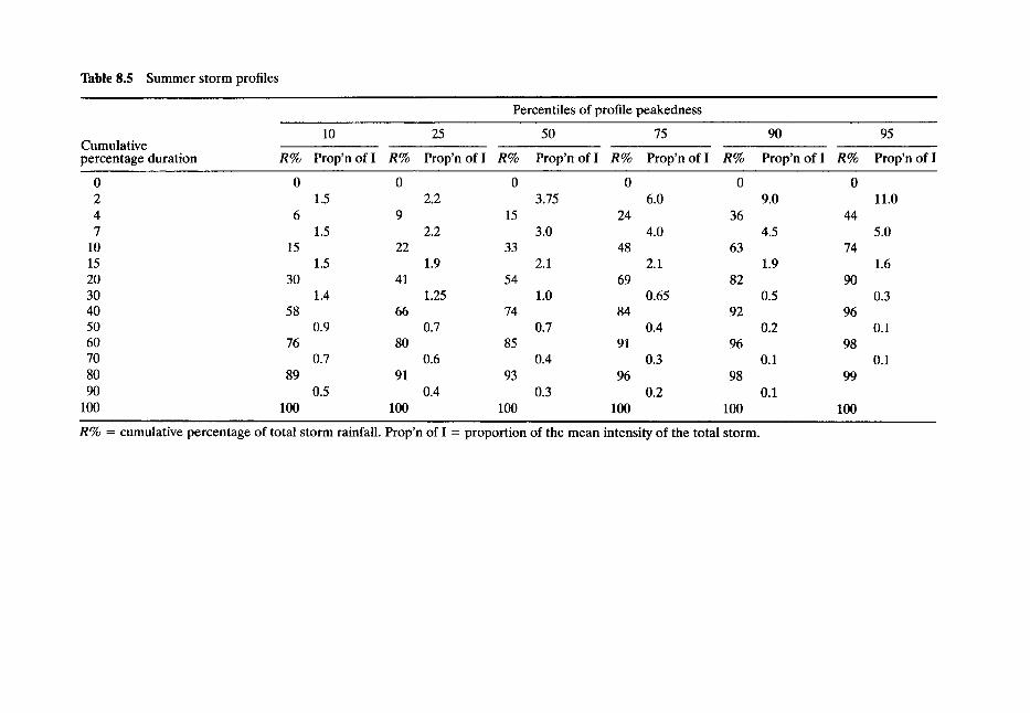
Table 8.5 Summer storm profiles i
Percentiles of profile peakedness
Cumulative percentage duration
10 25
R% P r o p ' n o f I R% P r o p ' n o f I R%
50 75
P r o p ' n o f I R% P r o p ' n o f I R%
90
Prop'n of I R%
95
Prop'n of I
0 0 0 2 1.5 4 6 9 7 1.5
10 15 22 15 1.5 20 30 41 30 1.4 40 58 66 50 0.9 60 76 80 70 0.7 80 89 91 90 0.5
100 100 100
0 0 0 0 2.2 3.75 6.0 9.0 11.0
15 24 36 44 2.2
33 1.9
54 1.25
74 0.7
85 0.6
3.0 4.0 4.5 5.0
2.1
1.0
0.7
48 63 74 2.1 1.9
69 82 90 0.65 0.5
84 92 96 0.4 0.2
91 96 98
1.6
0.3
0.1
0.4 0.3 0.1 0.1 93 96 98 99
0.4 0.3 0.2 0.1 100 100 100 100
R% = cumulative percentage of total storm rainfall. Prop'n of I = proportion of the mean intensity of the total storm.
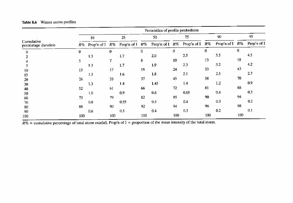
Table 8.6 Winter storm profiles
Percentiles of profile peakedness
10 25 75 50 Cumulatwe percentage duration R% Prop'n of I R% Prop'n of I R% Prop'n of I R% Prop'n of I R%
0 0 0 0 0 0 2 1.3 1.7 2.0 2.5 3.5 4 5 7 8 10 13 7 1.3 1.7 1.9 2.3 3.2
10 13 17 19 24 33 15 1.3 1.6 1.8 2.1 2.5 20 26 33 37 45 58 30 1.3 1.4 1.45 1.4 1.2 40 52 61 66 72 81 50 1.0 0.9 0.8 0.65 0.4 60 73 79 82 85 90 70 0.8 0.55 0.5 0.4 0.3 80 88 90 92 94 96 90 0.6 0.5 0.4 0.3 0.2
100 100 100 100 100 100
90
Prop'n of I R%
0
18
43
70
88
94
98
100
95
Prop'n of I . .
4.5
4.2
2.7
0.9
0.3
0.2
0.1
R% = cumulative percentage of total storm rainfall. Prop'n of I = proportion of the mean intensity of the total storm.
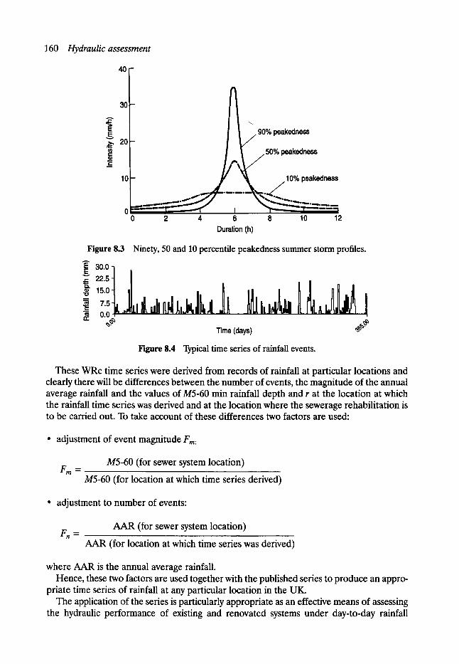
160 Hydraulicassessment
40
A
b ~176176 / ~176
t 101 ~ J _ _ .10% peakedness ..,~" .__+~t~~~.~
o ' " - " - " - - - 0 2 4 6 8 10 12 Duration (h)
Figure 8.3 Ninety, 50 and 10 percentile peakedness summer storm profiles.
E 30.0 E 22.5
..++ 7.5 . I .I,, 1 llt_l ,,,_ �9 m 0 . 0 - ,
= ~ ,,,+,<<.;,<+, Time (days) Figure 8.4 Typical time series of rainfall events.
These WRc time series were derived from records of rainfall at particular locations and clearly there will be differences between the number of events, the magnitude of the annual average rainfall and the values of M5-60 min rainfall depth and r at the location at which the rainfall time series was derived and at the location where the sewerage rehabilitation is to be carried out. To take account of these differences two factors are used:
�9 adjustment of event magnitude Fro:
F m '-" M5-60 (for sewer system location)
M5-60 (for location at which time series derived)
�9 adjustment to number of events:
F n ~ AAR (for sewer system location)
AAR (for location at which time series was derived)
where AAR is the annual average rainfall. Hence, these two factors are used together with the published series to produce an appro-
priate time series of rainfall at any particular location in the UK. The application of the series is particularly appropriate as an effective means of assessing
the hydraulic performance of existing and renovated systems under day-to-day rainfall
Rainfall losses 161
conditions and subsequently of the pollution impact of sewer systems as the frequency, rate, volume and duration of the flows within the system may be assessed on an annual basis. However, as the WRc time series represents a typical year of rainfall, it is important to remember that the existing series do not contain any particularly extreme events, i.e. those of return period much greater than one year. In sewerage rehabilitation and, in particular, when the planned upgrade of a system includes a review and rationalisation of CSO and storage ancillary structures, the performance of the system for more extreme events, i.e. 5-, 10- or even 50-year return period may be of particular importance.
Cowperthwaite et al. (1991) developed a stochastic technique for the generation of time series rainfall. The model, termed the stochastic rainfall generator (SRG), is based on a clustered Poisson process which takes account of the dependence inherent in rainfall events. The model is based on five parameters:
1. Mean waiting time between the beginning of storm events (h). 2. Mean number of rain cells per storm. 3. Mean duration of each rain cell (h). 4. Mean intensity of each rain cell (mm/h). 5. Mean waiting time for each rain cell after the beginning of the storm (h).
These parameters have been derived for each month from historical records of measured rainfall at a number of sites throughout the UK and these may be used to simulate 100 years of hourly time series rainfall. Annual time series rainfall for a typical year may then be extracted from the 100-year record and subsequently the 100 most severe events may then be derived from the simulated typical year. The extreme events in an annual series of 5, 20, or 50-year return period may also be established in a similar way.
8.2. 7 SUMMARY OF RAINFALL INPUTS
In summary therefore the design engineer has several options in the selection of the appro- priate rainfall input. These include:
�9 intensity duration frequency curves �9 synthetic design storms �9 observed storm events �9 time series storms either based on historical rainfall records or stochastic generation.
In sewerage rehabilitation it is recommended that synthetic design storms are used in cases where there is replacement, enlargement or relining of pipes to upgrade the hydraulic performance of the system and that time series rainfall is used when consideration is given to integrated pollution control where the performance of combined sewer overflow, storage and the wastewater treatment plant are essential components of the upgrading option. The WRc series (Henderson, 1986) is appropriate for a one-year return period (assessment of annual performance) whereas the stochastic rainfall generator (Cowperthwaite et al., 1991) may be used to predict time series storms of longer return period.
8.3 Rainfall losses As stated in Section 8.1, rainfall loss mechanisms include absorption and wetting, inter- ception, depression storage, evapotransportation and infiltration. Mathematical models to
162 Hydraulicassessment
describe these processes have been developed (see Section 8.5) and in the text a contrast has been made between approaches adopted in the UK Wallingford Software HYDROWORKS model and the MOUSE model from the Danish Hydraulics Institute
8. 3.1 I N T E R C E P T I O N A N D WETTING
This loss is due to the interception of rainfall by vegetation and the initial wetting of the catchment surface including any loss due to absorption. Usually, such losses are small, and are generally within the range of 0.05 to 0.5 mm.
In the HYDROWORKS model the interception and wetting losses are included as part of the overall loss defined by a percentage runoff equation whereas in the MOUSE (modelling of Urban Sewers) model, as can be seen from Table 8.7, a global value of 0.05 mm is specified unless otherwise defined by the user.
8.3.2 EVAPOTRANSPIRATION
Evaporation may be considered to be the conversion of water into water vapour from the catchment surface whilst transpiration is the water movement through the plant that is lost to the atmosphere. Both losses are usually of similar magnitude and hence they are frequent- ly lumped together as evapotranspiration, i.e. the sum of evaporation and transpiration.
Factors affecting evapotranspiration include solar radiation, wind, relative humidity and temperature. The process of evapotranspiration is therefore a very complex one, but attempts have been made to establish empirical relationships which describe the rate of evaporation from the catchment surface.
In general these relationships take the form:
E = C(e~ - e)f(u) (8.2)
where E is the open water evaporation per unit time, C is the empirical constant, es is the saturation vapour pressure, e is the actual vapour pressure in the air above the surface and u is the wind speed at some standard height above the ground.
However, in the HYDROWORKS model the evapotranspiration loss is not specifically defined whereas in the MOUSE model a default global value of 2 x 10 -8 m/s is assumed for all catchment surfaces, unless otherwise specified.
8. 3. 3 DEPRESSION S TORA GE
This loss is associated with the filling of voids on the catchment surface. The magnitude of the loss is therefore very much a function of the initial catchment wetness at the beginning of the storm event and hence of the depth of rainfall which is required to completely fill the voids.
In the HYDROWORKS model the depression storage loss is represented as an initial loss and is considered as a function of the characteristics and slope of the catchment where
D = K / S 1/2
D is the loss due to depression storage, K is the constant dependent of catchment surface and S is the slope of catchment.

Rainfall losses 163
To take account of the antecedent wetness of the catchment surface the depth of rainfall in the voids preceding the storm event is user defined with the remaining depression storage being subtracted as from the rainfall hyetograph as an initial loss. An appropriate value of K for paved and roof surfaces is 0.07 and for previous surfaces is 0.28.
In the MOUSE model the rainfall loss due to depression storage is considered also as an initial loss which occurs after infiltration has started, but prior to any surface runoff. The loss is defined as a function of the catchment surface and specific values are listed in Table 8.7. These range from 1 mm for an impervious flat roof to 5 mm for an impervious area with vegetation.
Attempts have also been made to describe the depression storage loss as a variable loss rate which takes account of the variability in the take up of storage due to differences in the size of the voids and depressions on the catchment surface, Lindsey presented an equation of the form:
ia = ie exp (Ie/La) (8.3)
where ia is the depression storage loss rate, i e is the net rainfall rate, Ie is the cumulative net rainfall volume and La is the maximum depression capacity.
The net rainfall rate and cumulative net rainfall are a function of the losses due to interception, wetting, evaporation and infiltration and hence to use equation (8.3) it is required that details of all other losses are known. This adds significant complexity to the problem and hence it is usual for most mathematical models to adopt a simple expression or initial loss to describe the loss due to depression storage.
Infiltration
The amount and a rate at which rainfall infiltrates into the ground is a function of the structure of the catchment surface, the soil type and cover and of the initial moisture content of the soil and depth of water above the catchment surface.
A commonly used empirical expression was outlined by Horton (1933) where:
f = (f0 - fc)exp (-kt) + fc (8.4)
where f is the infiltration rate (mm/h), f0 is the initial rate of infiltration (mm/h), fc is the infiltration capacity (mm/h), k is the empirically derived constant dependent on soil type, cover, etc. and t is the time from start of infiltration.
A typical relationship between infiltration rate and time is shown in Fig. 8.5 and from which it can be seen that initially the rate of infiltration is large with an exponential decay to a value of the infiltration capacity after which time the rate of infiltration is considered constant.
Darcy first showed in 1880 that, in saturated soils, the horizontal velocity of flow through the soil was a function of the hydraulic conductivity (permeability) of the soil and the hydrau- lic (pressure) gradient of the phreatic groundwater surface, in the form of equation (8.5)
v = K( /ctL) (8.5)
where V is the velocity of flow, K is the hydraulic conductivity and dh/dL is the hydraulic gradient of the groundwater surface.
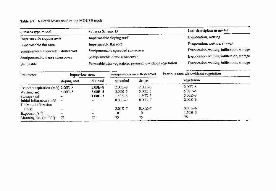
Table 8.7 Rainfall losses used in the MOUSE model
Subarea type model
Impermeable sloping area
Impermeable fiat area
Semipermeable spreaded stonecover
Semipermeable dense stonecover
Permeable
Subarea Scheme D
Impermeable sloping roof
Impermeable fiat roof
Semipermeable spreaded stonecover
Semipermeble dense stonecover
Permeable with vegetation, permeable without vegetation
Loss description in model
Evaporation, wetting
Evaporation, wetting, storage
Evaporation, wetting, infiltration, storage
Evaporation, wetting, infiltration, storage
Evaporation, wetting, infiltration, storage
Parameter Impervious area
sloping roof flat roof
Semipervious area stonecover
spreaded dense
Pervious area with/without vegetation
vegetation
Evapotranspiration (m/s) 2.00E-8 Wetting (m) 5.00E-5 Storage (m) Initial infiltration (m/s) - Ultimate infiltration
(m/s) Exponent (s -x) Manning No. (ml/3s -1) 75
2.00E-8 2.00E-8 2.00E-8 5.00E-5 5.00E-5 5.00E-5 1.00E-3 1.50E-3 1.50E-3 - 8.00E-7 8.00E-7
75
8.00E-7 8.00E-7 0 0
75 75
2.00E-8 5.00E-5 5.00E-3 2.00E-6
3.00E-6 1.50E-3 75
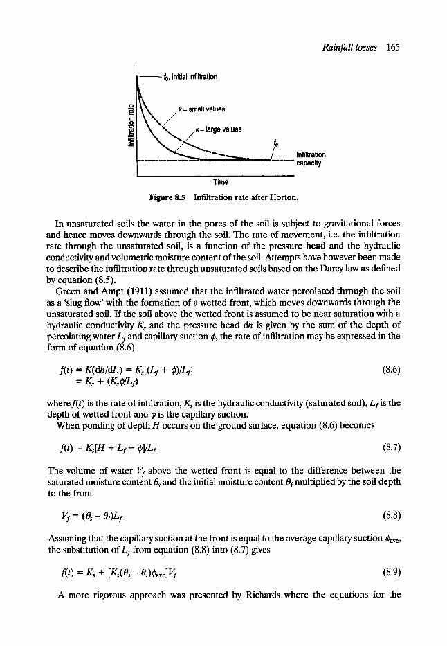
f0, initial infiltration
Rainfall losses 165
0
t - O o~
k= small values
k= large values
f Infiltration . . . . . . capacity
Time
Figure 8.5 Infiltration rate after Horton.
In unsaturated soils the water in the pores of the soil is subject to gravitational forces and hence moves downwards through the soil. The rate of movement, i.e. the infiltration rate through the unsaturated soil, is a function of the pressure head and the hydraulic conductivity and volumetric moisture content of the soil. Attempts have however been made to describe the infiltration rate through unsaturated soils based on the Darcy law as defined by equation (8.5).
Green and Ampt (1911) assumed that the infiltrated water percolated through the soil as a 'slug flow' with the formation of a wetted front, which moves downwards through the unsaturated soil. If the soil above the wetted front is assumed to be near saturation with a hydraulic conductivity Ks and the pressure head dh is given by the sum of the depth of percolating water Lf and capillary suction ~, the rate of infiltration may be expressed in the form of equation (8.6)
f(t) = K(dh/dL) = Ks[(L f + ~)/Lf] = Ks + (Ksdp/Lf)
(8.6)
wheref(t) is the rate of infiltration, Ks is the hydraulic conductivity (saturated soil), L/is the depth of wetted front and ~ is the capillary suction.
When ponding of depth H occurs on the ground surface, equation (8.6) becomes
f(t) = Ks[H + Lf + r (8.7)
The volume of water Vf above the wetted front is equal to the difference between the saturated moisture content 0~ and the initial moisture content 0~ multiplied by the soil depth to the front
Vf - - (0 s - Oi) t f (8.8)
Assuming that the capillary suction at the front is equal to the average capillary suction Cave, the substitution of Lf from equation (8.8) into (8.7) gives
f(t) = Ks + [Ks(Os- 0i)~ave]Vf (8.9)
A more rigorous approach was presented by Richards where the equations for the
166 Hydraulicassessment
conservation of mass and momentum were applied to an unsaturated pervious media. The change in soil moisture content was defined in terms of the unsaturated hydraulic conduc- tivity and the hydraulic diffusivity of the soil, where
dO/dt = d/dZ(D[dffdZ] + K) (8.10)
and where 0 is the soil moisture content, Z is the soil depth, D is the soil water diffusivity and K is the hydraulic conductivity.
The soil water diffusivity may be defined by the relationship
D = K(ddp/dO) (8.11)
where ~ is the capillary suction head and hence is a function of many parameters which include the homogeneity and void ratio of the soil. The numerical solution of equations (8.10) and (8.11) yields the infiltration rate into the unsaturated soil.
However, equations (8.6)-(8.11) all require a considerable knowledge of the soil characteristics, the initial wetness state of the soil prior to individual storm events and of the way this changes in the unsaturated zone. As a result it is common for the mathematical models to utilise empirical relationships to define the infiltration process and in the MOUSE model the rate of infiltration is defined using equation (8.3) (after Horton). For semi- pervious areas a constant global rate of 8 x 10 -7 rn/s is assumed, but for pervious areas an initial infiltration rate of 2 x 10 -5 rn/s and an infiltration capacity of 3 x 10 -6 m/s are suggested.
In the HYDROWORKS model use is made of a regressional relationship to describe the percentage runoff as a function of the catchment characteristics. Parameters which influence the rate of infiltration are included within this relationship and these are described in Section 8.4.
8.4 Rainfall runoff
The conversion of rainfall to surface runoff is concerned with the way in which the rain falling on the catchment is changed into a runoff hydrograph at the points of entry to the sewer system. This is a complex process and is not only a function of the rainfall loss mechanisms that occur, but also on the topographical features and natural drainage path- ways of the catchment surface. These in turn will be a function of the rainfall intensity and duration. Several techniques have been developed to describe the rainfall-runoff/overland processes and these include the use of runoff coefficients, time area diagrams, unit hydro- graphs, linear and non-linear reservoirs and the complete solution of the governing St Venant equations.
8.4.1 PROPORTIONAL LOSS MODEL
The simplest technique is the use of a proportional loss model where, following the sub- traction of initial losses, a runoff coefficient is applied to the actual rainfall to give the net rainfall, i.e.
net rainfall = C(actual rainfall) (8.12)
Typical values of C would be 0.7--0.95 for impervious surfaces and 0.1-0.4 for pervious surfaces.

Rainfall runoff 167
8. 4.2 SOIL CONSERVATION SERVICE MODEL
The Soil Conservation Service model (SCS), developed in the United States, is a rainfall runoff model which allows the runoff coefficient to be changed as the wetness of the catch- ment changes over the duration of an event. The model is primarily intended for rural catchments, but it is also appropriate and has been successfully applied to urban catchments in which there is a large area of pervious surface.
The model predicts the runoff volume corresponding to a particular storm rainfall based on standardised infiltration rates, the available soil storage depth and an antecedent wetness index based on the rainfall in the preceding five days. Initial losses are subtracted from the rainfall prior to runoff and the cumulative runoff volume from the cumulative rainfall is given by an expression of the form
Q = P - s (8.13)
where Q is the cumulative runoff volume, P is the cumulative storm rainfall and S is the storage volume on and within the soil.
The soil, depression storage and cover have a saturation storage value S', but prior to satu- ration, the relationship between rainfall, runoff and the rainfall that enters the soil storage will be given by equation (8.13). At saturation the rate of rainfall excess (runoff) will equal the rate of rainfall and a proportional relationship may be developed, where, at any time
S/S' = Q/P (8.14)
Combining equations (8.13) and (8.14) gives
(P - Q)/S' = Q/P (8.15)
At the time when the initial loss is equal to zero the relationship becomes
Q = P2/(p+s') (8.16)
The initial loss is considered to be proportional to the potential soil saturation S' and the soil conservation service recommended a value of the constant of proportionality equal to 0.2. In this case equation (8.15) becomes
Q = [ ( P - 0.2s')]/[P + 0.8s'] if P > 0.2s' (8.17)
and
Q = 0 if P ~< 0.2s' (8.18)
Hence, once runoff has commenced, the infiltration loss rate into the ground at any instant in time may be related to the rainfall and the potential soil saturation S'. The value of S' is related to the soil type, ground cover and catchment moisture content by a runoff curve num- ber CN, which ranges from 0 to 100 corresponding to zero and 100% runoff. The relation- ship between S' and CN is given by
S' = (25,400/CN)- 254 (8.19)
Soil types are listed in Table 8.8 and the values of CN corresponding to different cover types and quality are listed in Table 8.9.
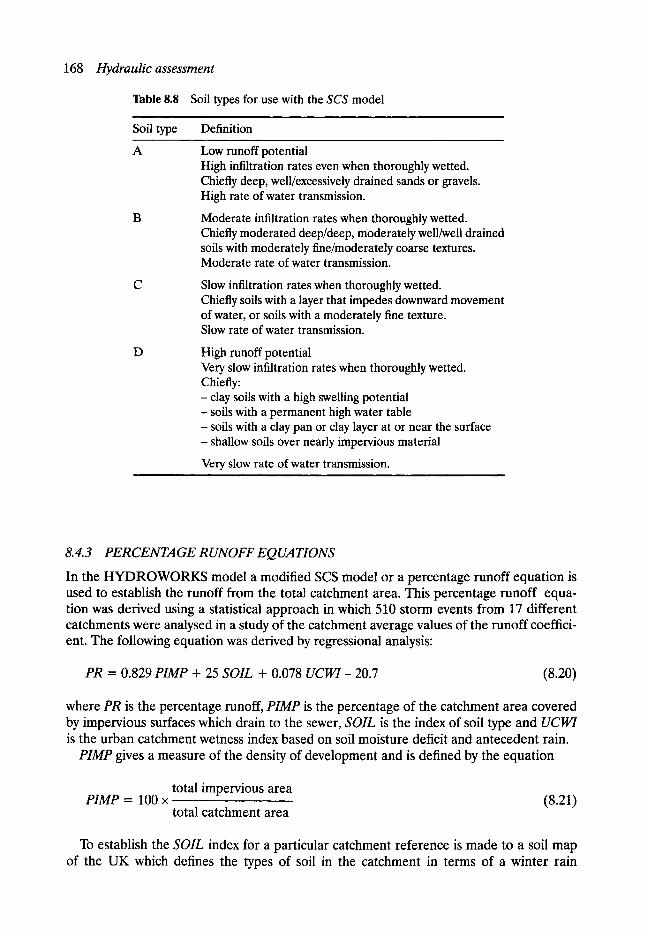
168 Hydraulic assessment
T a b l e 8 . 8 Soil types for use with the SCS model , , ,
Soil type Definition
A
D
Low runoff potential High infiltration rates even when thoroughly wetted. Chiefly deep, well/excessively drained sands or gravels. High rate of water transmission.
Moderate infiltration rates when thoroughly wetted. Chiefly moderated deep/deep, moderately well/weU drained soils with moderately fine/moderately coarse textures. Moderate rate of water transmission.
Slow infiltration rates when thoroughly wetted. Chiefly soils with a layer that impedes downward movement of water, or soils with a moderately fine texture. Slow rate of water transmission.
High runoff potential Very slow infiltration rates when thoroughly wetted. Chiefly: - clay soils with a high swelling potential - soils with a permanent high water table - soils with a clay pan or clay layer at or near the surface - shallow soils over nearly impervious material
Very slow rate of water transmission.
8. 4. 3 PERCENTAGE RUNOFF EQ UA TIONS
In the H Y D R O W O R K S model a modified SCS model or a percentage runoff equation is used to establish the runoff from the total catchment area. This percentage runoff equa- tion was derived using a statistical approach in which 510 storm events from 17 different catchments were analysed in a study of the catchment average values of the runoff coeffici- ent. The following equation was derived by regressional analysis:
PR = 0.829 PIMP + 25 SOIL + 0.078 UCWI- 20.7 (8.20)
where PR is the percentage runoff, PIMP is the percentage of the catchment area covered by impervious surfaces which drain to the sewer, SOIL is the index of soil type and UCWI is the urban catchment wetness index based on soil moisture deficit and antecedent rain.
PIMP gives a measure of the density of development and is defined by the equation
total impervious area PIMP = 100 x (8.21)
total catchment area
To establish the SOIL index for a particular catchment reference is made to a soil map of the UK which defines the types of soil in the catchment in terms of a winter rain

Rainfall runoff 169
Table 8.9
Land use
Values of curve number CN for use in the SCS model
Cover
Treatment or practice Hydrologic condition A
Hydrologic soil group
B C D
Fallow
Row crops
Straight row
Straight row Poor Straight row Good Contoured Poor Contoured Good Contoured and terraced Poor Contoured and terraced Good
77 86 91 94
72 81 88 91 67 78 85 89 70 79 84 88 65 75 82 86 66 74 80 82 62 71 78 81
Small grain Straight row
Contoured
Contoured and terraced
Poor 65 76 84 88 Good 63 75 83 87 Poor 63 74 82 85 Good 61 73 81 84 Poor 61 72 79 82 Good 59 70 78 81
Close-seeded legumes Straight row or rotation meadow Straight row
Contoured Contoured Contoured and terraced Contoured and terraced
Poor 66 77 85 89 Good 58 72 81 85 Poor 64 75 83 85 Good 55 69 78 83 Poor 63 73 80 83 Good 51 67 76 80
Pasture or range
Contoured Contoured Contoured
Poor 68 79 86 89 Fair 49 69 79 84 Good 39 61 74 80 Poor 47 67 81 88 Fair 25 59 75 83 Good 6 35 70 79
Meadow Good 30 58 71 78
Woods Poor 45 66 77 83 Fair 36 60 73 79 Good 25 55 70 77
Farmsteads - 59 74 82 86
Roads (dirt) - 72
(hard surface) - 74
Source: U.S. Department of Agriculture National Engineering Handbook, Soil
82 87 89
84 90 92 i
Conservation Service.
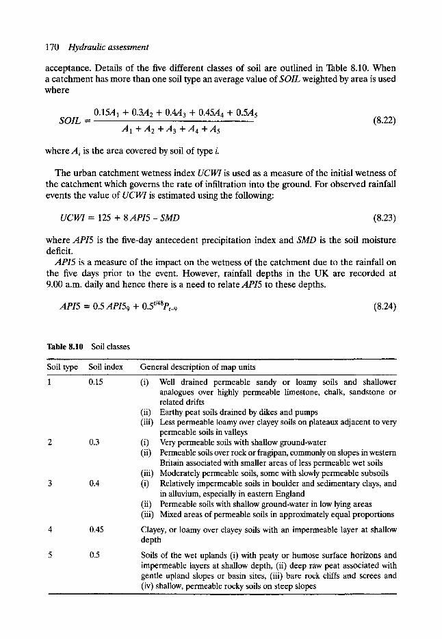
170 Hydraulicassessment
acceptance. Details of the five different classes of soil are outlined in Table 8.10. When a catchment has more than one soil type an average value of SOIL weighted by area is used where
0.15A1 + 0.3A2 + 0.4A3 + 0.45A 4 -I- 0.5A 5 SOIL = (8.22)
AI +A2 +A3 + A 4 +A5
where Zi is the area covered by soil of type i.
The urban catchment wetness index UCWI is used as a measure of the initial wetness of the catchment which governs the rate of infiltration into the ground. For observed rainfall events the value of UCWI is estimated using the following:
UCWI = 125 + 8 A P I 5 - SMD (8.23)
where API5 is the five-day antecedent precipitation index and SMD is the soil moisture deficit.
API5 is a measure of the impact on the wetness of the catchment due to the rainfall on the five days prior to the event. However, rainfall depths in the UK are recorded at 9.00 a.m. daily and hence there is a need to relate API5 to these depths.
API5 = 0.5 API59 + 0.5t/48pt_ 9 (8.24)
Table 8.10 Soil classes
Soil type Soil index General description of map units
1 0.15
2 0.3
3 0.4
4 0.45
5 0.5
(i) Well drained permeable sandy or loamy soils and shallower analogues over highly permeable limestone, chalk, sandstone or related drifts
(ii) Earthy peat soils drained by dikes and pumps (iii) Less permeable loamy over clayey soils on plateaux adjacent to very
permeable soils in valleys (i) Very permeable soils with shallow ground-water (ii) Permeable soils over rock or fragipan, commonly on slopes in western
Britain associated with smaller areas of less permeable wet soils (iii) Moderately permeable soils, some with slowly permeable subsoils (i) Relatively impermeable soils in boulder and sedimentary clays, and
in alluvium, especially in eastern England (ii) Permeable soils with shallow ground-water in low lying areas (iii) Mixed areas of permeable soils in approximately equal proportions
Clayey, or loamy over clayey soils with an impermeable layer at shallow depth
Soils of the wet uplands (i) with peaty or humose surface horizons and impermeable layers at shallow depth, (ii) deep raw peat associated with gentle upland slopes or basin sites, (iii) bare rock cliffs and screes and (iv) shallow, permeable rocky soils on steep slopes
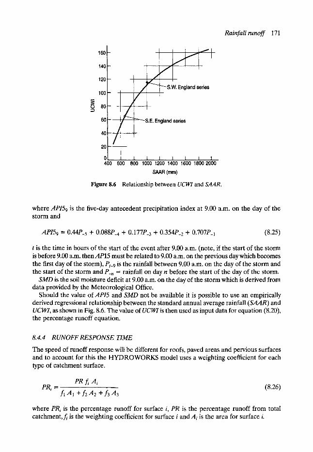
160 -
140 -
120 -
_ 100 L 80 I
~ I / - L 60 [ -'-S.E. England series
t 40
20
0
W. England series
L...~ 1 !
I l i I i I I ! 400 600 800 1000 1200 1400 1600 1800 2000
SAAR (mm)
Figure 8.6 Relationship between UCWI and SAAR.
Rainfallrunoff 171
where API59 is the five-day antecedent precipitation index at 9.00 a.m. on the day of the storm and
API59 = 0.44P_5 + 0 .088P_ 4 -+- 0.177P_3 + 0.354P_ 2 + 0.707P_a (8.25)
t is the time in hours of the start of the event after 9.00 a.m. (note, if the start of the storm is before 9.00 a.m. thenAP15 must be related to 9.00 a.m. on the previous day which becomes the first day of the storm), Pt-9 is the rainfall between 9.00 a.m. on the day of the storm and the start of the storm and P-n = rainfall on day n before the start of the day of the storm.
SMD is the soil moisture deficit at 9.00 a.m. on the day of the storm which is derived from data provided by the Meteorological Office.
Should the value of API5 and SMD not be available it is possible to use an empirically derived regressional relationship between the standard annual average rainfall (SAAR) and UCWI, as shown in Fig. 8.6. The value of UCWI is then used as input data for equation (8.20), the percentage runoff equation.
8.4.4 RUNOFF RESPONSE TIME
The speed of runoff response will be different for roofs, paved areas and pervious surfaces and to account for this the HYDROWORKS model uses a weighting coefficient for each type of catchment surface.
PR fi Ai PR~ = (8.26)
f lA1 +f2A2 +f3A3
where PRi is the percentage runoff for surface i, PR is the percentage runoff from total catchment, ~ is the weighting coefficient for surface i and A i is the area for surface i.
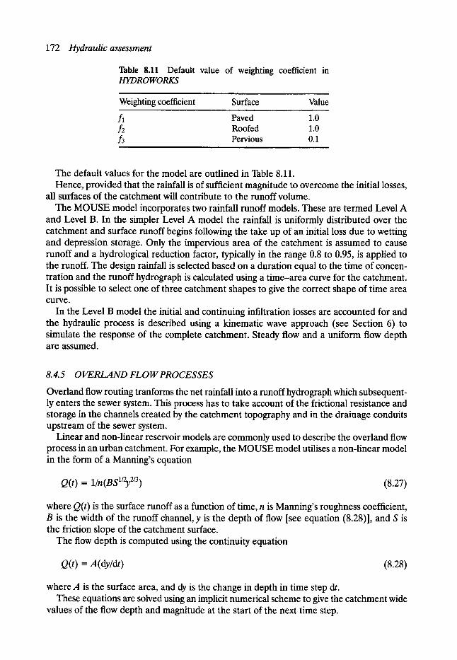
172 Hydraulic assessment
Table 8.11 Default value of weighting coefficient in HYDROWORKS
Weighting coefficient Surface Value
fl Paved 1.0 f2 Roofed 1.0 f3 Pervious 0.1
The default values for the model are outlined in Table 8.11. Hence, provided that the rainfall is of sufficient magnitude to overcome the initial losses,
all surfaces of the catchment will contribute to the runoff volume. The MOUSE model incorporates two rainfall runoff models. These are termed Level A
and Level B. In the simpler Level A model the rainfall is uniformly distributed over the catchment and surface runoff begins following the take up of an initial loss due to wetting and depression storage. Only the impervious area of the catchment is assumed to cause runoff and a hydrological reduction factor, typically in the range 0.8 to 0.95, is applied to the runoff. The design rainfall is selected based on a duration equal to the time of concen- tration and the runoff hydrograph is calculated using a time-area curve for the catchment. It is possible to select one of three catchment shapes to give the correct shape of time area curve.
In the Level B model the initial and continuing infiltration losses are accounted for and the hydraulic process is described using a kinematic wave approach (see Section 6) to simulate the response of the complete catchment. Steady flow and a uniform flow depth are assumed.
8.4.5 O I ~ R L A N D FLO W PROCESSES
Overland flow routing tranforms the net rainfall into a runoff hydrograph which subsequent- ly enters the sewer system. This process has to take account of the frictional resistance and storage in the channels created by the catchment topography and in the drainage conduits upstream of the sewer system.
Linear and non-linear reservoir models are commonly used to describe the overland flow process in an urban catchment. For example, the MOUSE model utilises a non-linear model in the form of a Manning's equation
Q(t) = 1/n(BS1/2y 2/3) (8.27)
where Q(t) is the surface runoff as a function of time, n is Manning's roughness coefficient, B is the width of the runoff channel, y is the depth of flow [see equation (8.28)], and S is the friction slope of the catchment surface.
The flow depth is computed using the continuity equation
Q(t) = A (dy/dt) (8.28)
where A is the surface area, and dy is the change in depth in time step dt. These equations are solved using an implicit numerical scheme to give the catchment wide
values of the flow depth and magnitude at the start of the next time step.
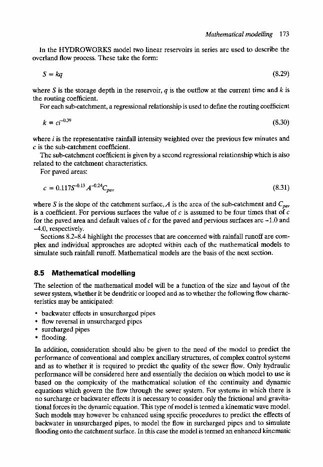
Mathematical modelling 173
In the HYDROWORKS model two linear reservoirs in series are used to describe the overland flow process. These take the form:
S = kq (8.29)
where S is the storage depth in the reservoir, q is the outflow at the current time and k is the routing coefficient.
For each sub-catchment, a regressional relationship is used to define the routing coefficient
k = c i -0"39 (8.30)
where i is the representative rainfall intensity weighted over the previous few minutes and c is the sub-catchment coefficient.
The sub-catchment coefficient is given by a second regressional relationship which is also related to the catchment characteristics.
For paved areas:
C = 0.117S -0"13 A-~ v (8.31)
where S is the slope of the catchment surface, A is the area of the sub-catchment and Cpa v is a coefficient. For pervious surfaces the value of c is assumed to be four times that of c for the paved area and default values of c for the paved and pervious surfaces are -1.0 and -4.0, respectively.
Sections 8.2-8.4 highlight the processes that are concerned with rainfall runoff are com- plex and individual approaches are adopted within each of the mathematical models to simulate such rainfall runoff. Mathematical models are the basis of the next section.
8.5 Mathematical modelling The selection of the mathematical model will be a function of the size and layout of the sewer system, whether it be dendritic or looped and as to whether the following flow charac- teristics may be anticipated:
�9 backwater effects in unsurcharged pipes �9 flow reversal in unsurcharged pipes �9 surcharged pipes �9 flooding.
In addition, consideration should also be given to the need of the model to predict the performance of conventional and complex ancillary structures, of complex control systems and as to whether it is required to predict the quality of the sewer flow. Only hydraulic performance will be considered here and essentially the decision on which model to use is based on the complexity of the mathematical solution of the continuity and dynamic equations which govern the flow through the sewer system. For systems in which there is no surcharge or backwater effects it is necessary to consider only the frictional and gravita- tional forces in the dynamic equation. This type of model is termed a kinematic wave model. Such models may however be enhanced using specific procedures to predict the effects of backwater in unsurcharged pipes, to model the flow in surcharged pipes and to simulate flooding onto the catchment surface. In this case the model is termed an enhanced kinematic
174 Hydraulicassessment
wave model. A model which gives a complete solution of the governing equations is termed a dynamic wave model. This type of model will simulate each of the above factors and, in addition, will predict the effect of any flow reversal and the hydraulic performance of systems which contain loops in the pipe network. It should be remembered however that the data requirements and computation time increase with the complexity of the model as does the required level of understanding and interpretation of the model user.
8.5.1 MATHEMATICAL SIMULATION MODELS
In almost every European country and in the United States there exists a mathematical model which is appropriate for the hydraulic simulation of sewer system performance in that particular country. A detailed description of each of these models is beyond the scope of this text, but three models which are commonly used world-wide are the SWMM model from the United States, the MOUSE model from Denmark and the Wallingford (HYDROWORKS) suite of models from the UK.
SWMM (Storm Water Management Model)
This model was originally developed for the US Environmental Protection Agency (Huber et al., 1986). SWMM is segmented into blocks and these are tiffed Rainfall, Transport, Extran, Storage/Treatment and Statistics. Version 4 of the model, may be used with a single event or continuous rainfall, and is appropriate for use with dendritic (tree like) or looped systems (Extran block). SWMM can simulate backwater profiles and surcharged flow conditions and in the Storage/Treatment block both CSO and storage tank performance may be simulated by the use of removal functions and sedimentation theory. The performance of pumping stations and several types of flow control device may also be described.
MOUSE (Modelling of Urban Sewers)
The development of the MOUSE model was coordinated by the Danish Hydraulic Institute Lindberg and two alternative methods may be used to simulate the rainfall runoff process. Level A is a simple technique based on a time area computation whereas Level B takes into account an initial and a continuing loss of rainfall.
The sewer flow routing may be carried out using kinematic, diffusive or dynamic wave theory and hence complex looped networks may be simulated. Similarly all ancillary struc- tures may also be modelled.
HYDR O WORKS Wallingf ord Software
The Wallingford Procedure (1981) is a suite of programs for the design and simulation of urban drainage systems and is appropriate for use with a wide range of rainfall conditions, i.e. UK and overseas. In the renovation of existing sewer systems the appropriate model to use is the HYDROWORKS quantity model which is applicable for both dendritic and looped systems or systems which involve an interaction between the various drainage components. The hydraulic performance of flow controls, pumping stations and all other forms of ancillary structure may also be simulated.
Microcomputer versions of each model are available and all these models are capable of the simulation of large complex networks. As a result the input data requirements are large and skilled personnel are therefore required to operate the models and to interpret and understand the results output. However, it is not always necessary to use the most complex
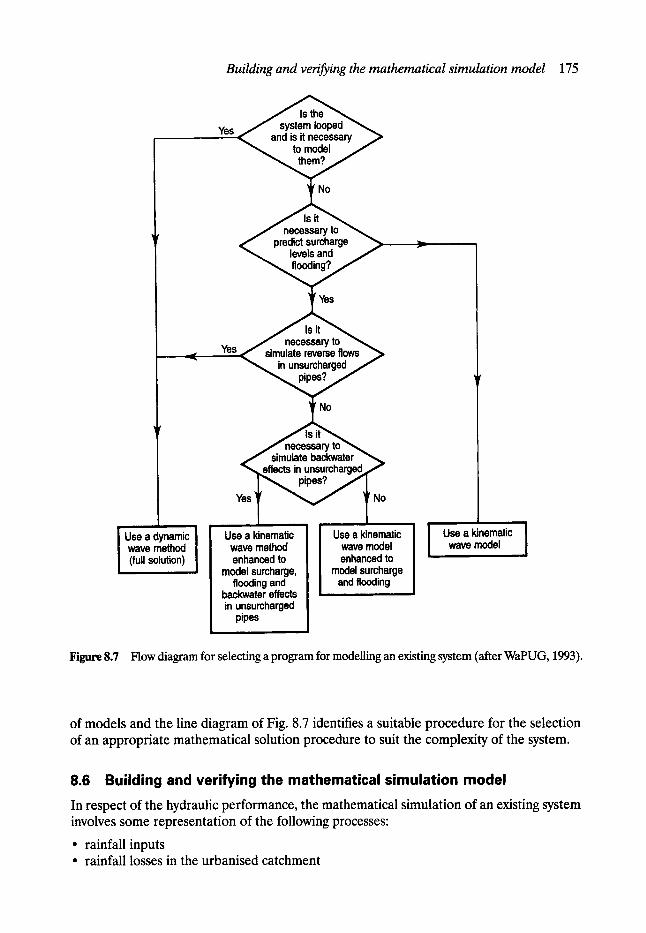
I Use a dynamic I wave method I (full solution) !
Building and verifying the mathematical simulation model 175
No
Yes
r
Yes ," necessary to ", simulate reverse flows .~ in unsurcharged.,
No
f necessary to simulate backwater
"~,~effects in unsurcharged~f
Use a kinematic wave method enhanced to
model surcharge, flooding and
backwater effects in unsurcharged
pipes
| Use a kinematic J
wave model ! enhanced to
model surcharge and flooding
Use a kinematic | wave model J
Figure 8.7 Flow diagram for selecting a program for modelling an existing system (after WaPUG, 1993).
of models and the line diagram of Fig. 8.7 identifies a suitable procedure for the selection of an appropriate mathematical solution procedure to suit the complexity of the system.
8.6 Building and verifying the mathematical simulation model In respect of the hydraulic performance, the mathematical simulation of an existing system involves some representation of the following processes:
�9 rainfall inputs �9 rainfall losses in the urbanised catchment
176 Hydraulicassessment
�9 overland flow across the catchment surface �9 routing of the runoff hydrograph in the sewer system.
The hydraulic model is therefore required to simulate the response of the catchment to rainfall and to accurately represent the mechanisms and processes associated with the collec- tion and losses of rainfall, and the flow routing components of overland flow and in-sewer transport.
In this latter respect it is required that the model should simulate the transition between free surface and surcharged flow, account for backwater effects and predict zones of surcharge and surface flooding. Similarly it is required that the hydraulic performance of any sewer system ancillary structures such as manholes, silt traps, combined sewer overflows and storage tanks should also be accurately simulated by the model. It is also preferable that the flood volume and the area bounded by the flood is predicted.
The hydraulic model must also be widely applicable and relatively inexpensive to con- struct, operate, run and verify. Firstly the mathematical model should be efficient in terms of the volume, complexity and editing of the input data required to operate the model and in terms of the ease and speed of computer operation. Similarly the data which must be collected to verify the model should also be relatively inexpensive and easy to collect and, once verified, the model should easily accommodate changes to the hydrological, catchment and sewer system data such that the hydraulic and pollutant retention performance of different engineering options may be quickly and easily assessed.
8.6.1 BUILD HYDRAULIC MODEL
The complexity, verification and standard of a model is a function of the objectives and purpose for which the model is to be used in addition to the considerations of time scale and cost. The latter factor is usually a function of the level of detail which is required to achieve the objective of the model. Four types of model may be defined (WaPUG, 1993):
�9 Type 1: Skeletalplanning, course macro orplanning model. For this type of model the num- ber of nodes would be typically 2-6 per 1000 head of population and hence the skeletal planning model represents a very simplified model of the system. Such a model may be applied to examine the overall hydraulic performance of the complete catchment or to simulate the flow eonclitions at a specific location or section of sewer. For example the model may be used at the initial stage of a rehabilitation study to examine the influence of selected upgrading options on the hydraulic performance of the system or of the changes to the flow in the system as a result of any proposed developments. Similarly, the skeletal planning model would be used to simulate the outflow at a particular location within the system.
In this latter respect it is a particularly valuable tool to establish the inputs from individ- ual catchments to trunk and intercepting sewers and hence to identify any part of the system which has a large spare capacity or is surcharged and/or subject to flow reversal. Such information may then be used to define the boundary conditions at each outfall which may then be used as input data when a more sophisticated modelling exercise on that part of the system upstream of the outlet is to be carried out, for example, a drainage area planning model.
�9 Type I I - drainage area planning model. A drainage area planning model is used to assess the hydraulic performance within a specific drainage area with a view to identifying the sewer lengths in which there is a hydraulic problem and hence a need for performance

Building and verifying the mathematical simulation model 177
upgrading. The drainage area planning model is then used to compare the performance of potential upgrading options and to assess the impact on the specific drainage area of any future developments which may influence the hydraulic performance of the system. This model may also be utilised to provide a useful indicator of the overall CSO spilled flow and hence to present a broad assessment of potential water quality implications for the receiving watercourse. Between 6 and 20 nodes per 1000 head of population are appropriate for a drainage area planning model.
�9 Type I I I - detailed design model This type of model is used for detailed investigation of the performance of the existing system, of the performance of alternative upgrading options and for the detailed design of selected schemes. The modelling exercise is carried out for a specific drainage area and the extent of the area should include any downstream control structures, e.g. CSOs and pumping stations, which may influence the hydraulic performance within the sewer system which forms part of the drainage area plan. This model should provide a full description of the hydraulic performance at all ancillary structures and hence should provide all hydraulic data for use with a water quality model. The number of nodes for this type of model has to be sufficient to accurately describe the hydraulic performance of the system and this will obviously be a function of the complexity of the existing system and the proposed upgrading option.
�9 Type I V - sewer quality model The application of a sewer flow quality model requires that the verified hydraulic model produces high precision results of the flow and depth hydrographs for a range of free surface and surcharged flow conditions. Similarly, in many sewer flow quality models it is assumed that the pollution load in the combined sewer flow is, in some way, linked to the quantity and quality of the dry weather flow and to the deposition, build-up, erosion and transport of sediments from the catchment surface, in the pipes of the sewer system and at ancillary structures. The hydraulic model must also describe the diurnal pattern of dry weather flow (which includes the simulation of any major industrial inputs) as well as predicting the flow conditions at which sediments will deposit, and subsequently at what flow condition these sediments will erode and move through the system. The sewer flow quality model uses this hydraulic information to predict the build-up of sediments in the sewer system at times of dry weather and subsequently, at times of storm flow to predict the pollution load associated with the dry weather flow and with the erosion and transport of these deposited sediments. Similarly, the pollution associated with the wash-off of pollutants from the catchment surface and the pollution retention efficiency of any ancillary structure has also to be fully described.
In respect of sewerage rehabilitation the objective is to establish a mathematical simula- tion model of the system which may be used to establish, for a given rainfall input, the hydraulic performance (flow, velocity depth) within each pipe of the existing system, and sub- sequently, once the model has been proved to work (verified), to use the model to predict the hydraulic performance within each of the systems which are proposed as upgrading options.
The first step in the model building exercise is to define the extent of the catchment which is to be modelled and to ensure that the model represents, in sufficient detail, all charac- teristics of the catchment and of the sewer system. In large catchments the spatial distri- bution of rainfall may need to be considered or there may be a need to break down the catchment into a number of discrete sub-areas which are more easily managed or to reduce the extent of the catchment or number of pipes to be modelled. To simplify the size of the system to be modelled, three techniques are commonly employed:
178 Hydraulicassessment
�9 p run ing - to exclude the pipes on the periphery of the system and to input any flow into the next downstream pipe
�9 merging- grouping together a number of consecutive pipes into a single pipe �9 equivalence - replacing a complex layout with a simpler layout.
It is essential, however, that the accuracy of computation is not compromised by any of the above simplification procedures. Where sub-areas are used the hydraulic performance of each sub-area is pulled together into a single model to represent the complete catchment. In this latter respect it is of special importance that the hydraulic inputs to the core area and critical sewers are correctly simulated by the model. Hence, one of the most arduous tasks in the development of the mathematical model is the collection of the basic catchment and sewer system data. Invariably it is required to break down the catchment into pervious and impervious surfaces with the latter further subdivided into surfaces with fast (roofed areas) and slow (paved areas) runoff response. The sewer system data is usually obtained from Ordnance survey and sewer system maps which are partially or fully supplemented by manhole surveys where appropriate. Such surveys require the physical inspection of the size and shape of the manhole, and of the pipes which enter and leave the manhole, in addition to the cover level of the manhole and the invert/soffit level of each pipe. The results of a typical manhole survey are shown in Fig. 8.8. Several software packages have subsequently been developed to transfer this information into a database format suitable for graphical display or as a data file suitable for input into a mathematical model to simulate the hydraulic performance of the system.
8. 6.2 VERIFY M O D E L
The object of this step is to establish that the simulated predicted performance of the system corresponds with the actual performance. It is usual that the actual hydraulic performance corresponding to a measured rainfall input is recorded within one or several pipes of the system such that, should the predicted and actual results not correspond, the system data may be examined to identify any deficiencies or errors in the data which may be the cause of the recorded differences in the hydraulic performance. Corrections are then subsequently made to the input data until good agreement is reached between the actual and simulated performance. It is stressed however that this 'verification process' must be applied to a range of storm inputs preferably with significant differences in the rainfall intensity, depth and duration of the events. If good agreement is obtained for all events then the model may be considered to be verified and is termed a verified model. This model may then be used with confidence to predict performance deficiencies within the existing system and in any proposed rehabilitation options, with the proviso that the catchment and sewer system response corresponding to the design rainfall is similar to that which was monitored during the verification period. Care should therefore be taken when the verified model is used to predict the hydraulic performance corresponding to storms of longer return period than those monitored as part of the verification exercise and in situations where surcharge and flooding are simulated by the model.
8.6.3 USE M O D E L TO A S S E S S HYDRAULIC P E ~ O R M A N C E A N D CAUSES OF P E R F O R M A N C E DEFICIENCIES
The verified model is then used to simulate the hydraulic performance of each pipe within the system and of any ancillary structures for a range of design storm inputs. These inputs
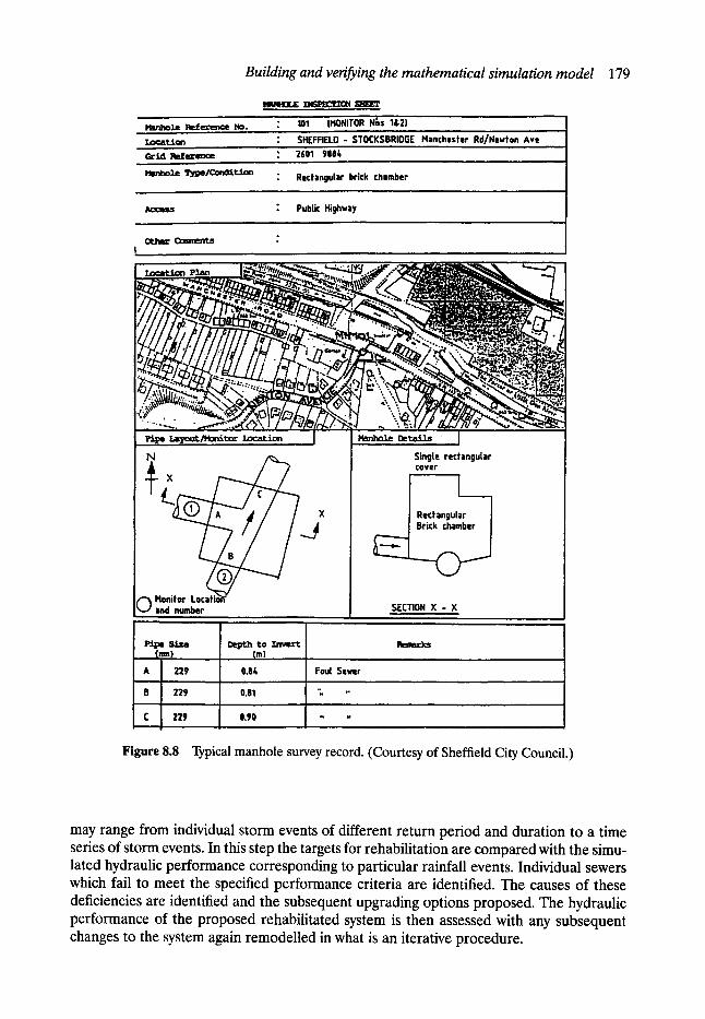
Building and verifying the mathematical simulation model 179
H~n~ole ~s It:).
HReZ4OZ, E ~ Sl~eF " 101 IMONITOR" N~s ':l&2) �9 SHEFFIELD - STOCKSBRIDGE Manchester Rd/Nevton Ave �9 2601 9084
esm~oXe 5~pe/C~xzSLtdu~n " Rectangular brick chamber
" Public Highway ,
o o t ~ Cauments
I !I II l;z.~,~ ~ : / z T ~ 7 �9 : ~
.7 "'~-" " ... b " "
"::~" '."'~/~ ,/,?_ , . ~ ' X .r~i~/c,, L /
Pi~ I ~ o ~ ~ t o ~ Location
Monitor and number
s~e ~ t o (rim) (m) ,~, . . . .
A 229 0.84
B 229 0.81
C 229 0.90
Foul Sewer
e , R
~ , o . . ~
HanhoZe DetaJ.ls ] Single rectangular COVer
,. ,
I Rectangular l Brick chamber
SECTION X - X . . . .
ll~m:im
Figure 8.8 Typical manhole survey record�9 (Courtesy of Sheffield City Council.)
may range from individual storm events of different return period and duration to a time series of storm events. In this step the targets for rehabilitation are compared with the simu- lated hydraulic performance corresponding to particular rainfall events. Individual sewers which fail to meet the specified performance criteria are identified. The causes of these deficiencies are identified and the subsequent upgrading options proposed. The hydraulic performance of the proposed rehabilitated system is then assessed with any subsequent changes to the system again remodelled in what is an iterative procedure.
180 Hydraulicassessment
8.7 Catchment and sewer system data
8. 7.1 INPUT DATA
To construct a mathematical model it is requested to input data on the catchment charac- teristics and of the sewer system that is to be renovated
The data required as input to the simulation model consist of a combination of catchment and sewer system data. This information is usually held on some form of sewer system data (SSD) file. For example in the Wallingford procedure the following information is required to be input as basic data.
�9 Pipe branch reference number �9 Pipe and manhole characteristics
Length Size Shape (major and minor dimension) Invert or soffit levels Gradient Hydraulic roughness Loss coefficient at manholes
�9 Catchment characteristics Total area drained to each pipe Impervious area (paved and roofed) Pervious area Slope Cover level Paved area per gully Area flooded for a particular flood volume
* Dry weather flow Population Industrial effluent Infiltration.
Additional information is required for all ancillary structures and this has to be of sufficient detail in order to define the hydraulic performance of the structure. Such informa- tion will be a function of the requirements of each particular simulation model, but generally for a CSO chamber this data includes the chamber geometry, and the discharge coefficients to define the head discharge relationships for the continuation flow outlet and for the weir or siphon arrangement which is used to spill the excess flow from the chamber. In pumping stations details of the layout and geometry of the station together with the head discharge characteristics of the pumps, and any pump and pipeline losses have to be specified as do the switch on and switch off levels for the pumps. In pumping stations where multiple pumps are utilised, the hydraulic analysis may be further complicated if the specified switch on and switch off levels of the individual pumps are different and when the pumps are of a different size or operate with variable speed. The simulation model adopted has therefore to take into account all these factors such that the hydraulic performance of the ancillary structures may be accurately predicted.
For outfalls which have a flap vane it is necessary to specify the water level at which the flap vane is closed and to input the relationship which links the water levels upstream (in sewer) and downstream of the flap valve and the flow through the valve when it is partially
Catchment and sewer system data 181
open. When free outfalls become submerged it is required to specify the initial water level and the variation in the water level with time.
8. 7.2 TRIGGERS A N D TARGETS FOR REHABILITATION
The mathematical model is used to predict the hydraulic performance of the system for a number of storm events such that it is possible to identify the return period and duration of the design storm events which cause the 'onset of surcharge' and the 'onset of flooding' in each individual pipe of the system. This information is subsequently used to identify triggers for early rehabilitation and to define the target level for upgrading. Design storms of return period in the range of 1-50 years are commonly used, but the duration of the design event is a function of the time of concentration for the system, i.e. the time at which the rainfall falling over the complete catchment contributes to the flow in the system. The time of concentration is equal therefore to the time that the rainfall takes to enter the system plus the time that the in-pipe sewer flow resulting from the rainfall runoff process takes to reach the downstream end of the pipe under consideration, i.e.
time of concentration = time of entry + time of flow
It is necessary therefore to utilise a range of durations to assess the peak flow in the system and it has been commonly found that the peak flow occurs when the duration of the storm is equal to approximately twice the time of concentration for the system. It is recommended therefore that the model be run for a storm of arbitrarily selected return period, say one in two years, and for durations corresponding to 1, 2, 3 and 4 times the time of concentration to establish the duration of storm which results in the peak outflow. This duration should subsequently be used with other return period storms to identify the appropriate triggers for rehabilitation within each part of the system.
Such triggers are usually identified as a return period flooding and this is obviously a function of the land use and the type of property which drain to each pipe or sub-catchment of the system. Individual Water Utilities and Municipalities will specify the appropriate criteria and examples of such triggers and targets are outlined in Table 8.12.
Pipes in the system which do not meet the required performance criteria are identified on sewer network plans and these are used as a trigger to initiate a detailed examination of the system to find out why these performance deficiencies occur. This information is then used to prioritise the need for rehabilitation and to assist in the development of a phased drainage area plan for the system to meet upgrading performance targets within a specified period of time or as costs dictate.
Table 8.12 Example of triggers and targets for rehabilitation
Trigger for early rehabilitation Target for upgrading
Flooding of street occurs twice in two years
Flooding inside occupied premises occurs twice in one year
No surcharge for one in 1-year storm No flooding on streets one in 20-year storm
No flooding inside occupied premises one in 50-year storm
i ,
182 Hydraulicassessment
8. 7.3 MODEL VEIUFICATION
The verification of a mathematical model is essentially a checking process whereby the predicted output from the model is checked against known data in the form of a structured process of comparative analysis. Errors in those elements of data which are selected or input by the modeller are identified and corrected until the simulated and measured performance agree with acceptable limits.
Two sources of data may be used in the verification process:
�9 historical data such as recorded system performance and flood events corresponding to known storm events. This data may include sewer system flow and surcharge level, occurrence of CSO operation, flooding frequency, flood level and area of flood inunda- tion, inflows recorded at pumping stations and at waste water treatment works, etc.
�9 field measurements specifically designed to give the sewer flow magnitude and depth corresponding to a number of monitored rainfall events. Such measurements may take the form of permanent long-term flow monitoring installations to record major storm events, temporary installations designed to be operated in the medium term and to record the hydraulic performance of the system for a number of significant events, for example, a one in one year storm and a short-term flow survey of a few weeks' duration and in which it may be expected to monitor one significant rainfall event, say, that corresponding to a return period storm of three in one year, and a number of smaller events.
It is recommended that historic records are used in the first instance as this allows identification of areas in which the performance of the system is deficient. Additional attention may then be focused on a strategy to explain these performance deficiencies and to ensure that any field monitoring stations are strategically located within the catchment. It should be remembered however that a performance deficiency in one part of the system may very well occur due to a weakness at another location, and hence the selection of the location for flow monitoring stations requires considerable care.
The extent or scale of the survey will be a function of the likely cost of rehabilitation works, the time available for the study and the time required to collect a sufficient amount of reli- able data. For small low cost schemes it may be appropriate to use only historic data, provided that, of course, the data are of sufficient quality to allow an accurate simulation of the measured hydraulic performance of the system. For schemes where little or no historic data is available and for large schemes where the cost of the capital works for rehabilitation is likely to be high, a detailed program of field measurements should be carried out.
8. 7.3.1 SHORT-TERM FLOW SURVEYS
The recommended flow survey procedure is fully described in the WRc Report ER 175E 'Guide to sewer flow surveys'. Essentially the procedure involves the installation of flow (velocity and depth) or depth monitors at key locations within the sewer system and rain gauges on the catchment surface.
8. 7. 3. 2 RA INFA L L MEA S UREMEN T
The first step in the procedure is to select the location and number of sites at which the rainfall is to be measured. It is necessary therefore to identify and inspect potential rain gauge sites and subsequently to select the required number of sites which will give an aceu-
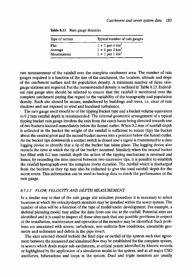
Catchment and sewer system data 183
Table 8.13 Rain gauge densities i i
Type of terrain Typical number of rain gauges
Flat 1 + I per 4 km 2 Average 1 + I per 2 km 2 Mountainous 1 + 1 per I km 2
rate measurement of the rainfall over the complete catchment area. The number of rain gauges required is a function of the size of the catchment, the location, altitude and slope of the catchment surface and the population density. A minimum number of three rain- gauge stations are required, but the recommended density is outlined in Table 8.13. Individ- ual rain gauge sites should be selected to ensure that the rainfall is monitored over the complete catchment paying due regard to the variability of the topography and population density. Each site should be secure, unsheltered by buildings and trees, i.e. clear of rain shadows and not exposed to wind and localised turbulence.
The rain gauge used should be of the tipping bucket type and a bucket volume equivalent to 0.2 mm rainfall depth is recommended. The internal geometric arrangement of a typical tipping bucket rain gauge involves the rain from the catch basin being directed towards one of two buckets located immediately below the funnel outlet. When 0.2 mm of rainfall depth is collected in the bucket the weight of the rainfall is sufficient to rotate (tip) the bucket about the central pivot and the second bucket moves into a position below the funnel outlet. As the bucket tips downwards a contact switch is closed and a signal is transmitted to a data logging device to identify that a tip of the bucket has taken place. The logging device also records the time at which the tip of the bucket occurred. Similarly when the second bucket has filled with 0.2 mm rainfall depth the action of the tipping mechanism is reversed and hence, by recording the time interval between two successive tips, it is possible to establish the rainfall hyetograph over the complete storm duration. The rainfall which is discharged from the buckets as they tip may also be collected to give the total rainfall depth for the storm event. This information can be used as backup data to check the performance of the rain gauge.
8. 7.3.3 FLOW, VELOCITYAND DEPTH MEASUREMENT
In a similar way to that of the rain gauge site selection procedure it is necessary to select locations at which the velocity/depth monitors may be installed within the sewer system. The number of sites will be a function of the type of model under development. For example, a skeletal planning model may utilise the data from one site at the outfall. Potential sites are identified and it is usual to inspect all these sites such that any possible problems in respect of the installation, maintenance and operation of the monitor may be identified. Such prob- lems are associated with access, turbulence, non-uniform flow conditions, unsuitable geo- metry and sediments and debris in the pipe invert.
The sites selected should include the final pipe or outfall of the system such that agree- ment between the measured and simulated flow may be established for the complete system, in sewers which drain major sub-catchments, at critical points identified by historic records or highlighted by the application of a simulation model to the system, and at all major CSO ancillaries, bifurcations and loops in the system. Dual and triple monitors are usually
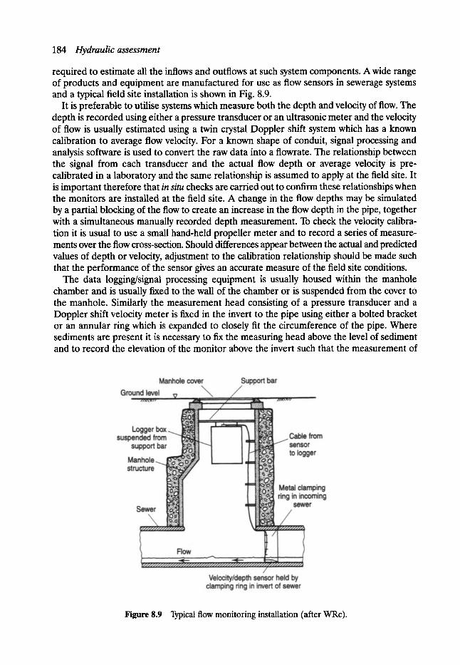
184 Hydraulicassessment
required to estimate all the inflows and outflows at such system components. A wide range of products and equipment are manufactured for use as flow sensors in sewerage systems and a typical field site installation is shown in Fig. 8.9.
It is preferable to utilise systems which measure both the depth and velocity of flow. The depth is recorded using either a pressure transducer or an ultrasonic meter and the velocity of flow is usually estimated using a twin crystal Doppler shift system which has a known calibration to average flow velocity. For a known shape of conduit, signal processing and analysis software is used to convert the raw data into a flowrate. The relationship between the signal from each transducer and the actual flow depth or average velocity is pre- calibrated in a laboratory and the same relationship is assumed to apply at the field site. It is important therefore that in situ checks are carded out to confirm these relationships when the monitors are installed at the field site. A change in the flow depths may be simulated by a partial blocking of the flow to create an increase in the flow depth in the pipe, together with a simultaneous manually recorded depth measurement. To check the velocity calibra- tion it is usual to use a small hand-held propeller meter and to record a series of measure- ments over the flow cross-section. Should differences appear between the actual and predicted values of depth or velocity, adjustment to the calibration relationship should be made such that the performance of the sensor gives an accurate measure of the field site conditions.
The data logging/signal processing equipment is usually housed within the manhole chamber and is usually fixed to the wall of the chamber or is suspended from the cover to the manhole. Similarly the measurement head consisting of a pressure transducer and a Doppler shift velocity meter is fixed in the invert to the pipe using either a bolted bracket or an annular ring which is expanded to closely fit the circumference of the pipe. Where sediments are present it is necessary to fix the measuring head above the level of sediment and to record the elevation of the monitor above the invert such that the measurement of
Figure 8.9 Typical flow monitoring installation (after WRc).
Catchment and sewer system data 185
flow depth may subsequently be adjusted to give the correct value. All cables connecting the measurement head and the signal processing/data logging equipment should be neatly fixed around the circumference of the pipe and along the pipe soffit to prevent any collection of debris and subsequent blockage which may influence the performance of the meters.
When the depth measurement is recorded ultrasonically the meter head is again usually fixed to the chamber wall. The ultrasonic signal transmitted by the meter is reflected from the water surface in the manhole chamber and is received back at the meter. It is required therefore that the minimum operational distance between the instrument head and the maximum anticipated water level in the chamber is maintained at all times. This distance is specified by the equipment manufacturer. Ultrasonic meters may therefore be unsuitable for use at manholes where surface flooding or high levels of surcharge may be anticipated.
8. 7.3.4 INSTALLATION OF F L O W SURVEY EQUIPMENT
The installation of the monitor should also minimise the potential for blockage and, more particularly should not create any build-up of sediment in the vicinity of the meter. Careful attention has therefore to be given to the installation procedure and in this respect the sensor should ideally be located where the flow conditions are steady over a wide range of flow depth. Hence, the sensor is best sited in the pipe upstream of the manhole and should ideally be located some 2-4 pipe diameters upstream of the manhole.
The sensor should also preferably be located in a manhole without a major junction, particularly if the junction is poorly designed and creates significant turbulence as the flow components interact within the manhole chamber. Also, under surcharged conditions, one inflow component to the manhole may dominate the flow regime with the result that there may be a backup of the flow or even a flow reversal at the junction. In such circumstances it is important that both the depth and velocity of flow are recorded as both sets of data may help to explain what is happening at the monitoring station, for example, if the flow is backed up the depth is increased whereas the velocity is reduced. However, should it be considered essential to locate a monitoring station at a junction manhole it is preferable that each inflow to the junction should be monitored using an individual sensor.
To record the performance of CSO chambers it is preferable that the monitors are located in both the inflow and the continuation flow pipes and in the outfall pipe which conveys the spilled flow to the receiving watercourse. Positioning the monitors on the weir of a chamber, although sometimes necessary, is undesirable due to problems associated with the curvature of the water surface over end weirs and spatially varied flow over side weirs. The effect on the hydraulic performance of each type of weir due to the presence of a scumboard or baffle arrangement has also to be taken into consideration.
8. 7.3.5 DURATION OF MONITORING EXERCISES
The duration of the monitoring exercise has to be sufficiently long such that good quality data is recorded for a number of dry weather days and for a number of individual storm events in which there is a notable increase in the depth and velocity of flow. Measurement of dry weather flow should ideally be measured on each day of the week to establish the diurnal pattern in the flow and the extent of any significant industrial inputs. Similarly good records of dry weather flow and, more particularly, a comparison of the diurnal pattern on days which precede and follow a storm event, will also identify the magnitude of any infiltra- tion inputs to the system.
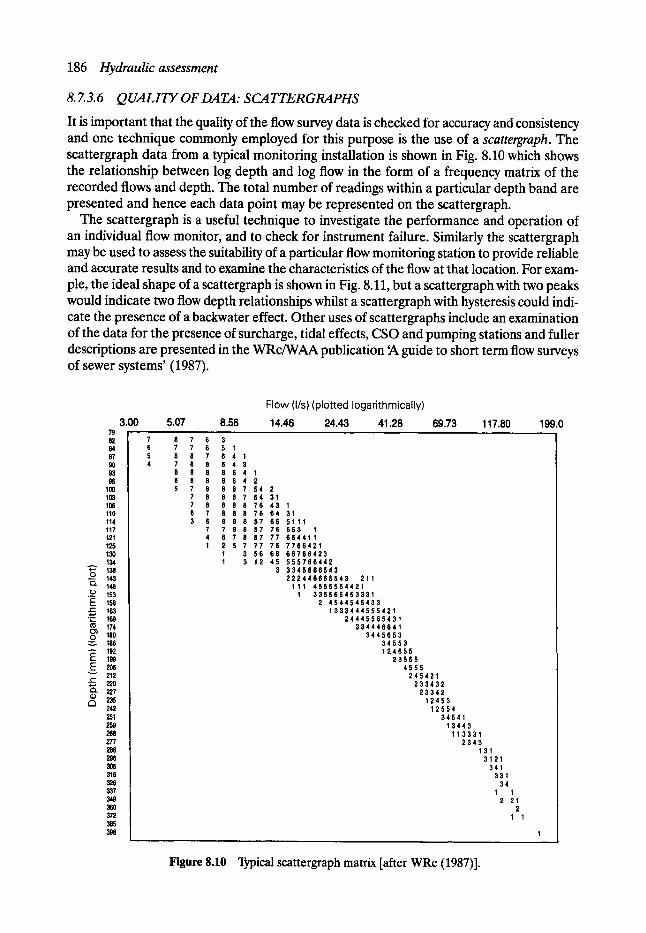
186 Hydraulicassessment
8. 7.3.6 QUALITY OF DATA: SCATTERGRAPHS
It is important that the quality of the flow survey data is checked for accuracy and consistency and one technique commonly employed for this purpose is the use of a scattergraph. The scattergraph data from a typical monitoring installation is shown in Fig. 8.10 which shows the relationship between log depth and log flow in the form of a frequency matrix of the recorded flows and depth. The total number of readings within a particular depth band are presented and hence each data point may be represented on the scattergraph.
The scattergraph is a useful technique to investigate the performance and operation of an individual flow monitor, and to check for instrument failure. Similarly the scattergraph may be used to assess the suitability of a particular flow monitoring station to provide reliable and accurate results and to examine the characteristics of the flow at that location. For exam- ple, the ideal shape of a scattergraph is shown in Fig. 8.11, but a scattergraph with two peaks would indicate two flow depth relationships whilst a scattergraph with hysteresis could indi- cate the presence of a backwater effect. Other uses of scattergraphs include an examination of the data for the presence of surcharge, tidal effects, CSO and pumping stations and fuller descriptions are presented in the WRc/WAA publication ~ guide to short term flow surveys of sewer systems' (1987).
3.00 79 82 84 87 9O 93 96
100 103 106 110 114 117 121 125 130 134
+-' 138 C) 143 Q" 148
._o 153 E 158 r,,- 163
�9 ~_.. 169 174
0 180 186
"-- 192 F: 199 E e-
C3 242
259
277 286
316 326 337 349
372 385 398
Flow (I/s)(plotted logarithmically) 5.07 8.56 14.46 24.43 41.28 69.73 117.80 199.0
8 7 6 3 7 7 6 5 1 8 8 7 6 4 1 7 8 8 6 4 3 8 8 8 8 6 4 1 6 8 8 8 6 4 2 5 7 8 8 8 7 5 4 2
7 8 8 8 7 64 31 7 8 8 8 8 76 43 1 6 7 8 8 8 76 64 31 3 6 8 8 8 87 66 5111
7 7 8 8 87 76 653 1 4 6 7 8 87 77 664411 1 2 5 7 77 76 7 7 6 6 4 2 1
1 3 56 66 6 6 7 6 6 4 2 3 1 3 12 45 5 5 5 7 6 6 4 4 2
3 3 3 4 5 6 6 6 5 4 3 2 2 2 4 4 6 6 6 5 5 4 3 211
111 4 5 5 5 5 5 4 4 2 1 1 3 3 5 5 6 5 4 5 3 3 3 1
2 4 5 4 4 5 4 5 4 3 3 1 3 3 3 4 4 4 5 5 5 4 2 1
2 4 4 4 5 5 6 5 4 3 1 3 3 4 4 4 6 6 4 1
3 4 4 5 6 5 3 3 4 5 5 3 1 2 4 5 5 5
2 3 5 5 5 4555
245421 2 3 3 4 3 2
23342 12453
12554 34541
13443 113331
2343 131
3121 341
331 34
1 1 2 21
2 1 1
Figure 8.10 Typical scattergraph matrix [after WRc (1987)].
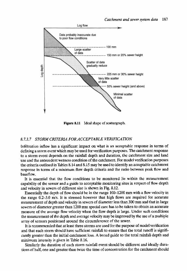
Catchment and sewer system data 187
Figure 8.11 Ideal shape of scattergraph.
8. 7.3. 7 STORM CRITERIA FOR ACCEPTABLE VERIFICATION
Infiltration inflow has a significant impact on what is an acceptable response in terms of defining a storm event which may be used for verification purposes. The catchment response to a storm event depends on the rainfall depth and duration, the catchment size and land use and the antecedent wetness condition of the catchment. For model verification purposes the criteria outlined in Tables 8.14 and 8.15 may be used to identify an acceptable catchment response in terms of a minimum flow depth criteria and the ratio between peak flow and baseflow.
It is essential that the flow conditions to be monitored lie within the measurement capability of the sensor and a guide to acceptable monitoring sites in respect of flow depth and velocity in sewers of different size is shown in Fig. 8.12.
Essentially the depth of flow should be in the range 100-1200 mm with a flow velocity in the range 0.2-3.0 m/s. It is stressed however that high flows are required for accurate measurement of depth and velocity in sewers of diameter less than 300 mm and that in large sewers of diameter greater than 1200 mm special care has to be taken to obtain an accurate measure of the average flow velocity when the flow depth is large. Under such conditions the measurement of the depth and average velocity may be improved by the use of a multiple array of sensors positioned around the circumference of the sewer.
It is recommended that at least three storms are used for the purpose of model verification and that each storm should have sufficient rainfall to ensure that the total runoff is signifi- cantly greater than the initial catchment loss. A broad guide to the total rainfall depth and minimum intensity is given in Table 8.16.
Similarly the duration of each storm rainfall event should be different and ideally dura- tions of half, one and greater than twice the time of concentration for the catchment should
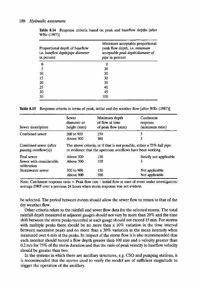
188 Hydraulicassessment
Table 8.14 Response criteria based on peak and baseflow depths [after WRc (1987)]
Proportional depth of baseflow i.e. baseflow depth~pipe diameter in percent
Minimum acceptable proportional peak flow depth, i.e. minimum acceptable peak depth~diameter of pipe in percent
0 0 5 30
10 30 15 30 20 30 25 40 30 45 50 100
Table 8.15 Response criteria in terms of peak, initial and dry weather flow [after WRc (1987)]
Sewer Minimum depth Catchment diameter or of flow at time response
Sewer description height (ram) of peak flow (mm) (minimum ratio)
Combined sewer 300 to 900 150 5 Above 900 300 3
Combined sewer (after passing overflow(s))
Foul sewer Sewer with considerable infiltration Stormwater sewer
The above criteria, or if that is not possible, either a 75% full pipe or evidence that the upstream overflows have been working
Above 300 150 Strictly not applicable Above 300 150 3
300 to 900 150 Not applicable Above 900 300 Not applicable
Note: Catchment response ratio = Peak flow rate - initial flow at start of event under investigation/ average DWF over a previous 24 hours when storm response was not evident.
be selected. The period between events should allow the sewer flow to return to that of the dry weather flow.
Other criteria relate to the rainfall and sewer flow data for the selected storms. The total rainfall depth measured at adjacent gauges should not vary by more than 20% and the time shift between the storm peaks recorded at each gauge should not exceed 15 min. For storms with multiple peaks there should be no more than a 10% variation in the time interval between successive peaks and no more than a 30% variation in the mean intensity when measured over 6 min at the peaks. In respect of the storm flow it is also recommended that each monitor should record a flow depth greater than 100 mm and a velocity greater than 0.2 m/s for 75% of the storm duration and that the ratio of peak velocity to baseflow velocity should be greater than two.
In the systems in which there are ancillary structures, e.g. CSO and pumping stations, it is recommended that the storms used to verify the model are of sufficient magnitude to trigger the operation of the ancillary.
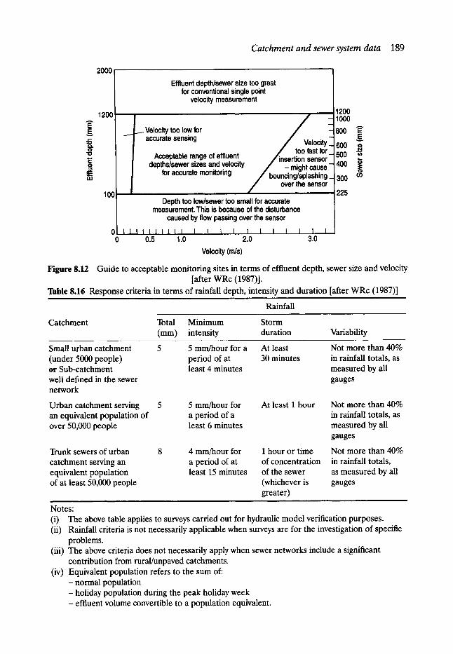
Catchment and sewer system data 189
E E r
Q .
1 0
t..-
:3 E I L l
2000 Effluent depth/sewer size too great
for conventional single point velocity measurement
1200 i
100' =
I Velocity too low for accurate sensing
Acceptable range of effluent depths/sewer sizes and velocity
for accurate monitoring
i
0J I I I t I ! 1111 I I I 1 I i I I I I I 0 0.5 1.0 2.0 3.0
1200 Z - 1000
800 ~ Iocity_- 600 "~
/ !oo fast for / insert ion sensor- 500 "~
/ - might cause- 400 ~ ' bouncin~splashing_ 300 cn
over the sensor 225
Depth too low/sewer too small for accurate measurement. This is because of the disturbance
caused by flow passing over the sensor
Velocity (m/s)
Figure 8.12 Guide to acceptable monitoring sites in terms of effluent depth, sewer size and velocity [after WRc (1987)].
Table 8.16 Response criteria in terms of rainfall depth, intensity and duration [after WRc (1987)] , ,
Rainfall
Catchment Total Minimum Storm (mm) intensity duration Variability
Small urban catchment (under 5000 people) or Sub-catchment well defined in the sewer network
Urban catchment serving an equivalent population of over 50,000 people
Trunk sewers of urban catchment serving an equivalent population of at least 50,000 people
Notes:
5 5 mm/hour for a At least Not more than 40% period of at 30 minutes in rainfall totals, as least 4 minutes measured by all
gauges
5 5 mm/hour for At least 1 hour a period of a least 6 minutes
4 mm/hour for a period of at least 15 minutes
I hour or time of concentration of the sewer (whichever is greater)
Not more than 40% in rainfall totals, as measured by all gauges
Not more than 40% in rainfall totals, as measured by all gauges
(i) The above table applies to surveys carried out for hydraulic model verification purposes. (ii) Rainfall criteria is not necessarily applicable when surveys are for the investigation of specific
problems. (iii) The above criteria does not necessarily apply when sewer networks include a significant
contribution from rural/unpaved catchments. (iv) Equivalent population refers to the sum of:
- normal population - holiday population during the peak holiday week - effluent volume convertible to a population equivalent.
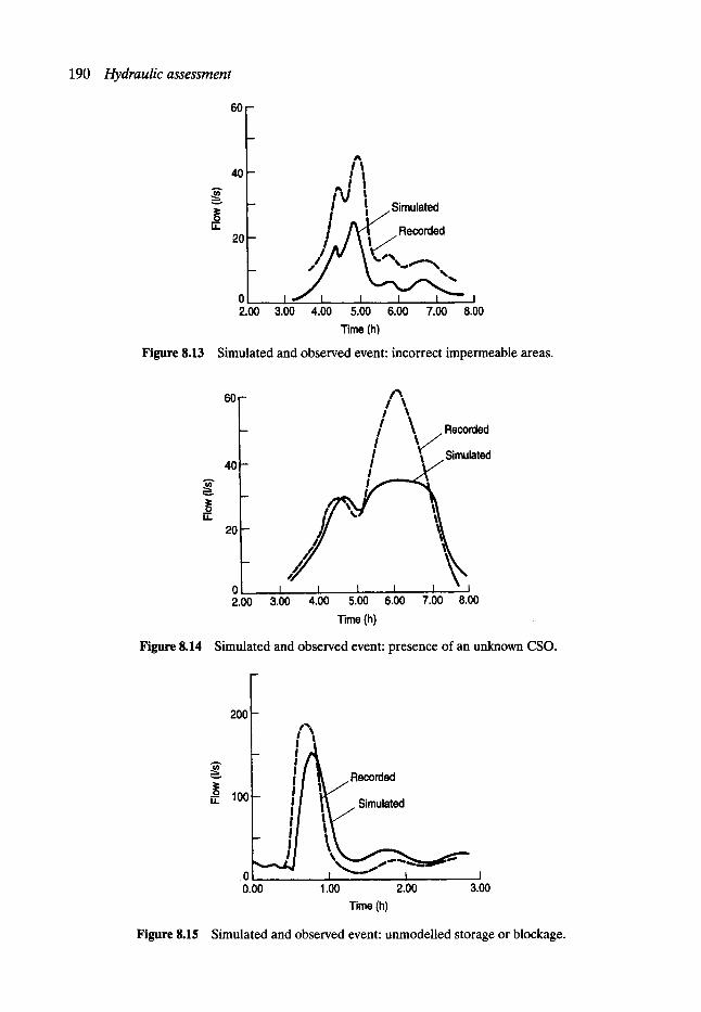
190 Hydraulicassessment
6 0 -
U..
40
20
I t - . / l
!U ! - ! [ Simulated
0 I I 2.q~0 3.00 4.00 5.00 6 .00 7 .00 8.00
Time (h)
Figure 8.13 Simulated and observed event: incorrect impermeable areas.
v
U .
60-
4 0 -
2 0 -
0 2.00
1% I %
/ \ ~ Recorded I I
/ ~t ~ Simulated
/
I ~ I ! I I " l 3.00 4.00 5.00 6 .00 7 .00 8.00
Time (h)
Figure 8.14 Simulated and observed event: presence of an unknown CSO.
200
g
~. 100
0 o.oo
/ • Recorded
- ~ Simulated
_ !
1.00 2.00 3.00 Time (h)
Figure 8.15 Simulated and observed event: unmodelled storage or blockage.

Catchment and sewer system data 191
The output of the mathematical model is then compared either to the historic data or the results of the short term survey for each individual monitored event. When historic data is used the model is verified against observed surface flooding and records of the surcharge level within the system corresponding to historic rainfall information. In respect of flooding the model should reproduce the location and severity of the observed floods and, when long- term rainfall records are available, the frequency of flooding should also be predicted. As a guide, the model may be considered to be verified when a simulated flood of 25 m 3 is substantiated by evidence of an observed flood and/or when the surcharge level is predicted to within +0.5--0.1 m of the recorded event. When the model is to be verified with flow survey data the shape of the simulated and measured flow and depth should be similar and differences in the two flow hydrographs should be within the following limits:
�9 peak flow rate �9 volume of flow �9 surcharge level
+25% to-15% + 20% to - 10%
+0.5 rn to-0.1 m.
The model is considered to be verified when two of the three observed events meet these criteria. If possible, the verified model should also be used with any historic data to simulate flooding and to confirm that there is good agreement between the predicted and observed events.
Invariably, however, at the start of the verification process there are large discrepancies between the simulated and observed values of depth, flowrate and flow volume. These differences often highlight inaccuracies in the catchment and sewer system data which is first input into the model. The reasons for these discrepancies have to be further investigated and, with a reasoned explanation, changes to the input data may subsequently be made. Some common reasons for differences between the observed results and simulated are outlined in Figs 8.13-8.15.
Figure 8.13 highlights that the shape of the observed and simulated events are very similar, but that the magnitude of the peak flow and flow volume are grossly in error, with a consistent difference of the ratio in the predicted and observed values. An increase in the impermeable area would improve the goodness of fit but, prior to any changes being made to the input data, it is essential that the reason for the deficiency of this data is fully appreciated. The impact of any changes in the data on the results of this storm should be fully explored by the application of the new data to other storm events,
The presence of an unknown CSO, as simulated in Fig. 8.14, is usually highlighted due to the fact that there appears to be a reasonable fit between the observed and simulated event in the early part of the storm, but that at a certain flowrate the observed data shows a cut-off in the peak flow which is maintained almost constant until the recession limb of the storm. The volumes of flow are therefore very different.
When the storage capacity of the system is incorrectly modelled, for example, too little storage included within the mathematical model, the peak flow and time to peak are different with the effect of the storage volume results in a lag and attenuation of the peak flow magnitude (see Fig. 8.15). Similarly on the recession limb of the storm the effect of the unmodelled storage is to enhance the flowrate and flow volume during this period. If too much storage is included in the mathematical model then effects which are opposite to those outlined above will be observed. In either case the total flow volume of the observed and simulated events will be approximately the same.
Should an input to the system be located at the wrong manhole or the response time of the catchment surface be incorrectly modelled (incorrect initial catchment wetness), the flow

192 Hydraulicassessment
volumes will be approximately the same, but there will be a mismatch in the timing and magnitude of the peak flows. The general shape of the hydrographs will however be the same.
It is clear therefore from Figs 8.13--8.15 that many factors may influence the discrepancy between the observed and simulated flow and depth hydrographs. In many situations, however, several parameters and factors may combine to produce the resultant mismatch and these, together with inadequacies of the field monitored data, can make the verification of mathematical models a most time consuming and frustrating task.
A verified model is however an essential component of the sewer system simulation process and in the assessment of the performance of the various rehabilitation options to be considered.
References ArneU, V. (1982). Rainfall data for the design of sewer systems. Report series A:8, Chalmers University
of Technology, GOteborg. Cowpertwaite, P. S. P. Metcalfe, A. V. O'Connell, P. E. Mawdsley, J. A. and Threlfall, J. L. Stochastic
rainfall generation of rainfall time series. Foundation for Water Research, Report No. FR02 17, 1991.
Green, W. H. and Ampt, G. A.. Studies on soil physics I, the flow of air and water through soils, Journal of Agricultural Science, Vol. 4, pp. 1-24, 1911.
Henderson, R. J. Rainfall time series for sewer system modelling. WRc, Report No. ER 195E, 1986. Horton, R. E. The role of infiltration in the hydrologic cycle. Tram. Am. Geophys. Union, Vol. 14,
pp. 443-460, 1933. Natural Environmental Research Council. Flood Studies Report, Vols I-V, NERC, 1975. WaPUG. Code of Practice for Hydraulic Modelling of Sewer Systems. WRc Publications, 1993. Water Research Centre. A Guide to Sewer Flow Surveys. Swindon, 1987.
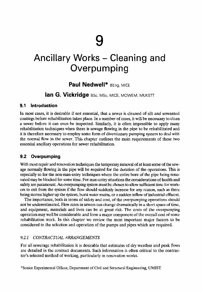
9 Ancillary Works - Cleaning
Overpumping and
Paul Nedwell* BEng, MICE
lan G. Vickridge BSc, MSc, MICE, MCIWEM, MUKSTT
9.1 Introduction In most cases, it is desirable if not essential, that a sewer is cleaned of silt and unwanted coatings before rehabilitation takes place. In a number of cases, it will be necessary to clean a sewer before it can even be inspected. Similarly, it is often impossible to apply many rehabilitation techniques when there is sewage flowing in the pipe to be rehabilitated and it is therefore necessary to employ some form of diversionary pumping system to deal with the normal flow in the sewer. This chapter outlines the main requirements of these two essential ancillary operations for sewer rehabilitation.
9.2 Overpumping With most repair and renovation techniques the temporary removal of at least some of the sew- age normally flowing in the pipe will be required for the duration of the operations. This is especially so for the non-man-entry techniques where the entire bore of the pipe being reno- vated may be blocked for some time. For man-entry situations the considerations of health and safety are paramount. An overpumping system must be chosen to allow sufficient time for work- ers to exit from the system if the flow should suddenly increase for any reason, such as there being storms higher up the system, burst water mains, or a sudden inflow of industrial effluent.
The importance, both in terms of safety and cost, of the overpumping operations should not be underestimated. Flow rates in sewers can change dramatically in a short space of time, and equipment, materials and lives can be at great risk. The costs of the overpumping operation may well be considerable and form a major component of the overall cost of some rehabilitation work. In this chapter we review the most important major factors to be considered in the selection and operation of the pumps and pipes which are required.
9.2.1 CONTRACTUAL ARRANGEMENTS
For all sewerage rehabilitation it is desirable that estimates of dry weather and peak flows are detailed in the contract documents. Such information is often critical to the contrac- tor's selected method of working, particularly in renovation works.
*Senior Experimental Officer, Department of Civil and Structural Engineering, UMIST.
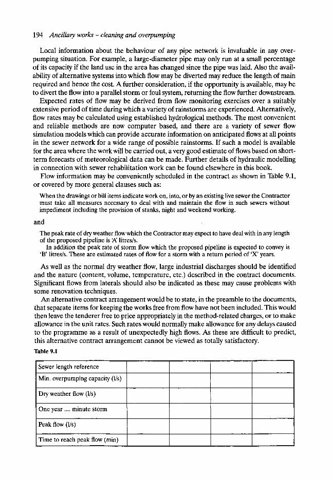
194 Ancillary works - cleaning and overpumping
Local information about the behaviour of any pipe network is invaluable in any over- pumping situation. For example, a large-diameter pipe may only run at a small percentage of its capacity if the land use in the area has changed since the pipe was laid. Also the avail- ability of alternative systems into which flow may be diverted may reduce the length of main required and hence the cost. A further consideration, if the opportunity is available, may be to divert the flow into a parallel storm or foul system, returning the flow further downstream.
Expected rates of flow may be derived from flow monitoring exercises over a suitably extensive period of time during which a variety of rainstorms are experienced. Alternatively, flow rates may be calculated using established hydrological methods. The most convenient and reliable methods are now computer based, and there are a variety of sewer flow simulation models which can provide accurate information on anticipated flows at all points in the sewer network for a wide range of possible rainstorms. If such a model is available for the area where the work will be carried out, a very good estimate of flows based on short- term forecasts of meteorological data can be made. Further details of hydraulic modelling in connection with sewer rehabilitation work can be found elsewhere in this book.
Flow information may be conveniently scheduled in the contract as shown in Table 9.1, or covered by more general clauses such as:
When the drawings or bill items indicate work on, into, or by an existing live sewer the Contractor must take all measures necessary to deal with and maintain the flow in such sewers without impediment including the provision of stanks, night and weekend working.
and
The peak rate of dry weather flow which the Contractor may expect to have deal with in any length of the proposed pipeline is ~ litres/s.
In addition the peak rate of storm flow which the proposed pipeline is expected to convey is 'B' litres/s. These are estimated rates of flow for a storm with a return period of 'X' years.
As well as the normal dry weather flow, large industrial discharges should be identified and the nature (content, volume, temperature, etc.) described in the contract documents. Significant flows from laterals should also be indicated as these may cause problems with some renovation techniques.
An alternative contract arrangement would be to state, in the preamble to the documents, that separate items for keeping the works free from flow have not been included. This would then leave the tenderer free to price appropriately in the method-related charges, or to make allowance in the unit rates. Such rates would normally make allowance for any delays caused to the programme as a result of unexpectedly high flows. As these are difficult to predict, this alternative contract arrangement cannot be viewed as totally satisfactory.
Table 9.1
Sewer length reference
Min. overpumping capacity (l/s)
Dry weather flow (l/s)
One year .... minute storm
Peak flow (l/s)
Time to reach peak flow (min)
Overpumping 195
As well as dealing with the anticipated flows, it will be necessary to specify the permitted location of the temporary rising mains, particularly in relation to property access and pedes- trian and vehicle movement. It may in fact be necessary in some city centre locations to require them to be buried beneath the road surface. In this connection, the method of dealing with the suction hoses and small pumps for controlling lateral connections on the length of sewer being treated should also be clearly defined.
It should also be appreciated that when a large sewer is being treated, cases may arise where there is a need for a temporary underground pumping station, complete with all the necessary switch gear and flow control mechanisms.
In most sewer rehabilitation work it is common that all the overpumping pumps, hoses and ancillary equipment will be provided by a specialist pump hire company. Although the main contractor for the work may expect to get specialist advice from the pump supply company, it is clearly important for him to have a sound understanding of the relative advantages and drawbacks of the various different pumping and pipe systems available. It may be that the client or contractor will subcontract the entire overpumping operation to include not only the supply but also the operation of the pumps. However, such an arrange- ment is comparatively rare, at least in the UK, as the contractor would normally prefer to retain complete control.
9. 2. 2 PUMP CHOICE
The selection of a suitable pump for a particular job will be dictated by not only the flow rate but also the suction and delivery heads, the length and diameter of the delivery pipes, the avail- ability of suitable power sources, the access to the sewer, environmental and other legislation (particularly that relating to noise), and the overall cost of hiring and operating the equipment.
The pump (or pumps) must obviously be capable of pumping the required flow rate against the total calculated head, and in this respect, the pump characteristics necessary to make this decision can be obtained from the manufacturers. However, the normal situation for sewer rehabilitation work is that flow to be diverted or overpumped will vary considerably with the time of day and the amount of rainfall. In order to provide a degree of flexibility in operation and to minimise overall pumping costs, it may therefore be advantageous to use several small pumps, or a combination of different capacities, rather than a single large pump. It is often possible to hire standby pumps (at a reduced rate). The contractor then can proceed with the rehabilitation work in the knowledge that sufficient pumping capacity will be available in emergency, without having to pay the full hire cost of large pumps, which may not be required.
Once the number and size of the required pumps has been decided, a further choice - between surface-mounted and submersible pumps- must be made. One of the critical factors to consider for surface-mounted pumps is the suction head or lift. The suction head will be the sum of the static lift required and the friction losses on the suction side of the pump. The maximum theoretically possible total suction head is that equivalent to atmospheric pressure, but for most practical situations will be considerably less. Many pumps will suffer from severely reduced efficiencies at high suction heads and this must be taken into account when selecting a suitable pump. A further factor to consider is that of the priming time, or the time taken for the pump to return to full capacity after suction has been lost. This increases rapidly with increased depth. Typical priming times could vary from 1.5 s at a suction head of 1.5 m to over 20 s at a suction head of 9 m. This can be a very important consideration in the design of any temporary works designed to hold back the flow, as a 20 s period when a pump is not operating could significantly increase the depth of water to be retained.
196 Ancillary works - cleaning and overpumping
One of the main factors limiting the use of submersible pumps is that of size, as the com- plete pump must be placed in the sewer at the point of pumping. By way of example, a submersible pump with a capacity of the order of 400 m3/h may have a casing diameter of up to 500 mm and an overall height in excess of 750 mm. It is clear that such a pump would not sit comfortably even in a relatively large diameter sewer.
A further important consideration is that of power for the pumps. Submersible pumps are usually electrically powered though there are some hydraulic units available. Surface- mounted pumps may be either electrically or diesel powered with a further choice of reduced noise engines for some pumps. Electrically operated pumps can derive their power either from a diesel generator or directly from the mains. This latter option requires the provision and metering of a suitable supply. Installation requires liaison with the local electricity supplier and the services of a trained industrial electrician and may take some time to arrange. Once installed, electrically powered pumps are not easy to relocate and therefore offer a less flexible option which may present problems for renovation systems, such as soft lining, which can be carried out rapidly. In these cases an overpumping system that can be moved easily from manhole to manhole as the job progresses may offer the best solution.
The problem of noise, especially for diesel-powered units running overnight in residen- tial areas, can be serious. However, it is as well to remember that some rehabilitation options require their own ancillary plant, which might include compressors, boilers and circulation pumps. These are usually either diesel powered or derive power from a diesel generator and are therefore themselves a source of noise. It may therefore be possible to reduce costs by considering noise reduction measures for the entire operation together rather than making independent arrangements for the overpumping.
9. 2.3 SUCTION AND D E L I V E R Y PIPES
While suction hoses are almost universally wire armoured, delivery pipes may be steel, rigid plastic, wire armoured or the flexible lay-flat type. The choice depends on the length of time a main may be in position, the need to bury part or all of it, and the anticipated flow rate and pressure. A further consideration in pipe choice is the type of connection to be used. Smaller diameter hoses often come with quick-release couplings, whilst larger steel mains often have bolted flanged connectors, which are more troublesome to connect.
For low flows and pressures over short periods, lay-flat hosing is probably the best choice. It is cheap, easy and quick to place and, should vehicular access be required, simple low ramps may be provided over the hose. Lay-flat hose is available in sizes up to approximately 200 mm diameter and, if the pump has to be frequently relocated, the hose is simple to roll up and move. In lay-flat operations it is usual for each pump to have its own hose.
For many operations rigid plastic pipes are the most common choice. The individual lengths are easily handled by two people and, with quick-release couplings, they can be quickly con- nected. The main problem arises in maintaining access to property or in crossing roads. For pipes of up to 75-mm diameter, ramps may be used, but the larger sizes require temporary burial if adequate access is to be maintained without damaging the pipes. If high pressures are to be maintained it may be preferable to use wire-armoured hose, though this is not at all common.
For large projects with high flows, the provision of a steel pumping main may be the best solution. Several pumps may be connected through a manifold arrangement into one line, thus reducing the total length. As with rigid plastic pipes there is often a problem in main- taining vehicular access, and several excavations may be required to bury the pipe at access points to individual properties or for road crossings. The drop and return bends on the pipe-
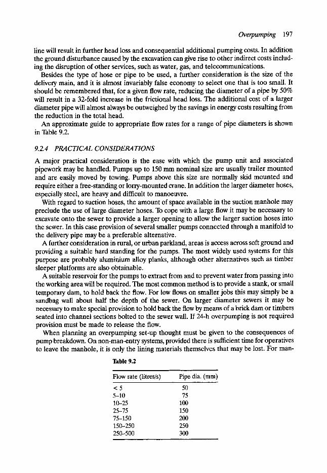
Overpumping 197
line will result in further head loss and consequential additional pumping costs. In addition the ground disturbance caused by the excavation can give rise to other indirect costs includ- ing the disruption of other services, such as water, gas, and telecommunications.
Besides the type of hose or pipe to be used, a further consideration is the size of the delivery main, and it is almost invariably false economy to select one that is too small. It should be remembered that, for a given flow rate, reducing the diameter of a pipe by 50% will result in a 32-fold increase in the frictional head loss. The additional cost of a larger diameter pipe will almost always be outweighed by the savings in energy costs resulting from the reduction in the total head.
An approximate guide to appropriate flow rates for a range of pipe diameters is shown in Table 9.2.
9.2.4 PRACTICAL CONSIDERATIONS
A major practical consideration is the ease with which the pump unit and associated pipework may be handled. Pumps up to 150 mm nominal size are usually trailer mounted and are easily moved by towing. Pumps above this size are normally skid mounted and require either a free-standing or lorry-mounted crane. In addition the larger diameter hoses, especially steel, are heavy and difficult to manoeuvre.
With regard to suction hoses, the amount of space available in the suction manhole may preclude the use of large diameter hoses. To cope with a large flow it may be necessary to excavate onto the sewer to provide a larger opening to allow the larger suction hoses into the sewer. In this case provision of several smaller pumps connected through a manifold to the delivery pipe may be a preferable alternative.
A further consideration in rural, or urban parkland, areas is access across soft ground and providing a suitable hard standing for the pumps. The most widely used systems for this purpose are probably aluminium alloy planks, although other alternatives such as timber sleeper platforms are also obtainable.
A suitable reservoir for the pumps to extract from and to prevent water from passing into the working area will be required. The most common method is to provide a stank, or small temporary dam, to hold back the flow. For low flows on smaller jobs this may simply be a sandbag wall about half the depth of the sewer. On larger diameter sewers it may be necessary to make special provision to hold back the flow by means of a brick dam or timbers seated into channel sections bolted to the sewer wall. If 24-h overpumping is not required provision must be made to release the flow.
When planning an overpumping set-up thought must be given to the consequences of pump breakdown. On non-man-entry systems, provided there is sufficient time for operatives to leave the manhole, it is only the lining materials themselves that may be lost. For man-
Table 9.2 i i
Flow rate (litres/s)
<5 5-10 10-25 25-75 75-150 150-250 250-500
i .
Pipe dia. (ram)
50 75
100 150 200 250 300
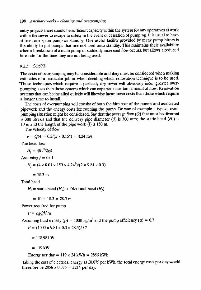
198 Ancillary works- cleaning and overpumping
entry projects there should be sufficient capacity within the system for any operatives at work within the sewer to escape to safety in the event of cessation of pumping. It is usual to have at least one spare pump on standby. One useful facility provided by many pump hirers is the ability to put pumps that are not used onto standby. This maintains their availability when a breakdown of a main pump or suddenly increased flow occurs, but allows a reduced hire rate for the time they are not being used.
9.2.5 COSTS
The costs of overpumping may be considerable and they must be considered when making estimates of a particular job or when deciding which renovation technique is to be used.
qqaose techniques which require a perfectly dry sewer will obviously incur greater over- pumping costs than those systems which can cope with a certain amount of flow. Renovation systems that can be installed quickly will likewise incur lower costs than those which require a longer time to install.
The costs of overpumping will consist of both the hire cost of the pumps and associated pipework and the energy costs for running the pump. By way of example a typical over- pumping situation might be considered. Say that the average flow (Q) that must be diverted is 300 litres/s and that the delivery pipe diameter (d) is 300 mm; the static head (H~) is 10 m and the length of the pipe work (l) is 150 m.
The velocity of flow
v = Q/A = 0.3/(z x 0.152) = 4.24 m/s
The head loss
Hf = 4flv2/2gd
Assumingf = 0.01
Hf = (4 x 0.01 x 150 x 4.242)/(2 x 9.81 x 0.3)
= 18.3m
Total head
Ht = static head (H~) + frictional head (Hf)
= 10 + 18.3 = 28.3 rn
Power required for pump
P = pgQHt/g
Assuming fluid density (p) = 1000 kg/m 3 and the pump efficiency (/~) = 0.7
P = (1000 x 9.81 x 0.3 x 28.3)/0.7
= 118,981 W
= l l 9 k W
Energy per day = 119 x 24 kWh = 2856 kWh
Taking the cost of electrical energy as s per kWh, the total energy costs per day would therefore be 2856 x 0.075 = s per day.
Sewer cleaning 199
In addition to the energy costs there are of course the costs of hiring the pumps, and together these costs can represent a significant percentage of the overall cost of the renova- tion work. Perhaps more significantly, it does illustrate the financial risks, often taken by the contractor, associated with delays in the work or unexpectedly high flow rates in the sewer.
9.3 Sewer cleaning Although cleaning should be regarded as a routine sewer maintenance operation, it is often necessary to clean a sewer before it can be inspected or before rehabilitation can be carried out. Sediment, in the form of grit, loose bricks, rags, and general rubble, together with organic material, including grease and oil, is invariably deposited in sewers, and can build up over time, in some cases to form a complete blockage within the pipe. An additional impediment to the successful surveying and rehabilitation of sewers may be tree roots and laterals protruding into the sewer. These sediments and protrusions must be removed before rehabilitation takes place. There are a variety of methods used for cleaning sewers, the most common being some form of jetting, winching, or rodding. In addition there are now a number of proprietary methods for the remote cutting of tree roots and protruding laterals.
9.3.1 HAND EXCAVATION
The earliest form of sewer cleaning was hand excavation, whereby labourers loaded sediment into skips which were then moved down the sewer and lifted out at manhole access points. The work is not only dirty, unpleasant and dangerous, it is also generally very costly. For these reasons it is now only considered when all other methods are not possible for one reason or another.
9. 3. 2 JETTING
The purpose of jetting is two-fold- to loosen sediments, debris and material coating the sewer, and to then move this material along the pipe, generally in a downstream direction, to a location from where it can be removed. Removal of the material is normally carried out using vacuum or air-displacement devices, which are now often combined with the jetting equipment and mounted together on one vehicle (see Fig. 9.1). Jetting machines for sewer cleaning are usually of the low-pressure-high-volume type, with operating pressures of between 140 and 200 bar and flow rates of 200 up to 750 litres/min.
Water is fed at pressure through small diameter (typically around 40 mm) jetting hoses to a jetting nozzle (see Fig. 9.2), which can be equipped with both perpendicular jets and backward-inclined jets. The purpose of the jets is to provide the forward propulsive force and to remove material on the sewer walls and invert.
Jetting machines using very high flow rates suffer from limitations on the length of time they can be operated, due to the fact that the water-storage capacity in the vehicles themselves is limited to a maximum of around 8000 litres. This problem can be overcome to some extent by using slave tankers to feed the main machine, but the latest developments are systems which can recycle the used water, and thus operate continuously. The supply of water available to jetting contractors should be clearly stated in the contract documents. Supplies may be drawn from hydrants or surface water sources if available and of a suitable quality.
Jetting at higher pressures of 800 bar up to 2000 bar is used for cutting tree roots and protruding laterals.
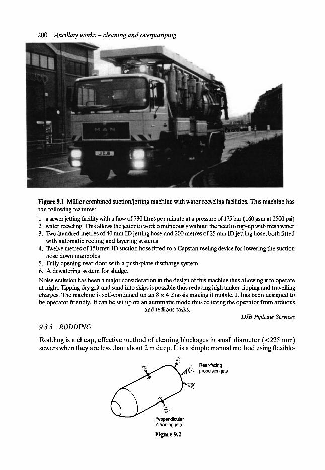
200 Ancillary works- cleaning and overpumping
Figure 9.1 MOiler combined suction/jetting machine with water recycling facilities. This machine has the following features:
1. a sewer jetting facility with a flow of 730 litres per minute at a pressure of 175 bar (160 gsm at 2500 psi) 2. water recycling. This allows the jetter to work continuously without the need to top-up with fresh water 3. Two-hundred metres of 40 mm ID jetting hose and 200 metres of 25 mm ID jetting hose, both fitted
with automatic reeling and layering systems 4. Twelve metres of 150 mm ID suction hose fitted to a Capstan reeling device for lowering the suction
hose down manholes 5. Fully opening rear door with a push-plate discharge system 6. A dewatering system for sludge.
Noise emission has been a major consideration in the design of this machine thus allowing it to operate at night. Tipping dry grit and sand into skips is possible thus reducing high tanker tipping and travelling charges. The machine is self-contained on an 8 • 4 chassis making it mobile. It has been designed to be operator friendly. It can be set up on an automatic mode thus relieving the operator from arduous
and tedious tasks. DJB Pipleine Services
9.3.3 RODDING
Rodding is a cheap, effective method of clearing blockages in small diameter (<225 mm) sewers when they are less than about 2 m deep. It is a simple manual method using flexible-
:...
% ~; ~....:~. Rear-facing ~I~.- propulsion jets
< Perpendicular cleaning jets
Figure 9.2
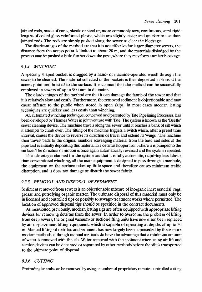
Sewer cleaning 201
jointed rods, made of cane, plastic or steel or, more commonly.now, continuous, semi-rigid lengths of coiled glass-reinforced plastic, which are slightly easier and quicker to use than jointed rods. The rods are simply pushed along the sewer to clear the blockage.
The disadvantages of the method are that it is not effective for larger diameter sewers, the distance from the access point is limited to about 20 m, and the materials dislodged by the process may be pushed a little further down the pipe, where they may form another blockage.
9.3.4 WINCHING
A specially shaped bucket is dragged by a hand- or machine-operated winch through the sewer to be cleaned. The material collected in the buckets is then deposited in skips at the access point and hoisted to the surface. It is claimed that the method can be successfully employed in sewers of up to 900 mm in diameter.
The disadvantages of the method are that it can damage the fabric of the sewer and that it is relatively slow and costly. Furthermore, the removed sediment is objectionable and may cause offence to the public when stored in open skips. In most cases modem jetting techniques are quicker and less costly than winching.
An automated winching technique, conceived and patented by Tate Pipelining Processes, has been developed by Thames Water in joint venture with Tate. The system is known as the 'Beetle' sewer cleaning device. The machine travels along the sewer until it reaches a bank of silt which it attempts to climb over. The tilting of the machine triggers a switch which, after a preset time interval, causes the device to reverse its direction of travel and extend its 'wings'. The machine then travels back to the original manhole scavenging material from the base and sides of the pipe and eventually depositing this material in a detritus hopper from where it is pumped to the surface. The direction of motion is once again automatically reversed and the cycle is repeated.
The advantages claimed for the system are that it is fully automatic, requiring less labour than conventional winching, all the main equipment is designed to pass through a manhole, the equipment on the surface takes up little space and therefore causes minimum traffic disruption, and it does not damage or disturb the sewer fabric.
9.3.5 REMOVAL AND DISPOSAL OF SEDIMENT
Sediment removed from sewers is an objectionable mixture of inorganic inert material, rags, grease and putrefying organic matter. The ultimate disposal of this material must only be in licensed and controlled tips or possibly to sewage-treatment works where permitted. The location of approved disposal tips should be specified in the contract documents.
As mentioned previously, modem jetting rigs are often equipped with appropriate lifting devices for removing detritus from the sewer. In order to overcome the problem of lifting from deep sewers, the original vacuum- or suction-lifting units have now often been replaced by air-displacement lifting equipment, which is capable of operating at depths of up to 30 m. Manual lifting of detritus and sediment has now largely been superseded by these more modem methods, although manual methods do have the advantage that a minimum amount of water is removed with the silt. Water removed with the sediment when using air lift and suction devices can be decanted or separated by other methods before the silt is transported to the ultimate point of disposal.
9.3. 6 CUTTING
Protruding laterals can be removed by using a number of proprietary remote-controlled cutting
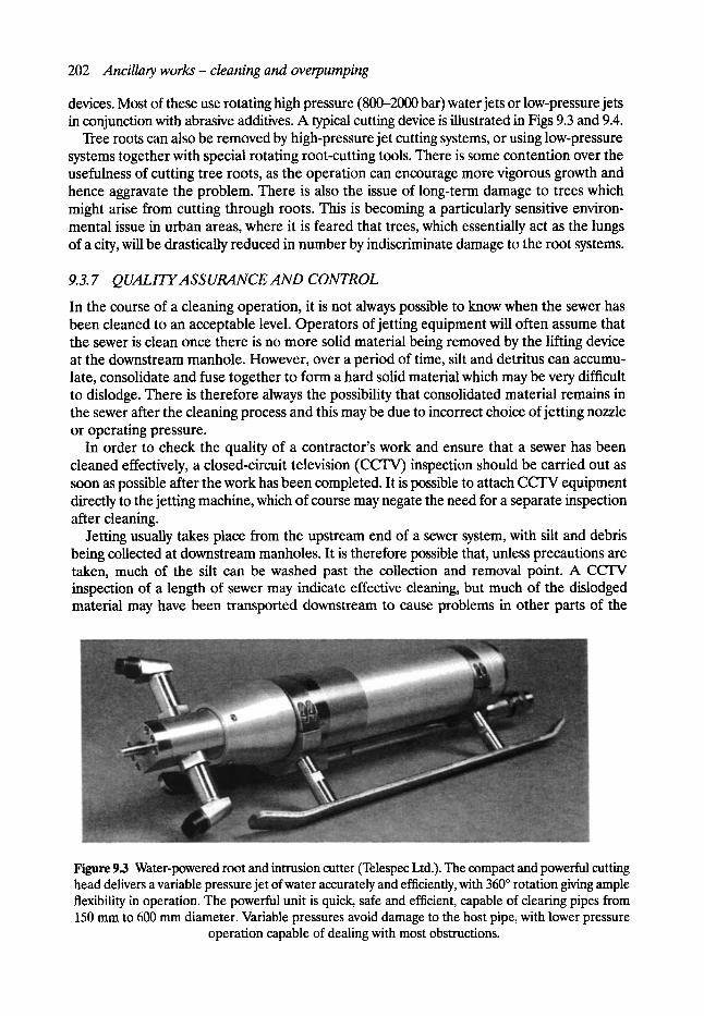
202 Ancillary works - cleaning and overpumping
devices. Most of these use rotating high pressure (800-2000 bar) water jets or low-pressure jets in conjunction with abrasive additives. A typical cutting device is illustrated in Figs 9.3 and 9.4.
Tree roots can also be removed by high-pressure jet cutting systems, or using low-pressure systems together with special rotating root-cutting tools. There is some contention over the usefulness of cutting tree roots, as the operation can encourage more vigorous growth and hence aggravate the problem. There is also the issue of long-term damage to trees which might arise from cutting through roots. This is becoming a particularly sensitive environ- mental issue in urban areas, where it is feared that trees, which essentially act as the lungs of a city, will be drastically reduced in number by indiscriminate damage to the root systems.
9.3. 7 QUALITYASSURANCE AND CONTROL
In the course of a cleaning operation, it is not always possible to know when the sewer has been cleaned to an acceptable level. Operators of jetting equipment will often assume that the sewer is clean once there is no more solid material being removed by the lifting device at the downstream manhole. However, over a period of time, silt and detritus can accumu- late, consolidate and fuse together to form a hard solid material which may be very difficult to dislodge. There is therefore always the possibility that consolidated material remains in the sewer after the cleaning process and this may be due to incorrect choice of jetting nozzle or operating pressure.
In order to check the quality of a contractor's work and ensure that a sewer has been cleaned effectively, a closed-circuit television (CCTV) inspection should be carried out as soon as possible after the work has been completed. It is possible to attach CCTV equipment directly to the jetting machine, which of course may negate the need for a separate inspection after cleaning.
Jetting usually takes place from the upstream end of a sewer system, with silt and debris being collected at downstream manholes. It is therefore possible that, unless precautions are taken, much of the silt can be washed past the collection and removal point. A CCFV inspection of a length of sewer may indicate effective cleaning, but much of the dislodged material may have been transported downstream to cause problems in other parts of the
Figure 9.3 Water-powered root and intrusion cutter (Telespec Ltd.). The compact and powerful cutting head delivers a variable pressure jet of water accurately and efficiently, with 360 ~ rotation giving ample flexibility in operation. The powerful unit is quick, safe and efficient, capable of clearing pipes from 150 mm to 600 mm diameter. Variable pressures avoid damage to the host pipe, with lower pressure
operation capable of dealing with most obstructions.
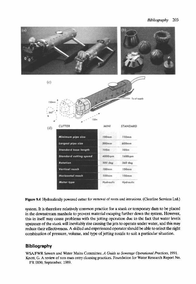
Bibliography 203
Figure 9.4 Hydraulically powered cutter for removal of roots and intrusions. (Clearline Services Ltd.)
system. It is therefore relatively common practice for a stank or temporary dam to be placed in the downstream manhole to prevent material escaping further down the system. However, this in itself may cause problems with the jetting operation due to the fact that water levels upstream of the stank will inevitably rise causing the jets to operate under water, and this may reduce their effectiveness. A skilled and experienced operator should be able to select the right combination of pressure, volume, and type of jetting nozzle to suit a particular situation.
Bibliography WSA/FWR Sewers and Water Mains Committee. A Guide to Sewerage Operational Practices, 1991. Knott, G. A review of non man entry cleaning practices. Foundation for Water Research Report No.
FR 0030, September, 1989.
10 Repair and Renovation
Geoffrey F. Read MSc, CEng, FICE, FIStructE, FCIWEM, FIHT, MILE, FIMgt, MAE, MUKSTT
Paul Nedwell* BEng. MICE
10.1 Introduction
Following hydraulic analysis and structural inspection it can often be concluded that a sewer is:
�9 structurally weak or �9 structurally adequate but hydraulically defective.
In either case it is generally more economic to renovate rather than replace. Renovation is defined in the Water Research Centre's (WRc) Sewerage Rehabilitation
Manual (SRM) as:
Methods by which the performance of a length of sewer is improved by incorporating the original sewer fabric, but excluding maintenance operations such as isolated local repair and root or silt removal.
In the late 1970s WRc initiated a system whereby renovation contractors and suppliers could become 'established techniques'. In order to do this WRc producd, in consultation with the industry, a series of Information and Guidance Notes (IGN) which sought to define more closely each of the techniques current at that time. This was achieved by a number of laboratory tests to define the mechanical performance of each material and specification for quality control testing to ensure continuing compliance. Each technique was subjected to a number of field trials overseen by WRc after which time it was recognised as an 'established technique'.
Novel systems which arrived after the initial phase were put through the same system and new IGNs written.
In the late 1980s WRc ceased administration of the IGNs which passed to the Water Industry Certification Scheme and the IGN became a WlS (Water Industry Specification).
Cost-effectiveness is the primary design criterion and if a renovation scheme cannot be shown to be cost-effective and safe to execute, the SRM's strategy would discard the renovation option.
If it is economically practical, renovation should be dealt with at the appropriate time - if not the stage will be reached where the more expensive replacement option will be the only solution.
The concept of 'life-cycle management' in relation to urban water systems generally has been proposed by Grigg (Fig. 10.1). It simply means effective management all through the
*Senior Experimental Officer, Department of Civil and Structural Engineering, UMIST.
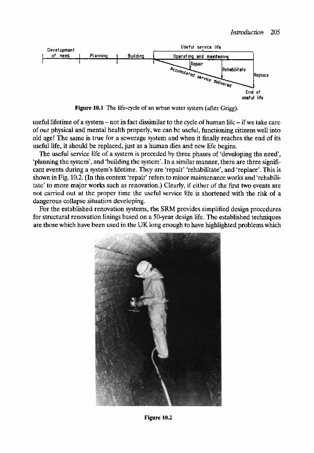
Introduction 205
Devetopment of need
Usefd service tife t Plannintj ] Buitdin9 L Operating andmaintaining ]
I ~ ~ _ [Repair I | Acco~..,~k,~ IRehabitifate J "''mUlaf'ed s~,.~~~. ~" ..... |Reptace -r c / ~
End of useful life
Figure 10.1 The life-cycle of an urban water system (after Grigg).
useful lifetime of a system - not in fact dissimilar to the cycle of human life - if we take care of our physical and mental health properly, we can be useful, functioning citizens well into old age! The same is true for a sewerage system and when it finally reaches the end of its useful life, it should be replaced, just as a human dies and new life begins.
The useful service life of a system is preceded by three phases of 'developing the need', 'planning the system', and 'building the system'. In a similar manner, there are three signifi- cant events during a system's lifetime. They are 'repair' 'rehabilitate', and 'replace'. This is shown in Fig. 10.2. (In this context 'repair' refers to minor maintenance works and 'rehabili- tate' to more major works such as renovation.) Clearly, if either of the first two events are not carried out at the proper time the useful service life is shortened with the risk of a dangerous collapse situation developing.
For the established renovation systems, the SRM provides simplified design procedures for structural renovation linings based on a 50-year design life. The established techniques are those which have been used in the UK long enough to have highlighted problems which
Figure 10.2
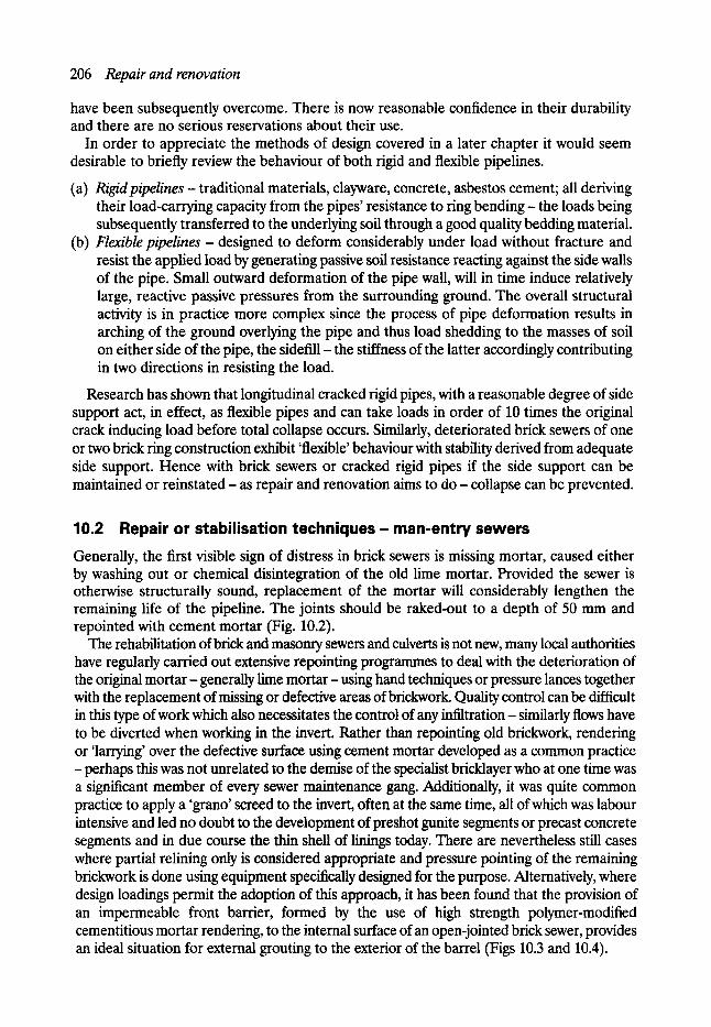
206 Repair and renovation
have been subsequently overcome. There is now reasonable confidence in their durability and there are no serious reservations about their use.
In order to appreciate the methods of design covered in a later chapter it would seem desirable to briefly review the behaviour of both rigid and flexible pipelines.
(a) Rigid pipelines - traditional materials, clayware, concrete, asbestos cement; all deriving their load-carrying capacity from the pipes' resistance to ring bending- the loads being subsequently transferred to the underlying soil through a good quality bedding material.
(b) Flexible pipel ines - designed to deform considerably under load without fracture and resist the applied load by generating passive soil resistance reacting against the side walls of the pipe. Small outward deformation of the pipe wall, will in time induce relatively large, reactive passive pressures from the surrounding ground. The overall structural activity is in practice more complex since the process of pipe deformation results in arching of the ground overlying the pipe and thus load shedding to the masses of soil on either side of the pipe, the sidefill- the stiffness of the latter accordingly contributing in two directions in resisting the load.
Research has shown that longitudinal cracked rigid pipes, with a reasonable degree of side support act, in effect, as flexible pipes and can take loads in order of 10 times the original crack inducing load before total collapse occurs. Similarly, deteriorated brick sewers of one or two brick ring construction exhibit 'flexible' behaviour with stability derived from adequate side support. Hence with brick sewers or cracked rigid pipes if the side support can be maintained or reinstated- as repair and renovation aims to d o - collapse can be prevented.
10.2 Repair or stabilisation techniques- man-entry sewers Generally, the first visible sign of distress in brick sewers is missing mortar, caused either by washing out or chemical disintegration of the old lime mortar. Provided the sewer is otherwise structurally sound, replacement of the mortar will considerably lengthen the remaining life of the pipeline. The joints should be raked-out to a depth of 50 mm and repointed with cement mortar (Fig. 10.2).
The rehabilitation of brick and masonry sewers and culverts is not new, many local authorities have regularly carried out extensive repointing programmes to deal with the deterioration of the original mortar- generally lime mortar- using hand techniques or pressure lances together with the replacement of missing or defective areas of brickwork. Quality control can be difficult in this type of work which also necessitates the control of any infiltration - similarly flows have to be diverted when working in the invert. Rather than repointing old brickwork, rendering or 'larrying' over the defective surface using cement mortar developed as a common practice - perhaps this was not unrelated to the demise of the specialist bricklayer who at one time was a significant member of every sewer maintenance gang. Additionally, it was quite common practice to apply a 'grano' screed to the invert, often at the same time, all of which was labour intensive and led no doubt to the development of preshot gunite segments or precast concrete segments and in due course the thin shell of linings today. There are nevertheless still cases where partial relining only is considered appropriate and pressure pointing of the remaining brickwork is done using equipment specifically designed for the purpose. Alternatively, where design loadings permit the adoption of this approach, it has been found that the provision of an impermeable front barrier, formed by the use of high strength polymer-modified cementitious mortar rendering, to the internal surface of an open-jointed brick sewer, provides an ideal situation for external grouting to the exterior of the barrel (Figs 10.3 and 10.4).
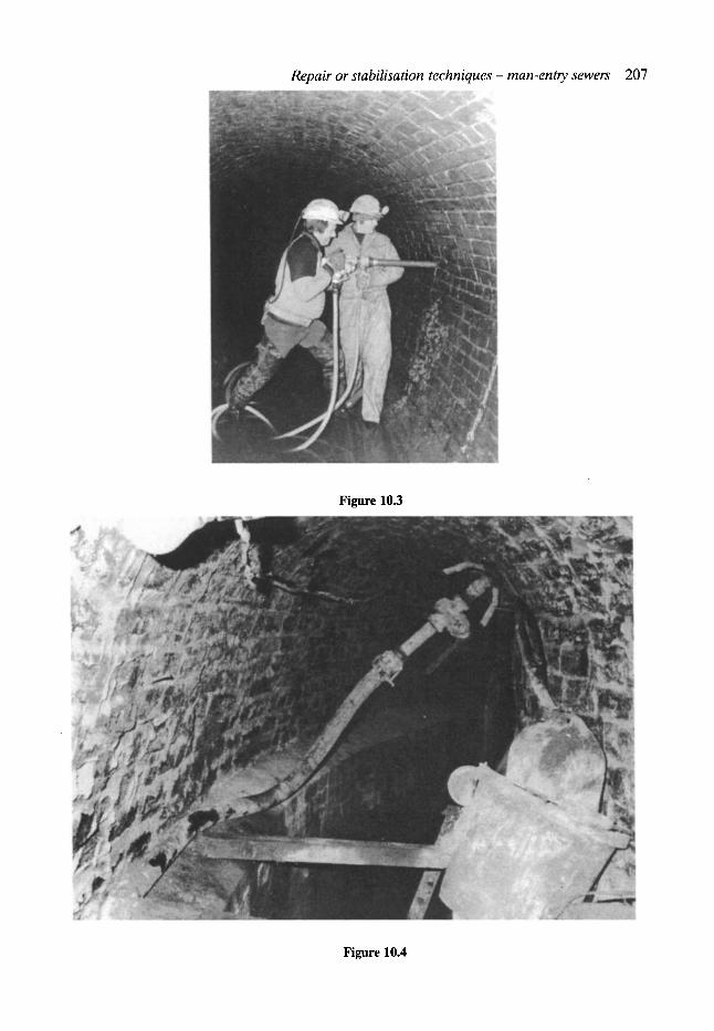
Repair or stabilisation techniques - man-entry sewers 207
Figure 10.3
Figure 10.4
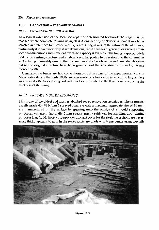
208 Repair and renovation , ,
10.3 Renovation- man-entrysewers 10.3.1 ENGINEERING BRICKWORK
As a logical extension of the localised repair of deteriorated brickwork the stage may be reached where complete relining using class A engineering brickwork in cement mortar is selected in preference to a preformed segmental lining in view of the nature of the old sewer, particularly if it has excessively sharp deviations, rapid changes of gradient or varying cross- sectional dimensions and sufficient hydraulic capacity is available. The lining is appropriately tied to the existing structure and enables a regular profile to be restored to the original as well as being reasonably assured that the annulus and all voids within and immediately exter- nal to the original structure have been grouted and the new structure is in fact acting monolithically.
Generally, the bricks are laid conventionally, but in some of the experimental work in Manchester during the early 1980s use was made of a brick type in which the largest face was pressed- the bricks being laid with this face presented to the flow thereby reducing the thickness of the lining.
10.3.2 PRECAST GUNITE SEGMENTS
This is one of the oldest and most established sewer renovation techniques. The segments, usually grade 40 (40 N/mm 2) sprayed concrete with a maximum aggregate size of 10 mm, are manufactured on the surface by spraying onto the outside of a mould supporting reinforcement mesh (normally 6-mm square mesh) sufficient for handling and jointing purposes (Fig. 10.5). In order to provide sufficient cover for the steel, the sections are neces- sarily thick, typically 40 mm. In the sewer joints are made with in situ gunite using specially
Figure 10.5
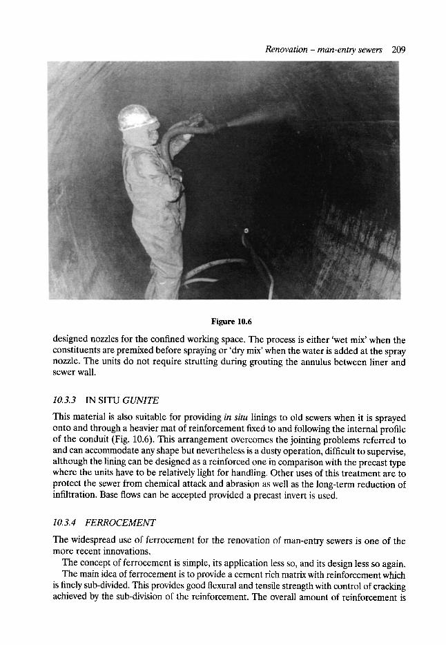
Renovation - man-ento, sewers 209
Figure 10.6
designed nozzles for the confined working space. The process is either 'wet mix' when the constituents are premixed before spraying or 'dry mix' when the water is added at the spray nozzle. The units do not require strutting during grouting the annulus between liner and sewer wall.
10.3.3 IN SITU G U N I T E
This material is also suitable for providing in situ linings to old sewers when it is sprayed onto and through a heavier mat of reinforcement fixed to and following the internal profile of the conduit (Fig. 10.6). This arrangement overcomes the jointing problems referred to and can accommodate any shape but nevertheless is a dusty operation, difficult to supervise, although the lining can be designed as a reinforced one in comparison with the precast type where the units have to be relatively light for handling. Other uses of this treatment are to protect the sewer from chemical attack and abrasion as well as the long-term reduction of infiltration. Base flows can be accepted provided a precast invert is used.
10.3.4 F E R R O C E M E N T
The widespread use of ferrocement for the renovation of man-entry sewers is one of the more recent innovations.
The concept of ferrocement is simple, its application less so, and its design less so again. The main idea of ferrocement is to provide a cement rich matrix with reinforcement which
is finely sub-divided. This provides good flexural and tensile strength with control of cracking achieved by the sub-division of the reinforcement. The overall amount of reinforcement is
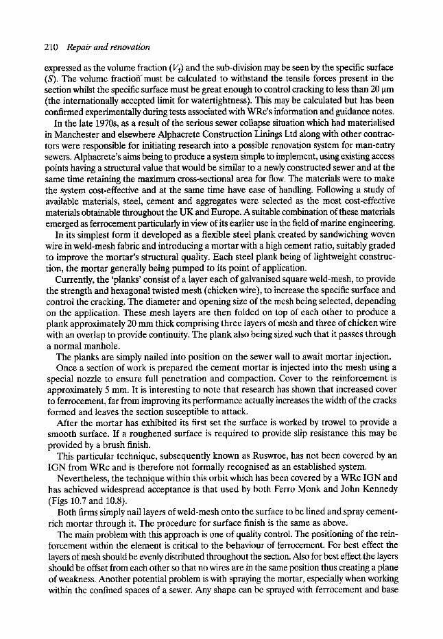
210 Repair and renovation
expressed as the volume fraction (Vf) and the sub-division may be seen by the specific surface (S). The volume fractio~must be calculated to withstand the tensile forces present in the section whilst the specific surface must be great enough to control cracking to less than 20 ~tm (the internationally accepted limit for watertightness). This may be calculated but has been confirmed experimentally during tests associated with WRc's information and guidance notes.
In the late 1970s, as a result of the serious sewer collapse situation which had materialised in Manchester and elsewhere Alphacrete Construction Linings Ltd along with other contrac- tors were responsible for initiating research into a possible renovation system for man-entry sewers. Alphacrete's aims being to produce a system simple to implement, using existing access points having a structural value that would be similar to a newly constructed sewer and at the same time retaining the maximum cross-sectional area for flow. The materials were to make the system cost-effective and at the same time have ease of handling. Following a study of available materials, steel, cement and aggregates were selected as the most cost-effective materials obtainable throughout the UK and Europe. A suitable combination of these materials emerged as ferrocement particularly in view of its earlier use in the field of marine engineering.
In its simplest form it developed as a flexible steel plank created by sandwiching woven wire in weld-mesh fabric and introducing a mortar with a high cement ratio, suitably graded to improve the mortar's structural quality. Each steel plank being of lightweight construc- tion, the mortar generally being pumped to its point of application.
Currently, the 'planks' consist of a layer each of galvanised square weld-mesh, to provide the strength and hexagonal twisted mesh (chicken wire), to increase the specific surface and control the cracking. The diameter and opening size of the mesh being selected, depending on the application. These mesh layers are then folded on top of each other to produce a plank approximately 20 mm thick comprising three layers of mesh and three of chicken wire with an overlap to provide continuity. The plank also being sized such that it passes through a normal manhole.
The planks are simply nailed into position on the sewer wall to await mortar injection. Once a section of work is prepared the cement mortar is injected into the mesh using a
special nozzle to ensure full penetration and compaction. Cover to the reinforcement is approximately 5 mm. It is interesting to note that research has shown that increased cover to ferrocement, far from improving its performance actually increases the width of the cracks formed and leaves the section susceptible to attack.
After the mortar has exhibited its first set the surface is worked by trowel to provide a smooth surface. If a roughened surface is required to provide slip resistance this may be provided by a brush finish.
This particular technique, subsequently known as Ruswroe, has not been covered by an IGN from WRc and is therefore not formally recognised as an established system.
Nevertheless, the technique within this orbit which has been covered by a WRc IGN and has achieved widespread acceptance is that used by both Ferro Monk and John Kennedy (Figs 10.7 and 10.8).
Both firms simply nail layers of weld-mesh onto the surface to be lined and spray cement- rich mortar through it. The procedure for surface finish is the same as above.
The main problem with this approach is one of quality control. The positioning of the rein- forcement within the element is critical to the behaviour of ferrocement. For best effect the layers of mesh should be evenly distributed throughout the section. Also for best effect the layers should be offset from each other so that no wires are in the same position thus creating a plane of weakness. Another potential problem is with spraying the mortar, especially when working within the confined spaces of a sewer. Any shape can be sprayed with ferrocement and base
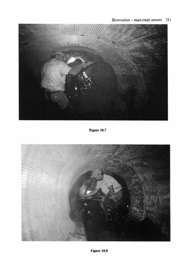
R e n o v a t i o n - m a n - e n t r y s e w e r s 211
Figure 10.7
Figure 10.8
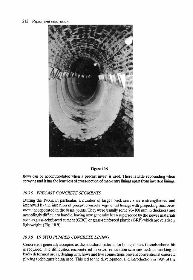
212 Repair and renovation
Figure 10.9
flows can be accommodated when a precast invert is used. There is little rebounding when spraying and it has the least loss of cross-section of man-entry linings apart from inverted linings.
10.3.5 PRECAST CONCt~TE SEGMENTS
During the 1960s, in particular, a number of larger brick sewers were strengthened and improved by the insertion of precast concrete segmental linings with projecting reinforce- ment incorporated in the in situ joints. They were usually some 70--100 mm in thickness and accordingly difficult to handle, having now generally been superseded by the newer materials such as glass-reinforced cement (GRC) or glass-reinforced plastic (GRP) which are relatively lightweight (Fig. 10.9).
10.3.6 IN SITU PUMPED CONCRETE LINING
Concrete is generally accepted as the standard material for lining all new tunnels where this is required. The difficulties encountered in sewer renovation schemes such as working in badly deformed areas, dealing with flows and live connections prevent conventional concrete placing techniques being used. This led to the development and introduction in 1984 of the
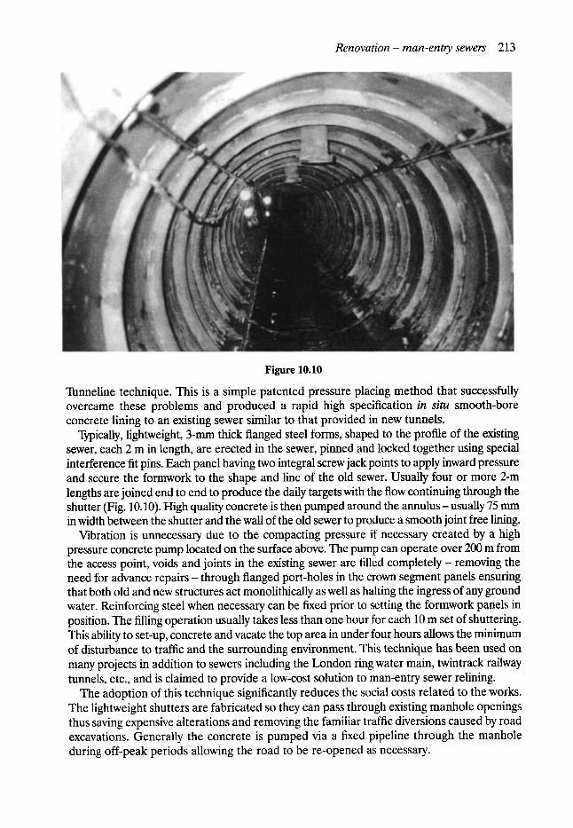
Renova t ion - m a n - e n t o , sewers 213
Figure 10.10
Tunneline technique. This is a simple patented pressure placing method that successfully overcame these problems and produced a rapid high specification in si tu smooth-bore concrete lining to an existing sewer similar to that provided in new tunnels.
Typically, lightweight, 3-mm thick flanged steel forms, shaped to the profile of the existing sewer, each 2 m in length, are erected in the sewer, pinned and locked together using special interference fit pins. Each panel having two integral screw jack points to apply inward pressure and secure the formwork to the shape and line of the old sewer. Usually four or more 2-m lengths are joined end to end to produce the daffy targets with the flow continuing through the shutter (Fig. 10.10). High quality concrete is then pumped around the annulus- usually 75 mm in width between the shutter and the wall of the old sewer to produce a smooth joint free lining.
Vibration is unnecessary due to the compacting pressure if necessary created by a high pressure concrete pump located on the surface above. The pump can operate over 200 m from the access point, voids and joints in the existing sewer are filled completely- removing the need for advance repairs- through flanged port-holes in the crown segment panels ensuring that both old and new structures act monolithically as well as halting the ingress of any ground water. Reinforcing steel when necessary can be fixed prior to setting the formwork panels in position. The filling operation usually takes less than one hour for each 10 rn set of shuttering. This ability to set-up, concrete and vacate the top area in under four hours allows the minimum of disturbance to traffic and the surrounding environment. This technique has been used on many projects in addition to sewers including the London ring water main, twintrack railway tunnels, etc., and is claimed to provide a low-cost solution to man-entry sewer relining.
The adoption of this technique significantly reduces the social costs related to the works. The lightweight shutters are fabricated so they can pass through existing manhole openings thus saving expensive alterations and removing the familiar traffic diversions caused by road excavations. Generally the concrete is pumped via a fixed pipeline through the manhole during off-peak periods allowing the road to be re-opened as necessary.
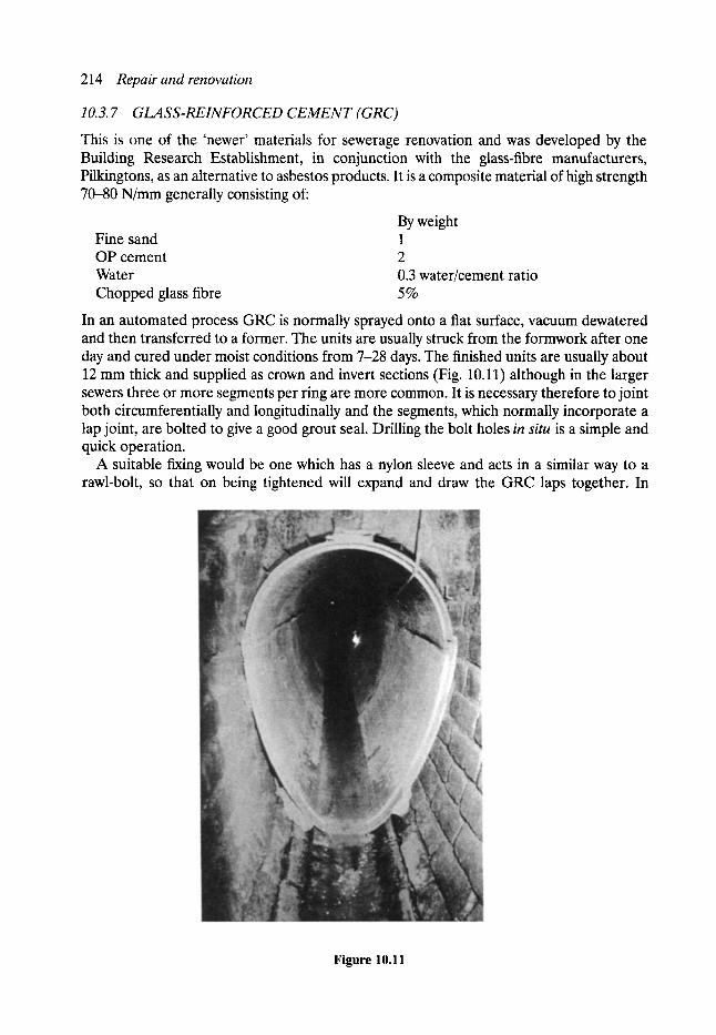
214 Repair and renovation
10.3.7 GLASS-REINFORCED CEMENT (GRC)
This is one of the 'newer' materials for sewerage renovation and was developed by the Building Research Establishment, in conjunction with the glass-fibre manufacturers, Pilkingtons, as an alternative to asbestos products. It is a composite material of high strength 70-80 N/mm generally consisting of:
By weight Fine sand 1 OP cement 2 Water 0.3 water/cement ratio Chopped glass fibre 5%
In an automated process GRC is normally sprayed onto a flat surface, vacuum dewatered and then transferred to a former. The units are usually struck from the formwork after one day and cured under moist conditions from 7-28 days. The finished units are usually about 12 mm thick and supplied as crown and invert sections (Fig. 10.11) although in the larger sewers three or more segments per ring are more common. It is necessary therefore to joint both circumferentially and longitudinally and the segments, which normally incorporate a lap joint, are bolted to give a good grout seal. Drilling the bolt holes in situ is a simple and quick operation.
A suitable fixing would be one which has a nylon sleeve and acts in a similar way to a rawl-bolt, so that on being tightened will expand and draw the GRC laps together. In
Figure 10.11
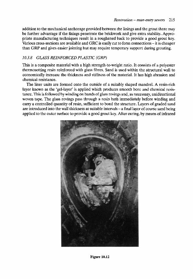
Renovation - man-entry sewers 215
addition to the mechanical anchorage provided between the linings and the grout there may be further advantage if the f~ngs penetrate the brickwork and give extra stability. Appro- priate manufacturing techniques result in a roughened back to provide a good grout key. Various cross-sections are available and GRC is easily cut to form connections- it is cheaper than GRP and gives easier jointing but may require temporary support during grouting.
10.3.8 G L A S S R E I N F O R C E D P L A S T I C (GRP)
This is a composite material with a high strength-to-weight ratio. It consists of a polyester thermosetting resin reinforced with glass fibres. Sand is used within the structural wall to economically increase the thickness and stiffness of the material. It has high abrasion and chemical resistance.
The liner units are formed onto the outside of a suitably shaped mandrel. A resin-rich layer known as the 'gel-layer' is applied which produces smooth bore and chemical resis- tance. This is followed by winding on bands of glass rovings and, as necessary, unidirectional woven tape. The glass rovings pass through a resin bath immediately before winding and carry a controlled quantity of resin, sufficient to bond the structure. Layers of graded sand are introduced into the wall thickness at suitable intervals- a final layer of course sand being applied to the outer surface to provide a good grout key. After curing, by means of infrared
Figure 10.12
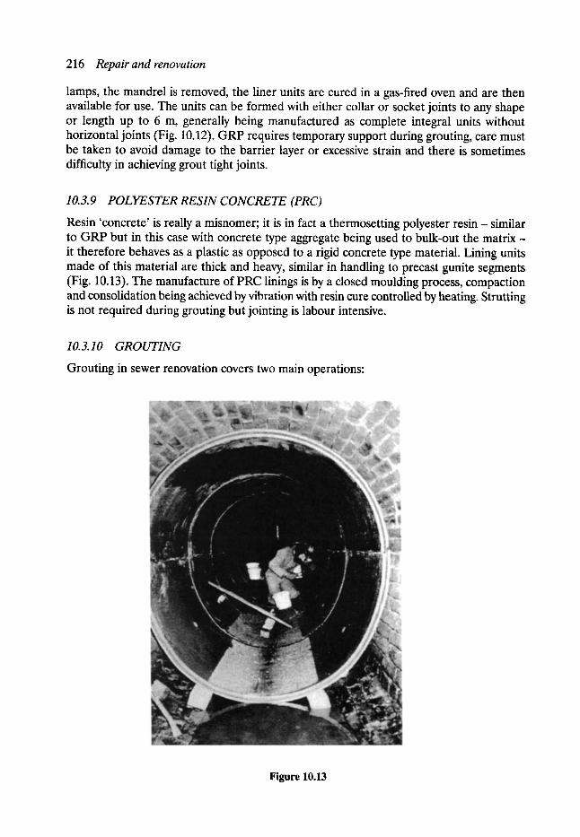
216 Repair and renovation
lamps, the mandrel is removed, the liner units are cured in a gas-fired oven and are then available for use. The units can be formed with either collar or socket joints to any shape or length up to 6 m, generally being manufactured as complete integral units without horizontal joints (Fig. 10.12). GRP requires temporary support during grouting, care must be taken to avoid damage to the barrier layer or excessive strain and there is sometimes difficulty in achieving grout tight joints.
10.3.9 POLYESTER RESIN CONCRETE (PRC)
Resin 'concrete' is really a misnomer; it is in fact a thermosetting polyester res in- similar to GRP but in this case with concrete type aggregate being used to bulk-out the matr ix- it therefore behaves as a plastic as opposed to a rigid concrete type material. Lining units made of this material are thick and heavy, similar in handling to precast gunite segments (Fig. 10.13). The manufacture of PRC linings is by a closed moulding process, compaction and consolidation being achieved by vibration with resin cure controlled by heating. Strutting is not required during grouting but jointing is labour intensive.
10.3.10 GROUTING
Grouting in sewer renovation covers two main operations:
Figure 10.13
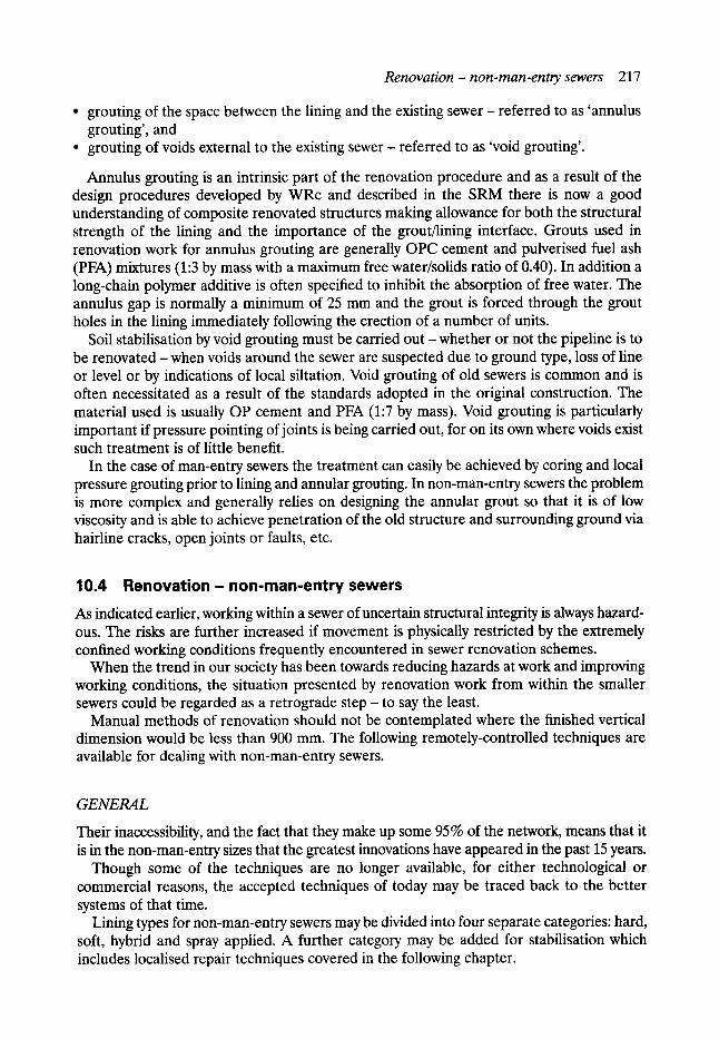
R e n o v a t i o n - n o n - m a n - e n t r y sewers 217
�9 grouting of the space between the lining and the existing sewer- referred to as 'annulus grouting', and
�9 grouting of voids external to the existing sewer referred to as 'void grouting'.
Annulus grouting is an intrinsic part of the renovation procedure and as a result of the design procedures developed by WRc and described in the SRM there is now a good understanding of composite renovated structures making allowance for both the structural strength of the lining and the importance of the grout/lining interface. Grouts used in renovation work for annulus grouting are generally OPC cement and pulverised fuel ash (PFA) mixtures (1:3 by mass with a maximum free water/solids ratio of 0.40). In addition a long-chain polymer additive is often specified to inhibit the absorption of free water. The annulus gap is normally a minimum of 25 mm and the grout is forced through the grout holes in the lining immediately following the erection of a number of units.
Soil stabilisation by void grouting must be carried out - whether or not the pipeline is to be renovated- when voids around the sewer are suspected due to ground type, loss of line or level or by indications of local siltation. Void grouting of old sewers is common and is often necessitated as a result of the standards adopted in the original construction. The material used is usually OP cement and PFA (1:7 by mass). Void grouting is particularly important if pressure pointing of joints is being carried out, for on its own where voids exist such treatment is of little benefit.
In the case of man-entry sewers the treatment can easily be achieved by coring and local pressure grouting prior to lining and annular grouting. In non-man-entry sewers the problem is more complex and generally relies on designing the annular grout so that it is of low viscosity and is able to achieve penetration of the old structure and surrounding ground via hairline cracks, open joints or faults, etc.
10.4 Renovat ion- non-man-entry sewers
As indicated earlier, working within a sewer of uncertain structural integrity is always hazard- ous. The risks are further increased if movement is physically restricted by the extremely confined working conditions frequently encountered in sewer renovation schemes.
When the trend in our society has been towards reducing hazards at work and improving working conditions, the situation presented by renovation work from within the smaller sewers could be regarded as a retrograde step - to say the least.
Manual methods of renovation should not be contemplated where the finished vertical dimension would be less than 900 mm. The following remotely-controlled techniques are available for dealing with non-man-entry sewers.
G E N E R A L
Their inaccessibility, and the fact that they make up some 95% of the network, means that it is in the non-man-entry sizes that the greatest innovations have appeared in the past 15 years.
Though some of the techniques are no longer available, for either technological or commercial reasons, the accepted techniques of today may be traced back to the better systems of that time.
Lining types for non-man-entry sewers may be divided into four separate categories: hard, soft, hybrid and spray applied. A further category may be added for stabilisation which includes localised repair techniques covered in the following chapter.
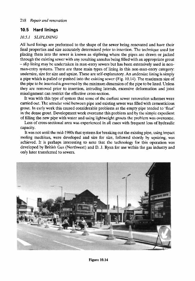
218 Repair and renovation
10.5 Hard linings 10.5.1 SLIPLINING
All hard linings are preformed to the shape of the sewer being renovated and have their final properties and size accurately determined prior to insertion. The technique used for placing them into the sewer is known as sliplining where the pipes are drawn or jacked through the existing sewer with any resulting annulus being filled with an appropriate grout - slip lining may be undertaken in man-entry sewers but has been extensively used in non- man-entry systems. There are three main types of lining in this non-man-entry category: undersize, size for size and upsize. These are self-explanatory. An undersize lining is simply a pipe which is pulled or pushed into the existing sewer (Fig. 10.14). The maximum size of the pipe to be inserted is governed by the minimum dimension of the pipe to be lined. Unless they are removed prior to insertion, intruding laterals, excessive deformation and joint misalignment can restrict the effective cross-section.
It was with this type of system that some of the earliest sewer renovation schemes were carried out. The annular void between pipe and existing sewer was filled with cementicious grout. In early work this caused considerable problems as the empty pipe tended to 'float' in the dense grout. Development work overcame this problem and by the simple expedient of filling the new pipe with water and using lightweight grouts the problem was overcome.
Loss of cross-sectional area was experienced in all cases with frequent loss of hydraulic capacity.
It was not until the mid-1980s that systems for breaking out the existing pipe, using impact moling machines, were developed and size for size, followed shortly by upsizing, was achieved. It is perhaps interesting to note that the technology for this operation was developed by British Gas (Northwest) and D. J. Ryan for use within the gas industry and only later transferred to sewers.
F i g u r e 1 0 . 1 4
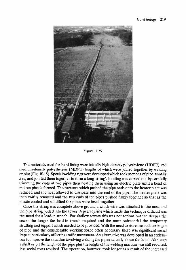
Hard linings 219
Figure 10.15
The materials used for hard lining were initially high-density polyethylene (HDPE) and medium-density polyethylene (MDPE) lengths of which were joined together by welding on site (Fig. 10.15). Special welding rigs were developed which took sections of pipe, usually 5 m, and jointed them together to form a long 'string'. Jointing was carried out by carefully trimming the ends of two pipes then heating them using an electric plate until a bead of molten plastic formed. The pressure which pushed the pipe ends onto the heater plate was reduced and the heat allowed to dissipate into the end of the pipe. The heater plate was then swiftly removed and the two ends of the pipes pushed firmly together so that as the plastic cooled and solidified the pipes were fused together.
Once the string was complete above ground a winch wire was attached to the nose and the pipe string pulled into the sewer. A prerequisite which made this technique difficult was the need for a lead-in trench. For shallow sewers this was not serious but the deeper the sewer the longer the lead-in trench required and the more substantial the temporary strutting and support which needed to be provided. With the need to store the built up length of pipe and the considerable working space often necessary there was significant social impact particularly affecting traffic movement. An alternative was developed in an endeav- our to improve the situation involving welding the pipes actually 'down the hole'. Although a shaft or pit the length of the pipe plus the length of the welding machine was still required, less social costs resulted. The operation, however, took longer as a result of the increased
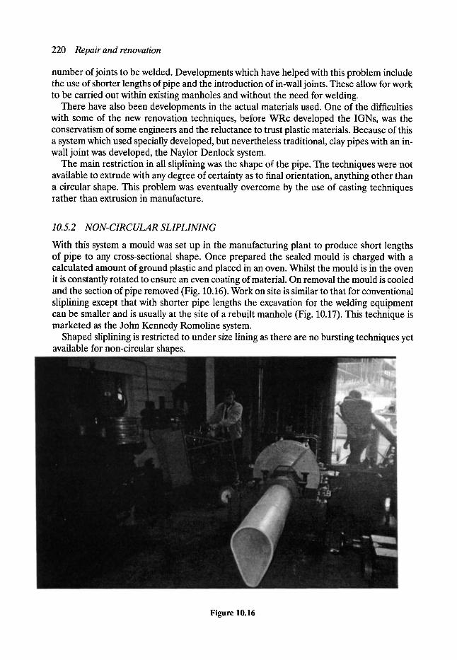
220 Repair and renovation
number of joints to be welded. Developments which have helped with this problem include the use of shorter lengths of pipe and the introduction of in-wall joints. These allow for work to be carried out within existing manholes and without the need for welding.
There have also been developments in the actual materials used. One of the difficulties with some of the new renovation techniques, before WRc developed the IGNs, was the conservatism of some engineers and the reluctance to trust plastic materials. Because of this a system which used specially developed, but nevertheless traditional, clay pipes with an in- wall joint was developed, the Naylor Denlock system.
The main restriction in all sliplining was the shape of the pipe. The techniques were not available to extrude with any degree of certainty as to final orientation, anything other than a circular shape. This problem was eventually overcome by the use of casting techniques rather than extrusion in manufacture.
10.5.2 NON-CIRCULAR SLIPLINING
With this system a mould was set up in the manufacturing plant to produce short lengths of pipe to any cross-sectional shape. Once prepared the sealed mould is charged with a calculated amount of ground plastic and placed in an oven. Whilst the mould is in the oven it is constantly rotated to ensure an even coating of material. On removal the mould is cooled and the section of pipe removed (Fig. 10.16). Work on site is similar to that for conventional sliplining except that with shorter pipe lengths the excavation for the welding equipment can be smaller and is usually at the site of a rebuilt manhole (Fig. 10.17). This technique is marketed as the John Kennedy Romoline system.
Shaped sliplining is restricted to under size lining as there are no bursting techniques yet available for non-circular shapes.
Figure 10.16
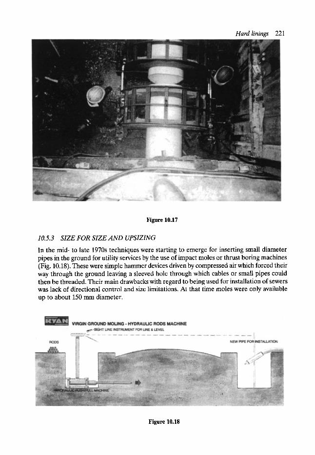
Hard linings 221
Figure 10.17
10. 5. 3 SIZE FOR SIZE AND UPSIZING
In the mid- to late 1970s techniques were starting to emerge for inserting small diameter pipes in the ground for utility services by the use of impact moles or thrust boring machines (Fig. 10.18). These were simple hammer devices driven by compressed air which forced their way through the ground leaving a sleeved hole through which cables or small pipescould then be threaded. Their main drawbacks with regard to being used for installation of sewers was lack of directional control and size limitations. At that time moles were only available up to about 150 mm diameter.
Figure 10.18
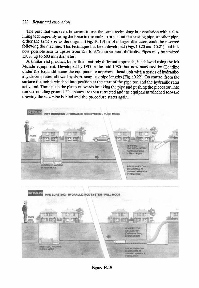
222 Repair and renovation
The potential was seen, however, to use the same technology in association with a slip- lining technique. By using the force in the mole to break out the existing pipe, another pipe, either the same size as the original (Fig. 10.19) or of a larger diameter, could be inserted following the machine. This technique has been developed (Figs 10.20 and 10.21) and it is now possible also to upsize from 225 to 375 mm without difficulty. Pipes may be upsized 150% up to 600 mm diameter.
A similar end product, but with an entirely different approach, is achieved using the Mr Muscle equipment. Developed by IPD in the mid-1980s but now marketed by Clearline under the Expandit name the equipment comprises a head unit with a series of hydraulic- ally driven plates followed by short, snaplock pipe lengths (Fig. 10.22). On control from the surface the unit is winched into position at the start of the pipe run and the hydraulic rams activated. These push the plates outwards breaking the pipe and pushing the pieces out into the surrounding ground. The plates are then retracted and the equipment winched forward drawing the new pipe behind and the procedure starts again.
Figure 10.19
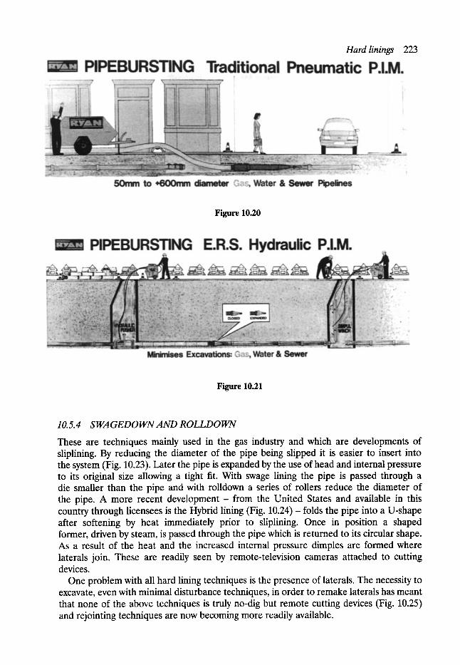
Hard linings 223
Figure 10.20
Figure 10.21
10.5.4 SWAGEDOWNAND ROLLDOWN
These are techniques mainly used in the gas industry and which are developments of sliplining. By reducing the diameter of the pipe being slipped it is easier to insert into the system (Fig. 10.23). Later the pipe is expanded by the use of head and internal pressure to its original size allowing a tight fit. With swage lining the pipe is passed through a die smaller than the pipe and with rolldown a series of rollers reduce the diameter of the pipe. A more recent development- from the United States and available in this country through licensees is the Hybrid lining (Fig. 10.24) - folds the pipe into a U-shape after softening by heat immediately prior to sliplining. Once in position a shaped former, driven by steam, is passed through the pipe which is returned to its circular shape. As a result of the heat and the increased internal pressure dimples are formed where laterals join. These are readily seen by remote-television cameras attached to cutting devices.
One problem with all hard lining techniques is the presence of laterals. The necessity to excavate, even with minimal disturbance techniques, in order to remake laterals has meant that none of the above techniques is truly no-dig but remote cutting devices (Fig. 10.25) and rejointing techniques are now becoming more readily available.
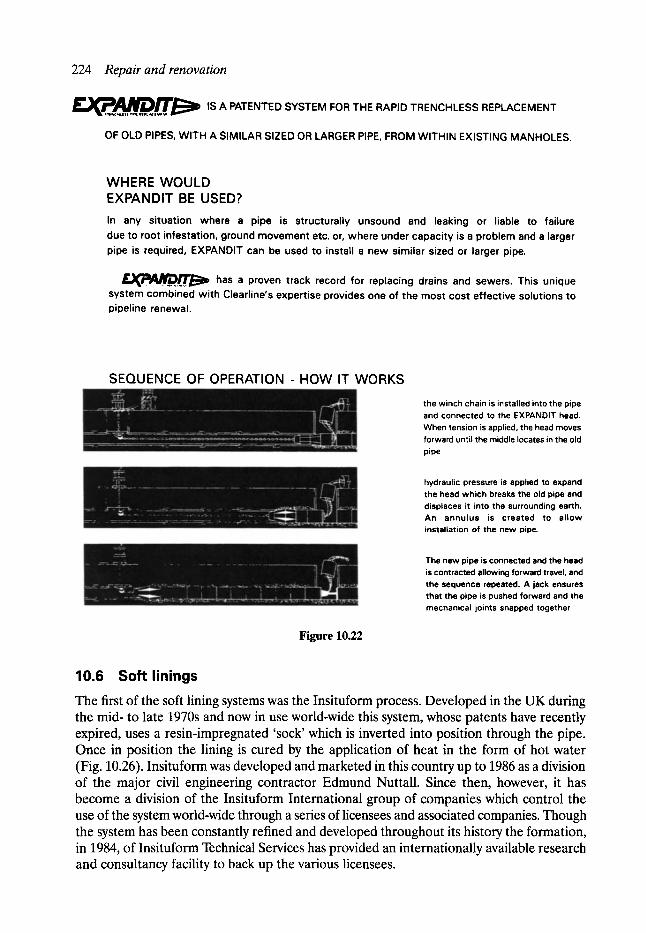
224 Repair and renovation
F B = d ~ , , ~ ~ , r r , , ~ is A PATENTED SYSTEM FOR THE RAPID TRENCHLESS REPLACEMENT
OF OLD PIPES, WITH A SIMILAR SIZED OR LARGER PIPE, FROM WITHIN EXISTING MANHOLES.
WHERE WOULD EXPANDIT BE USED? In any situation where a pipe is structurally unsound and leaking or liable to failure due to root infestat ion, ground m o v e m e n t etc. or, where under capac i ty is a problem and a larger pipe is required, EXPANDIT can be used to install a new similar sized or larger pipe.
~ ~ ~ . . r r . ~ l D has a proven track record for replacing drains and sewers. This unique system c o m b i n e d wi th Clearline's expertise provides one of the m o s t cost e f fect ive solut ions to pipeline renewal.
SEQUENCE OF OPERATION - HOW IT WORKS
Figure 10.22
the winch chain is installed into the pipe and connected to the EXPANDIT head. When tension is applied, the head moves forward until the middle locates in the old pipe
hydraulic pressure is applied to expand the head which breaks the old pipe and displaces it into the surrounding earth. An annulus is created to allow installation of the new pipe.
The new pipe is connected and the head is contracted allowing forward travel, and the sequence repeated. A jack ensures that the pipe is pushed forward and the mechanical joints snapped together
10.6 Soft linings
The first of the soft lining systems was the Insituform process. Developed in the UK during the mid- to late 1970s and now in use world-wide this system, whose patents have recently expired, uses a resin-impregnated 'sock' which is inverted into position through the pipe. Once in position the lining is cured by the application of heat in the form of hot water (Fig. 10.26). Insituform was developed and marketed in this country up to 1986 as a division of the major civil engineering contractor Edmund Nuttall. Since then, however, it has become a division of the Insituform International group of companies which control the use of the system world-wide through a series of licensees and associated companies. Though the system has been constantly refined and developed throughout its history the formation, in 1984, of Insituform Technical Services has provided an internationally available research and consultancy facility to back up the various licensees.
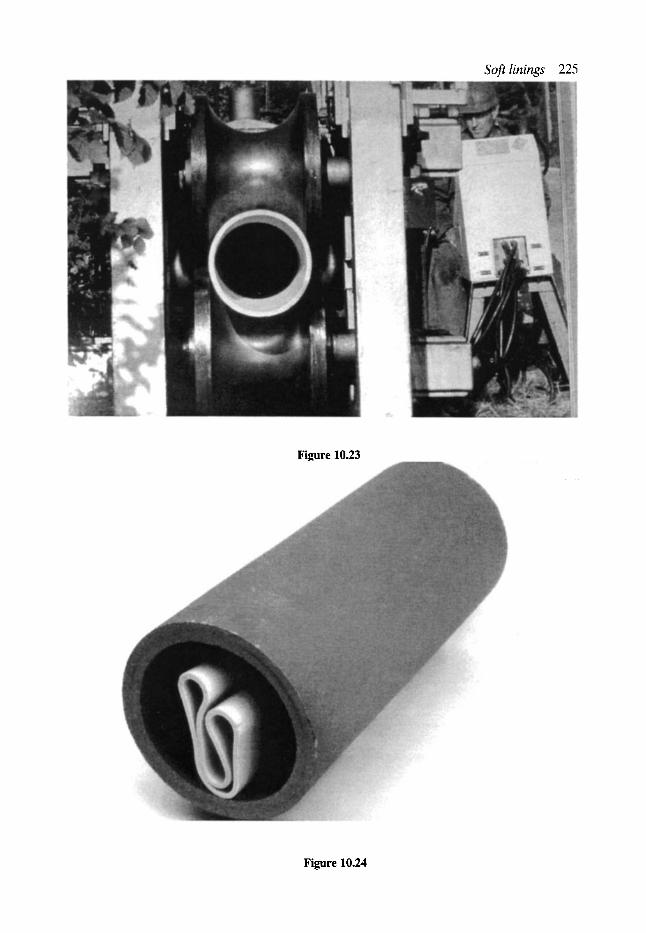
Soft linings 225
Figure 10.23
Figure 10.24
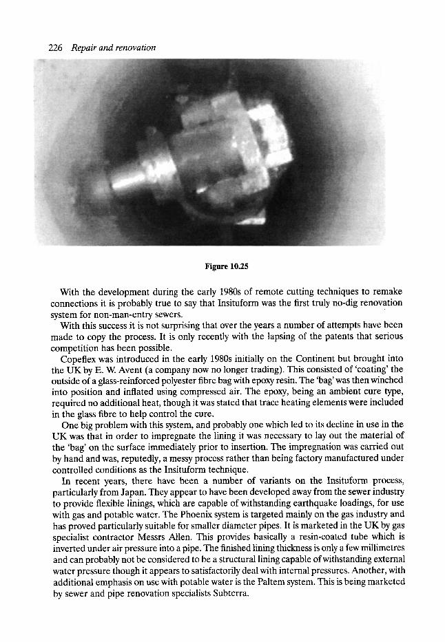
226 Repair and renovation
Figure 10.25
With the development during the early 1980s of remote cutting techniques to remake connections it is probably true to say that Insituform was the first truly no-dig renovation system for non-man-entry sewers.
With this success it is not surprising that over the years a number of attempts have been made to copy the process. It is only recently with the lapsing of the patents that serious competition has been possible.
Copeflex was introduced in the early 1980s initially on the Continent but brought into the UK by E. W. Avent (a company now no longer trading). This consisted of 'coating' the outside of a glass-reinforced polyester fibre bag with epoxy resin. The 'bag' was then winched into position and inflated using compressed air. The epoxy, being an ambient cure type, required no additional heat, though it was stated that trace heating elements were included in the glass fibre to help control the cure.
One big problem with this system, and probably one which led to its decline in use in the UK was that in order to impregnate the lining it was necessary to lay out the material of the 'bag' on the surface immediately prior to insertion. The impregnation was carried out by hand and was, reputedly, a messy process rather than being factory manufactured under controlled conditions as the Insituform technique.
In recent years, there have been a number of variants on the Insituform process, particularly from Japan. They appear to have been developed away from the sewer industry to provide flexible linings, which are capable of withstanding earthquake loadings, for use with gas and potable water. The Phoenix system is targeted mainly on the gas industry and has proved particularly suitable for smaller diameter pipes. It is marketed in the UK by gas specialist contractor Messrs Allen. This provides basically a resin-coated tube which is inverted under air pressure into a pipe. The finished lining thickness is only a few millimetres and can probably not be considered to be a structural lining capable of withstanding external water pressure though it appears to satisfactorily deal with internal pressures. Another, with additional emphasis on use with potable water is the Paltem system. This is being marketed by sewer and pipe renovation specialists Subterra.
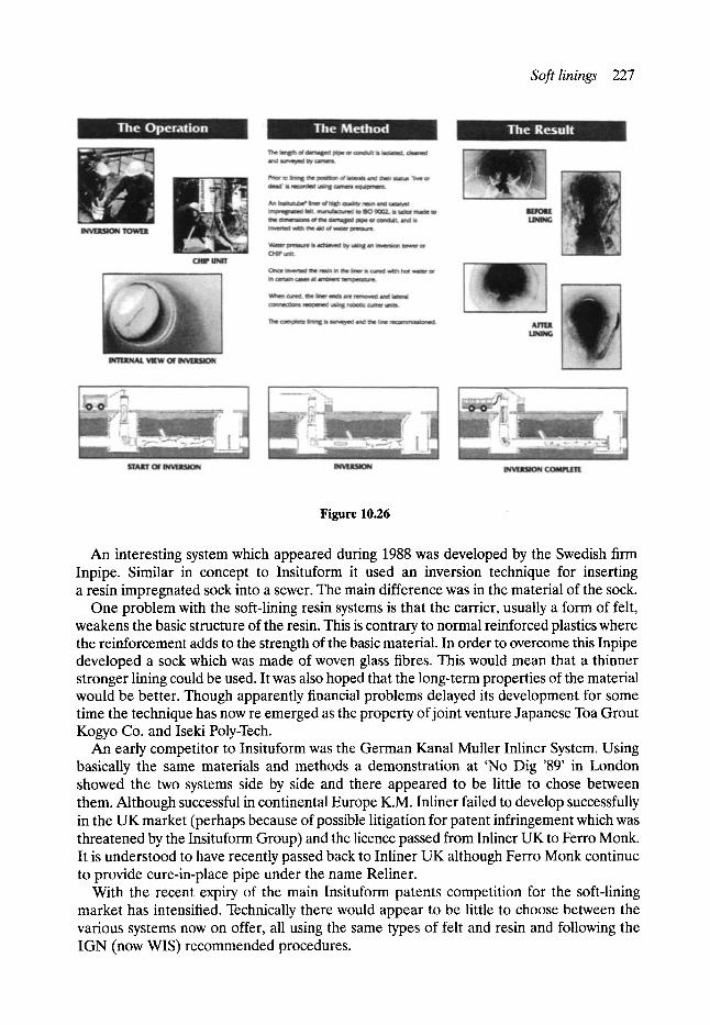
Soft linings 227
Figure 10.26
An interesting system which appeared during 1988 was developed by the Swedish firm Inpipe. Similar in concept to Insituform it used an inversion technique for inserting a resin impregnated sock into a sewer. The main difference was in the material of the sock.
One problem with the soft-lining resin systems is that the carrier, usually a form of felt, weakens the basic structure of the resin. This is contrary to normal reinforced plastics where the reinforcement adds to the strength of the basic material. In order to overcome this Inpipe developed a sock which was made of woven glass fibres. This would mean that a thinner stronger lining could be used. It was also hoped that the long-term properties of the material would be better. Though apparently financial problems delayed its development for some time the technique has now re emerged as the property of joint venture Japanese Toa Grout Kogyo Co. and Iseki Poly-Tech.
An early competitor to Insituform was the German Kanal Muller Inliner System. Using basically the same materials and methods a demonstration at 'No Dig '89' in London showed the two systems side by side and there appeared to be little to chose between them. Although successful in continental Europe K.M. Inliner failed to develop successfully in the UK market (perhaps because of possible litigation for patent infringement which was threatened by the Insituform Group) and the licence passed from Inliner UK to Ferro Monk. It is understood to have recently passed back to Inliner UK although Ferro Monk continue to provide cure-in-place pipe under the name Reliner.
With the recent expiry of the main Insituform patents competition for the soft-lining market has intensified. Technically there would appear to be little to choose between the various systems now on offer, all using the same types of felt and resin and following the IGN (now WlS) recommended procedures.
228 Repair and renovation
During their development Insituform have continually investigated variants designed to produce a better product. Two developments which showed promise but which have not yet found success in production were the use of acrylic felt and resins to produce a translucent lining, which assisted in the location of side connections, and the use of light-sensitive resin which enabled, especially large, linings to be cured 'cold'.
One of the problems with the inversion process is that the pressure head required to turn the liner inside out increases as the diameter of the liner decreases. In addition the head increases with length and the number and severity of any bends. Using traditional techniques smaller diameter linings either required tall and expensive inversion towers, and the inability to work from within a building, or were restricted to shorter lengths which could be pulled through. The development of the pressure inversion rig has meant that longer lengths of smaller diameter lining are accessible from positions with restricted headroom.
Another recent development, which has received an innovation award, is a technique for providing a lining to a lateral which is installed from within a pipeline. This provides for a complete sealing of the system.
10.7 Spray linings In the early 1980s one of the main problems with all renovation techniques was the need to excavate on to junctions in order that reconnection may be made at the earliest oppor- tunity. Techniques for cutting soft linings by means of remote cutting were still in their infancy.
One way which sought to overcome the problem of laterals was the use of spraying techniques. The basic concept was that as the spray head passed the lateral the material being sprayed would 'feather out' up the lateral with no need for reconnection. The idea was first propounded by RAM Services and advertised as a viable technique. Unfortunately a number of teething problems defeated the company who sold the process on to the Hume Corporation of Australia.
Meanwhile in the UK WRc had formed a consortium with a material supplier, a contractor and a material spraying equipment specialist to develop the idea further. Though equipment was built and trials carried out problems with control of the equipment to provide a good smooth even finish eventually led to it not proceeding.
At about the same time Streeters commenced to develop a spraying technique. Though problems were encountered an involvement by the major civil engineering contractor, Costain, led to development of the system. It is now available from Subterra under the tradename Polyspray, though it is understood that the equipment is little used and would require further development to make it competitive.
At one of the sewer rehabilitation technique courses held at University of Manchester Institute of Science and Technology (UMIST) in September 1987 the Manchester-based company, Tate Pipelining Processes, announced the results of their research and develop- ment, in conjunction with Laporte Chemicals, into a technique for spray application of lining material. However, it was only during 1990 that the system had been developed to a point where it has been licensed in the United States, but at this juncture the two companies separated and Tate continued development on their own.
The concept of the technique is simple. One of the major control problems is that of ensur- ing an even supply of spray to the pipe being lined. In a pumped system, should the spray head for some reason become obstructed the material, even for a few moments, could build
Stabilisation 229
up to form a considerable ridge. This, with some materials, could then collapse and subse- quently cure, blocking the pipe. Also with a pumped system if one component feed failed or was not working properly the proportioning of the mix would be altered and the mechanical properties of the finished product altered. The Tate system places prepackaged quantities of resin and hardener formulated to a 1:1 mix ratio in parallel tubes within the pipe to be lined. The spray machine then scavenges the material from the tubes, mixes them by force, rather than by use of a static in-line mixer, and then sprays it onto the pipe. If the machine becomes stuck there is no material for it to spray. Unfortunately whilst this section was being written Tate Pipelining ceased trading. The patents and development prototypes have, it is understood, been purchased from the receiver by Strabag, a German company, who intend to continue development.
A recent newcomer to the use of spray techniques, though not to the field of sewer rehabilitation, is John Kennedy (Construction). They have taken the original RAM patent and, in conjunction with Laporte, developed a spray technique based on the pumped system for use in circular sewers.
10.8 Problems associated with lining systems There are three main problems associated with, particularly, non-man-entry systems. The first is to ensure that the pipe is clean and free from any debris prior to lining. Techniques for cleaning are referred to elsewhere in this book. It is important that the pipe is inspected immediately prior to lining to ensure no debris has entered the pipe following a cleaning contract. This is especially important with soft linings which, because of the method of insertion, roll over smaller obstacles and encapsulate them leaving a bump in the lining.
The second is that of overpumping. Again non-man-entry techniques, which tend to have the whole pipe blocked for a period of time, are more critical where overpumping is concerned. The factors involved in deciding the level of overpumping required and the calculations of capacities are discussed in greater detail elsewhere in this book.
Finally, following lining the problem of reconnection is one which can influence the choice of technique employed.
All sliplining techniques require that reconnection be carried out externally. This may cause problems if the pipe is particularly deep or if there are a large number of connections to be remade.
Soft lining and hybrid techniques, as they produce an easily defined 'dimple', have resulted in the development of remote cutting techniques which are operated from within the pipe.
Choice is now available regarding the power source and method of cutting. Developments in Europe and the United States have led to machines powered by air, hydraulics and electrics. Cutting devices range from high-pressure water to reamer bits and tank saws. The choice depends on the contractor selected. Some of the equipment is also capable of being used to remove protruding laterals or tree roots prior to lining.
10.9 Stabilisation Two techniques, one from the earlier days of renovation, the other a more recent innovation are not covered by the structural techniques described above.
The first was an early technique primarily to prevent infiltration and exfiltration at joints in circular pipes. The Penetryne system comprised a unit designed specifically for individual
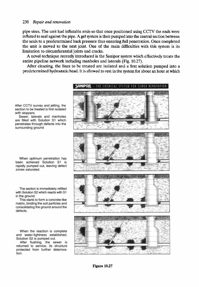
230 Repair and renovation
pipe sizes. The unit had inflatable ends so that once positioned using CCTV the ends were inflated to seal against the pipe. A gel system is then pumped into the central section between the seals to a predetermined back pressure thus ensuring full penetration. Once completed the unit is moved to the next joint. One of the main difficulties with this system is its limitation to circumferential joints and cracks.
A novel technique recently introduced is the Sanipor system which effectively treats the entire pipeline network including manholes and laterals (Fig. 10.27).
After cleaning, the lines to be treated are isolated and a first solution pumped into a predetermined hydrostatic head. It is allowed to rest in the system for about an hour at which
Figure 10.27
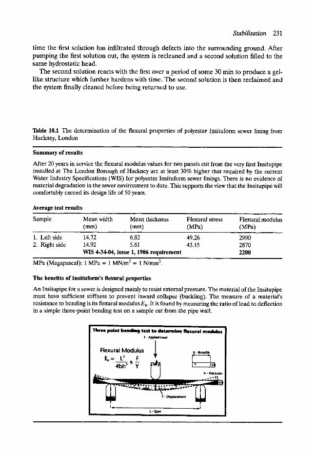
Stabilisation 231
t ime the first solution has infiltrated through defects into the surrounding ground. After pumping the first solution out, the system is recleaned and a second solution filled to the same hydrostatic head.
The second solution reacts with the first over a period of some 30 min to produce a gel- like structure which further hardens with time. The second solution is then reclaimed and the system finally cleaned before being returned to use.
Table 10.1 The determination of the flexural properties of polyester Insituform sewer lining from Hackney, London
Summary of results
After 20 years in service the flexural modulus values for two panels cut from the very first Insitupipe installed at The London Borough of Hackney are at least 30% higher that required by the current Water Industry Specifications (WIS) for polyester Insituform sewer linings. There is no evidence of material degradation in the sewer environment to date. This supports the view that the Insitupipe will comfortably exceed its design life of 50 years.
Average test results
Sample Mean width Mean thickness Flexural stress Flexural modulus (mm) (mm) (MPa) (MPa)
1. Left side 14.72 6.82 2. Right side 14.92 5.61
WIS 4-34-04, issue 1, 1986 requirement
MPa (Megapascal): 1 MPa = 1 MN/m 2 = 1 N/mm 2.
49.26 2990 43.15 2870
2200
The benefits of Insituform's flexural properties
An Insitupipe for a sewer is designed mainly to resist external pressure. The material of the Insitupipe must have sufficient stiffness to prevent inward collapse (buckling). The measure of a material's resistance to bending is its flexural modulus Eb. It is found by measuring the ratio of load to deflection in a simple three-point bending test on a sample cut from the pipe wall.
Three point bending test to determine flexural modulus F. ~ e d Load
Flexural Modulus ~ b- ~,,,,~h Eb = ._~L) 3 F '~, 1 X ,,~-~ ~ h--i 4bh Y r ~ ~ J~
I I I I h - Thiclmes$

232 Repair and renovation
10.10 R e n o v a t i o n - long t e r m
As indicated previously the SRM provided recommendations in regard to materials and systems that were then new and had been investigated in depth although the long-term characteristics had of necessity to be estimated using accelerated wear tests but traditional materials such as concrete and brick work which had been used for many years and had proved themselves suitable in practice, were not included in the SRM.
A fundamental factor influencing the choice of renovation systems being the expected service life which in turn depends upon factors such as abrasion resistance, resistance to chemical or biological attack and jointing integrity. It was accepted that it was virtually impossible to rank the service lives of both 'new' and 'traditional' materials in a general sewer environment with any degree of precision but general guidelines were provided.
It is now nearly 20 years since the first renovation schemes were carried out following the development of the current techniques in Manchester and elsewhere and the Sewerage Rehabilitation Unit in the Department of Civil and Structural Engineering at UMIST in Manchester is hoping to attract funding to enable a research programme to proceed in order to examine the performance of such materials in practice. Such research would form a logical extension to the research programme in relation to sewerage rehabilitation already carried out and would assist in the formulation of appropriate maintenance strategies as well as facilitating the development of suitable design criteria, etc.
In this connection it is interesting to note that in June 1991 two sample panels of the first Insituform lining in the UK inserted in a 1175 mm x 610 mm egg-shaped sewer in the London Borough of Hackney were removed and tested by independent test laboratories (M. J. S. Pendar Ltd), see Table 10.1.
11 Localised Repair Techniques for
Non-man-entry Sewers
Neil Bunting*
11.1 Background Before the advent of economical closed-circuit television (CCTV) inspection systems in the 1970s, the main indicators of sewer pipe failure were persistent blockages, highway depres- sions or collapses. The latter were occasionally spectacular where the flow had, over the years, scoured out a subterranean cavern into which a heavy vehicle would eventually fall when the roof span became too great for the highway construction to bridge. Given the right combination of flows and soil type, even a relatively small pipe could carve out a hole large enough to accommodate a bus.
While such events still occur and always will, their frequency can be reduced by a systematic approach to pipe inspection and rehabilitation. In the UK, the Water Research Centre (WRc) Sewerage Rehabilitation Manual (SRM) was the first coherent attempt to lay down procedures for the assessment and grading of sewers according to their importance and structural condition, and for the structural and hydraulic design of sewer liners. Other countries either adopted the SRM or developed their own approach. During the 1980s, the use of renovation techniques increased as the technology became established and acceptable to a traditionally cautious industry, and as the advantages of pre-emptive renovation rather than replacement or crisis management became apparent. Recently, the renovation momentum in certain countries has declined as resources have been diverted elsewhere. However, bearing in mind the age and condition of many sewers, water mains and other infrastructures in industrialised countries, and the proven advantages of preventative maintenance, it is surely only a matter of time before common sense accelerates demand to the levels once predicted - hopefully this will not be against a backdrop of significant collapses.
The concept of using localised no-dig techniques to treat individual defects within a pipeline, rather than renovating the whole manhole-to-manhole length, is fairly recent and has arisen for the following principal reasons:
�9 It is now appreciated that, where damage is restricted to only part of a sewer length, the repair of the specific defects or of the defective section can be more cost-effective than relining the entire sewer. The economics must be assessed in each case, but a widely accepted rule of thumb is that localised repairs may produce savings over full relining if less than about 25% of the total sewer length contains defects.
*Sub Tech Consultants.

234 Localised repair techniques for non-man-entry sewers
�9 The choice of localised repair systems has increased over the past few years as the various technologies have developed and the industry has responded to demand.
�9 As set-up costs are relatively low, many localised repair techniques are well suited to small- scale or emergency works.
�9 Although all the no-dig techniques offer social and environmental advantages over traditional replacement, localised repairs are generally less disruptive than full relining. In particular, the on-site plant and equipment requirements are often lower, the duration of the work is shorter, and many localised repair systems can be operated without diversion of sewage flows.
�9 Certain localised repair techniques are aimed at problems which are not addressed by manhole-to-manhole systems. The removal of intrusions, infiltration sealing, pipe re- rounding and the repair of connections are common examples.
�9 Following on from the above, there may be situations in which localised repairs are required as a precursor to full relining. Intrusion removal and the re-rounding of deformed pipes may be carried out in preparation for liner installation, and there is also a case for sealing major sources of infiltration.
�9 Although lateral reopening techniques have improved over the years, the procedure can still be costly and time-consuming, and it can be difficult to avoid lips and rough edges which may lead to ragging and blockages in the future. Hence, if the junctions or connections themselves are not defective, it may be preferable to avoid lining over them by the use of localised repair methods.
Whilst relatively few new developments in renovation technology have taken the industry by storm during the past few years, there has been an increase in the variety of available techniques, and a proliferation of variations on each theme. This is nowhere more true than in the case of localised repair systems.
11.2 Design criteria Many repair systems are, or claim to be, 'structural', but the exact definition of 'structural' in this context is open to debate. If it is intended to mean that the system restores the integrity of a pipe and/or its surround such that the sewer will remain serviceable and (literally) in good shape for the foreseeable future, then many supposedly non-structural systems are, in truth, structural.
Current liner design methods, such as those contained in WRc's manual (which are reviewed in another chapter) make some fairly sweeping assumptions about the state of the existing pipe and the loads which will be imposed on it after lining.
Type II linings are designed as flexible pipes requiring no bond between lining and grout or existing structures with no long-term strength being assigned to the existing sewer. Two factors are normally considered:
1. External water pressures with design checks for flotation and buckling failure. 2. Ground and traffic loading.
This approach should only be used whenever bond to the grout or old sewer cannot be obtained with confidence.
If the existing sewer is assessed by the engineer to be temporarily stable, e.g. up to 10% loss of cross-section of a cracked pipe or brick barrel, the supports offered to the lining by the old sewer, ground and grout (if applicable) can be judged to provide sufficient long-term
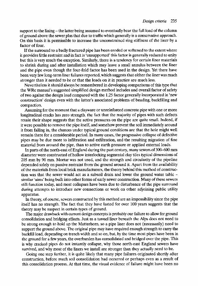
Designcriteria 235
support to the lining- the latter being assumed to eventually bear the full load of the column of ground above the sewer plus that due to traffic which generally is a conservative approach. On this basis it is permissible to increase the unconstrained ring stiffness of the liner by a factor of four.
If the surround to a badly fractured pipe has been eroded or softened to the extent where it provides little restraint and in fact is 'unsupported' this factor is generally reduced to unity but this is very much the exception. Similarly, there is a tendency for certain liner materials to shrink during and after installation which may leave a small annulus between the liner and the pipe even though the four-fold factor has been used in the design. Yet there have been very few long-term liner failures reported, which suggests that either the liner was much stronger than it needed to be or that the loads on it in practice are much less.
Nevertheless it should always be remembered in developing comparisons of this type that the WRc manual's suggested simplified design method includes and overall factor of safety of two against the design load compared with the 1.25 factor generally incorporated in 'new construction' design even with the latter's associated problems of beading, backfilling and compaction.
Assuming for the moment that a clayware or unreinforced concrete pipe with one or more longitudinal cracks has zero strength, the fact that the majority of pipes with such defects retain their shape suggests that the active pressures on the pipe are quite small. Indeed, if it were possible to remove the pipe itself, and somehow prevent the soil immediately around it from falling in, the chances under typical ground conditions are that the hole might well remain there for a considerable period. In many cases, the progressive collapse of defective pipes may be due more to infiltration and exfiltration, and the resulting migration of fine material from around the pipe, than to active earth pressure or applied external loads.
In parts of the north-east of England during the past century, many sewers of 300--600 mm diameter were constructed of hollow interlocking segmental clay tiles typical dimensions of 205 mm by 90 mm. Mortar was not used, and the strength and circularity of the pipeline depended solely on passive restraint from the ground around it. Apart from the availability of the materials from local brick manufacturers, the theory behind this method of construc- tion was that the sewer would act as a subsoil drain and lower the ground water table - similar 'aims' being built into other forms of early sewer construction. Many of these sewers still function today, and most collapses have been due to disturbance of the pipe surround during attempts to introduce new connections or work on other adjoining public utility apparatus.
In theory, of course, sewers constructed by this method are an impossibility since the pipe itself has no strength. The fact that they have lasted for over 100 years suggests that the theory may be suspect in certain types of ground.
The major drawback with current design concepts is probably our failure to allow for ground consolidation and bridging effects. Just as a tunnel liner beneath the Alps does not need to be strong enough to hold up the Matterhorn, so a pipe liner does not (necessarily) need to support the ground above. The original pipe may have required enough strength to carry the backfill load, depending on trench width and so on, but, by the time most pipes have been in the ground for a few years, the overburden has consolidated and bridged over the pipe. This is why cracked pipes do not instantly collapse, why those north-east England sewers have survived, and why most of the liners we install are stronger than they actually need to be.
Going one step further, it is quite likely that many pipe failures originated shortly after construction, before much soil consolidation had occurred or perhaps even as a result of this consolidation process. At that time, the visual evidence of failure might have been no
236 Localised repair techniques for non-man-entry sewers
more than a hairline crack. Over the years, progressive erosion and weakening of the support of a cracked pipe exacerbated the fault, eventually to the point of collapse.
In such cases, provided the sewer is renovated before deformation becomes too severe, the function of a 'structural' liner need be no more than to prevent the infiltration/ exfiltration cycle and to stabilise the existing pipe. Anything more is as unnecessary as holding up the Matterhorn. In fact, not dissimilar to the concept described by the editor (when he was the Manchester city engineer) in a paper to the Manchester Literary and Philosophical Society in 1982 entitled 'The development, renovation and reconstruction of Manchester's sewerage system':
It became clear in the early stages of the 'collapse era' that some form of internal lining of permanent formwork to strengthen the old sewers needed urgent examination in an endeavour to preserve, if at all possible, parts of the network which had not deteriorated too far and hence much development work was carried out both on-site and in the Department's Laboratories utilising the various materials then available.
Pipes treated with 'non-structural', ground-penetrating joint and crack-sealing systems have been exhumed to reveal a solid and impermeable soil mass around the defect. It is clear to anyone with an impartial eye that the structure of the pipe has been greatly enhanced, and that the risk of future failure is small. However, since the enhancement cannot be pre-quantified, such systems are not classed as structural.
The problem arises from engineers' natural caution, and from our love of figures. We cannot be absolutely sure that the loads on the pipe are low in any particular case, so we play safe and assume the worst. We cannot put a value on ring stiffness following resin injection, so we class the process as non-structural. However, if, using our engineering skill and judgement rather than computers, it appears that a damaged pipe has not exhibited rapid deterioration for reasons other than erosion, we can be sure beyond reasonable doubt that the loads are of such magnitude that they can be temporarily withstood by a pipe with no strength. If this is a valid assessment, and it will be in many cases, it must have a profound effect on the design of the liner or localised repair.
To be clear about all this, it is not suggested that a thin-walled, low-strength liner or a ground-penetrating resin would be suitable in all cases. For many non-circular pipes, especially bulging egg or U-shaped sewers, this is clearly not the case. Nor does it apply to deep sewers subjected to high external hydrostatic pressure, to shallow sewers where traffic loading is significant, to sewers in non-cohesive soils which may not bridge the load, or to situations where continuing ground movement is suspected. It will also be less applicable to larger diameter sewers where the 'bridge' span is greater and therefore less effective.
However, this still leaves a large number of small to medium-sized pipes at average depths where the requirements and costs of lining could be substantially reduced.
Perhaps the issue could be resolved if someone were willing to undertake field trials using thin-walled liners and ground-penetrating resins, in appropriate locations, and monitor their performance by deformation measurements over a period of a few years. If the results showed minimal deflection, we might in future be able to save a great deal of theorising and expenditure on over-designed liners. It would also, of course, reinforce the case for a 'stitch-in-time' approach to sewer renovation, and both increase the incentive and decrease the cost of catching the problem early.
Having said all that, if the requirement for a 'designed' structural liner persists, as presumably it will for a while at least, this tends to limit the application of the term 'struc- tural' to those localised repair systems which create an identifiable structural element whose strength can be measured independently. In effect, this means patch or short-lining systems,

Types of system 237
since almost all the other types function by restoring integrity and strength to the existing pipe and/or surround, in a way which is almost impossible to quantify.
Since short liners are just what their name suggests, if it is reasonable to design manhole- to-manhole cured-in-situ liners according to SRM type II procedures, the same rules may be applied also to patch repairs which use similar (usually stronger) materials. If anyone can suggest a means of quantifying with any precision the structural characteristics of pipes repaired by other means, we all would be delighted to hear from them. In the meantime, it can be argued quite reasonably that all localised repair systems enhance or stabilise the existing structure to some degree, and are therefore 'structural' in a qualitative if not a quantifiable sense. Unfortunately, this argument does not always impress those who believe only in the calculated approach.
11.3 Types of system Non-man-entry localised repair systems may be divided into five broad categories:
�9 patch or short-lining repairs �9 resin injection systems �9 robotic repairs �9 pipe re-rounding �9 pipe joint sealing.
It should be noted that some of the above techniques may be used also for the renovation of man-entry sewers which are outside the scope of this chapter.
11.3.1 PATCH OR SHORT-LINING I~PAIRS
Most patch-repair techniques entail impregnating a fabric with a suitable resin, pulling this into place within the sewer around an inflatable packer or mandrel, and then filling the packer with water, steam or air under pressure to press the patch against the existing sewer wall while the resin cures (see Fig. 11.1). Both heat- and ambient-cure systems are available, and patch repairs may be carried out in any size and shape of pipe (Fig. 11.2).
In many respects, patch repairs are short versions of cured-in-situ liners, although often the fabrics and resins used are stronger since material economy is less significant in the overall installation cost.
Packers may be either rigid or flexible. A rigid packer is easier to make, but clearly limits the maximum length of patch which can be installed from a normal manhole. Flexible packers can be of any length commensurate with on-site handling, and allow the installation of long patches.
It is important here to point out that a longitudinal crack in a clayware or concrete pipe is likely to travel the full length of the pipe, from joint to joint, whether or not a crack of such length is visible initially. Additionally, the inflation pressure of the packer will tend to open up longitudinal cracks and cause them to travel. In view of this, it seems a sensible precaution to always patch a full joint-to-joint pipe length if the pipe has longitudinal cracks, with a slight overlap to adjacent pipes at each end of the patch. Unfortunately, most rigid packer systems do not allow a single patch of such length to be installed.
Certain patch-repair systems have a throughflow hose built into the packer, so that some sewage flow can be maintained during installation without the need for overpumping. This reduces the set-up time and costs, and helps to minimise the amount of equipment on site.
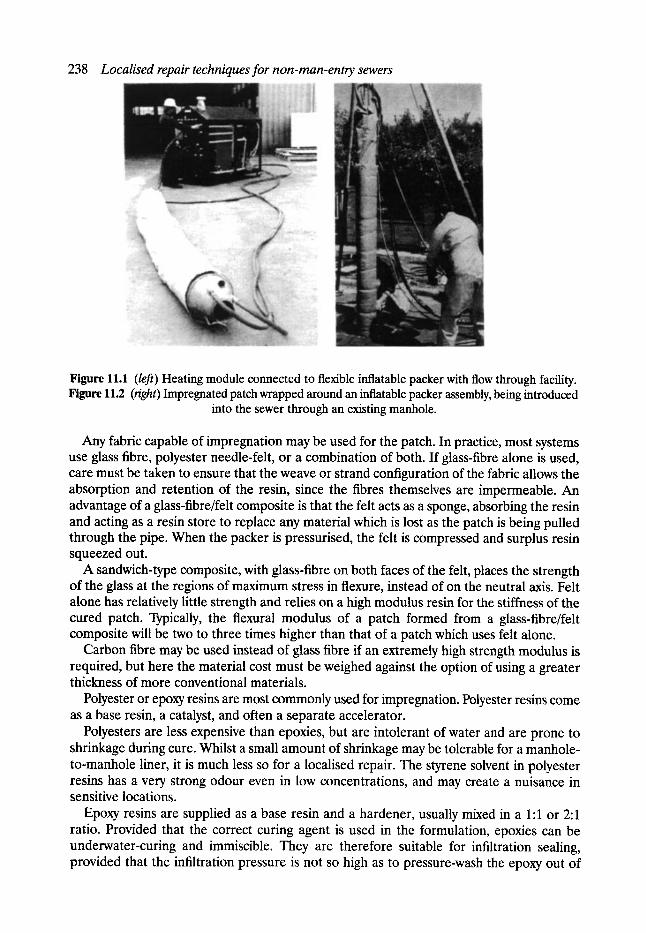
238 Localised repair techniques for non-man-entry sewers
Figure 11.1 (left) Heating module connected to flexible inflatable packer with flow through facility. Figure 11.2 (right) Impregnated patch wrapped around an inflatable packer assembly, being introduced
into the sewer through an existing manhole.
Any fabric capable of impregnation may be used for the patch. In practice, most systems use glass fibre, polyester needle-felt, or a combination of both. If glass-fibre alone is used, care must be taken to ensure that the weave or strand configuration of the fabric allows the absorption and retention of the resin, since the fibres themselves are impermeable. An advantage of a glass-fibre/felt composite is that the felt acts as a sponge, absorbing the resin and acting as a resin store to replace any material which is lost as the patch is being pulled through the pipe. When the packer is pressurised, the felt is compressed and surplus resin squeezed out.
A sandwich-type composite, with glass-fibre on both faces of the felt, places the strength of the glass at the regions of maximum stress in flexure, instead of on the neutral axis. Felt alone has relatively little strength and relies on a high modulus resin for the stiffness of the cured patch. Typically, the flexural modulus of a patch formed from a glass-fibre/felt composite will be two to three times higher than that of a patch which uses felt alone.
Carbon fibre may be used instead of glass fibre if an extremely high strength modulus is required, but here the material cost must be weighed against the option of using a greater thickness of more conventional materials.
Polyester or epoxy resins are most commonly used for impregnation. Polyester resins come as a base resin, a catalyst, and often a separate accelerator.
Polyesters are less expensive than epoxies, but are intolerant of water and are prone to shrinkage during cure. Whilst a small amount of shrinkage may be tolerable for a manhole- to-manhole liner, it is much less so for a localised repair. The styrene solvent in polyester resins has a very strong odour even in low concentrations, and may create a nuisance in sensitive locations.
Epoxy resins are supplied as a base resin and a hardener, usually mixed in a 1:1 or 2:1 ratio. Provided that the correct curing agent is used in the formulation, epoxies can be underwater-curing and immiscible. They are therefore suitable for infiltration sealing, provided that the infiltration pressure is not so high as to pressure-wash the epoxy out of

Types of system 239
the fabric prior to cure. Although the liner design does not usually rely on a bond to the substrate, epoxy resins have better adhesive properties than polyesters.
Unless contact between the impregnated fabric and water is somehow prevented until the resin has cured, it is clearly necessary for the resin to be immiscible in water. Underwater curing epoxies are available which resist wash-out.
The resin viscosity is quite important. Too high a viscosity will hinder mixing and impreg- nation, whilst a very low viscosity material may tend to drain out of the fabric during the insertion process. Viscosity is temperature-dependent, and mixing and impregnation should be carried out at the correct temperature.
Thorough mixing is essential to avoid 'hot spots' within the mix caused by locally high concentrations of catalyst or hardener. Ideally, mixing should be carried out by a means which does not cause excessive air entrapment, since trapped air bubbles may be slow to rise out of the material even after application to the fabric, and will hinder impregnation and lower the strength.
The curing time of all resins is highly dependent on temperature. Since the reaction is exothermic, the resin's pot-life after mixing is dependent on its bulk and the ability of heat to dissipate. If mixed and left in bulk, the exotherm will cause a rapid temperature rise which will speed up the reaction still further and may result in a 'flash' cure. Hence, resins should be mixed thoroughly but as quickly as possible, and should not be left in the bulk mixing vessel any longer than necessary. Once spread out in a thin layer, especially at low ambient temperatures, reaction heat is dissipated and the working time is extended.
The arguments for and against hot water, steam, or ambient temperature curing are legion. An ambient cure system requires less equipment, at the expense of a longer cure time. In general, ambient cure is suitable for smaller patches where the mixing, impregnation and installation time of the patch is quite short. If a resin has a long pot-life, the cure time at ambient temperature tends to be excessive. It should also be borne in mind that in-sewer temperatures, and therefore the required curing times, vary considerably.
Steam is not normally used alone for curing. The packer is initially inflated with com- pressed air, and steam is then introduced. It should be borne in mind that the steam will condense within the packer until the system reaches a temperature above boiling point, and that even then the packer walls will be at a lower temperature. Provision should be made for the removal of condensation, to ensure uniform heating of the packer. Initially, the condensing steam may cause a drop in packer pressure, which must be compensated by increasing the air pressure.
Hot water cure has the advantages of easy regulation and higher specific heat. The packer pressure may be obtained by static head alone, or by a combination of static head and pump pressure. If equipment fails, there is usually enough static head of water to keep thepacker inflated while repairs are carried out, whereas failure of the air compressor or steam generator in a steam-cured system can result in premature deflation of the packer. The higher specific heat of water tends to transfer heat to the packer walls more efficiently than a steam/air system. However, the volume of water needed for larger patches and packers can be considerable, which may result in lengthy filling and emptying times and slow down the installation process. It is essential to remove all the water from the packer before withdrawal, else the water runs to the downstream end forming a plug which jams the packer in the pipe.
Since the host pipe and the surrounding ground act as a large and unpredictable heat sink, and only one face of the patch is in contact with the hot packer, the patch temperature should be monitored by the use of thermocouples. Unless this is done, it is easy to overestimate the patch temperature and hence underestimate the required curing time.
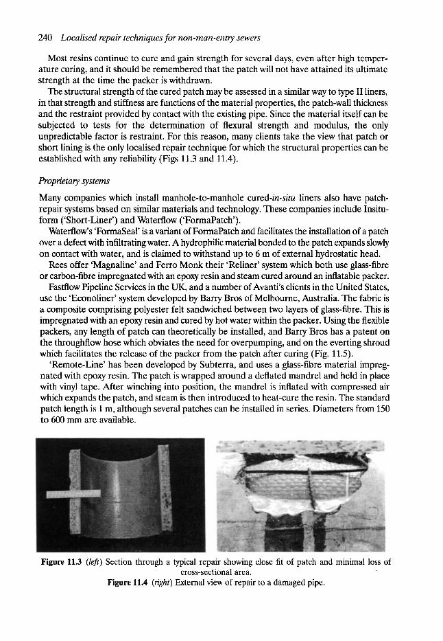
240 Localised repair techniques for non-man-entry sewers
Most resins continue to cure and gain strength for several days, even after high temper- ature curing, and it should be remembered that the patch will not have attained its ultimate strength at the time the packer is withdrawn.
The structural strength of the cured patch may be assessed in a similar way to type II liners, in that strength and stiffness are functions of the material properties, the patch-wall thickness and the restraint provided by contact with the existing pipe. Since the material itself can be subjected to tests for the determination of flexural strength and modulus, the only unpredictable factor is restraint. For this reason, many clients take the view that patch or short lining is the only localised repair technique for which the structural properties can be established with any reliability (Figs 11.3 and 11.4).
Proprietary systems
Many companies which install manhole-to-manhole cured-in-situ liners also have patch- repair systems based on similar materials and technology. These companies include Insitu- form ('Short-Liner') and Waterflow ('FormaPatch').
Waterflow's 'FormaSeal' is a variant of FormaPatch and facilitates the installation of a patch over a defect with infiltrating water. A hydrophilic material bonded to the patch expands slowly on contact with water, and is claimed to withstand up to 6 m of external hydrostatic head.
Rees offer 'Magnaline' and Ferro Monk their 'Reliner' system which both use glass-fibre or carbon-fibre impregnated with an epoxy resin and steam cured around an inflatable packer.
Fastflow Pipeline Services in the UK, and a number of Avanti's clients in the United States, use the 'Econoliner' system developed by Barry Bros of Melbourne, Australia. The fabric is a composite comprising polyester felt sandwiched between two layers of glass-fibre. This is impregnated with an epoxy resin and cured by hot water within the packer. Using the flexible packers, any length of patch can theoretically be installed, and Barry Bros has a patent on the throughflow hose which obviates the need for overpumping, and on the everting shroud which facilitates the release of the packer from the patch after curing (Fig. 11.5).
'Remote-Line' has been developed by Subterra, and uses a glass-fibre material impreg- nated with epoxy resin. The patch is wrapped around a deflated mandrel and held in place with vinyl tape. After winching into position, the mandrel is inflated with compressed air which expands the patch, and steam is then introduced to heat-cure the resin. The standard patch length is 1 m, although several patches can be installed in series. Diameters from 150 to 600 mm are available.
Figure 11.3 (left) Section through a typical repair showing close fit of patch and minimal loss of cross-sectional area.
Figure 11.4 (right) External view of repair to a damaged pipe.
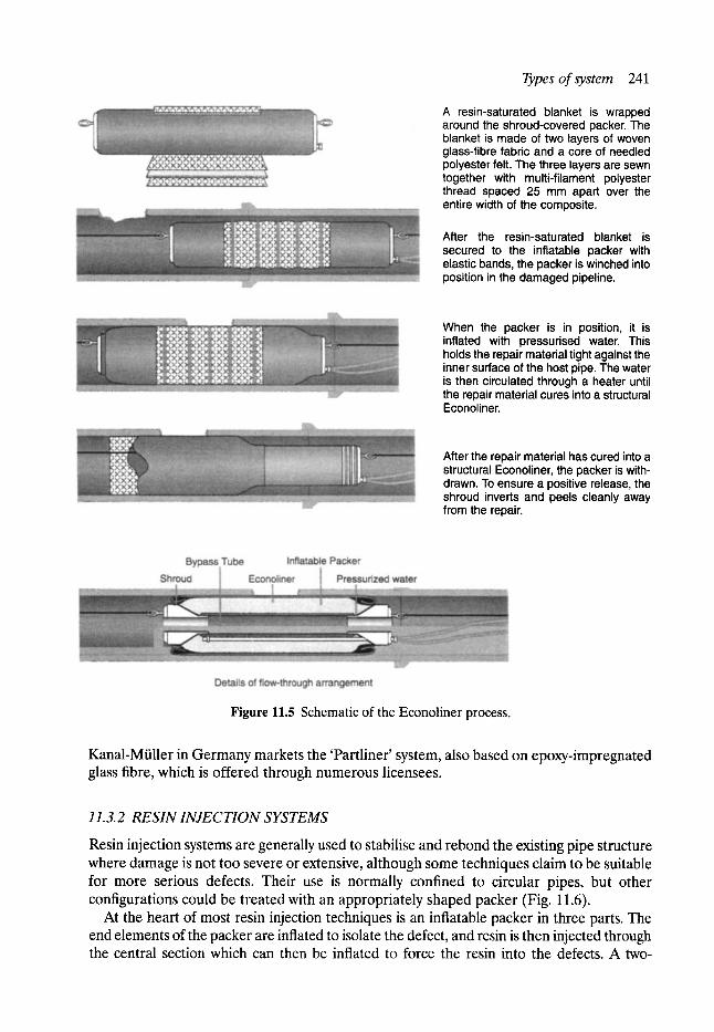
Types of system 241
A resin-saturated blanket is wrapped around the shroud-covered packer. The blanket is made of two layers of woven glass-fibre fabric and a core of needled polyester felt. The three layers are sewn together with multi-filament polyester thread spaced 25 mm apart over the entire width of the composite.
After the resin-saturated blanket is secured to the inflatable packer with elastic bands, the packer is winched into position in the damaged pipeline.
When the packer is in position, it is inflated with pressurised water. This holds the repair material tight against the inner surface of the host pipe. The water is then circulated through a heater until the repair material cures into a structural Econoliner.
After the repair material has cured into a structural Econoliner, the packer is with- drawn. To ensure a positive release, the shroud inverts and peels cleanly away from the repair.
Figure 11.5 Schematic of the Econoliner process.
Kanal-Miiller in Germany markets the 'Partliner' system, also based on epoxy-impregnated glass fibre, which is offered through numerous licensees.
11.3.2 RESIN INJECTION SYSTEMS
Resin injection systems are generally used to stabilise and rebond the existing pipe structure where damage is not too severe or extensive, although some techniques claim to be suitable for more serious defects. Their use is normally confined to circular pipes, but other configurations could be treated with an appropriately shaped packer (Fig. 11.6).
At the heart of most resin injection techniques is an inflatable packer in three parts. The end elements of the packer are inflated to isolate the defect, and resin is then injected through the central section which can then be inflated to force the resin into the defects. A two-
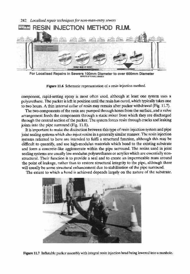
242 Localised repair techniques for non-man-ently sewers
Figure 11.6 Schematic representation of a resin injection method.
component, rapid-setting epoxy is most often used, although at least one system uses a polyurethane. The packer is left in position until the resin has cured, which typically takes one to two hours. A thin internal collar of resin may remain after packer withdrawal (Fig. 11.7).
The two components of the resin are pumped through hoses from the surface, and a valve arrangement feeds the components through a static mixer from which they are discharged through the central section of the packer. The system forces resin through cracks and leaking joints into the pipe surround (Fig. 11.8).
It is important to make the distinction between this type of resin injection system and pipe joint sealing systems which also inject resins in a generally similar manner. The resin injection systems referred to here are intended to fulfil a structural function, although this may be difficult to quantify, and use high-modulus materials which bond to the existing substrate and form a concrete-like agglomerate within the pipe surround. The resins used in joint sealing systems are usually low-modulus polyurethanes or acrylics which are essentially non- structural. Their function is to provide a seal and to create an impermeable mass around the point of leakage, rather than to restore structural integrity to the pipe, although there will usually be some structural enhancement due to stabilisation of the pipe surround.
The extent to which a bond is achieved depends largely on the nature of the substrate.
Figure 11.7 Inflatable packer assembly with integral resin injection head being lowered into a manhole.
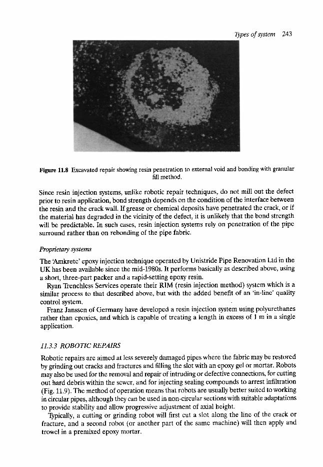
Types of system 243
Figure 11.8 Excavated repair showing resin penetration to external void and bonding with granular fill method.
Since resin injection systems, unlike robotic repair techniques, do not mill out the defect prior to resin application, bond strength depends on the condition of the interface between the resin and the crack wall. If grease or chemical deposits have penetrated the crack, or if the material has degraded in the vicinity of the defect, it is unlikely that the bond strength will be predictable. In such cases, resin injection systems rely on penetration of the pipe surround rather than on rebonding of the pipe fabric.
Proprietary systems
The ~Mnkrete' epoxy injection technique operated by Unistride Pipe Renovation Ltd in the UK has been available since the mid-1980s. It performs basically as described above, using a short, three-part packer and a rapid-setting epoxy resin.
Ryan Trenchless Services operate their RIM (resin injection method) system which is a similar process to that described above, but with the added benefit of an 'in-line' quality control system.
Franz Janssen of Germany have developed a resin injection system using polyurethanes rather than epoxies, and which is capable of treating a length in excess of 1 m in a single application.
11.3.3 ROBOTIC REPAIRS
Robotic repairs are aimed at less severely damaged pipes where the fabric may be restored by grinding out cracks and fractures and filling the slot with an epoxy gel or mortar. Robots may also be used for the removal and repair of intruding or defective connections, for cutting out hard debris within the sewer, and for injecting sealing compounds to arrest infiltration (Fig. 11.9). The method of operation means that robots are usually better suited to working in circular pipes, although they can be used in non-circular sections with suitable adaptations to provide stability and allow progressive adjustment of axial height.
Typically, a cutting or grinding robot will first cut a slot along the line of the crack or fracture, and a second robot (or another part of the same machine) will then apply and trowel in a premixed epoxy mortar.
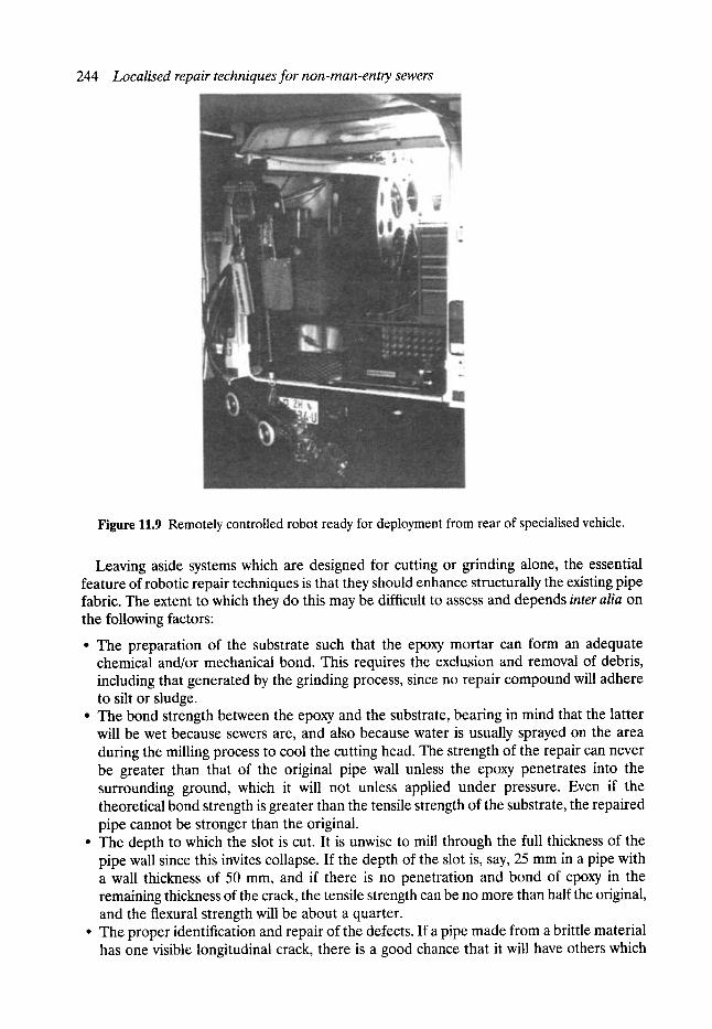
244 Localised repair techniques for non-man-entry sewers
Figure 11.9 Remotely controlled robot ready for deployment from rear of specialised vehicle.
Leaving aside systems which are designed for cutting or grinding alone, the essential feature of robotic repair techniques is that they should enhance structurally the existing pipe fabric. The extent to which they do this may be difficult to assess and depends inter alia on the following factors:
�9 The preparation of the substrate such that the epoxy mortar can form an adequate chemical and/or mechanical bond. This requires the exclusion and removal of debris, including that generated by the grinding process, since no repair compound will adhere to silt or sludge.
�9 The bond strength between the epoxy and the substrate, bearing in mind that the latter will be wet because sewers are, and also because water is usually sprayed on the area during the milling process to cool the cutting head. The strength of the repair can never be greater than that of the original pipe wall unless the epoxy penetrates into the surrounding ground, which it will not unless applied under pressure. Even if the theoretical bond strength is greater than the tensile strength of the substrate, the repaired pipe cannot be stronger than the original.
�9 The depth to which the slot is cut. It is unwise to mill through the full thickness of the pipe wall since this invites collapse. If the depth of the slot is, say, 25 mm in a pipe with a wall thickness of 50 mm, and if there is no penetration and bond of epoxy in the remaining thickness of the crack, the tensile strength can be no more than half the original, and the flexural strength will be about a quarter.
�9 The proper identification and repair of the defects. If a pipe made from a brittle material has one visible longitudinal crack, there is a good chance that it will have others which
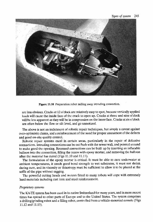
Types of system 245
Figure 11.10 Preparation robot milling away intruding connection.
are less obvious. Cracks at 12 o'clock are relatively easy to spot, because vertically applied loads will cause the inside face of the crack to open up. Cracks at three and nine o'clock will be less apparent as they will be in compression on the inner face. Cracks at six o'clock are often below the flow or silt level, and go unnoticed.
The above is not an indictment of robotic repair techniques, but simply a caveat against over-optimistic claims, and a reinforcement of the need for proper assessment of the defects and good on-site quality control.
Robotic repair systems excel in certain areas, particularly in the repair of defective connections. Intruding connections can be cut flush with the sewer wall, and pointed around to make good the opening. Recessed connections can be built up by inserting an inflatable balloon into the connection, filling the recess with epoxy mortar, and removing the balloon after the material has cured (Figs 11.10 and 11.11).
The formulation of the epoxy mortar is critical. It must be able to cure underwater at ambient temperatures, it needs good bond strength to wet substrates, it must not shrink during cure, and its viscosity or thixotropy must be sufficient to allow it to be placed at the soffit of the pipe without sagging.
The powerful cutting heads and motors fitted to many robots will cope with extremely hard materials including cast iron and steel reinforcement.
Proprietary systems
The KA-TE system has been used in its native Switzerland for many years, and inmore recent times has spread to other parts of Europe and to the United States. The system comprises a drilling/grinding robot and a filling robot, controlled from a vehicle-mounted console (Figs 11.12 and 11.13).
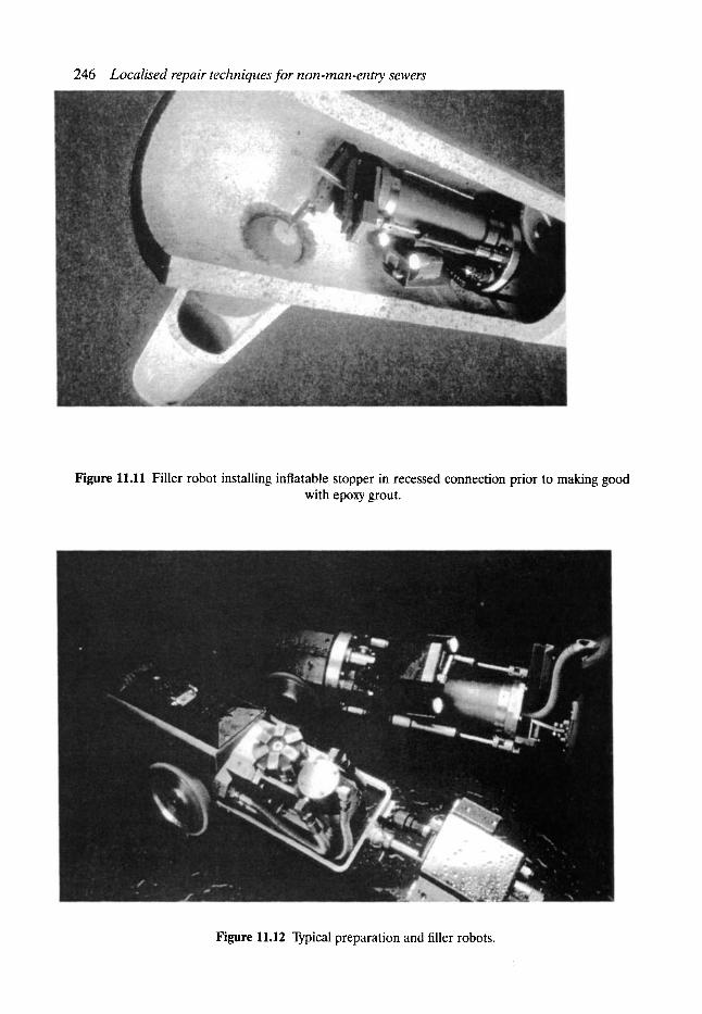
246 Localised repair techniques for non-man-entry sewers
Figure 11.11 Filler robot installing inflatable stopper in recessed connection prior to making good with epoxy grout.
Figure 11.12 Typical preparation and filler robots.
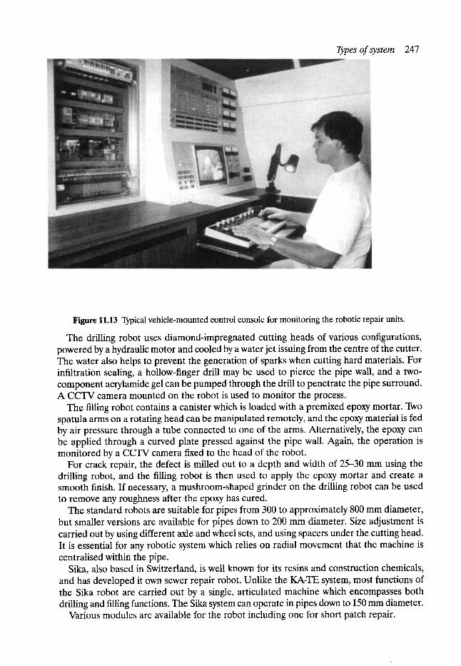
Types of system 247
Figure 11.13 Typical vehicle-mounted control console for monitoring the robotic repair units.
The drilling robot uses diamond-impregnated cutting heads of various configurations, powered by a hydraulic motor and cooled by a water jet issuing from the centre of the cutter. The water also helps to prevent the generation of sparks when cutting hard materials. For infiltration sealing, a hollow-finger drill may be used to pierce the pipe wall, and a two- component acrylamide gel can be pumped through the drill to penetrate the pipe surround. A CCTV camera mounted on the robot is used to monitor the process.
The filling robot contains a canister which is loaded with a premixed epoxy mortar. Two spatula arms on a rotating head can be manipulated remotely, and the epoxy material is fed by air pressure through a tube connected to one of the arms. Alternatively, the epoxy can be applied through a curved plate pressed against the pipe wall. Again, the operation is monitored by a CCTV camera fixed to the head of the robot.
For crack repair, the defect is milled out to a depth and width of 25-30 mm using the drilling robot, and the filling robot is then used to apply the epoxy mortar and create a smooth finish. If necessary, a mushroom-shaped grinder on the drilling robot can be used to remove any roughness after the epoxy has cured.
The standard robots are suitable for pipes from 300 to approximately 800 mm diameter, but smaller versions are available for pipes down to 200 mm diameter. Size adjustment is carried out by using different 'axle and wheel sets, and using spacers under the cutting head. It is essential for any robotic system which relies on radial movement that the machine is centralised within the pipe.
Sika, also based in Switzerland, is well known for its resins and construction chemicals, and has developed it own sewer repair robot. Unlike the KA-TE system, most functions of the Sika robot are carried out by a single, articulated machine which encompasses both drilling and filling functions. The Sika system can operate in pipes down to 150 mm diameter.
Various modules are available for the robot including one for short patch repair.
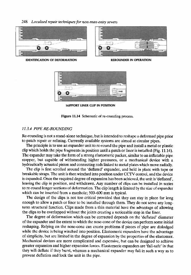
248 Localised repair techniques for non-man-entry sewers
Figure 11.14 Schematic of re-rounding process.
11.3. 4 PIPE RE-ROUNDING
Re-rounding is not a stand-alone technique, but is intended to reshape a deformed pipe prior to patch repair or relining. Currently available systems are aimed at circular pipes.
The principle is to use an expander unit to re-round the pipe and install a metal or plastic clip which holds the pipe fragments in position until a patch or liner is installed (Fig. 11.14). The expander may take the form of a strong elastomeric packer, similar to an inflatable pipe stopper, but capable of withstanding higher pressures, or a mechanical device with a hydraulically actuated piston and connecting rods linked to metal plates which move radially.
The clip is first scrolled around the 'deflated' expander, and held in place with tape or breakable straps. The unit is then winched into position under CCTV control, and the device is expanded. Once the required degree of expansion has been achieved, the unit is 'deflated', leaving the clip in position, and withdrawn. Any number of clips can be installed in series to re-round longer sections of deformation. The clip length is limited by the size of expander which can be inserted from a manhole; 500--600 mm is typical.
The design of the clips is not too critical provided that they can stay in place for long enough to allow a patch or liner to be installed through them. They do not serve any long- term structural function. Clips made from a thin material have the advantage of allowing the clips to be overlapped without the joints creating a noticeable step in the liner.
The degree of deformation which can be corrected depends on the 'deflated' diameter of the expander and the extent to which the nose-cone of the device can perform some initial reshaping. Relying on the nose-cone can create problems if pieces of pipe are dislodged while the device is being winched into position. Elastomeric expanders have the advantage of simplicity, but are limited in the degree of expansion by the properties of the elastomer. Mechanical devices are more complicated and expensive, but can be designed to achieve greater expansion and higher expansion forces. Elastomeric expanders are 'fail-safe' in that they will deflate if they burst, whereas a mechanical expander may fail in such a way as to prevent deflation and lock the unit in the pipe.
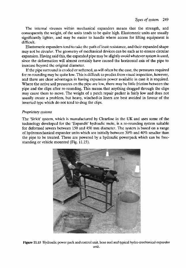
Types of system 249
The internal stresses within mechanical expanders means that the strength, and consequently the weight, of the units tends to be quite high. Elastomeric units are usually significantly lighter, and may be easier to handle where access for lifting equipment is difficult.
Elastomeric expanders tend to take the path of least resistance, and their expanded shape may not be circular. The geometry of mechanical devices can be such as to ensure circular expansion. Having said this, the expanded pipe may be slightly ovoid whatever system is used, since the deformation will almost certainly have caused the horizontal axis of the pipe to increase beyond the original diameter.
If the pipe surround is eroded or softened, as will often be the case, the pressures required for re-rounding may be quite low. This is difficult to predict from visual inspection, however, and there are clear advantages in having expansion power available in case it is required. Where the active soil pressures on the pipe are low, there may be little friction between the pipe and the clips after re-rounding. This means that anything dragged through the clips may cause them to move. The weight of a patch repair packer is fairly low and does not usually create a problem, but heavy, winched-in liners are best avoided in favour of the inverted type which do not tend to drag the clips.
Proprietary systems
The 'Sirkit' system, which is manufactured by Clearline in the UK and uses some of the technology developed for the 'Expandit' hydraulic mole, is a re-rounding system suitable for deformed sewers between 150 and 450 mm diameter. The system is based on a range of hydromechanical expander units which are initially between 30% and 40% smaller than the pipe to be treated. These are powered by a hydraulic powerpack which can be free- standing or vehicle mounted (Fig. 11.15).
Figure 11.15 Hydraulic power pack and control unit, hose reel and typical hydro-mechanical expander unit.
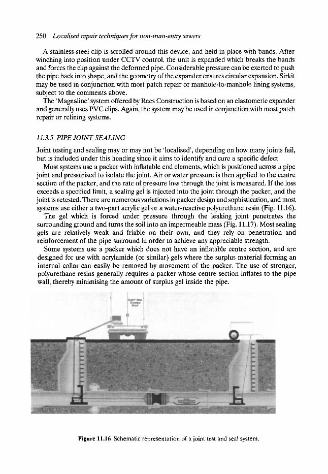
250 Localised repair techniques for non-man-enrcy sewers
A stainless-steel clip is scrolled around this device, and held in place with bands. After winching into position under CCTV control, the unit is expanded which breaks the bands and forces the clip against the deformed pipe. Considerable pressure can be exerted to push the pipe back into shape, and the geometry of the expander ensures circular expansion. Sirkit may be used in conjunction with most patch repair or manhole-to-manhole lining systems, subject to the comments above.
The 'Magnaline' system offered by Rees Construction is based on an elastomeric expander and generally uses PVC clips. Again, the system may be used in conjunction with most patch repair or relining systems.
11.3.5 PIPE JOINT SEALING
Joint testing and sealing may or may not be 'localised', depending on how many joints fail, but is included under this heading since it aims to identify and cure a specific defect.
Most systems use a packer with inflatable end elements, which is positioned across a pipe joint and pressurised to isolate the joint. Air or water pressure is then applied to the centre section of the packer, and the rate of pressure loss through the joint is measured. If the loss exceeds a specified limit, a sealing gel is injected into the joint through the packer, and the joint is retested. There are numerous variations in packer design and sophistication, and most systems use either a two-part acrylic gel or a water-reactive polyurethane resin (Fig. 11.16).
The gel which is forced under pressure through the leaking joint penetrates the surrounding ground and turns the soil into an impermeable mass (Fig. 11.17). Most sealing gels are relatively weak and friable on their own, and they rely on penetration and reinforcement of the pipe surround in order to achieve any appreciable strength.
Some systems use a packer which does not have an inflatable centre section, and are designed for use with acrylamide (or similar) gels where the surplus material forming an internal collar can easily be removed by movement of the packer. The use of stronger, polyurethane resins generally requires a packer whose centre section inflates to the pipe wall, thereby minimising the amount of surplus gel inside the pipe.
Figure 11.16 Schematic representation of a joint test and seal system.
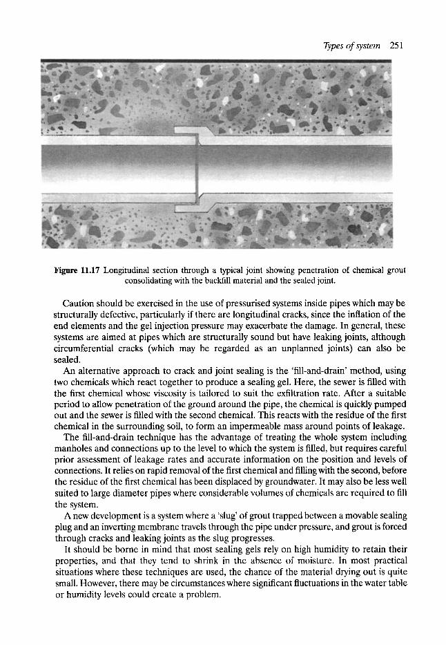
Types of system 251
Figure 11.17 Longitudinal section through a typical joint showing penetration of chemical grout consolidating with the backfill material and the sealed joint.
Caution should be exercised in the use of pressurised systems inside pipes which may be structurally defective, particularly if there are longitudinal cracks, since the inflation of the end elements and the gel injection pressure may exacerbate the damage. In general, these systems are aimed at pipes which are structurally sound but have leaking joints, although circumferential cracks (which may be regarded as an unplanned joints) can also be sealed.
An alternative approach to crack and joint sealing is the 'fill-and-drain' method, using two chemicals which react together to produce a sealing gel. Here, the sewer is filled with the first chemical whose viscosity is tailored to suit the exfiltration rate. After a suitable period to allow penetration of the ground around the pipe, the chemical is quickly pumped out and the sewer is filled with the second chemical. This reacts with the residue of the first chemical in the surrounding soil, to form an impermeable mass around points of leakage.
The fill-and-drain technique has the advantage of treating the whole system including manholes and connections up to the level to which the system is filled, but requires careful prior assessment of leakage rates and accurate information on the position and levels of connections. It relies on rapid removal of the first chemical and filling with the second, before the residue of the first chemical has been displaced by groundwater. It may also be less well suited to large diameter pipes where considerable volumes of chemicals are required to fill the system.
A new development is a system where a 'slug' of grout trapped between a movable sealing plug and an inverting membrane travels through the pipe under pressure, and grout is forced through cracks and leaking joints as the slug progresses.
It should be borne in mind that most sealing gels rely on high humidity to retain their properties, and that they tend to shrink in the absence of moisture. In most practical situations where these techniques are used, the chance of the material drying out is quite small. However, there may be circumstances where significant fluctuations in the water table or humidity levels could create a problem.
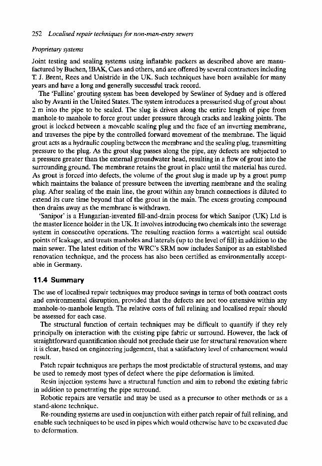
252 Localised repair techniques for non-man-entry sewers
Proprietary systems
Joint testing and sealing systems using inflatable packers as described above are manu- factured by Buchen, IBAK, Cues and others, and are offered by several contractors including T. J. Brent, Rees and Unistride in the UK. Such techniques have been available for many years and have a long and generally successful track record.
The 'Fulline' grouting system has been developed by Sewliner of Sydney and is offered also by Avanti in the United States. The system introduces a pressurised slug of grout about 2 rn into the pipe to be sealed. The slug is driven along the entire length of pipe from manhole.to manhole to force grout under pressure through cracks and leaking joints. The grout is locked between a moveable sealing plug and the face of an inverting membrane, and traverses the pipe by the controlled forward movement of the membrane. The liquid grout acts as a hydraulic coupling between the membrane and the sealing plug, transmitting pressure to the plug. As the grout slug passes along the pipe, any defects are subjected to a pressure greater than the external groundwater head, resulting in a flow of grout into the surrounding ground. The membrane retains the grout in place until the material has cured. As grout is forced into defects, the volume of the grout slug is made up by a grout pump which maintains the balance of pressure between the inverting membrane and the sealing plug. After sealing of the main line, the grout within any branch connections is diluted to extend its cure time beyond that of the grout in the main. The excess grouting compound then drains away as the membrane is withdrawn.
'Sanipor' is a Hungarian-invented fill-and-drain process for which Sanipor (UK) Ltd is the master licence holder in the UK. It involves introducing two chemicals into the sewerage system in consecutive operations. The resulting reaction forms a watertight seal outside points of leakage, and treats manholes and laterals (up to the level of fill) in addition to the main sewer. The latest edition of the WRC's SRM now includes Sanipor as an established renovation technique, and the process has also been certified as environmentally accept- able in Germany.
11.4 Summary The use of localised repair techniques may produce savings in terms of both contract costs and environmental disruption, provided that the defects are not too extensive within any manhole-to-manhole length. The relative costs of full relining and localised repair should be assessed for each case.
The structural function of certain techniques may be difficult to quantify if they rely principally on interaction with the existing pipe fabric or surround. However, the lack of straightforward quantification should not preclude their use for structural renovation where it is clear, based on engineering judgement, that a satisfactory level of enhancement would result.
Patch repair techniques are perhaps the most predictable of structural systems, and may be used to remedy most types of defect where the pipe deformation is limited.
Resin injection systems have a structural function and aim to rebond the existing fabric in addition to penetrating the pipe surround.
Robotic repairs are versatile and may be used as a precursor to other methods or as a stand-alone technique.
Re-rounding systems are used in conjunction with either patch repair of full relining, and enable such techniques to be used in pipes which would otherwise have to be excavated due to deformation.

Directory 253
Most joint testing and sealing systems aim to prevent infiltration and exfiltration in otherwise sound pipes, but will generate some structural enhancement through stabilisation and sealing of the pipe surround.
11.5 Directory Amkrete (UK) Ltd, Unit 69, Vale Business Park, Llandow, Cowbridge, South Glamorgan CF7 7PF,
UK. Tel: +44 (0)1446 775919. Fax: +44 (0)446 773613. Avanti International, 822 Bay Star Boulevard, Webster, TX 77598-1528, USA. Tel: + 1 713 486 5600.
Fax: + 1 713 486 7300. Barry Bros Specialised Services Pty Ltd, PO Box 274, 10- 16 Geddes Street, Mulgrave 3170, Victoria,
Australia, Tel: +61 3 9574 9988. Fax: +61 3 9574 9987. Buchen SIS Inc., 4200 Norex Drive, Chaska, MN 55318, USA. Tel: + 1 612 368 7400. Fax: + 1 612 368
7401. Clearline Services Ltd, Holmbush House, Holmbush Way, Midhurst, West Sussex GU29 9XY, UK.
Tel: +44 (0)1730 815455. Fax: +44 (0)1730 815684. Fastflow Pipeline Services Ltd, Castle House, Dunn Street, Newcastle upon Tyne NE4 7AL, UK.
Tel: +44 (0)191 272 3671. Fax: +44 (0)191 272 3349. Ferro Monk Systems Ltd, Peckfield, Great North Road, South Milford, Leeds LS25 5LH, UK.
Tel: +44 (0)1977 681777. Fax: +44 (0)1977 681888. Franz Janssen GmbH, Prostewardsweg 27, 4192 Kalkar-Wissel, Germany. Tel: +49 2824 60 51.
Fax: +49 2824 60 54. Insituform Technologies Inc., 1770 Kirby Parkway, Suite 300, Memphis, TN 38138, USA. Tel: + 1 901
759 7473. Fax: + 1 901 759 7500. Kanal Muller Gruppe, Am Oekerberg 3, D-32816 Schieder-Schwalenberg, Germany. Tel: +49 5284
7050. Fax: +49 5284 70582. KA-TE System AG, Leimbachstrasse 38, CH-8041 Zurich, Switzerland. Tel: +41 1 482 8888. Fax: +41
1 482 8978 Rees Construction Services Ltd, Blackwater Way, Ash Road, Aldershot GU12 4DG, UK. Tel: +44
(0)1252 345469. Fax: +44 (0)1252 345470. Ryan Trenchless Services, Inglewhite Road, Longridge, Preston PR3 2DA, UK. Tel: +44 (0)1772
783545. Fax: +44 (0)1772 784977. Sanipor (UK) Ltd, Gatcombe House, Hilsea, Portsmouth, Hampshire, PO2 0TU, UK. Tel: +44
(0) 1705 694900. Fax: + 44 (0) 1705 690606. SikaRobotics AG, Industriestrasse, CH-8627 Gruningen, Switzerland. Tel: +41 1 936 13 50. Fax: +41
1 935 26 89. Subterra Ltd, Dullar Lane, Sturminster Marshall, Wimborne, Dorset BH21 4DA, UK. Tel: +44
(0)1258 857556. Fax: +44 (0)1258 857960. Unistride Pipe Renovation Ltd, Red Lion House, Bentley, Farnham, Surrey GU10 5HY, UK. Tel: +44
(0)1420 23456. Fax: +44 (0)1420 22712. Waterflow Services Ltd, 14-16 David Road, Poyle Trading Estate, Colnbrook SL3 0DG, UK. Tel: + 44
(0)181 848 3030. Fax: +44 (0)1753 681442.

12 Structural Aspects of Sewer Rehabilitation
lan G. Vickridge BSc, MSc. MICE, MCIWEM. MUKSTT
12.1 Introduction
As with all underground pipelines, sewers must withstand the loads imposed by the sur- rounding soil and water pressure as well as from traffic and buildings on the surface. These loading conditions can change dramatically over the years, and many sewers are subjected to higher loads than those originally anticipated when they were first installed. The fabric of the sewer will inevitably deteriorate over time through abrasion, chemical attack, damage from tree root intrusion, and poorly made lateral connections, as well as loss of soil support and additional loads. Before a suitable rehabilitation technique can be selected, it is neces- sary to understand the mechanisms that cause sewer deterioration and failure in order that the visual information gathered during sewer surveys can be interpreted correctly. The structural strength of the renovated sewer will be dependent on the thickness and material of the lining, and the amount of support provided to the lining by the old sewer and surrounding soil. This chapter explores both the way in which the structural integrity of sewers deteriorates with time and some of the methods currently in use for the structural design of sewer linings.
12.2 Structural defects and their causes
Structural defects in sewers can be caused by a wide variety of factors and, whilst some may occur during or shortly after the time of construction, others may not develop until many years later. What might appear to be a small localised defect initially can be the cause of the onset of accelerated deterioration of large sections of the sewer as a whole. In assessing the structural condition of a sewer, it is therefore important to understand how defects are caused and to recognise the long-term implications of both minor and significant defects.
One of the most commonly noted defects in sewers is that of longitudinal cracks which invariably occur along the top or soffit of the pipe (12 o'clock), the bottom or invert (6 o'clock) and the springings (3 and 9 o'clock). This failure mechanism is the classic ring bending failure, as illustrated in Fig. 12.1, and is caused by general overload or lack of soil support. Where pipes exhibit this form of defect soon after construction, it is probable that errors have been made in the design and specification, or that the construction has been poorly carried out. Defects of this kind occurring some time after the completion of construction may also be due to poor construction, particularly inadequate compaction of
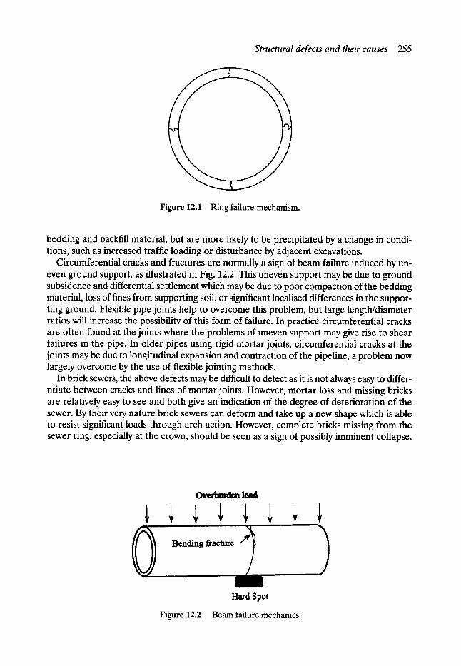
Structural defects and their causes 255
Figure 12.1 Ring failure mechanism.
bedding and backfill material, but are more likely to be precipitated by a change in condi- tions, such as increased traffic loading or disturbance by adjacent excavations.
Circumferential cracks and fractures are normally a sign of beam failure induced by un- even ground support, as illustrated in Fig. 12.2. This uneven support may be due to ground subsidence and differential settlement which may be due to poor compaction of the bedding material, loss of fines from supporting soil, or significant localised differences in the suppor- ting ground. Flexible pipe joints help to overcome this problem, but large length/diameter ratios will increase the possibility of this form of failure. In practice circumferential cracks are often found at the joints where the problems of uneven support may give rise to shear failures in the pipe. In older pipes using rigid mortar joints, circumferential cracks at the joints may be due to longitudinal expansion and contraction of the pipeline, a problem now largely overcome by the use of flexible jointing methods.
In brick sewers, the above defects may be difficult to detect as it is not always easy to differ- ntiate between cracks and lines of mortar joints. However, mortar loss and missing bricks are relatively easy to see and both give an indication of the degree of deterioration of the sewer. By their very nature brick sewers can deform and take up a new shape which is able to resist significant loads through arch action. However, complete bricks missing from the sewer ring, especially at the crown, should be seen as a sign of possibly imminent collapse.
~ lolld
i
Hard Spot
Figure 12.2 Beam failure mechanics.
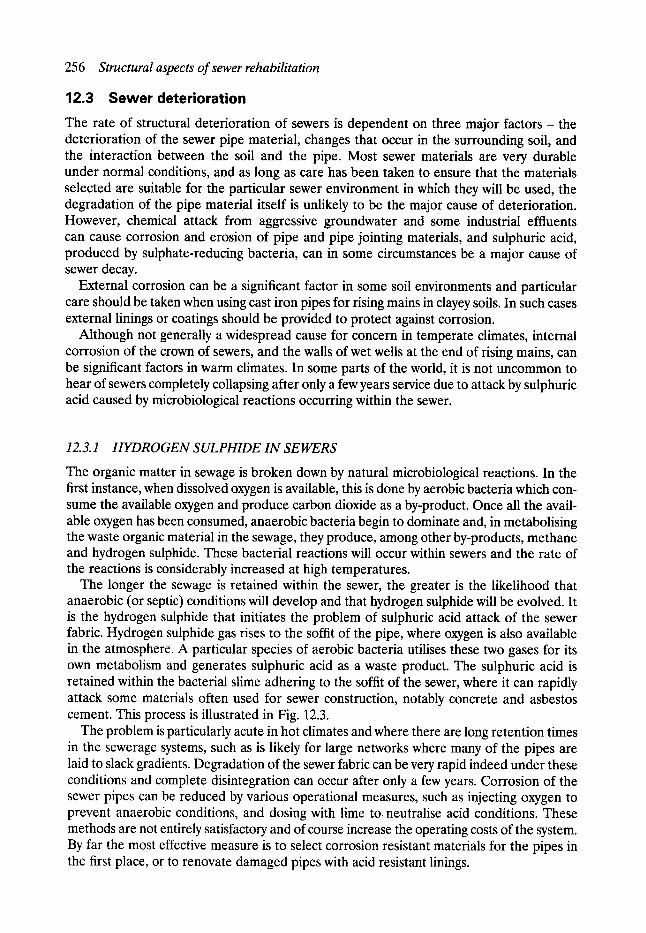
256 Structural aspects of sewer rehabilitation
12.3 Sewer deterioration The rate of structural deterioration of sewers is dependent on three major factors - the deterioration of the sewer pipe material, changes that occur in the surrounding soil, and the interaction between the soil and the pipe. Most sewer materials are very durable under normal conditions, and as long as care has been taken to ensure that the materials selected are suitable for the particular sewer environment in which they will be used, the degradation of the pipe material itself is unlikely to be the major cause of deterioration. However, chemical attack from aggressive groundwater and some industrial effluents can cause corrosion and erosion of pipe and pipe jointing materials, and sulphuric acid, produced by sulphate-reducing bacteria, can in some circumstances be a major cause of sewer decay.
External corrosion can be a significant factor in some soil environments and particular care should be taken when using cast iron pipes for rising mains in clayey soils. In such cases external linings or coatings should be provided to protect against corrosion.
Although not generally a widespread cause for concern in temperate climates, internal corrosion of the crown of sewers, and the walls of wet wells at the end of rising mains, can be significant factors in warm climates. In some parts of the world, it is not uncommon to hear of sewers completely collapsing after only a few years service due to attack by sulphuric acid caused by microbiological reactions occurring within the sewer.
12.3.1 HYDROGEN SULPHIDE IN SEWERS
The organic matter in sewage is broken down by natural microbiological reactions. In the first instance, when dissolved oxygen is available, this is done by aerobic bacteria which con- sume the available oxygen and produce carbon dioxide as a by-product. Once all the avail- able oxygen has been consumed, anaerobic bacteria begin to dominate and, in metabolising the waste organic material in the sewage, they produce, among other by-products, methane and hydrogen sulphide. These bacterial reactions will occur within sewers and the rate of the reactions is considerably increased at high temperatures.
The longer the sewage is retained within the sewer, the greater is the likelihood that anaerobic (or septic) conditions will develop and that hydrogen sulphide will be evolved. It is the hydrogen sulphide that initiates the problem of sulphuric acid attack of the sewer fabric. Hydrogen sulphide gas rises to the soffit of the pipe, where oxygen is also available in the atmosphere. A particular species of aerobic bacteria utilises these two gases for its own metabolism and generates sulphuric acid as a waste product. The sulphuric acid is retained within the bacterial slime adhering to the soffit of the sewer, where it can rapidly attack some materials often used for sewer construction, notably concrete and asbestos cement. This process is illustrated in Fig. 12.3.
The problem is particularly acute in hot climates and where there are long retention times in the sewerage systems, such as is likely for large networks where many of the pipes are laid to slack gradients. Degradation of the sewer fabric can be very rapid indeed under these conditions and complete disintegration can occur after only a few years. Corrosion of the sewer pipes can be reduced by various operational measures, such as injecting oxygen to prevent anaerobic conditions, and dosing with lime to neutralise acid conditions. These methods are not entirely satisfactory and of course increase the operating costs of the system. By far the most effective measure is to select corrosion resistant materials for the pipes in the first place, or to renovate damaged pipes with acid resistant linings.
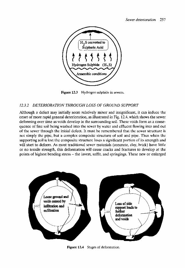
Figure 12.3 Hydrogen sulphide in sewers.
Sewer deterioration 257
12.3.2 DETERIORATION THROUGH LOSS OF GROUND SUPPORT
Although a defect may initially seem relatively minor and insignificant, it can induce the onset of more rapid general deterioration, as illustrated in Fig. 12.4, which shows the sewer deforming over time as voids develop in the surrounding soil. These voids form as a conse- quence of fine soil being washed into the sewer by water and effluent flowing into and out of the sewer through the initial defect. It must be remembered that the sewer structure is not simply the pipe, but a complex composite structure of soil and pipe. Thus when the supporting soil is lost the composite structure loses a significant portion of its strength and will start to deform. As most traditional sewer materials (concrete, clay, brick) have little or no tensile strength, this deformation will cause cracks and fractures to develop at the points of highest bending s t ress- the invert, soffit, and springings. These new or enlarged
Loose grouad and voids caused by ~ o n and exfilm~on I
Figure 12.4 Stages of deformation.
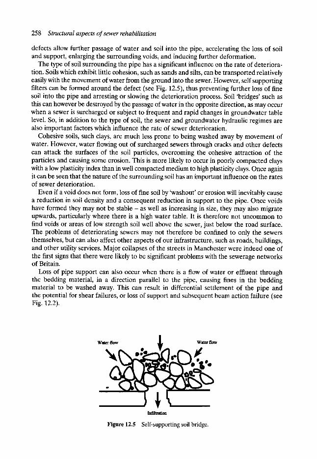
258 Structural aspects of sewer rehabilitation
defects allow further passage of water and soil into the pipe, accelerating the loss of soil and support, enlarging the surrounding voids, and inducing further deformation.
The type of soil surrounding the pipe has a significant influence on the rate of deteriora- tion. Soils which exhibit little cohesion, such as sands and silts, can be transported relatively easily with the movement of water from the ground into the sewer. However, self supporting filters can be formed around the defect (see Fig. 12.5), thus preventing further loss of fine soil into the pipe and arresting or slowing the deterioration process. Soil 'bridges' such as this can however be destroyed by the passage of water in the opposite direction, as may occur when a sewer is surcharged or subject to frequent and rapid changes in groundwater table level. So, in addition to the type of soil, the sewer and groundwater hydraulic regimes are also important factors which influence the rate of sewer deterioration.
Cohesive soils, such clays, are much less prone to being washed away by movement of water. However, water flowing out of surcharged sewers through cracks and other defects can attack the surfaces of the soil particles, overcoming the cohesive attraction of the particles and causing some erosion. This is more likely to occur in poorly compacted clays with a low plasticity index than in well compacted medium to high plasticity clays. Once again it can be seen that the nature of the surrounding soil has an important influence on the rates of sewer deterioration.
Even if a void does not form, loss of fine soil by 'washout' or erosion will inevitably cause a reduction in soil density and a consequent reduction in support to the pipe. Once voids have formed they may not be stable - as well as increasing in size, they may also migrate upwards, particularly where there is a high water table. It is therefore not uncommon to find voids or areas of low strength soil well above the sewer, just below the road surface. The problems of deteriorating sewers may not therefore be confined to only the sewers themselves, but can also affect other aspects of our infrastructure, such as roads, buildings, and other utility services. Major collapses of the streets in Manchester were indeed one of the first signs that there were likely to be significant problems with the sewerage networks of Britain.
Loss of pipe support can also occur when there is a flow of water or effluent through the bedding material, in a direction parallel to the pipe, causing fines in the bedding material to be washed away. This can result in differential settlement of the pipe and the potential for shear failures, or loss of support and subsequent beam action failure (see Fig. 12.2).
w
l l l f l l l l '~ l iol l
Figure 12.5 Self-supporting soil bridge.
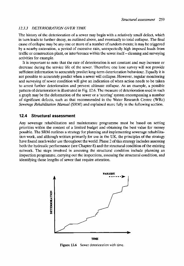
Structural assessment 259
12.3.3 DETERI01~ TION OVER TIME
The history of the deterioration of a sewer may begin with a relatively small defect, which in turn leads to further decay, as outlined above, and eventually to total collapse. The final cause of collapse may be any one or more of a number of random events; it may be triggered by a nearby excavation, a period of excessive rain, unexpectedly high imposed loads from traffic or construction plant, or interference within the sewer itself-cleaning and surveying activities for example.
It is important to note that the rate of deterioration is not constant and may increase or decrease during the service life of the sewer. Therefore one lone survey will not provide sufficient information to accurately predict long-term deterioration behaviour. Equally it is not possible to accurately predict when a sewer will collapse. However, regular monitoring and surveying of sewer condition will give an indication of when action needs to be taken to arrest further deterioration and prevent ultimate collapse. As an example, a possible pattern of deterioration is illustrated in Fig. 12.6. The measure of deterioration used in such a graph may be the deformation of the sewer or a 'scoring' system encompassing a number of significant defects, such as that recommended in the Water Research Centre (WRc) Sewerage Rehabilitation Manual (SRM) and explained more fully in the following section.
12.4 Structural assessment
Any sewerage rehabilitation and maintenance programme must be based on setting priorities within the context of a limited budget and obtaining the best value for money possible. The SRM outlines a strategy for planning and implementing sewerage rehabilita- tion work, and although written primarily for use in the UK, the principles of the strategy have found much wider use throughout the world. Phase 2 of this strategy includes assessing both the hydraulic performance (see Chapter 8) and the structural condition of the existing network. The steps involved in assessing the structural condition include planning an inspection programme, carrying out the inspections, assessing the structural condition, and identifying those lengths of sewer that require attention.
lrAIl, IJltJg
S f
J v
Figure 12.6 Sewer deterioration with time.
260 Structural aspects of sewer rehabilitation
12. 4.1 PLANNING THE INSPECTION
As with carrying out the rehabilitation work itself, it is clearly not possible to survey an entire sewerage network at any one time and therefore priorities must be set. The SRM strategy addresses this question by proposing a methodology for identifying 'critical sewers'. These critical sewers are those that would cause severe disruption to the operation of the system or to the road traffic above if the sewer were to collapse, and those that would incur high costs to repair or replace in the event of such a collapse. The priorities are therefore based not on the likelihood of failure (which cannot be determined until after a survey has been made), but on the consequences of failure.
The criteria for identifying the most critical sewers (Category A) are clearly laid out in Step 1.2 of the SRM and include the following:
brick sewers more than 2 m deep pipe sewers in good ground more than 6 m deep pipe sewers in bad ground more than 5 m deep any surface water or combined sewer more than 1500 mm diameter any foul water sewer more than 600 mm diameter. any sewer under an important traffic route (> 7500 vehicles per day) any sewer whose failure would disrupt hospital traffic any sewer under railways, canals, rivers, motorways, buildings, main shopping streets, primary access to industrial sites.
Similar criteria are identified for less critical sewers, which are termed Categories B and C in the SRM.
The categorisation of sewers in this way provides a basis for setting priorities as to which sewers should be surveyed first. Depending on the budget that is available, a sewerage authority or company could for example decide to survey only Category A sewers in the first instance. The method of gathering information on the sewers will normally be by closed- circuit television (CCTV) inspection, details of which can be found Chapter 5 of this book, although manual inspections of large sewers may also be a possibility.
In planning the inspection programme, consideration should be given to scheduling the work before the hydraulic assessment is carried out. The reason for this is that valuable information on the overall layout of the network, the roughness of the pipes, and the levels of silt and other obstructions to flow may be incorporated in the hydraulic model. It should also be noted that a certain amount of ancillary work may need to be carried out before or in conjunction with the survey itself. This might include, for example, constructing or enlarg- ing access shafts and cleaning and desilting the sewers. In some cases it may not be possible to get a CCTV camera through the sewer because of obstructions or collapses, and equip- ment to remove such obstructions may therefore be required. It is important that this equipment is available if severe delays to the survey are to be avoided.
12.4.2 VISUAL ASSESSMENT OF THE STRUCTURAL CONDITION
The assessment of the structural condition of sewers is mainly done through the inter- pretation and analysis of visual information in the context of a knowledge of the various modes of failure and deterioration outlined previously in this chapter. The visual information is normally in the form of videotape recorded during the CCTV survey. CCTV surveys generate a vast amount of visual information (a 10 km line survey might generate 30 h of
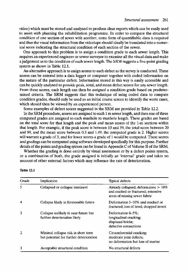
Structural assessment 261
video) which must be stored and analysed to produce clear reports which can be easily used to assist with planning the rehabilitation programme. In order to compare the structural condition of one section of sewer with another, some form of quantifiable data is required and thus the visual information from the videotape should ideally be translated into a numer- ical score indicating the structural condition of each section of the sewer.
One approach to this problem is to assign a condition grade to each sewer length. This requires an experienced engineer or sewer surveyor to examine all the visual data and make a judgement as to the condition of each sewer length. The SRM suggests a five-point grading system as shown in Table 12.1.
An alternative approach is to assign scores to each defect as the survey is conducted. These scores can be entered into a data logger or computer together with coded information on the nature of the particular defect. Information stored in this way is easily accessible and can be quickly analysed to provide peak, total, and mean defect scores for any sewer length. From these scores, each length can then be assigned a condition grade based on predeter- mined criteria. The SRM suggests that this technique of using coded data to compute condition grades, should only be used as an initial coarse screen to identify the worst cases, which should then be viewed by an experienced person.
Some examples of defect scores suggested in the SRM are provided in Table 12.2. In the SRM procedure, scores are assigned to each 1 m sewer length, and then one of three
computed grades are assigned to each manhole to manhole length. These grades are based on the total score for that length and the peak and mean scores of the 1-m sections within that length. For example, if the peak score is between 10 and 59, the total score between 20 and 99, and the mean score between 0.3 and 1.49, the computed grade is 2. Higher scores will warrant a grade of 3, and for lower scores a grade of 1 would be computed. These scores and gradings can be computed using software developed specifically for this purpose. Further details of the points and grading system can be found in Appendix C of Volume II of the SRM.
Whether the grading is done entirely by visual assessment or by a defect points system, or a combination of both, the grade assigned is initially an 'internal' grade and takes no account of other external factors which may influence the rate of deterioration.
Table 12.1
Grade Implication Typical defects
Collapsed or collapse imminent
Collapse likely in foreseeable future
Collapse unlikely in near future but further deterioration likely
Minimal collapse risk in short term but potential for further deterioration
Acceptable structural condition
Already collapsed; deformation > 10% and cracked or fractured; extensive areas of missing sewer fabric
Deformation 5-10% and cracked or fractured; loss of level; dropped invert
Deformation 0-5 %; longitudinal cracking; displaced bricks; defective connections
Circumferential cracking; moderate joint defects; no deformation but loss of mortar
No structural defects
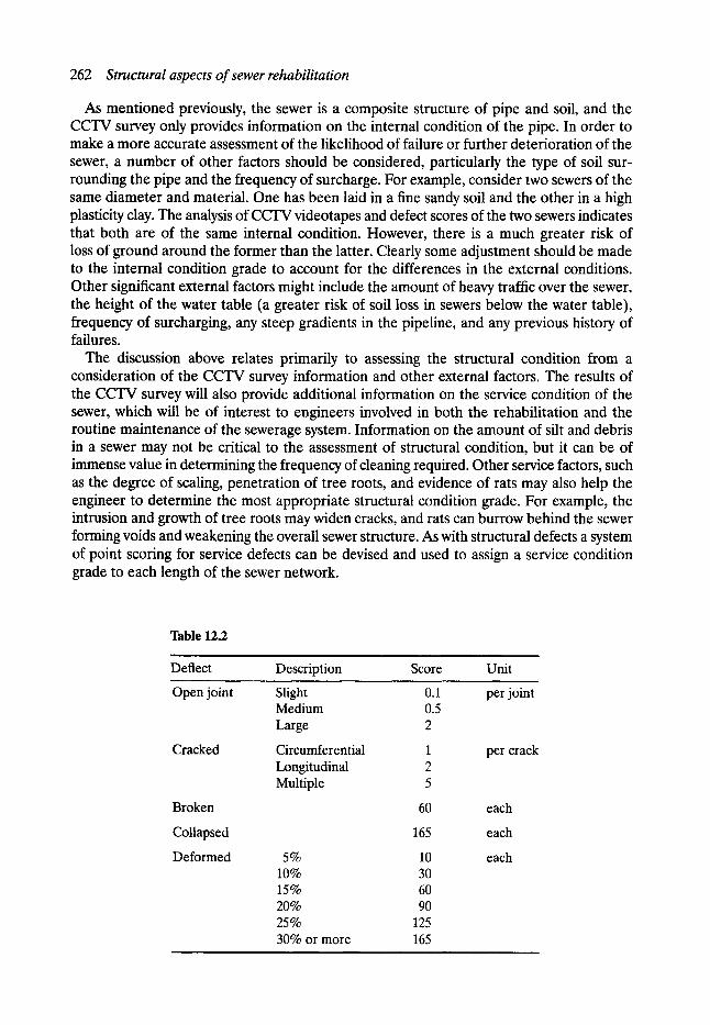
262 Structural aspects of sewer rehabilitation
As mentioned previously, the sewer is a composite structure of pipe and soil, and the CCTV survey only provides information on the internal condition of the pipe. In order to make a more accurate assessment of the likelihood of failure or further deterioration of the sewer, a number of other factors should be considered, particularly the type of soil sur- rounding the pipe and the frequency of surcharge. For example, consider two sewers of the same diameter and material. One has been laid in a fine sandy soil and the other in a high plasticity clay. The analysis of CCTV videotapes and defect scores of the two sewers indicates that both are of the same internal condition. However, there is a much greater risk of loss of ground around the former than the latter. Clearly some adjustment should be made to the internal condition grade to account for the differences in the external conditions. Other significant external factors might include the amount of heavy traffic over the sewer, the height of the water table (a greater risk of soil loss in sewers below the water table), frequency of surcharging, any steep gradients in the pipeline, and any previous history of failures.
The discussion above relates primarily to assessing the structural condition from a consideration of the CCTV survey information and other external factors. The results of the CCTV survey will also provide additional information on the service condition of the sewer, which will be of interest to engineers involved in both the rehabilitation and the routine maintenance of the sewerage system. Information on the amount of silt and debris in a sewer may not be critical to the assessment of structural condition, but it can be of immense value in determining the frequency of cleaning required. Other service factors, such as the degree of scaling, penetration of tree roots, and evidence of rats may also help the engineer to determine the most appropriate structural condition grade. For example, the intrusion and growth of tree roots may widen cracks, and rats can burrow behind the sewer forming voids and weakening the overall sewer structure. As with structural defects a system of point scoring for service defects can be devised and used to assign a service condition grade to each length of the sewer network.
Table 12.2
Deflect
Open joint
Cracked
Broken
Collapsed
Deformed
Description Score Unit
Slight 0.1 per joint Medium 0.5 Large 2
Circumferential 1 per crack Longitudinal 2 Multiple 5
60
165
5% 10 10% 30 15% 60 20% 90 25% 125 30% or more 165
each
each
each
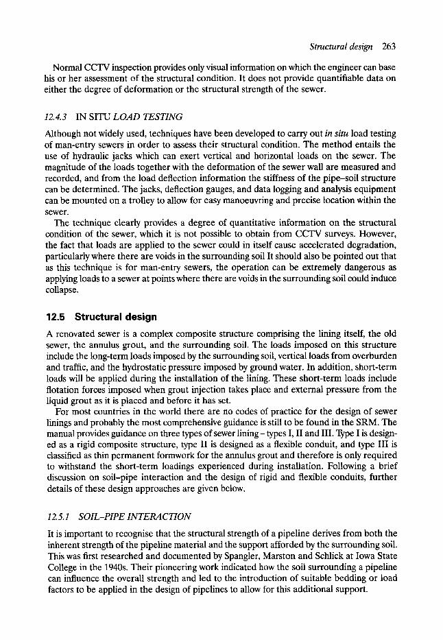
Structural design 263
Normal CCTV inspection provides only visual information on which the engineer can base his or her assessment of the structural condition. It does not provide quantifiable data on either the degree of deformation or the structural strength of the sewer.
12.4.3 IN SITU LOAD TESTING
Although not widely used, techniques have been developed to carry out in situ load testing of man-entry sewers in order to assess their structural condition. The method entails the use of hydraulic jacks which can exert vertical and horizontal loads on the sewer. The magnitude of the loads together with the deformation of the sewer wall are measured and recorded, and from the load deflection information the stiffness of the pipe-soil structure can be determined. The jacks, deflection gauges, and data logging and analysis equipment can be mounted on a trolley to allow for easy manoeuvring and precise location within the sewer.
The technique clearly provides a degree of quantitative information on the structural condition of the sewer, which it is not possible to obtain from CCTV surveys. However, the fact that loads are applied to the sewer could in itself cause accelerated degradation, particularly where there are voids in the surrounding soil It should also be pointed out that as this technique is for man-entry sewers, the operation can be extremely dangerous as applying loads to a sewer at points where there are voids in the surrounding soil could induce collapse.
12.5 Structural design A renovated sewer is a complex composite structure comprising the lining itself, the old sewer, the annulus grout, and the surrounding soil. The loads imposed on this structure include the long-term loads imposed by the surrounding soil, vertical loads from overburden and traffic, and the hydrostatic pressure imposed by ground water. In addition, short-term loads will be applied during the installation of the lining. These short-term loads include flotation forces imposed when grout injection takes place and external pressure from the liquid grout as it is placed and before it has set.
For most countries in the world there are no codes of practice for the design of sewer linings and probably the most comprehensive guidance is still to be found in the SRM. The manual provides guidance on three types of sewer lining- types I, II and III. Type I is design- ed as a rigid composite structure, type II is designed as a flexible conduit, and type III is classified as thin permanent formwork for the annulus grout and therefore is only required to withstand the short-term loadings experienced during installation. Following a brief discussion on soil-pipe interaction and the design of rigid and flexible conduits, further details of these design approaches are given below.
12. 5.1 SOIL-PIPE 1NTERA C TION
It is important to recognise that the structural strength of a pipeline derives from both the inherent strength of the pipeline material and the support afforded by the surrounding soil. This was first researched and documented by Spangler, Marston and Schlick at Iowa State College in the 1940s. Their pioneering work indicated how the soil surrounding a pipeline can influence the overall strength and led to the introduction of suitable bedding or load factors to be applied in the design of pipelines to allow for this additional support.

264 Structural aspects of sewer rehabilitation
Provided that voids have not formed as previously described, a sewer that has been in the ground for a considerable time will be surrounded by soil that has compacted naturally over a long period of time, thus providing a greater amount of lateral support than would be provided to a pipe newly installed by conventional trenching and backfilling. The value of renovation, rather than replacement by open trench methods, and the importance of retaining the hole in the ground, can therefore be seen in the context of greater structural strength and stability of the pipeline as well as reduced disruption at the surface.
The interaction between the soil and pipe is complex and not fully understood, but it is known that these two elements work together to resist the applied loads. The extensive amount of sewer survey data now available shows that there are numerous instances where severely cracked circular pipes have maintained a roughly ovoid shape, without totally collapsing, because of the support provided by the soil. Similarly, engineers can cite examples of sewers with bricks missing from the soffit, where the surrounding soil can be seen to bridge the gaps by natural arch action.
As previously described, one of the major causes of sewer deterioration is infiltration and exfiltration, leading to the formation of voids. The sealing of cracks and joints is a recognised technique to prevent further deterioration caused by this phenomenon. However, little is really known of how voids form and what happens to them once the cracks have been sealed. It would seem possible that voids will fill, reduce in size, and migrate, leaving a body of soil surrounding the pipe to gradually reconsolidate, thus further enhancing the ability of the pipe to sustain loads.
There is therefore a need for further research in order to fully understand these complex soil-pipe interactions, as these have a bearing on not only new pipeline design, but also on the design of sewer lining systems.
12.5. 2 RIGID AND FLEXIBLE PIPES
A brief discussion of the differences between rigid and flexible conduits is pertinent to the design of sewer linings, which are also available in both rigid and flexible materials. In essence, the difference between the two is in their mode of failure - rigid pipes will normally fail through excessive shear or bending stresses at relatively low deflections, whereas flexible pipes fail by buckling at large deflections. The design procedures for the two types of conduit are therefore quite different. Although the load carrying capacity of both types of pipe relies on the inherent material strength and the lateral support of the soil, rigid pipes rely more heavily on their inherent strength together with some support from active soil pressure, whilst flexible pipes generally have a lower inherent strength, deform more, and derive substantial support from passive soil pressure.
The design of a rigid pipe is based on calculating the allowable vertical load carrying capa- city of the pipe from the diameter, pipe wall thickness, ring bending stress, and the load factor. A suitable factor of safety is applied. The design of flexible pipes uses formulae which relate the allowable deflection to the applied vertical load, the pipe stiffness, and the embedment stiffness, which is dependent on the type of soil and the degree of compaction. Thus the rigid pipe design is stress limited whilst the flexible pipe design is strain limited.
12.5.3 DESIGN FOR SHORT-TERM INSTALLATION LOADS
Apart from when tight fit linings (such as 'cured-in-place') are used, it is normal to fill the annulus between the old pipe and the new lining with a suitable grout. This provides lateral
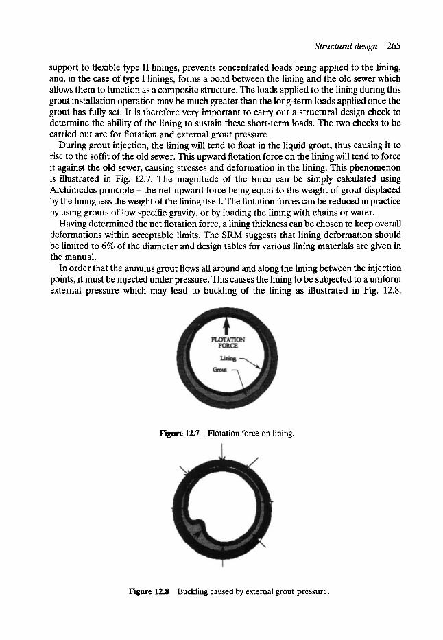
Structural design 265
support to flexible type II linings, prevents concentrated loads being applied to the lining, and, in the case of type I linings, forms a bond between the lining and the old sewer which allows them to function as a composite structure. The loads applied to the lining during this grout installation operation may be much greater than the long-term loads applied once the grout has fully set. It is therefore very important to carry out a structural design check to determine the ability of the lining to sustain these short-term loads. The two checks to be carried out are for flotation and external grout pressure.
During grout injection, the lining will tend to float in the liquid grout, thus causing it to rise to the soffit of the old sewer. This upward flotation force on the lining will tend to force it against the old sewer, causing stresses and deformation in the lining. This phenomenon is illustrated in Fig. 12.7. The magnitude of the force can be simply calculated using Archimedes principle - the net upward force being equal to the weight of grout displaced by the lining less the weight of the lining itself. The flotation forces can be reduced in practice by using grouts of low specific gravity, or by loading the lining with chains or water.
Having determined the net flotation force, a lining thickness can be chosen to keep overall deformations within acceptable limits. The SRM suggests that lining deformation should be limited to 6% of the diameter and design tables for various lining materials are given in the manual.
In order that the annulus grout flows all around and along the lining between the injection points, it must be injected under pressure. This causes the lining to be subjected to a uniform external pressure which may lead to buckling of the lining as illustrated in Fig. 12.8.
Figure 12.7 Flotation force on lining.
Figure 12.8 Buckling caused by external grout pressure.
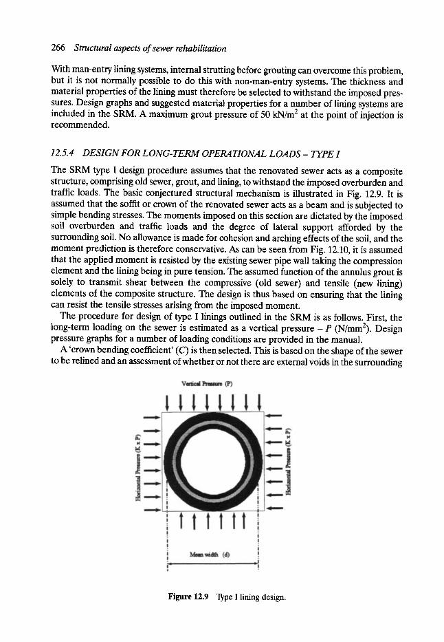
266 Structural aspects of sewer rehabilitation
With man-entry lining systems, internal strutting before grouting can overcome this problem, but it is not normally possible to do this with non-man-entry systems. The thickness and material properties of the lining must therefore be selected to withstand the imposed pres- sures. Design graphs and suggested material properties for a number of lining systems are included in the SRM. A maximum grout pressure of 50 kN/m 2 at the point of injection is recommended.
12.5.4 D E S I G N FOR L O N G - T E R M OPERATIONAL LOADS - TYPE I
The SRM type I design procedure assumes that the renovated sewer acts as a composite structure, comprising old sewer, grout, and lining, to withstand the imposed overburden and traffic loads. The basic conjectured structural mechanism is illustrated in Fig. 12.9. It is assumed that the soffit or crown of the renovated sewer acts as a beam and is subjected to simple bending stresses. The moments imposed on this section are dictated by the imposed soil overburden and traffic loads and the degree of lateral support afforded by the surrounding soil. No allowance is made for cohesion and arching effects of the soil, and the moment prediction is therefore conservative. As can be seen from Fig. 12.10, it is assumed that the applied moment is resisted by the existing sewer pipe wall taking the compression element and the lining being in pure tension. The assumed function of the annulus grout is solely to transmit shear between the compressive (old sewer) and tensile (new lining) elements of the composite structure. The design is thus based on ensuring that the lining can resist the tensile stresses arising from the imposed moment.
The procedure for design of type I linings outlined in the SRM is as follows. First, the long-term loading on the sewer is estimated as a vertical pressure - P (N/mm2). Design pressure graphs for a number of loading conditions are provided in the manual.
A 'crown bending coefficient' (C) is then selected. This is based on the shape of the sewer to be relined and an assessment of whether or not there are external voids in the surrounding
Figure 12.9 Type I lining design.
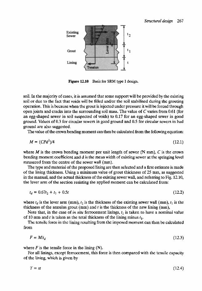
Structural design 267
Figure 12.10 Basis for SRM type I design.
soil. In the majority of cases, it is assumed that some support will be provided by the existing soil or due to the fact that voids will be filled and/or the soil stabilised during the grouting operation. This is because when the grout is injected under pressure it will be forced through open joints and cracks into the surrounding soil mass. The value of C varies from 0.61 (for an egg-shaped sewer in soil suspected of voids) to 0.17 for an egg-shaped sewer in good ground. Values of 0.3 for circular sewers in good ground and 0.5 for circular sewers in bad ground are also suggested.
The value of the crown bending moment can then be calculated from the following equation:
M = (CPd2)/4 (12.1)
where M is the crown bending moment per unit length of sewer (N mm), C is the crown bending moment coefficient and d is the mean width of existing sewer at the springing level measured from the centre of the sewer wall (mm).
The type and material of the proposed lining are then selected and a first estimate is made of the lining thickness. Using a minimum value of grout thickness of 25 mm, as suggested in the manual, and the actual thickness of the existing sewer wall, and referring to Fig. 12.10, the lever arm of the section resisting the applied moment can be calculated from:
t d = 0.67t 2 + t 1 + 0.5t (12.2)
where td is the lever arm (mm), t 2 is the thickness of the existing sewer wall (mm), t 1 is the thickness of the annulus grout (ram) and t is the thickness of the new lining (mm),
Note that, in the case of in situ ferrocement linings, t 1 is taken to have a nominal value of 10 mm and t is taken as the total thickness of the lining minus t 1.
The tensile force in the lining resulting from the imposed moment can then be calculated from
F = M/ta (12.3)
where F is the tensile force in the lining (N). For all linings, except ferrocement, this force is then compared with the tensile capacity
of the lining, which is given by
T = st (12.4)
268 Structural aspects of sewer rehabilitation
where T is the tensile capacity of the lining (N) and s is the maximum long-term tensile stress in the lining (N/mm2).
In the case of ferrocement linings, the required area of steel can be calculated from:
h s t -" (F/ fs ) • F o S (12.5)
where Ast is the required area of steel (mm2), f~ is the maximum allowable steel stress (the SRM recommends 200 N/mm 2 to avoid cracking) and FoS is the factor of safety (the SRM recommends 1.25 for ferrocement linings).
Values for the maximum long-term tensile stress (or long-term tensile strength) for various sewer lining materials are provided in the SRM. These maximum stresses are based on the breaking stresses for most materials, although the maximum allowable stress for glass- reinforced plastic (GRP) linings is based on limiting the stress to that required to induce a strain of 0.05%. The allowable stresses quoted in the SRM are double the actual values due to the fact that the design procedure incorporates a factor of safety of two for all linings other than ferrocement.
A simple check to assess whether T/F is greater than or equal to 2 should therefore be made. If the factor of safety is less than 2, the design should be repeated using either a stronger sewer lining material or one of greater thickness. The design is iterated until a satisfactory factor of safety is achieved.
The composite action of the relined sewer relies on a sufficient bond between the grout and the existing sewer, and also between the grout and the new lining, to transmit horizontal shear bond stresses between the old sewer and the new lining. Laboratory tests indicate that the maximum shear bond stress that can be developed between sewer lining material and grout is of the order of 1 N/mm 2 (Vickridge, 1989). It should be noted that the capacity to transmit this stress is highly dependent on the external roughness of the lining and some lining materials, such as GRP, require a rough outer layer to be applied during manufacture.
The latest edition of the SRM suggests that a value of 0.68 N/mm 2 should be used as the maximum allowable shear bond stress. The SRM assumes that shear bond between the old sewer and the grout is adequately provided for by the physical keys that are formed as the grout sets in between cracks and joints in the existing sewer wall. In order that the capacity to transmit shear is not exceeded, the early editions of the SRM limited the allowable tensile stress in the lining to a maximum value of 160/t regardless of the lining material. This procedure was based on limiting the shear bond stress to an acceptable value in a 600 mm diameter sewer. However, it was later felt that this approach was too conservative for the larger man-entry sewers, and the latest edition of the SRM therefore incorporates a revised procedure whereby a limiting value of 0.267wJt (N/mm 2) (where w~ is the width of the lining at the springings) is used as the upper limit for the allowable long-term tensile stress in the lining. So when determining T in equation (12.4), a check should be made on the value of s to ensure that it does not exceed this maximum of 0.267ws/t.
12.5.5 DESIGN FOR LONG-TERM OPERATIONAL LOADS - TYPE H
Where confidence in the effectiveness of grouting to transmit shear forces is lacking, the SRM suggests that design should be based on a different set of criteria to that used in the procedures outlined previously for type I linings. The SRM type II design method assumes that this transmission of shear stresses cannot be guaranteed for non-man-entry sewers or
Structural design 269
for close-fit linings. The type II approach is thus based on designing the lining as a flexible pipe, but making some allowance for lateral support from the existing pipe and surround- ing grout by the inclusion of ' enhancement' factors, which are analogous to 'bedding' factors in conventional flexible pipe design. The assumption is therefore that the lining itself acts as a flexible pipe and eventually bears the full load imposed from overburden, traffic, and water pressure - but the existing pipe, grout, and soil provide lateral support. The design procedure is simplified to a consideration of the external water pressure on the lining, with safe heads of water for different materials and a variety of thicknesses being tabulated in the manual. These safe heads of water include an allowance for enhancement from the existing soil-pipe structure and any annulus grouting.
The safe loads on a flexible pipe will be determined to some extent by the initial shape of the pipe - a circular pipe being more resistant to buckling than an ovoid or egg-shaped pipe. Circular linings may be deformed during the installation process due to flotation during grouting as detailed previously, and the safe head of water on the lining will be limited by the deformed shape of the lining after installation. The design procedure therefore requires the forces and the deformation occurring during installation to be calculated before using the 'safe head of water' tables given in the manual.
The rationale behind the SRM type II approach is that because there cannot be complete confidence in the grouting operation or, in the case of close-fit linings, there will always be cracks and defects in the old sewer, the lining may be subjected to the full pressure of water from the surrounding ground water table. The design is therefore based on ensuring that the lining can withstand this pressure making due allowance for the enhancement provided by the surrounding pipe and grout. Two modes of failure are possible - maximum allowable pipe stress being exceeded or excessive deformation and buckling.
The design procedure for type II linings is as follows. First, the design head of water is chosen. This should be based on past records and/or borehole investigations, making due allowance for the fact that, in relining the sewer, it is likely that the water table will rise as a consequence of cracks and defects being sealed and it will therefore no longer act as a land drain. If the lining is circular, safe heads of water are tabulated in the SRM for different lining materials and a range of initial deformations. It is therefore simply a matter of selecting an appropriate lining material and size from the tables.
However, if the original sewer is non-circular, a slightly more complicated design approach is outlined. A suitable lining material and thickness is first selected for an initial design check and the 'critical length' is determined. In the case of egg-shaped sewers, the critical length is defined as w or 2/3h, whichever is the greater, where w is the width at the widest part of the cross-section of the lining, and h is the height. For oval-shaped sewers the critical length is w or h - w, whichever is greater, where again w is the width and h is the height of the cross-section.
The stress limited safe head of water is then calculated from the following
H1 = 340Sm(t/l) 2 (12.6)
where H 1 is the safe external head of water limited by stress (m), SL is the long-term permissible bending stress (N/mm 2) and I is the critical length (m) - as defined above.
Values for the long-term permissible bending stress for a variety of sewer lining materials are given in the manual.
To ensure that long-term deflections will not exceed permissible values, a second check on the safe head of water is carried out as follows:
270 Structural aspects of sewer rehabilitation
HE = R236EL(t/l) 3 (12.7)
where H2 is the safe external head limited by deflection (m), R = 1 (for egg-shaped sewers having a curved critical length) and R = 0.5 (for oval-shaped sewers having a straight critical length), EL is the long-term circumferential bending modulus (N/mm 2) and t is the thickness of the lining (mm).
The design is deemed satisfactory if both the safe head limited by stress and the safe head limited by deflection are greater than the design head which was initially chosen. If this is not the case, the calculations should be repeated using a different lining thickness or material.
12.5.6 ISSUES RELATING TO STRUCTURAL DESIGN
When it was first published in 1984, the SRM provided comprehensive and much needed advice to engineers involved in the rehabilitation and maintenance of sewers in the UK. The manual has served drainage engineers well since that time and many of the principles embodied in it have been incorporated into the codes and practices of other countries. How- ever, the very use of these principles has highlighted certain areas of inconsistency where improvements could now be made.
For example, the SRM design procedures explained above are both based on an assump- tion that the existing sewer contributes to the load-carrying capacity of the renovated sewer. Type I, which is only applicable to man-entry pipes, is based on forming a composite structure between the old sewer and the new lining, whilst in the type II design procedure it is assumed that the old existing pipe provides the required lateral support to the new flexible lining. Thus both design procedures imply reliance on the old sewer to provide some of the struc- tural strength of the rehabilitated sewer.
A fundamental factor influencing the choice of renovation systems is the expected service life or durability of the renovated pipe. In evaluating a number of rehabilitation options, some assessment should be made of the expected life of each option if a cost-effective solution is to be chosen. Although accepting that it is extremely difficult to rank the service lives of both new and traditional materials in a particular sewer environment with any degree of precision, the SRM did provide general guidelines. However, SRM guidance on the life expectancy of relined sewers is based solely on the renovation system and does not take into account the condition of the existing sewer - even though the structural design is based on the existing sewer carrying some of the load.
There is therefore a need to review the design procedures and set them in the context of the expected life of the renovated sewer - which would include considerations of both the renovation technique and materials, as well as the condition of the existing sewer.
12.6 Future research and development needs Structural assessment of sewers using CC-qW data is as much an art as a science, and requires the services of experienced and trained engineers and technicians. Information relating to the surrounding soil must be deduced from visual evidence, and thus requires a good understanding of the behaviour of the soil-pipe composite structure and the causes of structural deterioration and deformation. Further developments in methods to obtain more quantitative information on the actual deformations, strength and stiffness of sewers will greatly assist all those involved in managing renovation and rehabilitation programmes.

References 271
Ideally, non-destructive methods should be used because of the risk of causing additional damage to the sewer fabric.
The behaviour of the soil-pipe composite structure over time is still not fully understood. When a sewer is renovated, the composite structure is even more complex in that an additional element is introduced. In order to maximise the long-term value of these underground assets, further research is required to provide a better understanding of these complex interactions between the soft, pipe, and lining, and hence determine design solutions which are both structurally adequate and cost-effective.
References Jones, G. M. A. The Structural Deterioration of Sewers, International Conference on the Planning,
Construction, maintenance, and Operation of Sewerage Systems, University of Reading, 12-14 September 1984, BHRA Fluid Engineering Centre, 1984.
Vickridge, I. Sewer linings- a comparative study of shear bond strength between GRC and GRP linings and the annulus grout. The Glass Fibre Reinforced Cement Association, 7th Biennial Congress, September, 1989.
WRc/WAA. Sewerage Rehabilitation Manual (editions in 1984, 1986 and 1994).
13 Assessment of Renovation
Techniques and Costs
Geoffrey F. Read MSc, CEng, FICE, FlStructE, FCIWEM, FIHT, MILE, FIMgt, MAE, MUKSTT
13.1 Introduction An engineer facing the problem of correcting a failing pipeline underneath a busy highway has a number of basic options available. First a solution must be chosen which will meet the technical criteria and project needs. Then these options have to be assessed for their local suitability. Also, the direct and indirect effects (or social costs) on the community and environment must be considered.
Finally, at the third stage consideration must be given to relative costs. However inexpen- sive a possible solution might appear if it is inadequate in such matters as technical perfor- mance, durability or third party effects it will be an expensive solution in the long term. The total costs must also be compared on a lifecycle basis and not just on initial construction costs.
It should be remembered that renovation is only one of the options to be considered in any sewerage improvement programme. Rehabilitation has, in fact, been defined, in the UK's Water Research Centre (WRc) Sewerage Rehabilitation Manual (SRM), as covering all aspects of upgrading the performance of existing sewerage systems and, therefore, includes repair, renovation and renewal. Renovation is not a panacea- merely an important option worthy of consideration at the outset - in fact, when the manual was launched, the message coming across from WRc was not renovation or renewal but rather 'has renovation been considered as an option?' The SRM has provided a great deal of detail for the design of renovation schemes and is an excellent common sense treatise on the subject for which WRc is to be congratulated, although it does not offer any fundamentally dramatic new concepts. It was intended to provide a framework for decision making which is consistent and technically justifiable, while still allowing the necessary flexibility for drainage engineers to apply personal judgement in particular situations. 'Renovation' is defined in the manual as 'methods by which the performance of a length of sewer is improved by incorporating the original sewer fabric but excluding maintenance operations such as isolated local repair and root or silt removal'.
Rather than a scheme being 'problem orientated' the starting point of the SRM strategy is a review of the complete drainage area followed by a fundamental reassessment of the network as a whole from which it is assumed related problems will emerge. Thebulk of the cost is nearly always associated with a few problems in the core area. These usually have wide impact on performance elsewhere in the network, are difficult to resolve and tend to result in significant disruption and inconvenience to the community. This wide feasibility study approach will, undoubtedly, necessitate the involvement of additional staff at the
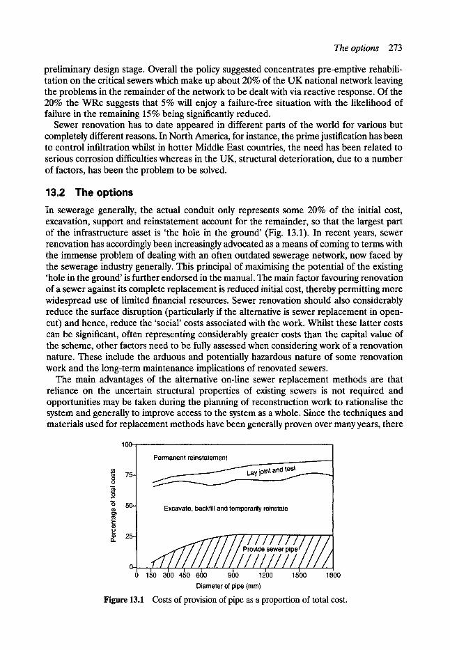
The options 273
preliminary design stage. Overall the policy suggested concentrates pre-emptive rehabili- tation on the critical sewers which make up about 20% of the UK national network leaving the problems in the remainder of the network to be dealt with via reactive response. Of the 20% the WRc suggests that 5% will enjoy a failure-free situation with the likelihood of failure in the remaining 15% being significantly reduced.
Sewer renovation has to date appeared in different parts of the world for various but completely different reasons. In North America, for instance, the prime justification has been to control infiltration whilst in hotter Middle East countries, the need has been related to serious corrosion difficulties whereas in the UK, structural deterioration, due to a number of factors, has been the problem to be solved.
13.2 T h e o p t i o n s
In sewerage generally, the actual conduit only represents some 20% of the initial cost, excavation, support and reinstatement account for the remainder, so that the largest part of the infrastructure asset is 'the hole in the ground' (Fig. 13.1). In recent years, sewer renovation has accordingly been increasingly advocated as a means of coming to terms with the immense problem of dealing with an often outdated sewerage network, now faced by the sewerage industry generally. This principal of maximising the potential of the existing 'hole in the ground' is further endorsed in the manual. The main factor favouring renovation of a sewer against its complete replacement is reduced initial cost, thereby permitting more widespread use of limited financial resources. Sewer renovation should also considerably reduce the surface disruption (particularly if the alternative is sewer replacement in open- cut) and hence, reduce the 'social' costs associated with the work. Whilst these latter costs can be significant, often representing considerably greater costs than the capital value of the scheme, other factors need to be fully assessed when considering work of a renovation nature. These include the arduous and potentially hazardous nature of some renovation work and the long-term maintenance implications of renovated sewers.
The main advantages of the alternative on-line sewer replacement methods are that reliance on the uncertain structural properties of existing sewers is not required and opportunities may be taken during the planning of reconstruction work to rationalise the system and generally to improve access to the system as a whole. Since the techniques and materials used for replacement methods have been generally proven over many years, there
100-
75- O tO
o 50-
l - ID
�9 25- I1.
O-
Permanent reinstatement nt and test
,
Excavate, backfill and temporarily reinstate
' 'p r/ov,//de//se/we//r p/p/e /
0 150 300 450 600 900 1200 1500 1800 Diameter of pipe (mm)
Figure 13.1 Costs of provision of pipe as a proportion of total cost.
274 Assessment of renovation techniques and costs
tends to be greater confidence in the long-term performance of the works. Although the established lining techniques, namely glass-reinforced concrete (GRC), glass-reinforced plastic (GRP), gunite, ferrocement, soft linings, polyethylene and PRC can now confidently be designed for 50-year lives, when the manual design procedures are followed and in theory, financial analysis can also allow for replacement costs at the end of this period.
It became clear to the Editor in the early stages of the 'collapse era' in Manchester, that some form of internal lining or permanent formwork to strengthen the old sewers needed urgent examination in an endeavour to preserve, if possible, parts of the network which had not deteriorated too far and hence, much development work was carried out both on site and in the department's laboratory, utilising the various materials then available. As a result, since 1979, many miles of sewer in the city centre have been rehabilitated, some by renovation, others being replaced. In the same period similar renovation works have also been carried out in suburban areas.
When selecting appropriate renewal methods (whether renovation or replacement) an assessment of the adequacy of the existing sewer is required; first, to determine its hydraulic carrying capacity for present and future needs (some renovation methods may significantly reduce sewer cross-sectional areas) and, secondly, to assess the condition of the existing sewer structure with regard, both to its short-term integrity for carrying out inspection and investigation and possible renovation work from within it and its longer term viability as part of the sewerage system. For this latter assessment, historical knowledge of the develop- ment of the system and the construction methods adopted is essential for an appreciation of the constraints imposed by the existing sewer conditions.
Renovation is frequently claimed to be a much quicker process than on-line recon- struction. While this is undoubtedly true of the formed in-place linings (resin impregnated felt) and slip lining and similar techniques, the differences are not always so clear-cut for some of the other renovation methods.
13.3 Safety and welfare Working within a sewer of uncertain structural integrity is always hazardous. The risks are further increased if movement is restricted by the confined working conditions frequently found in sewer renovation schemes on smaller sewers.
Safety factors to be assessed in such conditions are:
1. The psychological problems which may arise from working in confined spaces. 2. The difficulty of getting out of a sewer in an emergency, e.g. if the sewer collapses, a flood
or harmful discharge occurs or, if a dangerous atmosphere is detected. 3. The difficulty of mounting a rescue operation for workers trapped in a sewer. 4. The closeness to and unavoidable contact with potentially hazardous materials, e.g. skin
burns caused by cementitious grouts, the inhalation of dust from drilling and cutting operations and fumes from resinous plastics, the possibility of contracting Weil's disease because of increased contact with sewage.
Similarly, the unpleasantness of sewer work is increased when the working space is confined. Welfare conditions to be assessed include:
1. The need for adequate washing and changing facilities to be provided. 2. The recognition of the feelings of frustration experienced by workers who expend the
greater part of their energies in mere physical movement within the sewer rather than in carrying out productive work.
Sewer rehabilitation - the Manchester experience 275
3. The recognition that working procedures are likely to be inefficient and that frequent breaks in the working shift may be required.
These safety and welfare factors highlight the need for effective alarm/communication systems between the workplace and the surface level, the need for effective arrangements for dealing with flows and, the necessity for detailed planning of the works (including advance surveys) so that the extent of the work to be carried out underground from one point of access is minimised.
In addition many of the materials themselves such as chemicals used in sewer renovation work can be toxic, flammable, irritating to human skin or internal organs or otherwise harmful to persons. The system of working should deal specifically with the precautions to be taken when handling, storing and using hazardous materials underground. Processes may also generate dust and fumes. A careful check should be made on the levels of harmful atmospheric contaminants and appropriate remedial measures taken where necessary.
It should be remembered that safety and welfare considerations also apply to the super- vising staff.
In the Editor's experience few problems have materialised on the larger sewers where the work is not dissimilar from normal tunnelling work; but on smaller sewers, where full shift working was carried out in finished section sizes of 850-650 mm (vertical) and 670-400 mm (horizontal), some of the size-related problems have been acute to say the least.
Fortunately, no serious accidents on renovation schemes have been reported but the risks are always present. Burns from contact with grout are common; and on one site in Manchester, the renovation teams often showered and changed clothing three times a shift!
The exceptional unpleasantness and discomfort of the work has shown itself by high absen- teeism and the difficulties contractors have found in attracting and retaining labour, even though the rates of pay offered have been similar to the high rates earned by tunnel miners.
When the general trend in society has been towards reducing hazards at work and improv- ing working conditions, the conditions presented by attempting renovation work on the smaller sewers on the accepted border line between man-entry and non-man-entry may be regarded as a retrograde step.
13.4 Sewer rehabilitation- the Manchester experience The Manchester experience indicated that the minimum finished vertical dimension should be no less than 900 mm if renovation by manual methods is contemplated, although the SRM gives the following sizes: man-entry sewers- those above 900 mm vertical height; man- accessible sewers- those between 500 and 900 mm vertical height; and even suggests that segmental linings can be installed in 'man-accessible' sewers.
The Health and Safety Executive has nevertheless recommended that persons should not normally enter sewers of dimensions smaller than 0.9 m high by 0.6 m wide in nominal size. Even this, 'minimum size' may in certain circumstances (e.g. if there is a long distance between access points or silting-up of the sewer invert) be too small to enable a safe system of work to be put into operation.
In a number of cases, the decision has to be made after careful consideration of all the factors, not to attempt to renovate the sewer but to reconstruct completely.
Clearly, this is a combination of safety, practical consideration, economics and engineer- ing judgement. In Manchester city centre, where replacement has often been the only option, this necessitated tunnel construction rather than in open cut, when account has been taken of the full social costs, including those of traffic delays and diversions.
276 Assessment of renovation techniques and costs
In the smaller sewers, it may not be appreciated just how difficult the working conditions can be and safety conditions alone may call for sewer replacement rather than renovation.
In considering the economics of the situation it can be argued that a completely recon- structed sewer probably has a longer life than a renovated one, especially since connections are more readily made and more effectively protected from further collapse.
It is felt that when the effective life span of a renovated sewer has been reached, there will normally be no alternative to the replacement by a new sewer but time will tell.
Considering all the factors which influence the selection of renewal methods, such as mode of sewer construction and surrounding ground, depth below ground level and the location of the sewer relative to other aspects of the environment - it is clearly not possible to arrive at a 'standard' solution applicable to all situations; the choice for each particular sewer length must be taken on its merit by civil engineers experienced in this specialist field.
However, sufficient experience was gained of renewal work in Manchester during the early 1980s for guidelines to be suggested for assessing the feasibility of renovation methods. Renovation methods within the criteria laid down in the manual are acceptable for the larger man-entry sewers but the condition and size of the earlier and smaller man accessible sewers make renovation by manual labour completely unacceptable.
The prospects are better in these sewers for the use of renovation techniques relying on remote installation arrangements (e.g. soft lining, slip-lining and impact moling). For sub- man-entry sewers however, these techniques do not offer any means of positively dealing with voids external to the sewer and this is considered a serious disadvantage when dealing with the early brick sewers and the open-jointed clayware pipe lines of this era which the Victorians also designed to act as land drains. �9 Generally, the risks associated with the carrying out of sewer renovation are greater than
the corresponding aspects of replacement. However, there are many situations where renovation is the obvious answer but notwithstanding the excellent work carried out by WRc as a result of which a 50-year design life can be anticipated, there is nevertheless still a certain reluctance apparent in the use of these 'new' materials so far as sewerage is concerned, perhaps not unrelated to the problems that have arisen in regard to other 'new' techniques such as system building, particularly in high rise flats, high aluminium cement and more recently, the AAR problem. Nevertheless, renovation is now an option which must of necessity be carefully examined as part of the overall engineering feasibility investigation undertaken in connection with sewerage rehabilitation.
It is interesting to note in this connection as referred to in Chapter 10 that after 20 years in service the flexural modulus values for two panels cut from the very first Insituform lining installed in the London Borough of Hackney are at least 30% higher than required by the current water industry specification for polyester Insituform sewer linings. It is reported that there is no evidence of material degradation in the sewer environment to date which is a general indication that the 50-year design life obtained by adopting the manual's recommendations is on the conservative side.
It is the degree of control that can be exercised over the execution of the renovation work which is of paramount importance to the longevity and success of the other system. It must be fully understood that size limitations of the existing sewer considerably affect the quality of workmanship and similarly the supervision which can be achieved.
It is still very much a case of 'horses for courses' so far as sewerage rehabilitation is concerned. Each problem should be treated individually and a solution involving renovation and/or replacement determined without predisposition towards any one method.

Cost estimates 277
13.5 The future The emphasis in future research and development should therefore, be on further develop- ment of remote renovation methods for the smaller sewers which permit installation from the surface or from the base of the working shaft.
Progress in sewer renewal will be made by developing modem technology for innovative renovation and replacement, and so to reduce the hazards and laboriousness of conventional methods.
Whenever new technology is being developed or old established techniques are being updated, there is always a tendency to overlook the inherent risks. History tells us that little progress has been made without some risk but the solution is to ensure that the risks reveal themselves at an early stage in the development without causing harm and they then become part of the design criteria - this is very much the picture which has emerged in the relatively new techniques of sewer renovation.
Cost-effectiveness remains the primary design criteria and if a proposed renovation scheme, taking into account all the safety requirements, cannot be shown to be cost-effective the manual strategy would discard the renovation option.
13.6 Manual guidance renovation For the established renovation systems, the manual provides simplified design procedures with a view to 50-year design lives for structural renovation linings. The established techniques are those which have been used in the UK long enough to have highlighted any problems and have been developed to overcome them. There is reasonable confidence in the durability of the materials and there are no serious reservations about their use.
The principal aims of the renovation sections in the SRM are:
(a) to enable the practising engineer to decide whether or not the renovation option is appropriate
(b) to provide a procedure for undertaking detailed renovation design and (c) to advise on related issues such as contract documentation and new developments.
13.7 Hydraulic aspects A common objection to the use of renovation for structurally distressed sewers has been the supposed detrimental effect on the hydraulic capacity due to the loss of cross-section. WRc has undertaken research into the effective roughness of existing sewers and it has been found where the initial roughness is high, as is typically the case for a sewer in need of renovation, it is quite possible that no loss, or even an increase in capacity may result from the insertion of a smooth lining, even though there may be significant loss in sectional area. Examples of change in capacity for common sewer cross-sections and renovation techniques are given in Table 13.1.
However, the hydraulic behaviour of single elements of a sewerage network should not generally be considered in isolation, as localised hydraulic problems tend simply to be passed to another point in the system. The advent of computer-based modelling systems, which are capable of accurately simulating the occurrence of surcharge, flooding and storm overflow operation along with greatly improved model verification technique have made whole sewerage system planning more readily feasible. It in fact permits the development of more cost-effective overall solutions to both the structural and hydraulic needs of a network.
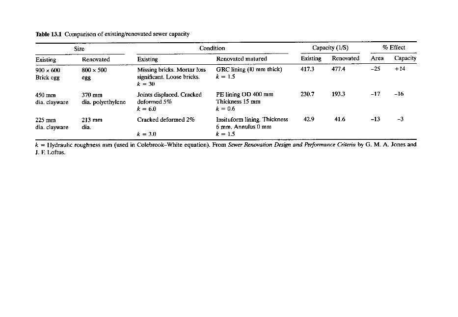
Table 13.1 Comparison of existing/renovated sewer capacity
Size Condition Capacity (1/S) % Effect
Existing Renovated Existing Renovated matured Existing Renovated Area Capacity
900 x 600 800 x 500 Missing bricks. Mortar loss GRC lining (10 mm thick) 417.3 477.4 -25 + 14 Brick egg egg significant. Loose bricks, k = 1.5
k = 30
450 mm 370 mm Joints displaced. Cracked PE lining OD 400 mm 230.7 193.3 -17 -16 dia. clayware dia. polyethylene deformed 5% Thickness 15 mm
k = 6.0 k = 0.6
225 mm 213 mm Cracked deformed 2% Insituform lining. Thickness 42.9 41.6 -13 -3 dia. clayware dia. 6 mm. Annulus 0 mm
k = 3.0 k = 1.5 i
k = Hydraulic roughness mm (used in Colebrook-White equation). From Sewer Renovation Design and Performance Criteria by G. M. A. Jones and J. E Loftus.
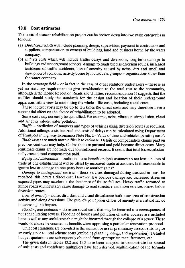
Cost estimates 279
13.8 Cost estimates The costs of a sewer rehabilitation project can be broken down into two main categories as follows:
(a) Direct costs which will include planning, design, supervision, payment to contractors and suppliers, compensation to owners of buildings, land and business borne by the water company.
(b) Indirect costs which will include traffic delays and diversions, long-term damage to buildings and underground services, damage to roads used as diversion routes, increased incidence of traffic accidents, loss of amenity caused by noise, dirt and smell and disruption of economic activity borne by individuals, groups or organisations other than the water company.
In the sewerage field - or in fact in the case of other statutory undertakers - there is as yet no statutory requirement to give consideration to the total cost to the community, although in the Horne Report on Roads and Utilities, recommendation 55 suggests that the utilities should study the standards for the design and location of their underground apparatus with a view to minimising the whole - life costs, including social costs.
These indirect costs may be up to ten times the direct costs and may therefore have a substantial effect on the choice of rehabilitation to be adopted.
Some costs may not easily be quantified. For example, noise, vibration, air pollution, visual and amenity values, water pollution.
Traffic - prediction of numbers and types of vehicles using diversion routes is required. Additional mileage costs incurred and costs of delays can be calculated using Department of Transport's 'Highway Economics Note No. 2 - Value of time and vehicle operating costs'.
Trade losses are much more difficult to estimate. Details of compensation claims paid on previous contracts may help. Claims that are pursued and paid become direct costs. Many legitimate claims are not made due to insufficient records. It seems that total losses substan- tially exceed total compensation paid.
Equity and distribution - traditional cost-benefit analysis assumes no net loss; i.e. loss of trade at one establishment will be offset by increased trade at another. Is it reasonable to ignore loss or damage to one party because another gains?
Damage to underground services - those services damaged during excavation must be repaired; this incurs a direct cost. However, less obvious damage and increased stress on exposed pipes may accelerate the incidence of future failures. Heavy traffic rerouted to minor roads will inevitably cause damage to road structure and those services buried below diversion routes.
Loss o f amen i t y - noise, dirt, dust and visual disturbance both near area of construction activity and along diversions. The public's perception of loss of amenity is a critical factor in assessing this impact.
Flooding and pollution - there are social costs that may be incurred as a consequence of not rehabilitating sewers. Flooding of houses and pollution of water courses are included here as well as any social costs that might be incurred through the collapse of a sewer. These would of course be counted as benefits when appraising a particular renovation proposal.
Unit cost equations are provided in the manual for use in preliminary assessments to give an early guide to total scheme costs (excluding planning, design and supervision). Detailed budget quotations are subsequently obtained from appropriate manufacturers, etc.
The given data in Tables 13.2 and 13.3 have been analysed to demonstrate the spread of unit costs and confidence multipliers have been derived. Multiplication of the formula
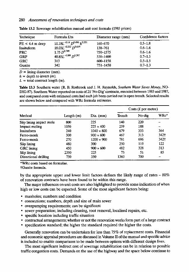
280 Assessment of renovation techniques and costs
Table 13.2 Sewerage rehabilitation manual unit cost formula (1985 prices)
Technique Formula s Diameter range (mm) Confidence factors
PE < 4.4 m deep 10.18L -0"14 D 0"496 h 0"351 160--670 Insituform 18.03L-~ D0.619 138-761 PRC 1.75 D 0"789 750-1575 GRP 40.85L -~176 D 0"397 530-1400 GRC 313 600-1158 Gunite 342 751-1450
D = lining diameter (ram). h = depth to invert (m). L = total contract length (m).
0.5-1.8 0.6-1.6 0.6-1.6 0.7-1.5 0.5-1.5 0.7-1.3
Table 13.3 Southern water (R. B. Rosbrook and J. H. Reynolds, Southern Water Saves Money, NO- DIG 87). Southern Water reported on costs of 21 'No-Dig' contracts, executed between 1983 and 1987, and compared costs with estimated costs had each job been carried out in open trench. Selected results are shown below and compared with WRc formula estimates.
Costs (s per metre)
Method Length (m) Dia. (mm) Trench No-dig WRc*
Slip lining impact mole 800 225 140 220 - Impact moling 1050 225 • 400 259 188 - Insituform 240 1040 x 800 679 333 364 Ferro-monk 300 900 x 600 467 313 342"t" Ferro-monk 270 1200 x 900 781 696 342t Slip lining 480 300 250 119 122 GRC lining 450 900 x 600 482 328 313 Slip lining 2350 225 73 51 85 Directional drilling 750 350 1360 700 -
*WRc costs based on formulae. tGunite formula.
by the appropriate upper and lower limit factors defines the likely range of rates - 80% of renovation contracts have been found to be within this range.
The major influences on unit costs are also highlighted to provide some indication of when high or low costs can be expected. Some of the most significant factors being:
�9 manholes; numbers and condition �9 connections; numbers, depth and size of main sewer �9 overpumping requirements; can be significant �9 sewer preparation; including cleaning, root removal, localised repairs, etc. �9 specific location including traffic situation �9 contractual arrangements; whether or not the renovation works form part of a large contract �9 specification standard; the higher the standard required the higher the costs.
Generally renovation can be undertaken for less than 75% of replacement costs. Financial and economic appraisal procedures are discussed in Volume II of the manual and specific advice is included to enable comparisons to be made between options with different design lives.
The most significant indirect cost of sewerage rehabilitation can be in relation to possible traffic congestion costs. Demands on the use of the highway and the space below continue to

Economicappraisal 281
increase each year. Highways have to carry traffic loads typically 5-10 times greater than they did 25 years ago. At the same time they have to accommodate the increasing demands of utili- ties including new arrivals such as cable television, e tc . - requiring regularly to open them up to repair, maintain and upgrade their plant. As an example there are approximately 2400 km of public sewers under Manchester ranging in size from 150 mm to 4.65 rn in diameter. These serve a population of approximately 450,000 people (or some 700,000 during the working day) within an administrative area of 117 km 2. Above this massive network of sewer lies a myriad of other public utilities possibly amounting to some 14,000 km in total over which some 400,000 vehicles travel daily on the main radial routes with 150,000 entering the city centre each working day. Hence it can be readily appreciated, notwithstanding the emergencies which arise, sewerage rehabilitation schemes can give rise to considerable congestion problems.
Although significant social or indirect costs will arise through the hydraulic or structural failure of sewers and the emergency works involved in repair which are rarely recorded, normal planned sewerage rehabilitation will itself cause traffic disruption although the level of social costs arising will depend on the techniques selected coupled with a number of other factors.
13.9 Economic appraisal Most civil engineering capital schemes are completed with a relatively short construction period and consideration of costs in the future generally centre on such things as operation and maintenance. In the case of drainage area planning it is almost certain that significant elements will not be carried out until the medium or long-term future - well after the initial works have been completed.
In assessing the real costs of such a sequence of works one cannot simply add the esti- mated cost of all the stages. Those occurring in the future must be 'discounted' according to when they are expected to occur.
All benefits and costs of a project are assessed in real terms, i.e. at constant current prices rather than at inflated prices. The real benefits and costs of a scheme are discounted to their present value. This must be done because society places a greater value on money available to it now rather than money expected to be available at some future date.
Central government recommend a discount rate of 5% for this purpose the 'real' interest rate (i.e. net of inflation). The value of s in the future is treated as being equal to the amount you would need to invest today to receive s in one year's time, in two years, etc. At 5% interest one would need to invest s = s to obtain s in one year. Similarly to obtain s in two years one would need to invest s 2 now, i.e. s (the 0.95 and 0.907 being the discount factors for one and two years, respectively). Hence, before adding
r the cost of individual stages each must be multiplied by 1/1.05 , where T is the time in years before the costs will arise.
This procedure is important because alternative proposed drainage area plans may involve significantly different cash expenditures at different intervals and by discounting these figures to the base year a proper comparison can be determined. When developing drainage area plans, it is necessary to consider whether the alternatives offer comparable levels of service -cos ts are not always the sole criteria.
New sewerage infrastructure is designed on the assumption that it will have a long life with economic appraisal in theory taking into account renewal at some stage. In practice using conventional material lasting at least 100 years this assessment is commonly ignored.
In the case of renovation where shorter lives are expected the situation is different. Then, the costs included in the scheme appraisal must include not only the initial cost but also an
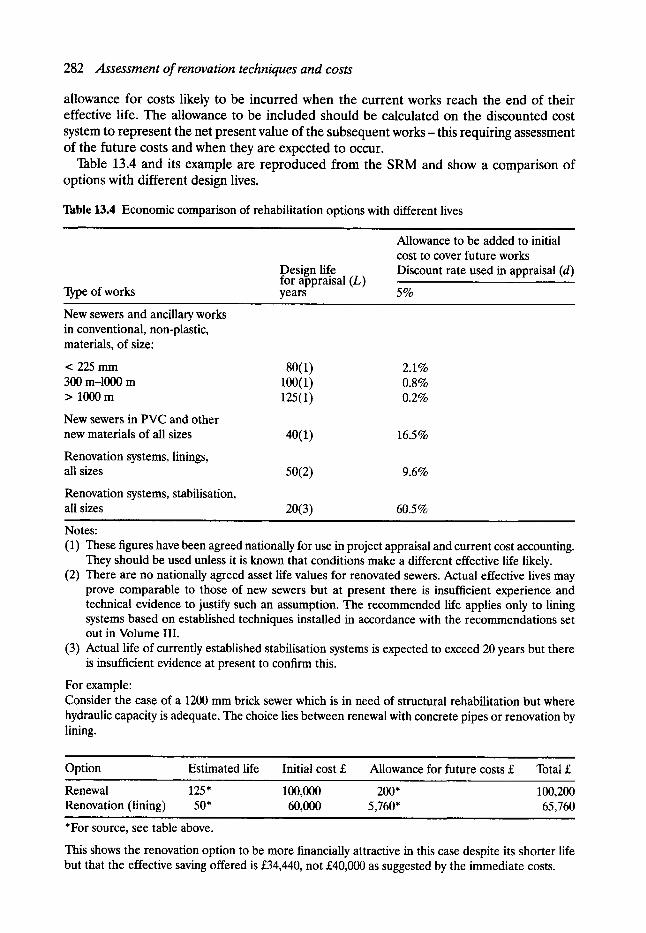
282 Assessment of renovation techniques and costs
allowance for costs likely to be incurred when the current works reach the end of their effective life. The allowance to be included should be calculated on the discounted cost system to represent the net present value of the subsequent works - this requiting assessment of the future costs and when they are expected to occur.
Table 13.4 and its example are reproduced from the SRM and show a comparison of options with different design lives.
Table 13.4 Economic comparison of rehabilitation options with different lives i
Allowance to be added to initial cost to cover future works
Design life Discount rate used in appraisal (d) for appraisal (L)
Type of works years 5%
New sewers and ancillary works in conventional, non-plastic, materials, of size:
< 225 mm 80(1) 2.1% 300 m-1000 m 100(1) 0.8% > 1000 m 125(1) 0.2%
New sewers in PVC and other new materials of all sizes 40(1) 16.5%
Renovation systems, linings, all sizes 50(2) 9.6%
Renovation systems, stabilisation, all sizes 20(3) 60.5 %
i
Notes: (1) These figures have been agreed nationally for use in project appraisal and current cost accounting.
They should be used unless it is known that conditions make a different effective life likely. (2) There are no nationally agreed asset life values for renovated sewers. Actual effective lives may
prove comparable to those of new sewers but at present there is insufficient experience and technical evidence to justify such an assumption. The recommended life applies only to lining systems based on established techniques installed in accordance with the recommendations set out in Volume III.
(3) Actual life of currently established stabilisation systems is expected to exceed 20 years but there is insufficient evidence at present to confirm this.
For example: Consider the case of a 1200 mm brick sewer which is in need of structural rehabilitation but where hydraulic capacity is adequate. The choice lies between renewal with concrete pipes or renovation by lining.
i
Option Estimated life Initial cost s Allowance for future costs s Total s
Renewal 125" 100,000 200* Renovation (lining) 50* 60,000 5,760*
, , , , , , , ,
*For source, see table above.
100,200 65,760
This shows the renovation option to be more financially attractive in this case despite its shorter life but that the effective saving offered is s not s as suggested by the immediate costs.
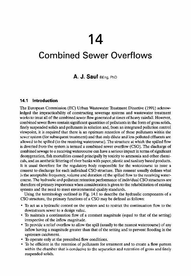
14 Combined Sewer Overflows
A. J. Saul BEng, PhD
14.1 Introduction
The European Commission (EC) Urban Wastewater Treatment Directive (1991) acknow- ledged the impracticability of constructing sewerage systems and wastewater treatment works to treat all of the combined sewer flow generated at times of heavy rainfall. However, combined sewer flows contain significant quantities of pollutants in the form of gross solids, finely suspended solids and pollutants in solution and, from an integrated pollution control viewpoint, it is required that there is an optimum retention of these pollutants within the sewer system (for subsequent treatment) and that only dilute and less polluted effluents are allowed to be spilled (to the receiving watercourse). The structure at which the spilled flow is diverted from the system is termed a combined sewer overflow (CSO). The discharge of combined sewage to a receiving watercourse can have a serious impact in terms of significant deoxygenation, fish mortalities caused principally by toxicity to ammonia and other chemi- cals, and an aesthetic littering of river banks with paper, plastic and sanitary based products. It is usual therefore for the regulatory body responsible for the watercourse to issue a consent to discharge for each individual CSO structure. This consent usually defines what is the acceptable frequency, volume and duration of the spilled flow to the receiving water- course. The hydraulic and pollutant retention performance of individual CSO structures are therefore of primary importance when consideration is given to the rehabilitation of existing systems and the need to meet environmental quality standards.
Using the terminology outlined in Fig. 14.1 to describe the hydraulic components of a CSO structure, the primary functions of a CSO may be defined as follows:
�9 To act as a hydraulic control on the system and to restrict the continuation flow to the downstream sewer to a design value.
�9 To maintain a continuation flow of a constant magnitude (equal to that of the setting) irrespective of the inflow magnitude.
�9 To provide a relief overflow to allow the spill (usually to the nearest watercourse) of any inflow having a magnitude greater than that of the setting and to prevent flooding in the upstream catchment.
�9 To operate only at the prescribed flow conditions. �9 To be efficient in the retention of pollutants for treatment and to create a flow pattern
within the chamber that is conducive to the separation and retention of gross and finely suspended solids.
284 Combined sewer overflows
Spilled flow (flow and quality)
Inflow (flow and quality) (flow and
quality)
Figure 14.1 Hydraulic components at a CSO structure.
�9 To be self-cleansing and maintenance free by avoiding blockage and complication in design.
Early designs of CSO chamber were based solely on the hydraulic performance of the system and the need to prevent flooding. Simple techniques were used to divert the excess flow from the system and these included relief pipes inserted at manholes, rectangular-plan- shaped chambers with full length low-side weirs and leaping weir overflows. In the latter type of chamber the spilled flow was intercepted from the trajectory of the inflow jet as it entered the chamber by a pipe or channel located in the downstream wall of the chamber with the continuation flow being the difference between the inflow and that intercepted. More recent designs include stilling ponds with end weirs, high-side weir chambers and vortex, swirl and dynamic separators. Details of each type of chamber are included in Section 14.3.
However, CSOs have long been recognised as one of the major cause of river pollution in the UK, and in 1970 the Ministry of Housing and Local Government technical committee on Storm Overflows and the Disposal of Storm Sewage (1970) reported that some 37% of 12,000 overflows in England and Wales were unsatisfactory in that they either operated in dry weather, caused visual pollution leading to public complaint or resulted in a significant deterioration in the chemical and biological quality of the receiving watercourse. Similarly the Scottish Development Department (1977) indicated that of the 2000 CSOs in Scotland some 20% were totally unsatisfactory. However, the privatisation of the UK water industry in 1989 has seen the development of asset management plans for sewerage systems and these have resulted in significant improvements in the knowledge of the number and type of ancillary structures within the sewerage systems of the UK. Morris (1993) reported that the number of CSO chambers in the UK was in the region of some 25,000 and of which approxi- mately one-third did not function in a satisfactory manner. This number of unsatisfactory CSO chambers is typical of those found in other EC member states, as detailed in Table 14.1.
14.1.1 CSO SETTING IN RELATION TO THE IMPACT ON R E C E M N G WATERS
It is necessary therefore to quantify what is an acceptable performance for a CSO chamber at any site-specific location. The EC Urban Wastewater Treatment Directive placed the responsibility on member states to decide on measures to limit the pollution from CSOs and indicated that measures could be based on three techniques:
�9 a dilution ratio between the quality of the sewer flow and that in the receiving stream �9 the capacity of the sewer system in relation to the dry weather flow �9 a specified number of overflows per year.

Introduction 285
However, in each EU member state, there are major differences in the legal, organisa- tional, operational and financial practices which, together with a wide range of cultural and geographical differences, have significantly influenced the development and implementa- tion of such pollution control measures. Details of the design criteria currently adopted in EU member states are outlined in Table 14.2. It is clear that in respect of the setting, the policy and practice varies throughout Europe and ranges from a multiple of the dry weather flow to a frequency of overflow operation.
Historically in the UK, following the recommendations of the Ministry of Health in 1919, the setting (i.e. continuation flow at first spill) was made equal to six times the dry weather flow with three times dry weather flow given full treatment at the wastewater treatment plant and with three times the dry weather flow discharged to storm tanks for subsequent treatment. These criteria take no account of the strength of the crude sewage from different areas and a refinement to this approach was published by the Ministry of Health and Local Government Technical Committee (1970) in the form of formula A where
setting = DWF + 1360P + 2E litres/day
D W F = P G + I + E
where P is the population, G is the number of litres per head per day, I is the infiltration and E is the industrial effluent.
Modifications to the constants 1360 and 2 in the formula could be made to account for changes in the strength of the sewage, but no account was taken of the situation of the overflow or of the flow magnitude and impact of the CSO spilled pollutants on the receiving watercourse.
The report of the Scottish Development Department (1977) considered the dilution available in the receiving stream and design guidelines were presented for the CSO setting and a required storage capacity based on a dilution factor given by the 95% exceedence flow in the stream divided by the dry weather flow in the sewer. Details of the factors are included in Table 14.3. The introduction of storage was considered to reduce the impact of the CSO discharge, but these predicted changes were not quantified mathematically.
In recent years the quality of rivers in the UK has been defined using the National Water Council (NWC) river classification system as detailed in Table 14.4, and in which the quality of the watercourse is based on chemical and biological criteria. These ranged from class 1A, a high-quality river capable of supporting a salmonoid fishery, to class 4, a grossly polluted river. In 1992 some 10% of the inland watercourses in the UK were class 3 or 4 and it is not surprising to find that many rivers in the heavily urbanised and industrialised areas are the most heavily polluted in the UK. The spilled flow from a large number of CSO structures in these areas contribute a significant pollutant load to these waters and subsequently help to maintain their poor quality classification. The data outlined in Table 14.1 show a similar picture throughout Europe.
The NWC standards are based on 95 percentile compliance, i.e. it is expected that the pollution concentration in the watercourse may exceed the standard for 5% of the time. This methodology may easily be applied to establish consent conditions for continuous discharges, albeit that extensive data collection is required, but it does not adequately account for the polluting impact from intermittent discharges. Hence short duration pollution pulses of unspecified quality (e.g. CSO spilled flow) which may effectively limit river biota through regular, but short-term exposure to pollution, are not taken into account.
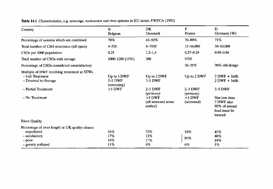
Table 14.1 Characteristics, e.g. sewerage, wastewater and river systems in EU states, EWPCA (1992)
Country B DK Belgium Denmark
F France
D Germany (W)
Percentage of systems which are combined
Total number of CSO structures (all types)
CSOs per 1000 population
Total number of CSOs with storage
Percentage of CSOs considered unsatisfactory
Multiple of DWF receiving treatment at STWs - Full Treatment - Diverted to Storage
- Partial Treatment
- No Treatment
River Quality
Percentage of river length in UK quality classes - unpolluted - satisfactory - poor - grossly polluted
70% 43-50% 70-80%
4-500 6-7000 15-16,000
0.25 1.2-1.4 0.27--0.29
1000-1200 (15 %) 300 9700
30-35%
Up to 3 DWF 3-5 DWF (screening) >5 DWF
56% 17% 18% 11%
Up to 2 DWF 2-5 DWF
2-5 DWF (primary) >5 DWF (all screened some settled)
72% 13% 11% 4%
Up to 2 DWF
2-3 DWF (primary) > 3 DWF (screened)
34%
8O%
6%
71%
50-60,000
0.80-0.96
30% old design
2 DWF + Infilt 2 DWF + Infilt
3-5 DWF
Not less than 7 DWF also 90% of annual load must be treated
45% 40% 14% 1%
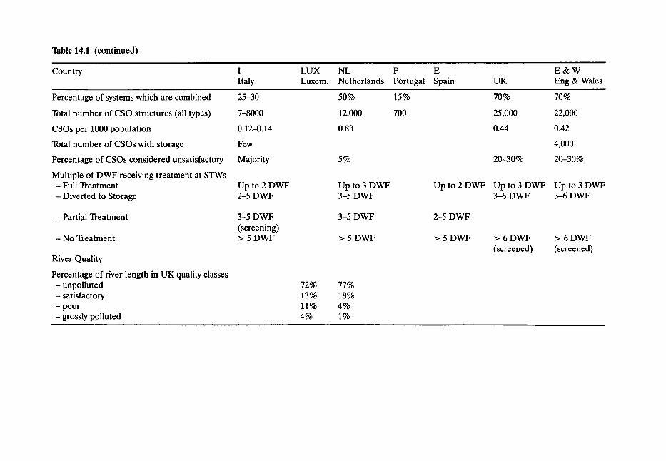
2~able 14.1 (continued)
Country I
Italy LUX Luxem.
NL Netherlands
P E Portugal Spain
E & W UK Eng & Wales
Percentage of systems which are combined
Total number of CSO structures (all types)
CSOs per 1000 population
Total number of CSOs with storage
Percentage of CSOs considered unsatisfactory
Multiple of DWF receiving treatment at STWs - Full Treatment - Diverted to Storage
- Partial Treatment
- No Treatment
River Quality
Percentage of river length in UK quality classes - unpolluted - satisfactory - poor - grossly polluted
25-30
7-8000
0.12--0.14
Few
Majority
Up to 2 DWF 2-5 DWF
3-5 DWF (screening) > 5DWF
5O%
12,000
0.83
5%
Up to 3 DWF 3-5 DWF
3-5 DWF
> 5 DWF
15%
700
72% 77% 13% 18% 11% 4% 4% 1%
70% 70%
25,000 22,000
0.44 0.42
4,000
20-30% 20-30%
Up t o 2 D W F Up t o 3 D W F Up t o 3 D W F 3-6 DWF 3-6 DWF
2-5 DWF
> 5 DWF > 6 DWF > 6 DWF (screened) (screened)
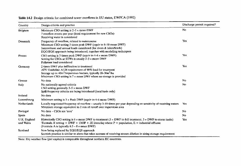
Table 14.2 Des ign cr i ter ia for c o m b i n e d sewer overflows in E U states, E W P C A (1992) . . . . . . . . . . , , . . . . . . . . , , , ,
Country Design criteria and practice Discharge permit required?
Belgium
Denmark
France
Germany
Greece
Italy
Ireland
Luxembourg
Netherlands
Portugal
Spain
U.K. England and Wales
Scotland
Note: Dry weather
Minimum CSO setting is 2-5 • mean DWF 7 overflow events per year (local requirement for new CSOs) Receiving water is considered
Frequency of overflow, related to watercourse Minimum CSO setting 5 times peak DWF (equiv to 8-10 mean DWF) Intermittent and annual loads considered (for rivers & lakes/fiords) EQO/EQS approach being introduced, together with modelling techniques
CSO setting is 3 times peak DWF (equiv to 4-6 x mean DWF) Setting for CSOs at STWs is usually 2-3 • mean DWF Pollutant load considered
2 times DWF plus infiltration to treatment ATV Guideline A128 requirement of 90% load for treatment Storage up to 40m3/impervious hectare, typically 20-30m3/ha Minimum CSO setting is 7 • mean DWF where no storage is provided
No data
No nationally agreed criteria CSO setting generally 3-5 x mean DWF Spill frequency criteria are being introduced (local basis only)
No data
Minimum setting is 3 x Peak DWF (equiv to 4--6 mean DWF)
Locally negotiated frequency of overflow - usually 3-10 times per year depending on sensitivity of receiving waters Minimum storage equivalent to 2 mm of runoff over impervious area
No data - CSOs are 'rare'
No data
Historically CSO setting is 6 x mean DWF to treatment (3 • DWF to full treatment. 3 • DWF to storm tanks) 'Formula ,a/setting = DWF + 1360P + 2E litres/day where P = population, E = industrial effluent (Formula A is typically 6.5 - 8 • mean DWF)
Now being replaced by EQO/EQS approach Scottish practice is similar to above but takes account of receiving stream dilution in sizing storage requirement
flow (per capita)is comparable throughout northern EC countries.
No
Yes
Yes
Yes
N o
No
Yes
N o
No
Yes

Table 14.3 CSO setting recommendations after Scottish Development Department (1977)
Dilution Overflow setting Storage tank
>8 Formula A + None >6 Formula A + None >4 Formula A + 401/hd > 2 Formula A + 801/hd > 1 Formula A + 1201/hd
Introduction 289
Mass balance techniques have been developed to assess the impact of intermittent discharges. QUALSOC (QUALity impacts of Storm Overflows: Consent procedure) extends the formula A approach and was developed by the Welsh National Rivers Authority. Five- day biological oxygen demand (BOD) is used in the analysis and the effect of varying the CSO spill rate on the water quality in the watercourse downstream of the CSO is estimated. The overflow impact is assessed against a maximum admissible concentration (MAC) of BOD in the downstream watercourse. Acceptable criteria for each river classification capable of supporting fish life were presented in the Urban Pollution Manual (1994) and these are outlined in Table 14.5.
r
A further development is to assess the impact of intermittent CSO discharges is the CARP (Comparative Acceptable River Pollution) procedure. This procedure utilises the fact that many rivers in the UK receive significant inputs of CSO spilled flow yet are able to maintain the desired water quality objective and to support and sustain a viable aquatic life.
CARP utilises the procedures outlined in Volume 2 of the Sewerage Rehabilitation Manual (SRM) (WRc, 1984) to compute the hydraulic and pollutant load inputs into the reach of known acceptable performance. Time series rainfall and a hydraulic simulation model of the sewerage system are used to compute the frequency, volume and duration of the spill into the reach and an average pollutant concentration is used to compute the corresponding pollutant load (flow x pollutant concentration) in the spilled flow. This information is then used to define what is the acceptable pollutant load which may be spilled into the individual reach for which overflow consents are required.
It is stressed however that the method is only applicable when the reach with acceptable performance has similar hydraulic characteristics and pollution inputs to the reach for which the design inputs are required.
Research by the Water Research Centre (WRc) has attempted to establish the relation- ships between acceptable pollutant concentration over long- and short-term exposures and the recurrence interval and recovery period between these exposures for a number of aquatic species. This information, together with the development in sewer simulation models (see Chapter 8) and river impact modelling techniques have allowed the quantitative and quali- tative dynamic response of sewer and river systems to be assessed. The impact of an inter- mittent CSO discharge on the quality of the receiving stream may therefore be predicted and, for consent purposes, the output from such models may be set against river quality standards which are appropriate to protect aquatic life from the intermittent impact of sewage discharges. Such standards for dissolved oxygen and ammonia are outlined in the Urban Pollution Management Manual (1994) and are based on three parameters:
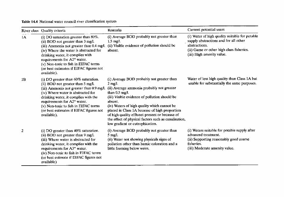
Table 14.4 National water council river classification system
River class Quality criteria Remarks Current potential users
1A
1B
(i) DO saturation greater than 80%. (i) Average BOD probably not greater than (ii) BOD not greater than 3 mg/l. 1.5 mg/l. (iii) Ammonia not greater than 0.4 mg/1. (ii) Visible evidence of pollution should be (iv) Where the water is abstracted for absent. drinking water, it complies with requirements for A2* water. (v) Non-toxic to fish in EIFAC terms (or best estimates if EIFAC figures not available).
(i) DO greater than 60% saturation. (i) Average BOD probably not greater than (ii) BOD not greater than 5 mg/l. 2 mg/l. (iii) Ammonia not greater than 0.9 mg/l. (ii) Average ammonia probably not greater (iv) Where water is abstracted for drinking water, it complies with the requirements for A2* water. (v) Non-toxic to fish in EIFAC terms (or best estimates if EIFAC figures not available).
than 0.5 mg/1. (iii) Visible evidence of pollution should be absent. (iv) Waters of high quality which cannot be placed in Class 1A because of high proportion of high quality effluent present or because of the effect of physical factors such as canalisation, low gradient or eutrophication.
(i) DO greater than 40% saturation. (ii) BOD not greater than 9 mg/l. (iii) Where water is abstracted for drinking water, it complies with the requirements for A3* water. (iv) Non-toxic to fish in EIFAC terms (or best estimate if EIFAC figures not available)
, ,
(i) Average BOD probably not greater than 5 mg/l. (ii) Water not showing physicals signs of pollution other than humic coloration and a little foaming below weirs.
(i) Water of high quality suitable for potable supply abstractions and for all other abstractions. (ii) Game or other high class fisheries. (iii) High amenity value.
Water of less high quality than Class 1A but usable for substantially the same purposes.
(i) Waters suitable for potable supply after advanced treatment. (ii) Supporting reasonably good coarse fisheries. (iii) Moderate amenity value.
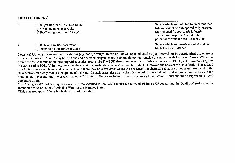
Table 14.4 (continued)
(i) DO greater than 10% saturation. (ii) Not likely to be anaerobic. (iii) BOD not greater than 17 mg/1.t
Waters which are polluted to an extent that fish are absent or only sporadically present. May be used for low-grade industrial abstraction purposes. Considerable potential for further use if cleaned up.
4 (i) DO less than 10% saturation. Waters which are grossly polluted and are (ii) Likely to be anaerobic at times, likely to cause nuisance.
Notes: (a) Under extreme weather conditions (e.g. flood, drought, freeze-up), or where dominated by plant growth, or by aquatic plant decay, rivers usually in Classes 1, 2 and 3 may have BODs and dissolved oxygen levels, or ammonia content outside the stated levels for those Classes. When this occurs the cause should be stated along with analytical results. (b) The BOD determinations refer to 5-day carbonaceous BOD (ATU). Ammonia figures are expressed as NH4. (c) In most instances the chemical classification given above will be suitable. However, the basis of the classification is restricted to a finite number of chemical determinants and there may be a few cases where the presence of a chemical substance other than those used in the classification markedly reduces the quality of the water. In such cases, the quality classification of the water should be downgraded on the basis of the biota actually present, and the reasons stated. (d) EIFAC's (European Inland Fisheries Advisory Commission) limits should be expressed as 0.5% percentile limits. *EEC category A2 and A3 requirements are those specified in the EEC Council Directive of 16 June 1975 concerning the Quality of Surface Water Intended for Abstraction of Drinking Water in the Member States. tThis may not apply if there is a high degree of reaeration.
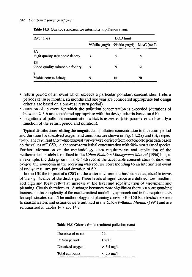
292 Combined sewer overflows
Table 14.5 Qualsoc standards for intermittent pollution rivers
River class BOD limit
95%ile (mg/l) 99%ile (mg/l) MAC (mg/1)
1A High quality salmonoid fishery 3 5 6
1B Good quality salmonoid fishery 5 9 12
2 Viable course fishery 9 16 20
�9 return period of an event which exceeds a particular pollutant concentration (return periods of three months, six months and one year are considered appropriate but design criteria are based on a one-year return period)
�9 duration of an event for which the pollution concentration is exceeded (durations of between 2-3 h are considered appropriate with the design criteria based on 6 h)
�9 magnitude of pollutant concentration which is exceeded (this parameter is obviously a function of the return period and duration).
Typical distributions relating the magnitude in pollution concentration to the return period and duration for dissolved oxygen and ammonia are shown in Fig. 14.2(a) and (b), respec- tively. The resultant three-dimensional curves were derived from ecotoxicological data based on the values of LC50, i.e. the short-term lethal concentration with 50% mortality of species. Further information on the methodology, data requirements and application of the mathematical models is outlined in the Urban Pollution Management Manual (1994) but, as an example, the data given in Table 14.6 record the acceptable concentration of dissolved oxygen and ammonia in the receiving watercourse corresponding to an intermittent event of one-year return period and duration of 6 h.
In the UK the impact of a CSO on the water environment has been categorised in terms of the significance of the discharge. Three levels of significance are defined: low, medium and high and these reflect an increase in the level and sophistication of assessment and planning. Clearly therefore as a discharge becomes more significant there is a corresponding increase in the complexity of the mathematical modelling approach and in the requirements for sophisticated data. The methodology and planning consents for CSOs to freshwaters and to coastal waters and estuaries were outlined in the Urban Pollution Manual (1994) and are summarised in Tables 14.7 and 14.8.
Table 14.6 Criteria for intermittent pollution event
Duration of event 6 h
Return period 1 year
Dissolved oxygen > 3.5 mg/1
Total ammonia < 0.5 mg/l
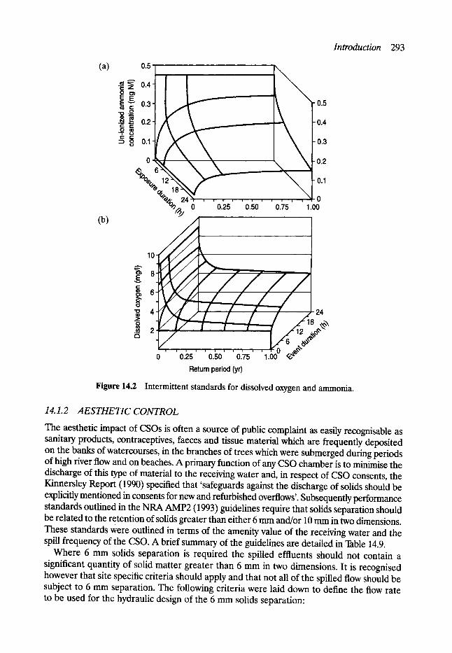
Introduction 293
(a) 0.5
04
o0
% (b) %
0.25 0.50 0.75
0.5
0.4
0.3
0.2
0.1
.-~1-o 1.00
10
5, 8 E
| 6
"~ 4 _.= O
.ca 2 r~
24
0 0.25 0.50 0.75 1.00
Return period (yr)
Figure 14.2 Intermittent standards for dissolved oxygen and ammonia.
14.1.2 AESTHETIC CONTROL
The aesthetic impact of CSOs is often a source of public complaint as easily recognisable as sanitary products, contraceptives, faeces and tissue material which are frequently deposited on the banks of watercourses, in the branches of trees which were submerged during periods of high fiver flow and on beaches. A primary function of any CSO chamber is to minimise the discharge of this type of material to the receiving water and, in respect of CSO consents, the Kinnersley Report (1990) specified that 'safeguards against the discharge of solids should be explicitly mentioned in consents for new and refurbished overflows'. Subsequently performance standards outlined in the NRA AMP2 (1993) guidelines require that solids separation should be related to the retention of solids greater than either 6 mm and/or 10 mm in two dimensions. These standards were outlined in terms of the amenity value of the receiving water and the spill frequency of the CSO. A brief summary of the guidelines are detailed in Table 14.9.
Where 6 mm solids separation is required the spilled effluents should not contain a significant quantity of solid matter greater than 6 mm in two dimensions. It is recognised however that site specific criteria should apply and that not all of the spilled flow should be subject to 6 mm separation. The following criteria were laid down to define the flow rate to be used for the hydraulic design of the 6 mm solids separation:

294 Combined sewer overflows
Table 14.7 Impact assessment criteria for setting consents for CSOs to freshwaters
Low significance Minimum Data Methods, e.g. Formula A, or possibly QUALSOC method
Dilution > 8:1 (foul DWF @ 5%ile low river flows) No interaction with other discharges
Medium significance Simple models (e.g. SDD method, QUALSOC, CARP + Sewer hydraulic model such as HVDROWORICS)
Dilution < 8:1 No interaction or limited interaction with other discharges > 2,000 population equivalent C~rinid fishery
High significance Complex models (e.g. sewer hydraulic models such as HYDROWORKS and river quality models such as MIKE II)
Dilution < 2:1 Interaction with other discharges > 10,000 population equivalent C~rinoid or salmonoid fishery
i
Table 14.8 Impact assessment criteria for setting consents into coastal waters and estuaries , , , , i , ,
Low significance Minimum data methods (e.g. Formula A)
Estuarine and coastal waters not containing EC identified bathing waters and/or shellfish waters.
Medium significance Simple models (sewer hydraulic model with frequency assessment of overflow spill)
Population equivalent 2000-10,000 Affects identified bathing waters and/or shellfish waters
High significance Complex models (sewer hydraulic and quality models with frequency assessment of overflow and spill and an option for coastal dispersion and impact assessment)
Population equivalent > 10,000 Affects identified bathing waters and/or shellfish waters
, , , , ,,
�9 for time series storms - at a maximum flow equivalent to 80% of the flow volume that would be discharged in an annual time series
�9 for design storms - at a flow rate which is equal to 50% of the volume that would be discharged in a once in one-year design event.
In addition the remaining flow up to that resulting from a once in five-year storm should also be subject to 10 mm solids separation. The retention of these solids within the sewer system is a function of the hydraulic and the solids separation performance of each individual CSO structure.
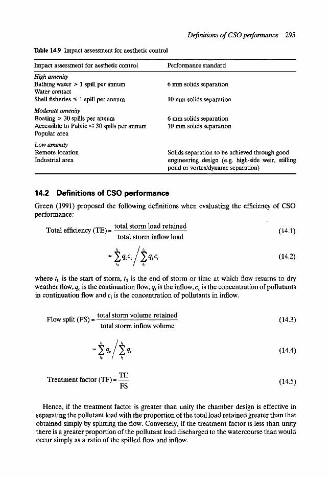
Definitions of CSO performance 295
Table 14.9 Impact assessment for aesthetic control
Impact assessment for aesthetic control Performance standard
High amenity Bathing water > 1 spill per annum Water contact Shell fisheries ~< 1 spill per annum
Moderate amenity Boating > 30 spills per annum Accessible to Public ~< 30 spills per annum Popular area
Low amenity Remote location Industrial area
6 mm solids separation
10 mm solids separation
6 mm solids separation 10 mm solids separation
Solids separation to be achieved through good engineering design (e.g. high-side weir, stilling pond or vortex/dynamc separation)
14.2 Definitions of CSO performance Green (1991) proposed the following definitions when evaluating the efficiency of CSO performance:
total storm load retained Total efficiency (TE)= (14.1)
total storm inflow load
= ~ q~cr qici (14.2) to / to
where to is the start of storm, tl is the end of storm or time at which flow returns to dry weather flow, qc is the continuation flow, qi is the inflow, Cc is the concentration of pollutants in continuation flow and ci is the concentration of pollutants in inflow.
total storm volume retained Flow split (FS) = (14.3)
total storm inflow volume
= ~qc ~qi (14.4) to / to
Treatment factor (TF)= TE FS (14.5)
Hence, if the treatment factor is greater than unity the chamber design is effective in separating the pollutant load with the proportion of the total load retained greater than that obtained simply by splitting the flow. Conversely, if the treatment factor is less than unity there is a greater proportion of the pollutant load discharged to the watercourse than would occur simply as a ratio of the spilled flow and inflow.
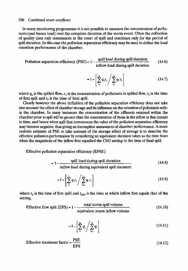
296 Combined sewer overflows
In many monitoring programmes it is not possible to measure the concentration of pollu- tants (and hence load) over the complete duration of the storm event. Often the collection of quality data only commences at the onset of spill and continues only for the period of spill duration. In this case the pollution separation efficiency may be used to define the load retention performance of the chamber.
Pollution separation efficiency (PSE)-- 1- spill load during spill duration
inflow load during spill duration (14.6)
-1-[~q'c~/~t qici ] (14.7)
where qs is the spilled flow, Cs is the concentration of pollutants in spilled flow, t2 is the time of first spill and t 3 is the time of final spill.
Clearly however the above definition of the pollution separation efficiency does not take into account the effect of chamber storage and its influence on the retention of pollutants with- in the chamber. In many instances the concentration of the effluents retained within the chamber prior to spill will be greater than the concentration of those in the inflow at that instant in time, and hence when spill first commences the value of the pollution separation efficiency may become negative, thus giving an incomplete assessment of chamber performance. A more realistic estimate of PSE to take account of the storage effect of storage is to describe the effective pollution performance by considering an equivalent duration taken as the time from when the magnitude of the inflow first equalled the CSO setting to the time of final spill.
Effective pollution separation efficiency (EPSE)
= 1- spill load during spill duration (14.8)
inflow load during equivalent spill duration
= 1 - q s c , q~ c~
[ / s c t t
(14.9)
where t2 is the time of first spill and tsett is the time at which inflow first equals that of the setting.
Effective flow split (EFS)= 1- total storm spill volume
equivalent storm inflow volume (14.10)
- 1 - qs qi 12 / / s e t t
(14.11)
Effective treatment factor -- - - - - PSE
EFS (14.12)
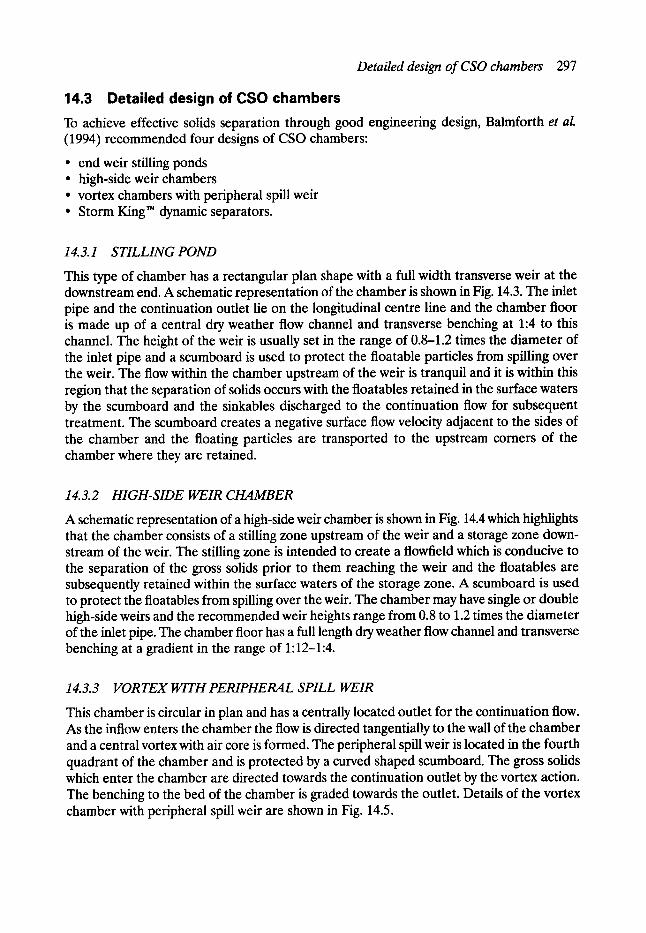
Detailed design of CSO chambers 297
14.3 Detailed design of CSO chambers To achieve effective solids separation through good engineering design, Balmforth et al. (1994) recommended four designs of CSO chambers:
�9 end weir stilling ponds �9 high-side weir chambers �9 vortex chambers with peripheral spill weir �9 Storm King TM dynamic separators.
14. 3.1 STILLING POND
This type of chamber has a rectangular plan shape with a full width transverse weir at the downstream end. A schematic representation of the chamber is shown in Fig. 14.3. The inlet pipe and the continuation outlet lie on the longitudinal centre line and the chamber floor is made up of a central dry weather flow channel and transverse benching at 1:4 to this channel. The height of the weir is usually set in the range of 0.8-1.2 times the diameter of the inlet pipe and a scumboard is used to protect the floatable particles from spilling over the weir. The flow within the chamber upstream of the weir is tranquil and it is within this region that the separation of solids occurs with the floatables retained in the surface waters by the scumboard and the sinkables discharged to the continuation flow for subsequent treatment. The scumboard creates a negative surface flow velocity adjacent to the sides of the chamber and the floating particles are transported to the upstream comers of the chamber where they are retained.
14.3.2 HIGH-SIDE WEIR CHAMBER
A schematic representation of a high-side weir chamber is shown in Fig. 14.4 which highlights that the chamber consists of a stilling zone upstream of the weir and a storage zone down- stream of the weir. The stilling zone is intended to create a flowfield which is conducive to the separation of the gross solids prior to them reaching the weir and the floatables are subsequently retained within the surface waters of the storage zone. A scumboard is used to protect the floatables from spilling over the weir. The chamber may have single or double high-side weirs and the recommended weir heights range from 0.8 to 1.2 times the diameter of the inlet pipe. The chamber floor has a full length dry weather flow channel and transverse benching at a gradient in the range of 1:12-1:4.
14.3.3 VORTEX WITH PERIPHERAL SPILL WEIR
This chamber is circular in plan and has a centrally located outlet for the continuation flow. As the inflow enters the chamber the flow is directed tangentially to the wall of the chamber and a central vortex with air core is formed. The peripheral spill weir is located in the fourth quadrant of the chamber and is protected by a curved shaped scumboard. The gross solids which enter the chamber are directed towards the continuation outlet by the vortex action. The benching to the bed of the chamber is graded towards the outlet. Details of the vortex chamber with peripheral spill weir are shown in Fig. 14.5.
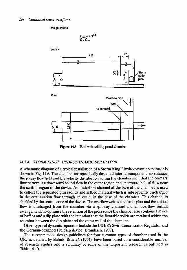
298 Combined sewer overflows
Design criteria
Dmin = K Q ~ D >_ Dr~ n
Section
~ _ _ . 2 .
~m 7D D/2
Plan Overflow pipe
Weir ~ Scumboard
Figure 14.3 End weir stilling pond chamber.
Storm outlet pipe
14.3.4 STORM KING TM HYDRODYNAMIC SEPARATOR
A schematic diagram of a typical installation of a Storm King TM hydrodynamic separator is shown in Fig. 14.6. The chamber has specifically designed internal components to enhance the rotary flow field and the velocity distribution within the chamber such that the primary flow pattern is a downward helical flow in the outer region and an upward helical flow near the central region of the device. An underflow channel at the base of the chamber is used to collect the separated gross solids and settled material which is subsequently discharged in the continuation flow through an outlet in the base of the chamber. This channel is shielded by the central cone of the device. The overflow weir is circular in plan and the spilled flow is discharged from the chamber via a spillway channel and an overflow outfall arrangement. To optimise the retention of the gross solids the chamber also contains a series of baffles and a dip plate with the intention that the floatable solids are retained within the chamber between the dip plate and the outer wall of the chamber.
Other types of dynamic separator include the US EPA Swirl Concentrator Regulator and the German-designed Fluidsep device (Brombach, 1987).
The recommended design guidelines for four common types of chamber used in the UK, as detailed by Balmforth et al. (1994), have been based on a considerable number of research studies and a summary of some of the important research is outlined in Table 14.10.
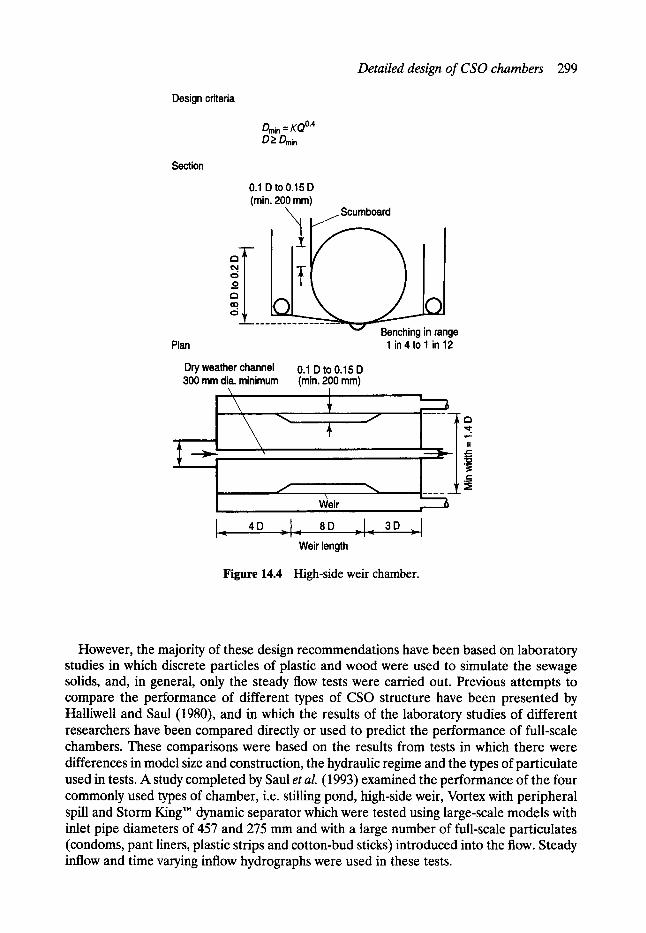
Detailed design of CSO chambers 299
Design criteria
Dmin = KQ 0.4 D_> D~n
Section
0.1 D to 0.15 D (min. 200 mm)
_Scumboard
El
ge Plan
Dry weather channel 300 mm dia. minimum
1 in 4 to 1 in 12
0.1D to 0.15 D (rain. 200 ram)
IA 4D
Weir
8D 3D " - I - '~ " - I ~'~ " - I
Weir length
Figure 14.4 High-side weir chamber.
However, the majority of these design recommendations have been based on laboratory studies in which discrete particles of plastic and wood were used to simulate the sewage solids, and, in general, only the steady flow tests were carried out. Previous attempts to compare the performance of different types of CSO structure have been presented by Halliwell and Saul (1980), and in which the results of the laboratory studies of different researchers have been compared directly or used to predict the performance of full-scale chambers. These comparisons were based on the results from tests in which there were differences in model size and construction, the hydraulic regime and the types of particulate used in tests. A study completed by Saul et al. (1993) examined the performance of the four commonly used types of chamber, i.e. stilling pond, high-side weir, Vortex with peripheral spill and Storm King TM dynamic separator which were tested using large-scale models with inlet pipe diameters of 457 and 275 mm and with a large number of full-scale particulates (condoms, pant liners, plastic strips and cotton-bud sticks) introduced into the flow. Steady inflow and time varying inflow hydrographs were used in these tests.
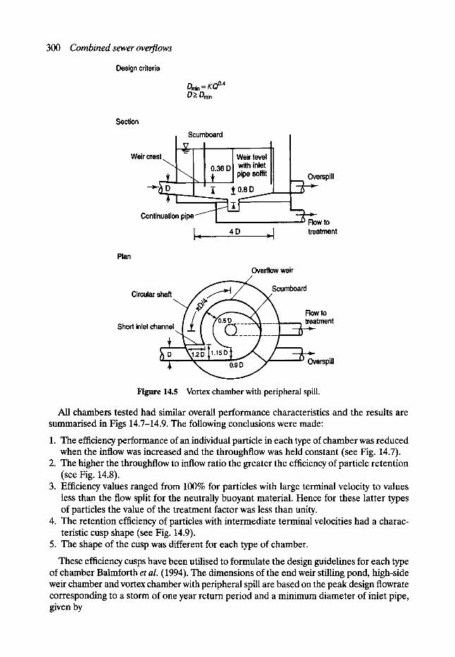
300 Combined sewer overflows
Design criteria
Drmn = KQ 0"4 DE Dn~n
Section I Scumboard
V I l Weircrest\ ! ~----I I ! Weir level I I
" - L I I o 36 D I with inlet II I 'q . ! + I Ii
Continuation pipe
I-< 4D , r I
.••erspill
'~~Row to treatment
Plan Overflow weir
Circular .=
Short inlet ch= v to tment
erspill
Figure 14.5 Vortex chamber with peripheral spill.
All chambers tested had similar overall performance characteristics and the results are summarised in Figs 14.7-14.9. The following conclusions were made:
1. The efficiency performance of an individual particle in each type of chamber was reduced when the inflow was increased and the throughflow was held constant (see Fig. 14.7).
2. The higher the throughflow to inflow ratio the greater the efficiency of particle retention (see Fig. 14.8).
3. Efficiency values ranged from 100% for particles with large terminal velocity to values less than the flow split for the neutrally buoyant material. Hence for these latter types of particles the value of the treatment factor was less than unity.
4. The retention efficiency of particles with intermediate terminal velocities had a charac- teristic cusp shape (see Fig. 14.9).
5. The shape of the cusp was different for each type of chamber.
These efficiency cusps have been utilised to formulate the design guidelines for each type of chamber Balmforth et al. (1994). The dimensions of the end weir stilling pond, high-side weir chamber and vortex chamber with peripheral spill are based on the peak design flowrate corresponding to a storm of one year return period and a minimum diameter of inlet pipe, given by
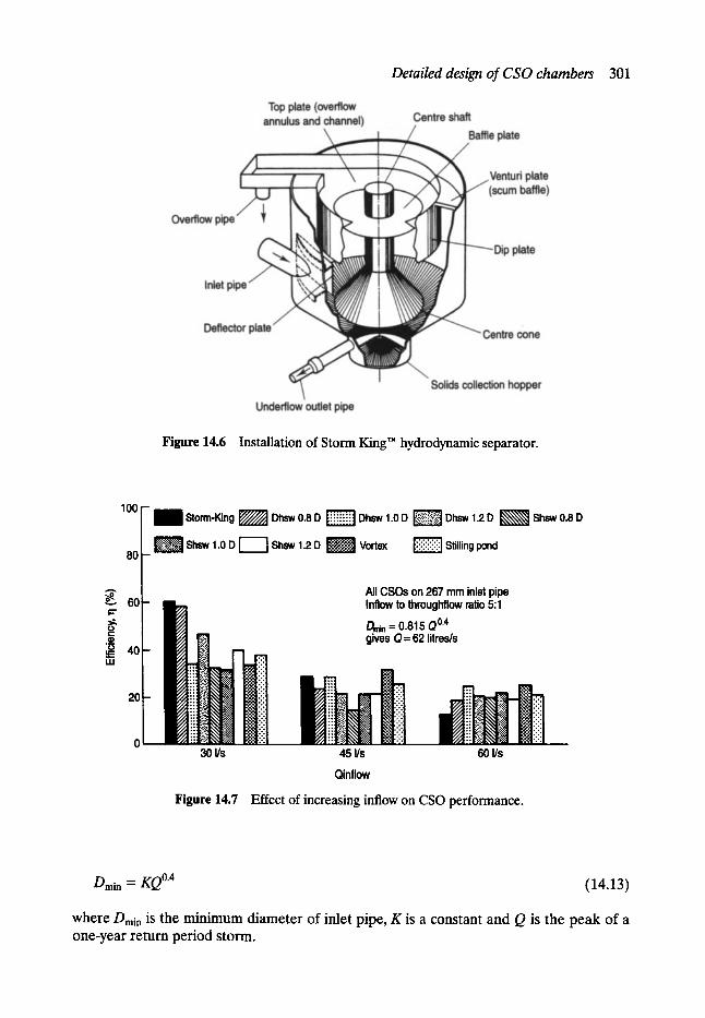
Detailed design of CSO chambers 301
Figure 14.6 Installation of Storm King" hydrodynamic separator.
100
80
A
60
t -
O . . .
~ 40 E
20
1 Storm-King ~ Dhsw 0.8 D [~iiiii~ Dhsw 1.0 D ~ Dhsw 1.2 D ~ ~ Shsw 0.8 D
[ ~ Shsw 1.0 D I I Shsw 1.2 D ~-:.';~] Vortex ~!ii!!ii!!i~ Stilling pond
All CSOs on 267 mm inlet pipe Inflow to throughflow ratio 5:1
Dm~ = 0.815 QO.4 gives Q= 62 litres/s
30 I/s 45 I/s 60 I/s
Qinflow
Figure 14.7 Effect of increasing inflow on CSO performance.
Dmin = g o 0"4 (14.13)
where Dmi n is the minimum diameter of inlet pipe, K is a constant and Q is the peak of a one-year return period storm.
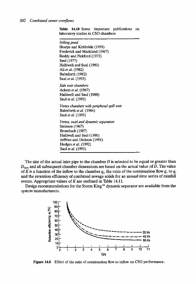
302 C o m b i n e d sewer overflows
Table 14.10 Some important publications on laboratory studies in CSO chambers
Stilling pond Sharpe and Kirkbride (1959) Frederick and Markland (1967) Reddy and Pickford (1973) Saul (1977) Halliwell and Saul (1980) Ali et al. (1982) Balmforth (1982) Saul et al. (1993)
Side weir chambers Ackers et al. (1967) Halliwell and Saul (1980) Saul et al. (1993)
Vortex chambers with peripheral spill weir Balmforth et al. (1984) Saul et al. (1993)
Vortex, swirl and dynamic separators Smisson (1967) Brombach (1987) Halliwell and Saul (1980) Jeffries and Dickson (1991) Hedges et al. (1992) Saul et al. (1993)
,
The size of the actual inlet pipe to the chamber D is selected to be equal or greater than Drain and all subsequent chamber dimensions are based on the actual value of D. The value of K is a function of the inflow to the chamber qi, the ratio of the continuation flow qc to qi and the retention efficiency of combined sewage solids for an annual time series of rainfall events. Appropriate values of K are outlined in Table 14.11.
Design recommendations for the Storm King'~ dynamic separator are available from the system manufacturers.
,00 A 90 o~ 80
70 60 ' ~ ' .
40 ~ . ~ . . . . . . . . . . . . . 30 I/s 30 "--. 45 I/s
~ 20 ~ 6 0 l / s 10 0 I I.,, I I I I I I I I J
0 1 2 .3 4 5 6 7 8 9 10 11 Ojq
Figure 14.8 Effect of the ratio of continuation flow to inflow on CSO performance.
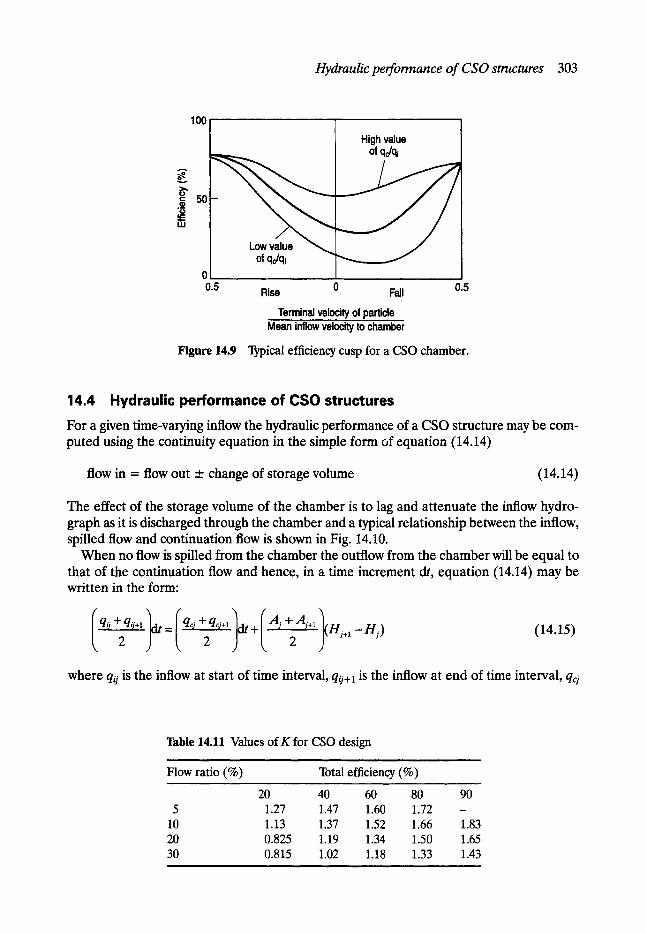
Hydraulic performance of CSO structures 303
100 High value
of qc/qi
5O ._m 0
Low value of qc/qi
0 0.5 Rise 0 Fall 0.5
Terminal velocity of particle Mean inflow velocity to chamber
Figure 14.9 Typical efficiency cusp for a CSO chamber.
14 .4 H y d r a u l i c p e r f o r m a n c e of C S O s t r u c t u r e s
For a given time-varying inflow the hydraulic performance of a CSO structure may be com- puted using the continuity equation in the simple form of equation (14.14)
flow in = flow out _.+ change of storage volume (14.14)
The effect of the storage volume of the chamber is to lag and attenuate the inflow hydro- graph as it is discharged through the chamber and a typical relationship between the inflow, spilled flow and continuation flow is shown in Fig. 14.10.
When no flow is spilled from the chamber the outflow from the chamber will be equal to that of the continuation flow and hence, in a time increment dt, equation (14.14) may be written in the form:
I q~176 2 2 (14.15)
where q~j is the inflow at start of time interval, qo+ 1 is the inflow at end of time interval, qcj
Table 14.11 Values of K for CSO design
Flow ratio (%) Total efficiency (%)
20 40 60 80 5 1.27 1.47 1.60 1.72
10 1.13 1.37 1.52 1.66 20 0.825 1.19 1.34 1.50 30 0.815 1.02 1.18 1.33
i
90 m
1.83 1.65 1.43
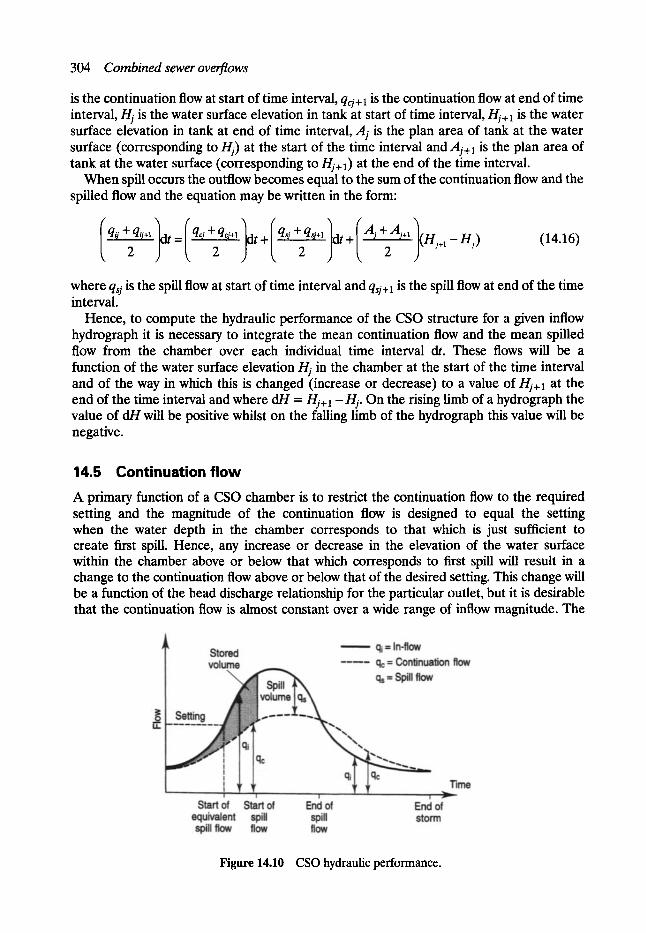
304 Combined sewer overflows
is the continuation flow at start of time interval, qcj+ 1 is the continuation flow at end of time interval, ~ is the water surface elevation in tank at start of time interval, ~+1 is the water surface elevation in tank at end of time interval, Aj is the plan area of tank at the water surface (corresponding to Hi) at the start of the time interval and Aj+I is the plan area of tank at the water surface (corresponding to ~-+1) at the end of the time interval.
When spill occurs the outflow becomes equal to the sum of the continuation flow and the spilled flow and the equation may be written in the form:
(qiJ2qij+l~--IqcJ2qcj+l~-blqsJ4~-2sj+lldtql-(AJ[-2J+ll(Hj+l-gj) (14.16)
where qsj is the spill flow at start of time interval and qsj+S is the spill flow at end of the time interval.
Hence, to compute the hydraulic performance of the CSO structure for a given inflow hydrograph it is necessary to integrate the mean continuation flow and the mean spilled flow from the chamber over each individual time interval dt. These flows will be a function of the water surface elevation/-/j in the chamber at the start of the time interval and of the way in which this is changed (increase or decrease) to a value of Hj+ 1 at the end of the time interval and where dH =/-/y+ 1 -- Hi. On the rising limb of a hydrograph the value of dH will be positive whilst on the falling limb of the hydrograph this value will be negative.
14.5 Continuation flow A primary function of a CSO chamber is to restrict the continuation flow to the required setting and the magnitude of the continuation flow is designed to equal the setting when the water depth in the chamber corresponds to that which is just sufficient to create first spill. Hence, any increase or decrease in the elevation of the water surface within the chamber above or below that which corresponds to first spill will result in a change to the continuation flow above or below that of the desired setting. This change will be a function of the head discharge relationship for the particular outlet, but it is desirable that the continuation flow is almost constant over a wide range of inflow magnitude. The
Figure 14.10 CSO hydraulic performance.
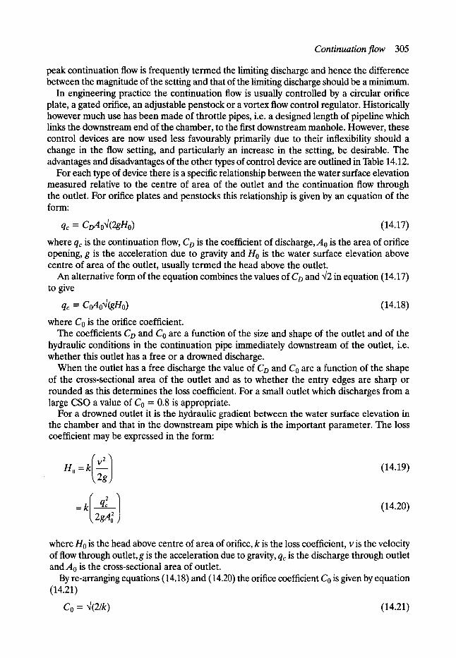
Continuation flow 305
peak continuation flow is frequently termed the limiting discharge and hence the difference between the magnitude of the setting and that of the limiting discharge should be a minimum.
In engineering practice the continuation flow is usually controlled by a circular orifice plate, a gated orifice, an adjustable penstock or a vortex flow control regulator. Historically however much use has been made of throttle pipes, i.e. a designed length of pipeline which links the downstream end of the chamber, to the first downstream manhole. However, these control devices are now used less favourably primarily due to their inflexibility should a change in the flow setting, and particularly an increase in the setting, be desirable. The advantages and disadvantages of the other types of control device are outlined in Table 14.12.
For each type of device there is a specific relationship between the water surface elevation measured relative to the centre of area of the outlet and the continuation flow through the outlet. For orifice plates and penstocks this relationship is given by an equation of the form:
qc = CoAo~l(2gHo) (14.17)
where qr is the continuation flow, Co is the coefficient of discharge, A0 is the area of orifice opening, g is the acceleration due to gravity and H0 is the water surface elevation above centre of area of the outlet, usually termed the head above the outlet.
An alternative form of the equation combines the values of CD and q2 in equation (14.17) to give
qc = CoAoq(gHo) (14.18)
where Co is the orifice coefficient. The coefficients CD and Co are a function of the size and shape of the outlet and of the
hydraulic conditions in the continuation pipe immediately downstream of the outlet, i.e. whether this outlet has a free or a drowned discharge.
When the outlet has a free discharge the value of Co and Co are a function of the shape of the cross-sectional area of the outlet and as to whether the entry edges are sharp or rounded as this determines the loss coefficient. For a small outlet which discharges from a large CSO a value of Co = 0.8 is appropriate.
For a drowned outlet it is the hydraulic gradient between the water surface elevation in the chamber and that in the downstream pipe which is the important parameter. The loss coefficient may be expressed in the form:
H~ = klV21~ 2g (14.19)
= k 2 q ~ (14.20)
where H0 is the head above centre of area of orifice, k is the loss coefficient, v is the velocity of flow through outlet, g is the acceleration due to gravity, q~ is the discharge through outlet and A0 is the cross-sectional area of outlet.
By re-arranging equations (14.18) and (14.20) the orifice coefficient Co is given by equation (14.21)
Co = q(2/k) (14.21)
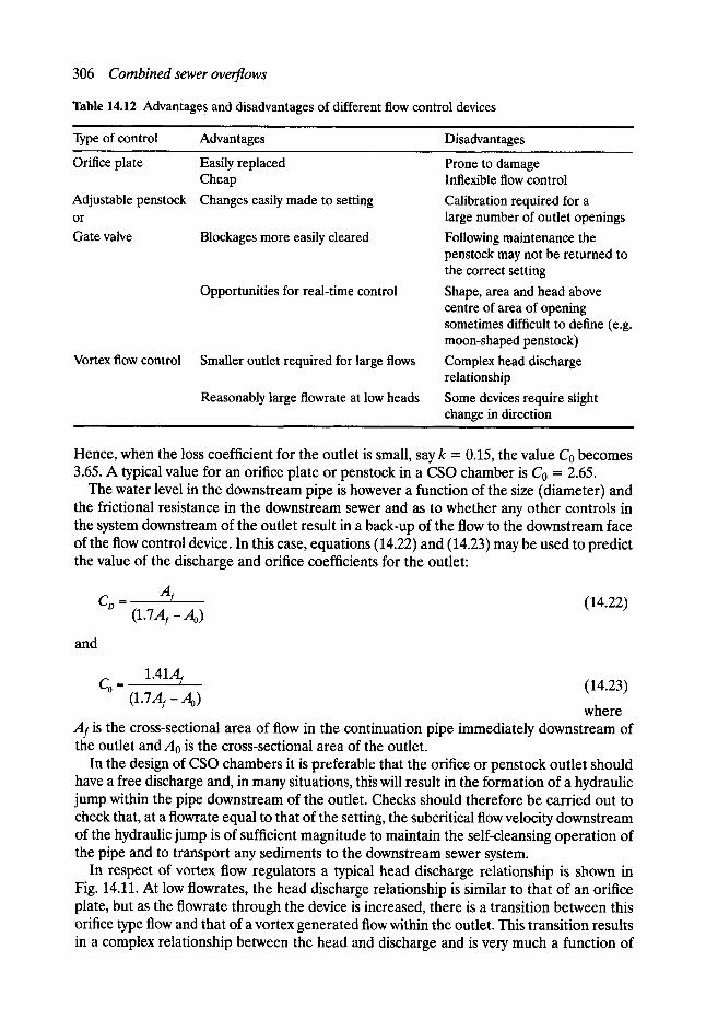
306 Combined sewer overflows
Table 14.12 Advantage s and disadvantages of different flow control devices
Type of control Advantages Disadvantages
Orifice plate Easily replaced Cheap
Adjustable penstock Changes easily made to setting or Gate valve Blockages more easily cleared
Opportunities for real-time control
Vortex flow control Smaller outlet required for large flows
Reasonably large flowrate at low heads
Prone to damage Inflexible flow control
Calibration required for a large number of outlet openings
Following maintenance the penstock may not be returned to the correct setting
Shape, area and head above centre of area of opening sometimes difficult to define (e.g. moon-shaped penstock)
Complex head discharge relationship
Some devices require slight change in direction
Hence, when the loss coefficient for the outlet is small, say k = 0.15, the value Co becomes 3.65. A typical value for an orifice plate or penstock in a CSO chamber is Co = 2.65.
The water level in the downstream pipe is however a function of the size (diameter) and the frictional resistance in the downstream sewer and as to whether any other controls in the system downstream of the outlet result in a back-up of the flow to the downstream face of the flow control device. In this case, equations (14.22) and (14.23) may be used to predict the value of the discharge and orifice coefficients for the outlet:
C~ -- Ar (14.22) (1.7A I -Ao)
and
Co= 1"41AI (14.23)
(I'7AI - A~ where
Af is the cross-sectional area of flow in the continuation pipe immediately downstream of the outlet and A0 is the cross-sectional area of the outlet.
In the design of CSO chambers it is preferable that the orifice or penstock outlet should have a free discharge and, in many situations, this will result in the formation of a hydraulic jump within the pipe downstream of the outlet. Checks should therefore be carried out to check that, at a flowrate equal to that of the setting, the subcritical flow velocity downstream of the hydraulic jump is of sufficient magnitude to maintain the self-cleansing operation of the pipe and to transport any sediments to the downstream sewer system.
In respect of vortex flow regulators a typical head discharge relationship is shown in Fig. 14.11. At low flowrates, the head discharge relationship is similar to that of an orifice plate, but as the flowrate through the device is increased, there is a transition between this orifice type flow and that of a vortex generated flow within the outlet. This transition results in a complex relationship between the head and discharge and is very much a function of
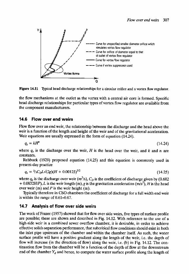
Flow over end weirs 307
, Y
t ............. r / / . . . . . Curve for unspecified smaller diameter orifice which simulates vortex flow regulator
�9 " - . . . . Curve for orifice of diameter equal to that ._- ' / of outlet of vortex flow regulator
/ / " Curve for vortex flow regulator �9 ~ ' " - . . . . . Curve if vortex suppression used
Vortex forms
Q
Figure 14.11 Typical head discharge relationships for a circular orifice and a vortex flow regulator.
the flow mechanisms at the outlet as the vortex with a central air core is formed. Specific head discharge relationships for particular types of vortex flow regulator are available from the component manufacturers.
14.6 Flow over end weirs
Flow flow over an end weir, the relationship between the discharge and the head above the weir is a function of the length and height of the weir and of the gravitational acceleration. Weir equations are usually expressed in the form of equation (14.24).
qs = k/~ (14.24)
where qs is the discharge over the weir, H is the head over the weir, and k and n are constants.
Rehbock (1929) proposed equation (14.25) and this equation is commonly used in present-day practice
qs = 2/3CDLx/(2g)(H + 0-00125) 3/2 (14.25)
where qs is the discharge over weir (m3/s), Co is the coefficient of discharge given by (0.602 + 0.0832H/P), L is the weir length (m), g is the gravitation acceleration (m/s2), H is the head over weir (m) and P is the weir height (m).
Typically therefore in CSO chambers the coefficient of discharge for a full width end weir is within the range of 0.61-0.67.
14.7 Analysis of flow over side weirs
The work of Frazer (1957) showed that for flow over side weirs, five types of surface profile are possible; these are shown and described in Fig. 14.12. With reference to the use of a high-side weir in a combined sewer overflow chamber, it is desirable, in order to achieve effective solids separation performance, that subcritical flow conditions should exist in both the inlet pipe upstream of the chamber and within the chamber itself. As such, the water surface profile will have a positive gradient along the length of the weir, i.e. the depth of flow will increase (in the direction of flow) along the weir, i.e. (b) in Fig. 14.12. The con- tinuation flow from the chamber will be a function of the depth of flow at the downstream end of the chamber Yd and hence, to compute the water surface profile along the length of
308 Combined sewer overflows
the weir, the analysis must start from the known conditions of Yd and Qd at the downstream end of the weir. De Marchi (1934) used an energy approach to describe the spatially varied flow over a side weir in a channel of constant width and slope. The specific energy of the flow was assumed constant where
dr:[ yO ]l O dx Q2 __ gn2y3 dx (14.26)
where y is the water surface elevation at distance x along the weir, Q is the main channel flowrate, B is the channel width, dQ/dx or the discharge over the weir per unit length and which equals -q with
q = 2/3CD~[(2g)n 3/2 (14.27)
where H = y - p . By integration De Marchi developed the following expression
with
f 2 E - 3_p E - y _ 3sin_ ~ - y = E p p
(14.29)
where Yu is the water depth at upstream end of weir, Yd is the water depth at downstream end of weir, E is the specific energy of flow and is equal to y + aV2/2g (assumed constant).
Values of f(y/E) were presented in graph form and these may be used to compute the spatially varied flow over an existing weir or to compute the length of weir required to spill a given proportion of the main channel flow.
More complete solutions were presented by Chow (1959) in which the governing equations were represented in a finite difference form and solved using an iterative approach. Balmforth (1978) presented a mathematical model for the flow over a side weir based on a momentum approach in which the longitudinal component of the velocity of the side weir spilled flow was is taken as being equal to the mean velocity of the mainstream flow. Application of the momentum equation over a short length of a weir section in a rectangular channel with a shallow uniform slope gave the following equation
dy [ 0-2#) --~ = S~ - Sr - qv gby (14.30)
where fl is the momentum coefficient (found to be constant at 1.06). The friction gradient Sf, was expressed using Manning's equation
Sf = (nv)2/R 4/3 (14.31)
and the perpendicular component of flow was described by the transverse weir equation
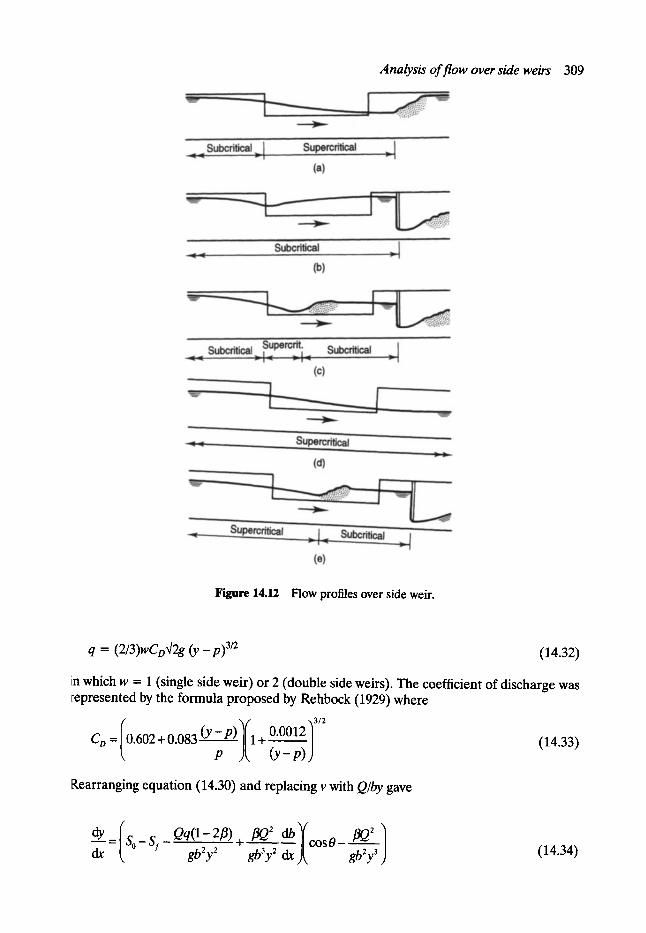
Analysis of flow over side weirs 309
Figure 14.12 Flow profiles over side weir.
q = (2/3)wCo~/2g (y _p)3/2 (14.32)
in which w = 1 (single side weir) or 2 (double side weirs). The coefficient of discharge was represented by the formula proposed by Rehbock (1929) where
_ (o 6o2+o o83 + o oo12 3,2 (14.33)
Rearranging equation (14.30) and replacing v with Q/by gave
dy So_s i_aq(1 2 f l ) + ~ cosO- dr, gb2y 2 gb3y 2 dx gb~y 3 (14.34)

310 Combined sewer overflows
As b is a function ofx, equation (14.34) can be written
dy/dx = F(x, y, Q) (14.35)
and, also, because q is a function of y, and dQ/dx = - q
dQ/dx = G(y) (14.36)
In the design of high-side weir chambers, however, it is usual that the maximum inflow qi and the maximum flow to treatment qc are specified as design parameters. Clearly, to design the geometry of a suitable side weir using these equations, it is necessary to vary the down- stream depth of flow and to solve the governing equations until the specified value of the inflow qi is attained. An iterative procedure is therefore required to solve equations (14.35) and (14.36).
Delo and Saul (1989) presented a graphical approach to predict the relationship between inflow, continuation flow and flow depth over the weir for a particular geometry of chamber. Their method was based on a dimensional analysis approach linked to the numerical solution of the equations (14.35) and (14.36) using a fourth-order Runge-Kutta numerical integration technique.
The parameters which influence the flow over a side weir may be expressed in the following form:
(Yu, qi) = (0f(P, ! t, r g, Yd, qc, L, Pu, ed, Bu, Bd, w, So, n) (14.37)
where suffix u denotes upstream and suffix d downstream with Yequal to the depth of flow, P the height of the weir, B the width of the chamber, w the number of weirs, So the longi- tudinal gradient of the chamber and n the Manning roughness coefficient, p,/z and t~ are the density, dynamic viscosity and surface tension of the liquid, respectively.
Using the dimensional analysis technique developed by Whittington (1963)with p, Bu and g as the measure system, equation (14.37) may be expressed in dimensionless form:
111032112 Yu q2 = f I-'Du • pBug Ya qc L Pu B d nu ' gnSu 11 ' r ' nu ' qi ' nu ' nu ' nu
,w, So, n i (14.38)
The term Q2u/gffu is analogous to the Froude number, and the terms pBu3/2gl/2/12 and pB~g/t5 are the Reynolds and Weber numbers, respectively. For similarity, it is not possible to satisfy equal values of each of these dimensionless groups simultaneously. However, for fully developed turbulent flow, the effects of viscosity and surface tension will be small, and hence the out-of-scale effects of the Reynolds and Weber numbers may be ignored, with similarity based on Froudian criteria.
Further, by expressing the flow depths at the upstream and downstream end of the weir relative to the height of the weir crest gives
/ / Y,,-Pu q2 = f ,-- 'g B5 flu q , ~ , ~ ,-~ ,w, (14.39)
Equation (14.39) may be represented in the form of a design chart by selecting four of the dimensionless groups as variables (axis) and by keeping the remaining six groups con-
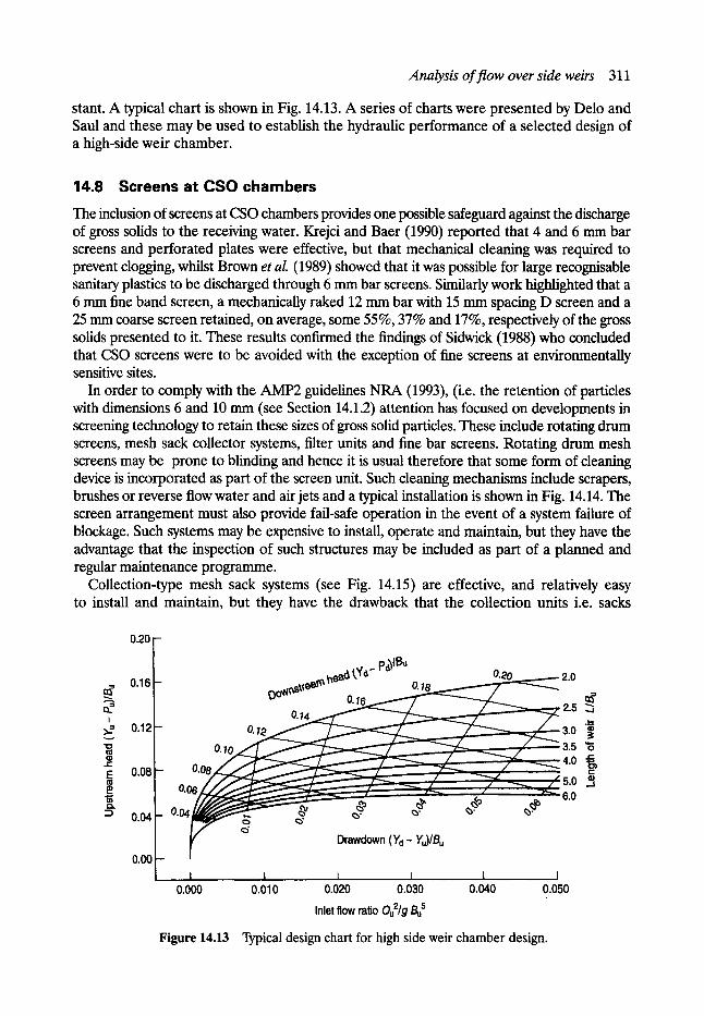
Analysis of flow over side weirs 311
stant. A typical chart is shown in Fig. 14.13. A series of charts were presented by Delo and Saul and these may be used to establish the hydraulic performance of a selected design of a high-side weir chamber.
14.8 Screens at CSO chambers
The inclusion of screens at CSO chambers provides one possible safeguard against the discharge of gross solids to the receiving water. Krejci and Baer (1990) reported that 4 and 6 mm bar screens and perforated plates were effective, but that mechanical cleaning was required to prevent dogging, whilst Brown et al. (1989) showed that it was possible for large recognisable sanitary plastics to be discharged through 6 mm bar screens. Similarly work highlighted that a 6 mm fine band screen, a mechanically raked 12 mm bar with 15 mm spacing D screen and a 25 mm coarse screen retained, on average, some 55%, 37% and 17%, respectively of the gross solids presented to it. These results confirmed the findings of Sidwick (1988) who concluded that CSO screens were to be avoided with the exception of fine screens at environmentally sensitive sites.
In order to comply with the AMP2 guidelines NRA (1993), (i.e. the retention of particles with dimensions 6 and 10 mm (see Section 14.1.2) attention has focused on developments in screening technology to retain these sizes of gross solid particles. These include rotating drum screens, mesh sack collector systems, filter units and fine bar screens. Rotating drum mesh screens may be prone to blinding and hence it is usual therefore that some form of cleaning device is incorporated as part of the screen unit. Such cleaning mechanisms include scrapers, brushes or reverse flow water and air jets and a typical installation is shown in Fig. 14.14. The screen arrangement must also provide fail-safe operation in the event of a system failure of blockage. Such systems may be expensive to install, operate and maintain, but they have the advantage that the inspection of such structures may be included as part of a planned and regular maintenance programme.
Collection-type mesh sack systems (see Fig. 14.15) are effective, and relatively easy to install and maintain, but they have the drawback that the collection units i.e. sacks
0.20
0.16 cff cff
I ~ 0.12
I1) r -
E 0.08 m
::a 0.04
0.00
0.08 0.10
0.14 ~ , . r
0.18 0.20
_ 0 .~
I 0.000
Drawdown (Yd - Yu)lBu
0.010 0.020 0.030 0.040
Inlet flow ratio Ou2/g Bu s
2.0
,:s 2.5 . . .j
L.
3.0 3.5 "6 4.0
r
s.o ~, 6.0
I
0.050 ,,.
Figure 14.13 Typical design chart for high side weir chamber design.
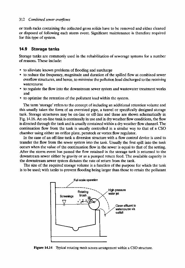
312 Combined sewer overflows
or trash racks containing the collected gross solids have to be removed and either cleaned or disposed of following each storm event. Significant maintenance is therefore required for this type of system.
14 .9 S t o r a g e t a n k s
Storage tanks are commonly used in the rehabilitation of sewerage systems for a number of reasons. These include:
�9 to alleviate known problems of flooding and surcharge �9 to reduce the frequency, magnitude and duration of the spilled flow at combined sewer
overflow structures, and hence, to minimise the pollution load discharged to the receiving watercourse
�9 to regulate the flow into the downstream sewer system and wastewater treatment works and
�9 to optimise the retention of the pollutant load within the system.
The term 'storage' refers to the concept of including an additional retention volume and this usually takes the form of an oversized pipe, a tunnel or specifically designed storage tank. Storage structures may be on-line or off-line and these are shown schematically in Fig. 14.16. An on-line tank is continually in use and in dry weather flow conditions, the flow is directed through the tank and is usually contained within a dry weather flow channel. The continuation flow from the tank is usually controlled in a similar way to that of a CSO chamber using either an orifice plate, penstock or vortex flow regulator.
In the case of an off-line tank a diversion structure with a flow control device is used to transfer the flow from the sewer system into the tank. Usually the first spill into the tank occurs when the value of the continuation flow in the sewer is equal to that of the setting. After the storm event has passed the flow retained in the storage tank is returned to the downstream sewer either by gravity or as a pumped return feed. The available capacity in the downstream sewer system dictates the rate of return from the tank.
The size of the required storage volume is a function of the purpose for which the tank is to be used; with tanks to prevent flooding being larger than those to retain the pollutant
Full-scale operation
Rotating'"""" High pressure " " , ,= / water jet brush Screenings _ ' \ \
�9 o o
I Clean effluent to / ~ watemourse via
[ outfall
Figure 14.14 Typical rotating mesh screen arrangement within a CSO structure.
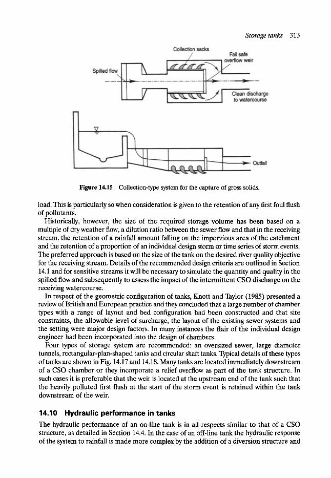
Storage tanks 313
Figure 14.15 Collection-type system for the capture of gross solids.
load. This is particularly so when consideration is given to the retention of any first foul flush of pollutants.
Historically, however, the size of the required storage volume has been based on a multiple of dry weather flow, a dilution ratio between the sewer flow and that in the receiving stream, the retention of a rainfall amount falling on the impervious area of the catchment and the retention of a proportion of an individual design storm or time series of storm events. The preferred approach is based on the size of the tank on the desired river quality objective for the receiving stream. Details of the recommended design criteria are outlined in Section 14.1 and for sensitive streams it will be necessary to simulate the quantity and quality in the spilled flow and subsequently to assess the impact of the intermittent CSO discharge on the receiving watercourse.
In respect of the geometric configuration of tanks, Knott and Taylor (1985) presented a review of British and European practice and they concluded that a large number of chamber types with a range of layout and bed configuration had been constructed and that site constraints, the allowable level of surcharge, the layout of the existing sewer systems and the setting were major design factors. In many instances the flair of the individual design engineer had been incorporated into the design of chambers.
Four types of storage system are recommended: an oversized sewer, large diameter tunnels, rectangular-plan-shaped tanks and circular shaft tanks. Typical details of these types of tanks are shown in Fig. 14.17 and 14.18. Many tanks are located immediately downstream of a CSO chamber or they incorporate a relief overflow as part of the tank structure. In such cases it is preferable that the weir is located at the upstream end of the tank such that the heavily polluted first flush at the start of the storm event is retained within the tank downstream of the weir.
14.10 Hydraulic performance in tanks The hydraulic performance of an on-line tank is in all respects similar to that of a CSO structure, as detailed in Section 14.4. In the case of an off-line tank the hydraulic response of the system to rainfall is made more complex by the addition of a diversion structure and
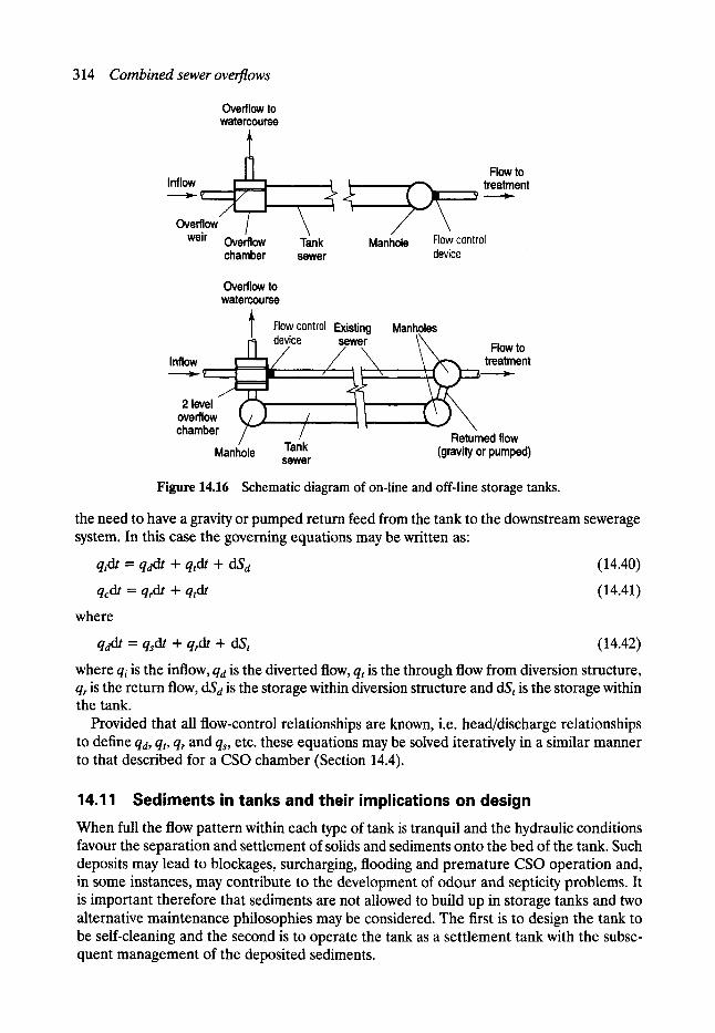
314 Combined sewer overflows
Overflow to watercourse
t N Inflow i ~_
- ' - ~ / ~ !, Overflow /
weir Overflow chamber
Tank sewer
Flow to / ~ , / ~ 1 ~ treatment
Manhole Flow control device
Overflow to watercourse
l Flow control Existing Manholes
Inflow ~ device sewer \ ~ Flow to I_ !,,/// / ~ - x , \ /~-,~_ treatment
------~- ,Z ~ . , ~1 " r ~ ~
2 level ~ l ~ overflow t~/1 ~l chamber F / Returned flow
Manhole Tank (gravity or pumped) sewer Figure 14.16 Schematic diagram of on-line and off-line storage tanks.
the need to have a gravity or pumped return feed from the tank to the downstream sewerage system. In this case the governing equations may be written as:
qidt = qddt -I- qrdt + dSd (14.40)
qcdt = qrdt + qtdt (14.41)
where
qddt = qsdt + qrdt + dSt (14.42)
where qi is the inflow, qa is the diverted flow, qt is the through flow from diversion structure, q~ is the return flow, dSd is the storage within diversion structure and dSt is the storage within the tank.
Provided that all flow-control relationships are known, i.e. head/discharge relationships to define qa, qt, qr and q~, etc. these equations may be solved iteratively in a similar manner to that described for a CSO chamber (Section 14.4).
14.11 Sediments in tanks and their implications on design When full the flow pattern within each type of tank is tranquil and the hydraulic conditions favour the separation and settlement of solids and sediments onto the bed of the tank. Such deposits may lead to blockages, surcharging, flooding and premature CSO operation and, in some instances, may contribute to the development of odour and septicity problems. It is important therefore that sediments are not allowed to build up in storage tanks and two alternative maintenance philosophies may be considered. The first is to design the tank to be self-cleaning and the second is to operate the tank as a settlement tank with the subse- quent management of the deposited sediments.
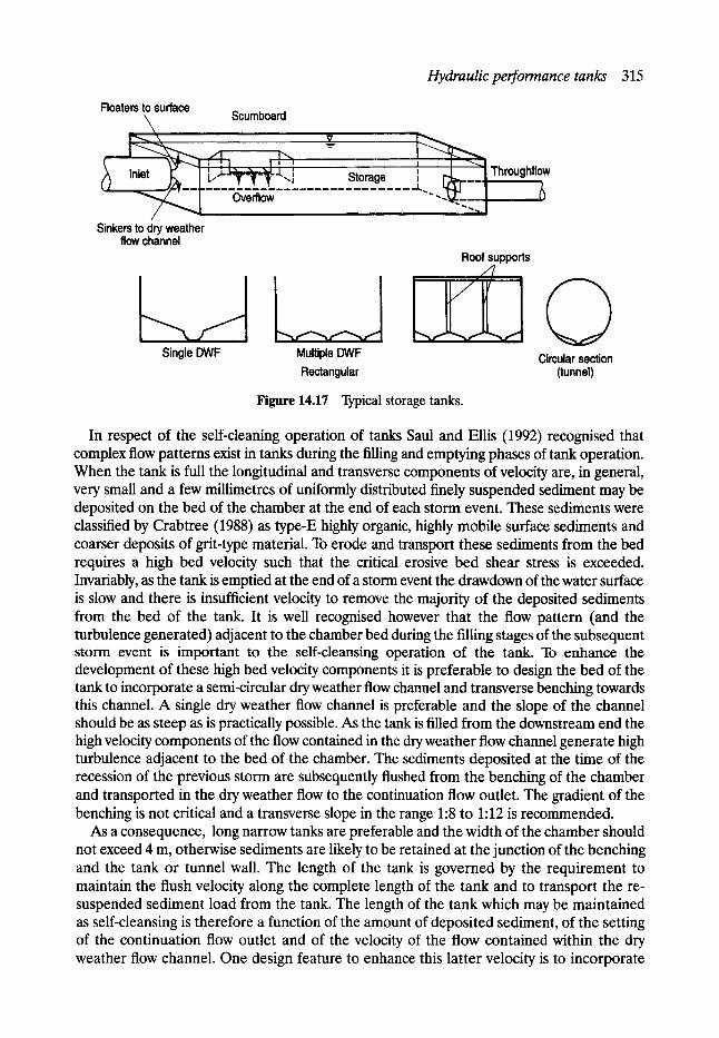
Hydraulic performance tanks 315
Floaters to surface
t
.....,~ Scumboard
i ' I I i i l i ~ I L.."--T-~-~-"-.J Storage ', Throughflow
Overflow ii
Sinkers to dry weather flow channel
Single DWF Multiple DWF Rectangular
Roof supports i ~ n i=
Circular section (tunnel)
Figure 14.17 Typical storage tanks.
In respect of the self-cleaning operation of tanks Saul and Ellis (1992) recognised that complex flow patterns exist in tanks during the filling and emptying phases of tank operation. When the tank is full the longitudinal and transverse components of velocity are, in general, very small and a few miUimetres of uniformly distributed finely suspended sediment may be deposited on the bed of the chamber at the end of each storm event. These sediments were classified by Crabtree (1988) as type-E highly organic, highly mobile surface sediments and coarser deposits of grit-type material. To erode and transport these sediments from the bed requires a high bed velocity such that the critical erosive bed shear stress is exceeded. Invariably, as the tank is emptied at the end of a storm event the drawdown of the water surface is slow and there is insufficient velocity to remove the majority of the deposited sediments from the bed of the tank. It is well recognised however that the flow pattern (and the turbulence generated) adjacent to the chamber bed during the filling stages of the subsequent storm event is important to the self-cleansing operation of the tank. To enhance the development of these high bed velocity components it is preferable to design the bed of the tank to incorporate a semi-circular dry weather flow channel and transverse benching towards this channel. A single dry weather flow channel is preferable and the slope of the channel should be as steep as is practically possible. As the tank is filled from the downstream end the high velocity components of the flow contained in the dry weather flow channel generate high turbulence adjacent to the bed of the chamber. The sediments deposited at the time of the recession of the previous storm are subsequently flushed from the benching of the chamber and transported in the dry weather flow to the continuation flow outlet. The gradient of the benching is not critical and a transverse slope in the range 1:8 to 1:12 is recommended.
As a consequence, long narrow tanks are preferable and the width of the chamber should not exceed 4 m, otherwise sediments are likely to be retained at the junction of the benching and the tank or tunnel wall. The length of the tank is governed by the requirement to maintain the flush velocity along the complete length of the tank and to transport the re- suspended sediment load from the tank. The length of the tank which may be maintained as self-cleansing is therefore a function of the amount of deposited sediment, of the setting of the continuation flow outlet and of the velocity of the flow contained within the dry weather flow channel. One design feature to enhance this latter velocity is to incorporate
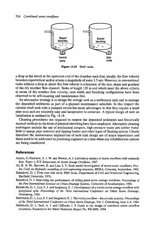
Central sump
Combined sewer overflows 316
Sloped benching
, ~ "-, _-n 'x
Side sump
Figure 14.18 Shaft tanks.
a drop in the invert at the upstream end of the chamber such that, ideally, the flow velocity becomes supercritical and/or attains a magnitude of some 1.5 m/s. However, in conventional tanks without a drop in invert this flow velocity is a function of the size, shape and gradient of the dry weather flow channel. Tanks of length 120 m and which meet the above criteria in terms of dry weather flow velocity, tank width and benching configuration have been observed to be self-cleaning and maintenance-free.
An alternative strategy is to design the storage tank as a settlement tank and to manage the deposited sediments as part of a planned maintenance schedule. In this respect the circular shaft tank with a pumped return has many advantages in that they require a small plan area and are relatively easy and inexpensive to construct. A typical design of such an installation is outlined in Fig. 14.18.
Cleaning procedures are required to remove the deposited sediments and historically manual methods in the form of physical shovelling have been employed. Alternative cleaning techniques include the use of mechanical scrapers, high-pressure water jets (either hand- held or sparge pipe systems) and tipping bucket and other types of flushing system. Clearly therefore the maintenance implications of such tank design are of major importance and these need to be addressed by practising engineers at a time when any rehabilitation options are being considered.
References Ackers, P., Harrison, A. J. M. and Brewer, A. J. Laboratory studies of storm overflows with unsteady
flow. Paper 4, ICE Symposium on Storm-Sewage Overflows, 1967. Ali, K. H. M., Burrows, R. and Lim, S. Y. Scale model investigation of storm-water overflows. Proc.
Int. Conf. on Hydraulic modelling of civil engineering structures, BHRA, Coventry, September, 1982. Balmforth, D. J. Flow over side weirs. PhD thesis, Department of Civil and Structural Engineering,
Sheffield University, 1978. Balmford, D. J. Improving the performance of stilling pond storm sewage overflows. Proceedings of
the First International Seminar on Urban Drainage Systems, University of Southampton, 1982. Balmforth, D. J., Lea, S. J. and Sarginson, E. J. Development of a vortex storm sewage overflow with
peripheral spill. Proceedings of the Third International Conference on Urban Storm Drainage, G6tenborg, 1984.
Balmforth, D. J., Lea, S. J. and Sarginson, E. J. The vortex overflow- theory into practice. Proceedings of the Third International Conference on Urban Storm Drainage, Vol. 3, G6tenborg, June 4-8, 1984.
Balmforth, D. J., Saul, A. J. and Clifforde, I. T. Guide to the design of combined sewer overflow structures. Foundation for Water Research, Report No. FR.0498, 1994.

Sediments in tanks and their implications on design 317
Brombach, H. Liquid-solid separation at vortex storm overflows. Fourth International Conference on Urban Storm Drainage, Lausanne 1987.
Brown, Set al. Preliminary Treatment of Marine Outfalls - User's Guide. Welsh Water/WRc, Wallingford, 1989.
Chow, V. T. Open Channel Hydraulics, pp. 327-353. McGraw-Hill, New York, 1959. Crabtree, R. W. A classifcation of combined sewer sediment types and deposits characteristics, WRc
Report No. FR0040, FWR, Marlow, 1988. De Marchi, G. Saggio di teoria del funzionamento degli stramazzi laterali (Essay of the performance
of lateral weirs). L'Energia Elettrica, Vol. 11, pp. 849-860, 1934. Delo, E. A. and Saul, A. J. Charts for the hydraulic design of high side weirs in storm sewage overflows.
Proc. Inst. Civil Engrs, Vol. 87, pp. 175-193, 1989. Frazer, W. The behaviour of side weirs in prismatic rectangular channels. Proc. Inst. Civil Engrs, Vol.
6, February, 1957. Frederick, M. R. and Markland, E. The performance of stilling ponds in handling solids. Paper 5, ICE
Symposium on Storm-Sewage Overflows, 1967. Green, M. J. Assessment of sewer overflow performance. WRc, Report No. UM 1193, 1991. Halliwell, A. R. and Saul, A. J. The use of hydraulic models to examine the performance of storm
sewage overflows. Proc. Inst. CAvil Engrs, Vol. 69, pp. 245-259, 1980. Hedges, Lockley, Martin and Novatech. A field study of an hydrodynamic separator CSO. Int. Conf.
On Innovative Technologies in the Domain of Urban Storm Drainage, Lyon, pp. 349-358, 1992. Jefferies, C. and Dickson, R. The design construction and performance assessment of a Stormking"
storm sewage overflow./WEM, Vol. 5 pp. 150-157, 1991. Knott, G. E. and Taylor, A. J. The use of detention tanks for attenuation - a review of current practice.
WRc, Report No. ER 171E, 1985. Krejci, V. and Baer, E. Screening structures for combined sewer overflow treatment in Switzerland.
Proc. 5th Int. Conf. on Urban Storm Drainage, Osaka, 1990. Ministry of Housing and Local Government, Technical Committee on Storm Overflow and the
Disposal of Storm Sewage. Final report, HMSO, 1970. Morris, G. The new standards - what it means in practice. Combined Sewer Overflows - Complying
with the new NRA Standards, Hydro Research and Development Seminar, Leeds, June, 1993. National Rivers Authority (NRA). Guidlines forAMP2, Periodic Review, Version 2, 1993. Reddy, Y. R. and Pickford, J. Stilling pond storm overflow studies. J. Sanitary Engng Div. Proc. Am.
Soc. Civil Engng, Vol. 98, No. SA4, pp. 609-622, 1973. Rehbock, T. Wassermessung mit Scharf Kautigan uber fallwehren. Z. Ver. dt. Ing., Vol. 73, pp. 817-823,
1929. Saul, A. J. The performance of storm sewage chambers. PhD thesis, Department of Civil Engineer-
ing, Heriot-Watt University, 1977. Saul, A. J. and Ellis, D. R. Sediment deposition in storage tanks. Water Sci. Tech.,Vol. 25, No. 8,
189-198, 1992. Saul, A. J., Ruff, S. J., Walsh, A. M. and Green, M. J. Laboratory Studies of CSO Performance. Report
No. UM 1421, 1993. Scottish Development Department Working Party on Storm Sewage (Scotland). Storm Sewage
Separation and Disposal, HMSO, Edinburgh 1977. Sharpe, D. E. and Kirkbride, T. W. Storm water overflows: operation and design of a stilling pond.
Proc. Inst. Civil Engrs, Vol 13, pp. 445-466, 1959. Sidwick, J. M. Screenings and grit in sewage: removal, treatment and disposal phase 3, stormwater
overflow and pumping station. Technical Note 132, CIRIA, London, 1988. Smisson, B. Design, construction and performance of vortex overflows. Proceedings of the Symposium
of Storm Sewage Overflows, Institution of Civil Engineers, pp. 81-92, London, 1967. Water Research Centre. Sewerage Rehabilitation Manual, 3rd edn, 1994. Whittington, R. B. A simple dimensional method for hydraulic problems. Proc. Am. Soc. C. E. J. Hyd.
Div., Vol. 89, No. HY5, September, 1963.

15 Contract Strategy
N. J. Smith* BSc, MSc, PhD, MICE, MAPM
15.1 Introduction The repair and renovation of sewers necessitates the use of a variety of contract strategies to cope with the range of client's requirements and physical site conditions. The scale of the works is likely to vary from minor, discontinuous repairs to individual pipes, with the emphasis on the minimum disruption of highway and other services, to relatively substantial contracts for the renovation of complete lengths of sewer in the minimum time. Conse- quently, the selection of the appropriate contract strategy to meet the client's objectives and to allocate responsibility between the parties, in an economical and time-efficient manner, is one of the most important decisions to be made.
In sewer repair and renovation work a number of different organisations may be consider- ed as the client. In the UK the water companies are the owners of the sewer infrastructure and are the clients for all major works, including the trunk sewers and treatment facilities. However, for the majority of the non-trunk sewers the relevant local authority, which could be a borough, or city authority, acts as agent to the water company. Consequently in terms of awarding contracts for repair and renovation, the agent is the client. There are also a number of private companies, usually manufacturing or processing companies with effluent which cannot be discharged directly into a public sewer without pretreatment, that act as client, directly awarding contracts for maintenance. Depending on the in-house expertise which the client possesses, the client's requirements can range from contracting out all responsibility for design, management and construction to being responsible for the design, project management, contract administration and, occasionally, the supervision of a direct labour organisation (DLO).
The term 'contract strategy' is used to describe the overall decision making process under- gone by the client in defining the organisation and procedures required for the design and construction of a project. These decisions affect the responsibilities of the parties and influence their coordination. Therefore, they affect the time, cost and quality of the works. Usually, the principal contractual relationship is between the client and the main contractor; with the implied understanding that the client wishes to obtain the completed job to specification and that the main contractor wishes to make a reasonable profit.
*Professor, Department of Civil Engineering, University of Leeds.

Organisational structure 319
The selection of a contract strategy is dependent on making sets of decisions in four main areas, which have a degree of interrelationship. These areas are, firstly, the characteristics of the project, secondly, the organisational structure of the parties to the contract, thirdly, the type of contract and finally the tendering process. The optimal contract strategy will only be obtained by a set of decisions which recognises the significance of integrating the individ- ual choices in each area of strategic choice.
15.2 Project characteristics In order to develop an optimal contract strategy the objectives of the client must be clearly and precisely determined. The main points to be decided by the client are the key objectives, their own role in the contract and the implications of the type of work to be undertaken.
The key objectives of any contract can usually be defined in terms of completion in the minimum time, completion for the minimum cost, construction to the appropriate quality or responsibility for the management of risk. Frequently, more than one of these objectives are fundamental to the client and this may cause a conflict which the client or the client's project manager has to resolve before a contract strategy can be selected.
The nature of the works can have implications for the levels of technical competence required from contractors and the possibility of additional needs for a multidisciplinary workforce and management. Working under a highway, as is the case in most of the cities and towns in the UK, there is often a need to coordinate the works with the other public sector and private sector utilities located nearby. This requires competence in industrial relations, as well as experience in working within heavily trafficked highway networks.
15.3 Organisational structure The inherent nature of repair and renovation work tends to restrict the practical choices for the organisation of design and construction work. In the UK for all construction work there are four main types of organisational structure currently in use; these are the direct labour (force account), organisation, the conventional system, the management contracting organi- sation and the package deal. Management contracting and the three forms of package deal, design and build, turnkey and build-own-operate-transfer, are becoming increasingly impor- tant for new works but are scarcely, if ever, used for maintenance works in the UK at present. In France and other countries, however, 'concession' contracts, a variation of the build- own-operate-transfer contract, have been used for over 100 years and the concessionaire has the responsibility for maintenance during the operational phase of the concession. The length of the operating phase is very important as the client naturally wishes to avoid the transfer of a facility which will require major renovation in a short period of time.
15.3.1 DIRECT LABOUR OR FORCE ACCOUNT
The term 'direct labour' is used to describe the construction workforce which consists of direct employees of the client. Since the turn of the century many UK local authorities had established DLOs, to undertake both new construction and routine and preventative maintenance work on roads and bridges, on the public sector housing stock and, usually in their role as agents to a water company, and formerly to a water authority, on the sewer systems. The main benefits of this type of organisation are that the workforce possess the relevant skills, that there is a wealth of historical data about the construction, operation and

320 Contract strategy
maintenance of the system and that, where applicable, the removal of the need for com- petitive tendering can allow an early start; which is often important in emergency or maintenance work. A further benefit is the flexibility of the workforce. This is possible because of the wide range of duties undertaken by the employees which can accommodate discontinuous working, or small value works, or even large-scale emergency repairs much more economically than a private contractor. However, as the scale of the works increase and the need for immediate action is reduced main contractors tend to offer the client a financial advantage.
With the downturn in the UK economy in the late 1970s and early 1980s and rises in unemployment it became even more important that DLOs should be tested against the private sector to confirm that they were still providing value for money and appropriate levels of service to the benefit of ratepayers and central government alike. In 1980, therefore, legislation was enacted (Local Government, Planning and Land Act 1980, Part 3), which laid down broad principles for the operation of DLOs. This was followed by several statutory instruments which said that a local authority should not use direct labour for the majority of its work unless it can demonstrate that to do so would save money.
The regulations, drawn up in the UK in the 1980s, restrict the sewerage work which can be undertaken by a DLO, without competitive tender, to contracts of up to s Each DLO is also required to make a rate of return on capital employed of at least 5% (under current legislation), in each of the following four specified categories of work:
�9 maintenance �9 new construction under s �9 new construction over s �9 highways and sewers.
This means that DLO prices now have to include for a rate of return so that they can be more easily compared with private firms in performance and tender competition. Similarly, all overhead and central establishment charges have to be allocated so that DLO prices represent a true cost to the client.
In order to minimise delays in the execution of sewerage repairs and renovation, but still comply with the regulations, most local authorities award annual term contracts based on schedules of prices. DLOs can of course bid for these contracts in competition with outside, private contractors.
There are two organisational structures for the direct labour approach and these are illustrated in Fig. 15.1(a) and (b), the pure DLO structure and the construction only DLO structure. The difference between the two is the provision of design expertise. In the pure DLO the designers are also employees of the client, although in different sections, and hence both the design and construction expertise is provided in-house. In the construction only
(Fee) r . . . . . . . . . . I I I
[ Consultant I (b)'
, i l l Client In-house design
Workforce
(a)
Figure 15.1 The two organisational structures for the direct labour approach.

The engineer 321
organisational structure the design expertise is provided by an external consultant. Both strategies can be suitable for sewer repair and renovation.
15.3.2 THE CONVENTIONAL SYSTEM
During the eighteenth century, works of public utility in the UK were carried out by engi- neers who conceived the works, broadly designed them and then undertook their construc- tion by using direct labour recruited locally. It was not until the nineteenth century that contractors, as we know them today, gradually made their appearance due to the emergence of people of character and initiative who were prepared to tackle construction works of this nature on a profit basis.
The conventional or traditional system for the organisation of the design and construc- tion of civil engineering works originated in the UK and reflects the historical development of the industry. The basis of the system is the complete separation of the design and construction functions. This relates to the growth from the time of Brunel, Stephenson and Locke, of individuals and partnerships who undertook design work, now referred to as consultants and individuals and organisations who were responsible for the large numbers of manual workers who undertook the construction and were referred to as general contrac- tors. Many other countries have integrated these and other functions, including manufac- turing industry and financial operations, to form large engineering companies able to offer a wide range of services to the client.
The UK construction industry is changing in response to the increasingly competitive markets and the impact of the single European market, but the conventional organisational method still accounts for about three-quarters of all UK construction work, and is widely used for sewer repair and renovation works.
Under this system the client has separate contracts for design and construction. Initially the client places a contract with a consultant for the detailed design of the works, usually on the basis of fee competition. The consultant usually completes the design prior to the client going to tender for the construction-only contract and is also responsible for preparing the tender documents and assisting in the evaluation of the returned tender bids. Once the client has appointed a main contractor then the consultant is responsible for liaison with the contractor throughout the duration of the work and for the general administration of the contract. It also is possible that some schemes might be designed directly by the water company in-house and then divided between the agents company and/or contractors operating within the water area, each of whom will act as client on their part of the works.
There are again two variants on the organisational structure for the conventional contract and these are illustrated in Figs 15.2(a) and (b); the conventional system and the authority- conventional system. The difference between the two is again in the provision of design expertise. In the conventional organisational structure there are three distinct parties, the client, the consultant and the contractor, whereas, in the authority--conventional organisa- tional structure the 'consultants' are also employees of the client. Once again both strategies can be used for sewer repair and renovation work.
15.4 The engineer The functions of the engineer in connection with a civil engineering contract include not only the design and technical direction of the work and the inspection of materials and workmanship but also a variety of administration duties; including, where appropriate the
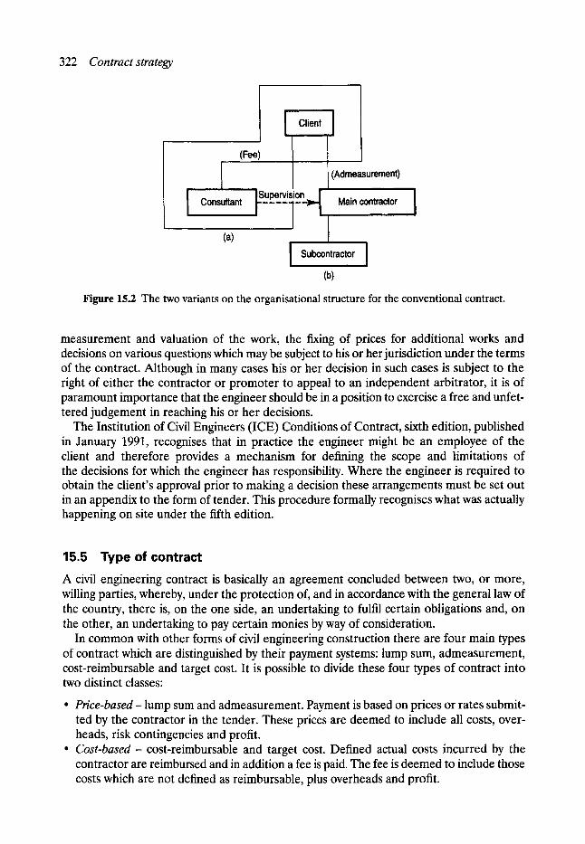
322 Cont rac t strategy
I (Fee)
Consultant rupe'rv--islon>']
Client I
(Admeasurement) i i
Main contractor I
(a) I S ubcontmctor ]
(b)
Figure 15.2 The two variants on the organisational structure for the conventional contract.
measurement and valuation of the work, the fixing of prices for additional works and decisions on various questions which may be subject to his or her jurisdiction under the terms of the contract. Although in many cases his or her decision in such cases is subject to the right of either the contractor or promoter to appeal to an independent arbitrator, it is of paramount importance that the engineer should be in a position to exercise a free and unfet- tered judgement in reaching his or her decisions.
The Institution of Civil Engineers (ICE) Conditions of Contract, sixth edition, published in January 1991, recognises that in practice the engineer might be an employee of the client and therefore provides a mechanism for defining the scope and limitations of the decisions for which the engineer has responsibility. Where the engineer is required to obtain the client's approval prior to making a decision these arrangements must be set out in an appendix to the form of tender. This procedure formally recognises what was actually happening on site under the fifth edition.
15.5 Type of contract A civil engineering contract is basically an agreement concluded between two, or more, willing parties, whereby, under the protection of, and in accordance with the general law of the country, there is, on the one side, an undertaking to fulfil certain obligations and, on the other, an undertaking to pay certain monies by way of consideration.
In common with other forms of civil engineering construction there are four main types of contract which are distinguished by their payment systems: lump sum, admeasurement, cost-reimbursable and target cost. It is possible to divide these four types of contract into two distinct classes:
�9 P r i c e - b a s e d - lump sum and admeasurement. Payment is based on prices or rates submit- ted by the contractor in the tender. These prices are deemed to include all costs, over- heads, risk contingencies and profit.
�9 C o s t - b a s e d - cost-reimbursable and target cost. Defined actual costs incurred by the contractor are reimbursed and in addition a fee is paid. The fee is deemed to include those costs which are not defined as reimbursable, plus overheads and profit.
Type of contract 323
Each of these four, basic types of contract has particular strengths and weaknesses which make them more or less suitable for inclusion in specific contract strategies. It is therefore important to be aware of the main features and the implications of each of these types of contract.
15.5.1 LUMP SUM CONTRACT
A lump sum contract is awarded on the basis of a single, tendered price for the whole works, usually determined from a specification and drawings. There is no breakdown of the tender figure and no means for the client to determine how the price is made up. Payment for the works by the client is usually staged at intervals of time throughout the duration of the works or might be related to achieved physical milestones with payment schedules agreed prior to the award of the contract. The shorter duration contracts, that is less than twelve months, tend to be fixed price but longer contracts or in periods of high inflation a cost rise-and-fall clause may be included in the contract.
One of the main implications of this type of contract, for the client, is that the final, de- tailed design must be completed prior to going to tender. Also, there must be no anticipation of change during the contract as there is usually no contractual mechanism for price adjustment. As price is the sole variable assessed at tender there is likely to be a high degree of tender competition to produce a low tender price. However, there will be other pressures including the cost of a high level of financing by the contractor and the risk contingency, which is likely to be high, and tend to increase the tender price.
The main advantages of this type of contract, from the client's viewpoint, are the high degree of certainty about the final price and the minimal demand on the client's resources for contract administration. There is also the advantage that under competitive tendering the pricing is likely to be keen and because of the payment mechanism there is an incentive for the contractor to work efficiently.
However, there is a possibility that the low bidder may quickly find themselves in a loss- making situation, especially where considerable risk has been placed with the contractor. This may lead to cost-cutting, trivial claims, and, in the extreme, bankruptcy. The other major drawback is that if unexpected change should occur there is no flexibility in the contract. Then the client, or the client's design organisation has only a minimal opportunity for involvement in the management of the variation.
These characteristics make the lump sum contract useful in situations where the design is complete at tender stage and little or no change is envisaged in the programme, the quant- ity or the content, and when the level of risk is low and quantifiable. It is also used where the client wishes to minimise resources involved in contract administration. Typically, this type of contract is hardly ever used in civil engineering contracts for new works, but is adopt- ed on short-term, 'one-off' contracts for buildings, process plants and maintenance work.
1s ADMEASUREMENT CONTRACT
Admeasurement literally means 'by measurement' and this type of contract is currently used for the bulk of UK civil engineering construction works in conjunction with the conventional organisational structure. The basis for this type of contract is the bill of quantities, or the schedule of rates, which breaks down the elements of the permanent works required into items or rates respectively. The contract is awarded as a result of competitive tendering based on the lowest evaluated tender price compiled by summing the prices entered in the
324 Contract strategy
bill of quantities or by pricing a number of typical jobs using the schedule of rates submitted. In most cases a cost escalation clause is included for UK work. Payment is based on a monthly measurement of the permanent works constructed on site which are then priced from the bill or schedule rates; this is known as the interim valuation. Payment is then certified by the client, based on the valuation and must be made within 28 days.
This type of contract is based on the ICE Conditions of Contract sixth edition. The Conditions of Contract, which allocate risk between the client and contractor, were drafted jointly by the ICE, the Association of Consulting Engineers and the Federation of Civil Engineering Contractors, and are well known and well understood throughout the industry. The conditions are general and hence applicable to any civil engineering contract in the UK; although they are predominantly suited for new construction works rather than repair and renovation. For international works using the admeasurement contract, the F6deration Internationale des Ing~nieurs-Conseils (FIDIC), Conditions of Contract, fourth edition, which have many similarities with the ICE Conditions of Contract, are widely used. Due to the greater uncertainties of using a model form of contract for works undertaken in many different countries the FIDIC conditions are divided into two parts. Part 1 contains the general conditions and forms of tender and agreement in a similar format to the ICE conditions, whereas part 2 aims to provide guidance on the preparation and use of Conditions for Particular Application.
The final price of an admeasurement contract is invariably different to the tender price due to the changes caused by the intrinsic nature of civil engineering work; and this is particularly so in sewer renovation. There is no guarantee that acceptance of the lowest price tender will result in the lowest final price. There is some limited flexibility to accommodate new rates, and variations can be provided for, but there is no systematic approach for evaluating the effect of change. As a price-based contract the implication for the client is that a contingency will be paid for risk whether or not the risk occurs. The magnitude of the financing charges depends on the disparity between the actual cost expended by the contractor and the revenues received.
This type of contract has been used for the majority of civil engineering contracts, which, despite recent privatisations, are still public sector oriented. It is a very well known, well understood and widely used contract. The public accountability of this type of contract has been one of its main advantages as there is a breakdown of the price information, and the contract can be shown to have been awarded, under conditions of free and fair competition, to the lowest tenderer. Although in most cases the design is complete prior to tender, the admeasurement contract does allow some overlap of design with construction, if required.
The difficulty of resolving claims due to the lack of accurate cost information, which can delay the settlement of the final account considerably, is a major disadvantage of this type of contract; although there is rarely more than a 20% overrun. Steps have been taken to mitigate this problem by the introduction of the Civil Engineering Standard Method of Measurement (CESMM) in 1976, which uses method-related charges to isolate resource costs. Each contractor is invited to write in any charges, either fixed or time related, which are directly related to the method of construction rather than proportional to the work done, and consequently to include only prices of relevant work against each bill item. Usually about 10-20 charges are identified which would account for approximately 20-30% of the contract value. Typically method-related charges would be made for site overheads, temporary works, general plant, access points and other definable non-quantity proportional items. This ensures that the bill of quantities item prices are much closer to the actual costs plus a margin

Type of contract 325
than previously. The current version of the CESMM, CESMM3, also contains a specific classification for renovation work: class Y, which makes it particularly useful for sewer maintenance works.
An admeasurement contract is well suited to the requirements of most public sector clients and many private sector clients, particularly when the technology is well known, the detailed design is complete and small changes in quantities may occur. Typically, this type of contract is adopted for roads, bridges, drains and sewers where no major change by the client is anticipated and where the perceived level of risk is low and quantifiable. The client benefits from competitive tendering and the relatively straightforward administration of a contract well known to both parties.
15.5.3 COST-REIMBURSABLE CONTRACT
A cost-reimbursable contract is based on the principles of reimbursing the contractor the actual cost expended on the works, together with the payment of a fee to cover the overheads and profit. Consequently the precise definition of actual cost has to be specified in a cost schedule in the tender documents; this avoids difficulties over the amount of discount due to the contract on a contractor's annual bulk purchases from major suppliers. This type of contract is usually awarded by competitive tender on fee although some of the larger public and private sector contracts are negotiated. Payment is made monthly based on the contractor's cost accounts which, within the limitations of the cost schedule, are open to the client (openbook accounting). These monthly payments may be made in advance, in arrears or from an imprest account.
The main implications of a cost-reimbursable contract are that the client is directly involved in the management of the contract and carries the risk of both the works and of the efficiency of the contractor. The contract is extremely flexible and there is no need for a risk contingency, or for financing charges. It permits the early involvement of the contractor prior to the completion of the detailed design allowing design modification and development during the construction period.
The strengths of this type of contract are the facility for the client to be directly involved in the management of the works and the high level of flexibility which permits extensive change to the programme, the work content, the design and the construction. Cost-reimburs- able contracts have the advantage that they are relatively straightforward to administer; partially due to the elimination of claims.
The lack of a direct financial incentive for the contractor to perform efficiently, even though the contractor's reputation is at stake, is the main weakness. The client has to reimburse the actual cost incurred by the contractor, as set out in the schedule and there is no contractual commitment by the contractor to the final cost to be paid by the client. There is also a limitation in contractor selection as only the fee element can be subject to direct financial quantification and competition at tender.
The main criterion for the use of a cost-reimbursable contract is that work has to be completed for a client and no other type of contract would be acceptable to tenderers. This may be for a number of practical reasons; for example it may be impossible to define the precise quantity of work to be undertaken or when the work contains elements of major unquantifiable risk or is likely to be affected by uncontrollable or unpredictable events.
It is used on large, complex projects where the work causes exceptional organisational difficulties and there may be major risks, or multicontract interfaces. However, it is also sometimes used for small projects or parts of projects, where the work is innovative and

326 Contract strategy
productivities are unknown, or when the client needs to be closely involved in the site management. Work of an emergency nature can also be suitable, particularly as the work is often vital to the project but small in relative value.
15.5.4 TARGET COST CONTRACT
A target cost contract is a modified form of cost reimbursable contract which retains most of that type of contracts' benefits and overcomes some of the principal shortcomings. Actual cost is reimbursed based on a cost schedule and a fee paid, as in the cost-reimbursable contract, but there is also an incentive payment. The incentive operates to the benefit of a contractor who works efficiently and avoids waste and to the benefit of both parties in the event of cost saving.
This type of contract is based on the calculation of the likely value of the works, the target cost. This may be derived from a bill of quantities or more likely a schedule of rates; in either case the target cost will subsequently have to be adjusted for any major changes in the work and the effects of cost inflation. Payment of the incentive is then based on the differences between the actual cost from the schedule and the target which are shared in a specified way:
contract price = actual cost (up to target cost) + fee + incentive
Figure 15.3 illustrates the key points of the incentive mechanism in graphical form. The basic structure of the target cost contract is very similar to the cost-reimbursable con-
tract, with the exception that the contractors performance and the final price is constrained by the incentive. As the target has to be adjusted this allows specified risks to be excluded from the target cost, if required, but otherwise this type of contract retains equitable payment and good control of risk.
The target cost contract has all the advantages of the cost-reimbursable contract and some additional benefits of its own. The incentive mechanism is such that both client and contrac- tor have a common interest in minimising cost. Joint planning aids integration of design and construction, efficient use of resources and satisfactory achievement of objectives. Fewer claims result and settlement is easier. The knowledge of actual cost and the incentive mech- anism means that the final price is known soon after completion of the works.
The major drawback is the increased and unfamiliar contract administration procedures, which also have cost implications. The preparation of the contract documentation is more
Target band
. . . .
~ 7 0 / 3 0 Target ~ Minimum cost ~ fee
I Actual cost
Maximum cost
Figure 15.3 Key points of the incentive mechanism.

Tendering procedure 327
demanding and additional staff including cost accountants and some measurement engineers will be required by both client and contractor for purposes of target adjustment.
The effects of the incentive mechanisms makes the target cost contract suitable for a wide range of types of construction. It is particularly suitable when the work involves major unquantifiable risks or when there is inadequate definition of the work at the time of tender. It facilitates an early start with some overlap of design and construction and, with an active management role for the client, is also used if the work is technically or organisationally complex.
Although until recently the use of target cost contracts for renovation works was restricted to exceptional cases, for example, where immediate action to avoid imminent collapse was required, there has been an interesting development adopted by the North West Water Company plc. For sewer renewal work they have prequalified three companies and are negotiating target cost contracts for design and construction packages such that the work over a three-year period will be allocated equally. By involving the contractor as early as possible the design is likely to be easier to construct and it is anticipated that quite large savings of possibly 25% or more might be achieved from this strategy.
In conjunction with this strategy the company has adopted the Institution of Chemical Engineers, (IChemE), Model Form of Conditions of Contract for Process Plants- suitable for reimbursable contracts in the UK, in preference to the ICE Conditions of Contract. Pre- viously the use of a target cost contract had been based on a modified version of the ICE Conditions of Contract derived from the information contained in the CIRIA Report 85.
The IChemE Conditions of Contract are specifically written for cost-reimbursable con- tracts and are generally regarded as less adversarial than the ICE sixth edition. The condit- ions permit the agreement of a target cost and a fixed percentage for overheads and profit, with a share incentive mechanism to encourage cost-effective performance. In the event of unforeseen ground conditions being encountered, the IChemE conditions under the target cost contract mean that the client is reimbursing the contractor's costs and hence eliminating a source of dispute. Some clients may be concerned about the additional contract admini- stration costs involved in a target cost contract and the reimbursement of expenditure rather than payment for the construction of the permanent works as under the ICE conditions. However, if the limited use of this strategy proves to be successful it is likely to become more popular.
15.6 Tendering procedure Clients can adopt a variety of tendering procedures which can be used in conjunction with company policy or with public sector standing orders. The procedures relate to the speed, time and openness of the method of contractor selection and the client's choice is influenced by the requirements of the work to be undertaken and by internal objectives. The tendering procedures used for civil engineering work in the UK are described below.
15. 6.1 COMPETITIVE TENDERING
As the name suggests, this procedure allows free and fair competition between contractors with the contract usually being awarded to the lowest priced bidder. However, there are two forms of this procedure; open and closed (or restricted) tendering. Under the open system anyone is permitted to enter a bid and for all but the smallest contracts this can cause administrative difficulties for the client with possibly hundreds of tenders and many of the
328 Contract strategy
lowest prices supplied by companies with no experience of the type of work involved. Almost all major civil engineering works are now undertaken under the closed system and would- be bidders have to prequalify to satisfy the client of their technical, managerial and financial standing, before being invited to tender. This ensures competition between contractors, each of which would be acceptable to the client.
Nevertheless, having determined a select list following public advertisement it is generally too large to form the tender list for a particular project. Accordingly, groups of six or seven firms are selected from the list on a rotational or serial basis in order to economise on overall tendering costs. This arrangement was successfully used by the editor when directing a large sewerage rehabilitation programme in Manchester and it ensured little delay between funds for the work becoming available and starting on site. It was also beneficial in harnessing the skills of the specialist contractors with the minimum of administrative expenditure.
The cost of preparing competitive tenders often constitutes an appreciable proportion of a contractor's head office establishment charges. It must be appreciated in the long run that all the costs of tendering, whether successful or not, are borne by the clients in the price they pay within accepted contracts. Therefore, any procedures which reduce the all-round cost within the industry will have an economic advantage.
15. 6. 2 TWO-STA GE TENDERING
Under this system the client begins the tendering process at a very early stage in the design process. The first-stage tender documents would only contain approximate quantities of the major items of the work or sometimes a schedule of key rates might be used. From the response to stage one a small number of interested and competitive bidders is identified, usually two or three, and these contractors are informed that they will be invited to tender more formally in stage two. The second stage is based upon the detailed design, which may have been influenced by the stage one tender responses, and the award is usually made to the lowest bidder.
15.6.3 NEGOTIATED TENDERING
Although considered as mainly a private sector procedure, there are many examples of public sector works being tendered on the basis of negotiation. The procedure is relatively quick and is often used for works requiring specialist skills or for those involving large and complex projects. The client will negotiate with between one and, usually, three contractors in order to be satisfied with the suitability of the contractor and to agree the tender sum.
15. 6.4 CONTINUITYAND SERIAL TENDE~NG
These procedures are often used by clients with a large workload consisting of many discrete contracts to save the time and cost of multiple individual tender competitions. Under the procedures for continuity tendering the contractors follow identical procedures to normal, closed competitive tendering with the added factor that the bidders are informed that the successful tenderer may be awarded continuation contracts for similar projects based on the original tender submission. Serial tendering is similar in structure but the bidders are informed that the successful tenderer will be offered a series of other contracts, often but not always of a similar nature, to a guaranteed minimum value.
Risk in contract strategy 329
15. 6. 5 TERM CONTRACTING
This procedure is a form of standing offer whereby the contractor undertakes a loosely defin- ed type of work of variable quantity, within a fixed period of time. Frequently, the term procedure is used for labour only, or labour- and plant-only contracts for minor or mainten- ance work.
15.7 Risk in contract strategy One of the principal functions of contract strategy is the equitable allocation of risks between the parties; usually the client and the contractor. A contract strategy which misconceives this allocation of risk is likely to be a main contributory factor to ultimate contract time and cost overruns. It has been estimated that about 5% of the project cost may be saved by choice of the most appropriate type of contract alone. The client, or the client's advisers, should have identified the main sources of risk and estimated their likely consequences during the precontract stage and should have ideas on how risk should be allocated prior to tender.
The majority of tendering in the UK is closed, competitive tendering where the contract is usually awarded to the lowest priced bid. The client has to estimate the risks for which responsibility is retained and to assess the cost of allocating a risk to the contractor. For a price-based contract the contractor has to include a risk contingency in the bid price and it is unlikely that the lowest bidder will have included for all the potential risks. The problem is compounded by the relatively brief tender periods which constrain the amount of detailed consideration and risk appraisal which contractors can undertake.
If a cost-based strategy is adopted then the contractor does not need to include a contin- gency for risk as the actual cost will be reimbursed. However, the client may prefer to use a target cost contract to ensure that there is an incentive placed on the contractor to mini- mise cost. If a higher degree of risk has been identified or is perceived by the client this could lead to major problems in accurately quantifying a realistic price and it would then be in the client's interest, as well as the interests of the tenderers, to adopt a cost-based contract type as a part of the overall strategy.
Change is inherent in civil engineering construction and this applies to repair and renovation works as much as to new works. The reasons for change can be many and varied and one of the purposes of a conditions of contract, the ICE Conditions of Contract sixth edition, FIDIC and the IChemE conditions, is to define clearly the accepted allocations of risk between the parties for common risk. These include things like unforeseen ground conditions, exceptional weather conditions, the discovery of fossils and historical artefacts and many other eventualities. Where the risk is shown as being the responsibility of the client the contractor can make a claim for any additional expenditure required to complete the works.
There are some intermediate steps between the identification of a risk and the allocation of that risk to one of the parties. It may be possible to reduce or completely eliminate some of the risk by additional site investigation or field study before finalising the design or awarding the contract. The client needs to consider carefully which party can best control the events which may lead to the risk occurring and also which party can best control the risk if it occurs. The client has several options from the decision to retain an involvement in the control of the risk to the decision to transfer it completely to the contractor.

330 Contract strategy
The emphasis on risk management highlights the different characteristics of the price- based and cost-based contracts. The lump sum contract is based on an underlying assumption that there will be no need for change from the client's side and that all other risks of construction are placed on the contractor. The other price-based contract, the admeasure- ment contract, provides some rate breakdown and a basis for limited flexibility to accom- modate a degree of client change. The allocation of risk defined but it is usual for a considerable number of claims, under the conditions of contract, to be made by the contractor during the course of the works. In contrast the cost-reimbursable contract retains the responsibility for risk with the client, including the additional risk of employing a contractor with no incentive to work in a cost-effective manner. The cost-based target cost contract offers a mechanism whereby the major risks are retained by the client, with a role in their management but without the risk of inefficient contracting performance.
15.8 Choice of contract strategy The selection of an optimal contract strategy can only be achieved by a detailed con- sideration of the project characteristics, the organisational method, the type of contract and the tendering process; together with an appreciation of the combined effects of the decisions at each stage and for the reasonable allocation of risk between the parties. A contract strategy should try to provide an incentive for both the client and the contractor, despite their differing objectives. Where necessary, the strategy should facilitate changes and at the same time provide for their systematic and equitable quantification and costing.
Often the first step in the determination of a contract strategy is to identify the client's dominant objective. The usual objectives in civil engineering work are minimum cost, minimum time, quality or the allocation of risk. Quite often many or all of these objectives will be important, but it is likely that one of these factors will be the prime objective. The satisfactory accomplishment of this objective, and the relative influences of the other important objectives, will thus shape the strategy.
Next, it is usual to consider other factors affecting the client, like the degree of manage- ment involvement required, the need to coordinate the site activities of the contractor with other events and the effect of payment mechanisms on project cash flow. The type of works also influences the strategy and factors such as the level of technology, the need for industrial relations skills and the problems of multidisciplinary working should be considered carefully.
Consider the two extreme cases mentioned at the beginning of this chapter; the repair of small discontinuous pipe breakages and the complete renovation of a major interceptor sewer; the derivation of an appropriate contract strategy would require further information but some general strategies can be suggested as below.
15.8.1 SMALL DISCONTINUOUS REPAIR
Considering the client's main objectives, risk and quality are not likely to be dominant and the seriousness of the leakage would determine whether it would be the minimum time or minimum cost as the dominant objective. Unless the losses or the associated consequences are serious it is most likely that minimum cost will be the dominant client objective. The technology is likely to be relatively low-level and well known and the client might want to be involved in the management and coordination of the works; however it is possible that on occasions a high level of technology might be required, especially with non-man-entry sewers.

Development affecting contractual practices 331
In the event of the client having a DLO, this would be an ideal structure to cope with this type of work. Usually there would have to be competitive tendering by the DLO, either for specific contracts or for a term contract. The work would be likely to be outlined in a schedule of rates or bill of quantities in an internal form of an admeasurement contract.
When using outside tenderers, and assuming that the client had not awarded annual term contracts, the strategy adopted would depend upon the urgency for the works. In an emergency situation there would be advantages in awarding a target cost contract for design and construction of the renovation works because of the saving in time and the flexibility to cope with unforeseen events which might arise during the course of the works. When an early start is essential it is likely that the contract would be negotiated with a contractor already prequalified and known to the client.
If the work is not urgent, as would be the majority of cases, the potential benefits of a target cost contract would be outweighed by the additional contract administration on a low value contract. Consequently the admeasurement contract would be the usual choice awarded on the basis of competitive tendering based on priced bill of quantities and the ICE Conditions of Contract.
15. 8.2 RENOVATION OF A MAJOR INTERCEPTOR SEWER
In this type of work, particularly if the sewer is of large diameter and at considerable depth, then the allocation of risk and the mechanism for its assessment is likely to be the dominant variable. The quality of the work and its cost and time of completion are important but the possibilities of major, unquantifiable risk will be the main influence on contract strategy.
The client might also wish to be involved in the sequencing of work or the coordination of additional works which might arise during the contract. This size of contract is almost exclusively awarded as a result of competitive tendering based on the conventional organisa- tional method separating the design and construction phases under an admeasurement contract. This is the procedure adopted for the majority of civil engineering construction in the UK.
The privatisation of the water authorities has caused a review of contract strategy to be undertaken. To accommodate the risk and management implications of major works, it would seem that the target cost contract could offer several advantages. The contract administration is different and the emphasis is on the management of change as it occurs and on providing both parties with an incentive to be effective in the execution of the works. It does not link payment to the permanent works or provide a clear estimate of the final price, but when used in conjunction with the IChemE conditions, it offers a more cooperative method for client and contractor to progress the contract which, ultimately, should result in cost savings.
15.9 Developments affecting contractual practices Recently many clients have expressed dissatisfaction with the contractual procedures for repair and renovation work generally, and some have adopted new practices to try to improve performance. This has coincided with a trend in the UK to privatise many existing public sector clients, which has introduced the opportunity for greater flexibility in the choice of contract strategy. The water companies were formed by the privatisation of the water authorities and the subsequent internal re-organisation had implications for the contract strategy adopted for repair and renovation work.

332 Contract strategy
The job of a private sector water company is complex but in terms of the sewerage function this has to be viewed in commercial terms and the best value for money needs to be obtained. This has led many companies to reduce considerably the number of agency agreements and consider either the use of a small number of 'mega-agents' or the development of manage- ment and maintenance contracts. The latter requires consistency between the structure of the client and the contractor as well as care to avoid conflict with the statutory and regulated procedures of the client. However, if applicable, the management and maintenance contract transfers responsibility and risk from the client to a third party whilst ensuring the level of service.
In 1991 the Public Streetworks Act was enacted in the UK, based on many of the findings of the Home Report. The Act provides the facility for, but does not enforce, the concept of charging for road space occupancy. This has obvious consequences for sewer repair and renovation work. The precursor of this mechanism was the Lane Rental approach developed by the Department of Transport in connection with motorway maintenance work. The basic concept of Lane Rental places an incentive on the contractor to minimise disruption by imposing a charge for the occupancy of the carriageway which reflected the economic cost of the closure. The Lane Rental system was developed into a penalty charge or a bonus by the use of a mechanism to return savings to both client and contractor in the event of the work being completed in a shorter time. These ideas have been developed further as a result of work carried out in the Department of Civil and Structural Engineering at the University of Manchester Institute of Science and Technology (UMIST), to include elements of the social costs associated with the occupancy of road space, and are examined in detail elsewhere in this book.
A new form of contract, the ICE New Engineering Contract was issued in 1993 and after consultation and modification a second edition was published in 1995, as the Engineering and Construction Contract (ECC). The ECC is flexible and clear and promotes good management, its provisions are designed to motivate the participants to cooperate and act promptly and efficiently. It promotes a project management approach to running a project. The traditional role of the engineer is formally divided between four people; the project manager, supervisor, designer and adjudicator, each with clearly defined roles and responsibilities.
The flexibility of the ECC makes it suitable for use with management and maintenance contracts and, although a standard conditions of contract, it offers the client the option of transferring or retaining particular aspects of risk or responsibility. Although it may be overtaken by a similar type of European contract when the harmonisation process of the European Union considers engineering contracts, nevertheless the use of some model contract document which contains sufficient flexibility to facilitate the implementation of the client's needs is likely to become widely used in the future.
Contract documents Institution of Chemical Engineers, Model Forms of Conditions of Contract for Process Plants. Suitable
for cost reimbursable contracts in the UK, Civil Engineering Standard Method of Measurement 3, July, 1976.
Institution of Civil Engineers. Thomas Telford, London, 1991. Institution of Civil Engineers, Conditions of Contract, 6th edition, 1991. Institution of Civil Engineers, Conditions of Contract, Engineering and Construction Contract, 1995.

Bibliography 333
Bibliography CIRIA 85. Target and cost-reimbursable contracts. CIRIA, 1982. CIRIA 100. Management contracting. CIRIA, 1983. Hayes, R. W., Perry, J. G. Thompson, P. A. and Willmer, G. Risk Management. Thomas Telford,
London, 1987. Merna, A. and Smith, N. J. Bid evaluation for U.IC public sector construction contracts, Proceedings
of the Institution of Civil Engineers, Vol. 88, pp. 9-105, 1990. Water Research Centre. Sewerage Rehabilitation Manual, Volume III, 1986.
16 Construction Management
N. J. Smith* BSc, MSc, PhD. MICE, MAPM
16.1 Introduction The wide range of techniques used for sewer repair and renovation, including both open-cut and trenchless methods, can all be successful if the optimal contract strategy has been adopted and if this is supported throughout the construction phase by appropriate construction management procedures. An inappropriate combination of contractual procedures and site management methods can negatively affect the best intentions of the client and contractor.
UK contractual procedures for sewer repair and renovation, including the procurement of the work by the client and the role and use of the key contract documents, are the means by which the contract strategy is administered and implemented. Once works commence on site, a variety of construction management procedures are available to the project mana- ger and it is the selection and integration of the most appropriate methods for use within the contract which will determine the success or otherwise of the project. Procedures will vary widely from country to country but the procedures and examples included in this chapter relate to practice in the UK.
16.2 Contractual procurement There are two stages at which the client has control over the process for the selection of con- tractors, first, before the invitation to tender and, secondly, before awarding the contract. Both stages of the evaluation process are important, but have different objectives. At the pretender, or prequalification stage the aim is to ensure that all contractors who bid are reputable, acceptable to the client and capable of undertaking the type of work and value of contract. During the pre-award or bid evaluation stage the aim is to ensure that the contractor has fully understood the contract, that the bid is realistic and that the proposed resources are adequate.
16.2.1 PREQUALIFICATION
The prequalification process is an assessment of the suitability of a company to undertake work for the client. The principal choice for a large client organisation is whether to adopt a full prequalification procedure prior to each contract or whether to develop standing lists of suitably qualified contractors for various sizes of contracts and types of work, as described
*Professor, Department of Civil Engineering, University of Leeds.

Contractual procurement 335
in Chapter 15. The advantages of drawing up a new prequalification list for each contract are that only genuine bids for the work are received and that there is no stigma in removing or excluding contractors from tendering for certain jobs.
In many of the European Union countries public works contracts in excess of a specified amount are advertised for open tender and with the creation of the single European market all major public contracts in excess of s million are open to contractors from each of the member states. Currently, open tendering often produces a large response, which could be anywhere between 40 and 100 contractors. Many can be rejected very quickly due to their obvious unsuitability for the particular work involved, but the client still has to adopt a rotation policy or to undertake the expensive and complex task of narrowing down the remainder to a tender list of about six to eight.
In the UK there is no standard procedure for prequalification despite the recommenda- tions of the Latham Report and each client has an individual system probably in between the two extremes of an informal methodology based on contractors' submissions to very lengthy and detailed formal questionnaires which require several man-days to complete. Contractors applying for prequalification are required to supply a minimum of information about the financial position of the company and sometimes, where appropriate, of the parent group, and details of the corporate management structure and key personnel; together with reference reports from previous contracts. The financial assessment often includes finan- cial data on the number and value of current contracts, the level of risk exposure, annual turnover, financial security and the companies' banking arrangements. Discussion or correspondence is arranged with previous clients who have experience of the contractor's performance, the use of sub-contractors and aspects of site work, including the attitude to safety, adherence to programme and contractual claims. The management structure can be assessed from an initial listing of the names and experience of key personnel, which could be followed by discussions with individual employees.
16.2.2 EVALUATION OF TENDERS
The purpose of the bid evaluation stage is to assess returned price tender bids, submitted by a number of contractors all of whom have been prequalified, so that a contract can be awarded in accordance with the chosen contract strategy and consistent with the client's requirements. In sewer repair and renovation, qualified or alternative bids are not always permitted. However, there may be occasions when a particular contractor might be able to offer considerable cost savings subject to a modification of the detailed specification and in these circumstances the tenderer must submit an unqualified, conforming tender bid as well. If the alternative bid involves modifications to the design then the tender must be accompanied by supporting information, in sufficient detail, to enable its technical viability and potential savings to be verified. Usually, when an alternative is permitted and is validated successfully, the award can be made without the need to retender the contract and the modified design becomes the design for the purpose of the contract.
Under an admeasurement contract a priced bill of quantities is submitted and unless further documents have been requested, little technical information can be derived directly from the bid. Nevertheless, the pricing of key sections of the bill could indicate potential problems, and the client might wish to clarify the pricing prior to the award of contract. Usually, the lowest three tenders are checked arithmetically and the key rates in the priced bill of quantities are examined and compared. The contract is almost always awarded to the lowest priced bid. Some clients consider that this is all that is necessary, given that all bidders had been prequalified.
336 Construction management
Due to the potentially disruptive nature of some sewer renovation work it is common practice to request the contractor to submit programmes of works with the tender bid. The programmes of works, and occasionally method statements, do not always become contrac- tual documents because flexibility of construction method has traditionally been regarded as the prerogative of the contractor. This arrangement can be of benefit to the client as there will be no associated legal or financial implications. However some clients prefer to review these documents at a pre-award meeting where the contractor's likely performance could be gauged from the major resources identified, the sequence of working and the timing of particular activities allowing the client to identify any major misconceptions. If, at the end of the meeting, the discussions have been satisfactory the programme and method statement might be adopted as contract documents, along with the minutes of the meeting. If the meeting was unsatisfactory and the client was not convinced by the contractor's proposals, then the lowest priced bid would be rejected and the second lowest bidder invited to attend a similar meeting.
For large contracts it is preferable to try to quantify each of the three lowest contractors' particular abilities to deal with the specified work. This is not an easy exercise since subjective judgement is required. However, many clients/project managers claim reasonable results by using a points system. Each variable to be considered is listed and may be weighted in recog- nition of their importance to a particular project. The contractors are ranked by allocating each bid a score against each variable although, in the end, the lowest price bid is generally accepted.
16.2.3 EVALUATION OF VERYLOWPRICED BIDS
The current bid evaluation procedure based on the justification of the lowest priced bid encourages bids which could be suicidally low or misconceived. A suicidally low bid is a bid which is grossly under the value of the client's estimate and below the other competing bids without qualification or explanation. A misconceived bid is a bid which, when compared with other bids appears, by virtue of its price, and possibly from other tender bid information supplied, to be based on a different perception of the work involved. However, the bid could equally be a justifiably low bid, which is a genuine bid including a commercially viable price for the same works from the same information base, which a particular contractor may be able to offer for a variety of reasons. Equally, the client's estimate may not be a particularly good indicator of the bid price since commercial factors, unknown to the client, will often determine the bid price. Therefore the problem is one of identification.
Although some clients ignore the problem arguing that a low bid price is the result of an informed decision made by an experienced and prequalified contractor and hence the lowest bid should always be accepted; other clients believe that very low priced bids might result in time and cost overruns, with resultant additional site supervision costs, and therefore require further investigation. Apart from the pre-award meeting the conventional bid evaluation procedures do not allow a contractor to identify the reasons for a low bid. The contract docu- ments should ensure that the balance of risk and the information submitted to the client should be sufficient to allow the client to identify misconceived, suicidally low or justifiably low bids.
16.2. 4 ANNUAL TERM CONTRACTS FOR MINOR WORKS
Where the repair and renovation work is on a relatively small scale, or is discontinuous, or is partially made up of known preventive maintenance work then the work is unlikely to be
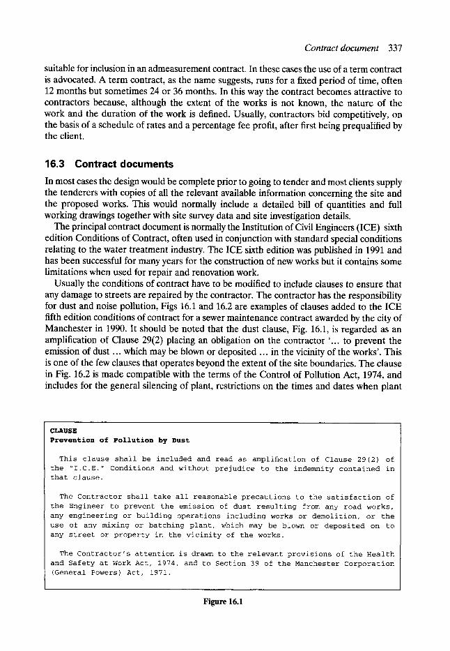
Contract document 337
suitable for inclusion in an admeasurement contract. In these cases the use of a term contract is advocated. A term contract, as the name suggests, runs for a fixed period of time, often 12 months but sometimes 24 or 36 months. In this way the contract becomes attractive to contractors because, although the extent of the works is not known, the nature of the work and the duration of the work is defined. Usually, contractors bid competitively, on the basis of a schedule of rates and a percentage fee profit, after first being prequalified by the client.
16.3 Contract documents In most cases the design would be complete prior to going to tender and most clients supply the tenderers with copies of all the relevant available information concerning the site and the proposed works. This would normally include a detailed bill of quantities and full working drawings together with site survey data and site investigation details.
The principal contract document is normally the Institution of Civil Engineers (ICE) sixth edition Conditions of Contract, often used in conjunction with standard special conditions relating to the water treatment industry. The ICE sixth edition was published in 1991 and has been successful for many years for the construction of new works but it contains some limitations when used for repair and renovation work.
Usually the conditions of contract have to be modified to include clauses to ensure that any damage to streets are repaired by the contractor. The contractor has the responsibility for dust and noise pollution, Figs 16.1 and 16.2 are examples of clauses added to the ICE fifth edition conditions of contract for a sewer maintenance contract awarded by the city of Manchester in 1990. It should be noted that the dust clause, Fig. 16.1, is regarded as an amplification of Clause 29(2) placing an obligation on the contractor '... to prevent the emission of dust ... which may be blown or deposited ... in the vicinity of the works'. This is one of the few clauses that operates beyond the extent of the site boundaries. The clause in Fig. 16.2 is made compatible with the terms of the Control of Pollution Act, 1974, and includes for the general silencing of plant, restrictions on the times and dates when plant
CLAUSE Prevention of Pollution by Dust
This clause shall be included and read as ampli~cation of Clause 29(2) of the "I.C.E." Conditions and without prejudice to the indemnity contained in that clause.
The Contractor shall take all reasonable precautions to the satisfaction of
the Engineer to prevent the emission of dust resulting from any road works,
any engineering or building operations including works or demolition, or the
use of any mixing or batching plant, which may be blown or deposited on to any street or property in the vicinity of the works.
The Contractor's attention is drawn to therelevant provisions of the Health
and Safety at Work Act, 1974, and to Section 39 of the Manchester Corporation (General Powers) Act, 1971.
Figure 16.1
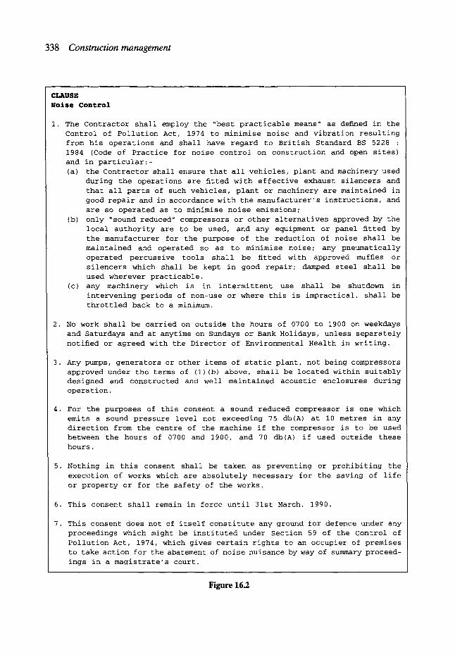
338 Construction management
CLkUSE N o i s e C o n t r o l
I. The Contractor shall employ the ~best practicable means" as defuned in the Control of Pollution Act, 1974 to minimise noise and vibration resulting from his operations and shall have regard to British Standard BS 5228 : 1984 (Code of Practice for noise control on construction and open sites)
and in particular:- (a) the Contractor shall ensure that all vehicles, plant and machinery used
during the operations are fitted with effective exhaust silencers and that all parts of such vehicles, plant or machinery are maintained in good repair and in accordance with the manufacturer's instructions, and
are so operated as to minimise noise emissions; (b) only ~sound reduced" compressors or other alternatives approved by the
local authority are to be used, and any equipment or panel fitted by the manufacturer for the purpose of the reduction of noise shall be maintained and operated so as to minimise noise; any pneumatically operated percussive tools shall be fitted with approved mufHes or silencers which shall be kept in good repair; damped steel shall be used wherever practicable.
(c) any machinery which is in intermittent use shall be shutdown in intervening periods of non-use or where this is impractical, shall be
throttled back to a minimum.
2. No work shall be carried on outside the hours of 0700 to 1900 on weekdays and Saturdays and at anytime on Sundays or Bank Holidays, unless separately
notified or agreed with the Director of Environmental Health in writing.
3. Any pumps, generators or other items of static plant, not being compressors approved under the terms of (i) (b) above, shall be located within suitably designed and constructed and well maintained acoustic enclosures during operation.
4. For the purposes of this consent a sound reduced compressor is one which emits a sound pressure level not exceeding 75 db(A) at i0 metres in any direction from the centre of the machine if the compressor is to be used between the hours of 0700 and 1900, and 70 db(A) if used outside these hours.
5. Nothing in this consent shall be taken as preventing or prohibiting the
execution of works which are absolutely necessary for the saving of life
or property or for the safety of the works.
6. This consent shall remain in force until 31st March, 1990.
7. This consent does not of itself constitute any ground for defence under any proceedings which might be instituted under Section 59 of the Control of
Pollution Act, 1974, which gives certain rights to an occupier of premises to take action for the abatement of noise nuisance by way of summary proceed-
ings in a magistrate's court.
Figure 16.2
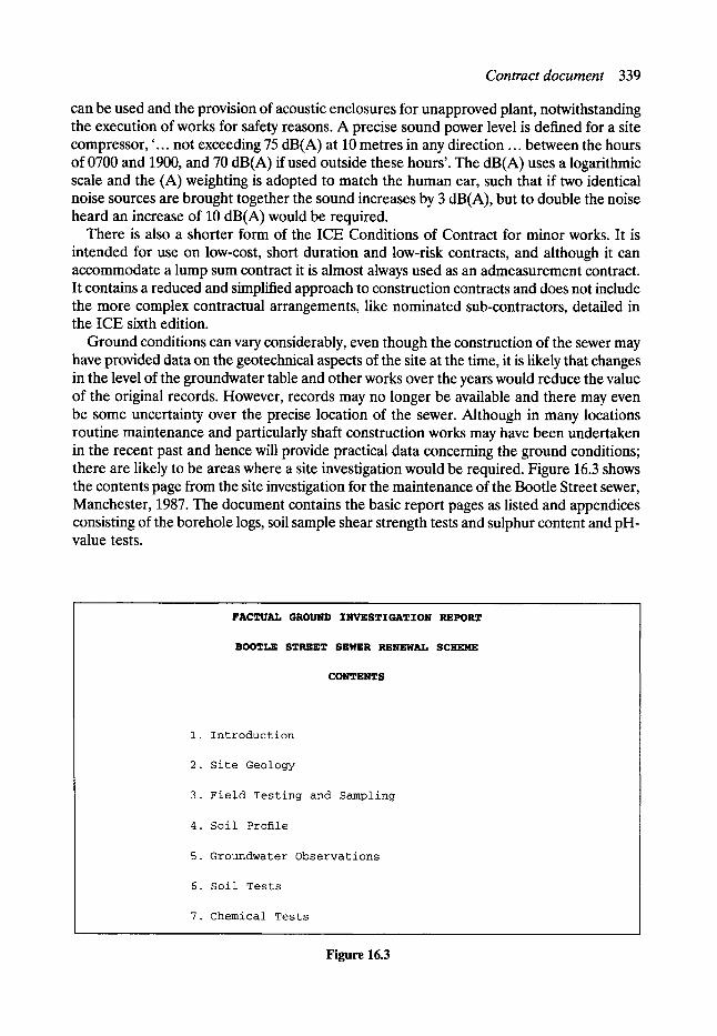
Contract document 339
can be used and the provision of acoustic enclosures for unapproved plant, notwithstanding the execution of works for safety reasons. A precise sound power level is defined for a site compressor, '... not exceeding 75 dB(A) at 10 metres in any direction ... between the hours of 0700 and 1900, and 70 dB(A) if used outside these hours'. The dB(A) uses a logarithmic scale and the (A) weighting is adopted to match the human ear, such that if two identical noise sources are brought together the sound increases by 3 dB(A), but to double the noise heard an increase of 10 dB(A) would be required.
There is also a shorter form of the ICE Conditions of Contract for minor works. It is intended for use on low-cost, short duration and low-risk contracts, and although it can accommodate a lump sum contract it is almost always used as an admeasurement contract. It contains a reduced and simplified approach to construction contracts and does not include the more complex contractual arrangements, like nominated sub-contractors, detailed in the ICE sixth edition.
Ground conditions can vary considerably, even though the construction of the sewer may have provided data on the geotechnical aspects of the site at the time, it is likely that changes in the level of the groundwater table and other works over the years would reduce the value of the original records. However, records may no longer be available and there may even be some uncertainty over the precise location of the sewer. Although in many locations routine maintenance and particularly shaft construction works may have been undertaken in the recent past and hence will provide practical data concerning the ground conditions; there are likely to be areas where a site investigation would be required. Figure 16.3 shows the contents page from the site investigation for the maintenance of the Bootie Street sewer, Manchester, 1987. The document contains the basic report pages as listed and appendices consisting of the borehole logs, soil sample shear strength tests and sulphur content and pH- value tests.
FACTUAL GROUND INVESTIGATION REPORT
BOOTLE STREET SEWER RENEWAL SCHEME
CONTENTS
I. Introduction
2. Site Geology
3. Field Testing and Sampling
4. Soil Profile
5. Groundwater Observations
6. Soil Tests
7. Chemical Tests
Figure 16.3
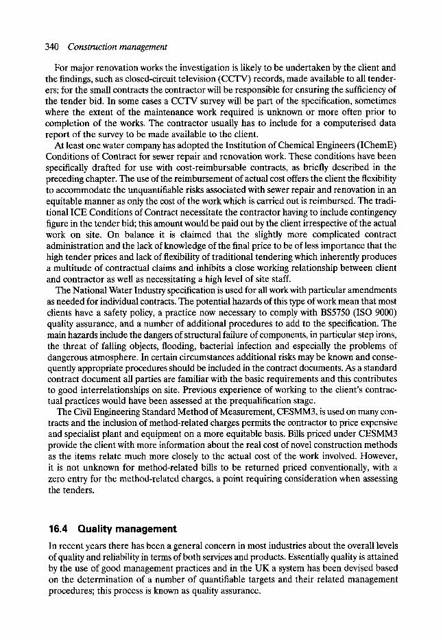
340 Construction management
For major renovation works the investigation is likely to be undertaken by the client and the findings, such as closed-circuit television (CCTV) records, made available to all tender- ers; for the small contracts the contractor will be responsible for ensuring the sufficiency of the tender bid. In some cases a CCTV survey will be part of the specification, sometimes where the extent of the maintenance work required is unknown or more often prior to completion of the works. The contractor usually has to include for a computerised data report of the survey to be made available to the client.
At least one water company has adopted the Institution of Chemical Engineers (IChemE) Conditions of Contract for sewer repair and renovation work. These conditions have been specifically drafted for use with cost-reimbursable contracts, as briefly described in the preceding chapter. The use of the reimbursement of actual cost offers the client the flexibility to accommodate the unquantifiable risks associated with sewer repair and renovation in an equitable manner as only the cost of the work which is carried out is reimbursed. The tradi- tional ICE Conditions of Contract necessitate the contractor having to include contingency figure in the tender bid; this amount would be paid out by the client irrespective of the actual work on site. On balance it is claimed that the slightly more complicated contract administration and the lack of knowledge of the final price to be of less importance that the high tender prices and lack of flexibility of traditional tendering which inherently produces a multitude of contractual claims and inhibits a close working relationship between client and contractor as well as necessitating a high level of site staff.
The National Water Industry specification is used for all work with particular amendments as needed for individual contracts. The potential hazards of this type of work mean that most clients have a safety policy, a practice now necessary to comply with BS5750 (ISO 9000) quality assurance, and a number of additional procedures to add to the specification. The main hazards include the dangers of structural failure of components, in particular step irons, the threat of falling objects, flooding, bacterial infection and especially the problems of dangerous atmosphere. In certain circumstances additional risks may be known and conse- quently appropriate procedures should be included in the contract documents. As a standard contract document all parties are familiar with the basic requirements and this contributes to good interrelationships on site. Previous experience of working to the client's contrac- tual practices would have been assessed at the prequalification stage.
The Civil Engineering Standard Method of Measurement, CESMM3, is used on many con- tracts and the inclusion of method-related charges permits the contractor to price expensive and specialist plant and equipment on a more equitable basis. Bills priced under CESMM3 provide the client with more information about the real cost of novel construction methods as the items relate much more closely to the actual cost of the work involved. However, it is not unknown for method-related bills to be returned priced conventionally, with a zero entry for the method-related charges, a point requiring consideration when assessing the tenders.
16.4 Quality management In recent years there has been a general concern in most industries about the overall levels of quality and reliability in terms of both services and products. Essentially quality is attained by the use of good management practices and in the UK a system has been devised based on the determination of a number of quantifiable targets and their related management procedures; this process is known as quality assurance.

Site management 341
Quality assurance, as formally defined in the UK by BS5750, is likely to become a pre- requisite for prequalification by most, if not all, client organisations in the next few years. Faced with increasing public concern about environmental issues, delays and congestion associated with repairs and now, in the UK, financial performance for shareholders as well as for customers, it could be argued that quality assurance is as important for the client as it is for the contractor.
Many clients have given contractors two years' notice to introduce and achieve certifica- tion for quality assurance. The objective behind this request is to improve the management of quality and hence increase the cost-effectiveness of the industry. Client organisations have been quick to recognise the advantages of quality assurance and several of the major UK contractors in this field have already achieved certification, well in advance of the deadline. Contractors will have to set out targets for performance and the procedures and appropriate levels of responsibility to ensure compliance. The client will benefit from the knowledge that contractors will perform under compatible systems and will avoid any wasteful duplication of effort. The more progressive contractors will also benefit from quality assurance by taking the opportunity to re-examine all aspects of the corporate operation and to promote their newly certified status with other clients.
The more traditional site-based aspects of quality control will be incorporated into the overall quality management policy. Quality control is still regarded as an important aspect of effective site management and this function in the UK has been mainly fulfilled by quantity surveyors. However, the traditional functions are being divided, particularly on works undertaken on a cost-reimbursable basis. The client has identified a need for an independent cost engineer or auditor to assist in costing the consequences of site decisions, and the contractors are moving towards a more integrated quality assurance approach to site quality control with greater responsibility for operations being assumed directly by the labour force. It is likely that quantity surveyors will be involved in both of these functions for the foreseeable future but this change in practice does bring the UK closer in line with the practice in many other countries.
The inherent nature of sewer repair and renovation work places a special emphasis on safety, and most clients have their own 'Statement of Safety Policy' in accordance with the establishment of quality assurance procedures. This statement will be matched by the inclusion of additional clauses added to the specification of contract documents. For man- entry sewers the contractor has to apply for a permit, to be signed by the client, to undertake certain works at a certain time. Figure 16.4 is a copy of a blank permit application relating to the Bootie sewer renewal scheme in Manchester.
16.5 Site management Client organisations place great emphasis on the phasing and location of repair and renovation works. Consequently, prior to commencement on site, both parties will be aware of the method of construction, the resources to be utilised and the sequence of working. Many different factors could affect the site but one common feature is the need for site safety. In the UK the Health and Safety at Work Act, 1974, places responsibilities and duties on both employer and employee for themselves and for third parties, which, given the restricted nature of many sites in city centres, urban and suburban areas, has a major impact on site management. Third parties could include adjacent residential or commercial property owners, vehicle and pedestrian access, and other utility services. The constraints could
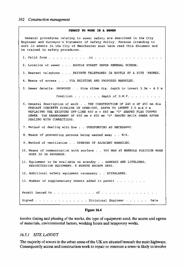
342 Construction management
PERMIT TO WORK IN A SEWER
General procedures relating to sewer safety are described in the City
Engineer and Surveyor's Statement of Safety Policy. Persons intending to
work in sewers in the City of Manchester must have read this document and
be trained in safety procedures.
i. Valid from . . . . . . . . . . . to . . . . . . . . . . . . . . . . . .
2. Location of sewer . . . BOOTLE STREET SEWER RENEWAL SCHEME.
3. Nearest telephone . . . PRIVATE TELEPHONES IN BOOTLE ST & SITE 'PHONES.
4. Means of access . . . VIA EXISTING AND PROPOSED MANHOLES.
5. Sewer details. PROPOSED . . Size 450mm dia. depth to invert 3.5m - 4.0 m
Condition . . . . . . . depth of D.W.F . . . . . . . . .
6. General description of work . . THE CONSTRUCTION OF 240 m OF 450 mm dia
PRECAST CONCRETE PIPELINE IN OPEN-CUT, DEPTH TO INVERT 3.5 m-4.0 m
REPLACING THE EXISTING OFF-LINE 600 m x 450 mm ~U" SHAPED FLAG TOPPED
SEWER. THE ABANDONMENT OF 600 mm • 450 mm ~U" SHAPED BRICK SEWER AFTER
DEALING WITH CONNECTIONS.
7. Method of dealing with flow . . OVERPUMPING AS NECESSARY.
8. Means of preventing persons being washed away . . N/A.
9. Method of ventilation . . OPENING OF ADJACENT MANHOLES.
I0. Means of communication with surface . . TOP MAN AT MANHOLE POSITION WHEN
WORK IS IN PROGRESS.
ii. Equipment to be available on standby . . HARNESS AND LIFELINES,
RESUSCITATION EQUIPMENT, 6 MINUTE ESCAPE SETS.
12. Additional safety equipment necessary . . SPIRALARMS.
13. Number of supplementary sheets added to permit . . . . . . . .
Permit issued to . . . . . . . . . . . of . . . . . . . . . . . . . . .
Signed . . . . . . . . . . . . . . Divisional Engineer . . . . . . Date
Figure 16.4
involve timing and phasing of the works, the type of equipment used, the access and egress of materials, environmental factors, working hours and temporary works.
16.5.1 SITE LAYOUT
The majority of sewers in the urban areas of the UK are situated beneath the main highways. Consequently access and construction work to repair or renovate a sewer is likely to involve

Site management 343
the occupation of road space, with the inherent effects on other road users. The varied and complex nature of the road network in many towns and cities makes the selection and sequencing of the method of construction very important, and any major restrictions on the work should have been identified in the tender documents. Hence the value of including programmes of work and method statements in addition to the priced bill. Figure 16.5 is a copy of the outline programme of work sheet included in the tender documents for the Portland Street sewer replacement scheme. The principal activities in the works have been identified by the client and, as part of the tender submission, the contractor has to use the sheet to produce a bar-chart programme. The contractor is also permitted to add any additional items of work to the activity list which he considers necessary.
In many locations it will be possible to mitigate some of the adverse consequences of the work on road traffic users by the use of traffic management schemes including diversions, traffic controls and temporary works. The suitability and availability of nearby diversions can often be the dominant factor in deciding between 'dig' and 'no dig' methods. Even 'no dig' techniques require the occupation of some of the road space and traffic management and often traffic controls are required for most of the duration of the works. The road space to be occupied will be clearly defined in the contract documents and it is the responsibility of the contractor to ensure that the demands of the method of construction and the level of site supervision are such that these limits are not exceeded.
Where no suitable diversions exist, consideration has to be given to the siting of temporary traffic lights and the length of one-way working which is needed. If the length is too long, delays occur and traffic can become blocked. Equally, in many areas, junctions and access openings have to be included causing more problems. Therefore, where possible, a series of short lengths might be the most effective solution. Except for emergency repair work, the client will have consulted the highway authorities, the bus operators and other third parties prior to going to tender and the relevant data will have been included in the tender information supplied to tenderers.
The site layout can also be influenced by other factors. In particular, environmental problems may be of concern to the client. Often the sewers undergoing repair or renovation are primarily serving residential areas, and the site works are in close proximity to residential properties. The client might have to constrain working hours and the resources used for construction in order to reduce the polluting effects of noise, vibration and other factors. Even 'no dig' techniques require access points and often require that plant and materials are stored temporarily on site, which can cause nuisance to residents. The client attempts to minimise these problems even though there may be cost implications over and above the budget for the works.
In the UK the ground beneath the highways also contains many other public utility mains and services, such as electricity, telephones, gas, water supply and cable television, often in close proximity to the sewer. It is important to minimise, if not eliminate, any down-time of these other mains and services due to the sewer repair and renovation works. A number of coordinating bodies exist in the UK like the Joint Utilities Group, in each region of the country to discuss issues of mutual concern and to facilitate communication between organisations when major works are being undertaken. In specific cases the client may take the risk for work undertaken adjacent to a particular service belonging to another organisation but generally the responsibility for damage to other services lies with the contractor.
The major utility organisations, most of which have been privatised in recent years, have their own requirements for work undertaken adjacent to their services. The special
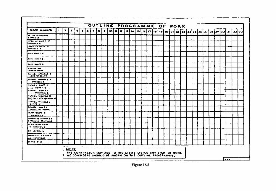
, - i i
W E ( K N U t d l i ( R I 7' 2 . _
s , I u * ( ~ ; ' ~ . _ ' - ' : - o , I OII Ir IC i l
l l d & l e e e O L I 6
4) intN uP I*,IMII V ~'ir i~l,*~**OL I I I
IkNm SU4P Ir I I . . . . .
t ) V l AImLIdi~N&
f u N h l | L k l J 4 ~ l ~ l . | eJ * , l A D O l ~ l l ~ _ . .
I lW*~dl4. ~l,~,l,li,*0~ll �9
�9 u ~ * E L DHMPT C - I * . 4 U k l I T a ~ _ ~ ,
,..~l~*d~ilt. Illl41A6 I C �9 e d A ~ l l G
~ * Y F A L L MTCHIP�9 I T
V , I N h J l I . . M~Ni4OLIt d) * ~ I A I ~ T A
TUNNI[L ~k4~ T A i i i
- * *E[AO r M w s
i l E A l ) - SI, IAFT 8 �9 b4J~o4OLI it _ . ,
r *** ,~ ,4Oi . l t t I l l t MILNII C~lUlOq.~NO ...
m l l l ~ I r l t oM T~L~DLk,. s O ~ A ~ l t 7
CC.)II+~Ik C' I I~ , l tb
ik4Alle4OL I L b l l dill. II
A I A IP',NJI~4Mff 41,e |
I l l I N O 1"11+.'I
" O U T L I N [ P R O G F t ' A M t4'1[ ' O I ~' W O R K . . . . . . . . . . , j . . . . . . . . . , , , , ~ , . . . . . .
I , . . . . . IIII
I m m m m
II II
m m m m m m m m m a a m m m
I
I
..• .. " -- - - + 1 "
,N,,OTE T H ( C O N T R A C T O R M A Y A O O T O T H E ~ T ~ M S L I S T ( O A N Y X T ( M O F W O R K I t ( C O N S I I ) s S H O U L D l l ( S H O W N O N TITLE: O U T L I N ( P R O G I N A k i k 4 1 [ .
32 ~3
I/
Figure 16.5

Site management 345
requirements in relation to British Gas, North West Region for the Lord Egerton sewer repair scheme are shown in Fig. 16.6. The requirement fall into three groups, firstly, British Gas staff will assist in locating services although not guaranteeing their precise location, secondly, safe working practices in close proximity to pipes and/or apparatus and, finally, procedures to be followed in the event of any damage caused by the contractor. In the same way each of the other utility organisations have particular requirements to suit their respective services.
16.5.2 PLANNING AND CONTROL
The successful realisation of a project will depend greatly on careful and continuous planning. The activities of the contractor must be organised and integrated to meet the objectives set by the client and the constraints commonly encountered in urban sewer repair. It is increasingly important to minimise the impact on the environment, in terms of noise, pollution, severance and visual obstruction, and to reduce as far as possible the social costs of executing the works.
In most cases a programme will form the basis of the plan. The most common technique in use in the industry in the UK is the bar or Gantt chart whereby sequences of activities are defined and linked on a time-scale. Although fairly simple to prepare, this type of programme can be easily understood and forms a good basis for communication between different parties to the work. Using this technique priorities can be identified and efficient use is made of expensive and/or scarce resources within the given physical space Constraints for the works.
Repair and renovation work inherently involves change and because of this uncertainty the plan should be flexible and accessible enough to facilitate updating quickly if it is to remain a construction management tool to assist in the decision making necessary to complete the project. The purpose of planning is to assist in making better decisions about the future and to persuade people to perform tasks before they delay the operations of other groups of people. In such a sequence the best use is made of available resources, without exceeding given constraints.
In addition to the bar chart, the most commonly used techniques in sewer repair include the critical path method and the time-location programme. These methods are well known and can be studied in any of the standard texts on planning for construction. Increasingly, with the low cost of microcomputers and the proliferation of project management software, the organisation and work breakdown structure are all derived from the master contract programme. The type of programme required is sometimes specified by the client, who may include outline programmes with the tender documents and instruct tenderers to complete the programme as part of the complying tender bid, with the completed programme operating as a contractual document.
16. 5. 3 ORGANISA TION AND MOT1VA TION
The contractor has to consider the site organisation at an early stage in the tender and has to be prepared to discuss this in detail with the client if called to a pre-award meeting. The organisation is influenced by the method of construction, the number of locations where work is being undertaken simultaneously and the level of technology required. Industrial relations are not usually a problem in this type of work as the contractors tend to use a relatively small workforce in man-entry sewers and to adopt plant-intensive construction
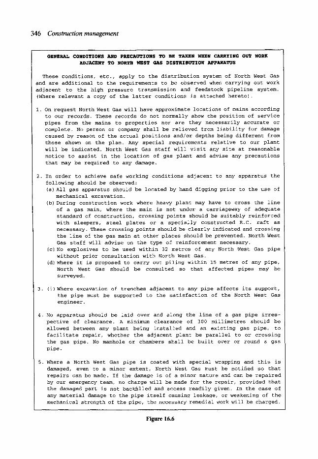
346 Construction management
GENERAL CONDITIONS AND PRECAUTIONS TO BE TAKEN WHEN CARRYING OUT WORK
ADJACENT TO NORTH WEST GAS DISTRIBUTION APPARATUS
These conditions, etc., apply to the distribution system of North West Gas and are additional to the requirements to be observed when carrying out work adjacent to the high pressure transmission and feedstock pipeline system. (Where relevant a copy of the latter conditions is attached hereto).
i. On request North West Gas will have approximate locations of mains according to our records. These records do not normally show the position of service pipes from the mains to properties nor are they necessarily accurate or complete. No person or company shall be relieved from liability for damage caused by reason of the actual positions and/or depths being different from those shown on the plan. Any special requirements relative to our plant
will be indicated. North West Gas staff will visit any site at reasonable
notice to assist in the location of gas plant and advise any precautions
that may be required to any damage.
2. In order to achieve safe working conditions adjacent to any apparatus the
following should be observed: (a) All gas apparatus should be located by hand digging prior to the use of
mechanical excavation. (b) During construction work where heavy plant may have to cross the line
of a gas main, where the main is not under a carriageway of adequate standard of construction, crossing points should be suitably reinforced with sleepers, steel plates or a specially constructed R.C. raft as necessary. These crossing points should be clearly indicated and crossing
the line of the gas main at other places should be prevented. North West Gas staff will advise on the type of reinforcement necessary.
(c) No explosives to be used within 32 metres of any North West Gas pipe
without prior consultation with North West Gas. (d) Where it is proposed to carry out piling within 15 metres of any pipe,
North West Gas should be consulted so that affected pipes may be
surveyed.
3. (i)Where excavation of trenches adjacent to any pipe affects its support, the pipe must be supported to the satisfaction of the North West Gas engineer.
4. No apparatus should be laid over and along the line of a gas pipe irres-
pective of clearance. A minimum clearance of 300 millimetres should be allowed between any plant being installed and an existing gas pipe, to facilitate repair, whether the adjacent plant be parallel to or crossing
the gas pipe. No manhole or chambers shall be built over or round a gas
pipe.
5. Where a North West Gas pipe is coated with special wrapping and this is
damaged, even to a minor extent, North West Gas must be notified so that repairs can be made. If the damage is of a minor nature and can be repaired by our emergency team, no charge will be made for the repair, provided that the damaged part is not backfilled and access readily given. In the case of any material damage to the pipe itself causing leakage, or weakening of the
mechanical strength of the pipe, the necessary remedial work will be charged.
Figure 16.6
Site management 347
methods for non-man-entry sewers. Sometimes there can be demarcation disputes between workers employed by a contractor but increasingly the site organisation is regarded as a production team with a blurring of trade boundaries and with bonus and incentive schemes relating to site performances rather than individual skills.
Although many of the contractors specialise in sewer renovation and repair work it is often necessary to engage sub-contractors for certain aspects of the work. This may include the use of television survey equipment for non-man-entry sewers to locate damage or to monitor completed renovation and other types of very specific service. The contractual arrangements, under the ICE sixth edition, allows for the conventional sub-contractor organisational structure whereby the client has a contract with the contractor, and the contractor has separate contracts with the sub-contractors. Hence there is no privity of contract between client and sub-contractor. The contract also allows for the use of nominated sub-contractors, who are nominated by the client engaged under a similar organisational structure to conventional sub-contractors but from whom the client protects the contractor in the event of delay or non-performance.
UK enabling legislation was brought into being in 1990 to facilitate, at some future date, an incentive mechanism which could be applied to occupiers of highway road space. The scheme has not yet been operated in practice but some basic principles have been widely discussed emanating from the Horne Report. Not all road space occupancy would be charg- ed for; only the 15% or so of the works deemed to be likely to cause serious congestion. One way in which the mechanism might work would be for the highway authority to charge the client utility who would then charge the contractor. It is also likely that this additional income to the highway authority would then be offset by a reduced grant from central government. Whatever the final form of the mechanism adopted it seems likely that, for some of the sewer renovation and repair work, incentive schemes are going to have to be devised, resulting in even more pressure on the contract strategy, the method of construc- tion, the works planning and the use of physical road space.
To achieve set performance objectives the contractor would need to be able to operate a bonus and incentive scheme to the workforce. From the experience of civil engineering contractors working on the lane rental schemes for the Department of Transport, it appears that incentives can be effective for relatively short periods of time but there is a high turnover of staff when the work involves periods of overtime and seven-day weeks in order to minimise road-space occupancy. Whilst it is desirable to minimise the disruption to the public and others any incentive mechanism must also consider the consequences for the contractor's staff.
16.5.4 METHODS AND EQUIPMENT
The method of construction is likely to depend on a certain amount of temporary works. Access to sewers may require excavation to considerable depths in confined locations and with the minimum effects on road traffic; possibly requiting sheet piling, cofferdams, bridges, dewatering and service diversions. The CESMM3 is particularly helpful in allowing the temporary works to be separately identified and charged as a combination of fixed and time related charges which eases the contractors' cash flow and produces a more realistic priced rate in the bill of quantities.
Change is likely to occur in renovation and repair work and with the current trend by the client to place the emphasis on planning and minimising road-space occupancy, there is pressure to define the method of construction in great detail. This can result in a tight
348 Construction management
programme having limited flexibility to incorporate new demands, without incurring excessive financial penalties, which is contrary to the client's long-term interests. A balance between these conflicting objectives has to be incorporated into an incentive scheme so as to facilitate minimum road-space occupancy and effective site management.
Contractors undertaking sewer renovation and repair work have frequently invested in specialist plant with high capital cost and the continued development of the company depends on a fairly high and continuous utilisation of the equipment. Reductions in the quantity reduces effectiveness of the plant and under an admeasurement contract also red- uces payment, part of which will be set against the plant costs.
16.6 Special types of construction In order to illustrate the complexities of construction management in sewer renovation and repair work two examples, taken from recent contracts completed in the north-west of England, are reviewed.
16. 6.1 TUNNELLING
On some of the larger repair and renovation contracts the chosen method of renovation is to break out the existing sewer and replace lengths with a lined tunnel sewer. As in most maintenance works, one of the major problems is to maintain the operating flows whilst carrying out the contract, often using pipes or temporary flumes.
The tunnel construction is easiest in cases where lengths of the tunnel are outside the line of the existing sewer. Consequently, the existing sewer does not have to be broken out and construction can proceed smoothly in the typical sequence of excavate, build ring and grout. A problem does arise with lateral connections entering the existing sewer on the side furthest from the tunnel. However, these connections can be incorporated by using short headings prior to the filling and grouting of the existing sewer.
An existing sewer which is partly within and partly without the proposed tunnel centre- line causes more difficulty. As the existing sewer is excavated the void created must be filled immediately with the new construction. The problems are exacerbated when the existing sewer is of the vertical masonry wall and stone flag soffit construction. As the excavation proceeds the flag may need to be removed and temporary works must be devised to support the ground, originally above the flag, until the tunnel segment erection, backfilling and grouting operations have been completed. Sometimes it is possible to retain a section of the flag which must be supported temporarily until the backfilling of the void is completed. Lateral connections are handled as described above.
16. 6.2 WORK WITHIN A N EASEMENT
On most sewer maintenance contracts, especially those in urban areas, it is difficult to avoid having to undertake some of the works within or across an existing easement relating to another client's services and plant. Usually, these locations are known in advance and have been identified in the contract documents, possibly including any special requirements which may affect the execution of the works.
Typically the prime concern of the easement holder is to ensure that the existing services and plant are protected. Therefore it is common practice to insist on the full agreement to all works and the construction methods to be adopted prior to commencement on site. Any
Construction management of sewer renovation and repair 349
excavation adjacent to the existing services must be undertaken by hand and the backfilling must satisfy the easement holder's engineer.
Easement crossing may range from placing wooden sleepers on the existing ground to the need to erect temporary Bailey-type bridges for the use of contractors' plant and equipment. Nevertheless, the contractor must indemnify the easement authority for the full cost of any damage during the contract.
16.7 Construction management of sewer renovation and repair Effective construction management depends on the integration of the key elements of the client's objectives, the contractor's abilities and the type of work.
The client is likely to have multiple objectives, some of which may be in conflict. One objective will be dominant, usually minimum time or minimum cost, and many secondary objectives which could include minimum disruption, minimum occupancy of road space, mitigation of potential environmental problems and the flexibility to tackle unforeseen circumstances in a cost-efficient manner. There is a two-stage approach adopted by the client, in that the client first assesses contracting companies to facilitate the preparation of a 'pool' or list of equally suitable, competitive contractors, from whom tenders can be invited. The client then adopts a contract strategy and bidding system to distinguish the most appropriate tenderer for a specific renovation or repair contract.
The format of the tender bid evaluation will be influenced by the need to secure a competitive bid, whilst at the same time being reassured about the tenderer's understand- ing of the problems, the tenderer's ability to tackle the job and a viable programme of works and method statement. There is mutual benefit in clear communication of intent and understanding in both the tender documents and the returned tender bids. The contractor with considerable construction management skills will be able to demonstrate these abilities through the programme and method statement and, at any pre-award meeting, which is likely to be of greater significance than the lowest returned price.
For major renovation contracts with a long planning and lead time it seems likely that incentive mechanisms will be introduced at some time in the future. It is important to recognise the need for flexibility to cope with change, which is inherent in renovation work, when constructing the mechanism to share risks and bonuses. Elements of standardisation can be introduced but the overall package is different in each case and the requirements and abilities needed from the contractor differ also. The key issue seems to be the need for compatibility between the clients' strategy, the contractor's method of construction and its practical implementation on site.
Due to the record of the construction industry as being one of the most dangerous in the UK, attempts have been made to try to prevent fatalities and accidents by better planning, training and supervision. In 1994 in association with the requirements of the Health and Safety at Work Act, the Construction (Design Management) Regulations, known popularly as CDM regulations, were issued. The regulations are applicable to all projects which will employ more than five people on construction and which will have a duration in excess of 30 days.
The regulations require that the client has to appoint a 'planning supervisor' to prepare a health and safety plan, to notify the appropriate health and safety authorities and to check that the designers have established a safe method of erecting or constructing the design. The client also has to appoint a 'principal contractor' who is usually the main contractor for the works. The principal contractor has to ensure that the health and safety plan is

350 Construction management
complied with and that all parties on site are aware of the plan and are prepared to cooperate throughout their time on site.
Acknowledgements The author gratefully acknowledges the City Engineer and Surveyor, Manchester City Council, for his permission to reproduce material from a number of unpriced tender documents for several contracts for sewer repair and renovation.
Bibliography Harris, E and McCaffer, R. Construction Plant- Management and Investment Decisions. Macmillan,
Basingstoke, 1990. Harris, E and McCaffer, R. Modem Construction Management, 4th edn. Blackwell Scientific, Oxford,
1995. Health and Safety Commission. Guidance Notes on the Construction (Design and Management)
Regulations and other Legislation. HMSO, London. Hellard, R. B. Total Quality in Construction Projects. Thomas Telford, London, 1993. Institution of Civil Engineers. Civil Engineering Procedure, 5th edition, 1996. Institution of Civil Engineers. Health and Safety in Construction, 1991. Martin, A. S. and Grover, E (eds). Managing People. Thomas Telford, London, 1988. McCaffer, R. and Baldwin, A. N. (eds). Estimating and Tendering for Civil Engineering Works. Blackwell
Scientific, Oxford, 1988. Wearne, S. H. (ed.). Civil Engineering Contracts. Thomas Telford, London, 1989. Constucting the Team. Report by Sir Michael Latham, HMSO, 1994.
17 Site Supervision
R. D. Tinsley* CEng, MICE, MIHT
17.1 Introduction Site supervision is provided to ensure the successful construction of the works in accordance with the contract. This chapter is an outline of those matters related to the site supervision of sewer works. Its contents are meant as a minimum guide relating to this subject and should not necessarily therefore be quoted as an authority for individual problems. It is meant to help those involved in the site supervision of sewer works without being an authoritative reference to case law or contract law on which so many contractual claims hinge. Contract law and related case law may be found in other publications and the various law reports.
17.2 Form of agreement The form of agreement typically describes the title of the works to be constructed and the participants to the contract. There are usually two such participants, the promoter of the scheme, i.e. 'the employer' and the organisation or person undertaking to construct the works, i.e. 'the contractor'. The person supervising the works, i.e. 'the engineer' is usually defined within the conditions of contract, which in turn are noted in the agreement. In relation to the contract, the engineer is expected (required) to act independently even though he or she may also be employed directly by the 'employer'. The form of agreement is based on the contractor's tender and it will also detail the particular conditions of the contract, typically the Institution of Civil Engineers fifth edition (ICE 5th); the drawings; the specification; and the priced bill of quantities or other means of determining the payments to be made to the contractor by the employer, e.g. schedule of rates. The conditions of contract and other contract documents are used as tools to define the duties and responsibilities of the participants and to assign the risks involved in the construction of the works.
17.3 Supervision- currency of contract Whereas the contractor is responsible for the superintendence of the works by the active direction of the means of construction, the engineer is responsible for the supervision of the works by exercising control over the various elements in the construction of the works in determining what will be accepted (and paid for). It is therefore the latter of these two
*Technical Services Engineer, City Engineer's Department, Manchester.

352 Site supervision
duties which is the subject of this chapter. Although there are various conditions of contract which could be defined in the form of agreement and are described in Chapter 15, in recent times by far the most commonly used in England and Wales are the ICE 5th. There is of course now the ICE sixth edition and also the FIDIC.
Whilst these documents may well differ in the responsibilities placed on the engineer and the engineer's representative the general principles advocated in this chapter especially those related to site documentation and reporting procedures are nonetheless fundamental in the supervision of any site works that the duties and responsibilities of the various parties to the contract are clearly defined and followed. The FIDIC conditions, for example, places a duty on the employer to carry out many tasks which in the UK local government scene would traditionally be performed by their directly employed engineer or appointed consulting engineer as part of the project design/control process. For ease of explanation only, the ICE 5th conditions will be referred to throughout this chapter.
Firstly it should be noted that the 'engineer' as defined in the ICE 5th conditions cannot delegate any duties conferred on the engineer under Clause 12(3), 44, 48, 60(3), 61, 63 and 66 to anyone else. It is, however, normal practice for engineers, particularly those who work for large organisations, to delegate all or most of those duties they are able to delegate to a representative. This representative is usually a resident engineer (RE) and typically the RE will have delegated responsibility for the obligations of supervision of the works on site. The RE will normally be aided by support staff. Contractually these staff have no status as there is no means of sub-delegation of duties under the ICE 5th although the existence of such staff is recognised in part. An RE's site staff establishment in its simplest form may be as shown in Fig. 17.1, although this will largely depend on the size, value and complexity of the works.
It is useful therefore to define those duties which have been delegated to the RE and for the RE in turn to define those items which the individual support staff are to 'look after' and bring to the attention of the RE or contractor should the need arise. The items to be covered by individual members of the RE's staff will vary from one contract to another. It is important however that these are defined, and clear channels of communications are established from the beginning of the contract, both between the RE and his or her staff and the contractor's site agent and his or her staff.
The degree and location of the expertise available within the engineer's establishment will tend to dictate the degree of delegation of the engineer's duties to the engineer's representative. In addition, the engineer may decide that the responsibility for some matters such as: Clause 12 - Action on Unforeseen Physical Conditions or Artificial Obstructions; Clause 40 - Power of Suspension; Clause 51 - Ordering of Variations; Clause 52 - Assessing
Assistant resident engineer
Resident engineer (engineers representative)
I "1
Assistant resident engineer (measurement)
Clerks of works
Figure 17.1 A resident engineer's site staff establishment.

Supervision - currency of contract 353
the Value of Any Delay, Extra Cost, etc.; Clause 55 - Correction of Errors in the Bill of Quantities; and Clause 59- Approval of Sub-contractors, are best dealt with away from the day-to-day supervision of the works on the site.
A set of delegated duties for the RE may be typically covered by the following clauses:
Clause number 13(1) 13 (2) 14 (1)-(6) 15(1) 18 19(1) 20 (2)
31(1) 32 33 35 36
37 38(1)
(2) 39
45 49
50
51
52 (3) (4)
53 (5) (6)
56(1) (3)
58 (4) (6)
(7) 60(1) 62
Description of duty Work to be to satisfaction of engineer. Approval of mode and manner of construction. Approval, revision and assessment of contractor's programme. Adequacy of contractor's superintendence. Instructing boreholes or exploratory excavation. Adequacy of measures for the safety and security of the site. Instructing reinstatement of the works during the construction period. Instructing provision of facilities for other contractors. Instructing how to dispose of fossils, coins, antiquities, etc. Approval of clearance of site on completion. Instructing contractor to provide plant and labour returns. Approval of quality of materials and workmanship and the right to carry out reasonable testing. Right of access to the site and any source of material etc. off the site. Approval of work before covering up. Instructing uncovering and making openings for inspection. Instructing the removal, re-excavation or replacement of improper work or materials. Permitting night or Sunday working. Approving the works at the end of the maintenance period. Instructing making-good of defects notified within the maintenance period. Assessing the liability for defects. Instructing the execution of searches, tests or trials to determine the cause of defects. Instructing variations (this will usually have an upper financial limit linked to the standing orders or financial regulations of the employer (and the engineers authorised delegated power)). Instructing dayworks. Instructing the keeping and maintenance of records associated with notified claims. Instructing provision of details of plant ownership. Giving permission to remove plant from site. Measuring and valuing the work done. Instructing contractor to attend for measurement purposes. Instructing work, etc. covered by prime cost items. Instructing production of vouchers, etc. relating to nominated sub- contractors. Instructing work, etc. covered by provisional sums. Receiving the monthly statement of account. Assessing and instructing urgent repairs.
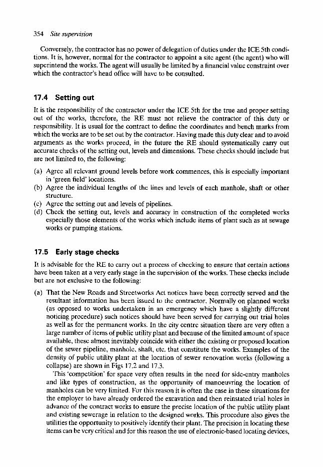
354 Site supervision
Conversely, the contractor has no power of delegation of duties under the ICE 5th condi- tions. It is, however, normal for the contractor to appoint a site agent (the agent) who will superintend the works. The agent will usually be limited by a financial value constraint over which the contractor's head office will have to be consulted.
17.4 Setting out It is the responsibility of the contractor under the ICE 5th for the true and proper setting out of the works, therefore, the RE must not relieve the contractor of this duty or responsibility. It is usual for the contract to define the coordinates and bench marks from which the works are to be set out by the contractor. Having made this duty clear and to avoid arguments as the works proceed, in the future the RE should systematically carry out accurate checks of the setting out, levels and dimensions. These checks should include but are not limited to, the following:
(a) Agree all relevant ground levels before work commences, this is especially important in 'green field' locations.
(b) Agree the individual lengths of the lines and levels of each manhole, shaft or other structure.
(c) Agree the setting out and levels of pipelines. (d) Check the setting out, levels and accuracy in construction of the completed works
especially those elements of the works which include items of plant such as at sewage works or pumping stations.
17.5 Early stage checks It is advisable for the RE to carry out a process of checking to ensure that certain actions have been taken at a very early stage in the supervision of the works. These checks include but are not exclusive to the following:
(a) That the New Roads and Streetworks Act notices have been correctly served and the resultant information has been issued to the contractor. Normally on planned works (as opposed to works undertaken in an emergency which have a slightly different noticing procedure) such notices should have been served for carrying out trial holes as well as for the permanent works. In the city centre situation there are very often a large number of items of public utility plant and because of the limited amount of space available, these almost inevitably coincide with either the existing or proposed location of the sewer pipeline, manhole, shaft, etc. that constitute the works. Examples of the density of public utility plant at the location of sewer renovation works (following a collapse) are shown in Figs 17.2 and 17.3.
This 'competition' for space very often results in the need for side-entry manholes and like types of construction, as the opportunity of manoeuvring the location of manholes can be very limited. For this reason it is often the case in these situations for the employer to have already ordered the excavation and then reinstated trial holes in advance of the contract works to ensure the precise location of the public utility plant and existing sewerage in relation to the designed works. This procedure also gives the utilities the opportunity to positively identify their plant. The precision in locating these items can be very critical and for this reason the use of electronic-based locating devices,
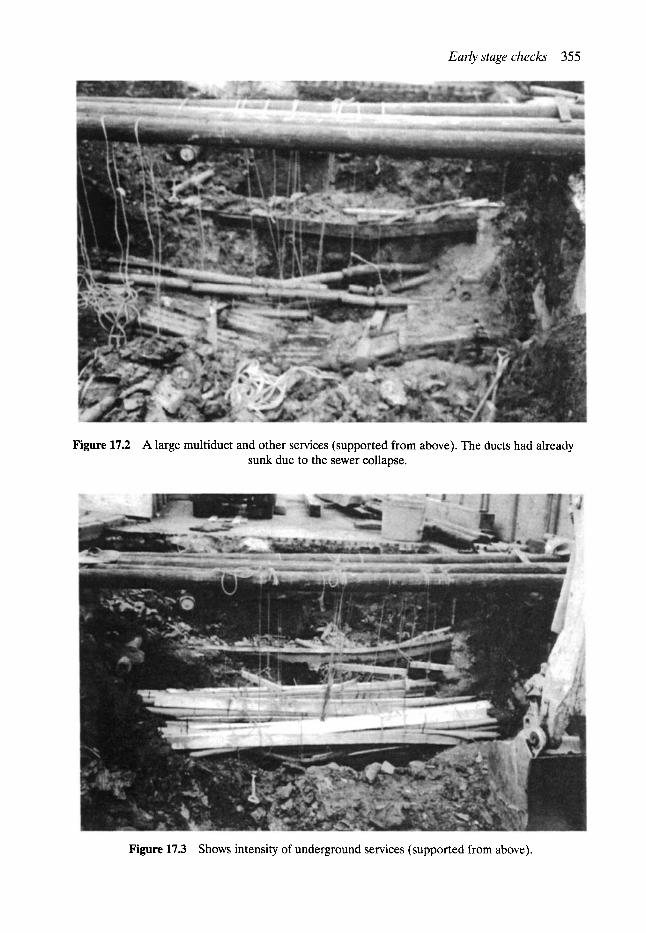
Early stage checks 355
Figure 17.2 A large multiduct and other services (supported from above). The ducts had already sunk due to the sewer collapse.
Figure 17.3 Shows intensity of underground services (supported from above).
356 Site supervision
whilst they may be an additional step before excavation takes place, can be of limited use. This type of trial hole also has the benefit of reducing the contractual risk in relation to method and programme for both the contractor and the employer. Having located (by trial holing) the utility plant details, including size, type, surround (if any), location and depth, this information should be conveyed to the contractor.
(b) That the local authority has been contacted (usually the Environmental Health Officer) regarding the levels of noise and/or vibration that will be considered acceptable under the requirement of the Control of Pollution Act 1974. It is usual for these upper accept- able levels (and any related times) to have been already established before tenders have been invited and for the requirements to have been written into the contract, as they may affect the methodof construction and programme of the works (and therefore the tender sum). The contractor's Clause 14 programme should be checked for this and other similar requirements that will result in a restriction to the contractor in the con- struction of the works.
(c) If the site accommodation is to be in place for more than 12 months, then planning permission for this may be necessary.
(d) That all the details including drawings necessary for the contractor to execute the works have been issued.
(e) If the works are to last more than six weeks then it is necessary to inform the Health and Safety Executive. This is done by completing Form F10 and sending it to the local office of the Health and Safety Executive. It is the contractor's responsibility to perform this task, but it is a 'good idea' for the RE to check that this has been done.
(f) It is almost certain that the works will involve entry into confined spaces. Sewers, especially live sewers (those already conveying effluent), are dangerous places. For these reasons certain safety checks, procedures and personnel responsibilities need to be established from the onset of the contract. These include at least all those items detailed under safety contained in the following section.
17.6 Safety Safety in relation to general sewer works will demand compliance with certain statutory and other non-statutory but nonetheless highly desirable regulations or rules. The statutory regulations include those related to:
1. Health and Safety at Work Act 1974 (including the COSHH regulations). 2. Factories Act 1961. 3. Construction (General Provisions) Regulations 1961 No. 1580. 4. Construction (Lifting Operations) Regulations 1961 No. 1581. 5. Construction (Working Places) Regulations 1966 No. 94. 6. Construction (Health and Safety) Regulations 1966 No. 95. 7. Protection of Eyes Regulations 1974 No. 1681. 8. Construction (Head Protection) Regulations 1989.
Where the works involve the use of explosives, or are undertaken in compressed air condi- tions or in other conditions likely to result in specific hazards, then additional regulations and recommendations need to be applied to the working practices on the site. So far as compressed air working conditions are concerned, CIRIA have published a very useful document - CIRIA Report No. 44, which contains details of procedures and legislation to be observed.

Permit to work 357
The subject of safety has been dealt with in Chapter 3. However, a timely reminder of the minimum safety procedures to be observed before entering a man-entry size sewer or manhole are as follows:
1. All persons, who in the normal course of their duties, are expected to enter or work in manholes or sewers must satisfy the following requirements: (a) they shall be medically examined and thereafter re-examined every 12 months (b) they shall be adequately trained in all aspects of sewer safety.
2. No person must enter a manhole except in the presence of, or as part of, a basic sewer squad. If more than one person is required to work in a manhole, then the squad must be augmented such that there will always be an operative on the surface.
3. No person must enter a sewer except in the presence of, or as part of, a sewer squad consisting of sufficient operatives, such that there is always visual and voice communi- cation between all operatives and one of whom must always remain on the surface.
4. Smoking or naked lights should be forbidden in the vicinity of open manholes and sewers. The safety procedures should in every case involve leaving matches or lighters on the surface.
5. It should go without saying that a person who is under the influence of alcohol or other substances should not form part of a sewer squad or attempt to enter a sewer or manhole.
6. All persons must wear the appropriate protective clothing and safety equipment. 7. Before any work is carried out in any part of a sewer system which involves access into
the system, the person in charge of carrying out the works on the site must first obtain a permit to work.
17.7 Permit to work
Anyone entering a part of the sewerage network whether live or not will almost certainly be entering a potentially hazardous confined space. Therefore, entry to any part of a sewer- age network should be controlled by a permit to work system.
Typically the permit to work should detail:
(a) The means of access, namely the location of manholes, any modifications necessary to the manhole to enable descent, for persons wearing breathing apparatus, etc.
(b) The method of dealing with flow and the lighting arrangements. (c) The method of ventilating the part of the sewerage system to be accessed. (d) The means of communication, e.g. disposition and duties of operatives, location of
nearest telephone, etc. (e) Any standby equipment to be available and its location. (f) Any special safety requirements concerning the particular part of the system to be
accessed, such as, known sudden flooding problems, dangerous discharges into the sewer, unusual gas problems.
The Local Government Training Board have published a booklet 'Safety in Sewers Training Manual' which highlights the rules to be observed when entering sewer systems and explains some of the risks.
A typical permit to work is shown in Fig. 17.4. Since the time of writing the Construction (Design and Management) Regulations 1994
have come into force. These require all the health and safety matters to be documented and made available in accordance with the regulations.
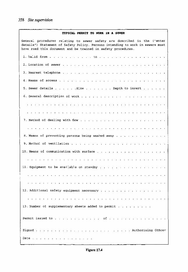
358 Site supervision
TYPICAL PERMIT TO WORK IN A SEWER
General procedures relating to sewer safety are described in the (~enter
details") Statement of Safety Policy. Persons intending to work in sewers must
have read this document and be trained in safety procedures.
i. Valid from . . . . . . . . . . . to . . . . . . . . . . . . . . . . .
2. Location of sewer . . . . . . . . . . . . . . . . . . . . . . . . . . .
3. Nearest telephone . . . . . . . . . . . . . . . . . . . . . . . . . .
4. Means of access . . . . . . . . . . . . . . . . . . . . . . . . . . .
5. Sewer details . . . . . . Size . . . . . . . Depth to invert . . . . . .
6. General description of work . . . . . . . . . . . . . . . . . . . . . .
7. Method of dealing with How . . . . . . . . . . . . . . . . . . . . . .
8. Means of preventing persons being washed away . . . . . . . . . . . . .
9. Method of ventilation . . . . . . . . . . . . . . . . . . . . . . .
i0. Means of communication with surface . . . . . . . . . . . . . . . . . .
ii. Equipment to be available on standby . . . . . . . . . . . . . . . . .
12. Additional safety equipment necessary . . . . . . . . . . . . . . . .
13. Number of supplementary sheets added to permit . . . . . . . . .
Permit issued to . . . . . . . . . . . . of . . . . . . . . . . . . . . .
Signed . . . . . . . . . . . . . . . . . . . . . . . . . Authorising Of~cer
Date . . . . . . . . . . . . . . . .
Figure 17.4

Site reports 359
17.8 Precontract and progress meetings It is highly desirable for the RE and other representatives on the engineer's staff to meet the contractor or his or her site agent at an early date, this is usually called the precontract or prestart meeting. Subsequently, further formal meetings should be held at regular intervals (often monthly) to discuss the progress of the works and other matters relating to the works. These meetings are normally chaired by a senior member of the engineer's staff responsible for the design of the works or the resident engineer. They are best conducted against a formal agenda and minutes should always be taken and circulated. A typical prestart meeting agenda is shown in Fig. 17.5 and a progress meeting agenda in Fig. 17.6.
17.9 Site reports Good practice dictates that the RE establishes a system for providing head office with periodic, usually monthly, reports on contract and project expenditure. This in turn will allow the engineer (if not on site full-time) to monitor the works and inform the employer accordingly.
The contract reports should include the expenditure to date and the projected final value compared with the original contract sum. This information may conveniently be broken down into general headings as follows:
(a) prime cost items (b) expenditure against provisional sums (c) measured works (d) dayworks (e) contract variations (excluding dayworks), including any action needed by the employer (f) contractual claims (g) contract price fluctuations (if any).
As regards contractual claims, these may be listed under this heading with a brief reason for the claim, but should in every case include an indication by the engineer or RE as to the current status of the claim, i.e.
(a) those not accepted in principle (b) those accepted in principle and the value ascertained, or (c) those accepted in principle but the value not fully ascertained.
The project reports should cover the technical issues in relation to the works and can be usefully covered by the following headings:
(a) Ground investigation/conditions. (b) Design- additions/omissions, amendments. (c) Supervision. (d) Land acquisitions. (e) Compensation payments/claims. (f) Public utilities. (g) Materials- suppliers, specifications. (h) Other items.
The project report may also include a request for the provision of additional finance where it is likely that the authorised sum for the project will be exceeded.
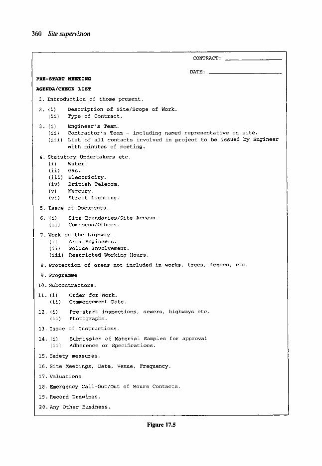
360 Site supervision
CONTRACT:
DATE: PRE-START MEETING
AGENDA/CHECK LXST
I. Introduction of those present.
2. (i) Description of Site/Scope of Work. (ii) Type of Contract.
3. (i) Engineer's Team. (ii) Contractor's Team - including named representative on site. (iii) List of all contacts involved in project to be issued by Engineer
with minutes of meeting.
4. Statutory Undertakers etc. (i) Water. ( ii ) Gas. (iii) Electricity. (iv) British Telecom. (v) Mercury. (vi) Street Lighting.
5. Issue of Documents.
6. (i) Site Boundaries/Site Access. (ii) Compound/Offices.
7. Work on the highway. (i) Area Engineers. (ii) Police Involvement. (iii) Restricted Working Hours.
8. Protection of areas not included in works, trees, fences, etc.
9. Programme.
I0. Subcontractors.
II. (i) Order for Work. (ii) Commencement Date.
12. (i) Pre-start inspections, sewers, highways etc. (ii) Photographs.
13. Issue of Instructions.
14. (i) Submission of Material Samples for approval (ii) Adherence or Specifications.
15. Safety measures.
16. Site Meetings, Date, Venue, Frequency.
17. Valuations.
18. Emergency Call-Out/Out of Hours Contacts.
19. Record Drawings.
20.Any Other Business.
Figure 17.5
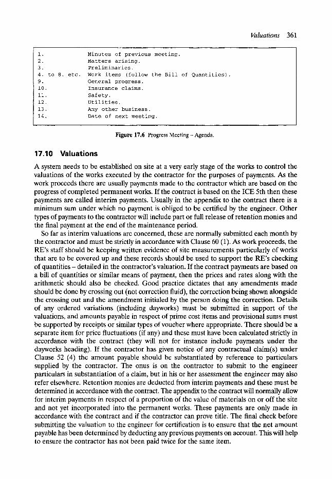
Valuations 361
i.
2. 3. 4. to 8. etc. 9. i0.
ii.
12.
13.
14.
Minutes of previous meeting. Matters arising. Preliminaries. Work items (follow the Bill of Quantities). General progress. Insurance claims.
Safety.
Utilities.
Any other business.
Date of next meeting.
Figure 17.6 Progress Meeting- Agenda.
17.10 Valuations
A system needs to be established on site at a very early stage of the works to control the valuations of the works executed by the contractor for the purposes of payments. As the work proceeds there are usually payments made to the contractor which are based on the progress of completed permanent works. If the contract is based on the ICE 5th then these payments are called interim payments. Usually in the appendix to the contract there is a minimum sum under which no payment is obliged to be certified by the engineer. Other types of payments to the contractor will include part or full release of retention monies and the final payment at the end of the maintenance period.
So far as interim valuations are concerned, these are normally submitted each month by the contractor and must be strictly in accordance with Clause 60 (1). As work proceeds, the RE's staff should be keeping written evidence of site measurements particularly of works that are to be covered up and these records should be used to support the RE's checking of quantities - detailed in the contractor's valuation. If the contract payments are based on a bill of quantities or similar means of payment, then the prices and rates along with the arithmetic should also be checked. Good practice dictates that any amendments made should be done by crossing out (not correction fluid), the correction being shown alongside the crossing out and the amendment initialed by the person doing the correction. Details of any ordered variations (including dayworks) must be submitted in support of the valuations, and amounts payable in respect of prime cost items and provisional sums must be supported by receipts or similar types of voucher where appropriate. There should be a separate item for price fluctuations (if any) and these must have been calculated strictly in accordance with the contract (they will not for instance include payments under the dayworks heading). If the contractor has given notice of any contractual claim(s) under Clause 52 (4) the amount payable should be substantiated by reference to particulars supplied by the contractor. The onus is on the contractor to submit to the engineer particulars in substantiation of a claim, but in his or her assessment the engineer may also refer elsewhere. Retention monies are deducted from interim payments and these must be determined in accordance with the contract. The appendix to the contract will normally allow for interim payments in respect of a proportion of the value of materials on or off the site and not yet incorporated into the permanent works. These payments are only made in accordance with the contract and if the contractor can prove title. The final check before submitting the valuation to the engineer for certification is to ensure that the net amount payable has been determined by deducting any previous payments on account. This will help to ensure the contractor has not been paid twice for the same item.
362 Site supervision
17.11 Measured items If a contract is let on the basis of a bill of quantity or schedule of rates, this forms the main element in the financial control of the works for both the contractor and the engineer. In the event of the contractual payment being based on a lump sum or similar payment regime the contractor is likely to have created his or her own 'quasi-bill' of quantities in order to achieve the same purpose. The reimbursement of the contractor's cost by means other than increased items, such as variations, contractual claims etc., although important to the contractor may be considered subservient to the measured items in that although payment of these items is required to be timely the payment itself is usually dependant on the contrac- tor presenting the necessary supporting documentation.
For sewer works, one of the most commonly used means of preparing bills of quantity and then measuring the works, is the application of the rules contained in the method CESMM2. This method of measurement enables the pricing of the works by itemising the main elements of the cost of the works. Although the contractor is not bound to build up his or her rates on the basis of their individually predicted cost, from the point of view of his or her cash flow during the progress of the works, it is best if this is the case. It will also facilitate (if applicable) the pricing of variation orders in the event of the variation order being able to be based on (but not necessarily exactly costed at) such a rate.
The golden rule in the valuation of the works under measured items is to ensure that the rules of measurement are applied in accordance with the contract. The site supervisory staff will be required to check the interim and final accounts submitted by the contractor. These checks must be based on actual measurements on site as the works progress and before the works are covered up, remembering that the application of the measurement rules are what counts and not necessarily the actual dimensions as recorded. It more than often helps in the case of disputed measures for the site supervisory staff to include a sketch in their diary or other recording system.
The site supervisory staff should keep site records of the contractor's activities, usually in the form of site diaries. These records should typically include the details needed for checking dayworks as outlined in the following section.
17.12 Dayworks There are several items in relation to the valuation of dayworks that are worthy of mention by way of a guide to newcomers in site supervision. Dayworks when included in the condi- tions of contract are a means of defining the payments (if so authorised) to the contractor for carrying out works incidental to the defined contract works. Almost every civil engineer- ing project will involve dayworks to some extent. This is particularly true of sewer works as they include to some degree their placement in the ground where a whole range of problems, which despite meticulous site investigation prior to the contract being let, are awaiting the project. These problems can vary from the discovery of old bones (sometimes human) to minor incidental repairs to adjacent sewers. Dayworks must be instructed by the RE prior to them being performed by the contractor, the instruction should include the method of payment. It is likely that the RE will involve him or herself, or a member of his or her staff, to some degree in the superintendence of dayworks by of direct instruction to the workforce. There is no reason why this should not be the case as the payment results from time and resources ordered from the contractor. Payments in respect of dayworks may be detailed in a number of ways:
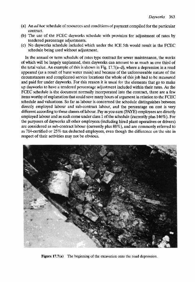
Dayworks 363
(a) An ad hoc schedule of resources and conditions of payment compiled for the particular contract.
(b) The use of the FCEC dayworks schedule with provision for adjustment of rates by tendered percentage adjustments.
(c) No dayworks schedule included which under the ICE 5th would result in the FCEC schedule being used without adjustment.
In the annual or term schedule of rates type contract for sewer maintenance, the works of which will be largely unplanned, then dayworks can amount to as much as one third of the total value. An example of this is shown in Fig. 17.7(a--d), where a depression in a road appeared (as a result of burst water main) and because of the unforeseeable nature of the circumstances and complicated service locations the whole of this job had to be measured and paid for under dayworks. For this reason it is usual for the elements that go to make up dayworks to have a tendered percentage adjustment included within their rates. As the FCEC schedule is the document normally incorporated into the contract, there are a few items worthy of explanation that could save many hours of argument in relation to the FCEC schedule and valuations. So far as labour is concerned the schedule distinguishes between directly employed labour and sub-contract labour, and the percentage on cost is very different according to these classes of labour. Pay as you earn (PAYE) employees are directly employed labour and as such come under class 1 of the schedule (currently plus 146%). For the purposes of dayworks all other employees (including hired plant operatives or drivers) are considered as sub-contract labour (currently plus 88%), and are commonly referred to as 714-certified or 25% tax deducted employees, even though the difference on the site in respect of their activities may not be obvious.
Figure 17.7(a) The beginning of the excavation onto the road depression.
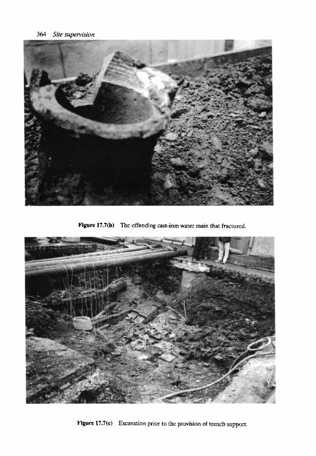
364 Site supervision
Figure 17.7(b) The offending cast-iron water main that fractured.
Figure 17.7(c) Excavation prior to the provision of trench support.

Dayworks 365
Secondly it is highly likely that if the dayworks involve excavation, trench support will be needed.
The FCEC Dayworks Schedule in Section 18 provides for steel trench sheeting to be charged as a material and the residual value thereof to be the subject of a special agreement. This type of trench sheeting is like pencils are to an office worker for a contractor. It is highly unlikely that the full history of the sheeting will be known unless it happens to have been purchased new for the particular job and, if not left in, it is anyone's guess how many more uses it will be put to. There is, therefore, difficulty in complying with Section 18 and the matter is best dealt with by way of a tendered rate (s at tender stage, along with a tendered rate for trench sheeting left in, as shown in Fig. 17.8.
The contractor will normally submit to the RE dayworks sheets identifying the labour, plant and materials used in this connection. These sheets should be endorsed to identify the variation/order number to which they refer and, when the RE has agreed with the princi- ple and accuracy of the sheet, it should be signed for record purposes. Copies of the day- works sheet should be sent to the employer with any original supporting documents such as receipt for materials at each valuation. It is important to ensure that the payment rates and calculations are correct. For instance, the FCEC schedule for plant will give a general description of an item and it is important that the particular manufacturer's model is allocated against the correct item. A useful guide in this respect is the 'Construction Weekly Plant Directory'.
In order to ensure that payments for work carried out on daywork can be properly substantiated, the following records may be kept:
1. The contractor should be requested to provide the RE with weekly returns of labour and plant (in accordance with Clause 35).
2. The RE should advise the clerk of works or other person supervising the dayworks of the precise nature of the work which he has ordered for payment in accordance with the schedule of dayworks and records should be referred accordingly.
3. The clerk of works in turn should record the following details: (a) time of arrival (of clerk of works) and departure from the site (b) the weather conditions/temperature (c) contractor's working hours (d) number and class of labour employed on the site (whether on or off that particular
site) and a brief description of work being undertaken, location and progress made (e) class of operatives, times and description ofwork when daywork is being carried out.
Also where the federation schedule is the basis for payment, whether operatives are PAYE, 714-certified or 25% tax deducted sub-contractor
(f) details of plant used on dayworks with note whether it is especially hired in (with or without operator) or owned; standing, working or broken down; make and model and other items such as huts, etc., as appropriate
(g) description and quantity of materials and details of any delivery tickets for materials used on daywork (the ticket itself may have to be returned to the contractor for record purposes). Also note any wasted materials
(h) any other matters as requested by the RE.
These items are the basics for all contracts whether work is being carried out on daywork or bill of quantities/schedule of rates measure, and in addition there is likely to be a requirement for recording other items such as: delays, disruptions, service damage, and instructions given and received.
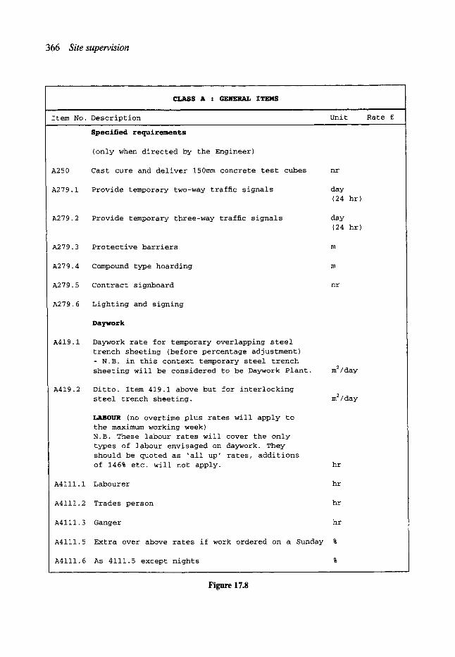
366 Site supervision
CLASS A �9 GENERAL ITEMS
Item No. Description Unit Rate s
Specified requirements
(only when directed by the Engineer)
A250 Cast cure and deliver 150mm concrete test cubes nr
A279.1 Provide temporary two-way traffic signals day (24 hr)
A279.2 Provide temporary three-way traffic signals day (24 hr)
A279.3 Protective barriers
A279.4 Compound type hoarding
A279.5 Contract signboard nr
A279.6 Lighting and signing
Daywork
A419.1 Daywork rate for temporary overlapping steel trench sheeting (before percentage adjustment) - N.B. in this context temporary steel trench sheeting will be considered to be Daywork Plant. m2/day
A419.2 Ditto. Item 419.1 above but for interlocking steel trench sheeting. m 2 / day
LABOUR (no overtime plus rates will apply to the maximum working week) N.B. These labour rates will cover the only types of labour envisaged on daywork. They should be quoted as 'all up' rates, additions of 146% etc. will not apply. hr
A4111.1 Labourer hr
A4111.2 Trades person hr
A4111.3 Ganger hr
A4111.5 Extra over above rates if work ordered on a Sunday %
A4111.6 As 4111.5 except nights
Figure 17.8
Contractual claims 367
17.13 Variation orders Variation orders (VO), that is to say, variations ordered under Clause 51 and/or variations which may be deemed to have been ordered under Clause 51 (for example under Clause 13), should only be issued by those authorised so to do under the contract. They should without exception be ordered in writing and each order should have a number which sequen- tially identifies it, thus enabling payments to be made and identified against each VO. They should also specify the particular clause or condition(s) of the contract under which the order/instruction is given. In every case copies of the orders should be sent to the engineer, engineer's representative and the contractor. They should also specify the method of payment at the time they are issued. The pricing of variations should be strictly in accordance with the requirements of Clause 52 and it should be noted whether the contract price fluctuations (CPF) clause is to apply. It is usual for the CPF clause to apply in the case where such a clause in included in the contract and the variation prices are based on tendered rates that also have CPF's applied. With the exception of emergencies the site supervision (RE) needs to report to the engineer (and in turn the engineer to the employer) variations that are proposed of a major nature, and the reasons for these proposals. The employer can then if necessary consider the proposal before the engineer issues the variation. This can be simply included in the contract report or, if time will not permit, the matter can be dealt with separately. In either case the engineer will need to assess the net effect of variation orders on the cost of the works. The RE may require from the contractor regular returns of contemporary records in relation to and in support of ordered variations. This can be requested by invoking Clause 35 of the conditions of contract. Dayworks sheets should not be used for this purpose (or for time spent on claim items which should be valued elsewhere).
17.14 Contractual claims Claims under the contract occur as a result of two main causes, these are:
1. Clauses in the contract which entitle the contractor to extra payment if certain situation arise and
2. Breaches of the contract.
Under Clause 11 of the ICE 5th, the contractor is deemed to have inspected the site, taken into account in the pricing of the tender anything that would be apparent from such a visit, and to have satisfied him or herself of the correctness and sufficiency of his or her rates and prices. Contractual claims are formed on the basis of the information available to the contractor up to the point in time when the tender is accepted. Substantiation of a claim will depend on the clarity of what was exactly to be done in the contract and what was actually done that was different from that which an 'average' contractor could have anticipated at the time of tender. Contractual claims will usually fall into one of two types:
(a) Those relating to measurement, which arise from errors in the documents, bill of quantities, variations, other contractors' facilities, inappropriate rates, etc. for which payment would be in accordance with Clause 52 (4).
(b) Those relating to delay and disruption, where payment would not include a profit element.
The clauses under (the ICE 5th) which claims arise and the resulting payment liability may be summarised as follows:

368 Site supervision
Clause 5 7 (3)
12 (3) 13 (3) 14 (6) 17
20 (2)
22 (2) 26(1) 27 (6)
31 (2)
32 36 (3) 38 (2) 40(1) 42(1) 49 (3) 50
52 (4) 59 (A) (3)
59 (B) (4) (6) 69 71
72
Reason Documents not mutually explanatory. Delay in issue of documents. Unforeseen conditions. Engineer's instructions. Method or programme revision. Errors in setting out, not the fault of the contractor. Care of the works - damage from excepted risks. Damage to property or persons. Notices and payment of fees. Delays attributable to variations re" Public Utilities Affording facilities to other contractors and Public Utilities Delays from discovery of fossils etc. Cost of tests Making openings or uncovering works Suspension of the works. Late possession of site. Repair work not contractor's fault. Contractor to search- not contractor's fault. Notice of claims- (f) late payment. Nominated sub-contractors (when employed). Renomination of sub-contractors. Labour tax matters. Metrication (now an infrequent occurrence). Contract price fluctuation (if incorporated in contract)
Liability Delay and extra cost Delay and extra cost Delay and extra cost and profit Delay and extra cost Delay and extra cost
Damages
Cost of making good Employer's risks Costs
Delay and extra cost
Delay and extra costs Delay and extra costs Costs Wrong party Delay and extra cost Delay cost Cost
Costs Interest
Delay and extra cost Delay and extra cost Extra cost
Delay and extra cost
Extra cost
A contractual claim may involve a request by the contractor for an extension of time to the contract period. The ICE 5th details several reasons that would justify the engineer in granting an extension of time should they arise. The engineer is required to consider extensions of time when evaluating and certifying the payments to be made to the contractor.
The reasons for extension of time may be summarised as follows:
Reason Variation instructed under Clause 52. Increased quantities not due to variations. Exceptional weather conditions. Failure to give information. Adverse physical conditions or artificial obstructions. Instructions or directions of the engineer. Delay in approving contractor's calculations. Street works delays (where employer's liability)
ICE 5th clause number 44(1) 44(1) 44(1)
7 (3) 12(3) 13 (3) 14 (6) 27 (6)
Contractual claims 369
Delay by employer's other contractors. Suspension of the works. Special circumstances of any kind. Failure to give possession of the site. Repudiation by a nominated sub-contractor. Delay due to metrication (see Clauses 13 and 51).
31 (2) 40(1) 44(1) 42(1) 59 B (4) (b) 71
The granting of an extension of time to the contract period does not necessarily entitle the contractor to additional payments. The sole purpose is to establish the date from which the contractor is to be liable for the deduction of liquidated damages from the payments. Contractors will, however, usually try to establish the need for extensions of time to be granted in order to justify delay claims. Therefore, in granting an extension of time, the engineer needs to take particular care in the wording used in the issuing of such an extension. In assessing the amount of time to be extended the contractor is entitled to any 'float' he or she may have built into his or her programme. Additionally, there may be other factors that may have a consequential effect on the timing of certain operations which result in a greater extension of time being granted than would otherwise have been the case.
The conditions place certain responsibilities on both the engineer and the contractor in respect of claims. The contractor is required under Clause 44(2) to give notice within 28 days, or as soon after as is reasonable, of the happening that gives rise to the entitlement. The engineer is required to make an assessment in respect of a request for an extension of time as soon as he receives particulars of the circumstances from the contractor. A further assessment is required at the date of completion or the extended date, if he has already been granted some extensions of time, and the contractor has not been issued with a certificate of completion. At the issue of the certificate of completion the engineer should make a final assessment in respect of any extensions of time granted to the contractor.
Considerations to Clause 52(4) claims can only be given on the timely receipt of such claims. In this sense timely may mean immediately on site from agent to RE (to engineer) or may be the subject of the contractor's headquarters policy consideration and as such may originate from one headquarters to the other (the engineer).
Each claim should be numbered consecutively as it arises and the engineer should acknowledge receipt and forward a copy to the employer. The contractor should state the clause in the contract under which the claim is being made. If this is not the case the RE/engineer should ask for clarification within the acknowledgement. The acknowledge- ment should also include notification to the contractor as to any records that are to be kept by the contractor in substantiation of the claim. On receipt of these records, which should be ordered to be forwarded by the contractor at regular intervals, the RE should check them for accuracy and record purposes. If the claim involves a rate higher than the one notified by the engineer, contemporary records (i.e. details of labour, plant and materials used) will be necessary to ensure proper substantiation of the claim.
The principle of allowing a claim must be decided by the engineer before any payment. is made. Following the engineer's decision, interim payments may be made on account in respect of each particular claim, but these should be based on the degree of substantiation produced by the contractor in support of the claim and accepted by the engineer. Claim settlements should identify the payment of costs separately from those for profit and the 'cost' should be ascertained from those costs actually and reasonably incurred by the contractor. A claim may be based on tendered rates and should be detailed to identify any inclusions for price fluctuations. In assessing claims, care needs to be taken to ensure each
370 Site supervision
claim is settled on an individual basis and that no duplication of payment occurs between measured items, varied works, dayworks or other claims.
It is good practice for the engineer, usually originating from the RE, to items report at regular intervals to the employer, the status of the contract in respect of contractual claims. Such a report could include the consecutive identification number with brief details, the result of the engineer's decision in principle (if any), the amount claimed to date, the amount paid to date, and 'a confidential estimate of the likely total amount to be paid under the claim'.
The records required in the evaluation of claims is little different from the normal supervision documentation. The records should include:
1. Letters of notification, with the relevant extracts from the contract. 2. A summary of the background facts leading up to and following receipt of the claim. 3. Contemporary records, including:
(a) weather (b) resources- labour, plant, materials, sub-contractors.
4. Daily (at least) outputs/production. 5. Ground conditions (if relevant). 6. Details of delays and cause, i.e. by engineer, by contractor.
In addition to the resource returns under Clause 35, further information will be required for the evaluation of the claim from the contractor. This information will include: 1. Tender preparation assumptions:
(a) resources and programme (b) outputs (c) timing.
2. Invoices for changed materials. 3. Tender quotes for changed materials. 4. Site overhead analysis (and breakdown). 5. Head office costs. 6. Expected profit (if applicable).
Claims as a result of breaches of the contract cannot be dealt with under the terms of the contract and therefore technically the engineer has no authority to deal with such claims within the contract. Such claims are dealt with by the contractor bringing a claim against the employer, or vice versa under the general law of contract, or that part of the law known as tort, which includes civil wrongs such as negligence and misrepresentation. Reference to the various law reports tends to dictate the liability in these matters although the defendant has no obligation to settle such claims until ordered so to do by a court. The engineer (and/or staff) would only advise or act as a witness in the event of such an action.
17.15 The final account
It is the responsibility of the contractor to produce the final account for the contract. However, under the ICE 5th the engineer is obliged to do this if the contractor defaults to produce the final account. It follows therefore that extensive records of the contractors' activities during the progress of the works need to be kept by the RE and his or her staff, not only to check the contractor's final account but also in the event of the engineer having to produce the final account or the contractor entering into liquidation or bankruptcy.
In any event the final account must be supported by detailed documentation showing how the final account value has been built up. It is absolutely essential that the rates and prices

Inspection of the works 371
have been cross-checked against the contract and a full arithmetical check has been carried out. All measured work items should have been remeasured on their completion and these should be supported by the written records of site measurements. Variations included in the final account should be supported by the written authorisation to carry out the work and must be valued in accordance with the contract with copies of daily agreed records of labour, plant and materials in support of dayworks. Any payments in respect of prime cost items and provisional sums must be supported by invoices accompanied by proof of payment.
It is usual for variable price contracts to have the contract price fluctuation calculations 'firmed up' at final account stage and in doing so these should be calculated strictly in accordance with the contract. Where contractual claims and/or liquidated damages form part of the final account their entitlement and evaluation must be documented to ensure compliance with the contract.
Payment of any retention monies or outstanding obligations under the contract should be allowed for in determining the final amount due and allowance needs to be made for previous payments, tax matters, credits and deletions of prime cost items, provisional sums and contingency items not used in the construction of the works.
17.16 Inspection of the works The works should be inspected as they progress to ensure compliance with the specification and a record of all such inspections should be kept by the site supervisor. The specification will normally include tolerances around a particular dimension or requirement which that element of the work fall within, for the item to be considered to specification. It would be most unusual for tolerances on tolerances to be specified. However, sound engineering judgement should always prevail over the question of compliance with the technical requirement of the work.
Many materials used in sewer works are manufactured or supplied under the control of a quality assurance (QA) system. This does not preclude the site supervisory staff from obtaining samples of these materials along with those not supplied under a QA system.
In obtaining samples for testing, which should be a regular feature of site supervision, it is essential that the samples are taken in such a manner as to be representative of that mater- ial. The means of achieving this representation is usually detailed in the British Standard appropriate to the material or if not it should be contained within the contract specifica- tion. There is little point in performing tests on materials if the sample is not representa- tive. It is equally important to record the location where the sample was taken and other relevant information. The British Standard to which the test is to be performed usually gives details which are to be included in the test report or certificate, those details necessarily will include information which is to be supplied to the site supervision.
The level of site inspections of the works needed will depend on a number of factors which include:
(a) RE's resources available. (b) Nature of the works and construction technique. (c) Performance and progress by the contractor. (d) Workmanship and site organisation. (e) Quality of materials and products supplied. (f) Degree of verification of contractor's setting out. (g) Ground conditions, e.g. variable or poor ground, general water problems, etc. (h) Adverse weather and other unforeseen factors.
372 Site supervision
There are two basic types of site inspection, these are (1) general and (2) formal.
1. General site inspections include the visual inspection of the works as they progress of such things as: (a) ground condition at formation level; the long-term integrity of the works can be
affected by soft spots or large intruding stones or poor trench support (b) British or other standard specification marks on products and other items, where
required by the specification (c) general suitability and dimensions of pipe bedding, laid pipes, etc. (d) compaction of concrete, backfilling, etc.
2. Formal site inspections include the witnessing of air, water or infiltration tests and other in situ tests such a workability of grout or concrete; sampling of material for laboratory testing. Other formal site inspections include measurement of the works, recording dimensions and production of as built sketches and drawings, checks on plant and labour returns and matters affecting the progress of the works.
As a result of these inspections it is likely that departures from the specification of draw- ings or defects in the works will be discovered. These defects or departures can arise as a result of many causes but may be categorised as follows:
1. Design (a) Improper detailing. (b) Lack of information on drawings, etc.
2. Construction (a) Lack of skill, care or knowledge. (b) Poor site organisation. (c) Poor protection of completed works. (d) Poor quality control of materials or products.
The ability of a sewer to perform its function can be significantly affected by activities on the site following the bacl~ling operation. This may be influenced by the overriding of con- struction traffic resulting in fractures, cutting into the sewer for connections, or other causes.
The type of inspection at completion and maintenance certification stages will depend on whether the sewer is of man entry size or not. Man-entry sewer inspections involve entering the sewer and recording the defects. These are usually inspections involving both the RE (or RE's staff) and contractor, thus enabling the mutual agreement of remedial measures to be undertaken by the contractor.
For non-man-entry sewers, inspection can be by means of closed-circuit television ( c c r v ) surveys. These surveys should be timed such that:
1. All laterals are connected or capped. 2. Temporary or permanent manhole, etc. covers have been fitted. 3. Debris has been removed (including laterals). 4. Backfilling to road base level has been completed. 5. No further mechanical excavation in the locality is planned. 6. Underground services have been dealt with.
The cost of CCTV surveys tends to be relatively high. However, the benefits that accrue include the proof of quality and they also result in a permanent time-based record. Also,
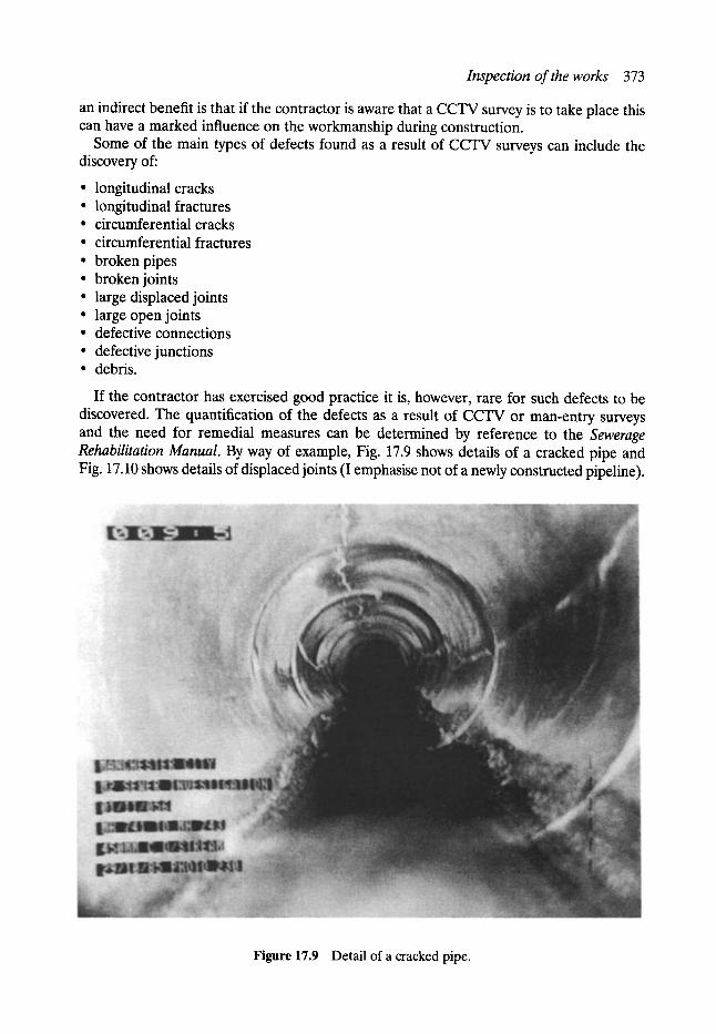
Inspection of the works 373
an indirect benefit is that if the contractor is aware that a CCTV survey is to take place this can have a marked influence on the workmanship during construction.
Some of the main types of defects found as a result of CCTV surveys can include the discovery of:
�9 longitudinal cracks �9 longitudinal fractures �9 circumferential cracks �9 circumferential fractures �9 broken pipes �9 broken joints �9 large displaced joints �9 large open joints �9 defective connections �9 defective junctions �9 debris.
If the contractor has exercised good practice it is, however, rare for such defects to be discovered. The quantification of the defects as a result of CCTV or man-entry surveys and the need for remedial measures can be determined by reference to the Sewerage Rehabilitation Manual. By way of example, Fig. 17.9 shows details of a cracked pipe and Fig. 17.10 shows details of displaced joints (I emphasise not of a newly constructed pipeline).
Figure 17.9 Detail of a cracked pipe.

374 Site supervision
Figure 17.10 Detail of displaced joints.
Bibliography Abrahamson, M. W. Engineering Law and the ICE Contracts. Applied Science Publishers, Barking,
Essex. ISBN 0-85334-824-X. ICE Conditions of Contract, 6th edn. Thomas Telford, Thomas Telford House, 1 Heron Quay, London
El4 4JD. ISBN 0-7277-1617 4. Sawyer, J. G. and Gillott, C. A. The FIDIC Digest. Thomas Telford, Thomas Telford House, 1 Heron
Way, London El4 4JD. ISBN. CIRIA Report No. 44, Medical Code of Practice for Work in Compressed Air. The Construction Industry,
Research and Information Association, 6 Storey's Gate, Westminster, London SWlP 3AU. CESMM 2, The Civil Engineering Standard Method of Measurement, 2nd edn. The Institution of Civil
Engineers, Thomas Telford, 1 Heron Quay, London El4 4JD. Schedule of Dayworks carried out Incidental to Contract Works. The Federation of Civil Engineering
Contractors, 6 Portugal Street, London. Construction Weekly Plant Directory. Morgan-Grampion (Construction Press), 30 Calderwood Street,
London. Sewer Rehabilitation Manual, 2nd edn. Water Research Council, EO. Box 85, Swindon, Wiltshire SF5
8YR.
Sewer 18
i. Repa r and Renovation in Japan
Satoru Tohyama*
18.1 Introduction The history of construction of modern-style public sewerage systems is relatively new in Japan, except in major cities such as Tokyo and Osaka. Therefore, the government has been investing over u trillion in recent years to construct more sewers and to maintain the water quality in the public sector. Thus, the maintenance system of sewers has become significant quite recently. So, advanced technologies of other countries have been adopted and modified to suit Japanese systems and conditions. In this chapter, sewerage maintenance technology in Japan is outlined. The commercial names of the methods which might be different from the original names are used for convenience.
18.2 The general situation of sewerage systems in Japan
18. 2.1 DIS TRIB UTION RATE OF SE WERA GE
In Japan 'the percentage of sewered population' is used to indicate the level of sewerage. The percentage in Japan is about 54% in 1996. This percentage is calculated as follows:
percentage of sewered population (%) =
(the population whose sewerage flows into the sewage treatment plant) x 100
(total population of the district)
The percentages of sewered population by size of city are detailed in Table 18.1. Table 18.1 shows that the percentage of big cities with a population over 1 million such as Tokyo and Osaka has almost reached 100%. On the other hand, percentages differ greatly between middle- and small-size cities. Some cities have sufficient sewerage, but other cities are now constructing systems or are still planning.
The Japanese government has formed five-year programmes starting in 1963 and execut- ing constructions by design. The seventh five-year programme (1991-1995) is underway. This plan aims at raising the percentage up to 54% by the end of 1995 and 70% in 2000.
*Chairman, Japan Society for Trenchless Technology.
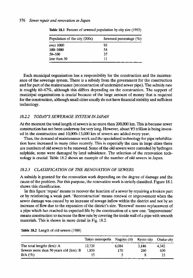
376 Sewer repair and renovation in Japan
Table 18.1 Percent of sewered population by city size (1993)
Population of the city (000s) Sewered percentage (%)
over 1000 93 100-1000 54 50-100 37 less than 50 11
Each municipal organisation has a responsibility for the construction and the mainten- ance of the sewerage system. There is a subsidy from the government for the construction and for part of the maintenance (reconstruction of undersized sewer pipe). The subsidy rate is roughly 60--67%, although this differs depending on the construction. The support of municipal organisations is crucial because of the large amount of money that is required for the construction, although small cities usually do not have financial stability and sufficient technology.
18.2.2 TODAY'S SEWERAGE SYSTEM IN JAPAN
At the moment the total length of sewers is no more than 200,000 km. This is because sewer construction has not been underway for. very long. However, about u trillion is being invest- ed in the construction and 10,000-13,000 km of sewers are added every year.
Thus, the demand of maintenance work and the specialised technology for pipe rehabilita- tion have increased in many cities recently. This is especially the case in large cities there are numbers of old sewers to be renewed. Some of the old sewers were corroded by hydrogen sulphide, some were damaged by land subsidence. The selection of the renovation tech- nology is crucial. Table 18.2 shows an example of the number of old sewers in Japan.
18.2.3 CLASSIFICATION OF THE RENOVATION OF SEWERS
A subsidy is granted for the renovation work depending on the degree of damage and the cause of the problem. For this purpose, the renovation work is strictly classified. Figure 18.1 shows this classification.
In this figure 'repair' means to recover the function of a sewer by repairing a broken part or by reinforcing a weak part. 'Reconstruction' means renewal or improvement when the sewer damage was caused by an increase of sewage inflow within the district and not by an increase of flow due to the expansion of the district's size. 'Renewal' means replacement of a pipe which has reached its expected life by the construction of a new one. 'Improvement' means construction to increase the flow rate by covering the inside wall of a pipe with smooth materials. This is shown in more detail in Fig. 18.2.
Table 18.2 Length of old sewers (1988) , , ,
Tokyo metropolis Nagoya city Kyoto city Osaka city
The total lengths (km): A 12,720 6,084 3,146 4,342 Sewers more than 50 years old (km): B 1,850 170 260 630 B/A (%) 15 3 8 15
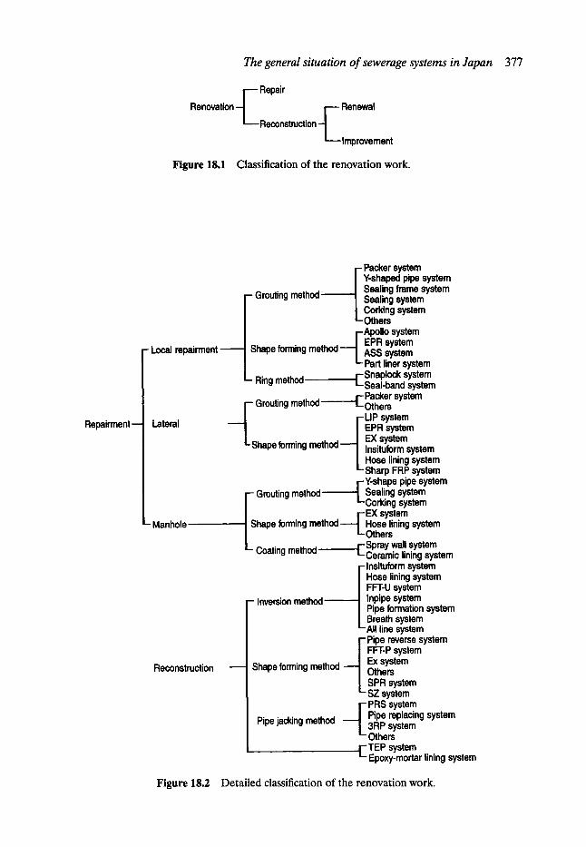
The general situation of sewerage systems in Japan 377
Renovation - ~ Repair
L.._Reconstruction f Renewal
Improvement
Figure 18.1 Classification of the renovation work.
Repairment --
- Local repairment
Lateral
- Manhole
Reconstruction
Grouting method
hape forming method
ing mlthod
- Grouting method [ .]-sGrOuting method
i Packer system Y-shaped pipe system Sealing frame system Sealing system Corking system Others
i Apollo system EPR system ASS system Part liner system
r -Snaplock system Seal-band system
r-Packer system LOthers FLIP system / EPR system
.,,,~,,,4__.J EX system Shape forming ........ ~ Insituform system
Hose lining system ' - S h a r p FRP system
FL Y-shape pipe system Sealing system Corking system EX system Hose lining system Others
-Spray wall system Ceramic lining system
F Insituform system | Hose lining system | FFT-U system ! Inpipe system -Inversion method I .Pipe formation system | Breath system '-All line system -Pipe reverse system
FFT-P system Ex system Shape forming method | Others
| SPR system '- SZ system r - PRS system
Pipe jacking method ] Pipe replacing system L 3RP system
Others r- TEP system L Epoxy-mortar lining system
Figure 18.2 Detailed classification of the renovation work.
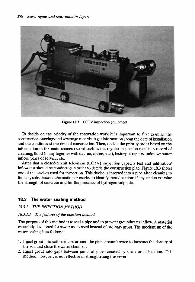
378 Sewer repair and renovation in Japan
Figure 18.3 CCTV inspection equipment.
To decide on the priority of the renovation work it is important to first examine the construction drawings and sewerage records to get information about the date of installation and the condition at the time of construction. Then, decide the priority order based on the information in the maintenance record such as the regular inspection results, a record of cleaning, flood (if any together with degree, claims, etc.), history of repairs, unknown water inflow, years of service, etc.
After that a closed-circuit television (CCTV) inspection capacity test and infiltration/ inflow test should be conducted in order to decide the construction plan. Figure 18.3 shows one of the devices used for inspection. This device is inserted into a pipe after cleaning to find any subsidence, deformation or cracks, to identify those locations if any, and to examine the strength of concrete and for the presence of hydrogen sulphide.
18.3 The water sealing method 18. 3.1 THE INJE C TION ME THOD
18. 3.1.1 The features of the injection method
The purpose of this method is to seal a pipe and to prevent groundwater inflow. A material especially developed for sewer use is used instead of ordinary grout. The mechanism of the water sealing is as follows:
1. Inject grout into soil particles around the pipe circumference to increase the density of the soil and close the water channels.
2. Inject grout into gaps between joints of pipes created by shear or dislocation. This method, however, is not effective in strengthening the sewer.
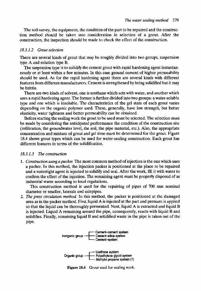
The water sealing method 379
The soil survey, the equipment, the condition of the part to be repaired and the construc- tion method should be taken into consideration in selection of a grout. After the construction, the inspection should be made to check the effect of the construction.
18.3.1.2 Grout selection
There are several kinds of grout that may be roughly divided into two groups, suspension type A and solution type B.
The suspension type is to solidify the cement grout with rapid hardening agent instantan- eously or at least within a few minutes. In this case ground cement of higher permeability should be used. As for the rapid hardening agent there are several kinds with different features from different manufacturers. Cement is strengthened by being solidified but it may be brittle.
There are two kinds of solvent, one is urethane which acts with water, and another which uses a rapid hardening agent. The former is further divided into two groups: a water-soluble type and one which is insoluble. The characteristics of the gel state of each grout varies depending on the organic polymer used. These, generally, have low strength, but better elasticity, water tightness and better permeability can be obtained.
Before starting the sealing work the grout to be used must be selected. The selection must be made by considering the anticipated performance the condition of the construction site (infiltration, the groundwater level, the soil, the pipe material, etc.). Also, the appropriate concentration and mixture of grout and gel time must be determined for the grout. Figure 18.4 shows grout types which can be used for water-sealing construction. Each grout has different features in terms of the solidification.
18.3.1.3 The construction
1. Construction using a packer. The most common method of injection is the one which uses a packer. In this method, the injection packer is positioned at the place to be repaired and a watertight agent is injected to solidify and seal. After the work, fill it with water to confirm the effect of the injection. The remaining agent must be properly disposed of as industrial waste according to local regulations.
This construction method is used for the repairing of pipes of 700 mm nominal diameter or smaller, laterals and sidepipes.
2. The press circulation method. In this method, the packer is positioned at the damaged area as in the packer method. First, liquid A is injected at the part and pressure is applied so that the liquid can be thoroughly permeated. Next, liquid A is extracted and liquid B is injected. Liquid A remaining around the pipe, consequently, reacts with liquid B and solidifies. Finally, remaining liquid B and solidified waste in the pipe is taken out of the pipe.
Inocganic group, I - Cement-cement system
Cement-silica system Cement-system
V Urethane system Organic group Polyethylene glycol system
Methylol propene system (?)
Figure 18.4 Grout used for sealing work.
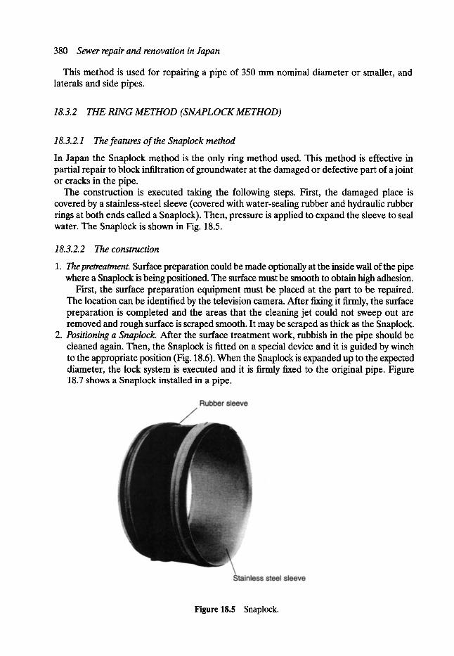
380 Sewer repair and renovation in Japan
This method is used for repairing a pipe of 350 mm nominal diameter or smaller, and laterals and side pipes.
18.3.2 THE RING METHOD (SNAPLOCK METHOD)
18.3.2.1 The features of the Snaplock method
In Japan the Snaplock method is the only ring method used. This method is effective in partial repair to block infiltration of groundwater at the damaged or defective part of a joint or cracks in the pipe.
The construction is executed taking the following steps. First, the damaged place is covered by a stainless-steel sleeve (covered with water-sealing rubber and hydraulic rubber tings at both ends called a Snaplock). Then, pressure is applied to expand the sleeve to seal water. The Snaplock is shown in Fig. 18.5.
18.3.2.2 The construction
1. Thepretreatment. Surface preparation could be made optionally at the inside wall of the pipe where a Snaplock is being positioned. The surface must be smooth to obtain high adhesion.
First, the surface preparation equipment must be placed at the part to be repaired. The location can be identified by the television camera. After f~ng it firmly, the surface preparation is completed and the areas that the cleaning jet could not sweep out are removed and rough surface is scraped smooth. It may be scraped as thick as the Snaplock.
2. Positioning a Snaplock. After the surface treatment work, rubbish in the pipe should be cleaned again. Then, the Snaplock is fitted on a special device and it is guided by winch to the appropriate position (Fig. 18.6). When the Snaplock is expanded up to the expected diameter, the lock system is executed and it is firmly fixed to the original pipe. Figure 18.7 shows a Snaplock installed in a pipe.
Figure 15.5 Snaplock.
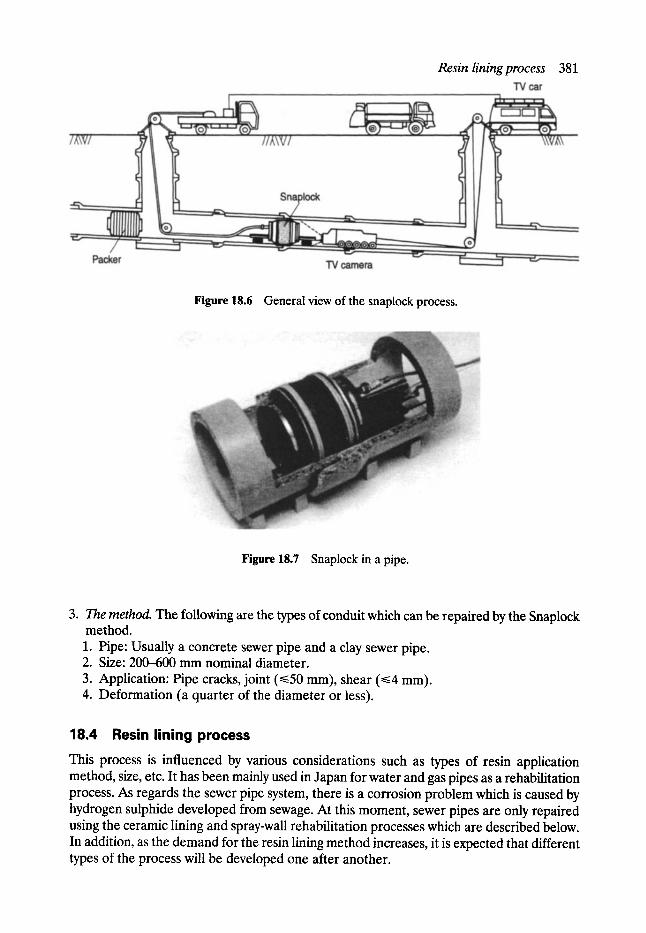
Resin lining process 381
Figure 18.6 General view of the snaplock process.
Figure 18.7 Snaplock in a pipe.
3. The method. The following are the types of conduit which can be repaired by the Snaplock method. 1. Pipe: Usually a concrete sewer pipe and a clay sewer pipe. 2. Size: 200--600 mm nominal diameter. 3. Application: Pipe cracks, joint (~<50 mm), shear (~<4 mm). 4. Deformation (a quarter of the diameter or less).
18.4 Resin lining process This process is influenced by various considerations such as types of resin application method, size, etc. It has been mainly used in Japan for water and gas pipes as a rehabilitation process. As regards the sewer pipe system, there is a corrosion problem which is caused by hydrogen sulphide developed from sewage. At this moment, sewer pipes are only repaired using the ceramic lining and spray-wall rehabilitation processes which are described below. In addition, as the demand for the resin lining method increases, it is expected that different types of the process will be developed one after another.

382 Sewer repair and renovation in Japan
18. 4.1 CERAMIC LINING
This is a process to protect the concrete pipe wall from corrosion by providing a fine covering of a paint mixture consisting of a hard ceramic powder and a reactive polymer (epoxy resin). As the paint mixture ispainted directly onto the concrete structure, full inspection of the concrete surface is necessary prior to commencement.
If any problem or failure is found in the inspection, then surface preparation needs be carried out as mentioned below.
18. 4.1.1 Water leaking
Fractures which allow water leakage need to be filled with quick drying cement or a chemical liquid (chemical grouting) to develop a fully watertight surface.
18.4.1.2 Voids and missing segments
Severely damaged pipe walls with voids and structural material missing need to be restored by grinding, cleaning with water and filling with resin mortar or similar filler to sufficiently refill any void.
18. 4.1.3 Crack
Substantially cracked parts need be cut in a V-shape of 20 and 50 mm width and depth, respectively, and the peripheral parts ground down. Any ground particles need to be washed away thoroughly from the V cut. After that, the V cut needs to be filled with resin mortar in the same way as above.
18.4.1.4 Joint between concrete walls
The joint between new and old concrete pipe walls needs to also be grooved in a V-shape and filled with resin mortar or similar after cleaning with water.
18. 4. 2 SPRAY WALL
This process is used to strengthen the structure of the sewer pipe system and protect it from corrosion by spraying a particular type of hard polyurethane resin on to deteriorating parts. The process to be followed is as described below.
18. 4.2.1 Preparation
A plug is set at the upstream end of the pipe to stop sewage flow coming down to the working site.
18.4.2.2 Cleaning
The inside wall of the manhole is cleaned with a water jet and a brush. After washing, water drops are wiped away with a cloth.
18. 4. 2. 3 Final preparation before spraying
In the case of water permeating from the joint between the manhole blocks this needs to be tentatively stopped using a resin mortar. Any void at a joint needs to be filled with resin mortar.
The inversion lining method 383
18. 4. 2. 4 Spray on wall
Spray is provided to the wall 500--600 mm above the bottom of the manhole in a prescribed thickness. After this the pipe is unplugged and the sewage is left to flow. Spray is continuously provided from the lower part to the upper part in an unprescribed thickness. The paint mixture piled up at the tip of nozzle is removed with a wire brush after completion of spraying.
18.5 The inversion lining method This method has been widely used for the rehabilitation of sewerage pipelines and other systems for many years.
18.5.1 INSITUFORM METHOD
In this method, first a sock material of the same inside diameter as the pipe to be repaired should be made prior to the construction. Such a sock is made from polyurethane-coated polyester felt.
Thermosetting resin is poured into the sock from one end and impregnated through at the polyester felt. This felt, Insituform liner, is inverted by water pressure into the pipeline to be repaired and can construct a new pipe of length sufficient to repair the damage (Fig. 18.1). The water used during the inversion process is heated after inversion and, the impregnated resin in the Insituform liner is cured. Thus, a new Insituform liner is formed in an old pipe. The method can be applied to short length and lateral pipes and to pipes of many different cross-sections.
18. 5. 2 THE HOSE LINING METHOD
In the hose lining method, thermosetting resin is introduced into a sock of woven polyester tubing and the sock is pressed into the pipeline by air pressure and cured inside the original pipe. In the inversion process a heating hose in which steam is delivered and is inserted in the pipe. It is important to heat the pipe uniformly, and after heating the pipe is cooled clown by water or compressed air while keeping the same pressure in the pipe (Fig. 18.8). The hose is then cut at the manhole entrance and sealed by epoxy resin mortar.
The lateral must be opened from the inside since it is dosed by the hose lining. There are, usually, two steps to drill. On the day of the installation, a temporary hole is made at the lateral and on the next day the work of opening is completed.
18.5.3 THE INPIPE METHOD
This method is a pipe renewal method developed by Inpipe Sweden AB. A glass-fibre sock is made prior to the construction. Light-curing polyester resin is impregnated into the stocking and this is inserted into the pipe by an inversion process with compressed air. When this soft sleeve is exposed to ultraviolet light, it is hardened and forms a new pipe keeping the same size as well as shape. This new pipe has the same strength as PVC or greater and is an independent pipe without joints. In this method, the reinforced plastic pipe (GFP) can be built without being affected by infiltrating groundwater from cracks in the original pipe
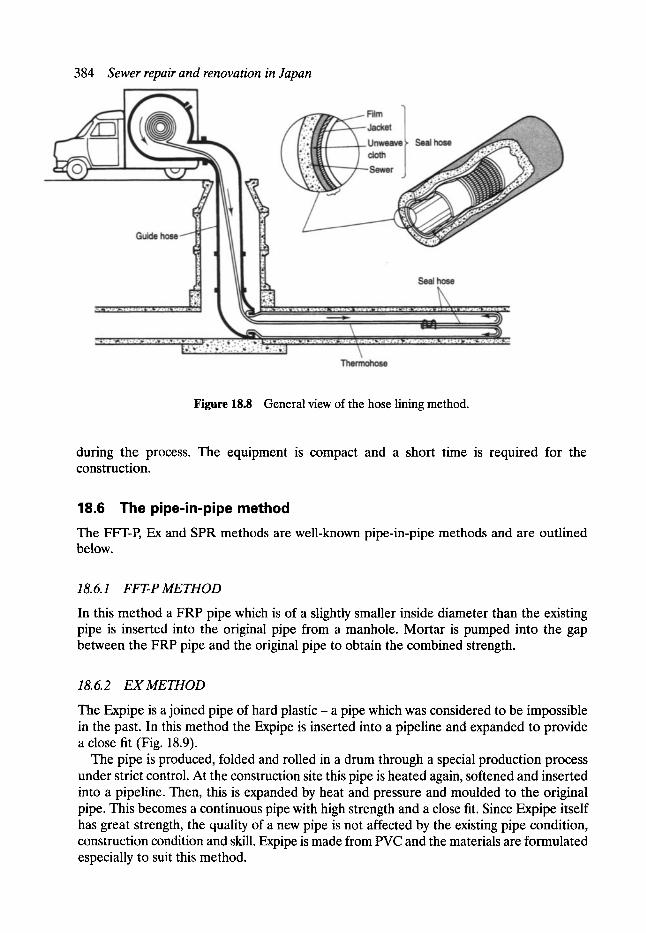
384 Sewer repair and renovation in Japan
Figure 18.8 General view of the hose lining method.
during the process. The equipment is compact and a short time is required for the construction.
18.6 The pipe-in-pipe method The FFT-P, Ex and SPR methods are well-known pipe-in-pipe methods and are outlined below.
18. 6.1 FFT-P ME THOD
In this method a FRP pipe which is of a slightly smaller inside diameter than the existing pipe is inserted into the original pipe from a manhole. Mortar is pumped into the gap between the FRP pipe and the original pipe to obtain the combined strength.
18. 6. 2 E X ME THOD
The Expipe is a joined pipe of hard plastic- a pipe which was considered to be impossible in the past. In this method the Expipe is inserted into a pipeline and expanded to provide a close fit (Fig. 18.9).
The pipe is produced, folded and rolled in a drum through a special production process under strict control. At the construction site this pipe is heated again, softened and inserted into a pipeline. Then, this is expanded by heat and pressure and moulded to the original pipe. This becomes a continuous pipe with high strength and a close fit. Since Expipe itself has great strength, the quality of a new pipe is not affected by the existing pipe condition, construction condition and skill. Expipe is made from PVC and the materials are formulated especially to suit this method.
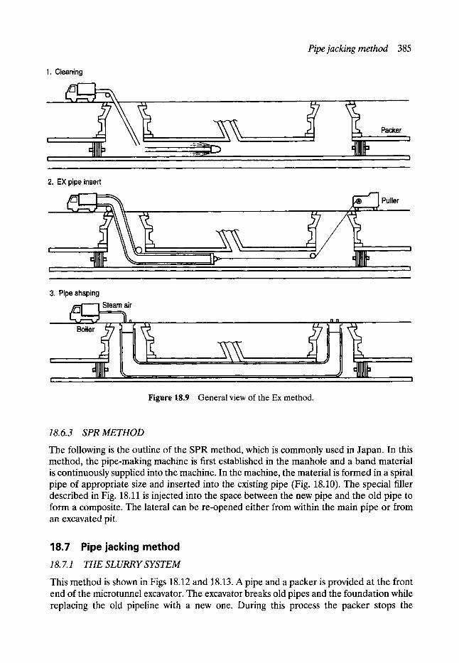
1. Cleaning
Pipe jacking method 385
Packer
2. EX pipe insert
~ , . ~ j ~ . . . . . . ~ Puller
. . . . . . . ~ , , ", j
' . . . . . . . . .
[ , , , , I
3. Pipe shaping Steam air
Boiler
Figure 18.9 General view of the Ex method.
18. 6. 3 SPR METHOD
The following is the outline of the SPR method, which is commonly used in Japan. In this method, the pipe-making machine is first established in the manhole and a band material is continuously supplied into the machine. In the machine, the material is formed in a spiral pipe of appropriate size and inserted into the existing pipe (Fig. 18.10). The special filler described in Fig. 18.11 is injected into the space between the new pipe and the old pipe to form a composite. The lateral can be re-opened either from within the main pipe or from an excavated pit.
18.7 Pipe jacking method 18. 7.1 THE S L URR Y S YS TE M
This method is shown in Figs 18.12 and 18.13. A pipe and a packer is provided at the front end of the microtunnel excavator. The excavator breaks old pipes and the foundation while replacing the old pipeline with a new one. During this process the packer stops the
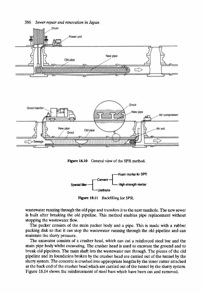
386 Sewer repair and renovation in Japan
Figure 18.10 General view of the SPR method.
[----Cement - - J Special f i l l e r - - - - 1 L _ _ . .
L . - - Urethane
Foam mortar for SPR
High-strength mortar
Figure 18.11 Backfilling for SPR.
wastewater running through the old pipe and transfers it to the next manhole. The new sewer is built after breaking the old pipeline. This method enables pipe replacement without stopping the wastewater flow.
The packer consists of the main packer body and a pipe. This is made with a rubber packing disk so that it can stop the wastewater running through the old pipeline and can maintain the slurry pressure.
The excavator consists of a crusher head, which can cut a reinforced steel bar and the main pipe body whilst excavating. The crusher head is used to excavate the ground and to break old pipelines. The main shaft lets the wastewater run through. The pieces of the old pipeline and its foundation broken by the crusher head are carried out of the tunnel by the slurry system. The concrete is crushed into appropriate lengths by the inner cutter attached at the back end of the crusher head which are carried out of the tunnel by the slurry system. Figure 18.14 shows the reinforcement of steel bars which have been cut and removed.
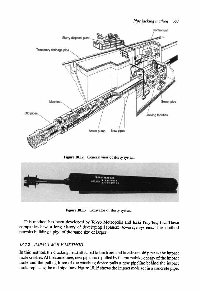
Pipe jacking method 387
Figure 18.12 General view of slurry system.
Figure 18.13 Excavator of slurry system.
This method has been developed by Tokyo Metropolis and Iseki Poly-Tec, Inc. These companies have a long history of developing Japanese sewerage systems. This method permits building a pipe of the same size or larger.
18. 7.2 IMPACT MOLE METHOD
In this method, the cracking head attached to the front end breaks an old pipe as the impact mole crashes. At the same time, new pipeline is pulled by the propulsive energy of the impact mole and the pulling force of the winching device pulls a new pipeline behind the impact mole replacing the old pipelines. Figure 18.15 shows the impact mole set in a concrete pipe.
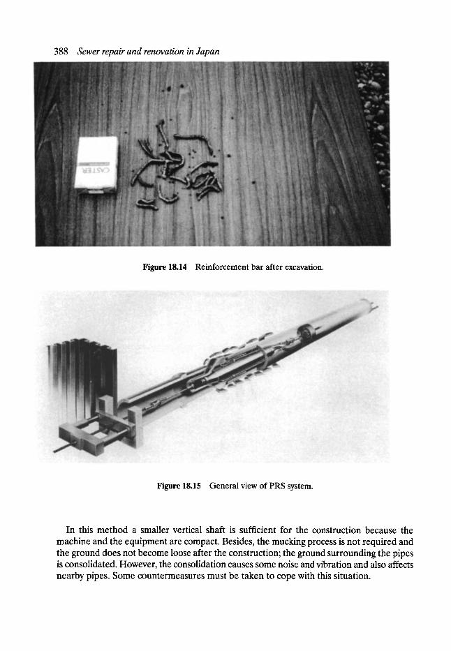
388 Sewer repair and renovation in Japan
Figure 18.14 Reinforcement bar after excavation.
Figure 18.15 General view of PRS system.
In this method a smaller vertical shaft is sufficient for the construction because the machine and the equipment are compact. Besides, the mucking process is not required and the ground does not become loose after the construction; the ground surrounding the pipes is consolidated. However, the consolidation causes some noise and vibration and also affects nearby pipes. Some countermeasures must be taken to cope with this situation.
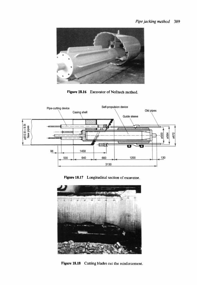
Pipe jacking method 389
Figure 18.16 Excavator of Nolltech method.
Figure 18.17 Longitudinal section of excavator.
Figure 18.18 Cutting blades cut the reinforcement.

390 Sewer repair and renovation in Japan
18. 7. 3 NOL TE CH ME THOD
In this method the excavator with a guide and a pipe-breaking device (Figs 18.16 and 18.17) breaks old pipes and replaces them with new pipes of the same size or larger. This method is now under development.
The pipe-breaking device has a cutter which vibrates back and forth by means of a special air hammer. This cutter breaks pipes as well as reinforced steel bars (Fig. 18.18).
This method has a simple mechanism which is easy to handle that may lessen accidents and also has high excavating speed but still leaves many problems that must be solved.
18.8 Conclusion The sewerage renovation methods currently being used in Japan have been discussed. The history of sewerage maintenance in Japan is quite new and most of the advanced technologies used are adopted from western countries which are modified to suit the Japanese situation. It is the case that the total length of sewers has been growing constantly, especially so in recent years. The length has increased by 1000 km each year. The construction of new pipelines will be completed in the near future and maintenance work will be increasingly more significant. Thus, it is necessary to keep sewerage maintenance records and to make an effort to develop new technologies.
19 Development and Research
Geoffrey I-. Read MSc, CEng, FICE, FIStructE, FCIWEM, FIHT, MILE, FIMgt, MAE, MUKSTT
lan G. Vickridge BSc, MSc, MICE, MCIWEM, MUKSTT
19.1 Introduction
19.1.1 THE PAST
In 1974 the sewerage function of the water cycle in the UK ceased to be a direct responsi- bility of local authorities. This was not perhaps a surprising change when one remembers that the usual attitude, when local authority budgets were being prepared, was that 'There's no votes in sewers', regardless of which political party had the overall majority at the time.
The Editor well remembers a former city treasurer observing during the sewer collapse era in Manchester, how unfortunate it had been over very many years that local authorities had given little priority at budget times to the need for sewer maintenance expenditure in comparison with more socially oriented projects - literally, out of sight, out of mind.
Under the Public Health Act 1936 local authorities had a responsibility to maintain a system of sewer records but as indicated earlier these were generally not complete and tend- ed to rely on the local knowledge of engineering staff plus the foremen of the sewerage maintenance teams rather than on the inadequacy of crumbling linen plans usually retained in a central location such as the Town Hall which in itself led to problems as and when emergencies developed.
It must be remembered that it was not until the late 1970s that the appropriate technology was developed so that the present condition of the non-man-entry part of the underground network could be assessed with any reasonable degree of accuracy- black and white initially but quickly replaced by relatively high-quality colour. Councillors could no longer have the excuse of ignorance and the myth that the Victorian's had provided a sewerage network to last 1000 years or more without attention.
Closed-circuit television (CCTV) provided a rapid and efficient method to critically examine and record the situation- provided funds could be made available to use it. The Association of CCTV Surveyors (ACCTVS) was formed and produced recommendations in regard to uniform reporting standards, classification documentation and training programmes in order to ensure overall data quality, etc. It was against this background that the sewerage function in England and Wales indeed the whole hydrological cycle- passed to ten new water authorities.

392 Development and research
Many of these new authorities were based on existing water boards which looked after the clean water side - hence initially they knew more about the provision of potable water than dealing with wastewater.
It was soon realised that the day-to-day maintenance of the sewerage infrastructure was dependent much more on local knowledge than the limited old records, and agency arrangements were quickly implemented with the local authorities being given delegated powers to do what they had previously done but now there were two layers of control instead of one - a situation that the person in the street found difficult to understand. Water authori- ties did not always see eye to eye with local councillors w h o - notwithstanding their previous shortcomings so far as funding was conce rned - still felt they held the responsibility for sewerage directly.
This shared arrangement obviously provided a learning situation for the water authori- ties and in due course they developed their own organisations and an improved knowledge of the sewerage infrastructure so that questions were then asked as to whether an agency system was the most efficient and cost-effective way of providing the service for which they had a mandatory responsibility. In addition there was also the inherent desirability of being seen to be in direct control of a function for which they were responsible. Consequently agency arrangements have from time to time been significantly reduced and nowadays with few exceptions are limited to day-to-day maintenance operations.
It is indisputable that water authorities acquired a massive, poorly maintained and docu- mented sewerage network. During this period it became apparent that in fact Victorian engineering does not last for ever and sewer collapses became a fact of life or perhaps an interference with normal life would be a more accurate description. Clearly, the level of funding required to replace this Victorian industrial legacy was not available even under the new arrangements and renovation was quickly adopted as a means of obtaining more operational life from an ageing infrastructure.
Renovation quickly developed as the 'buzz-word', the industry delighted to be backed at the highest level which at that time in turn gave an ever-increasing order book, although there was some concern amongst engineers as to the long-term effects.
19.1.2 THE PRESENT
In due course the spectre of the Stock Exchange and accountants entered the scene and the water industry in England and Wales is now controlled by privately owned, publicly quot- ed water companies. In the years immediately prior to privatisation the public perception and that of the sewer renovation industry, was that expenditure on maintenance of the national sewerage infrastructure would be in line with engineering requirements, and ade- quate funding would no longer be a problem. Privatisation was of course claimed to be a wonderful solution providing opportunities which were impossible under public ownership where they were controlled by government legislation, particularly so far as capital funding was concerned - but in practice it did not work like this. The company's primary responsi- bility was to its shareholders- customers, and the public in general, coming second to profit being clearly the present situation notwithstanding the presence of the government's watch dog - Ofwat (Fig. 19.1). Profits before tax for the water utilities amounted to s in 1994/5 - an increase of over 17% on 1993/4 figures. Profits have increased by 40% in real terms since privatisation in 1989.
It is interesting to note in this connection the following extract from Water Services:
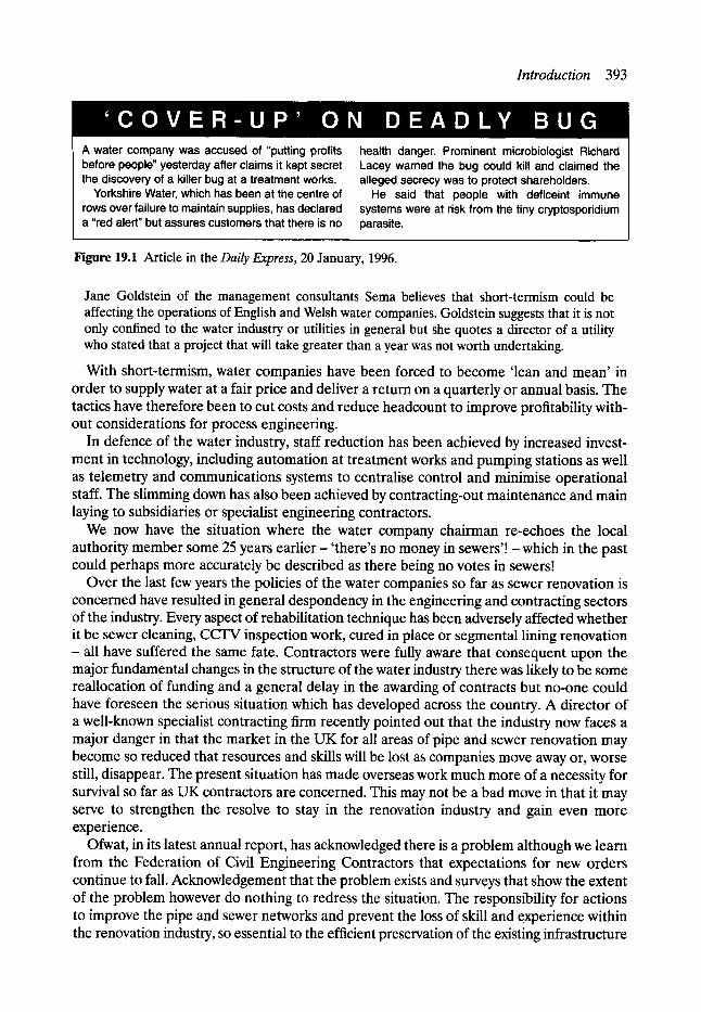
Introduction 393
A water company was accused of "putting profits before people" yesterday after claims it kept secret the discovery of a killer bug at a treatment works.
Yorkshire Water, which has been at the centre of rows over failure to maintain supplies, has declared a "red alert" but assures customers that there is no
health danger. Prominent microbiologist Richard Lacey wamed the bug could kill and claimed the alleged secrecy was to protect shareholders.
He said that people with deficeint immune systems were at risk from the tiny cryptosporidium parasite.
Figure 19.1 Article in the Daily Express, 20 January, 1996.
Jane Goldstein of the management consultants Sema believes that short-termism could be affecting the operations of English and Welsh water companies. Goldstein suggests that it is not only confined to the water industry or utilities in general but she quotes a director of a utility who stated that a project that will take greater than a year was not worth undertaking.
With short-termism, water companies have been forced to become 'lean and mean' in order to supply water at a fair price and deliver a return on a quarterly or annual basis. The tactics have therefore been to cut costs and reduce headcount to improve profitability with- out considerations for process engineering.
In defence of the water industry, staff reduction has been achieved by increased invest- ment in technology, including automation at treatment works and pumping stations as well as telemetry and communications systems to centralise control and minimise operational staff. The slimming down has also been achieved by contracting-out maintenance and main laying to subsidiaries or specialist engineering contractors.
We now have the situation where the water company chairman re-echoes the local authority member some 25 years earlier - 'there's no money in sewers'! - which in the past could perhaps more accurately be described as there being no votes in sewers!
Over the last few years the policies of the water companies so far as sewer renovation is concerned have resulted in general despondency in the engineering and contracting sectors of the industry. Every aspect of rehabilitation technique has been adversely affected whether it be sewer cleaning, CCTV inspection work, cured in place or segmental lining renovation - all have suffered the same fate. Contractors were fully aware that consequent upon the major fundamental changes in the structure of the water industry there was likely to be some reallocation of funding and a general delay in the awarding of contracts but no-one could have foreseen the serious situation which has developed across the country. A director of a well-known specialist contracting firm recently pointed out that the industry now faces a major danger in that the market in the UK for all areas of pipe and sewer renovation may become so reduced that resources and skills will be lost as companies move away or, worse still, disappear. The present situation has made overseas work much more of a necessity for survival so far as UK contractors are concerned. This may not be a bad move in that it may serve to strengthen the resolve to stay in the renovation industry and gain even more experience.
Ofwat, in its latest annual report, has acknowledged there is a problem although we learn from the Federation of Civil Engineering Contractors that expectations for new orders continue to fall. Acknowledgement that the problem exists and surveys that show the extent of the problem however do nothing to redress the situation. The responsibility for actions to improve the pipe and sewer networks and prevent the loss of skill and experience within the renovation industry, so essential to the efficient preservation of the existing infrastructure
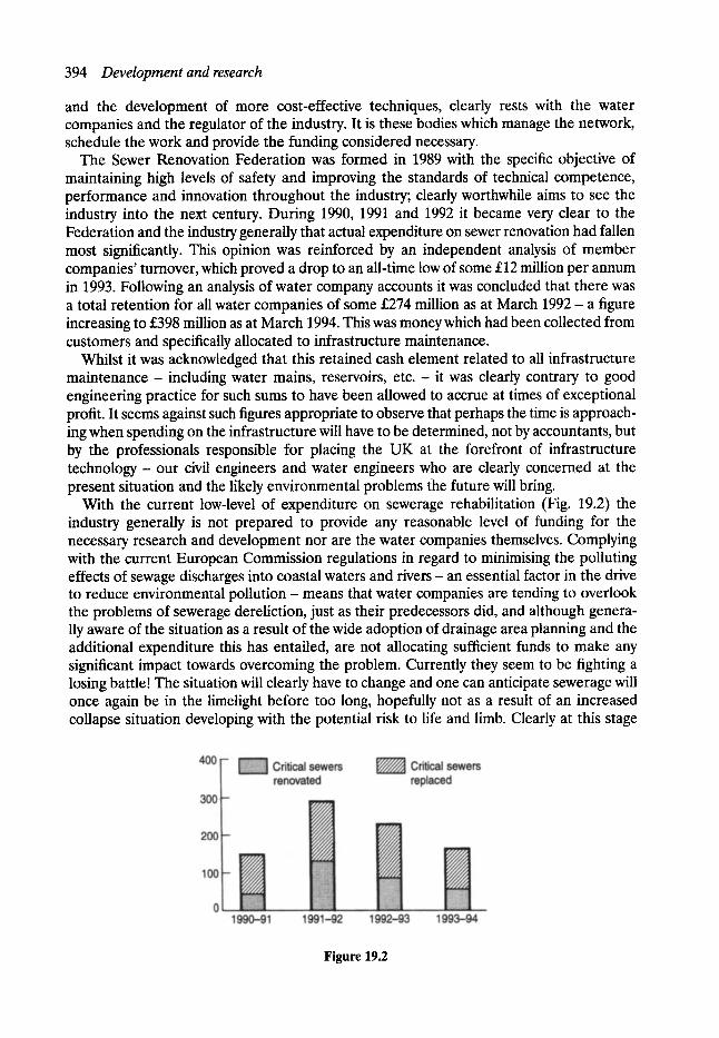
394 Development and research
and the development of more cost-effective techniques, clearly rests with the water companies and the regulator of the industry. It is these bodies which manage the network, schedule the work and provide the funding considered necessary.
The Sewer Renovation Federation was formed in 1989 with the specific objective of maintaining high levels of safety and improving the standards of technical competence, performance and innovation throughout the industry; clearly worthwhile aims to see the industry into the next century. During 1990, 1991 and 1992 it became very clear to the Federation and the industry generally that actual expenditure on sewer renovation had fallen most significantly. This opinion was reinforced by an independent analysis of member companies' turnover, which proved a drop to an all-time low of some s million per annum in 1993. Following an analysis of water company accounts it was concluded that there was a total retention for all water companies of some s million as at March 1992 - a figure increasing to s million as at March 1994. This was money which had been collected from customers and specifically allocated to infrastructure maintenance.
Whilst it was acknowledged that this retained cash element related to all infrastructure maintenance- including water mains, reservoirs, e t c . - it was clearly contrary to good engineering practice for such sums to have been allowed to accrue at times of exceptional profit. It seems against such figures appropriate to observe that perhaps the time is approach- ing when spending on the infrastructure will have to be determined, not by accountants, but by the professionals responsible for placing the UK at the forefront of infrastructure technology - our civil engineers and water engineers who are clearly concerned at the present situation and the likely environmental problems the future will bring.
With the current low-level of expenditure on sewerage rehabilitation (Fig. 19.2) the industry generally is not prepared to provide any reasonable level of funding for the necessary research and development nor are the water companies themselves. Complying with the current European Commission regulations in regard to minimising the polluting effects of sewage discharges into coastal waters and rivers- an essential factor in the drive to reduce environmental pollution- means that water companies are tending to overlook the problems of sewerage dereliction, just as their predecessors did, and although genera- lly aware of the situation as a result of the wide adoption of drainage area planning and the additional expenditure this has entailed, are not allocating sufficient funds to make any significant impact towards overcoming the problem. Currently they seem to be fighting a losing battle! The situation will clearly have to change and one can anticipate sewerage will once again be in the limelight before too long, hopefully not as a result of an increased collapse situation developing with the potential risk to life and limb. Clearly at this stage
Figure 19.2

The future- the need for research and development 395
sewerage renovation will inevitably reappear, utilising the techniques previously developed to date and described in this book but without the benefit of ongoing research and development which would have been part of an ongoing programme.
It is accepted that sewers in themselves do not generate profit, nevertheless they do appear as fixed assets on the balance sheets although one wonders how realistic these assessments are - no doubt before too long the accountants will start asking awkward questions.
19.2 The future- the need for research and development A great deal of research and development work took place during the 1970s and 1980s, when new methods for strategic planning, surveying and inspection, and the relining and replacement of defective sewers were devised and put into operation. However, the systems developed are not perfect and ongoing research and development is required to improve both management strategies and rehabilitation techniques.
It is against the issue of asset valuation that one starts to consider how in fact are these renovation techniques- developed in the 1970s and early 1980s against a background of crisis - working in practice. Are they coming up to expectations as to likely life span and what is the most cost-effective way of continuing the old pipeline in service when the renovation treatment - as we now know it - is no longer effective?
19. 2.1 A SSE T MANAGEMENT
There is a balance to be struck between carrying out too little maintenance (assets deterior- ate rapidly and expenditure is then necessary to replace or repair) and doing too much (assets may be preserved but at the cost of additional unnecessary maintenance).
A full analysis of the life-cycle costs of various maintenance strategies is therefore required in order to determine the most economic in any given situation. In order to carry out such an analysis, using discounted cash flow or other appropriate techniques some estimate of the effective life expectancy of materials and equipment must be made.
Failure to identify the most cost-effective option could result in significant unnecessary expenditure which in turn has implications for the service provided to consumers and the dividends paid to shareholders.
It was against this background that the Sewerage Rehabilitation Unit in the Department of Civil and Structural Engineering at the University of Manchester Institute of Science and Technology (UMIST) in 1992 produced a research proposal to study the performance of sewer renovation systems initially in the north-west of England where the first renovation techniques were developed. The main aim was to examine in practice the performance of typical sewer renovation schemes of various types and ages in both man-entry and non-man- entry sewers. It was anticipated that, following analysis of the information obtained and the examination of the original design and construction data, that it would be possible to make an assessment of the deterioration which has taken place and to predict the anticipated operational life span remaining.
The anticipated benefits to the water companies as a result of this research would relate to ensuring value for money spent on inspection, maintenance and rehabilitation. In particular, it was anticipated that the research would provide:
1. An improved knowledge of lining material performances in their practical application in the sewer environment.

396 Development and research
2. The possible estimation of life expectancy of the renovation systems studied. 3. Identification of any deficiencies in installation methods and practices. 4. Information of value in assessing the action to be taken once renovation systems reach
the end of their anticipated useful life. 5. The direct and indirect benefits of additional access shafts which would have to be
constructed as part of the project.
Although the Water Research Centre and North West Water were particularly interested in the proposal, funds could not at that time be made available to enable the programme to be carried out. Nevertheless this type of information will be necessary at some stage for the benefit of future planning, design and construction work.
19.2.2 LEGAL AND ADMINISTRATIVE ASPECTS
The sight of open excavations in the our urban streets, and the consequent disruption to life above ground, is still common throughout the world. The problem is exacerbated when the scene is repeated by a variety of utility organisations in a short space of time - first the water company, then the sewerage authority, closely followed by the gas, electricity, and telecommunications companies - all digging up the same stretch of road with little evidence of any coordination between these various utility companies. It is not therefore surprising that the general public are becoming more vocal in their resistance to such widespread and apparently unplanned disruption to their lives.
The development of trenchless rehabilitation techniques has helped to reduce this disruption somewhat, and new legislation (such as the New Roads and Street Works Act in the UK) has further improved things, but we are still far from an optimum solution to the problem. Some countries, such as Singapore, now prohibit open trenching in busy parts of the city, and others have a relatively well coordinated approach to the repair and replacement of underground services. Many Dutch towns and cities have relatively poor sub-soil conditions which cause newly laid road surfaces, sewers, cables, pipes and mains to sink relatively quickly and unevenly frequent maintenance results as a result of which a coor- dinated approach has been developed on the basis of planned and preventative management. In Rotterdam, for example, there is an integrated approach under the control of the Public Works Department to the maintenance of roads and all utility services beneath them. When any one of the utility companies needs to carry out major rehabilitation in a particular street, all other utilities are required to upgrade their services, and the road authority has to resurface the street, at the same time. There are then severe penalties for utility companies who wish to work on their services within an agreed period after this overall 'road renovation!'. Another approach to greater coordination between the utilities is that of integrated service tunnels, where one tunnel provides the space for all underground services and allows man access to the pipes and cables for easy inspection, repair and replacement (Fig. 19.3).
This concept is in fact one of the oldest ideas of modem city management. It was proposed immediately after the first side-effects of buried utility systems became apparent in the last century. Ever since, this format has remained at the back of the minds of people confronted with the day-to-day problems of urban management. In 1992 the German Society for Trenchless Technology organised two working groups to investigate the subject.
The idea having been around for over 150 years, one could ask why it has not been widely implemented in rapidly growing urban environments. No doubt the answer is that in the

The future - the need for research and development 397
Figure 19.3
past utility provision has been evaluated on the basis of least initial investment costs although in private business every manager knows that an investment on initial capital cost alone with- out considering life span, return of investment and maintenance does not give a valid answer.
Even with the latest technology, utility tunnels are in most situations initially more expensive than soil-bedded construction. On the other hand when considered on the basis of whole-life costing such tunnels are the cheapest.
A recent paper by a German engineer reported that there are some 1000 km of utility tunnels in the former East German states alone and an undetermined number of public and industrial utility tunnels in the former West Germany- none of which are widely known. He further suggests that for standard utility tunnels, the initial construction costs only exceed conventional construction by 10-15%.
The historical development of these essential services in many cities perhaps prevents this integrated service tunnel approach, but there is now a rapid growth of cities, particularly in the developing world- it is estimated that the world urban population is set to rise from 2.5 billion in 1990 to around 3.5 billion by the year 2000, most of this rise being in the developing world. National and local governments throughout the world could well benefit from introducing legislation and administrative mechanisms which allow much greater integration between the utility organisations.
19.2.3 SUB-SURFACE EXPLORATION
Although a knowledge of the ground conditions and accurate location of nearby services is required for installation and renewal of sewers, renovation does not generally require extensive site investigation of this type. Clearly we require to know the level of ground water in the vicinity of the conduit, and details of the inside of the sewer are readily available from

398 Development and research
CCIW or sonar surveys, but the missing element is often knowledge of the ground conditions immediately adjacent to the existing sewer.
In earlier chapters the problems of exffltration and infiltration have been discussed leading to the problems of cavitation which means that the sewer may have a lack of passive resistance laterally which in turn leads to settlement of the crown - with loss of bricks in the case of brick sewers and ultimately a collapse situation develops.
Generally as indicated in the Sewer Rehabilitation Manual (SRM) the mechanisms of failure and deterioration in old brick and pipe sewers are due to structural instability. This can be caused by loss of bricks as a result of mortar loss, loss of soil support due to infiltration and surcharging in a deteriorated structure, deformation and loss of shape.
As discussed earlier equipment is available to locate cavities outside the sewer but clearly further development of the technique is desirable so that it can be closely integrated with c c r v equipment and provide a view both inside and outside the pipe or barrel. Such a facility would be particularly valuable in relation to data handling and storage within the overall asset management operation.
This possible lateral extension of CCFV techniques is one of the areas where lack of investment in sewerage rehabilitation is resulting in lack of research and development which might otherwise be progressing. If the CCTV industry is to continue to move on, particularly in technological terms with relatively high research and development costs then some clear indication of likely investment levels are of paramount importance so as to satisfy contractors specialising in this field that there is likely to be a reasonable market in which to make a return.
Most of the data on the structural condition of sewers are obtained by visual inspection, either directly, or through the use of CCTV. There is no safe way of obtaining in situ infor- mation on the material properties of sewers, and hence an assessment of the actual strength and load-bearing capacity can be no more than a crude estimate. The oil and gas industries have developed sophisticated techniques for inspecting pipelines for defects and measuring wall thickness; it is possible that we will see these methods adapted for use in our sewers in the future, along with new methods for remote non-destructive testing of the pipe, the lining, and the surrounding ground.
At present, as mentioned earlier, there is a complete lack of information on sewerage survey investment. Equally concerning is the apparent cutback in sewer and flow surveys. One wonders whether the current level of spending in these areas is sufficient to identify future investment programme needs and equally important whether the investment will therefore be spent wisely.
19.2.4 RENOVATION TECHNIQUES
Many of the techniques described earlier in this book have contributed to enormous savings for those responsible for the installation and repair of sewerage systems, by preserving that asse t - the 'hole in the ground ' - and avoiding the high costs of collapses and complete replacement. These new methods have also led to savings for the general public in the form of less disruption, travel cost savings, and reduced accidents for example. However, all techniques require some occupation of road space - either simply for access through existing chambers, or for the construction of 'lead-in' trenches, or the reconnection of lateral connections. Each technique has its own particular merits and disadvantages and none are suited to all rehabilitation requirements- 'horses for courses'.

The future - the need for research and development 399
However, looking to the future, one might envisage the 'perfect' rehabilitation system as one which:
�9 can produce a structural lining (or new pipe) sufficiently strong to withstand all imposed loads
�9 can seal the sewer to completely prevent exfiltration and infiltration �9 does not interfere significantly with flow during rehabilitation operations �9 does not result in any significant loss of cross-sectional area (or better still actually
increases cross-sectional area) �9 can be inserted in one existing chamber, from where it can navigate large sections of the
sewerage network, carrying out rehabilitation operations under remote control �9 can rehabilitate both short and long lengths of sewer, using a variety of techniques to suit
each situation �9 is easily adapted for different pipe diameters �9 can rehabilitate lateral pipes from within the main sewer �9 can survey, clean, remove roots and other protrusions �9 does not require human operatives to enter confined and hazardous environments �9 is low cost.
Some readers may feel that they have additional requirements which could be added to the above list, and many will think that any system or process, which could satisfy all these demands, is merely a Utopian 'pipe dream'. However, it must be remembered that it is only 25 years since Eric Woods was filing a patent to repair pipes with a felt sock soaked in resin - an idea which must have struck many engineers at that time as totally implausible! Of course that idea (formed-in-place- or 'sort'-lining) is now used all over the world, and is probably the most common pipe renovation system.
Some of the requirements listed above can already be partly met by some systems. Lining laterals from within the existing pipe has been developed by Insituform, robotic repair and maintenance have been developed, tight-fit linings provide minimal loss of cross-sectional area, and pipe bursting techniques can be used to install a new pipe of larger diameter than the original. But, we are still awaiting the 'ideal' system, which is something to strive for even if it seems an impossible dream from the present vantage point.
One renovation system that showed a great deal of promise and potential was the sprayed lining technique, used so successfully to provide a cement mortar lining to water mains for many years. However, adapting the technology to the harsher sewer environment has proved expensive and elusive. The problem is to provide a material which will remain sufficiently fluid until sprayed on to the sewer where it will stick and harden sufficiently quickly into a strong durable structural lining to prevent ingress from any ground water, which would otherwise cause collapse of the soft uncured lining material. The main advantage of such a system is that there is no need to recut and reconnect laterals - indeed, the lateral connections are automatically renovated as the spraying of the main pipe takes place. More development of systems such as this would go some way towards to the ideal renovation system.
The chemical ground stabilisation technique developed by Sanipore can claim to have many of the benefits required of the 'ideal' system- it can be applied to fairly large sections of the network, it stabilises the ground around laterals as well as the main pipe, and it does not require any excavation. However, it is not applicable in all types of soil condition and it does fill and therefore stabilise large voids. The future may see improved techniques which overcome these deficiencies, and one area of research could be 'biostabilisation' processes
400 Development and research
in which selected microorganisms, along with an appropriate mix of nutrients could be injected into the soil. Once in the soil, the microorganisms would utilise the nutrients for their normal metabolic function and produce a strong hard substance as a waste product, in much the same way that coral reefs are formed. This would obviously require a significant amount of research effort, but could yield worthwhile results.
Our understanding of how the soil/pipe/lining composite structure actually behaves is still deficient, and our design procedures for linings may therefore be very conservative in some cases, as has been discussed in previous chapters of this book. There is considerable scope for more research in this area which could lead to the confident acceptance of thinner walled linings.
19.2.5 PRIVATE INDUSTRIAL~COMMERCIAL SEWERS
Consequent upon the availability of CCTV and the relatively low expenditure involved in carrying out surveys on industrial and commercial networks, including hospitals, there has been an increasing demand in this field although it has done little to ensure any worthwhile rehabilitation programmes being commissioned.
Clearly the underground infrastructure of any commercial complex is an integral part of the overall service provision. Increasingly, maintenance engineers and managers are becom- ing more and more aware of the need to ensure that this hidden part of their responsibilities continues to function in an efficient manner. This could well be related to possible pollution problems which may have been located by National Rivers Agency or Her Majesty's Inspec- torate of Pollution, prevention of operational difficulties or solely in relation to the growing interest in environmental and public health matters generally.
Whatever the cause, it is clear that the principles used to manage large sewerage networks can be successfully applied to such situations, notwithstanding that the company may well have to view the situation in comparison with other pressing objectives and may only have limited knowledge of the up-to-date cost-effective technology currently available. From the Editor's experience it would seem that clients, when they become aware of the need to review their underground assets, require some specialist knowledge regarding the extent of the necessary investigations and the cost implications in developing an appropriate mainten- ance strategy.
It is of paramount importance that the client understands the procedure so that he or she is in the position to make effective decisions in order for work to be carried out within approved budgets and give value for money.
The development of a planned maintenance and renovation strategy for a large commer- cial undertaking can preferably be determined on the lines of drainage area planning des- cribed in the SRM. The basic philosophy being, rather than responding to a crisis or problem oriented situation such as a collapse, to concentrate planned rehabilitation on those 'critical sewers' where collapse repairs would be very expensive or where such sewers were strategic- ally important. The main theme of this relatively new approach is to endeavour to retain the existing 'hole in the ground' whenever practical so as to prevent costly excavation, and the social cost this can bring, to optimise hydraulic performance, and maximise the use of renovation.
An example of a simplified flow chart is shown in Fig. 19.4. Priority has of necessity to be given to producing an updated, accurate and representative
drainage network plan. Generally an important aspect associated with the production of such
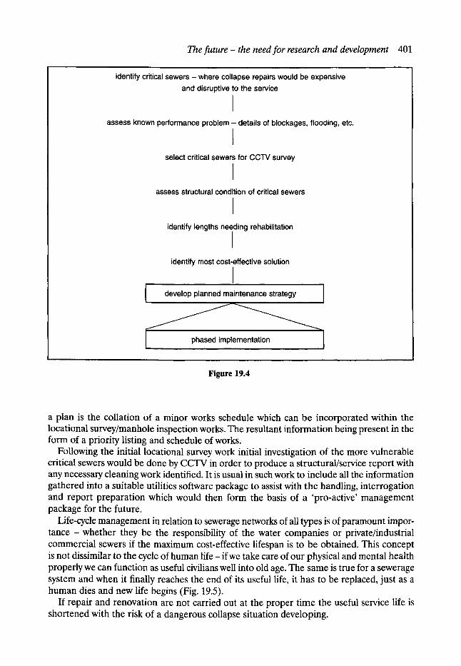
The future - the need for research and development 401
identify critical sewers - where collapse repairs would be expensive and disruptive to the service
I assess known performance problem - details of blockages, flooding, etc.
select critical sewers for CCTV survey
I assess structural condition of critical sewers
I identify lengths needing rehabilitation
I identify most cost-effective solution
I develop planned maintenance strategy I
, ,, phased implementat,on I
Figure 19.4
a plan is the collation of a minor works schedule which can be incorporated within the locational survey/manhole inspection works. The resultant information being present in the form of a priority listing and schedule of works.
Following the initial locational survey work initial investigation of the more vulnerable critical sewers would be done by CCTV in order to produce a structural/service report with any necessary cleaning work identified. It is usual in such work to include all the information gathered into a suitable utilities software package to assist with the handling, interrogation and report preparation which would then form the basis of a 'pro-active' management package for the future.
Life-cycle management in relation to sewerage networks of all types is of paramount impor- tance - whether they be the responsibility of the water companies or private/industrial commercial sewers if the maximum cost-effective lifespan is to be obtained. This concept is not dissimilar to the cycle of human life - if we take care of our physical and mental health properly we can function as useful civilians well into old age. The same is true for a sewerage system and when it finally reaches the end of its useful life, it has to be replaced, just as a human dies and new life begins (Fig. 19.5).
If repair and renovation are not carried out at the proper time the useful service life is shortened with the risk of a dangerous collapse situation developing.

402 Development and research
Development [ ofneed t Planning t
Useful service life ,A
Building L Operating and maintaining _l
' ' ,~"~'~...~='~ Repair Rehabilitate '1 ~Ceurnul~~.....,~ �88 Replace
.... qced S e r v e d of
useful life
Figure 19.5
Bibliography Grigg, N. S. Urban Water Infrastructure. ISTT Year Books. ISTT. Introduction to Trenchless Technology. Ofwat Annual Reports on the Financial Performance of the Water Companies. Proceedings of ISTT Conference: No Dig '90, Rotterdam.

Index
access 125-48 Manchester sewers 61-2
accidents 275 account, final 370-1 ACCTVS see Association of CCTV Surveyors acoustic detection systems 91 ad hoc schedule, resources 363 admeasurement contract 323-5 administrative aspects 396-7 aeration, tank 16 aerial surveys 91-2 aerobes 16 aesthetic control, combined sewer overflow
293-5 age 8, 39 agenda, precontract meetings 360 agreement, type 351 agriculture, solid waste 7 algorithm, selecting mathematical model
175 alignment, sewer wandering 32, 63 Alphacrete Construction Linings Ltd 210 amenity, loss 279 Amkrete, epoxy injection technique 243 Ampt 165 anaerobes 16 anaerobic conditions 256 ancillary works 193-203 annual term contracts 336-7 API5 see five-day antecedent precipitation index application pressure, epoxy resin 244 appraisal, renovation 281-2 aqueducts 5, 12, 63 areal rainfall 154-5 Arnell 150 asphalt 124
assessment hydraulic 78, 149-92 national 70 renovation techniques 272-82 structure 64-7, 259-63 visual 260-3
assets management 395-6 underground 85-98
Association of CCTV Surveyors (ACCTVS) 391
backfilling, sewer construction 60 bacteria, anaerobic 16 Baer 312 Balmforth 297, 298, 299, 300
flow analysis 309 bathing, Victorian period 19 beam failure mechanics 254-5 Beetle cleaning device 201 bending failure, ring 254-5 benefits, costs, SRM approach 79 bentonite lubrication 135, 137 bids, very low priced 336 bill of quantity 362 biological oxygen demand (BOD) 289 blind-eye
locations 127 shafts 31, 32, 61, 141, 142
BOD see biological oxygen demand bonding 243, 244 breaches, contracts 370 brick
covered drains, Indus valley 45 sewers 26, 30, 58-62, 66, 255
brickwork 33, 35, 208 British Gas, Model Consultative Procedure 145

404 I n d e x
British Standard Civil Engineering Code of Practice for Sewerage 1950 127
buckling, grout pressure 265 budget, priorities 259 Building Research Establishment 214 buses, diversions 108 business, effect 48
cables, renewal 118 caisson construction 133, 135-8 cameras 93-6, 94, 142 canals, coal transport 13 capacity comparison table 278 carbon fibre, patch repairs 238 CARP see Comparative Acceptable River
Pollution catchment 149, 182-92 category A/B sewers 76-7 category A/B/C sewers 260 cavities 105, 128 CCD see charge coupling device CDM see Construction (Design Management)
Regulations ceramic lining 382 CESMM see Civil Engineering Standard
Method of Measurement cesspools 3, 28 Chadwick, Edwin 20-1 chamber design 284, 297-303 chamber rings, manhole 129, 130-2 checks, early stage 354-6 choker ring 136 cholera 7, 13, 33 circumference, sewer cracks 255 city 44
centre 146-8 Civil Engineering Contractors, Federation
393 Civil Engineering Standard Method of
Measurement (CESMM) 324-5, 340, 347 civil engineers, Conditions of Contract 322, 329,
337, 339 claims, contracts 367-70 classification, sewer renovation 376-8 clauses, ICE contracts 352-3, 367-9 clayware 26, 40, 64, 235 cleaning sewers 193-203 Clearline system 222, 249 climates, hot 256 clips, support liner 248 closed-circuit television (CCTV) 24, 93-6, 202,
247, 378
camera 142 fault identification procedure 71-2 inspection 67, 260, 372-3 small pipes 84 sonde equipment 89
codes of practice manholes 138 New Road Act 1991 124 public utilities 145 Traffic Signs Manual 112
collapse 50--1, 54-7, 70 mechanism 66 sewers
environmental impact 47-54 examples 41-3 highway damage 55--6
traffic problems 103-9 UK numbers 54
collection system, gross solids 313 combined sewer overflow (CSO) 283-317
aesthetic control 293-5 chamber design 284, 297-303 hydraulic performance 303--4, 315 performance definition 295-6 receiving waters 284-93 storage tanks 313-15 structure 283-4, 303-4
combined systems 17, 33 commerce 48, 400-1 community health 1 Comparative Acceptable River Pollution
(CARP) 289, 294 competence, contractors 319 competition, tendering 327-8 composite, glass fibre 238 computers
maintenance management 80-1 support for surveying 98-100
concentration time 181 concrete 382
foam 123-4 pumped in situ 212-13 ready-mix 148 segments 38, 212 in situ manhole 129, 132
conduit cost 273 console, control vehicle 245-7 construction 26, 345-9
defects 372 management 334-50 materials 40 methods 59-60, 347-8

original methods impact 63-4 packers 379 programmes 141-3 renovation 349-50 shafts 133--8, 141-3 trunk sewers 39 UK industry 321
Construction (Design Management) Regulations (CDM) 349, 357
Construction Weekly Plant Directory 365 contamination, drinking water 47 continent, sewerage system 14-15 continuation flow, CSO chambers 305-7 continuity tendering 328 contractors 334, 338, 339
inflatable packers 252 Information and Guidance Notes 204, 210 overpumping 193-5
contracts 331-2, 351 annual term 336-7 claims 367-70 cost-reimbursable 325--6 documents 332, 337-40 final account 370-1 overpumping 194 procurement 334-7 strategy 318-33 supervision 351-4 types 322-7
control 115, 173 contractors 334 finance 362 flow devices 306 projects 345 vehicle console 245-7
convention, system organisation 321 conversion, shaft 135 Copeflex 226 corrosion, sewer 256 cost-based contract 322 costs 79, 273, 279-81
collapses 54-7 indirect, collapses 56 overpumping 198-9 reimbursable contract 325-6 renovation techniques 272-82
coupling device (CCD) 93 cracks 255, 382 critical sewer, screen 77 cross-sections, early sewers 25 crown bending coefficient 266-7 crude sewerage, strength 285
I n d e x 405
cryptosporidium parasite 393 CSO, see also combined sewer overflow CSO chambers 300, 302
continuation flow 305-7 screens 312-13
culverts 1, 22, 46, 57 cure-in-place pipe 227 curing time, epoxy resins 239, 240 curve number (CN) table 169 cutting 201-2, 243-4, 245
remote techniques 226
dams 197 danger, traffic diversion 105 Danish Hydraulics Institute 162 data 100, 180-1, 186-7 databases, surveying 99 dayworks 362-6 DDB see double decker bus factor deaths 7, 8 deep sewers, design criteria 236 defects 35, 372
scores 261, 262 deformation stages, sewers 257 delays, journeys 122 delivery pipes 196-7 dendritic system 173 Department of the Environment, new system
design 70 depression 104-5, 162--6 depth
measurement 183-5 sewers 126
dereliction, sewers 41-68 design 234-7, 282
defects 372 load safety 235 manhole 128 model, hydraulic 177 procedure 266--70 short-term loads 264--6 storm rainfall 151-4 structure 263-70
detection 86, 91, 144 deterioration, sewers 256-9 development 391-402 dewatering 138 dig v no dig methods 343 digital, mapping 100 direct costs, rehabilitation 279 direct inspection surveys 92 direct labour 319-21

406 I n d e x
directive, Urban Wastewater Treatment 283, 284-5
discharge 17 discontinuous repair strategy 330--1 discount rate, economic appraisal 281 displacement, joints 373-4 disposal, sediment 201 disruption traffic 103-9, 114 dissolved gases, intermittent standards 292, 293 distribution, sewerage rate 375--6 diversions 106-7, 108, 115 documents, contracts 332, 337-40 double decker bus (DDB) factor 48, 52-3 double-ring, brick sewer 66 drainage 16
area planning 81-2, 176-7 drains 5, 45 droughts, collapses 70 ducts, subsidence 354-5 dust clause, contracts 337 duties, resident engineer 353
early sewers, access 126-8 easement 348-9 Ecoliner process 240, 241 economics
collapses 54-7 renovation 281-2
ecotoxicological data, combined sewer overflow 292
effective flow split (EFS) 296 effective pollution separation efficiency (EPSE)
296 efficiency cusp, CSO chambers 300, 303 EFS see effective flow split egg-shape, sewer type 27, 28 Elastomeric expanders 248-9 Electricity Supply Regulations 1988 85 electromagnetic location methods 88-90 end weir 298, 307-8 engineering 112, 208
contract strategy 321-2 public health 1-21
environment acceptable renovation technique 252 sewer collapse 47-55
epoxy 243, 244 resins 238--40
EPSE see effective pollution separation efficiency
equivalence, hydraulic model 178 Europe, combined sewer overflow 285, 286-8
European Commission (EC) Urban Wastewater Treatment Directive 1991 283, 284-5
evaluation, tenders 335--6 evapotranspiration 162 excavation 134, 199 exfiltration 46-7 Expandit system 224 expansion, rate 24 Expipe method 384 exploration, sub-surface 397--8 extension, main drainage scheme 37-8
fabrication, shutters 213 failures 61, 254-5 fault identification procedure 71-2 FCEC schedule 363, 365 Federation of Civil Engineering Contractors
393 F6deration Internationale des Ing~nieur-
Conseils (FIDIC) 324, 329, 352 Ferro Monk, spray technique 210, 227 ferrocement 209-12, 268, 274 FFT-P method 384 FIDIC see F6deration Internationale des
Ing6nieur-Conseils Field 298 fill-and-drain system 252 filling round 36-7 final account, contracts 370--1 finance, measured item 362 fire equipment, obstruction 114 fishing 292 five-day antecedent precipitation index (API5)
170 flexibility
jointing systems 117 linings 231 pipes 206, 264
Flood Studies Report 151, 153 flooding 46, 279 flotation force, lining 265 flow 177, 194, 197, 307-12
control devices 306 measurement 183-5 monitoring installation 184 response criteria tables 188 surveys 182, 185
foam concrete 123-4 force account 319-21 FormaPatch repair system 240 FormaSeal repair system 240 formula A

Ministry of Health and Local Government Technical Committee 285
QUAI~OC 289 fractures 119-20, 255, 363, 364 Fraudian criteria 311 FuUine grouting system 252
Gantt chart 345 garderobes 7 gas apparatus, precautions 346 gases, dissolved 292, 293 gel-layer 215 gels, epoxy 243 Germany 396, 397 G F P see reinforced plastic pipe glass fibre 101, 227, 238
cables 101 glass reinforced
cement 214--15 concrete, life 274 plastic 128, 215-16
life 274 GPR see ground probing radar grading, structural condition 261 granular fill method, bonding 242, 243 GRC see glass reinforced cement Green 165 gridlock 121 grinding, robots 243-4 ground conditions 339 ground probing radar (GPR) 86-8 ground support, deterioration 257--8 grout 216--17, 379
Fulline system 252 penetration 251 pressure buckling 265
GRP see glass reinforced plastic gunite material 208-9, 274
hand excavation 199 handrails, manholes 139, 140 HDPE see high-density polyethylene head discharge, relationships 307 health, community 1 health and safety 125, 128 Health and Safety Executive 275 high-density polyethylene (HDPE) 219 high-side weir chamber 297, 299 Highway Authority 119 highways 113
disruption 103-9 sewer collapse 52--6
I n d e x 407
history 3-6, 69-71, 150 holes, trial 144 'holey city' 70 Holland, legal aspects 396 hollow interlocking clay tiles 235 Home Report 332 hose lining method 383 hoses see pipes hydraulics
assessment 78, 149-92 CSO structure 284, 303-4 cutters 202 model building 176-8 performance 178-9, 303-4 renovation assessment 277--8 tank performance 315 water mains 143
hydrodynamic separators 298--303 hydrogen sulphide 140--1, 256, 257 hydrographs 190--2 hydrologic soil groups 169 hydrological cycle 2 HYDROWORKS model 162, 168,
171-5 combined sewer overflow 294
hygiene, ancient 4-6
ICE see Institution of Civil Engineers IChemE see Institution of Chemical Engineers identification procedure, faults 71-2 IDF curves 151-4 IGN see Information and Guidance Notes impact assessment, combined sewer overflow
tables 294 impact mole method 387-9 in s i tu
gunite 209 load testing 263 pumped concrete lining 212-13
indirect costs, rehabilitation 279 infiltration 46-7, 162-6 inflatable packers 242, 252 Information and Guidance Notes (IGN),
contractors 204, 210 information signs 107 infrared thermography 91-2 infrastructure, transport 110 injection method, sealing 378-9 injection systems, resin 241-3 inpipe method 227, 383--4 Insituform 226, 227, 231, 240
method, Japan 383

408 Index
inspection 35, 371-4 CCTV 260 methods, comparison 98 programmes, planning 72-3 routine 104, 125 underground assets 92-8
installation flow survey equipment 185 Storm King separator 298, 301
Institution of Chemical Engineers (IChemE) contracts 327, 340
Institution of Civil Engineers (ICE) 351, 352, 368-9
Conditions of Contract 322, 329, 337, 339
interception, wetting 162 interceptor sewer 33-7, 331 interlocking clay tiles, hollow 235 intrusion cutter 202 inversion methods 383-4 investigation, shafts 62 investment, water industry 42
J sewer, reconstruction 40 jacking method, pipes 385-90 Japan 375-90
inversion lining method 383-4 jetting 199-200 John Kennedy systems 210, 220, 229 joints 117, 373-4
sealing 134-5, 250-2 testing 250, 252
journeys, delays 122
KA-TE system 245-7 Kanal-Miiller, Partliner system 241 kentledge 135, 136
ladders, manholes 139, 140 land drain, Victorian sewers 64 land use table 169 laterals, cutting 201-2 latrine, Romans 5, 6 lay-flat hosing 196 layouts
manholes 138-41 site 342-5
leakage, ceramic lining 382 leats 9 legal aspects 108, 396-7 length, UK sewers 42 lettered sewers 33-7
levels, critical 143 life-cycle management 204-5 lifespan 1837 8 lightline method 98 limestone, pipes 11 liners 218-29, 268, 381-4
design 234 pumped in situ 212-13
loads long-term, type 1 266--8 in situ testing 263
Local Government Training Board 357 location
electromagnetic method 88-90 records 143-4 underground assets 85-92
long-term loads, design 266-70 looped system 173 loss, amenity 279 lump sum contract 323
M5 rainfall, table 154 M5-60 min rainfall 153, 160 M A C see maximum admissible
concentration machines 200, 221 magnetometers, location methods 90,
92 mains
drainage 17-18, 37-8 temporary rising 195 water 46-7, 119-20, 363, 364
maintenance culvert funding 57 management systems 80-1 planning 69-83 sewer cleaning 199-203 strategy 71-4
major interceptor sewer, renovation 331
man-entry sewers 125 renovation 208-17 �9 stabilisation techniques 206-7
management 81, 340-1 assets 395-6 construction 334-50
Manchester 12, 30-3 brick sewers 58--62 rehabilitation 275-6 sewerage network 22-40
Manchester Literary and Philosophical Society 236

I n d e x 409
manhole 28, 30, 63 condition surveys 92-3 design, safety 128 internal layouts 138-41 location surveys 85-6 safety, design 128 spacing 125, 126, 127 survey record 179 types 129-32
maps digital 100 rainfall 153
materials 39, 59, 123 construction 40 gunite 208-9, 274 jointing 64 new 276
mathematical models 173-9 simulation graphs 190 storms 157
maximum admissible concentration (MAC) 289
MDPE see medium-density polyethylene measured item, financial control 362 medium-density polyethylene (MDPE) 219 merging, hydraulic model 178 mesh 210, 312 Mesopotania, main sewer 44 metalwork, specification 140 microtunneling 89 Middle East, ancient tunnels 8-9 minimum width, highway 113 Ministry of Health and Local Government
Technical Committee, formula A 285 minor works 336-7 Model Consultative Procedure 145 Model Form of Conditions of Contract for
Process Plants, IChemE 327, 340 model verification, catchment 182-92 Modelling of Urban Sewers see MOUSE model models 173-9
mathematics 78, 157, 190 mole method, impact 387-9 monasteries 6 monitoring exercises, duration 185 mortar 243, 245, 255 motivation, construction 345-7 MOUSE model 162, 163
hydraulic assessment 174 rainfall 164, 172
Mr Muscle equipment 222 municipal engineering, instigation 20
national network, sewerage 22-40 National Rivers Agency 400 national sewerage network 22-40 National Water Council (NWC) 285, 290-1 Natural Environmental Research Council 151 Naylor Denlock system 220 negotiated tendering 328 network, assessment 272 New Road Act 1991 56-7, 85, 124 'no waiting' cones 107 noise 122, 147, 200, 338 Noltech method 390 non-circular sliplining 220 non-man-entry sewers 125, 217, 233-53 numbered sewers 37-8
off-line storage tanks 313, 314 Ofwat, annual report 393 on-line
sewer replacement methods 273-4 storage tanks 313, 314
open sewers, rivers 13 openbook accounting 325 organisation 319-21
conventional system 321 site 345-7
outfall, main, Manchester 34 overflows 28, 283-317 overland flow process 149-50, 173 overpumping 193-99
packers 242, 379 pail closets 1 Paltem system 226 pan and tilt camera 94 parasite, cryptosporidium 393 Paris, sewerage system 14-15 Partliner system, Kanal-Miiller 241 Passenger Transport Executive 108 Pasteur, Louis 16 patch repairs 237-41 Paving and Sewering Department, Manchester
29 Paving and Soughing Committee 24 pay as you earn (PAYE) 363, 365 PAYE see pay as you earn penetration, grout 251 Pentryne system 229-30 percentage runoff equations 168-71 performance 178-9, 272
definition 295-6 permits 341, 342, 357-8

410 I n d e x
PFA see pulverised fuel ash Pilkingtons 214 PIMP equation 168 pipe-in-pipe method 384-5 Pipebursting system 222-3 pipelines 206 pipes 84, 206, 264
150 mm diameter 247 clayware 26, 40, 64, 235 cost proportion 273 cure-in-place 227 detection 86 flexible 264 flow rates 197 jacking method 385-90 limestone 11 liners 235-7 plastic 196 re-rounding process 248--52 socketed 40 suction 196-7 support 258 wooden 9
pit, timbered 129 planks 210 planning
inspection 260 programmes 72--4 projects 345 rehabilitation 69-83, 76-8 traffic management 110-17
plant, guide 365 plastic
pipes 196 welding 219-20
police 10-11, 23, 24, 108 pollution 285, 337
concentration 285, 292 cost estimates 279 river 284, 288, 290-1,400
Pollution of River Commissioners 1868:33 pollution separation efficiency (PSE) 296 polyester resin concrete (PRC) 216 polyethylene, life 274 polyurethanes, resin injection 243 pond, stilling 297 Poor Law Board 21 population 10, 13, 14, 375--6 power supply, pumps 196 practice developments, contracts
331-2 PRC see polyester resin concrete
precast segments 208-9, 212 precautions, gas apparatus 346 precontract meetings 359, 360 prequalification process 334-5 press circular method 379-80 pressure
depth measurement 184 epoxy application 244 jetting 199-200
pretreatment, sealing method 380 price-based contract 322 pricing, overpumping contracts 194 'primitive' sewer types 31 priorities, budget 259 private sewers 400-1 privy, in the middle ages 1, 6-7 process plants 327, 340 procurement, contracts 334-7 programme of work 343, 344 progress meetings 359 proportional loss model 166 p r u n i n g , hydraulic model 178 PSE see pollution separation efficiency public, risk 109 Public Health Act 1931 109 public health engineering 1-21 public relations 103-124 public standpipe 9-10 public utilities 119, 143-6 publications, CSO chambers 302 pulverised fuel ash (PFA) 217 pumping station 10, 195 pumps, choice 195-6
QA see quality assurance 'qanat' 8 quality 62, 186-7, 202-3
assurance 371 management 340-1 model 177
QUALity impacts of Storm Overflows: Consent procedure (QUALSOC) 289, 292, 294
QUALSOC see QUALity impacts of Storm Overflows: Consent procedure
radar, ground probing 86-8 rainfall 149, 161-73
hydraulic assessment 150-61 measurement 182-3 rates table 156-7
'rat runs' research, UMIST 48 RE see resident engineer

re-rounding process 248-50 Read, G. E 1-83, 204-232, 272-82, 391--402 ready-mix, concrete 148 receiving waters 284-93 reconstruction, J sewer 40 records 143--4, 370 recycling, water 200 reduction factors, areal 155 rehabilitation
see also Sewerage Rehabilitation Manual cost estimates 279-81 definition 272 Manchester 275-6 planning 69-83 structural aspects 254-71 targets 181
reinforced plastic pipe (GFP) 383-4 reinstatement works 123 remote cutting techniques 226 Remote-Line process 240 removal, sediment 201 renovation 204-32, 375-90
accidents 275 assessment 272-82 classification 376-8 costs 272-82 definition 204 environmental techniques 252 future 81-2, 398-400 major interceptor sewer 331 man-entry sewers 208-17 replacement 204, 280 stabilisation 229-31 techniques 70, 272-82, 398-400
repair 119, 204-32 construction management 349-50 Japan 375-90 localised techniques 233-53 man-entry sewers 206-7 non-man-entry sewers 233-53 robots 243-7 short-lining 237-41 spray wall 382-3 strategy 330-1
replacement 273-4 cost 280 renovation 204, 280
reports, site 359-61 research and development 270-1,391-402 resident engineer (RE) 352, 353
early stage checks 354-6 site reports 359
Index 411
residential area, noise 122 resin
injection, systems 241-3 lining process 381-3
resistivity, location methods 90, 92 resources, ad hoc schedule 363 response
criteria, flow tables 188 time, runoff 171-2
responsibilities, utilities 106 Riding 312 rigid pipes 206, 264 ring failure mechanism 254-5 ring method, sealing 380 rings 129, 130-2, 136 risk
contract strategy 329-30 public 109
rivers 13, 284 quality 285, 290-1
Road Traffic Regulation Act 1984 121 roads 44, 108, 111 robots 101, 243-7 rodding 200--01 rodents, cavities 128 rolldown system 223-4 roots, tree 202, 254 routine inspections 104, 125 Royal Commission 1842, health 5 runoff
equations 168-71 rainfall 166-73 response time 171-2
rural areas, diversions 115 Ruswroe technique 210
sack system, mesh 312 safety 96, 357
design load 235 renovation assessment 274-5 site supervision 356-7
Sanipor system 230-1, 252 satellites, manhole location 86 savings, SRM case studies 79 scattergraphs, data quality 186--7 Scottish Development Department 285, 289 screens, CSO chambers 312-13 SCS see Soil Conservation Service Model sealing method 378-81 sealing systems 250, 252 second generation, sewers 1828-90 24 sections, sewer standards 29-30

412 Index
sediment 201, 316-17 segments 38, 130-2 septic tank 3 serial tendering 328 setting out, works 354 sewer length 42 Sewer Renovation Federation 394 sewerage 285
dereliction 41--68 national network 22-40 rate 375-6 systems 1, 14-15, 125--48, 375-8
sewerage rehabilitation, mathematical objective 177
Sewerage Rehabilitation Manual (SRM) 45, 67, 70, 75-6
approach limitations 80 inconsistencies 270 planning programme 76-8 renovation 277
Sewerage Rehabilitation Unit, UMIST 395 Sewers Bill 1531 7 shafts 62, 317
construction 133-8, 141-3 reinforced concrete manhole 129
short-lining repairs 237-41 short-term, flow surveys 182 short-term loads, design 264-6 shutters, fabrication 213 side weirs, flow analysis 308-12 Sidwick 312 signboards 107, 115-17, 123 Sika system 247 silt 193 simulation models 174-9 'sin-nors' 8 Sirkit system 249 site 189
investigation 339 management 341-8 permits 357-8 reports 339, 359--61 safety 356-7 supervision 351-74
size, sewer 39, 59, 275 size for size techniques 221-3 skeletal planning, hydraulic model 176 sliplining 218-20 slug, grout 251, 252 slurry system 385-7 SMD see soil moisture deficit Snaplock sealing method 380
sock, glass fibre 227 socket type, pipes 40 soffit see crown soft lining 224--8 software support, surveying 98-100 soil 169, 170
rate of deterioration 258 types 168
Soil Conservation Service Model (SCS), rainfall runoff 167-8
SOIL equation 169, 170 soil moisture deficit (SMD) 170, 171 soil-pipe interaction 263--4 solid waste 7, 313 sonar 92, 96-8, 101 sonde equipment, CCTV 89 spacing manhole 125, 126, 127 special types, construction 348-9 spill weir, vortex 297, 300 SPR method 385 spray lining 228-9 spray wall repairs 382-3 SRG see stochastic rainfall generator SRM see Sewerage Rehabilitation Manual SRManual see Sewerage Rehabilitation
Manual SSD see system data stabilisation techniques 206-7, 229-31 stage checks 354-6 stainless steel 140 standards
intermittent, dissolved gases 292, 293 sewer section 29-30
Standing Committee for Sewers and Water Mains 70
stanks 197 steam, curing 239 stilling pond 297, 298 stochastic rainfall generator (SRG) 161 stone flags, failure 61 storage tanks 313-15 storm criteria 187-92 Storm King, hydrodynamic separator 298-303 storm profiles 155-7 storm sewers 15 Storm Water Management Model (SWMM)
174 streets 15, 56-7, 85, 114 structure
assessment 64-7, 259-63 defects, causes 254-5 definition 234

I n d e x 413
design 263-70 jointing material 64 organisation 319-21 sewer deterioration 256-9 sewer rehabilitation 254-71
sub-surface exploration 397-8 subsidence, ductS 354-5 suction, pipes 196-7 sulphuric acid corrosion 256 summer storm profiles 158 supervision, site 351-74 suppliers 204 support, pipe 258 survey 84-102, 179, 259
computer software support 98--100 databases 99 vehicles 96, 97
swagedown system 223-4 Sweden, Inpipe 383 Switzerland, KA-TE system 245-7 SWMM see Storm Water Management Model system data (SSD), catchment 180-92 systems 70, 321
discharge 17 Japan sewerage 375--8
tanks 3, 315, 316--17 aeration 16 storage 313-15
target cost contract 326-7 targets, rehabilitation 181 Tate Pipelining Processes 201, 228 technology, tunnels 126 tenders 327-9, 335--6 tensile stress, lining material 268 term contracting 329 thrust, boring machines 221 timber pit 129 time, concentration 181 time extension, contracts 368-9 time series rainfall 157--61 toilets, history 3 trade losses, cost estimates 279 tradition, system, organisation 321 traffic 108, 112, 114
cost estimates 279 diversion 55--6, 105 management 103--124, 110-17 public relations 103-24 sewer collapse 47--8 signing 107, 115-17, 123 volumes table 111
Traffic Signs Manual, traffic management 112, 115
training, safety 357 trams, sewer collapse 48 transport 13, 110 trees, roots 202, 254 trial holes 144 triggers, rehabilitation 181 trunk sewers, construction 39 tubbing 21 tuberculation 12 tubular sewers 28 tunnels 36, 89, 126
construction 59, 60, 348 two-stage tendering 328 Tyack 299 type I, design procedure, long-term loads 266-8 type II, design procedure 234, 268-70 types, sewer 26
U-shape 59 blind-eye shaft 31, 32, 61 sewer 27, 31, 236
UCWI see urban catchment wetness index ultrasonic inspection 96-8, 184, 185 UMIST see University of Manchester Institute
of Science and Technology underground
assets 85-98 pumping station 195
underpinning, shaft construction 133--5 unit costs, renovation assessment 280 University of Manchester Institute of Science
and Technology (UMIST) collapse prediction models 58 'rat runs' research 48 Sewerage Rehabilitation Unit 395
upsizing techniques 221-3 urban catchment wetness index (UCWI) 170 Urban Pollution Manua l 1994, standards 289,
292 Urban Wastewater Treatment Directive 1991
283, 284-5 urban water systems, life-cycle management
204-5 urbanisation, population 13 utilities
repair programme 119 responsibilities 106
valuations, site supervision 361 variation orders, clauses 367

414 I n d e x
vehicles 96, 97, 245-7 velocity measurement 183-5 verification, models 175-9, 182-92 Victorian sewers 32, 50-1, 62 visual, assessment 260-3 voids
ceramic lining 382 grouting 217
vortex chamber 140 spill weir 297, 300
Wales, sewer age 39 Wallingford Software 174-5 WALLRUS model 78 wandering, alignment 63 waste water 8-12 water 1, 8-12, 10, 16
combined sewer overflow 284-93 contamination 47 drainage 1800 16 hot curing 239 industry, investment 42 leakage 382 mains 143
failure 46-7 fracture 119-20, 363, 364
potable 226 recycling 200 sealing method 378-81 supply 10, 16
Water Act 1989:109 Water Industry Specification (WlS) 204 Water Research centre, time series rainfall 157,
160 Water Research Council (WRc) 45, 67, 70 water-bearing ground 138 Waterflow, repair system 240 weir
end 279 high-sided chamber 297, 299
welding, plastics 219-20 welfare, renovation assessment 274--5 wetness
antecedent 163 urban index 170
wetting, interception 162 winching 201 winter storm profiles 159 wire mesh 210 WlS see Water Industry Specification wood pipes 9 works
inspection 371--4 setting out 354
works execution, signboards 123 WRc see Water Research Council
Yorkshire Water 393


