Embed Size (px)
Citation preview

Sharing Attractions on the Net with VPARK
Chris Joslin, Tom Molet, Nadia Magnenat-Thalmann MIRALab – University of Geneva
{joslin,molet,thalmann}@cui.unige.ch
Joaquim Esmerado, Daniel Thalmann Computer Graphics Lab, EPFL {jle,thalmann}@lig.di.epfl.ch
Ian Palmer, Nic Chilton, Rae Earnshaw
University of Bradford, UK {i.j.palmer,n.chilton,r.a.earnshaw}@bradford.ac.uk
Abstract
In this paper we present the Virtual Park (or VPARK) system. This includes a Networked Virtual Environment (NVE) System, called W-VLNET (Windows Virtual Life Network) and an Attraction Building System, able to create and modify attractions used in the NVE System. Both systems have been developed in the Windows NT Operating System (OS). The paper details the techniques for communication, scene management, facial and body animation, and general user interaction modules. The use of VRML97 and MPEG-4 SHNC is overviewed to stress the compatibility of the system with other similar Virtual Reality systems. The software provides realistic virtual actors as well as sets of applicable high-level actions in real-time. Related issues on obtaining actor models and animating them in real-time are presented. The creation process of an attraction incorporates assembling animation units through a timeline. Using this software, users are then able to introduce their own scenario-based applications into a shared virtual environment. Keywords Network Virtual Environment, Advanced Interaction, Attraction, Planning, Building, Motion Tracking
1. Introduction Many virtual environments have been dealing with moving objects [1] and articulated human-like 3D characters [2]. Several attempts have been made to provide powerful tools for scripting complex movements and behaviors [3,4,5]. However, coming up with realistic virtual humans or actors still remains a challenge.
Realistic virtual humans (and Avatars) are as important as the virtual environment they reside in. This has been one of the main goals of most “Virtual Reality” systems. Numerous methods of real-time rendering [6,7,8], natural ways for interaction and communication [9] and providing virtual characters with intelligence [10,11] are related techniques for presenting true complexity and realism to all aspects of Virtual Environments. For many years it has been possible to visit virtual worlds using a real-time interactive system, to interact, and share experiences with people only connected via a simple network. However, due to the computing power required by such systems it has only been possible until recently to use high-end computers, based on the UNIX OS. This has recently changed with high-end machines being available to the general consumer market and high-performance graphics cards being inexpensive enough to be put into home computers. These complete systems have enabled the once UNIX dominated NVE Systems to be designed and implemented on a Windows OS system, using only a few techniques to maintain rendering speeds. In this paper we present VPARK, which is composed of two systems, the W-VLNET Networked Virtual Environment (NVE) System and the Attraction Builder system used to build attractions. The Attraction Builder enables the creation and editing of animations for use within the NVE System. Both systems are running under the Windows NT OS. Those attractions created by the Attraction Builder are then loaded and managed by W-VLNET as a complete networked attraction. The system is designed in a way that it is able to efficiently handle multiple attractions as well as multiple users. In general, the design requirements for an NVE system include [12]: • Participant Embodiment

• Network Topology specific to Virtual Environments
• Data and task distribution scheme for scalability • Dedicated Communication protocol We have put considerable efforts to develop and integrate several modules into a system capable of animating realistic virtual humans in a real-time performance. This includes modeling and representing virtual humans with high realism and the simulation of human face and body movements in real-time [13]. The feature of realism becomes even more important in NVE’s, where the communication among participants is crucial for their sense of presence. In the following section, we introduce our Attraction Builder software to describe the creation process as well as the framework for real-time animation of virtual actors, incorporating nonverbal and verbal animations. Section 3 describes the NVE System, W-VLNET, and how the attractions are integrated. Section 4 outlines the practical trials of the Attraction Builder and Section 5 Concludes on the work.
2. The Attraction Builder 2.1. Introduction One of the main goals for this research was to develop a complete tool for the creation of attractions in virtual environments where virtual actors play the main parts. In this system, the users are provided with a set of powerful functions to direct highly realistic virtual actors. High-level actions are provided in order to avoid low-level descriptions for each movement of an actor. An attraction is defined as a set of geometrical and temporal descriptions of the virtual actors and objects in the virtual environment. In this work, we focus on a number of issues related to creating and animating virtual actors in attractions: • Avatar model and animation data acquisition • Real-time performance in rendering and animation • Control on virtual human actions • Effective and easy-to-use way of attraction
creation • Support for standards (VRML, MPEG-4) for
scalability and flexibility 2.2. Virtual Avatars The representative and behavioral realism of virtual humans is the key feature of our system. Virtual Humans are given crucial functions to aid their visual perception and allow them to perform normal tasks (such as walking, speaking and generally interacting). The Avatars are realistically represented as can be seen in Figure 1, Avatars and Actors (Virtual Humans that
are autonomous and acting out a part) co-exist in the same environment. We consider face, body and speech animation as an essential set of virtual human simulations since they play an important role in our everyday communication. Facial expression and animation play an essential role in human communication concerning the speakers’ emotions. At the same time, speech animation and the corresponding lip movement is even more important to aid in communication.
Figure 1. In VPARK system, representative
avatars and virtual actors co-exist. 2.2.1. Face and Body Models Textured polygonal mesh representations of virtual actors from different sources are used. Face models are either from our in-house modeling tool [13] or from the automatic method of generating clones from two photos [14]. The latter allows participants to represent themselves in an effective way. In any case, face models are generated from the modification of a generic model, which is given with animation structure that they can be animated with the face animation module. Bodies for virtual actors are represented using VRML97 for their segments. By supporting H-ANIM [15], users can reuse available models from the Internet. The generation of H-ANIM individualized body models from two photos is on going. 2.2.2. Face Animation The MPEG4 Facial animation standard is based on the feature points located at several key places on the facial mesh geometry (e.g. tip of nose, corner of lips etc) There are 68 Facial Animation Parameters (FAPs), 66 of those are low-level parameters affecting these feature points directly. The animation is achieved by

specifying the displacement of these feature points with respect to their neutral position. These displacements are specified in the terms (units of) of certain feature distances of the facial model e.g. FAPs related to eye movement are expressed in terms of the horizontal distance between the pupils, whereas those related to lips are specified in terms of the distance between the corner lips. These feature distances are called Facial Animation Parameters Unites (FAPUs). The 2 high level FAPs are visemes and expressions (sadness, happiness, etc.). Figure 2 shows some of the predefined expressions applied to one of our face models.
Figure 2. Predefined facial expressions applied to a virtual actor (anger, surprise, hilarity,
disgust and happiness) 2.2.3. Body Animation Virtual human body animation is achieved by applying a set of degree of freedom values to each part of the body joints over time. To comply with VRML97 and independence with respect to proprietary embodiments, it was chosen to directly animate H-ANIM compliant models. These models can be obtained from a number of sources and tend to increase in number thus greatly enhancing representation flexibility for the end-user. The compliance with MPEG-4 is also assured by the usage of Body Animation Parameters (BAPs) for animation. A BAP specifies the relevant body joint degree of freedom at a given instant in time. At the users’ level, however, some preliminary gestures are available from the user interface so that they have rather high-level control over virtual actors (Figure 3).
Figure 3. Predefined body actions applied to a virtual actor (welcome, sit and talk, curious)
2.2.4. Speech Animation
We obtain text-to-phonemes by using a module developed by Microsoft [18]. From the generated phonemes, corresponding visemes (the visual counterparts of phonemes) are generated which are described as a set of FAPs so that they can be processed by our face animation engine. Generated visemes are moved to a buffer to be synchronized with phonemes. 2.3. Adding Scenarios to an Attraction With a powerful set of animation engines, providing effective and easy-to-use user interface to control, manipulate and animate objects and virtual humans remains a challenge. A script language based interface, though powerful, has been dropped since it requires specialized computer programming expertise from the user. We chose graphics user interface in combination with a high-level action specification. In this approach, the user can direct an actor by simply choosing an action from the menu. The selected action is then simulated by any of the engines provided. Here, an action may be an emotion, a gesture, or a sentence. Each high level action is considered to be a basic unit of animation. Collections of basic units are then assembled into an animation sequence, which composes an attraction together with geometric description of the scene. Users are aided with tools that enable them to adjust the duration time of the animation, move in the timeline, edit animation units, play back to see current status of the animation at any time, and load predefined animations as well as save current ones. Figure 4 shows an animation sequence on a timeline that is composed of six basic action units. Note that several action units are applicable simultaneously to an actor.
Actor1 : (smile)
T0
Actor2 : Hi.
Object1 : (start moving)
Actor2 : (curious)
T1
Actor2 : Do you sell this?
Actor1 : Hi, welcome to the virtual park.
T2
action0
action1
action2
action3
action4
action5 Figure 4. Timeline based scenario
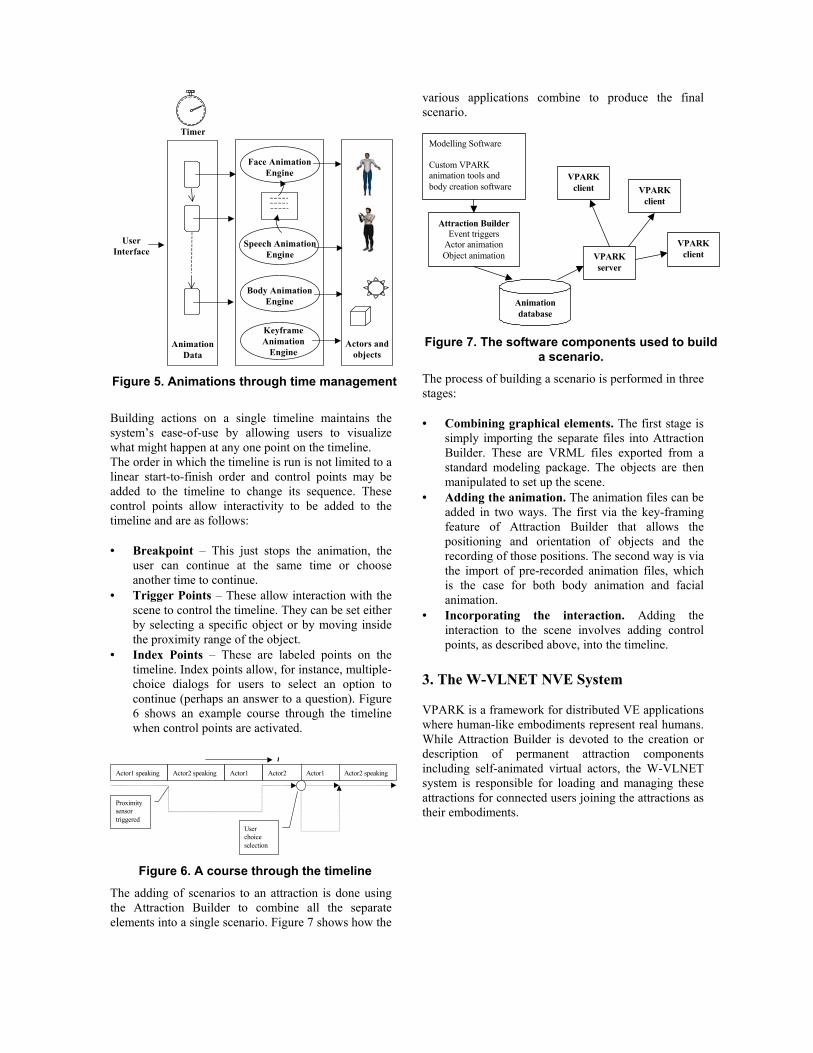
representation The key to linking the entire animation sequence and the animation engines lies in a timer that maintains the synchronization of actions to feed them into an animation engine at the correct point in time, as shown in Figure 5.
Face AnimationEngine
Body AnimationEngine
Speech AnimationEngine
AnimationData
Timer
Actors andobjects
KeyframeAnimation
Engine
UserInterface
Figure 5. Animations through time management Building actions on a single timeline maintains the system’s ease-of-use by allowing users to visualize what might happen at any one point on the timeline. The order in which the timeline is run is not limited to a linear start-to-finish order and control points may be added to the timeline to change its sequence. These control points allow interactivity to be added to the timeline and are as follows: • Breakpoint – This just stops the animation, the
user can continue at the same time or choose another time to continue.
• Trigger Points – These allow interaction with the scene to control the timeline. They can be set either by selecting a specific object or by moving inside the proximity range of the object.
• Index Points – These are labeled points on the timeline. Index points allow, for instance, multiple-choice dialogs for users to select an option to continue (perhaps an answer to a question). Figure 6 shows an example course through the timeline when control points are activated.
Actor1 speaking Actor2 speaking Actor1 Actor2
Proximitysensortriggered
Userchoiceselection
Actor1 Actor2 speaking
t
Figure 6. A course through the timeline
The adding of scenarios to an attraction is done using the Attraction Builder to combine all the separate elements into a single scenario. Figure 7 shows how the
various applications combine to produce the final scenario.
Modelling Software
Custom VPARKanimation tools andbody creation software
Attraction BuilderEvent triggers
Actor animationObject animation VPARK
server
Animationdatabase
VPARKclient VPARK
client
VPARKclient
Figure 7. The software components used to build
a scenario. The process of building a scenario is performed in three stages: • Combining graphical elements. The first stage is
simply importing the separate files into Attraction Builder. These are VRML files exported from a standard modeling package. The objects are then manipulated to set up the scene.
• Adding the animation. The animation files can be added in two ways. The first via the key-framing feature of Attraction Builder that allows the positioning and orientation of objects and the recording of those positions. The second way is via the import of pre-recorded animation files, which is the case for both body animation and facial animation.
• Incorporating the interaction. Adding the interaction to the scene involves adding control points, as described above, into the timeline.
3. The W-VLNET NVE System VPARK is a framework for distributed VE applications where human-like embodiments represent real humans. While Attraction Builder is devoted to the creation or description of permanent attraction components including self-animated virtual actors, the W-VLNET system is responsible for loading and managing these attractions for connected users joining the attractions as their embodiments.

3.1 Overall System Architecture The W-VLNET system is based on a previous architecture [16] implementation running on the UNIX OS (specifically IRIX, from Silicon Graphics). The previous system, also called VLNET, was written and optimized for UNIX and uses a multi-process/shared memory architecture. A shared memory protocol was used as the communication medium for processes (each process performing a different task). Although the W-VLNET system is similar, the underlying communication architecture was redesigned, due to the fact that the Windows OS does not utilize the Shared Memory architecture fully enough. Therefore the architecture was implemented using a special communication system and the concurrent task management was done using threads instead of processes. Threads are more dominant in the Windows OS and there are fewer restrictions imposed upon the design, as they do not require the use of shared memory to communicate. The control and execution of threads was combined with the communication architecture to create a faster communication mechanism. The communication is performed using a First In First Out Buffer (or FIFO Buffer) this allows flow control over the communication, whilst maintaining a fast transfer of data. The FIFO Buffer basically allows each thread to communicate with any other thread. The Thread Manager itself creates a thread for each task that has to be executed. Depending on the task type, a priority value is assigned to each thread to enable tasks that should be executed quickly, not to be blocked by simple tasks (such as GUI Control). The Thread Manager also controls the termination of threads, as too many concurrently running threads would cause a system to slow down, the Thread Manager limits the number of executing threads. In practical tests the upper limit is much greater than required. The remaining control for each thread is left to the module to determine and manage, as it is unrealistic for the Thread Manager to be too specific to ask task. These control tasks include mutual exclusion, global memory control and wait states. As threads are capable of running on multi-processor systems, and being distributed across these multiple processors, the only requirement of the individual modules themselves is to be separated enough that the multi-processor architecture is made use of, but singular enough that it doesn’t create dependencies. Figure 8 shows the communication between the main modules running through the System Manager (which is the collective of the Thread Manager and the FIFO Buffer)
Figure 8. System Communication
3.2 Plugins The entire system was designed and built around plugins; even the communication/thread managers were both designed with plugins in mind. The system was designed to be expandable, this being a key issue in the previous system (i.e. the inability to expand easily). The plugins used in this system are much the same as any other plugins; they enable the addition, changing and editing of any module without the need for recompilation. Also as all the main components are also plugins, the system can be upgraded without the user requiring major changes to the software. Users are allowed and actively encouraged to design plugins for the system to do a specific task they might require. An SDK is available, which is designed to aid users in understanding the plugin concept specific to this system. 3.3 Scene Manager In the same way that the System Manager (Section 3.1) controls the System, the Scene Manager controls all the aspects of the Scene. The Scene itself is quite complex and although OpenGL Optimizer controls the actual Scene Graph, there are many additional interactions that need to be taken care of. The Scene Manager is very similar, in its basic form, to the one used in the Attraction Builder. However, as there are multiple Clients with multiple Avatars, the database used to manage this is more complex. The system is no longer controlling, for example, Avatar 1,2,3 etc, it is in control of Avatar 1 on Client 1 and Avatar 1, 2 and 3 on Client 2 for instance. This causes more complications in the overall design, especially as the Attraction Builder is an effectively linear, single threaded system, whereas the W-VLNET system has highly concurrent tasks being processed throughout its architecture. 3.3.1 Database Control The database used has two layers: The Client Layer and the Item Layer. The Client layer contains a very simple reference to the Client. The Item (an Item being either an Object or an Avatar) Layer, which is below this,

contains the references for all Objects and Avatars in the system. This includes their name, scene graph reference(s) and locking switches. It is important to keep track of these objects and avatars in a very strict fashion as many complex things can happen (e.g. a Client could leave/join, crash, get disconnected etc) and this can have a very adverse effect if not handled correctly. Secondly, as mentioned in Section 3.1, concurrent tasks can be performed at once on the same Object or Avatar, and hence it is necessary to keep track of whether an Object/Avatar is being interacted with. The inability to keep track of these events will also have strange outcomes (such as strange animations, or objects/avatars ending up in different positions on different Clients). 3.3.2 Avatar Loading and Animation HANIM/MPEG4 compatible bodies are used in conjunction with MPEG4 compatible faces. These are exactly the same as the ones used in Attraction Builder (See Section 2.2.x). Each Client is expected to load at least one representative avatar, which also has to be uploaded to the Server and distributed to the other connected Clients (See Section 3.4). The Avatar files themselves are compressed into zip files, which makes the transfer to the Server lighter in comparison with uncompressed files (normally 7-8 times larger), but even these files are between 600K and 1M and hence a caching mechanism was also implemented to reduce wait times and bandwidth utilization. The caching mechanism works two-fold, firstly it acts in the normal way, which is to check if a copy of the file exists locally (this caching mechanism also works for object files) and then just transfer the basic information (like posture/position), which is extremely small in comparison. The second caching mechanism is used if the user has a small network connection to the server; it basically uses a default avatar representation (also stored locally) for all avatars, hence reducing the requirement to download other client’s representative avatar. Animation is also more complex on the NVE System as it is done completely on a frame/frame basis. Each frame (of either BAPs and FAPs) is compressed using a simple loss-less compression technique, and using a sequential numbering system is sent directly to the Server and distributed to other clients. This means that a Client can stop its animation at any time, or adjust it accordingly; there is no set time for which an animation can last. This works equally well for both file animations (animation streams stored in files) and for Motion Tracking Units (see Section 3.4). The loss-less compression is used to reduce the overall packet size of a body animation (as the animation of all the joints can produce up to 296 values that are 4 bytes in size), combine this with other necessary data and the packet is almost 1Kbytes in size. As the normal Maximum
Transmission Unit (MTU [17]) is 556 bytes, this is rather too large for normal Internet Transmissions (where the restricted MTU size of 576 bytes is often observed). The loss-less compression uses the upper and lower limits of each of the 296 values and reduces the sizes of each value to the maximum bit value required. Also even in the worst case conditions only a maximum 110 values are used. Hence the packet can be compressed to roughly within the MTU restriction. A Quantizer value could be used to reduce this value, with the cost of reducing the accuracy of the animations, but a better approach would be to use either Huffman or Arithmetic Coding to produce better loss-less compression. Quantizing the values produces (in reality) very little reduction to the packet size, at the cost of very poor animations. 3.3.3 Picking and Object Manipulation To really interact with virtual environment, it is necessary to use object picking and manipulation. Also as system uses a collaborative environment then the object on one Client must be seen moving on all other Clients. Picking is done on the basis of the Clients representative Avatar. The Avatar moves towards an object and then all objects within the View Frustum and within a specific range (variable, with default of 1 meter) are then selected as being pickable objects. The database of pickable objects is dynamically changed as the Avatar moves around. The pick mode then cycles through all pickable objects stored in the picking database and once the user has selected an object, it is then picked (selecting is done either by a button press, or by moving when the object is picked). The object is then moved with the Avatar as it moves (much in the same way as an object is moved in real life). The object can be deselected to unpick the object. All object movements are sent to the other Clients so that their database is completely up-to-date. 3.3.4 Proximity, Collision Detection and Gravity In order to provide greater interaction within the virtual environment proximity detection is available. The proximity function is actually a collaboration of several common functions (which can be turned on or off as necessary, according to requirements and computing power). The functions that are coordinated together are: Proximity, Collision Detection and Response and Gravity. Although gravity is not directly combined into the same task, it does work hand in hand with Collision Detection and Response. Gravity is applied to each and every object/avatar apart from the basic scene (as defined by the Server as the default object); each object/avatars speed is stored in the database (as specified in Section 3.3.1) and a simple gravitational equation is applied to each object/avatar. This equation
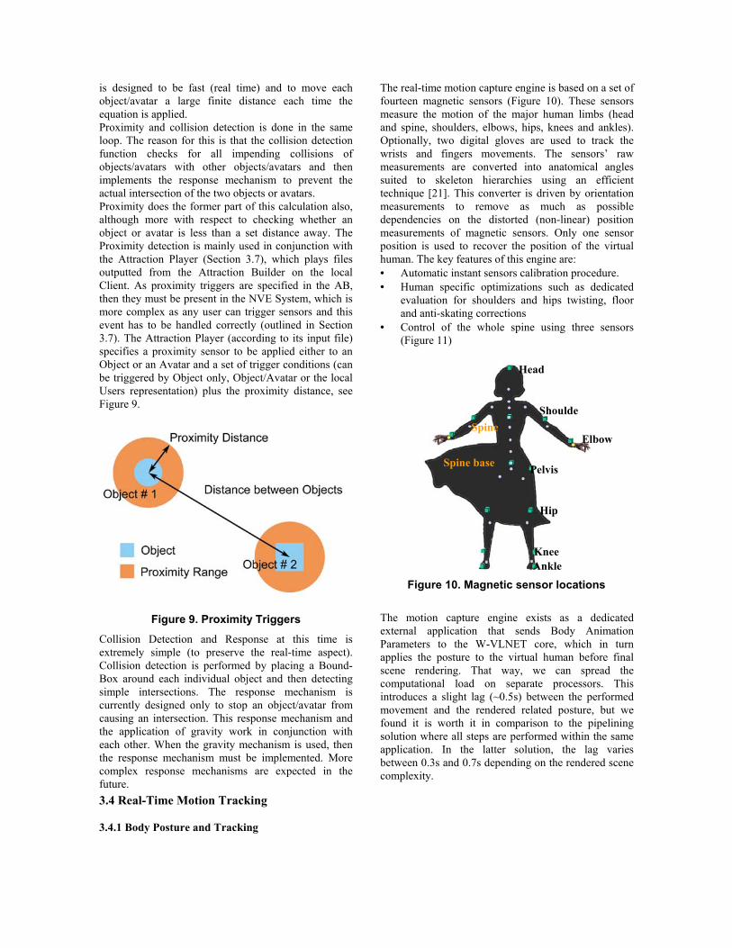
is designed to be fast (real time) and to move each object/avatar a large finite distance each time the equation is applied. Proximity and collision detection is done in the same loop. The reason for this is that the collision detection function checks for all impending collisions of objects/avatars with other objects/avatars and then implements the response mechanism to prevent the actual intersection of the two objects or avatars. Proximity does the former part of this calculation also, although more with respect to checking whether an object or avatar is less than a set distance away. The Proximity detection is mainly used in conjunction with the Attraction Player (Section 3.7), which plays files outputted from the Attraction Builder on the local Client. As proximity triggers are specified in the AB, then they must be present in the NVE System, which is more complex as any user can trigger sensors and this event has to be handled correctly (outlined in Section 3.7). The Attraction Player (according to its input file) specifies a proximity sensor to be applied either to an Object or an Avatar and a set of trigger conditions (can be triggered by Object only, Object/Avatar or the local Users representation) plus the proximity distance, see Figure 9.
Figure 9. Proximity Triggers
Collision Detection and Response at this time is extremely simple (to preserve the real-time aspect). Collision detection is performed by placing a Bound-Box around each individual object and then detecting simple intersections. The response mechanism is currently designed only to stop an object/avatar from causing an intersection. This response mechanism and the application of gravity work in conjunction with each other. When the gravity mechanism is used, then the response mechanism must be implemented. More complex response mechanisms are expected in the future. 3.4 Real-Time Motion Tracking 3.4.1 Body Posture and Tracking
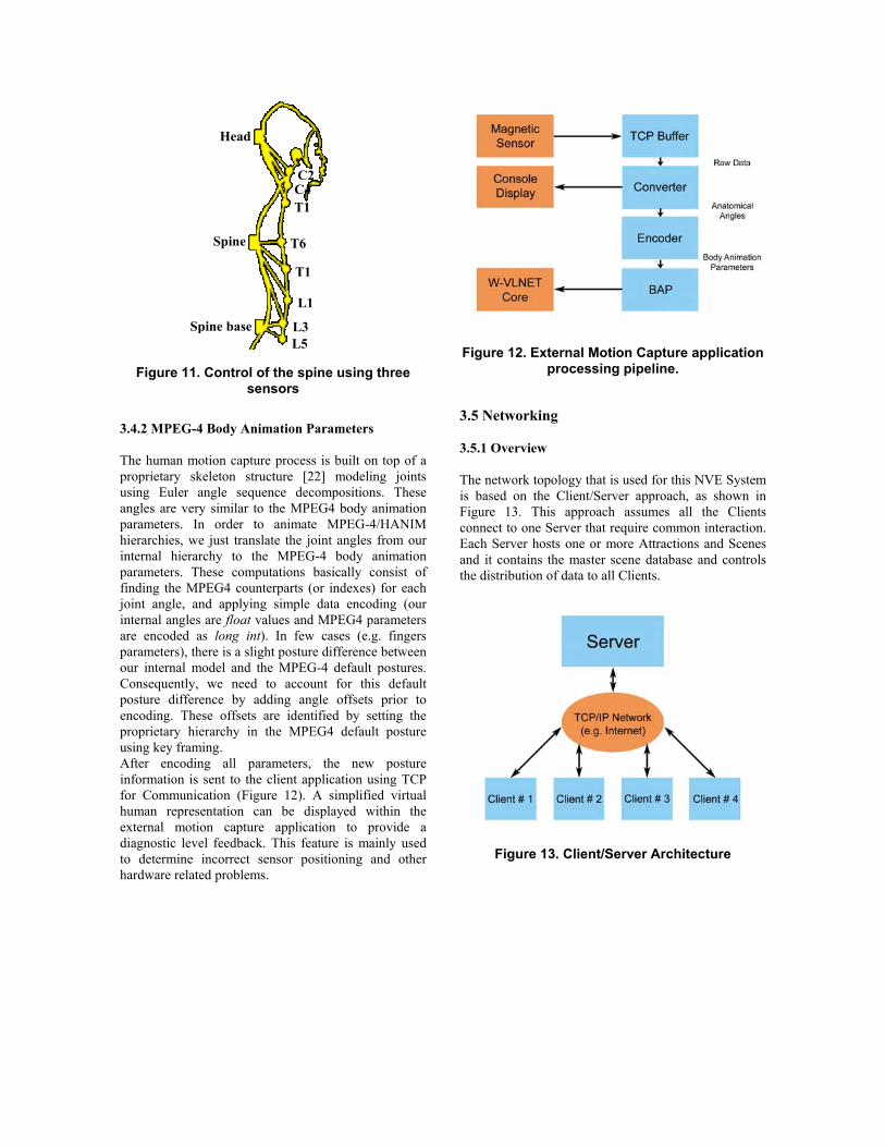
The real-time motion capture engine is based on a set of fourteen magnetic sensors (Figure 10). These sensors measure the motion of the major human limbs (head and spine, shoulders, elbows, hips, knees and ankles). Optionally, two digital gloves are used to track the wrists and fingers movements. The sensors’ raw measurements are converted into anatomical angles suited to skeleton hierarchies using an efficient technique [21]. This converter is driven by orientation measurements to remove as much as possible dependencies on the distorted (non-linear) position measurements of magnetic sensors. Only one sensor position is used to recover the position of the virtual human. The key features of this engine are: • Automatic instant sensors calibration procedure. • Human specific optimizations such as dedicated
evaluation for shoulders and hips twisting, floor and anti-skating corrections
• Control of the whole spine using three sensors (Figure 11)
Figure 10. Magnetic sensor locations
The motion capture engine exists as a dedicated external application that sends Body Animation Parameters to the W-VLNET core, which in turn applies the posture to the virtual human before final scene rendering. That way, we can spread the computational load on separate processors. This introduces a slight lag (~0.5s) between the performed movement and the rendered related posture, but we found it is worth it in comparison to the pipelining solution where all steps are performed within the same application. In the latter solution, the lag varies between 0.3s and 0.7s depending on the rendered scene complexity.
Head
Shoulde
Elbow
Spine base Pelvis
Hip
Knee
Spine
Ankle
Head
Spine base
Spine
L5 L3
L1
T1
T6
T1 C4 C2
Figure 11. Control of the spine using three sensors
3.4.2 MPEG-4 Body Animation Parameters The human motion capture process is built on top of a proprietary skeleton structure [22] modeling joints using Euler angle sequence decompositions. These angles are very similar to the MPEG4 body animation parameters. In order to animate MPEG-4/HANIM hierarchies, we just translate the joint angles from our internal hierarchy to the MPEG-4 body animation parameters. These computations basically consist of finding the MPEG4 counterparts (or indexes) for each joint angle, and applying simple data encoding (our internal angles are float values and MPEG4 parameters are encoded as long int). In few cases (e.g. fingers parameters), there is a slight posture difference between our internal model and the MPEG-4 default postures. Consequently, we need to account for this default posture difference by adding angle offsets prior to encoding. These offsets are identified by setting the proprietary hierarchy in the MPEG4 default posture using key framing. After encoding all parameters, the new posture information is sent to the client application using TCP for Communication (Figure 12). A simplified virtual human representation can be displayed within the external motion capture application to provide a diagnostic level feedback. This feature is mainly used to determine incorrect sensor positioning and other hardware related problems.
Figure 12. External Motion Capture application processing pipeline.
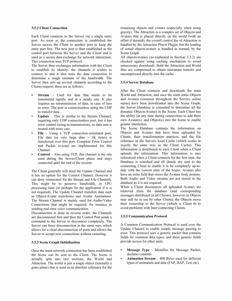
3.5 Networking 3.5.1 Overview The network topology that is used for this NVE System is based on the Client/Server approach, as shown in Figure 13. This approach assumes all the Clients connect to one Server that require common interaction. Each Server hosts one or more Attractions and Scenes and it contains the master scene database and controls the distribution of data to all Clients.
Figure 13. Client/Server Architecture
3.5.2 Client Connection Each Client connects to the Server via a single entry port. As soon as the connection is established the Server moves the Client to another port to keep the entry port free. The new port is then established as the control port between the Server and the Client and is used as a secure data exchange for network interaction. This connection uses TCP protocol. The Server then exchanges information with the Client to establish its identity, the channels it wishes to connect to and it also tests the data connection to determine a rough estimate of the bandwidth. The Server then sets up several channels according to the Clients request; these are as follows: • Stream – Used for data that needs to be
transmitted rapidly and at a steady rate. It also requires no retransmission of data, in case of loss or error. The port is connectionless using the UDP to transfer data.
• Update – This is similar to the Stream Channel, requiring only UDP connectionless port, but it has error control (using re-transmission), so data sent is treated with more care.
• File – Using a TCP connection-orientated port, File data (or very large data > 1K bytes) is transferred over this port. Complete Error Control and Packet re-send are implemented for this Channel.
• Control – Also using TCP, this channel is the one used during the Server/Client phase and stays connected until the end of the session.
The Client generally will need the Update Channel and it has no option for the Control Channel. However it can deny connection for the Stream and File Channels. This might be to preserve bandwidth, or CPU processing time (or perhaps for the application if it is not required). The Update Channel transfers data such as Object/Avatar transforms and Avatar Animations. The Stream Channel is mainly used for Audio/Video Connections that might be required, for instance in sending real-time voice communication. Disconnection is done in reverse order, the Channels are disconnected first and then the Control Port sends a command to the Server to disconnect completely. The Server can force disconnection in the same way, which allows for a clean disconnection of ports and allows the Server to accept new connections without restarting. 3.5.3 Scene Graph Initialization Once the main network connection has been established the Scene can be sent to the Client. The Scene is actually split into two sections, the World and Attraction. The world is just a single object (normally a grass plane) that is used as an absolute reference for the
remaining objects and avatars (especially when using gravity). The Attraction is a complex set of Objects and Avatars that is placed directly on the world (with an offset if desired), the overall control the of Attraction is handled by the Attraction Player Plugin, but the loading of actual objects/avatars is handled as normal; by the Scene Graph. All objects/avatars (as explained in Section 3.3.2) are checked against using caching mechanism to avoid unnecessary downloads. Both the Attraction and World files are compressed to obtain maximum transfer and uncompressed directly into the cache. 3.5.4 Server Database After the Client connects and downloads the main World and Attraction, and once the main static Objects and Avatars (common throughout the Servers online status) have been downloaded into the Scene Graph, the Server Database is consulted to determine all the dynamic Objects/Avatars in the Scene. Each Client has the ability (at any time during connection) to add there own Avatar(s), and Object(s) into the Scene to enable greater interaction. The Scene Database contains the information on Objects and Avatars that have been uploaded by Clients, their transformation matrices, and the file reference in the Servers local Cache (which works in exactly the same way as the Client Cache). This information is distributed to each Client when a Client uploads the information. This information is also referenced when a Client connects for the first time, the Database is searched and all details are sent to the connecting Client to enable it to be completely up-to-date with the current state of the Scene. Avatars also have an extra field that stores the Avatars body posture. Both Audio and Video streams are not stored in the database as it is not required. When a Client disconnects all uploaded Avatars are removed from the database (and corresponding messages distributed to all Clients), however as Objects may still be in use by other Clients, the Objects move their ownership to the Server (which is Client 0) to avoid problems with later connecting Clients. 3.5.5 Communication Protocol A Common Communication Protocol is used over the Update Channel to enable simple message passing to exist. This protocol uses a generic packet that contains fields for common data types, and three generic fields provide access for other units. • Message Type – Identifier for Message Packet,
declares contents • Animation Stream – 400 Bytes used for different
types of animation and data (FAP, BAP, Text etc).
• Message String – 32 Byte Text Identifier (e.g. Filename)
• Message Value 1,2,3 – Used for general values and references.
• Transformation Matrix – 4 by 4 float value. Used because most objects/avatars will require transformations in nearly every packet.
The Stream Channel uses a simplified version of this, with a Message Identifier and a Transformation Matrix for each packet, then 500 Bytes of compressed data. The File Channel splits all data into manageable packets and then sends it directly over the channel. Waiting for an acknowledgement from the receiving end that all data was received correctly, otherwise a packet-by-packet re-send message is transmitted to the sending end. The Control Channel receives undefined messages regarding the state of the Server (connections, load, Client status etc). The Client then has a rough database of the connected clients (to reduce network load, the updates of the Client database are done on very large time steps). 3.6 Multimedia Objects As can be seen from the Channel distribution, different types of data can be exchanged between Clients (using the Server as a network switch). The list of currently added data types/streams is as follows: • Audio Stream – The basic stream of audio is
transferred at 16Kbits/s and compressed using the G.728 Audio Compression Codec. However for larger bandwidth systems, or systems with less bandwidth but greater CPU power, the G.711 (64Kbits/s) and G.723.1 (5.3Kbits/s and 6.4Kbits/s) audio codecs both function on the same audio channel. Each audio stream is given a reference object in order that 3D Audio can be created.
• Speech – Speech communication over this type of system is useful for Clients connected over very low bandwidth connections. The Speech itself is transmitted as plain ASCII text and this is passed to a Text-to-Speech Engine. This converts the text not only into the Audio equivalent, but it creates the corresponding visemes (See Section 2.2.4).
3.7 Attraction Playing/Management To make the system completely clear and comprehensible, not only for the design of the system but the plugins that might be added later, the Attraction itself belongs to the Server. The Server acts as another Client, and therefore has a Client ID as well as a Server ID making it easy to add Avatars and Objects to the Database. Once the Client has connected to the Server the Attraction Player Plugin loads the Attraction into
the Scene Graph. This is done using APIs provided by the Scene Manager. The Attraction Player uses the same Caching mechanism and compression techniques as the Scene Manager. Loading an Attraction consists of loading the Autonomous Avatars, the animated Objects, the Script and the Proximity/Touch Sensors placed around the scene. The Server then sends the Attraction Player Plugin timing information to enable it to synchronize itself with the other connected Clients. As the time-line is set according to a linear time placement (although not necessarily linear when playing) the time reference applies to a specific set of postures and placements for Avatars and Objects respectively. This timing signal is sent to all Clients every one second (by default) to enable Clients to maintain synchronism (although each Client maintains its own timer). The Scene Manager sends the Attraction Player information about the scene (such as Proximity Sensors that have been triggered) and therefore the Attraction Player controls the Attraction itself without any intervention by the Scene Manager. If a generic NVE system is required, the Attraction Player Plugin can be removed without affecting the rest of the system, likewise the Server attempts communication with the Attraction Player and if there is no response it continues regardless.
4. Attractions 4.1 Virtual Theatre The first of two case study Attractions, the Virtual Theatre [19] supports users who can interact with the production and in a real sense [20] join the cast. This results in a form of real-time, dynamic theatre, where the production is changing in time according to the interactions of the digital actors and the participants within a predefined framework. An area of great interest and significance is where aspects of the performance relate to the interaction of participants. This includes work on collaborative set design, virtual rehearsal and presence in the virtual theatre. The theatre supports interactive drama. Up to three digital actors perform a predefined script in the absence of any users’ avatars. When a user's avatar enters the scene they are able to either watch the drama unfold as predefined or, by causing their avatar to approach on the digital actors they are able to affect the progress of events (as shown in Figure 14). This is through proximity triggering of the script, causing the digital actors to cease their current activities and to interact with the user's avatar.

Figure 14. Interactive Theatre
Lewis Carroll’s Alice in Wonderland provides the basic script and scenario, based upon Carroll’s photographs from the 1860s of Alice herself in the collection. As a character-driven rather than plot-based scenario, Alice provides a wide variety of immediately recognizable characters, representing different ages, genders, shapes and social types. All of the Museum’s1 visitors should therefore be able to identify with one or more of the characters. Alice’s episodic narrative allows for a non-linear storyline to be enacted without contradicting expectations of the basic scenario. The emphasis on imaginative imagery in the story allows features only possible within animation, whether computer-based or cell. The non-naturalistic setting also gives license to free experimental play of words and actions. Carroll’s text has been adapted to provide opportunities for interaction between avatars and virtual actors, as well as between avatars. This causes the timeline of the piece to be broken, returning to a linear nature when the users cease their interaction. In this way, the scene can progress without users being present, allowing people to join the theatre at any time. As an exhibit, it is proposed that visitors could choose from Alice, the Queen of Hearts and Tweedledee, or experience the different perspectives of all three. The Museum has worked with a theatrical production company to research ways of making the attraction lively and accessible. It is also conducting visitor research into how the exhibit will best function to provide maximum engagement between the participants, fluency with the proposed interface and understanding of the storyline. With the education department, we are also researching
1 National Museum of Photography, Film and Television, Bradford, UK
the potential uses and applications of the virtual theatre with schools and in live-link events. 4.2 Virtual Dance The second case study is an Attraction for a Teacher (attached to a motion tracking system at one location) to teach dance to a student (also attached to a motion tracking system in another geographically remote location). Both teacher and student were cloned by our in-house cloning system, to obtain a virtual copy of both humans, and attached to a motion tracking system, as shown in Figure 15 (one at University of Geneva and the other at EPFL, Switzerland). An overlaid musical sequence is used to enable the teacher and student to synchronize with each other, both teacher and student can see each other (virtually) on a screen (as shown in Figure 16) and therefore the teacher is able to see what the student is doing wrong and the student can watch the teacher to see what should be done. The system is fully interactive, allowing each participant the ability not only to see the exact movements of their counterparts, but also to talk with each other. This type of scenario is classical of an NVE System being used to its maximum benefit and certainly is difficult to replace with other conventional systems (such as Video Conferencing). The scenario is not limited to two participants; more users could join to provide a teacher with a class of students, providing the motion tracking equipment was available. To increase the teacher sense of submersion and also to enable a clearer perception of the situation a lightweight head mounted display could be used, although as dance typically uses great movement, the display should be rugged and should secure to the teacher so that the movement is not restricted.
Figure 15. Real Teacher and Student

Figure 16. Virtual Teacher and Student
5. Conclusion and Future work In our work, various pieces of research have been integrated to form a framework for the creation and description of attractions where realistic virtual actors exist. This powerful tool has been developed for creation of attractions, which allows the user to build a believable attraction in an effective and easy-to-use way. Design decisions, as well as related issues on creating and animating human-like virtual humans in real-time, have been discussed. We also presented the W-VLNET System, a powerful multithreaded system that is capable of running not only the attractions, but connecting two or more users together in a Networked Virtual Environment. The environment itself made more real by the integration of an animation system that completely animates the users virtual representation, and simple collision detection and response. This was coupled with our real-time body animation capturing system and full audio support for both sound and music, that adds to the realism of the experience. Both the W-VLNET System and the Attraction Builder were done on a Windows OS. Finally, both systems actively use the latest standards for scene and virtual avatar representations (VRML97 and MPEG4) to enable greater inoperability between the two systems presented here and other commercial products. To complete the work we have designed, created and tested two Attractions. This allowed us to visualize problems, prove the work in a real situation and finally to self-regulate ourselves and focus our research. In future work we aim to augment the overall experience of the virtual environment by improving the collision models and improving the depth of the multimedia inputs (including video and improving the audio perception in the environment). We also aim to improve the transmission rates for the system in real
time using better compression methods and Server filtering.
6. Acknowledgements The VPARK project (ACTS project Number AC353) is funded by the European Community and the Swiss Partners are sponsored by the “Federal Office for Education and Science”.
7. References 1. K. Lee, C. Sul and K. Wohn, Virtual Stage: A
Scenario-Based Karaoke System in Virtual Environment, Proc. of Pacific Graphics '97, 1997, pp. 159-167.
2. J. Piesk and G.Trogemann, Animated Interactive Fiction: Storytelling by a Conversational Virtual Actor, VSMM ’97, 1997, pp. 100-108.
3. K. Perlin and A. Golberg, Improv: A System for Scripting Interactive Actors in Virtual Worlds, Proc. of SIGGRAPH ’96, 1996, pp.205-216.
4. Carnegie Mellon University, Alice, http://www.alice.org
5. D. M. Shawver, Virtual Actors and Avatars in a Flexible User-Determined-Scenario Environments, Proc. Virtual Reality Annual International Symposium (VRAIS) ’97, 1997, pp. 170-177.
6. J. Cohen, A. Varshney, D. Manocha, G. Turk and H. Weber, Simplification Envelopes, Proc. SIGGRAPH ’96, 1996, pp. 119-128.
7. S. J. Teller and C.H. Séquin, Visibility Preprocessing for Interactive Walkthroughs, Proc. SIGGRAPH ’91, 1991, pp. 61-69.
8. G. Schaufler, Exploiting Frame-to-Frame Coherence in a Virtual Reality System, Proc. Virtual Reality Annual International Symposium (VRAIS) ’96, 1996, pp. 95-102.
9. L. Emering, R. Boulic and D. Thalmann, Interacting with Virtual Humans through Body Actions, IEEE Computer Graphics & Applications, Vol.18, No.1, 1998, pp. 8-11.
10. D. Thalmann and H. Noser, Towards Autonomous, Perceptive, and Intelligent Virtual Actors in: Artificial Intelligence Today, Lecture Notes in Artificial Intelligence, No 1600, Springer, pp. 457-472.
11. R. M. Jones, J. E. Laird, and P. E. Nielson, Real-Time Intelligent Characters for a Non-Visual Simulation Environment, Proc. of Computer Animation ’99, 1999, pp. 11-18.
12. T. K. Capin, I. S. Pandzic, N. Magnenat-Thalmann and Daniel Thalmann, Avatars in Networked Virtual Environments, Weiley, 1999.
13. P. Kalra, N. Magnenat Thalmann, L. Moccozet, G. Sannier, A. Aubel and D.Thalmann, Real-time animation of realistic virtual humans, IEEE Computer Graphics and Animation, 1998.
14. W. Lee, N. Magnenat-Thalmann, From Real Faces To Virtual Faces: Problems and Solutions, Proc. 3IA'98, Limoges (FRANCE), 1998.
15. H-ANIM Humanoid Animation Working Group, Specification for a Standard Humanoid Version1.1, http://ece.uwaterloo.ca/~h-anim/spec1.1/
16. I. S. Pandzic, T. K. Capin, N. Magnenat-Thalmann and D. Thalmann, VLNET: A Networked Multimedia 3D Environment with Virtual Humans, Proc. Multi-Media Modeling MMM`95 (World Scientific Press), Singapore, 1995.
17. W. Richard Stevens, TCP/IP Illustrated, Volume 1, 1994, pp. 29.
18. Microsoft Speech SDK. 19. C. Reeve and I. Palmer, Virtual Rehearsals over
Networks, Digital Convergence: The Information Revolution, J.Vince & R.Earnshaw (eds.), Springer-Verlag, London, 1999, pp. 101-115.
20. C. Reeve, Presence in Virtual Theatre, Presence (Special edition), MIT Press, forthcoming.
21. T. Molet, R. Boulic and D. Thalmann, Human Motion Capture Driven by Orientation Measurements, Presence, MIT, Vol.8, No.2, 1999, pp. 101-115.
22. R. Boulic, T. Capin, Z. Huang, L. Moccozet, T. Molet, P. Kalra, N. Magnenat-Thalmann, I. Pandzic, K. Saar, A. Schmitt, J.Shen and D. Thalmann, The HUMANOID Environment for Interactive Animation of Multiple Deformable Human Characters, Proc. Eurographics’95, Maastricht, 1995, pp. 337-348.