Embed Size (px)
Citation preview
sensors
Article
Smart Coat with a Fully-Embedded Textile Antennafor IoT Applications
Caroline Loss 1,2,3,*, Ricardo Gonçalves 2,4, Catarina Lopes 1,2, Pedro Pinho 2,5 and Rita Salvado 1
1 FibEnTech Research Unit, Universidade da Beira Interior, Rua Marquês D’Ávila e Bolama, Covilhã 6201-001,Portugal; [email protected] (C.L.); [email protected] (R.S.)
2 Instituto de Telecomunicações, Campus Universitário de Santiago, Aveiro 3810-135, Portugal;[email protected] (R.G.); [email protected] (P.P.)
3 Capes Foundation, Ministry of Education of Brazil, Brasília 70040-020, Brazil4 Departamento de Eletrónica, Telecomunicações e Informática, Universidade de Aveiro,
Campus Universitário de Santiago, Aveiro 3810-135, Portugal5 Instituto Superior de Engenharia de Lisboa, Rua Conselheiro Emílio Navarro, Lisboa 1959-009, Portugal* Correspondence: [email protected]; Tel.: +351-275-319-852
Academic Editors: Stefano Mariani, Dirk Lehmhus, Francesco Ciucci, Alberto Vallan and Thomas B. MesserveyReceived: 22 April 2016; Accepted: 17 June 2016; Published: 22 June 2016
Abstract: The Internet of Things (IoT) scenario is strongly related with the advance of the developmentof wireless sensor networks (WSN) and radio frequency identification (RFID) systems. Additionally,in the WSN context, for a continuous feed, the integration of textile antennas for energy harvestinginto smart clothing is a particularly interesting solution when the replacement of batteries is not easyto practice, such as in wearable devices. This paper presents the E-Caption: Smart and Sustainable Coat.It has an embedded dual-band textile antenna for electromagnetic energy harvesting, operating atglobal system for mobile communication (GSM) 900 and digital cellular system (DCS) 1800 bands.This printed antenna is fully integrated, as its dielectric is the textile material composing the coatitself. The E-Caption illustrates the innovative concept of textile antennas that can be manipulatedas simple emblems. Seven prototypes of these “emblem” antennas, manufactured by laminationand embroidering techniques are also presented. It is shown that the orientation of the conductivefabric does not influence the performance of the antenna. It is also shown that the direction andnumber of the stitches in the embroidery may influence the performance of the antenna. Moreover,the comparison of results obtained before and after the integration of the antenna into cloth showsthe integration does not affect the behavior of the antenna.
Keywords: textile antenna; energy harvesting; smart clothing; wearable devices
1. Introduction
Nowadays, the socio-economic development and lifestyle trends indicate an increasingconsumption of technological products and processes, powered by emergent concepts such as theInternet of Things (IoT), where everything is connected in a single network [1]. The development ofsmart objects for IoT applications, include the capacity of this objects to be identifiable, to communicateand to interact [2]. In this context, wearable technology has been addressed to make the person, mainlythrough his clothes, able to communicate with, and be part of, this technological network [3].
Wireless communication systems are made up of several electronic components, which, overthe years, have been miniaturized and made more flexible, such as batteries, sensors, actuators, dataprocessing units, interconnectors, and antennas [4]. In the systems for on-body applications, theantennas have been challenging, because they are conventionally built on rigid substrates, hinderingtheir efficient and comfortable integration into the garment.
Sensors 2016, 16, 938; doi:10.3390/s16060938 www.mdpi.com/journal/sensors
Sensors 2016, 16, 938 2 of 13
However, embedding antennas into clothing allows expanding the interaction of the user withsome electronic devices, making them less invasive and more discrete. Thus, textile antennas thatare designed combining the traditional textile materials with new technologies emerge as a potentialinterface of the human-technology-environment relationship. Textile antennas, thus, become anactive part in the wireless communication systems [5–9], aiming applications, such as tracking andnavigation [10–12], mobile computing, and others [13].
1.1. Textile Antennas
For IoT applications, embedding antennas into clothing makes the garments become a smartinterface for the interaction between the user and the network. The wearable antennas should bethin, lightweight, of easy or no maintenance, robust, and resistant to washing cycles and usage and,moreover, must be low cost for manufacturing and commercializing [14]. In this way, textile planarantennas, the microstrip patch type, have been proposed for garment applications, because they presentall of these characteristics, and also are adaptable to any surface [15]. This type of antenna is usuallyformed by overlapping conductive (patch and ground plane) and dielectric (substrate) layers [16].Therefore, the knowledge of the properties of textile materials that are used is crucial, as well as themanufacturing techniques for connecting the layers, such as gluing, seaming, and laminating withadhesive sheets. Furthermore, the microstrip patch antenna radiates perpendicularly to a groundplane, which serves as a shield to the antenna radiation, assuring that the human body absorbs only avery small fraction of the radiation.
1.2. Electromagnetic Energy Harvesting
The integration of electronic devices on clothing puts the question about how to feed them.The batteries are an obvious choice, but they are bulky, require frequent replacement or recharging,and their short longevity is an ecological concern of current times. Additionally, the research ofself-sustainable wireless devices is a growing challenge in IoT applications [17]. In this context, energyharvesting is a promising solution to consider in the next generation of wireless sensor networks (WSN).Nowadays, radio frequency (RF) energy is currently broadcasted from billions of radio transmittersand, thus, can be collected from the ambient environment or from dedicated sources [18]. Moreover,the advance of technology stimulates the growing number of wireless transmitters, especially in highlypopulated urban areas, increasing the power density of available RF in the environment [19].
Coherently, in the past years, different proposals of textile antennas for RF energy harvestinghave been proposed [19–21]. However, only two works [19,20] have outlined the integration of theseantennas in smart clothing. In [20] a scheme of jacket with harvester circuit is presented. A triple-bandring textile antenna for RF energy harvesting, operating at GSM900, GSM1800, and WiFi frequencies isalso proposed. This antenna was developed with a multilayer configuration and for its conductiveparts, the Global EMC shielding fabric with surface resistivity of 0.02 Ω/sq. was used. An unspecifiedfabric with εr = 1.23 was used as a substrate support of the antenna. The Kapton® fabric with εr = 3.4,tanδ = 0.002 and 1 mm of thickness, was used as the dielectric substrate. The predicted antennaefficiencies are 61% at 900 MHz, 54% at 1750 MHz, and 85% at 2450 MHz. In [21] the draft of a coat ispresented, where multiple body-worn embroidered textile antennas are proposed to be integrated intoa harvester system operating in the 2.45 GHz WLAN band.
2. Materials and Methods
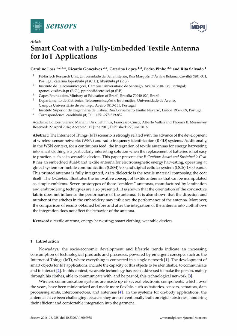
This paper is based on the dual-band textile antenna for GSM900 and DCS1800 frequencybands proposed in [22] that is shown in Figure 1 and which dimensions are given in Table 1 below.The next subsections will analyze the manufacturing process of making this antenna, presentingseven prototypes, made using two different manufacturing techniques: thermal adhesive laminationand embroidering. Further, the integration of the antenna into a smart coat, by fully embedding it intothe material constituting the coat, is described.
Sensors 2016, 16, 938 3 of 13
Sensors 2016, 16, 938 3 of 13
embroidering. Further, the integration of the antenna into a smart coat, by fully embedding it into the material constituting the coat, is described.
(a) (b) (c)
Figure 1. Textile antenna. (a) Design of the dual-band antenna; (b) Front; and (c) Back.
Table 1. Dimensions of the textile antenna.
Parameter Dimension (mm)L, Lgnd, Lf, Lfx 120, 100, 78, 30
Lm1, Lm2, gap, W 12, 5, 3.1, 80 Wf, Wm1, Wm2, Wm3, Wm4 1.5, 31, 21, 8, 4
2.1. Materials
The selection of textile materials for the development of antennas is critical, as discussed in [14]. In this work, all materials used to manufacture the wearable antennas are commercially available and described in the Table 2. For the dielectric substrate, a synthetic fabric with low regain was chosen, in order to minimize the effect of the moisture absorption on lowering the resonance frequency of the antenna.
Table 2. Characteristics of the textile materials used to develop wearable antennas.
Dielectric Materials
Fabric Mass per Unit Surface (g/m2) Composition Finish Thickness
(mm) εr tanδ
Cordura® Light
280 100% PA 6.6 Polyurethane
coated 0.5 1.9 0.0098
Conductive Materials
Fabric Mass per Unit Surface (g/m2)
Composition Finish Thickness
(mm) Conductivity
(S/m)
Zelt 55.87 100% Polyamide Copper and tin
plated 0.06 1.75105
Yarn Linear Mass (dtex) 1 Composition Finish - Conductivity
(S/m)
Silverpam 250 100% Polyamide Silver plated - 0.005
Other Materials
Fabric Mass per Unit Surface (g/m2) Composition Finish Thickness
(mm)
Atlantic 120 100% Polyester Oil + water repellent 0.3
Adhesive Sheet Type
Mass per Unit Surface (g/m2)
Composition - Thickness (mm)
Fixorete Losango
0.28 100% Polyamide - 0.01
1 Tex is the unit of the International System of Units used to characterize the linear mass of fibers and yarns. Tex is defined as the mass in grams per 1000 m. The subunit decitex (dtex) is the mass in grams per 10,000 m [23].
Figure 1. Textile antenna. (a) Design of the dual-band antenna; (b) Front; and (c) Back.
Table 1. Dimensions of the textile antenna.
Parameter Dimension (mm)
L, Lgnd, Lf, Lfx 120, 100, 78, 30Lm1, Lm2, gap, W 12, 5, 3.1, 80
Wf, Wm1, Wm2, Wm3, Wm4 1.5, 31, 21, 8, 4
2.1. Materials
The selection of textile materials for the development of antennas is critical, as discussed in [14].In this work, all materials used to manufacture the wearable antennas are commercially available anddescribed in the Table 2. For the dielectric substrate, a synthetic fabric with low regain was chosen,in order to minimize the effect of the moisture absorption on lowering the resonance frequency ofthe antenna.
Table 2. Characteristics of the textile materials used to develop wearable antennas.
DielectricMaterials
Fabric Mass per UnitSurface (g/m2) Composition Finish Thickness
(mm) εr tanδ
Cordura®
Light280 100% PA
6.6Polyurethane
coated 0.5 1.9 0.0098
ConductiveMaterials
Fabric Mass per UnitSurface (g/m2) Composition Finish Thickness
(mm)Conductivity
(S/m)
Zelt 55.87 100%Polyamide
Copper andtin plated 0.06 1.75105
Yarn Linear Mass(dtex) 1 Composition Finish - Conductivity
(S/m)
Silverpam 250 100%Polyamide Silver plated - 0.005
OtherMaterials
Fabric Mass per UnitSurface (g/m2) Composition Finish Thickness
(mm)
Atlantic 120 100%Polyester
Oil + waterrepellent 0.3
AdhesiveSheet Type
Mass per UnitSurface (g/m2) Composition - Thickness
(mm)
FixoreteLosango 0.28 100%
Polyamide - 0.01
1 Tex is the unit of the International System of Units used to characterize the linear mass of fibers and yarns.Tex is defined as the mass in grams per 1000 m. The subunit decitex (dtex) is the mass in grams per 10,000 m [23].
Sensors 2016, 16, 938 4 of 13
2.2. Manufacturing Techniques
Beyond choosing the textile materials, the construction technique of the antenna is also crucialbecause the textile materials are highly deformable. The geometrical dimensions of the conductivepatch and of the dielectric substrate should remain stable when connecting them, as the mechanicalstabilization of both materials is essential to preserve the desired characteristics of the antenna. Thegeometrical precision of the conductive patch is also critical as the proposed antenna has thin details,as shown in Table 1.
Moreover, the technique to connect the various layers should not affect the electrical propertiesof the patch, particularly its electrical resistivity. All antennas presented in the following sectionswere produced assembling the components with the thermal adhesive sheet (JAU Têxteis, Serzedo,Portugal), previously described in the Table 2. The antennas were glued by ironing without steam in avacuum table. Steam was not used deliberately, especially on materials with copper, to avoid oxidationof the conductive material and the consequent increase of its electrical resistivity.
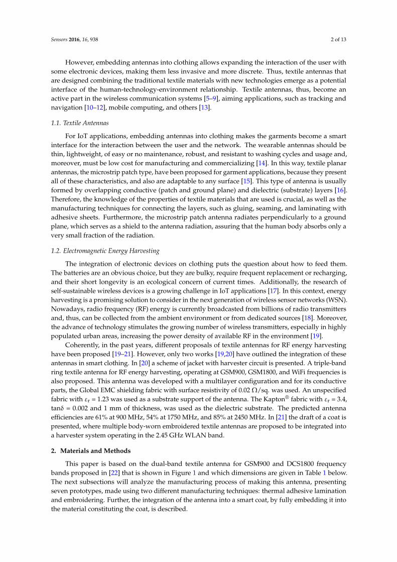
However, an extra antenna was produced by an ironing process with steam in order to analysethe influence of the steam in the performance of the antenna. Both antennas, with and withoutsteam, were assembled using the same ironing conditions, presented in the Table 3. Additionally, inorder to ensure the geometrical accuracy, the patches were cut by an LC6090C CCD (Jinan G. WeikeScience & Tecnology Co. Ltd., Jinan, China) laser cutting machine. The obtained results are shown inthe Figure 2.
Table 3. Ironing conditions.
Temperature (˝C) Pressure (bar) Time (s)
200 10 12 (6 for patch + 6 for ground plane)
Sensors 2016, 16, 938 4 of 13
2.2. Manufacturing Techniques
Beyond choosing the textile materials, the construction technique of the antenna is also crucial because the textile materials are highly deformable. The geometrical dimensions of the conductive patch and of the dielectric substrate should remain stable when connecting them, as the mechanical stabilization of both materials is essential to preserve the desired characteristics of the antenna. The geometrical precision of the conductive patch is also critical as the proposed antenna has thin details, as shown in Table 1.
Moreover, the technique to connect the various layers should not affect the electrical properties of the patch, particularly its electrical resistivity. All antennas presented in the following sections were produced assembling the components with the thermal adhesive sheet (JAU Têxteis, Serzedo, Portugal), previously described in the Table 2. The antennas were glued by ironing without steam in a vacuum table. Steam was not used deliberately, especially on materials with copper, to avoid oxidation of the conductive material and the consequent increase of its electrical resistivity.
However, an extra antenna was produced by an ironing process with steam in order to analyse the influence of the steam in the performance of the antenna. Both antennas, with and without steam, were assembled using the same ironing conditions, presented in the Table 3. Additionally, in order to ensure the geometrical accuracy, the patches were cut by an LC6090C CCD (Jinan G. Weike Science & Tecnology Co. Ltd., Jinan, China) laser cutting machine. The obtained results are shown in the Figure 2.
Table 3. Ironing conditions.
Temperature (°C) Pressure (bar) Time (s)200 10 12 (6 for patch + 6 for ground plane)
Figure 2. Comparison between ironing processes with, and without, steam.
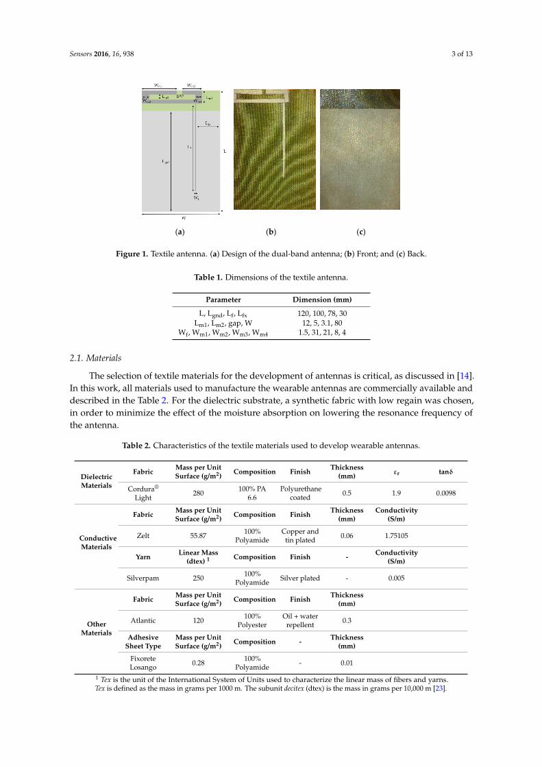
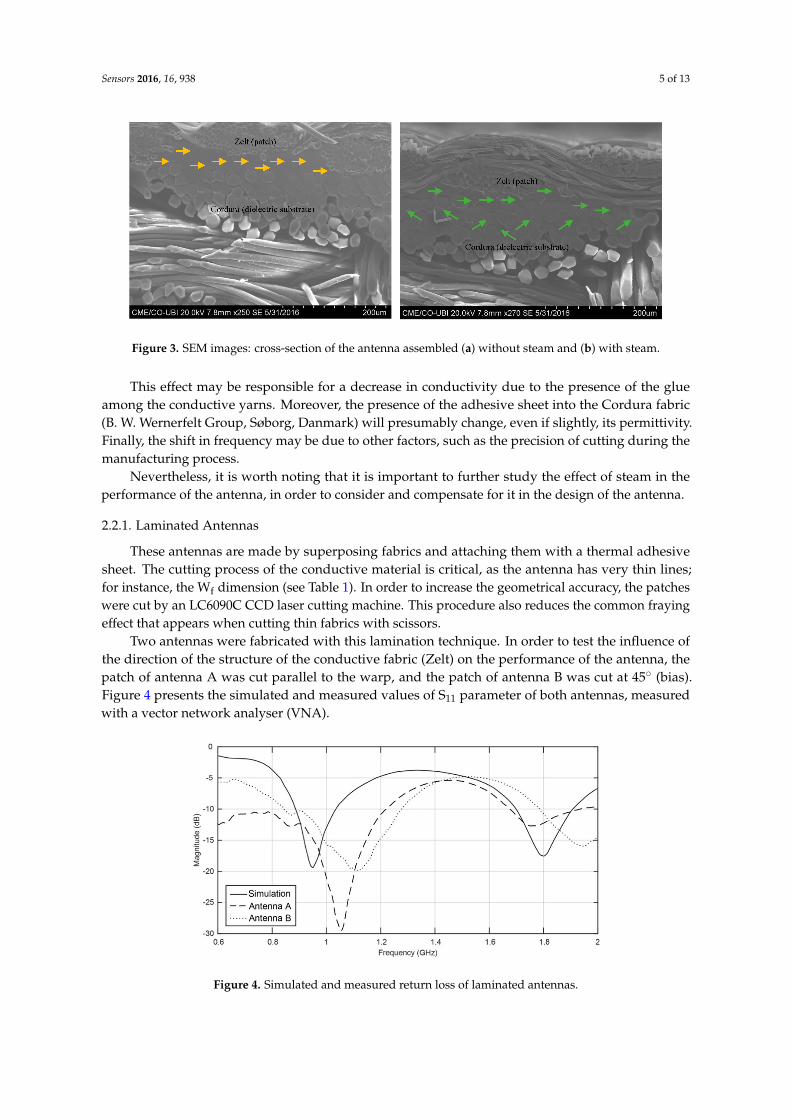
According to the measured results presented on Figure 2, one can see a higher frequency shift in the antenna made using steam in the ironing process. In order to investigate the cause of this shift, the thickness of the antenna was measured, using Kawabata’s Evaluation System (KES) for fabrics (KES-F-3 Compressional Tester). For the antenna without steam, the thickness is 0.62 mm, and for the antenna with steam it is 0.60 mm. This difference can be due to the higher compaction of the materials when steam is applied. As one can see in the scanning electron microscope (SEM) images in Figure 3, in the antenna without steam the adhesive sheet (see yellow arrows) remains at the interface between the conductive and dielectric layers. However, when the steam is applied, the adhesive sheet merges with the textile structure (see green arrows).
This effect may be responsible for a decrease in conductivity due to the presence of the glue among the conductive yarns. Moreover, the presence of the adhesive sheet into the Cordura fabric (B. W. Wernerfelt Group, Søborg, Danmark) will presumably change, even if slightly, its permittivity.
Figure 2. Comparison between ironing processes with, and without, steam.
According to the measured results presented on Figure 2, one can see a higher frequency shift inthe antenna made using steam in the ironing process. In order to investigate the cause of this shift,the thickness of the antenna was measured, using Kawabata’s Evaluation System (KES) for fabrics(KES-F-3 Compressional Tester). For the antenna without steam, the thickness is 0.62 mm, and for theantenna with steam it is 0.60 mm. This difference can be due to the higher compaction of the materialswhen steam is applied. As one can see in the scanning electron microscope (SEM) images in Figure 3,in the antenna without steam the adhesive sheet (see yellow arrows) remains at the interface betweenthe conductive and dielectric layers. However, when the steam is applied, the adhesive sheet mergeswith the textile structure (see green arrows).
Sensors 2016, 16, 938 5 of 13
Sensors 2016, 16, 938 5 of 13
Finally, the shift in frequency may be due to other factors, such as the precision of cutting during the manufacturing process.
Nevertheless, it is worth noting that it is important to further study the effect of steam in the performance of the antenna, in order to consider and compensate for it in the design of the antenna.
Figure 3. SEM images: cross-section of the antenna assembled (a) without steam and (b) with steam.
2.2.1. Laminated Antennas
These antennas are made by superposing fabrics and attaching them with a thermal adhesive sheet. The cutting process of the conductive material is critical, as the antenna has very thin lines; for instance, the Wf dimension (see Table 1). In order to increase the geometrical accuracy, the patches were cut by an LC6090C CCD laser cutting machine. This procedure also reduces the common fraying effect that appears when cutting thin fabrics with scissors.
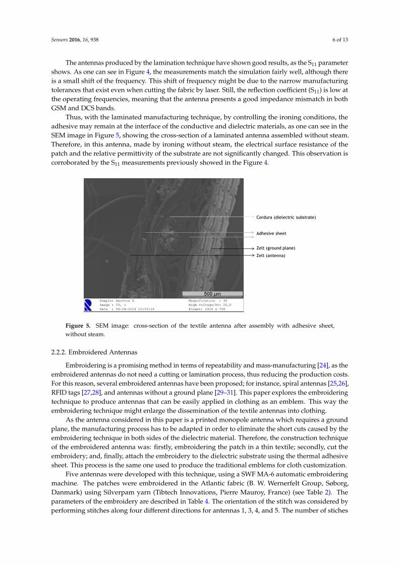
Two antennas were fabricated with this lamination technique. In order to test the influence of the direction of the structure of the conductive fabric (Zelt) on the performance of the antenna, the patch of antenna A was cut parallel to the warp, and the patch of antenna B was cut at 45° (bias). Figure 4 presents the simulated and measured values of S11 parameter of both antennas, measured with a vector network analyser (VNA).
Figure 4. Simulated and measured return loss of laminated antennas.
The antennas produced by the lamination technique have shown good results, as the S11 parameter shows. As one can see in Figure 4, the measurements match the simulation fairly well, although there is a small shift of the frequency. This shift of frequency might be due to the narrow manufacturing tolerances that exist even when cutting the fabric by laser. Still, the reflection coefficient (S11) is low at the operating frequencies, meaning that the antenna presents a good impedance mismatch in both GSM and DCS bands.
Figure 3. SEM images: cross-section of the antenna assembled (a) without steam and (b) with steam.
This effect may be responsible for a decrease in conductivity due to the presence of the glueamong the conductive yarns. Moreover, the presence of the adhesive sheet into the Cordura fabric(B. W. Wernerfelt Group, Søborg, Danmark) will presumably change, even if slightly, its permittivity.Finally, the shift in frequency may be due to other factors, such as the precision of cutting during themanufacturing process.
Nevertheless, it is worth noting that it is important to further study the effect of steam in theperformance of the antenna, in order to consider and compensate for it in the design of the antenna.
2.2.1. Laminated Antennas
These antennas are made by superposing fabrics and attaching them with a thermal adhesivesheet. The cutting process of the conductive material is critical, as the antenna has very thin lines;for instance, the Wf dimension (see Table 1). In order to increase the geometrical accuracy, the patcheswere cut by an LC6090C CCD laser cutting machine. This procedure also reduces the common frayingeffect that appears when cutting thin fabrics with scissors.
Two antennas were fabricated with this lamination technique. In order to test the influence ofthe direction of the structure of the conductive fabric (Zelt) on the performance of the antenna, thepatch of antenna A was cut parallel to the warp, and the patch of antenna B was cut at 45˝ (bias).Figure 4 presents the simulated and measured values of S11 parameter of both antennas, measuredwith a vector network analyser (VNA).
Sensors 2016, 16, 938 5 of 13
Finally, the shift in frequency may be due to other factors, such as the precision of cutting during the manufacturing process.
Nevertheless, it is worth noting that it is important to further study the effect of steam in the performance of the antenna, in order to consider and compensate for it in the design of the antenna.
Figure 3. SEM images: cross-section of the antenna assembled (a) without steam and (b) with steam.
2.2.1. Laminated Antennas
These antennas are made by superposing fabrics and attaching them with a thermal adhesive sheet. The cutting process of the conductive material is critical, as the antenna has very thin lines; for instance, the Wf dimension (see Table 1). In order to increase the geometrical accuracy, the patches were cut by an LC6090C CCD laser cutting machine. This procedure also reduces the common fraying effect that appears when cutting thin fabrics with scissors.
Two antennas were fabricated with this lamination technique. In order to test the influence of the direction of the structure of the conductive fabric (Zelt) on the performance of the antenna, the patch of antenna A was cut parallel to the warp, and the patch of antenna B was cut at 45° (bias). Figure 4 presents the simulated and measured values of S11 parameter of both antennas, measured with a vector network analyser (VNA).
Figure 4. Simulated and measured return loss of laminated antennas.
The antennas produced by the lamination technique have shown good results, as the S11 parameter shows. As one can see in Figure 4, the measurements match the simulation fairly well, although there is a small shift of the frequency. This shift of frequency might be due to the narrow manufacturing tolerances that exist even when cutting the fabric by laser. Still, the reflection coefficient (S11) is low at the operating frequencies, meaning that the antenna presents a good impedance mismatch in both GSM and DCS bands.
Figure 4. Simulated and measured return loss of laminated antennas.
Sensors 2016, 16, 938 6 of 13
The antennas produced by the lamination technique have shown good results, as the S11 parametershows. As one can see in Figure 4, the measurements match the simulation fairly well, although thereis a small shift of the frequency. This shift of frequency might be due to the narrow manufacturingtolerances that exist even when cutting the fabric by laser. Still, the reflection coefficient (S11) is low atthe operating frequencies, meaning that the antenna presents a good impedance mismatch in bothGSM and DCS bands.
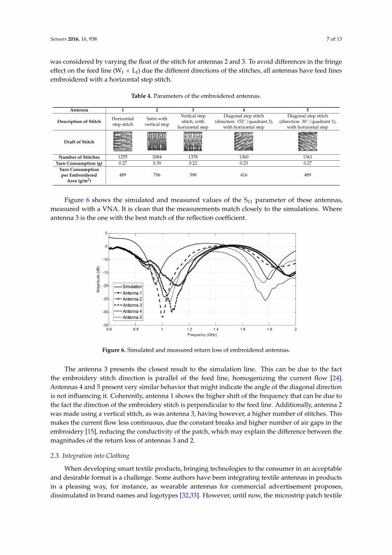
Thus, with the laminated manufacturing technique, by controlling the ironing conditions, theadhesive may remain at the interface of the conductive and dielectric materials, as one can see in theSEM image in Figure 5, showing the cross-section of a laminated antenna assembled without steam.Therefore, in this antenna, made by ironing without steam, the electrical surface resistance of thepatch and the relative permittivity of the substrate are not significantly changed. This observation iscorroborated by the S11 measurements previously showed in the Figure 4.
Sensors 2016, 16, 938 6 of 13
Thus, with the laminated manufacturing technique, by controlling the ironing conditions, the adhesive may remain at the interface of the conductive and dielectric materials, as one can see in the SEM image in Figure 5, showing the cross-section of a laminated antenna assembled without steam. Therefore, in this antenna, made by ironing without steam, the electrical surface resistance of the patch and the relative permittivity of the substrate are not significantly changed. This observation is corroborated by the S11 measurements previously showed in the Figure 4.
Figure 5. SEM image: cross-section of the textile antenna after assembly with adhesive sheet, without steam.
2.2.2. Embroidered Antennas
Embroidering is a promising method in terms of repeatability and mass-manufacturing [24], as the embroidered antennas do not need a cutting or lamination process, thus reducing the production costs. For this reason, several embroidered antennas have been proposed; for instance, spiral antennas [25,26], RFID tags [27,28], and antennas without a ground plane [29–31]. This paper explores the embroidering technique to produce antennas that can be easily applied in clothing as an emblem. This way the embroidering technique might enlarge the dissemination of the textile antennas into clothing.
As the antenna considered in this paper is a printed monopole antenna which requires a ground plane, the manufacturing process has to be adapted in order to eliminate the short cuts caused by the embroidering technique in both sides of the dielectric material. Therefore, the construction technique of the embroidered antenna was: firstly, embroidering the patch in a thin textile; secondly, cut the embroidery; and, finally, attach the embroidery to the dielectric substrate using the thermal adhesive sheet. This process is the same one used to produce the traditional emblems for cloth customization.
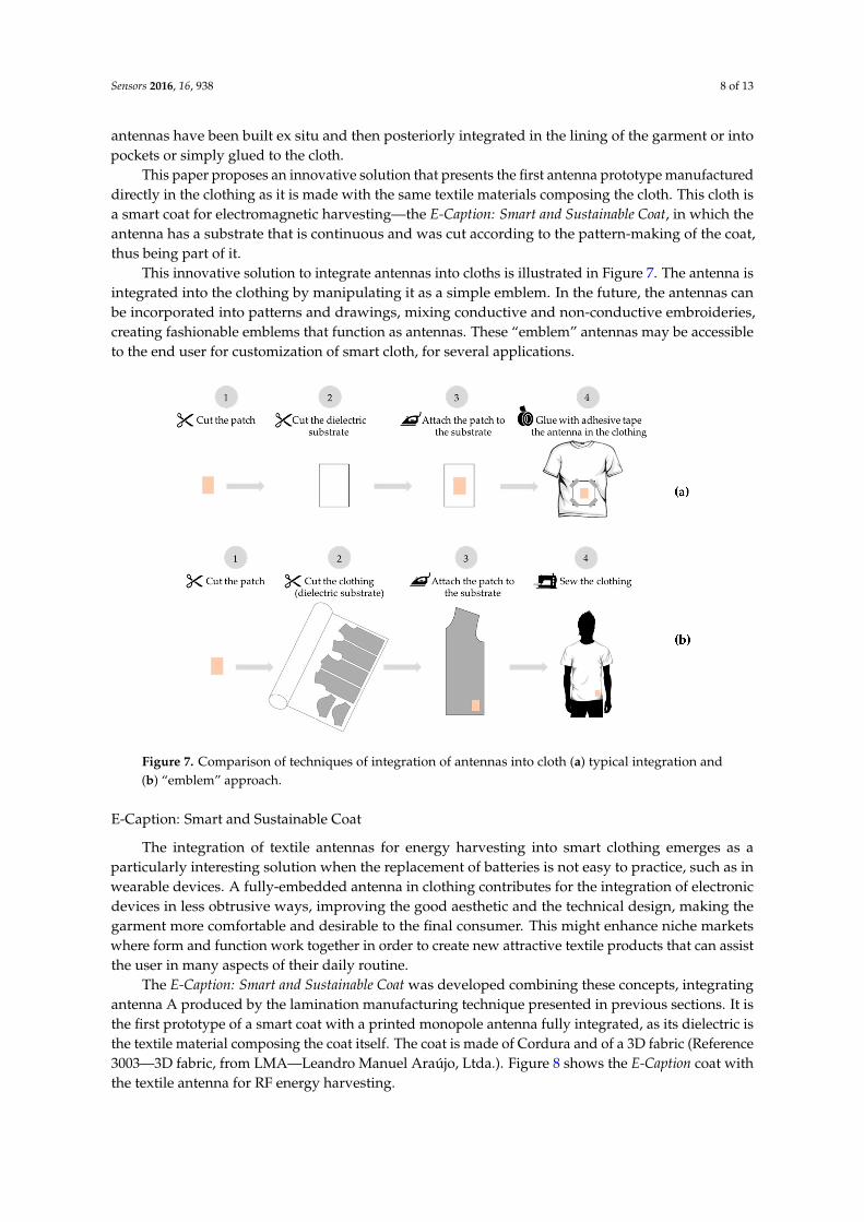
Five antennas were developed with this technique, using a SWF MA-6 automatic embroidering machine. The patches were embroidered in the Atlantic fabric (B. W. Wernerfelt Group, Søborg, Danmark) using Silverpam yarn (Tibtech Innovations, Pierre Mauroy, France) (see Table 2). The parameters of the embroidery are described in Table 4. The orientation of the stitch was considered by performing stitches along four different directions for antennas 1, 3, 4, and 5. The number of stiches was considered by varying the float of the stitch for antennas 2 and 3. To avoid differences in the fringe effect on the feed line (Wf × Lf) due the different directions of the stitches, all antennas have feed lines embroidered with a horizontal step stitch.
Figure 6 shows the simulated and measured values of the S11 parameter of these antennas, measured with a VNA. It is clean that the measurements match closely to the simulations. Where antenna 3 is the one with the best match of the reflection coefficient.
Figure 5. SEM image: cross-section of the textile antenna after assembly with adhesive sheet,without steam.
2.2.2. Embroidered Antennas
Embroidering is a promising method in terms of repeatability and mass-manufacturing [24], as theembroidered antennas do not need a cutting or lamination process, thus reducing the production costs.For this reason, several embroidered antennas have been proposed; for instance, spiral antennas [25,26],RFID tags [27,28], and antennas without a ground plane [29–31]. This paper explores the embroideringtechnique to produce antennas that can be easily applied in clothing as an emblem. This way theembroidering technique might enlarge the dissemination of the textile antennas into clothing.
As the antenna considered in this paper is a printed monopole antenna which requires a groundplane, the manufacturing process has to be adapted in order to eliminate the short cuts caused by theembroidering technique in both sides of the dielectric material. Therefore, the construction techniqueof the embroidered antenna was: firstly, embroidering the patch in a thin textile; secondly, cut theembroidery; and, finally, attach the embroidery to the dielectric substrate using the thermal adhesivesheet. This process is the same one used to produce the traditional emblems for cloth customization.
Five antennas were developed with this technique, using a SWF MA-6 automatic embroideringmachine. The patches were embroidered in the Atlantic fabric (B. W. Wernerfelt Group, Søborg,Danmark) using Silverpam yarn (Tibtech Innovations, Pierre Mauroy, France) (see Table 2). Theparameters of the embroidery are described in Table 4. The orientation of the stitch was considered byperforming stitches along four different directions for antennas 1, 3, 4, and 5. The number of stiches
Sensors 2016, 16, 938 7 of 13
was considered by varying the float of the stitch for antennas 2 and 3. To avoid differences in the fringeeffect on the feed line (Wf ˆ Lf) due the different directions of the stitches, all antennas have feed linesembroidered with a horizontal step stitch.
Table 4. Parameters of the embroidered antennas.
Antenna 1 2 3 4 5
Description of Stitch Horizontalstep stitch
Satin withvertical step
Vertical stepstitch, with
horizontal step
Diagonal step stitch(direction: 152˝/quadrant 2),
with horizontal step
Diagonal step stitch(direction: 30˝/quadrant 1),
with horizontal step
Draft of Stitch
Sensors 2016, 16, 938 7 of 13
The antenna 3 presents the closest result to the simulation line. This can be due to the fact the embroidery stitch direction is parallel of the feed line, homogenizing the current flow [24]. Antennas 4 and 5 present very similar behavior that might indicate the angle of the diagonal direction is not influencing it. Coherently, antenna 1 shows the higher shift of the frequency that can be due to the fact the direction of the embroidery stitch is perpendicular to the feed line. Additionally, antenna 2 was made using a vertical stitch, as was antenna 3, having however, a higher number of stitches. This makes the current flow less continuous, due the constant breaks and higher number of air gaps in the embroidery [15], reducing the conductivity of the patch, which may explain the difference between the magnitudes of the return loss of antennas 3 and 2.
Table 4. Parameters of the embroidered antennas.
Antenna 1 2 3 4 5
Description of Stitch Horizontal step stitch
Satin with vertical step
Vertical step stitch, with horizontal
step
Diagonal step stitch (direction: 152°/quadrant 2),
with horizontal step
Diagonal step stitch (direction: 30°/quadrant 1),
with horizontal step
Draft of Stitch
Number of Stitches 1255 2084 1378 1360 1361 Yarn Consumption (g) 0.27 0.39 0.22 0.23 0.27 Yarn Consumption per Embroidered
Area (g/m2) 489 706 398 416 489
Figure 6. Simulated and measured return loss of embroidered antennas.
2.3. Integration into Clothing
When developing smart textile products, bringing technologies to the consumer in an acceptable and desirable format is a challenge. Some authors have been integrating textile antennas in products in a pleasing way, for instance, as wearable antennas for commercial advertisement proposes, dissimulated in brand names and logotypes [32,33]. However, until now, the microstrip patch textile antennas have been built ex situ and then posteriorly integrated in the lining of the garment or into pockets or simply glued to the cloth.
This paper proposes an innovative solution that presents the first antenna prototype manufactured directly in the clothing as it is made with the same textile materials composing the cloth. This cloth is a smart coat for electromagnetic harvesting—the E-Caption: Smart and Sustainable Coat, in which the antenna has a substrate that is continuous and was cut according to the pattern-making of the coat, thus being part of it.
Number of Stitches 1255 2084 1378 1360 1361Yarn Consumption (g) 0.27 0.39 0.22 0.23 0.27
Yarn Consumptionper Embroidered
Area (g/m2)489 706 398 416 489
Figure 6 shows the simulated and measured values of the S11 parameter of these antennas,measured with a VNA. It is clean that the measurements match closely to the simulations. Whereantenna 3 is the one with the best match of the reflection coefficient.
Sensors 2016, 16, 938 7 of 13
The antenna 3 presents the closest result to the simulation line. This can be due to the fact the embroidery stitch direction is parallel of the feed line, homogenizing the current flow [24]. Antennas 4 and 5 present very similar behavior that might indicate the angle of the diagonal direction is not influencing it. Coherently, antenna 1 shows the higher shift of the frequency that can be due to the fact the direction of the embroidery stitch is perpendicular to the feed line. Additionally, antenna 2 was made using a vertical stitch, as was antenna 3, having however, a higher number of stitches. This makes the current flow less continuous, due the constant breaks and higher number of air gaps in the embroidery [15], reducing the conductivity of the patch, which may explain the difference between the magnitudes of the return loss of antennas 3 and 2.
Table 4. Parameters of the embroidered antennas.
Antenna 1 2 3 4 5
Description of Stitch Horizontal step stitch
Satin with vertical step
Vertical step stitch, with horizontal
step
Diagonal step stitch (direction: 152°/quadrant 2),
with horizontal step
Diagonal step stitch (direction: 30°/quadrant 1),
with horizontal step
Draft of Stitch
Number of Stitches 1255 2084 1378 1360 1361 Yarn Consumption (g) 0.27 0.39 0.22 0.23 0.27 Yarn Consumption per Embroidered
Area (g/m2) 489 706 398 416 489
Figure 6. Simulated and measured return loss of embroidered antennas.
2.3. Integration into Clothing
When developing smart textile products, bringing technologies to the consumer in an acceptable and desirable format is a challenge. Some authors have been integrating textile antennas in products in a pleasing way, for instance, as wearable antennas for commercial advertisement proposes, dissimulated in brand names and logotypes [32,33]. However, until now, the microstrip patch textile antennas have been built ex situ and then posteriorly integrated in the lining of the garment or into pockets or simply glued to the cloth.
This paper proposes an innovative solution that presents the first antenna prototype manufactured directly in the clothing as it is made with the same textile materials composing the cloth. This cloth is a smart coat for electromagnetic harvesting—the E-Caption: Smart and Sustainable Coat, in which the antenna has a substrate that is continuous and was cut according to the pattern-making of the coat, thus being part of it.
Figure 6. Simulated and measured return loss of embroidered antennas.
The antenna 3 presents the closest result to the simulation line. This can be due to the factthe embroidery stitch direction is parallel of the feed line, homogenizing the current flow [24].Antennas 4 and 5 present very similar behavior that might indicate the angle of the diagonal directionis not influencing it. Coherently, antenna 1 shows the higher shift of the frequency that can be due tothe fact the direction of the embroidery stitch is perpendicular to the feed line. Additionally, antenna 2was made using a vertical stitch, as was antenna 3, having however, a higher number of stitches. Thismakes the current flow less continuous, due the constant breaks and higher number of air gaps in theembroidery [15], reducing the conductivity of the patch, which may explain the difference between themagnitudes of the return loss of antennas 3 and 2.
2.3. Integration into Clothing
When developing smart textile products, bringing technologies to the consumer in an acceptableand desirable format is a challenge. Some authors have been integrating textile antennas in productsin a pleasing way, for instance, as wearable antennas for commercial advertisement proposes,dissimulated in brand names and logotypes [32,33]. However, until now, the microstrip patch textile
Sensors 2016, 16, 938 8 of 13
antennas have been built ex situ and then posteriorly integrated in the lining of the garment or intopockets or simply glued to the cloth.
This paper proposes an innovative solution that presents the first antenna prototype manufactureddirectly in the clothing as it is made with the same textile materials composing the cloth. This cloth isa smart coat for electromagnetic harvesting—the E-Caption: Smart and Sustainable Coat, in which theantenna has a substrate that is continuous and was cut according to the pattern-making of the coat,thus being part of it.
This innovative solution to integrate antennas into cloths is illustrated in Figure 7. The antenna isintegrated into the clothing by manipulating it as a simple emblem. In the future, the antennas canbe incorporated into patterns and drawings, mixing conductive and non-conductive embroideries,creating fashionable emblems that function as antennas. These “emblem” antennas may be accessibleto the end user for customization of smart cloth, for several applications.
Sensors 2016, 16, 938 8 of 13
This innovative solution to integrate antennas into cloths is illustrated in Figure 7. The antenna is integrated into the clothing by manipulating it as a simple emblem. In the future, the antennas can be incorporated into patterns and drawings, mixing conductive and non-conductive embroideries, creating fashionable emblems that function as antennas. These “emblem” antennas may be accessible to the end user for customization of smart cloth, for several applications.
Figure 7. Comparison of techniques of integration of antennas into cloth (a) typical integration and (b) “emblem” approach.
E-Caption: Smart and Sustainable Coat
The integration of textile antennas for energy harvesting into smart clothing emerges as a particularly interesting solution when the replacement of batteries is not easy to practice, such as in wearable devices. A fully-embedded antenna in clothing contributes for the integration of electronic devices in less obtrusive ways, improving the good aesthetic and the technical design, making the garment more comfortable and desirable to the final consumer. This might enhance niche markets where form and function work together in order to create new attractive textile products that can assist the user in many aspects of their daily routine.
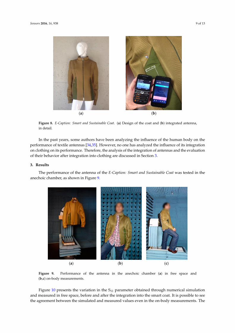
The E-Caption: Smart and Sustainable Coat was developed combining these concepts, integrating antenna A produced by the lamination manufacturing technique presented in previous sections. It is the first prototype of a smart coat with a printed monopole antenna fully integrated, as its dielectric is the textile material composing the coat itself. The coat is made of Cordura and of a 3D fabric (Reference 3003—3D fabric, from LMA—Leandro Manuel Araújo, Ltda.). Figure 8 shows the E-Caption coat with the textile antenna for RF energy harvesting.
In the past years, some authors have been analyzing the influence of the human body on the performance of textile antennas [34,35]. However, no one has analyzed the influence of its integration on clothing on its performance. Therefore, the analysis of the integration of antennas and the evaluation of their behavior after integration into clothing are discussed in Section 3.
Figure 7. Comparison of techniques of integration of antennas into cloth (a) typical integration and(b) “emblem” approach.
E-Caption: Smart and Sustainable Coat
The integration of textile antennas for energy harvesting into smart clothing emerges as aparticularly interesting solution when the replacement of batteries is not easy to practice, such as inwearable devices. A fully-embedded antenna in clothing contributes for the integration of electronicdevices in less obtrusive ways, improving the good aesthetic and the technical design, making thegarment more comfortable and desirable to the final consumer. This might enhance niche marketswhere form and function work together in order to create new attractive textile products that can assistthe user in many aspects of their daily routine.
The E-Caption: Smart and Sustainable Coat was developed combining these concepts, integratingantenna A produced by the lamination manufacturing technique presented in previous sections. It isthe first prototype of a smart coat with a printed monopole antenna fully integrated, as its dielectric isthe textile material composing the coat itself. The coat is made of Cordura and of a 3D fabric (Reference3003—3D fabric, from LMA—Leandro Manuel Araújo, Ltda.). Figure 8 shows the E-Caption coat withthe textile antenna for RF energy harvesting.
Sensors 2016, 16, 938 9 of 13
Sensors 2016, 16, 938 9 of 13
(a) (b)
Figure 8. E-Caption: Smart and Sustainable Coat. (a) Design of the coat and (b) integrated antenna, in detail.
3. Results
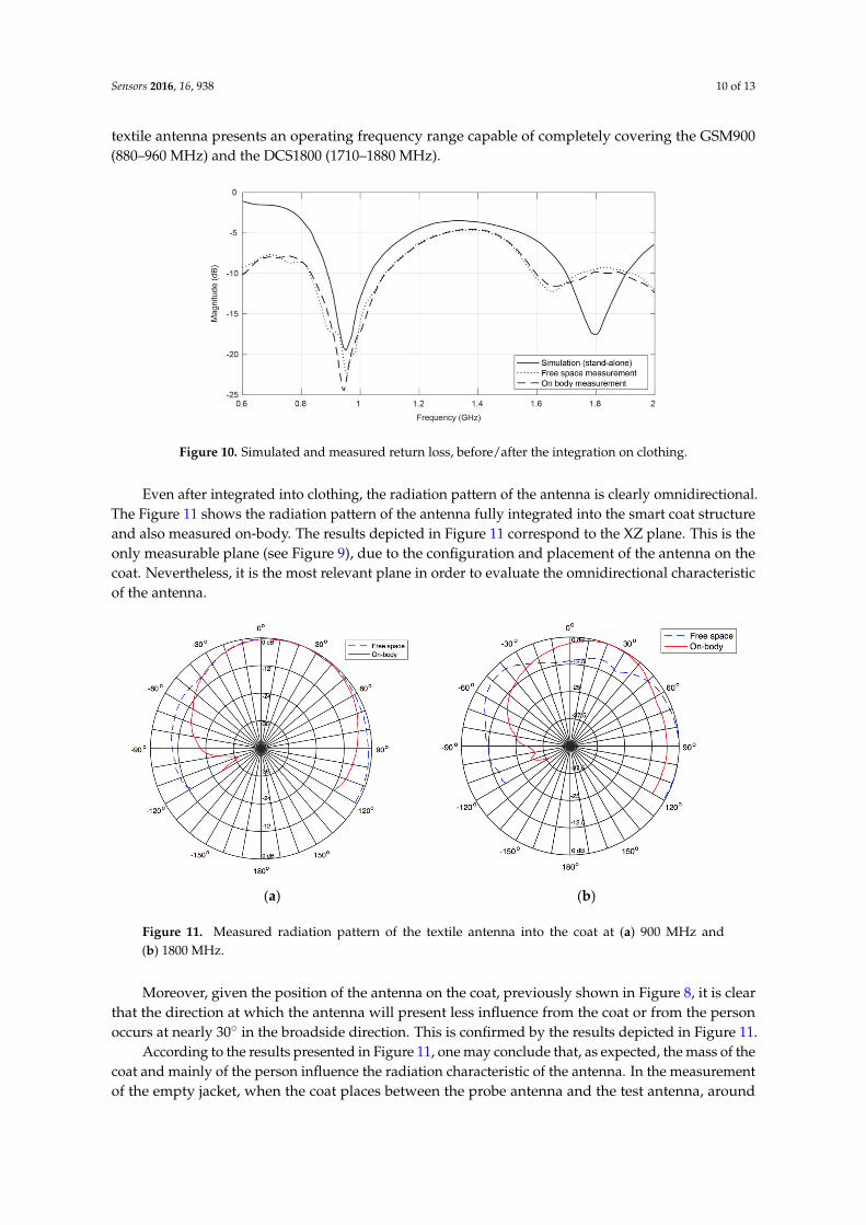
The performance of the antenna of the E-Caption: Smart and Sustainable Coat was tested in the anechoic chamber, as shown in Figure 9.
(a) (b) (c)
Figure 9. Performance of the antenna in the anechoic chamber (a) in free space and (b,c) on-body measurements.
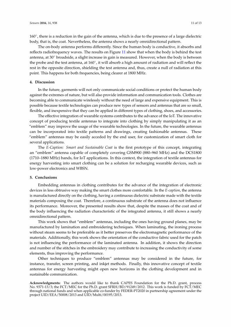
Figure 10 presents the variation in the S11 parameter obtained through numerical simulation and measured in free space, before and after the integration into the smart coat. It is possible to see the agreement between the simulated and measured values even in the on-body measurements. The textile antenna presents an operating frequency range capable of completely covering the GSM900 (880–960 MHz) and the DCS1800 (1710–1880 MHz).
Figure 8. E-Caption: Smart and Sustainable Coat. (a) Design of the coat and (b) integrated antenna,in detail.
In the past years, some authors have been analyzing the influence of the human body on theperformance of textile antennas [34,35]. However, no one has analyzed the influence of its integrationon clothing on its performance. Therefore, the analysis of the integration of antennas and the evaluationof their behavior after integration into clothing are discussed in Section 3.
3. Results
The performance of the antenna of the E-Caption: Smart and Sustainable Coat was tested in theanechoic chamber, as shown in Figure 9.
Sensors 2016, 16, 938 9 of 13
(a) (b)
Figure 8. E-Caption: Smart and Sustainable Coat. (a) Design of the coat and (b) integrated antenna, in detail.
3. Results
The performance of the antenna of the E-Caption: Smart and Sustainable Coat was tested in the anechoic chamber, as shown in Figure 9.
(a) (b) (c)
Figure 9. Performance of the antenna in the anechoic chamber (a) in free space and (b,c) on-body measurements.
Figure 10 presents the variation in the S11 parameter obtained through numerical simulation and measured in free space, before and after the integration into the smart coat. It is possible to see the agreement between the simulated and measured values even in the on-body measurements. The textile antenna presents an operating frequency range capable of completely covering the GSM900 (880–960 MHz) and the DCS1800 (1710–1880 MHz).
Figure 9. Performance of the antenna in the anechoic chamber (a) in free space and(b,c) on-body measurements.
Figure 10 presents the variation in the S11 parameter obtained through numerical simulationand measured in free space, before and after the integration into the smart coat. It is possible to seethe agreement between the simulated and measured values even in the on-body measurements. The
Sensors 2016, 16, 938 10 of 13
textile antenna presents an operating frequency range capable of completely covering the GSM900(880–960 MHz) and the DCS1800 (1710–1880 MHz).Sensors 2016, 16, 938 10 of 13
Figure 10. Simulated and measured return loss, before/after the integration on clothing.
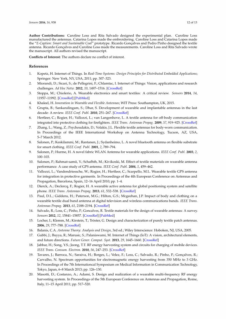
Even after integrated into clothing, the radiation pattern of the antenna is clearly omnidirectional. The Figure 11 shows the radiation pattern of the antenna fully integrated into the smart coat structure and also measured on-body. The results depicted in Figure 11 correspond to the XZ plane. This is the only measurable plane (see Figure 9), due to the configuration and placement of the antenna on the coat. Nevertheless, it is the most relevant plane in order to evaluate the omnidirectional characteristic of the antenna.
Moreover, given the position of the antenna on the coat, previously shown in Figure 8, it is clear that the direction at which the antenna will present less influence from the coat or from the person occurs at nearly 30° in the broadside direction. This is confirmed by the results depicted in Figure 11.
(a) (b)
Figure 11. Measured radiation pattern of the textile antenna into the coat at (a) 900 MHz and (b) 1800 MHz.
According to the results presented in Figure 11, one may conclude that, as expected, the mass of the coat and mainly of the person influence the radiation characteristic of the antenna. In the measurement of the empty jacket, when the coat places between the probe antenna and the test antenna, around 160°, there is a reduction in the gain of the antenna, which is due to the presence of a large dielectric body, that is, the coat. Nevertheless, the antenna shows a nearly omnidirectional pattern.
The on-body antenna performs differently. Since the human body is conductive, it absorbs and reflects radiofrequency waves. The results on Figure 11 show that when the body is behind the test antenna, at 30° broadside, a slight increase in gain is measured. However, when the body is between the probe and the test antenna, at 160°, it will absorb a high amount of radiation and will reflect the
Figure 10. Simulated and measured return loss, before/after the integration on clothing.
Even after integrated into clothing, the radiation pattern of the antenna is clearly omnidirectional.The Figure 11 shows the radiation pattern of the antenna fully integrated into the smart coat structureand also measured on-body. The results depicted in Figure 11 correspond to the XZ plane. This is theonly measurable plane (see Figure 9), due to the configuration and placement of the antenna on thecoat. Nevertheless, it is the most relevant plane in order to evaluate the omnidirectional characteristicof the antenna.
Sensors 2016, 16, 938 10 of 13
Figure 10. Simulated and measured return loss, before/after the integration on clothing.
Even after integrated into clothing, the radiation pattern of the antenna is clearly omnidirectional. The Figure 11 shows the radiation pattern of the antenna fully integrated into the smart coat structure and also measured on-body. The results depicted in Figure 11 correspond to the XZ plane. This is the only measurable plane (see Figure 9), due to the configuration and placement of the antenna on the coat. Nevertheless, it is the most relevant plane in order to evaluate the omnidirectional characteristic of the antenna.
Moreover, given the position of the antenna on the coat, previously shown in Figure 8, it is clear that the direction at which the antenna will present less influence from the coat or from the person occurs at nearly 30° in the broadside direction. This is confirmed by the results depicted in Figure 11.
(a) (b)
Figure 11. Measured radiation pattern of the textile antenna into the coat at (a) 900 MHz and (b) 1800 MHz.
According to the results presented in Figure 11, one may conclude that, as expected, the mass of the coat and mainly of the person influence the radiation characteristic of the antenna. In the measurement of the empty jacket, when the coat places between the probe antenna and the test antenna, around 160°, there is a reduction in the gain of the antenna, which is due to the presence of a large dielectric body, that is, the coat. Nevertheless, the antenna shows a nearly omnidirectional pattern.
The on-body antenna performs differently. Since the human body is conductive, it absorbs and reflects radiofrequency waves. The results on Figure 11 show that when the body is behind the test antenna, at 30° broadside, a slight increase in gain is measured. However, when the body is between the probe and the test antenna, at 160°, it will absorb a high amount of radiation and will reflect the
Figure 11. Measured radiation pattern of the textile antenna into the coat at (a) 900 MHz and(b) 1800 MHz.
Moreover, given the position of the antenna on the coat, previously shown in Figure 8, it is clearthat the direction at which the antenna will present less influence from the coat or from the personoccurs at nearly 30˝ in the broadside direction. This is confirmed by the results depicted in Figure 11.
According to the results presented in Figure 11, one may conclude that, as expected, the mass of thecoat and mainly of the person influence the radiation characteristic of the antenna. In the measurementof the empty jacket, when the coat places between the probe antenna and the test antenna, around
Sensors 2016, 16, 938 11 of 13
160˝, there is a reduction in the gain of the antenna, which is due to the presence of a large dielectricbody, that is, the coat. Nevertheless, the antenna shows a nearly omnidirectional pattern.
The on-body antenna performs differently. Since the human body is conductive, it absorbs andreflects radiofrequency waves. The results on Figure 11 show that when the body is behind the testantenna, at 30˝ broadside, a slight increase in gain is measured. However, when the body is betweenthe probe and the test antenna, at 160˝, it will absorb a high amount of radiation and will reflect therest in the opposite direction, shielding the test antenna and, thus, create a null of radiation at thispoint. This happens for both frequencies, being clearer at 1800 MHz.
4. Discussion
In the future, garments will not only communicate social conditions or protect the human bodyagainst the extremes of nature, but will also provide information and communication tools. Clothes arebecoming able to communicate wirelessly without the need of large and expensive equipment. This ispossible because textile technologies can produce new types of sensors and antennas that are so small,flexible, and inexpensive that they can be applied in different types of clothing, shoes, and accessories.
The effective integration of wearable systems contributes to the advance of the IoT. The innovativeconcept of producing textile antennas to integrate into clothing by simply manipulating it as an“emblem” may improve the usage of the wearable technologies. In the future, the wearable antennascan be incorporated into textile patterns and drawings, creating fashionable antennas. These“emblem” antennas may be easily acceded by the end user, for customization of smart cloth forseveral applications.
The E-Caption: Smart and Sustainable Coat is the first prototype of this concept, integratingan “emblem” antenna capable of completely covering GSM900 (880–960 MHz) and the DCS1800(1710–1880 MHz) bands, for IoT applications. In this context, the integration of textile antennas forenergy harvesting into smart clothing can be a solution for recharging wearable devices, such aslow-power electronics and WBSN.
5. Conclusions
Embedding antennas in clothing contributes for the advance of the integration of electronicdevices in less obtrusive way making the smart clothes more comfortable. In the E-caption, the antennais manufactured directly on the clothing, having a continuous dielectric substrate made with the textilematerials composing the coat. Therefore, a continuous substrate of the antenna does not influenceits performance. Moreover, the presented results show that, despite the masses of the coat and ofthe body influencing the radiation characteristic of the integrated antenna, it still shows a nearlyomnidirectional pattern.
This work shows that “emblem” antennas, including the ones having ground planes, may bemanufactured by lamination and embroidering techniques. When laminating, the ironing processwithout steam seems to be preferable as it better preserves the electromagnetic performance of thematerials. Additionally, this work shows the orientation of the conductive fabric used for the patchis not influencing the performance of the laminated antenna. In addition, it shows the directionand number of the stitches in the embroidery may contribute to increasing the conductivity of someelements, thus improving the performance.
Other techniques to produce “emblem” antennas may be considered in the future, forinstance, transfer, screen printing, and inkjet methods. Finally, this innovative concept of textileantennas for energy harvesting might open new horizons in the clothing development and insustainable communication.
Acknowledgments: The authors would like to thank CAPES Foundation for the Ph.D. grant, processNo. 9371-13/3; the FCT/MEC for the Ph.D. grant SFRH/BD/91249/2012. This work is funded by FCT/MECthrough national funds and when applicable co-funder by FEDER-PT2020 in partnership agreement under theproject UID/EEA/50008/2013 and UID/Multi/00195/2013.
Sensors 2016, 16, 938 12 of 13
Author Contributions: Caroline Loss and Rita Salvado designed the experimental plan. Caroline Lossmanufactured the antennas. Catarina Lopes made the embroidering. Caroline Loss and Catarina Lopes madethe “E-Caption: Smart and Sustainable Coat” prototype. Ricardo Gonçalves and Pedro Pinho designed the textileantenna. Ricardo Gonçalves and Caroline Loss made the measurements. Caroline Loss and Rita Salvado wrotethe manuscript. All authors revised the manuscript.
Conflicts of Interest: The authors declare no conflict of interest.
References
1. Kopetz, H. Internet of Things. In Real-Time Systems: Design Principles for Distributed Embedded Applications;Springer: New York, NY, USA, 2011; pp. 307–323.
2. Miorandi, D.; Sicari, S.; de Pellegrini, F.; Chlamtac, I. Internet of Things: Vision, applications and researchchallenges. Ad Hoc Netw. 2012, 10, 1497–1516. [CrossRef]
3. Stoppa, M.; Chiolerio, A. Wearable electronics and smart textiles: A critical review. Sensors 2014, 14,11957–11992. [CrossRef] [PubMed]
4. Khaleel, H. Innovation in Wearable and Flexible Antennas; WIT Press: Southampton, UK, 2015.5. Grupta, B.; Sankaralingam, S.; Dhar, S. Development of wearable and implantable antennas in the last
decade: A review. IEEE Conf. Publ. 2010, 251–267. [CrossRef]6. Hertleer, C.; Rogier, H.; Vallozzi, L.; van Langenhove, L. A textile antenna for off-body communication
integrated into protective clothing for firefighters. IEEE Trans. Antennas Propag. 2009, 57, 919–925. [CrossRef]7. Zhang, L.; Wang, Z.; Psychoudakis, D.; Volakis, J.L. Flexible textile antennas for body-worn communication.
In Proceedings of the IEEE International Workshop on Antenna Technology, Tucson, AZ, USA,5–7 March 2012.
8. Salonen, P.; Keskilammi, M.; Rantanen, J.; Sydanheimo, L. A novel bluetooth antenna on flexible substratefor smart clothing. IEEE Conf. Publ. 2001, 2, 789–794.
9. Salonen, P.; Hurme, H. A novel fabric WLAN Antenna for wearable applications. IEEE Conf. Publ. 2003, 2,100–103.
10. Salonen, P.; Rahmat-samii, Y.; Schafhth, M.; Kivikoski, M. Effect of textile materials on wearable antennaperformance: A case study of GPS antenna. IEEE Conf. Publ. 2004, 1, 459–462.
11. Vallozzi, L.; Vandendriessche, W.; Rogier, H.; Hertleer, C.; Scarpello, M.L. Wearable textile GPS antennafor integration in protective garments. In Proceedings of the 4th European Conference on Antennas andPropagation, Barcelona, Spain, 12–16 April 2010; pp. 1–4.
12. Dierck, A.; Declercq, F.; Rogier, H. A wearable active antenna for global positioning system and satellitephone. IEEE Trans. Antennas Propag. 2013, 61, 532–538. [CrossRef]
13. Paul, D.L.; Giddens, H.; Paterson, M.G.; Hilton, G.S.; Mcgeehan, J.P. Impact of body and clothing on awearable textile dual band antenna at digital television and wireless communications bands. IEEE Trans.Antennas Propag. 2013, 61, 2188–2194. [CrossRef]
14. Salvado, R.; Loss, C.; Pinho, P.; Goncalves, R. Textile materials for the design of wearable antennas: A survey.Sensors 2012, 12, 15841–15857. [CrossRef] [PubMed]
15. Locher, I.; Klemm, M.; Kirstein, T.; Tröster, G. Design and characterization of purely textile patch antennas.2006, 29, 777–788. [CrossRef]
16. Balanis, C.A. Antenna Theory: Analysis and Design, 3rd ed.; Wiley Interscience: Hoboken, NJ, USA, 2005.17. Gubbi, J.; Buyya, R.; Marusic, S.; Palaniswami, M. Internet of Things (IoT): A vision, architectural elements,
and future directions. Future Gener. Comput. Syst. 2013, 29, 1645–1660. [CrossRef]18. Jabbar, H.; Song, Y.S.; Jeong, T.T. RF energy harvesting system and circuits for charging of mobile devices.
IEEE Trans. Consum. Electron. 2010, 56, 247–253. [CrossRef]19. Tavares, J.; Barroca, N.; Saraiva, H.; Borges, L.; Velez, F.; Loss, C.; Salvado, R.; Pinho, P.; Gonçalves, R.;
Carvalho, N. Spectrum opportunities for electromagnetic energy harvesting from 350 MHz to 3 GHz.In Proceedings of the 7th Internationcal Symposium on Medical Information in Communication Technology,Tokyo, Japan, 6–8 March 2013; pp. 126–130.
20. Masotti, D.; Costanzo, A.; Adami, S. Design and realization of a wearable multi-frequency RF energyharvesting system. In Proceedings of the 5th European Conference on Antennas and Propagation, Rome,Italy, 11–15 April 2011; pp. 517–520.
Sensors 2016, 16, 938 13 of 13
21. Tallos, R.K.; Wang, Z.; Volakis, J.L. Wi-Fi energy harvesting system using body-worn antennas.In Proceedings of the Antennas and Propagation Society International Symposium (APSURSI), Memphis,TN, USA, 6–11 July 2014; pp. 1405–1406.
22. Gonçalves, R.; Carvalho, N.; Pinho, P.; Loss, C.; Salvado, R. Textile antenna for electromagnetic energyharvesting for GSM900 and DCS1800 bands. In Proceedings of the Antennas and Propagation SocietyInternational Symposium (APSURSI) 2013, Orlando, FL, USA, 7–13 July 2013; pp. 1206–1207.
23. Collier, A.M. A Handbook of Textiles, 3rd ed.; Wheaton: Exeter, UK, 1980.24. Tsolis, A.; Whittow, W.G.; Alexandridis, A.A.; Vardaxoglou Yiannis, J.C. Embroidery and related
manufacturing techniques for wearable antennas: Challenges and opportunities. Electronics 2014, 3, 314–338.[CrossRef]
25. Brebels, S.; Ryckaert, J.; Boris, C.; Donnay, S.; de Raedt, W.; Beyne, E.; Mertens, R.P. SOP integration andcodesign of antennas. IEEE Trans. Adv. Packag. 2004, 27, 341–351. [CrossRef]
26. Zhang, S.; Speight, D.; Paraskevopoulos, A.; Fonseca, D.; Luxey, C.; Whittow, W.; Pinto, J. On-bodymeasurements of embroidered spiral antenna. In Proceedings of the Loughborough Antennas andPropagation Conference, Loughborough, UK, 2–3 November 2015; pp. 1–5.
27. Ukkonen, L.; Sydänheimo, L.; Rahmat-Samii, Y. Sewed textile RFID tag and sensor antennas for on-bodyuse. In Proceedings of the 6th European Conference on Antennas and Propagation, Prague, Czech Republic,25–30 March 2012; pp. 3450–3454.
28. Elmahgoub, K.; Elsherbeni, T.; Yang, F.; Elsherbeni, A.Z.; Sydänheimo, L.; Ukkonen, L. Logo-antenna basedRFID tags for advertising application. Appl. Comput. Electromagn. Soc. J. 2010, 25, 174–181.
29. Huang, Y.P. Effect of sewing types on flexible embroidery antennas in UHF band. In Proceedings of the 43rdEuropean Microwave Conference, Nuremberg, UK, 7–10 October 2013; pp. 88–91.
30. Acti, T.; Chauraya, A.; Zhang, S.; Whittow, W.G.; Seager, R.; Vardaxoglou, J.C.; Dias, T. Embroidered wiredipole antennas using novel copper yarns. IEEE Antennas Propag. Lett. 2015, 14, 638–641. [CrossRef]
31. Kiourti, A.; Volakis, J.L. Stretchable and flexible e-fiber antennas with high geometrical accuracy.In Proceedings of the 9th European Conference on Anetnnas and Propagation, Lisbon, Portugal,12–17 April 2015; pp. 4–5.
32. Tak, J.; Choi, J. An all-Textile Louis Vuitton Logo Antenna. IEEE Antennas Propag. Lett. 2015, 1225, 3–6.[CrossRef]
33. Mahmud, M.S.; Dey, S. Design, performance and implementation of UWB wearable logo textile antenna.In Proceedings of the 15th International Symposium on Antenna Technology and Applied ElectromagneticsANTEM 2012, Toulouse, France, 25–28 June 2012; pp. 1–4.
34. Blecha, T.; Linhart, R.; Reboun, J. Screen-printed antennas on textile substrate. In Proceedings of the 2014Electronics System-Integration Conference, Helsinki, Finland, 16–18 September 2014; pp. 1–4.
35. Boyes, S.J.; Soh, P.J.; Huang, Y.; Vandenbosch, G.E.; Khiabani, N. Measurement and performance of textileantenna efficiency on a human body in a reverberation chamber. IEEE Trans. Antennas Propag. 2013, 61,871–881. [CrossRef]
© 2016 by the authors; licensee MDPI, Basel, Switzerland. This article is an open accessarticle distributed under the terms and conditions of the Creative Commons Attribution(CC-BY) license (http://creativecommons.org/licenses/by/4.0/).