Embed Size (px)
Citation preview
P##f#SM #nING TW lk1%
FQR
N o R
Teyti I e f i b res; Ya rn a n d b'z rn m a n uf a ctu ri ng;W eaving technology; Fabric structure and design; Specia I woven fabric production;
W eft and warp knitting technology; Knitted f abric design; Specia l knit fabric production;Swe ate r k n itt i n g;
Dyeing, printing and finishing.
Engr. Shah Alimuzzaman Belal G ext. ATI. (U.K.)Assistant Professor
College of Textile Engineering and TechnologyDhaka, Bangladesh
3 f dationPublished by BM N ounDhaka, Bangladesh.
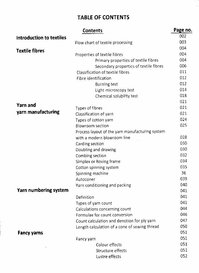
TABLE OF CONTENTS
Contents
Flow chart of textile processingIntroduction to textiles
Textile fibres
Page no.002003004004004006011O12012014018021O21
Properties of textile fibresPrimary properties of textile fibresSecondary properties of textile fibres
Classification of textile fibresFibre identification
Burning testLight microscopy testChemical solubility test
Types of fibresClassification of yarnTypes of cotton yarnBlowroom sectionProcess Iayout of the yarn manufacturing systemwith a modern blowroom IineCarding sectionDoubling and drawingCombing sectionSimplex or Roving frameCotton spinning systemSp i n n i n g mach i neAutoconerYarn conditioning and packing
DefinitionTypes of yarn countCalculations concerning countFormulae for count conversionCount calculation and denotion for pIy yarnLength calculation of a cone of sewing thread
Yarn andyarn manufaeturing 021
024025
02803003003203403536039040041041041
Yarn num bering system
044046O47050051051051051052
Fanc# YarnsFancy yarn
Colour effectsStructure effectsLustre effects
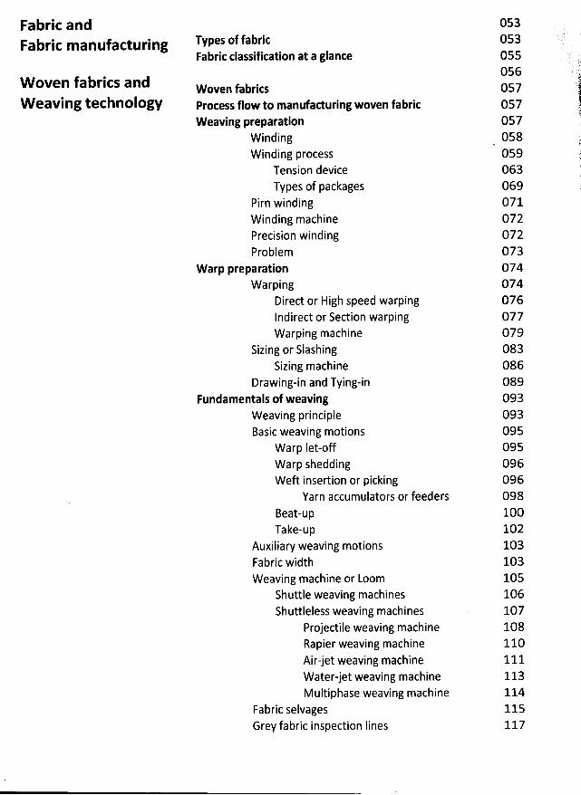
Fabric andFabric m anufacturing
W oven fabrics andW eaving technology
Types of fabricFabric classifitation at a glanee
W oven fabriesProeess flow to manufaduring woven fabricW eaving preparation
WindingWinding process
Tension deviceTypes of packages
Pirn windingWinding machinePrecision windingProblem
W arp preparationW arping
Direct or High speed warpingIndirect or Section warpingW arping machine
Sizing or SlashingSizing machine
Drawing-in and Tying-inFundamentals of weaving
Weaving principleBasic weaving motions
Warp Iet-offWarp sheddingWeft insertion or picking
Yarn accumulators or feedersBeat-upTake-up
Auxiliary weaving motionsFabric widthWeaving machine or Loom
Shuttle weaving machinesShuttleless weaving machines
Projectile weaving machineRapier weaving machineAirjet weaving machineWater-jet weaving machineM ultiphase weaving machine
Fabric selvagesGrey fabric inspection Iines
053053055056057057057058059063069071072072073074074076077079083086089093093095095096096098100102103103105106107108110111113114115117
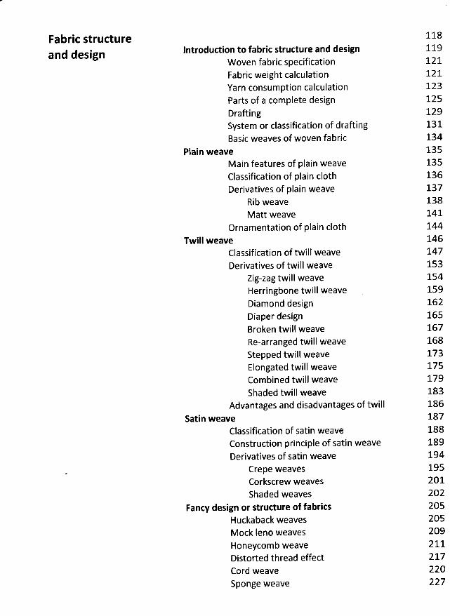
Fabric structureand design lntrodurtion to fabric strueture and design
W oven fabric specificationFabric weight calculationYarn consumption calculationParts of a complete designDraftingSystem or classification of draftingBasic weaves of woven fabric
Plain weave
118119121121123125129131134135135136137138141144146147153154159162165167168173175179183186187188189194195201202205205209211217220227
Main features of plain weaveClassification of plain c10thDerivatives of plain weave
Rib weaveM att weave
Ornamentation of plain (10thTwill w eave
Classification of twill weaveDerivatives of twill weave
Zig-zag twill weaveHerringbone twill weaveDiamond designDiaper designBroken twill weaveRe-arranged twill weaveStepped twill weaveElongated twill weaveCombined twill weaveShaded twill weave
Advantages and disadvantages of twillSatin weave
Classification of satin weaveConstrudion principle of satin weaveDerivatives of satin weave
Crepe weavesCorkscrew weavesShaded weaves
Fancy design or structure of fabritsHuckaback weavesMock Ieno weavesHoneycomb weaveDistorted thread e/ectCord weaveSponge weave
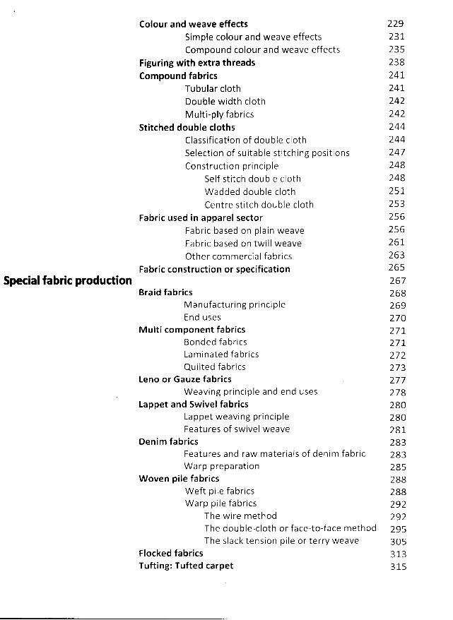
Colour and weave effectsSimple colour and weave effectsCompound colour and weave effects
Figuring with extra threadsCompound fabrics
Tubular c10thDouble width c10thMulti-ply fabrics
Stitched double clothsClassification of double c10thSelection of suitable stitching positionsConstruction principle
Self stitch double c10thW added double c10thCentre stitch double c10th
Fabric used in apparel sectorFabric based on plain weaveFabric based on twill weaveOther com mercial fabrics
Fabric construction or specificationspetial fabrit produdion
Braid fabricsM anufacturing principleEnd uses
M ulti com ponent fabricsBo n d e d f a b ri cs
2292312352382412412422422442442472482482512532562562612632652672682692702712 7 1
Lam inated fabrics 272Quilted fabrics 273
Leno or Gauze fabrics 277W eaving principle and end uses 278
Lappet and Sw ivel fabrics 280Lappet weaving principle 280Features of swivel weave 281
Denim fabrics 283Features and raw m ateriais of denim fabric 283W arp preparation 285
W oven pile fabrics 288W eft pile fabrics 288W arp pile fabrics 292
The w ire m ethod 292The doubIe-cloth or face-to-face m ethod 295The slack tension pile or terry weave 305
Flocked fabrics 313Tufling: Tufted carpet 315
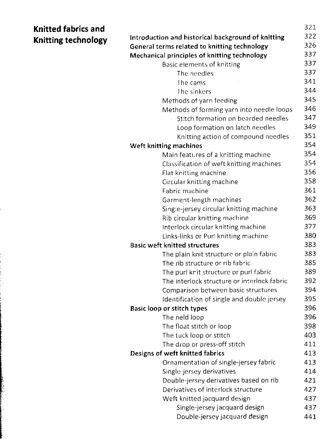
Knitted fabrics andKnitting technology Introduction and historical background of knitting
General term s related to knitting technologyM echanical principles of knitting technology
Basic elements of knittingTh e n e ed 1 e sTh e ca m sThe sinkers
M ethods of yarn feedingM ethods of form ing yarn into needle Ioops
Stitch formation on bearded needlesLoop formation on Iatch needlesKnitting action of com pound needles 351
W eft knitting m achines 354Main features of a knitting machine 354Classification of weft knitting machines 354Flat knitting m achine 356Circular knitting m achine 358Fa b ri c m a ch i n e 36 1Garment-length m achines 362Single-jersey circular knitting machine 363Rib circular knitting machine 369Interlock circular knitting m achine 377Links-links or Purl knitting machine 380
Basic weft knitted structures 383The plain knit structure or plain fabric 383The rib structure or rib fabric 385The purl knit structure or purl fabric 389The interlock structure or interlock fabric 392Com parison between basic structures 394Identification of single and double jersey 395
Basic Ioop or stitch types 396The held loop 396The float stitch or Ioop 398The tuck Ioop or stitch 403The drop or press-off stitch 411
Designs of weft knitted fabrics 413
Ornamentation of single-jersey fabric 413Single-jersey derivatives 414Double-jersey derivatives based on rib 421Derivatives of interlock structure 427Weft knitted jacquard design 437
Single-jersey jacquard design 437Double-jersey jacquard design 441
322326337337337341344345346347349
t. ,,yy;l ))). %-
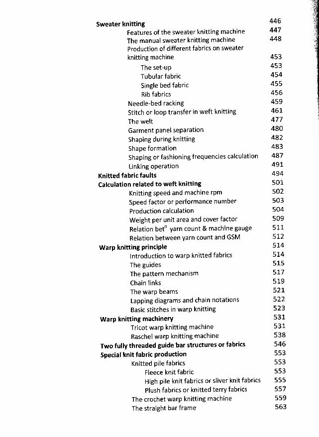
Sweater knitting 446 )lt'. t)(
Features of the sweater knitting machine 447 tyThe manual sweater knitting machine 448 tl@
.< 41
Production of different fabrics on sweater t'knitting machine 4s3 è
'7
The set-up 453 )Tubular fabric 454Single bed fabric 455 è
Rib fabrics 456Needle-bed racking 459 .
Stitch or loop transfer in weft knitting 461 jThe welt 477 @
i'Garment panel separation 480 )Shaping during knitting 482 i
r'
Shape formation 483Shaping or fashioning frequencies calculation 487Linking operation 491
Knitted fabric faults 494Calculation related to weft knitting 501
Knitting speed and machine rpm 502Speed factor or pedormance number 503Production calculation 504W eight per unit area and cover factor 5O9Relation beto yarn count & machine gauge 511Relation between yarn count and GSM 512
W arp knitting principle 514lntroduction to warp knitted fabrics 514The guides 515The pattern mechanism 517Chain finks 519The warp beams 521Lapping diagrams and chain notations 522Basic stitches in warp knitting 523
W arp knitting maehinery 531Tricot warp knitting machine 531Raschel warp knitting machine 538
Two fully threaded guide bar structures or fabrics 546Spetial knit fabric production 553
Knitted pile fabrics 553Fleece knit fabric 553High pile knit fabrics or sliver knit fabrics 555Plush fabrics or knitted terry fabrics 557
The crochet warp knitting machine 559The straight bar frame 563
Netting or net fabricsLace fabrics
Nonw oven fabrics Raw materialsW eb formationW eb bondingFinishingCharacteristics and uses of nonwoven fabricsSpecialty nonwoven products
Preparatory process or pre-dyeing treatmentsSingeingDesizing and ScouringBleachingMercerizingHeat settingElastic fabricW ashingDrying
Dyeing
568570579579580583588589590591592593594595596598599600
Textile dyeing, printingand finishing
605612613615619621622623624627
Preparation and dyeing machineryAutoclavesW inch dyeing machineJiggers
DyestuffsPrinting
Printing principlePrinting processes
Functional finishingM echanical finishing treatmentsChemical finishing treatments
630631640
Acknowledgem ents
Grateful acknowledgements are made to many of my friends, colleagues and dear studentswho have relentlessly encouraged me to write this kind of a book and read different chapter ofthis book, given encouragement and very helpful criticism.
Specially, I would Iike to show a huge appreciation to my beloved wife Sumona and my Iittlegirls Hafsa, Sumaia and Eusha. W ithout their support and patience l would never have beenable to finish this work.
02
INTRODUC ION TO TEXTILES
The word ''textile'' originally applied only to woven fabrics, now generally applied to fibres,
yarns, or fabrics or products made of fibres, yarns or fabrics. The term textile originatesfrom the Iatin verb texere - to weave - but, as the Textile Institute's Terms and DefinitionsGlossary explains, it is now /'a general term applied to any manufacture from fibres
,filaments or yarns characterized by flexibility
, fineness and high ratio of Iength tothickness''
Textiles, especially fabric is the fundamental component of a readymade garment, because
it is the basic raw material of a garment. So it is important to know the manufacturingsequence of fabric from fibre. The quality product is the main goal at present time
, W ithoutknowledge of Textile manufacturing i.e. fibre, yarn and fabrics it is impossible to maintainthe quality of a garment. Before elaborating on whole process of grey fabric manufacturinglet us look on what is textile fibre, yarn and fabric and what are the process flow chart ofTextile Manufacturing can be described.
. Textile:
A term originally appbied only to woven fabrics, but the terms textile and the pluraltextiles are now also applied to fibres, filaments and yarns, natural and manufactured,and most products for which these are a principal raw materiai.
* Textile Fibre:
Any substance, natural or manufactured, with a high Iength to width ratio and withsuitable characteristics for being processed into fabric; the smallest component
, hair Iikein nature, that can be separated from a fabric.
@ Yarn:
An assemblage of fibres that is twisted or laid together so as to form a continuousstrand that can be made into a textile fabric. So a yarn is a strand of natural or manmade fibres or filaments that have been twisted or grouped together for use in weaving
,
knitting, or other methods of constructing textile fabrics. The type of yarn to bemanufactured will depend on the fibres selected; the texture, or hand, of the fabric tobe made; and qualities such as warmth, resiliency, softness, and durability required inthe fabric's end uses.
q'
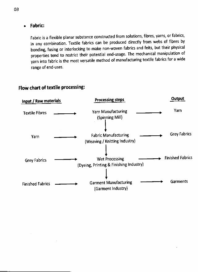
@ Fabrk:
Fabric is a ffexible pdanar substance construded from solutions, fibres, yarns, or fabrics,in any combination. Textile fabrics can be produced directqy from webs of fibres bybonding, fusing or interlocking to make non-woven fabrics and felts, but their physicalproperties tend to restrict their potential end-usage. The mechanical manipulation ofyarn into fabric is the most versatile method of manufacturing textile fabrics for a wide
range of end-uses.
FIoW chart of textile processing:
lnput / Raw materials
Textile Fibres
Protessing steps Output
Yarn
Grey Fabrics
Finished Fabrics
Yarn Manufacturing(Spinning MiII)
Yarn
Fabric Manufacturing(Weaving / Knitting Industry)
Grey Fabrics
Wet Processing Finished Fabrics
(Dyeing, Printing & Finishing Industry)
Garment Manufacturing Garments
(Garment Industry)
04
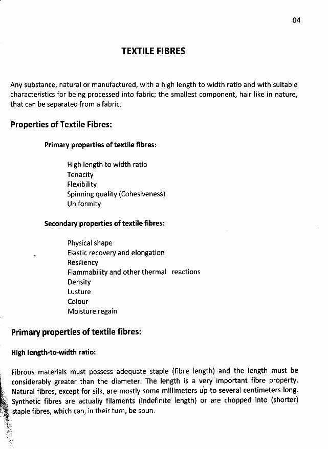
TEXTILE FIBRES
Any substance, natural or manufactured, with a high Iength to width ratio and with suitablecharacteristics for being processed into fabric; the smallest component, hair Iike in nature,that can be separated from a fabric.
Properties of Textile Fibres:
Primary properties of textile fibres:
High Iength to width ratioTenacityFlexibilitySpinning quality (Cohesiveness)Uniformity
Setondary properties of textile fibres:
Physical shapeElastic recovery and elongationResiliencyFlammability and other thermal reactionsDensityLustureColourMoisture regain
Prim ary properties of textile fibres:
High Iength-to-width ratio:
; Fibrous materials must possess adequate staple (fibre' considerably greater than the diameter. The length ist Natural fibres, except for silk, are mostly some millimeters(-tt Synthetic fibres are actually filaments (indefinite Iength)(: ' )j .( ?: staple fibres, which can, in their turn, be spun.E
( .. .CJLJ -. lh 'jk
. .yyj) l Lï' .:. ... .j....
Iength) and the Iength must bea vew im portant fibre property.u' to several centimeters Iong.p
or are chopped into (shorter)
06
--w-jujjje
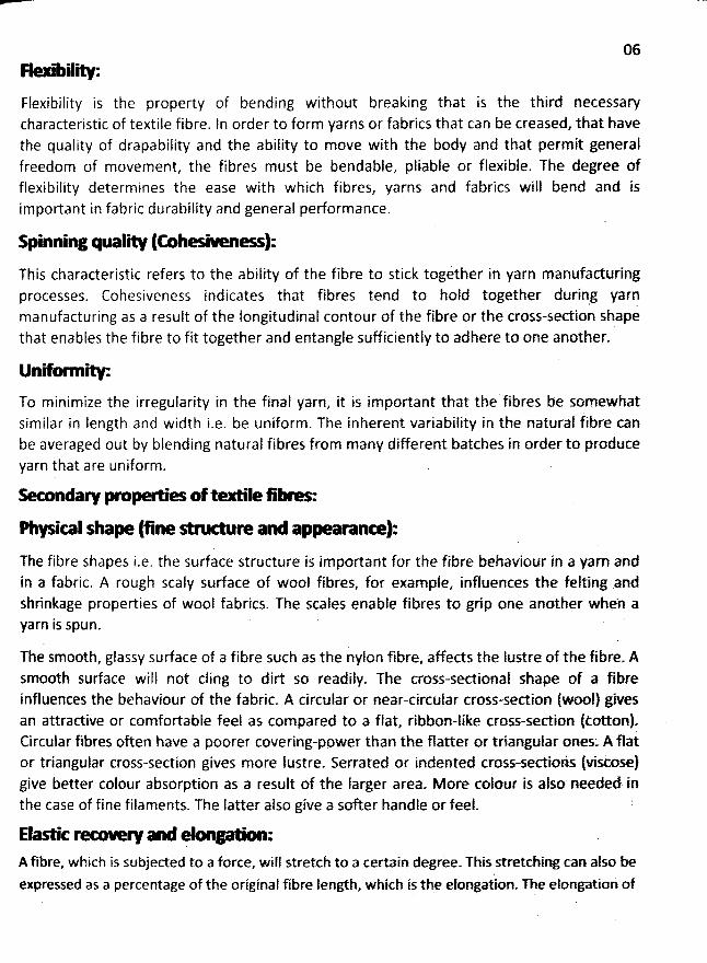
Flexibility is the property of bending without breaking that is the third necessawcharacteristic of textile fibre. In order to form yarns or fabrics that can be creased, that havethe quality of drapability and the ability to move with the body and that permit generalfreedom of movement, the fibres must be bendable, pliable or flexible. The degreq offlexibility determines the ease with which fibres, yarns and fabrics will bend and isimportant in fabric durability and general performance.
Spinninz qualiW (fnh-WR*--Q):This charaderistic refers to the ability of the fibre to stick together in yarn manufaduringprocesses. Cohesiveness indicates that fibres tend to hold together during yarnmanufacturing as a result of the longitudinal contour of the fibre or the cross-section shapethat enables the fibre to fit together and entangle sufficiently to adhere to one another-
Un' i* :To minimize the irregularity in the final yarn, it is important that the' fibres be somewhatsimilar in length and width i.e. be uniform. The inherent variabilit'y in the natural tibre canbe averaged out by blending natural fibres from many different batches in order to produceyarn that are uniform.
W onzaa - 'e oftoe lle & -' ':
* 0101 shaN (sne *n* .* a ' ap- o- ):The fibre shapes i.e. the sudace struclure is important for the fibre behaviour in a yarn andin a fabric. A rough scaly sudace of wool fibres, for example, ihfluences the feltingrandshrinkage properties of wool fabrics. The scales enable fibres to grip one another whe'n ayarn is spun.
The smooth, glassy sudace of a fibre such as the nylon fibre, affeds the lustre of the fibre-Asmooth sudace will not cling to dirt so readily. The cross-sectional shape of a fibre
influences the behaviour of the fabric. A circular or near-circular cross-section (wool) givesan attradive or comfortable feel as compared to a flat, ribbon-like cross-section lèottonl-Circular fibres often have a poorer covering-power than the flatter or triangular ones: A flat
or triangular cross-section gives more Iustre. Serrated or indented cross-sectio/s (viscose)give better colour absorption as a result of the Iarger area. M ore colour is also needed inthe case of fine filaments. The latter also give a softer handle or feel. :
Elao-c and - :
A fibre, which is subjeded to a force, will stretch to a certain degree- This stretching can also beexpressed as a percentage of the original fibre lenglh, which is the elongation- The elongatio: of
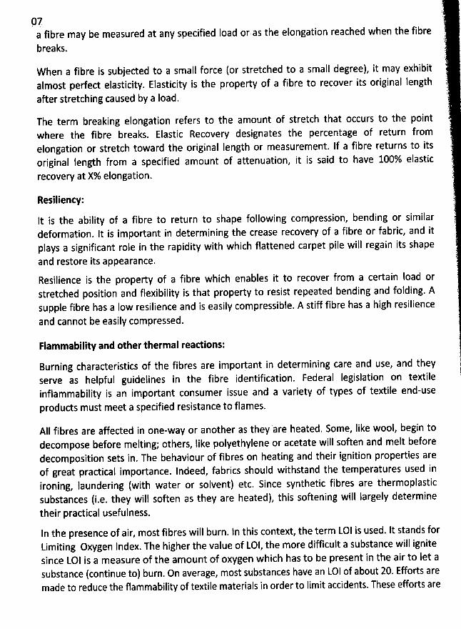
97fibre may be measured at any specified load or as the elongation reached when the fibrea
breaks.
When a fibre is subjeded to a small force (or stretched to a small degree), it may exhibitalmost pedect elasticity. Elasticity is the property of a fibre to recover its original length
after stretching caused by a Ioad.
The term breaking elongation refers to the amount of stretch that occurs to the pointwhere the fibre breaks. Elastic Recovery designates the percentage of return fromelongation or stretch toward the original Iength or measurement. If a fibre returns to itsoriginal length from a specified amount of attenuation, it is said to have 100% elastic
recovew at X% elongation.
Resilienty:
lt is the ability of a fibre to return to shape following compression, bending or similardeformation. It is important in determining the crease recovery of a fibre or fabric, and itplays a significant role in the rapidity with which flattened carpet pile will regain its shape
and restore its appearance.
Resilience is the property of a fibre which enables it to recover from a certain Ioad orstretched position and flexibility is that property to resist repeated bending and folding. Asupple fibre has a low resilience and is easily compressible. A stiff fibre has a high resilienceand cannot be easily compressed.
Flammability and other thermal readions:
Burning characteristics of the fibres are important in determining care and use, and theyserve as helpful guidelines in the fibre identification. Federal Iegislation on textileinflammability is an important consumer issue and a variety of types of textile end-use
products must meet a specified resistance to flames.
AII fibres are affected in one-way or another as they are heated. Some, Iike wool, begin todecompose before melting; others, Iike polyethylene or acetate will soften and melt beforedecomposition sets in. The behaviour of fibres on heating and their ignition properties areof great practical importance. Indeed, fabrics should withstand the temperatures used in
ironing, laundering (with water or solvent) etc. Since synthetic fibres are thermoplasticsubstances (i.e. they will soften as they are heated), this softening will Iargely determinetheir practical usefulness.
In the presence of air, most fibres will burn. ln this context, the term LOI is used. It stands forLimiting Oxygen Index. The higher the value of LOI, the more difficult a substance will ignitesince LOI is a measure of the amount of oxygen which has to be present in the air to let a
substance (continue to) burn. On average, most stlbstances have an LOI of about 20. Efforts aremade to reduce the flammability of textile materials in order to Iimit accidents. These efforts are
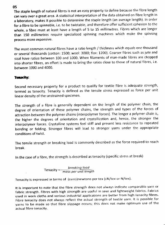
05The staple Iength of natural fibres is not an easy property to define because the fibre Iengthcan vary over a great area. A statistical interpretation of the data obtained on fibre length ina Iaboratory, makes it possible to determine the staple Iength (an average length). ln orderfor a fibre to be spinnable, i.e. to be twistable, and therefore offer sufficient cohesion to thewhole, a fibre must at least have a Iength of 5 to 15 millimetres. Fibres which are Iongerthan 150 millimetres require specialized spinning machines which make the spinningrocess m ore expensive. 'p
The most common natural fibres have a ratio Ienglh / thickness which equals one thousandor several thousands (cotton: 1500,' wool: 3000; flax: 1200). Coarser fibres such as jute andsisal have ratios between 100 and 1000. W hen filaments of man-made fibres are choppedinto shorter fibres, an effort is made to bring the ratios close to those of natural fibres, i.e.
between 1000 and 4000.
T *
Second necessaw property for a product to qualify for textile fibre is adequate strength,termed as tenacity. Tenacity is defined as the tensile stress expressed as force per unit
Iinear density of the unstrained specimen.
The strength of a fibre is generally dependent on the length of the polymer chain, thedegree of orientation of these polymer chains, the strength and types of the forces of
attraction between the polymer chains (interpolymer forces). The Ionger a polymer chain is,the higher the degrees of orientation and crystallization and, hence, the stronger theinterpolymer forces. Crystalline systems feel stiff and present less resistance to repeatedbending or folding. Stronger fibres will Iead to stronger yarns under the appropriate
conditions of twist.
The tensile strength or breaking load is com monly described as the force required to reach
break.
ln the case of a fibre, the strength is described as tenacity (specific stress at break)
breuking IoadTenacity = / tttm ass per unit enq
Tenacity is expressed in terms of (centilnewtons per tex (cN/tex or N/tex).
lt is im portant to note that the fibre strength does not always indicate com parable yarn orfabric strength. Fibres with high strength are useful in seer and Iightweight fabrics. Fabricsused in w ork cloths and various industrial applications are better from high tenacity fibres.Fibre tenacity does not always reflect the actual strength of textile yarn. It is possible foryarns to be m ade so that fibre slippage occurs; this does not m ake optim um use of the
actual fibre tenacity.
0'8
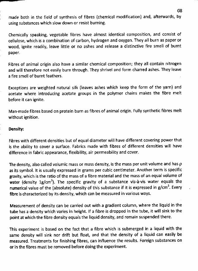
made both in the field of synthesis of fibres (chemical modification) and, afterwards, byusing substances which sfow down or resist burning.
Chemically speaking, vegetable fibres have aimost identical composition, and consist ofcellulose, which is a combination of carbon, hydrogen and oxygen. They aIl burn as paper orwood, ignite readily, Ieave Iittle or no ashes and release a distinctive fire smell of burnt
Paper.
Fibres of animal origin also have a similar chemical composition; they aII contain nitrogenand will therefore not easily burn through. They shrivel and form charred ashes. They Ieavea fire smell of burnt feathers.
Exceptions are weighted natural silk (Ieaves ashes which keep the form of the yarn) andacetate where introducing acetate groups in the polymer chains makes the fibre melt
before it can ignite.
Man-made fibres based on protein burn as fibres of animal origin. Fully synthetic fibres melt
without ignition.
Density:
Fibres with different densities but of equal diameter will have different covering power thatis the ability to cover a surface. Fabrics made with fibres of different densities will havedifference in fabric appearance, flexibility, air permeability and cover.
The density, also called volumic mass or mass density, is the mass per unit volume and has pas its symbol. It is usually expressed in grams per cubic centimeter. Another term is specificgravity, which is the ratio of the mass of a fibre material and the mass of an equal volume of
3 The specific gravity of a substance vis-à-vis water equals thewater (density lg/cm ).3numerical value of the (absolute) density of this substance if it is expressed in g/cm . Every
fibre is characterized by its density, which can be measured in various ways.
Measurement of density can be carried out with a gradient colum n, where the Iiquid in thetube has a density which varies in height. If a fibre is dropped in the tube, it will sink to thepoint at which the fibre density equals the Iiquid density, and remain suspended there.
This experiment is based on the fact that a fibre which is submerged in a Iiquid with thesame density will sink nor drift but float, and that the density of a Iiquid can easily bemeasured. Treatments for finishing fibres, can influence the results. Foreign substances onor in the fibres must be removed before doing the experiment.
09
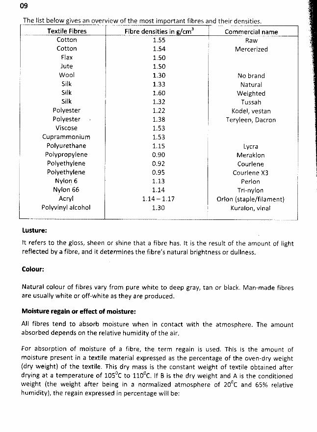
The Iist below gives an overview of the most important fibres and their densities.Textile Fibres Fibre densities in g/cm3 Commercial name
Cotton 1.55 RawCotton 1.54 M ercerizedFlax 1.50Jute 1.50W ool 1.30 No brandSilk 1.33 NaturalSilk 1.60 W eightedSilk 1.32 Tussah
Polyester 1.22 Kodel, vestanPolyester 1.38 Teryleen, DacronViscose 1.53
Cupram m onium 1.53Polyurethane 1.15 LycraPolypropylene 0.90 MeraklonPolyethylene 0.92 CourlenePolyethylene 0.95 Courlene X3Nyloq 6 1.13 PerlonNylon 66 1.14 Tri-nylon
Acryl 1.14 - 1.17 Orlon (staple/filament)Polyvinyl alcohol 1.30 Kuralon, vinal
Lusture:
lt refers to the gloss, sheen or shine that a fibre has. It is the result of the amount of Iightreflected by a fibre, and it determines the fibre's natural brightness or dullness.
Colour:
Natural colour of fibres vary from pure white to deep gray. tan or black. Man-made fibresare usually white or off-white as they are produced.
Moisture regain or effed of moisture:
AIl fibres tend to absorb moisture when in contact with the atmosphere. The amountabsorbed depends on the relative humidity of the air.
For absorption of moisture of a fibre, the term regain is used. This is the amount ofmoisture present in a textile material expressed as the percentage of the oven-dry weight(dry weight) of the textile. This dry mass is the constant weight of textile obtained after
OC to 1100c If B is the dry weight and A is the conditionëddrying at a temperature of 105 .
() j tiveweight (the weight after being in a normalized atmosphere of 20 C and 65% re ahumidity), the regain expressed in percentage will be:
) .tII.
'
E'
X
11
*
1
*
ïip
'
i: hj '
! Another relevant term;
t).i':; . . .ë : .
Moisture Regain A - B-- x100B
is moisture content and, expressed in percentage, is:
Moisture content A - Bx l00
A
10
The moisture content is the mass of moisture in a fibre and is expressed as a percentage ofthe total weight. It is a measure of the amount of water held under any particular set ofcircumstances. The moisture content is always Iower than the regain.
Fibres can present great variations in the amount of moisture they will absorb. W ool has aregain of 16% cotton of 8.5%, acetate only of 6%. Fibres, which can absorb sufficient moisture
,t itable for processing into clothing because' they will absorb perspiration from theare mos su
body and will hold considerable amounts of moisture without feeling clammy. The ability of a
fibre to a bsorb moisture will also affect the processing and finishing of fibres. Fibres which easilyabsorb moisture, will therefore Iet dyestuffs penetrate more easily during the dyeing process.Synthetic fibres, which often absorb little moisture, are easily washed and dried by comparisonwith fibres, which absorb a lot of moisture. On the other hand
, this entails the phenomenon ofelectrostatic charging.
The strength of a fibre is affected significantly by the water it absorbs. Fibres, which easilyabsorb moistu re, will usually be Iess strong when wet (except for flax an cotton) and will presentincreased elongation at break. One should also realize that absorption of moisture can alsomake the fibre swell to a considerable degree, w hich is im portant for fixating dyestuffs.
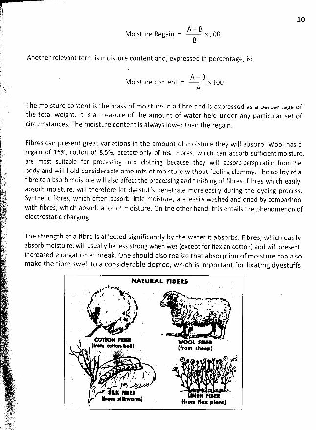
NM URAL FIBER:.*.ewtA'
. . & .* . Y< *Pr . j l . 'a .w . .. vy * *.. - . ij PX * *.> * e* . *' .. , . t k; . . < .% - *. . . j . l
. K.. . .A z. , - . . j -4/. w ! vv. , +,w . k. . à .. 1k R . e t&. / 4 . * r *f : t * ' J '. . 44 .
. *
W*G FI*ER.. (e o4) tjroo w..p), . t..n . . . .1 w. L ' > : . -'-. . . y: . k. . . . ; . . j . . . sj 1:. . 7 q . . : . . gy
#. ..... . .;. . ,m . . %. ' > . . k . #- y : . . . :. ..j pk.. , 4. . , zfk , . : a,.,.. .' .. J .. p ' # . # . e. e .t e j ' ? :' < I .' / . 'f. .
t4 w, ) m ,4r/f .x. s.u - . >! uN-(e - #Ikw@-)
w.. . pusvjLï .
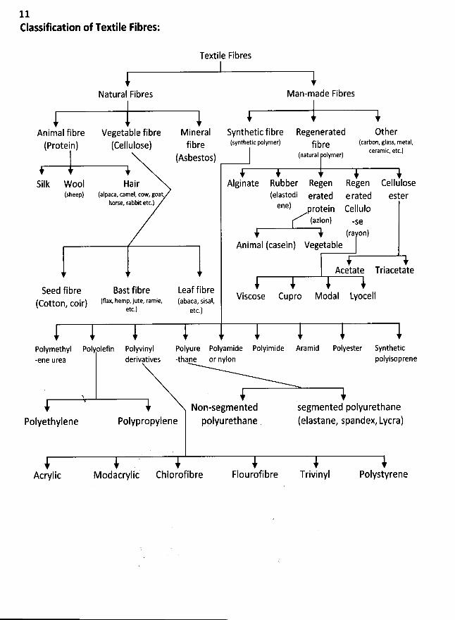
11Elassification of Textile Fibres:
Textile Fibres
Natural Fibres
Animal fibre Vegetable fibre Mineral Synthetic fibre Regenerated OtherProtein) (cellulose) fibre (SYnthetic polymer) fibre (carbon,glass, metal,(
ceramic, etc.)Asbestos) tnatural polymer)(
Silk Wool Hair Alginate Rubber Regen Regen Cellulose(sheep) (alpaca, camel, cow, goat, (elastodi erated e r3ted ester
horse, rabbit etc.) ene) rotein cellulop
(azlon) -se(ra on)
Animal (casein) Vegetable1 1
Acetate Triacetate
Seed fibre Bast fibre Leaf fibre Viscose Cupro Modal Lyocell(cotton coir) tflax- hemp-jute, ramie, (auaca, sisal#
etc.) etc.)
i i i i t t t tPolymethyl Polyolefin Polyvinyl Polyure Polyamide Polyimide Aramid Polyester Synthetic-ene urea derivatives -thane or nylon polyisoprene
N
Non-segmented segmented polyurethanePolyethylene Polypropylene pplyurethane (elastane, spandex, Lycra)
i ) ) ) )Acrylic Modacrylic Chlorofibre Flourofibre Trivinyl Polystyrene
Man-made Fibres
12
j Fibre Identification:C f the study of textile science
. At one time,i The identification of textile fibres is a vew important part ol Ie fibre identification was a relatively easy task; most consumers could tell by appearance and handsimp
whether a fabric was cotton, wool, silk, or Iinen. Once the first manmade fibres were introduced, theprocess became a bit more difficult. Consumers usually could identify the fibre composition of fabricsmade of 100 percent rayon or acetate, but blends of some fibres were difficult to identify. As morefibres were introduced, the task became progressively more difficult. Today, sophisticatedtechniques are usually required for accurate fibre identification.
The purpose of the Textile Fibre Products Identification Act was to provide inform ation on fibrecontent of textiles at the point of sale. Consumers were at once relieved of the responsibility toidentify fibre content of items they purchased; howeverz professionals working with textileproducts still m ust be able to identify fibres accurately. Such individuals include retailers whosuspect some textile products they bought for resale have been Iabeled inaccurately; customsosicials who m ust identify imported fibres; dry cleaners w ho m ust clean an item from which aIIthe labels have been removed; extension hom e econom ists who are asked to help solve aconsumer's problem with a textile product; and forensic scientists who m ust use a textile
sam ple to help solve a crim e.
For most individuals, the only information needed is a qualitative analysis of fibre content: whatfibre or fibres are present in this product? For others, a quantitative analysis of the product isalso im portant: in w hat percentages are the fibres present? W ith the num bers of fibresavailable today and the variety of blends being produced, neither analysis is easy.
M ethods for qualitative identification of fibres include such procedures as burning tests,m icroscopy, density determ ination, m oisture regain analysis, dye staining, chem ical solubility,melting point determination, infrared spectroscopy, and chrom atography. Sim plified versionsof the first six procedures are relatively easy to pedorm in most Iaboratories. They require theuse of a drying oven, an analytical balance sensitive to 0.005 gram, a com pound lightmicroscope capable of 200 x magnification, laboratory glassware, and a supply of chemicals.
A. Burning Test:The burning test is a good prelim inary test for categorizing fibres. Observation of burningprovides information on behavior in a flame, smoke generation, odor during burning, andash or residue. lt never should be used as the only method of identifying a fibre, but itprovides valuable information that may be used with other evidence to m ake a positiveidentification of an unknown fibre.
Blends of fibres are difficult to test using this procedure. Tbe reaction of the predom inantfibre may m ask the presence of a second fibre, which could have entirely different burningcharacteristics. Finishes, especially flameretardant finishes, can also give misleadinginform ation. Although the test is easy to perform, it does involve the use of an open flame, making itnecessary to observe certain safety precautions. Use a sm all flam e source in an area wherethere is no danger of igniting other materials. A candle in a stable base or a small alcohollamp is preferable to a hand-held m atch. A nonflam mable pad should be used under theburning m aterial to provide protection from molten drip and sm oldering ash. Do not touchash or tweezers while they are still hot.
13p- - ure:
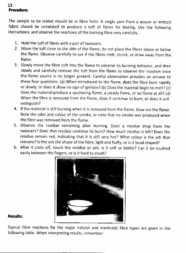
The sample to be tested should be in fibre form . A single yarn from a woven or knittedfabric should be untwisted to produce a tuft of fibres for testing. Use the followinginstructions, and observe the reactions of the burning fibre very carefully.
1. Hold the tuft of fibres with a pair of tweezers.2. M ove the tuft close to the side of the flame; do not place the fibres above or below
the flame. Observe carefully to see if the fibres melt, shrink, or draw away from thef lame .Slowly move the fibre tuft into the flame to observe its burning behavior
, and thenslowly and carefully remove the tuft from the flame to observe the reaction oncethe flame source is no longer present. Careful observation provides an answer tothese four questions: (a) When introduced to the flame, does the fibre burn rapidlyor slowly, or does it show no sign of ignition? (b) Does the material begin to melt? (c)Does the material produce a sputtering flame, a steady flame, or no flame at all? (d)W hen the fibre is removed from the flame, does it continue to burn, or does it selfextinguish?lf the material is still burning when it is removed from the flame, blow out the flame.Note the odor and colour of the smoke, or note that no smoke was produced whenthe fibre was removed from the flame.Observe the residue remaining after burning. Does a residue drop from thetweezers? Does that residue continue to burn? How much residue is Ieft? Does theresidue remain red, indicating that it is still vew hot? W hat colour is the ash thatremains? Is the ash the shape of the fibre, light and fluffy, or is it bead-shaped?
6. After it cools off, touch the residue or ash. Is it soft or brittle? Can it be crushedeasily between the fingers, or is it hard to crush?
Results:
Typical fibre reactions for the major natural and manmade fibre types are given in thefollowing table. W hen interpreting results, remember:
14It is difficult to detect the presence of blends with a burning test. One fibre in ablend may completely mask the proper ties of another fibre.
2. Dyes and finishes affect test results. Flame-retardant finishes are especiallym isI ea d i ng.Coloured fibres, especially those produced with pigments, may retain the colour inthe ash or residue.
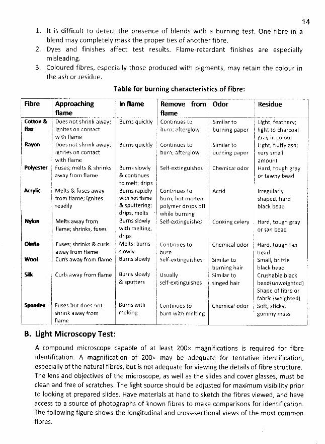
Table for burning characteristics of fibre:
1 Fibre Approaching 1j In flame Remove from 1 Odor l Residue i1 j li
flame !1 flame ,I Cotton & 1 Does not shrink away; Burns quickly Continues to 1 Similar to j Light, feathery;
flax ignites on contact 1 burn; afterglow 1 burning paper j Iight to charcoalj j j jour. ywith flame j gray n co! ! iI I ooes not shrink away; Burns quickly continues to ! similarto 11 Light, fluffy ash; r1
1 i nites on contact t burn; afterglow 11 burning paper 1 vew smallJ g1 with flame ' l amount1 11. Polyester Fuses; melts & shrinks Burns slowly Self-extinguishes Chemical odor Hard, tough grayI( away from flame & continues ; I or tawny bead1 lto melt; drips T t
.( h
'
I 1t t Melts & fuses away Burns rapidly 1 Continues to 1 Acrid IrregularlyI 1j from flame; ignites with hot flame burn; hot molten shaped, hardl dily & Sputtering; polymer drops off black beadrea
drips, melts while burningI I IMelts away from Burns slowly self-extinguishes t Cooking celery ' Hard, tough gray
rflame; shrinks, fuses with melting, : or tan bead
drips0e n Fuses; shrinks & curls Melts; burns continues to Chemical odor Hard, tough tan
away from flame Slowly I burn j beadwte Curls away from flame Burns slowly 1 self-extinguishes i Similar to Small, brittleI l
l b u rn i ng ha i r b I ack b ead&lk curls away from flame Burns slowly Usually Similar to Crushable black
& sputters self-extinguishes singed hair beadlunweighted)Shape of fibre orfabric (weighted)
-2-1 Fuses but does not Burns with l continues to Chemical odor ' Soft, sticky,+shrink away from melting ' burn with melting gummy masslfl a m e
B. Light M icroscopy Test:
A compound microscope capable of at Ieast 200x magnifications is required for fibreidentification. A magnification of 200x may be adequate for tentative identification,especially of the natural fibres, but is not adequate for viewing the details of fibre structure.The Iens and objectives of the microscope, as well as the slides and cover glasses, must beclean and free of scratches. The light source should be adjusted for maximum visibility priorto Iooking at prepared slides. Have materials at hand to sketch the fibres viewed? and haveaccess to a source of photographs of known fibres to make comparisons for identification.The following figure shows the longitudinal and cross-sectional views of the most commonfibres.
15Longitudinal mounts:It is possible to mount a single fibre, but it is Iess frustrating for m ost m icroscopists to useseveral fibres. A minimum of ten fibres is useful when the material to be studied is a blend.Too many fibres on a slide makes it difficult to focus on a single fibre to observe the detailsof its sudace contour. W hen taking a sam ple from a yarn in a fabric, untwist the yarncom pletely to separate tbe fibres. Tbe basic steps for making a Iongitudinal mount are as
follow s.
1. Place a single drop of water, glycerine. or m ineral oiI on the center of the glass'slide.M ineral oiI provides the best definition, but the other m aterials are adequate.
2. Carefully place the fibres in the drop of liquid with the Iength of the fibres parallel to
the Iong dimension of the slide.
3. Place the cover glass lightly over the drop of Iiquid and the specim en. Tap the coverglass gently to rem ove air bubbles.
4. W ith the objective in its highest position, place the slide on tbe stage of them icroscope. Lower the objective carefully before trying to focus the slide. It is veryeasy to damage the objective by scratching it or smearing it with oil.
Focus on low pow er and observe the fibre before focusing on high pow er. Note thegeneral shape of the fibre, then look at it carefully for signs of scales, convolutions,pockmarks, striations' and other features. Look carefully to see if more than one
type of fibre is present.
6. W ith the microscope focused on high power, move the fine adjustment very slowlyto see if variations in surface contour are visible. Again, look carefully to see if more
than one fibre type is present.7. Sketch the fibres as seen through the microscope, then compare your sketch with
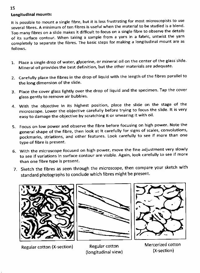
standard photographs to conclude which fibres might be present.
A N 98 . :4 ' '
< ' .- z
* . A
#' >
. Nt
<-
Regular cotton (X-section) Regular cotton(Iongitudinal view)
Mercerized cotton(X-section)
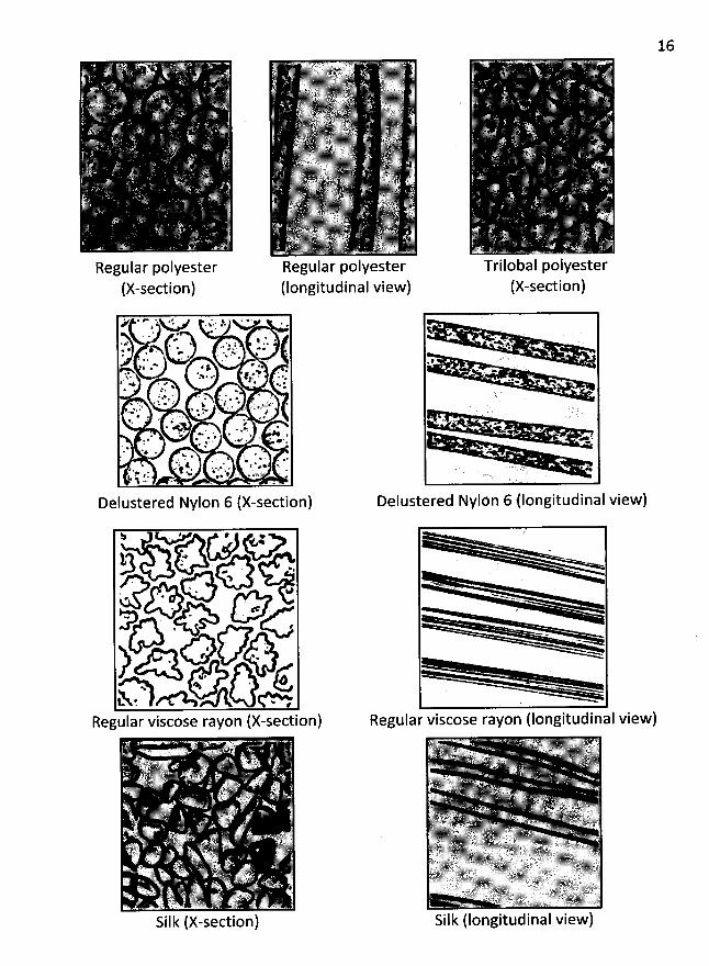
Regular polyester
(X-section)
Delustered Nylon 6 (X-section)
Regular polyester(longitudinal view)
''j.
Trilobal polyester(X-section)
Delustered Nylön 6 flongitudinal view)
w'< .
YN
Regular viscose rayon (longitudinal view)
$ tV : # o ;
$7 ? . ,- '. ' 3
. > N> @e' *
. . .. .
.# .
#
. e%
..,.
**
) .*' . Qw %
'Ill:-----'
'
'''''''''.'-''''k',-. --!r!
'
-.1,-------,------.112:2::7-----------::2111::--------,11.,,
*
-------,--,----''-''---;p1I1I''''-!1IIlk:,.-,-. j''':::;;::ï''''-''''-''''''''''''b-'-'''-''----'-.---'-.
'
.. ---l,,-,
Regular viscose rayon (X-section)
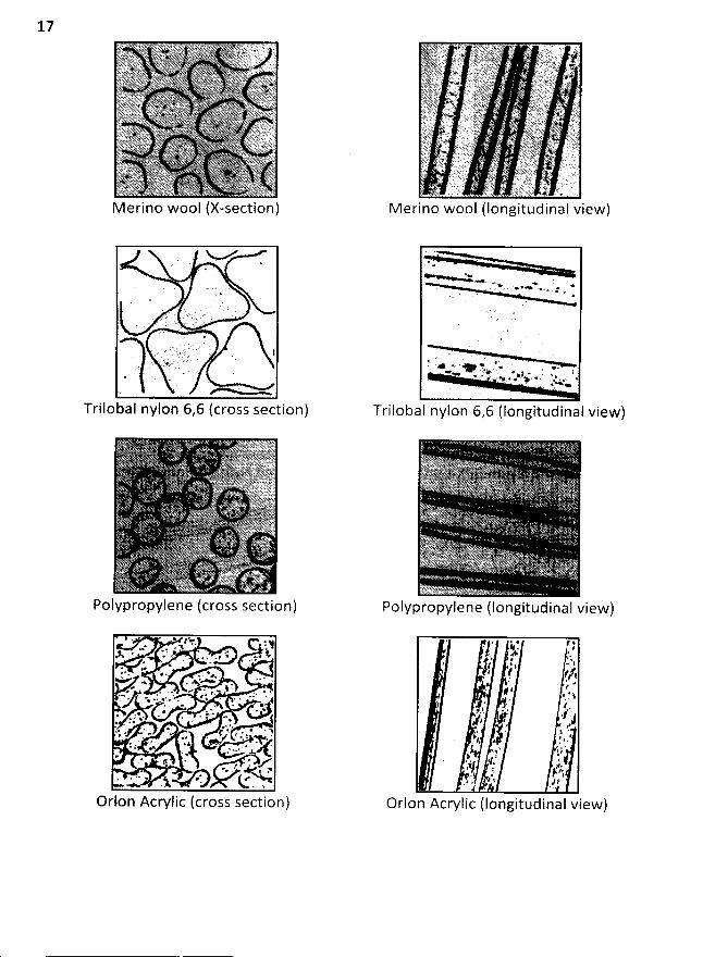
17
. , : ' j' l r ' ' '
- L4ï.nL J -
Trilobal nylon 6,6 (cross section)
Polypropylene (cross section)
Orlon Acrylic (cross section)
. a. ' -.> . . . - . .- L>**+ w>a r
*
-. .* %. . + A * . , ..-.> ,..y. . *. s . . . lw q -D. . + p . x. x #.' y + . > . . x: *.. . .< ,,1.
Tri Io ba I nylon 6,6 (Iongitud 1 naIview)
Polypropylene (longitudinal view)
/. '?.#. . '.. k' I tf' - '1. ! t Jt'
,. jk; e' # I ,*
. $*' . (! :
'
. lê. . 4 )/? , ,, . k
'
.# ' -. j !1. # .' .J# . '. $):.. -,: l..gj. . ;;,: h. 'G /
$ pj, # '
O r I o n A c ry I -1 c ( I o n g 1 t u d -1 n a I v 1 e w )
18
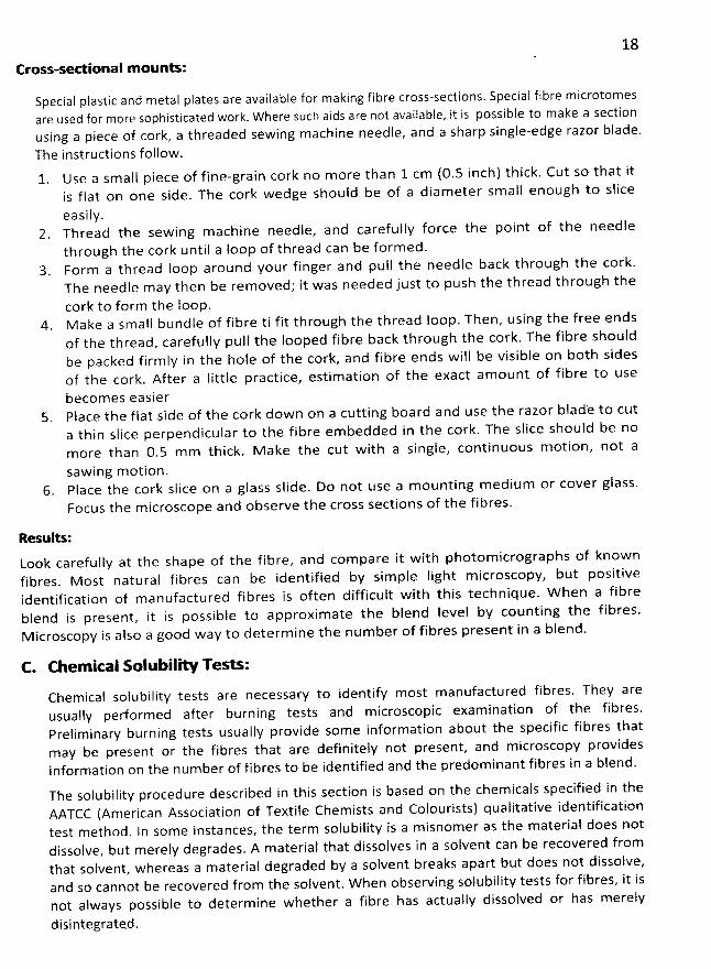
Cross-s<w- ional m ounts:
Special plastic and metal plates are available for making fibre cross-sections. Special fibre m icrotomesare used for more sophisticated work. W here such aids are not available, it is possible to make a sectionusing a piece of cork, a threaded sewing machine needle, and a sharp single-edge razor blade,The instructions follow.1. Use a small piece of fine-grain cork no more than 1 cm (0.5 inch) thick. Cut so that it
is flat on one side. The cork wedge should be of a diam eter sm all enough to slice
easily.Thread the sew ing m achine needle, and carefully force the point of the needlethrough the cork until a Ioop of thread can be form ed.Form a thread Ioop around your finger and pull the needle back through the cork.The needle may then be renhoved; it was needed just to push the thread through thecork to form the Ioop.
4. M ake a small bundle of fibre ti fit through the thread Ioop. Then, using the free endsof the thread, carefully pull the looped fibre back through the cork. The fibre shouldbe packed firm ly in the hole of the cork, and fibre ends wiîl be visible on both sidesof the cork. After a Iittle practice, estim ation of the exact am ount of fibre to use
becom es easier5. Place the flat side of the cork dow n on a cutting board and use the razor blad'e to cut
a thin slice perpendicular to the fibre em bedded in the cork. The slice should be nomore than 0.5 m m thick. M ake the cut with a single, continuous m otion, not a
saw ing m otion.6. Place the cork slice on a glass slide. Do not use a m ounting medium or cover glass.
Focus the m icroscope and observe the cross sections of the fibres.
Resulu :Look carefully at the shape of the fibrez and com pare it with photom icrographs of knownfibres. M ost natural fibres can be identified by sim ple Iight m icroscopy, but positiveidentification of manufactured fibres is often difficult with this technique. W hen a fibreblend is present, it is possible to approxim ate the blend Ievel by counting the fibres.M icroscopy is also a good way to determ ine the num ber of fibres present in a blend.
C. Chemirnl R lubiliw Teeq:Chemical solubility tests are necessary to identify most m anufactured fibres. They areusually performed after burning tests and m icroscopic exam ination of the fibres.Preliminary burning tests usually provide some inform ation about the specific fibres thatmay be present or the fibres that are definitely not present, and m icroscopy providesinformation on the number of fibres to be identified and the predominant fibres in a blend.
The solubility procedure described in this section is based on the chem icals specified in theAATCC (American Association of Textile Chemists and Colourists) qualitative identificationtest method. ln som e instances, the term soiubility is a misnomer as the material does notdissolve, but m erely degrades. A m aterial that dissolves in a solvent can be recovered fromthat solvent, whereas a material degraded by a solvent breaks apart but does not dissolve,and so cannot be recovered from the solvent. W hen observing solubility tests for fibres, it isnot always possible to determine w hether a fibre has actually dissolved or has m erely
disintegrated.
19AIl chemical tests should be conducted in a room with proper ventilation and chemicalsafety protedion devices. The required Material Safety Data Sheet (MSDS) for eachchem ical should be posted in areas where the chemical is used. Although only very smallamounts of chemicals are needed for testing, accidents sometimes happen. Adhere tochemical safety rules in performing fibre identification tests. W ear protective eye goggleswhen using chemical solvents. Organic solvents and heated Iiquids should be used only in afume hood! Follow Iocal laboratory regulations for disposing of used solvents and fibres
.
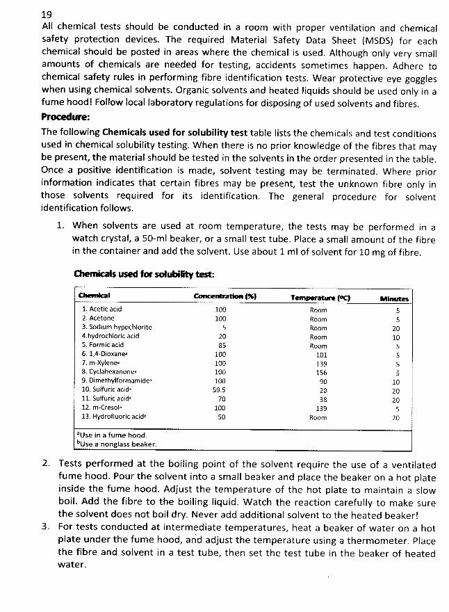
pr- -=ure:
The following Chem icals used for solubility test tabte (ists the chem icals and test conditionsused in chem ical solubility testing. W hen there is no prior knowlédge of the fibres that maybe present, the material should be tested in the solvents in the otder presented in the table.
Once a positive identification is made, solvent tesling may be terminated. W here priorinformation indicates that certain fibres may be present, test the unknown fibre only inthose solvents required for its identification. The general procedure for solventidentification follows.
W hen solvents are used at room temperature, the tests may be performed in awatch cwstal, a 50-mI beaker, or a small test tube. Place a small amount of the fibrein the container and add the solvent. Use about 1 ml of solvent for 10 mg of fibre.
N -x--o js v-aA jw euuyjW Fxl;
(%1 T (Y *.**-..e-1. Acetic acid 10O Room 52. Acetone 100 Room 53. Sodium hypochlorite 5 Room 204.hydrochloric acid 20 Room 105. Formic acid 85 Room 56. l,4-Dioxanea 100 101 57. m-xylenea 10O 139 58. Cyclahexanonea 100 156 59. Dimethylformamidea 100 90 1010. Sulfuric acida 59.5 20 2011. Sulfuric acida 70 38 2012. m-cresola 100 139 513. Hydrofluoric acidb 50 Room 20
ause in a fume hood.buse a nonglass beaker.
2. Tests pedormed at the boiling point of the solvent require the use of a ventilatedfum e hood. Pour the solvent into a small beaker and place the beaker on a hot plateinside the fume hood. Adjust the temperature of the hot plate to maintain a slowboil. Add the fibre to the boiling liquid. W atch the reaction carefully to m ake surethe solvent does not boil dry. Never add additional solvent to the heated beaker!For tests conducted at intermediate tem peratures, heat a beaker of water on a hotIate under the fume hood, an'd adjust the temperature using a thermometer. Placepthe fibre and solvent in a test tube, then set the test tube in the beaker of heatedw ater.
204. W atch the fibre in the Solvent carefully to observe the speed with which it breaks
down and the amount of the material dissolved. Note whether the material actuailydissolves, degrades into small pieces, or forms a plastic mass. lf all fibres are notdissolved in a specific solvent, carefully remove the undissolved fibres. Rinse them inwater, and attempt to dissolve them in another solvent.
Resqlts:
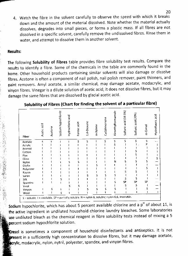
The following Solubility of Fibres table provides fibre solubility test results. Com pare theresults to identify a fibre. Some of the chemicals in the table are commonly found in thehome. Other household products containing similar solvents will also damage or dissolvefibres. Acetone is often a component of nail polish, nail polish remover, paint thinners, andpaint removers. Amyl acetate, a simifar chemical, may damage acetate, modacrylic, andvinyon fibres. Vinegar is a dilute solution of acetic acid; it does not dissolve fibres, but it maydamage the same fibres that are dissolved by glacial acetic acid.
Solubility of Fibres (Chart for findingthe solvent of a particular fibre)
-4 z ; :) g' 7:.s . à . ..a ::z. r à z ! :! z g
72 z :î 78 a z v 2 ! c -; ,g. z q'
.z .r .î ! % 42 < v ï ' d * ez s j .az z '! 'R ucz ww >, a j t! % %s 'RFiber < < tm X t'p izn =
Acetate s s 1 l S s l s s s s S --Acrylic I l 1 I I 1 1 1 s 1 I PAramid I I l l I I 1 l 1 I I 1 1Cotton l I I I 1 I 1 1 s I 1F4a x l I 1 I 4 l I l s j(.5 la ss I l I I I I I I 1 I I sNylon l 1 I s s I I I N S S S ..-.olef i n 1 I 1 I 1 1 s I I l 1 I ..-.Polyester I I I I I I 1 I I 1 I s IRayon l l l I I I 1 1 I s s I Isaran 1 I I 1 I s s s s l l I lSi I k I I s I 1 1 1 I I S S Ispa ndex I I I 1 I I I I s sp s p sp --
- vinal s s l I l l S .S I ..-.
'è; vinyon I S 1 I 1 s s s s l I s ..-.!i,)t' t. 'wool I 1 s I I I I j 1 l I I 1
. )) )')lè s = soluble. I = insoluble. SP = partially soluble. N = nylon 6, solubie; nylon 6,6, insoluble.
HSodium hypochlorite, which has about 5 percent available chlorine and a p of about 11, is the active ingredient in undiluted household chlorine Iaundry bleaches. Some Iaboratoriesisz: ., 2; use undiluted bleach as the chem ical reagent in fibre solubility tests instead of mixing a 5
- -t) 'rpercent sodium hypochlorite solution.?' ' :k-F .@. '.t
.' esol is sometimes a component of household disinfectants and antiseptics. It is not
C sent in a sufficiently high concentration to dissolve fibres, but it may damage acetate,5) )< ;
rylic, modacrylic, nylon, nytril, polyester, spandex, and vinyon fibres.y . ). i4;ky.' ' . i' :).' .
l .. c ' v. ,
21
YARN AND YARN M ANUFAW URING
An assem blage of fibres that is twisted or Iaid together so as to form a continuous strandth
at can be made into a textile fabric. So a yarn is a strand of natural or man-made fibres orfilaments that have been twisted or grouped together for use in weaving, knitting, or othermethods of constructing textile fabrics
. The type of yarn to be manufactured will depend onthe fibres selected; the texture
, or hand, of the fabric to be m ade; and qualities such aswarmth, resiliency, softness, and durabiiity required in the fabric's end uses
.
Types of Fibres:
A$l the textile fibres are classified according to their staple Iength into two categories, sucha
s staple fibre and filament.
staple sbres:
lt has a limited Iength that varies according to the type, such as cotton, wool, jute etc.There are tw
o types of staple fibre, one is short staple fibre another one is Iong stapiefibre. Cotton is mainly short staple fibre and other maximum natural fib
res are longstaple except silk. Silk is only natural fibre that is filament
.
Filament:
lt has continuous Iength that means the Iength of filament is equal to the Iength of yarn.AIl man-made fibres are filament
. M an-made fibres are produced as filament, althoughth
ey used as staple fibres if necessary. So filaments are used as staple fibre but staple
fibres never used as filament.
Classification of Yarn:
Uaee**--H-- of yarn O ing to their struGure:
Yarns may be divided into three types according to their structure as follows:
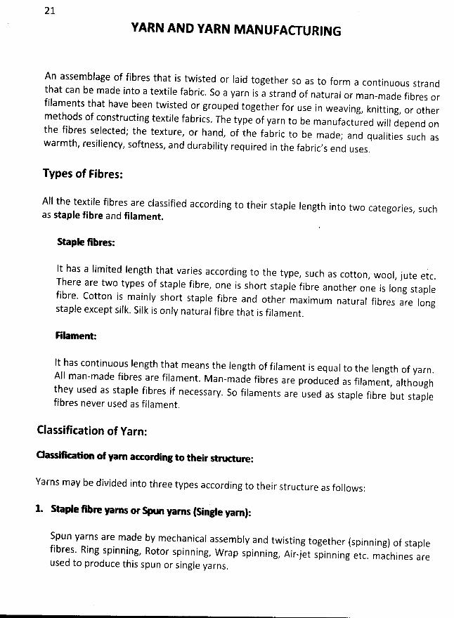
1. Raple 5h> yarns or * un yarns (single yarn):
Spun yarns are made by mechanical assembly and twisting together (spinning) of staplefib
res. Ring spinning, Rotor spinning, W rap spinning, Air-jet spinning etc. machines areused to produce this spun or single yarns
.
' L J 'F ' ''%'Cj ' ' . .
%(. Z. . ' .
Single or Spun yarn
22
j1)$ë;' j ' . . . r, ..,. . . .1é ' '' ''' 'w ' . .x. 'i@ ' '' '' .' ' ' ' ' ' ' q. ' iI' ' 'E ' '' lj . ?L.. ? vu ' ( -% ( y; ..j' y . ) ) z' ( ' 2/: . ' ' ' -717: ' '. a - . -. ....w .( . . . : . . = L ts r e . . . . s.. . ... ( L.. . ..L. .u. . t . a .. .t. .. -
Ring Spun Yarn Rotor Spun Yarn
%
dr...:t ' J .((:2.: . .
Carded cotton (ring) yarn
' . )': o; '. q) ' .' - , .' .:y () . grl. . %' t ' . -. . ' c- 133. .; ? -1F)). ;vf:r# 'r, ;è . . .)-).. .. .-(@ 14.2;)- u.'ik- .13..
Combed cotton (ring) yarn
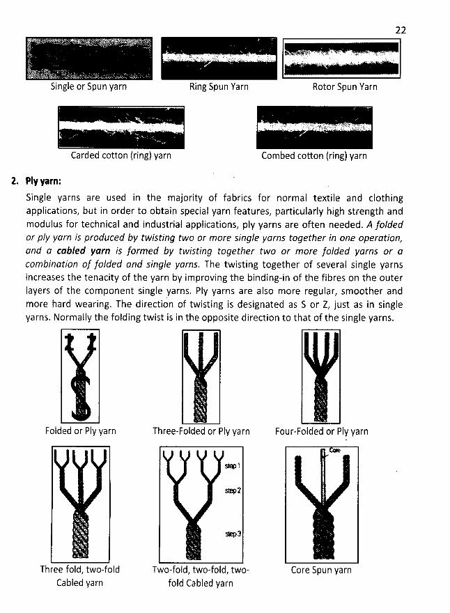
2. Ply yarn:
Single yarns are used in the majority of fabrics for normal textile and clothingapplications, but in order to obtain special yarn features, particularly high strength andmodulus for technical and industrial applications, ply yarns are often needed. A loldedor pIy yarn is produced by twisting two or more single yarns toqether in one operation,
and a cabled yarn is formed by twisting together t-o or more folded yarns or acombination of jolded and single yarns. The twisting together of several single yarnsincreases the tenacity of the yarn by improving the binding-in of the fibres on the outerIayers of the com ponent single yarns. PIy yarns are also more regular, smoother andmore hard wearing. The direction of twisting is designated as S or Z, just as in singleyarns. Normally the folding twist is in the opposite direction to that of the single yarns.
Folded or Fly yarn
. ' . y
Three fold, two-foldCabled yarn
Three-Folded or Fly yarn
so :
* 2
* 3
Two-fold, two-fold, two-fold Cabled yarn
ïFour-Folded or Fly yarn
Core Spun yarn
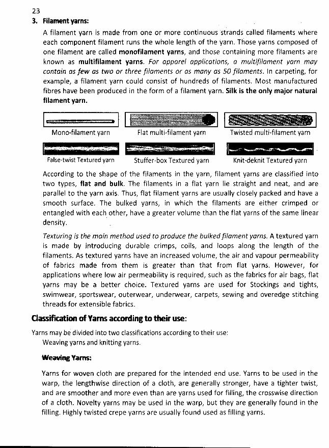
233. Filament yarns:
A filament yarn is made from one or more continuous sirands called filaments whereeach component filament runs the whole Iength of the yarn. Those yarns composed ofone filament are called monofilament yarns, and those containing more fiiaments areknown as multifilament yarns. For apparel applications, a multlhlament yarn maycontain as jew as two or three jilaments or as mlny as 50 hlaments. In carpeting, forexample, a filament yarn could consist of hundreds of filaments, M ost manufacturedfibres have been produced in the form of a filament yarn. Silk is the only major naturalfilament yarn.
Mono-filament yarn
* ( $- :' ' ' ' ''I4 & '. . .. : . ' ' .
Twisted multi-filament yarn
. . ' . . - .
Knit-deknit Textured yarn
1. - vu- 2 . - ' .: t. r J ') w Qw i:'-' .
False-twist Textured yarn
. Qwve 1. . . .' - -J ' 7 .. .. z.'.'- . ' > '''.-'D l . .. Z
Stuffer-box Textured yarn
According to the shape of the fiiaments in the yarn, filament yarns are classified intotwo types, flat and bulk. The filaments in a flat yarn Iie straight and neat, and areparallel to the yarn axis. Thus, flat filament yarns are usually closely packed and have asmooth surface. The bulked yarns, in which the filamentk are either crimped orentangled with each other, have a greater volume than the flat yarns of the same Iineardensity,
Texturinq is the main method used to produce the bulkedfilament yarns. A textured yarnis made by introducing durable crimps, coils, and loops along the Iength of thefilaments. As tertured yarns have an increased volume, the air and vapour permeabilityof fabrics made from them is greater than that from flat yarns. However, forapplications where Iow air permeability is required, such as the fabrics for air bags, flatyarns may be a better choice. Textured yarns are used for Stockings and tights,swimwear, sportswear, outerwear, underwear, carpets, sewing and overedge stitchingthreads for extensible fabrics.
Elaq- œ ofn rns arr- ingto their use:
Yarns may be divided into two classifications according to their use:Weaving yarns and knitting yarns.
W eaing Yam s:
Yarns for woven c10th are prepared for the intended end use. Yarns to be used in thewarp, the lengthwise direction of a c10th, are generally stronger, have a tighter twist,and are smoother and more even than are yarns used for filling, the crosswise directionof a c10th. Novelty yarns may be used in the warp, but they are generally found in thefilling. Highly twisted crepe yarns are usually found used as filling yarns.
24
KnM ing Yarns:
These may be divided into yarns for hand knitting and yarns for machine knitting.Knitting yarns are more slackly twisted than yarns for weaving. Hand knitting yarns aregenerally ply, whereas those for machine knitting can be either single or ply. Thefollowing are some of the yarns used for hand knitting:
1. Knitted worsted: The four-ply all-around yarn used for accessories, for the house,and for apparel. This is the most common weight of hand-knitting yarn,comprising 90 percent of the handmade yarn business.Fingering (baby or sock) yarn: The fine yarn that was originally wool, but is foundmost commonly in acrylic for comfort and ease of care.Sport yarn: The three-ply yarn used for socks, sweaters, and hats.Shetland yarn: The two-ply yarn used for sweaters.Fashion or novelty yarn: Any novelty strudure.
All the yarns listed may be found in any fibre. Of the major fibres, rayon is the least Iikely to beused in the handmade yarn business.
Types of totton yarn:There are two types of cotton yarn according to their manufacturing process as followsz
i. Carded yarnII. Combed yarn
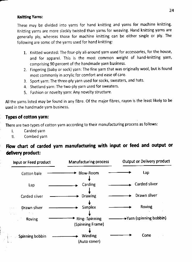
Flow thart of carded yarn manufaduring with input or feed and output or
delivew produd:
lnptlt or Feed produd Manufacturing process Output or Delivery produd
Cotton bale Blow-Room Lap
iLap Carding Carded sliver
iCarded sliver Drawing Drawn sliver
)Drawn sliver Simplex Roving
J 'Roving Ring- Spinning Yarn (spinning bobbin)
(Spinning Frame)i
, Spinning bobbin W inding Cone(Auto coner)
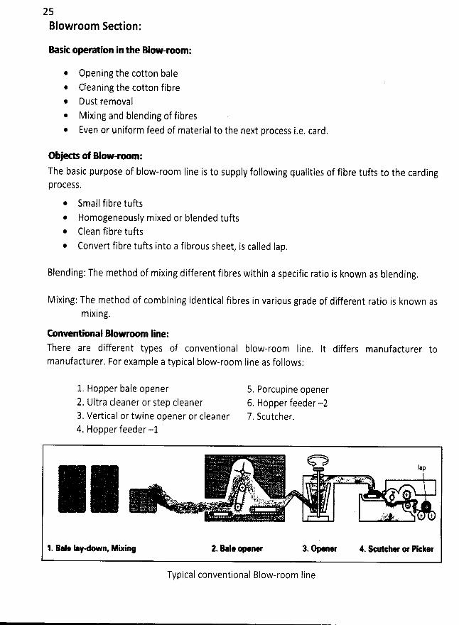
25Blowroom Section:
Basit opera:on inl e Blow-room:
* Opening the cotton baleCleaning the cotton fibreDust removal
* Mixing and blending of fibresEven or uniform feed of material to the next process i.e. card.
Objeds of Blow-x m:The basic purpose of blow-room Iine is to supply following qualities of fibre tufts to the cardingpr0CeSS.
* Small fibre tuftsHomogeneously mixed or blended tuftsClean fibre tuftsConvert fibre tufts into a fibrous sheet, is called Iap.
Blending: The method of mixing different fibres within a specific ratic is known as blending.
Mixing: The method of combining identical fibres in various grade of different ratio is known asmixing.
Conventional Blowroom Iine:There are different types of conventional blow-room Iine, It differs manufacturer tomanufacturer. For example a typical blow-room Iine as follows:
1. Hopper bale opener2. Ultra cleaner or Step cleaner3. Vertical or twine opener or cleaner4. Hopper feeder -1
5. Porcupine opener6. Hopper feeder -27. Scutcher.
bp. . . p,w ... . .jy o, t
.jy . . . .. . , + y' As T . .
- - - ... .. - t .,7 x - 'z'2. sak..u -- . % , .j, 4.%J . .
1. > Ie 1ay n, * ie 2. B.l* ne 3. 4. çher or PIe- ker
Typical conventional Blow-room line
26
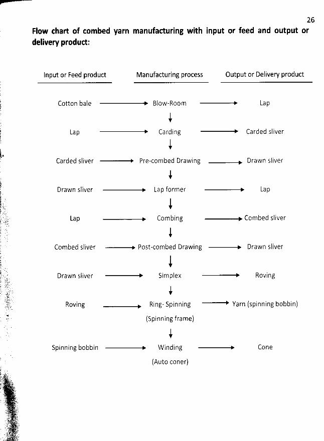
Flow chart of combed yarn manufaduring with input or feed and output ordelivery produd:
Input or Feed product Manufacturing process Output or Delivery product
Cotton bale Blow-Room Lap
iCarding
iCarded sliver Pre-combed Drawing Drawn sliver
iDrawn sliver Lap former Lap
Lap
iCombing Combed sliver
iCombed sliver Post-combed Drawing Drawn sliver
$Drawn sliver Simplex Roving
Lap Carded sliver
Roving
iRing- Spinning Yarn (spinning bobbin)
(Spinning frame)
iSpinning bobbin W inding
(Auto coner)
Cone
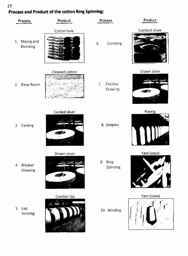
27Process and Produd of the cotton Ring spinning:
Process Product Process Produd
Combed sliver
% +
Drawn sliver
Cotton bale
. Q.. .. x . v . . .. : . ?z
M I X I n g 3 13 (:1 - -..'.'' ''- mra-at. . , . : .- i7'X ? -=
BIe nd I ng .-. ;. ax, .sg;' kk6;.x Q . ' 'E%wq>. '
Mztaz
Com bing
F i n i s h e rDrawing
Carding
Carded sliver
* *
Drawn sliver
+
Comber 1ap
. L' 2.'i.. ($1'
j
.':- .( .
4. BreakerDrawing
8. Simplex
Roving
...y.
1.i..
'
. Q
Yarn cops)
I.. ,#
.' yuv q'
9 . R i ngS pi n n i n g
5. Lapforming
Yarn (cone).
' ... . ;ir. q. '' $ 't. -t-è . ''f ' ' 2 . f'.
10 W 1 n d 1 n g :' l.k % ). vj s . .#y.:77.. .. ltrjrra ql)'rq. . . ..!#!''' jj!r' . 7.t. j)! . : : .
=' j)l p.7 J:. ' ' '
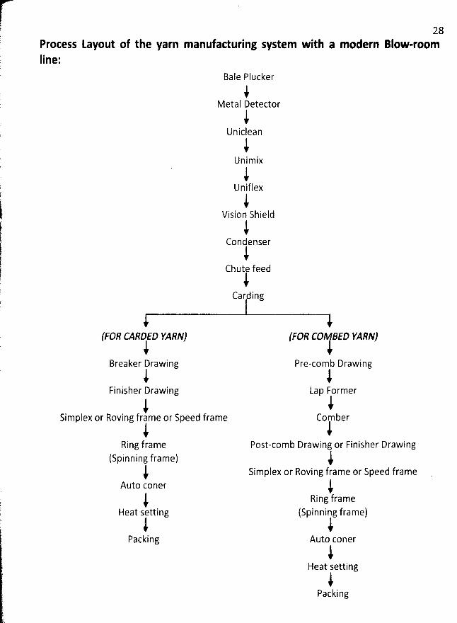
q 28l Process Layout of the yarn manufaduring system with a modern Blow-roomlp Iine:;
Bale Plucker
iMetal ùetector
iUniclean
iU n i m ix
iUniflex
iVision Shield
iCondenser
iChute feedi
Carding
(FOR C'AOD YARN) (FOR CO #fP YARN)iBreaker Drawing Pre-comb Drawing
i iFinisher Drawing Lap Former
i iSimplex or Roving frame or Speed frame Comber
i iRing frame Post-comb Drawing or Finisher Drawing
(spinning frame) )) simplex or Roving frame or Speed frame
Auto coner )i Rin: frame
Heat setting (Spinning frame)i i
Packing Auto coner
iHeat setting
iPacking
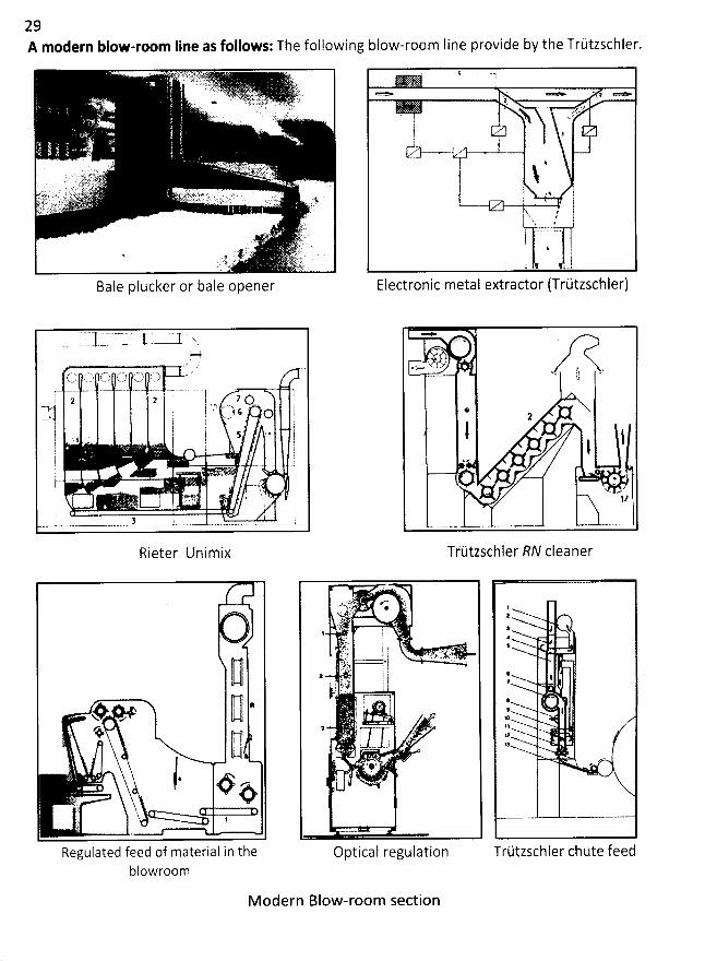
29A modern blow-room Iine as follows:The following blow-room Iine provide by the Trùtzschler.
Bale plucker or bale opener
. 1r
> ' - h . *
* ' W' S. , N -,If .,l;A-
1
N. 4I :
1 $ l'j1 .-
Electronic metal extractor (Trùtzschler)
Rieter Unimix
Il ,* .* 11 'k
': 9 jj . jy, p . o- .*
-) '$,q' Lk
1
Regufated feed of material in theblowroom
Optical regulation
1
: k4$
l# .-w I
# l*N11
13
Trùtzschler chute feed
*
'7Z'x ' z
*2
lI
* y
'
Nw x1/
Triitzschler RN cleaner
M odern Blow-room section
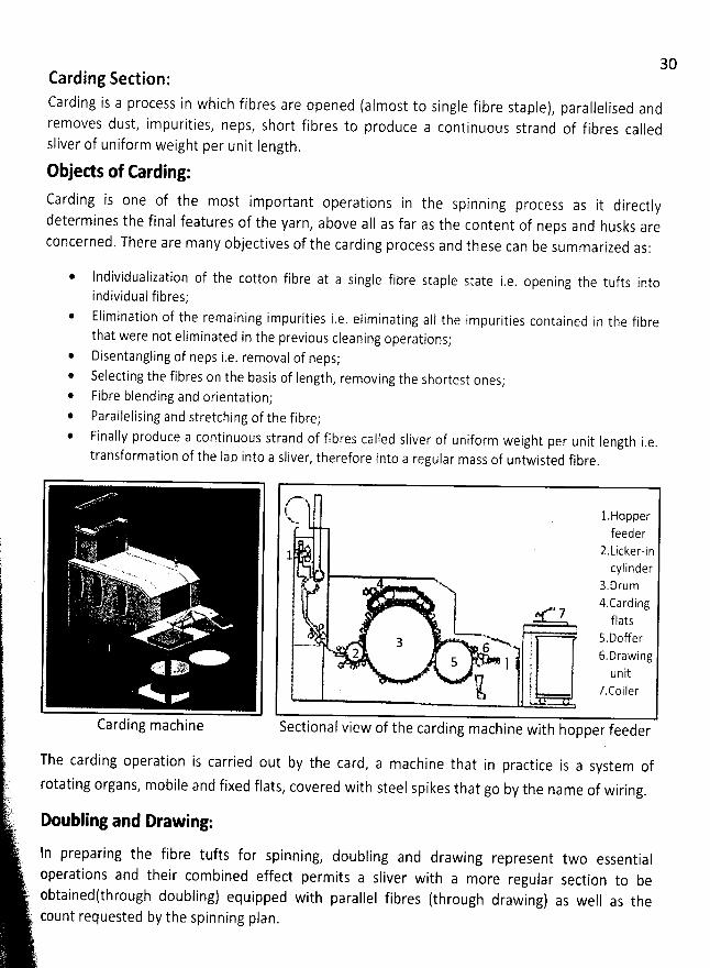
30Carding Section:
Carding is a process in which fibres are opened (almost to single fibre staple), parallelised andremoves dust, impurities, neps, short fibres to produce a continuous strand of fibres calledsliver of uniform weight per unit length.
Objeds of Carding:Carding is one of the most important operations in the spinning process as it directlydetermines the final features of the yarn
, above aII as far as the content of neps and husks areconcerned. There are many objectives of the carding process and these can be summarized as:
* Individualization of the cotton fibre at a single fibre staple state i.e. opening the tufts into
individual fibres;* Elimination of the remaining impurities i.e. eliminating alI the impurities contained in the fibre
that were not eliminated in the previous cleaning operations;@ Disentangling of neps i,e. removal of neps;* Selecting the fibres on the basis of length, removing the shortest ones;* Fibre blending and orientation;@ Farallelising and stretching of the fibre;* Finally produce a continuous strand of fibres called sliver of uniform weight per unit length i
.e.transformation of the lap into a sliver, therefore into a regular mass of untwisted fibre.
. <
. k w ,yj;l;j:-uL o
Carding machi ne
z-t l
.Hopperx.mfeeder
z.t-icker-in1cylinder
y , g) ru m4.carding
' 7 flats
.- j s.Doffer..--- 6 ;2
, 6,Drawing5 - 1 ï
unitkj. j .y , c o i j c rSectional view of the carding machine with hopper feeder
The carding operation is carried out by the card, a machine that in practice is a system of
rotating organs, mobile and fixed flats, covered with steel spikes that go by the name of wiring.
Doubling and Drawing:
ln preparing the fibre tufts for spinning, doubling and drawing represent two essentialoperations and their combined effect permits a sliver with a more regular section to beobtainedtthrough doubling) equipped with parallel fibres (through drawîng) as well as thecount requested by the spinning plan.
31The drawing operation done with the machine called the drawframe, permits a homogeneousblend both with fibres of the same nature as well as fibres with a different nature; the doubling
steps are usually between four and eight.On a par with fibre characteristics such as Iength and fineness, a sliver with parallel fibrespermits a yarn with better regularity and resistance. The drawing depends on some factors suchas the number of doublings carried out and the value of the count of the entry Sliver anddelivery sliver. W ith drawing, curls, crimps and hooks are also eliminated, meaning the fibres
folded in on themselves, present in the carded sliver.Drawing is a process in which the sliver is elongated by passing it through a series of pair ofroflers, each pair moving faster than the previous. This permits combination of several sliversand drawing and efongating them to straighten and create greater uniformity to form a regularsliver of smaller diameter. This action pulls the staple Iengthwise over each other, thereby
producing longer and thinner slivers, Finally the sliver is taken to the sliver can.
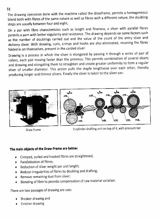
Draw frame
t,. .#t..o ..b.. ..ta;#* # #4 F*$
. X' z1 . Auk,u
'-Xx ' ..'Nxsxx..v'hNxhhju. Nhua.g.
%x ''x ' ' '
---x.&.t...xx . -mx.xjas . . Js' XXX ' qtxv. *.- ,:,% ImtJtr''e7r''r 2'sx . rsas o .z. . . .,x v-.v-ca' ' z- xpaâ - > ==-<
/ z.. z y.: . .y z yu . yy r' .'T2 . '..''. ,,''(;. .'.' .. .
dz'''. .e qk !
3-cylinder draftingunit on top of 4, with pressure bar
The main objeds of the Draw-Frame are below:
@ Crimped, curled and hooked fibres are straightened;* Parallelisation of fibres;* Reduction of sliver weight per unit length;* Reduce irregularities of fibres by doubiing and drafting;@ Remove remaining dust from sliver;* Blending of fibre to provide compensation of raw material variation.
There are two passages of drawing are uses
* Breaker drawing andFinisher drawing
X -
!
'
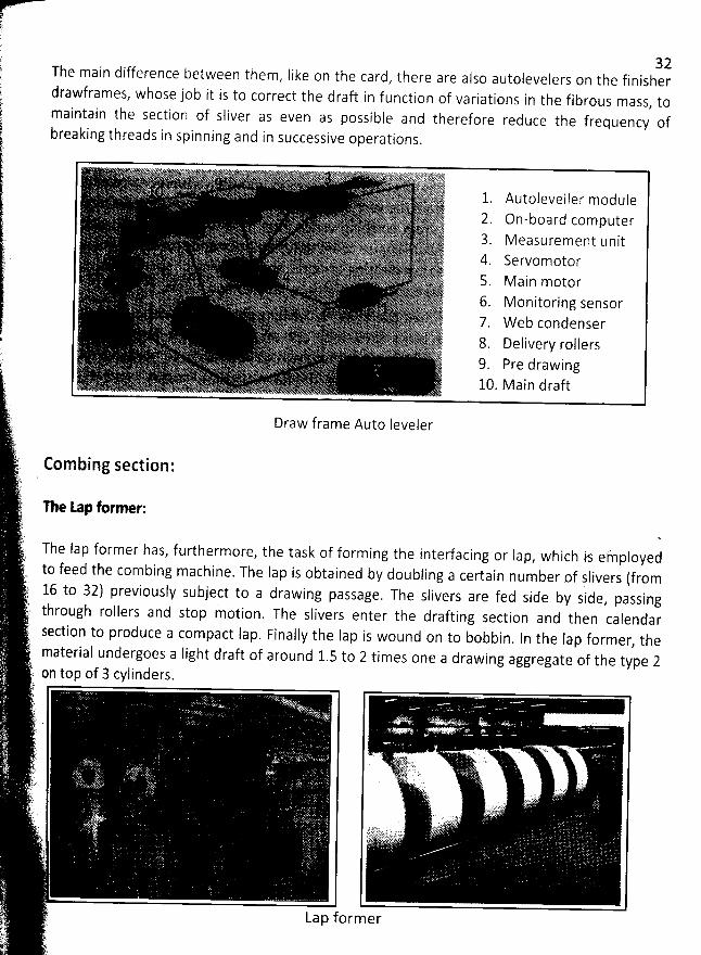
The main difference between them, like on the card, there are also autolevelers on the finisher' drawframes, whose job it is to correct the draft in function of variations in the fibrous mass, to
intain the section of sliver as even as possible and therefore reduce the frequency of ma
breaking threads in spinning and in successive operations.. (. . . . ': l è( .(F !. ( ' ' ' '! 2::'!7 '% ( ' '''' . . z'ï%bbbbbbb '. , é.>. . 4 Jr t, 1 . -#
. 1 'Z) .E-g . zE f 1. Autoseveller module'LL.'
; 2. On-board computerk. '- ..
- - '- a. Measurement unitr. ' 'j.
q ) 4. servomotor) ( s Main motor.
'
.. .... ''
'
lyry''.
d
1,
*
- 6. Monitoring sensor. 7. W eb condenser'n 6.
8. pejivery rollers . t... 9
. pre drawing
'
.
1o. v ajn draft't'':. Draw frame Auto Ievelert
. Combing section'./.'.)
The tap former:1
-r The Iap former has, furthermore, the task of forming the interfacing or Iap
, which is efnployed' to feed the combing machine. The Iap is obtained by doubling a certain number of slivers (fromt. .
y 16 to 32) previously subject to a drawing passage. The slivers are fed side by side, passing, through rollers and stop motion. The slivers enter the drafting section and then calendar' section to produce a compact lap. Finally the Iap is wound on to bobbin. ln the lap former, thematerial undergoes a light draft of around 1.5 to 2 times one a drawing aggregate of the type 2on top of 3 cylinders.
è .... .
r r . . ; .. . . .. . . . .). . . ,... . . . o . . (. '(
. .. .. . . . (Ng '' ).(:
. . ' cti. . a' ) . ' 'DfY'5?@ ..
y . . .yky .. ..' ) '- . t.i . . '''ii:''.. t g.''èt ''
. .. ' .. --'---'--' ' '.
jjjyj;..) ' ' yrtzt' . . L1''''' ''ttkxtt. t(k -
t).i.
.-
Lap former. -'.t .
'
)
32
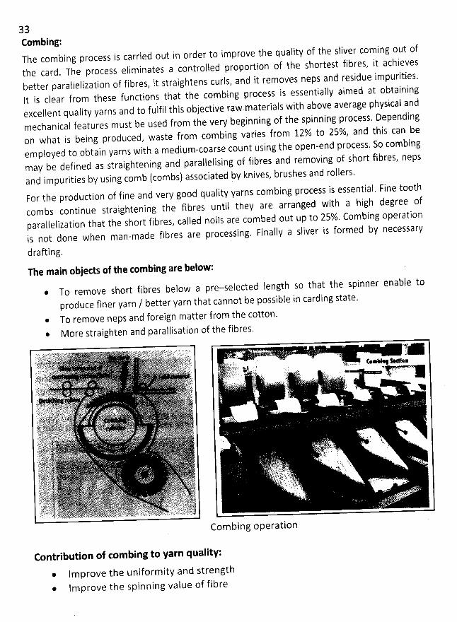
33Combing:
The combing processthe card. The process eliminates
is carried out inorder to improve the quaiîtyof the sliver cominga controlled proportion of the shortestfibres, it achieves
better parallelizationIt i s c l e a r
of fibres, it straightens curls,functions that the combing process
and it removes nepsand residue impurities.is essentially aimed at obtaining
from theseexcellent quality yarns and to fulfil this objective rawmechanicad features must be used from the very beginning of the spinning process. Dependingon what is being produced, waste from combing varies from 12% to 25%, and this can beemployed to obtain yarns with a medium-coarse count using the open-end process. So combingmay be defined as Straightening and paralielising of fibres and removing of short fibres, neps
and impurities by using comb (combs) associated by knives, brushes and rollers.
materials with above average physicaland
out of
For the production of fine and very good quality yarns combing process is essential. Fine .t00thcombs continue straightening the fibres until they are arranged with a high degree ofparallelization that the short fibres, called noils are combed out up to 25%. Combing operationis not done when man-made fibres are procesfing. Finally a sliver is formed by necessary
drafting.
The main objects of the combing are below:* To remove short fibres below a pre-selected Iength so that the spinner enable to
produce finer yarn / better yarn that cannot be possible in carding state.* To remove neps and foreign matter from the cotton.
More straighten and parallisation of the fibres.
Combing operation
Contribution of com bing to yarn quality:
Improve the uniform ity and strengthfm prove the spinning value of fibre
34
= 30Ne carded yarn
= 60Ne combed yarn@ lmprove yarn smoothness and Iusture
Produce much clearer yarn* lmprove/lncrease efficiency of the next process* Reduce the hairiness of yarn* Improve better twist distribution in the yarn
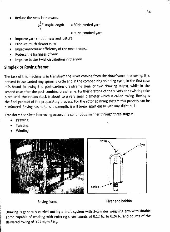
Simplex or Roving frame:
The task of this machine is to transform the sliver coming from the drawframe into roving. lt ispresent in the carded ring spinning cycle and in the combed ring spinning cycle, in the first case
it is found following the post-carding drawframe (one or two drawing steps), while in thesecond case after the post-combing drawframe. Further drafting of the slivers and twisting takeplace until the cotton stock is about to a very small diameter which is called roving. Roving isthe final product of the preparatory process. For the rotor spinning system this process can beeliminated. Roving has no tensile strength; it will break apart easily with any slight pull.
Reduce the neps in the yarn.1 ,, j
ngtj1- staple e8
Transform the sliver into roving occurs in a continuous manner through three stages:
@ Drawing* Twisting. winding
Roving frame
roving. flyer
I! i
1
bobbin
li Flyer and bobbink( ith doubleDrawing is generally carried out by a draft system with 3-cylinder weighing arm wk
' apron capable Of working with entering sliver counts of 0.12 Ne to 0.24 Ne and counts of the
, delivered roving of 0.27 Neto 3 Ne.?
'
(' .
35The twist is given by the rotation of the flyer Iocated on the spindles, in fact the exit rovingcoming from the draft cylinders enters in the higher hole of the flyer, passing through thehollow arm and then winding on the bobbin. The twist value is given by the following equation:
Revolutions of the spindle (flyer)NO. twists =
Exit Iength 1 st cylinder
The number of revolutions of the spindle can reach up to a maximum value of 1500 rpm. Thetwist rate given by the roving has a value of between 10 to 100 T/m (0.25 T/inch). It should benoted that the twist value to give the roving, this being an intermediate product, has afundamental practical importance for the next processing stage.
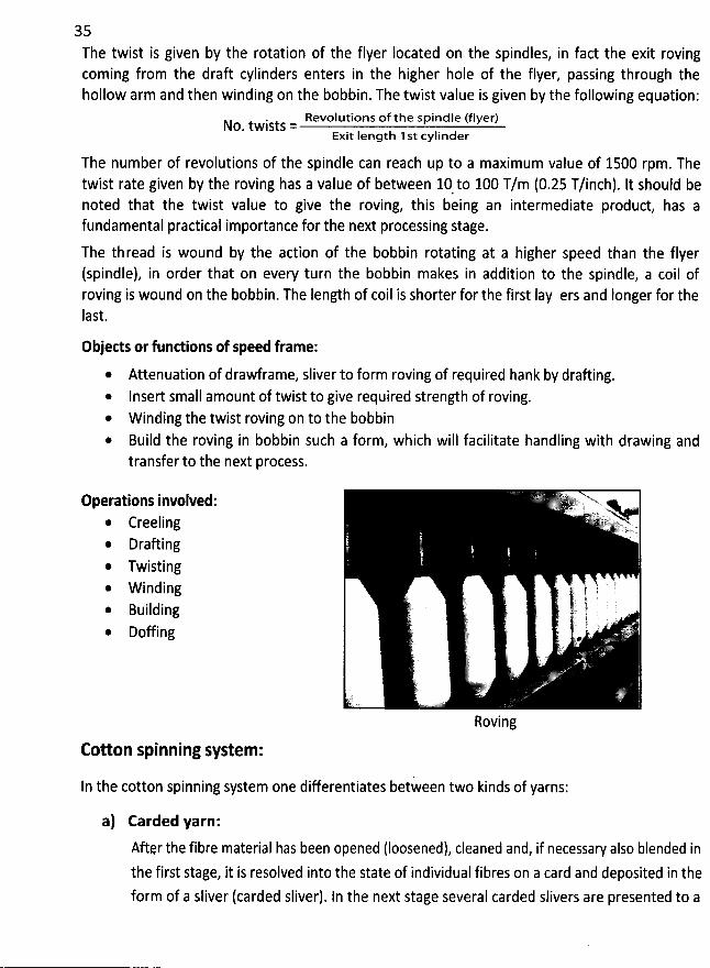
The thread is wound by the action of the bobbin rotating at a higher speed than the flyer(spindle), in order that on every turn the bobbin makes in addition to the spindle, a coil ofroving is wound on the bobbin. The Iength of coil is shorter for the first lay ers and Ionger for theIast.
Objects or funttions of speed frame:* Attenuation of drawframe, sliver to form roving of required hank by draûing.
Insert small amount of twist to give required strength of roving.W inding the twist roving on to the bobbin
* Build the roving in bobbin such a form, which will facilitate handling with drawing andtransfer to the next process.
Operations involved:@ Creeling
Draûing* Twisting
W inding. Building
Doffing
Roving
Cotton spinning system:
In the cotton spinning system one differentiates between two kinds of yarns:
a) Carded yarn:
Aftqr the fibre material has been opened (Ioosened), cleaned and, if necessary also blended inthe first stage, it is resolved into the state of individual fibres on a card and deposited in the
form of a sliver (carded sliver). In the next stage several carded slivers are presented to a
36draûing unit on a draw frame. Drafting Ieads to a reduction of the fibre mass per sliver.Subsequently the individual slivers, now with a Iower mass, are collected together toform a draw frame sliver. Compared to the carded sliver the drawn sliver displays
a better fibre alignment towards the Iongitudinal axis of the sliver anda higher degree of parallelization between the fibres.
A yarn finally spun out of this sliver is called a carded yarn.
b) Combed yarn:
In the cotton spinning system a combing of fibres out of draw frame slivers is basicallyan additional processing stage. Combing leads to the following results:
A pre-determined portion of short fibres is combed out (comber waste). This issignificant in the case of cotton, which as a natural fibre contains fibres in varyinglengths. Comber waste can amount to as much as 20% to 30% of the original weightof the fibre lot being processed on the comber. The portion of longer fibres isincreased in the combed material. With regard to the spinning limits the following
rule is valid:
The longer the fibres are, the finer one can spinThe shorter the fibres are, the lower is the spinning Iimit.
Thus one can spin finer yarns from the fibre 1ot (sliver) after combing
Combing leads to a higher degree of cleanliness in the fibre material.
Compared to carded yarns a combed yarn has a softer handle. This property is also
transferred to fabrics made out of it.
Spinning machineThis is the final stage of yarn manufacturing. The goal of this manufaduring process to get yarnis achieved by this machine. There are different types of spinning machine. Ring frame is aconventional spinning machine. This machine has very wide scope, because it can producecoarse to very fine yarn. Tifl now this ring spinning machine is widely used whole over the
world.There are also some modern spinning systems too. Rotor spinning system is one of them. Thissystem is also very famous, but it has some limitation. lt is mainly used for coarse yarn.
ln the following section the currently most important spinning techniques are described in
Some detail.
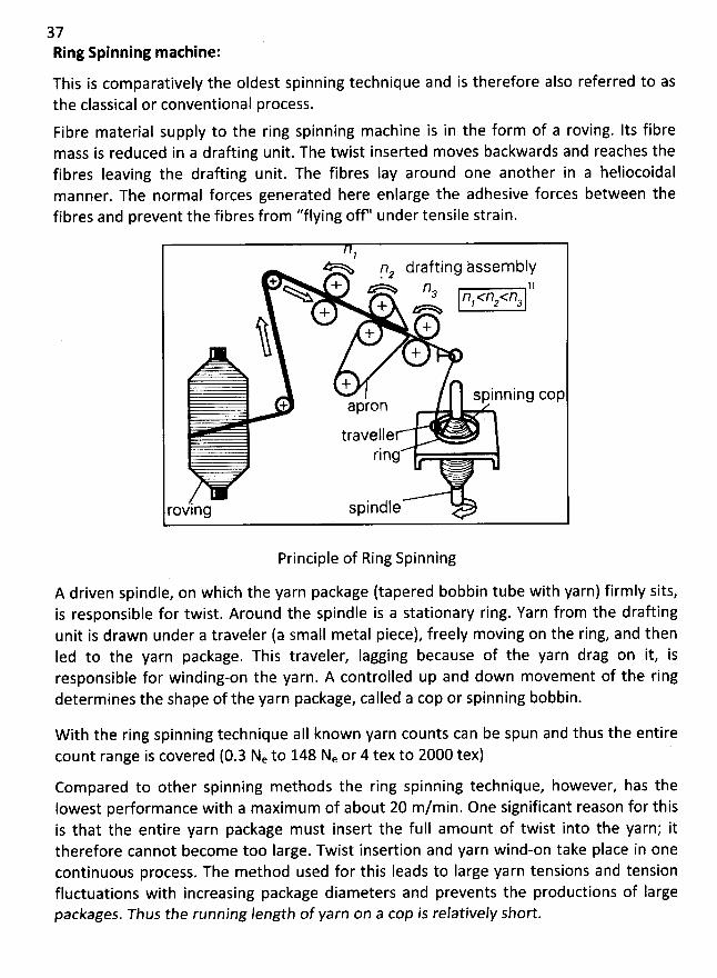
37Ring Spinning machine:
This is comparatively the oldest spinning technique and is therefore also referred to asthe classical or conventional process.
Fibre material supply to the ring spinning machine is in the form of a roving. Its fibremass is reduced in a drafting unit. The twist inserted moves backwards and reaches thefibres Ieaving the drafting unit. The fibres Iay around one another in a heliocoidalm anner. The normal forces generated here enlarge the adhesive forces between thefibres and prevent the fibres from ''flying oH'' under tensile strain.
'!G jlz drafting àssembly
+ + 1)==Q4 ns f)y <1:,<rq+ a
+++
+
. .,- +spinning cop
+ apron
travelle- - - rjng
roving spindle
Principle of Ring Spinning
A driven spindle, on which the yarn package (tapered bobbin tube with yarn) firmly sits,is responsible for twist. Around the spindle is a stationary ring. Yarn from the drafting
unit is drawn under a traveler (a small metal piece), freely moving on the ring, and thenIed to the yarn package. This traveler, Iagging because of the yarn drag on it, isresponsible for winding-on the yarn. A controlled up and down movement of the ringdetermines the shape of the yarn package, called a cop or spinning bobbin.
W ith the ring spinning technique aII known yarn counts can be spun and thus the entirecount range is covered (0.3 Ne to 148 Ne or 4 tex to 2000 tex) '
Compared to other spinning methods the ring spinning technique, however, has the
Iowest performance with a maximum of about 20 m/min. One significant reason for thisis that the entire yarn package must insert the full amount of twist into the yarn; ittherefore cannot become too large. Twist insertion and yarn wind-on take place in onecontinuous process. The method used for this Ieads to Iarge yarn tensions and tensionfluctuations with increasing package diameters and prevents the productions of Iargepackages. Thus the running length of yarn on a cop is relatjvely short.
38
- je .. .
.. . ... .
. .;,
. ..
.. , . /' j . .x.. y y.j . . ;. . . . .
. t s :* 2 . . . .
'
.-
'..
'' r .,- / y'g, . . #, ,y y
. . ,. ;y..k . . .. . j
cc . ' ;. . ..
-@ .. . ..' è-
.4... . ,.ê. 'zC ' . . . a
. .. y j))).j. .. . . .. . . . (. .
, q . . .' y. .
-: !i' p . . ' y' . y.). jk. . - . . , . -'Ekjt, .. .. : . ' . .. .. tjucqëy:.. -.. '' . .. .!.. -L . ... lyy yr . .
. u y - ( . . .-. ... ... c r .;( - . . -.. . t.). 9..
. - , , . .
- . .) . . .;. - )t ))
. ;c' .': j.
...: ' n*%-i.;ë L; :. . ' ' ö ... .. .'' '' . . .. .. ''ZL1l;. '' ')
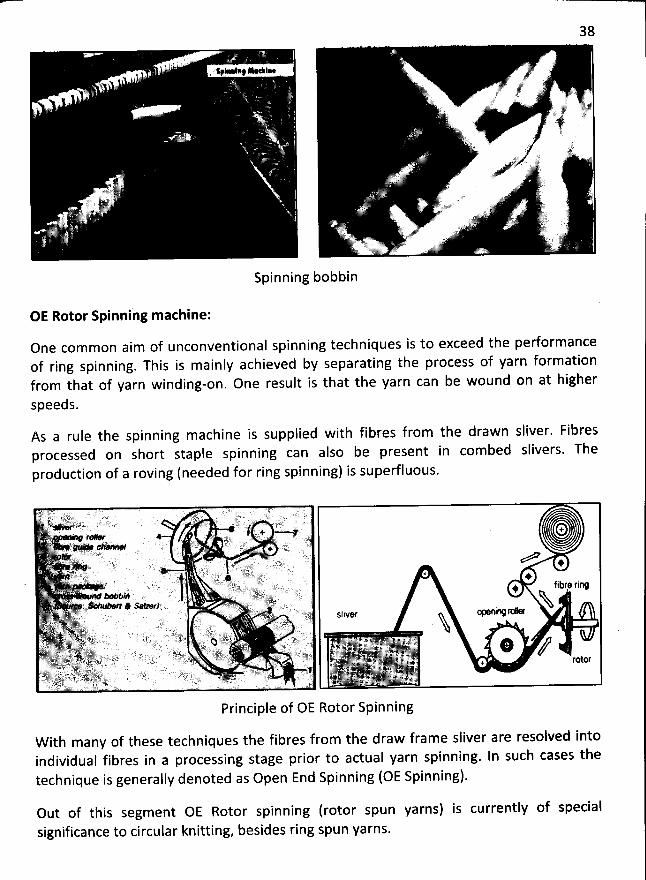
Spinning bobbin
OE Rotor Spinning machine:
One com mon aim of unconventional spinning techniques is to exceed the pedormanceof ring spinning. This is mainly achieved by separating the process of yarn formationfrom that of yarn winding-on. One result is that the yarn can be wound on at higher
speeds.
As a rule the spinning m achine is supplied with fibres from the drawn sliver. Fibresprocessed on short staple spinning can also be present in combed slivers. The
production of a roving (needed for ring spinning) is superfluous.
(1); ;-.,....jj)(.y t. -- . ! - - . . .. ''. (t( . . . . .. . . . . ..) . .kkj L . .,.. .. r.- . . .' . - . .(- ). '.. .. . ... .- . ' - .)).y . ï). . )X = j =' b tro. ' ' ' ' . s . c . ; . . ) .; .Lq . : . ? . . . . . . . ' . . x ' y ., - . - ë E ?y . ' . L . .. z , . . y r ; y. . . v y . ) ( . r ! ...; . ; o''.jlj**n-'-'---kï . m . . jrjjjjjjjyy . . .
. y. . j . 1. z . .
.'
.
.3f g. ..jj, y ... . . .tj. 4:442)j.4-
.. k -...k. . .y .... '. . . .
' . y . . ' a E!. t.':.àq .u. ..7( .-' - y x .. .#144,. z. . .
.. ..u tg ïi . ..' 7. . . . .. ' . ... ' . ' . ' . ' . . . . ' z' - vl,l..tyF . ' L. - . jsr:::::f:;,.1Là''b'b',bii3à''b,.. . .
-'. ;;-L,L.. r .. .' . . .
, '... ..
. . . .-) .. '
. .: . .. ..ï 2) .. .. -' . ...L,' yi'...
..-);,..,:-ïL. :'.-...yy. . -# ...
î . . .. . .
' ' .-111,..:P> y )v q .. )@,.;) r)j) . y7:.. .. . . . . .
. . .
.: . . ' . . .. . r . . . . ... . .. .'. .
. .. #r . . : ' t(( ..yy; jy .. . .
.. 'p. -44)p.
. . . . . . . .. j.. k. . u . ; . . . ( :.. . .- k- . . ... .. ,-.. ,...... ..
. .:
. .g ..... .)rjy' '.è....
.' . .y ...:yy. (yj:: y . tt.. . . .. yy . .dj)! llii 1:)81.11!1 ri IN
, qs.. L. .( . ..-. ....- . ,u.. .
. . . r .. k ...r ) (y y. . ); . . .' L. ''. - L'2'tb-'--'bô'. .d1I, klikkd''lk,rt.''r..,- . . . . .. .' . ... LL :. '.)y !,-:. : .tr (. . g.8è . yq)'-- i...'t7. j . . . . . .
.
. . - . t yy.ytp ?.. . .. ...., . - .. . . ; . . j- - . . .. .. jr,:)j,jjjjjr-. . . . - , ; . , -ïL- -- . . . . . y . -): , y ;,LL)jLq, .. .. t!i , i hdl-,',t 1- ,y ,r:pl:ldllklr,.'..llr;l.. . . ' '
.
'. -F. .#; ?jt'' ' ,. j'. .. -. y . y
.
t . y. yy
'
.. y . g-.#g..
'
.
.
'
y'
y . . - st,..r . y...
'
y-. .-
.
-
..
.,4j:j4.. .
.
y.
''
jtyyj... y).... - y '' -' '
-.. tt'. ,..
.
.,,.'
y
.Ey-'
.y' '.
,j
'
.
'
. j. .
-
,
'
.j.
'
.y
'
.yyqy.:)y'
. ... - .. . . y .. ..yr' - ' -. qlè tjjyk) .!. jj: è ... : C. . r. . . . ) . . . . . ; q-illl'E -é' -. .: . . . . r . . . ) y . - yy .. j-)... t sd rqrtyy y
y.;- . .,. ..y - yy, . .yy ,j)-; . . ,jj. yj-. .yyj y. -yy. .gy . .(
. yy-ry . . , -
.
-. .y. . . jjjjjy,yt-- . - jjjjjr;jjjj.Vx- ''. ,%<A.k' . -' ht ?j. Ejjy . j-y.yj. .....; .: . .. ):.. y . . yrty ..:,.. , ( .
.
....- .. ,.. iy . ,, y,.. ..... .., ..
.
.( . y. .:. ..y.,j,y...y....
,.y . . .. xyyg yy,...,;.yy -. . ...
,-- ..yy . r .. ,. LL . .-. j . . . - . . . . - , .
y .. j-jrgjy.. -i)....t>r . . . - -y- ' ,Ljq);.; .- ,y . . . ) . .. . . . . .. .. . . y yyy . . . . . . . yy. r . . . j .jj,i ,L'., jjkkj,jjtjty , jj?.)Lj),k;(.L, y@!jp7.11t)ilq7. yj . ir . ... ..y . .- . . ..L. .. , ' .- .. , . . . . . . . .... . ?. ..r . yj ,. . t .. . ,- , ,r . -y.'''
-. . ...
:..
-..... .y.k y-. ).). -. y y:...
. .
. .
.... rj . ;!. .. . t . . . . .
- , . . .
. y't7
.
''f:. . .. - . )#- r. . : 2 ..?TX. )...-t. . '. . . . . q ,r . - . . . qr . . . ... . .. c; ' - ''' ' . ' .. ;f f.J' - '. 7 .. ' . y ,' .: .. . . . .. . . . ). . , ' .. . ' '. J . .. ..'
Principle of OE Rotor Spinning
W ith many of these techniques the fibres from the draw frame sliver are resolved intoindividual fibres in a processing stage prior to actual yarn spinning. In such cases the
technique is generally denoted as Open End Spinning (OE Spinning).
Out of this segment OE Rotor spinning (rotor spun yarns) is cuirently of specialsignificance to circular knitting, besides ring spun yarns.
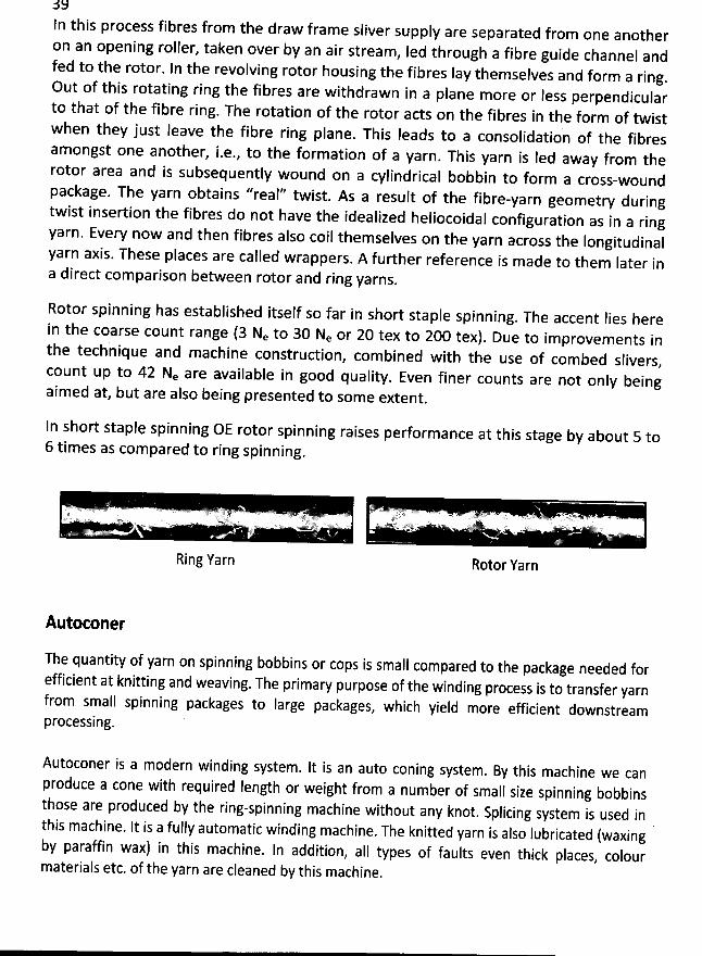
In this fram e sliver supply are separated from one another
on an opening roller, taken over by an air stream, Ied through a fibre guide channel and
fed to the rotor. In the revolving rotor housing the fibres Iay themselves and form a ring.Out of this rotating ring the fibres are withdrawn in a plane more or le
ss perpendicularto that of the fibre ring. The rotation of the rotor acts on the fibres in the form of twistwhen they just leave the fibre ring plane. This Ieads to a consolidation of the fibresamongst one another, i.e., to the form ation of a yarn
. This yarn is led away from therotor area and is subsequently wound on a cylindrical bobbin to form a cross
-woundpackage. The yarn obtains ''real'' twist
. As a result of the fibre-yarn geometry duringtwist insertion the fibres do not have the idealized heliocoidal configurati
on as in a ringyarn. Every now and then fibres also coil themselves on the yarn across the Iongitudinalyarn axis. These places are called wrappers
. A further reference is made to them Iater ina direct com parison between rotor and ring yarns
.
process fibres from the draw
Rotor spinning has established itself so far in short staple spinning. The accent lies here
in the coarse count range (3 Ne to 30 Ne or 20 tex to 200 tex). Due to im provem ents in
the technique and machine construdion, com bined witb the use of combed slivers
,count up to 42 Ne are available in good quality. Even finer counts are not only being
aimed at, but are also being presented to some extent.
In short staple spinning OE rotor spinning raises performance at this stage by about 5 to6 times as compared to ring spinning
.
.- k. t -.. . à u , . -.. . . ' ' .'tpv u . .. ï rql k.ex) x ak . -N *- H ' - Z ' AW' '/
Ring Yarn
. . . ... . v.. ,..::' Q-J ' ' ' fwL. ;'- - - '
Rotor Yarn
Autoconer
The quantity of yarn on spinning bobbins or cops is small compared to the package needed forefficient at knitting and weaving
. The primary purpose of the winding process is to transfer yarnfrom small spinning packages to Iarge packages
, which yield more efficient downstreamprocessing.
Autoconer is a modern winding system. It is an auto coning system . By this machine we can
produce a cone with required Iength or weight from a number of small size spinning bobbinsthose are produced by the ring-spinning machine without any knot
. Splicing system is used inthis machine. It is a fully automatic winding machine
. The knitted yarn is also Iubricated (waxingby paraffin wax) in this machine. ln addition, aI1 types of faults even thick places
, colourmaterials etc. of the yarn are cleaned by this machine
.
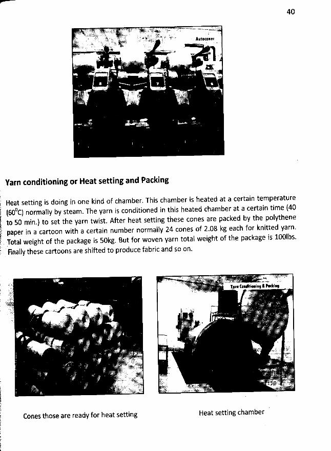
40
Yarn conditioning or Heat setting and Packing
Heat setting is doing in one kind of chamber. This chamber is heated at a certain temperature0c) normally by steam. Tbe yarn is conditioned in this heated chamber at a certain time (40(60
to 50 min.) to set the yarn twist. After heat setting these cones are packed by the polythenepaper in a cartoon with a certain number normally 24 cones of 2.08 kg each for knitted yarn.Total weight of the package is 50kg. But for woven yarn total weight of the package is 100lbs.
Finally these cartoons are shifted to produce fabric and so on.
Cones those are ready for heat setting Heat setting chamber
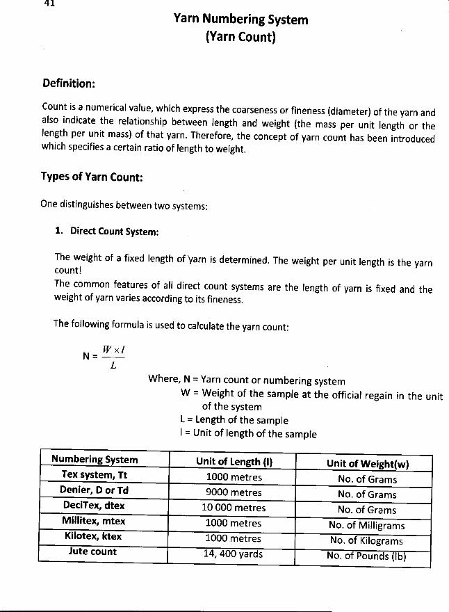
41
Yarn Num bering System
(Yarn Count)
Definition:
Count is a numerical value, which express tbe coarseness or fineness (diameter) of the yarn andalso indicate the relationship between length and weight (the mass per unit Iength or theIength per unit mass) of that yarn. Therefore
, the concept of yarn count has been introducedwhich specifies a certain ratio of Iength to weight
.
Types of Yarn Count:
One distinguishes between two systems:
1. Dirett Count System:
The weight of a fixed Iength of -yarn is determined. The weight per unit length is the yarn
count!The common features of aII direct count systems are the length of yarn is fixed and theweight of yarn varies according to its fineness
.
The following formula is used to calculate the yarn count:
IC x /N =
LW here, N = Yarn count or num bering system
W = W eight of the sample at the official regain in the unitof the system
L = Length of the sam pleI = Unit of Iength of the sample
Numbeeing System Unit of tength (I) Unit of Weightlw)Tex w stem, n 1000 metres No
. of GramsDenier, D or Td 9000 metres No
. of GramsDetiTey, dtex 10 000 metres No
. of GramsM illitex, mtex 1000 metres No
. of M illigramsKilotex, ktex 1000 metres No
. of Kilogram slute count 14
, 400 yards No. of Pounds (lb)
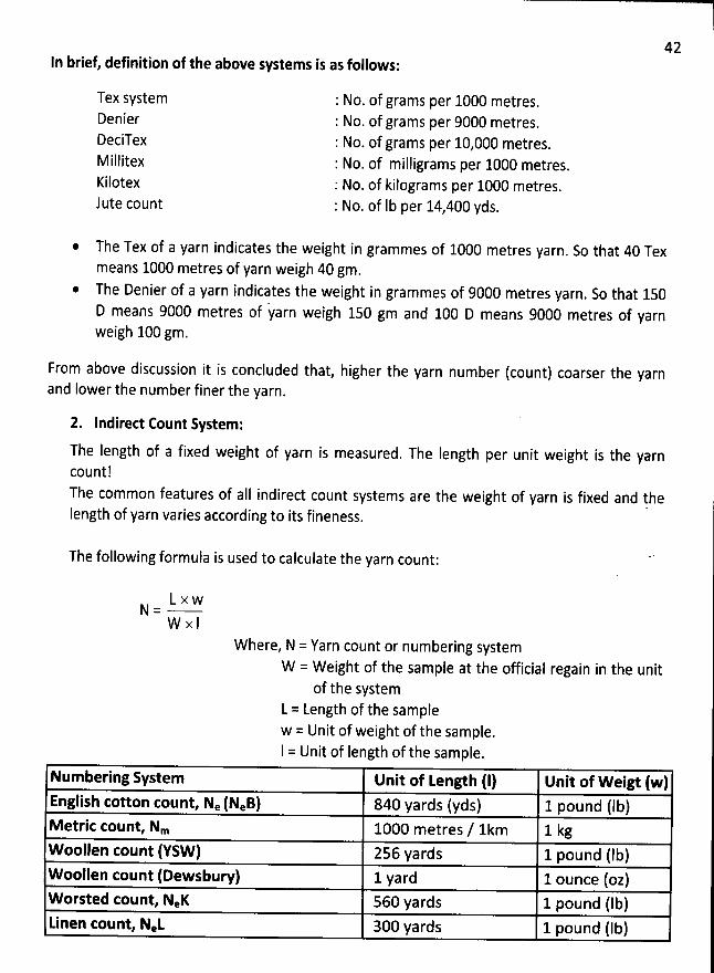
In brief, definition of the above42
systems is as follows:
NO. of grams per 1000 metres. 1Tex systemDenierDeciTexrkl illit (! )(KilotexJute count
No. ofNo. of grams per 10,000 metres.
grams per 9000 metres.
: No. of milligrams per 1000 metres.: No. of kilograms per 1000 metres.: No. of Ib per 14,400yds.
The Tex of a yarn indicates the weight in grammes of 1000 metres yarn. So that 40 Tex
means 1000 metres of yarn weigh 40 gm.The Denier of a yarn indicates the weight in grammes of 9000 metres yarn
. So that 150D means 9000 metres of 'yarn weigh 150 gm and 100 D means 9000 metres of yarnweigh 100 gm.
From above discussion it is concluded that, higher the yarn number (count) coarser the yarnand Iower the number finer the yarn.
2. Indired Count System:
The length of a fixed weight of yarn is measured. The Iength per unit weight is the yarncount!The common features of alI indirect count systems are the weight of yarn is fixed and thelength of yarn varies according to its fineness.
The following formula is used to calculate the yarn count:
L x wN =
W x IW here, N = Yarn count or numbering system
W = W eight of the sample at the official regain in the unitof the system
L = Length of the samplew = Unit of weight of the sample.I = Unit of Iength of the sample.
Numbering System Unit of Length (I) Unit of Wei, (w)English cotton count, Ne (NeB) 840 yards (yds) 1 pound (lb)Metric count, Nm 1000 metres / 1km 1 kgWoollen count (YSW) 256 yards 1 pound (lb)Woollpn tount (Dewsbury) 1 yard 1 ounce (oz)Worsted count, NeK 560 yards 1 pound (Ib)kinen count, NeL 300 yards 1 pound (Ib)
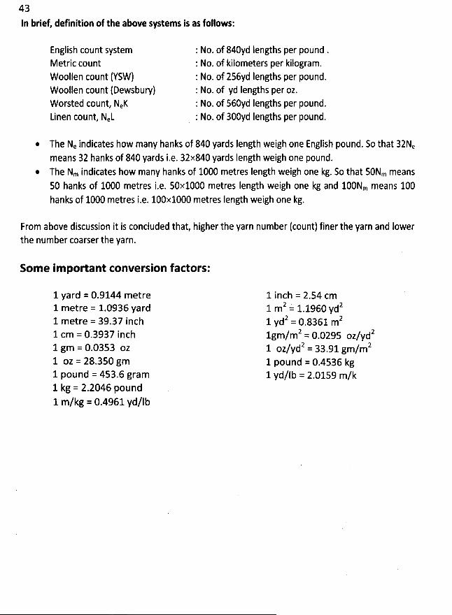
43
In briet definition of the above systems is as follows:
English count systemMetric count
Woollen count (YSW)Woollen count (Dewsbury)Worsted count, NeKLinen count, NeL
The Ne indicates how many hanks of 840 yards Iength weigh one English pound. So that 32Nemeans 32 hanks of 840 yards i.e. 32x840 yards Iength weigh one pound.The Nm indicates how many hanks of 1000 metres Iength weigh one kg. So that 50Nm means50 hanks of 1000 metres i.e. 50x1000 metres Iength weigh one kg and 100Nm means 100hanks of 1000 metres i.e. 100x1000 metres Iength weigh one kg.
: No. of 840yd lengths per pound .: No. of kilometers per kilogram.: No. of 256yd Iengths per pound.: No. of yd Iengths per oz.: No. of 560yd Iengths per pound.: No. of 300yd Iengths per pound.
From above discussion it is concluded that, higher the yarn number (count) finer the yarn and lowerthe number coarser the yarn.
Som e im portant tonversion factors:
1 yard = 0.9144 metre1 metre = 1.0936 yard1 metre = 39.37 inch1 cm = 0.3937 inch1 gm = 0.0353 oz1 oz = 28.350 gm1 pound = 453.6 gram1 kg = 2.2046 pound1 m/kg = 0.4961 yd/lb
1 inch = 2.54 cm2 1 1960 yd21 m = .
2 0 8361 m21 yd = .
2 0 0295 oz/ydzlgm/m = .2 33 91 gm/m21 oz/yd = .
1 pound = 0.4536 kg1 yd/lb = 2.0159 m/k
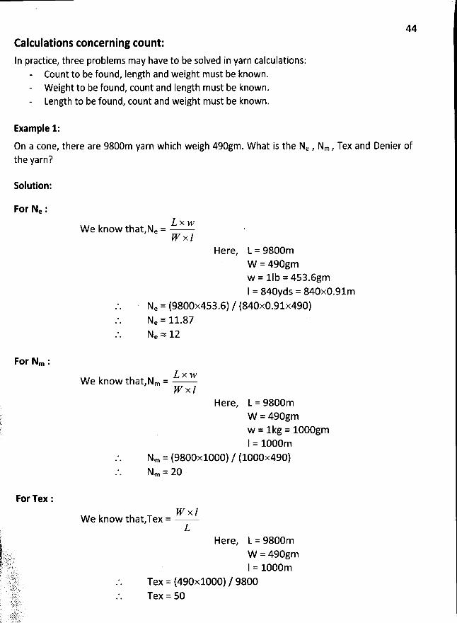
44
Ealculations concerning count:In practice, three problems may have to be solved in yarn calculations:
- Count to be found, Iength and weight must be known.W eight to be found, count and Iength must be known.Length to be found, count and weight must be known.
Example 1:
On a cone, there are 9800m yarn which weigh 490gm. W hat is the Ne , Nm , Tex and Denier ofthe yarn?
Solution:
For Ne :L x wW
e know that,Ne =pr x l
Here, L = 9800mW = 490gmw = 1Ib = 453.6gmI = 840yds = 840x0.91m
Ne = (9800x453.6) / (840x0.91x490)Ne = 11.87Ne = 12
For Nm :L x wW
e know that,Nm =I'F' x l
Here, L = 9800mW = 490gmw = 1kg = 1000gml = 1000m
Nm = (9800x1000) / (1000x490)Nm = 20
For Tex :pr x /W
e know thatTex =L
Here, L = 9800mW = 490gmI = 1000m
Tex = (490x1000) / 9800Tex = 50
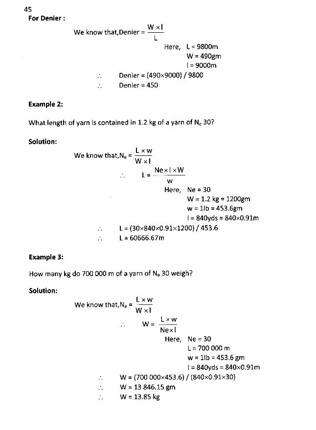
45For Denier :
W x IW e know thatDenier =
LHere, L = 9800m
W = 490gmI = 9000m
Denier = (490x9000) / 9800Denier = 450
Example 2:
w hat Iength of yarn is contained in 1.2 kg of a yarn of Ne 30?
Solution:L x w
W e know that,Ne =W x l
Nex I xWL =
W
Here, Ne = 30W = 1.2 kg = 1200gmw = 1Ib = 453.6gmI = 840yds = 840x0.91m
L = (30x840x0.91x1200) / 453.6L = 60666.67m
Exam ple 3:
How many kg do 700 000 m of a yarn of Ne 30 weigh?
Solution:L x w
W e know that,Ne =W x I
LxwW=
Ne x IHere, Ne = 30
L = 700 000 mw = 1Ib = 453.6 gml = 840yds = 840x0.91m
W = (700 000x453.6) / (840x0.91x30)W = 13 846.15 gmW = 13.85 kg
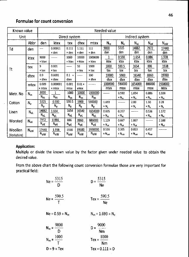
46
Formulae for count conversion
Known value Needed valueUnit Direct system Indirect system
Abbr den ktex tex dtex mtex Nm Ne NeL NeK New'u den -- 0.00011 0.111 1.111 111 Sûûû 5315 11882 7972 17449
x den x den x den x den den den ien den denktex 9000 --- 1000 10000 1000000 1 0.590 1,654 9.226 1.938
x ktex x ktex x ktex x ktex ktex ktex ktex ktex ktextpv 9 0.001 -- 10 1000 lûûû 59û.5 1654 826 1932
Tt --- x tex x tex x tex x tex tex tex tex tex tex
jtex 0.9 0.0001 0.1 x -- 100 lûûûû 59(5 16549 2269 19329x itex x dtex dtex x dtex dtex dtex dtex dtex dtex
mtex 0.009 0.000001 0.001 0.01 x --- lûûûûûû 590022 1654(50 826(59 1932999x mtex x mtex mtex mtex mtex mtex mtex mtex mtex
Metr. No Nm -9tXC 1 10ûC lûûoc lûoûûûo --- 0.590 1.654 0.886 1.938'Nm Nm Nm Nm Nm x Nm x Nm x Nm x Nm
ccttcn N. 5315 0.590 590.5 5900 590000 1.693 --- 2.80 1.50 3.28'
< N N N N N x N x N x N x Ne e e e e e e e e
ginen Nek 14822 1.651 1654 16540 1654000 0.605 0.357 --- 0.536 1.172NeL NeL NeL NeL NeL x Net x Nek x Net x Net
worsted Ner 7972 0.886 886 2260 286000 1.129 0.667 1.867 --- 2.188Nek Nek NeK Ner Nek x NeK x Nex x NeK x NeK
Woollen New 17440 1.938 1938 19380 1938000 0.516 0.305 0.853 0.457 ---New New New NeW NeW x New x New x New x New(Yorkshire)
Application:Multiply or divide the known value by the factor given under needed value to obtain thedesired value.
From the above chart the following count conversion formulae those are very important forpractical field:
5315 5315Ne = D =
D Ne
590.5 590.5Ne = Tex =
T Ne
Ne = 0.59 x Nm Nm = 1.693 x Ne
9000 9000Nm = D =
D Nm100â 1000N
m= Tex=T Nm
D = 9 x Tex Tex = 0.111 x D
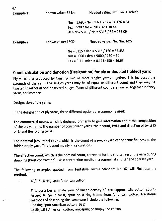
47Example 1: Known value: 32 Ne Needed value: Nm, Tex, Denier?
Nm = 1.693xNe = 1.693x32 = 54.176 = 54
Tex = 590 / Ne = 590 / 32 = 18.44Denier = 5315 / Ne = 5315 / 32 = 166.09
Example 2: Known value: 150D Needed value: Ne, Nm, Tex?
Ne = 5315 / den = 5315 / 150 = 35.433Nm = 9000 / den = 9000 / 150 = 60Tex = o.lllxden = 0.111x150 = 16.65
Count calculation and denotion (Designation) for pIy or doubled (folded) yarn:Ply yarns are produced by twisting two or more singles yarns together. This increases thestrength of the yarn. The singles yarns may be of equal or different count and they may betwisted together in one or several stages. Yarns of different count are twisted together in fancy
yarns, for instance.
Designation of ply yarns:
In the designation of pIy yarns, three different options are commonly used:
The tommertial count, which is designed ptimarily to give information about the compositionof the pIy yarn, i.e. the number of constituent yarns, their count, twist and direction of twist (Sor Z) and the folding twist.
The nominal (resultant) tount, which is the count of a singles yarn of the same fineness as thefolded or pIy yarn. This is used mainly in calculations.
The effedive count, which is the nominal count, corrected for the shortening of the yarn during
doubling (twist contraction). Twist contraction results in a somewhat shorter and coarser yarn.
The following examples quoted from Tentative Textile Standard No. 62 will iflustrate the
method.
40/1 Z 16 ring-spun American cotton
This describes a single yarn of linear density 40 tex (approx. 15s cotton count),having 16 tpi. Z twist, spun on a ring frame from American cotton. Traditional
.
'
methods of describing the same yarn include the following:15s ring-spun American cotton, 16 Z;
1/15s, 16 Z American cotton, ring-spun; or simply 15s cotton.
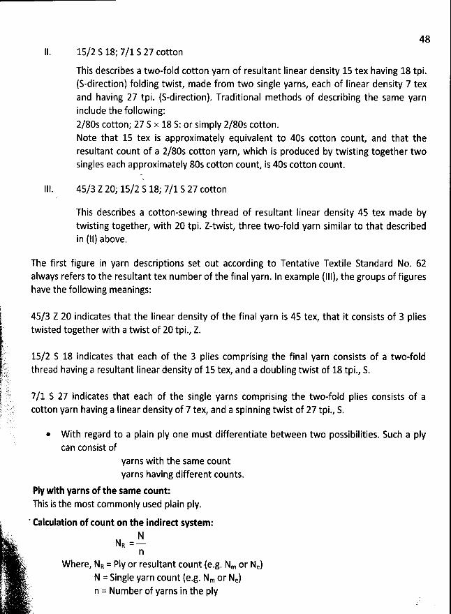
4815/2 S 18; 7/1 S 27 cotton
This describes a two-fold cotton yarn of resultant linear density 15 tex having 18 tpi.(S-direction) folding twist, made from two single yarns, each of Iinear density 7 texand having 27 tpi. (S-direction). Traditional methods of describing the same yarninclude the following:
2/80s cotton; 27 S x 18 S: or simply 2/80s cotton.Note that 15 tex is approximately equivalent to 40s cotton count, and that theresultant count of a 2/80s cotton yarn, which is produced by twisting together twosingles each approximately 80s cotton count, is 40s cotton count.
45/3 Z 20; 15/2 S 18; 7/1 S 27 cotton
This describes a cotton-sewing thread of resultant Iinear density 45 tex made bytwisting together, with 20 tpi. Z-twist, three two-fold yarn similar to that describedin (11) above.
The first figure in yarn descriptions set out according to Tentative Textile Standard No. 62always refers to the resultant tex number of the final yarn. In example (111), the groups of figureshave the following meanings:
45/3 Z 20 indicates that the Iinear density of the final yarn is 45 tex, that it consists of 3 pliestwisted together with a twist of 20 tpi., Z.
15/2 S 18 indicates that each of the 3 plies comprising the final yarn consists of a two-foldthread having a resultant Iinear density of lstex, and a doubling twist of 18 tpi., S.
7/1 S 27 indicates that each of the single yarns comprising the two-fold plies consists of acotton yarn having a linear density of 7 tex, and a spinning twist of 27 tpi., S.
* W ith regard to a plain pIy one must differentiate between two possibilities. Such a pIycan consist of
yarns with the same countyarns having different counts.
PIy with yarns of the same count:This is the most commonly used plain ply.
I ' Eakulation of count on the indired system:z't.t I!'ikI
. 2:t4 j!jjjl :::::s RtL)gr. Ir.!l' (.y-.t Where, NR = Ply or resultant count (e.g. Nm or Ne)
;.., z' N = Single yarn count (e.g. Nm or Ne)q-p !? êqt.t,,, .
.,. n = Number of yarns in the pIyL.: )jj, :. -r'.. r. .y(y.;.
49Example 1: A pIy consists of 2 single yarns, each having a count of Nm 50.
NSolution: PIy count NR = -
n
= 50 / 2 = 25 NmExample 2: A p1y consists of 2 single yarns, each having a count of Ne 40.
NSolution: PIy count NR = -
n
= 40 / 2 = 20 NeDenotion or designation based on the indired system:
N/n
The ply in the example is denoted as follows:Nm 50 / 2; Nm 30 / 2 / 3; Nm 40 / 2 / 3 / 4; Ne 40 / 29 Ne 40 / 39 Ne 60 / 2 / 3 etc.
Calculation of count on the dired system:
NR = N x nWhere, NR = PIy or resultant count (e.g. tex or den)
N = Single yarn count (e.g. tex or den)n = Number of yarns in the pIy
Example 1: A ply consists of 2 single yarns, each having a count of 20 tex.
Solution: PIy count NR = N x n= 20 x 2 = 40 tex
Example 2: A ply consists of 3 single yarns, each having a count of 50 den.solution: Ply ceunt NR = 50 x 3
= 50 x 3 = 150 den
Denotion or designation based on the direct system:
N x n
The pIy in the example is denoted as follows:
20 tex x 2; 50 den x 39 330 dtex x 2 x 3 etc.@ Thus the pIy denotion always contains the single yarn counts, written in a prescribed
manner. A knitted fabric is often produced by feeding-in two (very seldom three) yarnsat each feeder without their being twisted previously. lt is important to note that inspite of this the same nomenclature is used for denotion as in the case of a ply.
50Length calculation of a cone of sewing thread :
Example 1: What length of yarn is contained in 95gm of a yarn of Ne 50/2?solution:
L x wWe know that, Ne =
W x INex l xW
L =W
Here, Ne = 50/2 = 25W = 95gmw = 1lb = 453.6gmI = 840yds = 840x0.91m
L = (25x840x0.91x95) / 453.6L = 4002.31m
' From the above calrulation, the formula can be developed to caltulate the Iength of sewing
thread from a tone as follows:-,
For Ne system:L = (NRxW)x(840 x0.9144) / 453.6.'. t = (NR x W) x 1.6933
W here,j L = Length of the yarn in metre (m). NR = Resultant or pIy count of yarn in Ne system.i) :y' W = Weigit Of the Yarn in gramme (gm). 1.6933 = Constant value (0nIy for Ne system);J(
Nm system: L = (NRxW)x1000 / 1000(j. L = Nq X W. w jjrro
.( 2', .L
, L = Length of the yarn in metre (m) : t.è , NR = Resultant or pIy count of yarn * ' lte p W = Weight of the yarn in gramme (gm)13. : rt .. '7 ;?:' ?7 ) # .#...k .s .8A. ' E ' ). ..>=' ' y)
f',
.J..y 'ls
. q.
t'V.); .
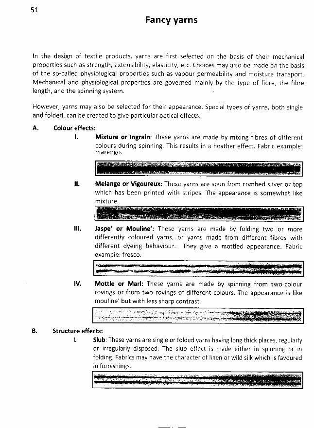
51
Fancy yarns
In the design of textile products: yarns are first selected on the basis of their mechanicalproperties such as strength, extensibility, elasticity, etc. Choices may also be made on the basisof the so-called physiological properties such as vapour permeability and moisture transport.Mechanical and physiological properties are governed mainly by the type of fibre, the fibreIength, and the spinning system . .
However, yarns may also be selected for their appearance. Special types of yarns, both singleand folded, can be created to give particular optical effects.
Colour effects:1. Mixture or Ingrain: These yarns are made by mixing fibres of different
colours during spinning. This results in a heather effect. Fabric example:marengo.
Melange or Vigoureux: These yarns are spun from combed sliver or topwhich has been printed with stripes. The appearance is somewhat Iikem ixture.
. . . ' ' - '.' .. o . ' . -. . . . ' .. . .. . . . . ... . . . . . ... ..e. . .-ér u ' -. -.i1
IV.
laspe' or Mouline': These yarns are made by folding two or moredifferently coloured yarns, or yarns made from different fibres withdifferent dyeing behaviour. They give a mottled appearance. Fabricexam ple: f resco.
. . . . . . . . . . . . . : .'' .:.u L; ; . . qkr. .r;tr :: e... . 7( . . ... . n. :. )w î .n( !::trL.'. s T$ ï )r .k. .,.4
Mottle or Marl: These yarns are made by spinning from two-colourrovings or from two rovings of different colours. The appearance is Iikemouline' but with Iess sharp contrast.. - Jy.7 . > - .a . è *--a.- <..- -x l '. .%'w*.r..... e (t af:kp.ùyL .w I ;' )ï@:r . t..-tt sbjt... r . . . . %x . . (. s.. . .s.-..ù.i. '' J ' ' . ' . ç'.: : ' ' ' ' .r :% kr 2i?. 1:..2:r >' '. .@. . ôtr. . rlytltk.. . . r!;:cL .r : . . t.q'l . . . r7 . k.w;t')yp w. j y . . j . . . .v . jgj; '. jyy .zjy.,;
'
ys.. . . . . . g; c ,) y ;yu . . . . .s . .cc ....m.-. -.w v -,.. ,.,,.pr.......wwjr.uwp),>+çw<u-g;.t..wz,,;y.. v.ryaa,sl-jseyrrzzzyrztzl.--,-sw.ws:.zw. . .ajt+u ,.u. / .s , ' . .
B. Structure effed s:1. Nub: These yarns are single or folded yarns having long thick places, regularly
or irregularly disposed. The slub effect is made either in spinning or infolding. Fabrics may have the character of Iinen or wild silk which is favouredin furnishings.
' y- . . .. . . . . ..o .: . . . j . .y . oy ug r .Js ..zr z 1..x . .a. . . g .. . . . . . a : .:k : n; w.. s .
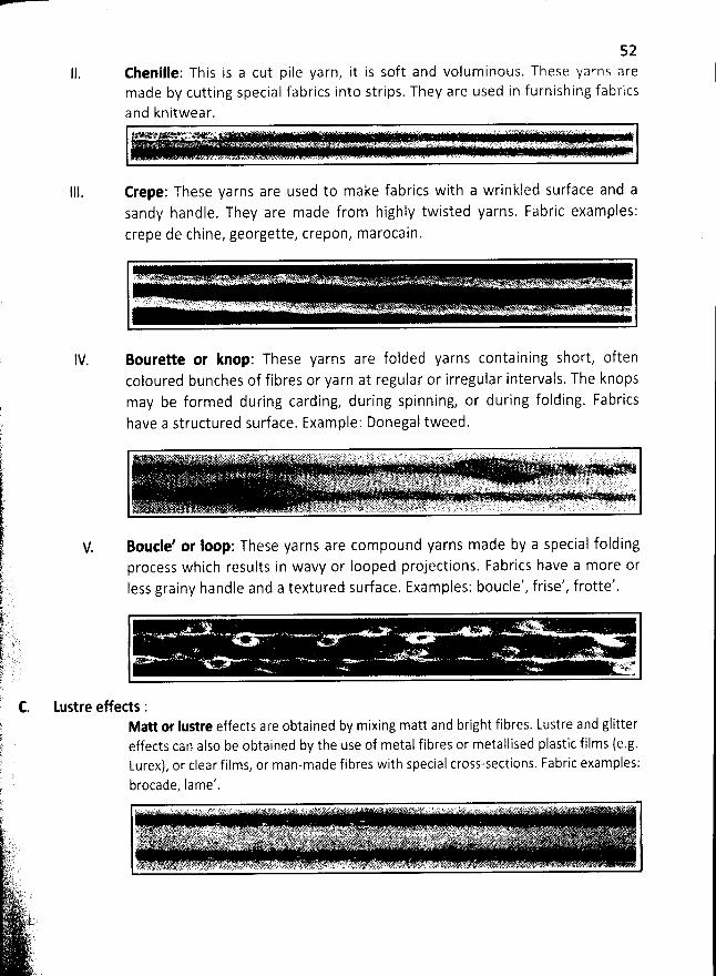
52Chenille: This is a cut pile yarn, it is soft and voluminous. These yarns aremade by cutting special fabrics into strips. They are used in furnishing fabrics
and knitwear.v u1 - ' ' ' .% ' . . . . . . . . .. TLU .;. . y h,; . g. . ..w o . . a z y.>. . v .. ..> ) - ; . . . . . . . .. J . . ..x oy . ..'......o ... ; : Qi . ...t c 7f; .. Vk (...$ z t.. . .. . ..). 7 .. ' ' à j. ' 'Ls. yzftgy y).t.,! u ;n: s. . c u <u.. y-sè.. 'E
Erepe: These yarns are used to make fabrics with a wrinkled surface and asandy handle. They are made from highly twisted yarns. Fabric examples:crepe de chine, georgette, crepon, marocain.
Bourette or knop: These yarns are folded yarns containing short, oftencoloured bunches of fibres or yarn at regular or irregular intervals. The knopsmay be formed during carding, during spinning, or during folding. Fabricshave a structured surface. Example: Donegal tweed.
V. Boude' or loop: These yarns are compound yarns made by a special foldingprocess which results in wavy or Iooped projections. Fabrics have a more orIess grainy handle and a textured sudace. Examples: boucle', frise', frotte'.
Matt or lustre effects are obtained by mixing matt and bright fibres. Lustre and glittereffects can also be obtained by the use of metal fibres or metallised plastic films (e.g.Lurex), or clear films, or man-made fibres w'lth special cross-sections. Fabric examples:brocade Iame'.?
'
... &: er c . . ... >:. t /@ x ) L 'L. tt ï .R t2%Y k - ï; t:@ 2 <. u'' % 7: f 'z>' 4! qtk L - w '' * . à 4+5 a ;. a( j' (/.. .nz 1 . . e .1 ee . ' œk B T :
y' tjjjo.' ; .1.'. Gf ' k>j )%'.j )y .x. v ' .... .p. . . . a J.4' ljjz'js ( tjk yyyjjjjtjykjgg jjyqjjj j x .j . . . . ;q.yjjhyyy. yjs,jy j yjji j,.gs y .js. jy p . .. .a. , kzw ! ... i . th).i!F!qrpaj;'; rskj .yjkâîs y n.t;fq;Lit-L.L jjayk.. ,p>':. é. y(We+#. alj.g .ky. s.su*m4x.%wx .)u.u)s-yj,t1k 4;.u . àï. .t;j;j,.. 4k;4a(,r))hE7r. . :p:.p. ;rq t. zzg... . t,.. y ?.)jjy.L g..(y. ;;,kj;-s.s x.;s... . . . . : . . ...a .llg'.. .:) ' L' . :a.t .Jr). C.. ' ,:$,/ 2 .$? i'jjzwgrgykhlpï' ,. ...r . .j. ,y .. A . tqùs. 4tj(111jk54 .. ... . . .. . a;t. - .tswy :C@1... ..#a.ï.y.'tz'..#p+ .. .v. - ,.N!r ;-;éLh . w.- . .,... .. . ;L ' - ïp féj?:' 4#. . . - . . . . ( .- . 2 n . . .jF,k.E . . . -.. . . . .. y . .. . .. /î p.l' . . . . . . .
?.%%Kx ).I ' . ' 1è' 's :ê. â'.w' >vû ïyr2i)jéi2'. tvL-.' :k., !. .'RJ)# :774)t .'.<s(.,< ((/:. !,:rl<t4..; p Tiq: $ piti :j9# 1. éùa.'kët . *-..àœ.. .s . '' t&..h...'t..,.'.a%;.' vs. v..: ..'., .'., a. . z,s... . xc z.. ... ... ... . .. .- . . . .c . -
C. Lustre effects :
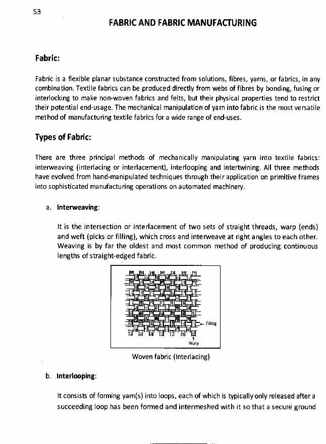
53
FABRIC AND FABRIC MANUFACTURING
Fabric:
Fabric is a flexible planar substance constructed from solutions, fibres, yarns, or fabrics, in anycombination. Textile fabrics can be produced directly from webs of fibres by bonding, fusing orinterlocking to make non-woven fabrics and felts, but their physical properties tend to restricttheir potential end-usage. The mechanical manipulation of ya rn into fabric is the most versatilemethod of manufacturing textile fabrics for a wide range of end-uses.
Types of Fabric:
There are three principal methods of mechanically manipulating yarn into textile fabrics:interweaving (interlacing or interlacement), interlooping and intertwining. AII three methodjhave evolved from hand-manipulated techniques through thei r application on primitive f ramesinto sophisticated manufacturing operations on automated machinery.
a. Interweaving:
It is the intersection or inte rlacement of two sets of straight threads, warp (ends)and weft (picks or filling), which cross and interweave at right a ngles to each other.W eaving is by far the oldest and most common method of producing continuousIengths of straight-edged fabric.
Woven fabric (Interlacing)
b. Interlx ping:
It consisl of forming yarnts) into Ioops, each of which is typically only released after asucceeding Ioop has been formed and intermeshed with it so that a securi ground
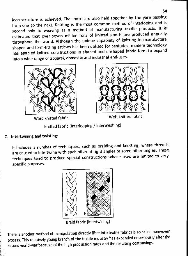
54
Ioop structure is achieved. The loops are also heîd together by the yarn passingfrom one to the next. Knitting is the most com mon method of interloping and issecond only to weaving as a method of manufacturing textile products. lt isestimated that over seven midlion tons of knitted goods are produced annuallythroughout the world. Although the unique capability of knitting to manufactureshaped and form-fitting articles has been utilized for centuries, modern technologyhas enabled knitted constructions in shaped and unshaped fabric form to expand
into a wide range of apparel, domestic and industrial end-uses.
W arp knitted fabric W eft knitted fabric
Knitted fabric (Interlooping / lntermeshing)
C. Intertwining and twisting:
It includes a number of techniques, such as braiding and knotti ng, where threadsare caused to intertwine with each other at right angles or some other angles. Thesetechniques tend to produce special constructions whose uses are limited to very
specific purposes.
'-% yxxyyx ),k% A. kk z
y G #yy,J' yh 4ebtsyhs Axs%' &k. khxszz/o ;,''> y ,y.% k%s 4..X>t- .,/' ck
. :;.ktyzo),.f vks 'ttt ,:..4-
k s#' zfkt-xx,:b , 'è7 ',p: .,, . . v.a
, Braid fabric (Intertwining)
.
There is another method of manipulating directly fibre into textile fabrics is so caçled nonwoven process. This relatively young branch of the textile industry has expanded enormously after the
second world-war because of the high production rates and the resulting cost savings.:
.
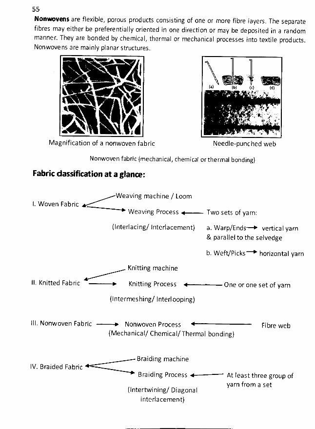
55None ve s are flexible, porous products consisting of one or more fibre layers
. The separatefibres may either be preferentially oriented in one directi on or may be deposited in a randommanner. They are bonded by chemical, thermal or mechanical processes into textile products.Nonwove ns are mainly planar structures.
y w y ju. , , , < a> . .t&
y.y jex'N3. . .,- . -51'!!1111111111111111111111111:-
.
. !l111I11111llll1.,,j----- . .11ù''-t- (, -jjjjjjl
Magnification of a nonwoven fabric Needle-punched web
Nonwoven fabric (mechanical, chemical or thermal bonding)
Fabric dassifir- ion at a glanœ :
Weaving machine / Loom1. W oven Fabric
W eaving Process Two sets of yarn:
(Interlacing/ Interlacement) a. Warp/Ends--+ vertical yarn& parallel to the selvedge
b. Weft/picks----+ horizontal yarn
Knitting machine
lI. Knitted Fabric Knitling Process One or one set of yarn
(Intermeshing/ Interl ooping)
111. Nonwoven Fabric -----+ Nonwoven Process Fibre web
(Mechanical/ Chemical/Thermal bonding)
Braiding machineIV. Braided Fabric
Braiding Process At Ieast three group of
yarn from a set(Intertwining/ Diagonalinterlacement)
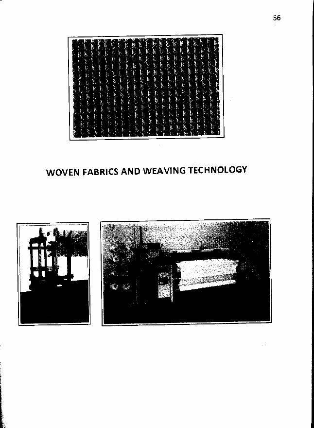
56
W OVEN FABRICS AND W EAVING TECHNOLOGY
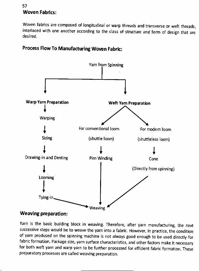
57
Rvoven FabKcs:
W oven fabrics are composed of Iongitudinal or wa rp threads and transverse or weft threads,
interlaced with one another according to the class of structure and form of design that aredesired.
Process Flow To M anufacturing W oven Fabric:
Yarn from Spinning
W arp Yarn Prm aration
iWarping
iSizing
W eR Yam Preparation
For conventional Ioom For modern Ioom
(shuttle Ioom) (shuttleless Ioom)
lDrawing-in and Denting
iPirn W inding
iCone
) (Directly from spinning)Looming
Tying-in
W eavingW eaving preparation:
Yarn is the basic building block in weaving. Therefore, after yarn manufacturing, the nextsuccessive steps would be to weave the yarn into a fabric. However, in practice, the conditionof yarn produced on the spinning machine is not always good enough to be used directly forfabric formation. Package size, yarn surface characteristics, and other factors make it necessaryfor b0th weft yarn and warp yarn to be further processed for efficient fabric formation
. Thesepreparatory processes are called weaving preparation.
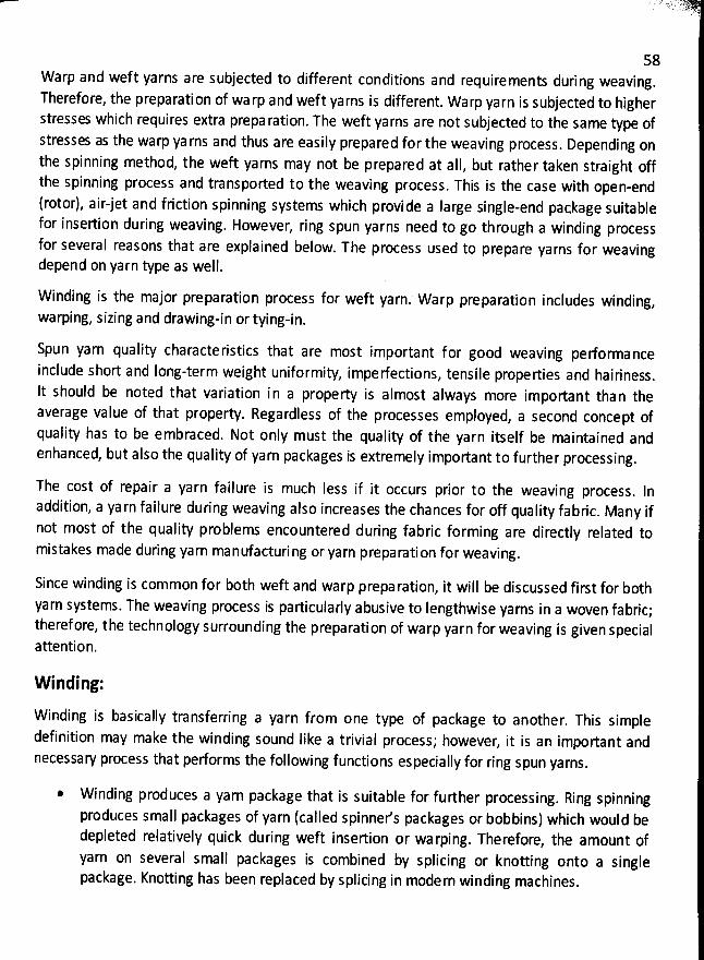
58Warp and weft yarns are subjected to different conditions and requirements duri ng weaving.Therefore, the preparation of wa rp and weft yarns is different. Warp yarn is subjected to higherstresses which requires extra prepa ration. The weft yarns are not subjected to the same type ofstresses as the warp ya rns and thus are easily prepared for the weaving process
. Depending onthe spinning method, the weft yarns may not be prepared at all, but rather taken straight offthe spinning process and transported to the weaving process. This is the case with open-end(rotor), airjet and friction spinning systems which provide a large single-end package suitablefor insertion during weaving. However, ring spun yarns need to go through a winding processfor several reasons that are explained below. The process used to prepare yarns for weavingdepend on yarn type as well.
Winding is the major preparation process for weft yarn. Warp preparation includes winding,warping, sizing and drawing-in or tying-in.
Spun yarn quality characteristics that are most important f or good weaving pe/orma nceinclude short and Iong-term weight uniformity
, imperfections, tensile properties and hairiness.lt should be noted that variation in a property is almost always more important than theaverage value of that property. Regardless of the processes employed, a second concept ofquality has to be embraced. Not only must the quality of the yarn itself be maintained andenhanced, but also the quality of yarn packages is extremely important to further processing
.
The cost of repair a yarn failure is much less if it occurs prior to the weaving process. ln
addition, a ya rn failure during weaving also increases the chances for off quality fabric. Many if
not most of the quality problems encountered during fabric forming are directly related tomistakes made during yarn manufacturi ng or yarn preparation for weaving.
Since winding is common for both weft and warp prepa ration, it will be discussed first for both
yarn systems. The weaving process is particularly abusive to Iengthwise yarns in a woven fabric;therefore, the technology surrounding the preparation of warp yarn for weaving is given specialattention.
W inding:
Winding is basically transferring a yarn from one type of package to another. This simpledefinition may make the winding sound like a trivial process; however
, it is an important andnecessary process that performs the following functions especially for ring spun yarns
.
W inding produces a yarn package that is suitable for further processing. Ring spinning
produces small packages of yarn (called spinner's packages or bobbins) which would bedepleted relatively quick during weft inselion or warping. Therefore, the amount ofyarn on several small packages is combined by splicing or knotting onto a singlepackage. Knotting has been replaced by splicing in modern winding machines
.
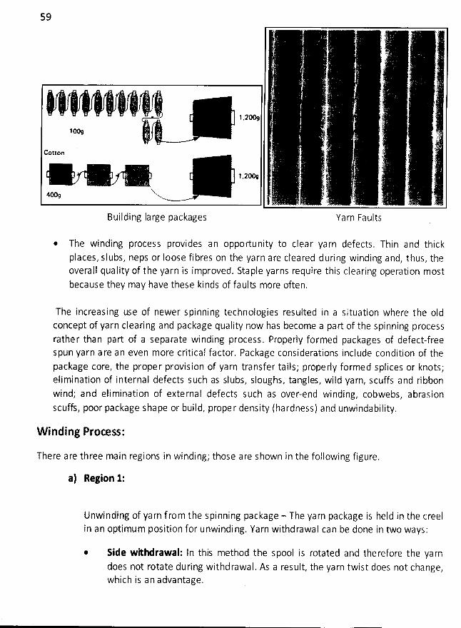
59
' T
. . (t . ..) t
. .
y 'O /. - ' ' -' , ---, ---' ---''--, ' .' ''.-'' . '..'' .'--'' ' '' '..''1% li .su .;:
Cotlon . ' ;.
'
,- .. -. ..
'
--
'
--
'
..
'
.
'
..
.
..
.
'
..
..
'
:.
.
'
.
'
ïk-
W. . - ..- - 8 ' ' ' '* ' ' . , , '.. Eq . ...t' .) .
Building Iarge packages Yarn Faults
* The winding process provides an opportunity to clear yarn defects. Thin and thickplaces, slubs, neps or Ioose fibres on the yarn are cleared during winding and, thus, theoverall quality of the yarn is improved. Staple yarns require this clearing operation mostbecause they may have these kinds of faults more often.
The increasing use of newer spinning technologies resulted in a situation where the oIdconcept of yarn clearing and package quality now has become a part of the spinning processrathe r than part of a separate winding process. Properly formed packages of defect-freespun yarn a re an even more critical factor. Package considerations include condition of thepackage core, the prope r provision of yarn transfer tails; prope rIy formed splices or knots;elimination of internal defects such as slubs, sloughs, tangles, wild yarn, scuffs and ribbonwind; and elimination of external defects such as over-end winding, cobwebs, abrasionscuffs, poor package shape or build, proper density (hardness) and unwindabilitv.
W inding Process:
There are three main regions in winding; those are shown in the following figure.
a) Region 1:
Unwinding of yarn f rom the spinning package - The yarn package is held in the creelin an optimum position for unwindi ng. Yarn withdrawal can be done in two ways :
Side wkhdrawal: In this method the spool is rotated and therefore the yarndoes not rotate during withdrawal. As a result, the yarn twist does not change,which is an advantage.
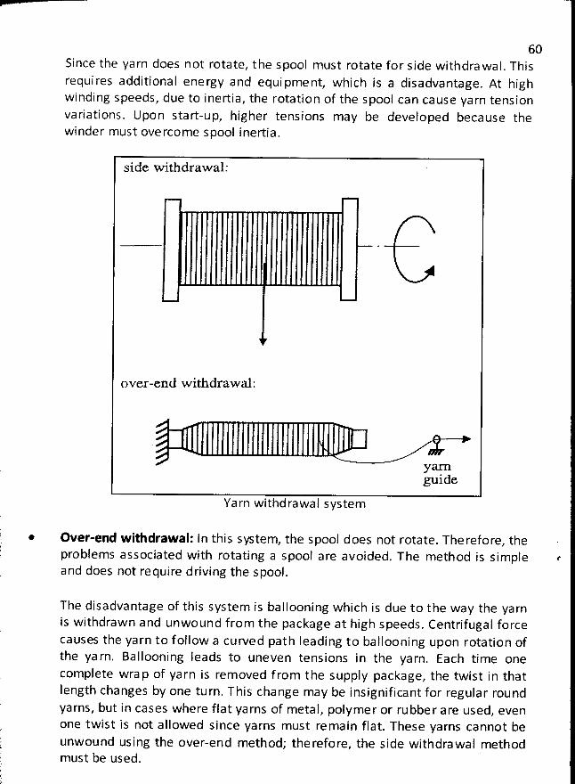
*
60Since the yarn does not rotate, the spool must rotate for side withdrawal. Thisrequi res additional energy and equi pment, which is a disadvantage. At highwinding speeds, due to inertia, the rotation of the spool can cause yarn tensionvariations. Upon start-up, higher tensions may be developed because thewinder must overcome spoo! inertia.
side w ithdraw al:
over-end w ithdraw z :
ynrnguide
Yarn withdrawal system
Over-end withdraw al: In this sp tem, the spool does not rotate. Therefore, theproblems associated with rotating a spool are avoided. The method is sim ple eand does not require driving the spool.
The disadvantage of this system is ballooning which is due to the way the yarnis withdraw n and unwound from the package at high speeds. Centrifugal forcecauses the yarn to f ollow a curved path leading to ballooning upon rotation ofthe ya rn. Ballooning leads to uneven tensions in the yarn. Each time onecomplete wra p of yarn is rem oved f rom the supply package, the twist in thatlength changes by one turn. This change may be insignificant for regular roundyarns, but in cases where flat yarns of metal, polymer or rubber are used, evenone twist is not allowed since yarns must remain flat. These yarns cannot be r1unw ound using the over-end method; therefore, the side withdrawal method !must be used.
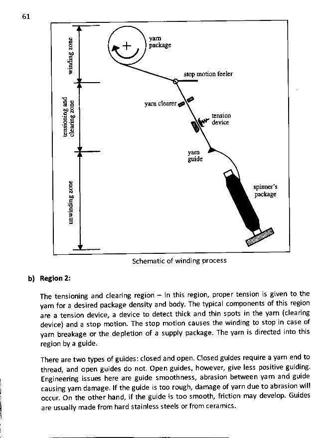
61
ia y arnox + PKW e.ô
Y stop motion feeler
= o 4:5 x yau clerery,x os.Q x tem jon>
.:.Q : device*> aS o
ymnD ide
e< .o sphmer sKx packageQ+- 11!<>
%.t :t: 'S'x#>
thtz
Schematic of winding process
b) Region 2:
The tensioning and clearing region - In this region, proper tension is given to theyarn for a desired package density and body. Tbe typical components of this region
are a tension device, a device to detect thick and thin spots in the yarn (clearingdevice) and a stop motion. The stop motion causes the winding to stop in case ofyarn breakage or the depletion of a supply package. The yarn is directed into this
region by a guide.
There are two types of guides: closed and open. Closed guides require a yarn end tothread, and open guides do not. Open guides, however, give Iess positive guiding.Engineering issues here are guide smoothness, abrasion between ya rn and guidecausing yarn damage. If the guide is too rough, damage of yarn due to abrasion willoccur. On the other hand, if the guide is too smooth, friction may develop. Guides
are usually made from hard stainless steels or from ceramics.
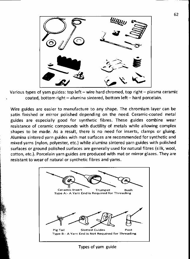
62. . . w .,
. ''
w . - . -w wj * ' w''
. .
/ 01t:::::14 ,-.-'' . ... .. ...
/ .
es > N
. f .> w ,- . kt. ...<
67 . .. .xzz x #' V
Various types of yarn guides: top left - wire hard chromed, top right - plasma ceramiccoated, bottom right - alum ina sintered, bottom Ieft - hard porcelain.
W ire guides are easier to manufacture to any shape. The chromium Iayer can besatin finished or mirror polished dependi ng on the need. Ceramic-coated metalguides are especially good for synthetic fibres. These guides com bine wearresistance of ceramic compounds with ductility of metals while allowing com plexshapes to be made. As a result, there is no need for inserts, clamps or gluing.Alum ina sintered yarn guides with mat surfaces are recom mended for synthetic andmixed yarns (nylon, polyester, etc.) while alumina sintered yarn guides with polishedsurfaces or ground polished sudaces are generally used for natural fibres (silk, wool,cotton, etc.). Porcelain yarn guides are produced with mat or mirror jlazes. They areresistant to wear of natural or synthetic fibres and yarns.
Ceram ic Inser't Trum pet BuslaTvpe A:- A Yarn End is Required for Threading
o <- '
Pig Tail Slotted Cuides PostTvpe B:- A Yarn End is Not Required for Threading
Types of yarn guide
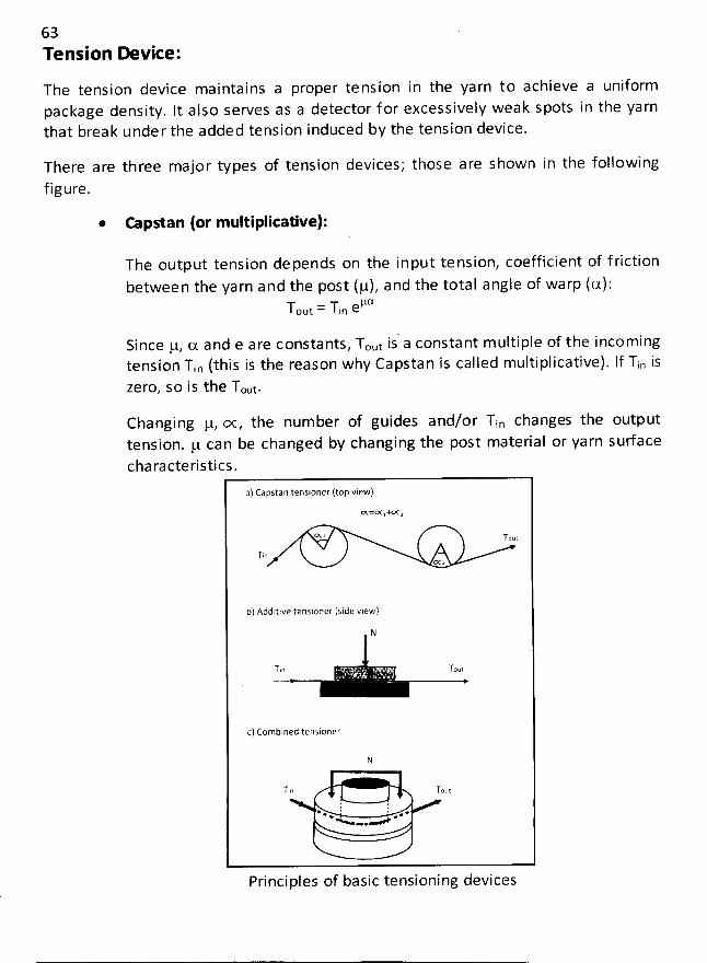
63Tension Y vice:
The tension device maintains a proper tension in the yarn to achieve a uniformpackage density. lt also serves as a detector f or excessively weak spots in the yarnthat break under the added tension indtnced by the tension device.
There are three major types of tension devices; those are shown in the followingfigure.
@ rmpstan (or multiplitative):
The output tension depends on the input tension, coefficient of f riction
betwee n the yarn and the post (g), and the total angle of warp (a):Y = Yin CVCOut
Since g, (x and e are constants, Tout is' a constant m ultiple of the incoming
tension Tin (this is the reason why Capstan is called multiplicative). lf Tio iszero, so is the Txt.
Changing g, œ , the number of guides and/or Tin changes the outputtension. g can be changed by changing the post material or yarn sudace
characteristics.
a) Capstan tensioner (top view)oçzrlxlxxxa
CN : 'r r0U
TInœ 2
b) Additive tensloner (side view)
N
T$n . . Tou!
c) Combined tensioner
N
T.o Tout
E !* * . ** +N -.
Principles of basictensioning devices
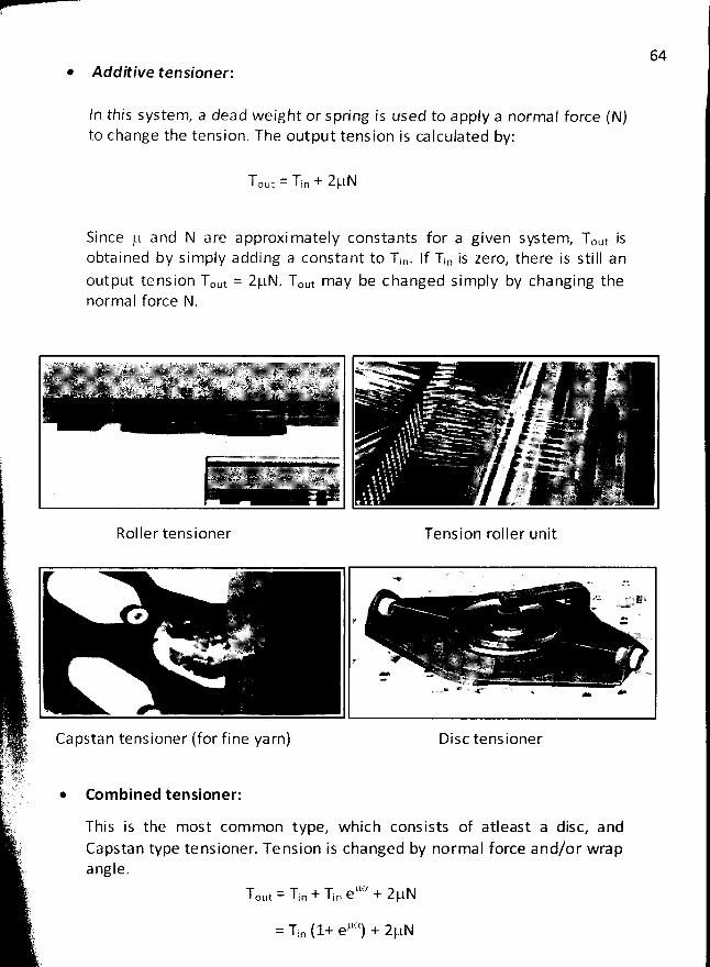
64* Addëive tensioner;
ln this system, a dead weight or spring is used to apply a normal force (N)to change the tension. The output tension is calculated by:
Tout = Tio + 2!-tN
Si nce jt and N are a pproxi mately constants for a given system, Tout isobtained by simply adding a constant to Tin. If Tjn is zero, there is still an
output te nsion Tout = ZgN. Tout may be c hanged simply by changing thenormal force N.
Roller tensioner Tension roller unit
m wrkyj.a+ 'f -
ay . . A:
> e .. '.. v ' r '' ' >
Capstan tensioner (for fine yarn) Disc tensioner
* Com bined tensioner:
This is the most com mon type, which consists of atleast a disc, andCapstan type tensioner. Te nsion is changed by normal force and/or wrapangle.
T t = Tin + Tin e't'x + 2gNOu
= Tin (1+ eB3 + 2gN
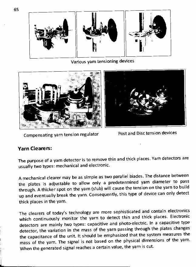
65
),lR , s
ik: a ' f .*j . . . . jj* .
. j
-. . . . Q N . . .> < < - <
.- ''i ' ) L' jl 11 1 .a
' j-
. )
VariousYarntensioningdevices
Post and Disc tension devicesCompensating yarn tension regulator
Yarn Cleareo :
The purpose of a yarn detector is to remove thin and thick places. Yarn detectors are
usualiy two types: mechanical and electronic.
A mechanical clearer may be as simple as two parallel blades. The distance between
the plates is adjustable to allow only a predetermined yarn diameter to passthrough. A thicker spot on the ya rn (slub) will cause the tension on the yarn to buildup and eventually break the yarn. Consequentiy, this type of device can only detect
thick places in the yarn.
The clearers of today's technology are more sophisticated and contain electronicswhich continuously monitor the yarn to detect thin and thick places. Electronicdetectors are mainly two types: capacitive and photo-electric. In a capacitive typedetector, the variation in the mass of the yarn passing througb the plates changesthe capacitance of the unit. It should be em phasized that the system measures themass of the yarn. The signal is not based on the physical dimensions of the yarn.W hen the generated signal reaches a certain value, the yarn is cut.
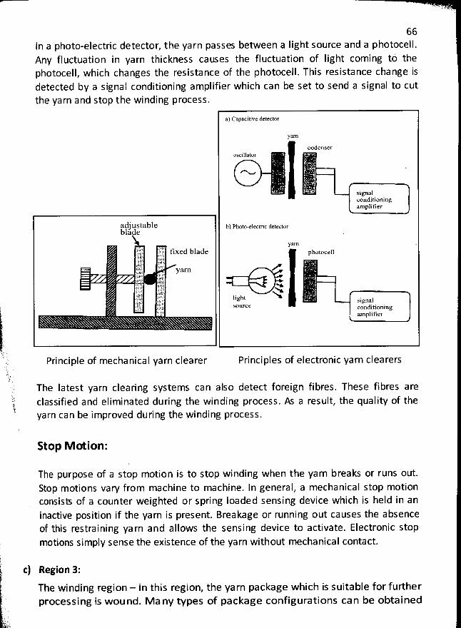
66In a photo-electric detector, the yarn passes between a Iight source and a photocell.Any fluctuation in yarn thickness catses the fluctuation of Iight coming tö thephotocell, which changes the resistance of the photocell. This resistance change isdetected by a signal conditioning amplifier which can be set to send a signal to cutthe yarn and stop the winding process.
a) Capacitive detector
yarn
codenseroscillator
N
. sîgnalconditioningamplitier
adjustable b) photo-elrclric detectorblade% yarn .itj qtjy tixed blade photocell:1'
. l.yk 1,,, xljû y a rn'jz r-.ti ij t t tt .-.Qtk. j) ljgu -h-x iguayrjr .g souree S d soning <.; ),/? con ;. ampl fier)
.1'h.' Principle of mechanical yarn clearer Principles of electronic yarn clearersè)qi..:, The Iatest yarn clearing systems can also detect foreign fibres. These fibres aret classified and eliminated during the winding process. As a result, the quality of the! yarn can be improved during the winding process
.
Stop M G ion:
The purpose of a stop motion is to stop winding when the yarn breaks or runs out.Stop motions vary from machine to machine. In general, a mechanical stop motionconsist of a counter weighted or spring loaded sensing device which is held in aninactive position if the yarn is present. Breakage or running out causes the absenceof this restraining ya rn and allows the sensing device to activate. Electronic stopmotions simply sense the existence of the yarn without mechanical contact.)
p-k c) Region 3:-
) The winding region - In this region, the yarn package which is suitable for furtherprocessing is wound. M a ny types of package configurations can be obtained
.k q
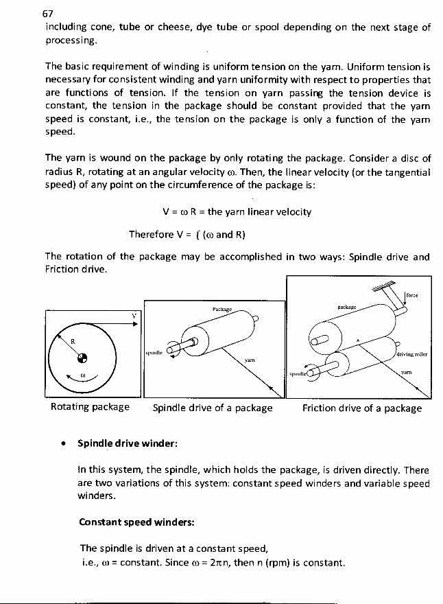
67including cone, tube or cheese, dye tube or spoolprocessing.
depending on the next stage of
The basic requirement of winding is uniform tension on the yarn. Uniform tension isnecessary for consistent winding and yarn uniformity with respect to properties thatare functions of tension. If the tension on yarn passiœ the tension device isconstant, the tension in the package should be constant provided that the yarnspeed is constant, i.e., the tension on the package is only a function of the yarnspeed.
The yarn is wound on the package by only rotati ng the package. Consider a disc of
radius R, rotating at an angular velocity fo. Then, the Iinear velocity (or the tangentialspëed) of any point on the circumference of the package is:
V = to R = the yarn Iinear velocity
Therefore V = f (œ and R)
The rotation of the package may be accomplished in two ways: Spindle drive andFriction drive.
force
packagcPackageV
R A
spindle driving rollerya.l'n
Spindle YZCRœ
Rotating package Spindle drike of a package Friction drive of a package
* Spindle drive w inder:
In this system, the spindle, which holds the package, is driven directly. Thereare two variations of this system : constant speed winders and variable speedwinders.
Constant speed winders:
The spindle is driven at a constant speed,
i.e., fo = constant. Since ç.o = 2an, then n (rpm) is constant.
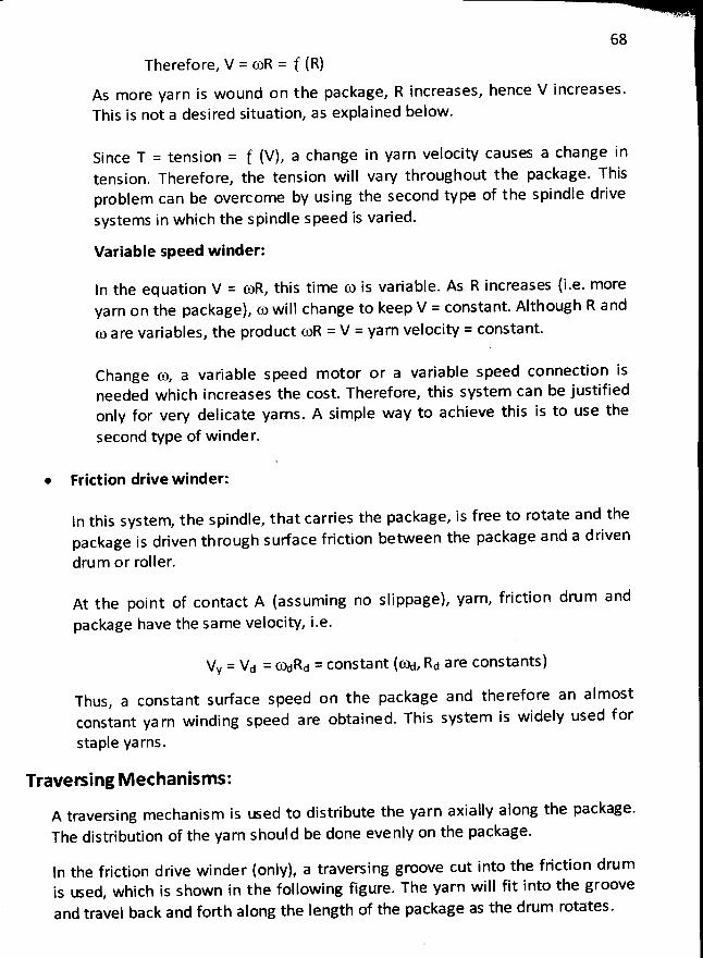
68
Therefore, V = YR = f (R)As more yarn is wound on the package, R increases, hence V increases.This is not a desired situation, as explained below .
Since T = tension = f (V), a change in yarn veçocity causes a change intension. Therefore, the tension will vary throughout the package. Thisprobjem can be overcome by using the second type of the spindle drivesystems in which the spindle speed is varied.
Variable speed winder:
In the equation V = foR, this time fo is variable. As R increases (i.e. moreyarn on the package), fo will change to keep V = constant. Although R and(0 are variables, the product YR = V = yarn velocity = constant.
Change fo, a variable speed motor or a variable speed connection isneeded which increases the cost. Therefore, this system can be justifiedonly for very delicate yarns. A simple way to achieve this is to use the
second type of winder.
* Frittion drive winder:
ln this system, the spindle, that carries the package, is free to rotate and thepackage is driven through sudace friction between the package and a driven
drum or roller.
At the point of contact A (assuming no slippage), yarn, friction drum andpackage have the same velocity, i.e.
Vy = Vd = ftàdRd = constant ((%, Rd are constants)
Thus, a constant sudace speed on the package and therefore an almostconstant ya rn winding speed are obtained. This system is widely used f or
staple yarns.
Traveoing M echanism s:
A traversing mechanism is tsed to distribute the yarn axially along the package.
The distribution of the yarn should be done evenly on the package.
ln the friction drive winder (only), a traversing groove cut into the friction drumis œ ed, which is shown in the following figure. The yarn will fit into the grooveand travel back and forth along the length of the package as the drum rotates.
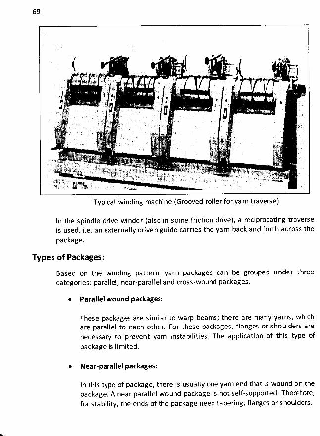
69
Typical winding machine(Grooved roller for ya rn traverse)
In the spindle drive winder (also in some friction drive), a reciprocating traverseis used, i.e. an externally driven guide carries the yarn back and forth across the
package.
Types of Packages:
Based on the winding pattern, yarn packages can be grouped under threecategories: parallel, near-parallel and cross-wound packages.
* Parallel wound packages:
These packages are similar to warp beams; the re are many yarns, whichare parallel to each other. For these packages, flanges or shoulders arenecessaw to prevent yarn instabilities. The application of this type of
package is limited.
* Near-parallel packages:
In this type of package, there is usually one yarn end that is wound on thepackage. A near parallel wound package is not self-supported. Theref ore,for stability, the ends of the package need tapering, flanges or shoulders.
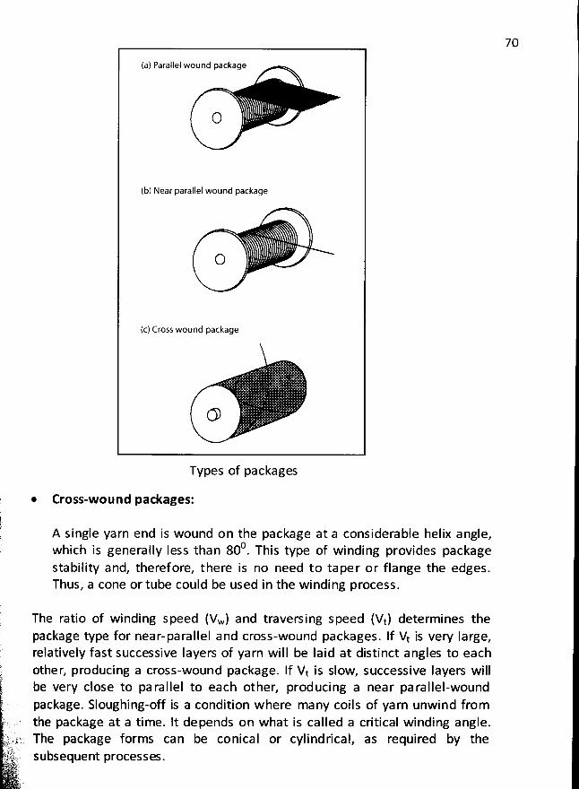
70
(a) Parallel wound package
(b) Near parallel wound package
O
(c) Cross wound package
Types of packages
Cross-wound packages:
A single yarn end is wound on the package at a considerable helix angle,0 This type of winding provides packagewhich is generally Iess than 80 .
stability and, theref ore, there is no need to taper or flange the edges.Thus, a cone or tube could be used in the winding process.
k
'
Erkt
:. .rz x.:fk. 1 : t > .2J . . ) ( . .uht' subsequent processes.,. . uk . .! ?
'kr
The ratio of winding speed (Vw) and traversing speed (Vt) determines thepackage type for near-parallel and cross-wound packages. If Vt is very Iarge,relatively fast successive Iayers of yarn will be Iaid at distinct angles to eachother, producing a cross-wound package. If Vt is slow, successive Iayers willbe very close to pa rallel to each other, producing a near pa rallel-woundpackage. Sloughing-off is a condition w here many coils of yarn unwind fromthe package at a time. lt depends on what is called a critical winding angle.The package forms can be conical or cylindrical, as required by the
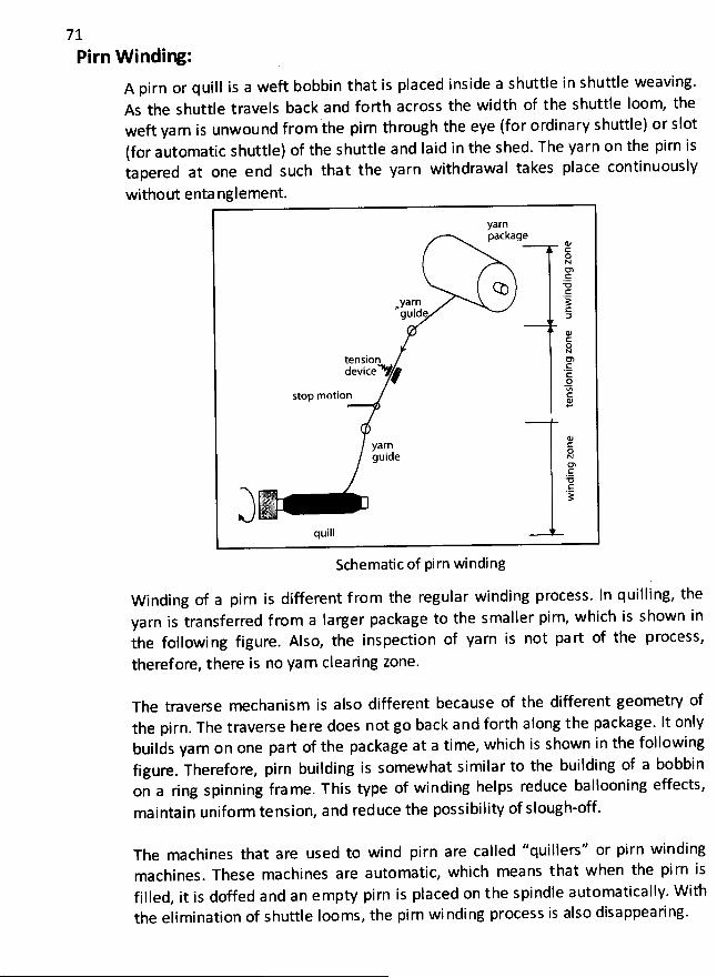
71Pirn Vvinding:
A pirn or quill is a weft bobbin that is placed inside a shuttle in shuttle weaving.As the shuttle travels back and forth across the width of the shuttle loom, theweft yarn is unwound from the pirn through the eye (for ordinary shuttle) or slot(for automatic shuttle) of the shuttle and Iaid in the shed. The yarn on the pirn iso pered at one end such that the yarn withdrawal takes place continuously
without enta nglement.
yarnpackage
œ
G% +.1ë
yarn :&guide cD
tension ohdeviceAYy .Gc
.2stop motion :
yarn 12guide 8
ELo.ER
(1 tlill
Schematic of pirn winding
W inding of a pirn is different f rom the regular winding process. ln quilling, theyarn is transferred f rom a Iarger package to the smaller pirn, which is shown inthe followi ng figure. Also, the inspection of yarn is not pa rt of the process,
theref ore, there is no yarn clearing zone.
The traverse mechanism is also different because of the different geometry ofthe pirn. The traverse here does not go back and forth along the package. It onlybuilds yarn on one part of the package at a time, which is shown in the followingfigure. Therefore, pirn building is somewhat similar to the building of a bobbinon a ring spinning fra me. This type of winding helps reduce ballooning effects,maintain uniform tension, and reduce the possibility of slough-off.
The machines that are used to wind pirn are called ''quillers'' or pirn windingmachines. These machines are automatic, which means that w hen the pi rn isfilled, it is doffed and an empty pirn is placed on the spindle automatically. W it'hthe elimination of shuttle Iooms, the pirn wi nding process is also disappearing.
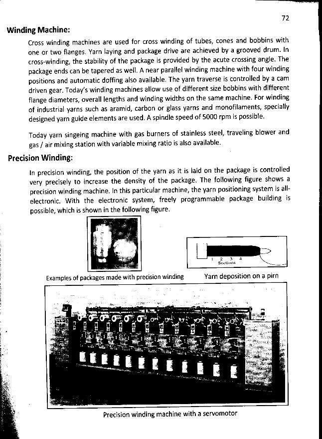
72
W inding Machine:Cross winding machines are used for cross winding of tubes, cones and bobbins withone or two flanges. Yarn laying and package drive are achieved by a grooved drum. Incross-winding, the stability of the package is provided by the acute crossing angle. Thepackage ends can be tapered as well. A near parallel winding machine with four windingpositions and automatic doffing also available. The yarn traverse is controlled by a camdriven gear. Today's winding machines allow use of different size bobbins with differentflange diameters, overall Iengths and winding widths on the same machine. For windingof industrial yarns such as aramid, carbon or glass yarns and monofilaments, speciallydesigned yarn guide elements are used. A spindle speed of 5000 rpm is possible.
Today yarn singeing machine with gas burners of stainless steel, traveling blower and
gas / air mixing station with variable mixing ratio is also available.
Precision W inding:In precision winding, the position of the yarn as it is Iaid on the package is controlledvery precisely to increase the density of the package. The following figure shows aprecision winding machine. ln this particular machine, the yarn positioning system is alI-electronic. W ith the electronic system, freely programmable package building is
possible, which is shown in the following figure.
.( tt . 'u:u'#-ttvv't :t v -. '1. a .. .
. :% 861 ' '. y sjy. 1 2 3 4.
Sections
Examples of packages made with precision winding Yarn deposition on a pirn
. . v .. . , v ;. g. . .!w .v. , -
' . ) ' ./ XY # i ' ' 6 W 6 ' 2 * @ * . . p. . . , wSXV' - VVY ' ' .
. .t.-y . .... . jqr . . . 4:;4 x .,s. ()r-f) s-kntuip,m .-yyyy -y), , .,$,;y ' .:.t . kk . . . ' . . :k-y ;k. t! . i r,yyyvy.kj ;j yg' .pw ' ((. . . . . .. . a; . . .
jj .( .. .. . ' .'. . . .. . v a.' .j.y1 !7.. j .. )k;.gr . . . .njj . . yyiy. ? u.. yjtyyr.. ..$. j y(yjyjj,
... yyyj jqq zy tj jj ,. ,-. ...
... .
... ,... . . ..y. .) ...r. ,.)v,,..,, ..r..(.. . . ,..y..,.,. ;.( . , : . . . .. . . ! .' wh,o r(..jt.t.u.uwr .rj,ygyyjjjy u.. ;.,; k,.. .
.
.o
..
y.
: , j y . j ) j g soyetllsa y Y( ..) ,, . .! , . . . yjjjyjyj;-pg jj(t;y. rt..y#Fk :c. . .7 , -. ; z....;.). ..yL. ..'. 't .' - - - ''> > ' .;.: . . '.t. szkv.v ., .- . . ... ..'t. ut'; . . .
.
y'. -.J:)jt .' ;. . .-j'/7 . ! =' . . .'' Precision winding machine with a servomotor
t
73Problem :
How Iong will it take for a winder to wind 3.00 Ibs of 16 Ne yarn if the winderoperates at 745 yd/min. with the efficiency 95%?
W e know that,
Time, t = Iength / speed
L= -
P'
Here, L = Length of yarn in the package
Speed, V = 745 yd/min.
W eight of the yarn in the package, W = 3.00 Ibs
Yarn count, Ne = 16
L x wWe know that, Yarn count, Ne =
1#' x /
Ne x p- x /Therefore, L =
W
16 x 3.00 x 840=
1
= 40,320 yds
40320* t =745
= 54.12 minutes (assuming no breaks or stops)
To consider the effect of efficiency,
54.12Therefore, t =0.95
= 56.97 minutes.
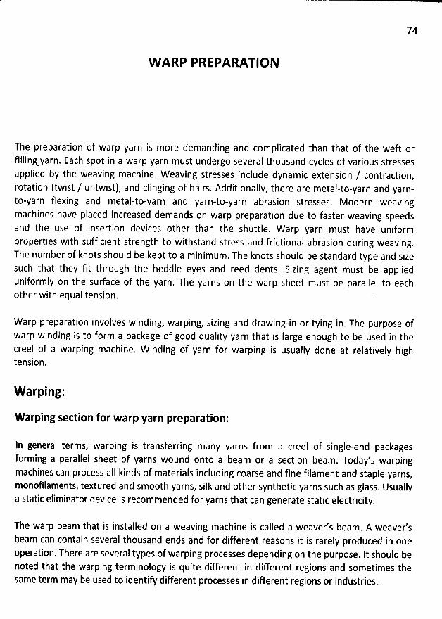
74
W ARP PREPARATIO N
The preparation of warp yarn is more demanding and complicated than that of the weft orfilling
-yarn. Each spot in a warp yarn must undergo several thousand cycles of various stressesappiied by the weaving machine. Weaving stresses include dynamic extension / contraction,rotation (twist / untwist), and clinging of hairs. Additionally, there are metal-to-yarn and yarn-to-yarn flexing and metal-to-yarn and yarn-to-yarn abrasion stresses. Modern weavingmachines have placed increased demands on warp preparation due to faster weaving speedsand the use of insertion devices other than the shuttle. W arp yarn must have uniformproperties with sufficient strength to withstand stress and frictional abrasion during weaving.
The number of knots should be kept to a minimum. The knots should be standard type and sizesuch that they fit through the heddle eyes and reed dents. Sizing agent must be applieduniformly on the surface of the yarn. The yarns on the warp sheet must be parallel to eachother with equal tension. .
Warp preparation involves winding, warping, sizing and drawing-in or tying-in. The purpose ofwarp winding is to form a package of good quality yarn that is large enough to be used in thecreel of a warping machine. W inding of yarn for warping is usually done at relatively hightension.
W arping:
W arping section for warp yarn preparation:
In general terms, warping is transferring many yarns from a creel of single-end packagesforming a parallel sheet of yarns wound onto a beam or a section beam . Today's warpingmacbines can process aII kinds of materials including coarse and fine filament and staple yarns
,
monofilaments, textured and sm00th yarns, silk and other synthetic yarns such as glass. Usuallya static eliminator device is recommended for yarns that can generate static electricity.
The warp beam that is installed on a weaving machine is called a weaver's beam . A weaver'sbeam can contain several thousand ends and for different reasons it is rarely produced in oneoperation, There are several types of warping processes depending on the purpose. lt should benoted that the warping terminology is quite different in different regions and sometimes thesame term may be used to identify different processes in different regions or industries.
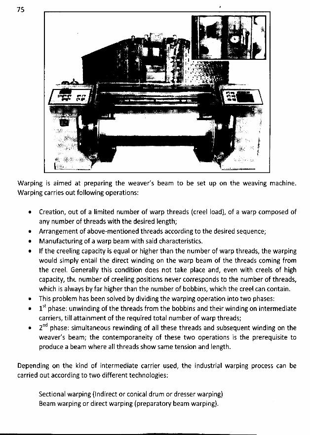
75
W arping is aimed at preparing the weaver's beam to be set up on the weaving machine.W arping carries out following operations:
Creation, out of a Iimited number of warp threads (creel Ioad), of a warp composed ofany number of threads with the desired length;Arrangement of above-mentioned threads pccording to the desired sequence;Manufacturing of a warp beam with said characteristics.
* If the creeling capacity is equal or higher than the number of warp threads, the warpingwould simply entail the direct winding on the warp beam of the threads coming fromthe creel. Generally this condition does not take place and, even with creels of highcapacity, thfu number of creeling positions never corresponds to the number of threads,which is always by far higher than the number of bobbins, which the creel can contain.This problem has been solved by dividing the warping operation into two phases:St h inding of the threads from the bobbins and their winding on intermediate* 1 p ase: unwcarriers, till attainment of the required total number of warp threads;nd h imultaneous rewinding of aII these threads and subsequent winding on the2 p ase: s
weaver's beam; the contemporaneity of these two operations is the prerequisite toproduce a beam where aII threads show same tension and Iength.
Depending on the kind of intermediate carrier used, the industrial warping process can becarried out according to two different technologies:
Sectional warping (Indirect or conical drum or dresser warping)Beam warping or direct warping (preparatory beam warping).
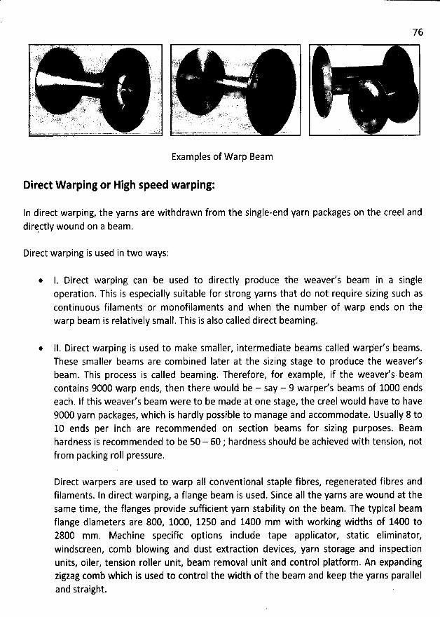
76
Examples of W arp Beam
Direct W arping or High speed warping:
ln direct warping, the yarns are withdrawn from the single-end yarn packages on the creel anddirçctly wound on a beam.
Direct warping is used in two ways:
* 1. Direct warping can be used to directly produce the weaver's beam in a singleoperation. This is especially suitable for strong yarns that do not require sizing such ascontinuous filaments or monofilaments and when the number of warp ends on thewarp beam is relatively small. This is also called direct beaming.
@ lI. Direct warping is used to make smaller, intermediate beams called warp'er's beams.These smaller beams are combined later at the sizing stage to produce the weaver'sbeam. This process is called beaming. Therefore, for example, if the weaver's beamcontains 9000 warp ends, then there would be - say - 9 warper's beams of 1000 endseach. If this weaver's beam were to be made at one stage, the creel would have to have9000 yarn packages, which is hardly possible to manage and accommodate. Usually 8 to10 ends per inch are recommended on section beams for sizing purposes. Beamhardness is recommended to be 50 - 60 ; hardness should be achieved with tension, notfrom packing roll pressure.
Direct warpers are used to warp aII conventional staple fibres, regenerated fibres andfilaments. In direct warping, a flange beam is used. Since aII the yarns are wound at thesame time, the flanges provide sufficient yarn stability on the beam. The typical beamflange diameters are 800, 1000, 1250 and 1400 mm with working widths of 1400 to2800 mm. Machine specific options include tape applicator, static eliminator,windscreen, comb blowing and dust extraction devices, yarn storage and inspedionunits, oiler, tension roller unit, beam removal unit and control platform. An expandingzigzag comb which is used to control the width of the beam and keep the yarns paralleland straight.
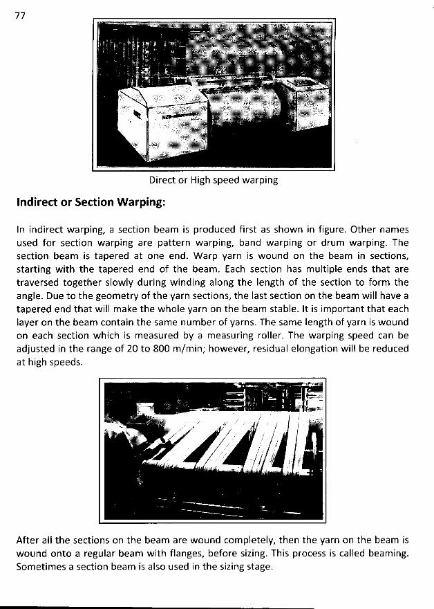
77
Direct or High speed warping
Indirect or Section W arping:
In indirect warping, a section beam is produced first as shown in figure. Other namesused for section warping are pattern warping, band warping or drum warping. Thesection beam is tapered at one end. W arp yarn is wound on the beam in sections,starting with the tapered end of the beam. Each section has multiple ends that aretraversed together slowly during winding along the Iength of the section to form theangle. Due to the geom etry of the yarn sections, the Iast section on the beam will have atapered end that will make the whole yarn on the beam stable. It is important that eachlayer on the beam contain the same number of yarns. The same Iength of yarn is woundon each section which is measured by a measuring roller. The warping speed can beadjusted in the range of 20 to 800 m/min; however, residual elongation will be reducedat high speeds.
After aII the sections on the beam are wound com pletely, then the yarn on the beam iswound onto a regular beam with flanges, before sizing. This process is called beaming.Sometimes a section beam is also used in the sizing stage.
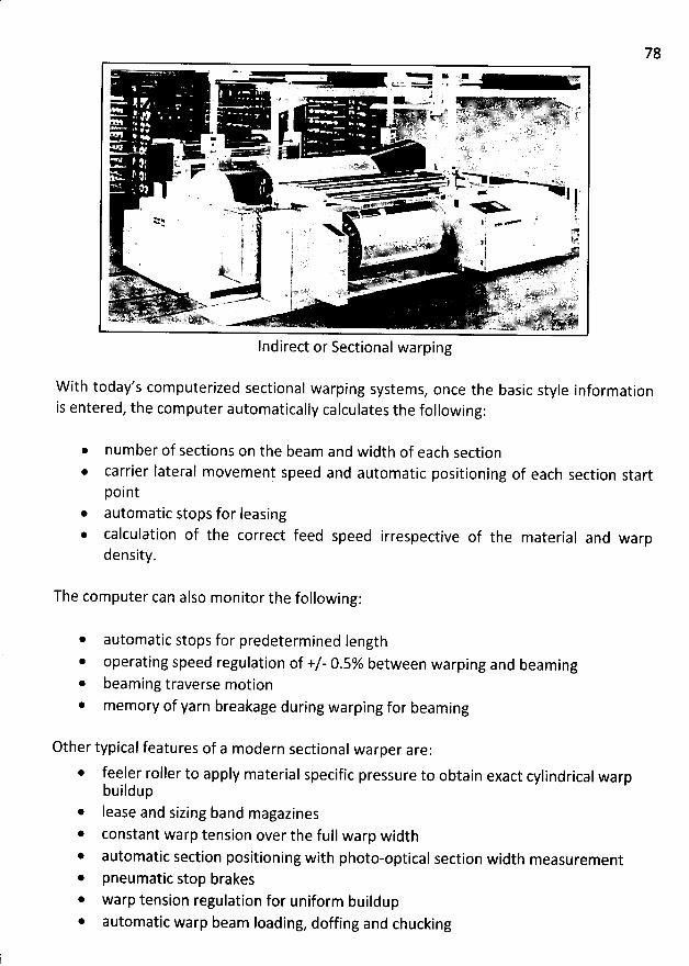
78
Indirect or Sectional warping
W ith today's computerized sectional warping systems, once the basic style informationis entered, the computer automatically calculates the following:
number of sections on the beam and width of each sectioncarrier Iateral movement speed and automatic positioning of each section startpointautomatic stops for Ieasingcalculation of the correct feed speed irrespective of the material and warpdensity.
The computer can also monitor the following:
automatic stops for predetermined Iength
operating speed regulation of +/- 0.5% between warping and beaming* beaming traverse motion
memory of yarn breakage during warping for beaming
Other typical features of a modern sectional warper are:
* feeler roller to apply material specific pressure to obtain exact cylindrical warpbuildup
* Iease and sizing band magazines
* constant warp tension over the full warp width* automatic section positioning with photo-optical section width measurement* pneumatic stop brakes
warp tension regulation for uniform buildup* automatic warp beam Ioading, doffing and chucking
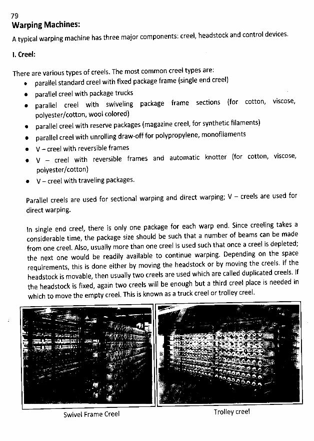
79W arping M achines:A typical warping machine has three major components: creel, headstock and control devices.
1- Creel:
There are various types of creels. The most common creel types are:* parallel standard creel with fixed package frame (single end creel)* parallel creel with package trucks* parallel creel with swiveling package frame sections (for cotton, viscose,
polyester/cotton, wool colored)* parallel creel with reserve packages (magazine creel, for synthetic filaments)* parallel creel with unrolling draw-off for polypropylene, monofilaments
* V - creel with reversible frames* V - creel with reversible frames and automatic knotter (for cotton, viscose,
polyester/cotton)* V - creel with traveling packages.
Parallel creels are used for sectional warping and direct warping; V - creels are used for
direct warping.
ln single end creel, there is only one package for each warpconsiderable time, the package size should be such that a number of beams can be madefrom one creel. Also, usually more than one creel is used such that once a creel is depleted;the next one would be readily available to continue warping. Depending on the spacerequirements, this is done eitber by moving tbe beadstock or by moving the creels. jf theheadstock is movable, then usually two creels are used which are called duplicated creels. lfthe headstock is fixed, again two creels will be enough but a third creel place is needed inwhich to move the empty creel. This is known as a truck creel or trolley creel.
end. Since creeling takes a
*kLY L v w ,i . Q. # '% '< K; ' zw >'' -' . . .
. . . .a.., s.. . v .. . jy . , .-s. . ,., ?,
. . . . . . ..u y > + + . .#%
' ' e7 .. .9* 'Z?i' ' ' -. '- '1% ''Me '''x
. , o .. e
' ' &. '; + ' *' X='7V2- '<' r 'J. .k . . 'lë .. - % i. ..o xz
.,. llb f
Swivel Frame Creel Trolley creel
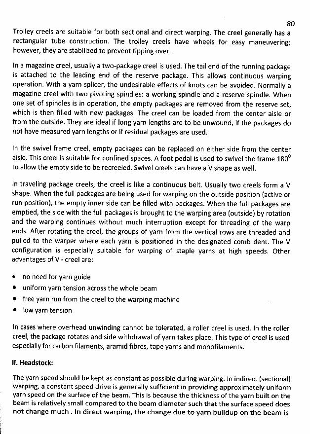
80Trolley creels are suitable for both sectional and direct warping. The creel generally has arectangular tube construction. The trolley creels have wheels for easy maneuvering;however, they are stabilized to prevent tipping over.
In a magazine creel, usually a two-package creel is used. The tail end of the running packageis attached to the leading end of the reserve package. This allows continuous warpingoperation. W ith a yarn splicer, the undesirable effects of knots can be avoided. Normally amagazine creel with two pivoting spindles: a working spindle and a reserve spindle. W henone set of spindles is in operation, the empty packages are removed from th
. e reserve set,which is then filled with new packages. The creel can be Ioaded from the center aisle orfrom the outside. They are ideal if Iong yarn Iengths are to be unwound, if the packages donot have measured yarn Iengths or if residual packages are used.
In the swivel frame creel, empty packages can be replaced on either side from the center0aisle. This creel is suitable for confined spaces. A foot pedal is used to swivel the frame 180
to allow the empty side to be recreeled. Swivel creels can have a V shape as well.
In traveling package creels, the creel is Iike a continuous belt. Usually two creels form a Vshape. When the full packages are being used for warping on the outside position (active orrun position), the empty inner side can be filled with packages. When the full packages areemptied, the side with the full packages is brought to the warping area (outside) by rotationand the warping continues without much interruption except for threading of the warpends. After rotating the creel, the groups of yarn from the vertical rows are threaded andpulled to the warper where each yarn is positioned in the designated comb dent. The Vconfiguration is especially suitable for warping of staple yarns at high speeds. Otheradvantages of V - creel are:
* no need for yarn guide
* uniform yarn tension across the whole beam
* free yarn run from the creel to the warping machine
@ low yarn tension
In cases where overhead unwinding cannot be tolerated, a roller creel is used. ln the rollercreel, the package rotates and side withdrawal of yarn takes place. This type of creel is usedespecially for carbon filaments, aramid fibres, tape yarns and monofilaments.
II. Headstock:
The yarn speed should be kept as constant as possible during warping. ln indirect (sectional)warping, a constant speed drive is generally sufficient in providing approximately uniformyarn speed on the surface of the beam. This is because the thickness of the yarn built on thebeam is relatively small compared to the beam diameter such that the surface speed doesnot change m uch . ln direct warping, the change due to yarn buildup on the beam is
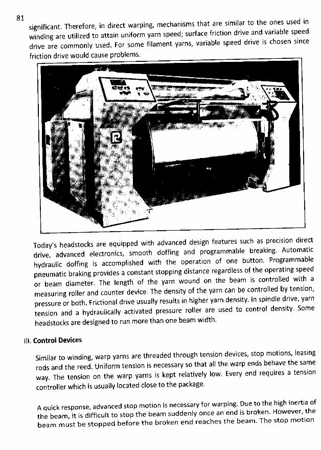
81 significant. Therefore, in direct warping, mechanisms that are similar to the ones used inwinding are utilized to attain uniform yarn speed; surface friction drive and variable speeddrive are commonly used. For some filament yarns, variable speed drive is chosen since
Today'sheadstocks are equipped with advanced designfeatures such as precisiondirectdrive, advanced electronics, smooth doffing and programmable breaking. Automatichydraulic doffing is accomplished with tbe operation of one button. Programmablepneumatic braking provides a constant stopping distance regardless of the operating speedor beam diameter. The length of the yarn wound on the beam is controlled with ameasuring roller and counter device. The density of the yarn can be controlled by tension,pressure or both. Frictional drive usually results in higher yarn density. In spindle drive, yarntension and a hydraulically activated pressure roller are used to control density. Someheadstocks are designed to run more than one beam width.
111. Control Devices
Similar to winding, warp yarns are threaded through tension devices, stop motions, Ieasingrods and the reed. Uniform tension is necessary so that aIl the warp ends behave the sameway. The tension on the warp yarns is kept relatively Iow. Every end requires a tension
controller which is usually Iocated close to the package.
A quick response, advanced stop motion is necessary for warping. Due to the high inertia ofthe beam, it is difficult to stop the beam suddenly once an end is broken. However, thebeam m ust be stopped before the broken end reaches the beam . The stop m otion
82electrically Iinks each warp end to the warper braking system; when a warp end breaks, thewarper stops. Powerful brakes are used for this purpose. A light indicates the Iocation of thebroken end. The warping process is generally irreversible, unwinding of the beam wouldcause yarn entanglement. The stop motion device, which can be mechanical or electronicfor quick response, is usually Iocated near the creel.
In an electronic, motion sensitive stop motion device; the electronic eye detects movementof individual ends to trigger a warp stop when there is no yarn movement.
To avoid static buildup, especially with manmade fibres, different methods can be usedincluding chemicals, ionization of air or humidification of air. Fans are used to prevent Iintaccumulation when warping staple yarns.
83
SIZING OR SLASHING
Sizing section also for warp yarn preparation
Although the quality and characteristics of the warp yarns coming out of the winding andwarping processes are quite good, they are still not good enough for the weaving process formost of the yarns. The weaving process requires the warp yarn to be strong, smooth and elasticor extensible to a certain degree. To achieve these properties on the warp yarns, a protective
coating of a polymeric film forming agent (size) is applied to the warp yarns prior to weaving;this process is called sizing or slashing. Sizing is not a value added process in woven fabricmanufacturing. This is because, after the fabric is woven, the size materials will be removedfrom the fabric during the finishing operation, which is called desizing.
The main purposes of sizing are as follows:
to increase the strength of the yarns* to reduce the yarn hairiness that would cause problems in weaving process* to increase the abrasion resistance of the yarns against other yarns and various weaving
machine elements* to reduce fluff and fIy during the weaving process for high speed weaving machines.
To increase the weaveability of the warp yarn, this is the main goal of sizing.
The ultimate goal of sizing is to eliminate or reduce warp breaks during weaving. Warp breaksare caused either by high tension or by Iow strength in the yarn. High tensions in the warp arecaused by Iarge shed openings, lack of proper tension compensation, high beat-up force and
iïudequate let-cq. Knots, ïafn entactîement and hith friction also cause tension buildup.
Sizing is a complementary operation which is carried out on warps formed by spun yarns withinsufficient tenacity or by continuous filament yarns with zero twist. ln general, when sizing isnecessary, the yarn is beam warped, therefore aII beams corresponding to the beams are fed,as soon as warping is completed, to the sizing machine where they are assembled. Sizingconsists of impregnating the yarn with particular stlbstances which form on the yarn surface afilm with the aim of improving yarn smoothness and tenacity during the subsequent weavii gstage. Thanks to its improved tenacity and elasticity, the yarn can stand without problems the
tensions and the rubbing caused by weaving.
There is not just one sizing 'recipe' which is valid for aII processes, on the contrary the sizingmethods change depending on the type of weaving machine used, on the yarn type and count,on the technician's experience and skill, but above alI on the kind of material in progress. The
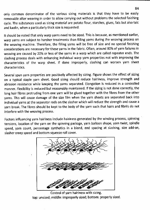
84only common denominator of the various sizing materials is that they have to be easilyremovable after weaving in order to allow carrying out without problems the sejected finishingcycle. The substances used as sizing material are potato flour, starches, glues, fats but also talcand kaolin, when a particularly thick size is requested.
It should be noted that only warp yarns need to be sized. This is because, as mentioned earlier,warp yarns are subject to harsher treatments than filling yarns during the weaving process onthe weaving machine. Therefore, the filling yarns will be free of size and no special finishingconsiderations are necessary for these yarns in the fabric. Often, around 80% of yarn failures inweaving are caused by 20% or Iess of the yarns in a warp which are called repeater ends. Theslashing process deals with enhancing individual warp yarn properties not with improving thecharacteristics of the warp sheet. If done improperly, slashing can worsen yarn sheet
characteristics.
Several spun yarn properties are positively affected by sizing. Figure shows the effect of sizingon a typical staple yarn sheet. Good sizing should reduce hairiness, improve strength andabrasion resistance while keeping the yarns separated. Elongation is reduced in a controlledmanner. Flexibility is reduced but reasonably maintained. ff the sizing is not done correctly, theIong hair fibres protruding from one yarn will be glued together with the fibres from the otheryarns. This will cause damage of the size film when the yarn sheets are separated back intoindividual yarns at the separator rods on the slasher which will reduce the strength and cause ayarn break. The fibres should be kept to the body of the yarn such that hairs and fibrils do not
interfere with the weaving process.
Factors influencing yarn hairiness include hairiness generated by the winding process, spinningtensions, Iocation of the yarn on the spinning package, yarn balloon shape, yarn twist, spindlespeed, yarn count, percentage synthetics in a blend, end spacing at slashing, size add-on,slasher creep speed and bottom squeeze roll cover.
) -r-
Control of yarn hairiness with sizing,top: unsized; middle: improperly sized; bottom; properly sized.
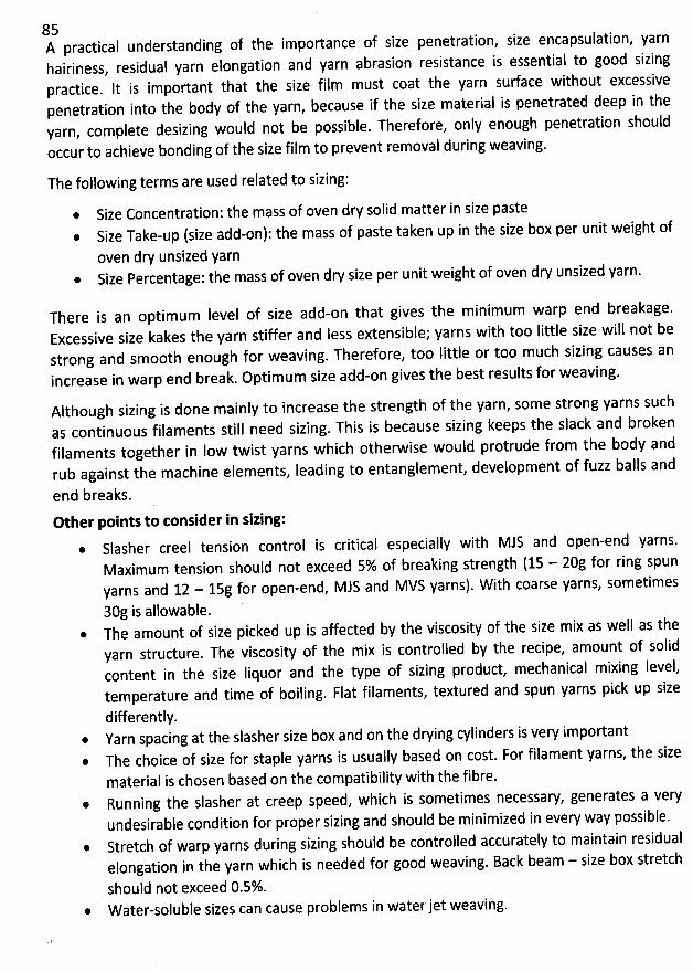
85A practical understanding of the importance of size penetration, size encapsulation, yarnhairiness, residuaq yarn elongation and yarn abrasion resistance is essential to good sizingpractice. lt is important that the size film must coat the yarn sudace without excessivepenetration into the body of the yarn, because if the size material is penetrated deep in theyarn, complete desizing would not be possible. Therefore, only enough penetration shouldoccur to achieve bonding of the size film to prevent removal during weaving.
The following terms are used related to sizing:
* Size Concentration: the mass of oven dry solid matter in size pasteSize Take-up (size add-on): the mass of paste taken up in the size box per unit weight ofoven dry unsized yarnSize Percentage: the mass of oven dry size per unit weight of oven dry unsized yarn.
There is an optimum level of size add-on that gives the minimum warp end breakage.Excessive size kakes the yarn stiffer and less extensible; yarns with too Iittle size will not bestrong and smooth enough for weaving. Therefore, too Iittle or too much sizing causes anincrease in warp end break. Optimum size add-on gives the best results for weaving.
Although sizing is done mainly to increase the strength of the yarn, some strong yarns suchas continuous filaments still need sizing. This is because sizing keeps the slack and brokenfilaments together in Iow twist yarns which otherwise would protrude from the body andrub against the machine elements, Ieading to entanglement, development of fuzz balls and
end breaks.Other points to tonsider in sizing:
Slasher creel tension control is critical especially with MJS and open-end yarns.
Maximum tension should not exceed 5% of breaking strength (15 - 20g for ring spunyarns and 12 - 15g for open-end, MJS and MVS yarns). With coarse yarns, sometimes30g is allowable.The amount of size picked up is affected by the viscosity of the size mix as well as theyarn strudure. The viscosity of the mix is controlled by the recipe, amount of solidcontent in the size Iiquor and the type of sizing product, mechanical mixing Ievef,temperature and time of boiling. Flat filaments, textured and spun yarns pick up size
differently.* Yarn spacing at the slasher size box and on the drying cylinders is very important .
The choice of size for staple yarns is usually based on cost. For filament yarns, the sizematerial is chosen based on the compatibility with the fibre.Running the slasher at creep speed, which is sometimes necessaw, generates a veryundesirable condition for proper sizing and should be minimized in every way possible.
@ Stretch of warp yarns during sizing should be controlled accurately to maintain residualelongation in the yarn which is needed for good weaving. Back beam - size box stretch
should not exceed 0.5%.* W ater-soluble sizes can cause problems in waterjet weaving.
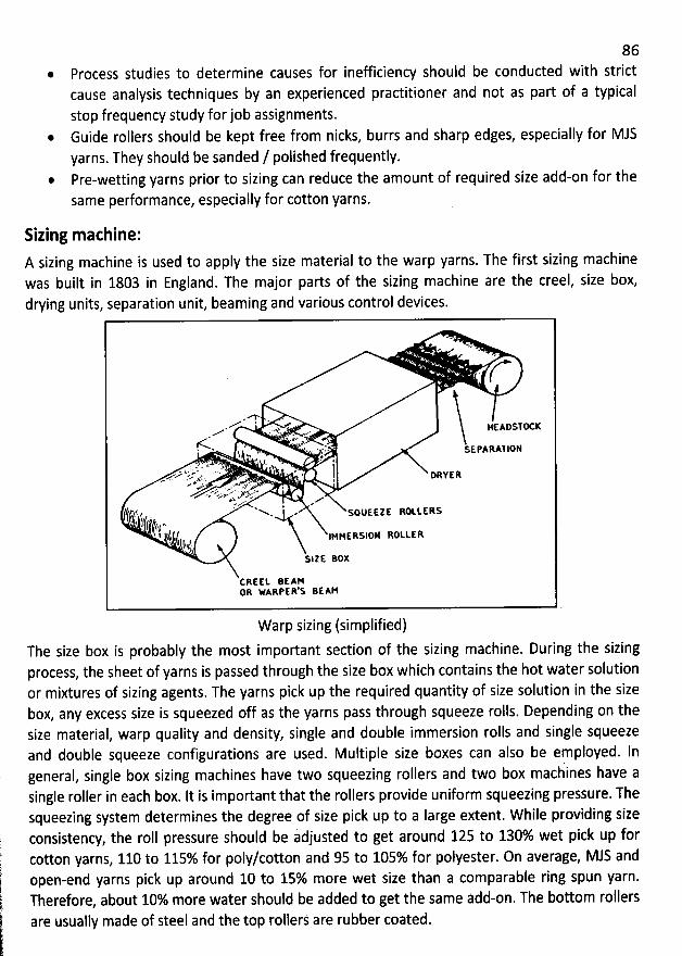
86Process studies to determine causes for inefficiency should be conducted with strictcause analysis techniques by an experienced practitioner and not as part of a typical
stop frequency study forjob assignments.* Guide rollers should be kept free from nicks, burrs and sharp edges, especially for MJS
yarns. They should be sanded / polished frequently.Pre-wetting yarns prior to sizing can reduce the amount of required size add-on for thesame performance, especially for cotton yarns.
Sizing machine:A sizing machine is used to apply the size material to the warp yarns. The first sizing machinewas built in 1803 in England. The major parts of the sizing machine are the creel, size box,drying units, separation unit, beaming and various control devices.
..e' * , *..-- .-4. ' BEAOSI'X KM
.
/C:- . ' '-' -. - , . . - ,- sE PARAI joN
; ,, .-s ' . ! I .. . .; . ''l ....# . ' 2 p
'
. Sz a . . . . - . , l pa y : q
.. ,r.' . x1. . . 1.- m* ..a v - j . . y.. . ' *:.*. . * ' #- z k.a- k:X +vç> . .e#
/ F ' W V( C, ; . NhN - SQUEE'E RW LERG
t.f (ir4('fr I -.' 1( ,( IMpgtqslo: RotttR!14f
'
,)SI'E BOX
CRE6t BEAMOR WARPER'S BEAM
Warp sizing (simplified)Thesize box is probably the most important section of the sizing machine. During the sizingprocess, the sheet of yarns is passed through the size box which contains the hot water solutionor mixtures of sizing agents. The yarns pick up the required quantity of size solution in the sizebox, any excess size is squeezed off as the yarns pass through squeeze rolls. Depending on thesize material, warp quality and density, single and double immersion rolls and single squeezeand double squeeze configurations are used. Multiple size boxes can also be employed. Ineneral, single box sizing machines have two squeezing rollers and two box maciines have agsingle roller in each box. It is important that the rollers provide uniform squeezing pressure. Thesqueezing system determines the degree of size pick up to a Iarge extent. W hile providing sizeconsistency, the roll pressure should be idjusted to get around 125 to 130% wet pick up forcotton yarns, 110 to 115% for poly/cotton and 95 to 105% for polyester. 0n average, MJS andopen-end yarns pick up around 10 to 15% more wet size than a comparable ring spun yarn.Therefore, about 10% more water should be added to get the same add-on. The bottom rollersare usually made of steel and the top rollers are rubber coated.
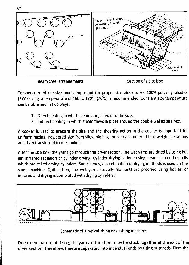
87. . 'xx. g'r . o . yPressklr'e .'*' - *. . ''.- #WX-VTWWe Roller
.e . ... eeSqueel A .w A > .w.tr.xuov'( a ) ( t ( ( . ted To co ntrot . .- .-.---,x,- .. . , .,.-.+% ..ee-Aulus , ...vW.,.xe' .- 'u . .yzrx . . .. ;jPick-t)p -'- -- . -' <'>' -- ' ./Z'Z''...,'''P ..'Size . .- z . .. .g z.,'c ..4 .- sv..p .x* ' f ,'f -= AQyy . = ...< %( ( '%,.. --
*:-.. ,.,,,-yt4, xsxsx -'''<. S. . +%sz +b ) .0 . - , J,f .,..,/ +kn( ue
wex. -jj jty ... x. .,az ...,yyj,yy$jjjy,yz.. . .s.... , ;jj yyy yyy j . ,. y jy..,,y .. . . . . . gy $ x..e.w x. . - ... - . . j,.p j, z.t , . ..,. a... . r:... . .. ......,. ,; . tr.
-7 .' 2. m v- , .,ee...--qe..o < - . r.'-. ., ...r< . .e. >
. ..' x SIZE LIQUOR.' rr w .#' . . .
.i V *W ' *'' '' T'' ' -* - ' - '- .:..s.- .. z . .
(c) *' u.% < STEAM BEATtNG
PIPES
Beam creel arrangements Section of a size box
Temperature of the size box is important for proper size pick up. For 100% polyvinyl alcohol0F (700c) is recommended. Constant size temperature(PVA) sizing, a temperature of 160 to 170
can be obtained in two ways:
1. Direct heating in which steam is injected into the size.2. Indirect heating in which steam flows in pipes around the double walled size box.
A cooker is used to prepare the size and the shearing action in the cooker is important foruniform mixing. Powdered size from silos, big-bags or sacks is metered into weighing stationsand then transferred to the cooker.
After the size box, the yarns go through the dryer section. The wet yarns are dried by using botair, infrared radiation or cylinder drying. Cylinder drying is done using steam heated hot rollswhich are called drying cylinders. Some-times, a combination of drying methods is used on the
same machine. Quite often, the wet yarns (usually filament) are predried using hot air orinfrared and drying is completed with drying cylinders.
* . *@
'
. $
'
4. ,. +
'
* j*
' '**
'
# . ë j !. 4gl
'. * @1 *J .
g w. '
Schematic of a typical sizing or slashing machine
Due to the nature of sizing, the yarns in the sheet may be stuck together at the exit of thedryer section. Therefore, they are separated into individual ends by using bust rods. First, the
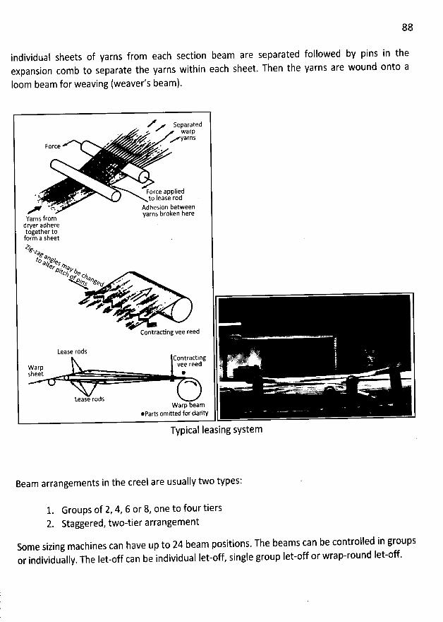
88
individual sheets of yarns from each section beam are separated followed by pins in theexpansion comb to separate the yarns witbin each sheet. Then the yarns are wound onto a
Ioom beam for weaving (weaver's beam).
V separatedM warp. . K
' Z e M Y3VZSz * e .eForce 'eJ e
z . . Force applied' :. to lease rod1 *
'
tn Adhesion betweenyarns broken here
Yarns fromdryer adheretogether toform a sheetôJte*,
eto *w44 e.çer &?eDttcnk'6eozw Me .zo z?e ..' ees ee
. j ...* .
::11:. . . *F + ' . c'
e eContracting vee reed
Lease rodsC tradinf F7'XOn ) t1:11 ' êl'>V'W=2ElVee ree ' '
.Warp ?JSheet @ 'k
e> . ''< >- ,- . . VVQQ Y 7 '
Lease rodsWarp beam
@parts omitted for clarity
Typical leasing system
Beam arrangements in the creel are usually two types:
Groups of 2, 4, 6 or 8, one to four tiersStaggered, two-tier arrangement
Some sizing machines can have up to 24 beam positions. The beams can be controlled in groupsor individually. The Iet-off can be individual let-off, single group let-off or wrap-round Iet-off.
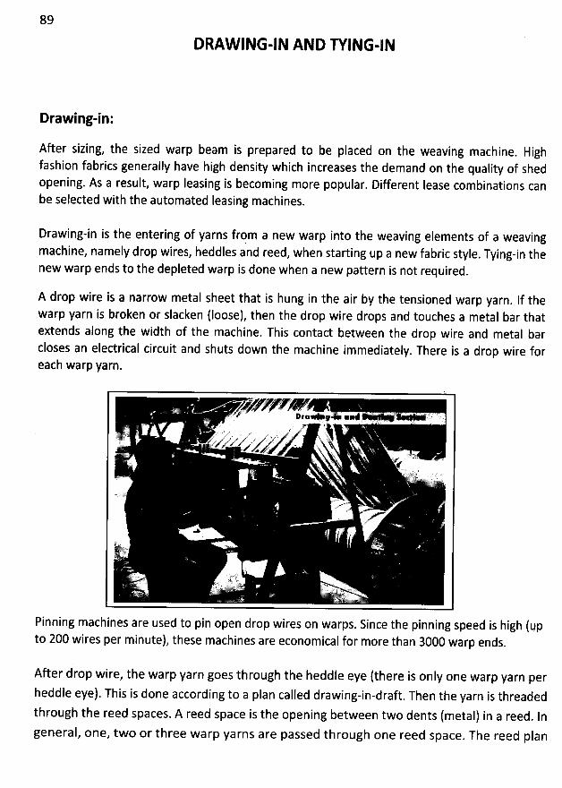
89
DRAW ING-IN AND R ING-IN
Drawing-in:
After sizing, the sized warp beam is prepared to be placed on the weaving machine. High
fashion fabrics generally have high density which increases the demand on the quality of shedopening. As a result, warp Ieasing is becoming more popular. Different Iease combinations canbe selected with the automated Ieasing machines.
Drawing-in is the entering of yarns from a new warp into the weaving elements of a weavingmachine, namely drop wires, heddles and reed, when starting up a new fabric style. Tying-in thenew warp ends to the depleted warp is done when a new pattern is not required.
A drop wire is a narrow metal sheet that is hung in the air by the tensioned warp yarn. If thewarp yarn is broken or slacken (Ioose), then the drop wire drops and touches a metal bar thatextends along the width of the machine. This contact between the drop wire and metal barcloses an electrical circuit and shuts down the machine immediately
. There is a drop wire foreach warp yarn.
Pinning machines are used to pin open drop wires on warps. Since the pinning speed is high (upto 200 wires per minute), these machines are economical for more than 3000 warp ends.
After drop wire, the warp yarn goes through the heddle eye (there is only one warp yarn perheddle eye). This is done according to a plan called drawing-in-draft. Then the yarn is threadedthrough the reed spaces. A reed space is the opening between two dents (metal) in a reed. Ingeneral, one, two or three warp yarns are passed through one reed space
. The reed plan
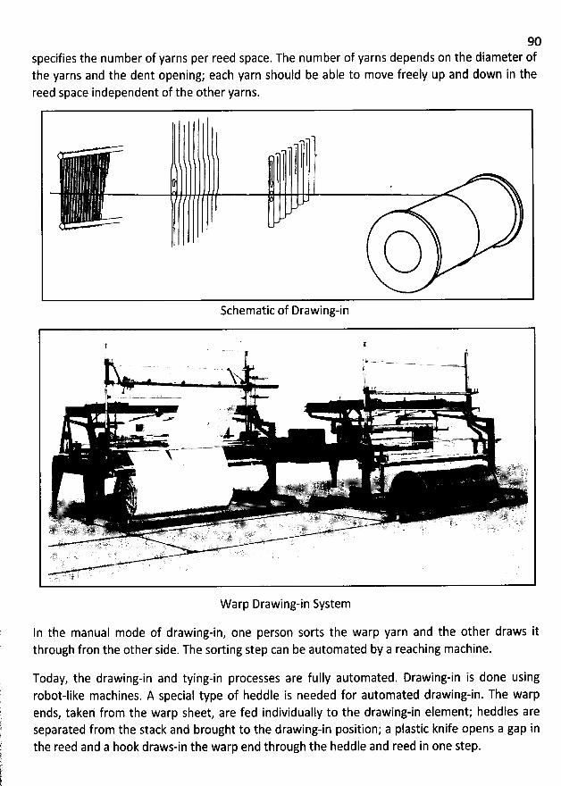
90specifies the number of yarns per reed space. The number of yarns depends on the diameter ofthe yarns and the dent opening; each yarn should be able to move freely up and down in thereed space independent of the other yarns.
Schematic of Drawing-in
W arp Drawing-in System
In the manual mode of drawing-in, one person sorts the warp yarn and the other draws itthrough fron the other side. The sorting step can be automated by a reaching machine.
Today, the drawing-in and tying-in processes are fully automated. Drawing-in is done usingrobot-like machines. A special type of heddle is needed for automated drawing-in. The warpends, takeh from the warp sheet, are fed individually to the drawing-in element; heddles areseparated from the stack and brought to the drawing-in position; a plastic knife opens a gap inthe reed and a hook draws-in the warp end through the heddle and reed in one step.
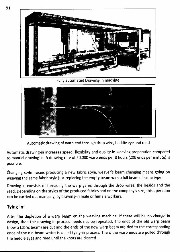
91
@ ' *. .- ss v,' .'!(.J) '' ...
E . .;
,. 1 $;.. ii-$ . .F
'
ji 1 ''. $ 2 ' j.
- !!
'
..'/ 1à '.. J'
.' (
mc . . C
. *! * Pq ' ''
. ...... ,''''''' ' k.csi. ..243' 11-. . . o O J = - j- .- ' , - . . . . o;.v- . - .- y ) ). . . 'i$
,w.>.. . .yfzfV. . W ' ' Gopm = ..e>t1f*z
Fully automated Drawing-in machine
Automatic drawing of warp end through drop wire, heddle eye and reed
Automatic drawing-in increases speed, flexibility and quality in weaving preparation comparedto manual drawing-in. A drawing rate of 50,000 warp ends per 8 hours (200 ends per minute) ispossible.
éhanging style means producing a new fabric style, weaver's beam changing means going onweaving the same fabric style just replacing the empty beam with a full beam of same type.DraWing-in consists of threading the warp yarns through the drop wires, the healds and thereed. Depending on the styles of the produced fabrics and on the company's size, this operationcan be carried out manually, by drawing-in male or female workers.
Tying-in:
After the depletion of a warp beam on the weaving machine, if there will be no change indesign, then the drawing-in process needs not be repeated. The ends of the old warp beam
(now a fabric beam) are cut and the ends of the new warp beam are tied to the correspondingends of the oId beam which is called tying-in process. Then, the warp ends are pulled throughthe heddle eyes and reed until the knots are cleared.
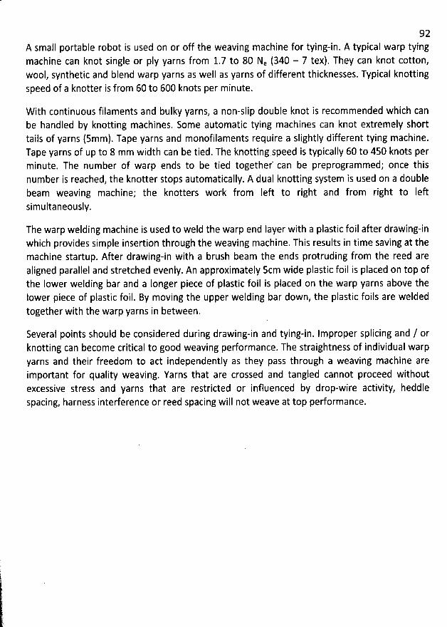
92A small portable robot is used on or off the weaving machine for tying-in. A typical warp tyingmachine can knot single or pIy yarns from 1.7 to 80 Ne (340 - 7 tex). They can knot cotton,wool, synthetic and blend warp yarns as well as yarns of different thicknesses. Typical knottingspeed of a knotter is from 60 to 600 knots per minute.
W ith continuous filaments and bulky yarns, a non-slip double knot is recommended which canbe handled by knotting machines. Some automatic tying machines can knot extremely shorttails of yarns (5mm). Tape yarns and monofilaments require a slightly different tying machine.Tape yarns of up to 8 mm width can be tied. The knotting speed is typically 60 to 450 knots perminute. The number of warp ends to be tied together' can be preprogrammed; once thisnumber is reached, the knotter stops automatically. A dual knotting system is used on a doublebeam weaving machine; the knotters work from Ieft to right and from right to Ieftsimultaneously.
The warp welding machine is used to weld the warp end layer with a plastic foil after drawing-inwhich provides simple insertion through the weaving machine. This results in time saving at themachine startup. After drawing-in with a brush beam the ends protruding from the reed arealigned parallel and stretcbed evenly. An approximately Scm wide plastic foil is placed on top ofthe Iower welding bar and a Ionger piece of plastic foil is placed on the warp yarns above thelower piece of plastic foil. By moving the upper welding bar down, the plastic foils are weldedtogether with the warp yarns in between.
Several points should be considered during drawing-in and tying-in. Improper splicing and / orknotting can become critical to good weaving performance. The straightness of individual warpyarns and their freedom to act independently as they pass through a weaving machine areimportant for quality weaving. Yarns that are crossed and tangled cannot proceed withoutexcessive stress and yarns that are restricted or influenced by drop-wire activity, heddlespacing, harness interference or reed spacing will not weave at top performance.
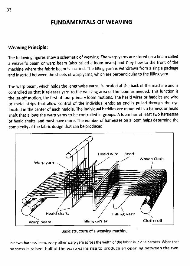
93
FUNDAM ENTALS OF W EAVING
W eaving Printiple:
The following figures show a schematic of weaving. The warp yarns are stored on a beam calleda weaver's beam or warp beam (also called a loom beam) and they flow to the front of themachine where the fabric beam is Iocated. The filfing yarn is withdrawn from a single packageand inserted between the sheets of warp yarns, which are perpendicular to the filling yarn.
The warp beam, which holds the fengthwise yarns, is Iocated at the back of the machine and iscontrolled so that it releases yarn to the weaving area of the Ioom as needed. This function isthe Iet-off motion, the first of four primary Ioom motions. The heald wires or heddles are wireor metal strips that allow control of the individual ends; an end is pulled through the eyelocated in the center of each heddle. The individual heddles are mounted in a harness or healdshaft that allows the warp yarns to be controlled in groups. A Ioom has at Ieast two harnessesor heald shafts, and most have more. The number of harnesses on a Ioom helps determine thecomplexity of the fabric design that can be produced.
Heald w ire ReedW oven (210th
Warp yarn /
XHeald shafts Filling yarn X
w arp beam filling carrier (210th roll
Basic structure of a weaving machine
ln a two-harness loom, every other warp yarn across the width of the fabric is in one harness. W hen that
harness is raised, half of the warp yarns rise to produce an opening between the two
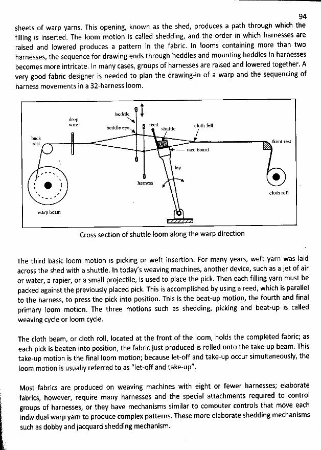
94sheets of warp yarns. This opening, known as the shed, produces a path through which thefilling is inserted. The loom motion is called shedding, and the order in which harnesses areraised and Iowered produces a pattern in the fabric. In looms containing more than twoharnesses, the sequence for drawing ends through heddles and mounting heddles in harnessesbecomes more intricate. In many cases, groups of harnesses are raised and Iowered together. Avery good fabric designer is needed to plan the drawing-in of a warp and the sequencing of
harness movements in a 3z-harness loom.
heddledropwire reed c10th fellhcddle eye jmttleNA S
backrest front rest
race-board
1ay. * * w,
#' N*
I j hamess$N ?x . 2 c10th roll- w -
wam beam
Cross section of shuttle loom along the warp direction
The third basic Ioom motion is picking or weft insertion. For many years, weft yarn was laidacross the shed with a shuttle. In today's weaving machines, another device, such as a jet of airor water, a rapier, or a small projectile, is used to place the pick. Then each filling yarn must bepacked against the previously placed pick. This is accomplished by using a reed, which is parallelto the harness, to press the pick into position. This is the beat-up motion, the fourth and finalprimary loom motion. The three motions such as shedding, picking and beat-up is called
weaving cycle or Ioom cycle.
The c10th beam, or c10th roll, Iocated at the front of the Ioom, hofds the compfeted fabric; aseach pick is beaten into position, the fabric just produced is rolled onto the take-up beam. Thistake-up motion is the final loom motion; because Iet-off and take-up occur simultaneously, theloom motion is usually referred to as ''Iet-off and take-up''.
Most fabrics are produced on weaving machines with eight or fewer harnesses; elaborate@ fabrics
, however, require many harnesses and the special attachments required to control
groups of harnesses, or they have mechanisms similar to computer controls that move eachindividual warp yarn to produce complex patterns. These more elaborate shedding mechanisms
?. such as dobby and jacquard shedding mechanism.
' .( .t. .
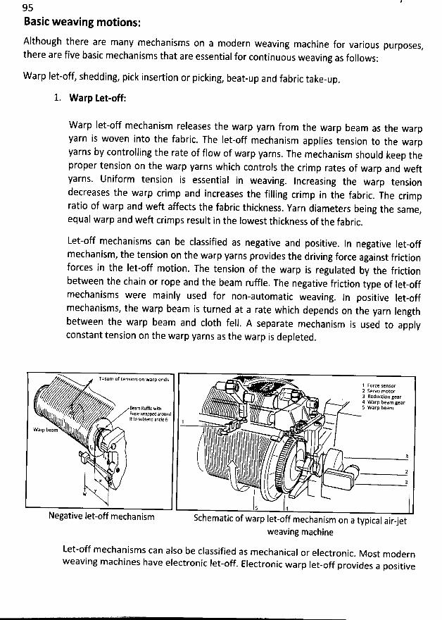
95Basic weaving motions:
Although there are many mechanisms on a modern weaving machine for various purposes,
there are five basic mechanisms that are essential for continuous weaving as follows:
W arp Iet-off, shedding, pick insertion or picking, beat-up and fabric take-up.
1. W arp Let-off:
W arp Iet-off mechanism releases the warp yarn from the warp beam as the warpyarn is woven into the fabric. The Iet-off mechanism applies tension to the warpyarns by controlling the rate of flow of warp yarns
. The mechanism should keep theproper tension on the warp yarns which controls the crimp rates of warp and weftyarns. Uniform tension is essential in weaving. Increasing the warp tensiondecreases the warp crimp and increases the filling crimp in the fabric
. The crimpratio of warp and weft affects the fabric thickness. Yarn diameters being the sàme
,equal warp and weft crimps result in the Iowest thickness of the fabric
.
Let-off mechanisms can be classified as negative and positive. In negative Iet-off
mechanism, the tension on the warp yarns provides the driving force against frictionforces in the Iet-off motion. The tension of the warp is regulated by the fridionbetween the chain or rope and the beam ruffle. The negative friction type of Iet-offmechanisms were mainly used for non-automatic weaving
. In positive Iet-offmechanisms, the warp beam is turned at a rate which depends on the yarn lengthbetween the warp beam and c10th fell. A separate mechanism is used to applyconstant tension on the warp yarns as the warp is depleted.
Tzzsblm of tension on warp ends -'''+1 Force sensorz sewo motor3 Reduction gear4 warp beam gears warp beam- B
qeo'p'ne : rlfflppe e*u i tah, o u p u
, '' Ià/. ' It to subtend ancle () ..- .-...-.! ( l ,,,i..l I r ,
-'--Warp beam ' l j'''''
'
6'''''''
'
,
,,t'''''''
'
,
,,,,,66''''''
'
,
,,,,,,,,,,'''''' -'-. ,,
'
-'''
'
'tx 31N .
/: $' -- 2! :.:.3X ' l
y' ..
. J, , j,Negative Iet-off mechanism Schematic of warp Iet-off mechanism on a typical air-jet
weaving machine
Let-off mechanisms can also be classified as mechanical or electronic. Most modern
weaving machines have electronic Iet-off. Electronic warp Iet-off provides a positive
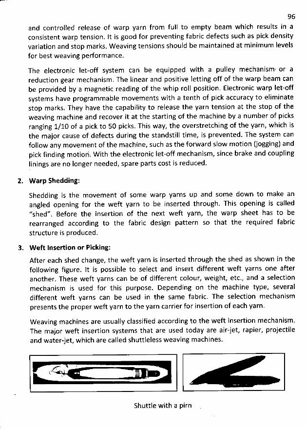
96and controlled release of warp yarn from full to em pty beam which results in aconsistent warp tension. It is good for preventing fabric defects such as pick densityvariation and stop m arks. W eaving tensions should be maintained at minimum Ievelsfor best weaving performance.
The electronic fet-off system can be equipped with a pulley mechanism. or areduction gear m echanism . The Iinear and positive letting off of the warp beam canbe provided by a magnetic reading of the whip roll position. Electronic warp let-offsystems have programmable movements with a tenth of pick accuracy to eliminatestop marks. They have the capability to release the yarn tension at the stop of theweaving machine and recover it at the starting of the machine by a num ber of picks
ranging 1/10 of a pick to 50 picks. This way, the overstretching of the yarn, which isthe major cause of defects during the standstill time, is prevented. The system canfollow any movement of the machine, such as the forward slow motion (jogging) andpick finding motioriî W ith the electronic Iet-off mechanism, since brake and couplingIinings are no Ionger needed, spare parts cost is reduced.
2. W arp Shedding:
Shedding is the movement of som e warp yarns up and some down to make anangled opening for the weft yarn to be inserted through. This opening is called''shed''. Before the insertion of the next weft yarn, the warp sheet has to berearranged according to the fabric design pattern so that the required fabric
structure is produced.
3. W eft Insertion or Picking:
After each shed change, the weft yarn is inserted through the shed as shown in thefollowing figure. lt is possible to select and insert different weft yarns one afteranother. These weft yarns can be of different colour, weight, etc., and a selectionmechanism is used for this purpose. Depending on the m achine type, severaldifferent weft yarns can be used in the same fabric. The selection mechanismpresents the proper weft yarn to the yarn carrier for insertion of each yarn.
W eaving m achines are usually classified according to the weft insertion mechanism.The major weft insertion systems that are used today are air-jet, rapier, projectileand water-jet, which are called shuttleless weaving machines.
r- QK .
Shuttle with a pirn
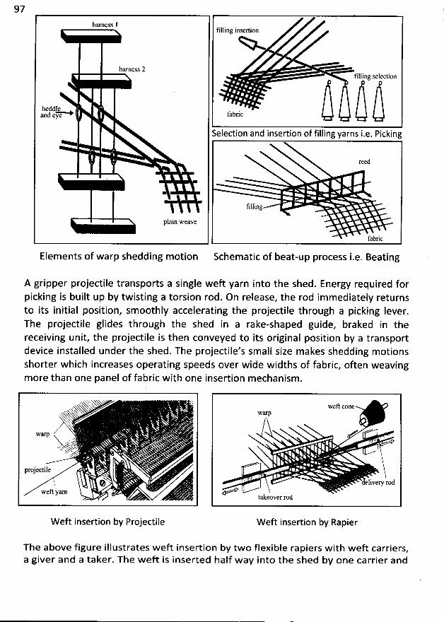
97harness l
tilling insertion
harness 2tilling selection
heddr .la n d e ''''-Ny e f a b ri c
Selection and insertion of filling yarns i.e. Picking
reed
tilling
P
e jxayyjjy
Elements of warp shedding m otion Schematic of beat-up process i.e. Beating
A gripper projectile transports a single weft yarn into the shed. Energy required forpicking is built up by twisting a torsion rod. On release, the rod immediately returnsto its initial position, smoothly accelerating the projectile through a picking lever.The projectile glides through the shed in a rake-shaped guide, braked in thereceiving unit, the projectile is then conveyed to its original position by a transportdevice installed under the shed. The projectile's small size makes shedding motionsshorter which increases operating speeds over wide widths of fabric, often weavingmore than one panel of fabric with one insertion mechanism.
.x XX
/waT. u's.k
-< S.Q Q''* .4kk' xN w
rojectile .Ph. @
wefl yarn
weft conewarp
. q ')%. zs
eljver.y rod
takeover rod
Wef't insertion by Projectile Weft insertion by Rapier
The above figure illustrates wef't insertion by two flexible rapiers with weft carriers,a giver and a taker. The w ef't is inserted half way into the shed by one carrier and
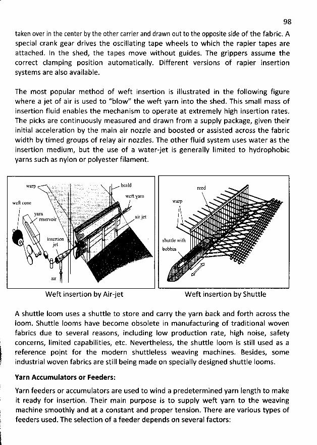
98
taken over in the center by the other carrier and drawn out to the opposite side of the fabric. Aspecial crank gear drives the oscillating tape wheels to which the rapier tapes areattached. In the shed, the tapes move without guides. The grippers assume thecorrect clamping position automatically. Different versions of rapier insertionsystems are also available.
The most popular method of weft insertion is illustrated in the following figurewhere a jet of air is used to ''blow'' the weft yarn into the shed. This small mass ofinsertion fluid enables the mechanism to operate at extremely high insertion rates.The picks are continuously measured and drawn from a supply package, given theirinitial acceleration by the main air nozzle and boosted or assisted across the fabricwidth by timed groups of relay air nozzles. The other fluid system uses water as theinsertion medium, but the use of a water-jet is generally Iimited to hydrophobicyarns such as nylon or polyester filament.
. . IJ ..: . . .L ' . r. ' ' ' ' ; ': : f r : We yarn
û : : ! iWC COnC ' :F ..t .... : .','.' .' ' > '' ' ' ' ' f2.':: .. r. . : . i . . '. . . ... .. . :.. , 'rr . .:. '..'jE 1,:.' q : .L. .. . . . . .. . s:?: . 2 . jq . . . .. . . .. . t..f .tq .ï .: . j' f !J:
' ': ë ' ' .i 7 )'); ' t ! ' ' ' ! ;.; ' '' '. . i: . . . .( ' :. ; :: k : j . k . . .: . . : . ! .y ! . :i. r.j(tf ) y j j. j : t. : j. : :. :E, . i (4 E . . ... . .;x. .I'CSCINOIr ' . ''..' '. . ')E: t :. E. . :: . . . )5. . jq :. '. . . . t . .ë )! . .
. , :inscrtion . ' . .E'gI () t .. :
'. . ''
air
reed
Warp
shuttle with -bobbin
W eft insertion by Airjet W eft insertion by Shuttle
A shuttle Ioom uses a shuttle to store and carry the yarn back and forth across theIoom. Shuttle Iooms have become obsolete in manufacturing of traditional wovenfabrics due to several reasons, including Iow production rate, high noise, safety)
; concerns, Iim ited capabilities, etc. Nevertheless, the shuttle loom is still used as a
jt reference point for the modern shuttleless weaving machines. Besides, some'r industrial woven fabrics are still being made on specially designed shuttle Iooms.
Yarn Accumulators or Feeders:
Yarn feeders or accum ulators are used to wind a predeterm ined yarn Iength to makeit ready for insertion. Their main purpose is to supply weft yarn to the weavingmachine smoothly and at a constant and proper tension. There are various types offeeders used. The selection of a feeder depends on several factors:
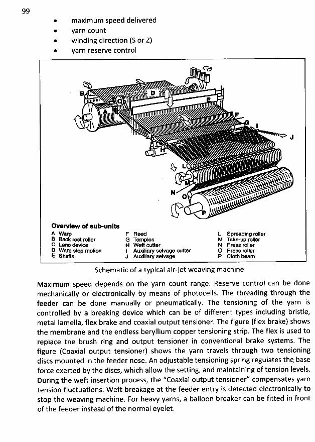
99* maxim um speed dqlivered@ yarn count
@ winding direction (S or Z)* yarn reserve control
OI ii j
$:11$ i'''h -- N*< %%%% '% '' X11 ..N%.% %%%* 1) -v . . . &.>
'
&
'
&
'
I N) -I 1111l / ' --.xx-w'
- x
Iï IJ
Y Ljhhhï
N
Np
œ ervlew of sumunltsA W am F RM - L spreadlng rollerB Back rest roller G Temples M Takmup rollerC Leno devlce H wu cutter N Prex rollerD Wam s'top motion I Auxiliary selvage cutter O Press rollerC Sllafts J Auxiliary selvage P Glom beam
Schematic of a typical air-jetweaving machine
M axim um speed depends on the yarn count range. Reserve control can be donemechanically or electronically by means of photocells. The threading through thefeeder can be done manually or pneumatically. The tensioning of the yarn iscontrolled by a breaking device which can be of different types including bristle,metal lamella, flex brake and coaxial output tensioner. The figure (flex brake) showsthe membrane and the endless beryllium copper tensioning strip. The flex is used toreplace the brush ring and output tensioner in conventional brake systems. The
figure (Coaxial output tensioner) shows the yarn travels through two tensioningdiscs mounted in the feeder nose. An adjustable tensioning spring regulates thqbaseforce exerted by the discs, which allow the setting, and maintaining of tension Ievels.During the weft insertion process, the ''Coaxial output tensioner'' com pensates yarntension fluctuations. W eft breakage at the feeder entry is detected electronically tostop the weaving machine. For heavy yarns, a balloon breaker can be fitted in frontof the feeder instead of the normal eyelet.
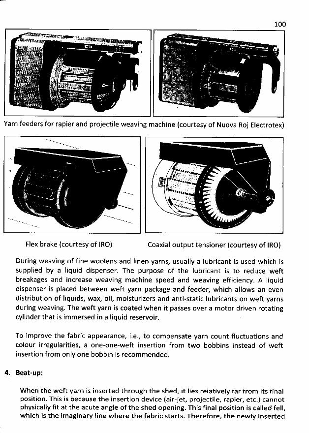
100
Yarn feeders for rapier andprojectile weaving machine(courtesy of Nuova Roj Electrotex)
Flex brake (courtesy of IRO)
.t? . '
7 .,. .. :. ï .: .' J7 4 k '' ) ' 'J * # . .' A.Q y G' k' h . ***ï ' .' ''% . .# . . #> . .ç # ç ' : . . ,
JJ jn . . '. . u -k . 4 . . . z% 4 4 ' t - I .$% ; . .
. . . . rw x ' > ..XNx ' '. Yx .N
Coaxial output tensioner (courtesy of IRO)
During weaving of fine woolens and Iinen yarns, usually a Iubricant is used which issupplied by a Iiquid dispenser. The purpose of the Iubricant is to reduce weftbreakages and increase weaving machine speed and weaving eficiency. A Iiquiddispenser is placed between weft yarn package and feeder, which allows an evendistribution of Iiquids, wax, oil, moisturizers and anti-static Iubricants on weft yarnsduring weaving. The weft yarn is coated when it passes over a motor driven rotatingcylinder that is immersed in a Iiquid reservoir.
To improve the fabric appearance, i.e., to compensate yarn count fluctuations andcolour irregularities, a one-one-weft insertion from two bobbins instead of weftinsertion from only one bobbin is recom mended.
4. Beat-up:
W hen the wef't yarn is inserted through the shed, it Iies relatively far from its finalposition. This is because the insertion device (air-jet, projectile, rapier, etc.) cannotphysically fit at the acute angle of the shed opening. This final position is called fell,w hich is the imaginary Iine w here the fabric starts. Therefore, the newly inserted
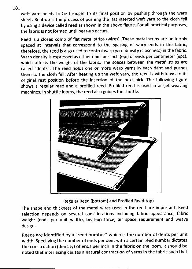
101weft yarn needs to be brought to its final position by pushing through the warpsheet. Beat-up is the process of pushing the Iast inserted weft yarn to the c10th fellby using a device called reed as shown in the above figure. For aII practical purposes,the fabric is not formed until beat-up occurs.
Reed is a closed comb of flat metal strips (wires). These metal strips are uniformlyspaced at intervals that correspond to the spacing of warp ends in the fabric;therefore, the reed is also used to control warp yarn density (closeness) in the fabric.Warp density is expressed as either ends per inch (epi) or ends per centimeter (epc),which affects the weight of the fabric. The spaces between the metal strips arecalled ''dents''. The reed holds one or more warp yarns in each dent and pushesthem to the c10th fell. After beating up the weft yarn, the reed is withdrawn to itsoriginal rest position before the insertion of the next pick. The following figure
shows a regular reed and a profiled reed. Profiled reed is used in airjet weavingmachines. In shuttle Iooms, the reed also guides the shuttle.
Regular Reed (bottom) and Profiled Reedttop)The shape and thickness of the metal wires used in the reed are important. Reedselection depends on several considerations including fabric appearance, fabric
weight (ends per unit width), beat-up force, air space requirement and weavedesign.
Reeds are identified by a ''reed num ber'' w hich is the num ber of dents per unitwidth. Specifying the number of ends per dent with a certain reed num ber dictatesthe construction (density) of ends per inch in the fabric on the Ioom. It should benoted that interlacing causes a natural contraction of yarns in the fabric such that
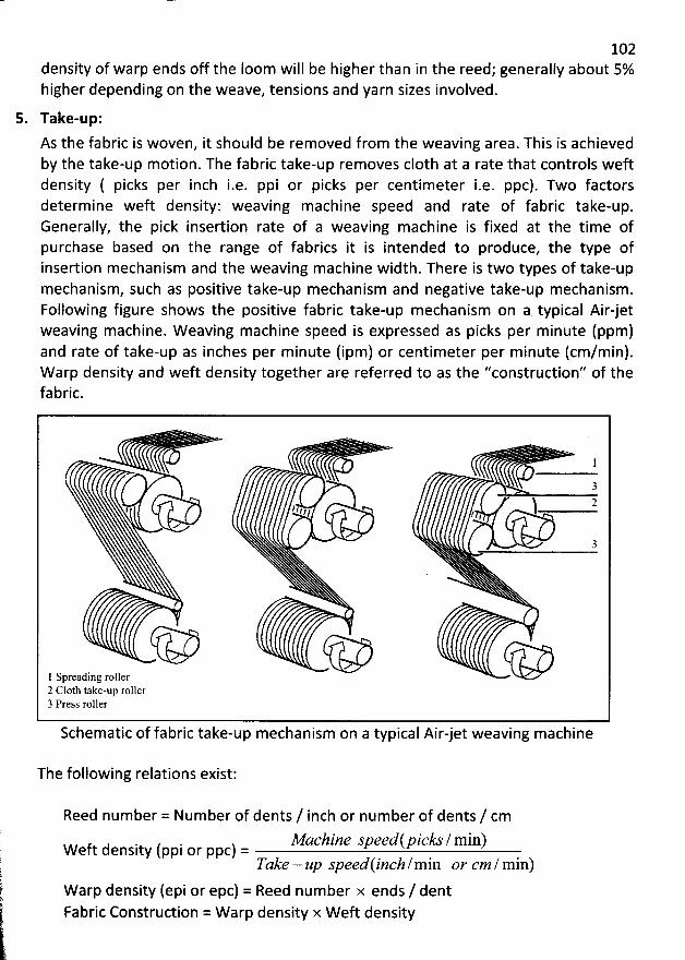
102density of warp ends off the Ioom will be higher than in the reed; generally about 5%higher depending on the weave, tensions and yarn sizes involved.
5. Take-up:
As the fabric is woven, it should be removed from the weaving area. This is achievedby the take-up motion. The fabric take-up removes c10th at a rate that controls weft
density ( picks per inch i.e. ppi or picks per centimeter i.e. ppc). Two factorsdeterm ine weft density: weaving machine speed and rate of fabric take-up.Generally, the pick insertion rate of a weaving machine is fixed at the time ofpurchase based on the range of fabrics it is intended to produce, the type ofinsertion mechanism and the weaving machine width. There is two types of take-upmechanism, such as positive take-up mechanism and negative take-up mechanism.Following figure shows the positive fabric take-up mechanism on a typical Air-jetweaving machine. Weaving machine speed is expressed as picks per minute (ppm)and rate of take-up as inches per minute (ipm) or centimeter per minute (cm/min).W arp density and weft density together are referred to as the ''construction'' of thefabric.
J l3N
) 24 z
'
t , /
'
t/
3
>
1 Spreading roller -.e''2 C10th take-up roller3 Press roller
Schematic of fabric take-up mechanism on a typical Airjet weaving machine
The following relations exist:
Reed number = Number of dents / inch or number of dents / cmMachine speedlpicks / min)Weft density (ppi or ppc) =
Take - up speedlinch/min or cm ! min)Warp density (epi or epc) = Reed number x ends / dentFabric Construction = W arp density x W eft density
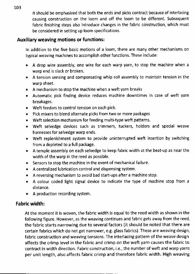
103It should be emphasized that both the ends and picks contract because of interlacingcausing construction on the Ioom and off the loom to be different. Subsequentfabric finishing steps also introduce changes in the fabric construction, which mustbe considered in setting up Ioom specifications.
Auxiliary weaving m otions or functions:
In addition to the five basic motions of a Ioom, there are many other mechanisms ontypical weaving machines to accomplish other functions.These include:
* A drop wire assembly, one wire for each warp yarn, to stop the machine when awarp end is slack or broken.
* A tension sensing and compensating whip roll assembly to maintain tension in thewarp sheet.A mechanism to stop the machine when a weft yarn breaksAutomatic pick finding device reduces machine downtimes in case of weft yarnbreakages. .
@ W eft feeders to control tension on each pick.Pick mixers to blend alternate picks from two or more packages
* W eft selection mechanism for feeding multi-type weft patterns.* W eft selvedge devices such as trimmers, tuckers, holders and special weave
harnesses for selvedge warp ends.* W eft replenishment system to provide uninterrupted weft insertion by switching
from a depleted to a full package.@ A temple assembly on each selvedge to keep fabric width at the beat-up as near the
width of the warp in the reed as possible.* Sensors to stop the machine in the event of mechanical failure.* A centralized lubrication control and dispensing system.* A reversing mechanism to avoid bad start-ups after a machine stop.@ A colour coded Iight signal device to indicate the type of machine stop from a
distance.@ A production recording system.
Fabric width:
At the moment it is woven, the fabric width is equal to the reed width as shown in thefollowing figure. However, as the weaving continues and fabric gets away from the reed,
the fabric starts narrowing due to several factors (it should be noted that there arecertain fabrics which do not get narrower, e.g. glass fabrics). These are weaving design,fabric construction and weaving tensions. The interlacing pattern of the weave designaffects the crim p Ievel in the fabric and crim p on the weft yarn causes the fabric tocontract in width direction. Fabric construction, i.e., the number of weft and warp yarnsper unit Iength, also affects fabric crim p and therefore fabric width. High weaving
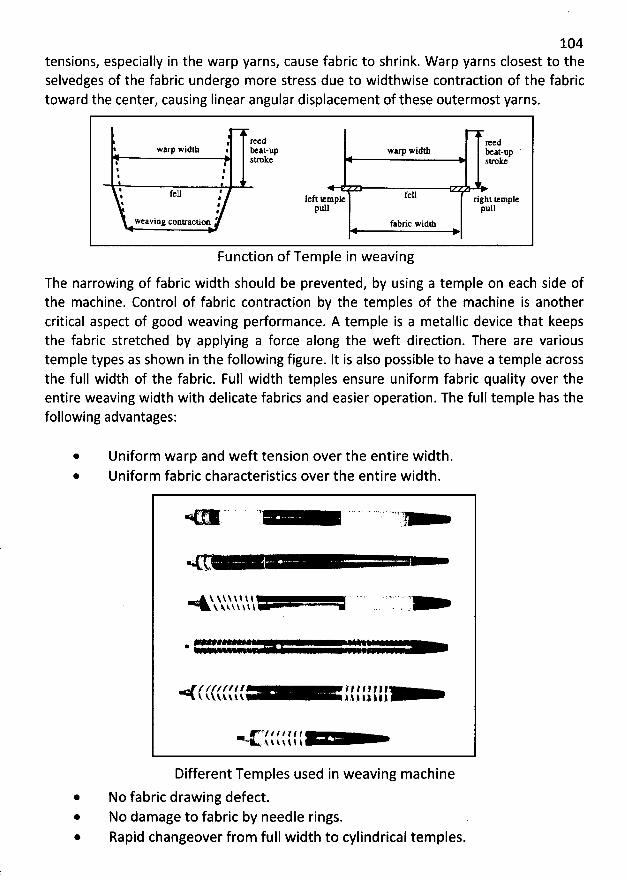
104tensions, especially in the warp yarns, cause fabric to shrink. W arp yarns closest to theselvedges of the fabric undergo more stress due to widthwise contraction of the fabrictoward the center, causing Iinear angular displacement of these outermost yarns.
: reed Iredwarp width . eat-up warp widtll eat-up
. stroke stroke%
'
e
'
%
'
#
' fell ' felle . left temple right temple% .
pull pull#Weaving contractim ' fabric widz
Function of Tem ple in weaving
The narrowing of fabric width should be prevented, by using a temple on each side ofthe machine. Control of fabric contraction by the temples of the machine is anothercritical aspect of good weaving performance. A temple is a metallic device that keepsthe fabric stretched by applying a force along the weft direction. There are varioustemple types as shown in the following figure. It is also possible to have a temple acrossthe full width of the fabric. Full width temples ensure uniform fabric quality over theentire weaving width with delicate fabrics and easier operation. The full temple has thefollowing advantages:
* Uniform warp and weft tension over the entire width.* Uniform fabric characteristics over the entire width.
. 1! ' : . e. ,'
& N.! : ! ! 1 l ' ''' ' '' ' ''' ' ' -' '''N. N. k $ y $ 1. $ . - .
*
/tz'z/.z.t' ? l t 1,,, , ,( t Ntv..k 1,$.1 l.3 kt)
. 'e/' / / / T f (. A N $ $ $ 1. $
Different Temples used in weaving m achine
* No fabric drawing defect.@ No dam age to fabric by needle rings.* Rapid changeover from full width to cylindrical tem ples.
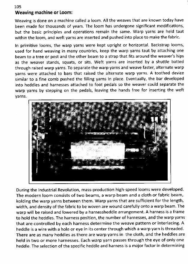
105W eaving machine or Loom :
W eaving is done on a machine called a Ioom. AII the weaves that are known today havebeen made for thousands of years. The Ioom has undergone significant modifications,but the basic principles and operations remain the same. W arp yarns are held tautwithin the Ioom, and weft yarns are inserted and pushed into place to make the fabric.
In primitive looms, the warp yarns were kept upright or horizontal. Backstrap Iooms,used for hand weaving in many countries, keep the warp yarns taut by attaching onebeam to a tree or post and the other beam to a strap that fits around the weaver's hipsas the weaver stands, squats, or sits. W eft yarns are inserted by a shuttle battedthrough raised warp yarns. To separate the warp yarns and weave faster, alternate warpyarns were attached to bars that raised the alternate warp yarns. A toothed devicesimilar to a fine com b pushed the filling yarns in place. Eventually, the bar developedinto heddles and harnesses attached to foot pedals so the weaver could separate thewarp yarns by stepping on the pedals, Ieaving the hands free for inserting the weft
yarns.
During the Industrial Revolution, m ass-production high-speed Iooms were developed.The m odern Ioom consists of two beam s, a w arp beam and a c10th or fabric beam,kolding the warp yarns between them . W arp yarns that are sufficient for the Iength,width, and density of the fabric to be woven are wound carefully onto a warp beam . Thewarp will be raised and Iowered by a harnessheddle arrangement. A harness is a frameto hold the heddles. The harness position, the num ber of harnesses, and the warp yarnsthat are controlled by each harness determ ine the weave pattern or interlacing. Aheddfe is a wire with a hole or eye in its center through w hich a warp yarn is threaded.There are as m any heddles as there are w arp yarns in the c10th, and the heddles areheld in two or m ore harnesses. Each warp yarn passes through the eye of only oneheddle. The selection of the specific heddle and harness is a major factor in determining
106
the structure of the fabric. The above figure (basic structure of a weaving machine)illustrates how a sim ple two-harness Ioom is used to raise one harness while the otherharness remains in its original position. W ith this arrangem ent, the yarns from a shedthrough which the'weft is inserted.
The carrier used for transporting the weft yarn m ay differ from one kind of Ioom toanother. The different devices used form the basis'for classifying different types ofIooms. The name of the Ioom often refers to the carrier used to insert the weft yarn.Originally, these carriers were fairly Iarge, somewhat oval wooden shuttles with abobbin of yarn in the center. W ithin the industry many people refer to newerequipment as weaving machines rather than Iooms. W eaving machines vary from older,shuttle Iooms to modern shuttleless m achines with sophisticated electronic controls.
A. Shuttle W eaving M achines:
For centuries, the basic loom operated with a shuttle to lay the weft yarn. By themiddle of the twentieth century, shuttle Ioom s had developed to a high level ofefficiency, allowing them to make fabric rapidly with reduced numbers of flaws.These shuttle weaving machines depend on a shuttle, a boat-shaped, metal-tippedcarrier, to supply a continuous Iength of weft yarn for the weaving operation. Theyarn is actually wound on a sm all spindle or bobbin known as a pirn or quill, which isplaced in an opening in the shuttle. The shuttle enters the shed and m oves acrossthe width of the fabric to Iay the pick; it stops at the opposite side of the fabric; and,after that pick is beaten into place, a new shed is formed and the shuttle returnsacross the Ioom , releasing yarn from the pirn to produce another pick. As thisoperation is repeated, the weft yarn is alternately woven over and under the warpyarns at the sides of the fabric to form the selvedge.
The width of the fabric is controlled by the num ber and spacing of the warp yarnsacross the Ioom . The yarn supply on each pirn is fairly small; it is enough to produceseveral inches of fabric Iength. Pirn in the shuttle m ust be replaced when the yarnsupply is exhausted. The frequency with which a pirn has to be replaced depends onthe fineness of the weft yarn. Coarse yarns require more frequent replacement;finer yarns need to be replaced Iess often.
In the mechanical changer, full pirns are kept ready in a revolving case. The macginerams them into the shuttle when the shuttle comes to rest briefly after crossing theyarn. The pressure of the full pirn crowds the em pty quill out of the shuttle. It fallsthrough a slot into a container under the Ioom . The new pirn is pushed mechanicallyinto place in the shuttle, which has a self-threading device that automatically picksup the yarn when the new pirn is inserted. This allows the weaving to continuewithout a stop.
107
A specialized process has been developed that allows winding of pirns to take placeat the Ioom. In the Unifil system, em pty pirns are carried on a conveyer belt to apoint w here yarn from a Iarge package is wound onto an empty pirn that is thenreturned to a position where it can be placed in the shuttle. This system requiresthat fewer wound pirns be supplied, but it has several limitations. It is useful only forsingle-colour picks, and because the cost of the system is high, it is most economicalfor coarse yarns that would require especially frequent pirn replacement. Pickingwhen two or more different colours or types of weft yarn are used requires two ormore shuttles and a more com plex and costly type of Ioom arrangement. Aconventional shuttle Ioom has one shuttle box on each side of the machine.
To insert yarns of diserent colours or types, a number of shuttle boxes m ust bemoved up and down to bring shuttles into position to create the pattern. Such Ioomsare often called pick-and-pick Iooms. Among the advantages of most shuttlelessIooms is that they draw yarn for each pick directly from yarn packages, making iteasier and Iess costly to insert a number of different colours or types of yarn.
The Iength of fabric produced by a single weaving machine is determined by theIength of the individual warp yarns wound on the warp beams. If a soo-yards Iengthof fabric is needed, each end on the warp beam will be Ionger than 500 yards toprovide enough yarn for the fabric Iength, plus an additional amount for certainallowances. The amount of fabric produced in a given time period is governed by thespeed at which the picks are inserted.
The speed with which weaving machines operate has traditionally been expressed inpicks per m inute, or ppm. It operates at speeds ranging from about 110 to 225 picksper minute (ppm). As shuttle equipment was operated at higher speeds to increasem ill productivity, the noise Ievel in weave rooms became intense. Shuttle Iooms areextremely noisy because the picker stick, or bar that hits the shuttle across the shed,and the bar that catches it on the other side make Ioud clacking noises each timethey make contact with the shuttle. The shuttle Ioom is the oldest kind of Ioom. It iseffective and versatile, but it has other disadvantages. The shuttle sometimes causesabrasion on the warp yarns as it passes over them and sometimes causes threadbreaks. This, in turn, results in machine stoppage in order to tie the broken yarns.Shuttle Iooms operate more slowly than some new types of Iooms.
B. Shuttleless W eaving M achines:
Shuttleless w eaving m achines were invented to increase the speed of w eaving,reduce the Iiterally deafening noise and overcom e the other disadvantages of theshuttle loom . The modern Ioom w ith a shuttle, although m uch faster in operationthan the earliest automatic looms, is not susceptible to further increases in speedbecause of the variety of operations that the m achine m ust perform . Tim e isrequired for stopping the shuttle and accelerating it in the other direction and the
108weight of yarn on the pirn that must be carried across the shed Iim its the speed. Forthis reason, future Ioom developments are Iikely to be in the area of shuttlelessweaving.
Shuttleless weaving machines wove 17 percent more fabric in 1987 than they did in1982, and Textile W orld predicts that shuttle Iooms will be outnum bered byshuttleless weaving machines in the early 1990s.
Shuttleless machines may be classified as to the method used in inserting the weftyarns. Four basic types have been developed:
* Machines with grippers or projectiles (throw across)@ Machines with mechanically operated gripper arms or iapiers (reach
across)* Machines employing air or water jets to carry the weft (spit or blow
across)@ Machines that form multiple sheds (multiphase)
In hand weaving and automatic shuttle weaving, the weft yarn is continuous andruns back and forth across the fabric, but in most shuttleless weaving, the weft yarnextends only from selvedge to selvedge, as it is cut off before it passes across theshed. In aII shuttleless weaving, the yarn for the pick is unwound from Iarge,stationary packages of yarn that are sometimes set on one side and at other timesset on both sides of the Ioom . Since weaving speed depends on fabric width, there isevew incentive to build wider machines for more efficient weft insertion.
Projectile, Missile, or Gripper W eaving Machine:
These weaving machines were developed in the 1950s in Switzerland and representthe first proven shuttleless weaving machine. In the gripper or projectile type ofweaving machine, a small bullet-shaped or hooklike device grips the end of the weftyarn, which is shown in the following figure. As the gripper is projected across thewarp shed, it tows the weft behind it. The projectile can move more quickly than aconventional shuttle because of its decreased size; it can travel farther more easily,thereby making possible the weaving of wider fabrics, and it does not require thestep of weft the shuttle; it pulls the yarn directly from a prepared yarn package.
Projectile Iooms with one or more projectiles are available; the multiple-projectiletype is more common. Two types of projectile Iooms are used. In one, the projectiletravels only in one directiis returned to the starting point by a conveyor belt.To maintain the weaving speed, each m achin m ust have several projectiles,although only one is in use at any one tim e. It is called m ultiple-prtile system s.They can be used in machines with a wide weaving bed so the projectile grippers cantransfer the pick across the fabric in a relay fashion. In other multiple-projectile
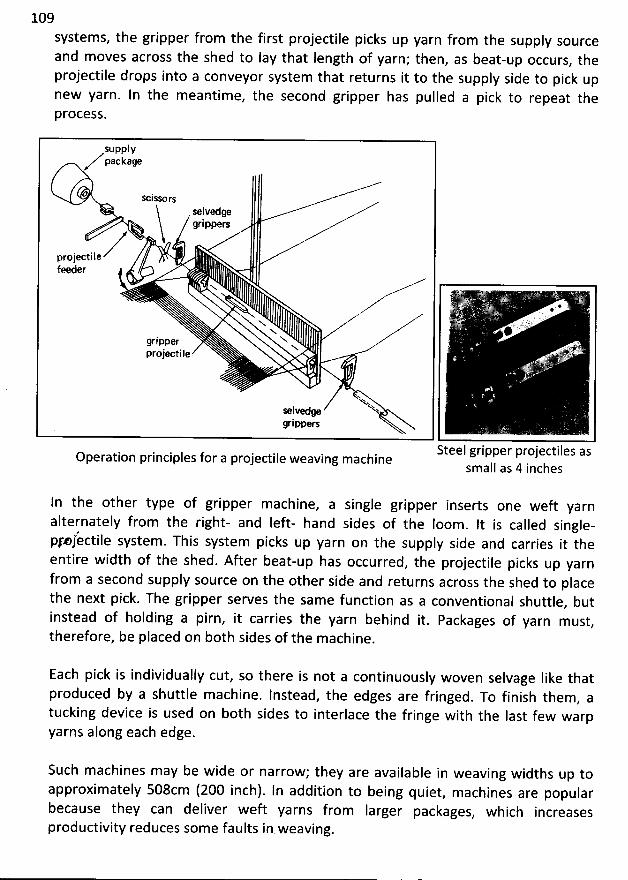
109
systems, the gripper from the first projectile picks up yarn from the supply sourceand m oves across the shed to lay that Iength of yarn; then, as beat-up occurs, theprojectile drops into a conveyor system that returns it to the supply side to pick upnew yarn. In the m eantime, the second gripper has pulled a pick to repeat thePrOCOSS.
supplypackage
/ scjssors
selvedgegrippers
projectile
feeder t - ,R @' !
. f .
Nx. . & Vx.x @ '
ripper N 'g N. ..
ak,:j,b.projectile ..'' ' ' * .î
'ks .'h'hselvedge 't
grippers
Steel gripper projectiles asOperation principles for a projectile weaving machinesmall as 4 inches
In the other type of gripper machine, a single gripper inserts one weft yarnalternately from the right- and Ieft- hand sides of the Ioom . It is called single-pfmfèctile system. This system picks up yarn on the supply side and carries it theentire width of the shed. After beat-up has occurred
, the projectile picks up yarnfrom a second supply source on the other side and returns across the shed to placethe next pick. The gripper serves the sam e function as a conventional shuttle
, butinstead of holding a pirn, it carries the yarn behind it. Packages of yarn m ust,therefore, be placed on both sides of the machine.
Each pick is individually cut, so there is not a continuously woven selvage Iike thatproduced by a shuttle machine. Instead, the edges are fringed. To finish them, atucking devîce is used on both sides to interlace the fringe with the Iast few warpyarns along each edge.
Such machines may be wide or narrow; they are available in weaving widths up toapproximately 508cm (200 inch). In addition to being quiet, machines are popularbecause they can deliver weft yarns from Iarger packages
, which increasesproductivity reduces som e faults in weaving.
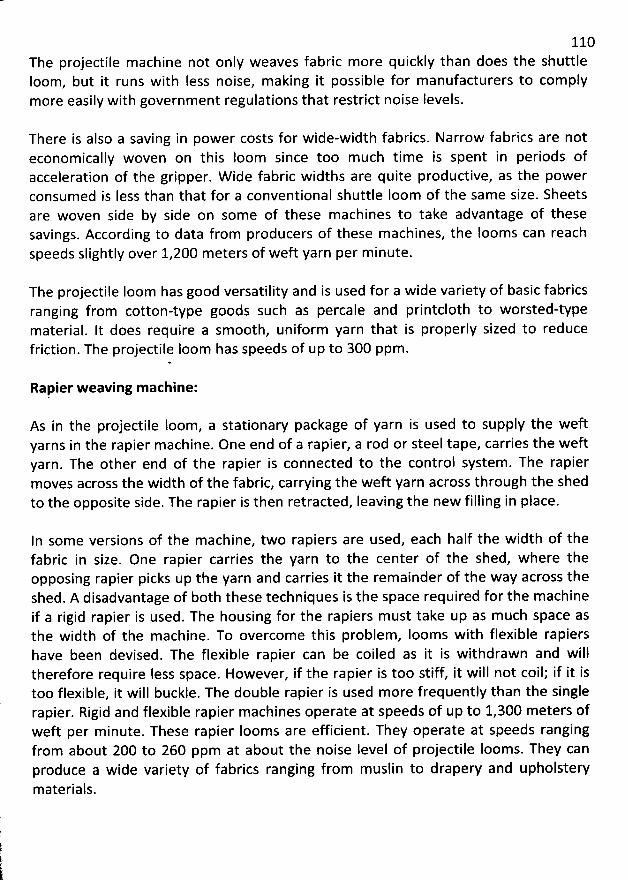
110The projectile machine not only weaves fabric more quickly than does the shuttleIoom, but it runs with Iess noise, making it possible for m anufacturers to complymore easily with government regulations that restrict noise Ievels.
There is also a saving in power costs for wide-width fabrics. Narrow fabrics are noteconom ically woven on this loom since too much time is spent in periods ofacceleration of the gripper. W ide fabric widths are quite productive, as the powerconsumed is Iess than that for a conventional shuttle joom of the sam e size. Sheetsare woven side by side on some of these m achines to take advantage of thesesavings. According to data from producers of these machines, the Iooms can reachspeeds slightly over 1,200 m eters of weft yarn per m inute.
The projectile Ioom has good versatility and is used for a wide variety of basic fabricsranging from cotton-type goods such as percale and printcloth to worsted-typematerial. It does require a sm ooth, uniform yarn that is properly sized to reduce
friction. The projectile loom has speeds of up to 300 ppm.
Rapier w eaving m achine:
As in tbe projectile loom, a stationary package of yarn is used to supply the weftyarns in the rapier machine. One end of a rapier, a rod or steel tape, carries the weftyarn. The other end of the rapier is connected to the control system . The rapierm oves across the width of the fabric, carrying the weft yarn across through the shedto the opposite side. The rapier is then retracted, Ieaving the new filling in place.
In some versions of the machine, two rapiers are used, each half the w idth of thefabric in size. One rapier carries the yarn to the center of the shed, where theopposing rapier picks up the yarn and carries it the rem ainder of the way across theshed. A disadvantage of both these techniques is the space required for the m achineif a rigid rapier is used. The housing for the rapiers m ust take up as m uch space asthe width of the m achine. To overcome this problem, Iooms with flexible rapiershave been devised. The flexible rapier can be coiled as it is w ithdrawn and willtherefore require Iess space. However, if the rapier is too stiff, it will not coil; if it istoo flexible, it will buckje. The double rapier is used more frequently than the singlerapier. Rigid and flexible rapier machines operate at speeds of up to 1,300 meters ofweft per m inute. These rapier looms are efficient. They operate at speeds rangingfrom about 200 to 260 ppm at about the noise Ievel of projectile Iooms. They canproduce a w ide variety of fabrics ranging from muslin to drapery and upholsterymaterials.
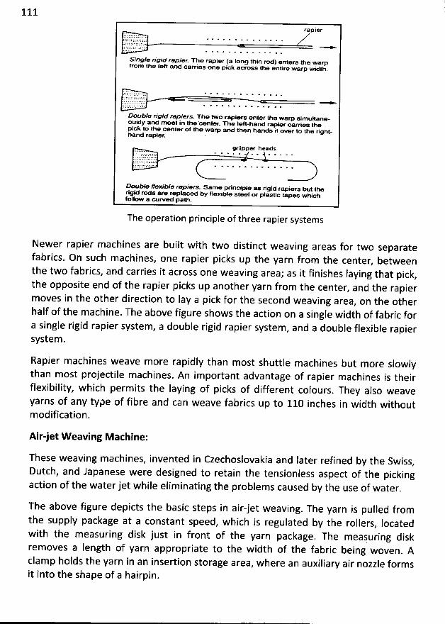
111
rapier;;J22t2 ::t: .
Single r/g/à rapier The rapier (a Iong thin rodl enters the warpfrom tbe Ieft and carries one pick across the entire wam widlh
.
. ')::5:' ':' '''
: 1. . . ' ' ' '
Double rigid rapiers. The two rapiers enter tbe warp simultanmously and meet in me oenter. 3%e Ieft-hand rapier oarries mepick to the center of tNe warp and then hands it over to tbe rignt-band rapier. '
gr ipper headsJJ.... . . . . . . . . . o . . .2 1 L'''JC:11. :' .; ' ' ''.. ....LC J7;' : 'k * C 'â ' .' ;' r : J'
N uble fex/Ne rapiers. Same principle as rigsd' rapiors but merige' rods are replacod by flexible steel or plastic tapes whichfollow a curved patb.
The operation principle of three rapier systems
Newer rapier machines are built with two distinct weaving areas for two separatefabrics. On such machines, one rapier picks up the yarn from the center
, betweenthe two fabrics, and carries it across one weaving area; as it finishes Iaying that pick
,the opposite end of the rapier picks up another yarn from the center
, and the rapierm oves in the other direction to lay a pick for the second weaving area
, on the otherhalf of the machine. The above figure shows the action on a single width of fabric fora single rigid rapier system, a double rigid rapier system
, and a double flexible rapiersystem .
Rapier machines weave more rapidly than most shuttle machines but more slowlythan most projectile machines. An important advantage of rapier machines is theirflexibility, which perm its the Iaying of picks of different colours
. They also weaveyarns of any type of fibre and can weave fabrics up to 110 inches in width withoutmodification.
Air-jet W eaving Machine:
These weaving machines, invented in Czechoslovakia and Iater refined by the Swiss,
Dutch, and Japanese were designed to retain the tensionless aspect of the pickingaction of the water jet while eliminating the problems caused by the use of water.
The above figure depicts the basic steps in air-jet weaving. The yarn is pulled fromthe supply package at a constant speed
, which is regulated by the rollers, locatedwith the measuring disk just in front of the yarn package. The meajuring diskremoves a length of yarn appropriate to the width of the fabric being woven
. Aclam p holds the yarn in an insertion storage area
, where an auxiliary air nozzle formsit into the shape of a hairpin.
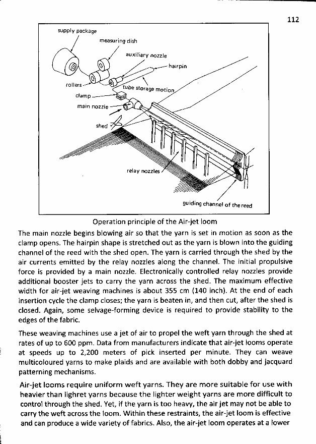
112
supply package
measuring dish
auxiliary nozzle
o 2 .........- - hairpin
Q Nrollers tuye storage motion
clam p
m ain nozzle
Shed *
' xN
. N NN
. N NN N
relay nozzles
guiding channel of tbe reed
Operation principle of the Air-jet loomThe main nozzle begins blowing air so that the yarn is set in motion as soon as theclamp opens. The hairpin shape is stretched out as the yarn is blown into the guidingchannel of the reed with the shed open. The yarn is carried through the shed by theair currents emitted by the relay nozzles along the channel. The initial propulsiveforce is provided by a main nozzle. Electronically controlled relay nozzles provideadditional booster jets to carry the yarn across the shed. The maximum effectivewidth for air-jet weaving machines is about 355 cm (140 inch). At the end of eachinsertion cycle the clam p closes; the yarn is beaten in, and then cut, after the shed isclosed. Again, some selvage-forming device is required to provide stability to theedges of the fabric.
These weaving machines use a jet of air to propel the weft yarn through the shed atrates of up to 600 ppm. Data from manufacturers indicate that airjet Iooms operateat speeds up to 2,200 meters of pick inserted per m inute. They can weavemulticoloured yarns to make plaids and are available with both dobby and jacquardpatterning mechanisms.
Air-jet Iooms require uniform weft yarns. They are more suitable for use withheavier than lighret yarns because the Iighter w eight yarns are more difficult tocontrol through the shed. Yet, if the yarn is too heavy, the air jet may not be able tocarry the weft across the loom. W ithin these restraints, the air-jet loom is effectiveand can produce a wide variety of fabrics. Also, the air-jet Ioom operates at a Iower
113noise Ievel than the shuttle, projectile, or rapier Iooms. Air-jet weaving is morepopular because the m achines cost less to purchase, install, operate, and m aintainthan rapier or projectile weaving machines, and the air-jet can be used on a broadervariety of yarns than a water jet.
Today automated flaw detectors installed on air-jet machines can inspect fabric. Theunit on the batcher is program m ed to stop the machine when defects that falloutside preset tolerances are detected. The batcher operator then cuts out thedefect, seam s the fabric, and restarts the fabric take-up. These flaw detectors arecapable of inspecting fabric at 400 ppm .
W ater-jet weaving machine:
These weaving m achines were first developed in Czechoslovakia in the 1950s andsubsequently refined by the Japanese in the 1960s. W ater-jet weaving machines arenot used as frequently as air jets, but they are preferred for some types of fabrics.The process is unsuitable for yarns of hydrophilic fibres because the fabric picks uptoo m uch m oisture. W ater-soluble warp sizings are used on most staple warp yarns.Therefore, the use of water-jet Iooms is restricted to filament yarns of acetate,nylon, polyester, and glass; yarns that are nonabsorbent, and those that do not losestrength when wet. Furtherm ore, these fabrics come off the loom wet and m ust bedried. In this technique a water jet is shot under force and, with it, a weft yarn. Theforce of the water as it is propelled across the shed carries the yarn to the oppositeside. This machine is economical in its operation. A water jet of only 0.1 centimeteris sufficient to carry a yarn across a 48 inch shed. The am ount of water required foreach weft yarn is Iess than 2.0 cubic centimeters. W ater-jet machines can reachspeeds of 2,000 meters of picks per minute. The water-jet looms can producesuperior high quality fabrics that have good appearance and feel.
Both air and water jet weaving machines weave rapidly, provide for Iaying differentcolours in the weft direction, and produce uniform, high quality fabrics. They are Iessnoisy and require Iess space than most other types of weaving machines. They causem inim al dam age to warp yarns during the weaving operation, because the air or
water jets are less abrasive than moving metal parts.
The speeds of shuttleless weaving m achines can be com pared by measuring the
picks per minute (ppm) or the yards Iaid per minute (ypm) in weft insertion. In 1990,the top speed for a projectile weaving machine was 420 ppm with between 1000and 1203 ypm weft insertion. Flexible rapier machines operated at 524 ppm andrigid rapiers at 475 ppm, Iaying weft at up to 1404 and 930 ypm, respectively. Air jetscould Iay as many as 1200 ppm and water jets up to 1500 ppm, Iaying 2145 and 2360ypm , respectively.
114If a fabric 60 inches wide is woven on each m achine at a density of 50 pice per inch
,
approximately 84 yards of weft yarn would be needed to produce an inch of fabric.
In theory, the projectile would produce approximately 8.4 inches of fabric perm inute; the flexible rapier, 10.5 inches; the rigid rapier, 9.5 inches; the air jet, 24inches; and the water jet, 30 inches. The slowest of the new machines could producea yard of fabric in 4.3 minutes, and the fastest would take just 1.2 minutes. Seldomdo weaving machines operate at full capacity, but even at 50 percent efficiency suchmachines could produce a yard of fabric every 2.5 m inutes.
M ul&iphase or m ultished w eaving machine:
AlI the weaving techniques discussed thus far require that the shed be open alI theway across the machine for the device carrying the filling yarns to pass through theshed. This imposes a limit on loom speed. The m ultiphase weaving m achineovercom es this Iim itation by form ing many different sheds at di/erent places acrossthe machine and form ing these only as the weft yarn inserted. In this way, a num berof weft yarns can be inserted, one behind the other. As a section of the shed opens,the weft passes, and the shed closes, opening again in the new pattern as the nextweft yarn arrives. Speed is increased because of the num ber of yarns that can beinserted almost sim ultaneously one right after the other, but the actual speed ofmovem ent of the weft yarns is Iower than in other types of m achines. For thisreason, weft yarns that are weakèr can be used. Sultzer Ruti, the manufacturer of amultiphase machine, states that its Ioom will insert up to 5,400 meters of pick perm inute.
The process transforms weaving into a continuous process rather than a cycle ofshedding, picking, and beating up. M ultiphase Ioom continually inserts weft yàrnsfrom yarn carriers. Rotary beat-up devices press inserted yarn firm ly againstpreviously form ed c10th. If the pattern cbanges, small groups of yarns are changedinto a new shedding position after each new yarn carrier has passed.
The operation of m ultished weaving m achines is based on a series of wavelikemotions across the weaving surface. In general, fabrics woven on these Iooms do nothave a true 9O- degree angle between warp and w eft; the weft yarns are slightlyslanted, or skewed. M ultished weaving is lim ited to special types of fabrics, but itcan be expected to gain acceptance in the years ahead.
M m any as 16 to 20 weft carriers insert the precut weft in a continuous processinstead of the interm ittent process of single-shed w eaving. Beating up and sheddingarrangements are different. ln this continuous weaving process, the number of picksper m inute is doubled. However, m ultiphase Ioom s have never been extensivelyused in the industry.).i
115
Fabric selvages or selvedges:
In yard goods, the outer edges are constructed so they will not raved. These finished
edges are called the selvages (self-edges) and are often made with heavier and moreclosely spaced warp yarns than are used in the rest of the fabric by using more orstronger warp yarns or by using a stronger weave. Selvages (also called selvedges)provide strength to fabric for safe handling of the fabric. Selvage should not curl. Thewarp yarns always run parallel to the selvedges. Proper use of the selvages can alsoprevent the bowing and bias conditions that occur in som e fabrics. The weavingmachines need mechanism s which through the formation of sufficiently strong selvagesbind the wefts together, thus imparting to the fabric a proper appearance and solidityand preventing the breaking up of the threads on the fabric edges during the
subsequent operations. '
In shuttle Iooms, there is no need for special selvedge; since the yarn is not cut aftereach weft insertion, the edges of the fabric are sm ooth and strong. On conventionalshuttle Iooms, it is formed when the weft yarns turns to go back across the fabric. Theconventional Ioom m akes the same kind of selvedge on both sides of the fabric. At thepresent time this is the only advantage of shuttle Ioom over shuttleless Ioom. Inshuttleless weaving, since the weft yarn is cut after every insertion, there is fringeselvedge on both sides of the fabric. In this case, special selvedges are needed to 'prevent slipping of outside warp yarns out of the fabric. There are several types ofselvedge designs that are used for this purpose with shuttleless looms. The kind ofselvedge used depends upon economy of production and the expected use of the fabric.
* Plain selvages:
These selvages àre constructed of the simple plain weave with tbe same sizeyarn as the rest of the fabric, but with the threads packed m ore closely together.Such sejvages are fairly durable and firm . Plain selvages are sim ilar to thestructure of the rest of the fabric. They do not shrink and can be used for seam
edges.
* Tape Selvages:
The tape selvages are sometim es constructed w ith the plain w eave but oflen aremade of the basket or twill weaves, which makes a flatter edge. Tape selvagesare m ade of heavier yarns or ply yarns, which provide greater strength. They arefirmer and wider than plain selvages. For towels, bed sheets, drapery and curtainfabrics, tape selvages give added strength to the edges. Selvages vary in widthfrom one-quarter to three-eights of an inch.
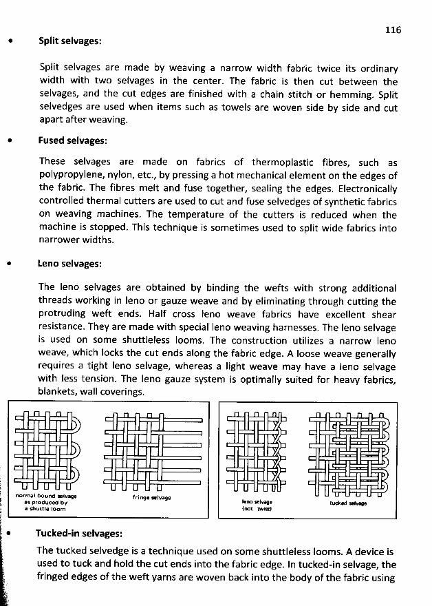
116Split selvages:
Split selvages are made by weaving a narrow width fabric twice its ordinarywidth with two selvages in the center. The fabric is then cut between theselvages, and the cut edges are finished with a chain stitch or hem ming. Splitselvedges are used when items such as towels are woven side by side and cutapart after weaving.
Fused selvages:
These selvages are m ade on fabrics of therm oplastic fibres, such aspolypropylene, nylon, etc., by pressing a hot mechanical element on the edges ofthe fabric. The fibres melt and fuse together, sealing the edges. Electronicallycontrolled therm al cutters are used to cut and fuse selvedges of synthetic fabricson weaving machines. The tem perature of the cutters is reduced when themachine is stopped. This technique is sometim es used to split wide fabrics intonarrower widths.
Leno selvages:
The Ieno selvages are obtained by binding the wefts with strong additionalthreads working in Ieno or gauze weave and by eliminating through cutting theprotruding weft ends. Half cross Ieno weave fabrics have excellent shearresistance. They are made with special Ieno weaving harnesses. The Ieno selvageis used on some shuttleless Iooms. The construction utilizes a narrow Ienoweave, which Iocks the cut ends along the fabric edge. A Ioose weave generallyrequires a tight Ieno selvage, whereas a Iight weave may have a leno selvagewith Iess tension. The Ieno gauze system is optimally suited for heavy fabrics
,
blankets, wall coverings.
normal o und x ivee f rilwe x lvagea: produce bya sbuttle Ioom
lefm Alvage tucked * vv(rm twistl
Tutked-in selvages:
The tucked selvedge is a technique used on some shuttleless Ioom s. A device isused to tuck and hold the cut ends into the fabric edge. In tucked-in selvage, thefringed edges of the weft yarns are woven back into the body of the fabric using
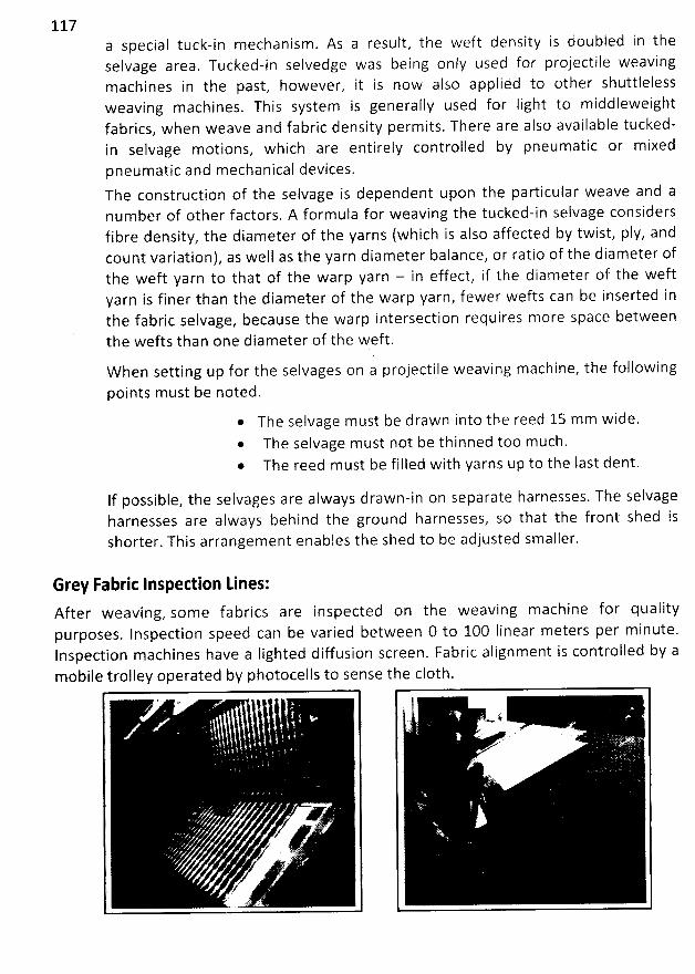
117a special tuck-in mechanism. As a result, the weft density is doubled in theselvage area, Tucked-in selvedge was being only used for projectile weavingmachines in the past, however, it is now also appliéd to other shuttlelessweaving machines. This system is generally used for Iight to middleweightfabrics, when weave and fabric density permits. There are also available tucked-in selvage motions, which are entirely controlled by pneumatic or mixedpneum atic and mechanical devices.The construction of the selvage is dependent upon the particular weave and anum ber of other factors. A formula for weaving the tucked-in selvage considersfibre density, the diameter of the yarns (which is also affected by twist, ply, andcount variation), as well as the yarn diameter balance, or ratio of the diameter ofthe weft yarn to that of the warp yarn - in effect, if the diameter of the weftyarn is finer than the diameter of the warp yarn, fewer wefts can be inserted inthe fabric selvage, because the warp intersection requires more space betweenthe wefts than one diameter of the weft.
W hen setting up for the selvages on a projectile weaving machine, the followingpoints m ust be noted.
* The selvage m ust be drawn into the reed 15 mm wide.* The selvage must not be thinned too much.* The reed must be filled with yarns up to the Iast dent.
If possible, the selvages are always drawn-in on separate harnesses. The selvageharnesses are always behind the ground harnesses, so that the front shed isshorter. This arrangement enables the shed to be adjusted smaller.
Grey Fabric lnspedion Lines:After weaving, som e fabrics are inspected on the weaving machine for qualitypurposes. Inspection speed can be varied between 0 to 1O0 Iinear meters per minute.Inspection machines have a Iighted diffusion screen. Fabric alignm ent is controlled by am obile trolley operated by photocells to sense the c10th.
* :e .
y
/.4 Sg y
118
FABRIC STRUCTURE AND DESIGN
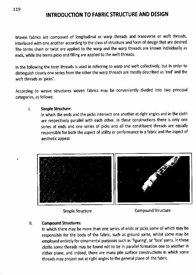
119INTRODUW ION T0 FABRIC STRUW URE AND DESIGN
Woven fabrics are composed of longitudinal or warp threads and transverse or weft threads,interlaced with one another according to the class of structure and form of design that are desired.The terms chain or twist are applied to the warp and the warp threads are known individually asends, while the terms picks and filling are applied to the weft threads.
In the following the term threads is used in referring to warp and weft collectively, but in order todistinguish clearly one series from the other the warp threads are mostly described as 'end' and the
weft threads as 'picks'.
According to weave structures woven fabrics may be conveniently divided into two principal
categories, as follows:
Simple Strudure:In which the ends and the picks intersect one another at right angles and in the c10thare respectively parallel with each other. In these constructions there is only oneseries of ends and one series of picks and aII the constituent threads are equallyresponsible for b0th the aspect of utility or performance in a fabric and tbe aspect ofaesthetic appeal.
*
Simple Structure Compound Structure
lI. Compound Strudures:ln which there may be more than one series of ends or picks some of which may beresponsible for the body of the fabric, such as ground yarns, whilst some may beemployed entirely for ornamental purposes such as 'figuring', or 'face' yarns. ln thesecloths some threads may be found not to be in parallel formation one to another iheither plane, and indeed, there are many pile surface constructions in whicb somethreads may project out at right angles to the general plane of the fabric.
120
Warp (End) and WeR (Pick / Filling) Yarn:Warp and weft yarns have different demands placed on them and may differ in their structure orfibre type. Thus, a fabric may not have the same performance characteristics for warp and weft. Thewarp must withstand the high tensions of the loom and the abrasion ef weavipg, sn the warp yarnsare stronger and more uniform with higher twist. Fillipg yarns at'e more pften fancy or special-fundion yarns such as high-twist crepe yarns, Iow-twist napping yarns, or boucle yarns.
Identification of warp and weft:
Differentiating between warp and weft is possible by carefully examining botb the fabric and thelength-wise and crosswise yarns.
1. The selvedge always runs in the lengthwise (warp) direction of aI1 fabrics.2. Most fabrics have Iower elongation in the warp direction.3. The warp yarns Iie straighter and are more parallel in the fabric because of Ioom tension.4. Fancy or special-fundion yarns are usually in the filling direction.5. Fabric characteristics may differentiate between the warp and weft directions. For
example, poplin has a weft rib and satin has warp floats.6. W arp yarns tend to be smaller, are more uniform in structure and appearance, and have
higher twist.7. Fabric crimp is usually greater for weft yarns since they must bend or flex over or under
warp yarns due to the way the loom operates.
Grain:
Grain refers to the geometry or position of warp yarns relative to filling yarns in the fabric. A fabricthat is on-grain has warp yarns parallel to each other and perpendicular to the filling yarns tbatmove straight across the fabric. Lengthwise grain is parallel to the warp yarns. Crosswise grain isparallel to the weft yarns. Fabrics are almost always woven on-graill. Handling, finishing, or stressdue to yarn twist, weave, or other fabric aspects may cause fabrics to distort and Iose their on-graincharacteristic. These fabrics are off-grain. Fabric quality has increased significantly and it is rare tnfind fabrics as badly off-grain.
off-grain fabrics: These create problems in production and use. During finishing, off-grain causesreruns or repeating finishing steps and Iowers fabric quality. Products do not drape properly or hangevenly and printed designs are not straight.
There are two kinds of off-grain. Skew occurs when the weft yarn is at an angle other than 90degrees to the warp. It usually occurs in finishing when one side of the fabric travels ahead of theother. Bow occurs when the weft yarns dip in the center of the fabric; it usually d:velops when thefabric center lags behind the two sides during finishing.
Fabrics should always be examined for grain. On-grain fabrics usually indicate high quality standardsand minimize problems in matching designs or patterns, in cutting and sewing.
121Structure:
In the manufadure of a fabric, by weaving on a loom, the technique - how the two series of threadare interlaced at right angles to each other is called strudure. Or the interlacements of warp anlweft threads are known as strudure.
Texture:
A term referring to the appearance or hand of a fabric and especially such features as strudurecoarseness, openness. This signifies the general quality of a fabric, developed by the interlacemenof yarn used weight, bulk, how it feels when handled etc. are also express by the term textureMaterials, count of the yarns relative density of threads are its main fadors.
Sett:
A term used to indicate the spacing of ends and/or picks in a woven c10th this is usually expressed athreads per inch, centimeter or other convenient unit. The state of the c10th of the time should bldescribed, eg. Grey, finished woven fabric setts are commonly given in a pare
warp x weft, as for example handkerchief - 36 x 36
Thread density in warp and weo:
Warp (ends) density is expressed in Ends per inch (EPl) Or Ends per cm (EPC)Weft (picks) density is expressed in Picks per inch (PPI) Or Picks per cm (PPC)
W oven fabric Specification:
W oven fabric construdion or specification as follows:
EPI x PPl x Fabric width ORWarp count x Weft count
Warp count x Weft countx Fabric Width
EPI x PPI
For example:
110 X 52 ,,X 56 ,20 X 16
30 X 30 ,,X 57 - 58130 X 70
Fabric weight calculation:
Thjre are two way of fabric weight calculation. 0ne is weight per unit area such as, GsMtgrams per'
2square meter) or oz / yd and another way is weight in running Iength.
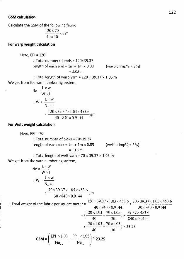
GSM taltulation:
Calculate.the GSM of the following fabric120 x 70 ,,
x 5840 x 30
For warp weight calculation
Here, EPI = 120.'.TotaI number of ends = 120x39.37
Length of each end = lm + lm x 0.03 (warp crimpo,zt = 31$)= 1.03m
.'. Total Iength of warp yarn = 120 x 39.37 x 1.03 m
We get from the yarn numbering system,L x w
Ne =W x IL x w
' W =N x le
120 x 39.37 x 1.03x 453.6= gm40
x 840 x 0.9 l44
For W eft weight calculation
Here, PPI = 70.'.TotaI number of picks = 70x39.37
Length of each pick = lm + lm x 0.05 (weft crimpL' = 594)= 1.05m
.'.TotaI Iength of weft yarn = 70 x 39.37 x 1.05 m
We get from the yarn numbering system,L x wN
e =W x IL x w' W =N e x I
70 x 39.37 x 1 .05 x 453.6= gm30 x 840 x 0.9144
l20 x 39.37 x 1 .03 x 453.6 70 x 39.37 x 1 .05x 453.6.'.TotaI weight of the fabric per square meter = +
40 x 840 x 0.9 l44 30 x 840 x 0.9144120 x 1.03 70x l .05 39.37 x 453.6
= ( + ) x40 30 840 x 0.9144
120 x 1 .03 70 x l .05= ( + ) x 23.2540 30
EPI x l .03 PPI x 1.05 xGSM = + 23.25
Newa Newe
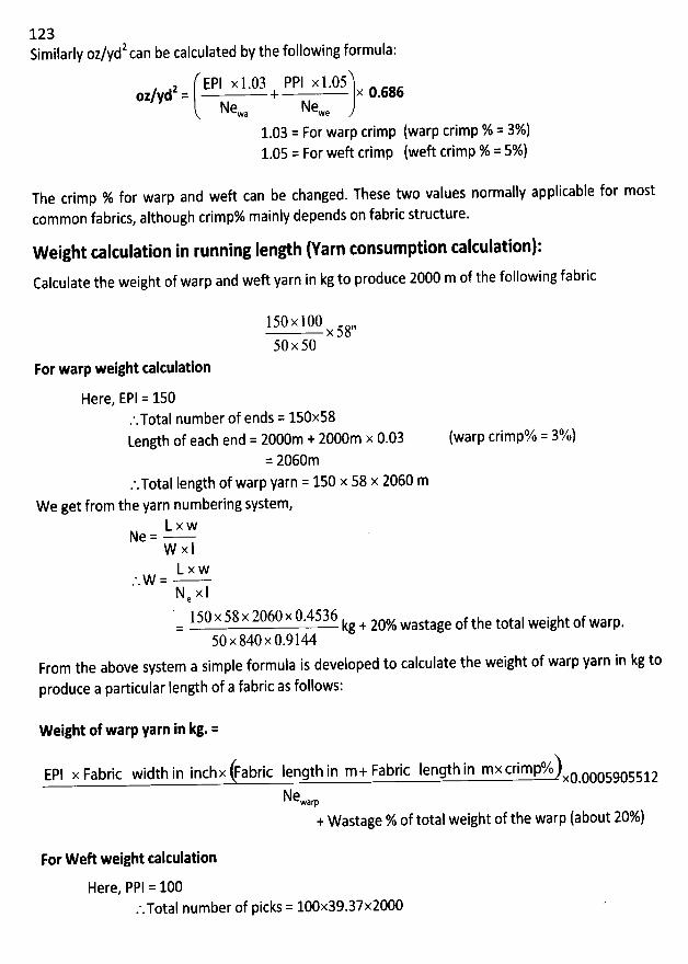
1232 be calculated by the following formula:Similarly oz/yd can
z EPI x 1.03 PPI x 1.05oz/yd = + x 0.686
Newa Newe
1.03 = For warp crimp (warp crimp % = 3%)1.05 = For weft crimp (weft crimp % = 5%)
The crimp % for warp and weft can be changed. These two values normally applicable for most
common fabrics, altbough crimp% mainly depends on fabric structure.
Weight calculation in running Ienlh (Yarn consumption calculation):Calculate the weight of warp and weft yarn in kg to produce 2000 m of the following fabric
150 x 100 ,,x 58
50 x 50For warp weight takulation
Here, EPI = 150.'.TotaI number of ends = 150x58Length of each end = 2000m + 2000m x 0.03
= 2060m
.'.Total length of warp yarn = 150 x 58 x 2060 m
We get from the yarn numbering system,L x wN
e =W x lL x w
*. h/s/ zz'
N x 1e150 x 58 x 2060 x 0.4536 j total weight of warp
.= kg 1 20% Wastage Of t e50 x 840 x 0.9144
From the above system a simple formula is developed to calculate the weight of warp yarn in kg to
produce a particular Iengtb of a fabric as follows:
(warp crimp% = 3%)
Weight of warp yarn in kg. =
EPl x Fabric width in inchx (Fabric length in m-i- Fabric length in mx crimp%lxcoctssx sslz
Newam
+ Wastage % of total weight of the warp (about 20%)
For W eft weight talculation
Here, PPI = 100.'.TotaI number of picks = 100x39.37x2000
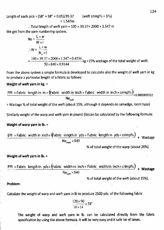
124
Length of each pick = (58// + 58/' x 0.05)/39.37= 1.547m
.'.TotaI Iength of weft yarn = 100 x 39.37x 2000 x 1.547 m
W e get from the yarn numbering system,L x wN
e =W x IL x w' W =N x le
100 x 39.37 x 2000x 1.547 x 0.4536= kg +15% wastage of the total weight of weft.
50 x 840 x 0.9144
(weft crimp% = 5%)
From the above system a simple formula is developed to calculate also the weight of weft yarn in kgto produce a particular Iength of a fabric as follows:
Weijht of weft yarn in kg. =
PPI x Fabric length in mx (Fabric width in inch+ Fabric width in inchx crimp%lxc.cx sx sslz
Neweft
+ Wastage % of total weight of the weft (about 15% although it depends on selvedge, loom type)
Similarly weight of the warp and weft yarn in pound (lblcan be calculated by the following formula:
W eight of warp yarn in Ib. =
EPI x Fabric width in inchx (Fabric Iength in yds+ Fabric Iength in ydsx crimp%) + wastageNewarp x 840
% of total weight of the warp (about 20%).
W eight of weft yarn in Ib. =
PPI x Fabric Iength in ydsx (Fabric width in inch+ Fabric width in inchx crimp%) + wastageNeweft x 840
% of total weight of tbe weft (about 15%1.Problem:
Calculate the weight of warp and weft yarn in Ib to produce 2500 yds. of the following fabric
120x 90 ,,x58
16x 14
The weight of warp and weft yarn in Ib. can be calculated directly from the fabricspecification by using the above formula. It will be very easy and it safe Iot of times.
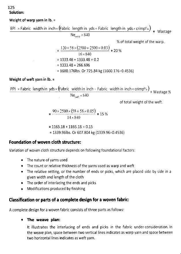
1 2 5Solution:
W eight of warp yarn in Ib. x
E?I x Fabric width in inchx (Fabric length in yd5 + Fabric Iength in ydsx crimpqbl + wastageNewarp X 840
% of total weight of the warp.
l 20 x 58 x (2500 + 2500 x 0.03)= + 20 %1 6 x 840
= 1333.48 'F 1333.48 x 0.2= 1333.48 'F 266.696
= 1600.176Ibs, Or 725.84 kg (1600.176x0.4536)
W eight of weft yarn in Ib. =
P?I x Fabric Iength in ydsx (Fabric width in inch + Fabric width in inch x crimptlkll .j. waytage %Ne,veft tk 840
of total weight of the weft.
90x 2500x (58 + 58x 0.05)= + 15 %14x 840
= 1165.18 'F 1165.18 x 0.15
= 1339.961bs. Or 607.804 kg (1339.96x0.4536)
Foundation of woven c10th strudure:
Variation of woven c10th structure depends on follcwing foundational factors:
The nature of yarns usedThe cotznt or relative thickness of the yarns used as warp and weftThe relative setting, or the number of ends or picks, which are placed side by side in agiven width and Iength of the c10thThe order of interlacing the ends and picks
* Modifications produced by finishing
Elassiscation or parts of a com plete design for a woven fabric:
A complete design for a woven fabric consists of three par'ts as follows:
* The weave plan:
It illustrates the interlacing of ends and picks in the fabric under consideration. lnthe weave plan, space between two vertical lines indicates as warp yarn and space Letweentwo horizontal Iines indicates as weft yarn.
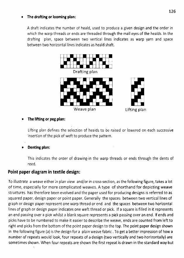
126* The drafting or Iooming plan:
A draft indicates the number of heald, used to produce a given design and the order inwhich the warp threads or ends are threaded through the mail eyes of the healds. In thedrafting plan, Space between two vertical lines indicates as warp yarn and spacebetween two horizontal Iines indicates as heald Shaft.
Drafting plan
W eave plan Lifting plan
The Iifting or peg plan:
Lifting plan defines the selection of healds to be raised or Iowered on each successiveinsertion of the pick of weft to produce the pattern.
Denting plan:
This indicates the order of drawing-in the warp threads or ends through the dents ofreed,
Pnint paper diagram in textile design:
To illustrate a weave either in plan view and/or in cross-section, as the following figure, takes a Iotof time, especially for more complicated weaves. A type of shorthand for depicting weavestructures has therefore been evolved and the paper used for producing designs is referred to assquared paper, design paper or point paper. Generally the spaces between two vertical lines ofgraph or design paper represent one warp thread or end and the spaces between two horizontalIines of graph or design paper indicates one weft thread or pick. If a square is filled in it representsan end passing over a pick whilst a blank square represents a pick passing over an end. If ends andpicks have to be numbered to make it easier to describe the weave, ends are counted from Ieft toright and picks from the bottom of the point paper design to the top. The point paper design shownin the following figure (a) is the design for a plain weave fabric . To get a better impression of how anumber of repeats would look, four repeats of a design (two vertically and two horizontally) aresometimes Shown. When four repeats are shown the first repeat is drawn in the standard way but
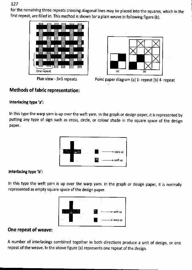
127for the remaining three repeats crossing diagonal Iines may be placed into the squares
, which in thefirst repeat, are filled in. This method is shown for a plain weave in following figure (b).
. y2One repeat
Plan view - 3x3 repeats
X XX X
XX
(a) (b)
Point paper diagram (a) 1- repeat (b) 4- repeat
Methods of fabri: representation:
lnterlacing type 'a':
In this type the warp yarn is up over the weft yarn. In the graph or design paper, it is represented byputting any type of sign such as cross, circle, or colour shade in the square space of the designpaper.
R -----> warp up
R -----'> Weft up
lnterlating type 'b':
ln this type the wek yarn is up over the warp yarn. In the graph or design paper, it is normally
represented as empty square space of the design paper.
R -----> weft upR ----+ warp up
One repeat of weave:
A number of interlacings combined together in both diredions produce a unit of design, or one
repeat of the weave. In the above figure (a) represents one repeat of the design.
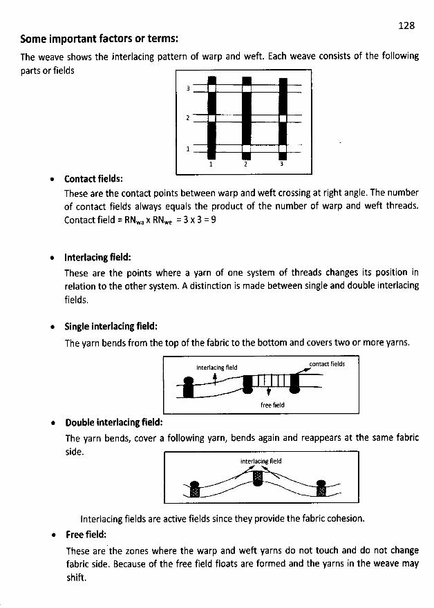
128Some important factors or terms:
The weave shows theparts or fields
interlacing pattern of warp and weft. Each weave consists of the following
3
2
1
1 2 3
Contact fields:These are the contact points between warp and weft crossing at right angle. The numberof contact fields always equals the product of the number of warp and weft threads.Contact field = RNwa x RNwe = 3 x 3 = 9
Interlacing field:
These are the points where a yarn of one system of threads changes its position inrelation to the other system. A distinction is made between single and double interlacingfields.
Single interlacing field:
The yarn bends from the top of the fabric to the bottom and covers two or more yarns.
contact fieldsinterlacing field
free field
Double interlacing field:
The yarn bends, cover a following yarn,side.
bends again and reappears at the same fabric
interlacing field
Interlacing fields are adive fields since they provide the fabric cohesion.
Free field:
These are the zones where the warp and weft yarns do not touch and do not changefabric side. Because of the free field floats are formed and the yarns in the weave mayshiû.
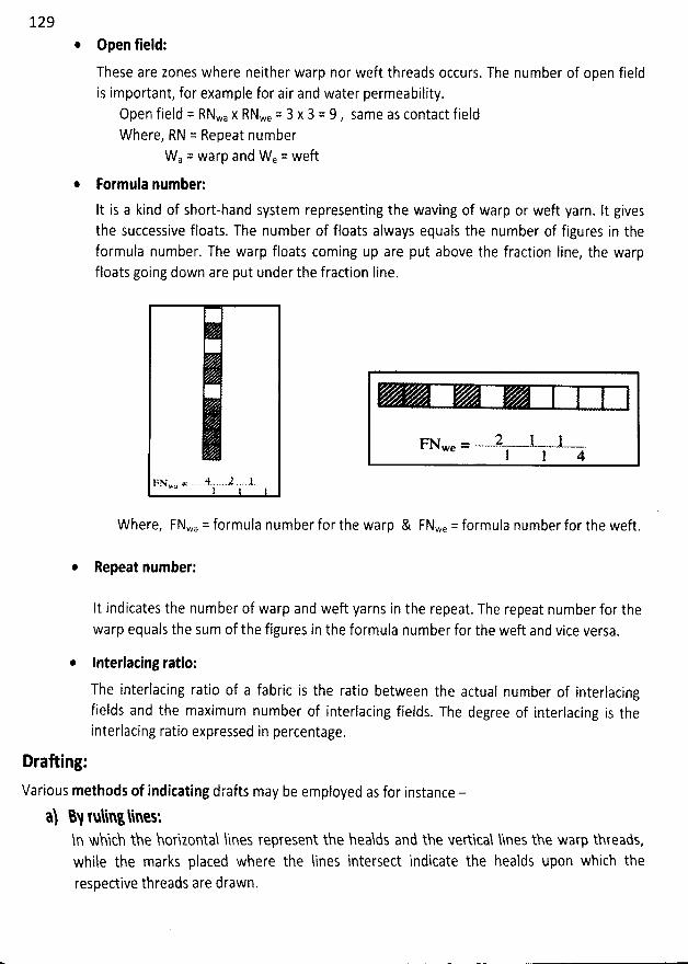
129@ Open field:
These are zones where neither warp nor weft threads occurs. The number of open fieldis important, for example for air and water permeability.
Open field = RNwa x RNwe = 3 x 3 = 9 , same as contact fieldWhere, RN = Repeat number
Wa = warp and We = weft
Formula number:
It is a kind of short-hand system representing the waving of warp or weft yarn. It givesthe successive floats. The number of floats always equals the number of figures in theformula number. The warp floats coming up are put above the fraction Iine, the warpfloats going down are put under the fraction Iine.
FN = .. 1 -2 .1wa1
Where, FNwa = formula number for the warp &
FNwe=--2--1- -t-1 1 4
FNwe = formula number for the weft.
Repeat number:
It indicates the number of warp and weft yarns in the repeat. The repeat number for thewarp equals the sum of the figures in the formula number for the wef't and vice versa.
* Interlacing ratio:
The interlacing ratio of a fabric is the ratio between the actual number of interlacingfields and the maximum number of interlacing fields. The degree of interlacing is theinterlacing ratio expressed in percentage.
Draoing:
Various methods of indicating drafts may be employed as for instance -
% %N tulih: lihetln which the horizontal ïines represent the healds and the Merticaî hnes the warp threads,while the marks placed where the lines intersect indicate the healds upon which therespective threads are drawn.
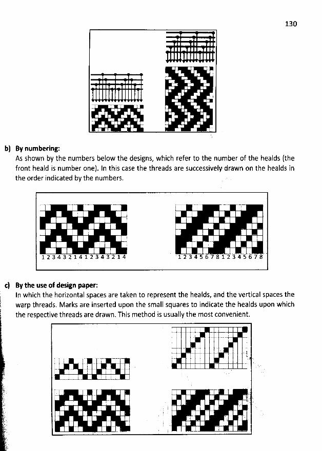
130
b) By numbering:As shown by the numbers below the designs, which refer to the number of the healds (thefront heald is number one). ln this case the threads are successively drawn on the healds inthe order indicated by the numbers.
h I I
1 2 34 3 2 1 4 1 2 3 4 3 2 1 4 1 2 3 4 5 6 7 8 1 2 34 5 67 8
By the use of design pae r:In which the horizontal spaces are taken to represent the healds, and the vertical spaces thewarp threads. Marks are inserted upon the small squares to indicate the healds upon whichthe respective threads are drawn. This method is usually the most convenient.
01 -0 ' t t
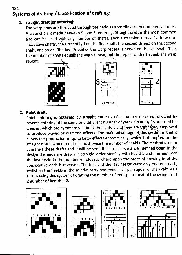
131Systems of drafting / classifiçation of drafting:
1. Straight draAThe warp ends are threaded through the
(or g):
A distinction is made betweenand can be used with 4ny number
i i d on the first shàft the.kecond thread on the secondsuccessive shafts, t e firs! yh 4, ,.
'
shaft, and so on. The Iajt thr#àd of the warp repeat is drawn on the Iast shaft. Thusthe number of shafts equalj the warp repeat. and the rvpeat of draft equals the warprepeat.
heddles according to their numerical order.S- ?nd Z- entering. Straight draft is the most common
of shaftsf Eaih stkcessive thread is drawn on
321 .l 2 3 4
S32
S-entering
4r t=3 I '2 '1.. 21 2 3 4
Z
Z-entering
2. Pointdeah:Point entering is obtained by straight entering of a number of 'yarns followed byreverse eritering of the same 9r a different numbér of yarns. Ppint drpfts are used for
'. 1 ' .1 .
weaves, whiéh are symmetrlçal about tbe center, and isey are fryj iitp?ly employedèd or diamorid effects. The main. advantae' qtjtàis jy'lièih is that itto produce wav
Il' èh if a'ttem/ ed on thealfows the produciion of quite farge effects economically, w istraight drafts would reqtlire almost twice the number of healds. The method used toconstruct these drafts and it will be seen that to achieve a well defined point in thedesign the ends are drawn in straight order starting with heald 1 and finishing withthe last heald in the number employed, where upon the order of drawing-in of theconsecutive ends is reversed. The first and the Iast healds carry only one end each,whilst aII the healds in the middle carry two ends each per repeat of the draft. As aresult, using this system of drafting the number of ends per repeat of the design is : 2
x number of healds - 2.
1 2 3 4 3 2 1 4
#
ij '
i
1 2 .' 3 4 3 2
!
5 ' !4 '
k j '3
2 E; . j
'
.1l1 2 3 4 5 6 7 8
54g2 . . .1
5 d I '. I !
4 I i J3 : 1 i2 , '
i
'
1 : ) :1 ' ...-f1 2 3 4 5 6 7 8 9 1 0 1 1 1 2 1 3 1 4.
y ; '
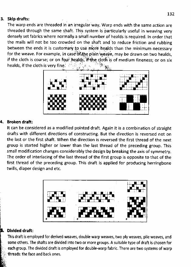
1323. Skip drafts:
The warp ends are threaded inan irregular way. W arp ends with the same action arethreaded through the same jh. aft. This.system is 'particularly useful in weaving verydensely set fabrics where normally a small nnumber of healds is required. In order that
jthe mails will not be too crowded on the s af't and to reduce friction andbetween the ends it is custèmàr. 1.0 tlsé rn4 r,è healds than the minimum necessary
w .i ' . . . è.. . . .. @: u ; ' .'7 ' $.'':f the plàinkeake, may be drawn on two healdsfor the weave. For example, irl case ö. >. , . , , ,
.. .s ' (7' l:.-Jf ; -- -k 1' L'i' . :if the c10th is coarse; or on fpùr
.
'xheax, 1ds, ifit.hqt ç10th, ij of medium fineness; or on six7 ' ) ) ' ' . .y
'
'
y ' ' .' - ; ( $ ï' ..g ; L; . ! êi ' ?.k ),jy j .healds
, if the c10th is very f ine. ,. ..... . n,. ;. . & ymltï..o.-, y âq .'. s 'k .,,. )(; . .. * . . j . 7. .-: '-- -r l i 777- 7y
v k + : =*-+-*sy.y , f7 m-.: : : . o.=
y;. I ; I . j ; . , .. j + i. , y , j jj . ; , ,! ! I ' i 1 ,
' j . :
( 1 ' l iI I : r
r . , '
rubbing
4. Broken draft:It can be considered as a modified pointed draft. Again it is a combination of straightdrafts with different directions of constructing. But the direction is reversed not onthe Iast or the first shaft. W hen the direction is reversed the first thread of the nextgroup is started higher or Iower than the last thread of the preceding group. Thissmall modification changes considerably the design by breaking the axis of symmetry.The order of interlacing of the Iast thread of the first group is opposite to that of the
first thread of the preceding group. This draft is applied for producinj herringbonetwills, diaper design and etc.
( .
( '
$
'
htkr
'
1.1,.
. Dlvided draft:This draft is employed for derived weaves, double warp weaves, two pIy weaves, pile weaves, and
t Some others. The shafts are divided into two or more groups. A suitable type of draft is chosen for)t: each group. The divided draft is employed for double-warp fabric. There are two systems of warp';'/,ïlt 'threads: the face and back ones.)( ,
.:k i: -' -
q-lt. t..,t..io
U 'F- +-! ' . l
! .11 f 7 -t-r- -
= 'x11 ' t
'
...,@ k i . 1p- . . ..
1 j : I ; j-Z: I
r- r- 1r- . : , j r
l .1k .1# # #
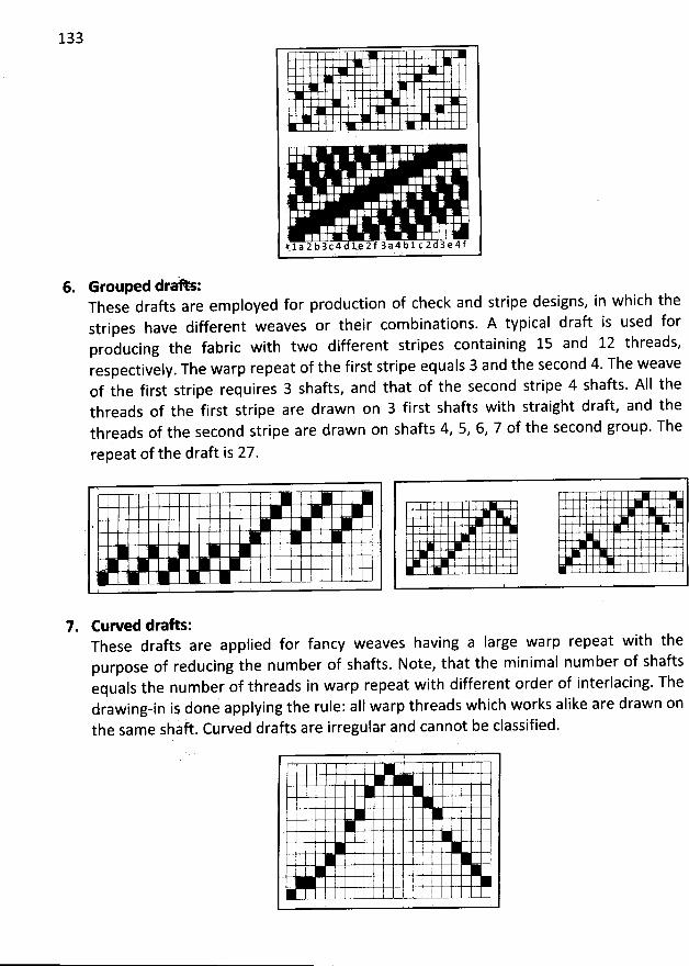
133
#1a2b3c4d1e2f3a4b1c2d3e4f
6. Grouped drahs:These drafts are employed for production of check and stripe designs, in which thestripes have different weaves or their combinations. A typical draft is used forproducing the fabric with two different stripes containing 15 and 12 threads,respectively. The warp repeat of the first stripe equals 3 and the second 4. The weaveof the first stripe requires 3 shafts, and that of the second stripe 4 shafts. AII thethreads of the first stripe are drawn on 3 first shafts with straight draft, and thethreads of the second stripe are drawn on shafts 4, 5, 6, 7 of the second group. The
repeat of the draft is 27.
7. Cuwed draœ :These drafts are applied for fancy weaves having a Iarge warp repeat with thepurpose of reducing the number of shafts. Note, that the minimal number of shaftsequals the number of threads in warp repeat with different order of interlacing. Thedrawing-in is done applying the rule: aIl warp threads which works alike are drawn onthe same shaft. Curved drafts are irregular and cannot be classified.
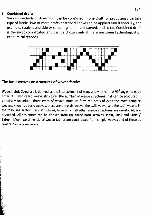
1348. Combined draft:
Various methods of drawing-in can be combined in one draft for producing a certaintype of fabric. Two or more drafts described above can be applied simultaneously, forexample, straight and skip or sateen, grouped and curved, and so on. Com bined draftis the most com plicated and can be chosen only if there are some technological oreconomical reasons.
The basic weaves or strudures of woven fabric:
0 I to eachWoven fabric Structure is defined as the interlacement of warp and weft yarn at 90 ang esother. It is also called weave structure. The number of weave structures that can be produced ispractically unlimited. Three types of weave structure form the basis of even the most complexweaves. Known as basic weaves, these are the plain weave, the twill weave, and the satin weave. Inthe following section basic structures, from which aII other weave structures are developed, arediscussed. AII structures can be derived from the three basic weaves: Plain, Twill and Satin /Sateen. Most two-dimensional woven fabrics are constructed from simple weaves and of these atIeast 90 % use plain weave.
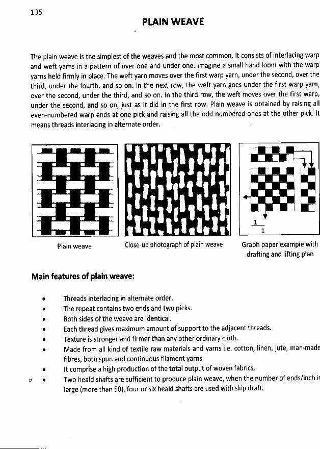
135
PLAIN W EAVE
The plain weave is the simplest of the weaves and the most common. It consists of interlacing warpand weft yarns in a pattern of over one and under one. Imagine a small hand Ioom with the warpyarns held firmly in place. The weft yarn moves over the first warp yarn, under the second, over thethird, under the fourth, and so on. In the next row, the weft yarn goes under the first warp yarn,over the secondy.under the third, and so on. In the third row, the weft moves over the first warp,under the second, and so on, just as it did in the first row. Plain weave is obtained by raising aII
d ' d t one pick and raising aII the odd numbered ones at the other pick. lteven-numbere warp en s a
means threads interlacinj in alternate order.
@Plain weave Close-up photograph of plain weave
W' 7- ;&.
11
Graph paper example withdraûing and Iifting plan
Main features of plain weave:
@
@
@
@
@
Threads interlacing in alternate order.The repeat contains two ends and two picks.Both sides of the weave are identical.Each thread gives maximum amount of support to the adjacent threads.Texture is stronger and firmer than any other ordinary c10th.Made from aII kind of textile raw materials and yarns i.e. cotton, Iinen, jute, man-madefibres, both spun and continuous filament yarns.It comprise a high production of the total output of woven fabrics.Two heald shafts are sufficient to produce plain weave, when the number of ends/inch i6Iarge (more than 50), four or six heald shafts are used with skip draft.
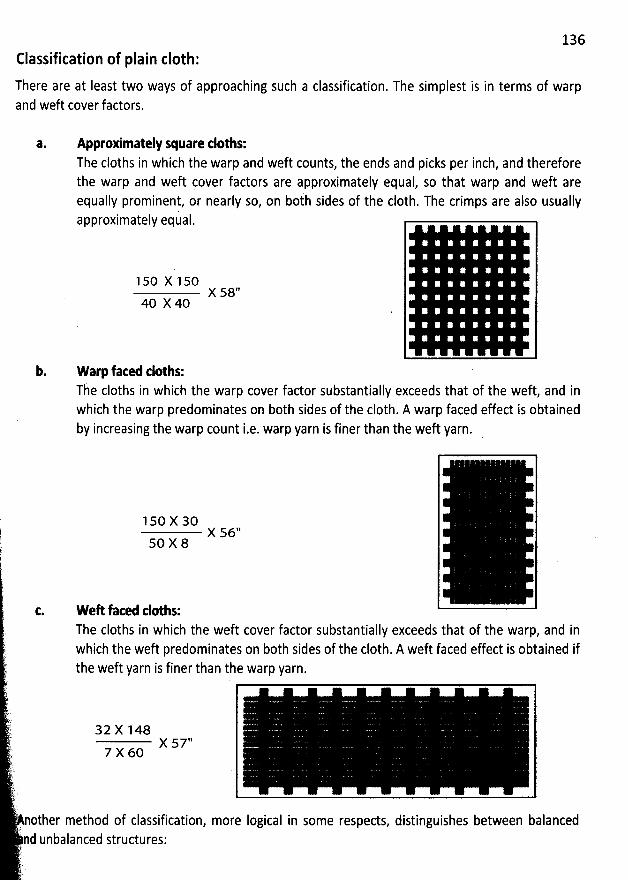
136Classification of plain c10th:
There are at Ieast two ways of approaching such a classification. The simplest is in terms of warpand weft cover factors.
a. Approximately square tloths:The cloths in which the warp and weft counts, the ends and picks per inch, and thereforethe warp and weft çover factors are approximately equal, so that warp and weft areequally prominent, or nearly so, on both sides of the c10th. The crimps are also usuallyapproximately equal.
1 50 X 1 50
40 X 40X 560
b. Warp fated tloths:The cloths in which the warp cover factor substantially exceeds that of the weft, and inwhich the warp predominates on both sides of the c10th. A warp faced effect is obtainedby increasing the warp count i.e. warp yarn is finer than the weft yarn.
$ 1so x 30k x s6''q so x 8
t. W eR fated doths:The cloths in which the weft cover factor substantially exceeds that of the warp, and in
'
which the weft predominates on b0th sides of the c10th. A weft faced effect is obtained if:
t the weft yarn is finer than the warp yarn.
i..gl
y'# 32 x 1 48.!:
1, j;X 577 7 x 6o
F;'
tèaLkLï'
'
nother method of classification, more Iogical in some respects, distinguishes between balanced' rn
nd unbalanced structures:-('...) j )
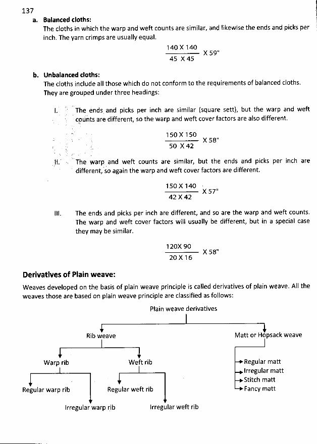
137Balanted cloths: àa
. 1The cloths in which the warp and weft counts are similar, and Iikewise the ends and picks per (inch. The yarn crimps are usually equal. è
140 X 140X 59''
45 X 45
b. Unbalanced tloths:The cloths include aII those which do not conform to the requirements of balanced cloths.They are grouped under three headings:
'
)L1. The ends and picks per inch are similar (square sett), but the warp and weft
' cpùnts are different, so the warp and weft cover factors are also different.'
(2 .
. , x s8''
. ) ' ,. 50 X 42,( t. x . .
11., The warp and weft counts are similar, but the ends and picks per inch arel . '' .
different, so again the warp and weft cover factors are different.
1 50 X 140 'X 57''
42 X 42
111. The ends and picks per inch are different, and so are the warp and weft counts.The warp and weft cover factors will usually be different, but in a special casethey may be similar.
120X 90X 58''
20 X 16
Derivatives of Plain weave:Weaves developed on the basis of plain weave principle is called derivatives of plain weave. AII theweaves those are based on plain weave principle are classified as follows:
Plain weave derivatives
Rib weave Matt or Hopsack weave
Warp rib W eft rib Regular mattIrregular mattStitch matt
Regular warp rib Regular weft rib Fancy matt
lrregular warp rib Irregular weft rib
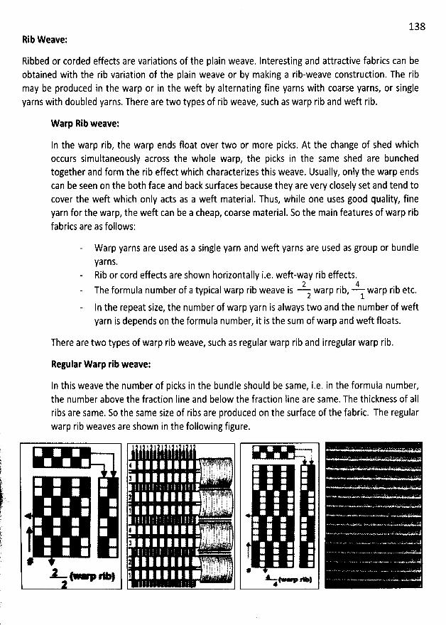
138Rib W eave:
Ribbed or corded effects are variations of the plain weave. Interesting and attractive fabrics can beobtained with the rib variation of the plain weave or by making a rib-weave construction. The ribmay be produced in the warp or in the weft by alternating fine yarns with coarse yarns, or singleyarns with doubled yarns. There are two types of rib weave, such as warp rib and weft rib.
Warp Rib weave:
In the warp rib, the warp ends float over two or more picks. At the change of shed whichoccurs simultaneously across the whole warp, the picks in the same shed are bunchedtogether and form the rib effect which characterizes this weave. Usually, only the warp endscan be seen on the b0th face and back surfaces because they are very closely set and tend tocover the weft which only acts as a weft material. Thus, while one uses good quality, fineyarn for the warp, the weft can be a cheap, coarse material. So the main features of warp ribfabrics are as follows:
Warp yarns are used as a single yarn and weft yarns are used as group or bundle
yarns.Rib or cord effects are shown horizontally i.e. weft-way rib effects.
2 4The formula number of a typical warp rib weave is warp rib, y warp rib etc.2
In the repeat size, the number of warp yarn is always two and the number of weftyarn is depends on the formula number, it is the sum of warp and weft floats.
There are two types of warp rib weave, such as regular warp rib and irregular warp rib.
Regular Warp rib weave:
ln this weave the number of picks in the bundle should be same, i.e. in the formula number,the number above the fraction Iine and below the fraction Iine are same. The thickness of aIIribs are same. So the same size of ribs are produced on the surface of the fabric. The regularwarp rib weaves are shown in the following figure.
7#.r - * )
I!@N - -
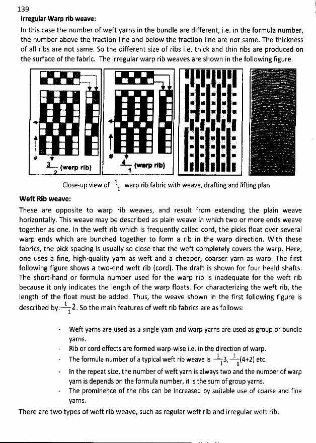
139Irregular W arp rib weave:
In this case the number of weft yarns in the bundle are different, i.e. in the formula number,the number above the fraction Iine and below the fraction Iine are not same. The thicknessof aII ribs are not same. So the different size of ribs i.e. thick and thin ribs are produced onthe sudace of the fabric. The irregular warp rib weaves are shown in the following figure.
t, !# #
x- M (..,p1:)(warp rlbl j
,1,,1,1,1Ii1: -:ItI-;I:.k 1 (1 1 '1
'
j-.,j;:j:;jt,kj:;4Close-up view of warp rib fabric with weave, drafting and lifting plan1
W eft Rib weave:
These are opposite to warp rib weaves, and result from extending the plain weavehorizontally. This weave may be described as plain weave in which two or more ends weavetogether as one. In the weft rib which is frequently called cord, the picks float over severalwarp ends which are bunched together to form a rib in the warp direction. W ith thesefabrics, the pick spacing is usually so close that the weft completely covers the warp. Here,one uses a fine, high-quality yarn as weft and a cheaper, coarser yarn as warp. The firstfollowing figure shows a two-end weft rib (cord). The draft is shown for four heald shafts.The short-hand or formula number used for the warp rib is inadequate for the wek ribbecause it only indicates the Iength of the warp floats. For characterizing the weft rib, theIength of the float must be added. Thus, the weave shown in the first following figure is
1described by: 2. So the main features of weft rib fabrics are as follows:1
W eft yarns are used as a single yarn and warp yarns are used as group or bundleyarns.Rib or cord effects are formed warp-wise i.e. in the direction of warp.
1 1The formula number of a typical weft rib weave is 3, (4+2) etc.1 1
In the repeat size, the number of weft yarn is always two and the number of warpyarn is depends on the formula number, it is the sum of group yarns.The prominence of the ribs can be increased by suitable use of coarse and fineyarns.
There are two types of weft rib weave, such as regular weft rib and irregular weft rib.
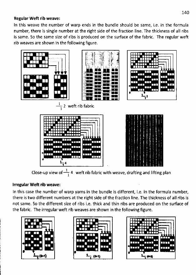
140Regular W eft rib weave:In this weave the number of warp ends in the bundle should be same, i.e. in the formulanumber, there is single number at the right side of the fraction Iine. The thickness of aII ribsis same. So the same size of ribs is produced on the surface of the fabric. The regular weftrib weaves are shown in the following figure.
.é o . '< '!p.'?: . .-:jjc.. -. --. .-... -t:jj-... i .- ...J? . 11èr'... -' 7-kp ' z . . s . j. y-. '1 .1 . + .j...--j4 wj 4 .. .l . . : .. V' .! 21 'Ju . . - c ...J à. 'jï k . . . u. .N.. -. . . . j j j. . . j . g j : . . s !li 1 ! y ) ; !' . i! o ! 1 ) 11 . l ,, ! a . i j ).
... w w wy % + %
î W Wj .a1A ''y. wïw
. , .1 w . raL- . -.. c O .' *: .> >
1 2 weft rib fabric1
. . .
. .y . ). ('.( - -.l - - l
= )
et ,
,#
. '
) . ) t . -yys... -t)'è
.
y - . . . .. .- . . y . t
( ..t )))jjjjjjjjjjjjjjjjjiiijiigjiijjljjjjjjjjjjjjjjjjjjjjjjjjjjjjjjjjjjj' .) .) .. -.
>. .-. - ---------kt , -,--- - . '-#1Close-up view of 41 weft rib fabric with weave, drafting and Iifting plan
lrregular W eft rib weave:In this case the number of warp yarns in the bundle is different, iae. in the formula number,there is two different numbers at the right side of the fraction Iine. The thickness of aII ribs isnot same. So the different size of ribs i.e. thick and thin ribs are produced on the surface ofthe fabric. The irregular weft rib weaves are shown in the following figure.
alr-
- ,
'
. ,.
g . -W j&jj
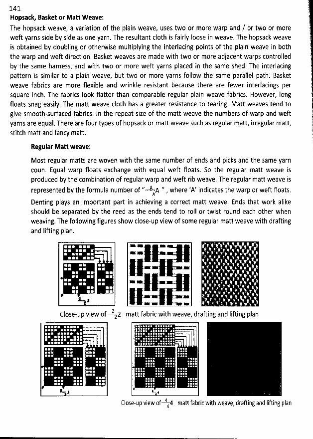
14 1Hopsatk Basket or Matt Weave:The hopsack weave, a variation of the plain weave, uses two or more warp and / or two or moreweft yarns side by side as one yarn. The resultant c10th is fairly loose in weave. The hopsack weaveis obtained by doubling or otherwise multiplying the interlacing points of the plain weave in b0ththe warp and weft direction. Basket weaves are made with two or more adjacent warps controlledby the same harness, and with two or more weft yarns placed in the same shed. The interlacingpattern is similar to a plain weave, but two or more yarns follow the same parallel path. Basketweave fabrics are more flexible and wrinkle resistant because there are fewer interlacings persquare inch. The fabrics Iook flatter than comparable regular plain weave fabrics. However, Iongfloats snag easily. The matt weave c10th has a greater resistance to tearing. Matt weaves tend togive smooth-surfaced fabrics. ln the repeat size of the matt weave the numbers of warp and weftyarns are equal. There are four types of hopsack or matt weave such as regular matt, irregular matt,stitch matt and fancy matt.
Regular Matt weave:
Most regular matts are woven with the Same number of ends and picks and the same yarncoun. Equal warp floats exchange with equal weft floats. So the regular matt weave isproduced by the combination of regular warp and weft rib weave. The regular matt weave isrepresented by the formula number of '' A A '' where 'A' indicates the warp or weft floats.A '
Denting plays an important part in achieving a correct matt weave. Ends that work alikeshould be separated by the reed as the ends tend to roll or twist round each other whenweaving. The following figures show close-up view of some regular matt weave with draftingand Iifting plan.
U z
2Close-up view of 22
j. .Ix x11--
matt fabric with weave, drafting and Iiûing plan
VV. , 5 if 1 4 matt fabric with weave
, drafting and Iiftink planClose-up view 0 j
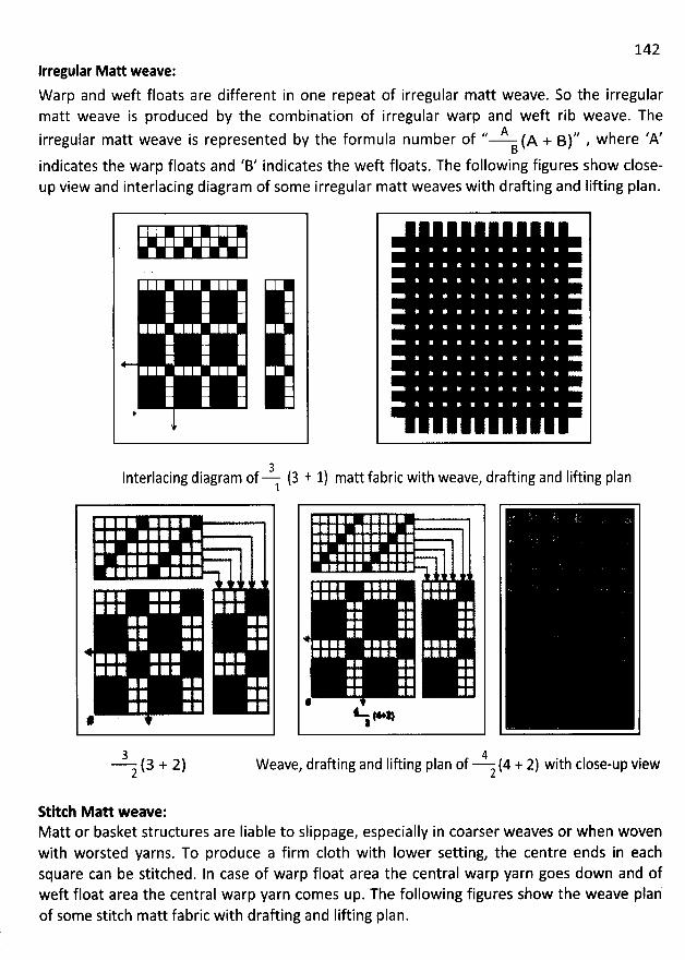
142Irregular Matt weave:W arp and weft floats are different in one repeat of irregular matt weave. So the irregularmatt weave is produced by the combination of irregular warp and weft rib weave. The
.. A ,, jere zA'irregular matt weave is represented by the formula number of (A + B) , wB
indicates the warp floats and 'B' indicates the weft floats. The following figures show close-up view and interlacing diagram of some irregular matt weaves with drafting and Iifting plan.
uy j3l
nterlacing diagram of (3 1 1) matt fabric with weave, drafting and Iifting plan1
*. ) '
V, s .
3 (3 + 2)2
IWeave, drafting and lifting plan of (4 + 2) with close-up view2
Stitch Matt weave:Matt or basket structures are Iiable to slippage, especially in coarser weaves or when wovenwith worsted yarns. To produce a firm c10th with Iower setting, the centre ends in eachsquare can be stitched. In case of warp float area the central warp yarn goes down and ofweft float area the central warp yarn comes up. The following figures show the weave planof some stitch matt fabric with drafting and Iifting plan.
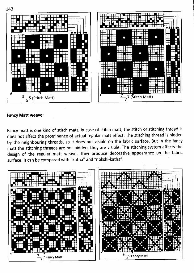
143
#5 s (stitch Matt)s
. . '
y
'
'
. .. .. 7 - ... è -.
. .'L.
-?- 7 ( titch Matt)7
!?r
Fancy Matt weave:
Fancy matt is one kind of stitch matt. In case of stitch matt, the stitch or stitching thread isdoes not affect the prominence of actual regular matt effect. The stitching thread is hiddenby the neighbouring threads, so it does not visible on the fabric surface. But in the fancymatt the stitching threads are not hidden, they are visible. The stitching system affects thedesign of tbe regular matt weave. They produce decorative appearance on the fabricsudace. It can be com pared with ''katha'' and ''nokshi-katha''.
U
' ! l ! i
*
7--.7 Fancy Matt7
. 7.
' ' ...:...> 1'
. . ---- ; t.
.g-) t : '. j . j . ! r
. . ; . ô. . l e
. ; . '
9 9 Fancy Matt9
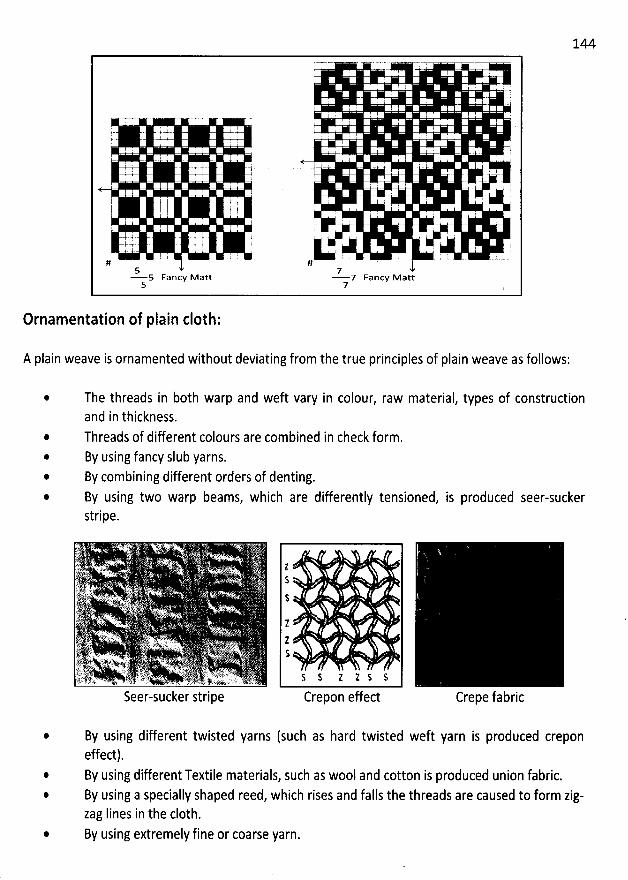
144:
. . I I .I I I
I . . ' .:
'
. .
t . . .
... l I I '.+ .E . :
. : 2 , I '
I :
'
. .
. I : t
'
, .. . ? ' .
: ' ! .. j . . - : 't. - - ' '7 l
I I :
t5 75 Fancy M att 7 Fancy M att
5 7
Ornamentation of plain c10th:
A plain weave is ornamented without deviating from the true principles of plain weave as follows:
@
The threads in b0th warp and weft vary in colour, raw material, types of constructionand in thickness.Threads of different colours are combined in check form.By using fancy slub yarns.By combining different orders of denting.By using two warp beams, which are differently tensioned, is produced seer-suckerstripe.
Seer-sucker stripe
tS
$
11$
% $ Z 1 $ S
Crepon effect
By using different twisted yarns (such as hard twisted weft yarn is produced creponeffect).By using different Textile materials, such as wool and cotton is produced union fabric.By using a specially shaped reed, which rises and falls the threads are caused to form zig-zag Iines in the c10th.By using extremely fine or coarse yarn.
145
End uses:
It is used for structures, which range from very heavy and coarse canvas and blankets made of thickyarns to the Iightest and finest cambries and muslins made in extremely fine yarns.
Advantages and disadvantages of plain weave fabric
Advantages:
@
Wears wellOffers appropriate background for printing, special finishes, and applied surface designs.
Is snag-resistantHas good dimensional stability if of high fabric count, i.e. high thread density.Is reversible if not printed or finished with special esects.@
Disadvantages:
. Ravels
@
Appears uninterestingShows wrinklingHas Iower tear Strength than some other weavesShows soil readily.
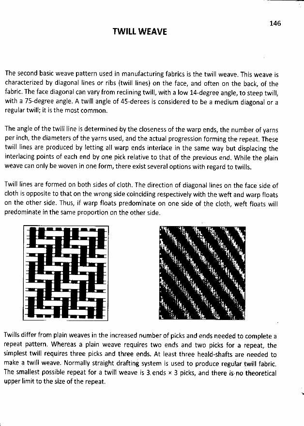
146TW ILL W EAVE
The second basic weave pattern used in manufacturing fabrics is the twill weave. This weave ischaracterized by diagonal Iines or ribs (twill Iines) on the face, and often on the back, of thefabric. The face diagonal can vary from reclining twill, with a Iow l4-degree angle
, to steep twill,with a 7s-degree angle. A twill angle of 45-derees is considered to be a medium diagonal or aregular twill; it is the most common.
The angle of the twill Iine is determined by the closeness of the warp ends, the number of yarnsper inch, the diameters of the yarns used, and the actual progression forming the repeat. Thesetwill Iines are produced by letting aII warp ends interlace in the same way but displacing theinterlacing points of each end by one pick relative to that of the previous end. W hile the plainweave can only be woven in one form, there exist several options with regard to twills.
Twill Iines are formed on both sides of c10th. The direction of diagonal Iines on the face side ofc10th is opposite to that on the wrong side coinciding respectively with the weft and warp floatson the other side. Thus, if warp floats predominate on one side of the c10th, weft floats willpredominate in the same proportion on the other side.
Twills differ from plain weaves in the increased number of picks and ends needed to complete arepeat pattern. W hereas a plain weave requires two ends and two picks for a repeat, thesimplest twill requires three picks and three ends. At Ieast three heald-shafts are needed tomake a twill weave. Normally straight drafting system is used to produce regulai' twill fabric
.
The smallest possible repeat for a twill weave is 3- ends x 3 picks, and there is no theoreticalupper Iimit to the size of the repeat.
N
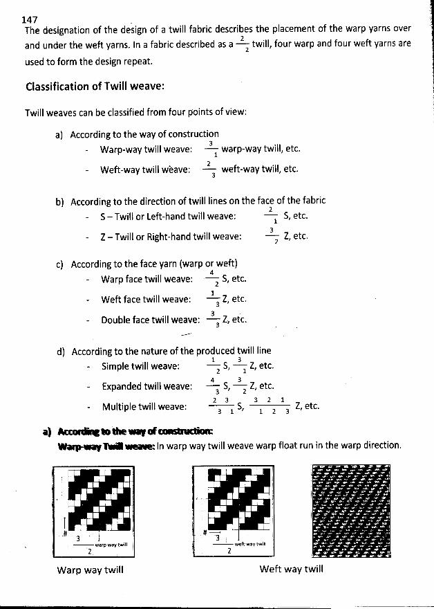
147 .The designation of the design of a twill fabric describes the placement of the warp yarns over
2and under the weft yarns. In a fabric described as a twiql, four warp and four weft yarns are2
used to form the design repeat.
Classification of Twill weave:
Twill weaves can be classified from four points of view:
a) According to the way of construdion3W arp-way twill weave: warp-way twill, etc.1
2W eft-way twill wèave: weft-way twill, etc.
3
b) According to the direction of twill Iines on the face of the fabric2
S - Twill or Left-hand twill weave: S, etc.13
Z - Twill or Right-hand twill weave: Z, etc.2
c) According to the face yarn (warp or weft)4
W arp face twill weave: z S, etc.1
W eft face twill weave: Z, etc.33 .
Double face twill weave: Z, etc.3
d) According to the nature of the produced twill Iine1 3
Simple twill weave: S, :. Z, etc.
24 3
Expanded twill weave: S, z Z, etc.32 3 3 2 1
Multiple twill weave; S, l z a Z, etc.3 1
*1 * - - * ' '--'- '- - In warp way twill weave warp float run in the warp direction.
!
j
i
I 2i# t3 ?
warp way twill j2 l;
W arp way twill
!1.
' )
'
?l
. lj1
#-- E3
t ' weft way twill1à 2
W eft way twill
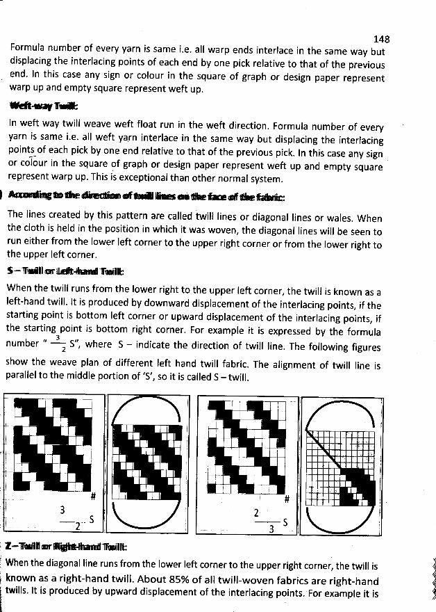
148Formula number of every yarn is same i.e. aII warp ends interlace in the same way butdisplacing the interlacing points of each end by one pick redative to that of the previousend. In this case any sign or colour in the square of graph or design paper representwarp up and empty square represent weft up.
e-- +- . . geN T
In weft way twill weave weft float run in the weft direction. Formula number of every
yarn is same i.e. all weft ya.rn interlace in the same way but displacing the interlacingpoints of each pick by one end relative to that of the previous pick
. ln this case any signor colour in the square of graph or design paper represent weft up and empty squarerepresent warp up. This is exceptional than other normal system
.
#. ** . . ..e . . + œ .N *.. .. .- *. - Y . . . + #.* O .K. -
The Iines created by this pattern are called iwill Iines or diagonal Iines or wales. W hen
the c10th is held in the position in which it was woven, the diagonal Iines will be seen to
run eitber from the lower left corner to the upper right corner or from the lower right tothe upper Ieft corner.
$ . yp Aj . jj - eu X . . 1: g% gji
W hen the twill runs from the lower right to the upper Ieft corner, the twill is known as a
Ieft-hand twill. It is produced by downward displacement of the interlacing points, if the
starting point is bottom Ieft corner or upward displacement of the interlacing points, if
the starting point is bottom right corner. For example it is expressed by the formula
1/ 3 ,, f twjjj jjne. rhe following figuresnumber S , where S - indicate the direction o
2
show the weave plan of different left hand twill fabric. The alignment of twill Iine is
parallel to the middle portion of 'S', so it is called S - twill.
;Ir---1Ik::qIIl Cl,r 111- 71i11iIIi: 'When the diagonat line runs from the lower left corner to the upper right corner, the twill is known as a right-hand twill. About 85% of aIl twill-woven fabrics are right-hand twills
. lt is produced by upward displacement of tbe interlacing points. For example it is .'
j
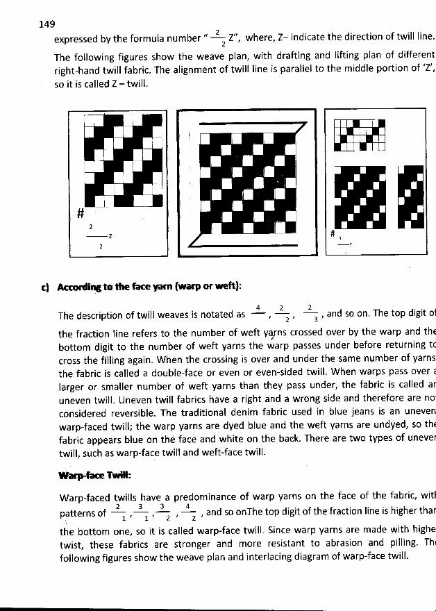
149.. ;! ,,expressed by the formula number Z , where, Z- indicate the direction of twill line.
2The following figures show the weave plan, with drafting and Iifting plan of differentright-hand twill fabric. The alignment of twill Iine is parallel to the middle portion of 'Z',
so it is called Z - twill.
,
'
,
'
#
z- z K 1#y,
c) Ae- iY o thefu - lwarporwe l:
4 2 2The description of twill weaves is notated as , z , a , and so on. The top digit ol
the fraction Iine refers to the number of weft y&rns crossed over by the warp and thEbottom digit to the number of weft yarns the warp passes under before returning tccross the filling again. W hen the crossing is over and under the same number of yarnsthe fabric is called a double-face or even or even-sided twill. W hen warps pass over ëIarger or smaller number of weft yarns than they pass under, the fabric is called aruneven twill. Uneven twill fabrics have a right and a wrong side and therefore are no'considered reversible. The traditional denim fabric used in blue jeans is an unevenwarp-faced twill; the warp yarns are dyed blue and the weft yarns are undyed, so th(fabric appears blue on the face and white on the back. There are two types of unevertwill, such as warp-face twill and weft-face twill.
:
W arp-faced twills have a predominance of warp yarns on the face of the fabric, witl2 3 3 4
patterns of , j.
, ; , -z , and so onThe top digit of the fraction Iine is higher thar, 1k
the bottom one, so it is called warp-face twill. Since warp yarns are made with highetwist, these fabrics are stronger and more resistant to abrasion and pilling. Thtfollowing figures show the weave plan and interlacing diagram of warp-face twill.
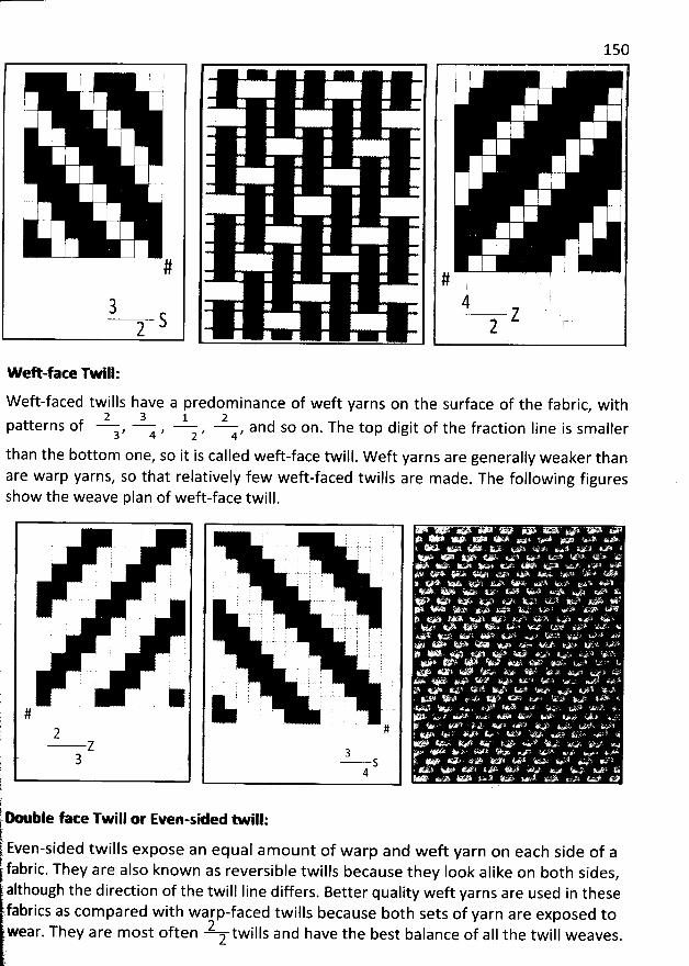
7 7 k. .
I
$ I'; ! q
I
I
#
3 S2
150
#4 Z
2
w eh-face Twill:
W eft-faced twills have a predominance of weft yarns on the surface of the fabric, with2 3 1 2
patterns of , a , z , u, and so on. The top digit of the fraction Iine is smaller3
than the bottom one, so it is called weft-face twill. W eft yarns are generally weaker thanare warp yarns, so that relatively few weft-faced twills are m ade. The following figuresshow the weave plan of weft-face twill.
Q' v . :,''' . 'r .1 * .&'+ . *'. a. . . &> . . .. .x r.. , : ! ( . .. . ' ï. k ? , . . . .i
, i 't i i mt . ..
'
! ( ! t . .J l ' .
' ', . . ' . . . ..3 , ' i . .. ..... .. . . .
' . ' '
. .. ..
: . . ) ) l 7 . . , , . ,. j y . y . '. . 'j y . '
.j
'
. . .
. ,: 2 . f. . - - ' . .
', .q jj . ., . . .' : . ; . - è
,1 .i - -. ' . - - - .,
$ k ( j w , . . . .. y .( ' ' S 1' ' ' ''* ' 'j . j ... . . y y . s . y ys s. . . ... . . . . .. . . y . . . .2 s sys .go. . .
. . .
- ' . ë l . . ' .. . ' ' ' ' ' '!
. .
' ( ( x . .. . .. . . .. .) 1.
i ' ' ' ' ' , '
. # ' > ' 4''-i' ' ' .
7 # . ''*
'
. ir q ..z '. . . . . .
q 3 . '' - ' ' 'k 3 s ' '
' 4 . . #. . ' . .. . . .. '
k: n--.ble face Twill or Even-sid-M - iII:
Even-sided twills expose an equal amount of warp and weft yarn on each side of a' fabric. They are also known as reversible twills because they Iook alike on both sides
,
although the direction of the twill Iine differs. Better quality weft yarns are used in thesefabrics as com pared w ith warp-faced tw ills because both sets of yarn are exposed to
They are m ost often 2 twills and have the best balance of aIl the twill weaves.wear. ;
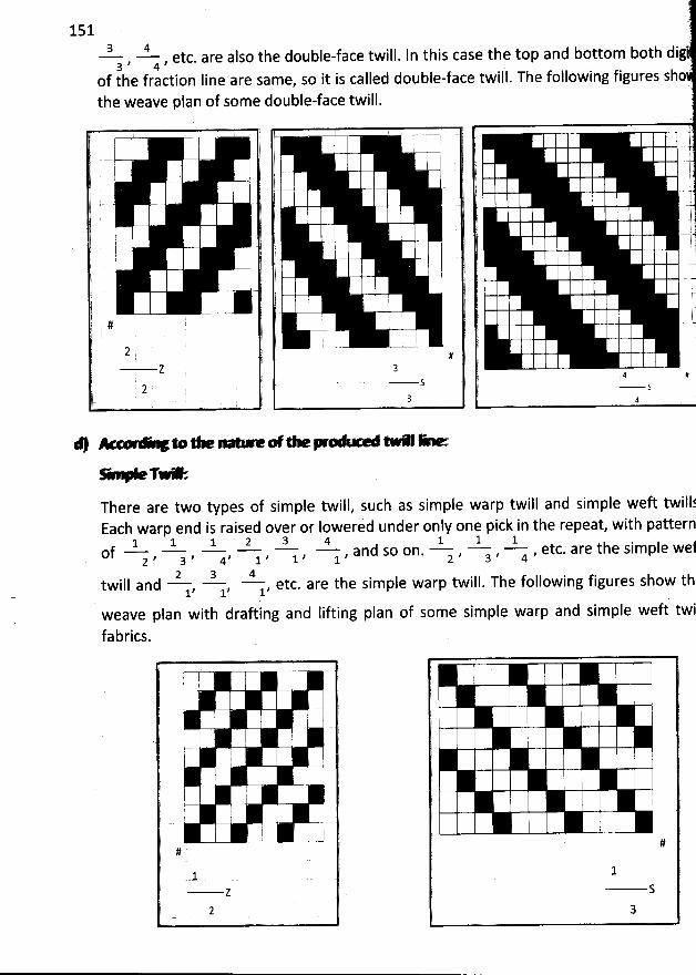
151 ;)
3 4 ., 4 , etc. are also the double-face twill. In this case the top and bottom both dig3 )'
of the fraction Iine are same, so it is called double-face twill. The following figures shothe weave plan of some double-face twill.
. j j.. . . . ) ' ) '7- I j t j
. .. .. . . j j I (. . j lj .. j. .
j i . .. ! l) t . .. jj . .. j . . t
. ! . (. .... . . : k(
: 11
*
.. . .. ' '
-! . .l 'j . '''j' l ' .. .r'..yt . l . u. I 1 l) . '; ..@r # 1 l -
' j j j è' .i
'
, l I :' .) 2 ? ( -- (: , # I. z @ 3 .
, 4 #: z . y s s
. ). 3 ! 4
G TY ;There are two types of simple twill, such as simple warp twill and simple weft twillfEach warn end is raised over or Iowerid under onlv one oick in the repeat, with pattern
1 - 1 1 2 3 4 1 ' 1 ' lOf , a , 4, 1 , 1 , y , and so on. z , a , 4 , etc. are the simple wef
22 3 4twill and , 1, y, etc. are the simple warp twill. The following figures show th.1
tweave pfan with draftlng and Iifting plan of some simple warp and simple weft twi
fabrics.
' / ))
' J
I I I! .
I i iI .
' j .' 1 ! :
. l ' ..--
#
2 Sm
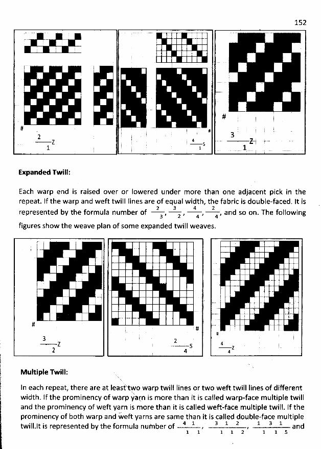
152
( -y - - j y , j y jw >
jl ,# *1 44
2 C TT 3- 2 - s ,
Expanded Twill:
Each warp end is raised over or Iowered under more than one adjacent pick in therepeat. lf the warp and weft twill Iines are of equal width, the fabric is double-faced. It is
a a 4 2represented by the formula number of , z , 4 , 4 , and so on. The following3
figures show the weave plan of some expanded twill weaves.
j '
11
t
'
#
3- Z
2
#
2- S
4
#
4- Z
4
lk! tlltillltq 1r!âlilI: u.xYx
U twill Iines or two weft twill Iines of differentIn each repeat, there are at Ieas tFo warpwidth. If the prominency of warp yàrn is more than it is called warp-face m ultiple twilland the prominency of weft yarn is more than it is called weff-face multiple twill. If theprominency of both warp and w- eft yarns are same than it is called double-face multiple
4 1 .' 3 1 2 1 3 1twillalt is represented by the form ula number of , , and1 1 1 1 2 1 1 5
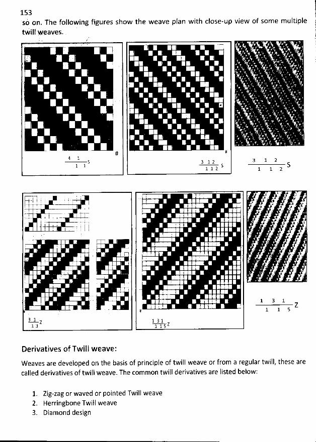
lsaù on. The following figures show the weave plan with close-up view of some multiplestwill wkaves. .
g
I
#4 1
S1 1
: E j
'
E'
I . ' !
; l
I
I#
S1 1 23 1 2
S1 1 2
k ' I 1 . ,p : I E j
2 I !
'
. : II . : ! 'X. i
7' ! j -
! 1 ; 'j I
I ; ' . !! !' j Ii
! . l
i .. : I
! ' .1
' . i I .
' j '
3 1- - - Z1 3
. ' . ' '
; l ( ' ,. (. I ' ! ! I i , .; ' i 11 1 r $ k
'
'
! h I ' I I I i E '1 , I I i .1 I I I I
. I. i
'
1.E ' ' r
l 2! 1I . ! . I I I '' .
! . I ' ,1 I k
'
I '
I 4 ' l i ' :2 . '
I I . i ; 'E :
'
I . ! I Il
/! k
'
' I .
i . ;' '.j 1. ! 11
I : . , II ' ' ; i I I i C
'
. . ' ' i ' .#
tql.z1 1 5
' à' # .v% .f 1. . + . . A
, 4 , ; . x./# ' . ' '. : . > .L.# . % . # ' .. . s j;
+% .# . >. y. # . ti' > ' * z. @ ' #>
..h i ' Lï ' '. . . R , #'#. . . . a .r g .. . . $
. E . '. .. '% ' f
:. v 1 I
.' . ' > . .
1 3 1Z
1 1 5
Derivatives of Twill weave:
W eaves are developed on the basis of principle of twill weave or from a regular twill, these arecalled derivatives of twill weave. The common twill derivatives are listed below:
Zig-zag or waved or pointed Twill weaveHerringbone Twill weaveDiamond design
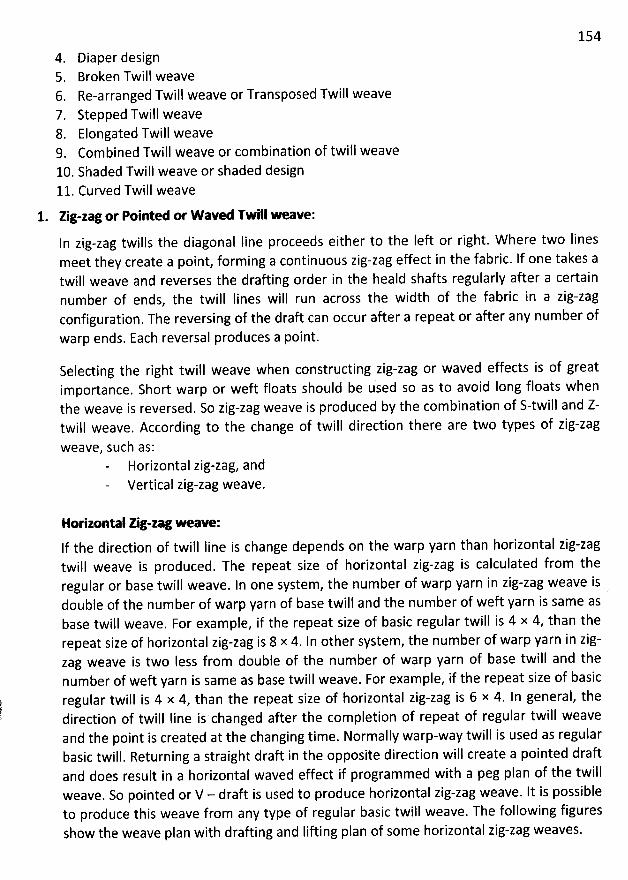
1544. Diaper design5. Broken Twill weave6. Re-arranged Twill weave or Transposed Twill weave7. Stepped Twill weave8. Elongated Twill weave9. Combined Twill weave or com bination of twill weave10. Shaded Twill weave or shaded design11. Curved Twill weave
1. Zig-zag or Pointed or W aved Twill weave:
In zig-zag twills the diagonal Iine proceeds either to the Ieft or right. W here two Iinesmeet they create a point, forming a continuous zig-zag effect in the fabric. If one takes atwill weave and reverses the drafting order in the heald shafts regularly after a certainnumber of ends, the twill Iines will run across the width of the fabric in a zig-zagconfiguration. The reversing of the draft can occur after a repeat or after any number of
warp ends. Each reversal produces a point.
Selecting the right twill weave when constructing zig-zag or waved effects is of greatimportance. Short warp or weft floats should be used so as to avoid Iong floats whenthe weave is reversed. So zig-zag weave is produced by the combination of S-twill and Z-twill weave. According to the change of twill direction there are two types of zig-zag
weave, such as:Horizontal zig-zag, andVertical zig-zag weave.
Horizontal Ng-zag weaw :lf the direction of twill Iine is change depends on the warp yarn than horizontal zig-zagtwill weave is produced. The repeat size of horizontal zig-zag is calculated from theregular or base twill weave. ln one system, the number of warp yarn in zig-zag weave isdouble of the num ber of warp yarn of base twilf and the number of weft yarn is same asbase twill weave. For example, if the repeat size of basic regular twill is 4 x 4, than therepeat size of horizontal zig-zag is 8 x 4. In other system, the number of warp yarn in zig-zag weave is two Iess from double of the number of warp yarn of base twill and thenumber of weft yarn is same as base twill weave. For example, if the repeat size of basicregular twill is 4 x 4, than the repeat size of horizontal zig-zag is 6 x 4. In general, thedirection of twill Iine is changed after the completion of repeat of regular twill weaveand the point is created at the changing time. Normally warp-way twill is used as regularbasic twill. Returning a straight draft in the opposite direction will create a pointed draftand does result in a horizontal waved effect if programmed with a peg plan of the twillweave. So pointed or V - draft is used to produce horizontal zig-zag weave. It is possibleto produce this weave from any type of regular basic twill weave. The following figuresshow the weave plan with drafting and Iifting plan of some horizontal zig-zag weaves.
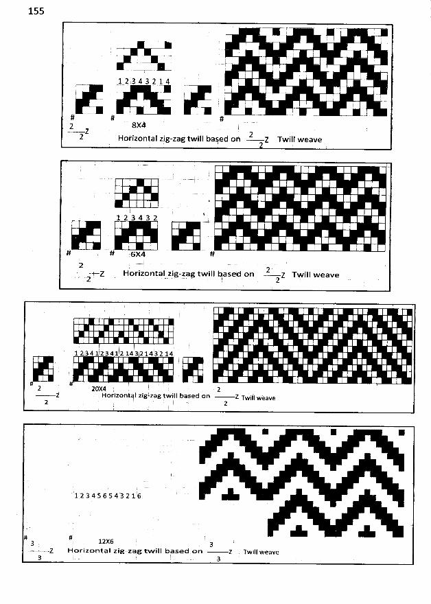
155-
7+ 7
I ' ( . '' ; I ;
'
' ;- = i !
I j '1 1 3 4 3 î .$ 4 , ' '= - c y
, j j y g y: i ' 1 :
'
. ' l
= >œ ..+ (-# # #
2 8X4Z 22
Horizontal zig-zag twill based on z Twill weave
I
%12 34 3 2
# . # 6X4 #g .2
Z Horipontal zig-zag twill based on z TFill weavez . . z
1 2 34 l 2 34 1 2 14 3 2 14 3'2 14
#2 20X4 2 .
z Horizontal zig-zag twill based on Z Twifl wèave2 N 2
* * K
123456543216
# #a 12x6 gz Horizontal zig-zag tw ill based on Z Twill weave
3 3
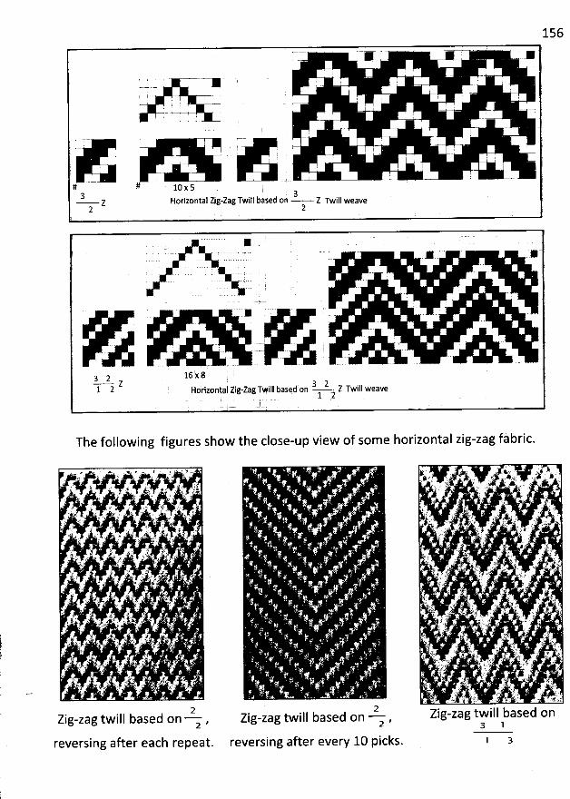
156
! .
' : . . ! I . . I .: 1
. i i
'
: , , .- - . - ..- -. . '
. . ; :
.
. . ; j j.. ! -
! . ' . g :# # 10 x 53 , !,j < = 3z Horizontal Zig-zag TwIII D3Se(I On Z Twill weave2 2
;
S
16 x 8Y-?- z Twill weaveHorilental zigqag Twill kased on1 2
The following figures show the close-up view of some horizontal zig-zag fàbric.
2Zig-zag twill based on ,2
reversing after each repeat.
2Zig-zag twill based on z ,
reversing after every 10 picks.3 1
1 3
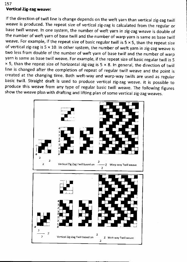
157Vedical zig-zag weave:
If the direction of twill line is change depends on the weft yarn than vertical zig-zag twillweave is produced. The repeat size of vertical zig-zag is calculated from the regular orbase twill weave. ln one system , the number of weft yarn in zig-zag weave is double ofthe num ber of weft yarn of base twill and the num ber of warp yarn is same as base twillweave. For example, if the repeat size of basic regular twill is 5 x 5
, than the repeat sizeof vertical zig-zag is 5 x 10. In other system, the number of weft yarn in zig-zag weave istwo less from double of the number of weft yarn of base twill and the number of warpyarn is same as base twill weave. For exam ple
, if the repeat size of basic regular twill is 5x 5, than the repeat size of horizontal zig-zag is 5 x 8
. In general, the direction of twillline is changed after the com pletion of repeat of regular twill weave and the point iscreated at the changing time. Both weft-way and warp-way twills are used as regularbasic twill. Straight draft is used to produce vertical zig-zag weave. It is possible toproduce this weave from any type of regular basic twill weave
. The following figuresshow the weave plan with drafting and lifting plan of some vertical zig-zag weaves.
F .
!' ;. i!>' 7
....-... ..- r: l .--L.o.o-=-o
.0
4 * @ ; '! ..12 i t 'h ! r 7 i !3
Im---r 4.-- ' ?--.4 6 ' t '; : -) 3 F- . : ? I. ...j ; ==-+ .=y1 : 2 ! F
: ':--.-œ 1 -...:... ...--..
' '
.. . g#
Z 2Vertical Zig-zag Twill based on Z Warp way Twill weave
2
. I
:: :. 1 k,
t i.,
'
. )I- -4l r 1 .4 ' !!
1 I '(
g3 . t 1 !
g '2 : 1 51 - ' '1 .. . -. . ..- . .-.
'..# ' #
Z 2Vertical Zig-zag Twill based on z weft way Twill weave
2
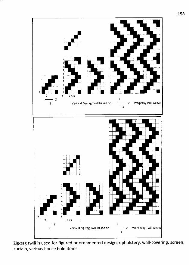
158
. - .. -..- . .' ...;. .
5 . .
12 .3 . :4 ...-.
'-.. . ....... ..). .
5 '. - ..... . ...t... . .-..-4 ;! . . t3 E
. ''i 72 : : : . !
# * 1 . * * . *) # s xl0
Z .
3 Vertical Zig-zag Twill based on Warp way Twill weave
!
q F ' - ')-- .- i'
I I ;/- ;
I E
'
i Ih 1 12.-
L
'
w j . y-a2 j '3 I -1 ! t ,: -- h - , . --4 q ! I I !q--p- .
. 5 ; ; : i4 I ' .-1 I. .. y. . .. .4 e3 j . J . t
.ï , --gk 2 !1
# #
2Vertical Zig-zag Twill based on z Warp way Twill weav
3
Zig-zag twill is used for figured or ornamented design,curtain, various house hold items.
upholstery, wall-covering, screen,
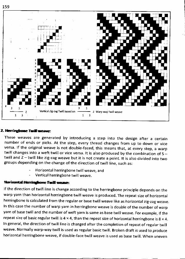
159
7 !- r-l ; I l )
E ' I 1. ! ! ' 2, r ,. f .
.
-;1. r :. .. .. .. . ... ..à .' j
'
t ! '. r ! ! '
'
'
'
. --) -- - - , .i ' .ç. . -t - -. ', .. . - . . :. ' ..) r i '' ;
'
l .! ....... rs . J -.. . ..-;. . - a - - . -. t -.' ' .. - . --yt , . ; . I u ,
- r ; :. ': .1 I !. - . ! -.i - - - t . .1. ' . )
'
. . . ;' ' -) . . , f . ;i j 1 r ; '
2 ; ' r $ '! . 'i 1 ') y - .4. .. .q 3 ' f l 1 i
, ' -. .j.- .4 . . ,
5 i k ! ! .)j ..w , -.;-1 6 I I ! I !:
, . .--j sq 7 I . !, ss . ; g j 4-S y y .1 > I =--= - ' . ' ' .- .1 i 7 , ; .1 r k .) ..-j . .# .- j6 '. ! ; ' : ;s r --
! !l ; . . . '
'
' i 4 I ù I f -E . . .- - -t . - !. 3 I ' ,-t- - q - -t . J2 I ' ! I ' 0I .-j .J--. . ! .t 1 ' ; 1 ... . .. - -= -. . = - -..
' . - .- ...# #
3 1 3 1(z Vertical Zig-zag Twill based on Z Warp way Twill weave
1 3 1 3
zo - y u .. . ...
These weaves are generated by introducing a step into the design after a certainnum ber of ends or picks. At the step, every thread changes from up to down or viceversa. lf the original w eave is not double-faced, this means that, at every step, a warptwill changes into a weft tw ill or vice versa. It is also produced by the com bination of S -twill and Z - tw ill like zig-zag weave but it is not create a point. It is also divided into twogroups depending on the change of the direction of twill Iine
, such as:
Horizontal herringbone twill weave, andVertical herringbone twill weave.
g: * .- . -'* .- 1 ** - .I T- 'M =
lf the direction of twill line is change according to the herringbone princi4le depends on thewarp yarn than horizontal herringbone twill weave is produced. The repeat size of horizontalherringbone is calculated from the regular or base twill weave Iike as horizontal zig-zag weave.In this case the number of warp yarn in herringbone weave is double of the number of warpyarn of base twill and the number of weft yarn is same as base twill weave
. For example, if therepeat size of basic regular twill is 4 x 4, than the repeat size of horizontal herringbone is 8 x 4
.
In general, the direction of twill Iine is changed afler the completion of repeat of regular tw illweave. Norm ally warp-way twill is used as regular basic twill. Broken draft is used to producehorizontal herringbone w eave, if double-face tw ill weave is used as base twill. W hen uneven
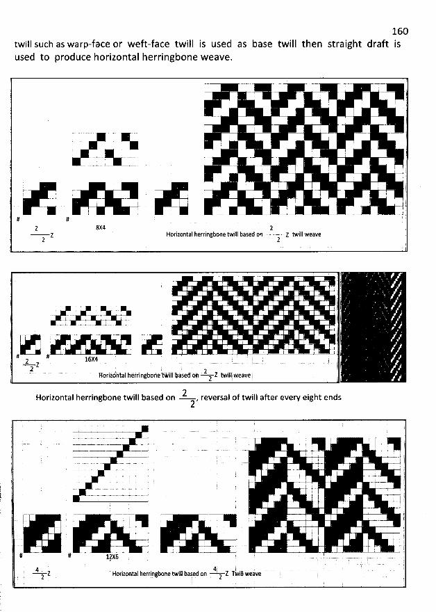
160draft istwill such as warp-face or weft-face twill is used as base twill then straight
used to produce horizontal herringbone weave.
. i . : ':-- . l l
: j . ; :. I i ii'
''''''''''''''''''''''''''''''''''''''''''''''''''''''''''''''''''''''''''''''''''''''''''''''''d
i I ;
'
! i '..
- -.-*. - j -.. j .! ; . ;
. j j : ,. j , j .j
i ! !
'
. t
r . I . t!= = .. .- . . . ' :
. :
'
.. : j . gr
'''''''''''''''''''''''''''''''''''''''''''''''''''''''''''''''''''''''''''''''''''''''''''''''''d
' ;.. - - ,. I r- I I j j
j . . . ' - ' -- -i - t
# # '7
l 11 based on z twill weave iz Horizontal herringbone twi2 2
: . i
1 l. - , ; j . . jl. . I - i . t @. . .
, j- - , ï 4! . t
.. . w. . . . . . .. . . . , !7 I ik-. +.- -+. . . . -..t- .s- - . , ;. ' ' ' ! I
.'
= =. . 'x..- -a.--z . - . .. ' j---- j
. ' I ' ! j j. . '
' jI r- I r l. j j . k-. - . . j.
. 1 .'# # I, g 16:4 j $9 Z . ; yà
.2 C ?. . 2 .. .., Horizontal herringbnne tWill based oh L twill weave2 ? ;
2 jat endsHorizontal herringbone twill based on , reversal of twill after ever'y eig2
( . . . .( L.-t- i ' ! :t ; f ; I . .7 L-.- --k -. #. i . ..z- .! z.t..z ! tp W -4- > .j ;- '..- I ' ' . '. . ' I ' ' - ) i
: ' h I i I ' I T) .---# --y- -)-. h-. z . ---.-. . )*2 I L . , I : Ij L.j..-.j-- . - -.s . # . , . . - , pj ' , ' i ' I ! z. : r1 ' I : , I ' ' ' i, : . i . . ) - l1
..#- .--k -.. i - )I ! .1 ; , . ' k I ! r
'
# -u ww jj . I ! ; I ). !
'
I t. .
. . . I ). ' ' -- -. 4 - . .. ... !I l I : y
. y-.y j. I ' j. j I ' ' . fI . i ; ; . )
... . ... . ' ' #1 . ! . i j '' j
'
. .. ....u- - j. l . ;,1 i ' 1 5 i l
# # Dx6 . . . 6
!
. 4 . . 4 . 'Z Horizontal herringbone twill based nn Z Twlll weave r.. 2 , . 1 . . . t
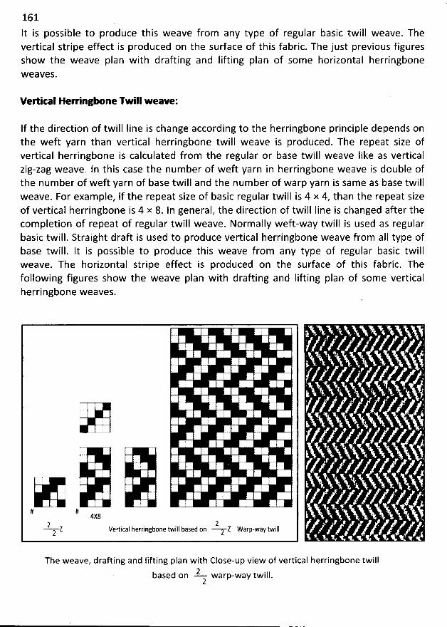
161
It is possible to produce this weave from any type of regular basic twill weave. Thevertical stripe effect is produced on the sudace of this fabric. The just previous figuresshow the weave plan with drafting and Iifting plan of some horizontal herringbonew eaves.
Vertical HerringO ne TM II w eave:
If the direction of twill Iine is change according to the herringbone principle depends onthe weft yarn than vertical herringbone twill weave is produced. The repeat size ofvertical herringbone is calculated from the regular or base twill weave like as verticalzig-zag weave. ln this case the num ber of weft yarn in herringbone weave is double ofthe number of weft yarn of base twill and the number of warp yarn is same as base twillweave. For exam ple, if the repeat size of basic regular twill is 4 x 4, than the repeat sizeof vertical herringbone is 4 x 8. In general, the direction of twill Iine is changed after thecom pletion of repeat of regular twill weave. Normally weft-way twill is used as regularbasic twill. Straight draft is used to produce vertical herringbone weave from aIl type ofbase twill. lt is possible to produce this weave from any type of regular basic twillweave. The horizontal stripe effect is produced on the surface of this fabric. Thefollowing figures show the weave plan with drafting and lifting plan of some verticalherringbone weaves.
! 2 ! '. l' i : ! ':
E .? i :i '. E i :
' , ' j :E E '! i 2
: E 7 l 7. j ',:
. b i . !' ' : i
j ' 'i l : ' ' '
i : h ! !
'
E .E EE è E '
. !
'
E
'
:: ! r ë E
'
E
'
i 1 i) .: : : y
'
: : E !i i 1 ! ' 1ë ! E !
'
'
E : ! 7 iE .
E : 1 q ! ! ? 2 Ei :. !
ë l l : ! E ' .i E i ' 'ï
'
.
# # 4X82 2
Z Vertical herringbone twill based on z Z Warp-way twill2
The weave, drafting and Iifting plan with Close-up view of vertical herringbone twill2 iIIbased on warp-w ay tw .2
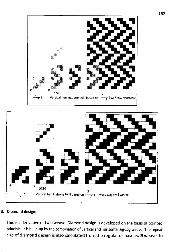
162
'. J u
(:71;1!!!!!!.:.-
*
.
'
'r-. iti
d
E
'
' '
'
!:r# . ug. st .1 t ' 'I7I '.: Ic ' y
. trp . .. - ljjjj j : ) .r: ''èE . )s;L;i? Ljg ) y:pc ..Sik::'è . à,.- L' ê
#4X82 2
Z Vertical herringbone twill based on Z Weft-way twill weave2 2
r i .
I :!
'
! ! ' 'i ;
'
ê
'
.1 . ! ' :q
'
' ' !. '
.. - . . ..-- ' -- , r ' -.I i ! j k
i ;
'
iE
'
; I i .: '
I .i . , !I ! ' I ' i . I7
. ? k i'- ': ' , . l .1 :i 1 i ; ' 1
I h l ' i '! . 1 I : j
'
;
t r- .I . d !
j ! .z k l# #
5X10a
Vertical herringbone twill based on Z warp way twill weave2
3. Diamond design:
This is a derivative of twill weave. Diamond design is developed on the basis of pointed
principle. It is build-up by the combination of vertical and horizontal zig-zag wqave. The repeatsize of diamond design is also calculated from the regular or base twill weave. In
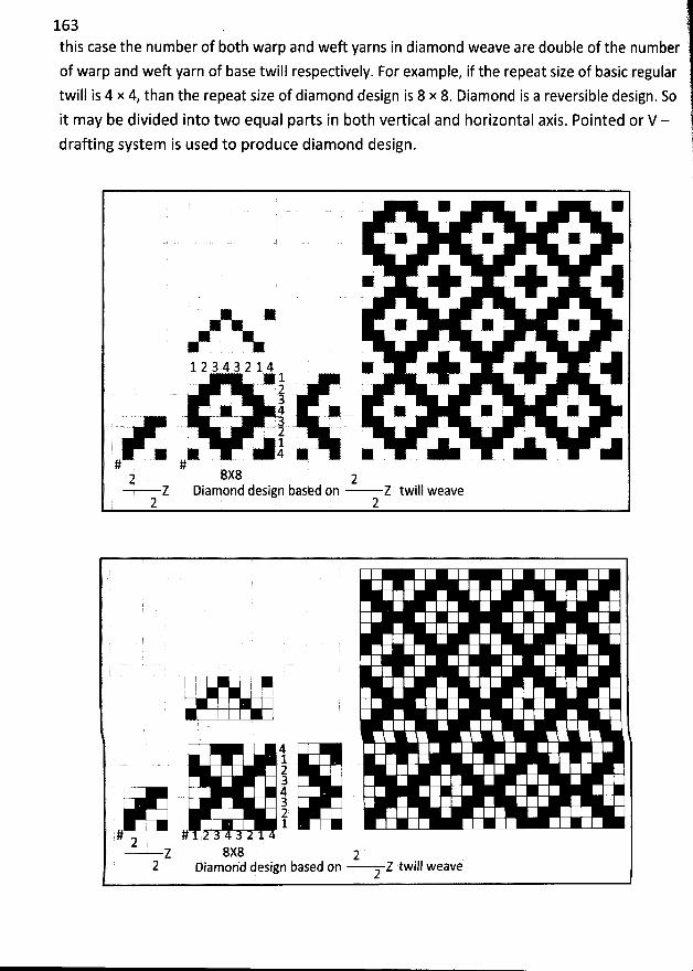
163 )this case the number of both warp and weft yarns in diamond weave are double of the number
of warp and weft yarn of base twill respectively. For example, if the repeat size of basic regulartwill is 4 x 4, than the repeat size of diamond design is 8 x 8. Diamond is a reversible design. So
it may be divided into two equal parts in both vertical and horizontal axis. Pointed or V -drafting system is used to produce diamond design. 11
1!:
'
l
1 2 3 4 3 2 1 ..4 1 * Y- o g!
.# ; g g x y g.-. . . . r . .1 . . .; . . . ( . .2
* * - 4 * * W W Z# #2 8X8 2
Z Diamond design based on Z twill weave2 2
t i
4123
. #32 k .1
# #2z 8x8 2
2 Diamon'd dejign based on Z twill weave2
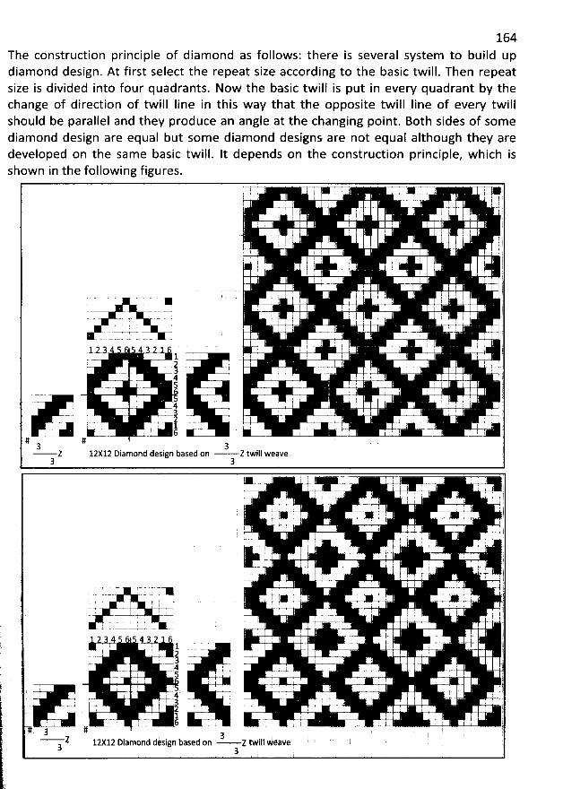
164The construction principle of diamond as follows: there is several system to build updiamond design. At first select the repeat size according to the basic twill. Then repeatsize is divided into four quadrants. Now the basic twill is put in every quadrant by thechange of direction of twill Iine in this way that the opposite twill Iine of every twillshould be parallel and they produce an angle at the changing point. Both sides of somediamond design are equal but some diamond designs are not equal although they aredeveloped on the sam e basic tFill. It depends on the construction principle, w hich isshown in the following figures.
' . ' ; ,; I ..
: , ! I I I I t. j4 . - .. , -. ; , . ' I I
I j ' I
; i. ::' il i I
i l E5
'
1 . . '
'
$
'
. I . I . .! . 'i . ji h l I I ,1 (. : . r
'
.yI .1 ' . , r
'
!
'
(. .j- j
# : I l f! I ! I I 1 iE
'
2 ' ' I I ! ' ' ii.
''''''''''''''''''''''''''''''''''''''''''''''''''''''''''''''''''''''''''''''''''''''''''''''''d
!
'
I : ! : I '
'
: . (.E
. . .- - ..- - I I ..i.. i -,. w- = .j .j I : ! : ! ! @
'
1 I .. - . - = . = - . .2
k ' 7 j 1 . ! ! .? :A i ! ; '''- . . I i4 7- : I r5 I --! ? I I i-.-.. i
' i I I I '4 . I ,
. j g ' ; g . jl.- .. ' - .; 2 ! : . . I ,- . -. . -+- j . - .- .
. - 1 . . l l ' -- .t- - .-- - -I- . - -- - -
# #3 3Z 12X12 Diamond design based on Z twill weave
3 3 '
* , .. c.- , . . :
. . v-x !; I ' ; ;' I 1 iu. .+. ! , ; I , )'
- .. )' ..;.-... - '.I 1 ..;. I j
' 4- .l . t 8--- #I I , ! g
). . . q E l. .. j! . . ( j
1. 2 l I :r- l 1
. . !j 'F ':
..- . -- ' ' '' ! . : . ' 1- ' ..- -.-a-.4. -.-. v v... . .4--4 kl I ' ' ' ' l '
i r z- RV..= . . .=- - - - - - v. j
. I ' L' .. j.2 4 4 ' . . , iI I 1 . . . I , I
I -7- g = ' . ) jI . . . . I
g . . 1.. ..-, - . I - 1. 4 ' ! . ' '-. .a .--. . .-..t.- . ..@:-
, ! 5 . . i ! ! ' ' j--v- . 4.. .. . jj . I ' ' ' I ! y
'
' .. .! i I 4 , I 'f . - p-- - . : . '. . m.. $ j. 3 ! 1 l ' .....k .-- g
I ' 2 : . I ) p. 1 . ë 1 . t
l -r- 6 , l.. . .x -.- .-.- .. I ' . . . p# g #' :.) )' '- '- - Z 12X12 Dlamond design based on Z tWill weave i
3 '3
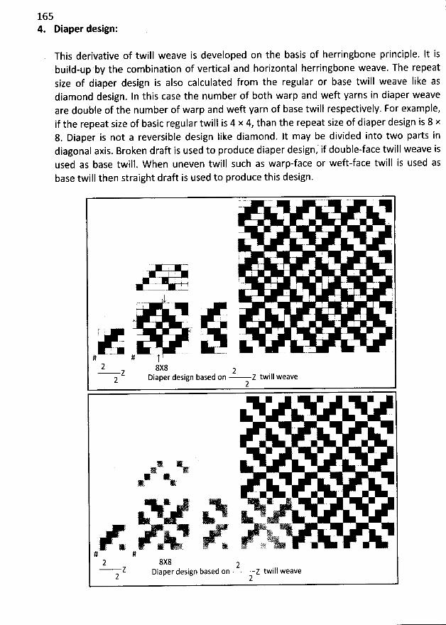
1654. Diaper design:
This derivative of twill weave is developed on the basis of herringbone principle. It isbuild-up'by the combination of vertical and horizontal herringbone weave. The repeatsize of diaper design is also calculated from the regular or base twill weave like asdiamond design. In this case the number of both warp and weft yarns in diaper weaveare double of the number of warp and weft yarn of base twill respectively. For example,if the repeat size of basic regular twill is 4 x 4, than the repeat size of diaper design is 8 x8. Diaper is not a reversible design like diamond. It may be divided into two parts indiagonal axis. Broken draft is used to produce diaper design; if double-face twill weave isused as base twill. W hen uneven twill such as warp-face or weft-face twill is used asbase twill then straight draft is used to produce this design.
a
! . I , .... . l . . .. .. . ..
' . . . ' ' ' !
! . .
..'-- -j ' . '
t ' I ! . : - 1: ! U '
3'
**************************************************************************************************
' I ! ' J
;
'
I .I ' .
. L & -# - # t2 8X8z 2
2 Diaper design based on Z twill weave2
1 )V1 G* ,
h* . ,
L . ' y i u' ' -<- . 2 . . - . . ';
, e 4u è e' - ;.; ts -...
' . ' . . ' . ... *. s z o ' 6 ' L% -S'W) -, *. .
# #2 gx8 2
Z Diaper design based on Z twill weave2 2
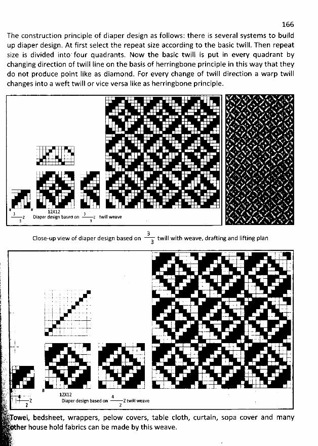
166
The construction principle of diaper design as follows: there is several systems to buildup diaper design. At first select the repeat size according to the basic twill. Then repeatsize is divided into' four quadrants. Now the basic twill is put in every quadrant bychanging direction of twill Iine on the basis of herringbone principle in this way that theydo not produce point Iike as diam ond. For every change of twill direction a warp twillchanges into a weft twill or vice versa Iike as herringbone principle.
11 # 12:12 a3 z Diaper design based on z twill weave
3 3 j) ) y y ( ( y3
Close-up view of diaper design based on twill with weave, drafting and Iifting plan3
7 I -7 : t d ! .
h
'
, I -
.t I -: s. .. I -;. I 'j
'
. , 1 j I , ; .
i 4..+. ' - '
f . .--..-. .. . ..-- .- --... ' -.. t-- : 'j--/- ' -j ,(
'
' ' ' : ' ' '
r . . , . . . ; - . .-t- , .w-c- ..p -s-.-s.-?- . -....è... ' ' I ' : -1j b--!- k ! . I , ; : .- k--y-1---.-).-' ...- q-. Y-= . - , y r ;
g-.u -J-=--' j z--.-4.-..y-y --: -.t.- ' ' )-! 7 J 2 ' 5 ' ' '. j.- . . .. . . ..-v.- -t--gh r ; ' 4. : t - . --. -i-.-.1 . l - ' ' ' ': ' .t : ' ' I I 1
: ; l . p . . : - ' --. rv r-h ; , I ,
: .-1 ---- --- .-- . k.. .- -.- -u--u . ; .-t- . --L-j-- . - -)-.:
'
' I ' ' ' l I. -p-; r , j . ,: : I
W')')- T T I 7- I ; : 1 r '... ... .. ... . j.... ' . .. j. r. . r.J : . ; .au ; : . : @-rC t yn ' - j -i -J..j .. -4. '
. a 7 . . : ! . ' I.: . ..-..t.. . -y , -j , j , -
.. . ( '
! ; : i : j r I F ,.. : ) . j r j : I ? ,L . .. f : ) r I I 1 '' : . . I I
. .. 1 ..j ! - - . . . . : I I .J . k - : '..t... .' tJ' - . . . ) ( . .t.. . .ri . 1 ) .. ). ..y. .j .j y. t .s-r 1 I y , .r .g ; . ..ë,- y i #è : . '.!.s) ) .., s lzxj.zt.q . .z . -4j.. 2k2''.' ' '' ; z Diaper design based on Z twill weavek:>: - . . !.,
, 2 2i') owel, bedsheet, wrappers, pelow covers, table c10th, curtain, sopa cover and manyher house hold fabrics can be made by this weave.
j ')..kfr
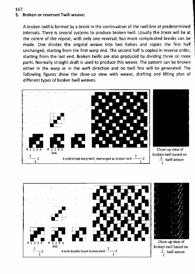
1675. Broken or reversed Twill weave:
A broken twill is formed by a break in the continuation of the twill iine at predeterminedintervals. There is several systems to produce broken twill. Usually the break will be atthe centre of the repeat, with only one reversal, but more complicated breaks can bemade. One divides the original weave into two halves and copies the first halfunchanged, starting from the first warp end. The second half is copied in reverse order,starting from the Iast end. Broken twills are also produced by dividing three or moreparts. Normally straight draft is used to produce this weave. The pattern can be brokeneither in the warp or in the weft direction and no twill Iine will be generated. Thefollowing figures show the close-up view with weave, drafting and lifting plan ofdifferent types of broken twill weaves.
: I Fl .
EJ ' ! .! ', ï
iE! I ! : ,) .
I. 4 . j .
1..4I : r ' 1b--''j - . ' j j
., . I I
# 1 2 3 4 # 1 -1- 4 3 ' ' -4X4
. 3 3' ' Z 4-end Simple warp twill, rearranged as broken twill Z
1 1
Close-up view ofbroken twill based on
3 iII weavetwl
j 1F ' ' ' 'k1 ' ;
'
! ''' 1 ! '' . . . .j(
'
' I I . iE' i
. i 'j I . I . t
I . I (
'
- d1 l ' ! ' 'ik ,
. --. , j -. :.!ë
'
I - . i I' l I . l ' i
'
! t . . .. -. . I
.y
'
, . , I '' ; ji 77 i I
. q I >- r- '
. ---. i . ' ...:*- :# 1 2 3 4 # 1 2 4 3 - - - - --
) 4X42 2
z 4-end double-faced broken twill Z2 2
Close-up view ofbroken twill based on
2 iI1 weavetw2
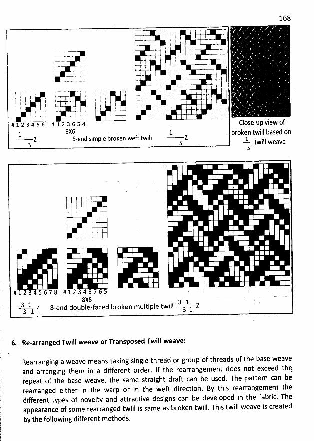
168
LT ) 7 i ; -7=, .- j- -j w-7- .4.-: . i ' .
y - j y , y g.. .-. . -. , ,
,, ysa,
. --k-t l '--- . ' -y- r r$ ' i i E :r -- j-- ,. --j . j j y: . J.- k-L r t-t- ,
. . t. ( t . I ' l%. ..j . : : , . : i. y . ;ic r 1 î
y..y.-j- j p..j .-t- .. y-?.. : -. y-y-4-. , ' 'I , l I s ; i j ; !
=-p. , . . s. j . j $.. s-% -.y-. g , j
' ' --. - ) .-t-gi I ) ) . . Ir I ' I ( : ' # . VI -y. .y--4 .. . j 4. g y y g , ,
z y y y j' . =- .-i t .# 1 2 3 4 5 6 # 1 2 3 6 j 4 Close-up view Y
6X6 1 b jen twijl based on1 ro- Z &end simple broken weft twill 2 15 5 'k- tw i I I we a ve
5
# 1 2 3 4 5 6 7 8 # 1 2 3 4 8 7 6 58x83 1 d double-faced broken multiple twill 3 1 2
Z 8-en3 1 3 1
6. Re-arranged Twill weave or Transposed Twill weave:
Rearranging a weave means taking single thread or group of threads of the base weaveand arranging them in a different order. lf the rearrangement does not exceed thirepeat of the base weave, the same straight draft can be used. The pattern can berearranged either in the warp or in the weft direction. By this rearrangement thedifferent types of novelty and attractive designs can be developed in the fabric. Theappearance of some rearranged twill is same as broken twill. This twill weave is created
by the following different methods.
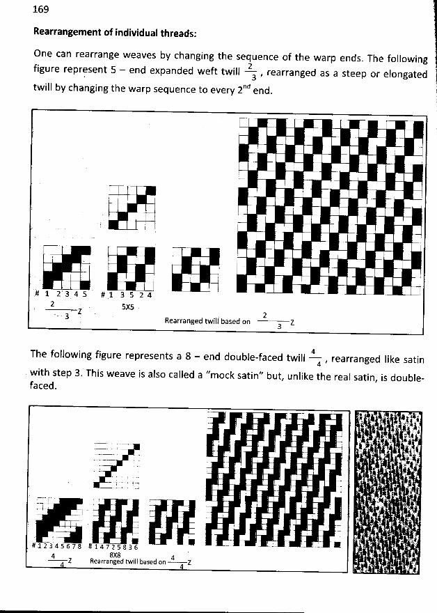
169
Rearrangement of individual threads:
One can rearrange weaves by changing the sequence of the warp ends. The following
2figure represent 5 - end expanded weft twill , rearranged as a steep or elongated. 3
iII b changing the warp sequence to every 2nd end.
tw y
i
: : i
'
) 0,
' . .
. k( J
'
. '
# 1 2 3 4 5 # 1 3 5 2 42 5X5
Z 2.
. g jj yased on ZRearranged twi3
.
4The following figure represents a 8 - end double-faced twill , rearranged Iike satin4
with step 3. This weave is also called a ''mock satin'' but, unlike the real satin, is double-
faced.
... ,
- ; , j . ,. .aj. - . - . . .
. ,4 j . .y- 't ê '' , ' ' C !! à. ï. . 4 # . : j
-.1 ' - . s . 1i E . .. ( t' . i- .l -, , ** kE %ju. 4 j 4 , .....- .. - . . ! : '
. c ' *, i .jrI . ) . ; . ' . . 4jz. - =-- y .u.:
'
''' r . . E . .:..- .. ..- . - .. . ' . f.- C t :
. : .4%-'- 4'' . : : Y C'. . - . ry ,=
- . , Gr . ...= . . ' '' NE' ;
'
' , i I . .
'' '-. ) ' - - - , ' '. . ?.
: I I I ' 1 ,
. ; . . .y4+1 y
- - ---. . . 1 . - --- ' - . .# .1 2 3 4 5 6 7 8 # 1 4 7 2 5 8 3 6 '
. '
.. . . k'8X8 ' ' ' '4 4
. . ' .Z Rearranged twill based on Z
. . - '
. . œ4 y . .' ::t
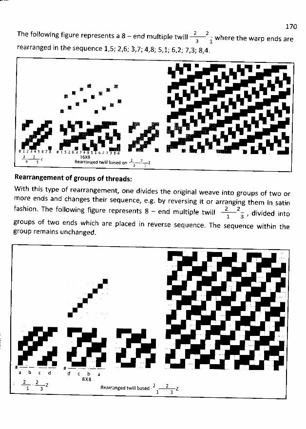
1702 2The following figure represents a 8 - end multiple twill where the warp ends are3 1
rearranged in the sequence 1,5; 2,6; 3,7,. 4,8; 5,1; 6,2; 7,3; 8,4.
* *
* >* 1
* ** **
*
NN * 'N%%N u
x . . a# 1 2 3 4 5 6 7 8 # 1 5 2 6 3 7 4 8 5 1 6 2 7 3 8 42 2 v 16X8
& d twill based on 2 2 z3. 1 Rearrange3 1
Rearrangem ent of groups of threads:
W ith this type of rearrangement, one divides the original weave into groups of two or
more ends and changes their sequence, e.g. by reversing it or arranging them in satin
2 2fashion. The following figure represents 8 - end m ultiple twill , divided into1 3
groups of two ends which are placed in reverse sequence. The sequence within the
group remains unchanged.
?
::
. ;. .
. . ' ' . . . . .
. ;!
:
- - .- j... . 'I :
'@- u u . t 1# ..- -.- .-. .-. # ..- -- -.-a b c d d c b a
8 X 82 2 2 2' l a Z Rearranged twill based Z1 3
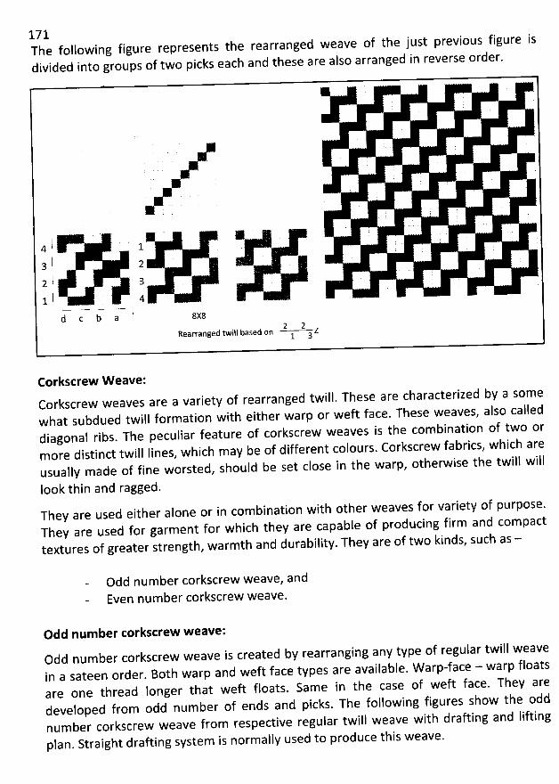
171The following figure represents the rearranged weave of the just previous figure isdivided into groups of two picks each and these are also arranged in reverse order.
. J ' . . .
* * .l , 14 :t .
' .
3 I 2
l a2j .
' .
1 1 4
d c b a ' 8X82 2Rearranged twill based on Z1 3
Corkscrew W eave:Corkscrew weaves are a variety of rearranged twill. These are characterized by a somewhat subdued twifl formation with either warp or weft face. These weaves, also calleddiagonal ribs. The peculiar feature of corkscrew weaves is the com bination of two ormore distinct twil. Iines, w hich may be of different colours. Corkscrew fabrics, which areusually made of fine worsted, should be set close in the warp, otherwise the twidl will
Iook thin and ragged.They are used either alone or in combination with other weaves for variety of purpose.They are used for garment for which they are capabîe of producing firm and compacttextures of greater strength, warmth and durability. They are of two kinds, such as -
Odd number corkscrew weave, andEven number corkscrew weave.
Odd num ber torkscrew weave:Odd num ber corkscrew weave is created by rearranging any type of regular twill weavein a sateen order. Both warp and weft face types are available. W arp-face - warp floatsare one thread Ionger that weft floats. Same in the case of weft face. They aredeveloped from odd number of ends and picks. The following figures show the oddnumber corkscrew weave from respective regular twill weave with drafting and Iifting
plan. Straight drafting system is normally used to produce this weave.
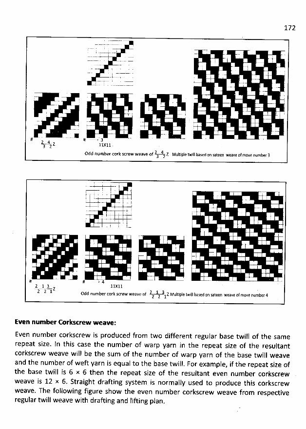
' ';
'
I ' 1
I I I j I i . ! .I i I r
'
. I . 'i ! r
'
O f ë: y
'
. : . . ,I . :i '
I '7% !j: . j ; '- j
I 7y. - . . . .- i... --
. ', I . j ! (a. . II I g I ; .ju
. !
'
' I I I
I . r ; l . --) . ; . , - i
œ !# # --W 3 '2 4
z ylxj,l3 22 4 z Multiple twill based on sateen weave of move number 30dd number cork screw weave of3 2
' I . ! i
'
lI I I r
'
I ' .I : . i I ? , '
. ': '; ' ' 1 ; ' r
'
I r
'
.1 ' : ' 1: I k
'
: .j. F . !
I . 2 ! 1' ; l 7
i I l ! I 1 ! ' 'ë .
. :j '
'
I I : ' :t ' I , . .
( ' ' ;.: I . .1 ! .! i: :1 ,I I . .
j '1 .:
'
! : I, r I ;
'
I ' j .# # --> 4
2 1 3 11xl1z2 2 1 odd number cork screw weave of 2 1 3 z Multiple twill based on sateen weave of move number42 2 1
Even num ber Corkscrew weave:
Even num ber corkscrew is produced from two different regular base twill of the samerepeat size. In this case the num ber of warp yarn in the repeat size of the resultantcorkscrew weave will be the sum of the num ber of warp yarn of the base twill weaveand the number of weft yarn is equal to the base twill
. For exam ple, if the repeat size ofthe base twill is 6 x 6 then the repeat size of the resultant even number corkscrewweave is 12 x 6. Straight drafting system is normally used to produce this corkscrewweave. The following figure show the even num ber corkscrew weave from respectiveregular twill weave with drafting and Iifting plan.
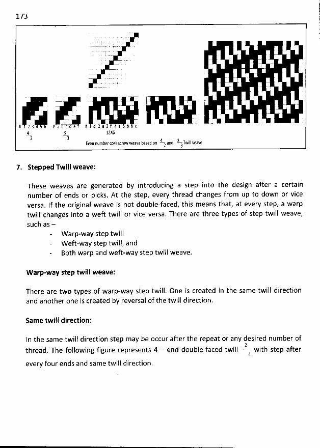
173
I
' j
!
i
. I
. .- - .. . . ï . . . - .# 234 #aj# e # e a b tS= J- 12X62 3 A
- and â-Twill veaveEven number cork screw weave based on2 3
7. Stepped Twill weave:
These weaves are generated by introducing a step into the design after a certainnumber of ends or picks. At the step, every thread changes from up to down or viceversa. If the original weave is not double-faced, this means that, at every step, a warptwill changes into a weft twill or vice versa. There are three types of step twill weave,such as -
W arp-way step twillW eft-way step twill, andBoth warp and weft-way step twill weave.
W arp-way step twill weave:
There are two types of warp-way step twill. One is created in the same twill directionand another one is created by reversal of the twill direction.
Same twill direction:
In the same twill direction step may be occur after the repeat or any desired number of2
thread. The following figure represents 4 - end double-faced twill with step after2
every four ends and same twill direction.
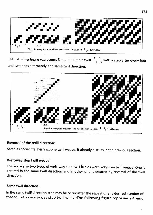
174
K .i
'
.
-. - .. - : .- u - ... -- -- - .. . - .-é .- '
-.. '
. . - . - - a# 2 #
Z 16X42 2Step after every four ends with same twill direction based on Z twill weave2
4 1The following figure represents 8 - end multiple twill with a step after every four1 2
and two ends alternately and same twill direction.
. . - - . . .. - a
1
!i
ff lzxg4 1 Z
I direction based on 4 1 z twill weave1 2 Step after every four ends with same twil1 2
Reversal of the twill direction:
Same as horizontal herringbone twill weave. It already discuss in the previous section.
W eft-way step twill weave:
There are also two types of weft-way step twill like as warp-way step twill weave. One is
created in the same twill direction and another one is created by reversal of the twilldirection.
Sam e twill direction:
ln the same twill direction step may be occur after the repeat or any desired num ber ofthread like as warp-w ay step tw ill w eaveThe follow ing figure represents 4 -end
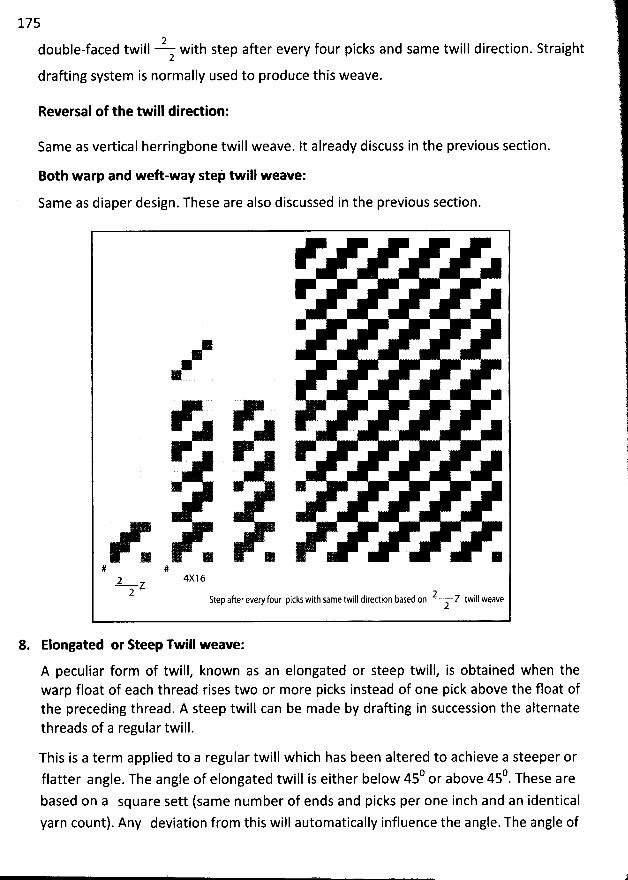
175
2double-faced twill with step after every four picks and same twill direction. Straight2
drafting system is normally used to produce this weave.
Reversal of the twill diredion:
Same as vertical herringbone twill weave. It already discuss in the previous section.
Both warp and weft-way s'e/ twill weave:Same as diaper design. These are also discussed in the previous section.
:
r P
# #2 4X16
Z2 2Step aherevery four picks with same twill direction based on Z twill weave2
8. Elongated or Reep Twill weave:
A peculiar form of twill, known as an elongated or steep twill, is obtained when thewarp float of each thread rises two or more picks instead of one pick above the float ofthe preceding thread. A steep twill can be made by drafting in succession the alternatethreads of a regular twill.
This is a term applied to a regular twill which has been altered to achieve a steeper or0 b 450 These areflatter angle
. The angle of elongated twill is either below 45 or a ove .
based on a square sett (same number of ends and picks per one inch and an identicalyarn count). Any deviation from this will automatically influence the angle. The angle of
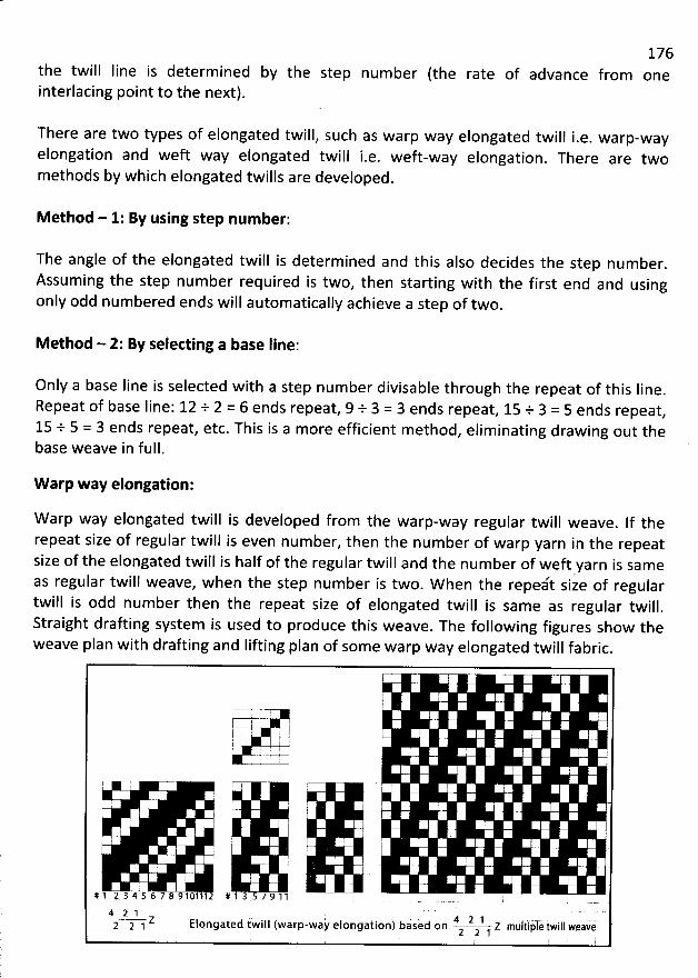
the twill Iine is determ ined by the step num berinterlacing point to the next).
There are two types of elongated twill, such as warp way elongated twill i.e. warp-wayelongation and weft way elongated twill i.e. weft-way elongation. There are twomethods by which elongated twills are developed.
176
(the rate of advance from one
M ethod - 1: By using step num ber:
The angle of the elongated twill is determined and this also decides the step number.
Assuming the step number required is two, then starting with the first end and usingonly odd num bered ends will automatically achieve a step of two.
M ethod - 2: By selecting a base line:
Only a base Iine is selected with a step number divisable through the repeat of this Iine.
Repeat of base line: 12 + 2 = 6 ends repeat, 9 + 3 = 3 ends repeat, 15 + 3 = 5 ends repeat,15 + 5 = 3 ends repeat, etc. This is a more efficient m ethod
, eliminating drawing out thebase weave in full.
W arp way elongation:
W arp way elongated twill is developed from the warp-way regular twill weave. If therepeat size of regular twill is even number, then the number of warp yarn in the repeatsize of the elongated twill is half of the regular twill and the number of weft yarn is same
J' ii e of regularas regular twill weave, when the step number is two. When the repe t stwill is odd number then the repeat size of elongated twill is same as regular twill
.
Straight drafting system is used to produce this weave. The following figures show theweave plan with drafting and Iifting plan of som e warp way elongated twill fabric
.
j '
T' 7 T--
t-! )--k- -- -L-4I I l .
4 .uyy. :. . I ... J
7 7- : 1 2 , ;
$ ' r
'
i ;
# 1 2 3 4 5 6 7 8 9 101 112 # 1 3 5 7 9 1 1 .
4 2 1 v . 4 2 1 - -2 2 1 <- Elongated twill (warp-way elongation) based on Z multiple iwill weave2 2 1
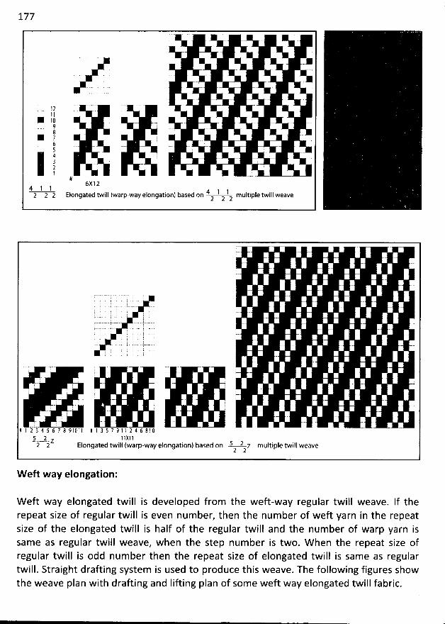
177
1 1 .- -
* 10 . .- . . .. -9 -!g '1 y6 . . . .-. -'
54 - - . . .3 è .2 ' I1 ---. -.
#6x1 2
4 1 1 4 1 1 Itiple twill weave2 2 2 Elongated twill (warp-way elongation) based on mu2 2 2
. ; . . . k ; . . - . . .
. . . .. . . ;
. .y -- .-z- -2- - . . . s- . . . .'? ':' i. u t '
c----- ...#. a - . - . -
. ! y q r ' : ' ' -. . .-...1..-1.. -c .- . .
- . . .. ,. . .. .L--... . . --.... .... . . ; , . - ..i--..----u--s- 7 . -
: .J . . ': ; : . . j1 : -
- - . - ' . .. -; ! ' .
i ; : - ' .
. ' ; . .
.:. - ;/ 1 'i 1$ 4 5 6 7 2 9 1 û 1 1 # 1 3 5 7 9 1 1 2 4 6 8 1 () ' ' ' - - ' - ' ' - ' -
s 2 1 1 xl 1Z s 22 2 Elongated twill (warp-way elongation) based on z multiple twill weave2 2
W eft way elongation:
W eft way elongated twill is developed from the weft-way regular twill weave. If therepeat size of regular twill is even num ber, then the num ber of weft yarn in the repeatsize of the elongated twill is half of the regular twill and the number of warp yarn issame as regular twill weave, when the step number is two. W hen the repeat size ofregular twill is odd number then the repeat size of elongated twill is same as regulartwill. Straight drafting system is used to produce this weave. The following figures showthe weave plan with drafting and Iifting plan of some weft way elongated twill fabric.
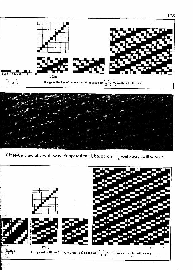
178
1 5 6 7 #12X6
4 l 1 4 1 J.2 2 2 Elongaled twill (weft-way elongalion) based on mulliple twill weave
2 2 2
I iew of a weft-way elongated twill, based on 4 weft
-wa'y twill weaveC Ose-up v4
'C
-;.j.k
'
-r 'y#.t . !. k
il .l-. . . ... . & .
1û864
. 24 1
97
z 5 . ''
gt 1 .'
ëj --...... . .... PF y yyy y . .. 2 .... ...... .. jii 2 s 2''f Z Elongated twill (weft-way etongation) based on z weft-way multiple twil) weaveë -. g z 2 2
j- '
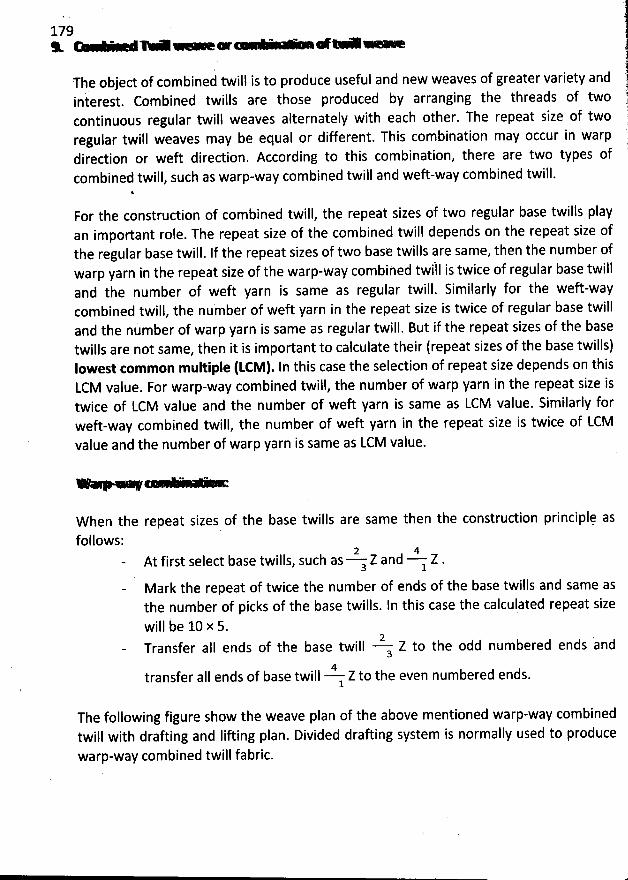
179
The object of combined twill is to produce useful and new weaves of greater variety andinterest. Combined twills are those produced by arranging the tbreads of twocontinuous regular twill weaves alternately with each other. The repeat size of tworegular twill weaves may be equal or different. This combination may occur in warpdirection or weft direction. According to this combination, there are two types ofcombined twill, such as warp-way com bined twill and weft-way combined twill.
For the construction of combined twill, the repeat sizes of two regular base twills playan important role. The repeat size of the combined twill depends on the repeat size ofthe regular base twill. If the repeat sizes of two base twills are same, then the number ofwarp yarn in the repeat size of the warp-way combihed twfll is twice of regular base twilland the number of weft yarn is same as regular twill. Similarly for the weft-waycombined twill, the number of weft yarn in the repeat size is twice of regular base twilland the nùmber of warp yarn is same as regular twill. But if the repeat sizes of tbe basetwills are not same, then it is important to calculate their (repeat sizes of the base twills)Iowest tommon multiple (LCM). In this case the selection of repeat size depends on thisLCM value. For warp-way com bined twill, the number of warp yarn in the repeat size istwice of LCM value and the number of weft yarn is same as LCM value. Similarly forweft-way com bined twill, the number of weft yarn in the repeat size is twice of LCMvalue and the number of warp yarn is same as LCM value.
* ** -*@ . ..
W hen the repeat sizes of the base twills are same then the construction principlç as
follows:2 4
At first select base twills, such as Z and Z .a 1
Mark the repeat of twice the number of ends of the base twills and same asthe number of picks of the base twills. In this case the calculated repeat sizewill be 10 x 5.
2 .Transfer alI ends of the base twill Z to the odd numbered ends and
34
transfer aII ends of base twill Z to the even numbered ends.1
The following figure show the weave plan of the above mentioned warp-way combinedtwill with drafting and lifting plan. Divided drafting system is normally used to producewarp-way combined twill fabric.
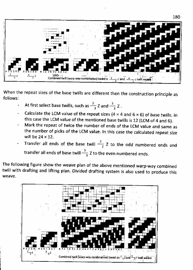
180l ' ' -r-'
yl . . .
1 'j .. .. ! ! ' '; i : ' I ,l r +-0 'l
.-X.V- i
-t--. .- . )-. I 'j .+ ; . ;= . ..%j . ..- . .,.-t--j , .
.. . , . ! -- . .I . : -. . .11.
*
1. '' '
'
, 1 .j - , j- r>- ' . ' Et ' ' . ' ' 'I
.+ . ,l # l 2 j-k s # a -c e # 1 a $--3 c 4 5 e . r ' .
'' ' ' '
, ..$
! , j
'
,;j ;( kr tk zr . (lk (:). 1,(1j;. . . .u....... . . - . . .; .-....-- ,. . ïy r)2.j 3 1 Combined twill fwarp-way combination) basèd fl ' 2 ' z end ' 4 : z twill wlqv' LL.'è . ,- 3 . , .1 r , .
W hen the repeat sizes of the base twills are different then the construction principle asfollows:
2 3At first select base twills, such as z Z and a Z .
Calculate the LCM value of the repeat sizes (4 x 4 and 6 x 6) of base twills. Inthis case the LCM value of the mentioned base twills is 12 (LCM of 4 and 6)
.
M ark the repeat of twice the number of ends of the LCM value and same asthe number of picks of the LCM value. In this case the calculated repeat sizewill be 24 x 12.
2Transfer aII ends of the base twill Z to the odd numbered ends and23transfer aIl ends of base twill Z to the even numbered ends.3
The following figure show the weave plan of the above mentioned warp-way combinedtwill with drafting and lifting plan. Divided drafting system is also used to produce thisW eave.
I ; ' y
'
:1 . ' . j
'
! 1 I l.
I jr
'
k ' ' II .. . r )
. '
t'$ . ; j
!. . . . u . . .. .)' ! j'
g
'
7 )j,. ' . . . '
. l; .:
:
'
j . ' It i 1 a 2 b 1 c 4 d 1. t 1J f 3. a 4 b 1 t 2 d j e 4 f L# 1 k 3 4 # a b t e f # . z â . : r . . . . .. . .2 3 . îz z
r) 11: . E1 . . . . .. . . .. ..... ...... . .... .. ...... .. .l èombined iwill (warp-way coiikbiniikon') basei :n 1 z Iand 3 a z twdkwea-ve. . 'E
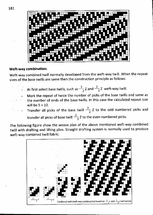
181
W eft-Fay com bination:W eft-way com bined twill normally developed from the weft-way twill. W hen tbe repeatsizes of the base twills are same then the construction principle as follows:
. a 2- At first select base twills, such as Z and Z weft-way twill.a 3
M ark the repeat of twice the num ber of picks of the base twills and same asthe number of ends of the base twills. In this case the calculated repeat size
will be 5 x 10.3 d icks andTfansfer aII picks of the base twill Z to the odd numbere p2
2transfer aII picks of base twill Z to the even numbered picks.3
Thçxfollpwing figure show the weave plan of the above mentioned weft-way combinedith drafting anà Iifting plan. Straigbt drafting system is normally used to producetwill w
weft-way combined twill fabric.
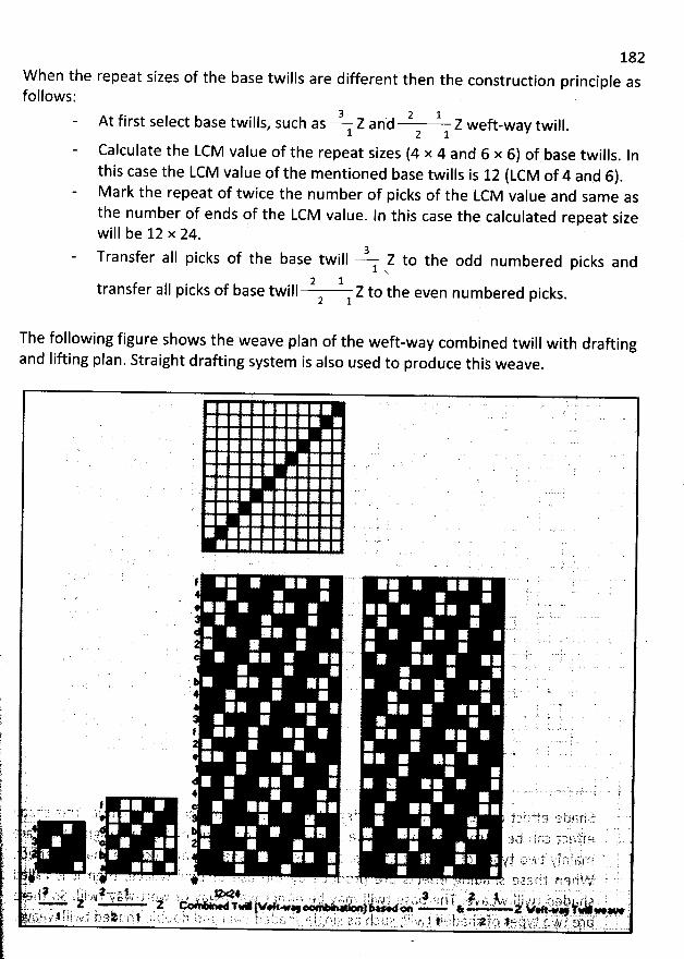
182W hen the repeat sizes of the base twills are different then the construction principle asfollows:
3 . 2 1At first select base twills, such as Z and Z weft-way twill
.l 2 1
Calculate the LCM value of the repeat sizes (4 x 4 and 6 x 6) of base twills. lnthis case the LCM value of the mentioned base twills is 12 (LCM of 4 and 6).M ark the repeat of twice the number of picks of the LCM value and same asthe number of ends pf the LCM value. ln this case the calculated repeat sizewill be 12 x 24.
3Transfer aII picks of the base twill Z to the odd numbered picks and1 x.
2 ltransfer aII picks of base twill Z to the even numbered picks.2 1
The following figure shows the weave plan of the weft-way com bined twill with draftingand Iifting plan. Straight drafting system is also used to produce this weave
.
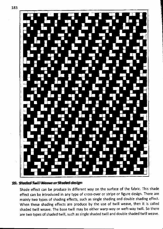
183
* .- > III- œr* * AShade effect can be produce in different way on the sudace of the fabric. This shadeeffect çan be introduced in any type of cross-over or stripe or figure design. There aremainly two types of shading effects, such as single shading and double shading effect.W hen these shading effects are produce by the use of twill weave, then it is calledshaded twill weave. The base twill may be either warp-way or weft-way twill. So thereare two types of shaded twill, such as single shaded twill and double shaded twill weave.
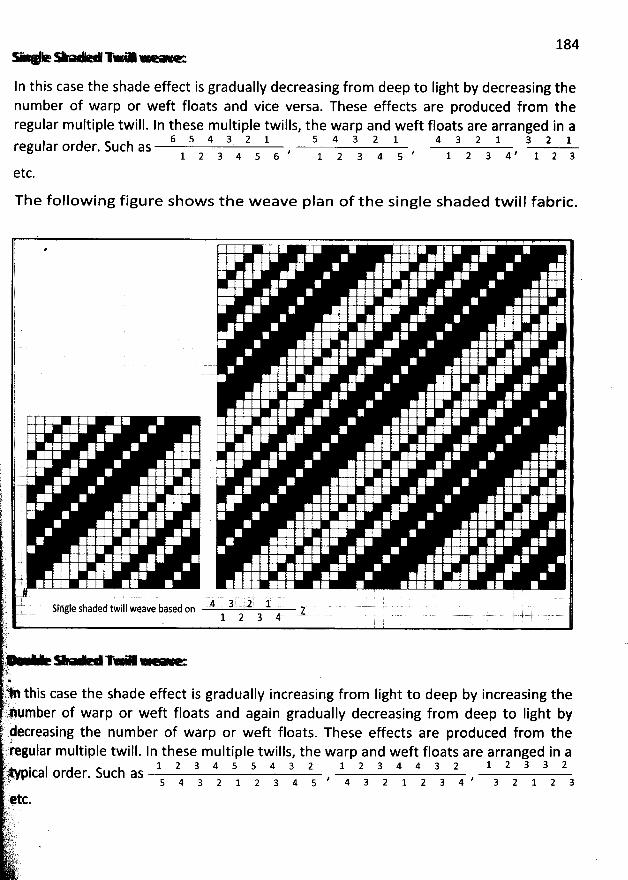
184- +- Te -
In this case the shade effect is gradually decreasing from deep to Iight by decreasing thenumber of warp or weft floats and vice versa. These effects are produced from theregular multiple twill. In these m ultiple twills, the warp and weft floats are arranged in a
6 5 4 3 2 1 5 4 3 2 1 4 3 2 1 3 2 1regular order. Such as , , :j g a 4 , j z a1 2 3 4 5 6 1 2 3 4 5
etc.
The follow ing figure show s the w eave plan of the single shaded tw ill fabric.
* ' ' : : : ' : t : ;t . .. è : 1 : i ..j : ) 2 : ' 2 .! : ; ' )
'
-!
'
; : I ' . .: : ' :
'
.
'
I ;!
: !. : : E1 : :
'
: : 7 -i E : : q
'
r -'k l q
'
' ' l
: ) : 7 ' k) : : . : : .l ' ' -- ' ' ': i . l L
'
I! ' : ) ' ) -
1 ! ! 1 7 : :
'
' '
l .. ' ' . ' . ' q . . ' 'j l . : : , k
'
:: ?
'
I . : :
'
i .1 I1 : ' : , . 2 ' : ' y '
l : q k . : : , ï : : . . . E'j 1 : . : : 2 . : : : , ë ' .F ' i : ) ': i 2 ' ( F
'
:
'
E
'
: ' .j
'
. : ) : : : :. : , :. j - . , .! : : . . : ! : : ; . ,: . : t ) :
'
. : : . : . t
'
: : :.i : ) . E : .: : i k :
'
' '
'
'
'
- '
'' ' : ï
'
.: : : : :
'
' .: . : ) : ' :
'
: - k
'
ij ... . E : 2 : . . ) :
: ! :
'
; : ! E
'
:
'
! : .7 : : ! i ë : : : : j ( , ) ' . 2
: : : : , : ! : , ' ' r' ' E
'
L
'
ë )
'
7 :
'
: ' ' '. : : ï ; :
'
' : : - l - (: q
'
E : ; ë : ' ' -t E ; )
t . ' )
'
! :
'
; '- i ' I ' : , 2 : è- '
y : -) .. . y : :) t : : : ? : l '
: E
'
;
'
: : L
'
' : ' q
'
'ty .. ... : : , ,11 -. . 4 3 2 1 - . . .. Sirsle shaded twill weave based on z
1 2 3 4
tf = . - - - . . .- . . . - - . . -T7$. . 'k:)V this case the shade effect is gradually increasing from Iight to deep by increasing the..t!' '.Xpmber of warp or weft floats and again gradually decreasing from deep to light by(decreasing the number of warp or weft floats. These effects are produced from the7iregular multiple twill. In these multiple twills, the warp and weft floats are arranged in aè ' 1 z 3 4 s s 4 3 2 1 2 3 4 4 3 2 1 2 3 3 2L:.p.-' pical order. Such as - , , a z :j z a,:.. s 4 3 2 l 2 3 4 s 4 3 2 1 2 3 4é ''qtc
..? .sf;)! t' è .) k).j.),:''-ri t..)t!)
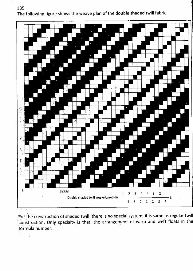
185The following figure shows the weave plan of the double shaded twill fabric.
!1I1.(E
.. '
J?;.. ' ! ..
J' ' .
. . .'
L . ' . 1 '. ù J' ' ' ' . '' . . ' '
's(
'
.. f? ' . .v ' ' ' 'u:;:. '' . .. (. , ' .j 2, . ' '(' . ' . .
' .
r ' . L ' . :
' : ' ' J.. a ' F ' '.* .( .., . '.. k ''' t. .tsa. . '
j.-.L ' ' 1
;. .j.:' ,. ..
'
'
'
''
'
..
.i t . . .R 'r'(r. . ' . .
. . ' ,) '>() ) r, . . .
# 3g:381 2 3 4 4 3 2
Double shaded twill weave based on z4 3
'Fos ifàè construction of shaded twill, there is no special system; it is same as regular twill'àns'tiiuction. only specialty is that, the arrangement of warp and weft floats in thec
'ttkréiù' ia number.
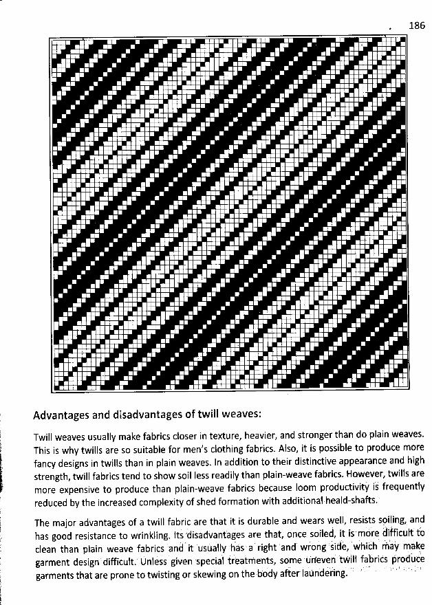
186
Advantages and disadvantages of twill weaves:
Twill weaves usually make fabrics closer in texture, heavier, and stronger than do plain weaves.This is why twills are so suitable for men's clothing fabrics. Also, it is possible to produce morefancy designs in twills than in plain weaves. In addition to their distinctive appearance and highstrength, twill fabrics tend to show soil Iess readily than plain-weave fabrics. However, twills are
more expensive to produce than plain-weave fabrics because Ioom productivitf is frequentlyreduced by the increased complexity of shed formation with additional heald-shafts.'
The major advantages of a twill fabric are that it is durable and wears well, resists spiling, anddisadkantàges are that, bnce soileà, it ij m6rk d' iMlculf tthas good resistance to wrinkling
. ltsclean than plain weave fabrics an8 it usually has a right and wrbng sidè, whith ràa#' màke
' . , ''
.
' J ' ' ' ' '2
garment design difficuit. Unîess given speciaî irèatments, some uneven twtlf tabrics krodùte'à fi t ti deilng ' Z ' ' ' ' ' ' ' 6 'garments that are prone to twisting or skewing on the bo y a ér a n .
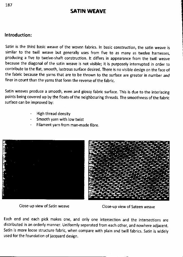
187
O n N W EAW
lntroduction:
Satin is the third basic weave of the woven fabrics. ln basic construction, the satin weave issimilar to the twill weave but generally uses from five to as many as twelve harnesses
,
producing a five to twelve-shaft construction. lt differs in appearance from the twill weavebecause the diagonal of the satin weave is not visible; it is purposely interrupted in order tocontribute to the flat, smooth, Iustrous surface desired. There is no visible design on the face ofthe fabric because the yarns that are to be thrown to the sudace are greater in number andfiner in count than the yarns tbat form the reverse of the fabric.
Satin weaves produce a smooth, even and glossy fabric surface. This is due to the interlacingpoints being covered up by the floats of the neighbouring threads. The smoothness of the fabricsurface can be improved by:
Higb thread density5m00th yarn with Iow twistFilament yarn from man-made fibre.
Close-up view of Satin weave Close-up view of Sateen weave
Each end and each pick makes one, and only one intersection and the intersections aredistributed in an orderly manner. Uniformly separated from each other
, and nowhere adjacent.Satin is more Ioose structure fabric, when compare with plain and twill fabrics. Satin is widelyused for the foundation of jacquard design.
188
Classification of satin weave:
0ne distinguishes between warp and weft satins depending on whether the fabric face showsthe warp or the weft. Weft satins are also called satçens. W ith the most common simple warpsatin, each warp end is Iowered only on one pick in the repeat while, with the weft satin, it isonly raised on one pick. The smallest regular satin weave is the 5 - end satin which can be
1 4represented either by (2) or by (3) where the figure in the bracket shows the size of the4 1
Step.
A , zSo the warp satin is denoted by the formula number (B), where A indicates the number of1
warp floats and 'B' indicates the step value of satin weave. Similarly the weft satin is denoted
1 : # t , djcatesby the formula number (B), where A indicates the number of weft floats and B in
A
the step value of satin weave. lt is important to note that when the face side of a fabriccomposed by the warp satin weave then the reverse side of this fabric should be composed by
the weft satin weave.
Both warp and weft satins are divided into two groups, such as
Regular warp satin and irregular warp satinRegular weft satin and irregular weft satin.
There is a step value or move number for regular warp or weft satin weave but there is no stepvalue for the irregular warp or weft satin weave. In general 4 - end and 6 - end satin weavesare irregular, because they have no step value. Other 5 - end to 16 - end satins are regular,
because they have step values.
M ove num ber or Step value selection for Satin weave:
W ith the satin weave, the distance between consecutive interlacing points is always the sameand is referred to as the step or step values or move numbers of the satin. The weaves aredeveloped with the help of this move or count number. To establish this number certain ruleshave to be considered. The number must be larger than one and must not be one Iess than thenumber of tbreads in the repeat, as this would create a twill. The number must not be a factor.The move number can be applied by counting warp-ways or weft-ways.
The value of the step indicates by how many picks the interlacing point on the next warp end to
the right moves upward. One obtains the value of the step by dividing the repeat number (i.e.the number of ends or picks in the weave repeat) into pairs of numbers. Of the two numbers ofa pair, either both or none can be used as a step value. Usable steps must mèet the following
conditions:
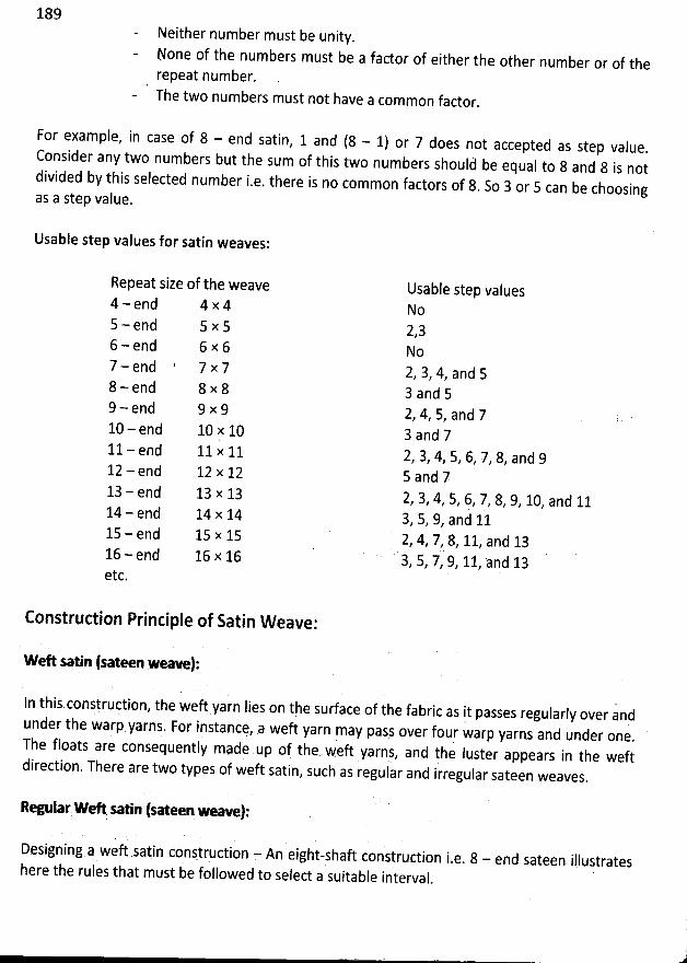
189Neither number must be unity.
None of the numbers must be a factor of either the other number or of therepeat number.
- The two numbers must not have a common factor.
For example, in case of 8 - end satin, 1 and (8 - 1) or 7 does not accepted as step value
.Consider any two numbers but the sum of this two numbers should' be equal to 8 and 8 is notdi
vided by this selected number i.e. there is no common factors of 8. So 3 or 5 can be choosing
as a step value.
Usable step values for satin weaves:
Repeat size of the weave4 - end 4 x 45 - end 5 x 56 - end 6 x 67 - end 7 x 78 - end 8 x 89 - end 9 x 910 - end 10 x 1011- end 11 x 1112 - end 12 x 1213 - end 13 x 1314 - end 14 x 1415 - end 15 x 1516 - end 16 A 16etc.
Usable step vabuesN o2,3No2, 3, 4, and 53 a nd 52, 4, 5, and 73 and 72, 3, 4, 5, 6, 7, 8, and 95 and 72, 3, 4, 5, 6, 7, 8, 9, 10, and 113, 5, 9, and 112, 4, 7, 8, 11, and 133, 5, 7, 9, 11, and 13
Construction Principle of Satin W eave:
weft sl n (sateen weave):
In thîs construction, tbe weft yarn lies on the surface of the fabric as it passes regularly over andunder the warp yarns. For instancq, a weft yarn may pasj over four warp yarns and under one
.The floats are consequently made up of the weft yarns, and tNe Iuster appears in the weft
direction. There are two types of weft satin, such as regular and irregular sateen weaves
.
Re lar WG saNn (sateen weave):
Designing,a weft satin construction = An eight-shaû construction i.e. 8 - end sateen illustratesh
ere the rules that must be followed to select a suitable interval.
i
11
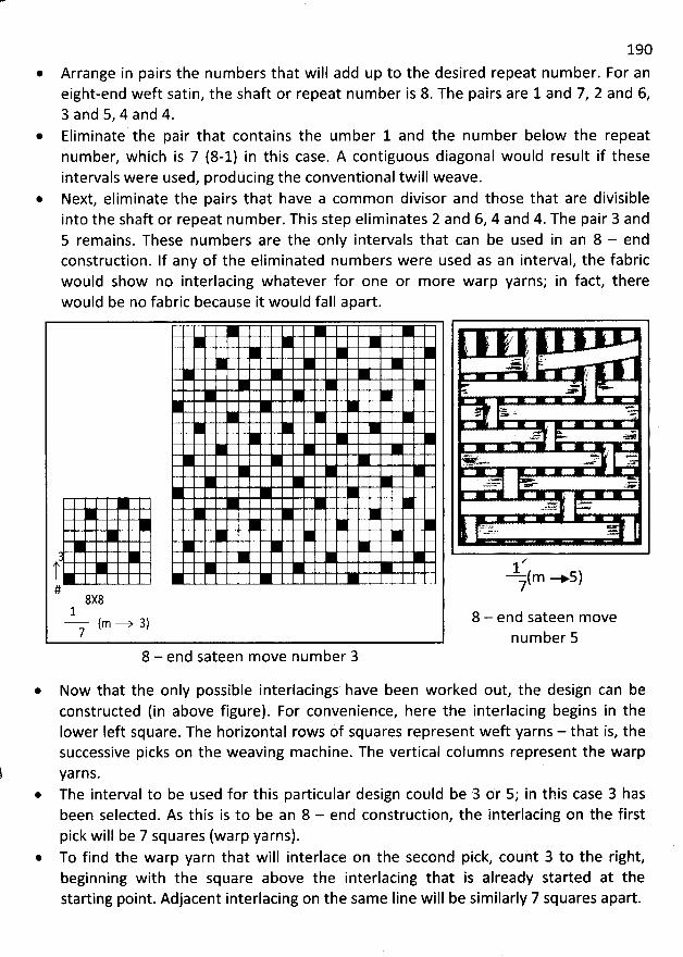
190
Arrange in pairs the num bers that will add up to the desired repeat num ber. For aneight-end weft satin, the shaft or repeat num ber is 8. The pairs are 1 and 7, 2 and 6,3 and 5, 4 and 4.
@ Eliminate the pair that contains the um ber 1 and the num ber below the repeatnumber, which is 7 (8-1) in this case. A contiguous diagonal would result if theseintervals were used, producing the conventional twill weave.Next, elim inate the pairs that have a common divisor and those that are divisibleinto the shafl or repeat num ber. This step eliminates 2 and 6, 4 and 4. The pair 3 and5 remains. These num bers are the only intervals that can be used in an 8 - endconstruction. lf any of the elim inated num bers were used as an interval, the fabricwould show no interlacing whatever for one or m ore warp yarns; in fact, therewould be no fabric because it would fall apart.
#8X8
1- jm .-y g)7
8 - end sateen move num ber 3
x.- y *x< J
f(.
+
- > -' '-
m </
.= < e
.>r2722
w..'xw -
1- m -+ 57
8 - end sateen movenum ber 5
* Now that the only possible interlacings have been worked out, the design can be
constructed (in above figure). For convenience, here the interlacing begins in theIower Ieft square. The horizontal rows of squares represent weft yarns - that is, thesuccessive picks on the weaving machine. The vertical columns represent the warp
yarns.* The interval to be used for this particular design could be 3 or 5; in this case 3 has
been selected. As this is to be an 8 - end construction, the interlacing on the first
pick will be 7 squares (warp yarns).* To find the warp yarn that will interlace on the second pick, count 3 to the right,
beginning with the square above the interlacing that is already started at thestarting point. Adjacent interlacing on the same Iine will be similarly 7 squares apart.
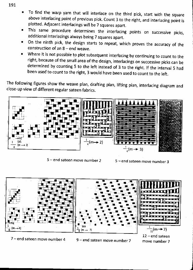
191
@ To find the warp yarn that will interlace on the thirdabove interlacing point of previousplotted. Adjacent interlacings will be 7 squares apart
.
This same procedure determines the interlacing points on successive
pick. Count 3
*
additional interlacings always being 7 squares apart.
* On the ninth pick, the design starts to repeat, which proves the accuracy of the
construction of an 8 - end weave.
picks,
W here it is not possible to plot subsequent interlacing by continuing to count to theright, because of the small area of the design
, interlacings on successive picks can bedetermined by counting 5 to the Ieft instead of 3 to the right
. If the interval 5 hadbeen used to count to the right
, 3 would have been used to count to the Ieft.
pick, start with the squareto the right, and interlacing point is
The following figures show the weave plan, draûing plan, Iifting plan, interlacing diagram and
close-up view of different regular sateen fabrics.
I : ' . 1 - ' '. . : . . . '. . .,( . y . j !! 1 . 5f ' '
.f.-j l .o- :' ' I ' 1 I . :T ' ' . '.
t . .: è, ' r . < '); -1 .-t . . I I . ..1 j . j- . j .m. - w j ; à.
'
' 1. ' . 1
*
:
'
.
'
. ' . ! ! ' . ; r 8 L. . . :r. l 1p 1 .' ''1 l > llgk : 1I I I L tE
. j :c= . ' = u . .g -1 77- 7 ; I r ;i k .: ' . l ' t . .:. 2 ..... . . : . )
. .I I . i . ' : . .. !( ..i1)'' .. .. i r I . . . . I . ., y . t 1j-
k .+> -+% . ( . e, ' I I l I ' I è . .u- . j# e m - 1 î ;- - (m-+ 2) ' ' '1 5X5 ; 4f
m --y 2) ' 14 - - dm- 3)4 *
5 - end sateen move num ber 2 5 - end sateen move num ber 3
r . . . .; * . * * ( 7t > . ,+ >
.. > . .. . ,> . ... .. > .J1 . . f > - . . > o i s=T'U .W x . - -è
.. W . . . . . W . .s . c ' A . ' . 1 2 -:* J 'QVI q , j . l . + . . . .p ,' .+ ' .'n. .' . .+ .) ,.. . . . . . j . .. . x y
. j....j.- ! ' . . . . x . . s . . . N u . . w
I . , . . ) .e u... . se . . .. . .+ . .. .J . :/ ( '> :e , >I -#-j ! ' ' )
. 3111 . 1111 11. ) cz. zovs, .= y . . * . . > .e . u. ,. k . . . .. .. . . ?. . . , . ..
: . . ) . * :e * . . J- ' ; . . > > . . .. . . . j az ,(F'.+ 7 L=+ =-, 7 sku L . ' x . , . jé ï +1W Le .W : è * .x .' . M . ' x ' '* . . . > . ; . u .' ' , ' , y * . , ... . . . % , w . .* . .+ ..) ' v.H A 4 ; ., I .u-+' .
'* * * kœ J . a; ; J # W % <. i-1
. ) ' ' . .g . . ;. . j' u . I . . . .- . . -# jK9 1'
(m -.4 -t- fm .... 7) --f1(m ---*' 7)7 - end sateen move number 4 9 - end sateen move number 7 12 - end sateen
move number 7
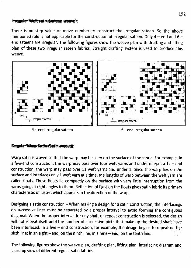
192
j e t-* œ- ,-*1 j v j:
There is no step value or move number to construct the irregular sateen. So the abovementioned rule is not applicable for the construction of irregular sateen. Only 4 - end and 6 -end sateens are irregular. The following figures show the weave plan with draûing and Iiûingplan of these two irregular sateen fabrics. Straight draûing system is used to produce thisW eave.
4 - end irregular sateen
7 W 2 T œ T T = I . > 7 '-ww..y.- x a... .x .- w k -.#..+wN . '.''. . , ': , ', . ' 1'
. ..z.y.X. : .jy-.k . gî 1: w.wj ,,., j ; j'i'# ;. y # k :j .. -.ù ' -.- .+.- w.m .4'
s-..v--,.- .-- - : (! ' : ' '',: -z'.' - 'i '' X' :: ''.! 6 77.' . .:' j' ' '' ' .. .. h.h. :. : ',. ;' :1 sI y! :: ;: :.k-.+-.x- . - , s.v 1, y . , y r .E ; . $ j . ir j jj--<- -u- x . . . 4.... ... r : : :. . : : r .. r j. y . ;; . . :.-.<- ..w $-4J-x-- - .+.' wjo . 1' x#xxy. '')
'
..- .-' .- -
'.'..:.x'...e..z,..-. : .''. . k..z',...t.
'
,.x: :.., ;,..,...y.. . . .
, jj:;. - - .,.- 4. . .- - . -&.. j. yjjuj.. ., .. ... #. .x ï-. --.. '-. k. .1111, .- $. ' it -fF- 11111. -.#. ' '. . .. .c 1K
. '
...-..-..*.. ' ',''--t'.-.'.-# .... .-.,...''t'*.. ... ''. '';t.,i......*. . .1111 ... ...--.-.1111 .-.. .-.-. -..--1111- ....-.--11111-. . ; -.-....11111. )1111----. .- .--1111.-.-. -.. ...1111..-.. .---.q11I1-..- -.-.71111.. ,-c.. --t.,
.K ..-,, ..K. .,-= .A .0 -x y, * ... .u .+ .,.w.si,.j .l ,'.' ë. . a.-z...uk . .....-. .- .. .....s.-.-..-.X.w= .z......' j) # 6xE$f
1 .,. Irregular sateenk q
6- end irregular sateen
Y *r- * M(* M> ):
Warp satin is woven so that the warp may be seen on the surface of the fabric. For example, ina five-end construction, the warp may pass over four weft yarns and under onepin a 12 - endconstruction, the warp may pass over 11 weft yarns and under 1. Since the warp Iies on theSurface and interlaces only 1 weft yarn at a time, the Iengths of warp between the weft yarn arecalled floats. These floats Iie compactly on the surface with very little interruption from theyarns going at right angles to them. Reflection of Iight on the floats gives satin fabric its primarycharacteristic of Iuster, which appears in the direction of the warp.
Designing a satin construction - W hen making a design for a satin construction, the interlacingson successive Iines must be separated by a proper interval to avoid forming the contiguousdiagonal. When the proper interval for any shaft or repeat construction is selected, the designwill not repeat itself until the number of successive picks that make up the desired shaft havebeen interlaced. ln a five - end construction, for example, the deslgn begins to repeat on tke
%sixth Iine; in an eight - end, on the ninth Iine; in a nine - end, on the tenth Iine.
The following figures show the weave plan, draûing plan, Iifting plan, interlacing diagram andclose-up view of different regular satin fabrics.
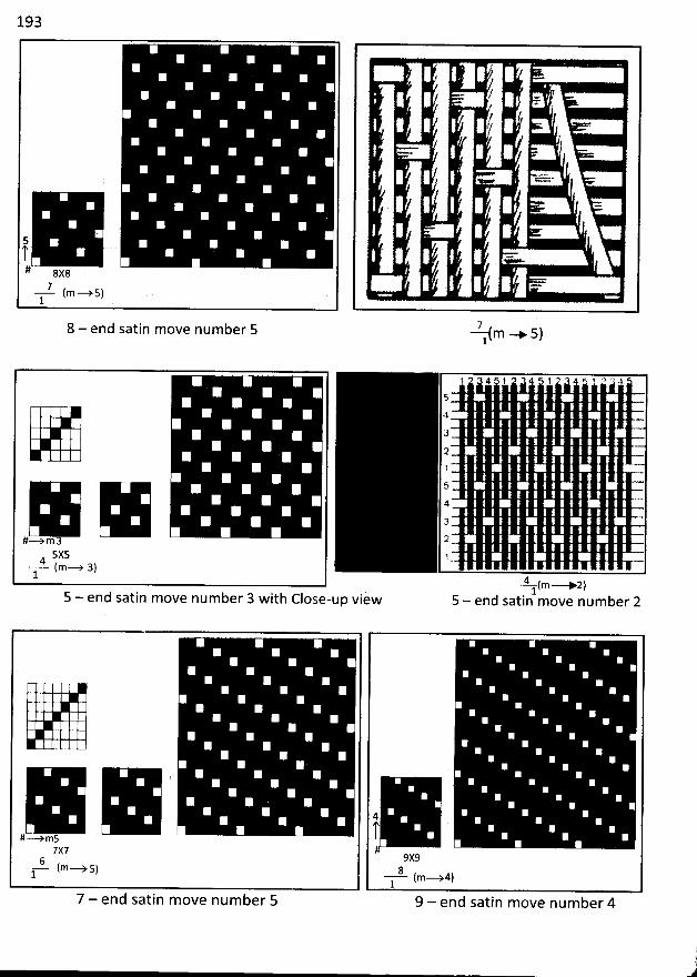
193
5q.# 8x8
---!. (m--ys)1
8 - end satin move number 5
#/ T
/
= =
7(m * 5)1
#-->m35X5
- -4. (m-+ a)1
4 1 1 ! -5
4
3
21
54
3
2
F-4 (m-- 2)
. 15 - end satin m ove num ber 3 with Close-up view 5 - end satin move num ber 2
#-->m57x7
6 (m- -ys)l
7 - end satin move number 5
4
9x98 (m- .+4)1
9 - end satin move number 4('
i1
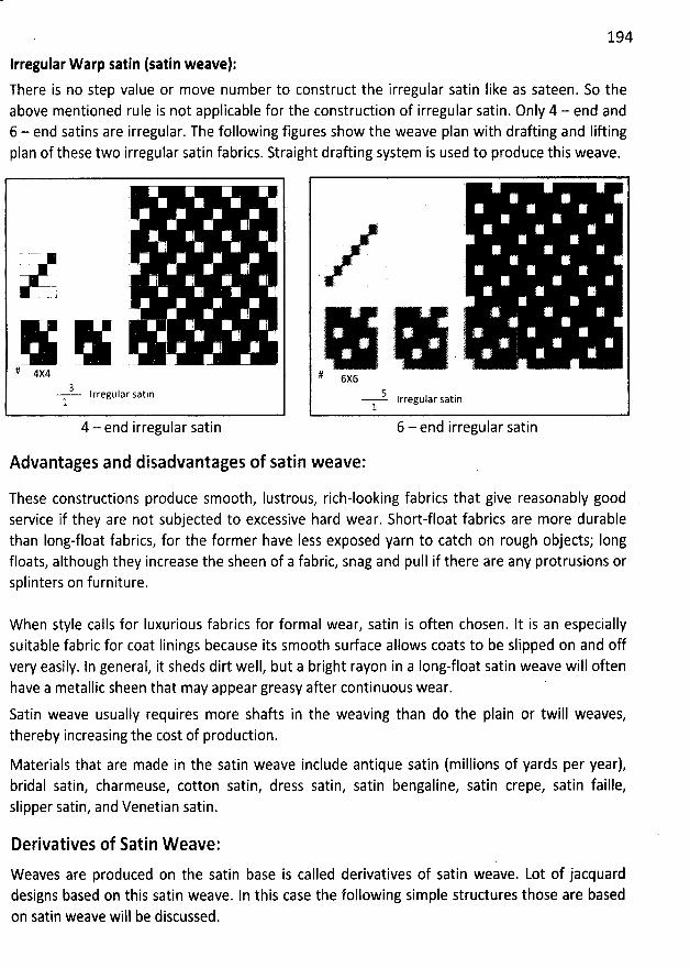
194
Irregular Warp satin (satin weave):There is no step value or move number to construct the irregular satin like as sateen. So theabove mentioned rule is not applicable for the construction of irregular satin. Only 4 - end and6 - end satins are irregular. The following figures show the weave plan with drafting and Iiftingplan of these two irregular satin fabrics. Straight drafting system is used to produce this weave.
I
! . I !. ; ;
: ' .
-- ( I
I I
# 4x4
3 Irregular satin1
4 - end irregular satin
( '(
( ;
'
'
( :(
ï ' . ' 't t :
'
. -
( è ': . !L . . . ) . . . . .l 7 .
è
'
u 2 ' .y ( . j
'
, . .. . y . . yT
'
; l# 6x6
5 lrregular satin1
6 - end irregular satin
Advantages and disadvantages of satin weave:
These constructions produce smooth, Iustrous, rich-looking fabrics that give reasonably goodservice if they are not subjected to excessive hard wear. Short-float fabrics are more durablethan Iong-float fabrics, for the former have Iess exposed yarn to catch on rough objects; Iongfloats, although they increase the sheen of a fabric, snag and pull if there are any protrusions orsplinters on furniture.
W hen style calls for Iuxurious fabrics for formal wear, satin is often chosen. It is an especiallysuitable fabric for coat Iinings because its smooth surface allows coats to be slipped on and offvery easily. In jeneral, it sheds dirt well, but a bright rayon in a Iong-float satin weave will oftenhave a metallic sheen that may appear greasy after continuous wear.
Satin weave usually requires more shafts in the weaving than do the plain or twill weaves,thereby increasing the cost of production.
Materials that are made in the satin weave include antique satin (millions of yards per year),bridal satin, charmeuse, cotton satin, dress satin, satin bengaline, satin crepe, satin faille,slipper satin, and Venetian satin.
Derivatives of Satin W eave:
Weaves are produced on the satin base is called derivatives of satin weave. Lot of jacquarddesigns based on this satin weave. In this case the following simple structures those are basedon satin weave will be discussed.
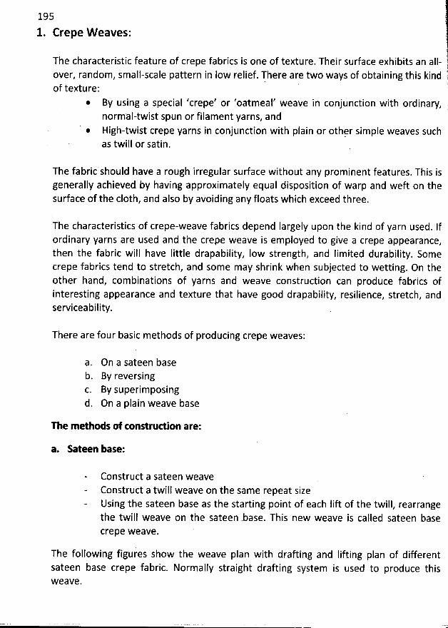
195
1. Crepe W eaves:
The characteristic feature of crepe fabrics is one of texture. Their surface exhibits an all-over, random, small-scale pattern in low relief. There are two ways of obtaining this kindof texture:
By using a special 'crepe' or 'oatmeal' weave in conjunction with ordinary,normal-twist spun or filament yarns, andHigh-twist crepe yarns in conjunction with plain or othçr simple weaves suchas twill or satin.
The fabric should have a rough irregular sudace without any prominent features. This isgenerally achieved by having approximately equal disposition of warp and weft on thesurface of the c10th, and also by avoiding any floats which exceed three.
The characteristics of crepe-weave fabrics depend Iargely upon the kind of yarn used. Ifordinary yarns are used and the crepe weave is employed to give a crepe appearance,then the fabric will have Iittle drapability, Iow strength, and Iimited durability. Somecrepe fabrics tend to stretch, and some may shrink when subjected to wetting. On theother hand, combinations of yarns and weave construction can produce fabrics ofinteresting appearance and texture that have good drapability, resilience, stretch, andserviceability.
There are four basic methods of producing crepe weaves:
a. On a sateen baseb. By reversingc. By superimposingd. On a plain weave base
The m ethods of tonstruuion are:
a. Sateen base:
Construct a sateen weaveConstruct a twill weave on the same repeat sizeUsing the sateen base as the starting point of each Iift of the twill, rearrangethe twill weave on the sateen .base. This new weave is called sateen basecrepe weave. '
The following figures show the weave plan with drafting and Iifting plan of differentsateen base crepe fabric. Normally straight drafting system is used to produce thisW eave.
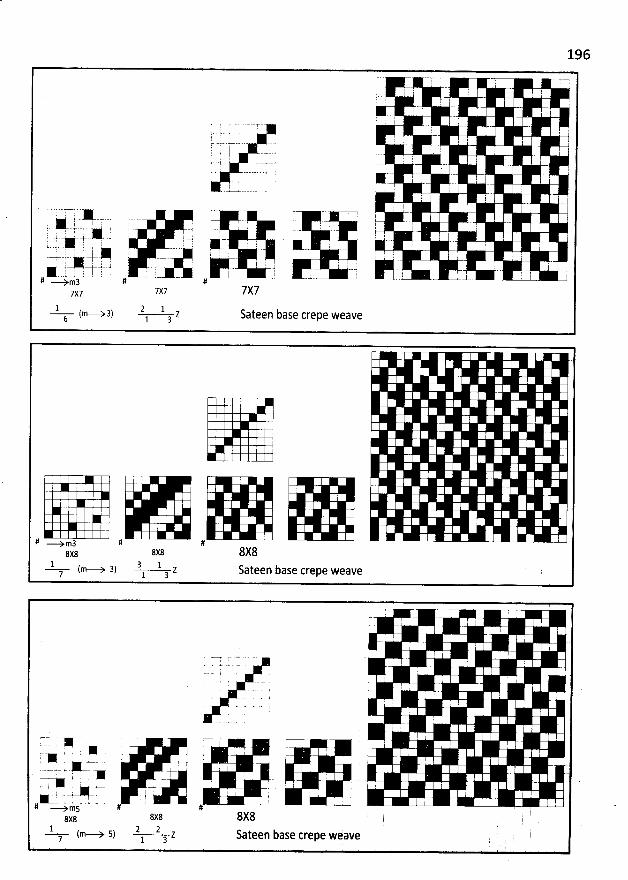
196
7 ! ; T' .1 ! . .;-
: t ..I '
I II . . ;'-7 q
: j r, .! I
r 7- I !.--=--y-- - >. . -. '. J' : ! I I
: ;' $ :-
i.q K t I2-. 1
1 EA 7 r 7 r ;..-asss)..j.. -. s..q k-.y.- I ,.- , .. - -e .t. ., ! - t ... '. ... y . , - ; - -, : . kj . j l . j '
, ,#L..k. -u....-î-.. . > , -( ..- - - -- .. j, . .* .-' -.. -E .j...' ; * $ . : I 'V
..... 4..* l -t l . i J . ' . : E . ' .'=-S..X--s. u ; . r .. I 1 : . , . t.., - ' i . , , b i3663.. ) ) -é---I-.-i ...- :-. --
# -..). .- --J .-:.-k-- ..J --. ..1 - - . -- -.# ---ymà #7x7 7X77s7
1 (.- -+3) 2 - 1 z Sateen base crepe weave6 1 3
# -->m3 # #8x8 8X88x8
1 3 1 b(m---> 3) Z Sateen aSe Crepe weave7 1 3
! rI ! ; -'
T ; 1! i .
L -. . . .. , . ' '
': . !l
. 9 I
A . - . 7 77-7'> , - 7
'.-* . z-. , .a ' '*- . +. 'L
. . - (4 r , !7* . v- - , '%jy -. ,
. .( . ,Yl . . . . . .. . ...-= .- .- ;# J-L-$ms # #
8x8 8X88x81 1 2(m- -> 5) z Sateen base crepe weave7 1 3
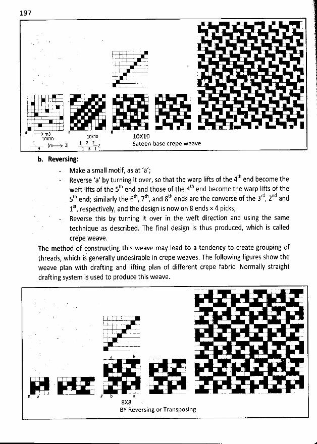
197
. ; , '-. : ' :L ' t . ' i '
U(-;- r . .-k- ' '--y-.y -.-,
' I !
' - . . q . k I :
' ' ' . . .. . . . '
'
'
'
' .
'
.
, . : '
. I r . .. I ! I !
I ' I . '
' . . , .
' Ih :
, > 4# ---> m3 # #
:0x10 10X10 10X101 (m- ..-> 3) 1 2 l z Sateen base crepe weave9 1 3 1
b. Reveuing:Make a small motif, as at 'a?;
' ' b turning it over, so that the warp Iif'ts of the 4th end become theReverse a yth thweft Iifts of the 5 end and those of the 4 end become the warp lifts of the
th tb th th rd nd5 end; similarly the 6 , 7 , and 8 ends are the converse of the 3 , 2 and
St I d the design is now on 8 ends x 4 picks;1 , respective y, anReverse this by turning it over in the weft direction and using the sametechnique as described. The final design is thus produced, which is called
crepe weave.The method of constructing this weave may Iead to a tendency to create grouping ofthreads, which is generally undesirable in crepe weaves. The following figures show theweave plan with drafting and Iifting plan of different crepe fabric. Normally straight
drafting system is used to produce this weave.
i .I
i . I
s=== .. . .% .-7 :
! - -
: u. . :. l .
a b ' : . :
I I ; ' '*. r
! . I .
. ' '
'
!
# a # a8X8 ,BY Reversing or Transposing
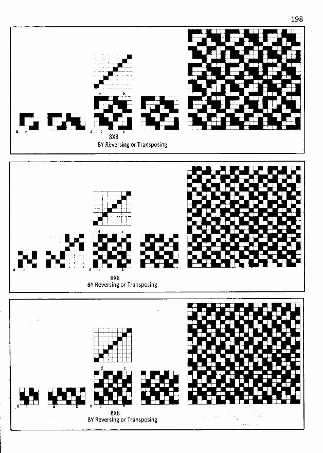
198
; .
I y
'
: ;
'
.
.: i 'a b --- !
r -T ; .
. ; r- ' 11 I-- . -A = ---x x-- -# a # Q c
8X8BY Rèversing or Transposing
' j .LQ - i. -V . .
- . -$- .1y- t t- ()y .j. # ..t .., -I .1= -
(2 . - ' E
. j '
. . . . r ...- - .-j . :( 1 1
.. t . u - .l , . a 2 . -. ... . . . . - 5
8X8BY Reversing or Transposing
d c
# a a # a8X8 '
BY Reversing or Transposing '
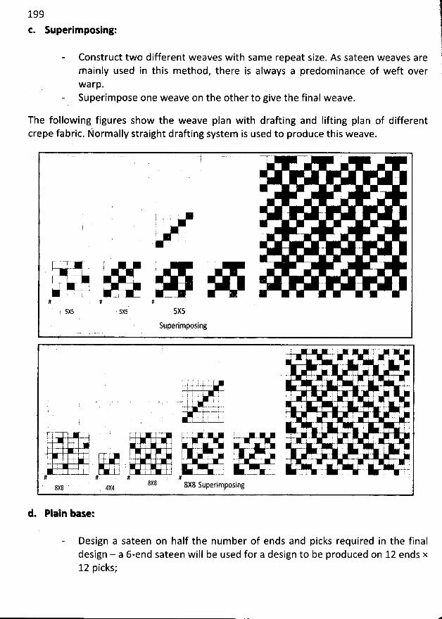
199
t. Superlm posing:
Construct two different weaves with same repeat size. As sateen weaves arem ainly used in this method, there is always a predominance of weft overwarp.Superim pose one weave on the other to give the final weave.
)èi!r
f
The following figures show the weave plan with drafting and lifting plan of differentcrepe fabric. Normally straight drafting system is used to produce this weave.
L. ' -.. . .
t !r- .L - -. -- - . . . . .. .. -- .-.. . . --j- . .- - ---- . . .. ..
+ . A. ---L-- -1 -. - -- ..
# # #5x5 sxs' 5X5
Superimposing
', .. ...-..'2''* . .. ,.' .. >. . . ''''r''''''3'*. .1' .. - . .. . ' E
. ! I .:
'
.: . . '
! . # -:2. . I .! ; : I I .: .y : I : . . : . . : 'k-..y-oc . .
Vk VX V 1. ! ; ' . I I I : . . g
'
I .r .44 - . .I ' ' : ' '' t ' .c ' ' -- t- . .. j .#-w-k->.a k '. , .E. .-r--u----j--, . . , , , : , -t--,
-t.2-...--G .. . .k2 u. I t ) i. . : ': : ' . j ' '''''.. I: y; ' C= ..W I : j '
k - .- - - -- . - -. ' - ' .. ' -4 - ' - : ' C'
, '; j
' p .- y .- , #: j
'' '.. .#: :.'.: ' : ....: : ' , .#
! . ' . : I , u' - --. .-.. -- . -.w .1..1 . . . ... ..1. . .
#' # . # #8X8 8X8 Superimposing8X8 ' 4X4
d. Plaln base:
Design a sateen on half the num ber of ends and picks required in the finaldesign - a 6-end sateen will be used for a design to be produced on 12 ends x12 picks;
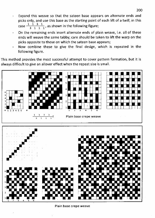
200
Expand this weave so that the sateen base appears on alternate ends andpicks only, and use this base as the starting point of each Iift of a twill, in this
1 1 3 1case , as shown in the following figure;3 1 1 1
On the rem aining ends insert alternate ends of plain weave, i.e. aII of theseends will weave the same tabby; care should be taken to Iift the warp on thepicks opposite to those on which the sateen base appears;Now combine these to give the final design, which is repeated in thefollowing figure.
This method provides the most successful attempt to cover pattern formation, but it isalways difficult to give an allover effect when the repeat size is small.
6
5
46s ' 343 2 '2l 1# 1 2 3 4 5 6 # l 2 3 4 5 6
l 1 3 1z Plain base crepe weave
3 1 1 1
1 I :
' : :r '
. -
j
1 '
. I
6 I .
5 ' 'I . (
4 ' 1 ' '
3 , . i.- p- >
2 i '
l : . u ..2 3 4 5 6
Plain base crepe weave
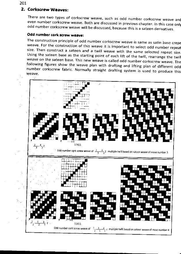
201
2. Corksceew W eaves:
There are two types of corkscrew w eave, such as odd number corkscrew weave and
even num ber corkscrew weave. 80th are discussed in previous chapter. ln this case onlj
odd num ber corkscrew weave will be discussed, because this is a sateen derivatives.
0dd number tork Rrew weavelThe construction principle of odd num ber corkscrew weave i
s sam e as satin base crepeweave. For the construction of this weave it is im portant to select odd n
um ber repeatsize. Then construct a sateen and a twill weave with the same selected repeat size
.Using the sateen base as the starting point of each lift of the twill, rearrange the twillweave on the sateen base. This new weave is called odd num ber corkscrew weave
. Thefollow ing figures show the w eave plan w ith drafting and lifting plan of different oddnum ber corkscrew fabric. Norm ally straight drafting system is used to produce thisFeave.
,. '. . . . .U I? , ! '
I , ' .. ! i ; i ' . tp.
, ' .
. ..j , -
O7- . -T-N' I'
.
' . I l '. ' .
!. 'J ! I '
I . j
'
E . ' l . '
I ' i ( ' ' ., !
4% I . y ! , : :.# # - -+!
11X112 4 z3 2
. Odd number ctyk sc.rew weave of 2 4 z multiple twill based on sateen weave of move number 3' . 3 2
. . ';. l !
- l . .- '- .J . : . . - ... . .. ...
* ' . y l
.1, 1 ' . I
' . -. ' . . . . . . - . . . . '. ' .
yt E :
! 2 : , (. . : . '
. . ..y, ' .:
'
, . . , : : ,I'.
; ; I$ . . ' ' . . '
. L
'
. ': . ' ' ;
. 1 ' ;
' ! :
# >2 1 3 z
ltxll2 2 1odd number cork screw weave of 2 1 3 7 multiple twils based on sateen weave of move number 42 2 1
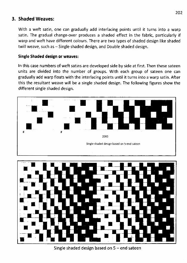
202
3. Shaded W eaves:
W ith a weft satin, one can gradually add interlacing points until it turns into a warpsatin. The gradual change-over produces a shaded effect in the fabric, particularly ifwarp and weft have different colours. There are two types of shaded design like shadedtwill weave, such as - Single shaded design, and Double shaded design.
Single Shaded design of weaves:
In this case numbers of weft satins are developed side by side at first. Then these sateenunits are divided into the number of groups. W ith each group of sateen one cangradually add warp floats with the interlacing points until it turns into a warp satin. Afterthis the resultant weave will be a single shaded design. The following figures show thedifferent single shaded design.
' K K
( -'--# #
Single shaded design based on 5-end sateen
K j + ;# , j ; ' k #' j j
.- - -. .. --
.jjjjjjjy; - --. ( , . j j j ( j y j y g- i-- -.-
j j j*- - j k , q r , ;* ;' +
i j ! ! 1 j g-
t y r j j -..t . . - , --- :.-- . , . . . . .. g--- , ! , '
j' -4 : ' - i - '
! . ' 7 i .. ..
. I I : ' - . :
.. ..
! . j j j I - j j ! :t j : j j g j* y ,'
, - j I k ''''''' ; 1 '''' '. ,#u = Js j
*M y ! ?K
L-j-i k
Single shaded design basedon 5 - end sateen
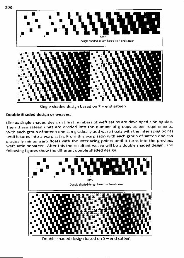
203
x ZZ X- x - xX ZXx s
# # 4gy7
Single shaded design based on 7-end sateen
* : . * . A : ** . : # . x j# . . . . . *.. - . - .. . . y c-
' '. W .' 8:. '. . ' -
. .
.
- -. A. -.-. . -. ' ' - . . ' ' -. '
x? . . . . . - . -- sx . - . . . - . ;% . . . . -. 7 . . .#
. . . - .) W . - . ., x ;...x . , ; .. . s. . , , y. u. , , . . 4 .. w . # . .-- .. œ ; . . .. . . . R . . . . - .K . . .. . r - ' . . . . . . .* ' . A .# . * . .' '
,* '. . . ' . - -.. . *. . . x . M . . r . . ' . .. x . # . . , x . . < . . .* . . ' ' . '. . , . ' M : . ' , .1
. . . . . # . . . . .K ,' . . . - . A . j .- * , , . K . . . . ., . . x .
' ' ; w -. 5 '. . * % R ' .. . .$
Single shaded design based on 7 - end sateen
Double Shaded design or w eaves:
Like as single shaded design at first num bers of w eft satins are developed side by side.Then these sateen units are divided into the num ber of groups as per requirem ents.W ith eacb group of sateen one can gradually add warp floats w ith the interlacing pointsuntil it turns into a w arp satin. From this warp satin w ith each group of sateen one cangradually m inus w arp floats w ith the interlacing points until it turns into the previousw eft satin or sateen. After this the resultant w eave w ill be a double shaded design. Thefollow ing figures show the different double shaded design.
y e x
# #30X5
Double shaded design based on s-end sateen
u < g . # : % ( é ; * q 4. , 4 h- u . -.# : yf x y) x j. ) :: : .k - . C . : x : . . x- xx : , x 4 è
r i -. g ..# e .. , w .
, k . x ., x 1. 'N : .'z I * k .* 1- wj
- ; ljk .; -: : , ,k 4.
y
k. - : ) g k k, .: j : j ,jxk - 4
.
' u : .: 1y A y x j u y y y y j.N .
.k l . .
*
Double shaded design based on 5 - end sateen
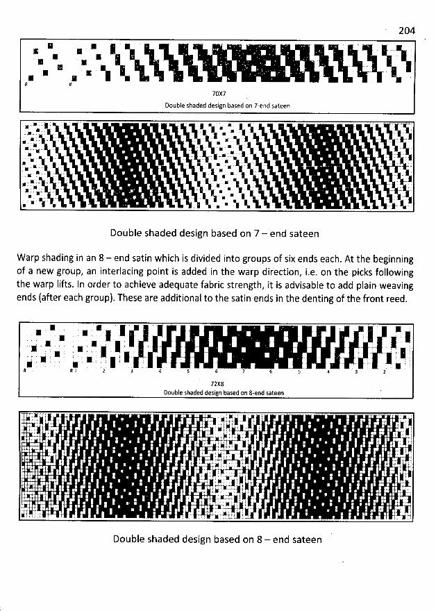
204
M * jK M .% * .
K . N
# #
70X7Double shaded design based on 7-end sateen
x * x ( ( ï . < # j x x ; g j . y X y.f %
.r .w- .k ; . : y . : r . - . . .
. - -I- a .$. . , . . . . w
x ..: . . . - . . - - . - - -s. x: .:Jex ; .
- k - ' . . .
. è ; ' .
'
- .
.a ' -. N- ' . $ -L . , -. . -. ' 'N . $. ) . r : . . . ' -- - : -%r -'
.
hak. ' . .
.
:.
y
'
: y
. -
. .
. . .
y : .
. - %'j. ' '.
'
. *, ..Q. *j -:' S'j ' '
.
' '
. .
'
.
- '
y , ( - .j. ' : , ( :2. -.% x ( . j . ) 1 - . y a j x .g gk ( . - g . . . .
- ( j . -. . . y .g . * a - - .
. - . ) .j#- ' . *( x ' :
.
C . ' :
. .
'
.
' - ' .
. 5.. ' E k ' *. x ' 1 j L r . ' - . . : $.. . : . ': x' '.
. ï. .
' '
. . '
.
''%' *. x . $ : . . ' ' . .
.
R y : 'w N * . *j :. N . C ti ':# * -
Double shaded design based on 7 - end sateen
W arp shading in an 8 - end satin which is divided into groups of six ends each. At the beginningof a new group, an interlacing point is added in the warp direction, i.e. on the picks followingthe warp Iifts. In order to achieve adequate fabric strength, it is advisable to add plain weavingends (after each group). These are additional to the satin ends in the denting of the front reed.
: # j , >* x * j x j).' '
,' 11 ' . . ', ' '. 11 '. . jjj '. # . . - .g- , '': ' ., # - : , .7 ' > . , : , . . ; - w y :> ' 7 : ', 7 , ' ' ) K '. 7 j ! ' z ' ' ) i, 4 t 7 '* r * - : - .j . ,ai *# #1 2 3 4 5 6 7 6 5 4
72X8Double shaded design based on 8-end sateen
OTW- ..:..:.1 r 7 T . r 7 < l . r ' . g ' i .#! M 4 , . j .Y, - , '$ . , . t-j ; - ; . . j j . u+ ) j71-81 . i ' l ' 1 Y r *-. / ) .# y . . ' . : 'r , k , y j . y y ) , mL> t e z
'f- # ' . - # j ;. t ..':' 6 ' ' ' . t' ,1# . j # ) t.4-rae ' I ,
' , i j' : !- . . . ' k j. jyw f. 1. . . # ' ' : I .M -t .k i 1 . 4. ' . . .j..t..jt
. , , ! ,: . ) y . $ , .. y. yi . . p( ji 4. ' . . ç:. , -j t ,
' j t c w .,. : j . x f *. ' Ij t j . 1. . . . ..l ! : 4 e. . ' . . . . '-y :. ' ' y.i . 4. 1 ' ' y' ; . . j I j. . . 4. .i w. o . . -j ; . . . . . 4.# .' -1..- ! i l ) ' 4. ' . . . . . . $. . . . ; y . , . . . , y. y . # j y y . j j j y. ; C t .. . . t d . . . ., j : i k' t , . .j wF . . j. p. ,. .k l . . . 1 ''
. ' , .'. .!. -
. lr. - ' .
'
.
'
. .:.' '
c.i .t. . - : .1,11r..-., . ' ri11k- ' .-'. ti.1L.- .. -'- -.. !)' (1111.' ''''.. 't . ... :'. ' '
- ' ' '
. . .
. . I . ,. tj1I:..t -.- .''-.
' . .
Double shaded design based on 8 - end sateen
205FANCY DESIGN OR STRUW URE OF FABRICS
The interlacing of the threads in a form which varies from that of the basic weaves alreadydescribed, is accomplished with a view to producing a fabric which is decorative in appearanceand may also utilize the characteristic features of the weave for some useful purpose. Theimportant features and construction principle of some decorative fabrics will be discussed in
this chapter.
Huckaback W eaves:
Main featutes:
These weaves are generally applied in the manufacture of non-pile towels. The main features of
this weave are as follows:
This weave is characterized by a rough surface, which is produced by floating
threads in groups arranged on a plain weave basis.A more balanced huckaback is produced if the weave-repeat size is twice an odd
number (i.e. 2 x 5 = 10; repeat size = 10 ends x 10 picks), but it is by no meansimpossible to produce the weave on a repeat which is complete on twice an even
number of threads.
*
* With these constructionsfabrics are produced.
hardwearing and extremely thick, moisture absorbing
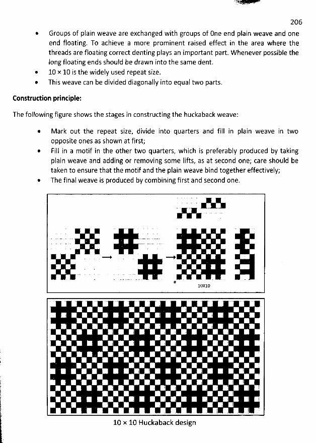
206
* Groups of plain weave are exchanged with groups of 0ne end plain weave and oneend floating. To achieve a more prominent raised effect in the area where thethreads are floating correct denting plays an important part. W henever possible thelong floating ends should be drawn into the same dent.
* 10 x 10 is the widely used repeat size.* This weave can be divided diagonally into equal two parts.
Construction principle:
The following figure shows the stages in constructing the huckaback weave:
Mark out the repeat size, divide into quarters and fill in plain weave in twoopposite ones as shown at first;Fill in a motif in the other two quarters, which is preferably produced by takingplain weave and adding or removing some lifts, as at second one; care should betaken to ensure that the motif and the plain weave bind together effectively;The final weave is produced by combining first and second one.
MM
#10Xl0
10 x 10 Huckaback design
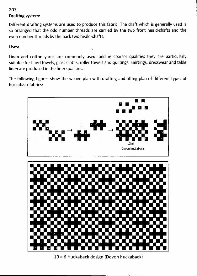
207Drafting system :
Different draûing systems are used to produce this fabric. The draft which is generally used isso arranged that the odd number threads are carried by the two front heald-shafts and theeven number threads by the back two heald-shafts.
Uses:
Linen and cotton yarns are commonly used, and in coarser qualities they are particularlysuitable for hand towels, glass cloths, roller towels and quiltings. Shirtings, dresswear and tableIinen are produced in the finer qualities.
The following figures show the weave plan with drafting and Iifting plan of diferent types ofhuckaback fabrics:
K K
10X6Devon huckaback
10 x 6 Huckaback design(Devon huckaback)
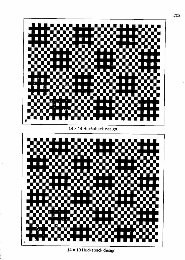
208
K K K.- * - -* *
#
14 x 14 Huckaback design
14 x 10 Huckaback design
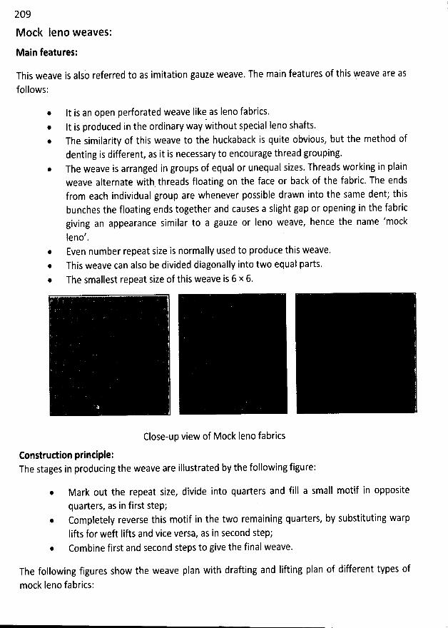
209
M ock Ieno weaves:
Main features;
This weave is also referred to as imitation gauze weave. The main features of this weave are as
follows:
It is an open perforated weave Iike as Ieno fabrics.@ It is produced in the ordinary way without special Ieno shafts.
The similarity of this weave to the huckaback is quite obvious, but the method ofdenting is different, as it is necessary to encourage thread grouping.The weave is arranged in groups of equal or unequal sizes. Threads working in plainweave alternate with threads floating on the face or back of the fabric. The endsfrom each individual group are whenever possible drawn into the same dent; thisbunches the floating ends together and causes a slight gap or opening in the fabricgiving an appearance similar to a gauze or leno weave, hence the name 'mock
Ieno'Even number repeat size is normally used to produce this weave,This weave can also be divided diagonally into two equal parts.
@ The smallest repeat size of this weave is 6 x 6.
Close-up view of Mock Ieno fabrics
Eonstruction printlple:The stages in producing the weave are illustrated by the following figure:
@ Mark out the repeat size, divide into quarters and fill a small motif in oppositequarters, as in first step;
@ Completely reverse this motif in the two remaining quarters, by substituting warpIifts for weft Iifts and vice versa, as in second step;
@ Combine first and second steps to give the final weave.
The following figures show 'the weave plan with drafting and lifting plan of different types of
mock Ieno fabrics:
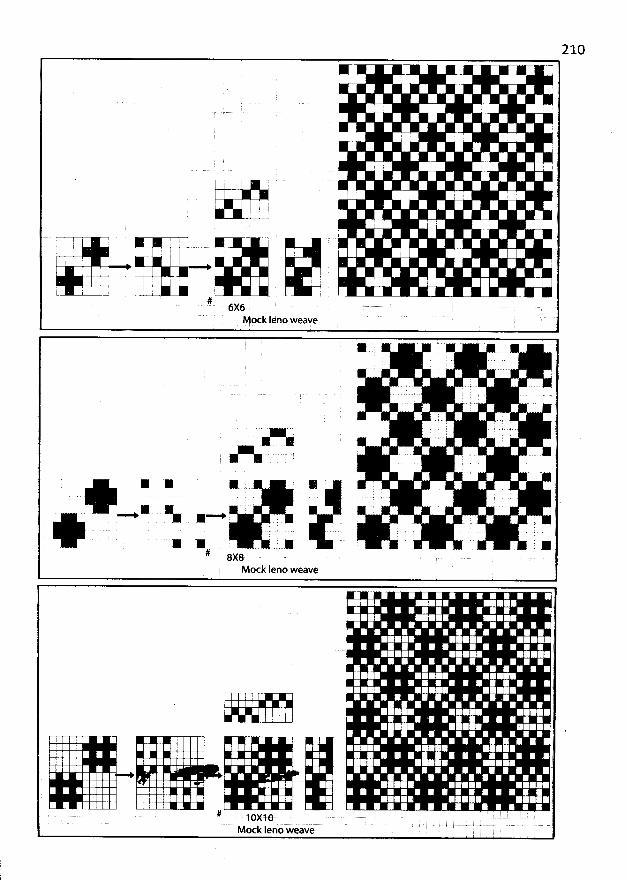
210
::
L
. j , '
! . I 1 ' Ij --
r -q (
I I j!
. ! I : '
k
'
I ! i .! ii 'i ! !
t.--x. i l i I- - J .
#. 6X6Mock Iéno weave
*
. .. ...).. .;-r )' ''
.' . ) . . -. ; .
. . ) . tm ''
' . ... . .. .
' '
(
w EE - % .- #'qg x xX X
# gx8Mock Ieno weave
# jcxjcMock leno weave
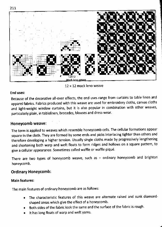
211
T '
' - - j; I I ;
'
.. - .
. ! j. 1
: . . , .
, j. . j
T 1. . j ' jI . -7 .I . j
. - - tl ' ! jl. .
' . jI I !
'
.. -j- ' )
. F-I s . . r . l j' n
. . -r k. I y . j
. ..o .+. jI . ' . . I I i
. . I .t
' . . t
12X12
12 x 12 mock Ieno weave
End uses:Because of the decorative all-over effects, the end uses range from curtains to table Iinen andapparel fabrics. Fabrics produced with this weave are used for embroidew cloths, canvas clothsand Iight-weight window curtains, but it is also popular in combination with other weaves,particularly plain, in tablelinen, brocades, blouses and dress-wear.
HoneyEomb weave:
The term is applied to weaves which resemble honeycomb cells. The cellular formations appearsquare in the c10th. They are formed by some ends and picks interlacing tighter than others andtherefore developing a higher tension. Usually single cloths made by progressively Iengtheningand shortening both warp and weft floats to form ridges and hollows on a square pattern, togive a cellular appearance. Sometimes called waffle or waffle piqué.
There are two types of honeycomb weave, such as - ordinary honeycomb and brighton
honeycomb.
Ordinary Honeycomb:
Main features:
The main features of ordinary honeycomb are as follows:
* The characteristic features of this weave are alternate raised and sunk diamond-shaped areas which giye the effect of a honeycomb.
* 80th sides of the fabric Iook the same and the surface of the fabric is rough.
* It has Iong floats of warp and weft yarns.
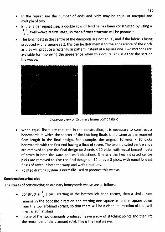
212In the repeat size the number of ends and picks may be equal or unequal andmultiple of two.In the Iarger repeat size, a double row of binding has been constructed by using a1 1
twill weave at first stage, so that a firmer structure will be produced.1 %
* The Iong floats in the centre of the diamonds are not equal, and if the fabric is beingproduced with a square sett, this can be detrimental to the appearance of the c10thas they will produce a rectangular pattern instead of a square one. Two methods areavailable for improving the appearance when this occurs: adjust either the sett orthe weave.
Close-up view of Ordinary honeycomb fabric
* W hen equal floats are required in the construction, it is necessary to construct ahoneycomb in which the shorter of the two Iong floats is the same as the requiredfloat length in the final design. For example, the original 10 ends x 10 pickshoneycomb with the first end having a float of seven. The two indicated centre endsare removed to give the final design on 8 ends x 10 picks, with equal Iongest floatsof seven in both the warp and weft directions. Similarly the two indicated centrepicks are removed to give the final design on 10 ends x 8 picks, with equal Iongestfloats of seven in both the warp and weft directions.
* Pointed drafting system is normally used to produce this weave.
ea- , -. ao' . x' ' y w :The stages of constructing an ordinary honeycomb weave are as follows:
1* Construct a - Z twill starting in the bottom leû-hand corner, then a similar one
J.
running in the opposite direction and starting one square in or one square downfrom the top Ieft-hand corner, so that there will be a clean intersection of the twillIines, as at first stage;
* ln one of the two diamonds produced, Ieave a row of stitching points and then Iift ' the remainder of the diamond solid. This is the final weave.r.
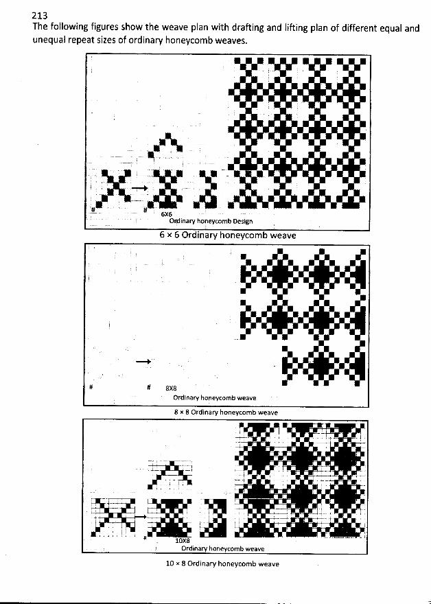
213The following figures show the weave plan with drafting and lifting pdan of different equal andunequal repeat sizes of ordinary honeycomb weaves.
*
*
. . . . .). . .. l G
y y y g# # '. 6x6
6 x 6 Ordinary honeycomb weave
K
y .# # 8x8Ordinary honeycomb weave
8 x 8 Ordinaw honeycomb weave
y . --a z- .- . + y. $, 7 . . . '
-r . -7 . I
; . .
. -4= r ;k J. k ' . .
.-.. . . ..y .. i . w--ys.-v = .,-, ! ! -r' -- . - -4 . --s . w- . + .;- '' I I . . . . ' '
: . . r . ' . I+.. . . .'i . I, , . : , IL -.?- .-1 --. . ' ' .-1 --1. . .t x . ' J% I : i ' .w-# :
-. cy @ . q#-t ' ; - '
I !# .10X8Ordinary honeycomb weave
10 x 8 Ordinary honeycomb weave
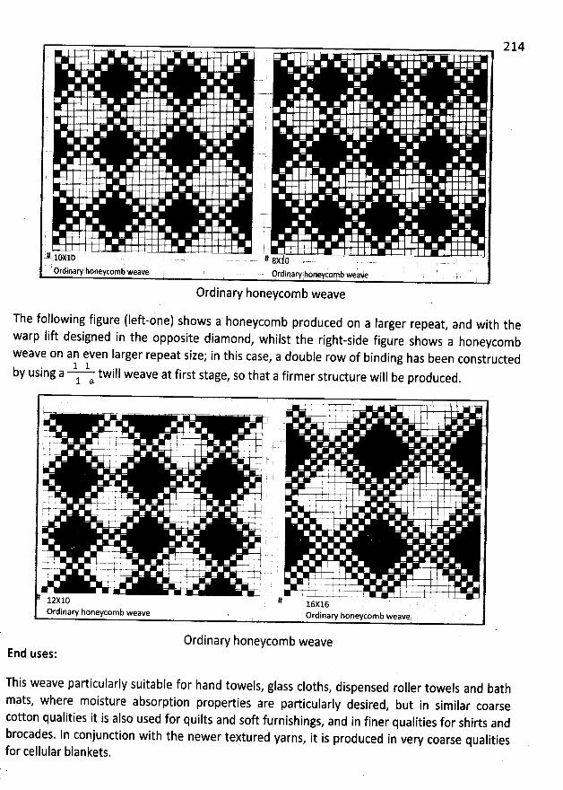
# lnxlt) # gxlo
' '; g.. rdinal.honeycomb weave . Ordinary:honeycomb weae
Ordinary honeycomb weave
214
The following figure (Ieft-one) shows a honeycomb produced on a Iarger repeat, and with the
warp Iift designed in the opposite diamond, whilst the right-side figure shows a honeycomb
weave on an even Iarger repeat size; in this case, a double row of binding has been constructed1 1by using a twill weave at first stage, so that a firmer structure will be produced
.1 a.
.... .. . .y.. ' ... .... I 7 ' I-7= V >- :+-Vv '
r , - ' -.- j--j - ' ' V-X#' é- #-
. . . 'â .f. .
A ..4-. , . , .0-V'. ' 1. I I p . I ! .
-. . g- - . . .u.uyv .- , .
- = w- ..=u- .N r ! I . I :; ; ., ...+ ..u., , ,'
s .12X10 'T. 16X16
Ordinary honeycomb weave Ordinary boneycomb weave
Ordinary honeycomb weaveEnd uses:
This weave particularly suitable for hand towels, glass cloths, dispensed roller towels and bath
mats, where moisture absorption properties are particularly desired, but in similar coarse
cotton qualities it is also used for quilts and soft furnishings, and in finer qualities for shirts and
brocades. In conjunction with the newer textured yarns, it is produced in very coarse qualities
for cellular blankets,
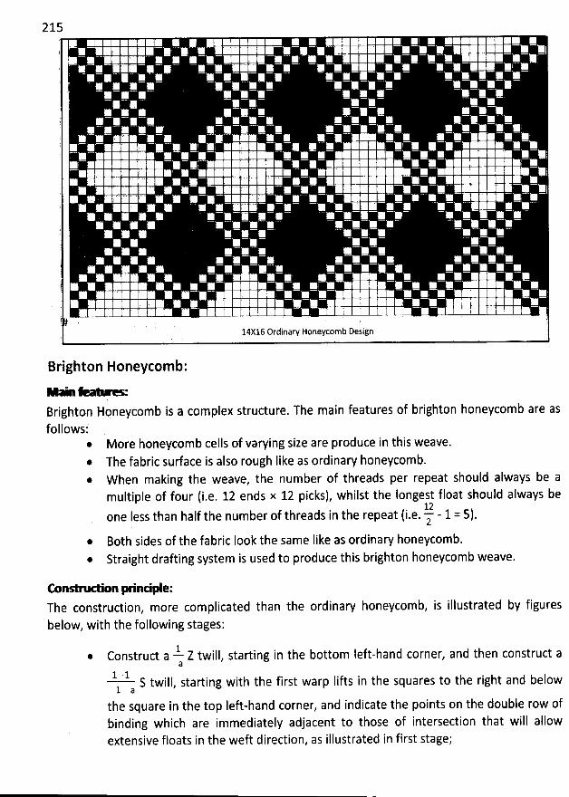
215
(
'
' )
'
i
. ' ' k
'
;
'
!
'
( 'J
) ' ' ' ''
! ,
l ';1 l4xl6'ordinary Honeycomb Design .. . )
'
Brighton Honeycomb:- - . e . e .- . --.- -
Brighton Honeycomb is a complex structure. The main features of brighton honeycomb are asfollows:
* More honeycomb cells of varying size are produce in this weave.* The fabric surface is also rough like as ordinary honeycomb.* W hen making the weave, the number of threads per repeat should always be amultiple of four (i.e. 12 ends x 12 picks), whilst the Iongest float should always be
!.!. - 1 . s) .one Iess than half the number of threads in the repeat (i.e.2
Both sides of the fabric Iook the same Iike as ordinary honeycomb.Straight draûing system is used to produce this brighton honeycomb weave.
rnnen- ' n Y nn'ple:The construction, more complicated than the ordinary honeycomb, is illustrated by figures
below, with the following stages:
Z Z twill, starting in the bottom Ieft-hand corner, and then construct aConstruct a
a
1 1 'S twill, starting with the first warp Iifts in the squares to the right and below1 a
the square in the top Ieft-hand corner, and indicate the points on the double row ofbinding which are immediately adjacent to those of intersection that will allowextensive floats in the weft direction, as illustrated in first stage;
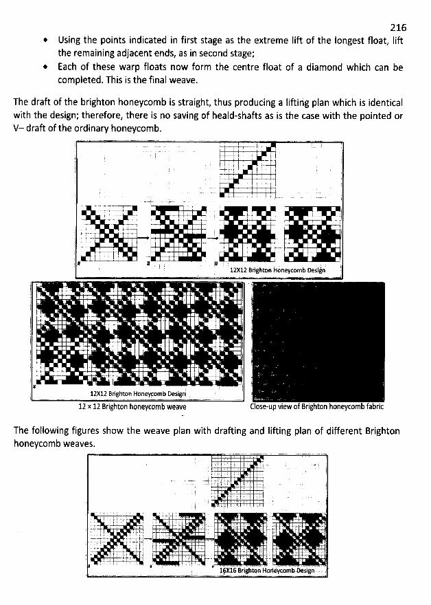
216@ Using the points indicated in first stage as the extreme Iift of the Iongest float, liftthe remaining adjacent ends, as in second stage;
* Each of these warp floats now form the centre float of a diamond which can becompleted. This is the final weave.
The draft of the brighton honeycomb is straight, thus producing a Iifting plan which is identicalwith the design; therefore, there is no saving of heald-shafts as is the case with the pointed orV- draft of the ordinary honeycomb.
) . . . ' ' -4. â-. ' l I I (j ' '
j ' . .j ' . . Ii k
'
' ; I J; .
. .. . . . .. @
. . - --.=--r-- : - r. !-7-. .. .!- . ' 4- ,t
.- ' . . -i ; ' ' . ( '$
. .- . -t--4.-a , : . , . t-.4. m- , . m#. C y . j. L t- 1. . . --- --- p..-.--).- ; - , , j.. ..
, , j. . . 1 l. I . p
'
' jj l ' ' ' jp # # . j , # . . jT 12:12 Brigkon koneycomb Desijnè @
pj
d
.
'
lj j;.'
'
l ' . 1 'l )l
. )'! r #
i'è14 -;- ! i; . .- j' j# ;-. . #
'
. j )- . , j. -r- .- #. ,- l .L' i
# 1 j2X12 Brighton Honeycemb Design l )1
12 x 12 zrighton honeycomb weave Close-up view of Brighton honeycomb fabric
The following figures show the weave plan with drafting and Iifting plan of different Brightonhoneycomb weaves.
. .. )
, .. . . . j
'
. . . . j.. 4 e- (
, I.. . . ). . iT 1 î . . . '.-.= =- = * .. :. ) .. ..r . . . . . - . . ... . . . . .- ..- .i. 1. . .
k ' j z rj' . ' . ' , r . ' . . ' '. . . ' . r . . ' +. . .. i .1 ' ' ' '...sj. . .--= -;J. . . . ==+ . . ... . . .- w *-4- *- ... .. x- - ;.q- = .y.; k . -. . . . . . . .. . . . j. .. . . . (-.. ..-..-.-. 4..4
. V-4-. . j . . . . . . . .. . . . .. .î j . . . - .1 L ' ' ' ' '
. # > '' '' '16X16 Br' ighlon Honeycormb Design . (' '
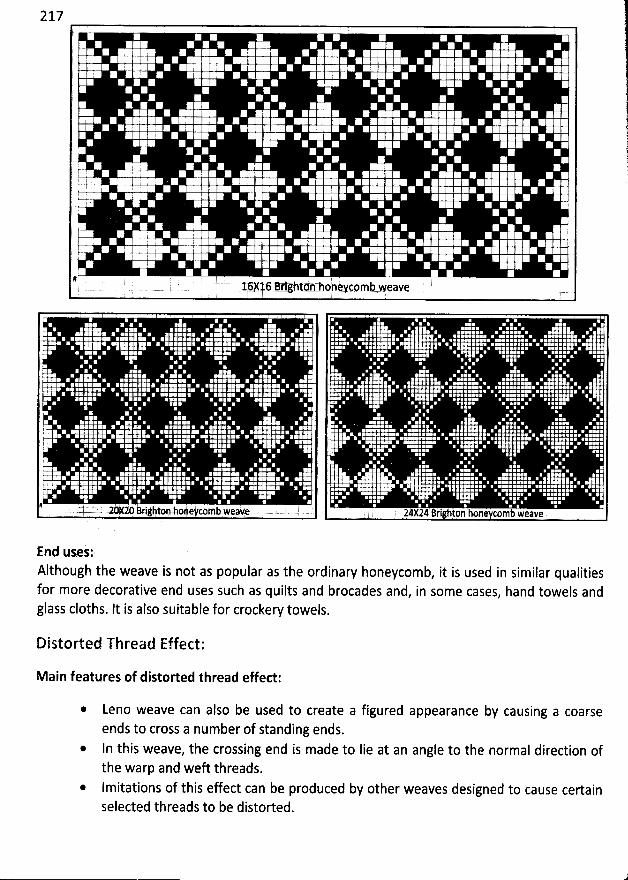
217
4 j ' '. . I p 4 . .I .. ( .
.. ' 5 ) ' . .
k
'
! ) i ) ( (' '( .
I ' . ' y
'
, ii :I : . ' 1 ! ' i . :
; . ( : ! y .
' y' I ; ! ' ' ' .
I . I I : ' j ( r E!. . : ! ) (
'
- . g (1 ' ' i
. )# # .
' ( )
. . . . 1.6/16 Bri#a t:n hpheyc4mb weave .
. !, y r
'
I r
'
, 2 . y
'
.' (, g E. E. E . ; j
'
' ' 'l E , . .:. E. !. ' (
'
.
' ' (
'
' )' : ' (
'
è
'
)
'
. ) ! : .l ; l r. ; i: y
'
y
'
, .?
'
)
'
l . )
'
. E. .
i' ,
'
. EI ) ' ' ' 'm j ( ) 7 j ( . 2 , 2 . , r. j ! . k
'
! . ! i . ' !
! ( ; ' ':. . . 7 ) E .Ll r . I . à . . . . ;
7 . :
'
. l y
'
.
, : t' ( ' # .' 20k20 Kjjlkton:oltycotnb wea#e , . .
' . 1 E ,
E' . ! l (
'
E' .E ; ' l E
'
l '. ' ' r ) ' 'E
'
: r .
. (
24X24 Bri hton hone comb weave
End uses:Although the weave is not as popular as the ordinary honeycomb, it is used in similar qualitiesfor more decorative end uses such as quilts and brocades and, in some cases, hand towels andglass cloths. It is also suitable for crockery towels.
Distorted Thread Effect:
Main features of distorted thread effed:
Leno weave can also be used to create a figured appearance by causing a coarseends to cross a number of standing ends.In this weave, the crossing end is made to Iie at an angle to the normal direction ofthe warp and weft threads.Imitations of this effect can be produced by other weaves designed to cause certainselected threads to be distorted.
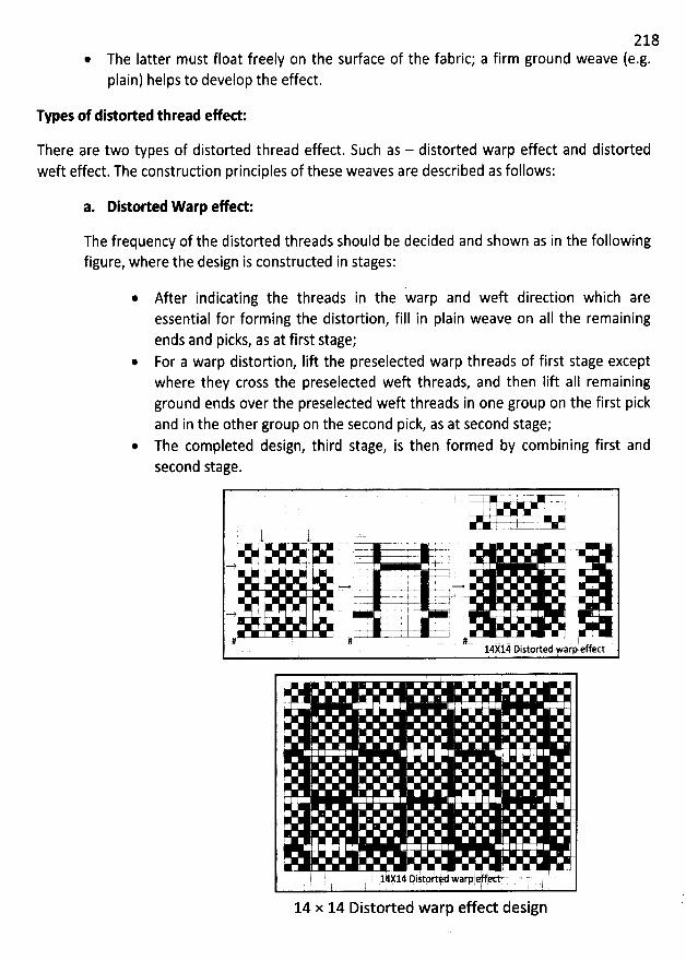
218@ The Iatter must float freely on the surface of the fabric; a firm ground weave (e.g.plain) helps to develop the effect.
Types of dikorted thread efed:
There are two types of distorted thread effect. Such as - distorted warp effect and distortedweft effect. The construction principles of these weaves are described as follows:
a. Distorted W arp efed:
The frequency of the distorted threads should be decided and shown as in the followingfigure, where the design is constructed in stages:
After indicating the threads in the warp and weft direction which areessential for forming the distortion, fill in plain weave on aIl the remainingends and picks, as at first stage;
@ For a warp distortion, Iift the preselected warp threads of first stage exceptwhere they cross the preselected weft threads, and then Iift aII remainingground ends over the preselected weft threads in one group on the first pickand in the other group on the second pick, as at second stage;
@ The completed design, third stage, is then formed by combining first andsecond stage.
5 -T-
- 1 ) -----=-t tT : -7- .
.--j--+ , -.4-..&. -j- . .-+. 5 ' .j- i . k . .
I . I . ' 2 I. f''e - . - s 4- *. . .#
' ' --. --r--.-- - - -.-
'--1t-' . ' '.- y ! . .
. ' . .. . . . -t .= ''* ' '+-' - j
# # ' - #. 14X14' ûistorted warp effect
:
' ,
' 14414 Dim ttv, d warpavu, rtt. ' '
14 x 14 Distorted warp effect design
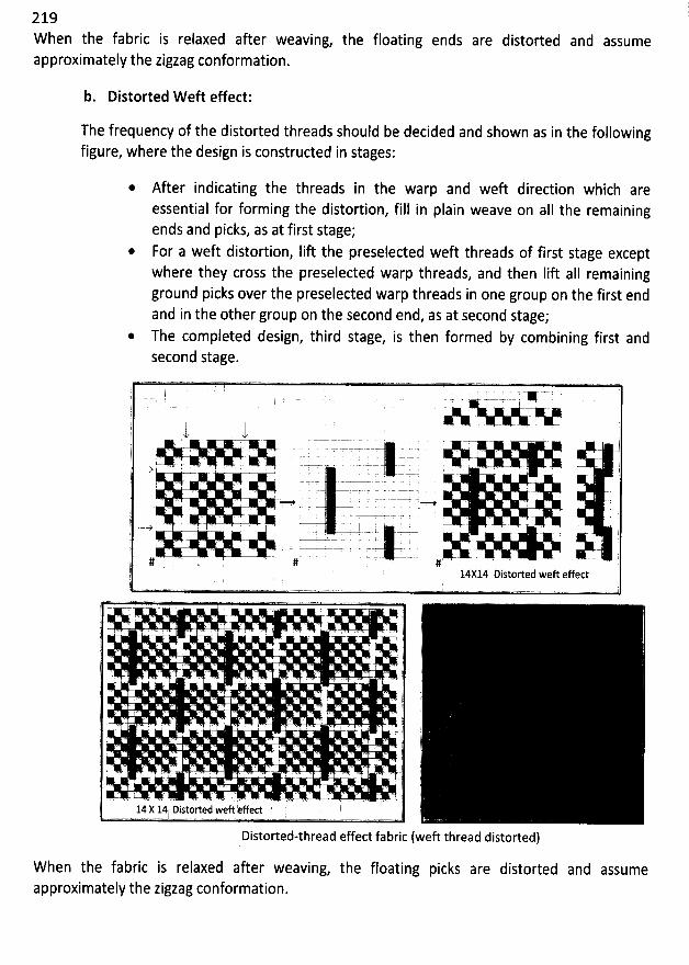
2 19W hen the fabric is relaxed after weaving, the floating ends are distorted and assumeapproximately the zigzag conformation.
b. Distorted W eft effect:
The frequency of the distorted threads should be decided and shown as in the followingfigure, where the design is constructed in stages:
* After indicating the threads in the warp and weft diredion which areessential for forming the distortion, fill in plain weave on a11 the remainingends and picks, as at first stage;
* For a weft distortion, lift the preselected weft threads of first stage exceptwhere they cross the preselected warp threads, and then Iift aIl remainingground picks over the preselected warp threads in one group on the first endand in the other group on the second end, as at second stage;
* The completed design, third stage, is then formed by combining first andsecond stage.
l '' ' - ' '
l 7 U : lA -.k
'
'!t ') . ;t tj -- .
7 L . . ' '
j . .. . . -r r c . .
) = # H i
ï . . - s= - .. . *- .--v . .. .. . ,, ---> . 5 , I ' . ' I kI . r -t- -4- : .
. . u . -:- 'r- !!. . . . . . :-p I . ! t
' # . # #' 14X14 Distorted weft effect' v..w,. .n...x+. .....v -w.- . .... .. -..u..
Distorted-thread effect fabric (weft thread distorted)
fabric is relaxed after weaving, the floating picks are distorted and assumeWhen theapproximately the zigzag conformation.
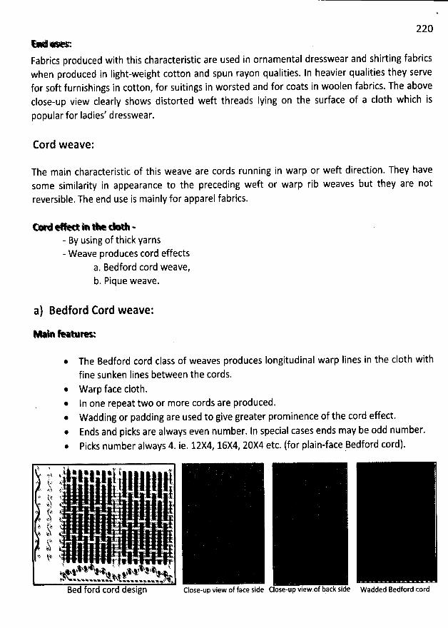
220*-> >
Fabrics produced with this characteristic are used in ornamental dresswear and shirting fabricswhen produced in Iight-weight cotton and spun rayon qualities. ln heavier qualities they servefor soft furnishings in cotton, for suitings in worsted and for coats in woolen fabrics. The aboveclose-up view clearly shows distorted weft threads Iying on the surface of a c10th which is
popular for ladies' dresswear.
Cord weave:
The main characteristic of this weave are cords running in warp or weft direction. They havesome similarity in appearance to the preceding weft or warp rib weaves but they are notreversible. The end use is mainly for apparel fabrics.
W u *. . - xk. . .k - œ1 w- By using of thick yarns- Weave produces cord effects
a. Bedford cord weave,b. Pique weave.
a) Bedford Cord weave:
Me e a-
The Bedford cord class of weaves produces Iongitudinal warp Iines in the c10th with
fine sunken Iines between the cords.* W arp face c10th.
In one repeat two or more cords are produced.* Wadding or padding are used to give greater prominence of the cord effect.
Ends and picks are always even number. In special cases ends may be odd number.
Picks number always 4. ie. 12X4, 16X4, 20X4 etc. (for plain-face Bedford cord).
j h : . ,j .i wjwjwjj t Atj., . ! lk . . . .. .jjj;...4: jpi .i(;.. .
. . c. , (jjy . ...y( ,.' 4.. @j . . . J..* .y : ' .
t, ' 41 # .t - . .h - ' .9 ? -J .ttz #? ' '.j: jj . .
@ jl. (j$- t. .
j.j .k .U F . Lj 1.% ' # a x%' +#
i+% e44.4% wW %w%ecwoxwwe oxwxxxwxwvxlBed ford cord design
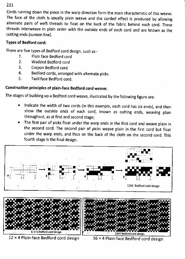
221
Cords running down the piece in the warp direction form the main characteristic of this weave.
The face of the c10th is usually plain weave and the corded effect is produced by allowingalternate pairs of weft threads to float on the back of the fabric behind each cord
. Thesethreads interweave in plain order with the outside ends of each cord and are known as thecutting ends (sunken line).
Types of Bedford cord:
There are five types of Bedford cord design, such as -
1. Plain face Bedford cord2. W added Bedford cord3. Crepon Bedford cord4. Bedford cords, arranged with alternate picks5. Twill face Bedford cord.
Construction principles of plain-face Bedford cord weave:
The stages of building up a Bedford cord weave, illustrated by the following figure are:
* Indicate the width of two cords (in this example, each cord has six ends), and then
show the outside ends of each cord, known as cutting ends, weaving plain
throughout, as at first and second stage;* The first pair of picks float under the warp ends in the first cord and weave plain in
the second cord. The second pair of picks weave plain in the first cord but floatunder the warp ends, and thus on the back of the c10th on the second cord
. Thisfourth stage is the final design.
TUU -r-r
. - # p )--- i f --t -1- . - .j - t y ..'X+ , . -
. VU O (YœI . ; . 4 ' . 1-
, I .. ..-. . ; .t .- : <. ' -2 - .-- .. z. -
277- - t u 1 - - .. u .
c c c (: c c c ' ' C C c c c c c c c
12X4 Bedford cor'd design
' .
' . ( ' 12 Y 4 Bedf/rt'cnrd kosign . ' . . 1:x# Betjord cord design ' '
12 x 4 Plain-face Bedford cord design 16 x 4 Plain-face Bedford cord design
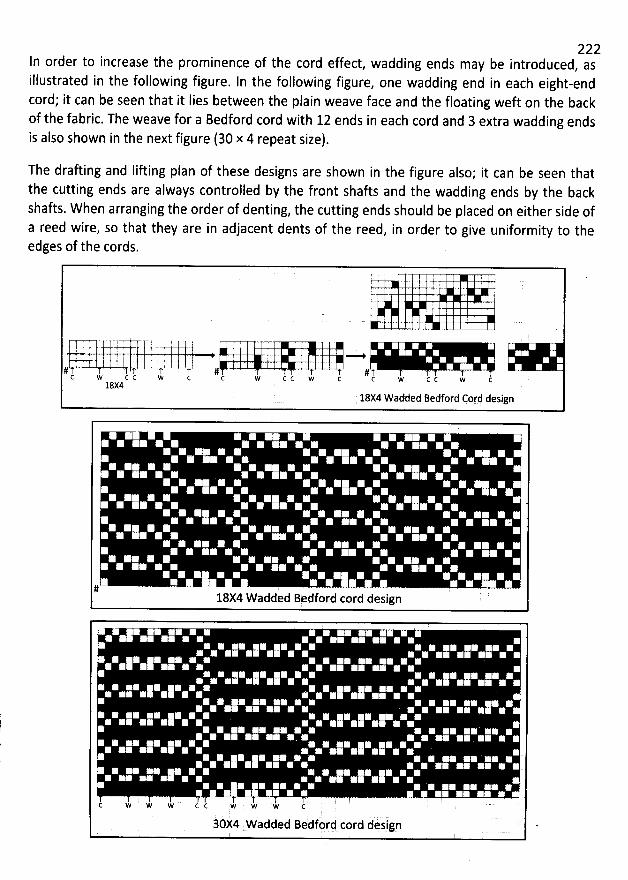
222In order to increase the prominence of the cord effect, wadding ends may be introduced, asillustrated in the following figure. In the following figure, one wadding end in each eight-endcord; it can be seen that it lies between the plain weave face and the floating weft on the backof the fabric. The weave for a Bedford cord with 12 ends in each cord and 3 extra wadding ends
is also shown in the next figure (30 x 4 repeat size).
The draûing and Iifting plan of these designs are shown in the figure also; it can be seen thatthe cutting ends are always controlled by the front shafts and the wadding ends by the backshafts. When arranging the order of denting, the cutting ends should be placed on either side ofa reed wire, so that they are in adjacent dents of the reed, in order to give uniformity to theedges of the cords.
f . # j. .
# . # . . g . .l c c w c c J cc w c c w c c w c c18X4
18X4 Wadded Bedford Cord design
# '18X4 W added Bedford cord design
C * ' w w c c w w 'w c ' '
à d design '30:4 Wadded Bedfor cor
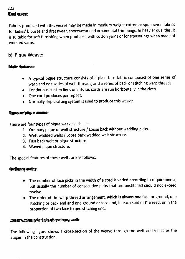
223H > ....-... .;
Fabrics produced with this weave may be made in medium-weight cotton or spun rayon fabricsfor Iadies' blouses and dresswear, sportswear and ornamental trimmings. In heavier qualities, itis suitable for soft furnishing when produced with cotton yarns or for trouserings when made of
worsted yarns.
b) Pique Weave:
* '*W* '* '
A typical pique structure consists of a plain face fabric composed of one series ofwarp and one series of weft threads, and a series of back or stitching warp threads.Continuous sunken lines or cuts i.e. cords are run horizontally in the c10th.
* One cord produces per repeat.* Normally skip drafting system is used to produce this weave.
Y * @'* œ- *,'
There are four types of pique weave such as -1. Ordinary pique or welt structure / Loose back without wadding picks.2. Weft wadded welts / Loose back wadded welt structure.3. Fast back welt or pique structure.4. W aved pique structure.
The special features of these welts are as follows:
@ The number of face picks in the width of a cord is varied according to requirements,but usually the number of consecutive picks that are unstitched should not exceed
twelve.* The order of the warp thread arrangement, which is always one face or ground, one
stitching or back end and one ground or face end, in each split of the reed, or in theproportion of two face to pne stitching end.
e- .*4m# e #*e e - e :
The following figure shows a cross-section of the weave through the weft and indicates the
stages in the construction:
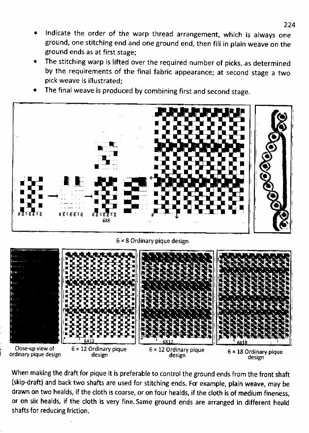
224* Indicate the order of the warp thread arrangement
, which is always oneground, one stitching end and one ground end, then fill in plain weave on theground ends as at first stage;
@ The stitching warp is lifted over the required number of picks, as determined
by the requirements of the final fabric appearance; at second stage a twopick weave is illustrated;
* The final weave is produced by combining first and second stage.
- - . . - .. . ).. . )
. . q
y -. ' 1, j ; u 4< ë ) g
- -# q r !. : . ) / ' ' 7p. y u y.w . j tk jX
I ; i * $. x j y t yN --, , , . ) . t.
. w . . . . r : ,' ! . r ' ' @
'
- . . , , j . )
. 4 y - ) i #1)
*
.
*
. - - . . .. - t . , (* . - , è l y;*' .- . . - # x. .. - , . . j ! + )t A -
é y y@ - j . )( . . ' .- . ; 1 l . ) 'YV''P f
sY v s-: s.:. 9 g-e.9. c sYsa' !w. --- lj .- - . - l i k l , * )E x lî 6X8
,. ' .. h. rg ' ' ;.
6 x 8 Ordinary pique design'
. - 1 . t, l r
'
j . , j L y j . j' - . 1. .; : . é r . t ) j, r? - . . . ' ..
. ï.y t . . .) j j! . t . '''*
'
'''*
'
. . - . j j
'
. . ! j . ,)j , . j : . j j . . yj
'
. r j . . y . . . t; j
'
. $ .). ty x - . . . i 'y ) ) . , 1
. . . . . . ls ) . . , ! . . )) 1 . ' ' r . l ' . . ;f j < . ' t ' . ! j j: . . . ) ( y
'
jt 4 ' - . i . . ) .i lf ' l 1 ) ' lj . . j r . . . . j j - . y
, l . . ' ) j ) . .. ' jj . . . y j . j .r ' . . . . j , . . 1, ) . . . jl . '
: . ' t .
' ; .
'
)) ! # ' ' ! j . 1 ij . . . . j ! . ! j . . . . )j + . .
' ' . ) l j ) . . )' 1. .u-- . . .. .. . .! ! . . . . . . . . . j j . . . . . . - -. . . -- . . - ... .- . /j y .. . y #: j y j! 6X 12 ) , X12 ( ) ,Close-up view of 6 x 12 Ordinary pique 6 x 12 Ordinary pique 6 x 18 ordinary piqueordinary pique design design design design
When making the draft for pique it is preferable to control the ground ends from the front shaft(skip-draft) and back two shafts are used for stitching ends. Fœ example, plain weave, may bedrawn on two healds, if the c10th is coarse
, or on four healds, if the c10th is of medium fineness,or on six healds, if the c10th is very fine. Same ground ends are arranged in different healdshafts for reducing fridion.
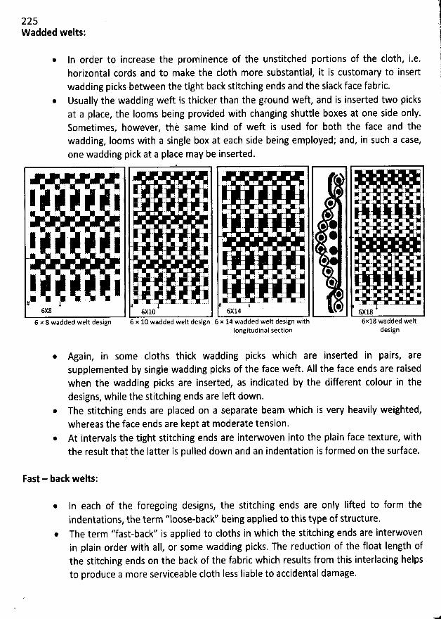
225W added welts:
In order to increase the prominence of the unstitched portions of the c10th, i.e.horizontal cords and to make the c10th more substantial, it is customary to insertwadding picks between the tight back stitching ends and the slack face fabric.Usually the wadding weft is thicker than the ground weft, and is inserted two picksat a place, the Iooms being provided with changing shuttle boxes at one side only.Sometimes, however, thè same kind of weft is used for both the face and thewadding, Iooms with a single box at each side being employed; and, in such a case,one wadding pick at a place may be inserted.
l jy, , , , . - . . y . TjljI 1 f-
.. ,,
, ,j' . I . ; : ' '
'
'i
: 'j . I .1 I l ... ; ' i
: jy . j ; . r . y . ( : .111111111111
*
. ' 111111111111. -y- .... -
'
'
'
: -
'
'
'
: -
'
-
'
.:2'r(..
'
-
'
'
'
yqq
d
'
'
'
tjrr!jIl11II11j.jrr!jIl11II11j..
'
-
. - .r-1 , , .1 : ;. - ' ..
( * y: - , ) , y. . g j .. ,1111y (y .. (r .. y)jljl111111 11111j . .11111y- :: . ' Cr - - ' è?
- .. -
rysq . ..
.
gr . ..
.
r yg,11,j. .. y .yr , , .K t *'.è-.. .:. -i.- T-:.. è-. r.-.1# #
6X8 6x1c6 x 8 wadded welt design 6 x 10 wadded welt design
. # .; ! ;
'
'''- '
. ' .
'
il : : .. . .. . i 6 C '
. @
@
# *: yj: : .1 .. @- I
- ' I- ' -
1 !*1Ii- , .L ..- -:- . -u L ,1r , ... .:. . . ,
@6X14 6x18
6 x 14 wadded welt design with 6x18 wadded weltIongitudinal section design
* Again, in some cloths thick wadding picks which are inserted in pairs, aresupplemented by single wadding picks of the face weft. AII the face ends are raisedwhen the wadding picks are inserted, as indicated by the different colour in thedesigns, while the stitching ends are Ieft down.
* The stitching ends are placed on a separate beam which is very heavily weighted,whereas the face ends are kept at moderate tension.
* At intervals the tight stitching ends are interwoven into the plain face texture, withthe result that the Iatter is pulled down and an indentation is formed on the surface.
Fast - back welts:
In each of the foregoing designs, the stitching ends are only Iifted to form theindentations, the term ''loose-back'' being applied to this type of structure.
@ The term ''fast-back'' is applied to cloths in which the stitching ends are interwovenin plain order with all, or some wadding picks. The reduction of the float length ofthe stitching ends on the back of the fabric which results from this interlacing helpsto produce a more serviceable c10th Iess liable to accidental damage.
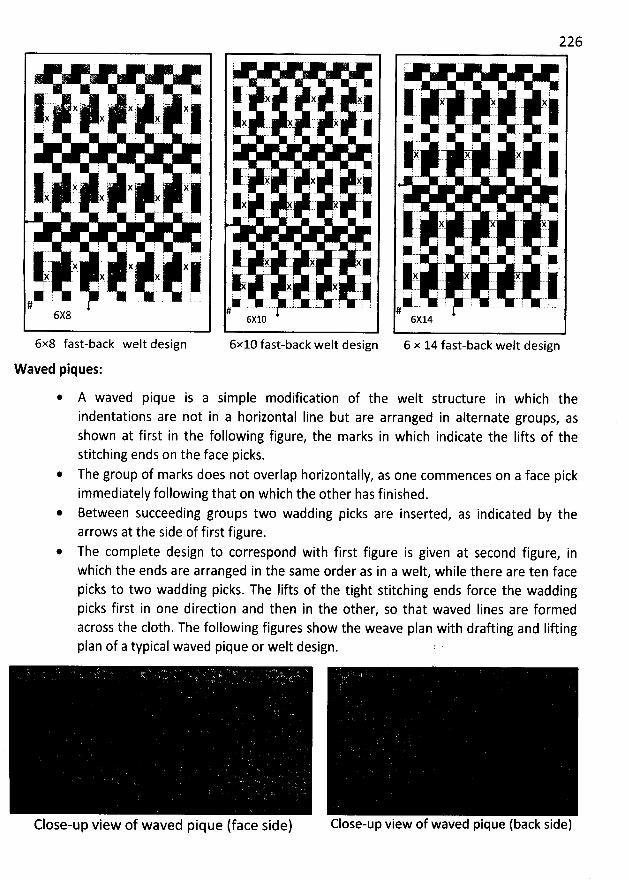
;
j' y' ' 77 X 1, - N F7- X jj- y 7-- j'mj
: ' ' 1 :
'
p
'
111111:- jy:'.' ?t. ' ' )( ,- @$i
.
.' jj:'
.
: )#:. .
'
. 4jjjj47 5' . :: : ë
'
.
. '
, g : ! !
111k,t. )(.' $(. : /4 -. jt' -.i é4- j'( 1 . ;
'
)( ..#
6X8
6x8 fast-back welt design
Waved piques:
, ' .
I k' .y' .y,; ' L.1s y > jf ' ! . . - . . . . .! .
;l
' -- q .. ' - l . 1-- l.-
jjj ; #) -ë :; yjjj. l! 2 : ; ) 'j : 2 .: ; JF ::
,!
:> .j. . $ ( ,k;
;'
. . : 7 : :
'
:
'
.. : ; . ( ! ; ' r
'
# # . #14:- '
.
-
- , :,4:
-
..
. x , y.yy-
j#. :-. ... ..u-- .t-- .: . -.L. !#6X10
6x10 fast-back welt design
226
) : L- y ! y ; :I l: k -) ;- --# r y y : ir g : . ;j. y t k
,-
, ,,, .
.èl! ! .) :r ;
l l . ; .: : ' '
). g-? C ' i è: ', .It -.t , ,
'.
. t ,
'. jk . , t . -'. C ètq q
.), - . t l.kl ? .. : .. i ' .. - , I , : . - ' ..1, . .' rj'-' -
' -'
; : - 1 . r;- .. '.
-
.-è- t - -
:'r.'-- ) - .
'.
.
-
- ,.111'.- . ! .#
6X14
6 x 14 fast-back welt design
A waved pique is a simple modification of the welt structure in which theindentations are not in a horizontal Iine but are arranged in alternate groups, asshown at first in the following figure, the marks in which indicate the Iifts of thestitching ends on the face picks.
The group of marks does not overlap horizontajly, as one commences on a face pickimmediately following that on which the other has finished.Between succeeding groups two wadding picks are inserted, as indicated by thearrows at the side of first figure.The complete design to correspond with first figure is given at second figure, inwhich the ends are arranged in the same order as in a welt, while there are ten facepicks to two wadding picks. The Iifts of the tight stitching ends force the waddingpicks first in one direction and then in the other, so that waved Iines are formedacross the c10th. The following figures show the weave plan with drafting and Iiûingplan of a typical waved pique or welt design.
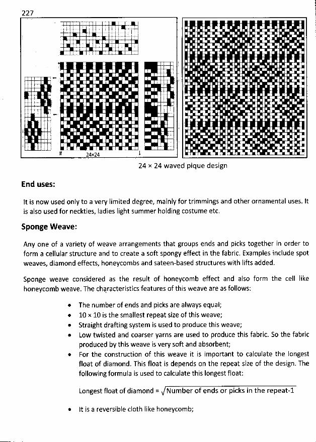
227, ' : 1 . I :
! 1 . '
! . 4 '' I l Ij
1 ' :I '
'
1 . ( I : .;
))
. e ! ëi .. . ' .i. (
5 ). . t
' ; E(
)
;
'
' Iji 'L .. '
1 .1 ' i '# j24x24 utgy y y y , )y t)y yt) )
24 x 24 waved pique design
End uses:
lt is now used only to a very Iimited degree, mainly for trimmings and other ornamental uses. ltis also used for neckties, Iadies Iight summer holding costume etc.
Sponge V/eave:
Any one of a variety of weave arrangements that groups ends and picks together in order toform a cellular structure and to create a soft spongy effect in the fabric. Examples include spotweaves, diamond effects, honeycombs and sateen-based structures with Iifts added.
Sponge weave considered as the result of honeycomb effect and also form the cell Iikehoneycomb weave. The ch4racteristics features of this weave are as follows:
* The number of ends and picks are always equal;10 x 10 is the smallest repeat size of this weave;Straight drafting system is used to produce this weave;Low twisted and coarser yarns are used to produce this fabric. So the fabricproduced by this weave is very soft and absorbent;For the construction of this weave it is important to calculate the Iongestfloat of diamond. This float is depends on the repeat size of the design. Thefollowing formula is used to calculate this Iongest float:
Longest float of diamond = Number of ends or picks in the repeat-l
* lt is a reversible c10th Iike honeycomb;
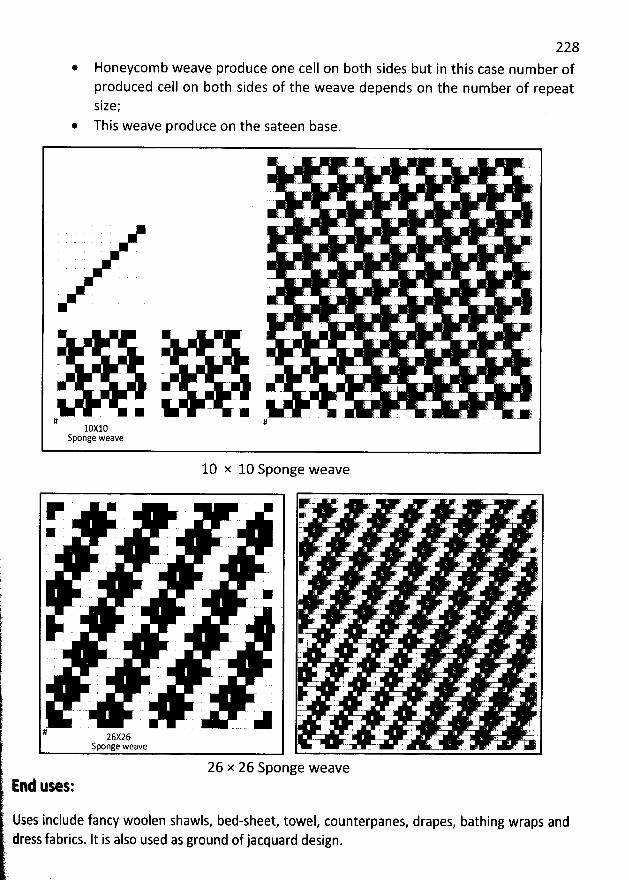
228Honeycomb weave produce one cell on both sides but in this case number ofproduced cell on both sides of the weave depends on the number of repeatsize;
* This weave produce on the sateen base.
10 x 10 Sponge weave
r
# 26X26Sponge weave
26 x 26 Sponge weaveE:d Qses:
Uses include fancy woolen shawls, bed-sheet, towel, counterpanes, drapes, bathing wraps anddress fabrics. It is also used as ground of jacquard design.
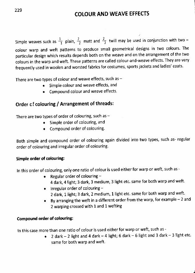
229COLOUR AND W EAVE EFFECTS
Y Iain, Z matt and Z twill may be used in conjunction with two -Simpie weaves such as
1 p 2 2colour warp and weft patterns to produce small geometrical designs in two colours. Theparticular design which results depends both on the weave and on the arrangement of the twocolours in the warp and weft. These patterns are called colour-and-weave effects. They are veryfrequently used in woolen and worsted fabrics for costumes, sports jackets and ladies' coats.
There are two types of colour and weave effects, such as -* Simple colour and weave effects, and* Compound colour and weave effects.
Order cf colouring / Arrangement of threads:
There are two types of order of colouring, such as -@ Simple order of colouring, and* Compound order of colouring.
Both simple and compound order of colouring again divided into two types, such as- regular
order of colouring and irregular order of colouring.
Simple order of colouring:
In this order of colouring, only one ratio of colour is used either for warp or weft, such as -
* Regular order of colouring -4 dark, 4 Iight; 3 dark, 3 medium, 3 Iight etc. same for both warp and weft.
@ lrregular order of colouring -2 dark, 1 light; 3 dark, 2 medium, 1 Iight etc. same for b0th warp and weft.By arranging the weft in a different order from the warp, for example - 2 and2 warping crossed with 1 and lwefting
Compound order of colouring:
In this case more than one ratio of colour is used either for warp or weft, such as -2 dark - 2 light and 4 dark - 4 Iight; 6 dark - 6 Iight and 3 dark - 3 light etc.same for both warp and weft.
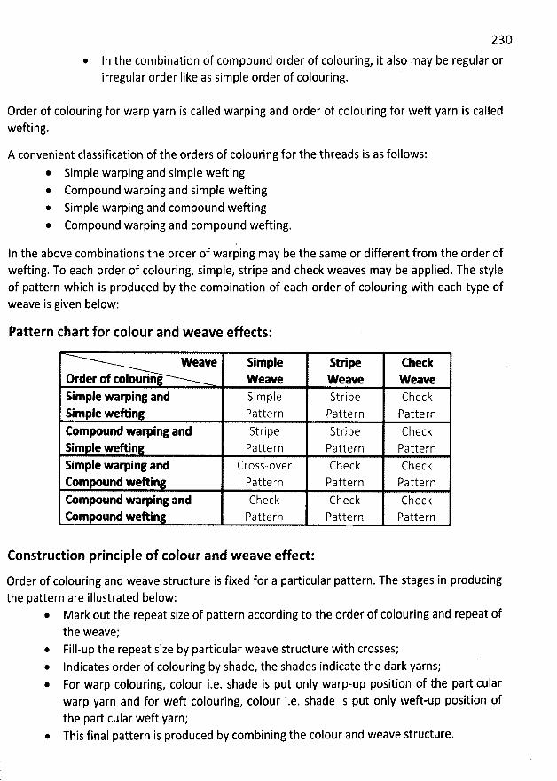
230
* In the combination of compound order of colouring, it also may be regular orirregular order Iike as simple order of colouring.
Order of colouring for warp yarn is called warping and order of colouring for weft yarn is calledwefting.
A convenient classification of the orders of colouring for the threads is as follows:* Simple warping and simple wefting
Compound warping and simple weftingSimple warping and compound weftingCompound warping and compound wefting.
ln the above combinations the order of warping may be the same or different from the order ofwefting. To each order of colouring, simple, stripe and check weaves may be applied. The styleof pattern which is produced by the combination of each order of colouring with each type ofweave is given below:
Pattern chart for colour and weave effects:
Weave Simple Stripe EhetkOrder of tolouring W eave W eave W eaveSimple warping and Simple Stripe CheckSimple weAin Pattern Pattern PatternCompound wam ing and Stripe Stripe CheckSim Ie weAin P/ttern Pattern PatternSimple warping and Cross-over Check CheckCompound weAing Pattern Pattern FatternCompound waming and Check Check CheckEompound weAin Pattern Pattern Pattern
Construdion principle of colour and weave effect:
Order of colouring and weave structure is fixed for a particular pattern. The stages in producingthe pattern are illustrated below:
* Mark out the repeat size of pattern according to the order of colouring and repeat ofthe weave;Fill-up the repeat size by particular weave structure with crosses;Indicates order of colouring by shade, the shades indicate the dark yarns;For warp colouring, colour i.e. shade is put only warp-up position of the particularwarp yarn and for weft colouring, colour i.e. shade is put only weft-up position ofthe particular weft yarn;
@ This final pattern is produced by combining the colour and weave structure.
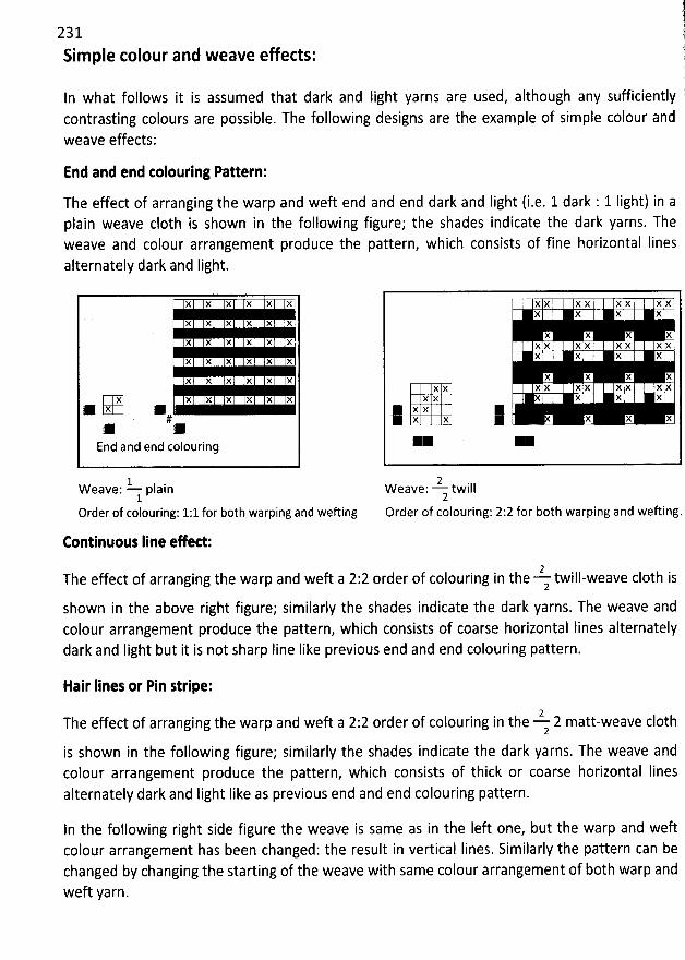
!231 1Simple colour and weave effects: j
1In what follows it is assumed that dark and light yarns are used, although any sufficiently 'contrasting colours are possible. The following designs are the example of simple colour andweave effects:
End and end toloufing Pattern:
The effect of arranging the warp and weft end and end dark and Iight (i.e. 1 dark : 1 Iight) in aplain weave c10th is shown in the following figure; the shades indicate the dark yarns. Theweave and colour arrangement produce the pattern, which consists of fine horizontal Iinesalternately dark and Iight.
X X X X X X
X X X X X X
X X X X X X
X X X X X X
X X X X X X
X X X X X X XM X M#
End and end colourin:
1W eave: plain1
Order of colouring: 1:1 for both warping and wefting
Continuoes line efed:
2The effect of arranging the warp and weft a 2:2 order of colouring in the twill-weave c10th is
2
shown in the above right figure; similarly the shades indicate the dark yarns. The weave andcolour arrangement produce the pattern, which consists of coarse horizontal Iines alternatelydark and Iight but it is not sharp Iine Iike previous end and end colouring pattern.
X X X X X X X XX X X X
X X X XX X X X X X X XX X X X
X X X XX X X X X X X X X X
X X X X X
j x x jX X X X X
2W eave: twill2
Order of colouring: 2:2 for both warping and wefting.
Hair lines or Pin stripe:
2The effect of arranging the warp and weft a 2:2 order of colouring in the 2 matt-weave c10th
2
is shown in the following figure; similarly the shades indicate the dark yarns. The weave andcolour arrangement produce the pattern, which consists of thick or coarse horizontal Iinesalternately dark and Iight Iike as previous end and end colouring pattern.
In the following right side figure the weave is same as in the Ieft one, but the warp and weftcolour arrangement has been changed: the result in vertical Iines. Similarly the pattern can bechanged by changing the starting of the weave with same colour arrangement of both warp andweft yarn.
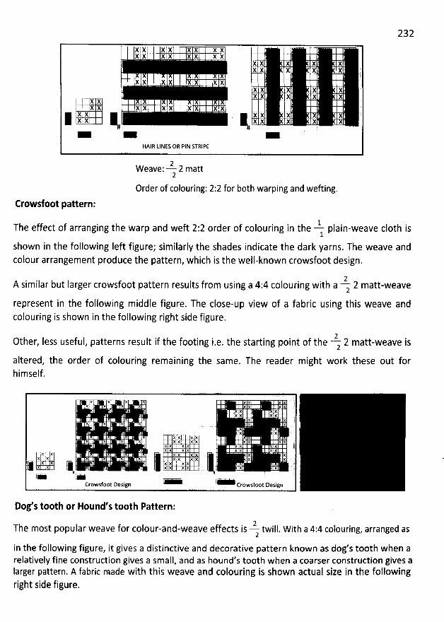
232
X K K X X K X X 'X X X X X X X X
X X 'E X . X XX X X X X :
X X X X X X X X yX X X X XX X X X E X 7
X X .X X X X X X X X X X
j X X M œ X X X X XX X 1 1 X X X X X# #X W W
HAIR LINES OR PIN STRIPE
2W eave: 2 matt2
Order of colouring: 2:2 for b0th warping and wefting.
Crowsfoot pattern:
1The effect of arranging the warp and weft 2:2 order of colouring in the plain-weave c10th is1
shown in the following Ieft figure; similarly the shades indicate the dark yarns. The weave andcolour arrangement produce the pattern, which is the well-known crowsfoot design.
2A similar but Iarger crowsfoot pattern results from using a 4:4 colouring with a z 2 matt-weave
represent in the following middle figure. The close-up view of a fabric using this weave andcolouring is shown in the following right side figure.
2Other, Iess useful, patterns result if the footing i.e. the starting point of the 2 matt-weave is2
altered, the order of colouring remaining the same. The reader might work these out forhimself.
X X x X xx xxXX XX t
X X jx x )( )( jX X j .
X X jx x
)( x X )(x x x x x x x x jx x x x x x tx x x x x x x x
x x x x x x x xx x x x x x x x
x x x x x x ' )11 x x x x x x x x ),4 i. 1
Crowsfoot Design Crowsfoot Design 1l
Dog's t00th or Hound's t00th Pattern:
2The most popular weave for colour-and-weave effects is twill. With a 4:4 colouring, arranged as2
in the following figure, it gives a distinctive and decorative pattern known as dog's t00th when arelatively fine construction gives a small, and as hound's t00th w hen a coarser construction gives aIarger pattern. A fabric made with this weave and colouring is shown actual size in the followingright side figure.
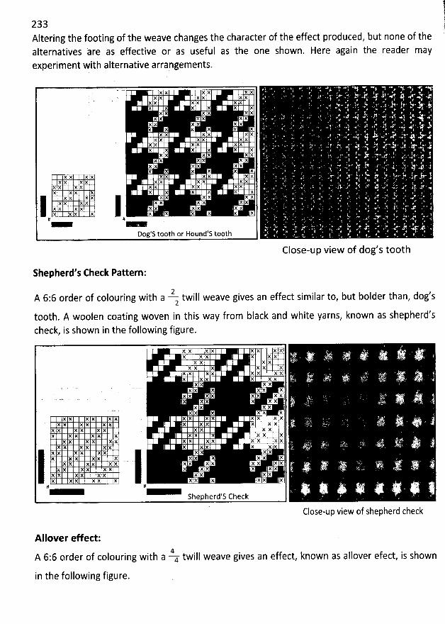
2a3 l!
Altering the footing of the weave changes the character of the effect produced, but none of the !alternatives are as effective or as useful as the one shown. Here again the reader mayexperiment with alternative arrangements.
X X X X X XX X X X X X ' '
X X X X X XX X X X X X k
X )( X X X XX X X X X X . .
X X X X X XX X X X X X
X X X X X XX X X X X X '
X )( )( X X XX X X x X X . *X )( X X X X
X X X X X )(X X X X X X . %
'
X X X X X XX x X X X X X X X h(
X X X X X M X X X XX X X X )( X X X X XX X X X X X X X X )(
X x X X X X X X X X)( X X X x X x x X X
X X x x x x x X x xX X X X x X x X X X
# # '
Dog's t00th or Houpd's t00th '
Close-up view of dog's t00th
shepherd's Check Pattern:
2 #A 6:6 order of colouring with a twill weave gives an effect similar to, but bolder than, dog s2
t00th. A woolen coating woven in this way from black and white yarns, known as shepherd'scheck, is shown in the following figure.
X X X X X X X X : . -. . .X X X X X X ** '' ' 7 U ' * ''tv ' '$' J Y ib %'<*.X X X X ' ' 'XX X XX X
X X x x X X xx ?x x x x x x . .. ' ' . 1.. Jk
x x x xx x X x x x
x x x )( x x x x ap. . a... ) . j . aX X X X X = ;--:' ' 'X X X X
XX X XX XXX X X X X . X X X X XX XX t
X X X X X X X X X X )( X ' ' F . ' V' '' ..X X X X X X z X X X XX X X X X X X X X X X X
X X X X X X X X X X X X X X . ' kX X X X X X X X X X X X ' ' '< ' :Z1'* 6XX X X XX XX XXX X X xx X xx X Xx X
XX xx XX xx XX xx XX '. ( . a.s .. j u- .X X X X X X X X X X X X .I6 + ' . . 'x ; - 'X X X X X X X X X XX X X X X X X X X X X X# # ' * ' ' ' ? Q ' ' 5 i. . -...j . ; . y ; .'. . -# - %. . L3
Shepherd S Check
Close-up view of shepherd check
Allover effect:4A 6:6 order of colouring with a 4 twill weave gives an effect, known as allover efect, is shown
in the following figure.
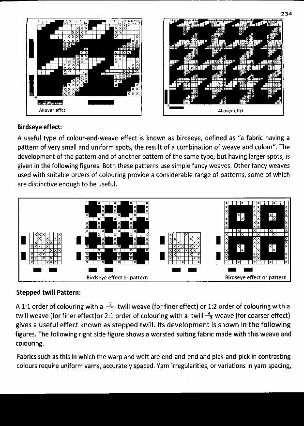
gx ' çxgx. pxx; ..xxX X X X X X
XX X X X XXX X X X X
X X X X X Xx x x x x xx x x x x xX x x x x x
X X X X X XX X x X X X
x x x x x xx x x x x x
M M X M x xX X X X x XXM ' X MM Fx x x x x x
M M M M M Mx; x >ç x M x
X x >( x A MXXX X X X
X XXX X XX X X XX X
#
Allover effct
Birdseye effect:
A useful type of colour-and-weave effect is known as birdseye, defined as '/a fabric having apattern of very small and uniform spots, the result of a combination of weave and colour/'. Thedevelopment of the pattern and of another pattern of the same type, but having Iarger spots, isgiven in the following figures. Both these patterns use simple fancy weaves. Other fancy weavesused with suitable orders of colouring provide a considerable range of patterns, some of whichare distinctive enough to be useful.
2B4
X X X X )( X X XX X X X X X X XX X X X X X X X
X x X x x X x XX )( X X x X X X
X X X X x X )( XX X X X X X X XX X X X X X X X
X X X % X X X X X X X X X X
j x X X X X R X X X X 8 X X X X 8 X X % XX X X œ X X X X œ X X X X œ X X X XX X X x X x X x x x x x x x x X )( X
X X X X X X X X X x X X X X X X X X
j X X X x R X X X X 1 x x x X 8 )( X )( XX X X x œ x X x X œ x X X X œ x X X XX X X X X X X X X X X X X X
Birdseye effect or pattern Birdseye effect or pattern
Stepped twill Pattern:
A 1:1 order of colouring with a 2: twill weave (for finer effect) or 1:2 order of colouring with atwill weave (for finer effectlor 2:1 order of colouring with a twill 3a weave (for coarser effect)gives a useful effect known as stepped twill. Its development is shown in the followingfigures. The following right side figure shows a worsted suiting fabric made with this weave andcolouring.
Fabrics such as this in which the warp and weft are end-and-end and pick-and-pick in contrastingcolours require uniform yarns, accurately spaced. Yarn irregulariiies, or variations in yarn spacing,
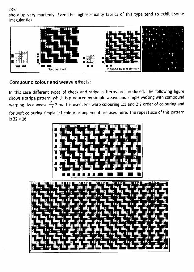
235show up very markedly. Even the highest-quality fabrics of this type tend to exhibit someirregularities.
XXX
XXX 1M XXX @ Xxx y x . j x .X X X @ XY X XX 1 1 X X 1# #
Stepped twill Stepped twill or pattern
Com pound colour and weave effects:
In this case different types of check and stripe patterns are produced. The following figureshows a stripe pattern, which is produced by simple weave and simple wefting with compound
iwarping. As a weave 2 matt is used, For warp colouring 1:1 and 2:2 order of colouring and2
for weft colouring simple 1:1 colour arrangement are used here. The repeat size of this pattern
is 32 x 16.X X X X X X X X
X X X X X X X X
g: X X X X XX X x X X x X X
X X X X X X X X
(# X X X X XX X X X x X X X
X X X X X X X X(# X X X X XX X X X X X x X
X X X X X X X X
g: x x x x
X X X X X Y X X X X X X X X X X
X
X
X
X
X
X
X
X
X#
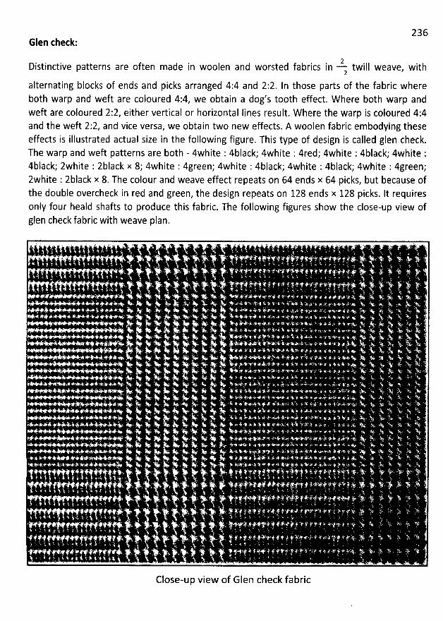
236Glen check:
Distinctive patterns are often made in 2woolen and worsted fabrics in twill weave, with2
alternating blocks of ends and picks arranged 4:4 and 2:2. ln those parts of the fabric whereboth warp and weft are coloured 4:4, we obtain a dog's t00th effect. W here both warp andweft are coloured 2:2, either vertical or horizontal Iines result. W here the warp is coloured 4:4and the weft 2:2, and vice versa, we obtain two new effects. A woolen fabric embodying theseeffects is illustrated actual size in the following figure. This type of design is called glen check.The warp and weft patterns are both - 4white : 4black; 4white : 4red; 4white : 4black; 4white :4black; zwhite : zblack x 8; 4white : 4green; 4white : 4black; 4white : 4black; 4white : 4green;zwhite : zblack x 8. The colour and weave effect repeats on 64 ends x 64 picks, but because ofthe double overcheck in red and green, the design repeats on 128 ends x 128 picks. It requiresonly four heald shafts to produce this fabric. The following figures show the close-up view ofglen check fabric with weave plan.
Close-up view of Glen check fabric
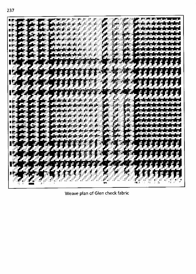
237
W eave plan of Glen check fabric
238FIGURING W ITH EXTRA THREADS
Main Features:
A distinguishing feature of fabrics in which extra materials are employed is that the withdrawalof the extra threads from the c10th Ieaves a complete ground structure under the figure. Theformation of a figure by means of extra threads thus does not detract from the strength orwearing quality of a c10th, except so far as the extra threads are Iiable to fray out, whereas inordinary fabrics, in which the figure is formed by floating the weft or warp threads Ioosely, thestrenmh of the c10th is reduced somewhat in proportion to the ratio of figure and ground.
One of the advantages of figuring with extra materials is that bright colours in sharp contrastwith the ground may be brought to the surface of the c10th in any desired proportion. Pleasingcolour combinations may thus be conveniently obtained, since the extent of surface allotted tothe figuring colour may be readily proportioned in accordance with the degree of its contrastwith the ground shade, without the Iatter being affected.
Methods of inte uting extra sguring threads:
The extra threads may be introduced either as weft or warp, or the two methpds may beemployed in combination. W hen the extra material is introduced as warp then a separate beamis required for each warp on account of the different take - up rates between the extra and theground ends. For extra weft figuring the weaving machine must have the capacity to insertmore than one colour or kind of weft. The form of the design may render it necessary for theextra threads to be inserted in continuous order with the ground threads, or in intermittentorder, while where they are introduced the arrangement of the figuring and ground threadsmay be l-and-l, l-and-z, 1-and-3 etc. according to the structure of the c10th and solidity offigure required. ln extra weft figures, for Iooms with changing boxes at one side only, similarresults to the l-and-l order may be produced by wefting 2-and-2; while the 2-and-4 order maybe substituted for the l-and-z, with, however, Iess satisfactory results as regards the solidity ofthe figure.
In this case extra warp and extra weft designs are presented by the following figures:
rame non' n of oO warp with extra weA Y ring:
In extra warp figuring there are two or more series of warp threads to one series of weftthreads, and the method has the following advantages and disadvantages, as compared withthe extra weft principle.
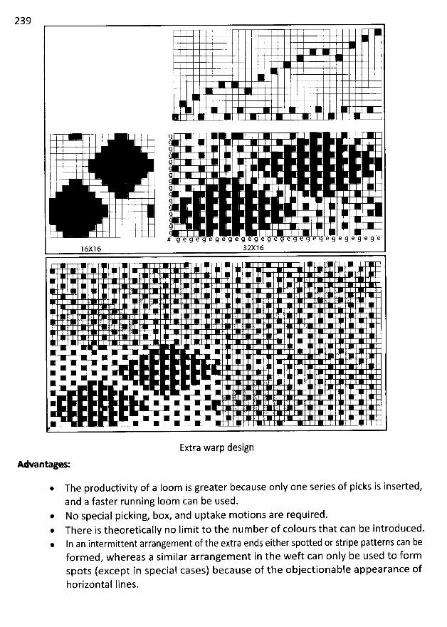
239
9I Ii . ; g
i : I I
q' . , 99
I9
9
9# g e g e g e g e g e g e g e g e g e g e g e g e g e 9 e g e g e
16X16 32X16
) . z TJ ' :' . J . ( .. ' '
j- ..( ' ty . t. . . r , s t. ;(
. . :' ;kL i - ; . '. . .
z E '.1 J. ' n (
% Xx-* w 'x .K < '#*
x * c*'+* '
.- .. . . k ty - .jlllllr''''lllllll7 . ,k lk '' ;-. j)' ; ;, .
.* * .), ' IE 'W M * ' l 7 ' lsK % K *K . W * * *
Extra warp design
AAante :
* The productivity of a Ioom is greater because only one series of picks is inserted,and a faster running loom can be used.
* No special picking, box, and uptake motions are required.@ There is theoretically no lim it to the number of colours that can be introduced.. In an intermittent arrangement of the extra ends either spotted or stripe patterns can be
form ed, whereas a sim ilar arrangement in the weft can only be used to formspots (except in special cases) because of the objectionable appearance ofhorizontal Iines.
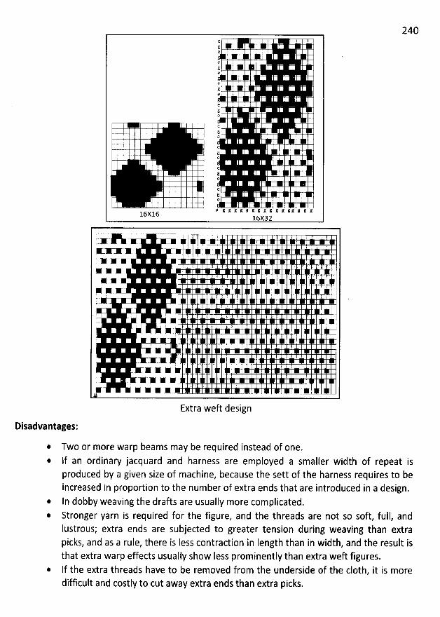
240eïe
e 1 Jge
ege
e
e
e
e
e
e
e
e
e
e
# g g g g : g g g g g g g g g g g16X1616X32
W 7 è77-*< < # *j
'
'
m- . ! I
x x
- : .)
ùk -
W XW 1 X
@ '#)* < *F + 'n -.* 7
Extra weft design
Disadvantages:
Two or more warp beams may be required instead of one.If an ordinary jacquard and harness are employed a smaller width of repeat isproduced by a given size of machine, because the sett of the harness requires to beincreased in proportion to the number of extra ends that are introduced in a design.
* In dobby weaving the drafts are usually more complicated.Stronger yarn is required for the figure, and the threads are not so soft, full, andIustrous; extra ends are subjected to greater tension during weaving than extrapicks, and as a rule, there is Iess contraction in Iength than in width, and the result isthat extra warp effects usually show Iess prominently than extra weft figures.lf the extra threads have to be removed from the underside of the c10th, it is moredifficult and costly to cut away extra ends than extra picks.
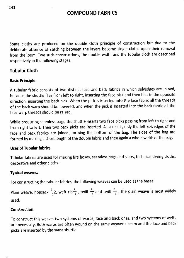
241COM POUND FABRICS
Some cloths are produced on the double c10th principle of construction but due to thedeliberate absence of stitching between the Iayers become single cloths upon their removalfrom the Ioom. Two such constructions, the double width and the tubular c10th are describedrespectively in the following stages.
Tubular C10th
Basic Principle:
A tubular fabric consists of two distinct face and back fabrics in which selvedges are joined,because the shuttle flies from left to right, inserting the face pick and then flies in the oppositedirection, inserting the back pick. W hen the pick is inserted into the face fabric aII the threadsof the back warp should be lowered, and when the pick is inserted into the back fabric all the
face warp threads should be raised.
W hile producing seamless bags, the shuttle inserts two face picks passing from left to right andfrom right to Ieft. Then two back picks are inserted. As a result, only the Iek selvedges of theface and back fabrics are joined, forming the bottom of the bag. The sides of the bag areformed by making a short Iength of the double fabric and then again a whole width of the bag.
Uses of Tubular fabrics:
Tubular fabrics are used for making fire hoses, seamless bags and sacks, technical drying cloths,
decorative and other cloths.
Typical weaves:
For constructing the tubular fabrics, the following weaves can be used as the bases:
2 2 2 2Plain weave, hopsack - 2, weft rib- , twill - and twill - . The plain weave is most widely2 2 1 2
used.
Construdion:
To construct this weave, two systems of warps, face and back ones, and two systems of weftsare necessary. Both warps are often wound on the same weaver's beam and the face and back
picks are inserted by the same shuttle.
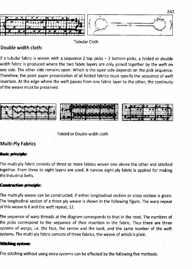
242. tj- 7* > 3. r .r . T cr qty 6 fY# yg .t tr ..i . ,-. .à.ë . ... x;L: If . ) . :1$ ply 1' ,364% p 1jk . f fqft 1. ,' ;K . . . .
. . . yj/ a,,.'.L ,:-;7.... . f; . yji yjm-qxxsqs .N j:. ..'a* ; .s.y:: zr ft - )fJ-41;, >. âp-j . uj:u- y r yr . . .x '. . '. .-3 à.>. i ... .';h11(l...:as. ' . a:.zr j j yw. . .,. . . ..-.-----....-.-zz...- . . . .... s:j..ç.s . . .. ..w.. .v. .. a...ouxe#* à$ % éc.
' kemxper..aAkza$... . zkk *'.u'lv-41-a -ri= sl-t -J:... Axjj .j4e.!j' zqjj-. Uy:J: - ' . azl: asy.: .J' ' ' s j4. - . .. .,< b : t 1. . L ;. . ,. 4. : yr . ka . .t pz , .. ... 1 , i ! . . , ?. , s i. , . . . l f m f. . lf i , s . $ r . 'x z i;. o .
dvhk ,i ' .. a . w..- r k xv.-' . . 4 ' . . ' '. . ;
11 'J $. .? . l '! ' . . $ j f. 11. . .) . 1 . .. J i) :
Tubular C10thIe -1 th cloth'OU .
If a tubular fabric is woven with a sequence 2 top picks - 2 bottom picks, a folded or doublewidth fabric is produced where the two fabrii Iayers are only joined together by the weft onone side. The other side remains open. W hich is the open side depends on the pick sequence.herefore, the point paper presentation of aII folded fabrics must specify the sequence of weftinsertion. At the edge where the weft passes from one fabric Iayer to the other, the continuityof the weave must be preserved.
Foided or Double width c10th
M ulti-ply Fabrics
* . .2 .
The multi-ply fabric consists of three or more fabrics woven one above the other and stitchedogether. From three to eight Iayers are used. A narrow eight-ply fabric is applied for makinghe Industrial belts.
r - .- -œ... . -œ8 - .- * 4*
he multi-ply weave can be constructed, if either longitudinal section or cross section is given.
he Iongitudinal section of a three ply weave is shown in the following figure. The warp repeatf this weave is 6 and the weft repeat, 12.
l'he sequence of warp threads at the diagram corresponds to that in the reed. The numbers ofthe picks correspond to the sequence of their insertion in the fabric. Thus there are threesystems of warps, i.e. the face, the centre and the back, and the same number of the weftystems. The multi-ply fabric consists of three fabrics, the weave of which is plain.
e
he stitching without using extra systems can be effeded by the following five methods:
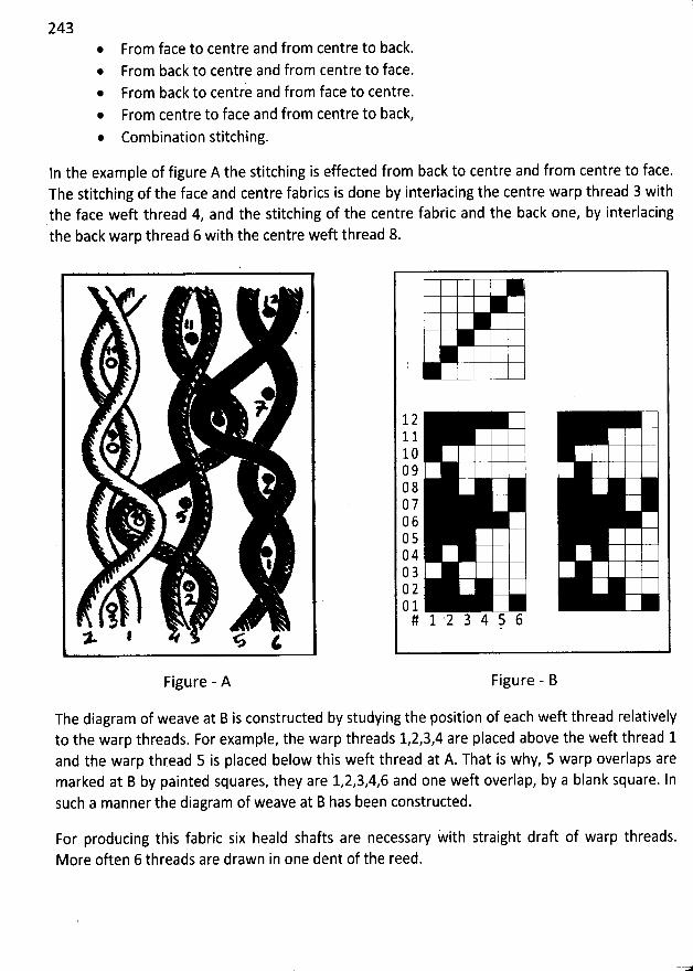
243
*
From face to centre and from centre to back.From back to centre and from centre to face.From back to centre and from face to centre.From centre to face and from centre to back,
* Combination stitching.
In the example of figure A the stitching is effected from back to centre and from centre to face.The stitching of the face and centre fabrics is done by interlacing the centre warp thread 3 withthe face weft thread 4, and the stitching of the centre fabric and the back one, by interlacingthe back warp thread 6 with the centre weft thread 8.
11@ '
@
7
#
1
*
î* I % i
Figure - A
The diagram of weave at B is constructed by studying the position of each weft thread relativelyto the warp threads. For example, the warp threads 1,2,3,4 are placed above the weft thread 1and the warp thread 5 is placed below this weft thread at A. That is why, 5 warp overlaps aremarked at B by painted squares, they are 1,2,3,4,6 and one weft overlap, by a blank square. Insuch a manner the diagram of weave at B has been constructed.
121110090807060504030201# 1 2 3 4 k 6
Figure - B
For producing this fabric six heald shafts are necessary with straight draft of warp threads.More often 6 threads are drawn in one dent of the reed.
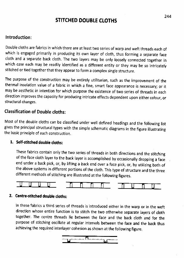
244STITCHED DOUBLE CLOTHS
Introductipn:
Double cloths are fabrics in which there are at Ieast two series of warp and weft threads each ofwhich is engaged primarily in producing its own Iayer of c10th
, thus forming a separate facec10th and a separate back c10th. The two layers may be only loosely connected together inwhich case each may be readily identified as a different entity or they may be so intricatelystitched or tied together that they appear to form a complex single structure
.
The purpose of the construction may be entirely utilitarian, such as the improvement of the
thermal insulation value of a fabric in which a fine, smart face appearance is necessary; or it
may be aesthetic in intention for which purpose the existence of two series of threads in eachdirection improves the capacity for producing intricate effects dependent upon e' ither colour
, orstructural changes.
Classification of Double cloths:
Most of the double cloths can be classified under well defined headings and the following Iistgives the principal structural types with the simple schematic diagrams in the figure illustratin
gthe basic principle of each construction.
1. Self-stitthed doeble tloths:
These fabrics contain only the two series of threads in both directions and the stitching
of the face c10th Iayer to the back Iayer is accomplished by occasionally dropping a face
end under a back pick, or, by lifting a back end over a face pick, or, by utilizing both ofthe above systems in different portions of the c10th
. This type of structure and the threedifferent methods of stitching are illustrated at the following figures
,
2. Centre-stltthed dooble tloths:
ln these fabrics a third series of threads is introduced either in the warp or in the weftdirection whose entire function is to stitch the two otherwise separate Iayers of c10thtogether. The centre threads Iie between the face and the back c10th and for thepurpose of stitching oscillate at regular intervals between the face and the back thusachieving the required interlayer cohesion as shown at the following figure
.
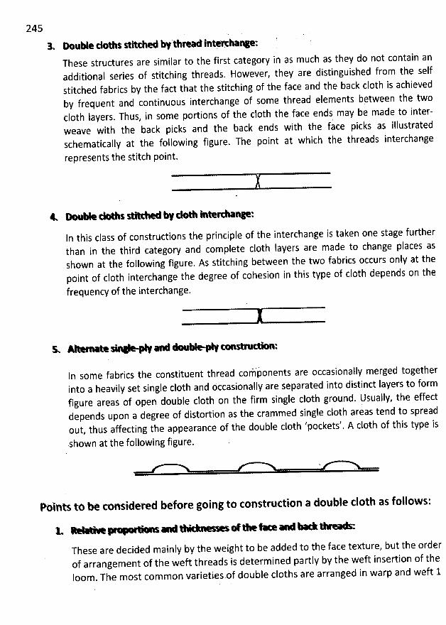
245
3. M uble dols seeehe W th--o Inoah:nm:Tbese structures are similar to the first category in as much as they do not contain anadditional series of stitching threads. However, they are distinguished from the selfstitched fabrics by the fact that the stitching of the face and the back c10th is achievedby frequent and continuous interchange of some tbread elements bçtween the twoc10th Iayers. Thus, in some portions of the c10th the face ends may be made to inter-weave with the back picks and the back ends with the face picks as illustratedschematicaîly at the following figure. The point at which the threads interchange
represents the stitch point.
WIn this class of constructions the principle of the interchange is taken one stage furtherthan in the third category and complete c10th layers are made to change places asshown at the following figure. As stitching between the two fabrics occurs only at thepoint of c10th interchange the degree of cohesion in thîs type of c10th depends on the
frequency of the interchange.
ln some fabrics the constituent thread covponents are occasionally merged togetherinto a heavily set single c10th and occasionally are separated into distinct Iayers to formfigure areas of open double c10th on the firm single c10th ground. Usually, the effectdepends upon a degree of distortion as the crammed single c10th areas tend to spreadout, thus affecting the appearance of the double c10th 'pockets'. A c10th of this type is
shown at the following figure.
Polnts to be considered before going to construction a double c10th as follows:
V - x. % . - Y - . . ..* - œ * k . - - - - - r ... - . ..* K. ...X. > k. . . .*t M * '
These are decided mainly by the weight to be added to the face texture, but the orderof arrangement of the weft threads is determined partly by the weft insertion of theIoom. The most com mon varieties of double cloths are arranged in warp and weft 1
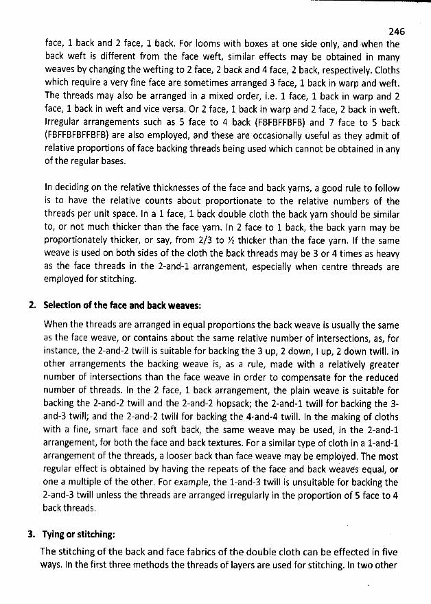
246face, 1 back and 2 face, 1 back. For looms with boxes at one side only, and when theback weft is different from the face weft, similar effects may be obtained in manyweaves by changing the wefting to 2 face, 2 back and 4 face, 2 back, respectively. Clothswhich require a very fine face are sometimes arranged 3 face, 1 back in warp and weft.The threads may also be arranged in a mixed order, i.e. 1 face, 1 back in warp and 2face, 1 back in weft and vice versa. Or 2 face, 1 back in warp and 2 face, 2 back in weft.Irregular arrangements such as 5 face to 4 back (FBFBFFEFB) and 7 face to 5 back(FBFFBFBFFBFB) are also employed, and these are occasionally useful as they admit ofrelative proportions of face backing threads being used which cannot be obtained in anyof the regular bases.
In deciding on the relative thicknesses of the face and back yarns, a good rule to followis to have the relative counts about proportionate to the relative numbers of thethreads per unit space. In a 1 face, 1 back double c10th the back yarn should be similarto, or not much thicker than the face yarn. In 2 face to 1 back, the back yarn may beproportionately thicker, or say, from 2/3 to X thicker than the face yarn. If the sameweave is used on both sides of the c10th the back threads may be 3 or 4 times as heavyas the face threads in the 2-and-1 arrangement, especially when centre threads areemployed for stitching.
2. R lettion of the fate and back weaves:
W hen the threads are arranged in equal proportions the back weave is usually the sameas the face weave, or contains about the same relative number of intersections, as, forinstance, the 2-and-2 twill is suitable for backing the 3 up, 2 down, I up, 2 down twill. Inother arrangements the backing weave is, as a rule, made with a relatively greaternumber of intersections than the face weave in order to compensate for the reducednumber of threads. In the 2 face, 1 back arrangement, the plain weave is suitable forbacking the 2-and-2 twill and the 2-and-2 hopsack; the 2-and-1 twill for backing the 3-and-3 twill; and the 2-and-2 twill for backing the 4-and-4 twill. In the making of clothswith a fine, smart face and soft back, the same weave may be used, in the 2-and-1arrangement, for both the face and back textures. For a similar type of c10th in a l-and-larrangement of the threads, a Iooser back than face weave may be employed. The mostregular effect is obtained by having the repeats of the face and back weaves equal, orone a multiple of the other. For example, the 1-and-3 twill is unsuitable for backing the2-and-3 twill unless the threads are arranged irregularly in the proportion of 5 face to 4back threads.
3. Tying or stitthing:
The stitching of the backand face fabrics of the double c10th can be effected in iiveways. In the first three methods the threads of Iayers are used for stitching. In two other
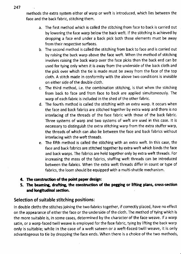
247methods the extra system either of warp or weft is introduced, which Iies between theface and the back fabric, stitching them.
a. The first method which is called the stitching from face to back is carried outby lowering the face warp below the back weft. If the stitching is achieved bydropping a face end under a back pick both these elements must be awayfrom their respective surfaces.
b. The second method is called the stitching from back to face and is carried outby raising the back warp above the face weft. W hen the method of stitchinginvolves raising the back Warp over the face picks then the back end can beused for tying only when it is away from the underside of the back c10th andthe pick over which the tie is made must be away from the face of the topc10th. A stitch made in conformity with the above two conditions is invisibleon either side of the double c10th.The third method, i.e. the combination stitching, is that when the stitchingfrom back to face and from face to back are applied simultaneously. Thewarp of each fabric is included in the shed of the other fabric.
d. The fourth method is called the stitching with an extra warp. lt occurs whenthe face and back fabrics are stitched together by extra warp and there is nointerlacing of the threads of the face fabric with those of the back fabric.Three systems of warp and two systems of weft are used in this case. It isnecessary to distinguish the extra stitching warp from the extra stuffer warp,the threads of which can also Iie between the face and back fabrics withoutinterlacing with the weft threads.
e. The fifth method is called the stitching with an extra weft. In this case, theface and back fabrics are stitched together by extra weft which binds the faceand back warps. The fabrics are held together only by extra weft threads. Forincreasing thi mass of the fabrics, stuffing weft threads can be introducedbetween the fabrics. W hen the extra weft threads differ in count or type offabrics, the Ioom should be equipped with a multi-shuttle mechanism.
4. n e O nstrudion of the N int pae r design:5. The Y mlnw deahinw the tonM dion of the pea ing or lifting plans, trou-sedion
and longitudlnal qe on.
Selection of suitable stitching positions:
In double cloths the stitches joining the two fabrics together, if correctly placed, have no effecton the appearance of either the face or the underside of the c10th. The method of tying which isthe more suitable is, in some cases, determined by the character of the face weave. If a warpsatin, or a warp-faced twill weave is employed for the face fabric, tying by Iifting the back warponly is suitable; w hile in the case of a weft sateen or a weft-faced twill weave, it is onlyadvantageous to tie by dropping the face ends. W hen there is a choice of the two methods,
248other things being equal, the former method is usually preferable, as the back warp is Iess Iiableto show on the face than the back weft, which in the Iatter system is pulled upwards.
Using the system of tying in which the back ends are raised for stitching over the face picks itmay not be possible to realize the above assumption with some weave combinations and someface to back thread ratios because for perfect placement of the tie the following four conditionsmust coincide:
1. The back end must be at that point away from the underside of the back c10th.2. lt must 'surface' between two Iong warp floats of the face weave.3. The face pick over which the back end is raised must be absent from the surface of the
face c10th.4. It must be only pulled down at a poin't at which its penetration into the back c10th level
is covered by two adjacent weft floats on the underside of the back fabric.
Clearly, in some circumstances it will not be possible to achieve the simultaneous coi'ùcjdenceof aII the four conditions. ' ,
Similarky, when the face ends ale lowerned for stiyching under the bgik picks:
1. ' The face end at that point mùst bêf'absent from the sudàce' 'ofxthe face c10th.ùtr ' 01 . -I mpjt be Iowered at a p6fnt at which two Iong baék wirp flpats coyjr
.it on the'
. .. ,. ; ). '( ..:. ;.. .,u k. . ..:, . .derside of the back c10th. .. . .. ..
....
',rttg..-.-
;tu n . . . .. . .. . k) !j. .. ..,3. The back pick at the tie point must be.away from the underside of the back clbtlsqt.t:y
. (s y ,.4. It must penetrate tcwards the surfacexat a point at which it Wik, be cilred bk-twoadjacent face weft floats on the surface of the face c10th.
Again, the simultaneous coincidence of the conditions may not, in some cases, be possible.
If it is conceded that the conditions (1) and (3) in each system of tying are absolutelycompulsory then a certain degree of freedom must be accepted with regard to the conditions(2) and (4).
Construction Principle:
% q%* u - . : r * - % :There is no need to separate stitching thread. The threads of the face and back c10th are usedfor stitching. There are three types of self stitch double c10th, such as -
- - . , *. * - = - * . .. .z % % o %- j. W D e :
In order to prevent confusion the diN rent stages in working out a double c10th designshould be represented by different kili4s of marks, as shown in the following figures,
s 4which illustrates, step by step, the construction of a twill and . twill structure in3 4which the ends and picks are arranged 1 face, 1 back. A and B represent the face and
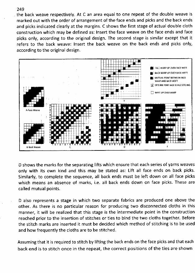
249. the back weave respectively. At C an area equal to one repeat of the double weave ismarked out with the order of arrangement of the face ends and picks and the back endsand picks indicated clearly at the margins. C shows the first stage of actual double c10thconstruction which may be defined as: Insert the face weave on the face ends and facepicks only, according to the original design. The second stage is similar except that itrefers to the back weave: lnsert the back weave on the back ends and picks only,according to the original design.
@ FACE WARP UP OVEI! FACE WEFTF MCK WARP UP OVER MCK KEFT1 MUTUAL POINT BETWEEN FACE
WARP AND BACK WEFT
IX STITCHING FOINT MCr T0 FA:f STITCHING
C) WEFT UP OVER WARP
E' B B
F FA-Face Weive B B
F FB 8F FB BF! FB BF Fj BF ' FB BF FB B. jz y x
B F B F B F B B B B B B F B F B F B B B B BB-Back Weave C D F
D shows the marks for the separating Iifts which ensure that each series of yarns weavesonly with its own kind and this may be stated as: Lift aII face ends on back picks.Sim ilarly, to complete the sequence, a1I back ends must be Ieft down on aII face pickswhich means an absence of marks, i.e. alI back ends down on face picks. These arecalled m utual points.
D also represents a stage in which two separate fabrics are produced one above theother. As there is no particular reason for producing two disconnected cloths in thismanner, it will be realized that this stage is the intermediate point in the constructionreached prior to the insertion of stitches or ties to bind the two cloths together. Beforethe stitch marks are inserted it m ust be decided which method of stitching is to be usedand how frequently the cloths are to be stitched.
Assuming that it is required to stitch by Iifting the back ends on the face picks and that eachback end is to stitch once in the repeat, the correct positions of the ties are show n
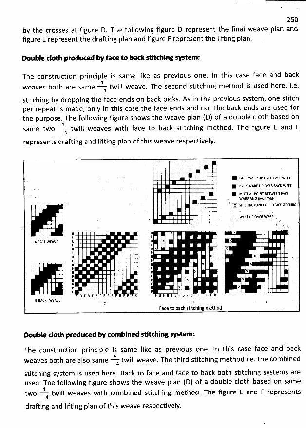
250by the crosses at figure D. The following figure D represent the final weave plan andfigure E represent the drafting plan and figure F represent the Iifting plan.
M * de pre e W f- tobackse ingsystem;
The construction principle is sam e Iike as previous one. In this case face and back4weaves both are same twill weave. The second stitching m ethod is used here, i.e.4
stitching by dropping the face ends on back picks. As in the previous system , one stitchper repeat is made, only in this case the face ends and not the back ends are used forthe purpose. The following figure shows the weave plan (D) of a double c10th based on
4same two 4 twill weaves wiih face to back stitching method. The figure E and Frepresents drafting and Iifting plan of this weave respectively.
@ FACE wARP up OVER FACE WCF'TK BACK WARP UP OVER BACK WEF'T
. * MUTUAL POINT BETWEZN FACEWARP AND BACK WEFT
X STITCHfNG POINT FACf T0 MCr STITCHING
WA:P'C) wEFT tlp ovER ,
E ' ' '
B q X X. F F .A-FACE WEAVE B B X X
F FB B x xF FB B N xF FB B x XF FB B. X X .F FB B x XF FB B X XF F
B F B F B F B F B B B B B F B r B F B F B B B BB-BACK WEAVE D
Face to back stitching method
nnuble de pre u'oa by com bined stitching a stem :
The construction principle is same like as previous one. In this case face and back4weaves both are also sam e 4 twill weave. The third stitching method i.e. the combined
stitching system is used here. Back to face and face to back both stitching systems are
used. The following figure shows the weave plan (D) of a double c10th based on same4two twill weaves with com bined stitching method. The figure E and F represents4
drafting and lifting plan of this weave respectively.
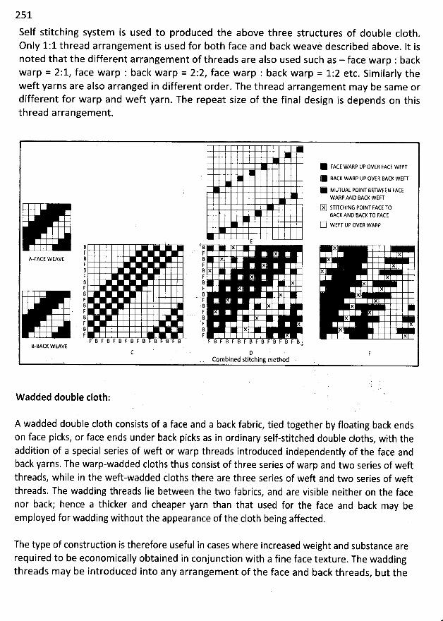
251
Self stitching system is used to produced the above three structures of double c10th.
Only 1:1 thread arrangem ent is used for both face and back weavè described above. It isnoted that the different arrangement of threads are also used such as - face warp : backwarp = 2:1, face warp : back warp = 2:2, face warp : back warp = 1:2 etc. Sim ilarly theweft yarns are also arranged in different order. The thread arrangement may be same ordifferent for warp and weft yarn. The repeat size of the final design is depends on thisthread arrangement.
@ FACE WARP UP OVER FACE WEF'T1 BACK WARP UP OVER BACK WEFTK MUTUAL POINT BETWEEN FACE
WARP AND BACK WEF'T
(X) STITCHING POINT FACE TOBACK AND BACK TO FACE
((((j WEFT UP OVER WARP
B B x xF F x x
A-FACE WEAVE B B X XF F x8 B x xF F XB B x xF FB B x xF FB B X x
. F I.: x8 B x XF , FB B x x
' F . . F xF B F B F B F B F B' F B F IB r B F B F B F B F B F B F 'B B F B
B-BACK WVv6 .(2 D '' . F'
. ,, . Combined stitching method k..
W added double c10th:
A wadded double c10th consists of a face and a back fabric, tied together by floating back endson face picks, or face ends under back picks as in ordinary self-stitched double cloths, with theaddition of a special series of weft or warp threads introduced independently of the face andback yarns. The warp-wadded cloths thus consist of three series of warp and two series of weftthreads, while in the weft-wadded cloths there are three series of weft and two series of weftthreads. The wadding threads Iie between the two fabrics, and are visible neither on the facenor back; hence a thicker and cheaper yarn than that used for the face and back may beemployed for wadding without the appearance of the c10th being affected.
The type of construction is therefore useful in cases where increased weight and substance arerequired to be economically obtained in conjunction with a fine face texture. The waddingthreads may be introduced into any arrangement of the face and back threads, but the
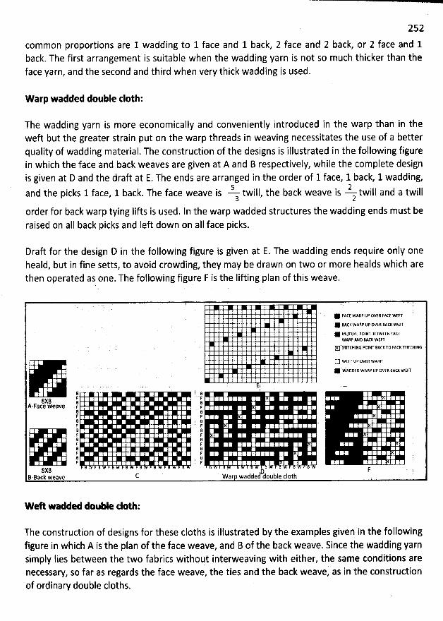
252
common proportions are 1 wadding to 1 face and 1 back, 2 face and 2 back, or 2 face and 1back. The first arrangement is suitable when the wadding yarn is not so much thicker than theface yarn, and the second and third when very thick wadding is used.
Warp wadded double eloth:
The wadding yarn is more economically and conveniently introduced in the warp than in theweft but the greater strain put on the warp threads in weaving necessitates the use of a betterquality of wadding material. The construction of the designs is illustrated in the following figurein which the face and back weaves are given at A and B respectively, while the complete designis given at D and the draft at E. The ends are arranged in the order of 1 face, 1 back, 1 wadding,
5 2and the picks 1 face, 1 back. The face weave is twill, the back weave is twill and a twill3 2
order for back warp tying lifts is used. In the warp wadded structures the wadding ends must beraised on aIl back picks and Ieft down on aII face picks.
Draft for the design D in the following figure is given at E. The wadding ends require only oneheald, but in fine setts, to avoid crowding, they may be drawn on two or more healds which arethen operated as one. The following figure F is the Iifting plan of this weave.
@ FACE WARP UP OVER FACt WEn'1 BACK WARP IJP OVE: BACK WEFF@ MUTUAL POINT BETWEEN FACEWARP AND MCK WEFTN'FITCHING POINT MCK T0 FACK STITCHING
C) WEF'T UP OVER WARP. . @' wADPED WARP UP OVER BACK WEFT
(j g 'r F8X8 :
BA-Face weave . r F .B ' Br FB Bf: FB BF Fi! . BF FB BF FB BF F
8X8 F - ''dlouble (:10th .B-Back weave (2 war wadde
w eA '-- Mde double dotb:
The construction of designs for these cloths is illustrated by the examples given in the followingfigure in which A is the plan of the face weave, and B of the back weave. Since the wadding yarnsimply lies between the two fabrics withoqt interweaving with either, the same conditions arenecessary, so far as regards the face weave, the ties and the back weave, as in 1he constructionof ordinary double cloths.
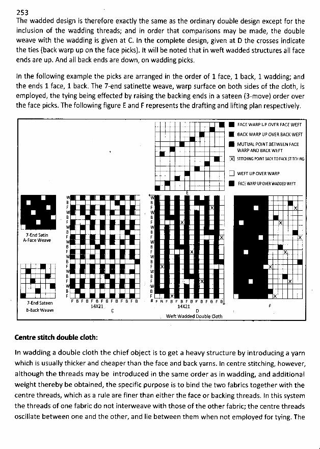
253The wadded design is therefore exactly the same as the ordinary double design except for theinclusion of the wadding threads; and in order that comparisons may be made, the doubleweave with the wadding is given at C. In the complete design, given at D the crosses indicate
the ties (back warp up on the face picks). It will be noted that in weft wadded structures aII faceends are up. And alI back ends are down, on wadding picks.
In the following example the picks are arranged in the order of 1 face, 1 back, 1 wadding; andthe ends 1 face, 1 back. The 7-end satinette weave, warp surface on both sides of the c10th, isemployed, the tying being effected by raising the backing ends in a sateen (3-move) order overthe face picks. The following figure E and F represents the drafting and Iifting plan respectively.
1 FACE WARP UP OVER FACE WEFTK BACK WARP UP OVER BACK WEF'TK MUTUAL POINT BETWEEN FACE
WARP AND BACK WEFT
X STITCHING FOINT ZACr T0 FACr STITCHING
(Z WEFT UP OVER WARPK FACE WAEF UFOVEE WAOZED WEFT
EW
2 BF F X x
WB BF F X )(
W
7-End Satin F F x xA-Face Weave W
B BF F X X
WB BF F X X
WB ' : 'F F s X X
. .W 'B B 'F F X X
d sateen F B F B F B F B F B F B F B # F B F B F B F B F B F B F B7-En14X21 14X21
B-Back Weave DWeft Wadded Double C10th
Centre stitch double :10th:
In wadding a double c10th the chief object is to get a heavy structure by introducing a yarnwhich is usually thicker and cheaper than the face and back yarns. In centre stitching, however,
although the threads m ay be introduced in the same order as in wadding, and additional
weight thereby be obtained, the specific purpose is to bind the two fabrics together with thecentre threads, which as a rule are finer than either the face or backing threads. In this system
the threads of one fabric do not interweave with those of the other fabric; the centre thfeads
oscillate between one and the other, and Iie between them when not employed for tying. The
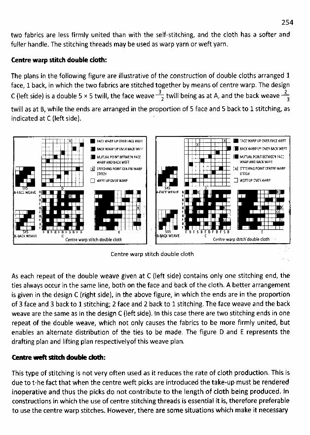
254
two fabrics are Iess firmly united than with the self-stitching, and the c10th has a softer andfuller handle. The stitching threads may be used as warp yarn or weft yarn.
Eentre warp eilch double clol :
The plans in the following figure are illustrative of the construction of double cloths arranged 1face, 1 back, in which the two fabrics are stitched together by means of centre warp. The design
3 2C (Ieft side) is a double 5 x 5 twill, the face weave z twill being as at A, and the back weave atwill as at B, while the ends are arranged in the proportion of 5 face and 5 back to 1 stitching, as
indicated at C (Ieft side). '
X M FACE WARF Up OVEq FACE WEFTIW BACK WARF UF OVER MCI WEF'T11 MUTUAL FOINT BETWEEN FACC
WARF AND BACK WEF'T
IXI STIKHING FOINT CENTRE WARFSTIKH
IZI WEF'T U? OVER WARFx 1)
-FACE WEAVE BFBFB à '.F .: 'iF oBF .
X5 F B F B F B F S B F B EB-MCK WEAVE C .
Centre warp stitch dodble cl@th
. X 1 FACE WARF UF OVER FACE WEF'Tx
11 Mc4 WAFP UF 0VE8 BACL WEF'T(1 MUTUAL FOINT BETWEEN FACEWARF ANI) BACL WEF'T
X STITCHING POINTCENTEE WARFSTITEH
Z WEFT UF OVER WAR?5x5 D
-FACE WEAVE BFB (
'
FBF7 o iBF oB .F
5X5 F B F S B F B F B F S B EB'-MqK WEAW (: .Centre warp stitch double c10th
Centre warp stitch double c10th
As each repeat of the double weave given at C (Ieft side) contains only one stitching end, theties always occur in the same Iine, both on the face and back of the c10th. A better arrangementis given in the design C (right side), in the above figure, in which the ends are in the proportionof 3 face and 3 back to 1 stitching; 2 face and 2 back to 1 stitching. The face weave and the back
weave are the same as in the design C tleft side). In this case there are two stitching ends in onerepeat of the double weave, which not only causes the fabrics to be more firmly united, butenables an alternate distribution of the ties to be made. The figure D and E represents thedrafting plan and Iifting plan respectivelyof this weave plan.
r . % % * r2.% $
This type of stitching is not very often used as it reduces the rate of c10th production. This isdue to t-he fact that when the centre weft picks are introduced the take-up must be renderedinoperative and thus the picks do not contribute to the Iength of c10th being produced. lnconstructions in which the use of centre stitching threads is essential it is, therefore preferebleto use the centre warp stitches. However, there are some situations which make it necessary
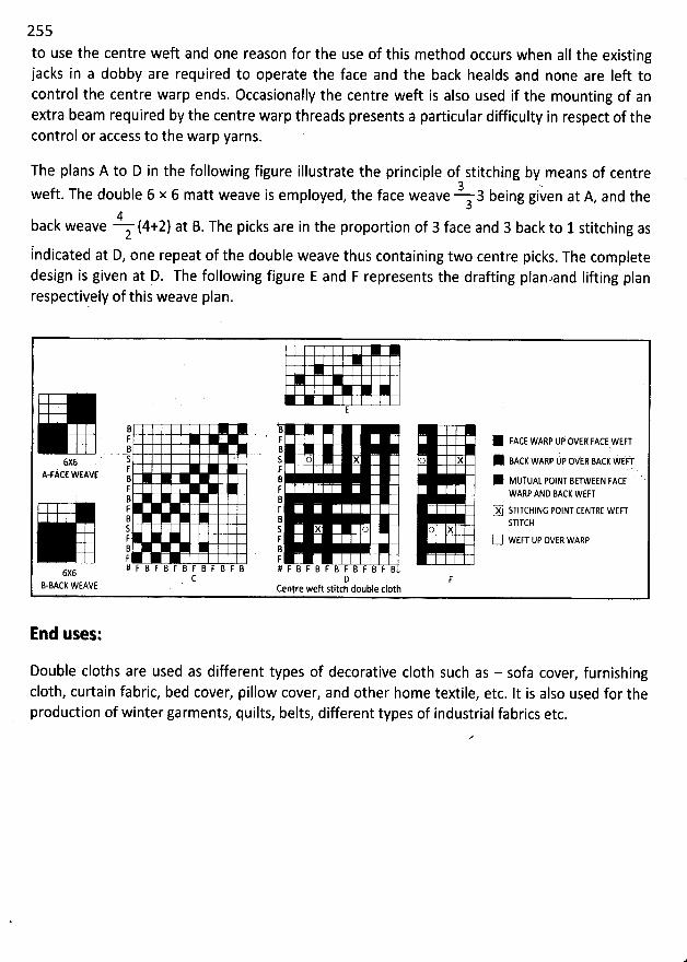
255
to use the centre wek and one reason for the use of this method occurs when aII the existingjacks in a dobby are required to operate the face and the back healds and none are Ieft tocontrol the centre warp ends. Occasionally the centre weft is also used if the mounting of anextra beam required by the centre warp threads presents a particular difficulty in respect of thecontrol or access to the warp yarns.
The plans A to D in the following figure illustrate the principle of stitching by means of centre3 -weft. The double 6 x 6 matt weave is employed, the face weave 3 being given at A, and the3
4back weave z (4+2) at B. The picks are in the proportion of 3 face and 3 back to 1 stitching aslndicated at D, one repeat of the double weave thus containing two centre picks. The completedesign is given at D. The following figure E and F represents the drafting planaand Iifting planrespectively of this weave plan.
E
B- F F ' 1 FACE WARP UP OVER FACE WEFTB
B '.. s . - s () X o X W BACK WARP UP OQ'EF BACK WEW6X: . .F F . .A
-FACE WEAW : : 1 MtlytlAt pojN.r BE-t-wEE:N FAcE 'F F wAqp ANI) BAcy WEFTB BF F (X STITCHING POINT CENTRE WEFTB
B s'rjycHS 5 X O (7 XF F Z WEF'T UP OVER WARPB BF F# F B F B F B F B F B F B # F B F B F B F B F B F B6X6
C D FB-BACK WEAVE ' centre weft stitch double 610th
End uses:
Double cloths are used as different types of decoratike c10th such as - sofa cover, furnishingc10th, curtain fabric, bed cover, pillow cover, and other home textile, etc. It is also used for theproduction of winter garments, quilts, belts, different types of industrial fabrics etc.
256
FABRIC USED IN APPAREL SECTOR
Fabric based on Plain weave:
1. Georgette: It is made with filament yarns. In georgette, the direction of the crepe twist(S or Z) for warp and weft yarns alternates. For example, even-numbered warp and weftyarns may be S-twist and odd-numbered yarns may be Z-twist. It can be a solid colour orprinted. It is very light weight, drape well, and is used in apparel. lt was originally madeof silk but now often is made from manufactured filament yarns
.
1. EhiWon: lt is made from fine, highly twisted filament yarns. Because of the tightly
twisted crepe yarns, chiffon has excellent drape, very Iight weight, and although it is
delicate in appearance, it is relatively durable. It can be a solid colour or printed. It wasoriginally made of silk but now often is made from manufactured filament yarns
. Sheerevening dresses, blouses, Iingerie, and other dressy apparel are constructed from thefabric.
3. Voile: Voile is a sheer fabric made with high twist or voile twist spun yarns that arecombed or worsted. It is a soft fabric with some what Iower fabric count and has adistinctive two pIy warp and good drapability. lt can be solid colour or printed. Voile wasoriginally a cotton or wool fabric, but it is now available with many fibre contents
.
4. Organdy: lt is the sheerest cotton fabric that is given a temporarily or permanentlystiffened finish. Combed yarns contribute to its sheer appearance
. Its sheerness andcrispness are the result of an acid finish on Iawn gray goods. Because of its stiffness andfibre content, it is vew prone to wrinkling. It is used for curtains and for summer weightapparel. It is available in solid colours or prints. Fabric construction: similar to Iawnfabric.
Georgette Chiffon Voile
c . . .... (c e .. tk:t
L ')-
Qj(,
Organdy
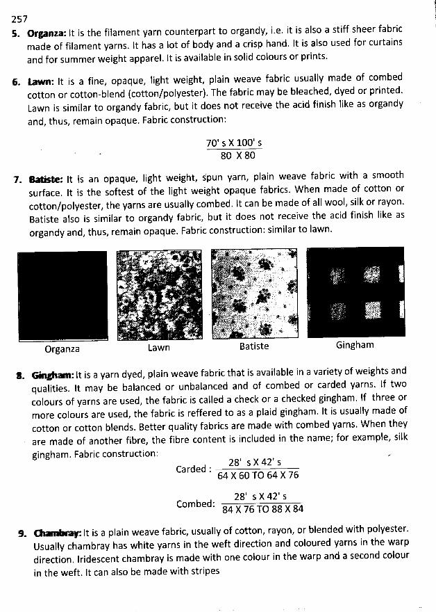
2575. - *: lt is the filament yarn counterpart to organdy, i.e. it is also a stiff sheer fabric
made of filament yarns. It has a Iot of body and a crisp hand. It is also used for curtainsand for summer weight apparel. It is available in solid colours or prints.
6. 1- : lt is a fine, opaque, light weight, plain weave fabric usually made of combed
cotton or cotton-blend (cotton/polyester). The fabric may be bleached, dyed or printed.Lawn is similar to organdy fabric, but it does not receive the acid finish like as organdy
and, thus, remain opaque. Fabric construction:
70' s X 100' s80 X 80
7- *------- It is an opaque, Iight weight, s'pun yarn, plain weave fabric with a smoothsurface. It is the softest of the Iight weight opaque fabrics. W hen made of cotton orcotton/polyester, the yarns are usually combed. lt can be made of alI wool, silk or rayon.Batiste also is similar to organdy fabric, but it does not receive the acid finish Iike asorgandy and, thus, remain opaque. Fabric construction: similar to lawn.
fQ W. oj T. . .. . . a. j..s. v .. .jjjjj;; 'L;1!4r *$111r ' ''' '
. . . :2
J. (. ' ... /+ .' .. . . '
'S: f' ''. .. ' . . : .. Ar . F .
.j . 1. - . .... ,.j
'
.. . ). .. NT
*# .i
Organza Lawn
*. :lt is a yarn dyed, plain weave fabric that is available in a variety of weights andqualities. lt may be balanced or unbalanced and of combed or carded yarns. lf twocolours of yarns are used, the fabric is called a check or a checked gingham. If three ormore colours are used, the fabric is reffered to as a plaid gingham. It is usually made ofcotton or cotton blends. Better quality fabrics are made with combed yarns. W hen theyare made of another fibre, the fibre content is included in the name; for exam ple, silk
gi ngham . Fabric construction :28' s X 42' s
Carded :64 X 60 TO 64 X 76
28' s X 42' sCombed: 84 X 76 TO 88 X 84
9. - It is a plain weave fabric, usually of cotton, rayon, or blended with polyester.Usually chambray has white yarns in the weft direction and coloured yarns in the warpdirection. Iridescent chambray is made with one colour in the warp and a second colour
in the weft. It can also be made with stripes
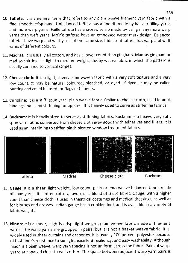
25810. Taffeta: It is a general term that refers to any plain weave filament yarn fabric with a
fine, smooth, crisp hand. Unbalanced taffeta has a fine rib made by heavier filling yarnsand more warp yarns. Faille taffeta has a crosswise rib made by using many more warpyarns than weft yarns. Moir'e taffetas have an embossed water mark design. Balancedtaffetas have warp and weft yarns of the same size. Iridescent taffeta has warp and weftyarns of different colours.
11. M adras: lt is usually aII cotton, and has a Iower count than gingham. Madras gingham ormadras shirting is a Iight to medium-weight, dobby weave fabric in which the pattern isusually confined to vertical stripes.
12. Cheese c10th: It is a Iight, sheer, plain woven fabric with a very soft texture and a very1ow count. lt may be natural coloured, bleached, or dyed. If dyed, it may be calledbunting and could be used for flags or banners.
13. Crinoline: It is a stiff, spun yarn, plain weave fabric similar to cheese c10th, used in bookbindings, hats and stiffening for apparel. It is heavily sized to serve as stiffening fabrics.
14. Buckram: lt is heavily sized to serve as stiffening fabrics. Buckram is a heavy, very stiff,spun yarn fabric converted from cheese c10th gray goods with adhesives and fillers. It isused as an interlining to stiffen pinch pleated window treatment fabrics.
. (.tii .. .
Taffeta M adras Cheese c10th Buckram
15. Gauge: It is a sheer, Iight weight, low count, plain or Ieno weave balanced fabric madeof spun yarns. It is often cotton, rayon, or a blend of these fibres. Gauge, with a highercount than cheese c10th, is used in theatrical costumes and medical dressings, as well asfor blouses and dresses. Indian gauge has a crinkled Iook and is available in a variety of
fabric weights.
16. Ninon: lt is a sheer, slightly crisp, Iight weight, plain weave fabric made of filamentyarns. The warp yarns are grouped in pairs, but it is not a basket weave fabric. It iswidely used in sheer curtains and draperies. It is usually 100 percent polyester becauseof that fibre's resistance to sunlight, excellent resiliency, and easy washability. Althoughninon is a plain weave, warp yarn spacing is not uniform across the fabric. Pairs of warpyarns are spaced close to each other. The space between adjacent warp yarn pairs is
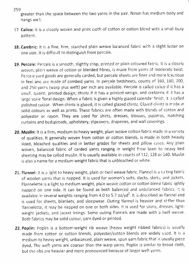
259greater than the space between the two yarns in the pair. Ninon has medium body andhangs well.
17 Calico: It is a closely woven and print c10th of cotton or cotton blend with a small busy
pattern.
18. Cambric: It is a fine, firm, starched plain weave balanced fabric with a slight Iuster onone side. lt is difficult to distinguish from percale.
19. N rcale: Percale is a sm00th, slightly crisp, printed or plain coloured fabric, lt is a closelywoven, plain weave of cotton or blended fibres, is made from yarns of moderate twist,Percale yard goods are generally carded, but percale sheets are finer and more luxuriousin feel and are made of combed yarns. In percale bedsheets, counts of 160, 180, 200,and 25O yarns (warp plus weft) per inch are available. Percale is called calico if it has asmalf, qua int, printed design; chintz if it has a printed design; and creton ne if it has alarge scale floral design. W hen a fabric is given a highly glazed caiendar finisln, it is calledpolished cotton. W hen chintz is glazed, it is called glazed chintz. Glazed chi rltz is made insolid colours as well as prints. These fabrics are often made with blends of cotton andpolyester or rayon. They are used for shirts, dresses, blouses, pajamas, matchingcurtains and bedspreads, upholstery, slipcovers, draperies, and wall coverings.
20. Muslin: lt is a firm, medium to heavy weight, plain weave cotton fabric made in a varietyof qualities. It generally woven from cotton or cotton blends, is made in b0th heavilysized, bleached qualities and in better grades for sheets and pillow cases. Any plainwoven, balanced fabric of carded yarns ranging in weight frow Iawn to heavy bedsheeting may be called m uslin. It is usually available in counts of 112, 128 or 140. M uslinis also a name for a medium weight fabric that is unbleached or white,
21. Flannel: lt is a light to heaky weight, plain or twill weave fabric. Flannel is a suiting fabricof woolen yarns that is napped. It is used for women's suits, slacks, skirts, and jackets.Flannelette is a Iight to medium weight, plain weave cotton or cotton blend fabric Iightlynapped on one side. It can be found as both balanced and unbalanced fabrics. It is
2 f 1 a n n e I a n davailable in several weights ranging from 4.O to 5.7 oz/yd . It is described as
is used for sheets, blankets, and sleepwear. Outing flannel is heavier and stiffer thanflannelette, it may be napped on one or b0th sides, It is used for shirts, dresses, Iight-weight jackets, and jacket linings, Some outing flannels are made with a twill weave.Both fabrics may be solid colour, yarn dyed or printed.
22. Poplin: Poplin is a bottom-weight rib weave (heavy weight ribbed fabrics) is usuallymade from cotton or cotton blends, polyester/cotton blends are widely used. It is amedium to heavy weight, unbalanced, plain weave, spun yarn fabric that is usually piecedyed. The weft yarns are coarser than the warp yarns. Poplin is similar to broad c10th,but the ribs are heavier and more pronounced because of Iarger weft yarns.
2 6023. Broad c10th: lt is a mediu m w'eight urlbalanced plain weave with fine ribs. The rib weave
makes it crisper than medium weight balanced weaves. It is often made from cotton orcotton blends.
24. Bengaline: It is a Iustrous, du rable, warp faced fabric with haavy weft cords completelycovered by the warp. It is heavy weight fabrics with Iarge ribs, are used mostly inupholstery and furnishings.
25. Bed ford cord: It is found most often in furnishing fabrics such as bed spreads. It hasspun warp varns that are Iarger than the weft yarns. lt is a sturdy fa bric constructed witha pronounced Iengthwise cord. Bed ford cord is a heavy, warp faced, unbalanced piqueweave fabric with wide warp cords created by extra weft yarns floating across the backto give a raised effect,
26. Fa i I l e : F a i I ; e h a s a p ro m I n e nt r i b a n d i s r''n a d e w it h f i n e f i i a m (p n t ya rn s i n t h e 'vhiu r p a n clheavy spun ya rns i n th e weft. It is usua lIy heavy weight . a I though I ighte r wt? ight tissuefailles are also produced.
27. Dimity: Di mity is a sheer u n ba Ia nced fa b ric used f or a ppa re ! a rid wi n bow treatments. Ith a s h e a vy wa r p co rd s a t i n t e rva I s a c ro ss t h e f a b r i c . Th e co rd s m a ïf L'' e f o r m e d b # ya rn s1 a rge r th a n th ose u sed e l sewh e re i n th e f a b ri c o r bï? g ro u p i ng ya rn s toget h e r i n t h atarea. Either tecilnique prcduces the unique narrow band or stripe indicative of dimity.D i m ity is wh ite o r p ri nted .
28. Oxford: It is usually a 2x1 or 3x2 basket weave, It is most common as a 2x1 half basketweave, It may have a yarn tiyed warp and white weft and be called oxford chambray.Oxford looks like a balanced fabric because the warp yarns are f iner and have highertwist than the weft. Because of soft yarns and loose weave, yarn slippage may occur.Oxford fabrics are medium weight, soft, porous, and Iustrous. lt is often made of cottonor cotton blends, that Is used for shirts. Frequently, it is made with narrow colouredstripes in the warp, or a coloured warp,
29. Duck: lt is a strong, coarser, heavy, plain or basket weave fabric available in a variety ofweights and qualities. lt is similar to canvas. Duck is m ade w ith single or pIy yarns.
Different types of duck relate to which yarns (warp or weft) are plied and how many
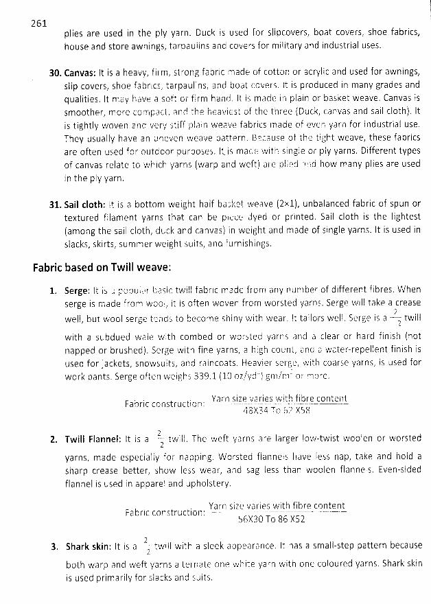
plies are used in the pIy yarn. Duck is used for Slipcovers, boat covers, Shoe fabrics,house and store awnings, tarpaulins and covers for military and induqtrial uses.
30. Canvas: It is a heavy, firm, strong fabric made of cotton or acrylic and used for awnings,slip covers, shoe fabrics, tarpaulins, and boat ccvers. It is produced in many grades andqualities. lt may have a soft or firm hanti. jt js made in plain or basket weave. Canvas issmoother, more compact, anc! the heat/iest of the three (Duck, canvas and Sail cloth). Itis tightly woven and verr Stiff plain weave fabrics made of even yarn for industrial use.They usually have an zneven weave pattern, Bqcause of the tight kveave, these fabricsare often used f or outdoor pu rposes. lt. is macl :? with Single or ply yarns, Different typesof canvas relate to which yarns (warp and weft) are pliecl olld how many plies are usedin the pIy yarn.
31. Sail c10th: It is a bottom weight half Lazket weave (2x1), unbalanced fabric of spun ortextured filament yarns that can be pktjce ulyed or printed. Sail c10th is the Iightest(among the sail c10th, duck and canvas) in weight and made of Single yarns. It is used inslacks, skirts, summer weight suits, and furnishipgs.
Fabric based on Twill weave:
Serge: lt i: ; popuic!r basic twill fabrlc made from any number of different fibres. ïvhenserge is cqade from wool, it is often woven from worsted yarns. Serge will take a crease
2weil, but wool serge tciiad.g to become shiny with wear. It tailors well, Serge is a twill2
with a subdued waie with combed or worsted yarns arid a clear or hard finish (notnapped or brushed). Serge with fine yarns, a high count, arnn a water-repellent finish isused for jackets, snowsuits, and raincoats. Heavier ser'ge, with coarse yarns, is used for
' / cl t) rc/r'rl' or more.work pants. Serge often weighs 389.1 (10 oz, y , g ,
Y a r n j i ; it y' a r.i q s .w' i t .!3 f i i:) r q? c C) n yytl l?-t.Fabric construction : - -- . . cq - -40/34 To 62 XS8
22, Twill Flannel: lt is a ' tkvirl. The weft varns are larger Iow-twist woofen or worsted
2yarns, made especially foi- napping, W orsted flannels have Iess nap, take and hold asharp crease better, show Iess wear, and Sag Iess than woolen flannels. Even-sidedflannel is used in apparel and upholstery.
Ya rn size va ri es with f i bre contentFa Lric construction : --'----'----- -- '- ' -' -'- - --' --'-56X30 T
o 86 XS2
- V twill with a sleek appearance. It has a small-step pattern because3. Shark skin: It is a 2
b0th warp ancl weft yarns alternate one white yarn with one coloured yarns. Shark skin
i s u S ed p ri m a ri Iy f o r s I a cks a n d s u i ts .
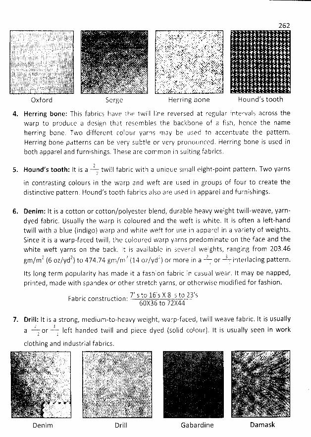
. 1 ' . *z.* .. yk . . .. ' ' g . è#. . .. #; . ; A .>. ujy y' y,y : ya. . , . . ' - z,r n'...g
t9q. 4,::.. . wqj, v( . . ) jg:we - s.' - . ,:. .yx.ua ?k . 1. . . .)3. ?qj . . sur v:,. jsvzyr.sz. aze..s.. ..1$, . kr. ;g.;qjj,. jjr ;4. . jjy.;,;. .pe Jfr .. >. . xr zn' x. yrl''. zr-:e >...x x ge ..xv . .. x u;. ,
Serge
4. Herring bone: This fabrics have the twill line reversed at regular intervals across thewarp to produce a design that resembles the backbone of a fish, hence the nameherring bone. Two different colour yarns may be used to accentuate the pattern.Herring bone patterns can be very' subtle or very pronotlnced, Herring bone is used inboth apparel and furnishings. These are common in suiting fabrics,
z 25. Hound s t00th: It is a twill fabric with a unique small eight-point pattern. Two yarns
2
in contrasting colours in the warp and weft are used in groups of four to create thedistinctive pattern . Hound's t00th fabrics also are used in apparel and furnishings.
Hound's t00th
6. Denim: It is a cotton or cotton/poiyester blend, durable heavy weight twill-weave, yarn-dyed fabric. Usually the warp is coloured and the weft is white. It is often a Ieft-hand
twill with a blue (indigo) warp and white weft for Use in apparel in a variety of weights.Since it is a warp-faced twill, the colotlred warp yarns predominate on the face and thewhite weft yarns on the back. lt is available in several weights, ranging from 203.46
2 2 2 2 2 3gm/m (6 oz/yd ) to 474.74 gm/m (14 oz/yd ) or more in a ? or : interlacing pattern.Its Iong term popularity has made it a fashion fabric in casual wear. It may be napped,printed, made with spandex or other stretch yarns, or otherwise modified for fashion.
7-J' .g-o 1 6 ' s X 8 ' j. t p 2 ) ' jFabric construction: . - .
60X36 to 7jkki
7. Drill : lt i S a strong, m ed i u m-to-h eavy weight, wa rp-f aced, twi l I weave f a bric. It is usua 1Iy2 3
a or -- Ieft handed twill and piece dyed (solid colour). It is usually seen in work2 l
clothing and industrial fabrics.
Gabardine Damask
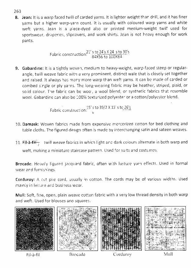
2 6 38. Jean: It is a warp faced twill of carded yarns. It is Iighter weight than drill, and it has finer
yarns but a higher warp-yarn count. It is usually with coioured warp yarns and whiteweft yarns. Jean is a piece-dyed also or printed medium-weight twill used forsportswear, draperies, slipcovers, and work shirts. Jean is not heavy enough for work
pants.
71.' 9 !9.-.?.4-1 ï- ?$ @ 1..3.(?.'îF a b r i c c o n st r u ct i o n .
-
j . j ja-jjq '84X5 to
Gabardine: lt is a tightly woven, medium to heavy-weight, warp-faced steep or regular-angle, twill weave fabric with a very prominent, distinct wale that is closely set togetherand raised. lt always has many more warp than weft yarns. lt can be made of carded orcombed single or pIy yarns. The Iong-wearing fabric may be heather, striped, plaid, orsolid colour. The fabric can be wool, a wool blend, or synthetic fabrics that resemble
wool. Gabardine can also be 100% texturized polyester or a cotton/polyester blend.
>@' %!:J-$?.ï-?,5' 1-$9-26'1Fabric construction .
v
10. Damask: W oven fabrics made from expensive mercerized cotton for bed clothing andtable cloths. The figured design often is made by interchanging satin and sateen weaves.
twill weave fabrics in which light ancl clark colours alternate in b0th warp and
Brocade: Heavily figured jacquard fabric, often with lusture yarn effects. Used in formalw e a r a n d f u r n i s h i n g s .
Corduroy: p. cut pile cord, usually in cotton. The cords may be of various widths, Used
m a I n Iy i n I e i 'S u re a n d bu s i n ess wea r.
M ulI: Soft, fine, open, plain weave cotton fabric with a very Iow thread density in b0th warpand weft. Used for blouses and squares.
F i I - ) - f i l Brocttde C.- ord tlroy M tlll
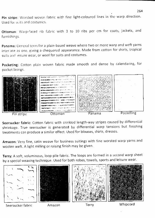
264
in the warp .direction.Pin stripe: W orsted woven fabric with fine Iight-coloured Iines
Used for suits arld costumes.
Ottom an:furnishings.
Panam a: General term for a plain-based weave where two or more warp and weft yarnsinterlace as one, giving a chequered appearance. M ade from cotton for shirts, tropical
suits arlcl Ieisure wear, or wool for suits and costumes.
Pocketing: Cotton plain woven fabric made sm00th and dense by calendaring, for
pocket linings.
to 10 ribs per cm for coats, jackets, andW a r p -f a c e d ri b
;a !
Pin strip e
f'
' J.*'2.$ '' '' ' '.y 'R * ' & '' o 'ö'' ' ' 4' F'
' 6' '' œ * ' ' t ' ' A1 4: .* *T1 .; s h . .:a ' '
' #T'' ># -r.. 2J' ff L '' '''K A'' *-S1 <' ''''' **' $4.% G +* ' - - ' '' Z# ' '' K ' ' ' ' '- 5'P9 # ' ' 'Z' /.R7. e l ' ' '' #ti*',*.Y ''PA $'$ V>X *%L* ' *' '2' '
' ïd''s* ''&F'* 'îV e' - *'1 >'' 'm*' ' ' ' -' '* 4 . t ' l'C# .#M<'A*W1+ey> # '*%Q 4* Hf 7 >'' '
e e Yt#sY@k'<' '** * '#* *' *4' '''*4--* - - - :- +. ç'z- ' > r ' '%*' a e- . * k>>e% +
..* Re .+'e '*' 'F% *Y > *' +ptx..vg ' ' .' a- - ' *w?> %f '
ttom an Poc eting
Seersucker fabric: Cotton fabric with crinkled Iength-way stripes caused by differentialshrinkage. True seersucker is generated by differential warp tensions but finishingtreatm ents can produce a similar effect. Used for blouses, shirts, dresses.
Amazon: Very fine, satin weave for business suitings with fine worsted warp yarns and
woolen weft. A light m illing or raising finish m ay be given.
Terry: A soft, voluminous, Ioop pile fabric. The loops are formed in a second warp sheetby a special weaving technique. Used for bath robes, towels, sports and Ieisure wear.
*' - %j.j N> w a
$ ...-
j -NMy .N
Seersucker fabric Amazon Terry W hipcord
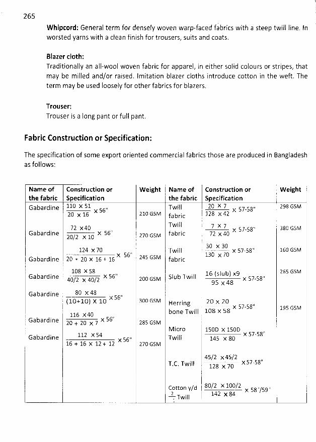
265
W hipcord: General term for densely woven warp-faced fabrics with a steep twill Iine. Inworsted yarns with a clean finish for trousers, suits and coats.
Blazer c10th:Traditionally an all-wool woven fabric for apparel, in either solid colours or stripes, thatmay be milled and/or raised. Imitation blazer cloths introjuce cotton in the weft. Theterm may be used Ioosely for other fabrics for blazers.
Trouser:Trouser is a Iong pant or full pant.
Fabric Construction or Specification:
The specification of some export oriented commercial fabrics those are produced in Bangladeshas follows:
Name of Construction or W eight Name of Construction or W eightthe fabric Specification the fabric I SpecificationGabardine 110 X 51 ,, Twill 20 X 7 ,, 298 GSMx 56 X 57-58
20 x 16 210 GSM fabric 128 X 42Twill 7 x 7 ,,
1
aac Gsv72 x40 x 57-58 jGabardine x 56'1 i.Jz Gsv fabric 72 x 4020/2 )( 10
30 x 30124 x 70 Twill x 57-58'' 160 GSM
x 56.1 z4s Gsu 130 x 70Gabardine 20 + 20 x 16 + 16 fabric
1O8 x 58 16 (sjub) x9 26S GSMGabardine 4042 x 40/2 X 56'' 2:o Gsu Slub Twill x 57-58.,
95 x 48
Gabardine 80 X 48x 56.'( 10+10) X 10 30O GSM Herring 20 X 20 '
x 5.2-s8'' 1,s Gsvbone Twill I 108 x 58
, ,1 1 1 6 x 4 O c c !Gabardine 2c + 2c x 7 X atl 28s GsM lM icro 15OD x 15OD
112 x 54 X 57-58.'Gabardine x s6'' Twill 145 x 8016 + 16 x 12 + 12 27O GSM
45/2 x45/2T C Twill X 57-581'. . jzg x 70
II 80/2 x looy
.y- ,, ,,cotton y/d x s8 /s9.-?-. 142 x 84Twill1
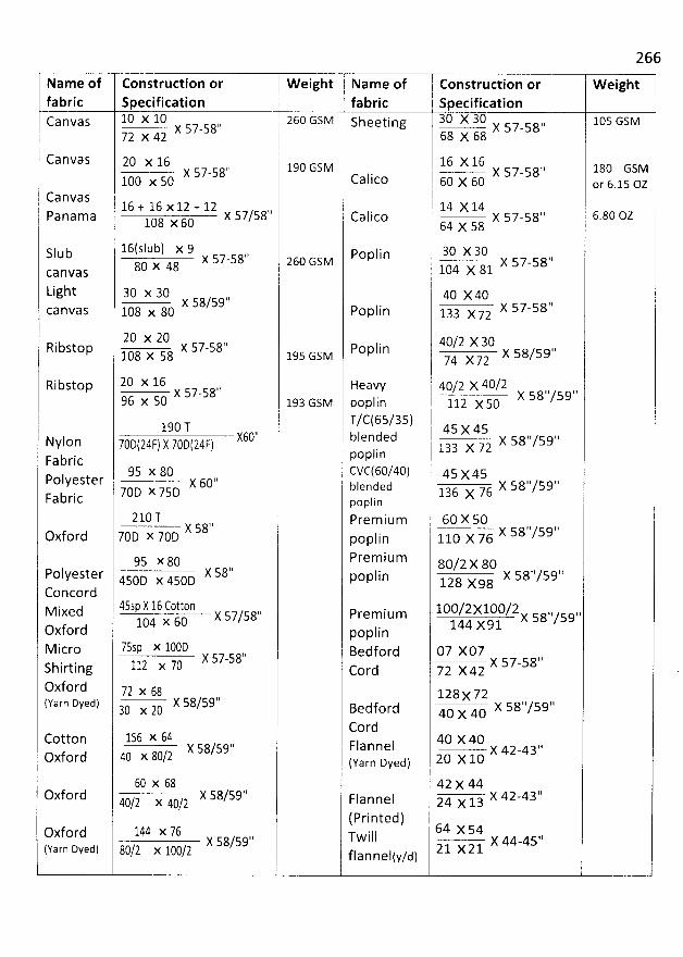
266
Name of Construction or Weight Name of j Construction or Weightfabric Specification fabric i Specification
canvas 10 x 10 26O GSM sheeting 30 X 30 1, 105 GSMI x 57-s8'' 6a x 6a X 57-5872 x 42
1Canvas 20 x 16 1,c Gsv 16 X 16 ,1 1ac Gsux 57-58'' j X 57-581O0 x 50 Calico 60 x 60 or 6
.15 ozi
'
Canvas16 + 16 x 12 + 12 lj l 14 X 14Panama x 57/58 c
alico I x 57-58'' 6.80 OZ108 x 60 64 x 581
I16(sIub) x 9 poplin 30 X 30Slub x s7-58'' z6c Gsv x s7-sa''80 x 48
1o4 x 81canvas
Light 30 x 30 ,, l 40 x 40
x 58/59 y s7-s8''canvas 1o8 x 80 Poplin 133 x 72
20 x 20 ,, 40/2 x 30Ribstop x 57-58 Poplin y s8/5at'1O8 x 58 195 GSM ./4 x72
Ribstop 20 X 16 Heavy 40/2 X 40/2x 57-58'' i 58,,/59,'96 x 50 193 Gsv poplin l 112 x 50
. T/c(65/35) 119O T j 4s x 45xo'' blended y s8''/s9''Nylon
7ûD(24F) y 7gD(24r) j laa x 72poplinFabric r
95 x 80 CVC(6O/4O) 45 x45Polyester x 60', bjended ./6 x s8''/59''7OD x 75D 136 x
Fabric poplin21O T Prem ium 60 X 50
X 58'' '' ''X 58 /59Oxford 7OD x 7OD poplin 110 X 7695 x 80 Premium 80/,. x 80P
olyester X 58'. Iin X 58''/59',450D x 450D P0P 128 x98Concord
d 45s;y 16 Cotton 1oo/2x1o0/2 ,, ,,M ixe y s7/s8'' Premium x s8 /s9104 X 60 144 X91
Oxford poplinM icro 7559 )( ICCD Bedford 07 XO7
X 57-58'' x s7-sa''Shirting 112 )( 70 cord 72 X42Oxford 72 x 62 128x 72(Yarn Dyed) X 58/591' Bedford 40 x 40 X 58''/59'130 x 20
CordCotton 156 X 61 40 X 40
X 58/59'' Flannel x 42-4a,,Oxford rû x 80/2 (yarn Dyed) 20 X 10
60 x 68 42 x 44Oxford X 58/59'' Flannel 24 x 13 X 42-43'.40/2 x 40/2
(Printed)Oxford 1M X 76 Twill 64 X 54X 58/59'' X 44-45.'('farn Dyed) 82/2 x 122/2 flannelty/d) 21 X21
267N. . 'AL ..z ' X
. 1* -..tX ' ' '=V
%. #
f . .. . x ... t. ' , oswcxy-ml1 .+. 'kjjjr' ' .. ;tjN';'lk..syy . , .. . to,..k: . . .. . .. . 4,. x.. . ..y . yy r .. 5 . w -, $! . . y . . . (.
c A r . . x. .k* .w... . . 'à . lj m. , pvsk w .. NM l
'! . . . . , ,-z.. f. y..... ..l x ..w. 'jsvçyw..ikx . , . . .! . w. . . . . y.>. . l > . .. &G.vt'O ' ' a -,#y. o. w..w ' . /' F. :. . .'.t . < x V. ' t .>'x ''- . x+*?* g i . p.....,> . .v r -..1 # /
e ' X k ''.? '' ' *li ...-. . -,'',,. .
..r . > r .. . S. .
> c . lK . .x.-. . . - ;. w f,
.s .au . . .z. . 11. . . . A i j; v ' '1 - . ''5 'FG',G . ' . - x.
# eli - >** '* ' ' '
1 .< ' .4 4 . . . . . ', A..> . .r ..x. < ' j . S :.1 é . M .J xt- la , ' . . Yz . -. . . . . . y ù
23 .1 . ....èb .. .. .. . ...; *' .î : . x !
SPECIAL FABRIC PRODUCTION
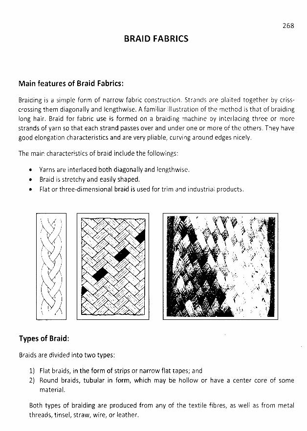
268
BRAID FA BRICS
Main features of Braid Fabrics:
Braiding is a simple form of narrow fabric construction. Strands are plaited together by criss-crossing them diagonally and lengthwise. A familiar illustration of the method is that of braidinglong hair, Braid for fabric use is formed on a braiding machine by interlacing three or morestrands of yarn so that each strand passes over and under one or more of the others. They havegood elongation characteristics and are very pliable, curving around edges nicely.
The main characteristics of braid include the followings:
@ Yarns are interlaced b0th diagonally and Iengthwise.Braid is stretchy and easily shaped.
* Flat or three-dimensional braid is used for trim and industrial products.
). b( )yz tl V ))/k,/'
' -(2/
;7
# î /'ï
. . z z .' x NXX N ' '. . . wZ, z % .
x y*.. . . z .z. . z'y' xxx zy ' . ' . zx .. . . . w z. N . w .x .'xx vgv xkx.. z xx., y x . x' . a y' . w V.,.'' x x x Z .N'.
. x ,,..* .... x . Z V ,. . x . . . x z..zw z . zz .
. ....' .z z ' x x x ''z.,,..%'-X NX''X 'x ' N zx 'x ..'.' s x .
X'x z-' z' sxs N ' z.s ..z. x . . x
K X X .N 'x x . w
. . .y* N X 'x f N'.' .Z . . A/ 'ze xM T. -zz-.. .-
zz-zzz-zz . .,-.Z x % ' '' .z . Z ' e /. X. rx . ..' . .
,z' ' z' N X. .z '.' z' , > z' x '' V' ' ' ' ' 'x ZV . N. Z 'x z . . zk x /.. x'xx Xx z
. / ..ZxN ..z' xx .. . zvK. ' . yy x 'x . z'z x x . z x xr N'. 'x zz' ' x 'x. .r y ' s- zsxm Z z
.z X. z. x x x .z'
Types of Braid:
Braids are divided into two types:
1) Flat braids, in the form of strips or narrow flat tapes; and2) Round braids, tubular in form, which may be hollow or have a center core of some
material.
Both types of braijing are produced from any of the textile fibres, as well as from metalthreads, tinsel, straw, wire, or leather.
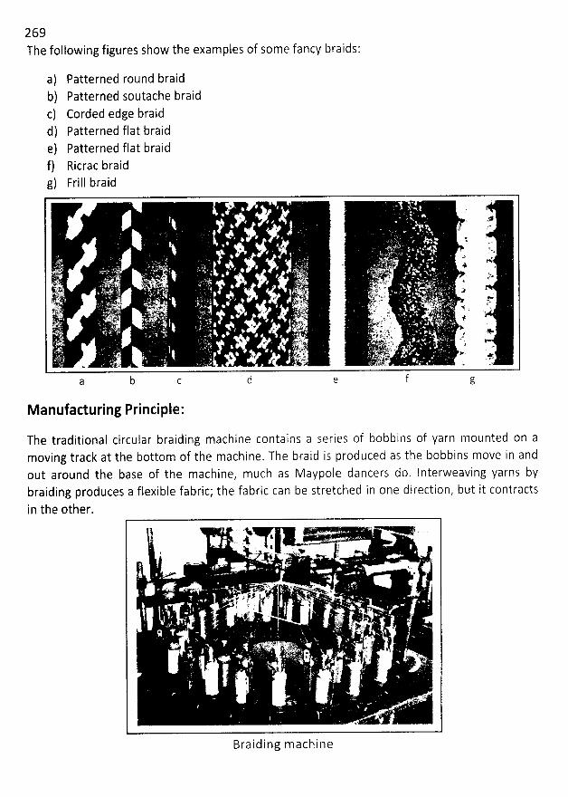
269The following figures show the examples of some fancy braids:
a) Patterned round braidb) Patterned soutache braidc) Corded edge braidd) Patterned flat braide) Patterned flat braidf) Ricrac braidg) Frill braid
M anufacturing Principle:
The traditional circular braiding machine contains a series of bobbins of yarn mounted on amoving track at the bottom of the machine. The braid is produced as the bobbins move in andout around the base of the machine, much as Maypole jancers do. Interweaving yarns bybraiding produces a flexible fabric; the fabric can be stretched in one direction, but it contractsin the other.
Braiding m achine
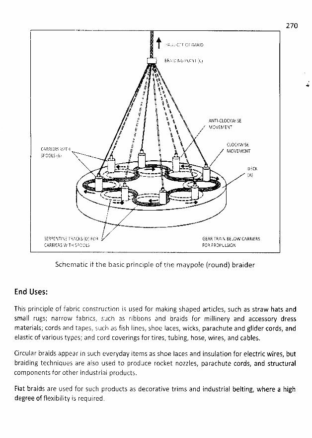
270
) HAJL-OFF 0F BFIAIDB RA1 D E NG PO1 NT ( C)
1. $1?/ t$.?? j.%1 q $ a
l -j 1 'q? , ..t lf t/ 1 l j4 /? $.. 4 , l
ç .rê l 1. 3
, ANTI-CLOCKwISE; // î j $, z VOVEaENT? ?? 't & ,'? 11 '$
. î ' /
?' j :l #? J $
. $ CLOCFCWiSECARFIIERT vk.'pTFi / t uovEvsNySpotlLs f8) Xx à
f.1 *-*.1 1 DECK
.V-Z * -W --vy. x.w . w...... jx ; (Ayw œ - - *
--p j . I .L*..< vk
xko . 1 : . .----- -
--
- - .. . -.! jv;.-- - ->. . ----- çQ --
SERPENTI N E TRACIIS (D) F0R GEAR TRAIN 8ELOW CARRIERSCARRI E RS WITH S@OO LS F0R P EOPU LS1 ON
Schematic if the basic principle of the maypole (round) braider
*
End Uses:
This principle of fabric construction is used for making shaped articles, such as straw hats andsmall rugs; narrow fabrics, such as ribbons and braids for millinery and accessory dressmaterials; cords and tapes, such as fish Iines, shoe Iaces, wicks, parachute and glider cords, andelastic of various types; and cord coverings for tires, tubing, hose, wires, and cables.
Circular braids appear in such everyday items as shoe Iaces anj insulation for electric wires, butbraiding techniques are also used to produce rocket nozzles, parachute cords, and structuralcomponents for other industrial products.
Flat braids are used for such products as decorative trims and industrial belting, where a highdegree of flexibility is required.
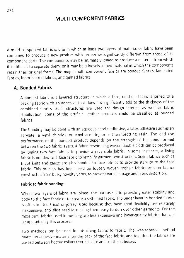
271
M ULTI COM PONENT FABRICS
A multi component fabric is one in which at least two Iayers of material or fabric have beencombined to produce a new product with properties significantly different from those of itscomponent parts. The components may be intimately joined to produce a material from whichit is difficult to separate them, or it may be a Ioosely joined material in which the componentsretain their original forms. The major multi component fabrics are bonded fabrics, laminatedfabrics, foam-backed fabrics, and quilted fabrics.
A. Bonded Fabrics
A bonded fabric is a Iayered structure in which a face, or shelt, fabric is joined to abacking fabric with an adhesive that does not significantly add to the thickness of thecombined fabrics. Such structures are used for design interest as well as fabricstabilization. Some of the artificial Ieather products could be classified as bonded
fabrics.
The bonding may be done with an aqueous acrylic adhesive, a Iatex adhesive such as anacrylate, a vinyl chloride or vinyl acetate, or a thermosetting resin. The end uSeperformance of the bonded product depends on the strength of the bond formedbetween the two fabric layers. A fabric resembling woven double c10th can be producedby joining two face fabrics to provide a reversible fabric. ln some instances, a liningfabric is bonded to a face fabric to simplify garment construction. Scrim fabrics such astricot knits and gauze are also bonded to face fabrics to provide stability to the facefabric. This process has been used on Ioosely woven mohair fabrics and on fabricsconstructed from bulky novelty yarns, to prevent yarn slippage and fabric distortion.
Fabric to fabric bonding:
When two Iayers of fabric are joined, the purpose is to provide greater stability andbody to the face fabric or to create a self-lined fabric. The under layer in bonded fabricsis often knitted tricot or jersey, used because they have good flexibility, are relativelyinexpensive, and slide readily, making them easy to don over other garments, For themost part, fabrics used in bondicg are less expensive and lower-quality fabrics that can
be upgraded by this process,
Two methods can be used for attaching fabric to fabric. The wet-adhesive methodplaces an adhesive material on the back of the face fabric, and together the fabrics arepassed between heated rollers that activate and set the adhesive.
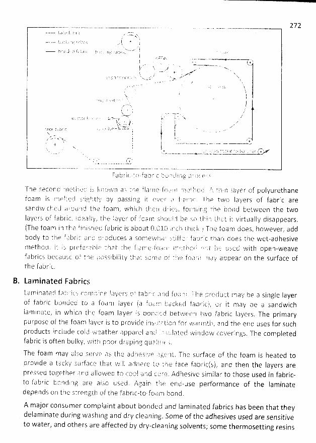
272
T h e s e c e n C# rfl et h f-)- (i t s k l-t () tA7 n a s t ht t:i f l a r-t'-l t? - 17 i'.'; a r'ln r'r'l f'.'? l 1,-1 (p (-.i . ?'.. t t ) i ln i. a ql e r of p o t y u r et h a nef o a m i s rn e l t e d s l i f.l h-2 't ! î,/ b y p a s s i n g i t c? v (r'5 r a f 1. ?') rll f û T h e t hA/ (.) I a y e rs of f a b r i c a reS a n d w i c h e J' a l-o u p? c-b t h e f o a ën'l , w h i c h t h e rl ci r- 1 fp !; , î, o / 1-:-. i 1' l g t h ia b o l '1 d betwe e n t h e twol a ye rs of fa i3 r' i c . t d ta a l l ''/ , t in e l aye r of 1:c a r'n s 1.è (.) tk ! J t'l e s a t il i (') t-f,-) a t i.t v i t-tu a l ly d i sa p pea rs .(Th e f oa m l n t h t? f i rn i s h e d f a b r i c i s a L') o u t O . 0 :1. 0 i rn (:. h t h i c k . .1 T !.3 e f o a crl kj- oe s , h oweve r, a d db od y to t h e f a b r i c a n tj p f o d u ces a so m e w i l C-S * -'ct i ff e j' f a t) r i c t i-) a ln d oe s t h e wet-a d h es ivem e t h o (.l . l t i :-, p re f a t' ,.) tn t êz'' t h a t t h e f. l a S''rh e - f (-1 a r ? ' . tn r t i-k o q ' ''t () t $,-.: tè- o s C2. d w i t h o p e n - w e a vef a b r i cs b e ca u se o f. t 8,-t e /.) t) s s i b i I i ty t h a t so rn ù'? 'o t' t I.a f.? tt7 J? !-i ) m t) y a p p e a r () n t h e s u rf a ce oft h e f a b r i t. .
B. Lam inated FabricsLa m i c atecl f ,..? !') l'i c s co n ) i) i rn e 1. aye rq c't f a ë) ri c -) c (1 f t)a y'v! -r p. ) e r; rc) C1, u ct m a y be a si ngle Iaye rof f a b ri c bor) ded to a foa m l aye r ( a f oa 7,) - 8-J a tèked f a b ri c ) , o i' it m ay be a sa n dwichla m i n ate, i n wh ich the foa m la ye r is bo n t-.1 r.ï t.'j betwee r) two fa b ric l a yers. Th e prima rypu rpose of the f oa m Iayer is to provide inst? tcèt iota fo r wk? rmth
, a nd the end uses for suchp rod u cts i n cl u d e co l cl..ïz'v't:?- at h e r a p p a re I a n ci ', ,7 z L1 I ?) ted wi rl d ow cove ri ngs . The co m p letedf abric is often bu I kv , k'.l it8 ! poor d ra pi (3g q u tq t t t tC. à .Th e foa m may a I so se Fve a s t h e a d ë-1 (a s t'v'e J) gf? n t . Th e s u rf a ce of th e foa m is heated top rovi d e a ta c ky s u rf, a ce t h a t vt' i I l a r.j h e re t (a t (7 e f a ce f a b ri ct s ) , a n d t h e n th e Ia ye rs a rep ressed togeth e r .? n d a l l owe cl to cot.a I a rq d t:L'. rt'? , Ad hes ive si m i I a r to those used i n fa bric-to-fa br ic bornd i rlg a re a Iso used . Aga i n tile end-use performance of the Ia minatedepeinds on the strength of the fabric-to-foa m bond .
A major consumer cornplaint about bonder.j and Iaminated fabrics has been that theydelaminate during washing and dry cleaning
. Some of the adhesives used are sensitiveto water, and others are affected by dry-cleaning solvents; some thermosetting resins
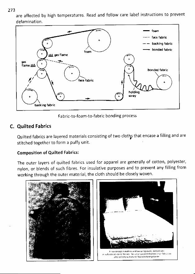
273are affected by highdelamination.
fK e fabric
+ ..... bx kjng fabric/'-*' foam o rded f'bric
* .< ys flame w..-
w- --w . +
f I .àl& '> - '*' *' .-ame -..x + o nded fabric
z * X; N N -/ f
xe fabricZ y )zz t
holdinq+ + Scr@Y
+Xba king fabric
temperatures. Read and follow care label instructions to prevent
Fabric-to-foam-to-fabric bonding process
C. Quilted Fabrics
Quilted fabrics are layered materials consisting of two clothé that encase a filling and arestitched together to form a puffy unit.
Composition of Quilted Fabrics:
The outer Iayers of quilted fabrics used for apparel are generally of cotton, polyester,nylon, or blends of such fibres. For insulative purposes and to prevent any filling fromworking through the outer material, the c10th should be closely woven.
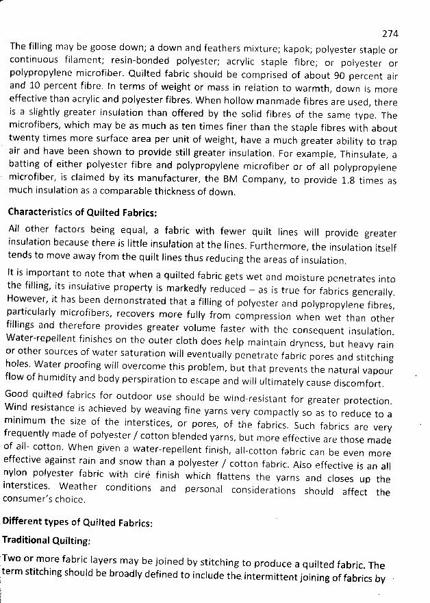
274The filling may be goose down; a down and feathers mixture; kapok; polyester staple orcontinuous filament; resin-bonded polyester; acrylic staple fibre; or pokyester orpolypropylene microfiber. Quilted fabric should be comprised of about 90 percent airand 10 percent fibre. In terms of weight or mass in relation to warmth
, down is moreeffective than acrylic and polyester fibres. W hen hollow manmade fibres are used
, thereis a slightly greater insulation than offered by the solid fibres of the same type
. Themicrofibers, which may be as m uch as ten times finer than the staple fibres with abouttwenty times more surface area per unit of weight, have a m uch greater ability to trapair and have been shown to provide still greater insulation. For exam ple, Thinsulate, abatting of either polyester fibre and polypropylene microfiber or of aII polypropylene
. microfiber, is claimed by its manufacturer, the BM Company, to provide 1.8 times asmuch insulation as a comparable thickness of down.
Characteristics of Quilted Fabrics:
All other factors being equal, a fabric with fewer quilt lines will provide greaterinsulation because there is Iittle insulation at the Iines
. Furthermore, the insulation itselftends to move away from the quilt Iines thus reducing the areas of insulation.
gets wet and moisturepenetrates intothe fillint, its insulativeHowever, it has been demonstrated that a
property is markedly reduced - as is true for fabricsgenerally.
filling of polyester and polypropylene fibres,particularly m icrofibers, recovers more fully from compression when wet than other
fillings and therefore provides greater volume faster with the consequent insulation.W
ater-repellent finishes on the outer c10th does heip m aintain dryness, but heavy rainor other sources of water saturation will eventually penetrate fab
ric pores and stitchingholes. W ater proofing will overcome this problem
, but that prevents the natural vapourflow of humidity and body perspiration to escape and will ultimately cause discomfort.
when a quilted fabricIt is im portant to note that
Good quilted fabrics for outdooruse should beprotection.W i
nd resistanc: is achieved by weaving fine yarns very com pactiy so as to reduce to aminimum the size of the interstices
, or pores, of the fabrics. Such fabrics are veryfrequently made of polyester / cotton blended yarns, but more effective are those m adeof a1l- cotton. W hen given a water-repellent finish
, all-cotton fabric can be even m oreeffective against rain and snow than a polyester / cotton fabric
. Also effective is an aIInylon polyester fabric with ciré finish which flattens th
e yarns and cioses up theinterstices. W eather conditions and personal considerations shouid affect theconsumer's choice.
wind-resistant for greater
Different types of Quilted Fabrics:
Traditional Quilting:
'I'wo or more fabric Iayers may be joined by stitching to produce a quilted fabric. Theterm stitching should be broadly defined to include the
. intermittent joining of fabrics by
275hand or m achinesewing, chemical point bonding, and ultrasonic pointquilted with both simple and more com plex patterns are available.
bondinj. Fabrics
M achine-stitched quilting
The traditional quilts stitched by hand had three layers: a face fabric, a fibre batt orfeather filling for warmth, and a backing fabric. Hand-sewn quilts are still produced ascraft item s, and machine-sewn products are also available. Such products are usedprimarify for bed coverings, but quilted apparel, upholstery fabric, and items such as
pot-holders are available as well.
Trapunto:
Trapunto is a type of quilting in which
then stuffed with fibres (orperiodically fashionable in
a design or pattern is outlined with stitches and
to form a high relief effect. Such designs aref i be rf i I I )apparel and upholstery.
Outline Quilting:
Outline quilting is a technique that stitches an outline around a printed designform a quilted fabric. Custom bedspreads and comforters of chintz or other printedfabrics often are made in this manner. Outline quilting is also called custom quilting.
motif to
Chemical Quilting:
Quilted products can also be produced by joining fabrictherm oplastic bonding agent. This process, called chemical
joining two fabrics than for joining three layers. The tradeprocess that produces a fabric by.joining two fabrics with
layers w ith an adhesive or aquiliing, is more popular fornam e chemstitch is useddifferent therm al stabilities.
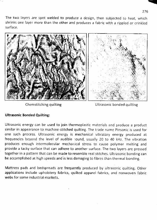
276
The two layers are spot welded to produce a design, then subjected to heat, whichshrinks one Iayer more than the other and produces a fabric with a rippled or crinkledsurface.
Chemstitching quilting Ultrasonic bonded quilting
Ultrasonic Bonded Quilting:
Ultrasonic energy can be used to join thermoplastic materials and produce a productsimilar in appearance to machine-stitched quilting. The trade name Pinsonic is used forone such process. Ultrasonic energy is mechanical vibratory energy produced atfrequencies beyond the Ievel of audible cound, usually 20 to 40 kHz. The vibrationproduces enough interm olecular mechallical stress to cause polymer melting andprovide a tacky surface that can adhere to another surface. The two layers are pressedtogether in a pattern that can be m ade to resemble real stitches. Ultrasonic bonding canbe accomplished at high speeds and'is Iess damaging to fibres than thermal bonding.
M attress pads and bedspreads are frequently produced by ultrasonicapplications inctude upholstery fabrics, quilted apparel fabrics, andwebs for some industrial markets.
quilting. Othernonwoven fabric
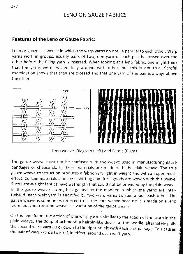
277
LENO OR GAUZE FABRICS
Features of the Leno or Gauze Fabric:
Leno or gauze is a weave in which the warp yarns do not Iie paralpel to each other, W arpyarns work in groups, usually pairs of two; one yarn of each pair is crossed over theother before the filling yarn is inserted. W hen Iooking at a Ieno fabric, one might thinkthat the yarns were twi.sted fully around each other, but this is not true. Carefulexamination shows that they are crossed and that one yarn of the pair is always abovethe other.
1& a r D
a/$F..
'
( , , t ' . y.jj/ j'. : .. +..-. Filling
j;
'''''''''''''''''''''''''''''''''''''''''''''''''''''''''''''''''''''''''''''''''''''''''''''''''d
. . . . j. , .i. j:jy. .. .,,( r
,tà),.... ,rz,,.
'ijj,yy..; . q.
- - .-y lkY ' qt j u sj o$. rk t h' ',-, , ,.
'. ïz a u N y/,t4 xz$,
.1 . k-$ -$
. ..'1b.
( z.-->y z' .- . Az-
,,z. c% .<
Leno weave: Diagram (Left) and Fabric (Right)
The gauze weave must not be confused with the weave used in manufacturing gauzebandages or cheese cloth; these materials are made with the plain weave. The truegauze weave construction produces a fabric very Iight in weight and with an open-mesheffect. Curtain materials and some shirtihg and dress goods are woven with this weave.
Such Iight-weight fabrics have a strength that could not be provided by the plain weave.
In the gauze weave, strength is gained by the manner in which the yarns are inter-twisted: each weft yarn is encircled by two warp yarns twisted about each other. Thegauze weave is sometimes referred to as the Ierlo weave because it is made on a lenoloom , but the true leno weave is a variation of the gauze w eave.
On the leno loom , thè action of one warp yarn is sim ilar to the action of the warp in theplain weave. The doup attachment
, a hairpin-like device at the heddle, alternately pullsthe second warp yarn up or down to the right or ieft with each pick passage. This causesthe pair of warps to be twisted
, in effect, around each weft yarn.
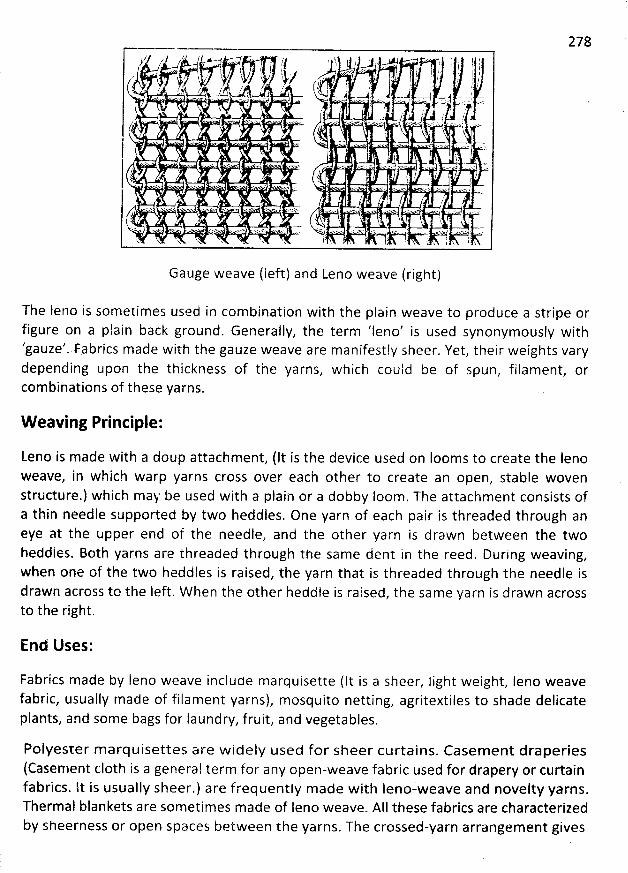
278
Gauge weave (Ieft) and Leno weave (right)
The deno is sometimes used in com bination with the plain weave to produce a stripe orfigure on a plain back ground. Generally, the term 'leno' is used synonymously with'gauze'. Fabrics m ade with the gauze weave are manifestly sheer. Yet, their weights varydepending upon the thickness of the yarns, which could be of spun, filament, orcom binations of these yarns.
W eaving Principle:
Leno is made with a doup attachment, (It is the device used on Iooms to create the denoweave, in which warp yarns cross over each other to create an open, stable wovenstructure.) which may be used with a plain or a dobby Ioom. The attachment consists ofa thin needle supported by two heddles. One yarn of each pair is threaded through aneye at the upper end of the needle: and the other yarn is drawn between the twoheddles. Both yarns are threaded through the same dent in the reed. During weaving,when one of the two heddles is raised, the yarn that is threaded through the needle isdrawn across to the Ieft. W hen the other heddle is raised, the sam e yarn is drawn acrossto the right.
End Uses:
Fabrics made by Ieno weave inciude marquisette (It is a sheer, light weight, Ieno weavefabric, usually made of filament yarns), mosquito netting, agritextiles to shade delicateplants, and some bags for laundry, fruit, and vegetables.
Polyester m arquisettes are w idely used for sheer curtains. Casem ent draperies(Casement (:10th is a general term for any open-weave fabric used for drapery or curtainfabrics. lt is usually sheer.) are frequently made with leno-weave and novelty yarns.Thermal blankets are sometimes made of leno weave. AII these fabrics are characterizedby sheerness or open spaces between the yarns. The crossed-yarn arrangem ent gives
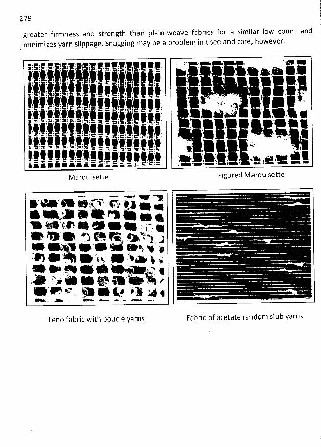
279 t11
greater firmness and strength than plain-weave fabrics for a similar Iow count and (m inimizes yarn slippage. Snagging may be a problem in used and care, however. (
11111k . dl;iljlk ,, ;; .9l . 1k jj 111 1) 41. . !! iryrijjk, j) , . lj. . . i. 3. d tj. ! j ta a j fj . ' ) . j j ., 4,:...111111111111' ik
d
'''' .11111!
. .;.,.,,
'
.. Jit
'
,j,
d
.
'
. '11111.111 .
'
jjy .
'
(jlj yjjj .
'
lg
'
jj ,,
'
1r
'
j. yj,:j
d
.
'
jjy
'
l. . 44g
*
. jjy
'
k;..
'
.
'
.71.71.
*
,j
'
,j
'
!j
'
111111111111111111
*
,
'
.
i , d !. !
'
i : ' 4 j j
'
t
'
. - $ .l . ' , z . a, . . ;' ; , , , j .- , , j j jj: -. , .: .1 .! : , : : t . .. . t ! ! j . - . t . : j . 1 -.. ) . .t l
T j j j j ' j ,11111111111 1Ir
'
,,.41
*
..d'
'
. .,
*
1.
*
.
'
..
'
di
'
4;.1:
*
.
'
.!r
'
!r
'
'
'
jj,'l' .1! 4j,1t. 4j
*
14 j,
'
,; ajj
'
l, .
'
4,9. , (i
'
(i
'
jr
'
d, aj;j; jj
'
jj
'
.
'
,
'
,
'
# .v%. , , . , ' , '! - ' .. . ...-. , . . # . ( ... .
1111 . -' . ' . i d' # f ' ' ') ' - ' ' '' % ' '. ' .. l ' $ I l #X 1 e / : 1 1 T #
'
' . ' ' l * '' ' ' . . 1 1 i '' '
. , ! ! ' f I f i - . .- , l 1 .111111111.- '-
'
.-
'
-. -,
'
-,
'
.--
*
1-
*
,--
'
--
'
,
'
--.,,
'
-
'
-----
'
1,-,-
*
--
'
--
'
--.--
'
-
'
---- -4111111111111141,
*
'
'
,.,.
'
'
,-
'
-- ----
'
'
,-
'
,- ,-
'
'
'
''
-- ,j' < e . . $ i- - ' y , $ i r . < , e r . j ! y x.p. j k u
.lgpgl I # Kyjyy j j y j Ajj 4:. . . *
'
4 ' >kt - . > i . . 1 > ' * < 4 '' . w ' ' ' . ' '.- . . ' e- m @ . .. . 1 . . . . - , . . t .- .
> ,#1 ' . : : 4 41118 ' ' . . . . . . .. ' ! i . , t* ' A - . ê 1 1 $. . e . . ' G. . % <. ' ' : -.- - . ' . - c ' . . -. . . t . . ' . - . - . k . '. . .: z: * :: :: :: :: :k ** ,*'-'- '- .- -,- - .
. . e
* >' , > , *( , . . . ,
< . y. 1. wx v . w .v
#' x '1f ' . ' ' ' ' ' 'Y ' . . ,. - . . . . # Yx:>+'*- 'N .
. .a x y .f . i
f
'
j, , q' . x .
F-- . . j. 4 < . . , x s uy s s w 1 , $Ww ' q & - > - y > .
, a . .t- .> .- . .- - :-
Figured MarquisetteM arquisette
, - v. r . ,m* - ' * e tynn o #z> . .. - ,x . e o . . .Y%. - ( , * e * e > : $ -, ** * * e) e G + Y*! J
. @ & V &$ x * ye e. . ) .. . .. * + . * k&, * . : œ' : t
o a . . x* 4'
x 7 ?.A ' > * * &t œ * . . &
. e . . qj j 4 x) ,. y.. .o.Leno fabric with bouclé yarns Fabric of acetate random slub yarns
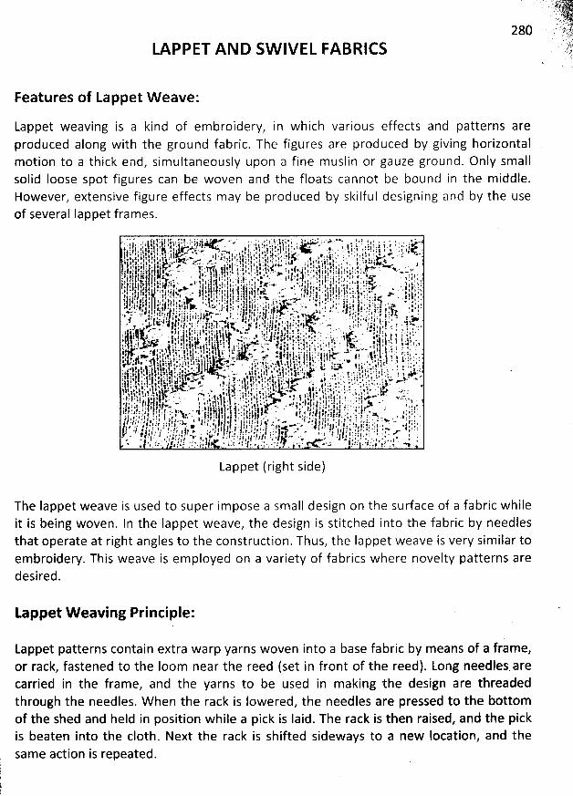
LAPPET AND SW IVEL FABRICS
Features of Lappet W eave:
Lappet weaving is a kind of em broidery, in which various effects and patterns areproduced along with the ground fabric. The figures are produced by giving horizontalmotion to a thick end, sim ultaneously upon a fine muslin or gauze ground. Only smallsolid loose spot figures can be woven and the floats cannot be bound in the m iddle.However, extensive figure effects may be produced by skilful designing and by the useof several Iappet frames.
Lappet (right side)
The Iappet weave is used to super im pose a small design on the surface of a fabric whileit is being woven. In the Iàppet weave, the design is stitched into the fabric by needlesthat operate at right angles to the construction. Thus, the Iappet weave is very sim ilar toem broidery. This weave is employed on a variety of fabrics where novelty patterns aredesired.
Lappet W eaving Principle:
Lappet patterns contain extra warp yarns woven into a base fabric by means of a frame,or rack, fastened to the Ioom near the reed (set in front of the reed). Long needles arecarried in the frame, and the yarns to be used in m aking the design are threadedthrough the needles. W hen the rack is lowered, the needles are pressed to the bottomof the shed and held in position while a pick is laid. The rack is then raised, and the pickis beaten into the c10th. Next the rack is shifted sideways to a new Iocation, and thesame action is repeated.
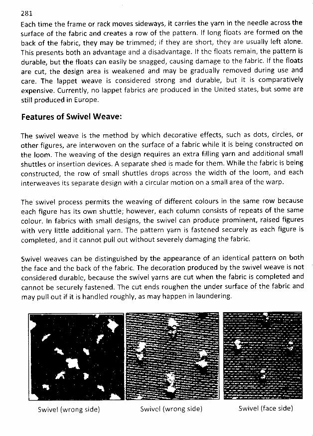
28 1Each tim e the frame or rack moves sideways, it carries the yarn in the needle across thesurface of the fabric and creates a row of the pattern. lf long floats are formed on theback of the fabric, they may be trimm ed; if they are short, they are usually left alone.This presents both an advantage and a disadvantage. If the floats remain, the pattern isdurable, but the floats can easily be snagged, causing damage to the fabric. If the floatsare cut, the design area is weakened and may be gradually removed during use andcare. The lappet weave is considered strong and durable, but it is comparativelyexpensive. Currently, no Iappet fabrics are produced in the United states, but some arestill produced in Europe.
Features of Swivel W eave:
The swivel weave is the method by which decorative effects, such as dots, circles, orother figures, are interwoven on the surface of a fabric while it is being constrtlcted onthe Ioom . The weaving of the design requires an extra filling yarn and additional smallshuttles or insertion devices. A separate shed is made for them. W hile the fabric is beingconstructed, the row of small shuttles drops across the width of the loom, and eachinterweaves its separate design with a circular motion on a small area of the warp.
The' swivel process perm its the weaving pf different colours in the same row becauseeach figure has its own shuttle; however, each column consists of repeats of the samecolour. ln fabrics with small designs, the swivel can produce prominent, raised figureswith very Iittle additional yarn. The pattern yarn is fastened securely as each figure iscompleted, and it cannot pull out without severely dam aging the fabric.
Swivel weaves can be distinguished by the appearance of an identical pattern on boththe face and the back of the fabric. The decoration produced by the swivel weave is notconsidered durable, because the swivel yarns are cut when the fabric is com pleted andcannot be securely fastened. The cut ends roughen the under surface of the fabric andmay pull out if it is handled roughly, as may happen in laundering.
Swivel (face side)Swivel (wrong side) Swivel (wrong side)
282The swivel weaves is employed with sheer light-weights
, such as dotted swiss (generallya voile or lawn construction woven with either clip spots or swivel dots
. The clip spot isthe more popular version. The fabric is given a crisp, clear finish, which may bepermanent or semi permanent. Often yarn dyed dots are woven on a white ground
, or adark ground has white dots. M any im itations on the market e.g. pigment and flock dots.)and grenadine (Fine, loosely woven Ieno fabric similar to marquisette. May be m ade onJacquard loom. Used for curtains, blouses, dresses.) and medium-weights, such asmadras (Cotton fabric of plain weave of coarse yarns. Usually comes in stripes
, checks,or plaids. Colours may bleed. Used for shirtingsa).
Sw ivel W eaving Principle:
Swivel designs are produced by winding extra weft yarns on small quills in specialshuttles. These shuttles are strategically located at the points where the design is tooccur. The pattern mechanism produces a shed, and the shuttle carries the yarn throughthe shed the distance of the pattern; in some cases
, only a few warp yarns areinterwoven to form the design. The process is repeated for each row of the designpattern. Between repeats of the pattern, the extra weft yarn floats on the back of thefabric; it is trimm ed after weaving is completed
.
Differences betw een Lappet and Sw ivel Design:
The essential difference between a lappet design and a swivel is that in the swivel thedesign is done with extra weft yarns, which are cut-off short at the end of each design.
The Iappet pattern appears only on the right side of the fabric, since the floats forming
the pattern are fastened to the ground fabric only at their extremities. Lappet designs
are made of one continuous yarn and are not clipped.
Lappet, swivel and clipped spot are all woven fabrics; none is embroidered, although the
effect is that of machine embroidery.
283DENIM FABRICS
Main Features of Denim Fabrics:Typical denim fabrics are woven from coarse, indigo-dyed cotton yarn. They are hard-wearing,high density fabrics with a high mass per unit area. Today, more denim is produced in the worldthan any other type of cfoth. Denim fabrics are made for a variety of applications and in a widerange of qualities and shades. Even today, classic denim is still dyed with indigo. lt is a specialprocess in which only the surface of the warp yarn is dyed; the core stays white. This is why thegarment subsequently develops the typical - and desired - signs of wear.
It is a cotton or cotton / polyester blend, durable heavy weight twill weave, yarn-dyed fabric.Usually the warp îs coloured and the weft is white. ft is often a (eft-hand twill with a bfue(indigo) warp and white weft for use in apparel in a variety of weights. Since it is a warp-facedtwill, the coloured warp yarns predominate on the face and the white weft yarns on the back. It
2 6 oz/ydz) to 474.74 gm/m' (14is available in several weights, ranging from 203.46 gm/m (
2 2 3oz/yd ) or more in a 1 or, 1 interlacing pattern. lts Iong term popularity has made it a fashion
fabric in casual wear. It may be napped, printed, made with spandex or other stretch yarns, or
otherwise modified for fashion.
(7's X 8's to 16's x 23's)Fabric construction: x Fabric width.(60 X 36 to 72 x 44)
Raw materials bf Denim Fabric:
To produce good quality denim, the conditions have to be optimal regarding the quality of allthe raw materials and yarn used. For raw cotton and the carded OE (rotor) or ring spun yarnsmade from it, the quality criteria are as follows:
* Minimum staple Iength: 2.7 cm* Proportion of short fibres (Iess than 12 mm Iong): under 40%* Micronaire value: 4.0 to 4.5* The Uster values for strength and elongation, the evenness CV and imperfections must
conform at least to the 25% plotThe usual count range of denim warp yarns is 50 to 90 tex and of weft yarns is 75 to 120tex; finer yarns as fine as 25 tex in twill or plain weave are often used in denim shirts
* Twist factor: 4.5 to S.0 for warp yarns, 4.2 for weft yarnsLow yarn hairiness
* Yarn strength and uniformity.
QIS.; y.y
. .. ,.-
7$j284 . ,1)
In the early 1990s, most of the yarns used in denim production were OE yarns. Reçently, there isa strong trend towards using more carded ring spun yarns in both warp and weft. They give thefabric a softer handle, fulfilling the requirements for f'soft denims''. The following table showsthe acceptable values for ring spun and OE cotton yarns with a fineness of 84 tex (7 Ne) forsuccessful denim production.
Properties Ring-spun yarn OE Rotor yarn
Strength (cN/tex) 17 13Elongation (%) 8.5 8.5Uniformity (CV%) 12 12.5Thin places (per 1000 m) 1 1Slubs (per 1000 m) 50 20 'Neps (per 1000 m) 50 3
Types of Denim :
Demand for fashion variants of classic denim will continue to grow. The most popular variantsare:
* Stone-washed and double stone-washed denimsChambrays
* Fancy multicolour denims* Denim with metal-effect yarns
Elastic denims* Printed denims
Jacquard-patterned denimsDenims with fancy yarns
Lightweight chambrays are used for shirt and blouses. Heavy, classic denims are made up intotrousers or coats. Besides classic indigo blue, the fabric is dyed in other fashion shades andcolours, the most popular being black denim. The fabrics are graded in clearly defined classesby weight, e.g, Iight denim 10 to 12 oz/sq.yd. or below it, heavy denim 14 to 16 oz/sq.yd. Atpresent time, the following denim fabrics with their specific commercial name are widelyproduced in the denim industry of Bangladesh.
b.
C.
d.e.
3Basic or regular denim -lRi
ng denim , there are 7, 9, 12 count of yarn used1
Slub denim only warp slub (one way slub) and weft slub (cross slub)Cross hatch denimStretch denim weft yarn (elastomer)Poly denim polyester used in weft.
285
Vvarp Preparation:
ln denim production, warp preparation, dyeing and sizing are cruciaily important. Dyeing withindigo requires detailed knowledge of the physicai and chemical processes involved. Thevarious dyeing and sizing methods, and the corresponding recipes and concentrations, reactionand oxidation times not only influence the weaving process; they are also largely responsiblefor the appearance and quality of the denim.
Besides the classic indigo rope dyeing process, indigo sheet dyeing is also used. One variant ofsheet dyeing is Ioop dyeing. Dyeing and sizing are either done separately, as in rope and doublesheet dyeing, or the two processes are combined in a single operation, as in sheet dyeing andloop dyeing.
lndigo Rope Dyeing:
In warp preparation for rope dyeing, 350 - 400 warp yarns are assembled on the ballwarper to form a rope 10,000 to 15,000 meters Iong. Between 12 and 36 ropes aredrawn through the dyeing range side by side. After dyeing they are dried on a drumdrier and deposited in cans. The ends are spread out on a rebeamer or Iong chainbeamer (lcb), and the yarn sheet is wound onto warp beams. These beams then come tothe sizing machine, where they are sized, dried and assembled in accordance with thetotal number of ends required to make up the weaving warp beam. This process ensuresoptimal dyeing of the indigo, but with the disadvantages that broken ends are morefrequent and yarn tensions are not always compensated. Modern indigo dyeing rangesnormally operate with six dye vats. Using state-of-the-art methods, the same dyeingquality can be achieved with just three vats, with a substantial reduction in theconsumption of chemicals. The production rate of this system is normally 2 to 3 timeshigher than the sheet dyeing system.
lndigo sheet dyeing and double sbeet dyeing:
In indigo sheet dyeing, warp beams are brought to the dyeing and sizing range insteadof ropes. Dyeing, drying, sizing and aûer repeated drying, assembly of the warp iscarried out in a single operation. In the case' of double sheet dyeing, dyeing and sizingare done in two separate steps. As far as indigo dyeing is concerned neither process isalways ideal, but both have the advantage that the number of broken ends is Iow andyarn tension can be extremely well controlled.
lndigo Ioop dyeing:
In the Ioop dyeing process, the yarn is dyed in a single bath instead of several. Thedesired depth of colour is attained by passing the yarn through the vat several times.Subsequently, as part of the same process, the yarn is sized. The advantages anddisadvantages of loop dyeing are the same as with sheet dyeing.
Sizing recipes:
The sizing process plays a key role in further processing of the warps. The choice of
sizing agents used to achieve the sizing effect is crucially important here. A relativelysoft handle can be achieved using a combination of modified starch with a polyacrylate
.
W arps sized in this way have good running properties, helping to ensure high efficiencyand an excellent final appearance. A practical example is given below:
286
Style data:
Warp: OE yarn, 84 tex (7 Ne), 24 ends/cmWeft: OE yarn, 100 tex (6 Ne), 16 picks/cmTotal number of warp ends: 3942
Size recipe for 100 Iiters of Iiquor:8.0 kg modified starch4.0 kg acrylate sizeO.2 kg textile waxSize concentration: 8.0 %
OSize temperature: 85 C
Squeezing pressure: approx. 15 IINSize pick up: 9 - 10 %
Advantages of the denim size recipe:
Sizing room:Easy separation of endsNo hard sizeOnly slight bleedingNo colour maskingMinimal dust and fibre fly.
W eaving room:High, constant weaving efficiencyEasy warp take-upMinimal dust and fibre fly.
W eaving:
For finished widths of 150cm to 156cm, reed widths of 160cm to 167cm are required. Denimsthat are stretchable in the weft do not follow this rule. When weaving with projectile weavingmachines, these fabrics are henerally woven in two panels with weaving widths of 360 or 390cm. in this way a high weft insertion rate of 1400 m/min is achieved at a machine speed ofapproximately 400 picks/mjn. For the production of heavy denims, leno selvedges areadvisable. Lighter denims, weighing less than 13 oz/sq. yd, can be woven with tucked selvedges.The fabrics can be inspected with an electronically controlled c10th inspection machine
.
287
The current demand on soft denims in the United States is to use Iyocell yarns (e.g. Tencel) inthe weft. For structured denims, structured yarns are used for the weft. Slub and knob effects
are especially popular.
Diversifitation of Denim :
This fabric became popular at first among people of western countries and then gradually allover the world. But, consumers' need for new products is unlimited. So, to meet this essentialdemand, the fabric designers and manufacturers were obliged to produce different types ofdenim at present, hundreds of derivatives of denim are available. Also new types of denimproducts are being developed. The diversification of denim has gone so far that some denimsare not even twill based. They are being produced on plain-based weave design.
Denim is comparatively heavy fabric composed of higher linear density yarn both in warp andweft. This fabric is not very soft in handle. Different fancy yarn - slub yarn, thick-thin yarns are
used in the diversification of denim. Wcra (elastomeric fibre) yarn is also introduced in thediversified denim. Diversification is also done by the change of EPI, PPl and count. Yarn ofdifferent count may be used in consecutive insertion for diversification. For increasing theagreed Ievel of denim throughout the world, diversification is the most important factor. Denimis very popular among the teenagers as well as older people.
Denim's popularity was also on the rise. lt was stronger and more expensive than jean, andthough the two fabrics were very similar in some ways, they did have one major differences:denim was made of one coloured thread and one white thread; jean was woven of two threadsof the same colour.
Denim is no Ionger a cotton product. Denims come with either polyamide, Iycra, polypropyleneor with polyester and especial bonding with a 100% nylon net for a more active look. Two waystretch fabrics and special coatings or rubberized effects continue to be a strong trend.
End Uses or Prospects:
In modern world, the apparels made from denim have become very popular among wearing.ps 'Now days, baby wear, men trouser, shirts, ladies wear are also made from denim fabric, and
day by day, its acceptability is increasing among consumers. Denim goods are now being usedamong almost aII type of peopie. Denim wear crosses the Iine of fashion boundary. In the past,it was used by workers as a safety wear. Now it is used for making decorative cap and ladieshand bag, school and college bag, and travel bag. So, range of denim apparels are widening dayby day. So Denim is used for jacket, pant, shirt, denim wine bags, denim pencil case, denimapron, denim pillows, denim quilt etc.
W OVEN PILE FABRICS
Pile fabrics have been defined as ''fabrics with cut or uncut Ioops which stand up densely on thesurface''. Pile fabrics may be created by weaving or through other construction techniques
,such as tufting, knitting, or stitch through. To create the Ioops that appear on the surface ofwoven pile fabrics, the weaving process incorporates an extra set of yarns that form the pile
.
Construction of woven pile fabrics, therefore, represents a complex form of weaving in whichthere are at Ieast three sets of yarns. Example of pile fabrics produced by the pile methodinclude corduroy, fleece, frieze, fake fur, plush, poodle c10th, terry c10th, velvet, velveteen andvelour.
Woven pile fabrics have an extra set of warp or weft yarns interlaced with the ground warp andweft in such a manner that loops or cut ends extend from the base fabric. The base fabric maybe constructed of either a plain or a twill weave.
The pile weave is a fancy weave that also includes a plain or a twill construction. In contrast tothe three basic weaves (plain, twill, satin) that produce a flat surface on a fabric, the pile weaveintroduces a decorative third dimension, creating an effect of depth. Its construction isespecially desirable when softness, warmth, and absorbency are desired. Pile weave fabrics arealso durable if the proper yarns and adequate compact construction are used.
Pile fabrics can be divided into fabrics with Ioop pile and cut pile. W oven carpets, velvet andterry fabrics are the best-known pile fabrics.
Types of W oven Pile Fabric:
W oven pile fabrics are divided into two categories depending on whether the extra set of yarnsis in the warp direction or the weft direction. Pile fabrics are woven by one of sevvral methods,depending on whether they are warp pile or weft pile fabrics. W arp pile fabrics have two sets ofwarp yarns and one set of weft yarns. Weft pile fabrics have two sets of weft yarns and one setof warp yarns.
A. W eft Pile Fabrics:
W eft pile fabrics are woven by the weft pile method. No special weaving m achines areneeded to weave weft pile fabrics. In this method there are two sets of weft yarns andone set of warp yarns. Although the ground may be of either twill or plain weave, a twillbase is preferred for its durability. The extra set of weft yarns forms floats that are over
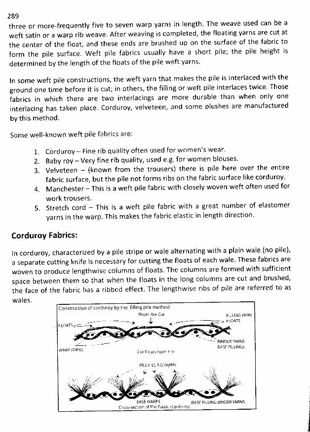
289three or more-frequently five to seven warp yarns in Iength. The weave used can be aweft satin or a warp rib weave. After weaving is com pleted, the floating yarns are cut atthe center of the float, and these ends are brushed up on the surface of the fabric toform the pile surface. W eft pile fabrics usually have a short pile; the pile height isdetermined by tbe length of tbe floats of the pile weft yarns.
In some weft pile constructions, the weft yarn that m akes the pile is interlaced with theground one time before it is cut; in others, the filling or weft pile interlaces twice. Thosefabrics in which there are two interlacings are more durable than when only oneinterlacing has taken place. Corduroy, velveteen, and some plushes are manufactured
by this m ethod.
Some well-known weft pile fabrics are:
1 Co' rduroy - Fine rib quaiity often used for women's wear.2. Baby roy - Verv fine rib quality, used eag. for women blouses.3. Velveteen - (known from the trousers) there is pile here over the entire
fabric surface, but the pile not forms ribs on the fabric surface Iike corduroy.M anchester - This is a weft pile fabric with closely woven weft often used for
work trouserj.Stretch cord - This is a weft pile fabric with a great num ber of elastomeryarns in the warp. This makes the fabric elastic in length direction.
Corduroy Fabrics:
In corduroyz characterized by a pile stripe or wale alternating with a plain wale (no pile),a separate cutting knife is necessary for cutting the floats of each wale. These fabrics arewoven to produce Iengthwise colum ns of floats. The colum ns are formed with sufficientspace between them so that when the floats in the Iong columns are cut and brushed,tbe face of the fabric has a ribbed effect. The Iengthwise ribs of pile are referred to as
wales.Construction of cerduroy by the filling pile method.
Floats Are Cut FILLIIkG YARN
%u.
n-*
w - '. . '.. ' ' '+ .' *' k e .. . ...- ... ayxe .- -- -
WARP YAPNS BASE FI LLINGSCut Floats Form Pile
PI LE F I LLI N G YA RN S. wk .v# .A : (.. w .. j
, . 's 4. I / . r T ' ' ....e' ' '' x '.; . i' h $ ?' .. 'b$.. ' . ..
'''.t::b'L. ..
' .: .. .-rr.'-''''. .,. .. ...
:2...:''..:..:.'t.'
..t7E'. :..:r.. '.?''......(j'. ..'-:', , ,1 ,,:,,
$'.
d;.?'-. E.k;r:.:yJy,. :ilgrlE... ''E.'-'..,.., k.
1.$ .
-''''''....,.,''--''
. :;,.ïjr.;;,;,ys:ir:'')... . .: . '-2k::'
,(:,''.,'')tS.'h.!$.-..J:, !!k,j,
'h'-!r ji'' ...,.'',:rr.(-'- -.r;
'. . ..
., '..' u ..' (.t.. . ; z' . ():5 N.Lj;. . 2' ... ..xj%= -. AKN,. x $, jjsy .:-.(kk . ..
.. . .. '''. h.. t. ''.'e.''..,. ' ''':):hs .. sv...''' '''' '',q '
. . #.,.*' , .. .
BASE WARPS sAs: FILLING BINDER YARNSCross-section of Plle Fabric (Corduroy)
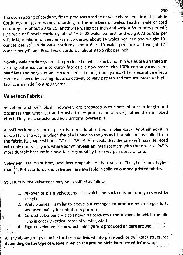
. 4. .....!, j: -A5tr.. ' . 7q4J 1' .
29 ' ' '>, >..i'*The even spacing of corduroy floats produces a stripe or wale characteristic of this fabric
Corduroys are given nam es according to the numbers of wales. Feather wale or cprdiçorduroy has about 20 to 25 Iengthwise wales per inch and weight 5: ounces per yd.;
Fine wale or Pinwale corduroy, about 16 to 23 wales per inch and weight 7k ounces per2 M id medium or regular wale corduroy, about 14 wales per inch and weight 10àyd ;
, ,
2 d Ie corduroy, about 6 to 10 wales per inch and weight 12àounces per yd ; W i e wa2 d Broad wale corduroy
, about 3 to 5 ribs per inch.ounces per yd ; an
Novelty wale corduroys are also produced in which thick and thin wales are arranged invarying patterns. Spme corduroy fabrics are now made with 100% cotton yarns in thepile filling and polyester and cotton blends in the ground yarns. Other decorative effectscan be achieved by cutting floats selectively to vary pattern and texture. M ost weft pilefa' brics are made from spun yarns.
Velveteen Fabrics:
Velveteen and weft plush, however, are produced with floats of such a Iength andcloseness that when cut and brushed they produce an all-over, rather than a ribbedeffect. They are characterized by a uniform, overall pile.
A twill-back velveteen or plush is more durable than a plain-back. Another point indurability is the way in which the pile is held to the ground. If a pile Ioop is pulled fromthe fabric, its shape will be a 'V' or a 'W '. A 'V' reveals that the pile weft has interlacedwith only one warp yarn, where as 'W ' reveals an interlacement with three warps. 'W ' ismore durable because it is held to the ground by three warps instead of one.
Velveteen has more body and Iess drapeability than velvet. The pile is not higher1 ' j h corduroy and velveteen are available in solid-colour and printed fabrics.than --2 . ot8
Structurally, the velveteens may be classified as follows:
All-over or plain velveteens - in which the surface is uniformly covered bythe pile.W eft plushes - similar to above but arranged to produce much Ionger tuftsand used mainly for upholstery purposes.Corded velveteens - also known as corduroys and fustians in which the pileruns in orderly vertical cords of varying width. . .
-
Figured velveteens - in which pile figure is produced on bare g'roqqd. .. ' ;t '.'; ' l
AII the above groups may be further sub-divided into plain-back or twill-back strudurefdepending on the type of weave in which the ground picks interlace with the warp. !
. . . . .. . .
'
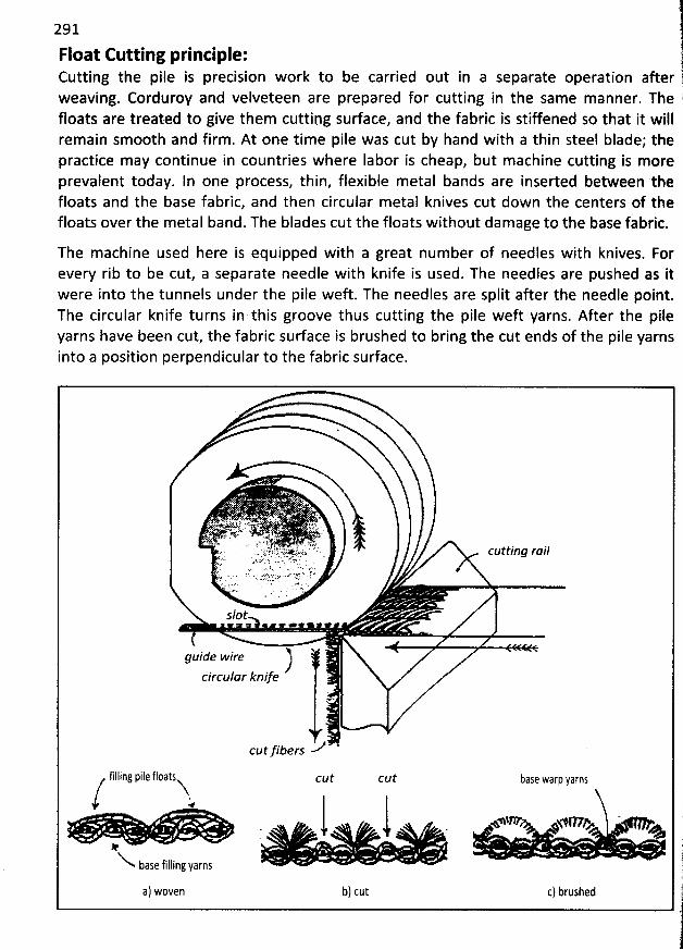
291
Float Cutting principle:Cutting the pile is precision work to be carried out in a separate operation after l
?weaving. Corduroy and velveteen are prepared for cutting in the same manner. The (
floats are treated to give them cutting surface, and the fabric is stiffened so that it willremain sm00th and firm . At one tim e pile was cut by hand with a thin steel blade; thepractice may continue in countries where Iabor is cheap, but machine cutting is moreprevalent today. ln one process, thin, flexible metal bands are inserted between thefloats and the base fabric, and then circular metal knives cut down the centers of thefloats over the metal band. The blades cut the floats without dam age to the base fabric.
The machine used here is equipped with a great num ber of needles with knives. Forevery rib to be cut, a separate needle with knife is used. The needles are pushed as itwere into the tunnels under the pile weft. The needles are split after the needle point.The circular knife turns in this groove thus cutting the pile weft yarns. After tbe pileyarns have been cut, the fabric sudace is brushed to bring the cut ends of the pile yarnsinto a position perpendicular to the fabric surface.
xjgjqqjkjtj ...<. yy .,44.9 .-''* 'jjjg.j%.' . . . .I ô' '. . .'ê. ,'e 'a. y hl ) 'k:. ' . :.k',rgr' .< . .
' ' . :'.r:!ycyg.'k; . : ' cgttjng rail. ' * . 9 . . . . .ah :' . : . - ': f :! ' ' .
y . . r. . . x y .. . . ; . i...: . .:.- ),! .. xJJ1..r . .
slot4 . . ..
guide wire
circular knife -
>cutfibers
filling pile floats cut cut base warp yarns
'W W VP ' ''' '. < j' t# ,
j.'base filling yarns !.1ia) woven b) cut c) brushed .
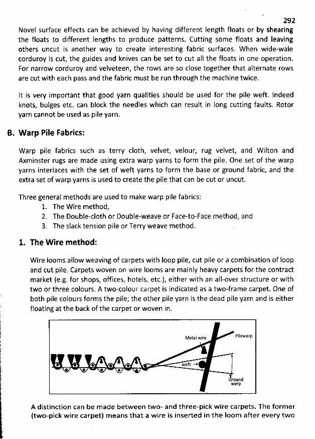
292Novel sudace effects can be achieved by having different Iength floats or by shearingthe floats to different Iengths to produce patterns. Cutting some floats and Ieavingothers uncut is another way to create interesting fabric surfaces. W hen wide-walecorduroy is cut, the guides and knives can be set to cut aII the floats in one operation.For narrow corduroy and velveteen, the rows are so close together that alternate rowsare cut with each pass and the fabric must be run through the machine twice.
lt is very important that good yarn qualities should be used for the pile weft. Indeedknots, bulges etc. can block the needles which can result in Iong cutting faults. Rotoryarn cannot be used as pile yarn.
B. W arp Pile Fabrics:
W arp pile fabrics such as terry c10th, velvet, velour, rug velvet, and W ilton andAxminster rugs are made using extra warp yarns to form the pile. One set of the warpyarns interlaces with the set of weft yarns to form the base or ground fabric, and theextra set of warp yarns is used to create the pile that can be cut or uncut.
Three general methods are used to make warp pile fabrics:1. The W ire method,2. The DoubIe-cloth or Double-weave or Face-to-Face method, and3. The slack tension pile or Terry weave method.
1. The W ire method:
W ire Iooms allow weaving of carpets with Ioop pile, cut pile or a combination of Ioopand cut pile. Carpets woven on wire Iooms are mainly heavy carpets for the contractmarket (e.g. for shops, offices, hotels, etc.), either with an all-over structure or withtwo or three colours. A two-colour carpet is indicated as a two-frame carpet. One ofboth pile colours forms the pile; the other pile yarn is the dead pile yarn and is eitherfloating at the back of the carpet or woven in.
PilewarpMetal wire
* * * @ weft -*@ * * *
roundwarp
A distinction can be m ade between two- and three-pick wire carpets. The former(two-pick wire carpet) means that a wire is inserted in the Ioom after every two
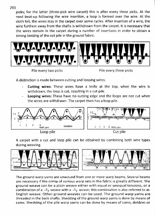
11
293 11
picks; for the Iatter (three-pick wire carpet) this is after every three picks. At the 'reed beat-up following the wire insertion, a Ioop is formed over the wire. At thec10th fell, the wires stay in the carpet over some cycles. After insertion of a wire, thewire furthest away from the shafts is withdrawn from the carpet. It is necessary thatthe wires remain in the carpet during a num ber of insertions in order to obtain astrong binding of the cut pile in the ground fabric.
e * @ * * @
Pile every two picks Pile every three picks
A distinction is made between cutting and looping wires:
Cutting wires: These wires have a knife at the top; when the wire iswithdrawn, the Ioop is cut, resulting in a cut-pile.Looping w ires: These have no cutting edge and the Ioops are not cut whenthe wires are withdrawn. The carpet then has a Ioop pile.
# ê . 4 y . k:L .
A',k- -. .i;
1-2 .... z.w.. / x .@ x.p -.. @ @ . . . . s # .3 N 'x- w u 'l
2 ' IIj. '2 4 neadpileWeft yarn
Loop p 1 Ie
'V' t . u z r/ 7- . # à ' .y )' z à z,.. , #.v., . ,,* k xr : .. -s# g'bt . . ..1L - ;! . &f j' ' .t
1... '--'R zo ,.or zo o .u . ....,....1 . h. v.w,.v. y g N g . .2 ... Z -...
3 3 .,, e . . , . s. . ,& .,
1 2 3 4 weft yarn
Cut pi I e
A carpet with a cut and Ioop pile can be obtained by com bining both wire typesdurlng weavlng.. . . z r. kt . .c-; . . 2 . Ajlk 11p . ji '. .- . 1Ij, t .. -. . -.z: . , d .t .. . . .. . jlk klt 11p 41j - ' ' ' jjk . k1-.';.î. '''. .' ):. g .. . ' '. . v . .y . . ï z. . , . . . ... s . uë 'k .j; ;' ' w . . . . , . . .-zï( .i- .-s ' ? -:1:' ' .Ny. . ...4 ' , u.,1.' .î ri.J ! . . - ,.. .. . .-. . , - > f . . - . . .. - '. z- .v. . ; ; .''.y''1@' :'q. . . , ,. . . . z 4 . p: , .. . . . - . . : yc n ' ' :3;... . .. ' ' . .). ' . . . .. ..c 1 2 a .I'L- . l . . j . . . . . y.jkxf - . x - . . . , . . s. ? . . . . . ; . .. : . .2 . . c; .j x .- , . y . . ! . . . , . . . qjjvqjqj.zlrk. . . : y . .
. )
'
..... . . '.yt x ., ) k y . . ( , 1.Y. . ...j g .j, t. t. 'A . .w # * * î . @ L- N@ .. : @.. 3 . vwse w. gw . ;/ . . . '.. : . Jr . .. . .. 1. . .. . . .. j # kg:% # 4 . v . ... . . .. 4 ywf -a2As.kk . . . .c g . v u . . - g
The ground warp yarns are unw ound from one or m ore w arp beam s. Several beam sare necessary if the crim p of various w arp sets in the fabric is greatly different. Theground w eave can be a plain w eave either w ith equal or unequal tensions, or acom bination of a 2: weave w ith a 1 weave; this com bination is also referred to as1English w eave. Other ground weaves can be used. The ground w arp yarns arethreaded in the back shafts. Shedding of the ground warp yarns is done by m eans ofcam s. Shedding of the pile w arp yarns can be done by m eans of cam s, dobbies or
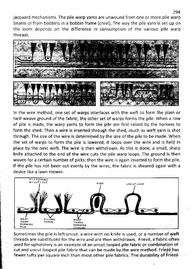
294jacquard mechanisms. The pile warp yarns are unwound from one or more pile warpbeams or from bobbins in a bobbin frame (creel). The way the pile yarn is set up onthe loom depends on the difference in consumption of the various pile warpthreads.
In the wire m ethod, one set of warps interlaces with the weft to form the plain ortwill-weave ground of the fabric; the other set of warps forms the pile. W hen a rowof pile is made, the warp yarns to form the pile are first raised by the harness toform the shed. Then a wire is inserted through the shed, much as weft yarn is shotthrough. The size of the wire is determined by the size of the pile to be m ade. W hen 'the set of warps to form the pile is Iowered, it Ioops over the wire and is held inplace by the next weft. The wire is then withdrawn. As this is done, a small, sharpknife attached to the end of the wire cuts the pile warp Ioops. The ground is thenwoven for a certain num ber of picks; then the wire is again inserted to form the pile.If the pile has not been cut evenly by the wires, the fabric is sheared again with adevice like a lawn mower.
P 1 L E F () R M E DB Y C LJT L ()0 P
. w4 a s oscov uoop
e e . . o . +
WARB F l LLING wAapYARN Y> RNS ' yAaxsFO R M I N G vo a v j xo .P l LE G R o N o .:
Sometimes the pile is Ieft uncut: a wire with no knife is used, or a num ber of Feftthreads are substituted for the wire and are then withdrawn. Friezé, a fabric pften
. i Q ''' (used for upholstery is an example of an uncut Iooped pile fabric or combinà.tlöp of
. :. .g . g ycut and uncut Iooped Dile fabric that can be m ade bv the w ire methöd. Frlezq.has:' ' * ' e
'
. '
. . . ''ù $2.8 , ëfewer tufts per square inch than m ost other pile fabrics
. The durability ot Frièzé
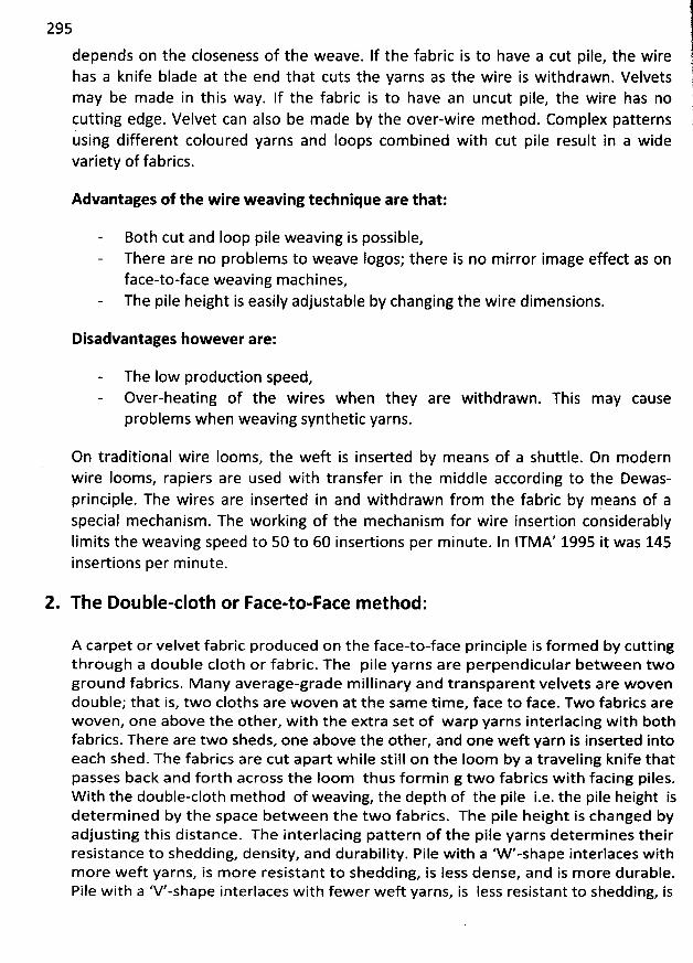
295
depends on the closeness of the weave. If the fabric is to have a cut pile, the wirehas a knife blade at the end that cuts the yarns as the wire is withdrawn. Velvetsm ay be made in this way. If the fabric is to have an uncut pile, the wire has nocutting edge. Velvet can also be m ade by the over-wire method. Com plex patternsusing different coloured yarns and Ioops combined with cut pile result in a widevariety of fabrics.
Advantages of the wire weaving technique are that:
Both cut and Ioop pile weaving is possible,There are no problems to weave logos; there is no m irror image effect as onface-to-face weaving machines,The pile height is easily adjustable by changing the wire dimensions.
Disadvantages however are:
The low production speed,Over-heating of the wires when they are withdrawn. This m ay causeproblems when weaving synthetic yarns.
On traditional wire Iooms, the weft is inserted by means of a shuttle. On modernwire looms, rapiers are used with transfer in the middle according to the Dewas-principle. The wires are inserted in and withdrawn from the fabric by m eans of aspecial mechanism . The working of the mechanism for wire insertion considerablyIim its the weaving speed to 50 to 60 insertions per m inute. In ITMA' 1995 it was 145insertions per m inute.
2. The DoubIe-cIoth or Face-to-Face m ethod:
A carpet or velvet fabric produced on the face-to-face principle is formed by cuttingthrough a double c10th or fabric. The pile yarns are perpendicular between twoground fabrics. M any average-grade m illinary and transparent velvets are wovendouble; that is, two cloths are woven at the sam e tim e, face to face. Two fabrics arewoven, one above the other, with the extra set of warp yarns interlacing with bothfabrics. There are two sheds, one above the other, and one weft yarn is inserted intoeach shed. The fabrics are cut apart w hile still on the Ioom by a traveling knife thatpasses back and forth across the loom thus form in g two fabrics with facing piles.W ith the doubIe-cIoth method of weaving, the depth of the pile i.e. the pile height isdeterm ined by the space between the two fabrics. The pile height is changed byadjusting this distance. The interlacing pattern of the pile yarns determ ines theirresistance to shedding, density, and durability. Pile with a 'W '-shape interlaces withm ore weft yarns, is m ore resistant to shedding, is less dense, and is m ore durable.Pile with a 'V'-shape interlaces w ith fewer weft yarns, is less resistant to shedding, is
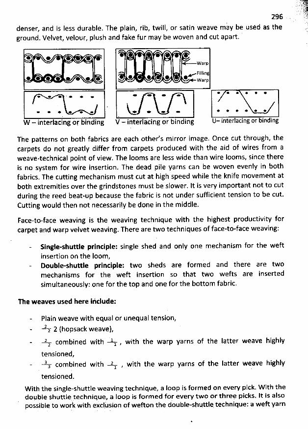
296denser, and is less durable. The plain, rib, twill, or satin weave may be uséd as theground. Velvet, velour, plush and fake fur may be woven and cut apart.
* * e *
* * * * @ * + *
* œ e * + .
e e * e '+ e
W - interlacing or, binding
* @Vvarp
Filling* @ W
arp
e * - + * * * * * *
* * œ - * * * * * *
V - interlacing or binding U- interlacing or binding
The patterns on b0th fabrics are each other's m irror image. Once cut through, thecarpets do not greatly differ from carpets produced with the aid of wires from aweave-technical point of view. The looms are less wide than wire Ioom s, since thereis no system for wire insertion. The dead pile yarns can be woven evenly in bothfabrics. The cutting mechanism m ust cut at high speed while the knife mùvem ent atboth extrem ities over the grindstones m ust be slower. lt is very important not to cutduring the reed beat-up because the fabric is not under sufficient tension to be cut.Cutting would then not necessarily be done in the middle.
Face-to-face weaving is the weaving technique with the highest productivity forcarpet and warp velvet weaving. There are two techniques of face-to-face weaving:
Single-shuttle printiple: single shed and only one mechanism for the weft
insertion on the loom,Double-shuttle principle: two sheds are form ed and there are twomechanism s for the weft insertion so that two wefts are insertedsim ultaneouslyi one for the top and one for the bottom fabric.
The weaves used here ihclude:
Plain weave with equal or unequal tension,22 2 (hopsack weave),2, com bined with lz , with the warp yarns of the Iatter weave highly
tensioned,3a com bined with 2 , with the warp yarns of the Iatter weave highly
1 . . .
tensioned.W ith the single-shuttle weaving technique, a Ioop is formed on every pick. W ith thedopble shuttle technique, a Ioop is form ed for every two or threç picks. It is alsopossiblq tq work with exclusion of wefton the double-shuttle technique: a weft yarn
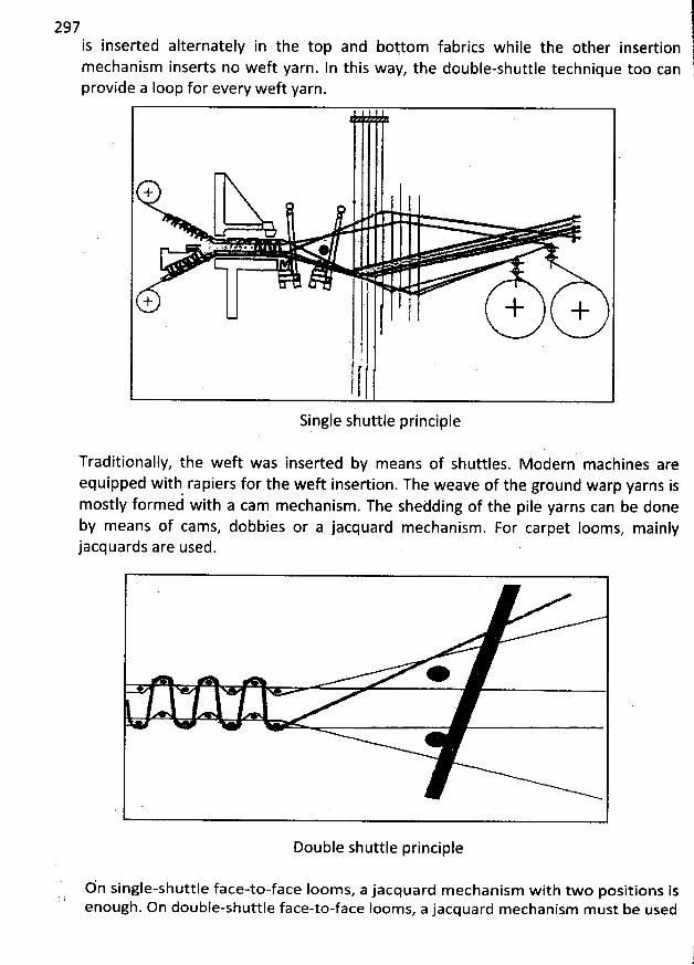
297is inserted alternately in the top and boytom fabrics while the other insertion
lmechanism inserts no weft yarn. ln this way, the double-shuttle technique too can (
provide a Ioop for every weft yarn. @(
Single shuttle principle
Traditionally, the weft was inserted by means of shuttles. M odern machines areequipped with rapiers for the weft insertion. The weave of the ground warp yarns ismostly formeé with a cam mechanism. The shedding of the pile yarns can be doneby means of cams, dobbies or a jacquard mechanism. For carpet Iooms, mainlyjacquards are used.
Double shuttle principle
Un single-shuttle face-to-face Iooms, a jacquard mechanism with two positions isenough. On double-shuttle face-to-face Iooms, a jacquard mechanism must be used
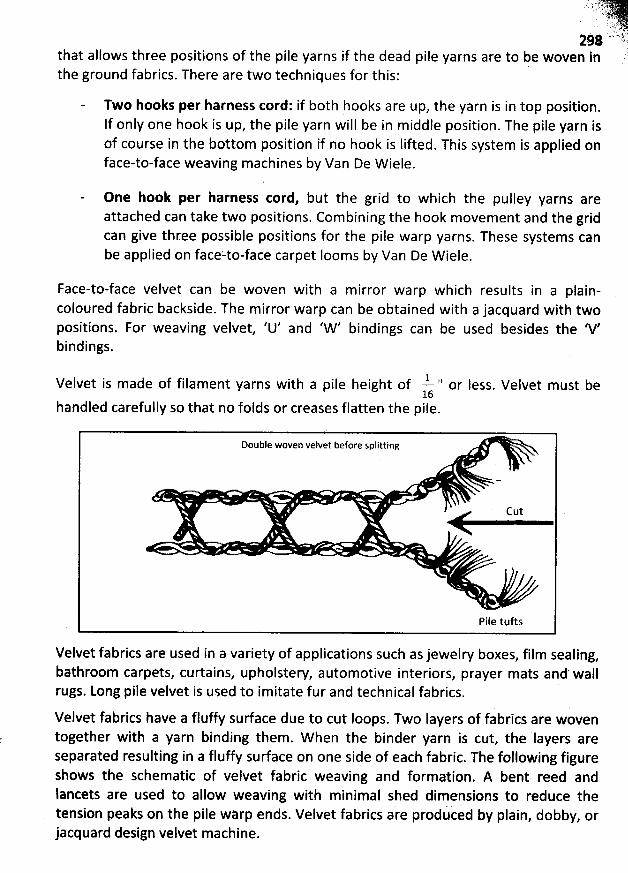
. ':'?:r4:.: '. *-'. :.:4.
. ':- yj'-, j. tyj2#8 ' ')
i
that allows three positions of the pile yarns if the dead pile yarns are to be woven in :the ground fabrics. There are two techniques for this:
Two hooks per harness cord: if both hooks are up, the yarn is in top position.
If only one hook is up, the pile yarn will be in m iddle position. The pile yarn isof course in the bottom position if no hook is Iifted. This system is applied onface-to-face weaving machines by Van De W iele.
One hook per harness tord, but the grid to which the pulley yarns areattached can take two positions. Combining the hook movement and the gridcan give three possible positions for the pile warp yarns. These systems canbe applied on faceito-face carpet Iooms by Van De W iele.
Face-to-face velvet can be woven with a m irror warp w hich results in a plain-coloured fabric backside. The mirror warp can be obtained with a jacquard with twopositions. For weaving velvet, 'U' and 'W ' bindings can be used besides the 'V'bindings.
Velvet is made of filament yarns with a pile height of Y 'i or Iess. Velvet must be
16handled carefully so that no folds or creases flatten the pile.
Double woven velvet before splitting
Cut
Pile tufts
Velvet fabrics are used in a variety of applications such as jewelry boxes, film sealing,bathroom carpets, curtains, upholstew, automotive interiors, prayer mats and' wallrugs. Long pile velvet is used to imitate fur and technical fabrics.
Velvet fabrics have a fluffy surface due to cut Ioops. Two Iayers of fabrics are woventogether with a yarn binding them. W hen the binder yarn is cut, the Iayers areseparated resulting in a fluffy surface on one side of each fabric. The following figureshows the schematic of velvet fabric weaving and formation. A bent reed andlancets are used to allow weaving with minimal shed dimensions to reduce thetension peaks on the pile warp ends. Velvet fabrics are produced by plain, dobby, orjacquard design velvet machine.
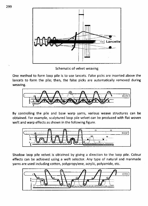
299
*r .
' = = Lanceue
*
lSchematic of velvet weaving
One m ethod to form loop pile is to use Iancets. False picks are inserted above theIancets to form the pile; then, the false picks are automatically removed duringweaving.
tâ-' ë! tt .6133
. 4::' 4::,
.
j ( :(t : r--ar;': '; ;. ;?! 2. ::i:!E: : : ;: :tj; ::: ël .rjy . :;$: . ::ë<: ::, .;). jjjjj :;:. , jjjjj . .. .: jjjjj! ':. 11114 ';:: 41114 ;:t: t t:. 4111, E: jlp!j: : ;: . :)!! ! ! T: ::1 : !: , .:;' :i: . ' . ;. r..
. ,.+ :.:. l . .:::.. :. ,:.:. r...: ' '3
By controlling the pile and base warp yarns, various weave structures can beobtained. For exam ple, sculptured Ioop pile velvet can be produced with flat wovenweft and warp effects as shown in the following figure.
o D O. . . ' . '' : ? . . .r r v n. ' . . 1 ' . ..
! '* , & e2
* 9L#t k ?'.#@E..--.::q jl:j 'ja o := r. o e e e o k o iE j
. . .k' ç.. . . . . . . . . . . ... . . .. . . . . . ... .. . . .T . . . . . .. . . ... .. . . .. . .. . . . .... . . J= i -!
Shadow Ioop pile velvet is obtained by giving a direction to the Ioop pile. Coloureffects can be achieved using a weft selector. Any type of natural and manmadeyarns are used including cotton, polypropylene, acrylic, polyam ide, etc.
O1 r'=
a e * m4 : j (#J. . ë œ . ..
j- r rr1 ? & e e3 , jLQBL23 .
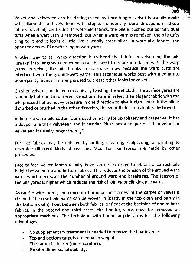
' h'r ï ' L '
' c - -,' x
- ' . ' ' 1'':' 5)
.. u!en fi)fibre length'
. velvet is usually made ''identify warp directions in these
Velvet and velveteen can be distinguished bywith filaments and velveteen with staple. Tofabrics, ravel adjacent sides. In weft-pile fabrics, the pile is pushed out as individualtufts when a weft yarn is removed. But when a warp yarn is removed, the pile tuftscling to it and it Iooks a little like a woolly cater pillar. ln warp-pile fabrics, theopposite occurs. Pile tufts cling to weft yarns.
Another way to tell warp direction is to bend the fabric. In velveteen, the pile'breaks' into Iengthwise rows because the weft tufts are interlaced with the warpyarns. ln velvet, the pile breaks in crosswise rows because the warp tufts areinterlaced with the ground-weft yarns. This technique works best with m edium-topoor-quality fabrics. Finishing is used to create other looks for velvet.
Crushed velvet is made by m echanically twisting the wet c10th. The surface yarns arerandomly flattened in different directions. Panné velvet is an elegant fabric with thepile pressed flat by heavy pressure in one direction to give it high luster. lf the pile isdisturbed or brushed in the other direction, the smooth, Iustrous Iook is destroyed.
Velour is a warp-pile cotton fabric used primarily for upholstery and draperies. It hasa deeper pile than velveteen and is heavier. Plush has a deeper pile than velour or
-t?.velvet and is usually Ionger than 4 .
Fur like fabrics may be finished by curling, shearing, sculpturing, or printing toresemble different kinds of real fur. M ost fur Iike fabrics are made by other
processes.
Face-to-face velvet Iooms usually have Iancets in order to obtain a correct pileheight between top and bottom fabrics. This reduces the tension of the ground warpyarns which decreases the num ber of ground warp end breakages. The tension ofthe pile yarns is higher whiçh reduces the risk of joining or clinging pile yarns.
As on the wire Iooms, the concept of 'number of frames' of the carpet or velvet is
defined. The dead pile yarns can be woven in (partly in the top c10th and partly inthe bottom cloth), float between both fabrics, or float at the backside of one of bothfabrics. In the second and third cases, the floating yarns m ust be removed onappropriate machines. The technique with bound in pile yarns has the followingadvantages:
No supplementary treatment is needed to rem ove the floating pile,Top and bottom carpets are equal in weight,The carpet is thicker (more comfort),Greater dimensional st'ability.
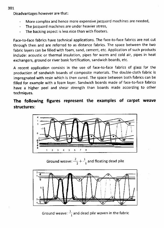
301Disadvantages however are that:
More complex and hence more expensive jacquard machines are needed,The jacquard machines are under heavier stress,The backing aspect is Iess nice than with floaters.
Face-to-face fabrics have technical applications. The face-to-face fabrics are not cutthrough then and are referred to as distance fabrics. The space between the twofabric layers can be filled with foam, sand, cem ent, etc. Application of such productsinclude: acoustic or therm al insulation, pipes for warm and cold air, pipes in heatexchangers, ground or river bank fortification, sandwich boards, etc.
A recent application consists in the use of face-to-face fabrics of glass for theproduction of sandwich boards of com posite materials. The double-c1oth fabric isim pregnated with resin which is then cured. The space between both fabrics can befilled for example with a foam Iayer. Sandwich boards madé of face-to-face fabricshave a higher peel and shear strength than boards made according to othertechniques.
The follow ing figures represent the exam ples of carpet w eave
strud ures:
4 -e . . f gk1 .
* * ' : .''&3 i? t .4 'i > FLt ?; 'C '!
t. 1 s gj j .:/ j. l til
.y ) .6 1 l )f.* * * y2 t .* * . *t7 l. g
S'1 2 3 4 5 6 7 8
2 -L d floating dead pileGround weave: + an
2 l
2.4 . .* r . : .1
... . . .
5.. ' . y 4 ; .e E .. @j .'t t '. tc. # .r
'
.
t ! 1 .'! j
'
. '
. k .i. f ï '.: J '(
;11 dlp 1 ' f i '#****'.. . jjj $ a y jjj < *3 ..4 3 e :.z .
.2- and dead pile woven in the fabricGround weave:1
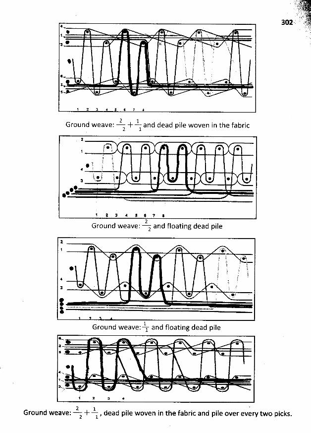
4* * . @ , *1 '.1 ) X h
. ,.2 j . . j.@ @ y'. * . J ' . * :3 ..y . f j .. tj y . jf t .' r'! 't t ïfi t. t; !é:E c' i '
% C V :11 f h:
'
E .i ! 'j :f. tli i .1.! p! !.i2 ; .
n: . '' h. :1 $ 2@ @ * *. *Ks' + @ *.: '. .'+ k
1 2 z 4 : 6 7 :
2 LGround weave: + and dead pile woven in the fabric2 1
: *.%> .r*j * * * @ . .!, il. .. '
.k6 1.. j : '* ê î 'î:; k411 .
': 'F
k k .1: @ f? * * @ * @ @ @ *: ' !,..11
*
.
*
@ '.#*@ .
t 1 . : 4 : : 7 .2
. .Ground weave: z and floatlng dead plle
1
1 * .*Wdllp ;' L' t/ $11,* 'zt;* : . .:: ;E ') 11 M
: 5 ! :k* i' 'k. fs r,E ! .: tE :
sI' : .' ù;i ! ;4 ! , f
. ;' i '* . * @ * t J3 . .
@ * @ . ' es .:
t -1 . .Ground weave: 1 and floatlng dead plle
< .e e * e . .
2* e e e . . .
*Ne e * *lx* œ o . . . .Rz
k 2 a *
2 .1.Ground weave: + , dead pile woven in the fabric and pile over every two picks.2 1
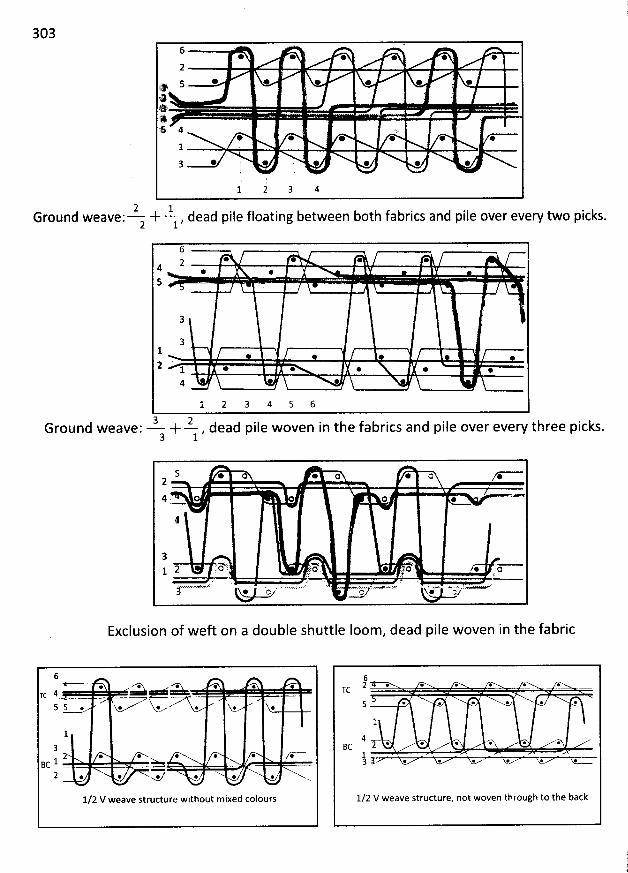
3036 @ @ @ * * @25 * * * * * @
y :@4:s 4 .s
@ * * * * *1 J
* ' ' . @ . .3 :
1 2 3 4
2 1Ground weave: + - , dead2 1 pile floating between both fabricsand pile over every two picks.
6z * * * @
4 @ @5
3
31 * * @2 1 . . . . .
4 * *
l 2 3 4 5 6
3 2Ground weave: + - , dead pile woven in the fabrics and pile over every three picks.3 1
5 * o @ o @ a @2
4 . o @
4
3E< < -2 :'0 '. 1.0 * 4 o : @ o1 . : .. . à :e < . ? . M
. .<. ' ' . ' 'j * 'a ,z * a/
Exclusion of weft on a double shuttle loom, dead pile woven in the fabric
6* ''''Xk* VX* * * ' ' -zc 4 !!!!!!i -
5 5 ... + *' * @. @
132 . * * . * *Bc 1 = >
2 . @ ..F @ . @ xx...
l/2 V weave structure without mixed colours
62 @. @ *. è . .TC
5 * * * * * *
1
4V* * @' @ @ * *BC
13 e * @ * @ *
1/2 V weave structure, not woven through to the back
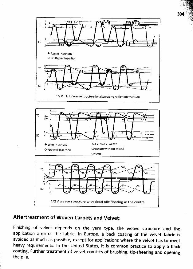
6 - - . çgv.----.--.-- . o- . u-!TC 4 - .. .-. - . . - - . . . - - . - -q * o o . o N. . o. 5 . .
3 o o .8C 1 - ..- '
2 1 > * o e .
* Rapier InsertionO No Rapier Insertion
6 . .* * oTC 4 --
5 * --- .-....-. : =---- . .
53 .1
3 . -.--- . -- .-- -2BC 1 ' --'-
2 .- e œ - -
1/2 V-+1/1 V weave structure by alternating rapier interruption
. ' . .l-o - oTC 45 . . . . .>
-
3
4. n -Bc 2 1- o -.- - o o o o
* ft Insertion 1/3V-*1/2V weavewe
structure without mixedo No weft Insertioncolours
6-Tc 2 --- -,--e
. ..x e * * *) 5215 4---%-
- . . . . .NBc 1
3
1 /2 V weave structure with dead pile floating in the centre
Aftertreatm ent of W oven Carpets and Velvet:
Finishing of velvet depends on the yarn type, the weave structure and theapplication area of the fabric. In Europe
, a back coating of the velvet fabric isavoided as much as possible, except for applications where the velvet has to meetheavy requirements. In the United States
, it is common practice to apply a backcoating. Further treatment of velvet consists of brushing
, tip-shearing and openingthe pile.
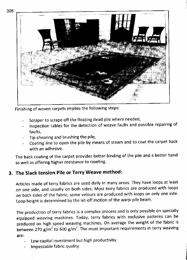
305
Finishing of woven carpets im plies the following steps:
Scraper to scrape off the floating dead pile where needed,Inspection tables for the detection of weave faults and possible repairing of
faults,Tip-shearing and brushing the pile,Coating Iine to open the pile by means of steam and to coat the carpet back
with an adhesive.The back coating of the carpet provides better bindihg of the pile and a better hand
as well as offering higher resistance to raveling.
3. The Slack tension Pile or Terry W eave m ethod:
Articles made of terry fabrics are used daily in many areas. They have Ioops at Ieaston one side, and usually on both sides. Most terry fabrics are produced with loopsoh both sides of the fabric; some velours are produced with Ioops on only one side.Loop height is determ ined by the let-off m otion of the warp-pile beam.
The production of terry fabrics is a complex process and is only possible on speciallyequipped weaving machines. Today, terry fabrics w ith exclusive patterns can beproduced on high speed weaving machines. On average the weight of the fabric is
2 6O0 g/m2 The most important requirements in terw weavingbetween 270 g/m to .36 P *
Low capital investm ent but high productivity.Impeccable fabric quality
Low spare parts consum ptionEasy operation, with few mechanical settings neededShort style changing times
Types of Terry Fabric:
There are basically two qualities of terry, according to the Ioop structure:
a) Classic terry, with upright Ioops (made of twisted yarns). These terries areusually patterned with dyed yarns.
b) Fashion terry, also ' known as milted or fulled goods, with spiral Ioops (ofsingle yarns). These are mainly piece dyed or printed fabrics.
Ablend of single and twisted yarns produces additional pattern effects.
According to the terry aspect, three types can be distinguished:
a) Terry with ordered standing Ioop piles: this is the type of pile fabrics which ismost produced. M ost of the tim e, unsized
, bleached or dyed pile warp yarnsare used in weaving which require no further aftertreatment
. The first washafter purchasing the product may cause a considerable change of the aspect(the Ioop pile appearance).
b) Terry with irregular loop piles: twisting and reversing pf pile Ioops ispromoted during the production of the terry. Sized, ecru or dyed single yarnsare used in the loop warp. These single yarns still possess great liveliness
.
Combined with an intensive wash during which the fabric is desized, the
fabric is given its typical irregular aspect and soft hand. These terry cloths are
then piece-dyed or printed. The appearance barely changes after the firstdomestic wash.
c) Terry with cut pile: velvet-like terw is obtained by tip-shearing the loop pile.
The pile yarns open up in a brush-like manner. These fabrics have an evensofter hand and even better water absorbency than terry with Ioop pile
.
Velvet toweling are high quality, expensive products.
Terry W eaving M echanism :
ln the production of terry fabrics, two w arps are processed sim ultaneously: theground warp, with tightly tensioned ends and the pile warp
, with Iighyly tensiopmdvnds. A special weaving method enables loops to be perform:d wjth th: Iightlytensioned warp ends on the fabric surface. In traditional terry weavipg, .bytmqansrpfa special device on the weaving m achine, two picks are inserted @A @ variàble
. . ' : ' . 'k 9 ! '' ' i'''; . . ' . .. ; . ' ;disiance - the Ioose pick distance - from the c10th fell. The lbos: piçk distaàv id kirted
ding to the desired Ioop height. w hen tie thii'd ' piik ls''ùeâièh t$ > th'eaCCOr ,,. . ,. . .. y. . y . . y, y ..
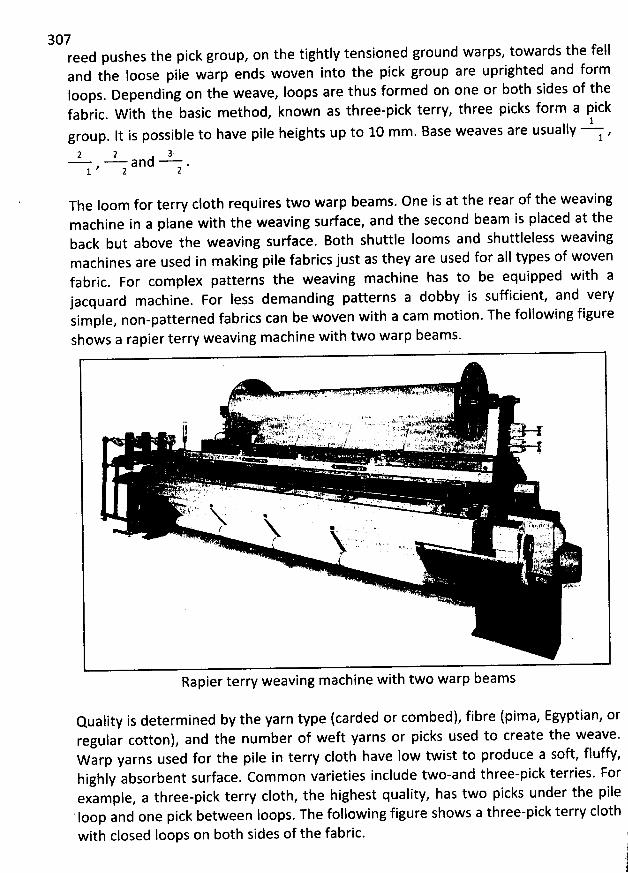
307reed pushes the pick group, on the tightly tensioned ground warps, towards the felland the Ioose pile warp ends woven into the pick group are uprighted and formloops. Depending on the weave, Ioops are thus formed on one or b0th sides of thefabric. W ith the basic m ethod, known as three-pick terry, three picks form a pick
1group. It is possible to have pile heights up to 10 mm . Base weaves are usually ,
12 2 , 3
a n (1 .1 ' 2 2
The Ioom for terry c10th requires two warp beams. One is at the rear of the weavingm achine in a plane with the weaving surface, and the second beam is placed at theback but above the weaving sudace. Both shuttle Iooms and shuttleless weavingmachines are used in making pile fabrics just as they are used for all types of wovenfabric. For complex patterns the weaving machine has to be equipped with ajacquard machine. For less demanding patterns a dobby is sufficient, and verysim ple, non-patterned fabrics can be woven with a cam motion. The following figureshows a rapier terw weaving machine with two warp beam s.
Quality is determined by the yarn type (carded or combed), fibre (pima, Egyptian, orregular cotton), and the number of weft yarns or picks usqd to create the weave.W arp yarns used for the pile in terry c10th have low twist to produce a soft, fluffy,highly absorbent surface. Common varieties include two-and tbree-pick terries. Forexam ple, a three-pick terry c10th, the highest quality, has two picks under the pile'Ioop and one pick between loops. The following figure shows a three-pick terry c10th
with closed Ioops on both sides of the fabric. j
1
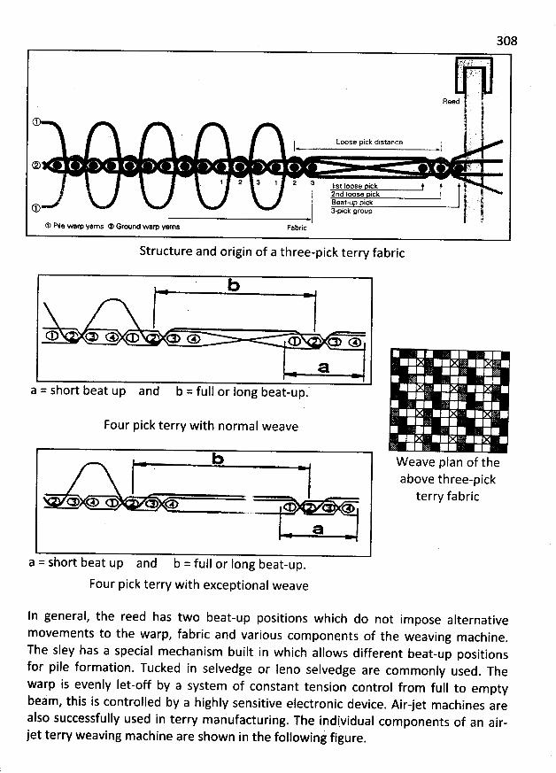
308
..
'
t:j)
'
..
'
1,;
*
'
'
.. .. .
'
. .
'
. . ( LIC ' '). .' '
aeed t
1 .
Loose pick distance '.''l l ,-
C VV ' ''
1 2 :$ 1 z s. , st I oo-se pi c. k f j! , 12nd Ioose pick' .:' Iih. Beat-up pick .
(13 Npick group ,-' 1@
* Pile wam yarns * Ground wam yarns Fabric
Structure and origin of a three-pick terry fabric
b
* & e œ o e o œ œ
a
a = short beat up and b = full or Iong beat-up.
Four pick terry with normal weave
b
œ e œ œ
a
a = short beat up and b = full or Iong beat-up.
Four pick terry with exceptional weave
ln general, the reed has two beat-up positions which do not impose alternativemovem ents to the warp, fabric and various components of the weaving machine
.
The sley has a special mechanism built in which allows different beat-up positionsfor pile formation. Tucked in selvedge or leno selvedge are com monly used
. Thewarp is evenly Iet-off by a system of constant tension control from full to emptybeam, this is controlled by a highly sensitive electronic device
. Air-jet machines arealso successfully used in terry mariufacturing. The individual com ponents of an air-jet terry weaving machine are shown in the following figure.
MW eave plan of theabove three-pickterry fabric
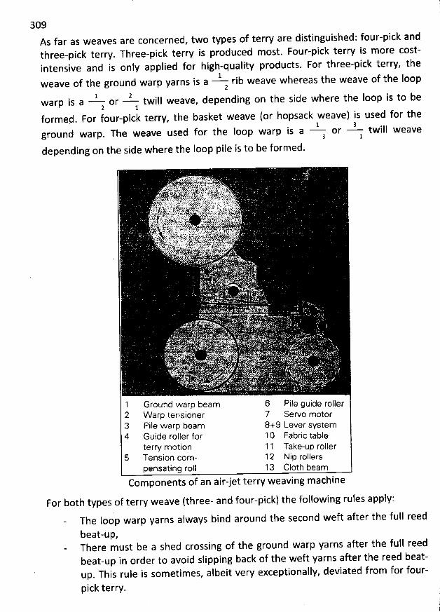
309As far as weaves are concerned, two types of terry are distinguished; four-pick andthree-pick terry. Three-pick terry is produced m ost. Four-pick terry is m ore cost-intensive and is only applied for high-quality products. For three-pick terry, the
1weave of the ground warp yarns is a rib weave whereas the weave of the Ioop2
1 2warp is a or twill weave, depending on the side where the Ioop is to be2 1
formed. For four-pick terry, the basket weave (or hopsack weave) is used for the1 3ground warp. The weave used for the Ioop warp is a or twill weave3 1
depending on the side where the Ioop pile is to be formed.
. .iyt . .a y. ) , yxyp. ''. r . xo x. . . ;vr, xuuv Kz yryu .y. '' ) . .. ' . . <wc .r '/oiy . w% w - g'xy y.y t c .l..g.4 s. . ..
y. . k q'w: xs . ma . . vxtpa +. . a . s k m. v. ss g u c.x .. . ''' ig . . akgkis,.,jrjygjy ......yjjjyjjyj. , ... yjygy.j.:.,yyjjyyj.;tr: ,;k;j(r..;. $gryyj;y:...y... yy,.
'
y. jjj....... .. s,j,ztq... .oy ,,
. ..o.,:...y..,....y tgj..zy.r.yy.yyj,y,..
'
. .,-. . . .y . ))u t, vz):.mjy. s
s)z.. .j ç.. .. ..-t. .yy.j(x.. gvy . qjsi. .xtyjy .y.. yyx.yj..: g... twx jp>. .;. x.k.. qtzltealjtittj yyyaitsys. p yazexy- s;k yj t: vv ;.j,..g ;, e . kt f , myk p N . y ) ggvyqj...'''I';.': z . kjlga ' a.,?7.& otpi%'fsk'ù-* k.# -.fyc ..,+.u . ..J z!. .v%.*'- 'ïs.éo'xê. Y .:1. t%;6 :371 t/f-slks '%-vsFxt.ti%zjp%.kh. pkiuv. .1%..b felkty %v..js tè r' .: ;y w ... . k x, . .4. T' t 'r . : ...tb. . .k. . . .x.f#..* . <,. .ey:s ,'
,y. ê,p :i w . .ewl4..a tjs .pF.z '. (46hs, p.- t . * - r!'?.) z ' pp x .. sv$, t r4 t'fkk -.y;,k&o.k.cîj1; wy-gtszs Jj/. ku îjgjy.. :à<.. z . - jjl - >.' .- -: ... ... . . 0.s. . ... ûyjyx '#p . .s1% ..'i .:;. T ' r - i w' ' ' J 4 e+ 'wytM%.;t. .' ' .:.:g- v4t!i .# s .:4p- - . , s we. :szr.);'k'I;>v,-t % ' .v ;k. k: .A'p z ., . ' e cjHjjkf ,.-'&. .Cx1 Y' 'x kk ..( Ya't-v.z 'L.n.- . . .'s , aewxe: . 4-+. . . > .
' . : .k- 'p;
'(x:. . . .
.ê . w ' pr '. #4. ' r
p .. ' . vkjjp. + . ,
T .' .. ' . v.
1 Ground warp beam 6 Pile guide roller2 arp tensioner 7 Servo motor3 Pile warp beam 8+9 Lever system4 Guide roller for 10 Fabrl'c table
ion 1 1 Take-up rollerterw m ot5 Tension com- 12 Nip rollers
pensating roll 13 C10th beam. . @ jj *Components of an alr-let terry weavlng mac Ine
For both types of terry weave (three- and four-pick) the following rules apply:The Ioop warp yarns always bind around the second weft after the full reed
beat-upzThere must be a shed crossing of the ground warp yarns after the full reedbeat-up in order to avoid slipping back of the weft yarns after the reed beat-up. This rule is som etim es, albeit vew exceptionally, deviated from for four-
pick terry.
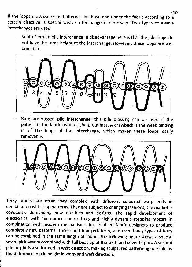
310lf the Ioops must be formed alternately above and under the fabric according to acertain directive, a special weave interchange is necessary. Two types of weaveinterchanges are used:
South-German pile interchange: a disadvantage here is that the pile loops donot have the same height at the interchange. However, these loops are wellbound in.
. N v.
)
* * o o o o p o o o o o oo o o o1
2 3 $ 5 6 7 8 . lc lj 2
Burghard-vossen pile interchange: this pile crossing can be used if thepattern in the fabric requires sharp outlines. A drawback is the weak bindingin of the Ioops at the interchange, which makes these Ioops easilyrem ovable.
' '. .
1Q e l o l e o o s o o o o o
illTerry fabrics are often very complex, with different coloured warp endscombination with Ioop patterns. They are subject to changing fashions, the market isconstantly demanding new qualities and designs. The rapid development ofelectronics, with microprocessor controls and highly dynamic stepping motors incom bination with modern m echanisms, has enabled fabric designers to producecompletely new patterns. Three- and four-pick terry, and even fancy types of terrycan be com bined in the same Iength of fabric. The following figure shows a specialseven pick weave combined with full beat up at the sixth and seventh pick. A secondpile height is also formed in weft dired ion, making sculptured patterning possible bythe difference in pile height in warp and weft direction.
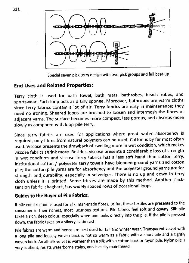
311*
!: - -' v..
<
1 2 34 5 7 1 2 3 4 5k
Special seven pick terry design with two-pick groups and full beat-up
End Uses and Related Properties:
Terry c10th is used for bath towel, bath mats, bathrobes, beach robes, andsportswear. Eacb loop acts as a tiny sponge. M oreover, bathrobes are warm clothssince terry fabrics contain a lot of air. Terry fabrics are easy in maintenance; theyneed no ironing. Sheared Ioops are brushed to loosen and intermesh the fibres ofadjacent yarns. The surface becomes more compact, less porous, and absorbs moreslowly as compared with Ioop-pile terry.
Since terry fabrics are used for applications where great water absorbency isrequired, only fibres from natural polymers can be used. Cotton is by far most oftenused. Viscose presents the drawback of swelling more in wet condition, which makesviscose fabrics shrink more. Besides, viscose presents a considerable Ioss of strengthin wet condition and viscose terry fabrics has a less soft hand than cotton terry.Institutional cotton / polyester terry towels have blended ground yarns and cottonpile; the cotton pile yarns are for absorbency and the polyester ground yarns are forstrength and durability, especially in selvedges. There is no up and down in terryc10th unless it is printed. Som e friezés are made by this method. Another slack-tension fabric, shagbark, has widely spaced rows of occasional loops.
Guides to the Buyer of Pile Fabrics:
If pile construction is used for silk, man-made fibres, or fur, these textiles are presented to theconsumer in their richest, most Iuxurious textures. Pife fabrics feel soft and downy. Silk piletakes a rich, deep colour, especially when one looks directly into the pile. If the pile is pressed
down, the fabric takes on a silvery, satin cast.
Pile fabrics are warm and hence are best used for fall and winter wear. Transparent velvet witha Iong pilq and Ioosely woven back is not so warm as a fabric with a short pile and a tightlywoven back. An all-silk velvet is warmer than a silk with a cotton back or rayon pile. Nylon pile isvery resilient, resists waterborne stains, and is easily maintained. '
(1.
j
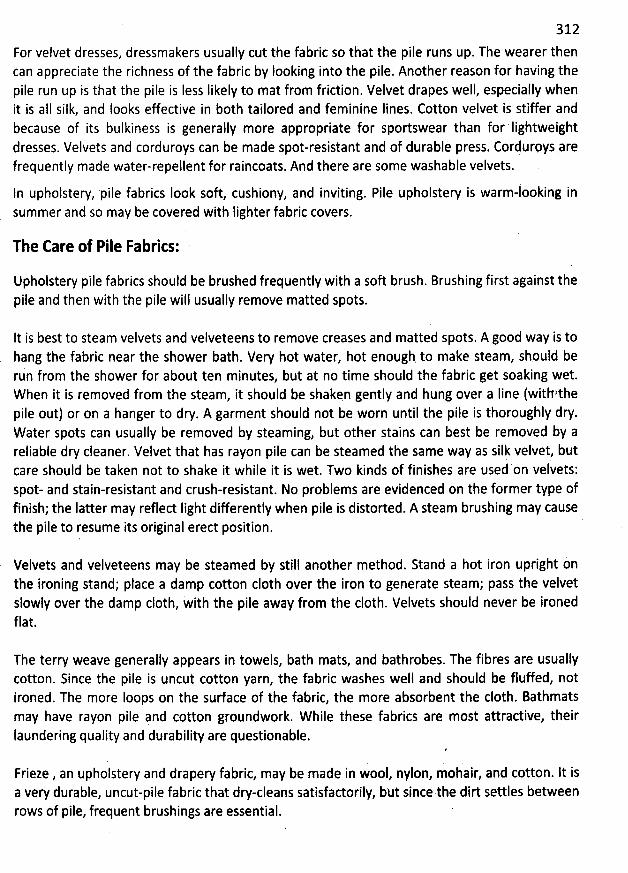
312
For velvet dresses, dressmakers usually cut the fabric so that the pile runs up. The wearer thencan appreciate the richness of the fabric by Iooking into the pile. Another reason for having thepile run up is that the pile is Iess Iikely to mat from friction. Velvet drapes well, especially whenit is aII silk, and Iooks e/ective in both tailored and feminine lines. Cotton velvet is stiffer andbecause of its bulkiness is generally more appropriate for sportswear than for 'Iightweightdresses. Velvets and corduroys can be made spot-resistant and of durable press. Corduroys arefrequently made water-repellent for raincoats. And there are some washable velvets.
ln upholstery, 'pile fabrics Iook soft cushiony, and inviting. Pile upholstery is warm-looking insummer and so may be covered with lighter fabric covers.
The Care of Pile Fabrics:
Upholstery pile fabrics should be brushed frequently with a soft brush. Brushing first against thepile and then with the pile will usually remove matted spots.
It is best to steam velvets and velveteens to remove creases and matted spots. A good way is tohang the fabric near the shower bath. Very hot water, hot enough. to make steam, should berun from the shower for about ten minutes, but at no time should the fabric get soaking wet.When it is removed from the steam, it should be shaken gently and hung over a Iine (withzthepile out) or on a hanger to dry. A garment should not be worn until the pile is thoroughly dry.W ater spots can usually be removed by steaming, but other stains can best be removed by areliable dry cleaner. Velvet that has rayon pile can be steamed the same way as silk velvet, butcare should be taken not to shake it while it is wet. Two kinds of finishes are used on velvets:Spot- and stain-resistant and crush-resistant. No problems are evidenced on the former type offinish; the Iatter may reflect Iight differently when pile is distorted. A steam brushing may causethe pile to resume its originai erect position.
Velvets and velveteens may be steamed by still another method. Stand a hot iron upright onthe ironing stand; place a damp cotton c10th over the iron to generate steam; pass the velvetslowly over the damp c10th, with the pile away from the c10th. Velvets should never be ironedflat.
The terry weave generally appears in towels, bath mats, and bathrobes. The fibres are usuallycotton. Since the pile is uncut cotton yarn, the fabric washes well and should be fluffed, notironed. The more Ioops on the surface of the fabric, the more absorbent the c10th. Bathmatsmay have rayon pile pnd cotton groundwork. W hile these fabrics are most attractive, theirIaundering quality and durability are questionable.
Frieze , an upholstery and drapery fabric, may be made in wool, nylon, mohair, and cotton. lt isa very durable, uncut-pile fabric that dry-cleans satisfadorily, but since the dirt settles betweenrows of pile, frequent brushings are essential. '
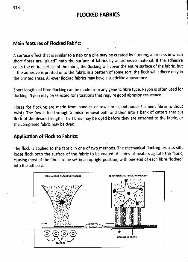
313
FLOCKqD FABRICS
M ain features of Flocked Fabric:
A surface effect that is similar to a nap or a pile may be created by flocking, a process in whichshort fibres are ''glued'' onto the surface of fabrics by an adhesive material. lf the adhesivecoats the entire surface of the fabric, the flockin'g will cover the entire surface of the fabric, butif the adhesive is printed onto the fabric in a pattern of some sort the flock will adhere only inthe printed aregs. All-over flocked fabrics may have a suedelike appearance.
Short Iengths of fibre flocking can be made from any generic fibre type. Rayon is often used forflocking. Nylon may be selected for situations that require good abrasion resistance.
Fibres for flocking are made from bundles of tow fibre (continuous filament fibres withouttwijt). The tpw is fed through a finish removal bath and then into a bank of cutters that cut
' 1 f the désired Iength. The fibres may be dyed before they are attached to the fabric, orfloc othe completed fabric may be dyed.
Applicàjion of Flock to Fabrics:
The flock is applied to the fabric in one of two methods. The mechanical flocking process sifts.loose flock onto the surface of the fabric to be coated. A series of beaters agitate the fabric,causing most of the fibres to be set in an upright position, with one end of each fibre ''Iocked''into the adhesive.
MECHANICAL FLX KING Pqr- co 'LEW BWTATIC FQX KING PRX EO
/ / A$ g z ,e-Nx ! ( '.e ..-
NNq j ! N , N 11 zN-. I l / f Y $ j ,--..<.-u' l 11 $N' Z Q' Y.Nq ...-. 1 N I z/ -h 'A @ - .-.--- / v $ js ..c sy x zh
.-- x! yg z, ..-.--. 1 L <. - -x. x $x- - .- ; f N : $
- x z l j xl sN- r / b $N: sI ''#' h4. N t . % %. & N 1N /J A $ t,' a -cj ) -.z' 1k.,-.t- , ) T1, j I
,1 r. ! Il. , g' I)- rl g r I
jNx ', ,1 N, îs / ', ) lj j' j. ' 1. : j ', 'j 1, .1 'j I ,
'
j 1, I j j j' j ,î 'f /N 'Nl h
'
hN1 jh $
'
xjj
'
s us jv, .....,> 1, I,
'
lj 1. j j j 'j 'j 1. ; I j ! I j 'j - j ) j I,.........-* zlks z,N s s , -,-e. . .àio o.-# .-*+'.''='u.'-- -
- 'e - FA:alc
o o o o - tN/BEATE8S
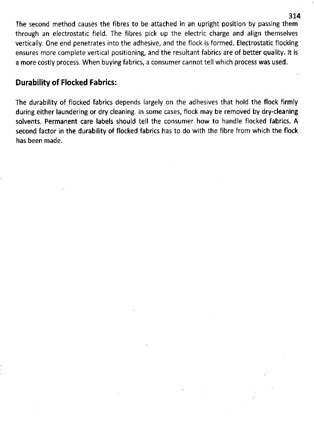
314The second method causes the fibres to be attached in an upright position by passing themthrough an electrostatic field. The fibres pick up the electric charge and align themselvesvertically. One end penetrates into the adhesive, and the flock is formed. Electrostatic flockingensures more complete vertical positioning, and the resultant fabrics are of better quality. lt isa more costly process. W hen buying fabrics, a consumer cannot tell which process was used.
Durability of Flocked Fabrics:
The durability of flocked fabrics depends Iargely on the adhesives that hold the flock firmlyduring either laundering or dry cleaning. In some cases, flock may be removed by dry-cleaningsolvents. Permanent care Iabels should tell the consumer how to handle flocked fabrics. Asecond factor in the durability of flocked fabrics has to do with the fibre from which the flockhas been made.
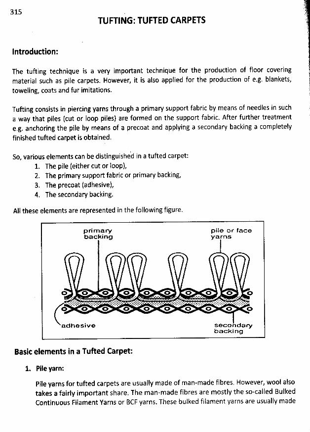
315TUFTING:TUFTED CARPETS
Introduction:
The tuûing technique is a very important technique for the production of floor coveringmaterial such as pile carpets. However, it is also applied for the production of e.g. blankets,
toweling, coats and fur imitations.
Tufting consists in piercing yarns through a primary support fabric by means of needles in such
a way that piles (cut or Ioop piles) are formed on the support fabric. After further treatmeote.g. anchoring the pile by means of a precoat and applying a secondary backing a compjetely
finished tufted carpet is obtained.
So, various elements can be distinguished in a tufted carpet:
1. The pile (either cut or Ioop),2. The primary support fabric or primary backing,
3. The precoat (adhesive),4. The secondary backing.
All these elements are represented in the following figure.
Basit elements in a TuRed Carpet:
1. Pile yarn:
Pile yarns for tufted carpets are usually made of man-made fibres. However, wool alsotakes a fairly important share. The man-made fibres are mostly the so-called BulkedContinuous Filament Yarns or BCF yarns. These bulked filament yarns are usually made
è yF .. . :)tt :-t.ty;;jj1
' 31.A ' .' .'v. .. . : ,
of polyamide, or sometimes polypropene or other man-made fibres. The pile yarn can ,contain metal or carbon fibres if antistatic properties are required.A pile yarn should present the following properties:
Be well wear resistant,Have good dyeing properties,Present good resilience,Difficult soilability,Easy cleanability (release of dirt particles).
Naturally, other important aspects which determine the choice of a pile yarn includeresistance to micro-organisms and insects, moisture absorption capacity, hiding of dirtparticles, soil resistance, electrostatic properties, flame resistance etc.It goes without saying that the yarn should have sufficient and uniform strength so as toavoid as many breakages, and hence machine jtops, as possible. M oreover, threading ofthe yarn through the needle eyes requires a uniform cross-section and therefpre regularthickness. Knots in the yarn must be avoided. Hence, yarns must preferably be joined .with latex or by air (splicers).
2. Support fabric (primary backing):
During tufting, pile yarn is stitched through a support fabric (or primary backing). It caneither be a woven fabric or a non-woven (actually, a spinning fleece). Fabrics includejute, polyester filament yarn or staple fibre, polypropene tapes, glass fibres etc. Non-wovens are mainly based on polyester and polypropene (sometimes blended withpolyethylene).W hilst before the fabric was almost always based on jute, nowadays this has almostcompletely disappeared. Indeed, jute contains oils which can penetrate the pile andthus cause soiling and problems when dyeing. Also, jute is Iess rot resistant andtherefore subject to micro-organisms.Polypropene is an important substitution product fot jute. Fabrics made of polypropene
2 h thin fabrics,tapes, usually in plain weave, have a mass of 80 to 150 g/m . T ese arewhich can easily be pierced and are sujted for alI needle gauges. Such material is
0c) Fraying at thedimensionally stable, but is sensitive to high temperatures (> 170 .
border can be avoided by applying a butyl coating on the warp and weft threads.Examples of such fabrics of polypropene tapes are polybac, polital etc. Polybac FLW isalso a fabric made of polypropene tapes but with a nylon cap needled on it. W ben dyed,the colour difference between the polypropene and the pile yarns will b: masked by theapplication of this nylon fleecè since nylon takes up dyestuff more readily thanpolypropene. Fuzzback is another example of such a construction.
Fabrics made of polyester filament yarn consist of highly shrinkable yarns of 1,100 dtexand with a weight up to approx. 120 g/m2. Such fabrics are strong, not sensitive to
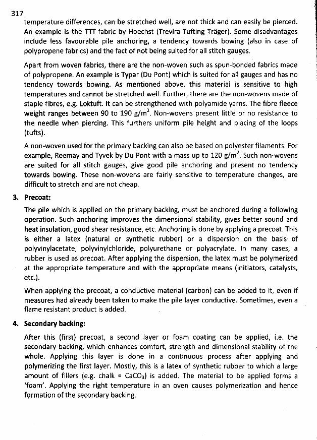
317 (temperature differences, can be stretched well, are not thick and can easily be pierced.An example is the Tu -fabric by Hoechst (Trevira-Tufting Tràger). Some disadvantagesinclude less favourable pile anchoring, a tendency towards bowing (also in case ofIypropene fabrics) and the fact of not being suited for aII stitch gauges. 1PO j
iApart from woven fabrics, there are the non-woven such as spun-bonded fabrics made jof polypropene. An example is Typar (Du Pont) which is suited for aIl gauges and has no ))tendency towards bowing. As mentioned above, this material is sensitive to high (temperatures and cqnnot be stretched well. Further, there are the non-wovens made ofstaple fibres, e.g. Loktuft. lt can be strengthened with polyamide yarns. The fibre fleece
2 little or no resistance to 'weight ranges between 90 to 190 g/m . Non-wovens presentthe needle when piercing. This furthers uniform pile height and placing of the Ioops(tufts).A non-woven used for the primary backing can also be based on polyester filaments. For
Ie Reemay and Tyvek by Du Pùnt with a mass up to 120 g/m2. Such non-wovensexamp ,are suited for aII stitch gauges, give good pile anchoring and present no tendencytowards bowing. These non-wovens are fairly sensitive to temperature changes, aredifficult to stretch and are not cheap.
3. Pretoat:
The pile which is applied on the primary backing, m ust be anchored during a followingoperation. Such anchoring improves the dimensional stability, gives better sound andheât insulation, good shear resistance, etc. Anchoring is done by applying a precoat. This
is either a Iatex (natural or synthetic rubber) or a dispersion on the basis ofpolyvinylacetate, polyvinylchloride, polyurethane or polyacrylate. In many cases, arubber is used as precoat. After applying the dispersion, the Iatex must be polymerized
at the appropriate temperature and with the appropriate means (initiators, catalysts,etc.).
When applying the precoat, a conductive material (carbon) can be added to it, even ifmeasures had already been taken to make the pile layer conductive. Sometimes, even aflame resistant product is added.
4. Setondary backing:
After this (first) precoat, a second layer or foam coating can be applied, i.e. thesecondary backing, which enhances comfort, strength and dimensional stability of thewhole. Applying this Iayer is done in a continuous process after applying andpolymerizing the first Iayer. M ostly, this is a latex of synthetic rubber to which a large
amount of fillers (e.g. chalk = CaCOa) is added. The material to be applied forms a'foam'. Applying the right temperature in an oven causes polymerization and henceformation of the secondary backing.
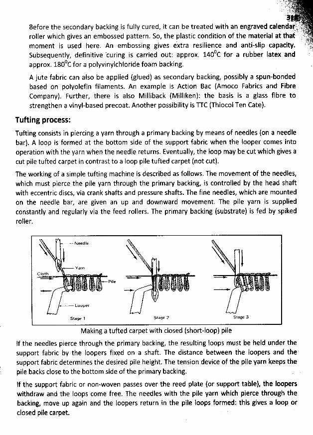
. 7 : J vitt. . -!j) .. ; . tt' . , ) jsoar. .J . . . k.<,.
. . Aojh 'Before the secondary backing is fully cured, it can be treated with an engraved calendaf ,:! Jt' i)r.hqtroller which gives an embossed pattern. So, the plastic condition of the material at that' 't7jjtr f .
).. syjgmoment is used here. An embossing gives extra resilience and anti-slip capacity. ' #
Subsequently, definitive curing is carried out: approx. 140 C for a rubber Iatex and :0c for a polyvinylchloride foam backing.approx. 180
A jute fabric can also be applied (glued) as secondaw backing, possibly a spun-bondedbased on polyolefin filaments. An example is Action Bac (Amoco Fabrics and FibreCompany). Further, there is also Milliback (Milliken): the basis is a glass fibre tostrengthen a vinyl-based precoat. Another possibility is U C (Thiocol Ten Cate).
Tufting process:
Tufting consists in piercing a yarn through a primary backing by means of needles (on a needlebar). A Ioop is formed at the bottom side of the support fabric when the Iooper comes intooperation with the yarn when the needle returns. Eventually, the Ioop may be cut which gives a
cut pile tufted carpet in contrast to a Ioop pile tufted carpet (not cut).Tile working of a simple tufting machine is described as follows. The movement of the needles,which must pierce the pile yarn through the primary backing, is controlled by the head shaftwith eccentric discs, via crank shafts and pressure shafts. The fine needles, which are mountedon the needle bar, are given an up and downward movement. The pile yarn is suppliedconstantly and regularly via the feed rollers. The primary backing (substrate) is fed by spikedroller.
! ..-. xeejjje
1ivarn 1 )
Cloth
Loo per
Stage 1 Stage 2 Slage 3
Making a tufted carpet with closed (short-loop) pileIf the needles pierce through the primary backing, the resulting Ioops must be held under thesupport fabric by the Ioopers fixed on a shaft. The distance between the Ioopers and thesupport fabric determines the desired pile height. The tension device of the pile yarn keeps thepile backs close to the bottom side of the primary backing.
lf the support fabric or non-woven passes over the reed plate (or support table), the looperswithdraw and the Ioops come free. The needles with the pile yarn which pierce through thebacking, move up again and the Ioopers return in the pile loops formed: this gives a Ioop èrclosed pile carpet.
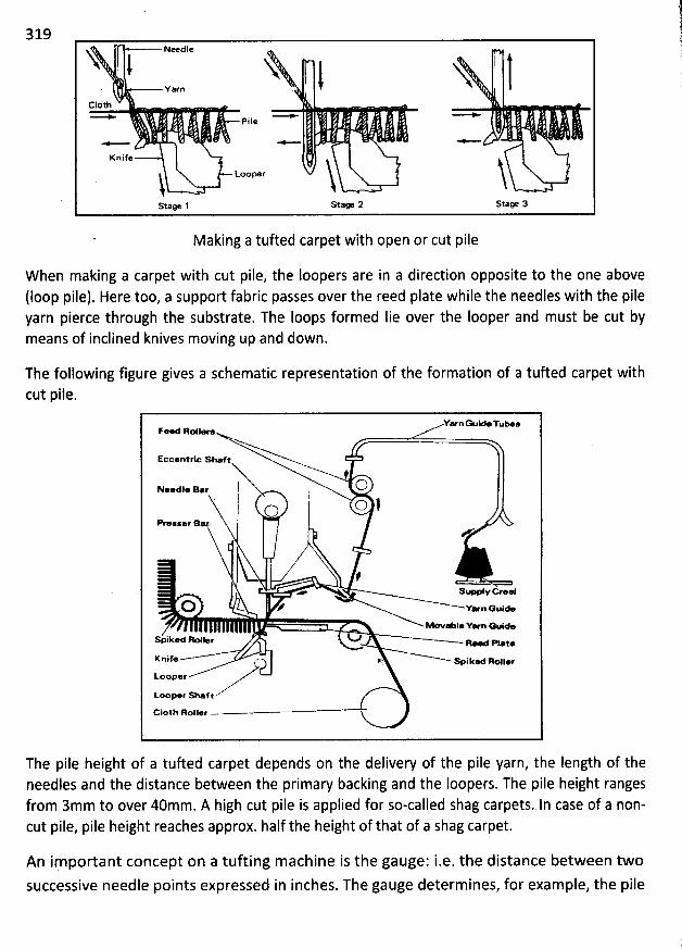
319
NeedleN i N lt X. varn
. iCloth
F'il:t
Knife
LooperiStage 1 S'age 2 Stage 3
Making a tufted carpet with open or cut pile
W hen making a carpet with cut pile, the Ioopers are in a direction opposite to the one above
(Ioop pile). Here too, a support fabric passes over the reed plate while the needles with the pileyarn pierce through the substrate. The loops formed Iie over the Iooper and must be cut bymeans of inclined knives moving up and down.
The following figure gives a schematic representation of the formation of a tufted carpet withcut pile.
YarnGuo 'ru- sFe Roll-
Eccentrle shaf:
fl ON-dle B.r . 1
. o lOM lser B
A
fw- s.- ycreel
U # Y-n Guie- * 1. Y- œ ide
spiked Ikpllee Q# a-w ptao
Koife t spiked Rtyjjl,
kooper
toop.r shaf t
c10th Roller -
Tbe pile height of a tufted carpet depends on the delivery of the pile yarn, the Iength of theneedles and the distance between the primary backing and the Ioopers. The pile height rangesfrom 3mm to over 40mm. A high cut pile is applied for so-called shag carpets. ln case of a non-cut pile, pile height reaches approx. half the height of that of a shag carpet.
An important concept on a tufting machine is the gauge: i.e. the distance between twosuccessive needle points expressed in inches. The gauge determ ines, for example, the pile
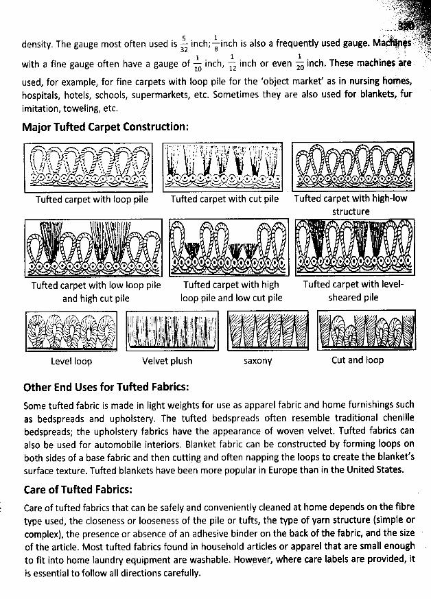
. . ..,- .jvy.y. . .- ;,jtL rot-7 J ' .s '
. .. . .. ia...* . , . $; >.. . z.. . - .
. ç.-.,. !. . ' Etltrtjl'i:jël .!; IL . .!y;, ,density. The gauge most often used is - inchi-a inch is also a frequently used gaugè- Ma 4s : i.,?$E5 ;! ' - ; i ':',! ; yttF-. 'p1 1 1 , r? ,with a fine gauge often have a gauge of - inch, -1z inch or even -x inch. These machines are
10
used, for example, for fine carpets with loop pile for the 'object market' as in nursing holés,hospitals, hotels, schools, supermarkets, etc. Sometimes they are also used for blankets, furimitation, toweling, etc.
Major Tufted Carpet Construction:
> o >lz-.. . --d#-*Rh.f r' 't & J ' :. il'--i & ...r- : .,4 -y , . .,- -; -) ,z;-) ,v ,.: x;,) ..,. .:.$ ...,3 H $ t > ï$ j z/' ', A jy . z ..v j y ' sy. . . zA u wr . . . h . ..-. .:D o. D . . .D . . sp . . D . . . . z;wv '-a ez ..-, N .<> '. x.-e s... w
Tufted carpet with Ioop pile
! ;.. e ... . . 1 ... ., . . .. ' . . j 11 ! 1* TF 5'1 t:; . 4 ;! r 1 .$ ' .1 lrE ' I ' * ' . ' ... . e . . f, , :! . ; . j lr ' ; 11 i .!. 17 ''cj . ., '. s i'.. i. )) (.. ,2 J:, 'kjk ,r/ f ;:. I./ , .!. ;.',: . , . .: - . :. , ., j 4 . . , t: -. j . ! k jj' . : l ' J ' l ; . . J .,: ' , ,1 j . ..
, ' 1 '! . . - I $ z ) w . j. I j . / .. ! '
. . & * . V . V . . , V ' . TN . e' y . : , , T ' y + , , y p& ' L' * .!z L. . ..!., .sr d, @ . . , . *V .F.; w' wwN-e , . x . . . x . <coe . ww,m x-v v-..cu . .- w .
Tufted carpet with cut pile Tufted carpet with higb-lowstructure
l
$:
.,.'t..$4.....T .I ........'.......'* . ' 4 .' . œ . * ' .*('* ' ''. ., .. . ; . .. 4
Tufted carpet with high Tufted carpet with Ievel-Ioop pile and Iow cut pile sheared pile
. . J'I 1i
.. . v*.. .'. .: ' .
Tufted carpet with Iow Ioop pileand high cut pile
' . qyrp'l?!;lhbk ,z,? i '' . ,j;:'-k j ,p ,,,.. ryyjj j y j j j Er . , j ' ' ; j j j ( $ j 'j ; ' j y j: ; t. j k ! . , j : jkj j j j ,. ;.1 j 1 j '! ',, , y jri ,/ s t , , . jf . , ' , , $ , j ij ! j ; , , ); ! gj j ;. ë ; . j j ) jj : : .J jyxosk j. ;, , . . j' j j j y j yj j r j j kj k o yjj rj j j jj j y y y ij jj. y j ;j j y,. .-x -. ij ; ; lj j lr ; i( j g ,1 t . j ! ! j; !; ! lj !; jt j j j j j . rj j j ,j,, ! d. $ .--.. ,lïr)k j Fj y t t I ,, ( jj i i . p l ! i j ;; j : 1, Ij ,( ! g j 4
, j jj j j j y j . gjx7- ,...? txt,. 41,,,. ..jj, , ,, . . j. . ,, .,Level Ioop Velvet plush
f J/ ,.2* Z X 'k
A'
SaXOnY
if .k j
Cut and Ioop
Other End Uses for Tufted Fabrics:Some tufted fabric is made in Iight weights for use as apparel fabric and home furnishings suchas bedspreads and upholstery. The tufted bedspreads often resemble traditional chenillebedspreads; the upholstery fabrics have the appearance of woven velvet. Tufted fabrics canalso be used for automobile interiors. Blanket fabric can be constructed by forming Ioops onboth sides of a base fabric and then cuttipg and often napping the loops to create the blanket'ssurface texture. Tufted blankets have been more popular in Europe than in the United States.
Eare of Tufted Fabries:
Care of tufted fabrics that can be safely and conveniently cleaned at home depends on the fibre
type used, the closeness or Iooseness of the pile or tufts, the type of yarn strudure (simple orcomplex), the presence or absence of an adhesive binder on the back of the fabric, and the sizeof the article. Most tufted fabrics found in household articles or apparel that are small enoughto fit into home laundry equipment are washable. However, where care labels are provided, itis essential to follow aII diredions carefully.
KNIU ED FABRIC AND KNIU ING TECHNO LOGY
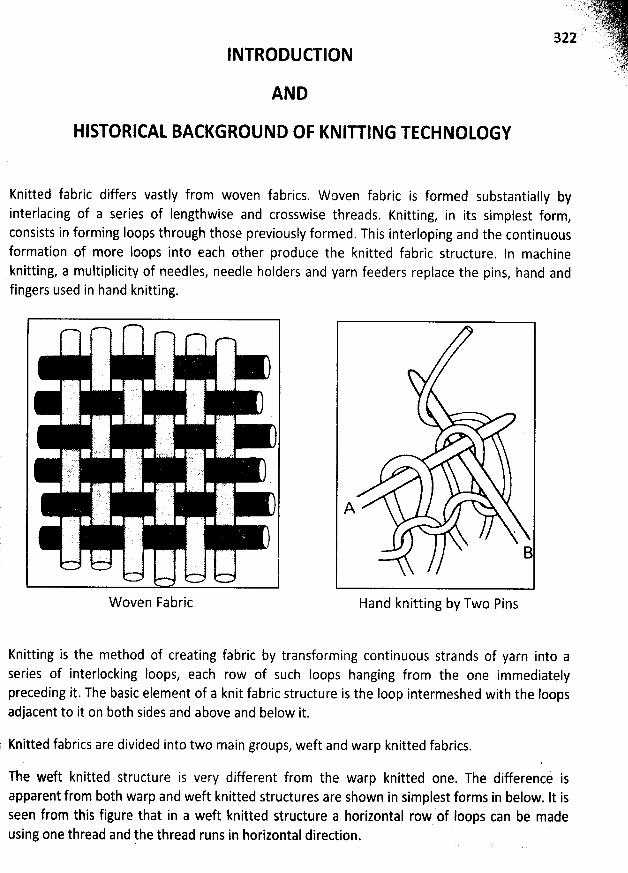
INTRODUCTION
AND
HISTORICAL BACKGROUND OF KNITTING TECHNOLOGY
Knitted fabric differs vastly from woven fabrics. W oven fabric is formed substantially byinterlacing of a series of Iengthwise and crosswise threads. Knitting, in its simplest form,consists in forming Ioops through those previously formed. This interloping and the continuousformation of more Ioops into each other produce the knitted fabric structure. ln machineknitting, a multiplicity of needles, needle holders and yarn feeders replace the pins, hand andfingers used in hand knitting.
W oven Fabric
>AHand knitting by Two Pins
Knitting is the method of creating fabric by transforming continuous strands of yarn into aseries of interlocking Ioops, each row of such loops hanging from the one immediatelypreceding it. The basic element of a knit fabric structure is the loop intermeshed with the Ioopsadjacent to it on both sides and above and below it.
j Knitted fabrics are divided into two main groups, weft and warp knitted fabrics.
The weft knitted structure is very different from the warp knitted one. The difference isapparent from both warp and weft knitted structures are shown in simplest forms in below. lt isseen from this figure that in a weft knitted structure a horizontal row of Ipopà can be madeusing one thread and the thread runs in horizontal direction.
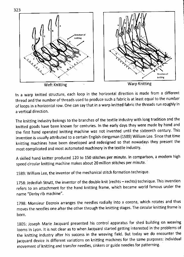
323
A
Direction ofCD , N 'h krllttlng
#* w< %xx* x
.. * h - x- w f wa. * x- ww eh A. .. N.> x j: A' N- w x
e. * fk x. Yx Y' x *'- N. N* * Wa. e & x... x h . x.a' '* x h ' h x
- < H w . xA x - N. $ xR x * .e x < hN x xJ' w % x 2' h.P w xN a. wQ w x #.(: ' x * % S x.Y N. # x. h F w* h
*x h v
& 1 x .. h y.d' x * * %h # %& Y w *
NN
Knittinge t
In a warp knitted structure, each Ioop in the horizontal direction is made from a differentthread and the number of threads used to produce such a fabric is at feast equal to the numberof loops in a horizontal row. One can say that in a warp knitted fabric the threads run roughly in
a vertical direction.
EF
G11
A ..œ. #'* - w
(: . Y x.' * x h h
x ew; w N.' I <w .. - (h s h
.. # N.- w #. #' Ax x e % A.x w N x.x - >. -* h: x * x hx w x % fN. >' N e h' N'
a, e' a' N wD .' x #' x .w X .P v - * N'& ' N Y Wx . %N a'# x e x,. ''x * xT .. %
e N * ., xN a.1 x Nx h %.N N YN e ## e
x Dlrectlon ofknitting
Warp Knitting
The knitting industry belongs to the branches of the textile ihdustry with Iong tradition and theknitted goods have been known for centuries. ln the early days they were made by hand andthe first hand operated knitting machine was not invented until the sixteenth century. Thisinvention is usually attributed to a certain English clergyman (1589) William Lee. Since that timeknitting machines have been developed and redesigned so that nowadays they present the
licated and most automated machinery in ihe textile industry.most comp
A skilled hand knitter produced 120 to 150 stitches per minute. In comparison, a modern highspeed circular knitting machine makes about 20 million stitches per minute. '
1589: W illiam Lee, the inventor of the mechanical stitch formation technique.
1758: Jedediah Strutt, the inventor of the double knit (rechts - rechts) technique. This inventionrefers to an attachment for the hand knitting frame, which became world famous under the
name ''Derby rib machine''
1798: Monsieur Decroix arranges the needles radially into a corona, which rotates and thusmoves the needles one after the other through the knitting stages. The circular knitting frame is
born.
1805: Joseph Marie Jacquard presented his control apparatus for shed building on weavingIooms in Lyon. It is not clear as to when Jacquard started getting interested in the problems ofthe knitting industry after his success in the weaving field. But today we do encounter thejacquard device in different variations on knitting machines for the same purposes: individualmovement of knitting and transfer needles, sinkers or guide needles for patterning.
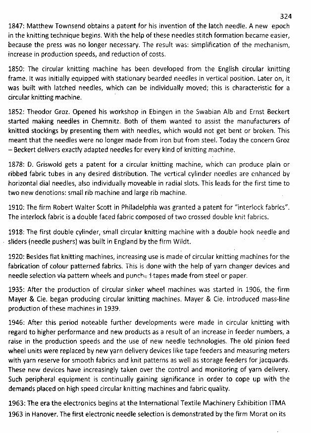
3241847: Matthew Townsend obtains a patent for his invention of the Iatch needle. A new epochin the knitting technique begins. W ith the help of these needles stitch formation became easier,because the press was no Ionger necessary. The result was: simplification of the mechanism,increase in production speeds, and reduction of costs.
1850: The circular knitting machine has been developed from the English circular knittingframe. lt was initially equipped with stationary bearded needles in vertical position. Later on, itwas built with Iatched needles, which can be individually moved; this is characteristic for acircular knitting machine.
1852: Theodor Groz. Opened his workshop in Ebingen in the Swabian AIb and Ernst Beckertstarted making needles in Chemnitz. Both of them wanted to assist the manufacturers ofknitted stockings by presenting them with needles, which would not get bent or broken. Thismeant that the needles were no Ionger made from iron but from steel. Today the concern Groz- Beckert delivers exactly adapted needles for every kind of knitting machine.
1878: D. Griswold gets a patent for a circular knitting machine, which can produce plain orribbed fabric tubes in any desired distribution. The vertical cylinder needles are enhanced byhorizontal dial needles, also individually moveable in radial slots. This Ieads for the first time totwo new denotions: small rib machine and Iarge rib machine.
1910: The firm Robert W alter Scott in Philadelphia was granted a patent for ''interlock fabrics''.The interlock fabric is a double faced fabric composed of two crossed double knit fabrics.
1918: The first double cylinder, small circular knitting machine with a double hook needle andsliders (needle pushers) was built in England by the firm Wildt.
1920: Besides flat knitting machines? increasing use is made of circular knitting machines for thefabrication of colour patterned fabrics. This is done' with the help of yarn changer devices andneedle selection via pattern wheels and puncht: :1 tapes made from steel or paper.
1935: After the production of circular sinker wheel machines was started in 1906, the firmMayer & Cie. began producing circular knitting machines. Mayer & Cie. introduced mass-lineproduction of these machines in 1939.
1946: After this period noteable further developments were made in circular knitting withregard to higher performance and new products as a result of an increase in feeder numbers, araise in the production speeds and the use of new needle technologies. The oId pinion feedwheel units were replaced by new yarn delivery devices Iike tape feeders and measuring meterswith yarn reserve for smooth fabrics and knit patterns as well as storage feeders for jacquards.These new devices have increasingly taken over the control and monitoring of yarn delivery.Such peripheral equipment is continually gaining significance in order to cope up with thedemands placed on high speed circular knitting machines and fabric quality.
1963: The era the electronics begins at the International Textile M achinery Exhibition ITMA
1963 in Hanover. The first electronic needle selection is demonstrated by the firm Morat on its
325film-taper-controlled ''Moratronie', which later on gets into serial production. Today acomputer is used for data storage and a diskette is the data carrier.
1967: The Iegendary OVJA 36, which is probably world-wide the most successful circularknitting machine so far, is exhibited at the ITMA in Basle. More than 7000 machines of this type
were built in the following years.
1987: The firm Mayer & Cie begins with the serial production of the RELANIT, a plain (rechts-links) circular knitting machine having a relative movement between needles and sinkers. lt willbe producing more than 1000 machines till the ITMA 1991.
Modern circular knitting technology will be determined by increases in pedormance, reductionsin setting-up times and flexible utilization. The technical designer will have to deal with this
challenge now and in the future..
Knitting is the most common method of interloping and is second only to weaving as a methodof manufacturing textile structures. It is estimated that over seven million tons of knitted goodsare produced annually throughout the world. Although the unique capability of knitting tomanufacture shaped and form-fitting articles has been utilized for centuries, moderntechnology has enabled knitted constructions in shaped and unshaped fabric form to expandinto a wide range of apparel, domestic and industrial end-uses.
Knitted fabrics of a wide variety of types are presently enjoying unprecedented consumerdemand. In many end-uses, where formerly woven fabrics held undisputed away, knitted c10thhas taken a commanding Iead, while in those end-uses where the knitted fabric traditionally hasbeen supreme, production advanced by Ieaps and bounds.
To most people, knitted fabric is somewhat of an unknown quantity. Few people can distinguishit readily from woven fabrics; fewer still have any conception how it is produced.
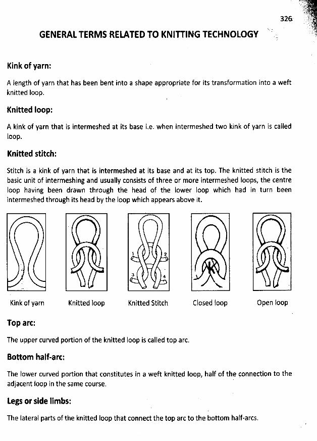
GENERALTERM S RELATED TO KNIU ING TECHNOLOGY
Kink of yarn:
A length of yarn that has been bent into a shape appropriate for its transformation into a weftknitted loop.
Knitted Ioop:
A kink of yarn that is intermeshed at its base i.e. when intermeshed two kink of yarn is calledloop.
Knitted stitch:
Stitch is a kink of yarn that is intermeshed at its base and at its top. The knitted stitch is thebasic unit of intermeshing and usually consists of three or more intermeshed loops, the centreIoop having been drawn through the head of the lo/er Ioop which had in turn beenintermeshed through its head by the Ioop which appears above it.
), ,Kink of yarn
Top arc:
The upper curved portion of the knitted Ioop is callid top arc.
'
------pjiiqrjlklyty-rtyyljljjiyr-------kë!:qi;i!!):l
Knitted loop
1 2
3 4
Knitted Stitch Closed Ioop Open Ioop
Bottom half-arc:
The Iower curved portion that constitutes in a weft knityed Ioop, half of the çonnection to the
d t loop in the same course.a jacen
Legs or side limbs:
The Iateral parts of the knitted Ioop that conned the top arc to the bottom half-arcs.
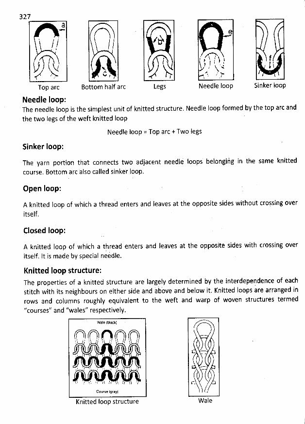
327
w
q '
l l//l
. , )7 ? h k's/ >v
Top arc
/
N.C ,
Bottom half arc
Needle loop:The needle Ioop is the simplest unit of knitted structure. Needle loop formed by the top arc and
the two Iegs of the weft knitted loop
Needle loop = Top arc + Two legs
Sinker Ioop:
. 7 ,
eè
i ,
%Legs
e
. j ;%h : h )t / .z k 4
.$ ,.. y
Needle loop
f, ) l
$
Sinker Ioop
The yarn portion that connects two adjacent needli Ioops belongiig in the same knittedcourse. Bottom arc àlso called sinke'r Ioop.
Open Ioop:
A knitted loop of which a threaà enters and Ieaves at the opposite sides without croFsing overitself .
Closed Ioop:
A knitted Ioop of which a thread enters and Ieaves at the opposite sides with crossing overitself. It is made by special neidle.
Knitted Ioop structure:The properties of a knitted structure are Iargely determined by the interdependence of each
stitch with its neighbours on either side and above and below it. Knitted loops are arranged inrows and columns roughly equivalent to the weft and warp of woven structures termed
''courses'' and '/wales'' respectively.
Wale
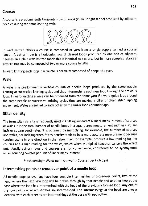
328
Course:
A course is a prejominantly horizontal row of Ioops (in an upright fabric) produced by adjacentneedles during the same knitting cycle.
In weft knitted fabrics a course is comppsed of yarn from a single supply termed a courseIength. A pattern row is a horizontal row of cleared Ioops produced by one bed of adjacentneedles. In a plain weft knitted fabric this is identical to a course but in more complex fabrics apattern row may be composed of two or more course lengths.
In warp knitting each Ioop in a course is normally composed of a separate yarn.
W ale:
A wale is a predominantly vertical column of needle Ioops produced by the same needleknitting at successive knitting cycles and thus intermeshing each new loop through the previousloop. ln warp knitting a wale can be produced from the same yarn if a warp guide laps aröundthe same needle at successive knitting cycles thus are making a pillar or chain stitch Iapping
movement. Wales are joined to each other by the sinker loops or underlaps.
Stitch density:
The term stitch density is frequently used in knitting instead of a Iinear measurement of coursesor wales, it is the total number of needle loops in a square area measurement such as a squareinch or square centimeter. It is obtained by multiplying, for example, the number of coursesand wales, per inch together. Stitch density tends to be a more accurate measurement becausetension acting in one direction in the fabric may, for example, produce a Iow reading for thecourses and a high reading for the wales, which when multiplied together cancels the effectout. Usually pattern rows and courses are, for convenience, considered to be synonymouswhen counting courses per unit of Iinear measurement.
Stitch density = Wales per inch (wpi) x Courses per inch (cpi).
Interm eshing points or cross over point of a needle loop:
AI1 needle Ioops or overlaps have four possible intermeshing or cross-over points, two. at thehead, where the next new Ioop will be drawn through by that needle and another two at thebase where the loop has intermeshed with the head of the previously formed Ioop. Any one ofthe four points at which stitches are intermeshed. The intermeshings at the head are alwaysidentical with each other as are intermeshings at the base with each otber.
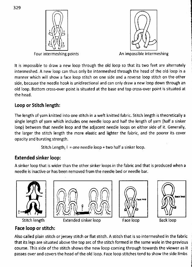
329
1 a
3 4
Four intermeshingpoints An impossible intermeshing
It is impossible to draw a new Ioop through the oId Ioop so that its two feet are alternatelyintermeshed. A new Ioop can thus only be intermeshed through the head of the oId Ioop in amanner which will show a face Ioop stitch on one side and a reverse Ioop stitch on the otherside, because the needle hook is unidirectional and can only draw a new Ioop down through anoId loop. Bottom cross-over point is situated at the base and top cross-over point is situated atthe head.
toop or Stitch Iength:
The length of yarn knitted into one stitch in a weft knitted fabric. Stitch Iength is theoretically asingle Iength of yarn which includes one needle Ioop and half the Iength of yarn (half a sinkerIoop) between that needle Ioop and the adjacent needle Ioops on either side of it. Generally,the Iarger the stitch Iength the more elastic and Iighter the fabric, and the poorer its coveropacity and bursting strength.
Stitch Length, l = one needle loop + two half a sinker Ioop.
Extended sinker Ioop:A sinker loop that is wider than the other sinker Ioops in the fabric and that is produced when aneedle is inactive or has been removed from the needle bed or needle bar.
j t--j ,. ! - , ) j $ / /
: :
) û ) 't. : '
, . )
'
t . - kt , h-a , .I .
Stitch Iength Extended sinker Ioop
Face Ioop or stitch:
Fpce kKm
Face Ioop Back Ioop
Also called plain stitch or jersey stitch or flat stitch. A stitch that is so intermeshed in the fabric l;th
at its Iegs are situated above the top arc of the stitch formed in the same wale in the previous jcourse. This side of the stitch shows the new loop coming through towards the viewer as it jpasses over and covers the head of the oId Ioop. Face Ioop stitches tend to show the side Iimbs 1
l
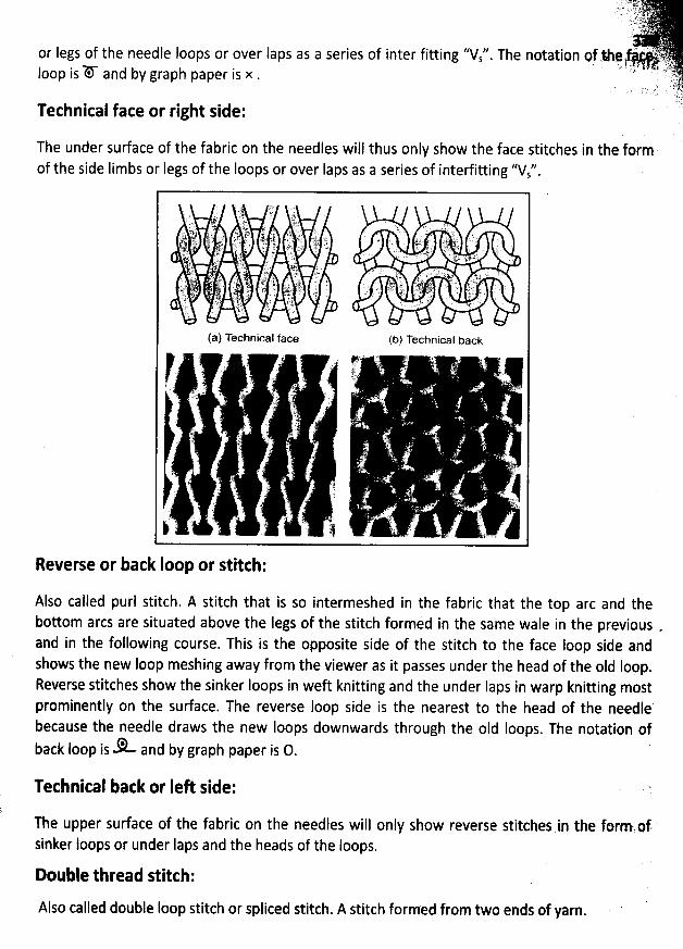
' IJ y ;.4 k:.L s lli .;' 1ïV'L' L '*. y .,. yyyt;;y t. .. : . ;tf
or Iegs of the needle Ioops or over Iaps as a series of inter fitting ''V '' The notation Qf .1e :'%!; . jj . z . ..),q$ ,. ', 4. 7;,z : .
i. . .( jy.Ioop is 'D-* and by graph paper is x . ,s,
. y . ;')' jê r- !+
7;rTechnical face or right side:
The under surface of the fabric on the needles will thus only show the face stitches in the formof the side Iimbs or Iegs of the loops or over Iaps as a series of interfitting &Vs''.
Reverse or back Ioop or stitch:
Also called purl stitch. A stitch that is so intermeshed in the fabric that the top arc and thebottom arcs are situated above the Iegs of the stitch formed in the same wale in the previous .and in the following course. This is the opposite side of the stitch to the face loop side andshows the new Ioop meshing away from the viewer as it passes under the head of the oId Ioop.
Reverse stitches show the sinker Ioops in weft knitting and the under Iaps in warp knitting mostprominently on the surface. The reverse Ioop side is the nearest to the head of the needlebecause the needle draws the new loops downwards through the oId Ioops. The notation of
* and by graph paper is 0.back Ioop is
Technical back or IeA side:
The upper surface of the fabric on the needles will only show reverse stitches in the formxinf.
sinker Ioops or under Iaps and the heads of the loops.
Double thread stitch:
Also called double Ioop stitch or spliced stitch. A stitch formed from two ends of yarn.
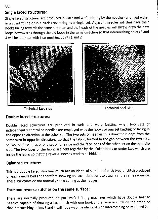
331 :
Single faced structures:Single faced structures are produced in warp and weft knitting by the needles (arranged either :1in a straight Iine or in a circle) operating as a single set. Adjacent needles will thus have their :hooks facing towards the same direction and the heads of the needles will always draw the new lloops downwards through the old Ioops in the same direction so that intermeshing points 3 and
4 will be identical with intermeshing points 1 and 2.
Technical face side
Double faced structures:
Double faced structures are produced in weft and warp knitting when two sets ofI d needles are employed with the hooks of one set knitting or facing inindependently control e
the opposite direction to the other set. The two sets of needles thus draw their Ioops from thesame yarn in opposite directions, so that the fabric, formed in the gap between the two sets,shows the face loops of one set on one side and the face Ioops of the other set on the oppositeside. The two faces of the fabric are held together by the sinker Ioops or under Iaps which areinside the fabric so that the reverse stitches tend to be hidden.
.- p ' ' % , t A..iyx'.. :F$ . r < x ;y.-. . . ' X # . . . . >
. ' . . .
. . . .' ' . . '
. , uw . ., a x' -...' x- - <. ' .' *'r*'''M''=+*.AT . ',
. 1 JL # W* 4 ' ' '' zy s swsx* qyxx* vi asjze ... w++P.W A. x t . s: >.%Av#V. 7* v
xl . y .Wv*vf . ' f'
xv4vxew: .wwwwhvx-k: khl .'
e.d'# 'Vu k - 'z
Technical back side
Balanced structure:
This is a double faced structure which has an identical number of each type of stitch producedon each needle bed and therefore showing on each fabric su/ace usually in the same sequence.These structures do not normally show curling at their edges.
Face and reverse stitches on the same surface:
These are normally produced on purl weft knitting machines which have double headedneedles capable of drawing a face stitch with one hook and a reverse stitch on the other, sothat intermeshing points 3 and 4 will not always be identical with intermeshing points 1 and 2.
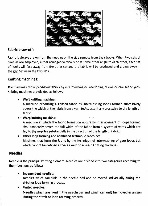
Fabric draw-off:
Fabric is always drawn from the needles on the side remote from their hooks. W hen two sets ofneedles are employed, either arranged vertically or at some other angle to each other, each setof hooks will face away from the other set and the fabric will be produced and drawn away inthe gap between the two sets.
Knitting machines:
The machines those produced fabrics by intermeshing or interloping of one or one set of yarn.Knitting machines are divided as follows-
* W eft knitting machine:A machine producing a knitted fabric by intermeshing Ioops formed successivelyacross the width of the fabric from a yarn fed substantially crosswise to the length offabric.
* . W arp knitting machine:A machine in which the fabric formation occurs by interlacement of Ioops formedsimultaneously across the full width of the fabric from a system of yarns which arefed to the needles substantially in the direction of the length of fabric.
@ Other Ioop forming and combined technique machines:Machines that form the fabric by the technique of intermeshing of yarn Ioops butwhich cannot be defined either as weft or as warp knitting machines.
Needles:
Needle is the principal knitting element. Needles are divided into two categories according tot.their functions as follows-
* Independent needles:Needles which can slide in the needle bed and be moved individually during tàestitch or Ioop forming process.
@ United needles:Needles which are fixed in the needle bar and which can only be moved in unisonduring the stitch or Ioop forming process.
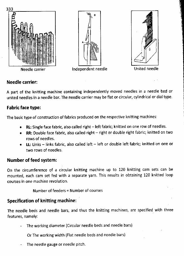
Needle carrier:
A part of the knitting machine containing independently moved needles in a needle bed orunited needles in a needle bar. The needle carrier may be flat or circular, cylindrical or dial type.
B
0
A
Q!
Independent needle1United needle
Fabric face type:
The basic type of construction of fabrics produced on the respective knitting machines:
Rt: Single face fabric, also called right - Ieft fabric; knitted on one row of needles.@ RR: Double face fabric, also called right - right or double right fabric; knitted on two
rows of needles.@ LL: Links - Iinks fabric, also called Ieft - Ieft or double Ieft fabric; knitted on one or
two rows of needles.
Number of feed system :
On the circumference gf a circular knitting machine up to 120 knitting cam sets can bemounted, each cam set fed with a separate yarn. This results in obtaining 120 knitted loopcourses in one machine revolution.
Number of feeders = Number of courses
Specification of knitting machine:
The needle beds and needle bars, and thus the knitting machines, are specified with threefeatures, namely:
The working diameter (Circular needle beds and needle bars)
Or The working width (FIat needle beds and needle bars)
The needle gauge or needle pitch.
. .. . :. . .Lq3ï....tt .
.
;'- .'t.. . .250-- '.
The working diameter: ' qit. , .' sy z.yThe diameter of a knitting machine is measured at the bottoms of two opposite: -t:..r.needle grooves in a cylinder or at the tops of two opposite needles in a circular bar, @ $t)
and is usually expressed in inches. : 7
The working width:The working width of the machine should not be miss used with the 'tadual workingwidth''. The working width of a knitting machine is a measure (in cm or inches)describing the distance between the first and Iast needle in a flat needle bed
, whilstthe ''actual working width'' is the distance between the first and Iast needle actuallyused in the needle bed during knitting.
Machine or needle gauge:
The needle gauge of a knitting machine (also called cut or gage) is a measureexpressing the number of needles per a unit of the needle bed (bar) width.
Gauge, N = How many needles are used in one English inch.
Num ber of needlesN =One English inch.
Highest needle gauge is about 60 and lowest needle gauge is about 2 to2.5.
The needle pitch is the distance between two neighbouring needles in the same
needle bed (bar), from the centre of a needle to the centre of the neighbouringneedle.
Relationship between the needle gauge and the needle pitch is as follows:
1Needle pitch (Length units / needle) =N
eedle gauge (Iength unit)The pitch or distance between one needle and another is proportional to the needle gauge or
thickness and therefore to the space available for the yarn. As the diameter of a yarn isproportional to its count, a relationship exists between the range of optimum counts of yarnwhich may be knitted on a particular machine and its machine gauge. Machine gauge thusinfluences choice of yarn and count, and affects fabric properties such as appearance and
weight. For a given machine diameter or width, finer gauge machinestend to knit a widerfabric
as more wales are involved. For example a 30* diameter circular machine might have 1716cylinder needles in 18 G and 1872 cylinder needles in 20 G. Coarse gauge machines have Iatchneedles with Iarger dimensions requiring greater movements. During knitting the size of theknitting cams are correspondingly Iarge so Iess cam systems can be accommodated
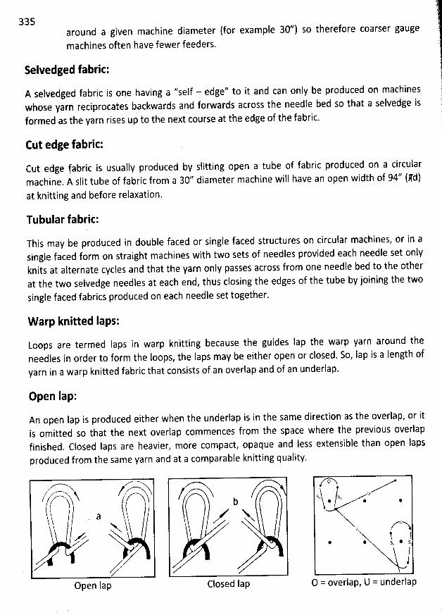
335around a given machine diameter (for example 30'') so therefore coarser gaugemachines often have fewer feeders.
Selvedged fabric:
A selvedged fabric is one having a ''self - edge'' to it and can only be produced on machineswhose yarn reciprocates backwards and forwards across the needle bed so that a selvedge isformed as the yarn rises up to the next course at the edge of the fabric.
Cut edge fabric:
cut edge fabric is usually produced by slitting open a tube of fabric produced on a circularmachine. A slit tube of fabric from a 302 diameter macbine will have an open width of 94'' (#d)at knitting and before relaxation.
Tubular fabric:
This may be produced in double faced or single faced structures on circular machines, or in asingle faced form on straight machines with two sets of needles provided each needle set onlyknits at alternate cycles and that the yarn only passés across from one needle bed to the otherat the two sejvedge needles at each end, thus closing the edges of the tube by joining the twosingle faced fabrics produced on each needle set together.
W arp knitted Iaps:
Loops are termed Iaps in warp knitting because the guides Iap the warp yarn around theneedles in order to form the Ioops, the Iaps may be either open or closed. So, Iap is a Iength ofyarn in a warp knitted fabric that consists of an overlap and of an underlap.
Open lap:
An open lap is produced either when the underlap is in the same direction as the overlap, or itis omitted so that the next overlap commences from the space where the previous overlapfinished. Closed laps are heavier, more compact, opaque and Iess extensible than open lapsproduced from the same yarn and at a comparable knitting quality.
> - $.Open lap
?A-->b
V Y
Closed Iap
t/msrj . /s, .u .
X z'aU ,
! l* * s @ sl
1O = overlap, U = underjap
Closed Iap:
A closed lap is produced when an underlap follows in the opposite direction to the overlap andthus Iaps the thread around both sides of the needles.
..j4- ..?
3% ''
The overlap:
The overlap is a shog usually across one needle hook by a warp guide which forms the warpyarn into the head of the loop. The swinging movement of the guide to the hook side and thereturn swing after the overlap produce the two side limbs or legs of the Ioop which has a verysimilar appearance on the facq side of the fabric to a needle Ioop produced by weft knitting. So,overlap is a Iength of yarn in a warp knitted fabric that has been placed over the needle duringloop formation.
The underlap:
The underlap shog occurs across the side of the needles remote from the hooks, on the front ofsingle bar and in the centre of double bar needle machines, it supplies the yarn between oneoverlap and the next. So, underlap is a length of yarn in a warp knitted fabric that connects twooverlaps in consecutive courses.
Underlaps as well as overlaps are essential in aII warp knitted structures in order to join thewales of Ioops together, but they may be contributed by a different guide bar to those for theoverlaps.
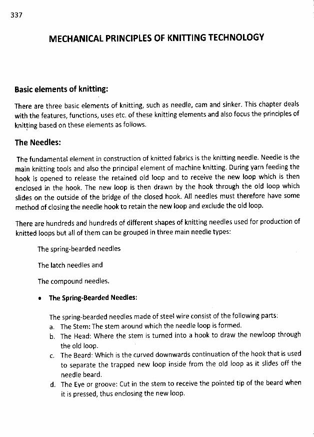
337
M ECHANICAL PRINCIPLES OF KNIU ING TECHNOLOGY
Basic elements of knitting:
There are three basic elements of knitting, such as needle, cam and sinker. This chapter dealswith the features, functions, uses etc. of these knitting elements and also focus the principles of
knitling based on these elements as follows.
The Needles:
The fundamental element in construction of knitted fabrics is the knitting needle. Needle is themain knitting tools and also the principal element of machine knitting. During yarn feeding thehook is opened to release the retained old loop and to receive the new loop which is thenenclosed in the hook. The new Ioop is then drawn by the hook through the oId Ioop whichslides on the outside of the bridge of the closed hook. AIl needles must therefore have somemethod of closing the needle hook to retain the new Ioop and exclude the oId Ioop.
There are hundreds and hundreds of different shapes of knitting needles used for production ofknitted loops but aII of them can be grouped in three main needle types:
The spring-bearded needles
The Iatch needles and
The compound needles.
* The Spring-Bearded Needles:
The spring-bearded needles made of steel wire consist of the following parts:a. The Stem: The stem around which the needle Ioop is formed.b. The Head: W here the stem is turned into a hook to draw the newloop through
the oId loop.c. The Beard: Which is the curved downwards continuation of the hook that is used
to separate the trapped new Ioop inside from the o1d loop as it slides off the
needle beard.d. The Eye or groove: Cut in the stem to receive the pointed tip of the beard when
it is pressed, thus enclosing the new Ioop.
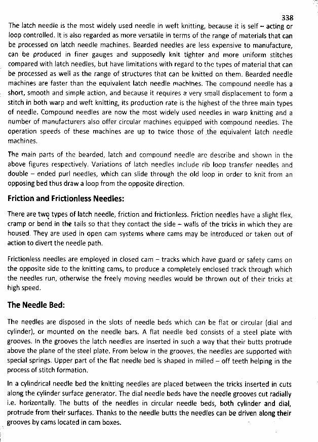
338The Iatch needle is the most widely used needle in weft knitting, because it is self - acting orIoop controlled. It is also regarded as more versatile in terms of the range of materials that canbe processed on Iatch needle machines. Bearded needles are Iess expensive to manufacture,can be produced in finer gauges and supposedly knit tighter and more uniform stitchescompared with Iatch needles, but have Iimitations with regard to the types of material that canbe processed as well as the range of structures that can be knitted on them. Bearded needlemachines are faster than the equivalent Iatch needle macbipes. The compound needle has ashort, smooth and simple action, and because it requires a very small displacement to form astitch in both warp and weft knitting, its production rate is tlie highest of the three main typesof needle. Compound needles are now the most widely used needles in warp knitting and anumber of manufacturers also offer circular machines equipped w' ith compound needles. Theoperation speeds of these machines are up to twice those of itie equivalent latch needlemachines.
The main parts of the bearded, Iatch and compound needle are describe and shown in theabove figures respectively. Variations of Iatch neqdles ipclude rib Ioop transfer needles anddouble - ended purl needles, which can slide through the oId Ioop in order to knit from anopposing bed thus draw a loop from the opposite direction.
Friction and Frictionless Needles:
There are twq types of Iatch needle, friction and frictionless. Friction needles have a slight flex,cramp or bend in tl:e tails so that they contact the side - walls of the tricks in which they arehoused. They are used in open cam systems where cams may be introduced or taken out ofaction to divert the needle path.
Frictionless needles are employed in closed cam - tracks which have guard or safety cams onthe opposite side to the knitting cams, to produce a completely enclosed track through whichthe needles run, otherwise the freely moving needles would be thrown out of their tricks athigh speed.
The Needle Bed:
The needles are disposed in the slots of needle beds which can be flat or circular (dial andcylinder), or mounted on the needle bars. A flat needle bed consists of a steel plate withgrooves. In the grooves the latch needles are inserted in such a way that their butts protrudeabove the plane of the steel plate. From below in the grooves, the needles are supported withspecial springs. Upper part of the flat needle bed is shaped in milled - off teeth belping in theprocess of stitch formation.
In a cylindrical needle bed the knitting needles are placed between ihe tricks inserted in cutsalong the cylinder surface generator. The dial needle beds have the needle grooves cut radially
' i.e. horizontally. The butts of the needles in circular needle beds, both cylinder and dial, protrude from their surfaces. Thariks to the needle butts the needles can be dtiven along theirgrooves by cams located in cam boxes.
. ''
;..
'
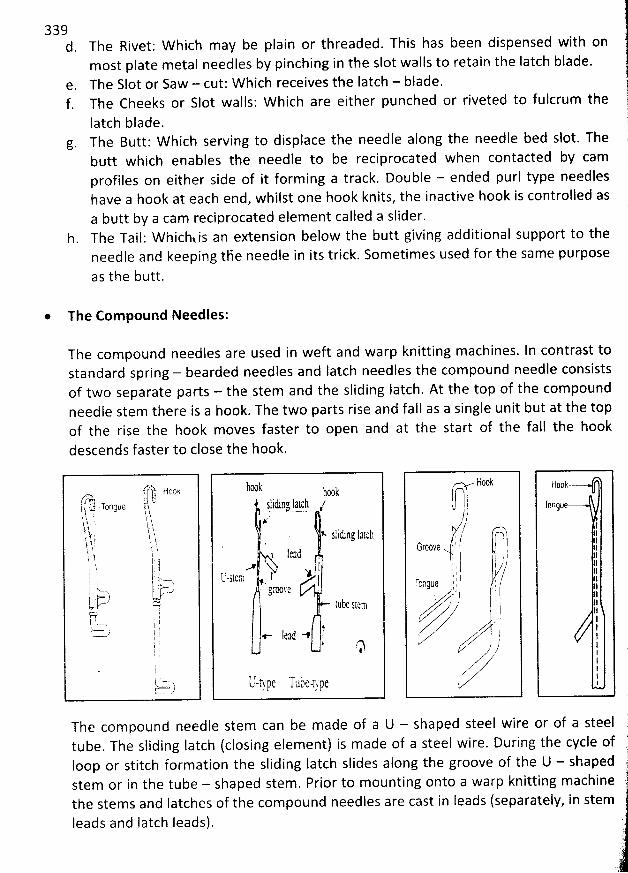
339d. Tbe Rivet; W hich may be plain or threaded. This has been dispensed with on
m ost plate metal needles by pinching in the slot walls to retain the Iatch blade.The Slot or Saw - cut: W hich receives the Iatch - blade.The Cheeks or Slot walls: W hich are either punched or riveted to fulcrum the
latch blade.g. The Butt: W hich serving to displace the needle along the needle bed slot. The
butt which enables the needle to be reciprocated when contacted by camprofiles on either side of it forming a track. Double - ended purl type needleshave a hook at each end, whilst one hook knits, the inactive hook is controlled asa butt by a cam reciprocated element called a slider.
h. The Tail: W hichvis an extension below the butt giving additional support to theneedle and keeping tBe needle in its trick. Sometimes used for tbe same purpose
as the butt.
* The Com pound Needles:
The com pound needles are used in weft and warp knitting machines. In contrast tostandard spring - bearded needles and latch needles the com pound needle consistsof two separate parts - the stem and the sliding Iatch. At the top of the compoundneedle stem there is a hook. The two parts rise and fall as a single unit but at the topof the rise the hook moves faster to open and at the start of the fall the hook
descends faster to close the hook.
The com pound needle stem can be m ade of a U - shaped steel wire or of a steeltube. The sliding Iatch (closing element) is made of a steel wire. During the cycle ofIoop or stitch formation the sliding Iatch slides along the groove of the U - shapedstem or in the tube - shaped stem. Prior to m ounting onto a warp knitting m achine
the stems and Iatches of the compound needles are cast in leads (separately, in stemleads and latch leads).
. lttmk joj1 s
-l-iding latcà tjjj, '
yt slitb ns lilt h
k 1t:1 (1 .A ' I
'-sttm f Y1- J
ârtsh'th.tt 5ltc:
,,- Itaë -s, ri
IJ-tJ'FC Tuàe-t-ygt
Flook
u )/--,/1
t,j ( pGrtmê: 1 l . !: rt ?L y. :: (,/''rcngne y
. . ./ !E i iy y
.z' M J
,z- )Vz
340The latch needle is the most widely used needle in weft knitting, because it is self - acting orIoop controlled. It is also regarded as more versatile in terms of the range of materials that canbe processed on latch needle machines. Bearded needles are less expensive to manufacture,can be produced in finer gauges and supposedly knit tighter and more uniform stitchescompared with Iatch needles, but have Iimitations with regard to the types of material that canbe processed as well as the range of structures that can be knitted on them. Bearded needlemachines are faster than the equivalent Iatch needle machines. The compound needle has ashort, smooth and simple action, and because it requires a very small displacement to form astitch in b0th warp and weft knitting, its production rate is the highest of the three main typesof needle. Compound needles are now the most widely used needles in warp knitting and anumber of manufacturers also offer circular machines equipped with compound needles. Theoperation speeds of these machines are up to twice those of the equivalent Iatch needlemachines.
The main parts of the bearded, Iatch and compound needle are describe and shown in theabove figures respectively. Variations of latch needles include rib Ioop transfer needles anddouble - ended purl needles, which can slide through the old loop in order to knit from anopposing bed thus draw a Ioop from the opposite direction.
Friction and Frictionless Needles:
There are two types of latch needle, friction and frictionless. Friction needles have a slight flex,cramp or bend in the tails so that they contact the side - walls of the tricks in which they arehoused. They are used in open cam systems where cams may be introduced or taken out ofaction to divert the needle path.
Frictionless needles are employed in closed cam - tracks which have guard or safety cams onthe opposite side to the knitting cams, to produce a completely enclosed track through whichthe needles run, otherwise the freely moving needles would be thrown out of their tricks athigh speed.
The Needle Bed:
The needles are disposed in the slots of needle beds which can be flat or circular (dial andcylinder), or mounted on the needle bars. A flat needle bed consists of a steel plate withgrooves. In the grooves the Iatch needles are inserted in such a way that their butts protrudeabove the plane of the steel plate. From below in the grooves, the needles are supported withspecial springs. Upper part of the flat needle bed is shaped in milled - off teeth helping in theprocess of stitch formation.
ln a cylindrical needle bed the knitting needles are placed between the tricks inserted in cuts
along the cylinder surface generator. The dial needle beds have the needle grooves cut radiallytj i.e. horizontally. The butts of the needles in circular needle beds, both cylinder and dial, protrude from their surfaces. Thanks to the needle butts the needles can be driven along their rooves by cams Iocated in cam boxes
.
gjjk-.
-.
*
.
*
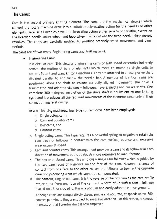
341
The Cams:
Cam is the second primary knitting element. The cams are the mechanical devices whichconvert the rotary machine drive into a suitable reciprocating action for the needles or otherelements. Because aIl needles have a reciprocating action either serially or seriatim, except onthe bearded needle sinker wheel and Ioop wheel frames where the fixed needle circle merelyrevolves. The cams are carefully profiled to produce preciselptimed movement and dwell
i d s 'pe r O .
The cams are of two types, Engineering cams and Knitting cams.
* Engineering Cam:It is circular cam. This circular engineering cams or high speed eccentiics indirectlycontrol the motion of bars of elements which move en masse as single units incottons Patent and warp knitting machines. They are attached to a rotary drive shaftsituated parallel to and beiow the needle bar. A number of identical cams arepositioned alopg the shaft to ensure correctly aligned movement. The drive istransmitted and adapted via cam - followers, levers, pivots and rocker shafts. Onecomplete 360 - degree revofution of the drive shaft is equivalent to one knittingcycle and it produces aII the required movements of the elements once only in their
correct timing relationship.
In warp knitting machines, four types of cam drive have been employed:
a. Single acting camsCam and counter cams
c. Box cams, andd. Contour cams.Single acting cams: This type requires a powerful spring to negatively retain thecam truck or follower in contact with the cam surface, bounce and excessive
wear occurs at speed.b. Cam and counter cams: This arrangement provides a cam and its follower in each
direction of movement but is obviously more expensive to manufacture.The box or enclosed cams: This employs a single cam follower which is guided bythe two cam races of a groove on the face of the cam. However, change ofcontact from one face to the other causes the follower to turn in the oppositedirection producing wear which cannot be compensated.
d. The contour, ring or pot cams: It is the reverse of the box cam as the cam profileprojects out from one face of the cam in the form of lip with a cam - followerplaced on either sije of it. This is a popular and easily adaptable arrangement.
Although cams are comparatively cheap, simple and accurate, at speeds above 800courses per minute they are subject to excessive vibration. For this reason, at speedsin excess of that Eccentric drive is now employed.
l
1#'
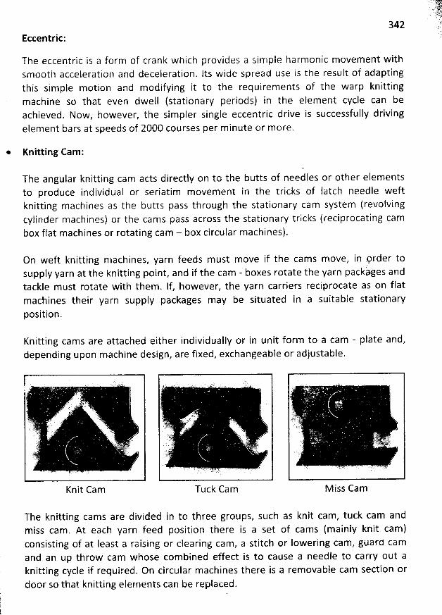
342Eccentric:
The eccentric is a form of crank which provides a sim ple harmonic movement withsmooth acceleration and deceleration. lts wide spread use is the result of adaptingthis simple motion and modifying it to the requirements of the warp knitting
machine so that even dwell (stationary periods) in the element cycle can beachieved. Now, however, the sim pler single eccentric drive is successfully drivingelement bars at speeds of 2000 courses per minute or more.
* Knitting Cam:
The angular knitting cam acts directly on to the butts of needles or other elem entsto produce individuai or seriatim movement in the tricks of latch needle weft
knitting machines as the butts pass through the stationary cam system (revolvingcylinder machines) or the cams pass across the stationary tricks (reciprocating cambox flat machines or rotating cam - box circular machines).
On weft knitting machines, yarn feeds must move if the cams m ove, in prder tosupply yarn at the knitting point, and if the cam - boxes rotate the yarn packhjes andtackle must rotate with them . If, however, the yarn carriers reciprocate as on flatmachines their yarn supply packages may be situated in a suitable stationaryposition.
Knitting cams are attached either individually or in unit form to a cam - plate and,
depending upon machine design, are fixed, exchangeable or adjustable.
Knit Cam Tuck Cam M iss Cam
The knitting cams are divided in to three groups, such as knit cam, tuck cam andmiss cam. At each yarn feed position there is a set of cams (mainly knit cam)consisting of at least a raising or clearing cam, a stitch or Iowering cam, guard camand an up throw cam whose com bined effect is to cause a needle to carry out aknitting cycle if required. On circular m achines there is a removable cam section ordoor so that knitting elernents can be replaced.
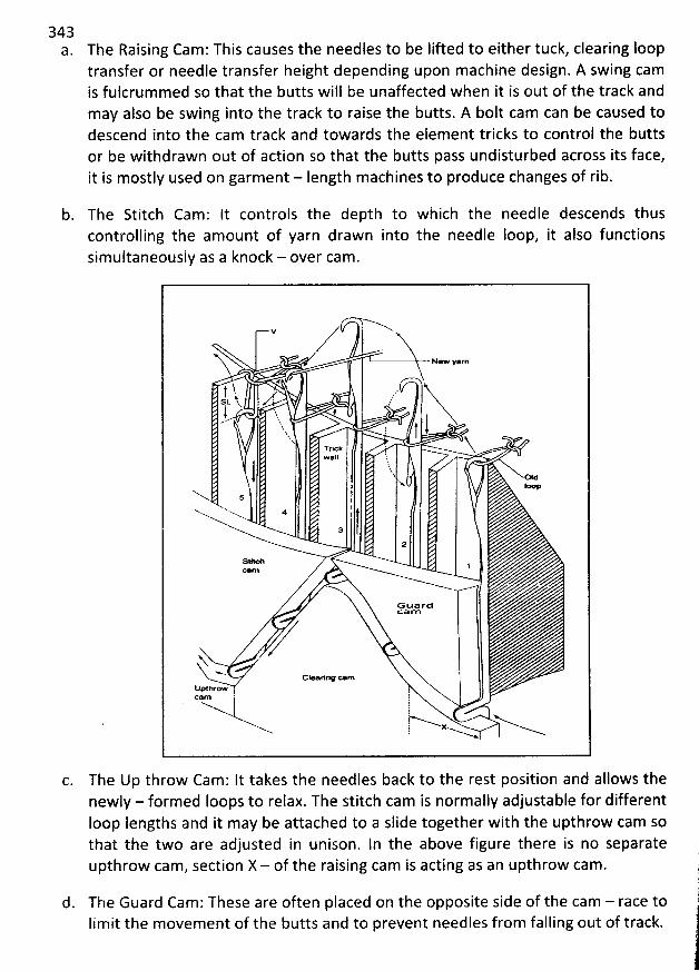
3433. The Raising Cam : This causes the needles to be lifted to either tuck, clearing loop
transfer or needle transfer height depending upon machine design. A swing camis fulcrummed so that the butts will be unaffected when it is out of the track andmay also be swing into the track to raise the butts. A bolt cam can be caused todescend into the cam track and towards the elem ent tricks to control the buttsor be withdrawn out of action so that the butts pass undisturbed across its face,it is mostly used on garment - Iength m achines to produce changes of rib.
b. The Stitch Cam: It controls the depth to which the needle descends thuscontrolling the amount of yarn drawn into the needle Ioop, it also functionssim ultaneously as a knock - over cam .
V
N/w y*m
##
1h : . .'tsi i- hkx
' -.'
. ,
'
t ......- : jr'' . . YTrrk
wall hl* od'.q
5
*
a2
sfeh 1c*m
G uardcam
N< .
GleariY c.mklpthrow !O m !'
j!! xE
'
The Up throw Cam : lt takes the needles back to the rest position and allows thenewly - formed Ioops to relax. The stitch cam is normally adjustable for differentIoop Iengths and it may be attached to a slide together with the upthrow cam sothat the two are adjusted in unison. ln the above figure there is no separateupthrow cam , section X - of the raising cam is acting as an upthrow cam .
d. The Guard Cam ; These are often placed on the opposite side of the cam - race toIimit the m ovement of the butts and to prevent needles from falling out of track.
).
1
j
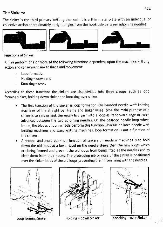
344The Sinkers:
The sinker is the third primary knitting element. It is a thin metal plate with an individual orcollective action approximately at right angles from the hook side between adjoining needles.
Functions of Sinker:
< <It may perform one or more of the following functions dependent upon the machines knittingaction and consequent sinker shape and movement:
Loop formationHolding - down andKnocking - over.
According to these functions the sinkers are alsc divided into three groups, such as Ioopforming sinker, holding-down sinker and knocking-over sinker.
* The first function of the sinker is loop formation. On bearded needle weft knittingmachines of the straight bar frame and sinker wheel type the main purpose of asinker is to sink or kink the newly Iaid yarn into a Ioop as its forward edge or catchadvances between the two adjoining needles. On the bearded needle Ioop wheelframe, the blades of burr wheels perform this function whereas on Iatch needle weftknitting machines and warp knitting machines, Ioop formation is not a function ofthe sinkers.
@ A second and more common function of sinkers on modern machines is to holddown the oId Ioops at a lower Ievel on the needle stems than the new Ioops whichare being formed and prevent the old loops from being fifted as the needfes rise toclear them from their hooks. The protruding nib or nose of the sinker is positionedover the sinker loops of the oId Ioops preventing them from rising with the needles.
. /?, /
( '-....j l qx..- I k-.. . iN -.. j j .>2..
----... .+'. L - ' z
N r? âza . . . xx..x. 'xxM>.. N =' Nxxx lj'xw N... .. w.
*
Loop forming Sinker
f(Lf-,1 1 i l 'î:l
1
f >(
Holding - down Sinker
- -.'-* , T
.. Bx. Q) . '
NN t- ky 'y..w .
N' x lI - . su
:. ) . 7y , -' .w..t I
! :
'
,1l i
!i!1,
1
Knocking - over Sinker .
345On tricot warp knitting machines and single bed weft knitting machines, a slot orthroat is cut to hold and control the oId loop. The sole function of the sinker may beas a web holder or stitch comb as on the Raschel warp knitting machine in whichcase only the underside of the nose performs the function.
On latch needle weft knitting machines the holding-down sinkers have a rectangulart on their upper surface remote from the nose into which the sinker cam racegaP CU
fits to positively control the sinker's movement.
Hoiding-down sinkers enable tighter structures with improved appearance to beobtained, the minimum draw-off tension is reduced, higher knitting speeds arepossible and knitting can be commenced on empty needles.
Holding-down sinkers may be unnecessary when knitting with two needle beds asthe second bed restrains the fabric Ioops whilst the other set of needles move.
* The third function of the sinker - as a knock-over surface - where its upper sudaceor belly supports the oId loop as the new loop is drawn through it.
On tricot warp knitting machines the sinker belly is specially shaped to assist withIanding as well as knock-over.
On Iatch needle machines the verge or upper surface of the trick - plate serves asthe knock - over sudace.
The Jack:The jack is a secondary weft knitting eiement which may be used to provide flexibility of Iatchneedle selection and movement. it is placed below and in the same trick as the needle and hasits own operating butt and cam system. The needle may thus be controlled directly by its buttand cam system or indirectly by the movement of the jack.
M ethods of Yarn Feeding:
There are two methods of yarn feeding. Yarn feeding involves either moving the yarn past theneedles or moving the needles past a stationary yarn feed position.
W hen the yarn moves past the needles, the fabric will be stationary because the Ioops hangfrom the needles. This arrangement exists on aII warp knitting machines and on weft knitting
machines with straight beds or circular machines with stationary cylinder and dials. On straightmachines of both weft and warp type the yarn carrier or guide has a reciprocating traversingmovement which takes it towards and away from a suitably - placed yarn supply. On stationarycylinder and dial machines, however, the yarn supply packages must rotate in order to keepwith the continuously revolving yarn feeds. Because the Iatch needle beds of these flat andcircular weft knitting machines are stationary, it is necessary to reciprocate the cam - carriages l
1
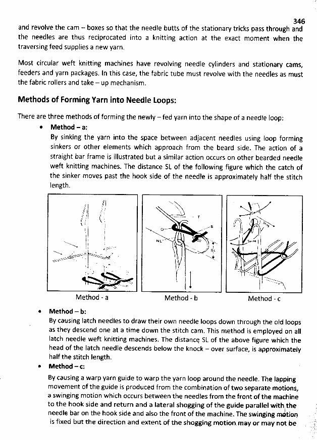
346and revolve the cam - boxes so that the needle butts of the stationary tricks pass through andthe needles are thus reciprocated into a knitting action at the exact moment when thetraversing feed supplies a new yarn.
Most circular weft knitting machines have revolving needle cylinders and stationary cams,
feeders and yarn packages. ln this case, the fabric tube must revolve with the needles as mustthe fabric rollers and take - up mechanism.
Methods of Forming Yarn into Needle Loops:
There are three methods of forming the newsy - fed yarn into the shape of a needse loop:
* Method - a:By sinking the yarn into the space between adjacent needles using Ioop formingsinkers or other elements which approach from the beard side. The action of astraight bar frame is illustrated but a similar action occurs on other bearded needleweft knitting machines. The distance SL of the following figure which the catch ofthe sinker moves past the hook side of the needle is approximately half the stitchlength.
Method - a
* Method - b:
N 'x'XxX
- B
N L ---' ' Mx .1 F'w'x. ' 1
SLj . ''
'w +t i Nl it/'l11'j1
Method - b
,,-.AyyaZ*-'w. ..$+ l
ù i ck! b/l zl 1.....e
j s w , oq / j xaaxz..,vq -% a
7. ..r.z. . ;
Method - c
By causing latch needles to draw their own needle Ioops down through the oid loopsas they descend one at a time down the stitch cam . This method is employed on aIIIatch needle weft knitting machines. The distancq SL of the above figure which thehead of the Iatch needle descends below the knock - over surface, is approximatelyhalf the stitch Iength.Method - t:
By causing a warp yarn guide to warp the yarn loop around the needle. The lappingmovement of the guide is produced from the combination of two separate motions
,a swinging motion which occurs between the needles from the front of the maçhineto the hook side and return and a lateral shogging of the guide parallel with the
!needle bar on the hook side and also the front of the machine. The swinging mntionis fixed but the direction and extent of the shogging motion may or may not be
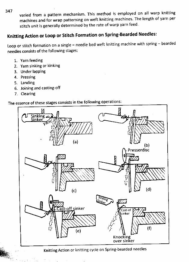
347 varied from a pattern mechanism. This method is employed on all warp knittingmachines and for wrap patterning on weft knitting macbines. The length of yarn perstitch unit is generally determined by tbe rate of warp yarn feed.
Knitting Action or Loop or Stitch Formation on Spring-Bearded Needles:
toop or stitch formation on a single - needle bed weft knitting machine with spring - bearded
needles consists of the following stages:
1. Yarn feeding2. Yarn sinking or kinking3. Under lapping4. Pressing5. Landing6. Joining and casting-off7. Clearing
Tbe essence of these stages consists
Sinking'nker t k -f ïA (, t ( ,/$ / z?'-z. y , j x xyz , 14 s.'-t , g c. - x 's..S . -'X-
I 1,Q@ hl l / . .
, (a) >.>' (b)
Presserdisct
2 kt l . x v.;!*N x.. ' '' ' 'xs ' x x > x (. )1.t x, s.xy%x%g œy x., o
'x, .. x x - t .( X ' Y/
. vw
x' t/ hX 4N
'
'--' k (c) (d)
'n g,z .# hk '-'f ..'. '
ez r
ast-off sinker cast-ofk '- inker xfz F .
.
(. tz .. , y ,--t / .' .. . q, - .vt- x 'NX /kl sxX x. ' xt
x,.h kx . q;-hz 3$ lkt w ( k. j 'q ( jj/ ''., ( e ) J -. î
K * ' Nk
Knockinferover sin
in the following operations:
Knitting Action or knitting cycle on Spring-bearded needlesAya . .- . lw . .-1 A..W.
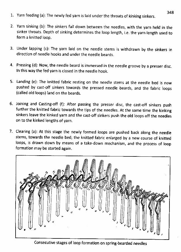
3481. Yarn feeding (a): The newly fed yarn is Iaid under the throats of kinking sinkers.
2. Yarn sinking (b): The sinkers fall down between the needles, with the yarn held in thesinker throats. Depth of sinking determines the Ioop length
, i.e, the yarn Iength used toform a knitted Ioop.
3. Under Iapping (c): The yarn Iaid on the needle stems is withdrawn by the sinkers indirection of needle hooks and under the needle beards.
4. Pressing (d): Now, the needle beard is immersed in the needle groove by a presser disc.In this way the fed yarn is closed in the needle hook.
Landing (e): The knitted fabric resting on the needle stems at the needle bed is nowpushed by cast-off sinkers towards the pressed needle beards
, and the fabric loops(called oId Ioops) Iand on the beards.
6. Joining and Casting-off (f): After passing the presser disc, the cast-off sinkers pushfurther the knitted fabric towards the tips of the needles. At the same time the kinkingsinkers Ieave the kinked yarn and the cast-off sinkers push the oId Ioops off the needleson to the kinked lengths of yarn.
Clearing (a): At this stage the newly formed loops are pushed back along the needlestems, towards the needle bed; the knitted fabric enlarged by a new course of knittedIoops, is drawn down by means of a take-down mechanism
, and the process of Ioopformation may be started again.
I ./6 ë Fz R# V,
,# N ! 3 , J6 (2'
.
..v , .1C
@ C 4* 'c M a yg cyg c c c?7' j y; z, ,
g . .+ *' j C;j y c y y
a , yl #
11 zz 'Iê .?.ZJ#
/# '
;2r J' '#le
. .4 #
z
Consecutive stages of Ioop formationon spring-bearded needîes
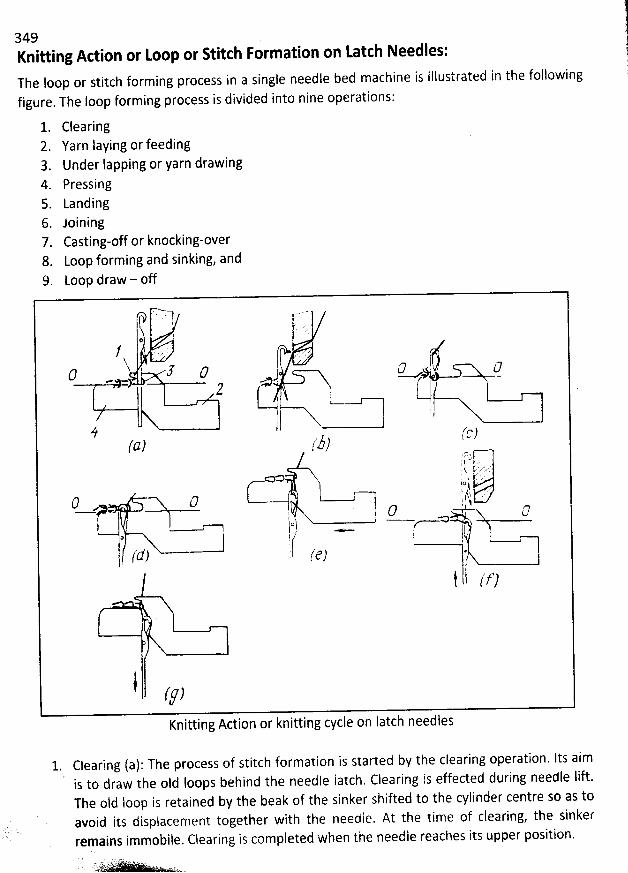
349Knitting Action or toop or Stitch Formation on tatth Needles:The loop or stitch forming process in a single needle bed machine is illustrated in the foilowing
figure. The loop forming process is divided into nine operations:
1. Clearing2. Yarn laying or feeding3. Under lapping or yarn drawing4. Pressing5. tanding6. Joining7. Casting-off or knocking-over8. Loop forming and sinking, and9. Loop draw - off
' . ...
..w. -.
ft'/ p ,o l .
/ î ' , '' '7 z. -'h 5 (7 . c I c0 - A w
2 * (-jI' l ij i '4 i '- -'é iC07(G) t )
'
p .; t.O 1 $ *1*= ;# (' k .
(57 t:/ f$6) ' ''ejiL).e . #-1 t (zjyid ,,.
'
'Ik.....';'''
'
,
'
= j . I - c= ,- ,) 1 j?
! j . '(d) -
( (t-)t
i (F)Knitting Action or knitting cycle on latch needles
1. Clearing (a): The process of stitch formation is started by the clearing operation. Its aim' is to draw the o1d Ioops behind the needle Iatch. Clearing is effected during needle lift.The old loop is retained by the beak of the sinker shifted to the cylinder centre so as toavoid its dispiacement together with the needle. At the time of ciearing, the sinkerremains immobile. Clearing is completed when the needle reaches its upper position.
. - .. Iïié'- -. - ' .. . ...:.. .
!7
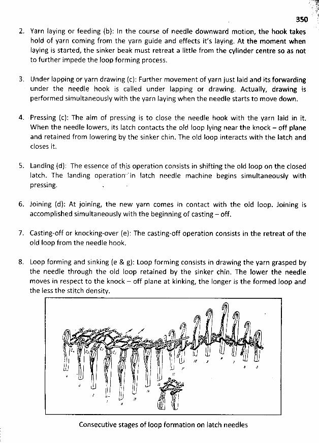
2. Yarn Iaying or feeding (b): In the course of needle downward motion, the hook takeshold of yarn coming from the yarn guide and effects it's laying. At the moment whenlaying is started, the sinker beak m ust retreat a Iittle from the cylinder centre so as notto further impede the loop forming process.
3. Under lapping or yarn drawing (c): Further movement of yarn just Iaid and its forwardingunder the needle hook is called under lapping or drawing. Actually, drawing isperformed simultaneously with the yarn Iaying when the needle starts to move down.
4. Pressing (c): The aim of pressing is to close the needle hook with the yarn Iaid in it.W hen the needle Iowers, its Iatch contacts the oId Ioop Iying near the knock - off planeand retained from lowering by the sinker chin. The o1d Ioop interacts with the Iatch andcloses it.
5. Landing (d): The essence of thi.s operation consists in shifting the oId Ioop on the closedIatch. The Ianding operation'''in Iatch needle machine begins simultaneously withpressing.
6. Joining (d): At joining, the new yarn comes in contact with the oId Ioop. Joining isaccomplished simultaneously with the beginning of casting - off.
7. Casting-off or knocking-over (e): The casting-off operation consists in the retreat of theoId Ioop from the needle hook.
8. Loop forming and sinking (e & g): Loop forming consists in drawing the yarn grasped bythe needle through the old Ioop retained by the sinker chin. The Iower the needlemoves in respect to the knock - off plane at kinking, the Ionger is the formed lèop andthe less the stitch density.
# /.....e- .. z, ,/
,1( l
t c. t, c- c, . j I j fty jl !) ' -, -
'
.' I k-.j :,' j
, - JJ
J ) 'Jl ,.2J ? l
Consecutive stages of Ioop formation on Iatch needles
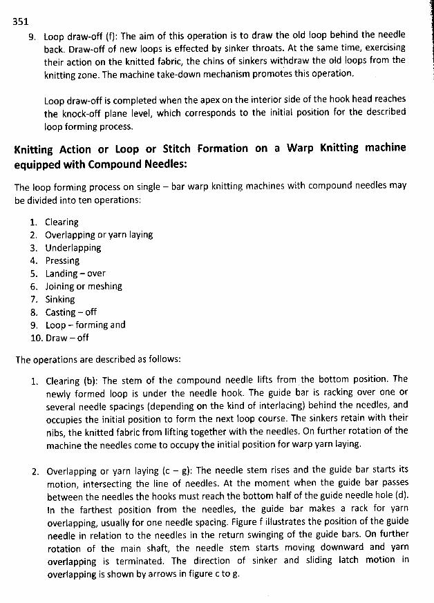
3519. Loop draw-off (f): The aim of this operation is to draw the oId loop behind the needle
back. Draw-off of new Ioops is effected by sinker throats. At the same time, exercisingtheir action on the knitted fabric, the chins of sinkers withdraw the oId Ioops from theknitting zone. The machine take-down mechanism promotes this operation.
Loop draw-off is completed when the apex on the interior side of the hook head reachesthe knock-off plane Ievel, which corresponds to the initial position for the describedIoop forming process.
Knitting Action or toop or Stitch Formation on a W arp Knitting m achine
equipped with Compound Needles:
The Ioop forming process on single - bar warp knitting machines with compound needles maybe divided into ten operations:
1. Clearing2. Overlapping or yarn Iaying3. Underlapping4. Pressing5. Landing - over6. Joining or meshing7. Sinking8. Casting - off9. Loop - forming and10. Draw - off
The operations are described as follows:
1. Clearing (b): The stem of the compound needle lifts from the bottom position. Thenewly formed Ioop is under the needle hook. The guide bar is racking over one orseveral needle spacings (depending on the kind of interlacing) behind the needles, andoccupies the initial position to form the next Ioop course. The sinkers retain with theirnibs, the knitted fabric from Iifting together with the needles. On further rotation of themachine the needles come to occupy the initial position for warp yarn laying.
2. Overlapping or yarn Iaying (c - g): The needle stem rises and the guide bar starts itsmotion, intersecting the Iine of needles. At the moment when the guide bar passesbetween the needles the hooks must reach the bottom half of the guide needle hole (d).In the farthest position from the needles, the guide bar makes a rack for yarnoverlapping, usually for one needle spacing. Figure f illustrates the position of the guideneedle in relation to the needles in the return swinging of the guide bars. On furtherrotation of the main shaft, the needle stem starts moving downward and yarnoverlapping is terminated. The direction of sinker and sliding Iatch motion in
overlapping is shown by arrows in figure c to g.
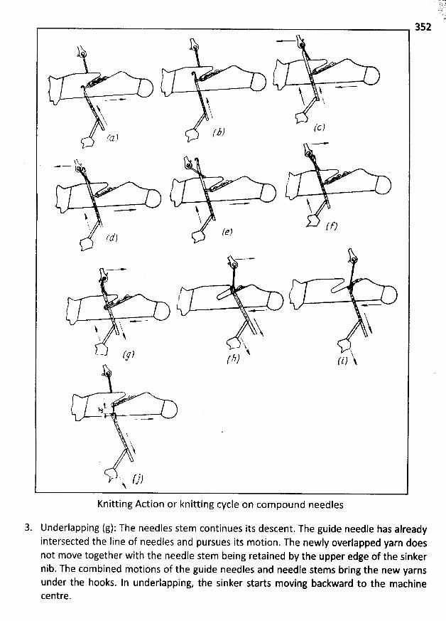
352
$ * -'$$k ----.- j
N$ î$
(c )J.JJf'J )2
. -
33 .
- y--* i$ '$... u fr)#
!ï f ..
. N -c: .x : e
lkjj
WYZV'ZR-----XHOO 56$44j444
5561444i
'.y $ ,N
k.? fg) p,y N 'j/ (i)
H
$
'
N
'
$1
''#
., ().)q.
Knitting Action or knittingcycle on com pound needles
3. Underlapping (g): The needles stem continues its descent. The guide needle has alreadyintersected the Iine of needles and pursues its motion. The newly overlapped yarn doesnot move together with the needle stem being retained by the upper edge of the sinkernib. The combined motions of the guide needles and needle stems bring the new yarnsunder the hooks. In underlapping, the sinker starts moving backward to the machinecentre.
3534. Pressing (h): The needle continues its downward motion having risen to its highest )
position, the sliding Iatch overlaps the needle hook so that the hook tip engages into the )groove in the upper part of the Iatch. The sinker continues its motion and, with its belly, ,brings tbe old loop along tbe sliding latch to the closed hook of the needle.
5. Landing - over (h): The sinker continues its travel and, with its belly, brings the oId loopon tbe siiding latch. The guide needle continues to retreat. The sliding latch together
with the stem moves downwards.
6. Joining or meshing (i): The needle stem with the sliding Iatch continues the downwardmotion. On the descent of the needle head to the Ievel of the upper edge of the sinkerbelly, the oId loop joins the new warp yarn which is under the needle hook. The guideneedle continues to move away from the machine centre.
Sinking (l,j): This operation (i.e. bending the new warp yarn which is under the needlehook) is effected by further needle Iowering.
8. Casting-of'f (i): The needle stem with the sliding latch Iowers below the upper edge ofthe sinker belly. The old Ioop with the sliding latch is cast on to the newly formed loopwhich is under the needle hook.
9. Loop forming (i): The needle continues to move downward.
10. Draw - off (j): Draw - off is carried out on further rotation of the machine's main shakand needle Iift. As the needle Iifts, the yarn may be drawn from the newly formed Ioop
to the guide.
W EFT KNIU ING M ACHINES
M ain features of a knitting machine:
A knitting machine is thus an apparatus for applying mechanical movement, either hand orpower derived, to primary knitting elements, in order to convert yarn into knitted Ioopstructures. The machine incorporates and co - ordinates the action of a number of mechanismsand devices, each performing specific functions that contribute towards the efficiency of theknitting action.
The main features of a knitting machine are listed below:
@ Frame: The frame, normally free - standing and either circular or rectilinear accordingto needle bed shape, provides the support for the majority of the machinesmechanisms.
* Power supply: The machine control and drive system co - ordinates the power for thedrive of the devices and mechanisms.
* Yarn supply or feeding: The yarn supply consists of the yarn package or beamaccommodation, tensioning devices, yarn feed control and yarn feed carriers or guides.
* Knitting action: The knitting system includes the knitting elements, their housing, driveand control, as well as associated pattern selection and garment - Iength controldevices (if equipped).
@ Fabric Take - away: The fabric take away mechanism includes fabric tensioning, wind -up and accommodation devices.
* Quality control: The quality control system includes stop motions, fault detectors,automatic oilers and Iint removal systems.
Machines may range from high - production, Iimited - capability models to versatile, multi- purpose models having extensive patterning capabilities. The more complex the structurebeing knitted, the Iower the knitting speed and efficiency. The simplest of the knittingmachines would be hand - powered and manipulated whereas power - driven machinesmay be fully automatically - programmed and controlled from a computer system.
Classification of weft knitting machines:
W eft knitting machines are divided into the several ways as follows:
A. According to the frame design and needle bed arrangement or construction1. Circular knitting machinell. Flat knitting machine
355B. According to the num ber of needle bed or num ber of needle set used
1. Single Jersey knitting machineII. Double Jersey knitting machine
C. According to the end product of the weft knitting m achine1. Fabric machineII. Garm ent Iength machine
D. According to the basic structure of the weft knitting1. Plain or Single jersey circular knitting machineII. Rib Circular or Flat knitting m achine111. Interlock circular knitting nhachineIV. Links-links or Purl flat or circular knitting machine
E. According to the types of needle used1. Knitting machine equipped with Latch needle
a. Circular knitting m achineOne needle bed
Plain, Single-jersey jacquard, Pife and Sliver knit machine
Two needle beds (Dial-cylinder machine)
Rib, lnterlock, Double-jersey jacquard macbine
Double cylinder
Purl knitting m achine
b. Flat-bed knitting machineOne needle bed
Domestic type
Two needle beds
Vee-bed, Flat purl knitting machine
Knitting machine equipped with Spring Bearded needlea. Circular knitting machine
One needle bed
Sinker wheel, Loop wheel frame
b. Straight bar frameOne needle bed and Two needle beds
Cotton's Patent or Fully-fashioned machine
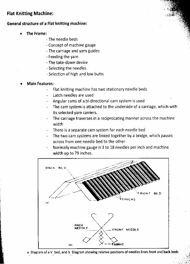
Flat Knitting M achine:
General structure of a Flat knitting machine:
The Frame:- The needle beds- Concept of machine gauge- The carriage and yarn guides- Feeding the yarn- The take-down device- Selecting the needles- Selection of high and Iow butts
* Main Features:Flat knitting machine has two stationary needle bedsLatch needles are usedAngular cams of a bi-directional cam system is usedThe cam system is attached to the underside of a carriage, which withits selected yarn carriers.The carriage traverses in a reciprocating manner across the machinewidthThere is a separate cam system for each needle bedThe two cam systems are Iinked together by a bridge, which passesacross from one needle bed to the other.Normally machine gauge is 3 to 18 needles per inch and machinewidth up to 79 inches.
m'- ..w-.'-> .*.-' z ujjvu'w.'e -
B xc K e c o ..--'------'''R% -.r -..''* ..
X ..--* w..m ' .Yx -m. -'*... v'
.'.W
..> '
.A .z N.76 ..-. Xz .. .-- qs a ox y e,, o
az z -.-e* v-. !z ..w Z--= ' '.. .
'
4T R 1 c K s
D
BACKNEEDLE
- - x FRONT NCCDLEN
A,)*'- Fa- lcf t: )
a Diagram of a V bed, and b Diagram sbowing relative positions of needles from front and back beds
357Advantages of Flat knitting machine:
The flat machine is the most versatile of weft knitting machines, its stitch potentialincludes needle selection on one or both beds, racked stitches, needle-out designs,striping, tubular knitting, changes of knitting width and Ioop transfer.A wide range of yarn counts may be knitted per machine gauge including a iumberof ends of yarn in one knitting system, the stitch Iength range is wide and there isthe possibility of changing the machine gauge.
* The operation and supervision of the machines of the simpler type is relatively Iessarduous tban for other weft knitting machines.
* The number of garments or panels simultaneously knitted across the machine isdependent upon its knitting width, yarn carrier arrangement, yarn path and packageaccommodation.
Uses of Flat knitting machines:
Articles knitted on flat machines range from trimmings, edgings and collars to garmentpanels and integrally knitted garments. The common products: jumpers, pullovers,cardigans, dresses, suits, trouser suits, hats, scarves, accessories, ribs for straight-bar
machines (fully fashioned machines). Cleaning clothes, three-dimensional and fashionedproducts for technical applications, multiaxial machines are under development.
Classifications of Flat machines:
M achines range from hand propelled and manipulated models to fully-automatedelectronically controlled power driven machines. The four classes of flat knittingmachines are:
a) The Vee-bed flat which is by far the iargest class;b) Flat bed purl machines which employ double ended or double headed Iatch needlesc) Machines having a single bed of needles which include most domestic models and
the few hand manipulated intarsia machinesd) The uni-directional multi-carriage machines made by one manufacturer,
a) Vee-bed Flat knitting machine:
Vee-bed flat knitting machines are widely used for the production of sweater, collar-cuff, etc. This machine describe in details in the following chapter of sweaterknitting.
b) Flat Purl knitting machine:(
'
Flat purl or Iinks-links machine with double-headed Iatch needles are Iess common (kthan Vee-bed types to which they are similar in method of operation. jL
:e' : ! t m
358* They share with Vee-bed type very good patterning scope
, increasing shapingpotential and relatively Iow productivity.
End-uses and machine types show slightly less diversity than Vee-bed equipment buthand operated types and circular-flat purl machines exist.
c) Domestic Single bed Flat machine:* These machines are no longer produced for industrial use.
The needles are actuated by cams mounted in a carriage traversed by hand.
Patterning and ability to shape the fabric depend upon manual operations.A typical machine has a 36 inch working width with 5 to 6 needles per inch
.
Circular knitting machine;
The term circular covers aII those weft knitting machines whose needle beds are
arranged in circular cylinders and / or dials, including latch, spring bearded and veryoccasionally compound needle machinery, producing a wide range of fabric structures,garments, hosiery and other articles in a variety of diameters and machine gauges
.
Features of a Circular knitting machine:
The common features of a circular knitting machine as follows:
* Circular knitting machine normally has rotating (clockwise) cylindrical needle bed (s).* On circuiar knitting machines latch and compound needles are used
. 0ne seldomfinds bearded needles or other needle types. Normally one or two sets of Latchneedles are used.
@ For single-jersey machine holding down sinkers are used, one between every needlespace.
* Normally stationary angular cam systems are used for needle and sinker.
* Latch needle cylinder and sinker ring (for single-jersey machine) / dial (for double-jersey rib and interlock machine) revolve through the stationary knitting camsystem.
@ For single-jersey machine, sinker trick ring which is simply and directly attached tothe out6ide top of the needle cylinder thus causing the sinkers to revolve in unisonwith the needles.Needle retaining spring is also used
* Stationary yarn feeders are situated at regular intervals around the circumference ofthe rotating cylinder,
* Yarn is supplied from cones, placed either on an integral overhead bobbin stand oron a freestanding creel through tensioners, stop motiohs and yarn guide eyes downto the yarn feeder guides.
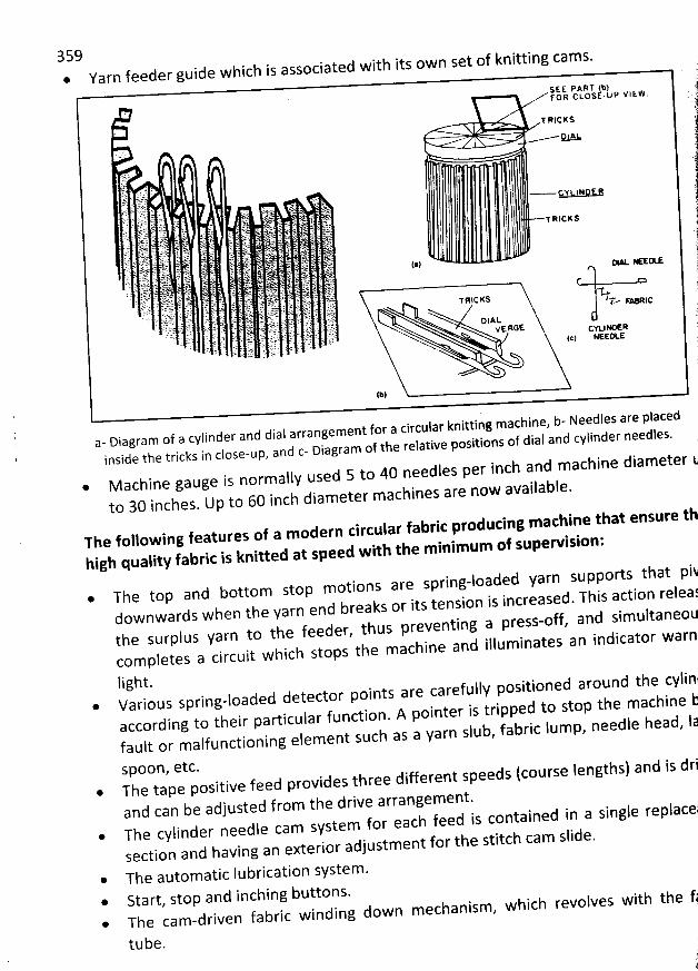
359. . . ted with itS Ownide whlch IS 3SSO(2Ia
Yarn feeder gu*SE E PART (b)O R C L O S E ' U P V l EW .F
T R IC K S
1.1 1 ' ' 'J:.9.i.;'r y . i 1 cy LIND E er:t, :ù k
'
. f?. .,i ' 1t. ïk''. . . ..q..j . . gJ rl .1:. . ib . . r '' éy; . i:.. t 4 j . . .$. . . . . . jg i' .' .- '; ' ûtL 'r:' î'-;@' (-
,- .: ;;r;:.. ,&' t!:!r. . é. .'(y ;. , .:k-. tp1C,. ' '- ,:. q,jï?F l 'r I''I , '::k ,,4- tii(.. - - ,ik.:) i . J - ,k.5 ; ? <. ' @tl : . : . gt ;: ?r .. . . e . .. ;33, 1 1.';: .. tû ju.l. .: .L..r ;'. $y. v . ; ). , (ilqlï,, w . . 'D ' j ï. p 73k l . '. .. ,: 't ?. : . x... . ( !t:.. f.: k z. h;C4. , tz ... ;4r ;t ., wl t; jr q '7kî.4.E ; . ,. . 'b'à( ;(; ' 't . :;; rsi z)L. .
.. :. kty!i . . g. : gj nrè ... . ., . . jj,j;.' ): jr ... . 'g. .. . j;j k.g;y!g. 4j;.. 1;. .(;1; . ,plt: . shr.çj' . . . .. jq :'T . . 6E,41(. : . Jj:sE: .j.. :' ' . : .:. ;!J: ' r (:,$,jj,7 . 13 li :. .' ' ;11$E)
v.;zà.ï. : t jjF k .t; . ;, . : .t j !;ty ...$f. k,. è> ' ; s o.. .'rrktt j jj ) ç)sdkl.. ,iIE:!E f?ll 1!'.', t :2 i f: . . . ljj.. .' : ' yj,jj j .r;; g zj z () yj . . . ZJ j Ng ). . y/hî. . J. zi?: . ! ,..c .s ..1z .1 ï. .. .. $ # . ' . ' ' $ . 'X'
-' . .. ay à SJ : ' ' '=f:.m . J : ''..p .,.9 ?. .
1 . . : J . f; . j ' qr : . fz.4 . rl '
y7$9$'' $ . '.j?)j(; me . - rf ty (jjh yy . iklj --y;u.:. sfz' !. ,j zf y; /2 ,k ,;.,,., .. , ..t v . .7 ,: ! ' . 4r$j) jp j;$.;);.. L; (k.. . '.. lt f .. )j$j. . :j. z.-*'. ;y. .. );n. .;. ;;$ tr j e.vryktt. .y. jpj j j:i jjr y; k .;r.... jrjkjjj;j j (;. ('$' e'. ' : r .X: r. z . ,..; .); Ek.. . j; tj .:â; :4: (j :t ; g1t. ., yr yjyjjj;j. N( ,jr. g y!tj :; . j :,;jg;. k. ' ' :y p jr. ( . (. : yï .f. qa .v :# . t . . :) sq ar $: , k . .' :@ . . ..s Ehii r ;; ALzï . . ' ' , . .. fi k; f... tjïkltr. ....y ... 1 , ). @: TLi. ) :. :#r y;?'.; . .)LL J. t j'.' ;' 7 a ' .. jgr G. . , . . A. .Jy .( . y :v j;j j jlk $..:.(. .1(:.. .. rtj;. . . : ;1.. .j12. ' . : . ... : :.i.''tl (t!. 91: (ïr . , j; . . SF (i t. E , t .. . zs : , ') ). . . ;r. t ,3:3 ci i ' hl ,. : lzl , v E eGt cvk.l G R' T: C C t . r; L ', .. , . 5.gj jJ. i (g.:' o., ... .J.; j. r .j.; g jjjgl jr jijj.jr. 7 R ' k / ' ' j : :: ( t: jL'. .2 . :,. i.. : : ) ..6t. . qy. :.. irj:. . t?. . t.,.;. z.. (.ï . . hry :, . ;, .. .);,: r.. . i ij yy. . . .. :,; .(..y; ,(7 .. . . !j, .' ( S ï '' ' ' :. 7% . .;. .. é(,L. ' ' , .'' . : t! , . :';''
(b)
' b- Needles are ptaced' knitting machlne,' ement for a clrcular
. f a cylinder and dlal arrang . . . j and cylinder needles.- Dlagram o . jative posltlons of d1a3 d E- D'3VrZZ3 Of the FP' ' h t r 1 c k S 1 n C l O S e - U P , 3 rl . .lnslde t e
. hjne dlameter kch and mac40 needles per ln' nOrm3llY used 5 to. achine gauge IS . ailable.' 3Cb'BPS 3fe Z0W 3V
' U to 60 inch dlametef mto 30 lnches. 1:1
set ofknitting cams.
The following features of a modern circular fabric producing machine that ensure th
high quality fabric is knitted at speed w ith the minim um of supervision:
* The top and bottom stop motions are spring-loaded yarn supports that pi&downwards when the yarn end breaks or its tension is increased. This action releaïthe surplus yarn to the feeder, thus preventing a press-off, and sim ultaneoucom pletes a circuit which stops the machine and illum inates an indicator warn
light.* Various spring-loaded detector points are carefully positioned around the cylindaccording to their particular function. A pointer is tripped to stop the machine ifault or malfunctioning elem ent such as a yarn slub, fabric lump, needle head, ja
spoon, etc.* The tape positive feed provides three different speeds (course lengths)
and can be adjusted from the drive arrangement.* The cylinder needle cam system for each feed is contained in a single replace;
section and having an exterior adjustment for the stitch cam slide.
* The automatic lubrication system .* Start, stop and inching buttons.@ The cam-driven fabric winding down m echanism, which revolves with the fj
tube.
and is dri
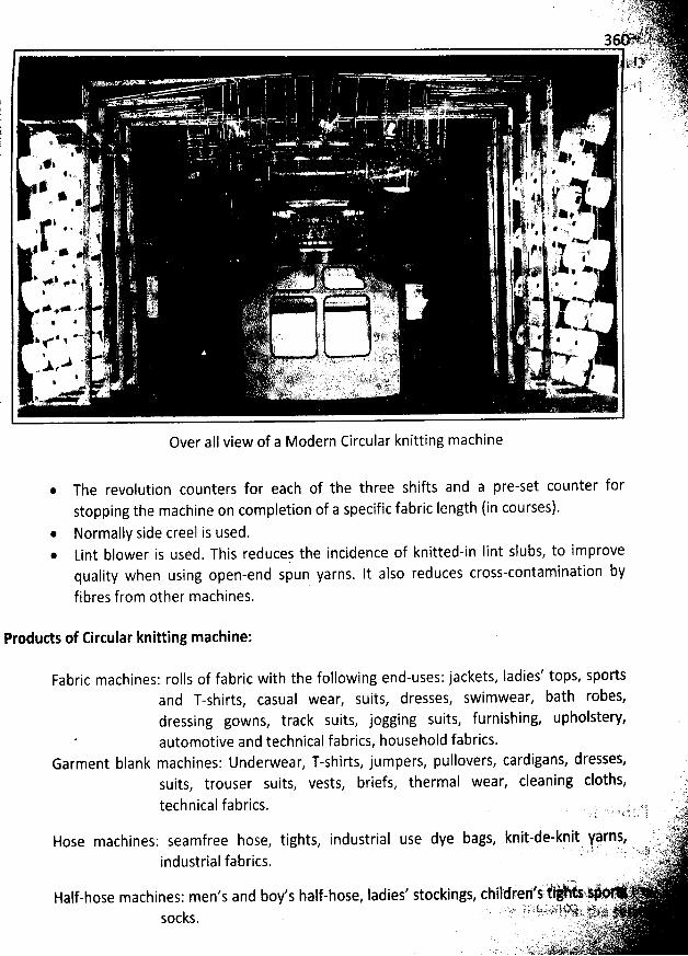
Over aII view of a Modern Circular knitting machine
* The revolution counters for each of the three shifts and a pre-set counter forstopping the machine on completion of a specific fabric Iength (in courses).
@ Normally side creel is used.* Lint blower is used. This reducej the incidence of knitted-in Iint slubs, to improve
quality when using open-end spun yarns. lt also reduces cross-contamination by
fibres from other machines.
Products of Circular knitting machine:
Fabric machines: rolls of fabric with the followingand T-shirts, casual wear, suits,dressing gowns, track suits, jogging suits, furnishing, upholstery,automotive and technical fabrics, household fabrics.
Garment blank machines: Underwear, T-shirts, jumpers, pullovers, cardigans, dresses,suits, trouser suits, vests, briefs, thermal wear, cleaning cloths, ' Cytechnical fabrics. . ' .t9.. . . .i , .k.. ,. :. .'') kc)
'! . .#. :7k):444jr J,iHose machines'. seamfree hose, tights, industrial use dye bags, knit-de-knlt yârns, . y.r .' i ;. .. ' '- : :$? '- :'a ;i2 .d tria I f ab rics . .1 ttJ ')i n us , .
.: .j 's-t.rjl...s$j.t $#,t '. J ' ' ' ' ': rHalf-hose machines: men's and boy's half-hose, Iadies' stockings, childrelfsrt '.' ' , -
. . '.'( .k..; :ï.;.$' ) s' ' i ikz ).#; '(.J''/).6k11i>-- *,4114j;2 ' '' '14: tsk - ' ' . - '- ' ' , t'd017'1'''?hr ::111'. z 'i' ' .ë5k (:)p (:: . . x; ;y: ,;kjk::. .:
k :'-.tt ëjljyjjt)- 7))këkk..... - y y-: jkke .:)' :' E 22;1/,23 t è ,r lyt. '' '
. q ï' . . - àz. .) n 's-) .! ;):tq.
'it)tjëjkjjéjjjji!j' '' ' x jj;lijr. .
end-uses: jackets, ladies' tops, spodsdresses, swimwear, bath robes,
361
classifitatidn of iirtular knitting mathines:h - h t es of circular knitting machinesT ere are t ree yp .
a) Revolving tylinder lattb needle machines:They produce most weft knitted fabrics. They are of two main types -
1. Open top or Sinkçr top or Single jersey machines'lI. Dial and cylinder machine
Open top machines have one set of needles usually arranged in the cylinder.Except in the case of certain effed fabric machines such as pelerine, cylinder ànddial machines are of either the rib or interlock type.M achines of both types may or may not have patterning capabilities.
b) Revolving cylinder bearded needle single-jersey fabrit mathine:There are two types of circular bearded needle single-jersey fabric machines stillmanufactured,
The Sinker Wheel machine or French or Terrot type machine.The Loop wheel frame or English type machine.
Both have the following features in common:@ Needles are fixed in needle bed.* Revolving needle bed* Ancillary elements moving yarn and Ioops along the needle stems.
Fabric tube knitted with its technical back facing outwards.* Less number of feeders accommodates.* Comparatively Iow productivity compensated by an ability to produce unusual
and superior quality knitted structures.
c) Circular garment Iength machines:* They are generally of body-width size or larger having a cylinder and dial
arrangement or a double cylinder.@ They are of the small-diameter hosiery type with either a single cylinder, a
cylinder and dial or double cylinders.
Fabric M achine:
The fabric machine has the following main features:
* Circular machines, knitting tubular fabric in a continuous uninterrupted Iength of
constant width.
362Large diameter, Iatch needle machines, knit fabric at high speed (also known as yardgoods or piece goods machines).The fabric is manually cut away from the machine; usually in roll form, after aconvenient Iength has been knitted.Most fabric is knitted on circular machines, either single-cylinder (single-jersey) orcylinder and dial (double-jersey), of t'he revolving needle cylinder type, because oftheir high speed and productive efficiency.
* Sinker wheel and loop wheel frames could knit high quality specialty fabrics, with
bearded needles, although circular machines employing bearded needles are nowobsolete. The production rates of these machines were uncompetitive.Unless used in tubular body-width, the fabric tube requires splitting into open width.
@ The fabric is finished on continuous finishing equipment and is cut-and-sewn intogarments, or it is used for household and technical fabrics.
* The productivity, versatility and patterning facilities of fabric machines varyconsiderably.
* Generally cam settings and needle set-outs are not altered during the knitting of thefabric.
Garment-length machines:
The garment-length machine has the following main features:
* They include straight bar frames, most flats, hosiery, Ieg wears and glove machines,and circular garment machines including sweater strip machines. .They knitting garment-length sequences, which have a timing or counting device toinitiate an additional garment-length programming (collectively termed ''themachine control/') mechanism. This co-ordinates the knitting action to produce agarment-length structural repeat sequence in a wale-wise direction. The garmentwidth may or may not vary with in the garment Iength.They are coarser gauge machine than fabric machines.lt automayically initiates any alteration to the other facilities on the machine neededto knit a garment-length construction sequence instead of a continuous fabric.The machine control may have to initiate correctly-timed changes in some or aII ofthe following:
Cam-settings, needle set-outs, feeders and machine speeds.
It must be ableto override and cancel the effect of the patterning mechanism in ribborders and be easily adjustable for different garment sizes. .The fabric take-down mechanism must be more sophisticated than for continuousfabric knitting.
* This take-down mechanism has to adapt to varying rates of production dtlring theknitting of the sequence and, on some machines be able to assist both in the setting
363up on empty needles and the take-away of separate garments or pieces oncompletion of the sequence.
* Garments may be knitted to size either in tubular or open-width; in the latter casemore than one garment panel may be knitted simultaneously across the knittingbed.
@ Large-diameter circular machines and wide Vee-bed flat machines can knit garmentblanks that are latter split into two or more garment widths (blanket-width knitting).
* They produce knitwear, outerwear and underwear. Underwear may be knittedeither in garment-length or fabric form, whereas knitwear is normally in garment-Iength form, which is a generic term applied to most weft knitted outerweargarments such as pullovers, jumpers, cardigans and sweaters, usually knitted inmachine gauges coarser than E14. Jersey wear is a generic name applied to weft
knitted fabric (single-jersey, doublejersey). lt is cut and made-up from fabric usuallyknitted on large circular machines (26* or 30* diameter), although there are Iargerand smaller diameter machines used. Generally, gauges are finer than E14.
Plain or Singledersey Circular Latch Needle Knitting M achine:
Description of the machine:
Plain fabric is a single jersey fabric and is produced by one set of needle. Most of single -jerseyfabric is produced on circular machines whose latch needle cylinder and sinker ring revolvethrough the stationary knitting cam systems, which together with their yarn feeders aresituated at regular intervals around the circumference of the cylinder.
The yarn is supplied from cones, placed either on an integral overhead bobbin stand or on afree - standing creel, through tensioners, stop motions and guide eyes down to the yarn feederguides. The fabric, in tube form, is drawn downwards from inside the needle cylinder by tensionrollers and is wound onto the fabric batching roller of the winding down frame. The windingdown mechanism revolves in unison with the cylinder and fabric tube and is rack - Ieveroperated via cam - followers running on the underside of a profiled cam ring.
As the sinker cam - plate is mounted out side on the needle circle, the centre of the cylinder isopen and the machine is referred to as an open top or sinker top machine. Compared with a ribmachine, a plain machine is simpler and more economical with a potential of more feeders,higher running speeds and the possibility of knitting a wider range of yarn counts. The mostpopular diameter is 26'' giving an approximate finished fabric width of 60'' to 70''.
n 2-F-. where Ne = cottonAn approximately suitable count may be obtained using the formula Ne = ,18
count or English system and G = gauge in npi. For fine gauges a heavier and stronger count may
be necessary.
The following figure shows a cross-section of the knitting head alI of whose stationary parts areshaded.
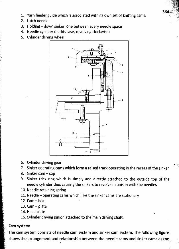
1. Yarn feeder guide which is associated with its oWn set of knitting cams.2. Latch needle3. Holding - down sinker, one between every needle space4. Needle cylinder (in this case, revolving clockwise)5 Cylinder driving wheel
7 x. 1... .- z
'+ . v)'.k <w' xw . 'Nx. z . xx...
.... x a
; . N4. J .
% ;
. ;
'N.
13
( lt// -.,'
$t-.! 4 '
s
15
6. Cylinder driving gear7. Sinker operating cams which form a raised track operating in the recess of the sinker8. Sinker cam - cap9. Sinker trick ring which is simply and directly attached to the outside top of the
needle cylinder thus causing the sinkers to revolve in unison with the needles10. Needle retaining spring11. Needle - operating cams which, like the sinker cams are stationary12. Cam - box13. Cam - plate14. Head plate15. Cylinder driving pinion attached to the main driving shaft.
Cam system:
The cam system consists of needle cam system and sinker cam system. The following figure
shows the arrangement and relationship between the needle cams and sinker cams as the ,. . '
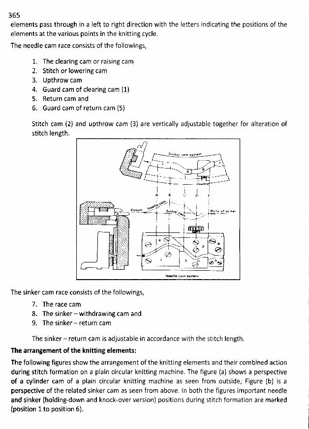
365elements pass through in a Iek to right direction with the Ietters indicating the positions of theelements at the various points in the knitting cycle.
The needle cam race consists of the followings,
1. The clearing cam or raising cam2. Stitch or Iowering cam3. Upthrow cam4. Guard cam of clearing cam (1)5. Return cam and
6. Guard cam of return cam (5)
Stitch cam (2) and upthrow cam (3) are vertically adjustable together for alteration ofstitch Iength.
*. . S , n k e r u a m s v s te fn..'.';..'. ..... %.
..'-.< -' 77.g' 9a
- t..... a .'
. rl I ,. 'p 1A B c o EI v a x..m xx . j '. ysy . . -t. x j ,Z <D* ttl m . .'v ' sja k ' Xw t B e 9 I y o f : 1 n k e r
N '-y- . -'Nw--'x , . '
I> .X. xrzx -e -. --. vy j w a o(73 'N'v 6,d' I a;M , y o e,V ZA,.- x 0. . e &y' .y,l ---
Ne le cam w xtem
The sinker cam race consists of the followings,
7. The race cam8. The sinker- withdrawing cam and9. The sinker - return cam
The sinker - return cam is adjustable in accordance with the stitch length.The arrangement of the knitting elements:
The following figures show the arrangement of the knitting elements and their combined actionduring stitch formation on a plain circular knitting machine. The figure (a) shows a perspectiveof a cylinder cam of a plain circular knitting machine as seen from outside; Figure (b) is aperspedive of the related sinker cam as seen from above. ln both the figures important needleand sinker (holding-down and knock-over version) positions during stitch formation are marked(pèsition 1to position 6).
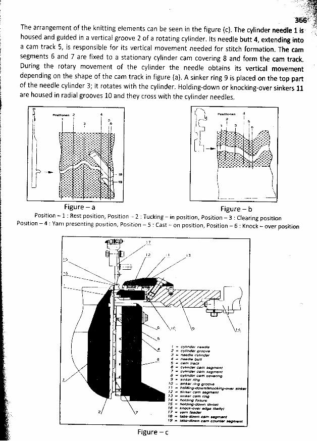
. . ....;q.: tpr'q jjyjjèj. ! . . -- , r t. :-k ..y. ;i, y.'36:, i.è%. : ''
.. :.1't)2The arrangement of the knitting elements can be seen in the figure (c). The cylinder needle 1 is -yhoused and guided in a vertical groove 2 of a rotating cylinder. lts needle butt 4, extending into
a cam track 5, is responsible for its vertical movement needed for stitch formation. The tam
segments 6 and 7 are fixed to a stationary cylinder cam covering 8 and form the cam track.
During the rotary movement of the cylinder the needle obtains its vertical movementdepending on the shape of the cam track in figure (a). A sinker ring 9 is placed on the top partof the needle cylinder 3,' it rotates with the cylinder. Holding-down or knocking-pver sinkers 11are housed in radial grooves 10 and they cross with the cylinder needles
.
Figure - aPosition - 1 Rest position, Position - 2 :Tucking - in
Position - 4 : Yarn presenting position, Position - 5 : Cast - on
Figure - bposition, Position - 3 Clearing positionposition, Position - 6 : Knock - over position
j . ., j y
- 12 1A 13!S
7, . +.g.:6
!N
t
6 I () 9 j a
5
l - cvunder neet#?e* 2 .. cvlinder grooee3 a. needle cW/nder
s 4 = needle tytm5 = carp trac:5 =e cvllnden eeam segmant7 - cvlinder cam segment8 a. cvlinder cam co-rfng& = s'nker ring3îO = wnker ring grow et / =, holdinq-down/kna ktngmh- sin#pe22 = sinker cam legmearp 3 = sinker cam rinç!# = tmtdinq pxttzr@35 = tkotding-down z/lroar$$ z'e knxkm-r > f-//y'?2 7 ' 7 - Yarn feefe28 ae tak*-down c#m - - t/ 9 aw '.ke* wn c#m çovnt- v @af
Figure - c
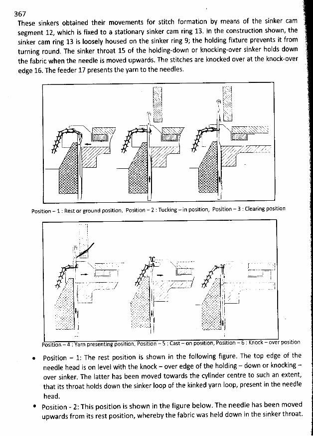
367These sinkers obtained their movements for stitch formation by means of the sinker camsegment 12, which is fixed to a stationaw sinker cam ring 13. In the construction shown, thesinker cam ring 13 is Ioosely housed on the sinker ring 99 the holding fixture prevents it fromturning round. The sinker throat 15 of the holding-down or knocking-over sinker holds downthe fabric when the needle is moved upwards. The stitches are knocked over at the knock-overedge 16. The feeder 17 presents the yarn to the needles.
r'r 7-,j . . xw'h .x...' z. '
.) %. ' ' M ) x2x x)x
'. (g% x x.-sxx ; . sg..'y txxx--) h k'x .'x N.x j o ) à . ..'jrR, ' xh'k 1 ' x ' ' .1 ! F- sxgys. jjy g(yh''..CL--.*1. h bx- ., lx!I l '
' ''XX- . x . .
. j , v.z . ; z s :i.@ * l
,z'Z I z' . x ' z ' ' V . z' z' r . . .' z , . ' / ' ' . '
( A y ' .7z ,.x zl , / .M . .' .x ,, . z z
z'. az,
z-
t t
Position - 1 : Rest or ground position, Position - 2 : Tucking - in position, Position - 3 : Clearing position
Position - 1: The rest position is shown in the following figure. The top edge of theneedle head is on level witb the knock - over edge of the holding - down or knocking -over sinker. The latter has been moved towards the cylinder centre to such an extent,that its throat holds down the sinker loop of the kinked yarn Ioop, present in the needle
head.Position - 2: This position is shown in the figure below. The needle has been movedupwards from its rest position, whereby the fabric was held down in the sinker throat.
' 17 6JIJOIF 'r. -q- ,r; .,--.t--.:1q7--
. ' , .f; ., . ..z S;jL. jyyk .lv. ...
jj , ( jj,y.jjygo #.. ..
., ).))y.The oId Ioop has opened the needle Iatch and Iies on it
. The arrangement of the #arrt'.fcllfeeder prevents the closing of the Iatch when the needle is moved further up
. The sinker .'ptrests in this position.
Position - 3: From the tucking-in position the needle has now been moved into itshighest position. Since the fabric had been held down by the throat of the sinker
, the oIdIoop slides on the needle stem to a position beneath the Iatch. The yarn feeder preventsa closing of the Iatch. The sinker remains at rest.
Position - 4: The needle is moved down from the clearing position. Just beforé the old
Ioop begins to close the Iatch the new yarn must be Iaid into the needle head by theyarn feeder. In order that the Iatch can be closed by a further downward movement ofthe needle, yarn feeding must be completed immediately after crossing the yarnpresenting position. In the figure, the sinker begins moving towards the right and awayfrom the cylinder centre, since the fabric no Ionger needs to be held by the sinkerthroat. The vertical position of the needle is the same in the yarn presenting positionand the tucking-in position. The fundamental difference
, however, is that in the tucking-in position the oId Ioop from the previous row Iies on the needle Iatch
, but is beneaththe Iatch for stitch formation in the yarn presenting position
.
* Position - 5: From the yarn presenting position the needle is moved further downwardsby means of the take-down segment 18 along with the counter guide segment 19
, figure(a). Now the needle latch is closed by the oId Ioop and the new yarn is held in the closedneedle head. The sinker has been moved into its extreme right position
, so that the oIdIoop Iies on the knock-over edge and the new yarn can be pulled through the old Ioop
.
* Position - 6: The needle is moved further dowiwards by means of the take-down camsegment 18 and the counter guide segment 19, figure (a) and it pulls the new yarnthrough the old Ioop. This is now knocked over as a new stitch
. At the same time a Ioopis formed by the new yarn. The take-down segment 18 and the counter guide segment19 can be shifted diagonally and be exactly set to given values with the help of a scale
.
Thus it is possible to precisely adjust the Iength of the newly formed Ioop.
Sinker Timing:
The most forward position of the sinker during the knitting cycle is known as the push point andits relationship to the needles is known as the sinker timing
.
If the sinker cam ring is adjusted so that the sinkers are advanced to the point where they robyarn from the new stitches being formed, a lighter-weight fabric with oversized sinker lpopsand smaller needle Ioops is produced.
lf the ring is moved in the opposite direction a tighter, heavier fabric is produced having smaller
sinker Ioops and Iarger needle Ioops. The timing is normally set between these two extremom
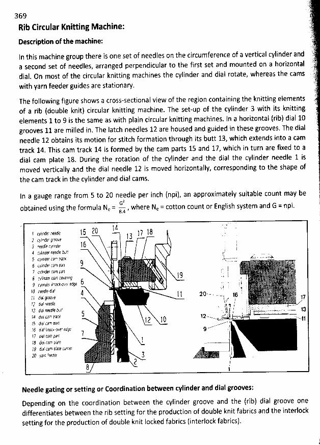
369
Rib Circular Knitting M achine:
Destription of the machine:
In this machine group there is one set of needles on the circumference of a vertical cylinder anda second set of needles, arranged perpendicular to the first set and mounted on a horizontaldial. On most of the circular knitting machines the cylinder and dial rotate, whereas the cams
with yarn feeder guides are stationary.
The following figure shows a cross-sectional view of the region containing the knitting elementsof a rib (double knit) circular knitting machine. The set-up of the cylinder 3 with its knitting.elements 1 to 9 is the same as with plain circular knitting machines. ln a horilontal (rib) dial 10grooves 11 are milled in. The latch needles 12 are housed and guided in these grooves. The dialneedle 12 obtains its motion for stitch formation througb its butt 13, which extends into a camtrack 14. This cam track 14 is formed by the cam parts 15 and 17, which in turn are fixed to adial cam plate 18. During the rotation of the cylinder and the dial the cylinder needle 1 ismoved vertically and tbe dial needle 12 is moved horizontally, corresponding to the shape of
the cam track in the cylinder and dial cams.
ln a gauge range from 5 to 20 needle per inch (npi), an approximately suitable count may beG2
obtained using the formula Ne = u , where Ne = cotton count or English system and G = npi.
z cg ..;j, ' . r
! t .- .zt, 1 5 ?0 1 ? 1 8 '..! cyl/nder ,7:9 ! 3 .
2 cyprder grnope,') nietje ckllnder 1 6 - . 74 Cyllnder need/e fIt/rJ i
t ;' .--. . -- -5 (rl4nlgr rlm rrdck . - .+ . . . x-u,>hS 1 - - '-' - ' N6 c//nà:f :an Jurl ( .
7 c/fntfer cdm pdrt - N Z l - -d I
$ ck/fnler cirn rpk'er/ng t: 1 S t - : (O v , # ' L .2 cy/lnlcr kcoct-ovi?r fdge ! )l
: i j . TE .! () 983$10 Ydl k 1 '' i1 I ! ao
- -.-- l jo . l rl / dinl qrccve ---t y v j.yà 'f I72 ttai neetj: ! jI...? t,ai aeetle tutr s - . .
'$'yj j / '. 1). ,..,..1.' ..: ..-..: .ttt. . .. ---.....,.-t.' .' , -..-. .-ja
;-t t;,.à( cdo 'rasi .!a .....- .. .! l ! 0 .- . ' - .
---..-41?5 t,a: cao p..?r? #?6 (f,..., kcoci-av', etsçe :.......--
71 / tu? fum Ildr!1 ,71 tial tum p/zv:
72 (fid/ cam èdlf carngf t29 yarn feetbç ! i l
? )!1
Needle gating or setting or Coordination between cylinder and dial grooves:
Depending on the coordination between the cylinder groove and the (rib) dial groove onedifferentiates between the rib setting for the production of double knit fabrics and the interlock
setting for the production of double knit locked fabrics (interlock fabrics).
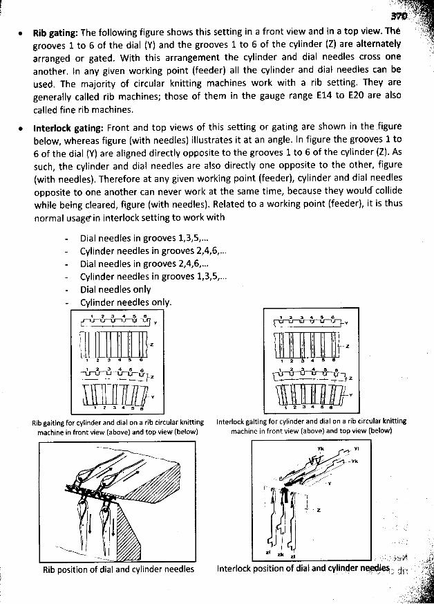
* Rib gating: The following figure shows this setting in a front view and in a top view. Thègrooves 1 to 6 of the dial (Y) and the grooves 1 to 6 of the cylinder (Z) are alternatelyarranged or gated. W ith this arrangement the cylinder and dial needles cross oneanother. In any given working point (feeder) aIl the cylinder and dial needles can beused. The majority of circular knitting machines work with a rib setting. They aregenerally called rib machines; those of them in the gauge range E14 to E20 are alsocalled fine rib machines.
* Interlotk gating: Front and top views of this setting or gating are shown in the sfigurebelow, whereas figure (with needles) illustrates it at an angle. In figure the grooves 1 to6 of the dial (Y) are aligned directly opposite to the grooves 1 to 6 of the cylinder (Z). Assuch, the cylinder and bial needles are also directly one opposite to the other, figure(with needles). Therefore at any given working point (feeder), cylinder and dial needlesopposite to one another can never work at the same time, because they would- collidewhile being cleared, figure (with needles). Related to a working point (feeder), it is thusnormal usagein interlock setting to work with
Dial needles in grooves 1,3,5,...Cylinder needles in grooves 2,4,6,...Dial needles in grooves 2,4,6,...Cylinder needles in grooves 1,3,5,...Dial needles onlyCylinder needles only.
! 2 :! 4 # #.XJ v1 . . . .. .
l ( l ;
'
t1 ,: j 1 Z. 7 I
l4 2
, 2 a g j y. ... . . w z
! - Y
' 2 a * s s
Rib gaiting for cylinder and dial on a rib circular knittingmachine in front view (above) and top view (below)
. j . j$) '' $ j
Rib position of dial and cylinder needles
1 Y :! 5 5 eY
i l l ' 'f
'
1 : li j I I j j zl , t k, I l 14 2 a *
4 2 t! # p .. t
'
' Z
t
'
t
'
''i :
'
$
'
f
'
t j 'T . : i .-g, l , , ! ;
1 2 3 * 5 e
lnterlock gaiting for cylinder and dial on a rib circular knittingmachine in front view (above) and top view (below)
Fk #11 ..-
v .:.kv-yu, - --' - . -- ----'
. ' ...''''-
-M' .<.. -< Ce-'- n- .'xx 28
. - ' .. )4
! ' ')@k. . j 11 .y-.. zl' I l; I: 1 .
l
aj 'zk j . . . sa . : . , ;) o xg
Interlock position of dial and cylinder ne. 0.5.- jj-y. x. .. wq
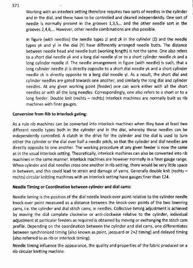
1371 1
fore requires two sorts of needles in the cylinder lWorking with an interlock setting thereand in the dial, and these have to be controlled and cleared independently. One sort of '.needle is normally prejent in the grooves 1,3,5,.. and the other needle sort in thegrooves 2,4,6,... However, other needle combinations are also possible.
In figure (with needles) the needle types zl and zk in the cylinder (Z) and the needletypes yk and yl in the dial (Y) have differently arranged needle butts. The distancebetween needle head and needle butt (working length) is not the same. 0ne also refersto a short dial needle yk and a Iong dial needle yl or to a short cylinder needle zk and aIong cylinder needle zl. The needle arrangement in figure (with needle) is such, that aIong cylinder needle zl is directly opposite to a short dial needle yk and a short cylinderneedle zk is directly opposite to a Iong dial needle yI. As a result, the short dial andcylinder needles are gated towards one another, and similarly the Iong dial and cylinder
needles. At any given working point (feeder) one can work either with aII the shortneedles or with aII the Iong needles. Correspondingly, one also refers to a short or to aIong feeder. Double knit (rechts - rechts) interlock machines are normally built as ribmachines with finer gauges.
Conversion from Rib to Interlock gating:
As a rule rib machines can be converted into interlock machines when they have at Ieast twodifferent needl: types both in the cylinder and in the dial, whereby these needles can beindependently controlled. A clutch in the drive for the cylinder and the dial is used to turneither the cylinder or the dial over half a needle pitch, so that the cylinder and dial needles aredirectly opposite to one another. The working procedure at any given feeder is now the sameas in the usual interlock setting. Theoretically, interlock machines can also be converted into ribmachines in the same manner. Interlock machines are however normally in a finer gauge range.W hen cylinder and dial needles cross one another in rib setting, there would be very Iittle spacein between, and this could Iead to strain and damage of yarns. Generally double knit (rechts -rechts) circular knitting machines with an interlock setting have gauges finer than 224.
Needle Timing or Coordination between cylinder and dial cams:
Needle timing is the position of the dial needle knock-over point relative to the cylinder needleknock-over point measured as a distance between the knock-over points of the two lowering
cams, i.e. the cylinder and dial stitch cams, in needles. Collective timing adjustment is achievedby moving the dial camplate clockwise or anti-clockwise relative to the cylinder, individualadjustment at particular feeders as required is obtained by moving or exchanging the stitch camprofile. Depending on the coordination between the cylinder and dial cams, one differentiates
between synchronized timing (also known as point, jacquard or 2x2 timing) and delayed timing(also referred to as rib or interlock timing).Needle timing influence the appearance, the quality and properties of the fabric produced on arib circular knitting machine.
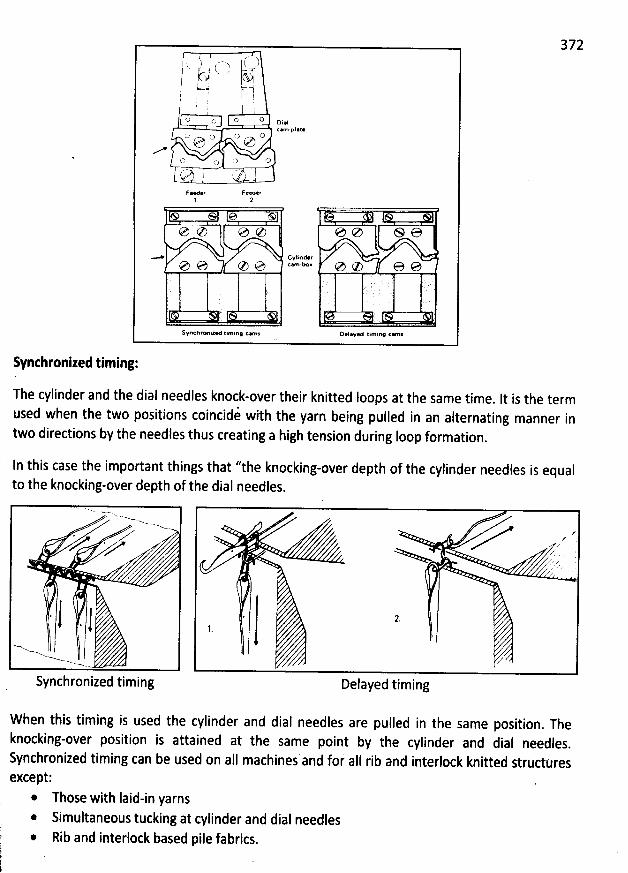
372, t ) : (- - - 'x j k. )I (.. t x .z - !-J .9 It%);
wl j-.,1 -a! ' i i. )
'
! .. I :
'
j
'
o o o o oial
:-) o r7 , C)e 7M
o o () (J
d' j '' )
Feeder Feeder1 2
e C) e C) @ e S e
* CYC'C'tKT ' 'e e C) 1 '-w'' e C) 6 e
S#nchrY lzed tlrnlng ce $ D@I>v@d tlmirw car-
Synthronized timing:
The cylinder and the dial needles knock-over their knitted Ioops at the same time. lt is the term
used when the two positions coincidi with the yarn being pulled in an alternating manner intwo directions by tbe needles thus creating a high tension during loop formation
.
In this case the important things that ''the knocking-over depth of the cylinder needles is equalto the knocking-over depth of the dial needles.
Synchronized timing
#
. N KZzz ..' Z
/
Delayed timing
W hen this timing is used the cylinder and dial needles are pulled in the same position. The
knocking-over position is attained at the same point by the cylinder and dial needles.
Synchronized timing can be used on all machines and foi aII rib and interlock knitted struduresexcept:
* Those with Iaid-in yarns* Simultaneous tucking at cylinder and dial needles* Rib and interlock based pile fabrics.
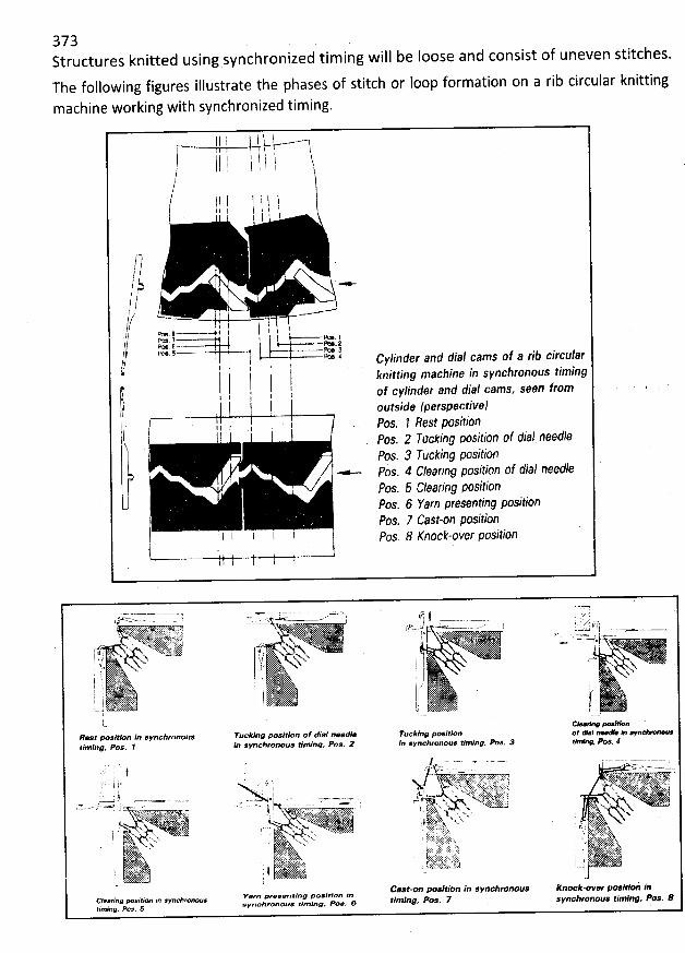
373Structures knitted using synchronized tim ing will be loose and consist of uneven stitches.
The following figures illustrate the phases of stitch or Ioop formation on a rib circular knitting
machine working with synchronized timing.
11 l i ' t
# 11 1, t , ,ff l ! l ( l
. jl ! l t I jI
1-3/ .I/j -/' //' -,.(? ' ' ; ,// r!:l;;r . qj . .......'' I ' ' i.): - ,, a: )// r
'I l t u I jrcuparb' ' J , cvlinder and dia/ cams ef a tib c
t;. l . j tj knitting macsne in svncbronous timingl 1 l l f cvqnde, and dial cams, seen /,.0,,I l ; 1 1 Ooutside (petspective)
I I l I l l Pns. 1 PeSt position/*:. 2 Tncking position d/ d1'4/ nnedle
h Pos. 3 Fuciing Fsition.- Pôs. 4 Cleaçthg position of dial need/e
Pos. 5 C'/ddr/ng positionPos. 6 Fdrn prepnting positïenPos. 7 Cdlt-on position
! l t l l I pos, 8 x'ncck-over pcsition
f<:'m - , '.' . -=va- ..' tG j L ' ''
--''ss.. ... .;,- z.. r.. , ;r.s':: -'-' - ' 's .. ..
... c :- ..-y' ? .. --j..--,'' .. -' ' - -----'-..
'-.- - l ....?t t- c-.
. 4E;'.''.'e' . 'r:,'zr(4t'..'tt..'. j. rl.. 'u < ' ... <.= CL..- : o 'èj .
' ' a. L. X-UJZ ' I ... . , -uxxx-. - u- ...------xnx-
' x4Nquhk . N: . . .' : J & '.C'X$K... 2i.. , -.w....,w 4 ( . .... >y '*h...& 'c . ..c.riJJ.$ 1 - . ( .< c- .. - 1---.. . --lj .. ,
Nqw. .<4;:. s.u ..'.;<'s 62. . -,(; , . -... , k h Slt. . .
i . S q ' Nvxt ( .. . )k N '. $ x s-u.J , , 1 c' .
%bk
i :. . . I .
j l K L ' j E. $ .
I . ! 1 , ': k ,,; . I : )
. .'W . c l.. - ..; ,
;: : I
Rest Jaxee in sm//lrtvax,,ç Tucking pew/rkvl p# 4ial zzeetfl Tvcklng posltion o: tga/ #, yy.tzmlng. Pos. 1 in lmcl/ropotl,e timing. Pos. 2 fn svnchronous rlmkng. Po.. a t Pos 4
z 1 j . . 'e-.'- '.. . . -. -.-.-. . .. ' 4X2-.-.--0 ------ --=.,. ,
. j/q :.. - ---. . .. . . . . -).
- xr-z... .,. . .. . . . . .s=-,.,.. , ) .:- . . .. jr ..z, :.),qkk ,z.t ?;v. .x. .y.ax.:.......: .. .u...+...z.o. ...,..-.... .u .;?i. .., ,' ' <
, xr .. q:.... .. ...Jjy.. . j%) .xz.q..'...,.jj.. sau.y y .( . . .,sz. . z . . ,.)su N .. ....zu.y.r)' j . ' x . . > ;: .p x . . çk 4s . .
x , . . < . . .. I . : kc istp. .)! .ç $ . . ) x . . ..y
.. . 1 , ' .x. . ' '$ ... .. . ...' i .'-; - . . - . j ' à ' ' '. . z q ; . . - 4 - , . . .a.ou. . . . .1j . ): :::Et7' ' ':6k; ' . .r' '.I .' ..* .: . . . . . ' . . X N . '.': x
; ' .rp q. 5; : . . l'. : .x% u. 'b... .;. kks'''. . . 1 ! j jjyrL, . ,' y' .'s... l!L. sj. -%.v. r. .
' . . .' '. .
. < y..... . jjp. , yj , jk : A . . A N 'ci' ' .). '? 's w x . qn;z: .. ... .u .>. :;jjN. . jj.(). .. .s. %k . . **j(?*5V *.. 1: '' '.... . '. 4 jj,'ï. '
... a 'x mxu . k vclll'' xx:k. $: > $ j . .'>....
1 N, . 'N x w 2. .,':r. e'z. ..'..'.v.. '. k I .. V ' . ..+. . . . j . . a. . y yj k u . : ....> . .>à..'Ak.. I ç JY: $$2 I%. r4 . . rt ' C:;:t .1 ' 'ct'kYt . z >, .qz: f ) < ' < L .
. .. . 'snzs'n i$. Ft ).$t'.. >:. $''ç . t:%''' ': p ' '%..j . ) . j. . . ).r)s . . .;. :: j..ïr;. . . . :: ,..:jt'.. rq:jky .. trg.s j . ..t x p.r,à . jj 'x. . . .. ,y - . . .j
u .. E: . .JCast-on p/*1t1* n /'n svnchronous Xpock-over posm' '*' in
l r/ Itlon J,l svnchronous Yern m'eeene?z'g posîtîort i'AC @# ng #- / * pos 7 s agjjmax s xmjag pos. asrrvchronous ezvz/rvge Pos.. # t Mlfl#' ' # etiminw eos. 5
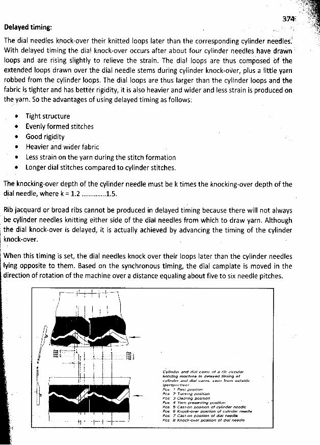
Delayed timing: , . , ;
The dial needles knock-over their knitted Ioops Iater than the corresponding cylinder neéàles.?With delayed timing the dial knock-over occurs after about four cylinder nee'dles have drain 'loops and are rising slightly to relieve the strain. The dial Ioops are thus composed bf theextended Ioops drawn over the dial needle stems duiing cylinder knock-oker, plus a little yainrobbed from the cylinder loops. The dial Ioops are thus larger than the cylinder Ioops and thefabric is tighter and has bettér rijidity, it is also heavier and wider and Iess strain is produced onthe yarn. So the advantiges of using delayed timing as follows:
Tight structure* Evenly formqd stitches* èood rigidity* Heavier and wider fabric@ Less strain on the yarn during the stitch formation
Longer dial stitches compared to cylinder stitches.
The knocking-over depth of the cylinder needle must be k times the knocking-over depth of the(ji 1,I rl (, t? ($ I(, l!, #1 (, rtq 1: cz 1L. ;! .............. 1L.6;.
Rib jacquard or broad ribs cannot be produced in delayed timing because there will not alwaysbe cylipder needles knitting either side of the dial needles from which to draw yarn. Although
dial knock-over is delayed, it is actually achieved by advancing the timing of the cylinderkpock-over.r
'
W hen this timing is set, the dial needles knock over their Ioops Iater than the cylinder needlesIying opposite to them. Based on the synchronous timing, the dial camplate is moved in thedirection of rotation of the machine over a distance equaling about five to six needle pitches.
1 1 l 1 I lr l t
'
I !
'
)
/ 1( 1 l l hl ' ' :
'
I lt i I 1l
/ '* -/ - . - .-
. . I ) ' , t $M f -.-- - ( .. . . .- = )t:z j ..-- ..!y . .x jê
I . 1 1 I
I ' ,1 l ' Cvtinder and diol csms of a rib circtz/ar' l ..j. J kn'tk.îng mazzsfr,e in le/azer.r tîming o:1 t t ! ' 1 c vlinder ant# diai rxams. seezl trom outside. ,1 1 (pcrspekttivel
. Pos. 7 Resî pos/t/on' Pos. 2 rtzcp/ng poslïion
Pos. 3 oean'ng positionPos. 4 Yarn presenting posl'r/orl 'Pos. 5 Cast-on position of cvlinder needlePos. 5 Knock-over m sït/cm of cvlinder needle
' . Pos. 7 Càst-on position 0/ dial needl*- .-.- ' Pos. 8 Knock-over position of dial needle
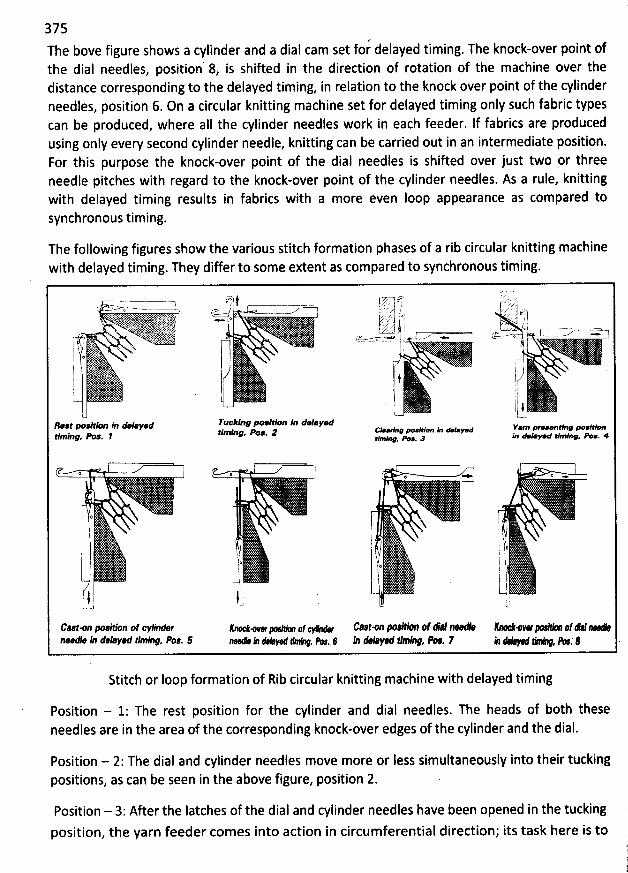
375The bove figure shows a cylinder and a dial cam set for delayed timing. The knock-over point ofthe dial needles, position' 8, is shifted in the direction of rotation of the machine over thedistance corresponding to the delayed timing, in relation to the knock over point of the cylinderneedles, position 6. On a circular knitting machine set for delayed timing only such fabric typescan be produced, where alI the cylinder needles work in each feeder. If fabrics are producedusing only every second cylinder needle, knitting can be carried out in an intermediate position.For this purpose the knock-over point of the dial needles is shifted over just two or threeneedle pitches with regard to the knock-over point of the cylinder needles. As a rule, knittingwith delayed timing results in fabrics with a more even loop appearance as compared tosynchronous timing.
The following figures show the various stitch formation phases of a rib circular knitting machinewith delayed timing. They differ to some extent as compared to synchronous timing.
r.r - -Y- - r'y j j ;- j.'- r rJ$' ' . J ) ) , i-b-zu'.z--- .- .--V ,.a. . J ja . ....-.-.j-.7*- ( ;., jjy y f.; Zi g j.j... <y *' ; z/ :7 yj ( * I ,' '. . . '*- / ? j jR . . . . . s-X j j . / o j s ......m=...m-j'' ' ' .)'j.n ' ' .w.a.x .
' y , ...' . - (Tr s.- q : ..1/.--.-; . - . ; . h.l ....-..-... .. (1 . 1 !l
i ) . ë . ..1 k 'xl !@ % --jj l ry
t (1 i I 'I # 1.,/j . !I ' r' ,1
i I .1- ' 1 )1
...tRest p- elx fa u-'-v.d F@@âlY F @l**n '/ d* Y*d e'a-av #'o,f- k. - v.d Y*m p-- * p@lfetlmlng
. a a. 2 ya ouv- swx. - . .tlmlng. - . , smlv - . a
t o , . j ' ç,; * j * !
(o i I .i :
'
i I ; .l I ! ! k: ( . li
y . j'. 1
j ; ., ; g j jj; I j h! $ : !1 j re '/o i 1) p ! ' ! ll l
-1 ' i. L1 l'ol . 'i
- u -
c-tm Ixv*oa of cyl/ad:r Klœ mw ' af ' Cnst-on --'-'-- ôf 44 --- 'M' E---''4w 4f e -n-''- 1 dWay', tlmlp#, Pos. 5 --'*- i) # + -. , % . 6 ill Al-ye #mlng, % . F b ' , % . $ .
Stitch or Ioop formation of Rib circular knitting machine with delayed timing
Position - 1: The rest position for the cylinder and dial needles. The heads of both theseneedles are in the area of the corresponding knock-over edges of the cylinder and the dial.
Position - 2: The dial and cylinder needles move more or less simultaneously into their tuckingpositions, as can be seen in the above figure, position 2.
Position - 3: After the latches of the dial and cylinder needles have been opened in the tucking
position, the yarn feeder comes into action in circumferential direction; its task here is to
376prevent a premature closing of the Iatches. The cylinder and dial needles attain their clearingpositions, above figure, position 3, roughly at the same time.
Position - 4: The cylinder and dial needles are pulled back again and they move into their yarnpresenting positions. The newly presented yarn is Iaid in the open needle hooks of both theneedles, above figure, pqsition 4.
Position - 5: Since the dial cams have been shifted in the direction of rotation of the machinethe cylinder needles are pulled earlier than the dial needles
. The cylinder needle Ioop closes thelatch and lies on the closed head of the cysinder needle
. The dial needle is approximately in itsyarn presenting position, above figure, position 5. The yarn feeder stops prior to the cast-onposition, so that the cylinder needle Iatch can be closed.
Position - 6: The cylinder needle is pulled further until it reaches its Iowest point in the clearingposition, as shown in the above figure
, position 6. The dial needle is still roughly in its yarnpresenting position. The newly presented yarn is pulled through the cylinder needle loop toform a new Ioop. The oId loop is knocked over as a cylinder stitch
. The Iength of this newcylinder Ioop determines the Iength of the cylinder and dial stitches to be formed Iater
, sincethe dial needle can obtain yarn only from the neighbouring cylinder Ioops during knock-over.Thefefore the drawing-in depth of the cylinder needle is set somewhat Ionger in delayed timingas compared to synchronous timing.
Position - 7: The dial needle is rïow pulled back and it moves into the cal-on position, abovefigure position 7; the loop lies on the closed Iatch of the dial needle
. From its knock-overposition the cylinder needle now begins to move upwards in the direction of its rest position
.
Position - 8: ln this position, the dias needle attains its knock-over position, while the cylinderneedle is still approaching its rest position. Here the drawing-in depth of the dial needle mustbe sufficiently measured so that the dial needle can form a Ioop out of the yarn Iengths of thecylinder Ioops, drawn in earlier by the neighbouring cylinder needles in their knock-overpositions, position 6. A closer examination reveals that
, while being pulled back, the dial needledraws in more yarn from the cylinder Ioop placed contrary to the direction of machine rotation
,as compared to the other neighbouring cylinder Ioop
, since the Iatter has already given up apart of its yarn reserve to the previously formed dial Ioop
.
Due to the delayed knock-over of the dial needle one obtains more uniform stitch Iengths, since
the given yarn length, determined by the drawing-in depth of the cylinder needle, is evenly
distributed over several stitches. This results in a more even appearance of the fabric. After theknock-over position the dial needle is guided into its rest position
.
Advanted timing:This is reverse of delayed timing in that the cylinder Ioops rob from the dial producing tighterdial Ioops, advancement can only be about one needle
, this type of timing is sometimes used inthe production of figured ripple double jersey fabrics where selected cylinder needles can robfrom the aII knitting dial needles.
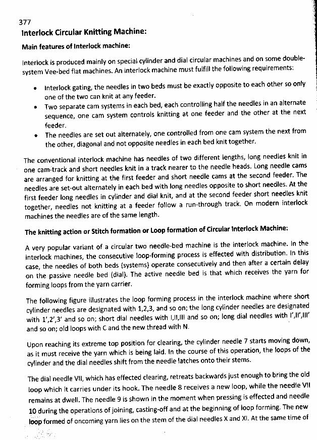
377lnterlock Circular Knitting M achine:
Main features of Interlock machine:
lntérlock is produced mainly on special cylinder and dial circular machines and on some double-system Vee-bed flat machines. An interlock machine must fulfill the following requirements:
lnterlock gating, the needles in two beds must be exactly opposite to each other so only
one of the two can knit at any feeder.Two separate cam systems in each bed, each controlling half the needles in an alternatesequence, one cam system controls knitting at one feeder and the other at the next
feeder.* The needles are set out alternately, one controlled from one cam system the next from
the other, diagonal and not opposite needles in each bed knit together.
The conventional interlock machine has needles of two different Iengths, Iong needles knit inone camztrack and short needles knit in a track nearer to the needle heads. Long needle camsare arranged for knitting at the first feeder and short needle cams at the second feeder. Theneedles are set-out alternately in qach bed with long needles opposite to short needles. At thefirst feeder long needles in cylinder and dial knit, and at the second feeder short needles knittogether, needles not knitting at a feeder follow a run-through track. On modern interlock
machines the needles are of the same length.
The knitting action or Stitch formation or toop formation of Circular Interlock Mathine:
A very popular variant of a circular two needle-bed machine is the interlock machine. ln theinterlock machines, the consecutive loop-forming process is effected with distribution. ln thiscase, the needles of both beds (systems) operate consecutively and then after a certain delayon the passive needle bed (dial). The active needle bed is that which receives the yarn forforming loops from the yarn carrier.
The following figure illustrates the loop forming process in the interlock machine where shortcylinder needles are designated with 1,2,3, and so on; the long cylinder needles are designatedwith 1',2/,3' and so on; shor't dial needles with 1,11,11! and so on; long dial needles with 1',11',111'
and so on; old loops with C and the new thread with N.
Upon reaching its extreme top position for clearing, the cylinder needle 7 starts moving down,as it must receive the yarn which is being laid. In the course of this operation, the loops of thecylinder and the dial needles shift from the needle Iatches onto their stems.
The dial needle VIl, which has effected clearing, retreats backwards just enough to bring the oIdloop whicb it carries under its hook. The needle 8 receives a new Ioop, while the needle VI1remains at dwell. The needle 9 is shown in the moment when pressing is effected and needle
10 during the operations of joining, casting-off and at the begihning of Ioop forming. The new1.. % :Ioop formed of oncoming yarn lies on the stem of the dial needles X and Xl. At the same time of
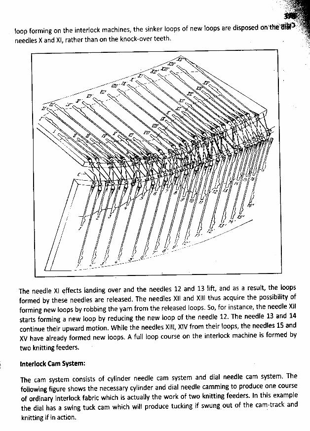
E .' . '?tj. k k .- , j. y).. . 1.) 2.-' kt ;/)' . .y- -
. .u . 1 u u . .u . u j z j .a . u j .u. ., ' .> uykjsn .j%?100: formlng On tne InterlocK macnlnes, tne SlnKer IOO9S 01 neW IOO9S 3re ulS9OSe? OD tntzqlœ- ' ',7,(ij- )j
. qj(6 ;.needles X and Xl, rather than on the knock-over teeth. ' r.
.lsj.
. . bj'
'
::
'
,.
'
T
' yzzxzJ>* *<' - - . .
z -''- .. * '*
r --,,'''-m ' -
,y'' , -, z7 - - .& e 'eDF --
- zz' -- .- J:v, -
,&rzy' > . .
xe WRZ# . xy& > . x: C x t N. I
..t** . xt . x î N. $
.F' & . . î x N&
. t x!*$
. .. - . $ N. .
x x & $ o
N. . j j . .. * j j .
. ' . . l l % '
j '' e- e e * l *I .* . '. )
* . p
j ' . ,ê . .$ zy /. z'y (œ z
. . . . 7 a zz z'.y> l
. F -' a'/
v JFJ#, y; zrtçe
, Jt <-' zv,.% '
z zv.l '1 ''z ' .-? I zz . -----''/ -.-
l g z z.....s/ . / fl e 42 --'/ j a z ..f ..'' - -' - -f '' Y -
---Y'S-'-- '- '
J % .ZL--G
> < .1r ' 4...-..-.-Z ' c <......- .v'
-.- mW
The needle XI çffects Ianding over and the needles 12 and 13 Iift, and as a result, the loopsformed by these needles are released. The needles X6l and Xl4I thus acquire the possibility offorming new loops by robbing the yarn from the released Ioops. So, for instance, the needle XIIstarts forming a new Ioop by reducing the new Ioop of the needle 12. The needle 13 and 14continue their upward motion. W hile the needles Xlll, XIV from their Ioops, the needles 15 andXV have already formed new loops. A full Ioop course on the interlock machine is formed by
two knitting feeders.
lnterlotk Cam System:
The cam system consists of cylinder needle cam system and dial needle cam system. Thefollowing figure shows the necessary cylinder and dial needle cam ming to produce one course
. J
of ordinary interlock fabric which is actually the work of two knitting feeders. ln this examplethe dial has a swing tuck cam which will produce tucking if swung out of the cam-track and
knitting if in action.
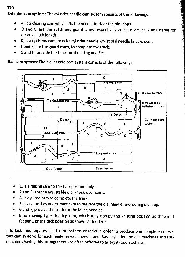
379fylinder <am system : The cylinder needle cam system consists of the followings
,
* A, is a clearing cam which lifts the needle to clear the oId Ioops.B and C, are the stitch and guard cams respectively and are vertically adjustable forvarying stitch length.
* D, is a upthrow cam, to raise cylinder needle whilst dial needle knocks over.* E and F, are the guard cams, to complete the track.* G and H, provide the track forthe idling needles.
Dial tam system: The dial needle cam system consists of the followings,
. 1 a 6.... .
' on ne je yrack1* @ 1. . c 5 .:2
4 3 Dial cam wstem
. ...; ' :àf'L.:',....
'
j c,... % .. ( Drawn on an* 5 7 2 inf inite radius)
. x. aejay
DelaY Cylinder camF B E w stem
H
f AG C D
F EB
Hon n * trK
A c D G
Odd feeder Even feeder
* 1, is a raising cam to the tuck position only.* 2 and 3, are the adjustable dial knock-over cams.
4, is a guard cam to complete the track.* 5, is an auxiliary knock-over cam to prevent the dial needle re-entering oId loop.
6 and 7, provide the track for the idling needles.8, is a swing type clearing cam, which may occupy the knitting position as shown atfeeder 1 or the tuck position as shown at feeder 2.
Interlock thus requires eight cam systems or locks in order to produce one complete course,
two cam systems for each feeder in each needle bed. Basic cylinder and dial machines and flat-machines having this arrangement are often referred to as eight-lock machines.
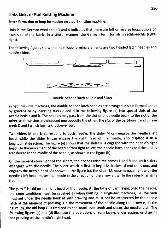
380
Links-tinks or Purl Knitting M achine
stitch formation or Ioop formation on a purl knitting machine:
Links is the German word for Ieft and it indicates that there are Ieft or reverse Ioops visible on
each side of the fabric. In a similar manner, the German term for rib is rechts-rechts (right-right).
The following figures show the main loop-forming elements are two headed Iatch needles andneedle sliders.
L)))))))))))))))))))))))))))))))))))))))))))))--------------------------''------------Double headed Iatch needle and Slider
In flat Iinks-links machines, the double headed Iatch needles are arranged in slots formed either
by grinding or by inserting tricks c and d in the following figure (a) into special slots of theneedle beds a and b. The needles may pass from the slot of one needle bed into the slot of the
other, as these slots are disposed one opposite the other. Th&ribs of the partitions c and d haveteeth D and J which form a knock-over bar.
Two sliders M and N correspond to each needfe. The slider M can engage the needle's Iefthead, while the slider N can engage the right head of the needle, and displace it in alongitudinal direction. The figure (a) shows that the slider N is engaged with the needle's righthead. On the movement of the needle from right to left, the needle Iatch opens and the loop istransferred to the middle of the needle, as shown in the figure (b).
On the forward movement of the sliders, their heads raise the bosses L and R and both slidersdisengage with the needle. The slider which is first to begin its backward motion Iowers andengages the needle head. As shown in tbe figure (c), the slider M, upon engagement with theneedle's left head, moves the needle in the direction of the arrow es while the slider N remainsfree.
The yarn Y is Iaid on the right head of the needle. At the time of yarn Iaying onto the needle,the same conditions must be satisfied as when knitting in single-bar machines, i.e. the yarnmust get under the needle hook at yarn drawing and must not be intersected by the needlelatch at the moment of pressing. On the movement of the needle along the arrow el in thefigure (d), the old Ioop O is retained by the knock-over teeth and closes the needle latch. Thefollowing figures (c) and (d) illustrate the operations of yarn laying, underlapping, or drawingand pressing on the needle's right head.
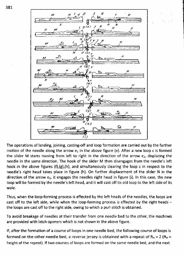
381Z zz W Z X 'M // & W
' . . .. . .. , . ..' .s . ....' . . . ' .
z .41 u w(a) J #Z 2 // a
& M
1 l &N f4Jr Y Rv
z / R NM ,a cf
N z7 rrpr* v //w! - atl tn:x z
.'...' . <..u .z c x - , ..''* .'e..' ' .z ...' z '$z7 r+Jv
Az e v &= aa c I>x z/
I ''' ' 'K N x
o (e)mz - = . s. s
d? lZ y'gy R
e,g M & K //. x a . .x. . ...... z'x . z v . ..' ,.' ..<;
z t'F7 e e+z r 3 ,f/
. y $. x .' . .v .'e ..' ' . x.$&fh)
- &+ s
1(i)
The operations of Ianding, joining, casting-off and Ioop formation are carried out by the furthermotion of the needle along the arrow el in the above figure (e). After a new loop c is formedthe slider M starts moving from Ieft to right in the direction of the arrow e2, displacing theneedle in the same direction. The hook of the slider M then disengages from the needle's Ieft
hook in the above figures (f),(g),(h), and simultaneously clearing the Ioop c in respect to theneedle's right head takes place in figure (h). On further displacement of the slider N in thedirection of the arrow ez, it engages the needles right head in figure (i). ln this case, the newloop will be formed by the needle's Ieft head, and it will cast off its oId Ioop to the Ieft side of itsjeWa .
Thus, when the loop-forming process is effected by the Ieft heads of the needlej, the Ioops aricast off to the Ieft side, while when the loop-forming process is effected by the right heads -the loops are cast off to the right side, owing to which a purl stitch is obtained.
To avoid breakage of needles at their transfer from one needle bed to the other, th'e machinejare provided with Iatch openers which is not shown in the above figure.
If, after the formation of a course of loops in one needle bed, the following course of Ioops is
formed on the other needle bed, a reverse jersey is obtained with a repeat of RH = 2 (RH ::1height of the repeat). If two courses of loops are formed on the same needle bed, and the next
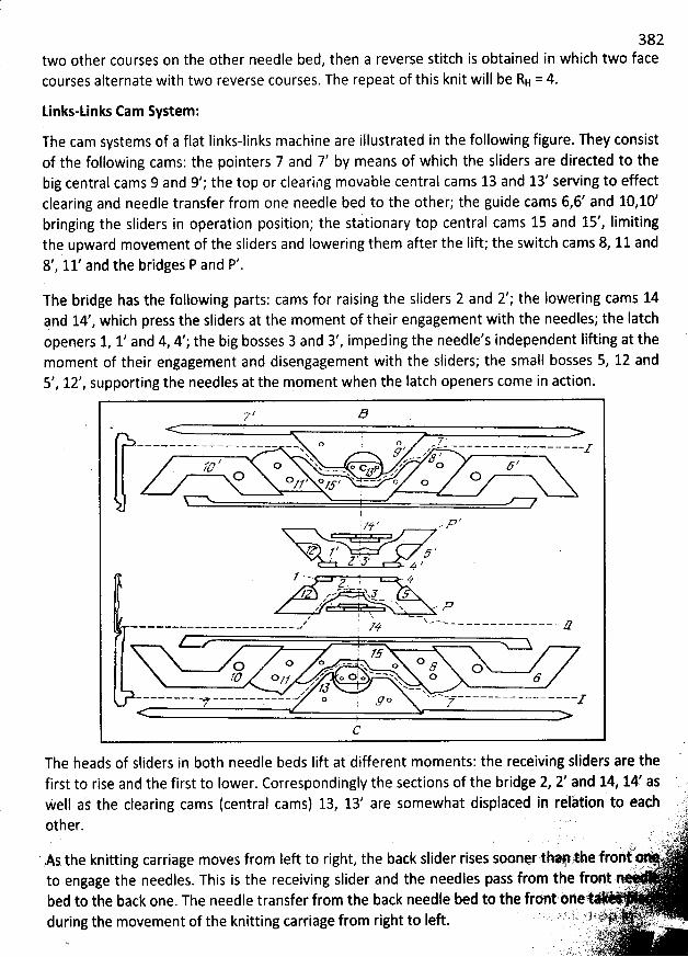
382two other courses on the other needle bed, then a reverse stitch is obtained in which two facecourses alternate with two reverse courses. The repeat of this knit will be RH = 4.
Links-unks Cam System:
The cam systems of a flat Iinks-links machine are illustrated in the following figure. They consistof the following cams: the pointers 7 and 7' by means of which the sliders are directed to thebig central cams 9 and 9'; the top or clearilng movable central cams 13 and 13' serving to effectclearing and needle transfer from one needle bed to tbe other; the guide cams 6,6' and 10,10'bringing the sliders in operation position; the stationary top central cams 15 and 15', Iimitingthe upward movement of the sliders and Iowering them after the Iift; the switch cams 8, 11 and8' 11' and the bridges P and P'.#
The bridge has the following parts: cams for raising the sliders 2 and 2'; the Iowering cams 14and 14/, which press the sliders at the moment of their engagement with the needles; the Iatchopeners 1, 1/ and 4, 4'; the big bosses 3 and 3', impeding the needle's independent Iifting at themoment of their engagement and disengagement with the sliders; the small bosses 5, 12 and5', 12', supporting the needles at the moment when the latch openers come in action.
r 57 ,
I y ,o I o m z .. - .. . . . . .. - - . . . . - - . .z-x . ' z -V z zx . .. . ty/ N ,' z4t/ o x o c z o F/ x - - - X;P zC7 * -* C7O z o J x ---// /J' O C
l. . , z:z z' ,''# .- .
y ' p=* z .1. z ' 5, 4 /
f ..--. -.jZ )
/ r-w xlz ' N pz N .'R
z 1 N < -z ' N.-w . - . - . . . - . . . - . - s$
;. /F1Fo o -- w o D(7 .-r x F (7
z o; '- -- -- w o10 o gz z o o x 6' J'J *--z N.. - F M e' ** *' v' v- '* .'- ----------- . co z z7 . r - .
C
The heads of sliders in both needle beds Iift at different moments: the receiving slidèrs are thefirst to rise and the first to Iower. Correspondingly thesections of the bridge 2, 2' and 14, 14' as. y
' gwell as the clearing cams (central cams) 13, 13 are somewhat displaced in relàtion to each ':j
Oth er. :. .è6.)..q è' XX' 1 ' 'E*
. trgjé -kr. ;, . ..As the knittina carriage moves from left to right, the back slider rises sponer ShN .'he froNi .
the needles. This is the receiving slider and the needles pass from the front n 'to engagek 1, 'rF ?rlllk'lt ' .
b d to the back one. The needle transfer from the back needle bed to the frontèhext ' ' 'e. f)tj.. .. ! . ; -. vu )e1! .
d tl f i rlg th e m OVe m e n t Of th e kn itti n g ca rri age f rom right to l eft . ''''' l i l 't) f..>#-. ' . .jj;.n ..gï . ;- ... . .. , :). , . , . .1 .
j y Ljlj.. lv hz . . ...: ,?:.y. .f: ?.. . J . ....: 1: . '... .. . .
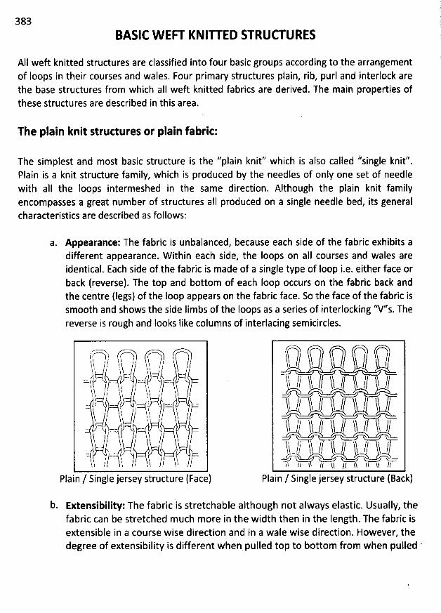
383
BASIC W EFT KNIU ED STRUW URES
AII weft knitted structures are classified into four basic groups according to the arrangementof Ioops in their courses and wales. Four primary structures plain, rib, purl and interlock arethe base structures from which aII weft knitted fabrics are derived. The main properties ofthese structures are described in this area.
The plain knit structures or plain fabric:
The simplest and most basic structure is the ''plain knit'' which is also called ''single knit''.Plain is a knit structure family, which is produced by the needles of only one set of needlewith aI1 the loops intermeshed in the same direction. Although the plain knit familyencompasses a great number of structures aII produced on a single needle bed, its generalcharacteristics are described as follows:
a. Appearante: The fabric is unbalanced, because each side of the fabric exhibits adifferent appearance. W ithin each side, the Ioops on aII courses and wales areidentical. Each side of the fabric is made of a single type of Ioop i.e. either face or
back (reverse). The top and bottom of each loop occurs on the fabric back andthe centre (Iegs) of the Ioop appears on the fabric face. So the face of the fabric issmooth and shows the side Iimbs of the Ioops as a series of interlocking ''V''s. Thereverse is rough and looks Iike columns of interlacing semicircles.
-> rh-)pltst---------'? ,;) y hsk ,, y
- O,/)ï y y yuzj --- ,--/- cn-'$ ?/ '?- 'ï
yt 'r 'yh ' 'îh ï( w....,. ..
,,,,,.,,.,,,222:22:4:'--'(1-........... ;. :::::2:::::::::::142'''. ............
'
.... ..............
'.h$.
h-- //' 'h--
- yl..,/ s . -h
''s . / /V''''''I / , , y , -plain / single jersey structure (Face)
b Extensibility: The fabric is stretchable although not always elastic. Usually, thefabric can be stretched m uch m ore in the width then in the Iength. The fabric isextensible in a course wise direction and in a wale wise direction. However, thedegree of extensibility is different when pulled top to bottom from when pulled '
$-) )..
ê
lmh , ' / h ,.-x y--xy / / / y-xq / /y Y Y Y
ïï 11 yy // ls---/t-ir-----'ïï / h-----tîï /-
f / / y / / yy 7--ù)-V'r-4-7 , k-t ),-s vut >-
Plain / Single jersey strudure (Back)
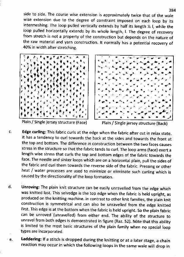
384side to side. The course wise extension is appfoximately twice that of the walewise extension due to the degree of constraint imposed on each Ioop by itsintermeshing. The Ioop pulled vertically extends by half its Iength X 1
, while theloop pulled horizontally extends by its whole length
, 1. The degree of recoveryfrom stretch is not a property of the construction but depends on the nature ofthe raw material and yarn construction. It normally has a potential recovery of40% in width after stretching.
r' j / # # #' # * y' N 4 ' * *t 4 .k #) f . . a k, j ,. . . x. v q, * . # : * $ v' #. + , 7 p 4ç ..# , j j , 4 4 4 4 ( y 4
' ? , . jl # !. . i . . .# t' . x t # j 4, . 4 w
, . .t v' t * ' > , # k ) J . 4 # * .# / 4 t 4 ' t,i f t .-. ,y j t . j y' t'
4 '* 4 j : # : t + j At j &' k > # . # $ : j t w t. ; j
. j # 4?' . . t i #. ,,. 4 4 jf v ' 4 # v 4 s # , t j . 4, #
. # .t 4 ft , , . x 8 A . j # j t t. * ( k
4 44 $ . . # j. 4' # #k k . # ! ! ! # . # $6 # '. #r : i t. è, t, # 4 t 4# k t #: / # f #' ' v 4. < ,z # . #. w, xë k
Plain / Single jersey structure (Face)
Edge curling: This fabric curls at the edge when the fabric after cut in relax state.
lt has a tendency to curl towards the back at the sides and towards the front atthe top and bottom. The difference in construction between the two faces causesstress in the stiucture so that the fabric tends to curl. The Ioop arms (face) exert aIength wise stress that curls the top and bottom edges of the fabric towards theface. The needle and sinker Ioops which are on a horizontal plain
, pull the sides ofthe fabric and curl them towards the reverse side of the fabric
. Pressing or otherheat / water processes are used to minimize or eliminate such curling which iscaused by the directionality of the Ioop formation.
* >' v w + v +* *è :, x v . w. A, w # +Ijj't x +''' '. .2 . $eY * + e 'y
z ' # y'< ' A$ + A A < # ##v 1 . . .v. yv vw v m <
X' > + w. x. w. ... k < ..- .,+$' #. e
' p' # .z,> + p *'4 K- A & #;- ., *. A K. # *. u e#@ < 4* +' @ + < .g <- X V Y A. # h *. # A'4 . v. . . g .e # k
4 x 4> *: * *y > ,y . ee' 1 *' # + #'. e < # *
kv .* .s * ',< . < x Kx #' ' a Ae' v <' W A'' XV# #. v 4: 4r *A >' .' .>. k A ' 1+ * .k *.v
.w* . - + M e. r # +'z, ,*k xA;W .. à. A. k. . K. ..4 .. ,, .y +. .$.6 y.s +. wx e' Ns j*.. $y. w .. jJ; A # ev *: % + JW * ' <
r < # e s r + f' *. x x w j-. * *. y- w * u -.
Plain / Single jersey structure (Back)
d. Unroving: The plain knit structure can be easily unravelled from the edge whichwas knitted Iast. This selvedge is the top edge when the fabric is held upright
, asproduced on the knitting machine. ln contrast to other knit families, the plain knitconstruction is symmetrical and can also be unravelled from the edge knittedfirst. This edge is at the bottom when the fabric is held upright
. So the plain fabriccan be unroved (unravelled) from either end. The ability of the structure tounravel from both edges is demonstrated in figure (Raz. 52). Nite that this abilityis limited to the most basic structures of the plain family when no special Sooptypes are incorporated.
e. Laddering: If a stitch is dropped during the knitting or at a later stage, a chain
reaction may occur in which the following Ioops in the sam, wale will drop in
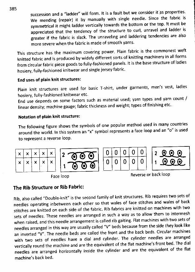
385succession and a ''Iadder'' wiil form . It is a fault but we consider it'ps properties.We mending (repair) it by manually with single needle. Since the fabric issymmetrical it might ladder vertically towards the bottom or the top. lt must beappreciated that the tendency of the structure to curl, unravel and Iadder isgreater if the fabric is slack. The unraveling and Iaddering tendencies are also
more severe when the fabric is made of smooth yarns.
This structure has the maximum covering power. Plain fabric is tbe commonest weftknitted fabric and is produced by widely different sorts of knitting machinery in aII formsfrom circular fabric piece goods to fully-fashioned panels. It is the base structure of ladies
hosiery, fully-fashioned knitwear and single jersey fabric.
End uses of plain knit structures:
Plain knit structures are used for basic T-shirt under garments, men's vest, Iadies
hosiery, fuljy-fashioned knitwear etc.End use depends on some factors such as material used; yarn types and yarn count /linear density; machine gauge; fabric thickness and weight; types of finishing etc.
Notation of plain knit structure:
The following figure shows the symbols of one popular method used in many countriesaround the world. In this system an ''x'' symbol represents a face loop and an '/0'/ is used
to represent a reverse loop.
X X X X X 2 * * *x X X X X
1 * * *
Face loop
0 0 0 0 0 2 0. 0. o.0 0 0 0 0 1 -O. 0. 0.
. - .- .e
Reverse or backloop
The Rib Structure or Rib Fabric:
Rib, also calledneedles Operating
''Double-knit'' is the second family of knit structures. Rib requiresinbetween each other so that walesof face stitches and wales of back
stitches are knitted onsets of needles.when raised,needles arranged in this way are usually calledan inverted ''V'' The needle beds are called the front and the back beds. Circular machineswith two sets of needles have a dial and cylinder. The cylinder needles are arrangedvertically round the machine and are the equivalent of the flat machine's front bed. The dialneedles are arranged horizontally inside the cylinder and are the equivalent of the flat
machines with twoeach side of the fabric. Rib fabrits are knitted onin such aThese needles are arrahged W3Y aSto allow them to intermesh
Flat machines withand this needle arrangement is called rib gaiting. two sets of''V'' beds because from the side they Iook Iike
two sets of
machine's back bed.
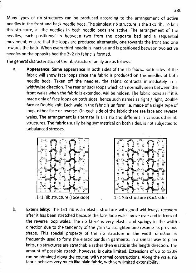
386
Many types of rib structures can be produced according to the arrangement of activeneedles in the front and back needle beds. The simplest rib structure is the 1x1 rib. To knitthis structure, aII the needles in both needle beds are active. The arrangement of theneedles, each positioned in between two from the opposite bed and a sequentialmovement, ensure that the Ioops are produced alternately, one towards the front and onetowards the back. W hen every third needle is inactive and is positioned between two activeneedles on the opposite bed the 2x2 rib fabric is formed.
The general characteristics of the rib structure family are as follows:
a. Appearante: Same appearance in both sides of the rib fabric. 80th sides of thefabric will show face loops since the fabric is produced on the needles of bothneedle beds. Taken off the needles, the fabric contracts immediately in awidthwise direction. The rear or back Ioops which can normally seen between thefront wales when the fabric is extended, will be hidden. The fabric Iooks as if it ismade only of face Ioops on both sides, hence such names as right / right, Doubleface or Double knit. Each wale in the fabric is uniform i.e. made of a single type ofIoop, either face or reverse. On each side of the fabric there are face and reversewales. The arrangement is alternate in 1x1 rib and different in various other ribstructures. The fabric usually being symmetrical on both sides, is not subjected tounbalanced stresses.
f-7l roh tr-''o)h t. / l - j t j/ ; d
-l :6 ,/. t ?/y-
/ a 4 .-.. - ï : .
..y:c-)). .. qj /)=- -k j j j j j. ))$, - -, ,- yjs $j::-a- tt jj;,-- h-- , /-'tr-$ , k .y . ,%sz:::$4 , .
.., ! y 3.,.( . ! ) ;'')i îh;::a//?. '11k lL h; y'Il
s
i k!li' . '' -s-
'
,, jr--- ,-gj j ,,-k. . .t; - . --kr. :::::t , ...R . /î î )' ,? $8 h /' , !1'.,4!. /!k' 1. :. / i!ï yccy/s y; ,, '
,..F4tC. 1, . .):R .u:? . , i- $ a .( =
!ï
'
/!' ' l ï // !l, ii. .,t . ,,. ,;t ; j: ?/cc?'p-%?)
, $)JDl,-)- ' -4-777t),cc:ï. . ? !11- /k '.. ks f ' /k! ! . ë .
1x1 Rib structure (Face side)
r?=--2) f (-'=V ' !:-:7--$h- / , i) :.t j,,ï ! ï
'
lj j
'
y -y , yl ï, i , yu- v' ' -(ï! (l( . ïh vj1 ? Lytv-jl/-a X
r-,o.:-r/ ? , : $, ?'!.'h...- )/ hs ,/ lk ï
. J z % y'h. // î) // y //
-n' E , V-h.h 11 ) yy /z-t.>Q wTl. 1l' , I . ï
'
ï //
1x1 Rib structure (Back side)
Extensibility: The 1x1 rib is an elastic structure with good widthways recoveryafter it has been stretched because the face loop wales move over and in front ofthe reverse Ioop wales. The rib fabric is very elastic and springy in the widthdirection due to the tendency of the yarn to straighten and resume its previousshape. This special property of the rib structure in the width direction isfrequently used to form the elastic bands in garments. In a similar way to plainknits, rib structures are stretchable rather then elastic in the length direction. Theamount of possible stretch, however, is quite Iim'ited. Extensions of up to 120%can be obtained along the course, with normal constructions. Along the wale, ribfabric behaves very much Iike plain fabric, with very Iimited extensibility.
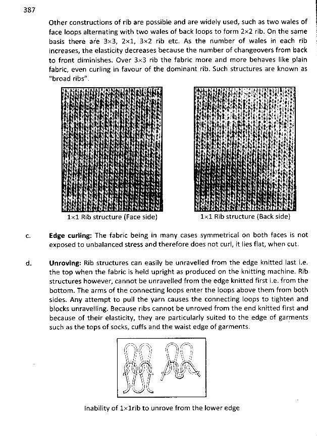
387
Other constructions of rib are possible and are widely used, such as two wales offace loops alternating with two wales of back Ioops to form 2x2 rib. On the samebasis there a/e 3x3, 2x1, 3x2 rib etc. As the number of wales in each ribincreases, the elasticity decreases because the num ber of changeovers from backto front dim inishes. Over 3x3 rib the fabric more and more behaves Iike plainfabric, even curling in favour of the dominant rib. Such structures are known as''broad ribs''
àj , A. . . . x .t
'ji .j .. k
g #.
. . , . . . . j
#
1x1 Rib structure (Face side)
'
. -.t112,''1!'.. ,. .- . .-...
,jjjkr,(1I2'';,''tj-.. ,-.F'-8;---6;,?. -''--',.'--!tj,,
''C'-lsy 1ii-..-''-. ..-'''''-', ''ii-.''- ---1-;: t1Iit.'. ik- liIië7--' --'. .-!1,.--,,.- . . ;''''kè(,!-. yhf-t!r ---1--,j,,'--1'9.. .-,,;. 11t:.,,,,-. ..-;. .1 .j m. j j , .j k j #i ). j # y. . y # j
. .. 4 y!., j' ! @.t.. ' # j! )j jjj ., ' ,;, .jy' . .
. z.: t. . -. t #.; w ' r , ) y-t j4j #j' ' .h' 1' ,', j ,1 ;'j.
'
' t. ! #' ï .# v t ') j ). - jl î'.('.. . r. , 1. j4 .j ) j j' ;! ' : ''--rw . j i j ' ., - ï1 * i . :, j a,.. , !. ' . -p y )j . j +. ;'! .f . P y. 1.4 t m 2*.) e?i. ,.
. j xj . -. . .j?. #, 4,.,'. , . ,k-
.
. ..-!i-.- .
'
. :f,. .,!k -,1i''' idIl;:k--... . ,,3tïL.. .., 411,-.-. tii llllk-.' ):. $1,1. ..' .
'j# ).-' û . : ) èj 4 , i . xy1r''''j;x '1lj'y 6 jj.'h't r'
. . *-?!' ' . 1r . pik jj''j- . 'jrh! J'jjyj'.-ï, 7$'. jiyj.'1l 'j . ' . ...
- yj Aj yjty y.l' 4, f u ,13 1 . .
. . .
.j .js ),' q. . . . j... xI
. . ' . . ' i '
1x1 Rib structure (Back side)
Edge curling: The fabric being in many cases symmetrical on b0th faces is notexposed to unbalanced stress and therefore does not curl, it Iies flat, when cut.
d. Unroving: Rib structures can easily be unravelled from the edge knitted Iast i.e.the top when the fabric is held upright as produced on the knitting machine. Ribstructures however, cannot be unravelled from the edge knitted first i.e. from thebottom . The arms of the connecting Ioops enter the Ioops above them from bothsides. Any attempt to pull the yarn causes the connecting Ioops to tighten andblocks unraveiling. Because ribs cannot be unroved from the end knitted first andbecause of their elasticity, they are particularly suited to the edge of garmentssuch as the tops of socks, cuffs and the waist edge of garments.
,------------
; .,------'r-------.ï----)à (----------.----------, ) k-'iîî-'--ïï--bq ) ,7--'V./ h-y ,/-, -
,/-// h---'- ,, ,?!
: h l 'r/ ' %$ ;;t .
/' 'i . '''' hj f' 'jlç k-
y '. )$U u
lnability of lxlrib to unrove from the Iower edge
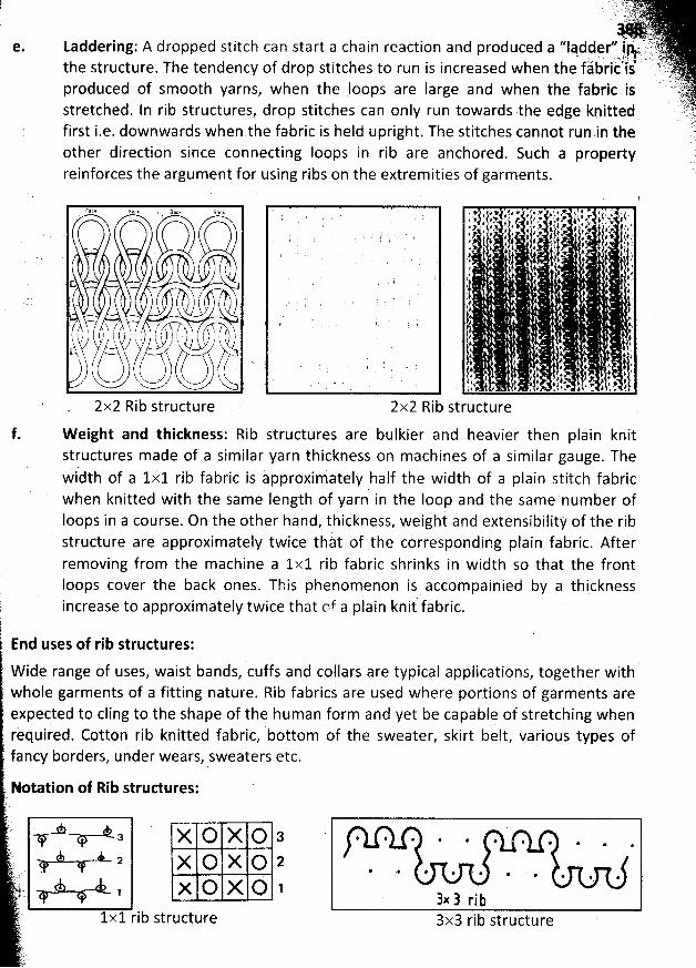
e.
: , q.k . t;(yy -,,.. . ,j,. jjjyj )( , ,tyJ' .. .- ii'iq'qjk. (t.-.:.Laddering: A dropped stitch can start a chain reaction and produced a ''ladder'' iWt. ttk. r'
, . . .. - ; ;; j r. .:. . . . , ;the structure
. The tendency of drop stitches to run is increased when the fàbrit ls 'igt. (. jkproduced of smooth yarns, when the loops are Iarge and when the fabric is: ' )#
jyjstretched. In rib structures, drop stitches can only run towards the edge knitted .!:.jL r
'
first i.e. downwards when the fabric is held upright. The stitches cannot run,in the 'cother direction since connecting loops in rib are anchored. Such a propertyreinforces the argument for using ribs on the extrem ities of garments.
2x2 Rib structureg. '' . .'
2x2 Rib structure
and heavier thenW eight and thickness: Rib structures are bulkier plain knitstructures made of a similar yarn thickness on machines of a sim ilar gauge. Thewidth of a 1xl rib fabricis appr:ximately half the width of a plain stitch fabricwhen knitted with the same Ièngth of yarn in the Ioop and the sam e num ber ofIoops in a course. On the other hand, thickness, weighi and extensibility of the ribstructure are approximately twice thàt of the correspohding plain fabric. Afterremoving from the machine a 1x1 rib fabric shrinks in width so that the frontIoops cover the back ones. This phenomenon is accompainied by a thickness
) : .increase to approximately twice that tnf a plain knit fabric.t4End uses of rib structures:
W ide range of uses, waist bands, cuffs and collars are typical applications, together withwhole garments of a fitting nature. Rib fabrics are used where portions of garments areexpected to cling to the shape of the human form and yet be capable of stretching whenrequired. Cotton rib knitted fabric, bottom of the sweater, skirt belt, various types offancy borders, under wears, sweaters etc.
? Notation of Rib structures:
'f .a X O X O 3 . . . . ' . . . . .ïq.
rL p x o g o pJt . . . . . .. . . . . . . .)j ' - *.
j.. , x O X Q 1 s ) rjj(.
.) 1x1 rib structùre 3x3 rib structure
tfz
f.
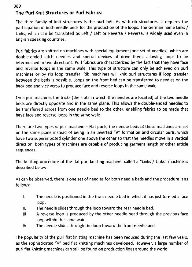
!389 JjThe Purl Knit Structures or Purl Fabrics: q(
The third family of knit structures is the purl knit. As with rib structures, it requires the 1participation of both needle beds for the production of the Ioops. The German name Links / 'Links, which can be translated as Left / Left or Reverse / Reverse, is widely used even inEnglish speaking countries.
Purl fabrics are knitted on machines with special equipment (one set of needles), which aredouble-ended latch needles and special devices of drive them, allowing Ioops to beintermeshed in two directions. Purl fabrics are characterized by the fact that they have faceand reverse Ioops in the same wale. This type of structure can only be achieved on purlmachines or by rib loop transfer. Rib machines will knit purl structures if Ioop transferbetween the beds is possible. Loops on the front bed can be transferred to needles on theback bed and vice versa to produce iace and reverse Ioops in the same wale.
On a purl machine, the tricks (the slots in which the needles are Iocated) of the two needlebeds are directly opposite and in the same plane. This allows the double-ended needles tobe transferred across from one needle bed to the other, enabling fabrics to be made thathave face and reverse loops in the same wale.
There are two types of purl machine - Flat purls, the needle beds of these machines are seton the same plane instead of being in an inverted ''V'' formation and circular purls, whichhave two superimposed cylinder one above the other so that the needles move in a verticaldirection, both types of machines are capable of producing garment Iength or other articlesequences.
The knitting procedure of the flat purl knitting machine, called a ''Links / Links'' machine isdescribed below:
As can be observed, there is one set of needles for both needle beds and the procedure is asfollows:
The needle is positioned in the front needle bed in which it has just formed a faceIoop.The needle slides through the Ioop toward the rear needle bed.A reverse Ioop is produced by the other needle head through the previous faceIoop within the same wale.The needle slides through the Ioop toward the front needle bed.
The popularity of the purl flat knitting machine has been reduced during the last few years,as the sophisticated ''V'' bed flat knitting machines developed. However, a Iarge number ofpurl flat knitting machines can still be found on production Iines around the world.
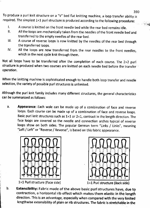
390To produce a purl knit structure on a ''V'' bed flat knitting machine
, a loop transfer ability isrequired. The simplest 1x1 purl structure is produced according to the following procedure:
A course is knitted on the front needle bed while the rear bed remains idle.
AIl the loops are mechanically taken from the needles of the front needle bed andtransferred to the empty needles of the rear bed.
111. A course of reverse loops is now knitted by the needles of the rear bed throughthe trpnsferred loops.
IV. AII the Ioops are now transferred from the rear needles to the front needles,
which in the next cycle knit through them.
Not all Ioops have to be transferred after the completion of each course. The 2x2 purl
structure is produced when two courses are knitted on each needle bed before the transferoperation.
W hen the knitting machine is sophisticated enough to handle both Ioop transfer and needleselection, the variety of possible purl structures is unlimited
.
Although the purl knit family includes many different structures, the general characteristics
can be summarized as follows:
a. Appearance: Each wale can be made up of a combination of face and reverseIoops. Each course can be made up of a combination of face and reverse Ioops
.
Basic purl knit structures such as 1x1 or 2x1, contract in the Iength direction. The
face loops are covered so the needle and connection arches typical of reverseIoops show on both sides. The popular German term ''Links / Links'' meaning''Left / Left'' or ''Reverse / Reverse'' is based on this fabric appearance.l
b.
/ . y
k- . = =
n <
1 11 lt // Sï // !$ 11 ïà 11
1x1 Purl structure (Face side)
Extensibiliw : Fabric made of the above basic purl strucfures have, due tocontraction, a horizontal rib elect which makvs them elastic ih iàk lengt-hdiredion. This is an advantage
, especially when com pared with the very lim itedIengthwise extensibility of plain or rib strudures. The fabrit iststrétcliible in 1he
1x1 Purl structure (Back side)
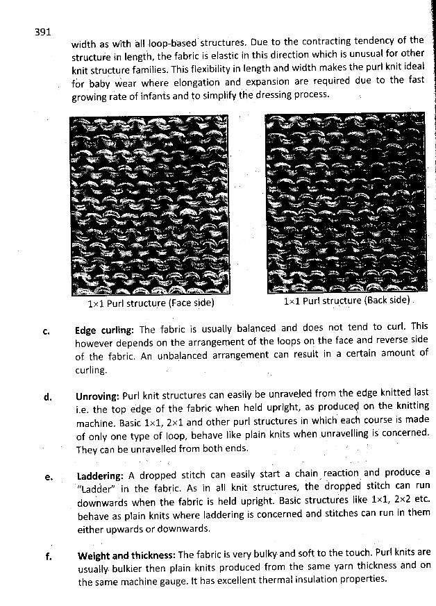
391width as with aII Ioop-based structures. Due to the contracting tendency of thestruciuie ii Iength, the fabric is elastic in this direction which is unusual for otherknit struçture families. This flexibility in length and width makes the purl knit ideal
, '
fàr baby wear where elongation and expansion are required due to the fastjgrowing rate of infants and to simplify t q dressing process.
I.X 1 PU rl Strudufe (FaCe Side)
' . .se . >
. . m . <
. . ;; . '
. 'A*P*hEFnw''
1x1 Purl strqcture (Back side)
ç. Edge curling: The fabric is usually balanced and does not tend to curl. Thishowever depends on the arrangement of the loops on the face and reverse sideof the fabric. An unbalanced arrangement can resuit in a certain amount ofcurling.
d. Unroving: Purl knit structures can easiiy be unraveled frpm the edge knitted Iasti.e. the top edge of the fabric when held upright, as producet on the knitting
hich' each course is mademachine. Basic lxl, 2x1 and other purl structures in w
of only one type of Ioop, behave like plain knits when .unravelliqg is concerned.They can be upravelled from both ends. l '
Laddering: A dropped stitch can easily start a chain reaction 9nd produce a''Ladéer'' in the fabric. As in all knit structures, the' àroppeé stitch can rundownwards when the fabric is held upright. Basic strudures Iike lxl, 2x2 etc.behave as plain knits wbere laddering is concerned and stitches can run in them
either upwards or downwards.
e.
f. W eight and thickness: The fabric is very bulky and soft to the touch. Purl knits arevsually' bulkier then plain knits produced from the same yarn thickness and onthe same machine gauge. lt has excellent thermal insulation properties.
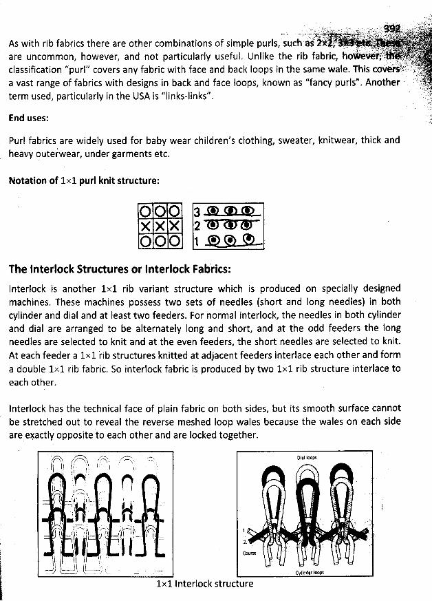
- . . . ,$()) f;'.i. '
. . . .' j. . t ' ' ' . . ' tjy 1j( 1) wtk ;( .t. ' . u . . tqiyw u v . ..; / yy jg. juyy t. jq yqyyjjjlLj'h y ).' 2..' .;.-- . ,. .:gr.
,v yaij , jqjyyy.. . > J y, oyyq. y....,jjy --.i;j y.., . ; s.rj.jjkg,u . (4. .ày yjjj .As with rib fabrics there are other combinations of simple purls, such a<- )-'' ' . '
y.:. . . yk. . t . ..1 0( kpyttya yyyxz grjjyj;jy ..' .t : '. r . . yare uncom mon
, however, and not particularly useful. Unlike the rib fabric, hoWév*riq. . . rr.v$k,:.'. : L ': . J' qjgjt .#.êt z
'
z ''7 ik %'Q-,', t-. ;? .t .classification purl covers any fabric with face and back Ioops in the same wale. This cbvetkbt/.. ,9,,k;ji ' 43f fabrics with designs in back and face Ioops, known as ''fancy purlf'. Another '''i ''' 'a Vast range O yj
j' -jterm used, particularly in the USA is ''Iinks-linkf'. ..Xë. ).
'
. , '''
'
. .
'
JE,((
'
.
'
. . .: .
End uses:
Purl fabrics are widely used for baby wear children's clothing, sweater, knitwear, thick andheavy outer'wear, under garments etc.
Notation of 1x1 purl knit structure:
O O O 3 * * *x x X 2*O O O 1* W * -
The Interlock Structures or Interlock Fab'rics:
Interlock is another 1x1 rib variant structure which is produced on specially designedmachines. These machines possess two sets of needles (short and Iong needles) in bothcylinder and dial and at Ieast two feeders. For normal interlock, the needles in both cylinderand dial are arranged to be alternately long and short, and at the odd feeders the longneedles are selected to knit and at the even feeders, the short needles are selected to knit.At each feeder a 1x1 rib structures knitted at adjacent feeders interlace each other and forma double 1x1 rib fabric. So interlock fabric ls produced by two 1x1 rib structure interlace toeach other.
Interlock has the technical face of plain fabric on both sides, but its smooth surface cannotbe stretched out to reveal the reverse meshed Ioop wales because the wales on each sideare eyactly opposite to each other and are Iocked together.
'
/J;7:))h .,::::ï;)ts. zri::ls. , -r7t ?-.t ! 1 -) #
'
#' . '' )
'
( r p r tI
' j l , ;lhn r l
' . ill!' '' ;
'
.
'
é
'
' '
'
t l ) ? ' .. .' ) T'.7Q k .' ' . .
. . , j ., r j j . . y i , . .. U:i ! : 4 i 7-
, rs -j à . . . j ,,, .'
h :s . : ..y.k , - -- i' ; , ,sj- r,) j )p7, / $ fc-?)?)
.- ..-.. =j! h-l-, jdlj;h?- . ,',, . !1Ii- jlllr q''hk ',$ j/' l'. 1
-?r l-
à. ''.
:::g) ,. i, ,!
.u uus.
1x1 Interlockstructure
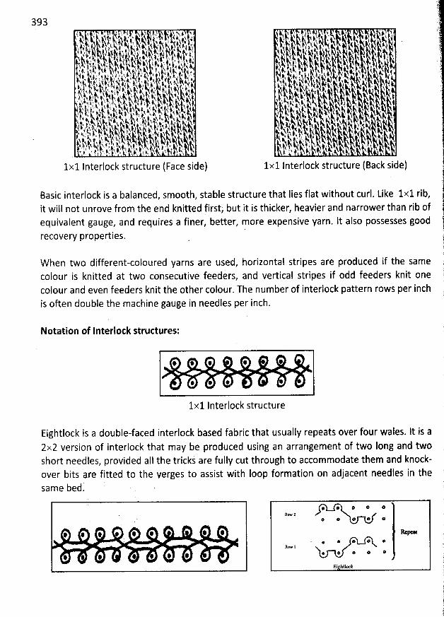
393. ,j . . .! - ; . $ . .xj j, i! , ; , #. .k-p jtj . j ,, . .j, jjlyk qjyK , a, y , j) , ,
. a
, s, qj j jj jj t.. tj. . #,, ., . tsty,q,, yqt, j, zj, jsjyjty ,k x'# '$ tj-r jj y .5 , j q, q . j,. j,. y jq j.+jjwtvt,tjj., ,.k, j , A.j, . nq y,.k ., j, y; yjyt .tkk i .. lk 4 # 'jij # ' j 4 . . j j.q !., kjt-l t.,, 8,4 ''.qkî,#)N. t; s.q. i ) kyjk, - y tt::
. zs K. j k'As . Sst t.''j f, tt iz, (.j . j..,,' .. jo t ,, N'u, k, Nj,, #.Nkt N, j #.yxt yyi. ) t. r , :. vsjj .q,, k ANA ,q, , .N.qqfq. .. fqisjyt, k%) . y, j rjsj ,j ,,j. j> t..jlA. ', .t.k,.q, jjpf j
,$ j ,, !t y. , qj. q f , .q t. k, t,.4t , ,, wp jk $ . $, ..N.h kj q'A # 4.4 )1 ' j! ?N jt . aj # ; . jj y w, yy y a, Nj-.:.#-
,,.-?.,x...t-x- .ttj-q.!k r , . ,.,.,, ., .). q .''.k '.
,,h 't 't,,. h, qs- '
), 7). )..- ). kpyjj ',,. -(,. 'k,,, ) , )y' ->,j., 'y ,.q# ,, . , jt ,. jt.k,, .R ': i
.' 'ï ) $ $.. i x . j. .), ..4 . .. q.
1,
1x1 lnterlock structure (Face side)
Basic interlock is a balanced, smooth, stable structure that lies flat without curl. Like 1x1 rib,it will not unrove from the end knitted first, but it is thicker, heavier and narrower than rib ofequivalent gauge, and requires a finer, better, more expensive yarn. It also possesses goodrecovery properties.
'i ' . jt CE 44 '!, ., j' .$kk.'t)!.'çiky- $' ' . i ''', ts' kk- ,,--. .
'
-k<.. 'k-,--- ,;t:-.. 1k(l-..-- '--k.k,--- liïlr ë-' '-'.kt,t- lk--, . !ij@@,- !kg-:k,. è- ' i -.
, 'kl,k-l k:lt :L!;7,j 1.,1 'Ikk,)k
j ,kqk!- jj, .!i:qj,t!li'' .-jjk, -- -.k,j'''-kjkj-
,lji2 . .k;pz'' jgh;- '' dtj:yj , 4-tk'- .#.k
.tt,k kf ,f( )
, ïkkj ,j,,.t. jqjs k ,, (j, .$jq,-,t,sjt..tkj,l jjyyj,; y , .j, 11!;
.12k. -- !:;t) .'-;t.L,-. . !lëy. - ,ê,k.,,:.,y-k... ,-.,-il 1,,1--, ,,,--- rysy ,k,,- ,-,., j---.,,, jjrjj. y
-''' 'è'ï,blL
-
'-bi3t);,-à-)-,b,i
3- '''r
jk,j,-
-.
,
!)j:,y),, .-
y
'--'
-'kkjk,y:t'$;.
.!$g!t,,
..!$rL-,t
-
--'r!jjjj!kpk-. ,y,?iht-. '!k2$y- - jkj--: -!k:, !1)k,-k, ,kkj-,k-'tl.1x1 lnterlock structure (Back side)
W hen two different-coloured yarns are used, horizontal stripes are produced if the samecolour is knitted at two consecutive feeders, and vertical stripes if odd feeders knit onecolour and even feeders knit the other colour. The number of interlock pattern rows per inchis often double the machine gauge in needles per inch.
Notation of Interlock structures:
@ * @ * @ @
@ @ * @
1x1 Interlock structure
Eightlock is a double-faced interlock based fabric that usually repeats over four wales. lt is a2x2 version of interlock that may be produced using an arrangement of two Iong and twoshort needles, provided aIl the trickj are fully cut through to accommodate them and knock-over bits are fitted to the verges to assist with Ioop formation on adjacent needles in thesame bed.
# # , # # : # @
# # # ' '
@ @ @ @ *
@ @ * * @
' @ * @ @ *
* @ * @ *
Ei htlock
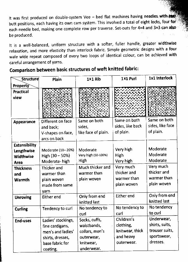
. ;. . ).)q tj;.J . tgd . .
. ' r'' C '
.lyytj,yIt was first produced on double-system Vee - bed flat machines having needlesr Ath3*' -*:1):
butt positions, each having its own cam system. This involved a total of eight Iocks, four for î ,'yF'j; yeach needle bed, making one complete row per traverse. Set-outs for 4x4 and 3x3.can' #!n urhj. ' '.. . ; .jjy. :!be produced. )
It is a well-balanced, uniform structure with a softer, fuller handle, greater widthwiserelaxation, and more elasticity than interlock fabric. Simple geometric designs with a fourwale wide repeat composed of every two loops of identical colour, can be achieved with
careful arrangement of yarns.
Comparison between basit structures of weft knitted fabric:
Struttur plain 1x1 Rib - 1x1 Purl 1x1 lnterlotk
PropertyPractical t 't ' h ' !' ' * # i ' iy è..*è(.. .'N e f $ * i .
i'yl 1p1'1,' .ijjkk jr j. lp sjwkjCksj >..h<&>x.4,..v :$,$.ï 11 tlp ' j. ktview j , :# y,ljjjlti,tiyrt ky j jsijjj; ,.4: r s-t-srx-x--rt.ktk4k. < .,.n k; ) yrjj j, : ,;t k j -ityjl, ) y p) :;.,tt.k):' kvvk -sesr--Axd. ))$t v'lji ),) 1t.),)t
: l-lil:-t:tt:ij ;.; j) ; t1;i)-,t:$j:,,j.;'; xieev--k.,su---ax--:-r'-o.oa j#:; t,.!:-,-:.).,-tj, jj.i' , i'. :$4.1.9 i1.t.' -),.,, . k. ,/2,:,,, t .,f,,:- ..,: ...,... ..p.xo....k.sx. ,:. 4). :# # ;t.t (, ,, ,$ : l
Appearance Different on face Same on both Same on both Same on bothand back; sides, sides, Iike back sides, Iike faceV-shapes on face, like face of plain. of plain. of plain.
arcs on backExtensibilitytengthwise Moderate (10- 20%) Moderate Very bigh ModerateWidthwise High (30 - 50%) Vew high (50-100%) High ModerateArea Moderate- high High vew high ModerateThickness Thicker and M uch thicker and Very much Very muchand warmer than warmer than thicker and thicker andWarmth plain woven pfain woven warmer than warmer than
made from same plain woven plain woven
yarnUnfoving Either end Only from end Either end Only from end
knitted Iast knitted lastCurling Tendency to curl No tendency to No tendency to No tendency
curl curl to curlEnd-uses Ladies' stockings, Socks, cuffs, Children's Underwear,
fine cardigans, waistbands, clothing, shirts, suits,men's and ladies' collars, men's knitwear, thick trouser suits,shirts, dresses, outerwear, and heavy sportswear,base fabric for knitwear, outerwear. dresses.coating. underwear.
395
ldentifieation of Single jersey and Double jersey fabric:
Weft knitted fabrics may be approximately divided into single or double jersey (double-knit)according to whether they were knitted with one or two sets of needles.
Single jersey fabrics have the following features -
AIl face Ioops are in one side and alI back loops are in other side.* Both sides are should be different appearance.
Double jersey fabrics have the following features -
* Both sides of the fabric contain only face loops (basic rib and interlock fab/ics) or onlyback loops (basic purl fabri.c) or combination of face and back Ioops.
* Both sites are same appearance for basic and balanced structure, but different onother structures.
BASIC LOOP OR STIK H TYPES
. ..'!vy. .j.s.k ;,2tr. r'.z.i.*-'
i . 2 ' . , ..!. .. r t .. ..!j,:. .. sqg.. . / /:.,E9'. y. j,. .. . . . . s ou-. jr.v 0. ..y, .. , ... . . . l.j. * v:k.'..f. s * 1 ''> . . .,,V
. ',.#
' : .' ='.#' 7r
t : . ..'
troduced as elhgl nAs mentioned in the previous chapter, the basic structure famifies wereconstructed of only one type of knitted Ioop. In reality however, most knitted strudurescontain, in addition to the standard knit Ioops. The standard loop is a flexible formationr caneasily change its shape under small Ioads and is responsible for the strètchabte
characteristics of the fabric.
A knitted loop stitch is produced when at each yarn feed, a needle receives a new loop andknocks-over the oId Ioop which is held from the previous knitting cycle, so that the oId loop
now becomes a needle loop of ndrrhal configuration.
Other types of stitch may be produced on each of the four needle arrangement basestructures by varying the timing of the intermeshing sequence ot the old and new Ioops.These stitches may be deliberptely selected as part of the design of. the weft and warpknitted structure or they may be produced accidentally by a malfunction of the knitting
action so that they occur as fabric faults.
W hen these stitches are deliberately selected, a preponderance of knitted Ioop stitches isnecessary within the structure in order to maintain its requisite physical properties. Apartfrom the knitted Ioop stitch, the two most commonly-produced stitches are the float or missstitch and the tuck stitch. Each is produced with a 'held loop' and shows its own particularIoop most clearly on the reverse side of the stitch as the Iimbs of the held loop cover it from
view on the face. ' -
To simplify explanations, a1I knit structure families were described as being made only ofbasic loops. In reality however, other loop types exist which, together with the simple one,combine to enhance the patterning potential and the variet'y of knitted garments.
The held Ioop:
A held ioop is an old knit loop which the needle has retained and not released and knocked-ov:r at the next yarn feed. A held loop can only be retained by a needle for a llmitèd nulberof knitting cycles before it is cast-off and a new loop drawn thrèùgh, ètherwis: the tensionon the yarn in the loop becomes excessive even though there is a tehdencylo rob extra yarn
fröm adjarent loops in the same course. ' '
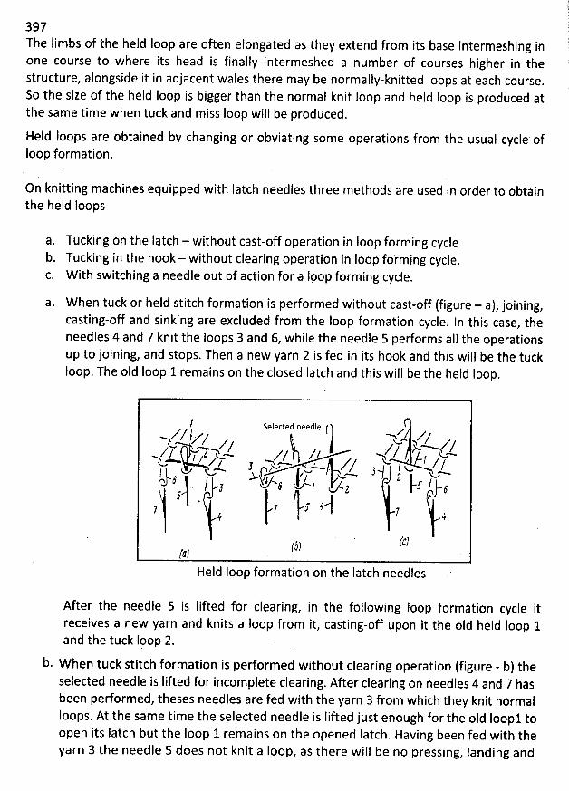
11397 1
The Iimbs of the held Ioop are often elongated as they extend from its base intermeshing in rone course to where its head is finally intermeshed a number of courses higher in the h
structure, alongside it in adjacent wales there may be normally-knitted Ioops at each course. !ESo the size of the held Ioop is bigger than the normal knit loop and held Ioop is produced at
the same time when tuck and miss loop will be produced.
Held Ioops are obtained by changing or obviating some operations from the usual cycle ofloop formation.
On knitting machines equipped with Iatch needles three methods are used in order to obtainthe held Ioops
a. Tucking on the Iatch - without cast-off operation in Ioop form ing cycleb. Tucking in the hook - without clearing operation in Ioop forming cycle.
W ith switching a needle out of action for a Ipop forming cycle.
a. When tuck or held stitch formation is performed without cast-off (figure - a), joining,casting-off and sinking are excluded from the Ioop formation cycle. In this case, theneedles 4 and 7 knit the loops 3 and 6, while the needle 5 pedorms aIl the operationsup to joining, and stops. Then a new yarn 2 is fed in its hook and this will be the tuckIoop. The oId Ioop 1 remains on the closed Iatch and this will be the held Ioop.
I selected needle ( .a
->.Q/ l z-z z y t . J zyy 2 ;cZm/ , zz/ @' -D*
l '-y 4t q / / u.> ' , y yMy-w qj-. J yw s,=. jsc/ J jj j u u.1, /y; >w-, yl , u , r, fy #f s1 . o , t, j..j
, )7 . I
(c)rl)$)
Held loop formation on the latch needles
After the needle 5 is lifted for clearing, in the following Ioop formation cycle itreceives a new yarh and knits a Ioop from it, casting-off upon it the oId held Ioop 1and the tuck Ipop 2.
b. When tuck stitch formation is pedormed without cleàring operation (figure - b) theselected needle is Iifted for incomplete clearing. After clearing on needles 4 and 7 hasbeen performed, theses needles are fed with the yarn 3 from which they knit normalIoops. At the same time the selected needle is Iifted just enough for the oId Ioe ltoopen its Iatch but the Ioop 1 remains on the opened Iatch. Having been fed with theyarn 3 the needle 5 does not knit a loop, as there wilî be no pressing, Ianding and
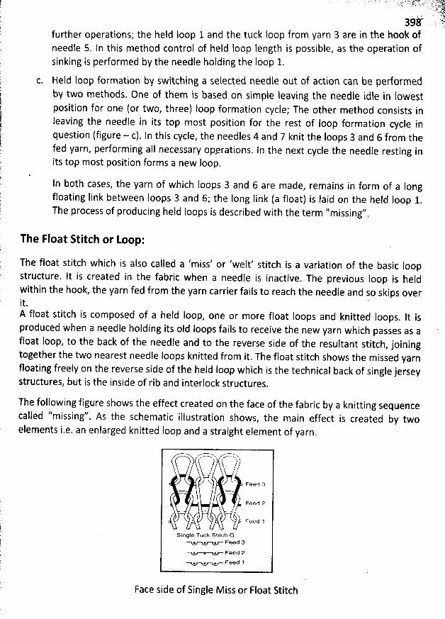
-. . . w - .. ..kg; t jqlljqjj-z?t)j y; syyrjjjj... ..,,y
39é . 7further operations; the held Ioop 1 and the tuck loop from yarn 3 are in the hook ofneedle 5. ln this method control of held Ioop length is possible, as the operation ofsinking is performed by the needle holding the Ioop 1.
Hesd loop formation by switching a selected needle out of action caG be performedby two methods. One of them is based on simple leaving the needle idle in lowestposition for one (or two, three) Ioop formation cycle; The other method consists inleaving the needle in its top most position for the rest of Ioop formation cycle inquestion (figure - c). ln this cycle, the needles 4 and 7 knit the Ioops 3 and 6 from thefed yarn, performing aII necessary opvrations. In the next cycle the needle resting inits top most position forms a new Ioop.
ln both cases, the yarn of which Ioops 3 and 6 are made, remains in form of a Iongfloating link between Ioops 3 and 6) the Iong Iink (a float) is Iaid on the held Ioop 1.The process of producing held Ioops is described with the term ''missing''
.
The Float Stitch or Loop:
The float stitch which is also called a 'miss' or 'wegt' stitch is a variation of the basic loopstructure. It is created in the fabric when a needle is inactive. The previous Ioop is heldwithin the hook, the yarn fed from the yarn carrier fails to reach the needle and so skips overit.A float stitch is composed of a held loop, one or more float loops and knitted loops. It isproduced when a needle holding its oId loops fails to receive the new yarn which passes as afloat Ioop, to the back of the needle and to the reverse side of the resultant stitch
, joiningtogether the two nearest needle Ioops knitted from it. The float stitch shows the missed yarnfloating freely on the reverse side of the held Ioop which is the technical back of single jerseystructures, but is the inside of rib and interlock structures.
The following figure shows the effect created on the face of the fabric by a knitting sequence
called ''missinf'. As the schematic illustratîon shows, the main effect is created by twoelements i.e. an enlarged knitted Ioop and a straight element of yarn
.
' C A
k.. . . Feed a
. Feed 2
, Feed 1
Single Tuck Stitcb G. . . Feed 3
. . Feed 2
. * . Feed 1
Face side of Single M iss or Float Stitch
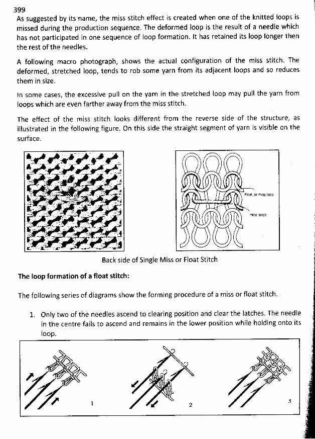
'
q'399 qAs suggested by its name, the miss stitch effect is created when one of the knitted Ioops is )missed during the production sequence. The deformed Ioop is the result of a needle which :has not participated in one sequence of Ioop formation. lt has retained its Ioop longer then i
the rest of the needles.
A following macro photograph, shows the actual configuration of the miss stitch. Thedeformed, stretched loop, tends to rob some yarn from its adjacent loops and so reducesthem in size.
In some cases, the excessive pull on the yarn in the stretched Ioop may pull the yarn fromIoops which are even farther away from the miss stitch.
The e#ect of the miss stitch Iooks different from the reverse side of the structure, asillustrated in the following figure. On this side the straight segment of yarn is visible on the
surface.
Float or mlss lœp
Held Mplch
Back side of Single Miss or Float Stitch
The Ioop formation of a float stitch:
The following series of diagrams show tbe form ing procedure of a m iss or float stitch.
1. Only two of the needles ascend to clearing position and clear the Iatches. The needlein the centre fails to ascend and remains in the Iower position while holding onto itsIoop.
ye z ) Xa y Xz
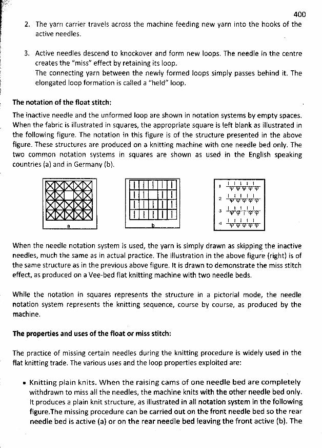
4002. Theyarn carrier travels across the machine feeding new yarn into the hooks of the
active needles.
3. Active needles descend to knockover and form new Ioops. The needle in the centrecreates the ''miss'' effect by retaining its Ioop.The connecting yarn between the newly formed loops simply passes behind it. Theelongated Ioop formation is called a ''held'' Ioop.
The notation of the float stitch:
The inactive needle and the unformed Ioop are shown in notation systems by empty spaces.W hen the fabric is illustrated in squares, the appropriate square is left blank as illustrated inthe following figure. The notation in this figure is of the structure presented in the abovefigure. These structures are produced on a knitting machine with one needle bed only. Thetwo common notation systems in squares are shown as used in the English speakingcountries (a) and in Germany (b).
8
W hen the needle notation system is used, the yarn is simply drawn as skipping the inactiveneedles, much the same as in actual practice. The illustration in the above figure (right) is ofthe same structure as in the previous above figure. It is drawn to demonstrate the miss stitcheffect, as produced on a Vee-bed flat knitting machine with two needle beds.
W hile the notation in squares represents the structure in a pictorial mode, the needlepotation system represents the knitting sequence, course by course, as produced by themachine.
The properties and uses of the float or miss stitch:
The practice of missing certain needles during the knitting procedure is widely used in theflat knitting trade. The various uses and the Ioop properties exploited are:
. Knitting plain knits. W hen the raising cams of one needle bed are com pletelywithdrawn to miss all the needles, the machine knits with the other needle bed only.lt produces a plain knit structure, as illustrated in aIl notatioh system in the followingfigure.The missing procedure can be carried out on the front needle bed so the rearneedle bed is active (a) or on the rear needle bed leaving the front active (b). The
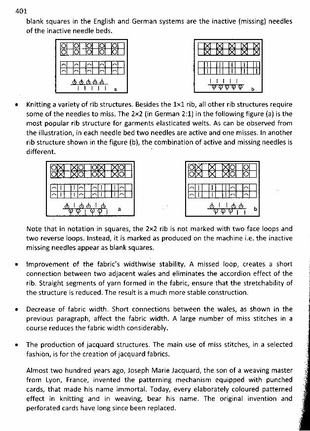
401
blank squares in the English and German systems are the inactive (missing) needlesof the inactive needle beds.
0 0 0 0 00 0 0 0 0
r% rN Gh MN MN
l I I I I a
* Knitting a variety of rib structures. Besides the 1x1 rib, aII other rib structures requiresome of the needles to miss. The 2x2 (in German 2:1) in the following figure (a) is themost popular rib structure for garments elasticated welts. As can be observed fromthe illustration, in each needle bed two needles are active and one misses. In anotherrib structure shown in the figure (b), the combination of active and missing needles isdifferent. '
O 0 0 OO 0 0 O
''x I l ,''x '-% I I ..'%'-x l I ''x ''% I I '-v
I IaI I
O 0 0O 0 0
'-h l I I .-% ,-wn I I l n ''x
1 I bI I
Note that in notation in squares, the 2x2 rib is not m arked with two face Ioops andtwo reverse Ioops. lnstead, it is marked as produced on the machine i.e. the inactivemissing needles appear as blank squares.
@ Im provem ent of the fabric's widthwise stability. A m issed Ioop, creates a shortconnection between two adjacent wales and eliminates the accordion effect of therib. Straight segments of yarn formed in the fabric, ensure that the stretchability ofthe structure is reduced. The result is a m uch more stable construction.
@ Decrease of fabric width. Short connections between the wales, as shown in theprevious paragraph, affect the fabric width. A large number of miss stitches in acourse reduces the fabric width considerably.
@ The production of jacquard structures. The main use of miss stitches, in a selectedfashiön, is for the creation of jacquard fabrics.
Almost two hundred years ago, Joseph M arie Jacquard, the son of a weaving masterfrom Lyon, France, invented the patterning mçchanism equipped with punchedcards, that made his name im mortal. Today, every elaborately coloured patternedeffect in knitting and in weaving, bear his name. The original invention andperforated cards have Iong since been replaced.
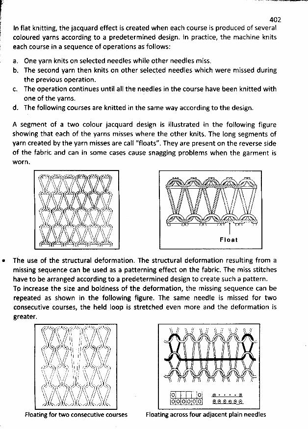
j ' - ' 'f 4o2k-
t ln flat knitting, thejacquard effect is created when each course is produced of severalf loured yarns according to a predetermined design. ln practice, the machine knits; co
$ each course in a sequence of operations as follows:1
$
'
a. One yarn knits on selected needles while other needles miss.b. The second yarn then knits on other selected needles which were missed during
the previous operation.The operation continues until aII the needles in the course have been knitted withone of the yarns.
d. The following courses are knitted in the same way according to the design.
A segment of a two colour jacquard design is illustrated in the following figureshowing that each of the yarns misses where the other knits. The Iong segments ofyarn created by the yarn m isses are call ''floats''. They are present on the reverse sideof the fabric and can in some cases cause snagging problems when the garment isW orn.
/C2V ôsjs Ta4.è'- ' 'h. ) - yy ( - . r ' ï ;
'
-k a , -
'h / 1hk 1, ( (. . . . qt , .L( h). u '- .
, , . - .
( . . . . : j sjjj,t ''k .
, r . , -
.
, .
.
, y-cq.,4x( ) k . - ) n - , y
, y , j'illl'k ,-'T-. ' ' h
y;jt.. ,(? ,, .. ht-hhy- ytgy '$j.;f'),j'-,j
' t4-wy '.. . u-.itkjylp'-. . y ,-.zL4..-. (yj .. u. ..---:6,--. yyr/ry .. . ....y, fsé'ryy . : bbttjtt--
kï, .
(.. : . jr ';/ hk îjk . y/// .Tk.S. ,pry y bk
-
lfj), //f)l)!- ' . -;j(.-. . . - ---j(---(t)r - ,(..-'ffèL-. ...!(j(), .'' . . .lF I o a t
@ Tàe use of the structural deformation. The structural deformation resulting from am issing sequence can be used as a patterning effect on the fabric. The miss stitcheshave to be arranged accqrding to a predetermined design to create such a pattern.To increase the size and boldness of the deformation, the missing sequence can berepeated as shown in the following figure. The sam e needle is m issed for twoconsecutive courses, the held Ioop is stretched even more and the deform ation isgreater.
,' SZ'N ' '-.h. $j47,:92.. ' v-:z ;r zttx Lï' -j,j ?t 28;, ,:)f.$isLL- ' -fr, . - .. , k..).---y k . ,; ?$. ) y. -).- ).!..h qs
'
.k ,//ï : ; , h,- / - ï t'j -k -- y.,, y j , (, y.tzj ,,,, y-y ,(jhï y , ,
.è . ( . k k y ? ;. k yj. t .,k' r(7' . .
'
Y A') y ! . ; . ) ) . tj - $/. y'-r js.y'Fhyyï y,/,
/' 1k,îïy ,/'
.// i i p / 'yk''$.. ,/,'/ ty'-y yf(
-,/'..
. h, // ' : i ! . y'y / / h yï j-t.i h )t . /' t I @. , , a.? , -k b.l ,
.-r) '-z iqx'--jrtyrbzz! tx--k..ky- i l / 1. , '(r'r$,' 'x-.:-èl yj--'r ,).-,'é îx-xtq..-yz ( *) . ! $ / ! y , . ,, ,$$ y t . .j k
'
: .F ,, f , $ .j ;'t 't / / h L ti j 1 ) ' ? ï. hh- / / th. . ,/ i-$.-hj ? ? 't. 'y ?' / k ! 'j y l f 'k 'ï$ ; ,/ï
v/ / ,$ tv/ ,,i î . . I / '.. . , ,t. r--1-.. 'L-/xxl-tt-j-.sltz- ,,--1,.'.-. lkz x-fxth-. -, ;j( .;-;'rr ' t--,' '.' .j!-.;:;),- -)f 'k.- -.--)ç..- -'(-,z.'. '--IC-r'64?S'Jh î
'
. / y / y'$, h. l . / h, ,. y '$. ,j '$ 'y ,yy . / y',k /,/ q,y j; j y ,/ yy ,/yh $ ' ''j j. (. /- x ,). . x :..--/ ,) h tx1. x s )- ( . x - r;f
Floating for two consecutive courses
' / ï // // y' /'/ 'b // //11 / i ' ;
/
i
(:1, (:21 t-).' * . .' . (7),,O O o O O O o. 0. 0* e o. 0. .
Floating across four adjacent plain needles
403
The repeated missed sequence is limited by the properties of tbe yarn forming tbeheld Ioop. The Ioad is placed on this yarn and the number of misses possible depeqds
on its tensile properties.
* Marking of garments. The different appearance of the missed Ioop can be used forthe marking of cutting Iines. Arm holes or a ''V'' neck Iines can be defined the on
garments, during the knitting process.On ionger production lines, garments can be code marked in a hidden place to allowmachine recognition and trouble shooting during Iater production processes.
The Tuck Loop or Slitch:
The tuck stitches are the knitted structures in which certain Ioops are intermeshed withelements of two kinds: tuck loop and held loops. Tuck stitches can be weft and warp knitted,
and are produced on machknes equipped with any known types of needles. .
A tuck stitch is composed of a held loop, one or more tuck Ioops, and knitted Ioops. It isproduced when a needle holding its Ioop also receives the new loop which becomes a tuckIoop because it is not intermeshed through the oId Ioop, but is tucked in behind it on the
reverse side of the stitch.
Its side Iim bs are therefore not restricted at their feet by the head of an oId Ioop so that theycan open outwards towards the two adjoining needle loops formed in the same course. Thetuck loop thus assumes an inverted 'V' or 'U' - shaped configuration. Tuck stitch structuresshow a faint diagonal Iine effect on theii sudace. '
ln analysis, a ttlck stitch is identified byimmediately the needle loopbe separately withdrawn and a miss stitch would always be floating freely on the technical
the fact that its head is released as a hump shapeabove it is withdrawn, whereas a knitted loop would require to
back.
The following figure shows a stitch created by a knitting sequence called ''Tuckinf'. Theeffect is created by an enlarged knitted loop with a segment of yarn tucked behind it. Acomparison with figure of the miss stitch, reveals a similarity to the float stitch construction.The stretched loop appears in botb miss stitcb and tuck stitches.
The tuck stitch is formed, as suggested by its name, when the yarnstructure by the needle, instead of being formed into a loop. The stretched deformed loop
is tucked into the
originated as a normal knitted loop which was held by the tucking needle while the other
needles knitted an additional course.
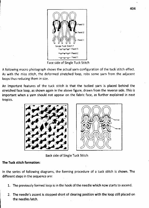
404
. Feed 3
Feed 2
Feed 1
Single Tuck Stitch F. * . Feed 3
. . Feed 2
. @ . Feed 1
Face side of Single Tuck Stitch
A following macro photograph shows the actual yarn configuration of the ttlck stitch effect.As with the niiss stitch, the deformed stretched Ioop, robs some yarn from the aàjacentIoops thus reducing them in size.
An important features of the tuck stitch is that the tucked yarn is placed behind thestretched face loop, as shown again in the above figure, drqwn from the reverse side. This isimportant when a yarn should not appear on the fabric face, as further explained in nexttropics.
. . ' yxk fxp
-
j
Back side of Single Tuck Stitch
The Tutk stitth formation:
In the series of following diagrams, the forming procedure of a tuck stitch is shown. Thedifferent steps in the sequence are:
1. The previously formed Ioop is in the hook of the needle which now starts to ascend.
2. The needle's ascent is stopped short of clearing ppsition with the Ioop still placed onthe needles Iatch.
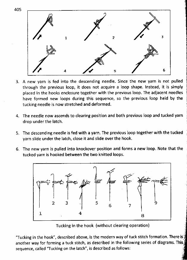
405
N?, , / , X- ,>M N
,?*-. - .
-
- .
3. A new yarn is fed into the descending needle. Since the new yarn is not pulledthrough the previous Ioop, it does not acquire a Ioop shape. Instead, it is simplyplaced in the hooks enclosure together with the previous loop. The adjacent needleshave formed new loops during this sequence, so the previous Ioop held by thetucking needle is now stretched and deformed.
4. The needle now ascendsto clearing position and both previousIoop and tucked yarndrop under the latch.
5. The descending needle is fed with a yarn. The previous Ioop together with the tuckedyarn slide under the Iatch, close it and slide over the hook.
6. The new yarn ispulled into knockover positièn ahd forms a new loop. Note that thei k itted loops.tucked yarn is hooked between the wo n
u j r m.. y. y . ao m o..
1 o J-<.- . y q , a. . z,-(,- qm5-'!
2 3 . 5 96 7
l 4 8
Tucking in the hook(without clearing operation)
''Tucking inanother way for forming a
the hookd', described above, is the modern way of tuck stitch formation.tuck stitch, as described in the following
sequence, called ''Tucking on the Iatch'' is described as follows:lseries of diagrams.
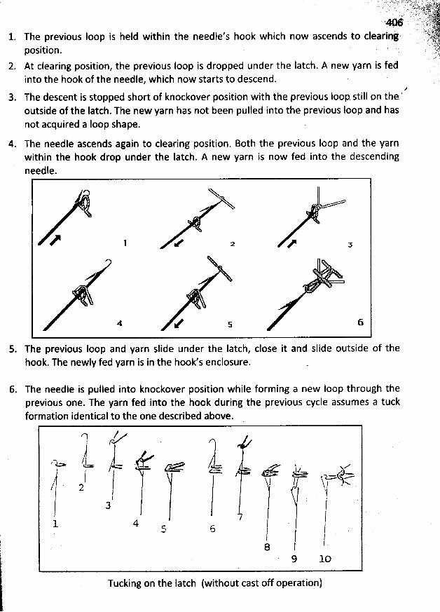
' ' . ; 'ïiîjïLll'7 qt? jLqj.jjjjj $ .;.' ' > jjjL));('''.. .. . ..-. .-. . . .
.-. ..,-,- :yyy?#.-.y.a . . .
,, )y,. s) . y.j y -.. . .., .
. . ë - (. . . t. gyyjy't ' ' '' :: 1.
. .- . . . .0 ,è. ( ?:L jjyy.. ,' h k which now ascends to clearing. ' Y'ft'71
. The previous Ioop is held within the needle s oo ,,.k jt
position. . 'JjAt clearing position, the previous Ioop is dropped under the Iatch. A new yarn is fed Sinto the hook of the needle, which now starts to descend.
?3. The descent is stopped short of knockover position with the previous Ioop. still on the '
outside of the Iatch. The new yarn has not been pulled into the previous Ioop and hasnot acquired a Ioop shape.
4. The needle ascends again to clearing position. Both the previous Ioop and the yarnwithin the hook drop under the latch. A new yarn is now fed into the descendingneedle.
? >' ' A' 1 e u zNS M o yy W V s
5. The previous Ioop and yarn slide under the Iatch, close it and slide outside of thehook. The newly fed yarn is in the hook's enclosure.
6. The needle is pulied into knockover position while forming a new loop through theprevious one. The yarn fed into the hook during the previous cycle assumes a tuckformation identical to the one described above.
l r) .
. . - -. g. ... w . y m q y g/ <- =/ y--
/ , x:72! '- jr3 J7
4 l5 6 Il .8 '
9 10
Tucking on the latch (without cast off operation)
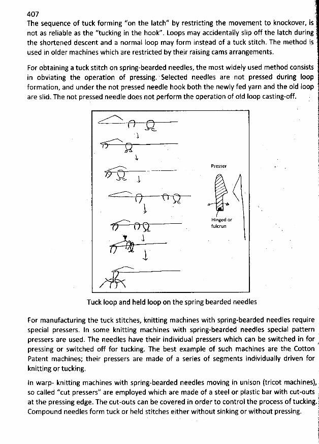
E(
407 )The sequence of tuck forming ''on the latch'' by restricting the movement to knockover, isnot as reliable as the ''tucking in the hook''. Loops may accidentally slip off the latch during (the shortened descent and a normal loop may form instead of a tuck stitch. The method is 'used in older machines which are restricted by their raising cams arrangements.
For obtaining a tuck stitch on spring-bearded needles, the most widely used method consistsin obviating the operation of pressing. ' Seleded needles are not presied during loopformati6n, and under the not pressed needle hook both the newly fed yarn and the oId loopare slid. The not pressed needle do.es not pedorm the operation of old Ioop casting-off!
x. jï 12
.1f '. 1
'
jj
. Presser j. ---.- .--
yp ys (w w J g
' j
'
' t$ k.
Hinged or
l sww ftllcrun# J1
1
N
Tuck Ioop and held loop on the spring bearded needles
For manufacturing the tuck stitches, knitting machines with spring-bearded needles requirespecial pressers. In some knitting machines with spring-dearded needles special pattern .pressers are used. The needles have their individual pressers which can be switched in for ;pressing or switched off for tucking. The best example of such machines are the CottonPatent machines; their pressers are made of a series of segments individually driven forknitting or tucking. q
iln warp- knitting machines with spring-bearded needles moving in unison (tricot machines),so called ''cut pressers'' are employed which are made of a steel or plastic bar with cut-outs i
1at the pressipg edge. The cut-outs can be covered in order to control the process of tucking-jcompound needles form tuck or held s'titches either without sinking or without pressing. j'
. i
!..11l
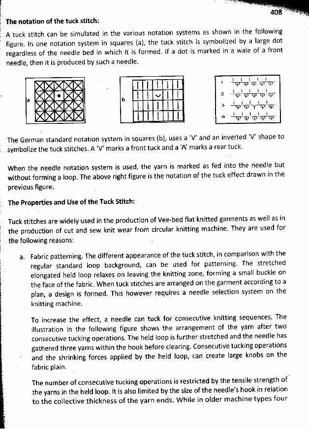
The notation of the tuck stitth:
A tuck stitch can be simulated infigure. In one notation system in squaresregardless of the needle bed in which it isneedle, then it is produced by such a needle.
the various notation systems as shown în the fodlowing(a), the tuck stitch is symbolized by a large dotformed. lf a dot is marked in a wale of a front
W2 *Th@ German standard notation system in squares (b), uses a 'V' and an inverted 'V' shape tosymbolize the tuck stitches. A 'V' marks a front tuck and a 'A' marks a rear tuck.
W hen the needle notation system is used, the yarn is marked as fed into the needle butwithout forming a loop. The above right figure is the notation of the tuck effect drawn in the
'previous figure.
The Properties and Use of the Tuck Stitch:
Tuck stitches are widely used in the production of Vee-bed flat knitted garments as well as inthe production of cut and sew knit wear frol circular knitting machine. They are used for
the following reasons:
a. Fabric patterning. The different appearance of the tuck stitch, in comparison with theregular standard Ioop background, can be used for patterning. The stretchedefongated held loop relaxes on Ieaving the knitting zone, forming a small buckle onthe face of the fabric. W hen tuck stitches are arranged on the garment according to aplan, a design is formed. This however requires a needle selection system on the
knitting machine.
To increase the effect, a needle can tuck for consecutive knitting sequences. Theillustration in the following figure shows the arrangement of the yarn after twoconsecutive tucking operations. The held Ioop is further stretched and the needle hasgathered three yarns within the hook before clearing. Consecutive tucking operationsand the shrinking forces applied by the held Ioop, can 'create Iarge knobs on the
fabric plain.
The number of consecutive tucking operations is restricted by the tensile strength ofthe yarns in the held Ioop. It is also Iimited by the size of the needle's hook in relationto the collective thickness of tbe yarn ends. W h iIe in older machine types four
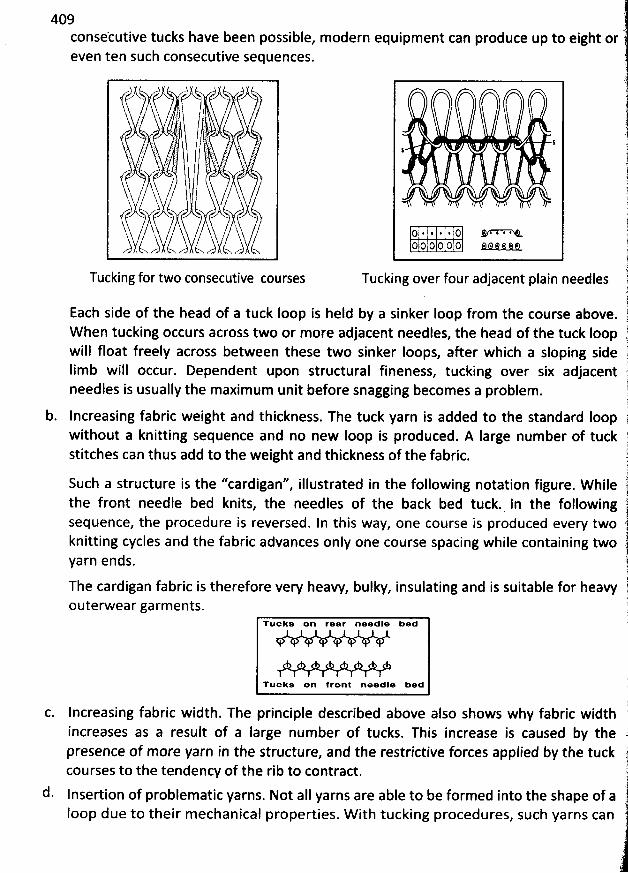
409consekutive tucks have been possible, m oderneven ten such consecutive sequences.
equipment can produce up to eight or
--)--)6-. ï ' .
ç'-- y;)- . - . . ,. 9
'; ; . .
. .' a.
ï o
$$
() . j & . . () â/i-k-;''-i-%,-O O ' 0 0 o 0 @ t.) @ e i) #)
Tucking for two consecutive courses Tucking over four adjacent plain needles
Each side of the head of a tuck Ioop is held by a sinker Ioop from the course above.W hen tucking occurs across two or more adjacent needles, the head of the tuck loopwill float freely across between these two sinker loops, after which a sloping sideIimb will occur. Dependent upon structural fineness, tucking over six adjacentneedles is usually the m aximum unit before snagging becomes a problem .
b. Increasing fabric weight and thickness. The tuckyarn is added to the standard loopis number of tuckwithout a knitting sequence and no new loop produced. A large
stitches can thus add to the weight and thickness of the fabric.
Such a structure is the ''cardigan'', illustrated in the following notation figure. W hilethe front needle bed knits, the needles of the back bed tuck. In the followingsequence, the procedure is reversed. In this way, one course is produced every twoknitting cycles and the fabric advances only one course spacing while containing twoyarn ends.
The cardigan fabricis therefore very heavy, bulky, insulating and is suitable for heavyouterwear garm ents.
Tucks on rear needle bed
Tuoks on #ront noedle bed
lncreasing fabric width. The principle described above also shows why fabric widthincreases as a result of a Iarge number of tucks. This increase is caused by thepresence of more yarn in the structure, and the restrictive forces applied by the tuckcourses to the tendency of the rib to contract.
d. Insertion of problematic yarns. Not aII yarns are able to be formed into the shape of aloop due to their m echanical propelies. W ith tucking procedures, such yarns can
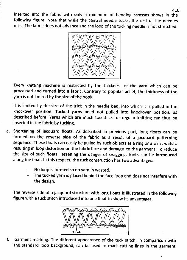
410inserted into the fabric with only a m inimum of bending stresses shows in thefollowing figure. Note that while the central needle tucks, the rest of the needlesm iss. The fabric does not advance and the Ioop of the tucking needle is not stretched.
. . u g yu & pxzvxux . <
n- .
A >>>N ex N
.= ..- m N r /v ..o
Every knitting machine is restricted by the thickness of the yarn which can beprocessed and turned into a fabric. Contrary to popular belief, the thickness of theyarn is not Iimited by the size of the hook.
lt is lim ited by the size of the trick in the needle bed, into which it is pulled in theknockover position. Tucked yarns need not pulled into knockover position, asdescribed before. Yarns which are much too thick for regular knitting can thus beinserted in the fabric by tucking.
e. Shortening of jacquard floats. As described in prekious part, Iong floats can beformed on the reverse side of the fabric as a result of a jacquard patterningsequence. These floats can easily be pulled by such objects as a ring or a wrist watch,resulting in loop distortion on the fabric face and damage to the garmeny. To reducethe size of such floats, Iessening the danger of snagging, tucks can be introducedalong the float. ln this respect, the tuck construction has two advantages:
No loop is foimed so no yarn in wasted.The tucked yarn is placed behind the face loop and does not interfere withthe design.
The reverse side of a jacquard structure with Iong floats is illustrated in the followingfigure with a tuck stitch introduced into one float to show its advantages
.
. . '
. ..''
)Tuek
f. Garment marking. The different appearance of the tuck stitch, in comparison with
the standard loop background, can be used to mark cutting Iines in the garment
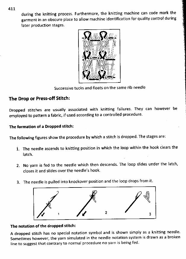
411during the knitting process. Furthermore, the knitting machine can code mark thegarment in an obscure place to allow machine identification for quality control during
later production stages.
l .1/ s l t ,/ / ...kz
-?/ (/ï /- . ,z. -- .. -- .7.
Successive tucks and floats on the same rib needle
The Drop or Press-o/ R itch:
Dropped stitches are usually associated with knitting failures. They can however beemployed to pattern a fabric, if used according to a controlfed procedure.
The formation of a Dropped stitch:
The following figures show the procedure by which a stitch is dropped. The stages are:
t. The needle ascends to knitting position in which the Ioop within the hook clears thelatch.
2. No yarn is fed to the needle which then descends. The Ioop slides under the Iatch,closes it and slides over the needle's hook.
3. The needle is pulled into knockover position and the loop drops from it.
X. /. , / ' '' .The notation of the dropped stitch:A dropped stitch has no special notation symbol and is shown simply as a knitting needle.Sometimes however, the yarn simulated in tbe needle notation system is drawn as a brokenline to suggest that contraw to norm al procedure no yarn is being fed.
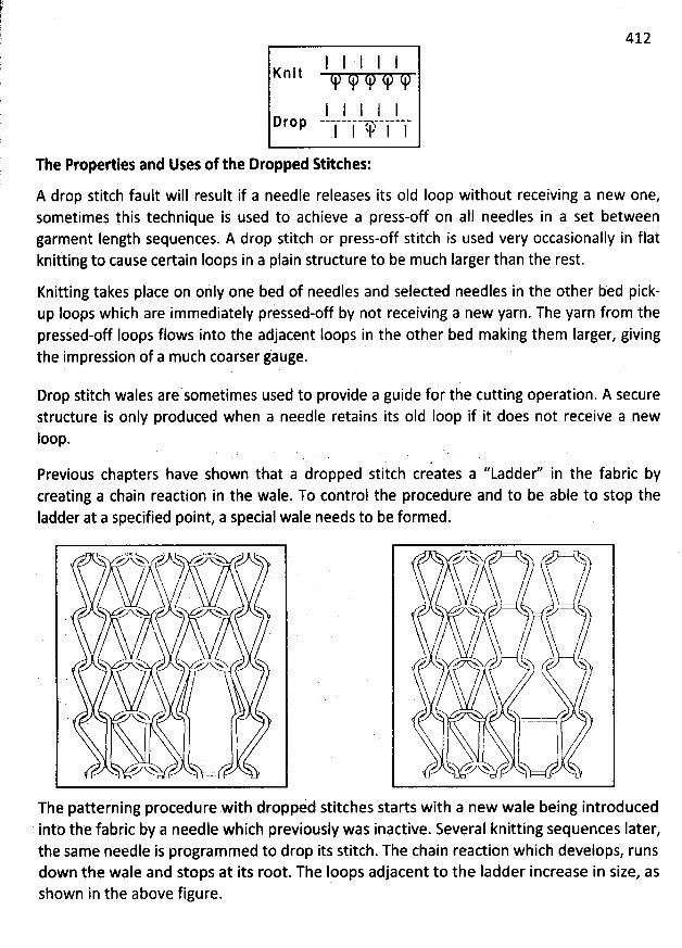
412
l I I I IK n i t
I l I I lI 1 lk I 'a- l l
The Properties and Uses of the Dropped Stitches:
A drop stitch fault will result if a needle releases its oId loop without receiving a new one,sometimes yhis technique is used to achieve a press-off on all needles in a set betweengarment Iength sequences. A drop stitch or press-off stitch is used very occasionally in flatknitting to causê certain loops in a plain structure to be much Iarger than the rest.
Knitting takes place on ohly one bed of needles and selected needles in the other bed pick-up loops which are immediately pressed-off by not receivihg a new yarn. The yarn from the
pressed-off Ioops flows into the adjacent loops in the other bed making them larger, givingthe impression of a much coarser jauge.
Drop stitch wales are sometimes used to provide a guide for tile cutting operation. A securestructure is only produced when a needle retains its oId Iooh if it does not receive a newIoop.
Previous chapters have shown that a dropped stitch creates a ''Ladder'' in the fabric bycreating a chain reaction in the wale. To control the procedure and to be able to stop theIadder at a specified point, a special wale needs to be formed.
D y .A.. Vw
) ) j. N
'
.ya jjr'mtf ,
The patterning procedure with dropp/d stitches starts with a new wale being introducedintb the fabric bk a needle which previouslk was inactive. Several knitting sequences Iater,the same needle is programmed to drop its stitch. The chain reaction which develops, runs
down the wale and stops at its root. The loops adjacent to the ladder increase in size, asshown in the above figure.
> 'y /ytà , /U''N/ j '- / -
ï / /h.
'
$
/=- SJ
413DESIGNS OF W EFT KNIU ED FABRICS
As mentioned in the previous chapter there are only four knit structure families, thecom bination of which makes aII the knitted fabrics and garments produced in weft knitting.To simplify explanations, aII the basic weft knit structure families were described as beingmade only of basic knit Ioops. In reality however, other loop types exist which, together withthe simple one, combine to enhance the patterning potential and the variety of knittedfabrics and garments.
AlI the knit structures excluding the basic structures are made of a com bination of the threeIoop structures described previous chapter i.e. the standard knit Ioop, the missed and thetucked stitch. W hen tuck or miss Ioop or both tuck and miss loop are combined with thestandard knit loop in case of plain or single jersey structure then it is called derivatives ofsingle jersey structures. Similarly there is Iot of rib based structures i.e. called derivatives ofrib structure, interlock based structure i.e. called derivatives of interlock structure and purlbased structure i.e. called derivatives of purl structure.
Decoration or ornamentatipn of plain knit or single jersey fabrics:
A single jersey fabric is ornamented withoutstructure as follows:
* The yarn vary in colour, raw material, types of construction and in thickness. Asthe fabric consists of yarn and yarn is made up of fibres or filaments theornamentation can start from the fibre, filament stages. Fibre dyeing, yarndyeing, fabric dyeing are some of the means by which attractive colours can beprovided to fibres, yarns, filaments or fabrics to enhance the beauty of the fabric.
*
deviating from the true principles of plain
Threads of different coiours are combined in stripe form. lf different dyed orcontrasting colours are used at different feeds by supplying packages of colouredyarn on a multi-feed machine of a single jersey structure, a variety of horizontalstripes can be obtained on the sudace of the knitted fabric. For casual T-shirtgarments such horizontal coloured stripes are commonly used.
* By usiig fancy yarns. Instead of simple regular single yarn. fancy yarn such asslub, knop, mélange, Ioop, crepe yarn etc. can be carefully knitted in the fabric togive some interesting results.
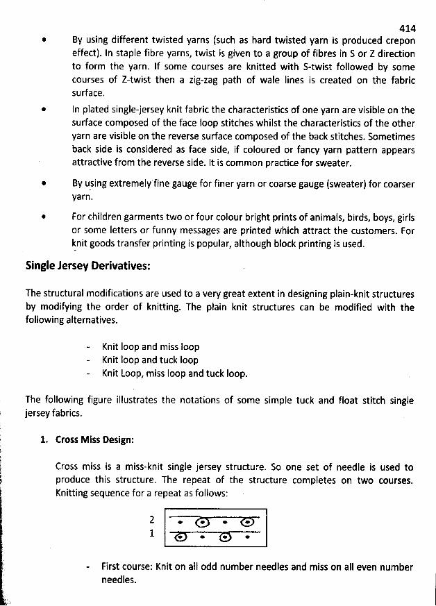
*
@
414By using different twisted yarns (such as hard twisted yarn is produced creponeffect). In staple fibre yarns, twist is given to a group of fibres in S or Z directionto form the yarn. If some courses are knitted with S-twist followed by somecourses of Z-twist then a zig-zag path of wale Iines is created on the fabricsurface.
In plated single-jersey knit fabric the characteristics of one yarn are visible on thesurface composed of the face loop stitches whilst the characteristics of the otheryarn are visible on the reverse sudace composed of the back stitches. Sometimesback side is considered as face side, if coloured or fancy yarn pattern appearsattractive from the reverse side. It is common practice for sweater.
By using extremely fine gauge for finer yarn or coarse gauge (sweater) for coarserYarn.
For children garments two or four colour bright prints of animals, birds, boys, girlsor some Ietters or funny messages are printed which attract the customers. Forknit goods transfer printing is popular, although block printing is used.
*
Single Jersey Derivatives:
The structural modifications are used to a very great extent in designing plain-knit structuresby modifying the order of knitting. The plain knit strudures can be modified with thefollowing alternatives.
Knit loop and miss IoopKnit Ioop and tuck loopKnit Loop, miss Ioop and tuck Ioop.
The following figure illustrates the notations of some simple tuck and float stitch singlejersey fabrics.
1. Cross Miss Design:
Cross miss is a miss-knit single jersey strudure. So one set of needle is used toproduce this structure. The repeat of the structure completes on two courses.Knitting sequence for a repeat as follows:
2 . . . .1 * * * *
I
First course: Knit on aII odd number needles and miss on alI even numberneedles.
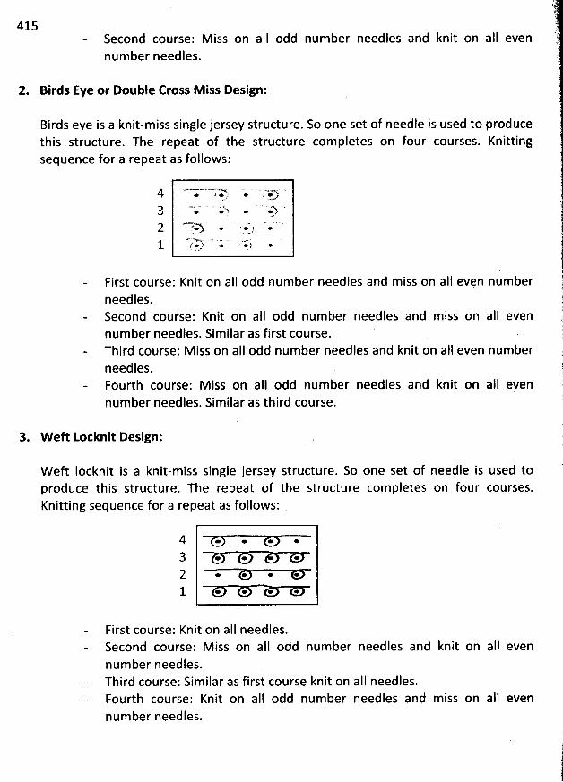
415Second course: M iss on aIl odd num bernumber needles.
needles and knit on alI even
2. Birds Eye or Double Cross M iss Design:
Birds eye is a knit-miss single jersey structure. So one set of needle is used to producethis structure. The repeat of the structure completes on four courses. Knittingsequence for a repeat as follows:
First course: Knit on aIl odd number needles and miss on aII even numberneedles.Second course: Knit on aII odd num ber needles and miss on aII evennumber needles. Similar as first course.Third course: M iss on aII odd num ber needles and knit on aI1 even num berneedles.Fourth course: M iss on aII odd number needles and knit on aII evennumber needles. Similar as third course.
3. W eft Lotknit Design:
W eft Iocknit is a knit-miss single jersey structure. So one set of needle is used toproduce this structure. The repeat of the structure com pletes on four courses.Knitting sequence for a repeat as follows:
4 . . . .3 . . .2 . . * *1 . . * *
First course: Knit on aII needles.Second course: M iss on alI odd number needles and knit on aII evennum ber needles.Third course: Sim ilar as first course knit on aII needles.Fourth course: Knit on aII odd num ber needles and miss on aIl evennum ber needles.
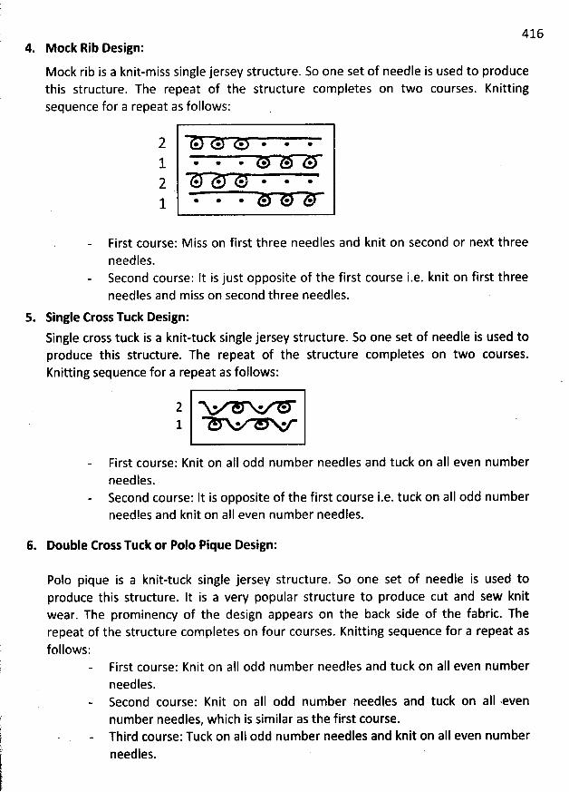
4164. M ock Rib Design:
Mock rib is a knit-miss single jersey structure. So one set of needle is used to producethis structure. The repeat of the structure completes on two courses. Knittingsequence for a repeat as follows:
2 * @ * œ * e
1. * * * @ * *Q @ @ * * * @
* * * @ * @1
First course: M iss on first three needles and knit on second or next threeneedles.Second course: It is just opposite of the first course i.e. knit on first threeneedles and miss on second three needles.
5. Single Eross Tuck Design:
Single cross tuck is a knit-tuck single jersey structure. So one set of needle is used toproduce this structurç. The repeat of the structure completes on two courses.Knitting sequence for a repeat as follows:
2 . * *1 . . e
First course: Knit on alI odd num ber needles and tuck on aII even numberneedles.Second course: It is opposite of tbe first course i.e. tuck on aII odd numberneedles and knit on aII even num ber néedles.
6. Double Cross Tutk or Polo Pique Design:
Polo pique is a knit-tuck single jersey structure. So one set of needle is used toproduce this structure. It is a very popular structure to produce cut and sew knitwear. Thê prominency of the design appears on the back side of the fabric. Therepeat of the structure completes on four courses. Knitting sequence for a repeat asfollows:
First course: Knit on alI odd number needles and tuck on all even numberneedles.Second course: Knit on aII odd number needles and tuck on alI -evennumber needles, which is similar as the first course.Third course: Tuck on aII odd number needles and knit on aII even numberneedles.
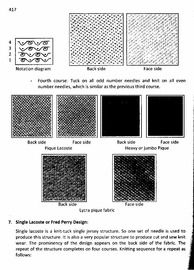
417
4 . . . .3 . . .2 . .1 . .
Notation diagram
- . gg > va e' . ' m ' m v' > #z q+4 . .. e A,. .. #: * , y.eI ** #' j ' < #' #' > * * *i. .. z . -. +'' > .. m . . p. .+ *. + #j *, R . t +. ee . - e; . . , . jw - *. . f . ..#.= #. 5* a + w -. Ye f' .' *.. *4 z, . - . #t '@z . .' < '* *' #:P * *' ' +' *' ' '< '' '* *'' #> ' + #* ? ,m â M M' ' * ' *'* . ' .w * > z , #. . .w > . m -. *. lp2 *y *.e *. *' ' ' *' '. .. w + .. #p *'* o# * 4* + ' G *. ' *'d . * + + wv #' . '- ..< + + #*- -' + -. .w o% + . . w > .+ . . . . .4 : . .e1 ' *' #è @ #J * *' ' . * * .. -. . .* ## . - ... . &. . .. . w . ez . . .w &. . .. - * *. *' ' >' - ..ed *j . . . < - e' . ** +. - * ' > #i , - e. *.. +. . ##' * ' + ' *>e> z vz ' * M. * * '* ' *'', - e' * &. T** * '< , . , > #. . > e.D > *. * . . . > à -. + w +@. *' . . . - + - + . w + . .. >. '. + *. . . .. h +, e. # . Fb * :> ' z e. > #' . Y. . . @è-. @; . . .+ ' w #: . ' a .. #. *. e' #z* *. * ' m... @. . . . >; m ' * . + .+. a e .. o . + #: ., ., @. +. ; x #: #.** . , . @ ... < @ ' o .. .. 4. . ' +. > @. . .. *#> . . ,y.. #. +y ., - x,& f* . * - # *4 . # *% . - +$ . . . e Az*. # - œ > * ' *. '**. .' ># #e 8*. . p . < e v . *y #' , > . #. .. # . . - *è . .. . #> - . #@ e '. ' > + Ra #' ê ' +ey ?' @ê ee - #, *. . + ' *. eç P . v . *w ' *k' . ,, .. . x: va . . . <. .4 . v .. >. + . . .?. e. x - * < e. +' ** ' >i' * 'o * +. , .. > ' >>. e, . - . > . . a *y. . p > p . a. ? . w . w. @ + . . . x . x. ' 4: * ... *,+ * ' . ... ...< * * * C* .w ' . ' >* ' <.. ' e'r r* V r - #, e. i .: * @*' ... . > ao '+. + * - f* . - #* * o
Back side Face side
Fourth course: Tuck on aII odd num ber needles and knit on aII evennum ber needles, which is similar as the previous third course.
Back side Face sidePique Lacoste
Back side Face sideHeavy orjumbo Pique
. ' . .
Back sideLycra pique fabric
k ... .. '%
Face side
7. Single Lacoste or Fred Perry Design:
Single lacoste is a knit-tuck single jersey structure. So one set of needle is used toproduce this structure. It is also a very popular structure to produce cut and sew knitwear. The prominency of the design appears on the back side of the fabric. Therepeat of the structure com pletes on four courses. Knitting sequence for a repeat asfollows:
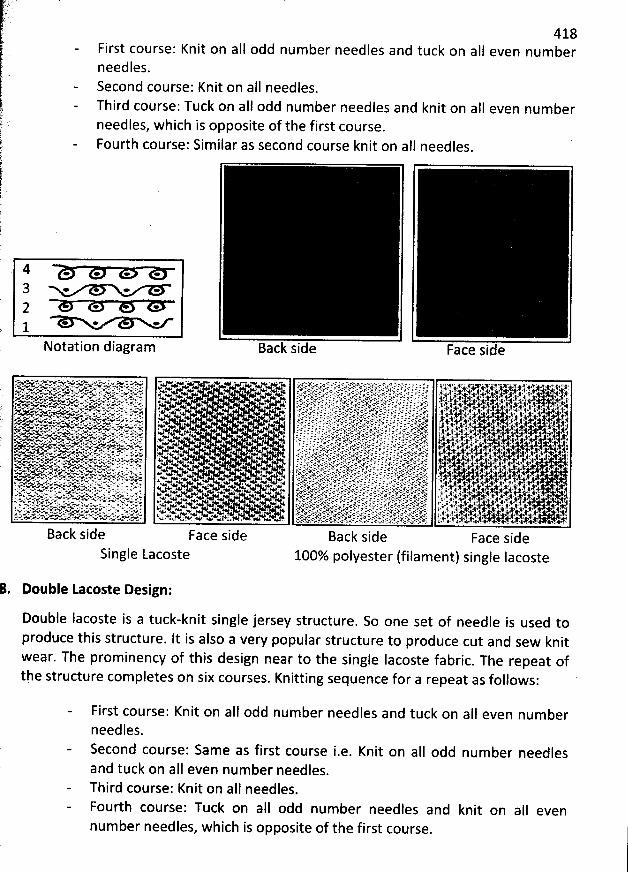
418First course: Knit on aII odd number needles and tuck on aIl even numberneedles.Second course: Knit on aII needles.Third course: Tuck on aII odd num ber needles and knit on aII even numberneedles, w hich is opposite of the first course.
Fourth course: Similar as second course knit on aII needles.
4 . . . .3 . . . .2 * *j. * * *
Notation diagram Face side
Back side
Single Lacoste 100% polyester (filament) single Iacoste
. Double Lacoste Design:
Double Iacoste is a tuck-knit single jersey structure. So one set of needle is used toproduce tbis structure. lt is also a very popular structure to produce cut and sew knitwear. The prominency of this design near to the single Iacoste fabric
. The repeat ofthe structure com pletes on six courses. Knitting sequence for a repeat as follows:
First course: Knit on aII odd number needles and tuck on aII even num berneedles.Second course: Same as first course i.e. Knit on aII odd number needlesand tuck on aIl even number needles.Third course: Knit on alI needles.Fourth course: Tuck on a1l odd number needles and knit on all evennum ber needles, which is opposite of the first course.
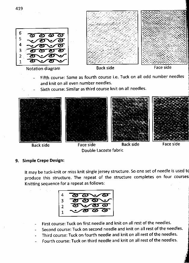
1 ... . . . . . . . . .. . . ..x . . . .- . . ,. .qz . xw w. . w . . . . .. .e ,r ;qr .. . .-- .
. . . . -. s . z.- . r . .-. .s. . .v .r, . ..,w : .- . .. . ww. . . ..,.'qJ, x, . . -., . ., . ,f u...r. y... . s.,. . x. N. . . ,w x , ... .- . . . . . . .a .. w . . ,.;. . ,. . w. *. . . - . ' ' ' ><'-a. f 44 9.J .%' '1Y ' ' ' . ' à . XF '*j . hsj. *(.' *&#/. . . . - . w. , . , . . .. .. . .. . . . ... ' . . . ., . . . .x, z... ...x . . . . . . . ... ..-. . .w ,... . .. . ., . ' .... , ... ' .*. . . ,' + *( .+.e. .s.. .+t' +'. ..N. > w- . > . .. . .. .>- . .. . ...- ,. .. - ...z. w .a.. . .. . . ,. .... x. q, ... . .%t. ., p.*, .. u. .' N, . ,v. .,..x.y.. . ... . .. . .- .v. . w . s.. . . . . . .s - ... .. . . ., . o $ . $ v, .l. .
. . . . . . ..'.. '.. . . ' . . & . ,.' t: +$ $ ' . f e;. ..-. . . r . . .,... . . . . . . .. .. .q. , . , .+ '.
..w. - . . . .q. >.. . . . . . . * . .. xm x. . . . . . . .' -% - + .u - .J. . - w . , - . . .c a ...: . e.- .-. .'r ..*. ' .ww - . A. . .. . . ..- . ' . - N, . ' v. , . N. X. . . , ' , . q .. ' X w' %*'. , ;* , . . . A; . . uu .
. . . >. w. : . -av' . ? . . . . *' +. 'N ... .>.v; >.- . . .v. -. ..... . up .y.. . Ay . , w . K.. . ; . , z . .#$ A . .. u . .. e- .-x...- w . >. #. . œ- - ' = k. :, %: vv. .'$ . . 4 > l v ît ,xp.. . . . .w. .. . ..'. . <x . .. w : . . , . hv %/W .Ns+ ..%.. :2 4h' 'r' '>. w. '' .. > ... '-r.. ' z>. .-Y .-....x ....J -œ '. .' ' = - M HK NFN h:'..,(#' . 6 '. %. '+? >K, lz 'e +.w?*. <.Ax?'. ''%' >%v .+,. a. m eu -- - . ' . .vc . I XK N AJ 4 % . .' .#k. *I' .... .. . . . u . . . . .. 4.' . y . '*; &
'
.: ...r . .... . ... .''. .a
'
. e 4 . . 1 # # ...,. . . .... .. .... -.... . . . . . .. .- - - .-. . -.- - .tt a -,. .t ., . .v... . . . . . .* * .: .. . . . - . .. . . . . . .*. .%r . . '., . . .. ..w . ... . m-. .-. ,a. . .-. .- - ,.-. - .; .we . - ... .. .- - . . .. . .
....N;. %. ..wt . .K ...?. . s. .!., . v. ..' x,. .+.%. . w. ..x .. ..-.. ..- . . . . . , g-.. .., . a . . s w .:e. .v . . .. .rt . # . .41: 41: 4:: .' * * ' ' ' b: ''' . ' A ' # ' # ' ' '
* * * '*<' .-. w ''' .m Q' ' ' ' ' ' > œ l ' N * ' ' '. -. w.-.... - v . . . .- . . . 4 ., z . k * : # . ..a . . # 4u , . . , = >.. x .. . > . . . *< p , . . * +1 + N*. #z . .. - . ' . . . . >. . ' ' . ..N. .w. ... 4 xt ' N 'V A Ve t? . t' # b '. . .. .* x. . . . hK *, . ' . . K -y . twa q. ' . ) *' ë '. . - ..v > .. . - . , . . .w . ... . . . . x w
'
*: . xw' 'x. . . . . . . . . w.a . .,. . : , . . t . . + .. @ p
'
.. . . . , . .. . . .a.. . . . , . . . . .. 4 .. s , . . , .. . .- .. . 'w . . z . . . h . . . . . .. '.. . :.
.. , , . ..h.. e . ...- k. . . < w . @L s . . . . *. a . ' .. . . ! . v... . . .wc .... - . . x <.. w? , . % w' . . . 4. *f
. .. . . . . .. ...-. .,.. . - .. . . A . . . .... e . , i.A +. w ..ê %, . x.., *. w! * ./ .., w.
o v
'
.. .y . - < - .. ' - . - # jl . ' . . f ' . '' ' ': .p. . . - . xv, . r. l ., . % . + *1 . . . * * +' q %'- - . . .-. - . x . . . $* w v . w, . . . 4 . .w c
*
'
. . ' e . ... , ' #' 'e. .e ' . ' ! z . A ' .1. . *
otatlon Ia ra ac S1 e Face sl e
*. . * . '
Fl t course: a e as Ou Course I.e. UC On a O nu er nee es 1't en nu er nee es 'an nl On a ev .
IXt Course: I 1 ar aS 12 lr Course nIt On 3 nee eS. .)111
&
. 1
!
ac sl e Face sl e ac sl e Face sl eDouble Lacoste fabric
9. Sim ple Crepe Design:
It may be tuck-knit or miss knit single jersey structure. So one set of needle is used tçk
'
produce this structure. The repeat of the structure com pletes on four côursestKnitting sequence for a repeat as follows:
4 . . . .3 * * *2 * * -
e * e1
First course: Tuck on first needle and knit on aII rest of the needles.Second course: Tuck on second needle and knit on a11 rest of the needles.Third course: Tuck on fourth needle and knit on aII rest of the needles.Fourth course: Tuck on third needle and knit on aII rest of the needles.
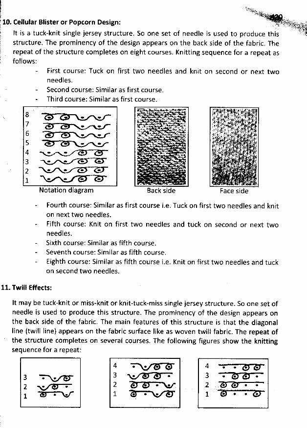
.. . .
z tgyy,1q)b(l..qjjjjjj(j;;y'!:. )s. > .. . . .;- . . -- s . .---..-p 10. Cellular Blister or Popcorn Design: -.f.jJ':r'%f1.'@2J'
.)).#x: .,' ,f )). -
. 'J â-,- ryzltyhï-ltlljiiôë.
' Iài8 It is a tuck-knit single jersey structure. So one set of needle is used to produce this 17751$ .
structure. The prominency of the design appears on the back side of the fabric. The f the structure completes on eight courses. Knitting sequence for a repeat as repeat o
follows:
k First course'. Tuck on first two needles and knit on second or next twoneedles.Second course'. Similar as first course.Third course: Similar as first course.
8 .e *7 . .6 . .5 * * * *4 * - * -3 - . * *2 . . . -1 * œ * *
Notation diagram
r vy. wN. +% kek
. w. . . +k . -. .:x%. , û*'ç. Y
. .5. ' .
%
4 . . . <.
Back side
Fourth course: Sim ilar as first course i.e. Tuck on first two needles and kniton next two needles.Fifth course: Knit on first two needles and tuck on second or next twoneedles.Sixth course: Sim ilar as fifth course.Seventh course: Similar as fifth course.Eighth course: Sim ilar as fifth course i.e. Knit on first two needles and tuckon second two needles.
11. Twill Effects:
It may be tuck-knit or miss-knit or knit-tuck-miss single jersey structure. So one set ofneedle is used to produce this structure. The prom inency of the design appears onthe back side of the fabric. The main features of this structure is that the diagonal
Iine (twill Iine) appears on the fabric surface Iike as woven twill fabric. The repeat ofthe structure completes on several courses. The following figures show the knittingsequence for a repeat:
3 M. . .2 <* *1 n
4 . . . .3 . .2 . . .1 . . .
4 . . . .3 . . . .2 . . . .
.'---
. k .
1 * @ @ @
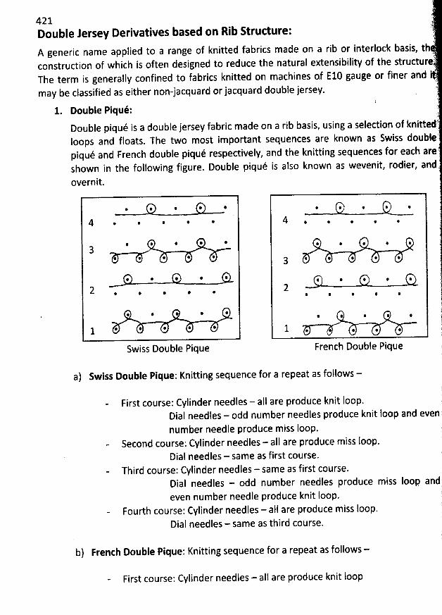
tè-
421 7zDouble Jersey Derivatives based on Rib Structure: :?.à
!A generic name applied to a range of knitted fabrics made on a rib or interlock basis, th7
construction of which is often designed to reduce the natural extensibility of the structure?The term is generally confined to fabrics knitted on machines af E10 gauge or finer and ' '
may be classified as either non-jacquard orjacquard double jersey.
1. Double Piqué: i?
'
Double piqué is a double jersey fabric made on a rib basis, using a selection of knitted,loops and floats. The two most important sequences are known as Swiss doubleèpiqué and French double piqué respectively, and the knitting sequences for each are'shown in the following figure. Double piqué is also known as wevenit, rodier, andC
overnit.
. * @ * @ @ .(j.. . . .
4 @ @ @ * 4 . . . . .
@ @ @ @ @ . . . . 4 .
3 @ * @ @ * . . . 4 . .
. @ w @ * : . , . .(g
2 - - -* @ * @ @ @ . @
i. . . . i
. . . . . . j1 . . . . . 1 . . . . . j,
Swiss Double Pique French Double Pique iE
a) Swiss Double Pique: Knitting sequence for a repeat as follows -!
First course: Cylinder needles - all are produce knit loop. )Dial needles - odd number needles produce knit Ioop and even;number needle produce miss loop. j
Second course: Cylinder needles - all are produce miss loop. )Dial needles - same as first course. 1
Third course: Cylinder needles - same as first course. )
les - odd number needles produce miss Ioop and)Dial needeven number needle produce knit Ioop. t
Fourth course: Cylinder needles - aII are produce miss Ioop.Dial needles - same as third course.
b) French Double Pique: Knitting sequence for a repeat as follows -
First course: Cylinder needles - aII are produce knit Ioop
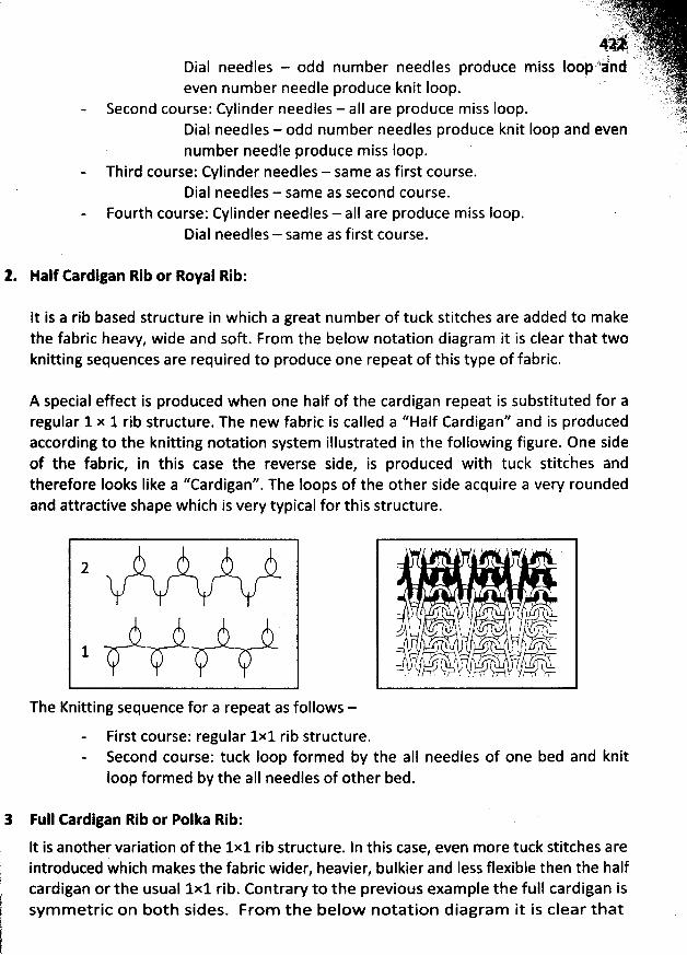
Dial needles - odd num ber needles produce m isseven number needle produce knit Ioop.
Second course: Cylinder needles - aI1 are produce m iss loop.Dial needles - odd num ber needles produce knit Ioop and evennumber needle produce miss loop.
Third course: Cylinder needles - sam e as first course.Dial needles - same as second course.
Fourth course: Cylinder needles - aII are produce m iss Ioop.Dial needles - same as first course.
'. Half Cardigan Rib or Royal Rib:
It is a rib based structure in which a great num ber of tuck stitches are added to makethe fabsic heavy, wide and soft. From the below notation diagram it is clear that twoknitting sequences are required to produce one repeat of this type of fabric.
A special effect is produced when one half of the cardigan repeat is substituted for aregular 1 x 1 rib structure. The new fabric is called a ''Half Cardigan'' and is producedaccording to the knitting notation system illustrated in the following figure. One sideof the fabric, in this case the reverse side, is produced with tuck stitc'hes andtherefore Iooks Iike a ''Cardigan''. The loops of the other side acquire a very roundedand attractive shape which is very typical for this structure.
' vt/vv'////
The Knitting sequence for a repeat as follows -
1 l ,
, , y o, î , t, , kyh-'pkp q y y . ks,#.-h îc:/ t . k , (.0 . , , j , ë ïq j-ss .-? k ,n ' r
,.0 st îq f ' u..cw ' ï ? '''-/ usct,-, r-h-o'c! , k?-,rA' , . . v 1) î$ g y1. ,/
First course: regular 1x1 rib structure.Second course: tuck Ioop formed by the aI1 needles of one bed and knitloop formed by the aII needles of other bed.
3 Full Cardigan Rib or Polka Rib:
lt is another variation of the 1x1 rib structure. ln this case, even more tuck stitches areintroduced which makes the fabric wider, heavier, bulkier and Iess flexible then the halfcardigan or the usual 1x1 rib. Contrary to the previous example the full cardigan issym m etric on both sides. From the below notation diagram it is clear that
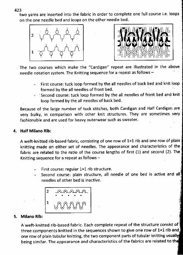
423two yarns are inserted into the fabric in order to complete one full course i.e. Ioops t.on the one needle bed and Ioops on the other needle bed.
7
2
1
The two courses which m ake the ''Cardigan'' repeat are illustrated in the aboveneedle notation system . The Knitting sequence for a repeat as follows - k '
- First course: tuck Ioop formed by the aII needles of back bed and knit Ioopformed by the alI needles of front bed. '
- ' Second course: tuck Ioop form ed by tbe all needles of front bed and knitIoop formed by the aII needles of back bed.
Because of the Iarge num ber of tuck stitches, both Cardigan and Half Cardigan arevery bulky, in comparison with other knit structures. They are som etimes veryfashicnable and are used for heavy outerwear such as sweater. ë
. . , . . ,
4. Half M ilano Rib:1
A weft-knitted rib-based fabric, consisting of one row of 1x1 rib and one row of plain )knitting made on qither set of needles. The appearance and characteristics of thefabric are related to the ratio of the course Iengths of first (1) and second (2). TheKnitting sequence for a repeat as follows - )
(
- First course: regular 1x1 rib structure. )- Second course; plain structure, all needle of one bed is active and all'
.tneedles of other bed is inactive. :'
.; )t'2 r3. 67. t-). --l'-)o 4-3 .
o '
* @ * @ j
1 . . . . . :)). ï
7
s Milano Rib: ()
A weft-knitted rib-based fabric. Each com plete repeat of the structure consist ofthtee com ponents knitted in the sequences show n to give on'e row of 1x1 rib and
. .Eone row of plain tubular knitting, the two component parts of tubular knitting usuall4being sim ilar. The appearance and characteristics of the fabrics are related to th '
li,
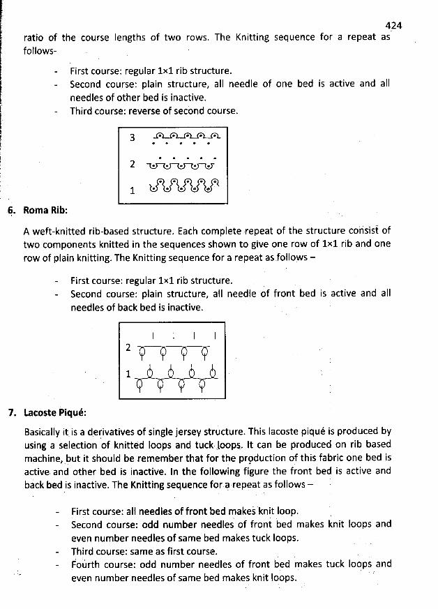
ratio of the course Iengths of two rows. The Knitting sequence for afollows-
424repeat as
First course: regular 1x1 rib structure.Second course: plain structure, aII needle of one bed is active and aIIneedles of other bed is inactive.Third course: reverse of secbnd course.
(-5. . f-5. f-s. f-5. :-3.3* @ o *' @
* e + @ e
2 . . . . .
* e * e o
@ * * o @1
Rom a Rib:
A weft-knitted rib-based structure. Each complete repeat of the structure cohsist oftwo components knitted in the sequences shown to give one row of 1x1 rib and onerow of plain knitting. The Knitting sequence for a repeat as follows -
First course: regular 1x1 rib structure.i b d is active and aIISecond course: plain structure, alI needle of fron e
needles of back bed is inactive.
2s2/W'////
7. Latoste Piqué:
Basically itis a derivatives of single jersey structure. This Iacoste piqué is produced byusing a selection of knitted loops and tuck rloop.. It can b: produced on rib basedmàchine,.but it should be remember that for the prpduction of this fabric one bed isactive. and other bed is inactive. In the following fijure the front bed is active andbick bed is inactive. Tbe Knitting sequencê for 4 repeat as follows -
First course: aIl needles of front bed makej knit Ioop.Second course: odd number needles of front bed makes knit loops andeven number needles of same bed makes tuck Ioops.Third course: same as first course.potirth course: odd number needles of front bed makes tuck Ioops andeven num ber needles of same bed makes knit Ioops.
( .'
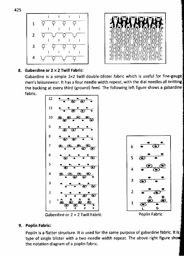
425
l I l
1I I I
2l I l l
3I I I I
4 V - W-V -C-
8. Gaberdine or 2 x 2 Twill Fabric:
Gabardine is a simplemen's Ieisurewear. It has a four needle width repeat,
2x2 twill double-blister fabric which is useful forwith the dial needles all
the backing at every third (ground) feed. The following Ieft figure shows afabric.
12 * * * ** * * *
11 * * e ** e * *
10 * e *+ e * e
9 e * * *œ œ * e
8 e * e *e o * *
7 œ * * ** * + +
6 * * * *œ œ e e
5 o *. e ** * o
4 * e e eœ + * *
3 o e . ee e e e
2 e * o *œ œ * e
$ % B A B1 e e e
e e e œ1 2 a 4
Gaberdine or 2 x 2 Twill Fabric
* *
6 * *
* *
5 * *
* *
4 * *
* *3 * *
* e2 . .
% e* *
1 . .t- s
Poplin Fabric
9. Poplin Fabrie:
Poplin is a flatter structure. lt is used for the same purpose of gabardine fabric. Ittype of single blister with a two needle width repeat.the notation diagram of a poplin fabric.
The above right figure
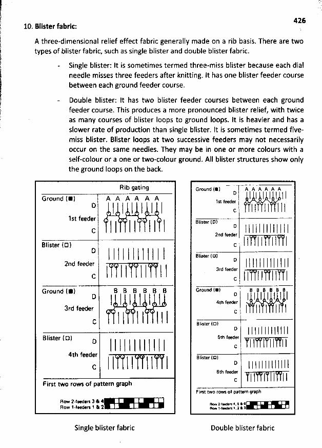
42610. Blister fabric:
A three-dimensional relief effect fabric generally made on a rib basis. There are twotypes of blister fabric, such as single blister and double blister fabric.
Single blister: It is sometimes termed three-m iss blister because each dialneedle misses three feeders after knitting. It has one blister feeder coursebetween each ground feeder course.
Double blister: lt has two blister feeder courses between each groundfeeder course. This produces a more pronounced blister relief, with twiceas many courses of blister Ioops to ground Ioops. It is heavier and has aslower rate of production than single blister. It is sometimes termed five-miss blister. Blister Ioops at two successive feeders may not necessarilyoccur on the same needles. They may be in one or more colours with aself-colour or a one or two-cojour ground. AII blister structures show onlythe ground Ioops on the back.
nib gating
Ground (*) A A A A A A
D I I l I I I1st feeder
l l I I #
'
l lC
D l I l I l I l 1 I I l I2nd feeder I l l l l l lC
Ground (*) B B B B B BD ! l I l l l
3rd feeder
I l I I . I I 1C
Blister ( D) n I l I I l l I I l I I I4th feederl I
. l l l l lCFirst two ro- of pattern graph
zrw ï'.:t*-: t l 1
Single blister fabric
Ground (*) A A A A A A::'
'
! I l I I I l l,st feeder j j j j j j j jC
Blister (D1'' 1 I l I I l I I I l I I I2nd feeerI l l I l I 1C
Blister ( D )''
'
l 1 I ! I I I l l l I I I3rd feeder
l l I l l I IC jGround (*) B B B B B 8
t' I I I I l l I4th feederl l l I l l l l
C
Blister ( D)o iI I I I l l I I l I l l I
5th fna--rI I l l I I lC
Blister ( E!)E'
'
I I I 1 I l I I l I I l I6th fte er
(:: I l l I l I 1First two rows of pattern graph
21t1--':7'11-111
Double blister fabric
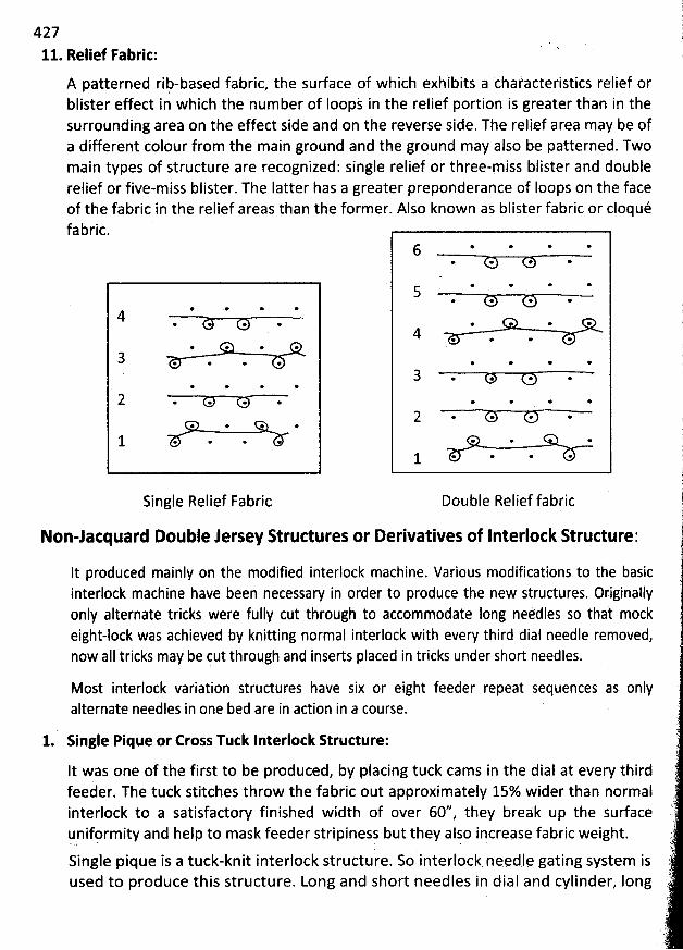
42711. Relief Fabric:
A patterned rib-based fabric, the surface of which exhibits a chasacteristics relief orblister effect in which the number of Ioopj in the relief portion is greater than in thesurrounding area on the effect side and on the reverse side. The relief area may be ofa different colour from the main ground and the ground may aljo be patterned. Twomain types of structure are recognized: single relief or three-miss blister and doublerelief or five-miss blister. The Iatter has a greater preponderance of Ioops on the faceof the fabric in the relief areas than the former. Also known as blister fabric or cloquéfabric.
@ * * @4@ * * @.
* * * *
3 @ @ @ @
* * * @
2 . . . .
@ * * @
1 . . . .
Single Relief Fabric
@' * * e6@. * * *
* * * *5* * * *
* * * *
4 e @ * *
@ œ * *
3 . . . . ' '* + *' @
2 . . . .* * *
1 . @ . *
Double Relief fabric
Non-lacquard Double lersey Structures or Derivatives of Interlock Structure:
lt produced mainly on the modified interlock machine. Various modifications to the basicinterlock machine have been necessary in order to produce the new structures. Originallyonly alternate tricks were fully cut through to accommodate long neédles so that mockeight-lock was achieved by knitting normal interlock with every third dial needle removed,now alI tricks may be cut through and inserts placed in tricks under short needles.
Most interlock variation structures have six or eight feeder repeat sequences as onlyalternate needles in one bed are in adion in a course.
1. Single Pique or Eross Tutk Interlock Structure:
It was one of the first to be produced, by placing tuck cams in the dial at every thirdfeeder. The tuck stitches throw the fabric out approximately 15% wider than normalinterlock to a satisfactory finished width of over 60'/ they break up the sudace!unifprmity and help to mask feeder stripiness but they alsp iqcrepse fabric weight.
Single pique is a tuck-knit interlock structure. So interlock nqed.l.e gating system isused to produce this structure. Long and short needles in dial and cylinder, Iong
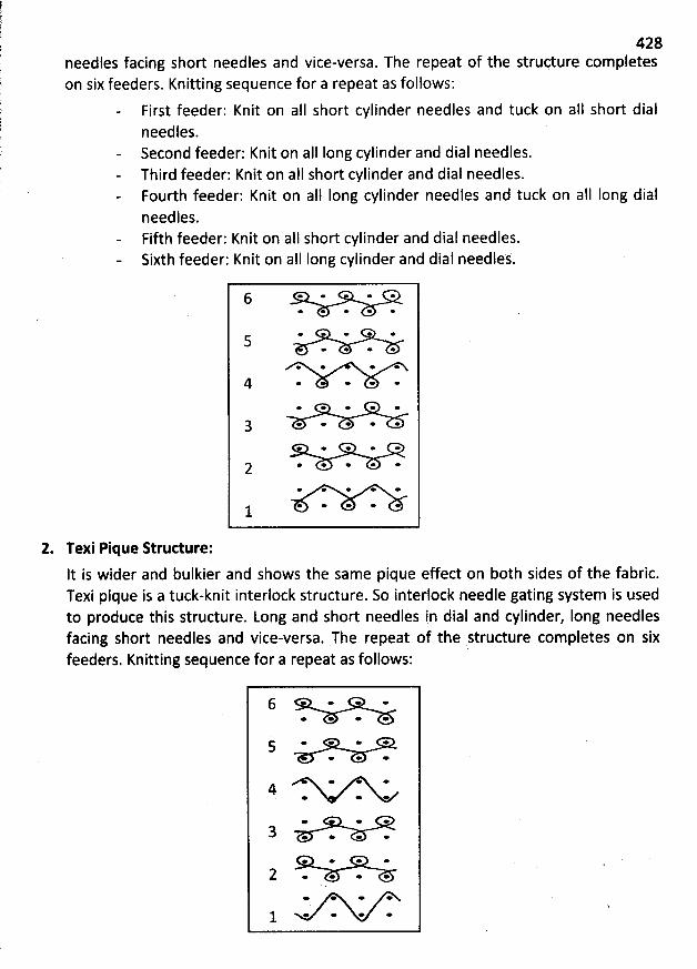
428needles facing short needles and vice-versa. The repeat of the structure completeson six feeders. Knitting sequence for a repeat as follows:
First feeder: Knit on all short cylinder needles and tuck on aI1 short dialneedles.Second feeder: Knit on all Iong cylinder and dial needles.Third feeder: Knit on alI short cylinder and dial needles.Fourth feeder: Knit on aII long cylinder needles and tuck on alI Iong dialneedles.Fifth feeder: Knit on al1 short cylinder and dial needles.Sixth feeder: Knit on all long cylinder and dial needles.
6 * * * *e o * e *
* * * e'5* * *
* e * *
4 * * * ** * * e *
g . . . . .+ * * * *
* * * * *2* * * * *
* e' * * *1
2. Texi Pique Strudure:
lt is wider and bulkier and shows the same pique effect on both sides of the fabric.Texi pique is a tuck-knit interlock structure. So interlock needle gating system is usedto produce this structure. Long and short needles in dial and cylinder, Iong needlesfacing short needles and vice-versa. The repeat of the structure completes on sixfeeders. Knitting sequence for a repeat as follows:
6 * œ ** œ * e
* * * e5+ * œ
* e4 * * *
* * *
3 . . .*
o * * *
2 . . . .+ e + *
j. * * * *
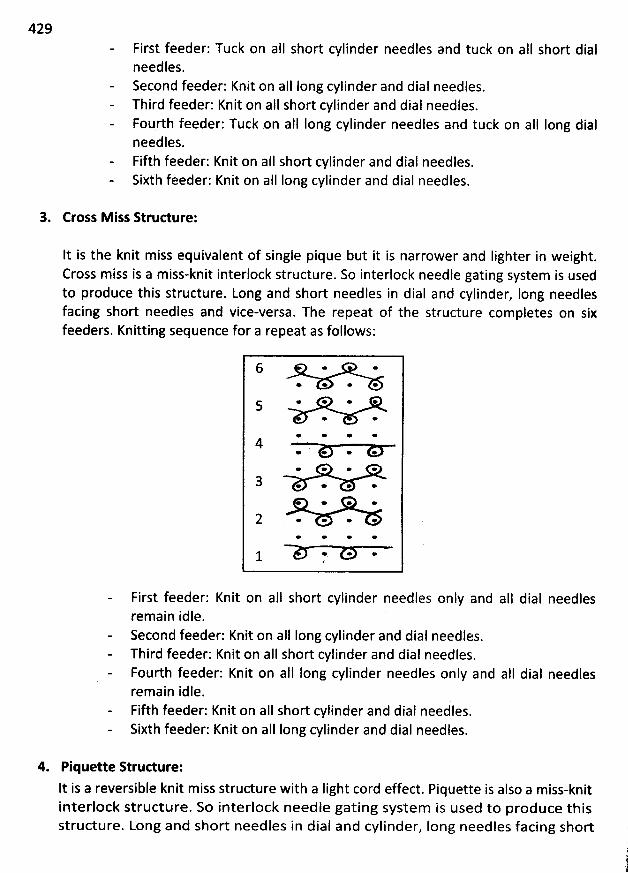
429First feeder: Tuck on aII short cylinder needles and tuck on alI short dialneedles.Second feeder: Knit on aII Iong cylinder and dial needles.Third feeder: Knit on aIl short cylinder and dial needles.Fourth feeder: Tuck .on all Iong cylinder needles and tuck on alI long dialneedles.Fifth feeder: Knit on alI short cylinder and dial needles.Sixth feeder: Knit on aII Iong cylinder and dial needles.
3. Cross M iss Structure:
lt is the knit miss equivalent of single pique but it is narrower and Iighter in weight.Cross miss is a miss-knit interlock structure. So interlock needle gating system is usedto produce this structure. Long and short needles in dial and cylinder, Iong needlesfacing short needles and vice-versa. The repeat of the structure com pletes on sixfeeders. Knitting sequence for a repeat as follows:
6 * ** * * *
* * e *5* *
+ * * *4
* * * *
* * œ *
3 . . .** * * *
2 . . . .* * * *
1 *' * *
First feeder: Knit on aII short cylinder needles only and aI1 dial needlesremain idle.Second feeder: Knit on all Iong cylinder and dial needles.Third feeder: Knit on aII short cylinder and dial needles.Fourth feeder: Knit on aII long cylinder needles only and aIl dial needlesremain idle.Fifth feeder: Knit on aII short cylinder and dial needles.Sixth feeder: Knit on aII Iong cylinder and dial needles.
4. Piquette Structure:
It is a reversible knit miss structure with a Iight cord effect. Piquette is also a m iss-knitinterlock structure. So interlock needle gating system is used to produce thisstructure. Long and short needles in dial and cylinder, Iong needles facing short
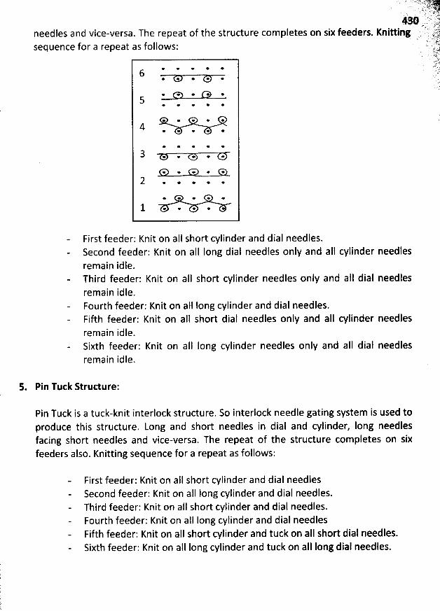
needles and vice-versa. The repeatsequence for a repeat as follows:
of the structure completes on
. . '.. 'ty: J4.'F .. . ....z.. J7%.. .
'
''
'
'
'
..;
'
:éL. .
'
..
'
..(;jki..
'
.. ...54' .. .s uy :jjz . .s5x
w * r' m'' slil''sIx feeders. Kn1 Ing ,1.5.. R.Q'. . . ' ' k!- F Y. . . ry. ,j. sak ' . . ' r... ;.l
7'.4r'L-* * * * *
6* * * * *
. . . .&. . .5
* e * * *
* * * * *
4 * * * * @
* * e e *
3 . . . . .
e * * e +
2 . . . . .
* * o * e
1 . . . . .
First feeder: Knit on all short cylinder and dial needles.Second feeder: Knit on aII long dial needles only and aIl cylinder needlesremain idle.Third feeder: Knit on aII short cylinder needles only and aIl dial needlesremain idle.Fourth feeder: Knit on aII long cylinder and dial needles.Fifth feeder: Knit on aIl short dial needles only and aII cylinder needlesremain idle.Sixth feeder: Knit on aII Iong cylinder needles only and aII dial needlesremain idle.
5. Pin Tuck Strudure:
Pin Tuck is a tuck-knit interlock structure. So interlock needle gating system is used toproduce this structure. Long and short needles in dial and cylinder, Iong needlesfacing short needles and vice-versa. The repeat of the structure completes on sixfeeders also. Knitting sequence for a repeat as follows:
First feeder: Knit on all short cylinder and dial needlesSecond feeder: Knit on aII Iong cylinder and dial needles.Third feeder: Knit on aII short cylinder and dial needles.Fourth feeder: Knit on aII Iong cylinder and dial needlesFifth feeder: Knit on aII short cylinder and tuck on aII short dial needles.Sixth feeder: Knit on all long cylinder and tuck on aIl Iong dial needles.
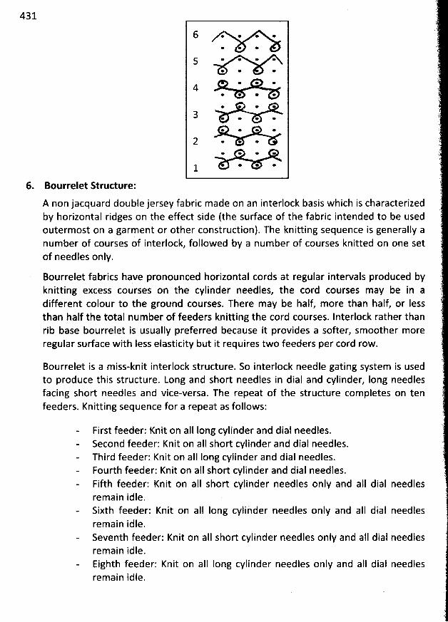
431
6 . . . .* *
5 * * * ** e *
* + *4
* * e *
o *
3 * * * *e * * *
2 . . .e * * e
* * *1
6. Bourrelet Structure:
A non jacquard double jersey fabric made on an interlock basis which is characterizedby horizontal ridges on the effect side (the surface of the fabric intended to be usedoutermost on a garment or other construction). The knitting sequence is generally anumber of courses of interlock, followed by a num ber of courses knitted on one setof needles only.
Bourrelet fabrics have pronounced horizontal cords at regular intervals produced byknitting excess courses on the cylinder needles, the cord courses may be in adifferent colour to the ground courses. There m ay be half, more than half, or Iessthan half the total number of feeders knitting the cord courses. Interlock rather thanrib base bourrelet is usually preferred because it provides a softer, smoother moreregular surface with Iess elasticity but it requires two feeders per cord row.
Bourrelet is a miss-knit interlock structure. So interlock needle gating system is usedto produce this structure. Long and short needles in dial and cylinder, long needlesfacing short needles and vice-versa. The repeat of the structure completes on tenfeeders. Knitting sequence for a repeat as follows:
First feeder: Knit on aII Iong cylinder and dial needles.Second feeder: Knit on aII short cylinder and dial needles.Third feeder: Knit on aII Iong cylinder and dial needles.Fourth feeder: Knit on aII short cylinder and dial needles.Fifth feeder: Knit on aII short cylinder needles only and aII dial needlesremain idle.Sixth feeder: Knit on aII long cylinder needles only and aII dial needlesremain idle.Seventh feeder: Knit on alI short cylinder needles only and aII dial needlesremain idle.Eighth feeder: Knit on aII Iong cylinder needles only and aII dial needlesremain idle.
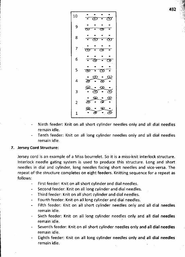
* * * *10* * * *
* * * *9* * e e
* * * *8 * e * *
* * * *
e e * œi
* * * *
* * * *
* * * *
* * * *
* * * *
4 . . .* * * e
* * * *
* * *
* * *
* * *
+ * *1
Ninth feeder: Knit on alI short cylinder needles only and aII dial needlesremain idle.Tenth feeder:remain idle.
7. Jersey Cord Structure:
Knit on aII Iong cylinder needles only and .aIl dial needles
Jersey cord is an example of a M iss bourrelet. So it is a miss-knit interlock structure.Interlock needle gating system is used to produce this structure. Long and shortneedles in dial and cylinder, Iong needles facing short needles and vice-versa. Therepeat of the structure completes on eight feeders. Knitting sequence for a repeat asfollows:
First feeder: Knit on aII short cylinder and dial needles.Second feeder: Knit on aII Iong cylinder and dial needles.Third feeder: Knit on aII short cylinder and dial needles.Fourth feeder: Knit on aII Iong cylinder and dial needles.Fifth feeder: Knit on aII short cylinder needles only and alI dial needlesremain idle.Sixth feeder: Knit on aIl long cylinder needles only and aII dial needlesremain idle. '
Seventh feeder: Knit on a1I short cylinder needles only and aII dial needlesremain idle.Eighth feeder: Knit on aII Iong cylinder needles only and all dial needlesremain idle.
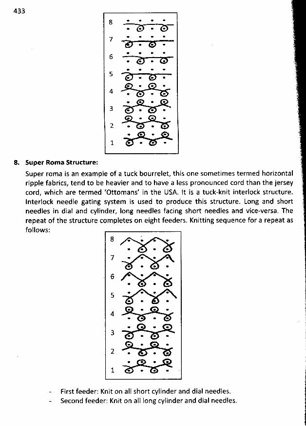
433
e * * *8e œ e *
* e * *7o * *
e * * *6
* * * *
* * œ *5
* * + *
e * o *
4 * * * ** e * *
3 . . . .* e * *
2 . . . .* * * *
1 * * * œ
8. super Rom a Strutture:
Super roma is an exam ple of a tuck bourrelet, this one sometimes termed horizontalripple fabrics, tend to be heavier and to have a Iess pronounced cord than the jerseycord, which are termed 'Ottomans' in the USA. lt is a tuck-knit interlock structure.Interlock needle gating system is used to produce this structure. Long and shortneedles in dial and cylinder, Iong needles facing short needles and vice-versa. Therepeat of the structure completes on eight feeders. Knitting sequence for a repeat asfollows:
8 . . . .e e e *
7 . * * *e * * +
6 * * ** * œ *
* * * *5* * *
* * * *4
* * e *
* * * e
3 * * * *
* * * *
2 . . .* * * *
1 * * * .
First feeder: Knit on aII short cylinder and dial needles.Second feeder: Knit on aIl Iong cylinder and dial needles.
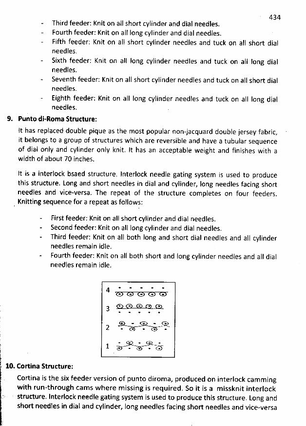
434Third feeder: Knit on aII short cylinder and dial needles.Fourth feeder: Knit on aII Iong cylinder and dial needles.Fifth feeder: Knit on al1 short cylinder needles and tuck on all short dialneedles.Sixth feeder: Knit on aII Iong cylinder needles and tuck on aII Iong dialneedles.Seventh feeder: Knit on aII short cylinder needles and tuck on aII short dialneedles.Eighth feeder: Knit on aII Iong cylinder needles and tuck on aII Iong dialneedles.
9. Punto di-Roma R rudure:
lt has replaced double pique as the most popular non-jacquard double jersey fabric,it belongs to a group of structures which are reversible and have a tubular sequenceof dial only and cylinder only knit. It has an acceptable weight and finishes with awidth of about 70 inches.
It is a interlock bsaed structure. Interlock needle gating system is used to producethis structure. Long and short needles in dial and cylinder, Iong needles facing shortneedles and vice-versa. The repeat of the structure completes on four feeders
.
Knitting sequence for a repeat as follows:l .
First feeder: Knit on aII shor't cylinder and dial needles.Second feeder: Knit on aIl Iong cylinder and dial needles.Third feeder: Knit on aII both Iong and short dial needles and aII cylinderneedles remain idle.Fourth feeder: Knit on alI both short and long cylinder needles and aII dialneedles remain idle.
k
)
jl!-
'
. .
t. 10. Eortina Structure:
Cbrtina is the six feeder version of punto diroma, produced on interlock camm ingw ith run-through cam s where m issipg is required. So it is a m issknit interlock
k) structure. lnterlock needle gating system is used to produce this structure. Long and
short needles in dial and cylinder, Iong needles facing short needles and vice-versa
(! .
* œ * * *4
3
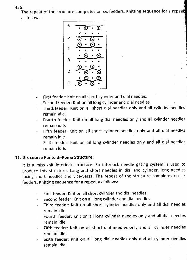
435The repeat of the structure com pletes on six feeders.as follows:
6* @ * *
@' @ * *
@ @ * *
* * * @
* @ @ *
. . . 0.@ * * @
@ @ @ *
@ @ @ @
# @ * @
. . p . .
t,i
Knitting sequence for a repea
)'
.1l11i1'(!1
dial needles.First feeder: Knit on aII short cylinder andSecond feeder: Knit on aII long cylinder and dial needles.Third feeder: Knit on alI short dial needles only and aII cylinder needles jrem ain idle.Fourth feeder: Knit on aIl Iong dial needles only and aII cylinder needlesremain idle.Fifth feeder: Knit on a1l short cylinder needles only and aII dial needles
remain idle.Sixth feeder: Knit on aIl long cylinder needles only and aII dial needlesremain idle.
11. Six course Punto di-Rom a Structure:
lt is a m iss-knit interlock structure. So interlock needle gating system is used toproduce this structure. Long and short needles in dial and cylinder, long needlesfacing short needles and vice-versa. The repeat of the structure completes on sixfeeders. Knitting sequence for a repeat as follows:
First feeder: Knit on aIl short cylinder and dial needles.Second feeder: Knit on all long cylinder and dial needles.Third feeder: Knit on aIl short cylinder needles only and aIl dial needlesremain idle.Fourth feeder: Knit on aIl Iong cylinder needles only and aII dial needlesremain idle. 'Fifth feeder: Knit on aII short dial needles only and alI cylinder needlesremain idle.Sixth feeder: Knit on alI long dial needles only and aII cylinder needlesrem ain idle.
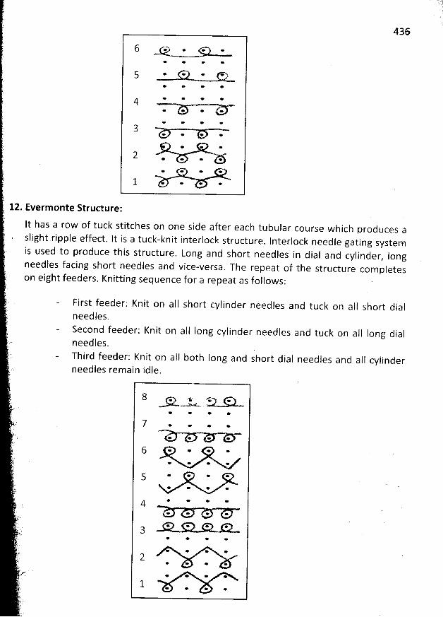
436
* * * *
* * * *
5 * G* * U** * * *
* * + *
* * * *
* * * *3
+ * * *
* * *
2 . . . ö.* * * *
1 . . .
12. Evermonte Structure:
It has a row of tuck stitches on one side after each tubular course which produces a
slight ripple effect. It is a tuck-knit interlock structure. Interlock needle gating systemis used to produce this structure. Long and short needles in dial and cylinder
, longneedles facing short needles and vice-versa
. The repeat of the structure completeson eight feeders. Knitting sequence for a repeat as follows:
First feeder: Knit on aIl short cylinder needles and tuck on alI short dialneedles.Second feeder: Knitneedles.Third feeder: Knit on aI1 b0th Iong andneedles remain idle.
short dial needles and aII cylinder
on alI Iong cylinder needles and tuck on aII Iong dial
8 . .x. . .e .N t- .. '
* * * e
7 . . . .+ * * *
6 * * . .+ * * *
* * * *
* * * œ
* * * *4* * e *
. . (3p. ::7. '* e * *
* * e *
* * *
* * * +
* * * *
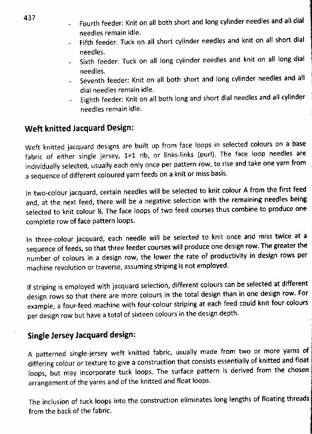
437 Fourth feeder: Knit on aII both short and long cylinder needles and all dial
needles remain idle.Fifth feeder: Tuck on alI short cylinder needles and knit on a!I sbort dial
needles.Sixth feeder: Tuck on aII Iong cylinder needles and knit on aII Iong dial
needles.Seventh feeder: Knit on all both short and long cylinder needles and aIl
dial needles remain idle.Eighth feeder: Knit on aIl both Iong and short dial needles and a1I cylinder
needles remain idle.
W eft knitted Jacquard Design:
Weft knitted jacquard designs are built up from face Ioops in selected colours on a basefabric of either single jersey, 1x1 rib, or Iinks-links (purl). The face Ioop needles areindividually selected, usually each only once per pattern row, to rise and take one yarn froma sequence of different coloured yarn feeds on a knit or m iss basis.
ln two-colour jacquard, certain needles will be selected to knit colour A from the first feedand, at the next feed, there will be a negative selection with the remaining needles beingselected to knit colour B. The face Ioops of two feed courses thus combine to produce one
com plete row of face pattern Ioops.
ln tbree-colour jacquard, each needle will be selected to knit once apd miss twice at asequence of feeds, so that three feeder courses will produce one design row. The greater thenumber of colours in a design row, the Iower the rate of productivity in design rows permachine revolution or traverse, assuming striping is not employed.
If striping is employed with jacquard selection, different colours can be selected at differentdesign rows so that there are more colours in the total design than in one design row. Forexample, a four-feed machine with four-colour striping at each feed could knit four coloursper design row but have a total of sixteen colours in the design depth.
?Single Jersey Jacquard design: j1
. çA patterned single-jersey weft knitted fabric, usuallv made from two or more yarns of jdiffering colour or texture to give a construction that consists essentialjy of knitted and floatIoops, but may incorporate tuck loops. The surface pattern is derived from the chosenarrangement of the yarns and of the knitted and float Ioops.
The inclusion of tuck Ioops into the construction eliminates Iong Iengths of floating threads
from the back of the fabric.
r
'
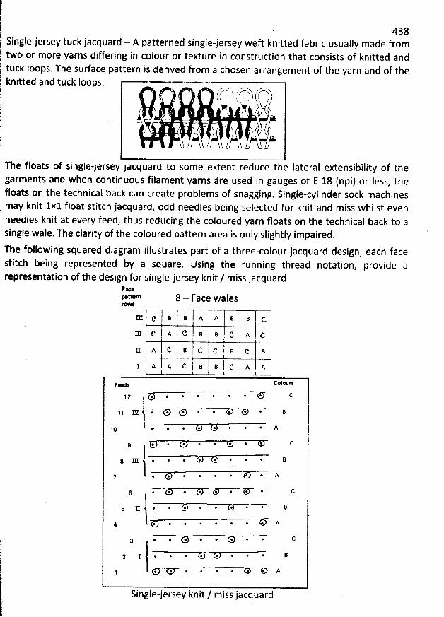
Single-jersey tuck jacquard - A patterned single-jersey weft knitted fabrictwo or more yarns differing in colour or texture in construction that consists of knitted andtuck loops. The surface pattern is derived from a chosenknitted and
arrangement of the yarn and of the
r fr-m',, '-x'''.. hI $ ' t ;! ''e f :! ,A - +
, '
yj#The floats of singlejersey jacquàrd to some extent reduce the Iateralgarments and when continuous filament yarns âre used in
tuck Ioops.
extensibility of thegaugesof E 18(npi) or Iess, the
floats on the technical back can create problems of snagging. Single-cylinder sock machinesmay knit 1x1 float stitch jacquard, odd needles being selected for knit and miss whilst evenneedles knit atsingle wale. The clarity of the coloured pattern
every feed, thus reducing thecoloured yarn floats on the technical back to aarea is only slightly impaired.
438usually made from
The following squared diagram illustrates part of a three-colour jacquard design, each facestitch being represented by a square. Using the running thread notation
, provide arepresentation of the design for single-jersey knit / miss jacquard.
Fa>ettern 8 - Face walesr@w:
' B I B d.IE c B B A Am c A C B e c A c
c I A c B c I c I B I c A1a,B.'c AlAjI A I A I C11-
*
1i
'
'
'
I(. 1,. 11
*
,... 11 11Faw'',h 091* 0
1 2 @ * * * * * * * O
1 1 X * * * * * * * * B
@ @ * * * * * * A10
9
g m * @ * *' * @ * @ B
7 * * * * * * * * X
* * *' * @ * * @
5 S * * * * * * * * 8
4 @ * * * * @ * * A
@ @ * * * * * *3
I @ @ * * @ * @ * B
. *. @ * * * * * A
Single-jersey knit / miss jacquard
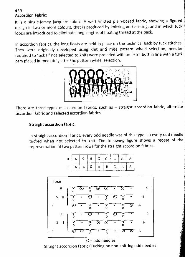
439Accordion Fabric:lt is a single-jersey jacquard fabric. A weft knitted plain-based fabric, showing a figureddesign in two or more colours, that is produced by knitting and missing, and in whichloops are introduced to eliminate Iong Iengths of floating thread at the back.
In accordion fabrics, the long floats arq held ln place on the technical back by tuck stitches.They were originally developed using knit and miss pattern wheel selection, needlesrequired to tuck (if not selected to knit) were provided with an extra butt in line with a tuckcam placed im mediately after the pattern wheel selection.
, ,' . . ', --, . z /. -qt î/! h / ; ts î- 73 y1 yf .hç ,,: )h
'
Sj ' ,' ,. h ' . h ., :/ , . ; f j Fs
. # , y, r , ( yg t, !
w #. s ;
,$ . . .k
'
. , j
'
j ..( 1 . ; ( y j .k 1 t $ . N? .
tz.z ' h / V-- '': - ' 't.p 'o L, .r9--1./- /.J ' lo
of accordion fabrics, such as - straight accordion fabric, alternateselected accordion fabrics.
There are three typesaccordion fabric and
Straight accordion fabric;
In straight accordion fabrics, every odd needle was of this type, so every oddtucked when not selected to knit. The following figure shows a repeat ofrepresentation of two pattern rows for the straight accordion fabrics.
needle
11 A C B C c B C, A
1 A A C B B C A A
Feeds
6 . . . . . . C. o O
6 .(I . @ . . @ BO O O
4 * *. . . . . AO O O
3 * @ * . . cO O O
2 I * . . + @ BO O O
@ @ . *. * . AO O
O = odd needlesStraight accordion fabric (Tucking on non-knitting odd needles)
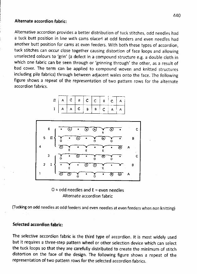
440Alternate accordion fabric:
Alternative accordion provides a better distribution of tuck stitches, odd needles had
a tuck butt position in Iine with cams nlace/i at odd feeders and even needles hadanother butt position for cams at even feeders. W ith both these types of accordion
,tuck stitches can occur close together causing distortion of face Ioops and allowing
unselected colours to 'grin' (a defect in a compound structure e.g. a double c10th inwhich one fabric can be seen through or 'grinning through' the other
, as a result ofbad cover. The term can be applied to compound woven and knitted structures
including pile fabrics) through between adjacent wales onto the face. The followingfigure shows a repeat of the representation of two pattern rows for the alternateaccordion fabrics.
=
c a c c t B t c. x i11 A1 A A C B B C A A
6 * @ . * * * * CE
5 11 * @ * * * BO O O
4 @ * @ * * AE E E
. . @ . @ CO O O
2 1 @ * * * *E E
1 @ . @ @ . * A0 O
O = odd needles and E = even.needlesAlternate accordion fabric
(Tucking on odd needles at odd feeders and even needles at even feeders when non knitting). (
'
:
selected accordion fabric:
The selective accordion fabric is the third type of accordion. It is most widely used
but it requires a three-step pattern wheel or other selection device which can selectthe tuck Ioops so that they are carefully distributed to create the minimum of stitchdistortion on the face of the design. The following figure shows a repeat of therepresentation of two pattern rows for the selected accordion fabrics
.
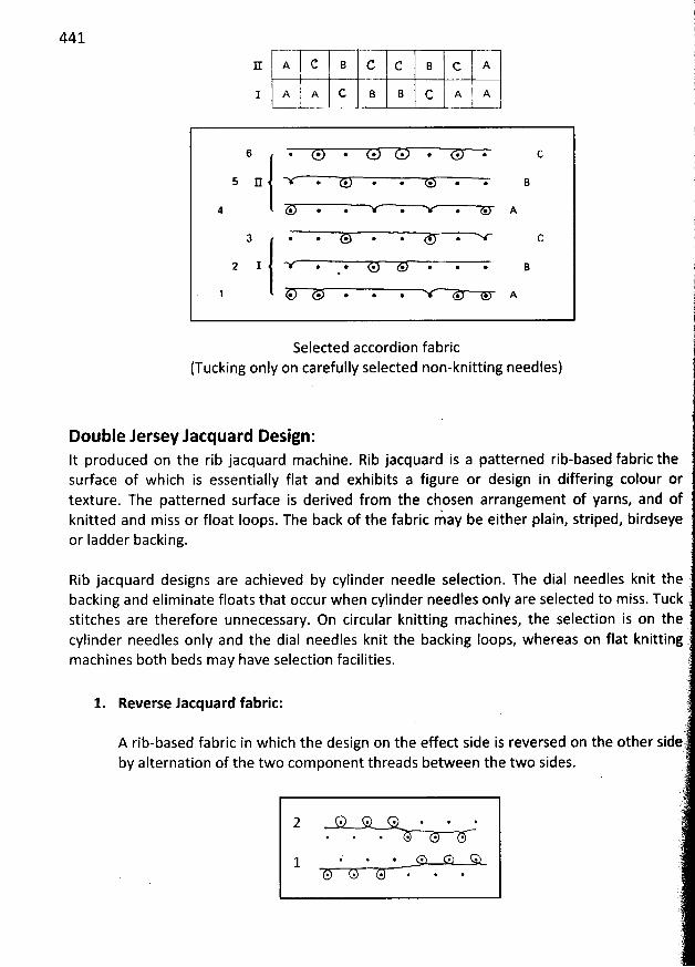
441
Ix A C B c c B c A
I x A c B e c 1 x 1 A I
6 . * . @ . @ . . c
5 11 . @ @ o * . . B
4 . . . @ . @ A
3 . . @. . @ . C
2 I . *' . @. . . . B
1 . . . . @ . . A
Selected accordion fabric(Tucking only on carefully selectednon-knitting needles)
Double Jersey lacquard Design:It produced on the rib jacquard machine. Rib jacquard is a patterned rit-based fabric thesurface of which is essentially flat and exhibits a figure or design in differing colour ortexture. The patterned surface is derived from the chosen arrangement of yarns, and ofknitted and miss or float Ioops. The back of the fabric m- ay be either plain, striped, birdseyeor Iadder backing.
Rib jacquard desighs are achieved by cylinder needle selection. The dial needles knit thebacking and eliminate floats that occur when cylinder needles only arestitches are therefore unnecessary. On circular knitting machines, the selection is on thecylinder needles only and the dial needles knit the backing Ioops, whereas on flat
selected to miss. Tuck
machines both beds may have selection facilities.
1. Reverse lacquard fabric:
A rib-based fabric in which the design on the effect side is reversed on the otherby alternation of the two component threads between the two sides.
; * @ * * @ @@ @ . @. *. @
i p * * * @1* * @ @ @. @
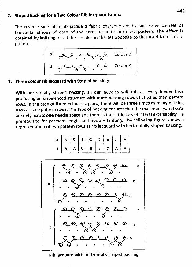
4422. Striped Backing for a Two Colour Rib Jacquard Fabric:
The reverse side of a rib jacquard fabric characterized by successive courses ofhorizontal stripes of each of the yarns used to form the pattern. The effect isobtained by knitting on aII the needles in the set opposite to that used to form the
pattern.
. . . . . . colour B* @ * * * *
--,k . s.!' .k,. /-k7'' '-' k2%:w
- -w. Colour A* * * @ * *
3. Three colour rib Jacquard with Striped backing:
W ith horizontally striped backing, ajl dial needles will knit at every feeder thusproducing an unbalanced structure with more backing rows of stitches than patternrows. ln the case of three-colour jacquard, there will be three times as many backingrows as face pattern rows. This type of backing ensures that the maxim um yarn floatsare only across one needle space and there is thus little Ioss of Iatçral extensibility - aprerequisite for garment Iength and hosiery knitting. The following figure shows arepresentation of two pattern rows as rib jacquard with horizontally-striped backing.
a A c B c c B c l A1 A A C B B C j A A
& * * * * e * *
* * * * * e *
* e @ * e * * *B
* * * *
* e * * + + * A
e * * * *
* * o e e œ * +
* e * e
e * * * * * .B
I* * o * e
* e * * œ * * A
* * * * *
Rib jacquard with horizontally striped backing
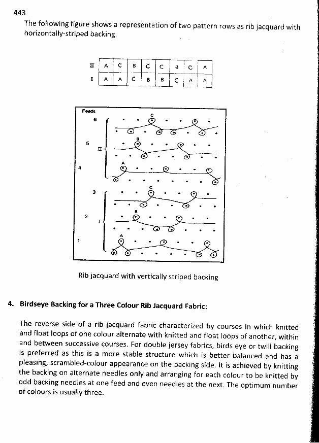
443
The following figure shows a representation of two pattern rows as rib jacquard withhorizontally-striped backing.
V--U-=:II A C a C c B ; c. i A- >- ol -
I A A C 8 B C A ! A) .- -t-
FC
6 * + . o .
*' *. + o @ o o .
B5 * e * e o œ
E .* *' e œ @ * > o
A4 * + + + + .
@ * * o o
C*. e' @ e e @
* e * * @. @ *
+ @ @ + . .1
* œ @. @. e .
Aj * + . . . . .
* *. o @ . . >
Rib jacquard with vertically striped backing
4. Birdseye Backing for a Three Colour Rib Jacquard Fabric:
The reverse side of a rib jacquard fabric characterized by courses in which knittedand float loops of one colour alternate with knitted and float Ioops of another
, withinand between successive courses. For double jersey fabrics, birds eye or twill backingis preferred as this is a more stable structure which is better balanced and has apleasing, scram bled-colour appearance on the backing side
. It is achieved by knittingthe backing on alternate needles only and arranging for each colour to be knitted byodd backing needles at one feed and even needles at the next
. The optimum numberof colours is usually three.
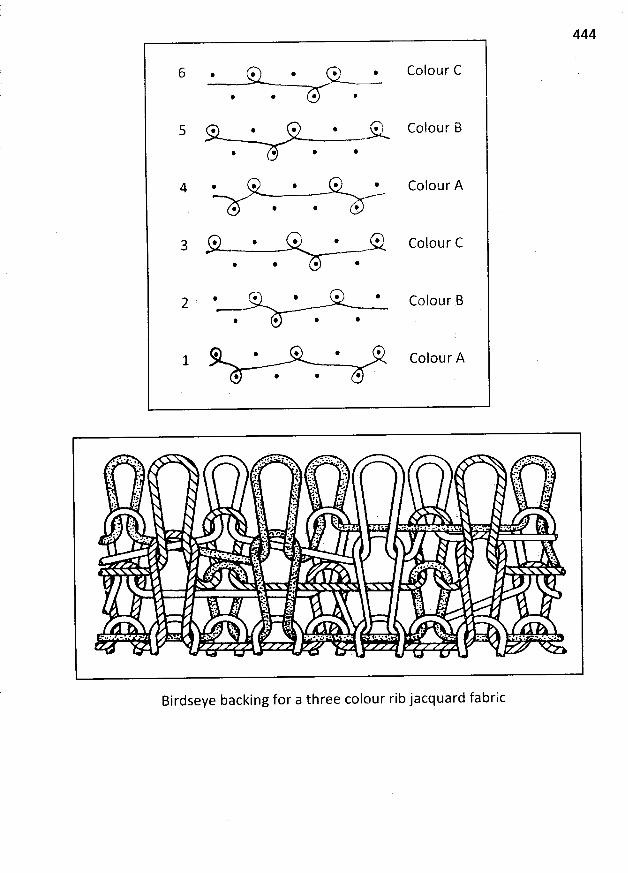
444
6 . . . . . Colour C
@ * @ @
s . . . . Z-7. c o I o u r B* @ * *
4 . . . . . colour A
@ * @ F
a . . . . ., colour c@ @ @ *
. G @ . @ j :Co our .
* @ @ @
@ @ * @ * Colour A@ @ @ * '
Birdseye backing for a three colour rib jacquard fabric
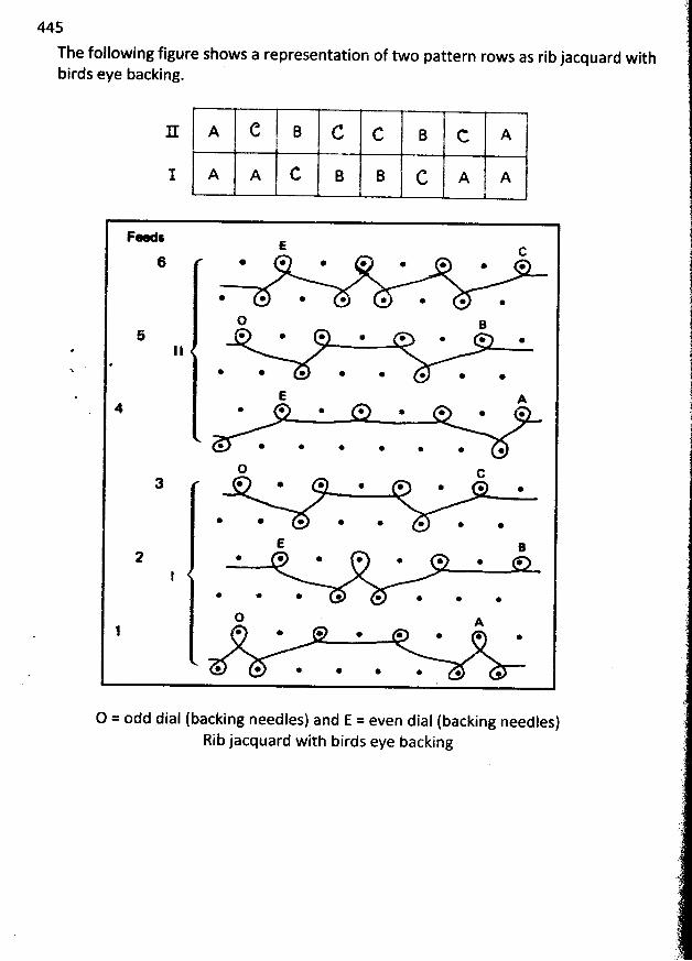
445
The following figure shows a representation of two pattern rows as rib jacquard withbirds eye backing.
r A C B C c B c A
1 A A C B B C A j Aj
'
Fe : E c
6 @ @ * * @ o . @
* * @ * @ @ @ @
O B5 * @ o . . . . .
11#'
@ * * @ @ @ @
E A4 * @ @ . . . . .
@ * * @ @ . .
O c
* * @ @ @ .
E B
* * @ * @
D A1 * @ . . . .. . .
* @ @ @ @ . . .
O = odd dial (backing needles) and E = even dial (backing needles)Rib jacquard with birds eye backing
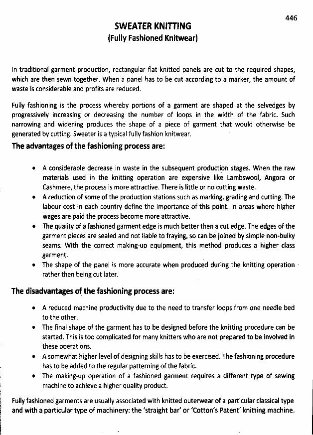
446SW EATER KNIU ING
(FuIIy Fashioned Knitwear)
ln traditional garment produdion, rectangular flat knitted panels are cut to the required shapes,which are then sewn together. W hen a panel has to be cut according to a marker, the amount ofwaste is considerable and profits are reduced.
Fuily fashioning is the process whereby portions of a garment are shaped at the selvedges byprogressively increasing or decreasing the number of Ioops in the width of the fabric. Suchnarrowing and widening produces the shape of a piece of garment that would otherwise begenerated by cutting. Sweater is a typical fully fashion knitwear. '
The advantages of the fashioning protess are:
A considerable decrease in waste in the subsequent produdion stages. W ben the rawmaterials used in the knitting operation are expensive Iike Lambswool, Angora orCashmere, the process is more attractive. There is Iittle or no cutting waste.A reduction of some of the produdion stations such as marking, grading and cutting. TheIabour cost in each country define the importance of this point. In areas where higherwages are paid the process become more attractive.
* The quality of a fashioned garment edge is much better then a cut edge. The edges of thegarment pieces are sealed and not Iiable to fraying, so can be joined by simple non-bulkySeams. With the corred making-up equipment, this method produces a higher classgarment.
* The shape of the panel is more accurate when produced during the knitting operation 'rather then being cut Iater.
The disadvantages of the fashioning process are:
A reduced machine productivity due to the need to transfer Ioops from one needle bedto tbe other.The final shape of thé garment has to be designed before the knitting procedure can bestarted. This is too complicated for many knitters who are not prepared to be involved inthese operations.
* A Somewhat higher Ievel of designing skills has to be exercised. The fashioning procedurehas to be added to the regular patterning of the fabric.
* The making-up operation of a fashioned garment requires a different type Df sewingmachine to achieve a higher quality product.
Fully fashioned garments are usually associated with knitted outerwear of a particular classical typeand with a particular type of machinery: the 'straight bar' or 'Cotton's Patent' knitting machine.
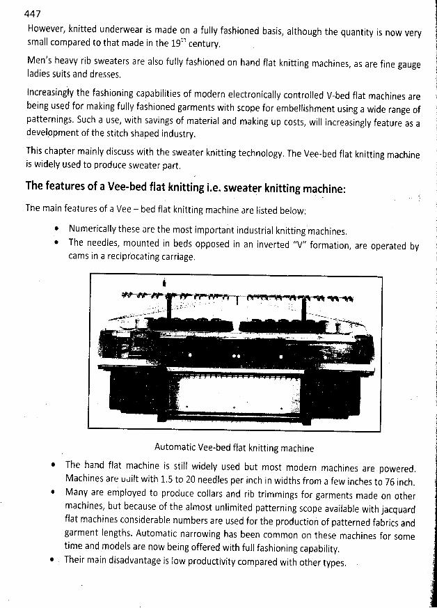
447
However, knitted underwear is made on a fuily fashioned basis, asthough the quantity is now very
thsmall compared to that made in the 19 century.
Men's heavy rib sweaters are also fully fashioned on hand flat knitting machines, as are fine gauge
Iadies suits and dresses.
lncreasingly the fashioning capabilities of modern electronically controlled V-bed flat machines arebeing used for making fully fashioned garments with scope for embellishment using a wide range ofpatternings. Such a use, with savings of materia! and making up costs
, will increasingly feature as adevelppment of the stitch shaped industry.
This chapter mainly discuss with the sweater knitting technology. The Vee-bed flat knitting machine
is widely used to produce sweater part.
The features of a Vee-bed flat knitting i-e. sweater knitting machine:
The main features of a Vee - bed flat knitting machine are Iisted below:
* Numerically these are the most important industrial knitting machines.
* The needles, mounted in beds opposed in an inverted 'fV'' formation, are operated by
cams in a reciprocating carriage.
Automatic Vee-bed flat knitting machine
@ The hand flat machine is still widely used but most modern machines are powered.
Machines are udilt with 1.5 to 20 needles per inch in widths from a few inches to 76 inch.
@ Many are employed to produce collars and rib trimmings for garments made on other
machines, but because of the almost unlimited patterning scope available with jacquardflat machines considerable numbers are used for the production of patterned fabrics andgarment Iengths. Automatic narrowing has been common on these machines for sometime and models are now being offered with full fashioning capability
.
Their main disadvantage is Iow productivity compared with other types.
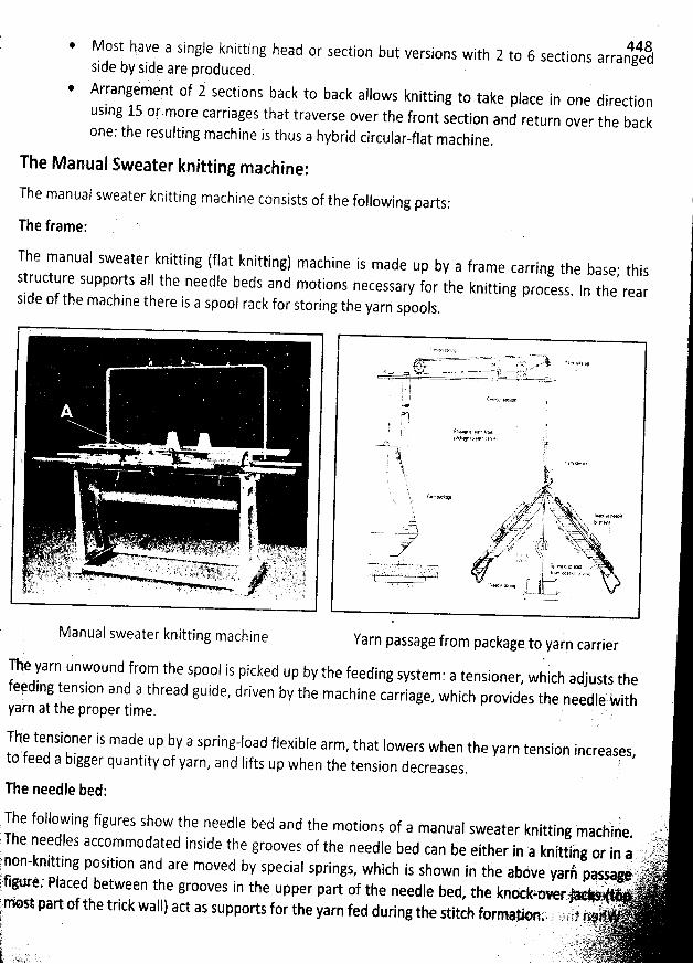
448w Most have a single knitting head or section but versions with 2 to 6 sections arranged
side by side are produced.
* Afrangémvpt of 1 sections back to back allows knitting to take place in one direction
using 15 or.more carriages that traverse over the front section and return over the backone: the resulting machine is thus a hybrid circular-flat machine.
The M anual Sweater knitting machine:
!tmachine consists of the following parts:
:The manual sweater knitting (flat knittiùg) machine is made up by a frame carring the base; thisst
ructure supjorts aII the needle beds and motions necessary for the knitting process. In the rear .side of the machine there is a spool rack for storing the yarn spools
.
k
' a.- ,.-. 7. = lo ; .- .,- .. .yk. . l '. ,.w .w ... . . - .. w.w.. . . . ' .- * L.k .
ï ' 't . '' C 'J *
'
'' . w,. 'z ' l .'k. . ' ' : ' ' J' Jm ' : - '
j'.'& ' , k.
y
s ' ./ -
- '
j ;( ''' ' . . '. . ' 2 ..'' . .n ....<k. .. . , . , . . ; . y, .?.. .
.'
zy
'
j hktk '%>...xx. jg ar.yyyyjgja, ,4:,jj,.'s z , . jjyjj' ,h. )j)jj.. .. . . qs. ,. . . -r;y- --- .j y --- lskts yytyyt .-hîkkk... ly')
. .
'
.);j:,j;L',, drj-dtr-lahh y-tsk--- vor
.
.... .
. v' .) -. '' .'k .k ,1 . ..... .. ' .-c -' .. .. '' . . x :66333. . . ...7', s F 't ':7. yj xàbxjb:; kq,i ir . 7 ?-V'' ' ,r . .. ,li)j. ' ' ''kt . . . - - :'-'- - %' ' - - -k ' '- '''?r ' -'' L;''*. ' ' !; '( . .-'qï1 7. '...tJ. >: -':tg; ,) (j) ' 1' -' i j lyr.. - tj;,$ a, ,, ec j; v- - ,. ..- ,'- . c.:-tpl );77?jJ!/,. ' . : ) à' .''k. ' t . t. ..qvk :-,.- . .y '.. . . .- 4jk,wm.;.. -. - ' '. / (k .'. - :ï . -;. ; y. j
t -.- ,r oc è. &.f .-1.:'th/ -t''1tlg-' ak :4(-:,,:ytè$y. . -. v,, , --L- . . . ' à' ' '' -t.).,.7. '1.. 'u3iï77ôï-F7lh -bt3'2.. '....:; ;t.'.. jq?.; .; TLL -t q)t -;!jt.+t .- e,:, k, qn,,rsr f'-----d '--'..z -----...,-.
7jt gr , .-,; . .. . . . . - .t .. . y 2 y:..y.r ..ky ......
( ? . '. . ' ' à. ..,. N . . . . . . . ' '.
..jy . .lli'x.'.a .. '' ' .
Manual sweater knitting machine Yarn passage from package to yarn carrier
The yarn unwound from the spool is picked up by the feeding system: a tensioner, which adjusts thefeè
, ding tension and a thread guide, driven by the machine carriage, which provides the needle With .'
t the proper time.yarn a
Th'e tensioner is made up by a spring-load flexible arm, that Iowers when the yarn tension increases
,to feed a bigger quantity of yarn, and Iifts up when the tension decreases. '
The needle bed:
q )( The following figures show the needle bed and the motions of a manual sweater knitting machine
. )',(., 2 ; ''i.yThe needles accommodated inside the grooves of the needle bed can be either in 'a knittihg or in a p',rlj)taqê k itting position and are moved b
y special springs, which is shown in the aböve yari pasjag#'rr
k''pff' ' non- n
j -') - ' ' r '. . . 1 ' t .B ikfigur..' Placed between the grooves in the upper part of th
e needle bed, the knotkyoe rz' .j:
,
è . .)) ... t,e :r*k part of the trick wall) act as supports for the yarn fed during the stitch formie n.', 7 ;.?;i'1 /$, tzjv.
. j ijjtyy .- : y yyyjs.-.
'.'- r 1 lg'tlrt.,;: .. ., 9-2-- -'. - - . ..
The manual sweater knitting
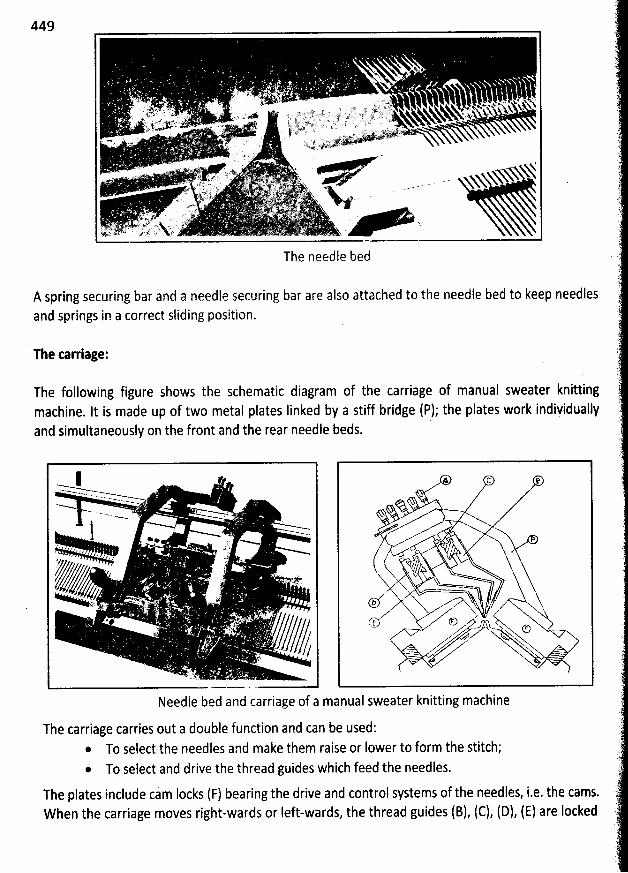
449
The needle bed
A spring securing bar and a needle securing bar are also attached to the needle bed to keep needlesand springs in a correct sliding position.
The tarriage:
The following figure shows the schematic diagram of the carriage of manual sweater knitting
machine. It is made up of two metal plates Iinked by a stiff bridge (P); the plates work indiyiduallyand simultaneously on the front and the rear needle beds.
Needle bed and carriage of a
C e
l/ ,j. '/x )(rl''p . x--iixx
,x Thy
(D C) w u oNu
= ..
!
manual sweater knitting machine
The carriage carries out a double function and can be used:* To select the needles and make them raise or Iower to form the stitch;* To select and drive the thread guides which feed the needles.
The plates include cam locks (F) bearing the drive and control systems of the needles, i.e. the cams.When the carriage moves right-wards or Ieft-wards, the thread guides (B), (C), (D), (E) are Iocked
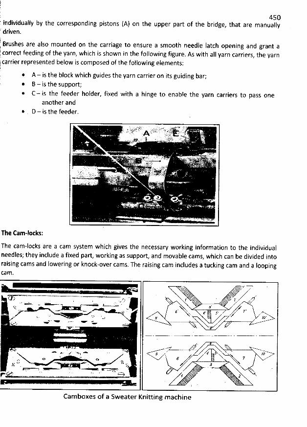
l
450k individually by the corresponding pistons (A) on the upper part of the bridge
, that are manuallyr' driven.
7 Brushes are also mounted on the carriage to ensure a sm00th needle Iatch opening and grant a correct feeding of the yarn, which is shown in the following figure. As with alI yarn carriers, the yarn
below is composed of the following elements:carrier represented
A - is the block which guides the yarn carrier on its guiding bar;l . B - is the support;r .
C - is the feeder holder, fixed with a hinge to enable the yarn carriers to pass oneanother and
D - is the feeder.
The Cam-loeks:
The cam-locks are a cam system which gives the necessary working information to the individualneedles; they include a fixed part, working as support, and movable cams, which can be divided intoraising cams and Iowering or knock-over cams. The raising cam includes a tucking cam and a IoopingCa n3.
z= NV '. zz xxNx ...- - , y y,p kzft ' l V
- = . y ' ,. < > 3t':y . u.. ..t-> o . g ' z z.q v.. o # , y d z. (-) ' . !), z-z
ap,''- -' t ()'.y< .
JV ' -''
'
i;.'
'
.
'
. . .-- gz-- ' '... v x :v. . ,'h..4 # x , y loA.. y z z xo .- e 7o
oso o. - . . c. a rà O<% . e>o '
r c::y 4 2
Camboxes of a Sweater Knitting m achine
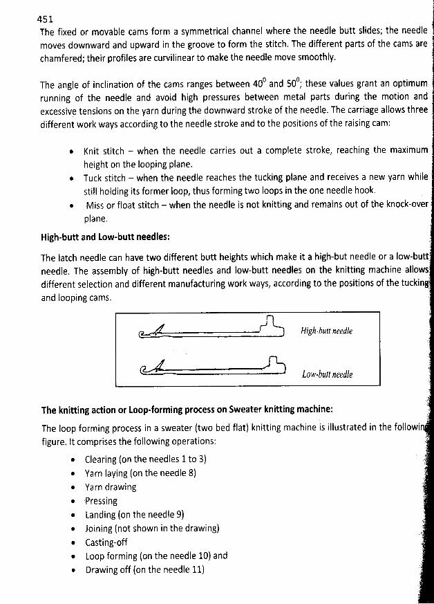
451The fixed or movable cams form a symmetrical channel where the needle butt slides; the needlemoves downward and upward in the groove to form the stitch. The different parts of the cams arechamfered; their profiles are curvilinear to make the needle move smoothly.
0 0 7The angle of inclination of the cams ranges between 40 and 50 ; these values grant an optimumrunning of the needle and avoid high pressures between metal parts during the motion andexcessivq tensions on the yarn during the downward stroke of the needle. The carriage allows threedifferent work ways according to the needle stroke and to the positions of the raising cam:
@ Knit stitch - when the needle carries out a complete stroke, reaching the maximumheight on the Iooping plane.
* Tuck stitch - when the needle reaches the tucking piane and receives a new yarn whilestill holding its former Ioop, thus forming two loops in the one needle hook.
@ Miss or float stitch - when the needle is not knitting and remains out of the knock-overplane. l
High-butt and Low-butt needles: r(
The latch needle can have two different butt heights wbich make it a high-but needle or a Iow-buttneedle. The assembly of high-butt needles and Iow-butt needles on the knitting machine allowsdifferent selection and different manufacturing work ways, according to the positions of the tucking)
and Iooping cams. :
Higb-bztt zeedk è' )
)The knitting action or Loop-forming process on Sweater knitting machine: r').
The loop forming process in a sweater (two bed flat) knitting machine is illustrated in the followi7
figure. It comprises the following operations: ,'(
* Clearing (on the needles 1to 3) )* Yarn Iaying (on the needle 8) :@ Yarn drawing* 'Pressing '
* Landing (on the needfe 9)@ Joining (not shown in the drawing) t@ Casting-off )* Loop forming (on the needle 10) and :)'i* Drawing off (on the needle 11) ,
)'
( '
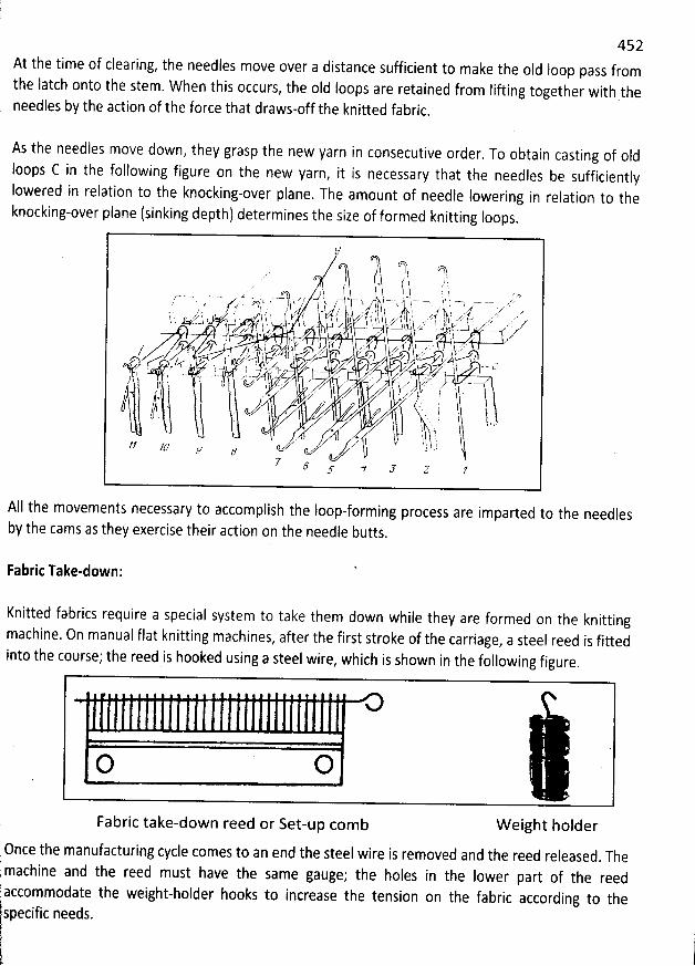
452At the time of clearing, the needles move over a distance sufficient to make the old Ioop pass fromthe latch onto the stem. When this occurs, the old Ioops are retained from Iifting together with theneedles by the action of the force that draws-off the knitted fabric
.
As the needles move down, they grasp the new yarn in consecutive order. To obtain casting of oldIoops C in the following figure on the new yarn
, it is necessary that the needles be sufficientlyIowered in relation to the knocking-over plane
. The amount of needle lowering in relation to theknocking-over plane (sinking depth) determines the size of formed knitting Ioops.
H/
7 o' j ; k/ J .. , '' $ r $. t,.....:o j k ï j r y, .,;.,... ' . f .tah .
ï , '
, r k n. ; . 1. zys - ..t' ;y, ty - d s . , ),y. j zy , y ..j zy/ j . * .
kk y .. ' ''' )j' '' / ..4'' , jq, t j .,, .y. j hy j . . ... . .3, j; j k... .y r.xz . j .t ..zy... . . .. z yyp.z- ï. 'u Ji/f. -.') 1 ' ' ly t ' . - k. . . l î h L' ' fe'j ' ja ; . '.- 1- ) p. j >j, ,- r x z .. ' z..-. - . z . ! , l z .z, : . k.--.
.,/'-% ''-# ' . . e..xj 3 . z à ' z Y ! . . . . . jr . . . '/ fn Z // . ' jg/ sz 5 ' $ z . x ? k--zze')z ' z')z j.....-#zr . , ') .: j--m?/ .',e- . .. . z., y . . yj zzr7 , cx , fe- , ' t z,z - . v z ') - c. xj ;
.'
j + Ij . . t ..y ) . œ y. ''-m . zZ-
. a. . . y yyy . .) $ o tts, k, zz . -t,z . t.. ,: %
w ', ' .'' **1 1 V' 1 '$ 'dv ,. .* j ' i/ ? ' ' -W'w Il : wt k
. *
'
w
'
l .-) I .. l , t- 'k ..t/; JIJ z
5 f
All the movements necessary to accomplish the loop-forming process are imparted to the needlesby the cams as they exercise their action on the needle butts
.
Fabric Take-down:
Knitted fabrics require a special system to take them down while they are formed on the knittingmachine. On manual flat knitting machines
, after the first stroke of the carriage, a steel reed is fittedinto the course; the reed is hooked using a steel wire, which i5 shown in the following figure.
O O
Fabric take-down reed or Set-up com b W eight holder('
Once the manufacturing cycle comes to an end the steel wire is removed and the reed released. The
; machine and the reed must have the same gauge; the holes in the Iower part of the reedaccommodate the weight-holder hooks to increase the tension on the fabric according to thespecific needs.
r
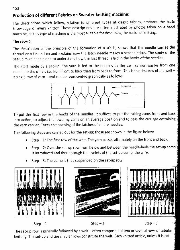
453 ll
Production of differenl Fabrics on Sweater knitting machine: ê../The descriptions which follow, relative to different types of classic fabrics, embrace the basic j
knowledge of every knitter. These descriptions are often illustrated by photos taken on a hand ymachine, as this type of machine is the most suitable for describing the basics of knitting. t
ïi
The set-up: 1
The description of the principle of the formation of a stitch, shows that the needle carries the ',thread or a first stitch and explains how the latch needle makes a second stitch. The study of the tset-up must enable one to understand how the first thread is jaid in the hooks of the needles. '.
):!
The start made by a set-up. The yarn is fed to the needles by the yarn carrier, passes from one ::..
needle to the other, i.e. from front to back then from back to front. This is the first row of the welt - ya single row of yarn - and can be represented graphically as follows: '
f
Y-e-g!l '.?. - - - - . - Jl -----Ya r n
(t
î.')To put this first row in the hooks of the needles, it suffices to put the raising cams front and backt'into action, to adjust the Iowering cams on an average position and to pass the carriage entraining '
the yarn carrier. Check the opening of the latches of aII the needles. .'l
The following steps are carried out for the set-up; those are shown in the figure below; yi
* Step - 1: The first row of the welt. The yarn passes alternately on the front and back. ',t-.
:7 ..* Step - 2: Over the set-up row from below and between the needle-beds the set-up combis introduced and then through the eyelets of the set-up comb, the wire. )
(r.
* Step - 3: The comb is thus suspended on the set-up row. :')
. . ' !
j ;' ,'1 ' I 1 : I ' ': x 1 .'
. . . j ... - . . y ; - i .j , . ..yjyt )
' ' '1 : ' I I j t $ I t y 1 j ) ' j l '' - #.. . '. - . . -- . ' . -. .. . - . ... - ''' . - -- '.: i
. l . ' . . (
jj jo j j . ;.r. . . .t ...0 . . , .I .; j !,J. j # f. j ,. lrj -' ;..- jjlb ' y,: g .
.
--
r
-
.
-'h a-.
----. ':ï:''' ' - .'1- -'' ' '
. . A' '
, ,. '. . ' . . . t . .
'
. - x . .,r.. , - .. :
. l ' ...1 . y. gj . j. . . ... . . j j ) jj , j jjj j jj jjj . Ljj. .y : 4.11. j . . jykr .y. ..4 # : ) : (--44 :é . --8 .. ( j vjvvvpv . ... . . . . . . 1, ,; , , , , ,j ' ! ; 1 l ' j ù. 1 j k . ) ) ' l i 1 ( j ip'x's . . . ; .'
jjjjj!k jjj;j' jkjjj,h jjjjj jjjjj- i jjjjj /pjj,jj, dqk; j' Jjf jj j' . - ' .. . -- .. . . . . . .. yrjgjyjjjjg. . . .. ,yy, , y. . ...
.
f!
Step - 1 Step - 2 Step - 3 ' 7'
The set-up row is generally followed by a welt - often composed of two or several rows of tubular ,:)knitting. The set-up and the circular rows constitute the welt. Each knitted article, unless it is cut, t8
)
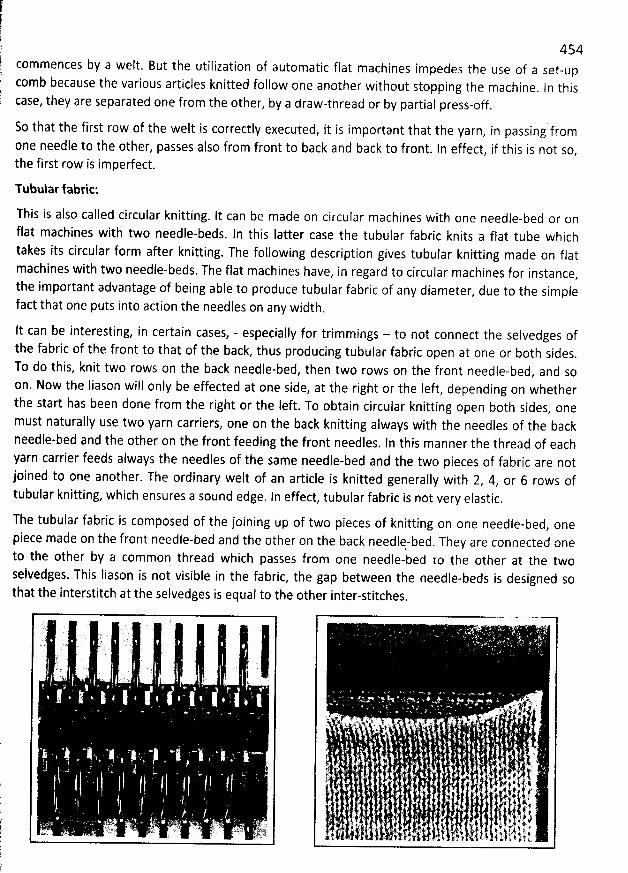
454commences by a welt. But the utilization of automatic flat machines impedes the use of a set-upcomb because the various articles knitted follow one another without stopping the machine
. In thiscase, they are separated one from the other, by a draw-thread or by partial press-off .
So that the first row of the welt is correctlv executed, it is important that the yarn, in passing from
0ne needle to the other, passes also from front to back and back to front. In effect, if this is not so,the first row is imperfect.
Tubular fabric:
This is also called circular knitting. It can be made on circular machines with one needle-bed or onflat machines with two needle-beds. ln this Iatter case the tubular fabric knits a flat tube whichtakes its circular form after knitting. The following description gives tubular knitting made on flatmachines with two needle-beds. The flat machines have
, in regard to circular machines for instance,the important advantage of being able to produce tubular fabric of any diameter
, due to the simplefact that one puts into action the needles on any width.
lt can be interesting, in certain cases, - especially for trimmings - to not connect the selvedges ofthe fabric of the front to that of the back, thus producing tubular fabric open at one or both sides.To do this, knit two rows on the back needle-bed, then two rows on the front needle-bed, and soon. Now the Iiason will only be effected at one side, at the right or the Ieft, depending on whetherthe start has been done from the right or the Ieft. To obtain circular knitting open b0th sides, onemust naturally use two yarn carriers, one on the back knitting always with the needles of the backneedle-bed and the other on the front feeding the front needles. In this manner the thread of eachyarn carrier feeds always the needles of the same needle-bed and the two pieces of fabric are notjoined to one another. The ordinary welt of an article is knitted generally with 2
, 4, or 6 rows oftubular knitting, which ensures a sound edge. In effect, tubular fabric is not very elastic.
The tubular fabric is composed of the joining up of two pieces of knitting on one needle-bed, one
piece made on the front needle-bed and the other on the back needlq-bed. They are connected oneto the other by a common thread which passes from one needle-bed to the other at the twoselvedges. This Iiason is not visible in the fabric, the gap between the needle-beds is designed sothat the interstitch at the selvedges is equal to the other inter-stitches
.
y k,' ..%.r,g9.9.. '. .. . ''. ' ..tdl''k . ' w : ' '= ..% : # . . ' ' j ( t '. ' . tJ . . ' .. . t '. . pe . ' .. . j 4 .. . . . u .
4. . . ... , . . k . . +. j' ' '
t j c , . ' . , . . ' ( .. ' . . y' . , ( t y, , . yt . .,tt
. .
. -. . . ., . t ,f
. . . . # , j a,,. . . . . . ' . . y. .. . . ù . #. . , .. #. k. .4 j' . . . . . . . . j: . . . (. ,k . 4. ?'. . ,. . z z $: z . 4. # y jj j . ., . . J . j . y, jz . y . y x y . . .y t. j y j , y a j ; j ywt f . ,. d'.' v: . .. r. o t w.. + 1. . t,.
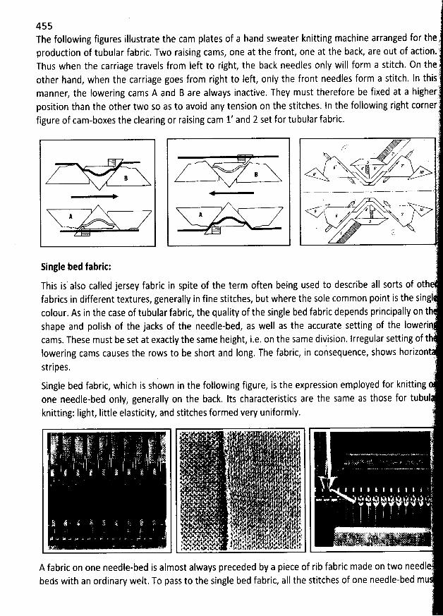
455The following figures illustrate the cam plates of a hand sweater knitting machine arranged for the
LSproduction of tubular fabric. Two raising cams, one at the front, one at the back, are out of action.'Thus when the carriage travels from left to right, the back needles only will form a stitch. On theotber hand, when the carriage goes from right to left, only the front needles form a stitch. ln this
(manner, the Iowering cams A and B are always inactive. They must therefore be fixed at a highertposition than the other two so as to avoid any tension on the stitches. In the following rigbt cornerfigure of cam-boxes the clearing or raising cam 1' and 2 set for tubular fabric.
)
ïr,'-i: x '
. 'x .
. 1 . l'X , ' Z ''# 4 .ç )R .. *'
B '- - . . .
... ' ' -- -.-....-.. j
, â sy Xx ?J.
'
/ tè.
Single bed fabric: '.
:2
This is also called jersey fabric in spite of the term often being used to describe aII sorts of othefabrics in different textures, generally in fine stitches, but where the sole common point is the singt îcolour. AS in the case of tubular fabric, the quality of the single bed fabric depends principally on thshape and polish of the jacks of the needle-bed, as well as the accurate setting of the lowericams. These must be set at exactly the same height, i.e. on the same division. lrregular setting of t 'lowering cams causes the rows to be short and long. The fabric, in consequence, shows horizont'
.L'
stripes..i
. (E .Single bed fabric, which is shown in the following figure, is the expression employed for knittingone needle-bed only, generally on the back. Its characteristics are the same as those for tubulknitting: Iight, Iittle elasticity, and stitches formed very uniformly. .
t . ' ' .
' . .1k l .. !' 'Ce ( , ) : . . y . p qj.)y . . . r . . y
s . '
' . x : . . . l . . . q . . . *.
'
. . .
. j,) i , y#. , . .Y-
. .; 1 ' ' ( .)
'' . . .. ; . '
- t . j.j . . . . .' . . ) ' ( . .# ,
. . . . . . j,, j a ... . .' ' ' .t.;14/ , . e . , . ? . . -- -- kiz. .. -'. :.g-?i.,,.. - . j-j , 2,:jN , . j s-ttjjj, i'jat, . . .. . -. ,J ' v'##.'.& .K'k ' ' , . .
A fabric on one needle-bed is almost always preceded by a piece of rib fabric made on two needl .beds with an ordinary welt. To pass to the single bed fabric, all the stitches of one needle-bed mu .
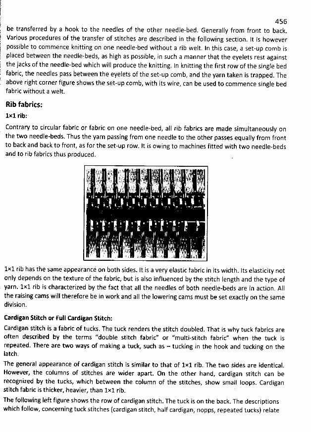
'
456 be transferred by a hook to the needles of the other needle-bed. Generally from front to back. Various procedures of the transfer of stitches are described in the following section
. It is however.' possible to commence knitting on one needle-bed without a rib welt. ln this case, a set-up comb is placed between the needle-beds, as high as possible, in such a manner that the eyelets rest against the jacks of the needle-bed which will produce the knitting. In knitting the first row of the single bed fabric, the needles pass between the eyelets of the set-up comb, and the yarn taken is trapped. The above right corner figure shows the set-up comb, with its wire, can be used to commence single bedfabric without a welt.
Rib fabrics:1x1 rib:
Contrary to circular fabric or fabric on one needle-bed, aII rib fabrics are made simultaneously onthe two needle-beds. Thus the yarn passing from one needle to the other passes equally from frontto back and back to front, as for the set-up row. It is owing to machines fitted with two needle-bedsand to rib fabrics thus produced.
1x1 rib has the same appearancé on both sides. lt is a very elastic fabric in its width. Its elasticity notonly depends on the texture of the fabric, but is also influenced by the stitch length and the type ofyarn. 1x1 rib is characterized by the fact that al1 the needles of both needle-beds are in action. A11the raising cams will therefore be in work and aII the Iowering cams must be set exactly on the samedivision.
Cardigan R itch or Full Cardigan R itcb:
Cardigan stitch is a fabric of tucks. The tuck renders the stitch doubled. That is why tuck fabrics areoften described by the terms ''double stitch fabric'' or ''multi-stitch fabric'' when the tuck isrepeated. There are two ways of m aking a tuck, such as - tucking in the hook and tucking on thelatch.The general appearance of cardigan stitch is similar to that of 1x1 rib
. The two sides are identical.However, the columns of stitches are wider apart. On the other hand, cardigan stitch can berecognized by the tucks, which between the column of the stitches, show small loops. Cardiganstitch fabric is thicker, heavier. than 1x1 rib.
The following left figure shows the row of cardigan stitch. The tuck is on the back. The descriptionswhich follow, concerning tuck stitches (cardigan stitch, half cardigan, nopps, repeated tucks) relate
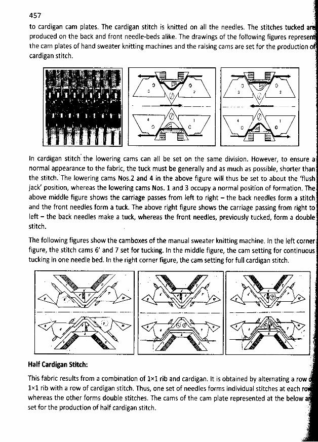
')ï
!n.457 7)7
di an cam plates. The cardigan stitch is knitted on aII the needles. The stitches tucked ato car gproduced on the back and front needle-beds alike. The drawings of the following figures representhe cam plates of hand sweater knitting machines and the raising cams are set for the produdion o .cardigan Gtitch. '
'). (.
. ) l . . .(
. ' 0 0 0 t)3 2 2 2. : . g g . .
r , (z g4 1 1 1. . . t) O O Q
. o-L ïJ:'-è .. . - $. ' ; è - L' wc.. e .,. a: .--- .. ) , 7.q, .() z. ..tr,. -.
'i..
. . ' bj 7) ..''î' ' 7 cL
-'jjjjq-'. , jjj . ......-- .. jjqyl .-..kt:
ln cardigan stitch the lowering cams can aII be set on the same division. However, to ensure anormal appearance to the fabric, the tuck must be generally and as much as possible, shorter thanthe stitch.'-rhe Iowering cams Nos.2 and 4 in the above figure will thus be set to about the 'flush
jack' position, whereas the lowering cams Nos. 1 and 3 occupy a normal position of formation. Theabove middle figure shows the carriage passes from Ieft to right - the back needles form a stitchand the front needles form a tuck. The above right figure shows the carriage passing from right toIeft - the back needles make a tuck, whereas the front needles, previously tucked, form a doublestitch.
The following figures show the camboxes of the manual sweater knitting machine. In the Ieft cornerfigure, the stitch cams 6/ and 7 set for tucking. In the middle figure, the cam setting for continuoustucking in one needle bed. In the right corner figure, the cam setting for full cardigan stitch.
. . '
. '
. '.q. aq 1. i* . 1, 1. . 1, 1'
:' yy ' z' â' j: 'r s / .. ZN.N r r z'r .N.. r s- / . .1r. 'z --jj--x. .a, .
!r Jlr Ir
',Z
a 'Z , X ' ' , ''-. t.
. .., . . . ...- . g y ),f z ; t wqs l.
. . . . j l ' .;t: '; '
jk
Half Cardigan Stitcb: .).
This fabric results from a combination of 1x1 rib and cardigan. lt is obtained by alternating a row:)1x1 rib with a row of cardigan stitch
. Thus, one set of needles forms individual stitches at each rowhereas the other forms double stitches. The cams of the cam plate represented at the below àset for the production of half cardigan stitch. 'r)
.).
J')
s Y
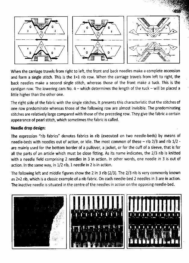
k'. -. ..
3 2@. . . . - . . . .
O/, jQ Q
Q ;
:$ 27. . . < . . . .
(744 't-' 1ô Q
''5
When the carriage travels from right to Ieft, the front and back needles make a complete ascensionand form a single stitch. This is the 1x1 rib row. W hen the carriage travels from left to right, theback needles make a second single stitch, whereas those of the front make a tuck. This is thecardigan row. The lowering cam No. 4 - which determines the Iength of the tuck - will be placed alittle higher than the other one.
The right side of the fabric with the single stitches. It presents this characteristic that the stitches ofone row predominate whereas those of the following row are almost invisible. The predominatingstitches are relatively Iarge compared with those of the preceding row. They give the fabric a certainappearance of pearl stitch, which sometimes the fabric is called.
Needle drop design:
The expression ''rib fabrics'' denotes fabrics in rib (executed on two needle-beds) by means ofneedle-beds with needles out of action, or idle. The most common of these - rib 2/3 and rib 1/2 -are mainly used for the bottom border of a pullover, a jacket, or for the cuff of a sleeve, that is fora1I the parts of an article which must be close fitting. As its name indicates, the 2/3 rib is knittedwith a needle field comprising 2 needles in 3 in action. ln other words, one needle in 3 is out of
action. ln the same way, in 1/2 rib, 1 needle in 2 is in action.
The following Ieft and middle figures show the 2 in 3 rib (2/3). The 2/3 rib is very commonly knownas 2x2 rib, wiich is a classic example of a rib fabric. On each needle-bed 2 needles in 3 are in action.The inactive needle is situated in the centre of the needles in action on the opposing needle-bed.
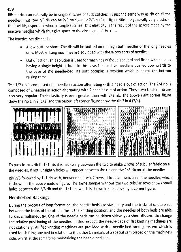
459Rib fabrics can naturally be in single stitches or tuck stitches, in just the same way as rib on aI1 theneedles. Thus, the 2/3 rib can be 2/3 cardigan or 2/3 half cardigan. Ribs are generally very elastic intheir width, especially when in single Stitches. This elasticity is the result of the spaces made by theinactive needles which thus give space to the closing up of the ribs.
The inactive needle can be:
@ A Iow butt, or short. The rib will be knitted on the high butt needles or the long needlesonly. Most knitting machines are equipped with these two sorts of needles.
Out of action. This solution is used for machines without jacquard and fitted with needleshaving a single height of butt. In this case, the inactive needle is pushed downwards tothe base of the needle-bed. lts butt occupies a position which is below the bottomraising cams.
The 1/2 rib is composed of a needle in action alternating with a needle out of action. The 2/4 rib iscomposed of 2 needles in action alternating with 2 needles out of action, These two kinds of rib are
also very popular. Their elasticity is even greater than with 2/3 rib, The above right corner figureshow the rib 1 in 2 (1/2) and the below left corner figure show the rib 2 in 4 (2/4).
To pass form a rib to 1x1 rib, it is necessary between the two to make 2 rows of tubular fabric on aIIthe needles. If not, unsightly holes will appear between the rib and the 1x1 rib on aII the needles.
Rib 2/3 followed by 1x1 rib with, between the two, 2 rows of tubular fabric on all the needles, whichis shown in the above middle figure. The same sample without the two tubular rows shows smallholes between the 2/3 rib and the 1x1 rib, which is shown in the above right corner figure.
Needle-bed Racking:
During the process of Ioop formation, the needle-beds are stationary and the tricks of one are setbetween the tricks of the other. This is the knitting position, and the needles of b0th beds are ableto knit simultaneously. 0ne of the needle beds can be driven sideways a short distance .to changethe relative positioning of the needles. In this respect, the needle-beds of flat knitting machines arenot stationary. AlI flat knitting machines are provided with a needle-bed racking system which isused for shifting one bed in relation to the other by means of a Special cam placed on the machine'sside, whilst at the same time maintairling the needle-bed gap.
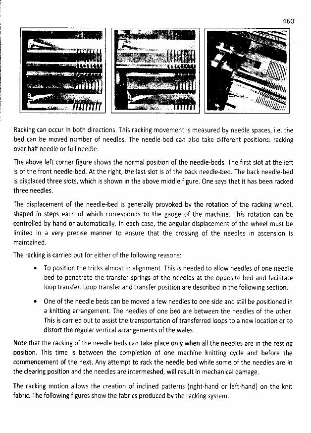
46O*s . -w-j *=P@--w..
% <.Nxm.
%VoL' ' <. . ogo? . p.Atx .. k .. r w
. )n .. ' -ik sz.
. . ..- . ., ws.. .t s. , j. . .. .4..*R.''*ew.o. ' . . .. ... --. . j4-//X , . .d.). . . . ,..4 ' e. ; . j x. , jl)v)y .
.. yjlt,
Racking can occur in both directions. This racking movement i5 measured by needle spaces, i.e. thebed can be moved number of needles, The needle-bed can also take different positions: rackingover half needle or full needle.
The above left corner figure shows the normal position of the needle-beds. The first slot at the Ieftis of the front needle-bed. At the right, the Iast slot is of the back needle-bed. The back needle-bedis displaced three slots, which is shown in the above middle figure. 0ne says that it has been rackedthree needles.
The displacement of the needle-bed is generally provoked by the rotation of the racking wheel,shaped in steps each of which corresponds to the gauge of the machine. This rotation can becontrolled by hand or automatically. In each case, the angular displacement of the wheel must belimited in a very precise manner to ensure that the crossing of the needles in ascension ismaintained.
The racking is carried out for either of the following reasons:
* To position the tricks almost in alignment. This is needed to aliow needles of one needlebed to penetrate the transfer springs of the needles at the opposite bed and facilitateIoop transfer. Loop transfer and transfer position are described in the foilowing section.
* One of the needle beds can be moved a few needles to one side and still be positioned ina knitting arrangement. The needles of one bed are between the needles of the other.This is carried out to assist the transportation of transferred Ioops to a new location or todistort the regular vertical arrangements of the wales.
Note that the racking of the needle beds can take place only when aII the needles are in the restingposition. This time is between the completion of one machine knitting cycle and before thecommencement of the next. Any attempt to rack the needle bed while some of the needles are inthe clearing position and the needles are intermeshed, will result in mechanical damage.
The racking motion allows the creation of inclined patterns (right-hand or Ieft-hand) on the knitfabric. The following figures show the fabrics produced by the racking System.
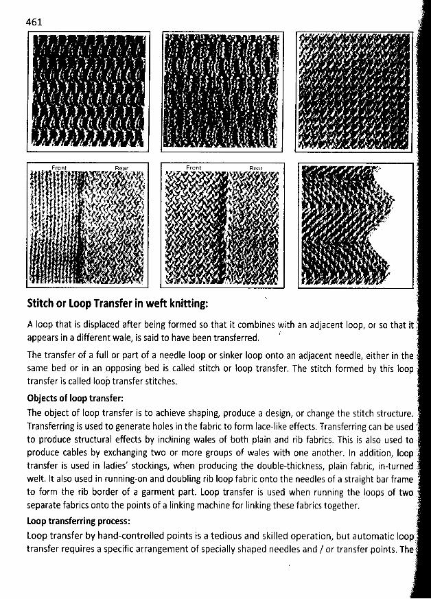
t
. ' ?' .? . ' '- . . l.
... - . , . ;. . ' ' ? y ' .
. 4 . . ' * ' ' . .kr . . . ') ,
' . 't
. .. . ' . r
. . . . . . r)
. ' ' . .: a ' '
. . ' j. . .'' ' '1 '. . r . j ; . ., . j
eE . I $ . . .
h
k ; . LFront Rear Front Rear ..;z17 3 - , '
k . *- Tr 2. , %1.P., j 9. . ' > - ' ' è .'1. : 1. 1 1. 't.. -,. . ,.j .' /. jj ,. y' '. . j . ' . , - ' ..- . ' . . , . . .. . ' . , ' ,j t: l 1. .) : i s s ;. .. . .. s , . : . . . . , .. . . .' : ' 1 # ' . ) . ! j ; . yjt
yyy 1). ,, . , ..
y wyj .
.
. . y. . . .. , g . .
.
.
.
.
, , .
.11$ b' ''
, 1C7 is
. ::5,,- .. tlt. ' . t,vt. ç
., .
.
,j,?th-.
.
., ilhs-y-
.
.. .,. .
.
. -
. -.,tt . . . . ,jj . .
. . . . . . : .. .
,
.
.
. .,,,, .. ,
;24 t .'6 1 # lj s jlk
.. . # f. '>. ; , ,t j . . . . . .
, .s ,) .,. . . . ' . , . .. ' # . - . -'
j , ' ) ' -... , , .
' . -
- . .. .
' ' 1 ' ' ' ''' . 't- - ' 7
' . . . . . . .
'' . .
*1 ' M u , ..
. 1. , . . ( . . t .*4 . . , x k c . . ë.' ' . . . . w . . . ;. s . . y . ) . , . x . ., . . ' - K '
. . ' < . . . . . . .
. .s ' . ' .. . . 'w ' ' ,. & ' ' r ' '
.. ' . , # ' %- .' ' . . . . ï z. <. k., . x j : ' ' '. .
' . . .
- ')
. . 3)Stitth or Loop Transfer in weR knitting:
A Ioop that is displaced after being formed so that it combines with an adjacent Ioop, or so that it )/appears in a different wale, is said to have been transferred. '
(
The transfer of a full or part of a needle Ioop or sinker Ioop onto an adjacent needle, either in the 7same bed or in an .opposing bed is called stitch or Ioop transfer. The stitch formed by this looptransfer is called Ioop' transfer stitches. :
Objects of Ioop transfer: .The object of Ioop transfer is to achieve shaping, produce a design, or change the stitch structure. rTransferring is used to generate holes in the fabric to form Iace-like effects. Transferring can be used ,to produce structural effects by inclining wales of both plain and rib fabrics. This is also used toproduce cables by exchanging two or more groups of wales with one another. In adàition, Ioop itransfer is used in Iadies' stockings, when producing the double-thickness, plain fabric, in-turned .welt. lt also used in running-on and doubling rib loop fabric onto the needles of a straight bar frameto form the rib border of a garment part. Loop transfer is used when running the Ioops of two
2separate fabrics onto the points of a Iinking machine for Iinking these fabrics together. ;''
(.Loop transferring process:))
Loop transfer by hand-controlled points is a tedious and skilled operation, but automatic Ioopj .
transfer requires a specific arrangement of specially shaped needles and / or transfer points. Thet.,7
2$
. '
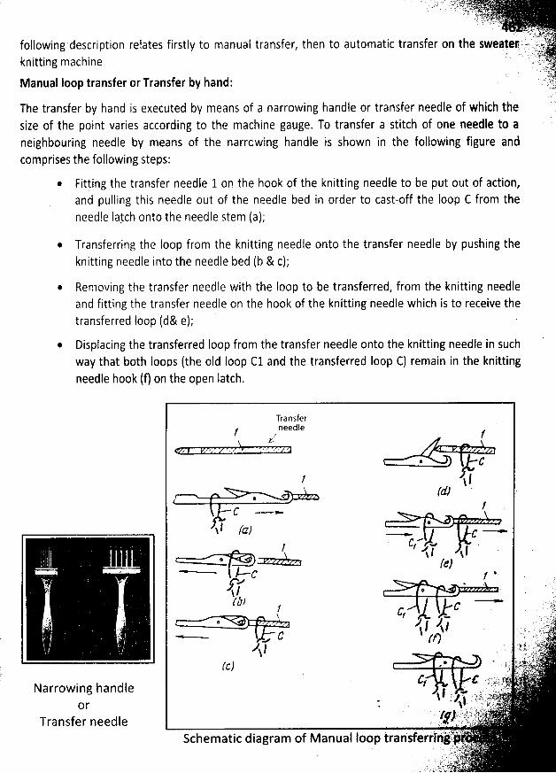
- . .. t-yzjyjc.. s i . z . g . ...v... : j .j ,: g. y. y;)w' 1 i! Y:-- ' 'r .: r -'
. . . :L ;; )N .. . . r.: ..-t
... L;)f.following description relates firstly to manual transfer, then to automatic transfer on the sweater .7 . lxyt',
. k .. .è't;v .k itting mach i n e ' ' ' -';);-t :n (4
tpManual Ioop transfer or Transfer by hand: '' ,)k'jL...'
The transfer by hand is executed by means of a narrowing handle or transfer needle of which thesize of the point varies according to the machine gauge. To transfer a stitch of one needle to aneighbouring needle by means of the narrcwing handle is shown in the following figure andcomprises the following steps:
@ Fitting the transfer needle 1 on the hook of the knitting needle to be put out of action,and pulling this needle out of the needle bed in order to cast-off the Ioop C from the
needle Iaych onto the needle gtem (a);
Transferring the loop from the knitting needle onto the transfer needle by pushing the
knitting needle into the needle bed (b & c);
@ Removing the transfer needle with the Ioop to be transferred, from the knitting needleand fitting the transfer needle on the hook of the knitting needle which is to receive the
transferred Ioop (d& e);Displacing the transferred loop from the transfer needle onto the knitting needle in such
way that both loops (the oId Ioop C1 and the transferred Ioop C) remain in the knittingneedle hook (f) on the open Iatch.
Transferneedle/ . /Y
. c
1 ! l/tf7 ' '
@Jf -
@ .l (a) --wï - - - c
/ l>*l $1* Ie)
c t *./->' . .J / . .î .
rJ) ---- :: tq1 C . . 2cr . ...k4.
. -,/1, j! -kk, jj , . . ..,v:,.s!t !ik . ... F . p .:- ,, ,..'.<
... C J/) . ; '' 'j). ,sJ ' ' '1 1 ' l V' 'l . . t ' t .!!.t,l . atf.@ m 6 . k' :t4 :k? k . *(c) - . '. ..) 'kn.tib'+. ... .k-, ..,,,.,C C
- $t- .4- '' -' '/ - '- ' . .Lf' % '' ''- .oT.; .l ? < ' ' ' -' L' '' 't
. z $ .'z;t, L1- .t-. j. : . .aj r. ... ; . ... yjy.,) .- c. );t L.L:'. u'.' .. . tgj. , .t). e. yga u.. .- s $. .: . a . S(:9. ' .
lp :, ' ' Q + 'i .L !lr ' llii *d ''2Schematlc dlagram of M anual Ioop transferrlngn
. s.' j u *1 ' . ' .. . ' sy. . . ..,) .y....' . #: .' ykj'. ' . eL t C'( ;:. t ....t, .'. . f q '.E . .e! ..
Narrowing handleor
Transfer needle
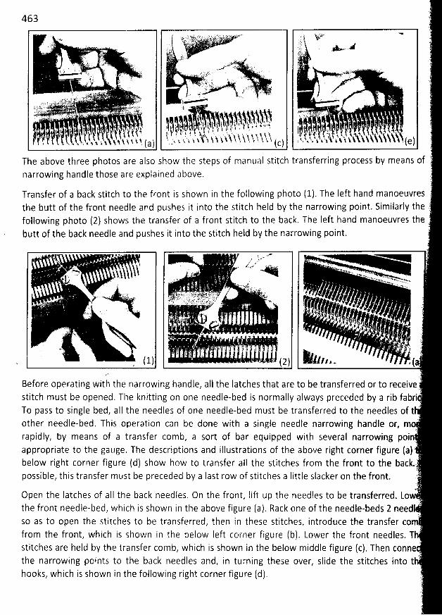
463. m s vnkux' x- '
.vo . s7'j;j e J jqA'nl. f'r'; ; LLj,1'LL '') '''.Lt) ''L''' .'1' 5 l *-14)6. ..'. -a' - -ytpxs u, v ) ; ''
. .. s y (( . sW . V. . .. . ' . . .. . u. î l t . .
'è. ') . ' . yj :) ?'' '''.
' , . y. .:, . . . ... . k ..:q!L. y ; . ., .sâj' . : . :). .. ( .. .' k r.w-at'' '' s . . .. . .
17.. . .. t? . qvk. IL -j ,j(, . ' ) - . . . . -. .'' . m; x . . .p. . w s . )y'' . .. .,- .. .t.c.; w ),. . . .. ut :, t - '
,
. -... c . . . . : ..y'
.') .) - tf t C e - . '.hz,,,,,,.,,,,,,,,.,;,.. . ,. y -d. j a lsiitkkili . ) . .- . . . . . . -'à;L)V.' < . - rjt),vy yr y;r.. .k; . . , ;... . . y. .... .
.( . .;,.
. . . js;y,z .... . . .. .. ..,.L;; . . - a.- .k. ;tz ' '' - L. : - '> ' - ' '''tt !Ct'' . : .
. . .1jj' djjjxljjjy 2ljj. j, ijjjjy 'ljjjj j, s. t..: , . . . zb...1. . . ., . . . . , , , ,, pjjj), .,..k, $. 'y-ht.hjj-).. t t.- t.), j , -.., ,jp j , . jy
j, .ç,y-j.,
y
.
yyyy
.
yyyyyyje, ,y;,:
'
jj. '
'
.
'
. . .
'
.
'
11,
*
..1$- .!hjr
'
,;
'
,!:j;;
'
j;j. .
'
1p:
'
,1k
'
,
j j j ..( j t y , ç ,. ., ,. , jy y ys,y.j.y'j jjjjyjjà, .:,,.q .q ,,,4 k.. . x x k. $ ! i y ,1 ï. ! ( a ) . . t' t k h. ï î ( c)
The above three photos are also show the steps of manual stitch transferring process by means of Lnarrowing handle those are explained above. )
èTransfer of a back stitch to the front is shown in the following photo (1). The Ieft hand manoeuvresthe butt of the front needle and pushes it into the stitch held by the narrowing point. Similarly the :
following photo (2) shows the transfer of a front stitch to the back. The left hand manoeuvres the .butt of the back needle and pushes it into the stitch held by the narrowing point. '
. ... . . -- . )$ . . . u. .. . ' ' at sn-f .< . L - . .
t . : t' . . . . k. .. .. ukljrsl, .,y a .
. '
. . . '' u . ''
. . ' c - . . Lt?. q ''- jt). àiyrjl - qjk tjj;. .1 . ' ' -#- . j. . - .(. ).,oy : rt)(...,s,,.,).))). .
... , j . .. : t- . , . . ,., ,
.. , .. . .
. . . ,. ( ( ((, y, (t)( , .
,
. i. .> ' .e .t j j i 2 j v ,..i . . :q i . jt . î f . .t. ' ' . '. (.,
- ( 1) . . . . . . ' - - . .' ( 2 ) 1ln z - J' (a
Before operating with the narrowing handle, aII the Iatches that are to be transferred or to receive 'stitch must be opened, The knitting on one needle-bed is normally always preceded by a rib fabriTo pass to single bed, alI the needles of one needle-bed must be transferred to the needles of t ''other needle-bed. This operation can be done with a single needle narrowing handle or, m
.
rapidly, by means of a transfer comb, a sort of bar equipped with several narrowing poin
appropriate to the gauge. The descriptions and illustrations of the above right corner figure fa) .7below right corner figure (d) show how to transfer aII the stitches from the front to the backj
possible, this transfer must be preceded by a Iast row of stitches a Iittle slacker on the front. ')
Open the Iatches of aII the back needles, On the front, Iift up the needles to be transferred. Lo,,' :'
the front needle-bed, which is shown in the above figure (a). Rack one of the needle-beds 2 needlfso as to open the stitches to be transferred, then in these stitches, introduce the transfer comfrom the front, which is shown in the below Ieft corner figure (b). Lower the front needles. Thstitches are held by the transfer comb, which is shown in the below middle figure (c). Then conne :'
..:k'
8
the narrowing points to the back needles and, in turning these over, slide the stitches into thooks, which is shown in the following right corner figure (d).
è
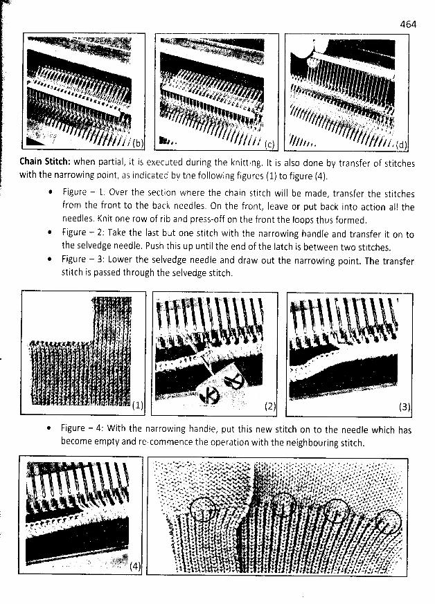
MN Tj '. . . ar ' .
/ttt/k4/r/4' --.' *. . ,; .) .z . / . ,.. e4t' *'+ (..?., . . z . . t,#'e , z ' z. .osz,g' , , . , . ,? ,q : y' *w4. z, .* ? ,r t '/,/z t ' ? ' '*' ,e*' 4. A ?#- ' / / ' ' g'. x #. . l,k,vt,t,, . :. y ,.r*'e 6#
. 2). . . f . . , à 4. . ,jr . . ';j. . $. . . . j. .k. ' ''p., p.'llk /.j1, j... . - . , . , .j jj ,,, ( k) )
Chain Stitch: when partial, it is executedwith the narrowing noint, as indicated
@
during the knitting. It is also done by transfer of stitchesby the following figures (1) to figure (4).
, . . ..m. . r.(jj(j(y. k!i .) Lî cv . . . ' .. . xyAy ; .. AV .
#zsZzzy'z o. ' . i ee e. l jz. : , . . r , ,z,k vt d fi'tt' .: t -
. 4 j'' ,$ '' '' '< # , ' JF pe df* - V Z3' z>'zz<. ' 1 'jj . s . . , . ;p .
.
* z ;. ++.z 4.e ?. s .,/ f ; ; , .8't.'$7 . ( .@ y, u. . ,t' '.?i.,.$? , 14 *.'-4.vL. ' > f: ..- ? . , .; ...
,y , ea4 t. ' . : ï 4 .ë .. . .:r. , ) j ,. . . , ? , ,. , g yj. . . '. !;w, xj x , . kj,,jt ,;,j.';)j .,,.,, . , , .jf.. , j. , jb j.f , .? / kk
/ /// ,?z. , (c)
464
!'
T -' rj - .
t ). # j. .$ i *'(.t#.- k . . . 'k , . . . ,:#4:k ' . . . .' f . jj .. .t. .
. J .. . ' . , i ' , .f ! ' * ' ij . '
,# 'jjy////// . zz .' , . , : '.. ,: ..,, ,,,'.4 .,i S,j, , ; , ;, . , ' 'i. - J.
kjjr . , . , . j yj ,y , .j; j ,'///?p , , ///////' /' /' /
- (d)
Figure - 1: Over the secticn where the chain stitch will be made, transfer the Stitchesfrom the front to the back needles, On the front, Ieave or put back into action aI! theneedles. Knit one row of rib and press-off on the front the loops thus formed.
* Figure - 2: Take the Iast but one stitch with the narrowing handle and transfer it on tothe Selvedge needle. Push this up until the end of the Iatch is between two stitches.
* Figure - 3: Lower the selvedge needle and draw out the narrowing point. The transferstitch is passed through the selvedge stitch.
Figure - 4: W ith the narrowing handle, put this new stitch on to the needle which hasbecome empty and re-commence the operation with the neighbouring stitch.
. . . v k . .'. < . . y., ; 4t
. 7 <A, . .. $ . .1t' - . . '. .k 'L .'. e t k ' .r *'
..F s s +.' #*'. ' . ' .p + . . x . wx rt o. N. . .f s .
. . . 4. ;j r y. ., j' #' oJj .xj#:&:. .v, q..k jg ktlk lj
x v > > e 6 l .*w AN * A < # *# A & '* a ? v' 2 ? $ * # ; * 1 * e '. e . + y * ' > w x # e k T * ' *' * : * 2 4 - q e. ...<* w . . . xx # # . .v 4 . . z r x *' a ' x. . G * * + Y ) a # . ë 6 ' a j' - '* '% > w Y Aw'v T Y F # * * : K ' a ' A' * +v t * '. w x. xw'n w X e x : 4 1 : * $v . <- v x * o . . i ,.. .* 4 # > <# 4 : e * z .* r # 1* t> w > <p.A xA+A* . :'* v k.ë * + : > > 4 e 4 a* # # >'x e 4.s v * . -+ * a 4. . < 4 sY k4 6 v r w . .& * p + #* F :. w . < p :. y . .A . y . : e . # < +. a # # ù *>. v . . *. * ; ,# AV < < . #' 'F' '#. avf k. .à e j .& : P x. *' +. * .* . 4 # # 6 <# e' * .'. . . . .# . . ' . ' 4 # j v. .. ,. .* #. .#. < v s & . .- . .G < . : ' . . .1 4 . : # .' .4 4. # y' # .* e N A .. 4e .. xx . >, .w, 4%. Gx . . j' . 4 . . j #' j. .è a A wj g '# . r ,* e é . >. ww ,.v,wgz. . . w Kv :.. x. .* . . . . * ( +'* N' A F' x a. A > #' !.. A 1 fz *' .z #' : *w .v . y z. . : . k #a. v . g er '* . 4. .y++. 44,2 '*. . x.. 4 x .w .4 e + g : x p ' + *' # .- '#' ' N' ' ,q. .% e w v. X . j. u ' 'f # 4 y 4 # % .<. #. . F >v#. y 4.< . .. x v 0. v '>. q...r- . . v ..i . # . ..u.#. 2 . ..# :aj x . . v. . v e # # x a' w.* . p. .v * * : ' '<' ''. ' = e: - m 'N*' % N e''Y . . . ; . .& m e '''r .A F > c vr t ' 'q' a - g. # # +' > J . : ' œ p .' .9 p *.. . - w < ..s, ' w *w . . .a. r v. p y. .y < .. .. * s w. YVV .. ' . V.. A . 4 $. * .A. % e * à # '$ 4j M' ..g :w w z. v. *' .S: . ' f k' #.4. *' ' ' .. ' .; 'w.. % *. 'x y . . . . .w4 j . e 4 . s r' .A < .w . e'l è w .1 ' A zr ''' .# e 4 g .'a a x. . .. v . j . . e' r y. u e ..*. 'e' - w. &. , . 'i ' . .. ' J ' ' C' *' #i >' ''* #. 4 rf . '%. . 5 '*<' i 4 #d F *.-# t .* , #. w . .2' . . . e. ,N . . . .rr. . , 4 z ek. , .e 4 r .. ' . .. > w # '*' . :.. .# ' x . ' #A + #. # .* . ..x . ) . . .. . . . . r . a .è . .,w eZM. a .>. ' . . p , >. , . #. . . j e. , .. . #. .r v* .. x. é .p.. . .y y w ,..% V. vj '* . ? F '4 . * . z . + r. y. . 1 .)' *' . ' . . . # . K ' ' ' ' ': * . . . . . # #. a' e >. vw '' '>' * #' N' . . . . . * .+ * +. *' + .+ ï' . X p. x. z . '* '> N ,#. #' e' . '). * e w. 4. ' . > >. -, $. . .v .+- .*. * *' te * *' .+ #'' * ' # #< w .. + '! #. 1' *' . >. *'j(. # * + ' w. I . . . y' .j. + $ e J J s r ' - -e + ' xe . ; # e. ..* . ' .k .. . ' *' e-. * e *. j .f J > . s. .* 'e - . v. ss . +.4. '* + ' 47 '* *# . * v# ' . .@. #' . #. + ' . y + J *' .- s.r.e . . z +. . -'* . + e' +' . . . ' '# . P ' #' < e' <. # A . . . ''. * * .# 'e % ' 7. +. * ' à . . # * . p *' e 'P, 4 ). 8 . . . . 4 . =.J . ' # * >. #. w ju- . e . # n# Y* . ' ' 1* c. * # 4 #'# + . # .+ w ' +. e a -.YF' .y ' . v. . *. m v. *' w '1. . . . . .4 >. w * p, @. y . # ' z# . . # . .x? F + . . # : y. p +, #. . .# I + + . . . 4. . . ..4 v pr # wke.vj p. z .
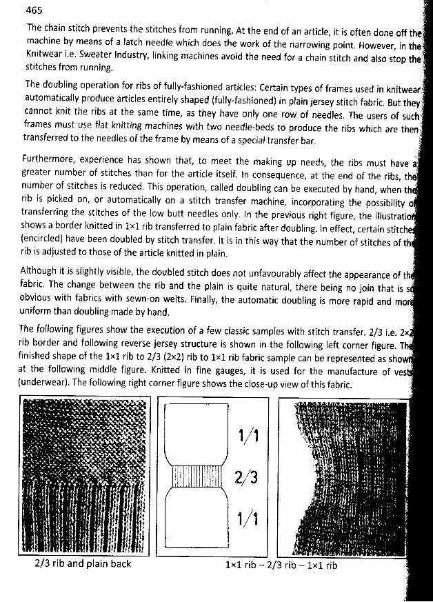
465#.The chain stitch prevents the stitches from running
. At the end of an article, it is often done off thv'èv'
machine by means of a Iatch needse which does the work of the narrowing point. However, in thelK
nitwear i.e. Sweater Industry, linking machines avoid the need for a chain stitch and also stop the)stitches from running. )The doubling operation for ribs of fully-fashioned articles: Certain types of frames used in knitwearrautomatically produce articles entirely shaped (fully-fashioned) in plain jersey stitch fabric
. But theyi),cannot knit the ribs at the same time
, as they have only one row of needles. The users of suchframes must use flat knitting machines with two needle-beds to prodace the ribs which are thenl
.(transferred to the needles of the frame by means of a special transfer bar.
t.? : (Furthermore, experience has shown that
, to meet the making tlp needs, the ribs must have 4,greater number of stitches than for the article itself. In consequence, at the end of the ribs, thnumber of stitches is reduced. This opqration, called doubjing can be executed by hand, when th 'rib is picked on, or automatically on a stitch transfer machine
, incorporating the possibilitytransferring the stitches of the Iow butt needles only
. In the previous right figure, the illustratio.)shows a border knitted in 1x1 rib transferred to plain fabric after doubling
. In effect, certain stitche(encircled) have been doubled by stitch transfer. It is in this way that the number of stitches of tbrib is adjusted to those of the article knitted in plain. :
J'Although it is slightly visible, the doubled stitch does not unfavourably affect the appearance of thfabric. The change between the rib and the plain is quite natural
, there being no join that is $:obvious with fabrics with sewn-on welts. Finally, the automatic doubling is more rapid and mor.
unifofm than doubling made by hand. è,
The following figures show the execution of a few classic samples with stitch transfer. 2/3 i.e. 2x
rib border and following reverse jersey structure is shown in the following Ieft corner figure. Tb'j. )'finished shape of the 1x1 rib to 2/3 (2x2) rib to 1x1 rib fabric sample can be represented as sho
at the following middle figure. Knitted in fine gauges, it is used for the manufacture of ves .
(underwear). The following right corner figure shows the close-up view of this fabric. )71..
+ . J . .
.. ' .
' ' .
' ' .
' . - . 1,, i!ll i!l ''.t4 ' '..' . :-' : . . ) - ' '. '' '
..'
Q ' . . ,.
' .L.
, : . , y/.. l 2/ 3 '' l
,
. . f -: .- ..j . J
! ,t 1 1 .i. 3 !t.'
I .- 1! ' ,- 11 1k 1k . .
'
. -
-
'
1! 1,-' jg l.. . 1!) jki , ,-
'
.. . . . .
'
2/3 rib and plain back 1x1 rib - 2/3 rib - 1x1 rib t
2
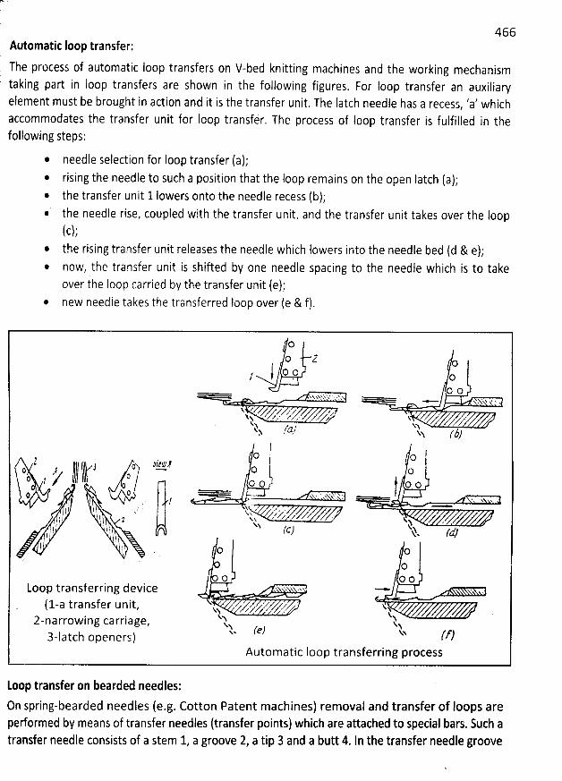
466k( Automatic Ioop transfer:
The process of automatic Ioop transfers on V-bed knitting machines and the working mechanism taking part in loop transfers are shown in the following figures. For Ioop transfer an auxiliaryelement must be brought in action and it is the transfer unit. The Iatch needle has a recess, 'a' whichaccommodates the transfer unit for Ioop transfér. The process of Ioop transfer is fulfilled in thefollowing steps:
@ needle Selection for Ioop transfer (a);rising the needle to such a position that the Ioop remains on the open Iatch (a);
* the transfer unit 1 Iowers onto the needle recess (b);@ the needle rise, coupled with the transfer unit, and the transfer unit takes over the Ioop
(c);* the rising transfer unit releases the needle which Iowers into the needle bed (d & e);
now, the transfer unit is shifted by one needle spacing to the needle which is to take
over the Ioop carried by the transfer unit (e);@ new needie takes the transferred Ioop over (e & f).
oo z o
i O 1. o/0 0. . L x . x '. . . x xN.YJ .:'. % ' ' x ... N
'
x x .kx%s' zri'.;r .z1 . z xk , z z
1 /tz7 NA> , ..N (3)
2 j (, vg z oo oo Io c , ,-----'J kr// lkhkltli--- oc , o o
. . . , t o oQ . - ri . % xh x
'
' ' ' .) 1 h x
, j . , ,, k; - vyy- , y ,yaz. . x? ?. . $ g k.t - ., . fc) kj tv/ ! k
.t. O C)
OO O O
Loop transferring device ' '. .x. - . .
( 1-a t ra n sf e r u n it, u / yy' z''z k' 1 kz-narrow ing carriage
, Q kX (e) ux y)3-latch openers)
Automatic loop transferring process
Loop transfer on bearded needles:
On spring-bearded needles (e.g. Cotton Patent machines) removal and transfer of Ioops areperformed by means of transfer needles (transfer points) which are attached to special bars. Such atransfer needle consists of a stem 1, a groove 2, a tip 3 and a butt 4. ln the transfer needle groove
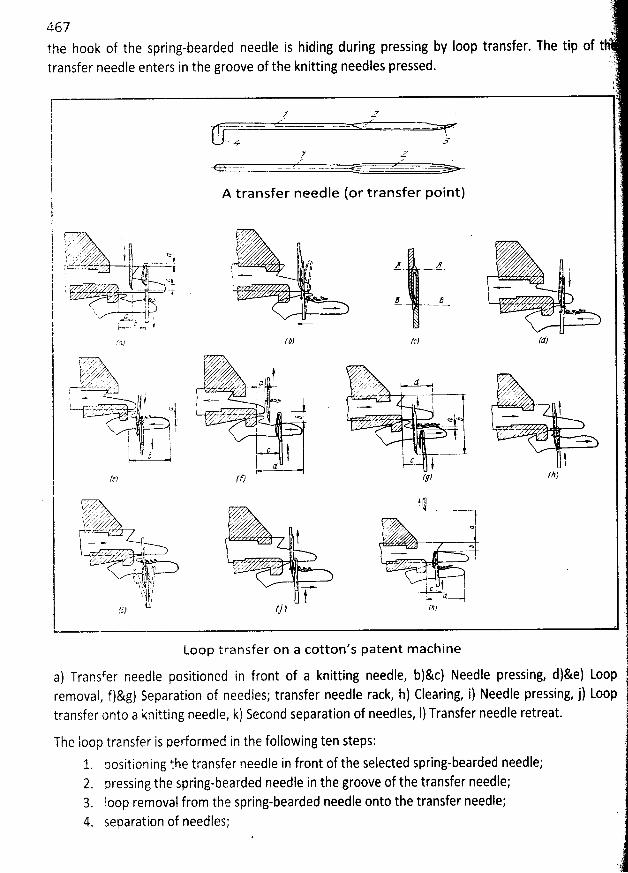
.
:167 '' ;the hook of the spring-bearded needle is hiding during pressing by Ioop transfer. The tip of t ''
.1.transfer needle enters in the groove of the knitting needles pressed. ..)'
j t.
l ' ,,. ,- gi . .. ---. . .. ... .....- .. . . . . .. ...-. - ..-.. .. ............s. ,. .
' . r
l1j- ..
A transfer needle (or transfer point)I 'j 'i tVV ) ' Cj . , . r , .q- , , lz.its..z.,;') - zt
.;; .:.)..v,,-z.$,),,L , y ..,j yzu-''kz.,,'-!
= ..-,..z -;t,r . . ë )) z . z .) r' . .z j ! -. - ,y . . ; .. $4 - ( ; . j .. . .( .. . ...y..y rL y < - - . .j .*--j f, . ..r ? s . y o y .1
. x
t
g '
. ...j! , ;.-). y ' c ' ' - z , .
.
- - j up ' -cew... = 4
%) /#2 (cz rtf)l
ï: ; , . , ,z)(yry');'r;#3-..#-. .--'' !' -' ---F :- . ''.z .f.L- ,.- h , y ; . ... 12 - .(Ylf.q. r)r e-tt!......k .Zr ; z' u. f,L. . . 1 ,.) z .
. ..- - j .....- j . . j j y zgyz2.-t'=)-m%;>d+:. / > w.w ;z $ -.-a - - jp - - - - xz % r.'',. N ' '<> ' . qa
. 7 '' j r - . 761I,'/ ''' . . ,V ; t - , . . .z ..11 'r!I;!: 'lr.d1) '' .....t ' j -c ! c - #d i lF
- ll)rt,) ('e) r.w f
' > ; y 4 J 't'('xrar. -.- .t)tl q) .Lïfîî:'-''.. r;;-.).,.'''''. ::;:b3, .----'-'.,'''e
. .
-- . . #y,t . -- * . J >
-3:. --.:?-.::6---;.9. rt----------- k -. ; .
.,k' . j z. . . . - - .'
-lq;-l1111.'?y - J,I ; î'1, ,' l -'' ' ' - . ' '. ,:!. , / ,.. l-.c lk. $ j ' : j -.-.,-...4 ...jt,.?rf ) (j ) /z)
Loop transfer on a cotton's patent m achine
a) Transfer needle positioned in front of a knitting needle, b)&c) Needle pressing, d)&e) Loop ,removal, f)&g) Separation of needles; transfer needle rack, h) Clearing, i) Needle pressing, j) Looptransfer onto a knitting peedle, k) Second separation of needles, 1) Transfer needle retreat.
The Ioop transfer is performed in the following ten steps: î1, oositioning the transfer needle in front of the selected spring-bearded needle;2. nressing the spring-bearded needle in the groove of the transfer needle;3. loop removal from the spring-bearded needle onto the transfer needle;4 separation of needles; '
y
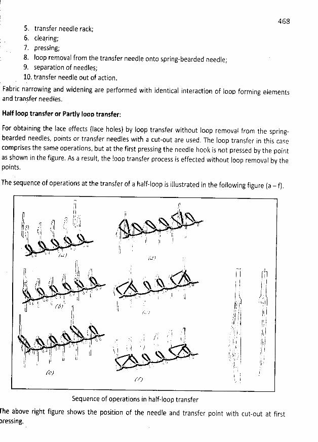
4685. transfer needle rack;6. clearing;i. pressing;8. Ioop removal from the transfer needle onto spring-bearded needle;9. separation of needles;lo.stransfer needle out of action.
Fabric narrowing and widening are performed with identical interaction of loop forming elementsand tranjfer qeedles.
Half Ioop transfer or Partlv Ioon transfer:
For obtaining the Iace effects (Iace holes) by Ioop transfer without Ioop removal from the spring-bearded needles, points or transfer needles with a cut-out are used
, The Ioop transfer in this casecomprises the same onerations, but at the first pressing the needie hook is not pressed by the pointas shown in the figure. As a result, the loop transfer process is effected without Ioop removal by thepoints.
The sequence of operations at the transfer of a half-loop is illustrated in the following figure (a - f).
Sequence of operations in half-loop transfer
rhe above right figure shows the position of the needle and transfer point with cut-out at firstressing.
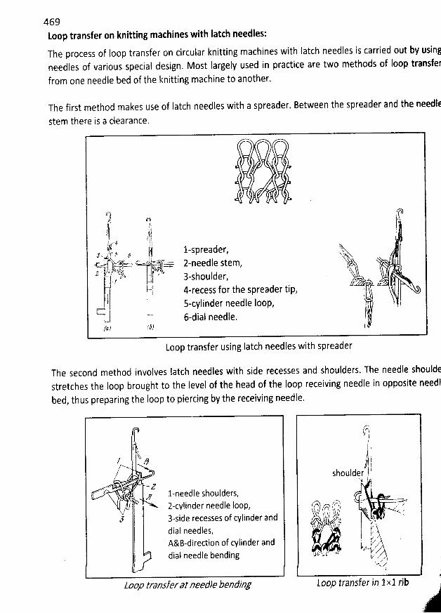
469toop transfer on knitting mathines with Iatch needles:
The process of loop transfer on circular knitting machines with Iatch needles is carried out by usin!needles of various special design. Most Iargely used in practice are two methods of Ioop transfeffrom one needle bed of the knitting machine to another,
The first method makes use of Iatch needles with a spreader. Between the spreader and the needl:
stem there is a dearance.
q pVt Q?)i ,i -,j'.!'( ' - ; 5 i i ïi?, . l-spreader, .sj...,. ,& , , $x, , .
.c . ..z, d- s z-needle stem,g . , k' , u ; uir r k( 3-shoulder,11 - /et ù.ùl 4-recess forthe spreadertip,h,t i 'k s-cyjinder needle Ioop,( 6-dial needle.(a ) /37
Loop transfer using Iatch needles with spreader
The second method involves Iatch needles with side recesses and shoulders. The needle shouldestretches the loop brought to the level of the head of the Ioop receiving needle in opposite needlbed, thus preparing the Ioop to piercing by the receiving needle.
i7 N
Z i ktY/n><-J j/
. Z-- ,,,y. l-needle shoulders,
! z-cviinder needle foop,.- //
j l 3-side recesses of cylinder anddial needles,A&B-direction of cylinder anddial needle bending
joop transfer at needle bending
?-)f,/ I/ k
41shoulder (
N
/7y .* . .r'n ?r') r / z zy? u q . 4k e-z1c 'Dk ,!1 I.'- t--,- ),$$yl
p z' c/
kzq. 'kz'AL J k ' ' 1
z$ zm V
Loop transfer in 1x1 rib .--1*--
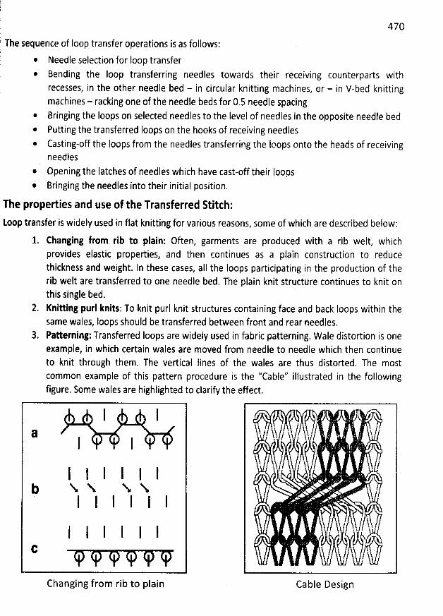
ril 470
The sequence of Ioop transfer operations is as follows:)p * Needle selection for loop transfer * Bending the Ioop transferring needles towards their receiving counterparts with
recesses, in the other needle bed - in circular knitting machines, or - in V-bed knittingmachines - racking one of the needle beds for 0.5 needle spacing
* Bringing the loops on selected needles to the Ievel of needles in the opposite needle bed* Putting the transferred Ioops on the hooks of receiving needles* Casting-off the Ioops from the needles transferring the loops onto the heads of receiving
needles
* Opening the latches of needles which have cast-off their Ioops@ Bringing the needles into their initial position.
The properties and use of the Transferred Stitch:
toop transfer is widely used in flat knitting for various reasons, Some of which are described below:
1. Changing from rib to plain: Often, garments are produced with a rib welt, whichprovides elastic properties, and then continues as a plain construction to reducethickness and weight. In these cases, all the loops participating in the production of therib welt are transferred to one needle bed. The plain knit structure continues to knit onthis single bed.
2. Knitting purl knits: To knit purl knit structures containing face and back Ioops within thesame wales, Ioops should be transferred between front and rear needles.
3. Patterning: Transferred Ioops are widely used in fabric patterning. W ale distortion is oneexample, in which certain wales are moved from needle to needle which then continueto knit through them. The vertical lines of the wales are thus distorted. The mostcommon example of this pattern procedure is the ''Cable'' illustrated in the followingfigure. Some wales are highlighted to clarify the effect.
I I
a I I
I l I I I lj N N N NI I I I I I
I l I I I IC
Changing from rib to plain Cable Design
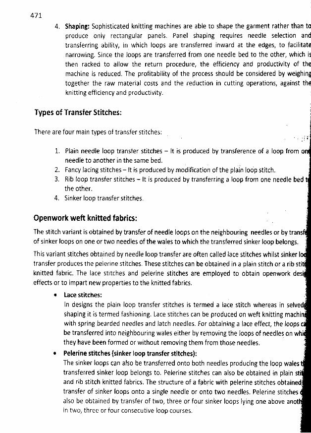
471
4. Shaping: Sophisticated knitting machines are able to shape the garment rather than tpproduce only rectangular panels. Panel shaping requires needle selection and
(
'
transferring ability, in which loops are transferred inward at the edges, to facilitatfnarrowing. Since the Ioops are transferred from one needle bed to the other, which ijthen racked to allow the return procedure, the efficiency and productivity of th#machine is reduced. The profitability of the process should be considered by weighint
ions agiinst thitogether the raw material costs and the reduction in cutting operat ,knitting efficiency and productivity. r
i1T
ypes of Transfer Stitches: 1
There are four main types of transfer stitches:.: f ?-
1. Plain needle Ioop transfer stitches - It is produced by transference of a Ioop from o 'needle to another in the same bed.
2. Fancy lacing stitches - It is produced by modification of the plain Iodp stitch.3. Rib loop transfer stitches - It is produced by transferring a Ioop from one needle bed t
the other.4 Sinker Ioop transfer stitches.
)openwork weft knitted fabrics: r'
The stitch variant is obtained by transfer of needle Ioops on the neighbouring needles or b? transof sinker Ioops on one or two needles of the wales to which the transferred sinker Ioop belongs.
!This variant Stitches obtqined by needle Ioop transfer are often called Iace stitches whilst sinker Io
transfer produces the pelerine stitches. These stitches can bq obtained in a plain stitch or a rib sti.7knitted fabric. The Iace stitches and pelerine stitches are employed to obtain openwork des
effects or to impart new properties to the knitted fabrics. TF
'
* Lace stitches: )ln designs the plain Ioop transfer stitches is termed a Iace stitch whereas in selvejhaping it is termed fashioning. Lace stitches can be produced on weft knitting machiq'with spring bearded needles and latch needles. For obtaining a lace effect, the loops cbe transferred into neighbouring wales either by removing the Ioops of needlej on whithey have been formed or without removing them from those needles. k
@ Pelerine stitches (sinker Ioop transfer stitches): jThe sinker Ioops can also be transferred onto both needles producing the Ioop walestransferred sinker Ioop belongs to. Felerine stitches can also be obtained in plain stiand rib stitch knitted fabrics. The structure of a fabric with pelerine stitches obtainedtransfer of sinker Ioops onto a single needle or onto two needles. Pelerine stitchesalso be obtained by transfer of two, three or four sinker Ioops Iying one above anotin two, three or four consecutive Ioop courses. '
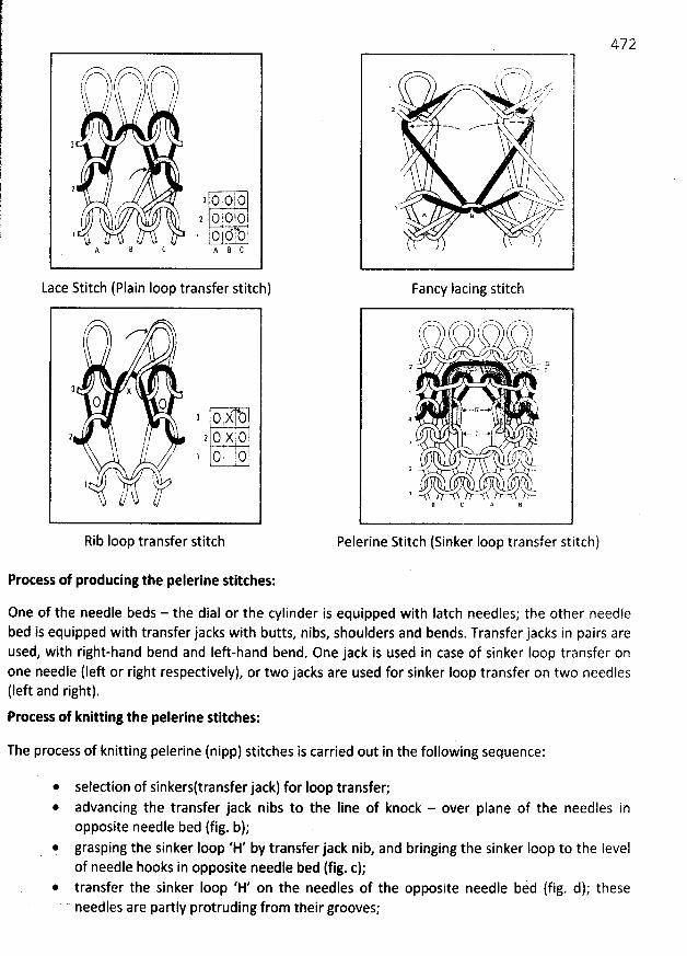
,?o ?'-A '-slfh-h. ,
,- .,- '--$-
h-- ,,t,--,;) (è- ',),-k!k
% (
2
z-2
3 o o o/, 2 o o c 1
3 I o i o r 1,! iA 8 C k s C
Lace Stitch (Plain Ioop transfer stitch)
zo
t /tj ' X
0 o
, ' 2 o ( :75/,' / ., t o t j o !
1 k
Rib Ioop transfer stitch
/' '.x N'., , . l/ / ..,..r'., 1/ .''' z by . J .. ' . .'O'sW ' z
z ' ,/
1
. N
A 6 B .5 /
Fancy Iacing stitch
y y . .x jt: (:) -; -'' .q
,V nk .2 - w.. . e. w. ' <r,:'J.. I
4 .'.. y ...--&N . .:
MDV2
L
B C A 6
Pelerine Stitch (Sinker Ioop transfer stitch)
Protess of producing the pelerine stitthes:
One of the needle beds - the dial or the cylinder is equipped with Iatch needles; the other needlebed is equipped with transfer jacks with butts, nibs, shoulders and bends. Transfer jacks in pairs areused, with right-hand bend and left-hand bend, One jack is used in case of sinker Ioop transfer onone needle lleft or right respectively), or two jacks are used for sinker loop transfer on two needlestleft and right).Process of knitting the pelerine stitches:
The process of knitting pelerine (nipp) stitches is carried out in the following sequence:
@ selection of sinkersltransfer jack) for loop transfer;* advancing the transfer jack nibs to the Iine of knock - over plane of the needses inopposite needle bed (fig. b);
* grasping the sinker Ioop 'H' by transfer jack nib, and bringing the sinker Ioop to the Ievelof needle hooks in opposite needle bed (fig. c);
* transfer the sinker loop 'H' on the needles of the opposite needle bed (fig. d); these' needles are partly protruding from their grooves;
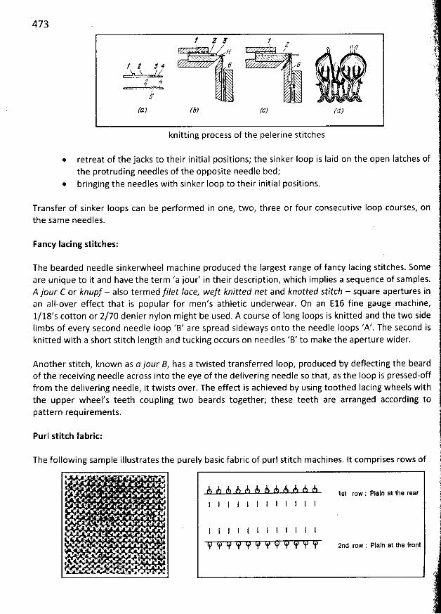
473
' z F z/ s , ' . zc
f Z 5 V 9 Y K C' '- Snu u ==/y
2 4 x/ .
(a) r& (d)
knitting process of the pelerine stitches
@ retreat of the jacks to their initial positions; the sinker Ioop is Iaid on the open Iatches ofthe protruding needles of the opposite needle bed;
@ bringing the needles with sinker loop to their initial positions.
Transfer of sinker Ioops canthe sam e needles.
be perform ed in one, two, three or four consecutive Ioop courses, on
Fancy Iacing stitches:
The bearded needle sinkerwheel machine produced the Iargest range of fancy Iacing stitches. Someare unique to it and have the term 'a jour' in their description, which impliès a sequence of samples.A jour f- or knupf - also termed filet Iace, weft knitted net and knotted stitch - square apertures inan all-over effect that is popular for men's athletic underwear. On an E16 fine gauge m achine,
1/18's cotton or 2/70 denier nylon might be used. A course of long loops is knitted and the two sideIim bs of every second needle Ioop 'B' are spread sideways onto the needle Ioops 'A'. The second isknitted with a short stitch length and tucking occurs on needles 'B' to make the aperture wider.
Another stitch, known as a jour B, has a twisted transferred Ioop, produced by deflecting the beardof the receiving needle across into the eye of the delivering needle so that, as the Ioop is pressed-offfrom the delivering needle, it twists over. The effect is achieved by using toothed lacing wheels withthe upper wheel's teeth coupling two beards together; these teeth are arranged according topattern requirements.
Purl stitch fabric:
The following sam ple illustrates the purely basic fabric of purl stitch machines. lt comprises rows of
A A A A A A A A fk A A è 1st row : plajn at the rearI I '1 I I I
l I I I
2nd row : Plain at the front
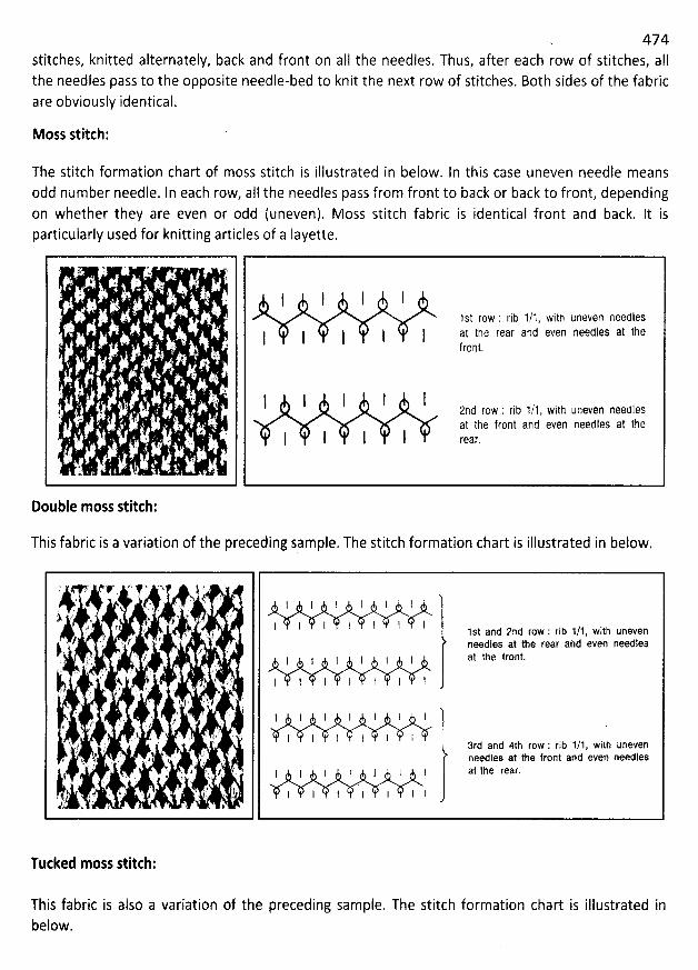
- 474stitches, knitted alternately, back and front on aII the needles. Thus, after each row of stitches, aIIthe needles pass to the opposite needle-bed to knit the next row of stitches. 80th sides of the fabricare obviously identical.
Moss stitch:
The stitch formation chart of moss stitch is illustrated in below. In this case uneven needle meansodd number needle. In each row, aII the needles pass from front to back or back to front, depending
on whether they are even or odd (uneven). Moss stitch fabric is identical front and back. It isparticularly used for knitting articles of a layette.
I I l I1st r0w : rib 1/1, witj uneven needles
l at t1e rear an1 even neetles at theIfront.
I I l I 2nd row : rib 1/1, with uneven needlesat the frcnt ant even needles at the
I I I I rear,
Double moss stitch:
This fabric is a variation of the preceding sample. The stitch formation chart is illustrated in below.
I I ! l l I '
l l l l 1 l l 1st and 2nd row : rib 1/1, with unevenneedles at the rear and even needles
1 i I al the tront.1 1 I
l l I l I 1
l 1 I I l I I )l I l l 3rd and 4th row : rib 1/1, with uneven
needles at the front and even needlesI l 1 1 ' l I Zt the reaf.
I I I I I I l
Tucked moss stitch:
This fabric is also a variation of the preceding sample. The stitch formation char't is illustrated inbelow.
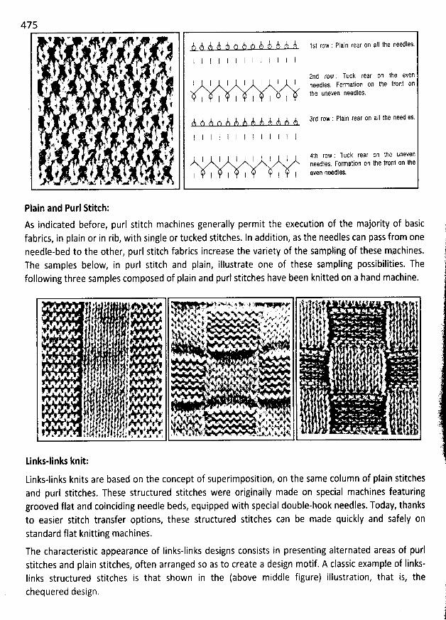
475*' #' #' r ' ' z#' . $.
' ' ,
Y 'G ' ' ' '* Y Y l Y J) Y Y Y Y Y Y Y l 1St roW : Plain rear Qn a1I the needies.
' i l ? f k 'ii'' . i , , - - - l 1 1 I I I I I I I l I
, '
vr I :!j ) . ., y .. js t # l!' ' ' ' @ 201 r0W ; TUCk rear on the even
. , . . , j j j j ! j ! font ()ry. l ! k . j' $, . needfes. Formation on the1 r- / # . 1
' t )) t1e uneVen needles.t . ' T ' .4 . t l i 1 1 l+ . s k &! . ' j y. ! 4. . . q v x... , j x . *
' . . ' '. % 7rj r0w : Plain rear Qn aIl the needies.
t $ 4 i # i t f A A A A A A A A A A A A A.. . / ' . . (i ) 4 j s.v j t i ! I I i l l I l l I l I1 . $. *'k . ' ' . . , ., .
,.
, . . y ,
. x-'l' '. ' t r. i ' ?' '$ i '' I I 1 I 1 1 Ith row : Tuck rear on the uneven' ' ' - ' ' ' peedles. Formatinn on the front on the: . J 2 '? i. # . .. k l I I 1 I 1 I I even needles.#' . . . .
,2.s . #' . ..,. . $ .. ,w .. - . .
Plain and Purl Ritch:
As indicated before, purl stitch machines generally permit the execution of the majority of basicfabrics, in plain or in rib, with single or tucked stitches. In addition, as the needles can pass from oneneedle-bed to the other, purl stitch fabrics increase the variety of the sampling of these mgchines.The samples below, in purl stitch and plain, illustrate one of these sampling possibilities. Thefollowing three samples composed of plain and purl stitches have been knitted on a hand machine.
f # ' ' *# - '' è'*'$..s' t Y . ' .' .7 ' * * - '* 1 T' a . Ws ' V . . # . . . y g l U $ , . . '1 *
-4.A $#v 4 N. ,. # . c ..%. .'N.Ny .s' w x' p. 4'
..,', g. y/ . . ij g, ô .
' '
.
' . ..
' y
t . , $.$4 tyxy , . . z y. y w ;. . yj 4.. . . . . . vj 9. ,,j* . .. .. . t ,- , , .i'ôbï. . jq. , . . . s. . 1qo ,,..,N,,',r.j,-ipjj .. p$..,,,r#..;.k,,, ,-,: qy, . j t . ,
, ! * # , . L v: F $,1 Sy - )t? C t ' ' . P . . '#' . * . . ' .
. . . ,#i , 4 . . . . .' # ' ' k. ' ' /
r . . 1 . 'j . . . ,y x t . . t> ' 't .f . . k ,.:1.9 ... . - .. . .#
. pk jh . a; .i ' ' . Ikjjr . y. . 1% . . zs I ' jj jjkz . . .'#
'
J ,t ) j j 5 t y. ' j : T
'
4.:. . . k .. - . . . . j . .. y y $ .. m. j . q . z y. j . . .' . # . . ' . ' ' . .j . ... . . . . ,
. # ' .. t x # ) $ . . 2,
. ' /# . .. I ) . j I ' . x, . - f . . j.-wkmk4.jx .j; . j.' (' . 1 ) ji' 1 1 j' r' . y i. y,. *k, '''!'- y . ., . . '
.
'
. . - ,s axlz., - j . ' ' . ,
. j y.' ' ' ' J .( /l 1 , ) 1. $. j kj l yqz., y p/ y, y, .. u ., , , . . o . . . . .
t. .,,.,.4$.) uh; t y . . . , . x. . .1 . x. k f 4 t # Ji 1. p ; . . x-.s . .
Links-links knit:
Links-links knits are based on the concept of superimposition, on the same column of plain stitchesand purl stitches. These structured stitches were originaily made on special machines featuringgrooved flat and coinciding needle beds, equipped with special double-hook needles. Today, thanksto easier stitch transfer options, these structured stitches can be made quickly and safely onstandard flat knitting machines.
The characteristic appearance of Iinks-links designs consists in presenting alternated areas of purlstitches and plain stitches, often arranged so as to create a design motif. A classic example of Iinks-Iinks structured stitches is that shown in the (above middle figure) illustration, that is, thechequered design.
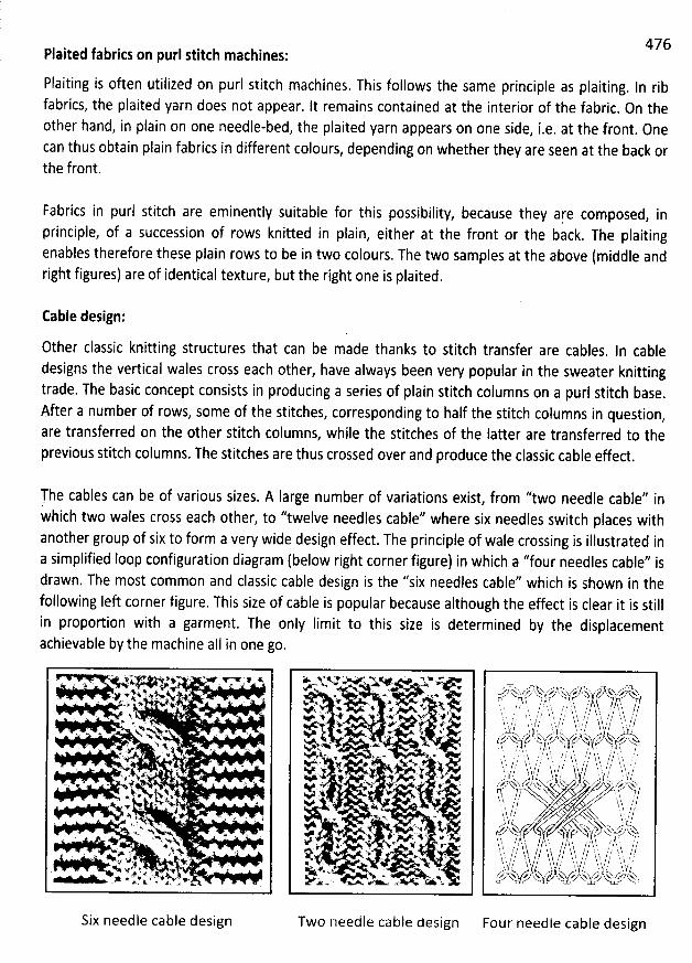
Plaited fabrics on purl stitth machines:
Flaiting is often utisized on puri stitch machines. This follows the same principle as plaiting. In ribfabrics, the plaited yarn does not appear. lt remains contained at the interior of the fabric
. On theother hand, in plain on one needle-bej, the plaited yarn appears on 0ne side, i.e. at the front. 0necan thus obtain plain fabrics in different colours, depending on whether they are seen at the back orthe front.
Fabrics in purl stitch are eminently suitabie for this possibility, because they aqe composed, in
principle, of a succession of rows knitted in plain, either at the front or the back. The plaitingenables therefore these plain rows to be in two colours. The two samples at the above (middle andright figures) are of identical texture, but the right one is plaited.
476
Cable design:
Other classic knitting structures that can be made thanks to stitch transfer are cables. ln cabledesigns the vertical wales cross each other, have always been very popular in the sweater knittingtrade. The basic concept consists in producing a series of plain stitch columns on a purl stitch base.After a number of rows, some of the stitches, corresponding to half the stitch columns in question,are transferred on the other stitch columns, while the stitches of the latter are transferred to theprevious stitch columns. The stitches are thus crossed over and produce the classic cable effect.
The cables can be of various sizes. A large number of variations exist, from ''two needle cable'' inwhich two wales cross each other, to ''twelve needles cable'' where six needles switch places withanother group of six to form a very wide design effect. The principle of wale crossing is illustrated ina simplified Ioop configuration diagram (below right corner figure) in which a ''four needles cable'' isdrawn. The most common and classic cable design is the ''six needles cable'? which is shown in thefollowing left corner figure. This size of cabie is popujar because although the effect is dear it is stillin proportion with a garment. The only Iimit to this size is determined by the displacementachievable by the machine aII in one go.
X *i r v P Yeé V*N' G &. . . . ë. .x.' . . A. ' 1 '. . + j . <
. N s* .q . .. . x . . .
. . k. . W . . .. , '%k .N
. ' . e . . - -.A. ' ., u. ..h# ... 4. # . t . . .. .% a '
lk k. k) xé..' .. .*' a. - *.*. . '' ' .%' . vy .' jW@ . . , '' . ; i.Nt ... w. >. v i:lj. '. 1* >.
. .+ ' wk. 4 .h
.-s .' :. x '. .* t ? .. u v . .ez .w .. % e = ' ' .. . % , '
-.' .. A. ' # # ' #' .!. ...- . w w e , .- *, - .*. . 4. y 4 . .w *
> '*>''% ' * . ' M Y.e'X ** X a- , % .+
V Y '> ' X.. - ,; . ..-- Ql.. -< . . . s* 9 '* . 2A. . w zj> t v
. N. .%v . .< , w .=t. ; . xr #( . @..* f .
x.a .y v . > .yx'
j ' *# . - . ' . , :' . . 7 . .o'+ ,.s .
' V %' . ' #, .:* '+ '' .< A .
. YN: % ' *
# + .. v ,y * v *. * Ni. .. . o y ..g..( .4v. .5 . çN .k . X ''x. .. A s
. . xX.1 w . x.- .'< c< œ u
,/ k.ku fz-s u-k. v, :,. .hh/iy ..4 ï # x. w''xv s-. '(' . '4' . . r! , ? 1 ' $ '. . 1, & / ?,.y.- ' .. : ? . . h
- , .- . .h
-y ,. -, -, $t.. ,.- ,,. h- -y : . ,.' ---
--j ,J-1i . . J
'
;'. ! , , t ï
'
. !. ! $i . ; h, t ' j t / . t / j .y I J . f !, jf $. j ) ' t /l t ' j' , '' ,1 I t
'
; / $ . ? : l .. ? l ï '$ / /,,7.2% .f i tkxs' . ' ';' ,1 ? ', ' ,7 'g . x < z 's y,. y , t-- x: ) ''n / %-t ; , . h %-f;l . .$ l t ï ' ). J . ' . ? ?
'
f . .. - .. . ., -, . , $
'
. f ; k
'
. () ,, .,, /y , , ;. .?.g .k , ,, ,, . . h . , . à, j ,j j ) : q $ ,h h / , k ) / j j / ? . ; / . , ti ,.z $ 't ' yk' / !
'
. , d ) / '. t
'
j .s t /jv. u j y .: j . a s y . , x g x : y x.t..x'h.2t?t!. . .. $/..... ss...yp,..gjl. ï
'
.. I !l y ' .' l ' .' (ï . ( / .
- h 'j /àï ? /' ' .. ?/, t . 'y ?N. i ?'N
x z*N . ' y z y z' ! ,? , i J fl $ ï / y q t , 3$' . $. ,
/ i'bb *' /
J,?'$
$ t ;.. /' ï y gl / $ ts j / y j j. /. .. à. .:, ,.f j, $, y /t ï I :: î$ ' '? ? hj h J f $ k. r l $. 1. f j îj $ ,J ,'$ lh l / j';h t / . t ,z ; t ). ' , y, / , h tv . j.. $ u y ï. u z,k k. o,(.,tz e u,k x z y p k.j z.-g vw?= . ' % u. .x.
Two needle cable design Four needle cable designSix needle cable design
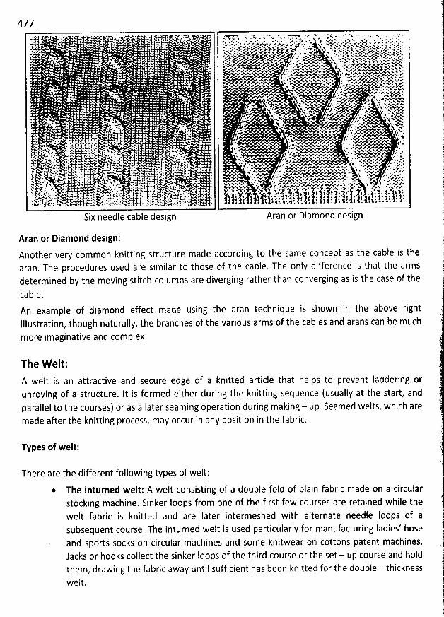
477* v >%* - p: .M A.* N ''- ''G 'T ** eM'v c e 'Y e K q ' *' *
'
J . . 1''X*U ' ' *' w - . ' + . . * ' .' ' *v . 'e+
'
' v . < .. .w
'
w . m . ' *
'
* . * e
'
vh; . v w 'e * '. . . e
'
# '@' e+ *
'
. ' * .e
'
K ' e ' F . A * e' ' #' '' * ' ' 'w al . ' .g. . e ' < 4 x N # v
'
'' e
'
> * T * h ' +. w . .. . w ' @' w . e
'
œ ' * , j
'
'*m : T p *
'
e
'
'
. . + R œ* W < - V K A* # # # # * %* < * 'A W < V *Ap ' w. . e - w .A *. N. œw . z w. u e. x w . - Y <. *w %u N. N N dY Y.>x. Y œk ''> 'N - 'w Y -* e *W'e* VA W' WV K'YK <' ' * * * Y ** * *' * * IWWW W e * p * - * *@ . . r .r#@ x '' w - *. *. *. '%. *w N. * RG * F Y' x * e' ' N* '* *>. # W'* C' ' > W@ M * * * **
. . . ? * y D .vb # * . . '+ N e+A.# .e'<Y <'w*o *wN *< - e* . . . w. e. w. w* a . ' . . > w. p w Aa w.o ... w w v- N Y
. .% v w. *& . <. % - w >. w svp z a. g* * e*r' . g W R œ < Y FW R v w'*w@ @. e *'ew>. a ' *.N.+* e N YN * * @# ** %' P. . . . e v > e - N. .. w A - w . 'F @ '@ %.A Aw. . . %
'
.- e e. v-1 ez 'AA <' .# . %' *< w + .e
. z J w- . * N.lp *.. . wl vv a xr . . .e + 4 . q . .x.o. ...v Aa vAee . ....e.;,. ' * A e M -vs.w w. - p 4 ' > e VA'K ew X x * T '. . . v,e. h -+z+g w . . . -w . . xxvwx w.N N *n. vwx * # *V V ** * * * PW
. . . e @ a. . . z . h, x. xx,vsv
. . . xa $ z 'e.. ..1 ' . v # +. . - w v NN %, > * *?* w . . 4 ' PO
. . 5 * # - . 'v e Ae . -. - . ' . e < * V œ * YN' 'N N. - . / - * 4 e. * * Y. . e x. .N.Y >. V e . k NNe2 ' + * N * e u* '' * * %. r -w ' e # - w# M % ' *' , * * ' **' e . q k' x 'e'r ,. '> ' '. N.
. ' v ' 4 z x.. . x /.e* v < N a. wkx s ' . 4 .< : ' z.N 5 x.. >kN- e: zw . s ..%.* k. - % . e < >w ... . A c'* @ i k
'
.z* '* 'ke v $ 7 A# N* -v . . ' % N . N N.%. # v J. ..-' , . x .. v . er < . # * v 4 .YL < + ' : '
# . t.j t.. J . a . k. e # vw.w J . . e e e * vw .r .t .; Ke ..'.. wd.k v . . x- : .z C't.*. # l . j .! t * e * , . *. e -. v h . w.v a w'x tx * . * ew . *7 - . e '$ t:.h A.z. %. %. . e e .4 ' . e.. N. . . l .k. y.!.a w . . 'w. w + .*% . : ..- K .N :+ * < .&. 4 k. t. * < h .%-% Y . - * - % < x' ' * '#@' # * *. ***' h a z' > . . p r . 1 .A. . >
'
sl . a . 4 . ' %G *
'
; . . '. # @ . >
'
. < v
'
,. . r .. . N.V .' *. * N S. a' @
'
Y ! j <. w . .% . * -. :% .#
'
v
'
@ # w. >
'
A. *
'
* *. *
'
.' e
'
' ' %. < #
'
x x ..-. e a. vu w > e . * . i w ' . e ' N e# s ' Z ## # t ' .Ne * * 1: t * k. 4 .. t * ' .- * <. *V.'*.'*'%.* z - . *.' * I.A w$. K . .. ya * < Y w y ' wNv M . s . ..p,. u vk-kulvz..w t-'..t.h. & ' . A.R. * 1. .- * ee<ee.e<wvv-- - v''eee . * .G .' # 1: e h t # ,% w*.vA, ' X a.4 & . : 4 . .œ % @ z . v,*v**e .u WV e 1 >. v- ( , .> ., e. * V a . A . v *'V V *' u ' vv f.e #.s. zp .V + *. a k (. x +' * * . ve''e . . 0.e7K. * wJe l < V 4+. l . . * Y. .jq Qv VG . . * , e VWPWW *. ' e '< * l * * $ 1 ' e' NN 'v* N' * @ A '- ** *w.v : . .*. @ > * v A NNN v * ' : ' + e R#<
. . z , 1 . > . q : ..v . . .. * .v*. , . . e.e..e v<. , pkv . . vI. v * % vk.. . *4 . . ..ve eveeee . .k. N *k k *l. Aw' ' * ' * x * ' a > '%.#>' 'e = *' ' ' * *e** *. *' t #. te p . v .*%. . * . . N.*e N 4 e 2''e r e . m * j . R 4:.*.. '' K' e & 'e . . .... . ç . + . . Y- '- * # ''' ..- AVYH . M''#**W Z> . - N ' > : > .' * XZD . -x ' A* .. .. $$.. . .< <7w. . . .. &,.. -.. ... . . -.-..q . : .4mv.w v. . * . w 'e . . z . e e* 4 . G. . ' ? . * . # z 1 .a K-t '*
'
A%q . # e? t ) . < Y ' ' ... ! ' . 2 2v .. 4. 1va . ',% ç
'
.4..'< A: 4- 'e* .z . u:u . t . vla . .Ij ., '* . .,; ! . . ..y+
'
.j .; 4 .: k 1 , l . .i . . $ .. >
'
1 . 4 . 1 X
'
;. zskc... .1 w
'
..:.t. -k : N I 4 . ,t . $
'
A
'
4 4 .. 4 z. 4 : ., t 4 4. . : .. sz t . ) t. vK- .c''* e . ; t:4 * e o ...a ..j < ..'- .1 . 4 j 4 4 ! t a , * j . . w
'
.#
'
1 . .j 4 . ! . j
'
k. . .. g..f : . x 4. N. * ! . * * 'k vâ . 4 . ..v . G X kqv. p . . . j .-1z < s ,% -'- x-zu -'Ne aoze-xxh -'*( u N * * . t 9 A & - u . - , . * - . - . . - - * '
Six need e ca e design Aran or Diamon esign
Aran or Diamond design:
Another very common knitting structure made according to the same concept as the cable is thearan. The procedures used are similar to those of the cable. The only difference is that the armsdetermined by the moving stitch columns are diverging rather than converging as is the case of the
cable.An example of diamond effect made using the aran technique is shown in the above rightillustration, though naturally, the branches of the various arms of the cables and arans can be muchmore imaginative and complex.
The W elt:A welt is an attractive and secure edge of a knitted article that helps to prevent laddering orunroving of a structure. It is formed either during the knitting sequence (usually at the start, andparallel to the courses) or as a Iater seaming operation during making - up. Seamed welts, which aremade after the knitting process, may occur in any position in the fabric.
Types of welt:
There are the different following types of welt:
The inturned welt: A welt consisting of a double fold of plain fabric made on a circularstocking machine. Sinker Ioops from one of the first few courses are retained while thewelt fabric is knitted and are Iater intermeshed with afternate needie Ioops of asubsequent course. The inturned welt is used particularly for manufacturing ladies' hoseand sports socks on circular machines and some knitwear on cottons patent machines.Jacks or hooks collect the sinker Ioops of the third course or the set - up course and holdthem, drawing the fabric away until sufficient has been knitted for the double - thicknesswelt.
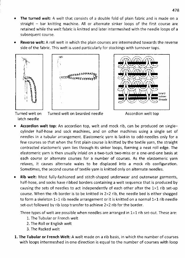
478
* The turned welt: A welt that consists of a double fold of plain fabric and is made on astraight - bar knitting machine. AII or alternate sinker loops of the first course areretained while the welt fabric is knitted and Iater intermeshed with the needle Ioops of asubsequent course.
* Reverse welt: A roll welt in which the plain courses are intermeshed towards the reverseside of the fabric. This welt is used particularly for stockings with turnover tops.
V ' >/' j
j t/j' ;1 if!' ;
'
i )! @' l
Turned welt onlatch needle
*
;.f
Turned welt on bearded needle
!/< <-
1 n laidrubberthreads
..>' 7
Accordion welt top
Accordion welt top: An accordion top, welt and mock rib, can be produced on single-cylinder half-hose and sock machines, and on other machines using a single set ofneedles in a tubular arrangement. Elastomeric yarn is Iaid-in to odd. needles only for afew courses so that when the first plain course is knitted by the textile yarn, the straightcontracted elastomeric yarn Iies through its sinker Ioops, forming a neat roll edge. Theelastomeric yarn is then usually inlaid on a two-tuck two-miss or a one-and-one basis ateach course or alternate courses for a number of courses. As the elastomeric yarnreiaxes, it causes alternate wales to be displaced into a mock rib configuration.Sometimes, the second course of textile yarn is knitted only on alternate needles.
* Rib welt: Most fully-fashioned and stitch-shaped underwear and outerwear garments,half-hose, and socks have ribbed borders containing a welt sequence that is produced bycausing the sets of needles to act independently of each other after the 1x1 rib set-upcourse. W hen the rib border is to be knitted in 2x2 rib, the needle bed is either shoggedto form a skeleton 1x1 rib needle arrangement or it is knitted on a normal 1x1 rib needleset-out followed by rib loop transfer to achieve 2x2 rib for the border.
Three types of welt are possible when needles are arranged in 1x1 rib set-out. These are:1. The Tubular or French welt2. The Roll or English welt3. The Racked welt
1. The Tubular or French W elt: A welt made on a rib basis, in which the number of courseswith loops intermeshed in one direction is equal to the number of courses with Ioop
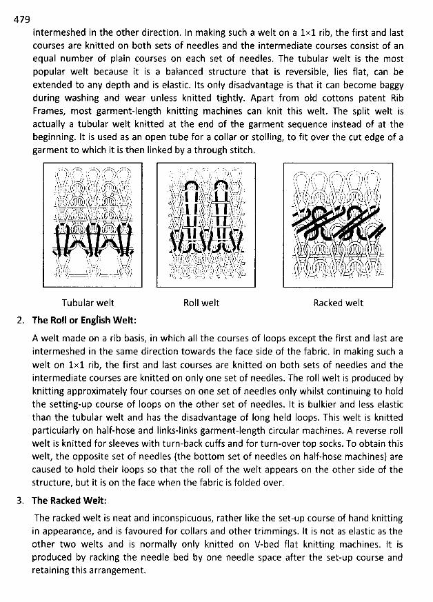
479intermeshed in the other direction. In making such a welt on a 1x1 rib, the first and Iastcourses are knitted on both sets of needles and the intermediate courses consist of anequal number of plain courses on each set of needles. The tubular welt is the mostpopular welt because it is a balanced structure that is reversible, Iies flat, can beextended to any depth and is elastic. Its only disadvantage is that it can become baggyduring washing and wear unless knitted tightly. Apart from old cottons patent RibFrames, most garment-length knitting machines can knit this welt. The split welt isactually a tubular welt knitted at the end of the garment sequence instead of at thebeginning. It is used as an open tube for a collar or stolling, to fit over the cut edge of agarment to which it is then Iinked by a through stitch.
Tubular welt
2. The Roll or English Welt:
- . . x 7- T N z - - N z . . .r ,. . .. . . .. / : . h, . i .. $ . .' l h. s ' hb J . . Jç rr/ .' ' , t;:;?, ' .. ;qï@ kgs' ? ' ' .j;f ,t ;.x k t)1)j.'J i f 'î ky.' ' h. :' 1'. fy TTy) ,, ' J:ft rrtc $.$ . ? a 'x -
-..?3b..bàï...à'''''' 1111k' à'kjïïé''f. 4jj.,.. (., :h)$( 'liE:, .,. :'p't. ,,t(i )'. y) l .< . . s v y y.xY -- t -r F. l / )) jl!y .- ;/ , - L', t/. )$ f .zt ' -E .. . -' t f9?, k-. , i ,A t tj' j b ) . t ' 1 l . ) j'z .- /= '' V'; I 1
. >,rf; :- - Z - . . . . >
,M 7 X .r . ( J T') ( ) t ( t 2. ) , ..k. .,k .-- -.,z .. - .?x- , ,,.? -,u
.a)j 7 (! . %y :' ((+. ->. 'j. ', j (' $ ; (' jy ) ( /!. ) i jy à, ( k, )' ) ,..j s ),..k kjq, vs-t;y s-t.)- .a tzcz' V - . t-. - . .+ , . ,v y v ., g) $ : $,.. ..$h s .. :.) F. t (.; .( zt ç . .,j q , p. .rI )' ï $ L , ) . . kf à . ( t o ) $ ) ) . ; ,..) t y x g kj; . y t.oA w . j .t--.. .u' o- rt )t ( et- a.: ' >w ...J : y. 'ï
Roll welt
----' wxx.s z''-.------.
-----hhs , '-es7:sCt7'x ''-z;bî::ll hx ,' ze ::7'77'' A
( $ t't ') ) ( 1. ? ) it (y ) 1 th f.y 1 )1$ 'h ./ J ''$, h, , .' h . / /, yy,..../.,.,? j . / .,h. . . .,? .' h t ..-z.k(/ ) .. . .V?' ( /1icx., , ( k, ) ( ï. S-'', , ') ,' .'.) ))V, bt, .)l k? ' . ..t.x ' scl k t -1
> , ........
'
'''
'
...j()k..
'
: ' ZO' 'h
r v . ,' j( l#( )) . . ( .(h)
. ï,, h? , , , 's,A, . , - t h/ .Lz
Racked welt
A welt made on a rib basis, in which aII the courses of Ioops except the first and last areintermeshed in the same direction towards the face side of the fabric. In making such awelt on 1x1 rib, the first and last courses are knitted on both sets of needles and theintermediate courses are knitted on only one set of needles. The roll welt is produced byknitting approximately four courses on one set of needles only whilst continuing to holdthe setting-up course of Ioops on the other set of needles. lt is bulkier and Iess elasticthan the tubular welt and has the disadvantage of Iong held Ioops. This welt is knittedparticularly on half-hose and Iinks-links garment-length circular machines. A reverse rollwelt is knitted for sleeves with turn-back cuffs and for turn-over top socks. To obtain thiswelt, the opposite set of needles (the bottom set of needles on half-hose machines) arecaused to hold their Ioops so that the roll of the welt appears on the other side of thestructure, but it is on the face when the fabric is folded over.
3. The Racked W elt:
The racked welt is neat and inconspicuous, rather Iike the set-up course of hand knittingin appearance, and is favoured for collars and other trimmings. It is not as elastic as theother two welts and is normally only knitted on V-bed flat knitting machines. It isproduced by racking the needle bed by one needle space after the set-up course andretaining this arrangement.
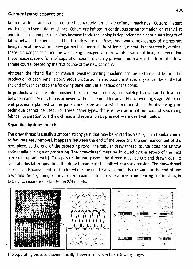
480Garment panel separation:
Knitted articles are often produced separately on single-cylinder machines, Cottons Patentmachines and some flat machines. Others are knitted in continuous string formation on many flatand circular rib and purl machines because fabric tensioning is dependent on a continuous Iength offabric between the needles and the take-down rollers. Also, there would be a danger of latches notbeing open at the start of a new garment Sequence. If the string of garments is separated by cutting,there is a danger of either the welt being damaged or of unwanted yarn not being removed. Forthese reasons, some form of separation course is usually provided, normally in the form of a drawthread course, preceding the first course of the new garment.
Although the ''hand flat'' or manual sweater knitting machine can be re-threaded before theproduction of each panel, a continuous production is also possible. A Special yarn can be knitted atthe end of each panel so the following panel can u$e it instead of the comb.
ln products which are Iater finished through a wet process, a dissolving thread can be insertedbetAeen panels. Separation is achieved without the need for an additional working stage. When nowet process is planned or the panels are to be separated at another stage, the dissolving yarntechnique cannot be used. For these panel types, there is two principal methods of separatingfabrics - separation by a draw-thread and separation by press-off- are dealt with below.
Separation by draw-thread:
The draw thread is usually a smooth strong yarn that may be knitted as a slack, plain tubular courseto facilitate easy removal. lt appears between the end of the piece and the commencement of thenext piece, at the end of the protecting rows. The tubular draw thread course does not unroveaccidentally during wet processing. The draw-thread must be followed by the set-up èf the nextpiece (set-up and welt). To separate the two pieces, the thread must be cut and drawn out. Tofacilitate this Iatter operation, the draw-thread must be knitted at a slack tension. The draw-threadis particularly convenient for fabrics where the needle arrangement is the same at the end of onepiece and the beginning of the next. For example, to separate articles commencing and finishing in
1x1 rib, to separate ribs knitted in 2/3 rib, etc.
The separating process is schematically shown in above, in tbe foitowing stages:
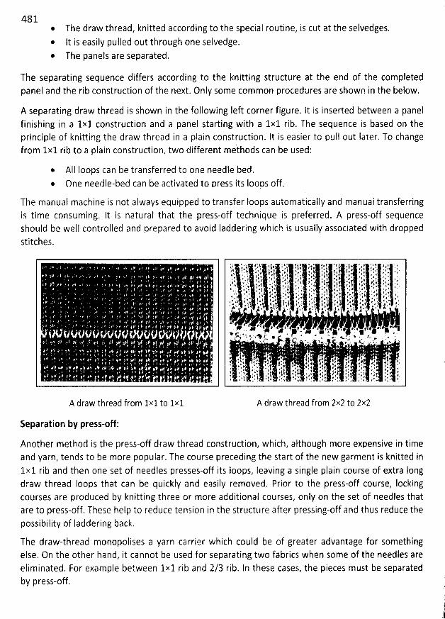
481@ The draw thread, knitted according to the special routine, is cut at the selvedges.
It is easily pulled out through oné selvedge.@ The panels are separated.
The separating sequence differs according to the knitting structure at the end of the completedpanel and the rib construction of the next. Only some common procedures are shown in the below.
A separating draw thread is shown in the following left corner figure. It is inserted between a panelfinishing in a 1x1 construction and a panel starting with a 1x1 rib. The sequence is based on theprinciple of knitting the draw thread in a plain construction. It is easier to pull out Iater. To changefrom 1x1 rib to a plain construction, two different m/thods can be used:
@ AII loops can be transferred to one needle bed.One needle-bed can be activated to press its Ioops off.
The manual machine is not always equipped to transfer Ioops automatically and manuai transferringis time consuming. It is natural that the press-off technique is preferred. A press-off Sequenceshould be well controlled and prepared to avoid Iaddering which is usually associated with droppedstitches.
A draw thread from 1x1 to 1x1 A draw thread from 2x2 to 2x2
Separation by press-off:
Another method is the press-off draw thread construction, which, although more expensive in timeand yarn, tends to be more popular. The course preceding the start of the new garment is knitted in1x1 rib and then one set of needles presses-off its Ioops, leaving a single plain course of extra Iongdraw thread Ioops that can be quickly and easily removed. Prior to the press-off course, Iockingcourses are produced by knitting three or more additional courses, only on the set of needles thatare to press-off. These help to reduce tension in the structtbre after pressing-off and thus reduce thepossibility of Iaddering back.
The draw-thread monopolises a yarn carrier which could be of greater advantage for somethingelse. On the other hand, it cannot be used for separating two fabrics when some of the needles areeliminated. For example between 1x1 rib and 2/3 rib. In these cases, the pieces must be separatedby press-off. ('
'
tti1.ï
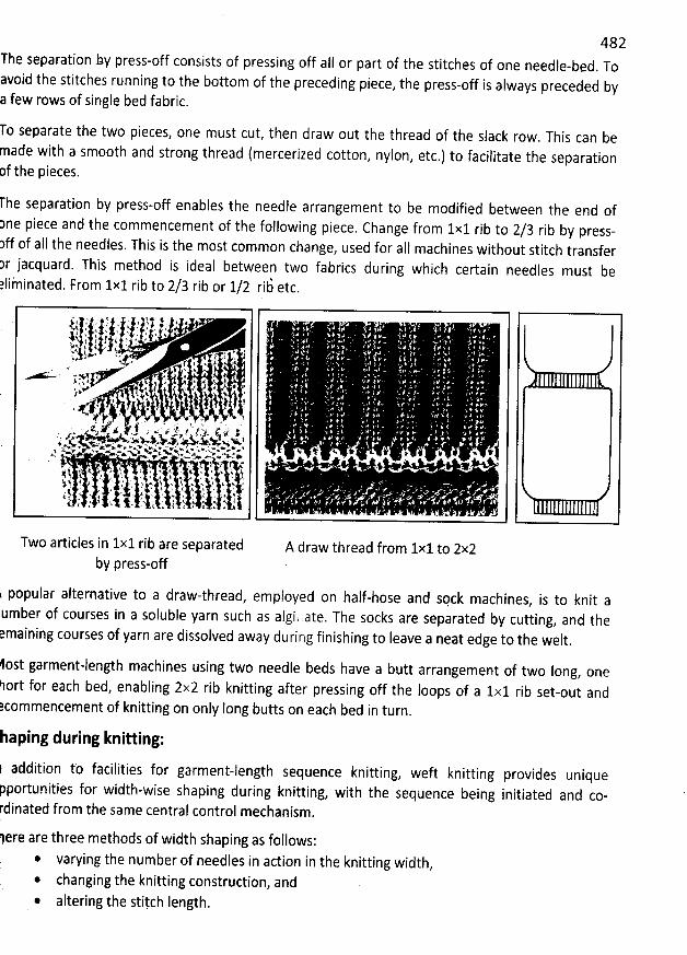
482The separation Ny press-off consists of pressing off all or part of the stitches of one needle-bed. Toavoid the stitches running to the bottom of the preceding piece
, the press-off is always preceded by few rows of single bed fabric.
o separate the two pieces, one must cut, then draw out the thread of the slack row. This can beade with a smooth and strong thread (mercerized cotton, nylon, etc.) to facilitate the separationf the pieces.
he separation by press-off enables the needle arrangement to be modified between the end of3ne piece and the commencement of the following piece. Change from 1x1 rib to 2/3 rib by press-ff of all the needles. This is the most common change
, used for a11 machines without stitch transferr jacquard. This method is ideal between two fabrics during which certain needles must beliininated. From 1x1 rib to 2/3 rib or 1/2 ri6 etc.
1$ - ' v , - ,. . .. *' t 1 A. < N .: . .1. $, dk (i (j , ,,'' .,. !jkr. lt. '.' t ,1 ... -6). x j ( v y
'
. . . .p
'
. :''*AJI . . . 4 '. % ., , . .k 4 z . . j ., xu-.', ( ë l ... , . -r j* q v . .. +' , ? .e+ a e . . '3
N&: ) i # # . >, .p. , jq t.. .. . . t , ,,y> q. s.. .-
. . i j j ) ,? , . . '* ''t . . ; u . 'ew
,é% ' z. j. . o,. . g kp . y j x . j g . y ., ' J . .>. e ..- . . . - .g. y. * . w'.U z . x.. . j . !' v. - . . . * v ' .k <.>@' k . '.. M . > u . '. i w. . xvx e'. - 'w. . v ..w.. w . .w .. vsaw >,., . u 4. p # . y x #y k '# . x . .< - n%wN Y x + *. w w xw...>+ % * + .- ..+ A. . c -
. . * . s y . s' ). . .,. l ' < . .. ' y
'
N. k w
'
&. t y < K . k. 'k j.4 . h *.. t . . & 4 A : K
'
+ . : x .Aj 4 j . ' '' ' $
'
% $. .v
'
.. k k 4% , . . . ,. , ) . y z
'
, , .. . . . 4 ., N' $ 4 ' . z . v w t . k $ . A -- ' .< t 1 . v t* ,. t * . . ' :.' f . . ' ' .,%. *' R f
'
z & t b
'
z
'
t ' : 1 ..j
Two articles in 1x1 rib are separatedby press-off
k popular alternative to a draw-thread, employed on half-hose and spck machines, is to knit aumber of courses in a soluble yarn such as algi. tate. The socks are separated by cutting, and themaining courses of yarn are dissolved away during finishing to Ieave a neat edge to the welt
.
A draw thread from lxlto 2x2
ost garment-length machines using two needle beds have a butt arrangement of two Iong, one
ort for each bed, enabling 2x2 rib knitting after pressing off the loops of a 1x1 rib set-out and?commencement of knitting on only Iong butts on each bed in turn
.
aping during knitting:
1 addition to facilities for garment-length sequence knitting, weft knitting provides unique
portunities for width-wise shaping during knitting, with the sequence being initiated and co-dinated from the same central control mechanism'.
ere are three methods of width shaping as follows:* varying the number of needles in action in the knitting width
,
* changing the knitting construction, and* altering the stiych length.
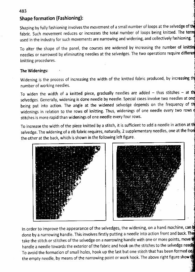
483 hJ.
Shape formation (Fashioning): '. : ;Shaping by fully fashioning involves the movement of a smajl number of Ioops at the selvedge of tfabric. Such movement reduces or increases the total number of loops being knitted. The ter
.t.used in the industry for such movements are narrowing and widening, and collectively fashioning. t(..
To alter the shape of the panel? the courses are widened by increasing the number of knitti 'l
needles or narrowed by eliminating needles at the selvedges. The two operations require differe
knitting procedures.
The W idenings: .
W idening is the process of increasing the width of the knitted fabric produced, by increasing t
number of working needles.
To widen the width of a knitted piece, gradually needles are added - thus stitches - at t 'selvedges. Generally, widening is done needle by needle. Special cases involve two needles at onbeing put into action. The angle at the widened selvedge depends on the frequency of twidenings in relation tt) the rows of knitting. Thus, widenings of one needle every two rowsstitches is more rapid than widenings of one needle every four rows. :
To increase the width of the piece knitted by a stitch, it is su#icient to add a needle in adion at tselvedge. The widening of a rib fabric requires, naturally, 2 supplementary needles, one at the frothe other at the back, which is shown in the following Ieft figure.
' () . ..1E s .
. ' ê j
k , . .- à. ' 4. :k. , .èt
' .m # ..' '; ! (
;k! .
' .
.. . 2 kr . .
. dI
) '.j - jy
'k ' . .
ln order to improve the appearance of the selvedges, the widening, on a hand machine, can,.24.
done by a narrowing handle. This involves firstly putting a needle into action front and back. Thtake the stitch or stitches of the selvedge on a narrowing handle with one or more points, move'
. .)handle a needle towards the exterior of the fabric and hook on the stitches to the selvedge nee
., )).
To avoid the formation of small holes, hook up the Iast but one stitch that has been formed)?
the empty needle, by means of the narrowing point or work hook. The above right figure show q''%j(#;))'i
,. )'
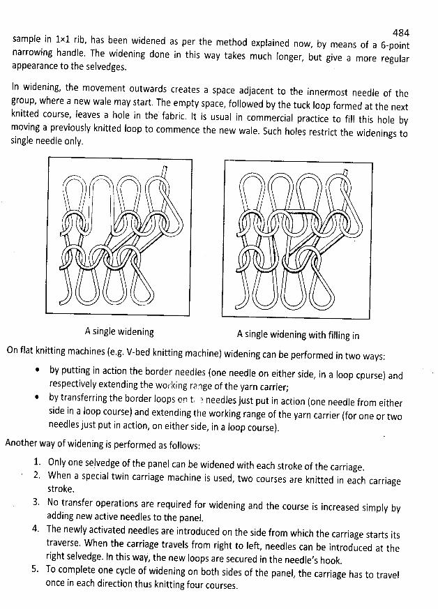
484sample in 1x1 rib, has been widened as per the method explained now
, by means of a 6-pointnarrowing handle. The widening done in this way takes mtlch Ionger
, but give a more regularappearance to the selvedges. '
In widening, the movement outwards creates a space adjacent to the innermost needle of the
group, where a new wale may start. The empty space? followed by the tuck Ioop formed at the nextknitted course, Ieaves a hole in the fabric
. It is usual in commercial practice to fill this hole bymoving a previously knitted Ioop to commence the new wale
. Such holes restrict the widenings tosingle needle only.
yyyyyyyyyyjyjjjyjy-A single wideningV
A single widening with filling in
On flat knitting machines (e.g. V-bed knitting machine) widening can be performed in two ways:
by putting in action the border needles (one needle on either side, in a Ioop cpurse) and
respectively extending the working racge of the yarn carrier;* by transferring the border loops on tk a needles just put in action (one needle from eitherside in a loop course) and extending the working range of the yarn carrier (for one or twoneedles just put in action, on either side, in a Ioop course).
Another way of widening is performed as follows:
Only one selvedge of the panel can be widened with each stroke of the carriage.W hen a special twin carriage machine is used
, two courses are knitted in each carriageStroke.No transfer operations are required for widening and the course is increased simply byadding new active needles to the panel.
4. The newly activated needles are introduced on the Side from which the carriage starts itstraverse. When the carriage travels from right to Ieft
, needles can be introduced at theright selvedge. In this way, the new Ioops are secured in the needle's hook.
5. To complete one cycle of widening on b0th sides of the panel, the carriage has to travel
once in each direction thus knitting fous courses.
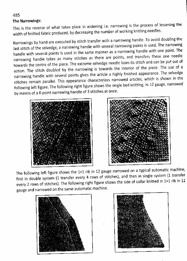
l11
*
.
485The Narrowings:This is the reverse of what takes place in widening i.e. narrowing is the process of lessening thewidth of knitted fabric produced, by decreasing the number of working knitting needles.
Narrowings byhand are executedIast stitch of the selvedge, a narrowing handle with several narrowing points is used. The narrowinghandle with several points is used in the same manner as a narrowing handle with one point. Thenarrowing handle takes as many stitches as there are points, and transfers these one needletowards the centre of the piece. The extreme selvedge needle loses its stitch and can be put out ofaction. The stitch doubled by the narrowing is towards the interior of the piece. The use of anarrowing handle with several points gives the article a highly finished appearance. The selvedgestitches remain parallel. This appearance characterizes narrowed articles, which is shown in thefollowing left figure. The following right figure shows the single bed knitting, in 12 gauge, narrowed
by means of a 6-point narrowing handle of 3 stitches at once.
by stitch transfer witha narrowing handle.To avoid doubling the
The following Ieft figure shows the 1x1 rib in 12 gauge narrowed on a typical automatic machine,first in double system (1 transfer every 4 rows of stitches), and then in single system (1 transferevery 2 rows of stitches). The following right figure shows the side of collar knitted in 1x1 rib in 12gauge and narrowed on the same automatic machine.
K K
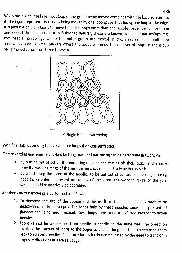
486When narrowing, the innermost Ioop of the group being moved combines with the Ioop adjacent toit. The figure represents two loops being moved by one loop space
, thus losing one loop at the edge.It is possible on plain fabric to move the edge Ioops more than one needle space
, Iosing more thanone loop at the edge. ln the fully fashioned industry these are known as 'needle narrowings' e
.g.two needle narrowings where the outer group are moved in two needles
, Such multi-loopnarrowings produce small puckers where the Ioops combine. The number of Ioops in the groupbeing moved varies from three to seven.
A Single Needle Narrowing
With finer fabrics tending to involve more Ioops than coarser fabrics.
On flat knitting machines (e.g. V-bed knitting machine) narrowing can be performed in two ways:
by putting out of action the bordering needles and casting off their Ioops; at the sametime the working range of the yarn carrier should respectively be decreased;by transferring the loops of the needles to be put out of action
, on the neighbouringneedses, in order to prevent unraveling of the loops; the working range of the yarncarrier should respectively be decreased.
Another way of narrowing is performed as foilows:
To decrease the size of the course and the widih of the panel, needles have to bedeactivated at the selvedges. The Ioops held by these needles cannot be pressed-off(ladders can be formed). lnstead, these Ioops have to be transferred inwards to activeneedles.Loops cannot be transferred from needle to needle on the same bed. The operationinvolves the transfer of Ioops to the opposite bed; racking and then transferring themback to adjacent needles. The procedure is further complicated by the need to transfer inopposite directions at each selvedge.
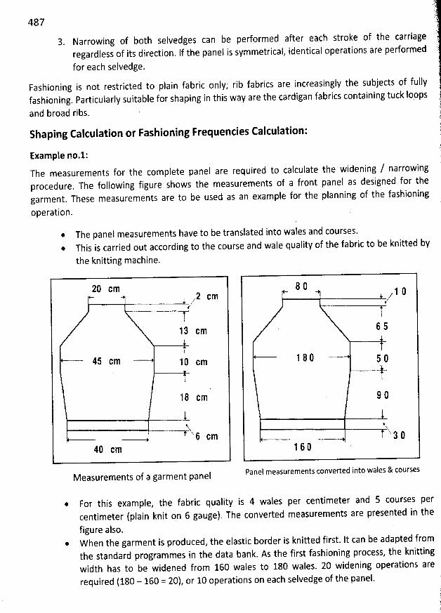
487Narrowing of both selvedges can be performed after each stroke of the carriageregardless of its direction. lf the panel is symmetrical, identical operations are performed
for each selvedge.
Fashioning is not restricted to plain fabric only; rib fabrics are increasingly the subjects of fullyfashioning. Particularly suitable for shaping in this way are the cardigan fabrics containing tuck Ioops
and broad ribs. .
Shaping Calculation or Fashioning Frequencies Calculation:
Example no.1:The measurements for the complete panel are required to calculate the widening / narrowingprocedure. The following figure shows the measurements of a front panel as designed for thegarment. These measurements are to be used as an example for the planning of the fashioning
operation.
The panel measurements have to be translated into wales and courses.* This is carried out according to the course and wale quality of the fabric to be knitted by
the knitting machine.
29 cm 2 cmy'
z
11 cm
15 cm 1û cm
1 2 cm
'xxNi cm
40 cm
Measurements of a garment panel
2 û, 1 ê/
55
12û 59
9û
%X-29
16û
Panel measurements converted into wales & courses
* For this example, the fabric quality is 4 wales per centimeter and 5 courses percentimeter (plain knit on 6 gauge). The converted measurements are presented in thefigure also.
* W hen the garment is produced, the elastic border is knitted first. It can be adapted fromthe standard programmes in the data bank. As the first fashioning process, the knittingwidth has to be widened from 160 wales to 180 wales. 20 widening operations are
required (180 - 160 = 20), or 10 operations on each selvedge of the panel. ,J(i
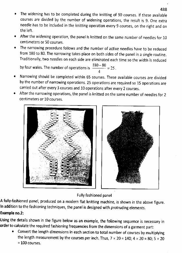
488* The widening has to be completed during the knitting of 90 courses
. lf these availablecourses are divided by the number of widening operations
, the result is 9, One extraneedle has to be included in the knitting operation every 9 courses
, on the right and onthe left.
* After the widening operation, the panel is knitted on the same number of needles for 10centimeters or 50 courses.
* The narrowing procedure follows and the number of active needles have to be reducedfrom 180 to 80. The narrowing takes place on both sides of the panel in a single routine
.
Trajitionally, two needles on each side are eliminated each time so the width is reduced180 - 80by four wales. The number of operations is = 25 .4
* Narrowing should be completed within 65 courses. These available courses are dividedby the number of narrowing operations. 25 operations are required so 15 operations arecarried out after every 3 courses and 10 operations after every 2 courses
.
* After the narrowing operations, the panel is knitted on the same number of needles for 2centimeters or 10 courses.
Fully fashioned panelA fully-fashioned panel, produced on a modern flat knitting machine
, is shown in the above figure.In addition to the fashioning techniques, the panel is designed with protruding elements.Example no.i:Msing the details shown in the figure below as an example
, the following sequence is necessary inrder to calculate the required fashioning frequencies from the dimensions of a garment part:
* Convert the Iength dimensions in each section to total number of courses by multiplyingthe length measurement by the courses per inch. Thus, 7 x 20 = 140; 4 x 20' = 80; 5 x 20= 100 courses.
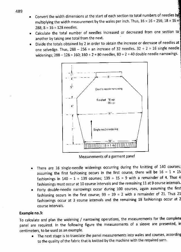
489
::
'
7'.t '.y J '
Convert the width dimensions at the start of each section to total numbers of needles b ?è
'
multiplying the width measurement by the wales per inch. Thus, 16 x 16 = 256,. 18 x 16 k,')!q
288) 8 x 16 = 128 needles. .Calculate the total number of needles increased or decreased from one section toèanother by taking one total from the next.Divide the totals obtained by 2 in order to obtain the increase or decrease of needles atone selvedge. Thus, 288 - 256 z: an increase of 32 needles. 32 + 2 = 16 single needlewidenings; 288 - 128 = 160,. 160 + 2 = 80 needles, 80 + 2 = 40 double needle narrowings.
)
! 1f
'##. - - - - - - j! ' ' 1
- .. - . .- .- - - .- <-. '' 6?' --#F !t t
'
f
'
5 ' 4' Doub'e needde narrohplnq
:b-
Finished 16 w'p,20 cpi
- - ....- -- -- - . - - - 18', '--- >ç1l
7'' Sinqle neetle wideninq11t ' -,6., --k
l l 1 x 1 rib
Measurements of a garment panel
* There are 16 single-needle widenings occurring during the knitting of 140 courses;assuming the first fasbioning occurs in the first course, there will be 16 - 1 = 15fashionings in 140 - 1 = 139 courses; 139 + 15 = 9 with a remainder of 4. Thtls 4fashionings must occur at 10 course intervals and the remaining 11 at 9 course intervals.
* Forty double-needle narrowings occur during 100 courses, again assuming the firstfashioning occurs in the first course; 99 + 39 = 2 with a remainder of 21. Thus 21fashionings occur at 3 course intervals and the remaining 18 fashionings occur at 2
course intervals.
Example no.3:To calculate and plan the widehing / narrowing operations, the measurements for the completepanel are required. In the following figure the measurements of a sleeve are presented, incentimeters, to be used as an example.
* The next stage is to translate the panel measurements into wales and courses, accordin!to the quality of the fabric that is knitted by the machine with the required yarn.
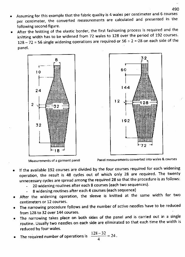
49c* Assuming for this exam pie that the fabric quality is 4 wales per centimeter and 6 courses
per centimeter, the converted measurements are calculated and presented in the
following second figure.@ After the knitting of the elastic border, the first fashioning process is required and the
knitting width has to be widened from 72 wales to 128 over the period of 192 courses.128 - 72 = 56 single widening operations are required or 56 +. 2 =-28 on each side df the
panel.
li1 0 fkl 82 Qftft 0. k.àfaft .CZQC.?ftnnjzfzqqqrzqjzIKQVAqfsqtzlli.pGa
2 4 Qqio'm''lKKlKrsjjsfkauusajuQQQa kfzfsvaaafzan fzQa Qœ lt P ft Qa l l Q'a jl O.Q j jzftfzftfmœrzfmafzk
açzq fzn.rs2 x 52n. œ kz ft fsjkz11 KPQQQœ î.a s ljpœaœq-qaœ :QI??EQIQœ'LL? *allQœQQaaQa
5 2 Q'QAQqEQœ, Qaoœlaœaasœ aœaœjkala œaaa œ ajxqakœjssllpaœ
nano
œsœEs Eiaâipâsi:Q ;k QQ )QQQIIQAQQ
1e
M easurements of a garment panel
5 2
KE6 0 K
2lQEIllzli/lkfséllrs 8: s:7: l js j 1ij1 44 ajza tz rs!!ll:Qs!ll2spojuujjjual Kuua
jaftll''œ a a1 2 x 2 :Ks
-
uuaaaqrjps j j j q I.:. x o.
j j* s: k s l/ jj j1 9 2 Q œ 11 n.œ
klkâ@QQftx u,.I l z:u y: I l *Ek
72
Panel measurements converted into wales & courses
If the available 192 courses are divided by the four courses required for each wideningoperation, tbe result is 48 cycles out of wbich only 28 are required. The twentyunnecessary cycles are spread among the required 28 so that the procedure is as follows:
20 widening routines after each 8 courses (each two sequences).8 widening routines after each 4 courses (each sequence)
* After the widening operation, tbe sleeve is knitted at the sam e width for two
centim eters or 12 courses.* The narrowing procedure follows and the number of active needles have to be reduced
from 128 to 32 over 144 courses.* The narrowing takes place on both sides of the panel and is carried out in a single
routine. Usually two needles on each side are eliminated so that each time the width is
reduced by four wales.128 - 32* The required number of operations is = 24 .
4
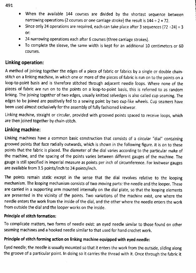
491
W hen the available 144 courses are divided by the shortest sequence between
narrowing operatibns (2 courses or one carriage stroke) the result is 144 + 2 = 72.Since only 24 operations are required, each can take place after 3 sequences (72 +24) = 3or:
* 24 narrowing operations each after 6 courses (three carriage strokes).To complete the sleeve, the same width is kept for an additional 10 centimeters or 60EOUCSES.
Linking operation:
A method of joining together the edges of a piece of fabric or fabrics by a single or double chain-stitch on a Iinking machine, in which one or more of the pieces of fabric is run on to the points on aIoop-to-point basis and is therefore stitched through adjacent needle foops. Where none of thepieces of fabric are run on to the points on a Ioop-to-point basis, this is referred to as randomlinking. The joining together of two edges, usually knitted selvedges is also called cup seaming. Theedges to be joined are positively fed to a sewing point by two cup-like wheels. Cup seamers havebeen used almost exclusively for the assembly of fully fashioned knitwear.
Linking machine, straight or circular, provided with grooved points spaced to receive Ioops, which
are then joined together by chain-stitch.
unking machine:
Linking machines have a common basic construction that consists of a circular '/dial'? containinggrooved points that face radially outwards, which is Shown in the following figure. lt is on to thesepoints that the fabric is placed. The diameter of the dial varies according to the particular mak: ofthe machine, and the spacing of the points varies between different gauges of the machine. Thegauge is still specified in imperial measure as points per inch of circumference. For knitwear gaugesare avaijable from 3.5 points/inch to 24 points/inch.
The points remain static except in the Sense that the dial revolves relative to the Ioopingmechanism. The Iooping mechanism consists of two moving parts: the needle and the Iooper. Theseare carried in a supporting arm mounted internally on the dial plate, so that the Iooping elementsare presented in the vicinity of the points. Two variations of the machine exist, one where theneedle enters the work from the inside of the dial, and the other where the needle enters the workfrom outside the dial and the Iooper works on the inside.
Principle of stitch formation:
To cömplicate matters, two forms of needle exist: an eyed needle similar to those found on otherseaming machines and a hooked needle similar to that used for hand crochet work.
Printiple of stitch fofming attion on linking machine equipped with eyed needle:
Eyed needle; the needle is usually mounted so that it enters the work from the outside, sliding alongthe groove of a particular point. In doing so it carries the thread with it. Once through the fabric it
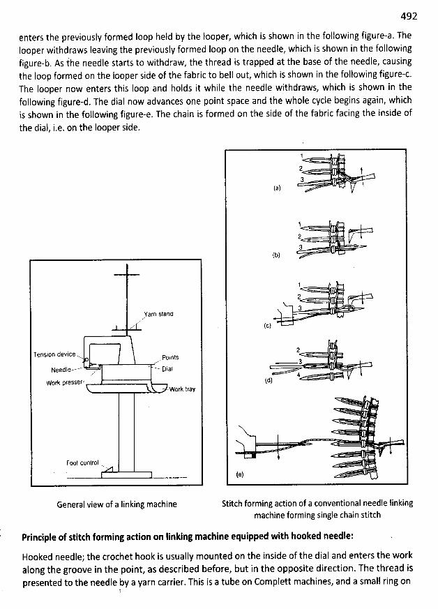
492
enters the previously formed Ioop held by the Iooper, which is shown in the following figure-a. TheIooper withdraws Ieaving the previously formed Ioop on the needle, which is shown in the followingfigure-b. As fhe needle starts to withdraw, the thread is trapped at the base of the needle, causingthe loop formed on the looper side of the fabric to bell out, which is shown in the following figure-c.The looper now enters this loop and holds it while the needle withdraws, which is shown in thefollowing figure-d. The dial now advances one point space and the whole cycle begins again, whichîs shown in the following figure-e. The chain is formed on the side of the fabric facing the inside ofthe dial, î.e. on the Iooper side.
Yarn stand
zA
Tension device-w. points
Needle----' --- Dialzr
Work pfessef z.. .work tray
Foot control
General view of a Iinking machine
1
23
(a)
1
, #=3
(t))
1
2 r,+3
(c)
2. - 3
4+td)
(e)
Stitch forming action of a conventional needle Iinkingmachine forming single chain stitch
Principle of stitth forming adion on Iinking machine equipped with hooked needle:
Hooked needle; the crochet hook is usually mounted on the inside of the dial and enters the workalong the groove in the point, as described before, but in the opposite direction. The thread ispresented to the needle by a yarn carrier. This is a tube on Complett machines, and a small ring on
t
493
Mathbirk machinery. The thread enters the hook of the needle which withdraws dragging a loopthrough the fabric and through the previously formed Ioop. The needle retains the loop on its stemas the dial moves on one point and the cycle starts again.
The chaining again takes place on the inside of the dial. Both types of Ioop forming principles exist inreversed versions, with inside mounted conventional needles and outside mounted crochetneedles. Uses and advantages are claimed for each version. For both needle types entering fromoutside the dial, there is a tendency for the work to be pushed back on the points, requiring Iesspresser plate control.
Thread control is effected by two principal methods: a tension device usually of the spring loadeddisc type, and a yarn take up device that controls slackness in the thread between the disc tensionand the stitch forming zone. Most Iinkers also have fitted a yarn trapping device that acts when theneedle is withdrawing on the conventional needle type. Linkers are used in the making up of knittedouterwear in operations where a Ioop for Ioop seam is required or where a seam is precisely Iocateddown a particular wale.
Examples of loop for loop seams are closing the shoulder seams of some types of fully fashionedgarments or closing the toe on socks. An example of wale seaming for precision is the attaching of apocket to the front panel of a cardigan.
By far the commonest use of Iinking machines is for attaching neck ribs to knitwear. The operator ofthe machine sits on a seat positioned so that the dial is just below eye level. The dial and the armare free to rotate around the central support pillar, making it easier for the operator to progress thework on to the points. Sometimes two operatives run on work to the same dial, working onopposite sides of the machine. The bulk of the garment being seamed hangs down from the points,usually into an annular cup-shaped support tray. The drive to the machine is direct and not througha clutch, a foot switch turning the motor on and off. Speed of stitching is also controlled by a footpedal.
494
KNIU ED FABRIC FAULTS
Faults in circular knitting production can be caused in various ways and quite a few of themcannot be related to just one cause. The following explanations are expected to be helpful intrying to Iocate the causes of these faults easier.
Reasons of fabric faults:
Yarn manufacturing faultsFabric manufacturing faultsFabric processing faults - dyeing, printing or finishing faults
Sources of fabric faults:
The sources of faults could be (in circular knitting machine, 80% faults comes from yarn)
Faults in yarn and the yarn packageYarn feeding and yarn feed regulatorMachine setting and pattern defectsMachine maintenanceClimatic conditions in the knitting plant
Fabric faults:
Knitted fabric faults are very different in nature and appearance and are often superimposed.The most common faults are:
Broken ends, holes or cracksDrop stitchC10th fall-out or pressed-off stitchesSnagging or snagsTuck or double loop pr stitchesBunching-upVertical stripesHorizontal stripesSoil stripesColour fly or coloured tingesDistorted stitches or deformed or tilted Ioops
Holes:
Holes are the result of cracks or yarn breakages. During stitch formation the yarn had already
broken in the region of the needle hook. Depending on the knitted structure, yarn count,
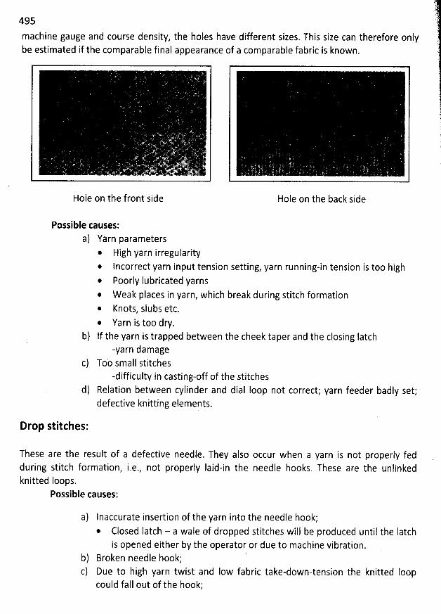
495
machine gauge and course density, the holes have different sizes. This size can therefore onlybe estimated if the comparable final appearance of a comparable fabric is known.
Hole on the front side Hole on the back side
Possible causes:a) Yarn parameters
* High yarn irregularity* lncorrect yarn input tension setting, yarn running-in tension is too high* Poorly Iubricated yarns@ W eak places in yarn, which break during stitch formation* Knots, slubs etc.* Yarn is too dry.
b) If the yarn is trapped between the cheek taper and the closing Iatch-yarn damage
Tob small stitches-difficulty in casting-off of the stitches
d) Relation between cylinder and dial Ioop not correct; yarn feeder badly set;defective knitting elements.
Drop stitches:
These are the result of a defective needle. They also occur when a yarn is not properly fedduring stitch formation, i.e., not properly Iaid-in the needle hooks. These are the unlinkedknitted Ioops.
Possible causes:
a) Inaccurate insertion of the yarn into the needle hook;* Closed Iatch - a wale of dropped stitches will be produced until the Iatch
is opened either by the operator or due to machine vibration.b) Broken needle hook;c) Due to high yarn twist and Iow fabric take-down-tension the knitted Ioop
could fall out of the hook;
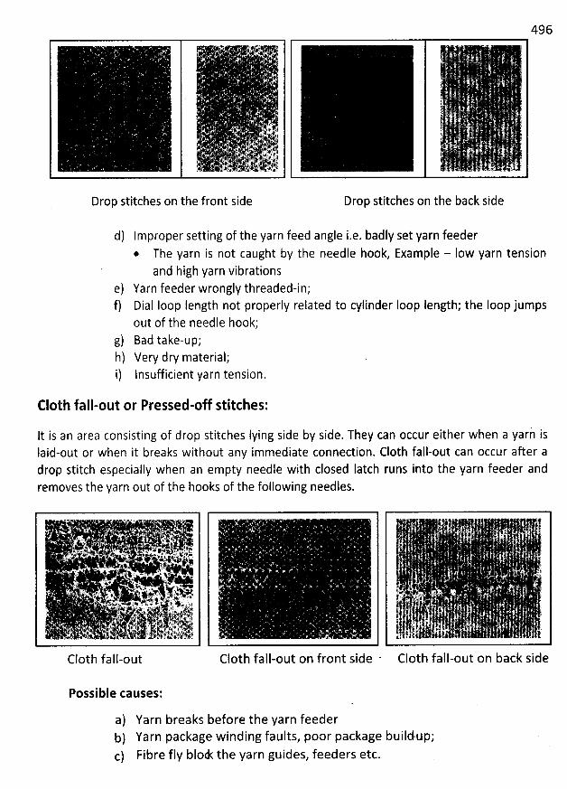
496
i: .; .
.#. ?. . ..p ,444A, . , ,. n
Drop stitches on the front side
d) Improper setting of the yarn feed angle i.e. badly set yarn feeder@ The yarn is not caught by the needle hook, Example - Iow yarn tension
and high yarn vibrationse) Yarn feeder wrongly threaded-in;f) Dial Ioop Iength not properly related to cylinder Ioop Iength; the Ioop jumps
out of the needle hook;g) Bad take-up;h) Very dry material;i) lnsufficient yarn tension.
Drop stitches on the back side
C10th fall-out or Pressed-off stitches:
It is an area consisting of drop stitches Iying side by side. They can occur either when a yari isIaid-out or when it breaks without any immediate connection. C10th fall-out can occur after adrop stitch especially when an empty needle with closed Iatch runs into the yarn feeder andremoves the yarn out of the hooks of the following needles.
. . .. . juwx'xe . . .#.*,... . * p.
. x . .e . -< . y, e 'r. xgh; . . . . .,
i . ''' s '. j;li. '':111.r'49..!. .. '
'
..
'
---
'
.
'
.. ..
'
. ., . - . . . 4 . . j .. .x. .. .v . ..(. . '*
. . . x ' . 24....aa . . .L+ .. :... xw. '*' . pj *1 ' X' 4..46. , . u.k .? < .. . . ' '
. . 4. k1,- !r. jk. -. . . #. v. ,.j,, .; yiltF t A' R'#'. . . . 't . .. . . .*. ''1 'e. . u. . .. qz .t # 'ek
. , o . . .. ...& u $! J : é . 4 .
C10th fall-out
Possible causes:
C10th fall-out on front side C10th fall-out on back side
a) Yarn breaks before the yarn feederb) Yarn package winding faults, poor package buildup;c) Fibre fIy blodt the yarn guides, feeders etc.
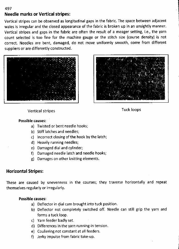
497Needle marks or Velical stripes:
Vertical stripes can be observed as Iongitudinal gaps in the fabric. The space between adjacentwales is irregular and the closed appearance of the fabric is broken up in an unsightly manner.Vertical stripes and gaps in the fabric are often the result of a meager setting, i.e., the yarncount selected is too fine for the machine gauge or the stitch size (course density) is notcorrect. Needles are bent, damaged, do not move uniformly smooth, come from differentsuppliers or are differently constructed.
Vertical stripes
jt)
Tuck Ioops
Possible causes:a) Twisted or bent needle hooks;b) Stiff Iatches and needles;c) Incorrect closing of the hook by the Iatch;d) Heavily running needles;e) Damaged dial and cylinder;f) Damaged needle Iatch and needle hooks;g) Damages on other knitting elements.
Horizontal Stripes:
These are caused by unevenness in the courses; theythemselves regularly or irregularly.
traverse horizontally and repeat
Possible causes:a) Deflector in dial cam brought into tuck position.b) Deflector not completely switched off. Needle can still grip the yarn and
forms a tuck Ioop.c) Yarn feeder badly set.d) Differences in the yarn running-in tension.e) Couliering not constant at alI feeders.f) Jerky impulse from fabric take-up.
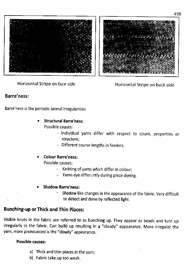
Horizontal Stripe on face side Horizontal Stripe on back side
Barre'ness:
Barre'ness is the periodic lateral irregularities
Structural Barre'ness:Possible causes:
- lndividual yarns differ with respect to count, properties orstructure;Different course Iengths in feeders.
Colour Barre'ness:Possible causes:
Knittipg of yarns which differ in colour;Yarns dye differently during piece dyeing.
Shadow Barfe'ness:Shadow like changes in the appearance of the fabric. Very difficultto detect and done by reflected Iight.
Bunching-up or Thick and Thin Plates:
Visible knots in the fabric are referred to as bunching up. Tbey appear as beads and turn upirregularly in the fabric. Can build up resulting in a ''cloudy'' appearance
. More irregular thearn more pronounced is the ''cloudy'' appearance.9 ,
Possible tauses:
a) Thick and thin places in the yarn;b) Fabric take-up too weak.
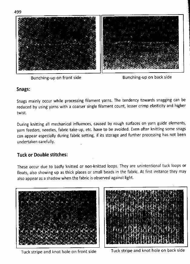
Bunching-upon front side Bunching-up on back side
Snags:
Snags mainly occur while processing filament yarns. The tendency towards snagging can bereduced by using yarns with a coarser single filament count, lesser crimp elasticity and bigher
twist.
During knitting aII mechanical influences, caused by rough surfaces on yarn guide elements,yarn feeders, needles, fabric take-up, etc. have to be avoided. Even after knitting some snagscan appear especially during fabric setting, if its storage and further processing has not been
undertaken carefully.
Tuck or Double stitches:
These occur due to badly knitted or non-knitted Ioops. They are unintentional tuck Ioops orfloats, also showing up as thick places or small beads in the fabric. At first instance they mayalso appear as a shadow when the fabric is observed against Iight.
Tuck stripe andknot hole on front side
! . . .. . v. ) . . . .
$ ' yj . .
. . . ' .
... ' .
i . . E . .
. . , g . .
Tuck stripe and knot hole on back side
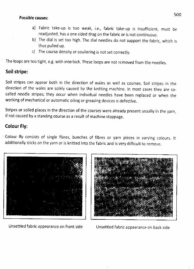
Possible causes:
a) Fabric take-up is too weak, i.e., fabric take-up is insufficient, must bereadjusted, has a one sided drag on the fabric or is not continuous.
b) The dial is set too high. The dial needles do not support the fabric, which isthus pulled up.
c) The course density or couliering is not set correctly.
5O0
The loops are too tight, e.g. with interlock. These loops are not removed from the needles.
Soil stripe:
Soil stripes can appear botb in the direction of wales as well as courses. Soil stripes in thedirection of the wales are solely caused by the knitting machine. In most cases they are so-called needle stripes; they occur when individual needles have been replaced or when theworking of mechanical or automatic oiling or greasing devices is defective
.
Stripes or soiled places in the direction of the courses were already present usually in the yarn,
if not caused by a standing course as a result of machine stoppage.
Colour Fly:
' Colour fIy consists of single fibres, bunches of fibres or yarn pieces in varying colours. Itadditionally sticks on the yarn or is kpitted into the fabric and is very difficult to remove
.
W yUnsettled fabric appearance on front side Unsettled fabric appearance on back side
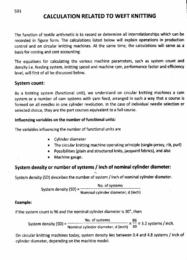
501CALCULATION RELATED TO W EFT KNIU ING
The function of textile arithmetic is to record or determine aII interrelationships which can berecorded in figure form. The calculations Iisted below will explain operations in produdioncontrol and on circular knitting machines. At the same time, the calculations will serve as abasis for costing and cost accounting.
The equations for calculating the various machine parameters, such as system count anddensity i.e. feeding system, knitting speed and machine rpm, performance factor and efficiencylevel, will first of all be discussed below.
System count:
By a knitting system (functional unit), we understand on circular knitting machines a camsystem or a number of cam systems with yarn feed, arranged in such a way that a course isformed on aII needles in one cylinder revolution. ln the case of individual needle selection orselected choice, they are the part courses equivalent to a full course.
Influencing variables on the number of functional units:
The variables influencing the number of functional units are
Cylinder diameter* The circular knitting machine operating principle (singlejersey, rib, purl)* Possibilities (plain and structured knits, jacquard fabrics), and also* Machine gauge.
System density or number of systems / inch of nominal tylinder diameter:*,
System density (SD) describes the number of system / inch of nominal cylinder diameter.
No. of systemsSystem density (SD) =Nominal cylinder diameter, d (inch)
Example:
If the system count is 96 and the nominal cylinder diameter is 30'', then
No. of system s 96System density (SD) = = = 3.2 Systems / inch.
Nominal cylinder diameter, d (inch) 30
On circular knitting machines today, system density Iies between 0.4 and 4.8 systems / inch ofcylinder diameter, depending on the machine model.
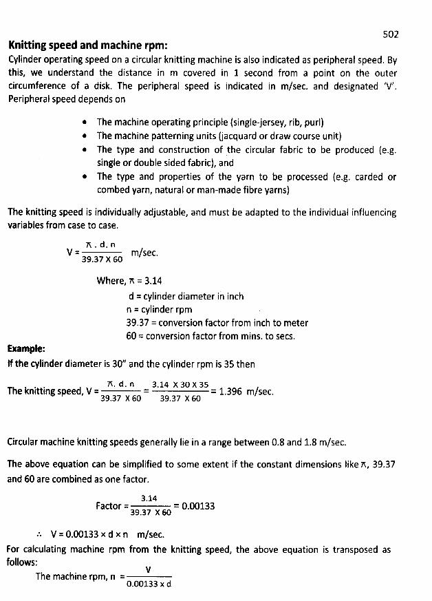
502Knitting speed and machine rpm:Cylinder operating speed on a circular knitting machine is also indicated as peripheral speed. Bythis, we understand the distance in m covered in 1 second from a point on the outer
circumference of a disk. The peripheral speed is indicated in m/sec. and designated tV'.Peripherai speed depends on
* The machine operating principle (singlejersey, rib, purl)@ The machine patterning units (jacquard or draw course unit)* The type and construction of the circular fabric to be produced (e.g.single or double sided fabric), and
* The type and properties of the yarn to be processed (e.g. carded orcombed yarn, natural or man-made fibre yarns)
The knitting speed is individually adjustable, and must be adapted to the individual influencingvariables from case to case.
'n . d . nV = m/sec.39
.37 X 60
W here, n = 3.14
d = cylinder diameter in inchn = cylinder rpm39.37 = conversion factor from inch to meter60 = conversion factor from mins. to secs.
Example:If the cylinder diameter is 302 and the cylinder rpm is 35 then
A. d . n 3.14 x 30 x 3sThe knitting speed, V = = = 1.396 m/sec.39
.37 X 60 39.37 X 60
Circular machine knitting speeds generally Iie in a range between 0.8 and 1.8 m/sec.
The above equation can be simplified to some extent if the constant dimensions like nt 39.37and 60 are combined as one factor.
3.14Factor = = 0.00133
39.37 X 60
.% V = 0.00133 x d x n m/sec.For calculating machine rpm from the knitting speed, the above equation is transposed asfollows:
vThe machine rpm, n =
0.00133 x d
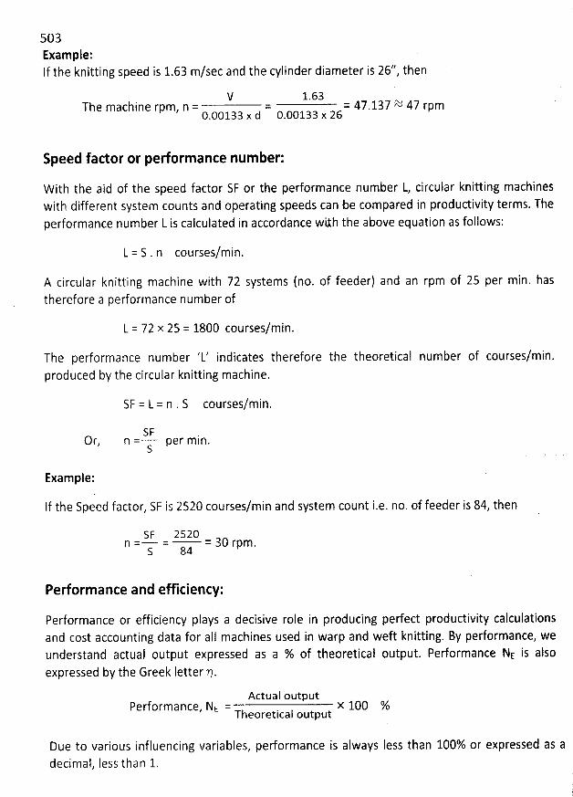
503Example:If the knitting speed is 1.63 m/sec and the cylinder diameter is 26*, then
V 1.63The machine rpm, n = = = 47.137 2$ 47 rpm
0.00133 x d 0.00133 x 26
Speed fador or performance num ber:
W ith the aid of the speed factor SF or the performance number L, circular knitting machineswith different system counts and operating speeds can be compared in productivity terms. Theperformance number L is calculated in accordance wilh the above equation as follows:
courses/min.
A circular knitting machine with 72 systems (no. of feeder) and an rpm of 25 per min. hastherefore a perforrnance number of
L = 72 x 25 = 1800 courses/min.
The performance number 'L' indicates therefore the theoretical number of courses/min.produced by the circular knitting machine.
SF = L = n . S courses/min.
SFOr, n = per m in.S
Example:
If the Speed factor, SF is 2520 courses/min and system count iae. no. of feeder is 84, then
SF 2520n = = = 30 rpm.
S 84
Performance and efficiency:
Performance or efficiency plays a decisive role in producing peëect productivity calculationsand cost accounting data for aIl machines used in warp and weft knitting. By performance, weunderstand actual output expressed as a % of theoretical output. Pedormance NE is alsoexpressed by the Greek Ietter p.
Actual outputPerformance, NE = x 100 %
Theoretical output
Due to various influencing variables, performance is always less than 100% or expressed as adecimal, Iess than 1.
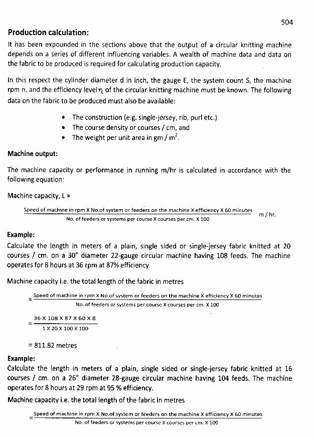
5O4Production calculation:It has been expounded in the sections above that the output of a circular knitting machinedepends on a series of different influencing variables. A wealth of machine data and data onthe fabric to be produced is required for cal'culating production capacity.
In this respect the cylinder diameter d in inch, the gauge E, the system count S, the machinerpm n, and the efficiency Ievelq of the circular knitting machine must be known. The following
data on the fabric to be produced must also be available:
* The construction (e.g. single-jersey, rib, purl etc.)* The course density or courses / cm, and
2* The weight per unit area in gm / m .
Machine output:
The machine capacity or performance in running m/hr is calculated in accordance with thefollowing equation:
Machine capacity, L =
Speed of machine in rpm X No.of system or feeders on the machine X efficiency X 60 minutesNo. of feeders or systems per course X courses per cm. X 100
Example:
Calculate the Iength in meters of a plain, single sided or single-jersey fabric knitted at 20courses / cm. on a 30'' diameter 22-gauge circular machine having 108 feeds. The machineoperates for 8 hours at 36 rpm at 87% efficielncy.
Machine capacity i.e. the total Iength of the fabric in metres
Speed of machine in rpm X No.of system or feeders on the machine X efficiency X 60 m inutes=
No. of feeders or systems per course X courses per cm. X l00
36 X 108 X 87 X 60 X 8=
1 X 20 x 100 X 10O
= 811.82 metres
Example:
Calculate the Iength in meters of a plain, single sided or single-jersey fabric knitted at 16courses / cm. on a 26* diameter 28-gauge circular machine having 104 feeds. The machineoperates for 8 hours at 29 rpm at 95 % efficiency.
Machine capacity i.e. the total Iength of the fabric in metres
Speed of machine in rpm X No.of system or feeders on the machine X efficiency X 60 m inutes=
No. of feeders or systems per course X courses per cm. X 100
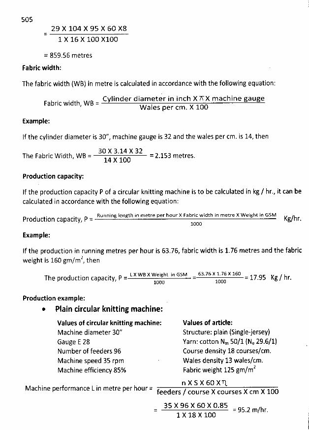
50529 X 104 X 95 X 60 X8
=
1 X 16 X 100 X100
= 859.56 metres
Fabric width:
The fabric width (WB) in metre is calculated in accordance with the following equation:
Cylinder diam eter in inch X A X m achine gaugeFabric width, W B = W ales per cm . X 100
Example:
If the cylinder diameter is 30*, machine gauge is 32 and the wales per cm. is 14, then
30 X 3. 14 X 32The Fabric W idth, W B = = 2.153 metres.14 X 100
Production capacity:
If the production capacity P of a circular knitting machine is to be calculated in kg / hr., it can becalculated in accordance with the following equation:
Running Iength in metre per hour X Fabric width in metre X Weight in GSMProduction capacity, P = Kg/hr.
looo
Example:
If the production in running metres per hour is 63.76, fabric width is 1.76 metres and the fabric2 hweight is 160 gm/m , t en
L X WB X Weight in GSM 63.76 X 1.76 X 160Yh0 Prod Uction C3P3CitY, P = = yxc = 17.95 Kg / hr.1000
Production example:
* Plain circular knitting machine:
Values of circular knitting machine:Machine diameter 30*Gauge E 28Number of feeders 96Machine speed 35 rpmMachine efficiency 85%
Values of article:
Structure: plain (Single-jersey)Yarn: cotton Nm 50/1 (Ne 29.6/1)Course density 18 courses/cm.Wales density 13 wales/cm.Fabric weight 125 gm/m2
n X S X 60 X'RMachine performance L in metre per hour = feeders / course X courses X cm X 100
35 X 96 X 60 X 0.85= = 95.2 m/hr.1 X 18 X 100
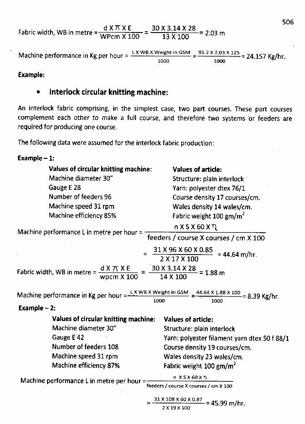
506d X A X E 30 X 3.14 X 28Fabric width, W B in metre = = = 2.03 mW pcm X 100 13 X 100
L X WB X Weight in GSM 95.2 X 2.03 X 125Machine performance in Kg per hour = = = 24.157 Kg/hr.loon 1000
Example:
* Interlock circular knitting machine:
An interlock fabric comprising, in the simplest case, two part courses. These part coursescomplement each other to make a full course, and therefore two systems br feeders arerequired for producing one course.
The following data were assumed for the interlock fabrîc production:
Example - 1:
Values of tircular knitting machine:Machine diameter 30''Gauge E 28Number of feeders 96Machine speed 31 rpmMachine efficiency 85%
Values of artide:Structure: plain interlockYarn: polyester dtex 76/1Course density 17 courses/cm.Wales density 14 wales/cm.
2Fabric weight 100 gm/mn X S X 60 X TtMachine performance L in metre per hour =
feeders / course X courses / cm X 10031 X 96 X 60 X 0.85
= 44.64 m/hr.2 X 17 X 100
d X '7V X E 30 X 3.14 X 28Fabric width, W B in metre = = = 1.88 m
wpcm X 100 14 X 100
L X WB X Weight in GSM 44.64 X 1.88 X 100Machine pedormance in Kg per hour = = . = 8.39 Kg/hr.100c looc
lxample - 2:
Values of tircular knitting mathine:Machine diameter 30''Gauge E 42 'Number of feeders 108Machine speed 31 rpmMachine efficiency 87%
Values of article:Structure: plain interlock
Yarn: polyester filament yarn dtex 50 f 88/1Course density 19 courses/cm.Wales density 23 wales/cm.
2Fabric weight 100 gm/m
n x s x 6o x nMachine pedormance L in metre per hour =feeders / course X courses / cm X 100
31 X 108 X 60 X 0.87= = 45.99 m/hr.2 x 19 x 100
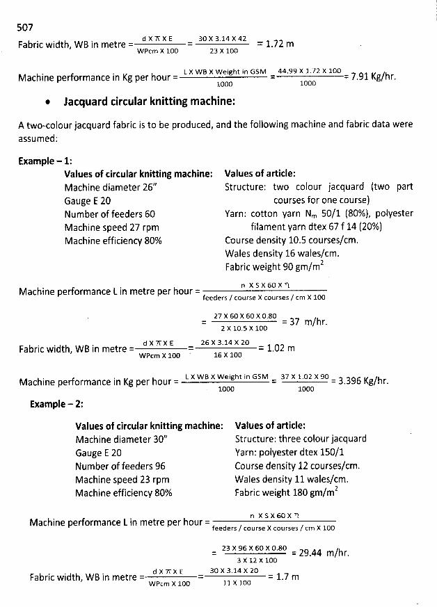
507d x 'n- x E 30 x 3.14 X 42Fabric width
, W B in metre = = = 1.72 mw pcm x 100 23 x 1o0
L X W B X Weight in GSM 44.99 X 1.72 X 10OMachine performance in Kg per hour = = = 7.91 Kg/hr.1000 1000
* Jacquard circular knitting machine:
A two-colourjacquard fabric is to be produced, and the following machine and fabric data wereassumed:
Example - 1:Values of circular knitting mathine:Machine diameter 26''Gauge E 20Number of feeders 60Machine speed 27 rpmMachine efficiency 80%
Values of article:
Structure: two colour jacquard (two partcourses for one course)
Yarn: cotton yarn Nm 50/1 (80%), polyesterfilament yarn dtex 67 f 14 (20%)
Coursè density 10.5 courses/cm.Wales density 16 wales/cm.
2Fabric weight 90 gm/m
n x s x 6o x nMachine pedormance L in metre per hour =
feeders / course X courses / cm X 1O0
27 X 60 X 60 X 0.80= = 37 m/hr.2 x 10
.5 X l00
d X W X E 26 X 3.14 X 20Fabric width, W B in metre = = = 1.02 m
W pcm X 100 16 X 100
L X WB X Weight in GSM 37 X 1.02 X 90Vachine pedof mance in Kg per hour = = = 3.396 Kg/hr.
. 1000 1000
Example - 2:
Values of circular knitting machine:Machine diameter 30''Gauge E 20Number of feeders 96Machine speed 23 rpmMachine efficiency 80%
Values of article:Structure: three colour jacquardYarn: polyester dtex 150/1Course density 12 courses/cm.Wales density 11 wales/cm.Fabric weight 180 gm/m2
n x s x 60 x nM achine performance L in metre per hour =f
eeders / course X courses / cm X 100
23 X 96 X 60 X 0.80= = 29.44 m/hr.3 X 12 X 100
d i W x E 30 X 3.14 X 20Fabric width, W B in metre = = = 1.7 m
w pcm x 1o0 11 X l00
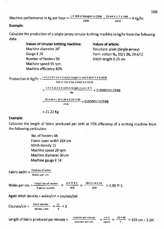
508L X WB X Weight in GSM 29.44 X 1.7 X 18OMachine performance in Kg per hour = = = 9 Kg/hr
.1000 looc
Example:
Calculate the production of a single-jersey circular knitting machine in kg/hr from the followingdata:
Values of circular knitting machine:Machine diameter 30''Gauge E 28Number of feeders 96Machine speed 35 rpmMachine efficiency 80%
Values of artide:Structure: plain (Singlejersey)Yarn: cotton Nm 50/1 (Ne 29.6/1)Stitch length 0.25 cm
n X S X (WX d X E X stitch length in cm) X 60 X N. X 0.4536Production in Kg/hr =lco x loo k Ne x 84c x 0.9144
n X S X (d X E X stithch Iength in cm.) X 'q. '= x 0.00001112598Ne
35 X 96 x ( 30 X 28 X 0.25) X 80= x 0.0000111259829.6
= 21.22 Kg.
Example:Calculate the Iength of fabric produced per shift at 75% efficiency of a knitting machine fromthe following particulars:
No. of feeders 48Fabric open width 264 cmStitch density 15Machine speed 20 rpmMachine diameter 30 cmMachine gauge E 14
Total no.of walesFabric width =W ales per cm.
Total no.of wales d X W X E 30 X 3.14 X 14Wales per cm. = = = = 4.99 2 5Fabric w idth W B 264
Again stitch density = wales/cm x courses/cm
Stitch density 15Courses/cm = = = 3wales / cm. s
Length of fabric produced per minute = courses per minute n X S= =COurSeS per Cm CPCY
20 X 48= 320 cm = 3.2m3
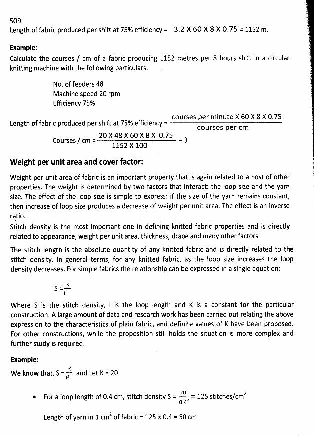
509tength of fabric produced per shift at 75% efficiency = 3.2 X 60 X 8 X 0.75 = 1152 m.
Example:
Calculate the courses / cm of a fabric producing 1152 metres per 8 hours shift in a circularknitting machine with the following particulars:
No. of feeders 48Machine speed 20 rpmEfficiency 75%
courses per minute X 60 X 8 X 0.75Length of fabric produced per shift at 75% efficiency =
courses per cm20 X 48 X 60 X 8 X 0.75
Courses / cm = = 31152 X 100
W eight per unit area and cover factor:
W eight per unit area of fabric is an important property that is again related to a host of otherproperties. The weight is determined by two factors that interact: the loop size and the yarnsize. The effect of the Ioop size is simple to express: if the size of the yarn remains constant,then increase of Ioop size produces a decrease of weight per unit area. The effect is an inverse
rqtio.Stitch density is the most important one in defining knitted fabric properties and is directlyrelated to appearance, weight per unit area, thickness, drape and many other factors.
The stitch Iength is the absolute quantity of any knitted fabric and is directly related to thestitch density. ln general terms, for any knitted fabric, as the Ioop size increases the Ioopdensity decreases. For simple fabrics the relationship can be expressed in a single equation:
KS = -12
W here S is the stitch density, I is the Ioop Iength and K is a constant for the particularconstruction. A large amount of data and research work has been carried out relating the aboveexpression to the characteristics of plain fabric, and definite values of K have been proposed.For other constructions, while the proposition still holds the situation is more complex andfurther study is required.
Example:-6. and Let K = 20we know that
, s = z1
20 2For a loop length of 0.4 cm, stitch density S = - 2 = 125 stitches/cm
0.4
2 f fabric = 125 x 0.4 = 50 cmLength of yarn in 1 cm o
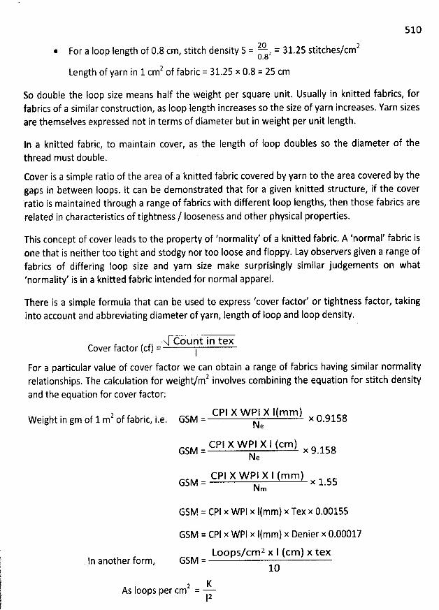
510
lQ. = 31 25 stitches/cmz. For a Ioop length of 0.8 cm, stitch density S = , .0.8
2 f fabric = 31.25 x 0.8 = 25 cmLength of yarn in 1 cm o
So double the Ioop size means half the weight per square unit. Usually in knitted fabrics, forfabrics of a similar construction, as Ioop Iength increases so the size of yarn increases. Yarn sizesare themselves expressed not in terms of diameter but in weight per unit Iength.
In a knitted fabric, to maintain cover, as the Iength of loop doubles so the diameter of thethread must double.
Cover is a simple ratio of the area of a knitted fabric covered by yarn to the area covered by thegaps in between Ioops. It can be demonstrated that for a given knitted structure, if the cover'ratio is maintained throtlgh a range of fabrics with different Ioop Iengths, then those fabrics arerelated in characteristics of tightness / Iooseness and other physical properties.
This concept of cover Ieads to the property of 'normality' of a knitted fabric. A 'normal' fabric isone that is neither too tight and stodgy nor too Ioose and floppy. Lay observers given a range of
fabrics of differing loop size and yarn size make surprisingly similar judgements on what'normality' is in a knitted fabric intended for normal apparel.
There is a simple formula that can be used to express 'cover factor' or tightness factor, takinginto account and abbreviating diameter of yarn, length of Ioop and Ioop density.
Count in texCover factor (cf) = I
For a particular value of cover factor we can obtain a range of fabrics having similar normality' involves combining the equation for stitch densityrelationships. The calculation for weight/m
and the equation for cover factor:
2 f fabric i-e.Weight in gm of 1 m o , CPI X W PI X 1(mm)GSM = x 0.9158N
e
CPI X W PI X I (cm)G5M = x 9.158Ne
CPI X W P1 X l (mm)GSM = x 1.55Nm
GSM = CPl x WPl x I(mm) x Tex x 0.00155
GSM = CPI x WPI x l(mm) x Denier x 0.00017Loops/cmz x l (cm) x texGSM
= 10ln another form,
2 KAs Ioops per cm =
12
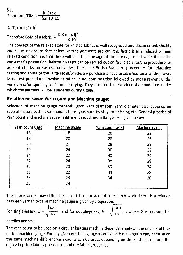
511Therefore GSM
2As Tex = (cf x 1)
K X (cf x I)2Therefore GSM of a fabric =I X 10
The concept of the relaxed state for knitted fabrics is well recognizèd and documented. Quality'control must ensure that before knitted garments are cut, the fabric is in a relaxed or nearrelaxed condition, i.e. that there will be Iittle shrinkage of the fabric/garment when it is in theconsumer's possession. Relaxation tests can be carried out on fabric as a routine procedure, oras spot checks on suspect deliveries. There are British Standard procedures for relaxationtesting and some of ihe large retail/wholesale purchasers have established tests of their own.Most test procedures involve agitation in aqueous solution followed by measurement underwater, and/or spinning and tumble drying. They attempt to reproduce the conditions underwhich the garment will be Iaundered during usage.
K X tex= I(cm) X 10
Relation between Yarn Eount and M achine gauge:Selection of machine gauge depends upon yarn diameter. Yarn diameter also depends onseveral factors such as yarn count, fibre type, yarn twist, yarn finishing etc. General practice ofyarn count and machine gauge in different industries in Bangladesh given below:
Yarn count used Machine gauge Yarn count used Machine aauge16 18 28 2218 20 28 2520 20 28 2820 24 30 2224 22 30 2424 24 30 2826 20 30 3426 22 34 2826 24 34 2826 28
The above values may differ, because it is the results of a research work. There is a relationbetween yarn in tex and machine gauge is given by a equation,
16so 1400For single-jersey, G = and for double-jersey, G = , where G is measured inTex Tex
needles per cm.
The yarn count to be used on a circular knitting machine depends Iargely on the pitch, and thuson the machine gauge. For any given machine gauge it can Iie within a Iarger range, because onthe same machine different yarn counts can be used, depending on the knitted structure, thedesired optics (fabric appearance) and the fabric properties.
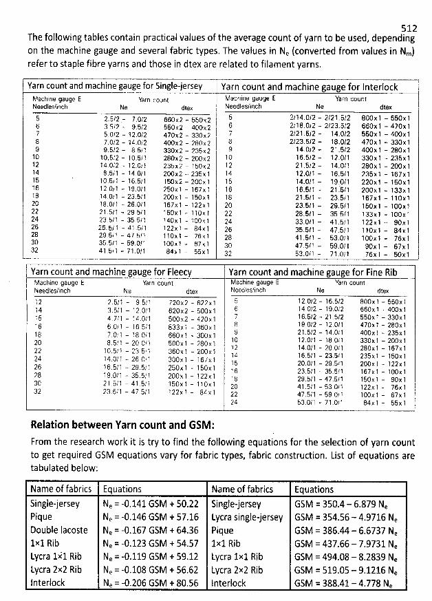
512The following tables contain practical values of the average count of yarn to be used, dependingon the machine gauge and several fabric types. The values in Ne (converted from values in Nm)refer to staple fibre yarns and those in dtex are related to filament yarns.
Yarn count and machine gauge for Single-jersey Yarn count and machine gauge for Interlockvachine gaugc E Yarn cotlnt Machine gauge E Yarn countseedles/inch Ne dtex Needles/inch Ne dtex
s 2.5/2 - 7.*12 660:2 - sbo.rz 5 2/14.0/2 - 2/21 .5/2 800x1 - 550x1t$ 3.s?z '- 9
.5/2 ssoxz - 4ooxz 6 2/18.0/2 - 2/23.5/2 660x1 - 470: 17 5.0/2 - 12.0/2 470:2 - aaoxa 7 2/21.5/2 - 14.0/2 660x1 - 400x18, ,
7 . Os /j 2,,
-
.
1 a4 . 0s , jr 2,
4., œ.m .x 20 .
- 20 80 0s X. 02 j oq 2 / 2, a3 . ,5 y/ 2, -. r1 8, .
.
0, j 2, 44 j 0, xy 1, -. ,3 ,3 0, xx 1g
10 1 0.5/2 - 1 0.5/ 1 280x 2 - 200: ? 1 0 16.5/2 - 12 .0/1 330: 1 - 235: 11 2 14.0/2 - 1 2.0/ 1 23bx2 - 1 50:2 1 2 2 1 .5/2 - 14.0/1 280x 1 - 200: 11 4 8 .5/ 1 - :4 .0/ 1 2O0x 2 - 236 x 1 14 12.0/ 1 - 16.5/1 235x 1 - 1 67x 115 1 0.5/ 1 - 1 6.5/ 1 1 5Ox 2 - 2O0x 1 1 5 14.0/ 1 - 19.0/ 7 220x 1 - 160x 116 1 2.0/1 - 19.02 1 250: 1 - 1 67x 1 1 6 16.5/1 - 21 .
'
6/1 200x 1 - 133x 11 8 .1 4.0/ 1 - 23.5/ 1 2O0x 1 - 1 5Ox 1 1 8 2 1 .5/ 1 - 23.6/ 1 167 x 1 - 1 10x 120 18.0/ 1 - 26.0/1 167: 1 - 1 22x 1 20 23.5/1 - 29.5/1 156: 1 - 100x )22 2 1 .5/ 1 - 29 5/1 750: 1 - 1 : 0x 1 22 28.5/1 - 35.5/1 7 33x 1 - 100x 124
23.5.8 7 - 35.5/ 1 14Ox 1 - 7 O0x 1 24 33.0/1 - 41 .5/ 1 1 22x 1 - 90x 126 26. 5/ 1 - 41 .5/1 1 22x 1 - 84x 1 26 35.5/1 -- 47.6/ 1 1 10x 1 - 84x 128 29.6/ G - 47.5/1 1 10x 1 - 76x 1 28 41
.5/7 - 63.0/ 1 1 0Ox 1 - 76x 130 3b.5/ 1 - 59.0/1 lOox 1 - 67 x 1 atj 47
.5/1 - 5:.(j/1 a()x g - 67x 132 41 ,b/ 3 - 71 .0/1 84x 1 - 55x 1 a; 5a
.()/? - 71 .oj 1 76x 1 - 5c: 1
Yarn count and machine gauge for Fleecy Yarn count and machine gauge for Fine RibMachine gauge E Yarn count Machine gauge E Yarn countNeedles/inch Ne dtex Needles/inch Ne dtex
1 2 2.52 1 - 9 5/1 720x 2 - 622: 1 5 1 2.0/2 - 16.5/2 800x 1 - 550x 11 4 3.5/1 - 1 2.0/1 620x2 - 500: 1 6 14.0/2 - 19.0/2 660x 1 - 400: 11 5 4. 71 1 - 1 4.0/ 1 500:2 - 420x 1 7 1 6.5/2 - 21 .5/2 550: 1 - 330x 1
.1 6 6 0'/ 1 - 1 6.5/1 833: 1 - 360: 1 8 1 9.0/2 - 1 2 0/1 470: 1 - 280: 1
.18 7 O/1 - 1 8,0/ 1 660x 1 - 3OOx 1 9 21 .5/2 - 14.0/1 4OOx 1 - 235x 1
.2O 8 5/ 1 - 20 0?' 1 50Ox : - 280x : 1 0 1 2.0/1 - 18.0/1 330x 1 - 20Ox 1
5/1 - 23.5/3 360: q - 2OOx 1 1 2 14.0/1 - 20.0/1 280x 1 - 167:122 1 o .
,1 26 o/: 3t)Ox 1 - 167: 1 14 16.5/1 - 23.5/1 235: 1 - 150x 124 14.0, - . qs 20
,0/1 - 29.5/1 2(mx : - ,22x 126 q 6.b/1 - 29.j/: 2sox 1 - 1 5cx 1 ,: za syp - as.5,,, jo.yx : . qccx ,28 q 9.0/1 - a5.5/ : 2oox 1 - 7 zz x , g a ra.
.syg . 4.7.5/, j stlx q . gox jac 2 p .5,'1 - 4 1 .5, q 1 scx 1 - 1 lox 1 20 4, s/g . sa,c/p j zzx : . ;sx 1
,,32 2a,s,. 1 - 47.st 1 : 2zx 1 - 84.: 1 22 4.,?'
.s/g . sa.oy ) , oox : . o.:y j24 53.o/q - 71 .0/1 8.4x 1 - 55x 1
Relation between Yarn count and GSM :
From the research work it is try to find the following equations for the selection of yarn countto get required GSM equations vary for fabric types, fabric construction. List of equations aretabulated below:
Name of fabrics Equations Name of fabrics Equations
Single-jersey Ne = -0.141 GSM + 50.22 Single-jersey GSM = 350.4 - 6.879 NePique Ne = -0.146 GSM + 57.16 Lycra single-jersey GSM = 354.56 - 4.9716 NeDouble Iacoste Ne = -0.167 GSM + 64.36 Pique GSM = 386.44 - 6.6737 Ne1x1 Rib Ne = -0.123 GSM + 54.57 1x1 Rib GSM = 437.66 - 7.9731 NeLycra 1k1 Rib Ne = -0.119 GSM + 59.12 Lycra 1x1 Rib GSM = 494.08 - 8.2839 NeLycra 2x2 Rib Ne = -0.108 GSM + 56.62 Wcra 2x2 Rib GSM = 519.05 - 9.1216 Nelnterlock Ne = -0.206 GSM + 80.56 Interlock GSM = 388.41- 4.778 Ne
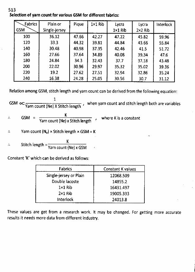
513Seledion of yarn count for various GSM for different fabrks:
Fabrics Plain or Pique 1x1 Rib Wcra Wcra lnterlockGSM Single-jersey 1x1 Rib 2x2 Rib
100 36.12 47.66 42.27 47.22 45.82 59.96120 33.3 44.32 39.81 44.84 43.66 55.84140 30.48 40.98 37.35 42.46 41.5 51.72160 27.66 37.64 34.89 40.08 39.34 47.6180 24.84 34.3 32.43 37.7 37.18 43.48200 22.02 30.96 29.97 35.32 35.02 39,36220 19.2 27.62 27.51 32.94 32.86 35.24240 16.38 24.28 25.05 30.56 30.7 31.12
Relation among GSM, stitch Iength and yarn count can be derived from the following equation:
1GSM = , when yarn count and stitch Iength b0th are variablesY
afn count (Ne) X Stitch length
KGSM =
Yarn count (Ne) x Stitch Iength
Yarn count (Ne) x Stitch Iength x GSM = K
KStitch Iength =Y
arn count (Ne) x GSM
where K is a constant
Constant 'K' which can be derived as folsows:
Fabrics Constant K values
Single-jersey or Plain 12068.509Double Iacoste 14855.2
1x1 Rib 16431.4972x1 Rib 19005.333Interlock 24013.8
These values are get from a research work. It may be changed. For getting more accurateresults it needs more data from different industry.
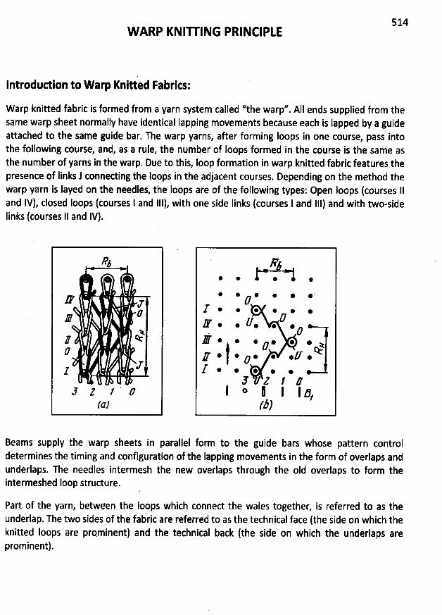
514W ARP KNIU ING PRINCIPLE
Introdudion to W arp Knitted Fabrics:
W arp knitted fabric is formed from a yarn system called ''the warp''. AII ends supplied from thesame warp sheet normally have identical Iapping movements because each is Iapped by a guideattached to the same guide bar. The warp yarns, after forming Ioops in one course, pass intothe fpllowing course, and, as a rule, the number of Ioops formed in the course is the same asthe number of yarns in the warp. Due to this, Ioop formation in warp knitted fabric features thepresence of Iinks J conneding the Ioops in the adjacent courses. Depending on the method thewarp yarn is Iayed on the needles, the loops are of the following types: Open Ioops (courses 11and 1V), closed Ioops (courses 1 and 111), with one side Iinks (courses I and 111) and with two-sideIinks (courses 11 and lV).
%
M z
J
I1
5 2 / ' #(a)
#X .* * *
* @ * * @ @ .
z . . &. . .
# . . . . . . .e
. .y .k* ) * o *E5 2 J #
I o l I I 5/(D)
Beams supply the warp sheets in parallel form to the guide bars whose pattern controldetermines the timing and configuration of the Iapping movements in the form of overlaps andùnderlaps. The needles intermesh the new overlaps through the oId overlaps to form theintermeshed loop structure.
Part. of the yarn, between the Ioops which connect the wales together, is referred to as theunderlap. The two sides of the fabric are referred to as the technical face (the side on which theknitted Ioops are pmminent) and the technical back (the side on which the underlaps areprominent).
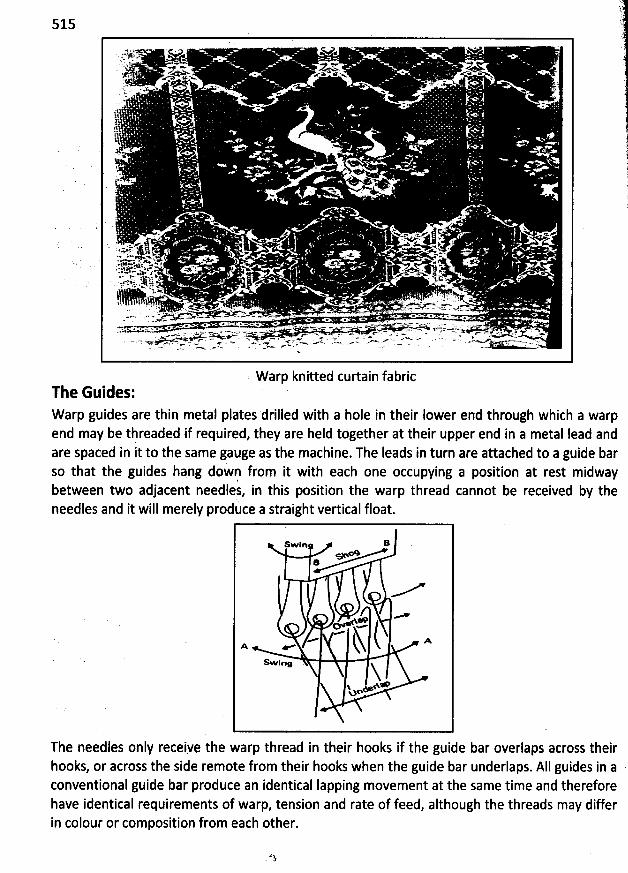
515
W arp knitted curtain fabricThe Guides:W arp guides are thin metal plates drilled with a hole in their Iower end through which a warpend may be thréaded if required, they are held tdgether at their upper end in a metal Iead andare spaced in it to the same gauge as the machine. The Ieads in turn are attached to a guide barso that the guides hang dowp from it with each one occupying a position at rest midwaybetween two adjacent needles, in this position the warp thread cannot be received by theneedles and it will merily produce a straight vertical float.
Sw in R
B
M
- kh ( -A eSwiew N
Yo
The needles only receiye the warp thread in their hooks if the guide bar overlaps atross theirhooks, or across the side remote from their hooks when the guide bar underlaps. AII guides in a .conventional guide bar produce an identical Iapping movement at the same time and thereforehave identical requirements of warp, tension and rate of feed, although the threads may differin colour or composition from each other.
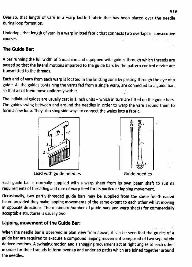
516Overlap, that Iength of yarn in a warp knitted fabric that has been placed over the needleduring Ioop formation.
Underlap , that Iength of yarn in a warp knitted fabric that çonnects two overlaps in consecutivecoursesk
The Guide Bar:
A bar running the full width of a maciine and equipped :1th guides through which threads arepassed so that the Iateral motions imparted to the guide bars by the pattern control àevice aretransmitted to the threads.
Each end of yarn from each warp is Iocated in the knitting zone by passipg through the eye of aguide. AIl the guides containing the yarns fed from a single warp, are coqneded to a guide bar,so that aII of them move uniformly with it. t
The individual guides are usually cast in 1 inch units - which in turn are fiited on the guide bars.The guides swing between and around the needles in order to warp the yarn arùund them toform a new loop. They also shog side ways to connect the wales into a fabric.
; l
5
2 .
Lead with guide needles Guide needles
Each guide bar is normally supplied with a warp sheet from its own beam shaft to suit itsrequirements of threading and rate of warp feed for its particular Iapping movement.
occasionally, 1wo partly-threaded guide bars may be supplied from the same full-threadedbeam provided they make Iapping movements of the same extent to each other wh11st movingin opposite diredions. The minimum number of guide bars and warp sheets for commerciallyacceptable structures is usually two.
tapping movement of the Guide Bar:
When the needle bar is observed in plan view from above, it can be seen that the guides ot aguide bar are required to execute a compound Iapping movement composed of two separatelyderived motions. A swinging motion and a shogging movement ad at right angles to each otherin order for their threads to form overlap and underlap paths which are joined together aroundthe needles.
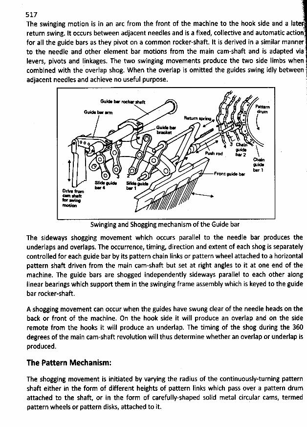
i
517 i
The swinging motion is in an arc from the front of the machine to the hook side and a Iat treturn swing. It occurs between adjacent needles and is a fixed, collective and automatic adioi'
)for aII the guide bars as they pivot on a common rocker-shaft. It is derived in a similar mannerto the needle and other element bar motions from the main cam-shaft and is adapted via rIevers, pivots and Iinkages. The two swinging movements produce the two side Iimbs whencombined with the overlap shog. W hen the overlap is omitted the guides swing idly between
adjacent needles and achieve no useful purpose. 41.
. .1N 1
Guie œ ''.- - (* pato
Guie Y a * drum*Rewrn > lx ...'* .
œ e ** * - *
. @@
Q e ; a caj @. . u. jO o - r- wz
O o cb lQO o o o yojj. .
* 1O a 2
sle wo sle w oa= f. * 4 * 1
Swinging and Shogging mechanism of the Guide bar
The sideways shogging movement which occurs parallel to the needle bar produces theunderlaps and overlaps. The occurrence, timing, direction and extent of each shog is separatelycontrolled for each guide bar by its pattern chain Iinks or pattern wheel attached to a horizontalpattern shaft driven from the main cam-shaft but set at right angles to it at one end of themachine. The guide bars are shogged independently sideways parallel to each other alongIinear bearings which support them in the swinging frame assembly which is keyed to the guidebar rocker-shaft.
A shogging movement can occur when the guides have swung clear of the needle heads on theback or front of the machine. On the hook side it will produce an overlap and on the sideremote from the hooks it will produce an underlap. The timing of the shog during the 360degrees of the main cam-shaft revolution will thus determine whether an overlap or underlap isproduced.
The Pattern M echanism:
The shogging movement is initiated by varying the radius of the continuously-turning patternshaft either in the form of different heights of pattern Iinks which pass over a pattern drumattached to the shaft, or in the form of carefully-shaped solid metal circular cams, termedpattern wheels or pattern disks, attached to it.
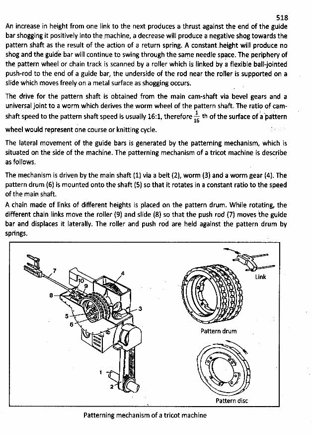
s1àAn increase in height from one Iink to the next produces a thrust against the end of the guidebar shogging it positively into the machine, a decrease will produce a negative shog towards thepattern shàft as the result of the action of a retqrn spring. A constant .height will produce noshog and the guidà bar will continue to swing through the same needle space. The periphery ofthe pattern wheel or chain track is scanned by a roller which is Iinked by à flexible ball-jointedpush-rod to the end of a guide bar, the underside of the rod near the roller'is supported on aslide which moves freely on a metal surface as shogging occurs.
. '.
The drive for the pattefn shaft is obtained from the main cam-shaft via bevet gears and auniversal joint to a worm which derives the worm wheel of the pattern shaft. The ratio of cam-
-!- ' :shaft speed to the pattern shaft speed is usually 16:1, therefore th of the sudace of a péttern16
wheel would represent one course or knitting cycle.
The lateral movement of the guide bars is generated by the patterning mechanism, which issituated on the side of the machine. The patterning mechanism of a tricot machine is describeas follows. '
The mechanism is driven by the main shaft (1) via a belt (2), worm (3) and a worm gear (4). Thepattern drum (6) is mounted onto the shaft (5) so that it rotates in a constant ratio to the spqedof the main shaft.A chain made of Iinks of different heights is placed on the pattern drum. W hile rotating, thedifferent chain Iinks move the roller (9) and slide (8) so that the push rod (7) moves the. guidebar and displaces it Iaterally. The roller and push roà are held against the pattern drum bysprings.
7 4Linklo l *
8 *
3 :%
'
$5 .6
. * pattern drum% *NwN -> .
w'.' o. . o @ N* N
j ' o IN.
.
. xY ''2
Pattern discA
Patterninj mechanism of a tricpt machine
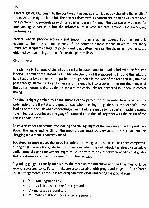
(1l519 l
A Iateral gatihg adjustment to the position of thq guides is carried out by changing the length ofthe push rod using the bolt (10). The pattern drum with its pattern chain can be easily replacedby a patterp disk, precisely pre-cut for a certain design. Although the disk can only be used forone Iapping sequence, it has the advantage of a very accurate, smooth and high-speedperformance.
Pattern wheels provide accuracy and smooth running at high speeds but they are onlyrconomical for Iong production runs of the common simple repeat structures; for fancystructures, frequent changes of pattern and Iong pattern repeats, the shogging movements areobtained by assembling a chain of re-usable pattern Iinks.
Ehain Iinks:
The identically Y-shaped chai.n links #re similar in appearance to a tuning fork with the fork end
leading. The tail of the preceding Iink fits into the fork of the succeeding link and the Iinks areheld together by pins which are pushed through holes in the side of the fork and tail, the pinspass through aIl the tracks and chains and the ends fit into grookes in the serrated flanges ofthe pattern drum so that as the drum turns the chain Iinks are advanced in unison, in corredtiming.
The link is slightly arched to fit the surface of the pattern drum. ln order to ensure that thewider side of the Iink takes the greater Ioad when pushing the guide bars
, the fork side is theIeading part of the Iink when connecting a chain. Links are made to fit a certain machine gauge.To eliminate any confusion, the gauge is stamped on to the link, together with the height of thelink in needle spaces.
Tp ensure smooth oprration, the Ieading and trailing edges of the Iinks are ground to produce aslope. The angle 'and Iength of the ground edge must be very accurately set, so that theshogging movement is correctly timed.
TMo steep an anyle moves the guide bar before the swing to the hook side has been completed.A long angle causes the guide bar to move Iater when the swing-back hatalready started. Abadly timed shogging movement might cause the yarn to be cut between needles and guidesand, in extreme cases, knitting elements can be damaged.
A grinding gauge is usually supplied by the machine manufadurer and the Iinks must only beground accorhing to it. Pattern Iinks are also available with preground edges to fit differentchain arrangements. These Iinks are designated by Ietters indicating the ground edge.
@ 'a' - is an unground link.'b' - is a Iink on which the fork is ground.
* 'c' - indicates a ground tail.@ 'd' - means that both fork and tail are ground.
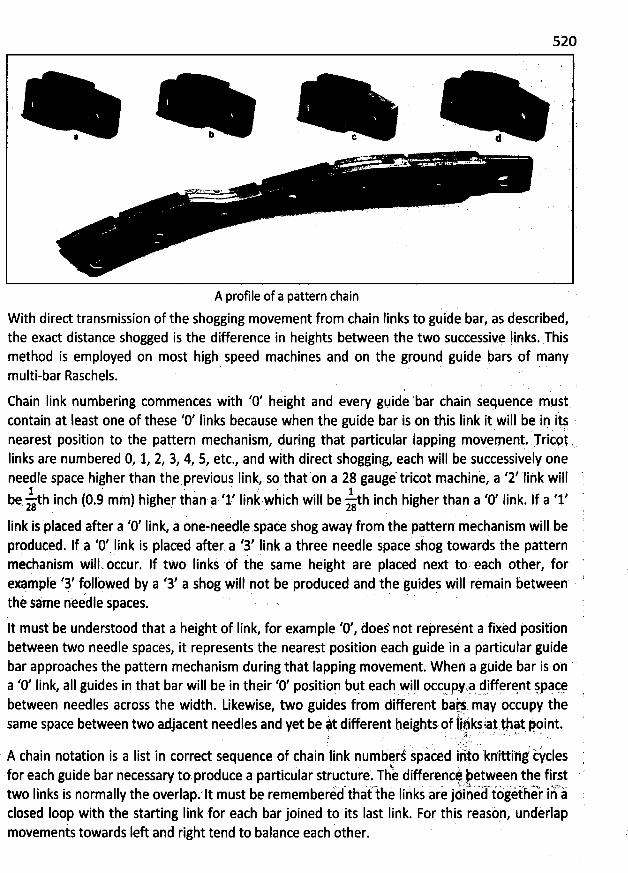
520
b c d*
. i . . ... . => @7 ... . .
A profile of a pattern chain
With direct transmission of the shogging movement from chain Iinks to guide bar, as described,the exact distance shogged is the difference in heights between the two successie links.:Thismethod is employed on most high speed machines and on the ground guide bars of manymulti-bar Raschels.
Chain Iink numbering commences with '0' height and every gqide 'bar chain sequepce mustcontain at Ieast one of these '0' Iinks because when the guide bar is on thiq link it will be in i:nearest position to the pattern mechanism, during that particular lapping movement. Triçpylinks are numbered 0, 1, 2, 3, 4, 5, etc., and wtth direct shogging, each will be successively oneneedle space higher yhan the previou! Iink so that on a 28 gaugé tricot machine, a '2' Iihk will '
. . . , ;
..â. . , ,y,,be Zth inch (0
.9 mm) higher than,av'l' Iink wàich will be zgth inch higher than a 0 link. lf a' 28g ' 'link is placed after a 0' link z onvlneedlq.space shog away from the pattern: mechanism will be
. , . , j) d tjle patternprpduced. lf a 0 . Iink is placed after a 3 Iink a three needle space s og towar smechanism will- ôccur. If two Iinks èf the same height are placed next to, each other, forepmple '3' follpwed by a '3' a shog will hot be produced and the tuides will remain between ' '
' .. ' . . . . ' .
the $àme nèedle sjaces. . . qIt must be understood that a height of Iink, for example '0', doefnot rejresént a fixed positlonbetween two needle spaces, it represents the nearest position each guide in a particular guidebar approaches the pattern mechanism during that lapping movement. W hen a guide baf is ona '0' link, aII guides in that bar will bq in their '0' positioq bqt qach will occqqylq .
d,jffçrqn! jplççg . '
between needles across the width. Likewise, two guides from dlfferent bat/? m?y occupy thesame space between two adjacent needles and yet be k different hqights pf jékjiat tha' yoint.yh w ' . !: . '=. 'J ; . ' ' ' . '
.E.' ' r -
. x % ('? . '' '
..
, . . )g .. . ? . i , .A chain notation is a Iist in correct sequence of chain link numbqri kpaced iéiö knittihg iycles ,
for each guide bar necessary toeproduce a particular stiuctufe. TV differenci ietween the first '- . .- . . . o' C,t. m .. . . . s -.! x vk.
two Iinks is normally the overlap.'lt must be rememberid thai the liiks are jö.ined iigiiher iii àclosed Ioop with the starting Iink for each bar joined to its Iast Iink. For this reasèp, undèrlapmovemenis towards Ieft and right tend to balance each other.
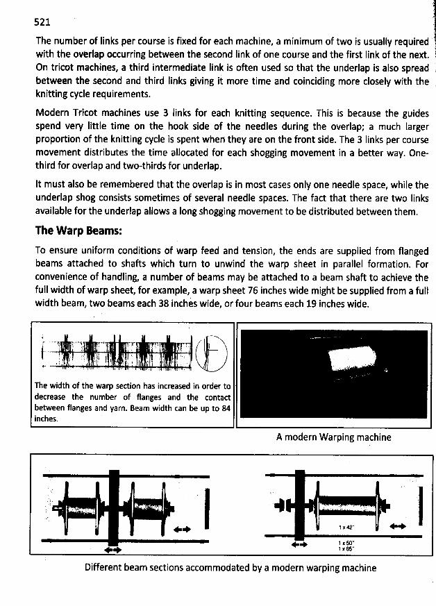
J
521 7è.The number of links per course is fixed for each machine, a minimum of two is usually required''
1with the ovèrlap occurring between the second Iink of one course and the first Iink of the next. !
On tricot machines, a third intermediate Iink is often used so that the underlap is also spread id and third Iinks giving it more time and coinciding more closely with the 1between the secon
lknitting cycle requirements.
Modern Tricot machines use 3 Iinks for each knitting sequence. This is because the guidesspend very Iittle time on the hook side of the needles during the overlap; a much Iargerproportion of the knitting cycle is spent when they are on the front side. The 3 Iinks per coursemovement distributes the time allocated for each shogging movement in a better way. One-third for overlap and two-thirds for underlap.
It must also be remembered that the overlap is in most cases only one needle space, while theunderlap shog consists sometimes of several needle spaces. The fact that there are two linksavailable for the underlap allows a Iong shogging movement to be distributed between them.
The W arp Dmams:
To ensure uniform conditions of warp feed and tension, the ends are supplied from flangedbeams attached to shafts which turn to unwind the warp sheet in parallel formation. Forconvenience of handling, a number of beams may be attached to a beam shaft to achieve thefull width of warp sheet, for example, a warp sheet 76 inches wide might be supplied from a fullwidth beam, two beams each 38 inches wide, or four beams each 19 inches wide.
!' , i:q ! f , ! 41 Ij . . i/j g .. ,,) . jI ... .. . ; . . , . , . . i : j ;' ' ! ' i :1 1. j j j ' j - , j - . y'' 1. ' j! lEy 7 I '. ' ' . 'j ' $E ' ! l ! ; . . ; - l .j , .y j j àb . . ! .. .. -, S . h . q . r ! ! E ) , .i ! . .. , . . .
The width of the warp sedion has increased in order todecrease the number of flanges and the contactbetween flanges and yarn. Beam width can be up to 84inches.
A modern Warping machine
a ,sn j
1 x42'' + ++ +
. + + 1 xK':+ + 1 X6S*
Different beam sections accommodated by a modern warping machine
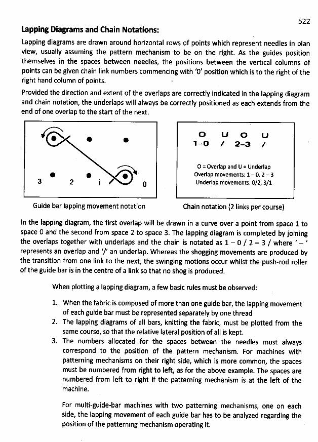
522Lapping Diagrams and Chain Notations:
Lapping diagrams are drawn around horizontal rows of points which represent needles in planview, usually assuming the pattern mechanism to be on the right. As the guides positionthemselves in the spaces between needles, the positions between the vertical columns ofpoints can be given chain Iink numbers commencing with '0' position which is to the right of theright hand column of points. '
Provided the direction and extent of the overlaps are correctly indicated in the Iapping diagramand chain notation, the underlaps will always be correctly positioned as each extends from theend of one overlap to the start of the next.
é->. . .
* @ @a 2 t z c
Guide bar lapping movement notation
ln the lapping diagram, the first overlap will be drawn in a curve over a point from space 1 tospace 0 and the second from space 2 to space 3. The Iapping diagram is completed by joiningthe overlaps together with underlaps and the chain is notated as 1 - 0 / 2 - 3 / where ' - 'represents an overlap and '/' an underlap. Whereas the shogging movements are produced bythe transition from one link to the next, the swinging motions occur whilst the push-rod rollerof the guide bar is in the centre of a Iink so that no shog is produced.
W hen plotting a Iapping diagram, a few basic rules must be observed:
o U o u1-o / 2-a /
O = Overlap and U = UnderlapOverlap movements: 1- 0, 2 - 3Underlap movements: 0/2, 3/1
Chain notation (2 Iinks per course)
W hen the fabric is composed of more than one guide bar, the lapping movementof each guide bar must be represented separately by one thread
2. The Iapping diagrams of aII bars, knitting the fabric, must be plotted from thesame course, so that the relative lateral position of a1l is kept.
3. The numbers allocated for the spaces between the needles must alwayscorrespond to the position of the pattern mechanism. For machines withpatterning mechanisms on their right side, which is more common, the spacesmust be numbered from right to left as for the above example. The spaces arenumbered from Ieft to right if the patterning mechanism is at the Iek of themachine.
For multi-guide-bar machines with two patterning mechanisms, one on eachside, the Iapping movement of each guide bar has to be analyzed regarding theposition of the patterning mechanism operating it.
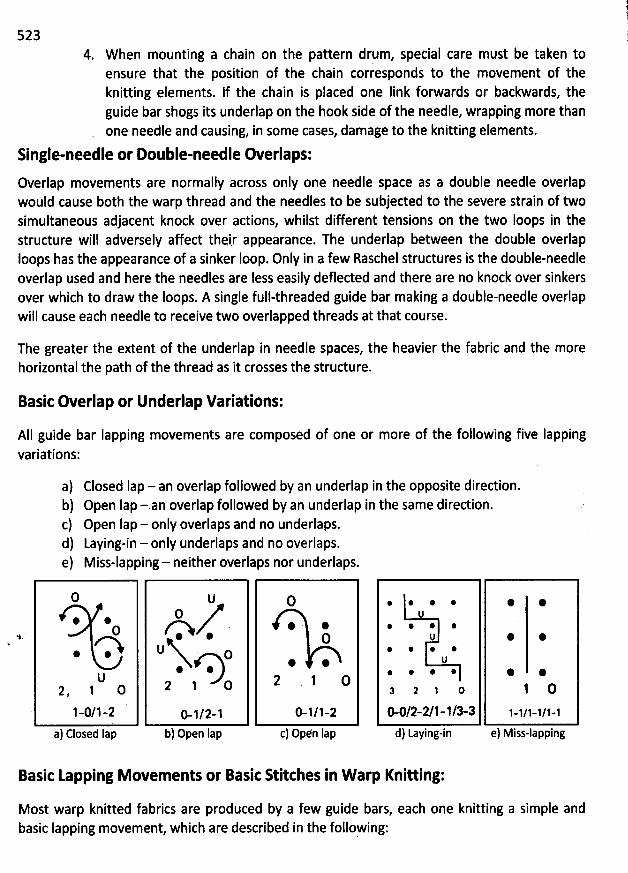
5234. W hen mounting a chain on the pattern drqm, special care must be taken to
ensure that the position of the chain corresponds to the movement of theknitting elements. lf the chain is placed one Iink forwards or backwards, theguide bar shogs its underlap on the hook side of the needle, wrapping more thanone needle and causing, in some cases, damage to the knitting elements.
Single-needle or Double-needle Overlaps:
Overlap movements are normally across only one needle space as a double needle overlapwould cause both the warp thread and the needles to be subjected to the severe strain of twosimultaneous adjacent knock over actions, whilst different tensions on the two Ioops in thestructure will adversely affect thei.r appearance. The underlap between the double overlaploops has the appearance of a sinker Ioop. Only in a few Raschel structures is the double-needleoverlap used and here the needles are less easily defleded and there are no knock over sinkersover which to draw the Ioops. A single full-threaded guide bar making a double-needle overlapwill cause each needle to receive two overlapped threads at that course.
The greater the extent of the underlap in needle spaces, the heavier the fabric and the morehorizontal the path of the thread as it crosses the structure.
Basic Overlap or Underlap Variations:
AII guide bar Iapping movements are composed of one or more of the following five lappingvariations:
a) Closed Iap - an overlap followed by an underlap in the opposite direction.b) Open Iap - an overlap followed by an underlap in the same direction.c) Open Iap - only overlaps and no underlaps.d) Laying-in - only underlaps and no overlaps.e) Miss-lapping - neither overlaps nor underlaps.
0
* @O
* *
U2 ' 1 O
. 1 .;/j .,a
a) Closed Iap
U0A .*U o
@ @2 1 O
G 1/2-1b) Open Iap
O
@ @O
* @
2 1 O
ë 1/1-2
c) Opyn Iap
. @ @ * @ @U
* * @ .$1 * @
@ * @U
@ * @ @ * @a , o O
0-0/2-2/1-1/3-3 1-1/1-1/1-1
d) Laying-in e) Miss-lapping
Basic Lapping Movements or Basit Stitches in W arp Knitting:
Most warp knitted fabrics are produced by a few guide bars, each one knitting a simple andbasic Iapping movement, which are described in the folloFing:
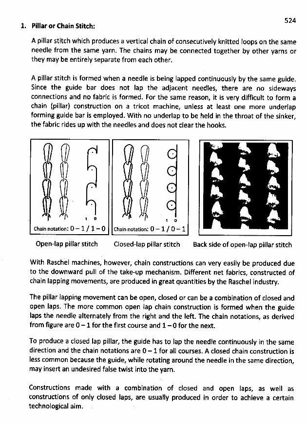
5241. Pillar or Chain Ritch:
A pillar stitch which produces a vertical chain of consecutively knitted Ioops on the sameneedle from the same yarn. The chains may be connected together by other yarns orthey may be entirely separate from each other.
A pillar stitch is formed when a needle is being Iapped continuousl: by the same guide.Since the guide bar does not Iap the adjacent needles, there are no sidewaysconnections and no fabric is formed. For the same reason, it is very difficult to form achain (pillar) construction on a tricot machine, unless at least one more underlapforming guide bar is employed. W ith no underlap to be held in the throat of the sinker
,
the fabric rides up with the needles and does not clear the hooks.
/ f) - C? '? $-ï? . ) -(-2 . (/ ..
yj .) l .$ o I zj o
chain notatiop: 0 - 1 / 1 - 0 chain notation: 0 - 1 / 0 - 1
Open-lap pillar stitch Closed-lap pillar stitch Back side of open-lap pillar stitch
W ith Raschil machines, however, chain construdions can very easily be produced dueto the downward pull of the take-up mechanism. Different net fabrics, constructed ofchain Iapping movements, are produced in great quantities by the Raschel industry.
The pillar lapping movement can be open, closed or can be a combination of closed andopen Iaps. The more common open lap chain construction is formed when the guideIaps the needle alternately from the right and the Ieft. The chain notations
, as derivedfrom figure are 0 - 1 for the first course and 1- 0 for the next.
To produce a closed lap pillar, the guide has to lap the needle continuously in the samedirection and the chain notations are 0 - 1 for aII courses. A closed chain construdion isIess common because the guide, while rotating around the needle in the same diredion
,
may insert an undesired false twist into the yarn.
Constructions made with a combination of closed and open Iaps, as well asconstrudions of only closed Iaps, are usually produced in order to achieve a certaintechnological aim.
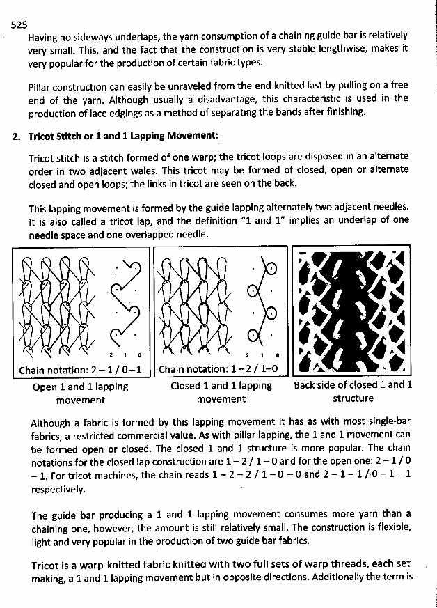
525Having no sideways underlaps, the yarn consumption of a chaining guide bar is relativelyvery small. This, and the fact that the construction is very stable Iengthwise, makes itvery popular for the production of certain fabric types.
Pillar construction can easily be unraveled from the end knitted last by pulling on a freeend of the yarn. Although usually a disadvantage, this characteristic is used in theproduction of Iace edgings as a method of separating the bands after finishing.
2. Tritot R itch or 1 and 1 O pping Movement:
Tricot stitch is a stitch formed of one warp; the tricot Ioops are disposed in an alternateorder in two adjacent wales. This tricot may be formed of closed, open or alternateclosed and open Ioops; the Iinks in tricot are seen on the back.
This Iapping movement is formed by the guide lapping alternately two adjacent needles.It is also called a tricot lap, and the definition ''1 and 1'' implies an underlap of oneneedle space and one overlapped needle.
v p vyjkg--''.'l -' -- jjr -- l,''jjjjjjjjjj;;;.. . .
...
.
* * :
,jt. . j #C X N X X U z , , z , , ie x> d
@ zx v x v achain notation: 2 - 1/ 0-1 Chain notation: 1-2 / 1-0open land llapping Closed land 1 lapping Back side of closed 1 and 1
m ovem ent m ovem ent structure
Although a fabric is formed by this Iapping movement it has as with most single-barfabrics, a restricted commercial value. As with pillar lapping, the 1 and 1 movement canbe formed open or closed. The closed 1 and 1 structure is more popular. The chainnotations for the closed lap construction are 1- 2 / 1 - 0 and for the open one: 2 - 1 / 0- 1. For tricot machines, the chain reads 1 - 2 - 2 / 1 - 0 - 0 and 2 - 1 - 1 /.0 - 1 - 1respectively.
The guide bar producing a 1 and 1 Iapping movement consumes more yarn than achaining one, however, the amount is still relatively small. The construction is flexible,light and very popular in the produdion of two guide bar fabrics.
Tricot is a warp-knitted fabric knitted with two full sets of warp threads, each set . qking, a 1 and 1 lapping movement but in opposite directions. Additionally the term is lma
. l1!
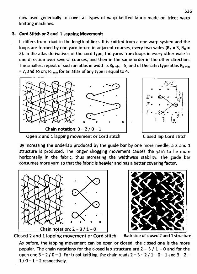
now used generically to cover aII types of warp knitted fabricknitting machines.
3. Cord Stitth or 2 and 1 tapping Movement:
It differs from tricot in the length of links. lt is knitted from a one warp system and theloops are formed by one yarn inturn in adjacent courses, every two wales (Rb = 3, RH =2). In the atlas derivatives of the cord type, the yarns from Ioops in every other wale inone diredion over several courses, and then in the same order in the other direction.The smallest repeat of such an atlas in width is kb min = 5, and of the satin type atlas Rb min= 7, and so on; Rh min for an atlas of any type is equal to 4.
526
made on tricot warp
/ œ *'l l+ *'
% %'
. . ./
$ * .l l
N N N< .a 2 o
Chain notation'. 3- 2 / 0 - 1Open 2 and 1 Iapping m ovement or Cord stitch
Rs =5l =' =,6 *
%.
'
----
'
-111,.-
*
-11.,-. -11.1-.,
*
'i 1'
*
::::,1:::r
*
11)
*
%: I& t= * * * -
i!* @ @ >-T;
. 7 / p e;k Lr:l ti I r'?
u1
Closed 1ap Cord stitch
By increasing the underlap produced by the guide bar by one more needle, a 2 and 1structure is produced. The Ionger shogging movement causes the yarn to lie morehorizontally in the fabric, thus increasing the widthwise stability. The guide barconsumes more yarn so that the fabric is heavier and has a better covering factor.
j j * ** .
; z j o
Chain notation: 2 - 3/ 1- 0Closed 2 and 1 Iapping m ovem ent or Cord stitch
As before, the Iapping movement can be open or closed, the closed one is the morepopular. The chain notations for the closed Iap structure are 2 - 3 / 1 - 0 and for theopen one 3- 2 / 0 - 1. For tricot kniiting, the chain reads 2 - 3 - 2 / 1 - 0 - 1 and 3- 2 -1 / 0 - 1- 2 respectively.
e '< - ws* 1
. #
. j
' . - ej
Back side of closed 2 and 1 structure
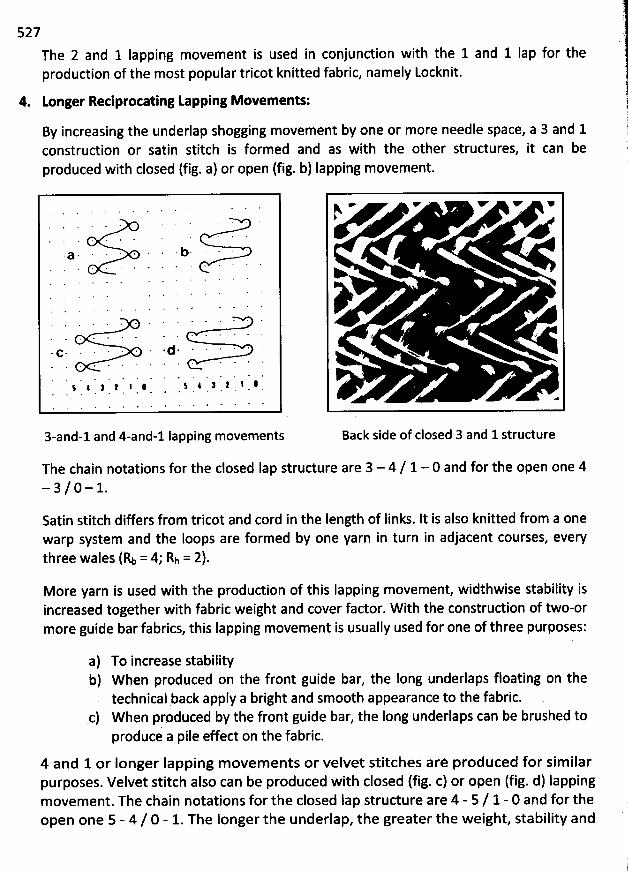
'.i
527
The 2 and 1 Iapping movement is used in conjunction with the 1 and 1 Iap for theproduction of the most popular tricot knitted fabric, namely Locknit.
4. Longer Reciprotating tapping Movements: 1
By increasing the underlap shogging movement by one or more needle space, a 3 and 1 1construction or satin stitch is formed and as with the other structures, it can be ,
produced with closed (fig. a) or open (fig. b) Iapping movement. j
3-and-1 and 4-and-1 lapping movements
The chain notations for the closed Iap structure are 3 - 4 / 1 - 0 and for the open one 4- 3 / 0 - 1.
- v V v YN
#
y , ./ ' J
N
e
Back side of closed 3 and 1 structure
Satin stitch differs from tricot and cord in the Iength of links. It is also knitted from a onewarp system and the Ioops are formed by one yarn in turn in adjacent courses, everythree wales (% = 49 Rh = 2).
More yarn is used with the produdion of this Iapping movement, widthwise stability isincreased together with fabric weight and cover factor. W ith the construdion of two-ormore guide bar fabrics, this Iapping movement is usually used for one of three purposes:
a) To increase stabilityb) When produced on the front guide bar, the long underlaps floating on the
technical pack apply a bright ànd smooth appearance to the fabric.c) When produced by the front guide bar, the Iong underlaps can be brushed to
produce a pile effect on the fabric.
4 and 1 or longer Iapping m ovem ents or velvet stitches are produced for sim ilarpurposes. Velvet stitch also can be produced with closed (fig. c) or open (fig. d) Iappingmovement. The chain notations for the closed Iap structure are 4 - 5 / 1 - 0 and for theopen one 5 - 4 / 0 - 1. The Ionger the underlap, the greater the weight, stability and
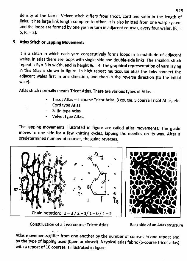
528density of the fabric. Velvet stitch differs from tricot
, cord and satin in the Iength ofIinks. It has Iarge Iink Iength'compare to other. It is also knitted from one warp systemand the loops are formed by one yarn in turn in adjacent courses, every four wales, (Rb =S; Rh = 2).
5. Atlas Stitrh or Lapping Movement:
It is a stitch in which each yarn consecutively forms Ioops in a multitude of adjacentwales. ln atlas there are loops with single-side and double-side Iinks
. The smallest stitchrepeat is Rb = 3 in width, and in height Rh = 4. The graphical representation of yarn Iayingin this atlas is shown in figure. In high repeat m ulticourse atlas the Iinks connect theadjacent wales first in one direction, and then in the reverse direction (to the initialwale).
Atlas stitch normally means Tricot Atlas. There are various types of Atlas -
Tricot Atlas - 2 course Tricot Atlas, 3 course, 5 course Tricot Atlas, etc.Cord type AtlasSatin type AtlasVelvet type Atlas.
The Iapping movements illustrated in figure are called atlas movements. The guide
moves to one side for a few knitting cycles, Iapping the needles on its way. After apredetermined number of courses, the guide reverses.
#z
J . .
- n r . . .I I ê.- l u
-n x x xI 1 %W -h. . #z
J Wfj , j ag
Chain notation: 2 - 3 / 2 - 1/ 1- 0 / 1 - 2
p * .@4#k4p1%Ii
.
% p. : j#* z $14 $ j+ +
k# 1*.4 t% p*!
,.tI11 j,'. ,p.1i11I Ik
Back side of an Atlas structureConstrudion of a Two course Tricot Atlas
Atlas movementsl#l#er from one another by the number of courses in one repeat and' . .$' '
by the type of Iappihg ùsed (open or closed). A typical atlas fabric (s-course tricot atlas)with a repeat of 10 courses is illustrated in figure.
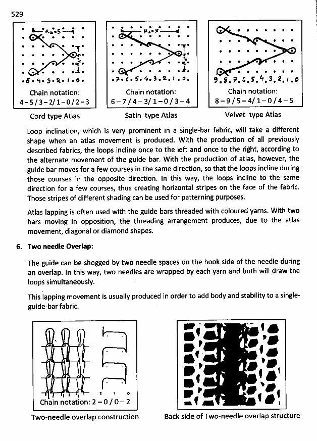
529
@ t @ * * * *R1.5 --%@ @ @ * * * *
@ * @ * * * *T* * * * @ * + *
%* @ @ @ @ @œ @:.* @ @ @ @ *
.F . N. 1.A.,.o.
Chain notation'.4-5/3-2/1-0/2-3
Cord type Atlas
Loop inclination, which is very prominent in a single-bar fabric, will take a differentshape when an atlas movement is produced. W ith the production of a1I previouslydescribed fabrics, the loops incline once to the left and once to the rijht, according tothe alternate movement of the guide bar. W ith the production of atlas, however, theguide bar moves for a few courses in the same direction, so that the loops incline duringthose courses in the opposite direction. In this way, the Ioops incline to the samedirection for a few courses, thus creating horizontal stripes on !he face of the fabric.Those stripes of different shading can be used for patterning purposes.
Atlas Iapping is often used with the guide bars threaded with coloured yarns. W ith twobars moving in opposition, the threading arrangement produces, due to the atlasmovement diagonal or diamond shapes.
6. Two needle Overlap:
@ * @ * @ @ @ * @9.&%7
@ * * * * * @ @
* @ * * * *1@ @ * * @ @ * @ @T
œ* * * @ @ @ @ < *
3.@ * * @ @ *..>.<. ç.é.1.*.l.@.
Chain notation'.6 -7/4- 3/1-0/3- 4
Satin type Atlas
@ @ @ * @ *
@ * @ @ @ @
@ * * * * * * @
@ * * * * * *
@ @ * @ @ @ @ *
9 # > & f h 3 R / :* * * @ * # * @ *
Chain notation'.
8 - 9/5 - 4/1 - 0/4 - 5
Velvet type Atlas
The guide can be shogged by two needle spaces on the hook side of the needle duringan overlap. ln this way, two needles are wrapped by each yarn and both will draw theIoops simultaneously. '
This Iapping movement is usually produced in order to add body and stability to a single-guide-bar fabric.
l I 11 2 *
chain notation'. 2 - 0 / 0 - 2
Two-needle overlap construction
f ' e* :.e ' *4é . e
* %@. y j* f *f
.* .. #
fZf - f * ,Back side of Two-needle overlap strudure
530The facts that two separate loops must be drawn from a relatively small am
ount of yarnand that one of the two has no access to the guide'and warp cause a Iot of stress to beplaced on the yarns and the needles
. Usually, when producing a two-bar fabric, withincorporated two n
eedle overlap, the movement should be produced by the front guidebar
. The yarns of the front guide bars float freely on the face of the fabric and
, ifnecessary, can move more easily into the knitted Ioop.
Figure illustrates a construction in which chaining and two needle overlap are combined
.As can be observed, each needle receives two yarns and horizontal connectionsbetween the wales are formed. The fabric has erect Ioops
, is relatively stable andresembles the appearance of two-bar fabrics
.
The chain notations for the structure in figure are 2 - 0 / 0 - 2 and for tricot machine
with 3 links per course movement 2 - 0 - 0 / 0 - 2 - 2.
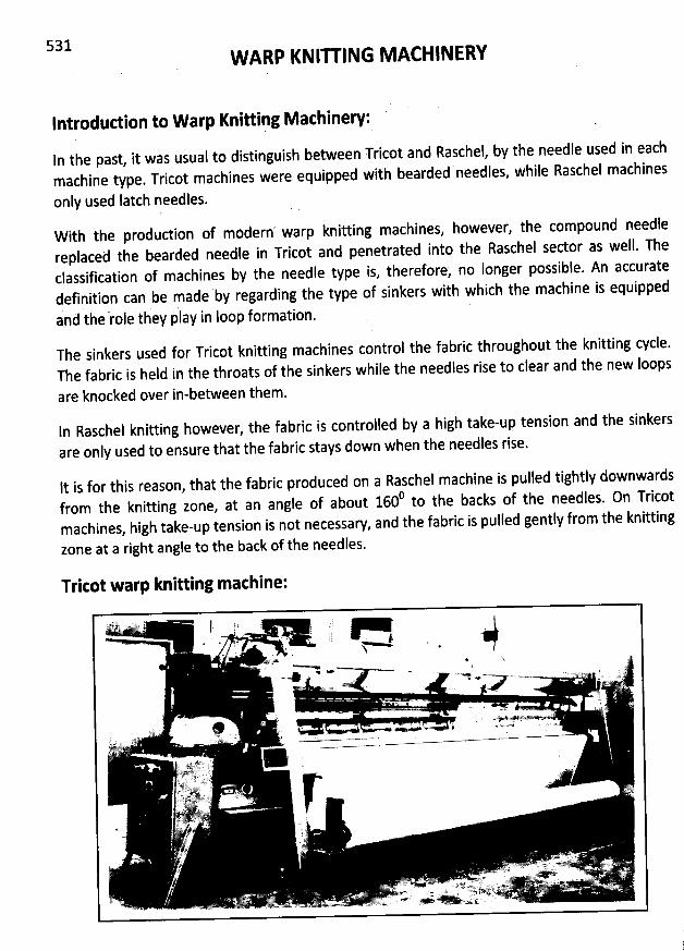
531 W ARP KNIU ING M ACHINERY
Introdudion to W arp Knitting Machinery:
In the past, it was usual to distinguish between Tricot and Raschel, by the needle used in eachmachine type. Tricot machines were equipped with bearded needles, while Raschel machines
only used (atch needles.
W ith tbe produdion of modern warp knitting machines, however, the compound needlereplaced the bearded needle in Tricot and penetrated into the Raschel sedor as well. Theclassification of machines by the needle type is, therefore, no Ionger possibde. An accuratedefinition can be made by regarding the type of sinkers with which the machine is equipped
and the role they jlay in loop formation.The sinkers used for Tricot knitting machines control the fabric throughout the knitting cycle.The fabric is held in the throats of the sinkers while the needles rise to clear and the new Ioops
are knocked over in-between them.
ln Raschel knitting however, the fabric is controlled by a high take-up tension and the sinkers
are only used to ensure that the fabric stays down when the needles rise.
lt is for this reason, that the fabric produced on a Raschel machine is pulled tightly downwards0 he backs of the needles. 0n Tricotfrom the knitting zone, at an angle of about 160 to t
machines, high take-up tension is not necessary, and the fabric is pulled gently from the knitting
zone at a right angle to the back of the needles.
Tritot warp knitting machine:
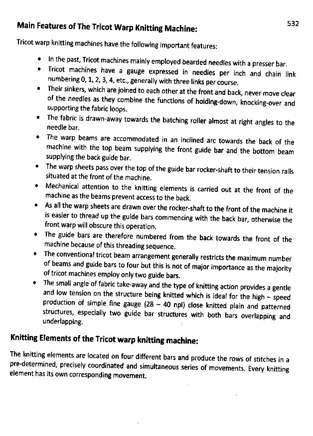
M ain Features of The Tritot W arp Knitting M acbine:
Tricot warp knitting machines have the following important features:
* In the past, Tricot machines mainly employed bearded needles with a presser bar.T
ricot machines have a gauge expressed in needles per inch and chain Iink
numbering 0, 1, 2, 3, 4, etc., generally with three Iinks per course.
Their sinkers, which are joined to each other at the front and back, never move clearof the needles as they combine the fundions of holding
-down, knocking-over andsupporting the fabric loops.The fabric is drawn-away towards the batching roller almost at
right angles to theneedle bar.The warp beams are accommodatedmachine with the top beam supplyingsupplying the back guide bar.
in an inclined arc towards the back of thetbe front guide bar and the boytom beam
* The warp sheets pass over the top of the guide bar rocker-shaft to their tension railssituated at the front of the machine
.
* Mechanical attention to the knitting elements is carried out at the front of themachine as the beams prevent access to the back
.
* As all the warp sheets are drawnthread up the
@
front warp will obscure this operation.
The guide bars are therefore numbered from the backmachine because of thisThe conventional tricot beamof beams and
*
towards the front ofthethreading sequence.
arrangement generally restritts the maximum numberguide bars to four but this isnot of major importance as the majority
of tricot machines employ only twoThe small
guide bars.angle of fabric take-away and the type of knitting action provides a
gentleand Iow tension on the structure being knitted which is ideal for the high - speedproduction of simple fine gauge (28 - 40 npi) close knitted plain and patternedstrudures, especially two guide bar structeres with both bars overlapping andunderlapping.
is easier toover the rocker-shaft to the front of thq machine it
guide bars coymencing with the back bar, otherwise the
532
Knitting Elements of the Tricot warp knitting mathine:
The knitting elements are Iocated on four different bars and produce the rows of stitcbes in a7 ies of movements
. Every knittingpre-determined, precisely coordinated and simultaneous ser
element has its own corresponding movement.
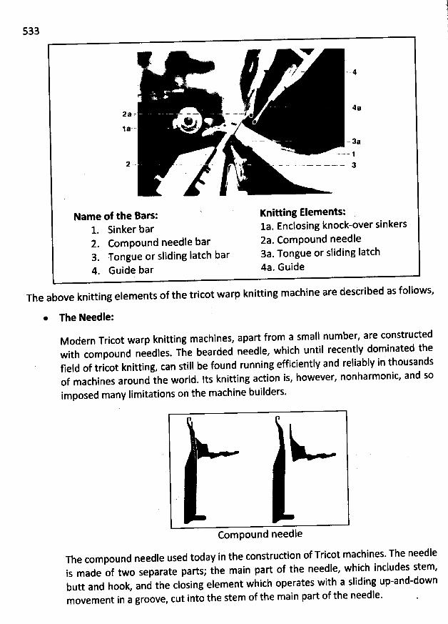
533
Y. -
z- . y/z -. . #
Ji5 . .
' (,
2a - - - - - -=/ 42
@ . . .j a -.. ...
- 3aN .
..- -. -. j
f i
Nam e of the Bars: Kniuing Elem ents:1. Sinker bar 1a. Enclosing knock-over sinkers2. Compound needle bar 2a. Compound needle3. Tongue or sliding Iatch bar 3a. Tongue or sliding Iatch4. Guide bar 4a. Guide
The above knitting elements of the tricot warp knitting machine are described as follows,
* The Needle:
M odern Tricot warp knitting machines, apart from a small number, are constructedwith compound needles. The bearded needle, which until recently dominated thefield of tricot knitting, can still be found running efficiently and reliably in thousandsof machines around the world. Its knitting action is, however, nonharmonic, and so
imposed many Iimitations on the machine builders.
k-
Com pound needle
The compound needle used today ii the construdion of Tricot machines. The needleis made of two separate parts; the main part of the needle, which includes stem,butt and hook, and the closing element which operates with a sliding up-and-downmovement in a groove, cut into the stem of the main part of the needle.
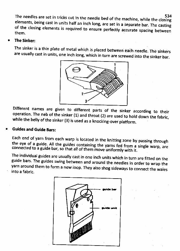
534The needles are set in tricks cut in the needle bed of the machine, Fhile the closingelements, being cast in units half an inch long, are set in a jeparate bar. The castingof th
e closing elements is required to ensure perfectly accurate spacing betweenthe
m .
* The Sinker:
The sinker is a thin plate of metal which is placed between éaih needle. Thè sinkirsare usually cast in units, one inch Iong, which in turn are screwed into the sinker bar
.
Different names are givenoperation. The neb of the
WW'to different parts of the sinker according to their
sinker (1) and throa! (2) are used to hold down the fabric,while the belly of the sinker (3) is used as a knocking-over platform
.
* Guides and Guide Bars:
Each end of yarn from each warp is Iocated in the knitting zone by passing throughth
e eye of a guide. All the guides containing the yarns fed from a single warp. areconnected to a guide b
ar, so that all of them move uniform ly with it.
The individual guides are usually cast in one inch units which in turn are fitted on tbeguide bars. The guides swing between and around the ne
edles in order to wrap theyarn around them to form a new Ioop. They also shog sideways to conned the walesinto a fabric.
# wa -a
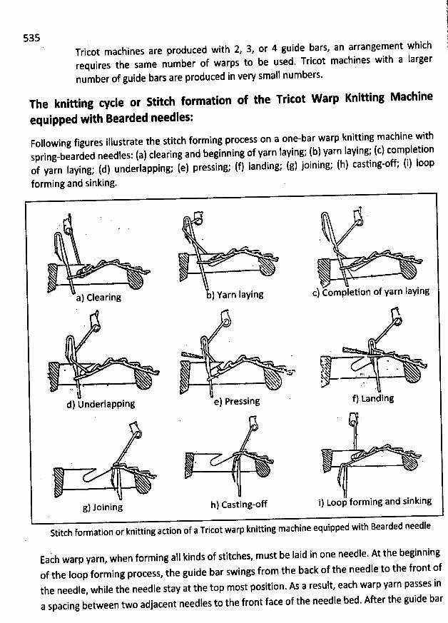
535Tricot machines are produced witb 2, 3, or 4 guide bars, an arrangement whichrequires the same number of warps to be used. Tricot machines with a larger
number of guide bars are produced in very small numbers.
The knitting cycle or Stitth formatibn of the Tricot W arp Knitting M achine
equipped with Bearded needles:Following figures illustrate the stitch forming process on a one-bar warp knitting machine with
spring-bearded needles: (a) clearing and beginning of yarn Iaying; (b) yarn laying; (c) completionof yarn Iaying; (d) underlapping; (e) pressing; (f) Ianding; (g) joining; (h) casting-off; (i) Ioopforming and sinking.
1
* .
N( N
NN $. .
a) Clearing b) Yarn laying c) Completion of yarn Iaying
1 . .$
'
. . . j; .s .*
&q . .4j .., 1t.&K . .XX -S' 1 x . e ' .xx t
..
n' . ' ..
.i .d) Underlapping e) Pressing f) Landing
. . Ah
g) Joining h) Casting-off i) Loop forming and sinking
Stitch formation or knitting action of a Tricot warp knitting machine equipped with Bearded needle
Eacb warp yarn, when forming alI kinds of stitches, must be laid in one needle. At the beginningof the Ioop forming process, the guide bar swings from the back of the needle to the front of
the needle, while the needle stay at the top most position. As a result, each warp yarn passes in
a spacing between two adjacent needles to the front face of the needle bed. After the guide bar
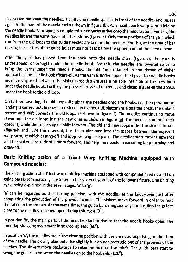
536bas passed between the needles, it shifts one needle spacing in front of ihe needles and psssesagain to the back of the needle bed as shown in figure (b). As a result, each warp yarn is Iaid onthe needle hook. Yarn Iaying is completed when yarns arrive onto the needle stem
. For this, theneedles Iift and the yarns pass onto their stems (figure-c). Only those portions of the yatn whichrun from the oId loops to the guide needles are laid on the needles. For this, at the time of barracking the centres of the guide holes must not pass below the upper point of the needle head
.
After the yarn has passed from the hook onto the needle stem (figure-c), the yarn isunderlapped, or brought under the needle hook. For this, the needles are Iowered so as tobring the yarns under the needle hooks; the oId Ioop retained in the throat of sinker
approaches the needle hook (figure-d). As the yarn is underlaphed, the tips of the needle hooksmust be disposed between the sinker nibs; this ensures a reliable insertion of the new Ioopunder the needle hook. Further, the presser presses the needles and çloses (figure-e) the accessunder the hook to the old Ioop.
0n furtber lowering, the old Ioops slip along the needles onto the hooks, i.e. the operation ofIanding is carried out. In order to reduce needle hook displacement along the press
, the sinkersretreat and shift upwards the old loops as shown in figure (f). The needles continue to movedown until the old Ioops join the new ones as shdwn in figure (g). The needles continue theirdescent, while the sinkers again shift forward. The old and new Ioops enter the sinker throats(figure-h and i). At this moment, the sinker nibs pass into the spaces between the adjacent'warp yarn, at which casting-off and loop forming take place. The needles start moving upwardsand the sinkers protrude still more forward, and help the nqedle in executing Ioop forming anddraw-off.
Basic Knitting adibn ofCompound needles:
a Tricot W arp Knitting M àchine equipped with
The knitting action of a Tricot warp knittihg machine equipped with compound needles 9nd twoguide bars is schematically illustrated in thè seven diagrams of the following figure
. One knittingg 'cycle being explained in the seven stages a' to 'g'.
'a' can be regarded as the starting position, wità the neéàles at the knock-over just aftercompleting the production of the previous course. The sinkers move forward in order to holdthe fabric in the throats. At the same time, the guide bars shog sideways to positidn the guides'
. ' . J
'
. .
0 .close to the needles to be wrapped during this cycle (0 ).
In position 'b', the main parts of the needles stak to rise so that the needle hooks open. The0 ,underlap shogging movement is now completed (60 ).
In position 'c', the needles are in the clearing posiiion with the previous Ioops Iying on the stemof the needle. The closing elements rise slightly but do not hrotrude out of the grooves of theneedles. The sinkers move backwards to relax the hold on the fabric. The guide bars start to
h ides in between the needles on to the hook side (1200).swing t e gu
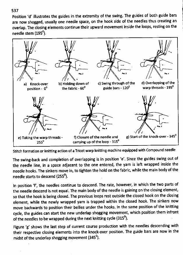
Position 'd' illustrates the guides in the extremity of the swing. The guides of both guide bars 1k side of the needles thus creating an 1are now shogged, usually one needle space, on the hoo
overlap. The closing elements continue their upward movement inside the loops, resting on the )c .
needle stem (195 ).
a . ''-*
N
<> M o
yf
/ '- 1 . z u ., a.#
. ve # @
z' 4. 4, y/ d) 4,J' J ?/' .' 1' th
a) Knock-over b) Holding down of c) Swing through of the d) Overlapping of the0 () 0 ' 0position - 0 the fabric - 60 guide bars - 120 warp threads - 195
*-. . *
o u
- - *
// e z/ . -: / -4 .. /
/ v l p'e) Taking the warp threads - f) Closure of the needle and g) Start of the knock-over - 3450
2550 carwing up of the Ioop - 3150
Stitch formation or knitting action of a Tricot warp knitting machine equipped with Compound needle
The swing-back and completion of overlapping is in position 'e'. Since the guides swing out of
the needle Iine, in a space adjacent to the one entered, the yarn is Ieft wrapped inside theneedle hooks. The sinkers move in, to tighten the hold on the fabric, while the main body of the
0needle starts to descend (255 ).In position 'f', the needles continue to descend. The rate, however, in which the two parts ofthe needle descend is not equal. The main body of the needle is gaining on the closing element,so that the hook is being closed. The previous Ioops rest outside the closed hook on the closingelement, while the newly wrapped yarn is trapped within the closed hook. The sinkers nowmove backwards to position their bellies under the hooks. ln the same position of the knittingcycle, the guides can start the new underlap shogging movement, which position them infront
0of the needles to be wrapped during the next knitting cycle (315 ).Figure 'g' shows the last step of current course production with the needles descending withtheir respective closing elements into the knock-over position. Tbe guide bars are now in the
0midst of the underlap shogging movement (345 ).
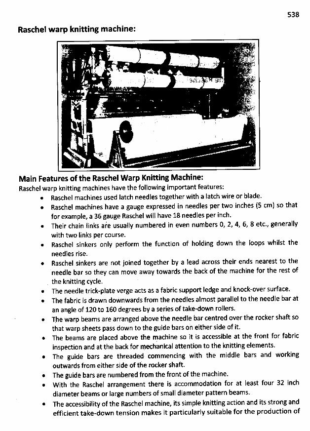
538
Raschel warp knitting m athine:
Main Features of the RaschelW arp Knitting M achine:Raschel warp knitting machines have the following important features:
@ Raschel machines used Iatch needles together with a Iatch wire or blade.Raschel machines have a gauge expressed in needles per two inches (5 cm) so thatfor example, a 36 gauge Raschel will have 18 needles per inch.Their chain Iinks aie usually numbered in even numbers 0, 2, 4, 6, 8 etc., generallywith two links per course.Raschel sinkers only perform the function ofholding down the loops whilst the
needles rise.Raschel sinkers are not joined together by a lead across their ends nearest to theneedle bar so they can move away towards the back of the machine for the rest ofthe knitting cycle.
@ The needle trick-plate verge acts as a fabric support Iedge and knock-over surface.* The fabric is drawn doWnwards from the needles almost parallel to the needle bar at
an angle of 120 to 160 degrees by a series of take-down rollers.* The warp beams are arranged above the needle bar centred over the rocker shaft so
that warp sheets pass down to the guide bars oi either side of it.@ The beams are placed above the machine so it is accessible at the front for fabric
inspection and at the back for mechanical attention to the knitting elements.* The guide bars are threaded iommencing witb the middle bars and working
outwards from either side of th: rocker shaft.* The guide bars àre numbered from the front of the machine.@ W ith the Raschel arrangement there is accommodation for at least four 32 inch
diameter beams or Iarge numbers of small diameter pattern beams.* The accessibility of the Raschel machine, its simple knitting adion and its strong and
efficient take-down tension makes it particularly suitable for the production of
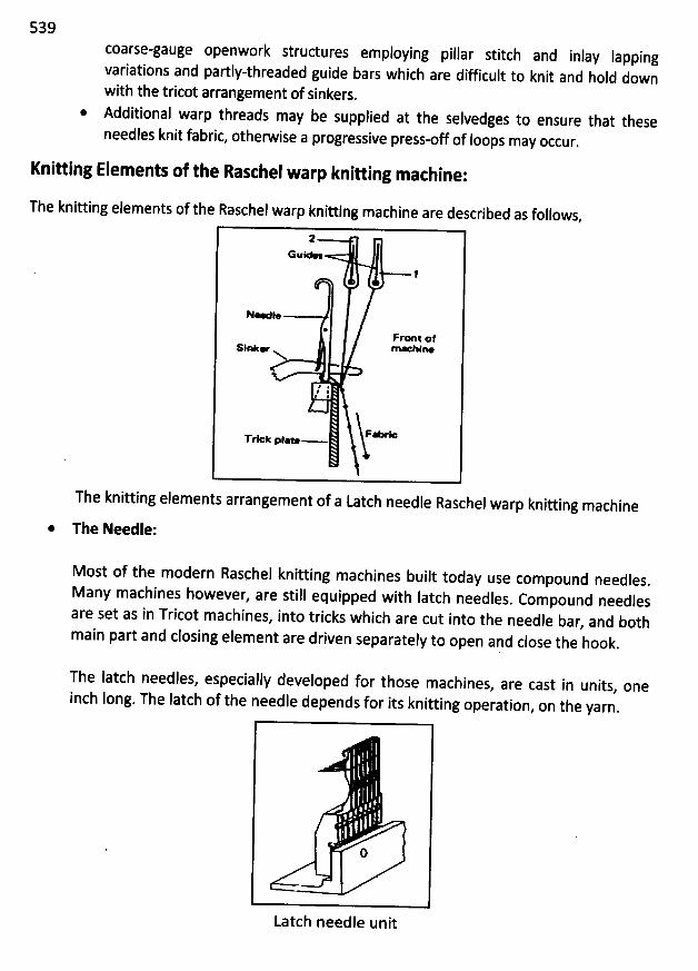
539
coarse-gauge openwork structures employing pillar stitch and inlay Iappingvariations and partly-threaded guide bars which are difficult to knit and hold downwith the tricot arrangement of sinkers.
* Additional warp threads may be supplied at the selvedges to ensure that these
needles knit fabric, otherwise a progressive press-off of Ioops may occur.
Knitting Elements of the Raschel warp knitting machine:
The knitting elements of the Raschel warp knitting machine are described as follows,
2Bue-
1
N-d*@
Pr* t /#SiO e MO WION
e
F.m--* .Trlek ptlw
The knitting elements arrangement of a Latch needle Raschel warp knitting machine
* The Needle:
Most of the modern Raschel knitting machines built today use compound needles.
M any machines however, are still equipped with latch needles. Compound needles
are set as in Tricot machines, into tricks which are cut into the needle bar, and both
main part and closing element are driven separately to open and close the hook.
The Iatch needles, especially developed for those machines, are cast in units, one
inch long. The Iatch of the needle depends for its knitting operation, on the yarn.
ALatch needle unit
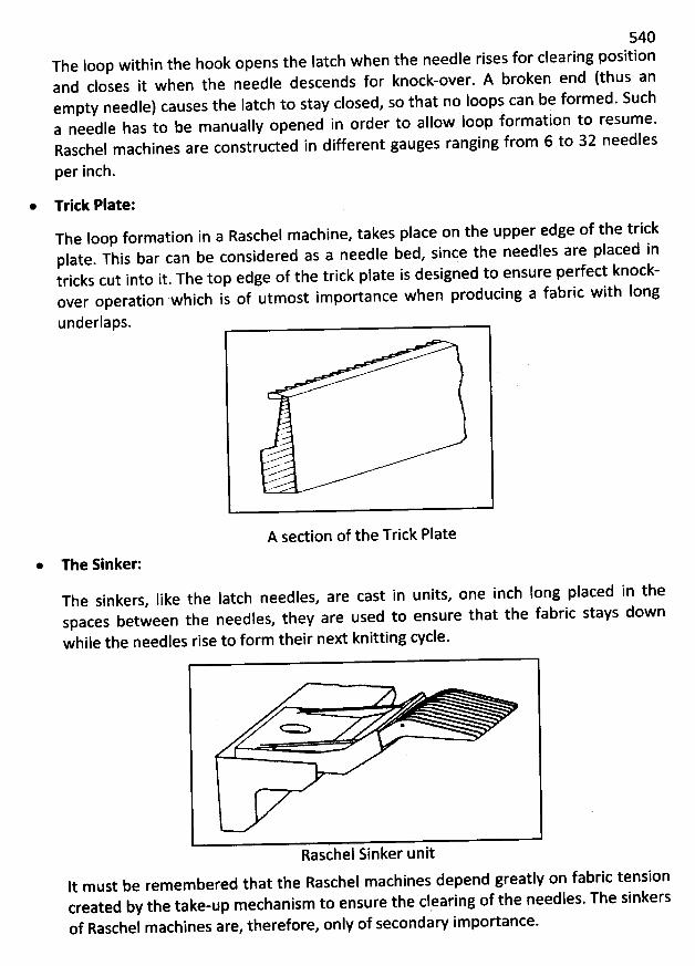
540The loop within the hook opens the Iatch when the needle rises for clearing position
and closes it when the needle descends for knock-over. A broken end (thus anempty needle) causes the Iatch to stay closed, so that no loops can be formed. Sucha needle has to be manually opened in order to allow Ioop formation to resum e.Raschel machines are constructed in different gauges ranging from 6 to 32 needles
per inch.
* Tritk Plate:The Ioop formation in a Raschel m achine, takes place on the upper edge of the trickplate. This bar can be considered as a needle bed, sinçe the needles are placed intricks cut into it. The top edge of the trick plate is designed to ensure perfect knock-over operation which is of utmost im portance when producing a fabric with Iong
underlaps.
A section of the Trick Plate
* The Sinker:
The sinkers, Iike the latch needles, are cast in units, one inch Iong placed in thespaces between the needles, they are used to ensure that the fabric stays down
while the needles rise to form their next knitting cycle.
= > .
Raschel Sinker unitIt m ust be remem bered that the Raschel m achines depend greatly on fabric tensioncreated by the takerup mechanism to ensure the clraring of the needles. The sinkersof Raschel m achines are, therefore, only of secondary importance.
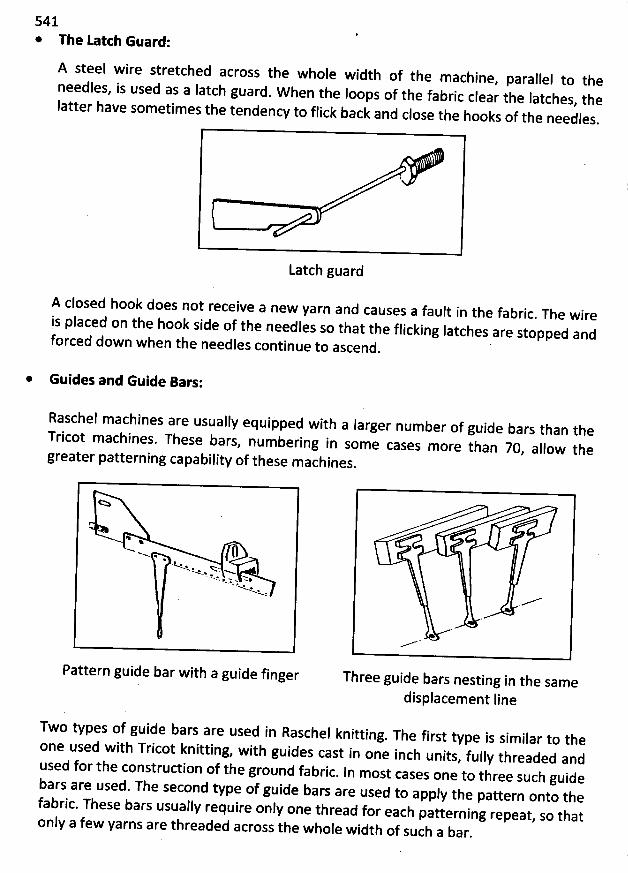
541* The tatth Guard:
A steel wire stretched across the whole width of the m achine, parallel to the
needles, is used as a latch guard. W hen the Ioops of the fabric clear the Iatches
, theIatter have sometimes the tendency to flick back and close the hooks of th
e needles.
Latch guard
A closed hook does not receive a new yarn and causes a fault in the fabric. The wireis placed on the hook side of the needles so that the flicking Iatches are stopped andf
orced dow n when the needles continue to ascend.
'
* Guides and Guide Bars:
Raschel machines are usually equipped with a Iarger number of guide bars than theT
ricot machines. These bars, num bering in some cases more than 70
, allow thegreater patterning capability of these m achines
.
* *
N N ** . tx p . .Qw , w . x .N .t> w.- .%. w ... . w .. p
'N * .N:
Pattern guide bar with a guide finger
Two types of guide bars are used in Raschel knitting. The first type is similar to the
one used with Tricot knitting, with guides cast in one inch units
, fully threaded andused for the construction of the ground fabric. In most cases one to three such guideb
ars are used. The second type of guide bars are used to apply the pattern onto thefabric. These bars usually require only one thread for each patterning repeat
, so thatonly a few yarns are tbreaded across the whole width of such a bar
.
Three guide bars nesting in the samedisplacement line
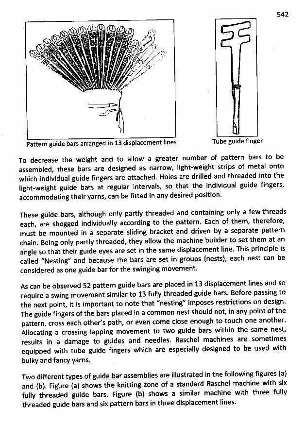
542.r#lk .9.J1. .. ..
- . . . .;.-,(CJ . f .. J.j . c, y(G . > , ç . #. . . . . :
$5 Ny,k ...NY N% . ' ..
' -'T . jy . . z. iJ.y t ... ), . y . .jslz .w# . . . uk. 5) ,. . ,. zta . ,
.+% x -%k .. 4J /J z . .. s.: A. xy . . ajj . ..2. év . : 4/ e
* @ x ' .'sk. > . . .) ' .. . .h . (; +V z X'e'.lo '
,zVk , ,:
Azz'
*+
> e
w 'z
Pattern guide bars arranged in 13 displacement Iines
To decrease the weight and to allow a greater number of pattern bars to beassem bled, these bars are designed as narrow, light-weight strips of metal ontowhich individual guide fingers are attached. Holes are drilled and threaded into thelight-weight guide bars at regular intervals, so that the individual guide fingers,accommodating their yarns, can be fitted in any desired position.
Tube guide finger
These guide bars, although only partly threaded and containing only a few threadseach, are shogged individually according to the pattern. Each of them, therefore,must be mounted in a separate sliding bracket and driven by a separate patternchain. Being only partly threaded, they allow the machine builder to set them at anangle so that their guide eyes are set in the same displacement Iine. This principle iscalled ''Nesting'' and because the bars are set in groups (nests), each nest can beconsidered as one guide bar for the swinging m ovem ent.
As can be observed 52 pattern guide bars ake placed in 13 displacement lines and sorequire a swing movement similar to 13 fully threaded guide bars. Before passing tothe next point, it is important to note that ''nesting'' imposes restrictions on design.The guide fingers of the bars placed in a common nest should not, in any point of thepattern, cross each other's path, or even come close enough to touch one another.Allocating a crossing Iapping movement to two guide bars within the same nest,results in a damage to guides and needles. Raschel machines are sometim esequipped with tube guide fingers which are especially designed to be used with
bulky and fancy yarns.
Two different types of guide bar assemblies are illustrated in the following figures (a)and (b). Figbre (a) shows the knitting zone of a standard Raschel machine with sixfully threaded guide bars. Figure (b) shows a similar machine with three fullythreaded guide bars and six pattern bars in three displacem ent Iines.
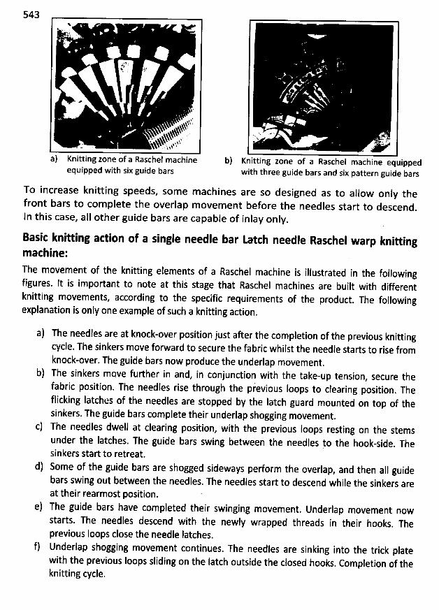
543%
'' k' s )
z/''+. c' 'F .
. * ,
. yï
$% s*%!% .
. . s%% . ,- .xxNN , t.tï.. ' %*
'
* . . : $
'
a) Knitting zone of a Raschel machineequipped with six guide bars
b)
. *.
) . L(' l'O '
Knitting zone of a Raschel machine equippedwith three guide bars and six pattern guide bars
To increase knitting speeds, some machines are so designed as to allow only thefront bars to com plete the overlap m ovem ent before the needles start to descend
.
ln this case, alI other guide bars are capable of inlay only.
Basit knitting adion of a single needle bar tatch needle Rasthel warp knittingm achine:The movement of the knitting elements of a Raschel machine is illustrated in the followingfigures. It is important to note at this stage that Raschel machines are built with differentknitting movements, according to the spçcific requirements of the product
. The followingexplanation is only one example of such a knitting action.
a) The needles are at knock-over position just after the completion of the previous knittingcycle. The sinkers move forward to secure the fabric whilst the needle starts to rise fromknock-over. The guide bars now produce the underlap movement
.
b) The sinkers move further in and, in conjunction with the take-up tension, secure the
fabric position. The needles rise through the previous loops to clearing position. The
flicking Iatches of the needles are stopped by tbe Iatch guard mounted on top of thesinkers. The guide bars complete their underlap shogging movement
.
c) The needles dwell at clearing position, with the previous Ioops resting on the stemsunder the latches. The guide bars swing between the needles yo the hook-side
. Thesinkers start to retreat.
d) Some of the guide bars are shogged sideways pedorm the overlap, and then aII guidebars swing out between the needles. The needles start to descend while the sinkers areat their rearmost position.
e) The guide bars have completed their swinging movement. Underlap movement nowstarts. The needles descend with the newly wrapped threads in their hooks
. Theprevious Ioops close the needle Iatches.
f) Underlap shogging movement continues. The needles are sinking into the trick platewith the previous loops sliding on the latch outside the closed hooks
. Completion of theknitting cycle.
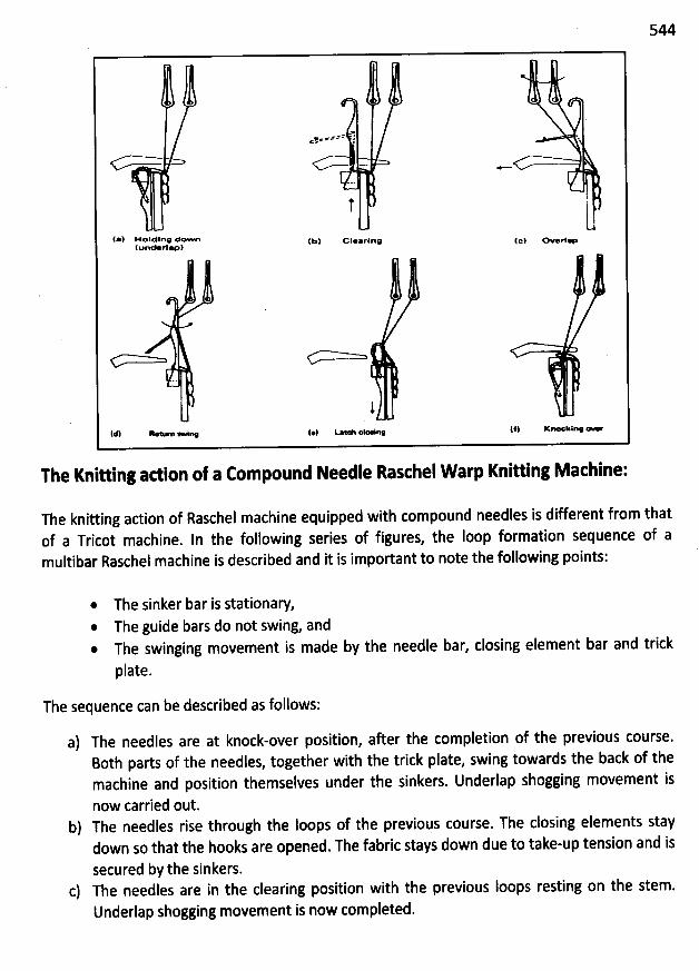
544
r WN- w*== l< x
&
* !
(*) Holding lown (bl clearing (e) overj.(uelm rllp)
1(* R- '- - a. (@1 ' - 01* 0. 1#1 K- kiro <-
The Knihing adion of a Eompound Needle Rasthel W arp Knitting Machine:
The knitting adion of Raschel machine equipped with compound needles is different from thatof a Tricot machine. In the following series of figures, the loop formation sequence of amultibar Raschel machine is described and it is important to note the following points:
The sinker bar is stationary,The guide bars do not swing, and
@ The swinging movement is made by the needle bar, closing element bar and trick
plate.
The sequence can be described as follows:
a) The needles are at knock-over position, after the completion of the previous course.Both parts of the needles, together with the trick plate, swing towards the back of themachine and position themselves under the sinkers. Underlap shogging movement is
now carried out.b) The needles rise through the Ioops of the previous course. The closing elements stay
down so that the hooks are opened. The fabric stays down due to take-up tension and is
secured by the sinkers.c) The needles are in the clearing position with the previous Ioops resting on the stem.
Underlap shogging movement is now completed.
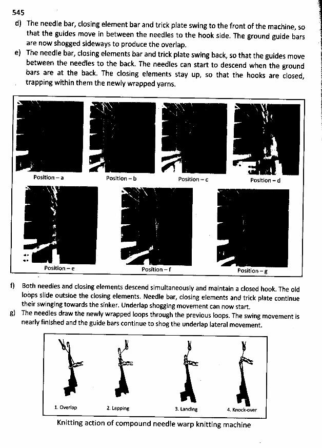
545
d) The needle bar, closing element bar and trick plate swing to the front of the machine, so
that the guides move in between the needles to the hook side. The ground guide bars
are now shogged sideways to produce the overlap.
e) The needle bar, closing elements bar and trick plate swing back, so that the guides move
between the needles to the back. The needles can start to descend when the groundbars are at the back. The closing elements stay up
, so that the hooks are closed,trapping within them the newly wrapped yarns.
Y:. . ww
.
'
' . .
'
r
'
* .
Position - a Position - b Position - c Position - d< A.
v.
* * . .
* @' .
Position - e Position - f Position - g
f) Both needles and closing elements descend simultaneously and maintain a closed hook. The old
loùps slide outsioe the closing elements. Needle bar, closing elements and trick plate continuetheir swinging towards the sinker. Underlap shogging movement can now start
.
g) The needles draw the newly wrapped Ioops through the previous Ioops. The swing movement isnearly finished and the guide bars continue to shog the underlap Iateral movement
.
1. Overlap 2. Lapping 3. Landing 4. Knock-over
Knitting action of compound needle warp knitting machine
546
> 0 FULW THREADED GUIDE BAR STRUC URES OR FABRICS
In order to reproduce a warp knitted fabric, it is necessary 'to obtain the information regardingits production. Many different data items are involved such as:
a) Information describing the knitting machine; number of guide bars, machine gauge,
width of the needle bed and special attachments used.
b) lnformation concerning the type and count of the yarn threaded in each guide bar.
c) Lapping movement of each bar.d) The run-in of each bar.e) Threading information if the guide bars are not fully and uniformly threadèd
.
f) Fabric quality and weight.g) The finishing process.
The above-mentioned information varies widely for different manufacturers and end-uses, so
that there is no pradical Iimit to the number of different fabrics that can be produced onmodern warp knitting machines.
Tbe single-bar strlletures are not suitable for most commercial applications. They are usually
very unstable dimensionally and some of them will even split easily if only slightly damaged.Furthermore, most single-bar strudures exhibit an unbalanced Ioop strudure and Ioop
inclination is very pronounced.
The bulk of the fabrics, manufactured today on tricot machines, are construded by two fullythreaded guide bars, fed from two separate warps and producing a different basic Iappingmovement. The relative movement of the two guide bars in combination with the magnitude ofthe shogging, determines the appearance as well as the properties of the fabrics
.
Tricot Fabrit or FuII Tricot Strudure:
The basic lapping movement of two fully threaded guide bars is the so-called tricot or double
tricot. ln figure the schematic lapping movement is illustrated with both guide bars knitting the
sqme l-and-l Iapping movement in opposite diredions. such a Iapping movement produces a
Iight-weight fabric since the underlaps are very short.
Although the fabric is commercially very attradive, it is only seldom used due to a major
disadvantage; each wale of this fabric is conneded only to the adjacent wales, so that the fabric
s/lits very easily if a yarn is broken or a stitch dropjed.
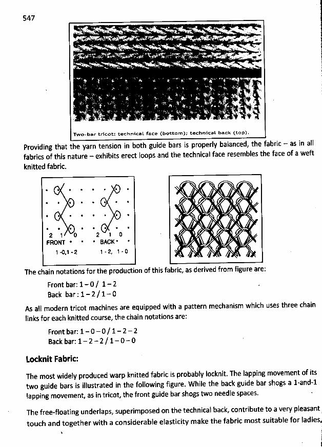
547. ' . 1. . ' . .... . i . '' 'C7 . . 1 .;h.. :. . .. . . 1; . .. . ; .. .-w.. tk. . ; àku , nks . . ' .): . ... . . w!
- . . . . .. . ,u ; . $ z. ::! @y' . . . . #. . ; . ' > ' k) u ' '. . .; . . - ;tj àa y. ,. . . . q . g ' . . '. .. . - .. , .. . . . . . y . .. . . . $4.. . . :. . . .) r:' u ';f '' ', '') j . . . . . . . .s ,) , . . . . . . . . '.q
. . NE
. . ., , ,. .
x :; .7 w . ) . '1' - 1. ' . x ''h''
. . 1 jà .j
. 1' ' ' ' , )k '. '. '. '' '. .k. . i . . . '
. t: ' ; 'k .f kt
' ' . ' . '
. . . . ' , '
'6 ' ?''. j' ; . ' '. . . '. ' . ,, -.1 . .. - . .. ' . . . . . L?.. t ., 17 ' .F .
' . . s. ' ' liil!'' -iy . s ; . . . .
Two-bar trscotz technlcat face (bottom ); technicat back (top).
- ' ' ' both guide bars is properly balanced, the fabric - as in allProvldlng that the yarn tenslon ln' ' hibits ered Ioops and the technical face resembles the face of a weftfabncs of thls nature - ex
knitted fabric.
@ @ @ @' * *
* @ * @ @
@ @ * @ @.
* @ * @ * @ @ *
2 1 0 2 1 0FRONT * * * 9ACK * *
1 m,1 - 2 1 - 2, 1 - 0
The chain notations for the produdionof this fabric, as derived from figure are:
Front bar: 1- 0 / 1- 2Back bar : 1- 2 / 1- 0
As alI modern tricot machines are equipped with a pattern mechanism which uses three chain
links for each knitted course, the chain notations are:
Front bar: 1- 0 - 0 / 1- 2 - 2Back bar; 1- 2 - 2 / 1-0 - 0
Lotknit Fabric:
The most widely produced warp knitted fabric is probably locknit. The lapping movement of itstwo guide bars is illustrated in the following figure. W hile the back guide bar shogs a l-and-llapping movement, as in tricot, the front guide bar shogs two needle spaces.
The free-floating underlaps, superimposed on the technical back, contribute to a very pleasant .è
touch and together with a considerable elasticity make the fabric most suitable for Iadiesk
' jji
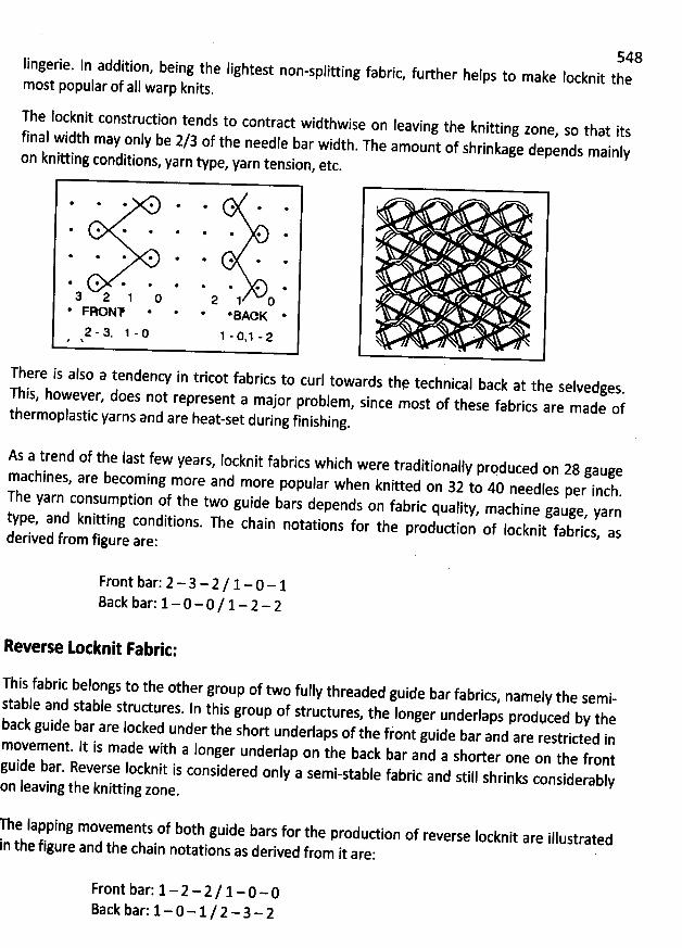
548Iingerie. In addition, being the Iighyest non-splitting fabric
, further helps to make Iocknit themost popular of all warp knits.
The Iocknit construction tends to contrad widthwise on leaving the knitting zone
, so that itsfinal width may only be 2/3 of the needle bar width. The amount of shrinkage depends mainly
on knitting conditions, yarn type, yarn tension, etc.
@ * * * * *
* @ @ * * *
* @. * @ @ * *
* @ * @ @ @ * * *
3 2 1 0 2 1 0* FRONP * * *BAOK *
2 - 3, 1 - 0 1 - 0, 1 - 2 V1There is also a tendency in tricot fabrics to curl towards thq technical back at the selvedges
.This, however, does not represent a major problem, since most of these fabrics are made of
thermoplastic yarns and are heat-set during finishing.
As a trend of the last few years, locknit fabrics which were traditionally prpduced on 28
gaugemachines, are becoming more and more popular when knitted on 32 t
o 40 needles per inch.The yarn consumption of the two guide bars depends on fabric quality, machine gauge
, yarntype, and knitting conditions. The chain notations for the production of Iocknit fabrics, asderived from figure are:
Front bar: 2 - 3 - 2 I 1- 0 - 1Back bar: 1- 0 - 0 / 1- 2 - 2
Reverse Lotknit Fabrit:
This fabric belongs to the other group of two fully threaded guide bar fabrics, namely the semi-stable and stabl
e structures. In this group of structures, the Ionger underlaps prodqced by theb
ack guide bar are locked under the short underlaps of the front guide bar and are restrided in
movement. lt is made with a longer underlap on the back bar and a shorter one on the frontguide bar
. Reverse Iocknit is considered only a semi-stable fabric and still shrinks considerablyon Ieaving the knitting zone
.
he Iapping movements of b0th guide bars for the pfodudion of reverse Iocknit are illustrated
n thq figure and the chain notations as derived from it are:
Front bar: 1- 2 - 2 / 1- 0 - 0Back bar: 1- 0 - 1/ 2 - 3- 2
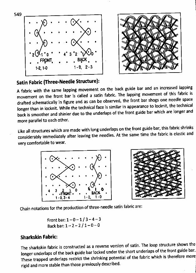
ji!
549
# # @ * 4 . *
@ @ . . @ @
ê @ . 4 :
# : @ # * * 4 : @ *2 1 0 4 2 2 1 0
FRœT BjGK@ : * . @ @ .1-2, 14 1 - '0' , '2 - :
Satin Fabric (Three-Needle Strudure):A fabric with the same lapping movement on the back guide bar and an increased Iappingmovement on tbe front bar is called a satin fabric. The lapping movement of this fabric isdrafted schematically in figure and as can be observed, the front bar shogs one needle spacelonger than in Iocknit. W hile the technical face is similar in appearance to Iocknit, the technicalback is smoother and shinier due to the underlaps of the front guide bar which are longer and
more parallel to each other.
Like alI structures which are made with Iong underlaps on thq front guide bar, this fabric shrinksconsiderably immediately after Ieaving the needles. At the same time the fabric is elastic and
very comfortable to wear.
* * # * * # W *
* # * : # @ : # #
# # # # * : * # *
% * * * * * * * @4
4 7 1 Q t I :. . . F NT . . . j AcK .
1 - 0. 3 - 4 1 - 2. 1 - 0
Chain notations for the produdion of three-needle satin fabric are:
Front bar: 1- 0 - 1/ 3-4 - 3Back bar: 1- 2 - 2 / 1-0- 0
Sharkskin Fabric:The sharkskin fabric is construded as a reverse version of satin. The loop structure shows theIonger underlaps of the back guide bar locked under the short underlaps of the front guide bar-!These trapped underlaps restrict the shrinking potential of tbe fabric which is therefore more?rigid and more stable than those previously described. /
.
'
il
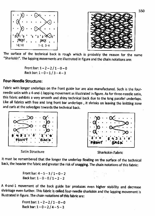
550* : : . : . * .
: # : @ * *
* . : . 4 4 #
4 # : @ : . . 4 . 42 1 û 4 2 2 û
JBO/T BAC/1-2. 1-û 1 . 0, 2 - 4
The surface of the technical back is rough which is probably the reason for the name''Sharkjkin''. The lapping movements are illustrated in figure and the chain notations are:
Front bar: 1- 2 - 2 / 1- 0 - 0Back bar: 1- 0 - 1 / 3 - 4 - 3
Four-Needle Strudure:
Fabric with longer underlaps on the front guide bar are also manufadured. Such is the four-
needle satin with a 4-and-1 Iapping movement as illustrated in figure. As for tbree-needle satin,
this fabric exhibits a very smooth and shiny technical back due to the Iong parallel underlaps.
Like all fabrics with free and Iong front bar underlaps , it shrinks on Ieaving the knitting zone
and çurls at the selvedges towards the technical back.
Satin Structure
' l * : : 3 1 1 :* @ * *' * @.
@ @. @p # *6
ùSharkskin 'F.a ric
lt must be remembered that the longer the underlap floàt. .ing onrthe sorface of the technicaljback the heavier the fabric and greater tbe risk of snagging. he chain hotations of this fabric:
Front bar: 4 - 5- 3/ 1- 0 - 2Back bar: 1- 0 - 0 / 1- 2 - 2
A 4-and-1 movement of the back guide bar produces even higher stability and decreaseshrinkage even further. This fabric ij called:fol-needle sharkskin and the Iapping movement is
- i f bric are:illustrated in figure. The chain notations oft is a
Front bar: 1- 2 - 2 / 1- 0 -0Back bar: 1- 0- 2 /4- 5- 3
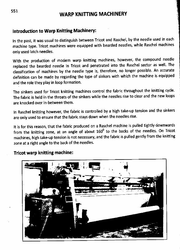
551 W ARP KNIU ING M ACHINERY
Introdud ion to W arp Knitting M achinery:
In the past, it was usual to distinguish between Tricot and Raschel, by the needle used in eachmachine type. Tricot machines were equipped with bearded needles, while Rascbel machines
only used latch needles.
W ith the production of modern warp knitting machines, however, the compound needlereplaced the bearded needle in Tricot and penetrated into the Rascheî sector as well. Theclassification of machines by the needle type is, therefore, no Ionger possible. An accuratedefinition can be made by regarding the type of sinkers with which the machine is equipped
and the role they play in Ioop formation.
The sinkers used for Tricot knitting machines conlrol the fabric throughout the knitting cycle.The fabric is held in the throats of the sinkers while the needles rise to clear and the new loops
are knocked over in-between them.
In Raschel knitting however, the fabric is controlled by a high take-up tension and the sinkersare only used to ensure that the fabric stays down when the needles rise.
lt is for this reason, that the fabric produced on a Rasche! machine is pulled tightly downwards0 h backs of the needles. 0n Tricotfrom the knitting zone
, at an angle of about 160 to t emachines, high take-up tension is not necessary, and the fabric is pulled gently from the knitting
zone at a right angle to the back of the needles.
Tritot warp knitting machine:
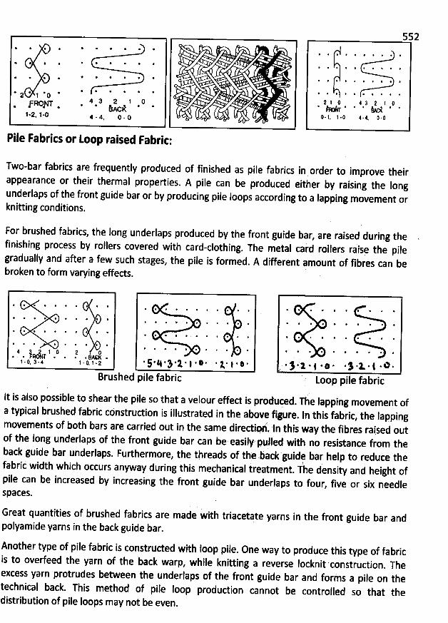
* * * @ * @' * * *
* * @ * * * * '
. @ @ @ * * *' *
* * * ** r * j * g *4 3 2 1'RO/T .. . hAck
1-2. 1-0 4 . 4 () - () '
Pile Fabrics or Loop raised Fabric:
Two-bar fabrics are frequently produced of finished as pile fabrics in ordçr to improve theirappearance or their thermal properties. A pile can be produced either by raising the Iongunderlaps of the front guide bar or by producing pile loops according to a Iapping moveme
nt orknitting conditions.
For brushed fabrics, the long underlaps produced by the front guide bar, are raised during the
finishing process by rollers covered with card-clothing. The metal caid rollers raisç the pile
gradually and after a few such stages, the pile is formed. A different amount of fibres can be
broken to form varying effeds.
@ * * @ : @ ê . : *
'
# : 4 @ *
'
. * * @ *
'
>
*
'
*
'
@ *
'
* @ @ * @ * # @' @ # + * @ * * @ .
* * @ @ * *
'
*
'
@
'
@ @ # # * : *
'
* * e * @
'
@% * * %
'
* * $ * *. * @ * . 4 @
'
. @ *4 j .1 () a n. . . . . . :ACK .1 .(t 3 - 4 1 . (L 1 .2 * 5 . 4 * $ @ 1 * I . : . . te l . : -
Brushed pile fabric
shear the pile so that a velour effed is produced. The Iapping movement of
a typical brushed fabric cdnstrudion is illustrated in the above figure. In this fabric, the Iapping
movements of both bars are carried out in the same diredio:. In this way the fibres raised outof the long underlaps of the front guide bar can be easily' pulled with no resistance from theback guide bar underlaps. Furthermore, the threads of the back'guidr bar help to reduce thefabric width which occurs anyway during this mechanical treatment
. The density and height ofpile can be increased by increasing the front guide bar underlaps to four
, five or six needleSpaces.
lt is also possible to
. . $ ..x . j . @ . . $ .1 . $ . 0 .Loop pile fabric
Great quantities of brushed fabrics are made with triacetate yarns in the front guide bar andpolyamide yarns in the back guide bar.
Another type of pile fabric is construded with Ioop pile. One way to produce this type of fabric
is to ovedeed the yarn of the back warp, while knittiig a reverse locknit construdion. The
excess yarn protrudes between the underlaps of the front guide bar and forms a pile on thetechnical back. This method of pile Ioop production cannot be controlled so that thedistribution of pile Ioops may not be even
.
''
(553 '
..).SPECIAL KNIT FABRIC PRODUW ION)-l
),Knio ed Pile Fabrits 7
l.:
The production of pile knits has steadily grown in variety, importance, and volume. They arconstruded as fleece, high pile, terry, and velour knits. Depending upon the type o 'construdion, they are used fir fur fabrics, rugs, and fashion apparel fabrics.
F
fFleete knit fabric:
, ).
Technically, fleece fabrics are not truly of a pil.e construction. Fleece fabrics are knitted so that, twhen finished, they will have a short to medium nap that has a soft, pleasant hand, will providewarmth and body, as well as moisture wicking and absorption, if desired. '
.1.
i)?'((.... .(.t/J .
' .)q'
t):)
-ï
Face side Back side
The kinds of fibres used are dependent upon the use objective. They are used for such purposesas Iiners, active sportswear, outerwear, and plush toys.
Fleece knits can be made on circular knit machines in any one of three different types ofconstrudion. The machines may be complex, utilizing either spring or Iatch needles employing Fsinker-top, dial, cylinder, or dial/cylinder mechanisms. With this equipment, various effects canbe produced.
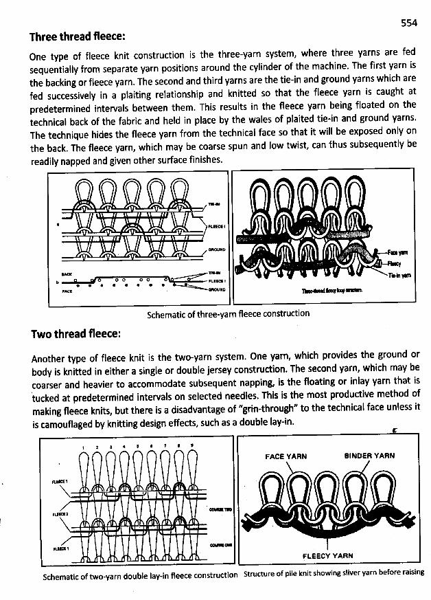
554Three thread fleece:0ne type of fleece knit construction is the three-yarn system, where three yarns are fedsequentially from separate yarn positions around the cylinder of the machine. The first yarn isthe backing or fleece yarn. The second and third yarns are the tie-in and ground yarns which arefed successively in a plaiting relationship and knitted so that the fleece yarn is caught atpredetermined intervals between them. This results in the fleece yarn being floated on thetechnical back of tbe fabric and held in place by the wales of plaited tie-in and ground yarns.The technique hides the fleece yarn from the technical face so that it will be exposed only onthe back. The fleece yarn, which may be coarse spun and Iow twist, can thus subsequently be
readily napped and given other sudace finishes.
T1'o
'kc K I. . .
. .;., ss.
(œ* * .,
J..' . jjr.:( (k .
> r
n-o o o o o
V**I >b Fkzeœ t
* * @ @ * @ @ @FMT e e - . .- . a . .
Schematic of three-yarn fleececonstruction
Two thread fleece:
Another type of fleece knit is the two-yarn system. One yarn, which provides the ground orbody is knitted in either a single or double jersey construdion. The second yarn, which may becoarser and heavier to accommodate subsequent napping, is the floating or inlay yarn that istucked at predetermined intervals on selected needles. This is the most produdive method ofmaking fleece knits, but there is a disadvantage of ''grin-through'' to the technical face unless itis camouflaged by knitting design effeds, such as a double lay-in.
f # : # ' : 7 ' :
FACE YARN BINDER YARN
Ftm s .
X , ,z' - .
F::1tE2
X&eœ1 .
FLEECY YARN
Schematic of two-yarn double lay-in fleece construdion Structure of pile knit showing sliver yarn before raising
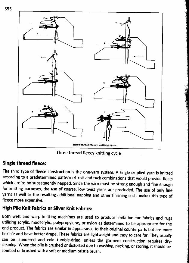
555
F<<
G N1
l . .
T---
1,
2
a e
1n ree-thrwad fleecy knitting cyçle.
Three thread fleecy knitting cycle
Single thread fleece:
The third type of fleece construction is the one-yarn system. A single or plied yarn is knitted
according to a predetermined pattern of knit and tuck combinations that would provide floatswhich are to be subsequently napped. Since the yarn must be strong enough and fine enoughfor knitting purposes, the use of coarse, Iow twist yarns are precluded. The use of only fineyarns as well as the resulting additional napping and other finishing costs makes this type offleece more expensive..
High Pile Knit rabrics or Sliver Knit Fabrits:
Both weft and warp knitting machines are used to produce imitation fur fabrics and rugsutilizing acrylic, modacrylic, polypropylene, or nylon as determined to be appropriate for theend produd. The fabrics are similar in appearance to their original counterparts but are moreflexible and have better drape. These fabrics are Iightweight and easy to care for
. They usuallycan be Iaundered and cold tumble-dried, unless the garment construction requires dry-cleaning. W hen the pile is crushed or distorted due to washing
, packing, or storing, it should becombed or brushed with a soft or medium bristle brush
.
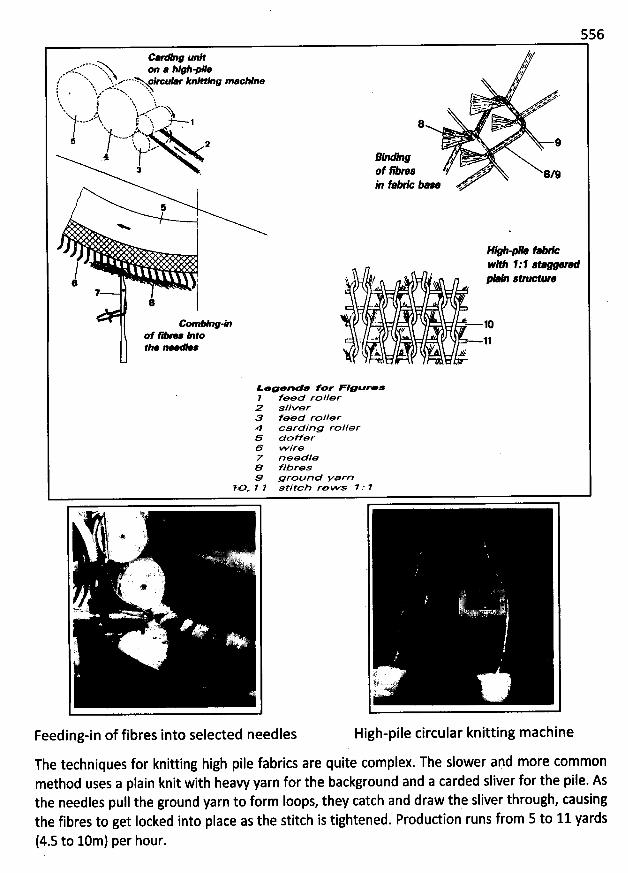
556
J unR zw,v. .. . . ;
.- N...m . ** O ae >. Y%e x. '> .e x q ...... . % xos;t x s. ,- xx. 4)1 lF $1 #'' #11: /
j % . -aw-w N% w* Nx wxl w .. .& l x : ,#- .ehs j q ..-- .'zz-=., ,.*%x. ..:.G.
1Z.'<-J- -Y% --.='- ' '#.. ; I .. - (, .--.....h é G
'
.
*N -- x z
1:1 t : .' .. 2 '.- 9N t.- xN* & g
3 . of #pas we/ :/9l*n fa * - - -
I5
N :
H*bw M* 1 - 1 s
. ? .* ' / AM e 'M
8''' .
'
** - 1Qf **' ' e hto C@ à
-a.- - . 11A .tk:
ieveevea for 'rlouree# feeG ro//erP .e//<orB Feea rol/er4 carcfjno roller& Soffer& w ire7 noec//e& Hbres& urounG Farn
HX T 1 stîtch row'.s ' J T
-9.79. . .
' .@; Gl
i .. .. .... qrë r..wF't .*/>. .; à
. .h
#
I'rr.w .J ' 2
2 .
k? #' 't. x
.9
Feeding-in of fibres into selected needles High-pile circular knitting m achine
The techniques for knitting high pile fabrics are quite complex. The slower and more commonmethod uses a plain knit with heavy yarn for the background and a carded sliver for the pile. Asthe needles pull the ground yarn to form Ioops, they catch and draw the sliver through, causingthe fibres to get Iocked into place as the stitch is tightened. Produdion runs from 5 to 11 yards
(4.5 to 10m) per hour.
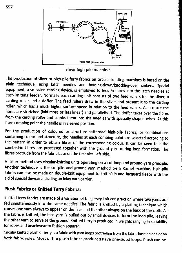
55751* t.*
(wfti- z- wj. .j. jze ?
l G-M l y.
//'
/I
10-&iver âig: plle' maclux
Sliver high pile machine
The production of sliver or high-pile furry fabrics on circular knitting machines is based on theplain technique, using Iatch needles and holding-down/knocking-over sinkers
. Specialequipment, a so-called carding device, is employed to feed-in fibres into the Iatch needles ateach knitting feeder. Normally each carding unit consists of two feed rollers for the sliver
, acarding rollef and a doffer. The feed rollers draw in the sliver and present it to the cardingroller, which has a much higher surface speed in relation to the feed rollers
. As a result ihefibres are stretched (Iaid more or Iess Iinear) and parallelised. The doffer takes over the fibresfrom the carding roller and combs them into the needles with specially shaped wires
. At thisfibre combing point the needle is in cleared position
.
For the production of coloured or strudure-patterned high-pile fabrics, or combinations
containing colour and structure, the needles at each combing point are selected according tothe pattern in order to obtain fibres of the corresponding colour
. lt can be seen that thecombed-in fibres are procqssed together with the ground yarn during Ioop formation
. Thefibres protrude from the fabric base on the technical Ieft side
.
A fastqr method uses circular-knitting units operating on a cut loop and ground-yarn principle.Another technique is the cut-pile and ground-yarn method on a Rachel machine
. High-pilefabrics can also be made on double-knit equipment to knit plain and Jacquard fleece with theaid of special devices including an inlay yarn carrier.
Plush Fabrics or Kni/ed Terl Fabrics:
Knitted terry fabrics are made of a variation of the jersey knit construdion where two yarns arefed simultai eously into the same needles. The fabric is knitted by a plaiting technique whichcauses one yarn always to appear on the face and the other alwgys on the back of the c10th
. Asthe fabric is knitted, the face yarn is pulled out by small devices to form the Ioop pile
, Ieavingthe other yarn to serve as the ground. Knitted terfy is produced in weights ranging in suitabilityfor robes and beachwear to fashion apparel.Circular knitted plush or terry is a fabric with yarn loops protruding from thq fabric base on one or onboth fabric sides. Most of the plush fabrics produced have one-sided Ioops. Plush can be
ss8
produced on plain or rib circular knitting machines. The most common method of produdionuses the plain circular knitting technique with combined holding-down / knocking-over sinkersfor making one sided plush fabrics. The Ioops are actually enlarged sinker loops and theyprotrude from the fabric base on the technical Ieft side.
Face side Back side
The most important demands are a firm fixing of the plush Ioops in the fabric base and a veryuniform Ioop length. The more uniform the Ioop length is, the Iess material is Iost when theIoops are cut to produce cut-pile fabrics. Therefore the base fabric should not be too looselystitched. On the technical right side a precise plating of the plush yarn through the ground yarnis extremely important during the cutting process for cut-pile fabrics. In usage this pre-requisiteis Iargely responsible for the firmness of the pile.
Single-sided plated plush or terry is a popular leisure and sports wear structure found in bothfabric and sock form having the form fitting elasticity of single jersey. The elongated jlushsinker Ioops show as a pile between the wales on the technical back as a result of having beenformed over a different surface to that of the normal Iength ground sinker Ioops with whichthey are plated.
Terry knits tend to be more flexible, softer, and more absorbent than woven terry c10th.However, they are not as sturdy or durable. They do not hold their shape as well and they tendto snag, causing the loop yarn to pull and trail. Should such a pull occur, it should not be cutbecause it would cause a run. Rather, it should be drawn through to the back of the material.
Velour Knit Fabric or Henkel plush Fabrit:Knitted velour fabrics are constructed in the same manner as knitted terry. After the material isknitted, the loop pile is sheared at a uniform height and then brushed. So velour is achievedduring finishing by cropping or shearing the Ioops in both directions, to leave the individualfibres exposed as a soft velvety surface whilst the ground Ioops remain intad. lt requires a finegauge strudure and involves a considerable Ioss of cropped yarn. The bearded needle sinkerwheel machine has long been renowned for this type of fabric construdion. This produces asoft suedelike surface that is somewhat Iike that of velvet. However, knitted velour is softerand has better drapability. lt is used for such fashion apparel as men's shirts and women'sdresses.
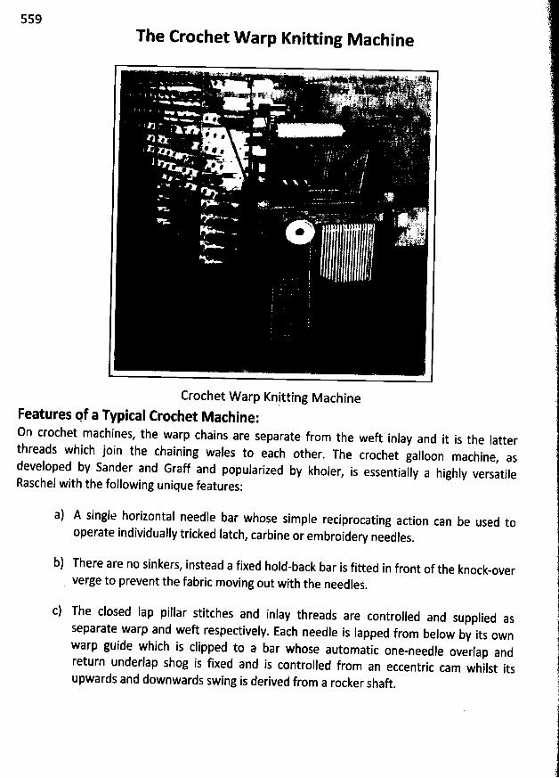
559The Crochet W arp Knitting M achine
Crochet W arp Knitting M acbineFeatures pf a Typical Crochet M achine:0n crochet machines, the warp ch#ins are separate from the weft inlay and it is the Iatterthreads which join the chaining wales to each other. The crochet galloon machine
, asdeveloped by Sander and Graff and popularized by kholer, is essentially a highly versatile
Raschel with the following unique features:
a) A single horizontal needle bar whose simple reciprocating action can be used tooperate individually tricked Iatch, carbine or embroidery needles
.
b) There are no sinkers, instead a fixed hold-back bar is fitted in front of the knock-oververge to prevent the fabric moving out with the needles
.
c) The closed Iap pillar stitches and inlay threads are controlled and supplied asseparate warp and weft respedively. Each needle is Iapped from below by its ownwarp guide which is clipped to a bar whose automatic one-needle overlap andreturn underlap shog is fixed and is controlled from an eccentric cam whilst itsupwards and downwards swing is derived from a rocker shaft
.
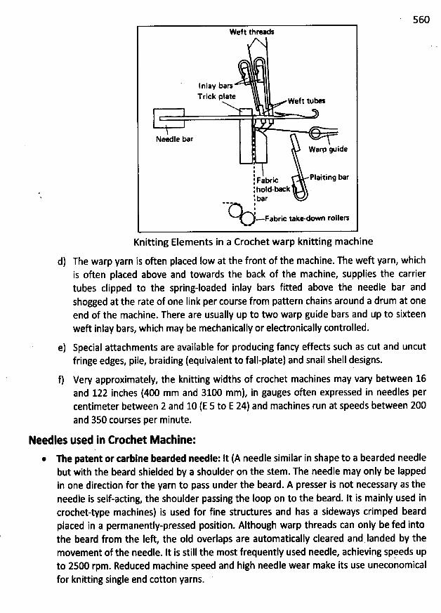
560Weft thren
lnlay barsTrick plate Wef' tu*
x.- .,je o rWarp w ide
:lgabrit Plaixinq bar:hold-bxk .:bar
1- Fabric take-- rolleo
Knitting Elementsin a Crochet warp knitting machine
d) The warp yarn is often placed Iow at the front of the machine. The weft yarn, whichis often placed above and towards the back of the machine, supplies the carriertubes clipped to the spring-loaded inlay bars fitted above the needle bar andshogged at the rate of one Iink per course from pattern chains around a drum at oneend of the machine. There are usually up to two warp guide bars and tfp to sixteenweft inlay bars, which may be mechanically or eledronically controlled.
e) Special attachments are available for producing fancy effeds such as cut and uncutfringe edges, pile, braiding (equivalent to fall-plate) and snail shell designs.
f) Very approximately, the knitting widths of crochet machines may vary between 16and 122 inches (400 mm and 3100 mm), in gauges often expressed in needles percentimeter between 2 and 10 (E 5 to E 24) and machines run at speeds between 200and 350 courses per minute.
Needles used in Crochet M athine:
* The patent or tarbine bearded needle: It (A needle similar in shape to a bearded needlebut with the beard shielded by a shoulder on the stem. The needle may only be Iappedin one direction for the yarn to pass under the beard. A presser is not necessary as theneedle is self-acting, the shoulder passing the loop on to the beard. lt is mainly used in
crochet-type machines) is used for fine strudures and has a sideways crimped beardplaced in a permanently-pressed position. Although warp threads can only be fed intothe beard from the Ieft the old overlaps are automatically cleared and Ianded by themovement of the needle. lt is still the most frequently used needle, achieving spqeds upto 2500 rpm. Reduced machine speed and high niedle wear make its use uneconomicalfor knitting single end cotton yarns.
561
Side Vi- Front View
Carbine needle
Embroidee or Lace needles: They are carbine needles with pointed heads that canpenetrate pre-woven structures to produce embroidery effects. The needles can bearranged for coarser gauges or for fancy set-outs, when the floating inlay threads maybe cut to produce separated fringed edgings. '
* The tompound needle: It patented by Miiller produces less stress on the yarn duringIoop formation so a wider range of yarns can be used, and compound needles Iast up tosix times Ionger than bearded needles.
* Latch needles: It operate at uneconomic speeds and have a short Iife due to Iatchbreakage.
The knitting adion of The Crothet M achine:The knitting action or stitch formation to produce one éourse of Ioops on a crochet machineequipped with Iatch.needles consists of the following stages:
1. The weft inlay2. Clearing the warp overlap3 The warp overlap wrap4. W arp knock.over and underlap
The essence of these stages consists in the following operations:
1. The weA inlay:Whilst the needle is withdrawn into its trick, during knock-6ver of the previous of warpoverlaps, the weft inlay tube is lowered so that, as it traverses in an underlap shog, theweft is Iaid below the Ievel of the needle and on top of the warp thread which extendsfrom its head to the warp guide.
2. Clearing the warp overlap:The weft tube rises slightly on completion of its traverse movement to allow the needleto move out of its trick to clear its oId warp overlap.
3. The warp overlap wrap:The warp guide rises between the needles and automatically overlaps from the Ieft.Iowering itself again on the right side of its needle.
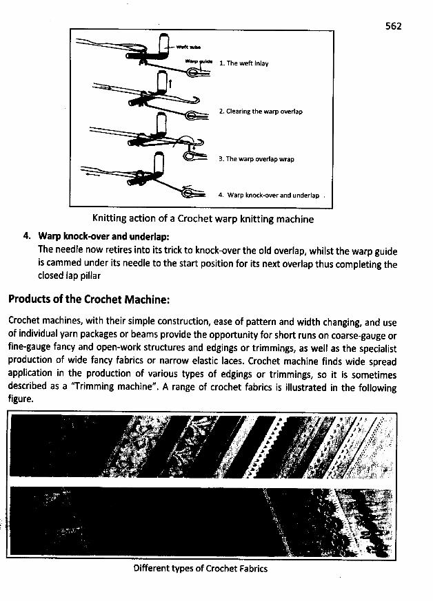
- e 1. The weft inlay
' 2. Clearing the warp overlap
4
3. The warp overlap wrap
<
4. Warp knock-over and underlap
Knitting action of a Crochet warp knitting m achine
562
4. Warp knotk-over and underlap:The needle now retires into its trick to knock-over the old overlap, whilst the warp guideis cammed under its needle to the start position for its next overlap thus completing theclosed Iap pillar
Produds of the Crothet M achine:
Crochet machines, with their simple construction, ease of pattern and width changing, and use
of individual yarn packages or beams provide the opportunity for short runs on coarse-gauge orfine-gauge fancy and open-work strudures and edgings or trimmings, as well as the specialistproduction of wide fancy fabrics or narrow elastic Iaces. Crochet machine finds wide spreadapplication in the production of various types of edgings or trimmings
, so it is sometimesdescribed as a ''Trimming machine''. A range of crochet fabrics is illustrated in the followingfigure.
Different types of Crochet Fabrics
563
The Straight Bar Fram e
The main features of a Straight bar frame:
The Straight bar frame is a special type of weft knitting machine. It has the following unique
features:
* Straight bar frames is a specific type of machine having a vertical bar of bearded needleswhose movement is controlled by circular engineering cams attached to a revolving
cam-shaft in the base of the machine.* The Iength of the machine is divided into a number of knitting heads (sections ordivisions) and each head is capable of knitting a separate but identically-dimensione'dfashion-shaped garment panel.
* The needles press their beards against a fixed pressing edge; Ioop formation prior tointermeshing is achieved by individually horizontally-moving Ioop-forming sinkers, andknock-over occurs when the needles descend below the knock-over bits.
@ At either edge of each knitting head, a group of rackably-controlled points transfer loopsto fashion shape the garment panel at the selvedges by widening or narrowing theknitting width. On completion of the garment panel, it is pressed-off the needles.
Knitting motions of the Rraight bar frame:
The three directions of motion required for the knitting action are provided from two separatesources. The rotary motion of the cam-shaft produces the vertical and horizontal movement ofthe fashioning points and the needle bar. The sideways reciprocating movement for the yarncarriers and for introducing the sinkers in seriatim sequence via the slurcock is obtained from acoulier or draw cam attached to a shaft set at right angles to the main cam-shaft at the back ofthe machine, which oscillates a draw Iever. A varipble draw ensures that the stroke of the drawis related to the varying knitting width thus more courses per minute are knitted on narrowerwidths. Operating speeds of a hundred courses per minute can be achieved.
The knitting head of the Straight bar frame:
The following figure shows the cross-section of the knitting head containing the different
elements:
A. Bearded needle, having a cranked end for Iocation in the tricked and drilled needle bar.B. Sinker, only one between every other needle space, with a reinforced back anà at the
front, a catch to sink the yarn around. the needles, and a 'neb' to separate the oId andnew loops until knock-over.
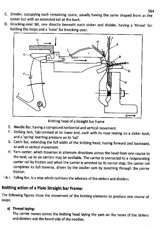
C. Divider, occupying each remaining space,
sinker but with an extended tail at the back.
D. Knocking-over Bit, one directly beneath each sinker and divider, having a 'throat' for
holding
1 2NwG l
H le l A
J //Ic O
BOww 0 'w
41 :
6 DF
$6
E
T - - -
S-
the Ioops and a 'nose' for knocking-over.
Knitting head of a Straight bar frame
564usually having the same shaped front as the
E. Needle Bar, having a compound horizontal and vertical movement.
F. Striking Jack, fulcrummed at its Iower end, each with its nose resting on a sinker back,
and a 'spring' exerting pressure on its 'tail',G. Catch Bar, extending the full width of the knitting head
, having forward and backward,as well as vertical movement.
H. Yarn carrier, which traverses in alternate directions across the head from one course tothe next, up to six carriers may be available. The carrier is connected to a reciprocatingcarrier rail by friction and when the carrier is arrested by its carrier stop
, the carrier railcompletes its full traverse, driven by the coulier cam by punching through the carrierfriction.
l & J. Falling Bar, is a stop which cushions the advance of the sinkers and dividers.
Knihing adion of a Plain R raight bar Frame:
The following figures show the movement of the knitting elements to produce one course ofloops:
a) Thread Iaying:The carrier moves across the knitting head Iaying the yarn on the noses of the sinkersand dividers and the beard side of the needles.
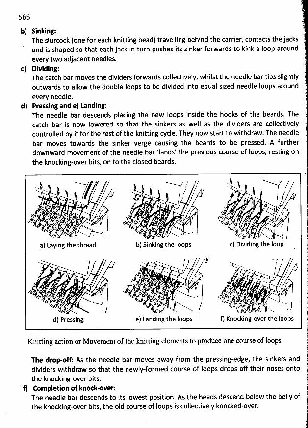
565
b) Sinking:The slurcock (one for each knitting head) travelling behind the carrier, contacts the jacksand is shaped so that each jack in turn pushes its sinker forwards to kink a Ioop aroundevery two adjacent needles.
c) Dividing:The catchbar moves the dividers forwards collectively, whilst the needle bar tips slightlyoutwards to allow the double loops to be divided into equal sized needle Ioops aroundevery needle.
d) Pressing and e) Landing:The needle bar descendscatch bar is now
placing the new loops inside the hooks of the beards. TheIowered so that the sinkers as well as the dividers are collectively
controlled by it for the rest of the knitting cycle. They now start to withdraw. The needlebar moves towards the sinker verge causing the beards to be pressed. A furtherdownward movement of the needle bar 'Iands' the previous course of Ioops, resting onthe knocking-over bits, on to the closed beards.
h
j I. . :
/
k.' .
. /.
a) Laying the thread b) Sinking the loops c) Dividing the Ioop
/ ' -Nw
- / Nxxwww./ ''x . '..
s , r
utL)' h
. . ' '
l. k N
d) Pressing e) Landing the Ioops f) Knocking-over the Ioops
Knitting action or M ovement of the knitting elem ents to produceone course of loops
The drop-off: Asdividers withdraw so that thethe knocking-over bits.
f) Completion of knotk-over:The needle bar descends to its Iowest position. As the heads descend below the belly ofthe knocking-over bits, the oId course of loops is collectively knocked-over.
the needle bar moves away from the pressing-edge, the sinkers andnewly-formed course of Ioops drops off their noses onto
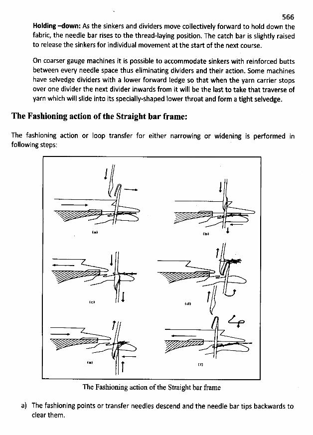
566Holding e own: As the sinkers and dividers move collectively forward to hold down thefabric, the needle bar rises to the thread-laying position. The catch bar is slightly raisedto release the sinkers for individual movement at the start of the next course.
On coarser gauge machines it is possible to accommodate sinkers with reinforced buttsbetween every needle space thus eliminating dividers and their adion. Some machineshave selvedge dividers with a Iower forward ledge so that when the yarn carrier stopsover one divider the next divider inwards from it will be the last to take that traverse ofyarn which will slide into its specially-shaped lower throat and fbrm a tight selvedge.
The Fashioning action of the Straight bar fram e:
The fashioning action or Ioop transfer forfollowing steps:
either narrowing or widening is pedormed in
11 - 1(., 4., 1
1
.-, 1 .-, î( --7*
1The Fashioning action of the Straight bar frame
a) The fashioning points or transfer needles descend and the needle bar tips backwards toclear them.
567
b) The needle bar moves towards the points causing the beards of needles engaged withpoints to be pressed and boxed or Iocated in the grooves of the points.
c) The sinkers and dividers, which are collectively controlled by the catch bar, retire, andthe needles and points descend together below the knocking-over bits so that the Ioopsare cast-off onto the points.
d) The needles and points now rise and move clear of each other so that the points canmak: the sideways 'fashion rack' at the selvedge either by one needle for widening orby one, two or four needles for narrowing.
e) The needles and points now descend and the needles box with the points again so theyreceive the transferred Ioops. As the needles and points descend below the sinkers, thesinkers and dividers move forwards to hold down the Ioops.
f) Once the needles have slid up into the grooves of the points to receive the Ioops, thepoints rise to their high inoperative position. The needle bar rises causing thetransferred Ioops to slip down onto the stems and the cam shaft is shogged back to theIeft again so that knitting can restart.
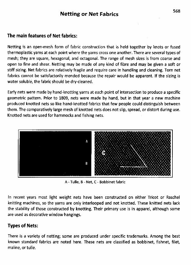
568Netting or Net Fabrics
The main features of Net fabrics:
Netting is an open-mesh form of fabric construction that is held together by knots or fusedthermoplastic yarns at each point where the yarns cross one another. There are several types ofmesh; they are square, hexagonal, and octagonal. The range of mesh sizes is from coarse andopen to fine and shear. Netting may be made of any kind of fibre and may be given a soft orstiff sizing. Net fabrics are relatively fragile and require care in handling and cleaning. Torn netfabrics cannot be satisfactorily mended because the repair would be apparent. If the sizing iswater soluble, the fabric should be dry-cleaned.
Early nets were made by hand-knotting yarns at each point of intersection to produce a specificgeometric pattern. Prior to 1809, nets were made by hand, but in that year a new machineproduced knotted nets so Iike hand-knotted fabrics that few people could distinguish betweenthem. The comparatively large mesh of knotted nets does not slip, spread, or distort during use.Knotted nets are used for hammocks and fishing nets.
A - Tulle, B - Net, C - Bobbinet fabric
In recent years most Iight weight nets have been constructed on either Tricot or Raschelknitting machines, so the yarns are only interlooped and not knotted. These knitted nets Iackthe stability of those constructed by knotting. Their primary use is in apparel, although someare used as decorative window hangings.
Types of Nets:
There is a variety of netting; some are produced under specific trademarks. Among the bestknown standard fabrics are noted here. These nets are classified as bobbinet, fishnet, filet,maline, or tulle.
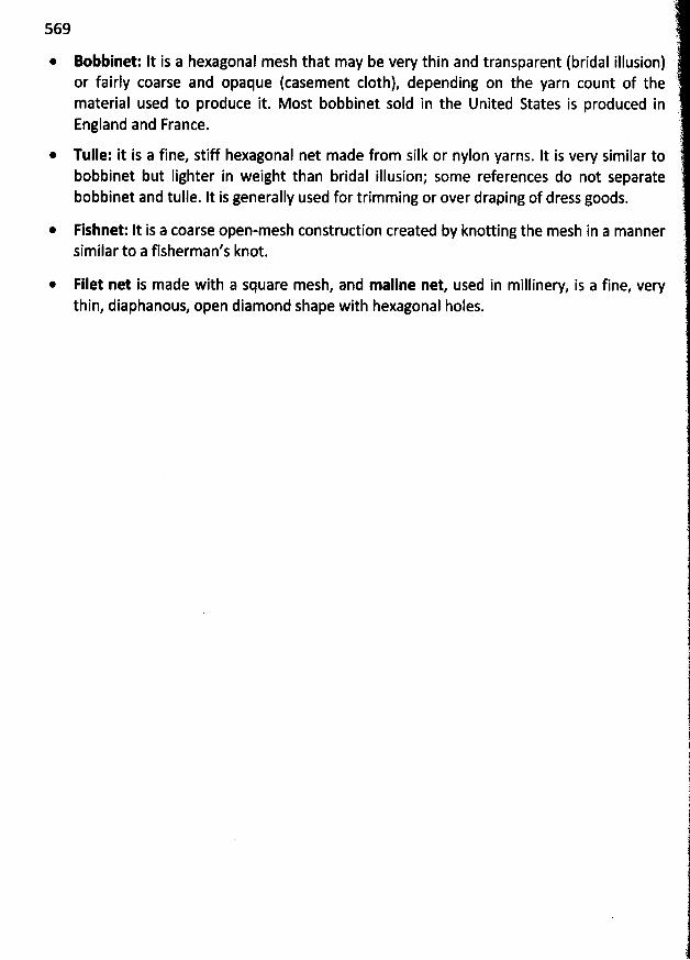
569
* Bobbinet: It is a hexagonal mesh that may be very thin and transparent (bridal illusion)or fairly coarse and opaque (casement cloth), depending on the yarn count of thematerial used to produce it. Most bobbinet sold in the United States is produced inEngland and France.
* Tulle: it is a fine, stiff hexagonal net made from silk or nylon yarns. It is very similar tobobbinet but Iighter in weight than bridal illusion; some references do not separatebobbinet and tulle. It is generally used for trimming or over draping of dress goods.
* Fishnet: It is a coarse open-mesh construdion created by knotting the mesh in a mannersimilar to a fisherman's knot.
@ Filet net is made with a square mesh, and maline net, used in millinery, is a fine, verythin, diaphanous, open diamond shape with hexagonal holes.

570Lace Fabrics
The main features of Lace fabrit:
Lace is an open work fabric consisting of a network of yarns formed into intricate designs. Lacemay be hand or machine made, and intricate patterns can be produced by either technique.Both narrow and wide Iace fabrics are available. The edges of the fabric may be straight orcurved.
It is an important trimming, for it is used for table cloths, curtains, handkerchiefs, dresses, andunderwear. Lace consists of two elements:
* The pattern, flower, or group, which forms the closer-worked and more solid portion,and
* The ground or filling, which serves to hold the pattern together.
Parts of tate Construttion:
ln identifying various kinds of Iace, references have. been made to their designs. These patternsare constructed of different parts, each having a particular designation.
* Bride, or Reseau: It is the fine yarn that forms the mesh which provides the sheerground (background) between the prominent parts of the pattern.
@ Cordonnet: It is the heavy yarn that outlines the pattern.* Picot: lt is a decorative Ioop used both in the pattern and on the edge of the lace.* Toile: lt represents the predominant parts of the pattern made by braiding, knotting,
Iooping, or twisting the yarn.
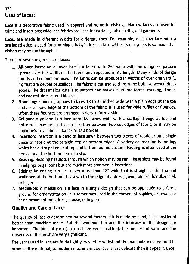
571
Uses of Lates:
Lace is a decorative fabric used in apparel and home furnishings. Narrow Iaces are used fortrims and insertions; wide Iace fabrics are used for curtains, table cloths, and garments.
Laces are made in different widths for different uses. For example, a narrow lace with ascalloped edge is used for trimming a baby's dress; a Iace with slits or eyelets is so made thatribbon may be run through it.
There are seven major uses of Iaces:1. All-over laces: An all-over Iace is a fabric upto 36'' wide with the design or pattern
spread over the width of the fabric and repeated in its Iength. Many kinds of designmotifs and colours are used. The fabric can be produced in widths of over one yard (1m) that are devoid of scallops. The fabric is cut and sold from the bolt like woven dressgoods. The dressmaker cuts it to pattern and makes it up into formal evening, dinner,and cocktail dresses and blouses.
2. Flouncing: Flouncing applies to Iaces 18 to 36 inches wide with a plain edge at the topand a scalloped edge at the bottom of the fabric. It is used for wide ruffles or flounces.Often these flounces are arranged in tiers to form a skirt.Galloon: A galloon is a Iace upto 18 inches wide with a scalloped edge at top andbottom. It may be used as an insertion between two cut edges of fabric, or it may beapplique'd to a fabric in bands or as a border.
4. Insertion: Insertion is a band of Iace sewn between two pieces of fabric or on a singlepiece of fabric at the straight top or bottom edges. A variety of insertion is footing,which has a straight edge at top and bottom but no pattern. Footing is often used at thebodice or at the bottom hem of a slip.
5. Beading: Beading has slots through which ribbon may be run. These slots may be foundin edgings or galloons but are much more common in insertions.
6. Edging: An edging is a Iace never more than 18'' wide that is straight at the top andscalloped at the bottom. It is sewn to the edge of a dress, gown, blouse, handkerchief,or Iingerie.Medallion: A medallion is a Iace in a single design that can be appliquéd to a fabricground for ornamentation. It is sometimes used in the corners of napkins, or towels oras an ornament fpr a dress, blouse, or lingerie.
Quality and Care of Lace:
The quality of Iace is determined by several factors. If it is made by hand, it is consideredbetter than machine made. But the workmanship and the intricacy of the design areimportant. The kind of yarn (such as Iinen versus cotton), the fineness of yarn, and thecloseness of the mesh are very significant.
The yarns used in Iace are fairly tightly twisted to withstand the manipulations required to
produce the material, so modern machine-made Iace is Iess delicate than it appears. Lace
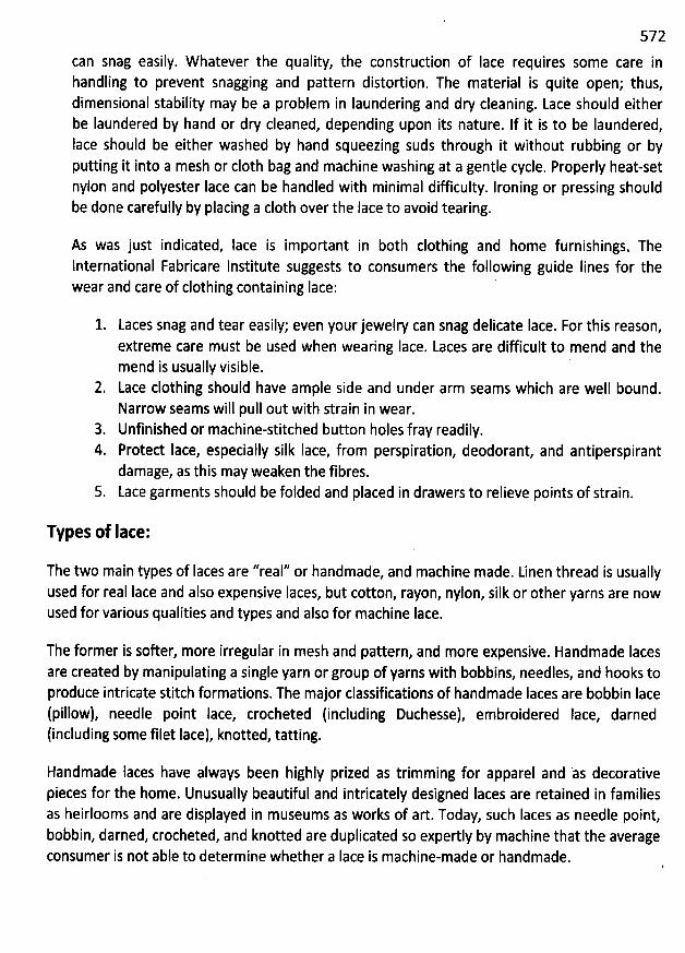
572
can snag easily. W hatever the quality, the construction of Iace requires some care inhandling to prevent snagging and pattern distortion. The material is quite open; thus,dimensional stability may be a problem in Iaundering and dry cleaning. Lace should eitherbe Iaundered by hand or dry cleaned, depending upon its nature. If it is to be Iaundered,Iace should be either washed by hand squeezing suds through it without rubbing or byputting it into a mesh or c10th bag and machine washing at a gentle cycle. Properly heat-setnylon and polyester Iace can be handled with minimal difficulty. Ironing or pressing shouldbe done carefully by placing a c10th over the Iace to avoid tearing.
As was just indicated, Iace is important in both clothing and home furnishingsq Thelnternational Fabricare Institute suggests to consumers the following guide lines for thewear and care of clothing containing Iace:
Laces snag and tear easily; even your jewesry can snag delicate lace. For this reason,extreme care must be used when wearing Iace. Laces are difficult to mend and themend is usually visible.Lace clothing should have ample side and under arm seams which are well bound.Narrow seams will pull out with strain in wear.
3. Unfinished or machine-stitched button holes fray readily.4. Proted Iace, especially silk Iace, from perspiration, deodorant, and antiperspirant
damage, as this may weaken the fibres.5. Lace garments should be folded and placed in drawers to relieve points of strain.
Types of Iace:
The two main types of Iaces are ''real'' or handmade, and machine made. Linen thread is usuallyused for real Iace and also expensive Iaces, but cotton, rayon, nylon, silk or other yarns are nowused for various qualities and types and also for machine Iace.
The former is softer, more irregular in mesh and pattern, and more expensive. Handmade lacesare created by manipulating a single yarn or group of yarns with bobbins, needles, and hooks toproduce intricate stitch formations. The major classifications of handmade Iaces are bobbin Iace(pillow), needle point Iace, crocheted (including Duchesse), embroidered Iace, darned(including some filet Iace), knotted, tatting.
Handmade Iaces have always been highly prized as trimming for apparel and 'as decorativepieces for the home. Unusually beautiful and intricately designed Iaces are retained in familiesas heirlooms and are displayed in museums as works of art. Today, such Iaces as needle point,bobbin, darned, crocheted, and knotted are duplicated so expertly by machine that the averageconsumer is not able to determine whether a Iace is machine-made or handmade.
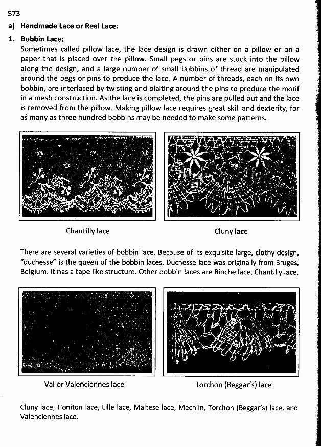
573
a) Handmade Lace or Real Lace:1. Bobbin Lace:
Sometimes called pillow Iace, the Iace design is drawn either on a pillow or on apaper that is placed over the pillow. Small pegs or pins are stuck into the pillowalong the design, and a Iarge num ber of sm all bobbins of thread are manipulatedaround the pegs or pins to produce the Iace. A num ber of threads, each on its ownbobbin, are interlaced by twisting and plaiting around the pins to produce the motifin a mesh construction. As the Iace is completed, the pins are pulled out and the Iaceis removed from the pillow. M aking pillow Iace requires great skill and dexterity, foraj many as three hundred bobbins may be needed to m ake som e patterns.
@
* . .' ,. . . . : .* . '* 4 4 * *.' N. .q 4 * . : #.>J .. ,# . ., t .# . 4 . # .. ' *
'
. . 4 . s .é
'
*' 6. . #. * 'V'A $ ' SZV'q .A.. .. . x *
'
1 . . I .-t N.. . . t s .w.. .. .-W . ... Q %* ,a ww- h . ...) . l. N e . >. r. * g e' s w yc *. . :, , i w g <
Chantilly lace Cluny Iace
There are several varieties of bobbin lace. Because of its exquisite Iarge, clothy design,''duchesse'' is the queen of the bobbin laces. Duchesse Iace was originally from Bruges,Belgium. It has a tape Iike structure. Other bobbin Iaces are Binche Iace, Chantilly lace,
VaI or Valenciennes Iace
#
.', .* + . # ... #6 4:
.* . .
zjqy .w. w . .A . . . j
.. *. .. .
Torchon (Beggar's) Iace
Cluny Iace, Honiton Iace, Lille Iace, Maltese Iace, Mechlin, Torchon (Beggar's) Iace, andValenciennes Iace.
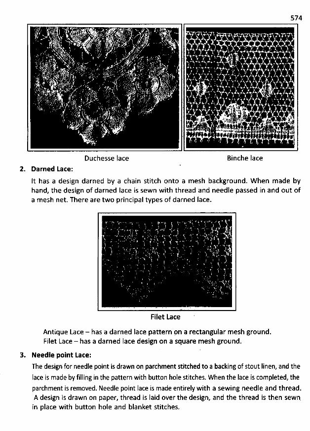
574
Duchesse lace Binche Iace
2. Darned Lace:
It has a design darned by a chain stitch onto a mesh background. W hen made byhand, the design of darned Iace is sewn with thread and needle passed in and out ofa m esh net. There are two principal types of darned Iace.
Filet Lace
Antique Lace - has a darned Iace pattern pn a rectangular mesh ground.Filet Lace - has a darned Iace design on a square mesh ground.
3. Needle point Lace:
The design for needle point is drawn on parchment stitched to a backing of stout Iinen, and the
lace is made by filling in the pattern with button hole stitches. When the Iace is completed, theparchment is removed. Needle point Iace is made entirely with a sewing needle and thread.A design is drawn on paper, thread is Iaid over the design, and the thread is then sewn.in place with button hole and blanket stitches.
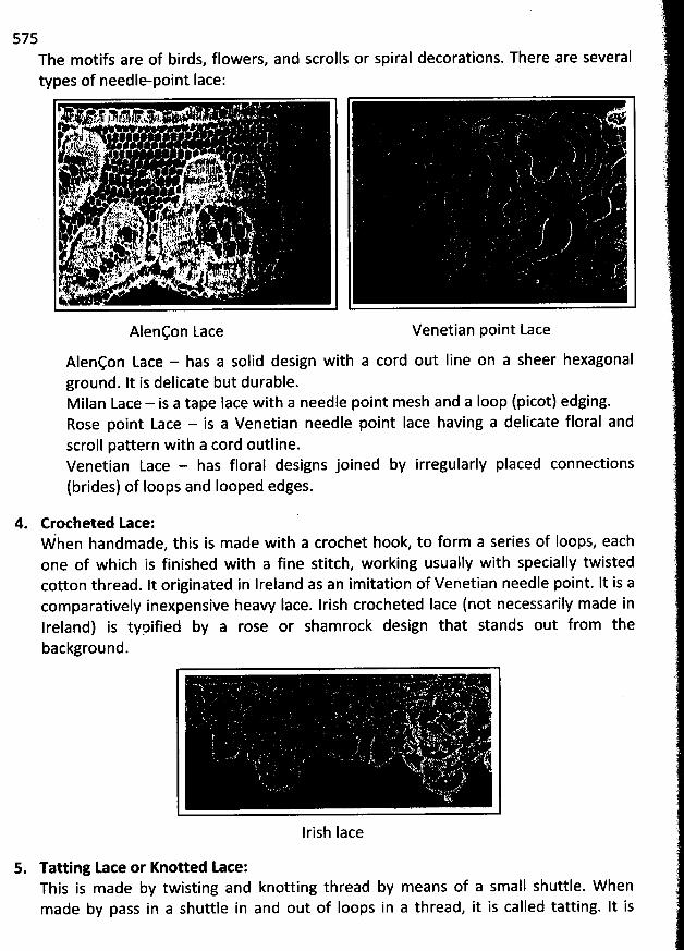
575The motifs are of birds, flowers, and scrolls or spiral decorations. There are severaltypes of needle-point Iace:
Alençon Lace Venetian point Lace
Alençon Lace - has a solid design with a cord out line on a sheer hexagonalground. It is delicate but durable.Milan Lace - is a tape lace with a needle point mesh and a Ioop (picot) edging.Rose point Lace - is a Venetian needle point lace having a delicate floral andscroll pattern with a cord outline.Venetian Lace - has floral designs joined by irregularly placed connections(brides) of Ioops and looped edges.
4. Crocheted Lace:When handmade, this is made with a crochet hook, to form a series of Ioops, eachone of which is finished with a fine stitch, working usually with specially twistedcotton thread. It originated in lreland as an imitation of Venetian needle point. It is acomparatively inexpensive heavy lace. Irish crocheted Iace (not necessarily made inIreland) is typified by a rose or shamrock design that stands out from thebackground.
UXIrish Iace
5. Tatting Lace or Knotted Lace:This is made by twisting and knotting thread by means of a small shuttle. W henmade by pass in a shuttle in and out of Ioops in a thread, it is called tatting. It is
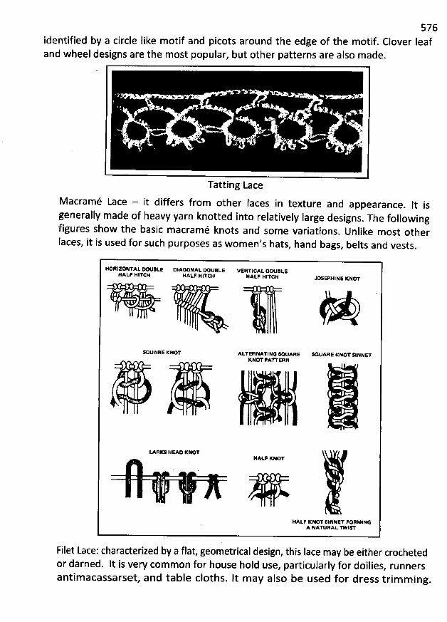
576Ieafidentified by a circle Iike motif and picots around the edge of the motif. Clover
and wheel designs are the most popular, but other patterns are also made.
Tatting Lace
Macramé Lace - it differs from other Iaces in texture and appearance. It is
generally made of heavy yarn knotted into relatively large designs. The following
figures show the basic m acram é knots and some variations. Unlike most other
Iaces, it is used for such purposes as wom en's hats, hand bags, belts and vests.
HORIZONTAL X tIBLE DIAGO/AL X tJBL.E VERTICAL K tlekeHALF HITCH HALF HITCH HALF HITCH V EPHINE KNOT
&QUANE KNOT ALTERNATING SQUARE 9QUARE KNOTSINNETKNOT 'ATTERN
LARKS HEAD KK THAQF K* T
(
HALF KNOT SINNET FORMINGA NAD RAL TwlW
Filet Lace: charaderized by a flat, geometrical design, this lace may be either crochetedor darned. It is very com mon for house hold use, particularly for doilies
, runnersantim acassarset, and table cloths. It m ay also be used for dress trim m ing.
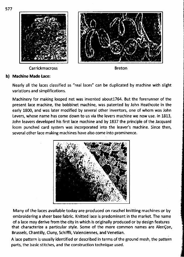
577
Carrickm across Breton
b) Mathine Made Lace:
Nearly aII the Iaces classified as ''real Iaces'' can be duplicated by machine with slightvariations and simplifications.
M achinery for making Iooped net was invented about1764. But the forerunner of thepresent Iace machine, the bobbinet machine, was patented by John Heathcote in theearly 1800s and was Iater modified by several other inventors, one of whom was JohnLevers, Fhose name has come down to us via the Ievers machine we now use. ln 1813,John Ieavers developed his first Iace machine and by 1837 the principle of the JacquardIoom punched card system was incorporated into the Ieaver's machine. Since then,several other lace making machines have also come into prominence.
M any of the Iaces available today are produced on raschel knitting machines or byembroidering a sheer base fabric. Knitted Iace is predominant in the market. The nameof a Iace may derive from the city in which is originally produced or by design featuresthat characterize a particular style. Some of the more common names are Alençon,Brussels, Chantilly, Cluny, Schiffli, Valenciennes, and Venetian.
A Iace pattern is usually identified or described in terms of the ground mesh, the patternparts, the basic stitches, and the construdion technique used.
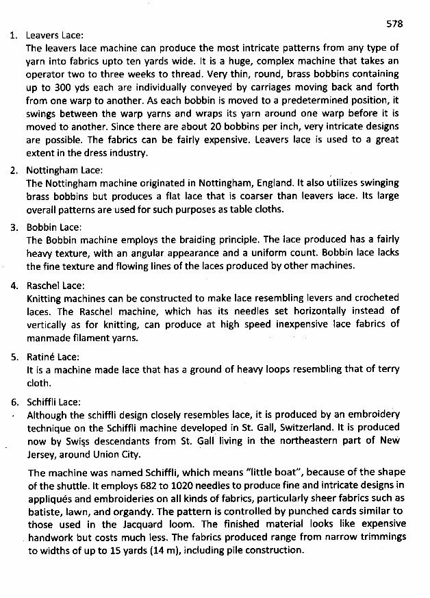
5781. Leavers Lace:
The Ieavers lace machine can produce the most intricate patterns from any type ofyarn into fabrics upto ten yards wide. lt is a huge, complex machine that takes anoperator two to three weeks to thread. Very thin, round, brass bobbins containingup to 300 yds each are individually conveyed by carriages moving back and forthfrom one warp to another. As each bobbin is moved to a predeterm ined position, itswings between the warp yarns and wraps its yarn around one warp before it ismoved to another. Since there are about 20 bobbins per inch, very intricate designsare possible. The fabrics can be fairly expensive. Leavers Iace is used to a greatextent in the dress industry.
2. Nottingham Lace: .The Nottingham machine originated in Nottingham, England. It also utilizes swingingbrass bobbins but produces a flat Iace that is coarser than leavers lace. Its largeoverall patterns are used for such purposes as table cloths.
3. Bobbin Lace:The Bobbin machine em ploys the braiding principle. The Iace produced has a fairlyheavy texture, with an angular appearance and a uniform count. Bobbin lace Iacksthe fine texture and flowing Iines of the Iaces produced by other machines.
4. Raschel Lace:Knitting machines can be constructed to make Iace resem bling levers and crochetedIaces. The Raschel machine, which has its needles set horizontally instead ofvertically as for knitting, can produce at high speed inexpensive Iace fabrics ofmanmade filament yarns.
5. Ratiné Lace:It is a machine made Iace that has a ground of heavy Ioops resem bling that of terryc10th.
6. Schiffli Lace:Although the schiffli design closely resembles Iace, it is produced by an embroiderytechnique on the Schiffli m achine developed in St. Gall, Switzerland. lt is producednow by Swijs descendants from St. Gall Iiving in the northeastern part of NewJersey, around Union City.
The m achine was nam ed Schiffli, which means ''little boat'', because of the shapeof the shuttle. It employs 682 to 1020 needles to produce fine and intricate designs inappliqués and embroideries on aII kinds of fabrics, particularly sheer fabrics such asbatiste, Iawn, and organdy. The pattern is controlled by punched cards sim ilar tothose used in the Jacquard Ioom . The finished m aterial Iooks Iike eypensivehandwork but costs m uch Iess. The fabrics produced range from narrow trim m ings
to widths of up to 15 yards (14 m), including pile construdion.
579
NONWOVEN FABRICS
Nonwovens are flexible, porous products consisting of one or more fibre Iayers. The separate fibres mayeither be preferentially oriented in one diredion or may be deposited in a random manner. They arebonded, by chemical, thermal or mechanical processes into textile produds. Nonwovens are mainlyplanar strudures-This relatively young branch of the textile industry has expanded enormously after thesecond world-war because of the high produdion rates and the resulting cost savings.
Contemporary nonwoven fabric dates to the early 1930s. At that time, a few textile companiesbegan experimenting with bonded materials as a way of utilizing cotton waste. The firstcommercial produdion of the produds now called nonwovens began in 1942 in the UnitedStates in an effort to produce fabric diredly from fibres. The market for nonwoven produds hasexperienced tremendous growth and has potential for more. '
Nonwovens may be classified as either disposable or durabli goods. Disposable, or nondurable,nonwovens include such one-time use produds as diapers, medical dressings, household wipes,and disposable protective clothing. Durable goods are used for apparel intedacings, automobileheadliners, road underlayments, and carpets.
M anufadure:
The basic sequence of steps in manufacturing contemporaw nonwoven fabrics is as follows:Preparation of the fibre---+ web formation ----+. web bonding---+ drying---+ curing ---+finishing.
For films, the chemical solution is prepared and extruded, or cast, as a film.
Raw M aterials:
Polyester is the most frequently used fibre in the United States; olefin and nylon are used fortheir strength, and cotton and rayon are used for absorbency. Some acrylic, acetate, and vinyonare also being used.
Fibres are seleded on the basis of their properties and expeded pedormance in end uses. New,first-quality fibres are preferred over reused or reprocessed fibres. Both staple and filamentfibres are used, and it is possible to blend fibres of different Iengths as well as fibres of differentgeneric groups. The seledion of fibres depends on the product proposed, the care typicallygiven it, and the expected or desired durability. As in the manufacture of aII fabrics, the cost ofthe fibres used is important, as it in turn influences the cost of the final produd.
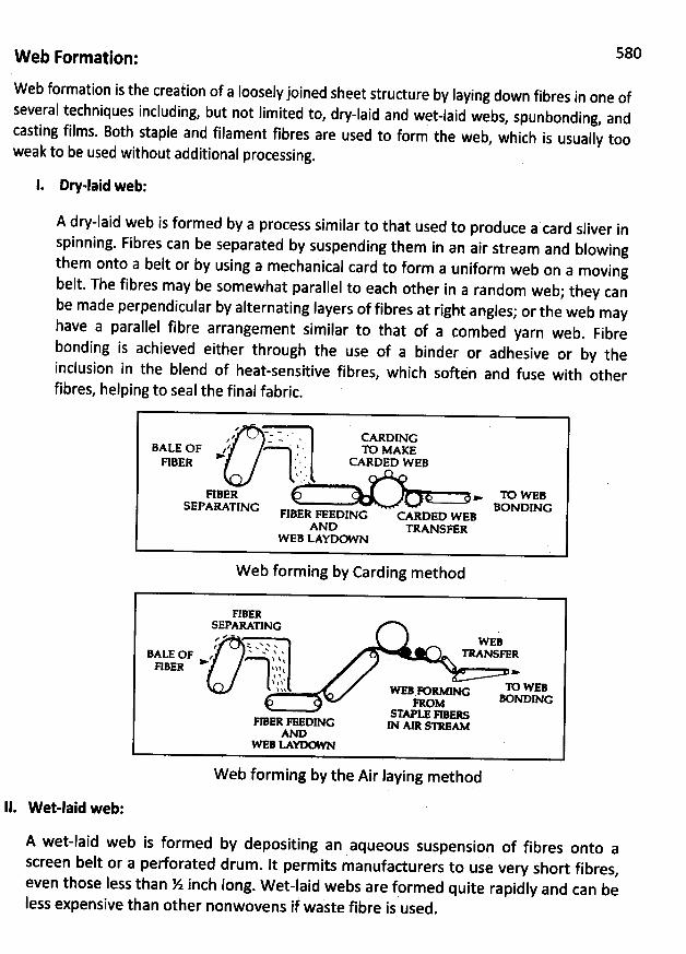
580W eb Formation:
Web formation is the creaiion of a Iooselyjoined sheet strudure by laying down fibres in one ofseveral techniques including, but not limited to
, dry-laid and wet-laid webs, spunbonding, andcasting films. Both staple and filament fibres are used to form the web
, which is usually tooweak to be used without additional processing.
1. Dry-laid web:
A dry-laid web is formed by a process similar to that used to produce a card sliver inspinning. Fibres can be separated by suspending them in an air stream and blowingthem onto a belt or by using a mechanical card to form a uniform web on a movingbelt. The fibres may be somewhat parallel to each other in a random web; they canbe made perpendicular by alternating Iayers of fibres at right angles; or the web mayhave a parallel fibre arrangement similar to that of a combed yarn web
. Fibrebonding is achieved either through the use of a binder or adhesive or by theinclusion in the blend of heat-sensitive fibres
, which softén and fuse with otherfibres, helping to seal the final fabric.
d' .-. . .
' z - ' . G RDING$ . . . m Mxx:BALE OF a .
RBER ' ' '. CARDED W EB1 d .
FIBER - TO W EBSEPARATING BONDINGFIBER
FEEDING CARDED W EBAND TRANSFER
W EB LAYDG N
W eb forming by Carding method
FIBE:SEPARATING
.
.- - w EB' %NN2 è TRANSFERBALE OF z - %h l y>
FIBER j1! $ >1 tk ) î' lo w:Bqw w a D - Nc
hOM O KDWGSTAPLE FIBERSF/E
R FEEDING jN Am s- we
WEBM YY
W eb forming by the Air laying method
II. W et-laid web:
A wet-laid web is formed by depositing an aqueous suspension of fibres onto ascreen belt or a perforated drum . It perm its manufacturers to use very short fibres
,even those less than % inch Iong. W et-laid webs are fprmed quite rapidly and can beIess expensive than other nonwovens if waste fibre is used
.
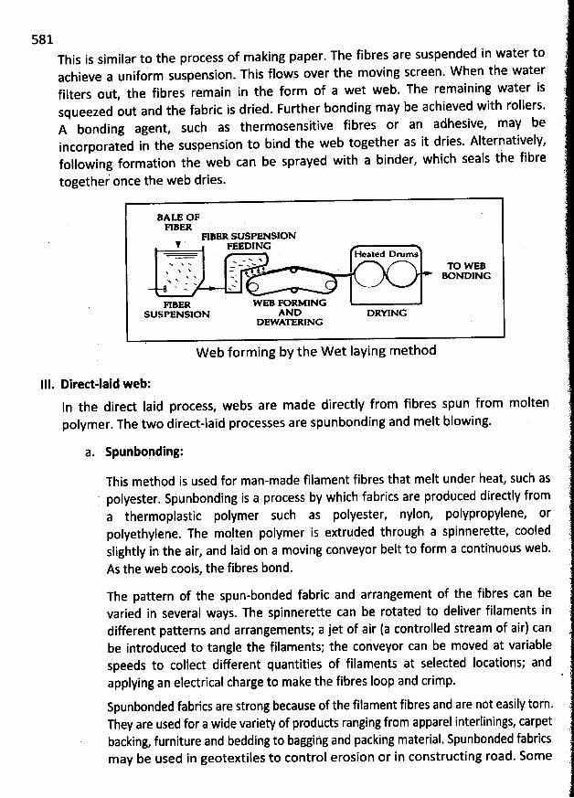
581This is similar tothe process of making paper. The fibres are suspended in water toachieve a uniform suspension. This flows over the moving screen. W hen the waterfilters out, the fibres remain in the form of a wet web. The remaining water issqueezed out and the fabric is dried. Further bonding may be achieved with rollers.A bonding agent, such as thermosensitive fibres or an adhesive, may beincorporated in the suspension to bind the web together as it dries. Alternatively,followinj formation the web can be sprayed with a binder, which seals the fibretogether once the web dries.
BALE OFRBER
FIBER SUSPENSION# yxsojwc
seated orums< w x' x
N$ - .. w <x
c # D W EBx x > K NDING
x w Yw N> N.
FIIER W EB PORMINGSUSPENSION AND DRYING
O- ATERING
W eb form ing by the W et laying m ethod
111. Diredzlaid web:ln the dired laid process, webs are made directly from fibres spun from moltenpolymer. The two direct-laid processes are spunbonding and melt blowing.
a. Spunbopding:
This method is used for man-made filament fibres that melt under heat, such as. polyester. Spunbonding is a process by which fabrics are produced directly froma thermoplastic polymer such as polyester, nylon, polypropylene, orpolyethylene. The molten polymer is extruded through a spinnerette, cooledslightly in the air, and laid on a moving conveyor belt to form a continuous web.As the web cools, the fibres bond.
The pattern of the spun-bonded fabric and arrangement of tbe fibres can bevaried in several ways. The spinnerette can be rotated to deliver filaments indifferent patterns and arrangements; a jet of air (a controlled stream of air) canbe introduced to tangle the filaments; the conveyor can be moved at variablespeeds to collect different quantities of filaments at selected Iocations; andapplying an electrical charge to make the fibres Ioop and crimp.
Spuhbonded fabrics are strong because of the filament fibres and are not easily torn.They are used for a wide variety of products ranging from apparel interlinings, carpetbacking, furniture and bedding to bagging and packing material. Spunbonded fabricsmay be used in geotextiles to control erosion or in constructing road. Som e
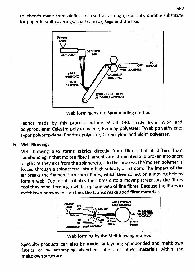
582spunbonds made from olefins are used as a tough, especially durabl'e substitutefor paper in wall coverings, charts, maps, tags and the like.
M > -C+
N G
D
s- o w w c
* COLIM ONAe wo G -
W eb form ing by the Spunbonding method
Fabrics made by this process include Mirafi 140, made from nylon andpolypropylene; Celestra polypropylene; Reem ay polyester; Tyvek polyethylene;Typar polypropylene; Bondtex polyester; Cerex nylon; and Bidim polyester.
b. M elt Blow ing:Melt blowing also forms fabrics diredly from fibres, but it differs fromspunbonding in that m olten fibre filaments are attenuated and broken into shortIengths as they exit from the spinnerettes. In this process, the molten polymer isforced through a spinnerette into a high-velocity air stream. The impad of theair breaks the filament into short fibres, whicb thèn collect on a movihg belt toform a web. Cool air distributes the fibres onto a moving screen. As the fibrescool they bond, forming a white, opaque web of fine fibreé. Because the fibres inmeltblown nonwovens are fine, the fabrics make good filter materials.
c- r c--My- O& &
W eb forming by the Melt blowing method
Specialty products can also be made by Iayering spunbonded and meltblownfabrics or by entrapping absorbent fibres or other materials within the
meltbloFp strudure.
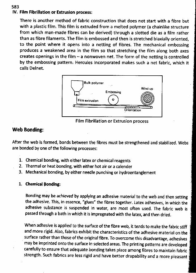
58311/.Film Fibrillation or Extrusion protess:
There is another method of fabric construction that does not start with a fibre but
with a plastic film. This film isextruded from a melted polymer (a chainlike structurefrom which man-made fibres can be derived) through a slotted die as a film ratherthan as fibre filaments. The film is embossed and then is stretched biaxially oriented
,
to the point where itopens into a netting of fibres. The mechanical embossingproduces a weakened area in the film so that stretching the film along both axescreates openings in the film - a nonwoven net. The form of the netting is controlledby the embossing pattern. Hercules Incorporated makes such a net fabric, which itcalls Delnet.
Bulk polymer
Wind-upEm* ssing
trilmiextrusion o OoOrientation
Film Fibrillation or Extrusion process
Web Bonding:
After the web is formed, bonds between the fibresare bonded by oneof the following processes:
must be strengthened and stabilized. W ebs
1. Chemical bonding, with either Iatex or chemical reagents2. Thermal or heat bonding, with either hot air or a calender3. Mechanical bonding, by either needle punching or hydroentanglement
1. Chemital Bonding:
Bonding may be achievedby applying an adhesive material to the web and then settingthe adhesive. This, in essence, ''glues'' the fibres together. Latex adhesives, in which theadhesive substance is suspended in water
, are most often used. The fabric web ispassed through a bath in which it is impregnated with the latex, and then dried.
W hen adhesive is applied to the surface of the fibre web, it tends to make the fabric stiffand more rigid. Also, fabrics exhibit the characteristics of the adhesive material on thesurface rather than those of the original fibre. To overcome this disadvantage, adhesivesmay be imprinted onto the surface in selected areas. The printing patterns are developedcarefully to ensure that adequate bonding takes place among fibres to maintain fabricstrength. Such fabrics are less rigid and have better drapability and a more pleasant
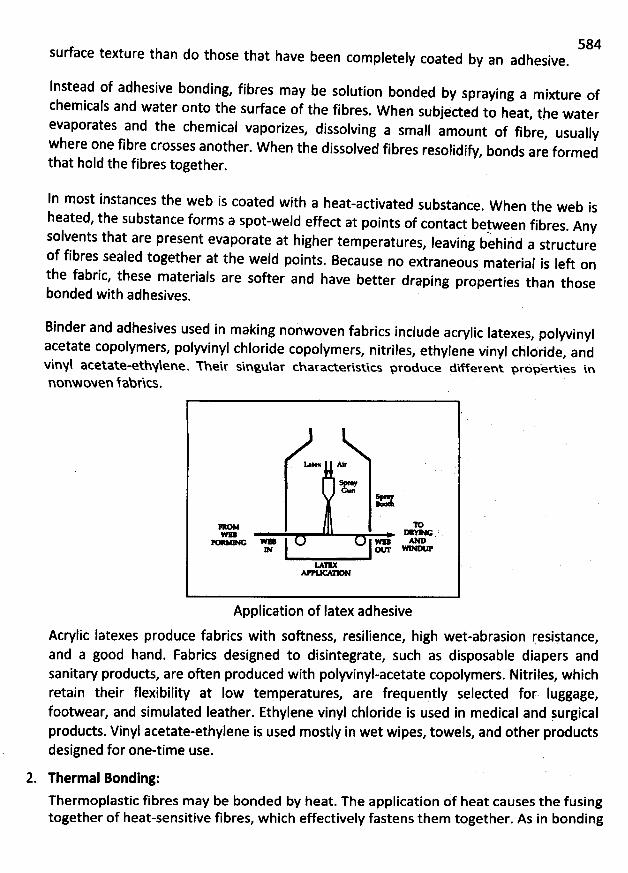
584surface texture than do those that have been completely coated by an adhesive.
Instead of adhesive bonding, fibres may be solution bonded by spraying a mixture ofchemicals and water onto the surface of the fibres
. When subjeded to heat, the waterevaporates and the chemical vaporizes, dissolving a small amount of fibre
, usuallywhere one fibre crosses another. W hen the dissolved fibres resolidifw bonds are formedthat hold the fibres together.
In most instances the web is coated with a heat-activated substance. W hen the web ish
eated, the substancç forms a spot-weld effect at points of contact betoween fibres. Anysolvents that are present evaporate at higher temperatures
, Ieaving behihd a strudureof fibres sealed together at the weld points
. Because no extraneous. material is Ieft on
the fabric, these materials are softer and have better draping properties than thosebonded with adhesives.
Binder and adhesives used in making nonwoven fabrics include acrylic Iatexes, polyvinyl
acetate copolymers, polyvinyl chloride copolymers, nitriles, ethylene vinyl chloride, and
vins acetate-e&hNlene. Theiç sinlusaç characteçistic.s pçoduc.e different pçopertkes innonwoven fabrics.
=n Oo . > T
w l 1- -
Application of Iatex adhesive
Acrylic latexes produce fabrics with softness, resilience, high wet-abrasion resiitance,and a good hand. Fabrics designed to disintegrate, such as disposable diapers andsanitary products, are often produced with polyvinyl-acetate copolymers. Nitriles, whichretain their flexibility at Iow temperatures, are frequently selected for. Iuggage,footwear, and simulated leather. Ethylene vinyl chloride is used in medical and surgicalproducts. Vinyl acetate-ethylene is used mostly in wet wipes, towels, and other productsdesigned for one-time use.
2. Thermal Bonding:
Thermoplastic fibres m ay be bonded by heat. The application of heat causes the fusingtogether of heat-sensitive fibres, which efectively fastens them together. As in bonding

585with adhesives, heat may be applied in a pattern to provide sufficient bonding fordurability and to allow greater flexibility and softness in the end product. Nonwovenscan also be formed with a small percentage of binder fibres of lower melting point thanthe predominant fibres. W hen the web is heated, the binder fibres melt, providing thenecessary adhesion.
Heat and pressure can be applied to bind fibres into a web. The two common thermalbonding methods are calendaring and air heating. In air heating, hot air fuses fibreswithin the web and on the surface of the web to make high-loft Iow-density fabrics. Thehot air is blown through the web in a conveyorized oven or sucked through the webwhile it is passed over a vacuumed porous drum. In the calendaring process, the web isdrawn over and between heated cylinders to produce strong, Iow-loft fabrics. Spunbondand meltblown nonwovens thermally bond when the molten flaments harden afterextrusion. Passing the spunbonded or meltblown fibre webs between heated cylinderscalled calendar rolls bonds fabrics more completely. Design effects can be produced ifthese cylinders have patterns embossed on their surfaces. Heat can also be applied towebs by infrared radiation or ultrasound.
.
mr ewo T- m> MNXP
H - C-X M DW% m Nx p
> NGH C*
HG G M
Air bonding process Calendar bonding process
3. Methanical Bonding:
Mechanical bonding is the oldest method of producing nonwovens; it entangles fibres toimpart strength to dry-laid webs. The most common mechanical methods are needlepunching, spunlacing, also called hydroentangling and stitch bonding.
1. Needle Punthing:
In needle punching, barbed needles are punched vertically through the web to hook andentangle tufts of fibres. Needle-punched nonwovens resemble felt in appearance, butthey are made primarily from fibres other than wool. Characterized by high densitycombined with some bulk, they are available in weights from 50 to 285 grams (1.7 to 10oz) and in thicknesses from 15 to 160 mils.
Two basic steps are involved in the construction of needle-punching nonwovens:
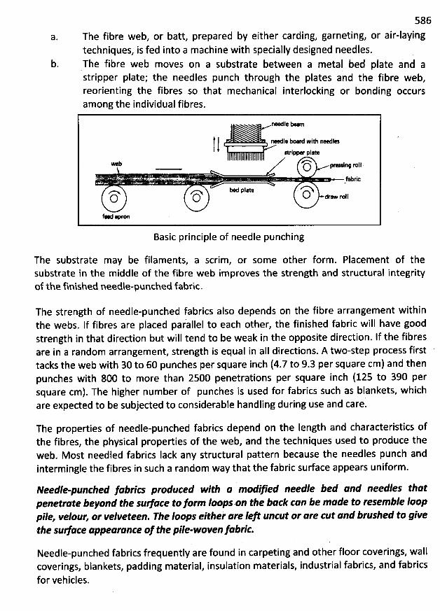
a.
586or air-laying
b.
The fibre web, or batt, prepared by either carding, garneting,techniques, is fed into a machine with specially designed needles.The fibre web moves on a substrate between a metal bed plate and astripper plate; the needles punch through the plates and the fibre web,reorienting the fibres so that mechanical interlocking or bonding occursamong the individual fibres.
re l: bearn
) t rel. bo.rd wi* relesxriiper pl-e b #''N pr- nq rojl.O7
. r . . k - --- 7- .rrr. . . - - .g...... jjjjj)jjjgr
e pl- r'Nz-x z'N o ajO O * r
Basic principle of needle punching
The substrate may be filaments, a scrim, or some other form. Placement of thesubstrate in the middle of the fibre web improves the strength and structural integrityof the finished needle-punched fabric.
The strength of needle-punched fabrics also depends on the fibre arrangement withinthe webs. If fibres are placed pa/allel to each other, tbe finished fabric will have goodstrength in that direction but will tend to be weak in the opposite direction. If the fibresare in a random arrangement, strength is equal in aII directions. A two-step process first 'tacks the web with 30 to 60 punches per square inch (4.7 to 9.3 per square cm) and thenpunches with 800 to more than 2500 penetrations per square inch (125 to 390 persquare cm). The higher number of punches is used for fabrics such as blankets, whichare expected to be subjected to considerable handling during use and care.
The properties of needle-punched fabrics depend on the Iength and characteristics ofthe fibres, the physica! properties of the web, and the techniques used to produce theweb. M ost needled fabrics Iack any structural pattern because the needles punch andintermingle the fibres in such a random way that the fabric sudace appears uniform .
Needle-punched Abrfc; produced with a mod@ed needle bed Jnd needles th/tpenetrute beyond the stldlee ko form Ioops on the blrk can be mlde to resemble looppile, veloun or velveteen. The Ioops eithei @re le# uncut or are cut Jpd brushed to Wvethe xlldlee uppeqrunce o; the pile-woven A:rfc.
Needle-punched fabrics frequently are found in carpeting and other floor coverings, wallcoverings, blankets, padding material, insulation materials, industrial fabrics, and fabricsfor vehicles.
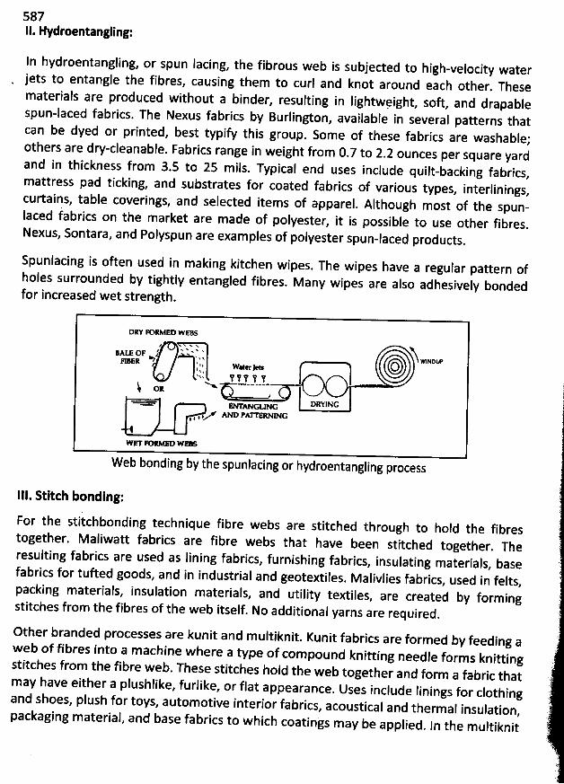
587II. Hydroentangling:
In hydroentangling, or spun Iacing, the fibrous web is subjected to high-velocity water
jets to entangle the fibres, causing them to curl and knot around each other. These
materials are produced without a binder, resulting in Iightwvight, soft and drapable
spun-laced fabrics. The Nexus fabrics by Burlington, available in several patterns that
can be dyed or printed, best typify this group. Some of these fabrics are washable;others are dw-cleanable. Fabrics range in weight from 0.7 to 2.2 ounces per square yardand in thickness from 3.5 to 25 mils. Typical end uses include quilt-backing fabrics,mattress pad ticking, and substrates for coated fabrics of various types
, interlinings,curtains, table coverings, and selected items of apparel
. Although most of the spun-laced fabrics on the market are made of polyester
, it is possible to use other fibres.Nexus, Sontara
, and Polyspun are examples of polyester spun-laced products.
Spunlacing is often used in making kitchen wipes. The wipes have a regular pattern of
holes surrounded by tightly entangled fibres. M any wipes are also adhesively bonded
for increased wet strength.
DR# FORMED WEBSe
xxxxxv x A
j:Atz OF ' x . q wlsptmFI ss R D ., , , w . tw > (3O.tt : t!
- y. !i oxDRYING
Z AND PAITERNINGIII
W eb bonding by the spunlacing or hydroentangling process
111. Stiteh bonding:
For the stitchbonding technique fibre webs are stitched through to hold the fibrestogether. Maliwatt fabrics are fibre webs that have been stitched t
ogether. Theresulting fabrics are used as lining fabrics
, furnishing fabrics, insulating materials, basefabrics for tufted goods, and in industrial and geotextiles
. Malivlies fabrics, used in felts,packing materials, insulation materials
, and utility textiles, are created by form ingstitches from the fibres of the web itself. No additional yarns are required.
Other branded processes are kunit and m ultiknit. Kunit fabrics are formed by feeding a
web of fibres into a m achine where a type of com pound knitting needle forms knittingstitches from the fibre web. These stitches hold the web together and form a fabric thatmay have either a plushlike, furlike
, or flat appearance. Uses include linings for clothingand shoes, plush for toys, autom otive interior fabrics
, acoustical and thermal insulation,packaging material, and base fabrics to which coatings m ay be applied
. ln the m ultiknit
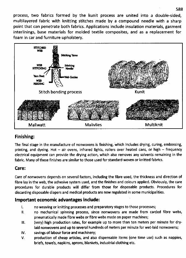
588process, two fabrics formed by the kunit process are united into a double-sided,multilayered fabric with knitting stitches m ade by a com pound needle with a sharppoint that can penetrate both fabrics. Applications include insulation materials, garm entinterlinings, base materials for m olded textile composites, and as a replacement forfoam in car and furniture upholstery.
Y
. + .' ' t u '. e V 'A l . . t . ., . . . , .. ''$. x z. r. . ' . . X
'
2 . - ' .; 1 1 - . 3 X. *1::1 ' % . '' .) ..' l 1 . ' 'i's '. . j . .. . . . j $ fy . . . . , .. . . . ' hy jj ,1 t', . 13. . )t. , pb kvs. . r , psy .!k!d $. lj . , ;11 I ,', / '. 4 ; ,' ' . j . A1I., ' ;k -!..)k.'. jq'.' . s ' rj,' 1. j,1r s ; ' I.t j! . ,. & ,j . )2 ...I $ l ' ç ' t 8 .1 jr ... l4. t: . ,. ygj)l t *kj jt;. % j, .. . . .. . y $, , ; -.;$; j(. .., .ivjjj'jI I . 4 t '. . l . . , i . : .,, .jk .; jj .Alf'lllllll j : . . !/' . , . .1 f -'l , !; f' ! , f ,: ;p Jr.t . zxj . , . , . jly . ,j, .. jjr!; $ , !%j. f l .. ,. j . ; klg: ; . jj jk . ... .$ % $ 0s % '' 1 i'. ' .,' ! .
' '' t* ,: '# 1 ) -# I ''r *è.% ; . : ' - '&
'
N
'
q
'
. . '. . s'
.( ,.... a .! i. ,e . .z /
'
$ ,'. ' q1.t j .fp . . ) ,..y/ . - .G 1 : . Bnf ' ' e ' ' . .' x ' ' :
. '
&
'
. z d . .. .,. ,.,p.. 1 . . .
Stitch bonding process Kunit
. . W .x . w < .. . . . y . z:. . - t X ' >' > v -'M> < .d7 .W Y k . < * w Zae . $. . r. . x . . ' .. . t %< . .' . $'. . . 13 .. ' . .VK'W . D ' h ' x
.ee'e A . ' 'k '. .'. o . .. . ..x N fA . x < e . ' . . - . . .. #Z.& . . k . ç.. xj. . . .a. . . . .. , *' kb ; j. ç. .
' z:' -. . . ;, . . - jp ... .jt....- .;. z'.y. .' . , ., . . ,...f-.
,.k..y.',.. ,-;:. :,( :' 'r' .ë j:.,'j;'t'. ..r?(;;. .. .. ' . .t!,jry:'.) , '' ' .a... . ; , '' -'. - -. ./;. . . . . . , ' .. . ;p,, . .g +'.x ' J%4$' t !. , 5 x z. ( L#. s ;. . , wa . j e ! ' . . ' .' ..J , ' a g >. ' 4. kz.'z/ .)y kk . , y4 . . x ; kwx %.r . t z-s' ,.%z. . ... - IA.. . .. . . .v .( . j . ... .. l .: e . ' d . t ' . :ç < I .c./ -. -e4 ' 9 .n% v'. . .' kt
vp . !!! ' *. /:; <f ).,,-1. . '-'' ':s : j ' , , ,yta.e:*' ' r ,:. v 9J s: z . J : i .l. trà S- ?.e' N.) .w ...z .z-. rs6. .1/Xc r.t''w .
ali att alivlies ultiknit
Finishing:
h final stage in the manufacture of nonwovens is finishing, which includes drying, curing, embossing,T eprinting, and dyeing. Hot - air ovens, infrared Iights, rollers over beated cans, or high - frequencyelectrical equipment can provide the drying action, which also removes any solvents remaining in thefabric. Many of these finishes are similar to those used for standard woven or knitted fabrics.
Care:
Care of nonwovens depends on several factors, including the fibre used, the thickness and diredion offibre Iay in the web, the adhesive system used, and the finishes and colours applied. Obviously, the careprocedures for durable products will differ from. those for disposable products. Procedures fordiscarding disposable diapers and medical products are now regulated in some municipalities.
Impodant etonom ic advantages include:
1. no weaving or knitting processes and preparatory stages to those processes;II. no mechanical spinning process, since nonwovens are made from carded fibre webs,
pneumatically made fibre webs or fibre webs made on paper machines;111. (very) high produdion rates, for example up to more than ten meters per minute for drp
laid nonwovens and up to several hundreds of meters per minute for wet-laid nonwovens;IV. savings of Iabourforce and machinew;V. produdion of cheap articles, and also dispensable items (one time use) such as nappies,
briefs, towels, napkins, aprons, blankets, industrial clothing etc.
589
Charaderistics of Nonwoven Fabrics:
The particular set of properties that a nonwoven fabric may have is dependent upon thecombination of factors in its production. The range of characteristics is wide.
The appearance of nonwoven fabrics may be paperlike, feltlike, or similar to that of woven
fabrics. They may have a soft, resilient hand, or they may be hard, stift or boardy with Iittle
pliability. They may be as thin as tissue paper or many times thickèr. Nonwovens may be
translucent or opaque. Their porosity may range from high, free aidlow to minute to
impermeable. Their strength may range from Iow tear and burst strength to very high tensilestrength. They may be fabricated by gluing, heat bonding, or spwing. The drapability ofnonwovens varies from good to none at all. Some nonwovens have excellent Iaunderability;others have none. Some may be dry-cleaned.
Nonwovens are engineered to provide particular properties suited to desired end uses. For
example, diapers can be construded of two different Iayers of nonwoven fabrics: an outer Iayercomposèd of a wetting-agent treated polyester that will permit rapid fluid penetration
, butwith minimal Iateral wicking, and an inner Iayer of absorbent rayon
. Thin, high-filtrationnonwoven fabrics for surgical masks can be composed of microdenier fibres; thick
, fluffy,insulating nonwovens for ski jackets can also be made of microdenier fibres. Researchcontinues in order to achieve or perhaps exceed certain properties of conventionallyconstruded c10th.
Uses of Nonwoven Fabrics:
The use of nonwoven produds continues to expand. The many uses of nonwovens may be
classified as disposables, durable consumer goods, and industrial materials. AI( these areas aremaking increasing use of this kind of merchandise because of its Iow cost and its suitability formany needs.
Disposable nonwovens are essentially made for one-time use; but some, such as dust doths,
may be laundered and reused a few times. General applications include personal hygiene
products, such as diapers and sanitary napkins; medical pfoduds such as surgical gowns andd
rapes; surgical and industrial masks, bandages, wipes and towels; bibs and even costumes for
special events. Tbe' y have recentl# become popular for Iightweight ''fun'' cloths that can bewashed a number of times.
Durable nonwovens have wide applications. Consumer durables include both household goods
or home furnishings, such ae for draperies, furniture upholstery, mattress padding, towels,
table dotbs, blankets and carpet backing and clothing or apparel, such as for caps, Iinings
,interlinings, interfacings and the reinforcemént of other fabrics.
590The many industrial uses include filters, insulation, packing materials, roadbed stabilizationsheeting or road-building materials geotextiles and roofing products.
specialty Nonwoven Products:
Fusible Nonwovens: A fusible nonwoven fabric is any nonwoven fabric with a heat-activatedadhesive resin coating. More than half of the interfacings used in apparel construction arefusibles. They are placed between garment Iayers to provide body, shape, support, additionalstrength, and foundation. Heat and pressure, applied for a specified time, activate the resin tobond the interfacing to the shell fabric.
N'
.
Fusible interfacings have some disadvantages. They sometimes produce a stiff or boardy hand;differential shrinkage between the fabrics being joined may produce a rippled garment; andseparation of the two fabric Iayers may occur when improperly applied interfacings areEleaned.
Other special nonwoven products are film fabrics, coated fabrics artificial suedes and Ieathersetc.
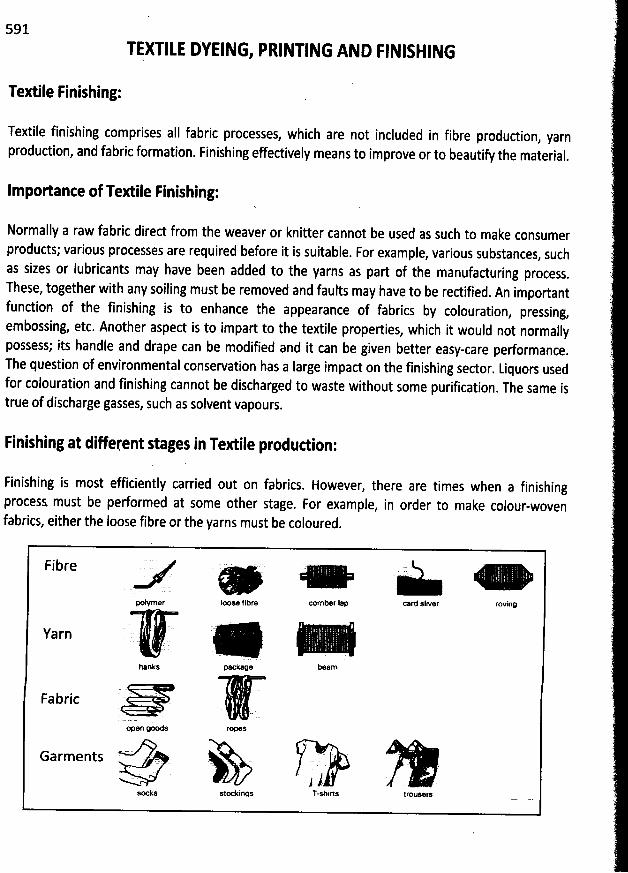
591
TqXTILE DYEING, PRINTING AND FINISHING
Textile Finishing:
Textile finishing comprises all fabric processes, which are not included in fibre produdion, yarnproduction, and fabric formation. Finishing effectively means to improve or to beautify the material
.
Impo/ante of Textile Finishing:
Normally a raw fabric direct from the weaver or knitter cannot be used as such to make consumerproducts; various processes are required before it is suitable. For example, various substances, suchas sizes or lubricants may have been added to the yarns as part of the manufacturing process
.
These, together with any soiling must be removed and faults may have to be redified. An important
fundion of the finishing is to enhance the appearance of fabrics by colouration, pressing,
embossing, etc. Another aspect is to impart to the textile properties, which it would not normally
possess; its handle and drape can be modified and it can be given better easy-care performance.
The question of environmental conservation has a Iarge impact on the finishing sector. Liquors used
for colouration and finishing cannot be discharged to waste without some purification. The same is
true of discharge gasses, such as solvent vapours.
Finishing at diferent stages in Textile produdion:
Finishing is most efficiently carried out on fabrics. However, there are times when a finishingprocess must be performed at some other stage. For example, in order to make colour-wovenfabrics, either the Ioose fibre or the yarns must be coloured.
F 1- b re E
xlymer Iomse fibre comber l:p card sliver roving
Yarn
hanks peckage be@m
Fabric rë. (. .
open goods ropel
Garments L. . . ..
' .j i<
socks s1c*k1r815 T-shirts trouars
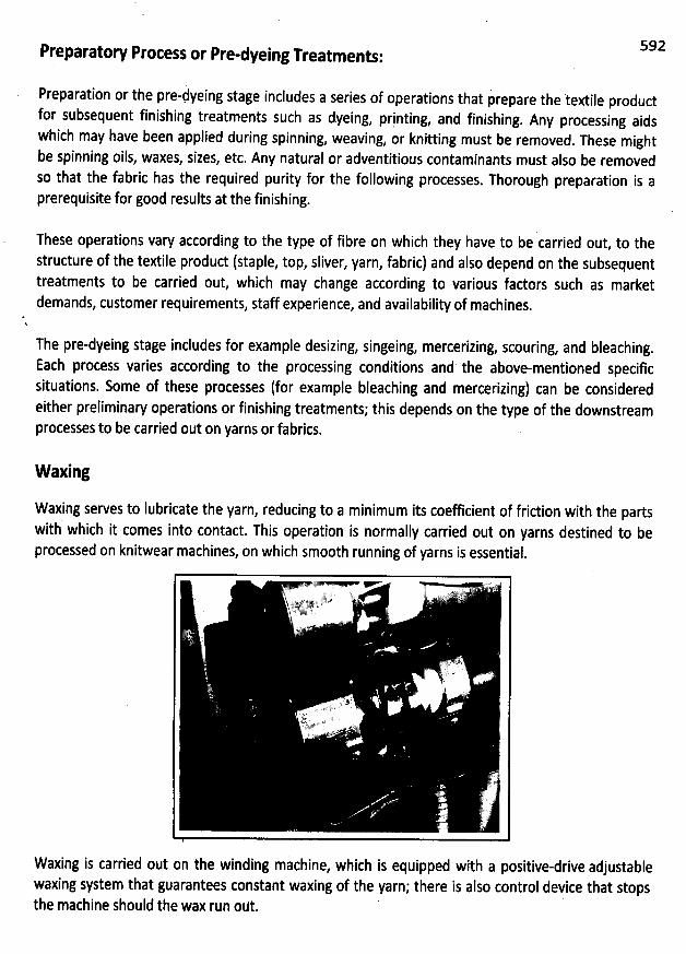
Preparatory Process or Pre-dyeing Treatments:
Preparatipn or the pre-hyeing stage includes a series of operations that p' repare the tegtile productfor subsequent finishing treatments such as dyeing
, printing, and finishing. Any processing aidswhich may have been applied during spinning, weaving, or knitting must be removed. These mightbe spinning oils, waxes, sizes, etc. Any natural or adventitious contaminants must also be removedso that the fabric has the required purity for the following processes. Thorough preparation is aprerequisite for good results at the finishing.
592
These operations vary according to the type of fibre on which they have to be carried out, to tbe
structure of the textile produd (staple, top, sliver, yarn, fabric) and also depend on the subsequenttreatments to be carried out, which may change according to various fadors such as marketdemands, customer requirements, staff experience, and availability of machines.
The pre-dyeing stage includes for example desizing, singeing, mercerizing, scouring, and bleaching.
Each process varies according to the processing conditions and the above-mentioned specific
situations. Some of these processes (for example bleaching and mercerizing) can be consideredeither preliminary operations or finishing treatments; this depends on the type of the downstreamprocesses to be carried out on yarns or fabrics.
W axing
Waxing serves to lubricate the yarn, reducing to a minimum its coefficient of fridion with the partswith which it comes into contact. This operation is normally carried out on yarns destined to beprocessed on knitwear machines, on which smooth running of yarns is essential.
Waxing is carried out on the winding machine, which is equipped with a positive-drive adjustablewaxing system that guarantees constant waxing of the yarn; there is also control device that stopsthe machine should the wax run out.
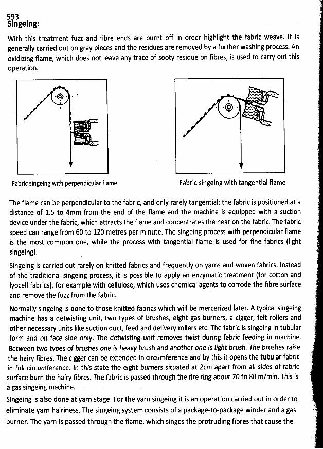
5?3Slngeing:W ith this treatment fuzz and fibre ends are burnt off in order bighlight the fabric weave. It isgenerally carried out on gray pieces and the residues are removed by a further washing process. Anoxidizing flame, which does not Ieave any trace of sooty residue on fibres, is used to carry out this
operation.
Fabric singeing with perpendicular flame
The flame can be perpendicular to the fabric, and only rarely tangential; the fabric is positioned at adistance of 1.5 to 4mm from the end of the flame and the machine is equipped with a suctiondevice under the fabric, which attracts the flame and concentrates the heat on the fabric. The fabricspeed can range'from 60 to 120 metres per minute. The singeing process with perpendicular flameis the most common one, while the process with tangential flame is used for fine fabrics (Iightsingeing).Singeing is carried out rarely on knitted fabrics and frequently on yarns and woven fabrics. Insteadof the traditional singeing process, it is possible to apply an enzymatic treatment (for cotton andIyocell fabrics), for example with cellulose, which uses chemical agents to corrode the fibre surfaceand remove the fuzz from the fabric.
Fabric singeing with tangential flame
Normally singeing is done to those knitted fabrics which will be mercerized Iater. A typical singeingmachine has a detwisting unit, two types of brushes, eight gas burners, a cigger, felt rollers andother necessary units Iike suction duct, feed and delivery rollers etc. The fabric is singeing in tubularform and on face side only. The detwisting unit removes twist during fabric feeding in machine.8etween two types of brushes one is heavy brush and another one is light brush. The brtlshes raisethe hairy fibres. The cigger can be extended in circumference and by this it opens the tubular fabricin full circumference. ln this state the eight burners situated at 2cm apart from all sides of fabricsurface burn the hairy fibres. The fabric is passed through the fire ring about 70 to 80 m/min. This isa gas singeing machine.Singeing is also done at yarn stage. For the yarn singeing it is an operation carried out in or'der to
eliminate yarn hairiness. The singeing system consists of a package-to-package winder and a gasburner. The yarn is passed through the flame, which singes the protruding fibres that cause the
s94hairiness. It runs at a rate of 400 to 1000 m/min. The machine must, in order to obtain evensingeing, maintain a constant yarn speed and an even flame.
The singeing system, in addition to normal machine control devices, also has a fIy fibre evacuationsystem and a flame temperature control system. Since this operation reduces the weight of theyarn, even by as much as 5-6 %, the yarn count will also be modified
, and this must be borne inmind when designing the yarn.
Desizing:
This treatment is carried out on woven fabrics to remove the sizing substance from the warp. Thesize must be totally eliminatid since the fabric must absorb the Iiquor of subsequent processeshomogeneously.
Since amylaceous sizes are generally used for cotton yarns, it is possible to apply amylolyticenzymes (enzymatic desizing), which carry out a biological degradation process of the starch,transforming it into soluble by-products which can be then eliminated by washing. The enzymaticprocess depends on the quantity of enzyme molecules per gram of fabric, while the thermal stabilityof the enzyme depends on the bacteria strain from which it originates. The amylases only react withstarch molecules and do not affect the other glucose polymer (cellulose), siice they attack tàe 1.4alpha-glucoside bond of starch and not the 1.4 beta-glucoside bond of cellulose.
This readion makes the use of amylases profitable (when applying starchy sizes) compared to otherdesizing agents such as alkali and oxidizing agents (oxidizing desizing), which attack both starch andcellulose.
The oxidizing desizing process is used to remove non-starchy sizes that do not dissolve in water or
to eliminate starchy sizes combined with polpinyl alcohol (this treatment is carried out before thehis last treatment requires accura'iely controlled operating conditions tosingeing process). T
solubilise only sizes and avoid any possible fibre degradation. Enzymatic desizing can be carried ogt
in discontinuous systems (jigger) but semi-continuous or continuous techniques are more frequentafter ihe pad-batch wetting of the fabric. The most frequently used processes are pad-roll and pad-steam. If tbe size is water-soluble, it can be eliminated by hot washing.
Stouring:
0n cotton fibres, this treatment removes fatty and pedic substances, softening motes andpreparing the material to absorb the subsequent treatment agents. Scouring is usually carried out in4oq water additivated with textile auxiliaries such as absorbing agents, detergents
, emulsifyingagents, caustic soda and/or Solvay Iye and sequestering agents. Alkali makes the fibre swell andenhance the adion of surfadants. This treatment can be carried out on filaments, yarns and fabrics.
595lnstead of the traditional scouring process, it is also possible to carry out an enzymatic scouringprocess (bioscouring) to remove non-cellulosic material from cotton fibres, to make themeasily wettable and enhance the subsequent absorption of finishing Iiquors.
The scouting process applied to synthetic fibres removes oils, Iubricants and anti-static substances,dust, contaminants and can be carried out on yarns and fabrics (when warp yarns have been
k. 9bonded, the treatment is called debondlng). It is carried out by means of surfactants, detergents
and emulsifying agents.
Scouring is usually carried out by means systems, with the sameHmachines used for downstream treatments; temperature, processing time, p , concentration
reagents, depend on the fibre and on the machine used. Incomplete scouring processes usuallyoriginate dyeing a'nd printing defeds due to different degrees of wettability and to inconsistentaffinity for dyes of the material.
of continuous or discontinuous
Bleaching:Bleaching treatments are applied to eliminate any impurity and obtain a pure white tone, toprepare substrates for Iow-density dyes or prints and to level off undesired tone variations.Bleaching agents mainly used for cellulosic fibres are sodium hypochlorite and hydrogen perixide.They b6th require the addition of sodium hydroxide in the bleaching Iiquor to make it alkaline it byfavouring the formation of the bleaching ion, which in the first case is the hypochlorite ion and inthe second one is the perhydroxyl ipn. '
H between 9 and 11 and the temperature must notW hen using hypochlorite the p must rangekceed 300c
. In fad, as far as the pH is conierned, pH values below 4 give rise to the formation ofeH I s ranging between 4 and 9 give rise to the formation of hypochlorous acid:chlorine while p va ue
these chemical substances affect the fibre negatively and do not perform a bleaching action. Afterthe bleaching with hypochlorite it is necessary to carry out an antichlor treatment. Fibres must betreated with hydrogen peroxide, which completely remöves the chlorine and avoids the formationof chloramines, which, in drying machines, could generate HCI dangerous for cellulose. Withhydrogen peroxide, in the presence of alkali, Iittle motes can be eliminated and the autoclave.
0 d 900 c andscouring can therefore be avoided. The optimum temperature ranges between 80 anB between 10
.7 and 10.9. Hydrogen peroxide at a concentration of 1 - 2 voI can be used alsothe pB f 8 -9 at 700- 800 c for 1- 2 hours.for silk afterdegumming, with a p o ,
From an environmental point of view, hydrogen peroxide is more suitable than hypochlorite since ithas a Iower impad on the environment and effluents can be decontaminated with simpleroperations. It is recommended to add sequestering agents to the bleaching Iiquors. Anotherbleaching agent used in textile processing is sodium chloride (suitable for synthetic fibres) that takesadvantage of the oxidizing action of chlorine dioxide generated as a result of the hot acidification ofthe solution of this salt. Unfortunately, chlorine dioxide is a toxic substance and attacks stainlesssteels; tberefore it is necessary to work in hermetically closed units equipped with suctipn systemswith resistant materials such as stoneware.
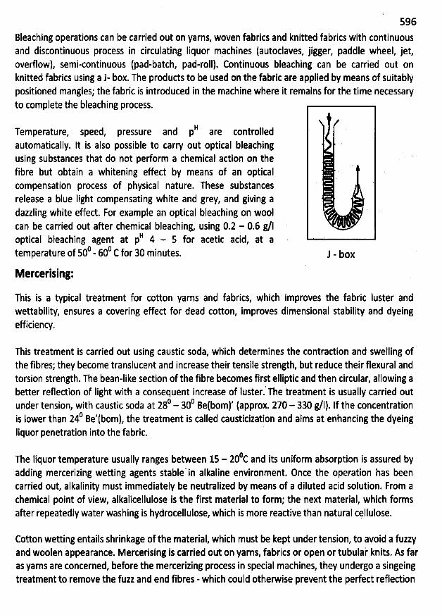
596
Bleaching operations can be carried out on yarns, woven fabrics and knitted fabrics with continuousand discontinuous process in circulating Iiquor machines (autoclaves, jigger, paddle wheel, jetoverflow), semi-continuous (pad-batch, pad-roll). Continuous bleaching can be carried out onknitted fabrics using a J- box. The products to be used on the fabric are applied by means of suitablypositioned mangles; the fabric is introduced in the mathine where it remains for the time necessaryto complete the bleaching process.
èI jjtj (jTemperature, speed, pressure and p are contro
automatically. It is also possible to carry out optical bleachingusing substances that do not perform a chemical action on thefibre but obtain a whitening effed by means of an opticalcompensation process of physical nature. These substancesrelease a blue Iight compensating white and grey, and giving adazzling white effed. For example an optical bleaching on woolcan be carried out after chemical bleaching, using 0.2 - 0.6 g/1
B 4 - s for acetic acid, at aoptical bleaching agent at p0 600 c for 30 minutes.temperature of 50 - J - box
Merterising:
This is a typical treatment for cotton yarns and fabrics, which improves the fabric luster andwettability, ensures a covering effed for dead cotton, improves dimensional stability and dyeingefficiency.
This treatment is carried out using caustic soda, which determines the contradion and swelling ofthe fibres; they become translucent and increase their tensile strength, but reduce their flexural andtorsion strength. The bean-like sedion of the fibre becomes first elliptic and then circular, allowing abetter refledion of light with a consequent increase ef Iuster. The treatment is usually carried out
0 300 Betboml' (approx. 270 - 330 g/1). If the concentrationunder tension, with caustic soda at 28 -0 B 'tbom) the treatment is called causticization and aims at enhancing the dyeingis Iewer than 24 e ,
liquor penetration into the fabric.
0c nd its uniform absorption is assured byThe liquor temperature usually ranges between 15 - 20 a
adding mercerizing wetting agents stable'in alkaline environment. Once the operation has beencarried out, alkalinity must immediately be neutralized by means of a diluted acid solution. From achemical point of view, alkalicellulose is the first material to form; the next material, which formsafter repeatedly water washing is hydrocellulose, which is more readive than natural cçllulose.
Cotton wetting entails shrinkage of the material, which must be kept under tension, to avoid a fuzzyand woolen appearance. Mercerising is carried out on yarns, fabrics or open or tubulai knits. As faras yarns are concerned, before the mercerizing process in special machines, they undergo a singeingtreatment to remove the fuzz and end fibres - which could otherwise prevent the perfect reflection
597
of Iight after mercerizing. There are two different types of machines to be used for woven fabrics: achain system and a cylinder system.
Chain merterizing: with the chain mercerizing process the fibres achieve perfect brightness thanksto optimum tension control. This system runs slowly and allows no flexibility when the width of thefabric varies.
Cylinder merterizing: this is a more compact and faster system compared to the previous one;cylinder mercerizing does not allow the contraction of the warp because the fabric is drawn in onthe cylinders. The contradion of the filling yarns is also prevented thanks to the tension pröducedby the simultaneous adion of the cylinders and of the fabric wetting. Cylinder mercerizing machinesare also used for flat knits.
Mercerising process can also be carried out on tubular knitted goods: after the wetting process, thefabric is Ieft reacting in a padding mangle. The withdrawal of the fabric width is controlled by meansof an adjustable ring spreader while the withdrawal of the fabric Iength is controlled by ''slowingdown'' the fabric before the final squeezing. The sodium hydroxide concentration is brought down
0 Be' by means of a circular shower. The fabric is then washed, neutralized andto approximately 4
rinsed.
A typical mercerizing process for tubular knitted fabric as follows. The mercerizing machine has adetwisting unit, a water trough, a sodium hydroxide Iiquor trough, swelling unit, four washing unitsand a neutralizing unit. The detwisting unit removes twist from fabric during feeding. In watertrough required water is supplied for caustic. In sodium hydroxide trough required amount ofcaustic is come from a central reservoir. The central reservoir store caustic at particularconcentration. There is also a chiller which maintains the caustic temperature. The swelling unit hassome dancing rollers which control the fabric tension. After swelling unit the fabric enters into firstwashing unit and then second washing unit. Each washing unit has cigger which extends the fabriccircumference as washing can be done very well. The cigger widths are kept same for first andfourth and same for second and third. But the temperatures are kept different for the aII fourwashing units. Before entering third and fourth washing units the fabric is passed throughneutralization padder. Here acetic acid is used and impregnation temperature is kept 700C.
Another well-proven mercerizing agent is Iiquid ammonia, which has to be applied for very shorttimes (about half a second). There are very few systems based on Iiquid ammonia due to thedifficulties connected to the use of Iiquid NHa.
Engineers have recently developed continuous mercerizing cycles and machines for combinedmercerizing and bleaching process.
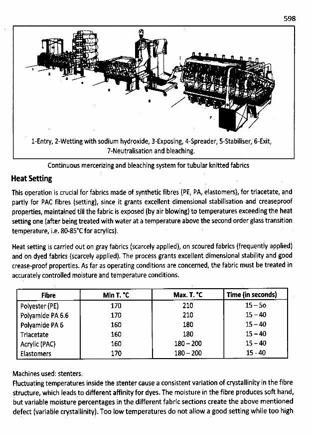
598
l
IJ
5 .tl'r -,,--.gg;k...----- .... ----'.. . . . .- .
*
5
*, ' .
l-Entry, z-Wetting with sodium hydroxide, 3-Exposing, 4-spreadef, s-stabiliser, 6-Exit,7-Neutralisation and bleaching.
Continuous mercerizing and bleaching system for tubular khitted fabrics
Heat setting
This operation is crucial for fabrics made of synthetic fibres (PE, PA, elastomers), for triacetate, andpartly for PAC fibres (setting), since it grants excellent dimensional stabilisation and creaseproofproperties, maintained till the fabric is exposed (by air blowing) to temperatures exceeding the heatsetting one (after being treated with water at a temperature above the second order glass transitiontemperature, i.e. 80-85*C for acrylics).
Heat setting is carried out on gray fabrics (scarcely applied), on scoured fabrics (frequently applied)and on dyed fabrics (scarcely applied). The process grants excellent dimensional stability and goodcrease-proof properties. As far as operating conditions are concerned, the fabric must be treaied 'inaccurately controlled moisture and temperature conditions.
Fibre Min T. @C MaX.T. *C Time (in setonds)polyester (PE) 170 210 15 - 50Polyamide PA 6.6 170 210 15 - 40Polyamide PA 6 160 180 15 - 40Triacetate 160 180 1$ - 40Acrylic (PAC) 160 180 - 200 15 - 40Elastomers 170 180 - 200 15 - 40
Machines used: stenters.Floctuating temperatures inside the stenter cause a consistent variation of crystallinity in the fibreqtrudure, which leads to different affinity for dyes. The moisture in the fibre produces soft hand,but variable moisture percentages in the different fabric sedions create the above mentionetdefed (variable crystallinity). Too Iow temperatures do not allow a good setting while too high
599
temperatures and too Iong setting times cause yellowing (PA and elastic fibres), Stiff hand (acrylics),and Ioss of elasticity (elastic fibres).
The presence of combustion gas (N0x) produces a yellowing of the elastomers. The heat settingprocess carried out before scouring could fix the stains on the fabric or make the scouring processmore difficult due to the modification of the Iubricating produds (cracking with emission ofpolluting gas). Heat setting after dyeing could lead to the sublimation of disperse dyes (if notaccurately selected).
Decortitatio: (only for polyester)This treatment is aimed at providing a siIky-smooth hand to polyester fabrics (till a few years agothis process was also used to obtain microfilaments by increasing the fibre fineness), a Iustrouseffed and an enhanced drapability. The best results can be obtained with fabrics produced withCoarser Yarns.
The open-width decortication process can be carried out on jiggers or beam dyeing machines; ropedecortication is performed on jet or overflow systems (batch systems). Decortication is carried outafter scouring and heat setting; it is better to carry out a heat setting treatment also after thedecortication process.
Operating conditions applied: the process is carried out at a temperature varying from 90-95*C to120-130 *C for 20-35 minutes, with 30-50 VI of Na0H 36@Bé. Once the process has been completed,the fabric is washed and neutralised. Processes and machines used: open-width process on jiggersor beam dyeing machines (batch systems) or special tensionless open-width continuous machines.
Elastit Fabrits
For elastic fibres, treatments depend on the chemical composition, which can be extremelyvariable. As far as the fabrics containing segmented polyurethane fibres are concerned, thesuggested treatments to be carried out are the following:
- relaxation- heat setting- scouring- bleachin/dyeing/printing- finishing
Relaxation: Before carrying out any further treatment, it is recommended to relax woven or knitted
goods to obtain a uniform shrinkage and avold stitcb distortion or fabric deformation, creases orwiinkles. The fabric relaxation is a crucial step to allow good shrinkage and give excellent elasticity
since the fabric width on looms is always bigger than tbe finished one (tensioned yarns on theIoom). Many techniques are used but here are some of the most frequently used ones: table
600
stealing, steaming carried out at tbe entry of the stenter, scouring carried out with hot solvents,relaxation in hot water with tensionless scouring; these techniques give poorer stabilisation resultsand do not provide permanent crease resistance to textiles and fabrics.
Heat setting: This process is crucial to give the fabric an optimum dimensional stability. It isretommended to carry out a heat setting treatment before any further wet treatment in order toavoid the formation of possible creases and folds. An optimum heat settiig requires a temperatureranging between 180*-200*C, which must be maintained constant for at Ieast 4j minutes. Anoptlmum heat setting also requires the use of an iidired-air heating stentes, illowing mote uniformtemperatures and no-gas conditions, which could lead to fibre yellowing. The fabric is wiighed atthe entry of the stenter and then subjeded to steaming. Since the fabric shrinks dufing the hèatsetting treatment, the fabric width on the stenter must exceed the desired width by 5-10%. Anexcessive heatsettingcould decolorisethefabricwhile an insugicient àeatseuingwlll result Ii poorfabricstability.
R ouring: It is necessary to carefully consider the characteristics of the fibre combined With the
polyurethane elastomer.
Bleathing: This treatment is carried out using sodium hydrosulphite; a suitable optical bleaching
agent can also be added.
W ashing
Rinsing and washing are the operations carried out most frequently during a complete textilefinishing cycle. They are almost always cohneded to key treatments and aimed at removing fromthe fabric insoluble matters, matters already in solution or an emulsion of other impurities. Duringthe fabric preparation process, for example, washing is carried out after desizing, boiling and otherbleaching and mercerising processes; in dyeing, the washing stage is necessary to complete thedyeing process itself or to eliminate the dyestuff which has not been fixed; during the printing stage,washing performs a finishing action. W hen using vat dyes or disperse dyes, the washing processaims at removing insoluble pigment substances from the fibre surface by means of wetting or
dissolving agents.
This could therefore be considered a crucial treatment in the whole textile process, because of thefrequent use and strong economic impad. Manufadurers increasingly focus their attention onreducing water consumption, which Ieads to subsequent energy and hot water saûing as well as aredudion in wastewater. Together with traditional washing systems with vats equipped with''vertical cylinders'' the market offers horizontal washing units, which reduce the liquor ratio and theenergy and water consumption for each kilogram of washed material. W ashing includes a chemical-physical process, which removes the dirt from the substrate, and a series of physical operationsaiming at improving the ''feedback actionn.
The seq'uence of the various washing steps is the follbwing:a. formation of the detergent Iiquor (transfer of matter + energy by mixing);b. reaching of the process temperature and wetting (transfer of the liquor to the material);
)'
t601c. separation of impurities and emulsification (transfer of matter from one step to th# ;
J.other); . :' '
t 'd. removal of the Iiquor from the fibre (transfer of macroscopic matter); )e. drying (interstage transfer of heat and matter). ''';
t ?qOften these steps occur simultaneously. The use of surfactants (detergents) during the washing)stage is extremely important te speed up the wetting of the textile material, to facilitate the '.removal of dirt from the substrate, thus keeping the emulsion inside the Iiquor and pfeventing the èparticles Iaying down again on the fibre. Crucial factors are water (which must be quite soft to avoidprecipitation of Ca and Mg salts which could give a rough and coarse hand to the textile) andchemical products to be used (emulsifying agents, softening agents and surfactants). )
)contaminants to be eliminated
obviously the use of detergents, as well as operating conditions, depends on the nature of the
chemical substances to be eliminated, which need to be generally classified. A general classification:is shown here below:
. ''y
1) Spinning oils: We must distinguish between fabrics made with yarns spun from combed or ).carded fibres, which are extremely different in terms of quantity (5 and 1% respectively) andthe nature of the substances added: as far as nature is concerned
, the Substances most '.frequently used are in b0th cases synthetic or mineral oils. These oils are usually made è
:iselfemulsifiable by means of suitable additives (materials must always be accurately :evaluated since a wide range or produds and prices are now available on the market); olein tcan be used for woollens (oleic acid) while for worsteds a good alternative can be ,represented by vegetal oils; i
2) Sizes: For treating wool (opposite to cotton, where it is possible to use finish, which '.requires a special treatment), the stuffs now used (carboxymethyil cellulose or polyvinyl .alcohol) tan be easily eliminated and do not give particular problems; ''3) oily stains: It is very difficult to eliminate these types of stain due to their characteristics '
.. ' j;and to their deep degree of penetration in the fabric; oily stains usually require a ,
pretreatment with solvents sprayed directly on the stain (by means of a special ''spray gun''). #They can also be removed using special expensive detergents containing solvents
, or by '.'means of dry washing; q'
:,L4) solid residues of various nature (dust, non-fixed dyestuffs, etc.), usually fixed on the fabric yby means of fatty substances. To eliminate these residues
, general cleansing rules must be 'observed and applied and special atteqtion must be given to the mechanical action of
-
Jfridion. It is worth specifying that the above mentioned discussion is not at aII exhaustive; inparticular, it is not a text relating to the treatment and elimination of severe stains (colors, r.metals, microbiological attacks, etc.), which cannot be treated with standard cleansing '(processes. Readers are recommended to consult the specific literature available on this ;subjed. 1
!, E) .ê
. Jk
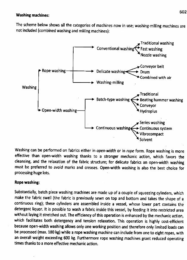
602Washing machines:
The scheme below shows all the categories of machines now in use; washing-milling machines arenot included (combined washing and milling machines):
Conveyor beltRope washing Delicate washing Drum
Combined with airWashing-milling
Washing
Open-width washing
TraditionalBatch-type washing Beating hammer washing
ConveyorHydroplus
Series washingContinuous washing Continuous system
VibrocompactSolvent
Traditional washingConventional washing Fast washing
Nozzle washing
W ashing can be performed on fabrics either in open-width or in rope form. Rope washing is moreeffedive than open-width washing thanks to a stronger mechanic action
, which favors thecleansing, and the relaxation of the fabric strudure; for delicate fabrics an open-width washingmust be preferred to avoid marks and creases. Open-width washing is also the best choice forprocessing huge lots.
Rope washing:
Substantially, batch piece washing machines are made up of a couple of squeezing cylinders, which
make the fabric swell (the fabric is previously sewn on top and bottom and takes the shape of acontinuous ring); these cylinders are assembled inside a vessel, whose Iower part contains thedetergent Iiquor. It is possible to wash a fabric inside this vessel
, by feeding it into restricted areawithout laying it stretched out. The efficiency of this operation is enhanced by the mechanic adion
,which facilitates both detergency and tension relaxation. This operation is highly cost-efficientbecause open-width washing allows only one working position and therefore only Iimited Ioads canbe processed (max. 180 kg) while q rope washing machine can include from one to eight ropes, withan overall weight exceeding 600 kg. Furthermore rope washing machines grant reduced operatingtimes thanks to a more effedive mechanic adion.
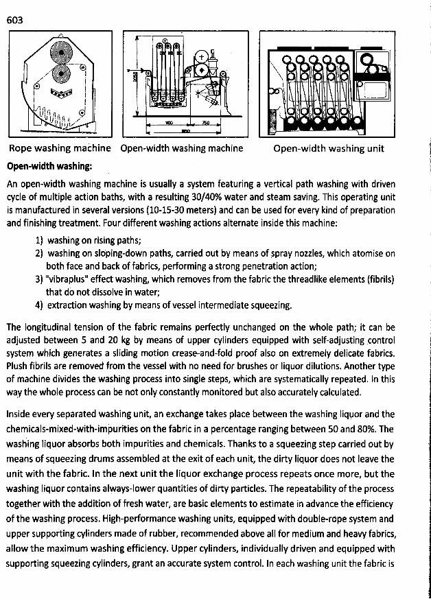
603
Rope wàshing machine
Open-width washing:
î-- -+ +iil!l -... -) -grq i- .. ---
.
-
- r -- ..
' -' ''
-,4j--:::(y;iE:j...I kz = -:.
uj
Open-width washing machine
i
'>$
'
l5 ë u- - wi! :4
. !.% ' k?
Open-width washing unit
An open-width washing machine is usually a system featuring a vertical path washing with drivencycle of multiple action baths, with a resulting 30/40% water and steam saving. This operating unitis manufactured in s:veral versions (10-15-30 meters) and can be used for every kind of preparationand finishing treatment. Four different washing adions alternate inside this machine:
1) washing on rising paths;2) washing on slèping-down paths, carried out by means of jpray nozzles, which atomise onboth face and back of fabrics, performing a strong penetration action;
3) ''vibraplus'' effed washing, which removes from the fabric the threadlike elements (fibrils)that do not dissolve in water;
4) extradion washing by means of vessel intermediate squeezing.
The Iongitudinal tension of the fabric remains perfectly unchanged on the whole path; it can beadjusted between 5 and 20 kg by means of upper cylinders equipped with self-adjusting controlsystem which generates a sliding motion crease-and-fold proof also on extremely delicate fabrics.Plush fibrils are removed from the vessel with no need br brushes or Iiquor dilutions. Another typeof machine divides the washing process into single steps, which are systematically repeated. In thisway the whole process can be not only constantly monitored but also accurately calculated.
Inside every separated washing unit an exchange takes place between the washing Iiquor and the
chemicals-mixed-with-imhurities on the fabric in a percentage ranging between 50 and 80%. Thewashing Iiquor absorbs both impurities and chemicals. Thanks to a squeezing step carried out bymeans of squeezing drums assembled at the exit of each unit, the dirty Iiquor does not Ieave theunit with the fabric. In the next unit the Iiquor exchange process repeats once more, but thewashing Iiquor contains always-lower quantities of dirty particles. The repeatability of the process
together with the addition of fresh water, are basic elements to estimate in advance the efficiency
of the washing process. High-pedormance washing units, equipped with double-röpe system andupper supporting cylinders made of rubber, recommended above aII for medium and heavy fabrics,allow the maximum washing efficiency. Upper cylinders, individually driven and equipped with
supporting squeezing cylinders, grant an accurate system control. In each washing unit the fabric is
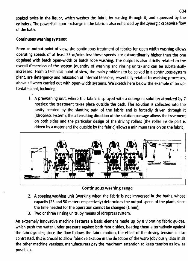
604
soaked twice in the Iiquor, which washes the fabric by passing through it, and squeezed by thecylinders. The powerful Iiquor exchange in the fabric is also enhanced by the synergic crosswise flowof the bath.
Continuou: washing sptems:
From an output point of view, the continuous treatment of fabrics f0r open-width washing alI0w5operating speeds of at least 25 m/minutes: these speeds are extraordinarily higher than the oneobtained with batch open-width or batch rope washing. The output is also strictly related to the
overall dimension of the system (quantity of washing and rinsing units) and can be substantiallyincreased. From a technical point of view, the main probl:ms to be solved in a continuous-systemplant, are detergency and relaxation of internal tensions, essentially related to washing processes
,
above aII when carried out with open-width systems. W e sketch here below the example of an up-to-date plant, including:
1. A prewashing unit, where the fabric is sprayed with a detergent solution atomized by 7nozzles: the treatment takes place outside the bath. The solution is collected into thecavity created by the slanting patb of the fabric and is forcedly driven through it(ldropress system); the alternating direction of the solution passage allows the treatmenton b0th sides and the particular design of the driving rollers (the roller inside part isdriven by a motor and the outside by the fabric) allows a minimum tension on the fabric;
9! ' .. '
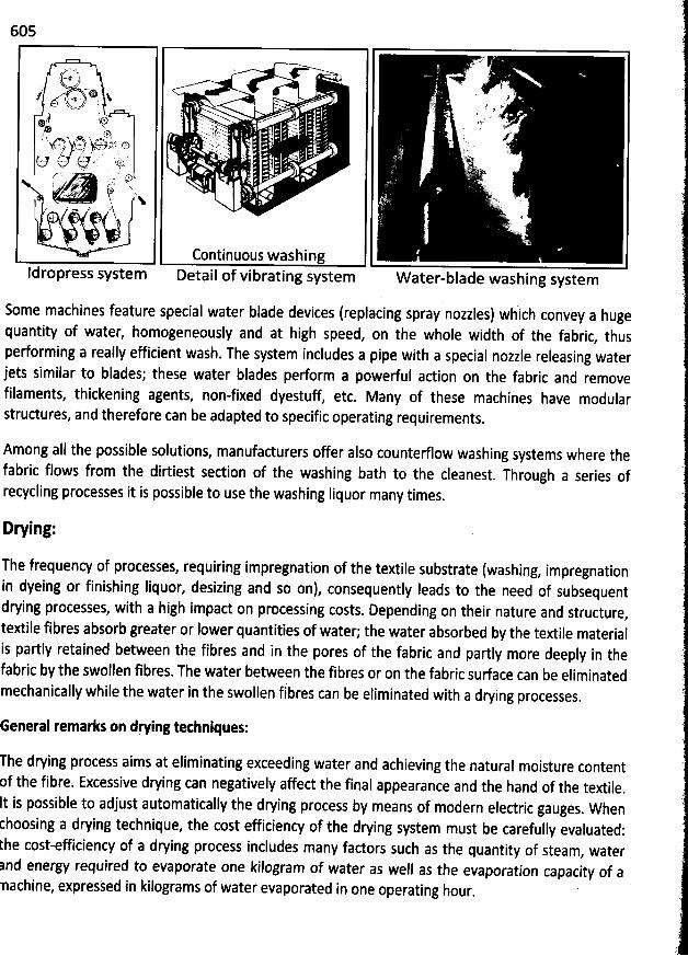
605
. = . . %N './ .- .r. : .è
'
' . a
'v @..- *. & . . u J./' ypnq' . - 1, g . . . x. . qv.J(r''.'' hu z' : .' -' '''
. . j y Z: à. , N . '. ' z '. 2' 'N ..M ' dt1! hj:jsliql x. ' .'.'.''.. . . . .'.' 'tg) ' s .v $,:,: .*/ . -.. )r . .jjjj Nx . ' . . . ' , . . . .j v. .. .sjjpw.,
' t .. ! ' . .' Ov v ,# . --k. .). k!n..+ . s!f t,r)t . . ...t. q.' ... -' !. . . - . ). ... !I.' a. . .N . ë# . ..$. r v.. u .e' * . . '''- ' <. '. . . .
.,(w Aup ', . . : 'x .' x. s ' ..: 2: * a
?ze ' l . .. .' lkl..'hi'b ' . ',g. , ...' .i j..'.i . *q .. #. w) . x . cr'.... y*' !jy 'ajjjjj x. u. ' .
., ' ..,.. z'lsk . . 4 .
Continuous washingIdropress system Detail of vibrating system W ater-blade washing system
Some machines feature special water blade devices (replacing spray nozzles) wàich convey a hugequantity of water, homogeneously and at high speed, on the whole width of the fabric
, thusperforming a really efficient wash. The system includes a pipe with a special nozzle releasing waterjets similar to blades; these water blades perform a powerful adion on the fabric and removefilaments, thickening agents, non-fixed dyestuff
, etc. Many of these machines have modularstrudures, and therefore can be adapted to specific operating requirements.
Among aII the possible solutions, manufacturers offer also counterflow washing systems where thefabric flows from the dirtiest sedion of the washing bath to the cleanest
. Through a series ofrecycling processes it is possible to use the washing Iiquor many times.
Drying:
The frequency of processes, requiring impregnation of the textile substrate (washing, impregnationin dyeing or finishing Iiquor, desizing and so on), consequently leads to the need of subsequentdrying processes, with a high impact on processing costs. Depending on their nature and structure
,textile fibres absorb greater or lower quantities of water; the water absorbed by the textile materialis partly retained between the fibres and in the pores of the fabric and partly more deeply in thefabric by the swollen fibres. The water between the fibres or on the fabric surface can be eliminatedmechanically while the water in the swollen ftbres can be eliminated with a drying processes.
General remarks on drying tethniques:
The drying process aims at eliminating exceeding water and achieving the natural moisture contentf the fibre. Excessive drying can negatively affect the final appearance and the hand of the textile
.
t is possible to adjust automatically the drying process by means of modern eledric gauges. Whenhoosing a drying technique, the cost efficiency of the drying system must be carefully evaluated:he cost-effitiency of a drying process includes many fadors such as the quantity of steam
, waternd energy required to evaporate one kilogram of water as well as the evaporation capacity of aachine, expressed in kilograms of water evaporated in one operating hour
.
606Adjustment of the moisture tontent in the drying process :The drying speed is determined by the difference between'the tension of water steam on the textilesurface and the tension of the water steam in thi drying unit: it increases proportionally to thedecrease of the moisture content in the air of the unit. In order to keep this content on low Ievels itis necessary to blow in the drying units huge quantities of heated air at tàe same temperature of thedrying unit, which Ieads to huge energy consumption. When setting the desired moisture degree ofthe air in the drying unit, it is worth considering that the best degree results from a correctproportion between efficient output speed and costeffective energy consumption.
Adjustment olthe drying speed:The optimum time a fabric spends within a drying unit must correspond exactly to the timenecessary to eliminate the moisture on the surface and between the free spaces of the fibres; thestay time must not exceed the optimum drying time (this would cause an extra drying) since the''natural'' moisture of the textile must not be eliminated. The feeding speed of the fabric is adjustedby means of the special devices assembled at the exit of the drying unit
, which vary proportionallyto the moisture of the fabric leaving the unit.
Heating of the drying unit:
The drying units are usually heated by means of steam with an average thermal efficiency of about64%. Better thermal efficiency is granted by dryers heated with thermal fluid (about 80%). Highlyefficient heating is obtained by means of direct gas combustion
, with an e#iciency of almost 95%.The operating temperature can be reached in very short times and heating can be stoppedsimultaneously with the machine.
Hydroextradion:
This process removes the water (the water quantity varies according to the type of fibre) dispersedin the fibres by mechanical action; this process aims at reducing energy consumption and is carriedout before the final fabric drying or between the various wet procéssing stages (washing, dyeing). Itcan be carried out in the following ways:
- Squeezing: The water dispersed on the surface and in the spaces of the fabric is removedby means of the pressure applied by two cylinders.
- Centrifugation: This process eliminates the greatest quantity of water dispersed on thesurface of the textile by centrifugal force. It is applied above aII to resistant yarns
, knittedgoods and fabrics.
- Steam pressure: A high-speed steam jet blown on the whole width of the stretched fabricpasses through the c10th and eliminates the water in excess. Extracted water and steam arecondensed and reused. '
- Vacuum: This method applies vacuum technology and is used to dry very wet fabrics ordelicate fabrics that do not stand up to the pressure of the cylinders of a squeezing unit
,
which could negatively affed the surface structure. The stretched fabric slides open-widthabove the opening of a cylinder-shaped structure coqneded to a suction system. The airdrawn from outside removes the exceeding water when passing through the textile c10th
.
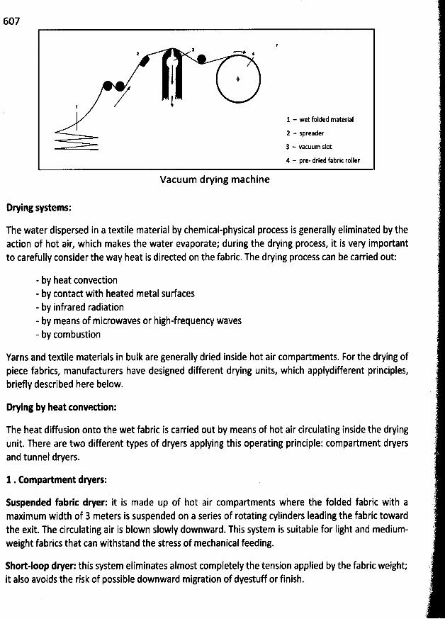
607
2 4
111 - wet folded material
2 - spreader
3 - vacuum slot
4 - pre- dried fabric roller
Vacuum drying machine
Drying systems:
The water dispersed in a textile material by chemical-physical process is generally eliminated by theaction of hot air, which makes the water evaporate; during the drying process, it is very importantto carefully consider the way heat is directed on the fabric. The drying process can be carried out:
- by heat convection- by contad with heated metal sudaces- by infrared radiation- by means of microwaves or high-frequency waves- by combustion
Yarns and textile materials in bulk are generally dried inside hot air compartments. For the drying ofpiece fabrics, manufacturers have dejigned different drying units, which applydifferent principles,briefly described here below.
Drying by heat tonvedion:
The heat diffusion onto the wet fabric is carried out by means of hot air circulating inside the dryingunit. There are two different types of dryers applying this operating principle: compartment dryersand tunnel dryers.
1 . Compartment dryers:
Suspended fabric dryer: it is made up of hot air compartments where the folded fabric with amaximum width of 3 meters is suspended on a series of rotating cylinders Ieading the fabric tewardthe exit. The circulating air is blown slowly downward. This system is suitable for Iight and medium-weight fabrics that can withstand the stress of mechanical feeding.
Short-loop dryer: this system eliminates almost completely the tension applied by the fabric weight;it also avoids the risk of possible downward migration of dyestuff or finish.
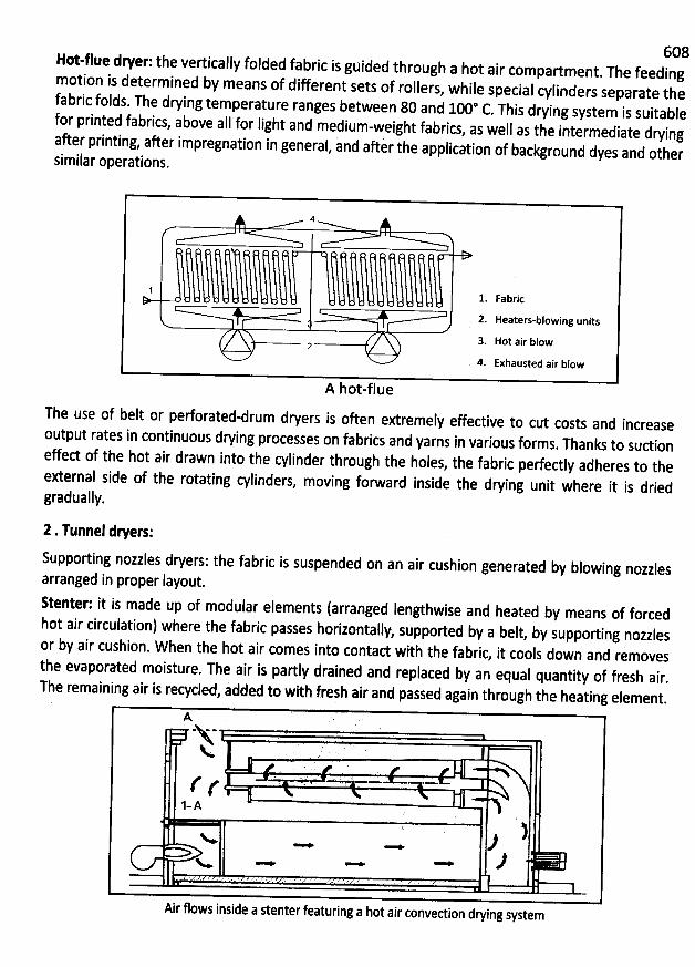
608Hot-flue deer: the vertically folded fabric is guided through a hot air compartment. The feedingmotion is dete
rmined by means of different sets of rollers, while special cylinders separate thef
abric fplds. The drying temperature ranges between 80 and 100* C. This drying system is suitablef
or printed fabrics, above aII for light and medium-weight fabrics, as well as the intermediate dryingafter printing, aker impregnation in general
, and aftir the application of background dyes and othersimilar operations.
4
1 1. Fabric
2. Heaters-blowing units
3. Hot air blow2
. 4. Exhausted air blow
A hot-flue
The use of belt or perforated-drum dryers is often extremely effective to cut costs and increase
output rates in continuous drying processes on fabrics and yarns in various forms. Thanks to suction
effed of the hot air drawn into the cylinder through the holes, the fabric pedectly adheres to the
external side of the rotating cylinders, moving forward inside the drying unit where it is dried
gradually.
2 .Tunnel dlers:
Supporting nozzles dryers: the fabric is suspended on an air cushion generated by blowing nozzlesarranged in proper Iayout.
Stenter: it is made up of modular elements (arranged Iengthwise and heated by means of forcedhot air circulation) where the fabric passes horizontally
, supported by a belt, by supporting nozzlesor by air cushion. When the hot air comes into contad with the fabric
, it cools down and removesthe evaporated moisture. The air is partly drained and replaced by an equal quantity of fresh air
.The remaining air is recycled, added to with fresh air and passed again through the heating element.
A (
, ,. '
'
.
'
k' ;'
( . . ! -(1-A
t . )< - - J
- J< - :
Air flows inside a stenter featuring a hot air convection drying system
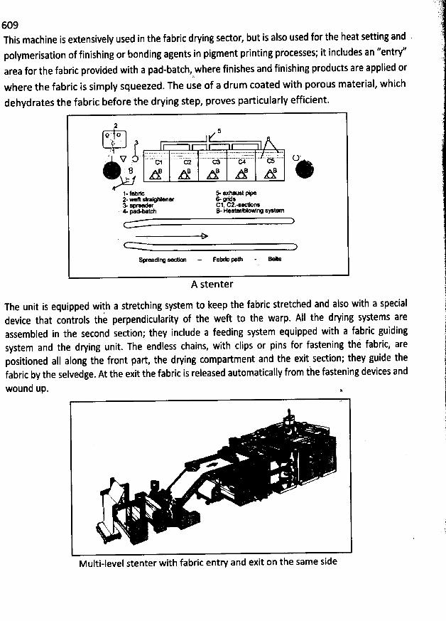
609This machine is extensively used in the fabric drying sector, but is also used for the heat setting and .
polymerisation of finishing or bonding agents in pigment printing pfocesses; it includes an ''entr/area for the fabric provided with a pad-batch, where finishes and finishing products are applied or
wbere the fabric is simply squeezed. The use of a drum coated with porous material, which
dehydrates the fabric before the drying step, proves particularly efficient.
5# ' tj'j; '; 'j. .... 7 . EL 5 ': :7 ..:-7 :. . - : :7 .7 7:. . 7 . 7.2:: -. . ..
hjjr . ..... .-.. ........ .. .. ..-..-.- .-- .--L -. ..... -* .. . . .... jkSj* .Ni ëi t)b iji c
8 e : B B BA A A A A:.*l-fabrt se axty-2-- G hten- Gyds3. s- c1. c2.-*- ' n:m pa d.batch B- H e a ter 'agowl r/ s > t em
so djrx ., oijjyu r.o . .
A stenter
The unit is equipped with a stretching system to keep the fabric stretched and also with a specialdevice that controls the perpendicularity of the weft to the warp. A11 the drying systems areassembled in the second sedion; they include a feeding system equipped with a fabric guidingsystem and the drying unit. The endless chains, with clips or pins for fastening thi fabric, arepositioned aII along the front part the drying compadment and the exit sedion; they guide thefabric by the selvedge. At the exit the fabric is released automatically from the fastening devices and
wound up. .
X .q
'
Multi-level stenter with fabric entry and exit on the same side
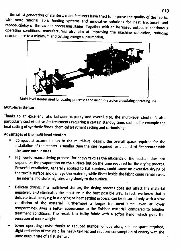
610ln the Iatest generation of stenters
, manufadurers have tried to improve the quality of the fabricswith more rational fabric feeding systems and innovative solutions for heat treatment andreproducibility of the various processing stages
. Together with an increased output in continuousoperating conditions, manufacturers also aim at improving the machine utilization, reducingmaintenance to a minimum and cutting energy consumption
.
y/
Multi-level stenter used for coating processes and incorporated on an existing operating Iine
Multi-level stenter: .
Thanks to an excellent ratio between capacity and overall size, the multi-level stenter is alsoparticularly cost effedive for treatments requiring a certain standby time
, such as for example theheat setting of synthetic fibres, chemical treatment setting and carbonising.
Advantages of the multi-level stenter:* Compad strudure: thanks to the multi-level design, the overall space requirqd for the
installation of the stenter is smaller than the one required for a standard flat stenter withthe same output rates.
* High-performance drying process: for heavy textiles the efficiency of the machine does notdepend on the evaporation on the surface but on the time required for the drying process
.
Powerful ventilation, generally applied to flàt stenters, could cause an excessive drking ofthe textile surface and damage the material, while fibres inside the fabric could remain wet.The internal moisture migrates very slowly to the sudace.
* Delicate drying: in a multi-level stenter, the dwing process does not affed the materialnegatively and eliminates the moisture in the best possible way
. In fact, we know that adelicate treatment, e.g in a drying or heat setting process, can be ensured only with a slowventilation of the material. Fulhermore a Ionger treatment time
, even at lowertemperatures, gives a better appearance to the finished material
, compared to toughertreatment conditions. The result is a bulky fabric with a softer hand, which gives thesensation of more weight.
Lower operating costs: thanks to reduced number of operators, smaller space required,slight redudion of the yield for heavy textiles and reduced consumption of energy with thesame output rate of a flat stenter.
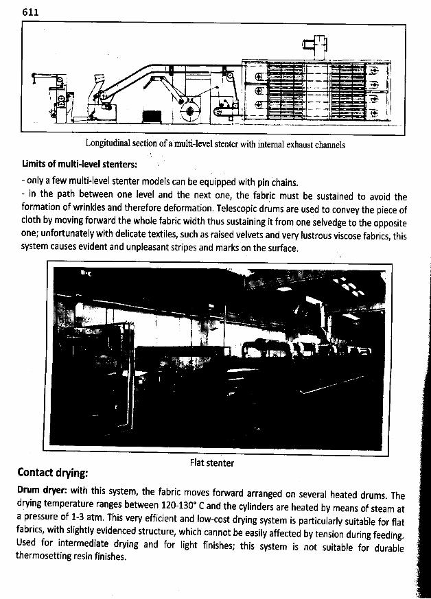
611
'v * ' ** 7 % j* t< . > .. t
, . j - ....- ...> j: ! +x t .- =t g Il i'. - ''
'- ' . ''''> .
.,' lI ' .. j , T . ''- ..- . ..... . ..+ ' ' ? -e'. , s !d * < .j h 3 '-' m.- -- t. . , r . j ''pe'- . . 4 . tN j ; ! - - .,- . ..w .
Longitudzal stction of a muld-ltvtl stenter with internal exhaust channels
timits of multi-level stenters:- only a few multi-level stenter models can be equipped with pin ihains.- in the path between one level and the next one
, the fabric must be sustained to avoid tbeformation of wrinkles and therefore deformation. Telescopic drums are used to convey the piece ofc10th by moving forward the whole fabric width thus sustaining it from one selvedge to the oppositeone; unfortunately with delicate textiles, such as raised velvets and very Iustrous viscose fabrics
, thissystem causes evident and unpleasant stripes and marks on the surface.
2 'v-j. . . . ' .' r .yL. . , j - -. . u
.. ( . . s jj .e k. !' , .' . ejjy/. ?u ' j.
x ' ï ) .;â ' .: ,. k ).
.. . ... )
Flat stenterContad dling:
Drum dryer: with this system, the fabric moves forward arranged on several heated drums. Thed
rying temperature ranges between 120-130* C and the cylinders are heated by means of steam ata pressure of 1-3 atm. This very efficient and Iow-cost drying system is particularly suitable for flatfabrics, with slightly evidenced structure
, which cannot be easily affected by tension during feeding.Used for intermediate drying and for Iight finishes; this system is not suitable for durable
thermosetting resin finishes.
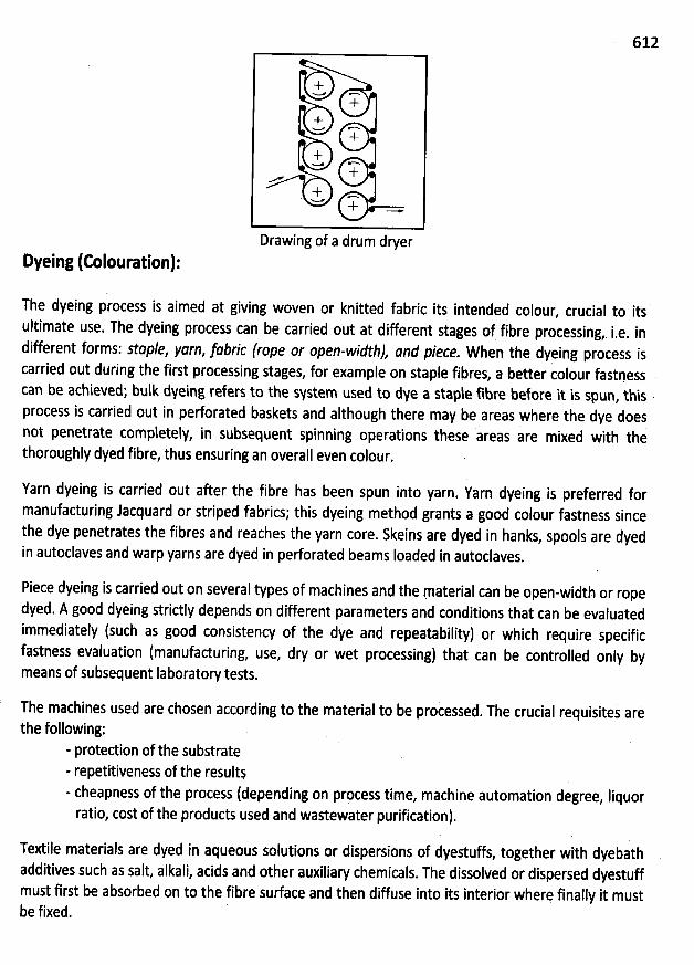
612
+W n
++w n
++w n
++ .-%-# +
Drawing of a drum dryer
Dyeing (Colouration):
The dyeing process is aimed at giving woven or knitted fabric its intended colour, crucial to its
ultimate use. The dyeing process can be carried out at differenl stages of fibre processing, i.e. in
different forms: staple, yarn, jabric (rope or open-widthj Jnd piece. When the dyeing process iscarried out during the first processing stages
, for example on staple fibres, a better colour fastpesscan be achieved; bulk dyeing refers to the sNstem used to dye a staple fibfe before it is spun
, thisprocess is carried out in perforated baskets and although there may be areas where the dye doesnot penetrate completely, in subsequent spinning operations these areas are mixed with thethoroughly dyed fibre, thus ensuring an overall even colour
.
Yarn dyeing is carried out aker the fibre has been spun into yarn. Yarn dyeing is preferred formanufacturing Jacquard or striped fabrics; this dyeing method grants a good colour fastness sincethe dye penetrates the fibres and reaches the yarn core
. Skeins are dyed in hanks, spools are dyedin autoclaves and warp yarns are dyed in perforated beams Ioaded in autoclaves
.
Piece dyeing is carried out on several types of machines and the material can be open-width or ropedyed. A good dyeing strictly depends on different parameters and conditions that can be evaluated
immediately (such as good consistency of the dye and repeatability) or which require specificfastness evaluation (manufacturing, use, dry or wet processing) that can be controlled only bymeans of subsequent Iaboratory tests.
The machines used are chosen according to the material to be processed. The crucial fequisites are
the following:- protedion of the substrate- repetitiveness of the results- cheapness of the process (depending on prpcess time, machine automation degree, Iiquorratio, cost of the products used and wastewater purification).
Textile materials are dyed in aqueous solutions or dispersions of dyestuffs, together with dyebathadditives such as salt, alkali, acids and other auxiliary chemicals. The dissolved or dispersed dyestuffmust first be absorbed on to the fibre surface and then diffuse into its interior where finally it mustbe fixed.
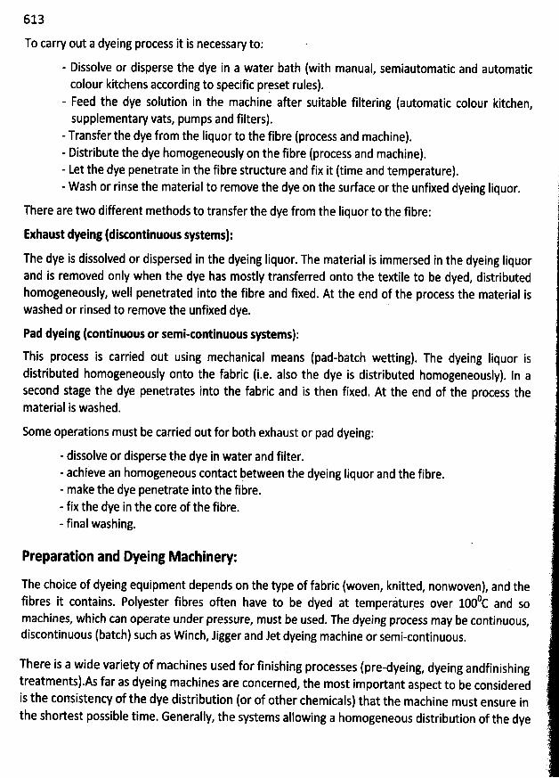
613
To carry out a dyeing process it is necessary to:
- Dissolve or disperse the dye in a water bath (with manual, semiautomatic and automaticcolour kitchens according to specific prpset rules).
- Feed the dye solution in the machine after suitable filtering (automatic colour kitchen,supplementary vats, pumps and filters).
- Transfer the dye from the Iiquor to the fibre (process and machine).- Distribute the dye homogeneously on the fibre (process and machine).- Let the dye penetrate in the fibre structure and fix it (time and temperature).- Wash or rinse the material to remove the dye on the sudace or the unfixed dyeing Iiquor.
There are two different methods to transfer the dye from the Iiquor to the fibre:
Exhaust dyeing (distontinuous systems):The dye is dissolved or dispersed in the dyeing liquor. The material is immersed in the dyeing liquorand is removed only when the dye has mostly transferred onto the textile to be dyed, distributedhomogeneously, well penetrated into the fibre and fixed. At the end of the process the material iswashed or rinsed to remove the unfixed dye.
Pad dyeing (tontinuous or semi-continuous systems):
This process is carried out using mechanical means (pad-batch wetting). The dyeing Iiquor isdistributed homogeneously onto the fabric (i.e. also the dye is distributed homogeneously). In asecond stage the dye penetrates into the fabric and is then fixed. At the end of the process thematerial is washed.
Some operations must be carried out for both exhaust or pad dyeing:
- dissolve or disperse the dye in water and filter.- achieve an homogeneous contact between the dyeing Iiquor and the fibre.- make the dye penetrate into the fibre.- fix the dye in the core of the fibre.- final washing.
Preparation and Dyeing Mathinel :
The choice of dyeing equipment depends on the type of fabric (woven, knitted, nonwoven), and the0 d sofibres it contains. Polyester fibres often have to be dyed at temperitures over 100 C an
machines, which can operate under pressure, must be used. The dyeing process may be continuous,discontinuous (batch) such as Winch, Jigger and Jet dyeing machine or semi-continuous.
There is a wide variety of machines used for finishing processes (pre-dyeing, dyeing andfinishingtreatmentsl.As far as dyeing machines are concerned, the most important aspect to be consideredis the consistency of the dye distribution (or of other chemicals) that the machine must ensure inthe shortest possible time. Generally, the systems allowing a homogeneous distribution of the dye
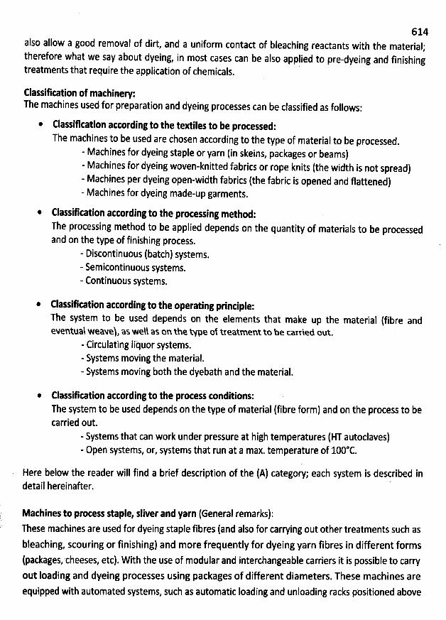
614also allow a good removal of dirt, and a uniform contad of bleaching reactants with the material;therefore what we say about dyeing
, in most cases can be also applied to pre-dyeing and finishingtreatments that require the application of chemicals.
Elassifkation of machinee:The machines used for preparation and dyeing processes can be classified as follows:
@ Classifkation acording to the textiles to be proçessed:The machines to be used are chosen according to the type of material to be processed
.
- Machines for dyeing staple or yarn (in skeins, packages or beams)- Machines for dyeing woven-knitted fabrics or rope knits (the width is not spread)- Machines per dyeing open-width fabrics (the fabric is opened and flattened)- Machines for dyeing made-up garments.
Classifkation attording to the processing method:The processing method to be applied depends on the quantity of materials to be processedand on the type of finishing process.
- Discontinuous (batch) systems.- Semicontinuous systems.- Continuous systems.
* Classifkation acording to the operating principle:The system to be used depends on the elements that make up the material (fibre andeventual weaveh, as well as on the type of treatmen: to be carrieu out.
- Circulating Iituor systems.- Systems moving the material.- Systems moving both the dyebath and the material.
Classifkation attording to the process conditions:The system to be used depends on the type of material (fibre form) and on the process to becarried out.
- Systems that can work under pressure at high temperatures (HT autoclaves)- Open systems, or, systems that run at a max. temperature of 100@C.
Here below the reader will find a brief description of the (A) category; each system is described indetail hereinaûer. '
Mathines to protess staple, sliver and yarn (General remarks):These machines are used for dyeing staple fibres (and also for carrying out other treatments such asbleaching, scouring or finishing) and more frequently for dyeing yarn fibres in different forms(packages, cheeses, etc). With the use of modular and interchangeable carriers it is possible to carryout Ioading and dyeing processes using packages of different diameters. These machines areequipped with automated systems, such as automatic loading and unloading racks positioned above
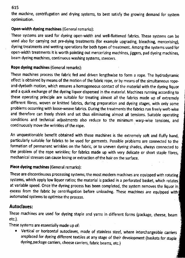
615
the machine, centrifugation and drying systems, to best satisfy the growing demand for systemoptimisation.
Open-width dyeing mathines (General remarks):These systems are used for dyeing open-width and well-flattened fabrics. These systems can beused also for carrying out pre-dying treatments (for example upgrading, bleaching, mercerising),dyeing treatments and wetting operayions for both types of treatment. Among the systems used foropen-width treatments it is worth pointing out mercerizing machines
, jiggers, pad dyeing machines,beam dyeing machines, continupus washing systems, stenters.
Rope dyeing mathines (General remarks):process the fabric fed and driven Iengthwise to form a rope. The hydrodynamic
effed is obtained by means of the motion of the fabric rope, or by means of the simultaneous rope-and-dyebath motion, which ensures a homogeneous contad of the material with the dyeing Iiquord a quick exchange of the dyeing Iiquor dispersed in the Material. Machines running according to 1an
tthese operating principle are suitable for treating almost aII the fabrics made up of extremely !different fibres, woven or knitted fabrics, during preparation and dyeing stages
, with only someproblems occurring with Ioose-weave fabrics. During the treatments the fabrics run freely wefbwiseand therefore can freely shrink and set thus eliminating almost aIl tensions. Suitable operating 'conditions and technical adjustments also reduce to the minimum warp-wise tensions, andcontinuously move the wrinkles of the rope.
An unquestionable benefit obtained with these machines is the extremely soft and fluffy hand, ''
blems are connected to the iparticularly suitable for fabrics to be used for garments. Possible proformation of permanent wrinkles on the fabric, or to uneven dyeing shades
, always connected to 'the problem of the rope wrinkles; for fabrics made up with very delicate or short staple fibres
, '2
mechanical stresses can cause Iosing or extraction of the hair on the surface. r
(
'
'
Piete dyeing mathines'tGeneral remarks):(.'These are discontinqous processing systems; the most modern machines are equipped with rotating j
systems, which apply low Iiquor ratios; the material is packed in a perforated basket, which rotatesr,at variable speed. Once the dyeing process has been completed, the system removes the Iiquor inrfexcess from the fabric by centrifugation before unloading. These machines are equipped withrautomated systems to optimise the process.
.)j.Autoclaves: uj
These machines are used for dyeing staple and yarns in different forms (package, cheese, beam ':etc-). k
These systems are essentially made up of: 1)* Vertical or horizontal autoclaves, made of stainless steet where interchangeable carriers )(areplaced for dyeing different textiles at any stage of their development (baskets for staple
dyeingzpackage carriers, cheese carriers, fabric beams, etc.) 6LL
)'
These machines
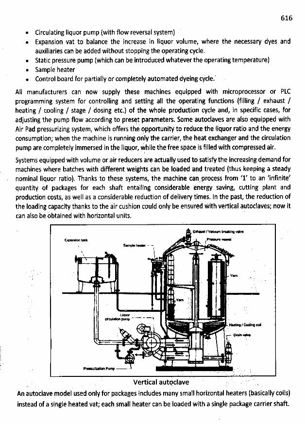
616
Circulating Iiquor pump (with flow reversal system). Expansion vat to balance the increase in Iiquor volume, where the necessary dyes and
auxiliaries can be added without stopping the operating cycle.. Static pressure pump (which can be introduced whatever the operating temperature). Sample heater. Control board for partially or completely automated dyeing cycle.
AII manufacturers can now supply these machines equipped with miiroprocessor or PLCing system for controlling and setting aII the operating fundions (filling / exhaust /programm
heating / cooling / stage / dosing etc.) of the whole produdion cycle and, in specific cases, foradjusting the pump flow according to presst parameters. Some autoclaves are also equipped withAir Pad pressurizing system, which offers the opportunity to reduce the liquor ratio and the energyconsumption; when the machine is runniqg pnly the carrier, the heat exchanger and the circulation
I tely immersed in the Iiquor, bhile,t'h: free spàce is filled with compressed air.pump are comp e
Systems equipped with volume Qr adr reducers are actually used to satisfythe increasing demand formachines where batches with different weights can be Ioaded and treated (thus keeping a steadynominal Iiquor ratio). Thanks to these systems, the machine can process from '1' to an 'infinite'quantity of packages for each shaft entailing considerablê qnergy saving, cutting plant andprodudion costs, as well as a considerable reduction of delivery times. In the past, the redudion ofhe Ioading capacity thanks to the air cushion could only be ensurèd With vertical auioclavés; n0w itt
l be obtained with horizontal units. 'can a so
r- -/v-.- Ke ov- . .
CO W ' WW XOWf. ne * . .m% ''M . $''. l'
u j .
. Yen
) '' . V* .1 ' ' .' ' 'l ' -' .'' . 'j ea- po----a y)
. . u- / -' txz! 4 ..
. . '
. .- - vw. l ''.
' g4 . '
- l
= ...>........... ' .% .. . . ' ' ' t
' l todav.e 'VCXIC: 3U ,
An atltoclave model used only for packages includes many small horizontal heaters (basically coils)instead of a single heated vat; each small heater can be Ioaded with a single package carrier shaft.
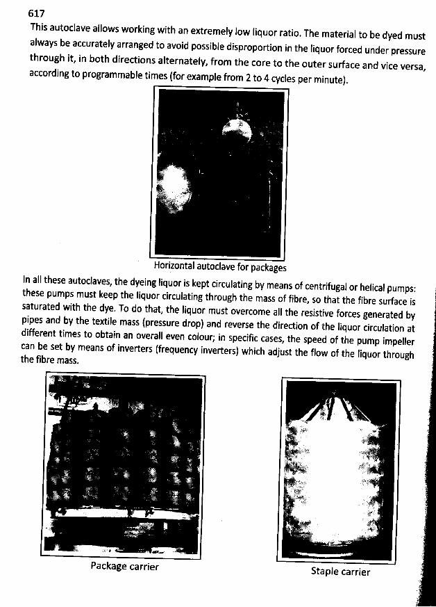
617This autoclave allows working with an extremely Iow (iquo
r ratio. The material to be dyed mustalways be accurately arranged to avoid possible dispropo
rtion in the Iiquor forced under pressurethrough it, in bothdiredionsalternately
, from the core to the outer surface and viceaccording toprogrammable times (for example from 2to 4 cycles per minute)
.
'',:()( ,1/311ï ..yy. . ... .. ..
. '&j . ' r. .
'
-.k. :n ,t)r 'y
vry)k L. z..7ïij,:k. j . ..l4jq
Horizontal autoclave fof packages
Versa,
ln all these autoclaves, the dyeing Iiquor is kept circulating by means of centrifugal or helical pumps:these pumps must keep the Iiquor circulating through the mass of fibre
, so that the fibre surface issaturated with the dye. To do that, the liquor must overcome alI the resistive forces generated b
ypipes and by the textile mass (pressure drop) and reverse the direction of the liquor circulation atdifferent times to obtain an overall even colour; in specific cases
, the speed of the pump impellercan be set by means of inverters (frequency inverters) which adjust the flow of the liquor throughthe fib
re mass.
Package carrier Staple carrier
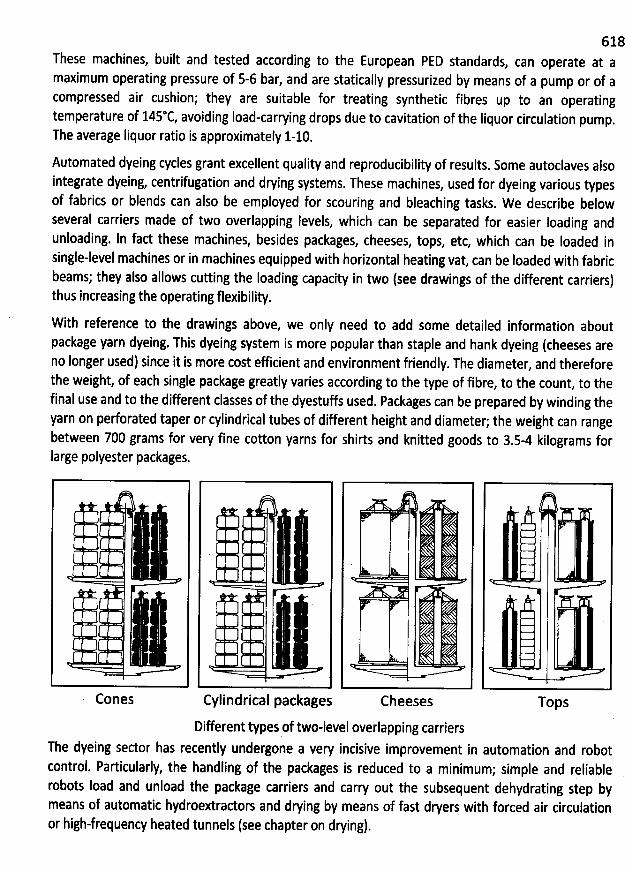
6 18These machines, built and tested according to the European PED standards
, can operate at amaximum operating pressure of 5-6 bar, and are statically pressurized by means of a pump or of acompressed air cushion; they are suitable for treating synthetic fibres up to an operatingtemperature of 145@C, avoiding Ioad-carrying drops due to cavitation of the Iiquor circulation pump.The average liquor ratio is approximately 1-10.
Automated dyeing cycles grant excellent quality and reproducibility of results. Some autoclaves alsointegrate dyeing, centrifugation and irying systems. These machines, used for dyeing various typesof fabrics or blends can also be employed for scouring and bleaching tasks. W e describe belowseveral carriers made of two overlapping levels, which can be separated for easier Ioading andunloading. In fact these machines, besides packages, cheeses
, tops, etc, which can be Ioaded insingle-level machines or in machines equippei with horizontal heating vat, can be loaded with fabricbeams; they also allows cutting the Ioading capacity in two (see drawings of the different carriers)thus increasing the operating flexibility.
With reference to the drawings above, we only need to add some detailed information aboutpackage yarn dyeing. This dyeing system is more popular than staple and hank dyeing (cheeses areno Ionger used) since it is more cost efficient and environment friendly. The diameter, and thereforethe weight, of each single package greatly varies according to the type of fibre
, to the count, to thefinal use and to the different classes of the dyestuffs used. Packages can be prepared by winding theyarn on perforated taper or cylindrical tubes of different height and diameter; the weight can rangebetween 700 grams for very fine cotton yarns for shirts and knitted goods to 3.5-4 kilograms forlarge polyester packages.
4Cones Cylindrical packages Cheeses Tops
Different types of two-level overlapping carriersThe dyeing sector has recently undergone a very incisive improvement in automation and robotcontrol. Particularly, the handling of the packages is reduced to a minimum; simple and reliablerobots load and unload the package carriers and carry out the subsequent dehydrating step bymeans of automatic hydroextradors and drying by means of fast dryers with forced air circulationor high-frequency heated tunnels (see chapter on dwing).
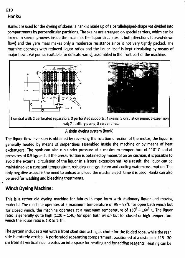
619
Hanks:
Hanks are used for the dyeing of skeins; a hank is made up of a parallelepiped-shape vat divided intocompartments by perpendicular partitions. The skeins are arranged on special carriers, which can beIocked in special grooves inside the macbine; the Iiquor circulates in both directions (up-and-downflow) and the yarn mass makes only a moderate resistance since it not very tightly packed. Themachine operates with reduced Iiquor ratios and the Iiquor itself is kept circulating by means ofmajor flow axial pumps (suitable for delicate yarns), assembled in the front part of the machine.
E ' 7C7 ' ; -1 ' ' ' ' '2 ''* ' S 'xus .. - ... . ; . ' .. (. .. '
. k. t.ct.!Vu.p .- - , t. ,
,. y .. .. - . . ,. ' . .
4 -.. ' v '6 *4 ' -''!); ,. . .
'. r.r jj..î j '. .. jr .. ,. .(;..r:DL'yv'
2 f '- è-.':.L ZA
O O O O7
5 8
1 central wall; 2 pedorated separators; 3 perforated supports; 4 skeins; 5 circulation pump; 6 expansionvat; 7 auxiliary pump; 8 serpentines.
A skein dyeing system (hank)The Iiquor flow inversion is obtained by reversing the rotation direction of the motor; the liquor isgenerally heated by means of serpentines assembled inside the machine or by means of heatexchangers.' The hank can also run under pressure at a maximum temperature of 110* C and atpressqres of 0.5 kg/cmz. If the pressurisation is obtained by means of an air cushion, it is possible toavoid the external circulation of the Iiquor in a Iateral extension vat. As a result, the Iiquor can bemaintained at a constant temperature, reducing energy, steam and cooling water consumption. Theonly negative asped is the need to unload and load the machine each time it is used. Hanks can alsobe used for washing and bleaching treatments.
W inth Dyeing Mathine:
This is a rather oId dyeing machine for fabrics in rope form with stationary Iiquor and mùvingoc for open bath winch butmaterial
. The machine operates at a maximum temperature of 95 - 980 1600 c The Iiquorfor closed winch
, the machine operates at a maximum temperature of 130 - .ratio is generally quite high (i:20 - 1:40) for open bath winch but for closed or high temperaturewinch the Iiquor ratio is 1:8 to 1:10.
The system inclndes a vat with a front slant side acting as chute for the folded rope, while the rear
side is entirely vertical. A pedorated separating compartment, positioned at a distance of 15 - 30cm from its vertical side, creates an interspace for heating and for adding reagents. Heating can be
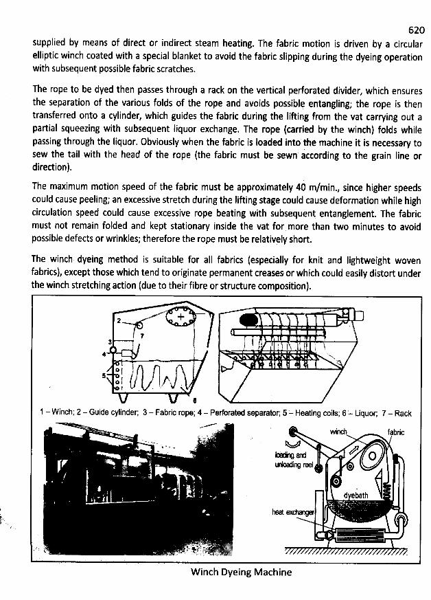
620supplied by means of direct or indirect stearh heating. The fabric motion is driven by a circularelliptic winch coated with a special blanket to avoid the fabric slipping during the dyeing operationwith subsequent possible fabric scratches.
The rope to be dyed then passes through a rack on the vertical perforated divider, which ensures
the separation of the various folds of the rope and avoids possiblq entangling; the rope is thentransferred onto a cylinder, which guides the fabric during the Iifting from the vat carrying out a
partias squeezing with subsequent liquor exchange. The rope (carried by the winch) folds whilepassing through the liquor. Obviously when the fabric is Ioaded into'the macbine it is necessary tosew the tail with the head of the rope (the fabric must be sewn according to the grain Iine ordirection).
The maximum motion speed of the fabric must be approximately 40 m/min., since higher speedscould cause peeling; an excessive stretch during the Iifting stage could cause deformation while highcirculation speed could cause excessive rope beating with subsequent entanglement. The fabricmust not remain folded and kept stationary inside the vat for more than two minutes to avoidpossible defects or wrinkles; therefore the rope must be relativçly short.
The winch dyeing method is suitable for aII fabrics (especially for knit and Iightweight wovenfabrics), except those which tend to originate permanent creases or which could easily distort underthe winch stretching adion (due to their fibre or structure composition).
x '
+2
' ..1 ( à
'
,, ,#. .
. . . )..j 'j ,kj &s.x
o t5o (t' . .
41 - Winch; 2 - Guide cylinder; 3 - Fabric rope; 4 - Perforated separator', 5 = Heating coils; 6 '- Liquor; 7 - Rack
. wincj fajric. . .. c ..y .' 1. ' '- L%' ' o s.. . ..
-v ... . .x .- , . a z or . '
. J '' *
. *f . '
dyebath
. . L't :. S # .- . k: . .t. ...<- . f tpqrjl-- . -,(E ..sï 7) - .. c.- Lk--. w, pt-yjlttkf
W inch Dyeing Machine
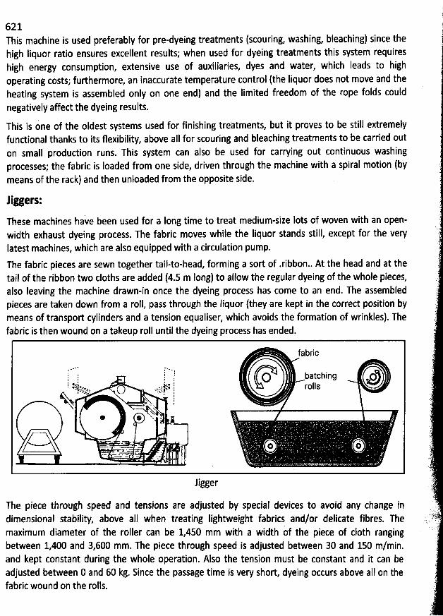
621This machine is used preferably for pre-dyeing treatments (scouring, washing, bleaching) since thehigh Iiquor ratio ensures excellent results; when used for dyeing tfeatments this system requireshigh energy consumption, extensive use of auxiliaries, dyes and water, which Ieads to highoperating costs; furthermore, an inaccurate temperature control (the Iiquor does not move and theheating system is assembled only on one end) and the Iimited freedom of the rope folds couldnegatively affect the dyeing results.
This is one of the oldest systems used for finishing treàtments, but it proves to be still extremelyfundional thanks to its flexibility, above aII for scouring and bleaching treatments to be carried outon small produdion runs. This system can also be used for carrying out continuous washingprocesses; the fabric is Ioaded from one side, driven through the machine with a spiral motion (bymeans of the rack) and then unloaded from the opposite side.
liggers:
These machines have been used for a Iong time to treat medium-size Iots of woven with an open-width exhaust dyeing process. The fabric moves while the Iiquor stands still, except for the veryIatest machines, which are also equipped with a circulation pump.
The fabric pieces are sewn together tail-to-head, forming a sort of .ribbon.. At the head and at thetail of the ribbon two cloths are added (4.5 m Iong) to allow the regular dyeing of the whole pieces,also Ieaving the machine drawn-in once the dyeing process has come to an end. The assembledpieces are taken down from a roll, pass through the liquor (they are kept in the correct position bymeans of transport cylinders and a tension equaliser, which avoids the formation of wrinkles). Thefabric is then wound on a takeup roll until the dyeing process has ended.
f abric
, ; , ! uatching o11 1 I .I l I
1 .e.. ja . .. jj. q<%- eœvo ssxo *x. ' r () See. c -c: I 'I .w . . I
x .* * N *
. . o o,...... ..
'
.......
'
.., ............
'
..
'
jj
d
Jigger
The piece through speed and tensions are adjusted by special devices to avoid any change indimensional stability, above all when treating Iightweight fabrics and/or delicate fibres. Themaximum diameter of the roller can be 1,450 mm with a width of the piece of c10th rangingbetween 1,400 and 3,600 mm. The piece through speed is adjusted between 30 and 150 m/min.and kept constant during the whole operation. Also the tension must be constant and it can beadjusted between 0 and 60 kg. Since the passage time is very short, dyeing occurs above aII on thefabric wound on the rolls.
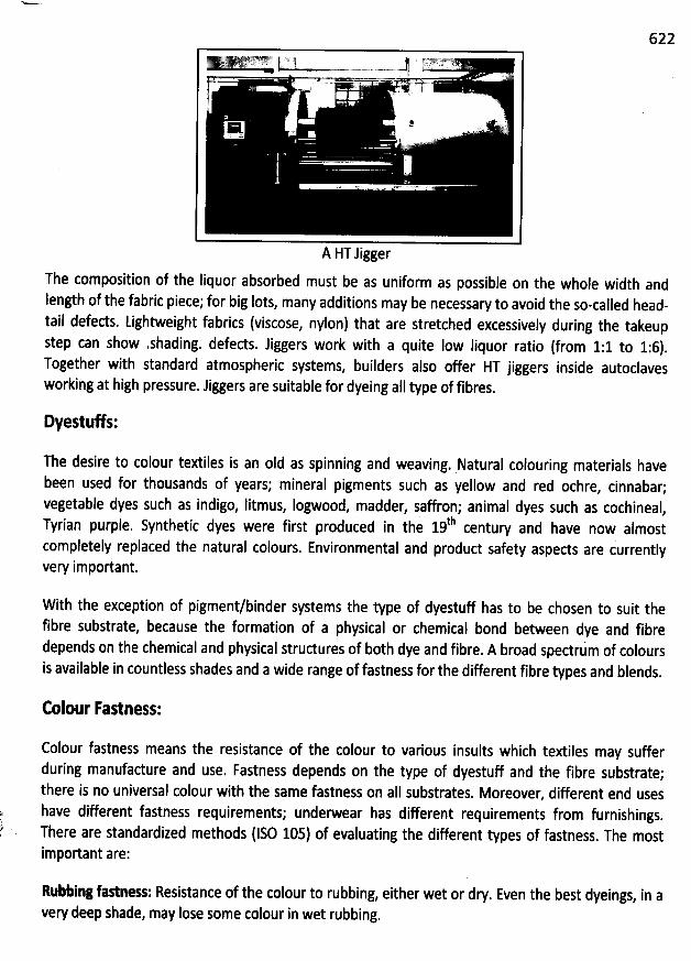
622y;.y yk M't'jy(y.yj j;:y?$' 1j jj jy.ky*'&.y z. w;; .7 'l: -' 'F.. j...' .. 1s... .. .. . .. .... ...-.. .-. .....y j J . '' '
'
.. '' g
E , '=# ' . '' .
)
; j!j J.z '.G . . . ' ''.
A HT Jigger
The composition of the liquor absorbed must be as uniform as possible on the whole width andlength of the fabric piece; for big Iots, many additions may be necessary to avoid the so-called head-tail defeds. Lightweight fabrics (viscose, nylon) that are stretched excessively during the takeupstep can show .shading. defects. Jiggers work with a quite Iow liquor ratio (from 1:1 to 1:6).Together with standard atmospheric systems, builders also offer HT jiggers inside autoclavesworking at high pressure. Jiggers are suitable for dyeing alI type of fibres.
DyestuWs:
The desire to colour textiles is an oId as spinning and weaving. Natural colouring materials havebeen used for thousands of years; mineral pigments such as yellow and red ochre
, cinnabar;vegetable dyes such as indigo, litmus, Iogwood, madder, saffron; animal dyes such as cochineal
,thTyrian purple. Synthetic dyes were first produced in the 19 century and have now almost
completely replaced the natural colours. Environmental and produd safety aspects are currentlyvery important.
With the exception of pigment/binder systems the type of dyestuff has to be chosen to suit thefibre substrate, because the formation of a physical or chemical bond between dye and fibredepends on the chemical and physical strudures of both dye and fibre. A broad spedru'm of coloursis available in countless shades and a wide range of fastness for the different fibre types and blends.
Colour Fastness:
Colour fastness means the resistance of the colour to various insults which textiles may sufferduring manufadure and use, Fastness depends on the type of dyestuff and the fibre substrate;there is no universal colour with the same fastness on aII substrates. Moreover, different end useshave different fastness requirements; underwear has different requirements from furnishings
.
There are standardized methods (IS0 105) of evaluating the different types of fastness. The mostimportant are:
Rubbing fastness: Resistance of the colour to rubbing, either wet or dry. Even the best dyeings, in avery deep shade, may Iose some colour in wet rubbing.
623
Washing fastness: The fastness to washing determines the wash program, which must be used by0C is expected.the consumer. Nowadays, fastness to a strong wash at 60
Perspiration fastness: Resistance to the effects of perspiration is important for underwear,outerwear, and sportswear.
Colours may also be required to be fast to light weather, sea water, solvents, ironing, etc.
Di/erent types of DyestuWs in relation to the fibre substrate:
@ Readive Dye: Applicable for cotton, linen, viscose, wool, silk. The dyestuff forms achemical Iink with the fibre. It has very jood fastness properties.
@ Disperse Dye: Applicable for polyester, nylon, acetate. It is water insoluble; applied'from dispersions; diffuse into the fibre at high temperature. It has also goodfastness properties.
@ Vat Dye: Applicable for cotton, Iinen, viscose. The insoluble dyestuff is madesoluble in a reducing vat so that it can diffuse into the fibre. After diffusion iscomplete, it is then re-oxidised into its insoluble form. It has high fastness towashing, chlorine, boiling, Iight, weather, rubbing and perspiration.
@ Dired Dye: Applicable for cotton, Iinen, viscose, silk. Simple diffusion into the fibre,from aqueous solution. It has relatively poor fastness properties to light, washingand perspiration. These fastness properties can be improved by aftertreatment.
Basit Dye: It is suitable for acrylic fibres (other fibres by mordanting). It reacts withacidic groups, or mordantsta chemical which can react or complex with achromophore to form an insoluble colour) in the fibre. It has good fastnessproperties on acrylic fibres.
@ Atid Dye: Applicable for wool, silk, nylon. Applied from an acidic dyebath. Thefastness properties of this dye-stuff depends on the fibre type.
There are also some other dyestuffs such as sulphur, azoic, metal complex, chrome dyes etc.
Printing:
Printing can be described as the controlled placing of defined areas of colour on to a substrate. Thecolourant must first be brought to the fibre surface usually in the form of a printing paste. If it is asoluble dyestuff, it must be diffused into the fibres. The colourant must then be fixed in place andfinally, excess unfixed colour has to be washed out.
Printing could be referred to as a sort of selective dyeing that makes an important contribution to
fabric decoration thanks to the combination of colours and dyeing methods. To obtain sharplydefiqed, precise and reproducible patterns, the dyebaths traditionally used are not sufficient,
because 'of ihe capillarity and/or hygroscopicity of fibres and migration of dyes that cannot grantshar.p and-well-defined colour patterns. It is therefore necessary to use special Iiquids,conventionally called ''printing pastes'', whose main charaderistic is a high degree of viscosity
*
624(improperiy called density); in other words these printing pastes colours are fluids which oppose a
high resistance or friction to sliding or motion.
As a consequence, the dyestuff applied on the fabric in well-defined areas to reproduce the desiredpattern cannot migrate to other areas of the fabric
. lt is also worth considering that the highviscosity of printing pastes will make the dye adhere to the surface of the fabric and the fibres, butnot penetrate into and fix on them. These operations (which may be referred to as diffusion andfixation during the dyeing process) will be carried out afterward with a steaming process
.
The application of the print dye on the fabric is carried out by forcing it through the gray fabric on
special printing blocks or perforated hollow rollers applied onto the fabric; the dye is then generallyfixed by means of a steaming process. '
ln other words, printing is a form of localized dyeing. Printing processes or techniques and printing
principles or styles can be distinguished. Printing processes include techniques such as roller
printing, .screen printing. Printing principles include direct pfinting, discharge printing, resistprinting, flock printing
, etc. Several of these processes and principles will be dealt with in thefollowings.
Printing Principles:Regardless of the printing process
, there are several basic printing principles:
Dired Printing or Overprinting:
The printing paste is applied directly to the prepared fabric surface. Overprinting indicates that a
plain dyed fabric is printed with a pattern in a darker colour. This method involves the following
steps: printing, drying, steaming and washing.
This type of printing is generally used for white or dyed cloths (usually dyed in pastel shades), byapplying the
sequence of all the colours, until the original pattern has been reproduced. This is themost common printing method and can be used with aII the main colour classes of d
yes and onfabrics produced with any kind of fibre (some problems may only arise with blends)
.
The technical limits of this printing method appear with endless design patterns (particularly thoseobtained
with screen printing methods, while no problems occur for roller printing). some problems
may also arise when printing on backgrounds dyed with pastel shades: in fad, this could createproblems on several areas of the design to be printed in light shades
, thus limiting the number ofreproducible pattern variants.
Distharge printing: C: Basic steps are printin
g, drying, steaming and washing. This technique is used on dyed fabrics''i luwally in dark shadesl.The fabric is dyed in the piece and then overprinted with a disch
arge paste(cbemical) that destroysor decolourises or changes the colour indesigned areas. A white discharge
625is when the original white is restored to the printed area. A colour discharge is when a separatecolour is applied at the same time as the discharge paste. Sometimes the base colour is removedand another colour is printed in its place; but usually a white area is desirable to brighten the overall
design.
This printing method is generally used to obtain designs with tiny details, sharp and welldefinedëdges on coloured backgrounds, patterns with Iow coverage ratio on coloured backgrounds, and toavoid pattern matching problems on endless design patterns with coloured backgrounds. Theresults obtained with this printing method could be hardly reproducible with direct printing since itwould be very difficult to obtain wide backgrounds, smooth and well penetrated, with sharp edges
without seam defects.
A problem for this printing method is represented by the need to choose perfectly destroyable dyesfor backgroupds, which cannot be affeded by the discharging agent used as brightener. Theselection restrids the number of applicable dyes and above all, for some colour classes, very fewdyes grant a good fastness to light and moisture, but excellent colour effeds. With this type ofprinting carried out on black or navy blue backgrounds it is also impossible to check if the variouscolours are correctly positioned; any mistake will be visible only after the steaming process and atthat point it would be impossible to corred it. This problem could be limited by testing the printing
result on a white c10th before beginning the printing process.
Resist Printing:
With the oId method of physica4 resist printing, (hydrophobic) products or printing pastes wereapplied to the fabric to avoid contact and penetration when the fabric was subsequently immersedin the dyeing liquor (Batik). Now the most diffused printing system is the chemical resist printingcarried out with different printing methods, using pastes containing chemicals, which avoid fixationof background dyes (particularly for .reactives on reactives. applied on fabrics made of cellulosefibres). Some of the printing methods are detailed in the following:
a) Resist printing on covered background: a pad dye is applied and dried; the printing is carriedout with printing pastes containing produds avoiding the fixing of background colour (butthey do not avoid the fixing of any brightener used). The fabric is then dried, steamed andwashed (this is the most diffused resist printing method).
b) Resist printing by overdyeing: the operations of the resist printing method previouslydetailed are carried out in inverse sequence; therefore the fabric is first printed and then
covered.c) Resist printing by overdyeing: this method is similar to the previous one, but the coveringoperation is replaced with the roller printing of the background.
d) Printing on polyester: polyester printing must be carried out applying the resist-dischargeprinting method. Printing pastes containing both the discharge and resist products appliedon covered background must be used.
626Transfer Printing:
The pattern is first printed onto a special type of paper with certain types of dyestuffs. These papers
are prepared by specialist suppliers. The pattern is simply transferred to the fabric with the aid of aheated calender. The temperature is high enough to cause the dyestuffs to pass into the vapourphase (sublime). Since it is held in close proximity to the paper, under pressure, some of the dyevapour finds its way onto the fabric and diffuses into the fibres. The process represents about 6% ofprint produdion and finds its most direct and simple application on synthetic fibre textiles
. Specialtechniques, papers, and fabric preparations have been developed for natural fibres and blends
.
W ith this efficient method disperse dyes, previously printed on special continuous paper on thefabric, are transferred on the fabric by means of rollers with engraved frames
. The design istransferred by contact between the paper and the fabric
, which is then passed through heatedrollers at a temperature of 190-210@C. With this method, disperse dyvs sublime (i.e. change diredlyfrom the solid to the gaseous state without passing through the tiqutd phase) mett, penetrate tàefibres and bind by heat and pressure onto the fabric surface in a few hundredths of a secohd
.
Beside these basit printiples, thefe are several types of printing tethnologies:
Flock Printing:
The fabric is printed with adhesive and cut fibre snippets are applied, which stick where the
adhesive is present. A velvet-like appearance to the print can be obtained by electrostatic flocking,
in which the fibre snippets are caused to stand upright in an eledrostatic field as they are beingapplied.
Pigment printing:
Pigments are colours which do not dissolve and penetrate into the fibres. They have to be applied
' together with a film-forming binder. More than 50% ot alI printing cplours are pigment types.
Pigment printing represents an alternative to direct printing. W. ith pigment printing there is no needto carry out a steaming process, as steaming is replaced by polymerisation (generally carried outsimultaneously with drying).
This type of printing process is very simple, Iow-cost and can be carried out tp es of
fabrics, padicularly on blends, since pigments can adhere to aII fibres; there is no need tp use dyesof different colour classes. 0n the other hand, tbe adhesives, which bind the pigments to the fabric,can give serious problems when the fabric hand yaries. For prints with a low
.coverage ratio, thehand variation can be acceptable but it is not#ccept#ble when the coverage ratio is high
, or at Ieastfor aII uses. Furthermore, the pigment Iivs on the sudace and has Iow fastness to fridion (thisdepends mainly upon the type and qu
.antity of bindiqg agent and upon the polymerizatiop degree).%me valid alternatives to this type of printing can give special effeds such as printing with swellingagents (generally synthetic polyurethane-base pastes are used), with covering pigments and glitter(metal powders or particles of plastic materials) etc.
easily on aII
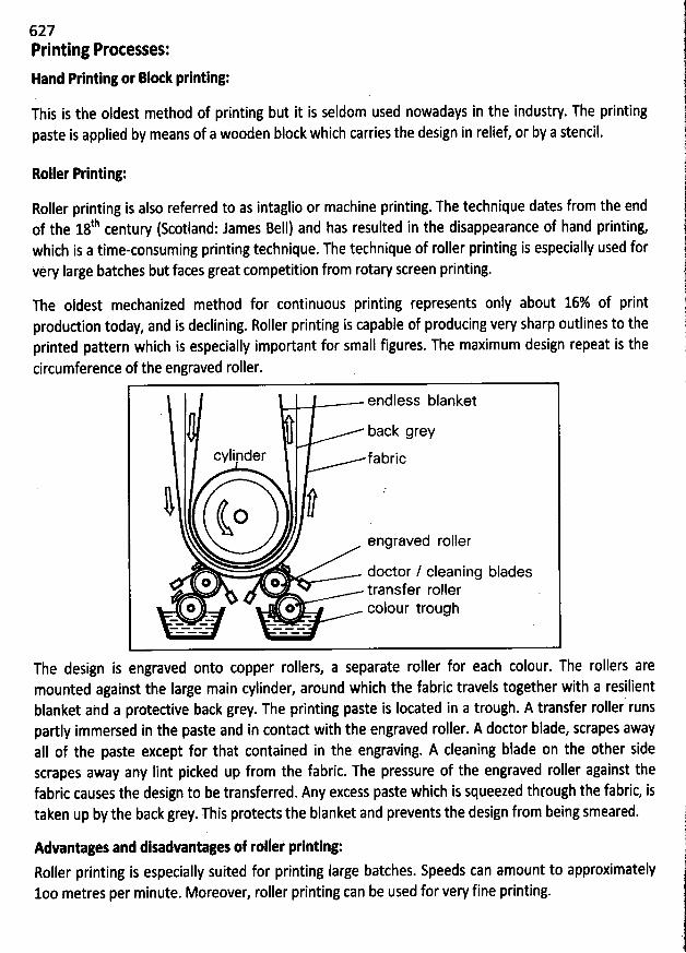
627Printing Protesses:
Hand Printlng or Blx k printing:
This is the oldest method of printing but it is seldom used nowadays in the industry. The printingpaste is applied by means of a wooden block which carries the design in relief, or by a stencil.
Roller Printing:
Roller printing is also referred to as intaglio or machine printing. The technique dates from the endth I d: James BeII) and has resulted in the disappearance of hand printing,of the 18 century (kot an
which is a time-consuming printing technique. The technique of roller printing is especially used forvery large batches but faces great competition from rotary screen printing.
The oldest mechanized method for continuous printing represents only about 16% of printprodudion today, and is declining. Roller printing is capable of producing very sharp outlines to theprinted pattern which is especially important for small figures. The maximum design repeat is thecircumference of the engraved roller.
endless blanket
back grey
cylinder fabric
l lOengraved roller
doctor / cleaning blades@ @ transfer roller
o o colour trough- - - = .. ..*
The design is engraved onto copper rollers, a separate roller for each colour. The rollers aremounted against the large main cylinder, around which the fabric travels together with a resilientblanket ahd a protedive back grey. The printing paste is Iocated in a trough. A transfer roller runspartly immersed in thê paste and in contact with the engraved roller. A doctor blade, scrapes awayaIl of the paste except for that contained in the engraving. A cleaning blade on the Qther sidescrapes away any Iint picked up from the fabric. The pressure of the engraved roller against thefabric causes the design to be transferred. Any excess paste which is squeezed through the fabric, istaken up by the back grey. This protects the blanket and prevents the design from being smeared.
Advantages and disadvantages of roller printing:Roller printing is especially suited for printing Iarge batches. Speeds can amount to approximately1oo metres per minute. Moreover, roller printing can be used for very fine printing.
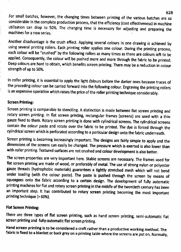
628For small batches, however, the changing times between printing of the various batches are soconsiderable in the complete production process
, that the efficiency (cost effectiveness) in machineutilization can drop to 50%. The changing time is necessaw for adjusying and preparing themachines f0r a new series.
Another àisadvantage is the crush èffect. Applying several colours in one drawing is achieved byusing several printing rollers. Each printing roller applies one colour
. During the printing process,: jj yyeach colour will be crushed by the following rollers as many times as there are colours left to be
applied. Consequently, the colour will be pushed more and more through the fabric to be printed.
Deep colours are hard to obtain, which benefits screen printing. There may be a reduction in colour
strength of up to 50%.
In roller printing, it is essential to apply the Iight tblours before the darker ones because traces ofthe preceding colour can de carried forward into the following colour
. Engraving the printing rollersis an expensive operation which raises the price of the roller printing technique considerably
.
Sereen Printing:
Screen printing is comparable to stenciling. A distinction is made between flat screen printing androtary screen printing. In flat screen printing
, rectangular frames (screens) are used with a thingauze fixed to them. Rotary screen printing is done with cylindrical screens
. The cylindrical screenscontain the colour paste and rotate over the fabric to be printed
. The dye is forced through thecylindrical screen which is perforated according to a particular design onto the fabric underneath
.
Screen printing is becoming increasingly important. The designs are fairly simple to apply and thedimensions of the screens can easily be changed. The pressure which is exerted is also lower thanwith roller printing. Textured surfaces are not crushed and colour development is also better
.
n e screenproperties are very important here. Stable screens are necessal. The frames used for
flat screen printing are made of woed, or preferably of Metal. The use ôf strong nylon or polyester
gauze threads (hydrophobic materials) guarantees a tlghtly stretched mesh which will not bendunder loading (with the colour paste). The paste is kuxhed through the screen by means ofsqueegees onto the fabric according to a certain design. The development of fully automaticprinting machines for flat and rotary screen printing in the middle of the twentieth century has beenan important step. It has contributed to rotae screen printing becoming the most importantprintingtechnique (> 60%).
rlat kreen Printing:
There are three types of flat screen printing, such as hand screen printing, semi-automatic flat
Rreen printing and felly-aetomatic flat screen printing.Hahd screen printing is to be considered a craft rather than a productive working method
. Thefabric is fixed to a blanket or back grey on a printing table where the screens are put on
. Normally,
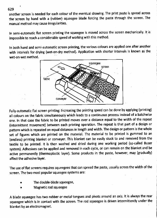
. ë629 !
1another screen is needed for each colour of the eventual drawing. The print paste is spread across )thefscreen by hand with a (rubber) squeegee blade forcing the paste through the screen.'-rhe pmanual method may cause irregularitiesk è
In semi-automatic tlat screen printing the squeegee is moved across the screen mechanically. lt isimpossible to reach a considerable speed of working with this method.
ln both hand and semi-automatic screen printing, the various colours are applied one after anotheri i (wet-on-dry method). Application with shorter intervals is known as thewith intervafs for ry ng
t t method. 'We -On-We
SqueegeeSCr n
. x # :' *; # ; :
6 # V * V Y 'lps!l I 4:2 '' '' .. ' .' .,.. . # 2l# '-%' ' âyzç ezhc C!u . '. 4.-,1 :.>.. hj ' - s#;L..,à . .... .11' d)k . ,:),)qv ? : j) .L. , j..##. . y . é,xqï>k.l. 9(- ïë:. lt A.. 2. . .- : ,r .:à. ...ftqbqbàb,itv . ,. y . t . . . A .jl. ..,î;:ï rs . ;ju. e:,. .J1ià:r-.;ï,rYè'%. q .,9111:,., ..L ...F,y:4.:) ,j ...e . n.$e. ,, k Cjjj . ..i18- ..ô : . àk . :..t: ::'' .*,1* t; ii ?- .. ' ' (;E,J!I1h1;.'-.'': 7r!!I1-. :bb3'6'b'':.'''ji ' Cêls ' .#. :,5'ï1111.. '0.1:...'( !c . c .k, çA. ;i( 74j0.:! t). J à y:. - ..rJ1j'ç f, :.5 Xk. '' .. .* ''i1i>' ...' : '' ' ' ' ' '1' f !.. ,) ii4:r ..5..- h..,. . wjjjjg. j; ...). . ..4 .. . sh vr... .. . , .;: .,;dIijE''.;I;;r.'. . ..: . .kkbçqt,.j'6ibtï':. h.ï.I,.';:id. k'i!1àr': .... ' .. k. :. a. vn'gîs' loas:w'enr.' . x'rzk .. mjjjz AlFe; .è.' .j .)j::hCe .' ï' . Eiq . .. . .
. . # . e>. .6 . s .t ; .. ; -.#. ; #.. . . . . j.î 1$: %' 'L jf' . .'J7 '@ & <;. JConveyer . ' % -.....35
Fully-automatic flat screen printing: Increasing the printing speed can be dine by applying (printing)aII colours on the fabric simultaneouslk which Ieads to a continuous process instead of a batchwiseone. ln that case the fabric to be printed moves over a distance equal to the width of the repeat(intermittent movement) between each printing operation. The repeat is that part of a design orpattern which is repeated on equal distances in Iength and width. The design or pattern is the wholeset of figures which are printed on the material. The material to be printed is gummed to an
(endless) printins blanket or conveyer. This blanket can be easily stuck to and removed from thetextile yo be printed. It is then washed and dried during one working period (sp-called Busersystem). Adhesives can be applied and reYoved in each cycle, or can remain on the blanket and beactive permanenyly (thermoplastic Iayer). Some products in the paste, however, may (gradually)affed the adhesive Iayer.
The use of flat screens requires squeegees that can spread the paste, usually across the width of the
screen. The two most popular squeegee systems are:
@
*
The double-blade squeegee,Magnetic rod squeegee
A blade squeegee has two rubber or metal tongues and pivots around an axis. It is always the rearsqueegee which is in contad with the screen. The rod squeegee is driven intermittently under the
blanket by an eledromagnet.
630Rotary Streen Printing:
. . ; ... , :' ' ' .
Fully-automatic flat screen printing is not continuous yet. Rotary screen printing pn the gther hand.is continuous. Rotating cylindrical screens are used which are automatically fed (by means ofpumps) with paste from inside. Driving the screens can be done at either side. During printing, thepaste is pressed through the surface (nickel: à 0.1 mm thick) via openings in ordqr to obtain thedesired design. The cylindrical screens allow more screens to be arranged per unit Iength th@g is thecase with flat screen printing. Speed range from 30 to 50 metres/min. The standard internalcircumference of cylindrical screens is 640 - 640.1 mm. However, other dimensions ' afe alsopossible.
screen cclour reservcirprintinç paste .
V 'zj ?:'. jjjtr;-:-îî5 )1441). . .-;.crt tjyjy).rJ ,; ïJJ?/ ...# è!l-'--.bgtL.. tyj
; j muee.> rdI
' fabr c ' - '
Fundional Finishiig:The chemical structure of natural, artificial or synthetic fibres detqrmines some of the properties 'that are naturally present also in finished products. Some fibres (such as Iineq, hemp, silk, nyl.on,polyester) àre stronger than others (wool, viscose, acwlic) acèording to more or Ièss cùntrolled
. * -- = * e -R. . . . 2', .
distribution of macromolecules in the polyme'r mass, strudure stiffnesj and any possible inter àqdmolecular interaction between the chains; other fibres tend to distort when stretched (cotton,
tiers eas' iIyviscose), and others recover their original shape after being distorted (wool); some oburn (cellulose), burn slowly and self-extinguish (wool, silk) or burn and melt (synthetic fibres). The
. . . .. 'ï
above mentioned characteristics and many others make up positive and negative properties of atextile material, which must be accurately considered ip view of their final application. Tàe textileprodud final application will be considered from many points of view: wearability, hand, mechanicalresistance, wettability, washability, deformability, fire-proof ability and many others.
The word ''tèxtile finishing'' defines a series of processing operations applied to gray fàbtics toenhance their appearance and hand, properties a:d possible applications. The term ''finishing''includes aII the treatments applied to gray fabrics such as scouring, bleaching, dyeing or printing'
, --' - -- -- ' --
. '.
hcile we will use the term 'functional finishinf with reference to aII the mechani'cal otchémicalWfinishing operations carried out on fabrics already bleached, dyed or printed to furiherenàancetheir properties and possibly add some new ones.The terms 'finishing' and 'fundional finishinfarethefefore similar and both play a fundamental role for the cdmmercial excellency of the iesults oftextiles, stridly depending on market requirements that are becoming increasihgly stringent and
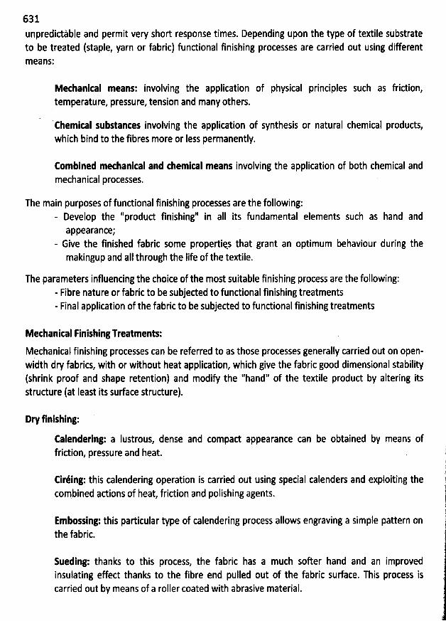
631unpredidàble and permit very short response times. Depending upon the type nf textile substrateto be treated (staple, yarn or fabric) fundional finishing processes are carried out using differentm eans:
Methankal means: involving the applicationtemperature, pressure, tension and many others.
of physical principles such as fridion,
'
chemital substantes involving the application of synthesis or natural chemical products,which bind to the fibres more or Iess permanently.
Combined methankal and themkal means involving the application of both chemical andmechanical processes.
The main purposes of fundional finishing processes are the following:- Develop the ''produd finishing'' in aIl its fundamental elements such as hand and
appearance;- Give the finished fabric some propertiqs that grant an optimum behaviour during themakingup and aII through the Iife of the textile.
The parameters influencing the choice of the most suitable finishing process are the following:- Fibre nature or fabric to be subjeded to functional finishing treatments- Final application of the fabric to be subjected to fundional finishing treatments
Methanical rinishing Treatments:
Mechanical finishing processes can be referred to as those processes generally carried out on open-width dry fabrics, with or without heat application, which give the fabric good dimensional stability(shrink proof and shaqe retention) and modify the ''hand'' of the textile produd by altering itsstrudure (at Ieast its surface strudure).
Dry finishing:
Ealendering: a Iustrous, dense and compad appearance can be obtained by means offridion, pressure and heat.
Ciréing: this calendering operation is carried out using special calenders and exploiting thecombined adions of heat fridion and polishing agents.
Embossing: this particular type of calendering process allows engraving a simple pattern onthe fabric.
Sueding: thanks to this process, the fabric has a much softer hand and an improvedinsulating effect thanks to the fibre end pulled out of the fabric surface. This process iscarried out by means of a roller coated with abrasive material.
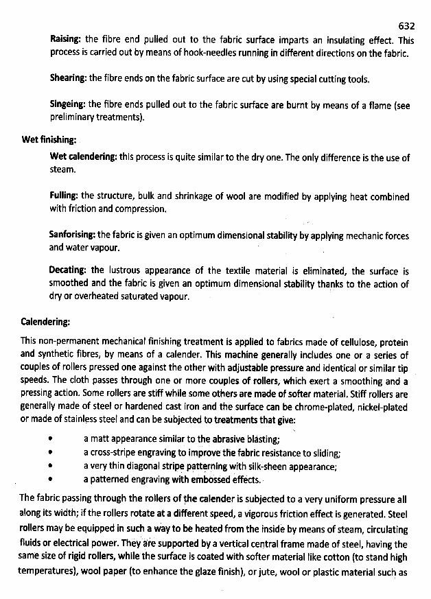
632Raising: the fibre end pulled out to the fabric surface imparts an insulating effed. This
i ied out by means of hook-needles running in different diredions on the fabric.process s carr
Shearing:the fibre ends on the fabric surface are cut by using special cutting tools.
singeing: the fibre ends pulled out to the fabric surface are burnt by means of a flame (seepreliminary treatments).
Wet finishing:
W et talendering: this process is quite similar to the dry one. The only difference is the use ofsteam.
Fulling: the structure, bulk and shrinkage of wool are modified by applying heat combinedwith friction and compression.
Sanforising: the fabric is given an optimum dimensional stability by applying mechanic forcesand water vapour.
Detating: the Iustrous appearance of the textile material is eliminated, the surface issmoothed and the fabric is given an optimum dimensional stability thanks to the adion ofdry or overheated saturated vapour.
calendering:
This non-permanent mechanical finishing treatment is applied to fabrics made of cellulose, proteinand synthetic fibres, by means of a calender. This machine generally includes one or a series ofcouples of rollers pressed one against the other with adjustable pressqre and identical or similar tipspeeds. The c10th passes through one or more couples of rellers, which exert a smoothing and apressing adion. Some rollers are stiff while some others are made of softer material. Stiff rollers aregenerally made of steel or hardened cast iron and the surface can be chrome-plated, nickel-platedor made of stainlqss steel and can be sobjeded to treâtments that give:
* a matt appearance similar to the abrasive blàsting;* a cross-stripe engraving to impiove the fabric resistancq to sliding;* a very thin diagonal stripe pqttsrping with silk-sheen appearance;* a patterned engraving with emboïsed effeds.
The fabric passing through the rollers of !he talender is subjeded to a very uniform pressure aIlalong its width; if the rollers rotate at a different speed, a vigorous fridion effed is generated. Steelrollers may be equipped in such a way td be heated from the insidè by means of steam, circulatingfluids or eledrical power. They afe supporteà by a vertical central frame made of steel, having thesame size of rigid rollers, while the surfàce is coated with softer material Iike cotton (to stand hightemperatures), wool paper (to enhance the glaze finish), orjute, wool or plastic material such as
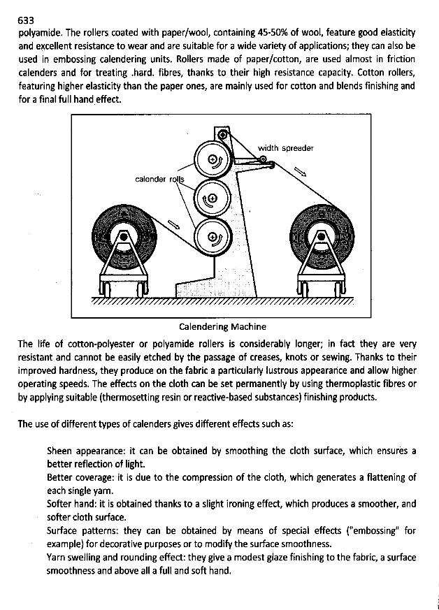
633polyamide. The rollers coated with paper/wool, containing 45-50% of wool, feature good elasticityand excellent resistance to wear and are suitable for a wide variety of applications; they can also beused in embossing calendering units. Rollers made of paper/cotton, are used almost in frictioncalenders and for treating .hard. fibres, thanks to their high resistance capacity. Cotton rollers,featuring higher elasticity than the paper ones, are mainly used for cotton and blends finishing andfor a final full hand effed.
wjdtjj qprgaégy
02 ' ': Na
calender roI s :) ' '(
O 't
%@ 9 : @J
. . : '. ? 'qkg . ') ' :y .' 'j ' . I.. c. .). -: ..... . q, ! .y .
.
Z
Calendering Machine
The Iife of cotton-polyester or polyamide rollers is considerably Ionger; in fad they are veryresistant and cannot be easily etched by the passage of creases, knots or sewing. Thanks to theirimproved hardness, they produce on the fabric a particularly lustrous appearahce and allow higheroperating speeds. The effeds on the c10th can be set permanently by using thermoplastic fibres or
by âpplying suitable (thermosetting resin or readive-based substances) finishing products.
The use of different types of calenders gives different effeds such as:
Sheen appearance: it can be obtained by smoothing the c10th surface, which ensures abetter reflection of Iight.Better coverage: it is due to the compression of the c10th, which generates a flattening ofeach single yarn.Softer hand: it is obtained thanks to a slight ironing effect, which produces a smoother, andsofter clolh surface.Surface patterns: yhey can be obtained by means of special effeds (''embossing'' forexample) for deco.rative purposes or to modify the surface smoothness.Yarn swelling and rounding effect: they give a modest glaze finishing to the fabric, a sudacesmoothness and above aII a full and soft hand.
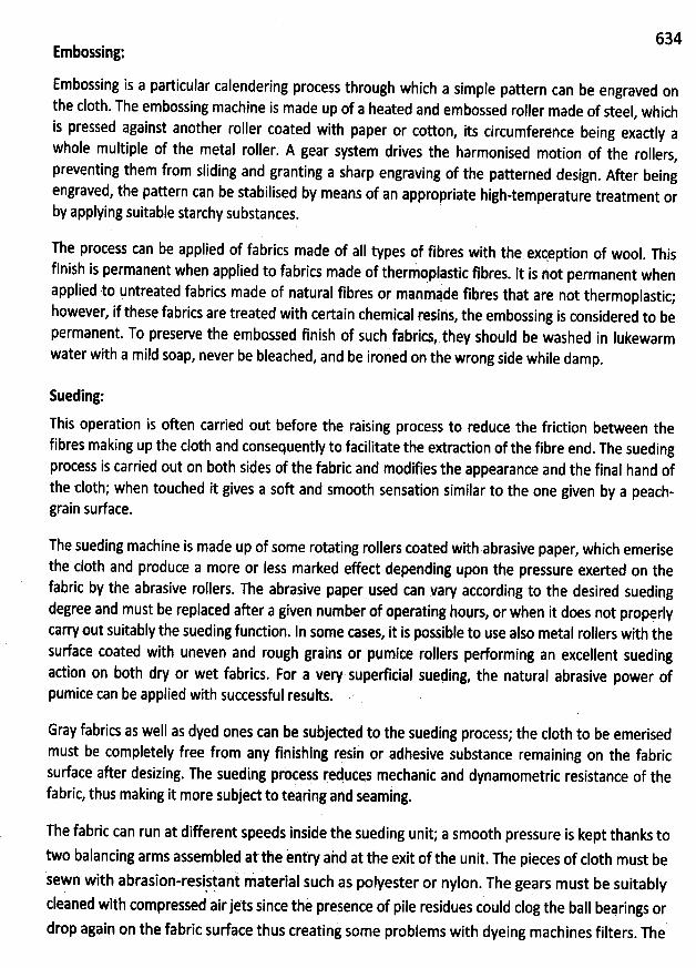
634Embossing:
Embossing is a particular calendering process through which a simple pattern can be engraved onthe cloth.The embossing machine is made tlp of a heated and embossed roller made of steel
, whichis pressed against another roller coated with paper or cotton
, its circumferehce being exactly awhole multiple of the metal roller. A gear system drives the harmonised motion of the rollers
,preventing them from sliding and granting a sharp engraving of the patterned design
. After beingengraved, the pattern can be stabilised by means of an appropriate high-temperature treatment orby applying suitable starchy substances.
The process can be applied of fabrics made of aII types of fibres with thq exçeption of wool. This
finish is permanent when applied to fabrics mâde of therm' oplastic fibres. It is not permanent when
applied to untreated fabrics made of natural fibres or manmpde fibres that are not thermoplastic;however, if these fabrics are treated with certain chemical resins
, the embossing is considered to bepermanent. T0 preserve the embossed finish of such fabrics, they should be washed in Iukewarmwater with a mild soap, never be bleached
, and be ironed on the wrong side while damp.
Sueding:
This operation is oken carried out before the raising process to reduce the friction between thefibres making up the c10th and consequently to facilitate the extradion of the fibre end. The suedingprocess is carried out on both sides of the fabric and modifies the appearance and the final hand ofthe c10th; when touched it gives a soft and smooth sensation similar to the one given by a peach-grain surface.
The sueding machine is made up of some rotating rollers coated with abrasive paper, which emerise
the c10th and produce a more or less marked effed depending upon the pressure exerted on thefabric by the abrasive rollers. The abrasive paper used can vary according to the desired suedingdegree and must be replaced after a given number of operating hours
, or wben it does not propçrlycarry out suitably the sueding fundion. ln some cases, it is possible to use also metal rollers with thesurface coated with uneven and rough grains or pqmice rollers pedorming an excellent suedingadion on b0th dry or wet fabrics. For a very superficial sueding
, the natural abrasive power ofpumice can be applied with successful results.
Gray fabrics as well as dyed ones can be subjeded to the sueding process; the c10th to be emerisedmust be completely free from any finishing resin or adhesive substance remaining on the fabricsurface after desizing. The sueding process reduces mechanic and dynamometric resistqnce of thefabric, thus making it more subjed to tearing aid seamlng.
The fabric can run at different speeds inside the sueding unit; a smooth pressure is kept thanks to
two balancing arms assembled atthe intry aàd at the exit of the unit. The pieces of c10th must besewn with abrasion-resisiani laterial sucb as polyester or nylon. The gears must be suitablycleaned with compressed airjets since thè preience of pile residues could clog the ball beprings ordrop again on the fabric surface thus creating some problems with dyeing machines filters
. The
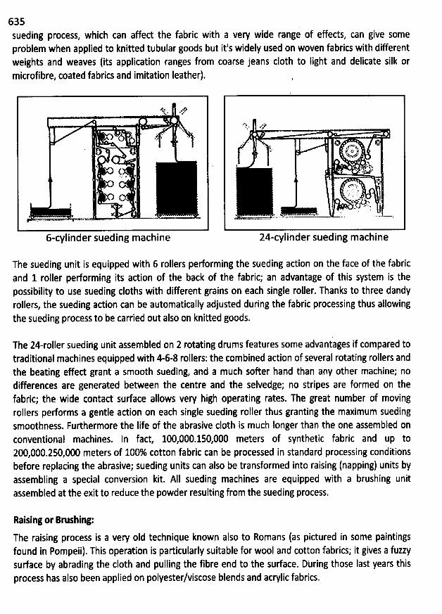
635sueding process, which can affed the fabric with a very wide range of effects, can give someproblem when applied to knitted tubular goods but it's widely used on woven fabrics with different
weights and weaves (its application ranges from coarse jeans c10th to Iight and delicate silk ormicrofibre, coated fabrics and imitation Ieather).
* ew@.,k . ..
y . '''J ,. e #.
%@
5
t
6-cylinder sueding machine
êïL' .. ..Lt'-
., . o' ,- k #. ;fn<1kp- :w. 1%k..R
. N.A!
t;!*- '' Y1yx .', g
x c ... jVr? U * .
v) .'e: . xe A' .
&- u - - -.,- Zk- -, . . . . . r
z4-cylinder sueding machine
The sueding unit is equipped with 6 rollers performing the sueding action on the face of the fabricand 1 roller performing its action of the back of the fabric; an advantage of this system is thepossibility to use sueding cloths with different grains on each single roller. Thanks to three dandyrollers, the sueding adion can be automatically adjusted during the fabric processing thus allowingthe sueding process to be carried out also on knitted goods.
The 24-roIIer suedihg unit assembled on 2 rotating drums features some advantages if compared totraditional machines equipped with 4-6-8 rollers: the combined action of several rotating rollers andthe beating effed grant a smooth sueding, and a much softer hand than any other machine; nodifferences are generated between the centre and the selvedge; no stripes are formed on thefabric; the wide contact surface allows very high operating rates. The great number of movingrellers performs a gentle action on each single sueding roller thus granting the maximum suedingsmootbness. Furthermore the Iife of the abrasive c10th is much Ionger than the one assembled onconventional machines. In fad, 100,000.150,000 meters of synthetic fabric and up to200,000.250,000 meters of 100% cotton fabric can be processed in standard processing conditionsbefore replacing the abrasive; sueding units can also be transformed into raising (napping) units byassembling a special conversion kit. AIl sueding machines are equipped with a brushing unitassembled at the exit to reduce the powder resulting from the sueding process.
Raising or Breshing:
The raising process is a very oId technique known also to Romans (as pictured in some paintingsfound in Pompeii). This operation is particularly suitable for wool and cotton fabrics; it gives a fuzzysudace by abrading the c10th and pulling the fibre end to the surface. Dbring those Iast years thisprocess has also been applied on polyester/viscose blends and acrylic fabrics.
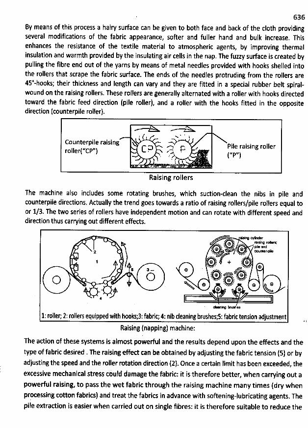
636By means of this process a iairy surface can be given to both face and back of the c10th providingseveral modifications of the fabric appearance, softer and fuller hand and bulk increase. Thisenhances the resistance of the textile material to atmospheric agents
, by improving thermalinsulation and warmth provided by the insulating air cells in the nap. The fuzzy surface is created bypulling the fibre end out of the yarns by means of metal needles provided witb hooks shelled intothe rollers that scrape the fabric surface. The ends of the needles protruding from the rollers are4s*-hooks; their thickness and Iength can vary and they are fitted in a special rubber belt spiral-wound on the raising rollers. These rollers are generally alternated with a roller with hooks directed
toward the fabric feed direction (pile roller), and a roller with the hooks fitted in the oppositediredion (counterpile roller).
't ' -''! -. , )Counterpile raising V --s/ pjj
e raising roller. . c p , I ) C D' D. . s C4. erollerl ,,p,,). .. -,2k 4:
l r j ...I
Raising rollers
The machine also includes some rotating brushes, which suction-clean the nibs in pile andcounterpile directions. Adually the trend goes towards a ratio of raising rollers/pile rollers equal toor 1/3. The two series of rollers have independent motion and can rotate with different speed anddirection thus carrying out different effects.
eY *%* OYX NWta n ?iW
2 *' * OUD'WVY
* + **5 3
- e
O s.-' o * o mo t
*
1: roller; 2: rcllers equipped with hooksi3:fabric; 4: nib cleaning brushesis: fabric tension adjustment
Raising (nzpping) machine:The adion of these systems is almost powerful and the results depend upon the effects and the
type of fabric desired . The raisingeffed can be obtained by adjusting the fabric tension (5) or byadjusting the speed and the roller rotation diredion (2). Once a certain Iimit has been exceeded, theexcessive mechanical strejs could damage the fabric: it is therefore better, when carrying out a
powedul raisinç, to pass the wet fabric through the raising machine many times (dry whenprocessing cotton fabrics) and treat the fabrics in advance with softening-lubricating agents. Thepile extraction is easier when carried out on single fibres: it is therefore suitable to reduce the
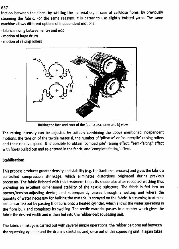
637fridion between the fibres by w:tting the material or, in case of cellulose fibres, by previouslysteaming the fabric. For the same reasons, it is better to use slightly twisted yarns. The samemachine allows different options of independent motions:- fabric moving between entry and exit- motion of Iarge drum- motion of raising rollers
.. 1 . n .n.. ''' A(d' ' >K'.Y4*' '; N k ' &
. *
b
+x & .r
Raising the face and back of the fabric; alscheme and b) view
The raising intensity can be adjusted by suitably combining the above mentioned independentmotions, the tension of the textile material, the number of 'pilewise' or 'counterpile' raising rollersand their relative speed. It is possible to obtain 'combed pile' raising effed, ''semi-felting'' effedwith fibres pulled out and re-entered in the fabric, and 'complete felting' effect.
Stabilisation:
This process produces greater density and stability (e.g. the Sanforset process) and gives the fabric acontrolled. compress' ion shrinkage, which eliminates distortions originated during previousprocesses. The fabric finished with this treatment keeps its shape also after repeated washing thusprovihing an excellent dimensional stability of the te#ile jubstrate. The fabric is fed into anopener/tension-adjusting device, and subsequently passes through a wetting unit where thequântity of water necessary for bulking the material is sprayed on the fabric. A steaming treatmentcan be carried out by passing the fabric onto a heated cylinder, which allows the water spreading inthe fibre bulk and completes its swelling. The textile material passes to a stenter which gives thefabric the desired width and is then fed into the rqbber-belt squeezing unit.
The fabric shrinkage is carried out with several simple operations: the rubber belt pressed betweènthe squeezing cylinder and the drum is stretched and, once out of this squeezing unit, it again takes
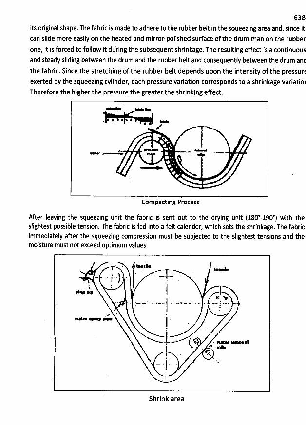
638
its original shape. The fabric is made to adhere to the rubber belt in the squeezing area and, since itcan slide more easily on the heated and mirror-polished sudace of the drum than on the rubber
one, it is forced to follow it during the subsequent shrinkage-The resulting effed is a continuousand steady sliding between the drum and the rubber belt and consequently between the drum ant
the fabric. Since the stretching of the rubber belt depends upon the intensity of the pressurtexerted by the squeezing cylinder, each pressure variation corresponds to a shrinkage variatior
Therefore the higher the pressure the greater the shrinking effect.
: #' # * #* e
* Z
* - **
Com pacting Process
After Ieaving the squeezing unit the fabric is sent out to the drying unit (180*-190*) with theslightest possible tension. The fabric is fed into a felt calender, which sets the shrinkage. The fabricimmediately after the squeezing compression must be subjeded to the slightest tensions and themoisture must not exceed optimum values.
'
e.J j .* jxs.' A
lF .
.teq> z:p:
v %
'
* >
'
@ œ. * .. -..$ * -*
'
-* r
'
Iw
'
* #œ w-H- .- * -
' * y
' . *<1
. .1ky **
. 1
Shrink arèa
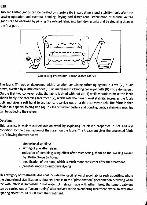
639
Tubular knitted goods can be treated on stenters (to impart dimensional stability), only after thecutting operation and eventual bonding. Drying and dimensional stabilisation of tubular knittedgoods can be obtained by passing the relaxed fabric into belt drying units and by steaming them inthe final path. '
G A1
T -- -- -- . .. --- -- -. . .--02
V
Compading Process forTubular Knitted Fabrics
The fabric (T), wet or dampened with a solution containing soûening agents in a vat (V), is Iaidown, overfed by a Iittle calender (C), on metal-mesh vibrating conveyor belts (N) into a drying unit.n the first two conveyor belts, the fabric is dried with hot air (1) while vibrations make the fabrichrink freely; the steaming treatment (2), which sets the dimensional stability, increases the fabricbulk and gives a soft hand to the fabric, is carried out on a third conveyor belt. The fabric is thenolded in a special folding unit (A). In case of further cutting and bonding units, a shrinking machinean be added to the system.
Detating:rhis process is mainly carried out on wool by exploiting its elastic properties in hot and wetonditions by the dired adion of the steam on the fabric. This treatment gives the processed fabriche following characteristics:
- dimensional stability;- setting of pile after raising;- reduction of possible glazing effect after calendering, thank to the swelling causedby steam blown on fibres;
- modification of the hand, which is much more consistent after the treatment;- pre-stabilisation to autoclave dyeing
rhis category of treatments does not include the stabilisation of wool fabrics such as potting, where:he dimensional stabilisation is obtained thanks to the ''plasticisation'' phenomenon occurring when'he wool fabric is immersed in hot water. 0n fabrics made with other fibres, the same treatmentan be carried out as ''steam ironing'' alternatively to the calendering treatment, when an excessiveglazing effect'' could result from the treatment.
j
640The steam decating, which is also referred to as dry decating, is carried out on decating machines inone continuous treatment or two discontinuous ones, according to the following operatingtechniques:
- drum decating (alternated at atmospheric pressure);- autoclave vacuum decating (KD);- continuous decating.
Chemital Finishing Treatments:
By applying chemicals of different origins, a fabric can receive properties otherwise impossible toebtain with mechanical means. Chemical finishing treatments:
- allow the stabilisation of fabrics already subjeded to mechanical finishing processes, suchas calendering;
- give fabrics some properties (e.g. flame retardancy and water repellency), which would beotherwise absent
The products used can be dassified as follows:
- Natefal (adhesives, fats, oils, starches)- Artifkial (modified starches, modified cellulose)- Synthetit (synthesis products) including: N-methylol derivatives (thermosetting, readants),Iinear readants (carbamates, epoxy resins), thermoplastic polymers (vinyl, acrylic,polyethylene), polyurethanes and silicones.
This classification, helpful for students, does not coincide with the produds adually sold on themarket since these products are blends containing also eatalpts and auxiliaries which interad andproduce complementary effeds. It is therefore necessary to underline how chemical finishing canaffed the textile prôdud by altering its mechanical properties, sometimes changing the colourshade of its original colour fastness. Different techniques are available for applying the abovementioned finishing substances: by solution, dispersion, and emulsion
, pad wetting, exhaustion,coating, Spraying, etc. The most appropriate technique must be carefully studied for each fibre type
,
and the most suitable chemical finishing process applied to obtain optimum results and grant areasonable safety margin for any possible error.
Applireion of tbe finish:
The operations to be carried out when applying the finish to a textile substrate are mostlyconditioned by the strudural and hygroscopic properties of the material to be processed, by thedesired effects, by the physical and chemical nature of the elements that make up the finishingsubstance and by the machine.s output rate. In textile finishing, we can distinguish between fivemain application techniques:
641a) padding;b) spraying by means of atomisers;c) exhaust process in treatment Iiquor;d) coating carried out by means of doctor knives;e) controlled application of Iow Iiquor quantities.
Padding is by far the most common among the various finishing techniques.
Padding:
This is certainly the most popular process for b0th the most conventional and innovative finishingtreatments. The machine used for this process cap be referred to with various definitions such aspadding unit, squeezing unit, etc. After ensuring that the textile substrate can be padded byevaluating its mecbanical and structural properties, this technique can be applied to carry out aIIwet finishing operations, except for some cases.
Spraying:
The application of finishing substances by spraying is used for carrying out gentle finishing processeswhich Ieave on the textile material a small concentration of produds, and is particularly indicatedfor applying softening, anti-static and anti-mildew agents. For a good and homogeneouspenetration and diffuslon of the finish in the textile material, it is better to Iet the sprayed andwound fabric rest for some hours before drying. In the Iast few years, a very important field hasbeen developed in the textile sedor, i.e. the production of webs made of synthetic fibres. For thisparticular type of produd, the resincoating process is carried out only by spraying tbe finish directlyon the fibrous substrate and by generally applying synthetic resins in aqueous emulsion.
Exhaustion:
The treatment of yarns or fabrics in exhaustion Iiquor is recommended above all when stablechemical produds are applied on the textile substrate. The manufaduring process undergone bythe material is useful to precisely evaluate the best method for applying the finish, for example onhosiery or tubular knitted goods. From a chemical point of view, the most suitable produds for theexhaust process are those with cationactive properties. In particular cation-active softening agentsare often applied with this process, as well as paraffin- and wax-based emulsions, and morerecently, cation-active polymer emulsions.
Coating:
At present, after the Iaqnch and diffusion of synthetic resins, the so called ''coating and bonding''applications have been experiencing an extraordinary growth, above aII in Italy.coated and bondedfabrics are now simply classified, according to their end use, i-e. forgarments, upholstew, draperiesand tapestries, footwear, leather goods and technical articles.Generally the process starts from afabric or from a non-woven fabric as a 'backingAll fibres can be used, from Iight silk to Iinen andhemp, from synthetic fibres to jlass fibres.As regards the resins used for the coating Iayer,
manufacturers once employed only natural substances, butsynthetic polymers of high molecular weight.
Today Manufadurers are constantly in the search for coating substances that are more and moreelastic, able to withstand di#erent mechanical stress and washing conditions, and above aII resistantto wearing and weather agents. These coating polymers are bondèd to thè fabiii backing by meansof calenders, in the fdrm ofthin sheets or are mainly spread in the form of aqujous dispersions or
Lsolutiois in solvents.. !
The charaderisyics and the properties of coated fabrics depend on the chemical structure of thecoating resins applivd and the type of backing fabric used. The coating Iayer uhdoubtedly plays the
'i 'i ' I i iyy its behaviour atE most important ro e . of zppelrance, hand and resistance properties: its e ast ç ,
'
''''
high and Iow temperztures, its' resistance to abrasion, to solvents and to the effed of ageing andweather agents, depend.on its chemical compcsition as a substance with a high mclecular weightand more or Iess thermoplastic qualities.
OAening:
642
are now using almost exclusively
As a general rule, each fibre has its specific softness value, which depends on its chemicalcomposition and physical strudure (less crystallinity = greater softness). The fineness of the fibre orof the filament directly affeds the softness of the yarn (woollens, worsteds, microfibers etc.). Theyarn twist ratio is inversely proportional to its softness. The weave also contributes to reducing(closer weave = plain) or incrèasing (Iooser weave = satin) the fabric softness. Furthermore, agreater number of yarhs per centimptre increase the stiffness of the fabric, thus reducing itssokness. Soûening is carried out when the soûness characteristics of a certain fabric must beimproved, always carefully tonsidering the composition and properties of the substrate. lt is alsoworth underlining that np standard methods have been developed and established to determineexadly what the softness of a fabric is. This evaluation is therefore almost personal and carried outon the basis of operatorks expèrience. It is anyway possible to distintuish between many tyhes ofsoûness:
a) surface softness, .b) surface smoothness,'c) elasticity (to compression and stretching).
. ; '
To change the hand properties of a fabric, we can apply mechanical, physical, chemical or combined.
' . >
'
l '
h i f these methods (sueding, raising) have already been ex'plainèà indetàil intec n ques; some oprevious secti6ns of this handbook, while some others refers to machines that give differentd rees of softness, by means of high-speed'rope protessing in wet or dry ionditions,with theeg
drying stage carried out durinjthe tréattnent (with or without softeners 6f enzymes.) T eipctional core pf these machines arv the twp tùnnels where the fabric lsfed thtdugh twèventuri'
. , ' ' ' ''''' .
tubes.The energy applied for drawtngthe material is produçed only by air anà pressurelhe fabricflowing throqgh the Venturi tubes is pushed at high speed against a grid on themachine rear side;
the fabric then slides on Teflon-coated chutes and reaches the machine frontside to start the cycle
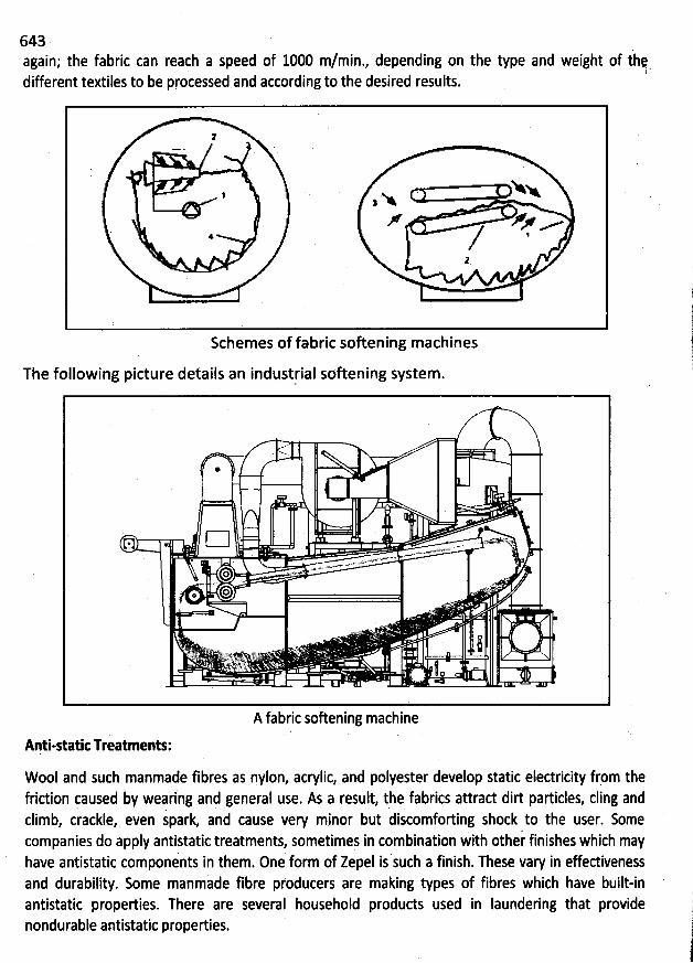
643again; the fabric can reach a speed of 1000 m/min., depending on the type and weight of thq
! Tdifferent textiles to be processed and according to the desired results.
2
Nx, x r r m
. / ,
Schemes of fabric softening machines
The following picture details an industrial softening system.
A fabric softening machine
Anti-static Treatments:
Wool and such manmade fibres as nylon, acrylic, and polyester develpp static eledricity frpm thefridion qaused by wearlng and general qse. As a result, the fabrics attrad dirt particles, cling andclimb, crackle, even spark and cause very minor but discomforting shock to the user. 5omecompanies do apply antistatic treatments, sometimes in combination with other finishes which :ayhave antistatic components in them. 0ne form of Zepel is such a finish. These vary in effedivenessand durability. Some manmade fibre pfoducers are making types of fibres which have built-inantistatic propedies. There are several household produds used in Iaundering that providenondurable antistatic properties.
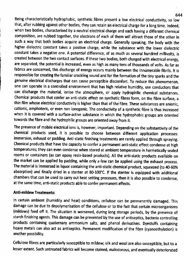
644Being characteristically hydrophobic, synthetic fibres present a Iow electrical condudivity
, so Iow. . . ; ' 'that
, after rubbing against other bodies, they cai retaln tn eledrical charge for a Iong time. Indeed,when two bodies, charaderised by a neutral electrical chargè and eàch having a different chemicalcomposition, are rubbed together, the electrons of each of them' will attrad those of the other ini il bodies acquire an eledrical charge. Generally speaking, the body with thesuc a way that bot
higher dielettric constant takes a positive charge, while the substance with the lower dielectricconstant takes i negative one. A potential difference, of as much as several hundred millivolts
, is.
'
created between the tWo contact surfaces. If these tFo bodies, both charged with eledrical enerjy,are separated, the pote'ntial is increased, even as high as many tens of thousands of volts. As far asfabrics are concerned, this discharge of energy occurs mainly between the innumerable fibrils
. Ii isresponsible for crsating the familiar crackling sound and for the formation of the tiny sparks and thegenuine eledrical discharges that can cause perceptible discomfort. To reduce this phenomenon,nne can operate in a controlled environment that has high relative humidity, use condudors that
i iterlal ionise the atmosphere, oi ap' pIy hydropàilic chemical substances.
can discharge t e m ,Chemical produds that confer an anti-static effect on synthetic fibred fori
, on the fibre surface, athin film whose elediical condudivity is higher than that of the'fibre. These substances are anionic,cationic, amphoteric, or even non ionogenic. The condudivity of a jynthetic fibre is thus increasedwhen it is covered with a surface-active substance in which the hydrophobic groups are orientedtoWards the fibre aqd the hydrophilic groups are oriented away ffom it.
The presence of mobile eledrical ions is, however, important. pepending on the jubstantivity of thechemical produds used, it is possible to choose between diffefent ppplication processes:immersion, exhaust or padding. Anti-static finishing treatments are rarely applied through spraying
.
Chemical produds that have the capacity to confer a permanent anti-static effed cond:nse at hightemperatures; they can even condense when storet at ambient temperature in hermetically sealedrooms or containers (as can epoxy resin-based produds). AIl the anti-static produds available onthe market can be applied by padding, while.only a few can be appliqd ujing the exhaust process.The material is immersed in Iiquor containing the anti-static chemical produd
, squeezed (to 40-60%absorption) and finally dried in a stenter at 80-100@C. If the stenter is equipped with additionalchambers that can be used to carry out heat setting processes, thei it is also possible to condense,pt the same time, anti-static products able to confer permanent effeds.
Anti-mildew Treatments:
ln certain ambient (humidity and heat) conditions, cellulose can be permanently damaged. Thisdamage can be due to depolymerisation of the cellulose or to the fad that certain microorganisms
(mildews) feed off it. The situation is worsened, during long storage periods, by the presence ofstarch finishing agents. This damage can be prevented by the use of antiseptics, baderia controllingproducts containing quaternary ammonium salts, and phenol derivatives. Dyestuffs containingheavy metals can also ad as antiseptics. Permanent modification of the fibre (cyanoethylation) isanother possibility.
Cellulose fibres are particularly susceptible to mildew; silk and wool are also susceptible, but to a
lesser extent. Such untreated fabrics will become stained, malodorous, and eventually deteriorated
645. . . . j ' '< (y .by the fungus if allowed to remain in a moist condition for a period of time. Shower curtains oi 'ljl
her cotton fabrics may be mildewproofed at home by soaking the material ih very soapy water, 'lt'Ot.. ,-- -. ,kjthen, without rinsing, dipping it into a solution of copper sulfate. Antisepticj, such as boric acid ind .jt
id growth of the mildew fungus. One compound that is not egsily '1)carbolic acid, also prevent rap
washed out is a 0.05% solution of phenyl mercuric acetate in wpter. This is 6ne of the most effediveIdewproofing agents. Certain erganometallic compounds, such as of tin and copper, are powedulmi
mildew retardants. Copper imparts a greenish colour to fabrics. Certain resins based on melamineformaldehyde are also valu#ble for mildewproofing. Rotproofing, an extension of mildewproofing, .ij
very important in agricultural applications . ,:
Dimensional stability:
Cotton knitted fabrics in tubular form often show excessive Iengthways shrinkage on washing unless .
given a pre-shrinking treatment based on compressing the fabric Iengthways. A new technique is to . (. )
pre-shrink the fabric by transferring it from one sudion drum to another, the second operating at a ji
Iower surface speed than the fitst.
The Koratron durable-press finish has been applied to polyester-cotton weft-knitted fabrics with @resulting improvement in dimensional stability on washing. A combined mechanical-chemical finish,namely, ''Perset'' has been applied to cotton and polyester-cotton fabrics and waqhing shrinkagel
has been restrided to about 5% in each difedibn by this treatment.
The Micrex Process is also a combined chemical-mechanical treatment when applied to open-widihknitted fabrics containing a substantial proportion of cellulosic fibre. The sequence is (a) pad withresin, (b) dry, (c) compressively shrink lengthways, and (d) cure, treatment usually by means ofinfra-red radiation. For fabrics containing a large proportion of polyester or polyamide fibre, thepadding and drying stagés are omitted, the fabric bving compressed and then heat-set in a relaxedstate. Fabrics treated by this process are claimed to have a Iengthways shrinkage on washing of lessthan 1%, and improved shape retention, lengthways stretch, and handle.