Embed Size (px)
Citation preview
energies
Article
Speed Control for Turbine-Generator of ORC PowerGeneration System and Experimental Implementation
Hyung-Seok Park 1 , Hong-Jun Heo 1 , Bum-Seog Choi 2, Kyung Chun Kim 3
and Jang-Mok Kim 1,*1 Department of Electrical Engineering, Pusan National University, Busan 46241, Korea;
[email protected] (H.-S.P.); [email protected] (H.-J.H.)2 Korea Institute of Machinery & Materials, Daejeon 34103, Korea; [email protected] School of Mechanical Engineering, Pusan National University, Busan 46241, Korea; [email protected]* Correspondence: [email protected]; Tel.: +82-51-510-2366
Received: 11 December 2018; Accepted: 3 January 2019; Published: 9 January 2019�����������������
Abstract: This paper presents a rotation speed estimation and an indirect speed control method fora turbine-generator in a grid-connected 3-phase electrical power conversion system of an organicRankine cycle (ORC) generation system. In addition to the general configuration mechanism andcontrol techniques that are required in the grid-connected ORC power generation system, the indirectspeed control method using the grid-side electric power control and the speed estimation method isproposed for the proper speed control of turbine-generators. The speed estimation method utilizes adigital phase-locked loop (PLL) method that uses a state observer to detect the positive-sequencevoltages. A 10 kW system where a Motor-Generator set is used as a turbine simulator and a 23 kWactual system for the grid-connected ORC power generation were designed and manufactured,respectively. This paper includes various experimental results obtained from field tests conducted onactual installed ORC systems.
Keywords: generator speed control; electrical power generation; turbine and generator;grid-connected converter; organic Rankine cycle; renewable energy
1. Introduction
As part of the renewable energy generation system, researches on power generation systemsusing heat sources have been developed. An organic Rankine cycle (ORC) system with an organiccompound having a low boiling point as a working fluid can obtain high-pressure steam even with alow-temperature heat source. Accordingly, there are many technical and economic advantages, and itis possible to generate high efficiency power from various heat sources [1,2].
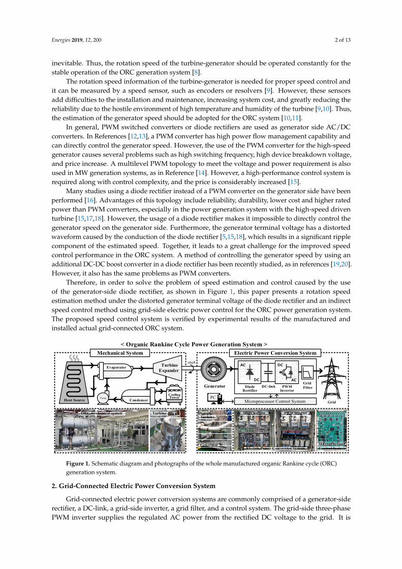
In the ORC generation system, the output power of the turbine is converted into electric powerby the generator, and it transferred to the grid network via an electric power conversion system.The generated electric power must be synchronized with the grid electric power under the constantfrequency before fed into the grid [3,4]. Figure 1 shows the schematic diagram and the photographs ofthe ORC generation system with the grid-connected electric power conversion system.
The generator is directly coupled to the turbine expander that is designed for a high-speed driveso as to reduce the size and increase the efficiency [5–7]. Additionally, the generator rotor will operateat variable speeds according to the operating conditions of the ORC system. However, due to theripple or fluctuation of the turbine rotation speed caused by the unpredictable nature of the ORCsystem, the generator is exposed to the speed ripple, which in turn causes significant vibration andnoise. This means that the degradation in control performance and durability of the ORC system are
Energies 2019, 12, 200; doi:10.3390/en12020200 www.mdpi.com/journal/energies
Energies 2019, 12, 200 2 of 13
inevitable. Thus, the rotation speed of the turbine-generator should be operated constantly for thestable operation of the ORC generation system [8].
The rotation speed information of the turbine-generator is needed for proper speed control andit can be measured by a speed sensor, such as encoders or resolvers [9]. However, these sensorsadd difficulties to the installation and maintenance, increasing system cost, and greatly reducing thereliability due to the hostile environment of high temperature and humidity of the turbine [9,10]. Thus,the estimation of the generator speed should be adopted for the ORC system [10,11].
In general, PWM switched converters or diode rectifiers are used as generator side AC/DCconverters. In References [12,13], a PWM converter has high power flow management capability andcan directly control the generator speed. However, the use of the PWM converter for the high-speedgenerator causes several problems such as high switching frequency, high device breakdown voltage,and price increase. A multilevel PWM topology to meet the voltage and power requirement is alsoused in MW generation systems, as in Reference [14]. However, a high-performance control system isrequired along with control complexity, and the price is considerably increased [15].
Many studies using a diode rectifier instead of a PWM converter on the generator side have beenperformed [16]. Advantages of this topology include reliability, durability, lower cost and higher ratedpower than PWM converters, especially in the power generation system with the high-speed driventurbine [15,17,18]. However, the usage of a diode rectifier makes it impossible to directly control thegenerator speed on the generator side. Furthermore, the generator terminal voltage has a distortedwaveform caused by the conduction of the diode rectifier [5,15,18], which results in a significant ripplecomponent of the estimated speed. Together, it leads to a great challenge for the improved speedcontrol performance in the ORC system. A method of controlling the generator speed by using anadditional DC-DC boost converter in a diode rectifier has been recently studied, as in references [19,20].However, it also has the same problems as PWM converters.
Therefore, in order to solve the problem of speed estimation and control caused by the useof the generator-side diode rectifier, as shown in Figure 1, this paper presents a rotation speedestimation method under the distorted generator terminal voltage of the diode rectifier and an indirectspeed control method using grid-side electric power control for the ORC power generation system.The proposed speed control system is verified by experimental results of the manufactured andinstalled actual grid-connected ORC system.
Energies 2019, 12, x FOR PEER REVIEW 2 of 13
The rotation speed information of the turbine-generator is needed for proper speed control and it can be measured by a speed sensor, such as encoders or resolvers [9]. However, these sensors add difficulties to the installation and maintenance, increasing system cost, and greatly reducing the reliability due to the hostile environment of high temperature and humidity of the turbine [9,10]. Thus, the estimation of the generator speed should be adopted for the ORC system [10,11].
In general, PWM switched converters or diode rectifiers are used as generator side AC/DC converters. In References [12,13], a PWM converter has high power flow management capability and can directly control the generator speed. However, the use of the PWM converter for the high-speed generator causes several problems such as high switching frequency, high device breakdown voltage, and price increase. A multilevel PWM topology to meet the voltage and power requirement is also used in MW generation systems, as in Reference [14]. However, a high-performance control system is required along with control complexity, and the price is considerably increased [15].
Many studies using a diode rectifier instead of a PWM converter on the generator side have been performed [16]. Advantages of this topology include reliability, durability, lower cost and higher rated power than PWM converters, especially in the power generation system with the high-speed driven turbine [15,17,18]. However, the usage of a diode rectifier makes it impossible to directly control the generator speed on the generator side. Furthermore, the generator terminal voltage has a distorted waveform caused by the conduction of the diode rectifier [5,15,18], which results in a significant ripple component of the estimated speed. Together, it leads to a great challenge for the improved speed control performance in the ORC system. A method of controlling the generator speed by using an additional DC-DC boost converter in a diode rectifier has been recently studied, as in references [19,20]. However, it also has the same problems as PWM converters.
Therefore, in order to solve the problem of speed estimation and control caused by the use of the generator-side diode rectifier, as shown in Figure 1, this paper presents a rotation speed estimation method under the distorted generator terminal voltage of the diode rectifier and an indirect speed control method using grid-side electric power control for the ORC power generation system. The proposed speed control system is verified by experimental results of the manufactured and installed actual grid-connected ORC system.
shaft
< Organic Rankine Cycle Power Generation System >
PumpHeat Source Condenser
Expander
Generator
GridPC
RectifierDiode
InverterPWMDC-link
AC
DC ACGridFilter
ORC mechanical system Turbine
GeneratorElectric Power Conversion System
Diode Rectifer
Turbine
Microprocessor Control System
PWM Inverter
MicroprocessorControl System
Mechanical System Electric Power Conversion System
Evaporator
CoolingTower
Turbine
DC
Figure 1. Schematic diagram and photographs of the whole manufactured organic Rankine cycle (ORC) generation system.
2. Grid-Connected Electric Power Conversion System
Grid-connected electric power conversion systems are commonly comprised of a generator-side rectifier, a DC-link, a grid-side inverter, a grid filter, and a control system. The grid-side three-phase PWM inverter supplies the regulated AC power from the rectified DC voltage to the grid. It is critical in grid-connected electric power conversion systems for optimized control to meet the grid interconnection and required electric power quality [21–24].
Figure 1. Schematic diagram and photographs of the whole manufactured organic Rankine cycle (ORC)generation system.
2. Grid-Connected Electric Power Conversion System
Grid-connected electric power conversion systems are commonly comprised of a generator-siderectifier, a DC-link, a grid-side inverter, a grid filter, and a control system. The grid-side three-phasePWM inverter supplies the regulated AC power from the rectified DC voltage to the grid. It is
Energies 2019, 12, 200 3 of 13
critical in grid-connected electric power conversion systems for optimized control to meet the gridinterconnection and required electric power quality [21–24].
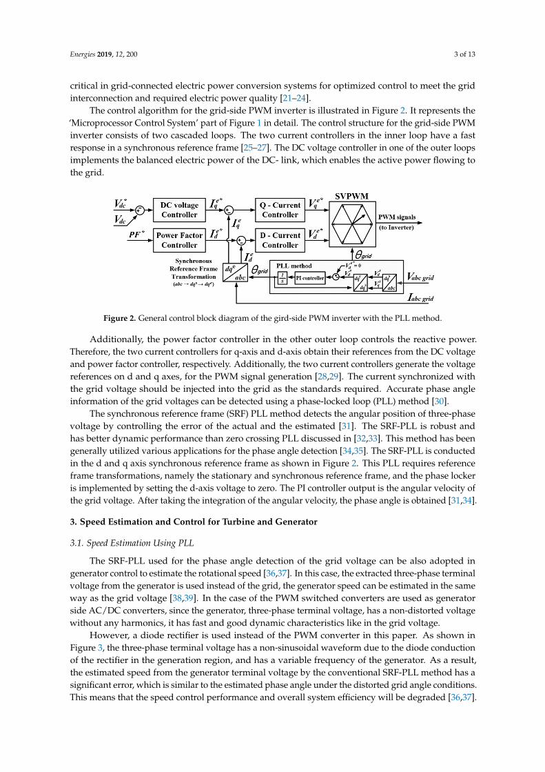
The control algorithm for the grid-side PWM inverter is illustrated in Figure 2. It represents the‘Microprocessor Control System’ part of Figure 1 in detail. The control structure for the grid-side PWMinverter consists of two cascaded loops. The two current controllers in the inner loop have a fastresponse in a synchronous reference frame [25–27]. The DC voltage controller in one of the outer loopsimplements the balanced electric power of the DC- link, which enables the active power flowing tothe grid.
Energies 2019, 12, x FOR PEER REVIEW 3 of 13
The control algorithm for the grid-side PWM inverter is illustrated in Figure 2. It represents the ‘Microprocessor Control System’ part of Figure 1 in detail. The control structure for the grid-side PWM inverter consists of two cascaded loops. The two current controllers in the inner loop have a fast response in a synchronous reference frame [25–27]. The DC voltage controller in one of the outer loops implements the balanced electric power of the DC- link, which enables the active power flowing to the grid.
Figure 2. General control block diagram of the gird-side PWM inverter with the PLL method.
Additionally, the power factor controller in the other outer loop controls the reactive power. Therefore, the two current controllers for q-axis and d-axis obtain their references from the DC voltage and power factor controller, respectively. Additionally, the two current controllers generate the voltage references on d and q axes, for the PWM signal generation [28,29]. The current synchronized with the grid voltage should be injected into the grid as the standards required. Accurate phase angle information of the grid voltages can be detected using a phase-locked loop (PLL) method [30].
The synchronous reference frame (SRF) PLL method detects the angular position of three-phase voltage by controlling the error of the actual and the estimated [31]. The SRF-PLL is robust and has better dynamic performance than zero crossing PLL discussed in [32,33]. This method has been generally utilized various applications for the phase angle detection [34,35]. The SRF-PLL is conducted in the d and q axis synchronous reference frame as shown in Figure 2. This PLL requires reference frame transformations, namely the stationary and synchronous reference frame, and the phase locker is implemented by setting the d-axis voltage to zero. The PI controller output is the angular velocity of the grid voltage. After taking the integration of the angular velocity, the phase angle is obtained [31,34].
3. Speed Estimation and Control for Turbine and Generator
3.1. Speed Estimation Using PLL
The SRF-PLL used for the phase angle detection of the grid voltage can be also adopted in generator control to estimate the rotational speed [36,37]. In this case, the extracted three-phase terminal voltage from the generator is used instead of the grid, the generator speed can be estimated in the same way as the grid voltage [38,39]. In the case of the PWM switched converters are used as generator side AC/DC converters, since the generator, three-phase terminal voltage, has a non-distorted voltage without any harmonics, it has fast and good dynamic characteristics like in the grid voltage.
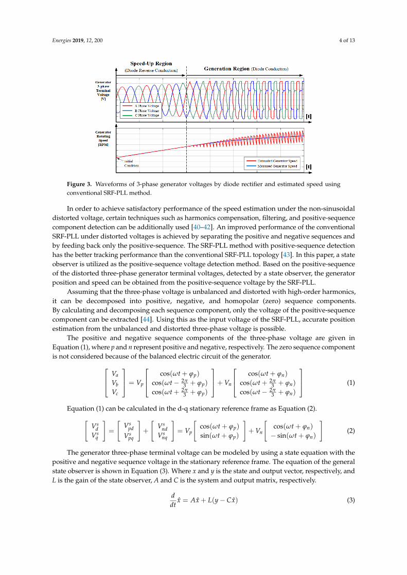
However, a diode rectifier is used instead of the PWM converter in this paper. As shown in Figure 3, the three-phase terminal voltage has a non-sinusoidal waveform due to the diode conduction of the rectifier in the generation region, and has a variable frequency of the generator. As a result, the estimated speed from the generator terminal voltage by the conventional SRF-PLL method has a significant error, which is similar to the estimated phase angle under the distorted grid angle conditions. This means that the speed control performance and overall system efficiency will be degraded [36,37].
Figure 2. General control block diagram of the gird-side PWM inverter with the PLL method.
Additionally, the power factor controller in the other outer loop controls the reactive power.Therefore, the two current controllers for q-axis and d-axis obtain their references from the DC voltageand power factor controller, respectively. Additionally, the two current controllers generate the voltagereferences on d and q axes, for the PWM signal generation [28,29]. The current synchronized withthe grid voltage should be injected into the grid as the standards required. Accurate phase angleinformation of the grid voltages can be detected using a phase-locked loop (PLL) method [30].
The synchronous reference frame (SRF) PLL method detects the angular position of three-phasevoltage by controlling the error of the actual and the estimated [31]. The SRF-PLL is robust andhas better dynamic performance than zero crossing PLL discussed in [32,33]. This method has beengenerally utilized various applications for the phase angle detection [34,35]. The SRF-PLL is conductedin the d and q axis synchronous reference frame as shown in Figure 2. This PLL requires referenceframe transformations, namely the stationary and synchronous reference frame, and the phase lockeris implemented by setting the d-axis voltage to zero. The PI controller output is the angular velocity ofthe grid voltage. After taking the integration of the angular velocity, the phase angle is obtained [31,34].
3. Speed Estimation and Control for Turbine and Generator
3.1. Speed Estimation Using PLL
The SRF-PLL used for the phase angle detection of the grid voltage can be also adopted ingenerator control to estimate the rotational speed [36,37]. In this case, the extracted three-phase terminalvoltage from the generator is used instead of the grid, the generator speed can be estimated in the sameway as the grid voltage [38,39]. In the case of the PWM switched converters are used as generatorside AC/DC converters, since the generator, three-phase terminal voltage, has a non-distorted voltagewithout any harmonics, it has fast and good dynamic characteristics like in the grid voltage.
However, a diode rectifier is used instead of the PWM converter in this paper. As shown inFigure 3, the three-phase terminal voltage has a non-sinusoidal waveform due to the diode conductionof the rectifier in the generation region, and has a variable frequency of the generator. As a result,the estimated speed from the generator terminal voltage by the conventional SRF-PLL method has asignificant error, which is similar to the estimated phase angle under the distorted grid angle conditions.This means that the speed control performance and overall system efficiency will be degraded [36,37].
Energies 2019, 12, 200 4 of 13Energies 2019, 12, x FOR PEER REVIEW 4 of 13
Figure 3. Waveforms of 3-phase generator voltages by diode rectifier and estimated speed using conventional SRF-PLL method.
In order to achieve satisfactory performance of the speed estimation under the non-sinusoidal distorted voltage, certain techniques such as harmonics compensation, filtering, and positive-sequence component detection can be additionally used [40–42]. An improved performance of the conventional SRF-PLL under distorted voltages is achieved by separating the positive and negative sequences and by feeding back only the positive-sequence. The SRF-PLL method with positive-sequence detection has the better tracking performance than the conventional SRF-PLL topology [43]. In this paper, a state observer is utilized as the positive-sequence voltage detection method. Based on the positive-sequence of the distorted three-phase generator terminal voltages, detected by a state observer, the generator position and speed can be obtained from the positive-sequence voltage by the SRF-PLL.
Assuming that the three-phase voltage is unbalanced and distorted with high-order harmonics, it can be decomposed into positive, negative, and homopolar (zero) sequence components. By calculating and decomposing each sequence component, only the voltage of the positive-sequence component can be extracted [44]. Using this as the input voltage of the SRF-PLL, accurate position estimation from the unbalanced and distorted three-phase voltage is possible.
The positive and negative sequence components of the three-phase voltage are given in Equation (1), where p and n represent positive and negative, respectively. The zero sequence component is not considered because of the balanced electric circuit of the generator.
cos( ) cos( )2 2cos( ) cos( )3 3
2 2cos( ) cos( )3 3
p na
b p p n n
c
p n
t tVV V t V tV
t t
ω ϕ ω ϕπ πω ϕ ω ϕ
π πω ϕ ω ϕ
+ +
= − + + + +
+ + − +
(1)
Equation (1) can be calculated in the d-q stationary reference frame as Equation (2).
cos( ) cos( )sin( ) sin( )
s s sp nd pd nd
p ns s sp nq pq nq
t tV V VV V
t tV V Vω ϕ ω ϕω ϕ ω ϕ
+ + = + = + + − +
(2)
The generator three-phase terminal voltage can be modeled by using a state equation with the positive and negative sequence voltage in the stationary reference frame. The equation of the general state observer is shown in Equation (3). Where x and y is the state and output vector, respectively, and L is the gain of the state observer, A and C is the system and output matrix, respectively.
)ˆ(ˆˆ xCyLxAxdtd −+= (3)
By differentiating Equation (2), the state equation can be derived as Equation (4).
Figure 3. Waveforms of 3-phase generator voltages by diode rectifier and estimated speed usingconventional SRF-PLL method.
In order to achieve satisfactory performance of the speed estimation under the non-sinusoidaldistorted voltage, certain techniques such as harmonics compensation, filtering, and positive-sequencecomponent detection can be additionally used [40–42]. An improved performance of the conventionalSRF-PLL under distorted voltages is achieved by separating the positive and negative sequences andby feeding back only the positive-sequence. The SRF-PLL method with positive-sequence detectionhas the better tracking performance than the conventional SRF-PLL topology [43]. In this paper, a stateobserver is utilized as the positive-sequence voltage detection method. Based on the positive-sequenceof the distorted three-phase generator terminal voltages, detected by a state observer, the generatorposition and speed can be obtained from the positive-sequence voltage by the SRF-PLL.
Assuming that the three-phase voltage is unbalanced and distorted with high-order harmonics,it can be decomposed into positive, negative, and homopolar (zero) sequence components.By calculating and decomposing each sequence component, only the voltage of the positive-sequencecomponent can be extracted [44]. Using this as the input voltage of the SRF-PLL, accurate positionestimation from the unbalanced and distorted three-phase voltage is possible.
The positive and negative sequence components of the three-phase voltage are given inEquation (1), where p and n represent positive and negative, respectively. The zero sequence componentis not considered because of the balanced electric circuit of the generator. Va
VbVc
= Vp
cos(ωt + ϕp)
cos(ωt − 2π3 + ϕp)
cos(ωt + 2π3 + ϕp)
+ Vn
cos(ωt + ϕn)
cos(ωt + 2π3 + ϕn)
cos(ωt − 2π3 + ϕn)
(1)
Equation (1) can be calculated in the d-q stationary reference frame as Equation (2).[Vs
dVs
q
]=
[Vs
pdVs
pq
]+
[Vs
ndVs
nq
]= Vp
[cos(ωt + ϕp)
sin(ωt + ϕp)
]+ Vn
[cos(ωt + ϕn)
− sin(ωt + ϕn)
](2)
The generator three-phase terminal voltage can be modeled by using a state equation with thepositive and negative sequence voltage in the stationary reference frame. The equation of the generalstate observer is shown in Equation (3). Where x and y is the state and output vector, respectively, andL is the gain of the state observer, A and C is the system and output matrix, respectively.
ddt
x̂ = Ax̂ + L(y − Cx̂) (3)
Energies 2019, 12, 200 5 of 13
By differentiating Equation (2), the state equation can be derived as Equation (4).
ddt
Vs
pdVs
pqVs
ndVs
nq
=
00ω
0
−ω
000
000
−ω
00ω
0
Vspd
Vspq
Vsnd
Vsnq
(4)
The output equation for the decomposed state variables of Equation (2) can be expressed asEquation (5).
y = cx =
[Vs
dVs
q
]=
[1 0 1 00 1 0 1
]Vs
pdVs
pqVs
ndVs
nq
(5)
The state observer equation is derived from Equations (3)–(5) and is given in Equation (6), wherethe angular speed variable ω̂ is estimated from the previous sample and the tuned observer constantshould be used.
ddt
V̂s
pdV̂s
pqV̂s
ndV̂s
nq
=
00ω̂
0
−ω̂
000
000
−ω̂
00ω̂
0
V̂spd
V̂spq
V̂snd
V̂snq
+
l11 l12
l21 l22
l31 l32
l41 l42
y −
[1 0 1 00 1 0 1
]V̂s
pdV̂s
pqV̂s
ndV̂s
nq
(6)
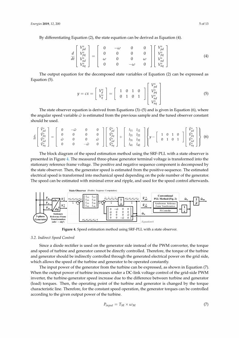
The block diagram of the speed estimation method using the SRF-PLL with a state observer ispresented in Figure 4. The measured three-phase generator terminal voltage is transformed into thestationary reference frame voltage. The positive and negative sequence component is decomposed bythe state observer. Then, the generator speed is estimated from the positive-sequence. The estimatedelectrical speed is transformed into mechanical speed depending on the pole number of the generator.The speed can be estimated with minimal error and ripple, and used for the speed control afterwards.
Energies 2019, 12, x FOR PEER REVIEW 5 of 13
0 0 00 0 0 0
0 00 0 0
s spd pds spq pqs snd nds snq nq
V VV VdV VdtV V
ω
ω ωω
− = −
(4)
The output equation for the decomposed state variables of Equation (2) can be expressed as Equation (5).
1 0 1 00 1 0 1
spd
s sd pqs sq nd
snq
VV V
y cxV V
V
= = =
(5)
The state observer equation is derived from Equations (3)–(5) and is given in Equation (6), where
the angular speed variable ω is estimated from the previous sample and the tuned observer constant should be used.
11 12
21 22
31 32
41 42
0 0 00 0 0 1 0 1 00
0 0 1 0 100 0 0
s s spd pd pd
s s spq pq pq
s s snd nd nd
s s snq nq nq
V V Vl ll lV V Vd yl ldt V V Vl l
V V V
ω
ω ωω
− = + − −
(6)
The block diagram of the speed estimation method using the SRF-PLL with a state observer is presented in Figure 4. The measured three-phase generator terminal voltage is transformed into the stationary reference frame voltage. The positive and negative sequence component is decomposed by the state observer. Then, the generator speed is estimated from the positive-sequence. The estimated electrical speed is transformed into mechanical speed depending on the pole number of the generator. The speed can be estimated with minimal error and ripple, and used for the speed control afterwards.
𝑽𝒖 𝒂𝒃𝒄𝒅𝒒
𝝎𝒆𝑽𝒅 𝒔𝑽𝒒 𝒔𝒔𝑽𝒗𝑽𝒘 𝐿 𝐿𝐿 𝐿𝐿 𝐿𝐿 𝐿
0 𝜔𝜔 0 0 0 0 0 0 00 0 0 𝜔𝜔 0 𝟏𝒔. 𝑽𝒑𝒅 𝒔
𝑽𝒑𝒒 𝒔𝝎𝒆
𝟏𝒔𝟒 𝟒 𝟒𝟒𝑽𝒑𝒅 𝒔 , 𝑽𝒏𝒅 𝒔 , 𝑽𝒑𝒒 𝒔 , 𝑽𝒏𝒒 𝒔 𝑽𝒑𝒅 𝒔 , 𝑽𝒏𝒅 𝒔 , 𝑽𝒑𝒒 𝒔 , 𝑽𝒏𝒒 𝒔𝑽𝒑𝒅 𝒔 , 𝑽𝒏𝒅 𝒔 , 𝑽𝒑𝒒 𝒔 , 𝑽𝒏𝒒 𝒔. . . 𝟐𝑷 𝝎𝒎
𝟒𝑽𝒑𝒅 𝒔 , 𝑽𝒏𝒅 𝒔 , 𝑽𝒑𝒒 𝒔 , 𝑽𝒏𝒒 𝒔
Synchronous ReferenceFrame Transformation
PI Controller
ConventionalPLL Method (Fig. 2)
(Positive Sequence Computation)State Observer
StationaryReference FrameTransformation(𝒂𝒃𝒄 → 𝒅𝒒𝒔)
3-phaseGenerator
Equation 6 Figure 4. Speed estimation method using SRF-PLL with a state observer.
3.2. Indirect Speed Control
Since a diode rectifier is used on the generator side instead of the PWM converter, the torque and speed of turbine and generator cannot be directly controlled. Therefore, the torque of the turbine and generator should be indirectly controlled through the generated electrical power on the grid side, which allows the speed of the turbine and generator to be operated constantly.
The input power of the generator from the turbine can be expressed, as shown in Equation (7). When the output power of turbine increases under a DC-link voltage control of the grid-side PWM inverter, the turbine-generator speed increase due to the difference between turbine and generator (load) torques. Then, the operating point of the turbine and generator is changed by the torque characteristic line. Therefore, for the constant speed operation, the generator torques can be controlled according to the given output power of the turbine.
input M MP T ω= × (7)
Figure 4. Speed estimation method using SRF-PLL with a state observer.
3.2. Indirect Speed Control
Since a diode rectifier is used on the generator side instead of the PWM converter, the torqueand speed of turbine and generator cannot be directly controlled. Therefore, the torque of the turbineand generator should be indirectly controlled through the generated electrical power on the grid side,which allows the speed of the turbine and generator to be operated constantly.
The input power of the generator from the turbine can be expressed, as shown in Equation (7).When the output power of turbine increases under a DC-link voltage control of the grid-side PWMinverter, the turbine-generator speed increase due to the difference between turbine and generator(load) torques. Then, the operating point of the turbine and generator is changed by the torquecharacteristic line. Therefore, for the constant speed operation, the generator torques can be controlledaccording to the given output power of the turbine.
Pinput = TM × ωM (7)
Energies 2019, 12, 200 6 of 13
The mechanical generator torque is expressed in Equation (8). At the steady state, the right-sidedifferential term of Equation (8) is zero. Neglecting the damping effect of the inertia moment andthe friction term, the mechanical turbine output torque is approximately equal to the load torque ofthe generator.
TM = Jdω
dt+ Bω + TL (8)
The load torque can be regarded as the generator electric torque delivered to the grid, as given inEquation (9). Where KT is the torque constant and ie
qs is the generated torque component current of theq-axis synchronous reference frame. Therefore, the mechanical speed of the turbine and generator canbe maintained by controlling the torque component current of the generator.
TL = Te = KT × ieqs (9)
The peak value of output voltage with the constant excitation of the generator is proportionalto the rotating speed of the machine. The variation of the q-axis current (the generated peak outputcurrent from the generator) depends on the difference between the peak output voltage of the generatorand the DC–link voltage. This implies that it is possible to control the torque component (q-axis)current by adjusting the DC-link voltage, which further controls the mechanical speed of the turbineand generator.
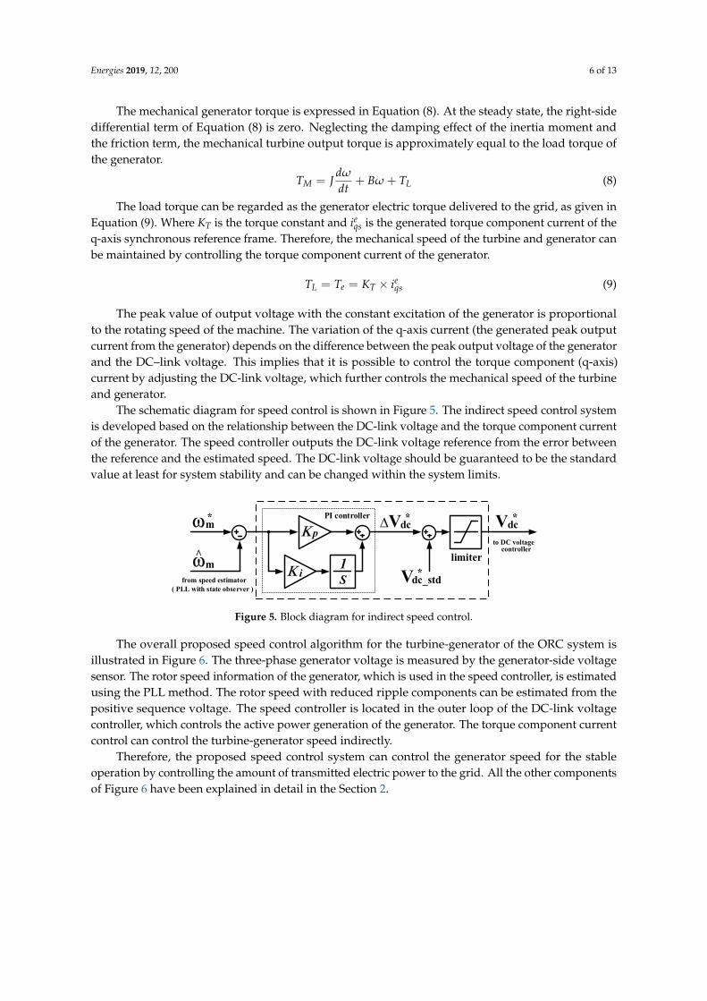
The schematic diagram for speed control is shown in Figure 5. The indirect speed control systemis developed based on the relationship between the DC-link voltage and the torque component currentof the generator. The speed controller outputs the DC-link voltage reference from the error betweenthe reference and the estimated speed. The DC-link voltage should be guaranteed to be the standardvalue at least for system stability and can be changed within the system limits.
Energies 2019, 12, x FOR PEER REVIEW 6 of 13
The mechanical generator torque is expressed in Equation (8). At the steady state, the right-side differential term of Equation (8) is zero. Neglecting the damping effect of the inertia moment and the friction term, the mechanical turbine output torque is approximately equal to the load torque of the generator.
M LdT J B Tdtω ω= + + (8)
The load torque can be regarded as the generator electric torque delivered to the grid, as given in Equation (9). Where KT is the torque constant and e
qsi is the generated torque component current
of the q-axis synchronous reference frame. Therefore, the mechanical speed of the turbine and generator can be maintained by controlling the torque component current of the generator.
eL e T qsT T K i= = × (9)
The peak value of output voltage with the constant excitation of the generator is proportional to the rotating speed of the machine. The variation of the q-axis current (the generated peak output current from the generator) depends on the difference between the peak output voltage of the generator and the DC–link voltage. This implies that it is possible to control the torque component (q-axis) current by adjusting the DC-link voltage, which further controls the mechanical speed of the turbine and generator.
The schematic diagram for speed control is shown in Figure 5. The indirect speed control system is developed based on the relationship between the DC-link voltage and the torque component current of the generator. The speed controller outputs the DC-link voltage reference from the error between the reference and the estimated speed. The DC-link voltage should be guaranteed to be the standard value at least for system stability and can be changed within the system limits.
ωm˄
ωm* ∆Vdc*
Vdc_std*
Κ p
Κ i S1
Vdc*
limiter
PI controller
to DC voltage
from speed estimator( PLL with state observer )
controller
Figure 5. Block diagram for indirect speed control.
The overall proposed speed control algorithm for the turbine-generator of the ORC system is illustrated in Figure 6. The three-phase generator voltage is measured by the generator-side voltage sensor. The rotor speed information of the generator, which is used in the speed controller, is estimated using the PLL method. The rotor speed with reduced ripple components can be estimated from the positive sequence voltage. The speed controller is located in the outer loop of the DC-link voltage controller, which controls the active power generation of the generator. The torque component current control can control the turbine-generator speed indirectly.
Therefore, the proposed speed control system can control the generator speed for the stable operation by controlling the amount of transmitted electric power to the grid. All the other components of Figure 6 have been explained in detail in the Section 2.
Figure 5. Block diagram for indirect speed control.
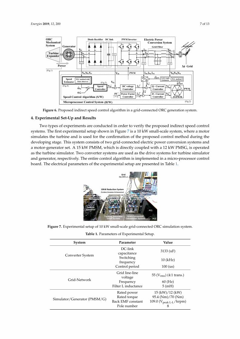
The overall proposed speed control algorithm for the turbine-generator of the ORC system isillustrated in Figure 6. The three-phase generator voltage is measured by the generator-side voltagesensor. The rotor speed information of the generator, which is used in the speed controller, is estimatedusing the PLL method. The rotor speed with reduced ripple components can be estimated from thepositive sequence voltage. The speed controller is located in the outer loop of the DC-link voltagecontroller, which controls the active power generation of the generator. The torque component currentcontrol can control the turbine-generator speed indirectly.
Therefore, the proposed speed control system can control the generator speed for the stableoperation by controlling the amount of transmitted electric power to the grid. All the other componentsof Figure 6 have been explained in detail in the Section 2.
Energies 2019, 12, 200 7 of 13
Energies 2019, 12, x FOR PEER REVIEW 7 of 13
Vdc PWM
C.T V.T
V.T
Electric Power
Grid Filter
PWM InverterDC linkDiode Rectifier
V.T
Generator
SpeedEstimator
SVPWMVd
e*
ωm˄
Vdc
SpeedController
ωm*
Vdc* DC voltageController
PLL method withState observer
abcdq
Power FactorController
PF * Ι de*
Ι qe*
Ι de
Ι qe
Q - CurrentController
D - CurrentController
Vqe*
Grid Angle Estimator
θgrid
3ϕ Grid
Conversion System
θgridPLL method
(Fig.4)(Fig.5)
(Fig.2)
(Fig.1)
Power
ExpanderTurbine
MechanicalSystem
Speed Control Algorithm (S/W)
Microprocessor Control System (H/W)
( ≈ 1) ( ≈ 0)
Ιag
Ιbg
Ιcg Vcg
Vbg
Vag
Vcs
Vbs
Vas
Vas,Vbs,Vcs Ιag,Ιbg, Ιcg Vag,Vbg,Vcg
PWM
ORC
Figure 6. Proposed indirect speed control algorithm in a grid-connected ORC generation system.
4. Experimental Set-Up and Results
Two types of experiments are conducted in order to verify the proposed indirect speed control systems. The first experimental setup shown in Figure 7 is a 10 kW small-scale system, where a motor simulates the turbine and is used for the confirmation of the proposed control method during the developing stage. This system consists of two grid-connected electric power conversion systems and a motor-generator set. A 15 kW PMSM, which is directly coupled with a 12 kW PMSG, is operated as the turbine simulator. Two converter systems are used as the drive systems for turbine simulator and generator, respectively. The entire control algorithm is implemented in a micro-processor control board. The electrical parameters of the experimental setup are presented in Table 1.
Generator
TurbineSimulator
10kW Reduction System(Turbine Simulator & Generator)
Turbine Simulator Grid-Connected
PC1
PC2
(3ϕ 220Vrms)Grid
Oscilloscope
Drive System Conversion System Figure 7. Experimental setup of 10 kW small-scale grid-connected ORC simulation system.
Table 1. Parameters of Experimental Setup.
System Parameter Value
Converter System DC-link capacitance 3133 (uF) Switching frequency 10 (kHz)
Control period 100 (us)
Grid-Network Grid line-line voltage 55 (Vrms) (4:1 trans.)
Frequency 60 (Hz) Filter L inductance 5 (mH)
Simulator/Generator (PMSM/G)
Rated power 15 (kW)/12 (kW) Rated torque 95.4 (Nm)/70 (Nm)
Back EMF constant 109.0 (Vpeak L-L/krpm) Pole number 8
Figure 6. Proposed indirect speed control algorithm in a grid-connected ORC generation system.
4. Experimental Set-Up and Results
Two types of experiments are conducted in order to verify the proposed indirect speed controlsystems. The first experimental setup shown in Figure 7 is a 10 kW small-scale system, where a motorsimulates the turbine and is used for the confirmation of the proposed control method during thedeveloping stage. This system consists of two grid-connected electric power conversion systems anda motor-generator set. A 15 kW PMSM, which is directly coupled with a 12 kW PMSG, is operatedas the turbine simulator. Two converter systems are used as the drive systems for turbine simulatorand generator, respectively. The entire control algorithm is implemented in a micro-processor controlboard. The electrical parameters of the experimental setup are presented in Table 1.
Energies 2019, 12, x FOR PEER REVIEW 7 of 13
Vdc PWM
C.T V.T
V.T
Electric Power
Grid Filter
PWM InverterDC linkDiode Rectifier
V.T
Generator
SpeedEstimator
SVPWMVd
e*
ωm˄
Vdc
SpeedController
ωm*
Vdc* DC voltageController
PLL method withState observer
abcdq
Power FactorController
PF * Ι de*
Ι qe*
Ι de
Ι qe
Q - CurrentController
D - CurrentController
Vqe*
Grid Angle Estimator
θgrid
3ϕ Grid
Conversion System
θgridPLL method
(Fig.4)(Fig.5)
(Fig.2)
(Fig.1)
Power
ExpanderTurbine
MechanicalSystem
Speed Control Algorithm (S/W)
Microprocessor Control System (H/W)
( ≈ 1) ( ≈ 0)
Ιag
Ιbg
Ιcg Vcg
Vbg
Vag
Vcs
Vbs
Vas
Vas,Vbs,Vcs Ιag,Ιbg, Ιcg Vag,Vbg,Vcg
PWM
ORC
Figure 6. Proposed indirect speed control algorithm in a grid-connected ORC generation system.
4. Experimental Set-Up and Results
Two types of experiments are conducted in order to verify the proposed indirect speed control systems. The first experimental setup shown in Figure 7 is a 10 kW small-scale system, where a motor simulates the turbine and is used for the confirmation of the proposed control method during the developing stage. This system consists of two grid-connected electric power conversion systems and a motor-generator set. A 15 kW PMSM, which is directly coupled with a 12 kW PMSG, is operated as the turbine simulator. Two converter systems are used as the drive systems for turbine simulator and generator, respectively. The entire control algorithm is implemented in a micro-processor control board. The electrical parameters of the experimental setup are presented in Table 1.
Generator
TurbineSimulator
10kW Reduction System(Turbine Simulator & Generator)
Turbine Simulator Grid-Connected
PC1
PC2
(3ϕ 220Vrms)Grid
Oscilloscope
Drive System Conversion System Figure 7. Experimental setup of 10 kW small-scale grid-connected ORC simulation system.
Table 1. Parameters of Experimental Setup.
System Parameter Value
Converter System DC-link capacitance 3133 (uF) Switching frequency 10 (kHz)
Control period 100 (us)
Grid-Network Grid line-line voltage 55 (Vrms) (4:1 trans.)
Frequency 60 (Hz) Filter L inductance 5 (mH)
Simulator/Generator (PMSM/G)
Rated power 15 (kW)/12 (kW) Rated torque 95.4 (Nm)/70 (Nm)
Back EMF constant 109.0 (Vpeak L-L/krpm) Pole number 8
Figure 7. Experimental setup of 10 kW small-scale grid-connected ORC simulation system.
Table 1. Parameters of Experimental Setup.
System Parameter Value
Converter System
DC-linkcapacitance 3133 (uF)
Switchingfrequency 10 (kHz)
Control period 100 (us)
Grid-Network
Grid line-linevoltage 55 (Vrms) (4:1 trans.)
Frequency 60 (Hz)Filter L inductance 5 (mH)
Simulator/Generator (PMSM/G)
Rated power 15 (kW)/12 (kW)Rated torque 95.4 (Nm)/70 (Nm)
Back EMF constant 109.0 (Vpeak L-L/krpm)Pole number 8
Energies 2019, 12, 200 8 of 13
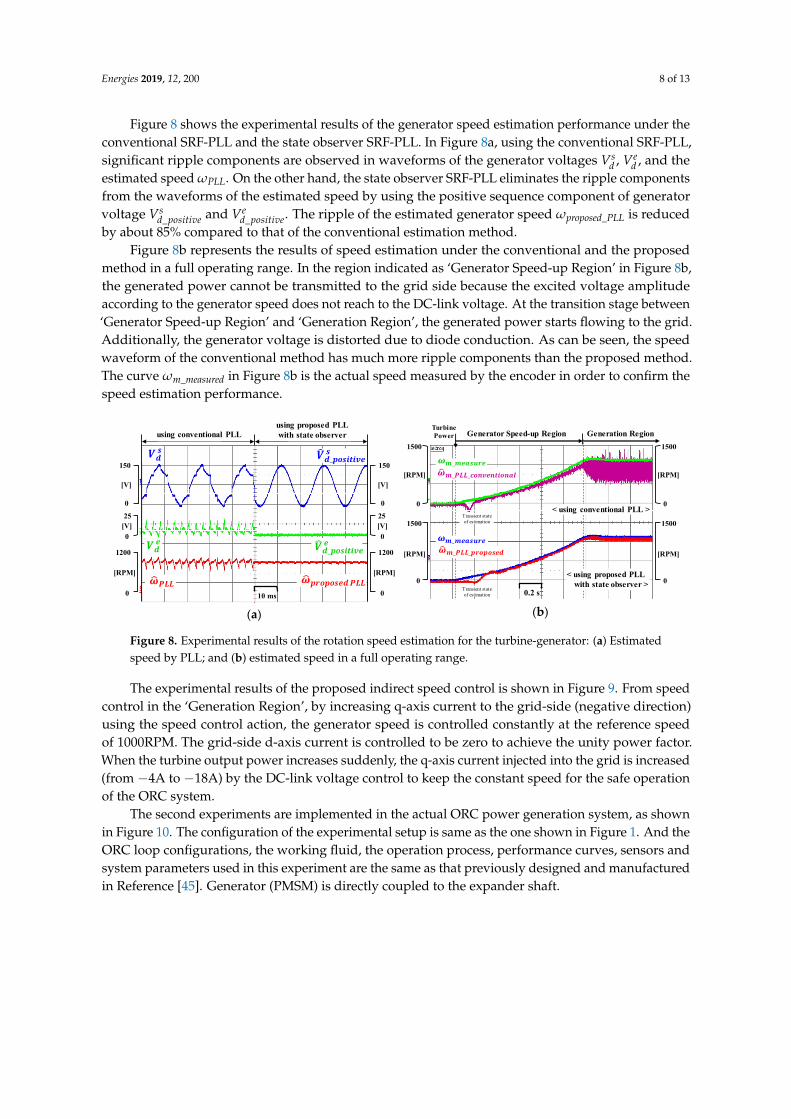
Figure 8 shows the experimental results of the generator speed estimation performance under theconventional SRF-PLL and the state observer SRF-PLL. In Figure 8a, using the conventional SRF-PLL,significant ripple components are observed in waveforms of the generator voltages Vs
d , Ved , and the
estimated speed ωPLL. On the other hand, the state observer SRF-PLL eliminates the ripple componentsfrom the waveforms of the estimated speed by using the positive sequence component of generatorvoltage Vs
d_positive and Ved_positive. The ripple of the estimated generator speed ωproposed_PLL is reduced
by about 85% compared to that of the conventional estimation method.Figure 8b represents the results of speed estimation under the conventional and the proposed
method in a full operating range. In the region indicated as ‘Generator Speed-up Region’ in Figure 8b,the generated power cannot be transmitted to the grid side because the excited voltage amplitudeaccording to the generator speed does not reach to the DC-link voltage. At the transition stage between‘Generator Speed-up Region’ and ‘Generation Region’, the generated power starts flowing to the grid.Additionally, the generator voltage is distorted due to diode conduction. As can be seen, the speedwaveform of the conventional method has much more ripple components than the proposed method.The curve ωm_measured in Figure 8b is the actual speed measured by the encoder in order to confirm thespeed estimation performance.
Energies 2019, 12, x FOR PEER REVIEW 8 of 13
Figure 8 shows the experimental results of the generator speed estimation performance under the conventional SRF-PLL and the state observer SRF-PLL. In Figure 8a, using the conventional SRF-PLL, significant ripple components are observed in waveforms of the generator voltages 𝑉 , 𝑉 , and the estimated speed ωPLL. On the other hand, the state observer SRF-PLL eliminates the ripple components from the waveforms of the estimated speed by using the positive sequence component of generator voltage 𝑉 _ and 𝑉 _ . The ripple of the estimated generator speed ωproposed_PLL is reduced by about 85% compared to that of the conventional estimation method.
Figure 8b represents the results of speed estimation under the conventional and the proposed method in a full operating range. In the region indicated as ‘Generator Speed-up Region’ in Figure 8b, the generated power cannot be transmitted to the grid side because the excited voltage amplitude according to the generator speed does not reach to the DC-link voltage. At the transition stage between ‘Generator Speed-up Region’ and ‘Generation Region’, the generated power starts flowing to the grid. Additionally, the generator voltage is distorted due to diode conduction. As can be seen, the speed waveform of the conventional method has much more ripple components than the proposed method. The curve ωm_measured in Figure 8b is the actual speed measured by the encoder in order to confirm the speed estimation performance.
150
[V]
025[V]0
1200
[RPM]
010 ms
using conventional PLLusing proposed PLLwith state observer
𝝎𝑷𝑳𝑳𝑽𝒅 𝒆 𝑽𝒅_𝒑𝒐𝒔𝒊𝒕𝒊𝒗𝒆 𝒆
𝑽𝒅 𝒔 𝑽𝒅_𝒑𝒐𝒔𝒊𝒕𝒊𝒗𝒆 𝒔
𝝎𝒑𝒓𝒐𝒑𝒐𝒔𝒆𝒅 𝑷𝑳𝑳
150
[V]
025
[V]0
1200
[RPM]
0
(a)
0.2 s
Generator Speed-up Region
𝝎𝒎_𝑷𝑳𝑳_𝒄𝒐𝒏𝒗𝒆𝒏𝒕𝒊𝒐𝒏𝒂𝒍Generation Region
[RPM]
1500
[RPM]
0
𝝎𝒎_𝒎𝒆𝒂𝒔𝒖𝒓𝒆< using conventional PLL >
< using proposed PLLwith state observer >
𝝎𝒎_𝒎𝒆𝒂𝒔𝒖𝒓𝒆
1500
0
[RPM]
1500
[RPM]
0
1500
0
TurbinePower
𝝎𝒎_𝑷𝑳𝑳_𝒑𝒓𝒐𝒑𝒐𝒔𝒆𝒅Transient stateof estimation
Transient stateof estimation
(b)
Figure 8. Experimental results of the rotation speed estimation for the turbine-generator: (a) Estimated speed by PLL; and (b) estimated speed in a full operating range.
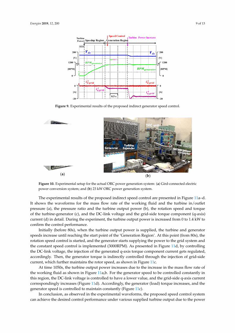
The experimental results of the proposed indirect speed control is shown in Figure 9. From speed control in the ‘Generation Region’, by increasing q-axis current to the grid-side (negative direction) using the speed control action, the generator speed is controlled constantly at the reference speed of 1000RPM. The grid-side d-axis current is controlled to be zero to achieve the unity power factor. When the turbine output power increases suddenly, the q-axis current injected into the grid is increased (from −4A to −18A) by the DC-link voltage control to keep the constant speed for the safe operation of the ORC system.
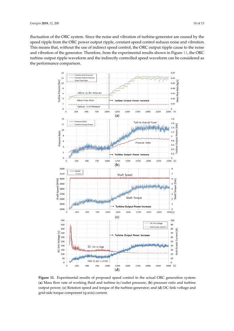
The second experiments are implemented in the actual ORC power generation system, as shown in Figure 10. The configuration of the experimental setup is same as the one shown in Figure 1. And the ORC loop configurations, the working fluid, the operation process, performance curves, sensors and system parameters used in this experiment are the same as that previously designed and manufactured in Reference [45]. Generator (PMSM) is directly coupled to the expander shaft.
Figure 8. Experimental results of the rotation speed estimation for the turbine-generator: (a) Estimatedspeed by PLL; and (b) estimated speed in a full operating range.
The experimental results of the proposed indirect speed control is shown in Figure 9. From speedcontrol in the ‘Generation Region’, by increasing q-axis current to the grid-side (negative direction)using the speed control action, the generator speed is controlled constantly at the reference speedof 1000RPM. The grid-side d-axis current is controlled to be zero to achieve the unity power factor.When the turbine output power increases suddenly, the q-axis current injected into the grid is increased(from −4A to −18A) by the DC-link voltage control to keep the constant speed for the safe operationof the ORC system.
The second experiments are implemented in the actual ORC power generation system, as shownin Figure 10. The configuration of the experimental setup is same as the one shown in Figure 1. And theORC loop configurations, the working fluid, the operation process, performance curves, sensors andsystem parameters used in this experiment are the same as that previously designed and manufacturedin Reference [45]. Generator (PMSM) is directly coupled to the expander shaft.
Energies 2019, 12, 200 9 of 13Energies 2019, 12, x FOR PEER REVIEW 9 of 13
0.5 s
200
[V]
0
-20
[A]
0
1200
[RPM]
0
Turbine Power IncreaseSpeedup Region
Speed Control
200
[V]
0
-20
[A]
0
1200
[RPM]
0
TurbinePower
𝒊𝒒 𝒈𝒓𝒊𝒅 𝒆𝒊𝒅 𝒈𝒓𝒊𝒅 𝒆
𝑹𝑷𝑴𝒈𝒆𝒏𝒆𝒓𝒂𝒕𝒐𝒓
𝒊𝒒 𝒈𝒓𝒊𝒅 𝒆𝒊𝒅 𝒈𝒓𝒊𝒅 𝒆
Generation Region
Figure 9. Experimental results of the proposed indirect generator speed control.
DiodeRectifier PWM
Inverter
DC link
DSP Control Board
(a)
(b)
Figure 10. Experimental setup for the actual ORC power generation system: (a) Gird-connected electric power conversion system; and (b) 23 kW ORC power generation system.
The experimental results of the proposed indirect speed control are presented in Figure 11a–d. It shows the waveforms for the mass flow rate of the working fluid and the turbine in/outlet pressure (a), the pressure ratio and the turbine output power (b), the rotation speed and torque of the turbine-generator (c), and the DC-link voltage and the grid-side torque component (q-axis) current (d) in detail. During the experiment, the turbine output power is increased from 0 to 1.4 kW to confirm the control performance.
Initially (before 80s), when the turbine output power is supplied, the turbine and generator speeds increase until reaching the start point of the ‘Generation Region’. At this point (from 80s), the rotation speed control is started, and the generator starts supplying the power to the grid system and the constant speed control is implemented (3000RPM). As presented in Figure 11d, by controlling the DC-link voltage, the injection of the generated q-axis torque component current gets regulated, accordingly. Then, the generator torque is indirectly controlled through the injection of grid-side current, which further maintains the rotor speed, as shown in Figure 11c.
At time 1050s, the turbine output power increases due to the increase in the mass flow rate of the working fluid as shown in Figure 11a,b. For the generator speed to be controlled constantly in this region, the DC-link voltage is controlled to have a lower value, and the grid-side q-axis current correspondingly increases (Figure 11d). Accordingly, the generator (load) torque increases, and the generator speed is controlled to maintain constantly (Figure 11c).
In conclusion, as observed in the experimental waveforms, the proposed speed control system can achieve the desired control performance under various supplied turbine output due to the power fluctuation of the ORC system. Since the noise and vibration of turbine-generator are caused by the speed ripple from the ORC power output ripple, constant speed control reduces noise and vibration. This means that, without the use of indirect speed control, the ORC output ripple cause to the noise
Figure 9. Experimental results of the proposed indirect generator speed control.
Energies 2019, 12, x FOR PEER REVIEW 9 of 13
0.5 s
200
[V]
0
-20
[A]
0
1200
[RPM]
0
Turbine Power IncreaseSpeedup Region
Speed Control
200
[V]
0
-20
[A]
0
1200
[RPM]
0
TurbinePower
𝒊𝒒 𝒈𝒓𝒊𝒅 𝒆𝒊𝒅 𝒈𝒓𝒊𝒅 𝒆
𝑹𝑷𝑴𝒈𝒆𝒏𝒆𝒓𝒂𝒕𝒐𝒓
𝒊𝒒 𝒈𝒓𝒊𝒅 𝒆𝒊𝒅 𝒈𝒓𝒊𝒅 𝒆
Generation Region
Figure 9. Experimental results of the proposed indirect generator speed control.
DiodeRectifier PWM
Inverter
DC link
DSP Control Board
(a)
(b)
Figure 10. Experimental setup for the actual ORC power generation system: (a) Gird-connected electric power conversion system; and (b) 23 kW ORC power generation system.
The experimental results of the proposed indirect speed control are presented in Figure 11a–d. It shows the waveforms for the mass flow rate of the working fluid and the turbine in/outlet pressure (a), the pressure ratio and the turbine output power (b), the rotation speed and torque of the turbine-generator (c), and the DC-link voltage and the grid-side torque component (q-axis) current (d) in detail. During the experiment, the turbine output power is increased from 0 to 1.4 kW to confirm the control performance.
Initially (before 80s), when the turbine output power is supplied, the turbine and generator speeds increase until reaching the start point of the ‘Generation Region’. At this point (from 80s), the rotation speed control is started, and the generator starts supplying the power to the grid system and the constant speed control is implemented (3000RPM). As presented in Figure 11d, by controlling the DC-link voltage, the injection of the generated q-axis torque component current gets regulated, accordingly. Then, the generator torque is indirectly controlled through the injection of grid-side current, which further maintains the rotor speed, as shown in Figure 11c.
At time 1050s, the turbine output power increases due to the increase in the mass flow rate of the working fluid as shown in Figure 11a,b. For the generator speed to be controlled constantly in this region, the DC-link voltage is controlled to have a lower value, and the grid-side q-axis current correspondingly increases (Figure 11d). Accordingly, the generator (load) torque increases, and the generator speed is controlled to maintain constantly (Figure 11c).
In conclusion, as observed in the experimental waveforms, the proposed speed control system can achieve the desired control performance under various supplied turbine output due to the power fluctuation of the ORC system. Since the noise and vibration of turbine-generator are caused by the speed ripple from the ORC power output ripple, constant speed control reduces noise and vibration. This means that, without the use of indirect speed control, the ORC output ripple cause to the noise
Figure 10. Experimental setup for the actual ORC power generation system: (a) Gird-connected electricpower conversion system; and (b) 23 kW ORC power generation system.
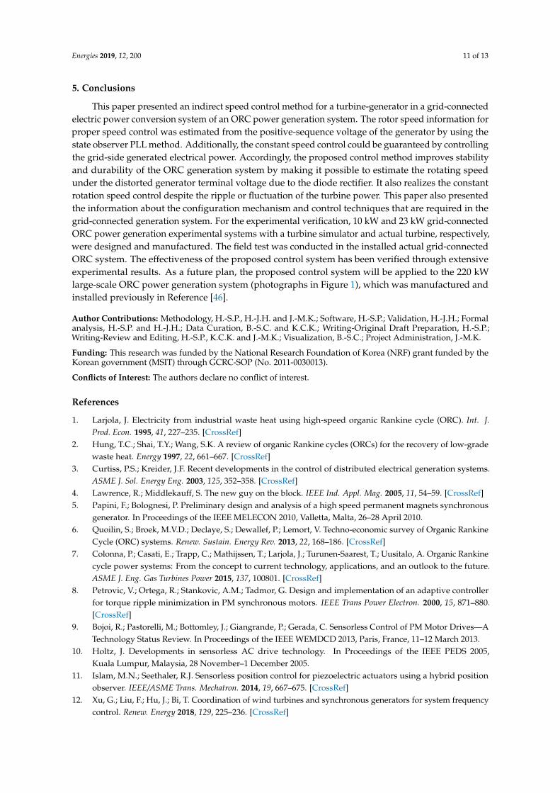
The experimental results of the proposed indirect speed control are presented in Figure 11a–d.It shows the waveforms for the mass flow rate of the working fluid and the turbine in/outletpressure (a), the pressure ratio and the turbine output power (b), the rotation speed and torqueof the turbine-generator (c), and the DC-link voltage and the grid-side torque component (q-axis)current (d) in detail. During the experiment, the turbine output power is increased from 0 to 1.4 kW toconfirm the control performance.
Initially (before 80s), when the turbine output power is supplied, the turbine and generatorspeeds increase until reaching the start point of the ‘Generation Region’. At this point (from 80s), therotation speed control is started, and the generator starts supplying the power to the grid system andthe constant speed control is implemented (3000RPM). As presented in Figure 11d, by controllingthe DC-link voltage, the injection of the generated q-axis torque component current gets regulated,accordingly. Then, the generator torque is indirectly controlled through the injection of grid-sidecurrent, which further maintains the rotor speed, as shown in Figure 11c.
At time 1050s, the turbine output power increases due to the increase in the mass flow rate ofthe working fluid as shown in Figure 11a,b. For the generator speed to be controlled constantly inthis region, the DC-link voltage is controlled to have a lower value, and the grid-side q-axis currentcorrespondingly increases (Figure 11d). Accordingly, the generator (load) torque increases, and thegenerator speed is controlled to maintain constantly (Figure 11c).
In conclusion, as observed in the experimental waveforms, the proposed speed control systemcan achieve the desired control performance under various supplied turbine output due to the power
Energies 2019, 12, 200 10 of 13
fluctuation of the ORC system. Since the noise and vibration of turbine-generator are caused by thespeed ripple from the ORC power output ripple, constant speed control reduces noise and vibration.This means that, without the use of indirect speed control, the ORC output ripple cause to the noiseand vibration of the generator. Therefore, from the experimental results shown in Figure 11, the ORCturbine output ripple waveform and the indirectly controlled speed waveform can be considered asthe performance comparison.
Energies 2019, 12, x FOR PEER REVIEW 10 of 13
and vibration of the generator. Therefore, from the experimental results shown in Figure 11, the ORC turbine output ripple waveform and the indirectly controlled speed waveform can be considered as the performance comparison.
(a)
(b)
Shaft Torque
Shaft Speed
Turbine Output Power Increase
(c)
(d)
Figure 11. Experimental results of proposed speed control in the actual ORC generation system: (a) Mass flow rate of working fluid and turbine in/outlet pressure; (b) pressure ratio and turbine output power; (c) Rotation speed and torque of the turbine-generator; and (d) DC-link voltage and grid-side torque component (q-axis) current.
5. Conclusions
This paper presented an indirect speed control method for a turbine-generator in a grid-connected electric power conversion system of an ORC power generation system. The rotor speed
Figure 11. Experimental results of proposed speed control in the actual ORC generation system:(a) Mass flow rate of working fluid and turbine in/outlet pressure; (b) pressure ratio and turbineoutput power; (c) Rotation speed and torque of the turbine-generator; and (d) DC-link voltage andgrid-side torque component (q-axis) current.
Energies 2019, 12, 200 11 of 13
5. Conclusions
This paper presented an indirect speed control method for a turbine-generator in a grid-connectedelectric power conversion system of an ORC power generation system. The rotor speed information forproper speed control was estimated from the positive-sequence voltage of the generator by using thestate observer PLL method. Additionally, the constant speed control could be guaranteed by controllingthe grid-side generated electrical power. Accordingly, the proposed control method improves stabilityand durability of the ORC generation system by making it possible to estimate the rotating speedunder the distorted generator terminal voltage due to the diode rectifier. It also realizes the constantrotation speed control despite the ripple or fluctuation of the turbine power. This paper also presentedthe information about the configuration mechanism and control techniques that are required in thegrid-connected generation system. For the experimental verification, 10 kW and 23 kW grid-connectedORC power generation experimental systems with a turbine simulator and actual turbine, respectively,were designed and manufactured. The field test was conducted in the installed actual grid-connectedORC system. The effectiveness of the proposed control system has been verified through extensiveexperimental results. As a future plan, the proposed control system will be applied to the 220 kWlarge-scale ORC power generation system (photographs in Figure 1), which was manufactured andinstalled previously in Reference [46].
Author Contributions: Methodology, H.-S.P., H.-J.H. and J.-M.K.; Software, H.-S.P.; Validation, H.-J.H.; Formalanalysis, H.-S.P. and H.-J.H.; Data Curation, B.-S.C. and K.C.K.; Writing-Original Draft Preparation, H.-S.P.;Writing-Review and Editing, H.-S.P., K.C.K. and J.-M.K.; Visualization, B.-S.C.; Project Administration, J.-M.K.
Funding: This research was funded by the National Research Foundation of Korea (NRF) grant funded by theKorean government (MSIT) through GCRC-SOP (No. 2011-0030013).
Conflicts of Interest: The authors declare no conflict of interest.
References
1. Larjola, J. Electricity from industrial waste heat using high-speed organic Rankine cycle (ORC). Int. J.Prod. Econ. 1995, 41, 227–235. [CrossRef]
2. Hung, T.C.; Shai, T.Y.; Wang, S.K. A review of organic Rankine cycles (ORCs) for the recovery of low-gradewaste heat. Energy 1997, 22, 661–667. [CrossRef]
3. Curtiss, P.S.; Kreider, J.F. Recent developments in the control of distributed electrical generation systems.ASME J. Sol. Energy Eng. 2003, 125, 352–358. [CrossRef]
4. Lawrence, R.; Middlekauff, S. The new guy on the block. IEEE Ind. Appl. Mag. 2005, 11, 54–59. [CrossRef]5. Papini, F.; Bolognesi, P. Preliminary design and analysis of a high speed permanent magnets synchronous
generator. In Proceedings of the IEEE MELECON 2010, Valletta, Malta, 26–28 April 2010.6. Quoilin, S.; Broek, M.V.D.; Declaye, S.; Dewallef, P.; Lemort, V. Techno-economic survey of Organic Rankine
Cycle (ORC) systems. Renew. Sustain. Energy Rev. 2013, 22, 168–186. [CrossRef]7. Colonna, P.; Casati, E.; Trapp, C.; Mathijssen, T.; Larjola, J.; Turunen-Saarest, T.; Uusitalo, A. Organic Rankine
cycle power systems: From the concept to current technology, applications, and an outlook to the future.ASME J. Eng. Gas Turbines Power 2015, 137, 100801. [CrossRef]
8. Petrovic, V.; Ortega, R.; Stankovic, A.M.; Tadmor, G. Design and implementation of an adaptive controllerfor torque ripple minimization in PM synchronous motors. IEEE Trans Power Electron. 2000, 15, 871–880.[CrossRef]
9. Bojoi, R.; Pastorelli, M.; Bottomley, J.; Giangrande, P.; Gerada, C. Sensorless Control of PM Motor Drives—ATechnology Status Review. In Proceedings of the IEEE WEMDCD 2013, Paris, France, 11–12 March 2013.
10. Holtz, J. Developments in sensorless AC drive technology. In Proceedings of the IEEE PEDS 2005,Kuala Lumpur, Malaysia, 28 November–1 December 2005.
11. Islam, M.N.; Seethaler, R.J. Sensorless position control for piezoelectric actuators using a hybrid positionobserver. IEEE/ASME Trans. Mechatron. 2014, 19, 667–675. [CrossRef]
12. Xu, G.; Liu, F.; Hu, J.; Bi, T. Coordination of wind turbines and synchronous generators for system frequencycontrol. Renew. Energy 2018, 129, 225–236. [CrossRef]

Energies 2019, 12, 200 12 of 13
13. Alcalá, J.; Cárdenas, V.; Espinozac, J.; Duránaa, M. Investigation on the limitation of the BTB-VSC converterto control the active and reactive power flow. Electr. Power Syst. Res. 2017, 143, 149–162. [CrossRef]
14. Bunjongjit, K.; Kumsuwan, Y.; Sriuthaisiriwong, Y. An implementation of three-level BTB NPC voltagesource converter based-PMSG wind energy conversion system. In Proceedings of the IEEE TENCON 2014,Bangkok, Thailand, 22–25 October 2014.
15. Vilathgamuwa, D.M.; Jayasinghe, S.D.G. Rectifier systems for variable speed wind generation—A review.In Proceedings of the IEEE ISIE 2012, Hangzhou, China, 28–31 May 2012.
16. Tan, K.; Islam, S. Optimum control strategies in energy conversion of PMSG wind turbine system withoutmechanical sensors. IEEE Trans. Energy Convers. 2004, 19, 392–399. [CrossRef]
17. Binder, A.; Schneider, T. Permanent magnet synchronous generators for regenerative energy conversion—Asurvey. In Proceedings of the IEEE EPE 2005, Dresden, Germany, 11–14 September 2005.
18. Rodriguez, J.; Franquelo, L.G.; Kouro, S.; Leon, J.I.; Portillo, R.C.; Prats, M.A.M.; Perez, M.A. Multilevelconverters: An enabling technology for high-power applications. Proc. IEEE 2009, 97, 1786–1817. [CrossRef]
19. Rahimi, M. Modeling, control and stability analysis of grid connected PMSG based wind turbine assistedwith diode rectifier and boost converter. Electr. Power Energy Syst. 2017, 93, 84–96. [CrossRef]
20. Aziz, A.; Mto, A.; Stojcevski, A. Full converter based wind turbine generator system generic modelling:Variations and applicability. Sustain. Energy Technol. Assess. 2016, 14, 46–62. [CrossRef]
21. Kazmierkowski, M.P.; Malesani, L. Current control techniques for three-phase voltage-source PWMconverters: A survey. IEEE Trans. Ind. Electron. 1998, 45, 691–703. [CrossRef]
22. Pozzebon, G.G.; Goncalves, A.F.Q.; Pena, G.G.; Mocambique, N.E.M.; Machado, R.Q. Operation of athree-phase power converter connected to a distribution system. IEEE Trans. Ind. Electron. 2013, 60,1810–1818. [CrossRef]
23. Song, S.-H.; Kang, S.-I.; Hahm, N.-K. Implementation and control of grid connected AC-DC-AC powerconverter for variable speed wind energy conversion system. In Proceedings of the IEEE APEC 2003, MiamiBeach, FL, USA, 9–13 February 2003.
24. Prodanovic, M.; Green, T.C. Control and filter design of three-phase inverters for high power quality gridconnection. IEEE Trans. Power Electron. 2013, 18, 373–380. [CrossRef]
25. Twining, E.; Holmes, D.G. Grid current regulation of a three-phase voltage source inverter with an LCLinput filter. IEEE Trans. Power Electron. 2003, 18, 888–895. [CrossRef]
26. Blaabjerg, F.; Teodorescu, R.; Liserre, M.; Timbus, A.V. Overview of control and grid synchronization fordistributed power generation systems. IEEE Trans. Ind. Electron. 2006, 53, 1398–1409. [CrossRef]
27. Dai, J.C.; Liu, D.; Hu, Y.; Shen, X. Research on joint power and loads control for large scale directly drivenwind turbines. ASME J. Sol. Energy Eng. 2013, 136, 021015. [CrossRef]
28. Svensson, J.; Lindgren, M. Vector current controlled grid connected voltage source converter-influenceof non-linearities on the performance. In Proceedings of the IEEE PESC Record, Fukuoka, Japan,22–22 May 1998.
29. Van der Broeck, H.W.; Skudelny, H.C.; Stanke, G.V. Analysis and realization of a pulse width modulatorbased on voltage space vectors. IEEE Trans. Ind. Appl. 1988, 24, 142–150. [CrossRef]
30. Chung, S.-K. Phase-locked loop for grid-connected three-phase power conversion systems. IEE Proc. Electr.Power Appl. 2000, 147, 213–219. [CrossRef]
31. Kaura, V.; Blasko, V. Operation of a phase locked loop system under distorted utility conditions. IEEE Trans.Ind. Appl. 1997, 33, 58–63. [CrossRef]
32. Nash, G. Phase-Locked Loop Design Fundamentals. Motorola Application Note AN-535 1994.33. Hsieh, G.; Hung, J.C. Phase-Locked Loop Techniques—A Survey. IEEE Trans. Lnd. Electron. 1996, 43, 609–615.
[CrossRef]34. Chung, S.-K. A phase tracking system for three phase utility interface inverters. IEEE Trans. Power Electron.
2000, 15, 431–438. [CrossRef]35. Amuda, L.N.; Cardoso Filho, B.J.; Silva, S.M.; Silva, S.R.; Diniz, A.S.A.C. Wide bandwidth single and
three-phase PLL structures for grid-tied PV systems. In Proceedings of the IEEE PVSC, Anchorage, AK,USA, 15–22 September 2000.
36. Nozari, F.; Mezs, P.A.; Julian, A.L.; Sun, C.; Lipo, T.A. Sensorless synchronous motor drive for use oncommercial transport airplanes. IEEE Trans. Ind. Appl. 1995, 31, 850–859. [CrossRef]

Energies 2019, 12, 200 13 of 13
37. Caliskan, V.; Perreault, D.J.; Jahns, T.M.; Kassakian, J.G. Analysis of three-phase rectifiers withconstant-voltage loads. IEEE Trans. Circuits Syst. 2003, 50, 1220–1225. [CrossRef]
38. Ketzer, M.B.; Jacobina, C.B. Sensorless control technique for PWM rectifiers with voltage disturbance rejectionand adaptive power factor. IEEE Trans. Ind. Electron. 2015, 62, 1140–1151. [CrossRef]
39. Blasko, V.; Moreira, J.C.; Lipo, T.A. A new field oriented controller utilizing spatial position measurement ofrotor end ring current. In Proceedings of the IEEE PESC Record, Milwaukee, WI, USA, 26–29 June 1989.
40. Song, H.; Nam, K. Dual current control scheme for PWM converter under unbalanced input voltageconditions. IEEE Trans. Ind. Electron. 1999, 46, 953–959. [CrossRef]
41. Limongi, L.R.; Bojoi, R.; Pica, C.; Profumo, F.; Tenconi, A. Analysis and comparison of phase lockedloop techniques for grid utility applications. In Proceedings of the IEEE PCCON 2007, Nagoya, Japan,2–5 April 2007.
42. Ko, Y.; Park, K.; Lee, K.-B.; Blaabjerg, F. A new PLL system using full order observer and PLL systemmodeling in a single phase grid-connected inverter. In Proceedings of the IEEE ICPE 2011, Jeju, South Korea,30 May–3 June 2011.
43. Freijedo, F.D.; Doval-Gandoy, J.; López, Ó.; Acha, E. A generic open-loop algorithm for three-phase gridvoltage/current synchronization with particular reference to phase, frequency, and amplitude estimation.IEEE Trans. Power Electron. 2009, 24, 94–107. [CrossRef]
44. Fortescue, C. Method of symmetrical coordinates applied to the solution of polyphase networks. Trans. AIEE1918, 37, 1027–1140.
45. Yun, E.; Kim, D.; Yoon, S.Y.; Kim, K.C. Experimental investigation of an organic Rankine cycle with multipleexpanders used in parallel. Appl. Energy 2015, 145, 246–254. [CrossRef]
46. Sung, T.; Yun, E.; Kim, H.D.; Yoon, S.Y.; Choi, B.S.; Kim, K.; Kim, J.; Jung, Y.B.; Kim, K.C. Performancecharacteristics of a 200-kW organic Rankine cycle system in a steel processing plant. Appl. Energy 2016, 183,623–635. [CrossRef]
© 2019 by the authors. Licensee MDPI, Basel, Switzerland. This article is an open accessarticle distributed under the terms and conditions of the Creative Commons Attribution(CC BY) license (http://creativecommons.org/licenses/by/4.0/).


