Embed Size (px)
Citation preview

PHYSICAL REVIEW B 89, 045305 (2014)
Spin relaxation in inhomogeneous quantum dot arrays studied by electron spin resonance
A. F. Zinovieva,* N. P. Stepina, A. I. Nikiforov, A. V. Nenashev, and A. V. DvurechenskiiInstitute of Semiconductor Physics, SB RAS, 630090 Novosibirsk, Russia
L. V. KulikInstitute of Chemical Kinetics and Combustion, SB RAS, 630090 Novosibirsk, Russia
M. C. Carmo and N. A. SobolevDepartamento de Fisica and I3N, Universidade de Aveiro, 3810-193 Aveiro, Portugal
(Received 11 October 2013; revised manuscript received 1 January 2014; published 16 January 2014)
Electron states in an inhomogeneous Ge/Si quantum dot array with groups of closely spaced quantum dotswere studied by the conventional continuous-wave electron spin resonance and spin-echo techniques. We havefound that the existence of quantum dot groups allows increasing the spin relaxation time in the system. Thecreated structures permit us to change the effective localization radius of electrons by an external magnetic field.With the localization radius being close to the size of a quantum dot group, we obtain a fourfold increase in thespin relaxation time T1 as compared to conventional homogeneous quantum dot arrays. This effect is attributed toan averaging of the local magnetic fields produced by 29Si nuclear spins and a stabilization of the Sz polarizationduring the electron back-and-forth motion within a quantum dot group.
DOI: 10.1103/PhysRevB.89.045305 PACS number(s): 73.21.La, 03.67.Lx, 72.25.Rb
I. INTRODUCTION
Electron spins in quantum dots (QDs) can be consideredas promising candidates for the implementation of quantumcomputation ideas and spintronics devices [1,2]. The mainparameter indicating the applicability of a system to quantumcomputation is the spin coherence time. An extremely longspin lifetime is observed in zero-dimensional structures due toa strong confinement in all three dimensions [3]. An especiallygreat potential for a long coherence time is expected in theGe/Si system with quantum dots. The electrons in this systemare localized in strained Si regions, where the spin-orbit(SO) coupling is very weak. However, recent investigationsof spin decoherence by the spin echo method in the Ge/SiQD system [4] demonstrated that the spin relaxation times areunexpectedly short (∼10 μs). It was suggested that the reasonof such an intensive spin relaxation consists of the appearanceof effective magnetic fields during electron tunneling betweenquantum dots. These magnetic fields (Rashba fields) [5]originate from the spin-orbit interaction and arise due to theabsence of mirror symmetry of the localizing potential for anelectron in the vicinity of a Ge QD. Spin relaxation occursthrough a stochastic spin precession in effective magneticfields during random tunneling between QDs (an analog ofthe Dyakonov-Perel mechanism for delocalized carriers [6]).Obviously, the suppression of the tunneling in an arrayof well separated quantum dots allows us to eliminate theexistence of in-plane fluctuating magnetic fields. In this casethe hyperfine interaction with 29Si nuclear spins comes intoforce and determines the spin relaxation time. If the tunnelingis suppressed not by the spatial separation of QDs, but by theCoulomb repulsion [7], the anisotropic exchange interactioncan also control the spin relaxation process.
The efficiency of each mechanism depends in different wayson the localization degree of electrons. By changing the tunnelcoupling between quantum dots (by changing their density)and, correspondingly, the localization degree of electrons,it is possible to alter the relative contribution of differentmechanisms. With increasing electron localization radius thecontribution of hyperfine interaction becomes smaller due toan averaging-out of different orientations of nuclear spins. Arelated increase of the relaxation time occurs until the momentwhen the wave function overlapping provides the hoppingbetween neighboring localization centers. In these conditions,the Dyakonov-Perel mechanism begins to control the spinrelaxation process [8]. The longest spin relaxation time isexpected right before the point where the Dyakonov-Perelmechanism comes into force. A similar effect was detected inn-type GaAs, where a threefold increase of the spin relaxationtime was obtained in the vicinity of the metal-to-insulatortransition [9].
In self-assembled tunnel-coupled QD structures it is hardto get a gradual change of the localization radius by changingthe QD array density. Stochastic nucleation of QDs upon theStranski-Krastanow growth mode [10] leads to the formationof regions with a high local density of QDs. In such regions,a strong tunnel coupling between the dots results in an in-tense spin relaxation through the Dyakonov-Perel mechanism.However, under certain conditions, the existence of groups ofclosely located QDs can provide not a decrease, but ratheran increase of the spin relaxation time. First, the QD groupsshould be well separated from each other. In this case, theeffective magnetic fields can be averaged due to the electronback-and-forth motion within each QD group. Secondly, theQDs inside a group should have a strong tunnel couplingproviding the effective localization radius comparable to theQD group size. As a result, the averaging of local magneticfields related to nuclear spins will take place.
The present work is devoted to an electron spin reso-nance (ESR) study of inhomogeneous QD arrays, where the
1098-0121/2014/89(4)/045305(8) 045305-1 ©2014 American Physical Society
A. F. ZINOVIEVA et al. PHYSICAL REVIEW B 89, 045305 (2014)
averaging of the Rashba and hyperfine fields inside QDgroups is expected to provide a long spin relaxation time.We succeeded in creating an experimental structure containingwell separated groups of QDs with a large electron localizationradius. The coupling between QDs and, consequently, theelectron localization radius in the structures under study turnedout to be dependent on the external magnetic field orientation.A fourfold increase of the spin relaxation time as compared tothe previous data for dense homogeneous QD arrays [4] hasbeen detected at a special orientation of the magnetic field,where the electron localization radius was close to the QDgroup size.
II. SAMPLES AND EXPERIMENTAL CONDITIONS
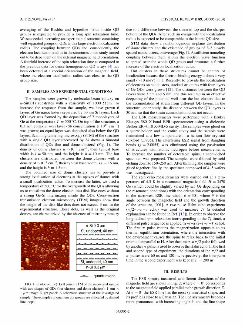
The samples were grown by molecular-beam epitaxy onn-Si(001) substrates with a resistivity of 1000 � cm. Toincrease the response from the sample, we have grown 6layers of Ge nanoclusters separated by 30 nm Si layers. EachQD layer was formed by the deposition of 7 monolayers ofGe at the temperature T = 550 ◦C. On top of the structure, a0.3 μm epitaxial n-Si layer (Sb concentration � 1017 cm−3)was grown; an equal layer was deposited also below the QDlayers. Scanning tunneling microscopy (STM) of the structurewith a single QD layer uncovered by Si shows a bimodaldistribution of QDs (hut and dome clusters) (Fig. 1). Thedensity of dome clusters is ∼1010 cm−2, their typical basewidth is l = 50 nm, and the height is h = 10 nm. The hutclusters are distributed between the dome clusters with adensity of ∼1011 cm−2, their typical base width is l = 15 nm,and the height is h = 1.5 nm.
The obtained size of dome clusters has to provide astrong localization of electrons at the apexes of domes witha small localization radius. To increase the latter, we used atemperature of 500 ◦C for the overgrowth of the QDs allowingus to transform the dome clusters into disk-like ones withouta strong Ge-Si intermixing inside the QDs. Cross-sectiontransmission electron microscopy (TEM) images show thatthe height of the disk-like dots does not exceed 3 nm in theexperimental structure. These dots, as well as the originaldomes, are characterized by the absence of mirror symmetry
FIG. 1. (Color online) Left panel: STM of the uncovered samplewith two shapes of QDs (hut clusters and dome clusters), 1 μm ×1 μm image. Right panel: A schematic structure of the investigatedsample. The examples of quantum dot groups are indicated by dashedline loops.
due to a difference between the smeared top and the sharperbottom of the QDs. After such an overgrowth the localizationradius is expected to be comparable to the lateral QD size.
STM data show a nonhomogenous in-plane distributionof dome clusters and the existence of groups of 2–3 closelyspaced nanoclusters, on average (Fig. 1). A sufficient tunnelingcoupling between them allows the electron wave functionto spread over the whole QD group and promotes a furtherincrease of the electron localization radius.
Hut clusters in these structures cannot be centers oflocalization because the electron binding energy on huts is verysmall (∼10 meV) [11]. Recently, to provide the localizationof electrons on hut clusters, stacked structures with four layersof Ge QDs were grown [12]. The distances between the QDlayers were 3 nm and 5 nm, and this resulted in an effectivedeepening of the potential well near the hut clusters due tothe accumulation of strain from different QD layers. In thestructure under study, the distance between the QD layers is30 nm, so that the strain accumulation does not occur.
The ESR measurements were performed with a BrukerElexsys 580 X-band EPR spectrometer using a dielectricBruker ER-4118 X-MD-5 cavity. The samples were glued ona quartz holder, and the entire cavity and the sample weremaintained at a low temperature in a helium flow cryostat(Oxford CF935). The interfering ESR signal from danglingbonds (g = 2.0055) was eliminated using the passivationof structures with atomic hydrogen before measurements.To increase the number of detectable spins, a sandwichedspecimen was prepared. The samples were thinned by acidetching down to 150–250 μm. After thinning, the samples wereglued together; finally, the specimen composed of 4–5 waferswas investigated.
The spin echo measurements were carried out at a tem-perature of 4.5 K in a resonance magnetic field H = 3470Oe (which could be slightly varied by ±5 Oe depending onthe resonance conditions) with the orientation correspondingto the narrowest ESR line width, θ = 30◦, where θ is theangle between the magnetic field and the growth directionof the structure, [001]. A two-pulse Hahn echo experiment(π/2–τ–π–τ echo) was used to measure T2 (a detailedexplanation can be found in Ref. [13]). In order to observe thelongitudinal spin relaxation (corresponding to the T1 time), adifferent pulse sequence is applied (π–τ–π/2–T –π–T echo).The first π pulse rotates the magnetization opposite to itsthermal equilibrium orientation, where the interaction withthe environment causes the spins to relax back to the initialorientation parallel to H. After the time τ , a π/2 pulse followedby another π pulse is used to observe the Hahn echo. In the firstand second type of experiment, the durations of the π/2 andπ pulses were 60 ns and 120 ns, respectively; the interpulsetime in the second experiment was kept at T = 200 ns.
III. RESULTS
The ESR spectra measured at different directions of themagnetic field are shown in Fig. 2, where θ = 0◦ correspondsto the magnetic field applied parallel to the growth direction Z.At θ = 0◦ the ESR line has the most symmetrical shape, andits profile is close to a Gaussian. The line asymmetry becomesmore pronounced with increasing angle θ , and the line shape
045305-2

SPIN RELAXATION IN INHOMOGENEOUS QUANTUM DOT . . . PHYSICAL REVIEW B 89, 045305 (2014)
FIG. 2. (Color online) ESR spectra at different orientations ofmagnetic field. For θ = 0◦ the magnetic field is parallel to the growthdirection of the structure [001]; θ = 90◦ corresponds to magneticfield applied along the crystallographic direction [110].
tends to a Lorentzian already at θ = 10◦. The line shapeanalysis performed at θ = 30◦ is shown in Fig. 3. A carefulexamination shows that the ESR line represents a sum of anabsorption line (dotted) and a dispersion line (dashed). Therotation of the sample in the magnetic field results in a changeof the width and position of the resonance line. The orientationdependence of the ESR line width for the structure under studyis demonstrated in Fig. 4. When the external magnetic fielddeviates from the growth direction up to θ ≈ 30◦, the ESR linewidth sharply decreases from �H = 1.9 Oe to �H = 1.4 Oe.A further tilt of the magnetic field leads to a line broadening upto a maximum of �H = 2.4 Oe at θ = 60◦. For the in-planemagnetic field, the ESR line width is narrowed again downto �H = 1.8 Oe. Such a nonmonotonous behavior is unusualfor electrons in a two-dimensional system and has not beenobserved to date.
The angular dependence of the g factor is shown in Fig. 5. Atsmall angles (up to θ = 30◦) the g factor slightly varies nearg = 1.9994(5). Between θ = 30◦ and θ = 40◦ the g factor
FIG. 3. (Color online) Analysis of the ESR line shape for θ =30◦. The solid line represents the sum of an absorption line (dotted),and a dispersion line (dashed).
FIG. 4. (Color online) Experimental angular dependence of theESR line width and the corresponding theoretical approximation[Eq. (6)] (solid line) for the structure under study. For θ = 0◦ themagnetic field is parallel to the growth direction of the structure.
value jumps to g = 1.9992 and remains nearly constant up toθ = 90◦.
The data of spin echo measurements performed at θ = 30◦,when the smallest ESR line width is observed, are shown inFigs. 6 and 7. According to the results of a two-pulse Hahnecho experiment, the spin echo behavior can be described bya superposition of two exponentially decaying functions:
M(t) = M (1)x,y exp
(−2τ/T(1)
2
) + M (2)x,y exp
(−2τ/T(2)
2
),
(1)
where M(0) = M (1)x,y + M (2)
x,y is the lateral (in QD plane)magnetization after a π/2 pulse. The decay parameters yieldtwo times the spin dephasing: T
(1)2 ≈ 0.26 μs and T
(2)2 ≈
1.5 μs.The analysis of the inversion signal recovery measured
in three-pulse echo experiments shows a nonexponentialbehavior (Fig. 7). The experimental curve can be describedby the superposition of two functions:
M(t) = M0z − M (1)z exp
(−τ/T(1)
1
) − M (2)z exp
(−τ/T(2)
1
),
(2)
FIG. 5. Angular dependence of the electron g factor for thestructure under study. For θ = 0◦ the magnetic field is parallel tothe growth direction of the structure.
045305-3

A. F. ZINOVIEVA et al. PHYSICAL REVIEW B 89, 045305 (2014)
FIG. 6. (Color online) Results of two-pulse spin echo experi-ments performed at θ = 30◦ (points) and the respective approxima-tion by the superposition of two exponential functions, Eq. (1) (solidline). The corresponding microwave pulse sequence is π/2–τ–π–τ
echo.
where M0z is the equilibrium magnetization, M0z = M(1)0z +
M(2)0z , M (1,2)
z = M(1,2)0z − M (1,2)
z (0), and Mz(0) = M1z (0) +
M2z (0) is the magnetization just after applying an inverting
π pulse. In accordance with this equation, at the beginning themagnetization recovers very fast. After some time, a fractionof spins returns to the equilibrium state, and the recovery ratebecomes much slower. The characteristic times obtained byfitting the experimental data are T
(1)1 ≈ 2 μs and T
(2)1 ≈ 35 μs.
All values of the spin relaxation times were determined withan uncertainty of ±20%.
IV. DISCUSSION
To explain the experimental results obtained in the presentwork, we propose the following model (see Fig. 8). Theelectrons are suggested to be localized mainly in the groups of
FIG. 7. (Color online) Amplitude of the inversion-recovery sig-nal versus interpulse delay τ [symbols are experimental data, the solidline is the approximation by Eq. (2)]. The corresponding microwavepulse sequence is π–τ–π/2–T –π–T echo. The experiments areperformed at θ = 30◦.
FIG. 8. (Color online) Illustration of the hopping model for thestructure under study. Hopping transitions inside the QD groupsprovide a narrowing of the ESR line with the deviation of magneticfield from θ = 0◦ to θ = 30◦. Hopping transitions between theQD groups provoke spin relaxation through the spin precessionmechanism and yield a special orientation dependence of the ESRline width in the range of θ ∈ {30◦–90◦}.
closely spaced QDs containing 2–3 dots on average (see STMdata). During the overgrowth the QDs lose their apexes andtransform into the disk-like shape QDs. As a result, the electronlocalization radius can become comparable with the QD lateralsize. Additional barriers for electrons limiting the electronmotion in the XY directions in the Si layer arise due to theexistence of regions with a nonzero Ge content. These regionsare located over the edges along the perimeter of the QDs, andthey are formed according to the formation mechanism of SiGerings described in Ref. [14]. Thus, the electron localizationradius can be taken to be about 50 nm for a spatially isolatedsingle QD. In the case of a group of closely spaced QDs, theseparating SiGe barriers between the dots inside the group areabsent because of energetically unfavorable positions of Geatoms between QDs due to a high strain [15]. SiGe barriersremain only along the external borders of QD groups. Then theelectron wave function can spread to the size of the QD group,l ∼ 100–150 nm. Since the confinement of the electrons is nottoo strong, the tails of electron wave functions from differentQD groups can overlap, providing hopping between the QDgroups. The external magnetic field applied along the growthdirection can considerably change the described picture. Themagnetic length λ = √
c�/eH is in our experimental setup(H = 3470 Oe) about 45 nm, which is comparable withthe electron localization radius for a single QD. In theseconditions, the magnetic field leads to depression of theelectron wave function tails [16], resulting in an enhancementof electron localization. Thus, the perpendicular magnetic fieldsuppresses the transitions between QD groups and decreasesthe electron localization radius in the QD group down tothe size of an individual QD. Nevertheless, the transitionsbetween QDs inside the groups still persist due to a smalldistance between the QDs. With the deviation of the magneticfield from the growth direction the wave function shrinkingeffect vanishes and the probability of electron transitions
045305-4

SPIN RELAXATION IN INHOMOGENEOUS QUANTUM DOT . . . PHYSICAL REVIEW B 89, 045305 (2014)
between dots increases. The conductivity in local areas (QDgroups) becomes higher. In the experiment, this correspondsto the appearance of a noticeable dispersion signal and to anenhancement of the asymmetry of the ESR line (the ESR lineacquires a nearly Dysonian shape [17]). A similar effect wasobserved for SiGe/Si/SiGe structures with a two-dimensional(2D) electron gas [18].
At the same time, the increase of the effective electronlocalization radius causes an averaging of the local magneticfields induced by nuclear spins and a smoothing of the QDparameter differences within a QD group. As a result, thenarrowing of the ESR line upon deviation of the magnetic fieldfrom θ = 0◦ to θ = 30◦ is observed. The minimum of the ESRline width at θ = 30◦ indicates that the electron localizationradius reaches the size of the QD group, and a full averaginginside each group takes place. A further increase of the electronlocalization radius leads to an enhancement of the hoppingbetween the groups and a decrease of the spin lifetime throughthe Dyakonov-Perel spin relaxation mechanism.
The decreasing spin relaxation time affects the ESR linewidth. From θ = 30◦ on the broadening due to the spin relax-ation, �H ∼= 1/T2, exceeds the nonhomogeneous broadening,and the further orientation dependence of the ESR line widthis controlled by the spin relaxation time.
It should be noted that there is another mechanismwhich can provide the anisotropy of the ESR line width,viz., relaxation assisted by the spin-phonon interaction. Thismechanism can be effective due to the lack of phononbottleneck in our structures with large QD sizes resultingin small confinement energies of electrons. In this case theanisotropy of spin relaxation processes is determined by theshape asymmetry of disk-like QDs. Their lateral size is oneorder of magnitude larger than their height, therefore only kx-and ky-phonon waves effectively influence the spin. However,the experimentally observed maximum of the ESR line widthat θ = 60◦ cannot be described in the framework of thespin-phonon interaction model [19], which should yield amonotonous orientation dependence of the ESR line width.
The Dyakonov-Perel mechanism allows describing thenonmonotonous behavior of the ESR line width on theassumption that τh depends on the magnetic field. Thisdependence, determined in the framework of the hoppingmodel [19], can be described as an exponential,
τh = τ0 exp(αHm
z
), (3)
where Hz is the projection of the magnetic field to the growthdirection; the coefficient m can be equal to m = 1/2 or m = 2for the case of strong or weak magnetic fields, respectively.For intermediate fields, λ ∼ l, this coefficient can take a valuein the range 1
2 < m < 2 (Ref. [16]).The spin relaxation time T2 in the framework of the Redfield
theory [20] is given by the following expression:
1
T2= γ 2δH 2
y sin2 θτh + 1
2T1, (4)
with
1
T1= γ 2
(δH 2
x + δH 2y cos2 θ
) τh
1 + ω20τ
2h
, (5)
where the correlation time of spin-orbit field fluctuations τc
was replaced by the hopping time τh; ω0 is the Larmorfrequency; δHx , δHy are the components of the effectivemagnetic field δH .
Thus, using Eq. (3) for τh, we obtain the followingexpression describing the orientation dependence of the ESRline width:
�H = B exp(A cosm θ )
(sin2 θ + 1 + cos2 θ
1 + C exp(2A cosm θ )
),
(6)
where B = γ δH 2y τ0, A = αHm, C = ω2
0τ20 . The experimental
data �H (θ ) in the range of θ ∈ [30◦,90◦] are well approx-imated by this expression (Fig. 4) with m = 3/2, A = 1.52,B = 1.78, C = 795.2. The obtained coefficient m correspondsto the case of intermediate magnetic fields (λ ∼ l) that arguesfor the accepted hopping model with τh depending on themagnetic field.
The magnitude of the effective magnetic field δH , estimatedfrom the B coefficient, turns out to be ≈15 Oe. This value istwice as small as that determined in our previous work [21] forhut clusters with the aspect ratio h/l = 0.1. It is known [22]that in a QD system the effective magnetic field depends onthe h/l value: the higher the aspect ratio, the larger the δH
value. For the QDs under study the aspect ratio is about 0.05,therefore the effective magnetic field proved to be smaller.
The spin echo data are in a good agreement with theproposed model implying the existence of closed groups ofquantum dots being the centers of electron localization. Theexperimental spin polarization behavior shows that the spinrelaxation occurs in two stages: a rapid and a slow one. Tounderstand the origin of this two-stage spin dynamics, wesimulated the spin relaxation process in a ring-shaped groupof QDs. The model includes a strong tunnel coupling betweenquantum dots in the circle. Hopping between any neighboringQDs is permitted with equal probability for the back-and-forthmotion. Each tunneling transition is accompanied by a spinrotation by a small fixed angle α = 0.1. The direction ofthe rotation axis is defined by the product [n × ez], wheren is the tunneling direction, and ez is the QD growthdirection. The external magnetic field is applied along ez andprovides the Larmor precession between tunneling events.The time intervals between tunneling events are distributedexponentially with a mean value τh. The spin relaxation causedby the interaction with phonons and nuclear spins was nottaken into consideration. The transport was simulated by theMonte Carlo method for different numbers of QDs in the circle.The simulation results for a ring consisting of 10 quantumdots are demonstrated in Fig. 9. The two-stage spin dynamicsis clearly seen. It turned out that this effect depends on therelation between the hopping time τh and the Larmor frequencyωl . The two-stage dynamics is observed when ωlτh � 1. Forexample, the data in Fig. 9 were obtained at ωlτh = 0.1. Thefirst stage of spin relaxation is related to the processes ofelectron spreading over the group of QDs. At this stage theloss of spin polarization occurs due to the precession in theeffective magnetic field during the tunneling between dots.The spin dynamics at the second stage is defined by the phasebreaking of the Larmor precession during a random walk along
045305-5

A. F. ZINOVIEVA et al. PHYSICAL REVIEW B 89, 045305 (2014)
μ
FIG. 9. (Color online) Results of a spin relaxation simulation ina closed ring-shaped group of QDs. The number of QDs in the ringis n = 10. The hopping time is taken as τh = 10−11 s; the Larmorfrequency is one order of magnitude smaller, ω = 1010 s−1. A two-stage dynamics is observed.
the QD ring. Generally speaking, this stage of spin relaxationcan be ruled by the spin-phonon or hyperfine interaction aswell, if one includes them in the consideration. The absence oftwo-stage dynamics in the case of ωlτh � 1 can be understoodby the simple consideration of the spin behavior in a referenceframe rotating with the Larmor frequency. The randomness ofhopping between dots leads to an averaging of the effectivemagnetic field (〈δH 〉 = 0) and elimination of spin relaxationat the first stage of the electron extension over the QD group.According to the simulation results, the first rapid stage ischaracterized by a special relation between the longitudinaland transverse spin relaxation times T1 and T2, akin to a 2Dsystem with the absence of mirror symmetry, viz., T2 ≈ 2T1.Such a relation was obtained by spin echo measurements for2D electron gas structures [23] and for dense homogeneousQD arrays [4], and follows from the in-plane arrangement ofthe fluctuating magnetic fields δH . Also we have verified thepresence of two-stage spin dynamics in QD clusters with otherspatial arrangements; for example, QD lines containing a fewdots. The described general features are well preserved uponchanging only the numerical values of T1 and T2.
In T2 measurements the first stage is characterized byT2 ≈ 0.26 μs. Based on the simulation results one can expectthe same shortness for T1. However, the three-pulse methodhas limitations in the measurements of such short times. Thedifference between the durations of the pulse sequences in theT1 and T2 experiments is comparable to the duration of the firstrapid stage of spin relaxation, which makes difficult the studyof the beginning of the Sz relaxation.
The second stage of spin relaxation has the characteristictimes T1 = 2 μs and T2 = 1.5 μs. Here, the special relationT2 ≈ 2T1 is not fulfilled because of the presence of someadditional spin relaxation mechanisms, for example, Larmorprecession phase breaking during a random walk along theQD group, or another one. The presence of long-living spinpolarization with the relaxation time T1 ≈ 35 μs is attributed tosome stabilization of the Sz component taking place during theelectron movement within a closed QD group. According to the
Ge QD SiGe
Si
wave functionθ[001]
[110]
FIG. 10. (Color online) Schematic picture of the electron wavefunction penetration into the SiGe barrier surrounding a Ge quantumdot at different magnetic field orientations. The dashed line representsthe wave function at θ = 0◦, the solid line corresponds to the wavefunction at θ = 90◦. The SiGe barrier is formed due to Ge diffusionto the QD periphery during the growth of the Si cover layer [14]. Thecase of a single quantum dot is depicted for simplicity.
simulation results at a high hopping frequency (ωlτh < 0.01),the spin polarization after the rapid stage is settled at some leveldepending on the parameters of the QD group. In this case, theLarmor precession can be neglected, and the sequence of smallturnings in the Rashba fields can be considered as an effectiveprecession around the growth direction Z. In these conditions,the Sz component is stabilized. In contrast, the transverse spincomponent relaxes quickly, which is why in the experimentwe did not observe the rest transverse spin polarization with along relaxation time.
The orientation dependence of the g factor allows us to addsome details to the considered model. The value g = 1.9994coincides, within the experimental error, with the typical g-factor value for electron states near the conduction band edge inSi [24]. The fact that the g factor stays close to this value up toθ ≈ 30◦ confirms that the electron is located in silicon until thisorientation of the magnetic field. In other words, the electronincreases its localization radius remaining in silicon. Afterthe θ = 30◦ point, the electron localization radius exceeds thesize of the QD group, and the g factor drastically changes tothe value g = 1.9992. Such a behavior can be explained bythe change of the electron wave function penetration into theSiGe barriers surrounding the QD groups (see Fig. 10). Thepenetration depends on the magnetic field orientation due tothe wave function shrinking effect that is more pronounced atsmall θ (dashed line in Fig. 10) than at large θ values (solid linein Fig. 10). The presence of Ge atoms can provide a decreaseof the g factor [21].
Let us verify this assumption and estimate the value of theGe content in the localization area of the electron providingthe g-factor value g = 1.9992. One can write the followingexpression for the electron g factor:
gel = g(Si)(1 − α) + g(Ge)α,
where α is the Ge content.The conduction band minimum in silicon is located in the
� point. Since the Ge content is small, we assume that in theSiGe regions the conduction band minimum is also located inthe � point. In our previous work [21] following the approachof Liu [25] we have found the principal g-factor values for
045305-6

SPIN RELAXATION IN INHOMOGENEOUS QUANTUM DOT . . . PHYSICAL REVIEW B 89, 045305 (2014)
the � point in germanium, gGe�
‖ = 2.0412, gGe�
⊥ = 1.8873.As the strain is small, for simplicity we use the value of the g
factor averaged over all � valleys, g(Ge) = 1/3g‖ + 2/3g⊥ =1.9386. For g(Si) we take the value of the g factor of theelectron states at the conduction band edge, g = 1.9995. Thenthe resulting g factor is given by
gel = 1.9995(1 − α) + 1.9386α.
Substituting gel = 1.9992 we find α ≈ 0.5%, which is areasonable value for our experimental structures. So, atθ < 30◦ the g factor of electrons localized in the structureunder study is g ≈ 1.9994(5) which corresponds to the Gecontent in the electron localization area α ≈ 0. At θ > 30◦the g factor of electrons is g ≈ 1.9992 which is providedby α ≈ 0.5%.
It should be noted that the same value of electron g
factor was obtained by us in another ESR experiment fora structure with large SiGe nanodisks having a diameter of100–150 nm. For this structure we used a substrate withspecially created nucleation sites to obtain a more orderedarray of quantum dots. These nucleation sites originated dueto strain modulation in the surface layer induced by previouslyburied QDs. Large dome-shaped clusters grown at a previousstage at a temperature of 650◦ have a good spatial orderingdue to a long-range elastic interaction between the QDs [15].On this strain-modulated surface we have grown 10 layers ofQDs using the same temperature regime as in the structureunder study (T = 550 ◦C for the QD growth and T = 500 ◦Cfor the overgrowth by Si). However, we reduce the amountof deposited Ge down to 4 ML in each QD layer, and, asa result, we obtain a well ordered array of nanodisks afterthe overgrowth with Si. Thus, we can compare two structures:(1) a nonordered array with groups of closely spaced QDs, and(2) a well ordered array of nanodisks, one nanodisk instead ofone QD group. The average size of QD groups coincides withthe characteristic size of nanodisks.
The ESR data obtained on the test structure with nanodisksconfirm the model proposed in this work. The ESR signal has
an isotropic g factor g = 1.9992 ± 0.0001 and an isotropicESR line width �Hpp ≈ 0.4 Oe. The absolute value of theg factor is the same as in the structure with QD groupsat θ > 30◦. This can be explained by the identical electronlocalization radius and identical temperature regime of theQD creation. The last factor determines the GeSi intermixingand strain in the QD system, which have a high influence onthe g-factor value. The isotropy of the ESR line is explained bythe absence of tunneling transitions between nanodisks whichare well ordered in the plane of QD array and positioned atequal distances (∼100 nm) from each other. The narrownessof the ESR line indicates a high averaging efficiency of nuclearmagnetic fields by the electron state with a large localizationradius and the high uniformity of the array of nanodisks(negligible inhomogeneous broadening). In the structure withQD groups the averaging by means of tunneling between thedots is not so efficient, so that we observe a few times largerESR line width.
V. CONCLUSION
In summary, we demonstrate that the existence of closelyspaced QD groups provides an increase of the spin relaxationtime in the QD system. Changing the electron localizationradius by an external magnetic field allows us to catch the effectof the ESR line narrowing and to obtain, at a special orientationof the magnetic field, a fourfold increased relaxation time T1
as compared to the case of the recently studied homogeneousQD arrays.
ACKNOWLEDGMENTS
This work was supported by RFBR (Grants No. 11-02-00629-a and No. 13-02-12105), SB RAS integration projectNo. 83 and DITCS RAS project No. 2.5, as well as by the FCTof Portugal through the projects PEst-C/CTM/LA0025/2011,RECI/FIS-NAN/0183/2012, and the European FP7 projectMold-Nanonet.
[1] I. Zutic, J. Fabian and S. Das Sarma, Rev. Mod. Phys. 76, 323(2004).
[2] D. Loss and D. P. DiVincenzo, Phys. Rev. A 57, 120 (1998);B. E. Kane, Nature (London) 393, 133 (1998).
[3] M. Kroutvar, Y. Ducommun, D. Heiss, M. Bichler, D. Schuh,G. Abstreiter, and J. Finley, Nature (London) 432, 81 (2004).
[4] A. F. Zinovieva, A. V. Dvurechenskii, N. P. Stepina, A. I.Nikiforov, A. S. Lyubin, and L. V. Kulik, Phys. Rev. B. 81,113303 (2010).
[5] Y. A. Bychkov and E. I. Rashba, J. Phys. C 17, 6039(1984).
[6] M. I. Dyakonov and V. I. Perel’, Sov. Phys. Solid State 13, 3023(1972).
[7] A. F. Zinovieva, A. V. Nenashev, and A. V. Dvurechenskii,Nanostructures: Physics and Technology, Proceedings of 18thInternational Symposium (Ioffe Physical-Technical Institute,St. Petersburg, 2010), p. 191.
[8] B. I. Shklovskii, Phys. Rev. B 73, 193201 (2006).
[9] R. I. Dzhioev, K. V. Kavokin, V. L. Korenev, M. V. Lazarev, B.Ya. Meltser, M. N. Stepanova, B. P. Zakharchenya, D. Gammon,and D. S. Katzer, Phys. Rev. B 66, 245204 (2002).
[10] I. N. Stranski and L. Krastanow, Sitzungsber. Akad. Wiss. Wien,Math.-Naturwiss. Kl., Abt. 2B 146, 797 (1938).
[11] A. I. Yakimov, A. V. Dvurechenskii, N. P. Stepina, A. V.Nenashev, and A. I. Nikiforov, Nanotechnology 12, 441 (2001).
[12] A. I. Yakimov, A. V. Dvurechenskii, A. I. Nikiforov, A. A.Bloshkin, A. V. Nenashev, and V. A. Volodin, Phys. Rev. B 73,115333 (2006).
[13] A. Schweiger and G. Jeschke, Principles of Pulse ElectronParamagnetic Resonance (Oxford University Press, Oxford,2001).
[14] C.-H. Lee, Y.-Y. Shen, C. W. Liu, S. W. Lee, B.-H. Lin, andC.-H. Hsu, Appl. Phys. Lett. 94, 141909 (2009).
[15] G. Capellini, M. De Seta, F. Evangelisti, V. A. Zinovyev, G.Vastola, F. Montalenti, and Leo Miglio, Phys. Rev. Lett. 96,106102 (2006).
045305-7

A. F. ZINOVIEVA et al. PHYSICAL REVIEW B 89, 045305 (2014)
[16] B. I. Shklovskii and A. L. Efros, ElectronicProperties of Doped Semiconductors (Springer, Berlin,1984).
[17] F. J. Dyson, Phys. Rev. 98, 349 (1955).[18] Z. Wilamowski and W. Jantsch, Phys. Rev. B 69, 035328
(2004).[19] A. F. Zinov’eva, A. V. Nenashev, and A. V. Dvurechenskii, JETP
Lett. 82, 302 (2005).[20] C. P. Slichter, Principles of Magnetic Resonance (Springer-
Verlag, Berlin, 1978).
[21] A. F. Zinovieva, A. V. Dvurechenskii, N. P. Stepina, A. S.Deryabin, A. I. Nikiforov, R. M. Rubinger, N. A. Sobolev, J.P. Leitao, and M. C. Carmo, Phys. Rev. B 77, 115319 (2008).
[22] A. F. Zinovieva, A. V. Nenashev, and A. V. Dvurechenskii, Phys.Rev. B 71, 033310 (2005).
[23] A. M. Tyryshkin, S. A. Lyon, W. Jantsch, and F. Schaffler, Phys.Rev. Lett. 94, 126802 (2005).
[24] C. F. Young, E. H. Poindexter, G. J. Gerardi, W. L. Warren, andD. J. Keeble, Phys. Rev. B 55, 16245 (1997).
[25] L. Liu, Phys. Rev. 126, 1317 (1962).
045305-8


