Embed Size (px)
Citation preview

Audi A7 (type 4K) Self-study programme 669
For internal use only
Audi Service Training

2
Reference
NoteThis self-study programme teaches a basic knowledge of the design and functions of new models, new vehicle components or new technologies. It is not a Workshop Manual. Any figures given here are for explanatory purposes only and refer to the data valid at the time of writing. Content is not updated.It is essential that you refer to the latest technical literature when carrying out maintenance and repair work.
Learning objectives of this self-study programme:
This self-study programme describes the design and function of the Audi A7 (type 4K). Once you have completed this self-study programme you will be able to answer questions on the following topics:
> Engines available at market launch > 48 Volt electrical system > New running gear features > New power transmission features > New features of the infotainment systems
Progressiveness, sportiness, intuitiveness and quality are the hallmarks of the new Audi A7 (type 4K). The 2nd generation of the Audi A7 (type 4K) is a special example of the new Audi design language. Viewed from any perspective, the wider low-set radiator grille and the athletic lines exude sportiness and progressiveness. Flared wheel arches accommodating up to 21 inch rims hint at the Audi A7’s quattro genes.
A look at the interior reveals two intuitive touch displays embed-ded beautifully in the dash panel.The full range of Audi connect services has been adopted from the Audi A8 to make the Audi A7 (type 4K) a fully networked Gran Turismo model in the Audi portfolio. With a total of 39 driver assist systems, the Audi A7 (type 4K) is a perfect companion on the road. Based on mild hybrid technology for enhanced convenience and efficiency, the 4-door Coupé can activate the coasting function between 55 and 160 km/h. All in all, it’s a Coupé, Saloon and Avant in one.
669_002
3
IntroductionPresentation _________________________________________________________________________________________________________________________________________________ 4Dimensions __________________________________________________________________________________________________________________________________________________ 6
BodyOverview _____________________________________________________________________________________________________________________________________________________ 8Body structure ______________________________________________________________________________________________________________________________________________10Body assembly ______________________________________________________________________________________________________________________________________________12
Power unitsPetrol engine / diesel engine _____________________________________________________________________________________________________________________________16Engine/gearbox combinations ____________________________________________________________________________________________________________________________17Fuel tank ____________________________________________________________________________________________________________________________________________________18SCR system (selective catalytic reduction) ______________________________________________________________________________________________________________20Exhaust system _____________________________________________________________________________________________________________________________________________22
Power transmissionOverview ____________________________________________________________________________________________________________________________________________________26Drive versions _______________________________________________________________________________________________________________________________________________28Gearbox functions – Automatic gearbox _________________________________________________________________________________________________________________317-speed dual clutch gearbox 0HL _________________________________________________________________________________________________________________________32Selector mechanism for automatic gearbox ____________________________________________________________________________________________________________34Parking lock manual release ______________________________________________________________________________________________________________________________36
Running gearOverview ____________________________________________________________________________________________________________________________________________________38Axles and wheel alignment _______________________________________________________________________________________________________________________________39Adaptive air suspension ___________________________________________________________________________________________________________________________________42Electronic damping control _______________________________________________________________________________________________________________________________45Steering system ____________________________________________________________________________________________________________________________________________46Brake system _______________________________________________________________________________________________________________________________________________48Wheels and tyres ___________________________________________________________________________________________________________________________________________50
Electrics and electronicsIntroduction ________________________________________________________________________________________________________________________________________________52Electrical system ___________________________________________________________________________________________________________________________________________54Networking _________________________________________________________________________________________________________________________________________________56Topology ____________________________________________________________________________________________________________________________________________________58Control units ________________________________________________________________________________________________________________________________________________62Exterior lighting ____________________________________________________________________________________________________________________________________________68Interior lighting ____________________________________________________________________________________________________________________________________________76
Air conditioningOverview ____________________________________________________________________________________________________________________________________________________80
Safety and driver assist systemsPassive safety _______________________________________________________________________________________________________________________________________________82Active safety ________________________________________________________________________________________________________________________________________________86Sensors ______________________________________________________________________________________________________________________________________________________87Driver assist systems ______________________________________________________________________________________________________________________________________90Driver assist systems control unit J1121 ________________________________________________________________________________________________________________91
Infotainment and Audi connectIntroduction and overview of versions _________________________________________________________________________________________________________________ 104Networking _______________________________________________________________________________________________________________________________________________ 108Emergency call module control unit and communication unit J949 ________________________________________________________________________________ 110Sound ______________________________________________________________________________________________________________________________________________________ 112Aerials _____________________________________________________________________________________________________________________________________________________ 116
Inspection and maintenanceOverview __________________________________________________________________________________________________________________________________________________ 121
AppendixSelf-study programmes _________________________________________________________________________________________________________________________________ 123
Contents

4
Presentation
Engines3.0 ltr. V6 TDI engine with single turbocharger
> Max. power: 210 kW > Max. torque: 620 Nm
3.0 ltr. V6 TFSI engine with single turbocharger > Max. power: 250 kW > Max. torque: 500 Nm
Audi laser lightThe laser light is utilised in the Audi A7 (type 4K) as an auxiliary main beam supplementing the LED main beam. The laser spot is activated in addition to the LED main beam at road speeds over approx. 60 km/h. This allows the main beam to be virtually doubled.
Driver assist sensorsThe sensor for adaptive cruise control J428 is fitted in the single-frame grille (top left). The control unit for laser distance control J1122 is fitted in the single-frame grille (top right).
The impressive appearance of the Audi A7 (type 4K) is due mainly to its dynamic and elegant character and a completely new interior design. It’s a Gran Turismo that captivates you across the board.
Like the Audi A8 (type 4N), the Audi A7 (type 4K) is based on Mild Hybrid Electric Vehicle (MHEV) technology. Below you will find summarised the key features of the new Audi A7.
Introduction

5
669_003
New light designA design highlight on the Audi A7 is the full-width tail-light band which greets the driver with an impressive light show when the vehicle is unlocked.
Electrical systemThe Audi MHEV technology is based on a newly developed 48 Volt main electrical system which also supplies power to the 12 Volt electrical subsystem. The 48 Volt electrical system is fed by a belt-driven starter generator (BSG) which is connected to the engine’s belt drive. A lithium-ion battery, located underneath the luggage compartment floor, is used to store power.
Displays and operationThe operating and display concept on the Audi A7 (type 4K) uses an MMI touch response system with two touchscreens, a switch module (optional) and a light switch module with haptic and acoustic feedback. Also integrated are intelligent handwritten letter input with full-word and multi-finger recognition. An Audi virtual cockpit with full HD resolution and a head-up display are available as optional extras.
Power transmissionPower transmission on the Audi A7 is exclusively via an automatic gearbox. New features on the Audi A7 (type 4K) include the following:
> quattro with ultra technology > 7-speed dual clutch gearbox 0HL > New selector mechanism featuring shift-by-wire technology
For further information, refer to the section starting on page 26.

6
1651
1908
14
22
1637
2118
960
11162926
4969
927
949
66
9
1026
1)
Dimensions
669_004 669_005
669_006

7
10
50
1175
14
53
3)
14
21
3)
15
25
2)
14
90
2)
669_007
1) Maximum headroom2) Elbow room width3) Shoulder room width4) Optional
All dimensions are given in millimetres and refer to the unladen weight of the vehicle.
Exterior dimensions and weights
Length in mm 4969
Width (not incl. mirrors) in mm 1908
Width (incl. mirrors) in mm 2118
Height in mm 1422
Front track in mm 1651
Rear track in mm 1637
Wheelbase in mm 2926
Unladen weight in kg 1815
Max. gross weight in kg 2470
Interior dimensions and other specifications
Front cabin width in mm 15252)
Front shoulder width in mm 14533)
Rear cabin width in mm 14902)
Rear shoulder width in mm 14213)
Load sill height in mm 669
Luggage compartment capacity in ltr.
535
Drag coefficient cw 0.27
Capacity of fuel tank in ltr. 63/734)

8
Overview
Key:
Sheet aluminium
Die-cast aluminium
Aluminium section
Ultra-high-strength steel (hot-formed)
Modern high-strength steel
High-strength steel
Soft steel
Composite steel/plastic
Like its predecessor, the body of the Audi A7 (type 4K) is a compos-ite construction using various materials. In addition to various grades of steel, die-cast aluminium is used for the front suspen-sion turret and for the node castings on the rear roof frame. An aluminium reinforcement plate is located on the D-pillar.
The bumper carriers with crash boxes, the body brace and the reinforcement struts on the underbody are manufactured from extruded aluminium profiles and the attachments from sheet aluminium.
The upper shell of the rear roof frame is made of a new type of steel/plastic composite material.
The main joining technologies used are (for steel) spot welding and laser welding on the sill panels, laser soldering on the roof/water channel and (for steel aluminium composite materials) punch riveting with adhesive bonding.
Body

9
669_117

10
Key:
Sheet aluminium
Die-cast aluminium
Aluminium section
Ultra-high-strength steel (hot-formed)
Modern high-strength steel
High-strength steel
Soft steel
Composite steel/plastic
The high torsional strength and crash safety of the body structure on the Audi A7 (type 4K) are achieved, in particular, by the intel-
Body structure
ligent mixture of different high-strength to ultra-high-strength types of sheet steel.
669_118

11
The number of ultra-high-strength hot-formed sheet steel parts in the passenger compartment has been increased. Some of these steel parts are hardened; others consist of tailored blanks with variable wall thicknesses. They are used in the lower area of the
bulkhead, the side members, the rear seat cross members, the top section of the tunnel, the rear longitudinal members, the B-pillars and the A-pillars.
669_119
One of the innovations and a special feature is the use of compos-ite steel/plastic material for the top section of the rear roof cross member. In this material, a 0.4 mm thick plastic sheet is combined with 0.2 mm thick steel sheets to form a composite sheet. The rigidity and flexural strength is similar to comparable steel parts, while the weight is significantly lower. In the production process,
the semi-finished product is deep-drawn just like a regular steel sheet and the two halves of the roof cross member are joined by punch riveting and adhesive bonding. Punch rivets and additional adhesive are also used to join the aluminium cast nodes at the sides.
Composite steel/plastic material
669_120

12
Semi-electric door lock
Unlike the Audi A8 (type 4N), which has fully electric door locks, semi-electric door locks are used on the Audi A7 (type 4K). In this version, the exterior door handle switches are not seated in the mounting bracket and the interior door handle switches are not seated in the door trim. Both switches are integrated in the lock itself and are actuated by Bowden cables connected to the exterior and interior door handles.A coil-spring in the door handle acts as a virtual intermediate stop when the door is opened from the inside. If the door cannot be opened electrically from the inside, e.g. while the vehicle is moving, when the exit warning system is activated or in the event of a system fault, there is an increased resistance when the interior handle is pulled firmly. The lock can then be opened mechanically via the Bowden cable by pulling the interior handle twice.
The Bowden cable for the exterior door handle can only open the door lock mechanically if the door control unit switched the door lock to TCR mode (temporary crash redundancy) beforehand.This is the case, for example, after an airbag deployment, if an electrical fault is detected in the lock or if the voltage in the door control unit falls below 10 V for approx. 5 seconds.The Bowden cable is therefore not normally connected mechani-cally to the exterior door handle. For this reason, before discon-necting the battery, it is necessary to check that the vehicle is not in safe mode, that at least one window is open and that the vehicle key is not inside the vehicle.
Body assembly
669_129
669_128
Microswitch for interior door handle
Microswitch for exterior door handle
Central locking motor
Central locking motor for Safelock function

13
Front bumper
To minimise the risk of a pedestrian sustaining knee injuries in the event of a collision with the Audi A7 (type 4K), a mechanism is integrated in the end plate of the front bumper cover to prevent the bumper cover from springing back against the pedestrian’s knee. This mechanism pushes the end plate into the headlight mounting where it latches onto a set of teeth which hold it there. Because damage can occur to the detent mechanism (e.g. if the teeth are blunt or broken), both parts must be replaced after an accident. This measure is intended to ensure that the mechanism functions properly should another pedestrian accident occur.
The connection between the end plate and the headlight mounting is made via an end plate adapter which is designed to break upon impact. This end plate adapter is the first part to break in small impacts, e.g. when parking. In this case, the end plate does not latch onto the headlight mounting. The end plate and the head-light mounting can continue to be used; only the adapter has to be replaced.
669_130
End plate adapter which breaks upon impact
Headlight mounting
End plate in bumper cover
Toothing

14
Rear spoiler
Like its predecessor, the Audi A7 (type 4K) has a retractable spoiler in the rear lid. At speeds above approx. 120 km/h, the adjustable rear spoiler motor V52 automatically extends the spoiler blade. The spoiler is automatically retracted when the speed drops below approx. 80 km/h. A button in the lower touch display J1060 can also be used to operate the spoiler manually. To retract the spoiler at speeds up to 20 km/h, the button in the lower touch display J1060 must be held until the spoiler is fully retracted. The following corresponding messages appear on the MMI display J685: "Press and hold to retract rear spoiler manually" and "The rear spoiler is retracted." At speeds above 20 km/h it is sufficient to press the button briefly. Two Hall sensors monitor
Dash panel
Even if the design of the dash panel in the Audi A7 (type 4K) bears certain similarities to the dash panel in the Audi A8 (type 4N), its structure is fundamentally different. The air outlets in the dash panel do not swivel electrically and do not have the movable covers. Because the dash panel trim on the passenger side sur-
whether the spoiler has reached the end positions. One of the sensors measures the end position of the extended rear spoiler while the other counts the number of drive motor revolutions while the spoiler is being retracted.Adjusters allow the height of the spoiler blade to be aligned vertically (z axis) in relation to the rear lid and side panel. Elon-gated holes are used for alignment in the longitudinal and trans-verse directions (x and y axes).Drain hoses on the right and left ensure that rainwater can be channelled out of the drive unit for rear spoiler adjustment. Since moulded hoses are used, the markings on both sides must align with each other when the hoses are fitted onto the mountings.
rounds the MMI monitor and forms a single unit with the top panel, the procedure for dismantling the dash panel is different to the Audi A8 (type 4N). Please always follow the instructions in the most recent service literature.
669_132
669_133
Spoiler blade
Adjuster
Drive unit for rear spoiler adjustment
Mounting for water drain
Water drain hose

15
Panorama glass sunroof
The Audi A7 (type 4K) can be equipped with a panorama glass sunroof which spans the entire width of the roof. A piece of glass trim is permanently installed in front of the moving sunroof panel.The glass panel can either be tilted at the rear or it can slide open over the roof towards the rear. An electrically operated blind provides protection against bright sunlight.
The water drain hoses on the left and right are located at the rear end of the roof insert. A new feature is that, instead of being clipped into the sunroof frame, the water drain hoses are attached directly to the roof reinforcement at the top and the wheel housing at the bottom.
669_131

16
Petrol engine / diesel engine
Torque/power curve of 3.0 ltr. TFSI engine EA839
Engine with code DLZA
Power in kW Torque in Nm
Engine speed [rpm] 669_009
Features Technical data
Engine code DLZA DDVB
Type V6 engine with 90° V angle V6 engine with 90° V angle
Capacity in cm3 2995 2967
Stroke in mm 89.0 91.4
Bore in mm 84.5 83.0
Number of valves per cylinder 4 4
Firing order 1-4-3-6-2-5 1-4-3-6-2-5
Compression ratio 11.2 : 1 15.5 : 1
Power output in kW at rpm 250 at 5000 – 6400 210 at 3500 – 4000
Torque in Nm at rpm 500 at 1370 – 4500 620 at 1750 – 3000
Fuel Premium unleaded 95 RON Diesel to EN 590
Turbocharging/supercharging Turbocharger with wastegate Single turbocharger with variable turbine geometry (VTG) and E-positioner
Engine management Bosch MDG 1 Bosch MD1 with OBD
Maximum injection pressure in bar 250 2000
Lambda/knock control Adaptive Lambda control, adaptive knock control
Mixture formation Direct injection Direct injection
Emission control 2 close-coupled ceramic cat. conv.Lambda probe before & after cat. conv.
NOx storage catalytic converter with SCR-coated diesel particulate filter
Emission standard EU 6 plus / LEV3 / Tier3 EU6 (AG)
Concept Mild hybrid (48V) Mild hybrid (48V)
Torque/power curve of 3.0 ltr. TDI engine EA897evo2
Engine with code DDVB
Power in kW Torque in Nm
Engine speed [rpm] 669_008
ReferenceFor further information about the engines used, please refer to self-study programme 655 "Audi 3.0l V6 TFSI engines of EA839 series" and self-study programme 656 "Audi 3.0l V6 TDI engine of EA897evo2 series".
Power units

17
3.0 ltr. TFSI engine 250 kW (DLZA)EA839 series
3.0 ltr. TDI engine 210 kW (DDVB)EA897evo2 series
7-speed dual clutch gearbox 0HLDL382+ -7A
8-speed automatic gearbox 0D5AL552-8Q
Rear final drive 09RHL195.U1 M
Rear final drive 0G2 HL195.S3 M
Optional equipment Rear final drive 0D3 — Sport differentialHL195.T2 M
Engine/gearbox combinations
The engine/gearbox combinations shown below are those available at market launch.
Gearbox typeD = Dual clutch gearboxA = Automatic
planetary gearbox
OrientationL = Longitudinal
Number ofgears
Front-wheel drive / four-wheel driveA = Four-wheel drive with sepa-
rate transfer box/centre dif-ferential or separate four-wheel drive coupling
Q = Four-wheel drive with inte-grated transfer box/centre differential
F = Front wheel drive
Development number— indicating torque capacity, generation and position of front final drive
DL382+ -7A
Key to manufacturer code designation
Gearbox
Fitting loc.H = Rear
Crown wheel diameter in mm Version1 = 1st generation2 = 2nd generation3 = 3rd generation
Manufacturer code: M = Magna Powertrain
Final drive typeS = Standard
(open differential)T = Torque Vectoring
(sport differential)U = ultra technology
(quattro ultra)
HL195.S3 MFinal drives
OrientationL = Longitudinal

18
Fuel tank
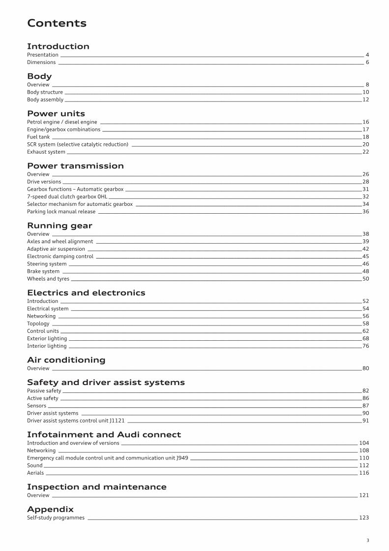
A plastic fuel tank with a capacity of 63 litres or 73 litres (optional) is fitted. The only differences between versions for TFSI and TDI are inside the tank.
In both tank cells, a tank cut-off valve is fitted in the lower part of the tank. The end of the pipe from this valve is located in the upper part of the liquid trap. The TFSI tank requires several roll-over valves for breathing.
Filler neck (capless)
Breather line (inserted through longitudinal member)
How the tank is emptiedWhen driving, fuel is pumped into the side chamber by the suction-jet pump. The vacuum which is produced in the pump causes fuel to be transferred from the side chamber to the main chamber, so that the side chamber is emptied first.
How the different tank capacities are achievedBaffles are used to achieve the different tank capacities. The volume of the fuel tank is changed by the baffles.
Connecting line for auxiliary heater
Reservoir with integrated fuel filterin delivery unit (long-life)
Level sender for main chamber
Tank cut-off valve
Baffle plate
19
669_017
669_041
Liquid trap
Breather line
Aggregate jet line
Baffle plate
Level sender for side chamber
Capless filler neckThe capless filler neck technology used on the Audi TT can now be used on the Audi A7 (type 4K) thanks to the newly developed body shape and wide "hips". A dual flap system is used for dust protection. The first flap provides a seal against dust, while the second seals against fuel. Plastic seals are used to seal the tank tightly against the outside.
Sealing flap 1
Seal
Sealing flap 2
Return spring Fuel tank breather
Return springSeal
Suction-jet pump with drive line connected
20
SCR system (selective catalytic reduction)
Equalisation chamber
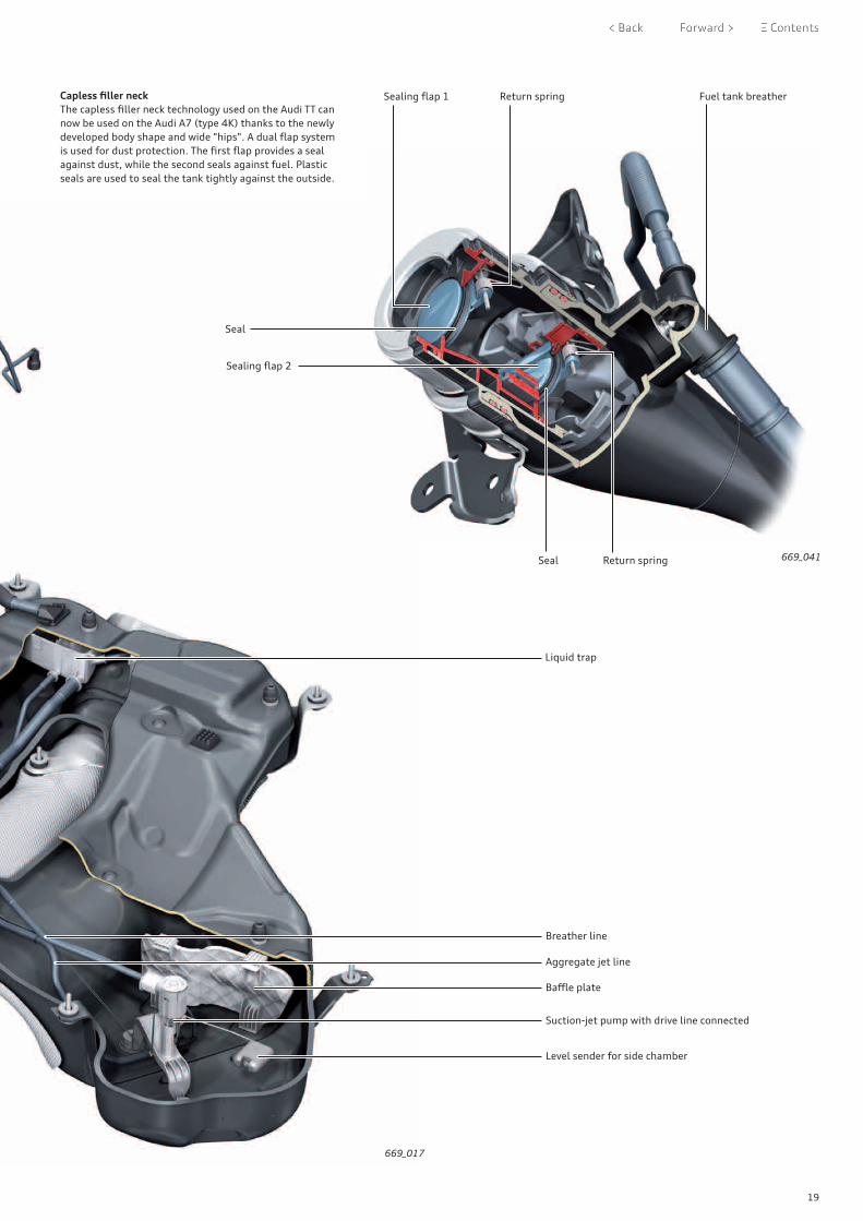
The breather system in the reducing agent tank is designed so that the reducing agent can be filled from the filler nozzles on AdBlue® filler pumps. To be able to hold the reducing agent flowing into the tank at a high flow rate, there is an equalisation chamber in the SCR tank and in the filler neck. The returning reducing agent would otherwise cause the pump nozzle to shut off too early. To prevent the flow-back of reducing agent in the filler neck, a non-return flap is installed at the end of the filler neck.
ReferenceFor further information about the SCR system, refer to self-study programme 657 "Audi Q5 (type FY)".
Filler neck for reducing agent
Equalisation chamber
Non-return flap
Breather line
Filler line
The reducing agent tank is manufactured and welded from two half-shells as an injection moulding (not as a blow-moulded tank). This has the advantage of reducing weight. The reducing agent tank has a capacity of 12 litres or 22 litres (optional).
AdBlue® quality check
By transmitting an ultrasonic beam and checking the frequency received, it is possible to check whether the SCR tank contains AdBlue® or other fluids. If the tank contains another fluid or the wrong concentration of AdBlue®, this is detected due to the different frequency and a message appears in the instrument cluster.
Heating element connection

21
669_020
Reducing agent tank
Delivery pump module
Heating mat
Delivery pump module
The reducing agent pump is housed in the delivery pump module. The pump is an orbital-type pump similar to a peristaltic pump. The fluid can be transported via a membrane which is compressed by an eccentric. The delivery module has its own heating element.
The level is measured by an ultrasonic signal which is reflected by the surface of the AdBlue® in the tank. The level of fluid in the SCR tank is determined from the amount of time taken for the signal to arrive back at the ultrasonic sensor. The delivery pump module cannot be renewed separately in after-sales service.
669_040
Sensor unit
Heating element
Orbital pump

22
Exhaust system
The gas flow paths are very short because the turbocharger module is located in the inner V. The catalytic converter is bolted
Catalytic converter module
The module is flanged-mounted directly to the turbocharger, which houses the main and secondary catalytic converters. Both catalytic converters are ceramic-type catalytic converters.
NOx storage catalytic converter
Centre silencer works on the absorption principle
Rear silencer works on the reflection and absorption principle
Damper element Front silencers work on the absorption principle
Main catalytic converter Secondary catalytic converter
directly to the turbocharger outlet. This allows the turbocharger to achieve light-off very quickly after a cold start.
EGR valve with EGR control motor 2 V339
Exhaust gas recirculation cooler
Flexible pipe
Low-pressure exhaust gas recirculation
3.0 ltr. TFSI engine

23
ReferenceFor further information about the low-pressure exhaust gas recirculation system, please refer to self-study programme 656 "Audi 3.0l V6 TDI engine of the EA897evo2 series".
669_024
The exhaust gas treatment system is a combined system compris-ing a close-coupled NOx storage catalytic converter and an SCR system. The unit comprising the NOx storage catalytic converter and the SCR-coated diesel particulate filter is followed by a trap catalytic converter which combines an SCR-coated catalyst with an oxidising catalyst to perform two tasks in one unit. Firstly, the CO which occurs during soot regeneration is oxidised to CO2 by a coating containing precious metals. Secondly, NH3 slip is reliably
eliminated. An additional low pressure exhaust gas recirculation system was integrated in the exhaust gas treatment to meet the requirements of the emissions standard. The TDI engines in the Audi A7 (type 4K) allow only a single exhaust, because the location of the SCR tank leaves no further room for a dual exhaust. The centre silencer also had to be moved further back.
Trap catalytic converter
SCR-coated diesel particulate filter
Flexible pipe
Particulate sensor
NOx sensor
Exhaust flap control unitJ883
Centre silencer works on the absorption principle
Rear silencer works on the reflection and absorption principle
669_023
3.0 ltr. TDI engine

24
Assembly mountings
Both of the engine versions for the Audi A7 (type 4K) have a three-point power unit mounting system. These comprise two switchable mountings on the power unit and a hydraulic gearbox mounting.
Hydraulic gearbox mounting
The hydraulic gearbox mounting is installed at the rear section of the gearbox and counteracts the drive forces. The hydraulic action improves vibration damping for a smoother ride.
669_126
669_124
Right electrohydraulic engine mounting solenoid valveN145
Left electrohydraulic engine mounting solenoid valve N144
Hydraulic gearbox mounting
This system achieves an extremely comfortable ride by switching the two engine mountings between soft (vehicle idling, current supply to mounting on) and hard (vehicle in motion, current supply to mounting off).
V6 TFSI

25
Left electrohydraulic engine mounting solenoid valve N144
Hydraulic gearbox mountingRight electrohydraulic engine mounting solenoid valveN145
669_125
Left electrohydraulic engine mounting solenoid valve N144
The vehicle diagnostic tester can be used to read out a measured value which indicates whether current is being applied to the engine mounting.
Diagnostics on engine mounting
Hydraulic engine mounting
669_028
V6 TDI

26
Overview
Manual release cable for parking lock
Selector mechanism with shift-by-wire and park-by-wire technology
> Refer to page 34
In terms of its power transmission system the Audi A7 (type 4K) has much in common with the B9 series, e.g. Audi A4 (type 8W), Audi Q5 (type FY) and Audi Q7/SQ7 (type 4M). For more informa-tion about this, please refer to SSP 644 and 657 and the Audi Service TV programmes at www.Audi-Training-Online.com (see further details on page 31).
This chapter provides information on changes and new features related to power transmission on the Audi A7 (type 4K).
7-speed dual clutch gearbox 0HL – S tronic
The 7-speed dual clutch gearbox 0HL is new.
This is a new version of the DL382 gearbox series for four-wheel drive featuring quattro with ultra technology. Specific measures have been implemented in order to raise the torque capacity from the previous level of 400 Nm to 500 Nm. Refer to page 32. In order to transmit this amount of torque to the rear axle, the 0HL gearbox is used in combination with the four-wheel drive coupling 0CX and rear final drive 09R. Refer to page 29.
quattro with ultra technology
The quattro four-wheel drive system with ultra technology is new to this class of vehicles (C8 series). To extend the possible applica-tions of this four-wheel drive system, it was designed for engine torques up to 500 Nm.
The following four-wheel drive concepts are available on the Audi A7, depending on engine type and customer requirements:
> quattro with ultra technology > quattro with self-locking centre differential > quattro with sport differential
Front-wheel drive and hybrid drive versions are planned for future model releases.
Actuator unit forParking lock manual release
> Refer to page 36
Four-wheel drive coupling 0CX
7-speed dual clutch gearbox 0HL > Refer to Overview – Automatic gearbox
Power transmission

27
Special instructions apply when installing the propshaft
> Refer to SSP 644
669_063
Overview – Automatic gearbox
Depending on engine type, the following gearboxes are available:
PR no. 1) Manufact.designation
Service designation Marketing designation
Drive version
G1C DL382-7F 7-speed dual clutch gearbox 0CK2
S tronic Front-wheel drive
G1D DL382-7A 7-speed dual clutch gearbox 0CJ2
S tronic quattro with ultra technology
G1D DL382+ -7A 7-speed dual clutch gearbox 0HL
S tronic quattro with ultra technology
G1G AL552-8Q 8-speed automatic gearbox 0D5 tiptronic quattro with self-locking centre differentialquattro with sport differential (optional)
PR no. 1) Manufacturer’sdesignation
Service designation Combination with gearbox
Four-wheel drive version
GH1 HL195.S3 M Rear final drive 0G2 0D5 quattro with self-locking centre differential
GH2 HL195.T2 M Rear final drive 0D3 0D5 quattro with sport differential (optional)
GH4 HL165.U1 M Rear final drive unit 0B02) 0CJ quattro with ultra technology
GH4 HL195.U1 M Rear final drive 09R 0HL quattro with ultra technology
Overview – Rear final drive
Depending on the quattro concept and customer requirements, the following rear final drive versions are available:
1) Production no./equipment2) To be introduced at a later date (not at time of market launch)
The illustration shows the drive train of the V6 3.0 ltr. TFSI with S tronic and the quattro four-wheel drive system with ultra technology.
Rear final drive 09R > with dog-clutch > Refer to page 29

28
quattro with ultra technology/four-wheel drive coupling
Four-wheel drive coupling 0CJ or 0CX is fitted in the Audi A7 (type 4K) with quattro ultra, depending on the engine version. The basic design and operating principle of the two versions are identi-cal. They differ exclusively in terms of the coupling torque which can be transmitted.
669_065
ATF filler and inspection plug > Accessible after removal of vibration damper > Please note the information on filling and checking the oil level in SSP 657 and in the Audi Service TV programme STV 0501 quattro with ultra technology - Part 2 – Service and workshop practice
Four-wheel drive control unitJ492 with clutch actuator for four-wheel drive V622and clutch position sender for four-wheel drive G969
Four-wheel drive coupling 0CJ is rated for torque levels up to 800 Nm.Four-wheel drive coupling 0CX is rated for torque levels up to 1200 Nm.
Four-wheel drive coupling 0CX has two additional clutch plate pairs to enable transmission of the higher torque level. Four-wheel drive coupling 0CX is slightly longer than four-wheel drive coupling 0CJ due to these changes.
ReferenceFor further information about quattro with ultra technology, refer to the following sources: – Self-study programme 657 "Audi Q5 (type FY)– Audi Service TV programme STV_0472_quattro with ultra technology - Part 1 - Design and function (from 29.05.2017)– Audi Service TV programme STV_0501_quattro with ultra technology - Part 2 - Service and workshop practice (from XX.XX.2018)
1) Manufacturer’s internal designation: VTK120 = Distributor coupling with 1200 Nm coupling torque – Four-wheel drive coupling 0CXVTK080 = Distributor coupling with 800 Nm coupling torque – Four-wheel drive coupling 0CJ
Four-wheel drive coupling 0CXVTK1201)
669_064
ATF drain plug
Drive versions
Control unit J492 can display two different driver messages in the instru-ment cluster:
Four-wheel drive: fault. You can continue driving. Please contact workshop
Meaning: a malfunction has occurred. The customer can continue driving but should drive to a qualified workshop soon to have the fault rectified. The four-wheel drive system may be unavailable.
Four-wheel drive: overheating Please adapt driving style. See owner's manual
Meaning: the vehicle has been driven hard, causing the temperature of the four-wheel drive coupling to rise significantly. A more restrained driving style is required so that the coupling can cool down. Until then, the four-wheel drive system will unavailable. When the temperature has dropped back down to normal, the driver message will disappear and the four-wheel drive system will be available again.
Four-wheel drive couplingwith 7 pairs of plates

29
Rear final drive 0B0 or 09R is fitted in the Audi A7 (type 4K) with quattro ultra, depending on the engine version. The basic design and operating principle of the two versions are identical. They differ exclusively in terms of the drive torque which can be trans-mitted.
The following are the main components which have been modified compared with final drive 0B0 to enable the higher level of drive torque to be transmitted by final drive 09R:
> Final drive gear set increased in size (crown wheel ⌀ 195 mm instead of ⌀ 165 mm on final drive 0B0)
> Differential increased in size (ball ⌀ 90 mm instead of ⌀ 80 mm on final drive 0B0)
> Dog-clutch increased in size (diameter, shafts, etc.)
> Bearings, flange shafts and housing increased in size
> Bearing for left flange shaft: 2 needle bearings
> Deflector used for oil transport
669_061
669_067Clutch actuator 2 for four-wheel drive V623
Propshaft speed sender G970
Gear oil drain plug Gear oil filler and inspection plug
Rear final drive 09R
quattro with ultra technology/rear final drive
Deflector for accurate oil transport

30
For engines developing more than 500 Nm of torque, the 8-speed automatic gearbox 0D5 is installed in conjunction with a self-locking centre differential.In conjunction with rear final drive 0G2 (with standard differen-tial), this four-wheel drive version is called quattro with self-locking centre differential.
As an optional extra, the 8-speed automatic gearbox 0D5 (with self-locking centre differential) can be combined with the sport differential (rear final drive 0D3).This four-wheel drive version bears the name quattro with sport differential.
The 0D3/0BX sport differential is an evolutionary, second-genera-tion unit based on the 0BF sport differential. The key modifications in sport differential 0D3 are:
> Final drive housing matched to the rear axle > Welded crown gear and various weight-saving measures > New gear oil and ATF > Shortened sensors for more clearance to exhaust system > Dual control unit concept in conjunction with J775 and J187 > Renaming of the sport differential control unit – previously
J492, now J187 > New address code – previously 0022, now 0032
The basic hardware of the sport differential (torque redistribution units, hydraulic control unit, sensors and actuators) is to a large extent identical to that of the first-generation sport differential.
quattro with self-locking centre differential quattro with sport differential
8-speed automatic gearbox 0D5 > tiptronic > For more information refer to SSPs 632, 644 and 662.
Self-locking centre differential withasymmetrical-dynamic torque split
> Two geometrically different centre differentials from two different manufacturers may be installed depending on the engine version. Both versions have similar properties.
> The version here is made by JTEKT.
> The other version is made by AAM.
Running gear control unit J775
669_069

31
Sport differential – Dual control unit concept
The key modification in the second-generation sport differential is the dual control unit concept.
In the case of the first-generation sport differential (sport differen-tial 0BF/0BE), the four-wheel drive control unit J492 is responsible for computing the redistribution of torque and controlling the actuators.
In the case of the second-generation sport differential (sport differential 0D3/0BX), the redistribution of torque for the sport differential is computed by the running gear control unit J775. J775 acquires information on driving status centrally, processes this and computes the value for the redistribution of torque. This value is then transmitted to the differential lock control unit J187 via FlexRay data bus. Using this information, J187 computes the drive voltage for the actuators and the required redistribution of torque. Control unit J187 is therefore purely responsible for per-forming the task.The dual control unit concept enables torque to be redistributed with greater precision and speed than in the first-generation sport differential, ultimately improving dynamic control.
For further information about the second-generation sport differ-ential, please refer to SSP 651.
Torque distribution display: The driver can display the qualitative distribution of drive torque to the wheels in a graphic on the MMI screen. To do so, the following menu item must be selected: Car > Vehicle information > quattro
The gearbox functions of the DL382 gearboxare virtually the same as in the B9 series and Audi Q5 (type FY).More information can be found in SSP 644.
The following change has been made regarding activationof the coasting function on page 62 and the special tiptronic steering wheel function on page 63:
The function for activating coasting with the + paddle lever is deactivated on the Audi A7 (type 4K). It is still possible to deacti-vate coasting with the – paddle lever however.
The gearbox functions of the AL552 gearboxare virtually the same as in the Audi Q7 (type 4M) and Audi A8 (type 4N).More information can be found in SSPs 632 and 662.
In the following Audi Service TV programmes you will find more information on power transmission that is also relevant for the Audi A7 (type 4K):
> STV_0411 from 26.02.2016 Audi A4 (type 8W) – Manual release mechanism for parking lock
> STV_0412 from 18.03.2016 Installing the gearbox in vehicles with a forward-mounted final drive
> STV_0366 from 16.01.2015 Dual-mass flywheel with centrifugal pendulum absorbers
Further information
Gearbox functions – Automatic gearbox
FlexRay data bus
Data bus diagnostic interface J533
Differential lock control unit J187
Rear final drive 0D3 > Sport differential (optional)
orRear final drive 0G2
> Standard (no extra charge)
669_068

32
7-speed dual clutch gearbox 0HL
The 0HL gearbox is a further variant of the DL382 gearbox series1). Specific measures have been implemented in order to raise the torque capacity from the previous level of 400 Nm to 500 Nm. In order to transmit this amount of torque to the rear axle, the 0HL gearbox is used in combination with the four-wheel drive cou-pling 0CX.
1) The DL382 gearbox series currently comprises the following gearbox variants:
DL382-7F – 7-speed dual clutch gearbox 0CK2)
DL382-7Q – 7-speed dual clutch gearbox 0CL3) See SSP 644
DL382-7A – 7-speed dual clutch gearbox 0CJ3) See SSP 657
DL382+-7A – 7-speed dual clutch gearbox 0HL3)
Gearbox selector lever for parking lock manual release > Changing the lever position: refer to page 36
Four-wheel drive coupling 0CX
ATF heat exchanger increased in size > 2 additional cooling plates
Four-wheel-drive control unitJ492
ATF drain screw – four-wheel-drive coupling
Gearset and bearings > Shot-peened toothing > Optimised transmission bearings
669_070
A key to the code designations can be found on page 17.2) This variant is available with and without shift-by-wire.3) This variant is exclusively available with shift-by-wire.

33
For information on DL382 gearboxes, please refer to SSPs 644 and 657 and the following Audi Service TV programmes:
> STV_0354 from 26.10.2014 7-speed dual-clutch gearbox 0CK – S tronic Part 1 / Design and function
> STV_0355 from 26.10.2014 7-speed dual-clutch gearbox 0CK – S tronic Part 2 / Service and workshop practice
> STV_0415 from 23.03.2016 7-speed dual-clutch gearbox 0CK/OCL – S tronic Part 3 / Park-by-wire (design and function)
> STV_0414 from 23.03.2016 7-speed dual-clutch gearbox 0CK/OCL – S tronic Part 4 / Service and workshop practice
Gearbox oil systems
The 0HL gearbox has two oil systems: an ATF system for the dual clutch and the electrohydraulic control unit, and an MTF system for the gear set and the front final drive (like the 0CK gearbox). The ATF must be changed at specified intervals, but the MTF is designed to provide lubrication for the lifetime of the gearbox and does not require servicing.
The four-wheel drive coupling 0CX has a separate oil system with ATF. The ATF does not have to be changed and so the oil system does not require servicing. For information on the special features of the oil system on the four-wheel drive coupling, please refer to Audi Service TV programme STV 0501 quattro with ultra technology - Part 2 – Service and workshop practice.
Dual clutch with enhanced durability
> One extra clutch plate per clutch and cross bar design
> Piston surface area increased by 10%
Dual-mass flywheel with pendulum-type absorber > Modified for higher engine torque > Refer to Audi Service TV programme information on page 31
Other modifications: > Modification to design of intake for ATF > Software modifications > Increased ATF pump rate for more cooling oil
Spacer ring on pinion shaft(previously Omega bushing)
Pinion shift running ondouble tapered roller bearing
Key:
Gearbox input, gear train half 1 Gearbox input, gear train half 2
669_072

34
Selector mechanism for automatic gearbox
The Audi A7 (type 4K) uses the latest Audi selector mechanism design with full shift-by-wire (SBW) capability. This means that parking lock operation is also fully automatic. The term used for this is "park-by-wire" (PBW). There is no selector cable connecting the selector mechanism to the gearbox.
With the introduction of this selector mechanism design to the C-series, all vehicle models with longitudinal engines now use this technology and operating concept.
The selector mechanism has been completely redesigned for the C8 model range. It has been made much more compact, lighter and more cost-efficient while retaining all of the original functions.
The new selector mechanism (E313 – selector lever) is a single unit with the following components:
> J587 Selector lever sensors control unit > G868 Sender for lateral selector lever lock > G727 Selector lever position sender > V577 Motor for lateral selector lever lock > N110 Selector lever lock solenoid
The complete unit must be renewed if one of these components is defective.
For more information on the selector mechanism and operating concept, please refer to SSPs 632, 643 and 644.
Function diagram – selector mechanism
669_073
669_074
Interface to parking lock solenoid – N486 + (pin A1)
Key:
E313 Selector lever (selector mechanism)E681 Button for selector lever releaseE816 Parking lock buttonG727 Selector lever position senderG868 Sender for lateral selector lever lockJ587 Selector lever sensors control unitK320 Parking lock indicator lampN110 Selector lever lock solenoidV577 Motor for lateral selector lever lockY5 Selected range displayA,B,C Connectors
Interface to parking lock solenoid – N486 - (pin A2)
CAN High
CAN Low
Only on DL382-series gearboxes}Dash panel insert CAN}

35
669_075
669_076
Selector mechanism versions
In addition to different selector mechanisms for right-hand drive and left-hand drive vehicles, the selector mechanisms vary for the tiptronic (AL522) and S tronic (DL382) gearboxes.On vehicles with DL382-series gearboxes, control unit J587 has two additional interfaces for controlling the parking lock sole-noid N486. Refer to the function diagram in Fig. 669_074 and SSP 644, page 48 ff.
Information exchange
Data is exchanged between the selector mechanism and the gearbox via the gateway. The selector lever sensors control unit J587 communicates via the CAN dash panel insert; the auto-matic gearbox control unit J217 communicates via the FlexRay with gateway J533.
Selector lever handle –Bottom section with selector lever boot
Release button –Button for selector lever releaseE681
Connector C
Selector lever
Selector lever handle –Top section
P button –Parking lock button E816 withparking lock indicator lampK320. K320 illuminatesthe P button (dimmed)and is brightly lit whenparking lock is active.
Selected range display Y5
Connector B
Connector A
Connector B
Selector mechanism (selector lever E313)
Selector leversensors control unitJ587

36
Parking lock manual release
The design and operating concept for the parking lock manual release mechanism have been largely adopted from the B9 series.
The design of the actuator unit and the socket wrench for the Audi A7 (type 4K) have been revised to improve operation.The new features and special characteristics are described below. For basic information on manual release of the parking lock, please refer to SSP 644 Chapter – Emergency-releasing the parking lock (revision status 11/2015) and watch the Audi Service TV pro-gramme – STV_0411 Audi A4 (type 8W) – Manual release mecha-nism for the parking lock.
Special features of manual parking lock release(compared to B9 series and Q5 (type FY))
The position of the manual release lever on the gearbox has been changed. This has enabled the optimisation of the cable guide for the manual release mechanism, a reduction in operating force and an improvement in acoustic performance.
The socket wrench for the manual release mechanism has a with-drawal lock. In conjunction with the adapted stop in the actuator unit, the socket wrench can only be withdrawn by approx. 5 mm (in order to release the lock) while in the actuated position (P-OFF). The socket wrench can then be turned back and withdrawn (P-ON position). This prevents the possibility of the socket wrench unin-tentionally being removed completely in the actuated position and of the manual release mechanism springing back.
Note: Starting at the beginning of 2018, the manual release mechanism with withdrawal lock will also be installed in B9-series vehicles and in the Audi Q5 (type FY).
669_078
Socket wrench Audi A7 (type 4F)
Socket wrench B9 series/Audi Q5 (type FY)
Withdrawal lock
Without with-drawal lock
Actuator unit for parking lock manual release
Gearbox selector lever for parking lock manual release
Stop for withdrawal lock

37
1
2
3
≈13°12
3
A
Installation location of the manual release mechanism
The actuator unit for the manual release mechanism is located under the cup holder in the centre console.
The acutator unit can be accessed by removing the rubber mat and the cover. A screwdriver is required in order to remove the cover.
Please note that the socket wrench must not be inserted vertically, but at an angle of approx. 13°. Refer to Fig. 669_079.
Insert the socket wrench into the actuator unit as shown.
Turn the socket wrench clockwise as far as the stop, then push it down about 5 mm to lock it into place at the stop.
Manual release of parking lock (P-OFF position)
Caution! Before actuating the parking lock the vehicle must be secured to prevent it from rolling away.Make sure that the socket wrench and the stop in the actuator unit are undamaged.Please observe the safety warnings in the Owner's Manual. Deactivating the manual release mechanism (P-ON position)
Pull the socket wrench out as far as the withdrawal lock (approx. 5 mm) and, holding it firmly, turn it back as far as the stop. The socket wrench can now be removed.
Note: Do not under any circumstances turn the socket wrench only anti-clockwise as this will damage the actuator unit and the socket wrench.
View A
669_079
669_080
669_077
DANGER
Socket wrench
Actuator unit for parking lock manual release

38
Overview
The running gear for the Audi A7 (type 4K) has been completely redesigned compared to the previous model. The technology and control systems already used in the Audi A8 (type 4N) and Q7 (type 4M) achieve even greater levels of comfort, dynamics and safety. Versions are available with steel suspension and controlled or non-variable damping in addition to air suspension with elec-tronic damping control.The front and rear axles are based on a high-precision lightweight five-link design.
Progressive steering, included in the standard vehicle equipment, reduces the amount of steering effort required. The dynamic four-wheel steering system introduced in the Audi A8 is available as an optional extra for the Audi A7 (type 4K).The generously dimensioned brake system delivers superb per-formance even when a more dynamic driving style is adopted.The 9th generation ESC system provides high-performance stabil-ity control for the vehicle.A wide range of steering wheels, wheels and tyres is available for further customisation.
669_138
The following suspension variants are available for the Audi A7 (type 4K):
Running gear with steel suspension and non-variable damping (1BA)This is the standard running gear.
Sport running gear with steel suspension and non-variable damping (1BE)This suspension system is optional. The springs, dampers and anti-roll bars are set up for dynamic handling. The ride height is approx. 10 mm lower than version 1BA.
Running gear with steel suspension and damping control (1BL)This suspension system is optional. Ride height is identical to that of standard suspension 1BA.
Suspension with air springs and damping control (adaptive air suspension – 1BK)This suspension system is optional. The ride height in "Auto" mode (normal level) is approx. 10 mm lower than version 1BA.
Running gear

39
Axles and wheel alignment
Front axle
The front axle is based on the proven design principle of the five-link suspension. A particular emphasis was placed on the lightweight construction. The main components are constructed from aluminium. The underlying platform is the MLBevo system, which has already been used as a development base for the current A4, Q5, Q7 and A8 models.
669_139
669_140
Shock absorberSingle and twin-tube versions with non-vari-able or controlled dampingShock absorber mountingMLBevo system component
Upper transverse linksForged aluminium componentAdopted from the Audi Q7Bonded rubber bush (new component)
Wheel bearing housingForged aluminium componentAdopted from the Audi Q5
Coupling rodTwo versions in plastic or aluminium depending on running gear variantMLBevo system components
Anti-roll barTubular anti-roll bars
SubframeThree sections, base carrier sheet steel construction with cast aluminium support bracketsadopted from Audi Q5 with modifications to anti-roll bar bolt attachment and rear connection of base frame.
Guide linkForged aluminium componentAdopted from Audi Q5 including hydro-bush
Wheel bearing/wheel hubSecond generation wheel bearingMLBevo system component
Track control linkForged aluminium componentBasic part adopted from Audi Q7Bonded rubber bush (new component)

40
Rear axle
The trapezium link rear axle used in the previous model has been replaced by a virtually new five-link axle. This is based on the MLBevo platform, which has already been used on the A4, Q5, Q7 and A8 models.The geometric layout of the suspension links provides a clear separation in the absorption of longitudinal and lateral forces. Elastomer bushes with a mixture of high-damping materials and integrated spacer sleeves allow for a high degree of radial stiff-ness with a low roll rate.The implementation of subframe bushes with hydraulic damping ensures that the axle is well-isolated from the vehicle body.The wheel bearings have been optimised to reduce friction, thereby helping to decrease rolling resistance.
669_141
669_142
Upper transverse link (rear)Sheet-steel partAdopted from the Audi Q7Bearings (hub carrier end) adopted from Audi A8
Shock absorberSingle-tube on 1BA and 1BETwin-tube on 1BL and 1BK
Upper transverse link (front)Forged aluminium component adopted from Audi Q5
Lower transverse link (front)Forged aluminium componentAdopted from Audi Q5 with high axle load (Q5 Security)
Coupling rod2 versions:Aluminium/plasticAluminium: adopted from Audi Q5 Plastic: new component
SubframeWelded steel constructionGeometry adopted from Audi A8Newly developed subframe mountings
Aero-deflectors for spring linksNew component, similar in geometry to Audi Q5
Spring linkForged aluminium componentAdopted from the Audi Q5
Anti-roll barTubular anti-roll bar Geometry same as Audi Q5Modified spring rate
Hub carrier Die-cast aluminiumAdopted from the Audi Q5
Wheel bearing/wheel hubAdopted from the Audi Q5
Track rodVehicles with steel coil springs: Sheet-steel part Adopted from the Audi Q7Vehicles with adaptive air suspension:Forged aluminium componentAdopted from the Audi Q7

41
Wheel alignment
The wheel alignment and adjustment procedures are the same as for the other MLBevo models. The adjustment points are also identical, for both the steel suspension and the adaptive air suspension.
NoteBefore beginning wheel alignment, it is necessary to check whether the steering adapter (on vehicles without dynamic four-wheel steering) or the rear axle steering unit is installed in the correct position on the subframe. If not, this may cause different variations in toe angle on each of the wheels when the suspension compresses and rebounds.
669_141
669_139
Toe setting at attachment point:track rod/subframe(not shown in illustration)
Camber setting at attachment point:spring link/subframe(hidden by aero-deflectors)
Toe setting
Camber balancing
42
Adaptive air suspension
Design and function
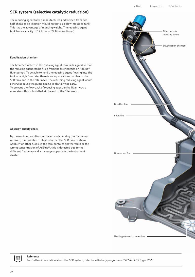
The adaptive air suspension is an optional extra for the Audi A7 (type 4K). The system has the same general layout as the adaptive air suspension system in the Audi Q5. The running gear control unit J775 (EFP 2.0) is likewise fitted. In addition to the regulating software for the air suspension and damping, the control unit also contains the sensor for registering vertical acceleration (upwards acceleration of the vehicle) as well as pitching and rolling moments (rotation about the vehicle’s lateral and longitudinal axes). This eliminates the need for the body acceleration senders fitted in previous systems.
The measured values for the yaw rate (rotation about the vehicle’s vertical axis) and the lateral acceleration are transmitted via FlexRay from the airbag control unit to the regulating software. The compressor for the air supply unit is the same as on the Audi Q5 (2-stage without boost function). The solenoid valve block is also the same. The vehicle level senders have also been adopted from the Audi Q5. Air intake is via the left wheel housing. Two aluminium accumulators with a total volume of approx. 4.4 litres are used. These are installed in the rear area of the side sills. The maximum system pressure is approx. 18 bar.
669_143
Air spring strut with damperFront right shock absorber damping adjustment valveN337
Front right vehicle level senderG289
Running gear control unit J775incorporating the control software for the air suspension and damping systems as well as sensors for measuring vehicle dynamics
Accumulator Rear right shock absorber damping adjustment valve N339
Air suspension
Air supply unitwith compressor V66 and solenoid valve block
Rear left shock absorber damping adjustment valveN338
Rear left vehicle level senderG76
AccumulatorRear right vehicle level senderG77
Front left vehicle level senderG78
Air spring strut with front left shock absorber damping adjustment valveN336
43
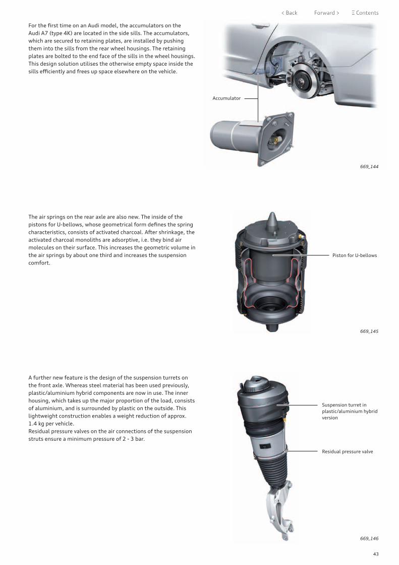
For the first time on an Audi model, the accumulators on the Audi A7 (type 4K) are located in the side sills. The accumulators, which are secured to retaining plates, are installed by pushing them into the sills from the rear wheel housings. The retaining plates are bolted to the end face of the sills in the wheel housings.This design solution utilises the otherwise empty space inside the sills efficiently and frees up space elsewhere on the vehicle.
The air springs on the rear axle are also new. The inside of the pistons for U-bellows, whose geometrical form defines the spring characteristics, consists of activated charcoal. After shrinkage, the activated charcoal monoliths are adsorptive, i.e. they bind air molecules on their surface. This increases the geometric volume in the air springs by about one third and increases the suspension comfort.
A further new feature is the design of the suspension turrets on the front axle. Whereas steel material has been used previously, plastic/aluminium hybrid components are now in use. The inner housing, which takes up the major proportion of the load, consists of aluminium, and is surrounded by plastic on the outside. This lightweight construction enables a weight reduction of approx. 1.4 kg per vehicle.Residual pressure valves on the air connections of the suspension struts ensure a minimum pressure of 2 - 3 bar.
669_144
669_145
669_146
Accumulator
Piston for U-bellows
Residual pressure valve
Suspension turret in plastic/aluminium hybrid version
44
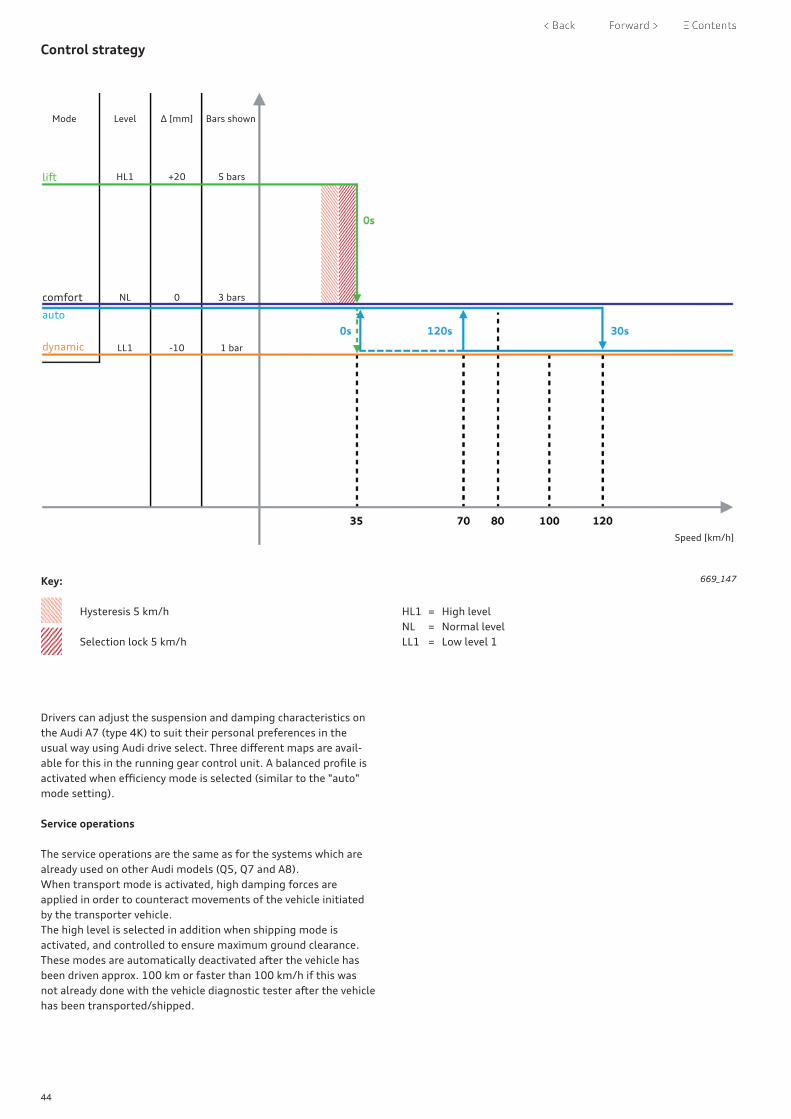
Control strategy
Mode Level Δ [mm] Bars shown
HL1 +20 5 bars
NL 0 3 bars
LL1 -10 1 bar
Speed [km/h]
Drivers can adjust the suspension and damping characteristics on the Audi A7 (type 4K) to suit their personal preferences in the usual way using Audi drive select. Three different maps are avail-able for this in the running gear control unit. A balanced profile is activated when efficiency mode is selected (similar to the "auto" mode setting).
Service operations
The service operations are the same as for the systems which are already used on other Audi models (Q5, Q7 and A8). When transport mode is activated, high damping forces are applied in order to counteract movements of the vehicle initiated by the transporter vehicle.The high level is selected in addition when shipping mode is activated, and controlled to ensure maximum ground clearance. These modes are automatically deactivated after the vehicle has been driven approx. 100 km or faster than 100 km/h if this was not already done with the vehicle diagnostic tester after the vehicle has been transported/shipped.
669_147Key:
Hysteresis 5 km/h
Selection lock 5 km/h
HL1 = High levelNL = Normal levelLL1 = Low level 1
lift
comfort
auto
dynamic

45
Electronic damping control
Suspension version 1BL available for the Audi A7 (type 4K) is equipped with steel springs and controlled dampers on the front and rear axles. The control software is implemented in the running gear control unit J775 (EFP 2.0). The controlled dampers on MLBevo models with steel suspension are CDCivo dampers. The supplement "i" = "internal" in the designation refers to the inte-gration of the solenoid valve in the damper.
The addition "evo" = "evolution" refers to the latest technically advanced damper generation.
ReferenceFor further information on design and function, operation, driver information and service operations, please refer to self-study programme 644 "Audi A4 (type 8W)".
669_148

46
Steering system
The Audi A7 (type 4K) uses the same electromechanical power steering used in the Audi Q5 (type FY). Progressive steering is standard. Dynamic four-wheel steering is optional.
The standard version of the Audi A7 (type 4K) uses steering columns with mechanical adjustment (approx. 60 mm lengthwise and approx. 50 mm heightwise). The design and function of these steering columns is similar to those on A4 (type 8W) and Q5 (type FY) models. Electrically adjustable steering columns are available as an optional extra. These have been adopted from the Audi A8 (type 4N). The steering columns with dynamic four-wheel steering are shorter to provide room for the dynamic steering actuator. The geometry of the intermediate steering shafts differs on right and left-hand drive vehicles.
Leather double-spoke, sport and sport contour steering wheels are available for the Audi A7 (type 4K).
The double-spoke leather steering wheel with 12 multi-function buttons is the standard version. For all steering wheels, the leather on the steering wheel and selector lever handle are matched to the preferred colour of the dash panel top.
Steering wheels with paddle levers and/or steering wheel heating are optional.
The sportiest version, the sport contour leather steering wheel, has a more contoured rim and is flattened at the bottom.
669_149
669_150
669_151
Basic equipment
Sport leather steering wheel with paddle levers
Sport contour leather steering wheel
47
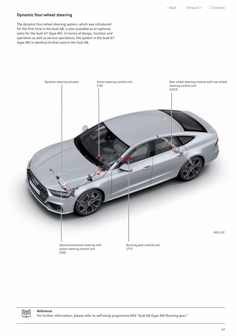
Dynamic four-wheel steering
The dynamic four-wheel steering system, which was introduced for the first time in the Audi A8, is also available as an optional extra for the Audi A7 (type 4K). In terms of design, function and operation as well as service operations, the system in the Audi A7 (type 4K) is identical to that used in the Audi A8.
ReferenceFor further information, please refer to self-study programme 663 "Audi A8 (type 4N) Running gear."
669_152
Dynamic steering actuator Active steering control unit J792
Rear wheel steering module with rear wheel steering control unit J1019
Running gear control unitJ775
Electromechanical steering with power steering control unit J500

48
Brake system
The Audi A7 (type 4K) is equipped with a generously dimensioned brake system which offers plenty of reserve capacity for corre-sponding driving situations. As with the current MLBevo models A8, Q7, Q5 and A4, the brakes on the front and rear axles of the Audi A7 (type 4K) have separate brake circuits ("black and white" system).
Front axle Rear axle
Engine 3.0 ltr. TDI (210 kW) 3.0 ltr. TFSI (250 kW) 3.0 ltr. TDI (210 kW)3.0 ltr. TFSI (250 kW)
Minimum wheel size 17" 18" 17"
Type of brakes AKE fixed caliper brakes(30-36-38)
AKE fixed caliper brakes(30-36-38)
TRW EPBi 43
Number of pistons 6 6 1
Brake disc diameter 350 mm 375 mm 330 mm
Brake disc thickness 34 mm 36 mm 22 mm
AKE fixed caliper brakes on front axle
TRW EPBi 43 brakes on rear axle with electro-mechanical parking brake
669_153 669_154

49
Tandem brake servos of size 8/9" are used on both left and right-hand drive vehicles.On vehicles with 48 Volt electrical system, a movement sensor is fitted instead of the brake light switch. The PWM signal from the sensor is used for recuperation.
The 9th ESC generation is used as on the Audi Q7 and A8 models. Depending on the vehicle equipment, the brake pressure is gener-ated by hydraulic pumps with either two or six pistons. The basic equipment version includes pumps with two pistons, in combina-tion with a pressure sensor to register the initial brake pressure. Vehicles with ACC are fitted with the six-piston version, with two additional pressure sensors to register the pressures from the two brake circuits.
The function, data communication, operation, driver information and service operations are the same as the ESC system on the Audi A8 (type 4N). The new loose wheel detection/warning system introduced on the Audi A8 has now also been implemented on the Audi A7.
ReferenceFor further information, please refer to self-study programme 663 "Audi A8 (type 4N) Running gear."
669_155
669_156
Brake servo
ESC unit

50
Wheels and tyres
The Audi A7 (type 4K) comes as standard with 18" cast aluminium wheels. 18" to 21" cast and forged aluminium wheels are avail-able as optional extras. The available tyres range from 225/55 R18 to 255/35 R21. Run-flat tyres are not available. Snow chains may be mounted on the 18" and 19" winter wheels.
The Tyre Mobility System (TMS) is part of the standard equipment. A temporary spare wheel is available optionally.A jack is included for vehicles with a temporary spare wheel or with winter wheels ordered from the factory.
Summer wheels Optional wheels Winter wheels
8.0J x 18Cast aluminium wheels225/55 R18
8.0J x 18Forged aluminium wheels225/55 R18
8.5J x 20Cast aluminium wheels255/40 R20
8.5J x 21Forged aluminium wheels255/35 R21
8.0J x 18Forged aluminium wheels255/55 R18
8.5J x 19Cast aluminium wheels245/45 R19
8.5J x 20Cast aluminium wheels255/40 R20
8.5J x 21Cast aluminium wheels255/35 R21
8.5J x 19Cast aluminium wheels245/45 R19
8.5J x 19Cast aluminium wheels245/45 R19
8.5J x 21Cast aluminium wheels255/35 R21
8.5J x 20Cast aluminium wheels255/40 R20
8.5J x 20Cast aluminium wheels255/40 R20

51
Tyre pressure monitoring
The 3rd generation Tyre Pressure Monitoring System is offered as optional equipment in the Audi A7 (type 4K) as an alternative to the standard Tyre Pressure Loss Indicator.
The system has the same design and function as the system in the Audi Q7 (type 4M) and Audi A8 (type 4N).
669_158
669_159
The Tyre Pressure Loss Indicator is an indirect measurement system. The values measured by the wheel speed sensors are used
ReferenceFor further information, please refer to the Service TV programme STV_0187 "Tyre pressure monitor display Plus".
to calculate the tyre circumferences and vibrations. The software is integrated in the ABS control unit J104.
The Tyre Pressure Monitoring System is a direct measurement system. The pressure loss is detected directly by evaluating the values measured by the tyre pressure sensors. The Tyre Pressure Monitor-
ing System control unit J502 also contains the antenna which receives the radio signals from the wheel pressure sensors.
ReferenceFor further information, please refer to self-study programme 663 "Audi A8 (type 4N) Running gear."

52
Introduction
The vehicle electrics and electronics on the Audi A7 (type 4K) are extremely similar to those on the Audi A8 (type 4N).
Various CAN bus systems are used in the vehicle electrical system and network. The FlexRay bus system allows real-time data trans-fer between the running gear control units and the driver assist system control units. FlexRay allows all regulating systems to access the sensors.
In comparison to the previous bus architecture, the system is like a six-lane motorway compared to a country road; the bandwidth has grown by a factor of 20.
A typical electrical system in a large saloon consists of up to 1,500 individual wires and weighs about 50 kg. Audi has significantly reduced the weight of the electrical system on the Audi A7 (type 4K), despite the numerous new functions. The cross sections of all the wires are as small as possible, and the main battery wire is made of light aluminium instead of copper.
Light digitally presented.The optionally available HD matrix LED headlights are a statement of the new light design language of the Audi A7 and take up the topic of digitalisation. Separated by narrow gaps, 12 light seg-ments are next to each other and conjure up associations with the principle of the numbers 0 and 1.
The interior lighting concept visualises the interior architecture when it is dark and emphasises the clear form language of the interior via longitudinal alignment of the lighting elements. Audi offers two lighting packages for the Audi A7 (type 4K): The contour lighting package The contour ambient lighting package.Both set the interior cabin, the space and the materials in scene. The ambient lighting in the dash panel and the centre console allows the architecture to "float". In the door, this increases the effect of space. Precise contour lighting runs along the centre console and the door trim; the quattro badge in the dash panel is also illuminated.
The narrow and precise placement of the light bands traces the entire interior architecture, thereby underlining the entire interior concept. The contour lighting can be set to 30 different colours and follows the colour profiles in the Audi drive select driving dynamics system. White light accents also shine from the bass loudspeakers in the doors if the Bang & Olufsen Advanced Sound System with 3D sound is on board. Illuminated sill panel trim (standard with the design selection and S line sports package) round off the interior lighting programme.
Overview of electrical system and vehicle electrics
LED headlight
Jump start terminal
Main battery wire
669_116
Electrics and electronics

53
Control unit rack
The convenience system central control unit J393 has a 4N0 part number, thereby showing its close relation to the Audi A8 (type 4N).
However, the fitting location has changed. On the Audi A7 (type 4K), J393 is fitted in the underbody of the luggage compart-ment, immediately behind the rear seat backrests.
J393 is part of a control unit rack. Depending on the vehicle equip-ment, various components and control units may be fitted in this special bracket, for example:
669_054
Fitting location
> Relay and fuse carrier SR4 > Adjustable rear spoiler control unit J223 > Trailer detector control unit J345 > Convenience system central control unit J393 > A 12 Volt power distributor > Emergency call module control unit and communication
unit J949 > Aerial amplifier for mobile telephone (compensor) R86 > Remote control receiver for auxiliary heater R64 > Heated windscreen control unit J505 > Differential lock control unit J187
Relay and fuse carrierSR4
Adjustable rear spoiler control unit J223
Trailer detector control unitJ345
Aerial amplifier for mobile telephone (compensor)R86
Remote control receiver for auxiliary heaterR64
12 Volt power distributor
Convenience system central control unitJ393
Differential lock control unitJ187
Emergency call module control unit and communication unitJ949
Heated windscreen control unitJ505

54
Electrical system
As with the Audi A8 (type 4N), the Audi A7 (type 4K) is equipped with both a 48 Volt electrical system and a 12 Volt electrical system. The 48 Volt electrical system is also the main electrical system on the Audi A7 as the current is generated via the 48 Volt starter-alternator when the engine is running.
The fitting locations of the batteries, the voltage converter, the 12 Volt pinion starter and the 48 Volt starter-alternator are, along with their functions and layout, identical to the components in the Audi A8 (type 4N).
Wiring junctions TV2 and TV3 with jump-start terminal 48 Volt positive wire
48 Volt belt starter-alternator
Relay and fuse carrier SR3on lower section of right A-pillar
12 Volt pinion starter
Relay and fuse carrier SR1in plenum chamber
Relay and fuse carrier SR2at foot rest (left-side)
Fuse holder SF on dash panel (left-side)

55
The fitting locations of the relay and fuse carriers hardly differ from the Audi A8, as can be seen in the illustration below. As the layout and functions of the Audi A7’s electrical system components (insofar as they relate to the engines described in this SSP) do not
differ from those described for the Audi A8, please refer to SSP 664 "Audi A8 (type 4N) Electrics and electronics" for descriptions thereof.
669_181
Relay and fuse carrier SR2at foot rest (left-side)
Fuse holder SF on dash panel (left-side)
Relay and fuse carrier SR4on control unit rack in luggage compartment
Battery, 48V, A6in spare wheel well
12 Volt main battery wire
Voltage converter, 48/12 Volt, A7
Battery, 12V, Ain rear right side panel
56
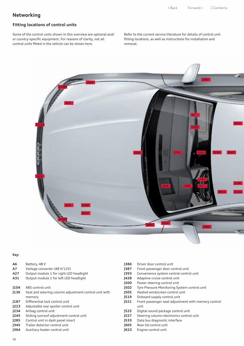
Networking
Fitting locations of control units
Some of the control units shown in this overview are optional and/or country-specific equipment. For reasons of clarity, not all control units fitted in the vehicle can be shown here.
Refer to the current service literature for details of control unit fitting locations, as well as instructions for installation and removal.
Key:
A6 Battery, 48 VA7 Voltage converter (48 V/12V)A27 Output module 1 for right LED headlightA31 Output module 1 for left LED headlight
J104 ABS control unit J136 Seat and steering column adjustment control unit with
memoryJ187 Differential lock control unitJ223 Adjustable rear spoiler control unitJ234 Airbag control unit J245 Sliding sunroof adjustment control unitJ285 Control unit in dash panel insert J345 Trailer detector control unit J364 Auxiliary heater control unit
J386 Driver door control unitJ387 Front passenger door control unitJ393 Convenience system central control unitJ428 Adaptive cruise control unitJ500 Power steering control unitJ502 Tyre Pressure Monitoring System control unitJ505 Heated windscreen control unitJ519 Onboard supply control unitJ521 Front passenger seat adjustment with memory control
unitJ525 Digital sound package control unitJ527 Steering column electronics control unitJ533 Data bus diagnostic interfaceJ605 Rear lid control unitJ623 Engine control unit
J500 R242
J898 J285 J527J136
J853
J869
J1121
J764
J519
J623
J104A31
J1088
J1122
A27
J364
J1089
J792 J234 J245
R7
J794J521
J386
J387
J428

57
The biggest difference between the Audi A7 (type 4K) and the Audi A8 (type 4N) regarding the fitting locations of the control units results from the luggage compartment concept.
This necessitated the use of a rack to hold a large number of control units in the luggage compartment. On the Audi A8, these control units were fitted behind the luggage compartment trim on both sides.
J764 Control unit for electronic steering column lockJ769 Lane change assist control unit J770 Lane change assist control unit 2J772 Reversing camera system control unitJ775 Running gear control unitJ792 Active steering control unitJ794 Control unit 1 for information electronicsJ853 Control unit for night vision systemJ869 Control unit for structure-borne soundJ880 Control unit for reducing agent metering systemJ898 Control unit for head-up displayJ926 Rear driver side door control unitJ927 Rear passenger side door control unitJ949 Emergency call module control unit and communication
unit
J1019 Rear wheel steering control unitJ1088 Front left radar sensor control unit for object detectionJ1089 Front right radar sensor control unit for object detectionJ1121 Driver assist systems control unitJ1122 Control unit for laser distance control
R7 DVD playerR64 Remote control receiver for auxiliary heaterR78 TV tunerR86 Aerial amplifier for mobile telephoneR242 Front camera for driver assist systems
669_182
A6
J772
J1019
J770
J187
J393
J345
J605
J502
J926
J505
R78
J769J880A7
R64
J533
J927
J775
J223
R86
J949
J525

58
Topology
Hybrid CAN
Convenience CAN
Infotainment CAN
Diagnostics CAN
Extended CAN
FlexRay
LIN bus
Key:
Modular infotainment matrix CAN (MIB)
Sub-bus systems/private CAN
MOST bus
USB wires
LVDS
Dash panel insert CAN
Ethernet connection
Convenience CAN 2
Connect CAN
J926
J927
N209
N210
J386
J387
J136
J521
N475
N477
J345
J605
J764
J245
H12
J453
J367
U13
C
A7
A6
J505
J223
G578
MX3
J938
MX4
MX13
MX13
J1169
J1170
G65
Control motors 1 - 2
E265
Heater controls 1 - 4
Control motors1 - 15
Ambient light 1 - 15
Ambient light 16 - 30
J126
Ambient light 31 - 45
V438V113
J897
J1101
Onboard supply control unit J519
J866
V388V390
E1
V389V391
G397G355
J400
J1100
A31
A27
Conven-ience system central control unitJ393
Diagnostic connector

59
669_121
Data bus diagnostic interface J533
EX22
EX23
Y7
J530
J528
J949
J1146
E67
J685
J1060
Driver assist systems control unitJ1121
R7 U41 R204
R293 R78
J525
Control unit 1 for information electronicsJ794
J898
J285
J587
Ultrasonic sensors 1 - 12
J706
J854
J428
J234
J492
J855
J583
J1183
J187
J881
J623
C29
G784
J1122
J1019
J104
J792
J500
J217
J775
J527
J1088
J769
J1089
J770
J502
J844
J869
J364
R64
V475
J1135
J880
R212
J853
J772
J794
R245
R246
R243
R242
R244
J1121
For presentation reasons, the FlexRay topology does not mirror the actual configuration of the control units. The order of the control units in the MOST ring in this illustration is also not identical to the actual sequence.

60
Key:
A6 Battery, 48 VA7 Voltage converter (48 V/12V)A27 Output module 1 for right LED headlightA31 Output module 1 for left LED headlightC AlternatorC29 Starter-alternatorE1 Light switchE67 Driver side volume regulatorE265 Operating and display unit for rear air conditioning
systemEX22 Centre switch module in dash panelEX23 Switch module 1 in centre consoleG65 High-pressure senderG355 Humidity senderG397 Rain and light sensorG578 Anti-theft alarm sensorG784 Particulate sensorH12 Alarm hornJ104 ABS control unitJ126 Fresh air blower control unitJ136 Seat and steering column adjustment control unit with
memoryJ187 Differential lock control unitJ217 Automatic gearbox control unitJ223 Adjustable rear spoiler control unitJ234 Airbag control unitJ245 Sliding sunroof adjustment control unitJ285 Control unit in dash panel insertJ345 Trailer detector control unitJ364 Auxiliary heater control unitJ367 Battery monitor control unitJ386 Driver door control unitJ387 Front passenger door control unitJ400 Wiper motor control unitJ428 Adaptive cruise control unitJ453 Multifunction steering wheel control unitJ492 Four-wheel drive control unitJ500 Power steering control unitJ502 Tyre Pressure Monitoring System control unitJ505 Heated windscreen control unitJ521 Front passenger seat adjustment with memory control
unitJ525 Digital sound package control unitJ527 Steering column electronics control unit J528 Roof electronics control unit
J530 Garage door operation control unitJ583 Control unit for NOx senderJ587 Selector lever sensors control unitJ605 Rear lid control unitJ623 Engine control unitJ685 MMI displayJ706 Seat occupied recognition control unitJ764 Control unit for electronic steering column lockJ769 Lane change assist control unitJ770 Lane change assist control unit 2J772 Reversing camera system control unitJ775 Running gear control unitJ792 Active steering control unitJ844 Main beam assist control unitJ853 Control unit for night vision systemJ854 Control unit for front left belt tensionerJ855 Control unit for front right belt tensionerJ866 Control unit for electrically adjustable steering columnJ869 Control unit for structure-borne soundJ880 Control unit for reducing agent metering systemJ881 Control unit for NOx sender 2J897 Control unit for air ionisation systemJ898 Control unit for head-up displayJ926 Rear driver side door control unitJ927 Rear passenger side door control unitJ938 Rear lid power opening control unitJ949 Emergency call module control unit and communication
unitJ1019 Rear wheel steering control unitJ1060 Lower touch displayJ1088 Front left radar sensor control unit for object detectionJ1089 Front right radar sensor control unit for object detectionJ1100 Windscreen washer pump control unitJ1101 Control unit for fragrance diffuser systemJ1122 Control unit for laser distance controlJ1135 Adaptive suspension compressor electronicsJ1146 Charging unit 1 for mobile devicesJ1169 Near field communication control unitJ1170 Near field communication control unit 2J1183 Control unit for NOx sender 3MX3 Left tail lightMX4 Right tail lightMX13 Centre rear tail light unit

61
Key:
N209 Lumbar support adjustment valve block on driver sideN210 Lumbar support adjustment valve block on front passen-
ger sideN475 Valve block 1 in driver seatN477 Valve block 1 in front passenger seatR7 DVD playerR64 Remote control receiver for auxiliary heaterR78 TV tunerR204 TV card readerR212 Camera for night vision systemR242 Front camera for driver assistance systemsR243 Front overhead view cameraR244 Left overhead view cameraR245 Right overhead view cameraR246 Rear overhead view cameraR293 USB hub
U13 DC/AC converter with socket, 12 V - 230 VU41 USB connection 1V113 Air recirculation flap control motorV388 Driver seat backrest fanV389 Front passenger seat backrest fanV390 Driver seat cushion fanV391 Front passenger seat cushion fanV438 Fresh air flap control motorV475 Auxiliary hydraulic pump 1 for gearbox oilY7 Automatic anti-dazzle interior mirror
Bus systems used on the Audi A7 (type 4K)
The bus systems used in the Audi A7 (type 4K) are known from the Audi A8. The only new feature is Connect CAN, which connects the
emergency call module control unit and communication unit J949 to the gateway.
Bus system Wire colour Configuration Data transfer rate
Connect CAN Electrical bus system 500 kbit/s
FlexRay
The FlexRay topology of the Audi A7 is identical to that of the Audi A8 (type 4N). However, the four-wheel drive control unit J492 may also be connected at branch 2A.
ReferenceFor further information about FlexRay, refer to self-study programme 664 "Audi A8 (type 4N) Electrics and electronics".
Key:
J217 Automatic gearbox control unitJ492 Four-wheel drive control unitJ500 Power steering control unitJ533 Data bus diagnostic interface (gateway)
669_183
J500
94 Ω
J492
2.6 kΩ
J217
2.6 kΩ
Branch 2A
94 ΩJ533

62
Control units
Data bus diagnostic interface J533
Brief description
The data bus diagnostic interface J533 (gateway) is one of the standard control units and therefore always fitted. On the Audi A7 (type 4K), it is fitted centrally under the rear seat bench. It can be reached via diagnosis address 0019 using the vehicle diagnostic tester.
The gateway performs the following functions:
> Network system gateway > Controller for FlexRay bus > Diagnostic master > Energy manager for low-voltage electrical system (12 Volt) > Energy manager for medium-voltage electrical system (48 Volt) > Interface for various connect services
Special feature:
> The gateway manages the diagnostic firewall.
It is a node of the following data bus systems:
> Hybrid CAN > Convenience CAN > Convenience CAN 2 > Infotainment CAN > Dash panel insert CAN > Extended CAN > Connect CAN > FlexRay > Diagnostics CAN > Ethernet
It is not a node of:
> CAN modular infotainment matrix (MIB) > MOST bus
It is the LIN master for:
> J367 Battery monitor control unit > C Alternator (12 Volt alternator) > J453 Multifunction steering wheel control unit > U13 DC/AC converter with socket, 12 V - 230 V
669_184
Data bus diagnostic interface J533

63
Onboard supply control unit J519 (BCM1)
Brief description
As on many other vehicles, the onboard supply control unit J519 is one of the main control units in the Audi A7 (type 4K). The tasks of J519 include reading in numerous sensors and activating actua-tors, the exterior lights and the wipers. Numerous integrated functions, such as the park assist or the activation of the seat heating, are also implemented in the onboard supply control unit.
As on the Audi A8 (type 4N), the onboard supply control unit J519 also activates the air conditioning on the Audi A7. J519 can be reached via diagnostic address 0009 using the vehicle diagnostic tester. This also applies to the diagnosis functions of the air condi-tioner components.
The onboard supply control unit performs the following func-tions:
> Exterior lighting master > Interior lighting master > Diagnostic gateway for the light control units
Integrated functions:
> Parking > Parking aid > Park assist
> Ambient lighting > Activating the interior light modules
> Climate control
The onboard supply control unit is the only node of convenience CAN 2. In addition, it is connected to the driver assist systems control unit J1121 and the output modules for the headlights (output module 1 for headlight) via a private CAN.In addition, the J519 is the master control unit for numerous LIN slaves.
Special feature:
The interior lighting modules of the ambient lighting and the air conditioner control motors can be connected both as a LIN series or parallel on the corresponding LIN branch. It is important to remember this when performing fault finding. Always consult the correct current flow diagram for the vehicle in its corresponding equipment version.
669_185
Onboard supply control unitJ519

64
Convenience system central control unit J393 (BCM2)
Brief description:
> Has diagnostic address 0046
> Node of convenience CAN data bus
> Has the following master functions: > Central locking system master > Immobiliser master
> LIN master for: > LIN1: Heated windscreen control unit J505, anti-theft alarm
sensor G578, adjustable rear spoiler control unit J223 > LIN2: Alarm horn H12 > LIN3: Rear lid power opening control unit J938, tail lights
> Has master function for both near field communication control units:
> Near field communication control unit J1169 > Near field communication control unit 2 J1170
Further integrated functions
> Terminal management > Entry and start authorisation > Central locking > Anti-theft alarm system > Activation of rear exterior lighting > Heated rear window > Turn signal control > Activation of rear roller blind > Rear lid release and luggage compartment lighting control > Tank filler flap locking > Power latching system for rear lid > Activation of sliding sunroof > Activation of sunroof sun blind > Electronic steering column lock > Sensor-operated rear lid opening > Tank sensor management > Automatic activation of hazard warning lights and unlocking of
doors in an accident in which the crash sensor is activated. > The HF device connection is not used on the Audi A7/nothing is
connected to it.
669_055
HF device connection(not used on Audi A7)
Convenience system central control unit J393

65
Instrument cluster
Two different instrument clusters are used for the Audi A7: > The analogue instrument cluster, also known as the TOP instru-
ment cluster. > The Audi virtual cockpit.
The customer is able to personalise both versions by storing personal settings in a personal profile.The profile used is then allocated to the vehicle key/Audi connect key (or Audi connect key card) currently in use.
When the vehicle is unlocked, the profile last active with the key used to unlock the vehicle is loaded and displayed on the instru-ment cluster.
Brief descriptionControl unit in dash panel insert J285
> Equipment:
> Fitting location:
> Diagnostic address:
> Data bus communication:
> Special features:
Always fitted
In dash panel
0017
> Dash panel insert CAN node > MOST bus node > Connected to control unit 1 for information electronics J794 via
an LVDS wire.
> Component protection system node > The instrument cluster is not integrated in the immobiliser. > The number and colour of the bar graph displays for coolant
temperature and fuel level are the same for both instrument cluster types.
Analogue instrument cluster
Coolant temperature gauge
Fuel gauge
Additional displays, for example with speedometer or selector lever position
Audi virtual cockpit
669_058
669_057

66
Control unit for head-up display J898
Head-up display (control unit for head-up display J898) is the term used for optical systems which project information from different vehicle systems into the driver’s extended field of vision. The head-up display allows the driver to retrieve important vehicle information quickly and precisely.
On vehicles with head-up display, the head-up display seems not to appear on the windscreen, but at a convenient distance of about 2 to 2 ½ metres away from the driver - it appears to be floating above the bonnet.Special windscreens are required for this.
Brief descriptionControl unit for head-up display J898
> Diagnostic address:
> Incorporation in data bus systems:
> Special features:
> Handling in service:
0082
J898 is both a node of the dash panel insert CAN and the MOST data bus.
J898 is not a node of the immobiliser nor of the component protec-tion.
The windscreen must be taken out before J898 can be removed.
The control unit for head-up display J898 is positioned in both outer brackets for head-up display; the brackets must not be removed in after-sales service.
No calibration board is used when J898 is renewed in after-sales service.
669_203
Control unit for head-up displayJ898
669_206
Order of MOST bus ring nodes
Key:
J285 Control unit in dash panel insertJ525 Digital sound package control unitJ794 Control unit 1 for information electronicsJ898 Control unit for head-up display
R78 TV tuner
Wiring colours:
Infotainment CAN
Dash panel insert CAN
MOST bus
J794
J285
J898
J525
R78
Brackets for head-up display

67
Convenience key with sensor-operated rear lid opening
On Audi A7 (type 4K) vehicles equipped with the convenience key with sensor-operated rear lid opening, the customer can open and close the rear lid with a foot gesture. This function is also imple-mented in vehicles with the optional towing bracket.
Both sender wires run along the rear bumper horizontally in the usual way.
On vehicles with the optional towing bracket, the lower wire runs around the recess for the towing bracket in the form of a curve.This does not affect the gesture control function.
669_205
Rear bumper with recess for towing bracket
Rear lid power opening control unitJ938
Rear lid power opening senderG750
Rear lid power opening sender 2G760
Recess for towing bracket
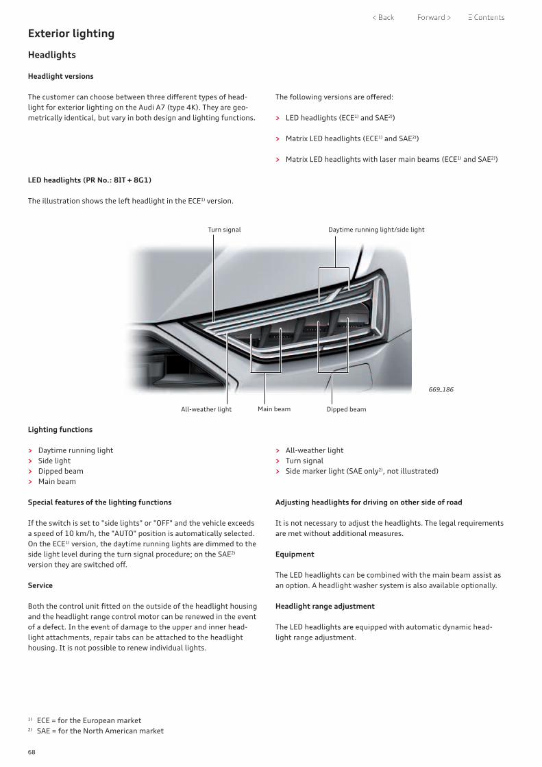
68
Exterior lighting
Headlights
Headlight versions
The customer can choose between three different types of head-light for exterior lighting on the Audi A7 (type 4K). They are geo-metrically identical, but vary in both design and lighting functions.
The following versions are offered:
> LED headlights (ECE1) and SAE2))
> Matrix LED headlights (ECE1) and SAE2))
> Matrix LED headlights with laser main beams (ECE1) and SAE2))
LED headlights (PR No.: 8IT + 8G1)
The illustration shows the left headlight in the ECE1) version.
669_186
All-weather light
Turn signal Daytime running light/side light
Dipped beamMain beam
Lighting functions
> Daytime running light > Side light > Dipped beam > Main beam
> All-weather light > Turn signal > Side marker light (SAE only2), not illustrated)
Special features of the lighting functions
If the switch is set to "side lights" or "OFF" and the vehicle exceeds a speed of 10 km/h, the "AUTO" position is automatically selected. On the ECE1) version, the daytime running lights are dimmed to the side light level during the turn signal procedure; on the SAE2) version they are switched off.
Service
Both the control unit fitted on the outside of the headlight housing and the headlight range control motor can be renewed in the event of a defect. In the event of damage to the upper and inner head-light attachments, repair tabs can be attached to the headlight housing. It is not possible to renew individual lights.
Adjusting headlights for driving on other side of road
It is not necessary to adjust the headlights. The legal requirements are met without additional measures.
Equipment
The LED headlights can be combined with the main beam assist as an option. A headlight washer system is also available optionally. Headlight range adjustment
The LED headlights are equipped with automatic dynamic head-light range adjustment.
1) ECE = for the European market2) SAE = for the North American market

69
Matrix LED headlights (PR No.: 8IT + 8G5)
The illustration shows the left headlight in the ECE1) version.
669_187
All-weather light/turning light
Daytime running light/side light/turn signal Dipped beam
Matrix beam main beam
Main beam Main beam
Lighting functions
> Daytime running light > Side light > Dipped beam > Matrix beam main beam > All-weather light
> Turning light > Dynamic turn signal > Motorway light > Side marker light (SAE only2), not illustrated)
Special features of the lighting functions
If the switch is set to "side lights" or "OFF" and the vehicle exceeds a speed of 10 km/h, the "AUTO" position is automatically selected. On the ECE1) version, the daytime running lights and the side lights are switched off during the turn signal procedure. On the SAE2) version, the daytime running lights are switched off during the turn signal procedure, and the side lights are active in the turn signal dark phase and dimmed when the turn signals are active. Service
The control unit fitted on the outside of the headlight housing, the fan, and the output module for matrix headlight can be renewed in the event of a defect. Because the output module for matrix headlight is located inside the headlight, the ESD (electrostatic discharge) workplace VAS 6613 must be used if the module is renewed. It is not possible to renew individual lights.
Adjusting headlights for driving on other side of road
It is not necessary to adjust the headlights. The legal requirements are met without additional measures.
Equipment
The Audi A7 with matrix LED headlights is fitted with a headlight washer system as standard. Headlight range adjustment
The matrix LED headlights are equipped with automatic dynamic headlight range adjustment.

70
Matrix LED headlights with laser main beams (PR No.: 8IZ + 8G5)
The illustration shows the left headlight in the ECE1) version.
All-weather light/turning light
Daytime running light/side light/turn signal Dipped beam
Background light
Laser light
Main beam
Matrix beam main beam
Lighting functions:
> Daytime running light > Side light > Background light > Dipped beam > Matrix beam main beam > Laser light
> All-weather light > Turning light > Intersection light > Motorway light > Dynamic turn signal > Side marker light (SAE only2), not illustrated)
Special features of the lighting functions
If the switch is set to "side lights" or "OFF" and the vehicle exceeds a speed of 10 km/h, the "AUTO" position is automatically selected. On the ECE1) version, the daytime running lights and the side lights are switched off during the turn signal procedure. On the SAE2) version, the daytime running lights are switched off during the turn signal procedure.
The side lights are active in the turn signal dark phase and dimmed when the turn signals are active.The blue background light is activated together with the daytime running lights and the side lights but is switched off during the turn signal procedure.
1) ECE = for the European market2) SAE = for the North American market
669_188
Service
The control unit fitted on the outside of the headlight housing, both fans, and the output module for matrix headlight can be renewed in the event of a defect. Because the output module for matrix headlight is located inside the headlight, the ESD (electro-static discharge) workplace VAS 6613 must be used if the module is renewed. It is not possible to renew individual lights.
Headlight range adjustment
The matrix LED headlights with laser main beams are equipped with automatic dynamic headlight range adjustment.
Adjusting headlights for driving on other side of road
It is not necessary to adjust the headlights. The legal requirements are met without additional measures.
Equipment
The Audi A7 with matrix LED headlights with laser main beams is fitted with a headlight washer system as standard.

71
Light signature
This set of images shows the most important lighting functions of a set of matrix LED headlights with laser main beams. The illustrations show the lighting functions of a set of headlights in the ECE1) version.
After-sales service must check the lighting functions as they are shown here. The laser main beams cannot be operated when the vehicle is stationary. The function is considered to be OK if no corresponding entry is stored in the event memory.
669_189Daytime running lights
669_190Turn signals
669_191Dipped beams
669_192Main beams
669_193Main beams and laser main beams

72
Activation of matrix LED headlights with laser main beams
Illustration for left headlight
669_194
Rain and light sensorG397
Light switch E1
Onboard supply control unit J519
Driver assist systems control unitJ1121
Front camera for driver assist systemsR242
Output module 1 for left LED head-lightA31
Dipped beam
Matrix beam main beam
All-weather light
Turning light
Laser light
Daytime running light
Side light
Background light
Dynamic turn signal
Side marker light (SAE2))
Headlight range control
2 fans
Key:
Convenience CAN 2
FlexRay
Sub-bus systems
Activation
The onboard supply control unit J519 communicates with output module 1 for left/right LED headlight (A31/A27) via a sub-bus system. These output modules activate all lighting functions, the headlight range control motors and, on the matrix headlights, the fan(s).
The control units are capable of self-diagnosis and can be accessed via diagnostic addresses 00D6/00D7. The illustration shows an example of the communication paths and the components involved. The activation process inside the head-light is not relevant for repairs and therefore not shown specifi-cally.
Main beam assist
Together with the front camera for driver assist systems R242, the driver assist systems control unit J1121 is responsible for the main beam assist function. If the camera detects oncoming vehicles or vehicles ahead, it passes this information on to the driver assist systems control unit J1121.
J1121 calculates which LEDs in the matrix headlights need to be switched off to avoid dazzling other road users. This information is sent to the output modules via the sub-bus system. On the LED headlights, only two conditions are possible: "main beams on" or "main beams off".
LVDS
LIN bus
Front left headlight MX1
2) SAE = for the North American market

73
H: +26´V
H
Calibrating matrix 2.0
Calibration of the matrix headlights is always required after the following work:
> Headlight position was changed (removed/installed, securing bolts loosened).
> Headlights were adjusted. > Running gear control unit J775 was recalibrated or renewed. > Driver assist systems control unit J1121 was replaced.
> Rear left vehicle level sender G76, rear right vehicle level sender G77, front left vehicle level sender G78 or front right vehicle level sender G289 has been renewed.
> The event memory contains the entry "No or incorrect basic setting / adaption".
Aligning reference segment
As with the first generation of the matrix LED headlight, the reference segment is measured using the headlight adjustment unit VAS 621 001 as the first step of the calibration process. The deviation value is then sent to the driver assist systems control unit J1121 with the help of the vehicle diagnostic tester. The yellow line on the image shows which edge the reference segment is being aligned to. In this example, a horizontal deviation of +26 minutes has been determined.
The matrix LED headlights on the Audi A7 (type 4K), as on the Audi A8 (type 4N), are two-row matrix headlights. When the dipped beams are adjusted, the height of the matrix beam main beam module is also corrected due to the inner layout of the headlight. When the matrix beam main beams are then calibrated, it is sufficient to determine the horizontal deviation of the refer-ence segment.
669_195
The illustration shows the reference segment of the left matrix LED headlight
NoteUp-to-date service literature must be used for all checking, repair and adjustment work.

74
Tail lights
General description
The tail lights on the Audi A7 (type 4K) are in three sections; two tail lights at the left and right sides and a light unit which covers the entire width of the rear lid.
Left tail lightMX3
Right tail lightMX4
Centre rear tail light unit MX13
Versions
The tail lights appear in the following principal versions:
The tail light versions are geometrically identical. The design varies between the ECE1) and SAE2) versions. There are differences in the functions and the activation of the tail lights. The highest equip-ment version (PR no. 8SQ) is equipped with dynamic turn signals and dynamic tail lights.
1) ECE = for the European market2) SAE = for the North American market
In addition to the three tail lights, the Audi A7 also has a high-level brake light. Only LED lights are used.
669_196
On the dynamic tail lights, the LEDs are activated at different moments as part of the "coming/leaving home" function. This allows an impressive light pattern to be presented when the vehicle is opened or locked with the central locking system.
Activation
The tail lights are activated by the convenience system central control unit J393.On the 8SQ version, the tail lights are connected to J393 via a LIN data wire in addition to the discrete wires.On this tail light version, the dynamic turn signal and dynamic tail light commands are sent via the LIN data wire.
> LED tail lights (low) > LED tail lights (low) with dynamic turn signals > LED tail lights (high) with dynamic turn signals
and dynamic tail light
PR no.: 8SK (ECE1) only)PR no.: 8SP (SAE2) only)PR no.: 8SQ (ECE1) and SAE2))

75
Light signature
All lighting functions of the tail lights are shown in these images to provide an impression of how the rear lighting of the Audi A7 looks. They show the tail lights in the ECE1) version.
As can be seen in the two bottom images, the Audi A7 is equipped with two reversing lights but only one centrally located fog light.
669_197
Tail lights
669_198
Tail lights and hazard warning lights
669_199
Tail lights and brake lights
669_201
Tail lights and reversing lights
669_202
Tail lights and fog light

76
Interior lighting
Various interior lighting concepts are available on the Audi A7. Audi offers three different interior lighting systems in the new Audi A7 (type 4K).
> Basic interior lighting (PR no. QQ0) > Contour lighting package (PR no. QQ1) > Contour ambient lighting package (PR no. QQ2)
Both lighting packages set the interior cabin, space and materials in scene.
The ambient lighting package is used in the dash panel, the centre console and the doors.The quattro badge or the Audi rings (on front-wheel drive vehicles) are illuminated in the dash panel.
The contour lighting can be set to 30 different colours and can follow the colour profiles in the Audi drive select driving dynamics system.
Illuminated sill panel trim rounds off the interior lighting pro-gramme.
Illuminated bass loudspeakers on Bang & Olufsen Advanced Sound System with 3D sound
Surround lighting in all four door handles - standard on both lighting packages
Illuminated sill panel trim(standard with the design selec-tion and S line sports package)
669_056

77
The PR no. QQ0 is the basic equipment level. It features the following:
> In the headliner: Front roof module, rear interior lights, make-up mirrors in sun visors
> In dash panel and centre console: Front footwell lighting, glove box light, illuminated centre console storage compartment
> In the doors: Illuminated interior door handles, door exit lighting
In addition to the QQ0 equipment, the ambient lighting package (PR no. QQ1) also features:
> Ambient lighting in the dash panel (driver side, centre, passenger side)
> Door panel lighting in inside of doors > Door surround lighting integrated in all exterior door handles
The ambient lighting QQ1 consists of white LED modules.
Dash panel with QQ0 features
Storage compartment lighting Front footwell lighting Glove box lighting
669_048
Interior lighting systems
The Audi A7 has three different equipment levels for interior lighting.
Basic interior lighting (PR no. QQ0) Contour lighting package (PR no. QQ1)

78
In addition to the equipment in the QQ1 package, the multi-coloured contour ambient lighting package (PR no. QQ2) also features:
> Illuminated door pockets front/rear > Contour lighting for front/rear doors > Ambient door panel lighting for front/rear doors > Ambient lighting for front centre console > Contour lighting for front centre console > Contour lighting with illuminated quattro badge or illuminated
Audi rings (on front-wheel drive vehicles) in the dash panel on the passenger side
> Ambient lighting in dash panel
The colour of all lighting exclusive to QQ2 can be adjusted. This is done separately for contour and ambient lighting.
On the Audi A7, the door pocket lighting can again be changed, but does not have capacitive sensor control.
Door trim with QQ2 features
Contour lighting
Inner door lighting
Door panel lighting
Door pocket lighting
Exit lighting
Contour lighting: "quattro" badge or Audi rings
Ambient lighting for dash panel
Dash panel with QQ2 features
669_049
669_050
Contour ambient lighting package (PR no. QQ2)
Ambient lighting for dash panel (driver side)
Storage compartment lighting
Ambient lighting for centre console
Contour lighting for centre console

79
Contour lighting: "quattro" badge or Audi rings
Ambient lighting for dash panel
> Exit warning system > On all four doors. > In a situation evaluated as potentially dangerous, the LEDs
light up in red. In addition, the LEDs for the lane change warning assist system in the relevant exterior mirror are activated.
> The exit warning system remains ready to give warnings for approximately three minutes after the ignition is switched off.
> Illuminated bass loudspeakers > White light accents also shine from the bass loudspeakers in
the doors if the Bang & Olufsen Advanced Sound System with 3D sound is on board.
> Luggage compartment lighting > Two LED light strips are used to illuminate the luggage
compartment on the Audi A7.
669_051
669_052
669_053
Light strip for exit warning system
Illumination for bass loudspeakers
Luggage compartment lighting (fitted on both sides of luggage compartment)

80
Overview
Back massage
Fragrance diffuser system
As with the Audi A8 (type 4N), the fragrance diffuser system with two different fragrance types is offered for the Audi A7 (type 4K). The fragrances are kept in cylindrical vials in the function unit for fragrance diffuser system GX43. A small blower guides the fra-grance from the vial into the outer front air outlets. In addition to the fragrance type, four levels of intensity can be selected.
Air ionisation system
An air ionisation system is used in the Audi A7 (type 4K) to improve the air quality. The air ionisation system works by negatively charging air particles to a limited extent. They are distributed in the vehicle interior via the side and front air outlets. These anions attract dust and similar very small particles. As a result, the air in the vehicle interior is cleaner.
A back massage function is offered for the front seats of the Audi A7 (type 4K).
A large number of new technical features appeared on the Audi A8 (type 4N) and are now making their way into the Audi A7 (type 4K). This self-study programme will give you an overview of the air conditioning systems in the Audi A7 (type 4K). For precise informa-tion about fitting locations and functions along with images and information on the new R744 refrigerant, please refer to self-study
programme 665; Audi A8 (type 4N) "New features of the air conditioning system and introduction of refrigerant R744". The Audi A7 (type 4K) has, in addition to the newly introduced fra-grance diffuser and air ionisation system, a 2-zone, a 3-zone and a 4-zone air conditioner. Depending on the equipment version, different operating units may be used in the rear cabin.
> Wave > Circles > Stretch > Rest
> Shoulder > Activation > Revitalisation
The following seven massage programmes can be selected.
Activation and revitalisation are the newest massage programmes; they were introduced in the Audi A8 (type 4N).
669_200
Air conditioning

81
Air conditioner controls in front of vehicle
Overview of MMI display (air conditioner operation)
669_046
The MMI display can be used, depending on the equipment fitted,to select the following functions and their settings:
> Ionisation > Perfume > Steering wheel heating
As was already the case with the Audi A8 (type 4N), there is no longer a Climatronic control unit J255 on the Audi A7 (type 4K). There is therefore no longer a separate air conditioner control unit. The system is operated via two touch displays. The air conditioner controls are now implemented in the onboard supply control unit J519. The communication between the onboard supply control unit J519 and the air conditioner components involved is achieved via the LIN bus system.The main new feature regarding the look and feel of the operation are the two displays. The upper MMI display and the lower touch display are both fitted centrally in the dash panel and the centre console. The air conditioner functions in the top MMI display can be accessed via the car menu.
> Synchronisation for driver/passenger side > Air conditioning for rear passengers/for rear > Auxiliary air conditioning > Air conditioning (A/C MAX, A/C OFF, A/C eco)
Air conditioner controls in rear of vehicle
Depending on the equipment version, two different operating units may be available in the rear.
> 2-zone air conditioning: No rear operating unit (only a knurled wheel to open and close the vents)
> 3-zone air conditioning: Rear operating unit with digital temperature display and buttons for seat heating
> 4-zone air conditioning: Rear touch operating unit including air conditioner regulation and seat heating, permanently fitted in the centre console
Car · A/C
3-zone air conditioning
The operating and display unit for rear air conditioning system E265 is offered as the operating unit in the rear.The seat heating can be set on this operating unit in addition to the temperature and the blower speed.
669_114
4-zone air conditioning
The optional operating and display unit for rear air conditioning system E265 is equipped with a sensory surface. It can therefore be operated by touch.
The following settings can be made:
669_115
> Automatic A/C > A/C on/off > Seat heating
> Temperature > Blower speed > Air distribution

82
Passive safety
Depending on country version and vehicle equipment, the passive occupant and pedestrian protection system in the Audi A7 (type 4K) may be comprised of the following components:
> Airbag control unit > Adaptive driver airbag > Adaptive passenger airbag
(two-stage passenger airbag) > Front side airbags > Side airbags for seat row 2 > Curtain airbags > Knee airbags > Crash sensors for front airbags > Crash sensors for side impact detection in doors > Crash sensors for side impact detection in C-pillars > Crash sensor for pedestrian protection system (centre)
(acceleration sensor) > Crash sensors for pedestrian protection system (left and right)
(pressure sensors) > Front belt retractors with pyrotechnic belt tensioners > Front belt retractors with electric belt tensioners
Airbags in vehicle
Passenger airbag
Driver airbag
Front side airbag
The following pages provide an overview of the occupant protec-tion system in the Audi A7 (type 4K).
> Front belt retractors with switchable belt force limiters > Belt retractors for seat row 2 with pyrotechnic belt tensioners
for driver and passenger side > Belt retractors for seat row 2 with electric belt tensioners for
driver and passenger side > Front lap belt tensioners for driver and passenger sides > Seat belt warning for all seats > Seat-occupied recognition system in passenger seat > Seat-occupied recognition system for seat row 2 > Key-operated switch to deactivate airbag on front passenger
side > Front passenger airbag warning lamp (OFF and ON) > Seat position detection for driver and passenger > Trigger for pedestrian protection system > Battery isolator, 12 Volt electrical system > Battery isolator, 48 Volt sub-system > Battery isolator, high-voltage system
Components
Knee airbag (driver side)
Knee airbag (passenger side)
Safety and driver assist systems
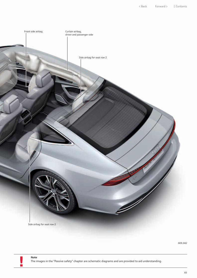
83
NoteThe images in the "Passive safety" chapter are schematic diagrams and are provided to aid understanding.
669_042
Front side airbag Curtain airbag,driver and passenger side
Side airbag for seat row 2
Side airbag for seat row 2

84
669_043
The system overview shows components which depend on the market and the vehicle equipment.
System overview

85
Equipment may vary due to the different demands and legal requirements that are made of vehicle manufacturers in the markets.
Key to diagram on page 84:
E24 Driver side belt switchE25 Front passenger side belt switchE224 Key operated switch to deactivate airbag on front pas-
senger side
F390 Belt switch for seat row 2, driver sideF391 Belt switch for seat row 2, middleF392 Belt switch for seat row 2, passenger side
G128 Seat occupied sensor, front passenger sideG177 Rear seat occupied sensor on driver sideG178 Rear seat occupied sensor on passenger sideG179 Side airbag crash sensor on driver sideG180 Side airbag crash sensor on front passenger sideG256 Rear side airbag crash sensor on driver sideG257 Rear side airbag crash sensor on passenger sideG283 Front airbag crash sensor for driver sideG284 Front airbag crash sensor for front passenger sideG551 Driver side belt force limiterG552 Front passenger side belt force limiterG553 Driver side seat position sensorG554 Front passenger side seat position sensorG598 Trigger 1 for pedestrian protectionG599 Trigger 2 for pedestrian protectionG693 Centre crash sensor for pedestrian protectionG851 Driver side crash sensor 2 for pedestrian protectionG852 Front passenger side crash sensor 2 for pedestrian pro-
tectionG1010 Rear seat occupied sensor, centre
J234 Airbag control unitJ285 Control unit in dash panel insertJ519 Onboard supply control unitJ528 Roof electronics control unitJ533 Data bus diagnostic interface (gateway)J706 Seat occupied recognition control unitJ854 Control unit for front left belt tensionerJ855 Control unit for front right belt tensioner
Wiring colours:
Diagnostics CAN
Dash panel insert CAN
Sub-bus system
Input signal
Output signal
FlexRay
LIN bus
Convenience CAN 2
Connection for seat occupied sensor, front passenger side G128
The connection for the seat occupied sensor, front passenger side G128 varies depending on market version.
1) Vehicles for the North American region (NAR):The seat occupied sensor, front passenger side G128 is connected to the seat occupied recognition control unit J706 via a discrete wire. The control unit communicates with the airbag control unit J234 via a LIN bus wire.
2) Vehicles for rest of world (ROW):The seat occupied sensor, front passenger side G128 is connected directly to the airbag control unit J234 via a discrete wire. A seat occupied recognition control unit J706 is not fitted.
J1097 Control unit for rear left belt tensionerJ1098 Control unit for rear right belt tensioner
K19 Seat belt warning system warning lampK75 Airbag warning lampK145 Warning lamp for airbag deactivated on front passenger
side (both ON and OFF status of passenger airbag is indi-cated)
N95 Airbag igniter on driver sideN131 Airbag igniter 1 on front passenger sideN132 Airbag igniter 2 on front passenger sideN153 Driver seat belt tensioner igniter 1N154 Front passenger seat belt tensioner igniter 1N196 Rear belt tensioner igniter on driver sideN197 Rear belt tensioner igniter on passenger sideN199 Side airbag igniter on driver sideN200 Side airbag igniter on front passenger sideN201 Rear side airbag igniter on driver sideN202 Rear side airbag igniter on passenger sideN251 Driver side curtain airbag igniterN252 Front passenger side curtain airbag igniterN253 Battery isolation igniterN295 Driver side knee airbag igniterN296 Front passenger side knee airbag igniterN297 Igniter for driver side seat belt tensioner 2 (lap belt ten-
sioner)N297 Igniter for front passenger side seat belt tensioner 2 (lap
belt tensioner)N490 Igniter for exhaust valve for driver airbagN491 Igniter for exhaust valve for front passenger airbagN563 High-voltage battery isolation igniterN751 Battery isolation igniter, 48 V
T16 16-pin connector, diagnostic connection
Additional equipment

86
Airbag control unit J234
The airbag control unit J234 fitted in the Audi A7 (type 4K) is based on the same control unit generation used in the Audi A8 (type 4N). The features and the setup of the airbag control unit J234 have been adapted to suit the Audi A7. For details of the equipment specification, refer to the system overview on page 84.
Be it Audi pre sense basic, pre sense rear, pre sense side, pre sense front or the Audi pre sense swerve assist or turn-off assist: The Audi A7 has the same pre sense functions as the Audi A8 (type 4N). The components have of course been adapted to suit the Audi A7 (type 4K).
669_044
Airbag control unit
Audi pre sense
Active safety
ReferenceFor further information on the airbag control unit J234 and Audi pre sense, please refer to self-study programme 662 "Audi A8 (type 4N)".
Intervention display
669_045

87
Sensors
Seat occupied sensor
Depending on the market, seat occupied sensors may also be fitted on the rear seats of the Audi A7 (type 4K).
Fitting location
The seat occupied sensors on the outer rear seats consist of pres-sure sensors. The sensors are clipped into the wire frame of the seat bench. The rear centre sensor is a foil sensor and is bonded onto the seat padding.
The seat occupied sensors for the rear seats have the following designations:
> Rear seat occupied sensor on driver side G177 > Rear seat occupied sensor on passenger side G178 > Rear seat occupied sensor, centre G1010
669_123
Rear seat occupied sensor on passenger side G178
Rear seat occupied sensor, centreG1010
Rear seat occupied sensor on driver side G177

88
Seat belt warning system with rear seat occupied sensors
In addition to the seat occupied sensor, front passenger side G128, the rear seat occupied sensors, the latch plates of the automatic belt retractors, the belt buckles, the airbag control unit J234 and the instrument cluster are all part of the seat belt warning system.
Diagnosis
The rear seat occupied sensors and the seat belt buckles are diagnosed via the airbag control unit J234. The control unit can diagnose the event "short circuit after earth" if the seat belt is not buckled.
The rear belt buckles can be in the following switch positions:
Seat belt not buckled Switch closed Resistance almost zero
Seat belt buckled Switch open Resistance almost infinite
The following statuses are therefore possible: > Seat not occupied and seat belt not buckled: In this case, the
airbag control unit detects approx. 400 Ω. > Seat occupied and seat belt not buckled: In this case, the airbag
control unit detects approx. 100 Ω.
The rear seat occupied sensors can be in the following switch positions:
Seat occupied Switch actuated Resistance approx. 100 Ω
Seat unoccupied Switch not actuated Resistance approx. 400 Ω
The rear seat occupied sensors are connected in series to the corresponding belt buckles.
> Seat occupied and seat belt buckled: In this case, the airbag control unit detects an almost infinite resistance.
> Seat unoccupied and seat belt buckled: In this case, the airbag control unit detects an almost infinite resistance.

89
The airbag control unit J234 evaluates the status of the seat belt buckles and the seat occupied sensors (connected in series) for the seat belt warning system. At approx. 100 Ω, the airbag control unit triggers the activation of the optical and acoustic seat belt warning in the instrument cluster. The acoustic seat belt warning depends on the speed and only starts at > 25 km/h.The acoustic warning concept and the optical display concept for the front seat belt warning system has been used for the rear seats.
Optical and acoustic seat belt warning with rear seat occupied sensors
In addition to the seat belt warning system warning lamp K19, the occupied status of the rear seats is also displayed via the familiar additional seat symbols. The additional symbols are only displayed if at least one of the rear seats is occupied and the corresponding seat belt is not buckled.
In some markets, no rear seat occupied sensors are fitted. This does not change the seat belt warning system process.
ReferenceFor further information on the seat occupied sensor, please refer to self-study programmes SSP 609 "Audi A3 ‘13", SSP 644 "Audi A4 (type 8W)" and the Service TV programme STV_0397_Audi TT - Seat belt warning system/seat occupied sensor".
Seat belt warning system warning lamp K19There is at least one seat occupant who is not wearing a seat belt.
Seat occupied and seat belt buckled and seat unoccupied and seat belt buckled
Seat not occupied and seat belt not buckled Seat occupied and seat belt not buckled
Warning lamps for seat belt warning system
669_082
Key:
Optical and acoustic seat belt warning without rear seat occupied sensors

90
Driver assist systems
Introduction
What the Audi A7 (type 4K) can offer in driver assist systems is pretty impressive! The Audi A7 (type 4K) offers the same range of driver assist systems as the Audi A8 (type 4N). A wider range of driver assist systems has never been offered in any other Audi model.
The introduction to this topic includes short descriptions of the five most important innovations in the Audi A7 (type 4K). All of these innovations made their début in the Audi A8 (type 4N), which was
introduced at the end of 2017. They have now all been introduced for the Audi A7 (type 4K). The innovations concern new hardware which continues to pave the way for autonomous driving, a new and innovative operating concept and new driver assist systems.
Further information on all the new features can be found on the following pages and more detailed information is available in self-study programme 668 "Audi A8 (type 4N) - Driver assistance systems".
Top driver assist system innovations in the Audi A7 (type 4K)
Driver assist systems control unit J1121
The J1121 control unit is the first step towards reducing the number of control units for driver assist systems. With an eye on the major vision of autonomous driving, Audi is gradually moving away from a decentralised approach with several individual control units to an approach with a powerful central computer. There are four versions of the J1121 control unit for the launch of the Audi A7 (type 4K). The version installed depends on the driver assist systems in the vehicle.
Control unit for laser distance control J1122
The Audi A7 (type 4K) is no longer fitted with two long range radar sensors to implement the longitudinal regulation functions of the adaptive cruise assist. They are replaced with a combination of a radar sensor and a laser scanner. The laser scanner is fitted at the front of the vehicle, has a scanning angle of approx 145° and can detect objects up to 80 m away. A significant strength of the laser scanner is that its measurement precision is not dependent on how far away an object is.
Profile master for driver assist systems
The profile master is a new operating concept that specifies the activation conditions for the different driver assist systems. A total of eight driver assist systems participate in the profile master system. The customer can choose between three profiles: maximum, individual and basic. The maximum setting switches all participating systems on. With the individual setting, the customer decides which systems to activate and with basic, a maximum of two permanently specified systems are switched on.
Intersection assist
The intersection assist helps the driver to avoid collisions with road users crossing the vehicle’s path. The intersection assist works between speeds of 0 km/h to 30 km/h. However, a brake applica-tion is only made at speeds of up to 10 km/h. The intersection assist is very similar to the rear cross-traffic assist. The main difference is that the intersection assist performs its task in front of and not behind the vehicle.
Lane departure warning and adaptive cruise assist
The two "new" assist systems in the Audi A7 (type 4K) ("lane departure warning" and "adaptive cruise assist") have been made from the existing Audi adaptive cruise control, Audi active lane assist and traffic jam assist systems. The lane departure warning warns the driver if there is a risk of inadvertently leaving the current lane. However, the adaptive cruise assist offers the cus-tomer combined longitudinal and lateral guidance for the vehicle at speeds between 0 km/h and 250 km/h.

91
Driver assist systems control unit J1121
Introduction
The Audi A7 (type 4K) is the second Audi model in which the driver assist systems control unit J1121 is fitted; the first was the Audi A8 (type 4N). In contrast to the Audi A8 (type 4N), the J1121 control unit in the Audi A7 (type 4K) is not standard equipment worldwide. In the Euro NCAP countries, Canada, the USA, and China, every Audi A7 (type 4K) will have a J1121 control unit. This is because Audi pre sense front, which requires a J1121 control unit for its functions, has been specified as standard equipment in these markets.
The J1121 control unit is the first step towards centralising the control units for driver assist systems. With an eye on the major vision of autonomous driving, Audi is gradually moving away from a decentralised approach with several individual control units to an approach with a powerful central control unit.
With the introduction of the J1121 control unit, the front camera for driver assist systems R242 has lost its status as the master control unit for various driver assist systems. In the Audi A7 (type 4K), the front camera still captures the area in front of the vehicle. However, the images from the camera are processed in the J1121 control unit. This control unit is now the master control unit for all driver assist systems for which calculations were previously performed in the front camera R242.
These include the following driver assist systems:
> Main beam assist > Camera-based traffic sign recognition > Lateral vehicle guidance (lane departure warning and lane
guidance by the adaptive cruise assist) > Emergency assist
The J1121 control unit remains the master control unit for the following driver assist systems:
> Surround view cameras (there is no longer a separate control unit for overhead view camera J928)
> Intersection assist (introduced in the Audi A8 (type 4N))
669_091
The J1121 control unit has two common designations. The first designation is "driver assist systems control unit J1121". This is used in the service literature and is part of the "master list". The second designation is zFAS control unit. This comes from technical
development and has established itself in general usage. zFAS is the abbreviation of the German term for "driver assist systems central control unit" (zentrales Steuergerät für Fahrerassistenz-systeme).

92
Versions of the J1121 control unit
As with the launch of the Audi A8 (type 4N), there are four differ-ent versions of the J1121 control unit for the launch of the Audi A7 (type 4K). The precise control unit version fitted depends on which
driver assist systems are chosen by the customer when the vehicle is configured.
669_092 669_093Control unit version A/A0 Control unit version C/D
The J1121 control unit in the Audi A7 (type 4K) has the same part number as the J1121 control unit in the Audi A8 (type 4N):
Allocation table for driver assist systems — Control unit version
The following table shows which version of the control unit is required (at least) by the different driver assist systems. The lowest version of the control unit is A0, the highest at the launch of the Audi A7 (type 4K) is version C. The higher versions are always backward-compatible, meaning that, for example, version C is also suitable for all assist systems with an X in the columns for A0, A and B.
The following table includes a fifth version of the J1121 control unit. This is version D, which also includes the software for the
traffic jam pilot. The traffic jam pilot will be introduced at a later date.
There are still four park assist systems in the bottom lines of the table; these will be part of the future assist package for parking. They are planned for introduction in 2018. These park assist systems are marked in a different colour because, unlike the assist systems above them, they are not already available at the launch of the Audi A7 (type 4K).
4N0.907.107. The control unit versions can only be differentiated by the index letters following the part number.

93
Control unit version zFAS not required
Version A0
Version A
Version B
Version C
Version D
Parking system plus X
Reversing camera X
Park assist X
Lane change warning X
Exit warning system X
Rear cross-traffic assist X
Night vision assist X
Lane departure warning X
Main beam assist X
Emergency assist X
Camera-basedtraffic sign recognition
X
Intersection assist X
Adaptive cruise assist X
Surround view cameras X
Kerb warning X
Manoeuvre assist X
Parking pilot X
Garage pilot X
Traffic jam pilot X
Allocation table for driver assist systems regarding control unit versions of J1121 control unit

94
Calling up the profile master for driver assist systems
The customer can call up the profile master for driver assist systems in two different ways:
> By selecting the basic function "Car" and then "Driver assist systems" after pressing the home button.
> By pressing the profile master button, which is located in a row of buttons in the centre console.
The profile master disappears from the display again after 5 seconds if the second method is used and if no touch input was detected on the upper touch display in that time. Profile master button 669_095
Profile master for driver assist systems
A new operating concept for switching the different driver assist systems on and off was introduced for the first time in the Audi A8 (type 4N): the profile master for driver assist systems.The aim when the concept was under development was not to increase the number of controls, but to reduce it. This is intended to keep the operation of the various driver assist systems simple for the customer, despite the increasing number of systems. The profile master is now being introduced in the Audi A7 (type 4K).
Some of the driver assist systems offered in the Audi A7 (type 4K) can be switched on and off in the profile master for driver assist systems. Other driver assist systems which the driver switches on and off specifically while the vehicle is moving continue to use the classic controls. These include, for example, the parking aid, the park assist and the adaptive cruise assist.
Overview of all driver assist systems participating in the profile master system
> Lane change warning > Emergency assist > Rest recommendation > Exit warning system
> Night vision assist > Distance warning > Intersection assist > Audi pre sense
The three profiles for the profile master for driver assist systems
> Maximum: All systems in the vehicle participating in the profile master system are switched on.
> Individual: The customer can specify which individual driver assist systems are switched on.
> Basic: Only two systems are switched on: Audi pre sense and the emergency assist. If neither system is fitted, the "Basic" profile is replaced with the "All off" profile.
This sprocket symbol allows all the driver assist systems fitted in the vehicle to be configured. This does not apply to the systems participating in the profile master system.
669_094
Car Driver assist

95
Lane departure warning
Description of function
The lane departure warning on the Audi A7 (type 4K) is an inde-pendent system. It was first introduced in the Audi A8 (type 4N). This function was previously known as Audi active lane assist with the steering input set to "late". As the lane departure warning is considered to be an active safety system, it is fitted as standard in the Euro NCAP countries and thereby plays a part in achieving the 5 star rating in this area. In other countries, it is offered as optional equipment.
The lane departure warning warns the driver if the vehicle is at risk of leaving its current lane without switching on the corresponding turn signal. If the turn signal is not activated, the system assumes that the driver does not intend to leave the lane.
The lane departure warning can be given in three different ways:
> By steering input from the system towards the middle of the lane
> By a steering wheel vibration (this warning can be switched off on the MMI)
> By colouring the lane demarcation line red in the function displays
The lane departure warning is switched on and off via a virtual button on the lower touch display. If the lane departure warning is switched off, this can be seen via a red bar above the function’s symbol. If the lane departure warning is switched off, this only ever applies for one terminal 15 cycle. It is active again the next time the ignition is switched on, regardless of whether it was on or off when the ignition was switched off.
669_097669_096
Lane departure warning switched on
Lane departure warning switched off
Lane departure warning - optical warning
In the two images below, the optical warning "vehicle is at risk of leaving the lane towards the right" is shown. The image below on the left shows the warning as it can be seen in the driver assist
view of the on-board computer; the image on the right shows how it appears in the speedometer.
669_099669_098
Master control unit
The master control unit for the lane departure warning is the driver assist systems control unit J1121. Version A0 of the J1121 control unit is sufficient for this function.
NoteThe steering assist button on the end of the turn signal lever is not relevant to the lane departure warning. It is only used to activate and deactivate the lane guidance system of the adaptive cruise assist.

96
Adaptive cruise assist
Description of function
The adaptive cruise assist was introduced for the first time in the Audi A8 (type 4N) and is now being offered with identical functions in the Audi A7 (type 4K). The adaptive cruise assist offers combined longitudinal and lateral guidance at speeds between 0 km/h and 250 km/h. Longitudinal guidance refers to accelerating and braking and lateral guidance refers to steering the vehicle. Because the longitudinal and lateral guidance has been merged in the adap-tive cruise assist, the driver assist systems "Audi adaptive cruise control (ACC)" and "Audi active lane assist (AALA)" can no longer be ordered for the Audi A7 (type 4K).
Restructuring of the longitudinal and side regulating systems
Audi has fundamentally restructured the functions of the Audi adaptive cruise control and the Audi active lane assist for the introduction of the new Audi C and D segment models. This has created the lane departure warning and the adaptive cruise assist.
The section of the Audi active lane assist with "early" steering input, the so-called "lane guidance", has been integrated into the adaptive cruise assist. The section with "late" steering input has become an independent system with the new designation "lane departure warning".
The lane guidance can be switched off on the adaptive cruise assist so that only longitudinal guidance remains active. If lane guidance is switched off, the vehicle behaves as it would previously have done when driving with adaptive cruise control. However, it is not possible to deactivate longitudinal guidance on the adaptive cruise assist when lane guidance is active at the same time.
This restructuring is shown by the diagram below. It is a compari-son of the systems in the Audi Q7 (type 4M) and Audi A4/A5 (type 8K) with those in the Audi A8 (type 4N) and Audi A6/A7 (type 4K).
669_100
System structure in Audi Q7 (type 4M) and Audi A4/A5 (type 8W)
System structure in Audi A8 (type 4N) and Audi A6/A7 (type 4K)
Audi adaptive cruise controlAudi active lane assist
Traffic jam assist
Adaptive cruise assistLane departure warning
IncludingPredictive efficiency assist
Steering input
Late Early

97
Displays and operation
There have been changes to the function symbols and displays for the vehicle side guidance systems. If lane guidance is active in the adaptive cruise assist, this is shown by green triangles on the left
and right of the vehicle. If two white triangles appear, lane guid-ance is switched on but not active. If no triangles are visible, lane guidance is switched off.
669_102669_101
The adaptive cruise assist is activated via the operating lever previously used for ACC. This operating lever can be used to set the desired speed and distance, as with ACC.
669_104669_103
ACC operating lever Turn signal lever with steering assist button.
The steering assist button on the end of the turn signal lever is only used to switch lane guidance on and off. The lane departure warning has received its own on/off button. This is located in the virtual row of buttons on the lower touch display.
Hardware and sensors
Both a long range radar sensor and a laser scanner are fitted on the Audi A7 (type 4K) to implement the longitudinal regulation func-tions of the adaptive cruise assist. The combination of two differ-ent types of sensor for the longitudinal regulation functions was
implemented for the first time in the Audi A8 (type 4N). Combin-ing the strengths of two types of sensor means that the longitudi-nal regulation functions perform better than they would if two sensors of the same type were used.
669_106669_105
Long range radar sensor Laser scanner
Master control unit
The master control unit assigned to the entire adaptive cruise assist function is the adaptive cruise control unit J428. However, the adaptive cruise assist’s basic functions (longitudinal and side regulating function) are implemented in different control units.
The master for longitudinal regulation functions is the adaptive cruise control unit J428 and the master for side regulation func-tions is the driver assist systems control unit J1121.

98
Radar sensor
On the Audi A7 (type 4K), a sensor unit is fitted at the front of the vehicle on the left side (as seen in direction of travel) at the same height as the Audi rings. As on the Audi A8 (type 4N), a 4th gen-eration radar system is used. As a result, the layout and functions of the system correspond to those of the Audi A8. This also applies to its servicing needs. The different installation position compared to the Audi A8 requires a corresponding adjustment when aligning the setting device as part of the adjustment process. However, the adjustment process itself is not affected. For design reasons, the sensor unit has been fitted with an additional trim cover which is optically similar to the radome of the laser scanner.
Laser scanner
The layout and functions of the laser scanner also correspond to those on the Audi A8 (type 4N). However, it also has a new installa-tion position on the Audi A7 (type 4K). The laser scanner is now on the right side (as seen in direction of travel) next to the Audi rings and symmetrical to the radar sensor. There are no significant differences to to the layout and functions of the laser scanner on the Audi A8. The servicing needs and adjustment process are identical. The changed position on the vehicle is taken into account via a corresponding adjustment to the alignment of the setting device.The washer jets are fitted above the laser scanner on the Audi A7 (type 4K) and not to the left and right of it as on the Audi A8.
669_087
669_088
669_089
Right adaptive cruise control sender G259 and adaptive cruise control unitJ428
Control unit for laser distance control J1122
New position of washer jets for laser scanner
ReferenceFor further information on the radar sensor and the laser scanner, please refer to self-study programme 668 "Audi A8 (type 4N) Driver assistance systems."

99
New lane guidance features
With the introduction of the adaptive cruise assist, the lane guid-ance is, for the first time, available to customers right up until the vehicle is stationary. This of course only applies if all the require-ments for the lane guidance have been met. With Audi active lane assist, it is only available at 65 km/h and above.Because of the lowering of the activation speed to 0 km/h, Audi endeavoured to find further objects/structures which could also be used to facilitate a lane guidance system. The Audi active lane assist only allowed lane guidance on the basis of road markings.
The following objects/structures can be used for lane guidance at low speeds:
> An Armco barrier following the course of the road. > A transition from the road to the area surrounding the road
which offers sufficient contrast. > A kerb following the course of the road. > Vehicle(s) ahead.
669_108669_107
Roads without a central reservation
The system still assumes that the road has two lanes if its width exceeds a defined minimum. If this is assumed, lane guidance can be implemented on the basis of the detected right lane marking and a virtual centre line. Calculating the progression of the virtual
centre line is the job of the J1121 control unit. As an alternative to the right lane marking, lane guidance can also, at lower speeds, be performed using one of the structures specified above.
669_109
New predictive efficiency assist features
The predictive efficiency assist was offered for the first time in 2015 in the Audi Q7 (type 4M). In the Audi Q7, it is a subordinate function to the Audi adaptive cruise control (ACC). It gives the option for the vehicle’s longitudinal guidance not only to regulate to a speed set by the driver, but also to adapt that speed automati-cally to the speed limits detected by the camera-based traffic sign recognition system. In addition, it is possible to adjust the vehicle’s speed for an upcoming corner as well as to reduce the vehicle’s speed before a roundabout which will then be driven through. The focus of the function is a predictive driving style focused on fuel saving via longitudinal regulation.
On the Audi A7 (type 4K), the predictive efficiency assist can also adjust the speed when the vehicle is approaching an intersection with stop signs and all other requirements for this have been met. In this case, the system automatically reduces the vehicle’s speed to 15 km/h. Continuing to brake the vehicle remains the responsi-bility of the driver. As with the adaptive cruise assist, the entire predictive efficiency assist function is a driver assist system. The driver alone remains responsible for controlling the vehicle at all times.

100
Camera-based traffic sign recognition
Description of function
The third generation of the camera-based traffic sign recognition introduced for the first time in the Audi A8 (type 4N) is offered for the Audi A7 (type 4K). Among other things, the 3rd generation differs from the 2nd generation in that it includes a no entry warning which helps the driver to avoid unintentionally driving the
wrong way down, for example, a motorway. This new function informs the driver of the current danger situation via the instru-ment cluster display. However, it is not actively included in the vehicle guidance function.
No entry warning
The no entry warning is activated if the camera-based traffic sign recognition’s image processing software detects one of the follow-ing two situations:
Situation 2: The vehicle passes a combination of a no entry sign and a round blue sign with a white arrow on the wrong side.
Situation 1: The vehicle passes a no entry sign on the left and right of the road it is currently travelling on.
669_110 669_111
669_112
An active no entry warning is ended if:
> the system detects a manoeuvre in which the vehicle turns around or
> reverse gear is engaged or
> traffic signs are detected to the left of the vehicle or on both sides of the road with applicable speed limits or no overtaking signs
Active no entry warning
Master control unit
The master control unit for the camera-based traffic sign recogni-tion is the driver assist systems control unit J1121. At least control unit version A is required for this system.
NoteDetecting a second no entry sign, as shown in the image, is not a requirement for activating the warning.

101
Emergency assist
Description of function
The emergency assist was introduced by Audi for the first time in the Audi Q2 in 2016. This emergency assist was enhanced in many areas for introduction in the Audi A8 (type 4N) and is now inte-grated in the driver assist systems control unit J1121. This version of the emergency assist is now being offered for the Audi A7 (type 4K).
The emergency assist is designed for situations in which the driver is affected by a medical emergency and is therefore no longer able to drive the vehicle.
The job of the emergency assist in this situation is to assume longitudinal and lateral guidance of the vehicle and then to brake the vehicle to a controlled stop in its lane. If the vehicle is approaching another road user too fast, the vehicle is braked more forcefully in an attempt to avoid an impending collision. If a collision can no longer be avoided, the system attempts to reduce the severity of the collision.
The emergency assist activates itself if the system does not detect any driver activity in a specified period of time. The driver activity is established from his/her steering behaviour and the longitudinal guidance the vehicle is receiving: active acceleration and braking.
When the emergency assist is active, a sequence of measures is set in motion in the vehicle. These have been implemented to protect the driver and to keep the risk of collision as low as possible.
The following measures are initiated during the braking procedure:
> Activation of the hazard warning lights to warn other road users.
> Full tensioning of the seat belt during the process of braking to a final standstill.
> Automatic closure of the windows and the panoramic sunroof.
Once the vehicle has come to a stop, the following measures are initiated.
> Transmission position "P" is selected > Vehicle doors are unlocked > Interior lighting is switched on > An emergency call is made
The second main job of the emergency assist is to take various measures to attempt to get an inactive driver to reassume the task of driving the vehicle. It could be the case that the driver is simply distracted and is no longer assuming the task of driving the vehicle as a result, even though he/she would have no problem doing so.
To do this, the system takes the following measures before and also during the braking procedure:
> Display of text notifications in the instrument cluster > Emitting acoustic signals > Giving a brake jolt > Giving a strong emergency brake jolt > Jerking the driver's seat belt > Muting the infotainment system’s audio output
If the driver is able to reassume the task of driving the vehicle, he/she can do so in the following ways:
> actively taking over the steering again or
> pressing the brake pedal or
> pressing the accelerator pedal
If the emergency assist detects that the driver is once again active, it deactivates itself and ends its longitudinal and lateral guidance. The emergency assist can be activated more than once in one terminal 15 cycle. This applies to both the Audi A7 (type 4K) and the Audi A8 but is one of the differences to the emergency assist in the Audi Q2.
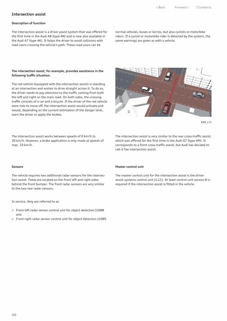
102
Intersection assist
Description of function
The intersection assist is a driver assist system that was offered for the first time in the Audi A8 (type 4N) and is now also available in the Audi A7 (type 4K). It helps the driver to avoid collisions with road users crossing the vehicle’s path. These road users can be
The intersection assist, for example, provides assistance in the following traffic situation:
The red vehicle (equipped with the intersection assist) is standing at an intersection and wishes to drive straight across it. To do so, the driver needs to pay attention to the traffic coming from both the left and right on the main road. On both sides, the crossing traffic consists of a car and a bicycle. If the driver of the red vehicle were now to move off, the intersection assist would activate and would, depending on the current estimation of the danger level, warn the driver or apply the brakes.
669_113
The intersection assist works between speeds of 0 km/h to 30 km/h. However, a brake application is only made at speeds of max. 10 km/h.
The intersection assist is very similar to the rear cross-traffic assist, which was offered for the first time in the Audi Q7 (type 4M). It corresponds to a front cross-traffic assist, but Audi has decided to call it the intersection assist.
Sensors
The vehicle requires two additional radar sensors for the intersec-tion assist. These are located on the front left and right sides behind the front bumper. The front radar sensors are very similar to the two rear radar sensors.
Master control unit
The master control unit for the intersection assist is the driver assist systems control unit J1121. At least control unit version B is required if the intersection assist is fitted in the vehicle.
In service, they are referred to as:
> Front left radar sensor control unit for object detection J1088 and
> Front right radar sensor control unit for object detection J1089.
normal vehicles, buses or lorries, but also cyclists or motorbike riders. If a cyclist or motorbike rider is detected by the system, the same warnings are given as with a vehicle.

103
Surround view cameras
As in the past, the surround view cameras are offered as optional equipment in the Audi A7 (type 4K). The surround view cameras are now in their third generation; this generation was introduced for the first time in the Audi A8 (type 4N).
The first two generations of the surround view cameras required a separate control unit; the control unit for overhead view camera J928. The software for the 3rd generation surround view camera function is now integrated in the driver assist systems control unit J1121 along with the software for other driver assist systems. The surround view cameras require a J1121 control unit of version C. All four surround view cameras transmit their images to the J1121 control unit via screened LVDS wires. The control unit then gener-ates the vehicle view desired by the customer from the camera images. The vehicle view is transmitted to the control unit 1 for information electronics J794 via two screened LVDS wiring pairs as a Full HD image. The image is shown on the upper touch display.
If the vehicle has both the parking system plus and the surround view cameras as optional equipment, 6th generation ultrasonic sensors are used to meet the requirements of the surround view camera system. The data from these ultrasonic sensors can only be read by the J1121 control unit (version C). In this case, the J1121 control unit is the master control unit for the surround view cameras and also the parking system plus.
If the vehicle has the parking system plus but not the surround view cameras as optional equipment, 5th generation ultrasonic sensors are used. The data from these can only be read by the onboard supply control unit J519. In this case, the onboard supply control unit J519 is the master control unit for the parking system plus. The customer can also order the park assist in this configura-tion. On the Audi A7 (type 4K), the master control unit for the park assist is always the onboard supply control unit J519.
Assist systems for parking Ultrasonic sensors Master control unit
Parking system plus
Park assist Reversing camera
Surround view cameras
5th genera-tion
6th genera-tion
Master control unit for systems
X - - - X - J519
X X - - X - J519
X - X - X - J519
X X X - X - J519
X - - X - X J1121
Possible combinations of different assist systems for parking at the launch of the Audi A7 (type 4K).
The installation positions of the surround view camera in the exterior mirrors have been changed to extend their range. They are located further outwards in the exterior mirrors of the Audi A7 (type 4K) and no longer "look" vertically downwards, but are tilted outwards. This allows the side detection area to be enlarged, which allows the area around the vehicle to be detected better.
With the third generation of the surround view cameras, two more two dimensional vehicle views are available:
> simultaneous view of the front left and front right wheels and
> simultaneous view of the rear left and rear right wheels
A three dimensional view of the vehicle is available to customers for the first time with the third generation surround view cameras.The viewing angle of the vehicle is not specified by the system, but can be freely chosen by the customer via the touchscreen. It is still possible to choose between three different preset viewing angles via three virtual buttons in the row of buttons.

104
Introduction and overview of versions
The Audi A7 (type 4K) features the MIB2+ version of the modular infotainment matrix infotainment system. Customers can choose between three MMI versions:MMI radio plus, MMI navigation and MMI navigation plus.
All three versions are based on the 2+ High version of the modular infotainment matrix; MIB2+ High for short.
The MMI navigation and MMI navigation plus versions may be equipped with Audi connect, depending on the country. However, they differ regarding the services available.The licence period is three years after the vehicle’s first registra-tion. It can be renewed after this time has elapsed.
Depending on the country, the following Audi connect infotain-ment services may be available with MMI navigation:
> Navigation data update (4 times per year online or via SD card via myAudi portal)
> Online routing > Individual news > Online traffic information > Twitter > Weather > Fuel prices > Parking information > Travel information > Destination entry via myAudi app
MMI navigation plus may, depending on the country, have the following additional Audi connect infotainment services:
> Connected radio (no licence period limits, but separate data package required)
> Google Earth > Google POI search via speech control > 3D city models > Messages (text message dictation) and e-mail > Traffic sign information > Hazard alerts
If the vehicle is equipped with Audi connect vehicle-related serv-ices (IW3), the following services may be available, depending on the country:
> Audi emergency call (licence period: 10 years) > Online roadside assistance (licence period: 10 years) > Audi service request (licence period: 10 years) > Vehicle status report (e.g. Mileage, fuel tank level, etc.)
(licence period: 3 years) > Remote locking/unlocking (licence period: 3 years) > Parking position (licence period: 3 years)
1) EL0 for markets without Audi connect2) IT1 means a three-year Audi connect licence without an Audi connect SIM card IT3 means a three-year Audi connect licence with an Audi connect SIM card3) Depending on country, emergency call only (IW1) or emergency call and service (IW3)4) The Audi connect data module becomes a full telephone module with SAP5) For markets in which no storage compartment with interface for mobile telephone (smartphone connection
to exterior aerial) is offered6) If digital radio (QV3) and TV tuner (QV1) are ordered together, the PR no. is QU1. If digital radio (QV3) and TV tuner with CI card reader (Q0A) are ordered together, the PR no. is Q0B.7) IW3 compulsory/licence period: 3 years8) Convenience key compulsory (4F2/4I3)9) IW3 compulsory/licence period: 1 year
ReferenceFor further information on MIB2+, please refer to self-study programme 666 "Audi A8 (type 4N) - Infotainment and Audi connect" and Audi Training Online.
Infotainment and Audi connect

105
MMI radio plus (I8E + 7Q0)
MMI navigation (I8V + 7UG)
MMI navigation plus (I8T + 7UG)
8.8" touch display with 1280 x 720 pixels
8.8" touch display with 1280 x 720 pixels
10.1" touch display with 1540 x 720 pixels
8.6" touch display with 1280 x 660 pixels
8.6" touch display with 1280 x 660 pixels
8.6" touch display with 1280 x 660 pixels
3D navigation system on SSD (7UG) 3D navigation system on SSD (7UG)
7" display in instrument cluster with driver information system (9S7)
7" display in instrument cluster with driver information system (9S7)
Audi virtual cockpit (9S8)
AM/FM radio AM/FM radio AM/FM radio Connected radio (Internet radio)
Satellite radio for North America (Sirius) (QV3)
Audi music interface with 2 USB sockets and 1 SDXC card reader (UF7)
Audi music interface with 2 USB sockets, 1 SDXC card reader and, depending on country, 1 SIM card reader (UF7)
Audi music interface with 2 USB sockets, 1 SDXC card reader and, depending on country, 1 SIM card reader (UF7)
Basic sound system (8RM) Basic sound system (8RM) Audi sound system (9VD)
Bluetooth interface (9ZX) Bluetooth interface (9ZX) Bluetooth interface (9ZX)
UMTS/LTE data module (EL3)1) including Audi connect (IT1/IT3)2)
UMTS/LTE data module (EL3)1) including Audi connect (IT1/IT3)2)
Emergency call & Audi connect vehicle-related services (IW3)3)
Emergency call & Audi connect vehicle-related services (IW3)3)
Emergency call & Audi connect vehicle-related services (IW3)3)
Optional equipment
Single DVD drive (7D5) Single DVD drive (7D5) Single DVD drive (7D5)
Audi music interface in rear with 2 USB sockets (UF8)
Audi music interface in rear with 2 USB sockets (UF8)
Audi music interface in rear with 2 USB sockets (UF8)
Audi smartphone interface (IU1) Audi smartphone interface (IU1)
Audi phone box including wireless charging (9ZE)
Audi phone box including wireless charging (9ZE)
Audi phone box including wireless charging (9ZE)4)
Audi phone box light (for wireless charging only) (9ZV)5)
Audi phone box light (for wireless charg-ing only) (9ZV)5)
Audi phone box, light (for wireless charging only) (9ZV)4), 5)
Audi sound system (9VD) Audi sound system (9VD)
Bang & Olufsen Premium Sound System with 3D sound (9VS)
Bang & Olufsen Premium Sound System with 3D sound (9VS)
Bang & Olufsen Advanced Sound System with 3D sound (8RF)
Bang & Olufsen Advanced Sound System with 3D sound (8RF)
DAB digital radio (QV3) DAB digital radio (QV3) DAB digital radio (QV3)6)
TV tuner (QV1/Q0A)6)
Audi connect key (2F1)7, 8)
Audi vehicle tracking system (7I1/with driver card 7I2)9)
Vehicle tracking system notification (7AL)7)
Vehicle tracking system notification (7AL)7)
Vehicle tracking system notification (7AL)7)
Preparation for Rear Seat Entertain-ment (9WQ)
Preparation for Rear Seat Entertainment (9WQ)
Preparation for Rear Seat Entertainment (9WQ)
RADIO MEDIA TELEPHONE
NAVIGATION CAR SETTINGS
MESSAGES
HELP
RADIO MEDIA TELEPHONE
MESSAGES NAVIGATION SETTINGS
RADIO MEDIA CAR
MESSAGES SETTINGS TELEPHONE

106
MIB2+ High without navigation system
The Audi A7 (type 4K) features the MMI radio plus as standard. The system is an MIB2+ High. In this version, however, it does not have a navigation function or Audi connect.
The control unit 1 for information electronics J794 is fitted under the dash panel in front of the glove box and cannot be seen by the customer.
The MMI radio plus has the following features as standard:
> Radio with phase diversity, FM dual tuner (very high frequency) and AM tuner (medium wave) and background tuner
> Internal audio amplifier up to 180 W (9VD) > Bluetooth interface for HFP and A2DP (9ZX) > Speech dialogue system > 1 image output for Audi virtual cockpit > 1 image output for both touch displays (1280 x 720 and
1280 x 660 pixels) > Audi music interface with 1 SDXC card reader and 2 USB
sockets (UF7) > GPS receiver for time
669_208MMI display J685 without MMI navigation
The following additional equipment can be ordered:
> Functions integrated in J794: > DAB dual tuner (digital radio) (QV3) > Audi sound system (9VD)
> Functions in separate control units: > Single DVD drive (7D5) > Audi phone box (9ZE) > Audi phone box light (for wireless charging only) (9ZV) > Audi music interface (rear) with 2 USB sockets (QF8)
If the vehicle has the PR numbers "I8T" plus "7UH", this means that it is equipped with MMI radio plus.
NoteA navigation aerial is also connected to the control unit 1 for information electronics J794 on the MMI radio plus. The time is set automatically via the GPS signal.
RADIO MEDIA CAR
MESSAGES SETTINGS TELEPHONE

107
MIB2+ High with navigation system
The Audi A7 (type 4K) can be equipped with the MMI navigation or MMI navigation plus system as an optional extra. Both cases involve MIB2+ High devices. Depending on the country, they may also include Audi connect.
The MMI display J685 has the same dimensions for the MMI navigation and MMI navigation plus versions. The active display, however, does not. It is possible to tell the two versions apart very easily by counting the number of menu items on the home screen.
The following equipment is standard:
> Radio with phase diversity, FM dual tuner (very high frequency) and AM tuner (medium wave) and background tuner
> Connected radio1)
> SDARS tuner (North America digital radio) (QV3) > Audi music interface with 1 SDXC card reader, 2 USB sockets
(UF7) and, depending on country, 1 SIM card reader (EL3) > 3D navigation with data on SSD with improved 3D city centre
models (7UG)1)
> UMTS/LTE-enabled mobile network module, possible data transfer rates of up to 300 Mbit/s (EL3) for:
> Audi connect with 3-year licence period (depending on country) (IT3) including Wi-Fi hotspot with a possible data transfer rate of up to 300 Mbit/s
> Navigation with online routing > Lifetime map updates (quarterly)
> Emergency call and Audi connect vehicle-related services (IW3) (depending on country)
> Internal audio amplifier, 80 W (8RM) or 180 W (9VD)1)
> Bluetooth interface for HFP and A2DP (9ZX) > Speech dialogue system > 7" display in instrument cluster (9S7) or Audi virtual cockpit
(9S8)1)
1) MMI navigation plus only2) If no DVD drive is ordered, the PR number is 7A03) QV1 for TV tuner and Q0A for TV tuner with CI card reader (CI = Common Interface for Pay TV)
669_163
669_164
MMI display J685 with MMI navigation
MMI display J685 with MMI navigation plus
The following additional equipment/connect services can be ordered:
> Single DVD drive (7D5)2)
> Audi music interface in rear with 2 USB sockets (UF8) > Audi smartphone interface (IU1) > Audi phone box including wireless charging (9ZE) > Audi phone box light (for wireless charging only) (9ZV) > Bang & Olufsen Premium Sound System with 3D sound and
705 W (9VS) > Bang & Olufsen Advanced Sound System with 3D sound and
1820 W (8RF) > DAB dual tuner (digital radio) (QV3) > TV tuner (QV1/Q0A)3,1)
> Preparation for Rear Seat Entertainment (9WQ)
RADIO MEDIA TELEPHONE
MESSAGES NAVIGATION SETTINGS
RADIO MEDIA TELEPHONE
NAVIGATION CAR SETTINGS
MESSAGES
HELP
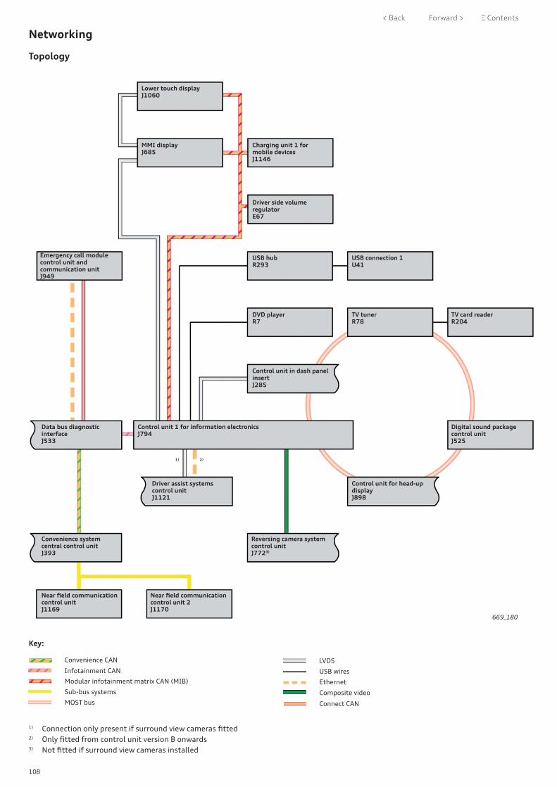
108
Convenience CAN
Key:
Modular infotainment matrix CAN (MIB)
Sub-bus systems
MOST bus
USB wires
LVDS
Ethernet
Composite video
Connect CAN
Infotainment CAN
Lower touch displayJ1060
MMI displayJ685
Charging unit 1 for mobile devicesJ1146
Driver side volume regulatorE67
Emergency call module control unit and communication unitJ949
USB hubR293
USB connection 1U41
DVD playerR7
TV tunerR78
TV card readerR204
Control unit in dash panel insertJ285
Digital sound package control unitJ525
Control unit for head-up displayJ898
Driver assist systems control unitJ1121
Control unit 1 for information electronicsJ794
Data bus diagnostic interfaceJ533
Reversing camera system control unitJ7723)
Convenience system central control unitJ393
Near field communication control unitJ1169
Near field communication control unit 2J1170
669_180
1) Connection only present if surround view cameras fitted2) Only fitted from control unit version B onwards3) Not fitted if surround view cameras installed
2)1)
Networking
Topology

109
Touch display
Introduction
The same MMI operating concept as on the Audi A8 (type 4N) is used on the Audi A7 (type 4K). The Audi A7 therefore also has two touch displays.
The upper display is for the MMI system; the lower display is used, among other things, for operating the air conditioning system.
The lower display is identical for all three MMI versions available (MMI radio plus, MMI navigation and MMI navigation plus).
The upper display can be fitted in two different versions. However, the only difference is the dimensions of the display surface. The outer dimensions of the displays are the same.Vehicles equipped with MMI radio plus or MMI navigation use the smaller display surface.
Technical features of the upper display(MMI display J685)
With MMI navigation plus: > 10.1 inch > 1540 x 720 pixels > LVDS connection from J794: black
With MMI radio plus and MMI navigation: > 8.8 inch > 1280 x 720 pixels > LVDS connection from J794: blue
The colour coding of the LVDS connection on the control unit 1 for information electronics J794 to J685 is black for all display ver-sions.
ReferenceFor further information on the displays and operation, please refer to self-study programme 666 Audi A8 (type 4N) "Infotainment and Audi connect".
669_165MMI display J685 (10.1 inch)
669_166MMI display J685 (8.8 inch)
Technical features of the lower display(Lower touch display J1060)
> 8.6 inch > 1280 x 660 pixels
669_207Lower touch display J1060
Connection to J1060
Connection from J794
Connection to J1060
Connection from J794
Connection fromJ685

110
Emergency call module control unit and communication unit J949
Introduction
The emergency call module control unit and communication unit J949 fitted in the Audi A7 (type 4K) will be referred to in the following as the connectivity box. It is planned to introduce this control unit for the first time in the North American market (USA and Canada) with a view to extending it to other markets and models in the future.
It is a new development which takes over the mobile network function from the gateway. The telephone module is "moved" from the connected gateway to the connectivity box. The connectivity box thereby assumes the tasks related to communicating with the outside world. This affects, for example, the Audi connect vehicle-related services.
Thanks to the introduction of the connectivity box, the number of versions of the gateway is reduced and the customer also benefits from the increase in processing power.
Aerial connection
The GSM, UMTS and LTE standards are supported. Two external aerials are available for communication; they are located in the bumper (rear right) and on the roof. The aerial in the bumper (rear right) is usually used (emergency call module aerial R263). If this aerial’s reception is poor in an emergency call situation, the con-nectivity box switches to the roof aerial R216.
669_167
Roof aerial R216
GPS signal input Emergency call module aerial R263
Emergency call module control unit and communication unit J949

111
eSIM
Design
The connectivity box is also equipped with a backup aerial. It is fitted in the inside of the box and can ensure communication in the event that the two external aerials fail.
An emergency battery is also fitted in the connectivity box. It is charged during operation and is maintenance-free.
If the vehicle is equipped with the Audi connect vehicle tracking system, the connectivity box also has a shock sensor. This is a three axis acceleration sender which is able, when the vehicle is locked, to react accordingly to shaking movements along the three axes and to minor changes in pitch (> 0.25°).
The connectivity box is included in the component protection and is part of the immobiliser system.
Installation position
On the A7, the connectivity box is fitted underneath the luggage compartment floor (front left).To avoid damage, the connectivity box is protected by impact resistant trim.
Data connection and diagnosis
The connectivity box is connected to the data bus diagnostic interface J533 via connect CAN. The maximum data transfer speed is 500 kbit/s. Both control units are also connected via an Ethernet cable which is used to transmit all mobile network data.
The diagnostic address of the emergency call module control unit and communication unit J949 is "0075 Emergency call module".
669_168
669_169
669_170
Power cutmonitoring
Shock sensor
Functionsperformed
Connectivity box CGW
Key:
Ethernet
Connect CAN
Emergency battery Backup aerial

112
Sound
The following sound systems are available for the Audi A7 (type 4K):
> Basic sound system (8RM) > Audi sound system (9VD) > Bang & Olufsen Premium Sound System with 3D sound (9VS) > Bang & Olufsen Advanced Sound System with 3D sound (8RF)
These can be combined with the MMI versions on offer in different ways (refer to the overview of versions on page 105).
The basic sound system has a total power output of 80 W and the Audi sound system has a total power output of 180 W.
With MMI navigation and above, the customer can choose between two Bang & Olufsen Sound systems as optional equipment: "Premium" (9VS) and "Advanced" (8RF).
Both Bang & Olufsen sound systems can generate the third dimen-sion of 3D sound using a special algorithm.
Front left treble loudspeakerR20
Front left mid-range loudspeakerR103
Front left bass loudspeakerR21
Front right treble loudspeakerR22
Centre loudspeakerR208
Front right mid-range loudspeakerR104
Front left mid-range loudspeaker 2R276

113
Rear left treble loudspeakerR14
Front right bass loudspeakerR23
669_171
Rear left bass loudspeakerR15
Digital sound package control unitJ525
Right effect loudspeakerR210
SubwooferR211
Left effect loudspeakerR209
Rear right bass loudspeakerR17
Rear right treble loudspeakerR16
Front right mid-range loudspeaker 2R277
The Bang & Olufsen Premium Sound System (9VS) provides the customer with a 15-channel sound system. It can reach a total power output of 705 W.
The premium sound system requires two loudspeakers to generate the 3D sound. They are fitted in the A-pillars.
Bang & Olufsen Premium Sound System with 3D sound (9VS)

114
Bang & Olufsen Advanced Sound System with 3D sound (8RF)
The best sound quality experience for customers is provided by the Bang & Olufsen Advanced Sound System. This system has 19 channels and reaches a total power output of 1820 W.
The Bang & Olufsen Advanced Sound System requires four loud-speakers to generate the 3D sound. Two of these are in the A-pil-lars and two are in the headliner in front of the handle.
On the Bang & Olufsen Advanced Sound System, the two treble loudspeakers in the dash panel are retractable, as previously.
Front left treble loudspeakerR20
Front left mid-range loudspeakerR103
Front left bass loudspeakerR21
Front right treble loudspeakerR22
Centre loudspeaker 2R219
Front right mid-range loudspeakerR104
Centre loudspeakerR208
Front left mid-range loudspeaker 2R276
Rear left mid-range loudspeakerR341

115
669_172
Rear left treble loudspeakerR14
Front right bass loudspeakerR23
Rear left bass loudspeakerR15
Digital sound package control unitJ525
Right effect loudspeakerR210
Left effect loudspeakerR209
Rear right bass loudspeakerR17
Rear right treble loudspeakerR16
Front right mid-range loudspeaker 2R277
Rear right mid-range loudspeaker 2R340
SubwooferR211

116
Aerials
Rear window aerials
The aerials for radio and TV reception in the Audi A7 (type 4K) are integrated in the rear window.
Depending on the vehicle equipment, the Audi A7 may be equipped with up to four aerial amplifiers fitted on the side of the rear window.
Whether these are fitted depends on exactly what equipment is fitted in the vehicle. Which aerial amplifiers are fitted varies depending on which connections are actually required.
Depending on the country of delivery, the equipment on offer may vary. The image below shows the maximum specification.
Aerial amplifier 2 R111
DAB connection
FM2 connection
Aerial amplifier 2 for TVR83
TV connection
DAB aerial

117
AM aerial
669_173
TV connection
FM1/AM/DAB connection
Aerial amplifier 1 for TV R82
TV connection
Aerial amplifier R24
DAB aerial 2(wire marked in green)

118
Mobile phone aerials
The mobile phone aerials in the Audi A7 (type 4K) are located on the roof, in the rear bumper and, depending on vehicle equipment and version, under the dash panel.
Mobile phone aerial for vehicles with Audi phone box
The Audi A7 can be equipped with the Audi phone box 9ZE as an optional extra. This is always connected to the LTE aerial 3 R330 which is positioned on the left in the rear bumper.
Mobile phone aerials for vehicles with Audi connect infotainment services only
If Audi connect infotainment services (IT1/IT3) are available for the vehicle but vehicle-related services are not, the mobile phone
669_174
669_175
Charging unit for mobile devices J1146
LTE aerial 3 R330
Aerial amplifier for mobile telephone R86
Control unit 1 for information electronicsJ794
LTE aerial 2 R306
LTE aerial 1 R297
aerial connections are as shown below, regardless of the country version.

119
Mobile phone aerials for vehicles with Audi connect infotainment and vehicle-related services with emergency call module control unit and communication unit J949
Depending on the country, the vehicle may be equipped with the emergency call module control unit and communication unit J949. This control unit, which is also referred to as the connectivity box, is being introduced for the first time in the North American market.
J949 is permanently connected to the emergency call module aerial R263 (main aerial) and the emergency call module aerial 2 R322 in the roof aerial. In this case, the roof aerial is only used by J949.
Mobile phone aerials for vehicles with Audi connect infotainment and vehicle-related services without emergency call module control unit and communication unit J949
The EU market launch version of the Audi A7 does not have a connectivity box. On this version, the telephone aerial on the roof is used both by the control unit 1 for information electronics J794 and the data bus diagnostic interface J533 (connected gateway).
669_176
669_177
Emergency call module controlunit and communication unitJ949
Emergency call module aerialR263
Control unit 1 for information electronicsJ794
LTE aerial 1 R297Emergency call module aerial 2R322
Data bus diagnostic interfaceJ533
Emergency call module aerialR263
LTE aerial 2 R306
An aerial splitter in J533 is used to switch between them. This switch-over function is described in the following.
The control unit 1 for information electronics J794 has an exclusive connection to two aerials: one in the rear bumper (right-side, LTE aerial 1 R297) and one centrally under the dash panel (LTE aerial 2 R306).
Control unit 1 for information electronicsJ794
LTE aerial 1 R297
Emergency call module aerial 2R322
LTE aerial 2 R306

120
Aerial splitter function in J533
The signal from the roof aerial (LTE aerial 1 R297) is usually sent to J794 via an aerial splitter in J533. If the emergency call module aerial R263 has sufficient reception, it will be used if an emergency call is required.
If the reception of the emergency call module aerial R263 is insufficient when an emergency call is required, the aerial splitter switches over and J533 uses the signal from the roof aerial (emer-gency call module aerial 2 R322).
The connection to J794 is thereby ended and the emergency call is made via the emergency call module aerial 2 R322 in the roof aerial.
Control unit 1 for information electronics J794
Data bus diagnostic interface J533
LTE aerial 1 R297
Emergency call module aerial R263
669_178
669_179
Control unit 1 for information electronics J794
Data bus diagnostic interface J533
Emergency call module aerial 2 R322
Emergency call module aerial R263

121
Overview
3.0 ltr. TFSI engine 3.0 ltr. TDI engine
Engine oil change According to service interval display, between 15,000 km/1 year and 30,000 km/ 2 years depending on driving style and conditions of use.
Inspection 30,000 km/2 years 30,000 km/2 years
Pollen filter change interval 60,000 km/2 years 60,000 km/2 years
Air filter change interval 90,000 km 60,000 km
Brake fluid change interval Change after 3, 5, ... years Change after 3, 5, ... years
Spark plug change interval 60,000 km –
Fuel filter change interval – 60,000 km
Valve gear Chain (maintenance-free) Chain (maintenance-free)
ATF change interval1) 60,000 km 60,000 km
Read out ash deposit mass in diesel particulate filter (in km)
– From 210,000 km, then every 30,000 km
Air ionisation systemVials in function unit for fragrance dif-fuser system GX43
30,000 km/2 years 30,000 km/2 years
NoteThe information provided in the up-to-date service literature applies.Change intervals apply to ESI markets.
The following service intervals are displayed: > Oil change service > Mileage-based service events > Time-based service events
Example of a service interval display on the MMI display
The value displayed in the mileage-based servicing events field is now 30,000 km for new vehicles and is counted down in 100 km blocks. The value displayed in the time-based servicing events field is 730 days (2 years) for new vehicles and is updated on a daily basis once the vehicle has a total mileage of about 500 km.
On new vehicles, the next oil change due field (flexible servicing event) is initially blank.
An interval calculated on the basis of the driving style and engine load can only be displayed after about 500 km.
Mileage-based service event
Flexible service event
Time-based service event
669_039
Next oil change in
---- mi / 730 days
Next inspection in
30000 mi / 730 days
Reset oil change interval
Car Service intervals
1) Only for vehicles with 7-speed dual clutch gearbox – S tronic
Inspection and maintenance

122
Overview of maintenance intervals for vehicles in the USA
Overview of maintenance intervals for vehicles in Canada
Overview of maintenance intervals for vehicles in China
669_038
669_038
10,000 miles /1 year
15,000 km /1 year
20,000 miles /2 years
30,000 km /2 years
30,000 miles /3 years
45,000 km /3 years
40,000 miles /4 years
60,000 km /4 years
50,000 miles /5 years
75,000 km /5 years
Oil
chan
ge s
ervi
ceO
il ch
ange
ser
vice
Insp
ecti
on w
ith
oil c
hang
eIn
spec
tion
wit
h oi
l cha
nge
Oil
chan
ge s
ervi
ceO
il ch
ange
ser
vice
Insp
ecti
on w
ith
oil c
hang
eIn
spec
tion
wit
h oi
l cha
nge
Oil
chan
ge s
ervi
ceO
il ch
ange
ser
vice
669_038
10,000 km /1 year later
20,000 km /1 year later
30,000 km /1 year later
40,000 km /1 year later
Insp
ecti
on w
ith
oil c
hang
e
Insp
ecti
on w
ith
oil c
hang
e
Insp
ecti
on w
ith
oil c
hang
e
Insp
ecti
on w
ith
oil c
hang
e
The Audi A7 (type 4K) is subject to fixed inspection and mainte-nance intervals in the USA.
The Audi A7 (type 4K) is subject to fixed inspection and mainte-nance intervals in Canada.
The Audi A7 (type 4K) is subject to fixed inspection and mainte-nance intervals in China.
USA
Canada
China
NoteThe information provided in the up-to-date service literature applies.

123
Self-study programmes
For further technical information on the Audi A7 (type 4K), please refer to the following self-study programmes.
SSP 410 Occupant Protection - Passive Systems
SSP 655 Audi 3.0l V6 TFSI engine of EA839 series
SSP 656 3.0l TDI engine EA897evo2 series
SSP 663 Audi A8 (type 4N)Running gear
SSP 664 Audi A8 (type 4N)Electrics and electronics
SSP 665 Audi A8 (type 4N)New air conditioning features and introduction of refrigerant R744
SSP 666 Audi A8 (type 4N)Infotainment and Audi connect
SSP 668 Audi A8 (type 4N) driver assistance systems
Appendix

All rights reserved.Subject to technical revision.
CopyrightAUDI AGI/[email protected]
AUDI AGD-85045 IngolstadtTechnical status 01/18


