Embed Size (px)
Citation preview
STABILIZATION OF ATOMIC HYDROGENAND DEUTERIUM
INIS-mf—8539
J. T. M. WALRAVEN ?
ii

STABILIZATION OF ATOMIC HYDROGENAND DEUTERIUM

STABILIZATION OF ATOMIC HYDROGENAND DEUTERIUM
ACADEMISCH PROEFSCHRIFT
ter verkrijging van de graad van doctor in de Wiskunde enNatuurwetenschappen aan de Universiteit van Amsterdam,op gezag van de Rector Magnificus, Dr. D. W. Brestérs,hoogleraar in de Faculteit der Wiskunde en Natuurweten-schappen, in het openbaar te verdedigen in de Aula derUniversiteit (tijdelijk in de Lutherse kerk, ingang Singel 411,hoek Spui) op woensdag 1 september 1982 te 15.00 uur
precies
door
JOANNES THEODORUS MARIA WALRAVEN
geboren te AMSTERDAM
kiips repro nusppel
Promotor : Prof. Dr. I .F. Silvera
Co-referent : Prof. Dr. N.J. Trappeniers
The work described in this thesis was carried out at the
'Natuurkundig Laboratorium' of the University of Amsterdam
and supported financially by the ' Stichting voor Fundamen-
tee l Onderzoek der Materie' (FOM).

Aan mijn ouders
Aan Marian

Introduction 1
Chapter 1 - Theoretical survey 3
1.1 Fundamentals 3
1.1.1 - Spin Polarized Atomic Hydrogen (H+) 3
1.1.2 - Method of spin polarization 4
1.1.3 - The Bose nature of H+ 7
1.2 Properties of H+ 1 6
1.2.1 - Introduction 16
1.2.2 - The non-interacting case 17
1.2.3 - Spatial Bose-Einstein condensation 19
1.2.4 - The interacting case 21
1.2.5 - Hartree-Fock approximation 22
1.2.6 - T > T 23c
1.2.7 - T < Tc 25
1.2.8 - The zero temperature limit 26
1.2.9 - Excitation spectrum 27
1.2.10- The concept of healing length 28
1.2.11- Spatial separation between condensate and normal com-
ponent at finite temperatures 29
1.2.12- Properties associated with the nuclear spin 30
1.2.13- Rapid nuclear relaxation 30
1.2.14- Slow nuclear relaxation - phase separation between
condensates 32
1.3 Interaction of H4- with, surfaces 34
1.3.1 - Introduction 34
1.3.2 - H+ in contact with the surface of liquid helium 34
1.3.3 - Further si-mplifications 36
1.3.4 - Saturation of the surface coverage 38
1.3.5 - BEC in the presence of surfaces 38
1.3.6 - Surface adsorption isotherms 39
1.4 The stability of H4- 41
1.4.1 - Introduction 41
1.4.2 - The direct three-body process 44
1.4.3 - The three-body scattering amplitude T. 45
1.4.4 - The Faddeev equations and the AGS theory 47
1.4.5 - Decomposition of the initial states 49

1.4.6 - State dependence for recombination 53
1.4.7 - Magnetic field dependence of recombination 54
1.4.8 - A simple phenomenological recombination model 56
Chapter 2 - Experimental considerations 61
2.1 - The production and cooling of atomic hydrogen 61
1 - Introduction 62
2 - The Experimental Apparatus 63
Overview 63
The dissociator 64
Transport of the gas 66
The accommodator 73
Beam formation 76
Peaking of the beam 77
The opaque mode 77
Velocity dis tr ibut ion 78
3 - Measurement procedures 79
Mass flow 79
Calibration of the quadrupole for H„ 79
Calibration of the quadrupole for H 80
The degree of dissociation 80
The density in the accoiranodator 81
The peaking correction 81
Time of flight analysis 82
Narrow s l i t chopper 83
Equal segmented chopper 83
Signal processing 85
Calibration of the time of flight scale 86
4 - Results 89
2.2 - The cryogenic system 99
Chapter 3 - Stabilization of atomic hydrogen at low temperature 106
Chapter 4 - Density, magnetization, compression and thermal lea-
kage of low-temperature atomic hydrogen 112
Chapter 5 - Magnetic equation of state of a gas of spin-polarized
atomic hydrogen 117
Chapter 6 - Spin-polarized atomic deuterium: s tabi l izat ion, l imi-
tations on density and adsorption energy on helium 122

Summary 127
Samenvatting 129
Nawoord 131

r-i
INTRODUCTION
The gaseous state of atomic hydrogen (H) is one of the sim-
plest and most interesting systems provided by nature. The simplicity arises
from the simple structure of the hydrogen atom: one proton and one electron.
Since the early days of quantum mechanics this aspect has stimulated physi-
cists to use the hydrogen atom as a test probe to verify physical hypotheses.
Its electronic spectrum has played a central role in the development of quan-
tum mechanics itself. The experiments of Lamb and Retherford were decisive
for our present understanding of the quantum electrodynamics. The hydrogen
maser provided a breakthrough in the development of lasers and time and fre-
quency measurement.
As a result of this intensive and continual study and the relative simplicity
of the problem, the hydrogen atom is-by far the best understood.atomic system.
ï Not only the atomic properties of hydrogen are studied intensively, but also
the interactions between two, three and four hydrogen atoms. In particular the
,\ { hydrogen molecule (H„) may be described with an unequaled accuracy for mole-
cular systems on the basis of "first principles".
The detailed knowledge of the atomic and molecular states of hydrogen provi-
des a firm basis to also enhance our knowledge of many-body atomic systems.
The reason why H has not yet served this interesting purpose is very simple.
With a textbook notion atomic hydrogen is said to recombine explosively to
form a "stable" molecular state (H~, H„0, CH, etc.).
v•) • ;j' This thesis deals with atomic hydrogen in the gaseous state. It is meant to
?! '- demonstrate rigorously that atomic hydrogen may be subjected to experimental
T'4" >\ investigation under (quasi-) equilibrium conditions as any "normal" gas. The
•t' , use of low temperature technology enables an enhancement of the "lifetime"
"•;,';..- of a sample by orders of magnitude, so that recombination no longer appears
'~'\ explosive to the human observer, but rather slow (in the course of hours).
4' This is experimentally realized by polarizing the electronic spins in a high

( 10 Tesla) magnetic field and by minimizing surface interactions by cove-
ring all low temperature (T <t 0*6 Kelvin) surfaces with a film of superfluid
helium-4. Hydrogen in this (meta-) stable state is commonly referred to as
Spin Polarized Atomic Hydrogen (H+) and is predicted to exhibit fascinating
properties as a quantum fluid below its degeneracy temperature. The recombi-
nation, although detremental from many points of view, may be put to advan-
tage as it enables an elegant determination of the adsorption energy of hy-
drogen on various surfaces. This is demonstrated for the isotope atomic deu-
terium and the surface of He. These points represent the main physical yield
of my thesis work and are subject of four letters to the Physical Review, re-
produced here as chapter 3, 4, 5 and 6. For the experiments, the development
of a reliable source of low temperature hydrogen atoms was of crucial impor-
tance. This source is described in detail in a paper accepted for publication
by the Review of Scientific Instruments and presented in chapter 2 along with
a description of the low temperature apparatus. Chapter 1 provides the theo-
retical frame work that places the work into an appropriate perspective.

CHAPTER 1
THEORETICAL SURVEY
1 . 1 . FUNDAMENTALS
1.1.1. Spin Polarized Atomic Hydrogen
The interaction between a pair of hydrogen atoms depends strongly
on the electronic state of the constituent atoms and, limiting ourselves
to the electronic ground state, in particular on the electronic spin sta-
te of the pair.
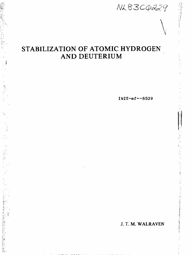
NUCLEAR
LU
oQ.-2
f
"f
B = 10
^ ^
TESLA
"
i
©.
M s = 1
Ms= 0
-Ms=-1
1 i
SEPARATION I A]
Fig. 1A-Interatomic potentials for a pair of hydrogen atoms inthe singlet (dashed line) and triplet (solid line) states.Fig.B shows3 on an expanded scale, the shallow minimum ofthe triplet potential. In a magnetic field the degeneracyof the triplet is lifted and one of the triplet potentialsis shifted below the singlet.
Phenomenologically the presence of spin leads to two potentials, the
£+ -potential in case of an anti-symmetric electronic spin state and
the E -potential in case of a symmetric electronic spin state. Accu-Erate calculations of these potentials were made by Kolos and Wolniewicz.1 2 3' ' Both potentials are shown in Fig. 1.

The £+ potential has a deep attractive well with a minimum of 4.75 eV at a
nuclear separation of 0.74 A. This potential gives rise to the strong covalent3 +
bond in the hydrogen molecule. In contrast the Z potential has a very shal-
low non-bonding minimum of 0.56 meV at an internuclear distance of 4.15 A, By
polarization of the electronic spin states, the atoms are forced to interact
pairwise via the non-bonding triplet potential which results, in the absence
of depolarizing forces, to a complete suppression of hydrogen molecule forma-
tion. A many-body system of hydrogen atoms, interacting pairwise via this E
potential, will be referred to as spin polarized atomic hydrogen. The pola-
rized gas is characterized by the symbol H+ or H+ where the arrow denotes the
direction of polarization of the electronic spins with respect to the magnetic
field. At low temperature H+ is the energetically favored state. A positive
scattering length a * 0.72 A may be associated with the triplet potential, in-
dicating that the energy of the gas increases with growing density. The gas
remains stable against liquid formation at higher densities. This was esta-
blished on the basis of numerical calculations by Hecht , Etters and cowor-6 7 8 9
kers ' ' and Nosanow and coworkers. We note that historically the symbol H+
was used for both H+ and H+ but this habit was left to avoid confusion between
the two states of polarization.1.1.2. The method of spin polarization
The hamiltonian describing the spin states of the H-atom is given by
K = ggViBBSz - gnPnBIz + al.3 (1.1.)
The first two terms are the electronic and nuclear Zeeman contributions res-
pectively, and the third term represents the hyperfine interaction with
coupling constant a. S and I are the electronic and nuclear spin operators
with components S and I along the magnetic field B. The electronic and
nuclear g-factors are written as g and g ; uD is the Bohr magneton, y theP n p n
nuclear magneton. Applying (1.1.) to the S = 1/2, I = 1/2 case of atomic
hydrogen one easily obtains the well known hyperfine level diagram named
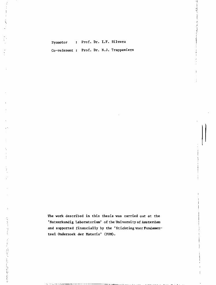
after Breit and Rabi and shown in Fig. 2.
The eigenstates corresponding to hamiltonian (1.1.) are commonly labeled
a, b, c and d with growing energy:

ZERO FEUD HIGH FIELD
Ut>
Fig.2-The hyper fine level diagram of an isolated hydrogen atom ina magnetic field B. Expressions for the spin states are givenfor both the zero field and the high field limits. In zero fieldF and M„ are good quantum numbers.
d > = | + * >
c > = cos 6 | + 4 >+sin 6|
b > = | + * >
* >(1.2.)
a > = - cos 6 >+sin
where the simple arrows refer to the electronic spin states (+ *v< m = + r)1
and the arrows with a bar to the nuclear spin states (* *• m = + r ) .
+3.
i 2 ~ 1 / 2
(1.3.)
where y- = g y + g y . In high fields (B » a/p+ - 506.2 Gauss) thep p *~ n n
mixing parameter e approaches zero asymptotically (0 •> 0) according to
e «** 2v+B(1.3a.)
In zero field 0 = ir/4 or e = - /T
The energy levels are given by (see Fig. 2):

Ed = 1/4 a [1 + 2
+ TE c = - 1/4 a tl - 2/l + (U-2) ]
a (1.4.)
Eb = 1/4 a [1 - 2 ü-5 ]3
+TTE11 = - 1/4 a [1 + 2/1 + ( - ]1 a
Spin polarization can be achieved in various ways. First we concentra-
ted our efforts on preparing a pure electronic spin state with an atomic
beam technique and Stern and Gerlach's principle to obtain a spatial se-
paration between spin "up" and spin "dc /n". The spin selected atoms were
subsequently condensed on a surface to study their properties. In a se-
cond stage it became clear that the original goal of our research could
best be realized with another approach. A flux of hydrogen atoms is gui-
ded into a high (B ss 10 T) magnetic field through a tube which also ser-
ves to cool the gas down to T ^ 400 mK. At B = 10 T the splitting between
the lowest and highest pair of hyperfine levels equals AE/k-5* 13 K(kD is15 15
Boltzmann's constant) so that at T = 400 mK the thermal occupation of the
upper two (|.c> and |d>) levels is suppressed by a factor e ** 10
Physically this means that atoms in the | c> or f.d> spin states cannot en-
ter the magnetic field. The atoms experience a force proportional to their
effective magnetic moment and the gradient of the magnetic field.
F£= Ug VB (1.5.)
where i 3E1 . , , ,. /n , xyeff = 3B~ l£(a» b» c« d) (1.6.)
As a result |a> and |b> state atoms are pulled into the magnetic field
whereas atoms in the |c> and |d> states are repelled. This last group
will recombine in low field or relax their electron spin and then enter
the the field in a second stage. Note that this process is not the same
as "Brute Force Polarization" where one fully relies on relaxation to ob-
tain thermal equilibrium. Such a process is likely to be inefficient in
atomic hydrogen as a maj or fraction of the gas could have recombined be-
fore the spins achieve thermal equilibrium.
Unfortunately the enormous suppression of the occupation of the | c> and
|d> state does not mean that the electron spin "up" component is also
suppressed by this amount, because the lowest hyperfine state (state |a>

in Fig.2) has an admixture of spin "up" due to the hyperfine coupling
between the nuclear and electronic spins. As the level of this admixture
depends only weakly on the magnetic field, as shown by equation (1.3a.)
it may not be rendered negligible with currently accessible fields. The2 2
probability of finding a spin "up" is e .For a field of 10 T, e = 6.4 x
10 which is a rather small but by no means negligible amount. In Sec-
tion 1.4. the consequences of this admixture in relation to recombination
processes wil be discussed.
1.1.3. The Bose-natwe of #+
On the basis that quasi-equilibrium conditions may be achieved for
a gas of spin-polarized atomic hydrogen, one of the first questions that
comes to mind concerns its statistical nature in relation to the internal
structure of the atoms. For properties where this internal structure need
not be considered the situation is unambiguous; H+ should obey Bose sta-
tistics as any other "composite" system with an even nui;.jer of (tightly
bound) elementary fermions per particle. In general the effects of quan-
tum statistics will not show unless the particles come close enough. The
only way to identify two identical particles is by specifying their posi-
tion and momentum sufficiently accurately. As shown by Heisenberg this be-
comes fundamentaly impossible at short distances. Then quantum mechanical
interference effects originating from the indistinguishability have to be
taken into account by symmetrizing (or anti-symmetrizin$ the wave functions
according to the nature of the particles. These points may be illustrated12
by the following elementary example.
Consider a system of two non-interacting identical particles with spin,
represented by wavefuctions (wave packets) ¥ (rTai) and <P (r-cO. where
r. and a. represent the dynamical variables for position and spin of par-
ticle i; ii and v define the (in general not orthogonal) spin states of the
particles. We assume the wave functions-to be separable of the form
¥y (TO) = ¥ (r) xv (a) (1.7a.)
where ¥ and x represent the orbital and spin states respectively, both
normalized to unity
S U y(a)|2 = 1 (1.7b.)
ƒ |¥ (r")|2 = 1 (1.7c.)
Analogous expressions are assumed for <p (ra) .

We now raise the question how does particle indistinguishability affect
the distribution of particles over space? The hamiltonian is invariant un-
der permutation of the particles, implying that the symmetry of the pair
wave function under permutation is a constant of the motion. The ymmetri-
zation postulate then teaches that the dynamical states of the system are
either all symmetric or anti-symmetric, depending on the nature of the par-
ticles, thus the total wave function is written as
where the + sign refers to the boson-case and the - sign to the fermion-
case, S represents an overlap integral required to conserve normalization.
The probability density of finding one of the particles at r. and the other
at r„ is
which is rewritten, using (1.7a.) and (1.7b.) to obtain
+ -v •* \ _ f ^x"-*- i /*• •*•
X # . » . , £ - » . _ -j. ->. .
here (l-«*2) indicates an exchange of the indices 1 and 2 and
Note that P (r,, r„) expresses the probability density of finding one out
of two distinguishable particles at r, and the other at ro. If P~(ris r.)-y -y L l s l l
- P CrT» r„) symmetrization is not required to calculate the spatial dis-
tribution of the pair. From equation (1.9b.) it can be seen that this is
the case if- the particles occupy disjunct regions of space:
I'(r) + 0 •*• V(T) = 0 (1.10.)
and vice versa
or
- the particles are in orthogonal spin states
2 X*(a) Xv(o) = 0 (1.11.)

More generally it can be shown that symmetrization is not required for the
evaluation of the expectation value of any operator O if
which is satisfied in particular for any spin-independent operator if con-
dition (1.11.) applies. However, if symmetrization is required, interfe-
rence effects between ¥ (r a.. )V (r2a2^ a n d * (r9a2^ ^ rl 0P m a y " o i n i n a t e
the physics: note that in general P (ra;ra) + 0, whereas P~(ra;ra) = 0.a S
There are two aspects in our present introductory survey of the H+ system,
where the foregoing considerations may be applied. Firs.;, we can establish
at what densities quantum s t a t i s t i c s will become important and, secondly,
when the composite particle approximation must break down. The t rans la t io-
nal states of the H+ atoms may be described by wave packets of typical s i -
ze w. Exchange effects become important when the wave functions overlap,
thus for densities
a K (1/w)3 (1.13a.)2 2 1/2
The uncertainty Ax H [ <x >-<x> ] in the position x of the atoms (Ax =
w/2) is estimated using Heisenberg's uncertainty relation Ax-Ap*3 h. The2 2 1 /2
uncertainty Ap = [ <p >-<p> ] in momentum p of the particles depends on
the temperature and is estimated for a Maxwellian gas using results of sim-2 2
pie kinetic theory: <p > = 3 mk^T and <p> = Srsk^T/n. We find
2 1mkVth
b
X , is the "thermal" de Broglie wave length of the par t ic les . For H+ at
T = 100 mK this means that deviations from classical s ta t i s t i cs are to be
expected for densities n "v n, = 6 x 10 H+/cm , n , = X . is the degene-d d tn
racy density of the gas.
Again, along the same line of reasoning, one predicts the composite parti-
cle approximation to bröak down if the electronic wave functions of sepa-
rate atoms overlap and thus quantum interference of the electronic wave
functions is no longer negligible. For two H+ atoms this happens at an
internuclear separation of <v 4A as demonstrated dramatically by the diffe-
rence between the singlet and triplet potentials (see Fig. 1). This diffe-
rence originates from the dependence of the electrostatic interaction on the
distance between the electronic charges, which depends in turn strongly on

the absence ( Z+) or presence ( E ) of the exchange effects. Hence for a
(non-interacting) gas of H+ these effects only become important for densi-> 1 3 —1 2? •}
ties n ^ (4-) A = 1.6 * 10 Hl/o» > orders of magnitude higher than the
Bose degeneracy density of the H4- and thus of no practical consequence for
observing effects associated with the Bose statistics.
We consider this second point in more detail, this time accounting expli-
citly for the internal structure of the atom. In view of the relevance for
high field, low temperature experiments we limit the discussion to the lo-
west hyperfine states (|a> and |b>).
Within the Born-Oppenheimer approximation the unsymmetrized "a-b" pair wave
function is written as4>ab(RlR2rlr2) = * ( Ri R2 } <K R
1r1;
R2 r2 )l a b ) (1.14.)
4.(Riri;R2r2) = ( R ^ M R ^ ) (1.14a.)
where R.. and r. represent the proton and electron coordinates respectively,
<P(R r ) are s-state electronic wave functions around the position R«,i i . . .
the orbital wave function of the pair and jab) is the unsymmetrized
5 |a>1|b>2
-R„)
spin state.
= - cos 6 (-H)!**) + sin 6 |++) **) (1.15.)• gi n en
where sin 8 is defined in equation (1.3.).
To symmetrize ¥ , with respect to protons and electrons we first decompose
|ab) in terms of symmetric and anti-symmetric (electronic and nuclear) spin
parts. This is most easily done by a transformation to the coupled spin re-
presentation using the appropriate Clebsch Gordon coefficients. Defining
S = S^ + S2 and I = I- + I_ the coupled representation is spanned by the
state vectors |S, Mc > |l, M_ > :o 6 x Tl
|ab) = - -4 cos 6 |l, -1> |l, 0 >V £. 6 xl
- 4; cos 8 |l, -1> |0, 0 >
Y (1-160+ -r: sin 0 11,0 > |l,-l >
•2 ' ' e1 n
+ ^j sin 9 |0,0 > |l,-l >
The symmetrization is now completed by multiplying the various terms of
(1.16.) with appropriately symmetrized electronic and orbital wave func-
tions. The electronic wave functions are Heitier-London like
<t> '(R^r-r-) = (fi(R rn;R_r„) + <KR-,ro:R„r ) (1.17.)
10

where + is used for the "bonding"-case and - for the "anti-bonding"-case. 53
The orbital wave functions are also either symmetric (S) or anti-symmetric f
(AS) vinder exchange of R. and R„
S , S
A S ( R ^ ) = (±) * A S ( R ^ ) (1.18.)
Thus the totally symmetrized pair wave function becomes
V l V l V - - 72 c o s 9l1-1el1 °n * ( " ) ( R Vn
cos 6|l-l>|0 0> i|)(~)(R1R„r1r„)*'(R1R9)en J. z i z i z (i.i9a.)
+ -7T s in e i 0> 1-1> <j>/ z ' e n L i. J. i.
1 , I ( + ) s i S ,+ 75 s i n 9 0 0> 1-1> <|> (R.-R-r-.r,,)* (
V2 ' e ' n T 1 2 1 2
Analogously one may'iwrite t o t a l l y symmetrized wave functions for the "a"
and "b-" case
;r s i n 2 6 | l , 0>j 1, 0> <j> (R-.R.jr.-r.,)* (RnR-)2 ' ' e ' n / + \ 1 2 1 2 1 2 ,.. ._, ,
+ J-- s in26 |o . 0>|0, 0> è (R,Ror..r„)* (RnRo) • '2 2 ( - ) S+ sin ell, l>|l,-l> (j) ($.,TCr,z,Tr,)$ (RnR~);« ' ' e' n 1 2 1 2 1 2
I1 ^ ( R ^ r ^ ) = |1,-1>|1,-1> <t.(~)(R1R2r1r2)*
S(R1R2) (1.19c.)
..; As is to Be expected, in the limit of high fields (6-*0) only anti-bonding
'.; electronic wave functions appear; i.e. in a Born-Oppenheimer picture the
~', atoms interact via the triplet potential in the presence of electrostatic
; interaction between the particles. We also note from (1.19a) that symme-
try does not exclude anti-symmetric orbital wave functions, even in high
" magnetic fields. The appearance of odd orbital wave functions is no sur-
• prise for a pair of hydrogen atoms. The most abundant modification of H„
(ortho H_) falls in this class (in combination with the bonding electronic
':;. orbital <j>(+)).
.' Again focussing our attention on states |a> and |b> we now investigate to
<j what extent two hydrogen atoms may be considered (composite) bosons. Bose-
}j nature means that the total wave function of the pair should be symmetric
i, under exchange of particles constituting the pair, i.e. under the simulta-
; neous exchange of both protons and electrons. As before we decompose |ab)
11

*>1R2
Analogously
r l r 2 )
aa
*bb
= -5- 1
+ T I
(R-,R2
( R1R2
[ |ab) +
[ |ab) "
r l r 2 ) "
r r ) =
|ba)]
|ba)]
|aa>
|bh>
in symmetric and anti-symmetric spin parts, however this time with respect
to the total atomic spin states (i .e. the hyperfine states)
|ab) = \ [ |ab) + |ba)] + y [ |ab) - |ba)] (1.20.)
and to complete the symmetrized (composite particle) pair wave function we
have to add the orbital wave function of the pair as well as the electronic
state. Since the individual electrons are not to be exchanged in our present
approach the electron wave function is given by (1.14a.). The orbital motion
of the atoms is again described by * or * "•, see (1.18.).
AS* (R-^) (1.21a.)
(1.21b.)
(1.21c.)
To enable a direct comparison with (1.19a.) we express the spin part in terms
of the coupled representation of the electronic and nuclear spin states.This
is done in two steps. First (1.21.) is rewritten in terms of electronic and
nuclear spin states and then terms are collected to yield
^ i V l V = - 75 C0S 6l1>-1el1' °n * (Vl ; R2 r2 ) *S(R1R2>
* j-2 sin ell, 0>|l,-l> •<R1r1;R2r2> ^2\, „ ,i AS (1.22a.)
- 72 cos 6|l,-l>|0, 0> •(R1r1;R2r2) * ( R ^ )
I , , " AS+ 72 sin 610, 0>|l,-l> *(R1r1;R2r2) * ( R ^ )
For completeness we also compare * and -.v :
*aa(RlR2rlr2) = + cos26|l,-l>|X» 1> «(.(R^;^^) ^ ( R ^ )
- \ sin29|l, 0>|l , 0> <C(R1r1;R9r ) * S ( L R )* e n 1 1 Z z 1 2 ( 1 2 2 b - )
+ -j sin29|0, 0>|0, 0> <()(R1r1;R2r2) * ( R ^ )
(1.22c.)
* sin26|l, 1>|1,-1> <j,(Riri;R2r2)
and
12
Comparing equations (1.22.) with (1.19.) we observe that both sets of equa-
tions are identical except for the fact that the equations (1.22.) lack the
exchange term <t)(R..r2;R2r,). This is of course not surprising since electro-
nic exchange is a consequence of the internal structure of the atom, which
was not considered in deriving (1.22.). To the extent that hydrogen atoms
satisfy (1.21.) we may call them bosons; according to (1.22.) and (1.19.)
everywhere except in regions of direct electronic overlap.
So far we focused our attention on non-interacting H4- atoms. What are the
effects of the interactions? Unlike the non-interacting case, in an interac-
ting system the effects of particle indistinguishability extend beyond the
regions of direct overlap. The interactions cause the atoms to be scattered
continuously. For the case of spin-zero bosons this gives rise to diffrac-
tion patterns characterized by even partial waves only. Many properties of
a weakly interacting system are not very sensitive for these phenomena.
Thermodynamic properties like pressure, internal energy, compressibility
or specific heat, properties which are well defined also for non-interac-
ting gases, are only affected modestly by the presence of the interaction.
Other properties, however, only exist by virtue of the interactions, in par-
ticular transport phenomena. In these cases the properties depend critical-
ly on the nature of the scattering processes and thus ïndistinguishability
effects may dominate the physics. A good example of the last class is pre-
sented by gaseous He where polarization of the nuclear spin is expected
to change the low temperature transport properties in a dramatic way. He
is a spin 1/2 fermion system. When both spin "up" and spin "down" atoms
are present, the atoms may be scattered via s-waves, the only scattering,,
channel which is energetically accesible at low temperature. This results
in a finite viscosity. By spin polarizing the system s-wave scattering is
inhibited by the fermion-nature of He. As a result the viscosity is ex-
pected to vanish at low temperature.
We return to the case of H+ with the aim to establish whether the atoms al-
so behave like bosons in scattering processes, in spite of electronic over-
lap during collisions. Clearly the bosons defined by equation (1.21.) have
a curious nature. We have decoupled total atomic spin states instead of
electronic and nuclear spin states separately, i.e. atoms are exchanged in
specific hyperfine states instead of electrons and protons with spin. Ato-
mic hyperfine states are undefined when the atoms overlap as demonstrated
13
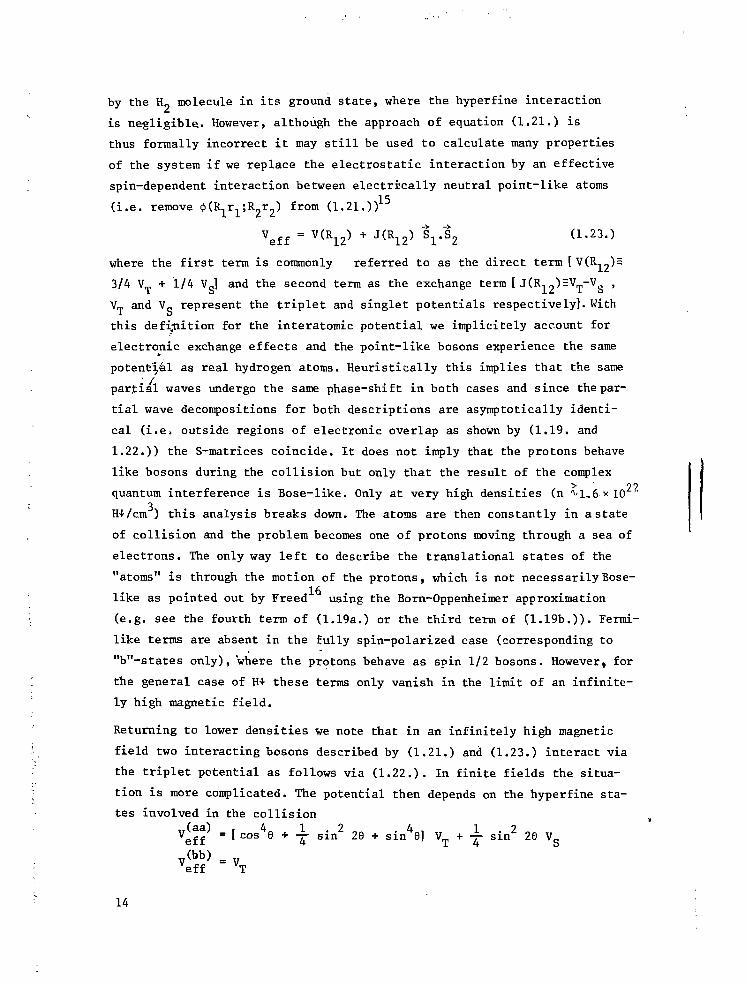
by the H„ molecule in its ground state, where the hyperfine interaction
is negligible.. However, although the approach of equation (1.21.) is
thus formally incorrect it may still be used to calculate many properties
of the system if we replace the electrostatic interaction by an effective
spin-dependent interaction between electrically neutral point-like atoms
(i.e. remove (Kl^r^R.,^) from (1.21.))15
Veff = V ( R 1 2 ) + J ( R 1 2 ) V ^ 2 (1.23.)
where the first term is commonly referred to as the direct term [VtR-,^)
3/4 V + 1/4 V ] and the second term as the exchange term [ J(R.. „)HV -V ,
V_ and Vo represent the triplet and singlet potentials respectively]. With
this definition for the interatomic potential we implicitely account for
electronic exchange effects and the point-like bosons experience the same
potential as real hydrogen atoms. Heuristically this implies that the same
partial waves undergo the same phase-shift in both cases and since the par-
tial wave decompositions for both descriptions are asymptotically identi-
cal (i.e. outside regions of electronic overlap as shown by (1.19. and
1.22.)) the S-matrices coincide. It does not imply that the protons behave
like bosons during the collision but only that the result of the complex> 99
quantum interference is Bose-like. Only at very high densities (n ^1,6*103
H+/cm ) this analysis breaks down. The atoms are then constantly in a state
of collision and the problem becomes one of protons moving through a sea of
electrons. The only way left to describe the translational states of the
"atoms" is through the motion of the protons, which is not necessarily Bose-
like as pointed out by Freed using the Born-Oppenheimer approximation
(e.g. see the fourth term of (1.19a.) or the third term of (1.19b.)). Fermi-
like terms are absent in the fully spin-polarized case (corresponding to
"b"-states only), where the protons behave as spin 1/2 bosons. However, for
the general case of H+ these terms only vanish in the limit of an infinite-
ly high magnetic field.
Returning to lower densities we note that in an infinitely high magnetic
field two interacting bosons described by (1.21.) and (1.23.) interact via
the triplet potential as follows via (1.22.). In finite fields the situa-
tion is more complicated. The potential then depends on the hyperfine sta-
tes involved in the collision
Veff^ = f cos4e + T sin2 29 + sinUfl VT + \ sin2 2e vs
V(bb> = Veff VT
14

- i
( M S Cl.24.)Veff = VT (scattering via * )
5 V„ + sin 9 V (scattering via
In the high field limit this reduces to
v ( b b ) = ve f f T (1.24b.)
VT (scattering via * S )
v + e 2 Vo (scattering via * A S)
2 2 - 5Thus for a field of 10 Tesla, where e = sin 9 = 10 , one may assume
V .. = V„ for all collisions. Some care is required since the triplet
potential is much shallower than the singlet. For most internuclear se-
parations the argument is trivial since |v | *> \v \ everywhere except
near the zero crossing of V . However, also the position of the cros-2
sing is not significantly affected by the E V_ term because at the cros-2
sing e |Ve|-«|v„(R . . )| (see section 1.1.1.).S' ' T minimum '
Thus, assuming that the various arguments presented in this section may be
generalized for a many-body system, an interacting gas of H+ atoms in a
high magnetic field behaves as a gas of chargeless point-like bosons inter-_q 22 3
acting via the triplet potential for densities X , <n < 1.6 x 10 H+/cm .
However, since the H4- atoms may exist in two different hyperfine states the
statistics of this system differ from the well known spin-zero Bose-statis-
tics. The properties of the gas will depend on the population of both spin
states and in particular the (nuclear) relaxation between these states. For
rapid relaxation the |b> state may be considered a spin excitation, whereas
in the absence of nuclear relaxation the system behaves as a mixture of two
distinguishable Bose systems.
15 i1i

1.2. PROPERTIES OF H+
1.2.1. Introduotion
Unlike He the properties of H+ are strongly influenced by the
presence of magnetic field gradients. This affects the single particle
properties -enabling us to spin polarize the system by spatial separa-
tion of H+ and H-t- - but also affects the many-body behavior. This aspect
of the H+ problem is not only very interesting but also essential to un-
derstand the behavior of the system. Magnetic field inhomogeneities may
be suppressed but can never be avoided completely under experimental con-
ditions, so it is important to be aware of their consequences.
We introduce the basic concepts of the many-body theory on the basis of
the experimental configuration used in our laboratory. It will be shown
that the magnetic field gradients lead to a unique spatial separation be-
tween Bose condensate and normal fluid, which is most evident for the
non-interacting gas {Sections (1.2.2) and (1.2.3)} but should remain an
important identifying feature for Bose-Einstein condensation also in the
presence of interactions {Sections (1.2.4) - 1.2.11)}. The presence of
the nuclear spin and the hyperfine interaction do not just complicate
the picture, but rather enrich the phenomena that can be observed once
the system is brought into the Bose-condensed state. Some of these pheno-
mena are discussed in Sections (1.2.12) - (1.2.14).
Clearly these properties, all associated with the spatial distribution of
the gas in an inhomogeneous field, represent only a very specific class of
phenomena that may be observed in H+. They were selected in view of their
relevance for the present thesis work (e.g. Chapter 4) and the recent in-
terest in these phenomena in the literature. Moreover, the important class
of thermodynamrc properties has received a lot of theoretical interest in
the past and has been reviewed extensively by Huang.^
Consider gaseous H+ to be confined in a tube positioned along the axis of
an axially symmetric magnetic field B(x, r.), which may be approximated
o v e r t n e region accessible to H+ by the following expressions:
B(x,o) = B [ 1 - (x/x )2] ,, , ,
:; where B H B(O,O) is the central field and x sets the length scale. ForA, ° mV the magnet used in our experiments B = 10 T and x = 51 mm. Neglecting: 16

the nuclear spin the hamiltonian of the system is given by
2
X = S {- £-A.+ gyftS.,B(r)}+ \ 2 . V(r..) (2.2a.)
where ft is Planck's constant, m the .atomic mass, g the Landé-factor, yD3 + .
Bohr's magneton and V the E -potential. The Zeeman term is interpreted as
an external single particle potential field so that the hamiltonian may be
rewritten as:
If j
with an appropriate choice of the zero of energy and ignoring the radial
field gradient
Uext(?) = Y ma,2 x2 (2.3a.)\,ith
2Bo
Without the interaction term the hamiltonian reduces to the simple harmonic
i oscillator form for motion in the x-direction, whereas in the yz-direction
• the motion is free particle like if the radial field gradients are ignored.
.' 1.2.2. The non-interacting oase
Before addressing ourselves to the more realistic situation of the
(weakly) interacting Bose gas some basic concepts in Bose systems are intro-
"j duced for the non-interacting case. The attraction of this simple theory
arises from i ts elegance and mathematical simplicity, but its presentation
: . seems only justified in view of the results of more sophisticated treat-
"v ments proving the model to give a correct qualitative description of various
'y • properties of H+. An early discussion of Bose-condensation in inhomogeneous'" ' 18•;; fields is given by De Groot et al .
To calculate the density distribution we work with a grand ensemble construe-
ted on the basis of the non-interacting hamiltonian.3C . The density distribu-
tion is then found as the ensemble average of the number density operator
P.(r)--<P(r) \ = | k k <r>| 2 <Vo (2-4->
•ko ^ ( W ^ ) . ! ( 2 . 4 a - )
17

where <n, > =<ïfii-> is the Bose occupation function for the single particleK 0 K. 0
eigenstates, with energy e, obtained from Schrödinger's equation
u is the chemical potential and B = (k T) ; n. is obtained by evaluating
the trace with the statistical operator p over all many-body eigenstates of
the system
• 5 Tr <pn> (2.6.)O K O
_X„B(UN - ft) (2.7.)Zgr
where Z is the grand partition function, N the number operator. The sym-
bol "~" is reserved to identify operators. The solutions of equation (2.5.)
are straightforward. The motion of the particles perpendicular to the x-axis
is free-particle-like, whereas the axial motion is oscillatory in nature.
If we limit the yz motion to aLxL area near the symmetry axis we obtain
-, ik y , ik z
k *i-i v L x\
o X
Note tha t we have introduced periodic boundary conditions to t r e a t the yz-
motion. T-, (x) i s an harmonic o sc i l l a to r e igens t a t e .™x
The exact knowledge of the wave functions may be useful i f we are in t e res -
ted in the de ta i l s of a p a r t i c u l a r s t a t e . Eor our present purpose,carry-
ing out summation (2 .4 . ) j i t i s more of a. nuissance. Under typica l experimen-—ft
t a l conditions T > hu / k = 5 x 10 K. Thus a large number of osc i l l a to rO ij
states is occupied and essentially all detail of thé individual wave function
will be averaged out by the summation. The problem may therefore be simpli-
fied by replacing the wave function by its quasi-classical approximation in
terms of the normalized first order VI K B solution to the Schrödinger
equation. (The conditions for the W K B solution to be justified are dis-
1
19cussed by Van den Bergh. ) .
mo)
We are now set up to evaluate the summation. If we first assume e Ek < 1
18
we may rewrite p(r) as a fugacity expansion.
, * . v A y k, ^ , , 2 (2.10.)p(r) = all z 1 e K ( r ) l
where z = e Ecr is the fugacity. e = -yhu . The summations over k and
k are now readily carried out by replacing the sums by integrals. They eachz -1 -1/2
yield a factor X , S. where X , is the thermal wave length defined in
section (1 .1 .3 . ) . The sum over n requires a bi t more care. Note that only
those terms contribute to p(x) for which x lies within the turning points
of ¥„ (x). This means that the f i r s t non-vanishing term in the series is re -•"x
lated to x through the turning point condition/ 1 M , 1 2 2
(nx + T ) hu)o = Tmoo x ( 2 > U j )
Again changing from summation to integration we obtain
)]" T (2.12.)or ^. _o
P(r) = XfcjJ 8 3 / 2 ( g ) (2 .12a . )
where oo „*•ga(x) , ^ ^ (2.13.)
S = exp{g Iv-eo-Uext(r)l } (2.14.)
For a tube (of cross-sectional area A) the total number of particles follows
by integration over the volume
Ax iTk T.
Expression (2.12a) can also be obtained by assuming local homogeneity and
requiring the chemical potential to be constant over the potential well.
Such an approach fails once the quasi-classical approximation breaks down.
1.2.3. Spatial Bose-Einstein condensation
Bose-Einstein condensation (EEC) occurs once the system can lower its
free energy by preferentially populating its ground state instead of main-
taining a smooth distribution of the population over all states. This hap-
pens when the chemical potential (negative at low densities) approaches e .
19

The relation for the critical temperature for BEC follows from equation
(2.15.) by setting 8 = 1 .3
2 i rh ) 2 .mk irk
(2.16.)ir m
Equation (2.4.) still holds, but we have to separate out <n > before it is
allowed to replace the sum by an integral
; to ) (2.17.)P(?)
whereth
E exp [-Püext(r)l
Integrating (2.17.) over space we find
Ax irk T
o «3 B °
(2.17a.)
(2.18.)
th
Expressing the second term of (2.18.) in terms of T, T and <N> (using
(2.16.) we obtain a relation for the ground state occupation below T
>2 ,' [1-(T/Tcr
c
(2.19.)
2 0
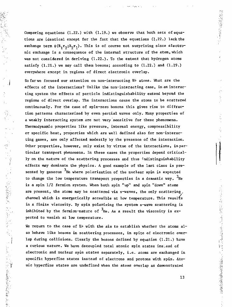
T = 0.1 KB= 10 T
-10 - 8 - 6 - 4 - 2 0 2 4 6 8DISTANCE FROM FIELD CENTER [mm] »
10
Fig. 3-Density distribution of E\ along the axis of a magneticfield configuration as used in our experiments with B =10 T.The gas is treated as an ideal Bose gas. Above the criticaldensity the condensate appears as a sharp spike in the den-sity profile (solid line). Well below n the density profilehas a gaussian shape (dashed line). a
20

The presence of the external field causes BEC to occur in the narrow region
of space defined by the oscillator ground state which has a width (between
classical turning points) of 2(h/mw ) = 6 x 10 cm for our system opera-
ted at 10 Tesla, see Fig. 3.
1.2.4. The interacting case
Before we solve Schrodinger's equation for the interacting case it is20
useful to follow the approach of Goldman et. al. and analyze the relative
importance of the various characteristic energies involved and the associa-
ted lengths:
- The zero point energy e = — hw ^ 2.5 x 10 mK
18- The interaction energy e. = p v * 0.4 (p/10 )mK
int o o ,,18 —-
- The thermal energy e = kTc = 16 (p/10 ) 3 mK
where p is the density in the center of the field in units (H+/cm ) ; v is
the interaction strength in the scattering length approximation, v =
4irah /m, a. is the s-wave scattering length. T is the (ideal gas) criti-
cal temperature for BEC. A field B = 10 T is assumed throughout this chap-
ter.
The associated characteristic lengths are obtained by balancing the charac-1 2 2
teristic energies against the external field according to e , = - -mtü x .
- x = ( h/mu ) 2 , * 3 • 10~4 cm ,zp o _1_ 1
" xint= ^ o V ^ l * °'04 <P/ lo l8)N- x , = (2kT /ma2) 2 « 0 . 2 ( p / 1 0 1 8 ) 2cm
t h co
The significance of these figures is straightforward. Above T and for any
experimentally conceivable density e , 9* E. . Hence the interactions may
be neglected (as in the preceeding Section) or treated perturbatively in a
weakly interacting Bose picture. Below T the ideal gas model predicts a ma-
croscopic occupation of the oscillator ground state with energy e . However,zp
x. > x so that an enormous broadening of the ground state is to be ex-
pected (as discussed in chapter 4 and ref. 21). A natural way to account for
this effect is to replace Schrodinger's equation (2.5.) by a self consistent
set of coupled (Hartree-Fock) mean field equations as done by Goldman et,20 , „ . . . . 22
al. and Huse and Siggia.
21

1.2.5. Hartree-Fook approximation
We firs t rewrite the hamiltonian (2.2b.) in terms of construction
operators, approximating the interactions by shape independent pseudopoten-
t ia ls
— .2 . V(r. .) = —v . £ . 5 ( r . . ) (2.20.)
We limit ourselves to the restricted set of terms of the operator density
3C(r) required to calculate the diagonal matrix elements of a, so far, unde-
termined number representation {|n >}
K = ƒ dr ff(r) (2.21a.)
We divide 3f(r) in two parts, separating the single particle terms from the
interaction terms:
3C(r) = JC^r) + JC2(r) (2.21b.)
w h e r e --> » -> h 2 2 -v ->3C, (r) = £ f, (r) [—-—V + U (r)]ip, (r)n, (2.21c.)1 k k 2m ext k Tc
* ->- v -+2 -y 2
J. .2 . _,. 2
The statistical variational principle
2
[-f | ^k(r)| ]
(2 .25. )
£1 < ü E a + « 3f-3C> " (2.22.)o o o
enables us to obtain an upper limit for the thermodynamic potentialÜ through
variation of the trial ensemble defined by a trial hamiltonian 3C .
We choose for 3C an arbitrary one-body trial hamiltonian 3f = ? H(r.)
H(r.) y, (r.) = E v>, (r.) (2.23.) ,l k l k k l |
3C (r) = s e |vk(r) [ iL (2.24.)
With the t r i a l ensemble we find for fi(r)
22

> = <n. > (2.26a.)k o \ o
Wo
where
2 <Vo (2-26c- )
One notes that expression (2.26c.) becomes unphysical when <i\> - 0(N).
This happens for the ground s tate <p (r) in the case of Bose-Einstein conden-
sation. Once a state becomes macroscopically occupied the ensemble leads to
macroscopic fluctuations (Ap ) in the density ..
= Y 0(N)
= 0(p)
A well known procedure to avoid this phenomenon is to use the Bogoljubov23ansatz which is here equivalent with replacing the number operator n by a
real numbern = N (2.27.)
o o1.2.6. T > Tf.
We first assume the fluctuations to remain finite in the thermodyna-
mic limit and minimize u by variation of the occupation numbers <n, > . This
is particularly simple for the case of the grand ensemble since there is no
restriction on the total number of particles
(r) 4 <nk>o + (2.28.)
22 8fiThe minimum is found when ——- = 0 for a l l values of k or equivalently
3 "k
This relation represents a set of Hartree-Fock equations coupled through
23

expression (2.4.) for the density.
Since e ,> e. as discussed in Section (1.2.4.) the equations may be solvedtn. int
to a satisfactory degree of self consistency by an iterative procedure.
First we set p(r)=0 and obtain the harmonic oscillator solutions (2.8.)
equivalent with the non-interacting density distribution (2.]2a.). For sim-
plicity we limit ourselves to the case that 1 _ _- -è-moV)° 2 ° (2.30.)
Furthermore , the strongest effects are to be expected in the center of the
field where the density is highest. Thus it seems justified to further appro-
ximate go/o for this analysis by a series expansion
p (r) = pQ [1 - (x/xQ)2 + ....] (2.31.)
where p is the density in the center of the field (see Section (1.2.4.))
and x is the half-width of the (non-interacting)gaussian density distribu-
tion 1
With (2.31.) the effective single particle potential of equation (2.29.) re-
duces to
Uext
( f - ) 2 • .... (2.33.)o
where the first term represents the first order shift of the energy levels
due to the perturbation and we used a slightly different definition of x. :1 2 2 lri
(2 v p = -r-mto x. .; compare with Section (1.2.4.)). Since x. < x we
note that one has obtained a rather good degree of self consistency after
one iteration and that the ideal gas provides a remarkably good approxima-
tion to the density profile above T .One may argue that in general the use of WKB-solutions to equation (2.29.)
is justified if the (effective) potential varies sufficiently slow with po-. . 19 22
sition. ' For our system this implies
? = A~"J g 3 / 2{ exp [ 6 (P"2vop (r) - Uexfc (?))]} (2.34.)
24

1.2.7. T < Ta
Below T we use the Bogoljubov ansatz (2.27.) and vary again with
respect to the occupation numbers N and <n,>. For [ 3J2(r)/3 <n,>] k ^ 0
° K <\,we o b t a i n t h e same r e s u l t s as above T ( 2 . 2 8 . ) , [ 3 0 / 3 <n >] however becomes
c o
(2NQ- 1) + (2.35.)
Thus below T (and putting 2N - 1 «= 2N ) the Hartree-Fock equations for <p
and <p. are different:
where
(2.36.)
^ ^ __p(r) = pc(r) + pn(r)
Pc(?) E ko(r)|2NQ .(2.37.)
At first glance the new equations have a rather serious deficiency that
violates the variational principle. We arrived at a result, where the ground
state requires a different hamiltonian than the excited states resulting in
non-orthogonality Between ground state and excitations. However, in the qua-
si-classical approximation for k -> °°
ƒ *>0(r) Vk(r) dr -> 0
so that the problem only is serious for the first few excited states. Sin-
ce this only affects a very restricted and finite set of equations it is
plausible that the non-orthogonality is of little relevance for the results
to be obtained. A more careful analysis of this problem has been made by
Huse and Siggia and by Goldman ' and leads to a non-local term in the
Hartree-Fock equations for k j* O which can be shown to be of no consequence
to the results.
25

1.2.8. The zero temperature limit
Before we continue with the self consistent solution to the Hartree-
Fock equations for finite temperature we first analyze the zero temperature
limit
This equation was first studied by Gross and Pitaevskii and may be sol-
ved approximatively (to obtain the density profile) by neglecting the kine-
tic energy completely (recall that E < E. ):zp int
Since p (r) must be positive, this may be rewritten as
po(?) = V[ V Uext(?)1 6[ V Uext(?)]°where 6 is the unit-step-function. The single particle ground state energy,
e , follows from (2.40.) by setting r = 0. After substituting the result
[E = v p (o)] into (2.40.) we arrive at the result shown in Fig. 4A alongo o o , ..
with the effective one particle potential U ..^(r) = Ü t ( r ) + v p (r).
P (r) = —[v p (o) - U _(r)] 9(x - x) (2.41.)o v oo ext zp
o
vopo(o) (for |x| < x.n t)
":) (for |x| >
This result is equivalent with the result of Walraven and Silvera (chapter
4). I t shows that the condensate will distribute itself in such a way that
the interaction energy is balanced by the external field.
A justification for the neglect of the kinetic energy term may be found in
first order perturbation theory with respect to the ground state [<p (r)]
of the unperturbed (non-interacting) oscillator.
ihvwhere
o
26

Note that the resul t for e is only correct since the density does not vary
significantly over the range of V (r) (recall that x < x. ) .
DISTANCE FROM FIELD CENTER - f
•' Fig. 4-Effective single-particle potentials atr T=OK. A. Potential used to describe conden-
sate. B. Potential used to describe the sin-gle-particle excitation spectrum. The distri- '.bution of the condensate along the axis ofthe magnet is also shown. The inset shows sche- , :
C matically how the condensate density falls off'(• smoothly to zero over a healing length ? . :
1.2.9. The excitation spectrum , \
The s ing l e p a r t i c l e e x c i t a t i o n spectrum follows from the Har t r ee -
Fock equations by assuming <n > = 0 for a l l s t a t e s Ü except V o , ( ? ) .
2
' [~fev 2 + Uext (?) + 2 v o p ( ? ) 1 *k(?) = V k ( ? ) (2'43-}
: Since p(r) - p (r) one notices immediately that there is a different effec-
f] tive potential for the excitations IT '(r) = U (r) + 2v p(r ) ; see Fig.; / 6 X 1 CAL O
I. 4 B .
i] u^c)(?)=. :;
: ' 27 I

We solve equation (2.43.) for e, using again first order perburtation theory
as in the preceeding section:
Ek = ( \ + T } hwo + 2vo J d* llpk°) ('}l p(*} (2.45.)
Limiting ourselves to the low-lying excitations and putting p = p this ex-
pression reduces to
e k = (nk + \) huo + 2vQpo(o) (2.45a.)
Note that the first order perburtation theory leads to a gap of size v p (o)
in the excitation spectrum:
E = Neo o
E = (N-l)e + e. ,0 ., .o,k o k (2.46.)
= E + v p (o) + n. huo o o K o
The gap is known to be an artifact of the first order perturbation theory
and may be avoided using a canonical transformation to quasi-particles -the
Bogoljubov transformation. From Fig. 4B one expects the low-lying excitations
to be localized at the minima of the effective potential. However, Huse and
Siggia point out that within the Bogoljübov-Hartree-Fock approximation thelow-
lying excitations experience an effective potential almost identical to that
seen by the condensate. This implies phonon-like excitations throughout the4
condensate as is the case for He.
1.2.10. The concept of healing length
An obvious deficiency of the result of equation (2.40.), shown in
Fig. 4, is the sharp edge of the condensate density at x = x. which is in
contradiction with the omission of the kinetic energy term from the hamil-
tonian. A better approximation is shown in the inset of Fig. 4. where the
condensate density falls off smoothly to zero, over a region £ . This dis-* o
tance ? Q , over which the wave function can adjust itself to a rapidly varying(effective), potential, is known as the healing length and studied in detail
27By Gross in relation to the structure of vortices in liquid helium.
The healing length may he estimated by reducing the size of a cube of linear
dimension until the kinetic energy of a single particle in its translational
ground state equals the interaction energy due to the presence of other par-
tides- in the box:
28

£ = (8irpv ) 2o o 1.
= 2.3 * 10~6 (1018/p)2cm (2.47.)
Note that for typical experimental conditions £ < x. , so that the results
of the mean field theory will be reliable as far as healing effects are con-
cerned.
1.2.11. Spatial separation of condensate and normal component at finitetemperatures
The solutions for the Hartree-Fock equations for T = 0 and T > T
are readily generalized to obtain a coupled pair of equations that describe
the density distributions of normal component and condensate at finite tem-
peratures .
p (r) = — {y-2v p (r)-U (r)} 9{y-2v p (r)-U (r)} (2.48a.)o
Pn(r) = ( l A t h )3 g3/2{exp [B(p-2voPn(r)-2voPo(r)-Uext<r))])
(2.48b.)
where we have replaced e by u since we are now interested in temperatures
below T . The expression for p (r) may be simplified by substituting equa-
tion (2.48a.) in (2.48b.). This leads to an expression for p (r) which no
longer depends explicitely on p (r) :
Pn(r) = \k go/ofexp -B|v-2v_p_(r)-U_..t(r)|} (2.49.)
Returning to equation (2.48a.) we note once more, as in Section (1.2.8.),
that the interactions' tend to broaden the density profile until the inter-
action energy is balanced by the external potential. However, for a given
density, the interaction energy is larger for the normal component than for
the condensate as seen from the Hartree-Fock equations. Therefore, the nor-
mal component will tend to spread more which results in a spatial separation
of the two components, although the effect is not complete. The equations
(2.48a.) and (2.48b.) have been solved to salf consistency by Goldman et. al.1 20 22
-' I and Huse and Siggia. Although there is a slight disagreement between
'/• both results as far as the detailed density profile at the edge of the con-: densate is concerned, all authors agree that the condensate may be recog-
V:, nized as a distinct feature of the density profile and as such may be used
:•;. to detect BEC as suggested by Walraven and Silvera (Chapter 4). The results
29

of Goldman et. al. are reproduced in Fig. 5.
Huse and Siggia suggest that the depression of the normal density (within
the condensate), implicit to equation (2.49.), is an artifact that disappears
with the use of the Bogoljubov-Hartree-Fock. approximation without affecting
the qualitative results for the density profiles presented above. Finally1 ft 9
we note that for cross-sectional densities of at least N/A = 10 H+/cmthe ideal Bose gas provides a remarkably good approximation for T . One
20 C
finds T = 30.2 mK for B = 10 T, whereas the mean field theory yields29.34 mK for the same experimental conditions.
1.2.12. Properties associated with the nuclear spin
So far we neglected the possible influence of the atomic hyperfine
structure on the collective properties of the gas. However, the nuclear spin
affects the total number of accessible states and therefore has a direct in-
fluence on the onset, possibly also the nature, of BEC.
The nuclear relaxation rate which determines the time scale over which ther-
mal equilibrium between the nuclear states is achieved is also important.
If the nuclear relaxation proceeds slowly, i.e. at a rate negligible in com-
parison to the experimental time scale, the system behaves as a mixture of
two distinguishable Bose systems (with separate chemical potentials) each
of which may undergo BEC. On the other hand, in the case of rapid relaxation,
one chemical potential is sufficient to describe the system and BEC only oc-
curs for the spin configuration with the lowest energy (the | a> -state de-
fined in section (1.1.2)).
1.2.13. Rapid nualear relaxation
In the case of fast relaxation one expects spontaneous nuclear po-
larization, once the |b> -state (for definition of symbols in this section
see (1.1.2.)) can no longer be populated thermally, thus for temperatures
T ^ T h f s where T h f g = (Efe - E )/kg corresponds to the hyperfine splitting
between the |a> - and |b> -states. In the high field limit T, _ = (a/2 +
h f s where T h f g = (Efe - E )/kg
e |a> - and |b> -states.
j j j ^ = 54 mK at 10 T. The relevance of this nuclear polarization with
i respect to BEC is straightforward. By polarizing the nuclear spins we re-
: duce the total number of accessible states by a factor 2 and therefore also
; the density required for BEC. Moreover, since T, . is field dependent, BEC
:. may be induced at constant density by varying the magnetic field. Aspects
of this nature have been discussed to some more detail by Mullin for an
ideal Bose gas of hydrogen atoms in a uniform external field.
3Q

s -
0.1 0.2DISTANCE (cm)
Fig.S-Axial density distribution of E\ nearthe critical temperature for BEC (after ref.20). The same field profile is assumed asin Fig. 3. The inset shows the temperaturedependence of the chemical potential y andthe single particle ground state energy e .
DISTANCE FROM FIELD CENTER —
Fig.6-Fhase separation in a two-compenent con-densate, containing atoms in both \a> and\b> hyperfine states. A change in densityat the interface accounts for the local pres-sure equilibrium.
31

1.2.14. Slow nuclear relaxation - Phase separation between aondensates
The other limit, negligible nuclear relaxation, is more interesting.
The system now behaves as a mixture of two distinguishable Bose systems, each
of which may undergo EEC. In contrast to what might be expected, nuclear po-
larization can also occur in this limit. As pointed out by Statt and Eerlins-29
ky this is to be the case if recombination dynamics are included in the
picture. A discussion of these aspects of the problem, which may well turn
out to be of most relevance to experiment, is postponed till section (1.4.).
The superfluid hydrodynamics of a Bose mixture have been studied by Siggia30 31
and Ruckenstein ' but a discussion of their analysis falls outside the
scope of this thesis, due to its rather specialized and detailed nature.
Here, we shall discuss one interesting feature of Bose mixtures: phase se-
paration of the two condensates of a Bose mixture of |a> - and |b> -state
hydrogen atoms in an inhomogeneous magnetic field. For this purpose we ex-
tend our variational analysis to allow for two condensates subject to the
same interactions:
We obtain for ft(r)
?2(r) = 2 n(r) + ft , (r) (2.51.)a ab
where fi has the same form as expression (2.25.), while
ab =- vo A l ka l2 ' Kb^l2 ^ a ^ V '
Limiting ourselves to T = 0 equation (2.51.) leads to a pair of coupled
Gross-Pitaevskiiequations describing the two condensates
2
b2 ^ ?
2 + u ( ^ + V(^)] V ^ V ( } (2.52b.)2m
where <p and «p are the ground-state wave functions and e , e, the ground-
state energies per particle for atoms in the |a> and |b> hyperfine states.
The total density is written as p(r) = p (r) + p, (r).a D
Note that the external potential now also depends on the hyperfine stateUext H ^ n Mo± x ' wo+ = v B/(mxm). [For definition of the various symbols
see section (1.1.2.) and (1.2.1.)] .
32

Calculating e and e, to first order in perturbation theory we find
e = 4 h ü ) ( + ) + v P<°> = v P<°> (2.53a.)a i o o o
eb = ThliJo") + vop ( o ) " V o p ( o ) (2.53b.)
The Gross-Pitaevskii equations may now be solved, neglecting the kinetic
energy terms as in Section (1.2.8.)
? f ^ ) ] (2.54a:)
o
o
Trivially these equations are only meant to be valid as far as they predict
p to be positive. Note that the solutions (2.54a.) and (2.54b.) seem to con-
tradict each other. The only way to avoid the paradox is to assume that they
apply to disjoint regions of space, as shown in Fig. 6. Near the center of
the field we find the lowest hyperfine state (p = p ) , whereas near the sur-
face of the condensate only the |b> -state is present (p = P.). The discon-
tinuity in the density at the interface is required to balance the pressure
on both sides of the interface. The exact position of the interface depends
on the relative concentrations of the two components. Of course a sharp in-
terface is physically not realistic. A proper treatment of the kinetic ener-
gy would show gradual ch'anges of the condensate densities over distances of
the order of the (local) healing length.
33
1.3. INTERACTION OF H4- WITH SURFACES
1.3.1. Introduction
Knowledge of the bulk properties of H4- as discussed in sections
(1.1.) and (1.2.) is not enough to understand the behaviour of the system
under real experimental conditions. This is caused by the gaseous nature of
H+ that requires containment at all temperatures. Unfortunately pure elec-
tro-magnetic confinement is not very promissing so that walls of rigid ma-
terials are required. However, since gaseous H+ itself is the most weakly
interacting atomic system known, the presence of a different material leads
to an important perturbation of the system. Especially at low temperatures,
where the most fascinating properties of H+ are to be expected, this leads
to strong surface adsorption followed by rapid recombination. In view of these-
considerations it is not surprising'that the main experimental effort ini-
tially has been concentrated on minimizing these surface effects. In this
context the first experimental demonstration that helium covered walls at
T ** 300 mK provide an enhanced lifetime of approximately eight orders of
magnitude, as presented in chapter (3), is to be considered as a breakthrough.
Subsequently the experimental effort was concentrated, as far as the surface
problem is concerned, on the determination of the adsorption energies of H3 4
on the surfaces of He and He. Here the publication of a study of spin po-
larized atomic deuterium, presented in chapter (6), provided the first com-
parison of experimental and theoretical values for an adsorption energy and
secondly establised that surface recombination is the dominant loss mecha-
nism for the hydrogen isotopes at low temperatures. For completeness we note4 3
that the adsorption energies of H on He and He (e * 1 K and e «0.4 Kres-
pectively) are also known. They were obtained essentially simultaneously and
by different experimental techniques by groups at the University of British
Columbia ' and the University of Amsterdam. ' However, this work falls
outside the scope of this thesis.
In this section we first briefly present theoretical estimates for the ad-
sorption energies. Then we discuss the interaction between bulk gas and sur-
faces in relation with BEC using a theory for the surface adsorption iso-
therm.
1.3.2. Hi in contact with the surface of liquid helium
With the knowledge that H+ may condense onto the surface of liquid
helium we have to reconsider our analysis of the weakly interacting Bose gas
34
and find out how the model is affected by surface adsorption. In this sec-
tion we will show that such an analysis (technically a calculation of the
surface adsorption isotherms)leads to two main conclusions. First the exis-
tence of a saturation coverage, i.e. only a limited amount can be in the
adsorbed state, and secondly that the surface has to be saturated before
BEC becomes possible in the bulk. Moreover, the saturation coverage will
be found to be essentially independent of temperature, so that there is
little preference to try and achieve BEC at low or high temperature as far
as the surface coverage is concerned.
The Hartree-Fock approximation presented in section (1.2.5.) may also be
used to study the atomic hydrogen system in contact with the surface of li-
quid helium. For convenience we shall neglect recombination and limit our-
selves to a configuration with uniform external field. We shall also sup-
press the additional degree of freedom provided by the nuclear spin, which
may supply some interesting features to the problem, but does not affect the
main conclusions of our analysis. These considerations have been discussed
by Goldman and Silvera. Finally we shall neglect any direct interaction
between atoms in the gas and the adsorbate.
To allow for surface adsorption we have to extend the Hartree-Fock equations
by a set of equations for the surface states <p (r). Only allowing for BEC inSq
the bulk we obtain
2[~lmv2 + 2v3p3 ] V ? ) = ek3)*k(^ k*° O.la.)
where p , p)j ' and p_ are the total, normal and condensate densities in
the bulk respectively, v_ and v„ are the bulk and surface scattering ampli--> J b
tudes, U (r) represents the surface adsorption potential and 2v_p_ is theO b b
interaction energy due to a finite density of adsorbate [p_(r)] on the sur-
face. We shall assumeand V s = V;3 <3-2-)
Us(r") = U(z) (3.3.)
Considerations concerning the validity of these two approximations are dis-37
cussed, m a slightly different context, by Edwards and Mantz. The use of
35

the bulk scattering amplitude v- is only justified if the interatomic po-
tential is not significantly changed by the presence of the helium surface.
Also the use of a uniquely defined adsorption potential U(z) is associated
with this point, since it assumes the surface potential to be independent of
the distance of neighboring atoms which implies that the surface of the li-
quid is not distorted by their presence. Both approximations are quite rea-38
sonable in view of Mantz and Edwards analysis of the adsorption problem
where the wave function was found to extend quite far above the helium sur-
face.
The main aspect of equations (3.1.) that seems to be questionable is the
very concept of a mean field, which neglects any correlation in the motion
of the atoms. Although the mean field approach was well suited for the ma-
croscopic external fields of section (1.2.) it seems to be less appropriate
to treat the interactions within the monolayer of adsorbate, having a
"thickness" comparable to the range of the interatomic potential. However,
an alternative treatment of the interactions is not available in the lite-
rature undoubtedly due to the strong anisotropy of the scattering problem
on these helium surfaces.
1.3.3. Further simplifications
In order to solve equations (3.1.) within the approximations (3.2.)
and (3.3.), we note that the two-dimensional translational invariance of the
isurface mean field hamiltonian enables us to decompose the adsorbate wave !
function in components normal (= z) and transverse (= xy) to the surface.
I *Sq(r) = • <*) \GL) (3.4.)
pc(r) = <J> (z) p_ (3.5.)
where (ji(z) is real and positive and will be referred to as the "bound state
wave function", normalized to unity
ƒ dz <j>2(z) = 1 (3.6.)
," i P2 is the two-dimensional density of hydrogen atoms, i.e. the number of
>"i atoms per unit area. To further simplify the adsorbate equations we inte-
:. grate over the bound state wave function
2[ -'T—V. + 2v„p„ J dz <j> (z) - e ] V (r, ) = e l ' (r, ) (3.7.)
'•• ea> the mean 'field solution to the adsorption energy is defined as
36

h2e a= { dz <Kz) [+—JiT - U(z)H(z) (3.8.)
37Returning to the line of thought of Edwards and Mantz we assume <j>(z) to
be independent of coverage so that the bound state wave function <J>-(z) for
one single atom adsorbed on the helium surface may be used and equation
(3.7.) reduces to
where v, = v. ƒ dz $ (z). The integral has been evaluated by Edwards and
Mantz, who find
ƒ dz 4,J(z) = 0.095 A"1 (3'10-)
The interpretation of this approximation is straightforward within the mean
field picture. The bound state wave function is not allowed to broaden, when
the surface density increases. Such a broadering leads to an increase in ki-
netic energy perpendicular to the surface (i .e. e becomes smaller), but alsocl
to a reduction of v„. Thus broadening of <J>(z) will become energetically fa-
vorable if the surface density is high enough. It remains to be seen however
whether a further minimization of the mean field energy would provide a bet-
ter approximation to the physical problem in view of the total neglect of
correlation energy.
We have now arrived at a point where the Hartree-Fock equations have been
simplified far enough to enable a solution, but before proceeding in this
direction we note that one may also start out from the beginning with equa-
tion (3.9.) through the ansatz of pure two-dimensional surface states and a
calculation of v_ in two dimensions. This approach, which tends to overesti-
mate the interaction energy due to phase space limitations, has been taken
results in
v2 = 2.9 h2/2m (3.11a.)
which is to be compared with the result of Edwards and Mantz
2v£ = 2.1 h /2m (3.11b.)
who based their results on the Monte Carlo calculations of Etters, Danilo-
wicz and Palmer. Using only the s-vave scattering length one obtains
2v2 = 1.7 h/2m
37
39by Silvera and Goldman and results in

1.3.4. Saturation of the surface coverage
Solving the Hartree-Fock equations separately to first order in per-
turbation theory as in section (1.2.) we obtain
(3.12b.)
P2 > (ea/2v2)H p s a t (3.13.)
For coverages
(2)the single-particle surface energies e become positive in the mean field
picture and one expects the surface coverage to saturate. Indeed, p„ does not
grow much above p as was established by a calculation of the adsorptionsat __isotherms (see section (1 .3 .6 . ) ) . Both Silvera ana Goldman and Edwards and
37
Mantz did not take into account exchange effects between identical parti-
cles, which give rise to the factors 2 in expressions (3.12.) and (3.13.).
The publication by Goldman and Silvera corrects for this effect. Here we14 -2
estimate p = 1.2 x 10 cm for an adsorption energy e = 1 K and a =SaL 3.
0.72 A using equations (3.11c.) and (3.13.).
1.3.5. BEC in the presence of surfaces
With the procedure of section (1.2.11.) we find expressions for the
bulk and surface densities in terms of y and T
P3 = P 3 O ) + ( l A t h ) 3 83/2^ e x p [ B ( y ~ 2 v3 p3 ) ] Ï (3.14.)
P2 = a/* t h>2 8X{ exp [ 3(P - 2v2p2 + ea)] } (3.15.)
We first note from equation (3.15.) that the adsorbate cannot Bose condense
due to the divergence of the g- (z) function (for z -*• 1), as discussed byTO J- t A
De Groot e t . a l .
vergence implies
De Groot et. al. (see also the book by Band ). Furthermore the same di-
V < 2 V 2 P 2 - e a (3.16.)
Then, to achieve BEC in the bulk one must satify
V = 2 V 3 P 3 (3.17.)
38
1

v-"Noting that this value is non-negative one may combine equations (3.16.) and
(3.17.) to obtain a general condition for BEC in the presence of surfaces
2V 2P 2 -
From this inequality one may draw two conclusions:
(3.18.)
- A non-interacting Bose gas (v„=v„=0) does not display BEC in thepresence of surfaces if a surface bound exists (e >0).
- To observe BEC in an interacting Bose gas in contact with surfa-ces, these surfaces have to be "saturated"
sat(3.18a.)
Over the range of densities of experimental in teres t the second term may be— ft oc
neglected (v„/v2 * 3.7 x 10 cm).
1,3.6. Surface adsorption isotherms
The adsorption isotherms, relating bulk and adsorbate densities at
constant temperature, are now readily obtained by eliminating the chemical
potential from the expressions (3.14.) and (3.15.) for p„ and p„. This was39
done numerically by Silvera and Goldman and, properly taking into account
the nuclear spin and exchange effects, by Goldman and Silvera. Results of
this last publication are reproduced in Fig. 7.
10B
1014 =
£ l013
1012 ^
10"
1
_
-
1 1II
1 ' 1 '
E Q = 0 . 9 K
T=OK
ml i 1 / I
1 ' 1
_ — - —
1 , 1
1 1
i 1
1 1
_^ .— !
1 1
1
- "
-
1
10B 10'6 10n v [HJ/cm3!
10'8 1019 1020 1021
Fig. 7-Adsorption isotherm for H\ on a He surface, f e = 0.9 K;after ref. 36). The surface density nq is plotted Vertical-ly, the bulk density ny horizontally. The neglect of exchan-ge effects leads to the dotted curves. The arrows indicatethe critical densities for BEC.
39

37Edwards and Mantz present explicit equations for the surface and bulk
chemical potentials which are correct to first order in the interaction.
Here we shall limit ourselves to some useful expressions that apply for
T P T . Then the functions g_ ._ and g. represent simple exponents and by
eliminating p we obtain a high temperature expression for the adsorption
isotherms
P2 = * t h P 3 exp [g(2v3P3 - 2 V 2 P 2 + ea)] (3.19.)
which reduces in the low density limit to the well known ideal gas result
P2 = Xthp3 exp (Bea) (3.20.)
This expression will be used in section (1.4.8.) where a phenomenological
theory for surface recombination is presented.
40 . ••!
!

£ 1 .4 . THE STABILITY OF H+
1.4.1. Introduetion
In any experimental study of the properties of atomic hydrogen one
cannot escape being confronted at some stage with the kinetics of the re-
combining gas. For this reason i t seems appropriate to consider here re-
combination in some detai l . The hydrogen recombination reaction is one of
the most fundamental chemical reactions and has been extensively studied,41both theoretically and experimentally for mote than fifty years.
Here, we do not aim at a detailed description of the various known recom-
bination processes, but rather emphasize the physics of recombination at
low temperature. In particular we shall analyze the magnetic field depen-
dence and in this way explain the remarkable s tabi l i ty of the gas in high
Ï',. magnetic fields. Also the dependence of the recombination rate on the va-
rious hyperfine states of the collision partners will be discussed.
The most likely process for the formation of a hydrogen molecule is a
three-body process
H + H + X •+ H2 + X (4.1.)
where X may be another hydrogen atom or an atom of a different gas. The
.] ' two-body radiative process
• •>' H + H •* H2 + hv (4.2.)
:•: was shown to be completely negligible on a laboratory time-scale by42Jones et a l . Reaction (4.1.) may also proceed in two steps
; H + X ->- (HX)*(4.3a.)
;;';_. (HX) + H -> H2 + X
where X H and the symbol is used to indicate that the intermedeate
•/"'_ . state is meta-stable. This process is known as an exchange process, be-
,~ cause the final step involves H X exchange to form H„. Another two-
'éJ s t e P reaction requires an energy transfer mechanism to stabilize the mo-
'?f' lecule:
'••r H + H •*• H *
h (4.3b.)J | H2 + X -»- H2 + X
;•- 4 i
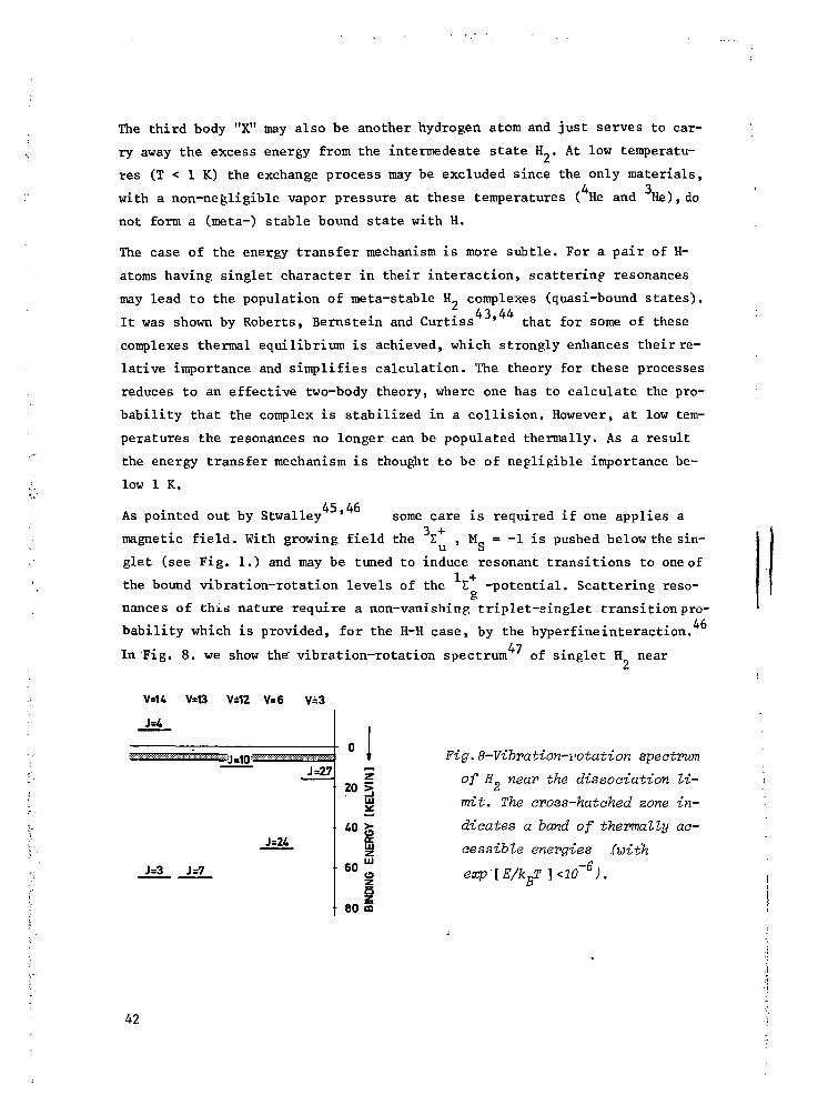
The third body "X" may also be another hydrogen atom and just serves to car-
ry away the excess energy from the intermedeate state H_. At low temperatu-
res (T < 1 K) the exchange process may be excluded since the only materials,
with a non-negligible vapor pressure at these temperatures ( He and He), do
not form a (meta-) stable bound state with H.
The case of the energy transfer mechanism is more subtle. For a pair of H-
atoms having singlet character in their interaction, scattering resonances
may lead to the population of meta-stable H„ complexes (quasi-bound states) .43 44
I t was shown by Roberts, Bernstein and Curtiss ' that for some of these
complexes thermal equilibrium is achieved, which strongly enhances their re-
lative importance and simplifies calculation. The theory for these processes
reduces to an effective two-body theory, where one has to calculate the pro-
babili ty that the complex i s stabilized in a coll is ion. However, at low tem-
peratures the resonances no longer can be. populated thermally. As a result
the energy transfer mechanism is thought to be of negligible importance be-
low 1 K.
,45,46As pointed out by Stwalley some care is required if one applies a
magnetic field. With growing field the E , M_ = -1 is pushed below the sin-U o
giet (see Fig. 1.) and may be tuned to induce resonant transitions to one of
the bound vibration-rotation levels of the Z -potential. Scattering reso-
nances of this nature require a non-vanishing triplet-singlet transition pro-
bability which is provided, for the H-H case, by the hyperfineinteraction.In Fig. 8. we show the" vibration-rotation spectrum of singlet H near
V±12 V=6 V=3
J=27
J=3 J=7
z203
HI
10 fc60 UJ
5
80 5
Fig.8-Vibration-rotation spectrum
of H near the dissociation li-
mit. The cross-hatched zone in-
dicates a band of thermally ac-
cessible energies (with
42

Fig.9-Effective interaction po-
tential of two H atoms as func-
tion of particle separation R.
Solid line: partiales interae-3 +
ting via the E -potential.
Dashed line: atoms interacting
via the I -potential
the dissociation limit along with a band of thermally accessible energies
for B = 10 T. Note that low J resonances (J < 4) are well below threshold.
Although the v = 14, J = 4 vibration-rotation state may be tuned above
threshold i t also turns out to be inaccessible at low temperatures. This
may be illustrated using Fig. 9, where we have plotted the effective inter-
atomic potential v (r) of two H-atoms for various values of relative angu-
lar momentum (J = 0,1,2,3,4). V (r) appears in the radial Schrödinger equa-
tion for the pair:
h2 d2
.2V (r) E v(r) + J(J+l)-2-5J 2pr2
(4.4b.)
where V(r) may be the triplet potential ( solid curve in ?ig'. 9. ) or the
singlet potential (dashed line in Fig. 9.) depending on the spin state of
the pair, u = m/2 is the reduced mass and r = |r. - r„| .
43

For all but the lowest states of relative angular momentum the effective
potential provides a barrier (rotational barrier) to the radial motion of
the pair, high in comparison to accessible energies at low temperatures.
The probability to tunnel through the barrier into the v = 14; J = 4 sta-
te may be shown to be negligibly small for energies E/k_ ^ 0.25 K.
We note that the absence of resonant recombination for H„ is somewhat fortu-
nate. For D-D collisions a resonance, associated with the v = 21; J = 0 vi-
brational state of D„ exists at ^ 1.7 cm below the dissociation limit, '
which may give rise to enhanced recombination in fields above "V 1.9 Tesla.
However, for the hydrogen case the non-resonant direct process will be domi-
nant.
1.4.2. The direct three-body prooess
The rate of recombination for the direct process
H + H + He + H2 + He (4.5.)
has been calculated by Greben, Thomas and Berlinsky (GTB), using a fully
quantum mechanical three-body scattering approach. Although the theory was49
developed in relation to experiments by Hardy and coworkers, who studied
the recombination of hydrogen atoms at I s 1 K in zero field, the results
are more generally applicable. In particular the theory is very useful to
understand the origin of the B field dependence of the recombination rate
in high fields. The fundamentals of the method also apply to surface recom-32-35
bination, dominant at low temperature, where the surface effectively
acts as a third body.
We define the recombination problem by considering an ensemble of initial
states \V >, composed of all (unsymmetrized) non-interacting atomic three-
body states
(4.6a.)
o> = Ik h k h -t >
I lnl*K2 n2'fe3
where k^ and k,, represent the momenta of H-atoms in hyperfine states h.. and
h 2 respectively and k3 represents the momentum of the He-atom. All three
atoms are assumed to be in the electronic ground state. The final states
y> consist of two particles, a hydrogen molecule with momentum p.._ and a
He-atom with momentum p„:
l<f>3> = l P 1 2» v, IJ^, IMj.; p3> (4.6b.)
44
The internal state of the molecule is represented by the vibrational (v),
rotational (L,Mj ) and nuclear-spin (I,M_) quantum numbers. L+I must be even,
as required by symmetry. Also in the final state only electronic ground sta-
tes are relevant for the present problem.
At this point one may raise the question if it is justified to use an initial
state which is not symmetrized with respect to exchange of the hydrogen atoms?
Applying the general considerations of section (1.1.3.) we note that in the
low density regime, where the atomic wave functions do not overlap (i.e. for
densities n < A , , symmetrized and non-symmetrized pair states lead to simi-
lar spatial distributions of pairs. Then symmetrization is of no practical
consequence, and thus not required, for the initial states. The validity of
the GTB theory is thus restricted to the low density (or high temperature)
regime. But even at low densities the atomic or even electronic wave func-
tions-will overlap during the scattering process. This will be accounted for
by decomposing the initial state (4.6a.) into states which are properly sym-
metrizod with respect to the exchange of both electrons and protons.
The rate equation describing the reaction kinetics of process (4.5.) in the
absence of the reverse reaction, is given by
dn,, „(4.7.)
k is the rate constant for the reaction and follows from a quantum mecha-
nical evaluation of the transition rate from three-body initial states (i)
to two-body final states (f):
k = (2i°7i!f pi |Tif'2 6(Vpf} 6 ( W (4-8-}
Here P. is the statistical probability that an ini t ial state is occupied,
T._ represents the amplitude for the i-»-f transition and the 6-functions en-
force conservation of momentum and energy.
1.4.3 . The three-body scattering amplitude T.„ij
The three-body scattering amplitudes T._ represent a generalization
: of the more familiar scattering amplitudes for the two-body case. Althoughj
a formal expression for T.- is easily obtained (and will be discussed later
in this section) any practical evaluation involves, as one might expect, so-
me kind of decomposition into two-body scattering terms. Before discussing
l' the scattering amplitudes in more detail we first introduce a notation that
45

enables such a decomposition in the next section.
Dropping the symbol '"*", used in the foregoing sections to identify opera-
tors, the three-body hamiltonian is written as
3C = XQ + Vx + V2 + V3 (4.9.)
3C describes the non-interacting three-body system with atoms labeled 1,2
and 3. V. represents the interaction between particles j and k [ i/j=k^i ;
i>j>k£(l>2,3)], thus i is the "spectator" index. For convenience of presen-
tation pure three-body forces will be neglected. The hamiltonian may be re-
written for specific "channels"
K = 3f. + V1 (A. 10.)where
W. = Jf + V. (4.11a.)i o l
V1 E S 3V. with V BO (4.11b.)q=9 j oj^i
3f. ,_ is the three-body hamiltonian, where only particles j and k interact.V
represents the interaction of j and k with the spectator (i). By including
j = 0 in the summation the notation conserves the flexibility to separate 3f
from the interactions. More specifically, if particle 3 is the helium atom,
as we assume from this point, then Jf is the hamiltonian of an interacting
pair of hydrogen atoms and a free helium atom. Note that the hydrogen atoms
may be paired into a molecule or be in a continuum state. The time develop-
ment of the unperturbed initial and final states * (t) and *-(t) is definedo o
by
" T 7F *o(t) = *o *o(t) V o ) = ¥ o (4'12-)
" T ~£t *3 ( t ) = X3 *3(t) V o ) = *3 (4.13.)
The dynamics of the state * ó ( t ) , that evolved from* (t) (and has the same
energy as f ) is governed by the full hamiltonian
" T TT*o(t> =ïc *o+)(t) *>> - < (4-u')
The relation between V* and ¥ has been studied extensively in the litera-50 51 .
ture. ' We limit ourselves to using the results:
|y*> » lim inG(z)|H- > (4.15.)
°
46

wb are
G(z) H -ï- ; z = E + ijl (4.16a.)
We shall use more generally
G.(z) E — ! — (4.16b.)i z-3C.
Analogously one writes
\f.> = lira - in G~(z)|(|>_> (4.17.)J TITO -5
In view of equations (4.12.) and (4.13.) it is attractive to evaluate the
transition rate in the interaction picture of 3f or Jf„. This leads to two
expressions for T. = T„~ (see ref. 51 for a detailed derivation)
T.n = «|>,| V3 | Y+> (4.18a.)
30 3' o
T--. = «f>~| V° | T > (4.18b.)30 3' o
Equations (4.18a.) and (4.18b.) represent remarkable matrix elements in the
sense that they involve a mixed representation. As one expects initial and
final states are connected by a perturbation operator, describing the inter-
action between particles. However, the interaction in the initial state,
where three essentially free atoms interact (via V ) is quite different from
the interaction in the final state, where only two particles interact (via3
V ) , the H~ molecule and the He atom. Remarkably enough (4.18a.) only con-
tains the final state interaction explicitely. This feature suggests a very
convenient approximation where V , the interaction between the H atoms, is
completely eliminated.
1.4.4. The Faddeev equations and the AGS theory
To evaluate the scattering amplitude (4.18a.) we have to rely on a
perturbative expansion for |f > or G. We discuss the decomposition of G in
terms of the propagators G.. This point is not straightforward because the
various two-body scattering processes mutually influence each other. Mathe-
matically this leads to a set of coupled scattering equations, the Faddeev
equations.
We first decompose G in analogy with the two-body case
G — r j- n IT^T (/. ia \
47

with i = o this forms the ansatz for the Born approximation in a Lippmann-
Schwinger picture, while i/o would lead to a distorted wave Born approxima-
tion. The Faddeev decomposition of G involves four components
G = G + S 3 G1 (4.20.)o i = 1
where
G1 = L ..o l
G1 = G V.G (4.21.)
Equations (4.19.) and (4.20.) are easily shown to be equivalent. Note that
the G1 ara interdependent. Substituting (4.19.) into (4.21.) we find
G1 = G V.G. + G V.G.V3^ (4.22.)0 l l o l l
Using the operator identity
G. = G + G V.G. (4.23a.)l o o l l= G + G t.G (4.23b.)
o o i o
which defines the two-body scattering problem in the presence of a non-
interacting spectator (i),one obtains the Faddeev equations for G
G1 = (G.-G ) + G t.(Gj+Gk) (4.24.)1 o' o i
where t. is a two-body transition operator. It may be shown that for in-
tegral equations of the Lippmann-Schwinger type a unique solution does not
exist in the three-body case. This problem does not arise for the Faddeev
decomposition if one requires equation (4.24.) to be satisfied.
Returning to (4.18.) for the transition amplitude we conclude that in
the evaluation of T Faddeev-like equations have to be enforced. This isen
most elegantly done by the method of Alt, Grassberger and Sandhas (AGS)
who expressed G in terms of scattering amplitudes U.. defined by
G = GjS-j + G.U^Gj i,j 6(0,1,2,3) (4.25.)
whereuij - " - V V + & W * j (4-26-)
We thus ask for T in terms of the U...
«frjv 3!^ = lim in «j),|v3G(z)|H' > (4.27a.)J ° + J °
48

= lira in «jj-lG-1 G -1JV > (4.27b.)n+o o j o
Now substituting (4.26.) with i=3 and j=0 we obtain in thé limit n+Othe sim-
ple relation
3 * (4.28.)
With this equation the three-body transit ion amplitude may be expressed as
a multiple scattering expansion only requiring G and the two-body t rans i -
tion operators t . . Moreover, the mathematical requirements as formulated by
Faddeev are enforced implicitely through (4.26.). For our problem (4.26.)
becomes
U„„ = G"1 + S2 t„G U. (4.29a.)30 o i=i I o Ho
which may be expanded by iteration to yield
U30 = C + (tl + t2) + £ W h + t2) + •••• (4-29b")
Following GTB we note that G |* > = 0 and thus G does not contribute to
the (energy conserving) scattering amplitude. Neglecting furthermore all mul-
tiple scattering terms we deal with the impulse approximation
U 3 Q - tx + t2 (4.29c.)
We note that in this approximation t , involving the interaction potential
between the H atoms does not contribute1. Physically this means that recombi-
nation occurs always when two hydrogen atoms, having some singlet character
in their interaction, collide in the presence of a helium atom. The only role
of the helium atom is to enable the reaction by conserving energy and momen-
tum in the process. The main justification for the use of the impulse appro-
ximation by GÏB seems to be the reasonable agreement with experiment. The es-
sence of this physical picture in relation to the field dependence of H+-atom
recombination in high fields was first pointed out by Silvera and published54
by Silvera and Walraven using a rough approximation to (4.1f.b.)
1.4.5. Deaomposition of the initial states
In the detailed discussion of three-body scattering, in relation to
the Faddeev theory and the multiple scattering expansion, the point of in-
distinguishability of identical particles was not raised. In general this
aspect can be accounted for by properly symmetrizing all states involved.
49

For our case GTB decomposed the. initial states (4.6a.) into states which are
properly symmetrized with respect to exchange of the electrons and protons
of the H atoms. The helium atom is treated as a distinguishable third body.
The final state ccnsists of two distinguishable particles, an H„ molecule and
a helium atom. Although, in principle, one also has to symmetrize all rele-
vant intermediate states this is, as usually, of no practical consequence be-
cause both the transition operators t. and the propagator G are symmetric
under exchange of identical particles, implying that only the properly sym-
metrized intermediate states can contribute. These concepts are reviewed by
Afnan and Thomas and, more in detail, by Goldberger and Watson.
We first consider the non-symmetrized initial state |f > more closely. Al-
though f = i+s is a good quantum number only for H in zero magnetic field,
the f representation also may be used to characterize the atomic hyperfine
states |h> in non-zero fields. To express the field dependence we specify
the field explicitely.
|h> = |B; f,m> (4.30.)
Within this representation the hypnrfine states become |a> = |B; O,O> ,
|b> H |B; 1,-1> , |c> = |B; 1,O> and |d > E |B; 1,1> and the unsymmetrized
H atom pair wave function, which is part of the initial state I* > (4.6a.)
may ba written as
1^22 lj 22
•*••*• + -> ^ 1 ^ 1 ^ 2 * * 2= |B; f ^ , f2m2) vO^rp *(R2r2) e L e (4.31,)
where <p represents an 1 s electronic wave function. To decompose (4.31.) in
fully symmetrized wave functions we first decompose the orbital, electronic
and spin parts separately.
The decomposition of the orbital wave function is done after transformation
to the relative coordinate system
(4.32.)
50

. . ., iq«(B_-R2) -iq-(R;,-R2) (4.33.)
$ ^ ( R . . R 2 ) - 75 te + (~i)a e 1
where a is even or odd, Q = lc..+ k„ and q = —(k--k2) represent the center of
mass momentum and relative momentum respectively. The spin part is decompo-
sed by a transformation to the coupled representation of I and S
|B;f m ,f m > = ^ |lMSN> <IMSN| B;f m ,f2m2> (4.34.)
14The coefficient may be expressed in terms of Clebsch-Gordon coefficients
and may be conveniently written as
A (B;f1m1Jf9m,;IMSN)E 5- < IMSNlBaf.m, ,f,nu> (4.35.)L I i •£ (m + m ) , (M + N) l i z z
1 2
Values for A are tabulated in Table 1. The electronic product wave function
finally is decomposed in terms of bonding and anti-bonding electronic wave
functions:
" [+(even)(R1R2r1r2) + 4,(odd) ( R ^ r ^ ) ] (4.36.)
with
(ci) | a )] (4.37.)
a being even or odd.
Substituting (4.32.), (4.34.) and (4.36.) into (4.31.) and retaining only
the terms consistent with the Fermi nature of the electrons and protons we
have completed the decomposition of (4.31.) in terms of properly symmetri-
zed H atom pair wave functions. With an obvious generalization to include
k„ the decomposition of ji> (4.6a.) is written as
' V = T I^HlQ.q;IMSNjk3>A(B;f1inlff2iii2;IMSN) (4.38.)
In the position representation the fully symmetrized two H atom pair state
is given by
IMSN> #l!"(R1R2r1r2) *U ' ( W e X l (4.39.)
Note the normalization N 3 <Q,q;IMSN|Q,q;IMSN> = 1
i
51

Table 1-The table contains the coefficients AfBif^m^f^m^IMSN);\ \ > = \Bj f^ > ; \a>= \BsO,O>,\b>=\B;l,-l>a\a>=\B:l,Ot>and \d>=\B;l,l>

-- 1.4.6. State dependence for reaombination
With equations (4.38.) and (4.39.) we arrived at a point where the for-
malism is developed sufficiently to derive some specific results. These re-
sults are 02E basic importance to understand the properties of the recombining
;••• gas. In the first place we shall discuss how the probability of the recombi-
nation depends on the hyperfine states of the incoming atoms. The next sec-
tion deals with the field dependence of the three-body recombination rate.
i To calculate the state-dependent recombination probability we ask for |T,,Q|
starting from an initial state containing two H atoms in specific hyperfine'% 9
states. Obviously, in evaluating jT__] only those terms of (4.38.) have to
be taken into account that may lead to the formation of a molecule. -In view
of the fact that t. and t_ are spin-independent this implies that only initi-
"t". al states with electronic "singlet"-character can contribute, i.e. S=0, N=0
/ and thus M = m. + m„.
t2|fo>|•I
= — S
(4.40.)
Note that the spin-deperuence of t., and t„ leads to a simple separation of
(4.40.) into two terms, one for recombination to para hydrogen (1=0), the
other for recombination to the ortho molecular state (1=1).
We evaluate (4.40.) for three different combinations of hyperfine states en-
tering in \v >:
-The a-a case (f1 = f2 = 0 ; m , = nu = 0):
Using table 1 we find
N 3 I V ^ o ^ l 2 = T sin2e cos2e|«). |t +t2|Q,q;o,o,o,o;k >|2
3 (4.4i.)i.e. only para-H„ results.
-The a-b case (f^ = 0, n^ = 0; f„ = 1, m„ = - 1 ) :
Again using table 1 one finds
N 3 I V H^o^2 = \ sin^h^l^+t^Q.q^.-l.o.o;^!2 (4.42.)
i.e. only ortho-H„ results.

' • ' ' * • « - • -
The b-b case (^ = f2 = 1 ; n^ = m2 = -1):
Table 1 leads to
(4.43.)
Equation (4.43.) shows that the GTB theory satisfies the intuitive picture
that collisions between fully polarized (|b> -state) atoms should not lead
to recombination. This implies preferential recombination for the |a> -state.29
As pointed out by Statt and Berlinsky this leads, in the limit of high mag-
netic fields and negligible relaxation between the hyperfine levels, to a de-
pletion of the |a> -state and thus to the formation of a doubly-polarized
gas (H+*) of only |b> -state atoms. H+t has been observed by Cline, Greytak
and Kleppner as well as by Sprik, Walraven, Van Yperen and Silvera. As
far as the experiments for this thesis are concerned we have been working in
a regime of rapid relaxation, implying thermal equilibrium between the |a> -
and |b> -state occupations.
Comparing (4.41.) and (4.42.) we note that they differ not only in 6-depen-
dence but also in the orbital matrix elements. According to GTB this leads
to a significant difference in temperature dependence between the a-a (para)
and a-b (ortho) recombination probability, with the a-b recombination rate
vanishing in the low temperature limit. A difference in recombination rates
for a-a and a-b collisions has been observed experimentally by Sprik et al.
but a discussion of their results falls outside the scope of this thesis.
1.4.7. The magnetie field dependenae of reoombination
The field dependence of the recombination rate may be obtained by
summing over the various hyperfine initial states:
sl , . .^ • + 2
where f represents the, field dependent, probability that the scattering
proceeds through the channel under consideration, f., for recombination to
ortho-H- and f., for recombination to para-H_.
f /Tj\ 7* « M I i /n r r- .x • \ I £ f t I T- \
1 2 1 2 i i z z i i z
With the aid of table 1 equation (4.45.) is evaluated for 1=0 and I=l,yiel-
54

f (e) = -7- [ (n2 + n2) sin2 26 + 2n n cos 26 + 2n,nJ (4.46a.)o 4 a c ac T> d
| fx(9) = sin2e(nanb+ n ^ ) + cos26(nand+ V ( . ) + T<na\+ " b V (4.46b.)
In particular we find for a 50/50 |a>/|b> mixture of H+ in the high field
limit (n = 1/2, t^ = 1/2, 9 •+ 0)
ï 1 2• f (e) » -j- e (4.47a.)
o 4
fx(e) * - |- E2 (4.47b.)
2 —2- where e ^ B as seen in (1.3a.). Since the field dependence of (4.44.) is
determined by the f (9) alone the rate of recombination scales, for a given
•^- temperature and density, inversely proportional with the square of the mag-
/ netic field. For the zero field case with equal occupation of the four hy-
:*>' perfine levels (n =n,=n =n,= 1/4, 6 = ir/4) we obtain•;••" a D c d
? i f (B=0) = -Yf- (4;48a.)
f.1 °"'." f,(B=0) = r;|- (4.48b.)•\ •• 1 ID
: In fact this result holds,more generally, for equal occupation of all hyper-
fine levels independent of the magnetic field. With the assumption that all
orbital matrix elements are approximately the same, the ratio of high fieldry
'••\, and zero f ield recombination ra tes i s given by 2E . For a 10 T field th is
,; implies that the recombination proceeds <v 10 times slower than in.zero field!
This feature of the theory i s believed to remain unchanged for surface r e -
combination and, in fact, only has been studied under surface limited condi-
t ions. Clearly the GTB theory provides an explanation for the remarkable
s tab i l i ty of H+ in high f ie lds , as discussed in chapters 3, 4 and 5, in com-32 -2
parison to the zero field resu l t s of Morrow et a l . The B field dependen-
ce was established experimentally by Matthey, Walraven and Silvera , but a
,u. description of these experiments fa l l s outside the scope of this t hes i s . F i -
nally we note that (4.47.) and (4.48.) suggest a difference in the ra te of
formation of ortho- and para-H_ between high and low f ie lds . This feature of
the theory has not yet been investigated experimentally.
55

1.4.8. A simple phenomenologiaal recombination model
In this section we present a very simple hard sphere recombination mo-
del that has proved to be very useful to describe second order volume and sur-
face recombination. The model is believed to fairly accurately describe both
the temperature and field dependence of these processes for various kinds of
"third bodies" (3He, 4He, H 2 -but not H) and surfaces (3He, 4He, H 2 ) .
We write for the phenomenological rate equation for second order recombina-
tion
-3T ="2f(B) T P A P i (4.49.)
where i = 3 refers to the volume process and i = 2 to the surface case, p. is2 1
the H atom density, f(B) = 2 f (B) is defined by (4.45.) and refers to the,
field dependent, probability of recombination per 3-body collision, 1/2 p.N.
is the total number of H-H collisions per unit volume (area) and time, N.is
the number of H-H collisions per H-atom and unit time and P. is the probabi-
lity that a He atom is found within the interaction range of two interacting
H atoms. The factor 2 appears because every recombination results in the loss
of 2 H atoms. For surface recombination we assume the third body always to be
present (P- = 1 ) , whereas for the three-dimensional case we write P_ = p. ft;
JJ is a reaction volume. For N. we use the well known expression from kinetic
theory for the -classical- hard sphere (disc) model
N. = JT p. v. a. (4.50.)
v. and a. are the average velocity and cross-section respectively.
- _ , 8kT T . - _ , TrkT ~~
a3 = TT$O ; a2 = 25o (4.52.)
Substituting (4.50.), (4.51.) and (4.52.) into (4.49.) we obtain
~St K3 P3 P ? ^ ; ~dF~ = " K2P2 ( 4 - 5 3 l )
with
T 2o v3n (4.54a.)
Q v 2 (4.54b.)
56

If we assume the recombination to proceed slow in comparison to the rate at
which thermal equilibrium is achieved we may use the adsorption isotherm to
relate p- and p„. In the low density limit, relevant for the experiments des-
cribed in this thesis, the adsorption isotherm is given by equation (3.20.)
and the rate equation for surface recombination may he transformed to show
the effects of surface recombination on p..
d p3 „eff 2 ,. c, N-jr-=~K2 P3 (4<55>)
where
K j " = 2&-§- f(B) <Sov2x2he E» (4.56.)
Combining (4.53.) and (4.56.) the overall rate equation for second order re-
combination becomes
dp3 _ 2 (He) eff 2 ,, „ ^"IT" " " K3P3 P " K2 P3 (4.57.)
By working at low temperatures (T < 0.6 K) the helium vapor pressure can be
made negligible and (4.57.) reduces to
dp _ „eff 2-£ K2 p3 (4.58.)
K may be determined experimentally as a function of temperature. If one
then assumes 6 to be temperature independent (4.56.) may be used to deter-
mine e . This method has been used to dertermine the adsorption energy of ato-
mic deuterium and is discussed in chapter 6.
57

REFERENCES
1. W. Kolos and L. Wolniewicz, J, Chem. Phys. 43, 2429 (1965).
2. W. Kolos and L. Wolniewicz, Chem. Phys. Lett. 27t, 457 (1974).
3. W. Kolos and L. Wolniewicz, J. Mol. Spectr. 54_, 303 (1975).
4. a * 0.72 A. See D.G. Friend and R.D. Etters, J. Low Temp. Phys. 39_,
409 (1980). The s-wave scattering length has been calculated by a num-
ber of authors yielding slightly different results. For a detailed ac-
count of the calculation see Y.H. Uang and W.C. Stwalley, J. de Phys.
41, C7 - 33 (1980).
5. C E . Hecht, Physica 25_, 1159 (1959).
6. J.V. Dugan and R.D. Etters, J. Chem. Phys. _59, 6171 (1973).
7. R.D. Etters, J.V. Dugan and R.W. Palmer, J. Chem. Phys. 62^ 313 (1975).
f 8. R.D. Etters, R.L. Danilowicz and R.W. Palmer, J. Low Temp. Phys. 33.»
K 305 (1978).
): 9. L.H. Nosanow, J. de Phys. 41_, C7 - 1 (1980) and references therein.
't. 10. G. Breit and I.I. Rabi, Phys. Rev. _38, 2082 (1931).
; , 11. J.T.M. Walraven, E.R. Eliel and I.F. Silvera, Phys. Lett. 66A, 247
='t (1978).
,f 12. A valuable discussion concerning particle indistinguishability is pre-
i'j sented in N.F. Mott and H.S.W. Massey, The Theory of Atomic Collisions,
;]"• 3rd edition, chapter XI, Clarendon Press, Oxford 1965.1 13. A detailed analysis of the statistical nature of the hydrogen atom in
relation to its composite structure is presented by M.D. • Girardeau,
^ J. Math. Phys. JL6_, 1901 (1975).
£:- 14. V. Heine, Group Theory in Quantum Mechanics, Pergamon Press, Oxford
1960.
"•: 15. In writing this expression for the effective potential we neglect the
;• presence of the nuclear-electronic spin interaction and relativistic
> terms in the diatomic hamiltonian. These terms may give rise to singlet-; triplet transitions, but are of no consequence for the H+-H4- case since
'.." relevant quasi-bound states are inaccessible at low temperature. For a
f discussion of the hyperfine potential energy curves see ref. 4 6 and re-
\i ferences therein.
ft 16. J.H. Freed, J . Chem. Phys. 72, 1414 (1980).
.? 17. K. Huang, Statistical Mechanics, John Wiley & Sons, New York 1963;
; K. Huang in Studies in Statistical Mechanics II,
1

J. De Boer and G.E. Uhlenbeck, eds. North-Holland Publ. Co. Amsterdam
1964,
18. S.R. De Groot, G.J. Hooyman and C A . Ten Seldam, Proc. Roy. Soc. A 203,
266 (1950).
19. M. Van den Bergh, Phys. Lett. 78A, 88 (1980)
20. V.V. Goldman, I.F. Silvera and A.J. Leggett, Phys. Rev. B, W_t 2870
(1981).
21. J.T.M. Walraven and I.F. Silvera, Journal de Physique, 41, 07-147,(1980).
I 22. D.A. Huse and E.D. Siggia, J. Low Temp. Phys. 46_, 137 (1982).
23. N.N. Bogoljubov, J. Phys, USSR, IJL, 23 (1947).
24. Private communication.
25. E.P. Gross, Nuovo Cimento, 20, 454 (1961).
26. L.P. Pitaevskii, Sov. Phys. - JEPT 13_, 451 (1961).
27. E.P. Gross, J. Math. Phys. 4-, 195 (1963).
28. W.J. Mullin, Phys. Rev. Lett. 44., 1420, (1980).
29. B.W. Statt and A.J. Berlinsky, Phys. Rev. Lett. 45_, 2105 (1980).
30. E.D. Siggia and A.E. Ruckenstein, Phys. Rev. Lett. 4_, 1423 (1980).
31. E.D. Siggia and A.E. Ruckenstein, Phys. Rev. B, 2j3, 3580 (1981).
32. M. Morrow, R. Jochemsen, A.J. Berlinsky and W.N. Hardy, Phys. Rev. Lett.
46, 195 (1981); erratum Phys. Rev. Lett. hl_, 455 (1981).
j 33. R. Jochemsen, M. Morrow, A.J. Berlinsky and W.N. Hardy, Phys. Rev. Lett.
; 47, 852 (1981).
34. A.P.M. Matthey, J.T.M. Walraven and I.F. Silvera, Phys. Rev. Lett. k&_,
668 (1981).
35. G.H. Van Yperen, A.P.M. Matthey, J.T.M. Walraven and I.F. Silvera, Phys.
Rev. Lett. 47^ 800 (1981).
36. V.V. Goldman and I.F. Silvera, Proceedings LT - 16, Physica 107B, 515
(1981) .
; 37. D.O. Edwards and I.B. Mantz, J. de Phys. 41 , C7, 257 (1980).
•; 38. I.B. Mantz and D.O. Edwards, Phys. Rev. B, 20, 4518 (1979).
39. I.F. Silvera and V.V. Goldman, Phys. Rev. Lett. 45, 915 (1980).
40. W. Band, An Introduction to Quantum Statistics, D. Van Nostrand, Prince-
.) ton 1955.
41. Classic investigations were done by I. Amdur and coworkers. See J. Am.
•; Chem. Soc. 55_, 1395 (1933); _5J7, 856 (1935); 60, 2347 (1938).
I 42. J.T. Jones, M.H. Johnson, H.L. Mayer and R.S. Wright, Aeronutronic Sys-
t terns Inc. Publ. No U-216 (1958).
59

';{ --f •
43. R.E. Roberts, R.B. Bernstein and C.F. Curtiss, J. Chem. Phys. 5£,
5163 (1969).
44. See also R.J. Le Roy and R.B. Bernstein, J. Chem. Phys. 54_, 5114 (1971).
45. W.C.-Stwalley, Phys. Rev. Lett. J37, ,1628. (1976) .
46. Y.H. Uang and W.C. Stwaïley, Phys. Rev. Lett. 45_, 627 (1980).
Y.H. Uang, R.F. Ferrante and W.C. Stwalley, J. Chem. Phys . 7^, 6256(1981).
47. T.G. Waech and R.B. Bernstein, J. Chem. Phys. hb_, 4905 (1967). These
values are known to be approximately 4 cm too high, see ref. 44 and
ref. 3.
48. J.M. Greben, A.W. Thomas and A.J. Berlinsky, Can. J. Phys. 59, 945 (1981).
49. W.N. Hardy, M. Morrow, R. Jochemsen, B.W. Statt, P.R. Kubrik, R.M. Marso-
lais, A.J. Berlinsky and A. Landesman, Phys. Rev. Lett. 45_, 453 (1980);
J. de Phys. 41, C7 157 (1980).
50. For a concise review oir the three-body scattering theory and the Faddeev
formalism see I.R. Afnan and A.W. Thomas in Modem Three Hadron Physics,
A.W. Thomas (ed.), Springer Verlag Berlin 1977.
51. M.L. Goldberger and K.M. Watson, Collision Theory, John Wiley & Sons,
New York 1964.
52. E.O. Alt, P. Grassberger and W. Sandhas, Nucl. Phys. B 2_, 167 (1967).
53. I.F. Silvera, Finish Low Temperature Winter School, Lammi. Finland, Jan.
1979, unpublished.
54. I.F. Silvera and. J.T.M. Walraven, Reaent Developments in Condensed Matter
FhysioSj J.T. Devreesre (ed.), Volume ], 29, Plenum Press, New York (1981).
55. R.W. Cline, T.J. Greytak and D. Kleppner, Phys. Rev. Lett. h]_, 1195(1981).
56. R. Sprik, J.T.M. Walraven, G.H. Van Yperen and I.F. Silvera, to be pu-
blished.
60

CHAPTER 2
EXPERIMENTAL CONSIDERATIONS
2.1. THE PRODUCTION AND COOLING OF ATOMIC HYDROGEN
A Helium-Temperature Beam Source of Atomic Hydrogen
J.T.M. Walraven and Isaac F. Silvera
Natuurkundig Laboratorium der Universiteit van Amsterdam,
Valckenierstraat 65, 1018 XE Amsterdam, The Netherlands
(accepted for publication by the Review of Scientific Instruments)
Abstract
We describe a technique for producing a high flux beam of atomic hydrogen
with a velocity distribution corresponding to liquid helium temperatures. We
have studied how a gas of hydrogen atoms (H) may be cooled to low temperatu-
res through interaction with cold walls. The gas was analyzed by forming an
atomic beam. We obtained fluxes $„ = 2.4 x 10 atoms/sec at T - 8 Kelvin,II
which corresponds to an increase in flux of low velocity atoms by a factor 20
over that of the same source operated at room temperature. The degree of dis-
sociation and the translational temperature of the gas were determined using
a quadrapole mass-spectrometer and time of flight techniques. A beam modula-
tion technique advantageous for s-uch a system is discussed and analyzed. Ge-
neral design considerations for the transport and cooling of H are presented
and illustrated with examples. The -methods of data analysis are discussed in
detail,
61

1. Introduction
In this paper we discuss a method by wich atomic hydrogen (H), produ-
ced at room temperature, is cooled to helium temperature through interaction
with cold walls, providing a high flux source. Although there exists an ex-
tensive literature on sources of H, only very recently have there been any re-1 2 3
ports of sources of liquid helium temperature H. ' ' The work described here
has been motivated by our endeavors to produce a stable gas of atomic hydrogen
at low temperature for studies of its predicted properties as a weakly inter-
acting Bose gas. However, the source is not limited to this type of research
and should have potential applications in many areas. As a time and frequency
standard the hydrogen maser can be improved by low temperature operation. '
Low velocity H beams are required to study the well-region of the interaction
potential of (for instance) the H+H„ system. Considerable interest also ex-
ists in high energy physics where low velocity atoms are of interest to im-8 9 10 11
prove the intensity of polarized proton sources and targets. ' ' '
The feasability of cooling H to helium temperature has been demonstra-
ted in numerous experiments where gas sous mixtures of H, H_ and (often) inert
gases are rapidly condensed onto a cold substrate in order to matrix isolate12 13
the H atoms. ' However, these experiments yield little information about
the efficiency of the cooling process. The present work is aimed towards the
study of the experimental conditions by which H can be cooled to low tempera-
tures and the efficiency of this process with respect to recombination. Our
experimental approach is to run H through a short cylindrical tube of varia-
ble temperature, the walls of which act as an accommodator. The gas emerging
from the accommodator forms an atomic beam and is analysed using standard beam
techniques. In this way we determine the atomic flux, degree of dissociation
and translational temperature of the gas. The measurements also enable an es-
timate of the average density of H in the accommodator. Although the paper
gives an account of these measurements, we have tried to emphasize design and
measurement technique considerations, in particular the transport of a recom-
bining gas of hydrogen. The advantages and use of an equal segmented chopper-
blade for time of flight measurements of hydrogen, rather than the usual nar-
row slit chopper, are discussed in detail. To our knowledge this technique has
not been discussed in the literature.
We have divided this paper into three main sections. First (Section 2)
we discuss' our experimental apparatus along with design considerations. Sec-
62
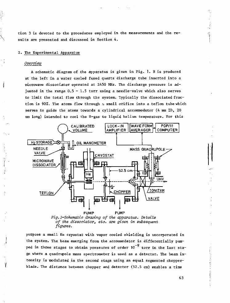
tion 3 is devoted to the procedures employed in the measurements and the r e -
sults are presented and discussed in Section 4.
2. The Experimental Apparatus
Overview
A schematic diagram of the apparatus is given in Fig. 1. H is produced
at the left in a water cooled fused quartz discharge tube inserted into a
microwave dissociator operated at 2450 MHz. The discharge pressure is ad-
justed in the range 0.5 - 1.5 tor r using a needle-valve which also serves
to limit the to ta l flow through the system. Typically the dissociated frac-
tion is 90%. The atoms flow through a small orifice into a teflon tube which
serves to guide the atoms towards a cylindrical accommodator (4 mm ID, 20
mm long) intended to cool the H-gas to liquid helium temperature. For this
WAVE FORMAVERAGER
CALIBRATEDv. VOLUME
MICROWAVEDISSOCIATORy
FUMP PUMPFig.1-Sohematia drawing of the apparatus. Details
of the dissociator, etc. are given in subsequentfigures.
purpose a small He cryostat with vapor cooled shielding is incorporated in
the system. The beam emerging from the accommodator is differentially pum-—9
ped in three stages to obtain pressures of order 10 torr in the last sta-
ge where a quadrupole mass spectrometer is used as a detector. The beam in-
tensity is modulated in the second stage using an equal segmented chopper-
blade. The distance between chopper and detector (52.5 cm) enables a time
63

of flight (TOF) analysis of the beam, using a waveform averager and a PDP/
11 computer for signal processing. Since we use an equal segmented chopper-
blade, the velocity distributions are found by differentiation of the de-
tector response. The principle advantage of this method is that one obtains
a high average flux, which enables easy alignment and continual monitoring
of the beam intensity with a lock-in amplifier. This is particulary impor-
tant with a species such as H in which rapid beam deterioration can result
in signal averaging of a non-existent signal and much wasted effort. A box-
car integrator was used for absolute intensity measurements. For these mea-
surements the gas handling system included a calibrated volume of 1140 cc
and an oil manometer.
The dissociator
Many publications concerning dissociation of hydrogen have appeared in
the literature, discussing the specific problems associated with various14technxques. Thermal beams of hydrogen atoms are currently produced using
electrodeless discharges employing r.f. or microwave power. We use a home-
made reentrant cavity operated at 2450 MHz (X=122 mm). The cavity, shown
in Fig. 2, consists of a 28 mm ID outer conductor (0C) of length 5X/4 = 153
mm and a (slightly shorter) inner conductor (IC) of 14.8 mm ID , A quartz
Fig.2-Microwave cavity operating at 2450 MHz. The assemblyof discharge tube and water cooling shown in Fig. 3 fitsinto the inner conductor. While the inner conductor re-mains fixed in position with respect to the discharge tu-be^ the outer conductor can be translated to tune the ca-vity .for optimum coupling.

discharge tube is inserted coaxially through the IC and the discharge oc-
curs in the gap of approximately 3.5 -mm between the end of the IC and a
cap tightly fitting over the end of the OC. The cavity is tuned capaciti-
vely by varying the gap-spacing. For this purpose the IC can be moved re-
lative to the OC using a fine adjustment screw. A simple A/4 finger joint
was used to minimize electrical losses in the sliding contact. The power is
coupled in inductively via an N-type connector making contact with the IC
via the finger joint. The discharge is started using a spark from a tesla
coil.
A variety of discharge tubes were tried. The discharge was most easily
operated using a 12 mm OD quartz tube which completely filled the bore of
the inner conductor, however poor cooling inherent to this geometry caused
a high operating temperature and resulted in irreversable deterioration of
the tube after a few hours. Deteriorated tubes invariably showed a dark
deposit, sometimes exhibiting a metallic appearance. The surfaces usually
could be cleaned somewhat using a strong oxidizing acid mixture (HNO„ +
H_SO,). However, the only way to completely remove the dark filmwas to
wash the tube in concentrated HF or NaOH for many hours after which the
film "peeled off" but did not dissolve. Our chemical experiences are con-
sistent with the Auger analysis of darkened surfaces of pyrex dissociator
envelopes obtained by Ritz et al. , who attributed the films to deposits
of carbon in its amorphous and carbide forms and to a lesser extent to
SigN,. Many procedures were tried to clean the tubes but in our experience
the best way to improve the discharge in case of deterioration was to re-
place the tube.
In our present system the discharge region is cooled from two sides, as
shown in Fig. 3, using water as a coolant, carefully shielded from the mi-
crowave by a metal envelope. Additional cooling is obtained by blowing air
in the cap region. Incorporation of the cooling facilities limited the si-
ze of the discharge tube to approximately 6 mm o.d. and was found to make
the tuning procedure a bit more subtile. Typically the dissociator is ope-
rated at a pressure of 0.5 torr using 25 W of microwave power; the system
reliably yields a degree of dissociation of order 90% up to a few torr. We
use standard 6 x 4 mm quartz tubing in which a flow impedance is fused in
to separate the discharge region from the transport tube which serves to
guide the atoms to the accommodator. The impedance is a 0.35 mm orifice in
a disk of ] mm thickness sliced off from thick walled quartz cappillary
65

tubing. Connections to the discharge tube are made using standard teflon
swagelock vacuum connectors.
V.Ï QUARTZ TUBINATO COOLING!" H J O *
Fig.Z-Two examples of discharge tube assemblies. \
A- Water-cooled system used for room tempe-rature dissociation. ,
B- Assembly where the temperature of the out- 'streaming gas can be varied from 77 K to600 K by varying the temperature of a aop-ipe-r cold plate.
Transport of the Gas
A flexible teflon tube connects the dissociator with the accommodator.
We shall present a simple phenomenological model describing Knudsen flow of
atoms through the tube in the presence of surface recombination. The model
enables an estimate of the recombination losses. For convenience the last
two centimeters of the tube are supposed to represent the accommodator and
will be considered to be at the same temperature as the tube for our pre- I
sent purpose. The model is very useful for design purposes where often only j
an estimate of the effect of recombination is required. More accurate re- ]
66 ;

\ ons
ï suits can be obtained with an analysis in terms of exact integral equati-
\ . ' The viscous flow regime is reviewed by Wise and Wood. A useful
formulation of the problem, in view of our needs, is obtained by conside-
ring a tube of length I and radius r closed at the left and open at the
right end and maintained at room temperature. The tube is assumed to be
"long" (& >> r). At the left side we introduce H through a small orifice
at the rate <j>. : the other side is assumed to end in an ideal vacuum. In
the case of Knudsen flow we may estimate the density profile of H along
the tube as well as the degree of dissociation of the gas leaving the tube
using a diffusion model:
y
^ * - ~ 2 DKn ^ <»
where <|>(z) and n(z) represent the atomic flux and density at distance z in2 -
the tube measured from the high pressure end, Dv = -=- rv is the atomic dif-
fusion constant for Knudsen flow, and v is the average atomic velocity. The
variation of <i>(z) along the tube due to recombination is written phenomeno-
• ' logically as a power series in n(z):
-j£-=-irr2K n 3 - 2irrK_on2 - 2irrK_,n (2)
: dZ V bZ o 1
; The first term describes three-body volume recombination, with rate con-
," ' stant K , the other two terms arise from surface recombination which can. 20
,: be first or second order in nature, with rate constants Ko, and Kco. The
surface density a is built up of two components: a = a + a . a is the
density of atoms trapped in catalytic sites. Below an activation tempera-
ture (which may be much higher than room temperature) these sites will be
continuously saturated and a will be a constant equal to the density of
these sites. The second component, a , represents weakly bound (physisor-
bed) mobile atoms, a and a are related to the bulk gas density through
an adsorption isotherm . a is proportional to n in the limit of low co-
verages. Recombination may proceed through interactions of trapped atoms
with mobile surface atoms or with gas-phase atoms, giving rise to first or-
der recombination or between two mobile adsorbate atoms resulting in second
j order recombination. On pyrex and quartz, recombination is known to be
; first order over a wide range of temperatures, however for T ^ 120 K and
T ^ 550 K, recombination is a second order process. At room temperature re-'•' • 21f combination on teflon is thought to be first order and we shall assumethis to be the case.
67

Using equation (1) and (2) the diffusion problem is reformulated for
Knudsen flow as
T T - T : (Ksin + Ks2n2 + r r V 3 >d z r v
d n 1 3 , /iu\
Sr~ 2T T * (3b)
r v
with boundery conditions n(z=Jl)=0 and <f>(z=O)=((>. .
For our present purpose volume recombination will be shown to be negli-
gible so that we limit the analysis to surface recombination. In the absen-
ce of any recombination (<(> = <j>. ) we obtain the well known relations for
Knudsen flow :n(z) = n Q (1 - z/l) (4)
of* 4 i nr v
23Equation (5) is often written in the Clausing form :
$ = -j~ K n v A (6)out 4 o
2 8where A = irr is the cross-section of the tube and K = -rr/H is the Clau-sing factor in the Knudsen limit (long tubes). For short tubes values for
24 . -
K are tabulated . The average number of wall collisions, N , that a parti
cle has ondergone after diffusing through the tube is given by
__ J (7a)out " 8 r
1 1where ^va^^= ƒ -£• •n(z)v2irr dz i s the total number of wall collisions per
unit time. Ttie average time the particle has spent in the tube i s given by
4Here N t Q t = ƒ n(z)ivr dz is the total number of atoms in the tube. We note
that in general <f>wall and N include a contribution due to particles which
never reach the end of the tube. This is for instance the case in the clas-
sical geometry of Knudsen (a channel connecting two big vessels) where only
a fraction z/X. of the particles colliding with the wall at a distance z in
the tube will reach the end. The rest of the particles return to the prima-
68

ry vessel. As a result only a third of the particles in the channel will
reach the secondary end, in which case
1 £ 2 - \ SL2= -7T (—) and t = -7 — (8)N
T T -=Our geometry is characterized by a negligible probability to return to the
discharge region (<|>. = <j) ) and thus eqs. (7a,b) are applicable.
In the case of first order recombination the rate coefficient can be
written as K = -r yv, where y is the recombination probability per wall
collision. With this convention the solution of equations (3) is
sinhn(z)
cosh [(9a)
c " ' c
N is given by equation (7a). n is the atomic density, achieved immediate-
ly behind the source orifice and calculated using equation (5).
A plot of n(z) versus z is given in Fig. 4. The degree of dissociation a
of the flux leaving the tube, defined as the fraction of all atoms in the
dissociated state (a = — = ) may be expressed, using (3b), as
a = = [cosh (9b)
FIRST ORDERRECOMBINATION
mig.4-Density profile of atomia hydrogen along a tubewith length I for the ease of first order recombina-tion, a is the degree of dissociation of the gasleaving the tube.
69

We note that the actual purity of the gas is higher (dissociation of
one molecule yields two atoms) , but in conforming with the literature on
dissociation we shall use a. Furthermore a = 0.46 for yN = 1 so that, as
a rule of thumb, for negligible recombination in the tube one should re-
quire
yN « 1 (9c)
Our objective is to use these results for designing a source with an
acceptable output flux. As an example we consider the teflon tube of typi-
cal length X. = 25 cm and radius r = 2.5 mm. We first estimate $^ . In the
discharge, operated at 0.5 torr, the atomic density is estimated to be
n, = 8 x 10 /cc (for 600 K and full dissociation). This implies
$. - 4- Kn.vA = 1.8 x 10 /secin 4 o d o
for the flux entering the transport tube, where K = 0.25 is the Clausing
2 °factor and A = 0.1 mm in the area of the source orifice. We calculate
1V Q ORn = 6 x 10 /cm using (5), corresponding to a mean free path of a fewmillimeters so that Knudsen flow may be assumed. Volume recombination can
1 3be neglected if -=- rK n « Kc.n. This requirement leads to an upper limit
for the density:I91 -S
? Using the data of Mitchell and Le Roy (y ,., = 2.1 x 10 and K• -32 6 - 2 - 1 'teflon 16 3 v
; 1.2 x 10 cm atom sec ) we conclude n « 3 x 10 /cm , a condition
£; easily met without limiting n .
0 The degree of dissociation at the end of the tube can now be evaluated
"|' with the aid of equation (9b). We find a - 93%. However, if we were dea-
1 ling with an imperfect teflon coating on a pyrex tube and 5% of the pyrex
\._; was exposed to the atoms, w e v* ould have a larger effective recombination
'fi coefficient (Ye£f = 2.2 x 10 , with y r e x = 4 x 10~3, see ref. 19) yiel-
'l ding a = 51%. This example shows that teflon tubing can be used to guide
të H-atoms over relatively large distances without excessive recombination
f* and that pyrex is inadequate for this purpose, at least at room temperatu-
i] re. For a similar uncoated pyrex tube one finds a = 8 x 10 . However, coo-
4 ling this tube to MOO K, where the recombination coefficient for pyrex isi' minimal, one again finds a = 93%, since for this temperature v = v ,.i- pyrex tef-' - on - 2 x 10 . One should notice that recombination coefficient may vary
A from sample to sample as witnessed by the larce scatter in v valu-k ° pyrex
-• 70

9fi 97 9ft 9Q
es * ' ' obtained by various authors in the literature. We have obser-
ved a teflon surface to deteriorate "overnight" in a vacuum chamber, proba-
ly due to oil contamination.
In view of these uncertainties the calculated values for a agree fairly
well with the experimental results where values of a up to = 60% were ob-
tained using commercial teflon tubing for the transport tube and teflon
coated quartz tube of 4 mm i.d. for the accommodator and for the first sec-
tion of the tube , i.e. the section immediately behind the discharge region
(see Fig. 1). A very pure atomic beam (a > 90%) was obtained using a 90 mm
long 4 mm wide uncoated quartz tube operated at nitrogen temperature (see
Fig. 3b).
For second order recombination the probability of recombination per wall
collision becomes density dependent (Y = 4 K__n/v). If we still use this
concept to express our results the solution of the equations (3) is given
by
n( z) = ° x2p (x;o,l) (lla)
Y N (a+z/£)o c
a =Y N ao c
(lib)
where P (x;O,l) is the equianhannonic case of the Weierstrass elliptic30
function and Y = Y ( Z = 0 ) . Furthermoreo
x = X(ZBQ), % » x and &)„ = 1.53 (see ref. 30J. The constant a has to be
determined from the relation
A plot of n(z) 'versus z according to equation (lla) is given in Fig. 5
for various- -values of a.
Equations (lla) and (lid) are most conveniently manipulated using eco-2 3 31
nomized polynomial expansions for x P(x;0,l) and x P'( x ; 0.1 ). Interms- of these polynomials n(z) is given by
3 P,(n)
fe ' P ü (12a)
71

The constant a (or £) has to be determined from
'o c
(12b)
To a good approximation (for 0 < n(or O < 12.8
Pjdi) = 1 + 3.571 x 10~2n + 9.8 x 10~5 r,2
Here n = x
P (O = -2 + 0.14286? + 9.81 x 10~4 £2
(12c)
(12d)
v.o
t sI 0.6-oc
l.U
0.8
0.6
0.4
0.2
0
V 1
l__
1 1 1
SECOND ORDERRECOMBiNATlOU
0.2 0Mz/l
0.6 0.8 1.0
Fig.S-Density profile of atomic hydrogen along a tubewith length I for the case of second order recombi-nation, a is the degree of dissociation of the gasleaving the tvbe.
The case of second order recombination is illustrated with the example
of a tube with the same dimensions as the teflon tube discussed earlier
(£ = 25 cm and r = 2.5 mm) but now maintained at T = 0.5 K and covered with
a superfluid film of He. Assuming a flux $. = 8 x 10 /sec to enter the
tube via a small orifice we again calculate n = 6 x 10 /cm using equati-o 32
on (5) so that the assumption of Knudsen flow is justified. Volume recom-
bination may be neglected if 2Kn «
S2rK
.-17as seen from equation (3a). Using the data of Morrow et al. K = 8 x 10
cm /sec, for T = 0.5 K and K = 2.8 x 10 cm /sec as measared by Hardy
72

33 17 3
et al. , we find n « 2.3 x 10 /cm . This condition is easily satisfied
over the whole length of the tube. Using y E 4Kgon/v, (7a), (12b) and (lib),
we may calculate y N - 0.14, a = 2.65, ? = -4.45 and a = 0.81. At this low
temperature a does not represent the degree of dissociation (which is unity
since H~ will freeze out on the walls) but simply the reduction in flux due
to recombination. We note that under these conditions transport of atoms at
0.5 K is comparable in efficiency with transport at room temperature with a
teflon tube. However, in a high magnetic field recombination is known to be34
strongly suppressed at low temperatures. Matthey et al. measured K „ =-21 4
3.8 x 10 cm /sec in 10 Tesla at T = 0.5 K. With this figure we calculate
for a tube of Jl = 2500 cm and r = 2.5 mm Y N = 0.068, again using n =
6 x 10¹⁴/cm3 ( or $. - 8 x 10¹³/sec). Thus a = 3.50, 5 = -6.73 and <|>out =
0.89 $. .We note that the atoms have spent on the average a time of 1875
seconds in the tube , as determined by equation (7b), without significant-
ly recombining. These results may be extended to other temperatures or other-2 - 1/2 34
magnetic fields (B > 0.5 Tesla) using K „ = K B T ' exp(2e /kT), whereQ^ o a
K is a scaling constant.
The aaaommodatoT
The considerations of the preceeding section can also be used for the
design of an efficient accommodator. The aim is to cool the. fluxing gas down
to approximately the temperature of the surface without it recombining. At
4.2 K the best known accommodator surface, with a low vapor pressure, is H_.
However, we point out that H„ has an adsorption energy e /k = 38 ± 5 K for35
H. In thermodynamic equilibrium most of the H would rapidly condense and
recombine. Thus the accommodator design must be such that the gas just ap-
proaches the wall temperature and then fluxes out into a subsequent stage.
Accommodation can usually be achieved with just a few collision so that a
choice of N = 1/y, resulting in a - 50%, (see relation (9c)) is satisfac-
tory.
From these qualitative arguments one concludes that one should select
wall materials with small adsorption energy, e , for use at low temperatu-a.
res. Then the surface coverage and thus y will remain minimal. The best
known surfaces to inhibit condensation of H are made of liquid 'He, He or-He- He mixtures with a measured e = 0.9 K and 0.34 K, respectively. 'Qt QT a
' However, use of these surfaces require very low temperatures to main-
tain a low density of the saturated helium vapor which catalyzes volume re-
73

combination. Therefore, except for the lowest temperatures (T 0.6 K) one
must rely on other surfaces with a weak physisorption potential for H, such
as H„ or Ne., From the work of Crampton we calculate Kg2= 3 x 10 cm /sec
at T = 4.2 K.With the aid of y = — Kg2n and using n = 10 /cm one finds
— = 250 showing that only very short H_ plated tubes can be used to accom-
modate H to 4.2 Kelvin.
In practice it is difficult to select a well characterized geometry to
cool H. Surface composition is often poorly known and temperature gradients
complicate the picture; therefore we have tested several accommodator de-
signs. Initially we followed the concept utilised by Toennies, Welz and*v 7 38
Wolf (TWW) , first described by Wilsch. In this designH, produced by RF
discharge, is cooled to ^90 K by passing the gas through a narrow metal
channel cooled with liquid nitrogen. Various wall metals were tested by TWWj (pyrex, boron nitride, copper), but best results were obtained using an>
aluminum channel. Since aluminum surfaces efficiently catalyze surface re-19
combination, the result was attributed to the formation of a thin oxide
'U layer efficiently cooled by the metallic substrate. It is interesting to
'-'% note that we have observed che copper-oxide surface to'be unstable in di-
jfe rect contact with H. A black, heavily oxidized, copper sample regained its
I? metallic appearance in a few minui.es under bombardment with H at a rate of7'"• 17 2
p 10 /cm sec. TWW also tried cooling their beams to hydrogen temperature
;: (20.4 K). However, under these conditions considerable recombination took
."- place while the remaining atoms were not effectively accommodated.
7. Following the concept of TWW an aluminum cap, containing a 0.5 mm dia-
* meter channel, was attached to the (uncooled) end of our discharge tube. We
round a good thermal contact between the aluminum and quartz to be of vital
importance to prevent the discharge tube from overheating. This requirement
>;.„; caused a considerable heat load on the cooling system. Although the degree
ij of dissociation was high (> 90%) down to nitrogen temperature, cooling to
helium temperatures was unsuccessful, while the system was susceptible to
'tl- breakage due to differential thermal contraction.
'. Good dissociation was also obtained using a discharge tube as drawn in
| Fig. 3b. This tube was partially water cooled and partially cooled with li-
<•!• quid nitrogen. For this purpose the quartz tube was glued into a copper cy-
' linder using silicone cement, an adhesive remaining reasonably flexible at
low temperature and consequently capable of compensating fir the rather
:; large differences in thermal contraction between copper and quartz. Thei.i
74

copper cylinder was screwed into an aluminum cold plate, cooled by circu-
lation of cryogenic liquids. Although this geometry worked very reliably
down to liquid nitrogen temperature, it had the disadvantage that a consi-
derable fraction of the microwave power dissipated in the discharge still
had to be carried away through the low temperature cooling system, limiting
the lowest achievable temperatures to about 20 K.
The most detailed study was made using a design where the accommodator
is completely thermally decoupled from the discharge region (see Fig. 1).
The atoms are guided to the accommodator using teflon tubing. In this way
an extremely flexible geometry is obtained. Por an accommodator we used a
cylindrical pyrex tube ( 6 x 4 mm; 20 mm long) coated with teflon, using FEP39
teflon dispersion fused at 350 K in a flowing oxygen atmosphere. Using
(7a) we calculate N = 38. The accommodator was glued into a copper block,
again employing silicone glue. The block is screwed to the bottom of a
small can which holds approximately 1 liter of liquid helium. The arrange-
ment is shown in Fig. 6. The main disadvantage of this design was that for
LIQUID
PYREX(TEFLON
;OATED;
TEFLON V7K-SHIELDTHERMOMETER
Fig.6-Sahematia diagram of the low temperature seotionof a helium oryostat used to cool a teflon coatedpyrex tube to helium temperatures.
high flows a background gas built up interfering with the beam and thus li-
miting the fluxes that could be studied. The properties of the accommodator
were studied as a function of temperature. At high temperature the teflon
75

surface is exposed to the H gas, whereas at helium temperature the teflon
is coated by H„. The lowest achievable temperatures were limited to 7.7. K
due to conduction and radiative heat leaks. For an accommodator used in stu-4
dying H as a stable low temperature gas , we simply used a copper or german
silver wall which is coated with H_ at T = 5 K.
Beam formation
The atomic beam that results when the gas leaving the accommodator ex-40
pands into vacuum can be described by a model of Giordmaine and Wang (GW) ,
who successfully applied kinetic theory to the problem of molecular beam
formation by long cylindrical channels connecting a source volume to an41
ideal vacuum. A similar study was made by Troitskii. GW assumed the den-
sity n(z) to fall linearly with the distance (z) along the channel as in
the case of Knudsen flown(z) - n 8 | (13)
where n is the density in the source, z is measured from the low pressures
end and I is the total length of the channel. Better approximations accoun-
ting for the non-zero density at the end of a i*eal channel have also been42
studied but lead to corrections which hardly affect our results.
GW considered two contributions to the center-line intensity, I, of the
beam:
a) A contribution due to atoms passing through the channel without colli-
sions
h - h- V s A exp {-*/2V (14)
where A is the molecular mean free path at density n and the exponent
accounts for beam attenuation due to scattering by the stagnant gas in
the channel.
b) A contribution due to particles scattered into the axial direction by
interatomic collisions in the channel
1 1 1I2 = ƒ dz -± n(z)vA —-^ exp {-z/2A(z)} (15)
4TT
Adding (14) and (15) one attains the total center-line intensity which may
be conveniently written as
oiI
— ngvA (16a)
76

/£_ erf (/ir1) (iet,)
(16c)
Peaking of the beam
It will turn out to be useful to characterize a beam source with a pa-
rameter x» called the peaking factor of the source, which relates the to-
tal intensity with the center-line intensity:
I = x*/* (17)
For a cosine emitting source x = ' s o that the peaking factor is a measure
for the directivity of a beam source, normalized to that of an ideal effu-
sive source. Comparing (16) with (17) and recalling the well known Clausing
formula (6) for the total flow through a channel ($ = -j- K n vA; where K4 O S O
is the Clausing factor) x may be written as
x . EMo
<j The opaque mode
-\ A specific mode of operation, of particular importance for our analysis,
) is the opaque mode, where particles have a negligible probability to pass
through the channel without a collision. In this mode we are still dealing
with Knudsen flow, but only process "b" will contribute to the beam. The
' condition for opacity in the channel is TIM) where the error function approa-
' ches unity to within 1% and can be approximated by
, ^ 1/2(19)
Expressing X in terms of the density, X = (/2an) , where a is a collision
cross-section, and using the "long channel approximation" for the Clausing
factor (K = — — —r—) leads, after a few manipulations, to a compact formu-
1*£oI!<: x--|-(!^t>"2
Equation (20) expresses a characteristic property of the opaque mode: for
a given total flow the peaking factor is independent of the length of the
channel.
77

Velocity distribution
Another property of importance for this study is the velocity distribu-
tion characterizing the channel sources. We assume thermal equilibrium in
theSiOurce. Hence the velocity distribution of the stagnant gas is given
by the Maxwell-Boltzmann (MB) expression:
2
f (x)dx = 4ir"1/2x2e~X dx (21a)a
with normalization ƒ f (x)dx = 1 ando
x = - ; v = (2kT/m)1/2 (21b)
v ct
where T is the source temperature, m the molecular mass and k the Boltz-
mann constant. At pressures low enough that only process "a" will contri-
bute to the beam, (this is called the transparant mode of the channel sour-
ce) one is clearly sampling the source volume in a "effusive" way, and the
beam resulting from the channel possesses a velocity-weighted Maxwellian43
distribution :f, (x)dx = 2x3e"X dx (22)b
again normalized to unity. If the source pressure is increased, the beam
will be attenuated in the channel. In the GW-model this is accounted for
by the exponentials in equations (14) and (15).
In order to obtain a first order correction to the velocity distribu-
tion Olander, Jones and Siekhaus (OJS) extended the GW analysis, which
is essentially a one-speed model, to allow for velocity dependence of the
mean free path, utilising the classical expression for the velocity ave-45
raged mean-free-path of a Maxwellian gas. This model leads to a shift of
the most probable velocity to a slightly higher value and predicts this ef-
fect to "saturate" with increasing opacity. In the opaque mode the veloci-
ty distribution is found to be independent of the total flow. OJS also re-
considered the peaking effect employing a velocity dependent mean free
path, but the differences with the GW-model were found to be insignificant
for practical use and hence eq. (20) remains adequate to estimate the pea-
king in channel sources.
Velocity distributions of channel sources have been reported at various pla-
ces in the literature. ' ' However, none of these experiments showed
the saturation effect in the opaque mode. To our knowledge no adequate theo-
78

ry is available describing this aspect of the velocity distribution of chan-
nel sources.
3. Measurement procedures
Mass flow
The gas supply to the dissociator is controlled with a needle valve
which determines the total flow through the system. The primary side of the
valve is connected to a gas handling manifold, including branches to a sim-
ple oil manometer and a pyrex bulb with a calibrated volume of 1140 cc. The
bulb serves as an H_ reservoir of known volume. Monitoring the pressure de-
cay in the bulb as a function of time by means of the oil manometer enables
an accurate determination of the mass flow (<|> ) through the system, defi-
ned as the flow of pairs of atoms (either in the atomic or molecular form).
The data were corrected for dead volume in the gas handling system and for
changes in the dead volume arising from varying levels in the oil manometer.
During the measurements the temperature of the bulb was observed to be sta-
ble within 0.1 K. The reference arm of the manometer was continiously dif-
fusion pumped to avoid errors caused by degassing of the oil. Typically our
' Calibration of the quadrupole for H
beams were operated at é = 1 0 pairs/sec.v m
2
The quadrupole mass-spectrometer is used to provide a convenient secon-
dary standard for the mass-flow through the system. Calibration, however,
is not straight forward since the experimental arrangement, shown in Fig. 1,
provides information only about the center-line intensity of the beam (I;
units of the flux/sterradian) and not about the total flux (<|>). As a result
the peaking effects, discussed earlier, will complicate the analysis. Fur-
thermore the quadrupole measures the effective beam density in the ionizer,
i .e . a velocity weighted intensity S instead of I directly:
S = r Q- ÜL (23)
° swhere V is the ionisaticn and extraction rate per particle, fi is the solid
_ i /2
angle of detection, L the length of the ionizer and v = (8 kT/?,m) , the
average velocity in the source.
In the case of non-Maxwellian velocity distributions, not v , but (in ge-s
neral) a different weighting factor is obtained, r is in general a function79
of velocity as discussed by Siekhaus, Jones and Olander. This effect is
strongly dependent on the type of ionizer and assumed to be negligible in
our case since Maxwellian distributions were obtained for low source pres-
sures. Combining (17) and (23) yields
<j> = — — S (24)Q.LTQ x
With these considerations in mind an H„-calibration of the quadrupole is
obtained, by chopping the beam with an equal segmented chopper and measuring
the peak to peak value (S ) of the observed waveform with the quadrupole
tuned to mass 2. S is proportional to the total Ho-flux as long as the pe-PP 2 . .
riod of the chopper-function is much longer than the average time of flight
through the system. A simultaneous measurement of <|> , using the mass-flow
technique discussed in the preceeding section, provides the corresponding
total flow (j) since for a purely molecular beam <j> = <f> .Once <f> and S are determined for one specific combination of tempera-
m ppture and mass-flow, scaling of x and v may be used to obtain a calibration
s
of the quadrupole reading for different temperature and flow conditions.
Special care is required if the velocity distributions show deviations from
Maxwellian behavior as a consequence of different velocity weighting in re-
lation (24). Scaling of v is straightforward; scaling of x is discussed
later in this section.Calibration of the quadrwpole for H
The calibration procedure used for H„ could also be applied to H if stri-
king of the discharge in the dissociator would result in a 100% pure atomic
beam, for then every molecule contributing to the mass flow (<j> ) through the
flow impedance would simply result in a pair of atoms, or <)>„ = 2<j> . How-
ever, under typical experimental conditions the dissociation is not comple-
te. The correction is straightforward once the degree of dissociation (a),
i.e. the dissociated fraction of 6 is known:m
(f>„ = 2cti)> (25)
The degree of dissociation
The experimental arrangement also enables a particularly simple deter-
mination of the dissociated fraction (a) of the beam by observation of the
relative change in mass 2 intensity upon striking the discharge. First the
80

off .Ho signal (S ) is measured with discharge off. This provides us with al PP
measure for the total H2 flux, using (24), which equals the mass flux in
this case. Then the discharge is started and the H„ signal drops until (af-
ter some transient effects) a new steady value is achieved (S°"). Since the
total mass flow is not affected by the status of the dissociator the H 2
flux now represents a direct measure of the non-dissociated fraction ( 1-a)
of the mass flow:
Y V S,, . on,,off off on on , u>(1-a) = $ /$ = — (26)
H2 2 x v S1 onVoff off
By stabilizing the accommodator temperature one achieves v = v f f .
This was checked experimentally by measuring the TOF distribution of H,,
with discharge on and discharge off. In practice determinations of a werei „on
made using S
« - , - Jfc (27).': ' on
This implies that errors due to possible changes of x were neglected.
"•. • The density in the aacommodator
An estimate for the (average) density in the accommodator is obtained
| | in a simple way using equation (3b) :
! - S-è-T--* <">r v
- Here I is the length of the accommodator and v is the average velocity of
V the stagnant gas. We note that this expression is only valid when the ac-
commodator is operated in the opaque mode.; The peaking correction
The geometry of our system, as described in Section 2, deviates in var-
ious ways from the geometry studied by Giordmaine and Wang (GW). Neverthe-
less we shall assume the GW results to be transferable to our geometry as
• ,' long as the source is operated in the opaque mode. This approximation cani • '•
I be considered t o be a gene ra l i s a t ion of the r e s u l t (20) in the sense that i t
•; • assumes the beam shape to be determined by the last section of the channel
only. This section is defined by the condition z ^ 2X(z), where z is the
r , distance in the accommodator, measured from the low pressure end. This is
\ r.he distance up to the point where the source becomes opaque. Furthermore:; 81

we require a homogeneous temperature distribution over the accommodator.
The concept of beam peaking as discussed before implies a change in pea-
king when the temperature of the accommodator is changed. This aspect of
the theory is of particular importance for the calibration of our measure-1/4
ments. In a hard sphere collision approximation x(T) T as results from
(20). The main uncertainty in (T) is due to the temperature dependence ofA
a, which was neglected in our estimates for the total atomic flux.
Time of flight analysis
Information about the temperature at which H leaves the accommodator can
be obtained by pulsing the beam and using the quadrupole to observe the tem-
poral dispersion of the pulses. We first present a somewhat general approach
to be used in our subsequent analysis. If the shape of the pulse in time is
represented by e(t) the response of the detection system can be written as
S(t) = T e(t) (29)
where T is a linear operator. Let h(t-t ) be the linear response of the sys-
tem to a 6-function pulse at t = t
h(t-tQ) = |6(t-to) (30)
with
J_ „ h(t-t )dt = 1; h(t-t ) = 0 for t < t (causality) (31)
The relation between the number of particles in the velocity interval (v,
v + dv) and the corresponding time interval (t, t + dt) is
ho(t-tQ) = -fb(v)dv/dt (32)
where t- t = L/v, L being the distance between chopper and detector and h
is the real (i .e. uncorrected for detector properties) time of flight (TOF)
distribution.
For a Maxwellian velocity distribution f, (v)dv is given by equation (22).
Setting t = 0 and using (32) we find
hQ(t) = fb(L/t)L/t2 (33)
For analysis of our measurements this result has to be corrected for the
v dependence in the sensitivity of the quadrupole (see the section on ca-
libration) , yielding the effective TOF distribution h(t) f, (L/t)/t writ-D
ten in a normalized form as
82

h(t) = f (L/t)L/t2 (34)s
For our Maxwellian distribution f (x) is defined by (21) and we can writes
-(B- ) 2
h(t) 77 ë ( t ) e (35)
where 6 = L/a is the TOF of the atoms with velocity a (see Fig. 7, curve
1). Thus a very simple relation exists between the velocity distribution
in the accommodator and the effective TOF distribution h(t) as measured
using a mass-spectrometer.
The linearity of T may be used to show that S(t) can be written as a
convolution integral:
s(t) " Si „ e(x)h(t-T)dr = e(t) * h(t) (36)
A useful property of this integral involves the time derivative:
S(t) = e(t) * h(t) (37)
Narrow slit chopper
A common procedure to pulse atomic beams is to use fast rotating chop-
per-blades containing one or more narrow slits. The finite width of any
real beam or chopper can be accounted for using equation (36). Assuming a
rectangular gate function (Fig. 7, curve 2') the response of the detector
is given by Fig. 7, curve 2:
tS(t) = SQ Jt' h(t-T)dT (38)
o
where S is the signal in absence of the chopper and the gate is assumed
to be open between t and t.. High resolution requires the use of narrow
slits. However, (38) shows that in the limit of a vanishing slit width
(t- - t -»• 0), the signal also vanishes.
Equal segmented chopper
In our apparatus we employ an equal segmented chopper to obtain the TOF.
e the stimulus e(t) z
changing value at t = t
Here the stimulus e(t) is ideally represented by a step function 6(t-t )
ts(t) = so ƒ_ M e(T-to)h(t-T)dx (39)
83

2 3 4TIME IARB. UNITS]
Fig. 7-TOF distribution for a Maxaellian beam and va-rious choices of e(t).
A- Case of narrow slit chopper. Curve 1: responseto delta function stimulus. Curve 2: response toblock pulse shown as curve 2'.
B-~ Case of equal segmented chopper. Curve 3: res-ponse to step function. Curve 4: response to stepfunction, taking into account the finite cut-offtime of the beam as shown with curve 4'. Theareas under curves 1 and 2 are normalized to 1.Note that curves 1 and 2 are the derivatives~ofcurve 3 and 4 respectively.
Knowing the response to the step function (Fig. 7, curve 3), the (effec-
tive) TOF distribution is obtained by differentiating S(t) with respect to
timeS(t) = SQh(t-to) (40)
As in the case, o'f the narrow s l i t chopper, one has to account for the
finite width of any real beam. This results in a distortion of the step
function, which however remains simple if s l i t shaped diaphragms are used
to define the beam (Fig. 7, curve 4 ' ) :
e(t) =
for t < t
for to< t < t ,
for t < t
(41)
84

The response to this e(t) is calculated by substituting equation (41)
into equation (36) and is plotted in Fig. 7, curve 4. The response is rela-
ted to the TOF by applying equation (37):
S tS(t) = S(t) r ^ r ƒ ' h(t-T)dt (42)
1 o o
h(t) is called the convoluted (effective) TOF distribution and is recogni-
zed as closely equivalent to the convolution of h(t) with the rectangular
gate function (i.e. equation (38)). However, in contrast to that case, in
the limit t. •+ t , h(t) reduces to S h(t-t ) and high resolution may be ob-
tained without any loss of signal. In comparing the merits of both techni-
ques we must also include noise considerations. If one is completely limi-
ted by background noise the equal segmented chopper will be favorable, while
in the limit of vanishing background noise the narrow slit chopper will
yield better results, since it minimizes noise due to fluctuations in the
signal itself, such as encountered for Poisson statistics. Except for the
large background signal the possibility of simultaneously monitoring the to-
tal atomic flux by standard lock-in techniques was decisive for our choice.
In the development of a cold H source, the beam flux is often unmeasurably
small. Using a narrow slit chopper requires about 15 minutes of signal ave-
raging to ascertain this, whereas about 1 sec is required with lock-in de-
tection, using an equal segmented chopper.
Signal processing
The signal originating from the mass-spectrometer was averaged on a
Fabri-Tek waveform analyser using 256 channels and a 20 ysec dwell time. Ty-
pically averaging was done over 10 spectra. The repetition rate is limited
by the width of the TOF spectrum, too high a rate causing overlap of spec-
tra and resulting in a distortion of the low velocity part of the distribu-
tion. No special arrangements, such as the use of a double bladed chop-48 49
per ' , were undertaken to remove this low velocity tail. The data was
transmitted to a PDP 11 mini-computer where further signal processing was
done. h(t) was obtained by numerical differentiation of S(t) with respect
to time using the Lanczos method. Then, applying equation (34) the data
(transformed to the velocity domain) yielded the convoluted (effective) ve-
locity distribution f (v). Finally the data was smoothed using a Gaussians
85

smoothing procedure, where the width of the Gaussian (2/A) was 25 m/sec:
Ï (v)dv (43)t> —— - S
For high velocities (v *> 2 km/sec) the width was taken slightly larger in
order to prevent the corresponding width in the time domain from becoming
less than the experimental resolution (.13 msec).
Any smoothing results in deformation of the signal, most apparent in re-
gions of large curvature. This effect is minimized by first subtracting a
theoretical curve ±. (v) selected by trial and error to approximately fit\ S
the data and then to do the smoothing on the noisy difference signal, where
significant deviations from the t r i a l distribution must have a small second
derivative.Then, after smoothing, the difference signal is added again tof (v) to produce the (smoothed) total signal:s
y /• \ 'i'th, \ . T+°° -X(v-v) fv / N T<th , , i , ii i\' <f (v)> = f (v) + J_oo e If (v ) - f (v)Jdv (44)
The advantage of t h i s method i s tha t deformation due to smoothing can on-
i ly occur i n the r e l a t i v e l y small dif ference s i g n a l , which in our case i s the
; ; devia t ion from idea l Maxwell-Boltzmann behavior . The approach i s e s p e c i a l l y
i i useful in measurements where the exact shape of the d i s t r i b u t i o n i s not too
c r i t i c a l , such as in the p re sen t experiment where the TOF i s used to de t e r -
mine the (Maxwellian) temperature of an ensemble of H-atoms in a cryogenic
environment.
•• Calibration of the time of flight scale
The signal averager was triggered using a pulse generated by an optical
chopping indicator. There is however a phase difference between the real
* chopping function of the beam and the periodic trigger signal resulting from
the electronics of the chopper indicator. Basically this phase difference
originates from the difference in position between the beam and the chopper-
f indicator, but is also due to the ion extraction time, the finite width of
; the trigger pulse and the pulse handling electronics. Evidently the measure-
?', ment time scale, i .e . the time initiated by the trigger pulse, has to be
corrected in order to obtain the real experimental time scale. David et al".CO
determined this zero of flight time by variation of the flight path. "Miller
\ used U.V. photons and an on axis ion detector. A mechanical velocity selec-
86

49tor was used by Beijerinck et al. to produce a known velocity beam, they
also replaced the molecular beam by a light source using a photomultiplier
for detection. Not all authors specify the estimated error in the zero of
time determination, but it seems difficult to achieve a high absolute accu-
racy since uncertainties up to 50 y sec are reported. Clearly this calibra-
tion requires great care because of the many aspects that come into play.
We used two independent methods to calibrate the time-scale of our TOF-sys-
tem. First an optical technique was used, replacing the beam by a small
He-Ne-laser and detecting the light using a fast light power-meter. This
measurement yielded a shift corresponding to 210 ± 20 u sec. This figure
has to be corrected for the time delay due to the finite ion-extraction time
when using an atomic beam instead of light. Such a correction is mass de-
pendent and for H and H_ calculated to be of the order of 4.1 ± 1 and 5.8
± 1 y sec respectively. The second method used to calibrate the TOF-time
scale is based on the assumption that our source, operated at low enough
pressures, will yield a Maxwellian velocity distribution. Then a simple fit-
ting procedure with a calculated distribution can be used to fix the time
scale. This procedure was used with H, H_ and He at room temperature and
leads to a phase correction of 240 ± 5 y sec. We also measured the distri-
butions of Ne, N„ and Ar, but in these cases the pressures could not be re-
duced enough to observe Maxwell-Boltzmann behavior, due to noise limita-
tions. In Fig. 8 the TOF distribution of H_ at 295 K is plotted and compa-
red with MB curves calculated for four different temperatures, taking into
account convolution effects due to the slit function. The curves are nor-
malized to the integrated intensity under the measured TOF distribution.
The observed deviations from the 295 K MB curve cannot be eliminated by a
shift in the time scale demonstrating that knowledge of the beam tempera-
ture is sufficient to distinguish a Maxwellian from a non-Maxwellian dis-
tribution and giving confidence that the observed (Maxwellian) TOF distri-
butions of H, H_ and He can be us»>d to obtain a reliable time scale cali-
bration.
No satisfactory explanation was found for the 25 u sec discrepancy be-
tween the two calibration techniques. A number of instrumental effects that
can induce a systematic error consistent with the observed discrepancy will
be briefly discussed here. The 0.13 m sec cut-off time of the beam gives
rise to an important convolution correction expecially for low mass, high
temperature beams (Fig. 9). A possible systematic error might be due to in-
87

Fig.8-Non-Maxwellian TOF distri-bution as measured in our sys-tem for molecular nitrogen atroom temperature. For explana-tion see text.
TIME OF FLIGHT [msec]
Fig.9-The importance of convolu-tion for fast beams demonstra-ted for the TOF of atomic hy-drogen at room temperature.
o.2 0.4 asTIME OF FLIGHT Imsecl
complete knowledge of the instrumental function used in the convolution.
This function was calculated assuming an ideal rectangular cross-section
of the beam and a position independent detection probability. The ionizer
of a mass-quadrupole will induce a distortion of the TOF spectrum if it is
operated above a critical emission current due to the build-up of space
charge causing ion extraction problems. No changes in the TOF spectrum were
observed by variation of the emission current up to 1.9 mA. Finally, memory
effects may be present due to periodic fluctuations of the background pres-
sure at the detection frequency caused by the beam randomized in the detec-
tion chamber. This effect is small in our system. The beam is passed through
the open structured ionizer of the quadrupole and well collimated so that
beam particles will not collide with the walls of the ionizer. Furthermore,
88

the final beam is randomized in a large volume (100 1) and pumped using a
ion-getter:titanium sublimation pumping combination with an overall pumping
speed of6000 1/sec for hydrogen. For average beam velocities below500 m/sec,
of primary concern in studying low temperature beams, uncertainties of order
25 ysec in the TOF-timescale correspond to errors of less than 2.5% in the
velocity or 5% in the Maxwellian temperature. The TOF system parameters are
summarized in table 1.
TABLE 1
TOF system parameters
flight distance
beam diameter at chopper
angular velocity of chopper
chopping period
resolution of signal averager
time resolution (cut-off time)
525 ± 5 mm
1.5 ± 0.02 mm
177.5 ± 1 rad/sec
8.85 + 0.05 msec
20 ysec
0.130 + 0.002 msec
4. Results
As a typical example of the results that can be achieved with our disso-
ciator design we first discuss a measurement of a that was done with the tu-
be shown in Fig. 3b. Here, the H leaving the discharge enters into a L = 90
mm, r = 2 mm (N = 759, see eq. 7a) quartz tube cooled to liquid nitrogenC 18
temperature. We measured a = 0.92 ± 0.02 for an estimated f lux è. - 2 x 10 /in
sec. Analyzing this result on the basis of first order recombination kine-
tics (a = 1 - yN ; for y% « 1 , see (9c)). We calculate y £ 10 . This re-
sult represents an upper limit since we assumed implicitly that <(>. is ful-
ly dissociated. Moreover, experience with other tubes leads to the conclu-
sion that the gas leaving the discharge region is never more than 94% dis-
sociated.
The most complete set of results was obtained with the apparatus shown
in Fig. 1, 2, 3a and 6.discussed in detail in Section 2. We stabilized the
total mass-flow through the system using the precision needle-valve and se-
lected a relatively low flow rate to ensure the absence of interference be-
tween beam and background gas. At room temperature we measured L = 7.2 x16
10 /sec with a = 0.31. The teflon tube connecting dissociatorwith accommo-
dator is characterized by N = 3750, using (7a). Equation (9b) now enablesc -4
an estimate of y „ , yielding y = 4.5 * 10 . Under best conditi-
89

-4ons we observed v ,, = 10' for commercial teflon tubing. No attempts we-
tefIon
re made to study the recombination kinetics. Reducing the accommodator tem-
perature to 78 K the H flux decreased to 65% of the room temperature value.
Further cooling to 7.7 K (the lowest achievable temperature for the accommo-
dator ) resulted in a flux decrease to 32% or <(>„ = 2.4 x 10 H./sec. On. 13 3
the basis of these results we calculate average densities of 3.4 x 10 /cm
at T = 7.7 K in the accommodator, using (28). Once the temperature of the
accommodator is reduced a detailed comparison between experiment and the mo-
del presented in Section 2 is no longer justified due to the presence of tem-
perature gradients. Especially at the lowest temperatures, care is required
in interpreting our results in view of uncertainties in the peaking correc-
tion for the beam, which is hard to estimate but could be of order of a fac-
tor 1.5. However, it is most likely that the reduction in atomic flux -with
lowering of the accommodator temperature- is due to an increase in the re-
combination probability y. If we assume this point of view we must conclu-
de that the surface of the accommodator is not covered with a saturated35
layer of solid molecular hydrogen. Using the results of Crampton we calcu-
late Y = 5 x 10 at 8 K and n = 10 /cm . For our accommodator N = 38, im-
plying that recombination would be negligible. A thick film of H„ is also
inconsistent with our H„ intensity measurements. A saturated vapor pressure
would result in an H_ beam three orders of magnitude more intense than was
observed experimentally. The exact composition of the accommodator surface
is unknown, althougu it seems reasonable to assume a surface coverage of at
most a few monolayers of solid H_.ATOMIC HYDROGEN
T=90 KELVIN
0.5TIME
1OF FLIGHT
1.5[ m sec] -
Fig.10-An example of raw data as obtained foratomic hydrogen at T = 90 Kelvin i
90

VELOCITY Ikm/secl
Fig.ll-The velocity distribution of atomic and molecularhydrogen as measured for three different temperatures.
Evidence that the gas was well accommodated to low temperature was ob-
tained by measuring the TOF distribution at the various accommodator tem-
peratures. The raw data, an example of which is shown in Fig. 10, was re-
duced to velocity distributions using the formalism of Section 3. Results
are shown in Fig. lla for the three different measured temperatures: 297 ±
3 K, 78 ± 2 K and 7.7 ± IK. The difference in error bar for different ve-
locities results from the transformation from time to velocity space: the
TOF can be measured very accurately for a low velocity beam due to a large
dispersion in time. However, this dispersion also leads to low intensities
and thus relatively large vertical error bars. The data can be fit to Max-
wellian distributions (convoluted with the slit function) corresponding to
temperatures 297 ± 5 K, 90 + 5 K and 8.5 ± 1 K. These temperatures were
found to be consistent with the distributions measured for H„ (see Fig. lib)
with discharge on. On the basis of the 8.5 K TOF we calculate an increase in
the flux of low velocity atoms (v < 2vD = 918 m/sec; where vo is the mostP i P
probable velocity in the beam) by a factor = 20 with respect to the room tem-
perature beam. (The reduction from the theoretical maximum value of 71 is
due to increased recombination losses.) This result shows that our source,
in combination with a velocity selector, could be a valuable tool for low
91

energy atomic beam scattering experiments with hydrogen atoms.
It is useful to raise the question what is to be expected if the accom-
modator is operated at still lower temperatures, say below 4 K. We expect a
steadily growing layer of solid molecular hydrogen to form; the calculated53
output flux of H„ -based on the known vapor pressure of the solid - is much
smaller than typical input fluxes. We thus may base our analysis on the work35
of Crampton , using an exponential scaling of the recombination rate with
temperature K_o = K° T exp(2e /kT). Recombination rapidly becomes limi-
- > f - a
ting once N ^ - = v/(4K„„n). Replacing n by the average density in the accom-
modator and using expressions (7a) and (28) we obtain a simple criterion to
decide whether the flux is recombination limited or not
, t a.. 4 . *£H. _L . exp(-2e m («,H 9 „3 nL, o a
1 B KS2
where r, Ü and T are the radius, length and temperature of the accommodator
respectively, e& = 38 K and K° 2 = 8.4 x 10~20cm4 K1/'2sec~1,54 With this ex-
pression recombination is found to become limiting for our accommodator at
4 K if <(> ^ 10 /sec. However, the effect has a strong temperature dependen-
ce. At 2.5 K we expect to be recombination limited already for <(>„ 10 /sec.n
Of course one may try a brute force approach of using high input fluxes and
accept considerable recombination losses to obtain some increase in output
flux. We note that this approach is very inefficient since recombination on ;-2 i
H. is second order and therefore scales with n . To double $„ (roughly pro-Z n
portional to n) we thus have to quadruple the input flux into the accommoda- :tor so that, even with (f>. = 1 0 /sec one only obtains $„ - If) /sec at 2.5 j
ln ti
K. Additional disadvantages of the brute force approach are the considerable ;
heat load and the rapid build-up of bulk solid which may give rise to plug- .!
ging up of the accommodator. A recombining flux <j> = 10 /sec corresponds to i3 'i
7 mm bulk solid per hour and a recombination heat load of 36 mW. \
A simple method to increase the recombination limited flux by approxima-
tely one order of magnitude would be to reduce the length of the accommoda- •
tor by a factor 2. This would of course reduce the number of wall collision ;
to below 10 but the masses of H and H are well enough matched to enable ef- ||
ficient energy accommodation in a few collisions so that the beam tempera- |
ture would remain unchanged.
A serious problem which can exist is a vacuum leak of air into the tef-
lon tube. In one such case after cooling; we observed the flux of H tp dete-
92

riorate from a high value to zero within some tens of minutes. Presumably
the air condenses on the cold teflon surface before the accommodator and
these air surfaces, which are not covered with H ? are efficient for recom-
bination. We believe that the most important process is first order recom-
bination of H with oxygen. Precautions should always be taken to use pure
H. gas and to protect the teflon from condensable gases or oils.
Subsequent to the measurements reported here, sources based on these de-
signs, operated at an accommodator temperature of T = 4 - 6 K were used to
load H into cells with liquid helium covered walls at temperatures below
^ 0.5 K (see Fig. 12 and Ref. 4).
< 0.5KA
FLUXING HELIUM VAPOR
Fig.12-Sóhematic diagram of the experimental ar-rangement of Ref. 4 to load H into a cell withhelium covered walls at temperatures below 0.5K.
An important design consideration of these sources has been to avoid col-
lisions of H with non-helium covered surfaces below 4,2 K. This was reali-
zed by using a very s.hort tube between accomodator and helium covered re-
gion, thus tolerating imcomplete accommodation on the H_ surface to avoid
total recombination. A non-quantitative confirmation of the importance of
the accommodator wall temperature was found when deuterium was loaded into
a similar helium covered cell. In this case the flux was orders of magni-
tude lower than when loading with H under similar conditions, due to the lar-
ger adsorption energy of D on D (this is unmeasured but much larger due to
the lower zero-point energy). Moderate heating of the accommodator yielded
substancial gains in flux.
An additional complication of configurations employing superfluid helium
covered surfaces at low temperature may be the presence of stagnant helium vjf
' : • %
93 •:$

gas in accommodator and transport tube. If the mean free path X of the H-
atoms in the stagnant gas is smaller than the diameter of the tube, the
transport of the H gas is no longer Knudsen-limited but may be described by
ordinary diffusion (with D = — T - X V ) . This leaves the analysis of Section 2
unchanged if we correct for an enhanced number of wall collisions in accom-
modator and transport tube: N x = Ï5 . 2r/X. For a pressure p = 10 torr
(corresponding to the saturated vapor pressure of He at 0.8 K),the density
of the stagnant gas in the accommodator (assumed to be at 4 K) is n ^ 3 x1 ft "
10 /cm , corresponding to 2r/X - 50 or equivalently a reduction of <j>„ by
the same amount if the flux is recombination limited.
Further we note that the most perilous region for the H-atoms is that be-
tween the 4 K accommodator and the i> 0.5 K cell. Between these two regions
of the tube the helium film is driven towards the accommodator and vapori-
zes at a point where T ;< 1 K, fluxing back to the cold region.
In the region 1 - 4 K the H. wall may be covered by but a monolayer or
so of helium and we expect most H-atoms that strike those walls to recombi-
ne. Obviously this region should be made as short as possible so that atoms
can make the transition without wall collisions. A stagnant He gas can pos-
sibly frustrate this. Alternatively much "hotter" atoms can be fluxed through
this region.
5. Acknowledgements
The authors thank E. Hartman for assistance with the data handling, ;•
O.H. Höpfner for his technical support and A. Zwart for making the dissoci- i
ator tubes. We gratefully acknowledge the financial support of the Stchting |
FOM. i
94 I
\l_ References
X 1. S.B. Crampton, T.J. Greytak, D. Kleppner, W.B. Phillips, D.A. Smith
and A. Weinrib, Phys. Rev. Lett. 4£, 1039 (1979)
2. W.N. Hardy, M. Morrow, R. Jochemsen, B.W. Statt, P.R. Kubik. R.M.
1. Marsolais, A.J. Berlinsky and A. Landesman, Phys. Rev. Lett. 45_. 453
(1979)
i \ 3. I.F. Silvera and J.T.M. Walraven, Phys. Rev. Lett. 74A» 193 (1979)
4. I.F. Silvera and J.T.M. Walraven, Phys. Rev. Lett. 44_, 164 (1980)
5 5. S.B. Crampton, W.D. Phillips, D. Kleppner, Bull. Am. Phys. Soc. 2J3,
'r\ 86 (1978)
;:: 6. M. Morrow, R. Jochemsen, A.J. Berlinsky and W.N. Hardy, Phys. Rev. Lett.
46_, 195 (1981); 47, 455 (1981)
7. R. Welz, Thesis, Bonn 1976, Max Planck-Institut für Strömungsforschung,
fe. Göttingen, Bericht 20/1976, see also J.P. Toennies, W. Welz and G. Wolf,
X J. Chem. Phys. ]l_, 614 (1979)
IA 8. M. Perrenoud, W. Grüebler and V. König, Helv. Phys. Acta 44., 594 (1971)
•• 9. A.A. Belushkina, V.P. Vadeev, A.I. Valevich, G.I. Goi, E.D. Donets,
•£;'. V.P. Ershov, L.S. Kotova, Y.A. Plis, Y.K. Pilipenko and V.V. Smelyanskii,
• • I Instrum. & Exp. Tech. (U.S.A.) 19, 1618 (1976)
ii'; 10. Y. Wakuta, Y. Koga, H. Hasuyama and H. Yamamoto, Nucl. Instr. Meth.147,
•/[ 461 (1977)
11. L. Dick and T. Niinikoski; G. Clausnitzer, private communications
:j 12. A.M. Bass and H.P. Broida (ed.) Formation and trapping of free radicals
i (Acad. Press 1960)
'f' 13. R. Hess, Thesis, Stuttgart (1971)
'•: 14. Our system is similar to the dissociator described by G.0. Brink,
R.O. Fluge and R.J. Hull, Rev. Sci. Instr. j}9, 1171 (1968)
Other designs are discussed in F.C. Fehsenfeld, K.M. Evenson and H.P
t' Broida, Rev. Sci. Instr. 36_, 294 (1965)
t B. McCarroll, Rev. Sci. Instr. «., 279 (1970)
;• . A. Ding, J. Karlau and J. Weise, Rev. Sci. Instr. 4£, 1002 (1977)
q D, Walker, R.M. St.John, J. Chem. Phys. 6^, 2394 (1974)
g: K.R. Way, Sze-Cheng Yang and W.C. Stwalley, Rev. Sci. Instr. £7, 1049
p: (1976); see also Ref. (7)
P- 15. Very High Frequency Techniques, vol. II, H.J. Reich ed., McGraw-Hill,
I New York 1947
f 95

16. V.H. Ritz, V.M. Bermudez andV.J. Folen, J. Appl. Phys. 48, 2096 (1977)
17. P.L. Chambrë, J. Chem. 32, 24 (1960)
18. A.T. Lifshits, I.M. Metter and L.E. Rikenglaz, Sov. Phys. Tech. Phys.
16, 276 (1971)
19. H. Wise and B.J. Wood, Adv. in At. and Mol. Phys. vol. 3 ed., D.R. Bates
and I. Estermann (Academie Press, New York 1967) pag. 291-353
20. We note that except for the factor -, K „ equals Kg used in Ref. (34)
21. D.N. Mitchell and D.J. Le Roy, J. Chem. Phys. 67. 1042 (1977)
22. M. Knudsen, Ann. Phys. 2ji, 999 (1909)
23. P. Clausing, Zeitschrift für Phys. 6J5, 593 (1930)
- P. Clausing, Thesis, Leiden 1928
24. S. Dushman, in Scientific Foundations of Vacuum Technique, J.M. Lafferty,
- ed. (Wiley, New York 1962), 2nd ed., pag. 93
- 25. As the cross-sections are different for singlet and triplet collisions
'"• . . . o
" we used here an average, the viscosity cross-section, a = 55 A at
, T = 300 K as calculated by R.A. Buckingham and E. Gal, Adv. At. Mol. Phys.
4_, 37 (1968)
26. J.E. Bennet and D.R. Blackmore, Proc. R. Soc. A. 305, 553 (1968)
J 27. A. Salop and A. Mandl, J. Phys. E 4_, 645 (1971): , 28. A. Mandl and A. Salop, J. Appl. Phys. 44, 4776 (1973)
/j. 29. M. Coulon, J.C. Fanton and L. Bonnetain, J. Chim. Phys. 70_, 1493 (1975)
30. N. Abramowitz and I.A. Stegun eds.,
Handbook of Mathematical Functions, National Bureau of Standards,
" Applied Mathematics Series no.55
p 31. See Ref. (30) relations 18.13.67 and 18.13.68
32. We use a = 1.6 x 10 /cm , where a = 4ira and a = 0.72 A is the s-wave
scattering length, as calculated for the triplet potential by D.G. Friend
and R.D. Etters, J. Low Temp. Phys. _39_, 409 (1980)
*-.; 33. W.N. Hardy, M. Morrow, R. Jochemsen, B.W. Statt, P.R. Kubik, R.M.
Marsolais, A.J. Berlinsky and A. Landesman, Phys. Rev. Lett. 45_, 453
•' (1980)
:;[ 34. A.P.M. Matthey, J.T.M. Walraven and I.F. Silvera. Phys. Rev. Lett. 46_,
'•; 668 (1981)
\\j 35. S.B. Crampton, J. de Phys. 41. C7-249 (1980); see also
5 S.B. Crampton, T.J. Greytak, D. Kleppner, W.D. Phillips, D.A. Smith
and A. Weinrib, Phys. Rev. Lett. 47, 1039 (1979)
96

36. G.H. van Yperen, A.P.M. Matthey, J.T.M. Walraven and I.F. Silvera,
Phys. Rev. Lett. 47, 800 (1981)
37. R. Jochemsen, M. Morrow, A.J. Berlinsky and W.N. Hardy, Phys. Rev.
Lett. 47., 852 (1981)
38. H. Wilsch, J. Chem. Phys. 56, 1412 (1971)
39. Du Pont de Nemours
The use of this dispersion was pointed out to us by W.D. Phillips
40. J.A. Giordmaine and T.C. Wang, J. Appl. Phys. Jtt, 463 (1960)
41. V.S. Troitskii, Sov. Phys. Techn. Phys. 7_, 353 (1962)
42. D.R. Olander and V. Kruger, J. Appl. Phys. 41_, 2769 (1970)
43. N.F. Ramsey, Molecular beams (Clarendon Press, Oxford 1956)
44. D.R. Olander, R,H. Jones and W.J. Siekhaus, J. Appl. Phys. 41., 4388
(1970)
45. E.H. Kennard, Kinetic Theory of Gases (McGraw-Hill, New York 1938)
46. W.W.J. Siekhaus, R.H. Jones and D.R. Olander, J. Appl. Phys. 41, 4392
(1970)
47. R.G. Wilmoth, J. Vac. Sci. Techn. £, 1121 (1972)
48. H.C.W. Beijerinck and N.F. Verster, J. Appl. Phys. 46_, 2083 (1975)
H.C.W. Beijerinck, Thesis, 1975, Eindhoven, The Netherlands
49. H.C.W. Beijerinck, R.J.G. M. Moonen and N.F. Verster, J< Phys. E Sci.
Instr. 7_, 31 (1974)
50. C. Lanczos, Applied Analysis, Pitman and Sons Ltd, London 1957
51. R. David, M. Faubel and J.P. Toennies, Chem. Phys. Lett. 1^, 87 (1973)
52. T.M. Miller, J. Appl. Phys. 45, 1713 (1974)
53. B.N. Esel'son, Y.P. Blagoi, V.N. Grigor'ev, V.G. Manzhelli, S.A.
Mikhailenco and N.P. Neklyndov, Properties of Liquid and Solid
Hydrogen, Keter Press, Jerusalem 1971
54. This value was derived from the results of Crampton, see Ref. (35)
55. I.F. Silvera and J.T.M. Walraven, Phys. Rev. Lett. 45, 1268 (1980)
97 I

LIQUID NITROGEN
CURRENT LEAD
LIQUID HELIUM
2.5 TESLA MAGNET
LIQUID NITROGEN
WCOVC
HYDROGENSTABILIZATIONCELL
11 TESLA MAGNET3HE BATH
77 KELVINRADIATION SHIELD
DISSOCIATOR
Fig.l-Schematic diagram of the cryogenic system.
98

2.2. THE CRYOGENIC SYSTEM
The cryostat used to stabilize atomic hydrogen and deuterium is schema-
tically shown in Fig. 1. H is produced in a coaxial dissociator of the tyr>e
discussed in chapter 2.1, mounted at the bottom-side of an all-metal cryostat
with bottom access. By opening a teflon valve (shown in Fig. 2.) the gas runs
up a tube towards the stabilization cell positioned in the bore of a supercon-
ducting magnet.
The helium reservoir is a 15 liter cylindrical tank connected to the top-flar-
ge by four thin walled stainless steel tubes (317 iran long, 12 mm diameter, 0,2
mm wall thickness). A 50 mm diameter central tube is connected to the He ves-
sel via a thin walled bellows. The tube has no structural function but only4
serves to carry away the boil off of the main bath to a He recovery system.
Two Nb-Ti superconducting magnets contained in a stainless steel housing are.
connected to the bottom of the helium reservoir. The lower magnet, with a 25
mm bore and 100 mm long is used to produce the main field (up to 11 Tesla) nee-
ded for the experiments. The large bore magnet runs up to 2,5 Tesla and may
hold a 0.5 1 salt pill for adiabatic demagnetization. In our experiments this
magnet was not used. The two magnets are surrounded by a 4.2 K shield which
separates the inner vacuum can (IVC), including the experimental space, from
the outer vacuum can (OVC), holding the liquid nitrogen radiation shield. The
two magnets have one current lead in common so that three leads run up to room
temperature current clamps via the central tube. The leads are designed to car-
ry 100 A each and consist of a brass foil folded to fit into a pyrex tube ex-
tending to the bottom of the helium tank. The pyrex tubes serve to force-cool
the leads employing the helium boil off from the main bath. The overall helium
consumption of this geometry is approximately 150 cc/hr.
3Temperatures below 1 K are achieved using two one-shot He evaporation cryo-
stats, included in the IVC. Before we enter in more detail we first briefly3
describe their operation. A one-shot He evaporation cryostat, shown in Fig. 3,
consists of four main components: a low temperature ( 300 mK) liquid reser-
voir, a sorption pump, a condenser and a room temperature storage tank. In be-3
tween measurements the He is stored in a 7 1 storage tank containing 8,5 li-3 3
ter NTP He. This tank serves both low temperature He systems. At the start3
of a low temperature run the He is condensed into the liquid reservoir by slow-
ly feeding the gas through the input line towards a small pumped He bath, ope-
99

mrFig.Ë-Valve assembly to isolate dissociator from the cryogenic stabili-
sation cell. All surfaces that come into contact with the H atoms aremade of teflon. To eliminate leaking, a commercial ("NUPRO-valves")bellows sealed construction is used. Vacuum tight connections are ma-de by squeezing rubber "o" rings around thin walled teflon extensiontubes on the main body of the valve, which in turn make the seal.Note that the construction enables a secondary acce^r- to the samplecell.
3Fig.3-Schematic dvaaing of a one-shot He evaporationcryostat. For explanation see the text.
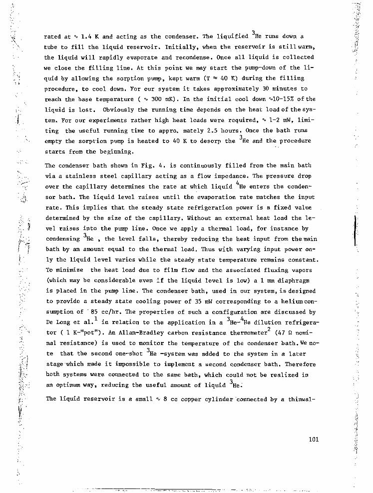
•",'•£"
3vï rated at *> 1.4 K and acting as the condenser. The liquified He runs down a
" > tube to fill the liquid reservoir. Initially, when the reservoir is still warm,
the liquid will rapidly evaporate and recondense. Once all liquid is collected
'•: we close the filling line. At this point we may start the pump-down of the li-
L ': quid by allowing the sorption pump, kept warm (T = 40 K) during the filling
procedure, to cool down. For our system it takes approximately 30 minutes to
reach the base temperature ( 300 mK). In the initial cool down ^10-15% of the
, liquid is lost. Obviously the running time depends on the heat load of the sys-
I tem. For our experiments rather high heat loads were required, 1-2 mW, limi-
ting the useful running time to appro, mately 2.5 hours. Once the bath runs
i 3empty the sorption pump is heated to 40 K to desorp the He and the procedure
starts from the beginning.
The condenser bath shown in Fig. 4. is continuously filled from the main bath
i r. via a stainless steel capillary acting as a flow impedance. The pressure drop•->-• . , 4
v over the capillary determines the rate at which liquid He enters the conden-
•,ii sor bath. The liquid level raises until the evaporation rate matches the input
rate. This implies that the steady state refrigeration power is a fixed value
/.[•- - determined by the size of the capillary. Without an external heat load the le-
••;'- ? vel raises into the pump line. Once we apply a thermal load, for instance by
£.; ; condensing He , the level falls, thereby reducing the heat input from the main
1 f bath by an amount equal to the thermal load. Thus with varying input power on-
f. . ly the liquid level varies while the steady state temperature remains constant.
::, To minimize the heat load due to film flow and the associated fluxing vapors
(which may be considerable even if the liquid level is low) a 1 mm diaphragm
•' / is placed in the pump line. The condenser bath, used in our system, is designed
:; to provide a steady state cooling power of 35 mW corresponding to a helium con-
sumption of " 85 cc/hr. The properties of such a configuration are discussed by1 3 4
[ De Long et al. in relation to the application in a He- He dilution refrigera-
• tor ( 1 K-"pot"). An Allan-Bradley carbon resistance thermometer (47 ft nomi-
nal resistance) is used to monitor the temperature of the condenser bath. We no-; . te that the second one-shot He -system was added to the system in a later••'• •'•' stage which made it impossible to implement a second condenser bath. Therefore
•J!.''J
hotti systems were connected to the same bath, which could not be realized in
an optimum way, reducing the useful amount of liquid He.
The liquid reservoir is a small i 8 cc copper cylinder connected by a thinwal-
101

il
led stainless steel "pumping line" ( 8 mm in diameter, 2oo mm long and with a
wall-thickness of 0.2 mm ) via the condenser bath to the sorption pump. In or-3
der to guarantee a good thermal contact between the liquid He and the copper
wall a copper braid is silver soldered into the bottom of the reservoir to mi-
nimize the thermal boundary resistance. The connection between sample cell and
the reservoir is also made by means of a copper braid. The temperature of the2
reservoir is measured using a Speer carbon resistance thermometer of 470 Q no-
minal resistance. The sorption pump consists of a cylindrical copper housing,3
containing a brass basket to hold approximately 25 cc of zeolite 5A. The pumpis heated to4 3
40 K to desorp the He using a button shaped heater glued to
the bottom of the copper housing. The heater is made of 37 fi/m manganin wire
bifilary wound on a copper former and impregnated with 1266 Stycast epoxy.
Once the heater is switched-off the sorption pump cools down via a heat link
to the main bath. The choice of the heat link results from a trade-off process.
One has to optimize the coojing rate while keeping the heat input into the main
bath acceptable during the desorption. In our case approximately 5.6 W is re-3
uired during 2.5 minutes to desorp the He. The system cools down again in about
half an hour. The temperature of the sorption pump is monitored using a but-
ton shaped copper wire resistance thermometer of a similar construction as the
button heaters. The thermometer is made to have a 100 Ü resistance at 0 C.
777%CONDENSER
BATH
FILLINGCAPILLARY
TO PUMP
HELIUM BATH
.FILM FLOW/CONSTRICTION
INDIUM SEAL
SORPTIONPUMP
TO LIQUID RESERVOIR
FILTER
CAPILLARY
Fig.4-Drawing of the condenser, continuously filled from themain bath via a stainless steel capillary. The thin walledtubing is folded to keep the design compact. The indiumsealed capillary joint, including a fine mesh metal filteris shown in detail at the right.
102

Fig. 5-Drawing of the experimental cell on a '80% re-duced scale.

We discuss the cryogenic aspects of the experimental cell. The aspects asso-
ciated with the physics of stabilizing H and the detection principle are dis-
cussed in chapter 3. The cell assembly is very compact and shown on a 80%
reduced scale in Fig. 5. It may be considered as a modular unit inserted into
the bore of the 11 T superconducting magnet. The various components are moun-
ted along a thin walled stainless steel tube providing thermal isolation be-
tween the sections. The tube is fed through a support flange, using a teflon
seal, the flange sealing the bottom of the T^C.
During operating conditions He is present in the cell and a film of the su-
perfluid covers all surfaces which are below i 1 K. Once the teflon valve
(see Fig. 1 and 2.) is opened the H atoms run up the tube, are thermally accom-
modated at ii 5 K and then enter the low temperature region where the walls are
covered by the superfluid. The gas is collected in the HSC (Hydrogen Stabili-3
zation Cell) which is thermally connected to one of the He reservoirs, using3
a copper braid. A single He system turned out to be inadequate to achieve
temperatures below ^ 0.6 K due to back fluxing helium vapor. The fluxing vapor
originates from the evaporating superfluid film which is driven to the lower
sections of the cell (the accommodator region) both by gravity and the thermo-
mechanical effect. To reduce the heat load on the HSC a second cooling stage,
the HEVAC (Helium Vapor Compressor) was added. With this two-stage designbase4
temperatures of *v> 270 mK were achieved at the HSC with He in the cell. Al-
though the fluxing vapors are detremental from a cryogenic point of view they |;
are put to advantage in this design since they give rise to some additional .;
compression of the gas. This explains the name. The HEVAC also contains a small I.
reservoir in which some bulk liquid may be collected. In this way the heat load i4 '-
on the HEVAC does not depend critically on the amount of He introduced in the [
cell. More details are given in chapter 3. The various components of the cell ;
are equipped with thermometers and heaters to register and regulate the tempe-2
rature. For the HSC and the HEVAC Speer carbon resistors (470 ft nominal re-
sistance) are used for thertnometry. On the accommodator we use an Allan-Brad-2
ley resistor (47 ft nominal resistance). The HSC thermometer is calibrated
against a germanium thermometer in turn calibrated in Leiden against CMN and
checked in our laboratory against an NBS 768 superconducting fixed point de- j
vice. The field dependence of the thermometer was established by running the .:
field up and down under stable temperature conditions. The thennometry is be- i
lieved to have an accuracy of approximately 3% in the experiments described \ii
in chapter 3, ^,5 and 6. \•i
104 •)

'V.. REFERENCES
1. L.E. De Long, O.G. Symko and J.C. Wheatley, Rev. Sci. Instr. U2_, 147
(1971).
2. G.K. White, Experimental Techniques in Low Temperature Physios, Claren-
don Press, Oxford 1979.
3. Supplied by BDH Chemicals Ltd, Poole, England.
4. R.R. Conte, Elements de cryogenie, Masson & Cie, Paris 1970
5. Supplied by Emerson and Cumming Inc., Oevel, Belgium.
6. T.M. Dauphinee and H. Preston-Thomas, Rev. Scientific Instr. 25^ 884,
1954.
7. Supplied by U.S. Department of Commerce, National Bureau of Standards,
Washington DC, USA.
I 1E ifI"- 105 S

CHAPTER 3
STABILIZATION OF ATOMIC HYDROGEN AT LOW TEMPERATURE
Isaac F . S i lvera and J . T. M. Walraven
Natuurkundig Laboratorium der U n i v e r s i t e i t van Amsterdam1018 XE Amsterdam, The Netherlands
Atomic hydrogen has been s t a b i l i z e d a t tempera-tures of 270 ± 20 mK and i n magnetic f i e lds upto 7 T. I t i s bel ieved to be gaseous. A sampledisplayed no measurable decrease in densi ty a f t e r532 s e c . Covering of exposed surfaces with a filmof ^He is essential.
[Phys. Rev. Lett. 44, 164 (1980)]
106

VOLUME 44, NUMBER 3 PHYSICAL REVIEW LETTERS 21 JANUARY 1980
Stabilization of Atomic Hydrogen at Low TemperatureIsaac F, Silvera and J. T. M. Walraven
Natuurkundig Laboratorium der Universiteit van Amsterdam, 1018 XE Amsterdam, The Netherlands(Received 19 November 1979)
Atomic hydrogen has been stabilized at temperatures of 270 ±20 mK and In magneticfields up to 7 T. It is believed to be gaseous. A sample displayed no measurable de-crease In density after 532 sec. Covering of exposed surfaces with a film of 4He is e s -sential.
Atomic hydrogen (H) with one proton and oneelectron is the simplest atomic system providedby nature. Just as helium and its isotopes displayfascinating properties at low temperature andhigh density, atomic hydrogen and its isotopesare expected to exhibit spectacular phenomena.Until now it has not been possible to study con-densed atomic hydrogen experimentally, as undernormal circumstances it is highly unstable withrespect to recombination to H2 which has a bind-ing energy eb/kB = 52 000 K in the singlet spinstate, lZg*. However, in the spin-polarizedstate, 3S g \ a pair of atoms have no bound state.We refer to a dense gas of atoms with electronspins polarized, so that all pairs interact within
the 3 £ u+ potential, as polarized hydrogen (Ht).
We have created a gas of H in a cell at 7" =2 70 ±20mK and in magnetic fields up to 7 T. Using spec-ially developed detectors we have establishedthat after loading the cell, the density did notchange to within experimental error for periodsup to 532 sec, the longest period investigated.Without our special conditions, we calculate thatthe sample would have-a decay-time constant of-80 jisec, due to surface recombination if kineticeffusion of the gas to the surface is rate limiting.The lifetime of this sample was increased by atleast a factor 7 xlO7 in this sense. We shall referto samples with increased lifetimes of > 10" asstabilized. In most cases we observed stabilized
-i• ï
164 © 1980 The American Physical Society 107

VOLUME 44, NUMBER 3 PHYSICAL REVIEW LETTERS 21 JANUARY 1980•X
é
samples for times of order 10-60 sec beforedestroying them. The highest density of a stabil-ized sample was n > 1.8 xlO14 atoms/cm3.
The first published discussion of some of theexciting phenomena expected for stable H* is dueto Hecht,1 who, in 1959, suggested that super-fluidity should exist in this boson gas. His articlewas evidently overlooked by researchers who be-came actively interested in H* in the 1970's, in-cluding ourselves. Etters and colleagues2 andStwalley and Nosanow3 reconsidered the proper-ties of the hydrogen isotopes. The stability of H*was first considered by Jones et al.* who foundthat it would be unstable at very high densities.Stwalley5 suggested that H+ would be stable in amagnetic field B for ratios fl/T^lO2 T/K. How-ever, Berlinsky ei al,e showed that his reasoningwas incomplete and that even at T = 0, for a givenmagnetic field there is a critical density abovewhich the Ht gas will become spontaneously un-stable.
Our research program to create and stabilizeH began in 1972 and was directed at stabilizing Hby polarizing an atomic beam and depositing iton a cold inert surface in a weak magnetic field,with the eventual objective of studying Bose-Ein-stein condensation in a quasi-two-dimensionalsystem. The results were discouraging as theatoms rapidly depolarized on the surface and re-combined.7 On the basis of the stability condi-tions found in Ref. 6 we decided to redirect ourefforts to stabilization of H+ as a three-dimen-sional gas in high magnetic fields at low tempera-tures.
Our design aims were based on an applied mag-netic field B= 10 T and a temperature T=300 mK.We recently developed a high-flux source of He-temperature atomic hydrogen8 required for theultimate goal of loading a cold cell to densitiesof 1018-1019 atoms/cm3. Our earlier experiencewith rapid recombination of H on surfaces sug-gested that any stabilization attempt using cur-rently available fields would be doomed becauseof condensation of the H on the surface followedby recombination. We conceived of the idea ofcoating all surfaces with a (superfluid) heliumfilm,9 believing that of all known materials thiswould have the weakest adsorption potential forH. This turns out to be vital for stabilization.
There are three important considerations forthe selection of the operating temperature. Firstof all, as discussed in the accompanying Letter,10
compression of a gas of H from a field-freeregion to a region of magnetic field B is propor-
tional to exp(ij.B/kT) (M is the magnetic momentof the H atom), which favors lowest possible tem-peratures. The region T-Q is also favored tominimize recombination due to spin-flip mecha-nisms11*4 and to minimize the density of thermal-ly populated spin-flipped states, which dependson exp(-2MB/feT). However, as a third point,the low operating temperatures may be limited bycondensation of H* on the liquid-helium-coveredsurfaces, where critical densities may be ex-ceeded. Recent calculations12'13 suggest that asurface state exists with a binding energy possi-bly greater than 0.6 K.
The heart of our low-temperature apparatus isshown in Fig. 1. The copper hydrogen stabiliza-tion cell (HSC) is in the center of a superconduc-ting solenoid (maximum field, B = 11 T). This isconnected by thin-walled German silver (GS) tub-ing to a helium vapor compressor (HEVAC). Thisis actually a miniature vapor diffusion pumpwhich uses a reservoir of superfluid helium asits pumping fluid. Both the HSC and the HEVACare cooled by sorption-pumped 3He refrigerators.During operation the HSC runs at T= 270 mK andhas an estimated residual background heliumvapor density of -5xlO8 atom/cm3. The HEVACwhich operates at 7=480 mK is connected by GStubing to a copper H accomodator pinned to 4Hetemperatures. A Teflon-lined GS tubing continuesout of the vacuum to a room-temperature hydro-gen discharge. The hydrogen atoms are fed in
mi'He
Fluxing ' H e Vapor
-»• Carton Tnermcffeter
Ü Heater
Room Temperature
H Source
FIG. 1. Low-temperature part of stabilization appa-ratus. See text for an explanation.
108

VOLUME 44, NUMBER 3 PHYSICAL REVIEW LETTERS 21 JANUARY 1980
I I
from the bottom of the cryostat to minimize thedistance and thus the recombination of H duringtransportation to the HSC; the atoms are cooledto liquid-helium temperature by the accomodatoras described elsewhere8 and are still unpolarizedat this point, The electron spin-down atoms aredrawn into the HSC by the field gradient, whereasthe spin-up states are retarded and either relaxto spin down or recombine. The system is pre-pared as follows. All surfaces above the Teflonlining are coated with molecular H2. The 3Herefrigerators are activated and 4He gas is con-densed in the HEVAC and HSC.
We shall briefly describe the operation of theHEVAC. A superfluid helium film is driven fromthe reservoir of the HEVAC, up, then down theGS tube towards the accommodator. As the filmflows down it comes into increasingly warmerregions, vaporizes and fluxes back to recondenseat the HEVAC. Without this fluxing gas the den-sity of 4He gas in the region of the HEVAC wouldbe - 10lVcm3 and the collisianal mean free path(A) for H-He would be about 2 cm." The back-fluxing gas is much denser (we estimate A-0.36mm for H-He collisions) so that hydrogen atomswill be directed into the HSC by momentum trans-fer from the four times more massive heliumatoms. The HEVAC not only guides the atomsinto the HSC, but also retards their leakage outwhen the discharge is turned off. As discussedin the accompanying Letter, the cell should emp-ty when the density of H in" zero field is zero. Weestimate that the emptying time constant is in-creased by a factor 79 by the HEVAC.
The presence of H in the HSC is detected withspecial bolometers. The principle is to build upa density of H in the cell and then trigger its re-combination by selectively making the bolometersactive recombination surfaces. The concomitantheating due to the recombination energy is easily
]•>f •
3 0 0 -
• ^ 2 0 0 -
1 ,5 «01-
Evatuated HSC• - • Helium Cooted HSC
HBlmmPlas jTFlowing H ^r
10 20 30
Zurrent ] I10"6omps)
«ognetii Fuld
50
5=0
(0
FIG. 2. Current-voltage characteristics of a hydrogenbolometer detector.
detected and provides a measurement of the Hdensity. The bolometers were made by cutting2x1 xO.2-mm3 chips from Speer resistors. Theyare connected to the top plate of the HSC by finecopper wires which serve not only as current-voltage (/- V) leads but also as the path which al-lows the 4He film to cover their surfaces. InFig. 2 we show the J- V curves. When 4He is intro-duced into the HSC the I- V curves develop a peak.The 4He on the bolometer surface is evaporatedas a result of Ohmic heating. Fresh 4He willflow along the wire leads to replenish the film;however, this flow is limited by the wire circum-ference.15 The peak in the /-Vcurve representsthe point where the H2-covered surface is firstexposed. This surface is an active source for re-combining H.16 When H is present while tracingan /- V curve, arrival at the desorption peak willtrigger recombination. This destroys the H gaswith a time constant 7 -AV/ï'A, where V is thevolume of the HSC, v is the average velocity,and A is the total area of the bolometer; we as-sume a probability of 1 for recombination whena particle strikes the surface. For our systemat r=27O mK, T=8 msec. Thus we see a sharpdownward-going spike on the I- V curve and a re-turn to a level determined by the steady-state re-combination on the bolometer of H flowing intothe hSC. The I-V curve has hysteresis becauseof the extra heating after desorption. From ear-lier work16 it is known that the recombining atomsdeposit only a small portion of the recombinationenergy on the bolometer surface, since the Hamolecules are desorbed upon recombination. Thesecond bolometer, operated below its desorptionpeak, will absorb part of this energy from the"hot" molecules. The rest will be absorbed inthe copper walls of the HSC (or blown out of thefilling tube) and is detected with a thermometer.By calibrating the heating of the HSC with an elec-trical heater, a lower bound for the number ofrecombinations, or the H density, can be deter-mined.
Proof of stabilization was obtained as follows.With the magnetic field and discharge on, wemeasured the recombination spike height as afunction of cell loading time. As the loadingperiod was increased the size of the spike in-creased, indicating that larger densities of Hwere being built up. We then loaded the cell fora period of time fL( ~30 sec), turned off the dis-charge, and waited a time, ts, before triggering.Starting with t,-l sec we continually doubled thewait time, finding no measurable attenuation in
109

VOLUME 44, NUMBER 3 PHYSICAL REVIEW LETTERS 21 JANUARY 1980
the size of the spikes. Periods longer than 532sec were not measured as we chose to use ourlimited experimental measuring time to investi-gate other aspects of the system. This providesproof of long-term stability of H. This was per-formed with a field of 7 T at T = 270 ± 20 mK. Al-though no detailed systematic studies have beenperformed we found that the recombination spikeheight decreased with both decreasing fields andincreasing temperature for a constant filling rate,as is to be expected. The largest density we ob-served was at 6 T (270 mK) with a very conserva-tive lower bound of 1.8 xlO" atom/cm3. No ef-fort has been made as yet to determine a maxi-mum achievable density.
We have also measured the time dependence ofthe density in zero field, where the gas is cer-tainly H (not H*) and should not be stable. Theresults are shown in Fig. 3. The decay does notappear to be controlled by volume recombination,probably because the density is low. If we rough-ly fit by an exponential decay, as would be ex-pected for thermal effusion, we find a time con-stant of 1.5 sec, as compared to a calculated 19ms without the HEVAC. This implies a compres-sion iactor of 79 for the HEVAC.
Indications that H exists in the gas phase arethe following. On the basis of the theoreticalestimate for the binding energy of H on a He sur-face, at the employed temperatures we expectthat in thermodynamic equilibrium a considerablefraction will be gaseous. Second, the H totallyrecombines in about 80 msec as measured bythe full width at the base of the bolometer spike.Since this can be several time constants long,the recombination rate is of the expected orderas determined by gaseous effusion to the bolome-ter surface. Third, if the bolometer signalswere due only to H on its surface, then, assum-ing a coverage of maximal 10u/cm2, the signalwould correspond to 2xlO12 recombinations, in-consistent with observations; a second triggeringwithout reloading the cell did not result in a re-combination spike as would be expected as a re-sult of surface diffusion which would recover thebolometers. Finally, we performed • A\ arimentsin which we sequentially triggered the two bolome-ters within 100 msec. Only the first triggeredbolometer displayed a recombination spike, whichwould not be the case if the H resided mainly onthe surface. Although no one argument hereprovides a hard proof of the state of H, altogetherthe evidence points to gaseous H. We hope to beable to increase the density by some orders of
B=7Tesla
n/no=exp(-ts/l-5)
1 5TIME,ts(seconds)
8 9^530 532
FIG. 3. Decay rate of H for T =270 mK at B »0 and7 T. ts is the elapsed time after loading the cell andn0 Is the density for Js »0. The error bars are due tocalibration uncertainties only.
magnitude to study the interesting properties ofthis almost ideal Bose gas. Already at presentdensities there are important implications forincreased stability of the hydrogen maser.17
We thank A. P. M. Mattheij, R. Sprik, andM. B. J. Diemeer for their help with the appara-tus and measurements. We warmly acknowledgediscussions with A. J. Berlinsky and E. R. Elielat the beginning states of these' experiments.The rapid and expert constructional work byO. H. Höpfner has been of inestimable value. Wethank the Stichting voor Fundamental Onderzoekder Materie for their great flexibility and under-standing in supporting this research of a morespeculative nature.
•C. E. Hecht, Physlca25, 1159 (1959).2J. V. Dugan and R. D. Etters, J. Chem. Phys. 59,
6171 (1973); R. D. Etters, J. V. Dugan, and R. W. Pal-mer, J. Chem. Phys. 62, 313 (1975); R. D. Etters,R. L. Danilowltz, and R. W. Palmer, J. Low Temp.Phys. 33, 305 (1978).
3W. C. Stwalley and L. H. Nosanow, Phys. Rev. Lett.36, 910 (1976).
4J. T. Jones Jr., M. H. Johnson, H. L. Mayer, S. Katz,
110

VOLUME 44, NUMBER 3 PHYSICAL REVIEW LETTERS 21 JANUARY 1980
and R. S. Wright, Aeronutronic Systems Inc. Publica-tion No. 6-216, 1958 (unpublished).
5W. C. Stwalley, Phys. Rev. Lett. 37, 1628 (1976).6A. J. Berlinsky, R. D. Etters, V. V. Goldman, and
I. F. Silvera, Phys. Rev. Lett. 38, 356 (1977).' j . T. M. Walraven, E. R. EHel, and I. F. Silvera,
Phys. Lett. 66A, 247 (1978).'i. F. Silvera and J. T. M. Walraven, Phys. Lett. 74A,
193 (1979).'Others have evidently also had this idea. W. C.
Stwalley, in Quantum Fluids and Solids, edited by S. B.Triclcey, E. D. Adams, and J. W. Dufty (Plenum, NewYork, 1977, p. 293.
l0J. T. M. Walraven and 1. F. Silvera, following LetterI Phys. Rev. Lett. 44, 168 (1980)).
"The necessary field for stability considered in Ref.6 will Increase for T *0 as the pair distribution functionwill allow for more penetrating pair collisions as T in-creases.
aR. A. Guyer and M. D. Miller, Phys. Rev. Lett. 42,1754 (1979).
13I. B. Mantz and D. O. Edwards, to be published.MJ. P. Toennies, W. Welz, and G. Wolf, Chem. Phys.
Lett. 44, 5 (1976).l5For properties of these films, see, for example,
J. Wllks, The Properties of Liquid and Solid Helium(Clarendon, Oxford 1967), Chap. 14.
ieSee Ref. 7 and references therein."S. B. Crampton, W. D. Phillips, and D. Kleppner,
Bull, Am. Phys. Soc. 23. 86 (1978).
I l l

CHAPTER 4
DENSITY, MAGNETIZATION, COMPRESSION, AND THERMAL LEAKAGE
OF LOW-TEMPERATURE ATOMIC HYDROGEN
J. T. M. Walraven and Isaac F. Silvera
Natuurkundig Laboratorium der Universiteit van Amsterdam1018 XE Amsterdam, The Netherlands
The density distribution of low-temperature spin-polarized atomic hydrogen in a realistic magneticfield profile is calculated for densities belowand above the critical value for Bose-Einstein con-densation. The distribution is an identifying cha-racteristic. Magnetic compression and instabilitydue to thermal leakage of the atoms is treated.
[Fhys. Rev. Lett. 44_, 168 (1980)]
112. j

VOLUME 44, NUMBER 3 PHYSICAL REVIEW LETTERS 21 JANUARY 1980
Density, Magnetization, Compression, and Thermal Leakageof Low-Temperature Atomic Hydrogen
J. T. M, Walraven and Isaac F. SilveraNatuurkundig Laboratorium der Universiteit van Amsterdam, 1018 XE Amsterdam, The Netherlands
(Received 19 November 1979)
The density distribution of low-temperature spin-polarized atomic hydrogen in arealistic magnetic field profile i s calculated for densities below and above the criticalvalue for Bose-Elnstein condensation. The distribution is an identifying characteristic.Magnetic compression and instability due to thermal leakage of the atoms is treated.
Atomic hydrogen (H) which has been shown inthe accompanying Letter1 to exist in a long-timestable state provides us with a new Bose 'fluid.Since in general it is necessary to prepare thisgas by injecting atoms into a magnetic field, atreatment of the effect of magnetic field gradientsis required. In this Letter we calculate the den-sity distribution for spin-polarized H (Ht) in arealistic magnetic field profile. Results are ob-tained below and above nc, the critical density forBose-Einstein (BE) condensation; the effects ofinteractions in the high-density BE condensedstate are shown to be non-negligible. The den-sity profile is a characteristic identifying featureof the gas. This calculation immediately pro-vides the local static magnetization, which isrelated to the density by a proportionality con-stant: the Bohr magneton. The important con-cept of a magnetic compression is introduced.Finally, we consider the instability of a magneti-cally confined gas in an open-ended container,due to thermal leakage. Comparisons are madewith experiment where possible.
At low temperatures Ht is considered to be anextremely weakly interacting Bose gas.2 To illus-trate this point we have plotted in Fig. 1 the p-V
curves for Ht at T =0 K as calculated by Etters,Danilowicz, and Palmer3 and for an ideal Bosegas at 7 =0.1 and 0.3 K. As the 0-K curve canbe looked upon as a measure of the interactions
« DENSITY ( id 8 Atoms/cc)6 3 2 1 .8 .6
2 4 6 8 10MOLAR VOLUME do'cC/MOL) -
FIG. 1. p-V relation for Ht In various approximationsand at various temperatures.
168 © 1980 The American Physical Society
113

VOLUME 44, NUMBER 3 PHYSICAL REVIEW LETTERS 21 JANUARY 1980
within the system, no significant deviations fromideal-Bose-gas behavior are to be expected formany properties down to molar volumes andtemperatures of order 105 cm3/mol and 100 mK.This feature makes Ht an ideal test probe tocompare theory and experiment for a weaklyinteracting Bose fluid.
Ht can only be maintained as a stable gas in amagnetic field. The confinement space (cell)must be open ended to allow loading from a sourceof cold atoms which can extend to zero-field re-gions. As a consequence the density distributionwill be inhomogeneous since the field gradientsexert a force on the magnetic moments of theatoms. This leads to compression of atoms inthe lower two hyperfine states4 into the high-fieldregion, whereas the other states are repelled.We first focus our attention on the steady-stateproperties of H* in the field of a small super-conducting magnet as used in the experiment de-scribed in the preceding Letter.1 The field pro-file along the symmetry (z) axis is shown in Fig.2 and is approximately quadratic over a range of60 mm around the field maximum. Any fieldgradients in the xy plane are neglected since theatoms are confined to the vicinity of the z axisby means of a cylindrical tube. If we neglect
EndolCal— DISTANCE FROM CENTER [mm I -
Fig. 2. (a) Magnetic field profile as a function of thedistance from the center of the magnet. The end ofthe magnetic coil and a quadratic fit to the field are in-dicated, (b) Density profiles on an expanded scale.See text for explanation.
114
wall effects as well as all terms in the Hamil-tonianbeyond the electronic Zeeman term (i.e.,we assume a high-field approximation), and re-place the real field profile by its quadratic ap-proximation, B{z) = Ba[l~{z/zmf], the Schröding-er equation for atoms in the ms =- \ electronicspin state reduces to a harmonic-oscillator (HC)problem:
[-£where m is the mass of the H atom, ZnK isPlanck's constant, g = 2 is the Lande g factor,HB is the Bohr magneton, Bo is the field at thecenter of the magnet, and zm =51 mm in. our sys-tem [see Fig. 2(a)].
The solutions of (1) are
where <ft,rte) is a HO state and exp(zk i'?J) aplane-wave state with propagation perpendicularto the symmetry axis. The energy spectrum con-sists of a series of bands, labeled by the HOquantum number and spaced at approximately4X10"" K. The corresponding oscillator fre-quency bi0 is given by
wo = (2/iB.Bo/»i.zm2)l/2, (3)
where wo« 5.5xlO3 rad/sec for a field of 7 T.If one considers a collection of H atoms in the
magnetic field, the occupation of the variousstates is governed by Bose statistics. As a con-sequence the density distribution of Ht dependsdramatically on the total number of atoms in thefield as shown in Fig. 2(b). At low density (curvea) the system behsves like an ideal gas. If thedensity is increased the statistics lead to acompression of the gas, causing a peaking ofthe distribution as shown in curve 6. Beyond acritical density (ne) a "divergence" in the den-sity occurs at the maximum field position be-cause of the Bose condensation into the HOground state. The classical turning points forthis state are separated by 6.8 urn. However,at these densities it is no longer realistic to treatthe system as an ideal Bose gas and interactionswill cause the divergence to broaden as shownin curve c for T = 0 K.
The density distribution n(z) of the gas is cal-culated with use of
« ff)= Tji Wt [ ip( (f) |a, (4)
where W, is the Bose probability for the occupa-tion of a given state. Even at the lowest achieva-

VOLUME 44, NUMBER 3 PHYSICAL REVIEW' LETTERS 21 JANUARY 1980
ble temperatures many states will be occupiedand as a consequence (for n « nc) Eq. (4) can becalculated very accurately using the classicalapproximation for the expectation values Uj(r)i2
of the HO states.5 This leads to
(5)
where \length,
, mkT)l/2 is the thermal wave-
1 = 1
H is the thermodynamic potential, and k is Boltz-mann's constant, n « nc corresponds to the con-dition F «1 .
The effect of the broadening of the condensatepeak is estimated using the theoretical resultsfor the ground-state energy per atom E^n) as afunction of density.316 The energy to add a par-ticle to the system is then given by
li = (B/Bn)[nElfyi)]*' 2 an- nBB (6)
for relatively low densities, where one may writeE^i) =an - fiBB with a/k =306 K A.3 Setting n = nc
= 1.4x10*° atoms/cm3 at 7 T and 0.27 K one eas-ily finds the density distribution (for the fieldprofile under study) to depend quadratically onthe distance from the center [curve c, Fig. 2(b),forr=0] .
In order to study the consequences of theseconcepts for somewhat realistic experimentalconditions, consider a tube extending from zeroto maximum field along the axis of a magnet.The tube is assumed to be at constant tempera-ture and does not catalyze recombination. Thezero-field density of H is maintained constant.This sets a value for the thermodynamic potentialand the density can be calculated at any point us-ing Eq. (5). It is elucidating to express this rela-tion in terms of a compression factor, c{z), andthe density at maximum field; no = c{z)n{z). Inthe low-density limit
c(z) -B(zj] /kT}. (7)
The strong dependence on B and T is seen in thefollowing examples. For the profile of Fig. 2(a)with a 7-T field at T =0.27 K and z =40 mm, wehave c = 8.6 x iff", whereas at 0.5 K, c = 133. For10 T and T=0.l K, c=1.5xl015.
From expression (7) we see that if, in an equi-librium condition, the density in zero field issuddenly reduced to zero (experimentally this
corresponds to turning off the H dischargesource), then the density n0 in the high field mustgo to zero. This presents an instability for anopen-ended system. The time constant for thisthermal leakage in the low-density limit is foundfrom
dN/dt =£TdzAP1(z) n(z)
(8)
where N is the number of atoms in the field, A isthe cross-sectional area of the tube, P^x) is ageometric factor describing the probability toescape the system (pass beyond z =zr) from theposition z without a wall collision, Pt{v,) = 0(ux
-w,{z)) is the probability that an atom moving inthe proper direction with a velocity v, can es-cape, 9 is a unit step function, and
wt{z) = [2n£B{z) -B(zr))/m]l/2
is the escape velocity;
is the normalized velocity distribution in the zdirection and «= (2kT/nill/i. Evaluating the ve-locity integral yields a simple rate equation,N=N/T, where T = 4cVeff/K«rA, ïï=C8kT/nm)1/2
is the average velocity of the atoms, Veff = N/ n0,and
is the effective Clausing factor7 for the system,r is the time constant of the system. For the ex-periment of Ref. 1 we have calculated a timeconstant T = 19 msec in zero field (V,.ff ==1.2 cm')and T = 110 sec at 7 T (Keff = 0.8 cm3), using K=0.1, ü = 100 m/sec, and A=12.5 mm2, for mag-netic compression only. The experiment yieldedT^1.5 and 532 sec, respectively. We attributethe difference to additional compression due tofluxing helium vapors (HEVAC), as discussed inRef. 1. From the experimental zero-field timeconstant of 1.5 sec, a HEVAC compression of 79is estimated. In the field of 7 T the time constantdue to both compressions would then be 8.7 x 10³
sec (2.4 h), consistent with observations.In summary, we stress the important result
that a realistic magnetic field profile leads to adensity distribution 'that displays macroscopicfeatures characteristic of the Bose nature of theparticles: narrowing and peaking up at the fieldmaximum as the gas approaches the critical den-sity. Measurement of the density or magnetiza-tion should provide a method of detecting BE con-
115
VOLUME 44, NUMBER 3 PHYSICAL REVIEW LETTERS 21 JANUARY 1980
densation. If this state can be created,- fromcurve c Fig. 2(b) we see that a sharp interfaceor "surface" in coordinate space should be acharacteristic of the condensate at low tempera-ture. At low density the gas behaves classically.The maximum c'ensity that can be loaded into amagnetic field for a gas stabilized against re -combination is limited by exp(B/T) and the zero-field density.
The authors acknowledge a number of stimulat-ing discussions on these subjects with A. J. Ber-linsky, H. P. Godfried, V. V. Goldman, andA. P. M. Mattheij, as well as the financial sup-port of the Stichting voor Fundamental Onder-zoek der Materie.
'i. F. Sllvera and J. T. M. Walraven, preceding LetteriPhya. Rev. Lett. 44, 164 (1980)1.
2C. E. Hecht, Physlca (Utrecht) 25, 1159 (1959»;R. D. Etters, J. V. Dugan, and R. W. Planner, J. Chem.Phys. 62, 313 (1975) j W. C. Stwalley and L. H. Nosa-now, Phys. Rev. Lett. 36, 910 (1976).
3R. D. Etters, R. L. DanUowicz, and R. W. Palmer,J. Low. Temp. Phya. 33, 305 (1978).
4N. F. Ramsey, Molecular Beams (Clarendon, Ox-ford, 1956), p. 263.
5L. I. Schiff, Quantum Mechanics (McGraw-Hill,New York, 1955), 2nd ed., p. 65.
6M. D. Miller and L. H. Nosanow, Phys. Rev. B 15,4376 (1977).
TS. Dushman, in Scientific Foundation of VacuumTechnique, edited by J. M. Lafferty (Wiley, New York,1962), 2nded., p. 93.
,' \l
116
CHAPTER 5
MAGNETIC EQUATION OF STATE OF A GAS OF SPIN-POLARIZED
ATOMIC HYDROGEN
J. T. M. Walraven, Isaac F. Silvera, and A. P. M. Matthey
Natuurkundig Laboratorium der Universiteit van Amsterdam1018 XE Amsterdam, The Netherlands
The magnetic equation of state of spin-polarizedatomic hydrogen is reported, relating density tomagnetic field (B £, 10.5 T), temperature (T £ 300
• ' mK), and atomic flux used to fill the sample cell.Densities greater than 10l6 atoms/cm^, more thantwo orders of magnitude greater than initial ob-
f • servations, have been achieved. Results are alsov presented on the buildup and decay of the densi-
ty as a function of external conditions. Prelimi-;'" . nary observations on the Fermi fluid, atomic deu-ƒ terium, are reported.
[Phys. Rev. Lett. 45_, 449 (1980)]
;: t •
Ê
117 1

VOLUME 45, NUMBER 6 PHYSICAL REVIEW LETTERS II AUGUST 1980
Magnetic Equation of State of a Gas of Spin-Polarized Atomic Hydrogen
J. T. M. Walraven, Isaac F. Silvera, and A. P. M. MattheyNatuurkundig Laboratorium der universiteit van Amsterdam, 101 fi-XE Amsterdam, The Netherlands
(Received 8 April 1980)The magnetic equation of state of spin-polarized atomic hydrogen is reported, relating
density to magnetic field (b - 10.ö T), temperature {T'- 300 mK), and atomic flux usedto fill the sample cell. Densities greater than lo"1 atoms/cm •, more than two ordersof magnitude greater than initial observations, have been achieved. Results are also pre-sented on the buildup and decay of the density as a function of external conditions. Pre-liminary observations on the Fermi fluid, atomic deuterium, are reported.
PACS numbers: 67.40.Db, 75.10.-b
Spin-polarized atomic hydrogen (Ht) has re-cently1'2 been stabilized over periods of minutesat 270 mK and densities of order 1014 atoms/cm3.In order to observe many of the fascinating pre-dicted properties such as Bose-Einstein conden-sation and the gaseous nature of this many-bodysystem at T =0 K, it is necessary to achieve sub-stantially higher densities. In this Letter we re-port density increases of more than two ordersof magnitude over previous values; no fundamen-tal limitations have yet been encountered. Ex-perimental results are presented on the temporalbehavior of Hi during filling of a hydrogen stabi-lization cell (HSC) and the subsequent decay afterfilling. We have also studied the magnetic equa-tion of state of Hi which provides an importantguide for efforts to increase the density. Finallywe report some preliminary measurements onthe stabilization of the Fermi fluid, spin-polar-ized atomic deuterium.
One of our principle objectives in this articleis to thermodynamically demonstrate that, al-though exotic, Hi behaves as a gas of magneticmoment bearing atoms that exists at very lowtemperatures. An ideal geometry for studyingthe thermodynamic properties would be an infinitespace with no surfaces having a uniform tempera-ture and including a region with a nonzero staticmagnetic field. The requirement that the chemi-cal potential be uniform in such a system yieldsa relationship between the equilibrium local mag-netization M, the magnetic field B, and the tem-perature T. This is the magnetic equation ofstate. Since I Ml =H B n (ft is the local gas densityand fi B the Bohr magneton), establishment of therelationship between n, B, and T provides thermo-dynamic evidence of the gaseous nature of Hi.
In our actual system,1 the gas is fed into theHSC from a room-temperature source with inter-mediate cooling states; it can exist in a nonequi-librium steady-state condition with a tempera-
ture extending from -0.3 to 300 K. However, thegas is confined in the HSC by magnetic compres-sion and a miniature low-temperature helium va-por compressor (HEVAC) and the density onlysuffers slow decay due to leakage or recombina-tion. As a consequence we treat the gas as aquasiequilibrium system. For the density dis-tribution we have2
n(B) = n(Bo) exp[- /i B(B0 - B)/kT], (1)
where BQ is the maximum field. The ratio of thedensity at field Bo to that at field B is called themagnetic compression factor, cM = exp[ n B(B0 - B)/kT\. The time constant r is determined by theexperimental design. In our system (desciibeiiin Ref. 1)
where cH is the HEVAC compression, Vetf=N/n(B0) is the effective volume2 of the HSC (withtotal number of particles M), A is the cross-sec-tional area of the fill tube with Clausing factor K,and v is the average atomic velocity of the gas.The expression for T is again only valid in the low-density limit; it neglects any recombination inthe cell and thus the decay is fully ascribed tofree atomic flow of H( towards the HEVAC wherean atom has a probability of l / c H to escape. Thismodel predicts the density to change exponential-ly towards a new steady-state value when the con-ditions are changed.
In our present geometry the HSC and the HEVACare in fields Bo and 0.56B0, respectively. TheHSC can be varied in temperature from -0.27 to0.8 K; the HEVAC operates at - 0 . 5 K. Below theHEVAC the temperature rises rapidly to 4.2 K atan accommodator3 used to cool the H gas generat-ed in a room-temperature discharge. It is quiteclear that the configuration differs from the idealuniform temperature system, yet we believe thatour system can be approximated by Eqs. (1) and
© 1980 The American Physical Society 449
118

VOLUME 45, NUMBER 6 PHYSICAL REVIEW LETTERS 11 AUGUST 1980
(2) with c„ evaluated with respect to the field atthe HEVAC. When the discharge is turned on asteady-state density (neff) of cold H is maintainedin front of the HEVAC in spite of surface recom-bination processes. If we assume these process-es to be first order in the density we expect neff
to scale linearly with the incoming flux, <p; weconclude4 that n(B0)~cHcw<p.
Measurements were made by filling the cell ata constant flux for specified periods. The densitywas determined by triggering the stable Ht gasto recombine by means of a bolometer.1 Therecombination energy was mainly dissipated inthe cell and caused an easily measured tempera-ture rise of the HSC with a characteristic waveform. The cell was calibrated for density byelectronically generating heat pulses in the bo-lometer to reproduce this wave form. Since aftertriggering, atoms and recombined moleculescould also be blown out of the HSC, our measureddensities represent lower bounds.
We shall first discuss our low-density Ifi s 3x l O u atoms/cm3) results. In Fig. l(a) we showa typical curve for the time dependence of fillingthe HSC. When the discharge is turned off, thedensity in the cell decays exponentially with atime constant T as shown in Fig. l(b). In zerofield at T =0.27 K we measured1 T =T 0 =1.5± 1sec. For 4 T, 0.39 K and 8 T, 0.37 K we find38.6±1 and 1998±37 sec, respectively. The long-
est period of stabilization was 47 min before trig-gering.
Writing T =T0{Vcf(/Va)exp[y 'HaB0/kT], whereVo is the geometric volume of the cell and y = (fl0-B)/Bo, enables us to solve for T0 and y usingthe measured time constants for 4 and 8 T. Thisyields T0 = 1.7 sec and y =0.53± 0.05, where wegive the error in y due to uncertainties in tem-perature. The value of T0 agrees well with ourdirect measurement at Bo =0; y =0.53 correspondsto a point within 2 mm of our estimate of the loca-tion of the compression side of the HE VAC,' sug-gesting that cM should be calculated with respectto the field in the HEVAC.6 In some circumstanc-es we observed almost steplike changes of thetime constant by factors of 2 or 3. We believethis may be due to different modes of operationof the HEVAC. During the measurements of r at4 and 8 T used to calculate y, changes of this na-ture were not observed. At higher densities, ns 10'? atoms/cm3, we observed initial decay ratesof order five times faster so that simple exponen-tial decay no longer applies. This may imply thatrecombination is becoming a problem.
One of our objectives has been to determine themagnetic equation of state. In steady-state equi-librium we can write n„x(Bo)=<pTocM/Vo. Fluxwas easily measured by filling the HSC for a timet«T and triggering to determine the number ofatoms N or <p =N/t. In Fig. 2 we plot the satura-
10"
10
1000 2000 3000 £000I
°-o-.. t
K • 4TESLA.0.39Ko BTESLA.0.37K
141014ATOMS/cc-
100 200 300 400
4TESLA.039K
100 200 300TIMEISECI » -
400
FIG. 1. (a) Density as a function of time during fillingof the cell at constant tp, Bo, and T. (b) Decay ofR (if0) in time at constant B and T. The upper scaleis for the 8-T data.
10"
j/jiO1
o
15
c" l0 1 4 r
10,13
: o B: * 2
: s a t
TESLA.0.37KTESLA. 0 40 K
0°
&
o * 0 0
A
101 1012
<!> [ATOMS/SEC]1013 10"
FIG. 2. Saturation density as function of the incoming .;,flux at constant Bo and T. The dotted line represents Jthe maximum possible density in case of systematic |
I
119

VOLUME 45, NUMBER 6 PHYSICAL REVIEW LETTERS II AUGUST 1980
tion density as a function of flux, with Bo and Theld constant. The simple theory suggests a lin-ear relationship which is found for low density(triangles). However, for higher density (circles),we see a deviation. Our detection method only de-termines a lower bound of n{B0). We can also setan upper bound by noting that the measured den-sity must be less than <ptt/V,.n, where tf is thefill time used to ensure that n(B0) =nat. This up-per bound is given by the dotted line. In Fig. 3we plot the saturation density versus BjT for aconstant flux, ^ = 1 . 3 x 1 0 " atoms/sec. The opencircles represent data obtained from variation ofthe magnetic field at constant temperature whilethe solid circles are obtained by varying the tem-perature, keeping the field constant. The dashedline represents the predicted behavior where nal
= <PT0CM/V0 and y =0.53; the dotted line again rep-resents an upper bound as determined by the inte-grated flux of atoms. The data are corrected forchanges in the mode of operation of the HEVACwhich were detected by measuring the saturationdensity at regular time intervals for a referencevalue of B, T, and <p. The instability of operationwas mainly responsible for the scatter in the data.The statistical error in measurement of field,temperature, time, and the wave forms used todetermine the density was at most a few percent.However, we estimate that the density calibra-tion, which covered more than three orders ofmagnitude could have a systematic error, in par-
5 10 15 20B0/T(TESLA/Kl *
25
FIG. 3. Saturation density as a function of £0/T forconstant incoming flux. For densities above ~3xlOM,the data are thought to represent a lower limit. The(lotted line represents an upper limit. For the dashedline, see text.
ticular at high density, of order 2. At a densityof 1015 atoms/cm3 the measured density could beas much as a factor of 5 lower than the actualdensity due to leakage of recombination energy(or atoms) out of the HSC.
The highest H» density achieved to now isn(B0)s-1 x 10¹⁶ atoms/cm3 in 10.5 T at 0.4 K. As theflux is increased the HSC warms up, probablydue to recombination that occurs during loadingand sorting out of spin-up and spin-down atoms.Thus our maximum density is limited by our cur-rent refrigeration power. The flux itself was nev-er a limit and usually was restricted to (1-10)%of its maximum value.
The presented data clearly show how higherdensities can be achieved in the HSC. The simpletheory of compression appears to have some va-lidity but is not accurately applicable due to non-uniformities in the temperature. Moreover athigher densities we only observe a lower limit forthe density, complicating interpretation. Devia-tions from the simple theory observed for higherdensities may possibly be related to the locationof the KEVAC and can be resolved by changingthe geometry. If deviations are due to the onsetof recombination in the HSC, then the problem isfundamental. However, density decay can alsoarise from recombination in the tail of the densitydistribution where a dense gas of helium can pro-mote three-body recombination, or where thewalls do not have a proper helium coverage.
We also report an interesting observation con-cerning the detection of Hi. With a sufficientnumber of atoms in the cell, after triggering, thecell temperature rises to a temperature Tf andthen remains constant, for periods th up to 2.6sec. Simultaneously triggering both bolometersin the HSC in order to d nib' e the active surfacearea did not affect T, or cb for a given density.However, simple kinetic considerations suggestthat the rate of recombination is proportional tothe bolometer area and that the process should becompleted within tens of milliseconds.1 This in-dicates that another (unidentified) process be-comes important at higher densities. A possibleexplanation is that after triggering, the initialrecombination heats the cell to temperaturesgreater than that of the HEVAC, also vaporizingsome helium. At this point the helium vapors be-gin to flow towards the HEVAC, compressing theH( between the HSC and the HEVAC. This is aself-controlled feedback process that keeps thetemperature of the HSC constant by recombiningthe H at a constant rate as long as a sufficient
120

VOLUME 45. NUMBER 6 PHYSICAL REVIEWVLETTERS 11 AUGUST 1980
number of atoms are available and for which t„is independent of the bolometer area.
Two of us (I.F.S. and J.T.M.W.) have injectedgas from a deuterium discharge into the HSC.The resultant trigger signals correspond to dis-appointingly low densities of stabilized gas. Thisresult could be due to a higher surface adsorptionenergy' for D as compared to H. It is quite clearthat D behaves differently than H, even at lowdensity. A complete report will be made afterfurther investigations are completed.
We thank R. Sprik for assistance with some ofthe measurements and gratefully acknowledge thefinancial support of the Stichting voor Fundamen-teel Onderzoek der Materie.
'l. F. Silvera and J. T. M. Walraven, Phys. Rev. Lett.44. 164 (1980); note that here we have changed the no-
tation from HI to H» for spin polarized H, which ispreferable since we stabilize the down (ms = - s ) spinstate.
2J. T. M. Walraven and I. F. Silvera, Phys. Rev. Lett.44, 168 (1980).~\. F. Silvera and J. T. M. Walraven, Phys. Lett. 74A,193 (1979).
'Measurements were mostly done at ~0.4 K, limitinggradients to 25% of the cell temperature so that ther-momolecular effects are small.
'This enables an improved estimate of cH= ir^KvA/Vo. Use of Vo = 1.44 cm3 , v = 93 m/sec, A = 0.125 cm2,and K = 0.11 with T0 = 1.7 sec leads to cH = 38. Thisvalue differs from that given in Ref. 2 as we have nowdetermined the helium condensation point of the HEVAC(the compression side) to be further from the HSC,changing Vo and K. In Ref. 2 due to a typographicalerror K was given as 0.1 instead of 0.18; the calcu-lated estimate, cH = 79, was correct as given.
'in Ref. 2 time constants were calculated taking B= 0 in the low-density tail.
7R. A. Guyer and M. D. Miller, Phys. Rev. Lett. 42,1754 (1979).
121

H
CHAPTER 6
SPIN-POLARIZED ATOMIC DEUTERIUM: STABILIZATION, LIMITATIONS ON
DENSITY, AND ADSORPTION ENERGY ON HELIUM
Isaac F. Silvera and J. T. M. Walraven
Natuurkundig Laboratorium der Universiteit van Amsterdam1018 XE Amsterdam, The Netherlands
Current limitations on the density of stabili-zed spin-polarized deuterium(D-t-) to 1014 atoms/era? are shown to arise from condensation on the% e surface and subsequent recombination. A newtechnique for measuring the adsorption enery isemployed to provide the first such measurementfor D4. on helium, yielding ea/k2 = 2.5 ± 0.4 K.
[Phys. Rev. Lett. 45, 1268 (1980)]
122
Y o u ME -Ï5. NUMBER 15 P H Y S I C A L R E V I E W L E T T E R S 13 OCTOBER J9HU
Spin-Polarized Atomic Deuterium: Stabilization, Limitations on Density,and Adsorption Energy on Helium
Isaac F. Silvera and J. T. M. WalravenNatuurkundig laboratorium der Universiteit van Amsterdam, 1018-XE Amsterdam. The Netherlands
(Received 10 July 1980)
Current limitations on the density of stabilized spin-polarized deuterium (D(J to ~1014
atoms/cm3 are shown to arise from condensation on the 4He surface and subsequent re-combination. A new technique for measuring the adsorption energy is employed to pro-vide the first such measurement for D^ on helium, yielding £a/*fl = 2.5±0.4 K.
PACS numbers: 67.40.Db, 68.45.Da
We have recently reported the stabilization of agas of spin-polarized atomic hydrogen, H,, in acell in which all surfaces were coated with super-fluid 4He.x Although densities greater than 1016
atoms/cm3 have already been achieved for H( ,2
attempts to achieve higher densities for spin-po-larized atomic deuterium, D , , have yielded den-sities n s 10M atoms/cm3. In this Letter we showthat the limitation is due to a fundamental prob-lem: the adsorption of D t on the 4He surface andsubsequent recombination to D2. The same proc-es s can ultimately prevent achievement of thehigher densities necessary for Bose-Einstein con-densation in Hi. We have developed a method formeasuring the adsorption energy and find eo/feB
= 2.5± 0.4 K for D t on 4He. We have also attempt-ed to stabilize H( and D t using pure 3He surfacesand detected no measurable density. However, amixture of 3He-4He, which is known to phase sep-arate and to provide a 3He surface, is effective.
D t is a spin-i or -1 particle and is expected tobehave as a Fermi gas.3 For temperatures low-er than the Fermi temperature, TF =fF/2mkB
x (<ov2n/gfn {g is the nuclear spin degeneracy) itbecomes a degenerate quantum gas. At even low-er temperatures it is conjectured to display su-perfluidity with several phases due to the variouspossible pairings of the fermion spin,4 in someanalogy with 3He. Densities of order 1O20 atoms/cm3 are required to observe these propertieswith the existing low-temperature technology.
We briefly describe our experimental technique,which is similar to that of Ref. 1. Atomic D orig-inating in a room-temperature microwave dis-charge enters our cryostat via a warm Teflontube and is abruptly cooled by an accommodator.This is a short length of cylindrical tubing cooledto T = 5 K by a weak thermal contact to a 4Hebath5 and covered with solid D2. The gas flowsinto a cold ( T Ï 270 mK) stabilization cell, whichwe call the HSC (hydrogen stabilization cell), sit-
ting in a solenoidal magnetic field which has avalue of 8.0 T in the present experiments. Thisfield polarizes and confines the atoms to theHSC.2'8 Confinement is further aided by a mix-ture helium vapor compressor (HEVAC) locatedbetween the accommodator and the HSC. Beforeloading with D t , the HSC and HEVAC walls arecovered with a film of 4He which extends almostto the accommodator. The density of H, confinedin such a cell decays exponentially, as a resultof thermal leakage?** with a time constant T ~ 2x 10³ sec for the current conditions; we expectabout the same value for D t . The number of D,atoms in the cell are measured by. precipitatingrapid recombination on the surface of a bolom-eter and measuring the subsequent temperaturerise of the HSC; calibration is done electronical-ly.1-2
We have found the density of D t to be limitedfor two reasons. First, in the presence of a de-cay process, the maximum density in the HSC de-pends on the loading flux of atoms. The flux ofD, was substantially lower than that of H t . Thiswas found to be due to condensation and recom-bination on the surfaces of the accommodator re-gion. By heating the accommodator up by sever-al degrees Kelvin, the D, flux could be increasedby a factor 5-10. This implies a larger adsorp-tion energy of D on D2 than H on H2.
7 A similarstudy for Ht yielded an increased flux of 2 -3 .However, even with the increased flux of D t themaximum density was limited to ~ 10!4 atoms/cmcm3, at least two orders of magnitude lower thanwhat we have thus far achieved for H t .
A second and more fundamental limitation wasfound by studying the temporal decay of D, sam-ples. We have measured the decay rate of thenumber of atoms in the HSC, N=Nt+Nt = Vn,+An3, where Nt is' the number in the gas phaseand N3 in the surface phase, V is the volume, andA is the area available to the D, . A theoretical
1268 1980 The American Physical Society123

VOLUME 45, NUMBER 15 PHYSICAL REVIEW LETTERS 13 OCTOBER 1980
I:
expression for the decay of atoms is found fromthe solution of the rate equation
- dN/dt = -Vdn, ,'dt -Adns Idt
where Kv and K3 are the volume and surface re-combination rate constants. For the measureddecay times of ~ 10 sec the first term is negligi-ble; we also expect the second term of (1) to beunimportant, although Kv has never been meas-ured. Assuming that the surface coverage andgas density remain in thermodynamic equilibriumduring decay, we can use the low-density-high-temperature form of the adsorption isotherm fora boson or fermion gas,8 n,=n!\exp(ea/kQT),where e„ is the adsorption energy and x = (2irfi2/mkBT)1/2 is the thermal de Broglie wavelength.Substituting this in Eq. (1) and using the fact thatN=Nt+Ns^N,, we find
-dN/dt
which has the solution N~l- Noml=Kf"<t -t0).
The decay of N was studied by filling the HSC toa known level, waiting for a time t, and thenmeasuring the remaining number of atoms. Theresults for two different temperatures are shownin Fig. 1. The data have been corrected for asmall hydrogen impurity that is present in our D2sample and arises from water that gets into thedischarge and is dissociated, but could be mini-mized by judicious cold trapping. The H( impur-ity is long lived and thus the sample in the HSCdecays rapidly to the Ht level which ranged from- (0-20)%. The data could be fitted with a second-order process after correcting for the H impur-ity; a possible third-order term was zero to with-in experimental error. We conclude that the gas-phase density of D, is limited by adsorption andrecombination on the 4He surface. Uang andStwalley9 have recently suggested that a D, im-purity in H, (the argument also applies for H, inD() has a giant spin-flip cross section-relative toH(-H( cross sections and would be destructive,leading to rapid recombination. Our measure-ments show that the two gases easily coexist atthe densities studied here.
From these studies we have been able to makethe first determination of the adsorption energyof a hydrogen isotope on 4He. The slopes of thedecay curves such as given in Fig. 1 yield Ks
eff,which we determined for several temperatures.The intrinsic rate constant K, is expected to vary
as T l /2 at high temperature, coming to a nonzerovalue at T = 0. For our temperature regime wetreat Ka to be independent of temperature. Theslope of a plot of ln(TKs
eff) vs 1/T, as shown inFig. 2, yields 2e„ and we find ea/feB =2.5 ±0.4 K.A Tuz dependence of K, would increase the valueby 4%. This value is substantially larger thanthe 1.11 K calculated by Guyer and Miller10 orthe 1.39 K due to Mantz and Edwards.11
The 4He used for surface coverage was takenfrom an ultrahigh-purity lecture bottle. The 3Heimpurity was unknown. We varied the quantitycondensed in the cell by about a factor 4 so thatthe film was probably undersaturated. Since 3Heimpurities would reside on the surface, thisshould vary a 3He impurity effect. Any differ-ences due to film thickness and impurity werewithin the noise level of our measurements.
Let us consider some of the implications ofthese results. First, using the adsorption iso-therm and nt = lx 1013 atoms/cm3 sec at T = 0.4 K,
12
10 -
10 20 30
TIME [sec] -so
FIG. 1. Decay of the total Dj particle number AT inthe HSC as a function of time (t) plotted as l/N(t) vst. All data are normalized to an initial value oiN = lx 1013 atoms/cm3. Open circles T = 0.44 K; closed cir-cles T = o.55 K. The lines represent a least-squaresfit to the data for which a pure second-order decayprocess is assumed.
124

VOLUME 45, NUMBER 15 PHYSICAL REVIEW LETTERS U OCTOBER 1980
1-8 1-9 2-0 2-1 2-2 2-3 2-4 2-5
1/T [KELVIN"1] -FIG. 2. Logarithmic plot oiTKs
eft vs 1/T allowingdetermination of the adsorption energy with applicationof a weighted-least-squares-fit procedure to a straightline. The value of the logarithm is given to within anadditive constant.
we find na = lx 109 atoms/cm2. This is a muchlower limiting coverage than has been anticipat-ed. Silvera and Goldman8 have shown that at 8 Tthe critical coverage for static stability is 1.5x 10¹⁴ atoms/cm2 for H, and we expect about thesame value for D t . The present results showthat this condition for metastability is of muchless importance than the rates for dynamicalthree-body decay from the metastable spin-polar-ized state to the molecular state. Second, sinceat present there is no adequate theory for the dy-namical decay processes, we cannot directly as-sess the implications for H,. We would not ex-pect Ks to be the same for H, and D,, becausethe molecules have different energy levels.12 Wecan make a rough check of this. Calculated val-ues of ea/kB for Ht on *He are 0.1 K (Ref. 10) and0.6 K." If we take a value of 1 K and assume K,to be the same for both H, and D,, we estimateK°ft=* 3.4x lO^Vsec at T =0.37 K and a half-lifeof 30 sec for an initial value Nt = 10" atoms.However, under these conditions we did not ob-
serve experimentally2 any significant deviationfrom an exponential decay with time constant T= 2000 sec, indicating that for Ht the values forK, and/or ea should be considerably smaller.This result is only to be taken as an exercise toshow that limitations on H t may be quite differ-ent. We note that to achieve Bose-Einstein con-densation in H t , a coverage ns- 1013-1014 atoms/cm8 must be contended with.8 A rough estimateof the maximum coverage of H( on helium can bemade as follows. The zero-field value of Kv forH-H-He collisions is 2.8x 10"31 cmYsec.13 Weestimate (see last referral, Ref. 1) this to be re-duced by a factor TJ = 8x 10"a in a field of 10 T.From the rate equation, dn/dt =- (77K„HHe)n
2 + <p(which resembles a surface rate equation) for aflux <p = 1018 cmVsec, we find a maximum density1.7x 10" atoms/cm3 (with nBe=n). Since finalstates in the recombination process on a surfaceare probably high energy and free particlelike,we treat the liquid helium as a dense gas of sur-face density (1022)2'3 atoms/cm2. Arguing thatthe dominant consideration of volume or surfacerecombination is the interparticle distance, wecan scale the maximum volume density to find amaximum surface coverage of H( to be ~ 5x 10⁹
atoms/cm2. We note that for densities of order1016 atoms/cm3 nonexponential-decay limitationswere observed.2 Assuming e„/feB = 1 K, we cal-culate n,= 3x 10¹⁰ atoms/cm2. As a third point,we note that we have a large amount of coppersinter in our HSC which provides a large valuefor A -400 cm2 in the expression for K,eff. Thiscan be reduced by 50-100 cm2 to enhance life-times and densities.
To relieve the surface problem it may be nec-essary to improve upon the use of 4He as a sur-face. The adsorption energy is very sensitive tothe surface density profile of the helium. 3He isexpected to have a more extended profile than 4Heand thus a lower H, or D, adsorption energy. Wehave lined our HSC with pure 3He and found nomeasurable density of Ht or D,. We estimateour detection limit to be 10s-10s atoms/cm3. Evi-dently the problem is that the tubing between theaccommodator and the HEVAC is not covered orprotected and the H recombines in this region,never reaching the HSC. The superfluid proper-ties of "He appear to be necessary. We have alsoused a 3He-4He mixture. This we found to be aneffective coverage for stabilization. The compo-nents phase separate with the dilute-superfluidphase covering the vital surf ,ces. 3He is expect-ed to reside on top of the 4He-rich phase to pres-
125

VOLUME 45, NUMBER 15 PHYSICAL REVIEW LETTERS 13 OCTOBER 1980
ent a 3He surface to the H ( . At our current ex-perimental temperature range the thermal re-sponse of the HSC is sluggish compared with pure•"He because of the substantially higher vaporpressure. Lower temperatures will relieve thisproblem.
The authors thank O. H. Höpfner for his finetechnical support, V. V. Goldman and E. J. M.Hartman for assistance with the data reduction,and gratefully acknowledge the financial supportof the Stichting voor Fundamenteel Onderzoekder Materie.
lI . F . Silvera and J . T. M. Walraven, Phys. Rev. Lett.44, 164 (1980), and J . Phys. (Paris), Colloq. 41, C7-137(1980), and in Pioceedings of the European PhysicalSociety Conference on Condensed Matter, Antwerpen,1980 (to be published).
2J. T. M. Walraven, I. F . Silvera, and A. P. M. Mat-they, Phys. Rev. Lett. 45, 449 (1980); R. Cline, T. J .
Greytak, D. Kleppner, and D. A. Smith, J . Phys.(Paris), Colloq. 41, C7-151 (1980).
3J. H. Freed, J . Chem. Phys. 72, 1414 (1980).4A. J . Leggett, J . Phys. (Paris), Colloq. 41, C7-19
(1980).51. F . Silvera and J . T. M. Walraven, Phys. Lett. 74A.
193 (1979).6J. T. M. Walraven and I. F . Silvera, Phys. Rev. Lett.
44, 168 (1980), and J . Phys. (Paris), Colloq. 41, C7-147(1980).
'The measured adsorption energy of H on H2 is 38 ±8K, S. B. Crampton, J . Phys. (Paris), Colloq. 41. C7-249 (1980).
*I, F . Silvera and V. V. Goldman, Phys. Rev. Lett. 45,915 (1980).
9Y. H. Uang and W. C. Stwalley, Phys. Rev. Lett. 45,627 (1980).
10R. A. Guyer and M. D. Miller, Phys. Rev. Lett. 42,1754 (1979).
" I . B . Mantz and D. O. Edwards, Phys. Rev. B 20,4518 (1979).
'2W. C. Stwalley, Phys. Rev. Lett. 37, 1628 (1976).I3W. N. Hardy, M. Morrow, R. Jochemsen, B. W.
Statt, P . R. Kubik, R. M. Marsolais, A. J . Berlinsky,and A. Landesman, Phys. Rev. Lett. 45, 453 (1980).
126
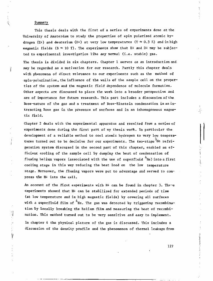
Summary
This thesis deals with the first of a series of experiments done at the
University of Amsterdam to study the properties of spin polarized atomic hy-
drogen (K-0 and deuterium (D+) at very low temperatures (T *> 0.3 K) and in high
magnetic fields (B * 10 T). The experiments show that H-t- and D+ may be subjec-
ted to experimental investigation like any normal (i.e. stable) gas.
The thesis is divided in six chapters. Chapter 1 serves as an introduction and
may be regarded as a -motivation for our research. Partly this chapter deals
with phenomena of direct relevance to our experiments such as the method of
spin-polarization, the influence of the walls of the sample cell on the proper-
ties of the system and the magnetic field dependence of molecule formation.
Other aspects are discussed to place the work into a broader perspective and
are of importance for future research. This part includes a discussion of the
Bose-nature of the gas and a treatment of Bose-Einstein condensation in an in-
teracting Bose gas in the pres-ence of surfaces and in an inhomogeneous magne-
tic field.
Chapter 2 deals with the experimental apparatus and resulted from a series of
experiments done during the first part of my thesis work. In particular the
development of a reliable method to cool atomic hydrogen to very low. tempera-
tures turned out to be decisive for our experiments. The two-stage He refri-
geration system discussed in the second part of this chapter, enabled an ef-
ficient cooling of the sample cell By dumping- the heat of condensation of
fluxing helium vapors (associated with the use of superfluid He) into a first
cooling stage in this way reducing the heat load on the low temperature
stage. Moreover, the- fluxing vapors were put to advantage and served to com-
press the H4- into the cell.
An account of the first experiments with H+ can be found in chapter 3. Theie
experiments showed that H+ can be stabilized for extended periods of time
(at low temperature and in high magnetic fields) by covering all surfaces
with a superf luid film of He. The gas was detected by triggering recombina-
tion by locally breaking the helium film and measuring the heat of recombi-
nation. This method turned out to be very sensitive and easy to implement.
In chapter 4 the physical picture of the gas is discussed. This includes a
discussion of the density profile and the phenomenon of thermal leakage from
127 I

the open structured sample cell. The density profile may be used to detect
Bose-Einstein condensation.
A second series of experiments is discussed in chapter 5. These measurements
were aimed at achieving high densities and to study the limiting processes.
They demonstrate that H+ behaves as a gas. Densities n ^ 10 H+/cm could be
achieved. At lower densities (n 10 H+/cm ) thermal leakage turned out to
be the dominant decay process while at higher densities also recombination
turned out to be important. At this stage of the research it was unknown
whether a- bound state existed for the H-atom on the surface of the heliumfilm,
although theoretical estimates pointed in this direction. To clearify this
point and to obtain information concerning the nature of the recombination one
can study the kinetics of the recombination process. Volume recombination
appears at low temperatures as a third order decay process. The decay constant
for the process only has a weak temperature dependence. In the presence of a
bound surface state surface recombination may become important. This process
leads to second order decay, decreasing exponentially with increasing tempe-
rature. This is caused by the exponential decrease of the surface density.
Thermal leakage gives rise to first order decay exponentially increasing with
the temperature. To study recombination one should thus aim for low tempera-
tures. However, our cryostat did not enable measurements below T « 270 mK,
not low enough to properly study recombination in H4-. Such a study could be
done with D+ where one expects a higher adsorption energy causing surface re-
combination to become dominant at higher temperatures. These measurements are
discussed in chapter 6 and showed that recombination predominantly occurs on
the surface of the helium film. From the temperature dependence of the recom-
bination rate the adsorption energy of D+ on He surfaces could be determined.
On the basis of thes'e experiments one may also expect a bound state for H+,
which was confirmed experimentally in a later stage. However the higher bin-
ding energy causes D4- to be much less stable than H+.
128

\ Samenvatting
In dit proefschrift worden de eerste van een reeks experimenten be-
sproken die in het Natuurkundig Laboratorium van de Universiteit van Amster-
dam zijn uitgevoerd aan spingepolariseerde atomaire waterstof (H+) en deute-
rium (D+) bij zeer lage temperatuur (T ** 0.3 K) en in hoge magneetvelden
(B * 10 T). Deze experimenten tonen aan dat H4- een gas i s dat zich zoals
ieder normaal ( i . e . stabiel) gas leent voor natuurkundig onderzoek.
I Het proefschrift bestaat uit zes hoofdstukken, waarvan hoofdstuk 1 dient ter
inleiding en motivatie. Naast aspecten die van onmiddellijk belang zijn voor
de hier beschreven experimenten zoals de methode van spin-polarisatie, het
verschijnsel dat het gas zich niet in de vloeibare toestand laat brengen, het
effect van wisselwerking met de wanden van de preparaat-ruimte en de (magne--«1
'•'. tische) veld afhankelijkheid van molecuul-formatie , worden hier aspecten be-
schreven die het onderzoek in een breder perspectief plaatsen en van belang
zijn voor toekomstig onderzoek. Hieronder vallen de bespreking van het Bose-
karakter van het gas en de condities waaronder Bose-Einstein condensatie waar-
genomen kan worden als men interacties tussen de atomen onderling en met de
wanden in rekening brengt.
Hoofdstuk 2 bevat de beschrijving van de experimentele apparatuur en vormt de
i neerslag van een reeks experimenten uit de eerste fase van mijn promotie on-
; derzoek. Met name da ontwikkeling van een betrouwbaar systeem om atomaire wa- >
terstof tot zeer lage temperaturen af te koelen, bleek van doorslaggevend be- i:.{
lang voor onze experimenten. Bij de cryogene apparatuur verdient het twee-3 [ ••••
traps He koelsysteem aandacht. Hiermede werd het mogelijk om de grote warmte- . . 4 'c', belasting die samenhangt met het gebruik van He in de experimenteercel, te J
onderdrukken. Bovendien blijkt de tweede koeltrap tevens te werken als minia-
tuur diffusie-pomp, waarmee H+ naar de meetcel gepompt kan worden.
Een verslag van de eerste experimenten met H+ vindt men in hoofdstuk 3. De
metingen tonen aan dat H+ voor langere perioden kan worden gestabiliseerd bij
lage temperaturen en in hoge magneetvelden, indien de wanden van de meetcel T
• t worden bedekt met een laagje superfluïde helium. De aanwezigheid van het gas
" f wordt bij deze experimenten aangetoond door meting van de warmte die vrij f
komt bij recombinatie naar de moleculaire toestand (H_). De recombinatie wordt ,;1
op gang gebracht door locaal de heliumfilm te verbreken. Hierdoor treedt mas- \'w
sale oppervlakte-adsorptie op met de gewenste recombinatie als gevolg. De SI
h I% 129 §

methode blijkt bijzonder gevoelig en vrij eenvoudig uitvoerbaar.
In hoofdstuk 4 wordt besproken hoe men zich het gas in de meetcel moet voor-
stellen. Hierbij komen de dichtheidsdistributie van het gas en het verschijn-
sel van thermische lek, samenhangend met de open structuur van de meetcel,
aan de orde. Bovendien wordt opgemerkt, dat de dichtheidsdistributie kan wor-
den gebruikt om het verschijnsel Bose-Einstein condensatie waar te nemen.
Een tweede serie experimenten is het onderwerp van hoofdstuk 5. Deze metingen
tonen aan dat H+ zich als een gas gedraagt. Zij hadden tot doel om een zo hoog
mogelijke gasdichtheid op te bouwen en na te gaan welke processen hierbij be-
perkend zijn. Dichtheden n ^ 10 H+/cm werden bereikt. Bij lagere dichtheden< 15 3
(n 10 H-t/cm ) bleek thermische lek het dominante vervalproces, terwijl bij
hogere dichtheden ook recombinatie een rol bleek te spelen. In dit stadium van
het onderzoek was het niet bekend of H+ kon worden gebonden aan het cppervlak
van de heliumfilm, alhoewel theoretische schattingen in deze richting wezen.
Om dit punt op te helderen en informatie te verkrijgen over de aard van de re-
combinatie kan men de reactie kinetiek bestuderen. 'Volume recombinatie mani-
festeert zich bij lage temperatuur als een derde orde vervalproces, waarbij
de vervalconstante slechts zwak van de temperatuur afhangt. Als er een gebon-
den oppervlaktetoestand bestaat kan oppervlakte recombinatie dominant worden.
Dit proces geeft aanleiding tot tweede orde verval van de dichtheid, exponen-
tieel afnemend met toenemende temperatuur tengevolge van een exponentiële af-
name van de oppervlakte dichtheid. Thermische lek geeft aanleiding tot een
eerste orde vervalproces dat exponentieel toeneemt met de temperatuur. Om re-
combinatie te bestuderen moet men dus werken bij zo laag mogelijke temperatu-
ren. Metingen beneden T « 270 mK waren echter met onze cryostaat niet moge-
lijk. Recombinatie kon daarentegen wel bestudeerd worden aan D4- waarvoor op
theoretische gronden een hogere adsorptieenergie wordt verwacht, zodat opper-
vlakte recombinatie reeds bij hogere temperaturen dominant wordt. De deute-
rium metingen komen aan de orde in hoofdstuk 6 en toonden aan, dat recombina-
tie voornamelijk aan het oppervlak plaats vindt. Uit de temperatuurafhanke-
lijkheid van de recombinatiesnelheid ken bovendien de adsorptieenergie van D+
aan het oppervlak van He worden bepaald. Op grond van deze experimenten kon
ook voor H+ een gebonden toestand worden verwacht, hetgeen in later stadium
is bevestigd. Ten gevolge van de grotere bindingsenergie is D+ (bij gelijke
temperatuur en veld) echter veel minder stabiel dan H+.
130
Nawoord
Bij de voltooiing van dit proefschrift wil ik graag allen bedanken die,
direkt of indirekt, hebben bij gedragen aan de tot stand koming ervan.
In de eerste plaats mijn promotor Prof.Dr.Isaac F. Silvera aan wie ik een
groot deel van mijn wetenschappelijke vorming te danken heb. Hij heeft mij de
kans gegeven te werken aan een probleem met uitzonderlijke mogelijkheden. In
de eerste, moeilijke fase , waarbij het onderzoek de nodige scepcis ondervond
is zijn inspirerende belangstelling en begeleiding bizonder waardevol geweest.
Met het uitkristalliseren van onze ideeën omtrent de juiste benaderingswijze
van het probleem, heeft zich onder zijn leiding een steeds intensievere en
uiterst stimulerende samenwerking kunnen ontwikkelen, die van doorslaggevend
belang is geweest voor het slagen van het onderzoek.
Daarnaast is ook de samenwerking op technisch gebied met Otto Hopfner van
groot belang geweest. Ik wil hem bedanken voor zijn volle en vakkundige inzet
die, met name in tijden van tegenspoed, altijd tot steun is geweest en die in
niet geringe mate heeft bijgedragen tot het welslagen van het onderzoek.
Prof.Dr. N.J. Trappeniers wil ik bedanken voor zijn bereidheid om op te treden
als coreferent. Dr.Victor V. Goldman ,Dr. Ad Lagendijk en Dr. A. John Berlinsky
bedank ik voor de collegiale samenwerking en begeleiding op theoretisch gebied.
In de beginfase van het onderzoek hebben Herman Godfried en vooral Eric Eliel
aan de experimenten mee gewerkt, later hebben Mart Diemeer, Rudolf Sprik en
Jeroen de Miranda een bijdrage geleverd. Hun enthousiasme is altijd een sti-
mulans voor mij geweest. Stijn Mattheij en Gert van Yperen wil ik bedanken
voor de plezierige samenwerking en het doorlezen van het manuscript.
Van de velen met wie ik op het lab heb samengewerkt wil ik nog een aantal met
name noemen.
H.Witteveld hielp bij de het ontwerpen van de apparatuur. Martin Bekelaar en
Jan hofman verzorgden een deel van de uitvoering. Ton Riemersma en Hugo Slatter
losten een aantal lastige technologische problemen op. Bert Zwart en Frans
Slagt verzorgden het glaswerk voor de dissociatorbuizen. Ad Veen, Rob Veen en
Charly Alderhout hielpen bij electronische problemen. Eef Hartman gaf adviezen
op softwaregebied. Mariet Bos zorgde er voor dat vele manuscripten snel de
deur uit konden. Ben Leonards leverde de foto's en een aantal tekeningen.Herman
Pothoven en Nico Jonker zorgden voor grote, grote hoeveelheden vloeibaar helium.
131

Daarnaast wil ik allen die hebben bijgedragen tot het tot stand komen van dit
proefschrift, maar niet met name zijn genoemd, har te l i jk bedanken.
Tenslotte, maar zeker niet in de laatste plaats wil ik mijn ouders bedanken,
die mijn belangstelling voor de wetenschap hebben gewekt en die mij in de ge-
legenheid hebben gesteld om een academische opleiding te volgen. Ik wil hen
ook danken voor de hulp bi j het vervaardigen van het manuscript.
Mijn vrouw Marian wil ik bedanken voor de liefdevolle steun en rus t , die al t i jd
bij haar te vinden was.
132 i'i

STELLINGEN
1. De grote belangstelling voor experimentele resultaten in het stabiliseren
van atomaire waterstof, de hevige concurrentie en de nieuwheid van de re-
sultaten hebben niet geleid tot de door Jochemsen verwachte onzorgvuldig-
heden bij de eerste publicaties op dit gebied.
| R. Jochemsen, proefschrift, stelling 4, Universiteit van Amsterdam (1978).
2. Bij de berekening van de invloed van nulpuntsfluctuaties van een helium-
oppervlak op de kernspinrelaxatietijd (T.) van geadsorbeerde atomaire
waterstof hebben Yapple en Guyer de invloed van hoogfrequente modes sterk
overschat.
J.Y. Yapple en R.A. Guyer, preprint.
3. De mobiliteit van triplet excitonen in vast stikstof kan goed bestudeerd
worden door excitatie met een atomaire stikstof bundel en detectie met
behulp van het luminescentie spectrum van geïsoleerde stikstof atomen
binnen de moleculaire matrix.
|' J.T.M. Walraven, E.R. Eliel en I.F. Silvera, Phys.Lett.23A, 119 (1979).
* 4. Gebruik makend van een supergeleidende afscherming van NbTi moet het moge-
"r lijk zijn om zeer kleine en laagfrequente magnetisatieveranderingen {van
; de orde van 5x10 Bohrmagnetonen /(cm sec)} nog waar te nemen in externe
-: velden van 10 Tesla.
J.T.M. Walraven en I.F. Silvera, Physica 107B, 517 (1981).
" 5. Bij hun studie van tijdelijke poreusheid van fosfolipide vesicles, geïndu-
ceerd door electrische velden, nemen Teissie en Tsong ten onrechte aan dat
deze deeltjes bolvormig zijn.
J. Teissie en T.Y. Tsong, Biochemistry 2£, 1548 (1981).. i
; 6. Bij de interpretatie van de vacature concentratie metingen aan CoGa en NiGa
'f' werd door Neumann en Chang, ten onrechte, de entropieverstoring bij defect
f formatie buiten beschouwing gelaten.
jif J.P. Neumann en Y. Chang, Z.Metallkunde 70, 118 (1979).
7. Bij de methode om de anisotrope potentiaal tussen twee waterstof moleculen
te ontwikkelen in bolfuncties en de coëfficiënten te bepalen uitgaande van
een beperkt aantal geometrische configuraties zoals berekend door Ree en
Bender, is het essentieel om alle significante termen mee te nemen, daar
anders ook voor de wel beschouwde termen geheel onjuiste resultaten kunnen
worden verkregen.
F.H. Ree en C.F. Bender, J.Chem. Phys. 7±, 5362 (1979).
J. van Kranendonk, preprint.
8. Recente metingen van Hsiang et.al. aan de soortgelijke warmte van Pd,
hebben het spinfluctuatie onderzoek aan sterk paramagnetische metalen
onnodig in discrediet gebracht.
T.Y. Hsiang, J.W. Reister, H. Weinstock, G. Crabtree, J.J. Vuillemin
Phys.Rev.Lett. 47, 523 (1981).
M.T. Bêal Monod, Physica 1982, preprint.
9. Om de experimenteel interessante N=l -*• N=5 rotationele Raman overgang in
moleculaire zuurstof waar te nemen, verdient het aanbeveling gebruik te
maken van een supersone expansie.
K. Altman, G. Strey, J.G. Hochenbleicher en J. Brandmüller,
Z.Naturforsch, 27a_, 56 (1972).
10.Toegang tot ongepubliceerde wetenschappelijke informatie is essentieel
voor goed onderzoek. Dit geldt met name voor zich snel ontwikkelende vak-
gebieden.
Amsterdam, 1 september 1982 J.T.M. Walraven


