Embed Size (px)
Citation preview

K o^lQCRAFT LIBRABVa^jT
-
TdeSUPERHETERQ
BOOK ■All About Superheterodynes
How They Work, How to Build
and How to Service Them.
by Clyde Fitch
l
R----------PUBLISHED BV -
d« Hisio,ie v/d R. ^ERNSBACK PUBLICATIONS /,*

r■ s
The 1935 (volume 2)
Official AUTO-RADIOSERVICE MANUAL
■:
*:•'j;|iijI$250 List T_J ERE NOW—is the second volume of the
•n- OFFICIAL AUTO'RADIO SERVICE MANUAL—the 1935 Edition.
With so large a number of new auto-radio sets placed on the market by different manufacturers, the 1935 OFFICIAL AUTO-RADIO ' SERVICE MANUAL becomes an essential part of Service Men's equipment. Remember, there are nearly 1,800,000 auto-radio sets in use today.
THERE IS ABSOLUTELY NO DUPLICATION OF MATERIAL BETWEEN THE 1933 EDITION (VOLUME I) AND THE NEW 1935 EDITION (VOLUME II). THE MATERIAL IS 100% NEW.
AUTO-RADIOSERVICE MANUAL :: :V.
V!n>Every radio man connected in any way with
the booming auto-radiq business needs a copy ol the 1935 OFFICIAL AUTO-RADIO SERVICE MANUAL. It contains only auto-radio service "dope.”
HERE ARE HIGHLIGHTS OF THE V)3S AUTO-RADIO MANUAL
SComplex Directory •-
• I Allt' 1
- Automobile Radio Receivers ''
;Full Inttallation and Service Guide .*!
240 pages crowded with diagrams, service material and other essential data required for proper servicing of new auto* radio receivers. Included arc diagrams of sets which appeared during 1934, and which were not included in the supplement to the first edition.Complete schematic diagrams, chassis layouts, voltage tabu-
fSSSM lations and servicing instructions arc included for practicallyall sets. "Under-side" tube symbols are also included to facilitate the job of servicing the sets.
Instructions are included with many sets telling how to suppress stubborn cases of ignition interference. This includes the newest "suppress- orlcss” sets—and what to do when interference is encountered with this type of set.Details on how. to make installation'in' "turret-top” cars arc included. The different methods used by car makers and set manufacturers are listed with the individual circuits and service information.The index contains the listing of sets which were published in the first edition; as well as the sets which 'appear in the new volume. This information helps the Service Man to locate the circuit and details for any receiver that has been made.The book is bound in a handy, flexible leatherette cover. To be sure the pages are sturdy, to withstand constant use, the book will be printed on a special “biblc" stock. This is a very durable, but thin paper. The book printed on this paper can be’ easily rolled to fit into your pocket or slipped in the service kit.
{■o. • :. i.
'}
Over 240 Pages Printed on Special Thin “Bible Paper”
Over 500 Illustrations
1
.Flexible;
Looseleaf Leatherette Covar;
Here Is a Partial List of Sets CoveredAtwater Kant Mfg. Co. Galvin Mfg.^Corp.Audlola Radio Co. General Electric Co.Autocrat Radio Co. General Motors Corp.Balmont Radio Corp. Graham-Paige Motors Corp.Century Radio Products Co. Grigsby-Grunow Co.Chavrolat Motor Corp. Chas. Hoodwin Co.Chryslar Motor Corp. Howard Radio Co.Colonial Radio Corp. Hudson Motor Car Corp.Croslay Radio Corp. International Radio Corp.Delco Appliance Corp. Karadlo Corp.Datrola Radio Corp. P. R. Mallory 4 Co.Emerson Radio & Phonograph Co. Montgomery Ward 4 Co.Fada Radio 4 Electric Corp. National Company, Inc.Ford Motor Corp. Noblitt-Sparks Industries, Inc.
' Ford-Majestic Philco Radio 4 -Television Corp.Franklin Radio Corp. Pierce Airo, Inc.
Send remittance of $2.50 in form of check or money order for your copy of the 1935 * OFFICIAL AUTO-RADIO SERVICE MANUAL. Register letter if it contains cash
THE MANUAL JS SENT TO YOU POSTAGE PREPAID. ,99SH HUDSON STREET NEW YORK, N. , Y.
RCA Manuacturing Co., Inc.Sears Roebuck 4 Co.Sentinel Radio Corp. Sparks-Withington Co.Stewart Radio Corp. Stewart-Warner Corp. Stromberg-Carlson Tel. Mfg. Co. . Transformer CoTp. of America United American Bosch Corp. United Motors Service, Inc.U. S. Radio 4 Television Corp. Wells Gardner 4 Co.Wilcox-Gay Corp.Rudolph Wurlitzer Mfg. Co.Zenith Radio Corp.
r .<
• 'i
or currency.
GERNSBACK PUBLICATIONS, Inc.
L mm

Il : 0\
BIBLIOTHEEKft% Tke N.V.H.R,iiC-
i Ii keterodynei! il!■s
1 !■
1:keterodAll Akout S ynesuper
Ik How They Ji^orJc, How to Build and
- * ervice ThHow to S emmky Clyde Fitck>fe|
BPi completely revised
kv Rokert R Kruse’i'r --Vi-' i
Mz\It iSSSl&
%
Mr- ■i; GERNSBACK PUBLICATIONS, Inc.;& Publishers
•VT; NEW YORK, N. Y.99 HUDSON ST.
mit

ContentsPage
4Chapter 1. Basic Principles of the Superheterodyne-----
____13Chapter 2. Signal Frequency Amplifiers
___ 17Chapter 3. Oscillators and Frequency Changers —
_______ 23Chapter 4. Single Dial Tuning Systems
..... 30Chapter 5. The Intermediate Amplifier
Chapter 6. The Second Detector, Audio Amplifier and Power Supply —..................... .......... 34
37Chapter 7. Practical Superheterodyne Construction
47Chapter 8. Commercial Superheterodyne Circuits
56Chapter 9. I. F. Transformer Design
59Chapter 10. Servicing Superheterodynes
Third Reprint
Printed In U. S. A.1st Edition
Copyright 1932 by G. P. Inc. 2nd Edition
Copyright 1934 by G. P. Inc.
Ul

P reface
'T'HE following pages were prepared to present in as simple and clear terms as possible the theory,
design and construction of superheterodyne receivers. The purpose is to give the reader a handy reference book and guide that will help him in his work, whether he is interested in servicing superheterodynes or plans to design and build them. In any event, a thorough knowledge of the subject will be found the shortest and most sure route to successful receiver performance.
The superheterodyne has always been considered the supreme type of radio receiver. It is more complex and versatile in its actions than other popular types of receivers, and for this reason, has always been found highly fascinating by those who have studied it. However, a highly technical knowledge of all of the various components of the superheterodyne is not absolutely necessary for the practical man; therefore, only sufficient data of this nature to meet practical requirements are given.
The main bulk of the book treats with modern receivers of conventional design. As many varieties as possible of these modern receivers are included so as to give the reader a breadth of vision and not hold him down to fixed rules. The older types of superheterodynes, which appeared in great variety several years ago, are not treated at any length as the circuits are all practically obsolete due to the advent of modern vacuum tubes.
—The Author.

CHAPTER 1
Basic Principles of the Superheterodyne
The universal adoption of the superheterodyne method of reception is due to causes so simple that they can be understood by anyone, and may be summed up in the one word—“Cheapness”.
ation now go to the simplified theory of the “heterodyne effect.”
Basic FormulaThe heterodyne phenomenon not only
in radio and electrical circuitsoccursbut in all other branches of physics as well. It is based upon the simple fact that when two sources of energy, A and B, vibrating at different frequencies, are combined, other frequencies are generated, equal to A -f- B and A — B. These two additional frequencies are called “beats,” and while other frequencies or harmonics are also generated, this simple formula is sufficient to explain many actions taking place in radio transmission and reception.
As stated above, the action occurs with any form of vibratory energy. In acoustics, the piano tuner often makes use of the beat note generated by two strings slightly out of tune with each other for tuning the instrument. In light, Newton’s interference rings are caused by the same action; namely, light waves of different frequencies combining and setting up a series of visible “beats” or fringes.
The heterodyning phenomenon as applied to radio circuits was first recognized and used by Reginald A. Fessenden and patented by him. (U.S. Pat. 1,060,728 Jan. 14, 1913). This invention applied mainly to the reception of continuous wave radio telegraph signals by means of a local oscillator, which heterodyned the received signals and produced an audible beat note which could be heard in a headset.
An extension of this principle resulted in the superheterodyne receiver. E. H. Armstrong (U.S. Pat. 1,347,886 June 8, 1920) made the beat note so high in pitch that it was inaudible, yet retained all the characteristics of the original signal, and was amplified by a
While other types of receivers can be built to equal or exceed the possibilities of the superheterodyne, they invariably cost more for the same performance, and ordinarily use more tubes as well. The reason for this difference is also relatively simple and can be explained in terms readily understood by the non-technical reader. Certainly there is nothing whatever to excuse the air of mystery which has been woven about the superheterodyne, presumably for reasons of commercial advantage.
Briefly then, the advantage of the superheterodyne lies in the great ease with which high amplification and great selectivity can be built into a longwave receiver of fixed wavelength— incapable of tuning adjustment. Such a receiver is in itself useless at any other wavelength, and it was a supply of just such useless long-wave receivers which is said to have suggested the idea of preceding them with a “converter”—that is to say a device capable of accepting a short-wave (or ordinary broadcast) signal and changing it into a long-wave signal which could then be fed into the long-wave receiver, therein to be amplified enormously without difficulty. The advantage—the trick, to be explained—the basic principle, all of them lie in this conversion-device which changes incoming signals to a longer wavelength. Having explained it, the rest of the story is simple. To make this explan-
4

THE SUPERHETERODYNE BOOK 5
high frequency amplifier and then detected and amplified by an audio frequency amplifier in the usual manner. This method of reception had many outstanding advantages. It was used during the World War to satisfy the demand for a supersensitive receiver that would work with extremely small aerials.
cause its frequencies (50 to 5000 cycles) are too low for efficient radiation. The carrier-frequency, f, will be radiated, as will also the frequencies (f AB) and (f — AB). These latter two produce the side bands.
We see from the above that a group of frequencies (namely, f, f AB, and f — AB) are radiated from the broadcast transmitter, having a maximum difference of f plus and minus 5000, or a total separation of 10,000 cycles, or 10 kc. For example, using a carrier of 1,000,000 cycles, a band of frequencies from 995,000 to 1,005,000 cycles will be radiated.
At the receiving end the action is reversed in the detector circuit. For this reason the detector is sometimes called
A study of our basic formula will reveal that the heterodyne action actually occurs in broadcast transmitters. While it is perfectly correct to consider a carrier wave being modulated by the audible frequencies, as is the usual custom, a clearer understanding of the entire phenomenon can be had by sticking closely to our basic heterodyne formula. By so doing the origin of side bands becomes obvious and the action of the detector in the receiver (also called “demodulator”) is at once explained. There is really no difference between modulating and heterodyning. This fact is not thoroughly recognized by many radio engineers, although in the Ultradyne superheterodyne receiver developed by R. E. La- cault, and in some more recent receivers using the autodyne principle, the heterodyne action is called modulation.' In radio transmission, since radiation of electric energy from the transmitting antenna must take place at very high frequencies to be efficient, a high- frequency generator is used at the transmitter. For broadcasting, frequencies from 650 to 1,500 kc. per second are used, each station having its own assigned operating frequency. This frequency is called the carrier-frequency or “carrier wave”. We will call this frequency f. Now, suppose we combine with this carrier frequency, f, the sound-frequencies (or music and speech-frequencies produced in the studio) and see what happens; keeping in mind that the music and speech-frequencies range from about 50 to 5,000 cycles per second. We will call these the audio-frequency band, or just “AB.”
From the heterodyne formula, we learn that four distinct frequencies are present; namely, the carrier-frequency f, the audio-frequency band AB, and the bands (f-f AB) and (f — AB).
The audio-frequency band AB will not be radiated from the antenna, be-
Flg. 1. Showing how a beat note Is produced by adding two currents of different
frequencies.
a demodulator. In this particular case the side-band frequencies and the carrier are mixed in the detector circuit and by heterodyne action produce beats; the beat frequencies are an exact duplicate of the original audio frequencies that were present at the transmitter. One side band and the carrier are sufficient to produce this action; that is, when the carrier f is subtracted from the upper sideband (f -}- AB) in accordance with our basic formula, AB alone remains. The lower side band (f — AB), mixed with the carrier, will give the same result. In actual figures the received carrier wave of 1,000,000 cycles is mixed with either the 995,000 side band or the 1,005,000 band and produces a 5000 cycle beat in the detector mixer circuit, which is audible.
Figure 1 shows graphically how two different frequencies, A and B, may be

SUPERHETERODYNE bookTHE6
in the usual manner so that the upper half cycles are amplified more or less than the lower half cycles and a balance no longer exists and a frequency represented by curve M-N appears in the plate circuit of the detector tube.
It is interesting to note that curve C in Fig. 1 is identical in shape with a curve obtained by modulating a higher frequency with a lower one (M-N)— further illustrating that heterodyning and modulating are two names for the same action.
In acoustics we can hear the beat note set up by two vibrating strings slightly out of tune with each other because of the non-linear action or detection characteristics of the human ear.
B are in phase, the result at C is an in amplitude; whereas when
out of phase (when the am-
equal) be-
increasethe two frequenciesthe result at C is plitudes of the waves cause at this instant the two frequencies oppose and neutralize each other.
Figure 2 shows electrically how this effect is accomplished. In circuit A, Fig. 2, an electrical current having a frequency represented by the curve A in Fig. 1 is generated; circuit B, Fig. 2, has a frequency generated in it represented by the curve B in Fig. 1; since circuit C is inductively coupled to circuits A and B, currents of both frequencies are generated in circuit C and
arezero
are
In the heterodyne action at the radio transmitter, the vacuum tubes present in the circuit cause the heterodyning and mixing of the frequencies because of their rectifying or detecting characteristics.
GENERATOR
& ° LAMP-,
TikTGENERATOR
I
9 'B' TI Explanation of Simple Heterodyne Radio CircuitFIG.2
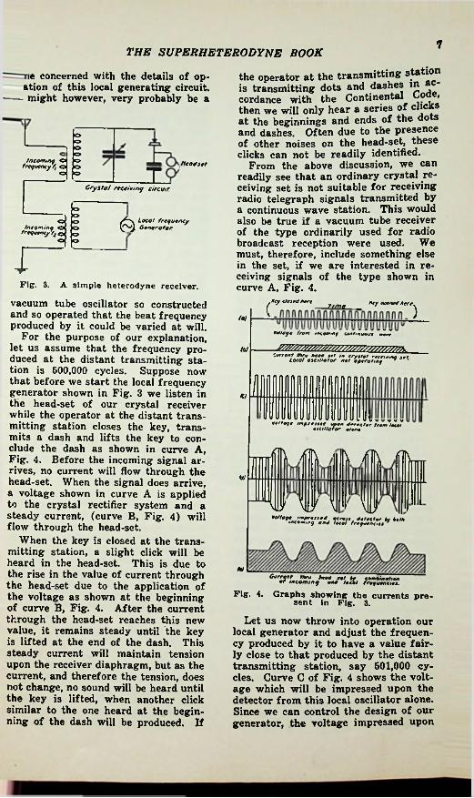
Before studying the superheterodyne, suppose we first become familiar with a simple heterodyne receiver. Figure 3 is in effect similiar to Fig. 2 with the exception that it applies to the heterodyne reception of radio waves and contains a crystal detector and head-set. for detecting the audible beat note. The series of curves illustrating the theory are shown in Fig. 4. Referring to this illustration, let us assume that curve A represents a dash as is made by closing the transmitting key for a given period of time and then lifting it as shown on the curve. Let us assume that we are located at some distance from the transmitting station at which this is done, and further that we are equipped with a radio receiving set, the circuit for which is shown in Fig. 3. The upper section of Fig. 3 shows a conventional crystal receiving set. In the lower portion of the figure, we have included a generating device for producing an undamped radio frequency voltage, which may also be applied to the crystal receiving circuit as shown. We are not at this particular
Electrical circuits for mixing frequencies.
the resultant is as shown at curve C in Fig. 1.
Strange as it may seem, no beat current is present in circuit C, although in many books on the subject a beat current is erroneously said to exist in this circuit. If we had a lamp in circuit C which would light due to the presence of the alternating current, and tune the circuit by means of a variable condenser, we would find that the lamp would light only when the circuit is tuned to the frequency of either circuit A or circuit B, but it will not light when tuned to a frequency equal to the sum or difference of frequencies A and B. The reason for this is that the upper halfcycles and the lower half-cycles of the heterodyne or beat current present in curve C, Fig. 1 exactly neutralize each other and the beat frequency represented by the curve M-N, drawn through the peaks of the waves, cannot be isolated by this simple method. It can only be separated by non-linear amplification or detection by using a detector
7THE SUPERHETERODYNE BOOK
the operator at the transmitting station is transmitting dots and dashes in accordance with the Continental Code, then we will only hear a series of clicks at the beginnings and ends of the dots and dashes. Often due to the presence of other noises on the head-set, these clicks can not be readily identified.
From the above discussion, we can readily see that an ordinary crystal receiving set is not suitable for receiving radio telegraph signals transmitted by a continuous wave station. This would also be true if a vacuum tube receiver of the type ordinarily used for radio broadcast reception were used. We must, therefore, include something else in the set, if we are interested in receiving signals of the type shown in curve A, Fig. 4.
Key t/ojrd Here
ie concerned with the details of op- ation of this local generating circuit.
----- might however, very probably be a
>=>K>h=>Incoming O
frequency f, o P=> head jet
To h=>Crystal receiving circuit
h=>o Local frequency P4 Generator.
o
Fig. 3. A simple heterodyne receiver.
vacuum tube oscillator so constructed and so operated that the beat frequency produced by it could be varied at will.
For the purpose of our explanation, let us assume that the frequency produced at the distant transmitting station is 600,000 cycles. Suppose now that before we start the local frequency generator shown in Fig. 3 we listen in the head-set of our crystal receiver while the operator at the distant transmitting station closes the key, transmits a dash and lifts the key to elude the dash as shown in curve A, Fig. 4. Before the incoming signal arrives, no current will flow through the head-set. When the signal does arrive, a voltage shown in curve A is applied to the crystal rectifier system and a steady current, (curve B, Fig. 4) will flow through the head-set.
When the key is closed at the transmitting station, a slight click will be heard in the head-set. This is due to the rise in the value of current through the head-set due to the application of the voltage as shown at the beginning of curve B, Fig. 4. After the current through the head-set reaches this new value, it remains steady until the key is lifted at the end of the dash. This steady current will maintain tension upon the receiver diaphragm, but as the current, and therefore the tension, does not change, no sound will be heard until the key is lifted, when another click similar to the one heard at the beginning of the dash will be produced. If
fry opened Here( Ztme )(a!
ecnege from inceeunf ienf.nueui mere
'"•uSTSSSM 'neVW'roXr"’
1*7
Veltege imprest** upon On,dor from tecel eicillotor o/on.
con-
!fll\ ilh h /IN /TIN
ii w \| MU
7‘.ZffSeWXS
MlCurrent Thru heed
ncominq "end*lei el pgZSSZ.
Fig. 4. Graphs showing the currents present In Fig. 3.
Let us now throw into operation our local generator and adjust the frequency produced by it to have a value fairly close to that produced by the distant transmitting station, say 601,000 cycles. Curve C of Fig. 4 shows the voltage which will be impressed upon the detector from this local oscillator alone. Since we can control the design of our generator, the voltage impressed upon

8 THE SUPERHETERODYNE BOOK
the detector from it can readily be made considerably greater than that impressed by the incoming signal from the distant station.
Let us now assume that the operator at the distant telegraph station again transmits a dash by means of the key. We will now have present in the crystal detector circuit not only the voltage impressed by the local oscillator of 601,000 cycles but also the incoming voltage of 500,000 cycles. These two voltages when added together will give a voltage such as is shown by curve D, Pig. 4. You will note that this is now a sine modulated wave. The variations in amplitude due to the mixing of the two frequencies are of a frequency equal to the difference between them, namely, 1000 cycles.
The application of a voltage to the crystal detector as shown by curveD, Fig. 4 produces a current through the head-set such as is shown by curveE, Fig. 4. Note that until the key is
amplitude of the incoming signal voltage will be quite low; the amplitude of the local oscillator voltage can be made many times this value. You will readily notice that the amplitude of the 1000 cycle tone produced in the head-set by heterodyne reception as shown by curve E is considerably greater than the amplitude of the “clicks” occurring at the beginning and end of the graph as shown by curve B. This is due to the effect of the local oscillator voltage. Therefore, by the use of heterodyne reception we can introduce great amplification into our signal. The amplitude of the resulting signal in the head-set from the incoming voltage alone is usually assumed to be proportional to the square of this voltage. However, the amplitude of the signal produced in the head-set by the combination of the incoming voltage and the local oscillator voltage is proportional to the product of the two voltages. Since the local voltage may be
1INTER
MEDIATE ICR
Si*-• FPE
GNAL FREQUENCY AMPLIFIER
AUDIOAMPLIFIER
SECONDDETECTOR
FREQUENCYCHANGER OSCILLATOR
AMPLIF
FIG. 5The basic superheterodyne layout. Note that it is divided into six components. Reading from left to right the various boxes contain the following. “Signal frequency amplifier’' is a T.R.F. amplifier adjusted to the wavelength of the transmitted signal. “Frequency changer” is a rectifying amplifier, or “mixer” or “first detector, and in some cases may be combined in the same tube with the “oscillator.” The rest of the system, to the right of the label “Fig. 5” is simply a long-wave T.R.F.
radio receiver, complete In every way, but incapable of tuning.
many times greater than the product of the two it may be many times greater than the square of the incoming volt- age.this great advantage over other types of reception—the process of heterodyning in itself introduces great amplification. It is limited, of course, by the maximum amount that the detector can handle without overloading.
closed at the transmitting station, the current through the head-set is steady and the receiver diaphragm is under constant tension. This steady current is produced by the local oscillator. When the voltage impressed upon the detector begins to vary in amplitude due to the effect of the incoming signal, then we have the current through the head-set varying as is shown in curve E. These variations will take place at a frequency of 1000 cycles, and this will cause the head-set diaphragm to vibrate at this frequency. Since 1000 cycles is well within the range of audibility, a 1000 cycle tone will be produced in the head-set.
There are a number of important deductions which can be made from the curves shown in Fig. 4. In general, the
Heterodyne reception possesses
The Superheterodyne
It only remains to carry this process one step farther to produce the superheterodyne action. To do this, adjust the local frequency generator so as to make the beat or difference frequency inaudible—say 176,000 cycles instead of 1000 cycles, and replace the head-set

THE SUPERHETERODYNE BOOK 9
rent of the intermediate or beat frequency delivered to it by the first detector.T.R.F. amplifier, as the intermediate frequency is always kept constant, by varying the frequency of the oscillator, regardless of the frequency of the incoming signal.
The second detector and audio frequency amplifier follow the intermediate frequency amplifier, and are designed in accordance with the general practice used in other types of radio receivers and therefore need not be described in more detail here.
Now that we have an outline of the entire superheterodyne, we can start with the broadcast station and show in actual figures the entire heterodyne action, from start to finish, all based upon the fundamental formula given in the first part of this chapter. Suppose we start with a broadcast station having a carrier frequency f of 1,000 kc. For simplicity, we will assume that a single sine wave audio note of the highest frequency for which the station is designed is being transmitted. This will be a note having a frequency of 5 kc. We will call this f 1.
There will be present at the transmitter the following frequencies:
-..1,000 kc.5 kc.
_..1,005 kc..... 995 kc.
of which frequencies (1), (3) and (4) will be radiated and reach the receiver.
At the receiver another frequency will be generated by the local oscillator having a frequency of 1,175 kc. We will call this fo. In the first detector or mixer circuit fo will combine with
with a vacuum tube amplifier designed to amplify the 175 kc. current. This amplifier is called the intermediate amplifier. The output from the intermediate amplifier is then fed into another detector (the second detector) after which the signal may be heard in the head-set, greatly amplified by the intermediate amplifier. When receiving telegraph signals from a continuous wave transmitter, only the key clicks will be audible in the head-set when using the superheterodyne method of reception, because in this case the beat frequency is above the audio frequency range. When speech or music is being broadcast, however, this will be heard.
Instead of using just a head-set connected to the second detector the modern superheterodyne employs an audio frequency amplifier and a loudspeaker.
Summing up, we have the basic superheterodyne layout as illustrated in Fig. 5. In a modern receiver it comprises first, a signal frequency amplifier. This is simply a tuned radio frequency amplifier designed to amplify at the signal frequency. It is the same as the- R.F. amplifier used in a tuned R.F. receiver. Its main purpose is to improve selectivity and eliminate “image frequency interference”, which will be discussed later. In addition, the signal frequency amplifier gives us a certain amount of gain and thereby reduces the amount of amplification necessary in the intermediate amplifier. In some superheterodynes a signal frequency amplifier is not used.
The output from the signal frequency amplifier is passed into the frequency changer, or first detector, as shown by the arrow, where the signal current is mixed with the current generated by the local oscillator (also shown in Fig. 5) and a resultant current of a difference or beat frequency is produced because of the non-linear characteristics of the first detector, as was previously explained.
The oscillator is simply a vacuum tube oscillator of constant amplitude output but whose frequency may be varied over a wide range. The output of the oscillator is coupled to some portion of the first detector circuit.
Next comes the intermediate frequency amplifier. This is a vacuum tube amplifier designed to amplify the cur-
This amplifier is a fixed
(1) f -----(2) fl _(3) f + fl(4) f—fl
the above frequencies (1), (3) and (4) so there will be present at the receiver the following:
(5) fo + f(6) fo — f(7) fo + (f + fl) 2,180 kc.
170 kc.—(9) fo+(f —fl) 2,170 kc.
(10) fo — (f — fl)
_____2,175 kc._____ 175 kc.—
(8) fo —(f + fl)
180 kc. — Because of the selective or filtering
action of the radio frequency transformers of the intermediate amplifier, which are tuned (broadly) to 175 kc., only frequencies (6), (8) and (10) of the above group will be passed through to the second detector. In other words,

10 THE SUPERHETERODYNE BOOK
frequencies of 176, 170 and 180 kc. reach the second detector, where they are mixed and by further heterodyne action produce the following:
(11) 176 -f 170 346 kc.^-(12) 176 _ 170
(13) 180 + 176 —r(14) 180 — 176
(16) 180 + 170„_(16) 180 — 170
portant ones. Of the frequencies that have been conveniently dropped in this explanation, because of selective filtering, we will have more to talk about later, as they are sometimes the source of trouble in actual practice and manifest themselves by heterodyning with other frequencies in the system and produce annoying audible squeals in the loudspeaker. They will be discussed in more detail in the chapter on “Servicing”.
6 kc. 366 kc.
6 kc. 360 kc.
10 kc.
//V 1005 KC.—-iooo kc.—
\V 995 KC.—AERIAL"*-
The AutodyneThe autodyne circuit is one in which
a saving of one tube is effected by combining the first detector and oscillator. It is necessary, however, to draw a sharp distinction between two manners of doing this thing with totally different results. The older, and altogether bad, method is represented in Fig. 8. Here the triode is attempting the impossible task of tuning to the same frequency as the incoming signal (for best gain) and at the same time detuning from it by 175 kc.—if that happens to be the frequency at which the fixed long-wave intermediate amplifier works. This is an absurdity, and it is evident that one needs to associate two tuned circuits with the tube’s grid so that one may be adjusted to the incoming signal, and the other be offset by 175 kc. (or whatever our intermediate frequency may be). The difficulties of doing this in a triode of the directly-heated sort shown in Fig. 8 are considerable, although these difficulties were mainly evaded in the ingenious bridge arrangement of Fig. 11, due to the original author of this book and here shown partly for historical interest, partly because it is still a most excellent arrangement for receivers using battery-heated filaments
AS $Vi *
X rt lA 9
<1 o >no o o>o o o>
R.F. AMPLIFIER AN MODULAT
(MIXER)
1000KC.ID
TORR.F.
OSCILLATOR
RADIO TRANSMITTER
FIG. 6The frequencies present In a 1000 kc.
broadcast station.Of these frequencies, only (12), (14)
and (16) will pass through the audio frequency amplifier to the loudspeaker. In other words, a powerful 5 kc. signal will reach the speaker corresponding with the original 5 kc. note (2) that was present at the broadcast station. The 10 kc. frequency (16) appears as a second harmonic. It will not appear if one side band was suppressed, as (16) above would not be present. This entire action is graphically illustrated in Figs. 6 and 7.
These figures do not include all of the various frequencies and harmonics that will be generated due to the mixing process, but they include the im-
160 KC.2.170 KC.
170 KC.2160 KC.
175 KC.2175 KC. 345 KC.1 5 KC. J—
AUOlolsKCl LOUO S AMP. SP’K'R
160 KC.1005 KC
‘Jit ZUO.170 KC.INT.AMP'F'R. D&T.
T* 10 kc TSUPERHETERODYNE RECEIVER
FIG.7The various frequencies present in a superheterodyne receiving the station illustrated
in Fig. 6.

11THE SUPERHETERODYNE BOOK
of the high-economy type working from dry cells. It is covered by U. S. Patents 1,667,513 and 1,762,221. Circuit A is tuned to the incoming signal, and does not affect circuit B (tuned to the oscillator frequency) because the “return tap” of A is placed at the center of B, and magnetic coupling between the two coils is avoided by shielding or careful placement of the coils.
Complex Autodynes
In Fig. 9 is shown another ingenious method of combining the mixer and oscillator functions in a simple tube of normal construction. This is due to E. V. Landon and the circuit is that of the Majestic type 15B receiver. The difficulty with this circuit is principally in the fact that there is some interlocking of the various trimming condensers, i.e. adjustment of one slightly
WrO
I.F.e> TRANSF.
II o| fo 2<3 0 IL-<3 »O Oo o On.8 § Hf
N JO / UvwJ
ifoFIG.6 -V + -*B* +
The autodyne circuit.
upsets the others, to the occasional bafflement of the Service Man. This circuit will now be described in some detail as it is still of the utmost usefulness for indirectly heated tubes of the tetrode (screen-grid) class (and workable for triodes of that type also), likewise the set illustrates a number of points which are of importance in
24 ,51-5 47I------- T1I ^£-1!
.Ji §jplT,T 8 § THTci] as oj
C6 RIOLI 12 / ) L Jit71
8tl
1g tvBU RSX X
kr{L3 RSce
sw.* /R4
-WV'WV*- J' R3 R5II------- VWA:)Rl ^ V RI2R2
rrr P.7.n usCl
0 MR a meC3 04ca y012
FIG. 9 usVWClCOIL SPXR..
Cl—Ganged tuning condensers with trimmers.
C2—Trimmer of first I. F. primary, also acting as coupling to R.F. coils.
C3—Series trimmer for oscillator.C4—Trimmer of first I. F. secondary.C5—Trimmer of second I. F. secondary,
disconnected with switch in "local" position.
C6—I. F. cathode bypass.C7—Audio coupling, .01 mf. mica.CS—Cathode bypass, 900 mmf.Rl and R2—Volume control, 10,000 ohms,
and 350 ohms.R3—Decoupling resistor feeding first de
tector, 2,000 ohms.R4—30,000 ohm dropping resistor.R5—"Bleeder" 25,000 ohms.
R6—Second detector cathode bias resistor,40.000 ohms.
R7—Second detector plate feed and coupling resistor, 0.3-megohms.
R8—Audio grid coupling resistor, 0.3-megohms.
R9 and R12—Audio bias voltage divider, .2 and 1 meg.
R10—R.F. grid-filter resistor, 0.1-megohm. Rll—Tone control.R12—First Detector cathode bias resistor,
10.000 ohms.LI, L2, L3, L4, L5—Tuned input system. L6, L7, L8—Oscillator coll system.L9, L10, Lll, L12—I. F. coils.L13, L14—Output transformer feeding mov
ing coil L15.LI—Speaker field used as filter choke.
The selectivity curve for this receiver is shown In Fig. 10. The sensitivity of this type of circuit will obviously vary with frequency, and in a typical set ran from 20
microvolts at 1,500 kc. to 60 microvolts at 550 kc.
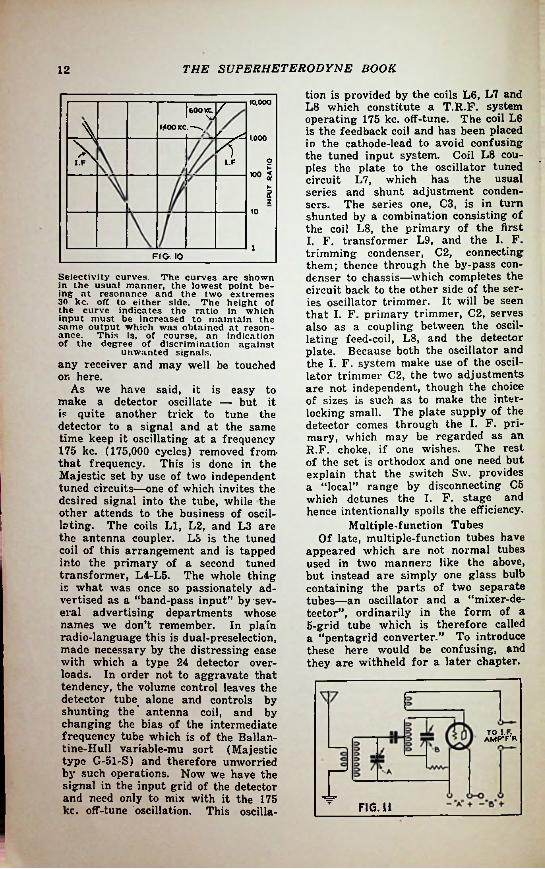
THE SUPERHETERODYNE BOOK12
tion is provided by the coils L6, L7 and L8 which constitute a T.R.F. system operating 175 kc. off-tune. The coil L6 is the feedback coil and has been placed in the cathode-lead to avoid confusing the tuned input system. Coil L8 couples the plate to the oscillator tuned circuit L7, which has the usual series and shunt adjustment condensers. The series one, C3, is in turn shunted by a combination consisting of the coil L8, the primary of the first I. F. transformer L9, and the I. F. trimming condenser, C2, connecting them; thence through the by-pass condenser to chassis—which completes the circuit back to the other side of the series oscillator trimmer. It will be seen that I. F. primary trimmer, C2, serves also as a coupling between the oscillating feed-coil, L8, and the detector plate. Because both the oscillator and the I. F. system make use of the oscillator trimmer C2, the two adjustments
not independent, though the choice of sizes is such as to make the interlocking small. The plate supply of the detector comes through the I. F. primary, which may be regarded as an R.F. choke, if one wishes. The rest of the set is orthodox and one need but explain that the switch Sw. provides a “local” range by disconnecting C5 which detunes the I. F. stage and hence intentionally spoils the efficiency.
Multiple-function Tubes Of late, multiple-function tubes have
appeared which are not normal tubes used in two manners like the above, but instead are simply one glass bulb containing the parts of two separate tubes—an oscillator and a “mixer-detector”, ordinarily in the form of a 5-grid tube which is therefore called a “pentagrid converter.” To introduce these here would be confusing, and they are withheld for a later chapter.
10.000|600KC v\ MOOKC.—-s.
i ydwl.F
1.000
2100 §
Q
10
1FIG. 10
Selectivity curves. The curves are shown in the usual manner, the lowest point being at resonance and the two extremes 30 kc. off to either side. The height of the curve indicates the ratio in which input must be increased to maintain the same output which was obtained at resonance. This is, of course, an indication of the degree of discrimination against
unwanted signals.any receiver and may well be touched on here.
As we have said, it is easy to make a detector oscillate — but it is quite another trick to tune the detector to a signal and at the same time keep it oscillating at a frequency 175 kc. (175,000 cycles) removed from- that frequency. This is done in the Majestic set by use of two independent tuned circuits—one of which invites the desired signal into the tube, while the other attends to the business of oscillating. The coils LI, L2, and L3 are the antenna coupler. L3 is the tuned coil of this arrangement and is tapped into the primary of a second tuned transformer, L4-L5. The whole thing is what was once so passionately advertised as a “band-pass input” by several advertising departments whose names we don’t remember. In plain radio-language this is dual-preselection, made necessary by the distressing ease with which a type 24 detector overloads. In order not to aggravate that tendency, the volume control leaves the detector tube alone and controls by shunting the* antenna coil, and by changing the bias of the intermediate frequency tube which is of the Ballan- tine-Hull variable-mu sort (Majestic type G-51-S) and therefore unworried by such operations. Now we have the signal in the input grid of the detector and need only to mix with it the 175 kc. off-tune oscillation. This oscilla-
are
AMP'/'RTO
FIG. 11

CHAPTER 2Signal Frequency Amplifiers
Since almost any desired degree of amplification may be produced in the fixed-frequency intermediate amplifier, it may appear senseless to use (also) a tuned radio frequency amplifier ahead of the “mixer” (converter or first detector). However this amplifier does appear in all of the better modern superheterodynes in the position just mentioned, which is that indicated farthest to the left in Fig. 6 by the box labeled “signal frequency amplifier” (which is merely another name for a T.R.F. amplifier).
This amplifier serves three very definite purposes:
1—It greatly improves the quietness of the receiver, since it amplifies the desired signal more than the noise-background, before either of them reaches the “mixer” (labeled “frequency changer” in Fig. 6.). While recent mixer tubes decrease this problem somewhat as explained jin chapter 3), any improvement in signal-to-noise ratio is worth while, especially at short waves where this is the normal limiting factor of reception.
tuned circuits used such as that shown in Figs. 9 and 10. However such schemes, without exception, cause some loss in the desired signal, since their tuned circuits unavoidably have some resistance. In consequence, the signal to noise ratio mentioned in item 1, above, is damaged or reduced somewhat. For this reason, the more expensive sets will invariably use a complete T.R.F. amplifier, not merely tuned circuits in cascade.
3—Finally, the use of 2 or more tuned circuits ahead of the mixer, instead of one only, can easily prevent still another type of interference caused by offrtune signals operating through the effect known as “image- frequency interference.” This effect can be explained as follows: referring back to chapter 1, you will recall that in a receiver with an I.F. amplifier system tuned to 175 kc., we could receive a 1000 kc. broadcasting station when the oscillator was tuned to 1,176 kc., since(osc.) 1,175 kc.—(signal) 1000 kc.
— 175 kc.and accordingly, the incoming 1000 kc. signal is converted to 176 kc. and passes easily through the I.F. amplifier. BUT- is also true that
2—Similarly, the T.R.F. amplifier (also called pre-amplifier), by favoring the desired signal, decreases the possibility that a strong off-tune signal will arrive at the mixer with enough strength to overload that tube, thereby “cross-modulating” the desired signal. Should this take place, the two will be detected together and thereafter no degree of selectivity in the I.F. amplifier can separate them. Therefore, selectivity ahead of mixing is important also for this reason. Note that the desired selectivity can be accomplished by pre-selection alone, amplification being non-essential. Hence, the T.R.F. tube may be omitted and a scheme of two cascaded
unfortunately it
4-w I ClHh1/G
ll.TTc I ±7T,o ( C°\\HI
FIG.12
Antenna input circuit for uniform gain.
13

the superheterodyne book14
Design of the Pre-amplifier (550-1500 kc. type)
In the simpler receivers intended only for the normal broadcast band of 550-1500 kc., or a trifle more, one ordinarily attempts to secure fairly even amplification over the tuning range of the pre-amplifier, for obvious reasons. Enormous masses of literature have been written on flat-gain T.R.F. amplifiers (refer to the files of Proceedings of the I.R.E. for good examples) and we can mention here, only briefly, a few methods.
In Fig. 12 the natural tendency of the amplifier gain is to fall off at longer wavelengths, because the tuning capacity C, is then larger and the voltage across it correspondingly lower (an explanation for this effect will be found in any standard radio text book). It is a tendency universal in T.R.F. amplifiers and painfully prominent in older T.R.F. sets. It may be compensated for in several ways.
A—We may make LI (Fig. 12) of such inductance that with the antenna connected, it will resonate at about 430 kc. (700 meters). As we tune toward the long-wave (500 kc.) end of the broadcast band, we approach the tune (natural frequency) of the resonant antenna and the gain goes up. This is the high inductance antenna coil scheme commonly used.
B—With the above scheme, or alone, we may use the device also shown in Fig. 12, of feeding the “B- plus” to the R.F. amplifier tube through a choke coil, L4, which is resonant at about 430 kc. (700 meters), and coupling the tube to the
bJX-j5
FREQUENCY
Pig. 13. The well-known curves of selectivity: A, that of a single circuit; B, that of three. The wider the bottom of the curve, the more opportunity for “cross-
modulation.”
(signal) 1,350—(osc.) 1,175—175 kc.Hence, the same oscillator setting will likewise convert a 1,350 kc. signal to 175 kc., and this, also, will pass through the I.F. system. Sharpening the I.F. system’s selectivity does no good in preventing this effect. Changing the intermediate frequency merely causes it to appear at another point; always we are faced by the fact that there will be two channels which are “tuned in”; these two stations being in every case separated by twice the intermediate frequency.
Protection against this effect must be provided by selectivity ahead of the mixer—it is ineffective after. It may manifestly be provided either by a full T.R.F. amplifier, or else by cascaded tuned circuits without R.F. tubes as in Figs. 9 and 19 already mentioned.
A signal frequency amplifier circuit. This requires a four gang condenser and Isvery selective.

THE SUPERHETERODYNE BOOK 15
Since the selectivity and amplification of a T.R.F. amplifier falls off as the wavelength becomes shorter (frequency becomes higher), a correctly designed multi-range receiver should use more stages of T.R.F. amplification in the short-wave ranges than in the broadcast range of 650-1500 kc. (example, General Electric model K- 80). The practice of dropping out the pre-amplifier when leaving the broadcast band is merely a way to cheapen the receiver; with reduced results as a consequence.
Cross-modulation in the T.R.F.Amplifier
It is necessary that selectivity be built up stage-by-stage in the T.R.F.
tuned grid-circuit of the next tube, by means of a very small capacity, Cl, usually not more than 10 micromicrofarads (.00001 mf.). The action here resembles that just described; as one tunes toward 500 kc., the tube shown acquires a load of higher impedance (as L4 approaches resonance), hence its output voltage increases. The deficiency of this scheme (which is due to the late Carl Trube) is that the tuned-circuit, L3 and C, is loaded with more fixed capacity than would be the case for a two-winding transformer method of coupling. In consequence, the same tuning range 550-1500 kc. ordinarily requires a 500 mmf. tuning condenser instead of a 350 mmf. unit, which decreases the 1500 kc. amplification some 30 per cent in each stage. This is not a serious loss, especially in a superheterodyne, where the I.F. system has “gain to burn.” It is merely mentioned to anticipate carping critics.
+w O C2LA
[/ HHLrV
+Short-wave Pre-amplifiers
In a superheterodyne receiver working at short waves the pre-amplifier or signal-frequency amplifier is much more essential than in a set operating on the 550-1500 kc. range. Its omission in many receivers is due purely to a desire of the manufacturer to build to a price, or perhaps to the fact that few radio listeners realize the vast improvement which the pre-amplifier can effect at short waves. It suffices here to say that all three types of interference cited above (noise, cross-modulation and image interference) are much worse at short waves; hence the pre-amplifier — not merely a pre-selector — should be present.
% T/ \ O // L3 § SSCl/
o /t
VHiFIG. 15—A three gang condenser circuit.
/* 10.0£ -SENSITIVITY-
CURVE'A'-FlG.WCURVEB-FI0.15
5
y.aMa«> 5.0
<9>f
5o2.5o
i ° 600 1000 1200 FREQUENCY IN KILOCYCLES
600
FIG.16Sensitivity curves of circuits Figs. 14 f nd 15
GROUNDED TO SHIELD
. I ■n*—ha rm5* *-«
i [LA-f (4-*!f—IKhff SLA - 415 T. N* 36 D.S.C.L - 126 T.NS-30 ENAMELFIG. 17
Oscillator coil data for circuit Fig. 16.Antenna coll data for circuit Fig. 16.

SUPERft&T®R°Dy*?E BOOKTHE16
I4J- OET
JTL I =kcg O
§ Tc>§g
O J45-----n »Hit T=■
^OUT U^6ECrREQ0CNCv),PtFIG.19-A
V 58§ S’-.im 1 JZlio
7TJT Stxf5 7To
f T“ STROMBERG-CARLSONWESTINGHOUSE
VoOtfotfW'WMW
JZ1 X]TT Ti\ TTi meg.
~~ KOLSTERZCNITH
FIG. 19Various band selector circuits used In commercial superheterodynes.
amplifier at a rapid rate, otherwise unwanted strong interfering signals will not be sufficiently held down, and will become amplified to the point of overloading either an R.F. amplifier tube, or the first detector (mixer). The use of the Ballantine-Snow “variable-mu” or “super-control” types of tubes (such as the 51, 35, 58, 78 etc.) largely prevents this, but in some cases the volume control must also act to reduce input from the antenna, besides controlling the gain in the tubes.
penalty for the greater selectivity. Coil data for circuit 15 appear in Figs. 17 and 18, the coils being suitable for a model 311-H tuning gang manufactured by the Radio Condenser Co., to whom Fig. 16 is due. The aluminum shield cans are indicated and must vary but little from the dimensions stated, otherwise the coil inductances will be altered and tedious cutting and trying result, may be a small “universal” coil such as used for R.F. chokes in broadcast receivers, while C2 may have a capacity of not more than 500 mmf. in any case, but is dependant to some extent on L2 and may be very much smaller.
The circuits of Fig. 19 have all been used by the makers listed and are quite sound, but less necessary with variable-mu tubes, which ordinarily permit either dropping out one of the tuned circuits, or the interposition of another R.F. stage.
L2
Practical NotesPractical examples of 550-1500 kc.
pre-amplifiers are shown in Figs. 14 and 15, the corresponding gain curves appearing in Fig. 16. Observe that the addition of the extra tuned circuit in Fig. 14 has had the usual consequence of an un-compensated tuned circuit—a sloping gain curve, as a

CHAPTER 3
Oscillators and Frequency Changers
As we have explained, the purpose of the oscillator is to supply an adjustable radio frequency voltage which at all times is different from the frequency of the received signal by just the amount which is represented by the intermediate frequency —or rather the tuning of the I.F. amplifier. For some years, I.F. amplifiers have been built to work at 175 kc. and oscillators have consequently run 175 kc. above the frequency of the received signal—since it happens to be more convenient mechanically to do this than to run the oscillator 175 kc. below the received signal frequency.
Thus we may set up examples of the operation of such a receiver:
Oscillator frequency 175 kc.
1675 kc. 1425 kc. 1175 kc.
925 kc.725 kc.
ing will not shift to 250 kc. (1200 meters)—but only to 500 kc. (600 meters). Thus, increasing the capacity to 4 times the former value has increased the wavelength to only twice the former value—and 2 is the square root of 4, illustrating the above statement.
In the receiver tabulated, we wish to tune from 500 to 1,500 kc. 1,500 is 3 times 500, and since the frequency change is in proportion to the square root of the tuning-capacity change, we evidently need a tuning condenser with a 9-to-l capacity range.the result when all the stray capacities in the set are connected across the system, and usually such a range is available with a tuning condenser whose maximum capacity is about 350 mmf., although some circuits require more, as mentioned in the discussion of Figs. 12, 14 and 15.
The case for the oscillator is different. Referring to the table again, 1675 kc. is only 2% times 675 kc. Therefore, the condenser (plus stray capacities) needs a range of capacity of only 2% x 2V2 = 6% to 1. Ordinarily we allow the minimum capacity of this condenser to be about the same as that of the condensers used to tune the T.R.F. amplifier—the minimum being the capacity in the circuit at 1500 kc. Thus, we evidently need a condenser section for the oscillator which has a smaller maximum, which is produced by means of a fixed (or adjustable) series condenser; or (for bandspread sets) is “tapped down” a few turns on its coil to lessen the tuning range, quality of tracking for these systems is in the order of their listing.
Also, since the minimum capacities are the same, it must be evident that
This 9-to-l range must be
R.F. and mixer frequency.
1500 kc.1250 kc. 1000 kc.
750 kc.550 kc.
Design of Oscillator and T.R.F.Circuits
From this we can at once find out something about the tuned circuits of the set. The frequency to which a coil-condenser combination tunes is dependant on the capacity, C, of the condenser (plus the stray capacities in the set) and the inductance, L, of the coil. However, the resonance frequency does not vary directly with the product of L and C; it varies with the square root of LC. Thus a condenser with a capacity of 250 mmf. connected across a coil with an inductance of 100 microhenries will tune to a frequency of 1000 kc., which is to say, a wavelength of 300 meters. If we quadruple the capacity to .001 mf. (1000 mmf.) the tun-
The
17

the superheterodyne book18the oscillator coil, tuning to 1676 can have only about 80% of the inductance of the T.R.F. coils whicn
1 500 kc. with another con- minimum capaci-
1DET OCT.o 5 -I*oIftune to
denser of the same 8^oooJty.This has been set down in some detail
because the reader will wish to work with other ranges, and with other values of intermediate frequency—but always with these same principles. How-
the reader is cautioned that
X PWW3HH
ever,theory is not too dependable here, since it cannot anticipate stray circuit capacities correctly and must be supplemented by painstaking cut-and- try.
osc
Fig. 21, left, illustrates magnetic coupling of detector and oscillator. Fig. 22, right, oscillator pick-up coil linked with a coil in cathode lead of detector.
Short-wave OscillatorsSpecial problems arise in connec
tion with oscillators for short-wave ranges, especially where it is desired to use the same tuning condensers for the 550-1,500 kc. range also. The unhappy consequence of this common combination is that one must use a tuning capacity of about 350 mmf. max. (see foregoing paragraphs) for the 550-1,500 kc. range, which is far too much for good amplification at short waves. Changes in the tuning capacity usually produce mechanical involvements and increased circuit losses, frequently leading to unreliable functioning at short waves. One
therefore frequently makes the best of a bad matter and uses the 350 mmf. (or thereabout) condenser in all ranges, and puts much thought and care into the design and test of an oscillator which is “sure fire” at short waves, without producing excessive output at longer waves, the various ranges are obtained by switching instead of plug-in coils, the utmost care is taken to minimize capacities in the switch, not principally because of the added micro-microfarads, but because these added micro-mikes produce all manner of undesired stray couplings and some added loss.
If
Where possible, the
FIG. 23 12 os. ° FIG.24+90V +90V« s cxCx\
\ “1 £ « u4 k CU7T'-vwvc>
T« T ® R1 IC3i°Perf,|es with grounded cathode and takes its bias from the 40,000 onm griaieak Rl, oscillation amplitude and harmonic production being limited by the
M00 ohm xrld series resistor R2.HSure 2« (right) operates with higher Initial bias due to the 6,500 ohm cathode re- ®i8tor R4, hence its limiting resistor R3 Is but 600 ohms. The values are for a 27.
range of 600-1,500 kc., L2 will have about 1/6------ , iiiimiug icsiatur
56 or similar tube. In the broadcast range of 600-1,600 kc., ___ ___v%„.. uumber of turns of LI, the latter being center-tapped for the grid connection.
If the tuning condenser C2 has the same capacity range as the sections used to tune the mixer Input and other signal-frequency circuits, the remaining capacities will be approximately; C3 adjustable 5 to 50 mmf. (ordinary trimmer found on condenser gang), used here to trim minimum, i.e., to 1675 kc. when other circuits are set at 1,500 kc.; C5 fixed, depends somewhat on C2, but about 750 mmf. (.00075 mf.); C4,
to correct C5, range about 15 to 75 mmf.; Cl, 500 to 750 mmf.

THE SUPERHETERODYNE BOOK 19
large part of the unsatisfactory performance and alleged “fading” of short-wave signals is due to such things.
Experience has shown that effects of type A can be minimized by the use of high-grade construction, while effects of type B and C are anticipated by the use of proper oscillatory circuits and by disposition of parts learned through care and experience. Here careful laboratory work is essential.
24 on 57Cl
___cu 4X-I MEG. ©
POTENTIOMETER (AMY CONVENIENT I BATTERY
(not a c;
4.5V +65-90V.
0.2 9V.
PIG. 25Oscillator Circuits
Although design conditions introduce various disguises, the oscillator normally uses some form of the Hartley circuit; or its close relative, the tuned grid coil with an untuned plate tickler. In Fig. 21 and in Fig. 22 are shown schemes for magnetically coupling such oscillators to a screen-grid detector, via the grid (input) circuit. In Fig. 21, this is done by magnetic coupling to the tuned coil, while in Fig. 22 it is done by magnetic coupling to a “pickup” coil, connected in series with the cathode—which is, after all, a part of the input circuit and hence equivalent except as to mechanical convenience. In both these diagrams the lower end of the detector grid input coil is, of course, understood to be grounded to the metallic chassis of the set.
An increasing tendency toward fixed screen-grid voltages has largely done away with the formerly common scheme of feeding the oscillator R.F. voltage into the detector screen- grid. One must not jump to conclusions on observing that an Oscillator draws its plate supply from some point apparently connected to R.F. and detector screen-grid. This is common practice because the oscillator commonly runs with a plate-supply voltage of about 90 and this is the screen-grid voltage of most R.F. and detector tubes. However, the D.C. takeoff to the oscillator is usually made near a bypass condenser which minimizes any possibility of R.F. coupling to the screen-grids. Frequently the filtering at this point is increased by taking off the oscillator supply through a 100 to 5,000 ohm resistor, as a decoupler.
A V.T. voltmeter for adjusting the output of the oscillator to optimum value.switch blade is kept grounded and only the contacts are raised “off- ground”—the reference of course being to R.F. voltages off chassis; D.C. voltages being unimportant.
The very serious problem of frequency instability enters here. In the 550-1,500 kc. range this is not too painful, since a change of an entire per cent (!) in frequency only puts one into the next broadcast channel. But, if we happen to be receiving at 25 meters and the frequency wanders only M of 1 per cent we go wandering off across a number of stations in succession, whereas a 1 per cent shift would cause us to shift the equivalent of 12 ordinary broadcast channels—which is intolerable.
Such frequency wanderings are due to several things—A—Aging effects.
Changes in the coils with time and weather.
Changes in the tubes with age.Gradual changes in trimmer con
densers.B—Heating effects.
Tube warmup.Warmup of tuning elements after
set is turned on.C—Irregular effects.
Changes in tubes (replacements). Antenna changes.Coil-shields shifting with respect to
coils.Line-voltage changes.Variable contacts between metal
parts.Against all these the short-wave
oscillator must provide if it is a good- enough job—and many are not. A
20 THE SUPERHETERODYNE BOOK
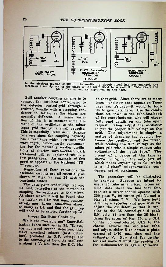
aItP ^ ITB Tr i3ov. -A- *B+" r~90V.90V. -B- -C-
-B+-PLATE GROUNDED
INSTEAD OF CATHODEFIG. 26
7 ELECTRON-COUPLEOCIRCUIT
ORDINARYOSCILLATOR.
sc reeif-gr kTMerely11 n gS 111 e*lp[' thef oscillatory circuit Itself ha^ not changed, theplate free to act as explained in the text.
This leaves the
Still another coupling scheme is to connect the oscillator control-grid to the detector control-grid through a resistor, usually with a stopping condenser in series, as the biases are normally different, tion -of this is to connect some element of the oscillator to the mixer input grid through a small capacity. This is especially useful in multi-range receivers since the coupling capacity has a reactance which decreases with wavelength, hence partly compensating for tile naturally weaker oscillations at shorter waves—which dark statement will be explained within a few paragraphs. An example of this practice appears in the National “FB- 7” receiver.
Regardless of these variations the oscillator circuits are all essentially as shown in Figs. 23 and 24 with the constants stated.
The data given under Figs. 23 and 24 hold, regardless of the method of coupling the oscillator to the mixer. At short waves it will be found that the tickler coil L2 will need comparatively more turns—sometimes almost as many as LI, and that the grid tap will need to be carried further up LI.
Proper Oscillator ConditionsWhile the “variable mu” Snow-Bal-
lantine tubes such as the 35, 78, etc., are not good second detectors, they make excellent mixers (first detectors) provided the R.F. voltage fed to the control-grid from the oscillator is about 1 V. less than the D.C. bias
on that grid. Since there are so many types—and new ones appear on Tuesdays and Fridays—it would be foolish to give data here. Use the conditions set down in the tube-data-book of the manufacturer, who will cheerfully send details on any tube upon request. Then adjust the oscillator to put the proper R.F. voltage on the grid. This adjustment is simply a matter of changing the coupling between the oscillator and the mixer, while reading the R.F. voltage at the mixer-grid with a simple vacuum-tube voltmeter of the “peak type.” circuit of a device of this type is shown in Fig. 25, the only part of which needs explaining is Cl, which is a “2-plate” midget-variable condenser, set at maximum.
The procedure will be illustrated by example. Suppose we intend to use a 35 tube as a mixer. From an RCA data sheet we find that this tube as a mixer should operate with 250 plate V., 90 screen-grid V., and a bias of minus 7 V. We have built it up in a receiver and now wish to adjust the oscillator so that it supplies to the 35 control-grid 6 peak R.F. volts (1 less than the 35 bias). Using the setup of Fig. 25, clip CL1 to the 35 control-grid, CL2 to the chassis, remove the oscillator tube and adjust slider S to obtain a plate current of 1/10—ma., then read the voltmeter V. Now start the oscillator and move S until the reading of the milliammeter is again 1/10—ma.
A minor varia-
The

THE SUPERHETERODYNE BOOK 21
Read V. once more and subtract the two readings. The difference should be the peak R.F. voltage applied to the 35 grid, unless stray pick up has spoiled your readings. To check this turn Cl to minimum. If the readings are repeated you should now get a smaller result—which is incorrect except as a check. If Cl has little or no effect, shield the whole rig by enclosing it in a metal can with only CL1 coming out through a thin mica window 1 in. across, the rest of the grid circuit of the meter-tube being inside. It may be necessary to decrease R to .1-megohm to obtain sensible readings. The meter then draws too much power from the oscillator, but is still vastly better than guesswork.
All this must be done with care (it is really no novice's job) but an observing user will improve his receiver with it just the same.
Electron-Coupled Oscillators
The difficulty of getting good frequency stability from normal oscillators working at short waves, and coupled in the ways mentioned, has led to the introduction of the Dow “electron-coupled” oscillator and its descendant, the “pentagrid converter.” One form of the electron- coupled oscillator appears in Fig. 26.
Since the plate of the circuit shown in Fig. 26B is bypassed to chassis, it is unable to develop any R.F. voltage differing from that of the chassis. It follows that the plate of Fig. 26C is screened from capacity coupling to the oscillator, even though the oscillator is in the same tube. From this it follows, in turn, that variations in the plate voltage or load cannot have much effect upon the oscillator frequency—which the effect we desire.
At the same time, R.F. power does reach the plate of Fig. 26C, by the following process. Since oscillation is taking place in the grid-cathode- screen combination, the control-grid must evidently be swinging up and down at radio frequency. It consequently is varying the electron stream which flows from the cathode through the grid to the plate—hence the stream arrives at the plate bringing
R.F. power with it. The plate accordingly is associated with the rest of the tube-action only through the electron stream — hence “electron- coupled.”
The Pentagrid Converter
The inconvenience of having the tube’s cathode “off ground” as in Fig. 26, immediately leads to the thought that we ought to have a tube with an extra grid to be used for oscillation so that we would not need to put the tickler between screen-grid and thode.
ca-This would be a tube with
a cathode, two oscillating grids, screen-grid and a plate, in other words a special sort of pentode. Such tubes have been made.
a
The next step is to put one moregrid in, using it to feed the incoming signal from the distant station into the tube—whereupon we have combined the “mixer” with the electron- coupled oscillator. This is the “pentagrid converter,” which has merits altogether aside from that of merely combining two tubes. A well-known sort is the 2A7 also 6A7).
Not only does it give us the good stability of the electron-coupled cillator; it also provides an oscillator- mixer coupling that is automatically right. The circuit of such a tube is shown in Fig. 27, while Fig. 28 shows coils which will work over the 500- 1,500 kc. broadcast band with a 175 kc. intermediate amplifier.
OS-
14 I.F.T 1(SEE FK>. 17;
XXAJ£
(TUNqc>h OR
larger
T 300 14s f T OHMS T
50.000 —- 1 J 15000OHMS
Zu )(tune; '“2 (
'250MMF.
C2
rHtbV> bV> h« r6 (CONTROL BIAS
UP TO 45 V. IF CONTROL IS NOT
WANTED, OMIT C ; *toov. 250VFIG. 27
The method of connecting the pentagrid converter as a frequency changer.

THE SUPERHETERODYNE BOOK
Oscillator CoilsShort-waveThe table, Fig. 29, at the end of
this chapter gives coil dimensions suited to various short-wave bands, but using a triode oscillator (type 56 or the like, with a pickup coil connected into the cathode circuit of a normal screen-grid detector (type 57 or the like). To adapt these oscillator coils to the 2A7 or similar tube, simply omit the pickup coil, since an electronic pick-up is built into the tube. The plate coil is also omitted and in its place is wound a coil corresponding to L2 of Fig. 27. This is wound directly over the grid coil with only one layer of oiled silk between, and spaced to have about % the length of the grid coil—the grid coil being, of course, LI (Fig. 27) which is connected to the first grid. The number of turns for the four coil-ranges is correct—but remember to space out the turns as described.
----CO<L OAT A ——< CAMr c*(.
AV M<0 M M »K
Stas«• MMC
sro.-M-M
•it JjiST9»-Mmm i«.r.mo vir•o-aao
FIG. 29
.6. *
i
Coll data for oscillator and detector colls for a S.W. superhet.
ding” condenser in series with it, corresponding to C4 and C6 of Figs. 24 and 25. This can be an adjustable condenser, of that capacity, or else a fixed one, shunted by an adjustable one, as in Figs. 24 and 25.
The “detector coil” winding is described for a receiver without an R.F. amplifier, but one can be—and should
added, using a variable-mu screen-grid tube of the sort represented by types 35, 68 and the like. The “det. coil” of the table then goes between this R.F. tube and antenna, while between the R-F. tube and the detector (corresponding to L4 of Fig. 28) there will be a similar coil—with this difference only—the “ant. coil” is omitted. In its place there is wrapped one turn of oiled silk over the grid coil, on which is wound a coil exactly like the grid coil (spaced the same as the grid coil) but only % as long and accordingly with only % as many turns. This is connected into the plate circuit of the R.F. tube. (Incidentally, the coil at Fig. 17 can easily be made into a good R.F. transformer [500- 1500 kc.] by such means.) The circuit of this receiver is shown in a later chapter as the "Simplified Mit- cherl Receiver.”
be
This set of short-wave coils is intended to work with tuning condensers of 150 mmf. maximum capacity, the oscillator section being like the others but having a .001 mf. “pad-
oNe LAYER.
OF OILEO SILK
V PLATECOIL\ (L2 -PIG. 27J
36 TURNS.N9.31 ENAM. WIRE CLOSE WOONO DIRECTLY
OVER "LOW'END OF LI
0.1-MG 27;92 TURNS.Nfi.32
ENAM. WIRE-CLOSE WOUNDFIG 26
An oscillator coil for the 1500-550 kc. band with a 175 kc. I.F. amplifier.

CHAPTER 4
Single Dial Tuning Systemsbecause even today, they are of interest in clarifying the problem.
The mechanical inconvenience of the McLaughlin device caused it to be largely abandoned in favor of another scheme, in which the coils are all fixed, the oscillator inductance being somewhat smaller than the others. The oscillator tuning condenser is made to have a slightly lower minimum capacity and a considerably lower maximum capacity by connecting a fixed condenser in series with it. Assuming the constants to have been chosen correctly by a somewhat tedious process of calculation, plus cut-and-try, we have the situation of Fig. 31, where A is the T.R.F. tuning curve, B the one we hope to have attained in the oscillator. The B curve is seen to lie 175 kc. above the A curve. It does not look so, but this is optical illusion, exposed by a few measurements on the graph. Actually, the results are seldom so perfect, one attains more nearly such a curve as C, which is not evenly spaced from A. One may then either locate it as shown, with both ends lying on the correct curve B, or else (and more usually) one chooses the least average error, by making both ends lie above B and the middle below B. This has given acceptable results in hundreds of thousand of receivers.
Since it is nearly impossible to have either the variable or the fixed oscillator condensers just right as to capacity one must in practice use the complication of Fig. 32, where C is the variable tuning condenser with its usual “trimmer” or “screwdriver makeup condenser,” marked C3, while the series fixed condenser Cl is likewise provided with a “trimmer,” C2. Actual values for a 175 kc. case
A S we have mentioned in earlier xJl chapters, the problem of tuning a superheterodyne receiver with one control-knob, differs from the same problem in a T.R.F. receiver, for the reason that the oscillator requires a tuning range which differs from that of the other tunable circuits in the superheterodyne receiver.
In the example given early in Chapter 3, we pointed out that while the T.R.F. stages must tune from 550 to 1,500 kc. to cover that range of received signals, the oscillator must, at the same time, tune from 675 to 1,675 kc., provided that the intermediate amplifier operates at 175 kc. If the I.F. amplifier works at a different frequency—and it often does— then the oscillator must have another range, always such that its frequency is at all times above the T.R.F. frequency (frequency of received signal) by an amount just equal to the I.F. (This statement neglects those infrequent sets in which the oscillator works “below” or “across” the received signals.)
Off hand, one might judge that it would be necessary only to reduce the inductance of the oscillator coil by removing turns, using a variable condenser exactly like that used for the other stages. This is impossible, since the resulting curve will not stay at a uniform distance from the T.R.F. curve, but will, instead, maintain a fixed percentage relation—which is useless.
An early method of accomplishing the proper “tracking” was proposed by McLaughlin in 1924. He used an oscillator tuning condenser like the T.R.F. condensers but used a variable oscillator inductance in the form of a variometer, driven by the condenser shaft. Figure 30 gives the details,
23

24 THE SUPERHETERODYNE BOOK
should be shielded as a concession to the comfort of the neighbors who may otherwise be subjected to squeals. Only the coil is especially in need of such shielding, and the radiation is very short-ranged, unless one deals with a primitive superheterodyne which lacks T.R.F. stages to prevent radiation from the antenna.
Special Condenser SectionsThe rather idealized tuning curves
of Fig. 33 have been saved up to this point, as they are not of the greatest practical importance. It has lately been recognized that such rigidly “straight line” tuning is of questionable value, even if it were readily obtainable. It is, moreover, not readily attained, partly because of the clumsy condenser plate-shape which is indicated, and partly because the best of the designs is to some extent defeated by the uncontrolled variation in the set.
Special plates do, however, serve a very real purpose in the oscillator section of a gang tuning condenser.
Design of Oscillator Condenser Plate Shape
The method of calculating the plate shape of an oscillator condenser so that it will accurately track with the condensers used in any R.F. tuning system and maintain a constant frequency difference of 175 kc. or any other value higher than the R.F. condensers at any setting in the range has been worked out and is used in many commercial receivers.
The first step in the procedure is to determine the tuning characteristics of the signal frequency amplifier as shown in Fig. 31 and with the intermediate frequency known (175 kc. for example), the theoretical oscillator curve can be drawn, as is shown by curve B. To avoid errors from lump minimum capacities which may exist in the circuit, the condenser is designed so that a small capacity will have to be added by means of a trimmer condenser so that the sum of the minimum distributed capacities can be controlled and set at a fixed starting point.
Next an inductance value for the oscillator circuit is selected which will
y iLl 2 ¥== Cl7ro
o rI
L2 o
>iL5I
l#-L4
L3
R.F.C.-COIL DATA- Ll-59T.NO l6 0.C.C.,3,<'«“0IA. ,LZ- 8 T. * - * - I •/•FROM LlL3-5T. • - - ,l5/« TUBE INSIDE L4 L4-54M*T.« - - ,3V«*0IA.L5-30T. ■CI.CZ-.0005-MF. EACH
FIG.30
- 1/4* FROM L4
B +An early single dial circuit using special
coils and identical condensers.
were given in Fig. 23 for a 175 kc. I.F. system, others will appear later.
Incidentally, Fig. 31 illustrates another, and more refined, method which is gradually becoming standard, some years after it should have been adopted. This is to start at the beginning—by making the oscillator tuning condenser of the proper size and shape for its job so that no extras are required and only the usual small “trimmer” is attached to it. The constants for that arrangement appear on the diagram of Fig. 31, and the necessary plate-shape is discussed later.
For the present, we wish to say a word more about the scheme of Fig. 32, which can be used by the amateur, both in that form and in a more simplified form.
If 175 kc. is the intermediate frequency, and 550-1,500 kc. is the tuning range, then the fixed series condenser must have about 2 times the capacity of the tuning condenser at maximum setting, although this rule must be used merely as a first approximation, subject to later adjustment. Fig. 23 and 24 are illuminating.
The oscillator-detector system will then look like Fig. 34, although the inductive coupling between the two may be replaced by any of the other feed methods suggested in earlier chapters. Oscillators, by the way,

THE SUPERHETERODYNE BOOK 25
allow the oscillator circuit spectrum to be covered with a condenser of practical size. Inductances of 150 to 200 microhenries are found in commercial receivers. In designing an inductance we must not lose sight of the fact that about 20% must be added to compensate for the loss of inductance when the coil is placed inside a shield.
Knowing the inductance we can calculate the necessary capacity values for the oscillator condenser at various dial settings. When these capacity values have been ascertained and the capacity values of the R.F. tuning condensers known at the same angle of rotation, the radii required to give the desired capacity curve to the oscillator condenser plate can be calculated by means of the following formula:
:i-4OOoooo CT To
FIG.32A padding: circuit for single dial control.
This formula may be used for solving any required curve and is not limited to this particular problem.
Curve A of Fig. 31 is a typical curve of a tuning condenser manufactured by The Radio Condenser Company.
Fig. 35 shows a capacity curve, A, of the oscillator condenser made by this same company. This curve was plotted with the oscillator trimmer condenser at the minimum position. This is not the capacity curve this unit has in actual use, because when used the minimum is raised to 60 mmf. at 12
Co
nro—
Cs
divisions by the lump stray capacity of the receiver and by means of the trim-
This graph should be compared
nWhere, Cs=rcapacity of R.F. condenser
at any given dial setting.Co—capacity of oscillator con
denser at corresponding setting.
r —radius of R.F. condenser plate.
ro =radius of oscillator condenser plate.
n —pairs of active surfaces in R.F. condenser unit.
mer.with that of curve B, showing the capacity curve of the R.F. tuning condenser as measured apart from the circuit.
The oscillator condenser is designed to be used with an oscillator coil secondary having an inductance of 143.6 micro-henries, capacity of the circuit is set to a value of 50 mmf. by means of the trimmer, the proper frequency distribution of the oscillator spectrum is that shown in Fig. 31, curve B.
In designing a receiver using these condensers, a check should be made to make certain that the R.F. amplifier closely follows the graph of Fig. 31, curve A and that the oscillator circuit follows graph B of Fig. 31. Both of these measurements should be made with the intermediate amplifier accurately adjusted to peak at 175 kc. A final check may be made by connecting a small 10 mmf. carefully calibrated condenser in parallel with the oscillator condenser, and supplying a modulated signal of known frequency by means of a signal generator in the usual manner.
When the minimum
CURVE AR.F. TUNER CURVE FOR
175 KC. SUPERHETERODYNE. ANT. AND COUPLING SECONDARIES™ 241.23 MM.. TUNING CAPACITY - 366 MMF. MAX.
1600
r1500
u 1400 CURVE BOSCILLATOR TUNING CURVE
OSC. COIL SEC.™ 143.63 MH. OSC. TUN. CONO.= 335 MMF. FIXED PADDING CAPACITY
- 14 MMF.
\d 1300$ Vo uoo 5 kX 1100
<§>2 1000 (S)l 900
d 600UJ
b. 700
600\
3000 20 40 60 60 100
DIAL DIVISIONS
FIG.31Typical tuning and oscillator curves.

THE SUPERHETERODYNE BOOK26
very materially, except insofar as the tube itself may require somewhat increased feedback coupling to give the same oscillator performance as was previously obtained from triode oscillators. The changes in the oscillator windings which then become necessary are suggested in Fig. 27 and the associated text.
T\irn the dial to the point where 1,500 kc. is a resonant frequency of the R.F. amplifier (equivalent to 12 divisions on Fig. 31A) and reduce the trimmer of the oscillator condenser until the capacity added by the small variable test condenser has been allowed for, and gain is maximum. The plates of the test condenser should be set at about 90 degrees when making this adjustment so that capacity can be either added or subtracted.
Readings should then be taken at various points throughout the 1,500 to 550 kc. range and the gain brought to a maximum at each reading by means of the small test condenser. The variation from the initial setting should be noted and correction made to the oscillator condenser by bending the slotted plates. The variations, in proper designs, will never be greater than can readily be corrected for by bending the plates. To avoid body capacity the adjustment of the test condenser should be made with a long insulated handle.
The Precise gang condenser, Fig. 36, for use in a superheterodyne having an intermediate frequency of 175 kilocycles is designed to work under approximately similar conditions.
Multiple-function tubes
The use of a multiple-function tube to combine the oscillator, the mixer and electron coupling in one envelope, does not ordinarily change the picture
Short-Wave Receivers So far, we have blandly talked
about 175 kc. I.F. systems, and 660 to 1,500 kc. tuning, as if there were nothing on earth but the standard broadcast band. In the process, we have mainly learned that for the amateur it is well to try no tricks, but to use an oscillator condenser like the other condensers, put twice its own capacity in series with it, reduce the oscillator inductance 22 per cent from that of the T.R.F. coils (compare L3 with LI in Fig. 18), and then finish the alignment by using a trimmer across the oscillator variable condenser to get the high- frequency end straight (best response on stations near 1,500 kc.) and making the low-frequency alignment with the trimmer across the fixed series or “padding” condenser. The propriety of this is seen by again referring to Figs. 32 and 34, from which it is apparent that the minimum capacity of the tuning condenser must be adjusted by the trimmer across it while the maximum must be adjusted by the
1C.DET.IFTItoi27
g 1 IWKc.
IgINPUT
-uII! ykv !&
550-1500 KC. "725-1675 KC.INDUCT
IVELY OSC.
J—T_*b+-
coup-LED
j jo __y iC4 t
o 'Cl
Fig. 33. The Ideal (not actual) tuning curve of a superheterodyne — absolute straight-line-frequency variation with the oscillator 175 kilocycles above the detector
tuner.Fig. 34. The tuning circuit. Constants for single-dial tuning are given in the text
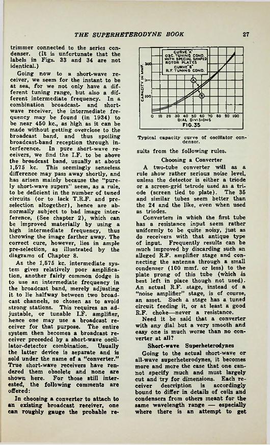
THE SUPERHETERODYNE BOOK 27
trimmer connected to the series condenser. (It is unfortunate that the labels in Figs. 33 and 34 are not identical.)
Going now to a short-wave receiver, we seem for the instant to be at sea, for we not only have a different tuning range, but also a different intermediate frequency. In a combination broadcast- and shortwave receiver, the intermediate frequency may be found (in 1934) to be near 450 kc., as high as it can be made without getting overdose to the broadcast band, and thus spoiling broadcast-band reception through interference. In pure short-wave receivers, we find the I.F. to be above the broadcast band, usually at about 1,575 kc. This seemingly senseless difference may pass away shortly, and has arisen mainly because the “purely short-wave supers” seem, as a rule, to be deficient in the number of tuned circuits (or to lack T.R.F. and preselection altogether), hence are abnormally subject to bad image interference, (See chapter 2), which can be improved materially by using a high intermediate frequency, thus throwing the image farther away. The correct cure, however, lies in ample pre-selection, as illustrated by the diagrams of Chapter 8.
As the 1,575 kc. intermediate system gives relatively poor amplification, another fairly common dodge is to use an intermediate frequency in the broadcast band, merely adjusting it to lie halfway between two broadcast channels, so chosen as to avoid strong stations. This requires an adjustable, or tunable I.F. amplifier, hence one may use a broadcast receiver for that purpose. The entire system then becomes a broadcast receiver preceded by a short-wave oscillator-detector combination. Usually the latter device is separate and is sold under the name of a “converter.” True short-wave receivers have rendered them obsolete and none are shown here. For those still interested, the following comments are offered:
In choosing a converter to attach to an existing broadcast receiver, one can roughly gauge the probable re-
CURVE AOSC. TUNING COND. WITH SPECIAL SHAPED ROTOR PLATES
CURVE’S'R.F. TUNING CONO.
7u; 300 725
>o
<100u
0 10 20 30 40 50 60 70 80 90 100DIAL DIVISIONS
FIG.35
Typical capacity curve of oscillator condenser.suits from the following rules.
Choosing a Converter A two-tube converter will as a
rule show rather serious noise level, unless the detector is either a triode or a screen-grid tetrode used as a triode (screen tied to plate). The 35 and similar tubes seem better than the 24 and the like, even when used as triodes.
Converters in which the first tube has a resistance input seem rather uniformly to be quite noisy, just as do receivers with that antique type of input. Frequently results can be much improved by discarding such an alleged R.F. amplifier stage and connecting the antenna through a small condenser (100 mmf. or less) to the plate prong of this tube (which is best left in place though not used). An actual R.F. stage, instead of a “noise amplifier” stage, is of course, an asset. Such a stage has a tuned circuit feeding it, or at least a good R.F. choke—never a resistance.
Need it be said that a converter with any dial but a very smooth and easy one is much worse than no converter at all?
Short-wave Superheterodynes Going to the actual short-wave or
all-wave superheterodynes, it becomes more and more the case that one cannot specify much and must largely cut and try for dimensions. Each receiver description is accordingly bound to differ in details of coils and condensers from others meant for the same wavelength range — especially where there is an attempt to get

28 THE SUPERHETERODYNE BOOK
This is the general tendency in the short-wave region, but trial beats calculation.
Typical constants for short-wave ranges using an I.F. near 450 kc. and a tuning-range of about 3 to 1; that is, for any one range the highest frequency (condenser set at minimum) is about 2 times the lowest. (Example 550-1500 kc.) Both pad and tuner have trimmers, of course.
maximum amplification by keeping the capacities of the T.R.F. and oscillator down. The effect then is to allow the “stray” circuit capacities to become relatively more important, and as they differ with constructional details, the statement above is substantiated.
Thus for example, we have in the General Electric K-80 series of allwave receivers, a case where stray capacities have been swamped out by deliberately using ample tuning and trimming capacities, the decreased amplification being made up by added R-F. stages—which incidentally helps the noise and image situation. Here we have, for example, a tuning range of 3,900 to 10,000 kc., which, with the 445 kc. I.F. used, calls for an oscillator range of 4,345 to 10,445 kc. The tuning condenser is a normal 335 mmf., one of broadcast- range type, which accounts for the tuning range of 3,900 to 10,000. Our previous rule of using twice as big a series condenser would be all wrong as the oscillator range is now almost as big as the T.R.F. In fact the series condenser has to be .000225 mf., about seven times the tuning capacity. For the range of 8,000 to 18,000 kc. it becomes .00234 mf.!!
Tuning range,
Another Method of AttackIn other designs it has been pre
ferred to minimize tuning capacity as previously explained. Thus, in the National “AGS” receiver a tuning
of about 4,100 to 7,200 kc. israngeobtained with a tuning capacity near 100 mmf. through somewhat special construction which reduces “stray” capacity, so that the 100 mmf. condenser produces about 3/5 of the tuning range which was obtained in the receivers mentioned above with capacities near 350 mmf. For a range- switching set, this would be objectionable, because of switch complexity— for a plug-in set, it is desirable as the per-stage amplification in the R.F. system is materially increased, which means fewer stages — hence fewer plug-in coils per set. One may
Series pad. capacity
100 to 150 mmf. 500 to 800 mmf.
.0010 to .0012 mf.
Tuning capacity max.
350 mmf.350 mmf.
kc.150-450
(200 to 750 meters) 550-1,500 (broadcast)
1,600-4,500 (66 to 200 meters) 350 mmf.
Fig. 36. The Precise three- and four-gang condensers. The arrows Indicate the oscillator units with special shaped plates.

THE SUPERHETERODYNE BOOK
ser, this small condenser to be provided with a microdrive dial of some sort. This does not cripple the performance of the set for other work.
The second, and commoner method is to use either very tiny tuning condensers or (what is equivalent) to connect a “padding” condenser across the coil, and to connect the tuning condenser across but a few turns, at a tap provided for that purpose. With plug-in coils, it is possible to provide an extra prong so that either a regular coil or one of these so-called “bandspread” coils may be plugged in. This is done in the National “AGS” and “FB7” receivers for both the R.F. and oscillator coils. The layout of such coils is a matter of almost pure cut^and-try. Printed descriptions, unless followed with painful exactness, do not suffice.
answer that more sets of coils are needed — but few want the entire range anyway. In this case, the rather limited range per coil is not great enough to modify greatly the trimming and padding rules.
“Bandspread”Some years ago a fad was begun
for receivers which enormously spread out some small tuning range, usually an amateur transmitting band. This has led to rather grotesque tuners, usually of plug-in variety, which are useless except in their narrow bands. Such “bandspreading” can be accomplished in two simple ways.
The first is to build a normal shortwave superheterodyne, and to connect a small “vernier” condenser of about 5 per cent of the tuning capacity across the oscillator tuning conden-

CHAPTER 5The Intermediate Amplifier
fication and jumping clear over the standard broadcast band to 1,575 kc. or some such value.Number of tubes and tuned circuits
T7R0M this point on, the reader will X find it to advantage if he will strive to keep in mind the fact that we have now reached that part of the superheterodyne which is nothing in the world but a long-wave T.R.F. receiver—complete. The so-called “intermediate amplifier” differs in no way from a normal T.R.F. amplifier; the “second detector” corresponds exactly to the detector of any T.R.F. receiver, and the audio system is normal in all ways.
Let us therefore remember that once we get beyond the “mixer” we are talking about nothing but a long-wave T.R.F. receiver. In fact, the simplest possible sort of T.R.F. receiver, for it is without even a tuning adjustment.
Choice of Intermediate FrequencyThis long-wave amplifier is set
once for all on some frequency chosen to reduce image interference (see Chapter 2), to avoid strong local interference (including the standard 550-1,500 kc. broadcast band and the 500 kc. ships), and yet low enough to permit good amplification without getting into an audio frequency and letting through noise.
In the past, this has simmered down to 175 kc. which is outside the audio range, yet low enough so that the second and third harmonics of 350 and 525 kc. miss the standard broadcast band, image ratioth.0'h600 range- tho“gh about
—or else gets furtb oa?ca8^ bandprovement by giving” lmage im_
y g g UP 8<>me ampli-
Since one of the main objects of using a superheterodyne circuit is to obtain high amplification and selectivity in the intermediate amplifier— where there are no variable conden-
finds that as a rule thissers, oneamplifier employs high-gain tubes and transformers, which not only have their secondaries tuned (as in the case of a normal T.R.F. amplifier) but also have some of the primaries tuned. The high-gain tubes are commonly screen-grid tetrodes or screen-grid R.F. pentodes, meaning tubes such as the 35, or else tubes such as the 78. The R.F. pentode gives about twice the amplification while drawing twice the plate current and sometimes a stage can be saved by usingit.
In Fig. 37 is shown an I.F. amplifier employing variable-mu screen-grid tetrodes in two I.F. stages, followed by a triode detector of the high-level bias type—that is, a detector operating at a high signal level and probably followed by only one audio stage. Observe that the system shows six tuned circuits. Even if regeneration is carefully worked out of the system, this will produce excessive sharpness and destroy tone fidelity, unless the selectivity curve is carefully adjusted. This is done by so spacing the primary and secondary of each transformer as to provide approximately “critical selectivity”— i.e., such coupling is used as will just begin to broaden the curve. Over- close coupling will result in a twohumped tuning curve, hence one sometimes uses a de-coupling washer
The selectivity and are acceptable for the
30

THE SUPERHETERODYNE BOOK 31
I FTI 3IZ fr------- -1-1- '35'35--------- 1
/ ®! 1/f i!1*
o 1 o
I e ois s .ztut
o o
o oooa T«
1500OhmsSHIELD
v+ 60V.+ ZOO V.£
FIG.37A two stage I.F. amplifier circuit. Note that three tuned I.F. transformers are employed.
almost entirely disappearing and nothing but rumbles, booms and grunts coming out, if a normal audio amplifier is used. Accordingly the audio system must restore the audio fidelity by first flattening the low notes down to the level of the attenuated high notes, then taking the resulting weak (but fairly undistorted) audio output and amplifying it up to normal level. Therefore a typical circuit (Fig. 38) shows not only the equalizing transformer (marked “filter” in Fig. 38) but also shows an unusual number of audio stages, 3 in this case. The net gain of the system, when capacity coupling is erased by proper setting of the crystal-bridge condensers, is to suppress greatly the ordinary background noise of reception.
The “Single Signal” Receiver It must be apparent that if the
Robinson equalizing audio system were replaced in a stenode receiver by a normal audio system we should find only low pitches in the output. If, in addition, the crystal bridge was unbalanced by deliberate setting of NC2 we should find a lopsoided transmission curve to result, virtually wiping out one sideband of the signal, an effect first used by Robinson, and
as in Fig. 39 and 42. If the curve is still too sharp at critical coupling, it may be slightly broadened by “staggering” the tuning deliberately. To do this by ear is exceedingly difficult, and in fact an oscilloscope (preferably of the cathode ray sort) is necessary for a proper job. By listening carefully a very observing person with ample time can do a fair job of such an adjustment by ear. Normally fewer tuned circuits are employed in the I.F. and this problem is less severe.
The “Stenode Radiostat”While on this subject of I.F. selec
tivity, one should mention the Robinson “Stenode Radiostat,” which is a superheterodyne whose I.F. amplifier has been enormously sharpened by using in it a “stenode bridge” which is simply an I.F. transformer employing one ordinary condenser-tuned circuit, plus a second tuned circuit which consists of a quartz-crystal resonator ground to the intermediate frequency. Without going to crystal theory, one can say that such a crystal plate is equivalent to a tremendously sharp tuned circuit, so that the “sideband cutting” becomes very extreme, the higher audio frequencies
Fig. 38. The “Stenode” receiver above shown differs from ordinary superheterodynes In the circled filter which accepts frequency variations not exceeding a hundred cycles.

THE SUPERHETERODYNE BOOK32
Crystal Filters for Broadcast Reception
Despite optimistic claims, your revisor has not yet heard a crystal-filter superheterodyne, which, on voice produced anything but exceedingly bad and low-intelligibility speech, except when equipped with a Robinson audio equalizer. The usual “single signal’* receivers when used on voice are either used in a desperate attempt to get some fragments of speech out of an intolerable mess of interference, or else are used with the crystal filtering deliberately broadened in some manner, either by switching the crystal out (leaving a plain I.F. transformer) ; by unbalancing the crystal bridge to decrease the sharpness; or by switching the crystal to produce a narrow band of suppression (instead of narrow band of transmission) and placing it on the unwanted interfering station, shown a commercial crystal filter working at 500 kc. with these adjustments provided.
In Fig. 43 isThe construction of the "Tran-Fig. 39.sitor’.' I.F. transformer, available in three designs.
explained by Batcher on the basis of Wheatstone-bridge theory — the so- called crystal bridge being nothing but a Wheatstone bridge in which condensers CIA and C1B are balanced against the capacity of NC2 and the crystal capacity . . . the system going off balance at crystal resonance—where the crystal is not a condenser but a tuned circuit, equivalent to both capacity and inductance.
Such a highly selective transmission curve can be used for continuous-wave telegraphic reception, to advantage, by exaggerating the LF. selectivity to the point where a band only about 50 cycles wide is passed. When a second oscillator (beat-note oscillator) is fixed at a point about 1000 cycles from the I.F., we find that ordinarily only one signal at a time can be heard, and that this signal appears only once as the tuning- knob is turned, the lopsided I.F. curve preventing the image from being effective to any great degree. This does not exactly describe the “Single Signal" receiver of Lamb, but indicates the general nature of its operation.
Fig. 40. The Hammarlund I.F. transformer. The shield is removed so as to show tne
inner construction.
I

THE SUPERHETERODYNE BOOK 33
■fi i -BAKEUTE I *r6ROD\ T\ ljw'/•'du.
I.F. coils used in the circuit of Fig. 37.Ordinary I.F. Transformers
In Fig. 39 is shown a commercial 175 kc. transformer with a copper decoupling washer to produce approximately critical coupling. The tuning of the windings is done by the compression condensers on the base and the frequency may be shifted to 165 or 186 kc. The output of this transformer drops about 8 decibels on either side of resonance. Several stages of this would ruin the audio fidelity, hence the other transformers are less sharp and drop only about .3-d.b. at 5 kc. off resonance.
In short-wave receivers where gain is at a premium, it is not uncommon to find the I.F. coils made of litzen- draht.
Another type of I.F. transformer is shown in Fig. 40.
Still another variation uses small air-insulated variable condensers instead of the compression type. Theoretically, the losses are lower and if they can be made to retain adjustment as well or better, such condensers should show some advantage over the compression type.
The dimensions of one 175 kc. transformer appear in Fig. 41, the coils being of the “lattice” or “universal” type of winding so built that if open circuited the grid coils resonate at about 850 kc. while the plate coils resonate at 880 kc.. In use, they are tuned by 150 or 200 mmf. condensers. The sharp transformer is shown at the right.
For home-made transformers—which are emphatically not worth while at the present prices of good manufactured ones—one may begin with the construction of Fig. 42, using 800 turns of No. 36 S.C.C. “scramble wound” into each spool, making one transformer
(L»e00T. N9.36 S.C.C.; C - I40MMP.)
FIG. 42Data for a home built I.F. transformer.
as shown, the others without the copper washer and with slightly wider spacing between coils.175 kc. For 450, 500 or even 1,676 kc. the number of turns is reduced, and the trimmer, or tuning condenser across the windings also reduced; otherwise serious loss in amplification results.closely to a printed description.
This is for
Here again, stick rather
The switchA National crystal filter, at the left permits the use of a series or parallel connections as desired, or the
be swltched-out, depending Thecrystal mayon the selectivity requirements, crystal Itself is in the round container, the I.F. peaking condenser Is reached through the lower opening and the phase- shifting condenser through the upper one. The milled knob acts upon the sel
ectivity-control condenser.

CHAPTER 6The Second Detector, Audio Amplifier and
Power Supply*T,HE second detector, audio ampli- X fier and power supply systems of
audio amplification using two type 45 or 47 tubes; or if a single output tube is employed, a screen-grid type 24 detector resistance coupled to the output tube is sufficient.
In superheterodyne receivers the plate circuit of the second detector requires greater attention as regards filtering of R.F. currents, because these currents are of a much lower frequency (175 kc.) than is found in T.R.F. receivers. This precaution is absolutely necessary because of the large number of heterodyne beats and harmonics in the plate circuit of this tube. In many receivers heterodyne whistles in the loudspeaker originate at this point. (See Chapter I.)
In the detector plate circuit of most receivers an R.F. choke L and either one or two fixed condensers C are used for this filter. The diagram is illustrated in Fig. 44. The values of the parts vary considerably in different receivers, but condensers of .001 mf. are suitable in most cases. The choke should be larger than that used in T.R.F. receivers.
The circuit of Fig. 44 shows a type 27 tube operated with a plate voltage of 200 and a grid bias resistance of 25,000 ohms, bypassed by a .1-mf. condenser. This circuit shows a push-pull audio transformer feeding two type 45 tubes.
superheterodynes differ little from the corresponding parts of T.R.F. receivers. Any of the various detector circuits and amplifiers may be employed, the particular type of circuit largely depending upon the tubes used.
While there are some slight changes necessary in superheterodyne operation as far as the second detector and the audio amplifier are concerned, the power supply system is identical to that in other receivers. It simply has to furnish sufficient filtered power at the various voltages required by the tubes. For this reason only the important points concerned with the second detector and audio amplifier will be discussed. A study of the various commercial diagrams in Chapter VIII will reveal the similarity between these circuits and those of T.R.F. receivers.
i
The Second Detector
The purpose of the second detector is to detect the incoming signal present in the intermediate frequency carrier. The theory is disclosed in Chapter I. In the majority of receivers a grid- biased or power detector is used. This may be a type 27 tube, transformer coupled to a single stage of push-pull
Combined 2nd Detector and Automatic Volume Control
In some receivers the second detector is connected as a diode, and is used to serve the double purpose of a detector and automatic volume control, plate and the cathode of a type 27 tube are connected together for operation in this manner. Rectification takes place between the grid and cathode. Because of the high damping of the circuit the I.F. transformer feeding the detector is not tuned.
This type of circuit is shown in Fig.
The
Second detector and audio amplifier circuit. In a later receiver, we might find the 27 tube replaced by a 56 and the 45 tubes by 2A3s. Similar changes without difference in operation may be included in
Pig. 45 and 46.34

86THE SUPERHETERODYNE BOOK
46. The signal current, after being rectified, passes through the resistors R and Rl, causing a potential drop across them which in turn applies a negative bias to the I.F. amplifier tubes. These tubes have a fixed bias, R3, whereby they are adjusted for maximum sensitivity. As soon as a signal comes through, an additional bias is supplied by the current passing through R and Rl which tends to reduce the gain in the I.F. amplifier. The amount of the reduction in gain is proportional to the strength of the rectified current in the detector. This automatically maintains a somewhat even level of volume from the loudspeaker.
The manifest difficulty of filtering a 175 kc. carrier out, while passing 100 cycles (1 kc.) unimpaired to the audio system, combined with the need of automatic volume control, and also the desire to limit the number of tubes in the receiver, has led to the recent introduction of the “Wunderlich” tube (push-pull detector and triode amplifier in one envelope) and to tubes which combine a diode detector, or a push-pull pair of diode detectors with an audio triode or pentode. The thought in each case is that the push-pull detector (whether grid-leak type as in the Wunderlich tube or diode as in the 66 et. al.) is self-balanced and produces essentially no R.F. output—hence removes the filtering difficulty to a large extent, even when resistance coupling is used.
At the same time, the D.C. detector output (rectified R.F.) emerges from the cathode of the tube and can be passed through a resistor across which appears a voltage proportional to this current (therefore proportional to the incoming signal’s carrier) hence suitable for feeding back to the cathodes or grids of R.F. and I.F. tubes for the purpose of A.V.C. (automatic volume control).
Finally, the audio output emerges from the plate of the triode or pentode section, available for further amplification. The designer and constructor have their problems enormously simplified thereby. A typical circuit is shown in Fig. 46, and com-
* mercial circuits in later chapters will show further details.
A.F.TUBE
ZHSOET.I.F.T. si m>§o
oo
§ s« o
5 FIR Rl*2 -r*ir*—i— « J29 --'---------------
‘—**'^f*~*~ bTas ■ ■o
FIG. 45Combined second detector and automatic
volume control.When such a tube is to be “grafted
into” an existing receiver it must be remebered that the detector will show less audio output than was obtained from a tetrode in the same position, but will be superior to a triode detector. Therefore, consider the sensitivity available before changing.
A. V. C. KinksIn general the addition of A.V.C.
of any type is advisable only in sets of excellent sensitivity, say with a sensitivity of better than 20 microvolts, i.e. less than 20 microvolts of R.F. signal with 30 per cent modulation needed to produce 100 milliwatts output. The tubes to be controlled should be of the variable-mu type if possible, as the ordinary tetrodes (such as the 24 type) block too easily. If the receiver does not use va- riable-mu tubes, in at least two sockets (R.F. or I.F.) it is better to forget the idea altogether. It is usually not advisable to control the mixer tube or the oscillator, although it is done in factory-made sets with special design. «»
Having picked the I.F. and R.F. tubes (usually two) to be controlled, one cuts the lower end of the tuned circuit loose from chassis as shown in Fig. 46B and introduces the R.F. filter shown in Fig. 46C. This change may seriously upset the tuning range, unless the greatest possible care is taken to keep the wiring of the same length as before. Remember to count the distance through the stopping condenser, Cl, which should be as compact as possible, with a capacity of not less than .01 mf., preferably of mica. Resistor R, may be of about

In this diagram, the detector is not push-pull, hence the output must be Altered free of R.F., especially as resistance coupling to the audio ampllAer is used. Close study -will show that the 2B7 diode-pentode works as follows: A—the I.F. signals rectiAed by the diode plates (acting as one) and the cathode, and the resulting D.C. and audio Aow through the 50,000 ohm resistor and the volume control (about Vk-megohm), as does the remaining R.F. B—the audio voltage across these resistors is fed, along with the R.F. voltage, through the volume control slider to the "audio grid”—but the D.C. is stopped by the 0.1- to 0.5-mf. condenser. C—the audio grid, with the cathode and the plate, make up an audio ampllAer whose output goes through the 50,000 ohm resistor, thence the audio Is fed to the audio tube’s grid, but the choke blocks the R.F. D—meanwhile, the D.C. voltage across the volume control and 50,000 ohm resistor, is in part picked off and fed back to the R.F. and I.F. grids to be controlled. If the signal increases, so does tne rectiAed output of the diode, hence this voltage raises and lowers the ampliAcation in proportion, holding level constant. E—Anally, the D.C. plate current of the tube Aows through the 800 ohm bias resistor of the 2B7 and provides bias as usual. Since the amplified audio also Aows through this path, a high capacity bypass is provided, because of the
high mu of the tube. Figs. 46B and 46C are explained in the text.
0.2 megohms but is not critical. C2 is merely a good non-inductive bypass of about 0.2-mf., and the length of wires to it are not especially important.
ing for an equally long time to go down after a weak station.
On the other hand if the system is too snappy, we may easily get into the maddening action formerly called “motorboating” — because it sounds like that devil’s invention, the unmuffled outboard motor.
General rules are hard to lay down, but if either of these effects are met, start changing resistors and condensers one at a time, carefully observing results on both tuning and fading each time a change is made, so as not to spoil the A.V.C. while curing the motorboating.
Time ConstantaThe “time constant” of an A.V.C.
determines the rate at which the system “takes hold” when the signal strength changes. If, for instance, R in Fig. 46C were made several megohms and C3 were 2 “mikes,” we should find the system always tagging behind, allowing a strong station to blast for a minute or more, and fail-

CHAPTER 7
Practical Superheterodyne ConstructionY this time the reader will feel weary o f abstract theoretical
considerations and desire to see them assembled in a workable receiver. For the sake of simplifying the general understanding of the subject, we shall, therefore, first show a perfectly workable receiver whose design is somewhat out of date—but only in the sense that it does not employ late economy tricks. Its performance is high-grade in every way and compares admirably with the latest. It is in no sense either cheap or obsolete—but a sound stra'ghtforward superheterodyne, covering the normal broadcast range of 550-1,500 kc. By way of confirming this, compare the circuit with the very high-grade commercial receiver of Fig. 64. This diagram is shown in Fig. 47. It includes a single stage signal frequency amplifier using a type 35 tube, a type 24 first detector, a type 27 oscillator, two stage I.F. amplifier using type 35 tubes, and a type 27 second detector, transformer coupled to two type 45 tubes connected in push-pull. A type 80 rectifier is used.
All the values are indicated on the diagram. If the reader cares to employ different tubes he can easily do so if the proper voltages for the tubes are applied. This would probably necessitate changes in resistor values.
The single control tuning arrangement illustrated requires specially cut condenser plates for the oscillator as outlined in Chapter IV. If the designer prefers, a condenser padding arrangement also described in Chapter IV, may be incorporated instead.
In midget set design, where space is a vital factor, it is possible to drop some of the tubes from this circuit and still retain a high degree of selectivity and sensitivity. While the circuit shows nine tubes (counting the
B rectifier), it is possible to drop the signal frequency stage and cut the total number of tubes to eight. The use of a single 45 output tube, or preferably a type 47 pentode, cuts the number down to seven. Even one of the I.F. stages may be dropped and the set will still perform with six tubes. By combining the first detector and oscillator as shown in Fig. 29, the total number is reduced to five.
The rest of this chapter will be devoted to the theoretical considerations in the design of a receiver followed by actual constructional data of home built sets. In selecting a set design the reader is also referred to the chapter on commercial superheterodyne circuits, from which source he will obtain a variety of ideas actually used in commercial receivers.
Theoretical ConsiderationsThree of the most important factors
to be taken into consideration in the design of a superheterodyne receiver are:
1. The sensitivity required to obtain the required power output from low signal inputs;
2. The degree of selectivity necessary per stage to give a satisfactory over-all selectivity in the receiver; and
3. Mechanical and cost considerations such as chassis size, coil-shield size, number of tubes, etc.
The logical way to design the set is. first, to determine the required degree of sensitivity. If we know the total overall gain required for a given output, we can ascertain the required gain per stage. We shall have a fair idea of the grid swings on successive stages at full power output, which will enable us to design our circuits for minimum tube distortion and maximum selectivity and stability. The solution of the 1st factor listed will be a guidepost in
87

38 THE SUPERHETERODYNE BOOK
W3XV3dS dO 1103 33IOA 01
PvOQOrO
Cl
5(Oin
2a§5 ©
~:o aoxdoo
CJ Z<S o£------- ro
cX 3 X5©
u
as> ©
?5 2u0000000 15fO * ©0000000
£ 5 OlOOI
5u° \8 S< £-¥CO+
’O©85 2 £ 9 /
s HH £U1I— o $w
od •C
s§1<T>0
U
h-|l< d
&8f Li 'S§5 OToq2 _ l 0000000°° -* nwwwv m • o
.d J «
\®
—•\to£*P p/41-
ww-1 oIt!' eo
£L- \ UflAJUflflJ-QoJ lopooooo £\ OoWtfWiO> V. 3
i;*§5 HH'* oi2ga ©X \ K •oo *S o
©JX *>v
Sw-* ©
81©Vp
§5 an>g*ra
is^vwvAaa*1
2 ©®i aa WM£V >2 O
85Ifl25 2j
Si oSSI ◄2° H-<

THE SUPERHETERODYNE BOOK 89the determination of factors 2 and 3.
Instead of using the conventional level of 50 milliwatts output, we shall use the rated power output of the tube or tubes as indicated in the various tables supplied by tube manufacturers.
If the power tube selected is of the 45 type, the power output will be 1,600 milliwatts at the maximum rated voltage. This means that if we want a power output of 1.6 watts (1,600 milliwatts) to be fed into the speaker, the input signal voltage on the grid of the 45 must not be greater than 50 volts peak (the value of the grid bias). Any increase of voltage on the grid will be the cause of undesirable distortion and, of course, must be avoided. It is best to use R.M.S. values in calculating the various signal voltages, and as the R.M.S. voltage of 50 V. is .707 X 50 = 35.35 volts, we find that the R.M.S. value which can be applied to the grid of the 45 is 35.35 volts.
Most radio sets today feed the audio output of the detector into the grid of the power tube by means of resistance coupling; in this case, the detector will have to deliver 35.3 volts to the grid of the output tube.
Figure 48 shows the circuit of a resistance-capacity
Fig. 48. Elementary circuit of power detector and output tube.
of the 24, 27, and 32 tubes plotted against the R.F. input volts (R.M.S.) and are very useful in view of the fact that they give the required operating potentials for these tubes used as detectors and the required R.M.S. values of the incoming signals to “kick” the power tube. Figs. 49, 50 and 51 also show the points where grid current will start due to overloading of the grid by the incoming signals.
Referring to Fig. 49, curve B, we find that a signal of 3.24 (R.M.S.) volts is necessary on the grid of the 24 detector to fulfill the requirements of the 45 for maximum power output. The signal on the grid should not exceed 4 volts R.M.S. or the grid will draw current, thus causing distortion. In the case of the 27, Fig. 50, we find that it would require an R.F. input of 12 volts to deliver an A.F. output of 13 volts. This tube will not satisfy the condition of maximum power output unless a high-primary-inductance A.F. transformer, with a turns ratio of at least 3.5 to 1, is used. A bad feature of such a tube is the fact that grid current starts to flow at about 12.5 to 13 (R.M.S.) R.F. volts. Under all con-
detectorpowercoupled to the output tube, and we find that in the case of a screen-grid detector and a 45, E3 will be 35.35 R.M.S. volts. No gain can be expected from the resistance-capacity unit, so the voltage at E2 must also be 35.35 volts. Figs. 49, 50 and 51 show the possible audio output of three standard tubes used as second detectors. These curves show the A.F. output volts (R.M.S.)
2 183 X = START OF GRID CURRENT
X - START OF GRID J__ i— CURRENT *32 TUBES
Eb - 174 V. ECG - -6 V. ESG ■ 67.5 V.
2 2d 16 CKa£ 14 i? 28■Xf^prCS X §12 §24o "7
4____B
§ 10/ 5205 50\Z7 TUBES
—r Eb ECG - CURVE A - 45V. -5V.
A CURVE B- 90V.-9V. ~ CURVE C «180V. -20V. .PLATE LOAD-.2-MEG.
I I I
*24 TUBES " CURVE-A CURVE-8 Eb'lflOV Eb - 180 V.
ESG- 45V. ESG.-75V. EcG'-4.5V. ECG' -7.5V.
PLATE LOAD ■ .2- MEG.
a I a
I; if“ o
5 16545 40 >30
o
Z:g 5 820 z S 4 \-U--------£ 0\A I___9 0 1 2 3 49 RAOIO FREQUENCY < INPUT VOLTS R.M.S.
g 10£ o o 0 2 4 6 8 10 12
RADIO FREQUENCY INPUT- VOLTS R.M.S.
2 0 1 2 3 4RADIO FREQUENCY INPUT-
VOLTS R.M.S.Q
3O
«Fig. 49, left. Curves showing the possible gain that may be expected from a 24 tube. Fig. 50, center. The same curves as in Fig. 49, only for a 27.Fig. 51, right. Same as for Figs. 49 and 50 but for a 32.

40 THE SUPERHETERODYNE BOOK
ditions, it is advisable to work the tube at some value below that which causes the flow of grid current.
It it is desired to use a type 47 pentode as the output tube with a screen- grid second detector, we find that an R.F. signal input of less than 2 volts
more stages of conventional T.R.F. ahead of the modulator tube (first detector), it is not absolutely necessary that the entire burden of amplification be borne by the I.F. amplifier. If there are two stages of T.R.F. ahead of the first detector, then there will be
I I F. I I.F.2 OET.2- - ------ - 11+ ■**. 11+ AUDIO OUTPUT.
RF.I40
RF2aj.A0
OET.l
§ sitO O “tl a a © o TIT ei = .oooc2-v. ES - O.S52-V. E6- 4.0V.E2- .oooav E 4 • 0.032-V.E3-0.032 V.
Fig. 42. Elementary circuit showing the various voltages developed at each stage.
will be sufficient to deliver a power output of 2.5 watts.
If push-pull circuits are used in the output stages, the A.F. signal voltages will have to be doubled and, as the output of the detector cannot be increased without severe distortion, it is necessary to add an additional A.F. stage or high ratio transformer so as not to overload the detector.
a voltage gain of about 1500 (assuming a gain of about 40 V. per stage) which must be considered in designing the I.F. amplifier. The reader will recognize the necessity of using pre- amplification before the modulator as this phase has been covered in another chapter.
Now let us see just what the final figures will be with the added gain obtained in the pre-amplifier.
Calculation of Gain If the input of the receiver is .00002- volt and the pre-amplifier has a gain of 1,500, then the input to the first I.F. transformer will be .00002 X 1500 or
The 4 V. required by the
Having determined the minimum R.F. voltages which must be supplied to the grid of the detector to deliver the maximum power output, we are in a position to determine the total gain which must be obtained from the I.F. amplifier.
Modern radio receivers of the superheterodyne type have an input sensitivity of less than 5 microvolts per meter and, with the standard height of the antenna set at 4 meters, we find that the absolute sensitivity will be about 20 microvolts (a microvolt being one-millionth of a volt). Thus, if we desire a receiver that will deliver about 4 volts of R.F. signal to the detector from an input signal of 20 microvolts, the total voltage gain of the amplifier will be
R.M.S. volts on grid of detector
.03 V.detector, divided by the .03 V. input to the I.F. amplifier, will then be the voltage gain required by the I.F. amplifier, which is 133.3 V.
As it will be impossible to obtain a gain of 133.3 in a single intermediate stage, it will be necessary to use two stages working at a gain of about 65, or three working at 44 per stage.
In the example cited above, the amplification due to heterodyning is ignored, as various conditions develop which cause the gain of this portion of the circuit to vary over wide ranges. The sensitivity and output will be affected by the strength of the received signal, by the power output of the local oscillator, and by any change in operating potentials which may take place as the receiver is functioning. Heterodyning, however, will cause an increase in gain and give greater sensitivity than these calculations will indicate.
The check for the correctness of the calculations can be made by multiply-
R.M.S. volts input from antenna 4 volts
r= 200,000 gainor.000020 volt
As a certain amount of amplification can be, and is, obtained by one or

41THE SUPERHETERODYNE BOOK
'T» +UUUUUUtfiJl JiMAaJrvJ^
O.JW dill"/ rtt M »Y Vfk* Sr=^Tir, TO'OUTPUT
TU WWMII
u» IT
fllT.3T
J.* ia.0 >in5«' u 24: *4,'\k 154
SI
i I rm riy**TWliT Af/lQ
.0 3***
s®440V AC ’
Fig. 63. Circuit of a homemade midget superheterodyne designed by Mr. H. G. Cisln.
ing the gain in the pre-modulator by the gain in the I.F. amplifier; thus 1,500 X 133.3 gives a value of 199,950.
Figure 52 shows a skeleton circuit with the voltages developed in the various circuits. Two stages of I.F. amplification are shown and, as each stage is not working at the maximum possible gain, the I.F. amplifier will be very stable.
If an actual condition exists where the gains and voltages are measured and found to be as indicated in Fig. 52, the volume control on the pre-amplifier end of the receiver will be full and the gain on the I.F. amplifier cut away down.
If the signal frequency amplifier is limited to one stage, it will be necessary to increase the gain of the I.F. amplifier if the same level of sensitivity is to be maintained.
makes with the usual padding as outlined in Chapter IV.
First, the aluminum sheet should be drilled for socket holes, mounting holes, etc. It is then folded so as to form a chassis of the required dimensions, Fig. 56. The eight sockets are mounted first. Wafer type sockets mounted from underneath are recommended. The two condenser blocks are mounted, then the midget condensers (7) and '35) and the by-pass condenser (38). The resistors (45) and (51) are mounted in an upright position. The Super-Tona- trol (18) is mounted on the front chassis wall. Next the two midget condensers (8) and (36A) are mounted in the positions indicated. The three pairs of intermediate coils are mounted on the three duplex condensers and the three units are then fastened in position as shown. The various small parts, such as the R.F. choke (36), the wire grid resistors (12, 17, 24), the “V” resistor (51 A), and the five metallized resis-Building an A.C. Midget Super-Het.
The following instructions are prepared from a set designed and built by H. G. Cisin and represents a typical circuit for a home-built midget superheterodyne. This is an eight tube set (including the rectifier), employing screen-grid tubes, band selector tuning and other interesting features of design. The complete data are given in the various illustrations, Figs. 63 to 58 inclusive, and the list of parts. It will be noted that single dial tuning is employed without the usual form of oscillator condenser padding, builder does not use the particular condensers specified he may use other
If the
Fla. 64. Layout of the midget auper-het.

BOOK
Fig. 55, left; view underneath the chassis.
Fig. 56, right; dimensions of metal chassis.
Fig. 57, below; front view of chassis.
CHASSIS DETAILS A C. MIDGET SUPER-HET
/50 FRONT VIEW OF CHASSIS
A.C.MIDGETSUPER-HET
tors, are soldered in place during the process of wiring. In order to facilitate the wiring, the transformer (39) and the special coil (3-A-B-C-D-E) are mounted after wiring in most of the other parts.
Before starting the wiring, the chassis is turned right side up and the three-gang variable condenser (4, 5, 6) is mounted at the front center. The power supply transformer (50) and also the seven binding posts are then mounted. The power switch (53) and the amperite (52) are wired in first and then all the filament circuits. All pairs of filament wires should be twisted. The grid circuits are wired next. Note that the double grid connections are made at the socket terminals. Flexible connectors terminating in clips are used for making the connections to the
caps of the screen-grid tubes. The flexible connection going to the cap of tube (11) should be fastened directly to the stator of the variable condenser (5). The other three flexible connections from the trimmers are brought up to the caps of the screen-grid tubes through small holes drilled in the chassis. Plate circuit wiring follows, then the wiring of the cathode circuits, negative returns and by-pass condensers. Finally, the antenna circuit, band selector and power supply wiring is completed. Connections are brought up to the power supply transformer and the variable three-gang condenser through small holes drilled in the aluminum chassis. All other wiring is concealed beneath the chassis deck.
In wiring the transformer (39), Only the secondary is used. The special coil (3) is wound on a composition form 1% ins. in diameter using No. 28 enameled wire. The finished coils mount underneath the chassis, directly under the variable gang condenser. After the coil is wired in and all wiring has been checked the speaker should be connected to the set, aerial and ground connections made, tubes inserted and the line plug connected to the 110 V. A.C. outlet.
The first step in adjusting the receiver is to regulate the trimmers to
82T| |J82tI 4IT J6 if*i-I2T5 A
cft]TO
ANTIhmTO-STA?”^
°8au** Grid of 8t oscu oscu.
ORS
COILmidgetfor the
super-hot.
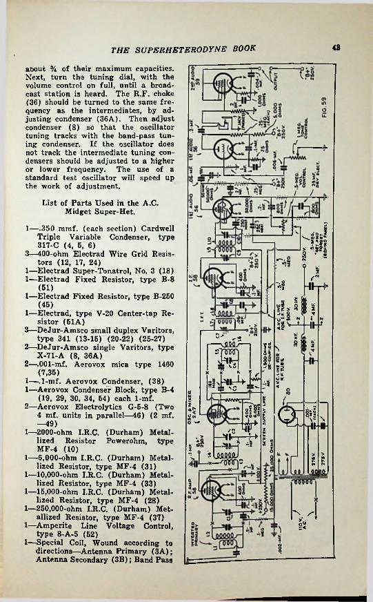
43THE SUPERHETERODYNE BOOK
about % of their maximum capacities. Next, turn the tuning dial, with the volume control on full, until a broadcast station is heard. The R.F. choke (36) should be turned to the same frequency as the intermediates, by adjusting condenser (36A). Then adjust condenser (8) so that the oscillator tuning tracks with the band-pass tuning condenser. If the oscillator does not track the intermediate tuning condensers should be adjusted to a higher or lower frequency. The use of a standard test oscillator will speed up the work of adjustment.
Mf&srv.
List of Parts Used in the A.C. Midget Super-Het.
1—.350 mmf. (each section) Cardwell Triple Variable Condenser, type 317-C (4, 5, 6)
3—400-ohm Electrad Wire Grid Resistors (12, 17, 24)
1—Electrad Super-Tonatrol, No. 3 (18)1—Electrad Fixed Resistor, type B-8
(61)1—Electrad Fixed Resistor, type B-260
(45)1— Electrad, type V-20 Center-tap Re
sistor (61A)3—DeJur-Amsco small duplex Varitors,
type 341 (13-16) (20-22) (25-27)2— DeJur-Amsco single Varitors, type
X-71-A (8, 36A)2—.001-mf. Aerovox mica type 1460
(7,35)1—.1-mf. Aerovox Condenser, (38)1— Aerovox Condenser Block, type B-4
(19, 29, 30, 34, 54) each 1-mf.2— Aerovox Electrolytics G-5-8 (Two
4 mf. units in parallel—46) (2 mf. —49)
1—2000-ohm I.R.C. (Durham) Metallized Resistor Powerohm, type MF-4 (10)
1—6,000-ohm I.R.C. (Durham) Metallized Resistor, type MF-4 (31)
1—10,000-ohm I.R.C. (Durham) Metallized Resistor, type MF-4 (33)
1—16,000-ohm I.R.C. (Durham) Metallized Resistor, type MF-4 (28)
1—250,000-ohm I.R.C. (Durham) Metallized Resistor, type MF-4 (37)
1—Amperite Line Voltage Control, type 8-A-5 (52)
1—Special Coil, Wound according to directions—Antenna Primary (3A); Antenna Secondary (3B); Band Pass
'Si I__ l> *sH
_ o g * a <1 £
u.
-4 ■#r*W i ffl«>■ si *'
juO d- ° N < N
IH<2S' -2 I «
8 » Sfi$n; v x x
\l h§ Hh5?x 7 * ? f dS
82z3 (*
*2 ©r$5Ssft i
3O
2/-n £ist 3 3■a5 §
-x—u. u. >8 S
NN. r~
■'I
urn
I>6*3

the superheterodyne book44
Secondary (30; Oscillator Grid Coil (3D); Oscillator Plate Coil (3E)
3—Pairs Find-All(14A-14B) (21A-21B) (26A-26B)
1—Trutest R.F. Long-Wave Choke (36) 1—.Trutest Power Supply Transformer
for furnishing Plate and Filament Voltages (60)
6—UY-type 6-prong Sockets (9, 16,23, 32)
3—UX-type Sockets (40, 41, 63)1—Special Amperite Socket, or 1- or
dinary UX-type Socket (62)1—27-type Tube (9)
4—24-type Screen-Grid Tubes (11, 16, 23, 32)
2—45-type Power Tubes (40, 41)1—80-type Full-Wave Rectifier Tube
(55)7—Binding Posts (1, 2, 42, 43, 44, 47,
48)1—Aluminum Sheet, 18 to 20 gauge, 17
x 19 ins., cut and bent so as to form a chassis 10 x 12 x 3% ins. high.
1—High-Grade Input Push-Pull Audio Transformer, Using Secondary Only(39)
1—Power Switch, toggle type (53)1—R o 1 a Midget Electro-dynamic
Speaker Model K-6—equipped with Push-Pull Voice Coil Transformer (40-75 volts)
INPUT CCIlS ( 2 FOR EACH RANGE;
113 (WHO OVER___ f- 1ING WrTH ONE LAYER. or OILED SILK I*----- *-----'I
LI OR OTHER wmo
jli'Ui.'ll! •' J
AN ALL-WAVE SUPERHETERODYNEL 2 OR L4
OSC. COILS ( 1 FOR EACH RANGE;
We will now go to a more recent type of receiver, which at the same time gives good performance at short- waves, by virtue of plug-in coils. It is thoroughly realized that switching has mechanical advantages, but the difficulties of getting good performance with switching are not to be ignored, and the home builder will, as a rule, do far better with plug-in coils, where each range can be attacked as a wholly separate problem, not interlocking with other bands.
The general nature of the circuit is shown by Fig. 57. By reason of its tuned input coil and its stage of va-
35 mmf shuntjumper.TRIMMER (ACROSS
L2 OR L4
FIXED MICA(MAKE UP WHEN
needed;
. VARIABLE, RART OFC5(see fig. 61;
FIG. 60
Ito’MOLe ^ FOR BAKE LITE
SCREWDRIVER.
STIFF WIRE* CONNECTION
TO L5
Coil details for the circuit of Fig. 69.
COIL DATA FOR FIG. 59
INPUT COILS NOTESALL LI a L3 COILS SPACED TO BE
1INCH LONG.ALL L2 * L4 COILS SPACEO TO BE
l '/2 INCH LONG. ALL.LS COILS SPACEO TO BE HA IN. LONG ALL L6 COILS SPACEO 5/a IN. CONG.
OSCILLATOR COILSRANGE
IN METERS C5 (SEE NOTE 2 below;
Ll*L3 L2 V L4 L5 L6
3«/210-20 NONE, CONNECT STRAIGHT THROUGH
5 3520-40 8 12 5 Vk11 .002- FIXED
.OOl-MF MICA IN PAR. WITH ISO—*
VARIABLE.40-80 16 25 22 11
32 *60-160 50 2245 ntoo, NS.36
ONELAVER
90. NS.36, ONE
LAVER
300MMF. MICA IN PAR. WITH ISO—IE MF. VARIABLE
WIREN9.24Q.S.C. FOR L2.L4.L5.N2. 36 D.S.C. FOR Li.L3.L6
160-320 60 « 46
170. NS. 36-SCRAMBLEWOUND"
153. NS.36'SCRAMBLE
WOUND*60 « 80275-550 it
NOTE: 2 THIS IS THE SERIES TRIMMER. BETWEEN L5 A NO THE 100' MMF CONOENSERIT MOUNTS IN THE COIL AS IN FIG. 60.
« • ANT. SERIES CAPACITOR NOT OVER SO MMF. FIG. 61

46THE SUPERHETERODYNE BOOK
for any reason, anyone imagines that more audio gain or output is needed, it may be attained at some sacrifice of fidelity by connecting the 69 as a pentode, (see maker’s tube data), at the same time changing the output transformer to provide suitable impedance matching also replacing the cathode bias resistor by one of 500 ohms, and using a bypass of at least 12 mf., low-voltage dry electrolytic.
TrackingIt is reasonably clear that differen
ces between individual coils in the T.R.F. circuits (L2 and L4) will require that the trimmer condensers be set differently for each coil. Therefore, they must be attached to the coils and be removable with them. In fact, they are ordinary “screwdriver type” condensers of about 20 mmf. maximum capacity placed inside the coil forms which carry them, as in Fig. 60.
To avoid special oscillator tuning condensers, we use the scheme of Fig. 32, slightly modified to avoid an extra plug-contact. The dimensions of the coils are shown in Fig. 61.
The I.F. transformers are perfectly normal ones of a design intended to operate near 450 kc. Both primary and secondary of both transformers should be tunable as shown. It is strongly recommended that these be purchased ready made, with shields.
While on this subject of shielding, it is well to mention that the coils L1-L2 and L3-L4 must plug into sockets which are separated by good shielding; the best (though most inconvenient) form being to place a
riable-mu R.F. amplification followed by a tuned detector input, this receiver is relatively quieter and more free from image interference than are those primitive sets which use no R.F. stage at all, or else use a “coupling stage” with resistance input. The input circuit is ordinarily thought to be difficult to “track” because of variations due to assorted antennas, but is here avoided by use of the special antenna winding due to Dana Bacon, and introduced in National’s “FB-7” receiver. In this winding, the terminals are reversed, putting the antenna end of the primary near the ground end of the secondary, where capacity differences are ineffectual. The top end, which could have an effect, is grounded and has a constant capacity effect, regardless of the antenna.
The rest of the set is tolerably orthodox. The mixer is of the penta- grid-converter type already described, that is it consists of a mixer fed by L4, which is electron-coupled to the oscillator working with coils L5 and L6, the combined output being in turn electron-coupled to the plate which feeds the I.F. transformer L7, L8. Since only a single I.F. stage is needed and used, all windings of both I.F. transformers are tuned, the frequency being chosen as described hereafter. The I.F. output is fed to the diode-pentode second detector and A.V.C. tube, whose operation has already been described. The D.C. output of this tube provides A.V.C. for the R.F. and I.F. tubes as previously described, while the audio output is fed through a resistance coupling to the first A.F. tube, a triode suited to headset reception when desired. With the headset plug withdrawn, its output is fed to the 59 triode, which is suited to loudspeaker driving. If connected as shown, a magnetic speaker may be put into the plate circuit, preferably through a condenser and choke coupling device. However, the fidelity of the system is ample to deserve a good dynamic speaker, for which must be provided a transformer suited to both the speaker and the 69 tube—remembering that the 59 is connected as a triode here. If,
COIL BASE
° as \ 11 ORL2 OR oL3o
o
TO 58 TUNE CONDENSER
GRID ANOTO A.V.C.LINE ,y (- * vww
0.1-MEG
ofo. -L--T ANT.(LI-L2J50 MMF.
VISTO 2A7
GRIDINPUT
O +2SOV I__
*INTERSTAGE
(L3-LA4 i!O.l-MF
TO 58 R.F. PLATEFIG. 62

46 THE SUPERHETERODYNE BOOK
section capacity of about 150 mmf. If such a gang cannot be had, do not tolerate a flimsy makeshift— least of all one with a sectional shaft. Instead, use a stout, thoroughly shielded, broadcast type and remove about % of the _plates from either the stator or the rotor (not both) of each section, treating all sections alike and bending nothing.
Adjustment
Having set up and found that without tubes approximately normal voltages appear everywhere, put in the tubes, run up the volume control and, with the 200-400 meter coils in place, trim the R.F. circuits (trimmers across L2 and L4); then the 4 I.F. trimmers, working for maximum background noise. The tendency will be for the A.V.C. to allow strong noise as long as no signal is tuned in, hence do this in the daytime, near the lower end of the tuning range and tuned off of any broadcasting station. In the case of the oscillator, start with C4 set about half way out and trim with C5 only. Now swing to the 400 meter end of this tuning range and re-trim the oscillator with the aid of C4, also checking the adjustments of the trimmers across L2 and L4. If they have to be moved, leave them halfway between the second and first settings.
Now tune in a signal, one that will “stay put” and try first a 50 foot antenna, then a 10 foot one. If the A.V.C. is working properly and the signal is fairly strong, there will not be a great deal of difference. If there is—check over detail by detail to find the error. Especially check back to see if the socket connections are as shown in Figs. 62 and 63; since a surprising amount of fair reception is possible with one coil quite incorrectly connected.
If something seems not to be working, try localizing it as follows: remove the R.F. and mixer-oscillator tubes. You now have simply a longwave receiver. Connect an antenna to the plate prong of the 2A7 socket and see if the receiver sounds “alive” in this way, also retrim the I.F. against noise in this way.
OO MMF
*OSC.COIL 'SOCKET
0.1-MF
II-^•o——vww—*250 1^00 Ohms
FIG-63
TO -*■ CATHODE
Plug-in coil connections for the oscillator.
metal cylinder of about 3 in. diameter and 4 in. tall around each socket. The screen-grid tubes, in fact all the tubes except the A.F. and rectifier tubes, should also have the customary metal shields. The chassis must, of course, be metallic, and the customary precautions must be taken to screen the detector and audio tubes from transformer vibrations, or stray magnetic fields from the transformer or chokes of the supply system. Leaving them loose until everything else is done and then juggling their relative positions is helpful.
Power SupplyThe filter capacities may be larger
than shown, anything up to 10 mf. each is an improvement. If a dynamic speaker is to be used, choose a type with a 6000 to 7500 ohm field and connect this across the second filter condenser, at the points Z,Z.
Under no circumstances use a mercury-type rectifier tube. The 80 and the 5Z3 are the best types to date.
Mechanical FeaturesNo one thing has been the cause
of so many short-wave failures as a bad tuning drive. The writer, in all seriousness, is of the opinion that only the “string drive” and the National triple-pinch (Model A and N “Velvet Vernier”) are altogether up to the job. If any unevenness whatever can be felt—throw it out! The vernier ratio need not be more than 5/1 if it is smooth—but a rough one can be 200/1 and still be hard to adjust. The tuning condenser should be a 3-gang type with a per-
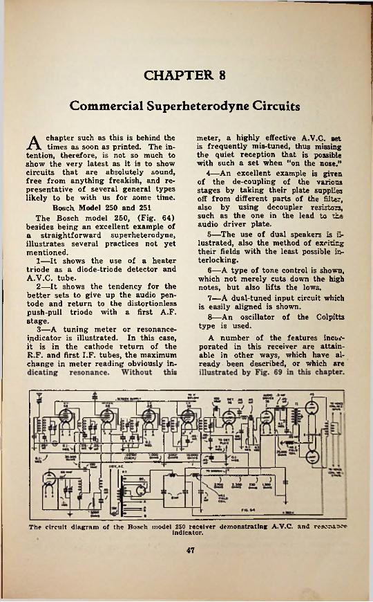
CHAPTER 8
Commercial Superheterodyne Circuits
A chapter such as this is behind the times as soon as printed. The in
tention, therefore, is not so much to show the very latest as it is to show circuits that are absolutely sound, free from anything freakish, and representative of several general types likely to be with us for some time.
Bosch Model 250 and 251The Bosch model 250, (Fig. 64)
besides being an excellent example of a straightforward superheterodyne, illustrates several practices not yet mentioned.
1— It shows the use of a heater triode as a diode-triode detector and A.V.C. tube.
2— It shows the tendency for the better sets to give up the audio pentode and return to the distortionless push-pull triode with a first A.F. stage.
3— A tuning meter or resonance- indicator is illustrated. In this case, it is in the cathode return of the R.F. and first I.F. tubes, the maximum change in meter reading obviously in
meter, a highly effective A.V.C. set is frequently mis-tuned, thus missing the quiet reception that is possible with such a set when “on the nose.”
4— An excellent example is given of the de-coupling of the various stages by taking their plate supplies off from different parts of the filter, also by using decoupler resistors, such as the one in the lead to the audio driver plate.
5— The use of dual speakers is illustrated, also the method of exciting their fields with the least possible interlocking.
6— A type of tone control is shown, which not merely cuts down the high notes, but also lifts the lows.
7— A dual-tuned input circuit which is easily aligned is shown.
8— An oscillator of the Colpitts type is used.
A number of the features incoiv porated in this receiver are attainable in other ways, which have already been described, or which are
The circuit diagram of the Bosch model 250 receiver demonstrating A.V.C. andindicator.
47

the SUPERHETERODYNE book48
l4LSK ‘S 3 ?7 ,*5su -nr
) COH.' »- -.kk j i ",rHHfl SS £2. ifS r
SSS2'; >T---- «Hr
8-500
70.000
sov.SSoix.'^S S.OI-Mft'V'
JO
MW BUS tBO*
V ISO V. ow AC.ei v. on o.c
(OO-vJ
nzs re 6A7 17 43
n ^440^leooMus
ANtOlV T7 TMI VALUrSrc* so crcits
% Of
FIIAMCN1 SNQVfHCtt!«oJ«OiLFIG. 65
The A.C.-D.C. principle of operation is illustrated by the RCA-Victor model R-22 set.
The Victor R-22 Universal A.C.-D.C.Receiver
Quite a different sort of receiver . is the recently developed “universal” sort which may be operated from either a D.C. or A.C. line at will, and are without transformers in the power supply system. These sets are based on indirectly heated tubes drawing 300 ma. at 6.3 V., all the heaters in the set being wired in series. Not the least important tube in the set is a rectifier of the same filament demand, although at higher voltage. This rectifier has two insulated cathodes and two plates, so that it can be used as a 4-terminal or “bridge” type of rectifier; approximately doubling the input voltage, less resistance drop. Thus 110 V. A.C. fed into the device will emerge as something like 160 V. after all losses are accounted for. When working on D.C., the rectifier tube becomes needless and if left in wastes valuable voltage—of which there is little enough anyway. In the Victor receiver shown in Fig. 65 it is, therefore, switched out in part. In other sets of this general sort, the 25Z5 is used as two half-wave rectifiers, one of which feeds the tubes and the other feeds the speaker field. When used on D.C., these things stay where they were and merely lower the voltage slightly. Thus the scheme shown in the diagram may supply 150 or 160 V. with A.C. line feed, dropping to perhaps 90 with a D.C. line, while the other scheme just mentioned will
show perhaps 98 and 108 respectively, the output tube being considered both times. Obviously one type performs more nearly the same, but one can object that it is always handicapped, while the switching type at least has a chance, on A.C.
Referring to the diagram of Fig. 65 will show that there is no novelty in the scheme once one has become accustomed to the abnormal power supply. Otherwise, it is an orthodox superheterodyne.
The National FB-7 and AGS Short-wave Receivers
To break the monotony we now go outright to a pure short-wave receiver, intended for nothing else, and in fact so designed that it cannot be conveniently adapted to 550-1,500 kc. use. This is the National “FB-7” receiver, a diagram of which appears as Fig. 66.
The principle points of interest here are the two electron-coupled oscillators, one of which performs the usual function of a superheterodyne oscillatorwhile the second performs the job of making a carrier audible as a whistle by beating with it in the 2nd detector—which after all is merely another heterodyne frequency conversion of 1000 cycles—i.e. 1 kc.
It should be observed that this oscillator can be readily cut off; also that the receiver has another switch (SW. 2) for the purpose of cutting
frequency conversion,

THE SUPERHETERODYNE BOOK 4957 se
552?(XM12 1-* /Jr « » rl Jff
70000
C o
F, 500 |£ 1*0
at «» i2S 0.1*
**7.5 m1/
TJ'Ml «.JS-MtO.'-’
20.000' 11-1?o.t-vN. 355?\ 3 000\ OHMJ
22.'j nO l-MCC
■J1
OOI M»
[31* nsr oi-urow.oooOHIOm ^ : Qi*M*A ^6 6^
-.8-* *04”saooo 5 »'FIG. 66
The National FB-7 receiver Is exclusively for short waves. The wiring is shown here.
off the plate supply during transmission, so as to avoid noise.
The connections of the tuning and trimming condensers in the antenna and oscillator coils are seen to be unusual. This is for the purpose of “bandspreading” as has been discussed in an earlier chapter. However, the coils are provided with bases having enough prongs so that all terminals come out, hence it is possible to plug in coils having the tuning condenser connected across the whole winding in the usual way. This expedient makes the receiver both a continuous range and a bandspread device.
In this case, the receiver is not equipped with an R.F. stage or a preselector, but, (in a more ambitious form known as the “AGS”) it has both of these things. The three plugin coils thus made necessary are inserted as a unit. This set also has A.V.C.
receivers at present available for the same purpose. There has been a perfectly unaccountable tendency to build receivers which use stages of R.F. pre-amplification, and fewer tuned circuits at short waves than at standard waves. Since noise, image interference, and relative amplification all demand the exact opposite of this, it is pleasing to see that in the K-80, the R.F. stage used in the broadcast range is not merely retained, but is supplemented by another extra stage—a tuned one—in the shortest waveband. This is a long step ahead, and greatly improves reception.
In other words, the set conforms with things already said, and there is no need of repetition. The constants largely appear on the diagram.
The Stromberg-Carlson No. 33 Automobile Receiver
The Stromberg-Carlson automobile radio receiver is diagrammed in Fig. 68, not only to show a set of this class, but also to illustrate another use of the 6A7 and 6B7 tubes—which differ from 2A7 and 2B7 only in filament voltage and current. We have here the 6A7 acting as a pentagrid converter, feeding an I.F. transformer as usual. However, there is no I.F. tetrode as usual. Instead of I.F. is fed at once into the pentode part of the 6B7 and by it is amplified at the same frequency, then detected by the two diode sections—the reverse of the examples shown before. There is another differ-
General Electric K-80 SeriesQuite another sort of receiver, in
tended for a different purpose is the General Electric K-80, a diagram of which appears in Fig. 67. Unlike the AGS and FB7 receiver it is not intended for the use of a transmitting operator, but primarily for broadcast listening, at standard as well as short waves—and in the export form for long waves in addition.
Almost automatically, it is based on an I.F. near 460 kc., but it differs in every important way from most

50 THE SUPERHETERODYNE BOOK
ence, the two diodes work separately, the output of one being used to feed the audio amplifier, while the other diode has the audio and I.F. filtered out and “wasted,” only the varying D.C. being used—of course, for A.V.C. purposes. We are not yet finished with the differences between this and ordinary circuits; the A.V.C. control applies not only to the single R.F. stage but also to the 6A7 converter and to a lesser degree to the 6B7 itself.
The plate supply has intentionally been omitted, as it is a rather conventional vibrating pole changer plus filter, the main point of interest being a relay which throws a load across the filter until the tubes heat up and take enough power to prevent excessive voltages.
The Howard Model 45 Receiver
Dropping back again to simpler tube types, there is shown in Fig. 69 a receiver which illustrates clearly a scheme of A.V.C. that can, with care, be added to most receivers having good gain. It must be understood that a type 51 tube is the same as a 35, and that either can in this diagram be replaced by a 78 without important consequences. Similarly the 27 may be replaced by a 56 and the 47 by a 2A5, although the last change makes an unimportant change in the biasing method, which is obvious.
The values of the components of this receiver chassis, Fig. 69, are as follows: Resistors Rl, R3, R5, 1/5-meg. (%- watt); R2, R6, 600 ohms (1/5-watt); R4, 6,000 ohms (V&-watt); R7, 30,000 ohms; R8, volume control, %-meg.; R9, %-meg.; R10, 3,000 ohms; Rll, 2,000 ohms; R12, R13, .15-meg. (Vfe-watt); R14, 2 megs.; R16-R16-R17-R18-R19, voltage divider, 9,900 ohms; R20, R21,10 ohms (center-tapped); R22, 200 ohms.
Condensers C4, C5, C6, C7, I.F. trim- 3 C9, CIO, C16, C16, 0.1-mf.;
mrof-: C12, ,001-mf.i C17, ni8, C19> C23, 0.6-mf.; C21,(420 v^Its)^(^O^olts).111''
itsthat the type 27 control tube
V9 be a selected one, with a definite plate current cut-off when tested at 180 V. plate and 20 V. bias on the grid. This cut-off should be less than 5 microamperes. If there is no means available for checking the tube (in the form of a special tube tester), an immediate check for tube performance can be obtained in the set itself.
For instance, disconnect the antenna and short-circuit the aerial lead, leaving the control tube out of the socket, and note the swing of the tuning meter. Then insert the tube in the socket and if it is a good A.V.C. tube, there should be no change in the position of the pointer on the tuning meter. If there is a change in the position of the tuning meter pointer, namely, a swing toward the right, it is an indication that the A.V.C. tube does not have a definite plate cut-off instead, it is drawing plate current and as a result the bias voltage on the regular R.F. and I.F. tubes has been raised, with the consequent cutting down in plate current.
The automatic volume control functions in holding the second-detector input voltage at a definite level, a system which is different from that in other receivers. A reduction of back-ground noises, between stations, will be noted.
The A.V.C. tube is so connected by means of a 2 meg. resistor, that the grid is at absolute “B—” potential. The cathode of the tube is connected to a point on the voltage divider which is at 24 V. positive, with respect to “B—” or the grid. There then exists between the cathode and the grid a potential difference of 24 V. with the grid negative by this amount. The plate of this tube connects toground by means of two .15-meg. resistors, R12-R13. Since ground is connected to 124 V., positive (withrespect to “B—”), there exists between the cathode and the plate a potential difference of 100 V. In order tobypass any R.F. energy which may appear on the plate, a non-inductive condenser C22 is connected from the plate of the A.V.C. tube to the cathode.
With the condition of no-signal there exists a bias of 24 V. and a plate potential of 100 V. Under theseconditions, there is no plate current
R14,
re-

THE SUPERHETERODYNE book 51
gapctgaiiF,4^1
rs*-~*
Si *< slfiS
2?5ix^
sgj-^SrSP i<fi?• «x QQQOOOO
w f&tfWoOO $1* “S
«8l*2211 c —a I
v ->; s *?—ykf? «
J<5 §1
Hllli “!titoi-ri'2*3
u3\—V*. 5< r----- '*-
'—v.qoq6oooH 00000 0(T'-/tL>’
3Vv5-*J- If:4? ^ llm 305525
'HH
3031 o ZXf& s
—m&'z:^tip5~i%n riH>
s'lj!kljddj9 13 tftSMsSMst o
%
5?! 5?>" ■■■ o 1$0
•'S5^p 9 °"^»1= -----<r —
3 N10l 6_ u
m m c•§ s?8<
fWH---- II----►-!§£*?§ ^8|
y ^8>f
n '°5 <5^77“^ S3rlH1" <T<
k8'*“M------ i,----------AVAVAi*1
1^4*kl
Cos®\:« «s\8*
»u9Z|(<773« §4
TtJ s! •p °5^ 5$
io J>*> o- IH*0 tooo oTo• WMVM
.S|fn L 2! a%CS 99999
*
Hi5M ©§J V*
s IS P
8

52 THE SUPERHETERODYNE BOOK
nected to a resistor in the plate circuit of the A.V.C. tube, that any potential existing across this resistor is added to the original bias and makes the grids more negative than the original bias by the amount of the voltage drop across the resistor in the A.V.C. tube plate.
It is at once apparent that the greater the signal voltage appearing at the grid of the A.V.C. tube, the more plate current will flow in the plate circuit: an increase in plate current means an increase in bias on the R.F., first-detector, and I.F. tubes; an increased bias on these tubes means less amplification and, therefore, less grid swing on the second-detector and A.V.C. tube. This cycle goes on until a constant voltage is obtained across the second-detector input, or, in other words, until a condition of equilibrium is reached.
Since R8 is located where the tone control is normally connected, it was necessary to relocate the tone control, C13-R9-C14. As less resistance is included between the two condensers, they become more effective in bypassing the higher audio frequencies; at the same time, they resonate the primary of T2 to a lower audio frequency.
flowing and the tube is said to be adjusted to cut-off. Since no plate current is flowing, there exists no voltage drop across the plate circuit resistors and, therefore, there is no bias voltage on the grids of the controlled tubes. The only bias on the R.F., first detector, and I.F. is caused by the respective voltage drops across their cathode resistors. These resistors are designed to give the most sensitive operating poinit.
In the case of a received signal, energy passes through the receiver to the second-detector grid. Here the A.V.C. (automatic volume control) tube grid, and the second-detector grid, are in parallel. The signal voltage is fed to the grid of the A.V.C. tube through a small fixed condenser, Cll.
It will be seen that during the positive half of the incoming cycle, the peak voltage of the signal swing subtracts from the original bias voltage; which means that the instantaneous bias on the tube is less than the original bias and the tube begins to draw current in its plate circuit. Since this current flows in the resistors in the plate circuit o’f the A.V.C. tube, there exists a voltage drop across these resistors; also, the flow of the electrons is from plate to ground so that the plate becomes negative with respect to ground. Now, since the original potential of the cathode of the R.F., first- detector, and I.F. tubes is positive with respect to ground, it follows that if the grids of the respective tubes are con-
A 1-tube ConverterTo complete our gallery of types
we may as well show a so-called “converter”; that is, a device to be applied to the input end of a normal broadcast receiver so that the combination will then become a short-wave super-
UJtV'HIOOC nus JPW J-WWO-I* I * TUMI
W r4f.ToWno*- mot AM0*0 AMP.TIM
tvo»e > w «»7M
l*T 1 V~ i5r ifr*J}—m H
I; or
3® 004
0 J*s■o* 400** OM -----
|.8V
if TJCjU- « * a 41r tS'
'•4-aov i art"""T- IIC— i f ztr
looVoSS•l
KIOOO0M“*.22“
•v. Hnar FIG. 68*w
**.t UHImu* ai-Mto
The Strombger-Carlson model 33 automobile superheterodyne receiver which employs the6A7 and 6B7 tubes.

THE SUPERHETERODYNE BOOK 68
Of VJ ?! sS| " gV^r—1—~g
f rwWr-4
uj «U aC
tilss)2.
Isii £8 o
i oo
„Sfgj ixrs4 i uj«o
r;H.H B |
KV
» £J=S °§ g:TOMp-2~hF \
*"O
5 -»V> ffe 2 «£rj
2d9393 ■**■' 41 jHKU
co• w
20
i §a5 Sl-~ -gws u II
£ CW5lid
F-:^S)j£lk/u,. .
Is8 2V CV «
£if— Z
I n§ I5unK *f o
3 v«o
£S Wg—AV—' *■f * 3 3
UJUJJUMULS >«UP? <S#4—
._______"•» / l/VV
I.1"
o lO ..■wo
tact
■ON
la«*go
, 8pf a~ 3 Sg•Q fc-cA
pt§"* rUrr*'!Jx' Hu? |
<5g g~T=^pUflMJ Gul
u>
IF“i i ; ^ i 4 -I 111 i s! 2ig / L--!
#1 rI-j
53 : *ui31 si| f/iJ u cjo
Ji **oH-
I J bas
St i— sf— :1%^^Ess
srf;ls^=K \
H R”i s¥ JJAJ ul
li'i;►r>> ► 2

54 THE SUPERHETERODYNE BOOK
heterodyne. This is admittedly a type of apparatus which is historical rather than current; being now largely placed by outright short-wave or combination superheterodynes. Commercial development has accordingly tended to stop in this field and the latest tubes do not appear in most of the available types. For this reason, the circuit shown here is not a commercial type at all, but an adaption of such type to a later tube.
The user of a converter does not have certain advantages which are available to the factory designer of a complete multi-range receiver. Therefore, it is somewhat advisable for him to attach a converter to a receiver which is unlikely to complicate the operation by introducing whistles. This is another way of saying that the converter will ordinarily live more peacefully with a T.R.F. receiver than with a superheterodyne, since in the latter case we shall have two oscillators (the one in the converter and the one in the receiver) with a virtual certainty that they or their harmonics will engage in controversies. Of course T.R.F. receivers are gradually being pushed into the background because of their lesser performance on a dollar basis, so that the converter and the T.R.F. set may disappear into the past at about the same time. Meanwhile, one of them may be made very simply into a quite acceptable sh >rt-wave superheterodyne by attaching to it such a converter as here shown (Fig. 70).
No power supply has been shown, since the drain is small and may usually be “borrowed” from the power supply of the receiver with which the converter is used. Should this supply be at other voltages than those listed, some changes may be necessary. If the plate voltage is below 180 V. oscillation may be uncertain. If so, decrease the cathode R (150 ohms at 150 volts) and also try increasing turns in L7 and L8. Voltages below 150 are unsatisfactory, and 250 V. are recommended. At this voltage the screen- grid may be fed from the plate supply through a simple voltage divider; ground the screen-grid through a 50,000 ohm resistor and connect to “plus 250” through 35,000 ohms.
The circuit can be made from standard parts, of v/hich only two need modification. The two-gang tuning condenser must have trimmers, and its capacity per section should be slightly above 200 mmf. Use a broadcast- range 2-gang condenser and remove about 1/3 of the plates from either the rotors of both sections or the stators of both sections. It is needless to take out both rotor and stator plates.
Since double-tuned 900 kc. transformers are not usually available, obtain a 175 kc. (or other frequency below 900 kc.) type which has double tuning and modify it as follows. First set up the broadcast receiver which is to be used and tune in a station at 900 kc., or not over a channel or so on either side. If a good station isn’t available, set up some sort of a simple oscillator with A.C. plate supply and tune to that— but set it at 900 kc. first, by comparison. Next, connect up the converter complete except that L7 and L8 are temporarily short-circuited to prevent oscillation and the connection is taken off the top (control-grid) cap of the tube. Now connect this cap to a short antenna, and also ground it to the chassis through a resistor—value not important, *but somewhere between .1- and 2. megohms. We now have an R.F. stage with an untuned input, coupled to the receiver through our I.F. transformer. Probably neither our 900 kc. station nor our 900 kc. oscillator can be heard since the I.F. transformer is still away off tune. Now by slow stages
re-
!
!1
SPfciai *oo«r If («« mi)
10 ^7 2A7. 6*7 PtWTAORlC
LARITER
1 OR 3'MIo comvia
as nT( !©*♦ » 0 »r»e*DAoasr Cf'Vi R VIO
TO 900**
200WMi
1
ft .1-1#.1 Uf
♦ 23QVTV i
T >400CMM3
♦ IOOV; TRIMMER .OOI-
woo, 17 OMM3 NOT* -
SWI R»w 2CAW M OHowe SWA.T OR 3CMMTC
JlS
u®£ »° ) £ 16' .ooi- fVM* ___
700 UMi520000 ^
S’ OHM**'.IWWOT* -
Cl RC2 0MMMC SMATT. GOOO _ WIOH-RATIO - r OML f MiWTlAL
fTiso RG.70
This short-wave converter is a modern version of a type that was very popular Some time ago. It uses an I.F. of 900 kc.

55THE SUPERHETERODYNE BOOK
remove turns from both windings of the I.P. transformer until it is possible to tune in the 900 kc. signal (station or our temporary A.C.-plate oscillator) with the I.F. trimmer condensers set most of the way out. While the range of the condensers in I.F. transformers varies, it will always be necessary to remove at least % of the turns to get to 900 kc.—usually much more. In some receivers best response is had by removing the original antenna coupling transformer and connecting the secondary of the I.F. transformer between the control-grid and chassis.
Finally connect everything per the diagram and proceed with short-wave reception.
In all of these maneuvers the receiver itself must stay at 900 kc.
The CoilsThough both on 1 in. forms, the os
cillator and tickler coils must not be on the same piece of tubing. Place them to minimize coupling; let the pentagrid tube attend to the coupling —but keep the leads short.
The windings are as follows; all close single layers.
oscillator coils used (spaced ^4-in. apart on tube)
Input coils used (spaced %-in. apart on tube)
Range in meters
Switch on 1 16 to 38 L4-6 T. No. 28 D.S.C.Ll-5% T. No. 28 D.S.C.
above plus L5 which is11 T. No. 28 Enam.
above plus L2 which is13 T. No. 28 Enam.
Switch on 2 35 to 90
both above plus L6 which is27 T. No. 28 Enam.
Switch on 3 84 to 212
both above plus L3 which is34 T. No. 28 Enam.

CHAPTER 9
I. F. Transformer Designof about 1500 (assuming a gain of about 40 V. per stage) which must be considered in designing the I.F. amplifier.
T TAVING determined the minimum X X R.F. voltages which must be supplied to the grid of the detector to deliver the maximum power output as explained in Chapter 7, we are in a position to determine the total gain which must be obtained from the I.F. amplifier. Figures 71 to 74 show a typical circuit and operating conditions.
Modern radio receivers of the superheterodyne type have an input sensitivity of less than 5 microvolts per meter and, with the standard height of the antenna set at 4 meters, we find that the absolute sensitivity will be about 20 microvolts (a microvolt being one-millionth of a volt). Thus, if we desire a receiver (as shown in Fig. 71) that will deliver about 4 volts of R.F. signal to the detector from an input signal of 20 microvolts, the total voltage gain of the amplifier will be
R.M.S. volts on grid of detector
Now, let us see just what the final figures will be with the added gain obtained in the pre-amplifier.
If the input to the receiver is .00002- V. and the pre-amplifier has a gain of 1500, then the input to the first I.F. transformer will be .00002 x 1500 or .03-V. The 4 volts required by the detector, divided by the .03-V. input to the I.F. amplifier, will then be the voltage gain required by the I.F. amplifier, which is 133.3 V.
As it will be impossible to obtain a gain of 133.3 in a single intermediate stage, it will be necessary to use two stages working at a gain of about 65, or three working at 44 per stage.
In the example cited above, the amplification due to the modulating tube is ignored, as various conditions develop which cause the gain of this portion of the circuit to vary over wide ranges. The sensitivity and output will be affected by the strength of the received signal, by the power output of the local oscillator, and by any change in operating potentials which may take place as the receiver is functioning.
The check for the correctness of the calculation can be made by multiplying the gain in the pre-amplifier by the gain in the I.F. amplifier; thus, 1,500 x 133.3 gives a value of 199,950.
Figure 75 shows a skeleton circuit with the voltages developed in the various circuits. Two stages of I.F. amplification are shown and, as each stage is not working at the maximum possible gain, the I.F. amplifier will be very stable and the coils easy to design.
If an actual condition exists where the gains and voltages are measured and found to be as indicated in Fig. 75, the volume control on the pre-amplifier
R.M.S. volts input from antenna 4 volts
= 200,000 gain.or.000020 volt
As a certain amount of amplification can be, and is, obtained by one or more stages of conventional T.R.F. ahead of the modulator tube (first-detector), it is not absolutely necessary that the entire burden of amplification be borne by the I.F. amplifier. If there are two stages of T.R.F. ahead of the modulator, then there will be a voltage gain
i.r.T. oeri P*A.TU8645
;
"b+*FIG.71 4- B+SO. *BV| .
Elementary circuit of an I.F. amplifier.:
56

67THE SUPERHETERODYNE BOOK
former can be made as large as desired; the limitations being defined by the R.F. resistance and the physical size of the coil and associated shield. As the frequency of the I.F. amplifier is generally lower than the broadcast- band frequencies, the effect of the circuit and coil capacities can be neglected for the moment as any calculation which we shall make will generally assume that the signal is fed into the tuned circuit by induction in the coil itself. In Fig. 76A, we find that the distributed capacity of the coil shunts the tuning condenser and is simply added to the circuit; in Fig. 76B, the signal is in series with the coil.
end of the receiver will be full on and the gain on the I.F. amplifier cut away down.
If the pre-modulator amplifier is limited to one stage, it will be necessary to increase the gain of the I.F. amplifier if the same level of sensitivity is to be maintained.
Unlike the conditions which exist in T.R.F. amplifiers (where the limitations of the minimum and maximum capacity range of the tuning condenser, plus the unavoidable circuit capacities, define the maximum ratio of the tuning inductance to its tuning capacity), we find that the tuning circuits of I.F. amplifiers are not limited as stated above, and the ratio of L to C can be any ratio desired, within sensible limits. The above information is a partial repetition of the data in Chapter 7, but is necessary to illustrate the use of the attached inductance chart.
Calculation of Load Impedance
To obtain the greatest percentage of the “mu” of a vacuum tube, it is necessary that the load in the plate circuit be as large as possible.
The effective impedance of the tuned circuit at resonance (Fig. 77) is equal to the following mathematical formula:
Inductance DesignThus, the inductance of the I.F. trans-
£ 18X « START OF GRID CURRENT
X - START OF- GRID __CURRENT 32 TUBES
Eb - 174 V. ■Ecg ■ -6 V, ESG- 67.5V.
* *a 16 £ 145 12
a aJ2 28
X 5 245 /8 110 i205 »a. X — —_U >'8,. 127 TUBES
J f \ * I ECO%— CURVE A • 45V. -5V. A CURVE B« 90V.-9 V. T~ CURVE C • 180V. -20V. . _ PLATE LOAD-.2-MEG.Ill
24 TUBES" CURVE-A CURVE S
Eb« 180V. Eb-lflOV. ESC- 45V Eso.« 75 V ECO-4.5V. EcG>-7.5V.
PLATE LOAO ■ .2- MEG.
5 1640§ 8 6 o r-50 6m5 S 820
9 0 1 2 3 49 RAOIO FREQUENCY < INPUT VOLTS R.M.S.
§4s 10 2 o9 0 12 3 45 RAOIO FREQUENCY INPUT-< FIG.72 V0LTS *-M-S.
ac FIG. 740 2 4 6 8 10 12
§ RAOIO FREQUENCY INPUT-< FIG.73 votTS RM S-2
FIG. 72—left. Curves showing the possible gain that may be expected from a 24 tube.FIG. 73—center. The same curves as In Fig. 72, only for a 27.FIG. 74—right. Same as for Figs 72 and 73 but for a 32.
AFl RfZ oer.l FIG.75 I F-1 l.F.Z DET.Zm. 40 .m.40 A4.il* -u. 114 AUOlO OUTPUT.
7* ci-jooooiv. ez-.oooav. ej-o.oizv. «4«o.oszv. n-o.s»v. E6«4.ov.
An elementary circuit illustrating how a signal Is increased through an amplifier.
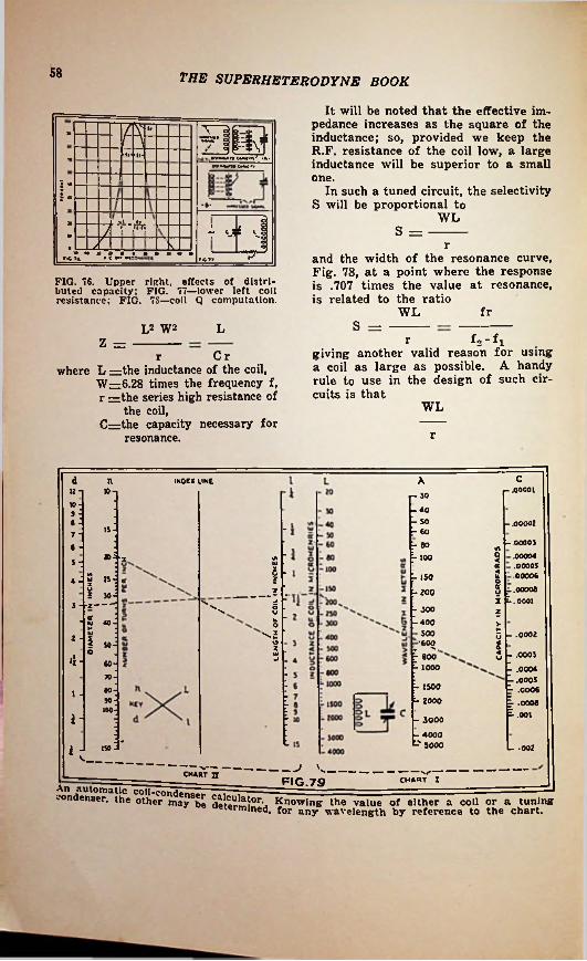
58 THE SUPERHETERODYNE BOOK
It will be noted that the effective impedance increases as the square of the inductance; so, provided we keep the R.F. resistance of the coil low, a large inductance will be superior to a small one.
g»»f/- fi< U»KiWy
5- In such a tuned circuit, the selectivity S will be proportional to
WL-B-
i»7 V. s =J o
o
■r/
T and the width of the resonance curve, Fig. 78, at a point where the response is .707 times the value at resonance, is related to the ratio
WL
*■6 7ft r-0T7
FIG. 76. Upper right, effects of distributed capacity; FIG. 77—lower left coil resistance; FIG. 7S—coil Q computation.
frS =LL2 W2
f o - f igiving another valid reason for using a coil as large as possible. A handy rule to use in the design of such circuits is that
rZ —Crr
where L —the inductance of the coil, W—6.28 times the frequency f, r =the series high resistance of
the coil,Crzthe capacity necessary for
resonance.
WL
r
cd An INOEX LINEr .0000110-| r~ 30
10--40 - 50 T 60
J -e - - .00002
157 --.00003
.00004
.00005
.00006
.00006
.0001
r eo6 -o»-■* - too
UJ5 -5 us is
2 303 -j-2-------
• 2 40
- 15024- o5 _______ 2 -200 y Es5 - 300
-4002
uV
0£ 500 -.00022 - I - -600 to
S -.ooos- .0004- .0005 r .0006 ^ .0006- .001
u - 800 - 100060
TO- 1500
- 2000801 •SO100
i - - 3000- 4000
t-" 5000 L .002i - 150V.
J v—CHART n CHAQT I. --------------------- ___------------------ FIG.79 _____________An automatic coil-condo -— — 1condenser, the other maySbe dete?m50I\ Knowing the value of either a coil or a tuning
«rmined, for any wavelength by reference to the chart.

CHAPTER 10
Servicing Superheterodynesr | ''ROUBLE shooting and servicing a X superheterodyne requires the same
any event, well calibrated instruments are essential. While home-made testing instruments may be suitable, we recommend that the serviceman invest in good manufactured equipment.
systematic procedure that most readers of this book are already familiar with in connection with T.R.F. receivers. When we realize that the signal frequency amplifier, the audio amplifier and the power supply in a superheterodyne are virtually the same as the corresponding units of a T.R.F. receiver, it is obvious that the same troubles are likely to occur in each and the correcting of these troubles in each case will be the same.
Since the superheterodyne has, in addition to the above units, an oscillator, first and second detectors and an intermediate amplifier, and the heterodyne method of reception being somewhat more complex than the ordinary, additional problems present themselves. When a superheterodyne fails to work or works improperly there are more places where trouble is likely to occur; and the method of finding them must be conducted in a systematic manner. We will limit this chapter mainly to discussing problems inherent only to the superheterodyne and show how to correct them without going into detailed instructions for trouble shooting and servicing the power supply, audio and T.R.F. amplifiers.
To properly service a commercial receiver it is advisable, if possible, to thoroughly study the service bulletins published by the manufacturer of the receiver. These will give detailed information about the particular set— which obviously cannot be included in a general treatise like this on the subject. But with a thorough general knowledge of superheterodynes backed with a fair amount of practical experience, a service-man can usually trace the source of trouble and correct it in very short order without the use of particular instructions. However, in
Equipment Required
A modern up-to-date analyzer is absolutely essential for accuracy and speed in servicing a receiver. This should be designed to accommodate the latest tubes. With its use a quick check of the voltages at the various sockets can be made, as well as plate current measurements, etc.; the tubes can be tested and in many cases the source of the trouble will immediately be localized.
Next in importance in superheterodyne servicing is an accurately calibrated R.F. and I.F. oscillator. This should generate modulated oscillations throughout the entire broadcast band of 1,500 to 550 kc. and throughout the intermediate band of 550 to 125 kc. Some commercial oscillators are designed to generate a fundamental frequency covering the intermediate band and the harmonics of this fundamental are used for covering the broadcast band.
An output meter and an ohmmeter are also essential equipment. These may be part of the set analyzer. In addition the customary service tools for making rapid repairs are necessary.
Complete instructions for using the above equipment are furnished by the makers. For this reason we will not go into a detailed analysis of their internal design and methods of use.
Harmonics
Unless an alternating current has a perfectly pure sine wave, harmonics of higher frequencies will be present.
59

60 THE SUPERHETERODYNE BOOK
Whenever vacuum tubes are used in a circuit the true sine wave is distorted because even the straightest portion of a tube’s characteristic curve is slightly bent. For this reason we have many harmonics in a superheterodyne receiver with which we have to contend.
Harmonics are always multiples of the fundamental frequency. The second harmonic has a frequency of double the fundamental; the third harmonic is three times the fundamental; the fourth, four times, etc. The most powerful harmonics are the ones nearest to the fundamental, such as the second and third, although harmonics up beyond the fifth may cause interference in a superheterodyne. For example, the fourth harmonic of 175 kc., is four times 175 or 700 kc. This harmonic and all those up to the eighth lie in the broadcast spectrum and may cause trouble due to heterodyning with other signal frequencies if the shielding of the receiver is defective.
As an example, suppose we are tuned to a broadcast station having a frequency of 690 kc. With an I.F. amplifier operating at 175 kc., the oscillator will be tuned to 865 kc. If for some reason the fifth harmonic of the I.F. frequency, which is 875 kc., gets into the same circuit with the broadcast carrier (say the second detector tube circuit), a 10,000 cycle beat frequency will be generated. Unless the audio amplifier has a cut-off below 10,000 cycles, this current will either produce a whistle or squeal in the loudspeaker or cause serious background noise. If the I.F. amplifier is slightly out of adjustment, so that the intermediate frequency is slightly below 175 kc. due to improper adjustment, the trouble may be worse. For example, if the frequency is 174 kc., our oscillator will be
864 kc* which may with the fifth harmonic of 174, which is 870kc. and produce a 6,000 cycle heterodyne whistle which would be quite serious in the audio amplifier. For this reason it is important that the inter- mediates be properly adjusted to 175 kc. Furthermore, if the oscilW l a tuner circuits are accuratev «r * ?n<^ track 176 kc. aparti ah*n*1to must be adjusted tn amPll*ierthe sensit“f the set wrn\UenCy 01ly reduced. Set wlU be great-
Aligning the Circuits
For a thorough check of the tuned circuits in a superheterodyne, an accurately calibrated modulated oscillator should be used. The pre-selector circuits in the signal frequency amplifier should be perfectly aligned and by means of the calibrated oscillator a curve such as is shown in Fig. 31, A, can be made, if desired. To do this the output meter or simply a milliam- meter connected in the plate circuit of the first detector should be used to indicate maximum sensitivity. The oscillator should be coupled to the input of the signal frequency amplifier; if shielded coils are used a couple of turns of wire inside of the shield can be brought out to a similar coil placed near the oscillator. The oscillator should be placed in operation and the trimmer condensers on the pre-selector circuits adjusted for maximum sensitivity.
The above procedure should then be repeated with the oscillator circuit. The dial should be set to 1,500 kc. and the oscillator tuned to 1,675 kc. by means of the high frequency trimmer condenser. Successive readings can then be made and the oscillator curve plotted as shown at B, Fig. 31. At the 600 kc. dial setting the oscillator should be adjusted by means of the low frequency trimmer to 625 kc. If the curve of the oscillator deviates from the theoretical curve it can be corrected by bending the slotted plates usually provided on variable condensers.
The next step is to acurately adjust the tuning condensers of each I.F. transformer so that the I.F. amplifier operates exactly at a peak of 176 kc. To do this the modulated oscillator should be set exactly at 176 kc. and the output loosely coupled to the grid of the first detector. With an output meter to indicate resonance, the tuning condensers of each transformer should be carefully adjusted until maximum resonance is indicated on the output meter.
Some receivers employ a visual tuning indicator. With such a receiver an output meter is not needed as the point of maximum resonance will be indicated by the visual tuning meter.

61THE SUPERHETERODYNE BOOK
While the above procedure assumes an intermediate frequency of 175 kc.f it should be definitely understood that the same process of aligning the circuits may be followed on sets having a different intermediate frequency.
If these instructions have been carried out properly, the set should now be in perfect alignment at all points on the dial, and further changes in the trimmers at any point on the dial should not be necessary.
na lead, will very often eliminate the whistles without appreciably cutting down the sensitivity of the set.
Repeat Points on Dial
Occasionally, on some supers, there will be found repeat points abiut 350 kc. off the proper place for a station. There are two remedies for this—either those already described for “birdies” (which will usually be found on sets having the repeat points) or by improving the shielding of the set from direct pickup; as, for example, mounting a set which has the chassis unshielded on the bottom, on a metal plate, so that the bottom will be shielded. Covering the top of the chassis with a grounded metal plate, so as to shield the variable condenser sections and grid caps is often very helpful.
Un-uniform Sensitivity
Poor sensitivity on one end of the band, as compared to the other end, or on both ends as compared to the middle, is almost invariably a sign of improper tracking, and can be corrected by making the adjustments already described. Lack of sensitivity all over the band, provided all other things are correct, is usually an indication that the intermediate transformers are not tuned accurately. As already stated, the adjustment of the intermediates to exactly 175 kc. is of extreme importance.
Microphonic Howls
Microphonic audio howls will be found troublesome in some imperfect supers, and the builder, naturally attributing it to a bad tube, will hunt in vain for the tube that is causing the trouble. Actually, the howl may be caused by vibration in the plates of the variable condensers. It can usually be cured by mounting the entire chassis on a piece of sponge rubber, allowing the entire chassis to vibrate, instead of just the condenser plates.
Whistles and Squeals
“Birdies”—sounds like a regenerative receiver passing stations at various points on the band—are caused either by the intermediates being tuned to some frequency other than 175 kc., or by insufficient selectivity in the R.F. tuning circuits. An easy way to find which i^ the cause is to short the oscillator tuning condenser, and then rotate the dial with the volume control turned well up. Under these conditions, no stations should be heard, in fact the receiver should be absolutely silent, if stations are heard at some points, without the oscillator tube operating, it is a certainty that the intermediates are not tuned properly. If the set is silent without the oscillator working, but whistling “birdies” are heard when it is working, the selectivity of the R.F. amplifier is insufficient. The simplest way of correcting this is to use a much shorter antenna, or to remove turns from the primary of the antenna coil. A very small condenser, of the order of 600 mmf., (a midget variable will do) inserted in the anten-
Poor Selectivity
Some sets will have ample selectivity so far as music is concerned, but on a station next to a powerful local, the loud notes of the local will “carry over” with a kind of scratching blast. This is a sign that the local is modulating a band more than 10 kc. wide, and inasmuch as the trouble originates in the air, it cannot be completely eliminated. It can, however, be considerably ameliorated by the addition of a band-pass stage ahead of the tuner. This will reduce the amount of signal from the local that reaches the grid of the first R.F. amplifier tube, but will not seriously affect the strength of the signal from the station to which the set is tuned.

62 THE SUPERHETERODYNE BOOK
Dead Spots Poor Quality
Some seta will be found which work very nicely over a portion of the band, usually the high frequency end, but which stop working entirely on other portions. This is caused by the oscillator tube having incorrect voltages, so that it stops oscillating in spots. A checkup of the voltages supplied to the oscillator tube, and the correction of these (if incorrect) will usually fix the trouble. Sets using dynatron oscillators are particularly subject to this trouble. In this case, trying out several tubes will result in one being found which will work properly over the whole band. Many 24 tubes will not oscillate at all as dynatrons, although they will function perfectly as detectors; and almost all tubes, so used, require very accurate settings of the screen and plate voltages to oscillate over the entire band.
Occasionally, a set will be found which has perfect quality on full volume, but when reduced, the quality “goes to pieces.” If this is the case, examination of the tubes will probably disclose a 24 in a socket where a 35 or 51 should be. Proper placement of the tubes will make this right. This trouble applies to T.R.F. sets only: the use of a 24 in an amplifier socket in a set built for the multi-mu tubes will invariably produce this phenomenom.
No reference has been made here to account for poor results due to improper connections, wrongly placed parts, or similar troubles which would apply to any receiver. It is presumed that the correct hookup has been followed throughout, and the receiver is free from all defects in wiring, parts, or similar mistakes on the builder’s part.

63THE SUPERHETERODYNE BOOK
Here you will find other titles
which are included in the Series
of the book you are now readingPresented on this page are the new book* of the RADIO-CRAFT LIBRARY—the most cora- plete and authentic set of volumes treating individually, important divisions of radio. Each book has been designed to give radio men the opportunity to specialize in one or more of the popular branches of the industry. The material contained in these books will increase your knowledge: you will find them a real help in your work and they will contribute to your money earning capacity. Read these books during your spare time at home.The authors of these books are well-known to everybody. Each one is an expert radio man;an authority on the subject—each is thoroughly familiar with tha field which he represents.This is perhaps the first real opportunity that you have ever had to build a radio_ library ofbooks that arc authentic, right-up-to-the-minute and written so that they are easily digested.
Book No. 9AUTOMOBILE RADIO AND
SERVICINGA Complete Treatise on the Subject Covering All Phases from Installing
to Servicing and Maintenance
By LOUIS MARTIN
Book No. IRADIO SET ANALYZERS
And How To Use Thera With Full Instructions and seriptlons ot Set Analyzers,
Checkers. Oscillators, Etc. By L. VAN DER MEL
Book No. 5HOW TO BECOME A RADIO
SERVICE MANHow To Get Started and How To
Make Money In Radio Servicing By LOUIS
De-Tube
MARTIN
Book No 6BRINGING ELECTRIC SETS
UP TO OATE With Pentodes. Multi-Mu namie Speakers—Complete
atlon How to Modernize A.C.. D.C. and Battery Operated
ReceiversBy CLIFFORD E. DENTON
Book No. 2MODERN VACUUM TUBES
And How They With Complete Techni
All Standard and Many Tubes
By ROBERT HERTZBERG
Book No. 10HOME RECORDING AND ALL
ABOUT ITs. Dy- Inform-Work
cal Data on Special A Complete Treatise on Instan
taneous Recordings. Microphones. Recorders. Amplifiers. Commercial
Machines. Servicing, etc.By GEORGE i. SALIBABook No. 7
RAOIO KINKS AND WRINKLES For Service Men and
Experimenters A Complete
Latest Radio
Book No. 3THE SUPERHETERODYNE BOOK
All About Superheterodynes How They Work. How to Build and
How to Service Them By CLYDE FITCH
Book No. 11POINT-TO-POINT RESISTANCE
MEASUREMENTS The Modern Method of Servicing
Radio Receivers By CLIFFORD DENTON
Book No. 12PUBLIC ADDRESS INSTALLA
TION AND SERVICEMethods of Servicing and
ng Public Address Equipment By J. T. BERNSLEY
p»rlmenters Compendium on the
Shnrt-Cuts and -Savers
PALMERMo ney
W.By C.Book No. 8
RADIO QUESTIONS AND ANSWERS
Most Impor Submitted by
tha Course
Book No. 4MODERN RADIO HOOK-UPS
The Best Radio Circuits A Complete Compendium of the Most Important Experimental and
Custom-built Receivers
tantA Selection of the of 3.000 Questions
Radio Mon During tl of One Year
By R. D. WASHBURNE
ModernInstall!
By R. D. WASHBURNE
ALL BOOKS UNIFORMThe books In the new RADIO-CRAFT LIBRARY arc all strictly up-to-date and written by men who know their subjects. The volumes urc all uniform size. 6x9 Inches, and contain on an average from o0 to 1-0 Illustrations. Kacli book Is printed on lino book paper.
Big Discount OfferedIn order to make it possible for everyone to buy tnese books, the fifty (50) cents price ha* been made uniform for all volumes. You can buy these books separately, but you should take advantage of our special offer:
WHEN FIVE (5) BOOKS OR MORE ARE ORDERED DEDUCT 20%FROM YOUR REMITTANCE ^ ,
Simply fill in the coupon below, and mail it to us together with your remittance. Checks, stamps or money orders accepted.
Clip Coupon and Mail TODAY
GERNSBACK PUBLICATIONS, INC. 96-98 Park Place, New York, N. Y.
I have circled below the numbers of books in the RADIO-CRAFT LIBRARY, which you are to send me, and have deducted 20% for ordering five (6) books or more. J have included my remittance in full, at the price of 50c each, when less than five books are ordered.The amount of my remittance is.Circle numbers wanted:
Name ..... ..........................
City ............................. .
_____ (Stamps, checks or money order* accepted.)3 4 5 6 7 8 9 10 11 12
___ Address
---- State
21
........SH

t
Li64 THE SUPERHETERODYNE BOOK fIlwill train you at home i£
«/& PAYI* -6:\\
*2
iJ* *’
.Vj
iFree Book ;*rutK:-.^i Tells Howu-J. E. Smith. President. Na
tional Radio Institute, the man who has directed the Homo Study Tnuoinic of more men Xor the Radio Industry than mar other man in America.
Get my big FREE book on the opportunities in Radio. Read how quickly you can learn at home in your spare time to be a Radio Expert—what good jobs my graduates have been getting—real jobs with real futures.
Mall Coupon! h1/■;!
!•Many Radio Experts Make $50 to $100 a WeekOver 300,000 jobs have been created by Radio’s growth, and thousands more will be created by its continued development. Many men and young men with the > right training—the kind of training I give you in the N. R. I. course—have stepped into Radio at two and three times their former salaries.
iir-
Many N.R.I. Men Have made $200 to $1000 in spare time while learning
vmuii wiin toe 1 master quickly for
neighborhood.ni and Ideas that have made I. students In their spare time while study-
Is famous as the course that pays
The day >uu you should in most every
the pla N. R.
lng My course for Itself.
material whichsend you doing 28 :Jobs, common
for sparetime money I give$200 to $1,000you
for !I have doubled ;and tripled the
in Aviation. Servicing and Merchandising Sets, al_; _ ^___ j.___1__.... Zr Jhisit*Broadcasting, Commercial and S' included. I am so sure that N. you satisfactorily that I will a to refund every penny of your •re not satisfied with mv Lesso tion Service upon completion.
Talking Movies, Television, Aircraft Radio Included
r
Get44-page Book^Inlormatlon a Job FILL OUT AND MAILwith aTHIS COUPOGet ^ your cojy today. It tells you where
you8tabou^° my course. what^otFiera who have taken it are doing and making. Find out what Radio offers you without the slightest obligation. ACT
Futuretells
J. E. SMITH. President National Radio Institute, Dept. 2ED7 Washington, D. C,
NOW1
NEW Radio Equipment for Broad Practical Experience Given Without Extra Charge
••Dear Mr. Smith: Send me your free
book. I understand this request dora not obligate me and that no salesman will call.
NAME.With this equipment you work out many things you read in textbooks. From it : the experience that tells an expert from a beginner. In a short time you have learned what would take years to learn in the field. You make experiments illustrating the important > principles in the 25 best known receiving seta. •
of the you e ADDRESS.
.STATE.CITY.

. * ■. T
-""•"far the real
servicing “dope**
yon can*t find a
better booh 1Mo,
lr®
k
WO other radio book is comparable n to the 1935 OFFICIAL RADIO SERVICE MANUAL. In contents, in style of printing, in grade of paper, in illustrations, there has never been published such a com' prehensive volume.The 19 3 5_ Manual contains over a
. thousand pages—yet it is only 1|4 inches thick because it is printed- on a special Bible stock which is in ex* .ceptionally good stock, yet one of the thinnest and most durable papers. This 1935 Manual is the most au» thentic and elaborate service guide
■ ever used in the radio industry Service Men and dealers who use this
1935 Manual arc astonished by finding in it such a wealth of profitable service information which has never been published before.
1 •[*j
t
M■Ull
/5-
m■V
V1'/
yWhat Others Say
about this Manual:
Norfolk, Va.I received the OFPI-
CIAL RADIO SERVICE MANUALS ordered as per my letter of March 20. 1935 in good order.
'am very well pleased witli same as it is a valuable Radio data reference and guide.
Arthur J. Freeney.
Contents oj the 1935 ManualOver 1,000 pages full of diagrams and. essential informa- tion of manufactured receivers—only data of real use in servicing is included. This new Manual is really portable since it will be extremely thin and light as well. • Volume V continues where the preceding manual left off. • Many circuits of old sets are included. • Service Men know every set has certain weak points which are really the cause of trouble. Wherever the information could be obtained, these weaknesses with their cures are printed. , right with the circuits. This is an entirely new and valu- able addition to the Manual* • All the latest receivers are included—all-wave sets, short-wave sets, auto-radio sets, midget and cigar-box. sets, etc., as well as P.A. amplifiers and equipment, and commercial servicing instruments.• The cumulative index is even more complete than before; including cross-reference to sets sold under different names, and type numbers. • Volume V includes resistance data; socket layout; I.F. data; and voltage data. • Tube data on latest tubes. • Free question and answer service —as included in our last three manuals.
veryService
Detroit, Mich. Received your
OFFICIAL RADIO SERVICE MANUAL and certainly is something to
. rave about. It’s great.A. Hedke.
1935
Stillwater, Maine I have received- the
1935 Manual, and I am much pleased withvery
my investment.Franklin J■ Holmes.
Swift Current, Saskatchewan, Canada.
I beg to acknowledge receipt of my 1935 issue of the OFFICIAL RADIO SERVICE MANUAL.
Your Manual is fine, and would not be without any of them. The Manuals may be improved for Canadian use.
A. M. Ford.
OVER 1,000 PAGES
Over 3,000 IllustrationsFlexible, Looseleaf Leatherette Covers
Yet only V/a' thickSize 9x12
Send remittance of $7.00 in form of check or money order for your copy of the 1935 OFFICIAL RADIO SERVICE MANUAL. Register letter if it tains cash or currency. The Manual Is Sent to You Postage Prepaid.
con-
GERNSBACK PUBLICATIONS, Inc.99SH HUDSON STREET NEW YORK, N. Y.

TTT
THIS IS THE ONLY COMPLETE• •• •'.-•• • • • - _ - r. - - ,.REFRIGERATION SERVICE
MANUAL EVER PUBLISHED ~OFFICIAL & 8 lREFRIGERATION
SERVICE MANUAL
VOLUME 2
MG*Official REFRIOF THE
S E R V IOVER 352 PAGES
I&0SBR& 'OVER 300 DIAGRAMS This Manual forms the previous OFFICII. MANUAL (Volume
Complete Service Data ume isThe OF
Flexible Looseleaf Hinderpared so?^0rT>tiOT °” ** Kr0W,'”,t ~fr“n
stesstt&s.I, faults, overhauling; estimating coil and machine
nnpassed in this new volume of refrig- *•'olume of the , Manual”
Servicing Expansion Valve ilts Systems* Servicing Thermostatic Valve
'ons Servicing Restrictor andCapillary Tube Systems
M Char,?„r,jElectrical Serv
Fuses,Service Kinks Estimating Re
Thta edition b printed on a Special Bible Stock which it extremely thin, yet durable.The «pecial grade of paper makes
Ref narration Manual muchtrou
tb«- ne\
tioi
g§£:List of Contents i “Official Refrii
HistoryFood Rreser.etion Theory end Fundamental Laws Methods of Refrigeration Refrigerant*, lubricants and
Brine*Handling Testing and Storage
of Refrigerants Compression Systems of
RafrigerationUguid Throttle Oevices and
Val.es Refnga c»#cvnc
E>Service To
Tool K
Un%l Wration Systems Control Oe
Compressors. TVal*tces
Seals FSarvicing Hi Valve Sy
RATION "sER VICK MANUAL <Vo utrib or currency THE MANUAL IS SENT TO
POSTAGE PREPAID.
1<spatValve* Capacities. Service
'oit and
Send fmllti OFFICIAL letter if It
or money oREFRK Re
oliotheek Ned. Ve_r:
GERNSBACK PUBLICATIONS. Inc. ^"voL n’..
' ••
_