Embed Size (px)
Citation preview

0889-9746/$ - se
doi:10.1016/j.jfl
�CorrespondPaulo - SP, 055
E-mail addr
Journal of Fluids and Structures 26 (2010) 1045–1057
www.elsevier.com/locate/jfs
Suppression of wake-induced vibration of tandem cylinderswith free-to-rotate control plates
G.R.S. Assia,�, P.W. Bearmana, N. Kitneyb, M.A. Tognarellic
aDepartment of Aeronautics, Imperial College, London, UKbBP Exploration Operating Company Ltd., Sunbury-on-Thames, UK
cBP America Production Company, Houston, USA
Received 14 December 2009; accepted 21 August 2010
Available online 20 October 2010
Abstract
Experiments have been carried out on a pair of circular cylinders to investigate the effectiveness of pivoting parallel
plates as wake-induced vibration suppressors. Measurements of amplitude of vibration and average drag are presented
for a circular cylinder, free to respond in the cross-flow direction, with mass ratio 2 and a damping level of 0.7% of
critical damping. Reduced velocities were up to nearly 30, with associated Reynolds numbers up to 2.3� 104 and the
results presented are for a centre-to-centre separation of cylinders of 4 diameters. It is shown how vortex-induced
vibration and wake-induced vibration of the downstream cylinder of a tandem pair can be practically eliminated by
using free to rotate parallel plates. The device achieves vibration suppression with a substantial drag reduction when
compared to a pair of fixed tandem cylinders at the same Reynolds number. Results for a single splitter plate and helical
strakes are also presented for comparison and were found not to be effective in suppressing wake-induced vibration.
& 2010 Elsevier Ltd. All rights reserved.
Keywords: Flow-induced vibration; Suppression; Drag reduction; Parallel plates; Helical strakes; Tandem circular cylinders
1. Introduction
The response of an elastically mounted single cylinder under vortex-induced vibration (VIV) is well known and has
been reviewed in detail by Sarpkaya (1979, 2004), Bearman (1984) and Williamson and Govardhan (2004), to cite only a
few. However, an additional phenomenon appears when an elastically mounted cylinder is immersed in the wake of
another identical cylinder placed upstream. The response of the cylinder with flow interference is very different from the
typical one observed for VIV. The wake generated by the upstream body interacts with the flow around the downstream
cylinder generating fluid forces that excite the structure into even higher amplitudes of vibration. This fluid-elastic
mechanism, known as wake-induced vibration (WIV), occurs whenever one or more cylinders are immersed in the
interference region of a bluff body wake.
Recently, the main motivation for studying this phenomenon is found in the offshore oil industry. A single floating
platform is able to accommodate a number of production risers in complex arrangements together with many other
e front matter & 2010 Elsevier Ltd. All rights reserved.
uidstructs.2010.08.004
ing author. Now at: Department of Naval Architecture and Ocean Engineering, POLI, University of Sao Paulo, Sao
08-900, Brazil. Tel.:þ55 11 30915646; fax:þ55 11 30915642.
ess: [email protected] (G.R.S. Assi).

G.R.S. Assi et al. / Journal of Fluids and Structures 26 (2010) 1045–10571046
cylindrical structures. Long drilling risers also suffer wake-interference from other structures attached to floating
platforms. As the ocean current changes its direction through the sea depth it becomes practically impossible to avoid
flexible structures from falling in the wakes of each other. This results in the probability of pipes developing severe WIV
and increases the risk of damage due to structural fatigue as well as clashing.
Attempts to understand flow-induced vibration with flow interference are found in the literature. Blevins (1990)
explains how a cylinder free to respond in two degrees of freedom (2-dof) can be excited into wake flutter when it is
placed downstream of a fixed cylinder but laterally displaced from the centreline of the wake (the so called staggered
arrangement). He shows how the mean velocity profile can input energy into the system as the cylinder oscillates in an
elliptical orbit. When the gap between the cylinder is in the order of a few diameters Zdravkovich (1977) proposes
another mechanism, called gap-flow-switching, which is able to excite cylinders in close proximity. If the separation
between the cylinders is smaller than a critical value – which varies with turbulence and Reynolds number (Zdravkovich
and Pridden, 1977) – the shear layers from the first cylinder may reattach on the second body and a vortex wake may
not develop in the gap. However, in the present work we are particularly interested in studying a type of WIV that is
different from the two mechanisms described above. We will focus on WIV that occurs when a pair of circular cylinders
is initially aligned with the direction of the flow (Fig. 1) with enough space between them for a vortex wake to develop in
the gap. In this arrangement the vortices from the front cylinder impinging on the second cylinder play a significant role
in causing the rear cylinder to vibrate.
Most of the related works found in the literature present data for the response of flexible cylinders in various tandem
and staggered configurations (King and Johns, 1976; Laneville and Brika, 1999). Bokaian and Geoola (1984), Hover
and Triantafyllou (2001) and Assi et al. (2006), on the other hand, present studies of the cross-flow response of a flexibly
mounted, rigid downstream cylinder in a tandem arrangement. While Bokaian and Geoola (1984) relate the dependency
of WIV on structural parameters such as mass and damping, very few works investigate the fluid mechanism causing the
excitation. A better understanding of the physical mechanism behind WIV has emerged from our recent study of
tandem cylinders (Assi et al., 2010; Assi, 2009); the main findings being that the excitation of the downstream body is
sustained by the unsteady force fluctuations caused by the vortices shed from the upstream body interacting with the
shedding from the downstream one.
We believe that only with a clear phenomenological understanding of the nature of the excitation will be possible to
start the development of suppressors that effectively reduce WIV. In this context, we present an experimental study that
is aimed at developing more efficient suppressors for cylinders in tandem arrangements under flow interference.
1.1. Suppression of VIV with control plates
A widely used method for suppressing VIV of long slender bodies of circular cross-section is the attachment of helical
strakes. Developed originally in the wind engineering field, strakes suffer from two major problems: the first being that they
increase drag and the second that, for a given strake height, their effectiveness reduces with decrease in the response
parameter m�z (where m* is the ratio of structural mass to the mass of displaced fluid and z is the structural damping
expressed as a fraction of critical damping). Whereas a strake height of 10% of cylinder diameter is usually sufficient to
suppress VIV in air, at least double this amount is often required in water, and this increase in height is accompanied by a
corresponding further increase in drag. For a fixed cylinder it is known that if regular vortex shedding is eliminated, say by
Fig. 1. Representation of two circular cylinders aligned in the flow direction (tandem arrangement). Upstream cylinder is fixed and the
downstream one is free to oscillate in the cross-flow direction (y-axis).

G.R.S. Assi et al. / Journal of Fluids and Structures 26 (2010) 1045–1057 1047
the use of a long splitter plate, then drag is reduced. Hence in theory an effective VIV suppression device should be able to
reduce drag rather than increase it. This idea underlies the work presented in this paper.
According to Bearman (1984), for example, a simple analysis for a linear oscillator model of VIV, assuming harmonic
forcing and harmonic motion, shows that response is inversely proportional to the product of m* and z. Hence the most
rigorous way to test the effectiveness of a VIV suppression device is to work at low mass and damping. In the
experiments to be described in this paper the parameter m�z was equal to 0.014. As concluded by Assi et al. (2009), it
seems that three-dimensional solutions like strakes or bumps are unlikely to provide the required combination of VIV
suppression and low drag.
In previous works (Assi and Bearman, 2008; Assi et al., 2009) we have investigated the efficiency of pivoting control
plates as VIV suppressors for a single cylinder. We concluded that suppression of cross-flow and in-line vibration
of a circular cylinder, with resulting drag coefficients less than that for a fixed plain cylinder, is achievable using
two-dimensional control plates. This has been accomplished at values of the combined mass and damping parameter
down to at least 0.014, showing that the method has potential applications in the offshore industry, for example. The
lowest drag coefficient of C x ¼ 0:63, equivalent to a drag reduction of about 38% interference to a static cylinder,
occurred when free-to-rotate (f-t-r) parallel plates were installed on the cylinder. A f-t-r splitter plate was also found to
suppress VIV but the plate adopted a mean deflection angle and this configuration developed a mean transverse force
towards the side to which the plate had deflected. This force could be eliminated by using a pair of splitter plates
arranged so that the shear layers that spring from the cylinder attach to the tips of the plates. Because the parallel plates
were found to be the most drag-efficient device to suppress VIV it became the focus of the present investigation.
In Assi et al. (2009) we have highlighted the importance of torsional resistance in stabilising f-t-r suppressors.
Torsional friction ‘‘needs to be high enough to hold the devices in a stable position, while still allowing them to realign if
the flow direction changes. Devices with torsional friction below a critical value oscillate themselves as the cylinder
vibrates, sometimes increasing the amplitude of cylinder oscillation higher than that for a plain cylinder.’’ In the present
work we kept the same parameters employed in that study to guarantee that our suppressor is working above the
critical value of torsional resistance.
1.2. WIV suppression of a pair of cylinders
Very few works investigated suppression of flow-induced vibration for bluff bodies with interference. Zdravkovich (1974),
whose study is probably the closest to the present one, presents a wind tunnel investigation of WIV suppression employing
an axial-rod shroud. His level of m�z was rather high, but the shrouds showed some effect in reducing WIV of the second
cylinder. It is interesting to note that the most effective suppression was achieved when both cylinders were fitted with
shrouds. This is evidence that the current understanding of the excitation mechanism, discussed in Assi et al. (2010), is
satisfactory. It is important to disrupt the coherent vortices coming from the upstream cylinder so as to reduce the
interaction with the downstream body. This is exactly what the shrouds accomplished in his experiments.
But it was in another paper that Zdravkovich (1988) brought further insight about VIV suppressors being used in
WIV. He wrote: ‘‘A wide variety of means for suppressing the vortex-shedding-induced oscillations [VIV] has been
developed in the past. These means might not only be ineffective for the interference-induced oscillations [WIV] but
even detrimental.’’ To cite an example, Korkischko et al. (2007) showed that helical strakes typically effective in
reducing VIV for an isolated cylinder are no longer successful if the body is immersed in the wake interference region.
Building up understanding from previous research we set out to explore new solutions that not only are successful in
suppressing VIV but also act on the vortex-structure interaction that drives WIV. It was not our intention to perform a
parametric study of all geometric and structural properties of potential suppressors, but rather to verify if a family of solutions
proven to be effective in suppressing VIV is a potential candidate for suppressing WIV. In addition, one of our objectives is to
find an effective WIV suppressor that is functional and does not incur a drag penalty, preferably it should reduce drag.
2. Experimental arrangement
Experiments were conducted in the Hydrodynamics Laboratory of the Department of Aeronautics at Imperial
College London. Tests were carried out in a recirculating water channel with a free surface and a test-section 0.6m wide,
0.7m deep and 8.0m long. The sidewalls and bottom of the section were made of glass, allowing a complete view of the
models for flow visualisation purposes. The free stream flow speed (U) was continuously variable and flow with
turbulence intensity less than 3% could be obtained up to at least 0.6m/s. The circular cylinder models were constructed
from 50mm diameter perspex tube, giving a maximum Reynolds number of approximately 30 000 (based on cylinder

G.R.S. Assi et al. / Journal of Fluids and Structures 26 (2010) 1045–10571048
diameter D and U incident on the upstream cylinder). The models were mounted vertically and passed through the free
water surface down to almost the full depth of the section. The downstream cylinder was mounted such that there was a
2mm gap between the lower end of the cylinder and the glass floor of the test section. With a wet-length of 650mm
(total length below water level) the resulting aspect ratio of the model was 13.
2.1. Elastic rig and cylinder models
The upstream cylinder was rigidly attached to the structure of the channel preventing displacements in any direction,
while the downstream cylinder was fixed at its upper end to an elastic mounting. Fig. 2 shows a schematic
representation of the apparatus and helps in describing the operation of the system. The support system is firmly
installed on the channel structure and the sliding cylindrical guides are free to move in the transverse direction, defined
by the y-axis. A load cell connects the moving parts of the base to the top end of the model and is able to measure
instantaneous fluid forces acting on the cylinder in the cross-flow and streamwise directions.
A pair of coil springs connecting the moving base to the fixed supports provides the restoration force for the system,
setting the natural frequency of oscillation (f0). All the moving parts of the elastic base contribute to the effective mass,
resulting in a mass ratio of m*=2.0 defined as the ratio of the total oscillating mass to the mass of displaced fluid. An
optical positioning sensor was installed to measure the y-displacement of the cylinder without introducing extra friction
to damp the oscillations. Thus, the cylinder is free to oscillate only in the y-direction with a very low structural damping
z¼ 0:7% (calculated as the percentage of the critical damping obtained from free decay oscillations performed in air)
giving a value of the product of mass ratio and damping of only m�z¼ 0:014. Measurements were made using one set of
springs and the reduced velocity range covered was from 1.5 to 30, where reduced velocity (U/Df0) is defined using the
cylinder natural frequency f0 measured in air. As shown in Fig. 1, the cylinders are aligned one behind the other in the
direction of the flow (known as tandem arrangement) with a longitudinal separation, measured from the centre of one
model to the centre of the other, kept at x0/D=4.0.
Throughout the study, cylinder displacement amplitude (y=D) was found by measuring the root-mean-square value
of response and multiplying byffiffiffi
2p
. This is likely to give an underestimation of the maximum peak response but, since it
offers a good measure of the overall amplitude for many cycles of vibration, it appeared to be suitable for assessing the
general effectiveness of suppression devices. The same method has been successfully employed by Assi et al. (2006, 2009)
and others. The experimental set-up was validated by carrying out measurements of VIV for a single cylinder and the
results were found to be in very good agreement with other works in the literature. Further details about the facilities,
apparatus and validation can be found in Assi (2009).
2.2. Free-to-rotate parallel plates
The suppression device studied was inspired by the early work of Grimminger (1945) related to suppressing VIV of
submarine periscopes, and its application to a single cylinder has been studied by Assi et al. (2009). It consists of two
Fig. 2. Illustration of the test-section. The flow is moving perpendicular to the page plane and the cylinder is allowed to oscillate in the
transverse direction (y-axis).

G.R.S. Assi et al. / Journal of Fluids and Structures 26 (2010) 1045–1057 1049
parallel plates running along the whole span of the cylinder. Starting at the 790� points each plate is 3mm thick (about
0.06D) and trails back 1D from the base of the cylinder (Fig. 5). The plates were mounted flush with the side of the
cylinder, as close as possible to the cylinder wall, leaving only a small gap of less than 1mm to allow for contactless
rotation. Both plates were held together and kept parallel to each other by a supporting arm mounted on ball bearings
at the extremities of the cylinder, freely rotating as one body around the centre of the cylinder.
The downstream cylinder, which was mounted on the elastic rig, could be fitted with free-to-rotate (f-t-r) plates. The
upstream cylinder was kept fixed and could be fitted with an identical pair of fixed parallel plates. In addition to the
reference configuration of two plain cylinders, three configurations with f-t-r plates were tested: plates fitted to both
cylinders and plates fitted to either the upstream or downstream cylinder.
3. Preliminary results: attempt to suppress WIV with helical strakes
In order to verify the results presented by Korkischko et al. (2007) and to generate data for comparison we performed
a series of tests with the most widespread of the VIV suppressors, helical strakes. The model had a diameter of 68mm, a
strake height of 0.1D and a helical pitch of 5D. While this geometry does not match strake geometries currently
employed by the offshore industry, it provides some insight into the ineffectiveness of strakes in reducing vibrations
when there is flow interference from an upstream wake. Separation was kept at x0/D=4.0 and only the downstream
cylinder was fitted with strakes as shown in Fig. 3(f). The upstream cylinder was left plain in order to generate a
correlated vortex wake in the gap and represent the worst scenario for WIV excitation.
Fig. 4 presents the results compared to the reference VIV and WIV curves for plain cylinders. First, we note that this
configuration of strakes installed on a single cylinder is able to reduce VIV amplitude by 44% at the resonance peak
when compared to the plain cylinder response. The level of vibration remains fairly low around y=D¼ 0:1 up to reduced
velocity 10, after which vibration builds up again reaching amplitudes around 0.4 at U/Df0=23. This increasing
response is an effect of random fluctuations in lift generated by the disruption of the flow by the strakes. The energy
content of the force fluctuations increases with flow speed, and so does the random response. These VIV results are in
good agreement with Bearman and Brankovic (2004), who found an almost 50% reduction of response at the resonance
peak for a similar cylinder mounted with helical strakes (strake height: 0.12D; pitch: 5D and Re=103–104).
Once a plain cylinder is placed 4D upstream of the straked cylinder the response changes significantly. The amplitude
returns to y=D¼ 0:8 at the VIV resonance peak; it then falls slightly as reduced velocity is increased, but remains at a
comparatively high level of around y=D¼ 0:5 for the rest of the reduced velocity range. As we can see, the response does
not reach the high values of WIV found for plain cylinders, but still the significant level of response is enough to
conclude that the strake loses efficiency when flow interference is present. In Fig. 4 we can also see the level of drag on
the cylinder generated by the device. On average, the cylinder with strakes showed a 26% increase in the drag coefficient
when compared to a static plain cylinder. The downstream cylinder with strakes also presented a higher drag coefficient
relative to a static cylinder in tandem. It should be noted that drag coefficients for all configurations are defined
throughout using the plain cylinder diameter and the undisturbed free stream velocity on the upstream cylinder.
Based on our current understanding of the WIV mechanism (Assi et al., 2010), we are able to conclude that the unsteady
wake from upstream is still able to interact with the downstream body and enhance the response even if it is fitted with
strakes. An ideal WIV suppressor has to work not only in disrupting the vortex formation from its own cylinder, but also
avoiding the vortex-structure interference coming from the upstream wake. In principle, if WIV suppression with drag
reduction is to be achieved the helical strake is not a family of solutions to be followed.
Fig. 3. Configurations tested as reference and to investigate strake effectiveness. Cylinders marked with a cross are not free to oscillate.
(a) Static single; (b) VIV plain; (c) VIV with strakes; (d) static tandem; (e) WIV plain; (f) WIV with strakes. Results are presented
in Fig. 4.

0 5 10 15 20 25 300
0.2
0.4
0.6
0.8
1
1.2
1.4
1.6
1.8
2
0 5 10 15 20 25 300
0.5
1
1.5
2
2.5
3
Fig. 4. WIV response (top) and mean drag coefficient (bottom) for cylinders fitted with strakes. Measurements are for the downstream
cylinder of the tandem pair. Configurations as shown in Fig. 3.
G.R.S. Assi et al. / Journal of Fluids and Structures 26 (2010) 1045–10571050
4. Results and discussion: WIV suppression with f-t-r parallel plates
Assi et al. (2009) have shown that two-dimensional control plates are very successful in suppressing VIV of a single
cylinder. The cylinder responds with vibration below 0.1D and a 38% drag coefficient reduction is achieved with
reference to a static cylinder. Hence, we selected the most effective configuration presented in that work, the parallel
plates, to investigate its effectiveness in suppressing WIV. Knowing that the WIV response decreases with increasing x0
we tested devices at x0/D=4.0, where we have found the most vigorous WIV response for a pair of plain cylinders (Assi
et al., 2010).
The downstream cylinder, which was mounted on the elastic rig, could be fitted with f-t-r plates. The upstream
cylinder was kept fixed and could be fitted with an identical pair of fixed parallel plates, resulting in three different
configurations presented in Fig. 5.
4.1. Preliminary results: upstream elastic cylinder
We started our investigation by fitting an elastically mounted cylinder with parallel plates but placing the static plain
cylinder downstream; similar to configuration Config. I in Fig. 5, but with the upstream cylinder being the one free to

Fig. 5. Configurations of downstream and upstream cylinders fitted with f-t-r parallel plates. Centre-to-centre separation is x0/D=4.0.
Cylinders marked with a cross are not free to oscillate.
G.R.S. Assi et al. / Journal of Fluids and Structures 26 (2010) 1045–1057 1051
oscillate. We observed that the presence of the downstream cylinder at x0/D=4.0 did not interfere with the response of
the upstream cylinder, i.e., when the second cylinder was positioned downstream of the cylinder mounted with the
suppressor the latter remained motionless in a stable condition confirming the effectiveness of the suppressor in that
configuration. This was important to validate our hypothesis that an upstream cylinder fitted with f-t-r parallel plates
would behave as a static cylinder due to the effectiveness of the suppressor, at least for x0=DZ4:0. This being true, we
could replace the upstream cylinder by a fixed cylinder fitted with fixed parallel plates and concentrate our attention on
the response of the downstream cylinder.
4.2. WIV response of the downstream cylinder
Results are presented in Fig. 6. The first set shows the response for a plain downstream cylinder when the upstream
cylinder is fitted with fixed plates (Config. I in Fig. 5). We know that WIV is related to the unsteady vortices from the
upstream cylinder and we believe the amplitude of vibration is directly related to the dynamics of the vortices that are
able to form in the gap between the cylinders (Assi, 2009). We also know that the parallel plates work by delaying the
interaction between the two shear layers, thus delaying the formation of vortices and weakening the wake in the gap
(Assi et al., 2009). (The fact that the drag on a single cylinder fitted with parallel plates is less than the drag on a plain
fixed cylinder indicates that the wake being generated is weaker.) Therefore, since the plates do not suppress the
formation of vortices from the first cylinder, but weaken them, the amplitude of vibration of the downstream cylinder is
expected to be less than that observed for a pair of plain cylinders under WIV. This is exactly what we see in Fig. 6. If
the upstream cylinder is the only one fitted with parallel plates (Config. I) the downstream cylinder still experiences
WIV, although with a reduced amplitude level.
Now, in Config. II (Fig. 5) the cylinder fitted with f-t-r plates is positioned downstream of a plain static cylinder and Fig. 6
presents a remarkable result. The WIV of the downstream cylinder was suppressed to levels around 10% of a diameter, the
same level of residual vibration measured for a single cylinder under VIV for reduced velocities after the synchronisation
region. This amplitude of vibration is considered to be low and we could say that the parallel plates have successfully
suppressed vibration to an acceptable level. We know that the upstream cylinder in Config. II is shedding vortices in a similar
way to an isolated cylinder (Assi et al., 2010); and hence, the wake coming from the upstream cylinder will be similar to that
found between two plain cylinders in a tandem arrangement. Therefore the parallel plates must be acting not only on the
vortex shedding mechanism of the downstream cylinder, but also on the vortex-structure interaction this body encounters
with the approaching flow. As a result, the vigorous type of WIV is suppressed.
The mass and damping parameters of the system play an important role and may reduce WIV for certain critical
values (Bokaian and Geoola, 1984; Zdravkovich and Medeiros, 1991). One might suggest that the presence of two long

0 5 10 15 20 25 300
0.2
0.4
0.6
0.8
1
1.2
1.4
1.6
1.8
2
0 5 10 15 20 25 300
0.5
1
1.5
2
2.5
3
0 0.5 1 1.5 2x 10⁴
Fig. 6. WIV response in 1-dof (top) and mean drag coefficient (bottom) for cylinders fitted with parallel plates. Measurements are for
the downstream cylinder of the tandem pair. Refer to Figs. 5 and 3.
G.R.S. Assi et al. / Journal of Fluids and Structures 26 (2010) 1045–10571052
plates along the cylinder axis may increase the hydrodynamic added mass and fluid damping in the direction of
movement. Although this change could be responsible for reducing the response it is probably not enough to suppress
the vibration completely. Therefore we believe the plates are acting directly on the WIV excitation mechanism and not
simply changing the dynamic characteristics of the system.
Finally, in Config. III we note the response of the downstream cylinder being suppressed to even lower levels. In this
configuration the unsteadiness of the wake in the gap is also attenuated by the presence of parallel plates installed
upstream and the response of the second body is further reduced. From this series of experiments we conclude that it is
essential to install parallel plates on the downstream cylinder to suppress WIV, but if plates are also installed on the
upstream cylinder the result is further improved.
4.3. Drag reduction
We know that the mean flow profile that reaches the second cylinder of a tandem pair has a deficit in velocity
compared to the free stream flow. Hence, the second cylinder of a tandem pair experiences a lower drag than the first

Table 1
Drag reduction for WIV in 1-dof.
Model C x Drag reduction
’ Static, plain single cylinder (Assi et al., 2009) 1.03 Reference
Single cylinder with parallel plates (Assi et al., 2009) 0.63 38%
& Static, plain tandem cylinders x0/D=4.0 0.49 Reference
Tandem cylinders: Parallel plates Config. II 0.33 33%
n Tandem cylinders: Parallel plates Config. III 0.38 22%
C x averaged in the range Re¼ 2� 10321:8� 104. The lower three rows pertain to the downstream cylinder of the tandem pair.
Symbols as in Fig. 6.
G.R.S. Assi et al. / Journal of Fluids and Structures 26 (2010) 1045–1057 1053
cylinder, which is exposed to the incident free stream U (Zdravkovich, 1977; Assi et al., 2010). However, as the body
oscillates in and out of the wake interference region, this shielding effect is reduced and the mean drag (Cx) is increased,
as shown in Fig. 6.
Fig. 6 also shows two reference sets of results for drag coefficients on static cylinders: one measured for a single
cylinder and the other for the downstream cylinder of a tandem pair. We clearly see that the level of C x for the rear
cylinder is half of that found for a single static cylinder. Therefore, a correct evaluation of drag reduction for WIV
suppressors must take the averaged C x ¼ 0:49 as a reference and not Cx around unity. Both configurations that
successfully suppressed WIV (Configs. II and III) also reduced drag when compared to a fixed cylinder in a tandem
arrangement. Table 1 summarises the data plotted in Fig. 6 averaging drag for the whole Re range.
In Assi et al. (2009) we have shown that the parallel plates act to delay the interaction between the shear layers and
form in effect a cavity behind the cylinder resulting in weaker vortices in the wake. This was clearly noted by a reduction
in the drag coefficient in relation to the cylinder without the plates. With weaker vortices coming from the upstream
cylinder in Config. II the WIV response of the downstream cylinder is reduced—this is in agreement with the
explanation for the WIV mechanism presented in Assi et al. (2010)—however it does not have as large an effect in
reducing the drag of the downstream cylinder. The upstream cylinder fitted with parallel plates generates a wake that
reaches the second cylinder with less of a mean velocity deficit than that for a plain cylinder, hence as a result the
downstream body experiences more drag with plates on the upstream cylinder. While Config. II produced a 33%
reduction in drag (Cx ¼ 0:33) in relation to a downstream static cylinder (Cx ¼ 0:49), the drag reduction in Config. III
was limited to 22% (C x ¼ 0:38).
5. Single splitter plate as a WIV suppressor
Knowing that parallel plates are effective in suppressing both VIV and WIV, we might investigate if a single, 1D-long
splitter plate is able to suppress WIV of cylinder arrays. The effectiveness of a f-t-r splitter plate was reported by Assi
et al. (2009) who showed that a f-t-r splitter plate requires a stable deflected position in order to suppress VIV, resulting
in a steady lift force being generated towards the side the plate has deflected. If the plate is not able to stabilise, say by
some interference in the flow or by having very low torsional resistance, it will wobble from one side to the other as the
cylinder oscillates.
The wake coming from the upstream cylinder contains coherent vortices that are responsible for the WIV excitation.
This leads to the question: With unsteady forcing coming from the upstream wake, is it possible for a f-t-r splitter plate
fitted on the downstream cylinder to find a stable position? In order to investigate this possibility, we performed an
experiment replacing the parallel plates in Config. II by a single f-t-r splitter plate (1D-long, aligned with the centre of
the cylinder) similar to the one employed in Assi et al. (2009). The result is presented in Fig. 7.
The plate was installed with a torsional friction above the critical value found for VIV suppression in Assi et al.
(2009). We found that the single splitter plate did not stabilise in a deflected position, but oscillated vigorously as the
cylinder responded with amplitudes between y=D¼ 0:6 and 1.0 for the whole range of reduced velocities. It appeared
that the vortex-structure interaction present in the wake was indeed acting on the plate to prevent it from finding a
stable angle.
The WIV excitation mechanism becomes more complex when a splitter plate is pivoting around the cylinder. During
WIV, the lift force acting on the downstream cylinder is enhanced or diminished by the interaction with vortices shed
from the upstream cylinder. Assi et al. (2010) has shown that strong vortex-structure interactions are necessary to
0 5 10 15 20 25 300
0.2
0.4
0.6
0.8
1
1.2
1.4
1.6
1.8
2
0 0.5 1 1.5 2x 10⁴
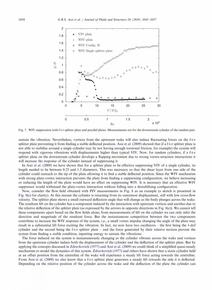
Fig. 7. WIV suppression with f-t-t splitter plate and parallel plates. Measurements are for the downstream cylinder of the tandem pair.
G.R.S. Assi et al. / Journal of Fluids and Structures 26 (2010) 1045–10571054
sustain the vibration. Nevertheless, vortices from the upstream wake will also induce fluctuating forces on the f-t-r
splitter plate preventing it from finding a stable deflected position. Assi et al. (2009) showed that if a f-t-r splitter plate is
not able to stabilise around a single cylinder (say by not having enough torsional friction, for example) the system will
respond with vigorous vibrations with displacements higher than typical VIV. Now, for tandem cylinders, if a f-t-r
splitter plate on the downstream cylinder develops a flapping movement due to strong vortex-structure interactions it
will increase the response of the cylinder instead of suppressing it.
In Assi et al. (2009) we have shown that for a splitter plate to be effective suppressing VIV of a single cylinder, its
length needed to be between 0.25 and 1.5 diameters. This was necessary so that the shear layer from one side of the
cylinder could reattach to the tip of the plate allowing it to find a stable deflected position. Since the WIV mechanism
with strong plate-vortex interaction prevents the plate from finding a suppressing configuration, we believe increasing
or reducing the length of the plate would have no effect on suppressing WIV. It is necessary that an effective WIV
suppressor would withstand the plate-vortex interaction without falling into a destabilising configuration.
Now, consider the flow field obtained with PIV measurements in Fig. 8 as an example (a sketch is presented in
Fig. 8(c) for clarity). At this instant the cylinder is returning from its outermost displacement, still with low cross-flow
velocity. The splitter plate shows a small outward deflection angle that will change as the body plunges across the wake.
The resultant lift on the cylinder has a component induced by the interaction with upstream vortices and another due to
the relative deflection of the splitter plate (as expressed by the arrows in opposite directions in Fig. 8(c)). We cannot tell
these components apart based on the flow fields alone; from measurements of lift on the cylinder we can only infer the
direction and magnitude of the resultant force. But the instantaneous competition between the two components
contribute to increase the WIV response of the system, i.e., a small vortex impulse changing the angle of the plate may
result in a substantial lift force exciting the vibration. In fact, we now have two oscillators – the first being the 1-dof
cylinder and the second being the f-t-r splitter plate – and the force generated by their relative motion prevent the
system from finding a stable condition, inputting energy to sustain the vibrations.
The force induced on the system is instantaneously changing as the cylinder vibrates across the wake and vortices
from the upstream cylinder induce both the displacement of the cylinder and the deflection of the splitter plate. But by
applying the concepts discussed in Zdravkovich (1977) and Assi et al. (2009) we could think of a simplified quasi-steady
mechanism to model the dynamics of this system. Zdravkovich (1977) and others have shown that a static cylinder held
at an offset position from the centreline of the wake will experience a steady lift force acting towards the centreline.
From Assi et al. (2009) we also know that a f-t-r splitter plate generates a steady lift towards the side it is deflected.
Depending on the relative position of the cylinder across the wake and the deflection of the plate the cylinder can

Fig. 8. Instantaneous vorticity contours (a) and velocity vectors (b) for a f-t-r splitter plate under WIV at U/Df0=6.0. PIV
measurements at Re=4500; x0/D=4.0. (c) Sketch of possible competition between components of lift generated by wake interaction
with a f-t-r splitter plate under WIV.
G.R.S. Assi et al. / Journal of Fluids and Structures 26 (2010) 1045–1057 1055
experience an amplification or reduction of the steady lift force. A positive energy transfer from the flow to the structure
may occur if the deflection of the splitter plate is able to alter the resultant force so that a favourable phase lag exists
between the displacement of the cylinder and lift.
Both unsteady and quasi-steady explanations given above could produce enough excitation to sustain the vibrations.
All that is required is that the relative motion between the f-t-r plate and the cylinder favours the WIV mechanism. This
was certainly the case in our experiments, as the response curve shows, since a f-t-r splitter plate developed flapping
motion under vortex interaction with the upstream wake. We suggest that devices requiring an asymmetric stable
deflection position will not be effective in suppressing WIV. The parallel plates are successful because they do not
depend in a deflected position to interact with the shear layers nor do they generate a destabilising lift force.
6. Conclusion
At the outset, parallel plates or any other device from this family of suppressors needs to be omni-directional in order
to be employed in practical offshore application. Hence f-t-r plates were considered as project requirement. In the case
of single splitter plates, this led to the discovery that a deflection angle was necessary for effective VIV suppression,

G.R.S. Assi et al. / Journal of Fluids and Structures 26 (2010) 1045–10571056
otherwise a rigid plate would induce the cylinder to gallop (Assi et al., 2009). However, when a f-t-r splitter plate was
tested as a WIV suppressor it was found that no stable, deflected position of the plate existed due to the interference
effect coming from the upstream wake, therefore single splitter plates were discarded. On the other hand, a pair of
parallel plates does not require a deflection angle due to its symmetric configuration, thus it appeared as a potential
suppressor for both VIV and WIV.
Cross-flow WIV suppression with drag reduction was achieved when f-t-r parallel plates were installed on the
downstream cylinder of a pair. Response below y=D¼ 0:1 was achieved at a value of the m�zo2� 10�2 for subcritical
Reynolds numbers. If both cylinders are fitted with suppressors, which should be the case for an offshore installation,
the drag coefficient can be as low as Cx ¼ 0:38, what amounts a 22% reduction compared to a downstream static
cylinder in tandem arrangement. If only the downstream cylinder is fitted with parallel plates the drag reduction is
around 33%.
The results presented in the present work refer only to a separation of x0/D=4.0. We already know that the
excitation mechanism may change as x0 is reduced below a critical separation (Zdravkovich and Pridden, 1977; Assi,
2009). We also know that the plates require a minimum length to be effective (Assi et al., 2009). By reducing the gap or
enlarging the plates we will enter the gap-flow-switching range (Zdravkovich, 1977) and a vigorous response may
return. Nevertheless, the study proves that suppressors based on parallel plates have great potential to suppress VIV
and WIV with substantial drag reduction.
It has been demonstrated that helical strakes, at least the configuration tested here, also lose their suppression
efficiency when unsteady excitation is present in the upstream wake.
The present work was concerned with validating a concept of f-t-r parallel plates in suppressing WIV, therefore a 1D-
long plate was chosen as the first trial. In Assi et al. (2009) we have tested the effect of plate length for a single splitter
plate employed to suppress VIV in a single cylinder. It is our intention to perform similar texts with parallel plates as
this would be the obvious step following from this piece of research. Future work should concentrate on optimising the
devices in respect of overall length and geometry. Also, a more detailed parametric investigation of the effects of
rotational inertia and torsional resistance should be carried out.
Acknowledgements
The authors wish to thank BP Exploration Operating Company Ltd. and BP America Production Company for their
support of this research. G.R.S. Assi was in receipt of a Ph.D. scholarship from CAPES, the Brazilian Ministry of
Education.
References
Assi, G., 2009. Mechanisms for flow-induced vibration of interfering bluff bodies. Ph.D. Thesis, Imperial College London, London,
UK, available from /www.ndf.poli.usp.br/�gassiS.
Assi, G., Bearman, P., 2008. VIV suppression and drag reduction with pivoted control plates on a circular cylinder. In: Proceedings of
OMAE2008—27th International Conference on Offshore Mechanics and Arctic Engineering, Estoril, Portugal.
Assi, G., Bearman, P., Kitney, N., 2009. Low drag solutions for suppressing vortex-induced vibration of circular cylinders. Journal of
Fluids Structures 25, 666–675.
Assi, G., Bearman, P., Meneghini, J., 2010. On the wake-induced vibration of tandem circular cylinders: the vortex interaction
excitation mechanism. Journal of Fluid Mechanics, doi:10.1017/S0022112010003095.
Assi, G., Meneghini, J., Aranha, J., Bearman, P., Casaprima, E., 2006. Experimental investigation of flow-induced vibration
interference between two circular cylinders. Journal of Fluids Structures 22, 819–827.
Bearman, P., 1984. Vortex shedding from oscillating bluff bodies. Annual Review of Fluid Mechanics 16, 195–222.
Bearman, P., Brankovic, M., 2004. Experimental studies of passive control of vortex-induced vibration. European Journal of
Mechanics B Fluids 23, 9–15.
Blevins, R., 1990. Flow-induced Vibration, second ed. Van Nostrand Reinhold.
Bokaian, A., Geoola, F., 1984. Wake-induced galloping of two interfering circular cylinders. Journal of Fluid Mechanics 146, 383–415.
Grimminger, G., 1945. The effect of rigid guide vanes on the vibration and drag of a towed circular cylinder. Technical Report 504,
David Taylor Model Basin.
Hover, F., Triantafyllou, M., 2001. Galloping response of a cylinder with upstream wake interference. Journal of Fluids Structures 15,
503–512.
King, R., Johns, D., 1976. Wake interaction experiments with two flexible circular cylinders in flowing water. Journal of Sound
Vibration 45, 259–283.

G.R.S. Assi et al. / Journal of Fluids and Structures 26 (2010) 1045–1057 1057
Korkischko, I., Meneghini, J., Casaprima, E., Franciss, R., 2007. An experimental investigation of the flow around isolated and
tandem straked cylinders. In: BBVIV5 5th Conference on Bluff Body Wakes and Vortex-Induced Vibrations, Brazil.
Laneville, A., Brika, D., 1999. The fluid and mechanical coupling between two circular cylinders in tandem arrangement. Journal of
Fluids Structures 13, 967–986.
Sarpkaya, T., 1979. Vortex-induced oscillations, a selective review. Journal of Applied Mechanics 46, 241–258.
Sarpkaya, T., 2004. A critical review of the intrinsic nature of vortex-induced vibrations. Journal of Fluids and Structures 19, 389–447.
Williamson, C., Govardhan, R., 2004. Vortex-induced vibrations. Annul Review of Fluid Mechanics 36, 413–455.
Zdravkovich, M., 1974. Flow-induced vibrations of two cylinders in tandem and their suppression. In: Naudascher, E. (Ed.), Flow
Induced Structural Vibrations. Springer-Verlag, Berlin, pp. 631–639.
Zdravkovich, M., 1977. Review of flow interference between two circular cylinders in various arrangements. ASME Journal of Fluids
Engineering, 618–633.
Zdravkovich, M., 1988. Review of interference-induced oscillations in flow past two circular cylinders in various arrangements. Journal
of Wind Engineering and Industrial Aerodynamics 28, 183–200.
Zdravkovich, M., Medeiros, E., 1991. Effect of damping on interference-induced oscillations of two identical circular cylinders.
Journal of Wind Engineering and Industrial Aerodynamics 38, 197–211.
Zdravkovich, M., Pridden, D., 1977. Interference between two circular cylinders: series of unexpected discontinuities. Journal of Wind
Engineering and Industrial Aerodynamics 2, 255–270.


