Embed Size (px)
Citation preview

arX
iv:c
ond-
mat
/980
8218
v1 [
cond
-mat
.sup
r-co
n] 2
0 A
ug 1
998
Surface barrier dominated transport in NbSe2
Y. Paltiel, D. T. Fuchs, E. Zeldov, Y. N. Myasoedov, and H. Shtrikman
Department of Condensed Matter Physics, The Weizmann Institute of Science, Rehovot 76100,
Israel
M. L. Rappaport
Physics Services, The Weizmann Institute of Science, Rehovot 76100, Israel
E. Y. Andrei
Department of Physics and Astronomy, Rutgers University, Piscataway, New Jersey 08855
(February 7, 2008)
Abstract
Transport current distribution in clean 2H-NbSe2 crystals is studied by mea-
suring the self-induced magnetic field across the sample. Below Tc most of the
current flows at the edges of the crystals due to strong surface barriers, which
are found to dominate the transport properties and the resistive transition.
The measured critical current is determined by the critical current for vortex
penetration through the surface barrier rather than by bulk pinning.
PACS numbers: 74.60.Ec, 74.60.Ge, 74.60.Jg
Typeset using REVTEX
1

Vortices in type-II superconductors have to overcome surface and geometrical barriers
(SB) in order to exit or penetrate into the superconductor. The effect of SB on the mag-
netic properties has been extensively studied theoretically [1–4]. In recent years numerous
studies have shown that SB dominate the magnetization behavior in clean crystals of high
temperature superconductor (HTSC), in particular at elevated temperatures [5–10]. Since
bulk pinning is strongly reduced by thermal fluctuations, the relative importance of the
SB is expected to grow with temperature [11]. At low temperatures, in contrast, and in
low-Tc superconductors in general, bulk pinning is expected to be the main source of hys-
teretic magnetization. Recent theoretical works [12,13] have suggested that SB can also
significantly modify the transport properties of superconductors. Current distribution mea-
surements in Bi2Sr2CaCu208 (BSCCO) crystals [14,15] have revealed that over a wide range
of temperatures and fields, the transport current indeed flows predominantly at the edges of
the crystals where vortices enter and exit the superconductor. In this paper we report that
SB dominate the transport behavior also in the low-Tc superconductor NbSe2. SB should
therefore be of significant importance in a wide range of superconductors in affecting the
transport as well as the magnetic properties.
High purity 2H-NbSe2 crystals with Tc=7.2K were grown as described previously [16].
Several crystals were cleaved and cut into a rectangular strip shape. The data presented
here are for one of the crystals with dimensions of 1.46 mm(l) × 0.35 mm(w) × 0.04 mm(d).
The features reported below were observed in all the investigated crystals. Four pads for
electrical contacts of 0.1 × 0.1 mm2 with 0.13 mm separation between pairs were prepared
by Ag/Au evaporation. The crystal was mounted onto an array of 19 two-dimensional
electron gas GaAs/AlGaAs Hall sensors 10 × 10 µm2 each with a 10 µm separation. The
inset to Fig. 1 shows a schematic top view of the experimental setup. A dc magnetic field
Hdc was applied perpendicular to the plane of the sensors and parallel to the c-axis of the
crystal. An ac transport current Iac in the range of 1 to 30 mA at 65 Hz was applied, and
the corresponding self-induced magnetic field Bac(x) across the crystal was measured by the
Hall sensor array. The four-probe resistance of the sample was measured under the same
2

conditions using a lock-in amplifier.
There are three main regimes for the flow of the transport current as described in Ref. [14]:
(a) Uniform current flow in the bulk of the sample. In this case, applying the Biot-Savart
law, the perpendicular component of the self-induced field, as measured by the sensors,
decreases monotonically from the left edge to the right. (b) Surface barrier dominated flow
for which most of the current flows at the two edges of the crystal in order to drive the
vortices over the entry and exit SB. The resulting self-induced field across the crystal is
opposite in sign and increases from left to right. (c) Vortex pinning which prevents vortex
motion and results in zero self-field inside the sample. The corresponding transport current,
in this case, has a characteristic Meissner distribution with a reduced current in the center
and enhanced at the edges [17–19].
Figure 1a shows an example of the self-induced field Bac as a function of temperature at
Hdc=0.1T and Iac=6mA. For clarity, only the sensors 3 to 18, which are under the crystal,
are shown. The corresponding resistance is shown in Fig. 1b. The observed behavior is very
similar to that reported for BSCCO crystals [14]. Above Tc, the current flows uniformly
as expected, and Bac decreases monotonically from the left edge of the crystal (sensor 3)
to the right edge (sensor 18). This behavior is seen more clearly in Fig. 2a, which shows
Bac(x) profile for all the sensors at 7.6K. As the temperature is decreased, the SB sets in
immediately below Tc drawing an increasingly larger fraction of the current to the edges.
This gives rise to the observed temperature dependence of Bac in Fig. 1a: a drop in Bac
just below Tc, followed by crossing of the curves and sign reversal at lower temperatures.
At the crossing point, half of the transport current flows across the bulk and the other half
at the two edges of the sample. At T = Tmax (see Fig. 1a) most of the current flows at
the crystal edges and the self-field profile inside the crystal is completely inverted relative to
the uniform flow case, as shown in Fig. 2a for T=6.8K. Note that any bulk mechanism or
finite skin depth effect will result in Bac which is either zero (perfect shielding) or positive
in the left half of the sample (finite shielding), but it cannot cause Bac to become negative
(negative permeability [10]). The sign reversal of Bac is a unique property of the SB. As
3

the temperature is further decreased, the vortices become immobile for T < Td due to the
combination of the SB and bulk pinning, resulting in a vanishing Bac response within the
crystal as shown by the 4.9 K profile in Fig. 2a.
In Ref. [14] arrays of seven Hall sensors were used, which allowed mapping of Bac typically
over only half of the sample width. Here we have extended the arrays to 19 sensors that
provide more detailed Bac(x) over the entire sample width. This improvement has two
significant advantages. First, we can readily examine both edges of the sample and evaluate
the symmetry of the current distribution. The second major advantage is that having
19 values of Bac field across the sample is sufficient in order to directly invert the field
distribution into the current distribution. We represent the sample by 19 current filaments
located at about half of the crystal thickness and equally spaced across the width. The
currents in the filaments are obtained by inverting the 19 × 19 matrix that transforms
between the current and the field values using the Biot-Savart law. Figure 2b shows the
obtained I(x) corresponding to the three field profiles in Fig. 2a. As expected, above Tc the
current flows uniformly across the crystal (7.6K profile). However, below Tc the current starts
to accumulate at the edges due to the strong SB. At T = Tmax practically all the current
flows at the two edges in a form of two δ functions with negligible current in the bulk (6.8K
profile). At low temperatures, 4.9K profile, the vortices become immobile and the current
is distributed in the corresponding self-shielding form [17–19] with a minimum in the center
and a rapid increase near the edges. Note that the actual current distribution is continuous
across the width and the thickness of the crystal, and hence our derivation of the discreet
current filaments in Fig. 2b is only an approximation. Yet, this simple analysis clearly
visualizes the underlying mechanisms, and in particular the main transition from a uniform
current flow above Tc to SB dominated flow below Tc. This finding shows that in clean
NbSe2 crystals the vortex flow rate is determined by the transmission probability through
the SB rather than by bulk vortex dynamics. An important experimental implication is that
the transport measurements in this case reflect the resistive properties of the SB rather than
the bulk properties.
4

Another aspect of the SB is its asymmetry with respect to vortex entry and exit [1].
Vortex entry requires a larger force than vortex exit. As a result a larger current flows at
the vortex entry edge in order to maintain the same vortex flow rate throughout the sample.
The role of the edges is interchanged as the direction of the ac current changes, with a larger
current flowing on the opposite edge of the crystal. This mechanism results in a significant
local second harmonic self-field signal, as shown in Fig. 3 for Hdc=0.5T and Iac=6mA.
Second harmonic is a unique feature of the SB due to its asymmetry with respect to the
current direction. Bulk vortex dynamics, in contrast, results only in odd harmonics, since
bulk I-V characteristics are antisymmetric with respect to the current. Figure 3 shows that
the second harmonic signal, and hence the SB, set-in immediately below Tc concurrently
with the resistive drop. The narrow dip in the resistance at Tp in Fig. 3 is the common peak
effect in NbSe2 [20–23], which in our high purity crystals is extremely narrow (see also Fig.
1a). Within our experimental resolution we do not observe substantial changes in current
distribution in this narrow peak-effect region.
In contrast to BSCCO, the thermal activation of vortices in NbSe2 is weak due to much
lower Tc and lower anisotropy. We can therefore simplify the description by analyzing
the behavior in Fig. 3 in terms of bulk and surface barrier critical currents, Ibc and Is
c ,
respectively. Let us first consider the case of finite bulk pinning with no SB, namely Isc =0.
The bulk critical current Ibc is generally expected to increase with decreasing temperature,
but as long as the applied current is larger than Ibc (T ), the current should flow uniformly
across the sample [17–19]. As a result, Bac should be positive like above Tc, and there should
be no second harmonic signal. When Ibc (T ) approaches the value of the applied current at
some characteristic temperature Tmax, vortices stop moving, and Bac should drop rapidly
from the full positive value to zero as the temperature is further decreased. This scenario is
inconsistent with the data in Fig. 3a: Bac is negative instead of positive above Tmax, and in
addition, significant second harmonic is present. Furthermore, below Tmax, Bac does drop
rapidly, but this drop occurs while Bac is negative rather than positive.
We now consider the opposite scenario of finite SB with no bulk pinning, Ibc=0. Since
5

Isc (T ) is related to the critical field Hc(T ), it is expected to grow rather linearly below Tc.
Therefore, upon cooling, a progressively larger fraction of the applied current should be
drawn towards the edges. The corresponding Bac should drop approximately linearly from
a full positive value at Tc down to a full negative value at a characteristic temperature at
which Isc (T ) reaches Iac, and as a result practically all the applied current flows at the edges.
In this temperature interval a significant second harmonic signal should be also present,
as explained above. The corresponding resistivity of the sample should decrease gradually
below Tc with a sharp drop towards zero at the same characteristic temperature. The data
in Fig. 3 above Tmax is fully consistent with this scenario, thus allowing us to identify Tmax
as the characteristic temperature at which Iac = Isc (T ).
Now let us examine the behavior below Tmax where Iac < Isc (T ) and no vortices can exit
or penetrate into the sample (in absence of thermal activation). Yet, if Ibc=0 the vortices
can move freely inside the sample and change their distribution according to Bac imposed
by the full Iac flowing on the edges. Since the edges have already absorbed all of Iac, there
should be no further change in the current distribution below Tmax, and Bac should remain
constant at its full negative value (as observed in BSCCO [14]). On the other hand, if a
small bulk Ibc is present in addition to Is
c , Bac should drop sharply to zero below Tmax since
vortices become immobile. Tmax in this case corresponds to the temperature at which Iac
becomes equal to the total critical current Ic(T ) = Ibc + Is
c . The pronounced drop of Bac at
Tmax in Fig. 3a indicates therefore the existence of some finite bulk Ibc . The fact that Bac is
practically fully inverted at Tmax shows, however, that Ibc ≪ Is
c . Note also that the second
harmonic signal should be absent below Tmax, since no vortices penetrate through the SB,
consistent with the data in Fig. 3a. The tail of Bac as well as the weak resistive tail below
Tmax indicate, furthermore, that a small flux creep is present resulting in some finite vortex
motion. Note, that even in this weak creep regime Bac is inverted, showing that most of the
current flows at the edges and vortex dynamics is governed by SB. The vortices become fully
immobile only at a lower temperature Td, below which the creep stops within our resolution.
Finally, we demonstrate here that the above condition, that the total critical current Ic is
6

determined mainly by the critical current of the SB, holds over the entire investigated range
of temperatures and fields. At low temperatures and relatively low current, the vortices
are immobile and the current flows with the characteristic Meissner distribution resulting
in vanishing Bac. In this case one concludes that the applied current Iac is below the total
critical current Ic = Ibc + Is
c , but the values of the individual critical currents cannot be
determined. In order to gain this important information one has to increase the applied
current just slightly above the total critical current. In this situation the applied current is
precisely divided between the bulk and the edges according to Ibc and Is
c . As a result the
vortices are set in motion, and the corresponding Bac signal provides the information on the
relative importance of Ibc and Is
c . Such a measurement is presented in Fig. 4 which shows
Bac, as measured by sensor 3, at various Iac between 5 and 30 mA at 0.3T. The arrows
indicate the temperatures Tmax at which Iac = Ic(T ) = Ibc + Is
c for the various applied
currents as described above. The corresponding Ic(T ) dependence is shown in the inset. We
find that in all cases when Iac reaches Ic(T ) the corresponding Bac signal is fully inverted (as
the 6.8K profile in Fig. 2a) indicating that practically all the current flows at the edges, and
that Ibc ≪ Is
c . Thus, in clean crystals of NbSe2 the measured Ic reflects mainly the critical
current of the SB and not the bulk critical current.
In summary, the distribution of transport current in clean platelet crystals of 2H-NbSe2
was studied by measuring the self-induced magnetic field. The use of extended arrays of
Hall sensors allows for a direct inversion of the self-field profile into the current distribution
profile across the crystal width. Below Tc the current is found to flow predominantly at the
sample edges due to strong surface barriers. The SB govern the apparent resistivity of the
crystals. Furthermore, the measured critical current is determined by the critical current of
the SB barrier rather than by bulk critical current.
We are grateful to A. Wold for the high purity NbSe2 crystals, and to G. Jung and S.
Bhattacharya for helpful discussions. This work was supported by grant no 97-00424 from
the United States-Israel Binational Science Foundation (BSF), Jerusalem, Israel, and by the
MINERVA Foundation, Munich, Germany.
7

REFERENCES
[1] C. P. Bean and J. D. Livingston, Phys. Rev. Lett. 12, 14 (1964).
[2] J. R. Clem, Low Temp. Physics - LT 13, Vol. 3, eds. K.D. Timmerhaus et al. (Plenum,
New York, 1974) p. 102.
[3] L. Burlachkov, Phys. Rev. B 47, 8056 (1993).
[4] E. Zeldov et al., Phys. Rev. Lett. 73, 1428 (1994).
[5] N. Chikumoto, M. Konczykowski, N. Motohira and A. P. Malozemoff, Phys. Rev. Lett.
69, 1260 (1992).
[6] M. Konczykowski, L. I. Burlachkov, Y. Yeshurun, and F. Holtzberg, Phys. Rev. B 43,
13707 (1991).
[7] M. V. Indenbom et al., Physica C 235-240, 201 (1994).
[8] C. J. van der Beek, M. V. Indenbom, G. D’Anna, and W. Benoit, Physica C 258, 105
(1996).
[9] E. Zeldov et al., Europhys. Lett. 30, 367 (1995).
[10] N. Morozov et al., Phys. Rev. Lett. 76, 138 (1996).
[11] L. Burlachkov and V. M. Vinokur, Physica C 235-240, 2993 (1994).
[12] L. Burlachkov, A. E. Koshelev, and V. M. Vinokur, Phys. Rev. B 54, 6750 (1996).
[13] M. Benkraouda and J. R. Clem, unpublished.
[14] D. T. Fuchs et al., Nature 391, 373 (1998).
[15] D. T. Fuchs et al., Phys. Rev. Lett. 80, 4971 (1998).
[16] H. N. S. Lee, H. McKinzie, D. S. Tannhauser, and A. Wold, J. Appl. Phys. 40, 602
(1969).
8

[17] E. Zeldov, J. R. Clem, M. McElfresh and M. Darwin, Phys. Rev. B 49, 9802 (1994).
[18] E. H. Brandt and M. V. Indenbom, Phys. Rev. B 48, 12893 (1993).
[19] W. T. Norris, J. Phys. D 3, 489 (1970).
[20] S. Bhattacharya and M. J. Higgins, Phys. Rev. Lett. 70, 2617 (1993); Phys. Rev. B 49,
10005 (1994).
[21] W. Henderson et al., Phys. Rev. Lett. 77, 2077 (1996).
[22] K. Ghosh et al., Phys. Rev. Lett. 76, 4600 (1996).
[23] G. D’Anna et al., Phys. Rev. B 54, 6583 (1996).
9
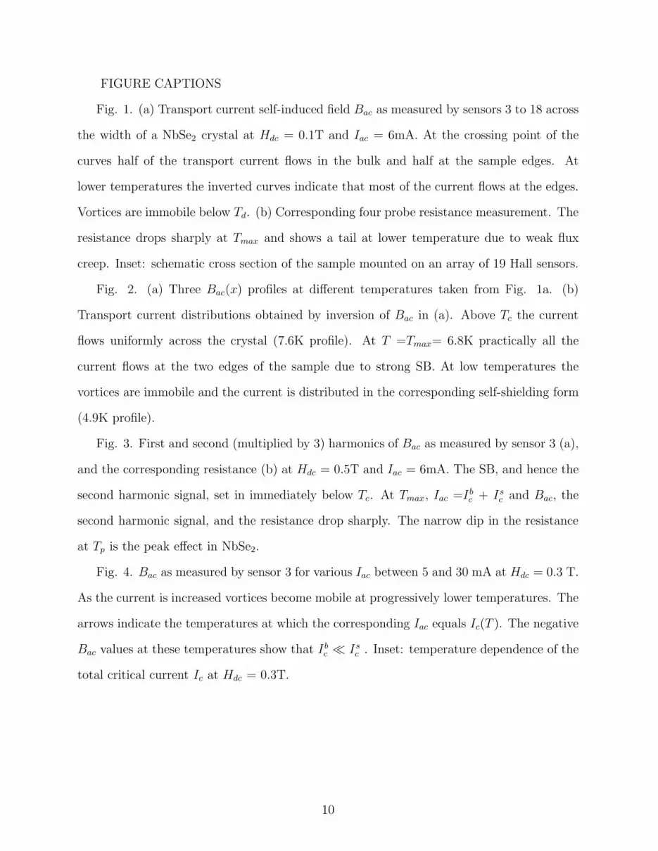
FIGURE CAPTIONS
Fig. 1. (a) Transport current self-induced field Bac as measured by sensors 3 to 18 across
the width of a NbSe2 crystal at Hdc = 0.1T and Iac = 6mA. At the crossing point of the
curves half of the transport current flows in the bulk and half at the sample edges. At
lower temperatures the inverted curves indicate that most of the current flows at the edges.
Vortices are immobile below Td. (b) Corresponding four probe resistance measurement. The
resistance drops sharply at Tmax and shows a tail at lower temperature due to weak flux
creep. Inset: schematic cross section of the sample mounted on an array of 19 Hall sensors.
Fig. 2. (a) Three Bac(x) profiles at different temperatures taken from Fig. 1a. (b)
Transport current distributions obtained by inversion of Bac in (a). Above Tc the current
flows uniformly across the crystal (7.6K profile). At T =Tmax= 6.8K practically all the
current flows at the two edges of the sample due to strong SB. At low temperatures the
vortices are immobile and the current is distributed in the corresponding self-shielding form
(4.9K profile).
Fig. 3. First and second (multiplied by 3) harmonics of Bac as measured by sensor 3 (a),
and the corresponding resistance (b) at Hdc = 0.5T and Iac = 6mA. The SB, and hence the
second harmonic signal, set in immediately below Tc. At Tmax, Iac =Ibc + Is
c and Bac, the
second harmonic signal, and the resistance drop sharply. The narrow dip in the resistance
at Tp is the peak effect in NbSe2.
Fig. 4. Bac as measured by sensor 3 for various Iac between 5 and 30 mA at Hdc = 0.3 T.
As the current is increased vortices become mobile at progressively lower temperatures. The
arrows indicate the temperatures at which the corresponding Iac equals Ic(T ). The negative
Bac values at these temperatures show that Ibc ≪ Is
c . Inset: temperature dependence of the
total critical current Ic at Hdc = 0.3T.
10

-100
-50
0
50
100
Bac
[mG
]
3
3
18
18
sensor #
(a)
0.1 T6 mA
Tmax
Td
0.1
1
10
100
1000
5 5.5 6 6.5 7 7.5 8 T [K]
(b)
R(T
) [µ
Ω]
Tp
Tc
Fig. 1,
1 19
Iac
Hdc
Paltiel et al.

-150
-100
-50
0
50
100
150
200T=4.9KT=6.8KT=7.6K
0 5 10 15 20
Bac
[mG
]
(a)
Sensor #
0.1 T6 mA
uniform
pinning
SB
0.0
0.5
1.0
1.5
2.0
0 100 200 300
T=4.9KT=6.8KT=7.6K
I(x)
[m
A]
X [µm]
(b)
Fig. 2, Paltiel et al.

-100
0
100
200B
ac [
mG
]
1st harmonic
2nd harmonicX 3
Tmax
Td
(a)
1
10
100
1000
4 5 6 7 8
R(T
) [µ
Ω]
T(K)
Tp
(b)
0.5 T6 mA
Fig. 3, Paltiel et al.

-1000
-500
0
500
1000
1500
4 4.5 5 5.5 6 6.5 7 7.5
Bac
[m
G]
T [K]
30mA
15mA20mA25mA
10mA5mA
0.3 T
5 60
10
20
30
T [K]
I c(T
) [m
A]
Fig. 4,Paltiel et al.


