Embed Size (px)
Citation preview

IEEE TRANSACTIONS ON ANTENNAS AND PROPAGATION, VOL. 63, NO. 5, MAY 2015 2141
Surface Integral Equation-Method of MomentsWith Multiregion Basis Functions
Applied to PlasmonicsDiego Martínez Solís, Jose Manuel Taboada, and Fernando Obelleiro Basteiro
Abstract—A surface integral equation-method of moments(SIE-MoM) approach is presented for the solution of multiplehomogeneous penetrable bodies. The problem is formulated usingmultiregion (MR) piecewise vector basis functions defined uni-formly on the boundary surfaces, interfaces, and line junctions.The MR bases are oriented functions implicitly satisfying theboundary conditions. Their use greatly simplifies the formulation,and thereby the implementation, for the solution of arbitrary com-plex composite problems having multiple junctions. Moreover, thegeneration of the MR functions involves a negligible overhead atthe setup. Numerical examples are presented to demonstrate theaccuracy and versatility of SIE-MoM with MR basis functions inplasmonics, where this approach remains much unexplored.
Index Terms—Method of moments (MoM), numerical analysis,plasmonics, surface integral equations.
I. INTRODUCTION
S URFACE integral equation (SIE) with the method ofmoments (MoM) [1]–[3] is a powerful tool for the solution
of electromagnetic scattering and radiation problems defined ascombinations of multiple homogeneous materials. SIE-MoMhas demonstrated accuracy and efficiency for the analysis ofcomposite objects with real conductors and dielectrics in radiofrequency and microwave regimes. Recently, it has successfullybeen extended to the solution of metamaterial and plamonicproblems in near infrared frequencies and in optics [4]–[12].
One of the most challenging issues in the analysis of arbitrarycomplex composite problems with SIE-MoM is the treatment ofmultiple junctions between three or more materials. Althoughthis topic has largely been discussed in the literature [2],
Manuscript received June 25, 2014; revised February 04, 2015; acceptedFebruary 16, 2015. Date of publication February 24, 2015; date of currentversion May 01, 2015. This work was supported by the European RegionalDevelopment Fund (ERDF) and the Spanish Government, Ministerio deEconomía y Competitividad, Dirección General de Investigación Científica yTécnica, under Projects TEC2011-28784-C02-01 and TEC2011-28784-C02-02and in part by the ERDF and the Galician Regional Government underagreement for funding the Atlantic Research Center for Information andCommunication Technologies (atlantTIC); the Spanish Government and theERDF under project TACTICA; and the ERDF and the Extremadura RegionalGovernment under Project IB13185.
D. M. Solis and F. Obelleiro are with the Departamento de Teoría do Sinale Comunicacións, Universidade de Vigo, 36301 Pontevedra, Spain (e-mail:[email protected]).
J. M. Taboada is with the Departamento de Tecnología de los Computadoresy de las Comunicaciones, Universidad de Extremadura, 10003 Cáceres, Spain(e-mail: [email protected]).
Color versions of one or more of the figures in this paper are available onlineat http://ieeexplore.ieee.org.
Digital Object Identifier 10.1109/TAP.2015.2406891
[13]–[22], in some cases the specific implementation detailsof the modeling of surface currents and the satisfaction ofthe boundary conditions at junctions are omitted. In othercases, these details are treated explicitly, but the chosen solu-tions burden the formulation resulting in rather complicatedimplementations. Thus, some approaches use triangular Rao–Wilton–Glisson (RWG) [23] half-basis functions to expand theequivalent currents at junctions and test the integral equations,complicating the satisfaction of the current continuity [15],[16], [21]. Other approaches first deal with each homogeneouspart (region) of the composite object separately using full RWGbasis functions, and then address the entire object afterward.The new unknowns are subsequently interrelated with the pre-vious ones through the boundary conditions, reducing the totalnumber of unknowns to the minimum required to model thejunction problem [20]. A similar procedure is applied in [22],where in the first step the homogeneous regions are discretizedseparately using RWG basis functions and tested using theGalerkin’s testing method. Then, the boundary conditions andthe desired integral equation formulation are enforced to com-bine and remove the extra unknowns and equations. A set ofrules is outlined to directly assemble the final system matrix inan efficient way, avoiding the computation of the extra columnsand rows. Even though this approach is very instructive, it obvi-ates the actual mathematical complexity for the general case, asthe bookkeeping rules are not explicitly included into the for-mulation, burdening the implementation with an intricate set ofdifferent possibilities.
In this paper, we present a novel method to unify the treat-ment of surfaces, interfaces, and junctions in solving piecewise-homogeneous bodies with arbitrary penetrable materials andmultiple junctions. The problem is formulated by introducingthe multiregion (MR) basis functions and using the Galerkin’stesting procedure. The MR bases are oriented piecewise func-tions devised to gather all the issues related with the expansionof the surface equivalent currents, the test of the integral equa-tions, and the satisfaction of the boundary conditions. They canbe defined uniformly on the boundary surfaces, interfaces, andjunctions between multiple materials, leading to a compact andunique formulation for the general problem directly addressingall the junction issues. Neither bookkeeping rules nor specialprocedures are required during the system matrix assembly,as the boundary conditions are implicitly included in the MRbasis functions definition. The proposed solution is similar tothe treatment of junctions in [17], with the use of the so-called
0018-926X © 2015 IEEE. Personal use is permitted, but republication/redistribution requires IEEE permission.See http://www.ieee.org/publications_standards/publications/rights/index.html for more information.
2142 IEEE TRANSACTIONS ON ANTENNAS AND PROPAGATION, VOL. 63, NO. 5, MAY 2015
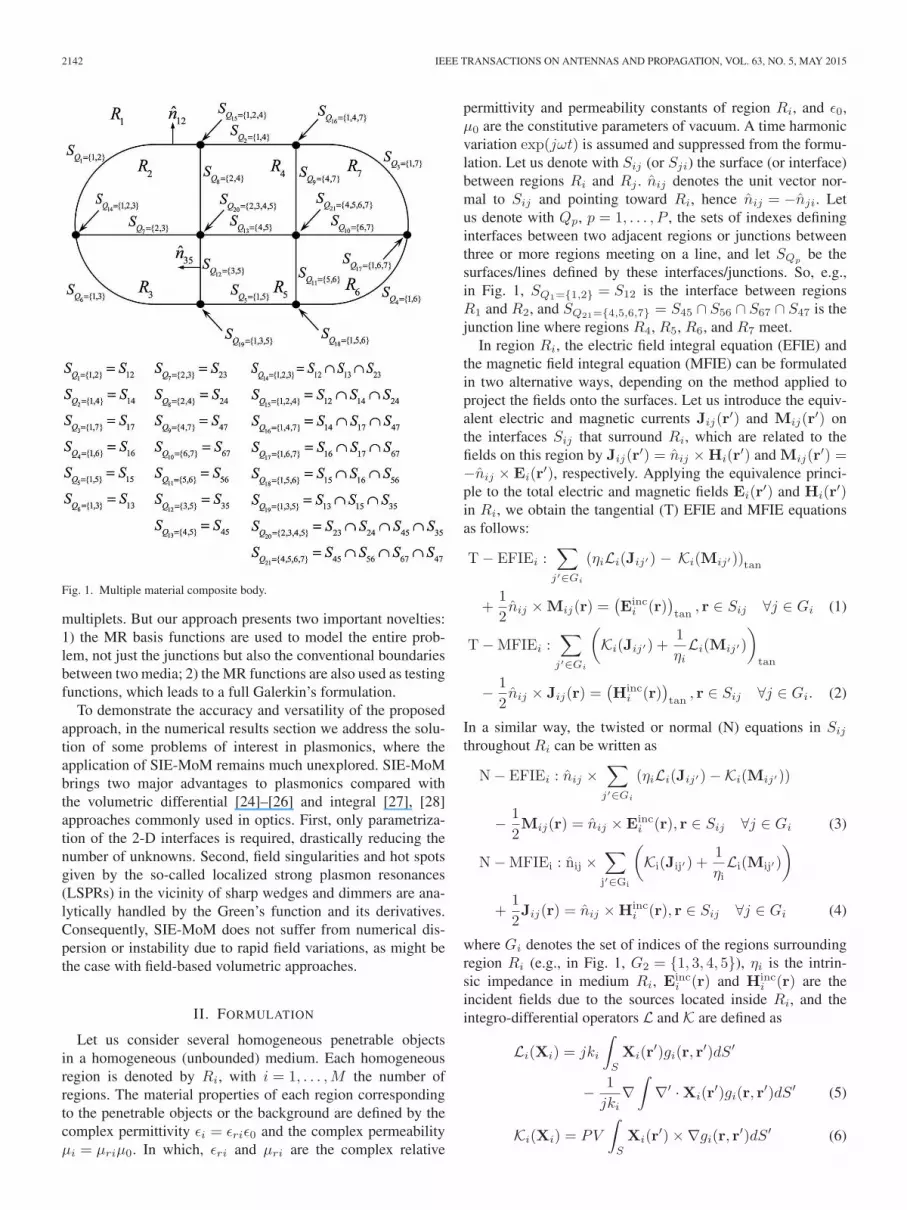
Fig. 1. Multiple material composite body.
multiplets. But our approach presents two important novelties:1) the MR basis functions are used to model the entire prob-lem, not just the junctions but also the conventional boundariesbetween two media; 2) the MR functions are also used as testingfunctions, which leads to a full Galerkin’s formulation.
To demonstrate the accuracy and versatility of the proposedapproach, in the numerical results section we address the solu-tion of some problems of interest in plasmonics, where theapplication of SIE-MoM remains much unexplored. SIE-MoMbrings two major advantages to plasmonics compared withthe volumetric differential [24]–[26] and integral [27], [28]approaches commonly used in optics. First, only parametriza-tion of the 2-D interfaces is required, drastically reducing thenumber of unknowns. Second, field singularities and hot spotsgiven by the so-called localized strong plasmon resonances(LSPRs) in the vicinity of sharp wedges and dimmers are ana-lytically handled by the Green’s function and its derivatives.Consequently, SIE-MoM does not suffer from numerical dis-persion or instability due to rapid field variations, as might bethe case with field-based volumetric approaches.
II. FORMULATION
Let us consider several homogeneous penetrable objectsin a homogeneous (unbounded) medium. Each homogeneousregion is denoted by Ri, with i = 1, . . . ,M the number ofregions. The material properties of each region correspondingto the penetrable objects or the background are defined by thecomplex permittivity ǫi = ǫriǫ0 and the complex permeabilityµi = µriµ0. In which, ǫri and µri are the complex relative
permittivity and permeability constants of region Ri, and ǫ0,µ0 are the constitutive parameters of vacuum. A time harmonicvariation exp(jωt) is assumed and suppressed from the formu-lation. Let us denote with Sij (or Sji) the surface (or interface)between regions Ri and Rj . n̂ij denotes the unit vector nor-mal to Sij and pointing toward Ri, hence n̂ij = −n̂ji. Letus denote with Qp, p = 1, . . . , P , the sets of indexes defininginterfaces between two adjacent regions or junctions betweenthree or more regions meeting on a line, and let SQp
be thesurfaces/lines defined by these interfaces/junctions. So, e.g.,in Fig. 1, SQ1={1,2} = S12 is the interface between regionsR1 and R2, and SQ21={4,5,6,7} = S45 ∩ S56 ∩ S67 ∩ S47 is thejunction line where regions R4, R5, R6, and R7 meet.
In region Ri, the electric field integral equation (EFIE) andthe magnetic field integral equation (MFIE) can be formulatedin two alternative ways, depending on the method applied toproject the fields onto the surfaces. Let us introduce the equiv-alent electric and magnetic currents Jij(r
′) and Mij(r′) on
the interfaces Sij that surround Ri, which are related to thefields on this region by Jij(r
′) = n̂ij ×Hi(r′) and Mij(r
′) =−n̂ij ×Ei(r
′), respectively. Applying the equivalence princi-ple to the total electric and magnetic fields Ei(r
′) and Hi(r′)
in Ri, we obtain the tangential (T) EFIE and MFIE equationsas follows:
T− EFIEi :∑
j′∈Gi
(ηiLi(Jij′) − Ki(Mij′))tan
+1
2n̂ij ×Mij(r) =
(
Einci (r)
)
tan, r ∈ Sij ∀j ∈ Gi (1)
T−MFIEi :∑
j′∈Gi
(
Ki(Jij′) +1
ηiLi(Mij′)
)
tan
−1
2n̂ij × Jij(r) =
(
Hinci (r)
)
tan, r ∈ Sij ∀j ∈ Gi. (2)
In a similar way, the twisted or normal (N) equations in Sij
throughout Ri can be written as
N− EFIEi : n̂ij ×∑
j′∈Gi
(ηiLi(Jij′)−Ki(Mij′))
−1
2Mij(r) = n̂ij ×E
inci (r), r ∈ Sij ∀j ∈ Gi (3)
N−MFIEi : n̂ij ×∑
j′∈Gi
(
Ki(Jij′) +1
ηiLi(Mij′)
)
+1
2Jij(r) = n̂ij ×H
inci (r), r ∈ Sij ∀j ∈ Gi (4)
where Gi denotes the set of indices of the regions surroundingregion Ri (e.g., in Fig. 1, G2 = {1, 3, 4, 5}), ηi is the intrin-sic impedance in medium Ri, E
inci (r) and H
inci (r) are the
incident fields due to the sources located inside Ri, and theintegro-differential operators L and K are defined as
Li(Xi) = jki
∫
S
Xi(r′)gi(r, r
′)dS′
−1
jki∇
∫
∇′ ·Xi(r′)gi(r, r
′)dS′ (5)
Ki(Xi) = PV
∫
S
Xi(r′)×∇gi(r, r
′)dS′ (6)

SOLÍS et al.: SIE-MOM WITH MR BASIS FUNCTIONS APPLIED TO PLASMONICS 2143
with r the observation points approaching to Sij from the inte-rior of region Ri and with r
′ ∈ Sij′ the source points at theboundaries surrounding Ri. ∇′ denotes the divergence in theprimed (source) coordinates, PV denotes the principal valueof the integral in (6), ki is the wavenumber in Ri, and wedefine
gi(r, r′) =
e−jki|r−r′|
4π|r− r′|(7)
which is the homogeneous Greens function in Ri. The summa-tions in (1)–(4) account for all the interfaces Sij′ surroundingRi (including Sij). At this point, fulfilling the procedure of[29] to derive a set of stable and well-tested SIEs, we com-bine the above integral equations in region Ri, leading tothe two following combined field integral equations (CFIE)on Sij
ai1
ηiT− EFIEi + biN−MFIEi (8)
−ciN− EFIEi + diηiT−MFIEi (9)
with ai, bi, ci, and di the appropriate complex combinationcoefficients. The next step is to combine (8) for regions Ri
and Rj into a single integral equation for each interface Sij
as follows:
ai∑
j′∈Gi
(
Li(Jij′)−1
ηiKi(Mij′)
)
tan
+ aj∑
j′′∈Gj
(
Lj(Jjj′′)−1
ηjKj(Mjj′′)
)
tan
+ bin̂ij ×∑
j′∈Gi
(
Ki(Jij′) +1
ηiLi(Mij′)
)
+ bj n̂ji ×∑
j′′∈Gj
(
Kj(Jjj′′) +1
ηjLj(Mjj′′)
)
+1
2
(
aiηin̂ij ×Mij(r) +
ajηj
n̂ji ×Mji(r)
)
+1
2(biJij(r) + bjJji(r))
= ai1
ηi
(
Einci (r)
)
tan+ aj
1
ηj
(
Eincj (r)
)
tan
+ bin̂ij ×Hinci (r) + bj n̂ji ×H
incj (r), r ∈ Sij . (10)
In the same way, we combine (9) for regions Ri and Rj toobtain another single integral equation on Sij
−cin̂ij ×∑
j′∈Gi
(ηiLi(Jij′)−Ki(Mij′))
− cj n̂ji ×∑
j′′∈Gj
(ηjLj(Jjj′′)−Kj(Mjj′′))
+ di∑
j′∈Gi
(ηiKi(Jij′) + Li(Mij′))tan
+ dj∑
j′′∈Gj
(ηjKj(Jjj′′) + Lj(Mjj′′))tan
+1
2(ciMij(r) + cjMji(r))
−1
2(diηin̂ij × Jij(r) + djηj n̂ji × Jji(r))
= −cin̂ij ×Einci (r)− cj n̂ji ×E
incj (r)
+ diηi(
Hinci (r)
)
tan+ djηj
(
Hincj (r)
)
tan, r ∈ Sij . (11)
The previous equations are valid for one or more homo-geneous penetrable objects that do not touch each other. Inthe case that the objects are touching, we should also explic-itly include the junction lines between surfaces where three ormore dielectric regions meet to properly enforce the bound-ary conditions. For this, we generalize (10) and (11) for thecase of a generic interface/junction SQp
defined by the set ofindexes Qp. Combining (10) for the different regions in Qp, weobtain
∑
i∈Qp
⎡
⎣ai∑
j′∈Gi
(
Li(Jij′)−1
ηiKi(Mij′)
)
tan
+ bin̂ij ×∑
j′∈Gi
(
Ki(Jij′) +1
ηiLi(Mij′)
)
+1
2
(
aiηin̂ij ×Mij(r) + biJij(r)
)
⎤
⎦
=∑
i∈Qp
[
aiηi
(
Einci (r)
)
tan+ bin̂ij ×H
inci (r)
]
,
r ∈ Sij ∩ SQp∀j ∈ Gi ∩Qp (12)
and combining (11) in the same way, we obtain
∑
i∈Qp
⎡
⎣−cin̂ij ×∑
j′∈Gi
(ηiLi(Jij′)−Ki(Mij′))
+ di∑
j′∈Gi
(ηiKi(Jij′) + Li(Mij′))tan
+1
2(ciMij(r)− diηin̂ij × Jij(r))
⎤
⎦
=∑
i∈Qp
[
diηi(
Hinci (r)
)
tan− cin̂ij ×E
inci (r)
]
,
r ∈ Sij ∩ SQp∀j ∈ Gi ∩Qp. (13)
In the last equations, the first summations account for all theregions Ri defining the interface/junction, whereas the secondsummations account for all the interfaces Sij′ surrounding eachregion Ri (including Sij). The observation point r approachesthe surface Sij (or the boundary of Sij touching the meet-ing edge in the case that SQp
is a junction) from the inner ofregion Ri, with j any region belonging to the interface/junction

2144 IEEE TRANSACTIONS ON ANTENNAS AND PROPAGATION, VOL. 63, NO. 5, MAY 2015
Fig. 2. Boundary conditions at (a) interfaces and (b) junctions.
and adjacent to Ri. In the simplest case of a conventionalinterface between two media, Qp = {i, j} and hence (12) and(13) become (10) and (11).
In the previous expressions, the boundary conditions ensur-ing the continuity of the tangential component of the fieldscan be enforced at every interface/junction as simply asfollows:
Xij(r′) = −Xji(r
′), r′ ∈ Sij ∀i ∈ Qp ∀j ∈ Gi ∩Qp
(14)
Xij(r′) = Xik(r
′), r′ ∈ Sij ∩ Sik
∀i ∈ Qp ∀j, k ∈ Gi ∩Qp (15)
where Xij stands for Jij or Mij on Sij . The first conditionimplies that surface currents on opposite sides of an inter-face are equal in magnitude but have opposite directions. Thesecond condition implies that the normal components of allcurrents flowing across a junction line are continuous acrossthe edge and have the same magnitude. These conditions areillustrated in Fig. 2 for a conventional interface between twomedia and a junction between four media. Note that equa-tion (15) only applies to junctions. To obtain the equivalentcurrents Jij and Mij on the interfaces/junctions SQp
, the stan-dard MoM procedure is applied to (12) and (13). First, thetotal currents on the interfaces/junctions of the whole body arecollected as
J(r) = Jij(r), r ∈⋃
i=1..Mj∈Gi
Sij (16)
M(r) = Mij(r), r ∈⋃
i=1..Mj∈Gi
Sij . (17)
Fig. 3. MR-oriented basis functions at (a) interfaces and (b) junctions.
Then, the currents on the whole body are expanded in a sum ofMR piecewise vector basis functions Λn in the form
J =N∑
n=1
JnΛn, r ∈⋃
p=1,...,P
SQp(18)
M =N∑
n=1
MnΛn, r ∈⋃
p=1,...,P
SQp. (19)
with N the total number of MR basis functions. Note that⋃
p=1,...,P SQp≡
⋃
i=1,...,M Sij
j∈Gi
, which accounts for all
interfaces/junctions defining the problem. The above piecewisebasis functions are defined on the interfaces SQp={i,j,...,k} asfollows:
Λn(r) =
⎧
⎪
⎪
⎪
⎪
⎨
⎪
⎪
⎪
⎪
⎩
fn|i, if r ∈ Ri
fn|j , if r ∈ Rj
...
fn|k, if r ∈ Rk
(20)
with fn|i being subsectional vector basis functions. With r ∈Ri, we mean that r approaches Sii′ from the inner of regionRi, with i′ any region belonging to the interface/junction andadjacent to Ri (r ∈ Sii′ , i
′ ∈ Gi ∩Qp). In this case, we use thewell known RWG, even though the formulation is general forany kind of subsectional vector basis functions. Note that weare relaxing notation in (20) for the sake of simplicity.
The MR basis functions defined in (20) are oriented func-tions fulfilling the boundary conditions of (14) and (15). Thisis illustrated in Fig. 3 for the case of a boundary surfaceand a junction between four different media. Substituting theexpansions (18) and (19), through (16) and (17), into (12)and (13) and applying Galerkin’s testing method, the boundaryconditions for the fields at surfaces and junctions are straight-forwardly guaranteed without burdening the formulation

SOLÍS et al.: SIE-MOM WITH MR BASIS FUNCTIONS APPLIED TO PLASMONICS 2145
(and thus the implementation), which remains compact andgeneral as follows:
∑
q∈GQp
∑
Λn∈SQq
(
AamnJn −Ba
mnMn +1
2I ′amnMn
)
+∑
q∈GQp
∑
Λn∈SQq
(
B′bmnJn +A′b
mnMn +1
2IbmnJn
)
= Em +H ′m,Λm ∈ SQp
(21)∑
q∈GQp
∑
Λn∈SQq
(
A′cmnJn −B′c
mnMn −1
2IcmnMn
)
+∑
q∈GQp
∑
Λn∈SQq
(
BdmnJn +Ad
mnMn −1
2I ′dmnJn
)
= E′m +Hm,Λm ∈ SQp
(22)
with GQpbeing the indexes of the interfaces/junctions shar-
ing at least one region with interface SQp(e.g., GQ21
={2..5, 8..13, 15..21} in Fig. 1), and where the following quanti-ties are defined
A(ad)mn =
∑
i∈Qp∩Qq
(
aidi
)
Am|i,n|i (23)
A′(bc)mn =
∑
i∈Qp∩Qq
(
bi/ηi−ciηi
)
A′m|i,n|i (24)
B(ad)mn =
∑
i∈Qp∩Qq
(
ai/ηidiηi
)
Bm|i,n|i (25)
B′(bc)mn =
∑
i∈Qp∩Qq
(
bi−ci
)
B′m|i,n|i (26)
I(bc)mn =
∑
i∈Qp∩Qq
(
bi−ci
)
Im|i,n|i (27)
I′(ad)mn =
∑
i∈Qp∩Qq
(
ai/ηidiηi
)
I ′m|i,n|i (28)
Em =∑
i∈Qp
aiηi
∫
∆m
fm|i ·(
Einci
)
tandS (29)
Hm =∑
i∈Qp
diηi
∫
∆m
fm|i ·(
Hinci
)
tandS (30)
E′m = −
∑
i∈Qp
ci
∫
∆m
fm|i ·(
n̂m|i ×Einci
)
dS (31)
H ′m =
∑
i∈Qp
bi
∫
∆m
fm|i ·(
n̂m|i ×Hinci
)
dS. (32)
In the previous equations, we define
Am|i,n|i =
∫
∆m|i
fm|i · Li(fn|i)dS (33)
Bm|i,n|i =
∫
∆m|i
fm|i · Ki(fn|i)dS (34)
A′m|i,n|i =
∫
∆m|i
fm|i · n̂m|i × Li(fn|i)dS (35)
B′m|i,n|i =
∫
∆m|i
fm|i · n̂m|i ×Ki(fn|i)dS (36)
Im|i,n|i =
∫
∆m|i
fm|i · fn|idS (37)
I ′m|i,n|i =
∫
∆m|i
fm|i · n̂m|i × fn|idS. (38)
Regrouping terms by interfaces and junctions in equations (21)and (22), the previous system of linear equations can beexpressed as a dense matrix system as
⎛
⎜
⎜
⎜
⎝
ZQ1Q1ZQ1Q2
. . . ZQ1QP
ZQ2Q1ZQ2Q2
. . . ZQ2QP
......
. . ....
ZQPQ1ZQPQ2
. . . ZQPQP
⎞
⎟
⎟
⎟
⎠
⎛
⎜
⎜
⎜
⎝
IQ1
IQ2
...IQP
⎞
⎟
⎟
⎟
⎠
=
⎛
⎜
⎜
⎜
⎝
VQ1
VQ2
...VQP
⎞
⎟
⎟
⎟
⎠
(39)
where each block of the impedance matrix is given by
ZQpQq=
⎛
⎝
Z1J
QpQqZ
1M
QpQq
Z2J
QpQqZ
2M
QpQq
⎞
⎠ (40)
with
Z1J
QpQq(m,n) =
∑
i∈Qp∩Qq
aiAm|i,n|i
+∑
i∈Qp∩Qq
biB′m|i,n|i +
1
2
∑
i∈Qp∩Qq
biIm|i,n|i (41)
Z1M
QpQq(m,n) = −
∑
i∈Qp∩Qq
aiηiBm|i,n|i
+∑
i∈Qp∩Qq
biηiA′
m|i,n|i +1
2
∑
i∈Qp∩Qq
aiηiI ′m|i,n|i (42)
Z2J
QpQq(m,n) = −
∑
i∈Qp∩Qq
ciηiA′m|i,n|i
+∑
i∈Qp∩Qq
diηiBm|i,n|i −1
2
∑
i∈Qp∩Qq
diηiI′m|i,n|i (43)
Z2M
QpQq(m,n) =
∑
i∈Qp∩Qq
ciB′m|i,n|i
+∑
i∈Qp∩Qq
diAm|i,n|i +1
2
∑
i∈Qp∩Qq
ciIm|i,n|i. (44)
Equations (39)–(44) allow easy and clean implementation ofthe SIE-MoM for the solution of arbitrary composite geome-tries, without requiring further matrix manipulations to adjustthe degrees of freedom and satisfy the boundary conditions.Remarkably, the matrix system given in (39) and (40) is not anapproximation, but the actual matrix system of the global prob-lem including all the required boundary conditions. In additionto ease of implementation in a computer code, this provides amuch better understanding of the whole problem. We do notneed to care about the fulfillment of the boundary conditions

2146 IEEE TRANSACTIONS ON ANTENNAS AND PROPAGATION, VOL. 63, NO. 5, MAY 2015
during the matrix assembly. Neither bookkeeping rules norspecial procedures must be considered. Additionally, the result-ing impedance matrix has a block-wise structure where thedifferent kinds of surfaces and the different kinds of junc-tions (joining different combinations of materials) are clearlyidentified. This facilitates further study of the formulationsin the multiple junction case, as well as the application ofspecific preconditioners [30], [31], and the implementation offast/parallel techniques, especially those based on the multilevelfast multipole algorithm (MLFMA) [7], [32], [33].
The MR basis functions can also straightforwardly be appliedto the case of perfect electric conducting (PEC) objects sur-rounded by or in contact with multiple penetrable objects. Inthis case, we can simply use either the EFIE, the MFIE, ora combination of both (known as the combined field integralequation) as the required integral equation by properly choos-ing the combination parameters in (12) and (13). Since thetangential electric field vanishes on PEC surfaces, the equiv-alent magnetic currents also vanish on interfaces and junctionsinvolving one or more of these surfaces. The reader is referredto [22] for a thorough explanation of the degrees of freedomrequired in these cases.
III. NUMERICAL RESULTS
We present several examples to demonstrate the versatil-ity and accuracy of the presented formulation in plasmonics,where the use of SIE-MoM approaches remains still unex-plored. Different known formulations can be directly appliedby properly selecting the complex combination coefficients ai,bi, ci, and di in (41)–(44) [6]. In the examples from this paper, acombined field formulation is applied, by coupling an improvedversion of the combined tangential formulation (CTF) [34], [35]with the modified normal Müller formulation [29]. In all cases,the direct factorization and the solution of the matrix system areapplied.
To begin with, we validate the accuracy of the formulationwith an homogeneous, although artificially composite, object.We consider a homogeneous dielectric sphere with ǫr = 4 andλ0 radius (λ0 being the wavelength at the vacuum background),which is illuminated from θ = 180◦ and φ = 0◦ by a planewave polarized in θ̂, and deliberately decompose it into threeparts (regions): a hemisphere at the bottom and two quarterspheres on top. This results in several “dummy” interfaces andline junctions between regions, in addition to the outer bound-ary surfaces between the sphere and the background. All theseinterfaces/junctions are equally addressed by using the MRbasis functions. It is worth noting that the above problem ischallenging, as the regions into which the sphere is decomposedare made of the same material, with no contrast at all betweenthem, which is usually associated to numerical instability andlack of precision [36], [37].
The surface equivalent electric currents for the decomposeddielectric sphere are shown in Fig. 4(a) compared with thesolution for the original problem. A very good agreement isobserved between both results. Despite the high value of theequivalent currents on the inner dummy surfaces, no artifactsare observed at the junctions where several regions meet nor on
Fig. 4. (a) Equivalent electric currents on the boundary surfaces and interfacesof a penetrable dielectric sphere (radius a = λ0, ǫr = 4) decomposed into threedummy regions (left) and original (right). Inset: 2-D plot of the equivalentelectric currents on the inner dummy interfaces (left) and frontal view of thecurrents on the outer surface of the decomposed sphere. (b) Same experimentfor a penetrable plasmonic gold sphere (a = λ0, ǫr = −22.8553− 1.4245j,λ0 = 785 nm).
the external surfaces. A perfect seamless continuity is obtainedfor the current on the circular interface between the lower hemi-sphere and the two upper quarters, for instance [see inset inFig. 4(a)].
The previous example is repeated for a plasmonic goldsphere. The incident wave has a wavelength of λ0 = 785nm. The dielectric permittivity of gold at this wavelengthis interpolated from the data of [38], being ǫr = −22.8553− 1.4245j. Fig. 4(b) shows the equivalent electric currents forthe decomposed sphere in comparison with the solution forthe original sphere. Again, very good agreement is observedbetween both results. Interestingly, and unlike in the previousexample, the inner currents in this case fall rapidly to zeroas we move into the interior of the sphere. This is in accor-dance with the evanescent behavior of fields inside plasmonicmetals.
Fig. 5(a) shows the magnitude of the calculated electric nearfield scattered by the decomposed dielectric sphere and thedecomposed gold sphere. The results are virtually identical tothose calculated for the original sphere and to the analyticalresults provided by the Mie’s series (the latter two are notshown for conciseness). The relative root-mean-square (RMS)error for the magnitude of the electric field of the decomposedspheres compared to the analytical fields is below 1.39× 10⁻³
for the dielectric sphere and below 4.23× 10⁻⁴ for the gold

SOLÍS et al.: SIE-MOM WITH MR BASIS FUNCTIONS APPLIED TO PLASMONICS 2147
Fig. 5. (a) Total electric near field for the decomposed dielectric sphere ofFig. 4(a) (left) and for the decomposed plasmonic gold sphere of Fig. 4(b)(right). (b) Bistatic RCS of the decomposed dielectric sphere of Fig. 4(a) andthe decomposed plasmonic gold sphere of Fig. 4(b) compared to the respectiveanalytical solutions.
sphere. The following definition for the relative RMS error hasbeen applied:
eRMS =
√
1P
∑P
p=1 |Esim(p)−EMie(p)|2
max(|EMie(p)|)(45)
where Esim and EMie are arrays with the simulated andanalytical scattered electric field over the P observation points.
Fig. 5(b) shows the θθ-polarized bistatic radar cross section(RCS) in the xz-plane simulated for the decomposed dielectricand gold spheres, compared with the analytical results by theMie’s series. An excellent agreement is observed between thenumerical and the analytical results in both cases. The RMSerror is below 6.12× 10⁻⁴ and 1.87× 10⁻⁴ for the dielectricand the plasmonic gold spheres, respectively. For further valida-tion of the SIE-MoM methodology in plasmonics, contrastingsimulation results with experimental data, the reader is referredto [39].
Next, we calculate the absorption and scattering crosssections at visible frequencies for different nanorods (NRs)immersed in water (refractive index n = 1.33). This can be seenas a system of reference for plasmonic applications, includingplasmonic biosensing, microscopy, spectroscopy, or fluores-cence [40]. The scattering cross section (σs) of a particle is theratio of the total power scattered by the particle to the incidentpower flux density, and can be calculated from the incident andscattered fields as [41]
σs =
∮
S0
12Re(Escat ×H
scat∗) · ds12|Re(Einc ×Hinc∗)|
. (46)
Fig. 6. Scattering cross section σs (solid curves), and absorption cross sectionσa (dashed curves), for different homogeneous and composite nanorods madeof gold and silver immersed in water (refractive index n = 1.33). Left inset:surface equivalent electric currents on the boundaries and interfaces. Rightinset: zoom on the resonant wavelengths of the composed gold/silver nanorods.
Similarly, the absorption cross section (σa) of a particle isdefined as the ratio of the total power absorbed by the particleto the incident power flux density, and can be found as
σa =−∮
S0
12Re(E×H
∗) · ds12|Re(Einc ×Hinc∗)|
. (47)
In the above expressions, E = Einc +E
scat and H = Hinc +
Hscat are the total fields, S0 is an arbitrary closed surface
enclosing the particle, ds is a vector representing the differentialsurface area directed outward, and ∗ is the complex conjugate.The sum of σs and σa is called the extinction cross section (σe).For this numerical experiment, we consider six different NRs(which are shown in the left inset of Fig. 6, from top left to bot-tom right): a gold nanorod, a silver nanorod, a nanorod in whichthe upper half is made of gold and the lower half is made of sil-ver (U/D NR), a nanorod composed of two longitudinal halves,the left half being of silver and the right half of gold (L/R NR),a gold nanorod with silver core (gold/silver-core NR), and a sil-ver nanorod with gold core (silver/gold-core NR). In all cases,the rod has circular section with a diameter of 21 nm, a totallength of 80 nm, and it ends with spherical end-caps. For thelast two NRs, the inner core amounts to 50% of the volume,while keeping the 80/21 ratio. The refractive indexes of goldand silver (which are dispersive medium at these frequencies)are interpolated from the experimental data of [38].
Fig. 6 shows the values of σs and σa for the six consideredNRs versus wavelength. The first conclusion to be drawn isthat the choice of materials has a great impact on the behaviorand resonant wavelength of the NR. The gold NR is reso-nant at 813 nm. This resonant wavelength is much larger thanwhat could be expected for a dipole with 80 nm in length,revealing the presence of a LSPR with effective wavelengthof about 160 nm. It can also be observed that absorption is

2148 IEEE TRANSACTIONS ON ANTENNAS AND PROPAGATION, VOL. 63, NO. 5, MAY 2015
Fig. 7. Mapping of the electric field intensity enhancement for the nanorods ofFig. 6 at their respective far field resonant wavelengths.
higher than scattering in the whole visible range, as opposedto what happens with the silver NR (with a lower loss tan-gent), that otherwise resonates at a slightly shorter wavelengthof 737 nm. Consequently, depending on the application, eithergold or silver NRs will be more suitable if a high or a lowabsorption/scattering ratio is to be sought, respectively.
Fig. 7 gathers the maps with the electric field intensityenhancement (squared magnitude of the electric near field scat-tered by the NR normalized by the squared magnitude of theincident wave). The precise calculation of this parameter is ofprimarily importance in applications such as surface enhance-ment Raman spectroscopy (SERS). The intensity maps arecalculated at the resonant wavelength in each case. Looking atthis figure, we can appreciate a high subwavelength confine-ment of fields around the rods due to the presence of LSPRs,leading to so-called hot spots (especially at the end-caps). In thecase of gold and silver (the two NRs at the top left in Fig. 7), wecan observe that the near field intensity enhancement is higherfor the silver NR. This corresponds with a higher value of thefar field parameter σs for this NR in Fig. 6, as well as a highermagnitude of the surface equivalent currents. Another interest-ing remark from Fig. 7 for these two NRs is that the penetrationof fields at their respective resonance wavelengths is higher insilver than in gold.
Let us focus now on the four composed NRs built partly ingold and partly in silver. Looking at Fig. 6, we can observe thatthe resonance frequencies are very similar for all of them, in thehalfway between the resonances of the silver NR and the goldNR. To fully appreciate the differences between the composedrods, a zoom centered on their resonance wavelenghts is shownin the right inset of Fig. 6. The resonance wavelenghts are 782nm for the U/D NR, 776 nm for the L/R NR, 770 nm for thegold/silver-core NR, and 781 nm for the silver/gold-core NR.The values of σa at resonance are also similar in the four cases.
Looking at the scattering cross sections, however, some differ-ences can be appreciated. The lower value of σs at resonanceis found for the U/D NR, followed by the silver/gold-core NR,while higher values are observed for the L/R NR, and especiallyfor the gold/silver-core NR.
As for the near field intensity enhancements, looking atFig. 7, we can see that the enhancements in the U/D and L/Rcomposed NRs (top right and bottom left NRs) are very sim-ilar, being higher than in the gold NR and lower than in thesilver one. It is noteworthy that the penetration of fields insidethe upper part of the U/D NR, made of gold, is quite greaterthan the penetration in the lower part, made of silver. This mayseem surprising at first, since the penetration of fields insidethe homogeneous silver NR is quite higher than in the homo-geneous gold NR. Nevertheless, this apparent contradiction canreadily be explained observing that the resonance wavelengthof the U/D NR is closer to the resonance of the gold NR. Theprevious phenomenon is not seen in the L/R NR. In this case,the penetration of fields is similar in both halves, somewhere inbetween the two homogeneous cases.
The intensity enhancement maps of the remaining two com-posed rods are shown at the bottom right of Fig. 7. For thegold/silver-core NR, a very high enhancement can be observed,similar to that of the silver NR, which also corresponds withthe high values of σs commented above for this composed par-ticle. A high intensity enhancement, although lower than inthe previous case, is also observed for the silver/gold-core NR.However, in this case this does not correspond to such a highvalue of σs. From Fig. 6, we can observe that the far field scat-tering cross section for the silver/gold-core NR is rather low,even lower than that of the L/R NR (which, however, presentsa noticeably lower near field intensity enhancement). This is anexample of the well known fact that high/low values in the farfield parameters not always coincide with high/low values inthe near field intensity enhancement, but there may be a shiftin the resonance frequencies of the hot spots with regard to thescattering/extinction cross sections.
Interestingly, a chiral arrangement of nanorods can produceoptical chirality, which is of current interest for potential appli-cations in plasmonics [42]. Fig. 8 shows the near-field intensityenhancement maps under left- and right-circularly polarizedlight irradiation for a complex arrangement of the compositegold/silver-core NRs of Figs. 6 and 7, describing the shape ofa spiral staircase. The vertical step-size along the axis is 23 nmand the pitch angle is 45◦. The excitation is along the spiralaxis, coming from the bottom. Fig. 9 shows the extinction crosssections for the left- and right-circularly polarized incidences(σL
e and σRe respectively), as well as the composed circular
dichroism calculated as CD = (σLe − σR
e )/(σLe + σR
e ). A largedischroism due to large chirality can be observed. The sameexperiment is repeated using more complex composite NRs inwhich one longitudinal half of the core (coating) is made ofgold (silver) and the other is made of silver (gold). As in theprevious case, the NRs have the same amount of gold and sil-ver, although distributed very differently. The extinction crosssections and the circular dichroism for this system, representedby dashed lines in Fig. 9, show minimal shifts of about 5 nmcompared to the previous case.

SOLÍS et al.: SIE-MOM WITH MR BASIS FUNCTIONS APPLIED TO PLASMONICS 2149
Fig. 8. Near-field intensity enhancement maps and equivalent surface electriccurrents for nanorods arranged describing a spiral staircase under left- andright-circularly polarized light irradiation at their respective far field resonantwavelengths (679 and 789 nm, respectively).
Fig. 9. Extinction spectra of the structure of Fig. 8 for left- and right-circularlypolarized light incidence along the spiral axis (σL
e and σRe ) and circular dichro-
ism (CD). Solid curves: nanorods made of silver core and gold coating; dashedcurves: nanorods with one longitudinal part of the core (coating) made of sil-ver (gold) and the other made of gold (silver). Inset: Surface equivalent electriccurrents on the boundary surfaces and interfaces for the bottom nanorod underleft- and right-circularly polarized light incidence.
Another reference system in nanoplasmonic applicationsconsists of the use of metallic nanostars (NSs). The high den-sity of hot spots that can be achieved in these nanoparticlessuggest their application as excellent platforms for plasmon-assisted sensing [43] and photothermal therapy [44], amongothers. Below, we consider four NSs (which are shown in theleft inset of Fig. 10 from top left to bottom right): a gold nanos-tar, a silver nanostar, a composite nanostar with gold core andsilver branches, and a composite nanostar with silver core andgold branches. In all cases, a symmetric structure containing 12sharp tips branching out from a central spherical core is con-sidered. The core diameter is 20 nm, whereas the branches’
Fig. 10. Scattering cross section σs (solid curves), and absorption cross sectionσa (dashed curves), for different homogeneous and composite nanostars madeof gold and silver immersed in water (refractive index n = 1.33). Left inset:surface equivalent electric currents on the boundaries and interfaces. Rightinset: zoom on the resonant wavelengths of the composed gold/silver nanostars.
length, base diameter, and tip apex are 14.7 nm, 16.22 nm,and 1.23 nm, respectively. Fig. 10 shows the values of σs andσa versus wavelength. As previously observed in the NRs sys-tem, the resonant wavelength is very sensitive to the materialcomposition. The gold NS has a resonance at 675 nm, whereasthe silver NS produces blueshifted plasmons around 585 nm.Interestingly, the resonance wavelength of the composite NSsdepends primarily on the branch material. The NS with goldcore and silver branches resonates at 619 nm, which is close tothe silver NS resonance, whereas the NS with silver core andgold branches resonates at 660 nm, very close to the gold NS.This is consistent with the plasmon modes gathered in Fig. 11,which are highly localized at the NS tips. Indeed, the color mapsin this figure illustrate how the near-field intensity enhancementemerges from the bases of the branches and reaches the maxi-mum values at the tips. The highest enhancements are obtainedfor those branches that are oriented along the direction of theincident light polarization, which is vertically polarized andcoming from the right. This is also consistent with the maxi-mum current values found along the branches, as can be seen inthe left inset of Fig. 10.
Finally, for the sake of completeness and to further illustratethe versatility of the presented formulation, we include the anal-ysis of a composite problem consisting of a λ0/2 radius PECsphere, which is surrounded by a dielectric coating with λ0/10thickness and ǫr = 4. The coating is artificially decomposedinto two halves resulting in a dummy interface, a line junctionbetween the dielectric regions and the background, and a linejunction between the dielectric regions and the PEC object. Allthe involved interfaces and junctions are modeled using the MRbasis junctions. Fig. 12(a) shows the surface equivalent elec-tric currents for the decomposed problem under a θ̂-polarizedplane wave illumination from θ = 180◦ and φ = 0◦. These cur-rents are compared with the solution for the original problem

2150 IEEE TRANSACTIONS ON ANTENNAS AND PROPAGATION, VOL. 63, NO. 5, MAY 2015
Fig. 11. Mapping of the electric field intensity enhancement for the nanostarsof Fig. 10 at their respective far field resonant wavelengths.
(only the exterior surface of the coating is shown). A perfectseamless continuity is observed for the current on the externalsurface of the decomposed case, which is in perfect agreementwith the reference solution. Fig. 12(b) shows the θθ-polarizedbistatic RCS in the xz-plane simulated for the decomposedcoated sphere, compared with the analytical results by the Mie’sseries. An excellent agreement is observed, with an RMS errorbelow 2.5× 10⁻⁴. The magnitude of the near field scatteredby the decomposed coated PEC sphere is shown in the insetof Fig. 12(b). No appreciable differences are observed betweenthis colormap and those provided by the original problem orthe analytical Mie’s series solution (not shown). The relativeRMS error for the magnitude of the electric field of the decom-posed problem with respect to the analytical solution is below2.2× 10−4.
Given all the above, and focusing on the plasmonic prob-lems, we can extract some additional findings of importance inthis field. First, it is clear that the resonance wavelength can betuned by fabricating composite nanoparticles combining vari-ous materials, without making alloys. This can greatly simplifythe manufacturing process. At least in the case of NRs made ofgold and silver (the two most common metals in plasmonics),the composite NRs present the behavior of a homogeneousNR, although tuned at intermediate resonance wavelengths.No imbalances are observed in the near field response withrespect to what would be expected for a homogeneous rod,which is explained by the high localization of the plasmonicmodes. Something similar comes about with the compositeNSs, although in this case the resonance depends more on thebranch composition and less on the core material, as the fieldsare highly localized at the tips. Otherwise, the above tuningcapability by composition is important in some applications,where the size of the nanoparticles is preset in advance (e.g.,in response to tissue penetration or thermal criteria). It is also
Fig. 12. (a) Equivalent electric currents on the boundary surfaces and inter-faces of a coated PEC sphere (radius a = λ0/2, coating thickness of λ0/10,and ǫr = 4) with the coating decomposed into two dummy regions (left), andoriginal undecomposed problem (right). (b) Bistatic RCS of the decomposedcoated PEC sphere compared to the analytical solution. Inset showing the totalelectric near field for the decomposed case.
worth noting that, among the four composite configurationsconsidered for the NR system, the gold/silver-core NR standsout for its best performance. Besides adjustability, this config-uration provides the high intensity enhancement of silver NRswhile avoiding the high toxicity of silver, which limits the useof this metal in many applications on live tissues.
IV. CONCLUSION
A new method is presented to handle the junction problemin the solution of composite objects with multiple touch-ing regions. Compared to previous approaches, the presentedformulation incorporates the satisfaction of the boundary con-ditions directly into the proposed MR basis functions. Thesefunctions are applied to both the current expansion and thetesting procedure under a Garlerkin scheme. They are uni-formly defined on the boundary surfaces, interfaces, and linejunctions between multiple materials, yielding a compact andunique formulation that eases the system matrix setup withoutneed of any recombination rules during the matrix assemblystage. The resulting system matrix has a block-wise struc-ture that facilitates identifying the corresponding block of aninterface or a junction, thus providing a much better under-standing of the whole problem and facilitating the application ofspecific preconditioners and fast/parallel techniques. The pro-posed approach can straightforwardly be applied to the solutionof a wide array of arbitrarily complex composite problems,from assemblies of multiple particles to multilayered dielectricobjects with multiple junctions. The method is first validated

SOLÍS et al.: SIE-MOM WITH MR BASIS FUNCTIONS APPLIED TO PLASMONICS 2151
through some canonical examples where the analytical solu-tion is available. Afterward, several application examples areaddressed which are of interest in the field of plasmonics,where the SIE approach, though not yet widespread, offersa real alternative to cope with complex structures for therealistic engineering of nanoplasmonic devices and sensingnanostructures.
REFERENCES
[1] A. J. Poggio and E. K. Miller, “Integral equation solutions ofthree-dimensional scattering problems,” in Computer Techniques for
Electromagnetics, R. Mittra, Ed. New York, NY, USA: Pergamon, 1973,ch. 4.
[2] B. M. Kolundzija and A. R. Djordjevic, Electromagnetic Modeling of
Composite Metallic and Dielectric Structures, Norwood, MA, USA:Artech House, 2002.
[3] R. F. Harrington, Field Computation by Moment Method. Piscataway, NJ,USA: IEEE Press, 1993.
[4] J. Rivero, J. M. Taboada, L. Landesa, F. Obelleiro, and I. García-Tuñón,“Surface integral equation formulation for the analysis of left-handedmetamaterials,” Opt. Express, vol. 18, pp. 15876–15886, 2010.
[5] J. M. Taboada, J. Rivero, F. Obelleiro, M. G. Araújo, and L. Landesa,“Method-of-moments formulation for the analysis of plasmonic nano-optical antennas,” J. Opt. Soc. Amer. A, vol. 28, pp. 1341–1348, 2011.
[6] M. G. Araújo et al., “Comparison of surface integral equation formu-lations for electromagnetic analysis of plasmonic nanoscatterers,” Opt.
Express, vol. 20, no. 8, pp. 9161–9171, 2012.[7] M. G. Araújo, D. M. Solís, J. Rivero, J. M. Taboada, and F. Obelleiro,
“Solution of large-scale plasmonic problems with the multilevel fastmultipole algorithm,” Opt. Lett., vol. 37, no. 3, pp. 416–418, 2012.
[8] Ö. Ergul, “Analysis of composite nanoparticles with surface integralequations and the multilevel fast multipole algorithm,”, J. Opt., vol. 14,p. 062701, May 2012.
[9] M. G. Araújo et al., “Electromagnetic engineering of metamaterials andplasmonic nanostructures with the method of moments,” IEEE Antennas
Propag. Mag., vol 54, no. 6, pp. 81–91, Dec. 2012.[10] D. M. Solís, J. M. Taboada, F. Obelleiro, and L. Landesa, “Optimization
of an optical wireless nanolink using directive nanoantennas,” Opt.
Express, vol. 21, no. 2, pp. 2369–2377, 2013.[11] D. M. Solís, J. M. Taboada, M. G. Araújo, F. Obelleiro, and J. O. Rubiños-
López, “Design of optical wide-band log-periodic nanoantennas usingsurface integral equation techniques,” Opt. Commun., vol. 301–302,pp. 61–66, 2013,
[12] F. Obelleiro, J. M. Taboada, D. M. Solís, and L. Bote, “Directive antennananocoupler to plasmonic gap waveguides,” Opt. Lett., vol. 38, no. 10,pp. 1630–1632, 2013.
[13] T. K. Sarkar, S. M. Rao, and A. R. Djordjevic, “Electromagnetic scatter-ing and radiation from finite microstrip structures,” IEEE Trans. Microw.
Theory Techn., vol. 38, no. 11, pp. 1568–1575, Nov. 1990.[14] E. Arvas, A. Rahhal-Arabi, A. Sadigh, and S. M. Rao, “Scattering
from multiple conducting and dielectric bodies of arbitrary shape,” IEEE
Antennas Propag. Mag., vol. 33, no. 2, pp. 29–36, Apr. 1991.[15] J. M. Putnam and L. N. Medgyesi-Mitschang, “Combined field integral
equation formulation for inhomogneous two- and three-dimensional bod-ies: The junction problem,” IEEE Trans. Antennas Propag., vol. 39, no. 5,pp. 667–672, May 1991.
[16] L. N. Medgyesi-Mitschang, J. M. Putnam, and M. B. Gedera,“Generalized method of moments for three-dimensional penetrable scat-terers,” J. Opt. Soc. Amer. A, vol. 11, pp. 1383–1398, Apr. 1994.
[17] B. M. Kolundzija, “Electromagnetic modeling of composite metallic anddielectric structures,” IEEE Trans. Microw. Theory Techn., vol. 47, no. 7,pp. 1021–1032, Jul. 1999.
[18] J. Shin, A. W. Glisson, and A. A. Kishk, “Analysis of combined con-ducting and dielectric structures of arbitrary shapes using an E-PMCHWintegral equation formulation,” in Proc. IEEE Antennas Propag. Symp.,2000, vol. 4, pp. 2282–2285.
[19] K. C. Donepudi, J.-M. Jin, and W. C. Chew, “A higher order multilevelfast multipole algorithm for scattering from mixed conducting/dielectricbodies,” IEEE Trans. Antennas Propag., vol. 51, no. 10, pp. 2814–2821,Oct. 2003.
[20] W. C. Chew, J.-M. Jin, E. Michielssen, and J. Song, Fast and Efficient
Algorithms in Computational Electromagnetics. Norwood, MA, USA:Artech House, 2001.
[21] M. Carr, E. Topsakal, and J. L. Volakis, “A procedure for modeling mate-rial junctions in 3-D surface integral equation approaches,” IEEE Trans.
Antennas Propag., vol. 52, no. 5, pp. 1374–1379, May 2004.[22] P. Ylä-Oijala, M. Taskinen, and J. Sarvas “Surface integral equation
method for general composite metallic and dielectric structures withjunctions,” Prog. Electromagn. Res., vol. 52, pp. 81–108, 2005.
[23] S. M. Rao, D. R. Wilton, and A. W. Glisson, “Electromagnetic scatteringby surfaces of arbitrary shape,” IEEE Trans. Antennas Propag., vol. 30,no. 3, pp. 409–418, May 1982.
[24] A. Taflove and M. E. Brodwin, “Numerical solution of steadystateelectromagnetic scattering problems using the timedependent Maxwellsequations,” IEEE Trans. Microw. Theory Techn., vol. 23, no. 8, pp. 623–630, Aug. 1975.
[25] T. Weiland, “A discretization method for the solution of Maxwells equa-tions for six-component fields,” AEU Arch. Elektron. Bertragungstech.,vol. 31, pp. 116–120, 1977.
[26] P. Monk, Finite Element Methods for Maxwell’s Equations. London,U.K.: Oxford Univ. Press, 2003.
[27] G. A. E. Vandenbosch, V. Volskiy, N. Verellen, and V. V. Moshchalkov,“On the use of the method of moments in plasmonic applications,” Radio
Sci., vol. 46, p. RS0E02, 2011.[28] X. Zheng et al., “Volumetric method of moments and conceptual mul-
tilevel building blocks for nanotopologies,” IEEE Photonics J., vol. 4,no. 1, pp. 267–282, Feb. 2012.
[29] P. Ylä-Oijala, M. Taskinen, and S. Järvenpää, “Surface integral equa-tion formulations for solving electromagnetic scattering problems withiterative methods,” Radio Sci., vol. 40, no. 6, pp. 1–19, Nov. 2005.
[30] L. Landesa, M. G. Araújo, J. M. Taboada, L. Bote, and F. Obelleiro,“Improving condition number and convergence of the surface integral-equation method of moments for penetrable bodies,” Opt. Express,vol. 20, pp. 17237–17249, Jul. 2012.
[31] B. M. Kolundzija and M. M. Kostic, “Matrix equilibration in methodof moment solutions of surface integral equations,” Radio Sci., vol. 49,pp. 1265–1276, Dec. 2014.
[32] J. M. Song, C. C. Lu, and W. C. Chew, “Multilevel fast multipolealgorithm for electromagnetic scattering by large complex objects,”IEEE Trans. Antennas Propag., vol. 45, no. 10, pp. 1488–1493, Oct.1997.
[33] J. M. Taboada, M. G. Araújo, F. Obelleiro, J. L. Rodríguez, andL. Landesa, “MLFMA-FFT parallel algorithm for the solution ofextremely large problems in electromagnetics,” Proc. IEEE, vol. 101,no. 2, pp. 350–363, Feb. 2013.
[34] D. M. Solís, J. M. Taboada, F. Obelleiro, and L. Landesa, “Novel surfaceintegral equation formulation for penetrable bodies,” in Proc. Int. Conf.
Electromagn. Adv. Appl. (ICEAA’13), Torino, Italy, Sep. 2013, pp. 1217–1219.
[35] D. M. Solís, J. M. Taboada, and F. Obelleiro, “Improved combined tan-gential formulation for electromagnetic analysis of penetrable bodies,”IEEE Trans. Antennas Propag., submitted for publication.
[36] T. W. Lloyd, J. M. Song, and M. Yang, “Numerical study of surfaceintegral formulations for low-contrast objects,” IEEE Antennas Wireless
Propag. Lett., vol. 4, no. 1, pp. 482–485, Dec. 2005.[37] Ö. Ergül and L. Gürel, “Stabilization of integral-equation formulations
for the accurate solution of scattering problems involving low-contrastdielectric objects,” IEEE Trans. Antennas Propag., vol. 56, no. 3, pp. 799–805, Mar. 2008.
[38] P. B. Johnson and R. W. Christy, “Optical constants of the noble metals,”Phys. Rev. B, vol. 6, no. 12, pp. 4370–4379, 1972.
[39] D. M. Solís, J. M. Taboada, F. Obelleiro, L. M. Liz-Marzán, andF. J. García de Abajo, “Toward ultimate nanoplasmonics modeling,” ACS
Nano, vol. 8, pp. 7559–7570, Aug. 2014.[40] J. Pérez-Juste, I. Pastoriza-Santos, L. M. Liz-Marzán, and P. Mulvaney,
“Gold nanorods: Synthesis, characterization and applications,” Coord.
Chem. Rev., vol. 249, pp. 1870–1901, 2005.[41] A. Ishimaru, Electromagnetic Wave Propagation, Radiation, and
Scattering. Englewood Cliffs, NJ, USA: Prentice-Hall, 1991.[42] A. Guerrero-Martínez, J. L. Alonso-Gómez, B. Auguié, M. M. Cid,
and L. M. Liz-Marz¡n, “From individual to collective chirality in metalnanoparticles,” Nano Today, vol. 6, pp. 381–400, 2011.
[43] A. Guerrero-Martínez, S. Barbosa, I. Pastoriza-Santos, and L. M. Liz-Marzán, “Nanostars shine bright for you: Colloidal synthesis, propertiesand applications of branched metallic nanoparticles,” Curr. Opin. Colloid
Interface Sci., vol. 16, pp. 118–127, 2011.[44] H. Yuan, A. M. Fales, and T. Vo-Dinh, “TAT peptide-functionalized gold
nanostars: Enhanced intracellular delivery and efficient NIR photother-mal therapy using ultralow irradiance” J. Amer. Chem. Soc., vol. 134,pp. 11358–11361, 2012.

2152 IEEE TRANSACTIONS ON ANTENNAS AND PROPAGATION, VOL. 63, NO. 5, MAY 2015
Diego Martínez Solís was born in O Grove, Galicia,Spain, in 1983. He received the M.Sc. and Ph.D.degrees in telecommunication engineering from theUniversity of Vigo, Pontevedra, Spain, in 2007 and2014, respectively.
From 2007 to 2010, he worked as a DigitalElectronics and Software Engineer with theAutomotive RD Sector, until 2011, he started hisresearch on computational electromagnetics andnanophotonics with the Department of Signal Theoryand Communications, University of Vigo, where he
currently holds a postdoctoral position. In 2006, he was a Visiting Studentat the Department of Acoustic Technology Ørsted, Danmarks TekniskeUniversitet, Denmark, where he defended his M.Sc. thesis. From 2012 to 2013,he carried out part of his doctoral research with the ElectroScience Laboratory,Ohio State University, Columbus, OH, USA, and with the Department ofElectronics and Telecommunications, Politecnico di Torino, Torino, Italy,respectively. His research interests include integral-equation-based numericaltechniques, plasmonics, and metamaterials.
Jose Manuel Taboada was born in Pontevedra,Galicia, Spain, in 1974. He received the M.S. andPh.D. degrees in telecommunication engineeringfrom the University of Vigo, Pontevedra, Spain, in1998 and 2001, respectively.
From 1998 to 2002, he worked as a Researcherwith the University of Vigo. In 2002, he joined theUniversity of Extremadura, Cáceres, Spain, as anAssociate Professor. His research interests includefast integral equation algorithms in computationalelectromagnetics, supercomputing, electromagnetic
compatibility, metamaterials and nanoplasmonic modelling.Dr. Taboada was the recipient of the International PRACE Award and Intel
Itanium Solutions Innovation Award in 2009 for his work in integration ofelectromagnetics and supercomputing.
Fernando Obelleiro Basteiro was born in Forcarei,Galicia, Spain, in 1968. He received the M.S. andPh.D. degrees in telecommunication engineeringfrom the University of Vigo, Pontevedra, Spain, in1991 and 1994, respectively.
In 1993, he was a Visiting Scholar at theElectro-Science Laboratory, Ohio State University,Columbus, OH, USA. In 1991, he joined theFaculty of the Telecommunication EngineeringSchool, University of Vigo. He became an AssociateProfessor in 1994 and Full Professor in 2001. He also
cooperates with the Spanish Navy as a Technical Consultant on electronic war-fare, radar signature, and electromagnetic compatibility issues. His researchinterests include computational electromagnetics, supercomputing, electromag-netic compatibility, metamaterials, and nanoplasmonic modeling for biosensingapplications.
Dr. Basteiro received the International PRACE Award and the IntelInnovation Award in 2009, both for his work in integration electromagneticsand supercomputing.


